An instrument for in situ comet nucleus surface density profile measurement by gamma ray attenuation
16
Planetary and Space Science 49 (2001) 961–976 www.elsevier.com/locate/planspasci An instrument for in situ comet nucleus surface density prole measurement by gamma ray attenuation Andrew J. Ball a; e ; ∗ , Stanislaw Gadomski b , Marek Banaszkiewicz b , Tilman Spohn a , Thomas J. Ahrens c , Matthew Whyndham d , John C. Zarnecki e a Institut f ur Planetologie, Westf alische Wilhelms-Universit at M unster, Wilhelm-Klemm-Strae 10, D-48149 M unster, Germany b Space Research Centre, Bartycka 18A, 00-716 Warsaw, Poland c Seismological Laboratory, Mail Code 252-21, California Institute of Technology, Pasadena, CA 91125, USA d Mullard Space Science Laboratory, Holmbury St. Mary, Dorking, Surrey RH5 6NT, UK e Planetary and Space Sciences Research Institute, The Open University, Walton Hall, Milton Keynes MK7 6AA, UK Received 11 December 2000; accepted 29 January 2001 Abstract The MUPUS experiment on the Rosetta Lander will measure thermal and mechanical properties as well as the bulk density of the cometary material at and just below the surface of the nucleus of comet 46P/Wirtanen. A prole of bulk density vs. depth will be obtained by measuring the attenuation of 662 keV gamma rays emitted by a 137 Cs source. Compton scattering is the dominant interaction process at this energy, the attenuation depending directly on the total number of electrons along the source–detector path. This in turn is approximately proportional to the column density. We report here on the design of the bulk density instrument and the results of related Monte Carlo simulations, laboratory tests and calculations of the instrument’s performance. The 137 Cs radioisotope source is mounted in the tip of the MUPUS thermal probe—a 10 mm diameter rod, to be hammered into the surface of the nucleus to a depth of ∼ 370 mm. Two cadmium zinc telluride (CZT) detectors mounted at the top of the probe will monitor the count rate of 662 keV photons. Due to the statistics of photon counting, the integration time required to measure column density to a particular accuracy varies with depth as well as with bulk density. The required integration time is minimised for a material thickness equal to twice the exponential attenuation length. At shallower depths the required time rises due to the smaller fractional change in count rate with varying depth, while at greater depths the reduced count rate demands longer integration times. The former eect and the fact that the rst 45 mm of the source–detector path passes not through the comet but through the material of the probe, mean that the rst density measurement cannot be made until the source has reached a depth of perhaps 100 mm. The laboratory experiments indicate that at this depth an integration time no less than 348 s (falling to 93:9 s at full penetration) would be required to measure a bulk density of 1000 kg m −3 to 5% accuracy, assuming a source activity of 1:48 mCi (decayed from an initial 2 mCi). Although solutions involving feedback of the measured bulk density into a time-budgeting algorithm are conceivable, a simple approach where equal time is spent per unit depth may be best, providing an accuracy in bulk density of around 5 –20%, for 25 mm slices and the expected range of parameters. c 2001 Elsevier Science Ltd. All rights reserved. 1. Introduction Space missions to the Moon and terrestrial planets have often included experiments to measure the basic physical properties of the ground, especially during the early phase of exploration when such surfaces were largely unfamiliar. Bulk density is one such parameter; instruments dedicated ∗ Corresponding author. Planetary and Space Sciences Research Insti- tute, The Open University, Walton Hall, Milton Keynes MK7 6AA, UK. E-mail address: [email protected] (A.J. Ball). to its measurement were built and launched to the Moon, Mars and Venus 1 (see also Carrier et al. (1991) for a re- view of lunar surface bulk density data, and Moore et al. (1977, 1999) for bulk density data from the Viking 1&2 and Mars Pathnder landers). Bulk density measurement has also been suggested for the BepiColombo Mercury lan- der, as part of a heat ow and physical properties package (Spohn et al., 2001). With the Rosetta mission to comet 1 Luna 13, 1966 (Cherkasov et al., 1967, 1968a,b; Morozov et al., 1968); Mars 2 & 3, 1971 and Mars 6 & 7, 1973 (Kemurdzhian, 1990; Kemurdzhian et al., 1993); Venera 9 and 10, 1975 (Surkov et al., 1976, 1977a,b; Surkov, 1997). 0032-0633/01/$ - see front matter c 2001 Elsevier Science Ltd. All rights reserved. PII:S0032-0633(01)00041-1
Transcript of An instrument for in situ comet nucleus surface density profile measurement by gamma ray attenuation
Planetary and Space Science 49 (2001) 961–976www.elsevier.com/locate/planspasci
An instrument for in situ comet nucleus surface density pro"lemeasurement by gamma ray attenuation
Andrew J. Balla;e; ∗, Stanislaw Gadomskib, Marek Banaszkiewiczb, Tilman Spohna,Thomas J. Ahrensc, Matthew Whyndhamd, John C. Zarneckie
aInstitut f�ur Planetologie, Westf�alische Wilhelms-Universit�at M�unster, Wilhelm-Klemm-Stra�e 10, D-48149 M�unster, GermanybSpace Research Centre, Bartycka 18A, 00-716 Warsaw, Poland
cSeismological Laboratory, Mail Code 252-21, California Institute of Technology, Pasadena, CA 91125, USAdMullard Space Science Laboratory, Holmbury St. Mary, Dorking, Surrey RH5 6NT, UK
ePlanetary and Space Sciences Research Institute, The Open University, Walton Hall, Milton Keynes MK7 6AA, UK
Received 11 December 2000; accepted 29 January 2001
Abstract
The MUPUS experiment on the Rosetta Lander will measure thermal and mechanical properties as well as the bulk density of thecometary material at and just below the surface of the nucleus of comet 46P/Wirtanen. A pro"le of bulk density vs. depth will beobtained by measuring the attenuation of 662 keV gamma rays emitted by a 137Cs source. Compton scattering is the dominant interactionprocess at this energy, the attenuation depending directly on the total number of electrons along the source–detector path. This in turn isapproximately proportional to the column density. We report here on the design of the bulk density instrument and the results of relatedMonte Carlo simulations, laboratory tests and calculations of the instrument’s performance. The 137Cs radioisotope source is mounted inthe tip of the MUPUS thermal probe—a 10 mm diameter rod, to be hammered into the surface of the nucleus to a depth of ∼ 370 mm.Two cadmium zinc telluride (CZT) detectors mounted at the top of the probe will monitor the count rate of 662 keV photons. Due to thestatistics of photon counting, the integration time required to measure column density to a particular accuracy varies with depth as well aswith bulk density. The required integration time is minimised for a material thickness equal to twice the exponential attenuation length. Atshallower depths the required time rises due to the smaller fractional change in count rate with varying depth, while at greater depths thereduced count rate demands longer integration times. The former e<ect and the fact that the "rst 45 mm of the source–detector path passesnot through the comet but through the material of the probe, mean that the "rst density measurement cannot be made until the source hasreached a depth of perhaps 100 mm. The laboratory experiments indicate that at this depth an integration time no less than 348 s (fallingto 93:9 s at full penetration) would be required to measure a bulk density of 1000 kg m−3 to 5% accuracy, assuming a source activityof 1:48 mCi (decayed from an initial 2 mCi). Although solutions involving feedback of the measured bulk density into a time-budgetingalgorithm are conceivable, a simple approach where equal time is spent per unit depth may be best, providing an accuracy in bulk densityof around 5–20%, for 25 mm slices and the expected range of parameters. c© 2001 Elsevier Science Ltd. All rights reserved.
1. Introduction
Space missions to the Moon and terrestrial planets haveoften included experiments to measure the basic physicalproperties of the ground, especially during the early phaseof exploration when such surfaces were largely unfamiliar.Bulk density is one such parameter; instruments dedicated
∗ Corresponding author. Planetary and Space Sciences Research Insti-tute, The Open University, Walton Hall, Milton Keynes MK7 6AA, UK.E-mail address: [email protected] (A.J. Ball).
to its measurement were built and launched to the Moon,Mars and Venus 1 (see also Carrier et al. (1991) for a re-view of lunar surface bulk density data, and Moore et al.(1977, 1999) for bulk density data from the Viking 1 & 2and Mars Path:nder landers). Bulk density measurementhas also been suggested for the BepiColombo Mercury lan-der, as part of a heat Iow and physical properties package(Spohn et al., 2001). With the Rosetta mission to comet
1 Luna 13, 1966 (Cherkasov et al., 1967, 1968a,b; Morozov et al.,1968); Mars 2 & 3, 1971 and Mars 6 & 7, 1973 (Kemurdzhian, 1990;Kemurdzhian et al., 1993); Venera 9 and 10, 1975 (Surkov et al., 1976,1977a,b; Surkov, 1997).
0032-0633/01/$ - see front matter c© 2001 Elsevier Science Ltd. All rights reserved.PII: S 0032 -0633(01)00041 -1
962 A.J. Ball et al. / Planetary and Space Science 49 (2001) 961–976
Wirtanen, the Rosetta Lander will allow physical proper-ties of cometary nucleus material to be measured in situ forthe "rst time. MUPUS, one of the instruments on the lan-der, aims to measure, aside from other parameters, the bulkdensity of the near-surface material.The measurement of both mass and volume to determine
the global bulk density of a comet nucleus is problematic.Observations of the nucleus are either hampered by the ac-tivity of the comet, or are obtained with low or withoutspatial resolution, so that estimates of the size of the nu-cleus are dependent on the assumed albedo. The gravita-tional inIuence of cometary nuclei is so small that deter-mination of their mass from observations of their perturba-tion of other bodies is very diLcult. Whipple (1950) wasthe "rst to suggest that the inIuence of non-gravitationalforces produced by a comet’s activity could be used to esti-mate its mass. Rickman (1986) used this method to estimatea value of 100–200 kg m−3 for the bulk density of cometHalley.With the Giotto and VeGa 1 & 2 encounters with Hal-
ley, the volume of its nucleus was obtainable from directimaging experiments. MerMenyi et al. (1990) produced ashape model based on images from all three spacecrafts,with a volume of 365 km3. The dimensions of the small-est box (with sides parallel to the axes of the nucleus)in which the model nucleus would "t are 15.3, 7.2 and7:22 km, with an error of ±0:5 km in all six directions.Using these values to compute the volume of a triaxialellipsoid, Keller et al. (1994) obtained 420 ± 80 km3.Calculating the mass using observations of non-gravitationalforces, Rickman (1989) derived a global bulk density of280–650 kg m−3 (using 550 ± 150 km3 for the volumefrom Keller (1987)) with preference given to the lowerend of the range. Physical models of momentum transferby sublimating volatiles continue to be re"ned, with thedensity range recently recalculated as 500–1200 kg m−3
(Skorov and Rickman, 1999), again using 550 km3 for thevolume. 2 Using Keller et al.’s volume of 420 km3 insteadwould raise this to 660–1500 kg m−3, while MerMenyi etal.’s volume would give 760–1760 kg m−3!Bulk densities have also been obtained for other comets.
Rickman et al. (1987) examined 29 short-period cometsand from statistical arguments came to the conclusion thatthey were most likely to have typical bulk densities below500 kg m−3, though this value can now be revised upwardsto 900 kg m−3 based on the improved model of Skorov andRickman (1999). Measurements of the radar albedo of asmall number of comet nuclei have also been used to de-rive surface bulk densities in the range 500–1000 kg m−3
(Harmon et al., 1999). Comparison of cometary nucleiwith associated bodies such as Saturn’s small icy satel-lites (Nicholson et al., 1992) and primitive asteroids (e.g.Mathilde—see Thomas et al. (1999)) also suggests a
2 The pre-encounter estimate of Rickman (1986) can be revised in thesame way, from 100–200 to 180–360 kg m−3.
porous, low-density character. The tidal break-up of cometShoemaker-Levy 9 during its close encounter with Jupiterallowed estimates of the bulk density of the parent body tobe made, based on models of the disruption and subsequentevolution of the fragments. Asphaug and Benz (1996) con-cluded that a non-rotating progenitor nucleus would havehad a bulk density of 600 ± 100 kg m−3. Peale (1989),however, had concluded that the uncertainties were suchthat a secure, informative constraint on the bulk densityof a comet nucleus could only be made by a spacecraftrendezvous mission.With regard to the target ofRosetta, comet 46P/Wirtanen,
the report of the Rosetta NucleusModelling Group (RNMG)Schwehm (2001) estimates minimum, nominal and maxi-mum global bulk densities of 200, 500 and 1300 kg m−3,respectively. Although navigation data and camera imagesfrom the Rosetta orbiter should enable Wirtanen’s globalbulk density to be derived (assuming the perturbing inIu-ences of gas and dust drag can be corrected for success-fully), an in situ measurement of the surface bulk densitymay yield a quite di<erent result. Moreover, local bulk den-sity measurements will help provide information about thesurface evolution of the cometary nucleus.From current models of the activity and evolution of
comets, we may expect there to be signi"cant variationsin bulk density on a wide range of linear scales (e.g.Donn and Hughes, 1986) and we may also expect thebulk density at the surface to have changed relative to theundisturbed material. The sublimation and loss of volatilecomponents are the principal modifying processes, with re-condensation, crust formation (KQuhrt and Keller, 1994) andsurface impacts (Matese and Whitman, 1994) as possiblesecondary processes. The thermal model of Benkho< andHuebner (1995) showed that bulk density can not only de-crease due to the loss of volatiles but can also increase justbelow the ‘sublimation fronts’ of volatile components, dueto the inward transport and condensation of volatiles. TheRNMG report (2001) gives an estimate for the surface bulkdensity of 200+300
−100 kg m−3 for a ‘desiccated cover layer’and 500+500
−300 kg m−3 for an ‘ice-snow surface’.The MUPUS experiment on the Rosetta Lander is de-
signed to measure thermal and mechanical properties ofthe near-surface material, as well as a pro"le of its bulkdensity down to a depth of about 0:3 m. The bulk densitydata will help us to understand the evolution of the nucleussurface and constrain existing models. In Section 2 we out-line the rationale for bulk density measurements, highlight-ing key links between the material’s bulk density and otherphysical parameters connected with evolution of the sur-face material. The physical principle of the measurement,by absorption and scattering of photons, and the experimen-tal realisation are described in Section 3. Section 4 presentsMonte Carlo simulations carried out to model the absorptionand scattering of photons produced by the instrument. Sec-tion 5 discusses brieIy the results of laboratory experimentscarried out using a breadboard model of the instrument.

A.J. Ball et al. / Planetary and Space Science 49 (2001) 961–976 963
Section 6 explores the issue of the time required to per-form accurate bulk density measurements and how they maybe combined with the gradual hammered penetration of theMUPUS probe. In combination with the results of Section5, we suggest a scenario for the sequence of measurementsto be performed at the cometary surface.
2. Rationale for surface bulk density measurement
External heating by solar radiation causes cometary ac-tivity in the form of a steady outgassing of volatiles, theejection of dust, and local outbursts (as indicated by the ob-servation of features in cometary comae). The activity isexpected to lead to complex chemical di<erentiation of thenucleus’ near-surface material. This process is important forthe comet’s evolution and its observed behaviour. While theinnermost region should retain relatively ‘pristine’ amor-phous ice and volatile-rich material, the volatile constituentsof the upper heated layers sublimate. The gases reach thesurface and "nally escape, although some may Iow inward,recondensing below the ‘sublimation fronts’ for the speciesin question (the most volatile species having the deepestsublimation fronts). The nature of the surface depends inpart on the relative timescales for processes such as crustand dust mantle formation and surface erosion. In any casethe resulting structure and albedo inIuence the thermal bud-get. One might "nd a hard icy crust, altered gradually bysolar irradiation, coated with a dust mantle. This may haveformed towards the end of the comet’s previous apparitionbut could be much older. The crust may be partly or com-pletely destroyed if activity breaks through.Thermally induced variations in material composition,
porosity and texture will in turn change the thermal proper-ties of the surface layer. Such variations are also connectedto the mechanical strength and electrical and seismic prop-erties of the material. The MUPUS experiment aims to mea-sure some key physical parameters of the comet’s surfacelayer that are related to the evolution of the nucleus. Its sci-enti"c objectives (MUPUS Proposal, 1995) are as follows:
• To understand the properties and layering of thenear-surface matter as these evolve with time as thecomet rotates and approaches the Sun.
• To understand the energy balance at the surface and itsvariation with time and depth.
• To understand the mass balance at the surface and itsevolution with time.
• To provide ground truth for thermal mapping from theOrbiter, and to support other instruments on the RosettaLander (e.g. SESAME-CASSE).
Outgassing and surface erosion are expected to havechanged and to continue changing the bulk density of thenear-surface nucleus material. Bulk density is related tothe porosity � and the densities �s and �g of the solid and
gaseous material, respectively. The bulk density �b is givenby
�b = (1− �)�s + ��g; (1)
though for the regime of cometary material �g��s; so wecan assume
�b ≈ (1− �)�s: (2)
Measurements of the bulk density, combined with an es-timate for �s (based on chemical and mineralogical infor-mation from other instruments), should enable estimationof the porosity. The bulk density is also related to severalother characteristics and phenomena of cometary material.We outline these connections in the sections below in termsof thermal, electrical and mechanical properties.
2.1. Thermal properties
The surface temperature of the nucleus (in the vicinityof the Lander) will be measured using the MUPUS TMinfrared sensor. Observations over several day=night cyclesof nucleus rotation can be used to derive the thermal inertiaP, i.e. the resistance of a material to temperature change:
P =√�p�bc; (3)
where �p is the thermal conductivity of the porous material.The thermal conductivity �p will be measured by MUPUSusing a line heat source technique similar to that describedby Seiferlin et al. (1996) and Banaszkiewicz et al. (1997),with heaters=temperature sensors arranged along an insertedprobe. The periodic solar heat Iux will also generate a de-caying heat wave propagating into the surface. Monitoringthe evolution of the near-surface temperature pro"le mayenable determination of the thermal skin depth dskin. Thiswill most easily be measurable if it is similar in scale to theprobe (the RNMG ‘fact sheet’ estimate for dskin is 0.01–0:1 m). The thermal skin depth dskin is related to the bulkdensity as follows:
dskin =
√�p��bc
; (4)
where is the rotation period of the nucleus. The bulk den-sity �b occurs in the volumetric heat capacity �bc, where c isthe speci"c heat capacity. Thermal measurements can thusbe combined with an independent bulk density measurementto determine c.From current knowledge of the physico-chemical pro-
cesses in low temperature condensates such as the presum-ably Iu<y, porous nucleus (Klinger, 1991), the gas phase inthe pores of the material can contribute signi"cantly to heattransport in the nucleus. The transport equation given below
964 A.J. Ball et al. / Planetary and Space Science 49 (2001) 961–976
describes how the heat gained by the material is the di<er-ence between the heat acquired through conduction and theheat lost by vapour transport and sublimation. For a porous,multi-component material with vapour Iow (e.g. Benkho<,1992; Benkho< and Huebner, 1995) the equation is asfollows:
[(1− �)�scs + ��gcg]@T@t
=∇ · (�p∇T )− ��gcgv · ∇T −n∑i=1
WHiqi; (5)
where � is the porosity, �s; g the densities of solid and gas,cs; g their speci"c heat capacities, T the temperature and vthe vapour Iow velocity. qi and WHi are the sublimation rateper unit volume and enthalpy of sublimation, respectively,of the ith of n volatile components. The surface temperatureis constrained by the balance between absorbed solar Iux,thermal reradiation, surface sublimation and heat transportacross the surface.Models based on the above approach can be used to cal-
culate the erosion rate of the comet nucleus surface. Suchmodels suggest that quite rapid surface erosion is possiblefor Wirtanen (De Sanctis et al., 1999). Long-term measure-ments of the column density of surface material may thusbe able to detect this erosion and monitor it during the life-time of the Rosetta Lander. If necessary the hammered in-sertion of the MUPUS probe can be restarted to ‘catch up’with erosion.
2.2. Electrical properties
The complex electrical permittivity of the nucleus mate-rial is also dependent on bulk density (cf. MQohlmann, 1996;MQatzler, 1998). This in turn determines the radar albedo, aquantity which has been measured for a small number ofcomets. These measured albedos imply surface bulk densi-ties of 500–1000 kg m−3 (Harmon et al., 1999). For refrac-tory materials there exist empirical relations between thereal part of the complex permittivity and the bulk density,e.g. Ulaby et al. (1990) and Keller (1989). The e<ectivepermittivity of a multi-phase or porous material is in generalimpossible to solve analytically, however Wiener (1912)produced an expression for the lower and upper limits. Anapproximation attributed to Landau and Lifshitz (1984) isappropriate for mixtures, where the permittivity varies fromthe mean by only a small amount. MQatzler (1998) employsyet another relation, appropriate for porous granular mate-rials (assuming homogeneous, isotropically oriented ellip-soidal grains). On the Rosetta Lander the SESAME-PPexperiment will measure electrical permittivity. One of theelectrodes for this purpose will in fact be mounted on theMUPUS thermal probe. The main aim of the permittivityexperiment is to monitor changes in the abundance of H2O(a polar molecule) in the surface layers.
2.3. Mechanical and seismic properties
Penetrometry measurements will be made by MUPUS us-ing the Lander’s anchoring harpoon (KQomle et al., 1997,2001). One of the decelerating forces is analogous to hy-drodynamic drag, i.e. proportional to both the bulk densityand the square of the penetration velocity. Also importantis the likely higher strength of less porous material—thisshould a<ect the progress of the MUPUS thermal probe asit is hammered into the surface. A depth sensor will mea-sure the penetrated depth after each hammer blow, allowinga strength pro"le to be obtained.The velocities VP and VS for P and S seismic waves
are given by Eqs. (6) and (7). Although at "rst it wouldseem that VP and VS should decrease with bulk density,in fact the elastic constants usually rise rapidly with bulkdensity so the reverse is true. The P and S wave veloci-ties will be determined for cometary surface material by theSESAME-CASSE instrument on theRosetta Lander. Piezo-electric sensors will be incorporated into the Lander’s threefeet; "rm contact with the surface will permit the transmis-sion of acoustic waves into the cometary surface (Kochanet al., 2000).
VP =
√E(1− �)
(1 + �)(1− 2�)�b;
VS =
√E
2(1 + �)�b;
(6)
where E is Young’s modulus and � is Poisson’s ratio. Al-ternatively,
VP =
√j�b;
VS =√��b;
(7)
where j is the elongational elasticity and � the shear mod-ulus. The quantity j can also be expressed in terms of thebulk modulus K and �:
j = K + 4�=3: (8)
3. Physical background and description of the MUPUSPEN-CBD instrument
The use of gamma rays is an attractive solution for themeasurement of bulk density on planetary surfaces. Thetechnique relies on the Compton scattering of photons (emit-ted from a gamma source, usually 137Cs 3 ) by electrons inthe material under investigation. For a given photon energy
3 The choice of gamma-emitting radioisotopes is rather limited. Manyhave unsuitable emission spectra or half-lives that are too short. 137Cs islong-lived enough for missions with long cruise times, having a half-lifeof 30:2 yr.
A.J. Ball et al. / Planetary and Space Science 49 (2001) 961–976 965
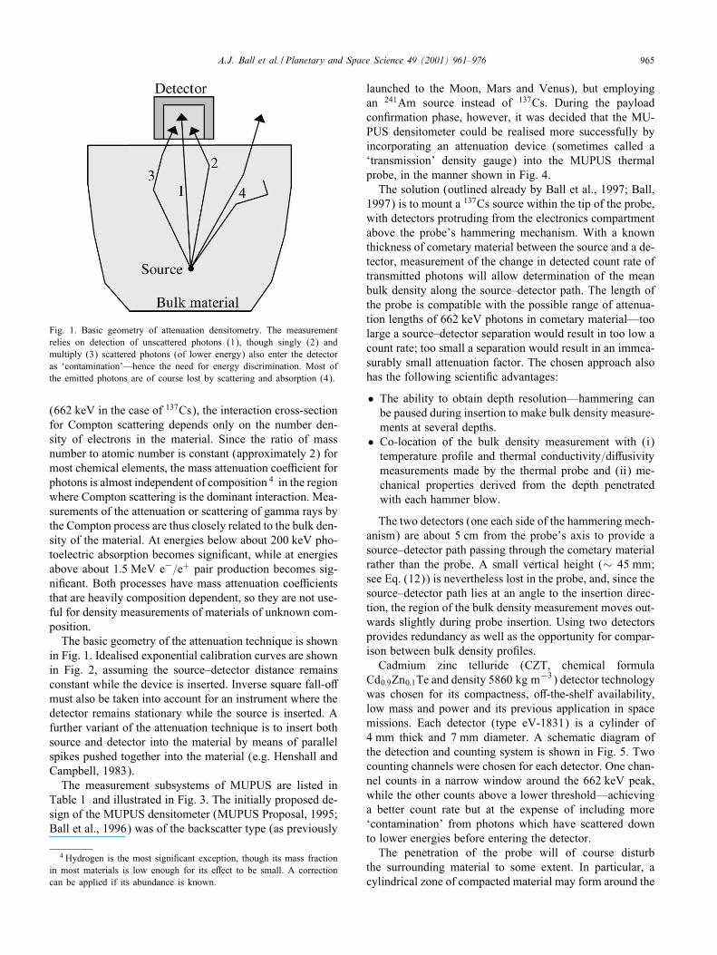
Fig. 1. Basic geometry of attenuation densitometry. The measurementrelies on detection of unscattered photons (1), though singly (2) andmultiply (3) scattered photons (of lower energy) also enter the detectoras ‘contamination’—hence the need for energy discrimination. Most ofthe emitted photons are of course lost by scattering and absorption (4).
(662 keV in the case of 137Cs), the interaction cross-sectionfor Compton scattering depends only on the number den-sity of electrons in the material. Since the ratio of massnumber to atomic number is constant (approximately 2) formost chemical elements, the mass attenuation coeLcient forphotons is almost independent of composition 4 in the regionwhere Compton scattering is the dominant interaction. Mea-surements of the attenuation or scattering of gamma rays bythe Compton process are thus closely related to the bulk den-sity of the material. At energies below about 200 keV pho-toelectric absorption becomes signi"cant, while at energiesabove about 1:5 MeV e−=e+ pair production becomes sig-ni"cant. Both processes have mass attenuation coeLcientsthat are heavily composition dependent, so they are not use-ful for density measurements of materials of unknown com-position.The basic geometry of the attenuation technique is shown
in Fig. 1. Idealised exponential calibration curves are shownin Fig. 2, assuming the source–detector distance remainsconstant while the device is inserted. Inverse square fall-o<must also be taken into account for an instrument where thedetector remains stationary while the source is inserted. Afurther variant of the attenuation technique is to insert bothsource and detector into the material by means of parallelspikes pushed together into the material (e.g. Henshall andCampbell, 1983).The measurement subsystems of MUPUS are listed in
Table 1 and illustrated in Fig. 3. The initially proposed de-sign of the MUPUS densitometer (MUPUS Proposal, 1995;Ball et al., 1996) was of the backscatter type (as previously
4 Hydrogen is the most signi"cant exception, though its mass fractionin most materials is low enough for its e<ect to be small. A correctioncan be applied if its abundance is known.
launched to the Moon, Mars and Venus), but employingan 241Am source instead of 137Cs. During the payloadcon"rmation phase, however, it was decided that the MU-PUS densitometer could be realised more successfully byincorporating an attenuation device (sometimes called a‘transmission’ density gauge) into the MUPUS thermalprobe, in the manner shown in Fig. 4.The solution (outlined already by Ball et al., 1997; Ball,
1997) is to mount a 137Cs source within the tip of the probe,with detectors protruding from the electronics compartmentabove the probe’s hammering mechanism. With a knownthickness of cometary material between the source and a de-tector, measurement of the change in detected count rate oftransmitted photons will allow determination of the meanbulk density along the source–detector path. The length ofthe probe is compatible with the possible range of attenua-tion lengths of 662 keV photons in cometary material—toolarge a source–detector separation would result in too low acount rate; too small a separation would result in an immea-surably small attenuation factor. The chosen approach alsohas the following scienti"c advantages:
• The ability to obtain depth resolution—hammering canbe paused during insertion to make bulk density measure-ments at several depths.
• Co-location of the bulk density measurement with (i)temperature pro"le and thermal conductivity=di<usivitymeasurements made by the thermal probe and (ii) me-chanical properties derived from the depth penetratedwith each hammer blow.
The two detectors (one each side of the hammering mech-anism) are about 5 cm from the probe’s axis to provide asource–detector path passing through the cometary materialrather than the probe. A small vertical height (∼ 45 mm;see Eq. (12)) is nevertheless lost in the probe, and, since thesource–detector path lies at an angle to the insertion direc-tion, the region of the bulk density measurement moves out-wards slightly during probe insertion. Using two detectorsprovides redundancy as well as the opportunity for compar-ison between bulk density pro"les.Cadmium zinc telluride (CZT, chemical formula
Cd0:9Zn0:1Te and density 5860 kg m−3) detector technologywas chosen for its compactness, o<-the-shelf availability,low mass and power and its previous application in spacemissions. Each detector (type eV-1831) is a cylinder of4 mm thick and 7 mm diameter. A schematic diagram ofthe detection and counting system is shown in Fig. 5. Twocounting channels were chosen for each detector. One chan-nel counts in a narrow window around the 662 keV peak,while the other counts above a lower threshold—achievinga better count rate but at the expense of including more‘contamination’ from photons which have scattered downto lower energies before entering the detector.The penetration of the probe will of course disturb
the surrounding material to some extent. In particular, acylindrical zone of compacted material may form around the

966 A.J. Ball et al. / Planetary and Space Science 49 (2001) 961–976
Fig. 2. Example calibration curves for a 137Cs attenuation densitometer, showing detected count rate vs. bulk density, normalised to the maximum.Curves are shown for four thicknesses (z) of intervening material. A mass attenuation coeLcient � of 8:31 × 10−3 m2 kg−1 was used, correspondingto 662 keV photons in H2O.
Table 1Measurement subsystems of the MUPUS experiment
Location Experimental subsystem Measurements
MUPUS penetrator Temperature probe Subsurface temperature pro"le(PEN; deployed from the (PEN-TP)a (resistance temperature sensors)Lander’s balcony) Thermal conductivity probe Thermal conductivity/di<usivity
(PEN-THC)a (active heating of temperature sensors)Penetrometer Strength of surface layers(PEN-M) (depth sensor during hammering)Densitometer Bulk density of surface layers(PEN-CBD)a (gamma ray attenuation technique during and
after probe insertion)
Top of Rosetta Lander Thermal mapper Surface temperaturebody, above the balcony (TM)a (IR sensors)
Rosetta Lander Anchor Anchor penetrometer Strength of surface layers(ANC; primary and backup (ANC-M) (piezoelectric accelerometer)anchors stowed on the Anchor temperature sensor Sub-surface temperaturelanding gear underneath the (ANC-T)a (PT100 sensor)baseplate)
aSubsystems which measure the evolution of these parameters with time.
probe—something that should be corrected for during dataanalysis. The thickness of the compacted zone can be esti-mated by assuming that the material is compacted from aninitial porosity � of 0.2–0.8 (the RNMG ‘fact sheet’ esti-mate for surface material) to a ‘locked’ porosity of 0.1 (forexample). The bulk density in the compacted zone wouldthen be higher than that of the undisturbed material byfactors of 1.125 and 4.5, respectively. Given that the radiusof the probe is 5 mm, the resulting thickness of the com-pacted zone can be calculated to be between 0:67 mm (for�= 0:8) and 10 mm (for �= 0:2). Independent constraintson the compressibility of the surface material (e.g. viamicrostructural models, laboratory analogue materials or
imagery showing deformation of the surface by the landinggear) would thus be useful for analysis of data from theMUPUS densitometer.
4. Monte Carlo simulations
Monte Carlo simulation can be employed to model aninserted attenuation densitometer. While the attenuation ofprimary photons is easily calculated analytically, the MonteCarlo method can also model the scattered radiation. Thedetection and counting system of the attenuation densitome-ter should aim to avoid counting too high a proportion of
A.J. Ball et al. / Planetary and Space Science 49 (2001) 961–976 967
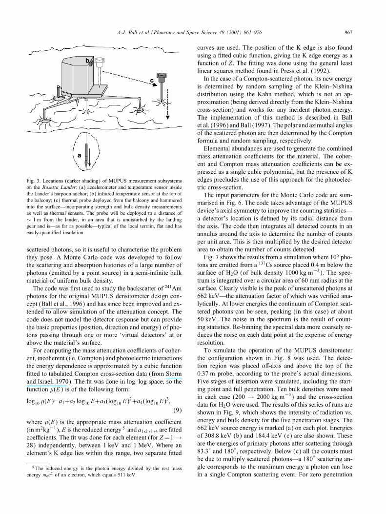
Fig. 3. Locations (darker shading) of MUPUS measurement subsystemson the Rosetta Lander: (a) accelerometer and temperature sensor insidethe Lander’s harpoon anchor; (b) infrared temperature sensor at the top ofthe balcony; (c) thermal probe deployed from the balcony and hammeredinto the surface—incorporating strength and bulk density measurementsas well as thermal sensors. The probe will be deployed to a distance of∼ 1 m from the lander, in an area that is undisturbed by the landinggear and is—as far as possible—typical of the local terrain, Iat and haseasily-quanti"ed insolation.
scattered photons, so it is useful to characterise the problemthey pose. A Monte Carlo code was developed to followthe scattering and absorption histories of a large number ofphotons (emitted by a point source) in a semi-in"nite bulkmaterial of uniform bulk density.The code was "rst used to study the backscatter of 241Am
photons for the original MUPUS densitometer design con-cept (Ball et al., 1996) and has since been improved and ex-tended to allow simulation of the attenuation concept. Thecode does not model the detector response but can providethe basic properties (position, direction and energy) of pho-tons passing through one or more ‘virtual detectors’ at orabove the material’s surface.For computing the mass attenuation coeLcients of coher-
ent, incoherent (i.e. Compton) and photoelectric interactionsthe energy dependence is approximated by a cubic function"tted to tabulated Compton cross-section data (from Stormand Israel, 1970). The "t was done in log–log space, so thefunction �(E) is of the following form:
log10 �(E)=a1+a2 log10 E+a3(log10 E)2+a4(log10 E)
3;(9)
where �(E) is the appropriate mass attenuation coeLcient(in m2kg−1), E is the reduced energy 5 and a1;2 ;3 ;4 are "ttedcoeLcients. The "t was done for each element (for Z=1 →28) independently, between 1 keV and 1 MeV. Where anelement’s K edge lies within this range, two separate "tted
5 The reduced energy is the photon energy divided by the rest massenergy mec2 of an electron, which equals 511 keV.
curves are used. The position of the K edge is also foundusing a "tted cubic function, giving the K edge energy as afunction of Z . The "tting was done using the general leastlinear squares method found in Press et al. (1992).In the case of a Compton-scattered photon, its new energy
is determined by random sampling of the Klein–Nishinadistribution using the Kahn method, which is not an ap-proximation (being derived directly from the Klein–Nishinacross-section) and works for any incident photon energy.The implementation of this method is described in Ballet al. (1996) and Ball (1997). The polar and azimuthal anglesof the scattered photon are then determined by the Comptonformula and random sampling, respectively.Elemental abundances are used to generate the combined
mass attenuation coeLcients for the material. The coher-ent and Compton mass attenuation coeLcients can be ex-pressed as a single cubic polynomial, but the presence of Kedges precludes the use of this approach for the photoelec-tric cross-section.The input parameters for the Monte Carlo code are sum-
marised in Fig. 6. The code takes advantage of the MUPUSdevice’s axial symmetry to improve the counting statistics—a detector’s location is de"ned by its radial distance fromthe axis. The code then integrates all detected counts in anannulus around the axis to determine the number of countsper unit area. This is then multiplied by the desired detectorarea to obtain the number of counts detected.Fig. 7 shows the results from a simulation where 106 pho-
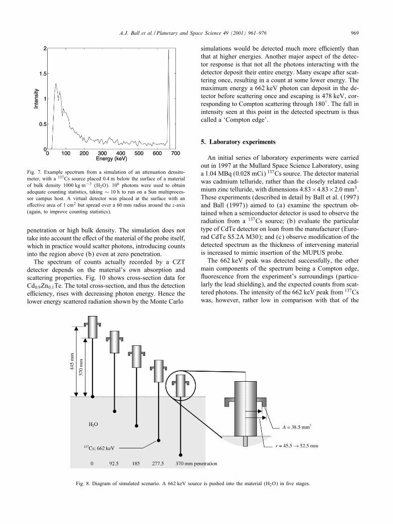
tons are emitted from a 137Cs source placed 0:4 m below thesurface of H2O (of bulk density 1000 kg m−3). The spec-trum is integrated over a circular area of 60 mm radius at thesurface. Clearly visible is the peak of unscattered photons at662 keV—the attenuation factor of which was veri"ed ana-lytically. At lower energies the continuum of Compton scat-tered photons can be seen, peaking (in this case) at about50 keV. The noise in the spectrum is the result of count-ing statistics. Re-binning the spectral data more coarsely re-duces the noise on each data point at the expense of energyresolution.To simulate the operation of the MUPUS densitometer
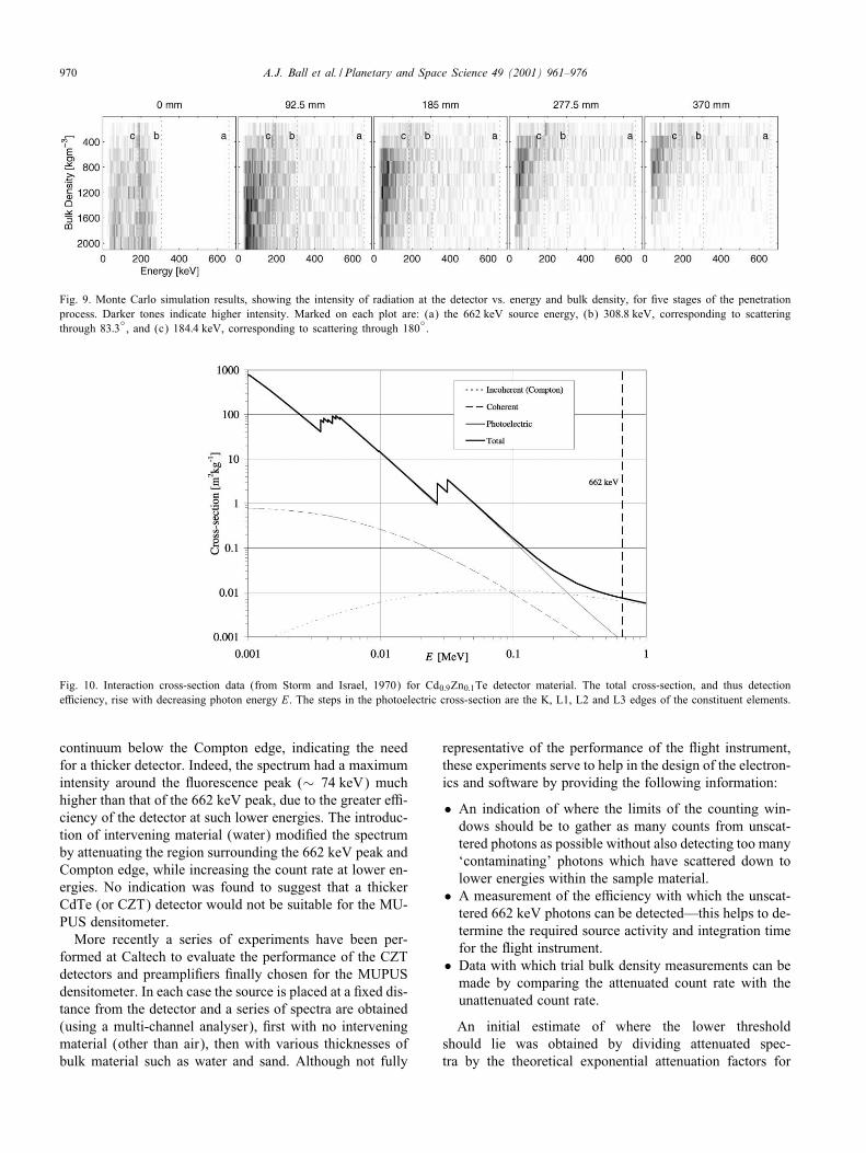
the con"guration shown in Fig. 8 was used. The detec-tion region was placed o<-axis and above the top of the0:37 m probe, according to the probe’s actual dimensions.Five stages of insertion were simulated, including the start-ing point and full penetration. Ten bulk densities were usedin each case (200 → 2000 kg m−3) and the cross-sectiondata for H2O were used. The results of this series of runs areshown in Fig. 9, which shows the intensity of radiation vs.energy and bulk density for the "ve penetration stages. The662 keV source energy is marked (a) on each plot. Energiesof 308:8 keV (b) and 184:4 keV (c) are also shown. Theseare the energies of primary photons after scattering through83:3◦ and 180◦, respectively. Below (c) all the counts mustbe due to multiply scattered photons—a 180◦ scattering an-gle corresponds to the maximum energy a photon can losein a single Compton scattering event. For zero penetration
968 A.J. Ball et al. / Planetary and Space Science 49 (2001) 961–976
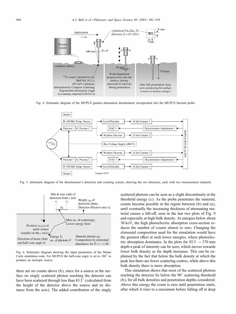
Fig. 4. Schematic diagram of the MUPUS gamma attenuation densitometer incorporated into the MUPUS thermal probe.
Fig. 5. Schematic diagram of the densitometer’s detection and counting system, showing the two detectors, each with two measurement channels.
Fig. 6. Schematic diagram showing the input parameters of the MonteCarlo simulation code. For MUPUS the half-cone angle is set to 180
◦to
produce an isotropic source.
there are no counts above (b), since for a source at the sur-face no singly scattered photon reaching the detector canhave been scattered through less than 83:3◦ (calculated fromthe height of the detector above the source and its dis-tance from the axis). The added contribution of the singly
scattered photons can be seen as a slight discontinuity at thethreshold energy (c). As the probe penetrates the material,counts become possible in the region between (b) and (a),until eventually the increasing thickness of attenuating ma-terial causes a fall-o<, seen in the last two plots of Fig. 9and especially at high bulk density. At energies below about30 keV, the high photoelectric absorption cross-section re-duces the number of counts almost to zero. Changing theelemental composition used for the simulation would havethe greatest e<ect at such lower energies, where photoelec-tric absorption dominates. In the plots for 92:5 → 370 mmdepth a peak of intensity can be seen, which moves towardslower bulk density as the depth increases. This can be ex-plained by the fact that below the bulk density at which thepeak lies there are fewer scattering centres, while above thisbulk density there is more absorption.This simulation shows that most of the scattered photons
reaching the detector lie below the 90◦ scattering threshold(b), for all bulk densities and penetration depths considered.Above this energy the count is zero until penetration starts,after which it rises to a maximum before falling o< at deep
A.J. Ball et al. / Planetary and Space Science 49 (2001) 961–976 969
Fig. 7. Example spectrum from a simulation of an attenuation densito-meter, with a 137Cs source placed 0:4 m below the surface of a materialof bulk density 1000 kg m−3 (H2O). 106 photons were used to obtainadequate counting statistics, taking ∼ 10 h to run on a Sun multiproces-sor campus host. A virtual detector was placed at the surface with ane<ective area of 1 cm2 but spread over a 60 mm radius around the z-axis(again, to improve counting statistics).
penetration or high bulk density. The simulation does nottake into account the e<ect of the material of the probe itself,which in practice would scatter photons, introducing countsinto the region above (b) even at zero penetration.The spectrum of counts actually recorded by a CZT
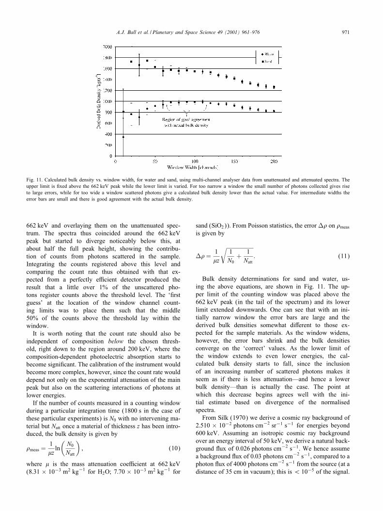
detector depends on the material’s own absorption andscattering properties. Fig. 10 shows cross-section data forCd0:9Zn0:1Te. The total cross-section, and thus the detectioneLciency, rises with decreasing photon energy. Hence thelower energy scattered radiation shown by the Monte Carlo
Fig. 8. Diagram of simulated scenario. A 662 keV source is pushed into the material (H2O) in "ve stages.
simulations would be detected much more eLciently thanthat at higher energies. Another major aspect of the detec-tor response is that not all the photons interacting with thedetector deposit their entire energy. Many escape after scat-tering once, resulting in a count at some lower energy. Themaximum energy a 662 keV photon can deposit in the de-tector before scattering once and escaping is 478 keV, cor-responding to Compton scattering through 180◦. The fall inintensity seen at this point in the detected spectrum is thuscalled a ‘Compton edge’.
5. Laboratory experiments
An initial series of laboratory experiments were carriedout in 1997 at the Mullard Space Science Laboratory, usinga 1:04 MBq (0:028 mCi) 137Cs source. The detector materialwas cadmium telluride, rather than the closely related cad-mium zinc telluride, with dimensions 4:83×4:83×2:0 mm3.These experiments (described in detail by Ball et al. (1997)and Ball (1997)) aimed to (a) examine the spectrum ob-tained when a semiconductor detector is used to observe theradiation from a 137Cs source; (b) evaluate the particulartype of CdTe detector on loan from the manufacturer (Euro-rad CdTe S5.2A M30); and (c) observe modi"cation of thedetected spectrum as the thickness of intervening materialis increased to mimic insertion of the MUPUS probe.The 662 keV peak was detected successfully, the other
main components of the spectrum being a Compton edge,Iuorescence from the experiment’s surroundings (particu-larly the lead shielding), and the expected counts from scat-tered photons. The intensity of the 662 keV peak from 137Cswas, however, rather low in comparison with that of the
970 A.J. Ball et al. / Planetary and Space Science 49 (2001) 961–976
Fig. 9. Monte Carlo simulation results, showing the intensity of radiation at the detector vs. energy and bulk density, for "ve stages of the penetrationprocess. Darker tones indicate higher intensity. Marked on each plot are: (a) the 662 keV source energy, (b) 308:8 keV, corresponding to scatteringthrough 83:3
◦, and (c) 184:4 keV, corresponding to scattering through 180
◦.
Fig. 10. Interaction cross-section data (from Storm and Israel, 1970) for Cd0:9Zn0:1Te detector material. The total cross-section, and thus detectioneLciency, rise with decreasing photon energy E. The steps in the photoelectric cross-section are the K, L1, L2 and L3 edges of the constituent elements.
continuum below the Compton edge, indicating the needfor a thicker detector. Indeed, the spectrum had a maximumintensity around the Iuorescence peak (∼ 74 keV) muchhigher than that of the 662 keV peak, due to the greater eL-ciency of the detector at such lower energies. The introduc-tion of intervening material (water) modi"ed the spectrumby attenuating the region surrounding the 662 keV peak andCompton edge, while increasing the count rate at lower en-ergies. No indication was found to suggest that a thickerCdTe (or CZT) detector would not be suitable for the MU-PUS densitometer.More recently a series of experiments have been per-
formed at Caltech to evaluate the performance of the CZTdetectors and preampli"ers "nally chosen for the MUPUSdensitometer. In each case the source is placed at a "xed dis-tance from the detector and a series of spectra are obtained(using a multi-channel analyser), "rst with no interveningmaterial (other than air), then with various thicknesses ofbulk material such as water and sand. Although not fully
representative of the performance of the Iight instrument,these experiments serve to help in the design of the electron-ics and software by providing the following information:
• An indication of where the limits of the counting win-dows should be to gather as many counts from unscat-tered photons as possible without also detecting too many‘contaminating’ photons which have scattered down tolower energies within the sample material.
• A measurement of the eLciency with which the unscat-tered 662 keV photons can be detected—this helps to de-termine the required source activity and integration timefor the Iight instrument.
• Data with which trial bulk density measurements can bemade by comparing the attenuated count rate with theunattenuated count rate.
An initial estimate of where the lower thresholdshould lie was obtained by dividing attenuated spec-tra by the theoretical exponential attenuation factors for
A.J. Ball et al. / Planetary and Space Science 49 (2001) 961–976 971
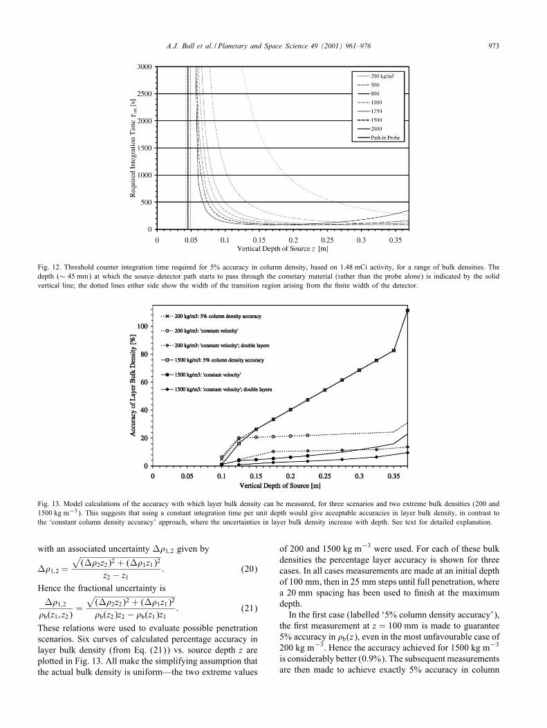
Fig. 11. Calculated bulk density vs. window width, for water and sand, using multi-channel analyser data from unattenuated and attenuated spectra. Theupper limit is "xed above the 662 keV peak while the lower limit is varied. For too narrow a window the small number of photons collected gives riseto large errors, while for too wide a window scattered photons give a calculated bulk density lower than the actual value. For intermediate widths theerror bars are small and there is good agreement with the actual bulk density.
662 keV and overlaying them on the unattenuated spec-trum. The spectra thus coincided around the 662 keVpeak but started to diverge noticeably below this, atabout half the full peak height, showing the contribu-tion of counts from photons scattered in the sample.Integrating the counts registered above this level andcomparing the count rate thus obtained with that ex-pected from a perfectly eLcient detector produced theresult that a little over 1% of the unscattered pho-tons register counts above the threshold level. The ‘"rstguess’ at the location of the window channel count-ing limits was to place them such that the middle50% of the counts above the threshold lay within thewindow.It is worth noting that the count rate should also be
independent of composition below the chosen thresh-old, right down to the region around 200 keV, where thecomposition-dependent photoelectric absorption starts tobecome signi"cant. The calibration of the instrument wouldbecome more complex, however, since the count rate woulddepend not only on the exponential attenuation of the mainpeak but also on the scattering interactions of photons atlower energies.If the number of counts measured in a counting window
during a particular integration time (1800 s in the case ofthese particular experiments) is N0 with no intervening ma-terial but Natt once a material of thickness z has been intro-duced, the bulk density is given by
�meas =1�z
ln(N0
Natt
); (10)
where � is the mass attenuation coeLcient at 662 keV(8:31 × 10−3 m2 kg−1 for H2O; 7:70 × 10−3 m2 kg−1 for
sand (SiO2)). From Poisson statistics, the error W� on �meas
is given by
W�=1�z
√1N0
+1Natt
: (11)
Bulk density determinations for sand and water, us-ing the above equations, are shown in Fig. 11. The up-per limit of the counting window was placed above the662 keV peak (in the tail of the spectrum) and its lowerlimit extended downwards. One can see that with an ini-tially narrow window the error bars are large and thederived bulk densities somewhat di<erent to those ex-pected for the sample materials. As the window widens,however, the error bars shrink and the bulk densitiesconverge on the ‘correct’ values. As the lower limit ofthe window extends to even lower energies, the cal-culated bulk density starts to fall, since the inclusionof an increasing number of scattered photons makes itseem as if there is less attenuation—and hence a lowerbulk density—than is actually the case. The point atwhich this decrease begins agrees well with the ini-tial estimate based on divergence of the normalisedspectra.From Silk (1970) we derive a cosmic ray background of
2:510 × 10−2 photons cm−2 sr−1 s−1 for energies beyond600 keV. Assuming an isotropic cosmic ray backgroundover an energy interval of 50 keV, we derive a natural back-ground Iux of 0:026 photons cm−2 s−1. We hence assumea background Iux of 0:03 photons cm−2 s−1, compared to aphoton Iux of 4000 photons cm−2 s−1 from the source (at adistance of 35 cm in vacuum); this is¡ 10−5 of the signal.

972 A.J. Ball et al. / Planetary and Space Science 49 (2001) 961–976
6. Required integration time and possible penetrationschemes
The Poisson statistics associated with the counting of pho-tons emitted randomly from radioactive decay needs to beconsidered when calculating the minimum integration timerequired to determine bulk density to the desired accuracy.If N photons are counted in a time "int, the count rate N="inthas an associated error of N 1=2="int. This error thus propa-gates to the density determinations.Since the probe carrying the source has a "nite diameter
d (10 mm) and the source–detector paths are at an angle #(∼ 6◦) from the probe’s axis, a vertical path z0 is lost in theprobe, i.e. only when the source has penetrated to a depth¿z0 do the unscattered photons reaching the detectors passthrough the cometary material. z0 is given by
z0 =d
2 tan #(12)
and is approximately 45 mm. The mean count rate C(z)of unscattered photons at penetrated depth z (¿z0) is thusgiven by the following exponential attenuation relation:
C(z) = C(0) exp(−��b(z)(z − z0)
cos #
); (13)
where � is the mass attenuation coeLcient at 662 keV. Notethat the count rate C(0) at zero penetration already takesinto account the attenuation of photons in the material of thetip and probe. �b(z) is the mean bulk density of cometarymaterial along the path to a detector, as de"ned by the fol-lowing integral:
�b(z) =1
z − z0
∫ z−z0
z′=0�(z′) dz′: (14)
Rearranging Eq. (13) gives an expression for bulk densityas a function of count rate:
�b(z) =cos #
�(z − z0)ln(C(0)C(z)
): (15)
From Poisson statistics the number of counts required tomeasure �b(z) to an accuracy W� is(�W�(z − z0)
cos #
)−2
: (16)
We have assumed here that the uncertainty in C(0) is negli-gible compared with that of C(z)—for this assumption to bevalid, values of C(0) for each of the four counting channelsmust be determined accurately enough, after deployment ofthe probe on the comet but before the start of penetration.The integration time required to measure �b(z) to an ac-
curacy W� is thus given by
"int(z) =(
cos #�W�(z − z0)
)2 1C(0)
exp(��b(z)(z − z0)
cos #
):
(17)
This function is shown in Fig. 12 for a range of bulk densi-ties, W�=�b(z)=5% and a possible procured source activity
of 2 mCi, decaying to 1:48 mCi by the time the source ar-rives at the comet in 2012 6 . Data from the Caltech labora-tory experiments was used to estimate C(0) for the thresholdcounter (giving 8:73 s−1) and hence calibrate the verticalaxis. Minima occur at depths
z = z0 +2 cos #��b
: (18)
At shallower depths the required time rises due to the smallerfractional change in count rate caused by the layer of inter-vening material, while at greater depths the reduced countrate demands longer integration times. For the MUPUS con-"guration the former is the more signi"cant challenge—atwhat depth should the "rst measurement be made? For bulkdensities at the lower end of the expected range there is adanger that the small change in count rate at particularlyshallow depths may be undetectable (or detectable only witha large uncertainty) in the time spent at that depth. An ini-tial measurement with the source at a depth of 100 mm maybe an acceptable solution; in any case, possible disturbanceof the surface material caused by initial entry of the probemay make measurements unreliable in the upper few tens ofmm, where the source–detector path is closest to the shaft.Although the hammered insertion of the probe will al-
low determination of a pro"le of bulk density vs. depth,careful planning of the penetration=bulk density measure-ment sequence is required to maximise scienti"c return.The penetrator cannot go backwards, so at each stage ofpenetration there is only one chance to measure the countrate successfully. Enough time must be spent to achievesuLcient accuracy, while still leaving enough time for mea-surements at greater depths (and, of course, the thermal mea-surements after full penetration). The uncertain mechanicalproperties of the surface material and the nature of the ham-mering process make it almost impossible to pause pene-tration at exactly the depths desired; the "nal penetrationscheme selected should thus take this into account.To attempt to maintain constant accuracy in �b(z) would,
as indicated by Fig. 12, mean varying the integration timewith depth, based on the feedback of measured bulk densityinto a time budgeting algorithm at each stage of penetration,as suggested by Ball (1997). While Fig. 12 shows the largevariations in integration time needed to achieve 5% accuracyin �b(z), from a scienti"c point of view it is important to beable to measure the bulk density of layers successfully. Thesimplest approach is to use two adjacent measurements towork out the bulk density of the material in between. Sup-pose mean bulk densities �b(z1)±W�1 and �b(z2)±W�2 aremeasured with the source at depths z1 and z2, respectively.The bulk density �b(z1; z2) of the intervening layer is thus
�b(z1; z2) =�b(z2)z2 − �b(z1)z1
z2 − z1; (19)
6 It now seems likely that the actual Iight model source activity willbe somewhat lower than the value used here, giving instead an activityof about 0:84 mCi on the comet in 2012.
A.J. Ball et al. / Planetary and Space Science 49 (2001) 961–976 973
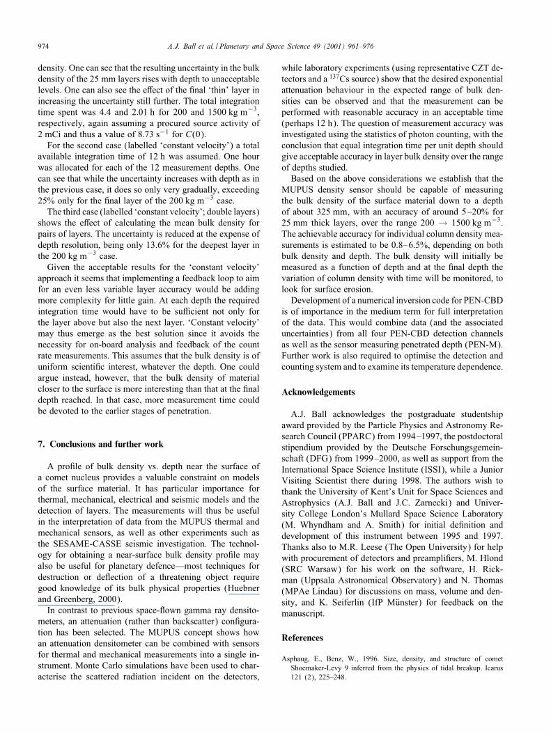
Fig. 12. Threshold counter integration time required for 5% accuracy in column density, based on 1:48 mCi activity, for a range of bulk densities. Thedepth (∼ 45 mm) at which the source–detector path starts to pass through the cometary material (rather than the probe alone) is indicated by the solidvertical line; the dotted lines either side show the width of the transition region arising from the "nite width of the detector.
Fig. 13. Model calculations of the accuracy with which layer bulk density can be measured, for three scenarios and two extreme bulk densities (200 and1500 kg m−3). This suggests that using a constant integration time per unit depth would give acceptable accuracies in layer bulk density, in contrast tothe ‘constant column density accuracy’ approach, where the uncertainties in layer bulk density increase with depth. See text for detailed explanation.
with an associated uncertainty W�1;2 given by
W�1;2 =
√(W�2z2)2 + (W�1z1)2
z2 − z1: (20)
Hence the fractional uncertainty is
W�1;2�b(z1; z2)
=
√(W�2z2)2 + (W�1z1)2
�b(z2)z2 − �b(z1)z1: (21)
These relations were used to evaluate possible penetrationscenarios. Six curves of calculated percentage accuracy inlayer bulk density (from Eq. (21)) vs. source depth z areplotted in Fig. 13. All make the simplifying assumption thatthe actual bulk density is uniform—the two extreme values
of 200 and 1500 kg m−3 were used. For each of these bulkdensities the percentage layer accuracy is shown for threecases. In all cases measurements are made at an initial depthof 100 mm, then in 25 mm steps until full penetration, wherea 20 mm spacing has been used to "nish at the maximumdepth.In the "rst case (labelled ‘5% column density accuracy’),
the "rst measurement at z = 100 mm is made to guarantee5% accuracy in �b(z), even in the most unfavourable case of200 kg m−3. Hence the accuracy achieved for 1500 kg m−3
is considerably better (0.9%). The subsequent measurementsare then made to achieve exactly 5% accuracy in column
974 A.J. Ball et al. / Planetary and Space Science 49 (2001) 961–976
density. One can see that the resulting uncertainty in the bulkdensity of the 25 mm layers rises with depth to unacceptablelevels. One can also see the e<ect of the "nal ‘thin’ layer inincreasing the uncertainty still further. The total integrationtime spent was 4.4 and 2:01 h for 200 and 1500 kg m−3,respectively, again assuming a procured source activity of2 mCi and thus a value of 8:73 s−1 for C(0).For the second case (labelled ‘constant velocity’) a total
available integration time of 12 h was assumed. One hourwas allocated for each of the 12 measurement depths. Onecan see that while the uncertainty increases with depth as inthe previous case, it does so only very gradually, exceeding25% only for the "nal layer of the 200 kg m−3 case.
The third case (labelled ‘constant velocity’; double layers)shows the e<ect of calculating the mean bulk density forpairs of layers. The uncertainty is reduced at the expense ofdepth resolution, being only 13.6% for the deepest layer inthe 200 kg m−3 case.Given the acceptable results for the ‘constant velocity’
approach it seems that implementing a feedback loop to aimfor an even less variable layer accuracy would be addingmore complexity for little gain. At each depth the requiredintegration time would have to be suLcient not only forthe layer above but also the next layer. ‘Constant velocity’may thus emerge as the best solution since it avoids thenecessity for on-board analysis and feedback of the countrate measurements. This assumes that the bulk density is ofuniform scienti"c interest, whatever the depth. One couldargue instead, however, that the bulk density of materialcloser to the surface is more interesting than that at the "naldepth reached. In that case, more measurement time couldbe devoted to the earlier stages of penetration.
7. Conclusions and further work
A pro"le of bulk density vs. depth near the surface ofa comet nucleus provides a valuable constraint on modelsof the surface material. It has particular importance forthermal, mechanical, electrical and seismic models and thedetection of layers. The measurements will thus be usefulin the interpretation of data from the MUPUS thermal andmechanical sensors, as well as other experiments such asthe SESAME-CASSE seismic investigation. The technol-ogy for obtaining a near-surface bulk density pro"le mayalso be useful for planetary defence—most techniques fordestruction or deIection of a threatening object requiregood knowledge of its bulk physical properties (Huebnerand Greenberg, 2000).In contrast to previous space-Iown gamma ray densito-
meters, an attenuation (rather than backscatter) con"gura-tion has been selected. The MUPUS concept shows howan attenuation densitometer can be combined with sensorsfor thermal and mechanical measurements into a single in-strument. Monte Carlo simulations have been used to char-acterise the scattered radiation incident on the detectors,
while laboratory experiments (using representative CZT de-tectors and a 137Cs source) show that the desired exponentialattenuation behaviour in the expected range of bulk den-sities can be observed and that the measurement can beperformed with reasonable accuracy in an acceptable time(perhaps 12 h). The question of measurement accuracy wasinvestigated using the statistics of photon counting, with theconclusion that equal integration time per unit depth shouldgive acceptable accuracy in layer bulk density over the rangeof depths studied.Based on the above considerations we establish that the
MUPUS density sensor should be capable of measuringthe bulk density of the surface material down to a depthof about 325 mm, with an accuracy of around 5–20% for25 mm thick layers, over the range 200 → 1500 kg m−3.The achievable accuracy for individual column density mea-surements is estimated to be 0.8–6.5%, depending on bothbulk density and depth. The bulk density will initially bemeasured as a function of depth and at the "nal depth thevariation of column density with time will be monitored, tolook for surface erosion.Development of a numerical inversion code for PEN-CBD
is of importance in the medium term for full interpretationof the data. This would combine data (and the associateduncertainties) from all four PEN-CBD detection channelsas well as the sensor measuring penetrated depth (PEN-M).Further work is also required to optimise the detection andcounting system and to examine its temperature dependence.
Acknowledgements
A.J. Ball acknowledges the postgraduate studentshipaward provided by the Particle Physics and Astronomy Re-search Council (PPARC) from 1994–1997, the postdoctoralstipendium provided by the Deutsche Forschungsgemein-schaft (DFG) from 1999–2000, as well as support from theInternational Space Science Institute (ISSI), while a JuniorVisiting Scientist there during 1998. The authors wish tothank the University of Kent’s Unit for Space Sciences andAstrophysics (A.J. Ball and J.C. Zarnecki) and Univer-sity College London’s Mullard Space Science Laboratory(M. Whyndham and A. Smith) for initial de"nition anddevelopment of this instrument between 1995 and 1997.Thanks also to M.R. Leese (The Open University) for helpwith procurement of detectors and preampli"ers, M. Hlond(SRC Warsaw) for his work on the software, H. Rick-man (Uppsala Astronomical Observatory) and N. Thomas(MPAe Lindau) for discussions on mass, volume and den-sity, and K. Seiferlin (IfP MQunster) for feedback on themanuscript.
References
Asphaug, E., Benz, W., 1996. Size, density, and structure of cometShoemaker-Levy 9 inferred from the physics of tidal breakup. Icarus121 (2), 225–248.
A.J. Ball et al. / Planetary and Space Science 49 (2001) 961–976 975
Ball, A.J., 1997. Measuring physical properties at the surface of a cometnucleus. Ph.D. Thesis. University of Kent, Canterbury.
Ball, A.J., Solomon, C.J., Zarnecki, J.C., 1996. A Compton backscatterdensitometer for the RoLand comet lander—design concept and MonteCarlo simulations. Planet. Space Sci. 44 (3), 283–293.
Ball, A.J., Trow, M.W., Smith, A., Zarnecki, J.C., 1997. Laboratorydevelopment of the MUPUS densitometer for the Rosetta comet lander.Poster PS076 at the European Geophysical Society, Vienna, 21–25April 1997. Abstract in: Ann. Geophysicae 15 (suppl. III), C810.
Banaszkiewicz, M., Seiferlin, K., Spohn, T., Kargl, G., KQomle, N., 1997.A new method for the determination of thermal conductivity andthermal di<usivity from linear heat source measurements. Rev. Sci.Instrum. 68 (11), 4184–4190.
Benkho<, J., 1992. Laborexperimente und Modellrechnungen zurUntersuchung der thermischen Evolution porQoser Eis-Staub-Probenunter Weltraumbedingungen: Konsequenzen fQur Kometen undandere planetare EiskQorper. Ph.D. Thesis, Institut fQur Planetologie,WestfQalische Wilhelms-UniversitQat, MQunster, Germany. ReiheGeowissenschaften, Shaker Verlag, Aachen.
Benkho<, J., Huebner, W.F., 1995. InIuence of the vapor Iux ontemperature, density, and abundance distributions in a multicomponent,porous, icy body. Icarus 114 (2), 348–354.
Carrier, W.D., Olhoeft, G.R., Mendell, W., 1991. Physical properties ofthe lunar surface. In: Heiken, G., Vaniman, D., Bevan, M. (Eds.),Lunar Sourcebook: A User’s Guide to the Moon. Cambridge UniversityPress, Cambridge, pp. 475–594.
Cherkasov, I.I., Kemurdzhian, A.L., Mikhailov, L.N., Mikheev, V.V.,Morozov, A.A., Musatov, A.A., Savenko, I.A., Smorodinov, M.I.,Shvarev, V.V., 1967. Determination of the density and mechanicalstrength of the surface layer of lunar soil at the landing site of theLuna 13 Probe. Kosm. Issled. 5(5), 746–757 (in Russian: Translationin Cosmic Res. 4, 636–645, 1968).
Cherkasov, I.I., Mikheyev, V.V., Smorodinov, M.I., Shvarev, V.V.,Zobachev, N.M., Morozov, A.A., Petrukhin, V.P., 1968a. The directdetermination of the structure, density, and mechanical properties oflunar soils with the aid of automatic stations. Izv. Akad. Nauk SSSR,Fiz. Zemli 6, 3–14 (in Russian: Translation in Izv. Acad. Sci. USSR,Phys. Solid Earth 6, 339–345, 1968).
Cherkasov, I.I., Vakhnin, V.M., Kemurjian, A.L., Mikhailov, L.N.,Mikheyev, V.V., Musatov, A.A., Smorodinov, M.I., Shvarev, V.V.,1968b. Determination of the physical and mechanical properties of thelunar surface layer by means of Luna 13 automatic station. In: Dollfus,A. (Ed.), Moon and Planets 2. North-Holland, Amsterdam, pp. 70–76.
De Sanctis, M.C., Capaccioni, F., Capria, M.T., Coradini, A., Federico,C., Orosei, R., Salomone, M., 1999. Models of P/Wirtanen nucleus:active regions versus non-active regions. Planet. Space Sci. 47 (6–7),855–872.
Donn, B., Hughes, D., 1986. A fractal model of a cometary nucleusformed by random accretion. In: Battrick, B., Rolfe, E.J., Reinhard, R.(Eds.), Proceedings of the 20th ESLAB Symposium on the Explorationof Halley’s Comet. ESA SP-250, Vol. III, pp. 523–524.
Harmon, J.K., Campbell, D.B., Ostro, S.J., Nolan, M.C., 1999. Radarobservations of comets. Planet. Space Sci. 47 (12), 1409–1422.
Henshall, J.K., Campbell, D.J., 1983. The calibration of a high resolutiongamma-ray transmission system for measuring soil bulk density andan assessment of its "eld performance. J. Soil Sci. 34 (3), 453–463.
Huebner, W.F., Greenberg, J.M., 2000. Needs for determining materialstrengths and bulk properties of NEOs. Planet. Space Sci. 48 (9),797–799.
Keller, G.V., 1989. Electrical properties. In: Carmichael, R.S. (Ed.),Practical Handbook of Physical Properties of Rocks and Minerals.CRC Press, Boca Raton, FL.
Keller, H.U., 1987. The nucleus of comet Halley. In: Rolfe, E.J., Battrick,B. (Eds.), Diversity and Similarity of Comets. ESA SP-278, pp. 447–454.
Keller, H.U., Curdt, W., Kramm, J.-R., Thomas, N., 1994. Images of thenucleus of comet Halley obtained by the Halley multicolour camera(HMC) on board the Giotto Spacecraft. ESA SP-1127, Vol. 1.
Kemurdzhian, A.L., 1990. From the Moon Rover to the Mars Rover. ThePlanetary Report X(4), pp. 4–11.
Kemurdzhian, A.L., Gromov, V.V., Kazhukalo, I.F., Kozlov, G.V.,Komissarov, V.I., Korepanov, G.N., Martinov, B.N., Malenkov, V.I.,Mitskevich, A.V., Mishkinyuk, V.K., Rogovsky, G.N., Sologub, P.S.,1993. Soviet developments of planet rovers in period of 1964–1990. In:Proceedings of the International Symposium on Missions, Technologiesand Design of Planetary Mobile Vehicles, Toulouse, September 1992.CNES/CMepadu[es- MEditions, Toulouse, pp. 25–43.
Klinger, J., 1991. Physical properties of frozen volatiles—their relevanceto the study of comet nuclei. In: Newburn, R.L., et al. (Eds.), Comets inthe Post-Halley Era, Vol. 1. Kluwer, Academic Publishers, Dordrecht,pp. 227–241.
Kochan, H., Feibig, W., Konopka, U., Kretschmer, M., MQohlmann,D., Seidensticker, K.J., Arnold, W., Gebhardt, W., Licht, R.,2000. CASSE—The Rosetta Lander comet acoustic surface soundingexperiment—status of some aspects, the technical realisation andlaboratory simulations. Planet. Space Sci. 48 (5), 385–399.
KQomle, N.I., Ball, A.J., Kargl, G., StQocker, J., Thiel, M., Jolly, H.S.,Dziruni, M., Zarnecki, J.C., 1997. Using the anchoring device of acomet lander to determine surface mechanical properties. Planet. SpaceSci. 45 (12), 1515–1538.
KQomle, N.I., Ball, A.J., Kargl, G., Keller, T., Macher, W., Thiel, M.,StQocker, J., Rohe, C., 2001. Impact penetrometry on a comet nucleus—interpretation of laboratory data using penetration models. Planet. SpaceSci. 49 (6), 575–598.
KQuhrt, E., Keller, H.U., 1994. The formation of cometary surface crusts.Icarus 109 (1), 121–132.
Landau, L.D., Lifshitz, E.M., 1984. Electrodynamics of Continuous Media,2nd Edition. Pergamon, Oxford.
Matese, J.J., Whitman, P.G., 1994. Meteoroid streams as probes of thesubsurface regions of comets. Icarus 109 (2), 258–266.
MQatzler, C., 1998. Microwave properties of ice and snow. In: Schmitt, B.,de Bergh, C., Festou, M. (Eds.), Solar System Ices. Kluwer AcademicPublishers, Dordrecht, pp. 241–257.
MerMenyi, E., FQoldy, L., SzegQo, K., TMoth, I., Kondor, A., 1990. Thelandscape of comet Halley. Icarus 86 (1), 9–20.
MQohlmann, D., 1996. Comet 46 P/Wirtanen Nucleus Reference Model,1st Edition. ROL-DLR/MQoh-TN, DLR, Cologne.
Moore, H.J., Hutton, R.E., Scott, R.F., Spitzer, C.R., Shorthill, R.W.,1977. Surface materials of the Viking landing sites. J. Geophys. Res.82 (28), 4497–4523.
Moore, H.J., Bickler, D.B., Crisp, J.A., Eisen, H.J., Gensler, J.A.,Haldemann, A.F.C., Matijevic, J.R., Reid, L.K., 1999. Soil-like depositsobserved by Sojourner, the Path"nder rover. J. Geophys. Res. 104(E4), 8729–8746.
Morozov, A.A., Smorodinov, M.I., Shvarev, V.V., Cherkasov, I.I., 1968.Measurement of the lunar surface density by the automatic station“Luna-13”. Dokl. Akad. Nauk SSSR 179(5), 1087–1090 (in Russian:Translation in Sov. Phys. Dokl. 13(2), 348–350, 1968).
MUPUS Proposal, June 1995. Responsible proposer: Prof. Tilman Spohn,Institut fQur Planetologie, WestfQalische Wilhelms-UniversitQat, MQunster.
Nicholson, P.D., Hamilton, D.P., Matthews, K., Yoder, C.F., 1992. Newobservations of Saturn’s coorbital satellites. Icarus 100 (2), 464–484.
Peale, S.J., 1989. On the density of Halley’s comet. Icarus 82 (1), 36–49.Press, W.H., Teukolsky, S.A., Vetterling, W.T., Flannery, B.P., 1992.
Numerical Recipes in FORTRAN: the Art of Scienti"c Computing,2nd Edition. Cambridge University Press, Cambridge.
Rickman, H., 1986. Masses and densities of comets Halley and Kop<. In:Melita, O. (Ed.), The Comet Nucleus Sample Return Mission. ESASP-249, pp. 195–205.
Rickman, H., 1989. The nucleus of comet Halley: surface structure,mean density, gas and dust production. Adv. Space Res. 9 (3),59–71.

976 A.J. Ball et al. / Planetary and Space Science 49 (2001) 961–976
Rickman, H., KamMel, L., Festou, M. C., FroeschlMe, C., 1987. Estimatesof masses, volumes and densities of short-period comet nuclei. In:Rolfe, E.J., Battrick, B. (Eds.), Diversity and Similarity of Comets.ESA SP-278, pp. 471–481.
Schwehm, G. (Ed.), 2001. Rosetta Nucleus Modelling Group Report.ESA SP–1165, in press.
Seiferlin, K., KQomle, N.I., Kargl, G., Spohn, T., 1996. Line heat-sourcemeasurements of the thermal conductivity of porous H2O ice, CO2ice and mineral powders under space conditions. Planet. Space Sci.44 (7), 691–704.
Silk, J., 1970. Di<use cosmic X- and Gamma radiation: the isotropiccomponent. Space Sci. Rev. 11 (5), 671–708.
Skorov, Yu.V., Rickman, H., 1999. Gas Iow and dust accelerationin a cometary Knudsen layer. Planet. Space Sci. 47 (8/9),935–949.
Spohn, T., Ball, A.J., Seiferlin, K., Conzelmann, V., Hagermann, A.,KQomle, N.I., Kargl, G., 2001. A heat Iow and physical propertiespackage for the surface of Mercury. Planet. Space Sci., submitted.
Storm, E., Israel, H.I., 1970. Photon cross sections from 1 keV to 100 MeVfor elements Z = 1 to Z = 100. Nucl. Data Tables A7, 565–681.
Surkov, Yu.A., 1997. Exploration of Terrestrial Planets fromSpacecraft: Instrumentation, Investigation, Interpretation, 2nd Edition.Wiley-Praxis, Chichester.
Surkov, Yu.A., Kirnozov, F.F., Khristianov, V.K., Korchuganov, B.N.,Glazov, V.N., Ivanov, V.F., 1976. Density of surface rock on Venusfrom data obtained by the Venera 10 automatic interplanetary station.Kosm. Issled. 14(5), 697–703 (in Russian: Translation in Cosmic Res.14(5), 612–618, 1976).
Surkov, Yu.A., Khristianov, V.K., Korchuganov, B.N., Kirnozov, F.F.,Glazov, V.N., 1977a. Method, equipment and main results of themeasurement of the Venusian rock density on “Venera-10”. Space Sci.Instrum. 3, 287–299.
Surkov, Yu.A., Kirnozov, F.F., Khristianov, V.K., Korchuganov, B.N.,Glazov, V.N., Ivanov, V.F., 1977b. Investigations of the density ofthe Venusian surface rocks by Venera 10. Space Res. 17, 651–657.
Thomas, P.C., Veverka, J., Bell, J.F., Clark, B.E., Carcich, B., Joseph, J.,Robinson, M., McFadden, L.A., Malin, M.C., Chapman, C.R., Merline,W., Murchie, S., 1999. Mathilde: size, shape, and geology. Icarus 140(1), 17–27.
Ulaby, F.T., Bengal, T.H., Dobson, M.C., East, J.R., Garvin, J.B., Evans,D.L., 1990. Microwave dielectric properties of dry rocks. IEEE Trans.Geosci. Remote Sensing 28 (3), 325–336.
Whipple, F.L., 1950. A comet model I. The acceleration of comet Encke.Astrophys. J. 111, 375–394.
Wiener, O., 1912. Abh. SQachs. Akad. Wiss. Leipzig. Math.-Naturwiss Kl.32, 509.