
An Initial Exploration of Transition Metal Nitroprussides as ...
58
Civilingenjörsprogrammet i kemiteknik UPTEC K 22001 Examensarbete 30 hp Februari 2022 An Initial Exploration of Transition Metal Nitroprussides as Electrode Materials for Sodium-ion Batteries Veronica Enblom
-
Upload
khangminh22 -
Category
Documents
-
view
0 -
download
0
Transcript of An Initial Exploration of Transition Metal Nitroprussides as ...

Civilingenjörsprogrammet i kemiteknik
Uppsal a universitets l ogotyp
UPTEC K 22001
Examensarbete 30 hp
Februari 2022
An Initial Exploration of Transition Metal Nitroprussides as Electrode Materials for Sodium-ion Batteries
Veronica Enblom Civilingenjörsprogrammet i kemiteknik

Teknisk-naturvetenskapliga fakulteten
Uppsala universitet, Utgivningsort Uppsala
Handledare: William Brant Ämnesgranskare: Reza Younesi
Examinator: Peter Broqvist
Uppsal a universitets l ogotyp
An Initial Exploration of Transition Metal Nitroprussides as
Electrode Materials for Sodium-ion Batteries
Veronica Enblom
Abstract
Na-ion batteries (NIBs) are expected to revolutionise the battery sector by promising an affordable
technology while capitalising on sustainable development. To compete with Li-ion batteries,
however, electrode materials with higher capacities need to be developed. Transition metal
nitroprussides (TM-NPs), NaxM[Fe(CN)5NO]1-y ·zH2O, is a material class derived from one of the
most popular positive electrode materials for NIBs, Prussian blue analogues (PBAs), where one of
the cyano ligands have been replaced by an electroactive nitrosyl (NO) ligand. Thus, in theory
TM-NPs should be able to reach higher capacities than PBAs and therefore be attractive candidates
for high-capacity electrodes. However, if the nitrosyl is redox active in NIBs and how the cycling
behaviour may be affected by the M cation is unknown. The focus in this thesis is therefore to
explore the charge-discharge behaviour of four different TM-NPs (M=Fe, Ni, Mn, and Cu) in
Na-ion half-cell batteries to gain an initial understanding of their electrochemical behaviour and
to set up research questions to be pursued in the future. Based on our observations and previous
studies, we propose that the nitrosyl is electrochemically active in all four TM-NPs, and that it
contributes with a considerable amount of capacity, although with a large voltage hysteresis. It is
further concluded that all M cations apart from Ni were redox active, but to varying degrees on
charging and discharging. We argue that both the redox and the voltage hysteresis is caused by
anisotropic charge transfer within the materials, and that it needs to be understood before
commercialisation of TM-NPs can be realised. Though there are challenges to overcome, the many
interesting attributes of TM-NPs, including anionic redox, anisotropic charge transfer and
structural diversity, makes them promising as a new type of cheap and sustainable electrode
material for NIBs. Teknisk-naturvetenskapliga fakulteten, Uppsala universitet . Utgivningsort U ppsal a. H andl edare: William Brant, Äm nesgranskar e: R eza Younesi, Exami nator: Peter Br oqvist

i
Svensk Populärvetenskaplig Sammanfattning
Kommersialisering av natriumjonbatterier förväntas bli nästa revolutionerande utveckling i
batterivärlden genom att förse världen med ett grönare alternativ till litiumjonbatteriet. För att
natriumjonbatterier ska kunna vara konkurrenskraftiga behöver vi dock utveckla material som
kan lagra en större mängd energi än i dagsläget.
2019 gick nobelpriset till Stanley Whittingham, John B Goodenough, och Akira Yoshino för
utvecklingen av den teknik som möjliggjort dagens mobiltelefoner, bärbara datorer,
pacemakers, och elbilar, nämligen litiumjonbatteriet. Det är tack vare dessa energirika och lätta
batterier som vi så snabbt kunnat övergå till ett trådlöst samhälle och på senare tid kunnat
minska vår användning av fossila bränslen. Idag förväntas de spela en nyckelroll i
bekämpningen mot klimatförändringarna genom att bland annat minska utsläppen från
transportsektorn och lagra överskottsenergi från vind- och solkraft.
Dagens litiumjonbatterier är dock starkt beroende av kritiskt begränsade material eller material
som länge förknippats med människorättsfrågor, så som litium, nickel, och kobolt. Forskare
och ingenjörer försöker nu därför utveckla alternativa tekniker som kan tillverkas på ett mer
ekologiskt och etiskt hållbart sätt för att även utvecklingen av energilagringssystemen skall vara
hållbar. Batterier baserade på natriumjonen i stället för litium, det vill säga natriumjonbatterier,
tros bli nästa stora genombrott bland annat på grund av dess likhet till litiumjonbatteriet och
den stora tillgången av natrium i jordskorpan.
Utvecklingen av natriumjonbatteriet har kommit en lång väg och nyligen blivit en kommersiell
realitet av det kinesiska företaget Contemporary Amperex Technology Co Ltd (CATL). Deras
batterier håller i dagsläget en energimängd runt 160 Wh/kg, vilket kan jämföras med Teslas
litiumjonbatterier som håller runt 200 Wh/kg. För att öka natriumjonbatteriets energidensitet
och därmed dess konkurrenskraftighet behöver dock nya batterimaterial utvecklas. I detta arbete
har vi därför tittat på en outforskad materialklass kallad Nitroprussider för att undersöka deras
potential som ett framtida material för natriumjonbatterier.
Elektroden: Från kemisk energi till elektricitet
Batterier består av två elektroder, en positiv och en negativ, separerade av en jonledande vätska
kallad elektrolyt. Det är i elektroderna som energi omvandlas från kemisk energi till elektricitet
genom vad som kallas redoxreaktioner. Platsen där detta sker kallas redoxcentra. Ju fler
redoxcentra ett elektrodmaterial har, ju mer energi kan vi utvinna från det.

ii
Ett miljövänligt och framgångsrikt elektrodmaterial
”Prussian white” är idag det mest populära elektrodmaterialet för natriumjonbatterier då
materialet kan framställas billigt och hållbart samtidigt som det håller en hög prestanda.
Materialet är endast uppbyggt av kol, kväve, järn, och natrium som alla är bland de mest vanligt
förekommande elementen i jordens skorpa, och har stora porer som tillåter snabb omvandling
av energi. Porositet är dock också grunden till dess största kritik, nämligen låg energiförvaring
per volymenhet, vilket innebär att ett större batteri behövs för att lagra samma mängd energi
som ett kommersiellt litiumjonbatteri. För en ökad energidensitet behöver vi därför titta på
material som liknar Prussian white men som har lägre porositet eller fler redoxcentra.
Extra redoxcentra lagrar mer energi
Nitroprussider liknar Prussian white i uppbyggnad, med undantag för en extra redoxaktiv grupp
kallad ”nitrosyl”, och kan därför framställas på samma billiga och miljövänliga sätt. Denna typ
av material har tidigare undersökts för andra applikationer så som sensorer och vätgasförvaring,
men har endast vid ett tidigare tillfälle testats i ett batterisystem och då ett litiumjonbatteri. Vårt
arbete är därför det första där olika typer av Nitroprussider undersökts i natriumjonbatterier,
och är ämnad som en vägledning för framtida batteriforskning inom området. Som förväntat
kunde vi se att nitrosylen är redoxaktiv i samtliga studerade Nitroprussider under upp- och
urladdning av natriumjonbatterier, vilket visar att de har potential som nya energitäta elektroder.
Komplexitet utmanar prestandan
Den extra reaktiviteten från nitrosylgruppen presenterar dock inte bara möjligheter utan också
utmaningar. Vi kunde se att det krävs mer energi för att ladda upp samtliga batterier jämfört
med den mängd energi som utvinns vid urladdning. Detta är såklart problematiskt eftersom det
innebär att vi förlorar massa energi för varje upp- och urladdningscykel, men är inte en ovanlig
syn tidigt i utvecklingen av nya elektrodmaterial. En mängd olika strategier kan tillämpas för
att undvika energiförlusten så länge orsaken är identifierad. Vi föreslår därför att nästa steg i
utvecklingen bör fokusera på att reda ut materialets komplexa natur på molekylär nivå.
Ett spännande material för framtidens batterier
Batterierna i Teslas elbilar tog runt 20 år att utveckla från det att man föreslog materialet till
vad de är idag på grund av en mängd olika utmaningar. Trots att Nitroprussiderna möter flera
utmaningar innan de kan kommersialiseras, ser vi därför en fundamental potential som innebär
att de kan ha en stor betydelse för utvecklingen av framtidens hållbara batterier.

iii
Table of Contents
Svensk Populärvetenskaplig Sammanfattning ............................................................................ i
Table of Contents ...................................................................................................................... iii
List of Figures ........................................................................................................................... iv
List of Tables ............................................................................................................................. iv
Abbreviations ............................................................................................................................. v
1. Introduction ......................................................................................................................... 1
1.1. Broader Context ........................................................................................................... 1
1.2. Principle of Na-ion Batteries ....................................................................................... 1
1.3. Progress in Electrode Materials for NIBs .................................................................... 3
1.3.1. Negative Electrodes .............................................................................................. 3
1.3.2. Layered Transition Metal Oxides ......................................................................... 4
1.3.3. Polyanionic Based Materials ................................................................................ 5
1.3.4. Prussian Blue Analogues ...................................................................................... 6
1.4. Transition Metal Nitroprussides .................................................................................. 8
1.4.1. Synthesis ............................................................................................................... 8
1.4.2. The Various Structures of TM-NPs ..................................................................... 9
1.4.3. Redox Activity of the Nitrosyl ........................................................................... 12
1.5. Project Aims .............................................................................................................. 14
2. Experimental ..................................................................................................................... 15
2.1. Materials for Synthesis .............................................................................................. 15
2.2. Method ....................................................................................................................... 15
2.2.1. Sample Preparation ............................................................................................ 15
2.2.2. Material Characterisation ................................................................................... 16
2.2.3. Electrochemical Evaluation ................................................................................ 19
3. Results and Discussion ..................................................................................................... 21
3.1. Structure and Purity ................................................................................................... 21
3.2. Composition ............................................................................................................... 24
3.3. Oxidation State of the Nitrosyl and TMs ................................................................... 28
3.4. Galvanostatic Cycling Behaviour .............................................................................. 31
4. Conclusion and Future Work ............................................................................................ 38
Acknowledgements .................................................................................................................. 41
References ................................................................................................................................ 42

iv
List of Figures
Figure 1.1: Architecture and working principle of a Na-ion battery…………………....…. 2
Figure 1.2: General structures of common electrode materials.………………………...…. 3
Figure 1.3: Capacity and voltages of various Layered transition metal oxides……….…… 5
Figure 1.4: Structure of cubic Transition metal nitroprussides…………………….…...… 10
Figure 1.5: Crystallographic structure of Manganese nitroprusside……………….……... 11
Figure 1.6: Crystallographic structure of Copper nitroprusside…………………….…..... 12
Figure 2.1: Experimental setup for synthesis of the samples………………………...….... 16
Figure 2.2: Swagelok battery cell design………………………………………………..... 20
Figure 3.1: X-ray diffractograms of hydrated and dehydrated samples………………..… 22
Figure 3.2: Anisotropic broadening and layer shifting in Copper nitroprusside……….….23
Figure 3.3: Thermogravimetric mass loss curves of hydrated samples……………....…... 26
Figure 3.4: Infrared spectroscopy spectra of hydrated and dehydrated samples………….. 29
Figure 3.5: First one and a half galvanostatic cycling curves for synthesised samples..… 33
Figure 3.6: First five galvanostatic cycling curves for the synthesised samples………….. 35
Figure 3.7: Cycling curves for CuNP over different voltages……………………..……... 36
List of Tables
Table 3.1: Cell-parameters and volume change on dehydration of the samples…………. 24
Table 3.2: Stoichiometry and structure of samples compared with reference structures... 27
Table 3.3: Important infrared active vibrations observed in the samples …………..….... 30

v
Abbreviations
ATR: Attenuated total reflection
CuNP: Copper nitroprusside
DEC: Diethyl carbonate
EC: Ethylene carbonate
FeC: Carbon bound Iron
FeN: Nitrogen bound Iron
FeNP: Iron nitroprusside
ICP-OES: Inductively coupled plasma optical emission spectroscopy
IR: Infrared spectroscopy
LIB: Lithium-ion battery
LTMO: Layered transition metal oxide
MLTC: Metal-to-ligand charge transfer
MnNP: Manganese nitroprusside
NaNP: Sodium nitroprusside
NiNP: Nickel nitroprusside
NP: Nitroprusside
PAM: Polyanionic based material
PBA: Prussian blue analogue
NIB: Sodium-ion battery
TGA: Thermogravimetric analysis
TM: Transition metal
TM-NP: Transition metal nitroprusside
XRD: X-ray diffraction

1
1. Introduction
1.1. Broader Context
Rechargeable batteries are an extraordinary technology that play a key role in transitioning from
fossil fuels to renewable energy sources.1,2 But for the development of the grid to be sustainable,
batteries, too, need to be sustainably sourced and made. However, the current state of the art,
Li-ion batteries (LIBs), are heavily dependent on elements like Li, Ni, and Co that are either
critically constrained, or associated with human rights issues.3–7 A more sustainable, and
potentially cheaper, alternative is batteries based on the highly abundant element sodium, i.e.,
Na-ion batteries (NIBs).8–12 This alternative, however, only gained popularity in the last few
years and is thus facing several challenges before catching up to the performance of LIBs. One
of these challenges is designing materials that can reversibly store a high amount of sodium at
a given voltage. The aim of this work is therefore to explore the potential of Transition metal
nitroprussides (TM-NPs) as a new type of battery material for NIBs. Before covering the details
of TM-NPs, an introduction will be given to the working principle of NIBs and state-of-the art
electrode materials.
1.2. Principle of Na-ion Batteries
NIBs are similar to the well-known LIBs in that they have a similar working principle and
architecture. Both consist of two electrodes, that are separated by an electrolyte and an electrical
insulator, often called separator, and externally connected via a conductive wire (Figure 1.1).
This design forces the charged species, the electrons and working ions (Na+ or Li+), to migrate
through separate paths. The driving force is the potential difference between the two electrodes,
which initiates redox reactions when in a closed circuit. On discharge, the electrode with a low
or negative reduction potential is oxidised and the positive electrode reduced. The electrons
pass from the negative to the positive electrode, through the external wire, to perform work. To
maintain charge neutrality, Na+ is simultaneously extracted from the negative electrode into the
electrolyte and intercalated into the positive electrode. Charging the battery entails applying a
current in the opposite direction and forces the charged species the other way, in other words,
favouring reversed redox reactions.13 It should be stated that the electrode at which oxidation
occurs is traditionally defined as the “anode” in electrochemistry, and the reduced electrode a
“cathode”. Although this nomenclature only applies during discharge and single-use batteries,

2
these terms have been adopted by battery science to refer to the negative and positive electrode
respectively and are growing by convention. To avoid confusion in this thesis, they will
henceforth strictly be referred to as negative and positive electrode.
A principal performance criteria for rechargeable batteries is a high amount of reversible energy
stored per cycle, i.e., energy density, at a given power requirement.13 Energy density is the
product of the cell’s voltage and capacity, and thus depends on the potential difference between
the electrodes (voltage) and the number of ions that can be stored in the battery per gram or
volume (capacity). NIBs commonly have a voltage around 3.4–3.6 V and capacities around
150–190 mAh/g and 300 mAh/g for the positive and negative electrode, respectively.12 This
can be compared with commercial LIBs that frequently have a nominal voltage around 3.7 V
and capacities around 200–300 mAh/g for the positive electrode and 370 mAh/g for the negative
electrode.14 Although, there are negative electrodes that go up to and even beyond 800–900
mAh/g for LIBs.15 Thus, developing electrodes with higher capacities is vital if NIBs are to
ever compete with LIBs.
Figure 1.1: Schematic of the architecture and general working principle of a Na-ion battery.

3
1.3. Progress in Electrode Materials for NIBs
To date, the most promising positive electrode materials for NIBs are various Layered
transition-metal oxides (LTMOs), Polyanionic based materials (PAMs) and Prussian blue
analogues (PBAs) (Figure 1.2).12,16 Among these, PBAs are showing the highest reversible
capacities of around 160 mAh/g, approaching common commercialised materials in LIBs.16 For
the negative electrode there is yet no viable commercial material, however, hard carbon will
likely become the preferred choice in the near future. TM-NPs considered in this work are
structurally derived from the positive electrode class of materials PBAs and thus a larger focus
will be given to positive electrode materials. However, for the sake of context and comparison
a brief introduction to current negative electrode materials will be presented.
Figure 1.2: Example structures of (a) a layered transition metal oxide, NaxCoO2, (b) a polyanionic based
material, NASICON, and (c) rhombohedral Prussian white.
1.3.1. Negative Electrodes
Graphite has long been the dominating material used for negative electrodes in LIBs because
of its low potential, low cost, and highly reversible intercalation of Li+ between the many layers.
Na+ intercalation, on the other hand, has proven to be unfavourable because of unstable
thermodynamics, resulting in extremely low capacities.17 Thus, many materials, including
carbon-based materials, titanium-based oxides, alloy and conversion materials, and 2D
transition-metal dichalcogenides, are being considered as new negative electrode materials for
NIBs.12 Carbon-based materials, dominated by the disordered amorphous carbon structure
“hard carbon”, seem to be the most popular candidate so far, with a reversible capacity around
300 mAh/g depending on the synthesis route and treatment.18 Hard carbon, however, suffers
from a low initial capacity due to irreversible binding of sodium to defects and pores, which

4
leads to low capacities in full battery cells, and is also difficult to produce reproducibly.12,19
Subsequently, pre-cycling of hard carbon in a half cell (against Na metal) prior to assembly in
a full cell is necessary, and makes it less convenient for practical purposes.18,19 For this reason,
other material classes, as mentioned above, are being considered as candidates. Titanium based
oxides have gained popularity due to a generally low cost and low operating voltages, but also
suffer from low reversible capacities and poor cycling stability.12 Large progress is hence
needed before it can compete with hard carbon. Alloy and conversion materials and 2D
transition-metal dichalcogenides can both show extremely high capacities. In the former case,
however, the high capacity is given at the expense of structural stability. As alloy and
conversion materials involve the formation of alloys with the working ion, large volume
expansions are inevitable.20 This subsequently leads to large mechanical stresses and eventually
pulverisation of the material during operation.20 2D transition-metal dichalcogenides, on the
other hand, were only recently considered as a candidate for negative electrodes in NIBs.
Hence, there is a general lack of understanding of the working principle and intercalation
mechanism that need to be understood before it can be commercialised.12
1.3.2. Layered Transition Metal Oxides
LTMOs are a complex class of materials with an immense landscape of combinatorial
possibilities and variations in electrochemistry. It is currently the commercial choice for many
LIBs and have subsequently also gained a large interest for NIBs. The general formula for
LTMOs is AxMO2, where A is the charged species (Li+ or Na+ in this case) and M a fraction of
one or several TMs (Figure 1.2(a)). The structure consists of MO2 layers consisting of face
sharing MO6 octahedra. Between these layers the A ions occupy different interstitial sites,
generally prismatic or octahedral sites if A=Na+.21,22 Since M can be a combination of several
TMs, the large combinatorial variety of NaxMO2 makes the material class complex and
challenging, but also leads to many possibilities to tune the electrochemistry, as demonstrated
in Figure 1.3. High initial capacities up to around 200 mAh/g can be reached23,24, but the
reversible capacity remains around 100–150 mAh/g at the highest.25 This capacity loss has been
attributed to oxygen redox reactions, which cause structural degradation during operation in the
form of transition metal (TM) migration and O2 release.25 Another major challenge with
LTMOs are slow Na+ diffusion because of their dense structure.12 Both of these problems,
however, are mitigated in PAMs and PBAs by large open structures and strong covalent
bonding’s within the framework.

5
Figure 1.3: Diagram of capacity and voltage with energy density curves for different transition metal oxides in
half-cell systems. 26
1.3.3. Polyanionic Based Materials
In addition to having open and structurally durable frameworks, PAMs are distinguished by
high redox potentials because of a unique inductive effect.27,28 Generally, PAMs can be
described as inorganic polymeric networks based on (XO4)n- tetrahedra and their derivatives
(XmO3m+1)n- linked by strongly covalently bonded MOx polyhedra (Figure 1.2(b)). The general
formula can be written as NaxMy(XO4)n where X = S, P, Si, As, Mo, or W, and M is a TM.29
This class of materials has been extensively explored both because of their similarity to LIB
polyanionic frameworks and vast variety of combinatorial elements, but mainly because of their
distinctive high voltage outputs, i.e., high redox potentials.30–32 As mentioned earlier, the latter
is desirable to design batteries with high energy densities. The high redox potential of PAMs,
compared to isostructural compounds with identical formal valance, was first described by
Manthiram and Goodenough27 and attributed to an inductive effect of the anion X on the M–O
bond. The strength of the covalent interaction between the M 3d and O 2sp orbitals determines
the redox potential of the material. In other words, a stronger M–O bond gives a lower redox
potential. However, since the electronegative anion X shares a nearest oxygen with M, stronger
X–O bonds subsequently leads to weaker M–O interactions. Thus, raising the redox potential

6
of PAMs compared to many other materials. Moreover, the strong X–O bond inhibits O2
evolution which also gives it a higher thermal stability compared to LTMOs.28 Despite these
advantages, low electronic conductivities and limited capacities still restricts further
application.32 The exception in terms of low conductivity are those based on vanadium,
particularly the NASICON structured Na3V2(PO4)3 and its fluoroderivatives
Na3(VO1-xPO4)2F1+2x.12,31 However, as vanadium and fluoride are both expensive and toxic,
replacing these elements with more benign ones, without harming the battery performance,
poses an ongoing research challenge.
1.3.4. Prussian Blue Analogues
PBAs are currently one of the most attractive material classes for NIBs with high capacities
while capitalising on the principle of affordable sustainable batteries.12,16,33–39 Their generalised
formula can be written as AxM[M’(CN)6]1-y ·zG, where A and G are mobile guest species in the
highly porous M[M’(CN)6]1-y host framework, M and M’ are TMs with a nitrogen- and carbon-
coordination, respectively and y is the number of hexacyanometallate, [M’(CN)6]n-, vacancies.
Further, G is a neutral guest species, most often H2O, and A is a charged species that when
removed coincides with a redox process occurring on the TM centre.37 Thus, in a battery
application, A is considered to be the working ion. PBAs crystallise in what can be called a
molecular perovskite-type structure where cyanide groups octahedrally coordinate metal
centres. These octahedra are subsequently corner linked to form three-dimensional open
frameworks with large interstitial voids for cations. For the majority of compositions and
temperatures, PBAs adopt the face-centred cubic structure, with the Fm-3m space group.40
Although, distortion to a monoclinic, rhombohedral (Figure 1.2(c)), or orthorhombic structure
can occur depending on the type of A ions, their oxidation states, and the material composition,
specifically the A, G and vacancy content.37 It should be stated that PBAs also may consist of
critical elements like cobalt and vanadium, however, unlike many LTMOs and PAMs, they are
not reliant on them to achieve high energy density. Most PBAs in NIBs therefore consist of Fe,
Mn, Ni or Cu. Hexacyanoferrates (M’=Fe) are considered the superior candidates for
commercial scale applications because of their low cost, competitive electrochemical capacity,
thermal and structural stability, and the abundance of Fe resources.16 Among these, the highest
reversible capacity yet reached is by Prussian white, NaxFe[Fe(CN)6]1-y ·zH2O, with a current
practical capacity around 160 mAh/g (93% of theoretical).12,36

7
The largest issues with PBAs are their moisture sensitivity, limited reversibility, and low
volumetric energy densities.41,42 The moisture sensitivity impacts PBAs in two subtle but
distinct ways. Firstly, as PBAs are porous compounds, they readily absorb moisture from the
air into the open structure. Water, when within the structure, increase the redox potential of the
carbon bound iron (FeC) to above the oxidative limit of water (3.94 V vs Na/Na+), subsequently
leading to irreversible gas formation, capacity degradation, and poor cycling lifespan.43,44
Secondly, in presence of oxygen, e.g., in preparation prior to incorporation in a battery cell,
water adsorbed to the surface of the material leaches sodium from the bulk to form NaOH which
subsequently reacts with the framework producing Na4[Fe(CN)6] and Fe(OH)3.42 Na4[Fe(CN)6]
is electrochemically active at a potential around 3.4 V vs Na/Na+ and can thus act as an
electroactive passivating layer.42,45 The effect of Fe(OH)3 on the cell is less known but is
predicted to be detrimental.42 On the other hand, the limited reversibility originates from the
combined effects of two inherent features of the PBA compound: low electronic conductivity
at high sodium contents and a structural transition between a cubic and rhombohedral phase
occurring between 1.2–2 Na+ per formula unit during cycling.37,46 The phase transition itself is
not necessarily detrimental, but comes with a large change in volume (up to 18%) that overtime
leads to particle cracking, loss of contact, and subsequently gradual capacity fading and
polarization increase.37,47 These issues related to moisture sensitivity and limited reversibility
can be mitigated by selective control of composition and drying conditions, but the low
volumetric energy density is inherent to the structure and so cannot be solved without going to
a new structure type.37,42 Therefore, for this type of electrode material to remain competitive,
we must look at materials that are similar to PBAs but fundamentally different to reach higher
volumetric capacities.

8
1.4. Transition Metal Nitroprussides
Transition metal nitroprussides (TM-NPs) are a material class structurally similar to the metal
hexacyanoferrates, only with the exchange of an axial cyano ligand to a nitrosyl (NO) ligand.
Subsequently, their generalised formula is AxM[Fe(CN)5NO]1-y ·zG, where again M is a TM,
and A and G are guest species. TM-NPs have previously been studied for applications such as
a negative thermal expansion material48, hydrogen storage49–51, catalysis52, and sensors53, but
were recently suggested as a new type of positive electrode material for batteries by Mullaliu
et al.54. This group has focused on copper nitroprusside (CuNP), Cu[Fe(CN)5NO], for
applications in LIBs with the aim of increasing the capacity compared to copper
hexacyanoferrate, Cu[Fe(CN)6]. Their results showed that Cu and the nitrosyl group were redox
active during cycling, suggesting that a higher energy density can be obtained.54,55 This
prompted the question of whether this phenomenon is limited to CuNP or if it extends to other
TM-NPs, and encouraged the current investigation. Perhaps by exploring the overall redox
activity in TM-NPs, a deeper understanding can be obtained on the redox processes, their
reversibility, and evolution over multiple cycles.
1.4.1. Synthesis
TM-NPs are primarily synthesised by aqueous co-precipitation between sodium nitroprusside
(NaNP) and a soluble salt of the target TM. The reaction can be described by Reaction 1, where
X is frequently (Cl−)2, (NO3−)2, or SO4
2−.56–60 For many TM-NPs, this reaction is spontaneous
and occurs instantaneously when the two solutions are mixed, but similar to PBAs, size and
stoichiometry of the crystals can be influenced by selectively controlling several parameters
during synthesis. Single crystals can be synthesised by liquid/liquid interdiffusion of 0.1 M
solutions at room temperature through a tetramethoxysilane (TMS) gel, or in an H-shaped
vessel.56,61 The gel method, sometimes called the “slow-diffusion-tube” method, is the slowest
of the two and takes about three to four months to achieve crystals of a size suitable for
diffraction studies.56,57,62 Powders, on the other hand, are more difficult to control but can be
influenced by varying concentrations (frequently around 0.01 M), precursor ratios, mixing
rates, and ageing.59,63,64
MX · nH2O + Na2[Fe(CN)5(NO)] · 2H2O → M[Fe(CN)5(NO)]1-y · zH2O + 2NaX (1)

9
Crystallisation of TM-NPs occur by bridging the cyano ligands in the nitroprusside (NP) anion,
(Fe(CN)5NO)2-, to the TM cations, forming a three-dimensional polymeric network. However,
the NO-ligands remain unbridged, causing structural pores that vary in size and geometry
depending on the composition and structure. Subsequently, TM-NPs, like PBAs, are moisture
sensitive and absorb water into the bulk.65 It is therefore reasonable to assume that a similar
handling, e.g., dehydration, is needed prior to any application in non-aqueous NIBs, and that
varying stoichiometry, water content and guest species can produce a range of polymorphs.
1.4.2. The Various Structures of TM-NPs
The anisotropic nature of the NP ion allows TM-NPs to adopt a variety of crystalline structures.
Generally, these can be described by different relationships between two rigid building blocks:
an octahedrally coordinated iron (NP) and a TM in an octahedral or square pyramidal
coordination environment.57,58,62,66–71 As mentioned, the iron atom is coordinated by five cyano
ligands, four equatorial and one axial, and a nitrosyl (NO+) ligand. However, because the
interatomic bond distance between Fe–NNO is considerably shorter than Fe–C, the octahedra
that is formed is distorted.57,58,62,66–71 Additional distortion is imparted by the larger
electronegativity of the nitrosyl compared to the cyano ligand, which causes a deformation of
the CNeq ligands away from the nitrosyl end such that the angle between Ceq–Fe–NNO is larger
than the angle between Ceq–Fe–Cax.57,62,66,71 Likewise, the TM in its hydrated form generally
adopts an octahedral environment by five cyano ligands and one water molecule. Copper,
however, is an exception as it forms octahedra’s of four cyano ligands and two water
molecules.58 Since water has a lower electronegativity than cyanide, the CN ligands deform
towards the water molecule.57,62,66,71 Moreover, additional water can hydrogen bond to the
coordinated water molecule in all TM-NPs to form crystalline water structures within the
porous network. The degree of hydration depends on the preparative method and the TMs
involved. All crystalline water leaves the pores upon heating around 60–100 °C, generally
leaving an anhydrous phase with a similar framework as the original hydrate.68,70 When the
water is removed, the coordination sphere of the TM becomes incomplete, and results in the
adoption of a square pyramidal coordination.68 Together, the NP and TM polyhedra connect via
the CN- ligands to form the three-dimensional network, where the final structure is determined
by the bond strength between metals and ligands and how the ligands are arranges relative to
each other between metal centres. The degree of octahedral irregularity become larger as the
metal to ligand interactions become larger, and thus depends on the cation occupying the M

10
position and reaches a maximum when the material is dehydrated.70 Similar to PBAs, many
different TMs occupy the M position, including Mo, Cd, Co, etc. Although, for sustainable
battery applications the most interesting are Fe2+, Ni2+, Mn2+, and Cu2+. The structures of these
TM-NPs will therefore be the focus hereafter.
FeNP and NiNP both adopt a cubic phase in the Fm-3m space group when synthesised into a
powder by precipitation.59,65,70 This structure is highly disordered, with relatively large pore
sizes related to vacancies of both NP octahedra and TM atoms, and can therefore not be
described accurately by a single unit cell. However, key local structures of cubic TM-NP exist
and are shown in Figure 1.4. As the TMs are coordinated by a water molecule during synthesis,
two types of cavities tend to form within the structure.65,70 Firstly, the nitrosyl ligands orient
themselves toward each other to form hydrophobic pockets (Figure 1.4(b)). Secondly, large
hydrophilic cavities (Figure 1.4(c)) are formed by the water coordinated end of the TMs where
there is NP vacancies. Instead of an NP octahedra, four more water molecules fill the cavity in
the form of a tetrahedra through hydrogen bonding interactions, giving a total of five water
molecules per formula unit.70 When the water is removed on heating, both the M–N and Fe–C
interatomic distances become shorter, resulting in a shorter unit cell length and a volume
reduction around 2%. The cell volume of NiNP, however, is always smaller than that of FeNP
due to stronger metal to ligand interactions.70 MnNP can also adopt a cubic structure when
rapidly precipitated.59
Figure 1.4: Pores in cubic transition metal nitroprussides (TM-NPs): (a) regular channels due to their inherently
porous structure, (b) NO ligand-cage, and (c) hydrophilic cavity with a nitroprusside (NP) vacancy.
If FeNP is instead slowly grown into a single crystal, it adopts the formation of a monoclinic
trihydrate with space group P21/n.62 This is also the preferred structure for MnNP (Figure
1.5(a)).66 Compared to the cubic structure, the distortions of the octahedra herein are larger,
resulting in a more thermally stable and compact wave-like structure with smaller pores, which
presents an opportunity to overcome the volumetric density issues in PBAs.62,64,66

11
Consequently, only two crystalline water molecules, compared to four in the cubic compounds,
can interact with the coordinated water. Additionally, one of the two zeolitic water molecules
have a shorter bond distance to the coordinated water than the other (2.740 Å vs 2.855 Å for
FeNP and 2.759 Å vs 2.854 Å for MnNP).62,66 According to Brown72, strong hydrogen bonding
has a bond length of approximately 2.73 Å, and becomes progressively weaker when the
interatomic distance increase. Subsequently, the weakly bound water is rapidly lost already at
room temperature, while the remaining two leave the structure at elevated temperatures (≤100
°C).62 The monoclinic trihydrates thus transform into the more symmetric, and slightly more
compact, orthorhombic symmetry with space group Pnma unless kept in solution.59,67 CuNP
can also adopt this structure if prepared as a single crystal.71 MnNP, however, also obtains this
structure through precipitation (Figure 1.5(b)).59 In contrast to the cubic structure, dehydration
of the orthorhombic structure only leads to a very small volume change (<1%).68
Figure 1.5: Crystallographic structure of Manganese nitroprusside as (a) a monoclinic trihydrate
(space group P21/n), and (b) an anhydrous orthorhombic (space group Pnma).
CuNP diverge from the structural behaviour of the Fe, Ni, and Mn analogues and adopts a
structure unique among the TM-NPs during precipitation. In its hydrated form, CuNP
crystallises as an orthorhombic layered dihydrate with space group Amm2 (Figure 1.6(a)).58 The
iron has its usual octahedral coordination of five cyano ligands and a nitrosyl group, but as
previously mentioned copper take on an octahedral coordination of four equatorial cyanide
groups and two axial water molecules in a trans-configuration. Thus, only the axial ligands are
coordinated to the iron, forming a structure of parallel two-dimensional layers of alternating
corner sharing NP and TM octahedra that are stacked in an off-set way along the c-direction
and held together by van der Waals interactions.58 Upon dehydration, the Cu atom loses its
coordinated water resulting in an incomplete coordination sphere. To increase the coordination
number, every second layer shifts half a unit cell length (a/2) withing the a-b plane in the
a-direction such that the Cu coordinates with the axial nitrogen of the cyanide in the adjacent

12
layer. In this new position, copper adopts a square pyramidal coordination with an elongated
top due to a Jahn-Teller distortion thanks to its +2 oxidation state and d9 electronic
configuration.58,71 The resulting anhydrous phase has a tetragonal structure in space group I4mm
(Figure 1.6(b)).58
Figure 1.6: Crystallographic structure of Copper nitroprusside as (a) a hydrous orthorhombic
(space group Amm2), and (b) an anhydrous tetragonal (space group I4mm).
1.4.3. Redox Activity of the Nitrosyl
The NO ligand is particularly known within biochemistry for its redox activity and ability to be
in three different oxidation states, NO+, NO0, and NO-.73,74 As a stable free radical, nitric oxide
(NO) is a highly reactive molecule that easily oxidises into the nitrosonium ion (NO+) or reduces
into the nitroxide ion (NO-).73 This behaviour is attributed to the unpaired electron which resides
in the molecule’s antibonding π* orbital.73 Consequently, nitric oxide is also redox active in
solution with a reduction potential (NO+ + e- ⇌ NO) around +1.2 V versus a saturated calomel
electrode (SCE), although the potential is strongly dependant on the solvent.75 Most
importantly, however, NO is known for its major influence on the chemistry and
electrochemistry of its TM complexes, e.g., TM-NPs.73 The nitrosyl ligand binds to the TM by
the N end, creating an M–N–O bond with a bent configuration.74 In this formation, the metal d
orbital, the π* orbital of the NO, and the molecular orbital that forms between them all have
similar energies, which allows for electron density transfer.63,73,76 The nature of the bond makes
it difficult to assign formal oxidation states to the metal and NO, respectively, as they more
often change between resonance structure.73 However, a general increase in the N–O bond
length is seen when the nitrosyl ligand is reduced to NO- as the π* orbital is further populated.77
Likewise, oxidation of the ligand to NO+ causes the bond to contract. To summarise, it is well

13
known that the nitrosyl ligand is redox active and that it influences the electrochemistry of its
metal complexes, yet it was not until recently that it was examined within a battery system.
Mullaliu et al.54 were the first to study the nitrosyl redox activity of a TM-NP within a LIB in
2017. The study was performed on CuNP that had been bulk synthesised by co-precipitation of
CuSO4 · 5H2O and NaNP. The exact composition, after dehydration at 130 °C for 6 h in air,
was Cu0.8[Fe1.2(CN)5(NO)] · 0.5H2O. Cyclic voltammetry and galvanostatic cycling were
performed at a potential range between 4.0 and 1.5 V vs. Li+/Li. The oxidation states of the
TMs and the nitrosyl were probed by operando X-ray absorption spectroscopy (XAS) and
infrared spectroscopy (IR), respectively. In the first discharge/charge cycle, three main features
were observed: (i) a plateau around 3.4 V corresponding to Fe(2+δ)+/Fe2+ redox, (ii) two plateaus
at 2.9 and 2.5 V, respectively, both attributed to Cu2+/Cu1+ redox with different local
environments, and (iii) a slope from 1.8 V to the lower cut-off voltage (1.5 V) attributed to the
reduction of nitrosyl.54 During charging, an additional slope was observed from 3.8 V to the
upper cut-off voltage (4.0 V) but was not assigned to any specific redox activity. According to
their operando IR results in the same study, however, this slope likely corresponds to oxidation
of the nitrosyl, as will be further discussed in section 3 Results and Discussion. Subsequently,
Mullaliu et al. showed that the nitrosyl ligand in CuNP is redox active during cycling in a
battery, albeit with a large polarisation. Although polarisation on this scale is unusual for battery
materials, it is not uncommon for other anionic redox phenomena, as proven by the large
polarisation of oxygen anionic redox in other materials.78,79 Overall, the initial capacity reached
for the CuNP was between 40 and 120 mAh/g depending on the discharge rate, but only 40
mAh/g (over 90 cycles) were reversible. The same material was later cycled against sodium
metal in a NIB half-cell, in which it reached an initial capacity around 85 mAh/g, and a
reversible capacity of 20 mAh/g.55
While Mullaliu have investigated CuNP over the past 5 years54,55,80–82 there remain other
TM-NP analogues which show promise. Thus, the most pressing question to be answered now
is whether the nitrosyl ligand is chemically active in TM-NP analogues beyond copper.
Investigating the electrochemistry of these materials is therefore of great importance as it could
pave the way for a new class of high capacity, and potentially higher volumetric capacity,
electrode materials for NIBs.

14
1.5. Project Aims
This work is an initial exploration of the charge-discharge cycling behaviour of TM-NPs as a
new class of electrode materials. Because this project is starting an entirely new research area
the aim is to set up research questions which can be pursued in the future. Focus in this report
is on the nitrosyl group and whether it is redox active during cycling in NIBs in TM-NP
analogues beyond copper, and if so, how they differ in behaviour. These questions will be
answered by electrochemically analysing four TM-NPs, FeNP, NiNP, MnNP, and CuNP, in
Na-ion half cell batteries. These four compounds were chosen for two reasons: (i) because of
the frequent use of these TMs in common electrode materials and (ii) because of their distinct
differences in structure. Consequently, all compounds will be characterised in terms of
structure, stoichiometry, and oxidation state, to elucidate differences in cycling behaviour.

15
2. Experimental
The compounds were synthesised by a controlled aqueous co-precipitation method that
produces the material in their hydrated state as powders. Subsequently, dehydration was
required before incorporation in a battery. All TM-NPs were galvanostatically (constant
current) cycled between charged and discharged states five times to measure their voltage
profile as a function of capacity, and in so doing, also measuring vital information about the
redox activity of the nitrosyl ligand. The electrochemistry was then interpreted with help of
structural, stoichiometric and oxidation state characterisation of both the as synthesised and
dehydrated materials. X-ray diffraction (XRD) was used to determine the structures, inductively
coupled plasma-optical emission spectroscopy (ICP-OES) and thermogravimetric analysis
(TGA) to establish the stoichiometry, and infrared spectroscopy (IR) was used to elucidate the
starting oxidation state of the nitrosyl. This chapter will give detailed information about the
materials and methods used.
2.1. Materials for Synthesis
All starting materials were used as purchased. Sodium nitroprusside dihydrate,
Na2[Fe(CN)5(NO)]·2H2O, copper nitrate trihydrate, Cu(NO3)2·3H2O, manganese nitrate
tetrahydrate, Mn(NO3)2·4H2O, and nickel nitrate hexahydrate, Ni(NO3)2·6H2O, were acquired
from Sigma-Aldrich, while iron chloride tetrahydrate, FeCl2·4H2O, was from Honeywell Fluka.
All materials had a purity ≥99%.
2.2. Method
2.2.1. Sample Preparation
Synthesis of the TM-NPs proceeded by a controlled aqueous co-precipitation method between
sodium nitroprusside (NaNP) and the nitrate or chloride salt of the target TM. Each salt,
including NaNP, was weighed out and dissolved in 50 mL distilled water to give a 50 mM
aqueous solution, with the exception of MnNP that required 100 mM of both salts for
precipitation to occur. It is known from previous studies that the synthesis of Mn has difficulties
because of the high solubility of the product in water.56,83 In the synthesis of FeNP, HCl was
added to each solution until the pH was 3 (around 1 mM HCl) to prevent Fe(OH)2 impurities.
After the salts had been dissolved, NaNP and the respective TM solution were simultaneously

16
added into 100 mL distilled water (giving a total ionic concentration of 12.5 mM in all cases
except for Mn2+ where it was 25 mM) at 4 mL/h, using a programmable syringe pump (NE-4000
Two Channel Syringe Pump). By adding the solutions dropwise, and by keeping the
concentration low, the ions are given more time to crystallise which can reduce nitroprusside
and TM vacancies. The reaction vessel was also kept under an inert (N2) atmosphere and
constant stirring. The mixed solutions were allowed to react and rest overnight.
The resulting precipitates were washed and decanted two times with water and one time with
ethanol, before being dried at 70 °C under vacuum for 12 h. Part of each powder was further
dried at 100 °C in a vacuum oven inside a glove box, for 20 h, to fully dehydrate the structure.
Figure 2.1 shows the setup for the controlled co-precipitation and the dried powders that were
obtained.
Figure 2.1: Pictures of synthesis setup (left) and dried powders (right).
2.2.2. Material Characterisation
2.2.2.1. Powder X-ray Diffraction (XRD)
The crystallographic structure and purity of the powders were determined with XRD, one of
the most powerful and frequently used tools to study a materials average bulk atomic structure.
The technique is based on analysing X-rays that have been irradiated on a sample and elastically
scattered by its electrons. The scattered waves constructively interfere at specific scattering
angles as determined by the unit cell dimensions and its symmetry. These are usually plotted as
a function of the experimentally measured scattering angle, 2θ, that are specified with the Bragg
equation84:
𝑛𝜆 = 2𝑑ℎ𝑘𝑙𝑠𝑖𝑛𝜃

17
Here λ is the wavelength of the incident radiation, n is an integer ≥1 that represents the harmonic
order of the diffraction, θ the scattering angle, and dhkl the interplanar distance of a set of parallel
crystallographic planes. The intensity, however, is determined by the structure, i.e., the atom
identities, fractional occupancies, thermal or positional displacements, and relative positions.
XRD is therefore a useful tool to identify the purity and structure of a sample.
Samples were prepared for laboratory XRD by filling the powders into 0.3 mm glass capillaries
in an argon-filled glovebox. The measurements were performed in transmission mode on a Stoe
& Cie GmbH Stadi X-ray powder diffractometer equipped with a Ge monochromator
(single-wavelength Cu Kα1). The scattered radiation was detected by a Mythen 1 K Si strip
detector in sweeping mode with an angular resolution of 2θ = 0.015°. In this thesis, X-ray
diffraction was used to check the purity and extract unit cell dimensions. Thus, Le-bail fits85
(no structural modelling) were performed in JANA200686 to index the pattern, determine
symmetry, and refine cell parameters.
2.2.2.2. Thermogravimetric Analysis (TGA)
TGA is an analytical technique in which the thermal evolution of a material is determined by
measuring the change in mass upon heating or cooling. In practice, this means that the mass of
a few mg of material is measured from inside a furnace while under a controlled temperature
and atmosphere. With this simple set-up, the instrument can be used to follow the thermal
decomposition of a material or reaction with the environment, or to quantify the loss of volatile
components.87
In this work, TGA was used to quantify the amount of crystalline water in the synthesized
samples and to determine the temperature onset of dehydration and decomposition temperature.
For the measurements, ca. 20 mg of sample was weighed in an alumina crucible and placed in
a top loaded Netzsch STA 409 thermal analyzer. Each sample was then individually heated
from 30 to 500 °C under flowing Ar (60 mL/min), at a ramp rate of 5 °C/min. The amount of
crystalline water was calculated by converting the mass loss percentage to gravimetric units
and dividing it by the molecular mass of water. The errors were estimated to 5% based on
previous measurements.

18
2.2.2.3. Inductively coupled plasma-optical emission spectroscopy (ICP-OES)
The cation ratios and sodium content of the samples were analysed by ICP-OES, which is an
accurate tool for determining metal ion concentrations in a compound. With this technique,
samples in solution are ionised in a radiofrequency-induced argon plasma and promoted to an
excited state. Once the ions relax to their ground states, the elements in the samples are
identified by measuring the characteristic wavelengths of the emitted photons. The total number
of photons is detected either in a radial or axial mode and is directly proportional to the
concentration of the elements in the original sample. Solid samples require extraction or acid
digestion to release the elements into a solution before being measured.88,89
ICP-OES measurements were made in a PerkinElmer ICP-OES Avio 200 system in attenuated
radial mode at a sample flowrate of 1 mL/min. Approximately 5 mg of each powder was
prepared by burning away the organic ligands in an oven at 500 °C for 500 min. The remaining
oxides were then dissolved in 3.75 mL of an HNO3:H2SO4:HCl (1:1:3 v/v) solution (ICP grade)
and diluted until the metal ion concentrations were around 10 µg/mL using a solution of 5 vol%
HNO3 in ultrapure Milli-Q water (blank). Before being measured, the solutions were all filtered
through a nylon membrane (VWR Syringe filter) with a 0.2 µm pore size. The metal ion
concentrations were calculated based on a standard provided by PerkinElmer, Pure Plus
Multi-Element Calibration Standard 3. The errors were estimated to 2% based on previous
measurements.
2.2.2.4. Infrared Spectroscopy (IR)
IR spectroscopy is a technique that measures molecular vibrations in a compound by detecting
their characteristic absorption of infrared light. To record a spectrum, a beam of IR light is
transmitted through the sample at different wavelengths, and the intensity of transmitted light
measured. Examining the frequency and intensity of the transmitted or absorbed light reveals
the vibrational frequency of the bonds and the relative proportion of modes absorbing that
energy. Hence, both qualitative and quantitative information is obtained about the bonds that
are present.90 Stronger bonds, i.e., bonds with a higher electronic density in bonding orbitals,
vibrate at higher frequencies. These frequencies are lowered if electrons begin occupying the
antibonding orbitals, weakening the bonds. Consequently, a higher number of electrons in the
antibonding orbitals results in further weakening of the bonds and thus even lower stretching
frequencies. As was discussed in Section 1.4.3 Redox Activity of the Nitrosyl, the LUMO in the
NP anion has an energy close to, and overlaps with, the antibonding π* orbital in the

19
nitrosyl.63,76 Thus, when the negative charge on the NO-ligand increases, as when the nitrosyl
is reduced, the bond within the NO-ligand weakens and vibrates at a lower frequency.77
Although it is difficult to determine the exact oxidation state on the iron and nitrosyl,
respectively, IR spectroscopy can still be used to give an indication of the oxidation states and
was therefore used on the synthesised TM-NPs.
IR measurements were performed over 5000–350 cm-1 on a Perkin Elmer Frontier instrument
with the attenuated total reflection (ATR) accessory, GladiATR. Powder samples were pressed
against the face of a single crystal (ATR crystal) and irradiated with IR light. 100 spectra were
collected for each sample to improve the data quality.
2.2.3. Electrochemical Evaluation
In battery research, the most common technique used to evaluate a materials electrochemical
performance is galvanostatic cycling. For this method, a constant current, positive when
charging and negative when discharging, is passed through the battery cell while recording the
voltage as a function of the total current passed. Multiplying the total current with the time it
was flowing gives the capacity of the cell. Upper and lower voltage cut-offs are set so that
specific electrochemical processes within that voltage range are probed, and the total current
consumed by them can be measured. The current used in the experiment is typically reported
in mAg-1 or in terms of C-rate. The latter is a material specific value that describes the time
required to reach a defined theoretical capacity during charge or discharge. For example, C/20
describes reaching theoretical capacity during (dis)charge in 20 h.91
There are many different cell designs that all have their specific advantages.91 One very
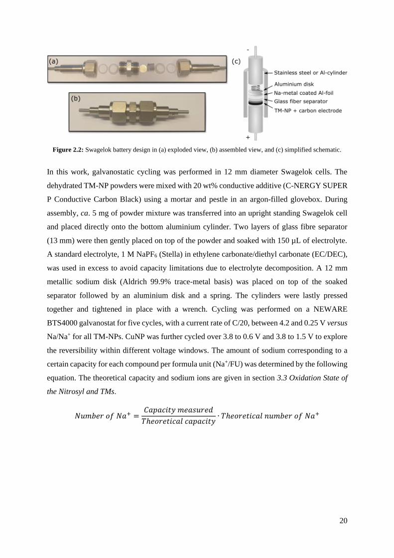
common cell for testing new materials is the Swagelok design (Figure 2.2). As can be seen in
the Figure, the cell consists of conductive cylinders that are pressing together the cell
components along with a spring and fittings. An insulating layer covers the inside of the outer
cylinder to avoid shortage. This cell design is quick to assemble and only requires a few mg of
material. It is therefore suitable for testing materials from small syntheses or with an unknown
behaviour that might require the building of many cells. Subsequently, this was the chosen
design for electrochemical evaluation of the TM-NPs.
20
Figure 2.2: Swagelok battery design in (a) exploded view, (b) assembled view, and (c) simplified schematic.
In this work, galvanostatic cycling was performed in 12 mm diameter Swagelok cells. The
dehydrated TM-NP powders were mixed with 20 wt% conductive additive (C-NERGY SUPER
P Conductive Carbon Black) using a mortar and pestle in an argon-filled glovebox. During
assembly, ca. 5 mg of powder mixture was transferred into an upright standing Swagelok cell
and placed directly onto the bottom aluminium cylinder. Two layers of glass fibre separator
(13 mm) were then gently placed on top of the powder and soaked with 150 µL of electrolyte.
A standard electrolyte, 1 M NaPF6 (Stella) in ethylene carbonate/diethyl carbonate (EC/DEC),
was used in excess to avoid capacity limitations due to electrolyte decomposition. A 12 mm
metallic sodium disk (Aldrich 99.9% trace-metal basis) was placed on top of the soaked
separator followed by an aluminium disk and a spring. The cylinders were lastly pressed
together and tightened in place with a wrench. Cycling was performed on a NEWARE
BTS4000 galvanostat for five cycles, with a current rate of C/20, between 4.2 and 0.25 V versus
Na/Na+ for all TM-NPs. CuNP was further cycled over 3.8 to 0.6 V and 3.8 to 1.5 V to explore
the reversibility within different voltage windows. The amount of sodium corresponding to a
certain capacity for each compound per formula unit (Na+/FU) was determined by the following
equation. The theoretical capacity and sodium ions are given in section 3.3 Oxidation State of
the Nitrosyl and TMs.
𝑁𝑢𝑚𝑏𝑒𝑟 𝑜𝑓 𝑁𝑎+ =𝐶𝑎𝑝𝑎𝑐𝑖𝑡𝑦 𝑚𝑒𝑎𝑠𝑢𝑟𝑒𝑑
𝑇ℎ𝑒𝑜𝑟𝑒𝑡𝑖𝑐𝑎𝑙 𝑐𝑎𝑝𝑎𝑐𝑖𝑡𝑦∙ 𝑇ℎ𝑒𝑜𝑟𝑒𝑡𝑖𝑐𝑎𝑙 𝑛𝑢𝑚𝑏𝑒𝑟 𝑜𝑓 𝑁𝑎+

21
3. Results and Discussion
As the structure and composition of TM-NP analogues vary with preparation method, thorough
characterisation of all synthesised materials needed to be performed before electrochemical
cycling in Na-ion cells. The results from the synthesis, including structure, composition, and
oxidation state will thus be presented first, followed by a detailed discussion on their cycling
behaviour.
3.1. Structure and Purity
Symmetry, unit cell dimensions, and purity of the synthesised powders before (H) and after
dehydration (DH) were determined by fitting a model to each XRD pattern and refining the cell
parameters by the Le-bail method85. The resulting diffractograms and assigned symmetry for
each sample is presented in Figure 3.1. No peaks other than the ones corresponding to the
assigned phases were observed for any of the compounds, suggesting that no crystalline
impurities were present in any of the samples. As expected from the synthesis (see section
1.4.2 The Various Structures of TM-NPs), FeNP and NiNP crystallised in the cubic (Fm-3m)
structure while MnNP crystallised as an orthorhombic dihydrate with Pnma symmetry. CuNP
on the other hand, was expected to crystallise as a two-dimensional orthorhombic dihydrate
with Amm2 symmetry and convert to the tetragonal I4mm structure upon dehydration. However,
the I4mm symmetry structure was observed in both the hydrous and anhydrous sample,
indicating that the material underwent partial dehydration at 70 °C under vacuum.
22
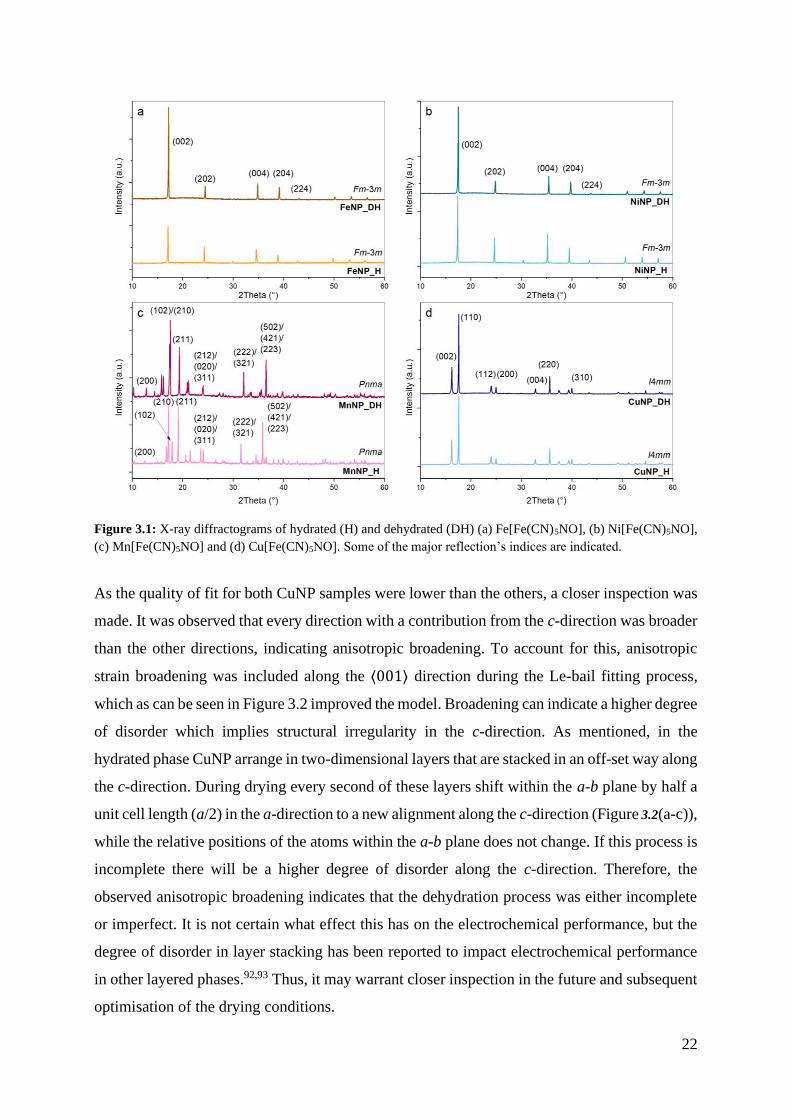
Figure 3.1: X-ray diffractograms of hydrated (H) and dehydrated (DH) (a) Fe[Fe(CN)5NO], (b) Ni[Fe(CN)5NO],
(c) Mn[Fe(CN)5NO] and (d) Cu[Fe(CN)5NO]. Some of the major reflection’s indices are indicated.
As the quality of fit for both CuNP samples were lower than the others, a closer inspection was
made. It was observed that every direction with a contribution from the c-direction was broader
than the other directions, indicating anisotropic broadening. To account for this, anisotropic
strain broadening was included along the ⟨001⟩ direction during the Le-bail fitting process,
which as can be seen in Figure 3.2 improved the model. Broadening can indicate a higher degree
of disorder which implies structural irregularity in the c-direction. As mentioned, in the
hydrated phase CuNP arrange in two-dimensional layers that are stacked in an off-set way along
the c-direction. During drying every second of these layers shift within the a-b plane by half a
unit cell length (a/2) in the a-direction to a new alignment along the c-direction (Figure 3.2(a-c)),
while the relative positions of the atoms within the a-b plane does not change. If this process is
incomplete there will be a higher degree of disorder along the c-direction. Therefore, the
observed anisotropic broadening indicates that the dehydration process was either incomplete
or imperfect. It is not certain what effect this has on the electrochemical performance, but the
degree of disorder in layer stacking has been reported to impact electrochemical performance
in other layered phases.92,93 Thus, it may warrant closer inspection in the future and subsequent
optimisation of the drying conditions.

23
Figure 3.2: Structural changes in Cu[Fe(CN)5NO] during dehydration (a-c) and illustration of the anisotropic
broadening in the XRD pattern by comparison of the model (red line) with the data (black dots) in the Le-bail
fitting process before (a) and after (b) adding anisotropic strain broadening along ⟨001⟩ to the fit.
Table 3.1 presents the resulting cell parameters from the Le-bail fit and corresponding volume
change on dehydration. The cubic compounds, i.e., FeNP and NiNP, exhibit an isotropic
volume change of ~2% as the interatomic distances M–N and Fe–C shortens when water is
evolved.70 MnNP, on the other hand, shows an anisotropic change in cell parameters with a
reduction in the a and b unit cell directions while the c-direction increases. One possible
explanation for this is that the loss of water results in stronger interactions between the
equatorial ligands and the TMs but weaker interactions between the TMs and the axial ligands,
but there may be other explanations as well. What implications this has for battery cycling is
uncertain, although, a similar anisotropic change in cell dimensions could be expected from
sodium insertion. This anisotropic change can lead to a reduced total change in volume (<1%)
compared to if it had been isotropic, presenting an opportunity to avoid large volume changes
during cycling and undesirable particle cracking. Finally, a slight volume change was observed
in CuNP even though both samples were found to have the anhydrous tetragonal (I4mm)

24
symmetry, which agrees with the previous suggestion that some water was still present in the
first CuNP sample. When the remaining water evolved from the structure a decrease was
observed in the c-direction, since completely removing the water allows stronger interactions
between the layers in the a-b plane.
Table 3.1: Cell parameters and volume of synthesised materials obtained from Le-bail fitting with corresponding
goodness of fit (GOF). In all materials α=β=γ=90°. The volume change percentage represents the reduction in cell
volume of the dehydrated (DH) material.
Compound Cell Parameters (Å) Volume (Å3)
Volume change
(%) GOF
FeNP_H a=b=c=10.3508(4) 1108.962
2.1 1.26
FeNP_DH a=b=c=10.2774(3) 1085.563 1.50
NiNP_H a=b=c=10.1898(1) 1058.031
2.0 1.69
NiNP_DH a=b=c=10.1210(2) 1036.738 1.85
MnNP_H
a=14.1264(4),
b=7.5261(2),
c=10.5549(3)
1122.155
0.71
1.24
MnNP_DH
a=13.7949(5),
b=7.3874(2),
c=10.9330(3)
1114.168 1.34
CuNP_H
a=b=7.1193(2),
c=10.9188(4) 553.4100
0.096
1.96
CuNP_DH
a=b=7.1199(2),
c=10.9065(4) 552.8812 2.08
3.2. Composition
Understanding the composition in TM-NPs is critical to estimating the initial oxidation states,
which ultimately determines the theoretical capacity. Thus, determining y and z in
M[Fe(CN)5NO]1-y ·zH2O is necessary. Cation ratios are particularly important for TM-NPs as
it determines the number of TM or NP vacancies in the material, which in turn determines the
oxidation states of all the species present and what redox reactions to expect. Furthermore,
using the known cation ratios it is possible to determine the relative crystalline water content
(z) from the mass loss in TGA. Measuring the water content is vital to understand the conditions
under which the material can be fully dehydrated and maintained in the dehydrated state. Thus,
compositions were determined through a combination of ICP-OES for cation ratios and remnant

25
sodium content and TGA for the water content. The results are summarised and compared with
previous studies in Table 3.2.
Elemental analysis of the TM-NPs revealed that the compositions of FeNP, MnNP and CuNP
were Fe[Fe(CN)5NO]NA· zH2O, Mn[Fe(CN)5NO]0.98(2)· zH2O and Cu[Fe(CN)5NO]0.89(2)· zH2O,
respectively. Thus, none of the materials showed any signs of remnant sodium from the
synthesis. The cation ratio in FeNP could not be discerned since the two Iron ions in the
structure cannot be differentiated from each other via ICP-OES. Unfortunately, NiNP was
unable to be dissolved into solution and so was not analysed.
As Figure 3.3 shows, the TGA indicates that all samples slowly begin losing water at 50 °C and
are completely dehydrated around 150 °C, or in the case of NiNP around 180 °C, similar to
previous studies.56,94,95 The water content calculated from the weight loss in the TGA curve
between these temperatures corresponds to 4.0(2) (FeNP), 4.2(2) (NiNP), 1.9(1) (MnNP), and
0.46(2) (CuNP) water molecules per formula unit. In all cases, lower values were obtained than
expected from the reference studies.56,58,68,70 This could potentially be due to differences in
nitroprusside or TM vacancies as higher vacancies lead to increased water content.96
Alternatively, it may indicate that all samples were partially dehydrated in the first drying step,
i.e., at 70 °C under vacuum for 12 h. The largest difference between the synthesised and
reference structures is seen for CuNP that contained approximately a fourth of the expected
water content, which would explain why only the anhydrous space group symmetry was
observed in XRD. Once formed, the tetragonal CuNP remains stable even in ambient conditions
and only restore the initial orthorhombic structure after at least a week immersed in water.95
This behaviour is highly unusual for a TM-NP or PBA, but makes handling of the dehydrated
material much easier. After dehydration when heated to higher temperatures, all samples very
slowly begin to decompose with the evolution of first nitrogen oxide (NO) and then cyanogen
gas (C2N2) up until 260 °C, after which they decompose to M[Fe(CN)4] with further gas
evolution.94,95 MnNP, on the other hand, remains stable up to above 300 °C.56 Thus, the window
where the anhydrous material is stable is much larger for MnNP compared to the other
compounds in this study. The origin of the increased stability remains unknown.

26
Figure 3.3: Mass loss in Fe[Fe(CN)5NO] (FeNP), Ni[Fe(CN)5NO] (NiNP), Mn[Fe(CN)5NO] (MnNP) and
Cu[Fe(CN)5NO] (CuNP) upon heating from 30 to 500 °C when measured by TGA. The samples were heated at a
ramp rate of 5 °C/min under flowing Ar (60 mL/min).
IR (Figure 3.4) can give us insight to the water content and bonding in TM-NPs, thus supporting
and building upon the TGA results above. Water exhibits many different peaks depending on
its coordination with respect to other water molecules or polar groups and the types of
interactions between them. The most characteristic spectral features include a broad band of
stretching frequencies extending between 3600–3000 cm-1 attributed to a variety of hydrogen
interactions between water molecules, several sharp peaks around 3650 cm-1 and 1600 cm-1 due
to symmetrical stretching and bending of the water molecules, respectively, and a shoulder or
peak around 800 cm-1 attributed to the liberational modes of coordinated water, i.e., small
rotations about their preferred orientation. Thus, as observed in Figure 3.4 the cubic structures
(FeNP and NiNP) have much more water present in their structures than MnNP and CuNP,
which agrees with the XRD and TGA results. The water in FeNP and NiNP is also interacting
more with each other as evident by the broad band between 3600–3000 cm-1, which suggests
that hydrophilic pores could be present as described in other studies.65 This band is much
smaller in MnNP as the number of water molecules are reduced from 4–5 to two. For the same
reason, the intensity of the vibration corresponding to the liberation of water is reduced in
MnNP compared to both cubic structures. Overall, there is a clear decrease in water vibrations
for all three compounds after dehydration as expected, without any noticeable change in the
other peaks, indicating that the dehydration in vacuum at 100 °C for 20 h was effective. CuNP,
on the other hand, only showed a hint of OH stretching and bending, and was thus almost fully
dehydrated in both cases, which agrees with the XRD and TGA results.

27
Table 3.2: A summary of stoichiometry, water content and structure of synthesised samples given by ICP, TGA and XRD compared to reference structures. Errors are given
as one standard deviation from the measured value and has been calculated from the relative standard deviation given for each sample by the instrument.
Sample Space
group
Water
content
Sodium
content
Fe:M
ratio Final structural formula
Reference structure
Space group Structural formula Type of sample Ref.
Hydrated
FeNP Fm-3m 4.0(2) 0.00(0) NA Fe[Fe(CN)5NO]NA · 4.0(2) H2O Fm-3m Fe[Fe(CN)5NO] · 4.78 H2O Powder 70
NiNP Fm-3m 4.2(2) NA NA Ni[Fe(CN)5NO]NA · 4.2(2) H2O Fm-3m Ni[Fe(CN)5NO] · 4.92 H2O Powder 70
MnNP Pnma 1.9(1) 0.00(0) 0.98(2):1 Mn[Fe(CN)5NO]0.98(2) · 1.9(1) H2O Pnma Mn[Fe(CN)5NO] · 2 H2O Single crystal 56
CuNP I4mm 0.46(2) 0.00(0) 0.89(2):1 Cu[Fe(CN)5NO]0.89(2) · 0.46(2) H2O Amm2 Cu[Fe(CN)5NO] · 2 H2O Powder 58
Dehydrated
FeNP Fm-3m 0.00(0) NA Fe[Fe(CN)5NO]NA Fm-3m Fe[Fe(CN)5NO] Powder 70
NiNP Fm-3m NA NA Ni[Fe(CN)5NO]NA Fm-3m Ni[Fe(CN)5NO]* Powder 70
MnNP Pnma 0.00(0) 0.98(2):1 Mn[Fe(CN)5NO]0.98(2) Pnma Mn[Fe(CN)5NO] Powder 68
CuNP I4mm 0.00(0) 0.89(2):1 Cu[Fe(CN)5NO]0.89(2) I4mm Cu[Fe(CN)5NO] Powder 58
* No anhydrous reference structure was found; thus, fitting was done after the hydrated structure.

28
3.3. Oxidation State of the Nitrosyl and TMs
IR spectra were collected for all samples to determine the initial oxidation state of the Nitrosyl.
The results, together with the results from ICP-OES, were subsequently used to deduce the
oxidation state of the TMs. Spectra for each compound and a summary of important vibrations
are presented in Figure 3.4 and Table 3.3, respectively. The assignments are based on the work
of Benavente et al.56.
The oxidation state of the nitrosyl was determined by the nitrosyl stretching frequencies,
denoted ν(NO). Generally in TM-NPs, this frequency is around 1940 cm-1 for NO+ but
decreases in frequency, by ca. 100–200 cm-1 for more negative oxidation states, when the
electron density increases.56,80,97 In this work, all samples had a nitrosyl stretching frequency
between 1940 and 1945 cm-1 and subsequently a positively charged nitrosyl ligand. Given the
composition, the known NO oxidation state, and that the cyano ligands always have a negative
(1-) charge,98 the sum of charges on both TMs must add up to 4+. How that charge is distributed
over FeC and the TM, however, depends on the presence of charged guest species and vacancies.
For example, in the CuNP synthesised by Mullaliu et al.54 where the Fe:Cu ratio was 1.2:0.8,
Fe had an oxidation state of (2+δ)+ to charge compensate for the Cu vacancies, while it has a
state of 2+ in similar compounds where the TM vacancies are low.63 Therefore, based on the
determined cation ratios of the TM-NPs synthesised herein, FeC must be 2+ which means that
the TMs are also in a 2+ state unless there are NP vacancies. In the case where the TM can have
an oxidation state lower than 2+, as in CuNP, it is possible for the TM to charge compensate
for missing NP anions. Mn can also adopt a 1+ charge, though it is much less stable than 2+ to
4+.99 This may explain why CuNP has a higher tendency for NP vacancies compared to MnNP
but must be confirmed with other techniques. The initial oxidation states of each material were
hence estimated to Fe2+[Fe2+(CN)5NO+], Ni2+[Fe2+(CN)5NO+], Mn2+[Fe2+(CN)5NO+]0.98(2), and
Cu(2-δ)+[Fe2+(CN)5NO+]0.89(2). This entails a maximum theoretical capacity of approximately
197, 195, 198, and 277 mAh/g for FeNP, NiNP, MnNP and CuNP, respectively, corresponding
to Na2Fe2+[Fe2+(CN)5NO-], Na2Ni2+[Fe2+(CN)5NO-], Na2Mn2+[Fe2+(CN)5NO-], and
Na(2.8-δ)Cu+[Fe2+(CN)5NO-]0.89.

29
Figure 3.4: Full IR spectra, from 5000–350 cm-1, of hydrated (H) and dehydrated (DH) samples of
(a) Fe[Fe(CN)5NO] (FeNP), (b) Ni[Fe(CN)5NO] (NiNP), (c) Mn[Fe(CN)5NO] (MnNP), and (d) Cu[Fe(CN)5NO]
(CuNP). The inset in each spectra shows a zoom in of the Cyano and Nitrosyl stretching vibration region.

30
Table 3.3: Summary of important infrared active vibrations observed in hydrous Fe[Fe(CN)5NO] (FeNP), Ni[Fe(CN)5NO] (NiNP), Mn[Fe(CN)5NO] (MnNP), and
Cu[Fe(CN)5NO] (CuNP) measured in attenuated total reflection mode. Assigned by help of reference 56.
Spectral
Feature
Position (cm-1)
Assignment Group/Structure
FeNP NiNP MnNP CuNP
Peaks 3650 3654 3649 (3649) ν(OH) symmetric Water
Band 3600–3000 3600–3000 – – ν (H–O···H) Water
Peak 2179; 2149; (2080) 2194; 2149 (2194) ; (2188); 2174 2207; 2193; (2165) ν(CN) Cyano ligand
Peaks 1941 1942 1945 1940 ν(NO) Nitrosyl ligand
Peak 1616 1616 1656; 1602 (1604) δ(H–O–H) Water
Shoulder Ca. 800 Ca. 800 770 – L(H–O–H) Water
Peaks >680 >680 >680 >680 ν/δ(M–C), ν/δ(M–N),
ν/δ(M–CN), …
Various Metal-ligand
vibrations
Abbreviations: ν, stretching; δ, bending; L, liberation

31
3.4. Galvanostatic Cycling Behaviour
As the intent of this study was to investigate the cycling behaviour of different TM-NPs in
NIBs, all dehydrated samples were galvanostatically cycled in Na half-cells between 4.2 and
0.25 V versus Na/Na+. The resulting cycling curves exhibited varied and complex behaviour.
Thus, to facilitate comparison and rationalisation for the obtained results, discussion will first
be focused on similarities and differences in the first one and a half cycles. This will be followed
by a discussion of changes which occur in the following 5 cycles. Finally, due to the large
difference in behaviour, this section will end with a deeper discussion of the CuNP behaviour.
The resulting galvanostatic cycling (Figure 3.5 and Figure 3.6) shows four distinct behaviours
for the compounds with the exception of one major common characteristic. That is, all materials
exhibit a sloping plateau below 1.0 V (1.3 V in CuNP) to the lower cut-off voltage during
discharge and another plateau above 3.1 V to the upper cut-off voltage during charging, both
corresponding to a significant amount of capacity. Similar behaviour was seen by Mullaliu et
al.54 when cycling CuNP against lithium metal. Using operando XAS and IR, they
demonstrated that the sloping region below 1.8 V versus Li/Li+ (corresponding to ca 1.4 V
versus Na/Na+) was caused by reduction of the nitrosyl. Unfortunately, in this study the redox
processes occurring in the higher voltage plateau during charging were not addressed in the
text. However, their results from operando IR showed a reappearance of the vibration
corresponding to stretching of the NO+ bond at 3.9 V versus Li/Li+ (corresponding to 3.5 V
versus Na/Na+). Thus, it was also shown that the nitrosyl was oxidised during charging to this
potential. It is likely that this was overlooked because of the unusually large voltage
polarisation. As will be discussed later in this thesis, however, voltage polarisation is not
uncommon for systems with anionic redox. Their results therefore suggest that the slopes
observed herein, below 1.0 V (discharge) and above 3.1 V (charge) versus Na/Na+, can be
attributed to reduction and oxidation of the nitrosyl ligand, respectively.
An additional common feature for all samples was the observed oxidation of FeC. When iron is
carbon bound as in the NP anion, it has a redox potential around 3.0 V versus Na/Na+, which is
lower than that of the predicted nitrosyl oxidation potential.54 Thus, while FeC is not redox
active during the first sodium insertion, the high polarisation on the nitrosyl during charging
leads to the oxidation of FeC from 2+ to 3+, allowing the transition metal to contribute to the
redox activity on subsequent cycles. This phenomenon should be observed in all studied
TM-NPs. While a plateau at 3.0 V is observable in FeNP and CuNP, it is more subtle in NiNP
and MnNP where only a small plateau at 3.4 V and a hint of a plateau at 3.5 V can be observed

32
respectively. Therefore, demonstrating that the M’ cation may also impact the redox behaviour
of the nitroprusside structural fragment. In CuNP, Mullaliu et al.54 confirmed both Cu+/Cu2+
reduction around 2.3–2.9 V versus Li/Li+ (1.9–2.5 V versus Na/Na+) on discharge and Fe2+/
Fe3+ oxidation around 3.3–3.5 versus Li/Li+ (2.9–3.1 V versus Na/Na+) on charging with
operando XAS, which confirms the hypothesis that FeC indeed is redox active. Given the
asymmetric redox behaviour and complexity as a function of composition, the exact redox
process will need to be confirmed by operando XAS and IR in a future study. Specifically, to
answer if FeC is solely responsible for the redox activity within a certain potential window or if
both FeC and the nitrosyl are simultaneously active? Does FeC retain its redox activity on
subsequent cycles or is there a charge transfer process which occurs once all sodium is removed
from the structure? Finally, further work would need to be performed to understand the role of
the M’ cation on the redox activity of the nitroprusside. Although for the latter, some insight
can be gained by comparison with their hexacyanoferrate analogues.
By comparing the first one and a half cycles in Figure 3.5 with the redox potentials for the
equivalent hexacyanoferrate analogues, it can be inferred that all TMs apart from nickel are
redox active. Nickel has lately been generally accepted as a non-active TM in similar materials
and is therefore considered to not partake in any redox activity herein.100,101 Manganese on the
other hand, has a Mn2+/Mn3+ redox potential at 3.8 V and can thus be observed as a plateau at
this potential in the middle of the nitrosyl oxidation slope on charging.102 Nitrogen bound iron
(FeN) has a redox potential around 3.0 V, i.e., close to the same potential range as FeC in this
case.36 It is therefore impossible to know whether the plateau in FeNP at 3.0 V is caused by
oxidation of FeC or FeN or both simultaneously without further measurements. Mössbauer
spectroscopy is a tool which can readily distinguish between two iron centres and can probe the
variance in local environment and oxidation state for two distinct Fe ions, and could therefore
be used to analyse this in a future study.42 Moving on, the Cu+/Cu2+ redox potential can be
assigned to the plateau at 2.1 V during charge and discharge by comparison with results from
Mullaliu et al.54. Interestingly, Mullaliu et al. saw two different potentials that they attributed
to Cu reduction (2.3 V and 2.9 V versus Li/Li+, respectively), which they believed corresponds
to two different Cu sites within the structure. They also observed a partial reduction of the FeC
from Fe(2+δ)+ to Fe2+ in the first discharge. Neither the two copper plateaus nor iron reduction,
however, can be observed in the results presented here, probably because of the difference in
composition between our samples. While they had copper vacancies (cation ratio 0.8:1.2 Cu:Fe)

33
that needed to be charge compensated for by the iron, our sample had NP vacancies (cation
ratio 1.0:0.89 Cu:Fe) that “locked” the iron into its Fe2+ state during the first discharge.
Figure 3.5: First one and a half cycles of galvanostatic cycling of (a) Fe[Fe(CN)5NO] (FeNP) and Cu[Fe(CN)5NO]
(CuNP), and (b) Ni[Fe(CN)5NO] (NiNP), and Mn[Fe(CN)5NO] (MnNP), in Na half-cells between 4.2 and 0.25 V.
To compare how each TM-NP evolves over time during cycling, the first five cycles are plotted
in Figure 3.6. NiNP and MnNP both have a very similar cycling behaviour that is dominated
by the nitrosyl activity above 3.1 V and below 1.0 V. NiNP has an initial discharge capacity of
80 mAh/g, but only 38 mAh/g (corresponding to 0.39 Na+/FU, i.e., less than a fourth of the
theoretical amount) is reversible, indicating that the additional first 42 mAh/g might be a result
of side reactions. After the first cycle however, each new cycle almost traces the others without
any loss of capacity. Since nickel is inert, this shows that the nitrosyl redox process is highly
reversible within this operating voltage. MnNP achieves a lower initial capacity compared to
NiNP but gains a similar reversible capacity around 43 mAh/g, corresponding to 0.43 Na+/FU.
It is interesting to note that the discharge capacity increases for each cycle after the second for
MnNP, although no gains are had on charging. This implies side reactions but could perhaps be
an indication of an increasing participation of the manganese ion, i.e., Mn2+/Mn3+ or Mn+/Mn2+
reduction. However, it is impossible to draw any conclusions without further evidence.
Surprisingly, FeNP shows a much higher reversible capacity than what can be predicted
theoretically. That is, 350 mAh/g compared to 197 mAh/g corresponding to 3.5 Na+/FU instead
of 2. What causes this increase is difficult to postulate. It could be side reactions, but since the
reversibility is so high after the first cycle, another phenomenon caused by the redox of one or
both the iron atoms is more likely. We do, for example, see an increased capacity from the
plateau at 3.0 V in the three last charges compared to the second (i.e., first after discharge),
which implies their involvement. Additionally, new plateaus not visible in any of the other

34
TM-NPs also appear after a few cycles, namely the small charge plateau at 0.8–0.9 V and a
minor plateau at 2.0 V. The plateau at 0.8–0.9 V could be partial oxidation of the nitrosyl but
in that case raises the question of why it is not observed in any of the other compounds. The
latter only appears after three cycles and cannot be explained without further work. However,
it does present an intriguing possibility that the nitrosyl can be oxidised without the inherent
voltage polarisation. Note, that the unstable voltage variation at 3.5–3.8 V in the third charging
curve is likely the result of new material being exposed due to particle cracking. Aside from
this one voltage instability, FeNP shows high reversibility.
The electrochemistry of CuNP initially differs from the rest of the TM-NPs in this study but
becomes similar to the others after a few cycles. As also seen in NiNP and MnNP, the initial
capacity of CuNP is much higher than in the following cycles. As the initial capacity is almost
350 mAh/g, which can be compared to its theoretical capacity of 277 mAh/g, some of this
capacity could be attributed to side reactions. In the following cycles, the capacity decreases by
~100 mAh/g (1.0 Na+/FU) in the second and third cycle, and by further ~40 mAh/g (0.40
Na+/FU) per cycle in the fourth and fifth. This coincides with a reduced redox activity of both
the Cu (2.1 V) and Fe (3.0 V), leading to only nitrosyl and minor Fe redox after two to three
discharges. This implies that the capacity fade could be due to a loss of Cu, perhaps Cu
dissolution into the electrolyte, or material degradation. Simultaneous to the fading activity of
Cu, the reduction potential of the nitrosyl goes from a higher value (1.3 V) to the same potential
as in the other TM-NPs (<1.0 V), which suggests that the nitrosyl is more easily reduced when
the Cu is redox active. What causes this potential difference, however, and what role the
different TMs play in the reduction potential is yet unknown. Another unique and interesting
feature in this compound is the high discharge capacity corresponding to Cu reduction in the
first discharge. In theory, the reduction of all Cu2+ to Cu+ should correspond to 1 Na+/FU, but
instead the intercalation of 1.3 Na+/FU (125 mAh/g) is observed, followed by the same amount
of sodium leaving the structure when Fe is oxidised in the subsequent charging without any Cu
activity. This TM redox hysteresis is already known from the work of Mullaliu et al.54 but is
not what one would expect and has yet not been given an explanation. That is, the question
remains why Cu is not active during charging. There is therefore much more work needed to
figure out what happens in this complex system.

35
Figure 3.6: Galvanostatic cycling over the first five charge-discharge cycles of (a) Fe[Fe(CN)5NO] (FeNP),
(b) Ni[Fe(CN)5NO] (NiNP), (c) Mn[Fe(CN)5NO] (MnNP), and (d) Cu[Fe(CN)5NO] (CuNP), in Na half-cells
between 4.2 and 0.25 V. Dashed lines indicate the initial one and a half cycles, and a decreasing colour shade
indicates subsequent cycles.
In order to understand the origin of the irreversibility in CuNP, separate cells were cycled over
three different voltages windows. As seen in Figure 3.7, the resulting cycling profiles were
similar in all three cases but with one major difference, namely the degree of Cu reversibility.
When the voltage window was restricted from 4.2–0.25 V to 3.8–0.6 V or 3.8–1.5 V some of
the copper was oxidised on charging and subsequently became more reversible. As mentioned,
Cu is both reduced and oxidised between 1.9–2.5 V versus Na/Na+ and therefore the oxidation
plateau at 2.2–2.5 V observed herein is attributed to Cu.54 Interestingly, Cu seems to become
more reversible when the lower cut-off voltage is set above the nitrosyl reduction potential
(1.5 V), but for some reason this has no larger effect on the total capacity which fades to ⁓60–
75 mAh/g regardless of the voltage range. Additionally, even though Cu is more reversible in
the smaller voltage window (Figure 3.7(c)), it is mainly during discharge. The charging capacity
is still dominated by Fe and nitrosyl oxidation, as in the other voltage ranges. Observe that the
nitrosyl is here oxidised but not reduced which illustrates the hysteresis in the redox reactions
on charging compared to discharge that has previously been mentioned. This hysteresis
suggests that there must be some type of anisotropic charge transfer phenomena occurring in

36
the material which allows some of the electron density to be transferred between overlapping
orbitals and subsequently favouring oxidation or reduction of the various species depending on
the electronic state.
Figure 3.7: Electrochemical characterisation of CuNP over the voltage range (a) 4.2–0.25 V, (b) 3.8–0.6 V, and
(c) 3.8–1.5 V, given as a function of capacity for five cycles. Dark blue indicates the first cycle, and a decreasing
colour shade indicates subsequent cycles.
It is known that the NP anion itself has a strong anisotropic metal-to-ligand charge transfer
(MLCT) that favours donation of electrons from Fe to the nitrosyl ligand more than to the cyano
ligands.98 This does not necessarily mean that FeC always donates its electron density to the
nitrosyl, because in that case FeC would never be observed with a 2+ charge which it is.
However, it does entail that it is easier to oxidise the iron compared to the nitrosyl and easier to
reduce the nitrosyl compared to the iron. This might explain why FeC is only active on charging,
the redox hysteresis of the TMs on charge/discharge, and the large voltage hysteresis of the
nitrosyl in all investigated TM-NPs. If this is true, however, and how the MLCT is affected by
the M’ cation and the structure is currently unknown. Exploring the mechanism of MLCT in
various TM-NPs could thus provide some insight into the complex electrochemical behaviour
of the TM-NPs and perhaps give ideas on how to tune the behaviour and reduce the voltage
hysteresis.

37
Voltage hysteresis is not necessarily an unfavourable property, depending on the application,
but it is detrimental for an electrode material.103 It entails that more energy is required to charge
the battery than what is gained when discharging it, thus resulting in a reduced energy density.
Voltage hysteresis is observed in many materials, including several LTMOs and PAMs, and
spans a range from a few mV to V.104–106 However, the magnitude can depend on whether the
hysteresis observed is caused by extrinsic or intrinsic factors. Extrinsic polarisation is a kinetic
effect caused by a combination of different sources of resistance and current density, e.g., poor
diffusivity due to a rapid charge rate, large particle size, or thick electrodes.105,106 Consequently,
extrinsic polarisation can be modified and reduced to near zero by lowering the
discharge/charge rate to slow down the reactions or by minimising the particle size and the
electrode thickness. Intrinsic polarisation on the other hand, is a thermodynamic effect where
the reduction of a species is thermodynamically different to the oxidation, meaning that the
electronic energy levels change between the charged and discharged states. Thus, it is affected
by inherent material properties such as phase transitions, elastic stiffness, and stoichiometric
concentration.105,106 Intrinsic polarisation can therefore not be reduced by optimising the
cycling conditions, but needs to be identified and treated at a chemical or structural level for
the specific material. For example, often it needs more creative solutions like doping or
selective control of the composition. In electrodes with oxygen anionic redox for example, a
voltage hysteresis up to ⁓2 V associated with the redox activity of oxygen is common.78,79,93,103
Recently, however, a strong link between the superstructure ordering and the magnitude of the
voltage hysteresis was demonstrated, suggesting that some structures of the same compound
can have less hysteresis.79 Consequently, understanding the origin of the voltage hysteresis for
a specific system is critical to minimise it and to design materials with higher energy densities.
In the case of TM-NPs, the origin of the hysteresis is very likely intrinsic and associated with
the anisotropic MLCT.

38
4. Conclusion and Future Work
For a sustainable development of electrical energy storage systems, electrode materials for
NIBs based on earth abundant elements with high gravimetric and volumetric capacities must
be developed. In this work, four TM-NPs, NaxM’[Fe(CN)5NO]1-y ·zH2O, with M’=Fe, Ni, Mn,
and Cu were synthesised and cycled in Na-ion half-cell batteries to gain an initial understanding
of the cycling behaviour and to set up research questions to be pursued in the future. All four
compounds could be synthesised by a facile and controlled aqueous co-precipitation method at
room temperature, and were characterised in three different crystallographic structures, cubic
Fm-3m (FeNP and NiNP), orthorhombic Pnma (MnNP), and tetragonal I4mm (CuNP). Using
the Le-bail method85, a structural irregularity (anisotropic broadening) in the c-direction was
found in CuNP, which has previously not been documented. Herein we concluded that it was
caused by an incomplete or imperfect dehydration process leading to incomplete stacking of
CuNP layers along the c-direction. This phenomenon should be followed up in future studies
when exploring a potential correlation between structural order and electrochemical properties.
It was also concluded that MnNP has a higher thermal stability than the other TM-NPs under
investigation, which potentially could be caused by a lower vacancy content and higher
structural ordering. Finally, IR showed that the nitrosyl ligand had an initial 1+ state in all
compounds. Consequently, the oxidation states of all species were deduced to (M’)2+, FeC2+,
CN-, and NO+.
The resulting galvanostatic cycling curves exhibited varied and complex behaviour, but all
materials exhibited a plateau below 1.0 V on discharge and above 3.1 V on charging, which
based on previous studies could be attributed to reduction and oxidation of the nitrosyl ligand,
respectively. Subsequently, based on our observations and previous studies we propose that the
nitrosyl is electrochemically active in all TM-NPs studied herein, and that it contributes with a
considerable amount of capacity, although with a large voltage hysteresis. Thus, for the first
time, nitrosyl redox is observed in TM-NP battery systems beyond CuNP. Theoretically this
will allow increased gravimetric capacities compared to their hexacyanoferrate analogues.
Assuming reduction of NO+ to NO-, and (M’)2+ to (M’)+ where likely, the theoretical capacities
for the specific stoichiometries were calculated to 197, 195, 198, and 277 mAh/g for FeNP,
NiNP, MnNP and CuNP, respectively.
It can further be concluded that all TMs apart from Ni were redox active to various degrees and
that FeC was active on charging, but not discharge, in all compounds. Thus, a redox hysteresis

39
was also observed, meaning that different species were active on charging and discharging. As
it is known that the NP anion has a strong anisotropic MLCT, we propose that both the redox
hysteresis of the TMs and the voltage hysteresis of the nitrosyl is caused by anisotropic charge
transfer within the materials. However, even though the mechanism behind the MLCT in the
NP anion is known, it is yet unknown how it is affected by the M’ cation and the structure.
Exploring the mechanism behind the anisotropic charge transfer in different TM-NPs could
therefore provide insight into the complex electrochemical behaviour of these compounds and
how to reduce the voltage hysteresis. This can be addressed by monitoring the oxidation state
of the nitrosyl ligand and the TMs using IR spectroscopy and XAS respectively as a function
of charge to unravel the complex charge compensation mechanisms. Since large voltage
hysteresis in electrode materials is detrimental for the energy efficiency, this problem needs to
be solved before TM-NPs can be applicable in battery systems.
Moreover, an interesting and unexpected electrochemical behaviour was observed for FeNP
and CuNP. FeNP, to begin with, showed a much higher reversible capacity than what was
predicted. That is, 350 mAh/g compared to 197mAh/g corresponding to an intercalation of 3.5
Na+/FU instead of 2. Since an increasing involvement of both iron atoms were observed within
the first five cycles, we hypothesise that the unexpectedly high capacity is partly caused by a
phenomenon connected to the anisotropic charge transfer. Although the role of side reactions
will need to be explored. Additionally, new plateaus that are not observed in any of the other
TM-NPs appeared after a few cycles. This presents an intriguing possibility that the nitrosyl
can be oxidised in FeNP without the inherent voltage polarisation. CuNP, on the other hand,
exhibited a huge capacity loss in the first five cycles, which was unique among the studied
TM-NPs. Furthermore, it also exhibited a higher reduction potential for the nitrosyl (1.3 V)
compared to the other compounds (<1.0 V) and a reduced redox activity of Cu with each cycle.
When the Cu was no longer active, and the capacity had severely faded, the reduction potential
of the nitrosyl was lowered to the same potential as in the other TM-NPs. Thus, the capacity
fade in CuNP could be due to a loss of Cu, perhaps Cu dissolution into the electrolyte, or
material degradation. Whatever the reason, however, it was reduced when the voltage window
was restricted to a potential above the nitrosyl reduction.
Clearly much more work needs to be done to understand this class of materials but its many
interesting attributes such as anionic redox, MLCT, and structural diversity, proves that such
work could be fruitful for several research fields. For a battery application, however, the voltage
hysteresis needs to be understood and reduced before any future commercialisation of TM-NPs

40
can be realised. Even though this class of materials is structurally derived from the positive
electrode class of materials PBAs, perhaps they also should be investigated as negative
electrode materials due to the low reduction potential of the nitrosyl? Overall, though there are
challenges that needs to be overcome, TM-NPs can have an impact on the future development
of cheap and sustainable electrode materials for NIBs.
41
Acknowledgements
I greatly want to thank everyone who has been alongside me on this journey over the past few
months. Without their help and guidance, this work would not have been as enjoyable as it was.
Most of all I want to thank my supervisor, Dr William Brant, for all his advice and support. In
particular for pushing and challenging me to perform my best, and for believing I can do so.
Without him, writing this thesis would have been a lot easier, but the end not nearly as
satisfying.
I also want to thank: my subject reviewer, Dr Reza Younesi, for his general support and patience
while waiting for the final thesis; Dr Dickson Ojwang for teaching me how to run the synthesis
and helping me with some of my TGA measurements; Dr Rebecca Clulow for the rest of my
TGA measurements and for the great company she provided at the DESY synchrotron and in
Prague during IUCr2021 mid project; Dr Mikaela Görlin for showing me how to prepare and
run samples for ICP-OES; and Professor Gunnar Westin and Markus Ek for helping me run the
IR measurements.
Lastly, thank you to everyone in the structural chemistry program and the inorganic chemistry
program at the Ångström laboratory for your company and support.

42
References
1. European Commission. In focus: Batteries-a key enabler of a low-carbon economy.
https://ec.europa.eu/info/news/focus-batteries-key-enabler-low-carbon-economy-2021-
mar-15_en (2021).
2. Barra, P. H. A., de Carvalho, W. C., Menezes, T. S., Fernandes, R. A. S. & Coury, D. V.
A review on wind power smoothing using high-power energy storage systems. Renew.
Sustain. Energy Rev. 137, 110455 (2021).
3. Simon, B., Ziemann, S. & Weil, M. Potential metal requirement of active materials in
lithium-ion battery cells of electric vehicles and its impact on reserves: Focus on Europe.
Resour. Conserv. Recycl. 104, 300–310 (2015).
4. Wentker, M., Greenwood, M., Asaba, M. C. & Leker, J. A raw material criticality and
environmental impact assessment of state-of-the-art and post-lithium-ion cathode
technologies. J. Energy Storage 26, 101022 (2019).
5. European Commission. Study on the EU’s list of Critical Raw Materials.
http://www.europa.eu (2020) doi:10.2873/904613.
6. Amnesty International. ‘THIS IS WHAT WE DIE FOR’: Human Rights Abuses in the
Democratic Republic of the Congo Power the Global Trade in Cobalt. (2016).
7. Nazarewicz, T. Cobalt: a critical commodity. Resour. World 52–53 (2016).
8. Hirsh, H. S., Li, Y., S Tan, D. H., Zhang, M., Zhao, E., Shirley Meng, Y., Hirsh, H. S.,
Li, Y., S Tan, D. H., Zhang, M., Zhao, E. & Meng, Y. S. Sodium-Ion Batteries Paving
the Way for Grid Energy Storage. Adv. Energy Mater. 10, (2020).
9. Vaalma, C., Buchholz, D., Weil, M. & Passerini, S. A cost and resource analysis of
sodium-ion batteries. Nat. Rev. Mater. 3, 18013 (2018).
10. Hwang, J. Y., Myung, S. T. & Sun, Y. K. Sodium-ion batteries: Present and future.
Chem. Soc. Rev. 46, 3529–3614 (2017).
11. Usiskin, R., Lu, Y., Popovic, J., Law, M., Balaya, P., Hu, Y.-S. & Maier, J.
Fundamentals, status and promise of sodium-based batteries. Nat. Rev. Mater. 6, 1020–
1035 (2021).
12. Tapia-Ruiz, N. et al. 2021 roadmap for sodium-ion batteries. J. Phys. Energy 3, (2021).

43
13. Goodenough, J. B. & Manthiram, A. A perspective on electrical energy storage. MRS
Commun. 4, 135–142 (2014).
14. Li, M., Lu, J., Chen, Z. & Amine, K. 30 Years of Lithium-Ion Batteries. Adv. Mater. 30,
1800561 (2018).
15. Mishra, A., Mehta, A., Basu, S., Malode, S. J., Shetti, N. P., Shukla, S. S., Nadagouda,
M. N. & Aminabhavi, T. M. Electrode materials for lithium-ion batteries. Mater. Sci.
Energy Technol. 1, 182–187 (2018).
16. Liu, Q., Hu, Z., Chen, M., Zou, C., Jin, H., Wang, S., Chou, S.-L., Liu, Y., Dou, S.-X.,
Liu, Q., Zou, C., Jin, H., Wang, S., Hu, Z., Chen, M., Chou, S.-L., Dou, S.-X. & Liu, Y.
The Cathode Choice for Commercialization of Sodium-Ion Batteries: Layered Transition
Metal Oxides versus Prussian Blue Analogs. Adv. Funct. Mater. 30, (2020).
17. Liu, Y., Merinov, B. V & Goddard, W. A. Origin of low sodium capacity in graphite and
generally weak substrate binding of Na and Mg among alkali and alkaline earth metals.
Proc. Natl. Acad. Sci. 113, 3735 LP – 3739 (2016).
18. Xiao, B., Rojo, T. & Li, X. Hard Carbon as Sodium-Ion Battery Anodes: Progress and
Challenges. ChemSusChem 12, 133–144 (2019).
19. Li, X., Yan, P., Engelhard, M. H., Crawford, A. J., Viswanathan, V. V, Wang, C., Liu,
J. & Sprenkle, V. L. The importance of solid electrolyte interphase formation for long
cycle stability full-cell Na-ion batteries. Nano Energy 27, 664–672 (2016).
20. Wang, L., Światowska, J., Dai, S., Cao, M., Zhong, Z., Shen, Y. & Wang, M. Promises
and challenges of alloy-type and conversion-type anode materials for sodium–ion
batteries. Mater. Today Energy 11, 46–60 (2019).
21. Delmas, C., Fouassier, C. & Hagenmuller, P. Structural Classification and Properties of
the Layered Oxides. Phys. B+C 99, 81–85 (1980).
22. Chenglong, Z., Qidi, W., Zhenpeng, Y., Jianlin, W., Benjamín, S.-L., Feixiang, D.,
Xingguo, Q., Yaxiang, L., Xuedong, B., Baohua, L., Hong, L., Alán, A.-G., Xuejie, H.,
Claude, D., Marnix, W., Liquan, C. & Yong-Sheng, H. Rational design of layered oxide
materials for sodium-ion batteries. Science 370, 708–711 (2020).
23. Sato, K., Nakayama, M., Glushenkov, A. M., Mukai, T., Hashimoto, Y., Yamanaka, K.,
Yoshimura, M., Ohta, T. & Yabuuchi, N. Na-Excess Cation-Disordered Rocksalt Oxide:

44
Na1.3Nb0.3Mn0.4O2. Chem. Mater. 29, 5043–5047 (2017).
24. Cao, X., Li, X., Qiao, Y., Jia, M., Qiu, F., He, Y., He, P. & Zhou, H. Restraining Oxygen
Loss and Suppressing Structural Distortion in a Newly Ti-Substituted Layered Oxide P2-
Na0.66Li0.22Ti0.15Mn0.63O2. ACS Energy Lett. 4, 2409–2417 (2019).
25. Liu, Q., Hu, Z., Li, W., Zou, C., Jin, H., Wang, S., Chou, S. & Dou, S. X. Sodium
transition metal oxides: The preferred cathode choice for future sodium-ion batteries?
Energy Environ. Sci. 14, 158–179 (2021).
26. Ma, J., Zheng, S., Das, P., Lu, P., Yu, Y. & Wu, Z.-S. Sodium Ion Microscale
Electrochemical Energy Storage Device: Present Status and Future Perspective. Small
Struct. 1, 2000053 (2020).
27. Manthiram, A. & Goodenough, J. B. Lithium insertion into Fe2(SO4)3 frameworks. J.
Power Sources 26, 403–408 (1989).
28. Li, H., Xu, M., Zhang, Z., Lai, Y., Ma, J., Li, H., Zhang, Z., Lai, Y. & Xu, M. Engineering
of Polyanion Type Cathode Materials for Sodium-Ion Batteries: Toward Higher
Energy/Power Density. Adv. Funct. Mater. 30, (2020).
29. Gong, Z. & Yang, Y. Recent advances in the research of polyanion-type cathode
materials for Li-ion batteries. Energy Environ. Sci. 4, 3223–3242 (2011).
30. Voronina, N., Sun, Y.-K. & Myung, S.-T. Co-Free Layered Cathode Materials for High
Energy Density Lithium-Ion Batteries. ACS Energy Lett. 5, 1814–1824 (2020).
31. Lv, Z., Ling, M., Yue, M., Li, X., Song, M., Zheng, Q. & Zhang, H. Vanadium-based
polyanionic compounds as cathode materials for sodium-ion batteries: Toward high-
energy and high-power applications. J. Energy Chem. 55, 361–390 (2021).
32. Jiao, L., Jin, T., Li, H., Zhu, K., Wang, P.-F. & Liu, P. Polyanion-type cathode materials
for sodium-ion batteries. Chem. Soc. Rev 49, 2342 (2020).
33. Wang, L., Lu, Y., Liu, J., Xu, M., Cheng, J., Zhang, D. & Goodenough, J. B. A superior
low-cost cathode for a Na-Ion battery. Angew. Chemie - Int. Ed. 52, 1964–1967 (2013).
34. Hurlbutt, K., Wheeler, S., Capone, I. & Pasta, M. Prussian Blue Analogs as Battery
Materials. Joule 2, 1950–1960 (2018).
35. Karyakin, A. A. Prussian Blue and Its Analogues: Electrochemistry and Analytical
45
Applications. Electroanalysis 13, 813–819 (2001).
36. Wang, L., Song, J., Qiao, R., Wray, L. A., Hossain, M. A., Chuang, Y.-D., Yang, W.,
Lu, Y., Evans, D., Lee, J.-J., Vail, S., Zhao, X., Nishijima, M., Kakimoto, S. &
Goodenough, J. B. Rhombohedral Prussian White as Cathode for Rechargeable Sodium-
Ion Batteries. J. Am. Chem. Soc 137, 15 (2015).
37. Brant, W. R., Mogensen, R., Colbin, S., Ojwang, D. O., Schmid, S., Hä Ggströ, L.,
Ericsson, T., Jaworski, A., Pell, A. J. & Younesi, R. Selective Control of Composition
in Prussian White for Enhanced Material Properties. Chem. Mater. 31, 7203–7211
(2019).
38. Lu, Y., Wang, L., Cheng, J. & Goodenough, J. B. Prussian blue: a new framework of
electrode materials for sodium batteries. Chem. Commun. 48, 6544–6546 (2012).
39. Lee, H.-W., Wang, R. Y., Pasta, M., Woo Lee, S., Liu, N. & Cui, Y. Manganese
hexacyanomanganate open framework as a high-capacity positive electrode material for
sodium-ion batteries. Nat. Commun. 5, 5280 (2014).
40. Boström, H. L. B. & Brant, W. R. Octahedral tilting in Prussian blue analogues. (2022).
Advance online publication. arXiv:2201.02467.
41. Song, J., Wang, L., Lu, Y., Liu, J., Guo, B., Xiao, P., Lee, J.-J., Yang, X.-Q., Henkelman,
G. & Goodenough, J. B. Removal of Interstitial H2O in Hexacyanometallates for a
Superior Cathode of a Sodium-Ion Battery. J. Am. Chem. Soc. 137, 2658–2664 (2015).
42. Ojwang, D. O., Svensson, M., Njel, C., Mogensen, R., Menon, A. S., Ericsson, T.,
Häggström, L., Maibach, J. & Brant, W. R. Moisture-Driven Degradation Pathways in
Prussian White Cathode Material for Sodium-Ion Batteries. ACS Appl. Mater. Interfaces
13, 10054–10063 (2021).
43. Rudola, A., Du, K. & Balaya, P. Monoclinic Sodium Iron Hexacyanoferrate Cathode and
Non-Flammable Glyme-Based Electrolyte for Inexpensive Sodium-Ion Batteries. J.
Electrochem. Soc. 164, A1098–A1109 (2017).
44. Guo, X., Wang, Z., Deng, Z., Li, X., Wang, B., Chen, X. & Ong, S. P. Water Contributes
to Higher Energy Density and Cycling Stability of Prussian Blue Analogue Cathodes for
Aqueous Sodium-Ion Batteries. Chem. Mater. 31, 5933–5942 (2019).
45. Qian, J., Zhou, M., Cao, Y., Ai, X. & Yang, H. Nanosized Na4Fe(CN)6/C Composite as

46
a Low-Cost and High-Rate Cathode Material for Sodium-Ion Batteries. Adv. Energy
Mater. 2, 410–414 (2012).
46. Li, W.-J., Chou, S.-L., Wang, J.-Z., Wang, J.-L., Gu, Q.-F., Liu, H.-K. & Dou, S.-X.
Multifunctional conducing polymer coated Na1+xMnFe(CN)6 cathode for sodium-ion
batteries with superior performance via a facile and one-step chemistry approach. Nano
Energy 13, 200–207 (2015).
47. Ojwang, D. O., Häggström, L., Ericsson, T., Ångström, J. & Brant, W. R. Influence of
sodium content on the thermal behavior of low vacancy Prussian white cathode material.
Dalt. Trans. 49, 3570–3579 (2020).
48. Matsuda, T., Kim, J. & Moritomo, Y. Network dimensionalities and thermal expansion
properties of metal nitroprussides. RSC Adv. 1, 1716–1720 (2011).
49. Culp, J. T., Matranga, C., Smith, M., Bittner, E. W. & Bockrath, B. Hydrogen Storage
Properties of Metal Nitroprussides M[Fe(CN) 5 NO], (M ) Co, Ni). J. Phys. Chem. B
110, 8325–8328 (2006).
50. Reguera, L., Balmaseda, J., Krap, C. P. & Reguera, E. Hydrogen storage in porous
transition metals nitroprussides. J. Phys. Chem. C 112, 10490–10501 (2008).
51. Reguera, L., Roque, J., Hernández, J. & Reguera, E. High density hydrogen storage in
nanocavities: Role of the electrostatic interaction. Int. J. Hydrogen Energy 35, 12864–
12869 (2010).
52. Rahut, S., Patra, S. K. & Kumar Basu, J. Surfactant assisted self assembly of novel
ultrathin Cu[Fe(CN) 5 NO] nanosheets for enhanced electrocatalytic oxygen evolution:
Effect of nanosheet thickness. Electrochim. Acta 265, 202–208 (2018).
53. Roque-Malherbe, R., Lozano, C., Polanco, R., Marquez, F., Lugo, F., Hernandez-
Maldonado, A. & Primera-Pedrozo, J. N. Study of carbon dioxide adsorption on a Cu-
nitroprusside polymorph. J. Solid State Chem. 184, 1236–1244 (2011).
54. Mullaliu, A., Sougrati, M. T., Louvain, N., Aquilanti, G., Doublet, M. L., Stievano, L. &
Giorgetti, M. The electrochemical activity of the nitrosyl ligand in copper nitroprusside:
a new possible redox mechanism for lithium battery electrode materials? Electrochim.
Acta 257, 364–371 (2017).
55. Mullaliu, A., Aquilanti, G., Plaisier, J. R., Giorgetti, M., Barbiellini, B., Kuriplach, J. &

47
Saniz, R. Cross-Investigation on Copper Nitroprusside: Combining XRD and XAS for
In-Depth Structural Insights. Condens. Matter 6, 27 (2021).
56. Benavente, A., De Morfin, J. A., Piro, ) O E, Casteilano, E. E. & Aymonino, P. J. Crystal
and anion structure, TGA, DTA, and infrared and Raman spectra of manganese(II)
nitroprusside dihydrate, Mn[Fe(CN)5NO]·2H2O. J. Chem. Crystallogr. 27, 343–352
(1997).
57. Mullica, D. F., Sappenfield, E. L., Tippin, D. B. & Leschnitzer, D. H. Synthesis,
spectroscopic studies and crystal structure analysis of zinc nitrosylpentacyanoferrate
trihydrate, ZnFe(CN)5NO·3H2O. Inorganica Chim. Acta 164, 99–103 (1989).
58. Gómez, A., Rodríguez-Hernández, J. & Reguera, E. Unique coordination in metal
nitroprussides: The structure of Cu[Fe(CN) 5 NO]·2H 2 O and Cu[Fe(CN) 5 NO]. J.
Chem. Crystallogr. 34, 893–903 (2004).
59. Reguera, E., Dago, A., Gomez, A. & Bertran, J. F. Structural Changes in Insoluble Metal
Nitroprussides on Ageing. Polyhedron 15, 3139–3145 (1996).
60. Garg, A. N. & Goel, P. S. Mossbauer Spectroscopic Studies of the Alkali Metal and
Transition Metal Nitroprussides. Inorg. Chem. 10, 1344–1347 (1971).
61. Pérez, H., Santo, A. Di, Piro, O. E., Echeverría, G. A., Cano, A., González, M.,
Rodríguez-Hernández, J., Altabef, A. Ben, Frontera, A. & Gil, D. M. A first exploration
of isostructurality in transition metal nitroprussides: X-ray analysis, magnetic properties
and DFT calculations. CrystEngComm 23, 1158 (2021).
62. Mullica, D. F., Tippin, D. B. & Sappenfield, E. L. The crystal structure analysis of iron
nitroprusside, Fe[Fe(CN)sNO] 9 3H20. J. crystallogr. spectrosc. res. 21, 81–85 (1991).
63. Reguera, L., Avila, Y. & Reguera, E. Transition metal nitroprussides: Crystal and
electronic structure, and related properties. Coord. Chem. Rev. 434, (2021).
64. Echevarría, F., Reguera, L., González, M., Galicia, J., Ávila, M. & Reguera, E.
Hydrothermal recrystallization of transition metal nitroprussides. Formation of the most
stable phases. J. Solid State Chem. 258, 566–572 (2018).
65. Balmaseda, J., Reguera, E., Gomez, A., Roque, J., Vazquez, C. & Autie, M. On the
microporous nature of transition metal nitroprussides. J. Phys. Chem. B 107, 11360–
11369 (2003).

48
66. Mullica, D., Tippin, D. B. & Sappenfield, E. L. The Crystal Structures of Two
Nitroprussides: Mn[Fe(CN)5NO]·3H20 and Cd[Fe(CN)5NO]·3H20. Inorganica Chim.
Acta 174, 129–135 (1990).
67. Rodríguez-Hernández, J., Reguera, E. & Gómez, A. Crystal structure of orthorhombic
ferrous nitroprusside: Fe[Fe(CN)5NO]· 2H2O. Powder Diffr. 20, 27–32 (2005).
68. Rodríguez-Hernández, J., Reguera, E., Mir, M. & Mascarenhas, Y. P. Crystal structures
of three anhydrous nitroprussides: M[Fe(CN)5NO] (M = Mn, Zn, Cd). Powder Diffr 22,
40–46 (2007).
69. Gómez, A., Reguera, E. & Cranswick, L. M. D. The structure of two orthorhombic
nitroprussides: Cd[Fe(CN)5NO]·2H2O and Zn[Fe(CN)5NO]·2H2O. Polyhedron 20,
165–170 (2001).
70. Gómez, A., Rodríguez-Hernández, J. & Reguera, E. Crystal structures of cubic
nitroprussides: M[Fe(CN)5NO]·xH2O(M = Fe, Co, Ni). Obtaining structural
information from the background. Powder Diffr. 22, 27–34 (2007).
71. Mullica, D. F., Tippin, D. B. & Sappenfield, & E. L. The Jahn-Teller Effect in the
Molecular Structure of Copper Nitroprusside. J. Coord. Chem. 25, 17–182 (1992).
72. Brown, I. D. On the geometry of O–H⋯O hydrogen bonds. Acta Crystallogr. A 32, 24–
31 (1976).
73. Mccleverty, J. A. Chemistry of Nitric Oxide Relevant to Biology. Chem. Rev. 104, 403–
418 (2004).
74. Daniel, C. & Gourlaouen, C. Structural and Optical Properties of Metal-Nitrosyl
Complexes. Molecules 24, (2019).
75. Lee, K. Y., Kuchynka, D. J. & Kochi, J. K. Redox equilibria of the nitrosonium cation
and of its nonbonded complexes. Inorg. Chem. 29, 4196–4204 (1990).
76. Manoharan, P. T. & Gray, H. B. Electronic Structure of Nitroprusside Ion. J. Am. Chem.
Soc. 87, 3340–3348 (1965).
77. Siegel, M. W., Celotta, R. J., Hall, J. L., Levine, J. & Bennett, R. A. Molecular
Photodetachment Spectrometry. I. The Electron Affinity of Nitric Oxide and the
Molecular Constants of NO-. Phys. Rev. A 6, 607–631 (1972).

49
78. Yabuuchi, N., Nakayama, M., Takeuchi, M., Komaba, S., Hashimoto, Y., Mukai, T.,
Shiiba, H., Sato, K., Kobayashi, Y., Nakao, A., Yonemura, M., Yamanaka, K.,
Mitsuhara, K. & Ohta, T. Origin of stabilization and destabilization in solid-state redox
reaction of oxide ions for lithium-ion batteries. Nat. Commun. 7, 13814 (2016).
79. House, R. A., Maitra, U., Pérez-Osorio, M. A., Lozano, J. G., Jin, L., Somerville, J. W.,
Duda, L. C., Nag, A., Walters, A., Zhou, K.-J., Roberts, M. R. & Bruce, P. G.
Superstructure control of first-cycle voltage hysteresis in oxygen-redox cathodes. Nature
577, 502–508 (2020).
80. Mullaliu, A., Stievano, L., Aquilanti, G., Plaisier, J. R., Cristol, S. & Giorgetti, M. The
peculiar redox mechanism of copper nitroprusside disclosed by a multi-technique
approach. Radiat. Phys. Chem. 175, (2019).
81. Mullaliu, A., Aquilanti, G., Stievano, L., Conti, P., Plaisier, J. R., Cristol, S. & Giorgetti,
M. Beyond the Oxygen Redox Strategy in Designing Cathode Material for Batteries:
Dynamics of a Prussian Blue-like Cathode Revealed by Operando X-ray Diffraction and
X-ray Absorption Fine Structure and by a Theoretical Approach. J. Phys. Chem. C 123,
8588–8598 (2019).
82. Musella, E., Mullaliu, A., Ruf, T., Huth, P., Tonelli, D., Aquilanti, G., Denecke, R. &
Giorgetti, M. Detailing the Self-Discharge of a Cathode Based on aPrussian Blue
Analogue. Energies 13, (2020).
83. Benavente, A. M., Gómez, M. I., De Fusco, D. C. D. & De Morán, J. A. Nucleation in
the reaction of sodium nitrosylpentacianoferrate (III) with Mn(II). An. des la Asoc. Quim.
Argentina 87, 7–14 (1999).
84. Bragg, W. L. The Diffraction of Short Electromagnetic Waves by a Crystal. Proc. Camb.
Philol. Soc. 17, 43–57 (1913).
85. Le Bail, A., Duroy, H. & Fourquet, J. L. Ab-initio structure determination of LiSbWO6
by X-ray powder diffraction. Mater. Res. Bull. 23, 447–452 (1988).
86. Petříček, V., Dušek, M. & Palatinus, L. Crystallographic Computing System JANA2006:
General features. Zeitschrift für Krist. - Cryst. Mater. 229, 345–352 (2014).
87. Wagner, M. 10 - Thermogravimetric Analysis. in Thermal Analysis in Practice, 162–186
(Hanser, 2018). doi:https://doi.org/10.3139/9781569906446.010.

50
88. Hou, X. & Jones, B. T. Inductively Coupled Plasma/Optical Emission Spectrometry.
Anal. Chem. 46, 1110A-1120A (1974).
89. Donati, G. L., Amais, R. S. & Williams, C. B. Recent advances in inductively coupled
plasma optical emission spectrometry. J. Anal. At. Spectrom. 32, 1283–1296 (2017).
90. Sridharan, K. Chapter 3 - IR Spectroscopy. in Spectral Methods in Transition Metal
Complexes, 69–97 (Elsevier, 2016). doi:https://doi.org/10.1016/B978-0-12-809591-
1.00003-7.
91. Talaie, E., Bonnick, P., Sun, X., Pang, Q., Liang, X. & Nazar, L. F. Methods and
Protocols for Electrochemical Energy Storage Materials Research. Chem. Mater. 29, 90–
105 (2017).
92. Matsunaga, T., Komatsu, H., Shimoda, K., Minato, T., Yonemura, M., Kamiyama, T.,
Kobayashi, S., Kato, T., Hirayama, T., Ikuhara, Y., Arai, H., Ukyo, Y., Uchimoto, Y. &
Ogumi, Z. Dependence of Structural Defects in Li2MnO3 on Synthesis Temperature.
Chem. Mater. 28, 4143–4150 (2016).
93. Menon, A. S., Ojwang, D. O., Willhammar, T., Peterson, V. K., Edström, K., Gomez, C.
P. & Brant, W. R. Influence of Synthesis Routes on the Crystallography, Morphology,
and Electrochemistry of Li2MnO3. ACS Appl. Mater. Interfaces 12, 5939–5950 (2020).
94. Inoue, H., Narino, S., Yoshioka, N. & Fluck, E. Thermal Decomposition of Prussian
Blue Analogues of the Type Fe[Fe(CN)5NO]. Zeitschrift für Naturforsch. B 55, 685–
690 (2000).
95. Torres-Garcia, E., Balmaseda, J., del Castillo, L. F. & Reguera, E. Thermal Evolution of
Microprous Nitroprussides on their Dehydration Process. J. Therm. Anal. Cal. 86, 371–
377 (2006).
96. Chen, R., Huang, Y., Xie, M., Wang, Z., Ye, Y., Li, L. & Wu, F. Chemical Inhibition
Method to Synthesize Highly Crystalline Prussian Blue Analogs for Sodium-Ion Battery
Cathodes. ACS Appl. Mater. Interfaces 8, 31669–31676 (2016).
97. De La Cruz, C. & Sheppard, N. A structure-based analysis of the vibrational spectra of
nitrosyl ligands in transition-metal coordination complexes and clusters. Spectrochim.
Acta A Mol. Biomol. Spectrosc. 78, 7–28 (2011).
98. Nanba, Y. A. L., Asakura, D., Okubo, M., Zhou, H., Amemiya, K., Okada, K., Glans, P.

51
A., Jenkins, C. A., Arenholz, E. & Guo, J. Anisotropic charge-transfer effects in the
asymmetric Fe(CN)5NO octahedron of sodium nitroprusside: A soft X-ray absorption
spectroscopy study. Phys. Chem. Chem. Phys. 16, 7031–7036 (2014).
99. Firouzi, A., Qiao, R., Motallebi, S., Valencia, C. W., Israel, H. S., Fujimoto, M., Wray,
L. A., Chuang, Y.-D., Yang, W. & Wessells, C. D. Monovalent manganese based anodes
and co-solvent electrolyte for stable low-cost high-rate sodium-ion batteries. Nat.
Commun. 9, 861 (2018).
100. You, Y., Wu, X.-L., Yin, Y.-X. & Guo, Y.-G. A zero-strain insertion cathode material
of nickel ferricyanide for sodium-ion batteries. J. Mater. Chem. A 1, 14061–14065
(2013).
101. Ji, Z., Han, B., Liang, H., Zhou, C., Gao, Q., Xia, K. & Wu, J. On the Mechanism of the
Improved Operation Voltage of Rhombohedral Nickel Hexacyanoferrate as Cathodes for
Sodium-Ion Batteries. ACS Appl. Mater. Interfaces 8, 33619–33625 (2016).
102. Sottmann, J., Bernal, F. L. M., Yusenko, K. V, Herrmann, M., Emerich, H., Wragg, D.
S. & Margadonna, S. In operando Synchrotron XRD/XAS Investigation of Sodium
Insertion into the Prussian Blue Analogue Cathode Material Na1.32Mn[Fe(CN)6]0.83·z
H2O. Electrochim. Acta 200, 305–313 (2016).
103. Lu, Z. & Dahn, J. R. Understanding the Anomalous Capacity of
Li/Li[NixLi(1/3−2x/3)Mn(2/3−x/3)]O2 Cells Using In Situ X-Ray Diffraction and
Electrochemical Studies. J. Electrochem. Soc 149, A815 (2002).
104. Ogasawara, T., Débart, A., Holzapfel, M., Novák, P. & Bruce, P. G. Rechargeable Li2O2
Electrode for Lithium Batteries. J. Am. Chem. Soc. 128, 1390–1393 (2006).
105. Song, Y. C., Soh, A. K. & Zhang, J. Q. On stress-induced voltage hysteresis in lithium
ion batteries: impacts of material property, charge rate and particle size. J. Mater. Sci.
51, 9902–9911 (2016).
106. Dreyer, W., Jamnik, J., Guhlke, C., Huth, R., Moškon, J. & Gaberšček, M. The
thermodynamic origin of hysteresis in insertion batteries. Nat. Mater. 9, 448–453 (2010).