An Enthalpy Formulation for Thermocline With Encapsulated PCM Thermal Storage and Benchmark Solution...
16
An enthalpy formulation for thermocline with encapsulated PCM thermal storage and benchmark solution using the method of characteristics Eric Tumilowicz, Cho Lik Chan ⇑ , Peiwen Li, Ben Xu Department of Aerospace and Mechanical Engineering, The University of Arizona, 1130 N. Mountain Ave., Tucson, AZ 85721, USA article info Article history: Received 8 April 2014 Received in revised form 3 August 2014 Accepted 6 August 2014 Keywords: Concentrated Solar Power (CSP) Latent heat storage system Phase change material (PCM) Enthalpy method Method of characteristics abstract An enthalpy-based model of thermocline operation applicable to both single phase and encapsulated phase change filler materials was developed. Numerical simulation of the model was created using MAT- LAB. The method of characteristics was applied in space and time, mapping fluid temperature and filler enthalpy to a numerical grid, and in the case of a melting filler, allowed accurate tracking of PCM filler phase state interfaces to fractional positions of the grid. Careful consideration of various possible heat transfer conditions along with placement of PCM filler phase state interfaces in the numerical grid allowed for great versatility and accuracy in model application. Input of fluid and filler properties, tank size, time of operation, and initial and boundary conditions to the program returned a full representation to any desired amount of charge/discharge processes or cycles. The paper covers mathematical formula- tion, certain intricacies of numerical implementation, model verification, and the beginnings of applica- tion to prove proper operation and generality. Ó 2014 Elsevier Ltd. All rights reserved. 1. Introduction With the constant expansion of modern civilization on a global scale, the gap between energy supply and energy demand contin- ues to grow. Such a reality has driven many to investigate energy sources alternate to the typical fossil fuel offerings, of which solar is a great contender. Concentrated Solar Power (CSP) plants harvest the sun’s radiation and convert the concentrated heat to electric energy. However, the resulting output is converted immediately, meaning the daylight supply does not correspond with evening peak demands [1]. To counteract this shortcoming, a thermal stor- age mechanism is applied, allowing a gathering of energy through- out hours of high solar density, to be discharged and applied as necessary at a later time. Of these storage mechanisms, we turn our attention to the thermocline. Contrary to older two tank designs, the thermocline employs natural thermal stratification to allow thermal energy storage with a single tank – an obvious savings in material costs alone. For a charge process, initially cold fluid in the tank is extracted through the bottom, drawing in solar heated high temperature fluid into the top of the tank. This high temperature fluid heats the bed of filler material as it passes through, storing the thermal energy in the tank. When the stored energy is desired, the discharge process pulls the high temperature fluid from the top of the tank, to be replaced with cold fluid at the bottom, together extracting the energy back from the filler. The discharged high temperature fluid is used to drive an external power cycle [2]. A schematic of this process is included in Fig. 1 for full understanding. In regards to thermocline filler material, the storage tank can operate on sensible heat, latent heat, or a combination of both. Based on properties alone, the use of a phase change material (PCM), combining both sensible and latent heat, allows a signifi- cantly higher energy storage density as compared to the use of sensible heat exclusively. Experimental studies of various tank fil- ler materials confirm enhanced performance through use of a PCM, show resulting tank volume reduction by as much as a factor of 10, and suggest PCM fillers as fully viably alternatives for all thermal energy storage applications [3–6]. Efforts in thermal energy storage modeling go back as far as Schumann in 1929 [7], whose equations set the basis for represent- ing fluid flow through a porous packed bed thermal storage tank. Following models [8,9] expand consideration, where most recently, Van Lew applied the method of characteristics to produce a direct, fast, and accurate numerical solution to model thermocline inter- actions [10]. A model by Felix Regin and Solanki [11] considered http://dx.doi.org/10.1016/j.ijheatmasstransfer.2014.08.017 0017-9310/Ó 2014 Elsevier Ltd. All rights reserved. ⇑ Corresponding author. Tel.: +1 520 621 2503; fax: +1 520 621 8191. E-mail address: [email protected] (C.L. Chan). International Journal of Heat and Mass Transfer 79 (2014) 362–377 Contents lists available at ScienceDirect International Journal of Heat and Mass Transfer journal homepage: www.elsevier.com/locate/ijhmt
Transcript of An Enthalpy Formulation for Thermocline With Encapsulated PCM Thermal Storage and Benchmark Solution...
International Journal of Heat and Mass Transfer 79 (2014) 362–377
Contents lists available at ScienceDirect
International Journal of Heat and Mass Transfer
journal homepage: www.elsevier .com/locate / i jhmt
An enthalpy formulation for thermocline with encapsulated PCMthermal storage and benchmark solution using the method ofcharacteristics
http://dx.doi.org/10.1016/j.ijheatmasstransfer.2014.08.0170017-9310/� 2014 Elsevier Ltd. All rights reserved.
⇑ Corresponding author. Tel.: +1 520 621 2503; fax: +1 520 621 8191.E-mail address: [email protected] (C.L. Chan).
Eric Tumilowicz, Cho Lik Chan ⇑, Peiwen Li, Ben XuDepartment of Aerospace and Mechanical Engineering, The University of Arizona, 1130 N. Mountain Ave., Tucson, AZ 85721, USA
a r t i c l e i n f o a b s t r a c t
Article history:Received 8 April 2014Received in revised form 3 August 2014Accepted 6 August 2014
Keywords:Concentrated Solar Power (CSP)Latent heat storage systemPhase change material (PCM)Enthalpy methodMethod of characteristics
An enthalpy-based model of thermocline operation applicable to both single phase and encapsulatedphase change filler materials was developed. Numerical simulation of the model was created using MAT-LAB. The method of characteristics was applied in space and time, mapping fluid temperature and fillerenthalpy to a numerical grid, and in the case of a melting filler, allowed accurate tracking of PCM fillerphase state interfaces to fractional positions of the grid. Careful consideration of various possible heattransfer conditions along with placement of PCM filler phase state interfaces in the numerical gridallowed for great versatility and accuracy in model application. Input of fluid and filler properties, tanksize, time of operation, and initial and boundary conditions to the program returned a full representationto any desired amount of charge/discharge processes or cycles. The paper covers mathematical formula-tion, certain intricacies of numerical implementation, model verification, and the beginnings of applica-tion to prove proper operation and generality.
� 2014 Elsevier Ltd. All rights reserved.
1. Introduction
With the constant expansion of modern civilization on a globalscale, the gap between energy supply and energy demand contin-ues to grow. Such a reality has driven many to investigate energysources alternate to the typical fossil fuel offerings, of which solaris a great contender. Concentrated Solar Power (CSP) plants harvestthe sun’s radiation and convert the concentrated heat to electricenergy. However, the resulting output is converted immediately,meaning the daylight supply does not correspond with eveningpeak demands [1]. To counteract this shortcoming, a thermal stor-age mechanism is applied, allowing a gathering of energy through-out hours of high solar density, to be discharged and applied asnecessary at a later time. Of these storage mechanisms, we turnour attention to the thermocline.
Contrary to older two tank designs, the thermocline employsnatural thermal stratification to allow thermal energy storage witha single tank – an obvious savings in material costs alone. For acharge process, initially cold fluid in the tank is extracted throughthe bottom, drawing in solar heated high temperature fluid intothe top of the tank. This high temperature fluid heats the bed of
filler material as it passes through, storing the thermal energy inthe tank. When the stored energy is desired, the discharge processpulls the high temperature fluid from the top of the tank, to bereplaced with cold fluid at the bottom, together extracting theenergy back from the filler. The discharged high temperature fluidis used to drive an external power cycle [2]. A schematic of thisprocess is included in Fig. 1 for full understanding.
In regards to thermocline filler material, the storage tank canoperate on sensible heat, latent heat, or a combination of both.Based on properties alone, the use of a phase change material(PCM), combining both sensible and latent heat, allows a signifi-cantly higher energy storage density as compared to the use ofsensible heat exclusively. Experimental studies of various tank fil-ler materials confirm enhanced performance through use of a PCM,show resulting tank volume reduction by as much as a factor of 10,and suggest PCM fillers as fully viably alternatives for all thermalenergy storage applications [3–6].
Efforts in thermal energy storage modeling go back as far asSchumann in 1929 [7], whose equations set the basis for represent-ing fluid flow through a porous packed bed thermal storage tank.Following models [8,9] expand consideration, where most recently,Van Lew applied the method of characteristics to produce a direct,fast, and accurate numerical solution to model thermocline inter-actions [10]. A model by Felix Regin and Solanki [11] considered
Nomenclature
c�r heat capacities ratio of PCM, solid to liquiddr diameter of encapsules (m)H overall height of storage tank (m)HCR dimensionless heat capacity ratioh heat transfer coefficient (W/m2 K)�h enthalpy (J/kg)k thermal conductivity (W/m K)Pr Prandtl numberR radius of storage tank (m)Re Reynolds numberr radius of packed bed particle (m)S surface area (m2)Sr surface area per length scale (m)Stf Stefan numberT temperature (�C)t time (s)U axial velocity in storage tank (m/s)V volume (m3)Z axial tank location (m)
Greek symbolse porosity of packed bedg dimensionless enthalpy
h dimensionless temperaturel dynamic viscosity (kg/m s)m kinematic viscosity (m2/s)q density (kg/m3)sr dimensionless time scale
Subscriptsf refers to HTFH refers to the highest value of a variableo refers to the initial condition of a variableL refers to the lowest value of a variablel refers to the liquidus interfacer refers to solid filler materialref refers to the reference value of a variabler_ref refers to a filler reference valuer_melt refers to a filler melting point valuer_s refers to the filler in a solid phase stater_l refers to the filler in a liquid phase states refers to the solidus interface
E. Tumilowicz et al. / International Journal of Heat and Mass Transfer 79 (2014) 362–377 363
a simple charge process of a tank with PCM filler for a parametricstudy of material properties. Following, a model by Wu et al. [12]applied an implicit finite difference method to solve the equationsfor the case with presence of PCM filler in the tank as a more gen-eral scenario, though results from the model featured numerousoddities and oscillations in temperature distribution profiles. Toovercome the lower thermal conductivity of PCM material, Nithy-anandam and Pitchumani [13,14] introduced heat transfer aug-mentation using thermosyphons or heat pipe. Differentconfigurations were investigated by using CFD. Optimal orienta-tion and design parameters were obtained. Archibold et al. [15]focused their attention on the fluid flow and heat transfer of thePCM within the spherical encapsulate. Recirculating vortexes werefound in the upper region and therefore more intense meltingoccurs in this region. On the other hand, Vyshak and Jilani [16]used a modified enthalpy method to investigate the melting timesfor rectangular, cylindrical, and cylindrical shell storage configura-tions. The melting time was the least for cylindrical shell storage.They also investigated the effects of inlet temperature of the heattransfer fluid. Nithyanandam et al. [18] developed a transientnumerical model for a latent thermocline storage system withencapsulated PCM. Repeated charging and discharging cycles weresimulated to investigate the dynamic response. They presented a
Solar Heated Fluid Packed Bed of Filler Material
External Power Cycle
Charge
Discharge
Fig. 1. General thermocline operation.
procedure for designing a thermocline tank packed with PCM. Theyfound that using smaller encapsulated PCM greatly reduces thetank size. Flueckiger and Garimella [19] developed a new finite-volume approach to simulate the mass and energy transport insidea latent heat thermocline tank at low computational cost. System-level model, incorporating the transport model, was then devel-oped to evaluate the viability of using latent heat storage. Theyfound that thermocline tanks filled with a single PCM is not effec-tive. They proposed a cascaded filler structure composed of multi-ple PCMs of different melting temperatures. In the present paperwe proposed a robust, comprehensive, and highly accurate modelfor thermal energy storage with an encapsulated PCM filler.
The current work followed suite after the success of Van Lew,with a much-needed expansion of analysis to an encapsulatedPCM filler [10]. An enthalpy-based version of the Schumannequations was used to allow tracking of interactions throughoutthe thermocline processes – a change especially necessary in thelatent region where PCM filler temperature remained constant.The new set of equations was non-dimensionalized for generalapplication. With the resulting equations being of hyperbolic type,the method of characteristics was applied for a numerical solution.The process gave fluid temperature and PCM filler enthalpy accord-ing to the discretized grid in time and space. With the equationsfollowing a similar form of those Van Lew obtained, we tooexpected the method to produce a direct solution that is bothhighly accurate and efficient.
The addition of enthalpy to consideration required an equationof state to close the gap in unknowns for solution. For proper appli-cation of this equation in the governing thermocline interactions,PCM filler phase states had to be tracked closely. More importantly,to maintain accuracy as these PCM filler phase states changesthroughout the space, a careful tracking of PCM filler phase stateinterfaces had to be implemented as well. This allowed properapplication of the equations to all possible orientations and condi-tions of the PCM filler phase state interfaces in the numerical gridof characteristics. The method of characteristics made this possible,though the extent of generality and versatility hinged on the com-pleteness of physical cases considered in its application.

364 E. Tumilowicz et al. / International Journal of Heat and Mass Transfer 79 (2014) 362–377
2. Assumptions and governing equations
To obtain the governing equations for fluid and PCM fillerinteractions in the thermocline, we first made some necessaryassumptions. The work assumed a strictly vertical fluid flowthrough the tank, along with a uniform fluid distribution in theradial direction. This reduced consideration into a single spatialdimension ‘z’, which followed the direction of fluid flow. In thisregard, ‘z’ became a coordinate system that can be chosen, allow-ing identical application of the governing equations to bothcharge and discharge processes. Fluid thermo-physical propertieswere assumed invariant with temperature, and thus constant. Ageneral representation of the to-be-modeled thermocline tankcan be viewed in Fig. 2.
Van Lew’s analysis of the Peclet number of the tank [17] found itto be large, allowing heat conduction in the axial direction to beneglected for both PCM filler and fluid. We also assumed the stor-age tank was well insulated. In regards to the tank’s filler material,we assumed it was a packed bed of spherical capsules of equalradius, each containing a fixed mass of PCM filler. For this, werequired a lumped capacitance assumption, which allows anyinternal temperature gradients present in the encapsulated fillerto be encompassed in its convection coefficient h [20]. Van Lewpreviously confirmed the validity of this application via analysisof the Biot number [17]. Though filler specific heat capacity wasallowed to vary with changes in phase, the fixed mass and volumeimplemented by the encapsulation assumption implied a fixeddensity throughout all PCM filler states.
We continue to considerations for the combination of fluid andPCM filler in the storage tank. Within the tank, after insertion ofthe PCM filler, there was only a small amount of void volume leftfor the fluid. We defined this as the average void fraction
e ¼ Vf
V tan kð1Þ
Experiments showed that the average void fraction followed asa function of the ratio of tank diameter to filler capsule diameter[21]. The capsules of PCM filler in constant radius in the packedbed allowed us to assume e as a constant, with which we could findthe effective cross sectional area seen by the fluid and PCM filler,respectively:
Af ¼ e � Atan k ¼ e � pR2 ð2Þ
Ar ¼ ð1� eÞ � Atan k ¼ ð1� eÞ � pR2 ð3Þ
Fig. 2. General thermocline for modeling.
The filler particles were assumed to have point contact, thoughactual formation may vary. Thus, for convective heat transfer anal-ysis, we defined the surface area per length of the tank as, Sr, as[22]:
Sr ¼f sAr
rð4Þ
where fs is the surface shape factor, which varies depending on theparticle packing scheme. Previous analysis by Van Lew found thisconstant to vary between 2 and 3 [10]. Having assumed a body cen-tered cubic packing scheme, the shape factor became
f s ¼6p
ffiffiffi3p
16� 2:04 ð5Þ
Based on the Colburn factor relation [20], the heat transfer coef-ficient characterizing the convective interaction between the pri-mary thermal storage material (porous media) and HTF can befound as follows [23]:
h ¼ 0:191 � Re�0:278 _mAf
� �cf Pr�2=3
f ð6Þ
Re ¼ 4rchar
mf qf
_mAf
� �ð7Þ
Prf ¼mf qf cf
kð8Þ
where the relation between the characteristic radius and averageparticle radius is
rchar ¼e � r
2ð1� eÞ ð9Þ
Values for fluid kinematic viscosity and fluid conductivity wereobtained using the same numerical approximations Van Lew usedin his work [10].
With assumptions covered, we applied an energy balance toboth fluid and filler for the chosen differential control volume.For the fluid, necessary terms included the enthalpy of the flowin and out of the volume, energy exchange between the fluid andPCM filler material within the volume, and the internal energychange of the fluid over the instance in time. The fluid governingequation became:
@Tf
@tþ U
@Tf
@z¼ hSrðTr � Tf Þ
qf Af cfð10Þ
For the PCM filler, we needed only consider the energyexchange between it and the fluid, and the change of internalenergy of the PCM filler over the instance in time [24]. The PCM fil-ler governing equation became
@�hr
@t¼ �hSrðTr � Tf Þ
qrArð11Þ
The above equations still retain a PCM filler temperature term,for which we applied an equation of state to relate to the enthalpyper PCM filler phase state.
Tr ¼
ð�hr��hr ref Þcr s
þ Tr ref
Tr melt
ð�hr�ð�hr meltþLÞÞcr l
þ Tr melt
8>><>>:
for
�hr <�hr melt
�hr melt 6�hr 6
�hr melt þ L�hr melt þ L < �hr
ð12Þ
For this enthalpy-based 1-D model, the lumped capacitanceassumption is applied considering the fact that the size of encapsu-lated fillers is small that ensures a small Biot number. However, ifthe encapsulated filler material is large that gives a large Biot num-ber, the internal thermal resistance becomes significant, and a
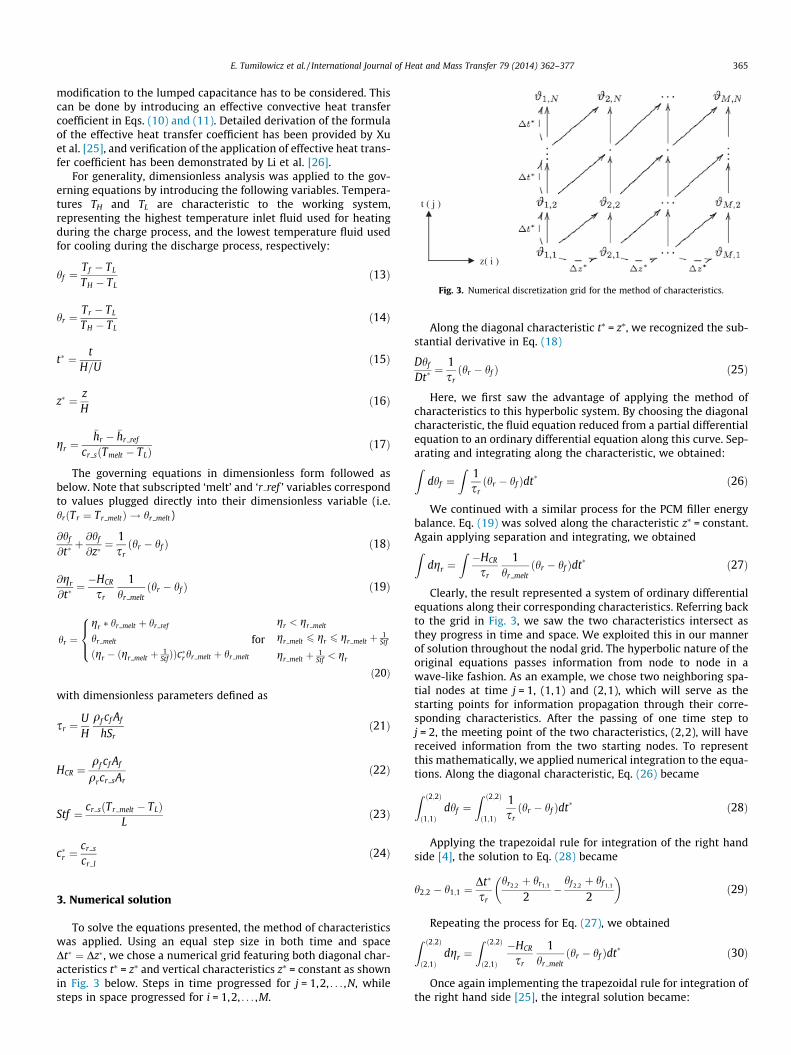
t ( j )
z( i )
Fig. 3. Numerical discretization grid for the method of characteristics.
E. Tumilowicz et al. / International Journal of Heat and Mass Transfer 79 (2014) 362–377 365
modification to the lumped capacitance has to be considered. Thiscan be done by introducing an effective convective heat transfercoefficient in Eqs. (10) and (11). Detailed derivation of the formulaof the effective heat transfer coefficient has been provided by Xuet al. [25], and verification of the application of effective heat trans-fer coefficient has been demonstrated by Li et al. [26].
For generality, dimensionless analysis was applied to the gov-erning equations by introducing the following variables. Tempera-tures TH and TL are characteristic to the working system,representing the highest temperature inlet fluid used for heatingduring the charge process, and the lowest temperature fluid usedfor cooling during the discharge process, respectively:
hf ¼Tf � TL
TH � TLð13Þ
hr ¼Tr � TL
TH � TLð14Þ
t� ¼ tH=U
ð15Þ
z� ¼ zH
ð16Þ
gr ¼�hr � �hr ref
cr sðTmelt � TLÞð17Þ
The governing equations in dimensionless form followed asbelow. Note that subscripted ‘melt’ and ‘r ref ’ variables correspondto values plugged directly into their dimensionless variable (i.e.hrðTr ¼ Tr meltÞ ! hr melt)
@hf
@t�þ @hf
@z�¼ 1
srðhr � hf Þ ð18Þ
@gr
@t�¼ �HCR
sr
1hr melt
ðhr � hf Þ ð19Þ
hr ¼gr � hr melt þ hr ref
hr melt
ðgr � ðgr melt þ 1StfÞÞc�r hr melt þ hr melt
8><>: for
gr < gr melt
gr melt 6 gr 6 gr melt þ 1Stf
gr melt þ 1Stf < gr
ð20Þ
with dimensionless parameters defined as
sr ¼UH
qf cf Af
hSrð21Þ
HCR ¼qf cf Af
qrcr sArð22Þ
Stf ¼ cr sðTr melt � TLÞL
ð23Þ
c�r ¼cr s
cr lð24Þ
3. Numerical solution
To solve the equations presented, the method of characteristicswas applied. Using an equal step size in both time and spaceDt� ¼ Dz�, we chose a numerical grid featuring both diagonal char-acteristics t⁄ = z⁄ and vertical characteristics z⁄ = constant as shownin Fig. 3 below. Steps in time progressed for j = 1,2, . . . ,N, whilesteps in space progressed for i = 1,2, . . . ,M.
Along the diagonal characteristic t⁄ = z⁄, we recognized the sub-stantial derivative in Eq. (18)
Dhf
Dt�¼ 1
srðhr � hf Þ ð25Þ
Here, we first saw the advantage of applying the method ofcharacteristics to this hyperbolic system. By choosing the diagonalcharacteristic, the fluid equation reduced from a partial differentialequation to an ordinary differential equation along this curve. Sep-arating and integrating along the characteristic, we obtained:Z
dhf ¼Z
1srðhr � hf Þdt� ð26Þ
We continued with a similar process for the PCM filler energybalance. Eq. (19) was solved along the characteristic z⁄ = constant.Again applying separation and integrating, we obtainedZ
dgr ¼Z �HCR
sr
1hr melt
ðhr � hf Þdt� ð27Þ
Clearly, the result represented a system of ordinary differentialequations along their corresponding characteristics. Referring backto the grid in Fig. 3, we saw the two characteristics intersect asthey progress in time and space. We exploited this in our mannerof solution throughout the nodal grid. The hyperbolic nature of theoriginal equations passes information from node to node in awave-like fashion. As an example, we chose two neighboring spa-tial nodes at time j = 1, (1,1) and (2,1), which will serve as thestarting points for information propagation through their corre-sponding characteristics. After the passing of one time step toj = 2, the meeting point of the two characteristics, (2,2), will havereceived information from the two starting nodes. To representthis mathematically, we applied numerical integration to the equa-tions. Along the diagonal characteristic, Eq. (26) became
Z ð2;2Þ
ð1;1Þdhf ¼
Z ð2;2Þ
ð1;1Þ
1srðhr � hf Þdt� ð28Þ
Applying the trapezoidal rule for integration of the right handside [4], the solution to Eq. (28) became
h2;2 � h1;1 ¼Dt�
sr
hr2;2 þ hr1;1
2�
hf 2;2þ hf 1;1
2
� �ð29Þ
Repeating the process for Eq. (27), we obtainedZ ð2;2Þ
ð2;1Þdgr ¼
Z ð2;2Þ
ð2;1Þ
�HCR
sr
1hr melt
ðhr � hf Þdt� ð30Þ
Once again implementing the trapezoidal rule for integration ofthe right hand side [25], the integral solution became:
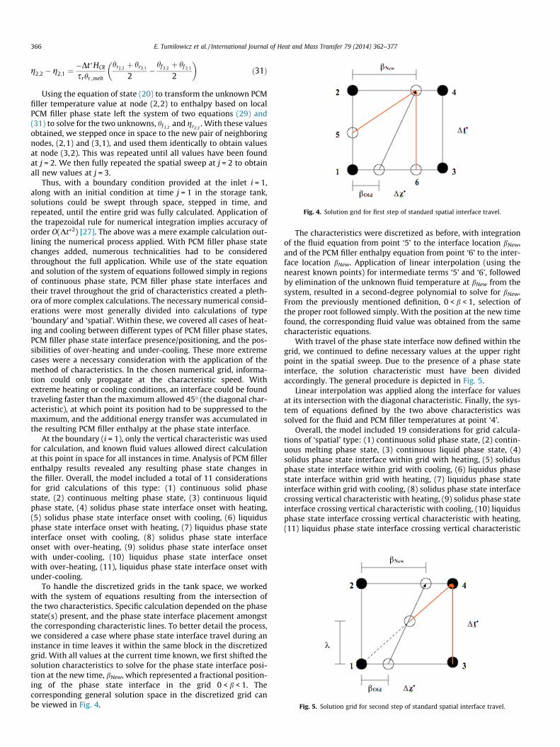
Fig. 4. Solution grid for first step of standard spatial interface travel.
Fig. 5. Solution grid for second step of standard spatial interface travel.
366 E. Tumilowicz et al. / International Journal of Heat and Mass Transfer 79 (2014) 362–377
g2;2 � g2;1 ¼�Dt�HCR
srhr melt
hr2;2 þ hr2;1
2�
hf 2;2þ hf 2;1
2
� �ð31Þ
Using the equation of state (20) to transform the unknown PCMfiller temperature value at node (2,2) to enthalpy based on localPCM filler phase state left the system of two equations (29) and(31) to solve for the two unknowns, hf 2;2
and gr2;2. With these values
obtained, we stepped once in space to the new pair of neighboringnodes, (2,1) and (3,1), and used them identically to obtain valuesat node (3,2). This was repeated until all values have been foundat j = 2. We then fully repeated the spatial sweep at j = 2 to obtainall new values at j = 3.
Thus, with a boundary condition provided at the inlet i = 1,along with an initial condition at time j = 1 in the storage tank,solutions could be swept through space, stepped in time, andrepeated, until the entire grid was fully calculated. Application ofthe trapezoidal rule for numerical integration implies accuracy oforder O(Dt⁄2) [27]. The above was a mere example calculation out-lining the numerical process applied. With PCM filler phase statechanges added, numerous technicalities had to be consideredthroughout the full application. While use of the state equationand solution of the system of equations followed simply in regionsof continuous phase state, PCM filler phase state interfaces andtheir travel throughout the grid of characteristics created a pleth-ora of more complex calculations. The necessary numerical consid-erations were most generally divided into calculations of type‘boundary’ and ‘spatial’. Within these, we covered all cases of heat-ing and cooling between different types of PCM filler phase states,PCM filler phase state interface presence/positioning, and the pos-sibilities of over-heating and under-cooling. These more extremecases were a necessary consideration with the application of themethod of characteristics. In the chosen numerical grid, informa-tion could only propagate at the characteristic speed. Withextreme heating or cooling conditions, an interface could be foundtraveling faster than the maximum allowed 45� (the diagonal char-acteristic), at which point its position had to be suppressed to themaximum, and the additional energy transfer was accumulated inthe resulting PCM filler enthalpy at the phase state interface.
At the boundary (i = 1), only the vertical characteristic was usedfor calculation, and known fluid values allowed direct calculationat this point in space for all instances in time. Analysis of PCM fillerenthalpy results revealed any resulting phase state changes inthe filler. Overall, the model included a total of 11 considerationsfor grid calculations of this type: (1) continuous solid phasestate, (2) continuous melting phase state, (3) continuous liquidphase state, (4) solidus phase state interface onset with heating,(5) solidus phase state interface onset with cooling, (6) liquidusphase state interface onset with heating, (7) liquidus phase stateinterface onset with cooling, (8) solidus phase state interfaceonset with over-heating, (9) solidus phase state interface onsetwith under-cooling, (10) liquidus phase state interface onsetwith over-heating, (11), liquidus phase state interface onset withunder-cooling.
To handle the discretized grids in the tank space, we workedwith the system of equations resulting from the intersection ofthe two characteristics. Specific calculation depended on the phasestate(s) present, and the phase state interface placement amongstthe corresponding characteristic lines. To better detail the process,we considered a case where phase state interface travel during aninstance in time leaves it within the same block in the discretizedgrid. With all values at the current time known, we first shifted thesolution characteristics to solve for the phase state interface posi-tion at the new time, bNew, which represented a fractional position-ing of the phase state interface in the grid 0 < b < 1. Thecorresponding general solution space in the discretized grid canbe viewed in Fig. 4.
The characteristics were discretized as before, with integrationof the fluid equation from point ‘5’ to the interface location bNew,and of the PCM filler enthalpy equation from point ‘6’ to the inter-face location bNew. Application of linear interpolation (using thenearest known points) for intermediate terms ‘5’ and ‘6’, followedby elimination of the unknown fluid temperature at bNew from thesystem, resulted in a second-degree polynomial to solve for bNew.From the previously mentioned definition, 0 < b < 1, selection ofthe proper root followed simply. With the position at the new timefound, the corresponding fluid value was obtained from the samecharacteristic equations.
With travel of the phase state interface now defined within thegrid, we continued to define necessary values at the upper rightpoint in the spatial sweep. Due to the presence of a phase stateinterface, the solution characteristic must have been dividedaccordingly. The general procedure is depicted in Fig. 5.
Linear interpolation was applied along the interface for valuesat its intersection with the diagonal characteristic. Finally, the sys-tem of equations defined by the two above characteristics wassolved for the fluid and PCM filler temperatures at point ‘4’.
Overall, the model included 19 considerations for grid calcula-tions of ‘spatial’ type: (1) continuous solid phase state, (2) contin-uous melting phase state, (3) continuous liquid phase state, (4)solidus phase state interface within grid with heating, (5) solidusphase state interface within grid with cooling, (6) liquidus phasestate interface within grid with heating, (7) liquidus phase stateinterface within grid with cooling, (8) solidus phase state interfacecrossing vertical characteristic with heating, (9) solidus phase stateinterface crossing vertical characteristic with cooling, (10) liquidusphase state interface crossing vertical characteristic with heating,(11) liquidus phase state interface crossing vertical characteristic
E. Tumilowicz et al. / International Journal of Heat and Mass Transfer 79 (2014) 362–377 367
with cooling, (12) solidus phase state interface leaving spatialdomain with heating, (13) solidus phase state interface leavingthe spatial domain with cooling, (14) liquidus phase state interfaceleaving the spatial domain with heating, (15) liquidus phase stateinterface leaving the spatial domain with cooling, (16) solidusphase state interface crossing vertical characteristic with over-heating, (17) solidus phase state interface crossing vertical charac-teristic with under-cooling, (18) liquidus phase state interfacecrossing vertical characteristic with over-heating, (19), liquidusphase state interface crossing vertical characteristic with under-cooling.
4. Verification
Reviewing the final governing equations of interactions in thestorage tank, educated choices in spatial positioning and PCM fillerphase state allowed for analytic solutions to this otherwise compli-cated pair of equations. Exploiting these simplifications, and hav-ing access to the previous model produced by Van Lew [10], wewere able to obtain additional confidence in the new model.
The first step for verification featured a test up the tank inletboundary. Here, fluid temperature was known as the inlet condi-tion, which we assumed to be constant for simplicity. Alsoassuming solid PCM filler only with reference temperature beingequal to the low temperature in the system, Eq. (19) reduced to asimple ordinary differential equation, whose solution followedsimply:
dhr
dt�þ HCR
srhr ¼
HCR
srhf inlet
ð32Þ
hr ¼ hf inletþ ðhrO � hf inlet
Þe�HCR
srt� ð33Þ
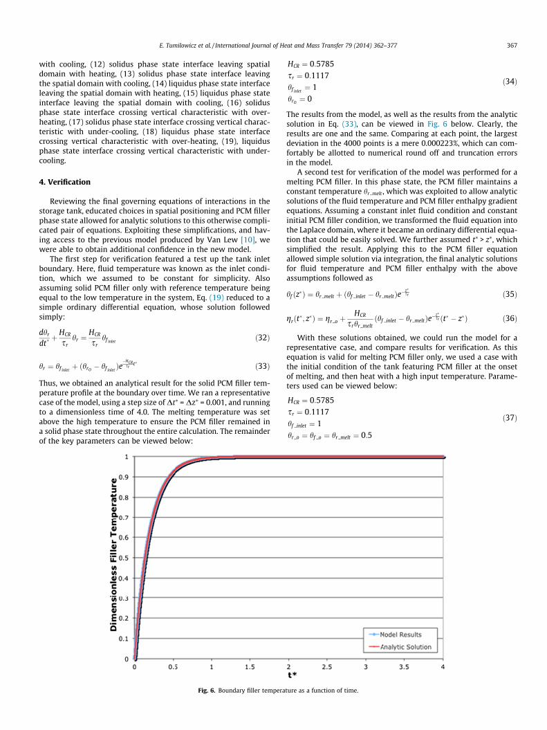
Thus, we obtained an analytical result for the solid PCM filler tem-perature profile at the boundary over time. We ran a representativecase of the model, using a step size of Dt⁄ = Dz⁄ = 0.001, and runningto a dimensionless time of 4.0. The melting temperature was setabove the high temperature to ensure the PCM filler remained ina solid phase state throughout the entire calculation. The remainderof the key parameters can be viewed below:
Fig. 6. Boundary filler tempera
HCR ¼ 0:5785sr ¼ 0:1117hf inlet
¼ 1hrO ¼ 0
ð34Þ
The results from the model, as well as the results from the analyticsolution in Eq. (33), can be viewed in Fig. 6 below. Clearly, theresults are one and the same. Comparing at each point, the largestdeviation in the 4000 points is a mere 0.000223%, which can com-fortably be allotted to numerical round off and truncation errorsin the model.
A second test for verification of the model was performed for amelting PCM filler. In this phase state, the PCM filler maintains aconstant temperature hr melt , which was exploited to allow analyticsolutions of the fluid temperature and PCM filler enthalpy gradientequations. Assuming a constant inlet fluid condition and constantinitial PCM filler condition, we transformed the fluid equation intothe Laplace domain, where it became an ordinary differential equa-tion that could be easily solved. We further assumed t⁄ > z⁄, whichsimplified the result. Applying this to the PCM filler equationallowed simple solution via integration, the final analytic solutionsfor fluid temperature and PCM filler enthalpy with the aboveassumptions followed as
hf ðz�Þ ¼ hr melt þ ðhf inlet � hr meltÞe�z�sr ð35Þ
grðt�; z�Þ ¼ gr o þHCR
srhr meltðhf inlet � hr meltÞe�
z�sr ðt� � z�Þ ð36Þ
With these solutions obtained, we could run the model for arepresentative case, and compare results for verification. As thisequation is valid for melting PCM filler only, we used a case withthe initial condition of the tank featuring PCM filler at the onsetof melting, and then heat with a high input temperature. Parame-ters used can be viewed below:
HCR ¼ 0:5785sr ¼ 0:1117hf inlet ¼ 1hr o ¼ hf o ¼ hr melt ¼ 0:5
ð37Þ
ture as a function of time.
368 E. Tumilowicz et al. / International Journal of Heat and Mass Transfer 79 (2014) 362–377
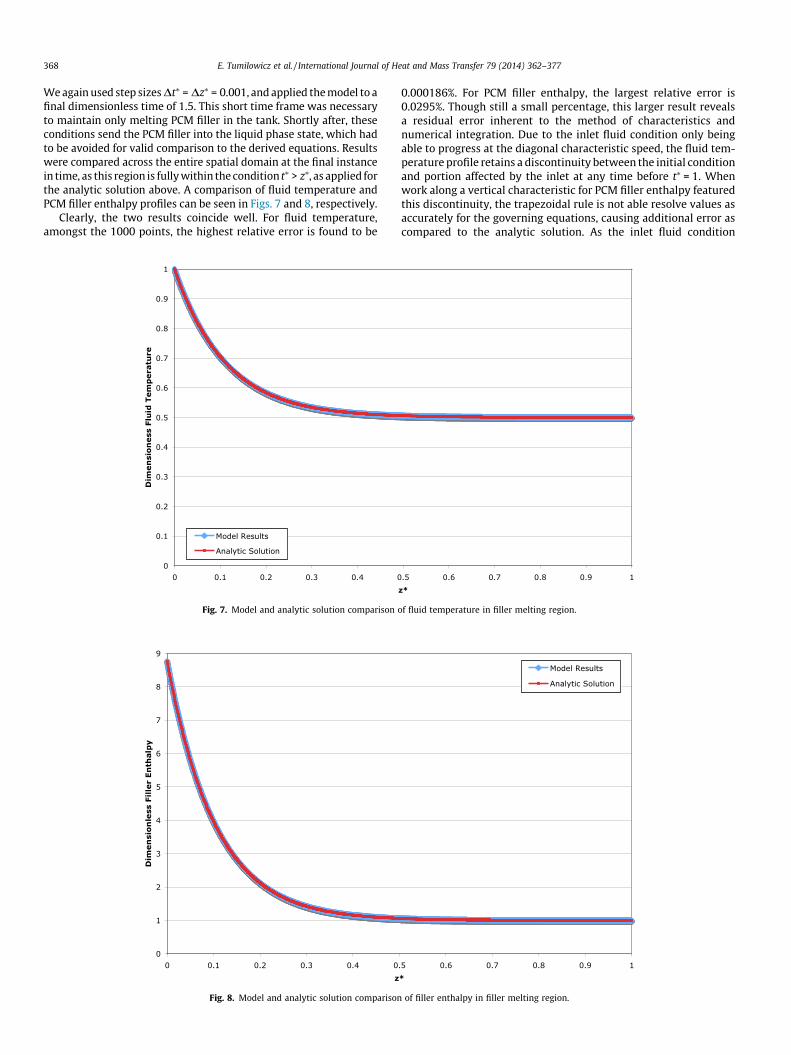
We again used step sizes Dt⁄ = Dz⁄ = 0.001, and applied the model to afinal dimensionless time of 1.5. This short time frame was necessaryto maintain only melting PCM filler in the tank. Shortly after, theseconditions send the PCM filler into the liquid phase state, which hadto be avoided for valid comparison to the derived equations. Resultswere compared across the entire spatial domain at the final instancein time, as this region is fully within the condition t⁄ > z⁄, as applied forthe analytic solution above. A comparison of fluid temperature andPCM filler enthalpy profiles can be seen in Figs. 7 and 8, respectively.
Clearly, the two results coincide well. For fluid temperature,amongst the 1000 points, the highest relative error is found to be
Fig. 8. Model and analytic solution comparison
Fig. 7. Model and analytic solution comparison o
0.000186%. For PCM filler enthalpy, the largest relative error is0.0295%. Though still a small percentage, this larger result revealsa residual error inherent to the method of characteristics andnumerical integration. Due to the inlet fluid condition only beingable to progress at the diagonal characteristic speed, the fluid tem-perature profile retains a discontinuity between the initial conditionand portion affected by the inlet at any time before t⁄ = 1. Whenwork along a vertical characteristic for PCM filler enthalpy featuredthis discontinuity, the trapezoidal rule is not able resolve values asaccurately for the governing equations, causing additional error ascompared to the analytic solution. As the inlet fluid condition
of filler enthalpy in filler melting region.
f fluid temperature in filler melting region.

E. Tumilowicz et al. / International Journal of Heat and Mass Transfer 79 (2014) 362–377 369
traverses through space, the discontinuity decreases, which in turnlower the resulting error, eventually to the same order of magnitudeseen before. As calculations continued in time, any errors introducedin space are further decreased. Though resulting errors in the pro-files become quite small at the end of run, it is important to under-stand this numerical intricacy inherent to the method.
Another step for verification of the model features comparison tothe previously constructed model by Van Lew [10]. Though the pre-vious work did not take a PCM filler into account, comparison of fillerand fluid temperatures could still be made for a filler in solid phasestate. Running an identical case (from the original boundary verifica-tion above) for the two models and comparing results at eachnumerical grid at the last instance in time, using the Van Lew resultsas a reference, the maximum percentage errors were found to be0.000861% and 0.000738% per PCM filler and fluid temperature,respectively. These very small deviations were likely due to the nat-ure of input to the models, mixed with standard numerical round-offerror. The newly developed model took properties as input, and cal-culates the corresponding dimensionless parameters from them,while Van Lew’s model simply took the dimensionless parametervalues as input directly. This was clearly a source of small error.However, we saw the minute deviation is already of the same mag-nitude as the numerical round off seen in previous verifications.Thus, the additional significant figures in accurate dimensionlessparameter calculation were not necessarily useful.
Finally, comparison to experimental results by Nallusamy et al.[3] was also made to demonstrate the validity of our numericalscheme. They used encapsulated spherical capsules of paraffinwith melting temperature at 60 �C as the PCM and water as theheat transfer fluid. The inlet fluid temperature was maintained at70 �C and the mass flow rate was fixed at 2 liters per minute. Usingtheir experimental conditions and properties given, we estimatedthe governing parameters:
Fig. 9. Comparison of fluid temperature
HCR ¼ 1:008sr ¼ 1:0269hf inlet
¼ 1hrO ¼ hf O
¼ 0hr melt ¼ 0:7368Dt� ¼ Dzþ ¼ 0:001
ð38Þ
Figs. 9 and 10 shows the comparisons of the fluid temperatureand the PCM temperature as a function of time located at the mid-dle of the tank, respectively. It can be observed that the results arein good agreement.
5. Model application
With the new model developed and verified, we briefly showsome of its capabilities in application. Having expanded consider-ations to a PCM filler, we first outline a simple charge/dischargeprocess for a thermocline utilizing this sort of material. We beginwith the charge process, with key numerical parameters as below:
HCR ¼ 0:5785sr ¼ 0:1117hf inlet
¼ 1hrO ¼ hf O
¼ 0hr melt ¼ 0:5Dt� ¼ Dzþ ¼ 0:001
ð39Þ
Heating occurred from the initial state to a final dimensionless timeof 4.0, for which temperature profiles are again displayed at dimen-sionless times 0, 0.1, 0.5, 1.0, 2.0, 3.0, and 4.0. These can be viewedin Figs. 11 and 12, per the fluid and PCM filler, respectively.
located at the middle of the tank.
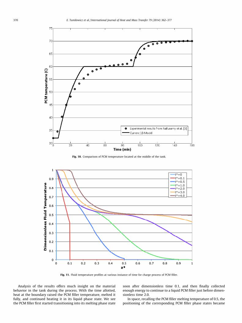
Fig. 10. Comparison of PCM temperature located at the middle of the tank.
Fig. 11. Fluid temperature profiles at various instance of time for charge process of PCM filler.
370 E. Tumilowicz et al. / International Journal of Heat and Mass Transfer 79 (2014) 362–377
Analysis of the results offers much insight on the materialbehavior in the tank during the process. With the time allotted,heat at the boundary raised the PCM filler temperature, melted itfully, and continued heating it in its liquid phase state. We seethe PCM filler first started transitioning into its melting phase state
soon after dimensionless time 0.1, and then finally collectedenough energy to continue to a liquid PCM filler just before dimen-sionless time 2.0.
In space, recalling the PCM filler melting temperature of 0.5, thepositioning of the corresponding PCM filler phase states became

Fig. 12. Filler temperature profiles at various instance of time for charge process of PCM filler.
E. Tumilowicz et al. / International Journal of Heat and Mass Transfer 79 (2014) 362–377 371
quite clear. At the end of the charge, with PCM filler temperature atthe outlet remaining just below the PCM filler melting tempera-ture, heat propagation sent the solidus phase state interface nearthe end of the tank, leaving only a small amount of solid PCM fillernear the outlet. The constant filler temperature of 0.5 throughoutmost of the space shows the large latent heat maintaining thePCM filler in this intermediate melting phase state. Finally, nearthe inlet, the temperature of the PCM filler finally rose above 0.5,signifying a liquid PCM filler, and placing the liquidus phase stateinterface near this inlet boundary. We review the interface posi-tions as functions of time in Fig. 13 below to confirm this behavior.
Fig. 13. Phase change interface positions as functions
The plot confirms what is seen in the temperature distributions.Melting occurred relatively soon after heating began, correspondingto the start of the solidus phase state interface. With continued heat-ing, this interface traveled through space, and is left near the end ofthe tank. Late in the charging cycle, enough heat had been put intoproduce a fully liquid PCM filler, corresponding to the beginning ofa liquidus phase state interface. With only little time left in the pro-cess, this second interface traveled only slightly into the space. Dis-continuities in the fluid temperature profiles are again seen beforedimensionless time 1.0 for the same reasons stated in the non-meltPCM filler case. In Fig. 14, the corresponding liquid fraction vs z⁄ at
of time for standard charge process of PCM filler.
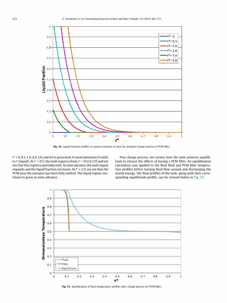
Fig. 14. Liquid fraction profiles at various instance of time for standard charge process of PCM filler.
372 E. Tumilowicz et al. / International Journal of Heat and Mass Transfer 79 (2014) 362–377
t⁄ = 0, 0.5, 1.0, 2.0, 3.0, and 4.0 is presented. It varies between 0 (solid)to 1 (liquid). At t⁄ = 0.5, the melt region is from z⁄ = 0 to 0.135 and wesee that this region is partially melt. As time advance, the melt regionexpands and the liquid fraction increases. At t⁄ = 2.0, we see that thePCM near the entrance has been fully melted. The liquid region con-tinues to grow as time advance.
Fig. 15. Equilibration of final temperature pr
Post charge process, we review how the tank achieves equilib-rium to extract the effects of having a PCM filler. An equilibrationcalculation was applied to the final fluid and PCM filler tempera-ture profiles before turning fluid flow around and discharging thestored energy. The final profiles of the tank, along with their corre-sponding equilibrium profile, can be viewed below in Fig. 15.
ofiles after charge process for PCM filler.
E. Tumilowicz et al. / International Journal of Heat and Mass Transfer 79 (2014) 362–377 373
Reviewing the results, we see the effects of latent heat of equil-ibration results. With the end of charge profile featuring mostlymelting PCM filler, the temperature difference between fluid andPCM filler was not enough to lift the PCM filler above its meltingtemperature. It was only close to the phase state interfaces, andin the solid and liquid PCM filler phase state regions, that thetwo profiles found a more intermediate position, though they wereoriginally so close that the change is very small. Thus, we saw a lar-ger reduction in a relatively wide portion of the fluid temperatureprofile from equilibration, leading to a larger decrease of fluid out-put temperature for eventual energy production.
Fig. 16. Fluid temperature profiles at various instan
Fig. 17. Filler temperature profiles at various instan
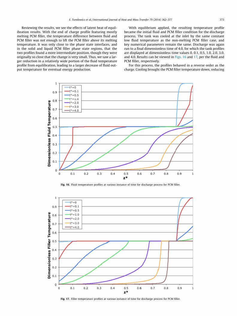
With equilibrium applied, the resulting temperature profilebecame the initial fluid and PCM filler condition for the dischargeprocess. The tank was cooled at the inlet by the same constantlow fluid temperature as the non-melting PCM filler case, andkey numerical parameters remain the same. Discharge was againrun to a final dimensionless time of 4.0, for which the tank profilesare displayed at dimensionless time values 0, 0.1, 0.5, 1.0, 2.0, 3.0,and 4.0. Results can be viewed in Figs. 16 and 17, per the fluid andPCM filler, respectively.
For this process, the profiles behaved in a reverse order as thecharge. Cooling brought the PCM filler temperature down, reducing
ce of time for discharge process for PCM filler.
ce of time for discharge process for PCM filler.

374 E. Tumilowicz et al. / International Journal of Heat and Mass Transfer 79 (2014) 362–377
the amount of liquid PCM filler, and increasing the amount of solidPCM filler. Just after dimensionless time 1.0, cooling sent the liqui-dus phase state interface out of the storage tank, thus removing allliquid PCM filler. Heat extraction continued until the solidus phasestate interface traveled past the position 0.8, leaving mostly solidPCM filler, with a comparatively small amount of melting PCM fil-ler. The fluid temperature profiles followed as expected, with dis-continuities between inlet affected fluid and initial state seenbefore dimensionless time 1.0, as before.
Finally, we showcase the versatility of the model by applying avariable boundary condition. With it, we aimed to apply heat to thePCM filler, forcing phase change(s), at which time the boundarycondition was reversed, removing heat to produce an additionalphase state interface reverting to the earlier phase state(s). Seeingsatisfactory modeling in a complex heat transfer case such as thiswill confirm the general consideration implemented. The modelwas run as a charge process until a final dimensionless time equalto 5.0. Key properties were as follows:
HCR ¼ 0:5725sr ¼ 0:1174hrO ¼ hf O
¼ 0hr melt ¼ 0:1
ð40Þ
with inlet fluid temperatures as below:
hf inlet ¼
1:00:60:30
8>>><>>>:
for
0 6 t� < 1:51:5 6 t� < 2:52:5 6 t� < 4:04:0 6 t� < 5:0
ð41Þ
This boundary condition represented a discontinuous series ofconstant fluid temperature values applied over specific amountsof time. Heating was applied quickly to produce two-phase stateinterfaces, and then a gradually stepped cooling was used to revertto a previous phase state. Below, we trace the temperature profileevolutions throughout the various changes in boundary condition.
We first look at the temperatures within the tank at dimension-less time 1.499, which is the last instance of inlet fluid condition
Fig. 18. Fluid and filler temperature pr
equal to 1.0. This can be viewed in Fig. 18. The profiles producedrepresent a simple constant inlet PCM filler temperature charge.Heating produced two-phase state interfaces, leaving 3 separatephase states of PCM filler in the tank. Though paraffin features alarge latent heat, the large temperature gradient left above themelting temperature due to the high inlet fluid temperature heatedthrough the melting PCM phase state relatively quickly. We nowcontinue to the distributions at dimensionless time 2.499, Fig. 19,which is the last instance in time with the inlet temperature of0.6 as the boundary condition.
At this instance in time, we see an interesting response in theprofiles. Due to the wide spread of PCM filler temperature afterthe previous heating, the new inlet condition worked to both cooland heat, depending on the inlet fluid’s relation to the tempera-tures within the tank at a certain position. The effect was seenthroughout the entire tank, as this new condition, traveling atthe characteristic speed, was able to traverse the entire space inthe Dt⁄ = 1.0 it was applied. When interacting with the high tem-peratures towards the tank inlet, we saw a cooling that brings bothPCM filler and fluid profiles gradually down to the inlet tempera-ture condition. Further in space, where tank temperature valuesremain lower, the new condition continued to heat the tank pro-files. The two heat transfer types met in a continuous parabolicfashion, representing the eventual change of liquid PCM filler beingheated to liquid PCM filler experiencing cooling. Heat propagationthrough the tank had also facilitated the propagation of the twopreviously mentioned interfaces, as expected. The initial solidusphase state interface was found very close to the outlet, leavinglittle solid PCM filler in the tank, while the creation of more liquidPCM filler placed the liquidus phase state interface past the mid-way point in the tank.
Past this time, another lower fluid boundary temperature wasapplied up until the dimensionless time 3.999. The profiles at thistime can be viewed in Fig. 20. As expected, this new inlet fluid tem-perature dropped temperature profiles even lower. All solid PCMfiller has now melted, meaning the solidus phase state interfacehas left the space at some time during the application of this inletcondition. Conditions had also produced even more liquid PCM fil-ler, and correspondingly shifted the liquidus phase state interface
ofiles at dimensionless time 1.499.
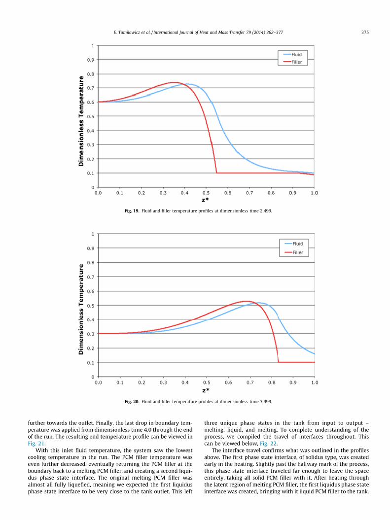
Fig. 19. Fluid and filler temperature profiles at dimensionless time 2.499.
Fig. 20. Fluid and filler temperature profiles at dimensionless time 3.999.
E. Tumilowicz et al. / International Journal of Heat and Mass Transfer 79 (2014) 362–377 375
further towards the outlet. Finally, the last drop in boundary tem-perature was applied from dimensionless time 4.0 through the endof the run. The resulting end temperature profile can be viewed inFig. 21.
With this inlet fluid temperature, the system saw the lowestcooling temperature in the run. The PCM filler temperature waseven further decreased, eventually returning the PCM filler at theboundary back to a melting PCM filler, and creating a second liqui-dus phase state interface. The original melting PCM filler wasalmost all fully liquefied, meaning we expected the first liquidusphase state interface to be very close to the tank outlet. This left
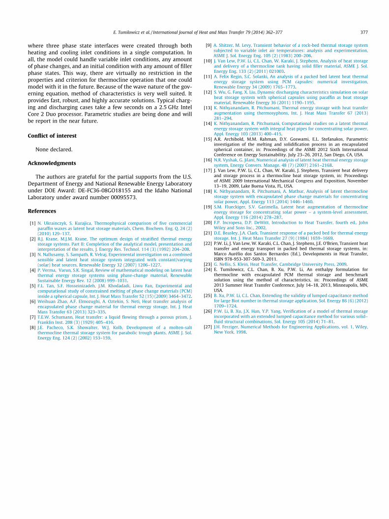
three unique phase states in the tank from input to output –melting, liquid, and melting. To complete understanding of theprocess, we compiled the travel of interfaces throughout. Thiscan be viewed below, Fig. 22.
The interface travel confirms what was outlined in the profilesabove. The first phase state interface, of solidus type, was createdearly in the heating. Slightly past the halfway mark of the process,this phase state interface traveled far enough to leave the spaceentirely, taking all solid PCM filler with it. After heating throughthe latent region of melting PCM filler, the first liquidus phase stateinterface was created, bringing with it liquid PCM filler to the tank.
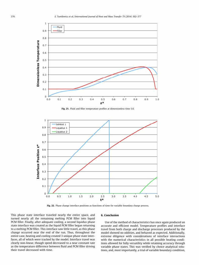
Fig. 21. Fluid and filler temperature profiles at dimensionless time 5.0.
Fig. 22. Phase change interface positions as functions of time for variable boundary charge process.
376 E. Tumilowicz et al. / International Journal of Heat and Mass Transfer 79 (2014) 362–377
This phase state interface traveled nearly the entire space, andturned nearly all the remaining melting PCM filler into liquidPCM filler. Finally, after adequate cooling, a second liquidus phasestate interface was created as the liquid PCM filler began returningto a melting PCM filler. This interface saw little travel, as this phasechange occurred near the end of the run. Thus, throughout theentire case, heating and cooling created 3 unique phase state inter-faces, all of which were tracked by the model. Interface travel wasclearly non-linear, though speed decreased to a near constant rateas the temperature difference between fluid and PCM filler drivingtheir travel decreased with time.
6. Conclusion
Use of the method of characteristics has once again produced anaccurate and efficient model. Temperature profiles and interfacetravel from both charge and discharge processes produced by themodel showed no oddities, and behaved as expected. Additionally,extreme diligence with considerations of interface interactionswith the numerical characteristics in all possible heating condi-tions allowed for fully versatility while retaining accuracy throughvariable phase states. This was verified by choice analytical solu-tions, and, most importantly, a trial of variable boundary condition,
E. Tumilowicz et al. / International Journal of Heat and Mass Transfer 79 (2014) 362–377 377
where three phase state interfaces were created through bothheating and cooling inlet conditions in a single computation. Inall, the model could handle variable inlet conditions, any amountof phase changes, and an initial condition with any amount of fillerphase states. This way, there are virtually no restriction in theproperties and criterion for thermocline operation that one couldmodel with it in the future. Because of the wave nature of the gov-erning equation, method of characteristics is very well suited. Itprovides fast, robust, and highly accurate solutions. Typical charg-ing and discharging cases take a few seconds on a 2.5 GHz IntelCore 2 Duo processor. Parametric studies are being done and willbe report in the near future.
Conflict of interest
None declared.
Acknowledgments
The authors are grateful for the partial supports from the U.S.Department of Energy and National Renewable Energy Laboratoryunder DOE Award: DE-FC36-08GO18155 and the Idaho NationalLaboratory under award number 00095573.
References
[1] N. Ukrainczyk, S. Kurajica, Thermophysical comparison of five commercialparaffin waxes as latent heat storage materials, Chem. Biochem. Eng. Q. 24 (2)(2010) 129–137.
[2] R.J. Krane, M.J.M. Krane, The optimum design of stratified thermal energystorage systems. Part II: Completion of the analytical model, presentation andinterpretation of the results, J. Energy Res. Technol. 114 (3) (1992) 204–208.
[3] N. Nallusamy, S. Sampath, R. Velraj, Experimental investigation on a combinedsensible and latent heat storage system integrated with constant/varying(solar) heat sources, Renewable Energy 32 (2007) 1206–1227.
[4] P. Verma, Varun, S.K. Singal, Review of mathematical modeling on latent heatthermal energy storage systems using phase-change material, RenewableSustainable Energy Rev. 12 (2008) 999–1031.
[5] F.L. Tan, S.F. Hosseinizadeh, J.M. Khodadadi, Liwu Fan, Experimental andcomputational study of constrained melting of phase change materials (PCM)inside a spherical capsule, Int. J. Heat Mass Transfer 52 (15) (2009) 3464–3472.
[6] Weihuan Zhao, A.F. Elmozughi, A. Oztekin, S. Neti, Heat transfer analysis ofencapsulated phase change material for thermal energy storage, Int. J. HeatMass Transfer 63 (2013) 323–335.
[7] T.E.W. Schumann, Heat transfer: a liquid flowing through a porous prism, J.Franklin Inst. 208 (3) (1929) 405–416.
[8] J.E. Pacheco, S.K. Showalter, W.J. Kolb, Development of a molten-saltthermocline thermal storage system for parabolic trough plants, ASME J. Sol.Energy Eng. 124 (2) (2002) 153–159.
[9] A. Shitzer, M. Levy, Transient behavior of a rock-bed thermal storage systemsubjected to variable inlet air temperatures: analysis and experimentation,ASME J. Sol. Energy Eng. 105 (2) (1983) 200–206.
[10] J. Van Lew, P.W. Li, C.L. Chan, W. Karaki, J. Stephens, Analysis of heat storageand delivery of a thermocline tank having solid filler material, ASME J. Sol.Energy Eng. 133 (2) (2011) 021003.
[11] A. Felix Regin, S.C. Solanki, An analysis of a packed bed latent heat thermalenergy storage system using PCM capsules: numerical investigation,Renewable Energy 34 (2009) 1765–1773.
[12] S. Wu, G. Fang, X. Liu, Dynamic discharging characteristics simulation on solarheat storage system with spherical capsules using paraffin as heat storagematerial, Renewable Energy 36 (2011) 1190–1195.
[13] K. Nithyanandam, R. Pitchumani, Thermal energy storage with heat transferaugmentation using thermosyphons, Int. J. Heat Mass Transfer 67 (2013)281–294.
[14] K. Nithyanandam, R. Pitchumani, Computational studies on a latent thermalenergy storage system with integral heat pipes for concentrating solar power,Appl. Energy 103 (2013) 400–415.
[15] A.R. Archibold, M.M. Rahman, D.Y. Goswami, E.L. Stefanakos, Parametricinvestigation of the melting and solidification process in an encapsulatedspherical container, in: Proceedings of the ASME 2012 Sixth InternationalConference on Energy Sustainability. July 23–26, 2012, San Diego, CA, USA.
[16] N.R. Vyshak, G. Jilani, Numerical analysis of latent heat thermal energy storagesystem, Energy Convers. Manage. 48 (7) (2007) 2161–2168.
[17] J. Van Lew, P.W. Li, C.L. Chan, W. Karaki, J. Stephens, Transient heat deliveryand storage process in a thermocline heat storage system, in: Proceedingsof ASME 2009 International Mechanical Congress and Exposition, November13–19, 2009, Lake Buena Vista, FL, USA.
[18] K. Nithyanandam, R. Pitchumani, A. Mathur, Analysis of latent thermoclinestorage system with encapsulated phase change materials for concentratingsolar power, Appl. Energy 113 (2014) 1446–1460.
[19] S.M. Flueckiger, S.V. Garimella, Latent heat augmentation of thermoclineenergy storage for concentrating solar power – a system-level assessment,Appl. Energy 116 (2014) 278–287.
[20] F.P. Incropera, D.P. DeWitt, Introduction to Heat Transfer, fourth ed., JohnWiley and Sons Inc., 2002.
[21] D.E. Beasley, J.A. Clark, Transient response of a packed bed for thermal energystorage, Int. J. Heat Mass Transfer 27 (9) (1984) 1659–1669.
[22] P.W. Li, J. Van Lew, W. Karaki, C.L. Chan, J. Stephens, J.E. O’Brien, Transient heattransfer and energy transport in packed bed thermal storage systems, in:Marco Aurélio dos Santos Bernardes (Ed.), Developments in Heat Transfer,ISBN 978-953-307-569-3, 2011.
[23] G. Nellis, S. Klein, Heat Transfer, Cambridge University Press, 2009.[24] E. Tumilowicz, C.L. Chan, B. Xu, P.W. Li, An enthalpy formulation for
thermocline with encapsulated PCM thermal storage and benchmarksolution using the method of characteristics, in: Proceedings of ASME2013 Summer Heat Transfer Conference, July 14–18, 2013, Minneapolis, MN,USA.
[25] B. Xu, P.W. Li, C.L. Chan, Extending the validity of lumped capacitance methodfor large Biot number in thermal storage application, Sol. Energy 86 (6) (2012)1709–1724.
[26] P.W. Li, B. Xu, J.X. Han, Y.P. Yang, Verification of a model of thermal storageincorporated with an extended lumped capacitance method for various solid–fluid structural combinations, Sol. Energy 105 (2014) 71–81.
[27] J.H. Ferziger, Numerical Methods for Engineering Applications, vol. 1, Wiley,New York, 1998.