An Enhanced Hardware Description Language ...
95
Graz University of Technology CERN-THESIS-2007-053 30/07/2007
-
Upload
khangminh22 -
Category
Documents
-
view
2 -
download
0
Transcript of An Enhanced Hardware Description Language ...

Dissertation
An Enhanced Hardware Description
Language Implementation for Improved
Design-Space Exploration in High-Energy
Physics Hardware Design
Dipl.-Ing. Manfred Mücke
�������������
Institut für Technische InformatikTechnische Universität Graz
Vorstand: O.Univ.-Prof. Dipl.-Ing.Dr. techn.Reinhold Weiÿ
Graz University of Technology
Begutachter: O.Univ.-Prof. Dipl.-Ing.Dr. techn.Reinhold Weiÿ
Zweitbegutachter: Dr. Richard Jacobsson (CERN)
Graz, im Juli 2007
CE
RN
-TH
ESI
S-20
07-0
5330
/07
/20
07

Kurzfassung
Die Zeit- und Ortsau�ösung sowie die erreichbare Integrationsdichte von Sensorele-menten in Hochenergiephysik (HEP)-Experimenten hat sich im Laufe der letzten beidenJahrzehnte drastisch erhöht. Die von aktuellen Experimenten generierten Datenraten grö-ÿer 1TB/s, erzwingen neue, hochperformante und über existierende Lösungen hinausge-hende Systeme zum Auslesen, Verarbeiten und Speichern der gewonnenen Daten. Field-Programmable Gate Arrays (FPGAs) bieten die Möglichkeit schnelle digitale Signalverar-beitung zu implementieren und erlauben durch Ihre Programmierbarkeit eine rasche An-passung an geänderte Problemstellungen ohne einen Austausch von Komponenten zu er-zwingen. Aufgrund dieser hervorragenden Eigenschaften werden FPGAs heute von zahlrei-chen Hochenergiephysikexperimenten zur Echtzeitdatenverarbeitung eingesetzt. Dement-sprechend ist auch die Bedeutung von Entwurfswerkzeugen zum Umsetzen von Signalver-arbeitungsalgorithmen auf FPGAs gewachsen, um die theoretisch erreichbaren Leistungenauch praktisch erzielen zu können.
Diese Arbeit untersucht bestehende Hardwarebeschreibungssprachen auf Ihre Unter-stützung von typischen Problemstellungen des Hardwareentwurfes in der Hochenergiephy-sik, wobei bestehende Mängel aufgezeigt werden. Besonderes Augenmerk wird dabei aufdie Möglichkeit und den Aufwand gelegt, Hardwarebeschreibungssprachen um spezi�scheSprachkonstrukte bzw. Hilfsmittel zu erweitern. Funktional Sprachen sind besonders ge-eignet, um entsprechende o�ene Strukturen e�zient zu implementieren. Dies wird anhandvon Fallstudien zur Komplexität von HEP-spezi�schen Erweiterungen der funktionalenHardwarebeschreibungssprache HDCaml dokumentiert.
Abstract
Detectors in High-Energy Physics (HEP) have increased tremendously in accuracy, speedand integration. Consequently HEP experiments are confronted with an immense amountof data to be read out, processed and stored. Originally low-level processing has beenaccomplished in hardware, while more elaborate algorithms have been executed on largecomputing farms. Field-Programmable Gate Arrays (FPGAs) meet HEP's need for everhigher real-time processing performance by providing programmable yet fast digital logicresources. With the fast move from HEP Digital Signal Processing (DSPing) applica-tions into the domain of FPGAs, related design tools are crucial to realise the potentialperformance gains.
This work reviews Hardware Description Languages (HDLs) in respect to the specialneeds present in the HEP digital hardware design process. It is especially concernedwith the question, how features outside the scope of mainstream digital hardware designcan be implemented e�ciently into HDLs. It will argue that functional languages areespecially suitable for implementation of domain-speci�c languages, including HDLs. Case-studies examining the implementation complexity of HEP-speci�c language extensions tothe functional HDCaml HDL will prove the viability of the suggested approach.
1

Acknowledgements
This work would have been an impossible venture without the help of many people.The Austrian Doctoral Student Program made my stay at CERN possible. Jorgen was anawesome supervisor, providing advice when needed, but giving freedom generously whereever possible. Together with Manuel and Paulo he dragged me o� the o�ce twice a weekfor some laps in the pool. Thanks for your friendship and for keeping me �t.Many people at CERN have explained to me their respective area of expertise with endlesspatience, giving me an idea of the complex environment of a high-energy physics experi-ment. Guido, Niko, Benjamin and Lars enabled my work and were my comrades-in-armsin endless working hours.Thanks to Alex ("you really should come to CERN") for initially promoting the optionof a PhD at CERN and all the subsequent support. Thanks to Angelika, Gudrun, Kurt,Stefan, Ulrich, Sonia, Peo, Karin, Tomas and many more for their friendship, making lifein Geneva so enjoyable.But the biggest share goes, without doubt, to Anja, my wife. Joining me in this adventurewithout hesitation, moving to Geneva, and accepting a thousand kilometers between usfor quite some time, she made these three years a time we love to look back at.
Graz, July 2007 Manfred Mücke
2

Extended Abstract
Thanks to a PhD grant, I had the opportunity to work for two and a half years withinthe LHC beauty (LHCb) collaboration at CERN, the European laboratory for particlephysics in Geneva, Switzerland. LHCb is one of the four experiments in preparation forthe Large Hadron Collider (LHC) due to be operational by the end of 2007.
This work is based on experience gained by tight cooperation between researchers fromdistinct domains. It provides insight into how Hardware Description Languages (HDLs) canserve better the speci�c needs of digital hardware designs in High-Energy Physics (HEP).
Introduction
HEP experiments installed at the LHC generate a tremendous amount of data (for LHCbabout 40MS/s * 80KB ≈ 3.05TB/s), exceeding streaming capabilities of current storagetechnologies by orders of magnitude. Consequently large massive-parallel processing facil-ities are used to select and/or compress data in real-time. Programmable logic (FPGAs)has proved to be a viable technology for implementation of such real-time �lters, meetingboth the demand of computing power and design �exibility.
Most Electronics Design Automation tools available today consider designs imple-mented in FPGAs as simple digital hardware, i.e. the typical design elements are wires,basic logic and arithmetic functions, registers and memories. However, mapping HEP al-gorithms into FPGAs and exploring the respective design space requires a very di�erentapproach and notation. This poses a considerable shift of objective, not being met by toolscurrently available.
This work identi�es special design needs of contemporary HEP digital hardware de-signs. It focuses on the used modelling language (usually a hardware description language)and how to make the relevant model information accessible to tools. Speci�cally (and incontrast to many other approaches) it considers the potential advantages functional lan-guages can provide. It suggests and demonstrates extensions to HDLs to satisfy typicaldesign needs of HEP experiments.
As the very goal of HEP research is to observe what has not been seen before, operatingalways at the edge of current technology, many crucial design decisions have to rely heavilyon simulations. Once data taking has started and new knowledge begins to take shape,researchers want to refocus detectors to incorporate the new knowledge. Recon�gurabletrigger-levels implemented in FPGAs allow - in principle - for such an adaptation withoutthe need to develop new hardware.
However, reality does not live up to the expectations. This is mainly due to lim-ited �exibility provided by the current design �ow for FPGAs. Design descriptions at
3

Register-Transfer Level (RTL) using VHSIC Hardware Description Language (VHDL) donot provide su�cient problem-abstraction to allow fast iteration on algorithm variations(i.e. delivering in short time both simulation and implementation data from a model vari-ant). Therefore every iteration has to be seen as a new design e�ort (requiring considerablemanpower).
Iterating on a trigger implementation means providing a set of alternative implemen-tations for evaluation in software �rst. The most promising candidate should then replacethe current implementation, possibly without a�ecting the surrounding functions. Experi-ence has shown that turn-around times for such iterations lie within the order of months,if iteration is considered at all. This is due to the di�culty to provide identical models forsoftware simulation and hardware implementation and the range of skills required.
One possibility to improve upon this situation would be to provide:
• a description of algorithms at RTL to guarantee predictable synthesis results;
• a more generic description of algorithms than provided by VHDL to reduce code-complexity and to improve �ne-grained design-space exploration;
• automatic generation of fast and bit-accurate simulation models from the same sourceused for hardware description;
• minimization of the e�ort required to implement language features enabling a design�ow as described above and potential future language extensions.
Objective
No HDL currently available ful�lls the requirements listed above. We therefore set out toshow that this scenario is nevertheless feasible. We chose an open source HDL allowingRTL description and providing an open type system and means of extending the language.As a proof of concept, we have made the internals of the language more accessible andhave implemented di�erent extensions to that HDL. To consider HDL extensions a fea-sible option for future projects, the amount of work to be invested for implementation isimportant. We will show that it is low with regard to other similar approaches.
During research of possible language platforms on which our extension could be based,we encountered a lack of suitable extendable traditional HDLs. This led to a more the-oretical review of language design principles. We found functional languages much moree�cient for domain-speci�c extensions than traditional imperative ones. While this is inaccordance with literature on domain-speci�c languages, this �nding has only rarely beenapplied to HDLs. We will compare implementation complexity of similar features usingboth paradigms.
There are many attempts to improve upon the existing HDLs. Most of these approacheshowever are not publicly accessible. We have the impression that due to the lack ofexisting language platforms on which investigative approaches can be based, the advancesin domain-speci�c HDLs are moderate to low. We have therefore put emphasis on an open-source approach. The improvements to the used HDL and most extensions have been made
4

available online1 and an extensive tutorial has been compiled2.
Hardware abstraction and problem abstraction are generally orthogonal language fea-tures. However, current approaches do not treat related issues independently, or concen-trate on hardware abstraction. Our work concentrates on the highest problem-abstractionpossible at a given hardware-abstraction level (RTL).
High-Energy Physics compliant simulation models
As access to accelerators is usually limited and expensive, simulation plays a dominantrole in preparing and optimizing HEP experiments. The HEP community has createdmany highly specialized tools or extensions to existing mainstream tools for simulationof very diverse events, ranging from particle-particle interaction to computing farm loaddistribution. In HEP experiments, algorithms implemented in FPGAs are only a smallpart of a very big system. Consequently the simulation models have to �t the existinginfrastructure rather than the other way round (as is the case in typical Electronics DesignAutomation environments).
One important language for large-scale simulation is C++ and there exists a variedand highly developed infrastructure of C++-based simulation frameworks. Each of theseframeworks requires speci�c coding conventions to be followed. We have explored HDL lan-guage extensions allowing automatic generation of C- and C++-models. We have furtherinvestigated the ease with which the generation of code can be tuned such that compliancewith speci�c simulation framework coding conventions can be achieved.
The idea of deriving HEP-speci�c simulation models from circuit descriptions was pre-sented at the 2005 IEEE Real-Time Conference3. A case study based on algorithms usedby the LHCb VErtex LOcator (VELO) sub detector was presented the following year atthe 12th Workshop on Electronics for LHC and future Experiments (LECC'06)4.
Abstract �xed-point data type
For most trigger algorithms, the Signal-to-Noise Ratio (SNR) is the dominant qualityfactor. In digital designs, this is equal to the Signal-to-quantization-Noise ratio (SQNR)which is determined by the bit widths chosen for the di�erent data paths. A speci�c bitwidth is typically a compromise between precision requirements (derived from physics) andavailable hardware resources. Physics requirements can however vary a lot over time anda new discovery, a changed trigger algorithm or improved hardware might fundamentallychange the respective precision required. It would therefore be favorable to maintain thehighest degree of �exibility possible with regard to data bit width over the whole lifetimeof a trigger implementation.
1Tom Hawkins. HDCaml Home Page. 2006. url: http://www.funhdl.org/wiki/doku.php/hdcaml.2Daniel Sánchez Parcerisa. HDCaml Tutorial. 2006. url: http://www.funhdl.org/wiki/doku.php/
hdcaml:tutorial.3Manfred Muecke. �C/VHDL codesign for LHCb VELO zero suppression algorithms�. In: 14th IEEE-
NPSS Real Time Conference. 2005. doi: 10.1109/RTC.2005.1547399. 156�157.4Manfred Muecke and Tomasz Szumlak. �Uni�ed C/VHDL Model Generation of FPGA-based LHCb
VELO algorithms�. In: 12th Workshop on Electronics for LHC and future Experiments (LECC'06). 2006.url: http://cdsweb.cern.ch/record/1034306.
5

Consequently we have chosen to implement a HDL-extension which provides an abstract�xed-point data type. Modelling using this data type separates bit width- and precision-considerations from the algorithmic description. It enables generation of design variationswith only minimal code changes (due to automatic signal property propagation). This workhas been presented at the 2006 Forum on speci�cation & Design Languages (FDL'06)5.
The feasibility of the suggested design �ow in combination with the abstract �xed-pointdata type will be shown by design-space exploration for the LHCb VELO Linear CommonMode Suppression (LCMS) algorithm. The LHCb VELO acLCMS algorithm is a real-world example, and (using a former VHDL model) is implemented in the LHCb DataAcquisition System (DAQ) interface board called TELL16, a custom-built multi-FPGAprocessing board of which 350 are currently being installed in the LHCb cavern.
Graph Description Language model generation
Control and Data Flow Graphs (CDFGs) are a useful intermediate representation whenmapping algorithms into sequential circuits and especially powerful when used in com-bination with graph transformation rules. The Graph Description Language provides aformat for exchange of graphs between di�erent applications. We have created a languageextension generating Graph Description Language (GDL)-compliant code from the originalcircuit description. A free tool (aiSee by AbsInt GesmbH) is available for visualization ofthe generated GDL �les. Comparison with similar tools shows a very low complexity re-quired for implementation (due to the direct and e�cient access to the language's internalintermediate circuit representation).
Original work
The chosen HDL platform used for the case studies in this work is called HDCaml. It isan open-source project not started by the author of this work, but the language has servedus7 well as a starting point for a number of projects, extensions and investigations. Someof the work has been made available to the public in form of �xes and partial releases. Theabstract �xed-point data type, C++ model generator and CDFG extraction are genuinework conducted by the author.
The scienti�c contribution of this work consists of:
• an extension to the HDCaml HDL providing automatic generation of bit-true C++simulation models. The resulting code can easily be tuned to comply with di�erentcoding conventions.
• an extension to the HDCaml HDL to represent abstract �xed-point data types, pro-viding a notation such that manual code-intervention is minimized when performing
5Manfred Muecke and Guido Haefeli. �A bitwidth-aware extension to the HDCaml Hardware Descrip-tion Language�. In: Proceedings of the Forum on speci�cation & Design Languages 2006, FDL'06. ECSI,2006.
6G. Haefeli et al. �The LHCb DAQ interface board TELL1�. In: Nuclear Instruments and Methods inPhysics Research Section A: Accelerators, Spectrometers, Detectors and Associated Equipment 560.2 (May2006). 494�502. doi: 10.1016/j.nima.2005.12.212.
7Jean-Philippe Brantut(CERN), Daniel Sánches Parcerisa (CERN), Reinhold Schmidt (ITI), StefanLickl (ITI), Karl Flicker(ITI)
6

bitwidth-related modi�cations to the design.
• showing that functional languages lend themselves to a very e�cient implementationof such a language extension, thereby furthering the case of using functional languagesfor implementation of domain-speci�c hardware description languages.
• a module allowing extraction and export of a corresponding control and data�ow-graph, thereby complementing similar e�orts for other RTL-HDLs. Comparisonshows a very low complexity of the required coding.
7

Contents
List of abbreviations . . . . . . . . . . . . . . . . . . . . . . . . . . . . . . . . . . 9
1 Introduction 10
2 Hardware Description Languages (HDLs) 13
2.1 History . . . . . . . . . . . . . . . . . . . . . . . . . . . . . . . . . . . . . . 142.2 Design Representation . . . . . . . . . . . . . . . . . . . . . . . . . . . . . . 182.3 Domain-speci�c Languages . . . . . . . . . . . . . . . . . . . . . . . . . . . 232.4 A Review of Experimental HDLs . . . . . . . . . . . . . . . . . . . . . . . . 27
2.4.1 Functional HDLs . . . . . . . . . . . . . . . . . . . . . . . . . . . . . 272.4.2 Imperative HDLs . . . . . . . . . . . . . . . . . . . . . . . . . . . . . 30
3 Digital Hardware Design in High-Energy Physics (HEP) 32
3.1 Overview . . . . . . . . . . . . . . . . . . . . . . . . . . . . . . . . . . . . . 323.2 HEP Digital Design Methodology . . . . . . . . . . . . . . . . . . . . . . . . 333.3 HEP-speci�c Electronics Design Automation Requirements . . . . . . . . . . 363.4 Review of Selected Designs . . . . . . . . . . . . . . . . . . . . . . . . . . . 37
4 An Improved HEP Hardware Design Process 47
4.1 Custom Simulation Models . . . . . . . . . . . . . . . . . . . . . . . . . . . 474.2 Domain Speci�city . . . . . . . . . . . . . . . . . . . . . . . . . . . . . . . . 494.3 On the Importance of Open-Source HDL Implementations . . . . . . . . . . 55
5 Case Study: Language Enhancements to the HDCaml HDL 57
5.1 Selection of HDCaml as Host-language . . . . . . . . . . . . . . . . . . . . . 575.2 VETRA-compliant C++ Simulation Models . . . . . . . . . . . . . . . . . . 585.3 Variable-bitwidth Arithmetic . . . . . . . . . . . . . . . . . . . . . . . . . . 655.4 Graph Description Language (GDL) Models . . . . . . . . . . . . . . . . . . 765.5 Evaluation . . . . . . . . . . . . . . . . . . . . . . . . . . . . . . . . . . . . . 80
6 Conclusion and Outlook 81
A HDCaml Implementation Details 83
A.1 Internal Circuit Representation . . . . . . . . . . . . . . . . . . . . . . . . . 83A.2 HDCaml C-code Generator . . . . . . . . . . . . . . . . . . . . . . . . . . . 84
List of References 87
8

List of abbreviations
ASIC Application-Speci�c Integrated Circuit
CDFG Control and Data Flow Graph
CERN Conseil Européen pour la Recherche Nucléaire
DAQ Data Acquisition System
DSL Domain-Speci�c Language
DSP Digital Signal Processor
DSPing Digital Signal Processing
EDA Electronics Design Automation
FPGA Field-Programmable Gate Array
GDL Graph Description Language
GPP General-Purpose Processor
HEP High-Energy Physics
HDCaml Hardware Description Objective Caml
HDL Hardware Description Language
IDE Integrated Development Environment
LHC Large Hadron Collider
LHCb LHC beauty (experiment)
LCMS Linear Common Mode Suppression
OCaml Objective Caml (functional programming language)
RTL Register-Transfer Level
SoC System-on-Chip
VELO VErtex LOcator
VHDL VHSIC (Very-High-Speed Integrated Circuit) Hardware Description Language
9

Chapter 1
Introduction
The aim of this work is to explore how Electronics Design Automation (EDA) tools can betuned to ful�ll better the needs of advanced digital designs in High-Energy Physics (HEP)experiments. Computer languages serving a speci�c community are called domain-speci�clanguages. We extend this nomenclature to Hardware Description Language (HDL), callingHDLs tuned toward the needs of a speci�c community domain-speci�c HDLs. Whilethe suggested specialisation and presented case studies are motivated by HEP designs, the�ndings on how to extend HDLs apply without restriction.
Motivation
HDLs currently used in industry, like VHDL and Verilog, have been originally designedas means to describe already existing electronic circuits for the purpose of documentation.Over time, and due to advances in EDA software, HDLs have become the dominant toolfor design entry. A typical design �ow nowadays uses the same HDL source code for circuitspeci�cation at register-transfer level (RTL), simulation/veri�cation and implementation.This results in a uni�ed design process.
Additionally, circuit size of designs has grown exponentially over time due to the everdecreasing feature size of modern integrated circuits. To cope with the increasing designsize, there is a continuous need to increase the level of abstraction used for circuit design.As circuits are mainly designed using HDLs, this implies increasing expressiveness of HDLs.Current HDLs fail to provide adequate levels of abstraction for an increasing number ofdesigns.
The research community has been investing much work in higher-level synthesis (alsocalled behavioural synthesis), which aims at synthesizing hardware from a more abstractdescription, usually above the register-transfer-level (RTL). While such an approach canlead to much shorter and more versatile descriptions, the �nal synthesis result is oftenunpredictable. High-level synthesis is an active area of research.
Therefore, by picking a language for circuit design entry, one has currently to choosebetween
• hardware-centric (low-level) descriptions, which lack problem abstraction, or
• algorithmic (high-level) descriptions where resulting hardware is hard to predict.
10

CHAPTER 1. INTRODUCTION 11
The latter is especially unfavorable for designs whose speed or resource requirements ap-proach the limit of the target platform.
Consequently, for complex digital designs, challenging todays hardware platforms, thereexists no HDL satisfying the needs of a uni�ed design process.
The design of circuits for digital signal processing (DSP) applications has su�eredfrom this fact ever since integrated circuits have become powerful enough to be used forDSP applications. Consequently the industry has come up with a plethora of designaids, among which C-to-Hardware approaches have been especially prominent in the lastyears. Most approaches allow for some kind of higher-level problem description and tryto compile suitable hardware, often directed by design directives given by the designer.While this increased abstraction enables fast design-space exploration, it also reduces thepredictability of generated hardware. This is of little concern to applications being movedfrom much slower platforms (like moving functionality originally implemented in softwareinto hardware). However, it renders these approaches unattractive for design iterationsrequiring predictable results. Predictable results are mandatory for fast evaluation of �ne-grained variations, typical for high-speed applications.
To improve upon this situation, better (i.e. more abstract) speci�cation languagestogether with predictable transformation rules to derive actual hardware (higher-level syn-thesis) are required. One possible approach is to incrementally extend currently availableHDLs to test e�ectiveness of experimental language features. Every e�ort to create, extendor modify a HDL however, has to take into consideration not only language design issuesbut also the respective implementation e�ort. This e�ort becomes the more importantthe smaller the respective user base becomes. A given e�ort might be acceptable for anexpected large user base, but might be prohibitive for features requested only by a smallcommunity. As HDLs in general have a very limited user base (compared e.g. to general-purpose computer programming languages) the e�ort required is of serious importance.
To facilitate future evaluation of domain-speci�c language extensions, an extendableHDL platform is required. This work will contribute to these e�orts by identifying possibleplatform candidates and by presenting case studies of languages extensions. Speci�callyit will elaborate on the potential bene�ts functional languages can provide to such anextendable HDL platform.
Document Structure
Chapter 2 gives a general overview on HDLs, their history, their place in the hardwaredesign �ow and typical levels of abstractions employed. Basic concepts of domain-speci�clanguages (DSLs) are introduced and discussed. Finally experimental HDLs are reviewedboth from a HDL and DSL point of view, outlining motivations for additional languagefeatures and respective implementation techniques.
Chapter 3 discusses HDLs from a perspective of hardware design in HEP experiments.Speci�c requirements will be identi�ed and shortcomings of current approaches will beoutlined. This discussion will be supported by a review of recently developed designs andrespective design methodologies.
Chapter 4 identi�es hardware design needs in HEP not shared with other applicationdomains (HEP-speci�c needs). Based on these HEP-speci�c needs, new language and tool

CHAPTER 1. INTRODUCTION 12
features are suggested to enable an improved HEP hardware design methodology.Chapter 5 will present case studies of HDL-speci�c tool and language feature imple-
mentations, relevant to needs identi�ed in the preceding chapter. For all three case studies,existing solutions and tools will be discussed. The HDCaml HDL will serve as a testbedfor the presented case studies. The case studies will
1. present an extension to the HDCaml C-model output generator, enabling mappingof existing models into C++ models conforming to speci�c coding conventions.
2. present an extension to the HDCaml HDL allowing �exible �xed-point models.
3. present a new HDCaml output generator, enabling mapping of existing models intothe graph description language (GDL).
Chapter 6 will summarize the work and will discuss possible future directions of re-search.
Appendix A gives technical details of the HDCaml implementation, referred to through-out chapter 5.

Chapter 2
Hardware DescriptionLanguages (HDLs)
"A language encapsulates the complete knowledge of all processes within itsscope of modeling."
"The very goal of any HDL is to enable a designer to express a desired func-tionality, such that it matches the behaviour of an existing or yet-to-be-buildhardware system."
Sumit Ghosh [Gho99]
HDLs provide a formal framework for modelling electronic circuits in a computer-readable manner. Formal speci�cations enable partial automation of the design process,thereby reducing its complexity. This in turn improves productivity, which is a key re-quirement to cope with continuously increasing design sizes.VanCleemput lists the three major areas of applications for HDLs [van77]:
1. Documentation of a design's speci�cation
• to allow communication between designers and users and
• to serve as a tool for teaching hardware design and computer architecture.
2. Providing input to the system level simulator (Simulation).
3. Providing input to the automatic hardware compiler or synthesizer (Implementation).
HDLs exist for modelling analogue systems, digital systems and a combination thereof(mixed-signal systems). This work's concern is with digital systems and observations willtherefore be restricted to HDLs targeting digital systems.
Understanding the development of HDLs, their features, de�ciencies and cost of imple-mentation, is the key to applying them e�ectively to future challenges in digital hardwaredesign. In the following, the history of HDLs, their place in the design �ow and the typesand levels of abstraction they provide will be reviewed. I will emphasize the �abstractiongap� and will present some experimental HDLs. Finally I will elaborate on the process ofcreating formal languages with features tuned speci�cally to the requirements of a givenapplication domain (domain-speci�c languages).
13
CHAPTER 2. Hardware Description Languages (HDLs) 14
2.1 History
HDLs emerged from simple tools for automating repetitive tasks in early circuit design.These tools were followed by tools allowing simulation of a set of interconnected logic gates(gate-level simulators). The languages de�ning the input to these tools can be consideredthe �rst HDLs. Examples are LAMP[Cha76] (Logic Analyzer and Maintenance Planning),SALOGS[CS78] (Sandia Logic Simulation System) and TEGAS[SL73] (Test Generationand Simulation System).
Following the increasing design size, new tools appeared during the late 1960s, allowingmore succinct formulation of models at a higher level of abstraction, namely at register-transfer level (RTL). Examples of such RTL HDLs are CDL[Chu65] (Computer DesignLanguage), DDL[DD68] (Digital System Design Language) and AHPL[HP87] (A HardwareProgramming Language).
All HDLs mentioned so far modeled digital combinational or synchronous logic. Trulyasynchronous (uncoordinated in time) systems could only be modeled with the advent ofthe �rst behaviour-level HDL: ADLIB[Hv79] (A Design Language for Indicating Behavior).ADLIB is a superset of PASCAL with special facilities for modelling concurrency andinterprocess communication. It is normally used under the SABLE simulation system.
Ghosh[Gho99, p.19] de�nes behavioural-level HDLs as being capable of modelling bothsynchronous and asynchronous system at any level of abstraction. He points out[Gho99,p.15] that the term has been often misused in literature as a synonym for �architectural-level�. A behavioural model is therefore one in which di�erent, potentially not synchro-nized, models at di�erent levels of abstraction (gate-level, register-transfer level, architec-tural level, ..) can coexist.
SDL[van77] (Structural Description Language) complemented ADLIB as a language toexpress structure and connectivity of a digital design at arbitrary levels of abstraction. Itfeatured a macro expansion syntax to support manual re�nement of designs.
Building upon the experience gained with ADLIB and in view of expected future veryhigh speed integrated circuits (VHSIC), the United States Department of Defense (DoD)decided to coordinate development of a new HDL. It outlined the requirements in its DraftRequest for Proposal[Dep82], DRFP F33615-83-R-1003, published in September 1982. Thelanguage was named VHDL (Very high speed integrated circuits Hardware DescriptionLanguage) and the DRFP requested that it was to adhere to the Ada programming lan-guage syntax wherever possible. Coordination of VHDL was later transferred from the DoDto the Institute of Electrical and Electronics Engineers (IEEE) and VHDL was adoptedin form of the IEEE Standard 1076[IEE88], Standard VHDL Language Reference Manual,in 1987 (often referred to as VHDL-87). In 1992, a revised version was proposed and�nally accepted in 1993, leading to VHDL-93[IEE94]. Another revision in 2001 led toVHDL-2002[IEE02], which is the current version as of time of writing (2007).
The Verilog HDLs was invented by Phil Moorby at Automated Integrated Design Sys-tems in 1985. Automated Integrated Design Systems was later renamed to Gateway De-sign Automation and purchased by Cadence Design Systems in 1990. Cadence transferredcoordination of the design e�ort to the Open Verilog International (OVI) organization.OVI submitted Verilog to the IEEE which led to acceptance of Verilog as IEEE Standard1364-1995, commonly referred to as Verilog-95. A revised version was published in 2001as IEEE Standard 1364-2001 (Verilog 2001). The latest revision dates from 2005, pub-

CHAPTER 2. Hardware Description Languages (HDLs) 15
lished as IEEE Standard 1364-2005 (Verilog 2005). Verilog's syntax borrows from the Cprogramming language, but conceptually provides the same modelling features as VHDL.Compared to the more elaborate VHDL, Verilog o�ers more compact model descriptions.Ghosh[Gho99, p.63] points out however that �it lacks a number of important characteristicsthat may cause the generation of erroneous results and hinder the correct representationof hardware�.
Verilog and VHDL have both achieved a wide acceptance and have together becomethe de-facto standard for digital system design. There are e�orts to extend both languages'scope to modelling analogue and mixed-signal (AMS) systems (VHDL-AMS, Verilog-AMS).
With the advent of Systems-on-Chip (SoC) at the end of the 1990s, i.e. the possibilityto integrate both processors and dedicated hardware units on a single chip, architecturalexploration (evaluating tradeo�s of varying high-level parameters in the construction ofa SoC) gained importance. To be able to evaluate impact of design decisions, a moreuni�ed simulation environment became necessary, allowing coexistence from software andhardware at di�erent levels of abstraction. SystemC and SystemVerilog were designed asa response to these needs.
SystemC is a �C++ class library for system and hardware design for use by designersand architects who need to address complex systems that are a hybrid between hardwareand software�[IEE06]. The libraries contain a simulation kernel, which enables executionof SystemC models. SystemC therefore is both a modelling language and a simulation en-vironment. SystemC allows separate description and iterative re�nement of modules andcommunication between these modules. It provides the means to describe a modules' func-tionality and communication as applicable to digital systems. It enables a self-containedsystem description at di�erent levels of abstraction, comprising both hardware and software(expressed in C++).
SystemC was originally invented by Cadence, Inc. during the 1990s. To enable wideracceptance, SystemC was released as open source and coordination was transferred to theOpen SystemC Initiative (OVI) in 1999. SystemC was accepted by the IEEE as Standard1666-2005[IEE06] in 2005.
While SystemC serves well the tasks of documentation and simulation, its usefulnessto synthesis (both practical and theoretical) is debatable. There is an ongoing academicargument on the suitability of C-like languages (SystemC being a prominent example)as input to hardware synthesis [Edw06]. The SystemC standard itself neither mentionshardware synthesis as a primary target, nor does it specify a synthesizeable subset of thelanguage (while there exists an e�ort to agree on a synthesizeable SystemC subset, as oftime of writing there exists only a draft [OSC04], which seems to make little progress sinceits appearance in 2004). It remains to be seen to what extent the iterative re�nement ofdesigns, as suggested by SystemC, can be automated by external tools.
Design Flow
HDLs are tools invented to support the hardware design process. To better understandrequirements and limitations of current HDLs, we review the hardware design process andpoint out links to HDLs.

CHAPTER 2. Hardware Description Languages (HDLs) 16
Hardware design usually follows a
1. speci�cation-
2. model construction/implementation-
3. veri�cation/simulation-
4. optimization-
5. re�nement-
iteration cycle at di�erent levels of abstraction. From a given Speci�cation, a model is con-structed. Using this model, the functionality is veri�ed by suitable tests at the respectivelevel of abstraction. If the model meets the functional requirements, it can be optimizedto meet speci�c design goals. The resulting description then serves as speci�cation to thenext cycle at a lower level of abstraction (re�nement). The lowest-level model will resultin actual hardware, complying to the requirements at all levels of abstraction.
A popular model to express these stages of design is the V-model. The picture shownin Figure 2.1 describes the basic development �ow in hardware design. The process startsby providing system-level speci�cations and re�nes them, while going down the �rst leg ofthe `V', capturing requirements, deriving more detailed speci�cations and architecture. Ateach stage tests are developed and applied to the re�ned models.
During the upward path of the `V', actual system integration is being performed withactual prototype components and tested in their respective environment. Arriving at thehighest level, the result should be a fully assembled system, consisting of tested subcom-ponents, complying to speci�cations on all levels of abstraction.
Development of tests and initial veri�cation of the models should take place in parallelwith the speci�cation or re�nement at the respective level of abstraction. This speci�callymeans that tests at all levels of abstraction should be available before actual hardwareimplementations exist.
It is recognized that the quality of the design speci�cation is one of the most deci-sive elements in the success of the design. Suitable test design is the most cost-e�ectiveprecaution to detect design �aws early in the design process.
We will give a short overview on levels of abstraction and refer to chapter 2.2 for fulldetails. Hardware design starts with a system-level speci�cation, which is then optimizedfor some given boundary conditions. Taking the optimization into account, the designis re�ned (implemented at the next lower level of abstraction) and veri�ed to be consis-tent with the original speci�cation. If the system-level description lacks synchronization(coordination in time), it is identical with a behavioural description.
Module-level speci�cation splits functionality into blocks corresponding to single phys-ical entities. System-on-Chip allows skipping of this step as all functional blocks are im-plemented on the same chip.
At architectural-level, basic functional units on a chip and their interaction is de�ned.At algorithmic-level, a part of the design is speci�ed by a de�ned sequence of steps
(algorithm). This can be done with or without explicit notion of hardware.Register-transfer-level (RTL) models describe functionality as a set of synchronized
memory elements (registers), and combinational logic, connecting them.

CHAPTER 2. Hardware Description Languages (HDLs) 17
Figure 2.1: V-model depicting phases of the hardware design process
Gate-level models describe functionality as a set of interconnected basic logic gates.
Transistor-level models describe functionality as a set of interconnected transistors.
Electronics Design Automation (EDA) software may support hardware designers at anyof the tasks described above. The preceding chapter has shown how HDLs have startedfrom the lowest level and continuously supported higher levels of abstraction. Today, RTLis the generally accepted level of abstraction for design entry of hardware designs, wheretools can be expected to support all necessary tasks down to hardware implementation.
A typical design-�ow for single-chip systems would therefore comprise speci�cation, ver-i�cation, implementation/simulation, optimization, and re�nement at system-, architecture-and register-transfer-level.
What jeopardizes this idealistic top-down design approach are existing building blocks(intellectual property, IP) at di�erent levels of abstraction and incomplete information toaccomplish optimization at a given level of abstraction.
• Existing building blocks introduce additional limitations to the optimization process,

CHAPTER 2. Hardware Description Languages (HDLs) 18
as block boundaries at the level of the IP have to be accepted. An existing IP-block atRTL i.e. can be simulated at architectural-level, but no functionality can be includedor stripped.
• Optimization of a given functionality usually requires stepping down several layersof abstraction (sample implementation) before the necessary data to evaluate therequested cost-function is available. Achievable clock frequencies, logic resource us-age or heat dissipation can usually only be derived accurately from a �xed (afterplace and route) gate-level description. This sample implementation should in prin-ciple span the whole range of possible implementations. The implied complexity andrequired e�ort are usually prohibitive however. This is often circumvented by replac-ing (time-consuming) sample implementations by (fast but imprecise) optimistic andpessimistic estimates of selected design key �gures. While the �gures might be keyrequirements to high-level optimization, simulation will deliver inherently (more orless) unreliable results.
Most real design processes are therefore a mixture between bottom-up and top-downapproaches and interoperability between the models at di�erent levels of abstraction is oneof the dominant factors to the overall achievable design performance. It also de�nes achiev-able implementation correctness as only automated tests, spanning all levels of abstraction,can guarantee compliance with original speci�cation. The more layers of abstraction a test-suite comprises, the more trustworthy will its results from a system-veri�cation point ofview be.
2.2 Design Representation
Depending on the needs of di�erent users, the same design can be described by usingdi�erent descriptions, or design representations. Di�erent design representation thereforepresent a di�erent view on a given design. They do not alter the design. Depending on thesuitability of the representation, di�erent tasks might however be easier or more di�cultto accomplish.
Gajski and Kuhn [GK83] have identi�ed the three most common types of design rep-resentations as: functional, structural and physical representation.
• Functional representation de�nes the response of a functional block as a functionof its inputs and expired time. Whatever description is used, it has no relation to theactual implementation inside the functional block (black box). Computer-readablefunctional representation is the classical domain of HDLs.
• Structural representation describes a system in terms of basic building blocks,instances thereof and interconnects (wires). The computer-readable form of a struc-tural representation is called a netlist.
• Physical representation contains a detailed description of the physical character-istics of each building block including dimensions, locations relative to each otherand the connections given in the structural representation. The physical representa-tion typically used in chip design is the layout, from which the masks for integratedcircuit production are derived.

CHAPTER 2. Hardware Description Languages (HDLs) 19
The Y-chart introduced by Gajski and Kuhn [GK83] depicts these three representationby using three axes, forming the characteristic �Y� (see �gure 2.2). The circles connectingspeci�c representations at same distance from the center, show distinct levels of abstraction.
Figure 2.2: Y-chart depicting di�erent levels of abstractions and design representations inhardware design (pursuant to [GK83]).
While the di�erent representations are equivalent in the Y-chart, di�erent representa-tions are typically more or less suited for the dominant tasks at a given level of abstraction.Figure 2.3, showing examples of dominant representations at di�erent levels of abstractionis therefore less precise but more intuitive.
Figure 2.3: Examples of dominant design representations at di�erent levels of abstractionin hardware design [Sch01].
As this work aims at improving the design process by HDLs features at Register-Transfer Level (RTL) (HDL models at RTL and above being a functional design view),functional representations will be emphasized in the following. This is however not limitingthe importance of structural and physical representations for other design tasks.

CHAPTER 2. Hardware Description Languages (HDLs) 20
Types and Levels of Abstraction
Abstraction is the act of considering something as a general quality or char-acteristic, apart from concrete realities, speci�c objects or actual instances.
Webster English Dictionary[Web94]
Abstraction typically results in complexity reduction, leading to a simpler conceptu-alization of a domain in order to facilitate processing or understanding of many speci�cscenarios in a generic way.
In the simplest case, the desired functionality can immediately be expressed by the de-signer in terms of available basic building blocks and necessary interconnects. The languageonly needs to support constructs and data types matching exactly the target hardware'scapabilities. It acts merely as a tool for documentation and veri�cation/simulation.
The more complex the desired functionality however, the more unlikely it becomes thata designer will be able to map it directly into basic building blocks. Increasing the level ofabstraction is one of the driving forces behind development of new HDLs as design sizesincrease continuously.
The task of re�nement, i.e. mapping a given speci�cation into a model at a lowerlevel of abstraction is one of the native tasks of a system designer. Formal Languagessupporting this process should provide constructs and data types matching the designersneed at the relevant level of abstraction. Languages without direct implementation arecalled Speci�cation Languages. A HDL is a (speci�cation) language at a level of abstractionlow enough to allow automatic implementation of the described circuit by a tool (hardwarecompiler, synthesizer).
The di�erence in level of abstraction between the used pure speci�cation language andthe used HDL determines the e�ort required by the designer. This di�erence in abstractionhas been found to be important in contemporary hardware design.
HDLs can be characterized by the level of functional abstraction they provide. If theconsidered HDLs target similar hardware (digital logic in our case), the level of functionalabstraction can be compared easily between di�erent languages and serves well as a com-mon classi�cator.
Domain-speci�city determines how natural one can express a speci�c problem in thegiven HDL. HDLs do usually not match very well the original problem domain. It isalso very di�cult to compare di�erent HDLs against each other as the range of problemdomains is wide and increases continuously with digital logic penetrating more and moreapplications. I will motivate in the following why domain-speci�city should be considereda vital feature of HDLs and that hardware-abstraction and domain-speci�city are notnecessarily correlated.
Functional Abstraction of Hardware
Functional abstraction of hardware (hardware abstraction) allows description of a circuit(or subcircuits) by specifying its response to given input values over time. Gajski's andKuhn's Y-chart [GK83] shows increasing levels of abstractions along its axes (see �gure 2.2).The levels of hardware abstraction can be found along its axes for functional representation.In the following we give an overview on the taxonomy of levels of hardware abstraction, asoutlined in [Gaj96]:

CHAPTER 2. Hardware Description Languages (HDLs) 21
• Circuit level: At the circuit level, a system is modeled using the basic elements of anelectric circuit (resistor, capacitor, inductor).
• Transistor level: At the transistor level, a system is modeled in terms of transistors.As transistors are the dominant basic building blocks of all digital systems, this levelof abstraction has gained special importance in design of digital system. It is alsothe level of abstraction di�erentiating digital systems from other electronic systems(which can usually not be modeled using transistor-level models).
• Gate level: At the gate level, a system is modeled in terms of digital logic gates,implementing basic boolean operations (and, or, nor, xor) on binary signals.
• Register-transfer level: At the register-transfer level (RTL), a speci�cation is given interms of interconnected combinational logic and storage elements (registers). Whilethe timing and data�ow is �xed, there is still freedom to the implementation of thecombinational logic itself.
• Architectural level: The architectural level borrows its meaning from computer archi-
tecture, the science of the conceptual design and fundamental operational structureof a computer system. At the architectural level, a system is modeled in terms ofbasic building blocks like memories, central processing units (CPUs), memory man-agement units (MMUs), coprocessors, busses and switches interconnecting di�erentfunctional blocks and inputs/outputs (I/Os).
• Algorithmic level: At algorithmic level a part of the design is speci�ed by a de�nedsequence of steps (algorithm). This can be done with or without explicit notion ofhardware.
Expressing algorithms in a mathematical notation (no reference to hardware) is mostoften encountered in signal processing systems which are built around algorithms. Forease of simulation, algorithmic models are often expressed in executable languages(MatLab, C, C++).
Expressing algorithms in terms of basic commands of a computer programming lan-guage (abstract references to basic abilities of a processor and memory model) canoften be encountered in control-dominant applications. Such algorithms can oftenbe mapped onto processors embedded in the design.
System-level languages aim at providing means to model both data-�ow- and control-�ow-dominant parts of a design in one common environment.
Domain-Speci�city
Domain-speci�city determines how natural one can express a speci�c problem in a givenlanguage. Natural language is usually ambiguous and professionals of di�erent �elds tendto establish a terminology allowing them to unambiguously describe a problem in fewwords. Mathematical notation is an example of such a domain-speci�c terminology.
In computer science, domain-speci�c programming languages (DSLs) trade generalityfor domain-speci�c language features. The use of domain-speci�c features usually enables

CHAPTER 2. Hardware Description Languages (HDLs) 22
improved analysis, veri�cation, optimization, parallelization and transformation in termsof language constructs [MHS05].
There are several ways to deliver domain-speci�city:
• Domain-speci�c notations increase productivity by allowing experts in the respectivedomain to express their knowledge in a native way. In hardware design e.g., time,a concept foreign to most computer programming languages, is of paramount im-portance. VHDL e.g. features a data type time, related units (hr, min, .., fs)and a wait statement, enabling modelling of delays in a natural and accurate way(wait for 50ns;).
In terms of logic gates, multiplication is a very complex operation. Yet all HDLstoday provide an operator '*', allowing abstract formulation of this mathematicaloperation enabling designers to express functionality in a familiar (mathematical)notation.
• Domain-speci�c constructs and abstractions map ideas important to the problemdomain into language features.
VHDL for example de�nes its signal assignment operation to be an atomic parallelaction: a <= b; c <= d; describes two parallel actions, independent of their relativelocation in the code (in contrast to most computer programming languages, wherehigher line count implies later execution in time).
The provision of relevant constructs and abstractions can - depending on the problemdomain - pose a major challenge and might require design of a language from groundup.
Hardware Abstraction vs. Domain Speci�city
The more constructs and data types, matching the needs of the original problem speci-�cation, a HDL provides, the easier the mapping from a speci�cation language into theHDL. Ideally, speci�cation language and HDL can be merged. Automatic re�nement toactual hardware (higher-level synthesis) however becomes usually the more di�cult, themore abstract the original speci�cation.
There are two ways to deal with this situation:
• One way aims at providing a powerful, single environment for speci�cation and re-�nement, accepting that automatic re�nement becomes a very complex problem orthat re�nement is de�ned as a manual task. In cases where automatic re�nementcan be implemented, this solution o�ers the most design alternatives and potentiallyenables �nding of an optimum solution.
• The other way makes a clear distinction between speci�cation language and imple-mentation language, allowing a more narrow feature set to the implementation lan-guage. Design decisions, requiring knowledge in between the lowest abstraction layerof the speci�cation language and the highest one of the implementation language,have to be taken by the designer. Automatic re�nement based on input formulatedin the implementation language can not revert these design decisions, leading toa more restricted design space. One trades ease of tool implementation for globaloptimization.

CHAPTER 2. Hardware Description Languages (HDLs) 23
The question is: Where to draw the line? To understand better potential bene�tsand burdens, it is important to understand implications of di�erent language featuresand abstractions. I will therefore review language features and abstractions identi�edin the past by reviewing the literature on experimental HDLs, each targeting a speci�cshortcoming of earlier approaches.
2.3 Domain-speci�c Languages
Domain-speci�c languages (DSLs) often emerge from experience and gradual discovery ofde�ciencies in initially used general-purpose programming language (GPL) for a speci�cdomain. While GPLs and corresponding tools (compilers, ..) are designed by professionalcomputer scientists, trained in language design and compiler construction, the opposite isoften true for DSLs. Modelling de�ciencies are usually discovered by users in the respectivedomain which most probably lack speci�c knowledge in language design and compilerconstruction. As Mernik et al. point out in their recent review on DSL development[MHS05], this might be the main reason why literature on DSLs design and construction isvery scattered. Consequently many projects end up using an ad-hoc approach neglectingthe (di�cult to access) body of already existing work.
This is even more true in the �eld of hardware design. From a computer science pointof view, HDLs are already domain-speci�c languages (for hardware description). The userbase of HDLs is much smaller than the one of GPLs and rarely extensively trained incomputer science, therefore lacking the theoretical foundations necessary to judge di�erentprogramming languages' features. Hardware designers usually accept HDLs as a necessarymean to cope with their design, but do not attempt to question the language itself. Thisis reinforced by the e�ort necessary to provide e�cient hardware synthesizers, the di�cultadaptation to devices of di�erent vendors (in the case of FPGAs) or process technologiesof di�erent production facilities (in the case of ASICs) and a wide-spread closed-source (aneven no-publish) approach present in the EDA industry.
These observations are in accordance with [Vah03], encouraging �hardware designers tobecome better programmers� and demanding that �curriculum designers must fundamen-tally rethink the introduction of programming and digital design to new engineering andcomputer science students�
Maybe this situation will improve over time as the computer engineering curriculumsuggested jointly by IEEE and ACM [McG03] identi�es programming language funda-mentals as a core knowledge, listing speci�cally: fundamental programming constructs,problem solving and data structures, programming paradigms, recursion, event-driven andconcurrent programming, and using application program interfaces (APIs).
In the following, some fundamentals on Domain-Speci�c Language (DSL) analysis,design and construction will be reviewed. A taxonomy taken from [MHS05] will be usedto classify DSLs. Programming paradigms and their impact on hardware design will bediscussed.
Analysis
DSL analysis is the task of identifying and understanding the problem domain to such anextent, that relevant notations, abstractions and language features can be derived. This

CHAPTER 2. Hardware Description Languages (HDLs) 24
step requires intimate understanding of the problem domain, language design and the targetapplication (it is important to remember that in hardware design, the target application isusually at least threefold: documentation, simulation and implementation). In contrast tocomputer languages, conforming to existing notations is paramount in DSLs, as it is thevery motivation of a DSL to serve better the needs of a highly specialized community (notnecessarily being trained programmers). The documentation of identi�ed notations andabstractions should be as precise and rigid as possible to foster a clear understanding ofthe aim of the DSL and to avoid inconsistencies and undesired implications in succeedingDSL design and implementation.
Design
DSL Design is the task of linking required notation and abstractions as identi�ed in DSLanalysis with implementable language features.
Mernik et al. [MHS05] list the following DSL design patterns, classifying the relation-ship between a DSL and existing languages:
• Language invention describes a DSL without any relation to existing languages. Thisis a very rare case.
• Language exploitation takes to some degree advantage of an existing languages, byany of the following means:
� Piggybacking tunes existing features of a language to provide domain-speci�cfunctionality. This alters the functionality of the original language.
� Specialization restricts an existing language to focus it on the targeted applica-tion domain. This reduces the functionality of the original language.
� Extension uses an existing language and extends it by adding functions, datatypes or notation. This extends the functionality of the original language, safe-guarding all of its original features (in contrast to piggybacking, where domain-speci�c functionality overlays and replaces original language features).
The language speci�cation can be given in an informal or a formal notation. Informalnotation usually encompasses some natural language description together with code ex-amples. Formal notation can take advantage of existing semantic de�nition methods andrelated tools (see [SK95] for a recent reveview).
Implementation
Implementing a DSL is a major undertaking. Implementation decisions and related con-sequences should be considered carefully. When reviewing DSLs from a common domain,having a sound understanding of implementation principles enables identi�cation of possi-ble paths for adoption and extension of existing languages.
Mernik et al. [MHS05] list the following basic DSL implementation principles:
• Interpreter: DSL constructs are recognized and interpreted using a standard fetch-decode-execute cycle. This approach is appropriate for languages having a dynamiccharacter or if execution speed is not an issue.

CHAPTER 2. Hardware Description Languages (HDLs) 25
• Compiler: DSL constructs are translated to base language constructs and librarycalls. A complete static analysis can be done on the DSL program. DSL compilersare often called application generators.
• Preprocessor: DSL constructs are translated to constructs in an existing language(the base language). Static analysis is limited to that done by the base languageprocessor.
• Embedding: DSL constructs are embedded in an existing GPL (the host language)by de�ning new abstract data types and operators. Application libraries are thebasic form of embedding.
• Extensible compiler/interpreter: A GPL compiler/interpreter is extended with domain-speci�c optimization rules and/or domain-speci�c code generation. While inter-preters are usually relatively easy to extend, extending compilers is hard unless theywere designed with extension in mind.
• Commercial O�-The-Shelf (COTS): Existing tools and/or notations are applied to aspeci�c domain.
• Hybrid: A combination of the above approaches.
Programming Paradigm
The two dominant programming paradigms are imperative and functional programming[MA01]. Choosing a programming paradigm is probably the most basic decision to betaken when designing a DSL.
Imperative programming is characterized by programs holding a state and commandsdepending on and modifying the current state. An imperative construct is de�ned as onechanging an already existing value[MA01]. The C-command x = x+1 overwrites the initialvalue at the memory position x refers to.
Functional programming is characterized by the fact that most computation is doneby evaluation of expressions that contain functions[MA01]. Functions calculate a resultdepending on a set of input values. If a function's result depends exclusively on thespeci�ed input values, it is called side-e�ect free[MA01]. Languages providing side-e�ectfree constructs only, are called pure functional languages[MA01].
The language paradigm chosen for a DSL in�uences all areas of the language, butprobably the following three ones the most:
1. Language design: Imperative and functional languages have a di�erent �look-and-feel�. Independent of the original reason to choose a language paradigm, one shouldbe aware of the implicit consequences.
2. Language implementation: Some applications qualify more or less for a speci�c pro-gramming paradigm. Implementing an application with a less suitable language willresult in increased implementation e�ort and maintenance cost. There is a strongopinion in the research community that functional languages are superior to imper-ative ones for implementing compilers and embedded languages [MHS05, p.330].

CHAPTER 2. Hardware Description Languages (HDLs) 26
3. User base: The more a new language di�ers from language concepts common to mostpredecessors in the respective application domain, the more di�cult it becomes toconvince prospective users to evaluate it. Consequently the initial user base willbe small and growth will not necessarily correlate with the quality of the solutionprovided.
The paradigm chosen in language design and in language implementation can di�er. Itis perfectly possible to implement an imperative programming language using a functionallanguage and vice versa. When exploitation is used as a design pattern however, theparadigm of the language chosen for implementation will be visible in the language itself.
Imperative vs. Functional Programming in Hardware Design
It is worth noting that all HDLs in use in industry today are imperative ones. Are thereforeimperative languages better suited for modelling hardware?
Low-level programming of von-Neuman architectures leads almost automatically to im-perative programming. A single instance (the CPU) being in a speci�c state (the contentsof all memory locations and registers) reads data from memory, modi�es it and writes itback to memory (changes the state). Because memory is a limited resource, values areusually overwritten, making them disappear after usage. This has led to C (designed fore�cient low-level programming of computers) adopting a very strong imperative program-ming paradigm.
Because results of expressions in imperative programming potentially rely not only onthe given input values but also on the current state, they encourage a sequential executionstyle. Only if the sequence of execution of a given set of commands is known, the resultcan be predicted. Therefore explicit execution order is crucial in imperative programming.Extracting parallelism (independent sequences of commands) from imperative programstherefore requires thorough analysis and is an active area of research [SSDM01]. It isa matter of controversial debate, to what extent original algorithmic parallelism can berecovered by analysis of sequential code [SSDM01; Edw06].
Hardware on the other hand is inherently parallel and exploiting this parallelism isone of the prominent tasks of hardware designers to achieve improved computing perfor-mance. Parallelism at di�erent levels of granularity can easily be extracted from functionalprograms [MA01].
There is actually a strong relation between the domain of parallel programming andfunctional programming languages[Szy94].
The answer to the initial question requires de�ning how important automatic extrac-tion of parallelism is for a given model. Clearly this is of low importance in structuralmodels, because the parallelism is explicitly stated by the designer (in hardware mod-elling, declaration of several instances of a building block usually implies that they areexecuted concurrently). The more abstract a functional description becomes however, themore important it is to identify potential parallelism to achieve optimal implementation inhardware. A suitable programming language allows automatic exploitation while the taskof providing variants of the design is left to the designer otherwise. It becomes clear fromthe above that the more abstract models of digital hardware become, the more the adop-tion of a functional programming paradigm will become an enabling factor for design-spaceexploration.

CHAPTER 2. Hardware Description Languages (HDLs) 27
There remain however two important questions to be answered:
• Can all tasks important to HDL designers be mapped e�ciently into functionalHDLs?
• Are hardware designers willing to learn a new HDL requiring not only knowledge ofnew syntax but also adoption of a new programming paradigm?
The �rst question can probably only be answered after broad evaluation.
The answer to the second question is however quite well known today. In a recentsurvey by Mentor Grapics [McC05] on adoption of new EDA Methodologies, 27% quote�having to learn a new language� as a reason for not adopting new methodologies. Thesurvey only considered languages relevant to industry, therefore narrowing the scope toimperative languages. It can therefore be expected that adoptions of functional languagesin hardware design will only gain importance,
• if example designs have shown that functional HDLs can provide all features currentimperative HDLs do,
• if automatic design-exploration becomes a pressing need for many designs (requiringsuitable formal input speci�cation to respective tools) and
• if it is acknowledged that imperative languages do not give satisfactory results byprinciple.
2.4 A Review of Experimental HDLs
We try to identify language features and abstractions introduced by reviewing experimentalHDLs. Two basic programming paradigms exist: imperative and functional programming.We will categorize the HDLs by the paradigm chosen to implement the respective compiler.Usually this also dictates the paradigm chosen by the HDL itself.
Some of the projects presented have been abandoned while others have a long history.This list is thought to provide an overview on existing projects and to enable identi�cationof main objectives of the languages mentioned rather than to imply any suitability foractual hardware design.
2.4.1 Functional HDLs
Hydra
Hydra is a functional HDL embedded in Haskell [O'D02]. It uses mathematical functions tomodel circuits and provides separate semantics for all basic constructs to enable simulation,netlist generation and timing analysis. Using distinct signal types for each task (booleanfor simulation, wire for implementation, path depth table for timing analysis) allows thesame circuit description to use the correct semantics based on type propagation. Whileall HDLs attempt to exploit parallelism when implementing a circuit, Hydra also providesmean to take advatage of the implicit parallelism of circuit descriptions for simulation,allowing distributed simulation on suitable platforms.

CHAPTER 2. Hardware Description Languages (HDLs) 28
HML
HML is a HDL based on the functional programming language SML (Standard ML) [LL00;Li95]. HMLmodels compile into VHDL. Emphasis of HML is on exploiting SML's advancedtype system to allow more succinct models. Speci�cally the type inference technique en-ables more generic models and automatic generation of interfaces.
Lava
Lava is a functional HDL implemented as a collection of modules (embedded) in the func-tional programming language Haskell [Bje98]. Lava builds upon earlier work of the groupon µFP [She84] and Ruby [SR93]. It exploits language features of Haskell like monads,type classes, polymorphism and higher-order functions for circuit design.
The motivation of Lava lies in the lack of suitable features in current HDL to supporttasks of increasing importance in circuit design like veri�cation. Lava was built to �be ableto describe hardware at di�erent levels of abstraction, and to analyse circuit descriptionsin many di�erent ways�[Bje98]. The tasks speci�cally supported by Lava are simulation,veri�cation and implementation.
For Veri�cation, Lava can generate input suitable for di�erent theorem provers, whilefor implementation it can generate VHDL output. Details on using Lava for design ofFPGAs is given in [SS].
The major aspect Lava is addressing is the concise exploitation of language features forhardware design and circuit veri�cation.
Hawk
Hawk is a microarchitectural design language embedded in Haskell [LLC99]. Its aim is tosupport succinct modelling and advanced veri�cation of current microprocessor designs.In many respects, Hawk is similar to Lava, but on a di�erent level of abstraction. LikeLava, it exploits type classes and monads, in addition it uses lazy lists and allows signalobservation via unsafePerformIO.
The speci�c aspects addressed by Lava is support of the microarchitectural abstractionlevel and veri�cation.
Verischemelog
Verischemelog is a functional HDL embedded in Scheme, compiling into Verilog [JB99].It was motivated by the observation that many hardware designers using Verilog, turnedto scripting languages to generate parameterized models when exceeding Verilog's built-incapabilities. It relies on list-based syntax to provide the required �exibility. Verischemelogcan be seen as an intelligent Verilog macro language embedded in Scheme. Interfaces arechecked automatically for consistency. Scheme provides an interactive working environmentwhich can also used with Verischemelog, providing direct feedback The language has beendesigned with extendability in mind, allowing convenient access to the language internals.
The major aspects adressed by Verischemelog are parameterizable models, interactiveprogramming and easy language modi�cation.

CHAPTER 2. Hardware Description Languages (HDLs) 29
Gropius
Gropius is a functional HDL for formal synthesis [EB99]. Its guiding principles are expres-siveness, unambiguous semantics and minimum size. Gropius is divided into sublanguages,each corresponding to a speci�c abstraction level (gate level, RT level, algorithmic level,system level). Models at all levels of abstraction are synthesizeable. Gropius was developedto serve experiments in formal synthesis. Formal synthesis describes a synthesis processwhere the implementation is derived from the speci�cation by applying elementary math-ematical rules within a theorem prover. As a result the implementation is guaranteed tobe correct [Eis99; Kum96].
Con�uence
Con�uence is a functional HDL invented by Tom Hawkins in 2003 [Haw05; Max03]. It aimsat improving expressiveness of models to reduce overall line count. Con�uence is a compilerimplemented in Objective Caml. It consists of two applications. The compiler converting aCon�uence model in a FNF-model (Free Netlist Format) and a set of converters to generateC, VHDL or Verilog models from the FNF description.
While Con�uence was originally a commercial product by Launchbird Inc., it was re-leased as open-source in 2005. The main limitation of Con�uence was its monolithiccompiler application, discouraging modi�cations to the original code by others.
The aspect addressed by Con�uence was succinct model description, enabled by takingadvantage of higher-order functions and lists allowing writing of very generic models.
HDCaml
HDCaml is a functional language for generic hardware description at RTL [Haw06]. It isembedded in the functional Objective Caml (OCaml) programming language. Implementedas a functional library, it inherits expressiveness of functional languages and makes itavailable to description of hardware designs. Compilation generates executables whichoutput models of the described hardware in di�erent formats. HDCaml is an open-sourceproject. Karl Flicker has analyzed and extended HDCaml to improve its robustness [Fli07].
HDCaml is the direct successor of Con�uence. Beneath the succinct model descriptioninherited from Con�uence, it especially addresses the issue of extending the code of theimplementation which is helped by implementing it as a functional library (rather than amonolithic compiler, as was the case with Con�uence).
HDCaml has been chosen as the host language for the case studies presented in thiswork. Further details on its internal organization can be found in chapter 5.1 and appendixA.
Jazz
Jazz [Vui] is a functional HDL for design of large and complex digital synchronous arith-metic circuits. It is based on the theory of circuit representation in [Vui94a]. Jazz derivesits type system from ML-sub, supports object-oriented design and type inference. The cur-rent environment comprises a compiler, simulators, and code generators for the Pamette

CHAPTER 2. Hardware Description Languages (HDLs) 30
Xilinx-based board. The compiler and supporting tools are implemented using Java andthe respective source code is available to the public.
Jazz was used for evaluation of the hough transform hardware implementation, enablingthe �rst real-time transition-radiation tracker at CERN [Vui94b].
MHDL
MHDL (microwave and millimeter wave integrated circuit hardware description language)is a functional HDL for design of high-frequency circuits [BD93]. It constitutes a specialcase amongst all other presented HDLs as it is not thought for design of digital circuits. Itis however most interesting from a language implementation point of view and is thereforeincluded. MHDL is based on Haskell and exploits very e�ciently its features. Advancedtopics are discussed in [Bar95].
2.4.2 Imperative HDLs
In contrast to pure functional languages, imperative ones allow multiple variable assign-ments. This can make analysis of data �ows very di�cult, but allows natural descriptionof state machines (relying on change of their state variables). To ease analysis complexity,many imperative HDLs aiming at data �ow centric applications restrict multiple assign-ment, resulting in single-assignment languages (like Sassy).
MyHDL
MyHDL is a Python-based hardware description and veri�cation language [Dec07; Goe06a].It allows generation of Verilog code from a MyHDL speci�cation. MyHDL models concur-rency using Python generators (resumable functions). The hardware abstraction providedis register-transfer level. Testbenches can however take advantage of the full Python featureset (including especially its extensive high-level class libraries).
The speci�c aspect adressed by JHDL is veri�cation, especially the extensive supportfor writing of e�cient testbenches.
JHDL
JHDL (Just-Another Hardware Description Language) is a structural HDL developed bythe Con�gurable Computing Laboratory at Brigham Young University, presented originallyin 1998 [BH98].
It is implemented as a tool-set and class library on top of the Java programming lan-guage. JHDL is a research vehicle to explore functionality of FPGA design tools. Hardwareabstraction provided by JHDL is register-transfer level. JHDL targets speci�cally recon-�gurable platforms (FPGAs) and allows modi�cation of the design in time. A designentity encapsulated as an JHDL-object can be moved dynamically between hardware andhost-PC, allowing matching of system capabilities with current application requirements.
The JHDL tool-set features an integrated development environment (IDE) and a com-piler generating EDIF output from JHDL speci�cations for Xilinx FPGAs. A uniquefeature of the JHDL IDE is the transparent presentation of design simulation (in software)and design execution (in hardware).

CHAPTER 2. Hardware Description Languages (HDLs) 31
The speci�c aspect adressed by JHDL is support of recon�gurable systems, consideringfunctional modules in hardware a movable resource.
SA-C
SA-C (Single Assignment C, also called Sassy) is a HDL based on the C programminglanguage for design of signal and image-processing applications [HDB99]. SA-C is a singleassignment language, implying that the value of a variable can only be set once. SA-C isa subset of C, speci�cally omitting pointers, multiple variable assignments and recursion.It extends however the functionality of C with multidimensional dynamic arrays, parallellooping mechanisms, variable bit-precision data types and �xed-point data types.
The user can guide generation of circuits via pragmas. A basic template mechanismfor providing data-type generic functionality is provided via the preprocessor.
Like JHDL, the toolset of SA-C speci�cally aims at support of recon�gurable systems.
RTL++
RTL++ is an imperative HDL for describing circuits at register-transfer level, improvingupon current languages by supporting pipelined operations (operations stretching morethan one clock cycle) [ZG05]. While RTL++ has been introduced as a language by Zhaoand Gajski, they state that their intention is only demonstration of features and that they�have not found an suitable language allowing [..] to de�ne the RTL semantics we wouldlike to propose� [ZG05, p.549]. A case study using SystemC and extending it by the centralRTL++ construct of pipelined register variables shows a reduced line count (40%) and amore adaptable model.
The central aspect addressed by RTL++ is the e�cient modelling of pipelined opera-tions and unambiguous synthesis thereof.
Occam for Hardware
Occam is a concurrent programming language implementing the concept of communicatingsequential processes [Wex89]. It was originally designed by INMOS Inc. in 1983 as theprogramming language for their Transputer computer system. Today implementations ofOccam for many computer platforms exist.
While Occam is not a HDL in itself it serves well many native tasks of HDLs as itsfeatures allow for e�cient analysis and hardware synthesis. This is due to the �ne-grainedparallelism typical to Occam, which corresponds well to the basic building blocks of low-level circuit design like distributed memory (registers), parallel execution (multiple circuitinstances) and direct interprocess communication (wires). Experiments using Occam todescribe functionality which can be veri�ed in software (executable speci�cation) and suc-cessfully mapped into hardware have shown that Occam (or other parallel programminglanguages) might serve well as future HDLs [PL91; PC00a].

Chapter 3
Digital Hardware Design inHigh-Energy Physics (HEP)
Programmable logic has become extremely popular in High-Energy Physics (HEP) exper-iments. Consequently, Hardware Description Languages (HDLs) have become more andmore important to respective designs.
We will outline requirements which the HEP community shares with other users of pro-grammable logic and the ones distinguishing it from other applications. We will present anumber of contemporary HEP designs, using FPGAs to implement digital signal processingalgorithms. Subsequently we will point out speci�c shortcomings in the design-�ow andwill discuss possible improvements.
3.1 Overview
HEP experiments are usually large projects, spanning several years, if not decades, andrequiring a large number of engineers and scientist to build them. Therefore any decisiontaken, bears the risk of being outdated at the time it is actually implemented. Hence it isone of the aims of HEP experiments (and all electronic designs therein) to retain as much�exibility as is technically and �nancially feasible.
Programmable Logic allows freezing parts of a design only very late in the design-cycle. Therefore it has enabled more �exible designs since its appearance in the 1980s. Inearly designs, programmable logic has been used mainly as glue-logic, i.e. to implementinterconnects between non-matching chip-interfaces.
HEP experiments tend to generate huge amounts of data (LHC beauty (LHCb) forexample will generate about 3200GB of raw data per second). Processing this data bothfast and accurate is a challenge, vital to any experiment's success. Therefore fast computingfacilities, both on- and o�-line, are an important enabling factor to HEP experiments. Theexperiment's subsystem responsible for collecting and �ltering of data is often called theData Acquisition System (DAQ).
In the late 1990s, capacity of logic resources available had grown to such an extentthat Digital Signal Processing (DSPing) became actually feasible to be implemented inprogrammable logic. Designs implementing DSPing on programmable logic combine the�exibility of software with the speed advantage of custom integrated circuits. The tech-
32

CHAPTER 3. DIGITAL HARDWARE DESIGN IN HIGH-ENERGY PHYSICS (HEP)33
nology allowed for the �rst time keeping fast signal processing �exible till very late in thedesign process. There is however an extra e�ort required due to the dominating hardware-centric design methodologies.
The trend in HEP toward more digital designs and usage of related computing archi-tectures (GPP, DSP, FPGA) has been documented in a survey by Angoletta [Ang03].
Today, DSPing on programmable logic provides a viable design alternative to
• Application-Speci�c Integrated Circuit (ASIC) which are fast, but are very expensiveto design and have a long lead-time and
• special-purpose processors (mainly Digital Signal Processors (DSPs)), which are pro-grammable, but lack �ne-grained parallelism, require higher clock frequencies and donot scale well for many applications.
Apart from availability of Field-Programmable Gate Arrays (FPGAs) providing su�-cient logic resources to implement required DSPing functionality, HDLs are the key en-abling factor to DSPing designs using programmable logic (see section 3.2 below for adiscussion). The VHDL and Verilog HDLs are the dominant tools for design entry in pro-grammable logic design today. DSPing designs push however the limits of current HDLsand Register-Transfer Level (RTL)-centric design �ows, rendering the design e�ort foradvanced DSPing implementations important to inhibitive.
In the following, we will elaborate on the speci�c requirements in HEP, related design�ow de�ciencies and possible solutions.
3.2 HEP Digital Design Methodology
The life cycle of a high-energy physics experiment has three very distinct phases: design,implementation and operation.
During design, a feasible compromise has to be found between concurring design re-quirements. HEP experiments usually comprise many systems of which digital logic isonly a fraction. High-level models emulating potentially hardware-based DSPing function-ality will be used to evaluate the overall system's performance. HDLs might be used toimplement proof-of-concept prototypes very late in the design phase.
During construction, the speci�cations of the experiment give a solid framework forre�nement and implementation. Hardware designers are typically free to explore designvariants within the limits of the original speci�cations. However, speci�cations might notalways be given in hardware-terms, complicating proper design-space de�nition.
During operation, new knowledge is gathered constantly by analyzing data and re-lating it with operating conditions and particle physics model's predictions. New insightsallow for re�nement of models. Deeper understanding will allow tuning of respective partsof the experiment to achieve improved measurements.
Bearing the aforementioned facts in mind, algorithms performed in programmable logic(expressed using HDLs) are of very high interest because programmable logic is oftenthe stage nearest to the detector, where modi�cations are feasible during operation (i.e.they do not require replacement of hardware but can be performed by recon�guretion).Algorithms performed in hardware need however to be designed with very much care,
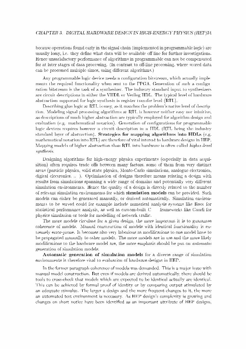
CHAPTER 3. DIGITAL HARDWARE DESIGN IN HIGH-ENERGY PHYSICS (HEP)34
because operations found early in the signal chain (implemented in programmable logic) areusually lossy, i.e. they de�ne what data will be available o� line for further investigations.Hence unsatisfactory performance of algorithms in programmable can not be compensatedfor at later stages of data processing. (In contrast to o�-line processing, where stored datacan be processed multiple times, using di�erent algorithms.)
Any programmable logic device needs a con�guration bitstream, which actually imple-ments the required functionality when sent to the FPGA. Generation of such a con�gu-ration bitstream is the task of a synthesizer. The industry-standard input to synthesizersare circuit descriptions in either the VHDL or Verilog HDL. The typical level of hardwareabstraction supported for logic synthesis is register-transfer level (RTL).
Describing glue-logic at RTL is easy, as it matches the problem's native level of descrip-tion. Modeling signal processing algorithms at RTL is however neither easy nor intuitive,as descriptions of much higher abstraction are typically employed for algorithm design andevaluation (e.g. mathematical notation). Generation of con�gurations for programmablelogic devices requires however a circuit description in a HDL (RTL being the industrystandard layer of abstraction). Strategies for mapping algorithms into HDLs (e.g.mathematical notation into RTL) are therefore of vital interest to hardware designs in HEP.Mapping models of higher abstraction than RTL into hardware is often called higher-level
synthesis.
Designing algorithms for high-energy physics experiments (especially in data acqui-sition) often requires trade o�s between many factors, some of them from very distinctareas (particle physics, solid state physics, Monte-Carlo simulations, analogue electronics,digital electronics, .. ). Optimization of designs therefore means relating a design withresults from simulations spanning a wide range of domains and potentially very di�erentsimulation environments. Hence the quality of a design is directly related to the numberof relevant simulation environments for which simulation models can be provided. Suchmodels can either be generated manually, or derived automatically. Simulation environ-ments to be served could for example include numerical analysis systems like Root forstatistical performance analysis, as well as custom-built C++ frameworks like Gaudi forphysics simulation or tools for modelling of network tra�c.
The more models circulate for a given design, the more important it is to guaranteecoherence of models. Manual construction of models with identical functionality is ex-tremely error-prone. It becomes also very laborious as modi�cations to one model have tobe propagated manually to other models. The more models are in use and the more likelymodi�cations to the hardware model are, the more emphasis should be put on automatic
generation of simulation models.Automatic generation of simulation models for a diverse range of simulation
environments is therefore vital to evaluation of hardware designs in HEP.
In the former paragraph coherence of models was demanded. This is a major issue withmanual model construction. But even if models are derived automatically, there should betools to cross-check that models which are expected to be identical actually are identical.This can be achieved by formal proof of identity or by comparing output stimulated byan adequate stimulus. The larger a design and the more frequent changes to it, the morean automated test environment is necessary. As HEP design's complexity is growing andchanges on short notice have been identi�ed as an important attribute of HEP designs,

CHAPTER 3. DIGITAL HARDWARE DESIGN IN HIGH-ENERGY PHYSICS (HEP)35
veri�cation (comparing implementation against their speci�cation, crosschecking derivedmodels) is a major issue in HEP design.
HEP experiments usually require huge amounts of data to be processed in �xed time.This leads to high-throughput solutions, often only achievable using programmable logic.The complex data structure (multiple sub detectors) and patterns (particle trajectories)require advanced algorithms to separate physics events from noise.
If these algorithms need to change, designers are in need of circuit models which canbe modi�ed to follow suggested or required changes. This requires a much more responsivedesign process than in conventional design �ows. There are two speci�c situations in HEPexperiments causing substantial changes to circuit models:
• The design of hardware for HEP experiments often relies on extensive assumptionsand simulations. If a model is �exible enough to follow shifting needs in the experi-ment's initial design phase, it can give substantial feedback on costs and bene�tsof di�erent design variations. If however the model is too static to allow e�cientevaluation of design variations, it can not contribute to the decision process and the�nal layout of the experiment might be suboptimal from a hardware design point ofview.
• Requirements to an algorithm might change substantially during operation. Whilethe initial design is usually embracing a more conservative perspective, researchers tryto refocus the detectors, once correct operation is con�rmed and operation experienceincreases. New discoveries or not matched predictions can trigger a major shiftcompared to the original intention.
Especially new discoveries (for which HEP experiments are built, after all) can occurmultiple times during the lifetime of an experiment.
The ability and speed of a circuit model to respond to changes in the mathematical
algorithm it implements considerably de�nes the responsiveness of a HEP experiment tonew knowledge.
How can a model increase responsiveness to unpredictable changes? In using a suitablenotation, expressing a design in generic terms where changes are most probable. TypicalHDLs often require explicit speci�cation of bitwidths. If a signal is expected to change itsbitwidth frequently, a more suitable expression would be to keep the bitwidth generic. Ifthe signal represents a �xed-point number, it would be wise to use a suitable data type,de�ned by precision and range.
Providing matching semantics for a given application domain is known as domainspeci�city in the design of domain-speci�c languages. Therefore what is required toprovide �exible circuit models in terms of HEP design parameters are HDLs with a highdomain speci�city with regard to HEP and the respective algorithms implemented.
The level of abstraction provided by current HDLs and related tools does not allow asuccinct description in terms of relevant design parameters. Small changes to an algorithmfrom a physicist's point of view can potentially trigger a major change in the most abstractHDL model available.

CHAPTER 3. DIGITAL HARDWARE DESIGN IN HIGH-ENERGY PHYSICS (HEP)36
3.3 HEP-speci�c Electronics Design Automation Requirements
In section 3.2 we have identi�ed four factors prominent to DSP-related designs in high-energy physics (mapping algorithms into HDLs, providing custom simulation models, veri�-cation, domain speci�city). In the following, we will contrast these factors with other appli-cation domains and with current state of the art in Electronics Design Automation (EDA).We will show which problems HEP designs share with other application domains and whichones are speci�c to HEP.
Mapping algorithms into HDLs is a common goal of all users of programmable logic forDSPing. There are many attempts to provide a consistent design �ow from more abstractalgorithmic descriptions to HDLs. Most prominent are currently C-based approaches whichextract circuit descriptions from untimed C-code [Men07; Cel04a; GDG04; Syn07]. Nogenerally accepted solution to this problem have evolved yet however.
It is generally understood, that veri�cation of designs (comparing an actual implemen-tation with the original speci�cation) is one of the most challenging task in circuit design.Providing support for veri�cation is therefore a common goal to all users of programmablelogic. Recent developments include availability of assertion-based veri�cation through in-tegration of the Property Speci�cation Language (PSL) in most digital electronics designtools [FMW05] and adoption of PSL as an IEEE standard [Psl].
Today, the use of PSL is often limited to adding assertions or properties to an alreadyexisting (and functional) RTL model. This results in redundant speci�cation (the RTLdesign intention is reproduced in the PSL commands). The PROSYD project (http://www.prosyd.org/), sponsored by the European Union in 2004-2006 aims at providing aconsistent tool �ow for property-based system design. Property-based system design meansusing a set of higher-level properties as the golden reference model, deriving hardwareimplementation, tests and simulation models from it.
Providing models to di�erent simulation environments is a requirement more specialto high-energy physics. This is a consequence of the ratio between the size of the overallsimulated system and the DSPing functionality in it. This ratio is especially high in HEPi.e. DSPing in programmable logic tends to be only a small part of the overall system.Most data analysis tools in HEP are custom-built or highly customized standard softwarepackages. Clearly, support for these HEP-speci�c tools is lacking in tools aiming at generalhardware design.
While some tools allow generation of executable models from HDL models (mostlyexpressed in C), no commercial tool we are aware of allows direct access to the codegeneration process. Therefore, adapting executable models to the requirements of a speci�csimulation environment is a laborious, in the case of closed source unfeasible, task.
Domain speci�city of models: In most digital systems, programmable logic helps toimplement a well-speci�ed functionality (top-down design approach). Typically, the more�exibility is required from a solution, the more likely it is to be implemented in software(where changes are easier and less costly). While this design trade-o� certainly applies toHEP designs as well, the importance of speci�c factors might deviate considerably whencompared to their respective importance in other application domains. Potentially, thisleads to more complex algorithms being implemented in programmable logic. This in turn

CHAPTER 3. DIGITAL HARDWARE DESIGN IN HIGH-ENERGY PHYSICS (HEP)37
leads to HEP hardware designs spearheading development and being ahead of requiredtool support.
The requirement to adapt to new knowledge at short notice is prominent in HEP de-signs. The combination of complex algorithms and the need to follow high-level changesto the algorithm requires a domain speci�city of circuit models unmatched by other appli-cation domains.
3.4 Review of Selected Designs
As outlined above, FPGAs are a viable platform for implementation of DSPing algorithms.This section will give examples of existing designs in HEP using FPGAs for advanced
DSPing. We de�ne �advanced DSPing� by the e�ort required to implement the DSPing-part of the design, compared to the general design e�ort for the respective FPGA. If eitherthe estimated design e�ort exceeds about 30%, or if the DSPing-part is foreseen to changeover the system's lifetime, we will consider the system.
Due to the sheer amount of electronic designs in HEP and the widespread literature,such a list can only represent an arbitrary sample. The sample given is certainly biasedtoward systems developed at CERN and being related to the large-hadron collider (LHC).It should however be generic enough to demonstrate scale of current systems, typical designapproaches and identi�ed de�ciencies thereof.
Each system will be characterised by the following data:
• Brand and type of FPGAs used
• FPGAs per board
We will only mention FPGAs related to DSPing functionality. Often further FPGAscan be found on-board, implementing interfaces or other low-level functionality.
• Identical boards in parallel use
• Logic resources used, clock frequency
• typical input/output data rate
One has to distinguish between the maximum data rate de�ned by the interface andthe actual data rate used by the application. Especially when low latency is an issue,systems tend to feature very fast interfaces, but use only a fraction of the availablebandwidth. To estimate available bandwidth for future upgrades, it is of interest toknow both. Where available, we will therefore give both �gures.
• primary task
• chosen design �ow
Generally we can distinguish HEP systems for DAQ and for (beam) control.
In DAQ, the main task is data reduction to handle the excessive amount of data col-lected by sub-detectors and to extract events of interest (physics events). Extensive in-put bandwidth, high throughput, on-board multi-channel processing and multiple boards

CHAPTER 3. DIGITAL HARDWARE DESIGN IN HIGH-ENERGY PHYSICS (HEP)38
working in parallel are characteristic for this application. DAQ systems usually consistof a number of cascaded trigger levels. The lowest level receives un�ltered data and triesto come to a decision in very little time by considering data only from certain regions ofinterest. Data identi�ed as belonging to a physics event is passed on to the next higherlevel, all other data is rejected.
In Beam Control, the signal processing is part of a control loop. Low latency is key.Systems are usually much smaller in terms of bandwidth and boards, but algorithms tendto be more advanced and tuned more toward fast results (low latency) than for parallelprocessing.
LHCb vertex locator zero suppression
The LHCb VErtex LOcator (VELO) provides precise track coordinates close to the in-teraction region of LHCb, one of the four experiments installed at the LHC. The VELOis based on silicon strip sensors. Two semicircular sensors with 2048 azimuthal or radialstrips respectively form a module, of which 50 are positioned along the beam axis (2 x2048 x 50 = 204800 strips in total).
All strips are read out in parallel with the LHC collision rate of 40.08MHz and storedin analogue memory. From there data is transmitted via twisted-pair cables to the LHCbDAQ interface board (TELL1) upon reception of a trigger signal (not exceeding 1.1MHzin average).
At each event, only a low percentage of channels will carry interesting information.Data volume of events can therefore be reduced signi�cantly by zero suppression (removingnoisy channels void of physics information).
The TELL1 digitizes incoming data and performs Digital Signal Processing (DSPing),speci�cally pedestal subtraction, common mode correction, zero suppression and data for-matting. For reasons of performance and �exibility, all DSPing is implemented in FPGAs.
The TELL1 is the common LHCb DAQ interface board [Hae06]. It is not only usedby VELO, but by most sub detectors of LHCb. There are a total of almost 300 TELL1boards installed at the LHCb cavern. The input stage is realized by mezzanine boardsfor either analogue (twisted pair) or digital (12-way optical �bers) data. The analogueversion as used by VELO provides a total user bandwidth of 25.6Gbps per TELL1. Theincoming, digitized data stream is processed in parallel by four preprocessing (PP)-FPGAs(Altera Stratix 1S25), each accompanied by 96MB local DDR SDRAM. A �fth FPGA(Altera Stratix 1S25) collects the processed data from the PP-FPGAS and formats it fortransmission to a dedicated PC-farm via GigabitEthernet.
The TELL1 comes with a VHDL framework, providing basic functionality, which can beextended by the respective subdetectors to adapt signal processing to their needs. Designentry is based on VHDL and schematic capture using MentorGraphics HDL Designer.
The TELL1 framework provides also test and monitoring features like in-system datagenerators and access to on-board RAM and register. There is as well a full suite ofC++-models for the basic algorithms provided.
To ease keeping C++ simulation models synchronized with the hardware implemen-tation, an approach deriving both models from one common source has been investigated[MS06] (see also chapter 5.2). The e�ort was however started too late and will not be usedin the system due to be ready for the �rst LHC beam end of 2007.

CHAPTER 3. DIGITAL HARDWARE DESIGN IN HIGH-ENERGY PHYSICS (HEP)39
Figure 3.1: TELL1 with optical and analogue receiver cards to the left (courtesy of GuidoHaefeli)
LHC Beam Loss Monitoring processing module
The Large Hadron Collider (LHC) beam loss monitor [Hol05] (BLM) is an importantpart of the LHC machine protection and quench prevention. Each turn, beam energy ismeasured by 4000 ionization chambers. Data is collected by 650 data acquisition cardslocated in the LHC tunnel. From the tunnel, data is transmitted via optical links to thesurface where turn-by-turn energy and variations thereof are calculated in real-time. Thecombination of high- and low-precision measurements, calculation of total beam energy,loss patterns and checking against given tolerance curves is performed in programmablelogic [Zam06] on the BLM processing module.
The main motivation for putting this functionality into FPGAs as quoted in [Hol05]was: meeting demanding timing requirements, �exibility with regard to future upgradesor changing system speci�cations.
The BLM processing module is a VME card named DAB64x [Deh06] (see �gure 3.2).The distributed processing system consists of about 350 boards, each carrying one AlteraStratix EP1S40 FPGA, 1MB Flash and 3x2MB SRAM. The current design requires almostall logic resources available (97% logic element usage).
Each DAB64x board carries a BLM mezzanine card featuring four optical gigabit linkreceivers providing low-latency communication with the cavern. While the theoreticalmaximum input bandwidth is 4 x 800Mbps = 3,125Gbps, only a small fraction (320bit x25kHz = 8Mbps) is actually used. The BLM is a security control system, intervening onlyif the beam is lost, therefore no continuous output data stream is necessary and the outputbandwidth is negligible (a VME PC reads data with 1Hz for monitoring).
The chosen design methodology is mostly VHDL at lower level and schematic captureat higher level. One design issue speci�cally mentioned in [Zam06] and not supported by

CHAPTER 3. DIGITAL HARDWARE DESIGN IN HIGH-ENERGY PHYSICS (HEP)40
Figure 3.2: Beam Loss Monitor Processing Module (DAB64x) with mezzanine board[Deh06].
tools is the optimization of memory resource usage (requiring resource sharing betweendi�erent building blocks).
The FPGA con�guration is expected to change rather frequently and major updateshave already been realised.
LEIR low-level radio frequency system
The CERN Low Energy Ion Ring (LEIR) low-level radio frequency (LLRF) system is a fullydigital beam control system. Commissioning took place in 2006 with prior tests performedin the PS Booster accelerator using a scaled-down system.
The very task of a LLRF system is control of the cavities RF voltage to provide a stablebeam and requested acceleration. Due to the very low latency imminent to this controltask, LLRF systems were typically implemented in analogue electronics until recently.Today, advances in digital technology allow fully digital LLRF systems [Ang06]. The mostprominent advantages of digital LLRF systems are: recon�gurability without hardwareintervention, multi-user operation (parameters on per-user basis), reproducibility, absenceof drifts caused by analogue devices and the ease with which built-in diagnostics can beimplemented.
The LEIR LLRF system achieves the required speed and �exibility by using bothFPGAs and DSPs. The FPGAs act as fast pre- or co-processors, providing processed datato real-time loops running on the DSPs.
The system used for the 2004 test [Ang05a] comprises one DSP carrier board carryingthree daughter cards, namely:
1. DDC: a four-channels, two-sites Digital Down Converter, performing digitisation,low-pass �ltering and decimation of analogue signals. Originally a commercial chip(Intersil ISL5216 DDC chip) was foreseen to provide the required functionality.Due to a phase discontinuity discovered in the prototype design, this approach wasdropped and all relevant functionality was implemented in a FPGA.
2. MDDS: a one-site Master Direct Digital Synthesiser, generating, under DSP control,a high-frequency analogue clock signal from a 100-MHz clock reference;

CHAPTER 3. DIGITAL HARDWARE DESIGN IN HIGH-ENERGY PHYSICS (HEP)41
3. SDDS: a one-channel, one site Slave Direct Digital Synthesiser, generating, underDSP control, an analogue signal from the MDDS-generated clock reference. Thisboard features an Altera Flex FPGA. Two look-up tables allow fast calculation ofsine- and cosine functions to convert I/Q data.
Figure 3.3: LEIR DLLRF DSP board equipped with daughter boards (picture taken from[Ang05b])
The carrier board is a 6U VME board. The used DSP is an Analog Devices ADSP-21160. All daughter cards and the carrier board itself feature one FPGA each.
The system has been developed in cooperation with Brookhaven National Laboratory,Upton, USA where it is used for control of the AGS Booster accelerator. The systemis foreseen to be employed to di�erent accelerators at CERN (LEIR, PSB, PS and AD),resulting in more uniform hardware and improved focus of further development.
An important problem requiring further attention is the limited availability of low-latency communication links between DSPs (limiting available computing power for low-latency applications).
CMS Endcap Preshower Data Concentrator Card
The Compact Muon Solenoid (CMS) is one of the four LHC experiments. CMS' EndcapPreshower (ES) sub-detector comprises 4288 silicon sensors, each containing 32 strips.The signals from each strip are ampli�ed, shaped, sampled every 25ns and stored inan analogue memory. On reception of a trigger (max. trigger frequency 100kHz), three

CHAPTER 3. DIGITAL HARDWARE DESIGN IN HIGH-ENERGY PHYSICS (HEP)42
consecutive samples per strip are digitized, formatted and sent via optical links to the ESdata concentrator cards (ES-DCC) located in the counting room.
The task of the ES-DCC is to receive data from up to 36 optical links, to verify dataintegrity and to perform on-line data reduction [Bar06; MSV06]. The bandwidth requiredis typically reduced by a factor of 20. The steps performed to achieve data reduction are:pedestal removal, channel calibration, common mode rejection and zero suppression.
The ES system contains approximately 40 ES-DCCs. The ES-DCC is a 9U VME board,equipped with 7 FPGAs:
• 3 Reduction FPGAs performing de-serialization of 12 incoming data streams eachand subsequent data reduction. The functionality of all three FPGAs is identical,providing su�cient resources for parallel processing of data from 3x12 optical �bers.
• 3 Spy FPGAs to provide on-line monitoring services via the VME bus. Each FPGAhas direct access to 3x18MB local static RAM. The FPGAs are less powerful thanthe reduction FPGAs (Altera Cyclone)
• 1 Merger FPGA collecting resulting data streams from the three reduction FPGAsand formatting of them.
Figure 3.4: CMS Endcap Preshower data concentrator card (ES-DCC), equipped withthree OptoRx12 receiver/processing modules (picture taken from [Bar06])
The reduction FPGAs are actually mounted on a small carrier board each, the OptoRx-12, providing a modular and �exible system [VR06]. The same module is used (and wasdeveloped in cooperation with) the TOTEM experiment. The OptoRx-12 can be equippedwith either of two devices from the Altera Stratix GX family: 1SGX25 or 1SGX40. The
CHAPTER 3. DIGITAL HARDWARE DESIGN IN HIGH-ENERGY PHYSICS (HEP)43
decisive factor for choosing the type of FPGAs used was the extensive number of distributedon-chip memories (1SGX25: 224 512bit blocks, 138 4kbit blocks, 2 512kbit blocks) allowingimplementation of multi-channel processing [VR06].
The theoretical input bandwidth of the ES-DCC is 36 x 800Mbps = 28.1Gbps, theactually used data rate at maximum trigger frequency is 600byte x 36�bers x 100kHz =16.8Gbps. The processed data is sent to the CMS data acquisition system via SLink,providing a bandwidth of 200MBps.
ALICE HLT pattern recognition
ALICE is one of the four LHC experiments. The central detector of ALICE is the TimeProjection Chamber (TPC). It consist of about 600 000 detector channels, resulting ina worst-case data rate of 75MB per event. The given bandwidth to permanent storageis 1.25GB/s, enabling storage of about 20 events/s. The High Level Trigger (HLT), amassive-parallel computing system, has been designed to perform
• real-time pattern recognition for on-line event selection and
• real-time data compression of selected events to increase data storage e�ciency.
Figure 3.5: Prototype of the ALICE High-Level Trigger Read-Out Receiver Card [Gra03]
The TPC is divided into 36 sectors, consisisting of 6 subsectors each. The data fromeach subsector is read out and send via optical link to the reception nodes of the HLT, calledHLT ReadOut Receiver Cards (HLT-RORC, see �gure 3.5). Each HLT-RORC features anFPGA co-processor to support data-intensive local tasks of the HLT pattern recognitionalgorithms [Gra03].
ATLAS Level2 Transition Radiation Detector (TRT)
ATLAS is one of the four LHC experiments. The ATLAS Transition Radiation Detector(TRT) uses straw tubes as sensing elements. It consists of a central barrel part (52 544straws parallel to the beam axis) and two end-caps (319 488 radial straws). The informationof all straws provides a two-dimensional position measurement for all particle tracks withinthe acceptance of the detector. Regions of interest can be identi�ed by searching localneighbourhoods only. For further selection, an unguided track search in the full TRT dataset is necessary.

CHAPTER 3. DIGITAL HARDWARE DESIGN IN HIGH-ENERGY PHYSICS (HEP)44
An algorithm for identi�cation of tracks in the full data set, the TRT-LUT, is describedin [Bai99]. It uses the Hough transform to reduce the search space. As the interactionpoint is known to be contained in each track, the transform for each position in the detectorvolume can be precalculated. A histogram is �lled with the transformed hit data. Trackdetection can subsequently be reduced to �nding maxima in the �lled histogram.
Khomich et al. [Kho06] have evaluated achievable speed-up of a hybrid CPU/FPGAimplementation in comparison to a CPU-only implementation. The algorithm was imple-mented in C++ and pro�led. The most time consuming tasks were identi�ed and manuallyreimplemented in VHDL.
For evaluation of the synthesized VHDL model the MPRACE board (Multi-PurposeRecon�gurable Accelerator/Computing Engine) developed by the University of Mannheimwas used. MPRACE is a 64bit/66MHz PCI card featuring a Xilinx VirtexII FPGA.
Only the initial track �nding was implemented in VHDL and synthesized for MPRACE.Thresholding, maximum �nding and further tasks were executed on the CPU. The imple-mentation required all of the VirtexII memory internal blocks (plus an external 9MB SRAMmemory) and about 80% of the FPGA's logic resources.
There were two approaches pursued to allow integration of the circuit models into theexisting ATLAS simulation framework:
1. Interfacing to a VHDL simulator through its programming language interface (PLI).This approach was not investigated further due to the ATLAS decision not to usecustom hardware.
2. Using SystemC as modelling language. While it would have allowed easier integrationinto the simulation environment, the lack of SystemC synthesis support has renderedthis option unattractive.
The reported speed-up is about 3 for the entire application. Higher speed-ups areexpected with faster FPGAs and wider memory busses. While the project has proven theprincipal feasibility, ATLAS has decided not to use custom hardware in the Level2 Trigger.Therefore this hardware will not be installed in the ATLAS experiment.
Summary
The reviewed designs all implement DSPing functionality on FPGAs (this was the selectioncriteria).
Except for one, all designs are �nal designs to be integrated into HEP experiments.Therefore they serve well to document the current state of the art in advanced HEP DSPingdesigns and to extract respective design needs. They do re�ect real engineering experiencerather than projected technology usage.
The designs' relevance to the success of the respective experiments is important, sup-porting the claim that DSPing on programmable logic plays a vital role in current HEPexperiments. The number and size of the boards, the complexity of the algorithms to beimplemented and the amount of �rmware to be produced shows that considerable resources(money and manpower) had to be assigned to the respective projects. We can thereforeconclude that a non-negligible part of HEP experiment budgets is bound by DSPing designson programmable logic.

CHAPTER 3. DIGITAL HARDWARE DESIGN IN HIGH-ENERGY PHYSICS (HEP)45
Design
Type
ofFPGA
FPGAs/
board
BoardsResources
used
f max
Input
band-
width
Output
band-
width
Primarytask
Design
entry
Tools
[LE]
[MHz]
[MB/s]
[MB/s]
LHCb
VELO
Altera
Stratix
EP1S25
5289
80%
120
25.6Gbps
3.84Gbps
/ 2.34Gbps
pedestal
sub-
traction,LCMS,
zero
suppression
VHDL,
schem
atic
Mentor
HDL
Designer,Quar-
tus,ModelSim
LHC
BLM
Altera
Stratix
EP1S40
1350
97%
403,125
/8M
bps
-BeamEnergy
es-
timation
VHDL,
schem
atic
Quartus,Model-
Sim
CMSES-
DCC
Altera
Stratix
GX
1SGx25
3+4
4090%
40,
8028.1,
16.8
1.56
pedestal
sub-
traction,
mean
calculation,zero
suppression
VHDL
Quartus,Model-
Sim
LEIR
DLLRF
Altera
Stratix
EP1S20
31
50-
90-160
--
Digital
Filters
VHDL
Quartus,Model-
Sim
,VisualElite
ATLAS
LVL2
TRT
Xilinx
VirtexII
XC2V
3000
11
80%
64/128
--
Track
selection
byHough
trans-
form
VHDL
Aldec
Active-
HDL,
Men-
tor
Graphics
LeonardoSpec-
trum
Table3.1:
Characteristicsof
di�erentdigital
signal
processingdesignsin
HEPusingFPGAs

CHAPTER 3. DIGITAL HARDWARE DESIGN IN HIGH-ENERGY PHYSICS (HEP)46
All designs use VHSIC Hardware Description Language (VHDL) for circuit speci�cation(i.e. FPGA con�guration bitstreams are generated by synthesizers taking VHDL modelsas input). While VHDL is not the only HDL available for circuit speci�cation, it is clearlythe language of choice in the reviewed designs. Consequently it is a valid assumption thatany HDL extension needs to be compared to VHDL when investigating its potential impacton current design �ows and e�ciency.
If cycle-accurate models were provided, they were maintained by hand. It is acknowl-edged by designers (while not frequently mentioned in publications) that providing suitablesimulation models and keeping them synchronized with the hardware implementation isone of the main concerns and also requires signi�cant (often originally not foreseen) man-power. This supports the claim that automatic generation of cycle-accurate simulationmodels is a major need of HEP designs, not met by the current design �ow.
Typical clock frequencies achieved are in the range of 80-120 MHz. This is about thecommon frequency range achievable with current FPGA technology without major tweak-ing of VHDL models. To exploit higher clock frequencies (theoretically current FPGAscan achieve up to about 250MHz), the e�ort of required model optimization increasesdisproportionate.
This fact is important in view of the LHC collision frequency of 40.08MHz. Currentdesigns therefore allow one (40MHZ) to three (120MHz) sequential operations betweencollisions. Higher requirements to future LHC designs therefore can hardly be met byincreasing the clock speed. At least not without either investing more time in optimizingmodels or changing the design methodology. The logical consequence is that designs needto further exploit either parallelism or pipelined architectures. All options show a need toconsiderable intervention to the original models. It is likely that many challenged hardwaremodels will be rewritten from scratch if increased computing power is demanded. Thismight provide an option to experiment with new hardware design methodologies.
In all designs, resource usage of FPGAs is high (∼80%). FPGA place and route toolstypically fail or become very slow if FPGA resource usage is above ∼80%. This supportsthe claim that the complexity of HEP designs challenges current technology. At suchhigh resource-usage and speed levels (see above) having direct control over implementationdetails at RTL becomes important to achieve working designs in case automated proceduresfail. This clearly contradicts the need of succinct high-level models required to model thecomplex mathematical algorithms in suitable terms.
Very limited information is given on possible design trade-o�s and if or how they wereevaluated. Usually all design decisions have been taken using a preliminary C/C++ model.No publication reports on a feedback from the HDL design to the physics performance. Allpublications give the impression that the VHDL model is a static implementation. Possiblythe genericity of hardware models is seen as being of little interest such that respectivedata is not reported in publications.

Chapter 4
An Improved HEP Hardware DesignProcess
In section 3.2 we have identi�ed four key issues for design of High-Energy Physics (HEP)Digital Signal Processing (DSPing) on programmable logic (mapping algorithms into Hard-ware Description Languages (HDLs), veri�cation, custom simulation models, domain speci-�city). We have argued in section 3.3 that the third and fourth factor are of crucial im-portance to HEP designs while of less interest to other application domains. Thereforethey can be considered HEP-speci�c Electronics Design Automation (EDA) needs. In thefollowing we will outline how these speci�c EDA needs (custom simulation models anddomain speci�city) could be met by modi�cations to
• the hardware design process,
• the way HDLs are designed,
• type and implementation of HDL features.
4.1 Custom Simulation Models
Hardware Design Process
To satisfy the need for custom simulation models, the design process should be such thatmodels for relevant simulation environments can be provided for each stage of modelling indigital design. To guarantee coherence of models and to allow for fast turn-around times,generation of respective models needs to be automated. It is not possible to specify exactlywhat "relevant HEP simulation environments" are. A generic approach to support a rangeof simulation environments and to add support for future environments is therefore crucial.
Custom simulation models are perfectly in line with the V-model, requiring test of thespeci�ed functionality at each level of abstraction. Each test requires a suitable model tobe connected with the respective test environment. Actually the lack of suitable supportin current tools can be considered a poor implementation of the V-model.
From a HW/SW-Codesign point of view, the importance of custom simulation mod-els for hardware designs is somewhat lower-ranking with regard to the central issue of
47

CHAPTER 4. AN IMPROVED HEP HARDWARE DESIGN PROCESS 48
HW/SW-partitioning. HW/SW-Cosimulation however deals with the question of how tosimulate models comprising functionality to be mapped into hardware and software respec-tively. If Cosimulation is used for evaluation of cost functions requiring speci�c simulationenvironments, the situation is comparable to the one we describe. Custom simulationmodels for hardware designs are therefore a subproblem of HW/SW-Codesign.
Figure 4.1: Design Flow for System-on-Chips (SoCs)
HDL Design
From a computer science point of view, generating custom simulation models from a givenhardware speci�cation is cross-compiling (generating executable code for targets di�erentthan the host platform). Most EDA tools targeting FPGAs are actually cross-compilers, asthey usually support at least two targets (FPGAs for implementation and CPUs for simu-lation). Because of the complexity of current HDLs, highly specialized tools have evolvedtargeting either hardware (HDL Synthesizer) or software (HDL Simulator). IntegratedDevelopment Environment (IDE) only combine these tools to make them more accessibleto the user.
Most current simulators read in HDL models, transform them into native code forthe host platform (PC or Workstation) and feed input stimuli to these fast, executablemodels. Theoretically, custom simulation models could be derived by suitable changes

CHAPTER 4. AN IMPROVED HEP HARDWARE DESIGN PROCESS 49
to the HDL simulator's code transformation module. These module's are however at thecore of HDL simulator manufacturer's business models and therefore undisclosed and alsohighly customized to meet the needs of the speci�c product.
What is needed to make generation of custom simulation models feasible, are accessibletransformation modules of HDL simulators. To reduce the e�ort required for modi�cations,these modules should be as simple as possible. This can be achieved by well-speci�ed,reduced-scope HDLs. This is opposing the approach followed by VHDL which supports awide range of domains and features very verbose syntax, making construction of tools veryexpensive.
What is needed therefore to allow implementation of generators for custom simulationmodels is an existing, accessible HDL simulator whose code transformation module issimple enough to be modi�ed with limited e�ort. One could consider this an extensibleHDLs simulator platform.
4.2 Domain Speci�city
Design Process
The V-model suggests stepwise re�nement of models. A modelling language spans a designspace in which a model can be transformed. Usually the accompanying tools provide meansto facilitate the respective (manual, user-guided or automatic) transformations.
Each step in the V-model comprises the relevant models at a given level of abstraction.Ideally, one model should fully specify the design at a given level of abstraction.
A domain-speci�c HDL increases the levels of abstraction at which the model can beused. Therefore a HDL with increased domain-speci�city allows covering several steps inthe V-model with the same model.
HDL Design
General-purpose programming languages usually have a long lead-time till new featuresare integrated into the language. This is even more true for HDLs. While in general-purpose programming languages extensive analysis of existing designs can be performedby language designers, in domain-speci�c languages the task is usually much more ad-hoc and carried out by users. Domain experts (users of domain speci�c-languages) cangive quali�ed feedback on what features suit best the needs of their applications. Theyusually lack however the knowledge on how to integrate suggested features in a language. Ifhowever the user-base for a language is small and/or the commercial interest in customizingit is low, the task stays with the domain experts rather than being passed on to languagedesigners.
Any language platform providing means for easy extension by users will bene�t fromincreased feedback. This is crucial for domain-speci�c languages and even more impor-tant where the domain can not be clearly de�ned (and features therefore not foreseen inadvance), as is the case in HEP.
To enable domain-speci�c HDLs for HEP it is therefore mandatory to provide a workinggeneral-purpose HDL which is easily extendable.

CHAPTER 4. AN IMPROVED HEP HARDWARE DESIGN PROCESS 50
Two important concepts to facilitate implementation of unforeseen language featuresare multi-stage processing and type inference.
Extendability
The literature on domain-speci�c languages knows several implementation patterns forDSLs [MHS05](see also section 2.3). While DSL implementation is usually a task performedonly once, some of the DSL implementation patterns are also suitable to keep the resultinglanguage permanently open to further extensions.
Embedding refers to extending an existing language by de�ning new abstract datatypes and operators. The applicability of resulting extensions heavily depends on theuser-de�nable operator syntax and type system provided by the host language.
Embedding is most useful if host language notation and domain notation share commonproperties (e.g. if both use in�x notation for arithmetic operators) and if the type systemsuits the target domain (dynamic typing will be of little help when targeting hardware).
If embedding is not �exible enough to accomodate the domain-speci�c extensions, ex-tending the language implementation or using a pre-processor allow for concepts and syntaxnot foreseen in the host language.
Extending the language implementation is the most powerful option but it is also knownthat compilers are particularly hard to extend [MHS05, p.330]. If however the compiler hasbeen designed with extension in mind, interfacing domain-speci�c extensions can becomeeasier. Kiczales and des Rivières [Kd91] have suggested the metaobject protocol, an object-oriented interface for speci�cation of language extensions and transformations (used by theCommon Lisp object system (CLOS)).
Pre-processors can help to add speci�c notation to a language and are also powerful inadding �exibility to originally static language constructs (see e.g. C++ templates). Thedrawback of a pre-processor is that debugging can become very di�cult as the functionalitylies outside the scope of the compiler.
To provide a HDL which enables addition of domain-speci�c features not foreseen atlanguage design and by non-experts (i.e. domain experts rather than language designeperts) in an e�cient manner, a HDL is required, featuring
• a versatile type system
• powerful user-de�nable operator syntax and
• de�ned interfaces to access the compiler implementation in case the former two op-tions are not su�cient.
Multi-stage processing
HDLs have to describe circuits unambiguously. Either because they are used for modellingor for synthesizing of a circuit. As a hardware design is static (excluding run-time recon-�gurable systems from our observations) HDLs are necessarily statically typed languages(i.e. the type of each symbol is known at compile time).
HEP requires however �exible models for evaluation of design variations. This �exibilityis contradictory to the level of detail typically required for circuit descriptions and tocompile-time type checking.

CHAPTER 4. AN IMPROVED HEP HARDWARE DESIGN PROCESS 51
A good example for this dilemma is the VHDL requirement of locally static rangebounds. Locally-static expressions are expressions whose value can be evaluated at analy-sis of the respective design unit1 [IEE02, p.113], i.e there is no inter-unit dependency to beresolved. This works well if parameters are directly speci�ed by local or global constants,but it fails if a more elaborate rule is required to evaluate the expression. One consequenceis that in VHDL it is impossible for an instantiation of a function to calculate any of itsown input- or output-signal's types (or parts thereof) as this would require combined eval-uation of the function's declaration and body (implementation). VHDL language designtrades model �exibility against implementation complexity (see [LMR94] for a discussionon implementation complexity of speci�c VHDL features).
Possibilities to allow more �exible models, yet assure a high level of detail and statictypes arise when a model is processed in multiple steps. Basic implementations of multi-step processing are macros and preprocessors. More advanced features are provided bymulti-pass compilers, i.e. a compiler which processes the code (or resulting internal repre-sentation) multiple times, building each time upon the preceding result. Languages whichbuild explicitly upon the features requiring multi-pass compilers are called multi-stage
languages [Tah99].
If specialized languages exist, serving well a speci�c sub domain, it can be useful to usegenerative programming to produce output in the given language for speci�c targets. Thisalso allows to rely on existing tools for the used language. VHDL for example serves verywell the purpose of hardware synthesis and there is an unmatched range of high-qualitytools available.
To enable �exible yet detailed models, some kind of multi-stage HDL is required, pro-viding means for predictable design variations at di�erent levels of detail.
To take advantage of existing tools, to blend into existing design �ows and to mini-mize work on reimplementations of already existing solutions, generative programming toproduce matching target models is required.
Type inference
"Type inference is the process of determining the types of expressions based onthe known types of some symbols that appear in them." [MA01, p.135]
Most low-level computer programming languages derive their basic data types fromfeatures of the underlying computing platform. A typical example would be the integertype in C which derives its range from the available bitwidth of the host system. Thisis motivated by the fact, that the operand bitwidth is hardwired and deviation from itprovides no advantage in execution speed or resource usage.
In hardware design however, any single operand's implementation (including bitwidth,but also encoding, wire length, ....) can (and should) be optimized. It is therefore favorableto replace the in�exible type set of CDLs by a more �exible family of types when designinga HDL. One (negative) example is the VHDL bit_vector type, which can be instantiatedwith a speci�c bit width. VHDL requires however explicit, locally static speci�cation
1A design unit in VHDL is either the declaration of an entity, con�guration or package, or the body ofan architecture or package
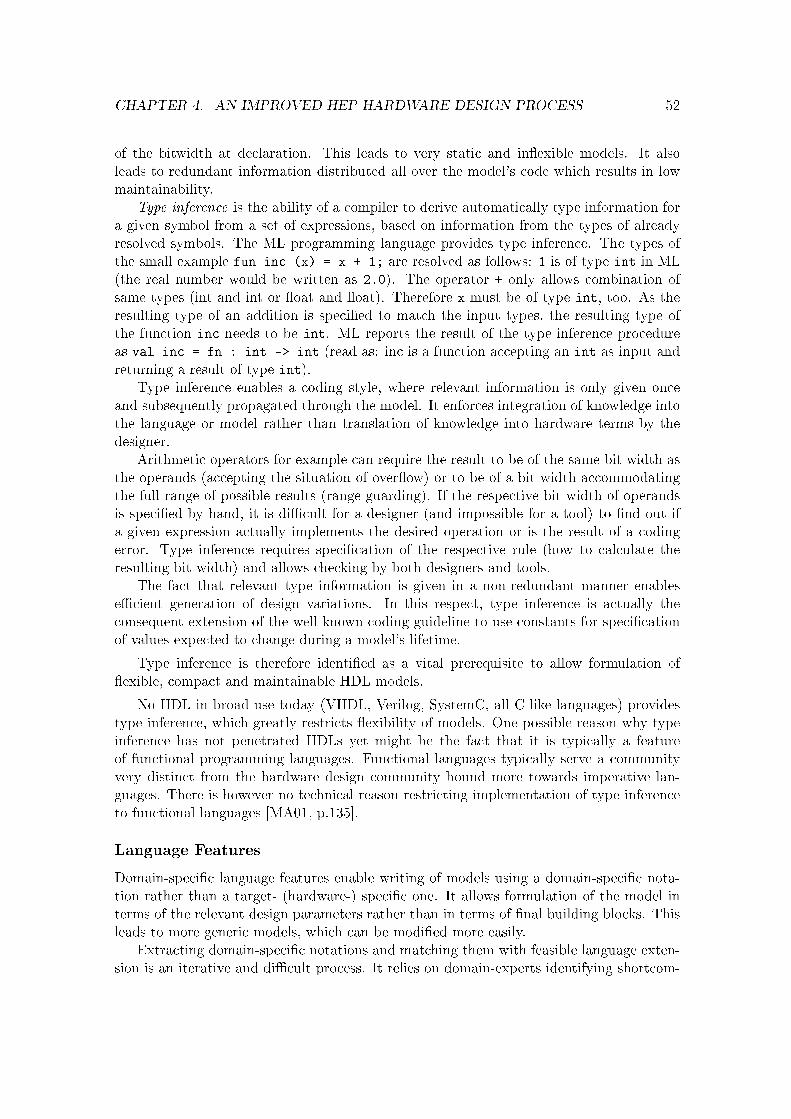
CHAPTER 4. AN IMPROVED HEP HARDWARE DESIGN PROCESS 52
of the bitwidth at declaration. This leads to very static and in�exible models. It alsoleads to redundant information distributed all over the model's code which results in lowmaintainability.
Type inference is the ability of a compiler to derive automatically type information fora given symbol from a set of expressions, based on information from the types of alreadyresolved symbols. The ML programming language provides type inference. The types ofthe small example fun inc (x) = x + 1; are resolved as follows: 1 is of type int in ML(the real number would be written as 2.0). The operator + only allows combination ofsame types (int and int or �oat and �oat). Therefore x must be of type int, too. As theresulting type of an addition is speci�ed to match the input types, the resulting type ofthe function inc needs to be int. ML reports the result of the type inference procedureas val inc = fn : int -> int (read as: inc is a function accepting an int as input andreturning a result of type int).
Type inference enables a coding style, where relevant information is only given onceand subsequently propagated through the model. It enforces integration of knowledge intothe language or model rather than translation of knowledge into hardware terms by thedesigner.
Arithmetic operators for example can require the result to be of the same bit width asthe operands (accepting the situation of over�ow) or to be of a bit width accommodatingthe full range of possible results (range-guarding). If the respective bit width of operandsis speci�ed by hand, it is di�cult for a designer (and impossible for a tool) to �nd out ifa given expression actually implements the desired operation or is the result of a codingerror. Type inference requires speci�cation of the respective rule (how to calculate theresulting bit width) and allows checking by both designers and tools.
The fact that relevant type information is given in a non-redundant manner enablese�cient generation of design variations. In this respect, type inference is actually theconsequent extension of the well-known coding guideline to use constants for speci�cationof values expected to change during a model's lifetime.
Type inference is therefore identi�ed as a vital prerequisite to allow formulation of�exible, compact and maintainable HDL models.
No HDL in broad use today (VHDL, Verilog, SystemC, all C-like languages) providestype inference, which greatly restricts �exibility of models. One possible reason why typeinference has not penetrated HDLs yet might be the fact that it is typically a featureof functional programming languages. Functional languages typically serve a communityvery distinct from the hardware design community bound more towards imperative lan-guages. There is however no technical reason restricting implementation of type inferenceto functional languages [MA01, p.135].
Language Features
Domain-speci�c language features enable writing of models using a domain-speci�c nota-tion rather than a target- (hardware-) speci�c one. It allows formulation of the model interms of the relevant design parameters rather than in terms of �nal building blocks. Thisleads to more generic models, which can be modi�ed more easily.
Extracting domain-speci�c notations and matching them with feasible language exten-sion is an iterative and di�cult process. It relies on domain-experts identifying shortcom-

CHAPTER 4. AN IMPROVED HEP HARDWARE DESIGN PROCESS 53
ings of current models and on compromise between domain-speci�city and general languagedesign.
A major limitation in circuit models, implementing digital signal processing, is the factthat most HDLs lack types corresponding to mathematical number sets.
The often encountered combination of a given set of n bits to form a natural number
of range 0 . . . 2n − 1 results in explicit coding of the required bitwidth. This contradictsboth mathematical intuition and good coding style (but has become common practice inHDL coding).
A more appropriate approach are range-based arithmetic data types. Operators couldcalculate the resulting range of their respective operation, given the operands' range. Suchdata types would allow models where range information is only given where necessary(inputs, speci�c intervention points). Changes to such models would be much easier andless error-prone than multiple manual bitwidth speci�cation.
Rational numbers are important to most DSPing models, but typically lack support inHDLs. HDL models usually map rational numbers into �xed-point data types (if available,in simple bitvectors otherwise), i.e. a bit vector where a given amount of bits is used torepresent the integer part and the fractional part of a signal respectively. For the twoparts, the same problems as for natural numbers apply. If taken together however, theadditional issue of correct binary point positioning after operations appears.
For modelling of arithmetic operations, a suitable �xed-point data type is thereforenecessary. Such a data type would allow range- and precision-independent model formu-lation. As precision information is available, varying precision scenarios could easily beevaluated. See the following case study (section 5.3) for a more detailed explanation.
Models at register-transfer level require manual placement of registers (i.e. explicitspeci�cation of the combinational functions to be evaluated in one clock cycle). Theachievable clock frequency directly depends on the longest resulting path between tworegisters. This in turn depends on the result of the routing algorithm which depends heavilyon type and size of a design. It is common that designs, running at a given frequency whenonly a low percentage of a FPGA's logic resources are used, achieve a much lower frequencywhen the percentage of used logic resources is high. This results in manual interventionvery late in the design process to reduce complexity of large combinational functions.
In most advanced designs (and especially in DSPing designs) manual speci�cation ofcombinational functions to be evaluated in one clock cycle is of little interest. What isimportant is that complexity of combinational logic between registers is well-balanced overthe whole design (to achieve maximum clock frequency) and that clock frequency tuninginterventions - if necessary - do not a�ect arithmetic functionality.
A concept which enables such a scenario are pipelined signals, i.e. combinational func-tions which are allowed to require more than one clock cycle. This allows writing of modelswhere throughput and latency can be guaranteed, but gives freedom to balance complexityof combinational logic between registers.
Pipelined signals have been suggested by Zhao and Gajski [ZG05]. It is interesting tonote that they speci�cally state that while they see the need for such a language feature,the could not locate a suitable HDL to embed it in.
FPGAs typically provide two types of storage elements: distributed single-bit memories

CHAPTER 4. AN IMPROVED HEP HARDWARE DESIGN PROCESS 54
and addressable memory blocks (of varying sizes). The former is ideally suited to implement�ne-grained distributed architectures, but is very ine�cient from a logic-resource point ofview. The latter uses available chip area very e�ciently, but requires sequential read andwrite operations (in the case of dual-port RAM, they can be parallelized, but multipleread/write cycles have to be performed sequentially). Optimization of memory resourceusage is a non-trivial task. It is also an optimization which highly depends on parametersvarying with modi�cations to an algorithm like bit width, number of samples processed,number of parallel channels, interleaving, ... .
Current HDLs usually do not support automatic usage of memory blocks (also calledmemory inference - automatic extraction of memory blocks from functional HDL code). Todate, memory blocks need to be instantiated by vendor-provided libraries. By instantiation,full control over suitable selection of size, bitwidth and access pattern is o�-loaded to thedesigner. New versions of the IEEE VHDL RTL Synthesis standard [IEE04] improveupon this situation by de�ning coding templates for RAM inference. This however is justportable RAM instantiation, omitting the vendor speci�c libraries.
While there are some attempts to improve memory inference from HDLs, their successis necessarily limited because current HDLs make the respective code analysis extremelydi�cult.
Especially designs which do not need to access all local data simultaneously (complexstate machines, pipelined designs) and designs featuring identical memory access patternson distributed data sets (multi channel designs) can greatly bene�t from a working memoryoptimization and inference scheme.
Weinhardt and Luk have shown rules for memory inference from software loops [WL99].These rules apply - to some extent - also to generic HDL designs. A more complete overviewon memory optimization techniques for embedded systems was published by Panda et al.[Pan01]. There is however no discussion how such optimizations could be supported bysuitable language features. So called single-assignment languages have shown that analysisof memory usage can be greatly simpli�ed.
Failsafe circuits are of paramount importance to radiation-exposed digital designs inHEP because digital designs su�er from single-event upsets (SEUs) caused by ionizingparticles when traversing the integrated circuit. For state machines, one possible conceptis redundancy combined with voting. For data integrity, error-checking codes are oftenemployed. These measures are in principal decoupled from a circuit's primary functionality.Hardware-centric modelling features require however mixture of the two, which results incomplex and di�cult to change models.
A language feature de�ning blocks as redundant and failure-aware allows automaticgeneration of multiple instances. It would allow automatic integration of failsafe-rules likeminimum block distance on the die, separate clocks, guard rings or frequent checks byexternal watchdog circuits2.
Usually HDLs assume use of binary representation for natural numbers and use oftwo's complement representation for integers. A more abstract range-based arithmetic datatype could allow selection of the underlying representation, including error-checking codes.Checking for data integrity could then be added as separate operation or as automatic
2So called radiation-tolerant FPGAs feature circuits continuously comparing the FPGAs con�gurationwith a Flash-based reference.

CHAPTER 4. AN IMPROVED HEP HARDWARE DESIGN PROCESS 55
feature.
Such failsafe language features would allow evaluation of design variations trading de-sign size and clock frequency against robustness in the case of SEUs.
The suggested language features can certainly be supplemented by many more featuresuseful to HEP (and also to other domains). Suitable extensions need however be identi�edin mutual discussion between hardware engineers and physicist.
4.3 On the Importance of Open-Source HDL Implementa-tions
Open-source is often used synonymously to express free access to a project's source code(in contrast to closed-source) and project's granting users the right to use and distributemodi�ed versions of the original project (in contrast to property rights remaining withthe original authors). Open source for EDA has been discussed recently by Sud et. al.[SC05] and Carballo [Car05] with special emphasis of education and commercial intellectualproperty respectively. We believe that fostering both aspects can help improving some tasksin design of digital systems for HEP. In the following, we will motivate this believe andidentify the relevant stages and required tools in the design �ow.
A solid framework for development of DSPing designs in HEP is not yet available andsome special requirements suggest, that even future commercial tools might not matchspeci�c HEP needs. It appears vital in such a phase of evolving design methodologiesto facilitate further research. This requires researchers to have access to source-code ofrelevant tools. It seems therefore vital to the HEP community to support an open-sourceapproach in hardware design where needs can not be expected to be satis�ed by futurestandard tools.
VHDL and Verilog HDLs and accompanying silicon compilers (synthesizers) have reacheda level of standardization and quality of results which quali�es them as best solution for thelast step in the design process (synthesizing hardware from a low-level RTL description).
SystemC has emerged as a viable solution for system simulation which designers inHEP should take advantage of wherever possible.
Design abstraction and generation of custom models is however a weak point of cur-rent tools. This is where HEP should look into open-source solutions and try to furtherunderstanding of HEP-speci�c needs and possibilities to satisfy them.
It seems therefore important for future designs in HEP to support an open-sourceapproach in modelling languages which combine concise problem description and mappinginto digital hardware as well as into di�erent domain-speci�c simulation models.
Outlook
Models for functional veri�cation and processing of large data sets do generally not requirecycle accuracy. Simulation speed could therefore be increased tremendously by providinguntimed models from circuit descriptions. Usually untimed models are used for evalua-tion and are later re�ned to actual circuit descriptions. When using untimed models for

CHAPTER 4. AN IMPROVED HEP HARDWARE DESIGN PROCESS 56
functional veri�cation of circuit descriptions, however, it is vital, that the untimed modelsare bit-accurate with respect to the hardware implementation. This is most important forprocessing of large data sets, where results will be misleading if arithmetic functionalityis not identical. Therefore untimed functional models for veri�cation should be derivedautomatically from circuit descriptions.
Interface design to allow seamless integration of models within their target environmentis a major task. Typically the interface is speci�ed in RTL and recoded every time theinterface is used. The lack of of a formal speci�cation renders proo�ng compliance with agiven set of interfaces often impossible.
A more general approach than RTL to provide generic interface descriptions could easeintegration and minimize errors. Transaction-level modelling might prove a very e�cientvehicle for portable interface descriptions. Klingauf and Kunzel have shown how TLM-based interface descriptions can e�ciently be mapped into hardware [KG05].
For register-based control interfaces, a straightforward approach to increase documenta-tion quality would be enabled by adoption of generic description schemes like the RegisterDescription Language [Goe06b]. Speci�cation of a set of registers in RDL (or similar lan-guages) would allow automatic extraction of documentation, test protocols and circuitdescription from one common model.

Chapter 5
Case Study: LanguageEnhancements to the HDCaml HDL
The scienti�c contribution of this work lies within the more versatile modelling features andcustom simulation models ful�lling speci�c requirements of High-Energy Physics (HEP).But above all it is the relative ease with which such features can be added to the baseimplementation if the underlying domain-speci�c Hardware Description Language (HDL)has a structure suitable for extension.
In chapter 2 HDLs and details on constructing DSLs were presented and discussed.Chapter 3 related general requirements of hardware design with speci�c challenges in HEP.Chapter 4 suggested an improved design process and required tools for HEP. This chapterwill demonstrate extensions to the HDCaml HDL, important to HEP. The existing litera-ture will be presented and it will be shown that the implemented features are not availablein similar design environments today. Sample implementations will be presented and datawill be given showing the complexity of the respective extensions.
5.1 Selection of HDCaml as Host-language
It is our aim to suggest feasible extensions to HDLs (i.e. whose implementation requiresacceptable e�ort), implementations and evaluation thereof. When selecting a host-languagewe therefore put emphasis on suitable access to the language/compiler implementationitself, enabling or facilitating implementation of planned extensions. This rules out anyclosed-source HDL implementation.
To reduce both the initial learning curve and the e�ort required for implementationof speci�c language extension, a well modularized base implementation of low-complexityis required. Functional languages have proved to be very e�cient for implementing com-piler applications [MHS05]. Especially recursive data structures and e�cient tree traversalfunctions reduce the implementation complexity of such applications. We therefore fo-cused on functional implementations of HDLs very early on. While the language used forimplementation and the language to be designed are in principle unrelated, it is often thecase that the language used for implementation also a�ects features in the language to bedesigned. This is also true in the case of HDCaml, which inherits many powerful featuresfrom its functional host language OCaml. Although functional languages are considered
57

CHAPTER 5. CASE STUDY: LANGUAGE ENHANCEMENTS TO THE HDCAML HDL58
rather exotic tools in the hardware design domain, they provide very succinct formulationof many hardware-related modelling issues.
Today, the dominant design strategy in high-performance hardware design is modellingof functionality at RT level, allowing the designer tight control over resulting timing. Whilehigher levels of hardware abstraction potentially provide a better design-space explorationand therefore better results in less time, the related tool e�ort is important. While thereexist tools for speci�c application domains allowing design entry at higher levels of hard-ware abstraction, they usually do not cover all needs of a design (as is the case at RTL).Consequently they fragment even further the design process.
I have shown that HEP is an application domain featuring requirements partially outof focus of the mainstream hardware design tools. Therefore I was looking for tools al-lowing exploration of potential HDL extensions starting from the currently used level ofhardware abstraction (namely RTL), yet the potential to improve upon them without amajor language redesign e�ort.
In short, what was required was an open-source HDL implementation, possibly imple-mented in a functional language and providing hardware abstraction at RTL.
This search coincided with the reimplementation of the experimental open-source Con-�uence HDL. The Con�uence compiler was originally implemented as a stand-alone appli-cation written in Objective Caml (OCaml, a pragmatic functional programming language[CM98]). While the compiler approach allowed much freedom in design of language fea-tures and notation, it limited its extendability due to the monolithic approach. Whenthis became evident (and a limiting factor to further improvements), the original inventor(Tom Hawkins) decided for a reimplementation by embedding the language into OCaml.While the syntax had to be adapted to comply with OCaml syntax, the implementationcould take advantage of existing OCaml language features, requiring only implementationof HDL-speci�c language features. This new language was named HDCaml (HardwareDescription in OCaml). My prior experience with Con�uence and the matching of therequirements listed above by the new implementation led to adoption of HDCaml as thehost language for our planned experimental language extensions.
While HDCaml has proven to be a very versatile base for experimental HDL extensions,we also encountered many shortcomings. Karl Flicker dedicated much work to improvingHDCaml's robustness and usability [Fli07]. Daniel Sánchez Parcerisa extended the HD-Caml Wiki pages by an comprehensive tutorial [Par06], which triggered many discussionsand serves well as a practical reference in daily work.
5.2 VETRA-compliant C++ Simulation Models
The LHC beauty (LHCb) collaboration has developed an extensive collection of softwareto satisfy the experiment's speci�c computing needs [LHC06]. VETRA[Szu06] is the dataanalysis suite developed by the LHCb VErtex LOcator (VELO) collaboration. It is writtenin C++ and based upon the Gaudi event data processing framework [Bar00] maintainedby CERN. VETRA can be fed with both simulated and real data. It allows physicsperformance characterization of the LHCb VELO sensor and subsequent signal processing.Parts of the signal processing relevant to the VELO's overall performance is implemented onFPGAs situated on the TELL1 Data Acquisition System (DAQ) front-end board [Hae06].

CHAPTER 5. CASE STUDY: LANGUAGE ENHANCEMENTS TO THE HDCAML HDL59
Coarse-grained, manual C++ algorithm implementations integrated in VETRA providea general impression of an algorithm's physics performance. Once algorithms are to betransferred into digital logic, however, a trade-o� between accuracy, resource usage andclock frequency is usually required. Getting a good estimate on the impact of designvariations on the overall physics performance is crucial in order to achieve an optimaldesign. Changes to an implementation can however a�ect overall physics performance in away, not necessarily obvious to the designer. The opposite is true, too. Transformations toan algorithm, not a�ecting the physics performance, can ease or complicate the hardwareimplementation considerably.
The usual approach is to recode the bit-accurate VHDL functionality in C++ andto perform evaluation using the models in conjunction with VETRA. Keeping two suchdesigns synchronized at bit-level is a very laborious and error-prone task.
Objective
We suggest generating both VHDL- and bit-accurate C++-models from one commonsource code. This allows for much faster design iteration. Assuming
• availability of tools for mapping model descriptions into a synthesizeable HDLs(speci�cally VHDL),
• availability of tools for mapping model descriptions into code for simulation, com-plying to the VETRA coding conventions and
• a representative data sample
a cost function comprising both hardware design parameters and physics performance canbe evaluated. This is an enabling factor for true design-space exploration.
VETRA is written in C++ and enforces speci�c coding guidelines [Cal01]. HDCamlin its standard implementation generates plain C for which wrappers for C++ and Sys-temC are provided. Neither of these output formats conforms however to VETRA codingguidelines.
In the following, we will give an overview on related approaches. We will contrastoriginal HDCaml-generated C-code with native C++ and VETRA-speci�c coding require-ments. We will show how the HDCaml C-code generator can be modi�ed to comply withVETRA requirements. We will discuss complexity of the required changes and of the re-sulting code. (We will give an outlook on the range of modi�cations possible and on theexisting limitations.)
Related Approaches
Code generators are usually studied within the framework of compiler construction. Whenconsidering the problem in the context of circuit design, special emphasis is on the manda-tory support of multiple targets (for implementation and simulation) and on bit- and cycle-accuracy between the generated codes to guarantee modelling coherence. The complexityof a code generator depends heavily on the �tness of the intermediate representation tobe transformed into the respective target language. The closer the representation to thesemantics of the target, the simpler usually the code generator.

CHAPTER 5. CASE STUDY: LANGUAGE ENHANCEMENTS TO THE HDCAML HDL60
We will review work on generating bit-accurate circuit models in C/C++ with specialemphasis of the direct access available to adapt the code generator.
As VHDL and Verilog can be considered the standard input languages for digital hard-ware synthesis today, we will equate the term synthesizeable circuit model with a textualdescription in either VHDL or Verilog.
As we look for circuit models which can be integrated into existing simulation en-vironments, we need them to be self-executing, i.e. not requiring an external runtimeenvironment. Therefore we use the term executable circuit model to describe any self-executing code providing bit-accurate functionality as speci�ed by the respective circuitmodel. We do not require cycle-accuracy.
With the aforementioned de�nitions in mind, there are three possible constellations:
1. The executable circuit model is generated from a given synthesizeable circuit model.
2. The synthesizeable circuit model is generated from a given executable circuit model.
3. Both the synthesizeable circuit model and the executable circuit model are generatedfrom a given model.
We will review existing solutions for these three options.
Deriving executable circuit models
The �rst approach equals to matching the functionality of a given VHDL/Verilog modelwith some generated C-code.
V2C (VHDL to C translator) is a tool written in 1995 to generate executable C-modelsfrom a given VHDL model [Ghe]. It only accepts a subset of VHDL, one limitation beingthe restriction to data type bit and bit_vector. Lex and Yacc are used for parsing of theVHDL-model. The sources for V2C are freely available.
VHDL2C by Laurent Prud'hon is a tool to generate C from VHDL[Pru00]. It iswritten in Java and uses JavaCC (an open source parser generator) to parse a VHDL-subset(using a VHDL-93 grammar provided by Christoph Grimm, University of Frankfurt) andto generate C-code identical in functionality. It was written in 2000 and aims partly atimproving upon the limitations of V2C. It supports most of the synthesizeable subset ofVHDL including the data types bit_vector and std_logic_vector.
Both V2C and VHDL2C perform a language conversion, replacing VHDL constructswith corresponding C constructs. While this enables generation of executable C-models,it inhibits usage of more advanced target language features, not mapping directly intobasic VHDL constructs (including many code optimization techniques). To enable targetcode optimizations, it is necessary to provide an intermediate representation of the VHDLsource code, which re�ects its functionality instead of the VHDL code structure.
The �rst such tool extracting a control and data�ow graph (CDFG) from behaviouralVHDL is called CHESS and has been presented by Namballa et. al. in 2004 [Nam03;NRE04]. Their original motivation was extraction of CDFGs from VHDL for usage inhigh-level synthesis, where CDFGs are the model of choice for combining and evaluatingmodels from di�erent sources. Lex and YACC are used for lexical and syntactic analysisof the VHDL model. Further functionality implemented in C++ transforms the parse tree

CHAPTER 5. CASE STUDY: LANGUAGE ENHANCEMENTS TO THE HDCAML HDL61
obtained from YACC into the �nal CDFG. The source code of CHESS is not available tothe public.
Deriving synthesizeable circuit models
The second approach equals to translating a given C-model into VHDL/Verilog. C inher-ently lacks the capability to express parallelism, therefore one of the main tasks of any suchtool is to extract sequences of commands which can be executed in parallel. C also lacksthe notion of arbitrary-length bit vectors and therefore syntesizeable circuit descriptionsextracted from C have either to adopt bit widths of native C-types (basically 8,16,32) orrequire in-depth inspection of code to deduce more optimal bit widths from the given C-code. (See also the article by Edwards [Edw06] for a thorough discussion on fundamentalissues in C-based synthesis.)
Therefore a one-to-one mapping between C-code and VHDL/Verilog is unfeasible. Oneeither has to extend the C-language with suitable data types and expressions of parallelexecution or one has to give some freedom to the tool to approximate the given code witha generated synthesizeable circuit model.
Language extensions to the C/C++ programming language allowing a bit-accurateextraction of a synthesizeable circuit model from at least a subset of the language are forexample Handel-C [Cel04a] or SystemC [IEE06].
Approximation of required bit width from an algorithmic description is the domain of�oating-point to �xed-point tools. While there are many tools generating optimized codefor existing DSP architectures (implying constant operand bitwidth), there are only fewconsidering each operand's bitwidth separately, as is suitable for digital systems design.One example of such a tool is the FRIDGE framework [Ked98].
Deriving executable and synthesizeable circuit models
The third approach is more generic as it allows to choose any language appropriate forcircuit description. It then derives executable and synthesizeable circuit models choosingthe most suitable target language respectively (we require C++ and VHDL). While theformer two approaches always use one language for two purposes (VHDL/Verilog for mod-elling and implementation in the �rst case; C/C++ for modelling and simulation in thesecond case), this approach does not arti�cially limit circuit design �exibility by enforcingmodelling in either of the target languages. It allows usage of the best �tting language foreach domain.
CebaTech has developed the C2R Compiler which uses untimed C for design speci�-cation and exploration. It then generates fast cycle-accurate C and synthesizable VerilogRTL. CebaTech C2R Compiler is a commercial product and closed-source. Therefore wehave no access to its cycle-accurate C generator.
BlueSpec developed theBlueSpec Compiler which uses SystemVerilog, extended withBlueSpec speci�c design directives for circuit speci�cation. Term Rewriting Systems areused for internal circuit representation. From this common source, fast cycle-accurate Cand synthesizable Verilog RTL models are generated. BlueSpec Compiler is a commercialproduct and closed-source, therefore we have no access to its cycle-accurate C generator.
Occam is a parallel programming language, originally designed as the native languagefor transputers. Extensive know-how has been collected during the 1990s on compiling Oc-

CHAPTER 5. CASE STUDY: LANGUAGE ENHANCEMENTS TO THE HDCAML HDL62
cam into FPGAs [PL91; PC00a; PC00b, see also chapter 2.4.2]. Roger Peel has presentedan advanced Occam-to-FPGA compiler written in Java [PI05]. The parsing is based onSableCC, an object-oriented framework for compiler generation. The output of SableCCis further processed to obtain an optimized Netlist representation (in EDIF format) fordirect download into Xilinx FPGAs. The compiler is not publicly available. While theproject itself does not provide generation of executable models in C, there are a numberof Occam-to-C crosscompilers available (Kent Retargetable occam Compiler - KRoC, TheAmsterdam Compiler Kit - ACK). The approach distinguishes itself from the precedingones by the fact that it uses a parallel programming language as input, whose propertiesand related transformations have been investigated extensively. It has been observed thatmany Occam structures map e�ciently into hardware.
The Quiny SystemC Front-End allows SystemC-to-VHDL code transformation[SN06]. This is achieved by replacing the original SystemC library with the Quiny library.When the model is executed, it outputs pre-de�ned VHDL-macros for the hierarchicalstructure (modules, ports, processes), the functionality (process sensitivity lists, accessedports, statements and expressions) and the used types (ports, signals, variables, ...). TheQuiny library is publicly available. Generating VHDL from SystemC models using Quiny iscomparable to deriving C-models from HDcaml models. It di�ers however by the fact thatQuiny does not use an intermediate circuit representation, it is rather a macro extensionlibrary than a compiler or embedded language.
HDCaml C-model Style De�ciencies
The LHCb C++ coding conventions [Cal01] enforce speci�c rules to be followed. In thefollowing we will contrast these requirements with code style of standard HDCaml C modelsas generated by Systemc.output_model. Details of the generated HDCaml C-models aregiven in appendix A.2.
The �rst and most obvious di�erence between the LHCb coding conventions and HD-Caml generated C-models is that the former requires C++ code to be used, while HDCamlgenerates models in pure ANSI-C.
The �rst step therefore requires transforming the used functions and data types intoC++ compliant class members and containers. More speci�c, the following steps have tobe performed to reformulate models in an object-oriented manner:
• generating classes,
• converting functions to methods,
• replacing calls to functions by references to methods.
Another issue is the mapping of bit vectors in arrays of type unsigned long. Whilethis is not in contradiction to the LHCb coding conventions, it requires many awkwardand error-prone workarounds for bit vectors exceeding 32 bits and using two's complementrepresentation. It would be more convenient to use a library providing arbitrary-bitwidthvector types and respective operations.
The C model maps all internal signals into an anonymous array, providing namedpointers only for a subset of signals (inputs, outputs, named wires), thereby greatly limitingdebugging.

CHAPTER 5. CASE STUDY: LANGUAGE ENHANCEMENTS TO THE HDCAML HDL63
Implementation
The original HDCaml C-model generator provides a data structure enabling setting ofinput- and reading of output-ports. A function cycle_simulator propagated changes onthe inputs as corresponding to one clock cycle in a sequential circuit.
The new C++-model generator extends the original functionality by a data structure,providing full access to all signals in the circuit, enabling e�cient debugging. This isespecially desirable in view of future derived SystemC model generators, allowing to takeadvantage of SystemC integrated development environments for debugging. All code isISO C++ compliant and does therefore ful�ll the foremost requirement of the LHCb C++coding conventions.
In the original HDCaml C-model generator, bits and bit vectors were mapped into ar-rays of unsigned long. This required cumbersome and error-prone handling functions toguarantee arbitrary-width bit vectors. It also obscured the �nal model's code. The C++model generator takes advantage of the ac_int library by MentorGraphics [Tak06], pro-viding data types and respective operators for signed and unsigned bit vectors of arbitrarywidth. These data types have been designed to outperform and replace SystemC's datatypes. It can therefore be expected that eventual future SystemC models can use the sameor similar data types.
Implementation Complexity
The original HDCaml C-model generator (systemc.ml) requires about 700 lines of code.The reimplementation to generate ISO C++ compliant code (cpp.ml) requires only 310lines of code. The reduction is mostly due to the additional used ac_int library. Thecode is easily accessible and any future adaptation to varying C++ coding conventionsis expected to require only minor modi�cations. This includes changes to comply withSystemC coding conventions.
HDCaml Module Lines of Code
systemc.ml 712
cpp.ml 310
Table 5.1: Lines of code for HDCaml C and C++ model generators
Example
C-models of di�erent algorithms employed by the LHCb VELO subdetector were derivedfrom their Con�uence (the predecessor of HDCaml) models. Original data was recordedusing prototypes of the VELO detector. To integrate the C models into the existing Vetrasimulation framework alterations to the model had to be made by hand to comply to LHCbC++ coding conventions.
While integration of the C models into Vetra could be achieved and correct simula-tion could be shown [MS06], the manual intervention limited design-cycle time greatly.The required modi�cations to the output generator such that generated code would havecomplied to LHCb C++ coding conventions were considered rather complex, due to theinternal structure of the Con�uence compiler.

CHAPTER 5. CASE STUDY: LANGUAGE ENHANCEMENTS TO THE HDCAML HDL64
Figure 5.1: LHCb VELO data before and after processing by VETRA simulation frame-work using automatically generated code blocks.

CHAPTER 5. CASE STUDY: LANGUAGE ENHANCEMENTS TO THE HDCAML HDL65
Figure 5.1 shows Vetra-generated output of raw data before and after processing. Thecode employed for signal processing was derived from Con�uence models and adaptedmanually to comply to LHCb C++ coding conventions.
Due to the tight schedule of detector commissioning in 2007 prior to startup of theLarge Hadron Collider (LHC), the experiments could not be repeated with the respectiveHDCaml generated code. However, the HDcaml generated C++ model was compared tothe Con�uence-generated C model and was found to produce identical results.
Evaluation
The HDCaml VETRA-compliant C++ model generator presented provides a solution togenerate models from HDCaml models which can be integrated into VETRA without man-ual intervention to the generated code. It thereby removes the need to maintain manuallya VETRA simulation model for evaluation of cost function parameters requiring executionof VETRA. This is a big step toward provision of quali�ed feedback from hardware designto the designers of the respective HEP experiment. It also adds �exibility to hardwaredesign as experiment designers can give quali�ed feedback to a number of hardware designvariations.
However, the produced models are still cycle-accurate RTL models and interfacing themwith the surrounding VETRA data structures remains a tedious (although only singular)task to be accomplished manually.
5.3 Variable-bitwidth Arithmetic
When representing numbers in digital hardware, there are two basic choices:
• �xed-point representation
• �oating-point representation
Fixed-point representation provides �xed accuracy over the whole given number range,while �oating-point representation allows a much larger number range at the cost of variableaccuracy and more complex implementation of arithmetic operations.
When designing digital circuits where available logic resources are limited, �xed-pointrepresentation is often chosen for its cheaper implementation. GPPs or DSPs are usuallydesigned around a �xed operand bitwidth. When implementing arithmetic operations inprogrammable logic, however, it is possible to chose a di�erent bitwidth for every imple-mented operation, thereby balancing hardware resource usage and quantisation noise.
Bitwidth optimization of arithmetic circuits is a wide �eld in itself and there existmany di�erent optimization algorithms. It is therefore mandatory for any HDL allowingfor bitwidth-abstraction to provide an interface to external tools. An implementation ofsuch an interface in HDCaml, allowing export of data�ow-graphs, will be presented inchapter 5.4.
In the following, we will present related approaches and a bitwidth-aware extensionto the HDCaml HDL. We will discuss complexity of the extension and give examples todemonstrate its usage.

CHAPTER 5. CASE STUDY: LANGUAGE ENHANCEMENTS TO THE HDCAML HDL66
Objective
A proper design environment should allow bitwidth-independent modelling followed by are�nement of the bitwidths used where necessary. To implement such a design strategy, abitwidth-independent �xed-point data type is required. The same data type should acceptspeci�cation of bit widths, but should not require them. Where no bit width is given,operators should propagate the respective information such that range and accuracy areadapted as necessary to accomodate results.
While the importance of bitwidth-optimization is well known, there is currently noHDL supporting this design approach at register-transfer level.
Related Approaches
There are many design environments at di�erent levels of abstraction for helping designersto implement Digital Signal Processing (DSPing) algorithms in hardware. In the following,we will review both the hardware-abstraction and domain-speci�city provided by some ofthese systems.
As pointed out before, we are interested in bit width abstraction at Register-TransferLevel (RTL). There are many tools operating at higher levels of hardware-abstraction.Although we will review such tools and their data-abstraction at the highest level, wewill always point out what data-abstraction is still available at register-transfer level. Thisdistinction is useful, as only modelling at RTL enables direct control over a design's criticaltiming.
One can di�erentiate between language-based and blockset-based approaches. The for-mer provides a language for problem description and a set of tools which takes this descrip-tion as input. The latter provides the user with a set of predesigned blocks, most oftenallowing modi�cation of some generic parameter within a certain range. These blocks canbe interconnected to create new functionality.
While block-based approaches usually allow very e�cient coverage of functionality ina well de�ned domain, they lack the �exibility necessary for succinct algorithm expressionwhen the original domain is left or the optimization function di�ers from the one origi-nally foreseen. Where a wide or unde�ned application domain is targeted, language-basedapproaches are therefore clearly to be preferred.
VHDL
VHDL in its current version [IEE02] does not support any �xed-point data types. VHDLdoes however provide the numeric_std standard-logic-vector numeric operations package,which de�nes the datatypes unsigned and signed whose bitwidth can be chosen by theuser at declaration.
The main limitation in designing generic, bitwidth-independent functionality in VHDLis the requirement of range bounds to be locally-static. Locally-static expressions are ex-pressions whose value can be evaluated at analysis of the respective design unit [IEE02,p.113]. This is in contrast to globally static expression whose value can only be evaluatedafter elaboration of the respective design unit.
Due to this requirement, functions can not calculate any of their parameter's bitwidthsdepending on other parameter's data (like e.g. a unary operator its output bitwidth as

CHAPTER 5. CASE STUDY: LANGUAGE ENHANCEMENTS TO THE HDCAML HDL67
a function of the input bitwidth). Parameter bitwidths need to be computed outside thefunction implementing the intended functionality. This requires repetition of functional-ity as the determination of the best �tting bitwidth is usually tightly coupled with theperformed operation.
Doulus has made available a VHDL package allowing description of �xed-point datatypes in 2003 [Bro03]. This package adds information of the binary-point position toexisting VHDL data types.
There exists a suggestion for introducing a �xed-point type with the next update ofthe VHDL standard. An implementation for demonstration has been made available asdemonstration package fixed_pkg [Bis06]. It uses negative index values to denote frac-tional positions (i.e. sfixed (2 downto -2) stands for a 5bit-wide signal with three in-teger (index 2..0) and two fractional (index -1..-2) bits). Listing 5.1 demonstrates basicusage of the suggested data types. Observe that the declaration of signal atimesb at line4 explicitly needs to state the bitwidth which has to be computed using the functionssfixed_high and sfixed_low.
For both packages applies that, while they ease expression of algorithms using �xed-point number representation, they can not revoke VHDL's locally static requirement forrange bounds. Therefore the same splitting of functionality as described above is stillrequired to provide bitwidth-independent functionality (using a little bit more compactnotation, though), practically rendering bitwidth independent model construction infeasi-ble.
1 [ . . . ]2 Signal a : s f i x e d (5 downto �3 ) ; −− 6 in t ege r , 3 f r a c t i o n a l b i t s3 Signal b : s f i x e d (7 downto �9 ) ; −− 8 in t ege r , 9 f r a c t i o n a l b i t s4
5 Signal atimesb : s f i x e d ( s f ixed_high (a , ` ∗ ' , b ) downto
6 s f ixed_low (a , ` ∗ ' , b ) ) ;7 Begin
8 atimesb <= a ∗ b ; −− s i gned f i x e d po in t mu l t i p l i c a t i o n9 [ . . . ]
Listing 5.1: Suggested �xed-point data type in VHDL-200X
SystemC
SystemC features several �xed-point data types [IEE06, p.276] (sc_fixed, sc_ufixed,sc_fxval). Therefore �xed-point data types can be used in SystemC models.
sc_fixed and sc_ufixed are �xed-precision types, requiring speci�cation of theirbitwidth at declaration (implying the same restriction as the requirement of locally staticrange bounds in VHDL). While this type enables bit-accurate modelling, it inhibits bitwidth-independent algorithm speci�cation.
The type sc_fxval is a variable-precision type, meaning that a variable of this typecan hold values of di�erent (arbitrary) precision over its lifetime.
As there exists no de�nition of a synthesizeable SystemC subset, support of data typesfor synthesis di�ers between tools. Current situation seems to be that only tools specializedon DSP designs aim at supporting �xed-point data types. While there is an e�ort bythe Open SystemC Initiative (OSCI) to agree upon a generally accepted synthesizeableSystemC subset (SSC), the relevant document [OSC04] has made little progress since its

CHAPTER 5. CASE STUDY: LANGUAGE ENHANCEMENTS TO THE HDCAML HDL68
appearance in 2004. In this draft, the support for synthesis of �xed-point data types isde�ned as mandatory, to comply with the future SSC. The variable-precision type sc_fxvalis explicitely excluded from the SSC.
Therefore abstraction of models with respect to �xed-point data types hardly variesbetween VHDL when using the packages discussed above and SystemC.
Handel-C
Handel-C is a small subset of C, extended with some constructs to provide guidance tohardware generation and to express parallelism [Cel04a]. Handel-C is the input languageto the DK tool-suite by Celoxica. DK aims at extracting both hardware and software froma given speci�cation in Handel-C. DK is a HW/SW-codesign tool.
Handel-C itself does not provide support for �xed-point types. Celoxica ships however a�xed-point library with its DK tool. The library provides a data structure (FIXED_SIGNED(intWidth, fracWidth)), interpreted as �xed-point type and a number of operations act-ing on the provided �xed-point structure. While integer- and fractional bitwidth can bespeci�ed, they need to be constant at compile-time [Cel04b, p.7]. Due to Handel-C's re-striction to C, the library can not implement operator overloading (which is only availablein C++) but has to use normal functions even for basic arithmetic operations (FixedAdd(),FixedSub(), ..).
1 FIXED_SIGNED( intWidth , fracWidth ) Fixed ;2 // This d e c l a r a t i on d e f i n e s the f o l l ow i n g s t r u c t u r e :3 // s t r u c t {4 // s i gned intWidth F i x ed In tB i t s ;5 // Width o f i n t e g e r par t o f the f i x ed−po in t s t r u c t u r e .6 // Must be p o s i t i v e and a compi le time cons tant .7 // s i gned fracWidth FixedFracBits ;8 // Width o f f r a c t i o n par t o f the f i x ed−po in t s t r u c t u r e .9 // Must be p o s i t i v e and a compi le time cons tant .10 // } ;
Listing 5.2: De�nition of �xed-point data type in Handel-C
1 #include <f i x ed . hch>2 s e t c l o ck = ex t e rna l "P1" ;3 typedef FIXED_UNSIGNED(4 , 8) MyFixed ;4 void main (void )5 {6 MyFixed f ixed1 , f ixed2 , f i x ed3 ;7 // Give the f i x ed−po in t number va lue 3.258 f i x ed1 = FixedLitera lFromInts (FIXED_ISUNSIGNED, 4 , 8 , 3 , 6 4 ) ;9 // Give the f i x ed−po in t number va lue 4.7510 f i x ed2 = FixedLitera lFromInts (FIXED_ISUNSIGNED, 4 , 8 , 4 , 1 92 ) ;11 // Add the numbers t o g e t h e r12 f i x ed3 = FixedAdd ( f ixed1 , f i x ed2 ) ;13 }
Listing 5.3: Usage of �xed-point data type in Handel-C

CHAPTER 5. CASE STUDY: LANGUAGE ENHANCEMENTS TO THE HDCAML HDL69
Impulse C
Impulse C [Imp06] aims at moving algorithms expressed in ANSI-C to an FPGA for al-gorithm acceleration. It provides data types to represent signed and unsigned �xed-pointnumbers of 8, 16 or 32bit [Bod06]. Fractional bitwidth can be chosen by the designer.Macros are provided for basic arithmetic operations (+, *, /) and for conversion to inte-ger and �oating-point types. Macros only accept operands having matching integer andfractional bitwidths. The designer is responsible for correct scaling of the operands andhas to specify explicitly the fractional bitwidth when calling the macro. When targetinghardware, the CoDeveloper tool can generate RTL-models in either VHDL or Verilog.
Impulse C and its tool chain does not support any arbitrary-bitwidth �xed-point datatype at any level of hardware abstraction.
Catapult Synthesis
Catapult Synthesis [Men07] is a high-level synthesis tool by Mentor Graphics Inc. It acceptsANSI C++ input from which optimized RTL designs are generated. Design explorationis guided through constraints speci�ed by the User. SystemC models are generated forveri�cation and VHDL or Verilog models for synthesis. Catapult seems to work best ondata �ow-centric applications [Dee06].
While Catapult allows designers to describe designs in C++, which does not provide any�xed-point data type, Catapult does use �xed-point data types to model di�erent designvariations. These �xed-point data types have been made available as a separate C++library free of charge [Tak06]. The library is said to be designed with special emphasis onhigh execution speed (a common problem with SystemC �xed-point data types). Usingthese libraries allows bit-accurate modelling, it does however not provide the means forbitwidth-independent modelling.
Internal working details of Catapult are not available and prices starting at $140,000for a one-year license make evaluation infeasible.
Forte Cynthesizer
Cynthesizer from Forte Design Systems is very similar to Catapult, but focuses on designspeci�cations in SystemC rather than C++. The tool generates RTL-models using aSystemC transaction-level-model (TLM) design description as input.
Cynthesizer generates RTL models from SystemCmodels containing sc_fixed or sc_ufixedtypes. As it does not provide synthesis support for sc_fxval, the principal modelling limi-tations mentioned earlier for SystemC still apply. It is not clear to what extent Cynthesizercan extract �xed-point models from algorithms expressed in pure C, using �oat or doubletypes.
Synplify DSP
Synplify DSP software [Syn07] is a high-level DSP synthesis tool accepting speci�cationsin form of Simulink models. It performs architectural optimizations and produces synthe-sizeable RTL models in either VHDL or Verilog. The ModelSim blockset allows automatic

CHAPTER 5. CASE STUDY: LANGUAGE ENHANCEMENTS TO THE HDCAML HDL70
propagation of �xed-point variable's parameters (bitwidth, binary point position). There-fore Synplify DSP enables bit width independent modelling of blocksets.
AccelDSP
AccelDSP [Xil07] is a high-level MATLAB-language based tool by Xilinx for designingDSP blocks for Xilinx FPGAs. The tool automates �oating- to �xed-point conversion,generates synthesizeable VHDL or Verilog, creates a testbench for veri�cation and a �xed-point C++ model for accelerated simulation. AccelDSP does not provide any means tomodel functionality at RTL.
HDFS
HDFS [Ray06] (Hardware design in F#, pronounced "F sharp") is a reimplementationof HDCaml in F# [Mic06]. It inherits all of HDcaml's features, but simpli�es compilerimplementation by exploiting advanced features of F#. There is a �xed-point library forHDFS which does however not allow positioning of the binary point outside the signal'sbit range, thereby limiting e�cient representation of scaled value ranges. However, HDFSprovides a type system comparable to HDCaml's and thereby enables similar features.
Summary
Support for synthesis of �xed-point data types is currently improving by the month. Re-viewing the current state of support for �xed-point data types can therefore only be con-sidered a snapshot.
One can di�erentiate two di�erent approaches:
1. Hardware-centric solutions provide �xed-point notation, but basically retain a prob-lem description in hardware-relevant terms. All reviewed solutions require the userto specify low-level details like bitwidth and binary-point position for each variable.
2. Algorithmic-centric solutions provide means to describe algorithms in an environmenttypically used for algorithm development (C, Matlab) using data types not beingconcerned with operand bit width. These solutions typically generate optimized(according to some cost function) �xed-point designs from a given �oating-pointspeci�cation.
While the former approach allows more direct control of the generated hardware, thein�exible type systems currently inhibit bitwidth-independent problem description. Thelatter approach allows bitwidth-independent problem description but does not providemeans for direct control of generated hardware. An exception is AccelDSP, which allowsautomatic propagation of �xed-point variables' properties, but only in the framework of ablockset-based design environment.
It seems that our approach provides for the �rst time support for synthesizeablearbitrary-width �xed-point data types in a functional HDL. The library available forHDFS is very similar, but only appeared after the library presented in this work.

CHAPTER 5. CASE STUDY: LANGUAGE ENHANCEMENTS TO THE HDCAML HDL71
Implementation
The HDCaml module fixp.ml provides a �xed-point data type and respective operatorsand handling functions. As with all HDCaml signals, the bitwidth needs only to be spec-i�ed for inputs or constants, all further bitwidth information is automatically propagatedthrough operators and functions applied to the signals to the output ports. The �xed-point data type fixp_signal is obtained by supplementing HDCamls basic signal datatype by a binary point position and a sign information. The binary point position is givenrelative to the right of the LSB, moving towards the MSB with increasing values (i.e. abinary point position of 0 denotes an integer, one of 2 denotes two fractional bits). Thebinary point can also be positioned outside the bit range of the signal, enabling e�cientmodelling of scaled value ranges. Conversion functions are provided between conventionalHDCaml signals and �xp signals. One can instantiate native �xp inputs and outputs aswell as constants (approximated from a given value of type float).
Replacement operators are provided for all of HDCaml's arithmetic operators (+, -,*, ==, /==, <, <=, >, >=). All operations retain full accuracy, i.e. the resulting signal'sbitwidth is extended to accommodate additional bits.
The module in itself is rather simple. Its power comes from combining HDCaml'sprinciple of signal type propagation with a syntax suitable for expressing �xed-point al-gorithms. This enables succinct formulation of �exible models. Because information likebinary-point position is only given once and propagated automatically subsequently, mod-els are kept smaller and can adapt if this information is changed (in contrast to modelsin conventional HDLs, where redundant information needs to be given at many points,speci�cally in and out ports of functions).
A second advantage, building upon these capabilities is the possibility to build sophis-ticated functions, encapsulating generic knowledge on optimization of �xed-point circuits.See the smart divider presented below for an example.
Implementation Complexity
The fixp.ml module is a classical data type extension with accompanying operators andhandling functions. It hides complexity from the user by providing a suitable notationfor �xed-point variables and respective operations. All functionality is directly mappedinto basic HDCaml signals, operators and functions. Figure 5.2 gives the lines of code offixp.ml.
HDCaml Module Lines of Code
�xp.ml 310
Table 5.2: Lines of code for the HDCaml �xp.ml module
The major drawback of the current implementation of fixp.ml is that the �xed-pointinformation is lost in the internal HDCaml circuit representation. The consequence is thatno output generator or optimization applied to the intermediate representation can takeadvantage of this information. The current implementation allows however to distributefixp.ml as a stand-alone module, without the need of a tight integration into the HDCamlbase implementation.

CHAPTER 5. CASE STUDY: LANGUAGE ENHANCEMENTS TO THE HDCAML HDL72
Example
Smart Constant Divider
This is a small example, showing the advantage of combining �xed-point notation with atype system allowing type propagation through functions.
Division is a costly operation in hardware. Many algorithms exist for deriving e�cientimplementations of this operation depending on the available hardware resources.
If the divisor is known in advance (constant), the respective inverse can be precomputed.Often the precision of the inverse is limited to reduce required hardware resources. Thisis identical to converting the inverse to a �xed-point representation and varying the usednumber of fractional bits. The number of fractional bits used determines the accuracy ofthe result.
A fractional bit ni positions to the right of the binary point has a weight of 2−ni .Therefore truncation of the signal at this position causes a maximum error of e < 2−ni+1 ifthe bit (and all bits of lower signi�cance) was set. The required fractional bitwidth nf toobtain an error smaller than e can be computed by nf > ld(e). The total maximum errorof the division is then given by ediv < 21+nf+dld(amax)e. Therefore to obtain a total errorsmaller than a given value e1, the required bitwidth of the inverse is nf = ld(e1) − (1 +dld(amax)e). This only applies if all trailing bits are set. If this is not the case, additionalunset fractional bits can be truncated without reducing the accuracy.
Table 5.3: Impact of fractional bitwidth on �xed-point representation accuracy
Bits used Binary representation Decimal representation Error
→∞ .0000 0101 0001... →0.02 →0
12 .0000 0101 0001 0.019775390625 0.0000415
8 .0000 0101 0.01953125 0.0004688
7 .0000 010 0.015625 0.004375
6 .0000 01 0.015625 0.004375
If the language used for modelling does not provide notation for �xed-point representa-tion, multiplication by the inverse maps into an integer multiplication followed by a shiftoperation. No information on accuracy and binary point position can be extracted fromthe model. The designer is responsible for calculating the correct values and keeping trackof correct implementation.
Reusable models however should emphasize error rather than bitwidth and consequentlya versatile division function should accept a divisor and acceptable error as input, com-puting the required bitwidth (of both the inverse and the output) by itself. HDCamltogether with fix.ml enables encapsulating of algorithms for bitwidth estimation and pro-vides binary-point information to connecting functional blocks. It can also be enhanced togive additional information to the user guiding him in his choice of acceptable error.
The HDCaml function div_const takes the divisor and a maximum acceptable divisionerror as input and computes the best matching �xed-point representation of the inverse.It also outputs information on the next lower and higher precision available and respectiveerror �gures.

CHAPTER 5. CASE STUDY: LANGUAGE ENHANCEMENTS TO THE HDCAML HDL73
1 > ocaml hdcaml . cma f i xp . cma2 Object ive Caml ve r s i on 3 . 0 8 . 13
4 # open Hdcaml ; ;5 # open Design ; ;6 # open Fixp ; ;7
8 # s t a r t_ c i r c u i t "Test " ; ;9 # let a = fixp_input ~s igned : f a l s e ~bp_pos :10 ~width :20 ~name : "a" ; ;10 # let a_scaled=mul_const a 0 .02 0 . 0 1 ; ;11
12 (mul_const ) : s i g n a l unsigned , bw 20 , f r a c 1013 (mul_const ) : f a c t o r = 0.020000 (=0b .00000101000111101011 . . . )14 (mul_const ) : r eques ted max . e r r o r = 0.01000015 (mul_const ) : minimum f r a c t i o n a l b i twidth r equ i r ed : 17 ( Error = 0.003438)16 (mul_const ) : next higher−accuracy f r a c t i o n a l b i twidth : 19 ( Error = 0.001484)17 (mul_const ) : next lower−accuracy f r a c t i o n a l b i twidth : 15 ( Error = 0.011250)
Listing 5.4: Demonstration of smart constant divider
Listing 5.4 shows usage of mul_const with the OCaml top-level system. Lines 1-8 setup HDCaml, in line 9, a �xed-point input is declared using 10 integer and 10 fractionalbits. The resulting signal is multiplied by 0.02 (= 1
50) and a total maximum error of 0.01is speci�ed at line 10. The function computes the correct bitwidth (17, see line 15),declares the respective constant �xed-point representation of the factor and provides asignal, holding the result of the multiplication. In line 16 and 17 additional information isprovided on further choices in case lower or higher errors would be speci�ed respectively.
LHCb VELO LCMS
The LHCb VELO sub detector [LHC01], delivers data in sets of 32 values. These setsare expected to contain a linear common mode, changing with every set. Therefore analgorithm has been conceived to be implemented in the TELL1 DAQ front-end board[Hae06] to calculate the mean and slope value for each set and to correct for the linearcommon mode. This signal preprocessing stage is called Linear Common Mode Suppression(LCMS). Guido Haefeli et al. have reviewed di�erent algorithms and their respectiveimpact on FPGA resource usage [BHK01].
The current implementation of the LCMS algorithm is based on a VHDL model and anaccompanying C simulation model. In VHDL, it is especially di�cult to retain generic mod-elling while optimizing the implementation for minimal resource usage and high through-put. We have therefore looked into possibilities to model LCMS in a generic way, yet al-lowing for low-level modi�cations necessary to guarantee optimum solutions. While LCMSaccepts and outputs integer values, the internals of the algorithm are tightly coupled to�xed-point variables of varying accuracy and range. The fixp.ml allows succinct formu-lation of the respective operations and avoids obscuring the code by �xed-point relatedoptimizations. It does however still enable direct access to hardware implementation andrespective bitwidth of signals where necessary. With such a model, exploration of thedesign-space becomes much easier than with the respective VHDL model.
Figure 5.2 shows the basic steps of the LCMS algorithm.There are two major areas a�ected by changes to the LCMS algorithm: FPGA resource
usage and physics performance. Reducing internal accuracy can save hardware resources,

CHAPTER 5. CASE STUDY: LANGUAGE ENHANCEMENTS TO THE HDCAML HDL74
Figure 5.2: Example of the LCMS algorithm being applied to a set of 32 values.
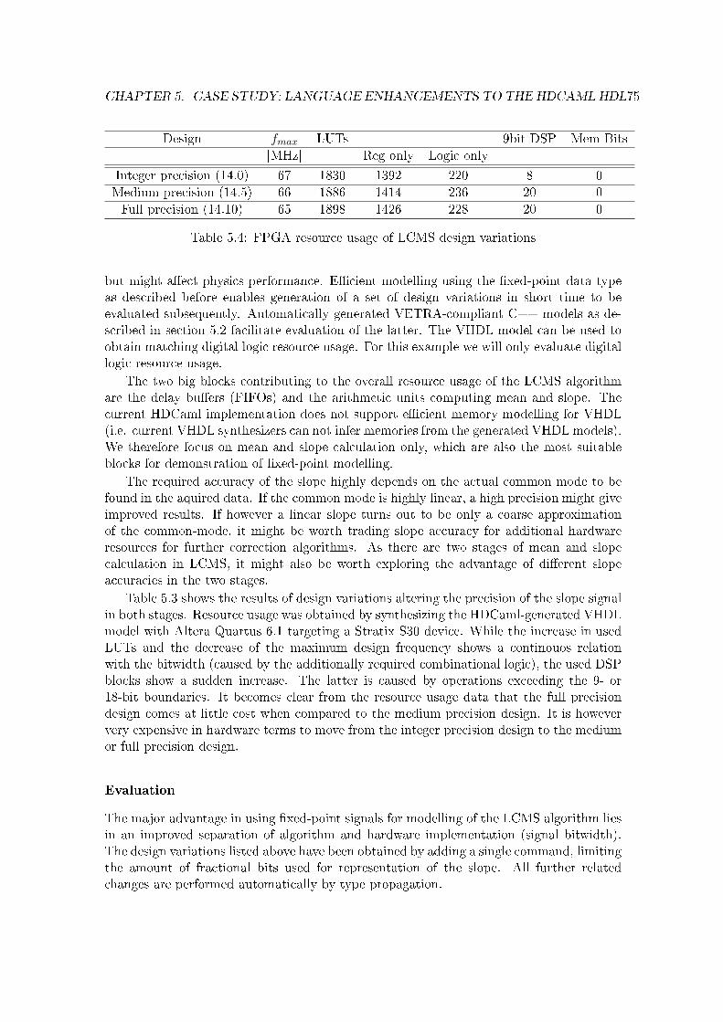
CHAPTER 5. CASE STUDY: LANGUAGE ENHANCEMENTS TO THE HDCAML HDL75
Design fmax LUTs 9bit DSP Mem Bits
[MHz] Reg only Logic only
Integer precision (14.0) 67 1830 1392 220 8 0
Medium precision (14.5) 66 1886 1414 236 20 0
Full precision (14.10) 65 1898 1426 228 20 0
Table 5.4: FPGA resource usage of LCMS design variations
but might a�ect physics performance. E�cient modelling using the �xed-point data typeas described before enables generation of a set of design variations in short time to beevaluated subsequently. Automatically generated VETRA-compliant C++ models as de-scribed in section 5.2 facilitate evaluation of the latter. The VHDL model can be used toobtain matching digital logic resource usage. For this example we will only evaluate digitallogic resource usage.
The two big blocks contributing to the overall resource usage of the LCMS algorithmare the delay bu�ers (FIFOs) and the arithmetic units computing mean and slope. Thecurrent HDCaml implementation does not support e�cient memory modelling for VHDL(i.e. current VHDL synthesizers can not infer memories from the generated VHDL models).We therefore focus on mean and slope calculation only, which are also the most suitableblocks for demonstration of �xed-point modelling.
The required accuracy of the slope highly depends on the actual common mode to befound in the aquired data. If the common mode is highly linear, a high precision might giveimproved results. If however a linear slope turns out to be only a coarse approximationof the common-mode, it might be worth trading slope accuracy for additional hardwareresources for further correction algorithms. As there are two stages of mean and slopecalculation in LCMS, it might also be worth exploring the advantage of di�erent slopeaccuracies in the two stages.
Table 5.3 shows the results of design variations altering the precision of the slope signalin both stages. Resource usage was obtained by synthesizing the HDCaml-generated VHDLmodel with Altera Quartus 6.1 targeting a Stratix S30 device. While the increase in usedLUTs and the decrease of the maximum design frequency shows a continouos relationwith the bitwidth (caused by the additionally required combinational logic), the used DSPblocks show a sudden increase. The latter is caused by operations exceeding the 9- or18-bit boundaries. It becomes clear from the resource usage data that the full precisiondesign comes at little cost when compared to the medium precision design. It is howeververy expensive in hardware terms to move from the integer precision design to the mediumor full precision design.
Evaluation
The major advantage in using �xed-point signals for modelling of the LCMS algorithm liesin an improved separation of algorithm and hardware implementation (signal bitwidth).The design variations listed above have been obtained by adding a single command, limitingthe amount of fractional bits used for representation of the slope. All further relatedchanges are performed automatically by type propagation.

CHAPTER 5. CASE STUDY: LANGUAGE ENHANCEMENTS TO THE HDCAML HDL76
5.4 Graph Description Language (GDL) Models
Control and Data Flow Graphs (CDFGs) are an important abstract representation of hard-ware designs for visualization, optimization, transformation and design-space exploration.There exist e�cient tools for optimization of di�erent design aspects and graph visualiza-tion. While construction of a CDFG is a natural (usual manual) step in design re�nement,extraction of CDFGs from existing formal HDL models is less common. The former is how-ever mandatory if design iterations, based on already existing HDL models want to useexisting high-level tools. A CDFG can also serve as an alternative description of an existingdesign, easing visibility of certain features otherwise obscured in a textual description.
As we have identi�ed fast design iterations as an important need in the HEP hardwaredesign process, we are most interested in providing a suitable path for CDFG extractionfrom existing HDCaml models.
We will review related approaches, demonstrate CDFG extraction from HDCaml mod-els suitable for display using the aiSee tool and will contrast the respective module's im-plementation complexity with other solutions.
Related Approaches
While there are tools abundant accepting some kind of textual graph description as input,there exist only few tools able to extract graph descriptions from formal models. Vallerioet al. [VJ03] present a tool to extract task graphs from embedded system descriptions inC. Ramballa et al. [NRE04] build upon this work, but address designs at a lower level ofabstraction, by extracting CDFGs from VHDL models. The Seoul National University'sdesign automation laboratory provides a tool for extracting CDFGs from VHDL [CJA05].Optimizations are subsequently applied to the CDFGs and results can be made availableas VHDL or C models. All projects include a component to parse the original model (Cor VHDL) to build an intermediate representation.
There exists no unique de�nition of CDFGs (see Orailoglu and Gajski [OG86] for anearly discussion on CDFGs; Wu et al. [Wu02] a CDFG description suitable for Hardware/-Software Codesign (allowing modelling of resolved signals)). A recent suggestion extendingon CDFG are behavioural network graphs (BNG) [Ber02] enabling both high-level trans-formation and e�cient resource usage estimation.
There is no generally accepted textual format for CDFGs. For graphical representationof graphs, the VCG tool [San96] (and its successor aiSee) is frequently used. aiSee by AbsIntGesmbH is provided free of charge for academic research and accepts input descriptions inthe Graph Description Language (GDL). GDL represents a graph by two distinct sets, onedescribing all nodes and one describing directed edges between given nodes.
Implementation
The new HDCaml module gdl.ml allows output of graph descriptions in GDL from anyHDCaml circuit description. gdl.output_cdfg maps the circuit's elements and wires intoCDFG nodes and edges. The resulting �les are ready for display using the aiSee tool. Someextra information is added to format the graphs such that they resemble typical schematicRTL circuit descriptions (using GDL formatting features).
Speci�cally

CHAPTER 5. CASE STUDY: LANGUAGE ENHANCEMENTS TO THE HDCAML HDL77
• The information �ows from top to bottom,
• Edges contain only vertical and horizontal sections and have a tree-like layout,
• The respective bit width is displayed for each multi-wire edge,
HDCaml's basic functional building blocks map directly into most CDFG's elements.Table 5.5 de�nes the used node types as generated by the HDCaml module gdl.ml andtheir graphical representation as visualised by aiSee. The complete set of HDCaml buildingblocks is listed in the third column, giving a direct relation between each building blockand the respective node type.
Edges represent directed �ow of information without delay. Each edge is annotatedwith its bitwidth (unnamed edges) or signal name and bitwidth (named edges).
Implementation Complexity
All related approaches presented in section 5.4 require processing of textual input (VHDLor C). This includes complex compiler-like parsing, analysis and transformations. Ourapproach relies on the fact that execution of any HDCaml program generates an internalrepresentation of the described circuit, available to all other HDCaml modules (includingthe GDL output generator). The extra e�ort required to extract a CDFG is thereforereduced considerably by accessing directly the intermediate representation.
Functional languages are especially suited for implementation of compiler-like tasks liketree construction and traversal due to their frequent support of cyclic recursive structuresand powerful means to traverse them. Therefore the use of a functional language (OCamlin our case) facilitates further the implementation.
The internal HDCaml representation maps naturally into basic elements of a CDFG,as shown in table 5.5. Therefore only minimal transformations are required.
Table 5.6 gives the lines of code of the module, as determined by ocamlwc [Fil01].The low linecount re�ects both the reduced complexity of mapping the intermediate datastructure into CDFG representation and of the e�cient coding accomplished using OCaml.Obviously modi�cations to such a small module are easy to perform.
Some limitations on the graph layout are caused by the lack of a suitable GDL featureto de�ne the position of an edge head relative to its target node (i.e. one can not enforcean edge to end to the left of the second line of its target node; This is however possible fororigins of edges). For some cases, a workaround is used, reversing the edge's direction anddrawing the arrowhead towards the source. Future versions of GDL/aiSee might improveupon this situation.
Example
A simple counter circuit serves as basic example to demonstrate visualization of circuits.The counter has two inputs: en (enable/disable counter) and up (count up/down), a registerholding the current value, two arithmetic units performing addition and subtraction andone multiplexer selecting either of the result for input to the register. Figure 5.3 shows theresult when using the generated CDFG in GDL format as input to the aiSee 3.0 Software.

CHAPTER 5. CASE STUDY: LANGUAGE ENHANCEMENTS TO THE HDCAML HDL78
Node type Graphical representation HDCaml basic elements
Input Signal_input
Constant Signal_const
binaryOperation
Signal_and, Signal_or, Signal_xor,Signal_eq, Signal_lt, Signal_add,Signal_sub, Signal_mul,Signal_mul_u, Signal_concat
unaryOperation
Signal_not, Signal_select
Choose Value Signal_mux
Register Signal_reg
unnamededge
all unnamed dependencies
named edge Signal_signal
Output Sink_output
Table 5.5: Control and data �ow graph elements as generated by the HDCaml modulegdl.ml and as visualised by aiSee.
HDCaml Module Lines of Code
gdl.ml 145
Table 5.6: Lines of code for the HDCaml gdl.ml module as given by ocamlwc

CHAPTER 5. CASE STUDY: LANGUAGE ENHANCEMENTS TO THE HDCAML HDL79
Figure 5.3: Visual representation of a CDFG derived from a HDCaml model using gdl.mland displayed using aiSee 3.0.

CHAPTER 5. CASE STUDY: LANGUAGE ENHANCEMENTS TO THE HDCAML HDL80
Evaluation
It is straightforward to adapt the module to other output formats, as long as it uses aset representation (nodes, edges) of the graph. Due to the limited coding required, evena full rewriting of a similar module for di�erent output formats is feasible within shorttime. As the CDFG is directly derived from the intermediate representation, the module isnot a�ected by changes to the grammar or the syntax of HDCaml, as long as the internalrepresentation is not a�ected.
5.5 Evaluation
Chapters 5.2, 5.3 and 5.4 have presented extensions to the HDCaml HDL, implement-ing generation of VETRA-compliant C++ models, bitwidth independent �xed-point datatypes and generation of GDL models respectively. The provided functionality is generallynot available in contemporary EDA tools. In cases where similar functionality is available,the respective tool requires considerable implementation e�ort (typically including parsingand lexical analysis).
The presented HDCaml extensions, in contrast, all show very low implementation com-plexity (as expressed by required lines of code). This is due to the fact that they can takeadvantage of the existing HDCaml language infrastructure including free access to all in-termediate stages of model construction.
The low complexity of the two custom model generators were enabled by the directaccess to HDCaml's intermediate model representation. The intermediate circuit represen-tation itself is a recursive data structure for which OCaml provides very e�cient notationand handling functions (both in terms of coding and execution speed). The low implemen-tation complexity therefore is fundamentally owed to the open-source approach of HDCaml(direct access to compiler internals) and its implementation using a functional language(recursive data structures and handling functions).
The bitwidth independent �xed-point data type derives its simple implementation fromHDCaml's signal type propagation mechanism, facilitated by OCaml's type inference mech-anism and the fact that the �xed-point type maps naturally into original HDCaml basictypes.
For all three examples it is the availability of functional features derived from OCamlas a host language and the accessibility of the HDCaml implementation which enables lowcomplexity of respective implementations.
The central point when evaluating HDCamls implementation, which sets it apart fromcurrent HDL implementations, is its intermediate model representation and the ease withwhich it can be accessed. This architecture allows separation of functionality (model entry,model-to-model transformation, model-to-target transformation).
The fundamental limitation of HDCaml is the inability to extend its internal repre-sentation. Therefore extension to the language can be implemented with ease, as long asits functionality is compatible with the existing intermediate representation. If this is notthe case, implementation e�ort becomes important. (One - currently not possible - ex-ample being the conservation of �xed-point types from model-entry through intermediaterepresentation to custom model output.)

Chapter 6
Conclusion and Outlook
This work has discussed the history of Hardware Description Languages (HDLs) and theirimportance to the hardware design process. Expanding the scope to language construc-tion in general, Domain-Speci�c Language (DSL) design and implementation issues werereviewed. Subsequently lessons learned from DSL design and implementation were relatedto HDLs design and implementation.
The design of digital systems for High-Energy Physics (HEP) experiments was analyzedand special needs were identi�ed. It was found that there exist HEP-speci�c needs (highlydomain speci�c models, automated generation of custom simulation models) not coveredby existing tools and methodologies. A sample of recent HEP designs showed that theissue is very real and a�ecting large-scale designs.
I have suggested to adopt an open-source approach to tools potentially requiring ad-dition of HEP-speci�c features. This includes HDLs used in HEP experiments. I haveargued that functional languages are superior in terms of implementation e�ciency andhave supported this argument by providing a case study of several extensions to the HD-Caml HDL, using a functional language as its host language. Complexity of related existingimplementations and of HDcaml extensions were discussed. HDCaml extensions show aconsiderably lower implementation complexity while integrating HEP-speci�c needs intothe language implementation (in contrast to add-on tools).
HDCaml together with its HEP-speci�c extensions provides a framework for integrationof tasks in HEP digital systems design executed separately before. It provides unprece-dented design-space exploration capabilities by enabling evaluation of multi-domain costfunctions. This is achieved by providing multiple custom simulation models and the nec-essary access to tune them for future needs.
The HDCaml HDL can act as a tool to evaluate new HDL language features withoutthe need to redesign a new HDL from scratch. For many extensions, it would however befavorable to have a more versatile intermediate circuit representation. Behavioural networkgraphs [Ber02] might prove a sensible choice. More advanced tranformation rules couldthen be explored for design-space exploration and circuit optimization. E�cient memoryallocation could be such a domain open to many further improvements, once representedin a suitable format.
Using a real-world example for evaluation of Con�uence and HDCaml (the LHCb VELOLCMS algorithm) has proven extremely helpful in that real needs of users were identi-
81

CHAPTER 6. CONCLUSION AND OUTLOOK 82
�ed very early on. It has however shown as well the many implications of a high-speedalgorithm-centric signal processing design, seldomly considered when concentrating on asmall part of a HDLs. Many foreseen experiments could not be conducted because of thetight timing and limited resources.
Outlook
With the availability of platforms to integrate new language features, identi�cation ofdomain-speci�c abstractions should potentially gain traction. Such abstraction shouldsubsequently allow formulation of more succinct and readable models, narrowing the com-munication gap between the worlds of application domain experts and hardware designers.They could also lead to improved veri�cation at lower levels of abstraction (like VHDL oreven at chip-level) as model knowledge could be propagated using e.g. PSL.
Recent publications like [ZG05] show that very basic features (seen from a signal pro-cessing perspective) are only now being suggested as HDL language features. Zhao andGajski [ZG05] even state explicitly that no suitable platform for integration of the sug-gested features could be found. It seems therefore likely that further additional features toHDLs will be suggested and discussed in the near future as HDLs are used for modelling ofincreasingly complex algorithm implementations. This process will be important to HEP.
Design of intellectual property (IP) blocks is an area of application for domain-speci�cHDLs, not discussed in this work. IP blocks are usually con�gured by the user but sub-sequently fail to deliver an optimized overall system due to the black-box approach theytake, limiting optimization to the scope of each block. Design of such blocks usually meanscreation of a (VHDL) code generator which is a tedious task and could be improved byuse of a more suitable language. Therefore there is a considerable need for HDLs enablingmore generic models in IP design. If the language used provided the necessary problem-abstraction to perform optimizations on a level above IP-block level, the result could besuperior to current solutions.

Appendix A
HDCaml Implementation Details
This appendix will give detailed information on selected parts of the HDCaml 0.2.10 im-plementation. Language extension as described in the main text are built upon these baseimplementation.
An in-depth discussion of more HDCaml internals and improvements (especially ondebugging) implemented in release 0.2.10 can be found in [Fli07].
To read the following subsections, a certain knowledge on OCaml notation might, whilenot essential, certainly be helpful.
A.1 Internal Circuit Representation
The circuits described using HDCaml functions are represented internally in a recursivedata structure of type:type circuit =
| Circuit of id * string * circuit list * signal list * sink list.
Each circuit consists of a list of signal inputs and transformations (type signal) anda list of signal sinks (type sink). The list of signal inputs and transformations is a linkedlist, representing the circuit by means of HDCaml basic building blocks and connectivitybetween them. Following any signal path through the structural description will �nallylead to a node of type sink. All functions attempting to extract some output descriptionfrom the internal circuit description just need to traverse backwards the list of signals,taking the elements of the list of sinks as starting points.
Only information contained in the type signal is available to any output generatorfunction. The full de�nition of the type signal is given in listing A.2.
1 open Hdcaml ; ;2 open Design ; ;3
4 s t a r t_ c i r c u i t "MyCircuit " ;5 (∗ some HDCaml c i r c u i t d e s c r i p t i o n f unc t i on s ∗)6
7 let myCircuit = ge t_c i r cu i t ( ) in
8 Systemc . output_model myCircuit ;9 Ver i l og . output_net l i s t myCircuit ;10 Vhdl . output_net l i s t myCircuit
83

APPENDIX A. HDCAML IMPLEMENTATION DETAILS 84
11 ; ;
Listing A.1: HDCaml circuit representation
1 type s i g n a l = | Signal_input of id ∗ s t r i n g ∗ width2 | S i gna l_s igna l of id ∗ s t r i n g ∗ width ∗ s i g n a l3 | S ignal_const of id ∗ s t r i n g4 | Signal_empty of id5 | S i gna l_s e l e c t of id ∗ i n t ∗ i n t ∗ s i g n a l6 | S ignal_concat of id ∗ s i g n a l ∗ s i g n a l7 | Signal_not of id ∗ s i g n a l8 | Signal_and of id ∗ s i g n a l ∗ s i g n a l9 | Signal_xor of id ∗ s i g n a l ∗ s i g n a l10 | S ignal_or of id ∗ s i g n a l ∗ s i g n a l11 | Signal_eq of id ∗ s i g n a l ∗ s i g n a l12 | S i gna l_l t of id ∗ s i g n a l ∗ s i g n a l13 | Signal_add of id ∗ s i g n a l ∗ s i g n a l14 | Signal_sub of id ∗ s i g n a l ∗ s i g n a l15 | Signal_mul_u of id ∗ s i g n a l ∗ s i g n a l16 | Signal_mul_s of id ∗ s i g n a l ∗ s i g n a l17 | Signal_mux of id ∗ s i g n a l ∗ s i g n a l ∗ s i g n a l18 | S ignal_reg of id ∗ s i g n a l ∗ s i g n a l
Listing A.2: De�nition of type signal
A.2 HDCaml C-code Generator
HDCaml provides a function Systemc.output_model to generate a bit- and cycle-accurateC-model of the described circuit. The generated �les provide a stand-alone simulator withdirect access to all inputs, outputs and intermediate signals. This simulator can be usedfor fast processing of large data sets or for assessing the accuracy of a speci�c hardwareimplementation within a software simulation framework.
All inputs, outputs and internal signals are represented as arrays of unsigned long.The least signi�cant bit (LSB) of the signal equals the LSB of the lowest element of thearray.
If the signal has more bits than a single element can hold1, another element is addedto the array2.
A sequential logic circuit consists of two basic functional building blocks: storage ele-ments and combinational logic. The HDCaml C-code generator maps all storage elementspresent in a circuit into an array memory of type unsigned long. Combinational logic isimplemented by reading values from memory, applying the respective function and writingthe results back into memory.
The generated data structure simulator_s combines the array memory with a structureof pointers for all signals, pointing at the respective position in memory each.
The generated function init_simulator resets all elements in memory to their initialvalues and sets all pointers, such that they point to the correct position in memory.
1On most computers, the unsigned long data type is 32-bit wide2For signals exceeding 32 bits, the �rst element would therefore hold bits 0-31, the second element bits
32-63 and so on

APPENDIX A. HDCAML IMPLEMENTATION DETAILS 85
The generated function cycle_simulator implements the combinational logic for thewhole circuit. Therefore a basic simulation loop looks like:
write circuit inputs
call cycle_simulator
read circuit outputs
The function Systemc.output_model writes a set of three �les:
• <Design Name>.c (the code to simulate the design)
• <Design Name>.h (the corresponding header �le)
• <Design Name>_sc.h (a wrapper for SystemC)
The generated code consists of three parts:
• struct simulator_s is a data structure providing access to the circuit's inputs, outputsand all (named and unnamed) internal signals.
• a list of public functions to set up the simulation (new_simulator, delete_simulator,init_simulator)), a convenience function to search for ports find_simulator_portand the function to advance the simulation by a single clock cycle cycle_simulator.
• a set of private functions used by cycle_simulator to implement the actual func-tionality of the design (hdcaml_mask, hdcaml_not, hdcaml_and, hdcaml_xor, hdcaml_or,hdcaml_concat, hdcaml_concat_simple, hdcaml_select, hdcaml_select0, hdcaml_select_inword,hdcaml_eq, hdcaml_lt, hdcaml_add, hdcaml_sub, hdcaml_mul, hdcaml_mul_u, hdcaml_sign_extend,hdcaml_mul_s, hdcaml_mux, hdcaml_reg, hdcaml_reg_update, hdcaml_assert).
get_circuit() maps all basic HDCaml operators into basic nodes of the internal datastructure of type circuit, which has subtypes corresponding to each basic HDCaml oper-ator. When Systemc.output_model analyzes the internal data structure, it can generallymap every single basic node directly into one basic C-function (or a set of a few).
1 #ifde f __cplusplus2 extern "C" {3 #endif
4
5 // Simulator Data Type6 struct s imulator_s {7 struct {8 struct {9 // inpu t s :10 unsigned long ∗ en ; // input en : 1 b i t s , 1 words11 // ou tpu t s :12 unsigned long ∗ cnt ; // output cnt : 5 b i t s , 1 words13 // wires :14 unsigned long ∗ n_11 ; // wire n_11 : 5 b i t s , 1 words15 unsigned long ∗ low ; // wire low : 1 b i t s , 1 words16 unsigned long ∗ high ; // wire h igh : 1 b i t s , 1 words17 unsigned long ∗ gnd ; // wire gnd : 1 b i t s , 1 words18 unsigned long ∗ vdd ; // wire vdd : 1 b i t s , 1 words19 // wires in s u b c i r c u i t s :

APPENDIX A. HDCAML IMPLEMENTATION DETAILS 86
20 } Counter ;21 } s i g n a l s ;22 unsigned long memory [ 1 0 ] ;23 } ;24
25 typedef struct s imulator_s ∗ s imulator_t ;26
27 // Simulator Constructor28 s imulator_t new_simulator ( ) ;29
30 // Simulator Des t ruc tor31 void de l e te_s imulator ( s imulator_t ) ;32
33 // Simulator I n i t i a l i z a t i o n34 void i n i t_s imu la to r ( s imulator_t ) ;35
36 // Find s i g n a l in s imu la tor s t r u c t u r e37 typedef struct _signal_t { unsigned long ∗ s i g n a l ; unsigned long width ; } s igna l_t ;38 s i gna l_t f ind_simulator_port ( s imulator_t sim , char ∗name ) ;39
40 // Simulator Cycle Ca l cu l a t i on41 void cyc l e_s imulator ( s imulator_t ) ;42
43 #ifde f __cplusplus44 }45 #endif
Listing A.3: counter.h - HDCaml-generated C header �le
List of References
[Ang06] Angoletta, Maria E. �Digital Low Level RF�. In: European Particle Accelerator Con-ference EPAC'06. 2006. url: http://cdsweb.cern.ch/record/971791.
[Ang03] Angoletta, Maria E. �Digital Signal Processing in Beam Instrumentation: LatestTrends and Typical Applications�. In: 6th European Workshop on Beam Diagnos-tics and Instrumentation for Particle Accelerators DIPAC 2003. 2003. url: http://cdsweb.cern.ch/record/624433.
[Ang05a] Angoletta, Maria E., et al. �Beam Tests of a New Digital Beam Control System forthe CERN LEIR Accelerator�. In: Proceedings of the Particle Accelerator ConferencePAC 2005. 2005. url: http://cdsweb.cern.ch/record/844032.
[Ang05b] Angoletta, Maria E., et al. PS Booster Beam Tests of the new Digital Beam ControlSystem for LEIR. AB-Note-2005-017. CERN-AB-Note-2005-017. Tech. rep. Geneva:CERN, 2005.
[Bai99] Baines, J. T. M., et al. Pattern Recognition in the TRT for the ATLAS B-PhysicsTrigger. ATL-DAQ-99-007. Tech. rep. Geneva: CERN, 1999. url: http://cdsweb.cern.ch/record/683897.
[Bar06] Barney, D., et al. Implementation of On-Line Data Reduction Algorithms in the CMSEndcap Preshower Data Concentrator Card. CMS Note. Tech. rep. CERN, 2006. url:http://cdsweb.cern.ch/record/1000411.
[Bar00] Barrand, G., et al. �GAUDI: The software architecture and framework for buildingLHCb data processing applications�. In: International Conference on Computing inHigh Energy and Nuclear Physics, CHEP 2000. 2000. 92�95. url: http://cdsweb.cern.ch/record/467678.
[BD93] Barton, D. L., and D. D. Dunlop. �An introduction to MHDL�. In: Microwave Sym-posium Digest, 1993., IEEE MTT-S International. Vol. 3. 1993. 1487�1490. url:http://ieeexplore.ieee.org/xpls/abs_all.jsp?arnumber=276859.
[Bar95] Barton, D. �Advanced modeling features of MHDL�. In: Proceedings of the In-ternational Conference on Electronic Hardware Description Languages. 1995. url:http://citeseer.ist.psu.edu/barton95advanced.html.
[BHK01] Bay, A., G. Haefeli, and P. Koppenburg. LHCb VELO o� detector electronics prepro-cessor and interface to the level 1 trigger. LHCb-2001-043. Tech. rep. Geneva: CERN,2001. url: http://cdsweb.cern.ch/record/691717.
[BH98] Bellows, P., and B. Hutchings. �JHDL-an HDL for recon�gurable systems�. In: FP-GAs for Custom Computing Machines, 1998. Proceedings. IEEE Symposium on.1998. 175�184. url: http://ieeexplore.ieee.org/xpls/abs_all.jsp?arnumber=707895.
87
LIST OF REFERENCES 88
[Ber02] Bergamaschi, R. A. �Bridging the domains of high-level and logic synthesis�. In:Computer-Aided Design of Integrated Circuits and Systems, IEEE Transactions on21.5 (2002). 582�596. url: http://ieeexplore.ieee.org/xpls/abs_all.jsp?
arnumber=998629.
[Bis06] Bishop, David. Fixed point package user's guide. 2006. url: http://www.vhdl.org/vhdl-200x/vhdl-200x-ft/packages/Fixed_ug.pdf.
[Bje98] Bjesse, Per, et al. �Lava: hardware design in Haskell�. In: ICFP '98: Proceedings ofthe third ACM SIGPLAN international conference on Functional programming. NewYork, NY, USA: ACM Press, 1998. isbn 1581130244. doi: 10.1145/289423.289440.174�184. url: http://portal.acm.org/citation.cfm?id=289423.289440.
[Bod06] Bodenner, Ralph. Fixed-Point Arithmetic in Impulse C. 2006. url: http://www.impulsec.com/IATAPP106_FIXEDPT.pdf.
[Bro03] Bromley, Jonathan. Synthesisable �xed-point package �x_std. 2003. url: http://www.doulos.com/knowhow/vhdl_designers_guide/models/fp_arith/fix_std_0.
2.zip.
[Cal01] Callot, Olivier. Revised C++ coding conventions. LHCb-2001-054. Tech. rep. Geneva:CERN, 2001. url: http://cdsweb.cern.ch/record/684691.
[Car05] Carballo, J. A. �Open HW, open design SW, and the VC ecosystem dilemma�. In:System-on-Chip for Real-Time Applications, 2005. Proceedings. Fifth InternationalWorkshop on. 2005. 3�6. url: http://ieeexplore.ieee.org/xpls/abs_all.jsp?arnumber=1530905.
[CS78] Case, G. R., and J. D. Stau�er. �SALOGS-IV: A Program to Perform Logic Sim-ulation and Fault Diagnosis�. In: Design Automation, 1978. 15th Conference on.1978. 392�397. url: http://ieeexplore.ieee.org/xpls/abs_all.jsp?arnumber=1585203.
[Cel04a] Celoxica. Handel-C Language Reference Manual. RM-1003-4.2. 2004. url: http://www.celoxica.com/techlib/files/CEL-W0410251JJ4-60.pdf.
[Cel04b] Celoxica. Platform Developer's Kit - Fixed-point Library Manual. RM-1021-1.0. 2004.
[Cha76] Chappell, S. G., et al. �Functional simulation in the LAMP system�. In: DAC '76:Proceedings of the 13th conference on Design automation. New York, NY, USA: ACMPress, 1976. doi: 10.1145/800146.804793. 42�47.
[CJA05] Choi, Kiyoung, Jinhwan Jeon, and Yong-Jin Ahn. Control-Data Flow Graph ToolsetHomepage. 2005. url: http://poppy.snu.ac.kr/CDFG/cdfg.html.
[Chu65] Chu, Yaohan. �An ALGOL-like computer design language�. In: Communications ofthe ACM 8.10 (Oct. 1965). 607�615. issn 0001-0782. doi: 10.1145/365628.365650.
[CM98] Cousineau, Guy, and Michel Mauny. The Functional Approach to Programming. Cam-bridge University Press, 1998. isbn 0521576814. url: http://dx.doi.org/10.2277/0521576814.
[Dec07] Decaluwe, Jan. MyHDL Home Page. 2007. url: http://myhdl.jandecaluwe.com.
[Dee06] DeepChip. Catapult C Synthesis Feedback. 2006. url: http://www.deepchip.com/items/else06-07.html.
[Deh06] Dehning, Bernd, et al. �The LHC Beam Loss Monitoring System's Surface BuildingInstallation�. In: Proceedings of the 12th Workshop on Electronics For LHC and FutureExperiments (Sept. 2006). url: http://cdsweb.cern.ch/record/1020105.
[Dep82] Department of the US Air Force. Draft Request for Proposal F33615-83-R-1003, VH-SIC Hardware Description Language (VHDL). Department of the US Air Force, 1982.
LIST OF REFERENCES 89
[DD68] Duley, J. R., and D. L. Dietmeyer. �A Digital System Design Language (DDL)�. In:Computers, IEEE Transactions on C-17.9 (1968). 850�861. url: http://ieeexplore.ieee.org/xpls/abs_all.jsp?arnumber=1687472.
[Edw06] Edwards, S. A. �The Challenges of Synthesizing Hardware from C-Like Languages�. In:IEEE Design & Test of Computers 23.5 (2006). 375�386. url: http://ieeexplore.ieee.org/xpls/abs_all.jsp?arnumber=1704728.
[Eis99] Eisenbiegler, Dirk. �Ein Kalkül für die Formale Schaltungssynthese�. PhD thesis. Uni-versity of Karlsruhe, 1999. url: http://www.ubka.uni-karlsruhe.de/cgi-bin/psview?document=/1999/informatik/1\&search=/1999/informatik/1.
[EB99] Eisenbiegler, Dirk, and Christian Blumenröhr. �Gropius - Advanced Reuse Conceptsin a New Hardware Description Language�. In: Proceedings of REUSE'99. 1999. url:http://citeseer.ist.psu.edu/632023.html.
[Fil01] Filliâtre, Jean-Christophe. ocamlwc - A program to count the lines of code and docu-mentation in OCaml sources. 2001. url: http://caml.inria.fr/cgi-bin/hump.en.cgi?contrib=409.
[Fli07] Flicker, Karl. �Analyse und Erweiterung der Hardwarebeschreibungssprache HD-Caml�. MA thesis. Technische Universität Graz, 2007.
[FMW05] Foster, Harry, Erich Marschner, and Yaron Wolfsthal. �IEEE P1850 PSL: The NextGeneration�. In: Proceedings of the Design & Veri�cation Conference, 2005 (DV-Con 2005). 2005. url: http://www.pslsugar.org/papers/ieee1850psl-the_next_generation.pdf.
[GK83] Gajski, D. D., and R. H. Kuhn. �New VLSI Tools�. In: Computer 16.12 (1983). 11�14.url: http://ieeexplore.ieee.org/xpls/abs_all.jsp?arnumber=1654264.
[Gaj96] Gajski, Daniel D. Principles of digital design. Upper Saddle River, NJ, USA: Prentice-Hall, Inc., 1996. isbn 0133011445. url: http://portal.acm.org/citation.cfm?id=248673.
[Ghe] Ghezzi, Cristian. V2C: VHDL to C translator. url: http://web.tiscali.it/
sito01/pro/v2c/main.htm.
[Gho99] Ghosh, Sumit K. Hardware Description Languages: Concepts and Principles. Wiley-IEEE Press, 1999. isbn 0780347447. url: http://portal.acm.org/citation.cfm?id=519673.
[Goe06a] Goering, Richard. �MyHDL - Scripting language takes silicon turn�. In: EETimes (Jan. 2006). url: http://eetimes.com/news/design/showArticle.jhtml?articleID=177101584.
[Goe06b] Goering, Richard. �Register language available through open source�. In: EE Times(Mar 2006). url: http://www.embedded.com/showArticle.jhtml?articleID=
181503468.
[Gra03] Grastveit, G., et al. �FPGA Coprocessor for High-Level Trigger Applications�. In:9th Workshop on Electronics for LHC Experiments LECC 2003. 2003. url: http://cdsweb.cern.ch/record/722065.
[GDG04] Gupta, Sumit, Nikil D. Dutt, and Rajesh Gupta. Spark: A Parallelizing Approach tothe High-Level Synthesis of Digital Circuits. Springer, 2004. isbn 978-1-4020-7837-8.
[Hae06] Haefeli, G., et al. �The LHCb DAQ interface board TELL1�. In: Nuclear Instrumentsand Methods in Physics Research Section A: Accelerators, Spectrometers, Detectorsand Associated Equipment 560.2 (May 2006). 494�502. doi: 10.1016/j.nima.2005.12.212.

LIST OF REFERENCES 90
[HDB99] Hammes, Je�rey P., Bruce A. Draper, and Willem A. P. Böhm. �Sassy: A Lan-guage and Optimizing Compiler for Image Processing on Recon�gurable ComputingSystems�. In: : Computer Vision Systems: First International Conference, ICVS'99,Las Palmas, Gran Canaria, Spain, January 1999. Proceedings. 1999. 83+. url:http://www.springerlink.com/content/1b0c54lrbhe5tcqe.
[Haw05] Hawkins, Tom. Con�uence Home Page. 2005. url: http://www.funhdl.org/wiki/doku.php?id=confluence.
[Haw06] Hawkins, Tom. HDCaml Home Page. 2006. url: http://www.funhdl.org/wiki/doku.php/hdcaml.
[Hv79] Hill, D., and W. vanCleemput. �SABLE: A Tool for Generating Structured, Multi-Level Simulations�. In: Design Automation, 1979. 16th Conference on. 1979. 272�279.url: http://ieeexplore.ieee.org/xpls/abs_all.jsp?arnumber=1600118.
[HP87] Hill, Frederick J., and Gerald R. Peterson. Digital Systems: Hardware Organizationand Design. 3rd ed. Wiley, 1987. isbn 0471808067.
[Hol05] Holzer, E. B., et al. �Beam loss monitoring system for the LHC�. In: Nuclear ScienceSymposium Conference Record, 2005 IEEE. vol. 2. 2005. 1052�1056. url: http://ieeexplore.ieee.org/xpls/abs_all.jsp?arnumber=1596433.
[Psl] IEEE Standard for Property Speci�cation Language (PSL). tech. rep. 2005. 1�143.url: http://ieeexplore.ieee.org/xpls/abs_all.jsp?arnumber=1524461.
[IEE06] IEEE SystemC Standard working group. IEEE Std 1666 - 2005 IEEE Standard Sys-temC Language Reference Manual. 2006. 0�423.
[IEE88] IEEE. 1076-1987 IEEE Standard VHDL Language Reference Manual. IEEE, 1988.isbn 0-7381-4324-3. url: http://ieeexplore.ieee.org/xpls/abs_all.jsp?
arnumber=1003477.
[IEE94] IEEE. 1076-1993 IEEE Standard VHDL Language Reference Manual. IEEE, 1994.isbn 0-7381-0986-X. url: http://ieeexplore.ieee.org/servlet/opac?punumber=3116.
[IEE02] IEEE. 1076-2002 IEEE Standard VHDL Language Reference Manual. IEEE, 2002.isbn 0-7381-3247-0. url: http://ieeexplore.ieee.org/servlet/opac?punumber=7863.
[IEE04] IEEE. IEEE Standard for VHDL Register Transfer Level (RTL) Synthesis. Tech. rep.2004. 1�112. url: http://ieeexplore.ieee.org/xpls/abs_all.jsp?arnumber=1342563.
[Imp06] Impulse Accelerated Technologies Inc. Impulse C Homepage. 2006. url: http://www.impulsec.com.
[JB99] Jennings, James, and Eric Beuscher. �Verischemelog: Verilog embedded in Scheme�.In: PLAN '99: Proceedings of the 2nd conference on Domain-speci�c languages. NewYork, NY, USA: ACM Press, 1999. 123�134. url: http://dx.doi.org/10.1145/331960.331978.
[Ked98] Keding, H., et al. �FRIDGE: a �xed-point design and simulation environment�. In:Design, Automation and Test in Europe, 1998., Proceedings. 1998. 429�435. url:http://ieeexplore.ieee.org/xpls/abs_all.jsp?arnumber=655893.
[Kho06] Khomich, Andrei, et al. �Using FPGA coprocessor for ATLAS level 2 trigger applica-tion�. In: Nuclear Instruments and Methods in Physics Research Section A: Accelera-tors, Spectrometers, Detectors and Associated Equipment 566.1 (Oct. 2006). 80�84.url: http://www.sciencedirect.com/science/article/B6TJM-4K2T3YP-9/2/
6dcdbdce046714b886157cf5847d9dc6.

LIST OF REFERENCES 91
[Kd91] Kiczales, Gregor, and Jim des Rivières. The Art of the Metaobject Protocol. The MITPress, 1991. isbn 0262610744.
[KG05] Klingauf, W., and R. Gunzel. �From TLM to FPGA: Rapid prototyping with SystemCand transaction level modeling�. In: 2005. 285�286. url: http://ieeexplore.ieee.org/xpls/abs_all.jsp?arnumber=1568563.
[Kum96] Kumar, Ramayya, et al. �Formal Synthesis in Circuit Design - A Classi�cation andSurvey�. In: FMCAD '96: Proceedings of the First International Conference on For-mal Methods in Computer-Aided Design. London, UK: Springer-Verlag, 1996. isbn3540619372. 294�309.
[LLC99] Launchbury, John, Je�rey R. Lewis, and Byron Cook. �On embedding a microar-chitectural design language within Haskell�. In: ICFP '99: Proceedings of the fourthACM SIGPLAN international conference on Functional programming. New York, NY,USA: ACM Press, 1999. isbn 1581131119. 60�69. url: http://dx.doi.org/10.1145/317636.317784.
[LMR94] Levia, Oz, Serge Maginot, and Jacques Rouillard. �Lessons in language design:cost/bene�t analysis of VHDL features�. In: DAC '94: Proceedings of the 31st an-nual conference on Design automation. New York, NY, USA: ACM Press, 1994. doi:10.1145/196244.196464. 447�453.
[LHC01] LHCb Collaboration. LHCb VELO (VErtex LOcator) Technical Design Report. Tech-nical Design Report LHCb. Geneva: CERN, 2001.
[LHC06] LHCb. The LHCb computing home page. 2006. url: http://lhcb-comp.web.cern.ch/lhcb-comp/.
[Li95] Li, Yanbing. �HML - An innovative Hardware Description Language and its translationto VHDL�. PhD thesis. Cornell University, 1995.
[LL00] Li, Yanbing, and M. Leeser. �HML, a novel hardware description language and itstranslation to VHDL�. In: IEEE Transactions on Very Large Scale Integration (VLSI)Systems 8.1 (2000). 1�8. url: http://ieeexplore.ieee.org/xpls/abs_all.jsp?arnumber=820756.
[MSV06] Manthos, N., G. Sidiropoulos, and P. Vichoudis. �An e�cient hardware design forrejecting common mode in a group of adjacent channels of silicon microstrip sensorsused in high energy physics experiments�. In: IEEE Transactions on Nuclear Science53.3 (2006). 1045�1050. url: http://ieeexplore.ieee.org/xpls/abs_all.jsp?arnumber=1644987.
[Max03] Max�eld, Clive. �New language makes waves�. In: EETimes.com (May 2003).url: http://www.eetimes.com/news/design/columns/max_bytes/showArticle.jhtml?articleID=17408320.
[McC05] McCloud, Shawn. Mentor Graphics European ESL Survey 2005. Tech. rep. MentorGraphics Corp., 2005. url: http://www.mentor.com/products/c-based_design/upload/ESL_Survey_Report_EU.pdf.
[McG03] McGettrick, A., et al. �Computer engineering curriculum in the new millennium�. In:Education, IEEE Transactions on 46.4 (2003). 456�462. url: http://ieeexplore.ieee.org/xpls/abs_all.jsp?arnumber=1245168.
[Men07] Mentor Graphics Corp. Catapult Synthesis. 2007. url: http://www.mentor.com/products/c-based_design/catapult_c_synthesis/index.cfm.
[MHS05] Mernik, Marjan, Jan Heering, and Anthony M. Sloane. �When and how to developdomain-speci�c languages�. In: ACM Computing Surveys 37.4 (Dec. 2005). 316�344.issn 0360-0300. url: http://portal.acm.org/citation.cfm?id=1118890.1118892.

LIST OF REFERENCES 92
[Mic06] Microsoft Research. F# project home page. 2006. url: http://research.microsoft.com/fsharp/fsharp.aspx.
[MA01] Mitchell, John C., and Krzysztof Apt. Concepts in Programming Languages. Cam-bridge University Press, 2001. isbn 0521780985.
[Mue05] Muecke, Manfred. �C/VHDL codesign for LHCb VELO zero suppression algorithms�.In: 14th IEEE-NPSS Real Time Conference. 2005. doi: 10.1109/RTC.2005.1547399.156�157.
[MH06] Muecke, Manfred, and Guido Haefeli. �A bitwidth-aware extension to the HDCamlHardware Description Language�. In: Proceedings of the Forum on speci�cation &Design Languages 2006, FDL'06. ECSI, 2006.
[MS06] Muecke, Manfred, and Tomasz Szumlak. �Uni�ed C/VHDL Model Generation ofFPGA-based LHCb VELO algorithms�. In: 12th Workshop on Electronics for LHCand future Experiments (LECC'06). 2006. url: http://cdsweb.cern.ch/record/1034306.
[NRE04] Namballa, R., N. Ranganathan, and A. Ejnioui. �Control and data �ow graph ex-traction for high-level synthesis�. In: Proceedingsof the IEEE Computer society An-nual Symposium on VLSI, 2004. IEEE Computer Society. 2004. 187�192. url: http://ieeexplore.ieee.org/xpls/abs_all.jsp?arnumber=1339528.
[Nam03] Namballa, Ravi K. �CHESS: A tool for CDFG extraction and high-level synthesis ofVLSI systems�. PhD thesis. University of South Florida, 2003.
[O'D02] O'Donnell, John. �Overview of Hydra: A concurrent language for synchronous digitalcircuit design�. In: Proceedings of the International Parallel and Distributed ProcessingSymposium 2002 (IPDPS 2002). 2002. 234�242. url: http://ieeexplore.ieee.org/xpls/abs_all.jsp?arnumber=1016653.
[OG86] Orailoglu, Alex, and Daniel D. Gajski. �Flow graph representation�. In: DAC '86:Proceedings of the 23rd ACM/IEEE conference on Design automation. Piscataway,NJ, USA: IEEE Press, 1986. isbn 0818607025. 503�509. url: http://portal.acm.org/citation.cfm?id=318093.
[OSC04] OSCI Synthesis Working Group. SystemC Synthesizable Subset Draft 1.1.18. Tech.rep. Open SystemC Initiative (OSCI), 2004. url: https://www.systemc.org/
download/5/47/73/128/.
[PL91] Page, Ian, and Wayne Luk. �Compiling Occam into �eld-programmable gate arrays�.In: Oxford Workshop on Field Programmable Logic and Applications. Ed. by W. Mooreand W. Luk. 15 Harcourt Way, Abingdon OX14 1NV, UK: Abingdon EE&CS Books,1991. 271�283. url: http://citeseer.ist.psu.edu/98799.html.
[Pan01] Panda, P. R., et al. �Data and memory optimization techniques for embedded systems�.In: ACM Trans. Des. Autom. Electron. Syst. 6.2 (Apr. 2001). 149�206. issn 1084-4309.doi: 10.1145/375977.375978.
[Par06] Parcerisa, Daniel Sánchez. HDCaml Tutorial. 2006. url: http://www.funhdl.org/wiki/doku.php/hdcaml:tutorial.
[PC00a] Peel, Roger M. A., and Barry M. Cook. �Occam on Field Programmable Gate Arrays- Fast Prototyping of Parallel Embedded Systems.�. In: Proceedings of the Interna-tional Conference on Parallel and Distributed Processing Techniques and Applications,PDPTA 2000, June 24-29, 2000, Las Vegas, Nevada, USA. 2000.
[PC00b] Peel, Roger M. A., and Barry M. Cook. �Occam on Field-Programmable Gate Ar-rays - Optimising for Performance�. In: Communicating Process Architectures - 2000(WoTUG 23). IOS Press, 2000. 227�238.

LIST OF REFERENCES 93
[PI05] Peel, Roger, and David Pizarro de la Iglesia. �Automatically Generated CSP Pro-vides Veri�cation for Occam-derived Logic Circuits.�. In: Proceedings of the Interna-tional Conference on Parallel and Distributed Processing Techniques and Applications,PDPTA 2005, Las Vegas, Nevada, USA, June 27-30, 2005. 2005. 180�186.
[Pru00] Prud'hon, Laurent. VHDL to C translator (in french). 2000. url: http://people.via.ecp.fr/~laurent/dev/vhdl2c/.
[Ray06] Ray, Andy. HDFS - Hardware Design in F# project home page. 2006. url: http://code.google.com/p/hdfs/.
[San96] Sander, Georg. �Visualisierungstechniken für den Compilerbau�. PhD thesis. Univer-sität des Saarlandes, 1996.
[Sch01] Schlosser, Joachim. �Development and Veri�cation of fast C/C++ Models for theStar12 Micro Controller�. MA thesis. Fachhochschule Augsburg, 2001. url: http://schlosser.info/diplomathesis/thesis.html.
[SN06] Schubert, Thorsten, and Wolfgang Nebel. �The Quiny SystemC Front End: Self-Synthesising Designs�. In: Forum on Speci�cation & Design Languages 2006. 2006.135�142. url: http://ehs.informatik.uni-oldenburg.de/publications/index.php?action=detail\&id=001378.
[SR93] Sharp, Robin, and Ole Rasmussen. �Transformational Rewriting with Ruby�. In:CHDL '93: Proceedings of the 11th IFIP WG10.2 International Conference on Com-puter Hardware Description Languages and their Applications. Amsterdam, TheNetherlands, The Netherlands: North-Holland Publishing Co., 1993. isbn 0444816410.243�260. url: http://portal.acm.org/citation.cfm?id=752235.
[She84] Sheeran, Mary. �muFP, a language for VLSI design�. In: LFP '84: Proceedings of the1984 ACM Symposium on LISP and functional programming. New York, NY, USA:ACM Press, 1984. isbn 0897911423. 104�112. url: http://dx.doi.org/10.1145/800055.802026.
[SS] Singh, S., and M. Sheeran. Designing FPGA Circuits in Lava. url: http://citeseer.ist.psu.edu/258055.html.
[SK95] Slonneger, Kenneth, and Barry L. Kurtz. Formal Syntax and Semantics of Program-ming Languages: A Laboratory Based Approach. Addison Wesley Longman, 1995. isbn0201656973.
[SSDM01] Séméria, Luc, Koichi Sato, and Giovanni De Micheli. �Synthesis of hardware modelsin C with pointers and complex data structures�. In: IEEE Trans. Very Large ScaleIntegr. Syst. 9.6 (Dec. 2001). 743�756. doi: 10.1109/92.974889.
[SC05] Sud, R., and M. Chaitanya. �Revolution in electronic EDA education/research:GOSPL�. In: Microelectronic Systems Education, 2005. (MSE '05). Proceedings. 2005IEEE International Conference on. 2005. 37�38. url: http://ieeexplore.ieee.org/xpls/abs_all.jsp?arnumber=1509353.
[Syn07] Synplicity. Synplify DSP Home Page. 2007. url: http://www.synplicity.com/
products/synplifydsp.
[Szu06] Szumlak, Tomasz. The VETRA home page. 2006. url: http://ppewww.physics.gla.ac.uk/LHCb/Simulation/Vetra.htm.
[SL73] Szygenda, S. A., and A. A. Lekkos. �Integrated techniques for functional and gate-level digital logic simulation�. In: DAC '73: Proceedings of the 10th workshop on Designautomation. Piscataway, NJ, USA: IEEE Press, 1973. 159�172. url: http://portal.acm.org/citation.cfm?id=804011.

LIST OF REFERENCES 94
[Szy94] Szymanski, B. K., et al. �Is there a future for functional languages in parallel pro-gramming?�. In: Proceedings of the 1994 International Conference on Computer Lan-guages, 1994. 1994. 299�304. url: http://ieeexplore.ieee.org/xpls/abs_all.jsp?arnumber=288371.
[Tah99] Taha, Walid M. �Multistage programming: Its theory and applications�. PhD thesis.1999. url: http://portal.acm.org/citation.cfm?id=931031.
[Tak06] Takach, Andres. Algorithmic C Bit Accurate Integer and Fixed Point C++ Data Types.2006. url: http://www.mentor.com/products/esl/high_level_synthesis/ac_datatypes.cfm.
[Vah03] Vahid, F. �The softening of hardware�. In: Computer 36.4 (2003). 27�34. url: http://ieeexplore.ieee.org/xpls/abs_all.jsp?arnumber=1193225.
[VJ03] Vallerio, K. S., and N. K. Jha. �Task graph extraction for embedded system synthesis�.In: VLSI Design, 2003. Proceedings. 16th International Conference on. 2003. 480�486.url: http://ieeexplore.ieee.org/xpls/abs_all.jsp?arnumber=1183180.
[van77] vanCleemput, W. M. �An hierarchical language for the structural description of digitalsystems�. In: DAC '77: Proceedings of the 14th conference on Design automation.Piscataway, NJ, USA: IEEE Press, 1977. 377�385. url: http://portal.acm.org/citation.cfm?id=809157.
[VR06] Vichoudis, Paschalis, and Serge Reynaud. �A multi-channel optical plug-in module forgigabit data reception�. In: 12th Workshop on Electronics for LHC and future Experi-ments. 2006. url: http://indico.cern.ch/contributionDisplay.py?contribId=9\&sessionId=13\&confId=574.
[Vui94a] Vuillemin, J. E. �On Circuits and Numbers�. In: IEEE Transactions on Computers43.8 (Aug. 1994). 868�879. url: http://dx.doi.org/10.1109/12.295849.
[Vui94b] Vuillemin, Jean E. �Fast linear Hough transform�. In: 1994. 1�9. url: http://
ieeexplore.ieee.org/xpls/abs_all.jsp?arnumber=331821.
[Vui] Vuillemin, Jean. How to do circuits with Jazz. url: http://www.exalead.com/jazz/.
[Web94] Webster. Webster's Encyclopedic Unabridged Dictionary of the english language.Gramercy Books, 1994.
[WL99] Weinhardt, Markus, and Wayne Luk. �Memory Access Optimization and RAM Infer-ence for Pipeline Vectorization�. In: 1999. 61�70. url: http://www.springerlink.com/content/rpq35xykvbak1knl.
[Wex89] Wexler, J. Concurrent Programming in Occam 2. Ellis Horwood, 1989. isbn 978-0131617384.
[Wu02] Wu, Qiang, et al. �A hierarchical CDFG as intermediate representation for hard-ware/software codesign�. In: IEEE 2002 International Conference on Communica-tions, Circuits and Systems and West Sino Expositions. Vol. 2. 2002. 1429�1432. url:http://ieeexplore.ieee.org/xpls/abs_all.jsp?arnumber=1179048.
[Xil07] Xilinx. AccelDSP Synthesis Tool Home Page. 2007. url: http://www.xilinx.com/ise/dsp_design_prod/acceldsp.
[Zam06] Zamantzas, Christos. �The Real-Time Data Analysis and Decision System for ParticleFlux Detection in the LHC Accelerator at CERN�. PhD thesis. Brunel Uninversity,2006. url: http://de.scientificcommons.org/17100050.
[ZG05] Zhao, Shuqing, and Daniel D. Gajski. �De�ning an Enhanced RTL Semantics�. In:DATE '05: Proceedings of the conference on Design, Automation and Test in Europe.Washington, DC, USA: IEEE Computer Society, 2005. doi: 10.1109/DATE.2005.111.548�553.