iTN2100 (P100R002) Hardware Description (Rel_08)
514
iTN2100 (P100R002) Hardware Description (Rel_08) www.raisecom.com
-
Upload
khangminh22 -
Category
Documents
-
view
1 -
download
0
Transcript of iTN2100 (P100R002) Hardware Description (Rel_08)

iTN2100 (P100R002)
Hardware Description
(Rel_08)
www.raisecom.com
Raisecom Technology Co., Ltd. provides customers with comprehensive technical support and services. For any
assistance, please contact our local office or company headquarters.
Website: http://www.raisecom.com
Tel: 8610-82883305
Fax: 8610-82883056
Email: [email protected]
Address: Raisecom Building, No. 11, East Area, No. 10 Block, East Xibeiwang Road, Haidian District, Beijing,
P.R.China
Postal code: 100094
-----------------------------------------------------------------------------------------------------------------------------------------
Notice
Copyright © 2022
Raisecom
All rights reserved.
No part of this publication may be excerpted, reproduced, translated or utilized in any form or by any means,
electronic or mechanical, including photocopying and microfilm, without permission in Writing from Raisecom
Technology Co., Ltd.
is the trademark of Raisecom Technology Co., Ltd.
All other trademarks and trade names mentioned in this document are the property of their respective holders.
The information in this document is subject to change without notice. Every effort has been made in the
preparation of this document to ensure accuracy of the contents, but all statements, information, and
recommendations in this document do not constitute the warranty of any kind, express or implied.

Raisecom
iTN2100 (P100R002) Hardware Description Preface
Raisecom Proprietary and Confidential
Copyright © Raisecom Technology Co., Ltd. i
Preface
Objectives This document describes components and cables of the iTN2100, including hardware features,
components, features implemented by each component, and appearance and technical
specifications of cables. The appendix lists terms, acronyms, abbreviations, and metrics of
SFP optical modules and XFP optical modules.
Versions The following table lists the product versions related to this document.
Product name Product version Chassis version Software version
iTN2100 P100R002 C.01 or later iTN2100-NMS-
C_V5.6 or later
Conventions
Symbol conventions
The symbols that may be found in this document are defined as follows.
Symbol Description
Indicate a hazard with a medium or low level of risk which, if
not avoided, could result in minor or moderate injury.
Indicate a potentially hazardous situation that, if not avoided,
could cause equipment damage, data loss, and performance degradation, or unexpected results.
Provide additional information to emphasize or supplement
important points of the main text.
Raisecom
iTN2100 (P100R002) Hardware Description Preface
Raisecom Proprietary and Confidential
Copyright © Raisecom Technology Co., Ltd. ii
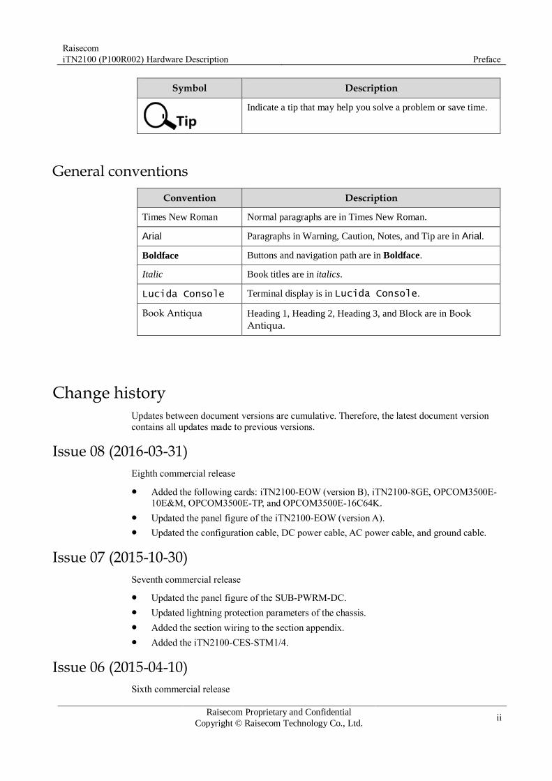
Symbol Description
Indicate a tip that may help you solve a problem or save time.
General conventions
Convention Description
Times New Roman Normal paragraphs are in Times New Roman.
Arial Paragraphs in Warning, Caution, Notes, and Tip are in Arial.
Boldface Buttons and navigation path are in Boldface.
Italic Book titles are in italics.
Lucida Console Terminal display is in Lucida Console.
Book Antiqua Heading 1, Heading 2, Heading 3, and Block are in Book Antiqua.
Change history Updates between document versions are cumulative. Therefore, the latest document version
contains all updates made to previous versions.
Issue 08 (2016-03-31)
Eighth commercial release
Added the following cards: iTN2100-EOW (version B), iTN2100-8GE, OPCOM3500E-
10E&M, OPCOM3500E-TP, and OPCOM3500E-16C64K.
Updated the panel figure of the iTN2100-EOW (version A).
Updated the configuration cable, DC power cable, AC power cable, and ground cable.
Issue 07 (2015-10-30)
Seventh commercial release
Updated the panel figure of the SUB-PWRM-DC.
Updated lightning protection parameters of the chassis.
Added the section wiring to the section appendix.
Added the iTN2100-CES-STM1/4.
Issue 06 (2015-04-10)
Sixth commercial release

Raisecom
iTN2100 (P100R002) Hardware Description Preface
Raisecom Proprietary and Confidential
Copyright © Raisecom Technology Co., Ltd. iii
Added the iTN2100-EOW card.
Revised VC4 distribution data of each slot on the chassis.
Issue 05 (2014-07-16)
Fifth commercial release
Added the following cards: OPCOM3500E-HSEEC, OPCOM3500E-HEESC,
OPCOM3500E-ACEWA, OPCOM3500E-EOSE-8FX (version C), OPCOM3500E-EOS-
8FE (version C), OPCOM3500E-8EOS-GC (version C), OPCOM3500E-Audio, iTN2100-8EOS-8GF (version B), and iTN2100-HSELD.
Added descriptions of the audio cable.
Deleted the following cards: OPCOM3500E-STM1-S (version A), OPCOM3500E-
P240EOS, OPCOM3500E-P240FE, OPCOM3500E-120FE×4-GE, OPCOM3500E-
240H×2, OPCOM3500E-DFPTGE, OPCOM3500E-8EOS-FE, and OPCOM3500E-8EOS-FX.
Changed the name of EOS access card to dual-network transmission card.
Updated metrics of the optical module
Fixed known bugs.
Issue 04 (2014-02-28)
Fourth commercial release
Fixed known bugs.
Issue 03 (2013-11-30)
Third commercial release
Fixed known BUGs.
Added sections 6.3 iTN2100-2STM16-M, 7.3 iTN2100-4STM4-S, 13.2 iTN2100-CES-
16E1T1, 15.6 OPCOM3500E-8EOS-GC, 24.9 E1-RJ45 cable, and 24.10.6 CBL-E1-DB37F (40)/16CC3F.
Added descriptions about the chassis and power supply of the iTN2100-NTU-4XG (C).
Issue 02 (2013-07-30)
Second commercial release
Fixed known bugs.
Added sections 4.3, 6.2, 8.2, 23.2, and 23.3, as well as chapter 11.
Issue 01 (2013-02-16)
Initial commercial release

Raisecom
iTN2100 (P100R002) Hardware Description Contents
Raisecom Proprietary and Confidential
Copyright © Raisecom Technology Co., Ltd. iv
Contents
1 Overview ................................................................................................................................... 1
1.1 Introduction ............................................................................................................................................... 1
1.2 Components .............................................................................................................................................. 1
2 Chassis ....................................................................................................................................... 5
2.1 Structure .................................................................................................................................................... 5
2.2 Slots .......................................................................................................................................................... 7
2.3 VC4 distribution ........................................................................................................................................ 8
2.4 GE distribution .......................................................................................................................................... 9
2.5 Specifications ............................................................................................................................................ 9
3 Fan ............................................................................................................................................ 10
3.1 Functions..................................................................................................................................................10
3.2 Appearance ............................................................................................................................................... 11
3.3 LEDs ........................................................................................................................................................ 11
3.4 Specifications ...........................................................................................................................................12
4 Power supplies ....................................................................................................................... 12
4.1 SUB-PWRII-DC/DC-300 .........................................................................................................................13
4.1.1 Appearance and functions ................................................................................................................13
4.1.2 Slots ................................................................................................................................................13
4.1.3 LEDs ...............................................................................................................................................14
4.1.4 Specifications ..................................................................................................................................14
4.2 SUB-PWRM-DC ......................................................................................................................................16
4.2.1 Appearance and functions ................................................................................................................16
4.2.2 Slots ................................................................................................................................................16
4.2.3 LEDs ...............................................................................................................................................17
4.2.4 Specifications ..................................................................................................................................17
4.3 SUB-PWRMF-DC ....................................................................................................................................19
4.3.1 Appearance and functions ................................................................................................................19
4.3.2 Slots ................................................................................................................................................19
4.3.3 Interface ..........................................................................................................................................20
4.3.4 LEDs ...............................................................................................................................................20
4.3.5 Specifications ..................................................................................................................................21

Raisecom
iTN2100 (P100R002) Hardware Description Contents
Raisecom Proprietary and Confidential
Copyright © Raisecom Technology Co., Ltd. v
4.4 SUB-PWRII-AC .......................................................................................................................................22
4.4.1 Appearance and functions ................................................................................................................22
4.4.2 Slots ................................................................................................................................................22
4.4.3 Interfaces .........................................................................................................................................23
4.4.4 LEDs ...............................................................................................................................................23
4.4.5 Specifications ..................................................................................................................................24
4.5 SUB-PWRM-AC ......................................................................................................................................26
4.5.1 Appearance and functions ................................................................................................................26
4.5.2 Slots ................................................................................................................................................26
4.5.3 Interfaces .........................................................................................................................................27
4.5.4 LEDs ...............................................................................................................................................27
4.5.5 Specifications ..................................................................................................................................28
5 NMS card ................................................................................................................................. 29
5.1 iTN2100-NMS .........................................................................................................................................30
5.1.1 Appearance and functions ................................................................................................................30
5.1.2 Slots ................................................................................................................................................30
5.1.3 Interfaces .........................................................................................................................................31
5.1.4 Buttons ............................................................................................................................................32
5.1.5 LEDs ...............................................................................................................................................32
5.1.6 Alarms .............................................................................................................................................33
5.1.7 Specifications ..................................................................................................................................33
6 SDH aggregation cards .......................................................................................................... 34
6.1 OPCOM3500E-2STM1/4-M .....................................................................................................................35
6.1.1 Appearance and functions ................................................................................................................35
6.1.2 Slots ................................................................................................................................................35
6.1.3 Interfaces .........................................................................................................................................36
6.1.4 LEDs ...............................................................................................................................................37
6.1.5 DIP switch .......................................................................................................................................38
6.1.6 Alarms .............................................................................................................................................38
6.1.7 Specifications ..................................................................................................................................40
6.2 iTN2100-4STM1-M .................................................................................................................................41
6.2.1 Appearance and functions ................................................................................................................41
6.2.2 Slots ................................................................................................................................................41
6.2.3 Interfaces .........................................................................................................................................42
6.2.4 LEDs ...............................................................................................................................................43
6.2.5 Alarms .............................................................................................................................................44
6.2.6 Specifications ..................................................................................................................................45
6.3 iTN2100-2STM16-M ...............................................................................................................................46
6.3.1 Appearance and functions ................................................................................................................46
6.3.2 Slots ................................................................................................................................................47
6.3.3 Interfaces .........................................................................................................................................47

Raisecom
iTN2100 (P100R002) Hardware Description Contents
Raisecom Proprietary and Confidential
Copyright © Raisecom Technology Co., Ltd. vi
6.3.4 LEDs ...............................................................................................................................................48
6.3.5 Logic diagram .................................................................................................................................49
6.3.6 Specifications ..................................................................................................................................50
7 SDH tributary cards ............................................................................................................... 51
7.1 OPCOM3500E-STM1-S ...........................................................................................................................52
7.1.1 Appearance and functions ................................................................................................................52
7.1.2 Slots ................................................................................................................................................52
7.1.3 Interfaces .........................................................................................................................................53
7.1.4 LEDs ...............................................................................................................................................54
7.1.5 Alarms .............................................................................................................................................55
7.1.6 Specifications ..................................................................................................................................55
7.2 OPCOM3500E-4STM1-S .........................................................................................................................57
7.2.1 Appearance and functions ................................................................................................................57
7.2.2 Slots ................................................................................................................................................57
7.2.3 Interfaces .........................................................................................................................................58
7.2.4 LEDs ...............................................................................................................................................58
7.2.5 Alarms .............................................................................................................................................59
7.2.6 Specifications ..................................................................................................................................60
7.3 iTN2100-4STM4-S ...................................................................................................................................61
7.3.1 Appearance and functions ................................................................................................................61
7.3.2 Slots ................................................................................................................................................62
7.3.3 Interfaces .........................................................................................................................................62
7.3.4 LEDs ...............................................................................................................................................62
7.3.5 Alarms .............................................................................................................................................63
7.3.6 Specifications ..................................................................................................................................64
7.4 OPCOM3500E-BSSH ..............................................................................................................................65
7.4.1 Appearance and functions ................................................................................................................65
7.4.2 Slots ................................................................................................................................................65
7.4.3 Interfaces .........................................................................................................................................66
7.4.4 LEDs ...............................................................................................................................................66
7.4.5 Alarms .............................................................................................................................................67
7.4.6 Specifications ..................................................................................................................................67
8 Ethernet aggregation cards .................................................................................................... 69
8.1 iTN2100-NTU-4GF ..................................................................................................................................70
8.1.1 Appearance and functions ................................................................................................................70
8.1.2 Slots ................................................................................................................................................71
8.1.3 Interfaces .........................................................................................................................................71
8.1.4 LEDs ...............................................................................................................................................72
8.1.5 Specifications ..................................................................................................................................72
8.2 iTN2100-NTU-4XG .................................................................................................................................73
8.2.1 Appearance and functions ................................................................................................................73

Raisecom
iTN2100 (P100R002) Hardware Description Contents
Raisecom Proprietary and Confidential
Copyright © Raisecom Technology Co., Ltd. vii
8.2.2 Slots ................................................................................................................................................73
8.2.3 Interfaces .........................................................................................................................................74
8.2.4 LEDs ...............................................................................................................................................74
8.2.5 Specifications ..................................................................................................................................75
9 Ethernet switching card ......................................................................................................... 76
9.1 iTN2100-PTU-4GE ..................................................................................................................................76
9.1.1 Appearance and functions ................................................................................................................76
9.1.2 Slots ................................................................................................................................................76
9.1.3 Interfaces .........................................................................................................................................77
9.1.4 LEDs ...............................................................................................................................................77
9.1.5 Specifications ..................................................................................................................................78
10 Ethernet access cards ............................................................................................................ 79
10.1 iTN2100-16GF .......................................................................................................................................80
10.1.1 Appearance and functions ..............................................................................................................80
10.1.2 Slots ..............................................................................................................................................81
10.1.3 Interfaces .......................................................................................................................................81
10.1.4 LEDs .............................................................................................................................................82
10.1.5 Specifications ................................................................................................................................82
10.2 iTN2100-8GE .........................................................................................................................................84
10.2.1 Appearance and functions ..............................................................................................................84
10.2.2 Slots ..............................................................................................................................................85
10.2.3 Interfaces .......................................................................................................................................85
10.2.4 LEDs .............................................................................................................................................85
10.2.5 Specifications ................................................................................................................................86
10.3 iTN2100-8GF .........................................................................................................................................87
10.3.1 Appearance and functions ..............................................................................................................87
10.3.2 Slots ..............................................................................................................................................88
10.3.3 Interfaces .......................................................................................................................................88
10.3.4 LEDs .............................................................................................................................................88
10.3.5 Specifications ................................................................................................................................89
10.4 iTN2100-16FX .......................................................................................................................................90
10.4.1 Appearance and functions ..............................................................................................................90
10.4.2 Slots ..............................................................................................................................................91
10.4.3 Interfaces .......................................................................................................................................91
10.4.4 LEDs .............................................................................................................................................91
10.4.5 Specifications ................................................................................................................................92
10.5 iTN2100-8FX .........................................................................................................................................93
10.5.1 Appearance and functions ..............................................................................................................93
10.5.2 Slots ..............................................................................................................................................94
10.5.3 Interface ........................................................................................................................................94
10.5.4 LEDs .............................................................................................................................................95

Raisecom
iTN2100 (P100R002) Hardware Description Contents
Raisecom Proprietary and Confidential
Copyright © Raisecom Technology Co., Ltd. viii
10.5.5 Specifications ................................................................................................................................95
10.6 iTN2100-2IGC .......................................................................................................................................97
10.6.1 Appearance and functions ..............................................................................................................97
10.6.2 Slots ..............................................................................................................................................97
10.6.3 Interface ........................................................................................................................................98
10.6.4 LEDs .............................................................................................................................................99
10.6.5 Specifications .............................................................................................................................. 100
10.7 OPCOM3500E-4FX ............................................................................................................................. 101
10.7.1 Appearance and functions ............................................................................................................ 101
10.7.2 Slots ............................................................................................................................................ 101
10.7.3 Interfaces ..................................................................................................................................... 102
10.7.4 LEDs ........................................................................................................................................... 102
10.7.5 DIP swtiches ................................................................................................................................ 103
10.7.6 Specifications .............................................................................................................................. 103
10.8 OPCOM3500E-8FX ............................................................................................................................. 104
10.8.1 Appearance and functions ............................................................................................................ 104
10.8.2 Slots ............................................................................................................................................ 104
10.8.3 Interfaces ..................................................................................................................................... 105
10.8.4 LEDs ........................................................................................................................................... 105
10.8.5 Specifications .............................................................................................................................. 106
11 Dual-network transmission cards .................................................................................... 107
11.1 iTN2100-8EOS-8GF ............................................................................................................................. 108
11.1.1 Appearance and functions............................................................................................................. 108
11.1.2 Slots ............................................................................................................................................ 108
11.1.3 Interfaces ..................................................................................................................................... 109
11.1.4 LEDs ........................................................................................................................................... 109
11.1.5 Logic diagram .............................................................................................................................. 110
11.1.6 Alarms ......................................................................................................................................... 111
11.1.7 Specifications .............................................................................................................................. 111
11.2 iTN2100-4STM1-GC ............................................................................................................................ 112
11.2.1 Appearance and functions............................................................................................................. 112
11.2.2 Slots ............................................................................................................................................ 113
11.2.3 Interfaces ..................................................................................................................................... 113
11.2.4 LEDs ........................................................................................................................................... 114
11.2.5 Alarms ......................................................................................................................................... 115
11.2.6 Specifications .............................................................................................................................. 115
11.3 iTN2100-HSELD .................................................................................................................................. 117
11.3.1 Appearance and functions............................................................................................................. 117
11.3.2 Slots ............................................................................................................................................ 118
11.3.3 Interfaces ..................................................................................................................................... 118
11.3.4 LEDs ........................................................................................................................................... 118

Raisecom
iTN2100 (P100R002) Hardware Description Contents
Raisecom Proprietary and Confidential
Copyright © Raisecom Technology Co., Ltd. ix
11.3.5 Logic diagram .............................................................................................................................. 119
11.3.6 Alarms ......................................................................................................................................... 120
11.3.7 Specifications .............................................................................................................................. 120
12 Clock card ............................................................................................................................ 121
12.1 iTN2100-TSU....................................................................................................................................... 122
12.1.1 Appearance and functions ............................................................................................................ 122
12.1.2 Slots ............................................................................................................................................ 122
12.1.3 Interfaces ..................................................................................................................................... 123
12.1.4 LEDs ........................................................................................................................................... 124
12.1.5 Specifications .............................................................................................................................. 125
13 TDMoP card ........................................................................................................................ 126
13.1 iTN2100-CES-16E1T1-BL ................................................................................................................... 127
13.1.1 Appearance and functions ............................................................................................................ 127
13.1.2 Slots ............................................................................................................................................ 128
13.1.3 Interfaces ..................................................................................................................................... 128
13.1.4 LEDs ........................................................................................................................................... 129
13.1.5 Logic diagram.............................................................................................................................. 129
13.1.6 Specifications .............................................................................................................................. 130
13.1.7 Cables ......................................................................................................................................... 130
13.1.8 Ordering information ................................................................................................................... 131
13.2 iTN2100-CES-16E1T1 ......................................................................................................................... 132
13.2.1 Appearance and functions ............................................................................................................ 132
13.2.2 Slots ............................................................................................................................................ 133
13.2.3 Interfaces ..................................................................................................................................... 133
13.2.4 LEDs ........................................................................................................................................... 133
13.2.5 Logic diagram.............................................................................................................................. 134
13.2.6 Specifications .............................................................................................................................. 135
13.2.7 Cables ......................................................................................................................................... 135
13.2.8 Ordering information ................................................................................................................... 136
13.3 iTN2100-CES-STM1/4 ......................................................................................................................... 137
13.3.1 Appearance and functions ............................................................................................................ 137
13.3.2 Version ........................................................................................................................................ 137
13.3.3 Slots ............................................................................................................................................ 138
13.3.4 Interfaces ..................................................................................................................................... 138
13.3.5 LEDs ........................................................................................................................................... 139
13.3.6 DIP switch ................................................................................................................................... 139
13.3.7 Logic diagram.............................................................................................................................. 139
13.3.8 Specifications .............................................................................................................................. 141
14 EOP cards............................................................................................................................. 142
14.1 OPCOM3500E-EOPFE ........................................................................................................................ 143
14.1.1 Appearance and functions ............................................................................................................ 143

Raisecom
iTN2100 (P100R002) Hardware Description Contents
Raisecom Proprietary and Confidential
Copyright © Raisecom Technology Co., Ltd. x
14.1.2 Slots ............................................................................................................................................ 143
14.1.3 Interfaces ..................................................................................................................................... 144
14.1.4 LEDs ........................................................................................................................................... 144
14.1.5 Alarms ......................................................................................................................................... 145
14.1.6 Specifications .............................................................................................................................. 145
14.2 OPCOM3500E-EOP3FE....................................................................................................................... 147
14.2.1 Appearance and functions ............................................................................................................ 147
14.2.2 Slots ............................................................................................................................................ 147
14.2.3 Interfaces ..................................................................................................................................... 148
14.2.4 LEDs ........................................................................................................................................... 149
14.2.5 Alarms ......................................................................................................................................... 149
14.2.6 Specifications .............................................................................................................................. 150
14.3 OPCOM3500E-EOP8FX ...................................................................................................................... 151
14.3.1 Appearance and functions ............................................................................................................ 151
14.3.2 Slots ............................................................................................................................................ 151
14.3.3 Interfaces ..................................................................................................................................... 152
14.3.4 LEDs ........................................................................................................................................... 152
14.3.5 Specifications .............................................................................................................................. 153
14.4 OPCOM3500E-EOP-FE16E1 ............................................................................................................... 154
14.4.1 Appearance and functions ............................................................................................................ 154
14.4.2 Slots ............................................................................................................................................ 154
14.4.3 Interfaces ..................................................................................................................................... 155
14.4.4 LEDs ........................................................................................................................................... 155
14.4.5 Alarms ......................................................................................................................................... 156
14.4.6 Specifications .............................................................................................................................. 156
14.5 OPCOM3500E-EOP-FEE1×8 ............................................................................................................... 158
14.5.1 Appearance and functions ............................................................................................................ 158
14.5.2 Versions ....................................................................................................................................... 158
14.5.3 Slots ............................................................................................................................................ 159
14.5.4 Interfaces ..................................................................................................................................... 159
14.5.5 LEDs ........................................................................................................................................... 160
14.5.6 Alarms ......................................................................................................................................... 160
14.5.7 Logic diagram.............................................................................................................................. 160
14.5.8 Specifications .............................................................................................................................. 161
14.6 OPCOM3500E-EOP-FXE1×8 .............................................................................................................. 162
14.6.1 Appearance and functions ............................................................................................................ 162
14.6.2 Versions ....................................................................................................................................... 162
14.6.3 Slots ............................................................................................................................................ 163
14.6.4 Interfaces ..................................................................................................................................... 163
14.6.5 LEDs ........................................................................................................................................... 164
14.6.6 Alarms ......................................................................................................................................... 164
14.6.7 Logic diagram.............................................................................................................................. 165

Raisecom
iTN2100 (P100R002) Hardware Description Contents
Raisecom Proprietary and Confidential
Copyright © Raisecom Technology Co., Ltd. xi
14.6.8 Specifications .............................................................................................................................. 165
14.7 OPCOM3500E-EOPS-8E1 ................................................................................................................... 167
14.7.1 Appearance and functions ............................................................................................................ 167
14.7.2 Slots ............................................................................................................................................ 167
14.7.3 Interfaces ..................................................................................................................................... 168
14.7.4 LEDs ........................................................................................................................................... 168
14.7.5 Alarms ......................................................................................................................................... 169
14.7.6 Cables ......................................................................................................................................... 169
14.7.7 Specifications .............................................................................................................................. 170
14.8 OPCOM3500E-HT-6FE24E1 ................................................................................................................ 171
14.8.1 Appearance and functions ............................................................................................................ 171
14.8.2 Versions ....................................................................................................................................... 171
14.8.3 Slots ............................................................................................................................................ 172
14.8.4 Interfaces ..................................................................................................................................... 172
14.8.5 LEDs ........................................................................................................................................... 173
14.8.6 Alarms ......................................................................................................................................... 173
14.8.7 Logic diagram.............................................................................................................................. 173
14.8.8 Specifications .............................................................................................................................. 174
14.9 iTN2100-EOT-GESTM4 ....................................................................................................................... 175
14.9.1 Appearance and functions ............................................................................................................ 175
14.9.2 Slots ............................................................................................................................................ 175
14.9.3 Interfaces ..................................................................................................................................... 176
14.9.4 LEDs ........................................................................................................................................... 176
14.9.5 DIP switches ................................................................................................................................ 177
14.9.6 Alarms ......................................................................................................................................... 178
14.9.7 Specifications .............................................................................................................................. 179
15 EOS cards............................................................................................................................. 180
15.1 OPCOM3500E-EOS-8FE ..................................................................................................................... 181
15.1.1 Appearance and functions ............................................................................................................ 181
15.1.2 Slots ............................................................................................................................................ 181
15.1.3 Interfaces ..................................................................................................................................... 182
15.1.4 LEDs ........................................................................................................................................... 182
15.1.5 DIP switches ................................................................................................................................ 183
15.1.6 Logic diagram.............................................................................................................................. 183
15.1.7 Specifications .............................................................................................................................. 184
15.2 OPCOM3500E-EOSE-4FX................................................................................................................... 185
15.2.1 Appearance and functions ............................................................................................................ 185
15.2.2 Slots ............................................................................................................................................ 185
15.2.3 Interfaces ..................................................................................................................................... 186
15.2.4 LEDs ........................................................................................................................................... 186
15.2.5 Alarms ......................................................................................................................................... 187
Raisecom
iTN2100 (P100R002) Hardware Description Contents
Raisecom Proprietary and Confidential
Copyright © Raisecom Technology Co., Ltd. xii
15.2.6 Specifications .............................................................................................................................. 187
15.3 OPCOM3500E-EOSE-8FX................................................................................................................... 188
15.3.1 Appearance and functions ............................................................................................................ 188
15.3.2 Slots ............................................................................................................................................ 189
15.3.3 Interfaces ..................................................................................................................................... 189
15.3.4 LEDs ........................................................................................................................................... 189
15.3.5 Alarms ......................................................................................................................................... 190
15.3.6 Logic diagram.............................................................................................................................. 190
15.3.7 Specifications .............................................................................................................................. 192
15.4 OPCOM3500E-4EOS-4FE ................................................................................................................... 193
15.4.1 Appearance and functions ............................................................................................................ 193
15.4.2 Slots ............................................................................................................................................ 193
15.4.3 Interfaces ..................................................................................................................................... 194
15.4.4 LEDs ........................................................................................................................................... 194
15.4.5 DIP switches ................................................................................................................................ 195
15.4.6 Alarms ......................................................................................................................................... 195
15.4.7 Specifications .............................................................................................................................. 196
15.5 OPCOM3500E-4EOS-4FX ................................................................................................................... 197
15.5.1 Appearance and functions ............................................................................................................ 197
15.5.2 Slots ............................................................................................................................................ 197
15.5.3 Interfaces ..................................................................................................................................... 198
15.5.4 LEDs ........................................................................................................................................... 198
15.5.5 DIP switches ................................................................................................................................ 199
15.5.6 Alarms ......................................................................................................................................... 200
15.5.7 Specifications .............................................................................................................................. 200
15.6 OPCOM3500E-8EOS-GC .................................................................................................................... 201
15.6.1 Appearance and functions ............................................................................................................ 201
15.6.2 Slots ............................................................................................................................................ 202
15.6.3 Interfaces ..................................................................................................................................... 202
15.6.4 LEDs ........................................................................................................................................... 203
15.6.5 DIP switches ................................................................................................................................ 203
15.6.6 Logic diagram.............................................................................................................................. 204
15.6.7 Specifications .............................................................................................................................. 205
15.7 OPCOM3500E-DSEE........................................................................................................................... 207
15.7.1 Appearance and functions ............................................................................................................ 207
15.7.2 Slots ............................................................................................................................................ 207
15.7.3 Interfaces ..................................................................................................................................... 208
15.7.4 LEDs ........................................................................................................................................... 208
15.7.5 Alarms ......................................................................................................................................... 209
15.7.6 Specifications .............................................................................................................................. 209
15.8 OPCOM3500E-HSEE........................................................................................................................... 210
15.8.1 Appearance and functions ............................................................................................................ 210

Raisecom
iTN2100 (P100R002) Hardware Description Contents
Raisecom Proprietary and Confidential
Copyright © Raisecom Technology Co., Ltd. xiii
15.8.2 Slots ............................................................................................................................................ 210
15.8.3 Interfaces ..................................................................................................................................... 211
15.8.4 LEDs ........................................................................................................................................... 211
15.8.5 Alarms ......................................................................................................................................... 212
15.8.6 Specifications .............................................................................................................................. 212
15.9 OPCOM3500E-HSEEC ........................................................................................................................ 213
15.9.1 Appearance and functions ............................................................................................................ 213
15.9.2 Slots ............................................................................................................................................ 214
15.9.3 Interfaces ..................................................................................................................................... 214
15.9.4 LEDs ........................................................................................................................................... 214
15.9.5 Logic diagram.............................................................................................................................. 215
15.9.6 Specifications .............................................................................................................................. 217
15.10 OPCOM3500E-HEESC ...................................................................................................................... 218
15.10.1 Appearance and functions........................................................................................................... 218
15.10.2 Slots .......................................................................................................................................... 218
15.10.3 Interfaces ................................................................................................................................... 219
15.10.4 LEDs ......................................................................................................................................... 219
15.10.5 DIP switches .............................................................................................................................. 220
15.10.6 Logic diagram ............................................................................................................................ 220
15.10.7 Specifications ............................................................................................................................ 221
15.11 OPCOM3500E-ACEWA ..................................................................................................................... 222
15.11.1 Appearance and functions ........................................................................................................... 222
15.11.2 Slots .......................................................................................................................................... 222
15.11.3 Interfaces ................................................................................................................................... 223
15.11.4 LEDs ......................................................................................................................................... 224
15.11.5 DIP switches .............................................................................................................................. 224
15.11.6 Logic diagram ............................................................................................................................ 224
15.11.7 Specifications............................................................................................................................. 225
16 PDH and RCMS cards ....................................................................................................... 227
16.1 OPCOM3500E-16E1/16E1-BL ............................................................................................................. 228
16.1.1 Appearance and functions ............................................................................................................ 228
16.1.2 Versions ....................................................................................................................................... 228
16.1.3 Slots ............................................................................................................................................ 229
16.1.4 Interfaces ..................................................................................................................................... 229
16.1.5 LEDs ........................................................................................................................................... 230
16.1.6 Alarms ......................................................................................................................................... 230
16.1.7 Cables ......................................................................................................................................... 231
16.1.8 Logic diagram.............................................................................................................................. 231
16.1.9 Specifications .............................................................................................................................. 232
16.2 OPCOM3500E-32E1/32E1-BL ............................................................................................................. 234
16.2.1 Appearance and functions ............................................................................................................ 234
Raisecom
iTN2100 (P100R002) Hardware Description Contents
Raisecom Proprietary and Confidential
Copyright © Raisecom Technology Co., Ltd. xiv
16.2.2 Versions ....................................................................................................................................... 235
16.2.3 Slots ............................................................................................................................................ 235
16.2.4 Interfaces ..................................................................................................................................... 235
16.2.5 LEDs ........................................................................................................................................... 236
16.2.6 DIP switches ................................................................................................................................ 236
16.2.7 Alarms ......................................................................................................................................... 237
16.2.8 Cables ......................................................................................................................................... 237
16.2.9 Logic diagram.............................................................................................................................. 238
16.2.10 Specifications ............................................................................................................................ 238
16.3 OPCOM3500E-120EOS×4 ................................................................................................................... 240
16.3.1 Appearance and functions ............................................................................................................ 240
16.3.2 Slots ............................................................................................................................................ 240
16.3.3 Interfaces ..................................................................................................................................... 241
16.3.4 LEDs ........................................................................................................................................... 241
16.3.5 DIP switches ................................................................................................................................ 242
16.3.6 Alarms ......................................................................................................................................... 244
16.3.7 Specifications .............................................................................................................................. 244
16.4 OPCOM3500E-120EOS×4L ................................................................................................................. 246
16.4.1 Appearance and functions ............................................................................................................ 246
16.4.2 Slots ............................................................................................................................................ 246
16.4.3 Interfaces ..................................................................................................................................... 247
16.4.4 LEDs ........................................................................................................................................... 247
16.4.5 Specifications .............................................................................................................................. 248
16.5 OPCOM3500E-DFPS ........................................................................................................................... 249
16.5.1 Appearance and functions ............................................................................................................ 249
16.5.2 Slots ............................................................................................................................................ 249
16.5.3 Interfaces ..................................................................................................................................... 250
16.5.4 LEDs ........................................................................................................................................... 250
16.5.5 DIP switches ................................................................................................................................ 251
16.5.6 Alarms ......................................................................................................................................... 253
16.5.7 Specifications .............................................................................................................................. 253
16.6 OPCOM3500E-120FE×8L-GE ............................................................................................................. 255
16.6.1 Appearance and functions ............................................................................................................ 255
16.6.2 Slots ............................................................................................................................................ 255
16.6.3 Interfaces ..................................................................................................................................... 256
16.6.4 LEDs ........................................................................................................................................... 257
16.6.5 Alarms ......................................................................................................................................... 257
16.6.6 Specifications .............................................................................................................................. 258
16.7 OPCOM3500E-240GE×4L ................................................................................................................... 259
16.7.1 Appearance and functions ............................................................................................................ 259
16.7.2 Slots ............................................................................................................................................ 260
16.7.3 Interfaces ..................................................................................................................................... 260

Raisecom
iTN2100 (P100R002) Hardware Description Contents
Raisecom Proprietary and Confidential
Copyright © Raisecom Technology Co., Ltd. xv
16.7.4 LEDs ........................................................................................................................................... 260
16.7.5 Alarms ......................................................................................................................................... 261
16.7.6 Specifications .............................................................................................................................. 261
16.8 OPCOM3500E-120H×4........................................................................................................................ 263
16.8.1 Appearance and functions ............................................................................................................ 263
16.8.2 Slots ............................................................................................................................................ 263
16.8.3 Interfaces ..................................................................................................................................... 264
16.8.4 LEDs ........................................................................................................................................... 264
16.8.5 DIP switches ................................................................................................................................ 265
16.8.6 Alarms ......................................................................................................................................... 266
16.8.7 Specifications .............................................................................................................................. 267
16.9 OPCOM3500E-DSPH .......................................................................................................................... 269
16.9.1 Appearance and functions ............................................................................................................ 269
16.9.2 Slots ............................................................................................................................................ 269
16.9.3 Interfaces ..................................................................................................................................... 270
16.9.4 LEDs ........................................................................................................................................... 270
16.9.5 DIP switches ................................................................................................................................ 271
16.9.6 Alarms ......................................................................................................................................... 271
16.9.7 Specifications .............................................................................................................................. 271
16.10 OPCOM3500E-HSPH ........................................................................................................................ 273
16.10.1 Appearance and functions........................................................................................................... 273
16.10.2 Slots .......................................................................................................................................... 273
16.10.3 Interfaces ................................................................................................................................... 274
16.10.4 LEDs ......................................................................................................................................... 274
16.10.5 Alarms ....................................................................................................................................... 274
16.10.6 Specifications ............................................................................................................................ 275
16.11 OPCOM3500E-3DS3/E3 .................................................................................................................... 276
16.11.1 Appearance and functions ........................................................................................................... 276
16.11.2 Slots .......................................................................................................................................... 276
16.11.3 Interfaces ................................................................................................................................... 277
16.11.4 LEDs ......................................................................................................................................... 278
16.11.5 DIP switches .............................................................................................................................. 278
16.11.6 Alarms ....................................................................................................................................... 280
16.11.7 Cables ........................................................................................................................................ 281
16.11.8 Specifications............................................................................................................................. 281
17 V.24 card .............................................................................................................................. 282
17.1 OPCOM3500E-8V24............................................................................................................................ 283
17.1.1 Appearance and functions ............................................................................................................ 283
17.1.2 Slots ............................................................................................................................................ 284
17.1.3 Interfaces ..................................................................................................................................... 284
17.1.4 LEDs ........................................................................................................................................... 284

Raisecom
iTN2100 (P100R002) Hardware Description Contents
Raisecom Proprietary and Confidential
Copyright © Raisecom Technology Co., Ltd. xvi
17.1.5 Cables ......................................................................................................................................... 285
17.1.6 Specifications .............................................................................................................................. 285
18 V.35 card .............................................................................................................................. 286
18.1 OPCOM3500E-8V35............................................................................................................................ 287
18.1.1 Appearance and functions ............................................................................................................ 287
18.1.2 Slots ............................................................................................................................................ 287
18.1.3 Interfaces ..................................................................................................................................... 288
18.1.4 LEDs ........................................................................................................................................... 288
18.1.5 Cables ......................................................................................................................................... 288
18.1.6 Specifications .............................................................................................................................. 289
19 64K cross-connection card ................................................................................................. 290
19.1 OPCOM3500E-DXC-DS0 .................................................................................................................... 291
19.1.1 Appearance and functions ............................................................................................................ 291
19.1.2 Slots ............................................................................................................................................ 291
19.1.3 LEDs ........................................................................................................................................... 292
19.1.4 Alarms ......................................................................................................................................... 292
19.1.5 Specifications .............................................................................................................................. 293
20 Multi-service cards ............................................................................................................. 294
20.1 OPCOM3500E-12MT........................................................................................................................... 295
20.1.1 Appearance and functions ............................................................................................................ 295
20.1.2 Slots ............................................................................................................................................ 295
20.1.3 Interfaces ..................................................................................................................................... 296
20.1.4 LEDs ........................................................................................................................................... 298
20.1.5 Specifications .............................................................................................................................. 299
20.1.6 Cables ......................................................................................................................................... 299
20.2 OPCOM3500E-8MT ............................................................................................................................ 300
20.2.1 Appearance and functions ............................................................................................................ 300
20.2.2 Slots ............................................................................................................................................ 300
20.2.3 Interfaces ..................................................................................................................................... 301
20.2.4 LEDs ........................................................................................................................................... 303
20.2.5 DIP switches ................................................................................................................................ 304
20.2.6 Specifications .............................................................................................................................. 304
20.2.7 Cables ......................................................................................................................................... 305
20.3 OPCOM3500E-MULTI ........................................................................................................................ 306
20.3.1 Appearance and functions ............................................................................................................ 306
20.3.2 Slots ............................................................................................................................................ 307
20.3.3 Interfaces ..................................................................................................................................... 307
20.3.4 LEDs ........................................................................................................................................... 313
20.3.5 DIP switches ................................................................................................................................ 314
20.3.6 Specifications .............................................................................................................................. 315
20.3.7 Cables ......................................................................................................................................... 315

Raisecom
iTN2100 (P100R002) Hardware Description Contents
Raisecom Proprietary and Confidential
Copyright © Raisecom Technology Co., Ltd. xvii
20.4 OPCOM3500E-Audio........................................................................................................................... 316
20.4.1 Appearance and functions ............................................................................................................ 316
20.4.2 Slots ............................................................................................................................................ 316
20.4.3 Interfaces ..................................................................................................................................... 317
20.4.4 LEDs ........................................................................................................................................... 322
20.4.5 DIP switches ................................................................................................................................ 322
20.4.6 Specifications .............................................................................................................................. 322
20.4.7 Cables ......................................................................................................................................... 323
20.5 iTN2100-EOW ..................................................................................................................................... 324
20.5.1 Appearance and functions ............................................................................................................ 324
20.5.2 Slots ............................................................................................................................................ 325
20.5.3 Interfaces ..................................................................................................................................... 325
20.5.4 LEDs ........................................................................................................................................... 327
1.1.2 DIP switch ..................................................................................................................................... 328
1.1.3 Specifications ................................................................................................................................ 328
20.6 OPCOM3500E-10E&M........................................................................................................................ 329
20.6.1 Functions and appearance ............................................................................................................ 329
20.6.2 Slots ............................................................................................................................................ 329
20.6.3 Interfaces ..................................................................................................................................... 330
20.6.4 LEDs ........................................................................................................................................... 333
20.6.5 Specifications .............................................................................................................................. 334
20.6.6 Cables ......................................................................................................................................... 334
21 Service aggregation cards .................................................................................................. 335
21.1 iTN2100-Gb ......................................................................................................................................... 336
21.1.1 Appearance and functions ............................................................................................................ 336
21.1.2 Slots ............................................................................................................................................ 336
21.1.3 Interfaces ..................................................................................................................................... 337
21.1.4 LEDs ........................................................................................................................................... 340
21.1.5 DIP switches ................................................................................................................................ 342
21.1.6 Specifications .............................................................................................................................. 345
21.1.7 Ordering information ................................................................................................................... 345
21.2 iTN2100-8SU-S.................................................................................................................................... 349
21.2.1 Appearance and functions ............................................................................................................ 349
21.2.2 Slots ............................................................................................................................................ 349
21.2.3 Interfaces ..................................................................................................................................... 350
21.2.4 LEDs ........................................................................................................................................... 350
21.2.5 Specifications .............................................................................................................................. 351
21.2.6 Optical performance metrics ........................................................................................................ 351
21.2.7 Networking applications .............................................................................................................. 351
21.2.8 Ordering information ................................................................................................................... 353
21.3 iTN2100-4SU-D ................................................................................................................................... 354

Raisecom
iTN2100 (P100R002) Hardware Description Contents
Raisecom Proprietary and Confidential
Copyright © Raisecom Technology Co., Ltd. xviii
21.3.1 Appearance and functions ............................................................................................................ 354
21.3.2 Slots ............................................................................................................................................ 354
21.3.3 Interfaces ..................................................................................................................................... 355
21.3.4 LEDs ........................................................................................................................................... 355
21.3.5 Specifications .............................................................................................................................. 355
21.3.6 Optical performance metrics ........................................................................................................ 356
21.3.7 Networking applications .............................................................................................................. 356
21.3.8 Ordering information ................................................................................................................... 358
22 Teleprotection ..................................................................................................................... 359
22.1 OPCOM3500E-TP................................................................................................................................ 360
22.1.1 Functions and appearance ............................................................................................................ 360
22.1.2 Slots ............................................................................................................................................ 361
22.1.3 Interfaces ..................................................................................................................................... 361
22.1.4 LEDs ........................................................................................................................................... 362
22.1.5 Specifications .............................................................................................................................. 362
23 64K access ............................................................................................................................ 364
23.1 16C64K ................................................................................................................................................ 365
23.1.1 Functions and appearance ............................................................................................................ 365
23.1.2 Slots ............................................................................................................................................ 365
23.1.3 Interfaces ..................................................................................................................................... 366
23.1.4 LEDs ........................................................................................................................................... 367
23.1.5 Specifications .............................................................................................................................. 367
24 Cables ................................................................................................................................... 368
24.1 Fibers ................................................................................................................................................... 368
24.1.1 Connectors................................................................................................................................... 368
24.1.2 Appearance .................................................................................................................................. 369
24.2 Ethernet cable ....................................................................................................................................... 370
24.2.1 Introduction ................................................................................................................................. 370
24.2.2 Appearance .................................................................................................................................. 370
24.2.3 Technical specifications ............................................................................................................... 371
24.3 Configuration cable .............................................................................................................................. 374
24.3.1 Introduction ................................................................................................................................. 374
24.3.2 Appearance .................................................................................................................................. 374
24.3.3 Wiring ......................................................................................................................................... 374
24.3.4 Technical specifications ............................................................................................................... 374
24.4 DC power cable .................................................................................................................................... 375
24.4.1 Appearance .................................................................................................................................. 375
24.4.2 Technical specifications ............................................................................................................... 375
24.5 AC power cable .................................................................................................................................... 376
24.5.1 POL-AC-European-3-pin/receptacle-0.75mm2-D/RoHS ............................................................... 376
24.5.2 POL-AC-American-3-pin/receptacle-18AWG-D/RoHS ................................................................ 377

Raisecom
iTN2100 (P100R002) Hardware Description Contents
Raisecom Proprietary and Confidential
Copyright © Raisecom Technology Co., Ltd. xix
24.6 Ground cable ........................................................................................................................................ 377
24.6.1 Introduction ................................................................................................................................. 378
24.6.2 Appearance .................................................................................................................................. 378
24.6.3 Technical specifications ............................................................................................................... 378
24.7 Alarm cable .......................................................................................................................................... 379
24.7.1 Introduction ................................................................................................................................. 379
24.7.2 PIN definitions............................................................................................................................. 380
24.8 E1-CC3 cable ....................................................................................................................................... 380
24.8.1 Introduction ................................................................................................................................. 380
24.8.2 Appearance .................................................................................................................................. 380
24.8.3 Technical specifications ............................................................................................................... 381
24.9 E1-RJ45 cable ...................................................................................................................................... 381
24.9.1 Introduction ................................................................................................................................. 381
24.9.2 CBL-E1-RJ45/RJ45 ..................................................................................................................... 381
24.9.3 CBL-E1-RJ45/2RJ45 ................................................................................................................... 383
24.10 E1-DB37 cable ................................................................................................................................... 384
24.10.1 Introduction ............................................................................................................................... 384
24.10.2 CBL-E1-DB37F (40)/16NC ....................................................................................................... 384
24.10.3 CBL-E1-DB37F/16BNCF .......................................................................................................... 386
24.10.4 CBL-E1-DB37F/16BNCM ......................................................................................................... 387
24.10.5 CBL-E1-DB37F/8RJ45 .............................................................................................................. 388
24.10.6 CBL-E1-DB37F (40)/16CC3F ................................................................................................... 389
24.11 E1-SCSI100 cable ............................................................................................................................... 389
24.11.1 Introduction ............................................................................................................................... 389
24.11.2 CBL-E1-SCSI100M (40)/32BNCF ............................................................................................. 390
24.11.3 CBL-E1-SCSI100M (40)/32BNCM ............................................................................................ 390
24.11.4 CBL-E1-SCSI100M (40)/16RJ45 ............................................................................................... 391
24.12 V24-HDB26 cable .............................................................................................................................. 392
24.12.1 Introduction ............................................................................................................................... 392
24.12.2 CBL-V24-HDB26M/4DB25F .................................................................................................... 393
24.12.3 CBL-V24-HDB26M/4DB25M ................................................................................................... 393
24.12.4 PIN definitions ........................................................................................................................... 394
24.13 V35-HDB26 cable .............................................................................................................................. 395
24.13.1 Introduction ............................................................................................................................... 395
24.13.2 CBL-V35-HDB26M/2M34F ...................................................................................................... 396
24.13.3 PIN definitions ........................................................................................................................... 396
24.14 MUL-HDB26 cable ............................................................................................................................ 398
24.14.1 Introduction ............................................................................................................................... 398
24.14.2 CBL-MUL-HDB26M/NC .......................................................................................................... 398
24.14.3 CBL-MUL-HDB26M (40)/NC ................................................................................................... 400
24.15 Audio cable......................................................................................................................................... 403
24.15.1 Introduction ............................................................................................................................... 403

Raisecom
iTN2100 (P100R002) Hardware Description Contents
Raisecom Proprietary and Confidential
Copyright © Raisecom Technology Co., Ltd. xx
24.15.2 CBL-VOICE-DB37F/NC-D ....................................................................................................... 403
25 Appendix ............................................................................................................................. 406
25.1 Power consumption of optical/electrical modules .................................................................................. 406
25.1.1 SFP modules ................................................................................................................................ 406
25.1.2 XFP modules ............................................................................................................................... 407
25.2 Metrics of SFP optical modules ............................................................................................................. 408
25.2.1 CSFP optical modules .................................................................................................................. 408
25.2.2 DSFP optical modules .................................................................................................................. 411
25.2.3 GSFP optical modules .................................................................................................................. 415
25.2.4 TSFP optical modules .................................................................................................................. 416
25.2.5 USFP optical modules .................................................................................................................. 418
25.2.6 USFP electrical module ................................................................................................................ 424
25.2.7 USFP+ optical module ................................................................................................................. 425
25.3 Parameters of XFP optical modules ....................................................................................................... 426
25.3.1 CXFP optical modules ................................................................................................................. 426
25.3.2 DXFP optical modules ................................................................................................................. 430
25.3.3 UXFP optical modules ................................................................................................................. 447
25.4 Wiring .................................................................................................................................................. 447
25.4.1 CBL-E1-SCSI100M(40)/16RJ45 .................................................................................................. 447
25.4.2 CBL-E1-SCSI100M(40)/32NC .................................................................................................... 450
25.4.3 CBL-E1-SCSI100M(40)/32BNCF(M) .......................................................................................... 453
25.4.4 CBL-E1-DB37F/16BNCF ............................................................................................................ 456
25.4.5 CBL-E1-DB37F/8RJ45 ................................................................................................................ 458
25.4.6 CBL-E1-DB9M/4BNCF .............................................................................................................. 459
25.4.7 CBL-E1-DB9M/2RJ45 ................................................................................................................ 459
25.4.8 CBL-VOICE-SCSI50M(40)/NC................................................................................................... 460
25.4.9 CBL-EM-HDB26M/NC ............................................................................................................... 463
25.4.10 CBL-V35-HDB26M/2M34F ...................................................................................................... 464
25.4.11 CBL-V24-HDB26M/4DB25F .................................................................................................... 465
25.5 Terms ................................................................................................................................................... 467
25.6 Acronyms and abbreviations ................................................................................................................. 469

Raisecom
iTN2100 (P100R002) Hardware Description Figures
Raisecom Proprietary and Confidential
Copyright © Raisecom Technology Co., Ltd. xxi
Figures
Figure 2-1 Front panel of the chassis ................................................................................................................ 5
Figure 2-2 Rear panel of the chassis ................................................................................................................. 6
Figure 2-3 Relations between slots and cards ................................................................................................... 7
Figure 3-1 Front panel of the FANS360 .......................................................................................................... 11
Figure 3-2 Rear panel of the iTN2100 ............................................................................................................. 11
Figure 6-1 Logic diagram of the iTN2100-2STM16-M....................................................................................49
Figure 11-1 Logic diagram of the iTN2100-8EOS-8GF ................................................................................. 110
Figure 11-2 Logic diagram of the iTN2100-HSELD ...................................................................................... 119
Figure 13-1 Logic diagram of the iTN2100-CES-16E1T1-BL ....................................................................... 129
Figure 13-2 Logic diagram of the iTN2100-CES-16E1T1 ............................................................................. 134
Figure 13-3 Logic diagram of the iTN2100-CES-STM1/4 ............................................................................. 140
Figure 14-1 Logic diagram of the OPCOM3500E-EOP-FEE1×8 ................................................................... 161
Figure 14-2 Logic diagram of the OPCOM3500E-EOP-FXE1×8................................................................... 165
Figure 14-3 Logic diagram of the OPCOM3500E-HT-6FE24E1 .................................................................... 174
Figure 15-1 Logic diagram of the OPCOM3500E-EOS-8FE ......................................................................... 183
Figure 15-2 Logic diagram of the OPCOM3500E-EOSE-8FX....................................................................... 191
Figure 15-3 Position of DIP switches on the OPCOM3500E-8EOS-GC ......................................................... 204
Figure 15-4 Logic diagram of the OPCOM3500E-8EOS-GC ........................................................................ 205
Figure 15-5 Logic diagram of the OPCOM3500E-HSEEC ............................................................................ 216
Figure 15-6 Logic diagram of the OPCOM3500E-HEESC ............................................................................ 220
Figure 15-7 Logic diagram of the OPCOM3500E-ACEWA........................................................................... 225
Figure 16-1 Logic diagram of the OPCOM3500E-16E1/16E1-BL ................................................................. 232
Figure 16-2 Logic diagram of the OPCOM3500E-32E1/32E1-BL ................................................................. 238
Figure 20-1 Interface PINs of the OPCOM3500E-12MT ............................................................................... 297
Figure 20-2 Interface PINs of the OPCOM3500E-8MT ................................................................................. 302
Figure 20-3 Voice gain DIP switch of the OPCOM3500E-8MT ..................................................................... 304

Raisecom
iTN2100 (P100R002) Hardware Description Figures
Raisecom Proprietary and Confidential
Copyright © Raisecom Technology Co., Ltd. xxii
Figure 20-4 DB37 interface PINs of the OPCOM3500E-Audio ..................................................................... 319
Figure 20-5 HDB26 interface PINs of the OPCOM3500E-Audio .................................................................. 321
Figure 1-1 ALM interface PINs of the iTN2100-EOW .................................................................................. 327
Figure 20-6 Interface PINs of the interface on the E&M ................................................................................ 331
Figure 20-7 E&M signaling type................................................................................................................... 333
Figure 21-1 Point-to-point networking application with the iTN2100-8SU-S ................................................. 352
Figure 21-2 OADM ring network with the iTN2100-8SU-S .......................................................................... 353
Figure 21-3 Point-to-point networking application with the iTN2100-4SU-D ................................................ 357
Figure 21-4 OADM ring network with the iTN2100-4SU-D .......................................................................... 357
Figure 24-1 LC/PC fiber connector ............................................................................................................... 369
Figure 24-2 SC/PC fiber connector ............................................................................................................... 369
Figure 24-3 FC/PC fiber connector ............................................................................................................... 370
Figure 24-4 Ethernet cable ............................................................................................................................ 371
Figure 24-5 Wiring of the straight-through cable ........................................................................................... 372
Figure 24-6 Wiring of the 100 Mbit/s crossover cable ................................................................................... 372
Figure 24-7 Wiring of the 1000 Mbit/s crossover cable.................................................................................. 373
Figure 24-8 Configuration cable ................................................................................................................... 374
Figure 24-9 Wiring of the configuration cable ............................................................................................... 374
Figure 24-10 DC power cable ....................................................................................................................... 375
Figure 24-11 European AC power cable ........................................................................................................ 376
Figure 24-12 American AC power cable ....................................................................................................... 377
Figure 24-13 Ground cable ........................................................................................................................... 378
Figure 24-14 OT terminal ............................................................................................................................. 378
Figure 24-15 PINs of the alarm terminal ....................................................................................................... 380
Figure 24-16 E1-CC3 cable .......................................................................................................................... 380
Figure 24-17 CBL-E1-RJ45/RJ45 cable ........................................................................................................ 382
Figure 24-18 CBL-E1-RJ45/2RJ45 cable ...................................................................................................... 383
Figure 24-19 CBL-E1-DB37F (40)/16NC cable ............................................................................................ 385
Figure 24-20 CBL-E1-DB37F/16BNCF cable ............................................................................................... 387
Figure 24-21 CBL-E1-DB37F/16BNCM cable ............................................................................................. 387
Figure 24-22 CBL-E1-DB37F/8RJ45 cable ................................................................................................... 388
Figure 24-23 CBL-E1-DB37F (40)/16CC3F cable ........................................................................................ 389
Figure 24-24 CBL-E1-SCSI100M (40)/32BNCF cable ................................................................................. 390

Raisecom
iTN2100 (P100R002) Hardware Description Figures
Raisecom Proprietary and Confidential
Copyright © Raisecom Technology Co., Ltd. xxiii
Figure 24-25 CBL-E1-SCSI100M (40)/32BNCM cable ................................................................................ 391
Figure 24-26 CBL-E1-SCSI100M (40)/16RJ45 cable .................................................................................... 392
Figure 24-27 CBL-V24-HDB26M/4DB25F cable ......................................................................................... 393
Figure 24-28 CBL-V24-HDB26M/4DB25M cable ........................................................................................ 394
Figure 24-29 CBL-V35-HDB26M/2M34F cable ........................................................................................... 396
Figure 24-30 CBL-MUL-HDB26M/NC cable ............................................................................................... 398
Figure 24-31 CBL-MUL-HDB26M (40)/NC cable ........................................................................................ 400
Figure 24-32 CBL-VOICE-DB37F/NC-D cable ............................................................................................ 403

Raisecom
iTN2100 (P100R002) Hardware Description Tables
Raisecom Proprietary and Confidential
Copyright © Raisecom Technology Co., Ltd. xxiv
Tables
Table 1-1 All cards on the iTN2100 and their corresponding BUS .................................................................... 2
Table 2-1 Descriptions of the chassis ............................................................................................................... 6
Table 2-2 VC4 distribution for OPCOM3500E-2STM1/4-M (STM-1 mode) as aggregation card ...................... 8
Table 2-3 VC4 distribution for OPCOM3500E-2STM1/4-M (STM-4 mode) as aggregation card ...................... 8
Table 2-4 VC4 distribution for iTN2100-4STM1-M as aggregation card........................................................... 8
Table 2-5 VC4 distribution for iTN2100-2STM16-M as aggregation card ......................................................... 8
Table 2-6 GE distribution ................................................................................................................................ 9
Table 2-7 Specifications of the iTN2100 .......................................................................................................... 9
Table 3-1 LEDs on the front panel of the FANS360......................................................................................... 11
Table 3-2 Specifications of the FANS360 ........................................................................................................12
Table 4-1 LEDs on the SUB-PWRII-DC/DC-300 panel...................................................................................14
Table 4-2 Specifications of the SUB-PWRII-DC/DC-300 ................................................................................14
Table 4-3 LEDs on the SUB-PWRM-DC panel ...............................................................................................17
Table 4-4 Specifications of the SUB-PWRM-DC ............................................................................................18
Table 4-5 Input parameters of the SUB-PWRM-DC ........................................................................................18
Table 4-6 Protection function parameters of the SUB-PWRM-DC ...................................................................18
Table 4-7 Interfaces on the SUB-PWRMF-DC panel .......................................................................................20
Table 4-8 LEDs on the SUB-PWRMF-DC ......................................................................................................20
Table 4-9 Specifications of the SUB-PWRMF-DC ..........................................................................................21
Table 4-10 Input parameters of the SUB-PWRMF-DC ....................................................................................21
Table 4-11 Protection function parameters of the SUB-PWRMF-DC ...............................................................21
Table 4-12 Interface on the SUB-PWRII-AC panel .........................................................................................23
Table 4-13 LEDs on the SUB-PWRII-AC panel ..............................................................................................23
Table 4-14 Specifications of the SUB-PWRII-AC ...........................................................................................24
Table 4-15 Input parameters of the SUB-PWRII-AC .......................................................................................24
Table 4-16 Protection function parameters of the SUB-PWRII-AC ..................................................................25

Raisecom
iTN2100 (P100R002) Hardware Description Tables
Raisecom Proprietary and Confidential
Copyright © Raisecom Technology Co., Ltd. xxv
Table 4-17 Interface on the SUB-PWRM-AC panel ........................................................................................27
Table 4-18 LEDs on the SUB-PWRM-AC panel .............................................................................................27
Table 4-19 Specifications of the SUB-PWRM-AC ..........................................................................................28
Table 4-20 Input parameters of the SUB-PWRM-AC ......................................................................................28
Table 4-21 Protection function parameters of the SUB-PWRM-AC .................................................................29
Table 5-1 Interfaces on the iTN2100-NMS panel ............................................................................................31
Table 5-2 Parameters of the SNMP interface on the iTN2100-NMS card .........................................................31
Table 5-3 Parameters of the CONSOLE interface on the iTN2100-NMS .........................................................31
Table 5-4 Buttons on the iTN2100-NMS panel................................................................................................32
Table 5-5 LEDs on the iTN2100-NMS panel ..................................................................................................32
Table 5-6 Alarms of the iTN2100-NMS ..........................................................................................................33
Table 5-7 Specifications of the iTN2100-NMS ................................................................................................33
Table 6-1 Interfaces on the OPCOM3500E-2STM1/4-M panel ........................................................................36
Table 6-2 Parameters of interfaces 1 and 2 on the OPCOM3500E-2STM1/4-M ...............................................36
Table 6-3 Parameters of 2 Mbit/s clock interface on the OPCOM3500E-2STM1/4-M ......................................36
Table 6-4 Parameters of the 2 MHz clock interface the OPCOM3500E-2STM1/4-M .......................................37
Table 6-5 LEDs on the OPCOM3500E-2STM1/4-M panel ..............................................................................37
Table 6-6 Configurations of DIP switch SW3 on the OPCOM3500E-2STM1/4-M ...........................................38
Table 6-7 Alarms of the OPCOM3500E-2STM1/4-M......................................................................................39
Table 6-8 Specifications of the OPCOM3500E-2STM1/4-M ...........................................................................40
Table 6-9 Interfaces on the iTN2100-4STM1-M panel ....................................................................................42
Table 6-10 Parameters of interfaces 1, 2, 3, and 4 on the iTN2100-4STM1-M .................................................42
Table 6-11 Parameters of 2 Mbit/s clock interface on the iTN2100-4STM1-M .................................................42
Table 6-12 Parameters of the 2 MHz clock interface the iTN2100-4STM1-M ..................................................43
Table 6-13 LEDs on the iTN2100-4STM1-M ..................................................................................................43
Table 6-14 Alarms of the iTN2100-4STM1-M ................................................................................................44
Table 6-15 Specifications of the iTN2100-4STM1-M ......................................................................................45
Table 6-16 Interfaces on the iTN2100-2STM16-M panel .................................................................................47
Table 6-17 Parameters of SFP optical interfaces on the iTN2100-2STM16-M ..................................................47
Table 6-18 Parameters of 2 Mbit/s clock interface on the iTN2100-2STM16-M ...............................................48
Table 6-19 Parameters of 2 MHz clock interface on the iTN2100-2STM16-M .................................................48
Table 6-20 LEDs on the iTN2100-2STM16-M ................................................................................................48
Table 6-21 Specifications of the iTN2100-2STM16-M ....................................................................................50

Raisecom
iTN2100 (P100R002) Hardware Description Tables
Raisecom Proprietary and Confidential
Copyright © Raisecom Technology Co., Ltd. xxvi
Table 7-1 Interfaces on the OPCOM3500E-STM1-S (Versions B) ...................................................................53
Table 7-2 Interfaces on the OPCOM3500E-STM1-S (Version C).....................................................................53
Table 7-3 Parameters of interfaces A and B on the OPCOM3500E-STM1-S (Versions B) ................................53
Table 7-4 Parameters of interfaces 1 and 2 on the OPCOM3500E-STM1-S (Version C) ...................................53
Table 7-5 LEDs on the OPCOM3500E-STM1-S (Versions B) panel ................................................................54
Table 7-6 LEDs on the OPCOM3500E-STM1-S (Version C) panel .................................................................55
Table 7-7 Alarms of the OPCOM3500E-STM1-S ............................................................................................55
Table 7-8 Specifications of the OPCOM3500E-STM1-S .................................................................................56
Table 7-9 Interfaces on the OPCOM3500E-4STM1-S panel ............................................................................58
Table 7-10 Parameters of interfaces 1–4 on the OPCOM3500E-4STM1-S .......................................................58
Table 7-11 LEDs on the OPCOM3500E-4STM1-S panel ................................................................................58
Table 7-12 Alarms of the OPCOM3500E-4STM1-S ........................................................................................59
Table 7-13 Specifications of the OPCOM3500E-4STM1-S .............................................................................60
Table 7-14 Interfaces on the iTN2100-4STM4-S panel ....................................................................................62
Table 7-15 Parameters of interfaces 1–4 on the iTN2100-4STM4-S .................................................................62
Table 7-16 LEDs on the iTN2100-4STM4-S panel ..........................................................................................63
Table 7-17 Alarms of the iTN2100-4STM4-S..................................................................................................63
Table 7-18 Specifications of the iTN2100-4STM4-S .......................................................................................64
Table 7-19 Interfaces on the OPCOM3500E-BSSH .........................................................................................66
Table 7-20 Parameters of interfaces A and B on the OPCOM3500E-BSSH ......................................................66
Table 7-21 LEDs on the OPCOM3500E-BSSH panel ......................................................................................66
Table 7-22 Alarms of the OPCOM3500E-BSSH .............................................................................................67
Table 7-23 Specifications of the OPCOM3500E-BSSH ...................................................................................67
Table 8-1 Interfaces on the iTN2100-NTU-4GF panel .....................................................................................71
Table 8-2 Parameters of interfaces 1–4 on the iTN2100-NTU-4GF ..................................................................71
Table 8-3 LEDs on the iTN2100-NTU-4GF ....................................................................................................72
Table 8-4 Specifications of the iTN2100-NTU-4GF ........................................................................................72
Table 8-5 Interfaces on the iTN2100-NTU-4XG panel ....................................................................................74
Table 8-6 Parameters of XFP interfaces on the iTN2100-NTU-4XG ................................................................74
Table 8-7 LEDs on the iTN2100-NTU-4XG ...................................................................................................75
Table 8-8 Specifications of the iTN2100-NTU-4XG .......................................................................................75
Table 9-1 Interfaces on the iTN2100-PTU-4GE panel .....................................................................................77
Table 9-2 Parameters of interfaces 1–4 on the iTN2100-PTU-4GE ..................................................................77

Raisecom
iTN2100 (P100R002) Hardware Description Tables
Raisecom Proprietary and Confidential
Copyright © Raisecom Technology Co., Ltd. xxvii
Table 9-3 LEDs on the iTN2100-PTU-4GE panel ...........................................................................................78
Table 9-4 Specifications of the iTN2100-PTU-4GE.........................................................................................78
Table 10-1 Interfaces on the iTN2100-16GF panel ..........................................................................................81
Table 10-2 Parameters of interfaces 1–16 of the iTN2100-16GF ......................................................................81
Table 10-3 Properties of the TSFP module of the iTN2100-16GF ....................................................................82
Table 10-4 LEDs on the iTN2100-16GF panel ................................................................................................82
Table 10-5 Specifications of the iTN2100-16GF .............................................................................................83
Table 10-6 Interfaces on the iTN2100-8GE panel ............................................................................................85
Table 10-7 Parameters of interfaces 1–8 of the iTN2100-8GE .........................................................................85
Table 10-8 LEDs on the iTN2100-8GE panel ..................................................................................................86
Table 10-9 Specifications of the iTN2100-8GE ...............................................................................................86
Table 10-10 Interfaces on the iTN2100-8GF panel ..........................................................................................88
Table 10-11 Parameters of interfaces 1–8 of the iTN2100-8GF ........................................................................88
Table 10-12 LEDs on the iTN2100-8GF panel ................................................................................................89
Table 10-13 Specifications of the iTN2100-8GF .............................................................................................89
Table 10-14 Interfaces on the iTN2100-16FX panel ........................................................................................91
Table 10-15 Parameters of interfaces 1–8 of the iTN2100-16FX ......................................................................91
Table 10-16 LEDs on the iTN2100-16FX panel ..............................................................................................91
Table 10-17 Specifications of the iTN2100-16FX ...........................................................................................92
Table 10-18 Interfaces on the iTN2100-8FX panel ..........................................................................................94
Table 10-19 Parameters of interfaces 1–8 of the iTN2100-8FX........................................................................94
Table 10-20 Transmission parameters of optical interfaces 1–8 of the iTN2100-8FX .......................................94
Table 10-21 LEDs on the iTN2100-8FX panel ................................................................................................95
Table 10-22 Specifications of the iTN2100-8FX .............................................................................................95
Table 10-23 Interfaces on the iTN2100-2IGC panel ........................................................................................98
Table 10-24 Parameters of GE1 and GE2 electrical interfaces on the iTN2100-2IGC .......................................98
Table 10-25 Parameters of GE1 and GE2 optical interfaces on the iTN2100-2IGC ..........................................99
Table 10-26 LEDs on the iTN2100-2IGC panel...............................................................................................99
Table 10-27 Specifications of the iTN2100-2IGC .......................................................................................... 100
Table 10-28 Interfaces on the OPCOM3500E-4FX panel .............................................................................. 102
Table 10-29 Parameters of interfaces 1–4 on the OPCOM3500E-4FX ........................................................... 102
Table 10-30 LEDs on the OPCOM3500E-4FX panel..................................................................................... 102
Table 10-31 Configurations of DIP switch SW1 on the OPCOM3500E-4FX ................................................. 103

Raisecom
iTN2100 (P100R002) Hardware Description Tables
Raisecom Proprietary and Confidential
Copyright © Raisecom Technology Co., Ltd. xxviii
Table 10-32 Specifications of the OPCOM3500E-4FX .................................................................................. 103
Table 10-33 Interfaces on the OPCOM3500E-8FX panel. ............................................................................. 105
Table 10-34 Parameters of interfaces 1–8 on the OPCOM3500E-8FX ........................................................... 105
Table 10-35 LEDs on the OPCOM3500E-8FX panel..................................................................................... 105
Table 10-36 Specifications of the OPCOM3500E-8FX .................................................................................. 106
Table 11-1 Interfaces on the iTN2100-8EOS-8GF panel ................................................................................ 109
Table 11-2 Parameters of interfaces 1–8 of the iTN2100-8EOS-8GF ............................................................. 109
Table 11-3 LEDs on the iTN2100-8EOS-8GF ............................................................................................... 109
Table 11-4 Alarms of the iTN2100-8EOS-8GF.............................................................................................. 111
Table 11-5 Specifications of the iTN2100-8EOS-8GF ................................................................................... 111
Table 11-6 Interfaces on the iTN2100-4STM1-GC panel ............................................................................... 113
Table 11-7 Parameters of interfaces 1–4 of the iTN2100-4STM1-GC ............................................................ 113
Table 11-9 Parameters of Combo RJ45 interfaces of the iTN2100-4STM1-GC .............................................. 114
Table 11-10 LEDs on the iTN2100-4STM1-GC ............................................................................................ 114
Table 11-11 Alarms of the iTN2100-4STM1-GC ........................................................................................... 115
Table 11-12 Specifications of the iTN2100-4STM1-GC ................................................................................ 115
Table 11-13 Interfaces on the iTN2100-HSELD panel ................................................................................... 118
Table 11-14 Parameters of interfaces 1–8 of the iTN2100-HSELD ................................................................ 118
Table 11-15 LEDs on the iTN2100-HSELD .................................................................................................. 118
Table 11-16 Alarms of the iTN2100-HSELD................................................................................................. 120
Table 11-17 Specifications of the iTN2100-HSELD ...................................................................................... 120
Table 12-1 Interfaces on the iTN2100-TSU panel.......................................................................................... 123
Table 12-2 Wiring of 2-way RJ45 interfaces transmitting 2 MHz or 2 Mbit/s clock signals ............................ 123
Table 12-3 Wiring of RJ45 interface 1 transmitting 1PPS+TOD clock signals ................................................ 124
Table 12-4 Wiring of RJ45 interface 2 transmitting 1PPS+TOD clock signals ................................................ 124
Table 12-5 LEDs on the iTN2100-TSU panel ................................................................................................ 125
Table 12-6 Specifications of the iTN2100-TSU ............................................................................................. 125
Table 13-1 Interfaces on the iTN2100-CES-16E1T1-BL panel ...................................................................... 128
Table 13-2 Parameters of interfaces 1–16 on the iTN2100-CES-16E1T1-BL ................................................. 128
Table 13-3 LEDs on the iTN2100-CES-16E1T1-BL panel ............................................................................ 129
Table 13-4 Specifications of the iTN2100-CES-16E1T1-BL ......................................................................... 130
Table 13-5 Cables available for the iTN2100-CES-16E1T1-BL ..................................................................... 131
Table 13-6 Ordering information about the iTN2100-CES-16E1T1-BL ......................................................... 131

Raisecom
iTN2100 (P100R002) Hardware Description Tables
Raisecom Proprietary and Confidential
Copyright © Raisecom Technology Co., Ltd. xxix
Table 13-7 Interfaces on the iTN2100-CES-16E1T1-BL panel ...................................................................... 133
Table 13-8 Parameters of the DB37 interface on the iTN2100-CES-16E1T1 .................................................. 133
Table 13-9 LEDs on the iTN2100-CES-16E1T1 panel .................................................................................. 133
Table 13-10 Specifications of the iTN2100-CES-16E1T1 .............................................................................. 135
Table 13-11 Adaptor and cables available for the iTN2100-CES-16E1T1 ...................................................... 135
Table 13-12 Cables available for the iTN2100-CES-16E1T1 ......................................................................... 136
Table 13-13 Ordering information about the iTN2100-CES-16E1T1 ............................................................. 136
Table 13-14 Hardware version of the iTN2100-CES-STM1/4 ........................................................................ 138
Table 13-15 Slots available for the iTN2100-CES-STM1/4 ........................................................................... 138
Table 13-16 Interfaces on the iTN2100-CES-STM1/4 ................................................................................... 138
Table 13-17 Parameters of SFP optical interfaces on the iTN2100-CES-STM1/4 ........................................... 138
Table 13-18 LEDs on the iTN2100-CES-STM1/4 panel ................................................................................ 139
Table 13-19 Specifications of the iTN2100-CES-STM1/4 ............................................................................. 141
Table 14-1 Interfaces on the OPCOM3500E-EOPFE panel ........................................................................... 144
Table 14-2 Parameters of interfaces 1–2 on the OPCOM3500E-EOPFE ........................................................ 144
Table 14-3 LEDs on the OPCOM3500E-EOPFE panel.................................................................................. 144
Table 14-4 Alarms of the OPCOM3500E-EOPFE ......................................................................................... 145
Table 14-5 Specifications of the OPCOM3500E-EOPFE ............................................................................... 145
Table 14-6 Interfaces on the OPCOM3500E-EOP3FE panel.......................................................................... 148
Table 14-7 Parameters of the RJ45 interface on the OPCOM3500E-EOP3FE ................................................ 148
Table 14-8 Parameters of interfaces 1–2 on the OPCOM3500E-EOP3FE ...................................................... 148
Table 14-9 LEDs on the OPCOM3500E-EOP3FE panel ................................................................................ 149
Table 14-10 Alarms of the OPCOM3500E-EOP3FE ..................................................................................... 149
Table 14-11 Specifications of the OPCOM3500E-EOP3FE ........................................................................... 150
Table 14-12 Interfaces on the OPCOM3500E-EOP8FX panel ....................................................................... 152
Table 14-13 Parameters of interfaces 1–8 on the OPCOM3500E-EOP8FX .................................................... 152
Table 14-14 LEDs on the OPCOM3500E-EOP8FX panel ............................................................................. 152
Table 14-15 Specifications of the OPCOM3500E-EOP8FX........................................................................... 153
Table 14-16 The interface on the OPCOM3500E-EOP-FE16E1 panel ........................................................... 155
Table 14-17 Parameters of the RJ45 interface on the OPCOM3500E-EOP-FE16E1 ....................................... 155
Table 14-18 LEDs on the OPCOM3500E-EOP-FE16E1 panel ...................................................................... 155
Table 14-19 Alarms of the OPCOM3500E-EOP-FE16E1 .............................................................................. 156
Table 14-20 Specifications of the OPCOM3500E-EOP-FE16E1 .................................................................... 157

Raisecom
iTN2100 (P100R002) Hardware Description Tables
Raisecom Proprietary and Confidential
Copyright © Raisecom Technology Co., Ltd. xxx
Table 14-21 Hardware versions of the OPCOM3500E-EOP-FEE1×8 ............................................................ 159
Table 14-22 Slots available for the OPCOM3500E-EOP-FEE1×8 ................................................................. 159
Table 14-23 Interface on the OPCOM3500E-EOP-FEE1×8 ........................................................................... 159
Table 14-24 Parameters of eight RJ45 interfaces on the OPCOM3500E-EOP-FEE1×8 .................................. 159
Table 14-25 LEDs on the OPCOM3500E-EOP-FEE1×8 panel ...................................................................... 160
Table 14-26 Alarms of the OPCOM3500E-EOP-FEE1×8 .............................................................................. 160
Table 14-27 Specifications of the OPCOM3500E-EOP-FEE1×8 ................................................................... 161
Table 14-28 Hardware versions of the OPCOM3500E-EOP-FXE1×8 ............................................................ 163
Table 14-29 Slots available for the OPCOM3500E-EOP-FXE1×8 ................................................................. 163
Table 14-30 Interfaces on the OPCOM3500E-EOP-FXE1×8 panel ................................................................ 163
Table 14-31 Parameters of the OPCOM3500E-EOP-FXE1×8........................................................................ 163
Table 14-32 LEDs on the OPCOM3500E-EOP-FXE1×8 panel ...................................................................... 164
Table 14-33 Alarms of the OPCOM3500E-EOP-FXE1×8 ............................................................................. 164
Table 14-34 Specifications of the OPCOM3500E-EOP-FXE1×8 ................................................................... 166
Table 14-35 The interface on the OPCOM3500E-EOPS-8E1 panel ............................................................... 168
Table 14-36 Parameters of the DB37 interface on the OPCOM3500E-EOPS-8E1 .......................................... 168
Table 14-37 LEDs on the OPCOM3500E-EOPS-8E1 panel ........................................................................... 168
Table 14-38 Alarms of the OPCOM3500E-EOPS-8E1 .................................................................................. 169
Table 14-39 Cables available for the OPCOM3500E-EOPS-8E1 ................................................................... 169
Table 14-40 Specifications of the OPCOM3500E-EOPS-8E1 ........................................................................ 170
Table 14-41 Hardware versions of the OPCOM3500E-HT-6FE24E1 ............................................................. 172
Table 14-42 Slots available for the OPCOM3500E-HT-6FE24E1 .................................................................. 172
Table 14-43 Interfaces on the OPCOM3500E-HT-6FE24E1 panel ................................................................. 172
Table 14-44 Parameters of interfaces 1–6 on the OPCOM3500E-HT-6FE24E1 .............................................. 172
Table 14-45 LEDs on the OPCOM3500E-HT-6FE24E1 panel ....................................................................... 173
Table 14-46 Alarms of the OPCOM3500E-HT-6FE24E1 ............................................................................... 173
Table 14-47 Specifications of the OPCOM3500E-HT-6FE24E1 .................................................................... 174
Table 14-48 Interfaces on the iTN2100-EOT-GESTM4 panel ........................................................................ 176
Table 14-49 Parameters of interfaces 1–4 on the iTN2100-EOT-GESTM4 ..................................................... 176
Table 14-50 LEDs on the iTN2100-EOT-GESTM4 panel .............................................................................. 176
Table 14-51 Configurations of the DIP switch on the iTN2100-EOT-GESTM4 .............................................. 177
Table 14-52 Alarms of the iTN2100-EOT-GESTM4 ...................................................................................... 178
Table 14-53 Specifications of the iTN2100-EOT-GESTM4 ........................................................................... 179

Raisecom
iTN2100 (P100R002) Hardware Description Tables
Raisecom Proprietary and Confidential
Copyright © Raisecom Technology Co., Ltd. xxxi
Table 15-1 Interfaces on the OPCOM3500E-EOS-8FE panel ........................................................................ 182
Table 15-2 Parameters of interfaces on the OPCOM3500E-EOS-8FE ............................................................ 182
Table 15-3 LEDs on the OPCOM3500E-EOS-8FE panel .............................................................................. 182
Table 15-4 Specifications of the OPCOM3500E-EOS-8FE (B)...................................................................... 184
Table 15-5 Specifications of the OPCOM3500E-EOS-8FE (C)...................................................................... 184
Table 15-6 Interfaces on the OPCOM3500E-EOSE-4FX panel...................................................................... 186
Table 15-7 Parameters of interfaces 1–4 on the OPCOM3500E-EOSE-4FX .................................................. 186
Table 15-8 LEDs on the OPCOM3500E-EOSE-4FX panel ............................................................................ 186
Table 15-9 Alarms of the OPCOM3500E-EOSE-4FX ................................................................................... 187
Table 15-10 Specifications of the OPCOM3500E-EOSE-4FX ....................................................................... 187
Table 15-11 Interfaces on the OPCOM3500E-EOSE-8FX (A/B version) panel .............................................. 189
Table 15-12 Interfaces on the OPCOM3500E-EOSE-8FX (C version) panel .................................................. 189
Table 15-13 Parameters of interfaces 1–8 on the OPCOM3500E-EOSE-8FX................................................. 189
Table 15-14 LEDs on the OPCOM3500E-EOSE-8FX panel .......................................................................... 190
Table 15-15 Alarms of the OPCOM3500E-EOSE-8FX ................................................................................. 190
Table 15-16 Specifications of the OPCOM3500E-EOSE-8FX (A/B version) ................................................. 192
Table 15-17 Specifications of the OPCOM3500E-EOSE-8FX (C version) ..................................................... 192
Table 15-18 Interfaces on the OPCOM3500E-4EOS-4FE panel..................................................................... 194
Table 15-19 Parameters of interfaces on the OPCOM3500E-4EOS-4FE ........................................................ 194
Table 15-20 LEDs on the OPCOM3500E-4EOS-4FE panel ........................................................................... 194
Table 15-21 Configurations of DIP switch SW1 on the OPCOM3500E-4EOS-4FE ....................................... 195
Table 15-22 Alarms of the OPCOM3500E-4EOS-4FE .................................................................................. 196
Table 15-23 Specifications of the OPCOM3500E-4EOS-4FE ........................................................................ 196
Table 15-24 Interfaces on the OPCOM3500E-4EOS-4FX panel .................................................................... 198
Table 15-25 Parameters of interfaces 1–4 on the OPCOM3500E-4EOS-4FX ................................................. 198
Table 15-26 LEDs on the OPCOM3500E-4EOS-4FX panel .......................................................................... 198
Table 15-27 Configurations of DIP switch SW1 on the OPCOM3500E-4EOS-4FX ....................................... 199
Table 15-28 Configurations of DIP switch SW2 on the OPCOM3500E-4EOS-4FX ....................................... 199
Table 15-29 Alarms of the OPCOM3500E-4EOS-4FX .................................................................................. 200
Table 15-30 Specifications of the OPCOM3500E-4EOS-4FX ....................................................................... 200
Table 15-31 Interfaces on the OPCOM3500E-8EOS-GC panel...................................................................... 202
Table 15-32 parameters of the RJ45 interface on the OPCOM3500E-8EOS-GC ............................................ 202
Table 15-33 Parameters of the SFP optical interface on the OPCOM3500E-8EOS-GC................................... 202

Raisecom
iTN2100 (P100R002) Hardware Description Tables
Raisecom Proprietary and Confidential
Copyright © Raisecom Technology Co., Ltd. xxxii
Table 15-34 LEDs on the OPCOM3500E-8EOS-GC panel ............................................................................ 203
Table 15-35 Configurations on DIP switched of the OPCOM3500E-8EOS-GC.............................................. 204
Table 15-36 Specifications of the OPCOM3500E-8EOS-GC (B) ................................................................... 206
Table 15-37 Specifications of the OPCOM3500E-8EOS-GC (C) ................................................................... 206
Table 15-38 Interfaces on the OPCOM3500E-DSEE panel ............................................................................ 208
Table 15-39 Parameters of interfaces 1–4 on the OPCOM3500E-DSEE......................................................... 208
Table 15-40 LEDs on the OPCOM3500E-DSEE panel .................................................................................. 208
Table 15-41 Alarms of the OPCOM3500E-DSEE ......................................................................................... 209
Table 15-42 Specifications of the OPCOM3500E-DSEE ............................................................................... 209
Table 15-43 Interfaces on the OPCOM3500E-HSEE panel ............................................................................ 211
Table 15-44 Parameters of interfaces 1–8 on the OPCOM3500E-HSEE......................................................... 211
Table 15-45 LEDs on the OPCOM3500E-HSEE panel .................................................................................. 211
Table 15-46 Alarms of the OPCOM3500E-HSEE ......................................................................................... 212
Table 15-47 Specifications of the OPCOM3500E-HSEE ............................................................................... 212
Table 15-48 Interfaces on the OPCOM3500E-HSEEC panel ......................................................................... 214
Table 15-49 Parameters of interfaces 1–8 on the OPCOM3500E-HSEEC ...................................................... 214
Table 15-50 LEDs on the OPCOM3500E-HSEEC panel ............................................................................... 215
Table 15-51 Specifications of the OPCOM3500E-HSEEC ............................................................................ 217
Table 15-52 Interfaces on the OPCOM3500E-HEESC panel ......................................................................... 219
Table 15-53 Parameters of the RJ45 interfaces on the OPCOM3500E-HEESC .............................................. 219
Table 15-54 LEDs on the OPCOM3500E-HEESC panel ............................................................................... 219
Table 15-55 Specifications of the OPCOM3500E-HEESC ............................................................................ 221
Table 15-56 Interfaces on the OPCOM3500E-ACEWA panel ........................................................................ 223
Table 15-57 Parameters of the RJ45 interface on the OPCOM3500E-ACEWA. ............................................. 223
Table 15-58 Parameters of the SFP optical interface on the OPCOM3500E-ACEWA ..................................... 223
Table 15-59 LEDs on the OPCOM3500E-ACEWA panel .............................................................................. 224
Table 15-60 Specifications of the OPCOM3500E-ACEWA ........................................................................... 225
Table 16-1 Hardware versions of the OPCOM3500E-16E1/16E1-BL ............................................................ 229
Table 16-2 Slots available for the OPCOM3500E-16E1/16E1-BL ................................................................. 229
Table 16-3 Interfaces on the OPCOM3500E-16E1/16E1-BL panel ................................................................ 229
Table 16-4 Parameters of the DB37 interface on the OPCOM3500E-16E1/16E1-BL ..................................... 229
Table 16-5 LEDs on the OPCOM3500E-16E1/16E1-BL panel ...................................................................... 230
Table 16-6 Alarms of the OPCOM3500E-16E1/16E1-BL .............................................................................. 231

Raisecom
iTN2100 (P100R002) Hardware Description Tables
Raisecom Proprietary and Confidential
Copyright © Raisecom Technology Co., Ltd. xxxiii
Table 16-7 Cables of the OPCOM3500E-16E1/16E1-BL .............................................................................. 231
Table 16-8 Specifications of the OPCOM3500E-16E1/16E1-BL ................................................................... 232
Table 16-9 lists hardware versions of the OPCOM3500E-32E1/32E1-BL. ..................................................... 235
Table 16-9 Hardware versions of the OPCOM3500E-32E1/32E1-BL ............................................................ 235
Table 16-10 Slots available for the OPCOM3500E-32E1/32E1-BL ............................................................... 235
Table 16-11 Interfaces on the OPCOM3500E-32E1/32E1-BL panel .............................................................. 235
Table 16-12 Parameters of the SCSI on the OPCOM3500E-32E1/32E1-BL ................................................... 235
Table 16-13 LEDs on the OPCOM3500E-32E1/32E1-BL panel .................................................................... 236
Table 16-14 Configurations of the DIP switch SW1 on the OPCOM3500E-32E1-BL .................................... 236
Table 16-15 Alarms of the OPCOM3500E-32E1/32E1-BL ............................................................................ 237
Table 16-16 Cables of the OPCOM3500E-32E1/32E1-BL ............................................................................ 237
Table 16-17 Specifications of the OPCOM3500E-32E1/32E1-BL ................................................................. 239
Table 16-18 Interfaces on the OPCOM3500E-120EOS×4 ............................................................................. 241
Table 16-19 LEDs on the OPCOM3500E-120EOS×4 panel .......................................................................... 241
Table 16-20 Configurations of DIP switch SW2 on the OPCOM3500E-120EOS×4 ....................................... 242
Table 16-21 Configurations of DIP switch SW3 on the OPCOM3500E-120EOS×4 ....................................... 242
Table 16-22 Configurations of DIP switch SW4 on the OPCOM3500E-120EOS×4 ....................................... 243
Table 16-23 Alarms of the OPCOM3500E-120EOS×4 .................................................................................. 244
Table 16-24 Specifications of the OPCOM3500E-120EOS×4........................................................................ 245
Table 16-25 Interfaces on the OPCOM3500E-120EOS×4L ........................................................................... 247
Table 16-26 Parameters of interfaces 1–4 on the OPCOM3500E-120EOS×4L ............................................... 247
Table 16-27 LEDs on the OPCOM3500E-120EOS×4L panel ........................................................................ 247
Table 16-28 Specifications of the OPCOM3500E-120EOS×4L ..................................................................... 248
Table 16-29 Interfaces on the OPCOM3500E-DFPS ..................................................................................... 250
Table 16-30 LEDs on the OPCOM3500E-DFPS panel .................................................................................. 250
Table 16-31 Configurations of DIP switch SW2 on the OPCOM3500E-DFPS ............................................... 251
Table 16-32 Configurations of DIP switch SW3 on the OPCOM3500E-DFPS ............................................... 251
Table 16-33 Configurations of DIP switch SW4 on the OPCOM3500E-DFPS ............................................... 252
Table 16-34 Alarms of the OPCOM3500E-DFPS .......................................................................................... 253
Table 16-35 Specifications of the OPCOM3500E-DFPS ............................................................................... 254
Table 16-36 Interfaces on the OPCOM3500E-120FE×8L-GE panel .............................................................. 256
Table 16-37 Parameters of the GE interface on the OPCOM3500E-120FE×8L-GE ........................................ 256
Table 16-38 Parameters of interfaces 1–8 on the OPCOM3500E-120FE×8L-GE ........................................... 256
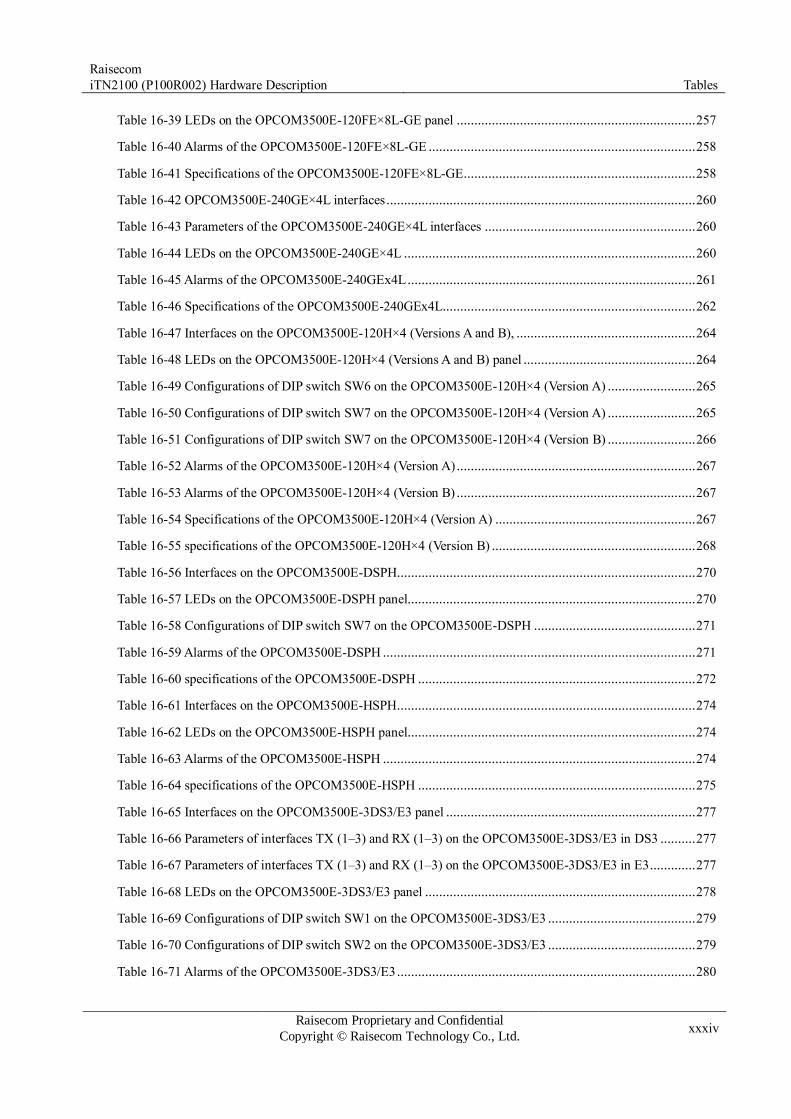
Raisecom
iTN2100 (P100R002) Hardware Description Tables
Raisecom Proprietary and Confidential
Copyright © Raisecom Technology Co., Ltd. xxxiv
Table 16-39 LEDs on the OPCOM3500E-120FE×8L-GE panel .................................................................... 257
Table 16-40 Alarms of the OPCOM3500E-120FE×8L-GE ............................................................................ 258
Table 16-41 Specifications of the OPCOM3500E-120FE×8L-GE .................................................................. 258
Table 16-42 OPCOM3500E-240GE×4L interfaces ........................................................................................ 260
Table 16-43 Parameters of the OPCOM3500E-240GE×4L interfaces ............................................................ 260
Table 16-44 LEDs on the OPCOM3500E-240GE×4L ................................................................................... 260
Table 16-45 Alarms of the OPCOM3500E-240GEx4L .................................................................................. 261
Table 16-46 Specifications of the OPCOM3500E-240GEx4L........................................................................ 262
Table 16-47 Interfaces on the OPCOM3500E-120H×4 (Versions A and B), ................................................... 264
Table 16-48 LEDs on the OPCOM3500E-120H×4 (Versions A and B) panel ................................................. 264
Table 16-49 Configurations of DIP switch SW6 on the OPCOM3500E-120H×4 (Version A) ......................... 265
Table 16-50 Configurations of DIP switch SW7 on the OPCOM3500E-120H×4 (Version A) ......................... 265
Table 16-51 Configurations of DIP switch SW7 on the OPCOM3500E-120H×4 (Version B) ......................... 266
Table 16-52 Alarms of the OPCOM3500E-120H×4 (Version A) .................................................................... 267
Table 16-53 Alarms of the OPCOM3500E-120H×4 (Version B) .................................................................... 267
Table 16-54 Specifications of the OPCOM3500E-120H×4 (Version A) ......................................................... 267
Table 16-55 specifications of the OPCOM3500E-120H×4 (Version B) .......................................................... 268
Table 16-56 Interfaces on the OPCOM3500E-DSPH ..................................................................................... 270
Table 16-57 LEDs on the OPCOM3500E-DSPH panel.................................................................................. 270
Table 16-58 Configurations of DIP switch SW7 on the OPCOM3500E-DSPH .............................................. 271
Table 16-59 Alarms of the OPCOM3500E-DSPH ......................................................................................... 271
Table 16-60 specifications of the OPCOM3500E-DSPH ............................................................................... 272
Table 16-61 Interfaces on the OPCOM3500E-HSPH ..................................................................................... 274
Table 16-62 LEDs on the OPCOM3500E-HSPH panel.................................................................................. 274
Table 16-63 Alarms of the OPCOM3500E-HSPH ......................................................................................... 274
Table 16-64 specifications of the OPCOM3500E-HSPH ............................................................................... 275
Table 16-65 Interfaces on the OPCOM3500E-3DS3/E3 panel ....................................................................... 277
Table 16-66 Parameters of interfaces TX (1–3) and RX (1–3) on the OPCOM3500E-3DS3/E3 in DS3 .......... 277
Table 16-67 Parameters of interfaces TX (1–3) and RX (1–3) on the OPCOM3500E-3DS3/E3 in E3 ............. 277
Table 16-68 LEDs on the OPCOM3500E-3DS3/E3 panel ............................................................................. 278
Table 16-69 Configurations of DIP switch SW1 on the OPCOM3500E-3DS3/E3 .......................................... 279
Table 16-70 Configurations of DIP switch SW2 on the OPCOM3500E-3DS3/E3 .......................................... 279
Table 16-71 Alarms of the OPCOM3500E-3DS3/E3 ..................................................................................... 280
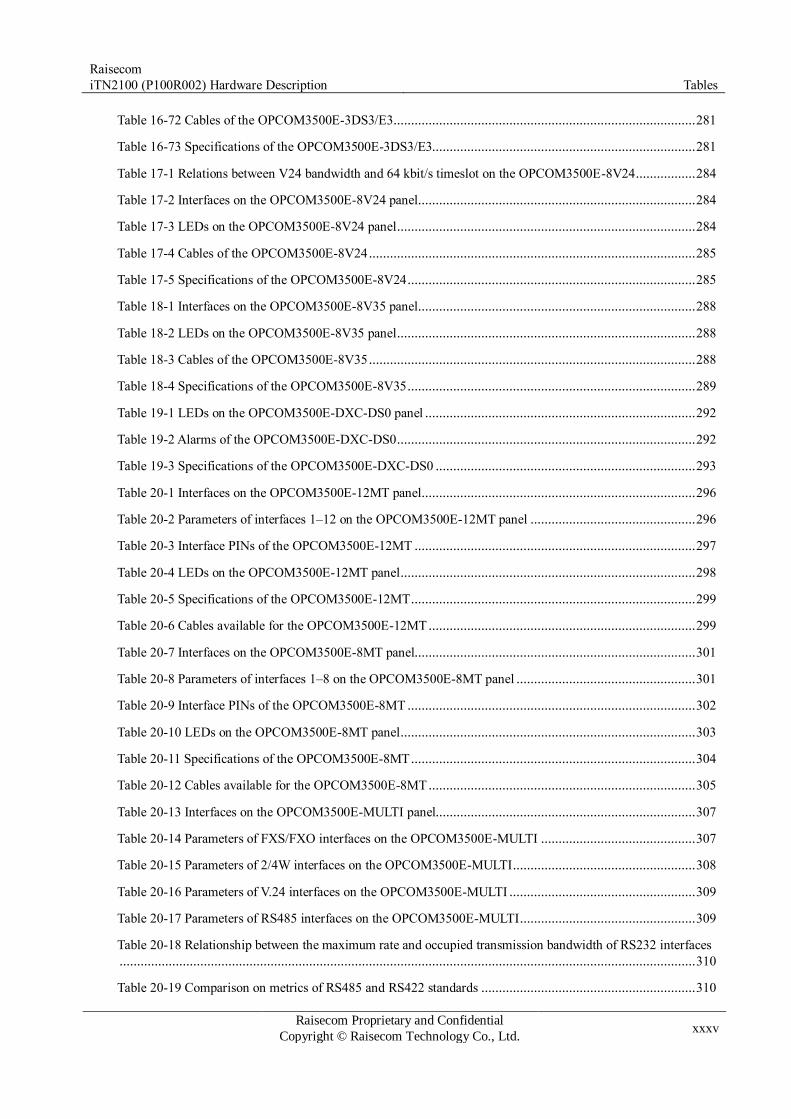
Raisecom
iTN2100 (P100R002) Hardware Description Tables
Raisecom Proprietary and Confidential
Copyright © Raisecom Technology Co., Ltd. xxxv
Table 16-72 Cables of the OPCOM3500E-3DS3/E3 ...................................................................................... 281
Table 16-73 Specifications of the OPCOM3500E-3DS3/E3........................................................................... 281
Table 17-1 Relations between V24 bandwidth and 64 kbit/s timeslot on the OPCOM3500E-8V24 ................. 284
Table 17-2 Interfaces on the OPCOM3500E-8V24 panel ............................................................................... 284
Table 17-3 LEDs on the OPCOM3500E-8V24 panel ..................................................................................... 284
Table 17-4 Cables of the OPCOM3500E-8V24 ............................................................................................. 285
Table 17-5 Specifications of the OPCOM3500E-8V24 .................................................................................. 285
Table 18-1 Interfaces on the OPCOM3500E-8V35 panel ............................................................................... 288
Table 18-2 LEDs on the OPCOM3500E-8V35 panel ..................................................................................... 288
Table 18-3 Cables of the OPCOM3500E-8V35 ............................................................................................. 288
Table 18-4 Specifications of the OPCOM3500E-8V35 .................................................................................. 289
Table 19-1 LEDs on the OPCOM3500E-DXC-DS0 panel ............................................................................. 292
Table 19-2 Alarms of the OPCOM3500E-DXC-DS0 ..................................................................................... 292
Table 19-3 Specifications of the OPCOM3500E-DXC-DS0 .......................................................................... 293
Table 20-1 Interfaces on the OPCOM3500E-12MT panel .............................................................................. 296
Table 20-2 Parameters of interfaces 1–12 on the OPCOM3500E-12MT panel ............................................... 296
Table 20-3 Interface PINs of the OPCOM3500E-12MT ................................................................................ 297
Table 20-4 LEDs on the OPCOM3500E-12MT panel .................................................................................... 298
Table 20-5 Specifications of the OPCOM3500E-12MT ................................................................................. 299
Table 20-6 Cables available for the OPCOM3500E-12MT ............................................................................ 299
Table 20-7 Interfaces on the OPCOM3500E-8MT panel................................................................................ 301
Table 20-8 Parameters of interfaces 1–8 on the OPCOM3500E-8MT panel ................................................... 301
Table 20-9 Interface PINs of the OPCOM3500E-8MT .................................................................................. 302
Table 20-10 LEDs on the OPCOM3500E-8MT panel .................................................................................... 303
Table 20-11 Specifications of the OPCOM3500E-8MT ................................................................................. 304
Table 20-12 Cables available for the OPCOM3500E-8MT ............................................................................ 305
Table 20-13 Interfaces on the OPCOM3500E-MULTI panel.......................................................................... 307
Table 20-14 Parameters of FXS/FXO interfaces on the OPCOM3500E-MULTI ............................................ 307
Table 20-15 Parameters of 2/4W interfaces on the OPCOM3500E-MULTI .................................................... 308
Table 20-16 Parameters of V.24 interfaces on the OPCOM3500E-MULTI ..................................................... 309
Table 20-17 Parameters of RS485 interfaces on the OPCOM3500E-MULTI .................................................. 309
Table 20-18 Relationship between the maximum rate and occupied transmission bandwidth of RS232 interfaces
.................................................................................................................................................................... 310
Table 20-19 Comparison on metrics of RS485 and RS422 standards ............................................................. 310

Raisecom
iTN2100 (P100R002) Hardware Description Tables
Raisecom Proprietary and Confidential
Copyright © Raisecom Technology Co., Ltd. xxxvi
Table 20-20 FXS/FXO interface PINs of the OPCOM3500E-MULTI ............................................................ 310
Table 20-21 2/4W interface PINs of the OPCOM3500E-MULTI ................................................................... 311
Table 20-22 Data interface PINs of the OPCOM3500E-MULTI .................................................................... 312
Table 20-23 LEDs on the OPCOM3500E-MULTI panel ................................................................................ 313
Table 20-24 DIP switch on the OPCOM3500E-MULTI ................................................................................. 314
Table 20-25 Specifications of the OPCOM3500E-MULTI ............................................................................. 315
Table 20-26 Cables available for the OPCOM3500E-MULTI ........................................................................ 315
Table 20-27 Interfaces on the OPCOM3500E-Audio panel ............................................................................ 317
Table 20-28 Parameters of the FXS/FXO interface on the OPCOM3500E-Audio........................................... 317
Table 20-29 Parameters of the magneto interface on the OPCOM3500E-Audio ............................................. 318
Table 20-30 DB37 interface PINs of the OPCOM3500E-Audio ..................................................................... 319
Table 20-31 HDB26 interface PINs of the OPCOM3500E-Audio .................................................................. 321
Table 20-32 LEDs on the OPCOM3500E-Audio ........................................................................................... 322
Table 20-33 Specifications of the OPCOM3500E-Audio ............................................................................... 322
Table 20-34 Cables available for the OPCOM3500E-Audio .......................................................................... 323
Table 20-35 Interfaces on the iTN2100-EOW ............................................................................................... 325
Table 20-36 Parameters of the FXS interface on the iTN2100-EOW .............................................................. 326
Table 20-37 ALM interface PINs of the iTN2100-EOW ................................................................................ 327
Table 20-38 FXS interface PINs of the iTN2100-EOW ................................................................................. 327
Table 20-39 LEDs on the iTN2100-EOW panel ............................................................................................ 328
Table 20-40 Specifications of the iTN2100-EOW ......................................................................................... 328
Table 20-41 Interfaces on the 10E&M card ................................................................................................... 330
Table 20-42 Parameters of the interface on the 10E&M card ......................................................................... 330
Table 20-43 PIN definitions of the interface on the E&M .............................................................................. 331
Table 20-44 Types of E&M signaling ............................................................................................................ 332
Table 20-45 LEDs on the 10E&M card ......................................................................................................... 333
Table 20-46 Specifications of the OPCOM3500E-10E&M ............................................................................ 334
Table 21-1 Interfaces on the iTN2100-Gb panel ............................................................................................ 337
Table 21-2 Client-side interface metrics (optical modules)............................................................................. 338
Table 21-3 Client-side interface metrics (electrical modules) ......................................................................... 340
Table 21-4 Line-side interface metrics .......................................................................................................... 340
Table 21-5 LEDs on the iTN2100-Gb panel .................................................................................................. 341
Table 21-6 BITs 1–8 of the DIP switch .......................................................................................................... 342
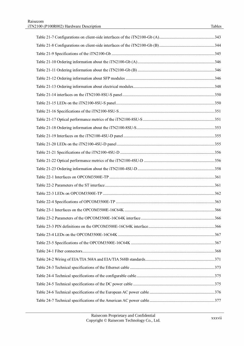
Raisecom
iTN2100 (P100R002) Hardware Description Tables
Raisecom Proprietary and Confidential
Copyright © Raisecom Technology Co., Ltd. xxxvii
Table 21-7 Configurations on client-side interfaces of the iTN2100-Gb (A) ................................................... 343
Table 21-8 Configurations on client-side interfaces of the iTN2100-Gb (B) ................................................... 344
Table 21-9 Specifications of the iTN2100-Gb ............................................................................................... 345
Table 21-10 Ordering information about the iTN2100-Gb (A) ....................................................................... 346
Table 21-11 Ordering information about the iTN2100-Gb (B) ....................................................................... 346
Table 21-12 Ordering information about SFP modules .................................................................................. 346
Table 21-13 Ordering information about electrical modules ........................................................................... 348
Table 21-14 interfaces on the iTN2100-8SU-S panel ..................................................................................... 350
Table 21-15 LEDs on the iTN2100-8SU-S panel ........................................................................................... 350
Table 21-16 Specifications of the iTN2100-8SU-S ........................................................................................ 351
Table 21-17 Optical performance metrics of the iTN2100-8SU-S .................................................................. 351
Table 21-18 Ordering information about the iTN2100-8SU-S ........................................................................ 353
Table 21-19 Interfaces on the iTN2100-4SU-D panel .................................................................................... 355
Table 21-20 LEDs on the iTN2100-4SU-D panel .......................................................................................... 355
Table 21-21 Specifications of the iTN2100-4SU-D ....................................................................................... 356
Table 21-22 Optical performance metrics of the iTN2100-4SU-D ................................................................. 356
Table 21-23 Ordering information about the iTN2100-4SU-D ....................................................................... 358
Table 22-1 Interfaces on OPCOM3500E-TP ................................................................................................. 361
Table 22-2 Parameters of the ST interface ..................................................................................................... 361
Table 22-3 LEDs on OPCOM3500E-TP ....................................................................................................... 362
Table 22-4 Specifications of OPCOM3500E-TP ........................................................................................... 363
Table 23-1 Interfaces on the OPCOM3500E-16C64K ................................................................................... 366
Table 23-2 Parameters of the OPCOM3500E-16C64K interface .................................................................... 366
Table 23-3 PIN definitions on the OPCOM3500E-16C64K interface ............................................................. 366
Table 23-4 LEDs on the OPCOM3500E-16C64K ......................................................................................... 367
Table 23-5 Specifications of the OPCOM3500E-16C64K ............................................................................. 367
Table 24-1 Fiber connectors .......................................................................................................................... 368
Table 24-2 Wiring of EIA/TIA 568A and EIA/TIA 568B standards ................................................................ 371
Table 24-3 Technical specifications of the Ethernet cable .............................................................................. 373
Table 24-4 Technical specifications of the configurable cable ........................................................................ 375
Table 24-5 Technical specifications of the DC power cable ........................................................................... 375
Table 24-6 Technical specifications of the European AC power cable ............................................................ 376
Table 24-7 Technical specifications of the American AC power cable ............................................................ 377

Raisecom
iTN2100 (P100R002) Hardware Description Tables
Raisecom Proprietary and Confidential
Copyright © Raisecom Technology Co., Ltd. xxxviii
Table 24-8 Technical specifications of the ground cable ................................................................................ 379
Table 24-9 Technical specifications of the OT terminal ................................................................................. 379
Table 24-10 PIN definitions of the alarm terminal ......................................................................................... 380
Table 24-11 Technical specifications of the E1-CC3 cable ............................................................................. 381
Table 24-12 E1-RJ45 cables available for the card of the iTN2100 ................................................................ 381
Table 24-13 Wiring of the CBL-E1-RJ45/RJ45 cable .................................................................................... 382
Table 24-14 Technical specifications of the CBL-E1-RJ45/RJ45 cable .......................................................... 382
Table 24-15 Wiring of the CBL-E1-RJ45/2RJ45 cable .................................................................................. 383
Table 24-16 Technical specifications of the CBL-E1-RJ45/2RJ45 cable......................................................... 384
Table 24-17 Relations between the E1-DB37 cable and the card on the iTN2100 ........................................... 384
Table 24-18 Technical specifications of the CBL-E1-DB37F (40)/16NC cable............................................... 385
Table 24-19 Definitions of PINs on the CBL-E1-DB37F (40)/16NC cable ..................................................... 386
Table 24-20 Technical specifications of the CBL-E1-DB37F/16BNCF cable ................................................. 387
Table 24-21 CBL-E1-DB37F/16BNCM cable ............................................................................................... 388
Table 24-22 Technical specifications of the CBL-E1-DB37F/8RJ45 .............................................................. 388
Table 24-23 Technical specifications of the CBL-E1-DB37F (40)/16CC3F cable ........................................... 389
Table 24-24 Relations between the E1-SCSI100 cable and the card on the iTN2100 ...................................... 389
Table 24-25 Technical specifications of the CBL-E1-SCSI100M (40)/32BNCF cable .................................... 390
Table 24-26 Technical specifications of the CBL-E1-SCSI100M (40)/32BNCM cable ................................... 391
Table 24-27 Technical specifications of the CBL-E1-SCSI100M (40)/16RJ45 cable ...................................... 392
Table 24-28 Relations between the V24-HDB26 cable and the card on the iTN2100 ...................................... 392
Table 24-29 Technical specifications of the CBL-V24-HDB26M/4DB25F cable............................................ 393
Table 24-30 Technical specifications of the CBL-V24-HDB26M/4DB25M cable .......................................... 394
Table 24-31 PIN definitions of the HDB26 interface on the OPCOM3500E-8V24 ......................................... 394
Table 24-32 Relations between the V35-HDB26 cable and the card on the iTN2100 ...................................... 395
Table 24-33 Technical specifications of the CBL-V35-HDB26M/2M34F cable ............................................. 396
Table 24-34 PIN definitions of the HDB26 interface on the OPCOM3500E-8V35 ......................................... 396
Table 24-35 Relations between the MUL-HDB26 cable and the card on the iTN2100 .................................... 398
Table 24-36 Technical specifications of the CBL-MUL-HDB26M/NC cable ................................................. 398
Table 24-37 Color patterns of the CBL-MUL-HDB26M/NC cable ................................................................ 399
Table 24-38 Technical specifications of the CBL-MUL-HDB26M (40)/NC cable .......................................... 400
Table 24-39 Color patterns of the CBL-MUL-HDB26M (40)/NC cable ......................................................... 401
Table 24-40 Relations between the VOICE-DB37F cable and the card on the iTN2100 ................................. 403

Raisecom
iTN2100 (P100R002) Hardware Description Tables
Raisecom Proprietary and Confidential
Copyright © Raisecom Technology Co., Ltd. xxxix
Table 24-41 Technical specifications of the CBL-VOICE-DB37F/NC-D cable .............................................. 403
Table 24-42 Color patterns of the CBL-VOICE-DB37F/NC-D cable ............................................................. 404
Table 25-1 Power consumption of SFP modules ............................................................................................ 406
Table 25-2 Power consumption of Raisecom XFP modules ........................................................................... 407
Table 25-3 Metrics of FE CSFP optical modules ........................................................................................... 408
Table 25-4 Metrics of GE CSFP optical modules ........................................................................................... 409
Table 25-5 Metrics of 2.5G CSFP optical modules ........................................................................................ 410
Table 25-6 Mapping between CSFP model xx and Tx wavelength ................................................................. 410
Table 25-7 Mapping between CSFP model yy and Tx wavelength ................................................................. 410
Table 25-8 Metrics of 2.5G DSFP optical modules ........................................................................................ 411
Table 25-9 Parameters of GSFP optical modules ........................................................................................... 415
Table 25-10 Parameters of FE TSFP optical modules .................................................................................... 416
Table 25-11 Parameters of GE TSFP optical modules .................................................................................... 417
Table 25-12 Parameters of FE USFP optical modules .................................................................................... 418
Table 25-13 Parameters of GE USFP optical modules ................................................................................... 420
Table 25-14 Parameters of 2.5G USFP optical modules ................................................................................. 422
Table 25-15 Parameters of FE USFP electrical module .................................................................................. 424
Table 25-16 Parameters of GE USFP electrical module ................................................................................. 424
Table 25-17 Parameters of 10G USFP+ optical module ................................................................................. 425
Table 25-18 Parameters of CXFP-192/S/xx optical modules (10 Gbit/s 40-km) ............................................. 426
Table 25-19 Parameters of CXFP-192/L/xx optical modules (10 Gbit/s 80-km/70-km) .................................. 427
Table 25-20 Parameters of DXFP-192/S/xx optical modules (10 Gbit/s 40-km) ............................................. 430
Table 25-21 Parameters of DXFP-192/L/xx optical modules (10 Gbit/s 80-km) ............................................. 438
Table 25-22 Parameters of 10G UXFP modules ............................................................................................ 447

Raisecom
iTN2100 (P100R002) Hardware Description 1 Overview
Raisecom Proprietary and Confidential
Copyright © Raisecom Technology Co., Ltd. 1
1 Overview
This chapter is an overview of the iTN2100, including the following sections:
Introduction
Components
1.1 Introduction The iTN2100, developed by Raisecom, is an integrated service access device targeted at the
network access layer.
The iTN2100, features with dual-network and dual-core structure, is compatible with both
SDH and Packet Switching (PS), thus implementing integrated access and comprehensive
management. The iTN2100 provides a wide variety of interfaces on the line side, through
which it can network with the Ethernet optical fiber transceiver, the PDH optical transceiver,
the Ethernet multiplexer, the protocol converter, and so on. In this way, it can meet customers'
diverse requirements.
The iTN2100 supports Operation, Administration and Maintenance (OAM) protocols.
Through its graphical interface on the Network Management System (NMS), it implements
service-based end-to-end monitoring, maintenance, and troubleshooting. Thus the quality of
the network and Quality of Service (QoS) are measureable and estimable. In a word, it can
improve OAM efficiency and ensure QoS on a network.
1.2 Components The iTN2100 is composed of a chassis, fans, power supplies, cards, and cables.
Chassis
The iTN2100 is equipped with a 19-inch 6U standard chassis, complying with the IEC297
standards.
Fan
The iTN2100 is equipped with an independent and intelligent 19-inch 1U fan named FANS360.
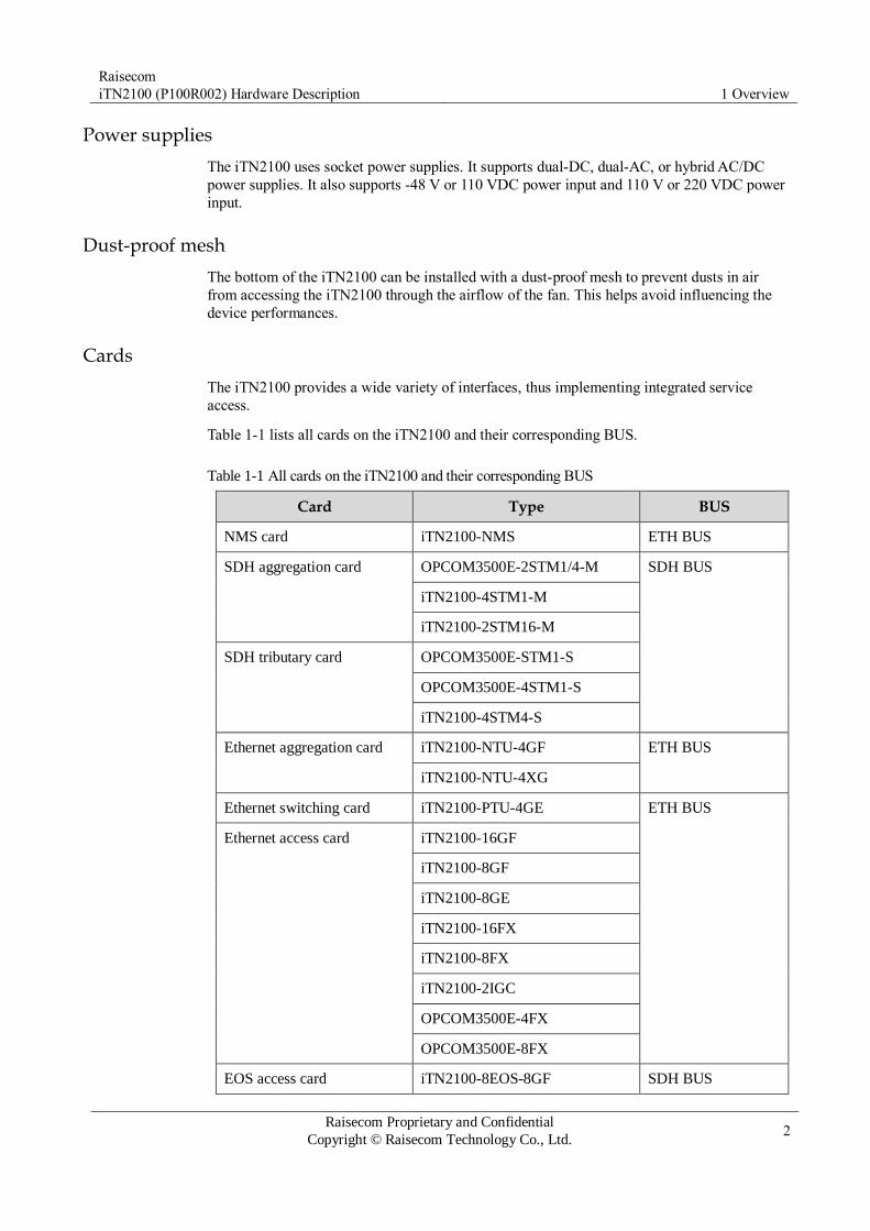
Raisecom
iTN2100 (P100R002) Hardware Description 1 Overview
Raisecom Proprietary and Confidential
Copyright © Raisecom Technology Co., Ltd. 2
Power supplies
The iTN2100 uses socket power supplies. It supports dual-DC, dual-AC, or hybrid AC/DC
power supplies. It also supports -48 V or 110 VDC power input and 110 V or 220 VDC power
input.
Dust-proof mesh
The bottom of the iTN2100 can be installed with a dust-proof mesh to prevent dusts in air
from accessing the iTN2100 through the airflow of the fan. This helps avoid influencing the
device performances.
Cards
The iTN2100 provides a wide variety of interfaces, thus implementing integrated service
access.
Table 1-1 lists all cards on the iTN2100 and their corresponding BUS.
Table 1-1 All cards on the iTN2100 and their corresponding BUS
Card Type BUS
NMS card iTN2100-NMS ETH BUS
SDH aggregation card OPCOM3500E-2STM1/4-M SDH BUS
iTN2100-4STM1-M
iTN2100-2STM16-M
SDH tributary card OPCOM3500E-STM1-S
OPCOM3500E-4STM1-S
iTN2100-4STM4-S
Ethernet aggregation card iTN2100-NTU-4GF ETH BUS
iTN2100-NTU-4XG
Ethernet switching card iTN2100-PTU-4GE ETH BUS
Ethernet access card iTN2100-16GF
iTN2100-8GF
iTN2100-8GE
iTN2100-16FX
iTN2100-8FX
iTN2100-2IGC
OPCOM3500E-4FX
OPCOM3500E-8FX
EOS access card iTN2100-8EOS-8GF SDH BUS

Raisecom
iTN2100 (P100R002) Hardware Description 1 Overview
Raisecom Proprietary and Confidential
Copyright © Raisecom Technology Co., Ltd. 3
Card Type BUS
iTN2100-4STM1-GC ETH BUS
Clock card iTN2100-TSU SDH BUS
TDMoP card iTN2100-CES-16E1T1-BL ETH BUS
iTN2100-CES-16E1T1
EOP card OPCOM3500E-EOPFE SDH BUS
OPCOM3500E-EOP3FE
OPCOM3500E-EOP8FX
OPCOM3500E-EOP-FE16E1
OPCOM3500E-EOP-FEE1×8
OPCOM3500E-EOP-FXE1×8
OPCOM3500E-EOPS-8E1
OPCOM3500E-HT-6FE24E1
iTN2100-EOT-GESTM4 SDH BUS
ETH BUS
EOS card OPCOM3500E-EOS-8FE SDH BUS
OPCOM3500E-EOSE-4FX
OPCOM3500E-EOSE-8FX
OPCOM3500E-4EOS-4FE
OPCOM3500E-4EOS-4FX
OPCOM3500E-8EOS-GC
OPCOM3500E-DSEE
OPCOM3500E-HSEE
PDH and RCMS card OPCOM3500E-16E1
OPCOM3500E-16E1-BL
OPCOM3500E-32E1
OPCOM3500E-32E1-BL
OPCOM3500E-120EOS×4
OPCOM3500E-120EOS×4L
OPCOM3500E-DFPS
OPCOM3500E-120FE×8L-GE
OPCOM3500E-240GE×4L

Raisecom
iTN2100 (P100R002) Hardware Description 1 Overview
Raisecom Proprietary and Confidential
Copyright © Raisecom Technology Co., Ltd. 4
Card Type BUS
OPCOM3500E-120H×4
OPCOM3500E-DSPH
OPCOM3500E-HSPH
OPCOM3500E-3DS3/E3
V.24 card OPCOM3500E-8V24
V.35 card OPCOM3500E-8V35
64K cross-connection card OPCOM3500E-DXC-DS0
Multi-service card OPCOM3500E-12MT SDH BUS
OPCOM3500E-8MT
OPCOM3500E-MULTI
OPCOM3500E-Audio
iTN2100-EOW
OPCOM3500E-10E&M
Service aggregation card iTN2100-Gb SDH BUS
iTN2100-8SU-S
iTN2100-4SU-D
64K access card OPCOM3500E-16C64K SDH BUS
Teleprotection card OPCOM3500E-TP SDH BUS
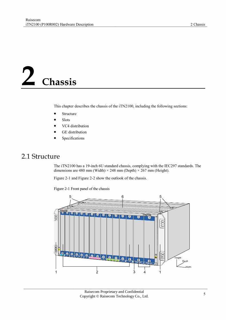
Raisecom
iTN2100 (P100R002) Hardware Description 2 Chassis
Raisecom Proprietary and Confidential
Copyright © Raisecom Technology Co., Ltd. 5
2 Chassis
This chapter describes the chassis of the iTN2100, including the following sections:
Structure
Slots
VC4 distribution
GE distribution
Specifications
2.1 Structure The iTN2100 has a 19-inch 6U standard chassis, complying with the IEC297 standards. The
dimensions are 480 mm (Width) × 248 mm (Depth) × 267 mm (Height).
Figure 2-1 and Figure 2-2 show the outlook of the chassis.
Figure 2-1 Front panel of the chassis

Raisecom
iTN2100 (P100R002) Hardware Description 2 Chassis
Raisecom Proprietary and Confidential
Copyright © Raisecom Technology Co., Ltd. 6
Figure 2-2 Rear panel of the chassis
Table 2-1 lists descriptions of the chassis.
Table 2-1 Descriptions of the chassis
No. Name Description
1 Rack-mount bracket Used to fix the chassis to a bench
2 Card slot Cards are inserted into slots 0–12.
3 Dust-proof mesh Used to contain the dust-proof cotton to prevent
dust from accessing the device.
4 Power supply card slot Power supply cards are inserted into slots POWER1
and POWRE2.
5 Tab Used to fix the fan on the chassis
6 Heat dissipation The fan is installed above the heat dissipating area
to dissipate hot air inside the chassis.
7 Alarm terminal Four-hole spring terminal supporting one-way
alarm input and one-way alarm output
The DC voltage connected to the alarm output terminal should not exceed 30 V and the current should not exceed 1 A. The AC voltage connected to the alarm output terminal should not exceed 125 V and the current should not exceed 0.3 A.
8 Fan power supply interface Used to supply power to the fan
9 Fan monitoring interface Used to connect to the fan and monitor its status

Raisecom
iTN2100 (P100R002) Hardware Description 2 Chassis
Raisecom Proprietary and Confidential
Copyright © Raisecom Technology Co., Ltd. 7
No. Name Description
10 Chassis grounding terminal Used to ground by the chassis
11 DC power interface DC power input
2.2 Slots Figure 2-3 shows relations between slots and cards.
Figure 2-3 Relations between slots and cards
The corresponding relations are as below:
NMS card: inserted into slot 0 only
Aggregation cards: inserted into slots 6 and 7 only
Switching cards: inserted into slots 1, 9, 10 and 11 only
Other service cards: inserted into slots 1–5 and 8–12
Power supplies: inserted into slots POWER1 and POWER2 only

Raisecom
iTN2100 (P100R002) Hardware Description 2 Chassis
Raisecom Proprietary and Confidential
Copyright © Raisecom Technology Co., Ltd. 8
2.3 VC4 distribution As the iTN2100 is inserted with different aggregation cards, VC4 distribution of each slot is
different.
Table 2-2 lists VC4 distribution when the aggregation card is OPCOM3500E-2STM1/4-M (STM-1 mode).
Table 2-2 VC4 distribution for OPCOM3500E-2STM1/4-M (STM-1 mode) as aggregation card
Slot 0 1 2 3 4 5 6 7 8 9 10 11 12
VC4
capacity
– 1 1 1 1 1 1–2 1–2 1 1 1 1 1
Table 2-3 lists VC4 distribution. when the aggregation card is OPCOM3500E-2STM1/4-
M (STM-4 mode).
Table 2-3 VC4 distribution for OPCOM3500E-2STM1/4-M (STM-4 mode) as aggregation card
Slot 0 1 2 3 4 5 6 7 8 9 10 11 12
VC4
capacity
– 1 1–4 1 1–4 1 1–8 1–8 1 1 1 1 1
Table 2-4 lists VC4 distribution when the aggregation card is iTN2100-4STM1-M.
Table 2-4 VC4 distribution for iTN2100-4STM1-M as aggregation card
Slot 0 1 2 3 4 5 6 7 8 9 10 11 12
VC4
capacity
– 1 1 1 1 1 1–4 1–4 1 1 1 1 1
Table 2-5 lists VC4 distribution when the aggregation card is iTN2100-2STM16-M.
Table 2-5 VC4 distribution for iTN2100-2STM16-M as aggregation card
Slot 0 1 2 3 4 5 6 7 8 9 10 11 12
VC4
capacity
– 1 1–4 1–4 1–4 1–4 1–32 1–3
2
1 1 1 1 1

Raisecom
iTN2100 (P100R002) Hardware Description 2 Chassis
Raisecom Proprietary and Confidential
Copyright © Raisecom Technology Co., Ltd. 9
2.4 GE distribution Table 2-6 lists GE distribution.
Table 2-6 GE distribution
Slot 0 1 2 3 4 5 6 7 8 9 10 11 12
VC4
capacity
– 2 2 2 2 2 0 0 2 2 2 2 2
2.5 Specifications Table 2-7 lists specifications of the iTN2100.
Table 2-7 Specifications of the iTN2100
Parameter Value
Dimensions 480 mm (Width) × 248 mm (Depth) × 267 mm (Height)
Weight < 7 kg
Power
consumption
Min. configuration < 50 W
Max. configuration < 300 W
DC input
voltage 1
Rated voltage -48 VDC
Voltage range -36 to -72 VDC
DC input
voltage 2
Rated voltage 110 VDC
Voltage range 70–140 VDC
AC input
voltage
Rated voltage 110 or 220 VAC
Voltage range 100–240 VAC (47/63 Hz)
Operating temperature -5 to 50°C
Operating humidity 10%–90% RH (indoor, non-condensing)
Air pressure 86–106 kPa
Lightning
protection
level
AC power in differential mode: 6 kV in common mode: 6 kV
DC power 2 kV in common mode 1 kV in differential mode
Ethernet interface
(RJ45), SNMP
interface, and NM-NEXT interface
Indoor: 1 kV in common mode Outdoor: 4 kV in common mode

Raisecom
iTN2100 (P100R002) Hardware Description 3 Fan
Raisecom Proprietary and Confidential
Copyright © Raisecom Technology Co., Ltd. 10
Parameter Value
E1 unbalanced
interface
Indoor: 1 kV in common mode
E1 balanced interface Indoor: 1 kV in common mode
SHDSL Outdoor: 4 kV in both differential mode and
common mode
DS3/E3 electrical
interface (CC3) Indoor: 1 kV in common mode
V35 interface Indoor: 1 kV in common mode
3 Fan
This chapter describes the intelligent fan of the iTN2100, which is named FANS360. The
FANS360 is 19 inch wide and 1 U high. It has four hooks through which it is fixed on the
upper part of the iTN2100. This chapter includes the following sections:
Functions
Appearance
LEDs
Specifications
3.1 Functions The FANS360 has the following functions:
Embed with three fans.
Adopt dual slower power-on scheme (powering on both the fan and circuit slowly), which enhances the system stability upon hot swapping.
Support 8-level revolving speed.
Support fault alarms, including fan stopping and revolving speed deterioration due to aging.

Raisecom
iTN2100 (P100R002) Hardware Description 3 Fan
Raisecom Proprietary and Confidential
Copyright © Raisecom Technology Co., Ltd. 11
Support intelligent speed adjustment, through which the iTN2100 can adjust revolving
speed automatically according to current temperature inside the chassis.
Support manual configuration of revolving speed for the fan.
Support speed feedback.
Support cold start.
3.2 Appearance The FANS360 is installed in the upper part of the iTN2100.
Figure 3-1 and Figure 3-2 show the appearance of the FANS360.
Figure 3-1 Front panel of the FANS360
Figure 3-2 Rear panel of the iTN2100
3.3 LEDs Table 3-1 lists LEDs on the front panel of the FANS360.
Table 3-1 LEDs on the front panel of the FANS360
LED Status Description
PWR Green Power supply LED
Green: the power supply is normal. Off: the power supply is abnormal.
ALM Red Working status LED
Red: the fan is working improperly. Off: the fan is working properly.

Raisecom
iTN2100 (P100R002) Hardware Description 4 Power supplies
Raisecom Proprietary and Confidential
Copyright © Raisecom Technology Co., Ltd. 12
3.4 Specifications Table 3-2 lists specifications of the FANS360.
Table 3-2 Specifications of the FANS360
Parameter Value
Dimensions 440 mm (Width) × 247 mm (Depth) × 44 mm (Height)
Weight 3.0 kg
Maximum power
consumption
28 W
Number of fans 3
Highest revolving speed 3250 r/min
Power supply voltage 30–57 V
Maximum current 0.5 A
Maximum power 28 W
4 Power supplies
This chapter describes power supplies supported by the iTN2100, including the following
sections:
SUB-PWRII-DC/DC-300
SUB-PWRM-DC
SUB-PWRMF-DC
SUB-PWRII-AC
SUB-PWRM-AC
The iTN2100 supports dual-power supply redundancy. It supports dual-DC, dual-AC, or
hybrid AC/DC power supplies.
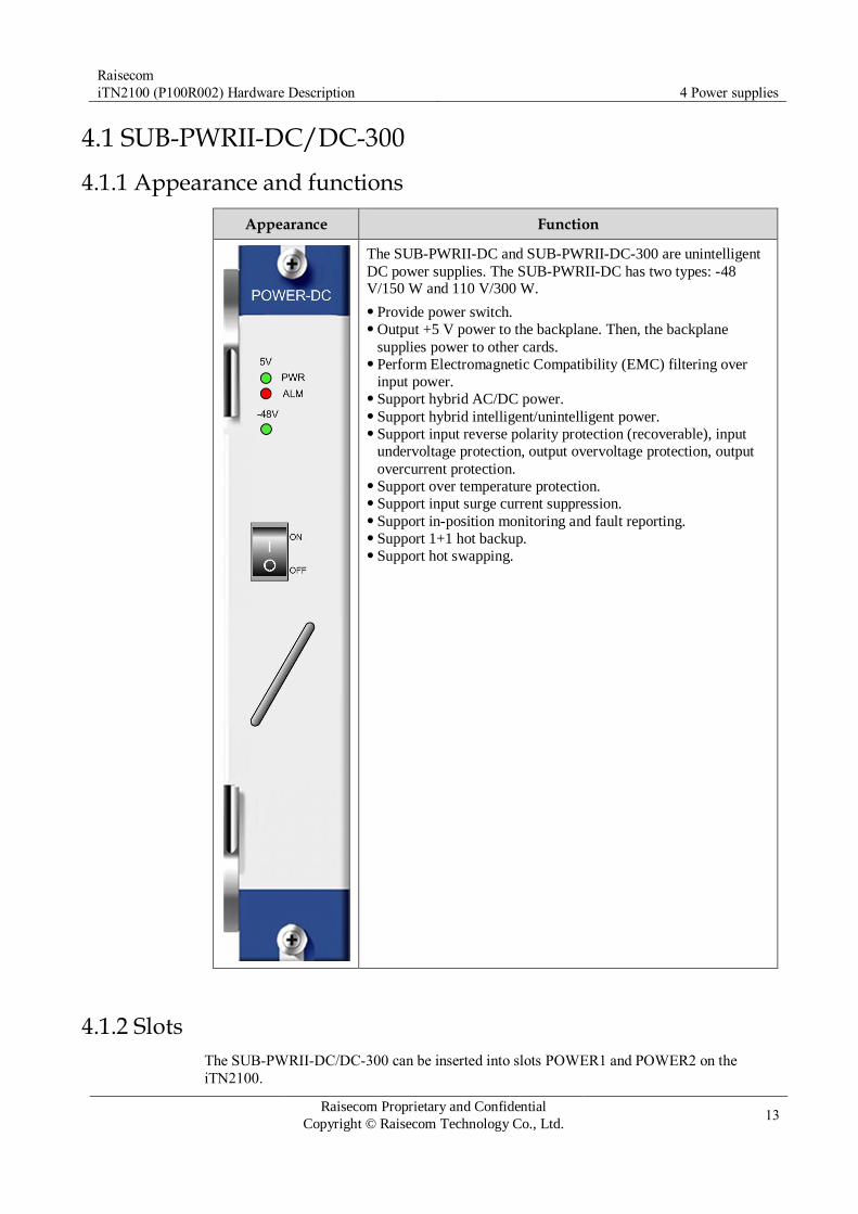
Raisecom
iTN2100 (P100R002) Hardware Description 4 Power supplies
Raisecom Proprietary and Confidential
Copyright © Raisecom Technology Co., Ltd. 13
4.1 SUB-PWRII-DC/DC-300
4.1.1 Appearance and functions
Appearance Function
The SUB-PWRII-DC and SUB-PWRII-DC-300 are unintelligent
DC power supplies. The SUB-PWRII-DC has two types: -48 V/150 W and 110 V/300 W.
Provide power switch. Output +5 V power to the backplane. Then, the backplane
supplies power to other cards. Perform Electromagnetic Compatibility (EMC) filtering over
input power. Support hybrid AC/DC power. Support hybrid intelligent/unintelligent power. Support input reverse polarity protection (recoverable), input
undervoltage protection, output overvoltage protection, output
overcurrent protection. Support over temperature protection. Support input surge current suppression. Support in-position monitoring and fault reporting. Support 1+1 hot backup. Support hot swapping.
4.1.2 Slots
The SUB-PWRII-DC/DC-300 can be inserted into slots POWER1 and POWER2 on the
iTN2100.

Raisecom
iTN2100 (P100R002) Hardware Description 4 Power supplies
Raisecom Proprietary and Confidential
Copyright © Raisecom Technology Co., Ltd. 14
4.1.3 LEDs
Table 4-1 lists LEDs on the SUB-PWRII-DC/DC-300 panel.
Table 4-1 LEDs on the SUB-PWRII-DC/DC-300 panel
LED Status Description
5V PWR Green +5 V power output LED
Green: +5 V power output is normal. Off: +5 V power output is off.
5V ALM Red +5 V power alarm LED
Red: +5 V power output is off or the voltage is abnormal. Off: +5 V voltage is normal.
Only when there is no voltage input for this power supply and the other power supply is working properly, the LED is probably red.
-48V Green -48 V power working LED
Green: -48 V power input is normal. Off: -48 V power input is off.
4.1.4 Specifications
Table 4-2 lists specifications of the SUB-PWRII-DC/DC-300.
Table 4-2 Specifications of the SUB-PWRII-DC/DC-300
Card
Parameter
SUB-PWRII-DC
(-48 V/150 W)
SUB-PWRII-DC (110 V/300 W)
SUB-PWRII-DC-300
Remark
Basic
parameters
Dimensions 38.5 mm (Width) × 224 mm (Depth) × 240 mm (Height) –
Weight 1.05 kg –
Zero-load power
consumption
5 W In rated input
voltage
Rated power
consumption
150 W 300 W 300 W –
Input
parameters
Rated input voltage -48 V 110 V -48 V –
Input voltage range -36 to -72 V 70–140 V -38.4 to -57.6
V
In full load
Rated input power 180 W 375 W 375 W –
Protection
function
Input under voltage
protection
34 V 64 V 34 V –

Raisecom
iTN2100 (P100R002) Hardware Description 4 Power supplies
Raisecom Proprietary and Confidential
Copyright © Raisecom Technology Co., Ltd. 15
Card
Parameter
SUB-PWRII-DC
(-48 V/150 W)
SUB-PWRII-DC (110 V/300 W)
SUB-PWRII-DC-300
Remark
parameters Output over voltage
protection
6 V 6 V 6 V –
Output overcurrent
protection
33 A 72 A 72 A –

Raisecom
iTN2100 (P100R002) Hardware Description 4 Power supplies
Raisecom Proprietary and Confidential
Copyright © Raisecom Technology Co., Ltd. 16
4.2 SUB-PWRM-DC
4.2.1 Appearance and functions
Appearance Function
The SUB-PWRM-DC is an intelligent 300 W DC power supply.
Provide a power switch. Provide 2:1 wide-range voltage: -36 to -72 V. Provide +5 V rated output voltage per card. Support hybrid AC/DC power. Support hybrid intelligent/unintelligent power. Support input reverse polarity protection (recoverable), input
undervoltage protection, input overvoltage protection, output
overvoltage protection, output overcurrent protection. Support over temperature protection. Support input surge current suppression. Support in-position monitoring and fault reporting. Support hierarchical alarms of input overvoltage and input
undervoltage. Support single-level alarms of output overvoltage and output
undervoltage. Support real-time reporting of power environment temperature. Support 1+1 hot backup. Support hot swapping.
4.2.2 Slots
The SUB-PWRM-DC can be inserted into slots POWER1 and POWER2 on the iTN2100.

Raisecom
iTN2100 (P100R002) Hardware Description 4 Power supplies
Raisecom Proprietary and Confidential
Copyright © Raisecom Technology Co., Ltd. 17
4.2.3 LEDs
Table 4-3 lists LEDs on the SUB-PWRM-DC panel.
Table 4-3 LEDs on the SUB-PWRM-DC panel
LED Status Description
5V PWR Green +5 V power output LED
Green: +5 V power output is normal. Off: +5 V power output is off.
5V ALM Red +5 V power alarm LED
Red: +5 V power output is off or the voltage is abnormal. Off: +5 V voltage is normal.
Vin Green Power input LED
Green: there is voltage input. Off: there is no voltage input or there is positive/negative
error.
Min Yellow Input voltage hierarchical alarm LED
Yellow: the input voltage is within range 1. Off: the input voltage is beyond range 1.
Maj Red Input voltage hierarchical alarm LED
Red: the input voltage is within range 2. Off: the input voltage is beyond range 2.
Cri Red Input voltage hierarchical alarm LED
Red: the input voltage is within range 3. Off: the input voltage is beyond range 3.
By default, range 1 for the absolute value of input voltage is (0, 46) U (56, +∞);
range 2 for the absolute value of input voltage is (0, 42) U (60, +∞); range 3 for the absolute value of input voltage is (0, 40) U (70, +∞). If the input voltage is -
36 V, the Min, Maj, and Cri LEDs are on since the absolute value 36 is within range 1, range 2, and range 3.
You can configure range 1, range 2, and range 3 but they must be between -36 V and -72 V. For detailed configurations, see iTN2100 Configuration Guide_TDM Part and iTN2100 Command Reference_Basic Configuration Part.
If input voltage hierarchical alarm LED is yellow or red, the input voltage is within the allowed range.
If the alarm LED is yellow or red, the power supply is supplying power to the backplane and power alarm Trap will be reported.
4.2.4 Specifications
Table 4-4 lists specifications of the SUB-PWRM-DC.

Raisecom
iTN2100 (P100R002) Hardware Description 4 Power supplies
Raisecom Proprietary and Confidential
Copyright © Raisecom Technology Co., Ltd. 18
Table 4-4 Specifications of the SUB-PWRM-DC
Parameter Value
Dimensions 38.5 mm (Width) × 224 mm (Depth) × 240 mm
(Height)
Weight 1.05 kg
Zero-load power consumption 5 W
Rated power consumption 300 W
Table 4-5 lists input parameters of the SUB-PWRM-DC.
Table 4-5 Input parameters of the SUB-PWRM-DC
Parameter Value Remark
Rated input voltage -48 V –
Input voltage range -36 to -72 V Under full load
Zero-load power
consumption
5 W Under rated input voltage
Table 4-6 lists protection function parameters of the SUB-PWRM-DC.
Table 4-6 Protection function parameters of the SUB-PWRM-DC
Parameter Value
Input undervoltage protection 34 V
Input overvoltage protection 90 V
Output overvoltage protection 6 V
Output overcurrent protection 72 A

Raisecom
iTN2100 (P100R002) Hardware Description 4 Power supplies
Raisecom Proprietary and Confidential
Copyright © Raisecom Technology Co., Ltd. 19
4.3 SUB-PWRMF-DC
4.3.1 Appearance and functions
Appearance Function
The SUB-PWRMF-DC is an intelligent 300 W DC power supply.
Provide a power switch. Provide 2:1 wide-range voltage: -36 to -72 V. Provide +5 V rated output voltage per card. Support hybrid AC/DC power. Support hybrid intelligent/unintelligent power. Support input reverse polarity protection (recoverable), input
undervoltage protection, input overvoltage protection, output
overvoltage protection, output overcurrent protection. Support over temperature protection. Support input surge current suppression. Support in-position monitoring and fault reporting. Support hierarchical alarms of input overvoltage and input
undervoltage. Support single-level alarms of output overvoltage and output
undervoltage. Support real-time reporting of power environment temperature. Support 1+1 hot backup. Support hot swapping.
4.3.2 Slots
The SUB-PWRMF-DC can be inserted into slots POWER1 and POWER2 on the iTN2100.

Raisecom
iTN2100 (P100R002) Hardware Description 4 Power supplies
Raisecom Proprietary and Confidential
Copyright © Raisecom Technology Co., Ltd. 20
4.3.3 Interface
Table 4-7 lists interface on the SUB-PWRMF-DC panel.
Table 4-7 Interfaces on the SUB-PWRMF-DC panel
Interface Description
– DC interface
4.3.4 LEDs
Table 4-8 lists LEDs on the SUB-PWRMF-DC panel.
Table 4-8 LEDs on the SUB-PWRMF-DC
LED Status Description
SYS Green Power supply working LED
Green: the power supply is working improperly. Off: the power supply is working improperly. Blinking green: the power supply is working properly.
5V PWR Green +5 V power output LED
Green: +5 V power output is normal. Off: +5 V power output is off.
5V ALM Red +5 V power alarm LED
Red: +5 V power output is off or the voltage is abnormal. Off: +5 V voltage is normal.
Vin Green Power input LED
Green: there is voltage input. Off: there is no voltage input or there is positive/negative
error.
Min Yellow Input voltage hierarchical alarm LED
Yellow: the input voltage is within range 1. Off: the input voltage is beyond range 1.
Maj Red Input voltage hierarchical alarm LED
Red: the input voltage is within range 2. Off: the input voltage is beyond range 2.
Cri Red Input voltage hierarchical alarm LED
Red: the input voltage is within range 3. Off: the input voltage is beyond range 3.
By default, range 1 for the absolute value of input voltage is (0, 46) U (56, +∞);
range 2 for the absolute value of input voltage is (0, 42) U (60, +∞); range 3 for

Raisecom
iTN2100 (P100R002) Hardware Description 4 Power supplies
Raisecom Proprietary and Confidential
Copyright © Raisecom Technology Co., Ltd. 21
the absolute value of input voltage is (0, 40) U (70, +∞). If the input voltage is -
36 V, the Min, Maj, and Cri LEDs are on since the absolute value 36 is within range 1, range 2, and range 3.
You can configure range 1, range 2, and range 3 but they must be between -36 V and -72 V. For detailed configurations, see iTN2100 Configuration Guide_TDM Part and iTN2100 Command Reference_Basic Configuration Part.
If input voltage hierarchical alarm LED is yellow or red, the input voltage is within the allowed range.
If the alarm LED is yellow or red, the power supply is supplying power to the backplane and power alarm Trap will be reported.
4.3.5 Specifications
Table 4-9 lists specifications of the SUB-PWRMF-DC.
Table 4-9 Specifications of the SUB-PWRMF-DC
Parameter Value
Dimensions 38.5 mm (Width) × 224 mm (Depth) × 240 mm
(Height)
Weight 1.05 kg
Zero-load power consumption 5 W
Rated power consumption 300 W
Table 4-10 lists input parameters of the SUB-PWRMF-DC.
Table 4-10 Input parameters of the SUB-PWRMF-DC
Parameter Value Remark
Rated input voltage -48 V –
Input voltage range -36 to -72 V Under full load
Zero-load power consumption
5 W Under rated input voltage
Table 4-11 lists protection function parameters of the SUB-PWRMF-DC.
Table 4-11 Protection function parameters of the SUB-PWRMF-DC
Parameter Value
Input undervoltage protection 34 V
Input overvoltage protection 90 V
Output overvoltage protection 6 V
Output overcurrent protection 72 A

Raisecom
iTN2100 (P100R002) Hardware Description 4 Power supplies
Raisecom Proprietary and Confidential
Copyright © Raisecom Technology Co., Ltd. 22
4.4 SUB-PWRII-AC
4.4.1 Appearance and functions
Appearance Function
The SUB-PWRII-AC is an unintelligent 600 W AC power supply.
Provide a power switch. Support heat dissipation through the fan of the iTN2100. Support full-range voltage input. Support 1+1 hot backup of power. Support hot swapping. Support hybrid AC/DC power. Support hybrid intelligent/unintelligent power. Support short-circuit protection. Support input overcurrent protection, output overcurrent
protection, input undervoltage protection, and output
overvoltage protection. Support over temperature protection. Support alarms on power supply type, power failure, input
overvoltage, and input undervoltage.
4.4.2 Slots
The SUB-PWRII-AC can be inserted into slots POWER1 and POWER2 on the iTN2100.

Raisecom
iTN2100 (P100R002) Hardware Description 4 Power supplies
Raisecom Proprietary and Confidential
Copyright © Raisecom Technology Co., Ltd. 23
4.4.3 Interfaces
Table 4-12 lists interface on the SUB-PWRII-AC panel.
Table 4-12 Interface on the SUB-PWRII-AC panel
Print Description
– AC interface
4.4.4 LEDs
Table 4-13 lists LEDs on the SUB-PWRII-AC panel.
Table 4-13 LEDs on the SUB-PWRII-AC panel
LED Status Description
SYS Green Power supply working LED
Green: the power supply is working improperly. Blinking green: the power supply is working properly. Off: the power supply is working improperly.
-48V PWR Green -48 V power output LED
Green: -48 V power output is normal. Off: -48 V power output is off.
-48V ALM Red -48 V power alarm LED
Red: -48 V power output is off or the voltage is abnormal. Off: -48 V voltage is normal.
5V PWR Green +5V power output LED
Green: +5V power output is normal. Off: +5 V power output is off.
5V ALM Red +5V power alarm LED
Red: +5V power output is off or the voltage is abnormal. Off: +5V voltage is normal.
100-240V Green Power input LED
Green: 110 V/200 V power input is normal. Off: power input is off.
Min Yellow Input voltage hierarchical alarm LED
Yellow: the input voltage is within range 1. Off: the input voltage is beyond range 1.
Maj Red Input voltage hierarchical alarm LED
Red: the input voltage is within range 2. Off: the input voltage is beyond range 2.
Cri Red Input voltage hierarchical alarm LED
Red: the input voltage is within range 3. Off: the input voltage is beyond range 3.

Raisecom
iTN2100 (P100R002) Hardware Description 4 Power supplies
Raisecom Proprietary and Confidential
Copyright © Raisecom Technology Co., Ltd. 24
Range 1 for the absolute value of input voltage is (0, 100) U (240, +∞); range 2 for the absolute value of input voltage is (0, 95) U (260, +∞); range 3 for the absolute value of input voltage is (0, 90) U (265, +∞). If the input voltage is -80
V, the Min, Maj, and Cri LEDs are on since the absolute value 80 is within range 1, range 2, and range 3.
If input voltage hierarchical alarm LED is yellow or red, the input voltage is within the allowed range, that is, 90–265 V.
If the alarm LED is yellow or red, the power supply is supplying power to the backplane and power alarm Trap will be reported.
4.4.5 Specifications
Table 4-14 lists specifications of the SUB-PWRII-AC.
Table 4-14 Specifications of the SUB-PWRII-AC
Parameter Value
Dimensions 38.5 mm (Width) × 224 mm (Depth) × 240 mm (Height)
Weight 1.1 kg
Zero-load power
consumption
10 W
Rated power consumption 600 W
Table 4-15 lists input parameters of the SUB-PWRII-AC.
Table 4-15 Input parameters of the SUB-PWRII-AC
Parameter Value
Nominal input voltage range 100–240 V
Rated input voltage 110 V/220 V
AC input frequency 47–63 Hz
Power consumption factor 0.95
Integrated equipment
efficiency
110 V input (full load) 80%
220 V input (full load) 80%
Table 4-16 lists protection function parameters of the SUB-PWRII-AC.

Raisecom
iTN2100 (P100R002) Hardware Description 4 Power supplies
Raisecom Proprietary and Confidential
Copyright © Raisecom Technology Co., Ltd. 25
Table 4-16 Protection function parameters of the SUB-PWRII-AC
Parameter Value
Input overcurrent protection 15 A
Input undervoltage protection 85 V
Output overcurrent protection -50 V 9 A
+5 V 90 A
Output overvoltage protection -50 V -60 V
+5 V 6 V

Raisecom
iTN2100 (P100R002) Hardware Description 4 Power supplies
Raisecom Proprietary and Confidential
Copyright © Raisecom Technology Co., Ltd. 26
4.5 SUB-PWRM-AC
4.5.1 Appearance and functions
Appearance Function
The SUB-PWRM-AC is an intelligent 600 W AC power supply.
Provide a power switch. Support heat dissipation through the fan of the iTN2100. Support full-range voltage input. Support 1+1 hot backup of power Support short-circuit protection. Support hybrid AC/DC power. Support hybrid intelligent/unintelligent power. Support input overcurrent protection, output overcurrent
protection, input undervoltage protection, and output
overvoltage protection. Support alarms on power supply type, power failure, over high
or over low input voltage. Support over temperature protection. Support hot swapping.
4.5.2 Slots
The SUB-PWRM-AC can be inserted into slots POWER1 and POWER2 on the iTN2100.

Raisecom
iTN2100 (P100R002) Hardware Description 4 Power supplies
Raisecom Proprietary and Confidential
Copyright © Raisecom Technology Co., Ltd. 27
4.5.3 Interfaces
Table 4-17 lists interface on the SUB-PWRM-AC panel.
Table 4-17 Interface on the SUB-PWRM-AC panel
Print Description
– AC interface
4.5.4 LEDs
Table 4-18 lists LEDs on the SUB-PWRM-AC panel.
Table 4-18 LEDs on the SUB-PWRM-AC panel
LED Status Description
SYS Green Power supply working LED
Green: the power supply is working improperly. Blinking green: the power supply is working properly. Off: the power supply is working improperly.
-48V PWR Green -48 V power output LED
Green: -48 V power output is normal. Off: -48 V power output is off.
-48V ALM Red -48 V power alarm LED
Red: -48 V power output is off or the voltage is abnormal. Off: -48 V voltage is normal.
5V PWR Green +5V power output LED
Green: +5V power output is normal. Off: +5 V power output is off.
5V ALM Red +5V power alarm LED
Red: +5V power output is off or the voltage is abnormal. Off: +5V voltage is normal.
100-240V Green Power input LED
Green: 110 V/200 V power input is normal. Off: power input is off.
Min Yellow Input voltage hierarchical alarm LED
Yellow: the input voltage is within range 1. Off: the input voltage is beyond range 1.
Maj Red Input voltage hierarchical alarm LED
Red: the input voltage is within range 2. Off: the input voltage is beyond range 2.
Cri Red Input voltage hierarchical alarm LED
Red: the input voltage is within range 3. Off: the input voltage is beyond range 3.

Raisecom
iTN2100 (P100R002) Hardware Description 4 Power supplies
Raisecom Proprietary and Confidential
Copyright © Raisecom Technology Co., Ltd. 28
By default, range 1 for the absolute value of input voltage is (0, 100) U (240, +∞); range 2 for the absolute value of input voltage is (0, 95) U (260, +∞); range 3 for the absolute value of input voltage is (0, 90) U (265, +∞). If the input
voltage is -80 V, the Min, Maj, and Cri LEDs are on since the absolute value 80 is within range 1, range 2, and range 3.
If input voltage hierarchical alarm LED is yellow or red, the input voltage is within the allowed range, that is, 90–265 V.
If the alarm LED is yellow or red, the power supply is supplying power to the backplane and power alarm Trap will be reported.
4.5.5 Specifications
Table 4-19 lists specifications of the SUB-PWRM-AC.
Table 4-19 Specifications of the SUB-PWRM-AC
Parameter Value
Dimensions 38.5 mm (Width) × 224 mm (Depth) × 240 mm (Height)
Weight 1.1 kg
Zero-load power
consumption
10 W
Rated power consumption 600 W
Table 4-20 lists input parameters of the SUB-PWRM-AC.
Table 4-20 Input parameters of the SUB-PWRM-AC
Parameter Value
Nominal input voltage range 100–240 V
Rated input voltage 110 V/220 V
AC input frequency 47–63 Hz
Power consumption factor 0.95
Integrated equipment
efficiency
110 V input (full load) 80%
220 V input (full load) 80%
Table 4-21 lists protection function parameters of the SUB-PWRM-AC.

Raisecom
iTN2100 (P100R002) Hardware Description 5 NMS card
Raisecom Proprietary and Confidential
Copyright © Raisecom Technology Co., Ltd. 29
Table 4-21 Protection function parameters of the SUB-PWRM-AC
Parameter Value
Input overcurrent protection 15 A
Input undervoltage protection 85 V
Output overcurrent protection -50 V 9 A
+5 V 90 A
Output overvoltage protection -50 V -60 V
+5 V 6 V
5 NMS card
This chapter describes the NMS card on the iTN2100, including the following section:
iTN2100-NMS

Raisecom
iTN2100 (P100R002) Hardware Description 5 NMS card
Raisecom Proprietary and Confidential
Copyright © Raisecom Technology Co., Ltd. 30
5.1 iTN2100-NMS
5.1.1 Appearance and functions
Appearance Function
The iTN2100-NMS is a NMS card specially used on the iTN2100.
Provide a console interface. Provide the user byte interface. Provide a NMS interface and an extended NMS interface. Provide a manual re-configure button through which you can re-
configure the card. Provide a buzzer control button. Support insertion and plugging, configuration, and query of cards,
alarms, performance, maintenance, and management. Provide Virtual Channel Connection (VCC) channel through E1
signals. Through this function, you can manage a remote iTN2100
through the transportation network. The iTN2100 supports up to four
VCCs. Support four DCCs by each slot. Each DCC supports three modes: D1-
D3, D4-D12, and D1-D12. Support monitoring and control of revolving speed of fans. Support a way of input alarms and a way of output alarms. Support monitoring working status of power supplies. Support automatical recovery of configuration data. Support automatical discovery of Network Element (NE) topology. Support end-to-end management of the iTN2100. Support online software upgrade for local and remote devices. Support hot swapping.
5.1.2 Slots
The iTN2100-NMS can be inserted into slot 0 of the iTN2100.

Raisecom
iTN2100 (P100R002) Hardware Description 5 NMS card
Raisecom Proprietary and Confidential
Copyright © Raisecom Technology Co., Ltd. 31
5.1.3 Interfaces
Interface types
There are four interfaces on the iTN2100-NMS panel, as listed in Table 5-1.
Table 5-1 Interfaces on the iTN2100-NMS panel
Print Connector type Description
SNMP RJ45 NMS interface
NM-EXT RJ45 Extended NMS interface
CONSOLE RJ45 Console interface
RS232 RJ45 User byte interface
Interface parameters
The SNMP interface and the NM-EXT interface have the same parameters, as listed in Table
5-2.
Table 5-2 Parameters of the SNMP interface on the iTN2100-NMS card
Parameter Description
Connector type RJ45
Interface rate 10/100 Mbit/s auto-negotiation
Duplex mode Full duplex
Wiring scheme Auto MDI/MDIX
Standard IEEE 802.3
Table 5-3 lists parameters of the CONSOLE interface on the iTN2100-NMS.
Table 5-3 Parameters of the CONSOLE interface on the iTN2100-NMS
Parameter Description
Connector type RJ45
Interface rate 9600 bit/s
Standard RS232
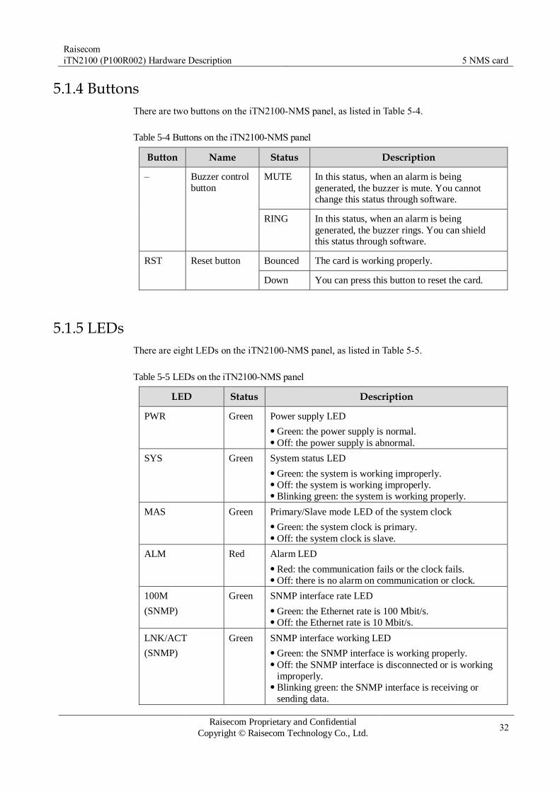
Raisecom
iTN2100 (P100R002) Hardware Description 5 NMS card
Raisecom Proprietary and Confidential
Copyright © Raisecom Technology Co., Ltd. 32
5.1.4 Buttons
There are two buttons on the iTN2100-NMS panel, as listed in Table 5-4.
Table 5-4 Buttons on the iTN2100-NMS panel
Button Name Status Description
– Buzzer control
button
MUTE In this status, when an alarm is being
generated, the buzzer is mute. You cannot change this status through software.
RING In this status, when an alarm is being
generated, the buzzer rings. You can shield this status through software.
RST Reset button Bounced The card is working properly.
Down You can press this button to reset the card.
5.1.5 LEDs
There are eight LEDs on the iTN2100-NMS panel, as listed in Table 5-5.
Table 5-5 LEDs on the iTN2100-NMS panel
LED Status Description
PWR Green Power supply LED
Green: the power supply is normal. Off: the power supply is abnormal.
SYS Green System status LED
Green: the system is working improperly. Off: the system is working improperly. Blinking green: the system is working properly.
MAS Green Primary/Slave mode LED of the system clock
Green: the system clock is primary. Off: the system clock is slave.
ALM Red Alarm LED
Red: the communication fails or the clock fails. Off: there is no alarm on communication or clock.
100M
(SNMP)
Green SNMP interface rate LED
Green: the Ethernet rate is 100 Mbit/s. Off: the Ethernet rate is 10 Mbit/s.
LNK/ACT
(SNMP)
Green SNMP interface working LED
Green: the SNMP interface is working properly. Off: the SNMP interface is disconnected or is working
improperly. Blinking green: the SNMP interface is receiving or
sending data.

Raisecom
iTN2100 (P100R002) Hardware Description 5 NMS card
Raisecom Proprietary and Confidential
Copyright © Raisecom Technology Co., Ltd. 33
LED Status Description
100M
(NM-EXT)
Green NM-EXT interface rate LED
Green: the Ethernet rate is 100 Mbit/s. Off: the Ethernet rate is 10 Mbit/s.
LNK/ACT
(NM-EXT)
Green NM-EXT interface working LED
Green: the NM-EXT interface is working properly. Off: the NM-EXT interface is disconnected or is
working improperly. Blinking green: the NM-EXT interface is receiving or
sending data.
5.1.6 Alarms
Table 5-6 lists alarms of the iTN2100-NMS.
Table 5-6 Alarms of the iTN2100-NMS
Alarm Cause Level
Chassis alarm The NMS channel between a card and the NMS card fails. The SDH clock module fails.
Critical
Cold reset The iTN2100 is rebooted upon power failure. Critical
5.1.7 Specifications
Table 5-7 lists specifications of the iTN2100-NMS.
Table 5-7 Specifications of the iTN2100-NMS
Parameter Value
Dimensions 25 mm (Width) × 232 mm (Depth) × 240 mm (Height)
Weight ≤ 0.43 kg
Maximum power
consumption
10 W

Raisecom
iTN2100 (P100R002) Hardware Description 6 SDH aggregation cards
Raisecom Proprietary and Confidential
Copyright © Raisecom Technology Co., Ltd. 34
6 SDH aggregation cards
This chapter describes the SDH aggregation card on the iTN2100, including the following
section:
OPCOM3500E-2STM1/4-M
iTN2100-4STM1-M
iTN2100-2STM16-M

Raisecom
iTN2100 (P100R002) Hardware Description 6 SDH aggregation cards
Raisecom Proprietary and Confidential
Copyright © Raisecom Technology Co., Ltd. 35
6.1 OPCOM3500E-2STM1/4-M
6.1.1 Appearance and functions
Appearance Function
The OPCOM3500E-2STM1/4-M is the SDH optical aggregation card used
by the iTN2100.
Provide 2 SFP optical interfaces. On these interfaces, you can configure
the interface rate to STM-1 or STM-4 through hardware DIP switch or
software configuration (higher priority). Provide card-level hot backup of two optical aggregation cards. If one
fails, the other can still enable the system to work properly. An aggregation card can provide multiplex section protection, channel
protection, or two independent lines of STM optical interface; two
aggregation cards can provide Multiplex Section Protection (MSP) and
channel protection between optical interface 1 of one card and optical
interface 1 of the other, and between optical interface 2 of one card and
optical interface 2 of the other, or four independent lines of STM-
4/STM-1 optical interface. The protection switching time is smaller
than 50ms. Support point-to-point, link, and ring network topology. Support inter-card protection for tributary cards. Support VC4/VC3/VC12 level cross connection. When the optical
interface rate of the aggregation card is STM-1, it supports 20×20 VC4,
60×60 VC3, and 1260×1260 VC12 cross connection. When the optical
interface rate of the aggregation card is STM-4, it supports 32×32 VC4,
96×96 VC3, and 2016×2016 VC12 cross connection. Support SDH line clock, external clock, and crystal oscillator as clock
source of the iTN2100. These sources provide protection by priority or
by clock quality. The card provides 2 Mbit/s or 2 MHz external clock
interface, complying with the ITU-T G.813 recommendations. The 2
Mbit/s or 2 MHz external clock module can be purchased
independently. Provide Automatic Laser Shutdown (ALS) for optical modules. Provide E1 Bit Error Rate Tester (BERT). Support Loss of Power (LPR) detection alarm for remote devices. Provide ECC in-band NMS channel with 3/9/12 byte. Provide complete alarm and performance monitoring. Provide 4 VCCs. Provide hot swapping.
6.1.2 Slots
The OPCOM3500E-2STM1/4-M can be inserted into slots 6 and 7.

Raisecom
iTN2100 (P100R002) Hardware Description 6 SDH aggregation cards
Raisecom Proprietary and Confidential
Copyright © Raisecom Technology Co., Ltd. 36
6.1.3 Interfaces
Interface types
There are five interfaces on the OPCOM3500E-2STM1/4-M panel, as shown in Table 6-1.
Table 6-1 Interfaces on the OPCOM3500E-2STM1/4-M panel
Interface Type Description
– MiniUSB Debugging interface
1, 2 SFP optical
interface
Service uplink interface. Tx indicates the sending interface and Rx
indicates the receiving interface.
SYNC-RX CC3 male interface 2 Mbit/s or 2 MHz clock synchronization input
interface. You can configure it to 2 Mbit/s or 2
MHz through software.
SYNC-TX CC3 male interface 2 Mbit/s or 2 MHz clock synchronization output
interface. You can configure it to 2 Mbit/s or 2 MHz through software.
Interface parameters
Table 6-2 lists parameters of interfaces 1 and 2 on the OPCOM3500E-2STM1/4-M.
Table 6-2 Parameters of interfaces 1 and 2 on the OPCOM3500E-2STM1/4-M
Parameter Description
Optical module SFP
Interface rate STM-1 or STM-4, configurable
Coding scheme NRZ
Multiplexing structure Comply with ITU-T G.707 recommendations.
Jitter features Comply with ITU-T G.783 and ITU-T G.825
recommendations.
Optical interface features Comply with ITU-T G.957 recommendations.
Table 6-3 and Table 6-4 list parameters of clock interfaces on the OPCOM3500E-2STM1/4-
M.
Table 6-3 Parameters of 2 Mbit/s clock interface on the OPCOM3500E-2STM1/4-M
Parameter Description
Connector CC3 male connector (unbalanced)

Raisecom
iTN2100 (P100R002) Hardware Description 6 SDH aggregation cards
Raisecom Proprietary and Confidential
Copyright © Raisecom Technology Co., Ltd. 37
Parameter Description
Signal rate 2048 kbit/s
Interface impedance 75 Ω
Electrical features Comply with ITU-T G.703 recommendations.
Table 6-4 Parameters of the 2 MHz clock interface the OPCOM3500E-2STM1/4-M
Parameter Description
Connector CC3 male connector (unbalanced)
Signal rate 2048 kHz
Interface impedance 75 Ω
Electrical features Comply with ITU-T G.703 recommendations.
6.1.4 LEDs
There are nine LEDs on the OPCOM3500E-2STM1/4-M panel, as listed in Table 6-5.
Table 6-5 LEDs on the OPCOM3500E-2STM1/4-M panel
LED Status Description
PWR Green Power supply LED
Green: the power supply is normal. Off: the power supply is abnormal.
SYS Green System status LED
Green: the system is working improperly. Off: the system is working improperly. Blinking green: the system is working properly.
SWH Green Protection switching LED
Green: a switching occurs. Off: no switching occurs.
ACT Green Primary/Slave LED
Green: the card is a master card or there is only this
aggregation card inserted into the chassis. Off: the card is a backup aggregation card.
STM1 Green STM-X rate LED
Green: the SFP optical interface rate is STM-1. Off: the SFP optical interface rate is STM-4.

Raisecom
iTN2100 (P100R002) Hardware Description 6 SDH aggregation cards
Raisecom Proprietary and Confidential
Copyright © Raisecom Technology Co., Ltd. 38
LED Status Description
LOF (1, 2) Red LOF alarm LED
Red: input LOF alarms are generated on optical
interfaces. Off: no input LOF alarms are generated on optical
interfaces.
LOS (1, 2) Red LOS alarm LED
Red: input LOS alarms are generated on optical
interfaces. Off: no input LOS alarms are generated on optical
interfaces.
6.1.5 DIP switch
Table 6-6 lists configurations of the Dual In-line Package (DIP) switch on the
OPCOM3500E-2STM1/4-M.
Table 6-6 Configurations of DIP switch SW3 on the OPCOM3500E-2STM1/4-M
DIP switch
Function Status Description
Bit1 Bit2
SW3 Configure the
optical interface rate.
ON ON Configure the optical
interface rate to STM-4.
OFF OFF Configure the optical
interface rate to STM-1.
By default, Bit1 and Bit2 of SW3 are OFF. If Bit1 and Bit2 of SW3 are not concurrently ON nor OFF and the optical
interface rate is not configured, the iTN2100 still configures the rate to STM-1 by default.
When you configure the optical interface rate of the OPCOM3500E-2STM1/4-M through DIP switch or software, the two optical interfaces must be configured to the same rate (STM-1 or STM-4). If two OPCOM3500E-2STM1/4-M cards are installed, the two optical interfaces must also be configured to the same rate.
You can use the add-card command to configure adding the OPCOM3500E-C-
2STM1-M card or the OPCOM3500E-C-2STM4-M card. You cannot use the DIP switch to re-select the card after successfully configuring the card with the command.
6.1.6 Alarms
Table 6-7 lists alarms of the OPCOM3500E-2STM1/4-M.
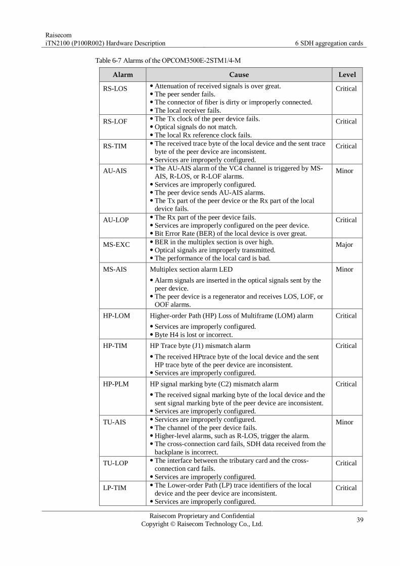
Raisecom
iTN2100 (P100R002) Hardware Description 6 SDH aggregation cards
Raisecom Proprietary and Confidential
Copyright © Raisecom Technology Co., Ltd. 39
Table 6-7 Alarms of the OPCOM3500E-2STM1/4-M
Alarm Cause Level
RS-LOS Attenuation of received signals is over great. The peer sender fails. The connector of fiber is dirty or improperly connected. The local receiver fails.
Critical
RS-LOF The Tx clock of the peer device fails. Optical signals do not match. The local Rx reference clock fails.
Critical
RS-TIM The received trace byte of the local device and the sent trace
byte of the peer device are inconsistent. Services are improperly configured.
Critical
AU-AIS The AU-AIS alarm of the VC4 channel is triggered by MS-
AIS, R-LOS, or R-LOF alarms. Services are improperly configured. The peer device sends AU-AIS alarms. The Tx part of the peer device or the Rx part of the local
device fails.
Minor
AU-LOP The Rx part of the peer device fails. Services are improperly configured on the peer device. Bit Error Rate (BER) of the local device is over great.
Critical
MS-EXC BER in the multiplex section is over high. Optical signals are improperly transmitted. The performance of the local card is bad.
Major
MS-AIS Multiplex section alarm LED
Alarm signals are inserted in the optical signals sent by the
peer device. The peer device is a regenerator and receives LOS, LOF, or
OOF alarms.
Minor
HP-LOM Higher-order Path (HP) Loss of Multiframe (LOM) alarm
Services are improperly configured. Byte H4 is lost or incorrect.
Critical
HP-TIM HP Trace byte (J1) mismatch alarm
The received HPtrace byte of the local device and the sent
HP trace byte of the peer device are inconsistent. Services are improperly configured.
Critical
HP-PLM HP signal marking byte (C2) mismatch alarm
The received signal marking byte of the local device and the
sent signal marking byte of the peer device are inconsistent. Services are improperly configured.
Critical
TU-AIS Services are improperly configured. The channel of the peer device fails. Higher-level alarms, such as R-LOS, trigger the alarm. The cross-connection card fails, SDH data received from the
backplane is incorrect.
Minor
TU-LOP The interface between the tributary card and the cross-
connection card fails. Services are improperly configured.
Critical
LP-TIM The Lower-order Path (LP) trace identifiers of the local
device and the peer device are inconsistent. Services are improperly configured.
Critical

Raisecom
iTN2100 (P100R002) Hardware Description 6 SDH aggregation cards
Raisecom Proprietary and Confidential
Copyright © Raisecom Technology Co., Ltd. 40
6.1.7 Specifications
Table 6-8 lists specifications of the OPCOM3500E-2STM1/4-M.
Table 6-8 Specifications of the OPCOM3500E-2STM1/4-M
Parameter Value
Dimensions 25 mm (Width) × 232 mm (Depth) × 240 mm (Height)
Weight < 0.5 kg
Maximum power
consumption
12 W

Raisecom
iTN2100 (P100R002) Hardware Description 6 SDH aggregation cards
Raisecom Proprietary and Confidential
Copyright © Raisecom Technology Co., Ltd. 41
6.2 iTN2100-4STM1-M
6.2.1 Appearance and functions
Appearance Function
The iTN2100-4STM1-M provides the following functions:
Provide 4 SFP optical interfaces and the interface rate is configured to
STM-1. Provide card-level hot backup of two optical aggregation cards. If one
fails, the other can still enable the system to work properly. Support hybrid insertion with the OPCOM3500E-2STM1/4-M. An aggregation card can provide MSP and channel protection. The
protection switching time is smaller than 50ms. Support point-to-point, link, and ring network topology. Support inter-card protection for tributary cards. Support VC4/VC3/VC12 level cross connection, realizing 18×18 VC4,
54×54 VC3, and 1134×1134 VC12 cross connection. Support SDH line clock, external clock, and crystal oscillator as clock
source of the iTN2100. These sources provide protection by priority or
by clock quality. The card provides 2 Mbit/s or 2 MHz external clock
interface, complying with the ITU-T G.813 recommendations. The 2
Mbit/s or 2 MHz external clock module can be purchased
independently. Provide Digital Diagnostics Monitoring (DDM) for optical modules. Provide Automatic Laser Shutdown (ALS) for optical modules. Provide E1 Bit Error Rate Tester (BERT). Support Loss of Power detection alarm for remote devices. Provide ECC in-band network management channel with 3/9/12 byte. Provide complete alarm and performance monitoring. Provide 4 VCCs. Provide hot swapping.
6.2.2 Slots
The iTN2100-4STM1-M can be inserted into slots 6 and 7 on the iTN2100.
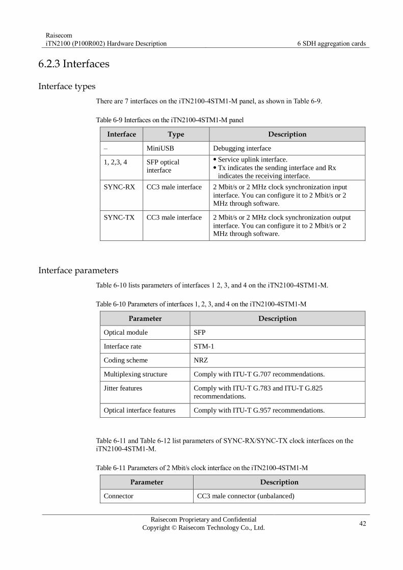
Raisecom
iTN2100 (P100R002) Hardware Description 6 SDH aggregation cards
Raisecom Proprietary and Confidential
Copyright © Raisecom Technology Co., Ltd. 42
6.2.3 Interfaces
Interface types
There are 7 interfaces on the iTN2100-4STM1-M panel, as shown in Table 6-9.
Table 6-9 Interfaces on the iTN2100-4STM1-M panel
Interface Type Description
– MiniUSB Debugging interface
1, 2,3, 4 SFP optical
interface
Service uplink interface. Tx indicates the sending interface and Rx
indicates the receiving interface.
SYNC-RX CC3 male interface 2 Mbit/s or 2 MHz clock synchronization input
interface. You can configure it to 2 Mbit/s or 2
MHz through software.
SYNC-TX CC3 male interface 2 Mbit/s or 2 MHz clock synchronization output
interface. You can configure it to 2 Mbit/s or 2 MHz through software.
Interface parameters
Table 6-10 lists parameters of interfaces 1 2, 3, and 4 on the iTN2100-4STM1-M.
Table 6-10 Parameters of interfaces 1, 2, 3, and 4 on the iTN2100-4STM1-M
Parameter Description
Optical module SFP
Interface rate STM-1
Coding scheme NRZ
Multiplexing structure Comply with ITU-T G.707 recommendations.
Jitter features Comply with ITU-T G.783 and ITU-T G.825
recommendations.
Optical interface features Comply with ITU-T G.957 recommendations.
Table 6-11 and Table 6-12 list parameters of SYNC-RX/SYNC-TX clock interfaces on the
iTN2100-4STM1-M.
Table 6-11 Parameters of 2 Mbit/s clock interface on the iTN2100-4STM1-M
Parameter Description
Connector CC3 male connector (unbalanced)
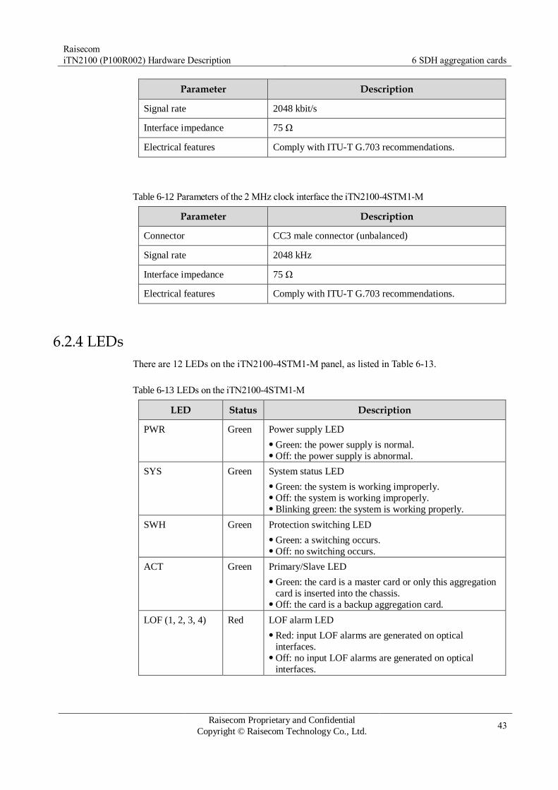
Raisecom
iTN2100 (P100R002) Hardware Description 6 SDH aggregation cards
Raisecom Proprietary and Confidential
Copyright © Raisecom Technology Co., Ltd. 43
Parameter Description
Signal rate 2048 kbit/s
Interface impedance 75 Ω
Electrical features Comply with ITU-T G.703 recommendations.
Table 6-12 Parameters of the 2 MHz clock interface the iTN2100-4STM1-M
Parameter Description
Connector CC3 male connector (unbalanced)
Signal rate 2048 kHz
Interface impedance 75 Ω
Electrical features Comply with ITU-T G.703 recommendations.
6.2.4 LEDs
There are 12 LEDs on the iTN2100-4STM1-M panel, as listed in Table 6-13.
Table 6-13 LEDs on the iTN2100-4STM1-M
LED Status Description
PWR Green Power supply LED
Green: the power supply is normal. Off: the power supply is abnormal.
SYS Green System status LED
Green: the system is working improperly. Off: the system is working improperly. Blinking green: the system is working properly.
SWH Green Protection switching LED
Green: a switching occurs. Off: no switching occurs.
ACT Green Primary/Slave LED
Green: the card is a master card or only this aggregation
card is inserted into the chassis. Off: the card is a backup aggregation card.
LOF (1, 2, 3, 4) Red LOF alarm LED
Red: input LOF alarms are generated on optical
interfaces. Off: no input LOF alarms are generated on optical
interfaces.

Raisecom
iTN2100 (P100R002) Hardware Description 6 SDH aggregation cards
Raisecom Proprietary and Confidential
Copyright © Raisecom Technology Co., Ltd. 44
LED Status Description
LOS (1, 2, 3, 4) Red LOS alarm LED
Red: input LOS alarms are generated on optical
interfaces. Off: no input LOS alarms are generated on optical
interfaces.
6.2.5 Alarms
Table 6-14 lists alarms of the iTN2100-4STM1-M.
Table 6-14 Alarms of the iTN2100-4STM1-M
Alarm Cause Level
RS-LOS Attenuation of received signals is over great. The peer sender fails. The connector of fiber is dirty or improperly connected. The local receiver fails.
Critical
RS-LOF The Tx clock of the peer device fails. Optical signals do not match. The local Rx reference clock fails.
Critical
RS-TIM The received trace byte of the local device and the sent trace
byte of the peer device are inconsistent. Services are improperly configured.
Critical
AU-AIS The AU-AIS alarm of the VC4 channel is triggered by MS-
AIS, R-LOS, or R-LOF alarms. Services are improperly configured. The peer device sends AU-AIS alarms. The Tx part of the peer device or the Rx part of the local
device fails.
Minor
AU-LOP The Rx part of the peer device fails. Services are improperly configured on the peer device. Bit Error Rate (BER) of the local device is over great.
Critical
MS-EXC BER in the multiplex section is over high. Optical signals are improperly transmitted. The performance of the local card is bad.
Major
MS-AIS Multiplex section alarm LED
Alarm signals are inserted in the optical signals sent by the
peer device. The peer device is a regenerator and receives LOS, LOF, or
OOF alarms.
Minor
HP-LOM HP Loss of Multiframe (LOM) alarm
Services are improperly configured. Byte H4 is lost or incorrect.
Critical
HP-TIM HP Trace byte (J1) mismatch alarm
The received HP trace byte of the local device and the sent
HP trace byte of the peer device are inconsistent. Services are improperly configured.
Critical
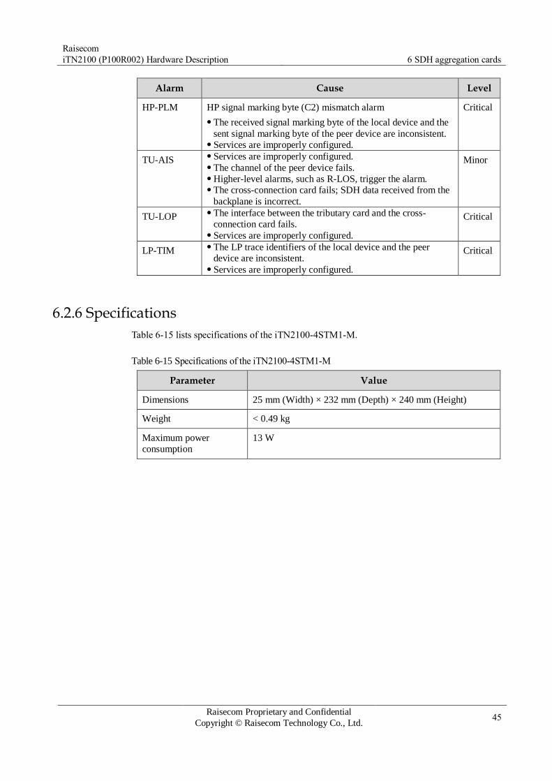
Raisecom
iTN2100 (P100R002) Hardware Description 6 SDH aggregation cards
Raisecom Proprietary and Confidential
Copyright © Raisecom Technology Co., Ltd. 45
Alarm Cause Level
HP-PLM HP signal marking byte (C2) mismatch alarm
The received signal marking byte of the local device and the
sent signal marking byte of the peer device are inconsistent. Services are improperly configured.
Critical
TU-AIS Services are improperly configured. The channel of the peer device fails. Higher-level alarms, such as R-LOS, trigger the alarm. The cross-connection card fails; SDH data received from the
backplane is incorrect.
Minor
TU-LOP The interface between the tributary card and the cross-
connection card fails. Services are improperly configured.
Critical
LP-TIM The LP trace identifiers of the local device and the peer
device are inconsistent. Services are improperly configured.
Critical
6.2.6 Specifications
Table 6-15 lists specifications of the iTN2100-4STM1-M.
Table 6-15 Specifications of the iTN2100-4STM1-M
Parameter Value
Dimensions 25 mm (Width) × 232 mm (Depth) × 240 mm (Height)
Weight < 0.49 kg
Maximum power
consumption
13 W

Raisecom
iTN2100 (P100R002) Hardware Description 6 SDH aggregation cards
Raisecom Proprietary and Confidential
Copyright © Raisecom Technology Co., Ltd. 46
6.3 iTN2100-2STM16-M
6.3.1 Appearance and functions
Appearance Function
The iTN2100-2STM16-M is a 2.5G aggregation card specialized for the
iTN2100.
Provide 2 SFP optical interfaces; support DDM and ALS. Support 1+1 protection between aggregation cards. Support 1+1 SNCP. Support VC4/VC3/VC12 level SNCP. Support interface protection. The STM-16 interface can be configured
to work in independent mode or protected mode. Support 1+1 linear MSP (single-end protection but not dual-end
protection) and VC4/VC3/VC12 channel protection in protected mode. The protection switching time is smaller than 50ms. When slot 6/slot 7 is inserted with the iTN2100-2STM16-M and when
slots 1–5 and 8–12 are inserted with common service cards, each slot
supports one VC4 being connected uplink to the aggregation card.
When slot 6/slot 7 is inserted with the iTN2100-2STM16-M and when
slots 2–5 are inserted with high-bandwidth cards, each slot supports
four VC4 being connected uplink to the aggregation card. Support VC4/VC3/VC12 level cross connection. The overall chassis
supports up to 118×118 VC4 cross connection. The LP supports
4032×4032 VC12 cross connection. Support monitoring SDH Regeneration Section (RS), Multiplex
Section (MS), HP, and LP overhead bytes. Support internal loopback and external loopback on the SDH interface. Support VC4/VC3/VC12 level timeslot loopback. Support 2 STM-16 line clocks, one 2 Mbit/s or 2 MHz input clock,
local clock; support free-run mode, locked mode, and holdover mode
of clocks; support SSM protocol and extended SSM protocol. Support 2 Mbit/s or 2 MHz external clock output (either system clock
or exported clock). Support one-way E1 BERT. Support LPR detection when being connected with Raisecom STM-16
devices. Support 4 VCCs and 2 DCCs. VCCs use VC12 to transmit network
management information while DCCs use DCC 3/9/12 byte to transmit
network management information. Support smoothly upgrading the OPCOM3500E-2STM1/4-M to the
iTN2100-2STM16-M without disturbing services. Support storing and querying default information about the device. Support version information about the device; support testing the
temperature of the kernel chip of the card. Support complete alarm and performance statistics. Support upgrading and backing up the system software, Bootrom
software, and FPGA software online. Implement point-to-point, link, and ring network topologies.

Raisecom
iTN2100 (P100R002) Hardware Description 6 SDH aggregation cards
Raisecom Proprietary and Confidential
Copyright © Raisecom Technology Co., Ltd. 47
6.3.2 Slots
The iTN2100-2STM16-M can be inserted into slots 6 and 7 on the iTN2100. In addition, slots
6 and 7 support being inserted with the same cards only. They do not support being inserted
with different cards.
6.3.3 Interfaces
Interface types
There are 5 interfaces on the iTN2100-2STM16-M panel, as shown in Table 6-16.
Table 6-16 Interfaces on the iTN2100-2STM16-M panel
Interface Type Description
– MiniUSB Debugging interface
1, 2 SFP optical
interface
Service uplink interface. Tx indicates the sending interface and Rx
indicates the receiving interface.
SYNC-RX CC3 male interface 2 Mbit/s or 2 MHz clock synchronization input
interface. You can configure it to 2 Mbit/s or 2 MHz through software.
SYNC-TX CC3 male interface 2 Mbit/s or 2 MHz clock synchronization output
interface. You can configure it to 2 Mbit/s or 2
MHz through software.
Interface parameters
Table 6-17 lists parameters of SFP optical interfaces on the iTN2100-2STM16-M.
Table 6-17 Parameters of SFP optical interfaces on the iTN2100-2STM16-M
Parameter Description
Optical module type DSFP, USFP, or CSFP
Interface rate 2488.32 Mbit/s
Coding scheme NRZ
Multiplexing structure Comply with ITU-T G.707 recommendations.
Clock features Comply with ITU-T G.813 recommendations.
Jitter features Comply with ITU-T G.783 and ITU-T G.825
recommendations.
Optical interface features Comply with ITU-T G.957 recommendations. Specific
metrics are provided by the inserted SFP module. For
details, see DSFP User Manual, USFP User Manual, and CSFP User Manual.

Raisecom
iTN2100 (P100R002) Hardware Description 6 SDH aggregation cards
Raisecom Proprietary and Confidential
Copyright © Raisecom Technology Co., Ltd. 48
Table 6-18 and Table 6-19 list parameters of SYNC-RX/SYNC-TX clock interfaces on the
iTN2100-2STM16-M.
Table 6-18 Parameters of 2 Mbit/s clock interface on the iTN2100-2STM16-M
Parameter Description
Connector CC3 male connector (unbalanced)
Signal rate 2048 kbit/s
Interface impedance 75 Ω
Electrical features Comply with ITU-T G.703 recommendations.
Table 6-19 Parameters of 2 MHz clock interface on the iTN2100-2STM16-M
Parameter Description
Connector CC3 male connector (unbalanced)
Signal rate 2048 kHz
Interface impedance 75 Ω
Electrical features Comply with ITU-T G.703 recommendations.
6.3.4 LEDs
There are 8 LEDs on the iTN2100-2STM16-M panel, as listed in Table 6-20.
Table 6-20 LEDs on the iTN2100-2STM16-M
LED Status Description
PWR Green Power supply LED
Green: the power supply is normal. Off: the power supply is abnormal.
SYS Green System status LED
Green: the system is working improperly. Off: the system is working improperly. Blinking green: the system is working properly.
SWH Green Protection switching LED
Green: a switching occurs. Off: no switching occurs.
ACT Green Primary/Slave LED
Green: the card is a master card or only this aggregation card is
inserted into the chassis. Off: the card is a backup aggregation card.

Raisecom
iTN2100 (P100R002) Hardware Description 6 SDH aggregation cards
Raisecom Proprietary and Confidential
Copyright © Raisecom Technology Co., Ltd. 49
LED Status Description
LOF (1, 2) Red LOF alarm LED
Red: LOF alarms are generated on optical interfaces. Off: no LOF alarms are generated on optical interfaces.
LOS (1, 2) Red LOS alarm LED
Red: LOS alarms are generated on optical interfaces. Off: no LOS alarms are generated on optical interfaces.
6.3.5 Logic diagram
Figure 6-1 shows the logic diagram of the iTN2100-2STM16-M.
Figure 6-1 Logic diagram of the iTN2100-2STM16-M
The iTN2100-2STM16-M consists of the management control module, SDH service module,
logic control module, and clock module. These modules work as below:
Management control module: exchange network management information with the NMS card; manage and control cooperation of other modules.
SDH service module: process SDH services of interfaces and tributary cards; process SDH clocks.

Raisecom
iTN2100 (P100R002) Hardware Description 6 SDH aggregation cards
Raisecom Proprietary and Confidential
Copyright © Raisecom Technology Co., Ltd. 50
Logic control module: collect status information and configurations of slots and optical
modules; re-configure cards; realize bus deserialization of service data; process SDH section overheads.
Clock module: when the iTN2100-2STM16-M is a master aggregation card, receive the
line clock, external clock, and local crystal oscillator of the master aggregation card, as
well as receive the line clock and external clock of the secondary aggregation card;
select the clock source from received clock sources; synchronize clocks; send the clock source.
The iTN2100-2STM16-M processes services as below:
Line side to the client side: STM16 optical signals enter the SDH service module and are
transmitted to SDH service cards through the backplane after being processed.
Client side to the line side: SDH signals, from the backplane, enter the SDH service
module, are aggregated to STM16 optical signals, and are transmitted through SFP optical interfaces on the front panel.
6.3.6 Specifications
Table 6-21 lists specifications of the iTN2100-2STM16-M.
Table 6-21 Specifications of the iTN2100-2STM16-M
Parameter Value
Dimensions 25 mm (Width) × 232 mm (Depth) × 240 mm (Height)
Weight < 0.53 kg
Maximum power
consumption
18 W
Raisecom
iTN2100 (P100R002) Hardware Description 7 SDH tributary cards
Raisecom Proprietary and Confidential
Copyright © Raisecom Technology Co., Ltd. 51
7 SDH tributary cards
This chapter describes the SDH tributary cards of the iTN2100, including the following
sections:
OPCOM3500E-STM1-S
OPCOM3500E-4STM1-S
iTN2100-4STM4-S
OPCOM3500E-BSSH

Raisecom
iTN2100 (P100R002) Hardware Description 7 SDH tributary cards
Raisecom Proprietary and Confidential
Copyright © Raisecom Technology Co., Ltd. 52
7.1 OPCOM3500E-STM1-S
7.1.1 Appearance and functions
Appearance Function
The OPCOM3500E-STM1-S is an optical SDH tributary card on the
iTN2100, with two versions: B and C.
Support SFP connectors for connecting fiber. Provide two SDH STM1 optical interfaces and support VC12 and VC3.
They support up to 63 VC12 channels if these two SDH STM1 optical
interfaces are independent. These two SDH STM1 optical interfaces support 1+1 dual-optical
interface protection, thus supporting inter-card protection if supported
by the optical SDH aggregation card on the iTN2100. Support MSP and channel protection. DCCs support three modes: D1-D3, D4-D12, and D1-D12. This is
supported by Version C only. The SDH optical interface supports local internal loopback and local
external loopback. Support ALS. Support LPR alarms on the remote device (if the remote device
supports LPR alarms). Support hot swapping.
The left is the OPCOM3500E-STM1-S panel (versions B) and the right is the OPCOM3500E-STM1-S panel (version C).
7.1.2 Slots
The OPCOM3500E-STM1-S can be inserted into slots 1–5 and 8–12 on the iTN2100.

Raisecom
iTN2100 (P100R002) Hardware Description 7 SDH tributary cards
Raisecom Proprietary and Confidential
Copyright © Raisecom Technology Co., Ltd. 53
7.1.3 Interfaces
Interface types
There are two interfaces on the OPCOM3500E-STM1-S panel, as listed in Table 7-1 and
Table 7-2.
Table 7-1 Interfaces on the OPCOM3500E-STM1-S (Versions B)
Interface Type Description
A, B 1×9 optical interface Service uplink interface Tx indicates the sending interface and Rx indicates
the receiving interface.
Table 7-2 Interfaces on the OPCOM3500E-STM1-S (Version C)
Interface Type Description
1, 2 SFP optical interface Service uplink interface Tx indicates the sending interface and Rx
indicates the receiving interface.
Interface parameters
Table 7-3 lists parameters of interfaces A and B on the OPCOM3500E-STM1-S (Versions B).
Table 7-3 Parameters of interfaces A and B on the OPCOM3500E-STM1-S (Versions B)
Parameter Description
Optical module type 1×9 optical module
Interface rate STM-1
Coding scheme NRZ
Multiplexing structure Comply with ITU-T G.707 recommendations.
Jitter features Comply with ITU-T G.783 and ITU-T G.825
recommendations.
Optical interface features Comply with ITU-T G.957 recommendations.
Table 7-4 lists parameters of interfaces 1 and 2 on the OPCOM3500E-STM1-S (Version C).
Table 7-4 Parameters of interfaces 1 and 2 on the OPCOM3500E-STM1-S (Version C)
Parameter Description
Optical module type SFP optical module
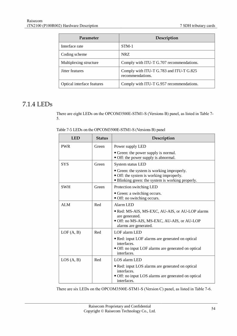
Raisecom
iTN2100 (P100R002) Hardware Description 7 SDH tributary cards
Raisecom Proprietary and Confidential
Copyright © Raisecom Technology Co., Ltd. 54
Parameter Description
Interface rate STM-1
Coding scheme NRZ
Multiplexing structure Comply with ITU-T G.707 recommendations.
Jitter features Comply with ITU-T G.783 and ITU-T G.825
recommendations.
Optical interface features Comply with ITU-T G.957 recommendations.
7.1.4 LEDs
There are eight LEDs on the OPCOM3500E-STM1-S (Versions B) panel, as listed in Table 7-
5.
Table 7-5 LEDs on the OPCOM3500E-STM1-S (Versions B) panel
LED Status Description
PWR Green Power supply LED
Green: the power supply is normal. Off: the power supply is abnormal.
SYS Green System status LED
Green: the system is working improperly. Off: the system is working improperly. Blinking green: the system is working properly.
SWH Green Protection switching LED
Green: a switching occurs. Off: no switching occurs.
ALM Red Alarm LED
Red: MS-AIS, MS-EXC, AU-AIS, or AU-LOP alarms
are generated. Off: no MS-AIS, MS-EXC, AU-AIS, or AU-LOP
alarms are generated.
LOF (A, B) Red LOF alarm LED
Red: input LOF alarms are generated on optical
interfaces. Off: no input LOF alarms are generated on optical
interfaces.
LOS (A, B) Red LOS alarm LED
Red: input LOS alarms are generated on optical
interfaces. Off: no input LOS alarms are generated on optical
interfaces.
There are six LEDs on the OPCOM3500E-STM1-S (Version C) panel, as listed in Table 7-6.

Raisecom
iTN2100 (P100R002) Hardware Description 7 SDH tributary cards
Raisecom Proprietary and Confidential
Copyright © Raisecom Technology Co., Ltd. 55
Table 7-6 LEDs on the OPCOM3500E-STM1-S (Version C) panel
LED Status Description
PWR Green Power supply LED
Green: the power supply is normal. Off: the power supply is abnormal.
SYS Green System status LED
Green: the system is working improperly. Off: the system is working improperly. Blinking green: the system is working properly.
LOF (1, 2) Red LOF alarm LED
Red: LOF alarms are generated on optical interfaces 1 and 2. Off: no LOF alarms are generated on optical interfaces 1 and 2.
LOS (1, 2) Red LOS alarm LED
Red: LOS alarms are generated on optical interfaces 1 and 2. Off: no LOS alarms are generated on optical interfaces 1 and 2.
7.1.5 Alarms
Table 7-7 lists alarms of the OPCOM3500E-STM1-S.
Table 7-7 Alarms of the OPCOM3500E-STM1-S
Alarm Cause Level
LOS alarm on the
STM1 optical interface
Attenuation of received signals is over great. The peer sender fails. The connector of fiber is dirty or improperly connected. The local receiver fails.
Critical
LOF alarm on the
STM1 optical
interface
The Tx clock of the peer device fails. Optical signals do not match. The local receiving referential clock fails.
Critical
AU-AIS, AU-LOP The optical signals sent by the peer device is faulty and
the right pointer cannot be obtained.
Critical
haMS-EXC BER in the multiplex section is over high. Optical signals are improperly transmitted. The performance of the local card is bad.
Critical
MS-AIS Multiplex section alarm LED
Alarm signals are inserted in the optical signals sent by
the peer device. The peer device is a regenerator and receives LOS,
LOF, or OOF alarms.
Minor
7.1.6 Specifications
Table 7-8 lists specifications of the OPCOM3500E-STM1-S.

Raisecom
iTN2100 (P100R002) Hardware Description 7 SDH tributary cards
Raisecom Proprietary and Confidential
Copyright © Raisecom Technology Co., Ltd. 56
Table 7-8 Specifications of the OPCOM3500E-STM1-S
Parameter Value
Dimensions 25 mm (Width) × 232 mm (Depth) × 240 mm (Height)
Weight < 0.45 kg
Maximum power
consumption
3 W

Raisecom
iTN2100 (P100R002) Hardware Description 7 SDH tributary cards
Raisecom Proprietary and Confidential
Copyright © Raisecom Technology Co., Ltd. 57
7.2 OPCOM3500E-4STM1-S
7.2.1 Appearance and functions
Appearance Function
The OPCOM3500E-4STM1-S is a STM-1 tributary card on the iTN2100.
Provide 4 STM-1 interfaces (SFP optical interfaces), through which it
can be connected to up to 4 OPCOM31xx series devices. Provide high-density interfaces, and thus is of high access ability. The STM-1 optical interface can be configured to independent mode or
1+1 linear MSP mode. When configured to the later, interfaces 1 and 2
protect each other, and interfaces 3 and 4 protect each other. Support low order path 1+1 protection. When two OPCOM3500E-4STM1-S cards are installed, they support
inter-card 1+1 protection. Support the in-band and out-of-band network management. The in-band
network management transmits network management information
through VC12. The out-of-band network management transmits network
management information by occupying DCC bytes. The bandwidth of network management channel can be configured to192
kbit/s, 576 kbit/s, and 768 kbit/s. Support remote LPR detection when being connected to Raisecom STM-
1 supportive devices. Support complete alarm and performance monitoring. Support SFP module DDM. Support ALS. Support online software upgrade over local and remote devices. Support hot swapping.
7.2.2 Slots
The OPCOM3500E-4STM1-S can be inserted into slots 1–5 and 8–12 on the iTN2100.

Raisecom
iTN2100 (P100R002) Hardware Description 7 SDH tributary cards
Raisecom Proprietary and Confidential
Copyright © Raisecom Technology Co., Ltd. 58
7.2.3 Interfaces
Interface types
There are five interfaces on the OPCOM3500E-4STM1-S panel, as listed in Table 7-9.
Table 7-9 Interfaces on the OPCOM3500E-4STM1-S panel
Interface Type Description
– MiniUSB Debugging interface
1–4 SFP optical
interface
Service downlink interface Each optical interface can transmit a way of SDH
services. Tx indicates the sending interface and Rx indicates the
receiving interface.
Interface parameters
Table 7-10 lists parameters of interfaces 1–4 on the OPCOM3500E-4STM1-S.
Table 7-10 Parameters of interfaces 1–4 on the OPCOM3500E-4STM1-S
Parameter Description
Connector type SFP optical interface
Interface rate STM-1
Coding scheme NRZ
Multiplexing structure Comply with ITU-T G.707 recommendations.
Clock features Comply with ITU-T G.813 recommendations.
Electrical features Comply with ITU-T G.957 recommendations.
Jitter features Comply with ITU-T G.783 and ITU-T G.825 recommendations.
7.2.4 LEDs
There are 10 LEDs on the OPCOM3500E-4STM1-S panel, as listed in Table 7-11.
Table 7-11 LEDs on the OPCOM3500E-4STM1-S panel
LED Status Description
PWR Green Power supply LED
Green: the power supply is normal. Off: the power supply is abnormal.

Raisecom
iTN2100 (P100R002) Hardware Description 7 SDH tributary cards
Raisecom Proprietary and Confidential
Copyright © Raisecom Technology Co., Ltd. 59
LED Status Description
SYS Green System status LED
Green: the system is working improperly. Off: the system is working improperly. Blinking green: the system is working properly.
LOF (1–4) Red LOF alarm LED
Red: input LOF alarms are generated on related optical
interfaces. Off: no input LOF alarms are generated on related
optical interfaces.
LOS (1–4) Red LOS alarm LED
Red: input LOS alarms are generated on related optical
interfaces. Off: no input LOS alarms are generated on related
optical interfaces.
7.2.5 Alarms
Table 7-12 lists alarms of the OPCOM3500E-4STM1-S.
Table 7-12 Alarms of the OPCOM3500E-4STM1-S
Alarm Cause Level
RS-LOS Attenuation of received signals is over great. The peer sender fails. The connector of fiber is dirty or improperly connected. The local receiver fails.
Critical
RS-LOF The Tx clock of the peer device fails. Optical signals do not match. The local receiving referential clock fails.
Critical
RS-TIM The received trace byte of the local device and the sent
trace byte of the peer device are inconsistent. Services are improperly configured.
Critical
AU-AIS The AU-AIS alarm of the VC4 channel is triggered by MS-
AIS, R-LOS, R-LOF alarms. Services are improperly configured. The peer device sends AU-AIS alarms. The Tx part of the peer device or the Rx part of the local
device fails.
Minor
AU-LOP The Rx part of the peer device fails. Services are improperly configured on the peer device. Bit Error Rate (BER) of the local device is over great.
Critical
MS-EXC BER in the multiplex section is over high. Optical signals are improperly transmitted. The performance of the local card is bad.
Major

Raisecom
iTN2100 (P100R002) Hardware Description 7 SDH tributary cards
Raisecom Proprietary and Confidential
Copyright © Raisecom Technology Co., Ltd. 60
Alarm Cause Level
MS-AIS Multiplex section alarm LED
Alarm signals are inserted in the optical signals sent by the
peer device. The peer device is a regenerator and receives LOS, LOF, or
OOF alarms.
Minor
HP-LOM HP Loss of Multiframe (LOM) alarm
Services are improperly configured. Byte H4 is lost or incorrect.
Critical
HP-TIM The received channel trace byte of the local device and the
sent channel trace byte of the peer device are inconsistent. Services are improperly configured.
Critical
HP-PLM The received signal marking byte of the local device and the
sent signal marking byte of the peer device are inconsistent. Services are improperly configured.
Critical
TU-AIS Services are improperly configured. The channel of the peer device fails. HP alarms, such as R-LOS, trigger the alarm. The cross-connection card fails.
Minor
TU-LOP The interface between the tributary card and the cross-
connection card fails. Services are improperly configured.
Critical
LP-TIM The LP trace identifiers of the local device and the peer
device are inconsistent. Services are improperly configured.
Critical
7.2.6 Specifications
Table 7-13 lists specifications of the OPCOM3500E-4STM1-S.
Table 7-13 Specifications of the OPCOM3500E-4STM1-S
Parameter Value
Dimensions 25 mm (Width) × 232 mm (Depth) × 240 mm (Height)
Weight 0.45 kg
Maximum power
consumption
8.4 W

Raisecom
iTN2100 (P100R002) Hardware Description 7 SDH tributary cards
Raisecom Proprietary and Confidential
Copyright © Raisecom Technology Co., Ltd. 61
7.3 iTN2100-4STM4-S
7.3.1 Appearance and functions
Appearance Function
The iTN2100-4STM4-S is a STM-4 tributary card used for the
iTN2100.
Provide 4 STM-4 interfaces (SFP optical interfaces), through which it
can be connected to up to 4 MASP devices or SDH multiplexer with
STM4 optical interfaces. Provide high-density interfaces, and thus is of high access ability. The STM-4 interface can be configured to independent mode or 1+1
linear MSP mode. When configured to the later, interfaces 1 and 2
protect each other, and interfaces 3 and 4 protect each other. Support low order path 1+1 protection. When two iTN2100-4STM4-S cards are installed, they support inter-
card 1+1 protection. Support in-band and out-of-band network management. The in-band
network management transmits network management information
through VC12. The out-of-band network management transmits
network management information by occupying DCC bytes. The bandwidth of network management channel can be configured
to192 kbit/s, 576 kbit/s, and 768 kbit/s. Support remote LPR detection when being connected to raisecom
STM-4 supportive devices. Support complete alarm and performance monitoring. Support DDM of the SFP module. Support ALS. Support online software upgrade over local and remote devices. Support hot swapping.

Raisecom
iTN2100 (P100R002) Hardware Description 7 SDH tributary cards
Raisecom Proprietary and Confidential
Copyright © Raisecom Technology Co., Ltd. 62
7.3.2 Slots
The iTN2100-4STM4-S can be inserted into slot 2 and slot 4 when working with the
OPCO3500E-2STM1/4-M. The iTN2100-4STM4-S can be inserted into slot 2, slot 3, slot 4,
and slot 5 when working with the iTN2100-2STM16-M.
7.3.3 Interfaces
Interface types
There are five interfaces on the iTN2100-4STM4-S panel, as listed in Table 7-14.
Table 7-14 Interfaces on the iTN2100-4STM4-S panel
Interface Type Description
– MiniUSB Debugging interface
1–4 SFP optical
interface
Service downlink interface Each optical interface can transmit a way of SDH
services. Tx indicates the sending interface and Rx indicates the
receiving interface.
Interface parameters
Table 7-15 lists parameters of interfaces 1–4 on the iTN2100-4STM4-S.
Table 7-15 Parameters of interfaces 1–4 on the iTN2100-4STM4-S
Parameter Description
Connector type SFP optical interface
Interface rate STM-4
Coding scheme NRZ
Multiplexing structure Comply with ITU-T G.707 recommendations.
Clock features Comply with ITU-T G.813 recommendations.
Electrical features Comply with ITU-T G.957 recommendations.
Jitter features Comply with ITU-T G.783 and ITU-T G.825 recommendations.
7.3.4 LEDs
There are 10 LEDs on the iTN2100-4STM4-S panel, as listed in Table 7-16.

Raisecom
iTN2100 (P100R002) Hardware Description 7 SDH tributary cards
Raisecom Proprietary and Confidential
Copyright © Raisecom Technology Co., Ltd. 63
Table 7-16 LEDs on the iTN2100-4STM4-S panel
LED Status Description
PWR Green Power supply LED
Green: the power supply is normal. Off: the power supply is abnormal.
SYS Green System status LED
Green: the system is working improperly. Off: the system is working improperly. Blinking green: the system is working properly.
LOF (1–4) Red LOF alarm LED
Red: input LOF alarms are generated on related optical
interfaces. Off: no input LOF alarms are generated on related
optical interfaces.
LOS (1–4) Red LOS alarm LED
Red: input LOS alarms are generated on related optical
interfaces. Off: no input LOS alarms are generated on related
optical interfaces.
7.3.5 Alarms
Table 7-17 lists alarms of the iTN2100-4STM4-S.
Table 7-17 Alarms of the iTN2100-4STM4-S
Alarm Cause Level
RS-LOS Attenuation of received signals is over great. The peer sender fails. The connector of fiber is dirty or improperly connected. The local receiver fails.
Critical
RS-LOF The Tx clock of the peer device fails. Optical signals do not match. The local receiving referential clock fails.
Critical
RS-TIM The received trace byte of the local device and the sent
trace byte of the peer device are inconsistent. Services are improperly configured.
Critical
AU-AIS The AU-AIS alarm of the VC4 channel is triggered by MS-
AIS, R-LOS, R-LOF alarms. Services are improperly configured. The peer device sends AU-AIS alarms. The Tx part of the peer device or the Rx part of the local
device fails.
Minor
AU-LOP The Rx part of the peer device fails. Services are improperly configured on the peer device. Bit Error Rate (BER) of the local device is over great.
Critical
MS-EXC BER in the multiplex section is over high. Optical signals are improperly transmitted. The performance of the local card is bad.
Major

Raisecom
iTN2100 (P100R002) Hardware Description 7 SDH tributary cards
Raisecom Proprietary and Confidential
Copyright © Raisecom Technology Co., Ltd. 64
Alarm Cause Level
MS-AIS Multiplex section alarm LED
Alarm signals are inserted in the optical signals sent by the
peer device. The peer device is a regenerator and receives LOS, LOF, or
OOF alarms.
Minor
HP-LOM HP Loss of Multiframe (LOM) alarm
Services are improperly configured. Byte H4 is lost or incorrect.
Critical
HP-TIM The received channel trace byte of the local device and the
sent channel trace byte of the peer device are inconsistent. Services are improperly configured.
Critical
HP-PLM The received signal marking byte of the local device and the
sent signal marking byte of the peer device are inconsistent. Services are improperly configured.
Critical
TU-AIS Services are improperly configured. The channel of the peer device fails. HP alarms, such as R-LOS, trigger the alarm. The cross-connection card fails.
Minor
TU-LOP The interface between the tributary card and the cross-
connection card fails. Services are improperly configured.
Critical
LP-TIM The LP trace identifiers of the local device and the peer
device are inconsistent. Services are improperly configured.
Critical
7.3.6 Specifications
Table 7-18 lists specifications of the iTN2100-4STM4-S.
Table 7-18 Specifications of the iTN2100-4STM4-S
Parameter Value
Dimensions 25 mm (Width) × 232 mm (Depth) × 240 mm (Height)
Weight 0.45 kg
Maximum power
consumption
8.4 W
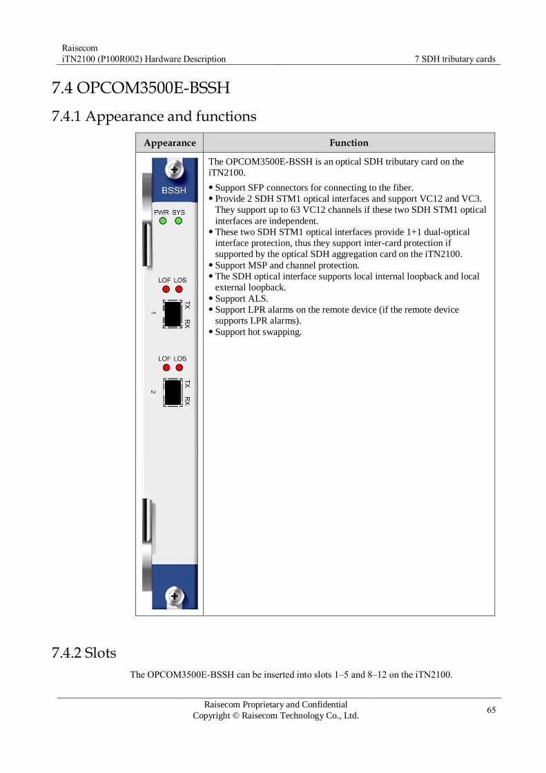
Raisecom
iTN2100 (P100R002) Hardware Description 7 SDH tributary cards
Raisecom Proprietary and Confidential
Copyright © Raisecom Technology Co., Ltd. 65
7.4 OPCOM3500E-BSSH
7.4.1 Appearance and functions
Appearance Function
The OPCOM3500E-BSSH is an optical SDH tributary card on the
iTN2100.
Support SFP connectors for connecting to the fiber. Provide 2 SDH STM1 optical interfaces and support VC12 and VC3.
They support up to 63 VC12 channels if these two SDH STM1 optical
interfaces are independent. These two SDH STM1 optical interfaces provide 1+1 dual-optical
interface protection, thus they support inter-card protection if
supported by the optical SDH aggregation card on the iTN2100. Support MSP and channel protection. The SDH optical interface supports local internal loopback and local
external loopback. Support ALS. Support LPR alarms on the remote device (if the remote device
supports LPR alarms). Support hot swapping.
7.4.2 Slots
The OPCOM3500E-BSSH can be inserted into slots 1–5 and 8–12 on the iTN2100.

Raisecom
iTN2100 (P100R002) Hardware Description 7 SDH tributary cards
Raisecom Proprietary and Confidential
Copyright © Raisecom Technology Co., Ltd. 66
7.4.3 Interfaces
Interface types
Table 7-19 lists two interfaces on the OPCOM3500E-BSSH panel.
Table 7-19 Interfaces on the OPCOM3500E-BSSH
Interface Type Description
A, B SFP optical interface Service uplink interface Tx indicates the sending interface and Rx
indicates the receiving interface.
Interface parameters
Table 7-20 lists parameters of interfaces A and B on the OPCOM3500E-BSSH.
Table 7-20 Parameters of interfaces A and B on the OPCOM3500E-BSSH
Parameter Description
Optical module type SFP optical module
Interface rate STM-1
Coding scheme NRZ
Multiplexing structure Comply with ITU-T G.707 recommendations.
Jitter features Comply with ITU-T G.783 and ITU-T G.825
recommendations.
Optical interface features Comply with ITU-T G.957 recommendations.
7.4.4 LEDs
Table 7-21 lists LEDs on the OPCOM3500E-BSSH panel.
Table 7-21 LEDs on the OPCOM3500E-BSSH panel
LED Status Description
PWR Green Power supply LED
Green: the power supply is normal. Off: the power supply is abnormal.
SYS Green System status LED
Green: the system is working improperly. Off: the system is working improperly. Blinking green: the system is working properly.

Raisecom
iTN2100 (P100R002) Hardware Description 7 SDH tributary cards
Raisecom Proprietary and Confidential
Copyright © Raisecom Technology Co., Ltd. 67
LED Status Description
LOF (A, B) Red LOF alarm LED
Red: input LOF alarms are generated on optical
interfaces. Off: no input LOF alarms are generated on optical
interfaces.
LOS (A, B) Red LOS alarm LED
Red: input LOS alarms are generated on optical
interfaces. Off: no input LOS alarms are generated on optical
interfaces.
7.4.5 Alarms
Table 7-22 lists alarms of the OPCOM3500E-BSSH.
Table 7-22 Alarms of the OPCOM3500E-BSSH
Alarm Cause Level
LOS alarm on the
STM1 optical interface
Attenuation of received signals is over great. The peer sender fails. The connector of fiber is dirty or improperly connected. The local receiver fails.
Critical
LOF alarm on the
STM1 optical interface
The Tx clock of the peer device fails. Optical signals do not match. The local receiving referential clock fails.
Critical
AU-AIS, AU-LOP The optical signals sent by the peer device is faulty and
the right pointer cannot be obtained.
Critical
MS-EXC BER in the multiplex section is over high. Optical signals are improperly transmitted. The performance of the local card is bad.
Critical
MS-AIS Multiplex section alarm LED
Alarm signals are inserted in the optical signals sent by
the peer device. The peer device is a regenerator and receives LOS,
LOF, or OOF alarms.
Minor
7.4.6 Specifications
Table 7-23 lists specifications of the OPCOM3500E-BSSH.
Table 7-23 Specifications of the OPCOM3500E-BSSH
Parameter Value
Dimensions 25 mm (Width) × 232 mm (Depth) × 240 mm (Height)
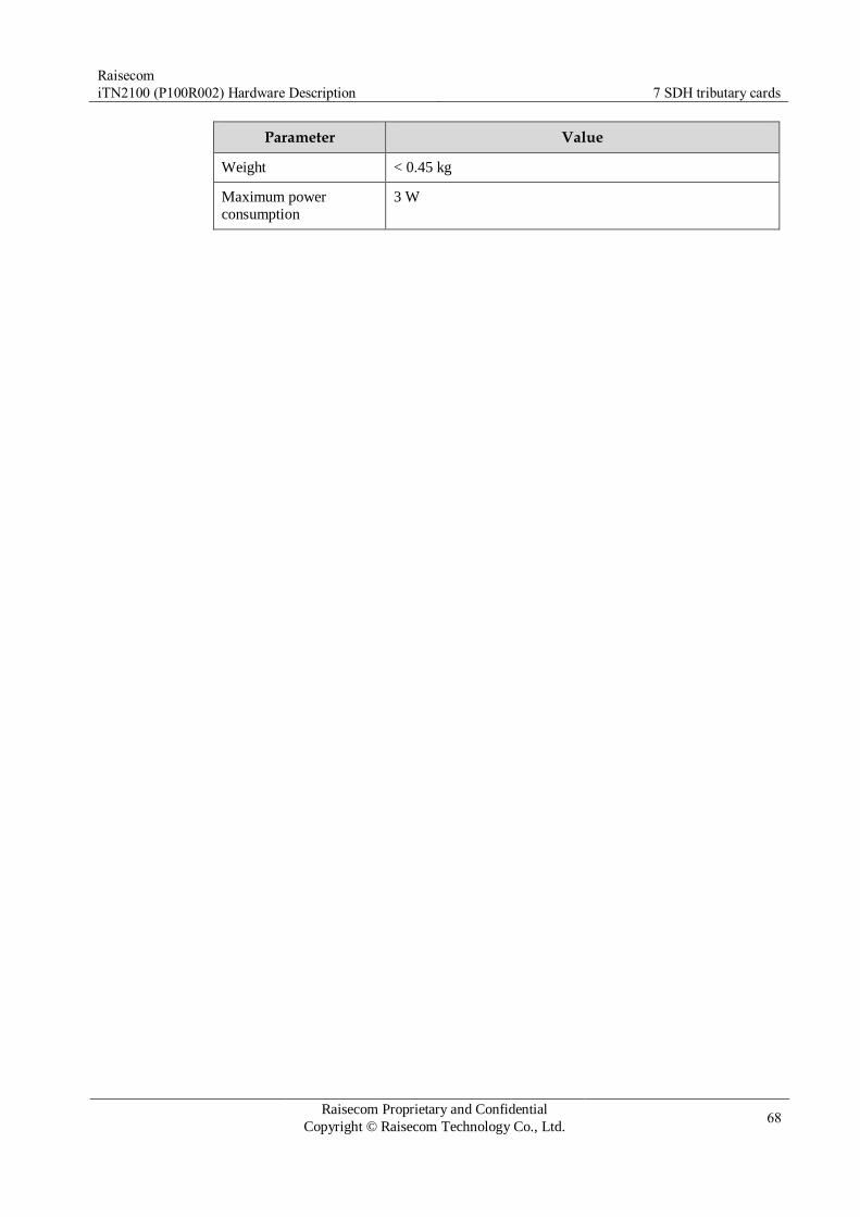
Raisecom
iTN2100 (P100R002) Hardware Description 7 SDH tributary cards
Raisecom Proprietary and Confidential
Copyright © Raisecom Technology Co., Ltd. 68
Parameter Value
Weight < 0.45 kg
Maximum power
consumption
3 W

Raisecom
iTN2100 (P100R002) Hardware Description 8 Ethernet aggregation cards
Raisecom Proprietary and Confidential
Copyright © Raisecom Technology Co., Ltd. 69
8 Ethernet aggregation cards
This chapter describes the Ethernet aggregation card of the iTN2100, including the following
section:
iTN2100-NTU-4GF
iTN2100-NTU-4XG

Raisecom
iTN2100 (P100R002) Hardware Description 8 Ethernet aggregation cards
Raisecom Proprietary and Confidential
Copyright © Raisecom Technology Co., Ltd. 70
8.1 iTN2100-NTU-4GF
8.1.1 Appearance and functions
Appearance Function
The iTN2100-NTU-4GF is a 1000 Mbit/s Ethernet aggregation card
used by the iTN2100. It has complete Multi-Protocol Label Switching-Transport Profile (MPLS-TP) networking capability.
The iTN2100-NTU-4GF is mainly used for the Packet Transport
Network (PTN). As the uplink card of the iTN2100-2IGC, iTN2100-
TSU, iTN2100-16GF, iTN2100-8FX, and iTN2100-CES-16E1T1-BL
service cards, the iTN2100-NTU-4GF forms a system-level MPLS-TP
networking scheme. It provides seamless communication with the
MPLS/PTN, meeting entrance test requirements of the Ministry of
Industry and Information Technology of the People's Republic of
China. Cooperating with the iTN remote devices, the iTN2100-NTU-4GF
provides a complete intelligent access solution. Support card-level protection and GE interface link aggregation
between two cards. Support master and secondary protection switching between two cards. Support hot swapping, High Availability (HA), and hot backup. Support 4 MPLS services: static Label Switching Path (LSP), Tunnel,
Pseudo-Wire Emulation Edge to Edge (PWE3), and Virtual Private
LAN Service (VPLS). Support 802.3ah, 802.1ag, Y.1731, MPLS-TP OAM, APS protocols,
Ethernet link-level, Ethernet service-level, and LSP-level connectivity
and performance detection, and LSP protection. Support Ethernet services, including Virtual Local Area Network
(VLAN), Medium Access Control (MAC) address table, QinQ, and
Ethernet protocols such as STP, G.8031, LLDP, and LACP. Support configuring the static IP address on the virtual interface to
manage the IP address of the managed device. Support simple static IP routing and DHCP. Support simple traffic classification, ACL, CAR, and queue
scheduling. TDM services support TDM accessing PWE3. Support Ethernet clock, CES clock, and 1588 V2 time
synchronization.
Functions realized by the iTN2100-NTU-4GF and other service cards
are shown as below:
The iTN2100-NTU-4GF and the iTN2100-8FX, iTN2100-16GF, or
iTN2100-2IGC work together to make the iTN2100 system realize
MPLS-based Ethernet leased services, providing end-to-end protection
and OAM. The iTN2100-NTU-4GF and the iTN2100-CES-16E1T1-BL work
together to make the iTN2100 system realize MPLS-based TDM
emulation services, providing end-to-end protection and OAM. The iTN2100-NTU-4GF and the iTN2100-TSU work together to carry
services of 2G and 3G base stations , supporting synchronous Ethernet
and CES service clock recovery.

Raisecom
iTN2100 (P100R002) Hardware Description 8 Ethernet aggregation cards
Raisecom Proprietary and Confidential
Copyright © Raisecom Technology Co., Ltd. 71
8.1.2 Slots
The iTN2100-NTU-4GF can be inserted into slots 9 and 10 on the iTN2100.
8.1.3 Interfaces
Interface types
There are 7 interfaces on the iTN2100-NTU-4GF panel, as listed in Table 8-1.
Table 8-1 Interfaces on the iTN2100-NTU-4GF panel
Interface Type Description
– MiniUSB Debugging interface
1–4 SFP optical interface Service uplink interface
SYNC-RX CC3 male connector BITS clock input
SYNC-TX CC3 male connector BITS clock output
Interface parameters
Table 8-2 lists parameters of interfaces 1–4 on the iTN2100-NTU-4GF.
Table 8-2 Parameters of interfaces 1–4 on the iTN2100-NTU-4GF
Parameter Description
Connector type SFP (LC/PC)
Coding scheme 8B/10B
Transmission rate 1.25 Gbit/s
Working mode Full duplex
MTU 13 Kbytes
Supported frame format Ethernet-II Ethernet-SAP Ethernet-SNAP
Supported network protocol IP
Compliance standard IEEE 802.3
Supported optical modules 100BASE-FX SFP 1000BASE-X SFP 1000BASE-T SFP 10/100/1000BASE-T SFP

Raisecom
iTN2100 (P100R002) Hardware Description 8 Ethernet aggregation cards
Raisecom Proprietary and Confidential
Copyright © Raisecom Technology Co., Ltd. 72
8.1.4 LEDs
There are 11 LEDs on the iTN2100-NTU-4GF, as listed in Table 8-3.
Table 8-3 LEDs on the iTN2100-NTU-4GF
LED Status Description
PWR Green Power supply LED
Green: the power supply is normal. Off: the power supply is abnormal.
SYS Green System status LED
Green: the system is working improperly. Off: the system is working improperly. Blinking green: the system is working properly.
ACT Green Primary/Slave LED
Green: the card is primary. Off: the card is slave.
1000M
(1–4)
Green SFP optical interface 1000 Mbit/s LED
Green: the Ethernet rate is 1000 Mbit/s. Off: the Ethernet rate is 100 Mbit/s or the connection fails.
LNK/ACT
(1–4)
Green SFP optical interface working LED
Green: the SFP optical interface is properly connected. Off: the SFP optical interface is improperly connected or
disconnected. Blinking green: the SFP optical interface is receiving or
sending data.
8.1.5 Specifications
Table 8-4 lists specifications of the iTN2100-NTU-4GF.
Table 8-4 Specifications of the iTN2100-NTU-4GF
Parameter Value
Dimensions 25 mm (Width) × 232 mm (Depth) × 240 mm (Height)
Weight 0.52 kg
Maximum power
consumption
26 W

Raisecom
iTN2100 (P100R002) Hardware Description 8 Ethernet aggregation cards
Raisecom Proprietary and Confidential
Copyright © Raisecom Technology Co., Ltd. 73
8.2 iTN2100-NTU-4XG
8.2.1 Appearance and functions
Appearance Function
The iTN2100-NTU-4XG is a 10GE aggregation card used by the
iTN2100. It has complete 10GE networking capability, supports
complete Telecom-grade Ethernet features and MPLS-TP networking scheme.
The iTN2100-NTU-4XG is mainly used for the PTN. As the uplink card
of the iTN2100-2IGC, iTN2100-TSU, iTN2100-16GF, and iTN2100-
CES-16E1T1-BL service cards, the iTN2100-NTU-4XG forms a system-
level MPLS-TP networking scheme. It provides seamless
communication with the MPLS/PTN and a dual-network and dual-core
solution for users, meeting requirements of big customer leased services.
Provide four 10GE interfaces. Support master and secondary protection switching between two cards.
In protection status, each interface on the master and secondary cards
can transmit services independently. Support 4 MPLS services: static LSP, Tunnel, PWE3, and VPLS. Support 802.3ah, 802.1ag, Y.1731, MPLS-TP OAM, APS protocols. Support SLA, Ethernet link-level, Ethernet service-level, and LSP-
level connectivity and performance detection, and LSP protection. Support Ethernet services, including Virtual Local Area Network
(VLAN), Medium Access Control (MAC) address table, QinQ, and
Ethernet protocols such as STP, RSTP, MSTP, G.8031, LLDP, and
LACP. Support configuring the static IP address on the virtual interface to
manage the IP address of the managed device. Support simple static IP routing and DHCP. Support simple traffic classification, ACL, CAR, and queue
scheduling. Support Ethernet clock synchronization. Support 10GE ring network. Support hot swapping.
8.2.2 Slots
The iTN2100-NTU-4XG can be inserted into slots 9 and 10 on the iTN2100.
When the iTN2100-NTU-4XG is working, the FANS360 fan of the iTN2100 must be working too. Chassis matched for the iTN2100-NTU-4XG (C) is the iTN2100-12 (C.10) or later. Power cards matched for (or compatible with) are shown as below: Only the SUB-PWRII-AC (E.01 or later) and the SUB-PWRM-AC (A.01 or later)
AC power cards are available. No limitation is on the DC power card.

Raisecom
iTN2100 (P100R002) Hardware Description 8 Ethernet aggregation cards
Raisecom Proprietary and Confidential
Copyright © Raisecom Technology Co., Ltd. 74
8.2.3 Interfaces
Interface types
There are 7 interfaces on the iTN2100-NTU-4XG panel, as listed in Table 8-5.
Table 8-5 Interfaces on the iTN2100-NTU-4XG panel
Interface Type Description
– MiniUSB Debugging interface
1–2 XFP optical interface Service uplink interface
3–4 XFP optical interface Service uplink interface
SYNC-RX CC3 male connector BITS clock input
SYNC-TX CC3 male connector BITS clock output
Interface parameters
Table 8-6 lists parameters of XFP interfaces on the iTN2100-NTU-4XG.
Table 8-6 Parameters of XFP interfaces on the iTN2100-NTU-4XG
Parameter Description
Connector type XFP (LC/PC)
Coding scheme 64B/66B
Transmission rate 10.3125 Gbit/s
Working mode Full duplex
MTU 13 Kbytes
Supported frame format Ethernet-II Ethernet-SAP Ethernet-SNAP
Supported network protocol IP
Compliance standard IEEE 802.3ae
Supported optical modules 10GBASE-SR XFP 10GBASE-LR XFP 10GBASE-ER XFP 10GBASE-ZR XFP
8.2.4 LEDs
There are 9 LEDs on the iTN2100-NTU-4XG, as listed in Table 8-7.

Raisecom
iTN2100 (P100R002) Hardware Description 8 Ethernet aggregation cards
Raisecom Proprietary and Confidential
Copyright © Raisecom Technology Co., Ltd. 75
Table 8-7 LEDs on the iTN2100-NTU-4XG
LED Status Description
PWR Green Power supply LED
Green: the power supply is normal. Off: the power supply is abnormal.
SYS Green System status LED
Green: the system is working improperly. Off: the system is working improperly. Blinking green: the system is working properly.
ACT Green Primary/Slave LED
Green: the card is primary. Off: the card is slave.
1000M
(3–4)
Green SFP optical interface 1000 Mbit/s LED
Green: the Ethernet rate is 1000 Mbit/s. Off: the Ethernet rate is 100 Mbit/s or the connection fails.
LNK/ACT
(1–4)
Green Optical interface working LED
Green: the optical interface is properly connected. Off: the optical interface is improperly connected or
disconnected. Blinking green: the optical interface is receiving or sending
data.
8.2.5 Specifications
Table 8-8 lists specifications of the iTN2100-NTU-4XG.
Table 8-8 Specifications of the iTN2100-NTU-4XG
Parameter Value
Dimensions 25 mm (Width) × 232 mm (Depth) × 240 mm (Height)
Weight 0.54 kg
Maximum power
consumption
44 W
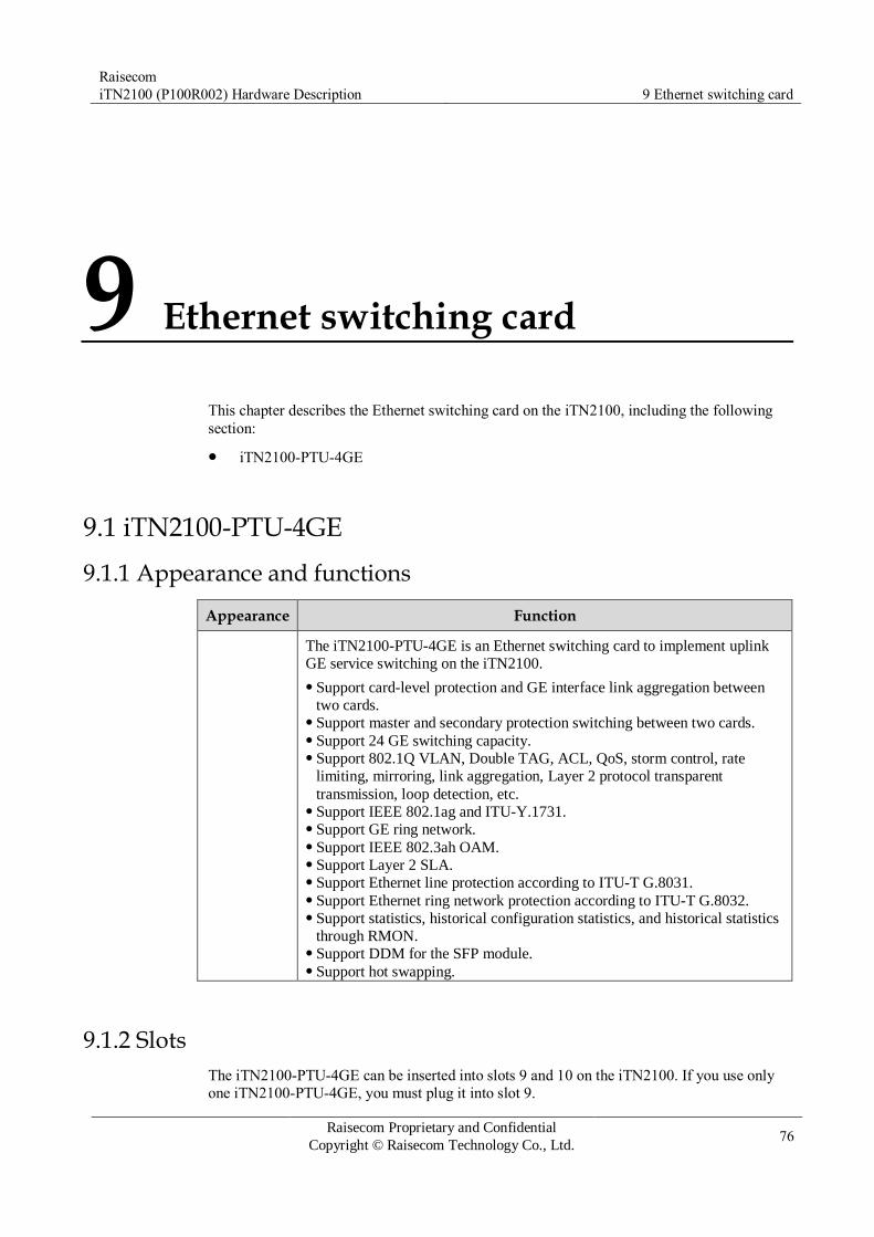
Raisecom
iTN2100 (P100R002) Hardware Description 9 Ethernet switching card
Raisecom Proprietary and Confidential
Copyright © Raisecom Technology Co., Ltd. 76
9 Ethernet switching card
This chapter describes the Ethernet switching card on the iTN2100, including the following
section:
iTN2100-PTU-4GE
9.1 iTN2100-PTU-4GE
9.1.1 Appearance and functions
Appearance Function
The iTN2100-PTU-4GE is an Ethernet switching card to implement uplink
GE service switching on the iTN2100.
Support card-level protection and GE interface link aggregation between
two cards. Support master and secondary protection switching between two cards. Support 24 GE switching capacity. Support 802.1Q VLAN, Double TAG, ACL, QoS, storm control, rate
limiting, mirroring, link aggregation, Layer 2 protocol transparent
transmission, loop detection, etc. Support IEEE 802.1ag and ITU-Y.1731. Support GE ring network. Support IEEE 802.3ah OAM. Support Layer 2 SLA. Support Ethernet line protection according to ITU-T G.8031. Support Ethernet ring network protection according to ITU-T G.8032. Support statistics, historical configuration statistics, and historical statistics
through RMON. Support DDM for the SFP module. Support hot swapping.
9.1.2 Slots
The iTN2100-PTU-4GE can be inserted into slots 9 and 10 on the iTN2100. If you use only one iTN2100-PTU-4GE, you must plug it into slot 9.

Raisecom
iTN2100 (P100R002) Hardware Description 9 Ethernet switching card
Raisecom Proprietary and Confidential
Copyright © Raisecom Technology Co., Ltd. 77
9.1.3 Interfaces
Interface types
There are seven interfaces on the iTN2100-PTU-4GE panel, as listed in Table 9-1.
Table 9-1 Interfaces on the iTN2100-PTU-4GE panel
Interface Type Description
– MiniUSB Debugging interface
1–4 SFP optical
interface
Service uplink interface Tx indicates the sending interface and Rx
indicates the receiving interface.
SYNC-RX CC3 male connector Reserved
SYNC-TX CC3 male connector Reserved
Interface parameters
Table 9-2 lists parameters of interfaces 1–4 on the iTN2100-PTU-4GE.
Table 9-2 Parameters of interfaces 1–4 on the iTN2100-PTU-4GE
Parameter Description
Connector type SFP (LC/PC)
Coding scheme 8B/10B
Transmission rate 1.25 Gbit/s
Working mode Full duplex
MTU 1522–13312 Bytes, configurable
Supported frame format Ethernet-II Ethernet-SAP Ethernet-SNAP
Supported network protocol IP
Compliance standard IEEE 802.3
Supported optical modules Interfaces 1 and 2: 1000BASE-X SFP and
1000BASE-T SFP Interface 3 and 4: 1000BASE-X SFP, 1000BASE-T
SFP, and 10/100/1000BASE-T SFP
9.1.4 LEDs
There are 11 LEDs on the iTN2100-PTU-4GE, as listed in Table 9-3.

Raisecom
iTN2100 (P100R002) Hardware Description 9 Ethernet switching card
Raisecom Proprietary and Confidential
Copyright © Raisecom Technology Co., Ltd. 78
Table 9-3 LEDs on the iTN2100-PTU-4GE panel
LED Status Description
PWR Green Power supply LED
Green: the power supply is normal. Off: the power supply is abnormal.
SYS Green System status LED
Green: the system is working improperly. Off: the system is working improperly. Blinking green: the system is working properly.
ACT Green Primary/Slave LED
Green: the card is primary. Off: the card is slave.
1000M
(1–4)
Green SFP optical interface 1000 Mbit/s LED
Green: the Ethernet rate is 1000 Mbit/s. Off: the Ethernet rate is 100 Mbit/s or the connection fails.
LNK/ACT
(1–4)
Green SFP optical interface working LED
Green: the SFP optical interface is properly connected. Off: the SFP optical interface is improperly connected or
disconnected. Blinking green: the SFP optical interface is receiving or
sending data.
9.1.5 Specifications
Table 9-4 lists specifications of the iTN2100-PTU-4GE.
Table 9-4 Specifications of the iTN2100-PTU-4GE
Parameter Value
Dimensions 25 mm (Width) × 232 mm (Depth) × 240 mm (Height)
Weight ≤ 0.49 kg
Maximum power
consumption
20 W

Raisecom
iTN2100 (P100R002) Hardware Description 10 Ethernet access cards
Raisecom Proprietary and Confidential
Copyright © Raisecom Technology Co., Ltd. 79
10 Ethernet access cards
This chapter describes Ethernet access cards of the iTN2100, including the following
sections:
iTN2100-16GF
iTN2100-8GE
iTN2100-8GF
iTN2100-16FX
iTN2100-8FX
iTN2100-2IGC
OPCOM3500E-4FX
OPCOM3500E-8FX

Raisecom
iTN2100 (P100R002) Hardware Description 10 Ethernet access cards
Raisecom Proprietary and Confidential
Copyright © Raisecom Technology Co., Ltd. 80
10.1 iTN2100-16GF
10.1.1 Appearance and functions
Appearance Function
The iTN2100-16GF is an Ethernet access card used by the iTN2100. It
aggregates 16-way 1000 Mbit/s Ethernet services of the iTN2100.
Support up to 16 ways of GE services. Support 802.1Q VLAN, QinQ, ACL, QoS, storm control, rate limiting,
port mirroring, link aggregation, Layer 2 protocol transparent
transmission, and loop detection. Support IEEE 802.3ah OAM, IEEE 802.1ag, ITU-Y.1731, and
extended OAM. Support the GE ring. Support ITU-T G.8031 ELPS. Support ITU-T G.8032 ERPS. Support basic functions of MPLS-TP, static LSP configurations, and
128 bidirectional LSPs. Support L2VPN. Support ALS. Support ST, RSTP, and MSTP. Support synchronous Ethernet. Support RMON functions, such as the statistics table, historical
statistics configuration table, and historical statistics table. Support Two-channel compact Small Form-factor Pluggable
transceiver (TSFP) module DDM. Support hot swapping.
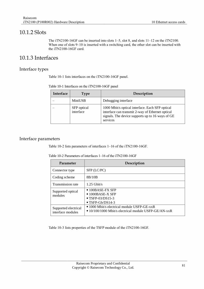
Raisecom
iTN2100 (P100R002) Hardware Description 10 Ethernet access cards
Raisecom Proprietary and Confidential
Copyright © Raisecom Technology Co., Ltd. 81
10.1.2 Slots
The iTN2100-16GF can be inserted into slots 1–5, slot 8, and slots 11–12 on the iTN2100.
When one of slots 9–10 is inserted with a switching card, the other slot can be inserted with
the iTN2100-16GF card.
10.1.3 Interfaces
Interface types
Table 10-1 lists interfaces on the iTN2100-16GF panel.
Table 10-1 Interfaces on the iTN2100-16GF panel
Interface Type Description
– MiniUSB Debugging interface
– SFP optical
interface
1000 Mbit/s optical interface. Each SFP optical
interface can transmit 2-way of Ethernet optical
signals. The device supports up to 16 ways of GE
services
Interface parameters
Table 10-2 lists parameters of interfaces 1–16 of the iTN2100-16GF.
Table 10-2 Parameters of interfaces 1–16 of the iTN2100-16GF
Parameter Description
Connector type SFP (LC/PC)
Coding scheme 8B/10B
Transmission rate 1.25 Gbit/s
Supported optical
modules
100BASE-FX SFP 1000BASE-X SFP TSFP-03/DS15-3 TSFP-Gb/DS14-3
Supported electrical
interface modules
1000 Mbit/s electrical module USFP-GE-xxR 10/100/1000 Mbit/s electrical module USFP-GE/AN-xxR
Table 10-3 lists properties of the TSFP module of the iTN2100-16GF.
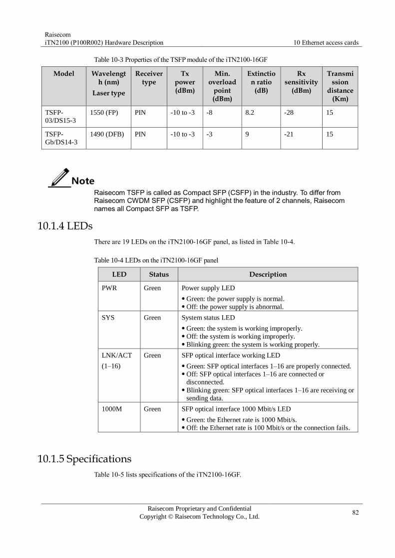
Raisecom
iTN2100 (P100R002) Hardware Description 10 Ethernet access cards
Raisecom Proprietary and Confidential
Copyright © Raisecom Technology Co., Ltd. 82
Table 10-3 Properties of the TSFP module of the iTN2100-16GF
Model Wavelength (nm)
Laser type
Receiver type
Tx power (dBm)
Min. overload
point (dBm)
Extinction ratio
(dB)
Rx sensitivity
(dBm)
Transmission
distance (Km)
TSFP-
03/DS15-3
1550 (FP) PIN -10 to -3 -8 8.2 -28 15
TSFP-
Gb/DS14-3
1490 (DFB) PIN -10 to -3 -3 9 -21 15
Raisecom TSFP is called as Compact SFP (CSFP) in the industry. To differ from Raisecom CWDM SFP (CSFP) and highlight the feature of 2 channels, Raisecom names all Compact SFP as TSFP.
10.1.4 LEDs
There are 19 LEDs on the iTN2100-16GF panel, as listed in Table 10-4.
Table 10-4 LEDs on the iTN2100-16GF panel
LED Status Description
PWR Green Power supply LED
Green: the power supply is normal. Off: the power supply is abnormal.
SYS Green System status LED
Green: the system is working improperly. Off: the system is working improperly. Blinking green: the system is working properly.
LNK/ACT
(1–16)
Green SFP optical interface working LED
Green: SFP optical interfaces 1–16 are properly connected. Off: SFP optical interfaces 1–16 are connected or
disconnected. Blinking green: SFP optical interfaces 1–16 are receiving or
sending data.
1000M Green SFP optical interface 1000 Mbit/s LED
Green: the Ethernet rate is 1000 Mbit/s. Off: the Ethernet rate is 100 Mbit/s or the connection fails.
10.1.5 Specifications
Table 10-5 lists specifications of the iTN2100-16GF.

Raisecom
iTN2100 (P100R002) Hardware Description 10 Ethernet access cards
Raisecom Proprietary and Confidential
Copyright © Raisecom Technology Co., Ltd. 83
Table 10-5 Specifications of the iTN2100-16GF
Parameter Value
Dimensions 25 mm (Width) × 232 mm (Depth) × 240 mm (Height)
Weight 0.5 kg
Maximum power
consumption
30 W

Raisecom
iTN2100 (P100R002) Hardware Description 10 Ethernet access cards
Raisecom Proprietary and Confidential
Copyright © Raisecom Technology Co., Ltd. 84
10.2 iTN2100-8GE
10.2.1 Appearance and functions
Appearance Function
The iTN2100-8GE is an Ethernet access card used by the iTN2100. It
aggregates 8 ways of 1000 Mbit/s Ethernet services of the iTN2100.
Support up to 8 ways of GE services. Support 802.1Q VLAN, QinQ, ACL, QoS, storm control, rate
limiting, port mirroring, link aggregation, Layer 2 protocol
transparent transmission, and loop detection. Support IEEE 802.3ah, IEEE 802.1ag, ITU-Y.1731, and extended
OAM. Support the GE ring. Support SLA. Support ITU-T G.8031 ELPS. Support ITU-T G.8032 ERPS. Support basic functions of MPLS-TP, static LSP, and 128
bidirectional LSPs. Support L2VPN. Support STP, RSTP, and MSTP. Support synchronous Ethernet. Support RMON functions, such as the statistics table, historical
statistics configuration table, and historical statistics table. Support hot swapping.

Raisecom
iTN2100 (P100R002) Hardware Description 10 Ethernet access cards
Raisecom Proprietary and Confidential
Copyright © Raisecom Technology Co., Ltd. 85
10.2.2 Slots
The iTN2100-8GE can be inserted into slots 1–5, slot 8, and slots 11–12 on the iTN2100.
When slot 9 or slot 10 is inserted with an iTN2100-PTU-4GE or iTN2100-NTU-4GF card,
the other slot can be inserted with the iTN2100-8GF card.
10.2.3 Interfaces
Interface types
Table 10-6 lists interfaces on the iTN2100-8GE panel.
Table 10-6 Interfaces on the iTN2100-8GE panel
Interface Type Description
– MiniUSB Debugging interface
1–8 RJ45 10/10/1000 Mbit/s auto-negotiation electrical interface
Interface parameters
Table 10-7 lists parameters of interfaces 1–8 of the iTN2100-8GE.
Table 10-7 Parameters of interfaces 1–8 of the iTN2100-8GE
Parameter Description
Connector type RJ45
Interface rate 10/100/1000 Mbit/s auto-negotiation
Duplex mode Full duplex/Half duplex auto-negotiation
Support choosing full duplex or half duplex in non-auto-negotiation mode.
MTU 9600 bytes
Wiring Auto MDI/MDIX
Flow control Full duplex: IEEE 802.3x flow control Half duplex: back pressure flow control
Compliance standard IEEE802.3 IEEE802.3u IEEE802.3ab
10.2.4 LEDs
Table 10-8 lists LEDs on the iTN2100-8GE panel.
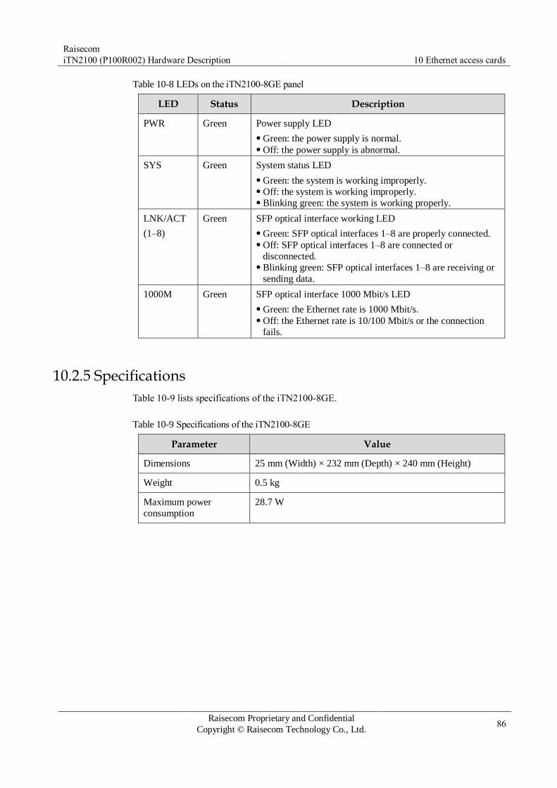
Raisecom
iTN2100 (P100R002) Hardware Description 10 Ethernet access cards
Raisecom Proprietary and Confidential
Copyright © Raisecom Technology Co., Ltd. 86
Table 10-8 LEDs on the iTN2100-8GE panel
LED Status Description
PWR Green Power supply LED
Green: the power supply is normal. Off: the power supply is abnormal.
SYS Green System status LED
Green: the system is working improperly. Off: the system is working improperly. Blinking green: the system is working properly.
LNK/ACT
(1–8)
Green SFP optical interface working LED
Green: SFP optical interfaces 1–8 are properly connected. Off: SFP optical interfaces 1–8 are connected or
disconnected. Blinking green: SFP optical interfaces 1–8 are receiving or
sending data.
1000M Green SFP optical interface 1000 Mbit/s LED
Green: the Ethernet rate is 1000 Mbit/s. Off: the Ethernet rate is 10/100 Mbit/s or the connection
fails.
10.2.5 Specifications
Table 10-9 lists specifications of the iTN2100-8GE.
Table 10-9 Specifications of the iTN2100-8GE
Parameter Value
Dimensions 25 mm (Width) × 232 mm (Depth) × 240 mm (Height)
Weight 0.5 kg
Maximum power
consumption
28.7 W
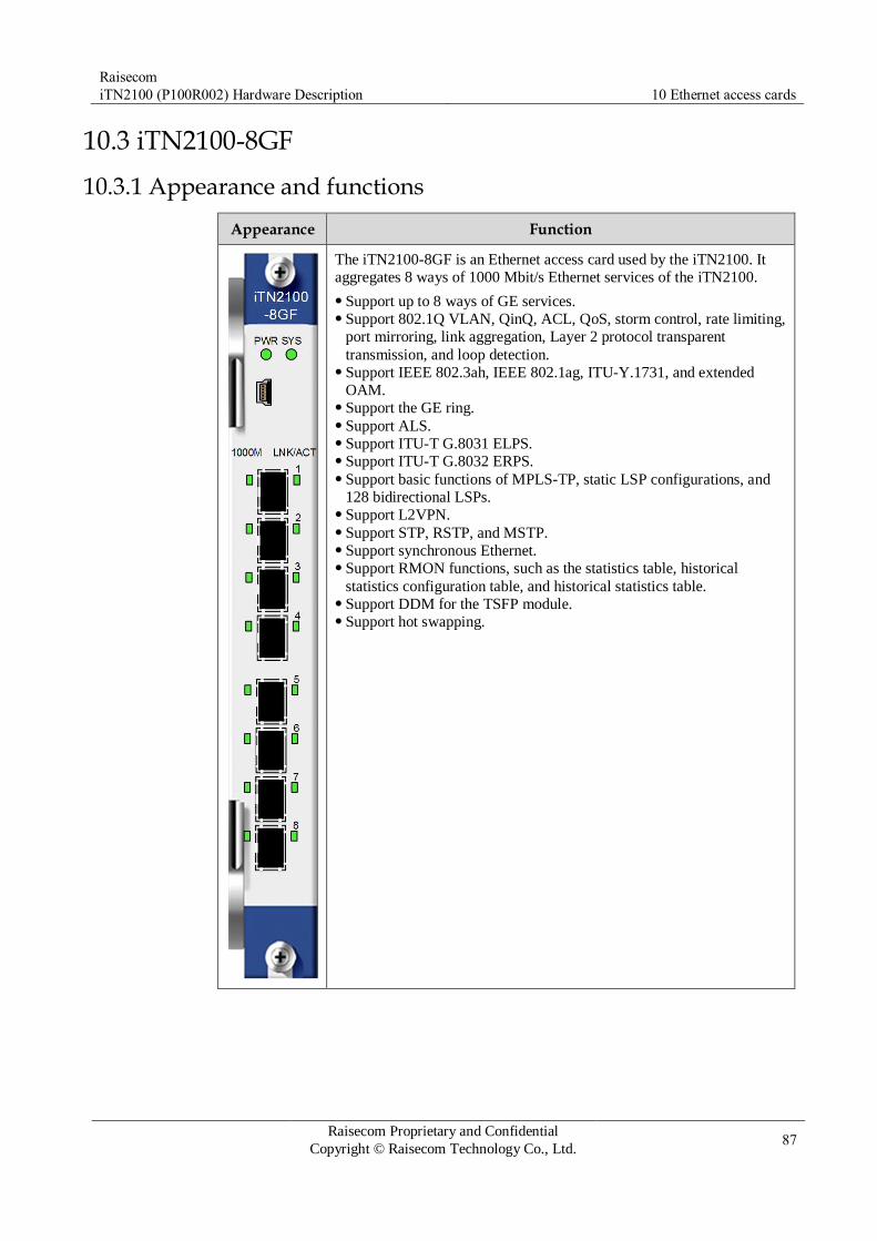
Raisecom
iTN2100 (P100R002) Hardware Description 10 Ethernet access cards
Raisecom Proprietary and Confidential
Copyright © Raisecom Technology Co., Ltd. 87
10.3 iTN2100-8GF
10.3.1 Appearance and functions
Appearance Function
The iTN2100-8GF is an Ethernet access card used by the iTN2100. It
aggregates 8 ways of 1000 Mbit/s Ethernet services of the iTN2100.
Support up to 8 ways of GE services. Support 802.1Q VLAN, QinQ, ACL, QoS, storm control, rate limiting,
port mirroring, link aggregation, Layer 2 protocol transparent
transmission, and loop detection. Support IEEE 802.3ah, IEEE 802.1ag, ITU-Y.1731, and extended
OAM. Support the GE ring. Support ALS. Support ITU-T G.8031 ELPS. Support ITU-T G.8032 ERPS. Support basic functions of MPLS-TP, static LSP configurations, and
128 bidirectional LSPs. Support L2VPN. Support STP, RSTP, and MSTP. Support synchronous Ethernet. Support RMON functions, such as the statistics table, historical
statistics configuration table, and historical statistics table. Support DDM for the TSFP module. Support hot swapping.
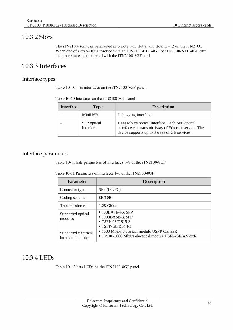
Raisecom
iTN2100 (P100R002) Hardware Description 10 Ethernet access cards
Raisecom Proprietary and Confidential
Copyright © Raisecom Technology Co., Ltd. 88
10.3.2 Slots
The iTN2100-8GF can be inserted into slots 1–5, slot 8, and slots 11–12 on the iTN2100.
When one of slots 9–10 is inserted with an iTN2100-PTU-4GE or iTN2100-NTU-4GF card,
the other slot can be inserted with the iTN2100-8GF card.
10.3.3 Interfaces
Interface types
Table 10-10 lists interfaces on the iTN2100-8GF panel.
Table 10-10 Interfaces on the iTN2100-8GF panel
Interface Type Description
– MiniUSB Debugging interface
– SFP optical
interface
1000 Mbit/s optical interface. Each SFP optical
interface can transmit 1way of Ethernet service. The device supports up to 8 ways of GE services.
Interface parameters
Table 10-11 lists parameters of interfaces 1–8 of the iTN2100-8GF.
Table 10-11 Parameters of interfaces 1–8 of the iTN2100-8GF
Parameter Description
Connector type SFP (LC/PC)
Coding scheme 8B/10B
Transmission rate 1.25 Gbit/s
Supported optical
modules
100BASE-FX SFP 1000BASE-X SFP TSFP-03/DS15-3 TSFP-Gb/DS14-3
Supported electrical
interface modules
1000 Mbit/s electrical module USFP-GE-xxR 10/100/1000 Mbit/s electrical module USFP-GE/AN-xxR
10.3.4 LEDs
Table 10-12 lists LEDs on the iTN2100-8GF panel.

Raisecom
iTN2100 (P100R002) Hardware Description 10 Ethernet access cards
Raisecom Proprietary and Confidential
Copyright © Raisecom Technology Co., Ltd. 89
Table 10-12 LEDs on the iTN2100-8GF panel
LED Status Description
PWR Green Power supply LED
Green: the power supply is normal. Off: the power supply is abnormal.
SYS Green System status LED
Green: the system is working improperly. Off: the system is working improperly. Blinking green: the system is working properly.
LNK/ACT
(1–8)
Green SFP optical interface working LED
Green: SFP optical interfaces 1–8 are properly connected. Off: SFP optical interfaces 1–8 are connected or
disconnected. Blinking green: SFP optical interfaces 1–8 are receiving or
sending data.
1000M Green SFP optical interface 1000 Mbit/s LED
Green: the Ethernet rate is 1000 Mbit/s. Off: the Ethernet rate is 100 Mbit/s or the connection fails.
10.3.5 Specifications
Table 10-13 lists specifications of the iTN2100-8GF.
Table 10-13 Specifications of the iTN2100-8GF
Parameter Value
Dimensions 25 mm (Width) × 232 mm (Depth) × 240 mm (Height)
Weight 0.5 kg
Maximum power
consumption
26 W

Raisecom
iTN2100 (P100R002) Hardware Description 10 Ethernet access cards
Raisecom Proprietary and Confidential
Copyright © Raisecom Technology Co., Ltd. 90
10.4 iTN2100-16FX
10.4.1 Appearance and functions
Appearance Function
The iTN2100-16FX is an Ethernet access card used by the iTN2100. It
aggregates 16 ways of 1000 Mbit/s Ethernet services of the iTN2100.
Support up to 16 ways of GE services. Support 802.1Q VLAN, QinQ, ACL, QoS, storm control, rate limiting,
port mirroring, link aggregation, Layer 2 protocol transparent
transmission, and loop detection. Support IEEE 802.3ah, IEEE 802.1ag, ITU-Y.1731, and extended
OAM. Support the FE ring. Support ALS. Support ITU-T G.8031 ELPS. Support ITU-T G.8032 ERPS. Support basic functions of MPLS-TP, static LSP configurations, and
128 bidirectional LSPs. Support L2VPN. Support STP, RSTP, and MSTP. Support synchronous Ethernet. Support RMON functions, such as the statistics table, historical
statistics configuration table, and historical statistics table. Support DDM for the TSFP module. Support hot swapping.
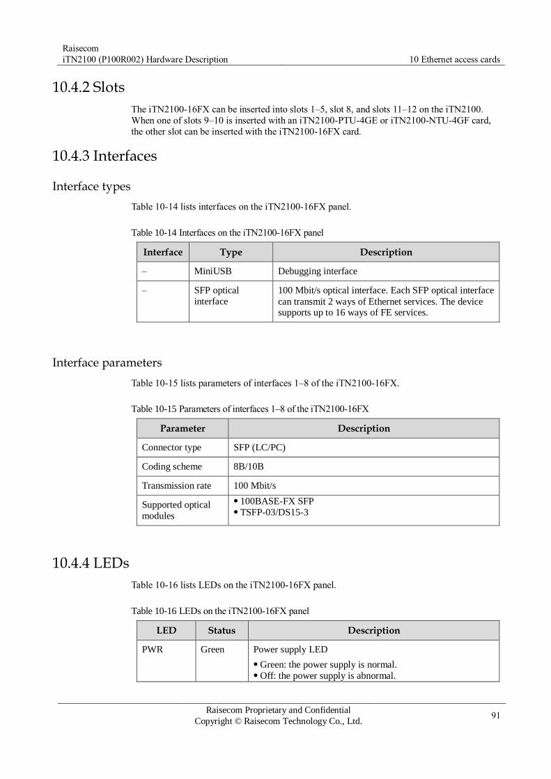
Raisecom
iTN2100 (P100R002) Hardware Description 10 Ethernet access cards
Raisecom Proprietary and Confidential
Copyright © Raisecom Technology Co., Ltd. 91
10.4.2 Slots
The iTN2100-16FX can be inserted into slots 1–5, slot 8, and slots 11–12 on the iTN2100.
When one of slots 9–10 is inserted with an iTN2100-PTU-4GE or iTN2100-NTU-4GF card,
the other slot can be inserted with the iTN2100-16FX card.
10.4.3 Interfaces
Interface types
Table 10-14 lists interfaces on the iTN2100-16FX panel.
Table 10-14 Interfaces on the iTN2100-16FX panel
Interface Type Description
– MiniUSB Debugging interface
– SFP optical
interface
100 Mbit/s optical interface. Each SFP optical interface
can transmit 2 ways of Ethernet services. The device supports up to 16 ways of FE services.
Interface parameters
Table 10-15 lists parameters of interfaces 1–8 of the iTN2100-16FX.
Table 10-15 Parameters of interfaces 1–8 of the iTN2100-16FX
Parameter Description
Connector type SFP (LC/PC)
Coding scheme 8B/10B
Transmission rate 100 Mbit/s
Supported optical
modules
100BASE-FX SFP TSFP-03/DS15-3
10.4.4 LEDs
Table 10-16 lists LEDs on the iTN2100-16FX panel.
Table 10-16 LEDs on the iTN2100-16FX panel
LED Status Description
PWR Green Power supply LED
Green: the power supply is normal. Off: the power supply is abnormal.

Raisecom
iTN2100 (P100R002) Hardware Description 10 Ethernet access cards
Raisecom Proprietary and Confidential
Copyright © Raisecom Technology Co., Ltd. 92
LED Status Description
SYS Green System status LED
Green: the system is working improperly. Off: the system is working improperly. Blinking green: the system is working properly.
LNK/ACT
(1–16)
Green SFP optical interface working LED
Green: SFP optical interfaces 1–16 are properly connected. Off: SFP optical interfaces 1–16 are connected or
disconnected. Blinking green: SFP optical interfaces 1–16 are receiving or
sending data.
10.4.5 Specifications
Table 10-17 lists specifications of the iTN2100-16FX.
Table 10-17 Specifications of the iTN2100-16FX
Parameter Value
Dimensions 25 mm (Width) × 232 mm (Depth) × 240 mm (Height)
Weight 0.5 kg
Maximum power
consumption
28 W

Raisecom
iTN2100 (P100R002) Hardware Description 10 Ethernet access cards
Raisecom Proprietary and Confidential
Copyright © Raisecom Technology Co., Ltd. 93
10.5 iTN2100-8FX
10.5.1 Appearance and functions
Appearance Function
The iTN2100-8FX is an 8-way 100 Mbit/s Ethernet optical signal access card on the
iTN2100.
Aggregate 8 ways of Ethernet optical signals into one way of GE signals and then send
them to the switching card through the backplane. Meanwhile, it sends clock signals
sent from the switching card to the peer device (such as transceiver). Provide eight SFP optical interfaces and each of them can transmit one way of Ethernet
optical signals. Support cooperation with dual-switching card on the iTN2100. Provide the debugging interface. Support querying and viewing manufacturing information Support management and maintenance of the SFP optical modules. Support configuration and management of Ethernet optical interfaces. Support RCLINK (a remote device management protocol specially developed by
Raisecom) management of remote devices connected to the downlink of the Ethernet
optical interfaces. – Support remote management for Raisecom transceivers (which support remote
management). – Support remote management through 802.3ah Ethernet OAM.
Support Layer 2 switching functions, including: – Support MAC address automatical learning; support management of the MAC address
table, including adding, deleting, and querying MAC address table entries; support
configuring MAC address aging time; support configuring the number of MAC
addresses learnt by the interface. – Support jumbo frame. – Support storm control over broadcast packets, unknown multicast packets, and DLE
packets. – Support port mirroring. You can configure the ingress and egress directions
independently. – Support rate limiting on ports. You can limit the rate on ingress and egress directions
independently. – Support 802.1Q VLAN and 4094 concurrent VLANs. – Support QinQ. – Support Ethernet loop detection. – Support Ethernet link aggregation. – Support Layer 2 transparent transmission. – Support QoS. – Support Access Control List (ACL). – Support Layer 2 SLA.
Support RMON. Support CFM and Y.1731. Support saving and recovering configurations of a card, and preconfigurations of a card. Support online software upgrade for the card. Support hot swapping.
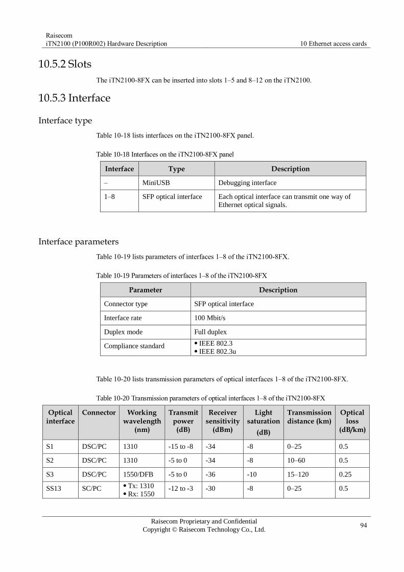
Raisecom
iTN2100 (P100R002) Hardware Description 10 Ethernet access cards
Raisecom Proprietary and Confidential
Copyright © Raisecom Technology Co., Ltd. 94
10.5.2 Slots
The iTN2100-8FX can be inserted into slots 1–5 and 8–12 on the iTN2100.
10.5.3 Interface
Interface type
Table 10-18 lists interfaces on the iTN2100-8FX panel.
Table 10-18 Interfaces on the iTN2100-8FX panel
Interface Type Description
– MiniUSB Debugging interface
1–8 SFP optical interface Each optical interface can transmit one way of
Ethernet optical signals.
Interface parameters
Table 10-19 lists parameters of interfaces 1–8 of the iTN2100-8FX.
Table 10-19 Parameters of interfaces 1–8 of the iTN2100-8FX
Parameter Description
Connector type SFP optical interface
Interface rate 100 Mbit/s
Duplex mode Full duplex
Compliance standard IEEE 802.3 IEEE 802.3u
Table 10-20 lists transmission parameters of optical interfaces 1–8 of the iTN2100-8FX.
Table 10-20 Transmission parameters of optical interfaces 1–8 of the iTN2100-8FX
Optical interface
Connector Working wavelength
(nm)
Transmit power (dB)
Receiver sensitivity
(dBm)
Light saturation
(dB)
Transmission distance (km)
Optical loss
(dB/km)
S1 DSC/PC 1310 -15 to -8 -34 -8 0–25 0.5
S2 DSC/PC 1310 -5 to 0 -34 -8 10–60 0.5
S3 DSC/PC 1550/DFB -5 to 0 -36 -10 15–120 0.25
SS13 SC/PC Tx: 1310 Rx: 1550
-12 to -3 -30 -8 0–25 0.5

Raisecom
iTN2100 (P100R002) Hardware Description 10 Ethernet access cards
Raisecom Proprietary and Confidential
Copyright © Raisecom Technology Co., Ltd. 95
Optical interface
Connector Working wavelength
(nm)
Transmit power (dB)
Receiver sensitivity
(dBm)
Light saturation
(dB)
Transmission distance (km)
Optical loss
(dB/km)
SS15 SC/PC Tx: 1550 Rx: 1310
-12 to -3 -30 -8 0–25 0.25
SS23 SC/PC Tx: 1310 Rx: 1550
-5 to 0 -32 -8 10–50 0.5
SS25 SC/PC Tx:1550 Rx:1310
-5 to 0 -32 -8 10–50 0.25
The transmission distance in Table 10-20 is the maximum transmission distance in typical fiber conditions. The actual transmission distance depends on the network.
10.5.4 LEDs
Table 10-21 lists LEDs on the iTN2100-8FX panel.
Table 10-21 LEDs on the iTN2100-8FX panel
LED Status Description
PWR Green Power supply LED
Green: the power supply is normal. Off: the power supply is abnormal.
SYS Green System status LED
Green: the system is working improperly. Off: the system is working improperly. Blinking green: the system is working properly.
LNK/ACT
(1–8)
Green SFP optical interface working LED
Green: SFP optical interfaces 1–8 are properly
connected. Off: SFP optical interfaces 1–8 are connected or
disconnected. Blinking green: SFP optical interfaces 1–8 are receiving
or sending data.
10.5.5 Specifications
Table 10-22 lists specifications of the iTN2100-8FX.
Table 10-22 Specifications of the iTN2100-8FX
Parameter Value
Dimensions 25 mm (Width) × 232 mm (Depth) × 240 mm (Height)
Weight 0.4 kg

Raisecom
iTN2100 (P100R002) Hardware Description 10 Ethernet access cards
Raisecom Proprietary and Confidential
Copyright © Raisecom Technology Co., Ltd. 96
Parameter Value
Maximum power
consumption
15 W

Raisecom
iTN2100 (P100R002) Hardware Description 10 Ethernet access cards
Raisecom Proprietary and Confidential
Copyright © Raisecom Technology Co., Ltd. 97
10.6 iTN2100-2IGC
10.6.1 Appearance and functions
Appearance Function
The iTN2100-2IGC is a 2-way 1000 Mbit/s Ethernet service access
card, which must be used together with the iTN2100-PTU-4GE to implement switching.
Provide two groups of GE interfaces (Combo interface, an optical
interface and an electrical interface in each group) for service access. Support detection of dual-switching cards when working on the
iTN2100 and support cooperation with dual-switching cards. Support selection of service channels on the backplane when working
on the iTN2100. Support saving, querying, and displaying manufacturing information. Support management and maintenance of the SFP optical modules. Support configuration and management of Ethernet optical interfaces. Support online software upgrade for the card. Support saving and recovering configurations of a card, and
preconfiguring the card. Support hot swapping.
10.6.2 Slots
The iTN2100-2IGC can be inserted into slots 1–5 and 8–12 on the iTN2100.

Raisecom
iTN2100 (P100R002) Hardware Description 10 Ethernet access cards
Raisecom Proprietary and Confidential
Copyright © Raisecom Technology Co., Ltd. 98
10.6.3 Interface
Interface types
Table 10-23 lists interfaces on the iTN2100-2IGC panel.
Table 10-23 Interfaces on the iTN2100-2IGC panel
Interface Type Description
– MiniUSB Debugging interface
–
(GE1–GE2 electrical interface)
RJ45 Each interface can transmit a way of 1000
Mbit/s Ethernet service.
–
(GE1–GE2 optical interface)
SFP optical
interface
Each interface can transmit a way of 1000
Mbit/s Ethernet service.
Interface parameters
Table 10-24 lists parameters of GE1 and GE2 electrical interfaces.
Table 10-24 Parameters of GE1 and GE2 electrical interfaces on the iTN2100-2IGC
Parameter Description
Connector type RJ45
Interface rate 10/100/1000 Mbit/s auto-negotiation
Duplex mode Full duplex/Half duplex auto-negotiation
Support choosing full duplex or half duplex in non-auto-
negotiation mode.
MTU 10 Kbytes
Flow control Full duplex: IEEE 802.3x flow control Half duplex: back pressure flow control
Wiring scheme Auto MDI/MDIX
Compliance standard IEEE802.3 IEEE802.3u IEEE802.3ab
Table 10-25 lists parameters of GE1 and GE2 optical interfaces.

Raisecom
iTN2100 (P100R002) Hardware Description 10 Ethernet access cards
Raisecom Proprietary and Confidential
Copyright © Raisecom Technology Co., Ltd. 99
Table 10-25 Parameters of GE1 and GE2 optical interfaces on the iTN2100-2IGC
Parameter Description
Connector type SFP optical interface
Interface rate 100/1000 Mbit/s
Duplex mode Full duplex
MTU 10 Kbytes
Compliance standard IEEE802.3u IEEE802.3z
10.6.4 LEDs
Table 10-26 lists LEDs on the iTN2100-2IGC panel.
Table 10-26 LEDs on the iTN2100-2IGC panel
LED Status Description
PWR Green Power supply LED
Green: the power supply is normal. Off: the power supply is abnormal.
SYS Green System status LED
Green: the system is working improperly. Off: the system is working improperly. Blinking green: the system is working properly.
1000M
(GE1/GE2 electrical interface)
Green GE1/GE2 electrical interface 1000 Mbit/s LED
Green: the GE1/GE2 electrical interface is working
at 1000 Mbit/s. Off: the GE1/GE2 electrical interface is working at
100 Mbit/s or 10 Mbit/s.
LNK/ACT
GE1/GE2 electrical
interface
Green GE1/GE2 electrical interface working LED
Green: the GE1/GE2 electrical interface is properly
connected. Blinking green: the GE1/GE2 electrical interface is
receiving or sending data. Off: the GE1/GE2 electrical interface is improperly
connected or disconnected.
1000M
(GE1/GE2 optical interface)
Green GE1/GE2 optical interface 1000 Mbit/s LED
Green: the GE1/GE2 optical interface is working at
1000 Mbit/s. Off: the GE1/GE2 optical interface is working at
100 Mbit/s or 10 Mbit/s.

Raisecom
iTN2100 (P100R002) Hardware Description 10 Ethernet access cards
Raisecom Proprietary and Confidential
Copyright © Raisecom Technology Co., Ltd. 100
LED Status Description
LNK/ACT
GE1/GE2 optical
interface
Green GE1/GE2 optical interface working LED
Green: the GE1/GE2 optical interface is properly
connected. Blinking green: the GE1/GE2 optical interface is
receiving or sending data. Off: the GE1/GE2 optical interface improperly
connected or disconnected.
10.6.5 Specifications
Table 10-27 lists specifications of the iTN2100-2IGC.
Table 10-27 Specifications of the iTN2100-2IGC
Parameter Value
Dimensions 25 mm (Width) × 232 mm (Depth) × 240 mm (Height)
Weight 0.36 kg
Maximum power
consumption
10 W

Raisecom
iTN2100 (P100R002) Hardware Description 10 Ethernet access cards
Raisecom Proprietary and Confidential
Copyright © Raisecom Technology Co., Ltd. 101
10.7 OPCOM3500E-4FX
10.7.1 Appearance and functions
Appearance Function
The OPCOM3500E-4FX is a 4-way optical interface Ethernet access
card on the iTN2100.
Provide four 100 Mbit/s Ethernet optical interfaces. Aggregate Ethernet services received from the front panel to the
switching card through the backplane, and transmit services uplink
through the switching card. Support storm control over broadcast messages, unknown multicast
messages, and DLF messages. Support interface isolation protection. Support interface aggregation. Support QoS and determine four output queues by priority. Support 802.1Q VLAN and 4K concurrent VLANs. Support QinQ. Support 8K MAC addresses and 30 static MAC addresses. Support enabling or disabling MAC address learning based on
interface. Support configurable aging time ranging from 0s to 3825s. Support interface-based non-linear rate limiting ranging from 62 kbit/s
to 100 Mbit/s. Support transparently transmitting BPDU, LACP, and 802.1x
management frames. Support remote management for remote transceivers, Gazelle RM531-
FE (B), and RC521H-FE. Support hot swapping.
10.7.2 Slots
The OPCOM3500E-4FX can be inserted into slots 1–5 and 8–12 on the iTN2100.

Raisecom
iTN2100 (P100R002) Hardware Description 10 Ethernet access cards
Raisecom Proprietary and Confidential
Copyright © Raisecom Technology Co., Ltd. 102
10.7.3 Interfaces
Interface types
Table 10-28 lists interfaces on the OPCOM3500E-4FX panel.
Table 10-28 Interfaces on the OPCOM3500E-4FX panel
Interface Type Description
1–4 1×9 optical interface Each interface transmits one way of Ethernet
optical signals. Tx indicates the sending interface and Rx indicates
the receiving interface.
Interface parameters
Table 10-29 lists parameters of interfaces 1–4 on the OPCOM3500E-4FX.
Table 10-29 Parameters of interfaces 1–4 on the OPCOM3500E-4FX
Parameter Description
Connector type 1×9 optical interface
Interface rate 100 Mbit/s
MTU 1632 bytes
Flow control Full duplex: IEEE 802.3x flow control Half duplex: back pressure flow control
10.7.4 LEDs
Table 10-30 lists LEDs on the OPCOM3500E-4FX panel.
Table 10-30 LEDs on the OPCOM3500E-4FX panel
LED Status Description
PWR Green Power supply LED
Green: the power supply is normal. Off: the power supply is abnormal.
SYS Green System status LED
Green: the system is working improperly. Off: the system is working improperly. Blinking green: the system is working properly.
SD
(1–4)
Green Optical signal detection LED
Green: optical signals are detected. Off: no optical signals are detected.

Raisecom
iTN2100 (P100R002) Hardware Description 10 Ethernet access cards
Raisecom Proprietary and Confidential
Copyright © Raisecom Technology Co., Ltd. 103
LED Status Description
LNK/ACT
(1–4)
Green Link working LED
Green: the link interface is properly connected. Off: the link interface improperly connected or disconnected. Blinking green: the link interface is receiving or sending data.
10.7.5 DIP swtiches
Table 10-31 lists configurations of DIP switch SW1 on the OPCOM3500E-4FX.
Table 10-31 Configurations of DIP switch SW1 on the OPCOM3500E-4FX
DIP switch
Function Status Description
Bit1 Bit2 Bit3 Bit4 Optical-interface component type
SW1 Configure
the type of
the optical-
interface component.
ON ON ON ON M
ON ON ON OFF S1
ON ON OFF ON S2
ON ON OFF OFF S3
ON OFF ON ON SS13
ON OFF ON OFF SS15
ON OFF OFF ON SS23
ON OFF OFF OFF SS25
The card is properly configured before delivery. Do not reconfigure it if not needed.
10.7.6 Specifications
Table 10-32 lists specifications of the OPCOM3500E-4FX.
Table 10-32 Specifications of the OPCOM3500E-4FX
Parameter Value
Dimensions 25 mm (Width) × 232 mm (Depth) × 240 mm (Height)
Weight 0.4 kg
Maximum power
consumption
12 W
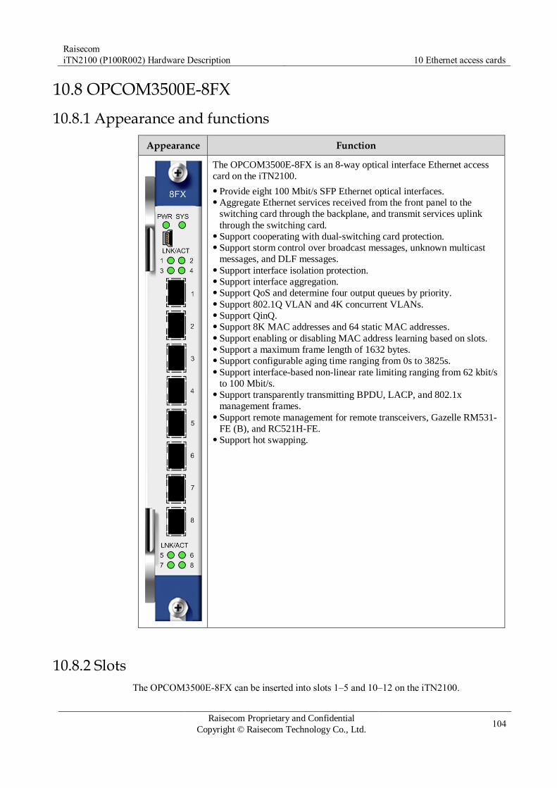
Raisecom
iTN2100 (P100R002) Hardware Description 10 Ethernet access cards
Raisecom Proprietary and Confidential
Copyright © Raisecom Technology Co., Ltd. 104
10.8 OPCOM3500E-8FX
10.8.1 Appearance and functions
Appearance Function
The OPCOM3500E-8FX is an 8-way optical interface Ethernet access
card on the iTN2100.
Provide eight 100 Mbit/s SFP Ethernet optical interfaces. Aggregate Ethernet services received from the front panel to the
switching card through the backplane, and transmit services uplink
through the switching card. Support cooperating with dual-switching card protection. Support storm control over broadcast messages, unknown multicast
messages, and DLF messages. Support interface isolation protection. Support interface aggregation. Support QoS and determine four output queues by priority. Support 802.1Q VLAN and 4K concurrent VLANs. Support QinQ. Support 8K MAC addresses and 64 static MAC addresses. Support enabling or disabling MAC address learning based on slots. Support a maximum frame length of 1632 bytes. Support configurable aging time ranging from 0s to 3825s. Support interface-based non-linear rate limiting ranging from 62 kbit/s
to 100 Mbit/s. Support transparently transmitting BPDU, LACP, and 802.1x
management frames. Support remote management for remote transceivers, Gazelle RM531-
FE (B), and RC521H-FE. Support hot swapping.
10.8.2 Slots
The OPCOM3500E-8FX can be inserted into slots 1–5 and 10–12 on the iTN2100.
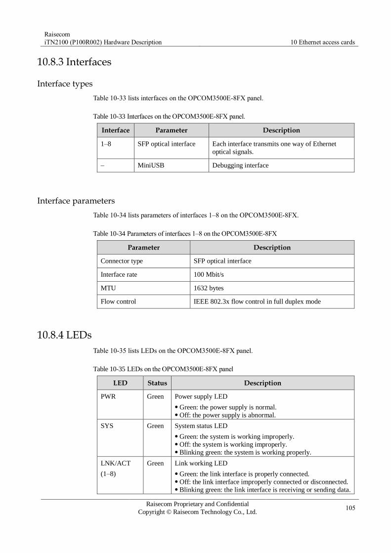
Raisecom
iTN2100 (P100R002) Hardware Description 10 Ethernet access cards
Raisecom Proprietary and Confidential
Copyright © Raisecom Technology Co., Ltd. 105
10.8.3 Interfaces
Interface types
Table 10-33 lists interfaces on the OPCOM3500E-8FX panel.
Table 10-33 Interfaces on the OPCOM3500E-8FX panel.
Interface Parameter Description
1–8 SFP optical interface Each interface transmits one way of Ethernet
optical signals.
– MiniUSB Debugging interface
Interface parameters
Table 10-34 lists parameters of interfaces 1–8 on the OPCOM3500E-8FX.
Table 10-34 Parameters of interfaces 1–8 on the OPCOM3500E-8FX
Parameter Description
Connector type SFP optical interface
Interface rate 100 Mbit/s
MTU 1632 bytes
Flow control IEEE 802.3x flow control in full duplex mode
10.8.4 LEDs
Table 10-35 lists LEDs on the OPCOM3500E-8FX panel.
Table 10-35 LEDs on the OPCOM3500E-8FX panel
LED Status Description
PWR Green Power supply LED
Green: the power supply is normal. Off: the power supply is abnormal.
SYS Green System status LED
Green: the system is working improperly. Off: the system is working improperly. Blinking green: the system is working properly.
LNK/ACT
(1–8)
Green Link working LED
Green: the link interface is properly connected. Off: the link interface improperly connected or disconnected. Blinking green: the link interface is receiving or sending data.

Raisecom
iTN2100 (P100R002) Hardware Description 10 Ethernet access cards
Raisecom Proprietary and Confidential
Copyright © Raisecom Technology Co., Ltd. 106
10.8.5 Specifications
Table 10-36 lists specifications of the OPCOM3500E-8FX.
Table 10-36 Specifications of the OPCOM3500E-8FX
Parameter Value
Dimensions 25 mm (Width) × 232 mm (Depth) × 240 mm (Height)
Weight 0.4 kg
Maximum power
consumption
12.5 W

Raisecom
iTN2100 (P100R002) Hardware Description 11 Dual-network transmission cards
Raisecom Proprietary and Confidential
Copyright © Raisecom Technology Co., Ltd. 107
11 Dual-network transmission cards
This chapter describes dual-network transmission cards of the iTN2100, including the
following sections:
iTN2100-8EOS-8GF
iTN2100-4STM1-GC
iTN2100-HSELD
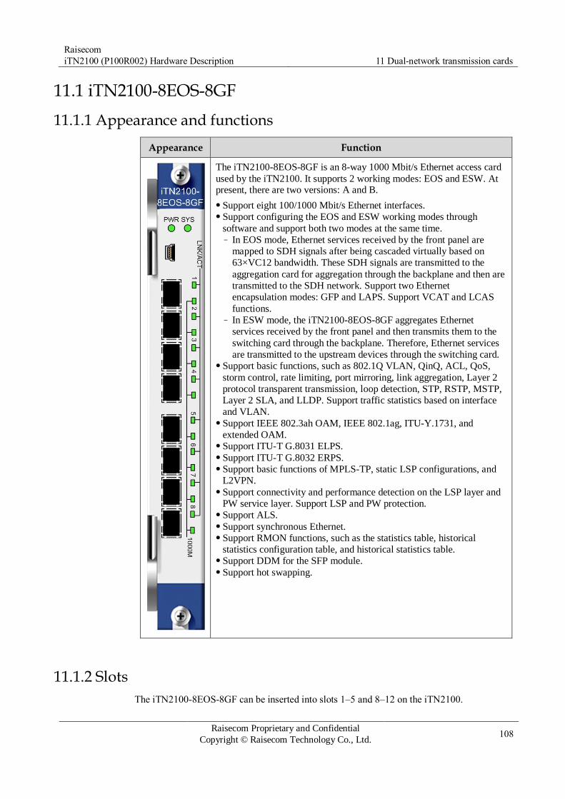
Raisecom
iTN2100 (P100R002) Hardware Description 11 Dual-network transmission cards
Raisecom Proprietary and Confidential
Copyright © Raisecom Technology Co., Ltd. 108
11.1 iTN2100-8EOS-8GF
11.1.1 Appearance and functions
Appearance Function
The iTN2100-8EOS-8GF is an 8-way 1000 Mbit/s Ethernet access card
used by the iTN2100. It supports 2 working modes: EOS and ESW. At present, there are two versions: A and B.
Support eight 100/1000 Mbit/s Ethernet interfaces. Support configuring the EOS and ESW working modes through
software and support both two modes at the same time. – In EOS mode, Ethernet services received by the front panel are
mapped to SDH signals after being cascaded virtually based on
63×VC12 bandwidth. These SDH signals are transmitted to the
aggregation card for aggregation through the backplane and then are
transmitted to the SDH network. Support two Ethernet
encapsulation modes: GFP and LAPS. Support VCAT and LCAS
functions. – In ESW mode, the iTN2100-8EOS-8GF aggregates Ethernet
services received by the front panel and then transmits them to the
switching card through the backplane. Therefore, Ethernet services
are transmitted to the upstream devices through the switching card. Support basic functions, such as 802.1Q VLAN, QinQ, ACL, QoS,
storm control, rate limiting, port mirroring, link aggregation, Layer 2
protocol transparent transmission, loop detection, STP, RSTP, MSTP,
Layer 2 SLA, and LLDP. Support traffic statistics based on interface
and VLAN. Support IEEE 802.3ah OAM, IEEE 802.1ag, ITU-Y.1731, and
extended OAM. Support ITU-T G.8031 ELPS. Support ITU-T G.8032 ERPS. Support basic functions of MPLS-TP, static LSP configurations, and
L2VPN. Support connectivity and performance detection on the LSP layer and
PW service layer. Support LSP and PW protection. Support ALS. Support synchronous Ethernet. Support RMON functions, such as the statistics table, historical
statistics configuration table, and historical statistics table. Support DDM for the SFP module. Support hot swapping.
11.1.2 Slots
The iTN2100-8EOS-8GF can be inserted into slots 1–5 and 8–12 on the iTN2100.

Raisecom
iTN2100 (P100R002) Hardware Description 11 Dual-network transmission cards
Raisecom Proprietary and Confidential
Copyright © Raisecom Technology Co., Ltd. 109
11.1.3 Interfaces
Interface types
Table 11-1 lists interfaces on the iTN2100-8EOS-8GF panel.
Table 11-1 Interfaces on the iTN2100-8EOS-8GF panel
Interface Type Description
– MiniUSB Debugging interface
1, 2, 3, 4, 5, 6, 7, 8 SFP optical interface Service downlink interface
Interface parameters
Table 11-2 lists parameters of interfaces 1–8 of the iTN2100-8EOS-8GF.
Table 11-2 Parameters of interfaces 1–8 of the iTN2100-8EOS-8GF
Parameter Description
Connector type LC/PC
Coding scheme 8B/10B
Transmission rate 1.25 Gbit/s
Supported optical modules 100BASE-FX SFP 1000BASE-X SFP
Supported electrical
interface modules
1000 Mbit/s electrical module USFP-GE-xxR 10/100/1000 Mbit/s electrical module USFP-GE/AN-xxR
11.1.4 LEDs
Table 11-3 lists LEDs on the iTN2100-8EOS-8GF panel.
Table 11-3 LEDs on the iTN2100-8EOS-8GF
LED Status Description
PWR Green Power supply LED
Green: the power supply is normal. Off: the power supply is abnormal or disconnected.
SYS Green System status LED
Green: the system is being powered on. Off: the system is working improperly. Blinking green: the system is working properly.
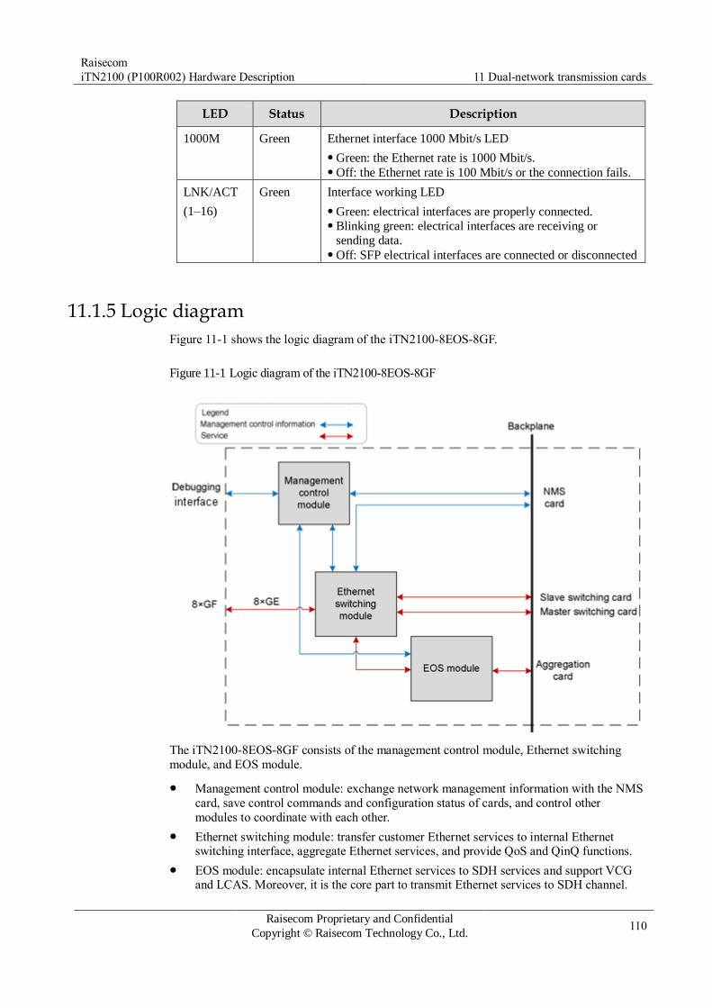
Raisecom
iTN2100 (P100R002) Hardware Description 11 Dual-network transmission cards
Raisecom Proprietary and Confidential
Copyright © Raisecom Technology Co., Ltd. 110
LED Status Description
1000M Green Ethernet interface 1000 Mbit/s LED
Green: the Ethernet rate is 1000 Mbit/s. Off: the Ethernet rate is 100 Mbit/s or the connection fails.
LNK/ACT
(1–16)
Green Interface working LED
Green: electrical interfaces are properly connected. Blinking green: electrical interfaces are receiving or
sending data. Off: SFP electrical interfaces are connected or disconnected
11.1.5 Logic diagram
Figure 11-1 shows the logic diagram of the iTN2100-8EOS-8GF.
Figure 11-1 Logic diagram of the iTN2100-8EOS-8GF
The iTN2100-8EOS-8GF consists of the management control module, Ethernet switching
module, and EOS module.
Management control module: exchange network management information with the NMS
card, save control commands and configuration status of cards, and control other
modules to coordinate with each other.
Ethernet switching module: transfer customer Ethernet services to internal Ethernet switching interface, aggregate Ethernet services, and provide QoS and QinQ functions.
EOS module: encapsulate internal Ethernet services to SDH services and support VCG and LCAS. Moreover, it is the core part to transmit Ethernet services to SDH channel.

Raisecom
iTN2100 (P100R002) Hardware Description 11 Dual-network transmission cards
Raisecom Proprietary and Confidential
Copyright © Raisecom Technology Co., Ltd. 111
11.1.6 Alarms
Table 11-4 lists alarms of the iTN2100-8EOS-8GF.
Table 11-4 Alarms of the iTN2100-8EOS-8GF
Alarm Cause Level
E1 LOS Signals are lost. Critical
E1 AIS E1 signals are all 1 because the transmitted data
are incorrect or the remote device outputs AIS
signals.
Minor
E1 LOF Data sent by the upstream node are incorrect
because services are configured improperly or the hardware fails.
Critical
E1 CRC An error on data occurs during transmission. Critical
E1 GID ERROR Inverse multiplexing configurations are incorrect. Critical
E1 remote alarms (AIS,
LOF, CRC, and LOS)
The remote device managed by the card generates
(AIS, LOF, CRC, and LOS) alarms.
Critical
E1 remote loopback
alarm
The remote device managed by the card generates
a loopback.
Critical
Ethernet interface Link
Down
Links of Ethernet interfaces are disconnected. Critical
11.1.7 Specifications
Table 11-5 lists specifications of the iTN2100-8EOS-8GF.
Table 11-5 Specifications of the iTN2100-8EOS-8GF
Parameter Value
Dimensions 25 mm (Width) × 232 mm (Depth) × 240 mm (Height)
Weight 0.5 kg
Maximum power
consumption
30 W

Raisecom
iTN2100 (P100R002) Hardware Description 11 Dual-network transmission cards
Raisecom Proprietary and Confidential
Copyright © Raisecom Technology Co., Ltd. 112
11.2 iTN2100-4STM1-GC
11.2.1 Appearance and functions
Appearance Function
The iTN2100-4STM1-GC has 4 STM1 interfaces and provides 8
Ethernet channels. Channels 1–4 and channels 5–8 share 63 VC12
respectively. The iTN2100-4STM1-GC aggregates services and then
transmits them to the switching card through the GE interface on the
backplane. In addition, the aggregated services can be directly
forwarded through the Combo GE interface on the front panel. In
addition, the iTN2100-4STM1-GC supports transmitting 1-way VC4 services to the aggregation card.
Support up to 4-way STM1 access services and 1-way GE access
services. Support using the NView NNM system or CLI to output aggregated
Ethernet services through the Ethernet interface on the front panel or
transmit them to the switching card through the backplane. Support storm control of broadcast, multicast, and DLF packets Support 802.1Q VLAN, QinQ, ACL, QoS, storm control, rate
limiting, port mirroring, link aggregation, Layer 2 protocol transparent
transmission, and loop detection. Support IEEE 802.3ah OAM, IEEE 802.1ag, ITU-Y.1731, and
extended OAM. Support the GE ring, Ethernet interface loop detection, ALS, and auto-
recovery. Support Layer 2 SLA. Support ITU-T G.8031 ELPS. Support ITU-T G.8032 ERPS. Support basic functions of MPLS-TP, static LSP configurations, and
128 bidirectional LSPs. Support L2VPN. Support ALS. Support ST, RSTP, and MSTP. Support synchronous Ethernet. Support RMON functions, such as the statistics table, historical
statistics configuration table, and historical statistics table. Support DDM of the SFP module. Support hot swapping. Support VC12 cross connection between STM1 optical interfaces or
between STM1 interfaces and aggregation cards. Support 8 VCGs. Each VCG is bound with up to 63 VC12. Support
flexible timeslot assignment from timeslots of STM1 optical
interfaces/aggregation cards to EOS interfaces. The timeslot type is
configured to VC12. Support GFP Ethernet encapsulation mode, VCAT, and LCAS. Support STM1 optical interface supports 1+1 MSP, channel
protection, and inter-card protection from dual service cards and
aggregation cards. The service capacity is configured to 1-way VC4
and the protection switching time is smaller than 50ms. Support 4 network management channels, which can be configured to
DCC or VCC independently. Support SDH overhead, alarm, and performance statistics.

Raisecom
iTN2100 (P100R002) Hardware Description 11 Dual-network transmission cards
Raisecom Proprietary and Confidential
Copyright © Raisecom Technology Co., Ltd. 113
11.2.2 Slots
The iTN2100-4STM1-GC can be inserted into slots 1–5 and 8–12 on the iTN2100.
11.2.3 Interfaces
Interface types
Table 11-6 lists interfaces on the iTN2100-4STM1-GC panel.
Table 11-6 Interfaces on the iTN2100-4STM1-GC panel
Interface Type Description
– MiniUSB Debugging interface
1, 2, 3, 4 SFP interface Service downlink interface Tx indicates the sending interface and Rx indicates
the receiving interface.
Combo SFP interface
RJ45 interface
Service uplink interface Transmitting 1 way of 1000 Mbit/s Ethernet services
Interface parameters
Table 11-7 lists parameters of interfaces 1–4 of the iTN2100-4STM1-GC.
Table 11-7 Parameters of interfaces 1–4 of the iTN2100-4STM1-GC
Parameter Description
Connector type SFP optical interface
Interface rate STM-1
Coding scheme NRZ
Multiplexing structure Comply with ITU-T G.707 recommendations.
Clock features Comply with ITU-T G.813 recommendations.
Electrical features Comply with ITU-T G.957 recommendations.
Jitter features Comply with ITU-T G.783 and ITU-T G.825 recommendations.
Table 11-8 lists parameters of Combo SFP interfaces of the iTN2100-4STM1-GC.
Table 11-8 Parameters of Combo SFP interfaces of the iTN2100-4STM1-GC
Parameter Description
Connector type SFP optical interface

Raisecom
iTN2100 (P100R002) Hardware Description 11 Dual-network transmission cards
Raisecom Proprietary and Confidential
Copyright © Raisecom Technology Co., Ltd. 114
Parameter Description
Interface rate 100/1000 Mbit/s
Duplex mode Full duplex
MTU 10 KB
Compliance standard IEEE 802.3u IEEE 802.3z
Table 11-9 lists parameters of Combo RJ45 interfaces of the iTN2100-4STM1-GC.
Table 11-9 Parameters of Combo RJ45 interfaces of the iTN2100-4STM1-GC
Parameter Description
Connector type RJ45
Interface rate 10/100/1000 Mbit/s auto-negotiation
MTU 1916 bytes
Wiring scheme Auto MDI/MDI-X
Duplex mode Full duplex/Half duplex auto-negotiation
Flow control Full duplex: IEEE 802.3x flow control Half duplex: back pressure flow control
11.2.4 LEDs
Table 11-10 lists LEDs on the iTN2100-4STM1-GC panel.
Table 11-10 LEDs on the iTN2100-4STM1-GC
LED Status Description
PWR Green Power supply LED
Green: the power supply is normal. Off: the power supply is abnormal.
SYS Green System status LED
Green: the system is working improperly. Off: the system is working improperly. Blinking green: the system is working properly.
LOF (1–4) Red LOF alarm LED
Red: input LOF alarms are generated on optical interfaces. Off: no input LOF alarms are generated on optical interfaces.
LOS (1–4) Red LOS alarm LED
Red: input LOS alarms are generated on optical interfaces. Off: no input LOS alarms are generated on optical interfaces.

Raisecom
iTN2100 (P100R002) Hardware Description 11 Dual-network transmission cards
Raisecom Proprietary and Confidential
Copyright © Raisecom Technology Co., Ltd. 115
LED Status Description
1000M Green Ethernet interface 1000 Mbit/s LED
Green: the Ethernet rate is 1000 Mbit/s. Off: the Ethernet rate is 100 Mbit/s or the connection fails.
LNK/ACT
(1–16)
Green Interface working LED
Green: electrical interfaces are properly connected. Blinking green: electrical interfaces are receiving or sending
data. Off: SFP electrical interfaces are connected or disconnected.
11.2.5 Alarms
Table 11-11 lists alarms of the iTN2100-4STM1-GC.
Table 11-11 Alarms of the iTN2100-4STM1-GC
Alarm Cause Level
E1 LOS Signals are lost. Critical
E1 AIS E1 signals are all 1 because the transmitted data
are incorrect or the remote device outputs AIS
signals.
Minor
E1 LOF Data sent by the upstream node are incorrect
because services are configured improperly or the hardware fails.
Critical
E1 CRC An error on data occurs during transmission. Critical
E1 GID ERROR Inverse multiplexing configurations are incorrect. Critical
E1 remote alarms (AIS,
LOF, CRC, and LOS)
The remote device managed by the card generates
(AIS, LOF, CRC, and LOS) alarms.
Critical
E1 remote loopback
alarm
The remote device managed by the card generates
a loopback.
Critical
Ethernet interface Link Down
Links of Ethernet interfaces are disconnected. Critical
11.2.6 Specifications
Table 11-12 lists specifications of the iTN2100-4STM1-GC.
Table 11-12 Specifications of the iTN2100-4STM1-GC
Parameter Value
Dimensions 25 mm (Width) × 232 mm (Depth) × 240 mm (Height)

Raisecom
iTN2100 (P100R002) Hardware Description 11 Dual-network transmission cards
Raisecom Proprietary and Confidential
Copyright © Raisecom Technology Co., Ltd. 116
Parameter Value
Weight 0.5 kg
Maximum power
consumption
20 W
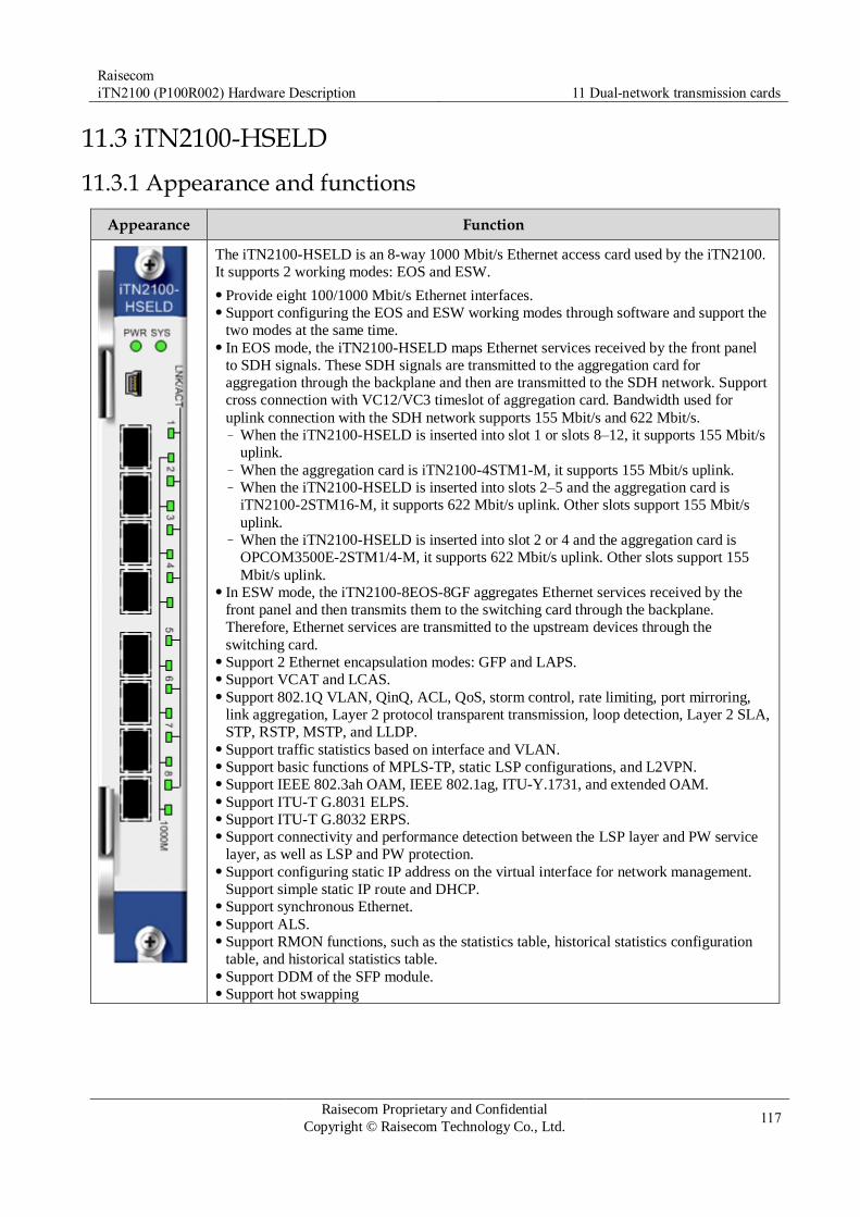
Raisecom
iTN2100 (P100R002) Hardware Description 11 Dual-network transmission cards
Raisecom Proprietary and Confidential
Copyright © Raisecom Technology Co., Ltd. 117
11.3 iTN2100-HSELD
11.3.1 Appearance and functions
Appearance Function
The iTN2100-HSELD is an 8-way 1000 Mbit/s Ethernet access card used by the iTN2100.
It supports 2 working modes: EOS and ESW.
Provide eight 100/1000 Mbit/s Ethernet interfaces. Support configuring the EOS and ESW working modes through software and support the
two modes at the same time. In EOS mode, the iTN2100-HSELD maps Ethernet services received by the front panel
to SDH signals. These SDH signals are transmitted to the aggregation card for
aggregation through the backplane and then are transmitted to the SDH network. Support
cross connection with VC12/VC3 timeslot of aggregation card. Bandwidth used for
uplink connection with the SDH network supports 155 Mbit/s and 622 Mbit/s. – When the iTN2100-HSELD is inserted into slot 1 or slots 8–12, it supports 155 Mbit/s
uplink. – When the aggregation card is iTN2100-4STM1-M, it supports 155 Mbit/s uplink. – When the iTN2100-HSELD is inserted into slots 2–5 and the aggregation card is
iTN2100-2STM16-M, it supports 622 Mbit/s uplink. Other slots support 155 Mbit/s
uplink. – When the iTN2100-HSELD is inserted into slot 2 or 4 and the aggregation card is
OPCOM3500E-2STM1/4-M, it supports 622 Mbit/s uplink. Other slots support 155
Mbit/s uplink. In ESW mode, the iTN2100-8EOS-8GF aggregates Ethernet services received by the
front panel and then transmits them to the switching card through the backplane.
Therefore, Ethernet services are transmitted to the upstream devices through the
switching card. Support 2 Ethernet encapsulation modes: GFP and LAPS. Support VCAT and LCAS. Support 802.1Q VLAN, QinQ, ACL, QoS, storm control, rate limiting, port mirroring,
link aggregation, Layer 2 protocol transparent transmission, loop detection, Layer 2 SLA,
STP, RSTP, MSTP, and LLDP. Support traffic statistics based on interface and VLAN. Support basic functions of MPLS-TP, static LSP configurations, and L2VPN. Support IEEE 802.3ah OAM, IEEE 802.1ag, ITU-Y.1731, and extended OAM. Support ITU-T G.8031 ELPS. Support ITU-T G.8032 ERPS. Support connectivity and performance detection between the LSP layer and PW service
layer, as well as LSP and PW protection. Support configuring static IP address on the virtual interface for network management.
Support simple static IP route and DHCP. Support synchronous Ethernet. Support ALS. Support RMON functions, such as the statistics table, historical statistics configuration
table, and historical statistics table. Support DDM of the SFP module. Support hot swapping

Raisecom
iTN2100 (P100R002) Hardware Description 11 Dual-network transmission cards
Raisecom Proprietary and Confidential
Copyright © Raisecom Technology Co., Ltd. 118
11.3.2 Slots
The iTN2100-HSELD can be inserted into slots 1–5 and 8–12 on the iTN2100.
11.3.3 Interfaces
Interface types
Table 11-13 lists interfaces on the iTN2100-HSELD panel
Table 11-13 Interfaces on the iTN2100-HSELD panel
Interface Type Description
– MiniUSB Debugging interface
1, 2, 3, 4, 5, 6, 7, 8 SFP optical interface Service downlink interface
Interface parameters
Table 11-14 lists parameters of interfaces 1–8 of the iTN2100-HSELD.
Table 11-14 Parameters of interfaces 1–8 of the iTN2100-HSELD
Parameter Description
Connector type LC/PC
Coding scheme 8B/10B
Transmission rate 1.25 Gbit/s
Supported optical modules 100BASE-FX SFP 1000BASE-X SFP
Supported electrical
interface modules
1000 Mbit/s electrical module USFP-GE-xxR 10/100/1000 Mbit/s electrical module USFP-GE/AN-xxR
11.3.4 LEDs
Table 11-15 lists LEDs on the iTN2100-HSELD panel.
Table 11-15 LEDs on the iTN2100-HSELD
LED Status Description
PWR Green Power supply LED
Green: the power supply is normal. Off: the power supply is abnormal or is disconnected.

Raisecom
iTN2100 (P100R002) Hardware Description 11 Dual-network transmission cards
Raisecom Proprietary and Confidential
Copyright © Raisecom Technology Co., Ltd. 119
LED Status Description
SYS Green System status LED
Green: the system is being powered on. Off: the system is working improperly. Blinking green: the system is working properly.
1000M Green Ethernet interface working rate LED
Green: the interface is working at the rate of 1000 Mbit/s. Off: the interface is working at the rate of 100 Mbit/s or
disconnected.
LNK/ACT Green Line working LED
Green: the electrical interface is connected properly. Blinking green: the electrical interface is transmitted data. Off: the electrical interface is disconnected or connected
improperly.
11.3.5 Logic diagram
Figure 11-2 shows the logic diagram of the iTN2100-HSELD.
Figure 11-2 Logic diagram of the iTN2100-HSELD
The iTN2100-HSELD consists of the management control module, Ethernet switching
module, and EOS module.
Management control module: exchange network management information with the NMS
card, save control commands and configuration status of cards, and control other modules to coordinate with each other.

Raisecom
iTN2100 (P100R002) Hardware Description 11 Dual-network transmission cards
Raisecom Proprietary and Confidential
Copyright © Raisecom Technology Co., Ltd. 120
Ethernet switching module: transfer customer Ethernet services to internal Ethernet
switching interface, aggregate Ethernet services, and provide QoS and QinQ functions.
EOS module: encapsulate internal Ethernet services to SDH services and support VCG and LCAS. Moreover, it is the core part to transmit Ethernet services to SDH channel.
11.3.6 Alarms
Table 11-16 lists alarms of the iTN2100-HSELD.
Table 11-16 Alarms of the iTN2100-HSELD
Alarm Cause Level
E1 LOS Signals are lost. Critical
E1 AIS E1 signals are all 1 because the transmitted data
are incorrect or the remote device outputs AIS signals.
Minor
E1 LOF Data sent by the upstream node are incorrect
because services are configured improperly or the
hardware fails.
Critical
E1 CRC An error on data occurs during transmission. Critical
E1 GID ERROR Inverse multiplexing configurations are incorrect. Critical
E1 remote alarms (AIS,
LOF, CRC, and LOS)
The remote device managed by the card generates
(AIS, LOF, CRC, and LOS) alarms.
Critical
E1 remote loopback
alarm
The remote device managed by the card generates
a loopback.
Critical
Ethernet interface Link
Down
Links of Ethernet interfaces are disconnected. Critical
11.3.7 Specifications
Table 11-17 lists specifications of the iTN2100-HSELD.
Table 11-17 Specifications of the iTN2100-HSELD
Parameter Value
Dimensions 25 mm (Width) × 232 mm (Depth) × 240 mm (Height)
Weight 0.5 kg
Maximum power
consumption
30 W

Raisecom
iTN2100 (P100R002) Hardware Description 12 Clock card
Raisecom Proprietary and Confidential
Copyright © Raisecom Technology Co., Ltd. 121
12 Clock card
This chapter describes the clock card of the iTN2100, including the following section:
iTN2100-TSU

Raisecom
iTN2100 (P100R002) Hardware Description 12 Clock card
Raisecom Proprietary and Confidential
Copyright © Raisecom Technology Co., Ltd. 122
12.1 iTN2100-TSU
12.1.1 Appearance and functions
Appearance Function
The iTN2100-TSU is a clock card used by the iTN2100. It can work with the iTN2100-
NTU-4GF to provide clock synchronization.
The iTN2100-TSU supports synchronous Ethernet and 1588 V2 time synchronization protocol, and provides the external clock synchronization interface.
The synchronous Ethernet supports the following features:
Support manual switch, force switch, and manual lockout of clock source. Support clock source auto-recovery.
The 1588 V2 protocol supports the following features:
Support OC and BC modes. Support unicast, multicast, L2, or L3 PTP packet encapsulation modes. Support Onestep and Twostep. Support E2E and P2P path delay measure modes. Support modifying the interval for sending Sync packets, Delay-Req packets, and
Announce packets. Support delay compensation, providing PTP interface path asymmetric delay
compensation and 1PPS+TOD interface input cable delay compensation. Support BMC algorithm. Support protection switching, providing 1PPS+TOD reference source protection switching
and trace path protection switching. Support Slave-Only in OC mode. Support configuring the frequency reference of time synchronization to EEC clock source
(1588+Sync) or obtaining the clock by controlling local PLL through 1588 V2 protocol. Support translating PTP interface states: Master, Slave, and Passive. Support 2-way 2 MHz or 2 Mbit/s clock signal input and output, and 3-way 1PPS clock
input, 2 RJ45 balanced interfaces, and 1 BNC interface. Support TDM clock operating modes of the Layer 3 clock: free-run, holdover, and locked. Support TDM clock metrics that meet G.813 requirements. Support detecting and reporting faults on all clock input sources.
The external clock synchronization interface supports the following features:
Support two 2 MHz or 2 Mbit/s external synchronization interfaces (120 Ω balanced
interfaces). Support two 1PPS+TOD interfaces (120 Ω balanced interfaces) for configuring time
signal input and output. Support one 1PPS interface (75 Ω unbalanced BNC interface) for configuring signal input
and output. Support protection, electrical level change, and impedance matching of external clock
signals. Support SSM signal processing and clock recovery of 2 Mbit/s signals. Support 2 MHz and 2 Mbit/s signal templates that meet the G.703 requirements.
12.1.2 Slots
The iTN2100-TSU can be inserted into slot 1, 5, or 8 on the iTN2100. Only one iTN2100-
TSU card is available for the iTN2100.

Raisecom
iTN2100 (P100R002) Hardware Description 12 Clock card
Raisecom Proprietary and Confidential
Copyright © Raisecom Technology Co., Ltd. 123
12.1.3 Interfaces
Interface types
Table 12-1 lists interfaces on the iTN2100-TSU panel.
Table 12-1 Interfaces on the iTN2100-TSU panel
Interface Type Description
2048 kHz or
2048 kbit/s
(1–2)
RJ45 Supports two 2048 kbit/s or 2048 kHz external
synchronization interfaces (120Ω balanced interfaces). Support protection, electrical level change, and
impedance matching of external clock signals. Support SSM signal processing and clock recovery of
2 Mbit/s signals. Support 2 MHz and 2 Mbit/s signal templates that meet
the G.703 requirements.
1PPS+TOD(I/O)
(1–2)
RJ45 Support two 1PPS+TOD interfaces for configuring
time signal input and output. One 1PPS+TOD electrical level support RS422 only
and the other 1PPS+TOD electrical level supports
RS422 and RS232. When 1PPS+TOD electrical level is configured to
RS232, it needs to cooperate with the APPS interface.
It means that the 1PPS+TOD interface transmits TOD
information only and supports translating different
forms of TOD.
1PPS(I/O) BNC Support one 1PPS interface for configuring time signal
input and output. Support translating different forms of TOD. Support TTL electrical level.
– Mini USB Debugging interface used for card software upgrade
debugging
Wiring of interfaces
Table 12-2 Wiring of 2-way RJ45 interfaces transmitting 2 MHz or 2 Mbit/s clock signals
PIN Signal definition
1 TX_P
2 TX_N
3 NC
4 RX_P
5 RX_N
6 NC

Raisecom
iTN2100 (P100R002) Hardware Description 12 Clock card
Raisecom Proprietary and Confidential
Copyright © Raisecom Technology Co., Ltd. 124
PIN Signal definition
7 NC
8 NC
Table 12-3 Wiring of RJ45 interface 1 transmitting 1PPS+TOD clock signals
PIN Signal definition Description
1 NC NC
2 NC NC
3 422_1_N 1PPS
4 GND GND
5 GND GND
6 422_1_P 1PPS
7 422_2_N TOD time information
8 422_2_P TOD time information
Table 12-4 Wiring of RJ45 interface 2 transmitting 1PPS+TOD clock signals
PIN Signal definition Description
1 RS-232-TXD
TOD time information, cooperating with the 1PPS
of the BNC interface
2 RS-232-RXD
TOD time information, cooperating with the 1PPS
of the BNC interface
3 422_1_N 1PPS
4 GND GND
5 GND GND
6 422_1_P 1PPS
7 422_2_N TOD time information
8 422_2_P TOD time information
12.1.4 LEDs
Table 12-5 lists LEDs on the iTN2100-TSU panel.

Raisecom
iTN2100 (P100R002) Hardware Description 12 Clock card
Raisecom Proprietary and Confidential
Copyright © Raisecom Technology Co., Ltd. 125
Table 12-5 LEDs on the iTN2100-TSU panel
LED Status Description
PWR Green Power supply LED
Green: the power supply is normal. Off: the power supply is abnormal.
SYS Green System status LED
Green: the system is working improperly. Off: the system is working improperly. Blinking green: the system is working properly.
LOCK Red Lockout state LED
Red: the current 1588 V2 time is in unlock state. Off: the current 1588 V2 time is in lockout state.
ALM Red Fault alarm LED
Red: LOS alarms are generated on current 2-way external clock
signals. The ALM LED is off when at least one-way signal is
displayed as normal/lof. Off: currently, at least one-way external clock signal is input
properly.
12.1.5 Specifications
Table 12-6 lists specifications of the iTN2100-TSU.
Table 12-6 Specifications of the iTN2100-TSU
Parameter Value
Dimensions 25 mm (Width) × 232 mm (Depth) × 240 mm (Height)
Weight 0.4 kg
Maximum power
consumption
20 W
Raisecom
iTN2100 (P100R002) Hardware Description 13 TDMoP card
Raisecom Proprietary and Confidential
Copyright © Raisecom Technology Co., Ltd. 126
13 TDMoP card
This chapter describes the TDMoP card of the iTN2100, including the following section:
iTN2100-CES-16E1T1-BL
iTN2100-CES-16E1T1
iTN2100-CES-STM1/4

Raisecom
iTN2100 (P100R002) Hardware Description 13 TDMoP card
Raisecom Proprietary and Confidential
Copyright © Raisecom Technology Co., Ltd. 127
13.1 iTN2100-CES-16E1T1-BL
13.1.1 Appearance and functions
Appearance Function
The iTN2100-CES-16E1T1-BL is a TDMoP card used by the iTN2100.
Provide 8 RJ45 interfaces and transmit up to 16 ways of E1 services. Support E1 framed, unframed, and multiframed modes. Support E1 external loopback, E1 internal loopback, E1 bidirectional
loopback, and no-loopback. Provide up to 64 bundles. Support SAToP and CESoPSN encapsulation protocols. Support enabling/disabling PW RTP. Support configuring Jitter Buffer depth to 375–16000us. Support configuring packet encapsulation time to 125–5000us. Support clock recovery mechanism, including the PSN line recovery
self-adaptive clock, TDM interface loopback recovery clock, system
clock, and external clock. Support MPLS/MEF encapsulation format for the PSN. Support network-side protection for emulation services (together with
PTN or Layer 2 Ethernet, support the protection feature). Support configuring AC alarm transparent transmission or termination. Support hot swapping.
No DIP switch is on the iTN2100-CES-16E1T1-BL.
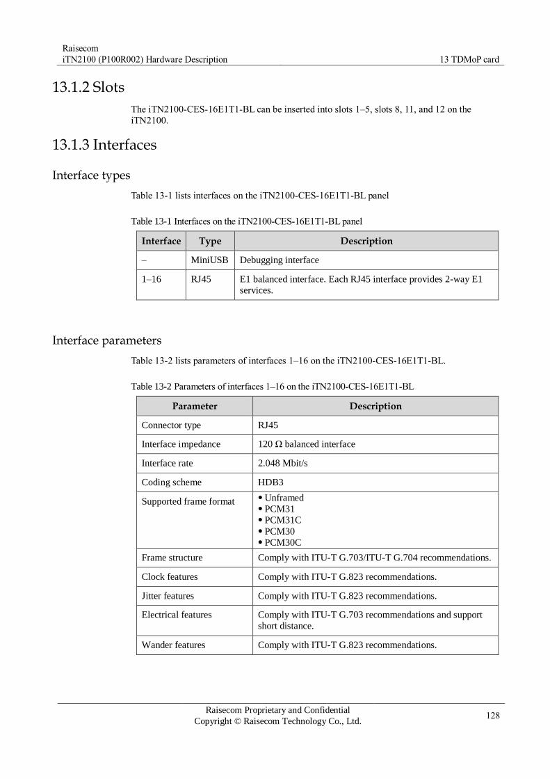
Raisecom
iTN2100 (P100R002) Hardware Description 13 TDMoP card
Raisecom Proprietary and Confidential
Copyright © Raisecom Technology Co., Ltd. 128
13.1.2 Slots
The iTN2100-CES-16E1T1-BL can be inserted into slots 1–5, slots 8, 11, and 12 on the
iTN2100.
13.1.3 Interfaces
Interface types
Table 13-1 lists interfaces on the iTN2100-CES-16E1T1-BL panel
Table 13-1 Interfaces on the iTN2100-CES-16E1T1-BL panel
Interface Type Description
– MiniUSB Debugging interface
1–16 RJ45 E1 balanced interface. Each RJ45 interface provides 2-way E1
services.
Interface parameters
Table 13-2 lists parameters of interfaces 1–16 on the iTN2100-CES-16E1T1-BL.
Table 13-2 Parameters of interfaces 1–16 on the iTN2100-CES-16E1T1-BL
Parameter Description
Connector type RJ45
Interface impedance 120 Ω balanced interface
Interface rate 2.048 Mbit/s
Coding scheme HDB3
Supported frame format Unframed PCM31 PCM31C PCM30 PCM30C
Frame structure Comply with ITU-T G.703/ITU-T G.704 recommendations.
Clock features Comply with ITU-T G.823 recommendations.
Jitter features Comply with ITU-T G.823 recommendations.
Electrical features Comply with ITU-T G.703 recommendations and support
short distance.
Wander features Comply with ITU-T G.823 recommendations.

Raisecom
iTN2100 (P100R002) Hardware Description 13 TDMoP card
Raisecom Proprietary and Confidential
Copyright © Raisecom Technology Co., Ltd. 129
13.1.4 LEDs
Table 13-3 lists LEDs on the iTN2100-CES-16E1T1-BL panel.
Table 13-3 LEDs on the iTN2100-CES-16E1T1-BL panel
LED Status Description
PWR Green Power supply LED
Green: the power supply is normal. Off: the power supply is abnormal.
SYS Green System status LED
Green: the system is working improperly. Off: the system is working improperly. Blinking green: the system is working properly.
LOS
(1–16)
Red LOS alarm LED
Red: LOS alarms are generated on E1 services. Off: no LOS alarm is generated on E1 services.
13.1.5 Logic diagram
Figure 13-1 shows the logic diagram of the iTN2100-CES-16E1T1-BL.
Figure 13-1 Logic diagram of the iTN2100-CES-16E1T1-BL

Raisecom
iTN2100 (P100R002) Hardware Description 13 TDMoP card
Raisecom Proprietary and Confidential
Copyright © Raisecom Technology Co., Ltd. 130
The iTN2100-CES-16E1T1-BL consists of the management control module, TDM service
module, CES service module, logic control module, and clock module. These modules work
as below:
Management control module: exchange network management information with the NMS
card; store control commands and configuration status of the card; control cooperation of other modules.
TDM service module: input E1 signals and process interface clock signals.
CES service module: encapsulate and decapsulate CES services.
Logic control module: process clock signals.
– Process internal TDM-side recovery clock (loopback clock) signals, PSN-side
recovery clock (ACR) signals, or external clock signals. External clocks are Building
Integrated Timing System (BITS) clocks or synchronous Ethernet clocks from the NTU series switching cards. Send the selected clock signals to the clock module.
– After configuring synchronous Ethernet of the card, process internal synchronous
Ethernet sources and select the clock source. Then send the clock source to the NTU
series switching cards for follow-up processing.
Clock module: receive the logic module and local crystal oscillator clocks. Send the
clock signal to the TDM service module and CES service module based on the configured clock source.
The iTN2100-CES-16E1T1-BL processes services as below:
TDM network to the PSN: E1 signals enter to the TDM service module and then enter
the CES service module after being processed. After being encapsulated, E1 signals are
changed to Ethernet signals and then are transmitted to the switching card through the backplane.
PSN to the TDM network: CES services from the backplane, enter the CES service
module and recovered to E1 signals after being decapsulated. E1 signals are processed by the TDM service module and then are transmitted through the TDM interface.
13.1.6 Specifications
Table 13-4 lists specifications of the iTN2100-CES-16E1T1-BL.
Table 13-4 Specifications of the iTN2100-CES-16E1T1-BL
Parameter Value
Dimensions 25 mm (Width) × 232 mm (Depth) × 240 mm (Height)
Weight 0.45 kg
Maximum power
consumption
15 W
13.1.7 Cables
E1 interfaces of the iTN2100-CES-16E1T1-BL are eight 120 Ω balanced interfaces (RJ45
interfaces). Each interface accesses 2-way E1 services. Table 13-5 lists cables available for
the iTN2100-CES-16E1T1-BL.

Raisecom
iTN2100 (P100R002) Hardware Description 13 TDMoP card
Raisecom Proprietary and Confidential
Copyright © Raisecom Technology Co., Ltd. 131
Table 13-5 Cables available for the iTN2100-CES-16E1T1-BL
Card Recommended cable
iTN2100-CES-16E1T1-BL CBL-E1-RJ45/RJ45 CBL-E1-RJ45/2RJ45
For details about these cables, see section 24.9 E1-RJ45 cable.
13.1.8 Ordering information
Table 13-6 lists ordering information about the iTN2100-CES-16E1T1-BL.
Table 13-6 Ordering information about the iTN2100-CES-16E1T1-BL
Model Hardware version
Description Remark
iTN2100-CES-16E1T1-BL A.00
Be available for the iTN2100
for E1 access in the CES
emulation format. Provide 8 RJ45 interfaces,
supporting up to 16-way E1
services (balanced mode).
–

Raisecom
iTN2100 (P100R002) Hardware Description 13 TDMoP card
Raisecom Proprietary and Confidential
Copyright © Raisecom Technology Co., Ltd. 132
13.2 iTN2100-CES-16E1T1
13.2.1 Appearance and functions
Appearance Function
The iTN2100-CES-16E1T1 is a TDMoP card used by the iTN2100.
Provide 2 DB37 interfaces and transmit up to 16-way E1 services. Support E1 framed, unframed, and multiframed modes. Support E1 external loopback, E1 internal loopback, E1 bidirectional
loopback, and no-loopback. Provide up to 64 bundles. Support SAToP and CESoPSN encapsulation protocols. Support enabling/disabling PW RTP. Support configuring Jitter Buffer depth to 375–16000us. Support configuring packet encapsulation time to 125–5000us. Support clock recovery mechanism, including the PSN line recovery
self-adaptive clock, TDM interface loopback recovery clock, system
clock, and external clock. Support MPLS/MEF encapsulation format for the PSN. Support network-side protection for emulation services (together with
PTN or Layer 2 Ethernet, support the protection feature). Support configuring AC alarm transparent transmission or termination. Support hot swapping.
No DIP switch is on the iTN2100-CES-16E1T1.

Raisecom
iTN2100 (P100R002) Hardware Description 13 TDMoP card
Raisecom Proprietary and Confidential
Copyright © Raisecom Technology Co., Ltd. 133
13.2.2 Slots
The iTN2100-CES-16E1T1 can be inserted into slots 1–5, slots 8, 11, and 12 on the iTN2100.
13.2.3 Interfaces
Interface types
Table 13-7 lists interfaces on the iTN2100-CES-16E1T1 panel.
Table 13-7 Interfaces on the iTN2100-CES-16E1T1-BL panel
Interface Type Description
– MiniUSB Debugging interface
1–16 DB37 male
interface
E1 unbalanced interface. Each DB37 interface provides 8-way
E1 services. The card transmits up to 16-way E1 services.
Interface parameters
Table 13-8 lists parameters of the DB37 interface on the iTN2100-CES-16E1T1.
Table 13-8 Parameters of the DB37 interface on the iTN2100-CES-16E1T1
Parameter Description
Connector type DB37 male connector
Interface rate 2048 kbit/s ± 50 ppm
Coding scheme HDB3
Interface impedance 75 Ω (unbalanced)
Electrical features Comply with ITU-T G.703 recommendations.
Frame structure Comply with ITU-T G.704 recommendations.
Jitter features Comply with ITU-T G.823 recommendations.
13.2.4 LEDs
Table 13-9 lists LEDs on the iTN2100-CES-16E1T1 panel.
Table 13-9 LEDs on the iTN2100-CES-16E1T1 panel
LED Status Description
PWR Green Power supply LED
Green: the power supply is normal. Off: the power supply is abnormal.

Raisecom
iTN2100 (P100R002) Hardware Description 13 TDMoP card
Raisecom Proprietary and Confidential
Copyright © Raisecom Technology Co., Ltd. 134
LED Status Description
SYS Green System status LED
Green: the system is working improperly. Off: the system is working improperly. Blinking green: the system is working properly.
LOS
(1–16)
Red LOS alarm LED
Red: LOS alarms are generated on E1 services. Off: no LOS alarm is generated on E1 services.
13.2.5 Logic diagram
Figure 13-2 shows the logic diagram of the iTN2100-CES-16E1T1.
Figure 13-2 Logic diagram of the iTN2100-CES-16E1T1
The iTN2100-CES-16E1T1 consists of the management control module, TDM service
module, CES service module, logic control module, and clock module. These modules work
as below:
Management control module: exchange network management information with the NMS
card; store control commands and configuration status of the card; control cooperation of
other modules.
TDM service module: input E1 signals and process interface clock signals.
CES service module: encapsulate and decapsulate CES services.
Logic control module: process clock signals.

Raisecom
iTN2100 (P100R002) Hardware Description 13 TDMoP card
Raisecom Proprietary and Confidential
Copyright © Raisecom Technology Co., Ltd. 135
– Process internal TDM-side recovery clock (loopback clock) signals, PSN-side
recovery clock (ACR) signals, or external clock signals. External clocks are BITS
clocks or synchronous Ethernet clocks from the NTU series switching cards. Send the selected clock signals to the clock module.
– After configuring synchronous Ethernet of the card, process internal synchronous
Ethernet sources and select the clock source. Then send the clock source to the NTU series switching cards for follow-up processing.
Clock module: receive the logic module and local crystal oscillator clocks. Send the
clock to the TDM service module and CES service module based on the configured clock source.
The iTN2100-CES-16E1T1 processes services as below:
TDM network to the PSN: E1 signals enter to the TDM service module and then enter
the CES service module after being processed. After being encapsulated, E1 signals are
changed to Ethernet signals and then are transmitted to the switching card through the
backplane.
PSN to the TDM network: CES services, from the backplane, enter the CES service
module and recovered to E1 signals after being decapsulated. E1 signals are processed by the TDM service module and then are transmitted through the TDM interface.
13.2.6 Specifications
Table 13-10 lists specifications of the iTN2100-CES-16E1T1.
Table 13-10 Specifications of the iTN2100-CES-16E1T1
Parameter Value
Dimensions 25 mm (Width) × 232 mm (Depth) × 240 mm (Height)
Weight 0.45 kg
Maximum power
consumption
15 W
13.2.7 Cables
One DB37/CC3 adaptor and 32 CC3 connectors are included with the iTN2100-CES-
16E1T1. After using this adaptor, you can make the CC3/CC3 or CC3/BNC cable as required.
In addition, you can purchase cables provided by Raisecom, as show in Table 13-11. These
cables are not included with the iTN2100-CES-16E1T1.
Table 13-11 Adaptor and cables available for the iTN2100-CES-16E1T1
Adaptor (included) Cable (excluded)
CC4B-16E1 CBL-E1-CC3/CC3-2.5m CBL-E1-CC3/BNCF-1m CBL-E1-CC3/BNCM-2.5m

Raisecom
iTN2100 (P100R002) Hardware Description 13 TDMoP card
Raisecom Proprietary and Confidential
Copyright © Raisecom Technology Co., Ltd. 136
In addition, the iTN2100-CES-16E1T1 can use the cable without the adaptor. Table 13-12
lists these cables, which are not included with the iTN2100-CES-16E1T1.
Table 13-12 Cables available for the iTN2100-CES-16E1T1
Card Recommended cable
iTN2100-CES-16E1T1 CBL-E1-DB37F (40)/16NC CBL-E1-DB37F/16BNCF CBL-E1-DB37F/16BNCM CBL-E1-DB37F(40)/16CC3F
For details about these cables, see section 24.10 E1-DB37 cable.
13.2.8 Ordering information
Table 13-13 lists ordering information about the iTN2100-CES-16E1T1.
Table 13-13 Ordering information about the iTN2100-CES-16E1T1
Model Hardware version
Description Remark
iTN2100-CES-16E1T1 A.00 Be available for the iTN2100 for
E1 access in the CES emulation
format. Provide 2 DB37 interfaces,
supporting up to 16-way E1
services (unbalanced mode). One DB37/CC3 adaptor and 32
CC3 connectors are included with
the iTN2100-CES-16E1T1.
–
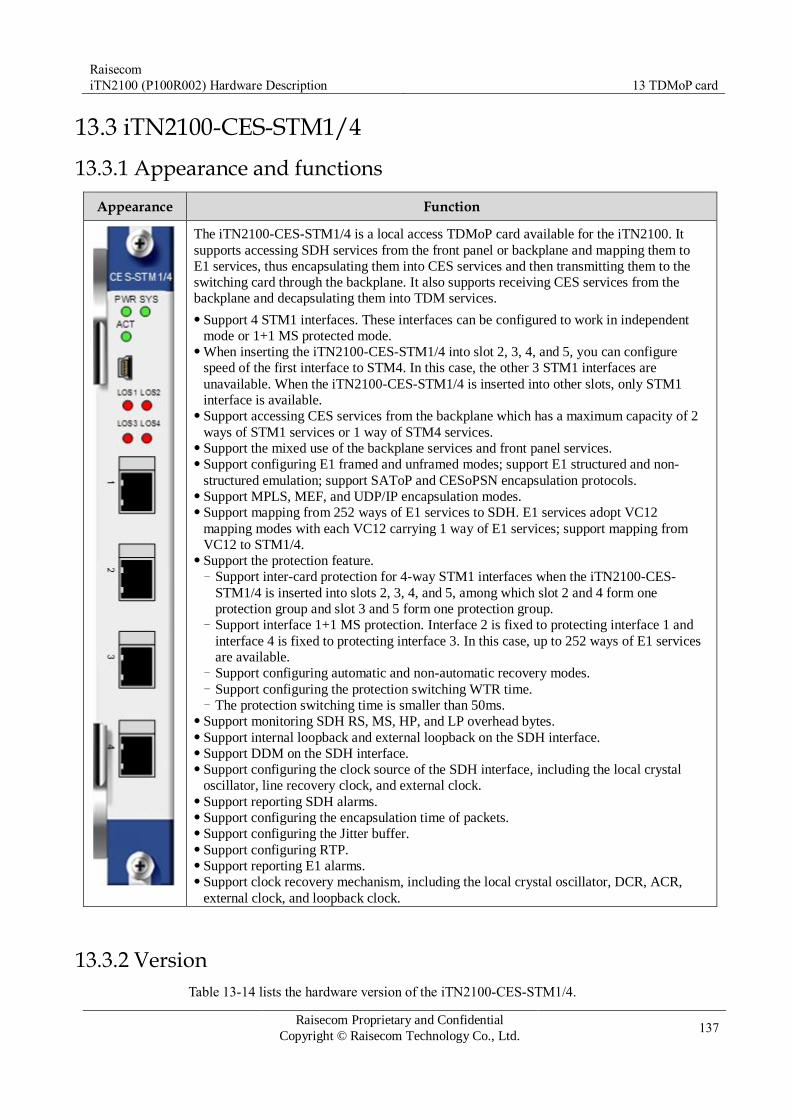
Raisecom
iTN2100 (P100R002) Hardware Description 13 TDMoP card
Raisecom Proprietary and Confidential
Copyright © Raisecom Technology Co., Ltd. 137
13.3 iTN2100-CES-STM1/4
13.3.1 Appearance and functions
Appearance Function
The iTN2100-CES-STM1/4 is a local access TDMoP card available for the iTN2100. It
supports accessing SDH services from the front panel or backplane and mapping them to
E1 services, thus encapsulating them into CES services and then transmitting them to the
switching card through the backplane. It also supports receiving CES services from the
backplane and decapsulating them into TDM services.
Support 4 STM1 interfaces. These interfaces can be configured to work in independent
mode or 1+1 MS protected mode. When inserting the iTN2100-CES-STM1/4 into slot 2, 3, 4, and 5, you can configure
speed of the first interface to STM4. In this case, the other 3 STM1 interfaces are
unavailable. When the iTN2100-CES-STM1/4 is inserted into other slots, only STM1
interface is available. Support accessing CES services from the backplane which has a maximum capacity of 2
ways of STM1 services or 1 way of STM4 services. Support the mixed use of the backplane services and front panel services. Support configuring E1 framed and unframed modes; support E1 structured and non-
structured emulation; support SAToP and CESoPSN encapsulation protocols. Support MPLS, MEF, and UDP/IP encapsulation modes. Support mapping from 252 ways of E1 services to SDH. E1 services adopt VC12
mapping modes with each VC12 carrying 1 way of E1 services; support mapping from
VC12 to STM1/4. Support the protection feature.
− Support inter-card protection for 4-way STM1 interfaces when the iTN2100-CES-
STM1/4 is inserted into slots 2, 3, 4, and 5, among which slot 2 and 4 form one
protection group and slot 3 and 5 form one protection group. − Support interface 1+1 MS protection. Interface 2 is fixed to protecting interface 1 and
interface 4 is fixed to protecting interface 3. In this case, up to 252 ways of E1 services
are available. − Support configuring automatic and non-automatic recovery modes. − Support configuring the protection switching WTR time. − The protection switching time is smaller than 50ms.
Support monitoring SDH RS, MS, HP, and LP overhead bytes. Support internal loopback and external loopback on the SDH interface. Support DDM on the SDH interface. Support configuring the clock source of the SDH interface, including the local crystal
oscillator, line recovery clock, and external clock. Support reporting SDH alarms. Support configuring the encapsulation time of packets. Support configuring the Jitter buffer. Support configuring RTP. Support reporting E1 alarms. Support clock recovery mechanism, including the local crystal oscillator, DCR, ACR,
external clock, and loopback clock.
13.3.2 Version
Table 13-14 lists the hardware version of the iTN2100-CES-STM1/4.

Raisecom
iTN2100 (P100R002) Hardware Description 13 TDMoP card
Raisecom Proprietary and Confidential
Copyright © Raisecom Technology Co., Ltd. 138
Table 13-14 Hardware version of the iTN2100-CES-STM1/4
Card Hardware version
iTN2100-CES-STM1/4 B.00
13.3.3 Slots
Table 13-15 lists slots available for the iTN2100-CES-STM1/4.
Table 13-15 Slots available for the iTN2100-CES-STM1/4
Chassis Slot
iTN2100 1–5, 8, and 11–12
13.3.4 Interfaces
Interface types
Table 13-16 lists the type of interfaces on the iTN2100-CES-STM1/4.
Table 13-16 Interfaces on the iTN2100-CES-STM1/4
Interface Type Description
– MiniUSB Debugging interface
1–4 SFP optical interface SDH service interface
Interface parameters
Table 13-17 lists parameters of SFP optical interfaces on the iTN2100-CES-STM1/4.
Table 13-17 Parameters of SFP optical interfaces on the iTN2100-CES-STM1/4
Parameter Description
Optical module type USFP
Interface speed STM1 or STM4 (available for the first interface)
Line code NRZ
Multiplexing structure Comply with ITU-T G.707 recommendations.
Clock parameters Meet jitter performance requirements defined by ITU-T
G.823, ITU-T G.825, and ITU-T G.8261 recommendations. Meet jitter and wander performance requirements defined by
ITU-T G.823 and ITU-T G.8261 recommendations.

Raisecom
iTN2100 (P100R002) Hardware Description 13 TDMoP card
Raisecom Proprietary and Confidential
Copyright © Raisecom Technology Co., Ltd. 139
Parameter Description
Jitter Comply with ITU-T G.783 and ITU-T G.825
recommendations.
Optical interface
parameters
Comply with ITU-T G.957 recommendations. Specific metrics
depend on the inserted SFP optical module.
13.3.5 LEDs
Table 6-20 lists the meaning of the LEDs on the TN2100-CES-STM1/4 panel.
Table 13-18 LEDs on the iTN2100-CES-STM1/4 panel
LED Status Description
PWR Green Power LED
Green: the power supply is normal. Off: the power supply is abnormal or no power is input.
SYS Green System status LED
Green: the system is working improperly. Off: the system is working improperly. Blinking green: the system is working properly.
ACT Green Card working status LED
Green: the card is the working card in the inter-card
protection mode; it is working properly in the
independent mode. Off: the card is the protection card in the inter-card
protection mode; it is working improperly in the
independent mode.
LOS (1–4) Red LOS alarm LED
Red: LOS alarms are generated on optical interfaces. Off: no LOS alarms are generated on optical interfaces.
If the STM interface is configured with internal loopback and is not inserted with the optical module, ignore the status of the LOS LED.
13.3.6 DIP switch
N/A
13.3.7 Logic diagram
Figure 13-3 shows the logic diagram of the iTN2100-CES-STM1/4.

Raisecom
iTN2100 (P100R002) Hardware Description 13 TDMoP card
Raisecom Proprietary and Confidential
Copyright © Raisecom Technology Co., Ltd. 140
Figure 13-3 Logic diagram of the iTN2100-CES-STM1/4
The iTN2100-CES-STM1/4 consists of the management control module, SDH service
module, CES service module, logic control module, and clock module. These modules work
as below:
Management control module: exchange network management information with the NMS
card; store control commands and configuration status of the card; control cooperation with other modules.
SDH service module: convert STM1/STM4 optical signals to E1 signals and vice versa;
process SDH clocks and SDH overheads.
CES service module: encapsulate and decapsulate CES services.
Logic control module: receive SDH clocks, including the STM line clock, external clock
(2 Mbit/s or 2 MHz clock signals from the switching card and aggregation card), and E1
recovery clock; receive E1 clocks, including the external clock (BITS clock signals or
SyncE clock signals from the switching card and 2 Mbit/s or 2 MHz clock signals from
the aggregation card), DCR (BITS clock signals or SyncE clock signals from the
switching card and 2 Mbit/s or 2 MHz clock signals from the aggregation card), ACR,
and loopback clock; send the clock to the clock module after selecting the clock source
from SDH clocks and E1 clocks; reset the card; process the card logic.
Clock module: receive the logic module and local crystal oscillator clocks; send the
clock to the SDH service module and CES service module after selecting the clock source.
The iTN2100-CES-STM1/4 processes services as below:
TDM network to the PSN: STM1/STM4 optical signals enter the SDH service module and are converted to E1 signals. Then, E1 signals enter the CES service module. After

Raisecom
iTN2100 (P100R002) Hardware Description 13 TDMoP card
Raisecom Proprietary and Confidential
Copyright © Raisecom Technology Co., Ltd. 141
being encapsulated, E1 signals are converted to Ethernet signals and then are transmitted
to the switching card through the backplane.
PSN to the TDM network: CES services, from the backplane, enter the CES service
module and are recovered to E1 signals after being decapsulated. After entering the SDH
service module, E1 signals are converted to STM1/STM4 optical signals and then are
transmitted out the SFP interface or transmitted uplink to the aggregation card.
13.3.8 Specifications
Table 13-19 lists specifications of the iTN2100-CES-STM1/4.
Table 13-19 Specifications of the iTN2100-CES-STM1/4
Parameter Value
Dimensions 25 mm (width) × 232 mm (depth) × 240 mm (height)
Weight < 1 kg
Maximum power
consumption
35 W
Raisecom
iTN2100 (P100R002) Hardware Description 14 EOP cards
Raisecom Proprietary and Confidential
Copyright © Raisecom Technology Co., Ltd. 142
14 EOP cards
This chapter describes EOP cards of the iTN2100, including the following sections:
OPCOM3500E-EOPFE
OPCOM3500E-EOP3FE
OPCOM3500E-EOP8FX
OPCOM3500E-EOP-FE16E1
OPCOM3500E-EOP-FEE1×8
OPCOM3500E-EOP-FXE1×8
OPCOM3500E-EOPS-8E1
OPCOM3500E-HT-6FE24E1
iTN2100-EOT-GESTM4

Raisecom
iTN2100 (P100R002) Hardware Description 14 EOP cards
Raisecom Proprietary and Confidential
Copyright © Raisecom Technology Co., Ltd. 143
14.1 OPCOM3500E-EOPFE
14.1.1 Appearance and functions
Appearance Function
The OPCOM3500E-EOPFE can abstract multiple EOP services from
SDH signals and then aggregate them to one way of Ethernet service.
Finally, the one way of Ethernet service can be output from the Ethernet
electrical interface on the front panel or transmitted to the switching card
through the backplane.
Support 1–31 ways of E1 signals for accessing the bandwidth. Support configuring aggregated one-way Ethernet service to be output
from the Ethernet electrical interface on the front panel or transmitted to
the switching card through the backplane. Support storm control over broadcast, multicast, and DLF packets. Support interface isolation protection. Support interface aggregation Trunk and protection, Support port mirroring. Support interface loop detection. Support traffic management based on the CoS priority, DSCP priority,
or interface ID and 4-way QoS queue scheduling. The scheduling rule
can be configured to SP or WRR. Support 802.1Q VLAN, 4K concurrent VLANs, and Double Tag
(QinQ). Support standard OAM (IEEE 802.3ah) protocol by 2 SFP interfaces on
the front panel. Support a maximum Rx/forwarding frame length of 1916 bytes. Support 802.3x flow control and back pressure flow control. Support 8K MAC addresses and 30 static MAC addresses. Support
configuring the aging time to 0–3825s. Support enabling or disabling
MAC address learning based on interface. Support interface-based rate limiting and non-linear rate limiting
ranging from 62 kbit/s to 100 Mbit/s. Support transparently transmitting BPDU, LACP, and 802.1x
management frames. Support the following operations in E1 inverse multiplexing mode:
– Support transmitting Ethernet frames to multiple E1 signals in a byte-
interleaving way. – Support Auto MDI/MDI-X. – Support the maximum relative delay ±200ms for E1 links. – Support automatic construction or destruction of E1 links.
Support the framed mode. It supports FAS+CRC4 PCM31 mode and
CRC self-adaption. You can configure them. Support E1 loop detection and BERT. Support remote management for the RC521H-FE and the Gazelle
RM531-FE (B). Support hot swapping.
14.1.2 Slots
The OPCOM3500E-EOPFE can be inserted into slots 1–5 and 8–12 on the iTN2100.
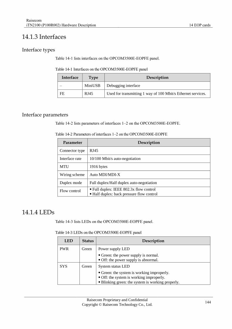
Raisecom
iTN2100 (P100R002) Hardware Description 14 EOP cards
Raisecom Proprietary and Confidential
Copyright © Raisecom Technology Co., Ltd. 144
14.1.3 Interfaces
Interface types
Table 14-1 lists interfaces on the OPCOM3500E-EOPFE panel.
Table 14-1 Interfaces on the OPCOM3500E-EOPFE panel
Interface Type Description
– MiniUSB Debugging interface
FE RJ45 Used for transmitting 1 way of 100 Mbit/s Ethernet services.
Interface parameters
Table 14-2 lists parameters of interfaces 1–2 on the OPCOM3500E-EOPFE.
Table 14-2 Parameters of interfaces 1–2 on the OPCOM3500E-EOPFE
Parameter Description
Connector type RJ45
Interface rate 10/100 Mbit/s auto-negotiation
MTU 1916 bytes
Wiring scheme Auto MDI/MDI-X
Duplex mode Full duplex/Half duplex auto-negotiation
Flow control Full duplex: IEEE 802.3x flow control Half duplex: back pressure flow control
14.1.4 LEDs
Table 14-3 lists LEDs on the OPCOM3500E-EOPFE panel.
Table 14-3 LEDs on the OPCOM3500E-EOPFE panel
LED Status Description
PWR Green Power supply LED
Green: the power supply is normal. Off: the power supply is abnormal.
SYS Green System status LED
Green: the system is working improperly. Off: the system is working improperly. Blinking green: the system is working properly.

Raisecom
iTN2100 (P100R002) Hardware Description 14 EOP cards
Raisecom Proprietary and Confidential
Copyright © Raisecom Technology Co., Ltd. 145
LED Status Description
100M Green Ethernet electrical interface 100 Mbit/s LED
Green: the Ethernet rate is 100 Mbit/s. Off: the Ethernet rate is 10 Mbit/s or the connection fails.
LNK/ACT Green Ethernet electrical interface working LED
Green: the Ethernet electrical interface is properly connected. Blinking green: the Ethernet electrical interface is receiving or
sending data. Off: the Ethernet electrical interface is improperly connected or
disconnected.
14.1.5 Alarms
Table 14-4 lists alarms of the OPCOM3500E-EOPFE.
Table 14-4 Alarms of the OPCOM3500E-EOPFE
Alarm Cause Level
E1 LOS Signals are lost. Critical
E1 AIS E1 signals are all 1 because the transmitted data
are incorrect or the remote device outputs AIS signals.
Minor
E1 LOF Data sent by the upstream node are incorrect
because services are configured improperly or the hardware fails.
Critical
E1 CRC An error on data occurs during transmission. Critical
E1 GID ERROR Inverse multiplexing configurations are incorrect. Critical
E1 remote alarms (AIS,
LOF, CRC, and LOS)
The remote device managed by the card generates
(AIS, LOF, CRC, and LOS) alarms.
Critical
E1 remote loopback
alarm
The remote device managed by the card generates
a loopback.
Critical
Ethernet interface Link
Down
Links of Ethernet interfaces are disconnected. Critical
14.1.6 Specifications
Table 14-5 lists specifications of the OPCOM3500E-EOPFE.
Table 14-5 Specifications of the OPCOM3500E-EOPFE
Parameter Value
Dimensions 25 mm (Width) × 232 mm (Depth) × 240 mm (Height)

Raisecom
iTN2100 (P100R002) Hardware Description 14 EOP cards
Raisecom Proprietary and Confidential
Copyright © Raisecom Technology Co., Ltd. 146
Parameter Value
Weight < 0.5 kg
Maximum power
consumption
18 W

Raisecom
iTN2100 (P100R002) Hardware Description 14 EOP cards
Raisecom Proprietary and Confidential
Copyright © Raisecom Technology Co., Ltd. 147
14.2 OPCOM3500E-EOP3FE
14.2.1 Appearance and functions
Appearance Function
The OPCOM3500E-EOP3FE can abstract multiple EOP services from
SDH signals and then aggregate them to one-way Ethernet services.
Finally, the one way of Ethernet service can be output from the
Ethernet electrical/optical interface on the front panel or transmitted to
the switching card through the backplane.
Support 1–31 ways of E1 signals for accessing the bandwidth. Support configuring aggregated one way of Ethernet service to be
output from the Ethernet electrical/optical interface on the front panel
or transmitted to the switching card through the backplane. Support storm control over broadcast, multicast, and DLF packets. Support interface isolation protection. Support interface aggregation Trunk and protection, Support port mirroring. Support interface loop detection. Support traffic management based on the CoS priority, DSCP
priority, or interface ID and 4-way QoS queue scheduling. The
scheduling rule can be configured to SP or WRR. Support 802.1Q VLAN, 4K concurrent VLANs, and Double Tag
(QinQ). Support standard OAM (IEEE 802.3ah) protocol by 2 SFP interfaces
on the front panel. Support a maximum Rx/forwarding frame length of 1916 bytes. Support 802.3x flow control and back pressure flow control. Support 8K MAC addresses and 30 static MAC addresses. Support
configuring the aging time to 0–3825s. Support enabling or disabling
MAC address learning based on interface. Support interface-based rate limiting and non-linear rate limiting
ranging from 62 kbit/s to 100 Mbit/s. Support transparently transmitting BPDU, LACP, and 802.1x
management frames. Support the following operations in E1 inverse multiplexing mode:
– Support transmitting Ethernet frames to multiple E1 signals in a
byte-interleaving way. – Support Auto MDI/MDI-X. – Support the maximum relative delay ±200ms for E1 links. – Support automatic construction or destruction of E1 links.
Support the framed mode. It supports FAS+CRC4 PCM31 mode and
CRC self-adaption. You can configure them. Support E1 loop detection and BERT. Support remote management for the RC521H-FE, Gazelle RM531-
FE (B), RC95X, and RC90X. Support hot swapping.
14.2.2 Slots
The OPCOM3500E-EOP3FE can be inserted into slots 1–5 and 8–12 on the iTN2100.

Raisecom
iTN2100 (P100R002) Hardware Description 14 EOP cards
Raisecom Proprietary and Confidential
Copyright © Raisecom Technology Co., Ltd. 148
14.2.3 Interfaces
Interface types
Table 14-6 lists interfaces on the OPCOM3500E-EOP3FE panel.
Table 14-6 Interfaces on the OPCOM3500E-EOP3FE panel
Interface Type Description
– MiniUSB Debugging interface
1, 2 SFP optical interface Service uplink interface Tx indicates the sending interface and Rx
indicates the receiving interface.
FE RJ45 Used for transmitting 1 way of 100 Mbit/s Ethernet
service.
Interface parameters
Table 14-7 lists parameters of the RJ45 interface on the OPCOM3500E-EOP3FE.
Table 14-7 Parameters of the RJ45 interface on the OPCOM3500E-EOP3FE
Parameter Description
Connector type RJ45
Interface rate 10/100 Mbit/s auto-negotiation
MTU 1916 bytes
Wiring scheme Auto MDI/MDI-X
Duplex mode Full duplex/Half duplex auto-negotiation
Flow control Full duplex: IEEE 802.3x flow control Half duplex: back pressure flow control
Table 14-8 lists parameters of interfaces 1–2 on the OPCOM3500E-EOP3FE.
Table 14-8 Parameters of interfaces 1–2 on the OPCOM3500E-EOP3FE
Parameter Description
Connector type SFP optical interface
Interface rate 100 Mbit/s
Duplex mode Full duplex
MTU 1916 bytes
Compliance standard IEEE 802.3u IEEE 802.3z

Raisecom
iTN2100 (P100R002) Hardware Description 14 EOP cards
Raisecom Proprietary and Confidential
Copyright © Raisecom Technology Co., Ltd. 149
14.2.4 LEDs
Table 14-9 lists LEDs on the OPCOM3500E-EOP3FE panel.
Table 14-9 LEDs on the OPCOM3500E-EOP3FE panel
LED Status Description
PWR Green Power supply LED
Green: the power supply is normal. Off: the power supply is abnormal.
SYS Green System status LED
Green: the system is working improperly. Off: the system is working improperly. Blinking green: the system is working properly.
100M Green Ethernet electrical interface 100 Mbit/s LED
Green: the Ethernet rate is 100 Mbit/s. Off: the Ethernet rate is 10 Mbit/s or the connection fails.
LNK/ACT
(electrical interface)
Green Ethernet electrical interface working LED
Green: the Ethernet electrical interface is properly
connected. Blinking green: the Ethernet electrical interface is receiving
or sending data. Off: the Ethernet electrical interface is improperly connected
or disconnected.
SD Green Optical interface input signal LED
Green: input signals are detected on the optical interface. Off: no input signal is detected on the optical interface.
LNK/ACT
(1/2 optical interface)
Green 1/2 optical interface working LED
Green: the 1/2 optical interface is properly connected. Blinking green: the 1/2 optical interface is receiving or
sending data. Off: the 1/2 optical interface is improperly connected or
disconnected.
14.2.5 Alarms
Table 14-10 lists alarms of the OPCOM3500E-EOP3FE.
Table 14-10 Alarms of the OPCOM3500E-EOP3FE
Alarm Cause Level
E1 LOS Signals are lost. Critical
E1 AIS E1 signals are all 1 because the transmitted data
are incorrect or the remote device outputs AIS signals.
Minor
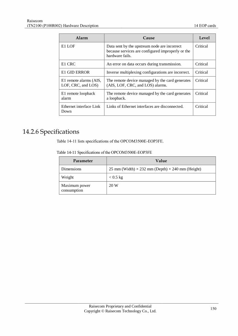
Raisecom
iTN2100 (P100R002) Hardware Description 14 EOP cards
Raisecom Proprietary and Confidential
Copyright © Raisecom Technology Co., Ltd. 150
Alarm Cause Level
E1 LOF Data sent by the upstream node are incorrect
because services are configured improperly or the hardware fails.
Critical
E1 CRC An error on data occurs during transmission. Critical
E1 GID ERROR Inverse multiplexing configurations are incorrect. Critical
E1 remote alarms (AIS,
LOF, CRC, and LOS)
The remote device managed by the card generates
(AIS, LOF, CRC, and LOS) alarms.
Critical
E1 remote loopback
alarm
The remote device managed by the card generates
a loopback.
Critical
Ethernet interface Link
Down
Links of Ethernet interfaces are disconnected. Critical
14.2.6 Specifications
Table 14-11 lists specifications of the OPCOM3500E-EOP3FE.
Table 14-11 Specifications of the OPCOM3500E-EOP3FE
Parameter Value
Dimensions 25 mm (Width) × 232 mm (Depth) × 240 mm (Height)
Weight < 0.5 kg
Maximum power
consumption
20 W
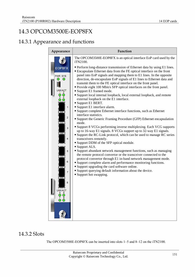
Raisecom
iTN2100 (P100R002) Hardware Description 14 EOP cards
Raisecom Proprietary and Confidential
Copyright © Raisecom Technology Co., Ltd. 151
14.3 OPCOM3500E-EOP8FX
14.3.1 Appearance and functions
Appearance Function
The OPCOM3500E-EOP8FX is an optical interface EoP card used by the
iTN2100.
Perform long-distance transmission of Ethernet data by using E1 lines. Encapsulate Ethernet data from the FE optical interface on the front
panel into EoP signals and mapping them to E1 lines. In the opposite
direction, de-encapsulate EoP signals of E1 lines to Ethernet data and
transmit them to the FE optical interface on the front panel. Provide eight 100 Mbit/s SFP optical interfaces on the front panel. Support E1 framed mode. Support local internal loopback, local external loopback, and remote
external loopback on the E1 interface. Support E1 BERT. Support E1 interface alarm. Support complete Ethernet interface functions, such as Ethernet
interface statistics. Support the Generic Framing Procedure (GFP) Ethernet encapsulation
mode. Support 8 VCGs performing inverse multiplexing. Each VCG supports
up to 16-way E1 signals. 8 VCGs support up to 32-way E1 signals. Support the RC-Link protocol, which can be used to manage RC series
transceivers remotely. Support DDM of the SFP optical module. Support ALS. Support abundant network management functions, such as managing
the remote protocol convertor or the transceiver connected to the
protocol convertor through E1 in-band network management mode. Support complete alarm and performance monitoring functions. Support upgrading the card software online. Support querying default information about the device. Support hot swapping.
14.3.2 Slots
The OPCOM3500E-EOP8FX can be inserted into slots 1–5 and 8–12 on the iTN2100.

Raisecom
iTN2100 (P100R002) Hardware Description 14 EOP cards
Raisecom Proprietary and Confidential
Copyright © Raisecom Technology Co., Ltd. 152
14.3.3 Interfaces
Interface types
Table 14-12 lists interfaces on the OPCOM3500E-EOP8FX panel.
Table 14-12 Interfaces on the OPCOM3500E-EOP8FX panel
Interface Type Description
– MiniUSB Debugging interface
1–8 SFP optical interface Service downlink interface
Interface parameters
Table 14-13 lists parameters of interfaces 1–8 on the OPCOM3500E-EOP8FX.
Table 14-13 Parameters of interfaces 1–8 on the OPCOM3500E-EOP8FX
Parameter Description
Connector type SFP (LC/PC)
Coding scheme 4B/5B block coding and NRZI line coding
Interface rate 100 Mbit/s
Interface specification 100Base-FX
Duplex mode Full duplex
Flow control IEEE 802.3x flow control in full duplex mode
Compliance standard IEEE 802.3u
14.3.4 LEDs
Table 14-14 lists LEDs on the OPCOM3500E-EOP8FX panel.
Table 14-14 LEDs on the OPCOM3500E-EOP8FX panel
LED Status Description
PWR Green Power supply LED
Green: the power supply is normal. Off: the power supply is abnormal.
SYS Green System status LED
Green: the system is working improperly. Off: the system is working improperly. Blinking green: the system is working properly.

Raisecom
iTN2100 (P100R002) Hardware Description 14 EOP cards
Raisecom Proprietary and Confidential
Copyright © Raisecom Technology Co., Ltd. 153
LED Status Description
LNK/ACT
(1–8)
Green Ethernet interface working LED
Green: the Ethernet interface is properly connected. Off: the Ethernet interface is improperly connected or
disconnected. Blinking green: the Ethernet interface is receiving or sending
data.
14.3.5 Specifications
Table 14-15 lists specifications of the OPCOM3500E-EOP8FX.
Table 14-15 Specifications of the OPCOM3500E-EOP8FX
Parameter Value
Dimensions 25 mm (Width) × 232 mm (Depth) × 240 mm (Height)
Weight 0.41 kg
Maximum power
consumption
13 W

Raisecom
iTN2100 (P100R002) Hardware Description 14 EOP cards
Raisecom Proprietary and Confidential
Copyright © Raisecom Technology Co., Ltd. 154
14.4 OPCOM3500E-EOP-FE16E1
14.4.1 Appearance and functions
Appearance Function
The OPCOM3500E-EOP-FE16E1 can abstract multiple EOP services
from SDH signals and then aggregate them to one-way Ethernet
services. Finally, the one-way Ethernet service can be output from the
Ethernet electrical interface on the front panel or transmitted to the
switching card through the backplane.
Support 1–16 ways of E1 signals for accessing the bandwidth. Support configuring aggregated one-way Ethernet service to be output
from the Ethernet electrical interface on the front panel or transmitted
to the switching card through the backplane. Support storm control over broadcast, unknown multicast, and DLF
packets. Support link aggregation. Support 802.1Q VLAN, 4K concurrent VLANs, and Double Tag
(QinQ). Support a maximum frame length of 1632 bytes. Support 802.3x flow control and back pressure flow control. Support 8K MAC addresses and 64 static MAC addresses. Support enabling or disabling MAC address learning based on
interface. Support configuring the aging time to 0–3825s. Support interface-based rate limiting ranging from 62 kbit/s to 100
Mbit/s. Support transparently transmitting BPDU, LACP, and 802.1x
management frames. Support the following operations in E1 inverse multiplexing mode:
– Support transmitting Ethernet frames to multiple E1 signals in a
frame-interleaving way. – Support Auto MDI/MDI-X. – Support the maximum relative delay ±16ms for E1 links. – Support automatic construction or destruction of E1 links.
Support the framed mode. It supports FAS+CRC4 PCM31 mode and
CRC self-adaption. You can configure them. Support E1 loop detection and BERT. Support remote management for the Gazelle RM531-FE (B) and
RC521H-FE. Support hot swapping.
14.4.2 Slots
The OPCOM3500E-EOP-FE16E1 can be inserted into slots 1–5 and 8–12 on the iTN2100.

Raisecom
iTN2100 (P100R002) Hardware Description 14 EOP cards
Raisecom Proprietary and Confidential
Copyright © Raisecom Technology Co., Ltd. 155
14.4.3 Interfaces
Interface types
Table 14-16 lists an interface on the OPCOM3500E-EOP-FE16E1 panel.
Table 14-16 The interface on the OPCOM3500E-EOP-FE16E1 panel
Interface Type Description
– RJ45 electrical interface Service downlink interface
Interface parameters
Table 14-17 lists parameters of the RJ45 interface on the OPCOM3500E-EOP-FE16E1.
Table 14-17 Parameters of the RJ45 interface on the OPCOM3500E-EOP-FE16E1
Parameter Description
Connector type RJ45
Interface rate 10/100 Mbit/s auto-negotiation
MTU 1632 bytes
Wiring scheme Auto MDI/MDIX
Duplex mode Full duplex/Half duplex auto-negotiation
Flow control Full duplex: IEEE 802.3x flow control Half duplex: back pressure flow control
14.4.4 LEDs
There are 5 LEDs on the OPCOM3500E-EOP-FE16E1 panel, as listed in Table 14-18.
Table 14-18 LEDs on the OPCOM3500E-EOP-FE16E1 panel
LED Status Description
PWR Green Power supply LED
Green: the power supply is normal. Off: the power supply is abnormal.
SYS Green System status LED
Green: the system is working improperly. Off: the system is working improperly. Blinking green: the system is working properly.
100M Green Ethernet electrical interface 100 Mbit/s LED
Green: the Ethernet rate is 100 Mbit/s. Off: the Ethernet rate is 10 Mbit/s or the connection fails.

Raisecom
iTN2100 (P100R002) Hardware Description 14 EOP cards
Raisecom Proprietary and Confidential
Copyright © Raisecom Technology Co., Ltd. 156
LED Status Description
LNK/ACT Green Ethernet electrical interface working LED
Green: the Ethernet electrical interface is properly connected. Off: the Ethernet electrical interface is improperly connected
or disconnected. Blinking green: the Ethernet electrical interface is receiving
or sending data.
FDX Green Duplex mode LED
Green: the Ethernet electrical interface works in full duplex
mode. Off: the Ethernet electrical interface works in half duplex
mode.
14.4.5 Alarms
Table 14-19 lists alarms of the OPCOM3500E-EOP-FE16E1.
Table 14-19 Alarms of the OPCOM3500E-EOP-FE16E1
Alarm Cause Level
E1 LOS Signals are lost. Critical
E1 AIS E1 signals are all 1 because the transmitted data
are incorrect or the remote device outputs AIS
signals.
Minor
E1 LOF Data sent by the upstream node are incorrect
because services are configured improperly or the hardware fails.
Critical
E1 CRC An error on data occurs during transmission. Critical
E1 GID ERROR Inverse multiplexing configurations are incorrect. Critical
E1 remote alarms (AIS,
LOF, CRC, and LOS)
The remote device managed by the card generates
(AIS, LOF, CRC, and LOS) alarms.
Critical
E1 remote loopback
alarm
The remote device managed by the card generates
a loopback.
Critical
Ethernet interface Link
Down
Links of Ethernet interfaces are disconnected. Critical
14.4.6 Specifications
Table 14-20 lists specifications of the OPCOM3500E-EOP-FE16E1.

Raisecom
iTN2100 (P100R002) Hardware Description 14 EOP cards
Raisecom Proprietary and Confidential
Copyright © Raisecom Technology Co., Ltd. 157
Table 14-20 Specifications of the OPCOM3500E-EOP-FE16E1
Parameter Value
Dimensions 25 mm (Width) × 232 mm (Depth) × 240 mm (Height)
Weight 0.7 kg
Maximum power
consumption
22 W

Raisecom
iTN2100 (P100R002) Hardware Description 14 EOP cards
Raisecom Proprietary and Confidential
Copyright © Raisecom Technology Co., Ltd. 158
14.5 OPCOM3500E-EOP-FEE1×8
14.5.1 Appearance and functions
Appearance Function
The OPCOM3500E-EOP-FEE1×8 is an electrical interface EoPDH
protocol converter card on the iTN2100.
Convert 8 ways of 100BASE-TX (electrical interface) Ethernet signals
input from the front panel through EoPDH, encapsulate them into E1
signals, send them to the aggregation card through the backplane, and
then transmit them to the SDH network through cross connection. In
reverse direction, it demaps 8 ways of E1 signals from the backplane,
abstracts Ethernet signals, and transmits them to the 100BASE-TX
interface on the front panel. The eight 100BASE-TX interfaces correspond to eight E1 channels
respectively and independently. Support hot swapping.
14.5.2 Versions
Table 14-21 lists hardware versions of the OPCOM3500E-EOP-FEE1×8.

Raisecom
iTN2100 (P100R002) Hardware Description 14 EOP cards
Raisecom Proprietary and Confidential
Copyright © Raisecom Technology Co., Ltd. 159
Table 14-21 Hardware versions of the OPCOM3500E-EOP-FEE1×8
Card Hardware version
OPCOM3500E-EOP-FEE1×8 A.00
OPCOM3500E-EOP-FEE1×8 B.00
14.5.3 Slots
Table 14-22 lists slots available for the OPCOM3500E-EOP-FEE1×8.
Table 14-22 Slots available for the OPCOM3500E-EOP-FEE1×8
Chassis Slot
iTN2100 1–5 and 8–12
14.5.4 Interfaces
Interface types
Table 14-23 lists interfaces on the OPCOM3500E-EOP-FEE1×8 panel.
Table 14-23 Interface on the OPCOM3500E-EOP-FEE1×8
Interface Type Description
– RJ45 electrical interface 100BASE-TX interface
Interface parameters
Table 14-24 lists parameters of eight RJ45 interfaces on the OPCOM3500E-EOP-FEE1×8.
Table 14-24 Parameters of eight RJ45 interfaces on the OPCOM3500E-EOP-FEE1×8
Parameter Description
Connector type RJ45
Interface rate 100Base-TX, supporting auto-negotiation (supporting 100
Mbit/s full duplex only).
Coding scheme 4B/5B block coding MLT-3 line coding
Duplex mode Full duplex
Flow control IEEE 802.3x flow control in full duplex mode
Wiring scheme Auto MDI/MDIX
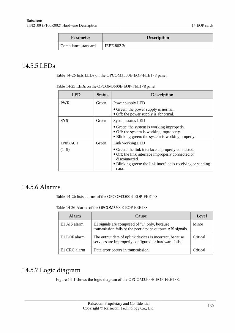
Raisecom
iTN2100 (P100R002) Hardware Description 14 EOP cards
Raisecom Proprietary and Confidential
Copyright © Raisecom Technology Co., Ltd. 160
Parameter Description
Compliance standard IEEE 802.3u
14.5.5 LEDs
Table 14-25 lists LEDs on the OPCOM3500E-EOP-FEE1×8 panel.
Table 14-25 LEDs on the OPCOM3500E-EOP-FEE1×8 panel
LED Status Description
PWR Green Power supply LED
Green: the power supply is normal. Off: the power supply is abnormal.
SYS Green System status LED
Green: the system is working improperly. Off: the system is working improperly. Blinking green: the system is working properly.
LNK/ACT
(1–8)
Green Link working LED
Green: the link interface is properly connected. Off: the link interface improperly connected or
disconnected. Blinking green: the link interface is receiving or sending
data.
14.5.6 Alarms
Table 14-26 lists alarms of the OPCOM3500E-EOP-FEE1×8.
Table 14-26 Alarms of the OPCOM3500E-EOP-FEE1×8
Alarm Cause Level
E1 AIS alarm E1 signals are composed of "1" only, because
transmission fails or the peer device outputs AIS signals.
Minor
E1 LOF alarm The output data of uplink devices is incorrect, because
services are improperly configured or hardware fails.
Critical
E1 CRC alarm Data error occurs in transmission. Critical
14.5.7 Logic diagram
Figure 14-1 shows the logic diagram of the OPCOM3500E-EOP-FEE1×8.
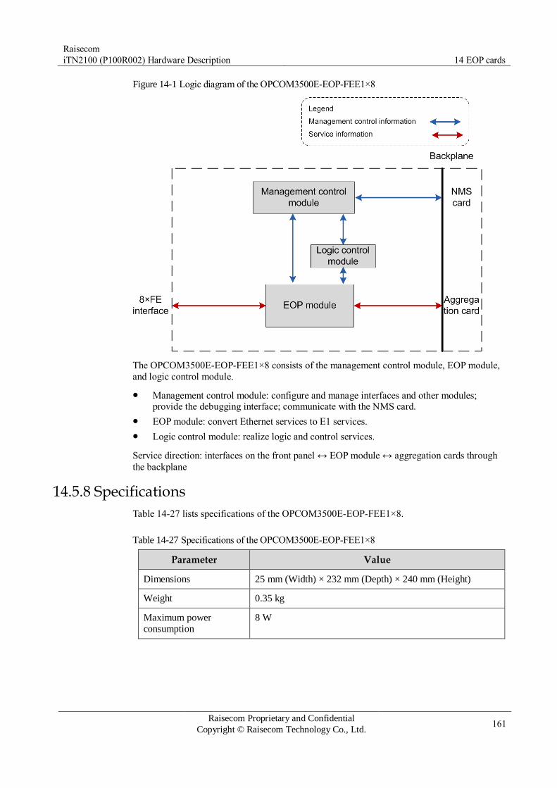
Raisecom
iTN2100 (P100R002) Hardware Description 14 EOP cards
Raisecom Proprietary and Confidential
Copyright © Raisecom Technology Co., Ltd. 161
Figure 14-1 Logic diagram of the OPCOM3500E-EOP-FEE1×8
The OPCOM3500E-EOP-FEE1×8 consists of the management control module, EOP module,
and logic control module.
Management control module: configure and manage interfaces and other modules; provide the debugging interface; communicate with the NMS card.
EOP module: convert Ethernet services to E1 services.
Logic control module: realize logic and control services.
Service direction: interfaces on the front panel ↔ EOP module ↔ aggregation cards through
the backplane
14.5.8 Specifications
Table 14-27 lists specifications of the OPCOM3500E-EOP-FEE1×8.
Table 14-27 Specifications of the OPCOM3500E-EOP-FEE1×8
Parameter Value
Dimensions 25 mm (Width) × 232 mm (Depth) × 240 mm (Height)
Weight 0.35 kg
Maximum power
consumption
8 W

Raisecom
iTN2100 (P100R002) Hardware Description 14 EOP cards
Raisecom Proprietary and Confidential
Copyright © Raisecom Technology Co., Ltd. 162
14.6 OPCOM3500E-EOP-FXE1×8
14.6.1 Appearance and functions
Appearance Function
The OPCOM3500E-EOP-FXE1×8 is an optical interface EoPDH
protocol converter of the iTN2100.
Convert 8 ways of 100BASE-FX Ethernet signals input from the
front panel through EoPDH, encapsulate them into E1 signals, send
them to the aggregation card through the backplane, and then
transmit them to the SDH network through cross connection. The eight 100BASE-TX interfaces correspond to 8 E1 channels
respectively and independently. E1 interfaces support framed and unframed modes. You can
configure them through command lines or NMS. Support local or remote loopback of E1 links. Support configurable clock modes: local clock or line clock. Support E1 link BERT which is optional. Support statistics of sent frames, received frames, package traffic,
number of error packages on each E1 interface. Support Automatical Laser Shutdown (ALS). Support LPR detection. Provide complete alarm and performance monitoring. Support remote management for the Gazelle RM531-FE (B) and
RC521H-FE. Support hot swapping.
14.6.2 Versions
Table 14-28 lists hardware versions of the OPCOM3500E-EOP-FXE1×8.
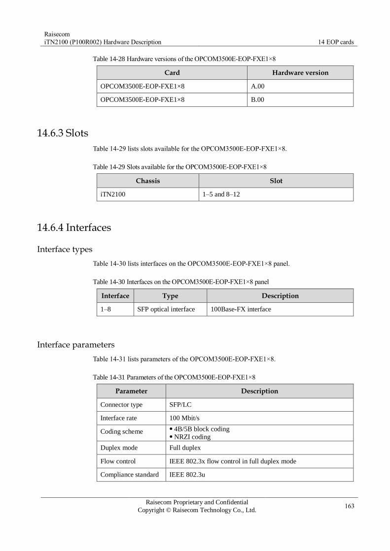
Raisecom
iTN2100 (P100R002) Hardware Description 14 EOP cards
Raisecom Proprietary and Confidential
Copyright © Raisecom Technology Co., Ltd. 163
Table 14-28 Hardware versions of the OPCOM3500E-EOP-FXE1×8
Card Hardware version
OPCOM3500E-EOP-FXE1×8 A.00
OPCOM3500E-EOP-FXE1×8 B.00
14.6.3 Slots
Table 14-29 lists slots available for the OPCOM3500E-EOP-FXE1×8.
Table 14-29 Slots available for the OPCOM3500E-EOP-FXE1×8
Chassis Slot
iTN2100 1–5 and 8–12
14.6.4 Interfaces
Interface types
Table 14-30 lists interfaces on the OPCOM3500E-EOP-FXE1×8 panel.
Table 14-30 Interfaces on the OPCOM3500E-EOP-FXE1×8 panel
Interface Type Description
1–8 SFP optical interface 100Base-FX interface
Interface parameters
Table 14-31 lists parameters of the OPCOM3500E-EOP-FXE1×8.
Table 14-31 Parameters of the OPCOM3500E-EOP-FXE1×8
Parameter Description
Connector type SFP/LC
Interface rate 100 Mbit/s
Coding scheme 4B/5B block coding NRZI coding
Duplex mode Full duplex
Flow control IEEE 802.3x flow control in full duplex mode
Compliance standard IEEE 802.3u
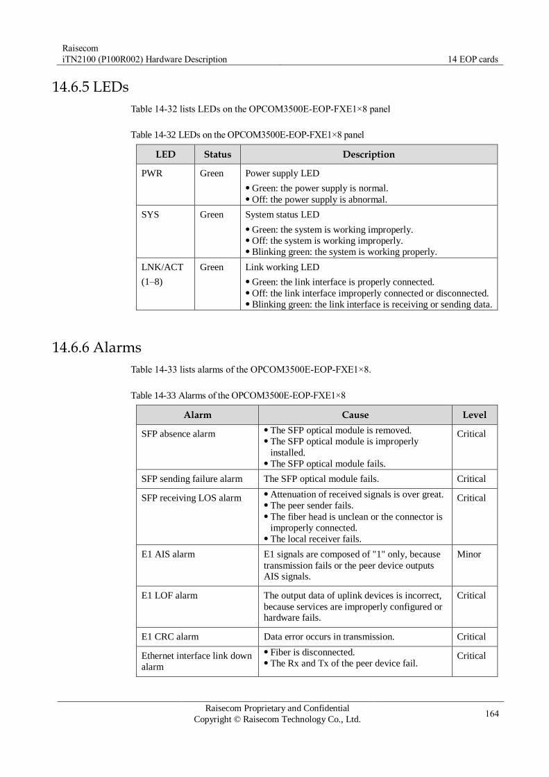
Raisecom
iTN2100 (P100R002) Hardware Description 14 EOP cards
Raisecom Proprietary and Confidential
Copyright © Raisecom Technology Co., Ltd. 164
14.6.5 LEDs
Table 14-32 lists LEDs on the OPCOM3500E-EOP-FXE1×8 panel
Table 14-32 LEDs on the OPCOM3500E-EOP-FXE1×8 panel
LED Status Description
PWR Green Power supply LED
Green: the power supply is normal. Off: the power supply is abnormal.
SYS Green System status LED
Green: the system is working improperly. Off: the system is working improperly. Blinking green: the system is working properly.
LNK/ACT
(1–8)
Green Link working LED
Green: the link interface is properly connected. Off: the link interface improperly connected or disconnected. Blinking green: the link interface is receiving or sending data.
14.6.6 Alarms
Table 14-33 lists alarms of the OPCOM3500E-EOP-FXE1×8.
Table 14-33 Alarms of the OPCOM3500E-EOP-FXE1×8
Alarm Cause Level
SFP absence alarm The SFP optical module is removed. The SFP optical module is improperly
installed. The SFP optical module fails.
Critical
SFP sending failure alarm The SFP optical module fails. Critical
SFP receiving LOS alarm Attenuation of received signals is over great. The peer sender fails. The fiber head is unclean or the connector is
improperly connected. The local receiver fails.
Critical
E1 AIS alarm E1 signals are composed of "1" only, because
transmission fails or the peer device outputs AIS signals.
Minor
E1 LOF alarm The output data of uplink devices is incorrect,
because services are improperly configured or hardware fails.
Critical
E1 CRC alarm Data error occurs in transmission. Critical
Ethernet interface link down
alarm
Fiber is disconnected. The Rx and Tx of the peer device fail.
Critical

Raisecom
iTN2100 (P100R002) Hardware Description 14 EOP cards
Raisecom Proprietary and Confidential
Copyright © Raisecom Technology Co., Ltd. 165
Alarm Cause Level
LPR alarm on the peer
device
The remote transceiver is powered off. Critical
14.6.7 Logic diagram
Figure 14-2 shows the logic diagram of the OPCOM3500E-EOP-FXE1×8.
Figure 14-2 Logic diagram of the OPCOM3500E-EOP-FXE1×8
The OPCOM3500E-EOP-FXE1×8 consists of the management control module, EOP module,
and logic control module.
Management control module: configure and manage interfaces and other modules; provide the debugging interface; communicate with the NMS card.
EOP module: convert Ethernet services into E1 services.
Logic control module: realize logic and control services.
Service direction: interfaces on the front panel ↔ EOP module ↔ aggregation cards through
the backplane
14.6.8 Specifications
Table 14-34 lists specifications of the OPCOM3500E-EOP-FXE1×8.

Raisecom
iTN2100 (P100R002) Hardware Description 14 EOP cards
Raisecom Proprietary and Confidential
Copyright © Raisecom Technology Co., Ltd. 166
Table 14-34 Specifications of the OPCOM3500E-EOP-FXE1×8
Parameter Value
Dimensions 25 mm (Width) × 232 mm (Depth) × 240 mm (Height)
Weight 0.35 kg
Maximum power
consumption
15 W

Raisecom
iTN2100 (P100R002) Hardware Description 14 EOP cards
Raisecom Proprietary and Confidential
Copyright © Raisecom Technology Co., Ltd. 167
14.7 OPCOM3500E-EOPS-8E1
14.7.1 Appearance and functions
Appearance Function
The OPCOM3500E-EOPS-8E1 is an EOP-to-EOS card with
unbalanced interfaces used by the iTN2100.
The OPCOM3500E-EOPS-8E1 has the following functions:
Provide one DB37 interface by the front panel, supporting 8 E1
channels which are independent from each other or reversely
multiplex. Reversely-multiplexed Ethernet services can be assigned based on
N×VC12 to be transmitted to the SDH network. Support framed and unframed modes by the E1 interface. They can
be configured through software. Support local and remote loopbacks on E1 links. Support making statistics on the number of received packets,
transmitted packets, error packets, and traffic. Support selecting a clock mode: local clock or line clock. Support optional E1 link BERT. Support GFP and LAPS Ethernet encapsulation modes. Support VCAT and Link Capacity Adjust Scheme (LCAS). Provide complete alarm and performance monitoring. Support managing any Raisecom RC95X series remote protocol
convertor regardless whether the device is directly connected or
connected through a device from other vendors. Support hot swapping.
14.7.2 Slots
The OPCOM3500E-EOPS-8E1 can be inserted into slots 1–5 and 8–12 on the iTN2100.
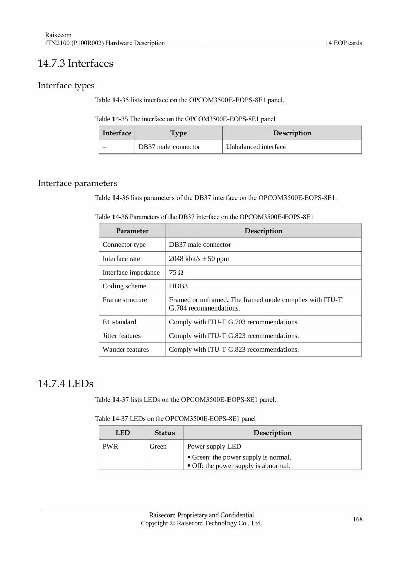
Raisecom
iTN2100 (P100R002) Hardware Description 14 EOP cards
Raisecom Proprietary and Confidential
Copyright © Raisecom Technology Co., Ltd. 168
14.7.3 Interfaces
Interface types
Table 14-35 lists interface on the OPCOM3500E-EOPS-8E1 panel.
Table 14-35 The interface on the OPCOM3500E-EOPS-8E1 panel
Interface Type Description
– DB37 male connector Unbalanced interface
Interface parameters
Table 14-36 lists parameters of the DB37 interface on the OPCOM3500E-EOPS-8E1.
Table 14-36 Parameters of the DB37 interface on the OPCOM3500E-EOPS-8E1
Parameter Description
Connector type DB37 male connector
Interface rate 2048 kbit/s ± 50 ppm
Interface impedance 75 Ω
Coding scheme HDB3
Frame structure Framed or unframed. The framed mode complies with ITU-T
G.704 recommendations.
E1 standard Comply with ITU-T G.703 recommendations.
Jitter features Comply with ITU-T G.823 recommendations.
Wander features Comply with ITU-T G.823 recommendations.
14.7.4 LEDs
Table 14-37 lists LEDs on the OPCOM3500E-EOPS-8E1 panel.
Table 14-37 LEDs on the OPCOM3500E-EOPS-8E1 panel
LED Status Description
PWR Green Power supply LED
Green: the power supply is normal. Off: the power supply is abnormal.

Raisecom
iTN2100 (P100R002) Hardware Description 14 EOP cards
Raisecom Proprietary and Confidential
Copyright © Raisecom Technology Co., Ltd. 169
LED Status Description
SYS Green System status LED
Green: the system is working improperly. Off: the system is working improperly. Blinking green: the system is working properly.
ALM
(1–8)
Red Overall alarm LED
Red: the LOS, LOF, AIS, or CRC_ERR alarm is
generated on the local device. Blinking red: the LOS, LOF, AIS, or CRC_ERR alarm is
generated on the remote device. Off: no LOS, LOF, AIS, or CRC_ERR alarm is generated
on the local and remote devices.
LOS
(1–8)
Red LOS alarm LED
Red: local E1 LOS alarms are generated. Off: no local E1 LOS alarms are generated.
14.7.5 Alarms
Table 14-38 lists alarms of the OPCOM3500E-EOPS-8E1.
Table 14-38 Alarms of the OPCOM3500E-EOPS-8E1
Alarm Cause Level
E1 AIS E1 signals are all 1 because the transmitted data
are incorrect or the remote device outputs AIS signals.
Minor
E1 LOF Data sent by the upstream node are incorrect
because services are configured improperly or the hardware fails.
Critical
E1 CRC An error on data occurs during transmission. Critical
TU-AIS Signals from the aggregation card fails. Minor
14.7.6 Cables
Table 14-39 lists cables available for the OPCOM3500E-EOPS-8E1.
Table 14-39 Cables available for the OPCOM3500E-EOPS-8E1
Card Recommended cable
OPCOM3500E-EOPS-8E1 CBL-E1-DB37F(40)/16NC CBL-E1-DB37F/16BNCF CBL-E1-DB37F/16BNCM
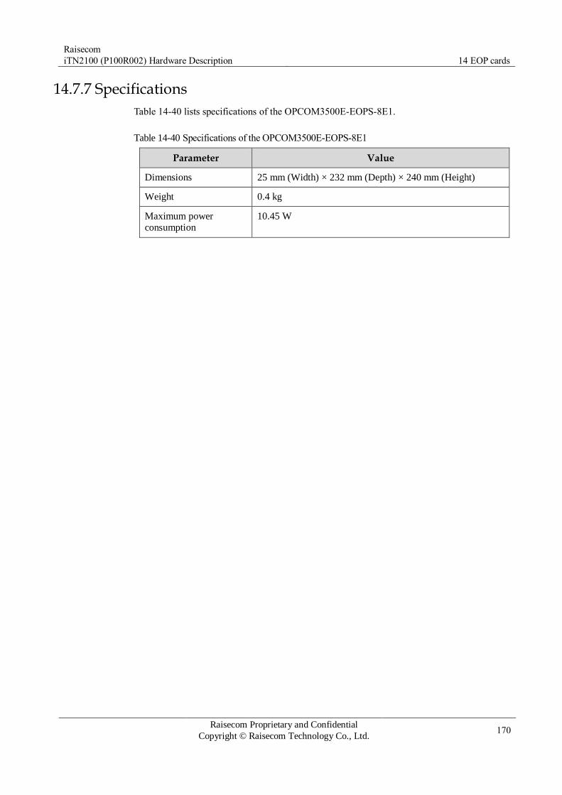
Raisecom
iTN2100 (P100R002) Hardware Description 14 EOP cards
Raisecom Proprietary and Confidential
Copyright © Raisecom Technology Co., Ltd. 170
14.7.7 Specifications
Table 14-40 lists specifications of the OPCOM3500E-EOPS-8E1.
Table 14-40 Specifications of the OPCOM3500E-EOPS-8E1
Parameter Value
Dimensions 25 mm (Width) × 232 mm (Depth) × 240 mm (Height)
Weight 0.4 kg
Maximum power
consumption
10.45 W

Raisecom
iTN2100 (P100R002) Hardware Description 14 EOP cards
Raisecom Proprietary and Confidential
Copyright © Raisecom Technology Co., Ltd. 171
14.8 OPCOM3500E-HT-6FE24E1
14.8.1 Appearance and functions
Appearance Function
The OPCOM3500E-HT-6FE24E1 is an electrical interface EoPDH
protocol converter card on the iTN2100.
You can configure the first 6 FE interfaces to 100 Mbit/s full duplex
mode fixedly or auto-negotiation mode (in this mode it supports 100
Mbit/s full duplex only). You can configure the wiring scheme to
MDIX or auto-negotiation. Support flow control on the FE interface. Support statistics of Tx and Rx of packets on the Ethernet interfaces. Each E1 interface supports framed and unframed modes in single-E1
mode. Support the following in E1 inverse multiplexing mode:
– Support inverse multiplexing of up to eight E1 links. – Support transmitting Ethernet frames to multiple E1 signals in a
frame-interleaving way. – Support Auto MDI/MDI-X. – Support the maximum relative delay ±16ms for E1 links. – Support automatic construction or destruction of E1 links.
Support the framed mode. It supports FAS+CRC4 PCM31 mode and
automatical CRC. You can configure them. Support E1 loop detection and BERT. Support statistics of sent frames, received frames, package traffic,
number of error packages on each E1 interface. Support remote management for remote protocol converters, attached
Ethernet transceivers, and the RC521H-FE and the Gazelle RM531-FE
(B). Support hot swapping.
14.8.2 Versions
Table 14-41 lists hardware versions of the OPCOM3500E-HT-6FE24E1.

Raisecom
iTN2100 (P100R002) Hardware Description 14 EOP cards
Raisecom Proprietary and Confidential
Copyright © Raisecom Technology Co., Ltd. 172
Table 14-41 Hardware versions of the OPCOM3500E-HT-6FE24E1
Card Hardware version
OPCOM3500E-HT-6FE24E1 A.00
OPCOM3500E-HT-6FE24E1 B.00
14.8.3 Slots
Table 14-42 lists slots available for the OPCOM3500E-HT-6FE24E1.
Table 14-42 Slots available for the OPCOM3500E-HT-6FE24E1
Chassis Slot
iTN2100 1–5 and 8–12
14.8.4 Interfaces
Interface types
Table 14-43 lists interfaces on the OPCOM3500E-HT-6FE24E1 panel.
Table 14-43 Interfaces on the OPCOM3500E-HT-6FE24E1 panel
Interface Type Description
1–6 RJ45 Six ways of EF electrical interfaces
DebugE and DebugC RJ45 Debugging interfaces
Interface parameters
Table 14-44 lists parameters of interfaces 1–6 on the OPCOM3500E-HT-6FE24E1.
Table 14-44 Parameters of interfaces 1–6 on the OPCOM3500E-HT-6FE24E1
Parameter Description
Connector type RJ45
Interface rate Support auto-negotiation (but in this mode it supports 100 Mbit/s full
duplex only).
Duplex mode Full duplex
Flow control IEEE 802.3x flow control in full duplex mode
Wiring scheme Auto MDI/MDIX
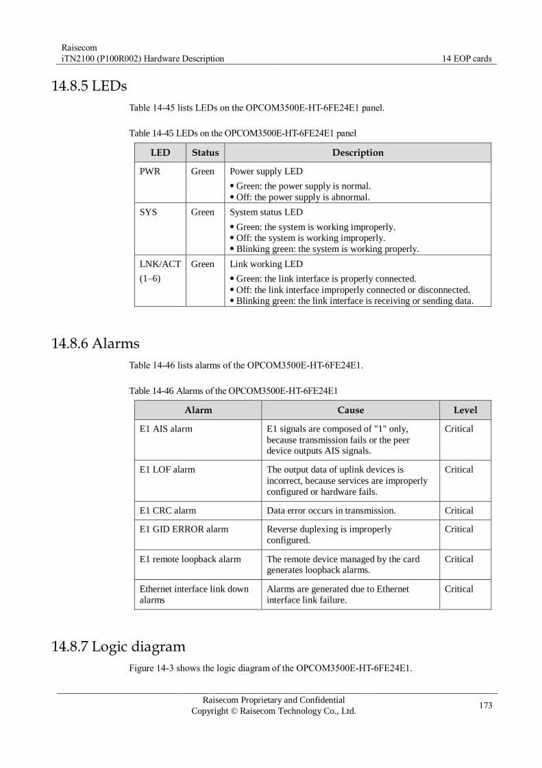
Raisecom
iTN2100 (P100R002) Hardware Description 14 EOP cards
Raisecom Proprietary and Confidential
Copyright © Raisecom Technology Co., Ltd. 173
14.8.5 LEDs
Table 14-45 lists LEDs on the OPCOM3500E-HT-6FE24E1 panel.
Table 14-45 LEDs on the OPCOM3500E-HT-6FE24E1 panel
LED Status Description
PWR Green Power supply LED
Green: the power supply is normal. Off: the power supply is abnormal.
SYS Green System status LED
Green: the system is working improperly. Off: the system is working improperly. Blinking green: the system is working properly.
LNK/ACT
(1–6)
Green Link working LED
Green: the link interface is properly connected. Off: the link interface improperly connected or disconnected. Blinking green: the link interface is receiving or sending data.
14.8.6 Alarms
Table 14-46 lists alarms of the OPCOM3500E-HT-6FE24E1.
Table 14-46 Alarms of the OPCOM3500E-HT-6FE24E1
Alarm Cause Level
E1 AIS alarm E1 signals are composed of "1" only,
because transmission fails or the peer device outputs AIS signals.
Critical
E1 LOF alarm The output data of uplink devices is
incorrect, because services are improperly
configured or hardware fails.
Critical
E1 CRC alarm Data error occurs in transmission. Critical
E1 GID ERROR alarm Reverse duplexing is improperly
configured.
Critical
E1 remote loopback alarm The remote device managed by the card generates loopback alarms.
Critical
Ethernet interface link down
alarms
Alarms are generated due to Ethernet
interface link failure.
Critical
14.8.7 Logic diagram
Figure 14-3 shows the logic diagram of the OPCOM3500E-HT-6FE24E1.
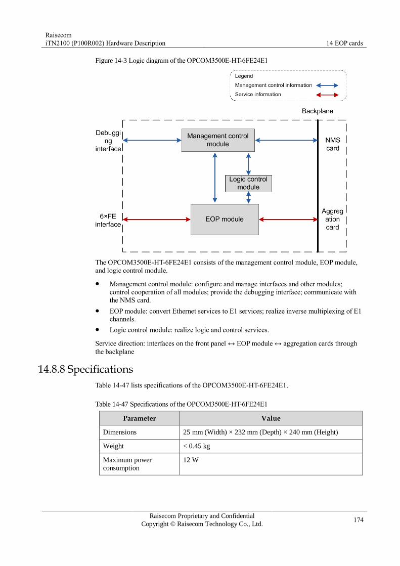
Raisecom
iTN2100 (P100R002) Hardware Description 14 EOP cards
Raisecom Proprietary and Confidential
Copyright © Raisecom Technology Co., Ltd. 174
Figure 14-3 Logic diagram of the OPCOM3500E-HT-6FE24E1
The OPCOM3500E-HT-6FE24E1 consists of the management control module, EOP module,
and logic control module.
Management control module: configure and manage interfaces and other modules;
control cooperation of all modules; provide the debugging interface; communicate with
the NMS card.
EOP module: convert Ethernet services to E1 services; realize inverse multiplexing of E1 channels.
Logic control module: realize logic and control services.
Service direction: interfaces on the front panel ↔ EOP module ↔ aggregation cards through
the backplane
14.8.8 Specifications
Table 14-47 lists specifications of the OPCOM3500E-HT-6FE24E1.
Table 14-47 Specifications of the OPCOM3500E-HT-6FE24E1
Parameter Value
Dimensions 25 mm (Width) × 232 mm (Depth) × 240 mm (Height)
Weight < 0.45 kg
Maximum power
consumption
12 W

Raisecom
iTN2100 (P100R002) Hardware Description 14 EOP cards
Raisecom Proprietary and Confidential
Copyright © Raisecom Technology Co., Ltd. 175
14.9 iTN2100-EOT-GESTM4
14.9.1 Appearance and functions
Appearance Function
The iTN2100-EOT-GESTM4 is EOPOS and EOS protocol converter
card on the iTN2100.
Support EOPOS and EOS. You can configure parameters for each
channel independently. You can configure 4 STM interfaces on the front panel to STM1 or the
first STM interface to STM4 (in this case, other interfaces become
invalid). EOPOS encapsulation supports GFP. EOS channels support N×VC12. Support up to 252 VCGs, with members as below:
– EOP supports 16×E1. – EOS supports 64×VC12.
Support flow classification based on VLAN tags. The maximum
number of flows is 4k. Support Ethernet flow control. Support QinQ. Support DDM of SFP modules. Support SDH overhead processing, statistics of alarms and
performance. Support configurable SDH clock source: local clock, line clock,
system TDM clock, or system Ethernet clock. Support SDH clock drifting, with jitter complying with ITU-T
standards. Support VC12 1+1 channel protection of SDH on the card. Support Automatical Switchover Protection (ASP) of the two
switching cards on the iTN2100. Support in-band remote management for EOP and EOS devices. Support hot swapping. Support SDH interface protection between 2 cards. However, the 2
cards must be inserted into specified slots: slots 2 and 4 or slots 3 and
5. Support accessing the SDH network through the aggregation card.
However, the card must be inserted into slot 2 or slot 4 of the
iTN2100.
14.9.2 Slots
The iTN2100-EOT-GESTM4 can be inserted into slots 1–5 and 8–12 on the iTN2100.

Raisecom
iTN2100 (P100R002) Hardware Description 14 EOP cards
Raisecom Proprietary and Confidential
Copyright © Raisecom Technology Co., Ltd. 176
14.9.3 Interfaces
Interface types
Table 14-48 lists interfaces on the iTN2100-EOT-GESTM4 panel.
Table 14-48 Interfaces on the iTN2100-EOT-GESTM4 panel
Interface Type Description
1–4 SFP optical interface Service uplink interfaces
– MiniUSB Debugging interface
Interface parameters
Table 14-49 lists parameters of interfaces 1–4 on the iTN2100-EOT-GESTM4.
Table 14-49 Parameters of interfaces 1–4 on the iTN2100-EOT-GESTM4
Parameter Description
Connector type SFP optical interface (LC)
Interface rate You can configure four STM interfaces on the front panel to STM1
or the first STM interface to STM4 (other interfaces becomes invalid).
Coding scheme NRZ
Clock features Comply with ITU-T G.813 recommendations.
Electrical features Comply with ITU-T G.957 recommendations.
Jitter features Comply with ITU-T G.783 and ITU-T G.825 recommendations.
14.9.4 LEDs
Table 14-50 lists LEDs on the iTN2100-EOT-GESTM4 panel.
Table 14-50 LEDs on the iTN2100-EOT-GESTM4 panel
LED Status Description
PWR Green Power supply LED
Green: the power supply is normal. Off: the power supply is abnormal.
SYS Green System status LED
Green: the system is working improperly. Off: the system is working improperly. Blinking green: the system is working properly.

Raisecom
iTN2100 (P100R002) Hardware Description 14 EOP cards
Raisecom Proprietary and Confidential
Copyright © Raisecom Technology Co., Ltd. 177
LED Status Description
ACT Green Primary/Slave LED for the aggregation card
In dual-card protection mode: – Green: the card is primary. – Off: the card is slave.
In non-protection mode: it is Green.
LOF (1–4) Red LOF alarm LED
Red: input LOF alarms are generated on optical
interfaces 1, 2, 3, and 4. Off: no input LOF alarms are generated on optical
interfaces 1, 2, 3, and 4.
LOS (1–4) Red LOS alarm LED
Red: input LOS alarms are generated on optical
interfaces 1, 2, 3, and 4. Off: no input LOS alarms are generated on optical
interfaces 1, 2, 3, and 4.
14.9.5 DIP switches
Table 14-51 lists configurations of the DIP switch on the iTN2100-EOT-GESTM4.
Table 14-51 Configurations of the DIP switch on the iTN2100-EOT-GESTM4
SW1 Function Status Description
No.
Bit1 Configure the
optical
interface rate.
ON Configure the rate of the first optical interface to
STM-4; others become invalid.
OFF Configure the rate of the four optical interfaces to
STM-1.
Bit2 Configure the
valid SDH
interface.
ON The SDN interface on the backplane takes effect.
Meanwhile, the SDH interface on the front panel is
invalid.
OFF The SDN interface on the front panel takes effect.
Meanwhile, the SDH interface on the backplane is invalid.
By default, Bit1 is OFF. When configuring the SDH interface on the backplane to take effect through Bit2, you need to configure Bit1 to ON.
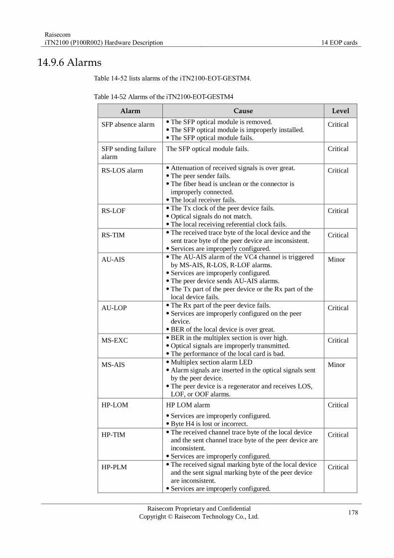
Raisecom
iTN2100 (P100R002) Hardware Description 14 EOP cards
Raisecom Proprietary and Confidential
Copyright © Raisecom Technology Co., Ltd. 178
14.9.6 Alarms
Table 14-52 lists alarms of the iTN2100-EOT-GESTM4.
Table 14-52 Alarms of the iTN2100-EOT-GESTM4
Alarm Cause Level
SFP absence alarm The SFP optical module is removed. The SFP optical module is improperly installed. The SFP optical module fails.
Critical
SFP sending failure
alarm
The SFP optical module fails. Critical
RS-LOS alarm Attenuation of received signals is over great. The peer sender fails. The fiber head is unclean or the connector is
improperly connected. The local receiver fails.
Critical
RS-LOF The Tx clock of the peer device fails. Optical signals do not match. The local receiving referential clock fails.
Critical
RS-TIM The received trace byte of the local device and the
sent trace byte of the peer device are inconsistent. Services are improperly configured.
Critical
AU-AIS The AU-AIS alarm of the VC4 channel is triggered
by MS-AIS, R-LOS, R-LOF alarms. Services are improperly configured. The peer device sends AU-AIS alarms. The Tx part of the peer device or the Rx part of the
local device fails.
Minor
AU-LOP The Rx part of the peer device fails. Services are improperly configured on the peer
device. BER of the local device is over great.
Critical
MS-EXC BER in the multiplex section is over high. Optical signals are improperly transmitted. The performance of the local card is bad.
Critical
MS-AIS Multiplex section alarm LED Alarm signals are inserted in the optical signals sent
by the peer device. The peer device is a regenerator and receives LOS,
LOF, or OOF alarms.
Minor
HP-LOM HP LOM alarm
Services are improperly configured. Byte H4 is lost or incorrect.
Critical
HP-TIM The received channel trace byte of the local device
and the sent channel trace byte of the peer device are
inconsistent. Services are improperly configured.
Critical
HP-PLM The received signal marking byte of the local device
and the sent signal marking byte of the peer device
are inconsistent. Services are improperly configured.
Critical

Raisecom
iTN2100 (P100R002) Hardware Description 14 EOP cards
Raisecom Proprietary and Confidential
Copyright © Raisecom Technology Co., Ltd. 179
Alarm Cause Level
TU-AIS Services are improperly configured. The channel of the peer device fails. HP alarms, such as R-LOS, trigger the alarm. The cross-connection card fails.
Minor
TU-LOP The interface between the tributary card and the
cross-connection card fails. Services are improperly configured.
Critical
LP-TIM The low order path trace identifiers of the local
device and the peer device are inconsistent. Services are improperly configured.
Critical
E1 AIS alarm E1 signals are composed of "1" only, because
transmission fails or the peer device outputs AIS signals.
Critical
E1 LOF alarm The output data of uplink devices is incorrect, because
services are improperly configured or hardware fails.
Critical
E1 CRC alarm Data error occurs in transmission. Critical
E1 remote loopback
alarm
The remote device managed by the card generates
loopback alarms.
Critical
14.9.7 Specifications
Table 14-53 lists specifications of the iTN2100-EOT-GESTM4.
Table 14-53 Specifications of the iTN2100-EOT-GESTM4
Parameter Value
Dimensions 25 mm (Width) × 232 mm (Depth) × 240 mm (Height)
Weight < 0.45 kg
Maximum power
consumption
30 W

Raisecom
iTN2100 (P100R002) Hardware Description 15 EOS cards
Raisecom Proprietary and Confidential
Copyright © Raisecom Technology Co., Ltd. 180
15 EOS cards
This chapter describes EOS cards of the iTN2100, including the following sections:
OPCOM3500E-EOS-8FE
OPCOM3500E-EOSE-4FX
OPCOM3500E-EOSE-8FX
OPCOM3500E-4EOS-4FE
OPCOM3500E-4EOS-4FX
OPCOM3500E-8EOS-GC
OPCOM3500E-DSEE
OPCOM3500E-HSEE
OPCOM3500E-HSEEC
OPCOM3500E-HEESC
OPCOM3500E-ACEWA

Raisecom
iTN2100 (P100R002) Hardware Description 15 EOS cards
Raisecom Proprietary and Confidential
Copyright © Raisecom Technology Co., Ltd. 181
15.1 OPCOM3500E-EOS-8FE
15.1.1 Appearance and functions
Appearance Function
The OPCOM3500E-EOS-8FE is an EOS tributary card with 8 electrical
interfaces on the iTN2100. At present, there are two versions: B and C.
Support up to 8 ways of 10/100 Mbit/s Ethernet electrical interfaces
services. Support assigning eight ways of Ethernet services with bandwidth of
N×VC12, transmitting them to the SDH network, and sharing bandwidth of
63×VC12. Support two Ethernet encapsulation modes: GFP and LAPS. Support VCAT and LCAS. Support configuring lower-order overhead bytes J2, K4, and V5. The byte
V5 is fixed as 0x05 in version C and thus it cannot be configured. Support decoding/scrambling core frame head and payload (supported by
version B only). Support online software upgrade for local devices. Support complete alarms and performance monitoring. Support complete Ethernet interface features. Support querying default information about the device. Support hot swapping.
The left is version B and the right is version C.
15.1.2 Slots
The OPCOM3500E-EOS-8FE can be inserted into slots 1–5 and 8–12 on the iTN2100.

Raisecom
iTN2100 (P100R002) Hardware Description 15 EOS cards
Raisecom Proprietary and Confidential
Copyright © Raisecom Technology Co., Ltd. 182
15.1.3 Interfaces
Interface types
Table 15-1 lists interfaces on the OPCOM3500E-EOS-8FE panel.
Table 15-1 Interfaces on the OPCOM3500E-EOS-8FE panel
Interface Type Description
– RJ45 Service downlink interfaces 8 FE electrical interfaces
Interface parameters
Table 15-2 lists parameters of interfaces on the OPCOM3500E-EOS-8FE.
Table 15-2 Parameters of interfaces on the OPCOM3500E-EOS-8FE
Parameter Description
Connector type RJ45
Interface rate 10/100 Mbit/s auto-negotiation
15.1.4 LEDs
Table 15-3 lists LEDs on the OPCOM3500E-EOS-8FE panel
Table 15-3 LEDs on the OPCOM3500E-EOS-8FE panel
LED Status Description
PWR Green Power supply LED
Green: the power supply is normal. Off: the power supply is abnormal.
SYS Green System status LED
Green: the system is working improperly. Off: the system is working improperly. Blinking green: the system is working properly.
ALM Red Alarm LED
Red: TU-AIS or TU-LOP alarms are generated in the LP of
service allocation. Off: no TU-AIS or TU-LOP alarms are generated in the LP of
service allocation.
100M
(1–8)
Green Interface rate LED
Green: the interface is working at 100 Mbit/s. Off: the interface is working at 10 Mbit/s.

Raisecom
iTN2100 (P100R002) Hardware Description 15 EOS cards
Raisecom Proprietary and Confidential
Copyright © Raisecom Technology Co., Ltd. 183
LED Status Description
LNK/ACT
(1–8)
Green Interface connection status LED
Green: the interface is connected properly. Off: the interface is disconnected or is connected improperly. Blinking green: the interface is receiving or sending data.
15.1.5 DIP switches
There are no DIP switches available for users on the OPCOM3500E-EOS-8FE.
15.1.6 Logic diagram
Figure 15-1 shows the logic diagram of the OPCOM3500E-EOS-8FE.
Figure 15-1 Logic diagram of the OPCOM3500E-EOS-8FE
The OPCOM3500E-EOS-8FE consists of the management control module, Ethernet
encapsulation module, EOS module, and timing adjustment module.
Management control module: exchange network management information, and control other modules to coordinate with each other.
Ethernet encapsulation module: adjust received Ethernet signals.
EOS module: encapsulate Ethernet signals into EOS signals, or decapsulate EOS signals.
Timing adjustment module: adjust the timing sequence of the timeslot.
Service direction:
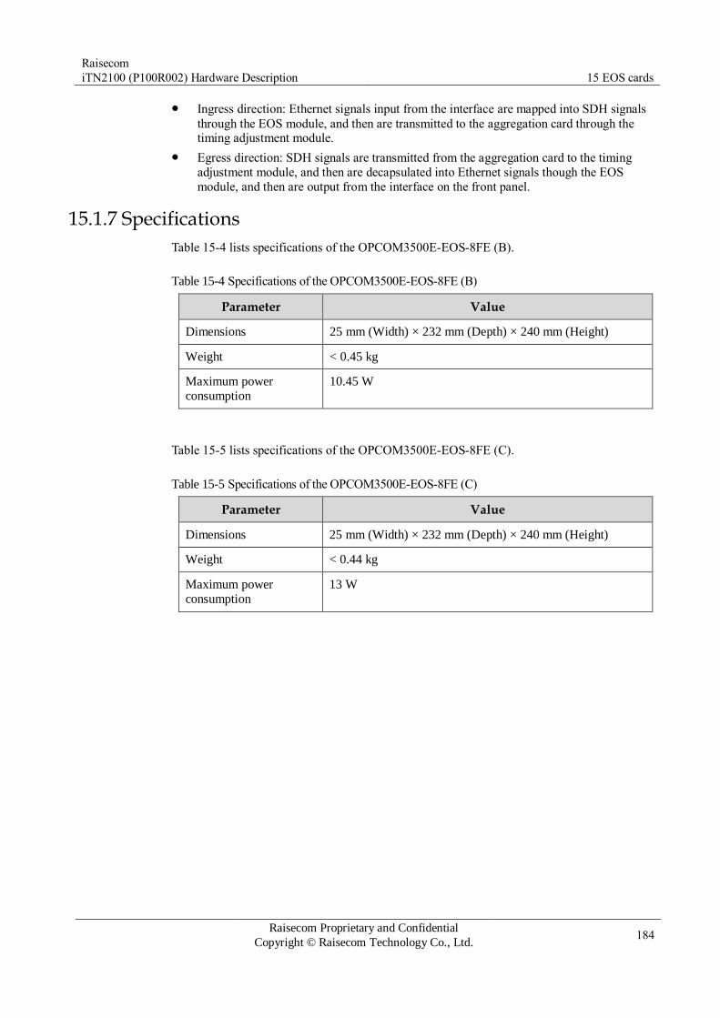
Raisecom
iTN2100 (P100R002) Hardware Description 15 EOS cards
Raisecom Proprietary and Confidential
Copyright © Raisecom Technology Co., Ltd. 184
Ingress direction: Ethernet signals input from the interface are mapped into SDH signals
through the EOS module, and then are transmitted to the aggregation card through the timing adjustment module.
Egress direction: SDH signals are transmitted from the aggregation card to the timing
adjustment module, and then are decapsulated into Ethernet signals though the EOS
module, and then are output from the interface on the front panel.
15.1.7 Specifications
Table 15-4 lists specifications of the OPCOM3500E-EOS-8FE (B).
Table 15-4 Specifications of the OPCOM3500E-EOS-8FE (B)
Parameter Value
Dimensions 25 mm (Width) × 232 mm (Depth) × 240 mm (Height)
Weight < 0.45 kg
Maximum power
consumption
10.45 W
Table 15-5 lists specifications of the OPCOM3500E-EOS-8FE (C).
Table 15-5 Specifications of the OPCOM3500E-EOS-8FE (C)
Parameter Value
Dimensions 25 mm (Width) × 232 mm (Depth) × 240 mm (Height)
Weight < 0.44 kg
Maximum power
consumption
13 W

Raisecom
iTN2100 (P100R002) Hardware Description 15 EOS cards
Raisecom Proprietary and Confidential
Copyright © Raisecom Technology Co., Ltd. 185
15.2 OPCOM3500E-EOSE-4FX
15.2.1 Appearance and functions
Appearance Function
The OPCOM3500E-EOSE-4FX is an EOS tributary card with 4
electrical interfaces on the iTN2100.
Provide 8 ways of 100 Mbit/s Ethernet electrical interfaces. Support adding standard 802.1q Tag for the Ethernet services
received inside the card. Support two Ethernet encapsulation modes: GFP and LAPS. Support VCAT and LCAS. Support assigning 4 ways of Ethernet services with bandwidth of
N×VC12 and N×VC3, transmitting them to the SDH network. Support the maximum frame size of the Ethernet data: 2000B. Support online software upgrade for local devices. Support managing remote 100 Mbit/s Ethernet optical transceivers,
such as, RC500 series, RC600 series, Gazelle RM531-FE (B), and
RC521H-FE. Support complete alarms and performance monitoring. Provide statistics of sending, receiving, and error packets for each
ACG frame. Support hot swapping.
15.2.2 Slots
The OPCOM3500E-EOSE-4FX can be inserted into slots 1–5 and 8–12 on the iTN2100.

Raisecom
iTN2100 (P100R002) Hardware Description 15 EOS cards
Raisecom Proprietary and Confidential
Copyright © Raisecom Technology Co., Ltd. 186
15.2.3 Interfaces
Interface types
Table 15-6 lists interfaces on the OPCOM3500E-EOSE-4FX panel.
Table 15-6 Interfaces on the OPCOM3500E-EOSE-4FX panel
Interface Type Description
1–4 1×9 optical interface Each interface transmits a way of Ethernet optical
signals. Tx indicates the sending interface and Rx indicates
the receiving interface.
Interface parameters
Table 15-7 lists parameters of interfaces 1–4 on the OPCOM3500E-EOSE-4FX.
Table 15-7 Parameters of interfaces 1–4 on the OPCOM3500E-EOSE-4FX
Parameter Description
Connector type 1×9 optical interface
Interface rate 100 Mbit/s
Duplex mode Full duplex
Flow control IEEE 802.3x flow control
Standard IEEE 802.3x, IEEE 802.3u, and IEEE 802.1q
15.2.4 LEDs
Table 15-8 lists LEDs on the OPCOM3500E-EOSE-4FX panel.
Table 15-8 LEDs on the OPCOM3500E-EOSE-4FX panel
LED Status Description
PWR Green Power supply LED
Green: the power supply is normal. Off: the power supply is abnormal.
SYS Green System status LED
Green: the system is working improperly. Off: the system is working improperly. Blinking green: the system is working properly.

Raisecom
iTN2100 (P100R002) Hardware Description 15 EOS cards
Raisecom Proprietary and Confidential
Copyright © Raisecom Technology Co., Ltd. 187
LED Status Description
ALM Red Alarm LED
Red: TU-AIS, TU-LOP, or LP-EXLOM alarm is generated in
VC-12. Off: no TU-AIS, TU-LOP, or LP-EXLOM alarm is generated
in VC-12.
LNK/ACT
(1–4)
Green Line working LED
Green: the interface is working properly. Off: the interface is disconnected or is working improperly. Blinking green: the interface is receiving or sending data.
15.2.5 Alarms
Table 15-9 lists alarms of the OPCOM3500E-EOSE-4FX.
Table 15-9 Alarms of the OPCOM3500E-EOSE-4FX
Alarm Cause
TU pointer loss/All-1 alarm,
TU-LOP, and TU-AIS
The SDH signal sent from the aggregation
card fails. The hardware of the card is faulty and SDH
data received on the backplane is incorrect. The clock timing signal of the card is lost.
LP-EXLOM Invalid K4 overhead is received in the
continuous three frames. The b1 of K4 byte
loses multiframe, and K4 byte sent from the peer EOS device fails.
LP-UNEQ The low-order path is loaded, and the V5
byte sent from the peer EOS device fails.
15.2.6 Specifications
Table 15-10 lists specifications of the OPCOM3500E-EOSE-4FX.
Table 15-10 Specifications of the OPCOM3500E-EOSE-4FX
Parameter Value
Dimensions 25 mm (Width) × 232 mm (Depth) × 240 mm (Height)
Weight 0.355 kg
Maximum power
consumption
10.1 W

Raisecom
iTN2100 (P100R002) Hardware Description 15 EOS cards
Raisecom Proprietary and Confidential
Copyright © Raisecom Technology Co., Ltd. 188
15.3 OPCOM3500E-EOSE-8FX
15.3.1 Appearance and functions
Appearance Function
A/B version C version The OPCOM3500E-EOSE-8FX is an EOS tributary
card with labeling function and 4 electrical interfaces on the iTN2100.
Provide 8 ways of 100 Mbit/s Ethernet electrical
interfaces. Support SFP module hot swapping. Support DDM for the SFP module. Support assigning 8 ways of Ethernet services with
bandwidth of N×VC12, transmitting them to the
SDH network, and sharing bandwidth of63×VC12. The backplane of the card supports 155 M
bandwidth. Support adding standard 802.1q Tag for the Ethernet
data packets received inside the card. Support two Ethernet encapsulation modes: GFP and
LAPS. Support VCAT and LCAS. Support RC-Link protocol. Support managing remote 100 Mbit/s Ethernet
optical transceivers, such as, RC500 series, RC600
series, and Gazelle RM531-FE (B). Support complete alarms and performance
monitoring. Support complete Ethernet interface features. Support querying default information about the
device. Support hot swapping.

Raisecom
iTN2100 (P100R002) Hardware Description 15 EOS cards
Raisecom Proprietary and Confidential
Copyright © Raisecom Technology Co., Ltd. 189
15.3.2 Slots
The OPCOM3500E-EOSE-8FX can be inserted into slots 1–5 and 8–12 on the iTN2100.
15.3.3 Interfaces
Interface types
Table 15-11 and Table 15-12 list interfaces on the OPCOM3500E-EOSE-8FX panel.
Table 15-11 Interfaces on the OPCOM3500E-EOSE-8FX (A/B version) panel
Interface Type Description
1–8 SFP optical
interface
Each interface transmits a way of Ethernet optical
signals.
Table 15-12 Interfaces on the OPCOM3500E-EOSE-8FX (C version) panel
Interface Type Description
1–8 SFP optical
interface
Each interface transmits a way of Ethernet optical
signals.
– MiniUSB Debugging interface
Interface parameters
Table 15-13 lists parameters of interfaces 1–8 on the OPCOM3500E-EOSE-8FX.
Table 15-13 Parameters of interfaces 1–8 on the OPCOM3500E-EOSE-8FX
Parameter Description
Connector type SFP optical interface
Interface rate 100 Mbit/s
Interface specification 100BASE-FX
Standard IEEE 802.3u
15.3.4 LEDs
Table 15-14 LEDs on the OPCOM3500E-EOSE-8FX panel

Raisecom
iTN2100 (P100R002) Hardware Description 15 EOS cards
Raisecom Proprietary and Confidential
Copyright © Raisecom Technology Co., Ltd. 190
Table 15-14 LEDs on the OPCOM3500E-EOSE-8FX panel
LED Status Description
PWR Green Power supply LED
Green: the power supply is normal. Off: the power supply is abnormal.
SYS Green System status LED
Green: the system is working improperly. Off: the system is working improperly. Blinking green: the system is working properly.
ALM Red Alarm LED (no alarm LED on the version C card)
Red: TU-AIS or TU-LOP alarm is generated in the service-
distributed lower order path. Off: no TU-AIS or TU-LOP alarm is generated in the
service-distributed lower order path.
LNK/ACT
(1–8)
Green Line working LED
Green: the interface is working properly. Off: the interface is disconnected or is working improperly. Blinking green: the interface is receiving or sending data.
15.3.5 Alarms
Table 15-15 lists alarms of the OPCOM3500E-EOSE-8FX.
Table 15-15 Alarms of the OPCOM3500E-EOSE-8FX
Alarm Cause Level
SFP absence alarm The SFP optical module is removed. The SFP optical module is improperly
installed. The SFP optical module fails.
Critical
SFP sending failure alarm The SFP optical module fails. Critical
SFP receiving LOS alarm Attenuation of received signals is over great. The peer sender fails. The fiber head is unclean or the connector is
improperly connected. The local receiver fails.
Critical
Ethernet interface link down
alarm
Fiber is disconnected. The Rx and Tx of the peer device fail.
Critical
LPR alarm on the peer
device
The remote transceiver is powered off. Critical
15.3.6 Logic diagram
Figure 15-2 shows logic diagram of the OPCOM3500E-EOSE-8FX. The debugging interface is available to the OPCOM3500E-EOSE-8FX (C) only.

Raisecom
iTN2100 (P100R002) Hardware Description 15 EOS cards
Raisecom Proprietary and Confidential
Copyright © Raisecom Technology Co., Ltd. 191
Figure 15-2 Logic diagram of the OPCOM3500E-EOSE-8FX
The OPCOM3500E-EOSE-8FX consists of the management control module, restoration
module, logic control module, EOS module, and power module.
Management control module: exchange network management information, save the
control command and configuration status of the card, and control other modules to coordinate with each other.
Restoration module: restore the management control module, EOS module, and logic control module.
Logic control module: complete functions of management control module, EOS module
communication, and clock processing.
EOS module: encapsulate Ethernet signals, and map them into SDH signals according to N×VC12 and communicate with aggregation card.
Service direction:
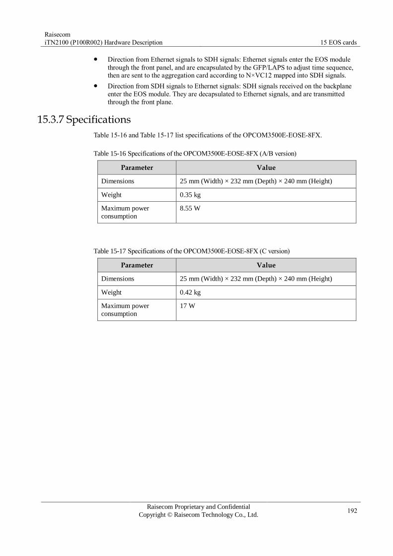
Raisecom
iTN2100 (P100R002) Hardware Description 15 EOS cards
Raisecom Proprietary and Confidential
Copyright © Raisecom Technology Co., Ltd. 192
Direction from Ethernet signals to SDH signals: Ethernet signals enter the EOS module
through the front panel, and are encapsulated by the GFP/LAPS to adjust time sequence, then are sent to the aggregation card according to N×VC12 mapped into SDH signals.
Direction from SDH signals to Ethernet signals: SDH signals received on the backplane
enter the EOS module. They are decapsulated to Ethernet signals, and are transmitted
through the front plane.
15.3.7 Specifications
Table 15-16 and Table 15-17 list specifications of the OPCOM3500E-EOSE-8FX.
Table 15-16 Specifications of the OPCOM3500E-EOSE-8FX (A/B version)
Parameter Value
Dimensions 25 mm (Width) × 232 mm (Depth) × 240 mm (Height)
Weight 0.35 kg
Maximum power
consumption
8.55 W
Table 15-17 Specifications of the OPCOM3500E-EOSE-8FX (C version)
Parameter Value
Dimensions 25 mm (Width) × 232 mm (Depth) × 240 mm (Height)
Weight 0.42 kg
Maximum power
consumption
17 W
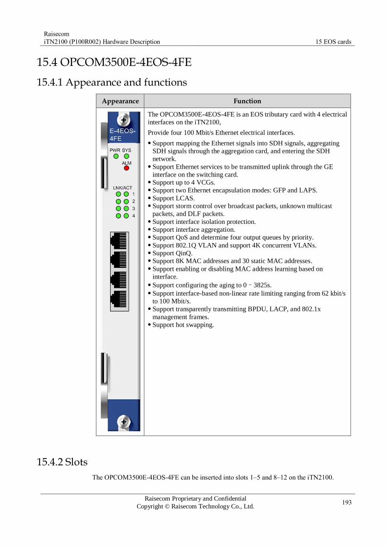
Raisecom
iTN2100 (P100R002) Hardware Description 15 EOS cards
Raisecom Proprietary and Confidential
Copyright © Raisecom Technology Co., Ltd. 193
15.4 OPCOM3500E-4EOS-4FE
15.4.1 Appearance and functions
Appearance Function
The OPCOM3500E-4EOS-4FE is an EOS tributary card with 4 electrical
interfaces on the iTN2100,
Provide four 100 Mbit/s Ethernet electrical interfaces.
Support mapping the Ethernet signals into SDH signals, aggregating
SDH signals through the aggregation card, and entering the SDH
network. Support Ethernet services to be transmitted uplink through the GE
interface on the switching card. Support up to 4 VCGs. Support two Ethernet encapsulation modes: GFP and LAPS. Support LCAS. Support storm control over broadcast packets, unknown multicast
packets, and DLF packets. Support interface isolation protection. Support interface aggregation. Support QoS and determine four output queues by priority. Support 802.1Q VLAN and support 4K concurrent VLANs. Support QinQ. Support 8K MAC addresses and 30 static MAC addresses. Support enabling or disabling MAC address learning based on
interface. Support configuring the aging to 0–3825s. Support interface-based non-linear rate limiting ranging from 62 kbit/s
to 100 Mbit/s. Support transparently transmitting BPDU, LACP, and 802.1x
management frames. Support hot swapping.
15.4.2 Slots
The OPCOM3500E-4EOS-4FE can be inserted into slots 1–5 and 8–12 on the iTN2100.
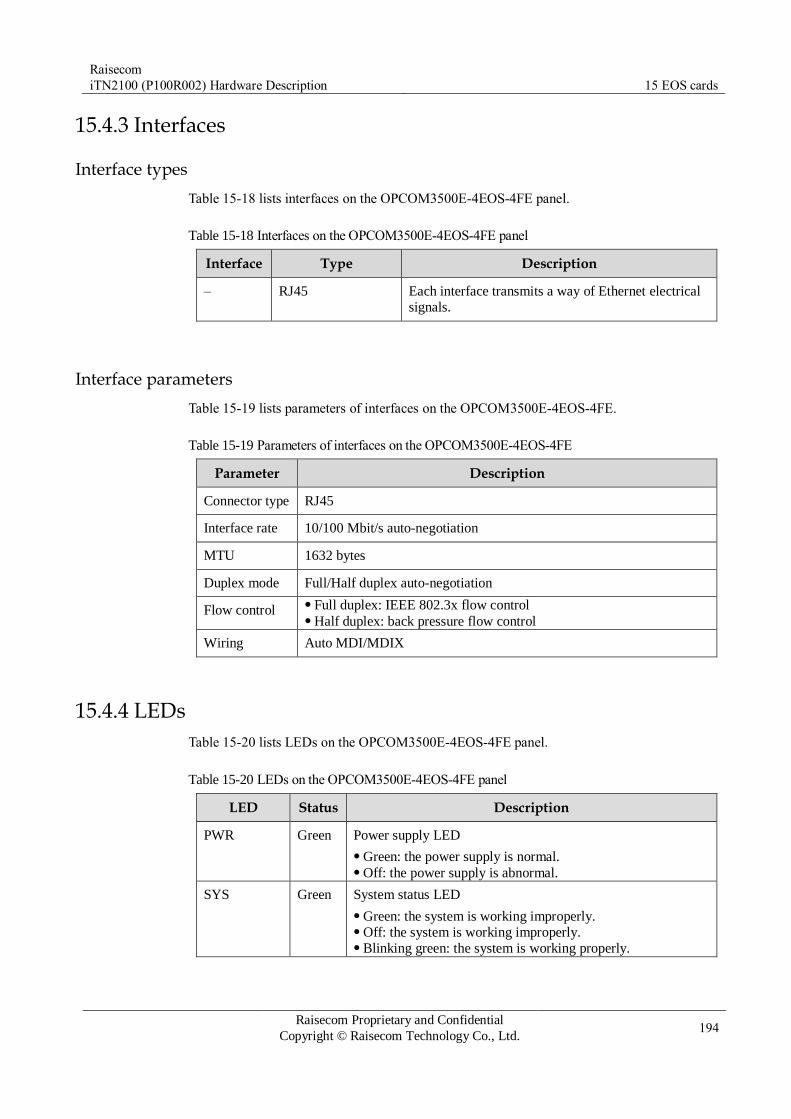
Raisecom
iTN2100 (P100R002) Hardware Description 15 EOS cards
Raisecom Proprietary and Confidential
Copyright © Raisecom Technology Co., Ltd. 194
15.4.3 Interfaces
Interface types
Table 15-18 lists interfaces on the OPCOM3500E-4EOS-4FE panel.
Table 15-18 Interfaces on the OPCOM3500E-4EOS-4FE panel
Interface Type Description
– RJ45 Each interface transmits a way of Ethernet electrical
signals.
Interface parameters
Table 15-19 lists parameters of interfaces on the OPCOM3500E-4EOS-4FE.
Table 15-19 Parameters of interfaces on the OPCOM3500E-4EOS-4FE
Parameter Description
Connector type RJ45
Interface rate 10/100 Mbit/s auto-negotiation
MTU 1632 bytes
Duplex mode Full/Half duplex auto-negotiation
Flow control Full duplex: IEEE 802.3x flow control Half duplex: back pressure flow control
Wiring Auto MDI/MDIX
15.4.4 LEDs
Table 15-20 lists LEDs on the OPCOM3500E-4EOS-4FE panel.
Table 15-20 LEDs on the OPCOM3500E-4EOS-4FE panel
LED Status Description
PWR Green Power supply LED
Green: the power supply is normal. Off: the power supply is abnormal.
SYS Green System status LED
Green: the system is working improperly. Off: the system is working improperly. Blinking green: the system is working properly.

Raisecom
iTN2100 (P100R002) Hardware Description 15 EOS cards
Raisecom Proprietary and Confidential
Copyright © Raisecom Technology Co., Ltd. 195
LED Status Description
ALM Red Alarm LED
Red: TU-AIS or TU-LOP alarm are generated in VC-12. Off: no TU-AIS or TU-LOP alarm are generated in VC-12.
100 M
(1–4)
Green Working rate of Ethernet electrical interface LED
Green: the working rate is under 100Mbit/s. Off: the working rate is under 100Mbit/s or the Ethernet
electrical interface is disconnected.
LNK/ACT
(1–4)
Green Line working LED
Green: the interface is working properly. Off: the interface is disconnected or is working improperly. Blinking green: the interface is receiving or sending data.
15.4.5 DIP switches
Table 15-21 lists configurations of DIP switches on the OPCOM3500E-4EOS-4FE.
Table 15-21 Configurations of DIP switch SW1 on the OPCOM3500E-4EOS-4FE
DIP switch
Function Status Description
Bit1 Bit2
SW1 Configure
working mode of the card
ON ON Configure the card in EOS and ESW
working mode.
EOS services can be transmitted to
the switching card through the
backplane, and also can be
transmitted through the front panel interface to access other devices.
OFF OFF Configure the card in EOS working
mode.
EOS services are transmitted from
the front panel only.
By default, SW1 is all OFF. Namely, the card is working in EOS mode by
default. After you configure working mode of SW1, configurations take effect after
power-on. Configuring SW1 in power-on status is not supported.
15.4.6 Alarms
Table 15-22 lists alarms of the OPCOM3500E-4EOS-4FE.
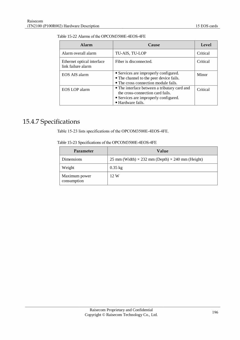
Raisecom
iTN2100 (P100R002) Hardware Description 15 EOS cards
Raisecom Proprietary and Confidential
Copyright © Raisecom Technology Co., Ltd. 196
Table 15-22 Alarms of the OPCOM3500E-4EOS-4FE
Alarm Cause Level
Alarm overall alarm TU-AIS, TU-LOP Critical
Ethernet optical interface
link failure alarm
Fiber is disconnected. Critical
EOS AIS alarm Services are improperly configured. The channel to the peer device fails. The cross connection module fails.
Minor
EOS LOP alarm The interface between a tributary card and
the cross-connection card fails. Services are improperly configured. Hardware fails.
Critical
15.4.7 Specifications
Table 15-23 lists specifications of the OPCOM3500E-4EOS-4FE.
Table 15-23 Specifications of the OPCOM3500E-4EOS-4FE
Parameter Value
Dimensions 25 mm (Width) × 232 mm (Depth) × 240 mm (Height)
Weight 0.35 kg
Maximum power
consumption
12 W

Raisecom
iTN2100 (P100R002) Hardware Description 15 EOS cards
Raisecom Proprietary and Confidential
Copyright © Raisecom Technology Co., Ltd. 197
15.5 OPCOM3500E-4EOS-4FX
15.5.1 Appearance and functions
Appearance Function
The OPCOM3500E-4EOS-4FX is an EOS tributary card with 4 optical
interfaces on the iTN2100, and it supports two working modes: EOS and ESW.
Provide four 100 Mbit/s Ethernet optical interfaces. Support two working modes: EOS and ESW.
– In EOS mode, Ethernet services received from the front panel are
mapped into SDH signals, and are transmitted to the aggregation
cards for aggregation, and then are transmitted to the SDH network. – In ESW mode, Ethernet services received from the front panel are
transmitted to the switching card through the backplane after
aggregation, and then are transmitted uplink through the switching
card. Support assigning four ways of Ethernet services with bandwidth of
N×VC12 for virtual cascading, and then transmitting them to the SDH
network. Support up to four VCGs. Support two Ethernet encapsulation modes: GFP and LAPS. Support VCAT and LCAS. Support storm control over broadcast messages, unknown multicast
messages, and DLF messages. Support interface isolation protection. Support interface aggregation. Support QoS and determine four output queues by priority. Support 802.1Q VLAN and support 4K concurrent VLANs. Support QinQ. Support 8k MAC addresses and 30 static MAC addresses. Support enabling or disabling MAC address learning based on
interface. Support configurable aging time ranging from 0s to 3825s. By default,
it is 300s. Support interface-based non-linear rate limiting ranging from 62 kbit/s
to 100 Mbit/s. Support transparently transmitting BPDU, LACP, and 802.1x
management frames. Support managing remote transceivers, the Gazelle RM531-FE (B),
and RC521H-FE. Support hot swapping.
15.5.2 Slots
The OPCOM3500E-4EOS-4FX can be inserted into slots 1–5 and 8–12 on the iTN2100.
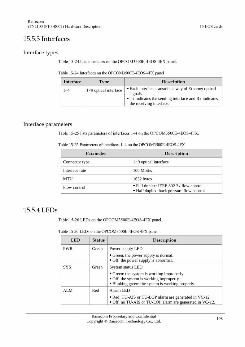
Raisecom
iTN2100 (P100R002) Hardware Description 15 EOS cards
Raisecom Proprietary and Confidential
Copyright © Raisecom Technology Co., Ltd. 198
15.5.3 Interfaces
Interface types
Table 15-24 lists interfaces on the OPCOM3500E-4EOS-4FX panel.
Table 15-24 Interfaces on the OPCOM3500E-4EOS-4FX panel
Interface Type Description
1–4 1×9 optical interface Each interface transmits a way of Ethernet optical
signals. Tx indicates the sending interface and Rx indicates
the receiving interface.
Interface parameters
Table 15-25 lists parameters of interfaces 1–4 on the OPCOM3500E-4EOS-4FX.
Table 15-25 Parameters of interfaces 1–4 on the OPCOM3500E-4EOS-4FX
Parameter Description
Connector type 1×9 optical interface
Interface rate 100 Mbit/s
MTU 1632 bytes
Flow control Full duplex: IEEE 802.3x flow control Half duplex: back pressure flow control
15.5.4 LEDs
Table 15-26 LEDs on the OPCOM3500E-4EOS-4FX panel.
Table 15-26 LEDs on the OPCOM3500E-4EOS-4FX panel
LED Status Description
PWR Green Power supply LED
Green: the power supply is normal. Off: the power supply is abnormal.
SYS Green System status LED
Green: the system is working improperly. Off: the system is working improperly. Blinking green: the system is working properly.
ALM Red Alarm LED
Red: TU-AIS or TU-LOP alarm are generated in VC-12. Off: no TU-AIS or TU-LOP alarm are generated in VC-12.

Raisecom
iTN2100 (P100R002) Hardware Description 15 EOS cards
Raisecom Proprietary and Confidential
Copyright © Raisecom Technology Co., Ltd. 199
LED Status Description
SD
(1–4)
Green Optical signal detection LED
Green: optical signals are detected. Off: no optical signals are detected.
LNK/ACT
(1–4)
Green Line working LED
Green: the interface is working properly. Off: the interface is disconnected or is working improperly. Blinking green: the interface is receiving or sending data.
15.5.5 DIP switches
Table 15-27 and Table 15-28 list configurations of DIP switches on the OPCOM3500E-
4EOS-4FX.
Table 15-27 Configurations of DIP switch SW1 on the OPCOM3500E-4EOS-4FX
DIP switch Function Status Description
Bit1 Bit2
SW1 Configure working mode
of the card
ON ON Configure the card in
ESW working mode.
OFF OFF Configure the card in
EOS working mode.
By default, SW1 is all OFF. Namely, the card is working in EOS mode by
default. After you configure working mode of SW1, configurations take effect after
power-on. Configuring SW1 during power-on is not supported.
Table 15-28 Configurations of DIP switch SW2 on the OPCOM3500E-4EOS-4FX
DIP switch
Function Status Description
Bit1 Bit2 Bit3 Bit4 Optical-interface component type
SW2 Configure
the type of
optical-
interface component.
ON ON ON ON M
ON ON ON OFF S1
ON ON OFF ON S2
ON ON OFF OFF S3
ON OFF ON ON SS13
ON OFF ON OFF SS15

Raisecom
iTN2100 (P100R002) Hardware Description 15 EOS cards
Raisecom Proprietary and Confidential
Copyright © Raisecom Technology Co., Ltd. 200
DIP switch
Function Status Description
Bit1 Bit2 Bit3 Bit4 Optical-interface component type
ON OFF OFF ON SS23
ON OFF OFF OFF SS25
SW2 is properly configured before the card leaves the factory. Do not configure it if not needed.
15.5.6 Alarms
Table 15-29 lists alarms of the OPCOM3500E-4EOS-4FX.
Table 15-29 Alarms of the OPCOM3500E-4EOS-4FX
Alarm Cause Level
Alarm overall alarm TU-AIS, TU-LOP Critical
Optical signal LOS No optical signals are input. Critical
Ethernet optical interface
link failure alarm
Fiber is disconnected. The Rx and Tx of the remote device fail.
Critical
EOS AIS alarm Services are improperly configured. The channel to the peer device fails. The cross connection module fails.
Minor
EOS LOP alarm The interface between a tributary card and
the cross-connection card fails. Services are improperly configured. Hardware fails.
Critical
Remote device LPR alarm The remote transceiver is powered off. Critical
15.5.7 Specifications
Table 15-30 lists specifications of the OPCOM3500E-4EOS-4FX.
Table 15-30 Specifications of the OPCOM3500E-4EOS-4FX
Parameter Value
Dimensions 25 mm (Width) × 232 mm (Depth) × 240 mm (Height)
Weight 0.4 kg
Maximum power
consumption
12 W
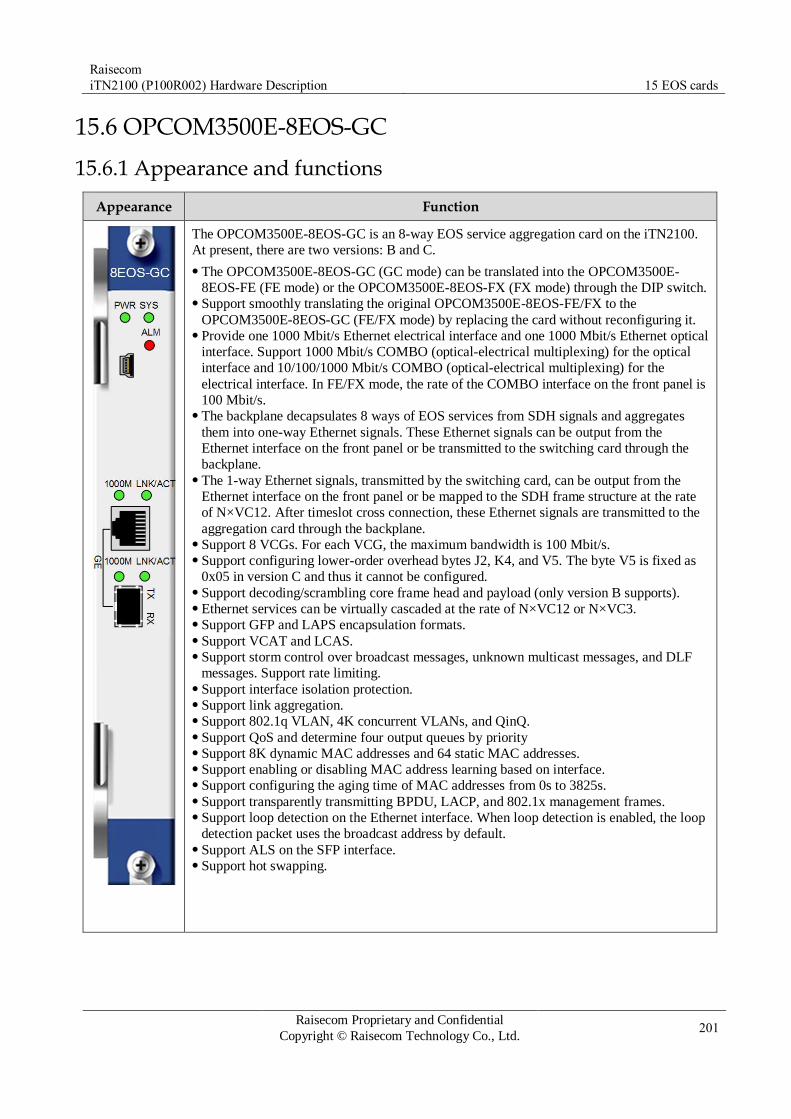
Raisecom
iTN2100 (P100R002) Hardware Description 15 EOS cards
Raisecom Proprietary and Confidential
Copyright © Raisecom Technology Co., Ltd. 201
15.6 OPCOM3500E-8EOS-GC
15.6.1 Appearance and functions
Appearance Function
The OPCOM3500E-8EOS-GC is an 8-way EOS service aggregation card on the iTN2100.
At present, there are two versions: B and C.
The OPCOM3500E-8EOS-GC (GC mode) can be translated into the OPCOM3500E-
8EOS-FE (FE mode) or the OPCOM3500E-8EOS-FX (FX mode) through the DIP switch. Support smoothly translating the original OPCOM3500E-8EOS-FE/FX to the
OPCOM3500E-8EOS-GC (FE/FX mode) by replacing the card without reconfiguring it. Provide one 1000 Mbit/s Ethernet electrical interface and one 1000 Mbit/s Ethernet optical
interface. Support 1000 Mbit/s COMBO (optical-electrical multiplexing) for the optical
interface and 10/100/1000 Mbit/s COMBO (optical-electrical multiplexing) for the
electrical interface. In FE/FX mode, the rate of the COMBO interface on the front panel is
100 Mbit/s. The backplane decapsulates 8 ways of EOS services from SDH signals and aggregates
them into one-way Ethernet signals. These Ethernet signals can be output from the
Ethernet interface on the front panel or be transmitted to the switching card through the
backplane. The 1-way Ethernet signals, transmitted by the switching card, can be output from the
Ethernet interface on the front panel or be mapped to the SDH frame structure at the rate
of N×VC12. After timeslot cross connection, these Ethernet signals are transmitted to the
aggregation card through the backplane. Support 8 VCGs. For each VCG, the maximum bandwidth is 100 Mbit/s. Support configuring lower-order overhead bytes J2, K4, and V5. The byte V5 is fixed as
0x05 in version C and thus it cannot be configured. Support decoding/scrambling core frame head and payload (only version B supports). Ethernet services can be virtually cascaded at the rate of N×VC12 or N×VC3. Support GFP and LAPS encapsulation formats. Support VCAT and LCAS. Support storm control over broadcast messages, unknown multicast messages, and DLF
messages. Support rate limiting. Support interface isolation protection. Support link aggregation. Support 802.1q VLAN, 4K concurrent VLANs, and QinQ. Support QoS and determine four output queues by priority Support 8K dynamic MAC addresses and 64 static MAC addresses. Support enabling or disabling MAC address learning based on interface. Support configuring the aging time of MAC addresses from 0s to 3825s. Support transparently transmitting BPDU, LACP, and 802.1x management frames. Support loop detection on the Ethernet interface. When loop detection is enabled, the loop
detection packet uses the broadcast address by default. Support ALS on the SFP interface. Support hot swapping.

Raisecom
iTN2100 (P100R002) Hardware Description 15 EOS cards
Raisecom Proprietary and Confidential
Copyright © Raisecom Technology Co., Ltd. 202
15.6.2 Slots
The OPCOM3500E-8EOS-GC can be inserted into slots 1–5 and 8–12 on the iTN2100.
15.6.3 Interfaces
Interface types
Table 15-31 lists interfaces on the OPCOM3500E-8EOS-GC panel.
Table 15-31 Interfaces on the OPCOM3500E-8EOS-GC panel
Interface Type Description
– MiniUSB Debugging interface
– RJ45 Service uplink interface and 1000 Mbit/s electrical interface
– SFP optical
interface
Service uplink interface and 1000 Mbit/s optical interface
Interface parameters
Table 15-32 lists parameters of the RJ45 interface on the OPCOM3500E-8EOS-GC.
Table 15-32 parameters of the RJ45 interface on the OPCOM3500E-8EOS-GC
Parameter Description
Connector type RJ45
Interface rate 10/100 Mbit/s auto-negotiation
Duplex mode Full duplex/Half duplex auto-negotiation
MTU 1632 bytes
Flow control Full duplex: IEEE 802.3x flow control Half duplex: back pressure flow control
Wiring scheme Auto MDI/MDIX
Compliance standard IEEE 802.3 IEEE 802.3u
Table 15-33 lists parameters of the SFP optical interface on the OPCOM3500E-8EOS-GC.
Table 15-33 Parameters of the SFP optical interface on the OPCOM3500E-8EOS-GC
Parameter Description
Connector type SFP (LC/PC)
Interface rate 100/1000 Mbit/s
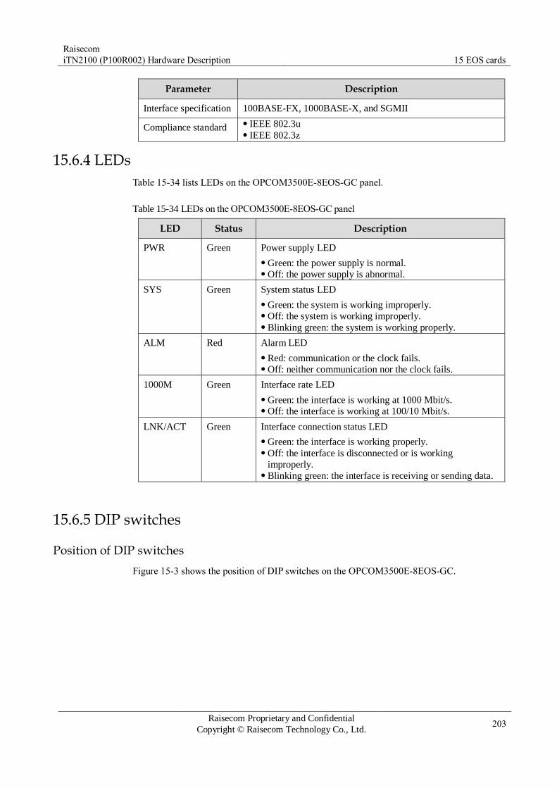
Raisecom
iTN2100 (P100R002) Hardware Description 15 EOS cards
Raisecom Proprietary and Confidential
Copyright © Raisecom Technology Co., Ltd. 203
Parameter Description
Interface specification 100BASE-FX, 1000BASE-X, and SGMII
Compliance standard IEEE 802.3u IEEE 802.3z
15.6.4 LEDs
Table 15-34 lists LEDs on the OPCOM3500E-8EOS-GC panel.
Table 15-34 LEDs on the OPCOM3500E-8EOS-GC panel
LED Status Description
PWR Green Power supply LED
Green: the power supply is normal. Off: the power supply is abnormal.
SYS Green System status LED
Green: the system is working improperly. Off: the system is working improperly. Blinking green: the system is working properly.
ALM Red Alarm LED
Red: communication or the clock fails. Off: neither communication nor the clock fails.
1000M Green Interface rate LED
Green: the interface is working at 1000 Mbit/s. Off: the interface is working at 100/10 Mbit/s.
LNK/ACT Green Interface connection status LED
Green: the interface is working properly. Off: the interface is disconnected or is working
improperly. Blinking green: the interface is receiving or sending data.
15.6.5 DIP switches
Position of DIP switches
Figure 15-3 shows the position of DIP switches on the OPCOM3500E-8EOS-GC.
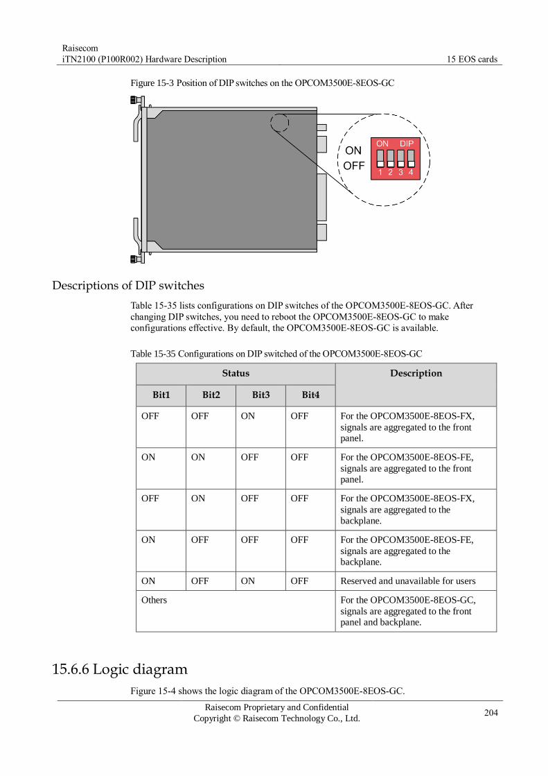
Raisecom
iTN2100 (P100R002) Hardware Description 15 EOS cards
Raisecom Proprietary and Confidential
Copyright © Raisecom Technology Co., Ltd. 204
Figure 15-3 Position of DIP switches on the OPCOM3500E-8EOS-GC
Descriptions of DIP switches
Table 15-35 lists configurations on DIP switches of the OPCOM3500E-8EOS-GC. After
changing DIP switches, you need to reboot the OPCOM3500E-8EOS-GC to make
configurations effective. By default, the OPCOM3500E-8EOS-GC is available.
Table 15-35 Configurations on DIP switched of the OPCOM3500E-8EOS-GC
Status Description
Bit1 Bit2 Bit3 Bit4
OFF OFF ON OFF For the OPCOM3500E-8EOS-FX,
signals are aggregated to the front panel.
ON ON OFF OFF For the OPCOM3500E-8EOS-FE,
signals are aggregated to the front panel.
OFF ON OFF OFF For the OPCOM3500E-8EOS-FX,
signals are aggregated to the
backplane.
ON OFF OFF OFF For the OPCOM3500E-8EOS-FE,
signals are aggregated to the backplane.
ON OFF ON OFF Reserved and unavailable for users
Others For the OPCOM3500E-8EOS-GC,
signals are aggregated to the front panel and backplane.
15.6.6 Logic diagram
Figure 15-4 shows the logic diagram of the OPCOM3500E-8EOS-GC.

Raisecom
iTN2100 (P100R002) Hardware Description 15 EOS cards
Raisecom Proprietary and Confidential
Copyright © Raisecom Technology Co., Ltd. 205
Figure 15-4 Logic diagram of the OPCOM3500E-8EOS-GC
The OPCOM3500E-8EOS-GC consists of the management control module, Ethernet
switching module, EOS module, and timing adjustment module.
Management control module: exchange network management information, and control other modules to coordinate with each other.
Ethernet switching module: aggregate 8 ways of Ethernet signals into 1 way, and transmit Ethernet signals among EOS module, front panel interfaces, and switching card.
EOS module: encapsulate Ethernet signals into EOS signals, or decapsulate EOS signals; exchange with the aggregation card.
Timing adjustment module: adjust the timing sequence of the timeslot.
Service direction:
Encapsulation direction: Ethernet signals transmitted from the switching card are
encapsulated through the EOS module, and are mapped into SDH signals at the granularity of VC12, and then are transmitted to the aggregation card.
Decapsulation direction: SDH signals are decapsulated through the EOS module, and are
transmitted to the Ethernet switching module for aggregation, and then are output from the front panel or transmitted to the switching card.
15.6.7 Specifications
Table 15-36 lists specifications of the OPCOM3500E-8EOS-GC (B).
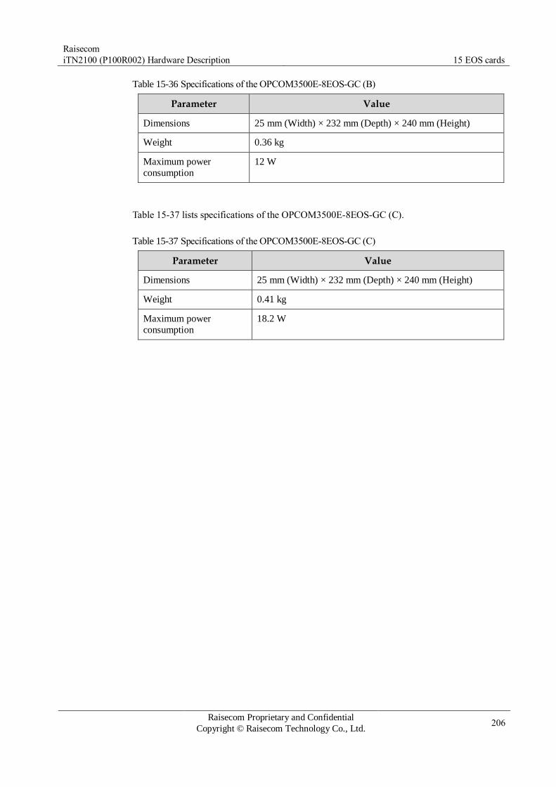
Raisecom
iTN2100 (P100R002) Hardware Description 15 EOS cards
Raisecom Proprietary and Confidential
Copyright © Raisecom Technology Co., Ltd. 206
Table 15-36 Specifications of the OPCOM3500E-8EOS-GC (B)
Parameter Value
Dimensions 25 mm (Width) × 232 mm (Depth) × 240 mm (Height)
Weight 0.36 kg
Maximum power
consumption
12 W
Table 15-37 lists specifications of the OPCOM3500E-8EOS-GC (C).
Table 15-37 Specifications of the OPCOM3500E-8EOS-GC (C)
Parameter Value
Dimensions 25 mm (Width) × 232 mm (Depth) × 240 mm (Height)
Weight 0.41 kg
Maximum power
consumption
18.2 W

Raisecom
iTN2100 (P100R002) Hardware Description 15 EOS cards
Raisecom Proprietary and Confidential
Copyright © Raisecom Technology Co., Ltd. 207
15.7 OPCOM3500E-DSEE
15.7.1 Appearance and functions
Appearance Function
The OPCOM3500E-DSEE is an EOS tributary card with labeling
function and 4 optical interfaces on the iTN2100.
Provide four 100 Mbit/s Ethernet electrical interfaces. Support adding standard 802.1q Tag for the Ethernet services received
inside the card. Support two Ethernet encapsulation modes: GFP and LAPS. Support VCAT and LCAS. Support assigning 4 ways of Ethernet services with bandwidth of
N×VC12 and N×VC3, transmitting them to the SDH network. Support the maximum frame size of the Ethernet data: 2000 bytes. Support online software upgrade for local devices. Support managing remote 100 Mbit/s Ethernet optical transceivers,
such as, RC500 series, RC600 series, Gazelle RM531-FE (B), and
RC521H-FE. Support complete alarms and performance monitoring. Provide statistics of sending, receiving, and error packets for each
ACG frame. Support hot swapping.
15.7.2 Slots
The OPCOM3500E-DSEE can be inserted into slots 1–5 and 8–12 on the iTN2100.
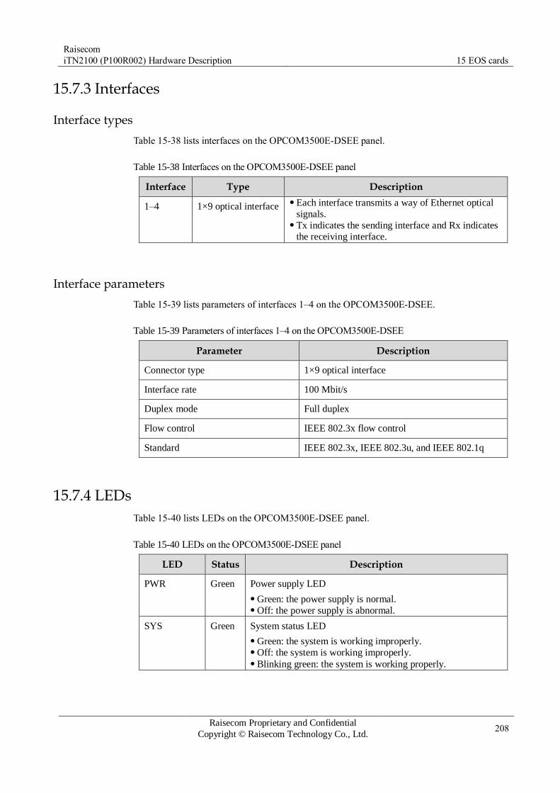
Raisecom
iTN2100 (P100R002) Hardware Description 15 EOS cards
Raisecom Proprietary and Confidential
Copyright © Raisecom Technology Co., Ltd. 208
15.7.3 Interfaces
Interface types
Table 15-38 lists interfaces on the OPCOM3500E-DSEE panel.
Table 15-38 Interfaces on the OPCOM3500E-DSEE panel
Interface Type Description
1–4 1×9 optical interface Each interface transmits a way of Ethernet optical
signals. Tx indicates the sending interface and Rx indicates
the receiving interface.
Interface parameters
Table 15-39 lists parameters of interfaces 1–4 on the OPCOM3500E-DSEE.
Table 15-39 Parameters of interfaces 1–4 on the OPCOM3500E-DSEE
Parameter Description
Connector type 1×9 optical interface
Interface rate 100 Mbit/s
Duplex mode Full duplex
Flow control IEEE 802.3x flow control
Standard IEEE 802.3x, IEEE 802.3u, and IEEE 802.1q
15.7.4 LEDs
Table 15-40 lists LEDs on the OPCOM3500E-DSEE panel.
Table 15-40 LEDs on the OPCOM3500E-DSEE panel
LED Status Description
PWR Green Power supply LED
Green: the power supply is normal. Off: the power supply is abnormal.
SYS Green System status LED
Green: the system is working improperly. Off: the system is working improperly. Blinking green: the system is working properly.

Raisecom
iTN2100 (P100R002) Hardware Description 15 EOS cards
Raisecom Proprietary and Confidential
Copyright © Raisecom Technology Co., Ltd. 209
LED Status Description
ALM Red Alarm LED
Red: TU-AIS, TU-LOP, or LP-EXLOM alarm is generated. Off: no TU-AIS, TU-LOP, or LP-EXLOM alarm is
generated.
LNK/ACT
(1–4)
Green Line working LED
Green: the interface is working properly. Off: the interface is disconnected or is working improperly. Blinking green: the interface is receiving or sending data.
15.7.5 Alarms
Table 15-41 lists alarms of the OPCOM3500E-DSEE.
Table 15-41 Alarms of the OPCOM3500E-DSEE
Alarm Cause
TU pointer loss/All-1 alarm,
TU-LOP, and TU-AIS
The SDH signal sent from the aggregation
card fails. The hardware of the card is faulty and SDH
data received on the backplane is incorrect. The clock timing signal of the card is lost.
LP-EXLOM Invalid K4 overhead is received in the
continuous three frames, the b1 of K4 byte
loses multiframe, and K4 byte sent from the peer EOS device fails.
LP-UNEQ The lower-order path is loaded, and the V5
byte sent from the peer EOS device fails.
15.7.6 Specifications
Table 15-42 lists specifications of the OPCOM3500E-DSEE.
Table 15-42 Specifications of the OPCOM3500E-DSEE
Parameter Value
Dimensions 25 mm (Width) × 232 mm (Depth) × 240 mm (Height)
Weight 0.35 kg
Maximum power
consumption
10.1 W

Raisecom
iTN2100 (P100R002) Hardware Description 15 EOS cards
Raisecom Proprietary and Confidential
Copyright © Raisecom Technology Co., Ltd. 210
15.8 OPCOM3500E-HSEE
15.8.1 Appearance and functions
Appearance Function
The OPCOM3500E-HSEE is an EOS tributary card with labeling
function and 8 optical interfaces on the iTN2100.
Provide 8 ways of 100 Mbit/s Ethernet optical interface services. Support assigning 8 ways of Ethernet services with bandwidth of
N×VC12, transmitting them to the SDH network, and sharing
bandwidth of 63×VC12. Support adding standard 802.1q Tag to the Ethernet packets received
inside the card. Support two Ethernet encapsulation modes: GFP and LAPS. Support VCAT and LCAS. Support online software upgrade for local devices. Support managing remote 100 Mbit/s Ethernet optical transceivers,
such as, RC500 series, RC600 series, and Gazelle RM531-FE (B). Support hot swapping.
15.8.2 Slots
The OPCOM3500E-HSEE can be inserted into slots 1–5 and 8–12 on the iTN2100.

Raisecom
iTN2100 (P100R002) Hardware Description 15 EOS cards
Raisecom Proprietary and Confidential
Copyright © Raisecom Technology Co., Ltd. 211
15.8.3 Interfaces
Interface types
Table 15-43 lists interfaces on the OPCOM3500E-HSEE panel.
Table 15-43 Interfaces on the OPCOM3500E-HSEE panel
Interface Type Description
1–8 SFP optical
interface
Each interface transmits a way of Ethernet optical
signals.
Interface parameters
Table 15-44 lists parameters of interfaces 1–8 on the OPCOM3500E-HSEE.
Table 15-44 Parameters of interfaces 1–8 on the OPCOM3500E-HSEE
Parameter Description
Connector type SFP optical interface
Interface rate 100 Mbit/s
15.8.4 LEDs
Table 15-45 LEDs on the OPCOM3500E-HSEE panel.
Table 15-45 LEDs on the OPCOM3500E-HSEE panel
LED Status Description
PWR Green Power supply LED
Green: the power supply is normal. Off: the power supply is abnormal.
SYS Green System status LED
Green: the system is working improperly. Off: the system is working improperly. Blinking green: the system is working properly.
ALM Red Alarm LED
Red: TU-AIS or TU-LOP alarm is generated in the LP for
allocating services. Off: no TU-AIS or TU-LOP alarm is generated in the
service-distributed lower order.

Raisecom
iTN2100 (P100R002) Hardware Description 15 EOS cards
Raisecom Proprietary and Confidential
Copyright © Raisecom Technology Co., Ltd. 212
LED Status Description
LNK/ACT
(1–8)
Green Line working LED
Green: the interface is working properly. Off: the interface is disconnected or is working improperly. Blinking green: the interface is receiving or sending data.
15.8.5 Alarms
Table 15-46 lists alarms of the OPCOM3500E-HSEE.
Table 15-46 Alarms of the OPCOM3500E-HSEE
Alarm Cause Level
SFP absence alarm The SFP optical module is removed. The SFP optical module is improperly
installed. The SFP optical module fails.
Critical
SFP sending failure alarm The SFP optical module fails. Critical
SFP receiving LOS alarm Attenuation of received signals is over great. The peer sender fails. The fiber head is unclean or the connector is
improperly connected. The local receiver fails.
Critical
Ethernet interface link down
alarm
Fiber is disconnected. The Rx and Tx of the peer device fail.
Critical
LPR alarm on the peer
device
The remote transceiver is powered off. Critical
15.8.6 Specifications
Table 15-47 lists specifications of the OPCOM3500E-HSEE.
Table 15-47 Specifications of the OPCOM3500E-HSEE
Parameter Value
Dimensions 25 mm (Width) × 232 mm (Depth) × 240 mm (Height)
Weight 0.35 kg
Maximum power
consumption
8.55 W

Raisecom
iTN2100 (P100R002) Hardware Description 15 EOS cards
Raisecom Proprietary and Confidential
Copyright © Raisecom Technology Co., Ltd. 213
15.9 OPCOM3500E-HSEEC
15.9.1 Appearance and functions
Appearance Function
The OPCOM3500E-HSEEC is an EOS tributary card with labeling
function and 8 optical interfaces on the iTN2100.
Support up to 8 ways of 100 Mbit/s Ethernet services through the
optical interface. Support SFP module hot swapping. Support SFP module DDM. Support the following backplane bandwidth:
– Accessed 8 ways of Ethernet services can be assigned with N×VC12
or N×VC3 bandwidth and then be transmitted to the SDH network. – Each EOS interface supports being configured with only one type of
VC12 or VC3 timeslot. Each EOS interface supports up to 155
Mbit/s (63×VC12 or 3×VC3). – The aggregation card is the iTN2100-2STM16-M. The backplane
supports 622 Mbit/s when it is inserted into one of slots 2–5; the
backplane supports 155 Mbit/s when it is inserted into other slot. – The aggregation card is the OPCOM3500E-2STM1/4-M. The
backplane supports 622 Mbit/s when it is inserted into slot 2 or 4;
the backplane supports 155 Mbit/s when it is inserted into other slot. The Ethernet interface supports adding or transparently transmitting
802.1Q VLAN Tag for input/output Ethernet data packets. Support two Ethernet encapsulation modes: GFP and LAPS. Support
VCAT and LCAS. Support RC-Link protocol, through which Raisecom 100 Mbit/S
Ethernet transceivers, such as, RC500 series, RC600 series, and
Gazelle-RM531-FE (B), can be managed remotely. Support complete alarm and performance monitoring. Support complete Ethernet interface features. Support software online upgrade for the local device. Support querying default information about the device. Support hot swapping.
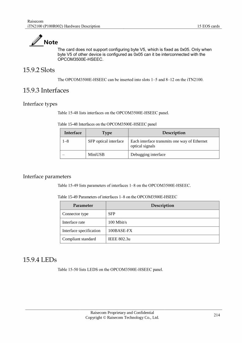
Raisecom
iTN2100 (P100R002) Hardware Description 15 EOS cards
Raisecom Proprietary and Confidential
Copyright © Raisecom Technology Co., Ltd. 214
The card does not support configuring byte V5, which is fixed as 0x05. Only when byte V5 of other device is configured as 0x05 can it be interconnected with the OPCOM3500E-HSEEC.
15.9.2 Slots
The OPCOM3500E-HSEEC can be inserted into slots 1–5 and 8–12 on the iTN2100.
15.9.3 Interfaces
Interface types
Table 15-48 lists interfaces on the OPCOM3500E-HSEEC panel.
Table 15-48 Interfaces on the OPCOM3500E-HSEEC panel
Interface Type Description
1–8 SFP optical interface Each interface transmits one way of Ethernet optical signals
– MiniUSB Debugging interface
Interface parameters
Table 15-49 lists parameters of interfaces 1–8 on the OPCOM3500E-HSEEC.
Table 15-49 Parameters of interfaces 1–8 on the OPCOM3500E-HSEEC
Parameter Description
Connector type SFP
Interface rate 100 Mbit/s
Interface specification 100BASE-FX
Compliant standard IEEE 802.3u
15.9.4 LEDs
Table 15-50 lists LEDS on the OPCOM3500E-HSEEC panel.

Raisecom
iTN2100 (P100R002) Hardware Description 15 EOS cards
Raisecom Proprietary and Confidential
Copyright © Raisecom Technology Co., Ltd. 215
Table 15-50 LEDs on the OPCOM3500E-HSEEC panel
LED Status Description
PWR Green Power supply LED
Green: the power supply is normal. Off: the power supply is abnormal.
SYS Green System status LED
Green: the system is working improperly. Off: the system is working improperly. Blinking green: the system is working properly.
LNK/ACT
(1–8)
Green Line working LED
Green: the interface is working properly. Off: the interface is disconnected or is working improperly. Blinking green: the interface is receiving or sending data.
15.9.5 Logic diagram
Figure 15-5 shows logic diagram of the OPCOM3500E-HSEEC.

Raisecom
iTN2100 (P100R002) Hardware Description 15 EOS cards
Raisecom Proprietary and Confidential
Copyright © Raisecom Technology Co., Ltd. 216
Figure 15-5 Logic diagram of the OPCOM3500E-HSEEC
The OPCOM3500E-EOSE-8FX consists of the management control module, restoration
module, logic control module, EOS module, and power module.
Management control module: exchange network management information, save the
control command and configuration status of the card, and control other modules to coordinate with each other.
Restoration module: restore the management control module, EOS module, and logic control module.
Logic control module: complete functions of management control module, EOS module
communication, and clock processing.
EOS module: encapsulate Ethernet signals, and map them into SDH signals according to N×VC12 and communicate with aggregation card.
Service direction:
Direction from Ethernet signals to SDH signals: Ethernet signals enter EOS module
through the front panel, and are encapsulated by the GFP/LAPS to adjust time sequence,

Raisecom
iTN2100 (P100R002) Hardware Description 15 EOS cards
Raisecom Proprietary and Confidential
Copyright © Raisecom Technology Co., Ltd. 217
then are reported to the aggregation card according to N×VC12 mapped into SDH
signals.
Direction from SDH signals to Ethernet signals: SDH signals received on the backplane
enter EOS module. They are decapsulated to Ethernet signals, and are transmitted through the front plane.
15.9.6 Specifications
Table 15-51 lists specifications of the OPCOM3500E-HSEEC.
Table 15-51 Specifications of the OPCOM3500E-HSEEC
Parameter Value
Dimensions 25 mm (Width) × 232 mm (Depth) × 240 mm (Height)
Weight 0.42 kg
Maximum power
consumption
17 W

Raisecom
iTN2100 (P100R002) Hardware Description 15 EOS cards
Raisecom Proprietary and Confidential
Copyright © Raisecom Technology Co., Ltd. 218
15.10 OPCOM3500E-HEESC
15.10.1 Appearance and functions
Appearance Function
The OPCOM3500E-HEESC is an EOS tributary card with 8 electrical
interfaces on the iTN2100.
Support up to 8 ways of 10/100 Mbit/s Ethernet services through the
electrical interface. Accessed 8 ways of Ethernet services can be assigned with N×VC12
bandwidth and then be transmitted to the SDH network. Support 622 Mbit/s at the backplane and share 4×63 VC12 (slot 2 or 4
when the aggregation card is the OPCOM3500E-2STM1/4-M; slots 2–
5 when the aggregation card is the iTN2100-2STM16-M). Support two Ethernet encapsulation modes: GFP and LAPS. Support VCAT and LCAS. Support VC3 cross connection. Support configuring bytes C2 and J1
for VC3. Support configuring lower-order overhead bytes J2 and K4. The byte
V5 is fixed as 0x05 and thus it cannot be configured. Support software online upgrade for the local device. Support complete alarm and performance monitoring. Support complete Ethernet interface features. Support querying default information about the device. Support hot swapping.
15.10.2 Slots
The OPCOM3500E-HEESC can be inserted into slots 1–5 and 8–12 on the iTN2100.

Raisecom
iTN2100 (P100R002) Hardware Description 15 EOS cards
Raisecom Proprietary and Confidential
Copyright © Raisecom Technology Co., Ltd. 219
15.10.3 Interfaces
Interface types
Table 15-52 lists interfaces on the OPCOM3500E-HEESC panel.
Table 15-52 Interfaces on the OPCOM3500E-HEESC panel
Interface Type Description
– RJ45 Service downlink interface 8 FE electrical interfaces
Interface parameters
Table 15-53 lists parameters of the RJ45 interfaces on the OPCOM3500E-HEESC.
Table 15-53 Parameters of the RJ45 interfaces on the OPCOM3500E-HEESC
Parameter Description
Connector type RJ45
Interface rate 10/100 Mbit/s auto-negotiation
15.10.4 LEDs
Table 15-54 lists LEDs on the OPCOM3500E-HEESC panel.
Table 15-54 LEDs on the OPCOM3500E-HEESC panel
LED Status Description
PWR Green Power supply LED
Green: the power supply is normal. Off: the power supply is abnormal.
SYS Green System status LED
Green: the system is working improperly. Off: the system is working improperly. Blinking green: the system is working properly.
ALM Red Alarm LED
Red: TU-AIS or TU-LOP alarms are generated in the LP of
service allocation. Off: no TU-AIS or TU-LOP alarms are generated in the LP
of service allocation.
100M
(1–8)
Green Interface rate LED
Green: the interface is working at 100 Mbit/s. Off: the interface is working at 10 Mbit/s or is disconnected.

Raisecom
iTN2100 (P100R002) Hardware Description 15 EOS cards
Raisecom Proprietary and Confidential
Copyright © Raisecom Technology Co., Ltd. 220
LED Status Description
LNK/ACT
(1–8)
Green Interface connection status LED
Green: the interface is connected properly. Off: the interface is disconnected or is connected improperly. Blinking green: the interface is receiving or sending data.
15.10.5 DIP switches
There are no DIP switches available for users on the OPCOM3500E-HEESC.
15.10.6 Logic diagram
Figure 15-6 shows the logic diagram of the OPCOM3500E-HEESC.
Figure 15-6 Logic diagram of the OPCOM3500E-HEESC
The OPCOM3500E-HEESC consists of the management control module, Ethernet
encapsulation module, EOS module, and timing adjustment module.
Management control module: exchange network management information, and control other modules to coordinate with each other.
Ethernet encapsulation module: adjust received Ethernet signals.
EOS module: encapsulate Ethernet signals into EOS signals, or decapsulate EOS signals.
Timing adjustment module: adjust the timing sequence of the timeslot.
Service direction:

Raisecom
iTN2100 (P100R002) Hardware Description 15 EOS cards
Raisecom Proprietary and Confidential
Copyright © Raisecom Technology Co., Ltd. 221
Ingress direction: Ethernet signals input from the interface are mapped into SDH signals
through the EOS module, and then are transmitted to the aggregation card through the timing adjustment module.
Egress direction: SDH signals are transmitted from the aggregation card to the timing
adjustment module, and then are decapsulated into Ethernet signals though the EOS
module, and then are output from the interface on the front panel.
15.10.7 Specifications
Table 15-55 lists specifications of the OPCOM3500E-HEESC.
Table 15-55 Specifications of the OPCOM3500E-HEESC
Parameter Value
Dimensions 25 mm (Width) × 232 mm (Depth) × 240 mm (Height)
Weight < 0.44 kg
Maximum power
consumption
13 W

Raisecom
iTN2100 (P100R002) Hardware Description 15 EOS cards
Raisecom Proprietary and Confidential
Copyright © Raisecom Technology Co., Ltd. 222
15.11 OPCOM3500E-ACEWA
15.11.1 Appearance and functions
Appearance Function
The OPCOM3500E-ACEWA is an 8-way EOS service aggregation card on the iTN2100.
Provide one 1000 Mbit/s Ethernet electrical interface and one 1000 Mbit/s Ethernet
optical interface. Support COMBO (optical and electrical multiplexing) of 1000 Mbit/s
optical interface and 10/100/1000 Mbit/s electrical interface. Decapsualte remote 8 ways of EOS services transmitted from the backplane from SDH
signals and aggregate them into 1 way of Ethernet signals. The 1 way of Ethernet signals
can be output form the Ethernet interface on the front panel and be transmitted to the
switching card through the backplane. The 1 way of Ethernet signals transmitted from the switching card can be output from the
Ethernet interface on the front panel, or be mapped into the SDH frame according to
N×VC12 and then be transmitted to the aggregation card through the backplane after
timeslot cross connection. Support 8 VCGs. For each VCG, the maximum bandwidth is 100 Mbit/s. Support dual-switching card protection. Support 622 Mbit/s at the backplane and share 4×63 VC12 (slot 2 or 4 when the
aggregation card is the OPCOM3500E-2STM1/4-M; slots 2–5 when the aggregation card
is the iTN2100-2STM16-M). Support VC3 cross connection. Support configuring bytes C2 and J1 for VC3. Support configuring lower-order overhead bytes J2 and K4. The byte V5 is fixed as 0x05
and thus it cannot be configured. Ethernet services can be virtually cascaded at the rate of N×VC12 or N×VC3. Support two encapsulation modes: GFP and LAPS. Support VCAT and LCAS. Support storm control on broadcast, unknown multicast and DLF packets. Support rate
limiting. Support interface-based flow control and frame statistics. Support interface isolation and link aggregation. Support 802.1q VLAN, 4K concurrent VLANS, and QinQ. Support QoS. Determine 4 output queues according to priorities. Support 8K dynamic MAC addresses and 64 static MAC addresses. Support enabling/disabling MAC address learning based on interface. Support configuring the aging time of MAC addresses from 0s to 3825s. Support transparently transmitting BPDU, LACP, and 802.1x management frames. Support loop detection of the Ethernet interface. After loop detection is enabled, loop
detection packets use broadcast addresses by default. Support ALS of the SFP interface. Support hot swapping.
15.11.2 Slots
The OPCOM3500E-ACEWA can be inserted into slots 1–5 and 8–12 on the iTN2100.

Raisecom
iTN2100 (P100R002) Hardware Description 15 EOS cards
Raisecom Proprietary and Confidential
Copyright © Raisecom Technology Co., Ltd. 223
15.11.3 Interfaces
Interface types
Table 15-56 lists interfaces on the OPCOM3500E-ACEWA panel.
Table 15-56 Interfaces on the OPCOM3500E-ACEWA panel
Interface Type Description
– MiniUSB Debugging interface
– RJ45 Service uplink interface GE electrical interface
– SFP optical interface Service uplink interface GE optical interface
Interface parameters
Table 15-57 lists parameters of the RJ45 interface on the OPCOM3500E-ACEWA.
Table 15-57 Parameters of the RJ45 interface on the OPCOM3500E-ACEWA.
Parameter Description
Connector type RJ45
Interface rate 10/100/1000 Mbit/s auto-negotiation
Duplex mode Full duplex/Half duplex auto-negotiation
MTU 1632 bytes
Flow control Full duplex: IEEE 802.3x flow control Half duplex: back pressure flow control
Wiring scheme Auto MDI/MDI-X
Compliant standard IEEE 802.3 IEEE 802.3u
Table 15-58 lists parameters of the SFP optical interface on the OPCOM3500E-ACEWA.
Table 15-58 Parameters of the SFP optical interface on the OPCOM3500E-ACEWA
Parameter Description
Connector type SFP (LC/PC)
Interface rate 100/1000M
Interface specification 100BASE-FX 1000BASE-X SGMII
Compliant standard IEEE 802.3u IEEE 802.3z

Raisecom
iTN2100 (P100R002) Hardware Description 15 EOS cards
Raisecom Proprietary and Confidential
Copyright © Raisecom Technology Co., Ltd. 224
15.11.4 LEDs
Table 15-59 lists LEDs on the OPCOM3500E-ACEWA panel.
Table 15-59 LEDs on the OPCOM3500E-ACEWA panel
LED Status Description
PWR Green Power supply LED
Green: the power supply is normal. Off: the power supply is abnormal or is disconnected.
SYS Green System status LED
Green: the system is starting or is working improperly. Off: the system is working improperly. Blinking green: the system is working properly.
ALM Red Alarm LED
Red: communication fails or clock fails. Off: no communication fault alarm or clock fault alarm is
reported.
1000M Green Interface rate LED
Green: the interface is working at 1000 Mbit/s. Off: the interface is working at 100 Mbit/s or 10 Mbit/s.
LNK/ACT Green Interface connection status LED
Green: the interface is connected properly. Off: the interface is disconnected or is connected improperly. Blinking green: the interface is receiving or sending data.
15.11.5 DIP switches
There are no DIP switches available for users on the OPCOM3500E-ACEWA.
15.11.6 Logic diagram
Figure 15-7 shows the logic diagram of the OPCOM3500E-ACEWA.

Raisecom
iTN2100 (P100R002) Hardware Description 15 EOS cards
Raisecom Proprietary and Confidential
Copyright © Raisecom Technology Co., Ltd. 225
Figure 15-7 Logic diagram of the OPCOM3500E-ACEWA
The OPCOM3500E-ACEWA consists of the management control module, Ethernet switching
module, and EOS module.
Management control module: exchange network management information, and control
other modules to coordinate with each other.
Ethernet switching module: aggregate 8 ways of Ethernet signals into 1 way, and transmit Ethernet signals among EOS module, front panel interfaces, and switching card.
EOS module: encapsulate Ethernet signals into EOS signals, or decapsulate EOS signals; exchange with the aggregation card.
Service direction:
Encapsulation direction: Ethernet signals transmitted from the switching card are
encapsulated through the EOS module, and are mapped into SDH signals at the granularity of VC12, and then are transmitted to the aggregation card.
Decapsulation direction: SDH signals are decapsulated through the EOS module, and are
transmitted to the Ethernet switching module for aggregation, and then are output from the front panel or transmitted to the switching card.
15.11.7 Specifications
Table 15-60 lists specifications of the OPCOM3500E-ACEWA.
Table 15-60 Specifications of the OPCOM3500E-ACEWA
Parameter Value
Dimensions 25 mm (Width) × 232 mm (Depth) × 240 mm (Height)
Weight 0.41 kg

Raisecom
iTN2100 (P100R002) Hardware Description 15 EOS cards
Raisecom Proprietary and Confidential
Copyright © Raisecom Technology Co., Ltd. 226
Parameter Value
Maximum power
consumption
18.2 W

Raisecom
iTN2100 (P100R002) Hardware Description 16 PDH and RCMS cards
Raisecom Proprietary and Confidential
Copyright © Raisecom Technology Co., Ltd. 227
16 PDH and RCMS cards
This chapter describes PDH and RCMS cards of the iTN2100, including the following
sections:
OPCOM3500E-16E1/16E1-BL
OPCOM3500E-32E1/32E1-BL
OPCOM3500E-120EOS×4
OPCOM3500E-120EOS×4L
OPCOM3500E-DFPS
OPCOM3500E-120FE×8L-GE
OPCOM3500E-240GE×4L
OPCOM3500E-120H×4
OPCOM3500E-DSPH
OPCOM3500E-HSPH
OPCOM3500E-3DS3/E3

Raisecom
iTN2100 (P100R002) Hardware Description 16 PDH and RCMS cards
Raisecom Proprietary and Confidential
Copyright © Raisecom Technology Co., Ltd. 228
16.1 OPCOM3500E-16E1/16E1-BL
16.1.1 Appearance and functions
Appearance Function
The OPCOM3500E-16E1 is a 16-way E1
unbalanced electrical interface service card on the iTN2100, with two versions: A and C.
The OPCOM3500E-16E1-BL is a 16-way E1
balanced electrical interface service card on
the iTN2100, with three versions: A, B, and C.
The OPCOM3500E-16E1 and
OPCOM3500E-16E1-BL have the same functions.
Provide two DB37 interfaces. Each DB37
interface supports eight ways of E1 signals. In Rx, it maps E1 signals received from the
E1 interface on the front panel to the VC12
of SDH signals, and then performs cross
connection or aggregation through the
aggregation card. In Tx, it demaps VC12 of
SDH signals from the aggregation card and
then transmits them to the E1 interface on
the front panel. Each way of E1 supports internal loopback
and external loopback on the interface. The OPCOM3500E-16E1 (Version C) and
OPCOM3500E-16E1-BL (Version C)
support E1 retiming. The E1 retiming
sources can be the system clock or 2 Mbit/s
external clock. Provide complete LP alarms and
performance monitoring. Support hot swapping.
The 4 figures are OPCOM3500E-16E1 (version A), OPCOM3500E-16E1 (version C), OPCOM3500E-16E1-BL (versions A and B), and OPCOM3500E-16E1-BL (version C) from left to right.
16.1.2 Versions
Table 16-1 lists hardware versions of the OPCOM3500E-16E1/16E1-BL.
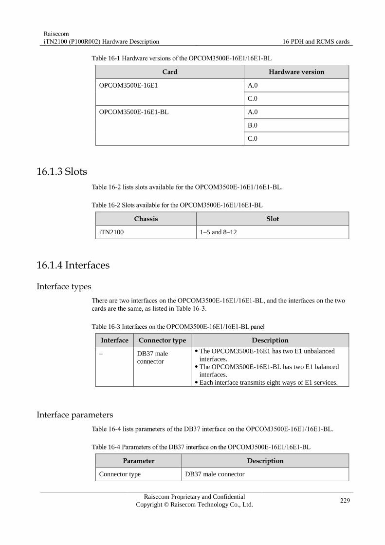
Raisecom
iTN2100 (P100R002) Hardware Description 16 PDH and RCMS cards
Raisecom Proprietary and Confidential
Copyright © Raisecom Technology Co., Ltd. 229
Table 16-1 Hardware versions of the OPCOM3500E-16E1/16E1-BL
Card Hardware version
OPCOM3500E-16E1 A.0
C.0
OPCOM3500E-16E1-BL A.0
B.0
C.0
16.1.3 Slots
Table 16-2 lists slots available for the OPCOM3500E-16E1/16E1-BL.
Table 16-2 Slots available for the OPCOM3500E-16E1/16E1-BL
Chassis Slot
iTN2100 1–5 and 8–12
16.1.4 Interfaces
Interface types
There are two interfaces on the OPCOM3500E-16E1/16E1-BL, and the interfaces on the two
cards are the same, as listed in Table 16-3.
Table 16-3 Interfaces on the OPCOM3500E-16E1/16E1-BL panel
Interface Connector type Description
– DB37 male
connector
The OPCOM3500E-16E1 has two E1 unbalanced
interfaces. The OPCOM3500E-16E1-BL has two E1 balanced
interfaces. Each interface transmits eight ways of E1 services.
Interface parameters
Table 16-4 lists parameters of the DB37 interface on the OPCOM3500E-16E1/16E1-BL.
Table 16-4 Parameters of the DB37 interface on the OPCOM3500E-16E1/16E1-BL
Parameter Description
Connector type DB37 male connector
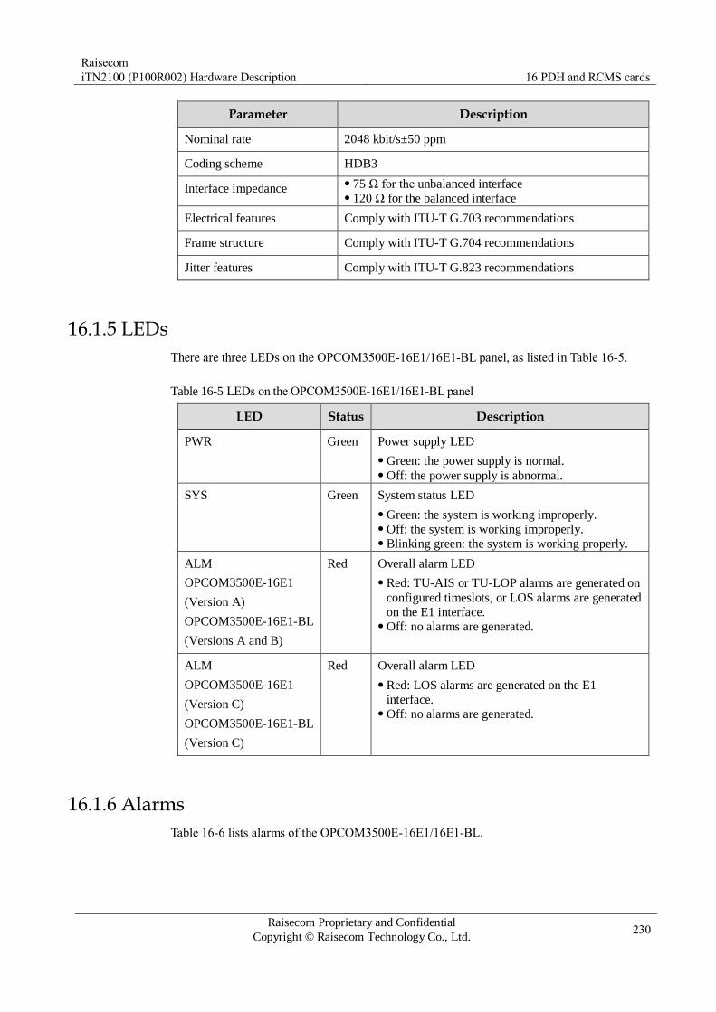
Raisecom
iTN2100 (P100R002) Hardware Description 16 PDH and RCMS cards
Raisecom Proprietary and Confidential
Copyright © Raisecom Technology Co., Ltd. 230
Parameter Description
Nominal rate 2048 kbit/s±50 ppm
Coding scheme HDB3
Interface impedance 75 Ω for the unbalanced interface 120 Ω for the balanced interface
Electrical features Comply with ITU-T G.703 recommendations
Frame structure Comply with ITU-T G.704 recommendations
Jitter features Comply with ITU-T G.823 recommendations
16.1.5 LEDs
There are three LEDs on the OPCOM3500E-16E1/16E1-BL panel, as listed in Table 16-5.
Table 16-5 LEDs on the OPCOM3500E-16E1/16E1-BL panel
LED Status Description
PWR Green Power supply LED
Green: the power supply is normal. Off: the power supply is abnormal.
SYS Green System status LED
Green: the system is working improperly. Off: the system is working improperly. Blinking green: the system is working properly.
ALM
OPCOM3500E-16E1
(Version A)
OPCOM3500E-16E1-BL
(Versions A and B)
Red Overall alarm LED
Red: TU-AIS or TU-LOP alarms are generated on
configured timeslots, or LOS alarms are generated
on the E1 interface. Off: no alarms are generated.
ALM
OPCOM3500E-16E1
(Version C)
OPCOM3500E-16E1-BL
(Version C)
Red Overall alarm LED
Red: LOS alarms are generated on the E1
interface. Off: no alarms are generated.
16.1.6 Alarms
Table 16-6 lists alarms of the OPCOM3500E-16E1/16E1-BL.
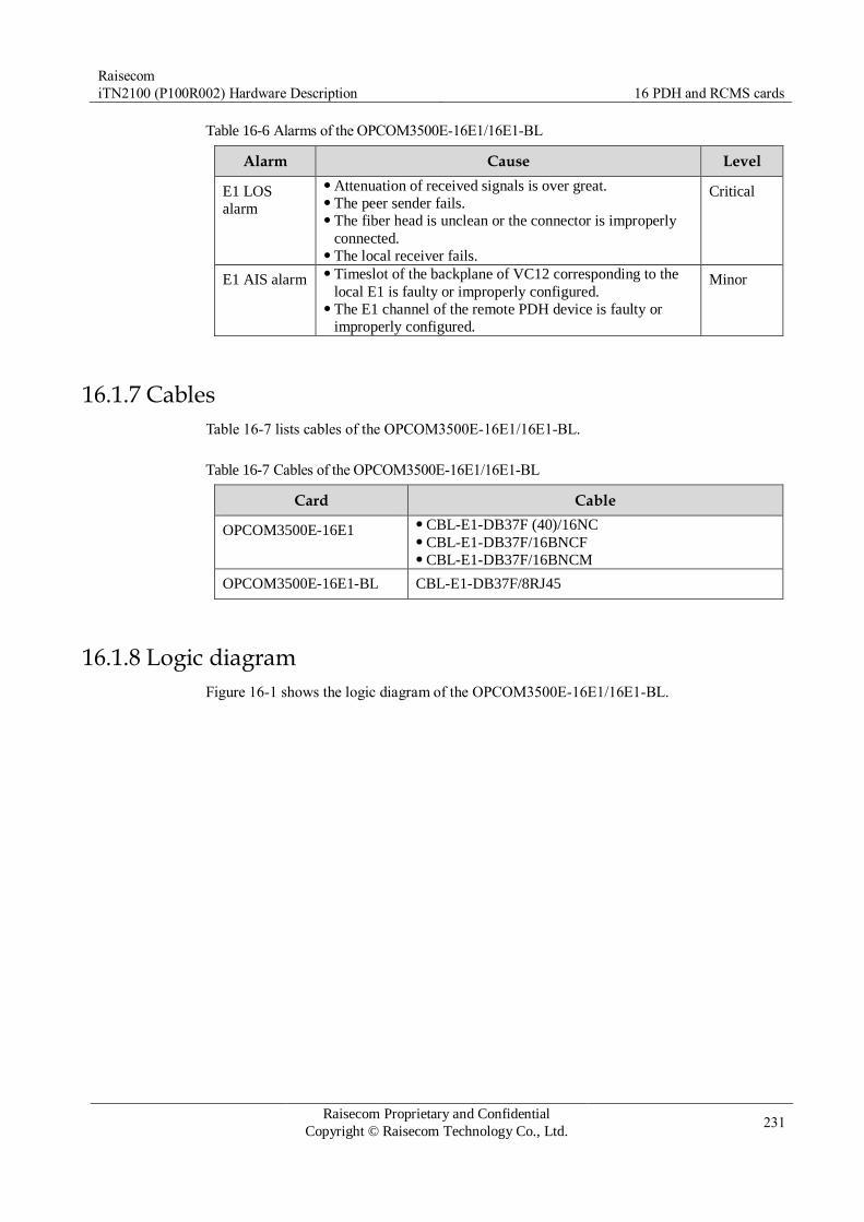
Raisecom
iTN2100 (P100R002) Hardware Description 16 PDH and RCMS cards
Raisecom Proprietary and Confidential
Copyright © Raisecom Technology Co., Ltd. 231
Table 16-6 Alarms of the OPCOM3500E-16E1/16E1-BL
Alarm Cause Level
E1 LOS
alarm
Attenuation of received signals is over great. The peer sender fails. The fiber head is unclean or the connector is improperly
connected. The local receiver fails.
Critical
E1 AIS alarm Timeslot of the backplane of VC12 corresponding to the
local E1 is faulty or improperly configured. The E1 channel of the remote PDH device is faulty or
improperly configured.
Minor
16.1.7 Cables
Table 16-7 lists cables of the OPCOM3500E-16E1/16E1-BL.
Table 16-7 Cables of the OPCOM3500E-16E1/16E1-BL
Card Cable
OPCOM3500E-16E1 CBL-E1-DB37F (40)/16NC CBL-E1-DB37F/16BNCF CBL-E1-DB37F/16BNCM
OPCOM3500E-16E1-BL CBL-E1-DB37F/8RJ45
16.1.8 Logic diagram
Figure 16-1 shows the logic diagram of the OPCOM3500E-16E1/16E1-BL.
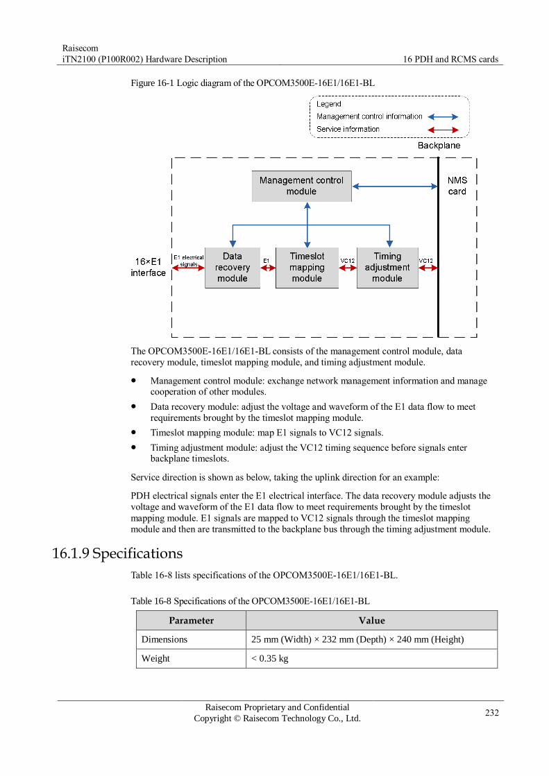
Raisecom
iTN2100 (P100R002) Hardware Description 16 PDH and RCMS cards
Raisecom Proprietary and Confidential
Copyright © Raisecom Technology Co., Ltd. 232
Figure 16-1 Logic diagram of the OPCOM3500E-16E1/16E1-BL
The OPCOM3500E-16E1/16E1-BL consists of the management control module, data
recovery module, timeslot mapping module, and timing adjustment module.
Management control module: exchange network management information and manage cooperation of other modules.
Data recovery module: adjust the voltage and waveform of the E1 data flow to meet
requirements brought by the timeslot mapping module.
Timeslot mapping module: map E1 signals to VC12 signals.
Timing adjustment module: adjust the VC12 timing sequence before signals enter backplane timeslots.
Service direction is shown as below, taking the uplink direction for an example:
PDH electrical signals enter the E1 electrical interface. The data recovery module adjusts the
voltage and waveform of the E1 data flow to meet requirements brought by the timeslot
mapping module. E1 signals are mapped to VC12 signals through the timeslot mapping
module and then are transmitted to the backplane bus through the timing adjustment module.
16.1.9 Specifications
Table 16-8 lists specifications of the OPCOM3500E-16E1/16E1-BL.
Table 16-8 Specifications of the OPCOM3500E-16E1/16E1-BL
Parameter Value
Dimensions 25 mm (Width) × 232 mm (Depth) × 240 mm (Height)
Weight < 0.35 kg

Raisecom
iTN2100 (P100R002) Hardware Description 16 PDH and RCMS cards
Raisecom Proprietary and Confidential
Copyright © Raisecom Technology Co., Ltd. 233
Parameter Value
Maximum power
consumption
3 W

Raisecom
iTN2100 (P100R002) Hardware Description 16 PDH and RCMS cards
Raisecom Proprietary and Confidential
Copyright © Raisecom Technology Co., Ltd. 234
16.2 OPCOM3500E-32E1/32E1-BL
16.2.1 Appearance and functions
Appearance Function
The OPCOM3500E-32E1 is a 32-way E1 service card on the iTN2100. The
interface is unbalanced electrical interface, which cannot be changed.
The OPCOM3500E-32E1-BL is a 32-way E1 service card on the iTN2100,
interfaces of which can be configured to balanced or unbalanced electrical
interfaces through software or the DIP switch. You should configure at least
16-way E1 services at a time (1–16, or 17–32).
The OPCOM3500E-32E1 and OPCOM3500E-32E1-BL have the same functions.
Provide two SCSIs. Each SCSI supports 16 ways of E1 signals. In Rx direction of signals, it maps E1 signals received from the E1
interface on the front panel to the VC12, and then performs cross
connection or aggregation through the aggregation card. In Tx direction of signals, it demaps VC12 from the aggregation card and
then transmits them to the E1 interface on the front panel. Support E1 retiming. The E1 retiming sources can be the system clock, 2
Mbit/s external clock, or one of the first four E1 interfaces. Each way of E1 supports internal loopback and external loopback on the
interface. Provide complete lower-order alarm and performance monitoring. Support hot swapping.

Raisecom
iTN2100 (P100R002) Hardware Description 16 PDH and RCMS cards
Raisecom Proprietary and Confidential
Copyright © Raisecom Technology Co., Ltd. 235
16.2.2 Versions
Table 16-9 lists hardware versions of the OPCOM3500E-32E1/32E1-BL.
Table 16-9 Hardware versions of the OPCOM3500E-32E1/32E1-BL
Card Hardware version
OPCOM3500E-32E1 A.0
OPCOM3500E-32E1-BL A.0
16.2.3 Slots
Table 16-10 lists slots available for the OPCOM3500E-32E1/32E1-BL.
Table 16-10 Slots available for the OPCOM3500E-32E1/32E1-BL
Chassis Slot
iTN2100 1–5 and 8–12
16.2.4 Interfaces
Interface types
There are two interfaces on the OPCOM3500E-32E1/32E1-BL, and the interfaces on the two
cards are the same, as listed in Table 16-11.
Table 16-11 Interfaces on the OPCOM3500E-32E1/32E1-BL panel
Interface Connector type Description
E1 1–16,
E1 17–32
SCSI female connector
(100 PINs)
The OPCOM3500E-32E1 has two unbalanced
interfaces. The OPCOM3500E-32E1-BL has two balanced
interfaces (by default). Each interface transmits 16 ways of E1 services.
Interface parameters
Table 16-12 lists parameters of the SCSI on the OPCOM3500E-32E1/32E1-BL.
Table 16-12 Parameters of the SCSI on the OPCOM3500E-32E1/32E1-BL
Parameter Description
Connector type SCSI female connector (100 PINs)
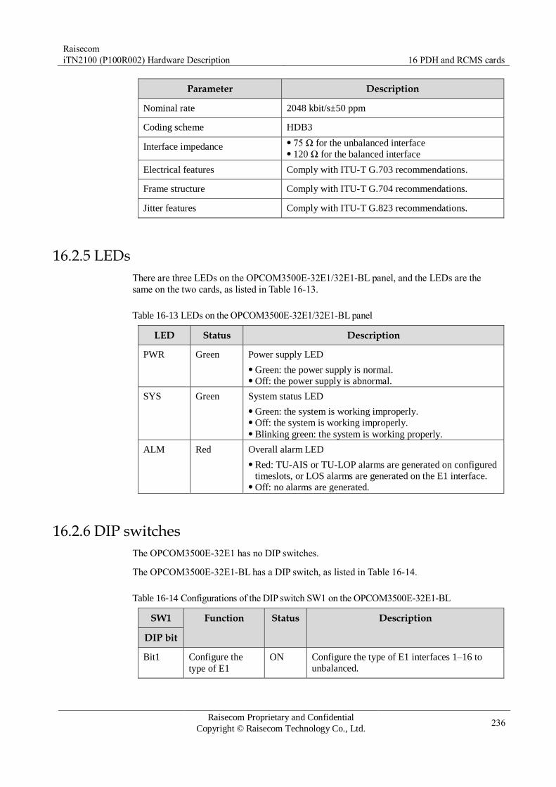
Raisecom
iTN2100 (P100R002) Hardware Description 16 PDH and RCMS cards
Raisecom Proprietary and Confidential
Copyright © Raisecom Technology Co., Ltd. 236
Parameter Description
Nominal rate 2048 kbit/s±50 ppm
Coding scheme HDB3
Interface impedance 75 Ω for the unbalanced interface 120 Ω for the balanced interface
Electrical features Comply with ITU-T G.703 recommendations.
Frame structure Comply with ITU-T G.704 recommendations.
Jitter features Comply with ITU-T G.823 recommendations.
16.2.5 LEDs
There are three LEDs on the OPCOM3500E-32E1/32E1-BL panel, and the LEDs are the
same on the two cards, as listed in Table 16-13.
Table 16-13 LEDs on the OPCOM3500E-32E1/32E1-BL panel
LED Status Description
PWR Green Power supply LED
Green: the power supply is normal. Off: the power supply is abnormal.
SYS Green System status LED
Green: the system is working improperly. Off: the system is working improperly. Blinking green: the system is working properly.
ALM Red Overall alarm LED
Red: TU-AIS or TU-LOP alarms are generated on configured
timeslots, or LOS alarms are generated on the E1 interface. Off: no alarms are generated.
16.2.6 DIP switches
The OPCOM3500E-32E1 has no DIP switches.
The OPCOM3500E-32E1-BL has a DIP switch, as listed in Table 16-14.
Table 16-14 Configurations of the DIP switch SW1 on the OPCOM3500E-32E1-BL
SW1 Function Status Description
DIP bit
Bit1 Configure the
type of E1
ON Configure the type of E1 interfaces 1–16 to
unbalanced.

Raisecom
iTN2100 (P100R002) Hardware Description 16 PDH and RCMS cards
Raisecom Proprietary and Confidential
Copyright © Raisecom Technology Co., Ltd. 237
SW1 Function Status Description
DIP bit
interfaces 1–16. OFF Configure the type of E1 interfaces 1–16 to
balanced.
Bit2 Configure the
type of E1 interfaces 17–32.
ON Configure the type of E1 interfaces 17–32 to
unbalanced.
OFF Configure the type of E1 interfaces 17–32 to
balanced.
By default, SW1 is all OFF. Namely, E1 interfaces 1–32 are configured to balanced.
You can configure the interface to balanced or unbalanced through the software or DIP switch. The latter takes effect.
16.2.7 Alarms
Table 16-15 lists alarms of the OPCOM3500E-32E1/32E1-BL.
Table 16-15 Alarms of the OPCOM3500E-32E1/32E1-BL
Alarm Cause Level
E1 LOS alarm Attenuation of received signals is over great. The peer sender fails. The fiber head is unclean or the connector is
improperly connected. The local receiver fails.
Critical
E1 AIS alarm Timeslot of the backplane of VC12 corresponding to
the local E1 is faulty or improperly configured. The E1 channel of the remote PDH device is faulty or
improperly configured.
Minor
16.2.8 Cables
Table 16-16 lists cables of the OPCOM3500E-32E1/32E1-BL.
Table 16-16 Cables of the OPCOM3500E-32E1/32E1-BL
Card Cable
OPCOM3500E-32E1 CBL-E1-SCSI100M(40)/32BNCF CBL-E1-SCSI100M(40)/32BNCM
OPCOM3500E-32E1-BL Unbalanced interface
Balanced interface CBL-E1-SCSI100M(40)/16RJ45
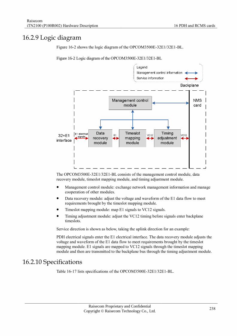
Raisecom
iTN2100 (P100R002) Hardware Description 16 PDH and RCMS cards
Raisecom Proprietary and Confidential
Copyright © Raisecom Technology Co., Ltd. 238
16.2.9 Logic diagram
Figure 16-2 shows the logic diagram of the OPCOM3500E-32E1/32E1-BL.
Figure 16-2 Logic diagram of the OPCOM3500E-32E1/32E1-BL
The OPCOM3500E-32E1/32E1-BL consists of the management control module, data
recovery module, timeslot mapping module, and timing adjustment module.
Management control module: exchange network management information and manage
cooperation of other modules.
Data recovery module: adjust the voltage and waveform of the E1 data flow to meet
requirements brought by the timeslot mapping module.
Timeslot mapping module: map E1 signals to VC12 signals.
Timing adjustment module: adjust the VC12 timing before signals enter backplane timeslots.
Service direction is shown as below, taking the uplink direction for an example:
PDH electrical signals enter the E1 electrical interface. The data recovery module adjusts the
voltage and waveform of the E1 data flow to meet requirements brought by the timeslot
mapping module. E1 signals are mapped to VC12 signals through the timeslot mapping
module and then are transmitted to the backplane bus through the timing adjustment module.
16.2.10 Specifications
Table 16-17 lists specifications of the OPCOM3500E-32E1/32E1-BL.

Raisecom
iTN2100 (P100R002) Hardware Description 16 PDH and RCMS cards
Raisecom Proprietary and Confidential
Copyright © Raisecom Technology Co., Ltd. 239
Table 16-17 Specifications of the OPCOM3500E-32E1/32E1-BL
Parameter Value
Dimensions 25 mm (Width) × 232 mm (Depth) × 240 mm (Height)
Weight < 0.45 kg
Maximum power
consumption
3 W

Raisecom
iTN2100 (P100R002) Hardware Description 16 PDH and RCMS cards
Raisecom Proprietary and Confidential
Copyright © Raisecom Technology Co., Ltd. 240
16.3 OPCOM3500E-120EOS×4
16.3.1 Appearance and functions
Appearance Function
The OPCOM3500E-120EOS×4 is a tributary service card on the
iTN2100.
Receive services accessed by Raisecom PDH optical transmitter &
receiver at the user end (such as RCMS28XX series). Support accessing 4 ways of PDH optical signal and each way
supports 4 ways of E1 services and 1 way of Ethernet services. It can
abstract up to 16 ways of E1 services and four ways of Ethernet
services within itself according to VC12 level, and then map them to
the SDH transportation network. The iTN2100 can be inserted with multiple OPCOM3500E-120EOS×4
cards. Each OPCOM3500E-120EOS×4 is connected to up to four
PDH optical transceivers. Provide 4 PDH optical interfaces. Support hybrid multiplexing of 16 ways of E1 signals and4 ways of
100 Mbit/s Ethernet data. Support complete alarms. Local and remote alarms can be displayed
concurrently. Support assigning input Ethernet services with N×VC12 bandwidth,
and then transmitting them to the SDH network. Support two Ethernet encapsulation modes: GFP and LAPS. Support VCAT and LCAS. Support remote management for Raisecom RCMS28XX and RC83X
series. If it is connected to the RCMS2811, they can implement 1+1
inter-card protection switching. Support local and remote loopback. Support LPR alarms. Support ALS. Support online software upgrade for local and remote devices. Support hot swapping.
16.3.2 Slots
The OPCOM3500E-120EOS×4 can be inserted into slots 1–5 and 8–12 on the iTN2100.
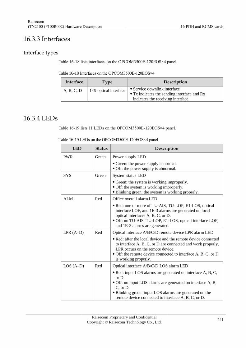
Raisecom
iTN2100 (P100R002) Hardware Description 16 PDH and RCMS cards
Raisecom Proprietary and Confidential
Copyright © Raisecom Technology Co., Ltd. 241
16.3.3 Interfaces
Interface types
Table 16-18 lists interfaces on the OPCOM3500E-120EOS×4 panel.
Table 16-18 Interfaces on the OPCOM3500E-120EOS×4
Interface Type Description
A, B, C, D 1×9 optical interface Service downlink interface Tx indicates the sending interface and Rx
indicates the receiving interface.
16.3.4 LEDs
Table 16-19 lists 11 LEDs on the OPCOM3500E-120EOS×4 panel.
Table 16-19 LEDs on the OPCOM3500E-120EOS×4 panel
LED Status Description
PWR Green Power supply LED
Green: the power supply is normal. Off: the power supply is abnormal.
SYS Green System status LED
Green: the system is working improperly. Off: the system is working improperly. Blinking green: the system is working properly.
ALM Red Office overall alarm LED
Red: one or more of TU-AIS, TU-LOP, E1-LOS, optical
interface LOF, and 1E-3 alarms are generated on local
optical interfaces A, B, C, or D. Off: no TU-AIS, TU-LOP, E1-LOS, optical interface LOF,
and 1E-3 alarms are generated.
LPR (A–D) Red Optical interface A/B/C/D remote device LPR alarm LED
Red: after the local device and the remote device connected
to interface A, B, C, or D are connected and work properly,
LPR occurs on the remote device. Off: the remote device connected to interface A, B, C, or D
is working properly.
LOS (A–D) Red Optical interface A/B/C/D LOS alarm LED
Red: input LOS alarms are generated on interface A, B, C,
or D. Off: no input LOS alarms are generated on interface A, B,
C, or D. Blinking green: input LOS alarms are generated on the
remote device connected to interface A, B, C, or D.
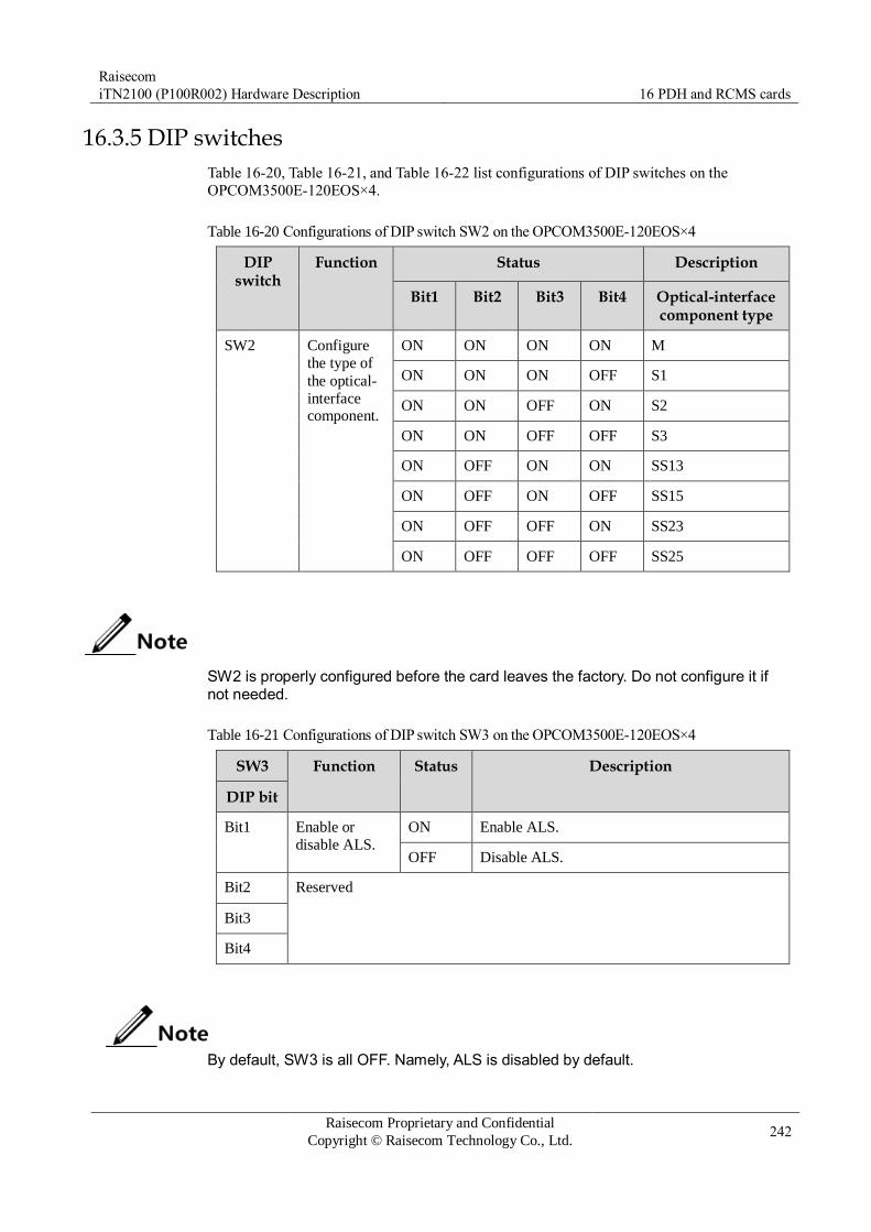
Raisecom
iTN2100 (P100R002) Hardware Description 16 PDH and RCMS cards
Raisecom Proprietary and Confidential
Copyright © Raisecom Technology Co., Ltd. 242
16.3.5 DIP switches
Table 16-20, Table 16-21, and Table 16-22 list configurations of DIP switches on the
OPCOM3500E-120EOS×4.
Table 16-20 Configurations of DIP switch SW2 on the OPCOM3500E-120EOS×4
DIP switch
Function Status Description
Bit1 Bit2 Bit3 Bit4 Optical-interface component type
SW2 Configure
the type of
the optical-
interface component.
ON ON ON ON M
ON ON ON OFF S1
ON ON OFF ON S2
ON ON OFF OFF S3
ON OFF ON ON SS13
ON OFF ON OFF SS15
ON OFF OFF ON SS23
ON OFF OFF OFF SS25
SW2 is properly configured before the card leaves the factory. Do not configure it if not needed.
Table 16-21 Configurations of DIP switch SW3 on the OPCOM3500E-120EOS×4
SW3 Function Status Description
DIP bit
Bit1 Enable or
disable ALS.
ON Enable ALS.
OFF Disable ALS.
Bit2 Reserved
Bit3
Bit4
By default, SW3 is all OFF. Namely, ALS is disabled by default.

Raisecom
iTN2100 (P100R002) Hardware Description 16 PDH and RCMS cards
Raisecom Proprietary and Confidential
Copyright © Raisecom Technology Co., Ltd. 243
Table 16-22 Configurations of DIP switch SW4 on the OPCOM3500E-120EOS×4
SW4 Function Status Description
DIP bit
Bit1 Configure E1 local
or remote loopback
on optical interface A.
ON Configure E1 local loopback on optical
interface A.
OFF Configure E1 remote loopback on optical
interface A.
Bit2 Enable or disable
NO.1–4 E1
loopback on optical interface A.
ON Enable NO.1–4 E1 tributary loopback on
optical interface A.
OFF Disable NO.1–4 E1 tributary loopback on
optical interface A.
Bit3 Configure E1 local
or remote loopback
on optical interface B.
ON Configure E1 local loopback on optical
interface B.
OFF Configure E1 remote loopback on optical
interface B.
Bit4 Enable or disable
NO.1–4 E1
loopback on optical
interface B.
ON Enable NO.1–4 E1 tributary loopback on
optical interface B.
OFF Disable NO.1–4 E1 tributary loopback on
optical interface B.
Bit5 Configure E1 local
or remote loopback
on optical interface
C.
ON Configure E1 local loopback on optical
interface C.
OFF Configure E1 remote loopback on optical
interface C.
Bit6 Enable or disable
NO.1–4 E1
loopback on optical
interface C.
ON Enable NO.1–4 E1 tributary loopback on
optical interface C.
OFF Disable NO.1–4 E1 tributary loopback on
optical interface C.
Bit7 Configure E1 local
or remote loopback
on optical interface
D.
ON Configure E1 local loopback on optical
interface D.
OFF Configure E1 remote loopback on optical
interface D.
Bit8 Enable or disable
NO.1–4 E1
loopback on optical interface D.
ON Enable NO.1–4 E1 tributary loopback on
optical interface D.
OFF Disable NO.1–4 E1 tributary loopback on
optical interface D.
By default, SW4 is all OFF. Namely, local or remote E1 loopback is disabled on all optical interfaces by default.
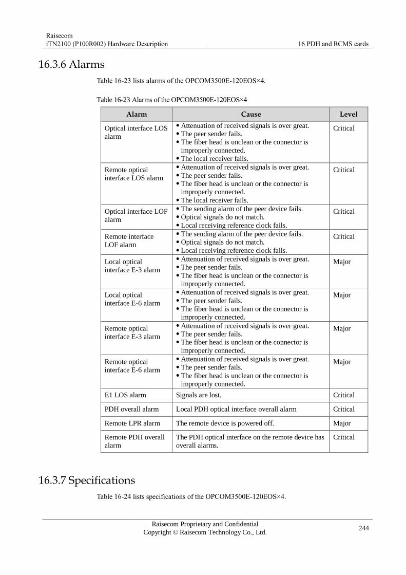
Raisecom
iTN2100 (P100R002) Hardware Description 16 PDH and RCMS cards
Raisecom Proprietary and Confidential
Copyright © Raisecom Technology Co., Ltd. 244
16.3.6 Alarms
Table 16-23 lists alarms of the OPCOM3500E-120EOS×4.
Table 16-23 Alarms of the OPCOM3500E-120EOS×4
Alarm Cause Level
Optical interface LOS
alarm
Attenuation of received signals is over great. The peer sender fails. The fiber head is unclean or the connector is
improperly connected. The local receiver fails.
Critical
Remote optical
interface LOS alarm
Attenuation of received signals is over great. The peer sender fails. The fiber head is unclean or the connector is
improperly connected. The local receiver fails.
Critical
Optical interface LOF
alarm
The sending alarm of the peer device fails. Optical signals do not match. Local receiving reference clock fails.
Critical
Remote interface
LOF alarm
The sending alarm of the peer device fails. Optical signals do not match. Local receiving reference clock fails.
Critical
Local optical
interface E-3 alarm
Attenuation of received signals is over great. The peer sender fails. The fiber head is unclean or the connector is
improperly connected.
Major
Local optical
interface E-6 alarm
Attenuation of received signals is over great. The peer sender fails. The fiber head is unclean or the connector is
improperly connected.
Major
Remote optical
interface E-3 alarm
Attenuation of received signals is over great. The peer sender fails. The fiber head is unclean or the connector is
improperly connected.
Major
Remote optical
interface E-6 alarm
Attenuation of received signals is over great. The peer sender fails. The fiber head is unclean or the connector is
improperly connected.
Major
E1 LOS alarm Signals are lost. Critical
PDH overall alarm Local PDH optical interface overall alarm Critical
Remote LPR alarm The remote device is powered off. Major
Remote PDH overall
alarm
The PDH optical interface on the remote device has
overall alarms.
Critical
16.3.7 Specifications
Table 16-24 lists specifications of the OPCOM3500E-120EOS×4.
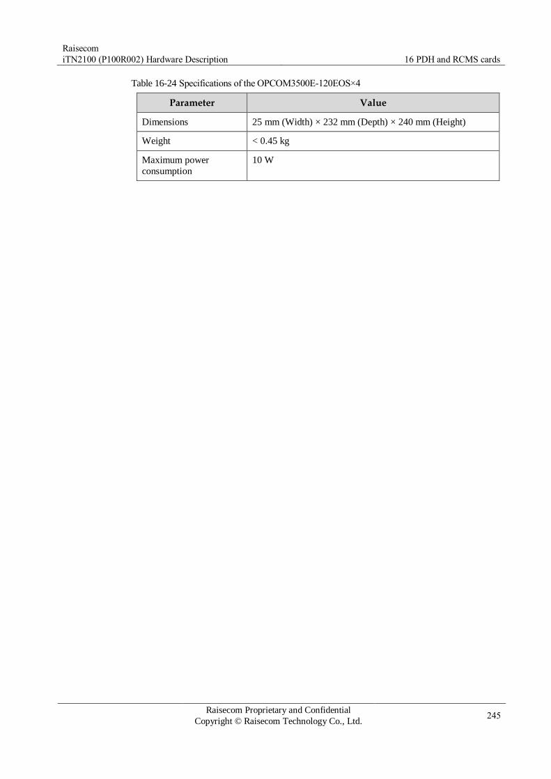
Raisecom
iTN2100 (P100R002) Hardware Description 16 PDH and RCMS cards
Raisecom Proprietary and Confidential
Copyright © Raisecom Technology Co., Ltd. 245
Table 16-24 Specifications of the OPCOM3500E-120EOS×4
Parameter Value
Dimensions 25 mm (Width) × 232 mm (Depth) × 240 mm (Height)
Weight < 0.45 kg
Maximum power
consumption
10 W

Raisecom
iTN2100 (P100R002) Hardware Description 16 PDH and RCMS cards
Raisecom Proprietary and Confidential
Copyright © Raisecom Technology Co., Ltd. 246
16.4 OPCOM3500E-120EOS×4L
16.4.1 Appearance and functions
Appearance Function
The OPCOM3500E-120EOS×4L is a tributary service card on the
iTN2100.
Receive services accessed by Raisecom PDH optical transmitter &
receiver at the user end (such as RCMS29XX and RC86X series). Support accessing 4 ways of PDH optical signals, and each way
supports 4 ways of E1 services and 1 way of 100 Mbit/s Ethernet
services. It can abstract up to 16 ways of E1 services and 4 ways of
Ethernet services within itself according to VC12 level, and then map
them to the SDH transportation network. The iTN2100 can be inserted with multiple OPCOM3500E-
120EOS×4L cards. Each OPCOM3500E-120EOS×4L is connected to
up to four PDH optical transceivers. Provide 4 PDH optical interfaces. Support hybrid multiplexing of 16 ways of E1 signals and four ways
of 100 Mbit/s Ethernet data. Support complete alarms. Local and remote alarms can be displayed
concurrently. Support assigning input Ethernet services with N×VC12 bandwidth,
and then transmitting them to the SDH network. Support two Ethernet encapsulation modes: GFP and LAPS. Support VCAT and LCAS. Support remote management for Raisecom RCMS29XX and RC86X
series. If it is connected to the RCMS2911, they can implement 1+1
inter-card protection switching. Support local and remote loopback. Support LPR alarms. Support ALS. Support online software upgrade for local and remote devices. Support hot swapping.
16.4.2 Slots
The OPCOM3500E-120EOS×4L can be inserted into slots 1–5 and 8–12 on the iTN2100.
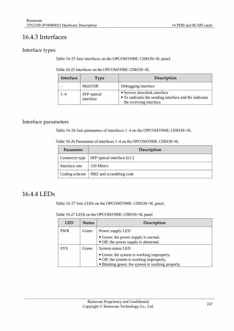
Raisecom
iTN2100 (P100R002) Hardware Description 16 PDH and RCMS cards
Raisecom Proprietary and Confidential
Copyright © Raisecom Technology Co., Ltd. 247
16.4.3 Interfaces
Interface types
Table 16-25 lists interfaces on the OPCOM3500E-120EOS×4L panel.
Table 16-25 Interfaces on the OPCOM3500E-120EOS×4L
Interface Type Description
– MiniUSB Debugging interface
1–4 SFP optical
interface
Service downlink interface Tx indicates the sending interface and Rx indicates
the receiving interface.
Interface parameters
Table 16-26 lists parameters of interfaces 1–4 on the OPCOM3500E-120EOS×4L.
Table 16-26 Parameters of interfaces 1–4 on the OPCOM3500E-120EOS×4L
Parameter Description
Connector type SFP optical interface (LC)
Interface rate 150 Mbit/s
Coding scheme NRZ and scrambling code
16.4.4 LEDs
Table 16-27 lists LEDs on the OPCOM3500E-120EOS×4L panel.
Table 16-27 LEDs on the OPCOM3500E-120EOS×4L panel
LED Status Description
PWR Green Power supply LED
Green: the power supply is normal. Off: the power supply is abnormal.
SYS Green System status LED
Green: the system is working improperly. Off: the system is working improperly. Blinking green: the system is working properly.

Raisecom
iTN2100 (P100R002) Hardware Description 16 PDH and RCMS cards
Raisecom Proprietary and Confidential
Copyright © Raisecom Technology Co., Ltd. 248
LED Status Description
LPR (1–4) Red Interface 1/2/3/4 remote device LPR alarm LED
Red: after the local device and the remote device connected to
interface 1, 2, 3, or 4 are connected and work properly, LPR
occurs on the remote device. Off: the remote device connected to interface 1, 2, 3, or 4 is
working properly.
LOS (1–
4)
Red Interface 1/2/3/4 LOS alarm LED
Red: input LOS alarms are generated on interface 1, 2, 3, or 4. Off: no input LOS alarms are generated on interface 1, 2, 3, or 4. Blinking green: input LOS alarms are generated on the remote
device connected to interface 1, 2, 3, or 4.
16.4.5 Specifications
Table 16-28 lists specifications of the OPCOM3500E-120EOS×4L.
Table 16-28 Specifications of the OPCOM3500E-120EOS×4L
Parameter Value
Dimensions 25 mm (Width) × 232 mm (Depth) × 240 mm (Height)
Weight < 0.4 kg
Maximum power
consumption
10 W

Raisecom
iTN2100 (P100R002) Hardware Description 16 PDH and RCMS cards
Raisecom Proprietary and Confidential
Copyright © Raisecom Technology Co., Ltd. 249
16.5 OPCOM3500E-DFPS
16.5.1 Appearance and functions
Appearance Function
The OPCOM3500E-DFPS is a tributary service card on the iTN2100.
Receive services accessed by the Raisecom PDH optical transceiver
(such as RCMS28XX series) at the end. Support accessing 4 ways of PDH optical signal and each way
supports 4 ways of E1 services and 1 way of Ethernet services. It can
abstract up to 16 ways of E1 services and 4 ways of Ethernet services
within itself according to VC12 level, and then map them to the SDH
transportation network. The iTN2100 can be inserted with multiple OPCOM3500E-DFPS
cards. Each OPCOM3500E-DFPS is connected to up to 4 PDH optical
transceivers. Provide 4 PDH optical interfaces. Support hybrid multiplexing of 16 ways of E1 signals and 4 ways of
100 Mbit/s Ethernet data. Support complete alarms. Local and remote alarms can be displayed
concurrently. Support assigning input Ethernet services with N×VC12 bandwidth,
and then transmitting them to the SDH network. Support two Ethernet encapsulation modes: GFP and LAPS. Support VCAT and LCAS. Support remote management of Raisecom RCMS28XX and RC83X
series. If it is connected to the RCMS2811, it can implement 1+1 inter-
card protection switching. Support local and remote loopback. Support LPR alarms. Support ALS. Support online software upgrade for local and remote devices. Support hot swapping.
16.5.2 Slots
The OPCOM3500E-DFPS can be inserted into slots 1–5 and 8–12 on the iTN2100.

Raisecom
iTN2100 (P100R002) Hardware Description 16 PDH and RCMS cards
Raisecom Proprietary and Confidential
Copyright © Raisecom Technology Co., Ltd. 250
16.5.3 Interfaces
Interface types
Table 16-29 lists interfaces on the OPCOM3500E-DFPS panel.
Table 16-29 Interfaces on the OPCOM3500E-DFPS
Interface Type Description
A, B, C, D 1×9 optical interface Service downlink interface Tx indicates the sending interface and Rx
indicates the receiving interface.
16.5.4 LEDs
Table 16-30 lists 11 LEDs on the OPCOM3500E-DFPS panel.
Table 16-30 LEDs on the OPCOM3500E-DFPS panel
LED Status Description
PWR Green Power supply LED
Green: the power supply is normal. Off: the power supply is abnormal.
SYS Green System status LED
Green: the system is working improperly. Off: the system is working improperly. Blinking green: the system is working properly.
ALM Red Office overall alarm LED
Red: one or more of TU-AIS, TU-LOP, E1-LOS, optical
interface LOF, and 1E-3 alarms are generated on local
optical interfaces A, B, C, or D. Off: no TU-AIS, TU-LOP, E1-LOS, optical interface LOF,
and 1E-3 alarms are generated.
LPR (A–D) Red Optical interface A/B/C/D remote device LPR alarm LED
Red: after the local device and the remote device connected
to interface A, B, C, or D are connected and work properly,
LPR occurs on the remote device. Off: the remote device connected to interface A, B, C, or D
is working properly.
LOS (A–D) Red Optical interface A/B/C/D LOS alarm LED
Red: input LOS alarms are generated on interface A, B, C,
or D. Off: no input LOS alarms are generated on interface A, B,
C, or D. Blinking green: input LOS alarms are generated on the
remote device connected to interface A, B, C, or D.

Raisecom
iTN2100 (P100R002) Hardware Description 16 PDH and RCMS cards
Raisecom Proprietary and Confidential
Copyright © Raisecom Technology Co., Ltd. 251
16.5.5 DIP switches
Table 16-31, Table 16-32, and Table 16-33 list configurations of DIP switches on the
OPCOM3500E-DFPS.
Table 16-31 Configurations of DIP switch SW2 on the OPCOM3500E-DFPS
DIP switch
Function Status Description
Bit1 Bit2 Bit3 Bit4 Optical-interface component type
SW2 Configure
the type of
the optical-
interface component.
ON ON ON ON M
ON ON ON OFF S1
ON ON OFF ON S2
ON ON OFF OFF S3
ON OFF ON ON SS13
ON OFF ON OFF SS15
ON OFF OFF ON SS23
ON OFF OFF OFF SS25
SW2 is properly configured before the card leaves the factory. Do not configure it if not needed.
Table 16-32 Configurations of DIP switch SW3 on the OPCOM3500E-DFPS
SW3 Function Status Description
DIP bit
Bit1 Enable or
disable ALS.
ON Enable ALS.
OFF Disable ALS.
Bit2 Reserved
Bit3
Bit4
By default, SW3 is all OFF. Namely, ALS is disabled by default.
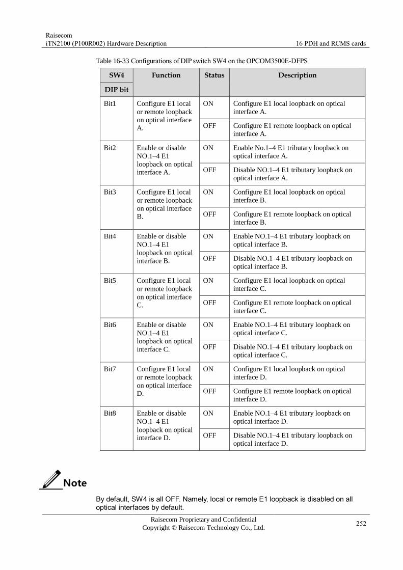
Raisecom
iTN2100 (P100R002) Hardware Description 16 PDH and RCMS cards
Raisecom Proprietary and Confidential
Copyright © Raisecom Technology Co., Ltd. 252
Table 16-33 Configurations of DIP switch SW4 on the OPCOM3500E-DFPS
SW4 Function Status Description
DIP bit
Bit1 Configure E1 local
or remote loopback
on optical interface A.
ON Configure E1 local loopback on optical
interface A.
OFF Configure E1 remote loopback on optical
interface A.
Bit2 Enable or disable
NO.1–4 E1
loopback on optical interface A.
ON Enable No.1–4 E1 tributary loopback on
optical interface A.
OFF Disable NO.1–4 E1 tributary loopback on
optical interface A.
Bit3 Configure E1 local
or remote loopback
on optical interface B.
ON Configure E1 local loopback on optical
interface B.
OFF Configure E1 remote loopback on optical
interface B.
Bit4 Enable or disable
NO.1–4 E1
loopback on optical
interface B.
ON Enable NO.1–4 E1 tributary loopback on
optical interface B.
OFF Disable NO.1–4 E1 tributary loopback on
optical interface B.
Bit5 Configure E1 local
or remote loopback
on optical interface
C.
ON Configure E1 local loopback on optical
interface C.
OFF Configure E1 remote loopback on optical
interface C.
Bit6 Enable or disable
NO.1–4 E1
loopback on optical
interface C.
ON Enable NO.1–4 E1 tributary loopback on
optical interface C.
OFF Disable NO.1–4 E1 tributary loopback on
optical interface C.
Bit7 Configure E1 local
or remote loopback
on optical interface
D.
ON Configure E1 local loopback on optical
interface D.
OFF Configure E1 remote loopback on optical
interface D.
Bit8 Enable or disable
NO.1–4 E1
loopback on optical interface D.
ON Enable NO.1–4 E1 tributary loopback on
optical interface D.
OFF Disable NO.1–4 E1 tributary loopback on
optical interface D.
By default, SW4 is all OFF. Namely, local or remote E1 loopback is disabled on all optical interfaces by default.

Raisecom
iTN2100 (P100R002) Hardware Description 16 PDH and RCMS cards
Raisecom Proprietary and Confidential
Copyright © Raisecom Technology Co., Ltd. 253
16.5.6 Alarms
Table 16-34 lists alarms of the OPCOM3500E-DFPS.
Table 16-34 Alarms of the OPCOM3500E-DFPS
Alarm Cause Level
Optical interface LOS
alarm
Attenuation of received signals is over great. The peer sender fails. The fiber head is unclean or the connector is
improperly connected. The local receiver fails.
Critical
Remote optical
interface LOS alarm
Attenuation of received signals is over great. The peer sender fails. The fiber head is unclean or the connector is
improperly connected. The local receiver fails.
Critical
Optical interface LOF
alarm
The sending alarm of the peer device fails. Optical signals do not match. Local receiving reference clock fails.
Critical
Remote interface
LOF alarm
The sending alarm of the peer device fails. Optical signals do not match. Local receiving reference clock fails.
Critical
Local optical
interface E-3 alarm
Attenuation of received signals is over great. The peer sender fails. The fiber head is unclean or the connector is
improperly connected.
Major
Local optical
interface E-6 alarm
Attenuation of received signals is over great. The peer sender fails. The fiber head is unclean or the connector is
improperly connected.
Major
Remote optical
interface E-3 alarm
Attenuation of received signals is over great. The peer sender fails. The fiber head is unclean or the connector is
improperly connected.
Major
Remote optical
interface E-6 alarm
Attenuation of received signals is over great. The peer sender fails. The fiber head is unclean or the connector is
improperly connected.
Major
E1 LOS alarm Signals are lost. Critical
PDH overall alarm Local PDH optical interface overall alarm Critical
Remote LPR alarm The remote device is powered off. Major
Remote PDH overall
alarm
The PDH optical interface on the remote device has
overall alarms.
Critical
16.5.7 Specifications
Table 16-35 lists specifications of the OPCOM3500E-DFPS.

Raisecom
iTN2100 (P100R002) Hardware Description 16 PDH and RCMS cards
Raisecom Proprietary and Confidential
Copyright © Raisecom Technology Co., Ltd. 254
Table 16-35 Specifications of the OPCOM3500E-DFPS
Parameter Value
Dimensions 25 mm (Width) × 232 mm (Depth) × 240 mm (Height)
Weight < 0.45 kg
Maximum power
consumption
10 W

Raisecom
iTN2100 (P100R002) Hardware Description 16 PDH and RCMS cards
Raisecom Proprietary and Confidential
Copyright © Raisecom Technology Co., Ltd. 255
16.6 OPCOM3500E-120FE×8L-GE
16.6.1 Appearance and functions
Appearance Function
The OPCOM3500E-120FE×8L-GE is a tributary service card used by
the iTN2100.
Support accessing 8 ways of optical signals. Each way of signals
support up to 4 ways of E1 services and 1 way of 100 Mbit/s Ethernet
services. Map up to 32 ways of E1 services to SDH signals at the card and then
aggregate them through the aggregation card. Aggregate up to 8 ways
of 100 Mbit/s Ethernet services into 1 way of GE services at the card
and then output them through the GE interface on the front panel or
transmitted to the switching card through the backplane. Provide 8 multiplexing optical interfaces and 1 GE interface. Support complete alarm indication feature. Local alarms and remote
alarms are displayed simultaneously. Support cooperating with the dual switching card protection. Support managing Raisecom RCMS29XX and RC86X series
remotely. Support 1+1 inter-card protection of E1 services when the iTN2100 is
connected to RCMS2911 series device. Support E1 local internal loopback, E1 local external loopback, and E1
local bidirectional loopback. Support querying local and remote E1 alarms. Support LPR alarms. Support ALS. Support interface isolation protection. Support link aggregation. Support QoS, identifying 4 output queues based on the priority. Support 802.1Q VLAN, 4K concurrent VLANs, and Double Tag. Support flow control. Support bandwidth monitoring of internal switching interfaces, such as
real-time traffic statistics. Support enabling or disabling MAC address learning based on
interface. Support configuring the aging time to 0–3825s. Support querying the MAC address table. Support DDM of the SFP module. Support software online upgrade. Support storing and querying default information about the device. Support hot swapping.
16.6.2 Slots
The OPCOM3500E-120FE×8L-GE can be inserted into slots 1–5 and 8–12 on the iTN2100.
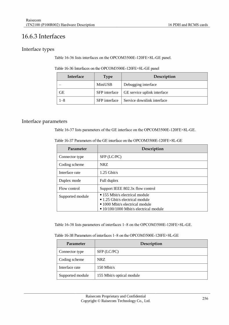
Raisecom
iTN2100 (P100R002) Hardware Description 16 PDH and RCMS cards
Raisecom Proprietary and Confidential
Copyright © Raisecom Technology Co., Ltd. 256
16.6.3 Interfaces
Interface types
Table 16-36 lists interfaces on the OPCOM3500E-120FE×8L-GE panel.
Table 16-36 Interfaces on the OPCOM3500E-120FE×8L-GE panel
Interface Type Description
– MiniUSB Debugging interface
GE SFP interface GE service uplink interface
1–8 SFP interface Service downlink interface
Interface parameters
Table 16-37 lists parameters of the GE interface on the OPCOM3500E-120FE×8L-GE.
Table 16-37 Parameters of the GE interface on the OPCOM3500E-120FE×8L-GE
Parameter Description
Connector type SFP (LC/PC)
Coding scheme NRZ
Interface rate 1.25 Gbit/s
Duplex mode Full duplex
Flow control Support IEEE 802.3x flow control
Supported module 155 Mbit/s electrical module 1.25 Gbit/s electrical module 1000 Mbit/s electrical module 10/100/1000 Mbit/s electrical module
Table 16-38 lists parameters of interfaces 1–8 on the OPCOM3500E-120FE×8L-GE.
Table 16-38 Parameters of interfaces 1–8 on the OPCOM3500E-120FE×8L-GE
Parameter Description
Connector type SFP (LC/PC)
Coding scheme NRZ
Interface rate 150 Mbit/s
Supported module 155 Mbit/s optical module

Raisecom
iTN2100 (P100R002) Hardware Description 16 PDH and RCMS cards
Raisecom Proprietary and Confidential
Copyright © Raisecom Technology Co., Ltd. 257
16.6.4 LEDs
Table 16-39 lists LEDs on the OPCOM3500E-120FE×8L-GE panel.
Table 16-39 LEDs on the OPCOM3500E-120FE×8L-GE panel
LED Status Description
PWR Green Power supply LED
Green: the power supply is normal. Off: the power supply is abnormal.
SYS Green System status LED
Green: the system is working improperly. Off: the system is working improperly. Blinking green: the system is working properly.
1000M
(GE)
Green Ethernet interface 1000 Mbit/s LED
Green: the Ethernet rate is 1000 Mbit/s. Off: the Ethernet rate is 100 Mbit/s or the connection fails.
LNK/ACT
(GE)
Green Ethernet interface working LED
Green: the Ethernet interface is properly connected. Off: the Ethernet interface is disconnected. Blinking green: the Ethernet interface is receiving or sending
data. The blinking frequency is related to the transmission rate.
LPR
(1–8)
Red Optical interface remote device LPR alarm LED
Red: after the local device and the remote device connected to
the related optical interface work properly, LPR occurs on the
remote device. Off: the remote device connected to the related optical
interface is working properly.
LOS
(1–8)
Red Optical interface LOS alarm LED
Red: input LOS alarms are generated on the related optical
interface. Blinking red: the related optical interface receives signals
properly while input LOS alarms are generated on the
connected device Off: no input LOS alarms are generated on the related optical
interface and connected remote device.
16.6.5 Alarms
Table 16-40 lists alarms of the OPCOM3500E-120FE×8L-GE.

Raisecom
iTN2100 (P100R002) Hardware Description 16 PDH and RCMS cards
Raisecom Proprietary and Confidential
Copyright © Raisecom Technology Co., Ltd. 258
Table 16-40 Alarms of the OPCOM3500E-120FE×8L-GE
Alarm Cause Level
Optical interface LOS
alarm
Attenuation of received signals is over great. The peer sender fails on the optical interface. The connector of fiber is dirty or improperly
connected. The local receiver fails.
Critical
Remote device LPR
alarm
The remote device is powered off. Critical
16.6.6 Specifications
Table 16-41 lists specifications of the OPCOM3500E-120FE×8L-GE.
Table 16-41 Specifications of the OPCOM3500E-120FE×8L-GE
Parameter Value
Dimensions 25 mm (Width) × 232 mm (Depth) × 240 mm (Height)
Weight 0.41 kg
Maximum power
consumption
19 W

Raisecom
iTN2100 (P100R002) Hardware Description 16 PDH and RCMS cards
Raisecom Proprietary and Confidential
Copyright © Raisecom Technology Co., Ltd. 259
16.7 OPCOM3500E-240GE×4L
16.7.1 Appearance and functions
Appearance Function
The OPCOM3500E-240GE×4L is a tributary service card on the
iTN2100.
Provide 8 SFP interfaces, where 4 interfaces are PDH optical
interfaces. Each optical interface supports up to 8 ways of E1 and 1
way of GE. This card maps up to 32 ways of E1 to the SDH network.
The other 4 interfaces are GE interfaces which can connect to SFP
optical interface or SFP electrical interface. These four interfaces are
responsible for demultiplexing GE from related PDH optical signals,
making Ethernet services received by the remote be sent to the local
switch one to one. Provide 8 SFP interfaces. Among them, 4 SFP interfaces are
connected to remote device, and the other 4 interfaces (optical
interface or electrical interface) access remote Ethernet service to local
switch one to one. Support 1+1 inter-card E1 service protection. If LOS or LOF occurs
on optical interface or the card is lost, protection switching will be
performed. Support querying and displaying manufacturing information (serial
number) of the card. Support SFP optical module DDM. The local GE interface can be
configured with optical/electrical SFP. For electrical SFP, only
1000BASE-T SFP electrical interface is supported. The GE interface rate is fixed to 1000 Mbit/s. Support enabling the
interface and configuring auto-negotiation. Support timeslot mapping from E1 to SDH network. Support managing downlink remote devices on the Line interface. Support LPR alarms. Support E1 local loopback, remote loopback and dual loopback
functions and support loopback auto-recovery function. Support ALS. Support fault-pass function, including faults passing from optical
interface to electrical interface (if LOS or LOF occurs on local or
remote optical interface, Ethernet electrical interface is shut down
before both ingress and egress optical interfaces become normal ) and
faults passing from electrical interface to electrical interface (if the
remote Ethernet electrical interface is in Link Down mode, the local
Ethernet electrical interface is shut down before remote device
recovers to Link UP mode). Support online upgrade for local and remote devices. Support saving and recovering service card configuration and support
pre-configuring service cards. Work with the remote RCMS2902-2E1GE-BL, RCMS2903-4E1-4GE,
RCMS2912-4E1T1GE, and RCMS2912-8E1T1GE, etc. Support hot swapping.

Raisecom
iTN2100 (P100R002) Hardware Description 16 PDH and RCMS cards
Raisecom Proprietary and Confidential
Copyright © Raisecom Technology Co., Ltd. 260
16.7.2 Slots
The OPCOM3500E-240GE×4L can be inserted into slots 1–5 and 8–12 on the iTN2100.
16.7.3 Interfaces
Interface types
Table 16-42 lists interfaces on the OPCOM3500E-240GE×4L panel.
Table 16-42 OPCOM3500E-240GE×4L interfaces
Interface Type Description
– MiniUSB Debugging interface
1–4 (GE) SFP optical interface Egress interface for GE service
1–4 (Line) SFP optical interface Service downlink interface
Interface parameters
Table 16-43 lists parameters of GE interfaces 1–4 of the OPCOM3500E-240GE×4L.
Table 16-43 Parameters of the OPCOM3500E-240GE×4L interfaces
Parameter Description
Connector type SFP optical interface
Interface rate 1000 Mbit/s
16.7.4 LEDs
Table 16-44 lists LEDs on the OPCOM3500E-240GE×4L panel.
Table 16-44 LEDs on the OPCOM3500E-240GE×4L
LED Status Description
PWR Green Power supply LED
Green: the power supply is normal. Off: the power supply is abnormal.
SYS Green System status LED
Green: the system is working improperly. Off: the system is working improperly. Blinking green: the system is working properly.

Raisecom
iTN2100 (P100R002) Hardware Description 16 PDH and RCMS cards
Raisecom Proprietary and Confidential
Copyright © Raisecom Technology Co., Ltd. 261
LED Status Description
LNK/ACT
(1–4)
Green Ethernet line LED
Green: Ethernet line interfaces 1/2/3/4 are connected properly. Off: the Ethernet line interfaces are disconnected or are
improperly connected. Blinking green: Ethernet line interfaces 1/2/3/4 are receiving or
sending data.
LPR
(1–4)
Red LPR LED for remote device that is connected to related optical
interfaces
Red: the remote device is powered off, when the remote
device, which is connected to the local device and optical
interfaces (Line), is working properly. Off: the remote device that is connected to related optical
interfaces (Line) is working properly.
LOS
(1–4)
Red LOS alarm LED on related optical interfaces (Line)
Red: input LOS alarm occurs on related optical interfaces
(Line). Blinking red: optical related interfaces (Line) receive signals
properly. However, input LOS alarm occurs on connected
remote devices. Off: related optical interfaces (Line) and connected remote
devices receive signals properly or optical module does not
exist.
16.7.5 Alarms
Table 16-45 lists alarms of the OPCOM3500E-240GEx4L.
Table 16-45 Alarms of the OPCOM3500E-240GEx4L
Alarm Cause Level
Optical interface LOS
alarm
Received signals are attenuated dramatically. The peer sender fails. Fiber connector of the sender is dirty or is not
connected properly. Local receiver fails.
Critical
Remote device LPR
alarm
The remote device is powered off. Critical
16.7.6 Specifications
Table 16-46 lists specifications of the OPCOM3500E-240GEx4L.

Raisecom
iTN2100 (P100R002) Hardware Description 16 PDH and RCMS cards
Raisecom Proprietary and Confidential
Copyright © Raisecom Technology Co., Ltd. 262
Table 16-46 Specifications of the OPCOM3500E-240GEx4L
Item Value
Dimensions 25 mm (Width) × 232 mm (Depth) × 240 mm (Height)
Weight < 0.4 kg
Maximum power
consumption
19 W

Raisecom
iTN2100 (P100R002) Hardware Description 16 PDH and RCMS cards
Raisecom Proprietary and Confidential
Copyright © Raisecom Technology Co., Ltd. 263
16.8 OPCOM3500E-120H×4
16.8.1 Appearance and functions
Appearance Function
The OPCOM3500E-120H×4 is a multi-service multiplexing tributary card
on the iTN2100. Now the OPCOM3500E-120H×4 has two versions: versions A and B.
Support accessing 4 ways of PDH optical signals and each way supports 4
ways of E1 services. Map up to 16 ways of E1 services to the SDH signals. Provide 4 PDH optical interfaces. Support multiplexing up to 16 ways of E1 signals. Support complete alarm features. Local alarms and remote alarms can be
displayed concurrently. Support remote management for Raisecom RCMS28XX and RC83X
series. If it is connected to the RCMS2811, they can implement 1+1 inter-
card protection switching. Support E1 local and remote bidirectional loopback. Support LPR alarms for remote devices. Support ALS. Support hot swapping. Support online software upgrade for local and remote devices (Version B
only).
The left is version A and the right is the version B.
16.8.2 Slots
The OPCOM3500E-120H×4 (Versions A and B) can be inserted into slots 1–5 and 8–12 on
the iTN2100.

Raisecom
iTN2100 (P100R002) Hardware Description 16 PDH and RCMS cards
Raisecom Proprietary and Confidential
Copyright © Raisecom Technology Co., Ltd. 264
16.8.3 Interfaces
Interface types
Table 16-47 lists interfaces on the OPCOM3500E-120H×4 (Versions A and B) panel.
Table 16-47 Interfaces on the OPCOM3500E-120H×4 (Versions A and B),
Interface Type Description
A–D
(Version A)
1×9 optical interface Service downlink interface Tx indicates the sending interface and Rx
indicates the receiving interface.
1–4
(Version B)
SFP optical
interface
Service downlink interface Tx indicates the sending interface and Rx
indicates the receiving interface.
16.8.4 LEDs
There are 11 LEDs on the OPCOM3500E-120H×4 (Versions A and B), and the LEDs have
the same functions on the two versions, as listed in Table 16-48.
Table 16-48 LEDs on the OPCOM3500E-120H×4 (Versions A and B) panel
LED Status Description
PWR Green Power supply LED
Green: the power supply is normal. Off: the power supply is abnormal.
SYS Green System status LED
Green: the system is working improperly. Off: the system is working improperly. Blinking green: the system is working properly.
ALM Red Office overall alarm LED
Red: one or more of TU-AIS, TU-LOP, E1-LOS, optical
interface LOF, and 1E-3 alarms are generated on local
optical interfaces A, B, C, or D. Off: no TU-AIS, TU-LOP, E1-LOS, optical interface LOF,
or 1E-3 alarms are generated.
LPR (A–D)
LPR (1–4)
Red Related interface remote device LPR alarm LED
Red: after the local device and the remote device connected
to the related interface are connected and work properly,
LPR occurs on the remote device. Off: the remote device connected to the related interface is
working properly.

Raisecom
iTN2100 (P100R002) Hardware Description 16 PDH and RCMS cards
Raisecom Proprietary and Confidential
Copyright © Raisecom Technology Co., Ltd. 265
LED Status Description
LOS (A–D)
LOS (1–4)
Red Related interface LOS alarm LED
Red: input LOS alarms are generated on the related
interface. Blinking green: input LOS alarms are generated on the
remote device connected to the related interface. Off: no input LOS alarms are generated on the related
interface.
16.8.5 DIP switches
Version A
The OPCOM3500E-120H×4 (Version A) has two DIP switches: SW6 and SW7, as listed in
Table 16-49 and Table 16-50.
Table 16-49 Configurations of DIP switch SW6 on the OPCOM3500E-120H×4 (Version A)
DIP switch
Function Status Description
Bit1 Bit2 Bit3 Bit4 Optical-interface component type
SW6 Configure
the type of
the optical-
interface component.
ON ON ON ON M
ON ON ON OFF S1
ON ON OFF ON S2
ON ON OFF OFF S3
ON OFF ON ON SS13
ON OFF ON OFF SS15
ON OFF OFF ON SS23
ON OFF OFF OFF SS25
SW6 is properly configured before the card leaves the factory. Do not configure it if not needed.
Table 16-50 Configurations of DIP switch SW7 on the OPCOM3500E-120H×4 (Version A)
SW7 Function Status Description
DIP bit
Bit1 Enable or disable ON Enable ALS.
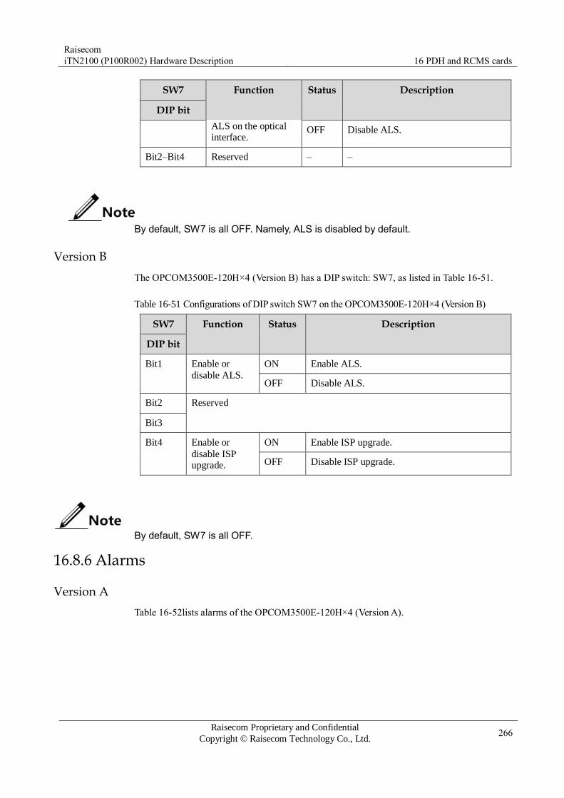
Raisecom
iTN2100 (P100R002) Hardware Description 16 PDH and RCMS cards
Raisecom Proprietary and Confidential
Copyright © Raisecom Technology Co., Ltd. 266
SW7 Function Status Description
DIP bit
ALS on the optical interface.
OFF Disable ALS.
Bit2–Bit4 Reserved – –
By default, SW7 is all OFF. Namely, ALS is disabled by default.
Version B
The OPCOM3500E-120H×4 (Version B) has a DIP switch: SW7, as listed in Table 16-51.
Table 16-51 Configurations of DIP switch SW7 on the OPCOM3500E-120H×4 (Version B)
SW7 Function Status Description
DIP bit
Bit1 Enable or
disable ALS.
ON Enable ALS.
OFF Disable ALS.
Bit2 Reserved
Bit3
Bit4 Enable or
disable ISP upgrade.
ON Enable ISP upgrade.
OFF Disable ISP upgrade.
By default, SW7 is all OFF.
16.8.6 Alarms
Version A
Table 16-52lists alarms of the OPCOM3500E-120H×4 (Version A).

Raisecom
iTN2100 (P100R002) Hardware Description 16 PDH and RCMS cards
Raisecom Proprietary and Confidential
Copyright © Raisecom Technology Co., Ltd. 267
Table 16-52 Alarms of the OPCOM3500E-120H×4 (Version A)
Alarm Cause Level
Optical interface LOS
alarm
Attenuation of received signals is over great. The peer sender fails on the optical interface. The connector of fiber is dirty or improperly
connected. The local receiver fails.
Critical
Remote device LPR alarm The remote device is powered off. Critical
Overall ALM One or more of TU-AIS/TU-LOP, E1-LOS,
optical interface LOF, and 1E-3 alarms
Critical
Version B
Table 16-53 lists alarms of the OPCOM3500E-120H×4 (Version B).
Table 16-53 Alarms of the OPCOM3500E-120H×4 (Version B)
Alarm Cause Level
Optical interface LOS
alarm
Attenuation of received signals is over great. The peer sender fails on the optical interface. The connector of fiber is dirty or improperly
connected. The local receiver fails.
Critical
Remote device LPR alarm The remote device is powered off. Critical
Overall ALM One or more of TU-AIS/TU-LOP, E1-LOS,
optical interface LOF, and 1E-3 alarms
Critical
16.8.7 Specifications
Version A
Table 16-54 lists specifications of the OPCOM3500E-120H×4 (Version A).
Table 16-54 Specifications of the OPCOM3500E-120H×4 (Version A)
Parameter Value
Dimensions 25 mm (Width) × 232 mm (Depth) × 240 mm (Height)
Weight 0.4 kg
Maximum power
consumption
4.95 W

Raisecom
iTN2100 (P100R002) Hardware Description 16 PDH and RCMS cards
Raisecom Proprietary and Confidential
Copyright © Raisecom Technology Co., Ltd. 268
Version B
Table 16-55 lists specifications of the OPCOM3500E-120H×4 (Version B).
Table 16-55 specifications of the OPCOM3500E-120H×4 (Version B)
Parameter Value
Dimensions 25 mm (Width) × 232 mm (Depth) × 240 mm (Height)
Weight < 0.5 kg
Maximum power
consumption
4.95 W
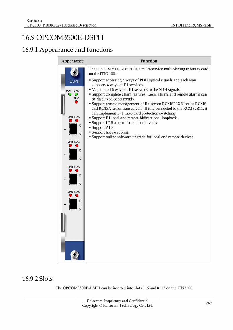
Raisecom
iTN2100 (P100R002) Hardware Description 16 PDH and RCMS cards
Raisecom Proprietary and Confidential
Copyright © Raisecom Technology Co., Ltd. 269
16.9 OPCOM3500E-DSPH
16.9.1 Appearance and functions
Appearance Function
The OPCOM3500E-DSPH is a multi-service multiplexing tributary card
on the iTN2100.
Support accessing 4 ways of PDH optical signals and each way
supports 4 ways of E1 services. Map up to 16 ways of E1 services to the SDH signals. Support complete alarm features. Local alarms and remote alarms can
be displayed concurrently. Support remote management of Raisecom RCMS28XX series RCMS
and RC83X series transceivers. If it is connected to the RCMS2811, it
can implement 1+1 inter-card protection switching. Support E1 local and remote bidirectional loopback. Support LPR alarms for remote devices. Support ALS. Support hot swapping. Support online software upgrade for local and remote devices.
16.9.2 Slots
The OPCOM3500E-DSPH can be inserted into slots 1–5 and 8–12 on the iTN2100.
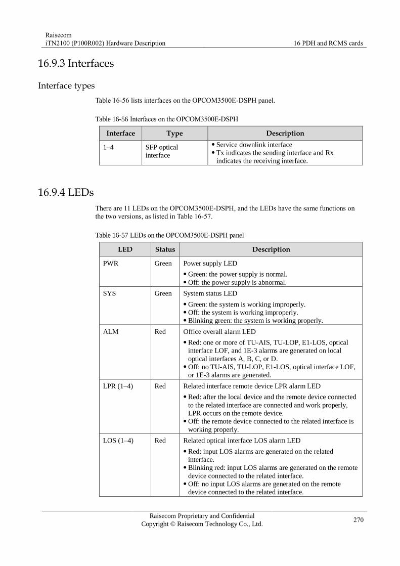
Raisecom
iTN2100 (P100R002) Hardware Description 16 PDH and RCMS cards
Raisecom Proprietary and Confidential
Copyright © Raisecom Technology Co., Ltd. 270
16.9.3 Interfaces
Interface types
Table 16-56 lists interfaces on the OPCOM3500E-DSPH panel.
Table 16-56 Interfaces on the OPCOM3500E-DSPH
Interface Type Description
1–4 SFP optical
interface
Service downlink interface Tx indicates the sending interface and Rx
indicates the receiving interface.
16.9.4 LEDs
There are 11 LEDs on the OPCOM3500E-DSPH, and the LEDs have the same functions on
the two versions, as listed in Table 16-57.
Table 16-57 LEDs on the OPCOM3500E-DSPH panel
LED Status Description
PWR Green Power supply LED
Green: the power supply is normal. Off: the power supply is abnormal.
SYS Green System status LED
Green: the system is working improperly. Off: the system is working improperly. Blinking green: the system is working properly.
ALM Red Office overall alarm LED
Red: one or more of TU-AIS, TU-LOP, E1-LOS, optical
interface LOF, and 1E-3 alarms are generated on local
optical interfaces A, B, C, or D. Off: no TU-AIS, TU-LOP, E1-LOS, optical interface LOF,
or 1E-3 alarms are generated.
LPR (1–4) Red Related interface remote device LPR alarm LED
Red: after the local device and the remote device connected
to the related interface are connected and work properly,
LPR occurs on the remote device. Off: the remote device connected to the related interface is
working properly.
LOS (1–4) Red Related optical interface LOS alarm LED
Red: input LOS alarms are generated on the related
interface. Blinking red: input LOS alarms are generated on the remote
device connected to the related interface. Off: no input LOS alarms are generated on the remote
device connected to the related interface.

Raisecom
iTN2100 (P100R002) Hardware Description 16 PDH and RCMS cards
Raisecom Proprietary and Confidential
Copyright © Raisecom Technology Co., Ltd. 271
16.9.5 DIP switches
Table 16-58 lists DIP switch SW7 on the OPCOM3500E-DSPH.
Table 16-58 Configurations of DIP switch SW7 on the OPCOM3500E-DSPH
SW7 Function Status Description
DIP bit
Bit1 Enable or
disable ALS.
ON Enable ALS.
OFF Disable ALS.
Bit2 Reserved
Bit3
Bit4 Enable or
disable ISP upgrade.
ON Enable ISP upgrade.
OFF Disable ISP upgrade.
By default, SW7 is all OFF.
16.9.6 Alarms
Table 16-59 lists alarms of the OPCOM3500E-DSPH.
Table 16-59 Alarms of the OPCOM3500E-DSPH
Alarm Cause Level
Optical interface LOS
alarm
Attenuation of received signals is over great. The peer sender fails on the optical interface. The connector of fiber is dirty or improperly
connected. The local receiver fails.
Critical
Remote device LPR alarm The remote device is powered off. Critical
Overall ALM One or more of TU-AIS/TU-LOP, E1-LOS,
optical interface LOF, and 1E-3 alarms
Critical
16.9.7 Specifications
Table 16-60 lists specifications of the OPCOM3500E-DSPH.

Raisecom
iTN2100 (P100R002) Hardware Description 16 PDH and RCMS cards
Raisecom Proprietary and Confidential
Copyright © Raisecom Technology Co., Ltd. 272
Table 16-60 specifications of the OPCOM3500E-DSPH
Parameter Value
Dimensions 25 mm (Width) × 232 mm (Depth) × 240 mm (Height)
Weight < 0.50 kg
Maximum power
consumption
4.95 W
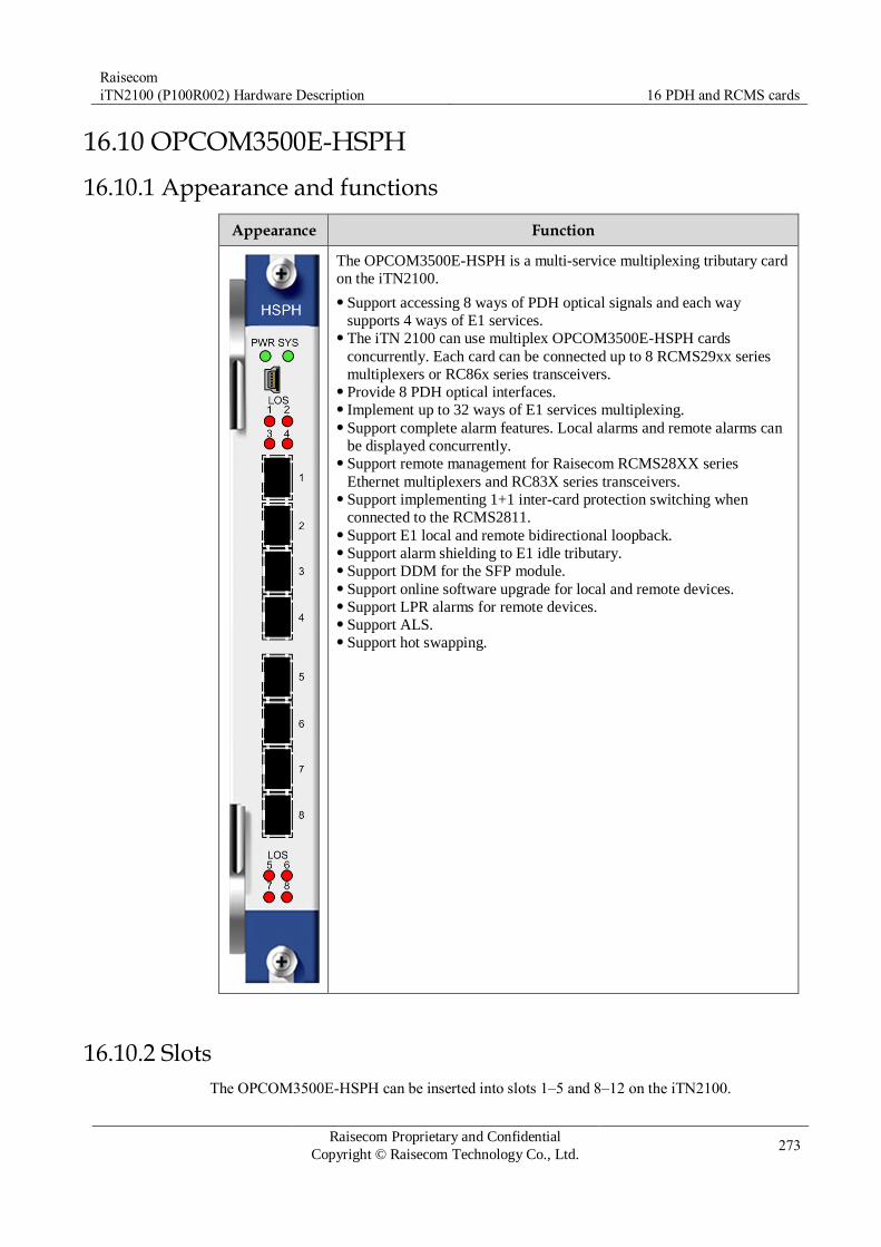
Raisecom
iTN2100 (P100R002) Hardware Description 16 PDH and RCMS cards
Raisecom Proprietary and Confidential
Copyright © Raisecom Technology Co., Ltd. 273
16.10 OPCOM3500E-HSPH
16.10.1 Appearance and functions
Appearance Function
The OPCOM3500E-HSPH is a multi-service multiplexing tributary card
on the iTN2100.
Support accessing 8 ways of PDH optical signals and each way
supports 4 ways of E1 services. The iTN 2100 can use multiplex OPCOM3500E-HSPH cards
concurrently. Each card can be connected up to 8 RCMS29xx series
multiplexers or RC86x series transceivers. Provide 8 PDH optical interfaces. Implement up to 32 ways of E1 services multiplexing. Support complete alarm features. Local alarms and remote alarms can
be displayed concurrently. Support remote management for Raisecom RCMS28XX series
Ethernet multiplexers and RC83X series transceivers. Support implementing 1+1 inter-card protection switching when
connected to the RCMS2811. Support E1 local and remote bidirectional loopback. Support alarm shielding to E1 idle tributary. Support DDM for the SFP module. Support online software upgrade for local and remote devices. Support LPR alarms for remote devices. Support ALS. Support hot swapping.
16.10.2 Slots
The OPCOM3500E-HSPH can be inserted into slots 1–5 and 8–12 on the iTN2100.

Raisecom
iTN2100 (P100R002) Hardware Description 16 PDH and RCMS cards
Raisecom Proprietary and Confidential
Copyright © Raisecom Technology Co., Ltd. 274
16.10.3 Interfaces
Interface types
Table 16-61 lists interfaces on the OPCOM3500E-HSPH panel.
Table 16-61 Interfaces on the OPCOM3500E-HSPH
Interface Type Description
– MiniUSB Debugging interface
1–8 SFP optical
interface
Service downlink interface
Choose 155 Mbit/s or higher SFP modules.
16.10.4 LEDs
Table 16-62 lists LEDs on the OPCOM3500E-HSPH panel.
Table 16-62 LEDs on the OPCOM3500E-HSPH panel
LED Status Description
PWR Green Power supply LED
Green: the power supply is normal. Off: the power supply is abnormal.
SYS Green System status LED
Green: the system is working improperly. Off: the system is working improperly. Blinking green: the system is working properly.
LOS (1–8) Red Related optical interface LOS alarm LED
Red: input LOS alarms are generated on the related
interface. Off: no input LOS alarms are generated on the related
interface.
16.10.5 Alarms
Table 16-63 lists alarms of the OPCOM3500E-HSPH.
Table 16-63 Alarms of the OPCOM3500E-HSPH
Alarm Cause Level
Optical interface
LOS alarm
Attenuation of received signals is over great. The peer sender fails. The fiber head is unclean or the connector is
improperly connected. The local receiver fails.
Critical

Raisecom
iTN2100 (P100R002) Hardware Description 16 PDH and RCMS cards
Raisecom Proprietary and Confidential
Copyright © Raisecom Technology Co., Ltd. 275
Alarm Cause Level
Remote optical
interface LOS alarm
Attenuation of received signals is over great. The peer sender fails. The fiber head is unclean or the connector is
improperly connected. The local receiver fails.
Critical
Optical interface
LOF alarm
The sending alarm of the peer device fails. Optical signals do not match. Local receiving reference clock fails.
Critical
Remote interface
LOF alarm
The sending alarm of the peer device fails. Optical signals do not match. Local receiving reference clock fails.
Critical
16.10.6 Specifications
Table 16-64 lists specifications of the OPCOM3500E-HSPH.
Table 16-64 specifications of the OPCOM3500E-HSPH
Parameter Value
Dimensions 25 mm (Width) × 232 mm (Depth) × 240 mm (Height)
Weight < 0.45 kg
Maximum power
consumption
9 W
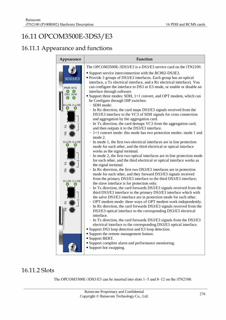
Raisecom
iTN2100 (P100R002) Hardware Description 16 PDH and RCMS cards
Raisecom Proprietary and Confidential
Copyright © Raisecom Technology Co., Ltd. 276
16.11 OPCOM3500E-3DS3/E3
16.11.1 Appearance and functions
Appearance Function
The OPCOM3500E-3DS3/E3 is a DS3/E3 service card on the iTN2100.
Support service interconnection with the RC802-DS3E3. Provide 3 groups of DS3/E3 interfaces. Each group has an optical
interface, a Tx electrical interface, and a Rx electrical interface). You
can configure the interface to DS3 or E3 mode, or enable or disable an
interface through software. Support three modes: SDH, 1+1 convert, and OPT modem, which can
be Configure through DIP switches: – SDH mode: – In Rx direction, the card maps DS3/E3 signals received from the
DS3/E3 interface to the VC3 of SDH signals for cross connection
and aggregation by the aggregation card. – In Tx direction, the card demaps VC3 from the aggregation card,
and then outputs it to the DS3/E3 interface. – 1+1 convert mode: this mode has two protection modes: mode 1 and
mode 2. – In mode 1, the first two electrical interfaces are in line protection
mode for each other, and the third electrical or optical interface
works as the signal terminal. – In mode 2, the first two optical interfaces are in line protection mode
for each other, and the third electrical or optical interface works as
the signal terminal. – In Rx direction, the first two DS3/E3 interfaces are in protection
mode for each other, and they forward DS3/E3 signals received
from the primary DS3/E3 interface to the third DS3/E3 interface;
the slave interface is for protection only. – In Tx direction, the card forwards DS3/E3 signals received from the
third DS3/E3 interface to the primary DS3/E3 interface which with
the salve DS3/E3 interface are in protection mode for each other. – OPT modem mode: three ways of OPT modem work independently. – In Rx direction, the card forwards DS3/E3 signals received from the
DS3/E3 optical interface to the corresponding DS3/E3 electrical
interface. – In Tx direction, the card forwards DS3/E3 signals from the DS3/E3
electrical interface to the corresponding DS3/E3 optical interface. Support DS3 loop detection and E3 loop detection. Support the remote management feature. Support BERT. Support complete alarm and performance monitoring. Support hot swapping.
16.11.2 Slots
The OPCOM3500E-3DS3/E3 can be inserted into slots 1–5 and 8–12 on the iTN2100.
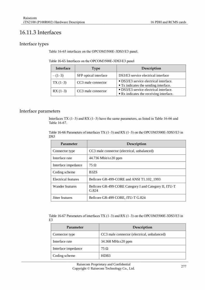
Raisecom
iTN2100 (P100R002) Hardware Description 16 PDH and RCMS cards
Raisecom Proprietary and Confidential
Copyright © Raisecom Technology Co., Ltd. 277
16.11.3 Interfaces
Interface types
Table 16-65 interfaces on the OPCOM3500E-3DS3/E3 panel.
Table 16-65 Interfaces on the OPCOM3500E-3DS3/E3 panel
Interface Type Description
– (1–3) SFP optical interface DS3/E3 service electrical interface
TX (1–3) CC3 male connector DS3/E3 service electrical interface. Tx indicates the sending interface.
RX (1–3) CC3 male connector DS3/E3 service electrical interface. Rx indicates the receiving interface.
Interface parameters
Interfaces TX (1–3) and RX (1–3) have the same parameters, as listed in Table 16-66 and
Table 16-67.
Table 16-66 Parameters of interfaces TX (1–3) and RX (1–3) on the OPCOM3500E-3DS3/E3 in
DS3
Parameter Description
Connector type CC3 male connector (electrical, unbalanced)
Interface rate 44.736 Mbit/s±20 ppm
Interface impedance 75 Ω
Coding scheme B3ZS
Electrical features Bellcore GR-499-CORE and ANSI T1.102_1993
Wander features Bellcore GR-499 CORE Category I and Category II, ITU-T
G.824
Jitter features Bellcore GR-499 CORE, ITU-T G.824
Table 16-67 Parameters of interfaces TX (1–3) and RX (1–3) on the OPCOM3500E-3DS3/E3 in E3
Parameter Description
Connector type CC3 male connector (electrical, unbalanced)
Interface rate 34.368 MHz±20 ppm
Interface impedance 75 Ω
Coding scheme HDB3

Raisecom
iTN2100 (P100R002) Hardware Description 16 PDH and RCMS cards
Raisecom Proprietary and Confidential
Copyright © Raisecom Technology Co., Ltd. 278
Parameter Description
Electrical features Comply with ITU-T G.703 recommendations.
Transferring features Comply with ITU-T G.823 recommendations.
Jitter features Comply with ITU-T G.823 recommendations.
16.11.4 LEDs
Table 16-68 lists LEDs on the OPCOM3500E-3DS3/E3 panel.
Table 16-68 LEDs on the OPCOM3500E-3DS3/E3 panel
LED Status Description
PWR Green Power supply LED
Green: the power supply is normal. Off: the power supply is abnormal.
SYS Green System status LED
Green: the system is working improperly. Off: the system is working improperly. Blinking green: the system is working properly.
DS3 Green DS3/E3 LED
Green: the card is working in DS3 mode. Off: the card is working in E3 mode.
ALM Green Overall alarm LED
Green: alarms are generated on the card. Off: no alarms are generated on the card.
O-LOS (1–3) Green/Red Optical interface 1/2/3 status LED
Green: optical interface 1, 2, or 3 is enabled and
working properly. Red: optical interface 1, 2, or 3 is enabled and LOS
alarms are generated on it. Off: optical interface 1, 2, or 3 is disabled.
E-LOS (1–3) Green/Red Electrical interface 1/2/3 status LED
Green: electrical interface 1, 2, or 3 is enabled and
working properly. Red: electrical interface 1, 2, or 3 is enabled and LOS
alarms are generated on it. Off: electrical interface 1, 2, or 3 is disabled.
16.11.5 DIP switches
The OPCOM3500E-3DS3/E3 has two DIP switches: SW1 and SW2, as listed in Table 16-69
and Table 16-70.
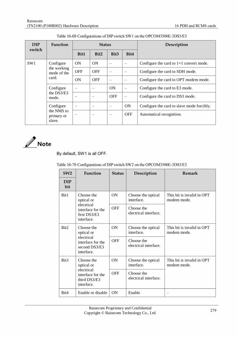
Raisecom
iTN2100 (P100R002) Hardware Description 16 PDH and RCMS cards
Raisecom Proprietary and Confidential
Copyright © Raisecom Technology Co., Ltd. 279
Table 16-69 Configurations of DIP switch SW1 on the OPCOM3500E-3DS3/E3
DIP switch
Function Status Description
Bit1 Bit2 Bit3 Bit4
SW1 Configure
the working
mode of the card.
ON ON – – Configure the card to 1+1 convert mode.
OFF OFF – – Configure the card to SDH mode.
ON OFF – – Configure the card to OPT modem mode.
Configure
the DS3/E3 mode.
– – ON – Configure the card to E3 mode.
– – OFF – Configure the card to DS3 mode.
Configure
the NMS to
primary or slave.
– – – ON Configure the card to slave mode forcibly.
– – – OFF Automatical recognition.
By default, SW1 is all OFF.
Table 16-70 Configurations of DIP switch SW2 on the OPCOM3500E-3DS3/E3
SW2 Function Status Description Remark
DIP bit
Bit1 Choose the
optical or
electrical
interface for the
first DS3/E3 interface.
ON Choose the optical
interface.
This bit is invalid in OPT
modem mode.
OFF Choose the
electrical interface.
Bit2 Choose the
optical or
electrical
interface for the
second DS3/E3
interface.
ON Choose the optical
interface.
This bit is invalid in OPT
modem mode.
OFF Choose the
electrical interface.
Bit3 Choose the
optical or
electrical
interface for the
third DS3/E3 interface.
ON Choose the optical
interface.
This bit is invalid in OPT
modem mode.
OFF Choose the
electrical interface.
Bit4 Enable or disable ON Enable –

Raisecom
iTN2100 (P100R002) Hardware Description 16 PDH and RCMS cards
Raisecom Proprietary and Confidential
Copyright © Raisecom Technology Co., Ltd. 280
SW2 Function Status Description Remark
DIP bit
local optical
interface outer loopback.
OFF Disable
Bit5 Enable or disable
local electrical
interface outer
loopback.
ON Enable –
OFF Disable
Bit6 Enable or disable
remote optical
interface outer loopback.
ON Enable –
OFF Disable
Bit7 Configure
protection mode.
ON Manual protection This bit is valid in 1+1
convert mode. OFF Automatical
protection
Bit8 Configure the
working line.
ON Line 2 This bit is valid in 1+1
convert mode. OFF Line 1
By default, SW2 is all OFF.
16.11.6 Alarms
Table 16-71 lists alarms of the OPCOM3500E-3DS3/E3.
Table 16-71 Alarms of the OPCOM3500E-3DS3/E3
Interface Alarm Cause Level
Optical
interface
LOS alarm Attenuation of received signals is over great. The peer sender fails. The fiber head is unclean or the connector is
improperly connected. The local receiver fails.
Critical
LOF alarm Received signals are out of synchronization. Critical
Electrical
interface
LOL alarm Loss of lock (LOL) alarms are generated on
the receiving clock. Minor
LOS alarm Attenuation of received signals is over great. The peer sender fails. The fiber head is unclean or the connector is
improperly connected. The local receiver fails.
Minor

Raisecom
iTN2100 (P100R002) Hardware Description 16 PDH and RCMS cards
Raisecom Proprietary and Confidential
Copyright © Raisecom Technology Co., Ltd. 281
Interface Alarm Cause Level
DMO
alarm
No output transmitted signals. Minor
LCV alarm Codes of received signals conflict. Minor
E3 AIS
alarm
Timeslot of the backplane of VC12
corresponding to the local E1 is faulty or
improperly configured. The E1 channel of the remote PDH device is
faulty or improperly configured.
Minor
16.11.7 Cables
Table 16-72 lists cables of the OPCOM3500E-3DS3/E3.
Table 16-72 Cables of the OPCOM3500E-3DS3/E3
Card Cable
OPCOM3500E-3DS3/E3 CBL-E1-CC3/BNCF
16.11.8 Specifications
Table 16-73 lists specifications of the OPCOM3500E-3DS3/E3.
Table 16-73 Specifications of the OPCOM3500E-3DS3/E3
Parameter Value
Dimensions 25 mm (Width) × 232 mm (Depth) × 240 mm (Height)
Weight < 0.45 kg
Maximum power
consumption
10 W

Raisecom
iTN2100 (P100R002) Hardware Description 17 V.24 card
Raisecom Proprietary and Confidential
Copyright © Raisecom Technology Co., Ltd. 282
17 V.24 card
This chapter describes the V.24 card on the iTN2100, including the following section:
OPCOM3500E-8V24

Raisecom
iTN2100 (P100R002) Hardware Description 17 V.24 card
Raisecom Proprietary and Confidential
Copyright © Raisecom Technology Co., Ltd. 283
17.1 OPCOM3500E-8V24
17.1.1 Appearance and functions
Appearance Function
The OPCOM3500E-8V24 is an 8-way V.24 data service card on the
iTN2100.
Provide 2 HDB26 interfaces. Each interface transmits 4 ways of V.24
data. Map V.24 data within itself to the VC12 of SDH directly or indirectly
(V.24 data are aggregated by the OPCOM3500E-DXC-DS0 first and
then mapped to the VC12 of the SDH), and every 4 ways of V.24 data
occupy one E1. Support application in DCE mode. Support independent configuration of bandwidth for each V24
channel. You can configure the bandwidth to 64 kbit/s, 128 kbit/s, or
256 kbit/s. The V24 channel is fixed to occupy the 64 kbit/s timeslot
of inner E1. Support local crystal oscillator, E1-1 recovery clock, or E1-2 recovery
clock as clock source. Support Tx and Rx phase adjustment on each V.24 interface
independently. The V.24 data channel supports three loopback modes:
– External loopback on the V.24 interface side – Internal loopback on the inner E1 side – External loopback on the inner E1 side
Support E1 BERT. When you send test codes to the backplane, you
can test only one way of E1 once. Support hot swapping.
Table 17-1 lists relations between V24 bandwidth and 64 kbit/s timeslot.

Raisecom
iTN2100 (P100R002) Hardware Description 17 V.24 card
Raisecom Proprietary and Confidential
Copyright © Raisecom Technology Co., Ltd. 284
Table 17-1 Relations between V24 bandwidth and 64 kbit/s timeslot on the OPCOM3500E-8V24
Bandwidth
V.24 data
64 kbit/s 128 kbit/s 256 kbit/s
Line 1 V.24 Occupy the first E1. TS1 TS1–2 TS1–4
Line 2 V.24 TS5 TS5–6 TS5–8
Line 3 V.24 TS17 TS17–18 TS17–20
Line 4 V.24 TS21 TS21–22 TS21–24
Line 5 V.24 Occupy the second E1. TS1 TS1–2 TS1–4
Line 6 V.24 TS5 TS5–6 TS5–8
Line 7 V.24 TS17 TS17–18 TS17–20
Line 8 V.24 TS21 TS21–22 TS21–24
17.1.2 Slots
The OPCOM3500E-8V24 can be inserted into slots 1–5 and 8–12 on the iTN2100.
17.1.3 Interfaces
Interface types
There are two interfaces on the OPCOM3500E-8V24 panel, as listed in Table 17-2.
Table 17-2 Interfaces on the OPCOM3500E-8V24 panel
Interface Connector type Description
1–4, 5–8 HDB26 female
connector
Service downlink interface Each interface can transmit four ways of V.24 data.
17.1.4 LEDs
There are 18 LEDs on the OPCOM3500E-8V24 panel, as listed in Table 17-3.
Table 17-3 LEDs on the OPCOM3500E-8V24 panel
LED Status Description
PWR Green Power supply LED
Green: the power supply is normal. Off: the power supply is abnormal.

Raisecom
iTN2100 (P100R002) Hardware Description 17 V.24 card
Raisecom Proprietary and Confidential
Copyright © Raisecom Technology Co., Ltd. 285
LED Status Description
SYS Green System status LED
Green: the system is working improperly. Off: the system is working improperly. Blinking green: the system is working properly.
TD
(1–8)
Green Blinking green: V.24 data channel interface 1/2/.../7/8 is sending
data from itself to the DTE device. Blinking frequency indicates
transmission rate. Off: V.24 data channel interface 1/2/.../7/8 is not sending data.
RD
(1–8)
Green Blinking green: V.24 data channel interface 1/2/.../7/8 is
receiving data from the DTE device to itself. Blinking frequency
indicates transmission rate. Off: V.24 data channel interface 1/2/.../7/8 is not receiving data.
17.1.5 Cables
Table 17-4 lists cables of the OPCOM3500E-8V24.
Table 17-4 Cables of the OPCOM3500E-8V24
Card Cable
OPCOM3500E-8V24 CBL-V24-HDB26M/4DB25F CBL-V24-HDB26M/4DB25M
17.1.6 Specifications
Table 17-5 lists specifications of the OPCOM3500E-8V24.
Table 17-5 Specifications of the OPCOM3500E-8V24
Parameter Value
Dimensions 25 mm (Width) × 232 mm (Depth) × 240 mm (Height)
Weight < 0.45 kg
Maximum power
consumption
4 W

Raisecom
iTN2100 (P100R002) Hardware Description 18 V.35 card
Raisecom Proprietary and Confidential
Copyright © Raisecom Technology Co., Ltd. 286
18 V.35 card
This chapter describes the V.35 card on the iTN2100, including the following sections:
OPCOM3500E-8V35
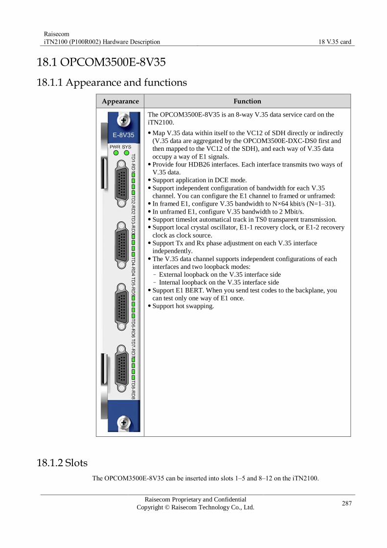
Raisecom
iTN2100 (P100R002) Hardware Description 18 V.35 card
Raisecom Proprietary and Confidential
Copyright © Raisecom Technology Co., Ltd. 287
18.1 OPCOM3500E-8V35
18.1.1 Appearance and functions
Appearance Function
The OPCOM3500E-8V35 is an 8-way V.35 data service card on the
iTN2100.
Map V.35 data within itself to the VC12 of SDH directly or indirectly
(V.35 data are aggregated by the OPCOM3500E-DXC-DS0 first and
then mapped to the VC12 of the SDH), and each way of V.35 data
occupy a way of E1 signals. Provide four HDB26 interfaces. Each interface transmits two ways of
V.35 data. Support application in DCE mode. Support independent configuration of bandwidth for each V.35
channel. You can configure the E1 channel to framed or unframed: In framed E1, configure V.35 bandwidth to N×64 kbit/s (N=1–31). In unframed E1, configure V.35 bandwidth to 2 Mbit/s. Support timeslot automatical track in TS0 transparent transmission. Support local crystal oscillator, E1-1 recovery clock, or E1-2 recovery
clock as clock source. Support Tx and Rx phase adjustment on each V.35 interface
independently. The V.35 data channel supports independent configurations of each
interfaces and two loopback modes: – External loopback on the V.35 interface side – Internal loopback on the V.35 interface side
Support E1 BERT. When you send test codes to the backplane, you
can test only one way of E1 once. Support hot swapping.
18.1.2 Slots
The OPCOM3500E-8V35 can be inserted into slots 1–5 and 8–12 on the iTN2100.
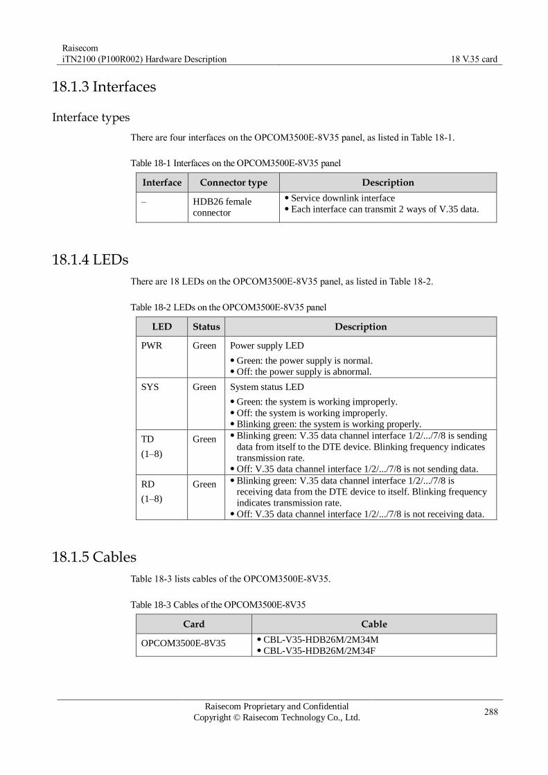
Raisecom
iTN2100 (P100R002) Hardware Description 18 V.35 card
Raisecom Proprietary and Confidential
Copyright © Raisecom Technology Co., Ltd. 288
18.1.3 Interfaces
Interface types
There are four interfaces on the OPCOM3500E-8V35 panel, as listed in Table 18-1.
Table 18-1 Interfaces on the OPCOM3500E-8V35 panel
Interface Connector type Description
– HDB26 female
connector
Service downlink interface Each interface can transmit 2 ways of V.35 data.
18.1.4 LEDs
There are 18 LEDs on the OPCOM3500E-8V35 panel, as listed in Table 18-2.
Table 18-2 LEDs on the OPCOM3500E-8V35 panel
LED Status Description
PWR Green Power supply LED
Green: the power supply is normal. Off: the power supply is abnormal.
SYS Green System status LED
Green: the system is working improperly. Off: the system is working improperly. Blinking green: the system is working properly.
TD
(1–8)
Green Blinking green: V.35 data channel interface 1/2/.../7/8 is sending
data from itself to the DTE device. Blinking frequency indicates
transmission rate. Off: V.35 data channel interface 1/2/.../7/8 is not sending data.
RD
(1–8)
Green Blinking green: V.35 data channel interface 1/2/.../7/8 is
receiving data from the DTE device to itself. Blinking frequency
indicates transmission rate. Off: V.35 data channel interface 1/2/.../7/8 is not receiving data.
18.1.5 Cables
Table 18-3 lists cables of the OPCOM3500E-8V35.
Table 18-3 Cables of the OPCOM3500E-8V35
Card Cable
OPCOM3500E-8V35 CBL-V35-HDB26M/2M34M CBL-V35-HDB26M/2M34F
Raisecom
iTN2100 (P100R002) Hardware Description 18 V.35 card
Raisecom Proprietary and Confidential
Copyright © Raisecom Technology Co., Ltd. 289
18.1.6 Specifications
Table 18-4 lists specifications of the OPCOM3500E-8V35.
Table 18-4 Specifications of the OPCOM3500E-8V35
Parameter Value
Dimensions 25 mm (Width) × 232 mm (Depth) × 240 mm (Height)
Weight < 0.45 kg
Maximum power
consumption
8 W

Raisecom
iTN2100 (P100R002) Hardware Description 19 64K cross-connection card
Raisecom Proprietary and Confidential
Copyright © Raisecom Technology Co., Ltd. 290
19 64K cross-connection card
This chapter describes the 64K cross-connection card on the iTN2100, including the
following section:
OPCOM3500E-DXC-DS0

Raisecom
iTN2100 (P100R002) Hardware Description 19 64K cross-connection card
Raisecom Proprietary and Confidential
Copyright © Raisecom Technology Co., Ltd. 291
19.1 OPCOM3500E-DXC-DS0
19.1.1 Appearance and functions
Appearance Function
The OPCOM3500E-DXC-DS0 is a 64K cross-connection card on the
iTN2100.
Support cross connection and multiplexing of 1536×1536 64 kbit/s
services (namely, 48×48 ways of E1 signals). Support no service interface. 64 kbit/s services can be transmitted
through other service cards. E1 supports framed and unframed modes. In framed mode, the card
can work in PCM30 or PCM21 mode. In PCM30 mode, it supports
cross connection of voice signaling. Support three clock modes: local clock, system clock, and E1 clock. If
the card works in slave clock mode, you can choose any E1 among 48
ways of E1 signals to recover clock. Support external loopback on the E1 interface. You can perform
loopback on E1 signals from other service cards. The iTN2100 can be inserted with multiple 64K cross-connection
cards. Any two of them support card-level hot backup. Manage the remote device through the Sa bit in framed E1 or
independent timeslots. Support remote management for the RC3000-2E1, RC3000-4E1,
RC3000-OPT-FE, and RC3000-OPT-2E1. Support online software upgrade. Support hot swapping.
19.1.2 Slots
The OPCOM3500E-DXC-DS0 can be inserted into slots 1–5 and 8–12 on the iTN2100.

Raisecom
iTN2100 (P100R002) Hardware Description 19 64K cross-connection card
Raisecom Proprietary and Confidential
Copyright © Raisecom Technology Co., Ltd. 292
19.1.3 LEDs
There are three LEDs on the OPCOM3500E-DXC-DS0 panel, as listed in Table 19-1.
Table 19-1 LEDs on the OPCOM3500E-DXC-DS0 panel
LED Status Description
PWR Green Power supply LED
Green: the power supply is normal. Off: the power supply is abnormal.
SYS Green System status LED
Green: the system is working improperly. Off: the system is working improperly. Blinking green: the system is working properly.
ALM Red Alarm LED
Red: TU-AIS or TU-LOP alarms are generated. Off: no TU-AIS or TU-LOP alarms are generated.
19.1.4 Alarms
Table 19-2 lists alarms of the OPCOM3500E-DXC-DS0.
Table 19-2 Alarms of the OPCOM3500E-DXC-DS0
Alarm Cause Level
E1 LOF alarm The Tx clock of the peer device fails. The E1 connector of the peer device is improperly
connected; the attenuation of sent signals is over great. The receiving reference clock of the card fails.
Critical
E1 AIS alarm Timeslot of the backplane of VC12 corresponding to
the local E1 is faulty or improperly configured. The E1 channel of the remote PDH device is faulty or
improperly configured.
Minor
E1 CRC alarm The working mode of E1 in the peer or local device is
improperly configured. CRC at the E1 sending side of the peer device is
disabled. The Tx clock of the peer device fails. The E1 connector of the peer device is improperly
connected; the attenuation of sent signals is over great. The receiving reference clock of the card fails.
Minor
E1 E-3/6 alarm The working mode of E1 in the peer or local device is
improperly configured. CRC at the E1 sending side of the peer device is
disabled. The Tx clock of the peer device fails. The E1 connector of the peer device is improperly
connected; the attenuation of sent signals is over great. The receiving reference clock of the card fails.
Minor

Raisecom
iTN2100 (P100R002) Hardware Description 19 64K cross-connection card
Raisecom Proprietary and Confidential
Copyright © Raisecom Technology Co., Ltd. 293
19.1.5 Specifications
Table 19-3 lists specifications of the OPCOM3500E-DXC-DS0.
Table 19-3 Specifications of the OPCOM3500E-DXC-DS0
Parameter Value
Dimensions 25 mm (Width) × 232 mm (Depth) × 240 mm (Height)
Weight < 0.36 kg
Maximum power
consumption
5 W

Raisecom
iTN2100 (P100R002) Hardware Description 20 Multi-service cards
Raisecom Proprietary and Confidential
Copyright © Raisecom Technology Co., Ltd. 294
20 Multi-service cards
This chapter describes the multi-service cards of the iTN2100, including the following
sections:
OPCOM3500E-12MT
OPCOM3500E-8MT
OPCOM3500E-MULTI
OPCOM3500E-Audio
iTN2100-EOW
OPCOM3500E-10E&M
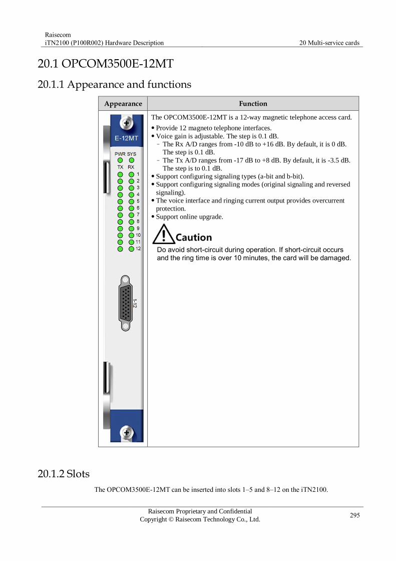
Raisecom
iTN2100 (P100R002) Hardware Description 20 Multi-service cards
Raisecom Proprietary and Confidential
Copyright © Raisecom Technology Co., Ltd. 295
20.1 OPCOM3500E-12MT
20.1.1 Appearance and functions
Appearance Function
The OPCOM3500E-12MT is a 12-way magnetic telephone access card.
Provide 12 magneto telephone interfaces. Voice gain is adjustable. The step is 0.1 dB.
– The Rx A/D ranges from -10 dB to +16 dB. By default, it is 0 dB.
The step is 0.1 dB. – The Tx A/D ranges from -17 dB to +8 dB. By default, it is -3.5 dB.
The step is to 0.1 dB. Support configuring signaling types (a-bit and b-bit). Support configuring signaling modes (original signaling and reversed
signaling). The voice interface and ringing current output provides overcurrent
protection. Support online upgrade.
Do avoid short-circuit during operation. If short-circuit occurs and the ring time is over 10 minutes, the card will be damaged.
20.1.2 Slots
The OPCOM3500E-12MT can be inserted into slots 1–5 and 8–12 on the iTN2100.
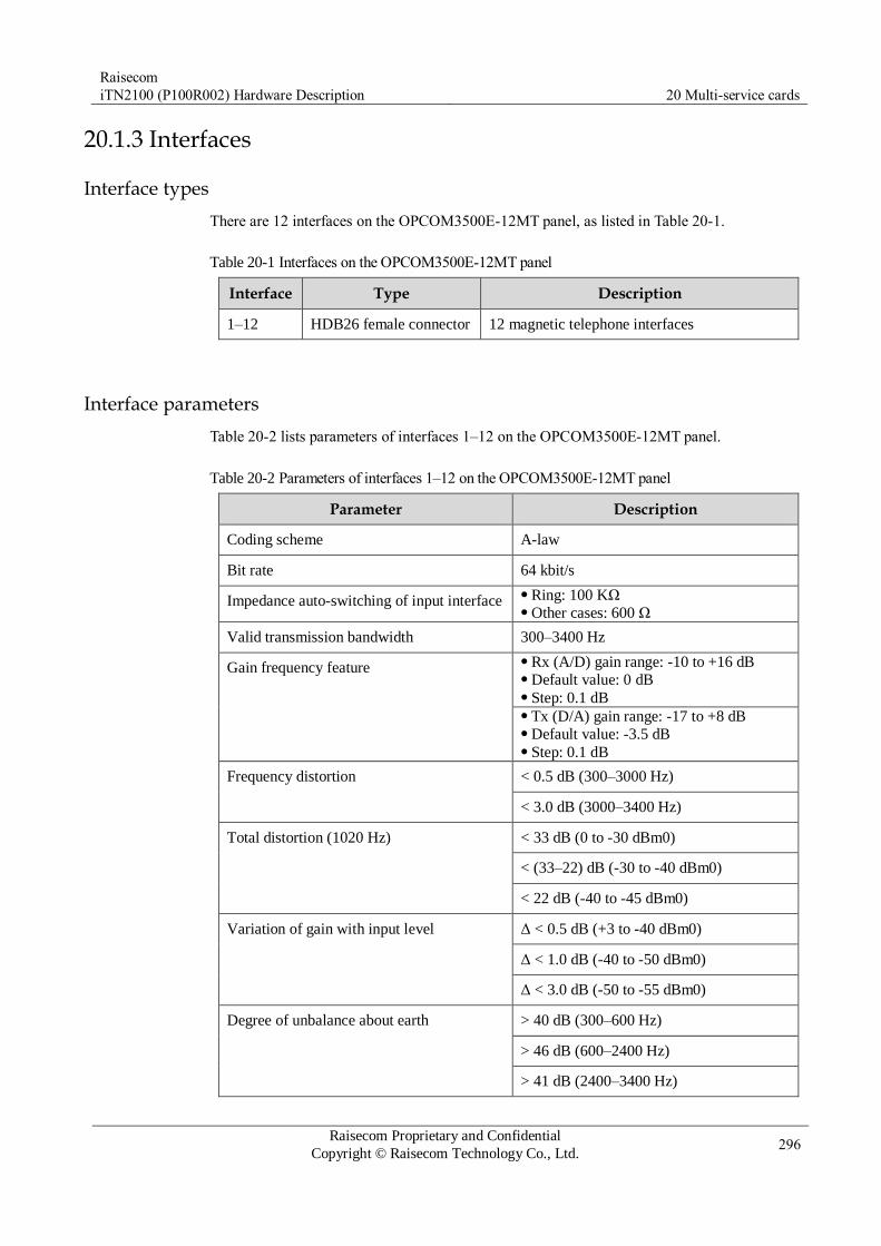
Raisecom
iTN2100 (P100R002) Hardware Description 20 Multi-service cards
Raisecom Proprietary and Confidential
Copyright © Raisecom Technology Co., Ltd. 296
20.1.3 Interfaces
Interface types
There are 12 interfaces on the OPCOM3500E-12MT panel, as listed in Table 20-1.
Table 20-1 Interfaces on the OPCOM3500E-12MT panel
Interface Type Description
1–12 HDB26 female connector 12 magnetic telephone interfaces
Interface parameters
Table 20-2 lists parameters of interfaces 1–12 on the OPCOM3500E-12MT panel.
Table 20-2 Parameters of interfaces 1–12 on the OPCOM3500E-12MT panel
Parameter Description
Coding scheme A-law
Bit rate 64 kbit/s
Impedance auto-switching of input interface Ring: 100 KΩ Other cases: 600 Ω
Valid transmission bandwidth 300–3400 Hz
Gain frequency feature Rx (A/D) gain range: -10 to +16 dB Default value: 0 dB Step: 0.1 dB Tx (D/A) gain range: -17 to +8 dB Default value: -3.5 dB Step: 0.1 dB
Frequency distortion < 0.5 dB (300–3000 Hz)
< 3.0 dB (3000–3400 Hz)
Total distortion (1020 Hz) < 33 dB (0 to -30 dBm0)
< (33–22) dB (-30 to -40 dBm0)
< 22 dB (-40 to -45 dBm0)
Variation of gain with input level Δ < 0.5 dB (+3 to -40 dBm0)
Δ < 1.0 dB (-40 to -50 dBm0)
Δ < 3.0 dB (-50 to -55 dBm0)
Degree of unbalance about earth > 40 dB (300–600 Hz)
> 46 dB (600–2400 Hz)
> 41 dB (2400–3400 Hz)

Raisecom
iTN2100 (P100R002) Hardware Description 20 Multi-service cards
Raisecom Proprietary and Confidential
Copyright © Raisecom Technology Co., Ltd. 297
Parameter Description
Idle-channel noise < -67 dBm0p
Ringing current voltage Typical 75VAC sine wave/30 Hz
Return loss > 12 dB (300–600 Hz)
> 15 dB (600–3400 Hz)
Interface PINs
Figure 20-1 shows interface PINs of the OPCOM3500E-12MT.
Figure 20-1 Interface PINs of the OPCOM3500E-12MT
Table 20-3 describes interface PINs of the OPCOM3500E-12MT.
Table 20-3 Interface PINs of the OPCOM3500E-12MT
HDB26M PIN PIN definition Description
7 CH-01A No.1 way of voice
17 CH-01B
8 CH-02A No.2 way of voice
18 CH-02B
25 CH-03A No.3 way of voice
26 CH-03B
5 CH-04A No.4 way of voice
15 CH-04B
6 CH-05A No.5 way of voice
16 CH-05B
23 CH-06A No.6 way of voice
24 CH-06B
3 CH-07A No.7 way of voice

Raisecom
iTN2100 (P100R002) Hardware Description 20 Multi-service cards
Raisecom Proprietary and Confidential
Copyright © Raisecom Technology Co., Ltd. 298
HDB26M PIN PIN definition Description
13 CH-07B
4 CH-08A No.8 way of voice
14 CH-08B
21 CH-09A No.9 way of voice
22 CH-09B
1 CH-10A No.10 way of voice
11 CH-10B
2 CH-11A No.11 way of voice
12 CH-11B
19 CH-12A No.12 way of voice
20 CH-12B
9 Idle –
10 Idle –
20.1.4 LEDs
There are 26 LEDs on the OPCOM3500E-12MT panel, as listed in Table 20-4.
Table 20-4 LEDs on the OPCOM3500E-12MT panel
LED Status Description
PWR Green Power supply LED
Green: the power supply is normal. Off: the power supply is abnormal.
SYS Green System status LED
Green: the system is working improperly. Off: the system is working improperly. Blinking green: the system is working properly.
TX Green Signaling output LED
Green: there is signaling being output. Off: no signaling is being output.
The signaling direction is based on the magnetic telephone. Tx refers the direction from the magnetic telephone to the 12MT.

Raisecom
iTN2100 (P100R002) Hardware Description 20 Multi-service cards
Raisecom Proprietary and Confidential
Copyright © Raisecom Technology Co., Ltd. 299
LED Status Description
RX Green Signaling input LED
Green: there is signaling being input. Off: no signaling is being input.
The signaling direction is based on the magnetic telephone. Rx refers the direction from the 12MT to the magnetic telephone.
20.1.5 Specifications
Table 20-5 lists specifications of the OPCOM3500E-12MT.
Table 20-5 Specifications of the OPCOM3500E-12MT
Parameter Value
Dimensions 25 mm (Width) × 232 mm (Depth) × 240 mm (Height)
Weight 0.47 kg
Maximum power
consumption
23 W
20.1.6 Cables
Table 20-6 lists cables available for the OPCOM3500E-12MT.
Table 20-6 Cables available for the OPCOM3500E-12MT
Recommended cable Description
CBL-MUL-
HDB26M(40)/NC
(Angled) HDB26 male connector-to-NC multi-function
cable
For details about the used cable color patterns, see section 24.14 MUL-HDB26 cable.
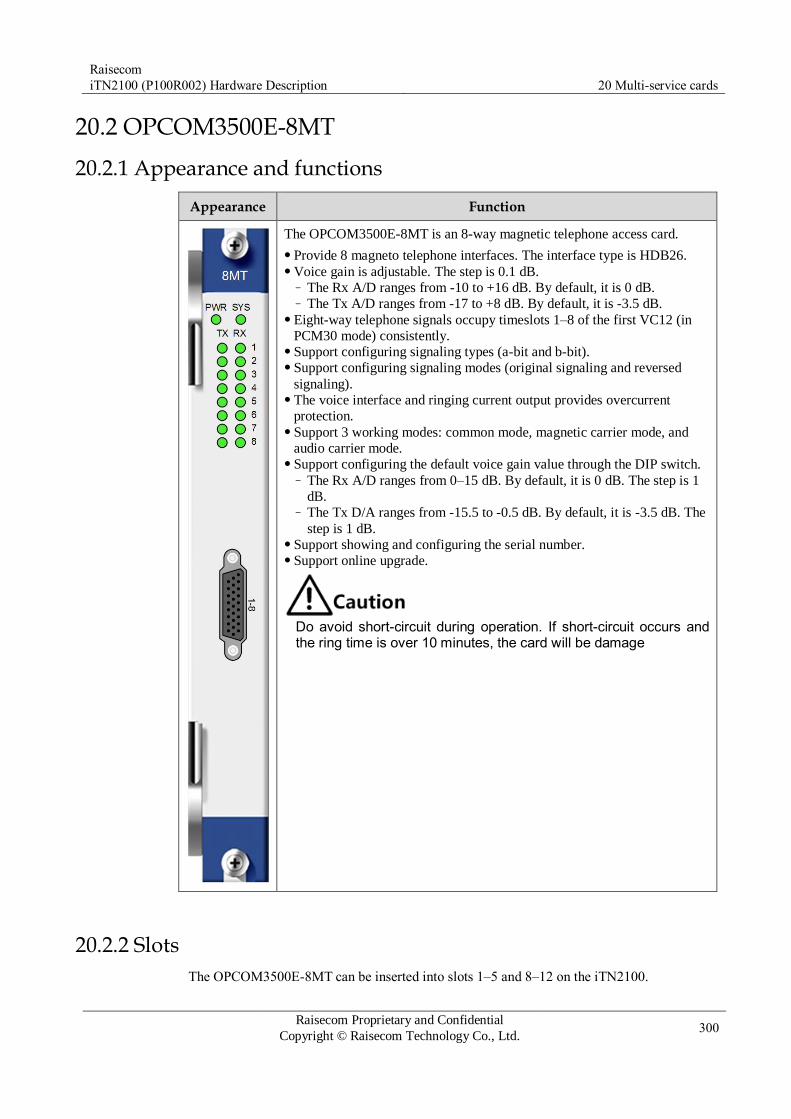
Raisecom
iTN2100 (P100R002) Hardware Description 20 Multi-service cards
Raisecom Proprietary and Confidential
Copyright © Raisecom Technology Co., Ltd. 300
20.2 OPCOM3500E-8MT
20.2.1 Appearance and functions
Appearance Function
The OPCOM3500E-8MT is an 8-way magnetic telephone access card.
Provide 8 magneto telephone interfaces. The interface type is HDB26. Voice gain is adjustable. The step is 0.1 dB.
– The Rx A/D ranges from -10 to +16 dB. By default, it is 0 dB. – The Tx A/D ranges from -17 to +8 dB. By default, it is -3.5 dB.
Eight-way telephone signals occupy timeslots 1–8 of the first VC12 (in
PCM30 mode) consistently. Support configuring signaling types (a-bit and b-bit). Support configuring signaling modes (original signaling and reversed
signaling). The voice interface and ringing current output provides overcurrent
protection. Support 3 working modes: common mode, magnetic carrier mode, and
audio carrier mode. Support configuring the default voice gain value through the DIP switch.
– The Rx A/D ranges from 0–15 dB. By default, it is 0 dB. The step is 1
dB. – The Tx D/A ranges from -15.5 to -0.5 dB. By default, it is -3.5 dB. The
step is 1 dB. Support showing and configuring the serial number. Support online upgrade.
Do avoid short-circuit during operation. If short-circuit occurs and the ring time is over 10 minutes, the card will be damage
20.2.2 Slots
The OPCOM3500E-8MT can be inserted into slots 1–5 and 8–12 on the iTN2100.

Raisecom
iTN2100 (P100R002) Hardware Description 20 Multi-service cards
Raisecom Proprietary and Confidential
Copyright © Raisecom Technology Co., Ltd. 301
20.2.3 Interfaces
Interface types
There are 8 interfaces on the OPCOM3500E-8MT panel, as listed in Table 20-7.
Table 20-7 Interfaces on the OPCOM3500E-8MT panel
Interface Type Description
1–8 HDB26 female connector 8 magnetic telephone interfaces
Interface parameters
Table 20-8 lists parameters of interfaces 1–8 on the OPCOM3500E-8MT panel.
Table 20-8 Parameters of interfaces 1–8 on the OPCOM3500E-8MT panel
Parameter Description
Coding scheme A-law
Bit rate 64 kbit/s
Impedance auto-switching of input interface Ring: 100 KΩ Other cases: 600 Ω
Valid transmission bandwidth 300–3400 Hz
Gain frequency feature Rx (A/D) gain range: -10 to +16 dB Default value: 0 dB Step: 0.1 dB Tx (D/A) gain range: -17 to +8 dB Default value: -3.5 dB Step: 0.1 dB
Frequency distortion < 0.5 dB (300–3000 Hz)
< 3.0 dB (3000–3400 Hz)
Total distortion (1020 Hz) < 33 dB (0 to -30 dBm0)
(33–22) dB (-30 to -40 dBm0)
< 22 dB (-40 to -45 dBm0)
Variation of gain with input level Δ < 0.5 dB (+3 to -40 dBm0)
Δ < 1.0 dB (-40 to -50 dBm0)
Δ < 3.0 dB (-50 to -55 dBm0)
Degree of unbalance about earth > 40 dB (300–600 Hz)
> 46 dB (600–2400 Hz)
> 41 dB (2400–3400 Hz)

Raisecom
iTN2100 (P100R002) Hardware Description 20 Multi-service cards
Raisecom Proprietary and Confidential
Copyright © Raisecom Technology Co., Ltd. 302
Parameter Description
Idle-channel noise < -67 dBm0p
Ringing current voltage Typical 75 VAC 25 Hz
Return loss > 12 dB (300–600 Hz)
> 15 dB (600–3400 Hz)
Interface PINs
Figure 20-2 shows interface PINs of the OPCOM3500E-8MT.
Figure 20-2 Interface PINs of the OPCOM3500E-8MT
Table 20-9 describes interface PINs of the OPCOM3500E-8MT.
Table 20-9 Interface PINs of the OPCOM3500E-8MT
HDB26M PIN PIN definition Description
7 CH-01A No.1 way of voice
17 CH-01B
8 CH-02A No.2 way of voice
18 CH-02B
25 CH-03A No.3 way of voice
26 CH-03B
5 CH-04A No.4 way of voice
15 CH-04B
6 CH-05A No.5 way of voice
16 CH-05B
23 CH-06A No.6 way of voice
24 CH-06B
3 CH-07A No.7 way of voice

Raisecom
iTN2100 (P100R002) Hardware Description 20 Multi-service cards
Raisecom Proprietary and Confidential
Copyright © Raisecom Technology Co., Ltd. 303
HDB26M PIN PIN definition Description
13 CH-07B
4 CH-08A No.8 way of voice
14 CH-08B
21 Idle –
22 Idle –
1 Idle –
11 Idle –
2 Idle –
12 Idle –
19 Idle –
20 Idle –
9 Idle –
10 Idle –
20.2.4 LEDs
There are 18 LEDs on the OPCOM3500E-8MT panel, as listed in Table 20-10.
Table 20-10 LEDs on the OPCOM3500E-8MT panel
LED Status Description
PWR Green Power supply LED
Green: the power supply is normal. Off: the power supply is abnormal.
SYS Green System status LED
Green: the system is working improperly. Off: the system is working improperly. Blinking green: the system is working properly.
TX (1–8) Green Signaling output LED
Green: there is signaling being output. Off: no signaling is being output.
The signaling direction is based on the magnetic telephone. Tx refers to the direction from the magnetic telephone to the card.

Raisecom
iTN2100 (P100R002) Hardware Description 20 Multi-service cards
Raisecom Proprietary and Confidential
Copyright © Raisecom Technology Co., Ltd. 304
LED Status Description
RX (1–8) Green Signaling input LED
Green: there is signaling being input. Off: no signaling is being input.
The signaling direction is based on the magnetic telephone. Rx refers to the direction from the card to the magnetic telephone.
20.2.5 DIP switches
The OPCOM3500E-8MT supports configuring the default voice gain value of 8 telephone
interfaces. DIP switches CH1–CH8 relate to telephone interfaces 1–8 respectively. You can
configure the Rx and Tx gain respectively for each telephone interface. Configuration
methods for the 8-pair DIP switches are identical. Here, take CH1 for an example, as shown
in Figure 20-3.
Figure 20-3 Voice gain DIP switch of the OPCOM3500E-8MT
The Rx A/D ranges from 0–15 dB. By default, it is 0 dB. The step is 1 dB.
The Tx D/A ranges from -15.5 to -0.5 dB. By default, it is -3.5 dB. The step is 1 dB.
The default voice gain value, configured through the DIP switch, takes effect after the card is
re-powered on. You can configure the configuration mode of the voice gain (hardware or
software mode) through the gain-cfg-mode command. If the configuration mode is hardware
mode, software configurations do not take effect, vice versa. For details about the CLI, see
iTN2100 Command Reference_TDM Part.
20.2.6 Specifications
Table 20-11 lists specifications of the OPCOM3500E-8MT.
Table 20-11 Specifications of the OPCOM3500E-8MT
Parameter Value
Dimensions 25 mm (Width) × 232 mm (Depth) × 240 mm (Height)
Weight 0.75 kg

Raisecom
iTN2100 (P100R002) Hardware Description 20 Multi-service cards
Raisecom Proprietary and Confidential
Copyright © Raisecom Technology Co., Ltd. 305
Parameter Value
Maximum power
consumption
25 W
20.2.7 Cables
Table 20-12 lists cables available for the OPCOM3500E-8MT.
Table 20-12 Cables available for the OPCOM3500E-8MT
Recommended cable Description
CBL-MUL-
HDB26M(40)/NC
(Angled) HDB26 male connector-to-NC multi-function
cable
For details about the used cable color patterns, see section 24.14 MUL-HDB26 cable.

Raisecom
iTN2100 (P100R002) Hardware Description 20 Multi-service cards
Raisecom Proprietary and Confidential
Copyright © Raisecom Technology Co., Ltd. 306
20.3 OPCOM3500E-MULTI
20.3.1 Appearance and functions
Appearance Function
The OPCOM3500E-MULTI is a multi-service access card used for
accessing voice and data services.
Provide 8 FXS/FXO voice interfaces, four 2/4W interfaces, and 4 data
interfaces. The interface name printed on the panel are VOICE, 2/4W,
and DATA respectively. FXS/FXO interfaces occupy 1–8 E1 timeslots. 2/4W interfaces
occupies 9–12 E1 timeslots. Each channel of the data interfaces
occupies 2 timeslots and 4 data channels occupy 13–15 and 17–21 E1
timeslots. In addition, the E1 is in PCM30 mode. FXS/FXO interfaces support FXS and FXO modules, which are
decided by the internally-inserted module. Up to 4 modules are
available. You can insert fewer modules or insert hybrid modules.
When inserting hybrid modules, you must insert the FXS module first
and then insert the FXO module. The voice gain of FXS/FXO interfaces is adjustable.
– Rx A/D ranges from -3 dB to 13 dB. By default, it is 0 dB. – Tx D/A ranges from -13 dB to 3 dB. By default, it is -3.5 dB.
FXS/FXO interfaces support configuring signaling modes (original
signaling and reversed signaling) and signaling types (a-bit/b-bit
signaling). FXS/FXO interfaces support the hotline mode but do not support
ringback tone. 2/4W interfaces support configuring 2/4W mode but do not support
signaling. The voice gain of the 2/4W interfaces is adjustable. The Rx A/D
ranges from -11 dB to +19 dB. The default value is configured by the
DIP switch. The Tx D/A ranges from -24 dB to +7dB. The default
value is configured by the DIP switch. 2/4W interfaces support internal loopback and external loopback. Data interfaces supports V.24 and RS485 modules, which is decided
by the internally-inserted module. Each module outputs 2-way data. V.24 interfaces can work in synchronous mode (V.24) or
asynchronous mode (RS232). RS485 interfaces can work in full
duplex mode (RS422) or half duplex mode (RS485). Four-way RS232 interfaces occupy 1-way transparent transmission E1
respectively. The E1 TX (in aggregation card direction) clock can be a
local crystal oscillator or a SDH system clock. Clock phased of both directions of V.24 interfaces are adjustable. Except for the RS485 mode, data interfaces support local internal
loopback and external loopback. – In RS232 mode, sampling frequency of interfaces can be 64 kHz,
128 kHz, or 2048 kHz and the related rates are 9.6 kbit/s, 19.2
kbit/s, and 460.8 kbit/s. – In V.24 mode, sampling frequency of interfaces can be 64 kHz or
128 kHz and the related rates are 9.6 kbit/s and 19.2 kbit/s. – In RS485/RS422 mode, sampling frequency of interfaces can be 64
kHz or 128 kHz and the related rates are 9.6 kbit/s and 19.2 kbit/s. Support upgrading the card online.

Raisecom
iTN2100 (P100R002) Hardware Description 20 Multi-service cards
Raisecom Proprietary and Confidential
Copyright © Raisecom Technology Co., Ltd. 307
20.3.2 Slots
The OPCOM3500E-MULTI can be inserted into slots 1–5 and 8–12 on the iTN2100.
20.3.3 Interfaces
Interface types
There are 3 interfaces on the OPCOM3500E-MULTI panel, as listed in Table 20-13.
Table 20-13 Interfaces on the OPCOM3500E-MULTI panel
Interface Type Description
VOICE RJ45 One RJ45 interface outputs 4-way FXS/FXO voice
services.
2/4W HDB26 female
connector
One HDB26 interface outputs 4-way 2/4W voice services.
DATA HDB26 female
connector
One HDB26 interface outputs 4-way V.24/ RS485 data
services.
Interface parameters
Table 20-14 lists parameters of FXS/FXO interfaces on the OPCOM3500E-MULTI.
Table 20-14 Parameters of FXS/FXO interfaces on the OPCOM3500E-MULTI
Parameter Description
Coding scheme A-law
Bit rate 64 kbit/s
Impedance of audio interface On-hook impedance: 2 MΩ Off-hook loopback impedance: 200 Ω + 600 Ω/0.1 μF
Valid transmission bandwidth 300–3400 Hz (600Ω)
Gain frequency feature Rx (A/D) gain range: -3 to +13 dB Default value: 0 dB Step: 0.1 dB Tx (D/A) gain range: -13 to +3 dB Default value: -3.5 dB Step: 0.1 dB
Frequency distortion < 0.5 dB (300–3000 Hz)
< 3.0 dB (3000–3400 Hz)
Total distortion (1020 Hz) < 33 dB (0 to -30 dBm0)
< (33–22) dB (-30 to -40 dBm0)
< 22 dB (-40 to -45 dBm0)

Raisecom
iTN2100 (P100R002) Hardware Description 20 Multi-service cards
Raisecom Proprietary and Confidential
Copyright © Raisecom Technology Co., Ltd. 308
Parameter Description
Variation of gain with input
level
Δ < 0.5 dB (+3 to -40 dBm0)
Δ < 1.0 dB (-40 to -50 dBm0)
Δ < 3.0 dB (-50 to -55 dBm0)
Degree of unbalance about
earth
> 40 dB (300–600 Hz)
> 46 dB (600–2400 Hz)
> 41 dB (2400–3400 Hz)
Idle-channel noise < -67 dBm0p
Feeding voltage (on-hook) Typical -48 V
Feeding current Typical 20 mA
Ringing current voltage Typical 60 V/30 Hz
Return loss > 12 dB (300–600 Hz)
> 15 dB (600–3400 Hz)
Table 20-15 lists parameters of 2/4W interfaces on the OPCOM3500E-MULTI.
Table 20-15 Parameters of 2/4W interfaces on the OPCOM3500E-MULTI
Parameter Description
Connector type HDB26 female connector
Coding scheme A-law
Bit rate 64 kbit/s
Impedance of audio interface On-hook impedance: 2000 Ω Off-hook loopback impedance: 200 Ω + 600 Ω//0.1 μF
Valid transmission bandwidth 300–3400 Hz (600 Ω)
Gain frequency feature The Rx (A/D) gain ranges from -11 to +19 dB. The
default value is configured by the DIP switch.
The Tx (D/A) gain ranges from -24 to +7 dB. The
default value is configured by the DIP switch.
Frequency distortion < 0.5 dB (300–3000 Hz)
< 3.0 dB (3000–3400 Hz)
Total distortion (1020 Hz) < 33 dB (0 to -30 dBm0)
< (33–22) dB (-30 to -40 dBm0)
< 22 dB (-40 to -45 dBm0)
Variation of gain with input Δ < 0.5 dB (+3 to -40 dBm0)

Raisecom
iTN2100 (P100R002) Hardware Description 20 Multi-service cards
Raisecom Proprietary and Confidential
Copyright © Raisecom Technology Co., Ltd. 309
Parameter Description
level Δ < 1.0 dB (-40 to -50 dBm0)
< 0.5 dB (300–3000 Hz)
Degree of unbalance about
earth
> 40 dB (300–600 Hz)
> 46 dB (600–2400 Hz)
> 41 dB (2400–3400 Hz)
Idle-channel noise < -67 dBm0
Feeding voltage (on-hook) Typical -48 V
Feeding current Typical 20 mA
Ringing current voltage Typical 60 V 30 Hz
Return loss > 12 dB (300–600 Hz)
> 15 dB (600–3400 Hz)
Table 20-16 lists parameters of V.24 interfaces on the OPCOM3500E-MULTI.
Table 20-16 Parameters of V.24 interfaces on the OPCOM3500E-MULTI
Parameter Description
Interface mode DCE mode
Connector type HDB26 female connector
Interface rate The sampling frequency can be 64 kHz and 128 kHz.
64 kHz sampling frequency: 9.6 kbit/s (maximum) 128 kHz sampling frequency: 19.2 kbit/s (maximum)
Features Comply with ITU-T V.24 recommendations.
Electrical feature Comply with V.28 recommendations.
Transmission distance 15 m (standard recommendation for the serial port)
Table 20-17 lists parameters of RS485 interfaces on the OPCOM3500E-MULTI.
Table 20-17 Parameters of RS485 interfaces on the OPCOM3500E-MULTI
Parameter Description
Connector type RJ45
Sampling frequency 64 kHz/128 kHz
Interface rate 64 kHz sampling frequency: 9.6 kbit/s (maximum) 128 kHz sampling frequency: 19.2 kbit/s (maximum)
Compliance standard Interface standards defined by RS485 and RS422 protocols

Raisecom
iTN2100 (P100R002) Hardware Description 20 Multi-service cards
Raisecom Proprietary and Confidential
Copyright © Raisecom Technology Co., Ltd. 310
Table 20-18 list the relationship between the maximum rate and occupied transmission
bandwidth of RS232 interfaces
Table 20-18 Relationship between the maximum rate and occupied transmission bandwidth of
RS232 interfaces
RS232 rate (kbit/s)
Occupied transmission bandwidth (kbit/s)
Number of occupied timeslots
Frame structure
9600 64 1 Framed
19200 128 2 Framed
130000 2048 32 Transparent
transmission
Table 20-19 compares metrics of RS485 and RS422 standards.
Table 20-19 Comparison on metrics of RS485 and RS422 standards
Parameter RS422 RS485
Maximum transmission distance (m) 1200 1200
Maximum transmission rate (Mbit/s) 10 10
Maximum common-mode voltage (V) -7 to +7 -7 to +7
Dropout voltage of differential output voltage 2–10 1.5–5
Internal resistance of sender (Ω) ≥ 100 ≥ 60
Internal resistance of receiver (KΩ) 4 12
Differential voltage range of receiver (mV) ±200 ±200
Interface PINs
Table 20-20 describes FXS/FXO interface PINs of the OPCOM3500E-MULTI. Each RJ45
outputs 4-way voice services.
Table 20-20 FXS/FXO interface PINs of the OPCOM3500E-MULTI
RJ45 RJ45 PIN Line name Description
1 TIP1 No.1 way of voice
2 RING1
3 TIP2 No.2 way of voice
4 RING2
5 TIP3 No.3 way of voice
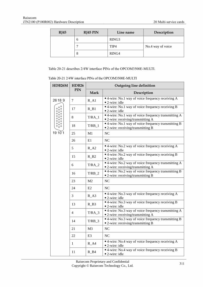
Raisecom
iTN2100 (P100R002) Hardware Description 20 Multi-service cards
Raisecom Proprietary and Confidential
Copyright © Raisecom Technology Co., Ltd. 311
RJ45 RJ45 PIN Line name Description
6 RING3
7 TIP4 No.4 way of voice
8 RING4
Table 20-21 describes 2/4W interface PINs of the OPCOM3500E-MULTI.
Table 20-21 2/4W interface PINs of the OPCOM3500E-MULTI
HDB26M HDB26 PIN
Outgoing line definition
Mark Description
7 R_A1 4-wire: No.1 way of voice frequency receiving A 2-wire: idle
17 R_B1 4-wire: No.1 way of voice frequency receiving B 2-wire: idle
8 T/RA_1 4-wire: No.1 way of voice frequency transmitting A 2-wire: receiving/transmitting A
18 T/RB_1 4-wire: No.1 way of voice frequency transmitting B 2-wire: receiving/transmitting B
25 M1 NC
26 E1 NC
5 R_A2 4-wire: No.2 way of voice frequency receiving A 2-wire: idle
15 R_B2 4-wire: No.2 way of voice frequency receiving B 2-wire: idle
6 T/RA_2 4-wire: No.2 way of voice frequency transmitting A 2-wire: receiving/transmitting A
16 T/RB_2 4-wire: No.2 way of voice frequency transmitting B 2-wire: receiving/transmitting B
23 M2 NC
24 E2 NC
3 R_A3 4-wire: No.3 way of voice frequency receiving A 2-wire: idle
13 R_B3 4-wire: No.3 way of voice frequency receiving B 2-wire: idle
4 T/RA_3 4-wire: No.3 way of voice frequency transmitting A 2-wire: receiving/transmitting A
14 T/RB_3 4-wire: No.3 way of voice frequency transmitting B 2-wire: receiving/transmitting B
21 M3 NC
22 E3 NC
1 R_A4 4-wire: No.4 way of voice frequency receiving A 2-wire: idle
11 R_B4 4-wire: No.4 way of voice frequency receiving B 2-wire: idle

Raisecom
iTN2100 (P100R002) Hardware Description 20 Multi-service cards
Raisecom Proprietary and Confidential
Copyright © Raisecom Technology Co., Ltd. 312
HDB26M HDB26 PIN
Outgoing line definition
Mark Description
2 T/RA_4 4-wire: No.4 way of voice frequency transmitting A 2-wire: receiving/transmitting A
12 T/RB_4 4-wire: No.4 way of voice frequency transmitting B 2-wire: receiving/transmitting B
19 M4 NC
20 E4 NC
9 NC Idle
10 NC Idle
Table 20-22 describes data interface PINs of the OPCOM3500E-MULTI.
Table 20-22 Data interface PINs of the OPCOM3500E-MULTI
PIN
RS232 PIN V.24 PIN RS422 PIN RS485 PIN
Mark Description Mark Description Mark Description Mark Description
1 TXD_
4 No.4 way of
data
TX_4 No.4 way of
data
TX_4
+ No.4 way of
transmitting
T/RX_
4+ No.4 way of
transmitting
and receiving 2 – TC_4 TX_4- T/RX_
4-
19 GND4 No.4 way of
grounding
GND
4
No.4 way of
grounding GND Grounding GND Grounding
11 RXD_4 Idle
RX_4 No.4 way of
clock
RX_4+ No.4 way of
receiving
– Idle
12 – RC_4 RX_4- –
20 GND Grounding GND
4
No.4 way of
grounding GND Grounding GND Grounding
3 TXD_
3 No.3 way of
data
TX_3 No.3 way of
data
TX_3
+ No.3 way of
transmitting
T/RX_
3+ No.3 way of
transmitting and receiving 4 – TC_3 TX_3-
T/RX_
3-
21 GND3 No.3 way of
grounding
GND
3
No.3 way of
grounding GND Grounding GND Grounding
13 RXD_
3 Idle RX_3 No.3 way of
clock
RX_3
+ No.3 way of
receiving
– Idle
14 – RC_3 RX_3- –
22 GND Grounding GND
3
No.3 way of
grounding GND Grounding GND Grounding

Raisecom
iTN2100 (P100R002) Hardware Description 20 Multi-service cards
Raisecom Proprietary and Confidential
Copyright © Raisecom Technology Co., Ltd. 313
PIN
RS232 PIN V.24 PIN RS422 PIN RS485 PIN
Mark Description Mark Description Mark Description Mark Description
5 TXD_
2 No.2 way of
data
TX_2 No.2 way of
data
TX_2
+ No.2 way of
transmitting
T/RX_
2+ No.2 way of
transmitting and receiving 6 – TC_2 TX_2-
T/RX_
2-
23 GND2 No.2 way of
grounding
GND
2
No.2 way of
grounding GND Grounding GND Grounding
15 RXD_
2 Idle RX_2 No.2 way of
clock
RX_2
+ No.2 way of
receiving
– Idle
16 – RC_2 RX_2- –
24 GND Grounding GND
2
No.2 way of
grounding GND Grounding GND Grounding
7 TXD_
1 No.1 way of
data
TX_1 No.1 way of
data
TX_1
+ No.1 way of
transmitting
T/RX_
1+ No.1 way of
transmitting and receiving 8 – TC_1 TX_1-
T/RX_
1-
25 GND1 No.1 way of
grounding
GND
1
No.1 way of
grounding GND Grounding GND Grounding
17 RXD_
1 Idle RX_1 No.1 way of
clock
RX_1
+ No.1 way of
receiving
– Idle
18 – RC_1 RX_1- –
26 GND Grounding GND
1
No.1 way of
grounding GND Grounding GND Grounding
9 – Idle – Idle – Idle – Idle
10 – Idle – Idle – Idle – Idle
20.3.4 LEDs
There are 18 LEDs on the OPCOM3500E-MULTI panel, as listed in Table 20-23.
Table 20-23 LEDs on the OPCOM3500E-MULTI panel
LED Status Description
PWR Green Power supply LED
Green: the power supply is normal. Off: the power supply is abnormal.

Raisecom
iTN2100 (P100R002) Hardware Description 20 Multi-service cards
Raisecom Proprietary and Confidential
Copyright © Raisecom Technology Co., Ltd. 314
LED Status Description
SYS Green System status LED
Green: the system is down or fails. Off: the CPU is working improperly. Blinking green: the system is working properly.
FXS FXO
V24 RS485
Green If the 4 LEDs are in green, it indicates that the MULTI-
FXS, MULTI-FXO, MULTI-V24, and MULTI-RS485
are inserted into the iTN2100.
IN-USE 1–8 Green Indicate the usage status of the voice channel. The LED
is lighten up for local off-hook (outputting signaling),
local ringing (inputting signaling), and conversation. It indicates that the voice channel is being used.
IN-USE13–16 Green Indicate the usage status of the data channel. The LED is
in blinking green when the data is being received or sent.
The blinking frequency is related to the data frequency.
20.3.5 DIP switches
Table 20-24 lists the DIP switch on the OPCOM3500E-MULTI. After the DIP switch is
configured by the software, default configurations of the DIP switch are invalid.
Table 20-24 DIP switch on the OPCOM3500E-MULTI
Service BIT of SW1
Description
Function ON OFF (default)
Voice interface
configuration 1
Configure polarity
inversion of FXS interfaces.
Note that polarity inversion
configured through
software is invalid. Supported Unsupported
2/4W interface
configuration
2 Configure 2/4W interface
modes. 2-wire mode 4-wire mode
3–5
Configure the default gain
value (providing 4 commonly-used values).
Gain value
configuration (A-D/D-A) SW1.3 SW1.4 SW1.5
0/0 OFF OFF OFF
0/-3.5 OFF OFF ON
+14/+4 OFF ON OFF
+16/+7 OFF ON ON
Data interface
configuration 6
Configure V.24 interface
modes. Synchronous (V.24)
Asynchronous
(RS232)

Raisecom
iTN2100 (P100R002) Hardware Description 20 Multi-service cards
Raisecom Proprietary and Confidential
Copyright © Raisecom Technology Co., Ltd. 315
Service BIT of SW1
Description
Function ON OFF (default)
7 Configure the duplex mode
of the RS485 interface. Full duplex (RS422)
Half-duplex
(RS485)
8 Configure the bandwidth. 64 kbit/s 128 kbit/s
20.3.6 Specifications
Table 20-25 lists specifications of the OPCOM3500E-MULTI.
Table 20-25 Specifications of the OPCOM3500E-MULTI
Parameter Value
Dimensions 25 mm (Width) × 232 mm (Depth) × 240 mm (Height)
Weight 0.5 kg
Maximum power
consumption
18 W
20.3.7 Cables
Table 20-26 lists cables available for the OPCOM3500E-MULTI.
Table 20-26 Cables available for the OPCOM3500E-MULTI
Recommended cable Description
CBL-MUL-HDB26M/NC HDB26 male connector-to-NC multi-function cable
CBL-MUL-HDB26M(40)/NC (Angled) HDB26 male connector-to-NC multi-function
cable
For details about the used cable color patterns, see section 24.14 MUL-HDB26 cable.
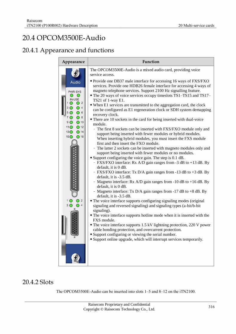
Raisecom
iTN2100 (P100R002) Hardware Description 20 Multi-service cards
Raisecom Proprietary and Confidential
Copyright © Raisecom Technology Co., Ltd. 316
20.4 OPCOM3500E-Audio
20.4.1 Appearance and functions
Appearance Function
The OPCOM3500E-Audio is a mixed audio card, providing voice
service access.
Provide one DB37 male interface for accessing 16 ways of FXS/FXO
services. Provide one HDB26 female interface for accessing 4 ways of
magneto telephone services. Support 2100 Hz signalling feature. The 20 ways of voice services occupy timeslots TS1–TS15 and TS17–
TS21 of 1-way E1. When E1 services are transmitted to the aggregation card, the clock
can be configured as E1 regeneration clock or SDH system demapping
recovery clock. There are 10 sockets in the card for being inserted with dual-voice
module. – The first 8 sockets can be inserted with FXS/FXO module only and
support being inserted with fewer modules or hybrid modules.
When inserting hybrid modules, you must insert the FXS module
first and then insert the FXO module. – The latter 2 sockets can be inserted with magneto modules only and
support being inserted with fewer modules or no modules. Support configuring the voice gain. The step is 0.1 dB.
– FXS/FXO interface: Rx A/D gain ranges from -3 dB to +13 dB. By
default, it is 0 dB. – FXS/FXO interface: Tx D/A gain ranges from -13 dB to +3 dB. By
default, it is -3.5 dB. – Magneto interface: Rx A/D gain ranges from -10 dB to +16 dB. By
default, it is 0 dB. – Magneto interface: Tx D/A gain ranges from -17 dB to +8 dB. By
default, it is -3.5 dB. The voice interface supports configuring signaling modes (original
signaling and reversed signaling) and signaling types (a-bit/b-bit
signaling). The voice interface supports hotline mode when it is inserted with the
FXS module. The voice interface supports 1.5 kV lightning protection, 220 V power
cable bonding protection, and overcurrent protection. Support configuring or viewing the serial number. Support online upgrade, which will interrupt services temporarily.
20.4.2 Slots
The OPCOM3500E-Audio can be inserted into slots 1–5 and 8–12 on the iTN2100.
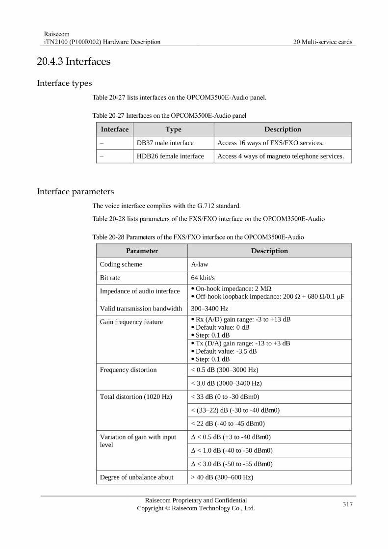
Raisecom
iTN2100 (P100R002) Hardware Description 20 Multi-service cards
Raisecom Proprietary and Confidential
Copyright © Raisecom Technology Co., Ltd. 317
20.4.3 Interfaces
Interface types
Table 20-27 lists interfaces on the OPCOM3500E-Audio panel.
Table 20-27 Interfaces on the OPCOM3500E-Audio panel
Interface Type Description
– DB37 male interface Access 16 ways of FXS/FXO services.
– HDB26 female interface Access 4 ways of magneto telephone services.
Interface parameters
The voice interface complies with the G.712 standard.
Table 20-28 lists parameters of the FXS/FXO interface on the OPCOM3500E-Audio
Table 20-28 Parameters of the FXS/FXO interface on the OPCOM3500E-Audio
Parameter Description
Coding scheme A-law
Bit rate 64 kbit/s
Impedance of audio interface On-hook impedance: 2 MΩ Off-hook loopback impedance: 200 Ω + 680 Ω/0.1 μF
Valid transmission bandwidth 300–3400 Hz
Gain frequency feature Rx (A/D) gain range: -3 to +13 dB Default value: 0 dB Step: 0.1 dB Tx (D/A) gain range: -13 to +3 dB Default value: -3.5 dB Step: 0.1 dB
Frequency distortion < 0.5 dB (300–3000 Hz)
< 3.0 dB (3000–3400 Hz)
Total distortion (1020 Hz) < 33 dB (0 to -30 dBm0)
< (33–22) dB (-30 to -40 dBm0)
< 22 dB (-40 to -45 dBm0)
Variation of gain with input
level
Δ < 0.5 dB (+3 to -40 dBm0)
Δ < 1.0 dB (-40 to -50 dBm0)
Δ < 3.0 dB (-50 to -55 dBm0)
Degree of unbalance about > 40 dB (300–600 Hz)
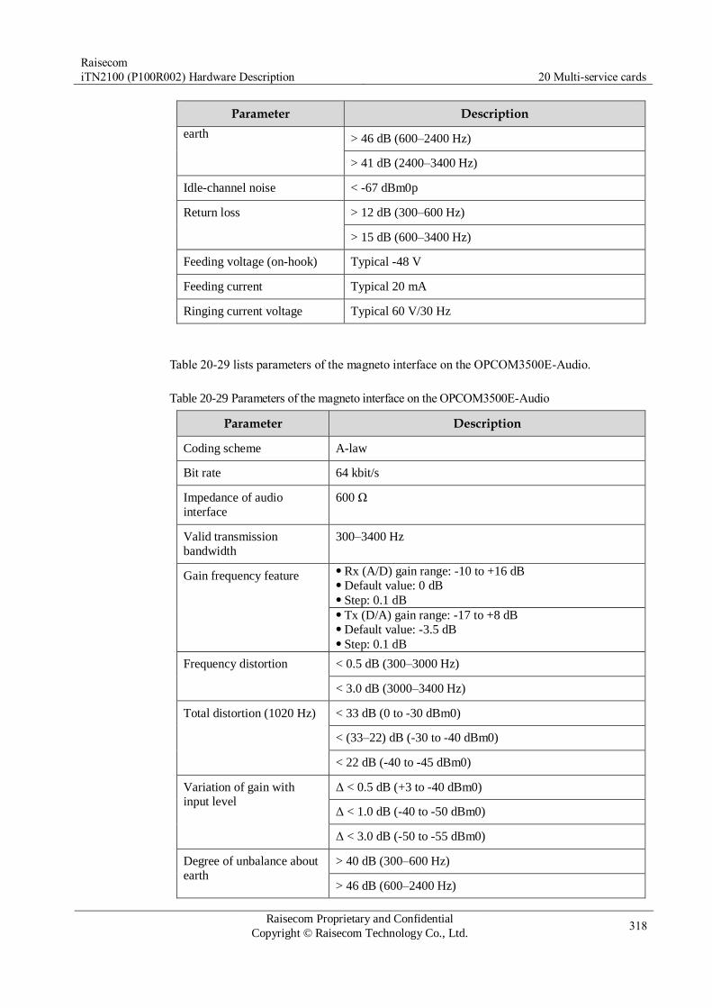
Raisecom
iTN2100 (P100R002) Hardware Description 20 Multi-service cards
Raisecom Proprietary and Confidential
Copyright © Raisecom Technology Co., Ltd. 318
Parameter Description
earth > 46 dB (600–2400 Hz)
> 41 dB (2400–3400 Hz)
Idle-channel noise < -67 dBm0p
Return loss > 12 dB (300–600 Hz)
> 15 dB (600–3400 Hz)
Feeding voltage (on-hook) Typical -48 V
Feeding current Typical 20 mA
Ringing current voltage Typical 60 V/30 Hz
Table 20-29 lists parameters of the magneto interface on the OPCOM3500E-Audio.
Table 20-29 Parameters of the magneto interface on the OPCOM3500E-Audio
Parameter Description
Coding scheme A-law
Bit rate 64 kbit/s
Impedance of audio
interface
600 Ω
Valid transmission
bandwidth
300–3400 Hz
Gain frequency feature Rx (A/D) gain range: -10 to +16 dB Default value: 0 dB Step: 0.1 dB Tx (D/A) gain range: -17 to +8 dB Default value: -3.5 dB Step: 0.1 dB
Frequency distortion < 0.5 dB (300–3000 Hz)
< 3.0 dB (3000–3400 Hz)
Total distortion (1020 Hz) < 33 dB (0 to -30 dBm0)
< (33–22) dB (-30 to -40 dBm0)
< 22 dB (-40 to -45 dBm0)
Variation of gain with
input level
Δ < 0.5 dB (+3 to -40 dBm0)
Δ < 1.0 dB (-40 to -50 dBm0)
Δ < 3.0 dB (-50 to -55 dBm0)
Degree of unbalance about
earth
> 40 dB (300–600 Hz)
> 46 dB (600–2400 Hz)
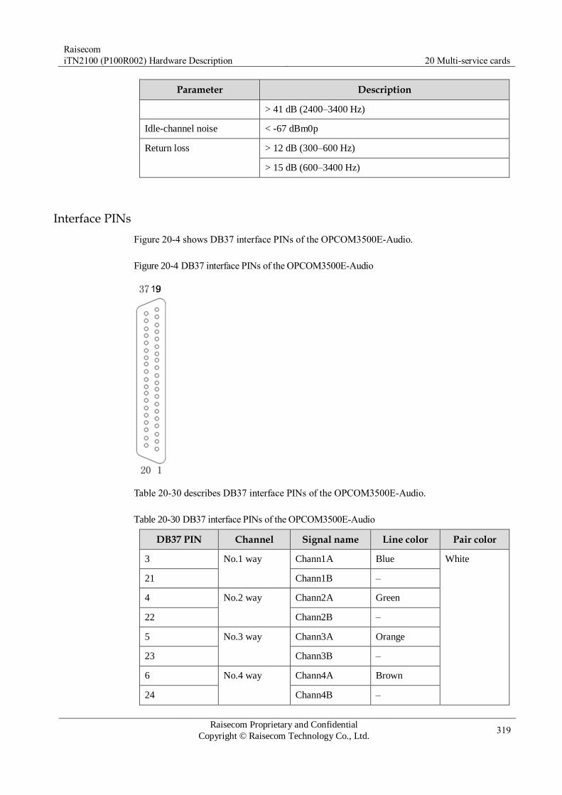
Raisecom
iTN2100 (P100R002) Hardware Description 20 Multi-service cards
Raisecom Proprietary and Confidential
Copyright © Raisecom Technology Co., Ltd. 319
Parameter Description
> 41 dB (2400–3400 Hz)
Idle-channel noise < -67 dBm0p
Return loss > 12 dB (300–600 Hz)
> 15 dB (600–3400 Hz)
Interface PINs
Figure 20-4 shows DB37 interface PINs of the OPCOM3500E-Audio.
Figure 20-4 DB37 interface PINs of the OPCOM3500E-Audio
Table 20-30 describes DB37 interface PINs of the OPCOM3500E-Audio.
Table 20-30 DB37 interface PINs of the OPCOM3500E-Audio
DB37 PIN Channel Signal name Line color Pair color
3 No.1 way Chann1A Blue White
21 Chann1B –
4 No.2 way Chann2A Green
22 Chann2B –
5 No.3 way Chann3A Orange
23 Chann3B –
6 No.4 way Chann4A Brown
24 Chann4B –

Raisecom
iTN2100 (P100R002) Hardware Description 20 Multi-service cards
Raisecom Proprietary and Confidential
Copyright © Raisecom Technology Co., Ltd. 320
DB37 PIN Channel Signal name Line color Pair color
7 No.5 way Chann5A Grey
25 Chann5B –
8 No.6 way Chann6A Blue Red
26 Chann6B –
9 No.7 way Chann7A Green
27 Chann7B –
10 No.8 way Chann8A Orange
28 Chann8B –
11 No.9 way Chann9A Brown
29 Chann9B –
12 No.10 way Chann10A Grey
30 Chann10B –
13 No.11 way Chann11A Blue Black
31 Chann11B –
14 No.12 way Chann12A Green
32 Chann12B –
15 No.13 way Chann13A Orange
33 Chann13B –
16 No.14 way Chann14A Brown
34 Chann14B –
17 No.15 way Chann15A Grey
35 Chann15B –
18 No.16 way Chann16A Blue Yellow
36 Chann16B –
Figure 20-5 shows HDB26 interface PINs of the OPCOM3500E-Audio.

Raisecom
iTN2100 (P100R002) Hardware Description 20 Multi-service cards
Raisecom Proprietary and Confidential
Copyright © Raisecom Technology Co., Ltd. 321
Figure 20-5 HDB26 interface PINs of the OPCOM3500E-Audio
Table 20-31 describes HDB26 interface PINs of the OPCOM3500E-Audio.
Table 20-31 HDB26 interface PINs of the OPCOM3500E-Audio
HDB26M PIN Mark Description Line color
7 R_A1 No. 1 way of voice White background and blue ring
17 R_B1 Blue background and white ring
8 T/RA_1 No. 2 way of voice White background and orange ring
18 T/RB_1 Orange background and white ring
25 M1 No. 3 way of voice White background and green ring
26 E1 Green background and white ring
5 R_A2 No. 4 way of voice White background and brown ring
15 R_B2 Brown background and white ring
6 T/RA_2 – White background and grey ring
16 T/RB_2 – Grey background and white ring
23 M2 – Red background and blue ring
24 E2 – Blue background and red ring
3 R_A3 – Red background and orange ring
13 R_B3 – Orange background and red ring
4 T/RA_3 – Red background and green ring
14 T/RB_3 – Green background and red ring
21 M3 – Red background and brown ring
22 E3 – Brown background and red ring
1 R_A4 – Red background and grey ring
11 R_B4 – Grey background and red ring
2 T/RA_4 – Black background and blue ring
12 T/RB_4 – Blue background and black ring

Raisecom
iTN2100 (P100R002) Hardware Description 20 Multi-service cards
Raisecom Proprietary and Confidential
Copyright © Raisecom Technology Co., Ltd. 322
HDB26M PIN Mark Description Line color
19 M4 – Black background and orange ring
20 E4 – Orange background and black ring
9 NC – Black background and green ring
10 NC – Green background and black ring
20.4.4 LEDs
Table 20-32 lists LEDS on the OPCOM3500E-Audio.
Table 20-32 LEDs on the OPCOM3500E-Audio
LED Status Description
PWR Green Power supply LED
Green: the power supply is normal. Off: the power supply is abnormal.
SYS Green System status LED
Green: the system is working improperly. Off: the system is working improperly. Blinking green: the system is working properly.
IN-USE (1–16
and 1–4)
Green Voice channel occupation LED
Green: the voice channel is in use (calling in or calling out). Off: the voice channel is not used.
20.4.5 DIP switches
There are no DIP switches available for users on the OPCOM3500E-Audio.
20.4.6 Specifications
Table 20-33 lists specifications of the OPCOM3500E-Audio.
Table 20-33 Specifications of the OPCOM3500E-Audio
Parameter Value
Dimensions 25 mm (Width) × 232 mm (Depth) × 240 mm (Height)
Weight 0.5 kg
Maximum power
consumption
24 W

Raisecom
iTN2100 (P100R002) Hardware Description 20 Multi-service cards
Raisecom Proprietary and Confidential
Copyright © Raisecom Technology Co., Ltd. 323
20.4.7 Cables
Table 20-34 lists cables available for the OPCOM3500E-Audio.
Table 20-34 Cables available for the OPCOM3500E-Audio
Recommended cable Description
CBL-VOICE-DB37F/NC-D M37 female connector-to-NC audio cable, the length of
which can be customized
CBL-MUL-HDB26M(40)/NC (Angled) HDB26 male connector-to-NC multi-function
cable
For details about the used cable color patterns, see section 24.14 MUL-HDB26 cable and section 24.15 Audio cable.
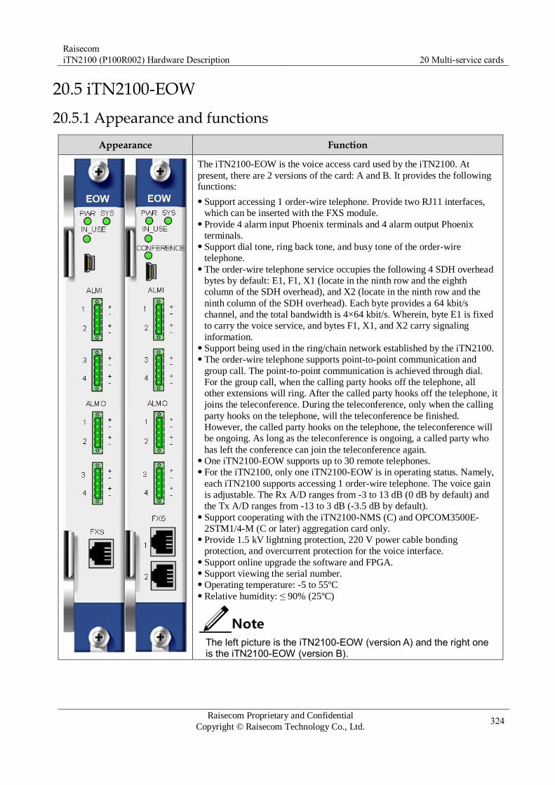
Raisecom
iTN2100 (P100R002) Hardware Description 20 Multi-service cards
Raisecom Proprietary and Confidential
Copyright © Raisecom Technology Co., Ltd. 324
20.5 iTN2100-EOW
20.5.1 Appearance and functions
Appearance Function
The iTN2100-EOW is the voice access card used by the iTN2100. At
present, there are 2 versions of the card: A and B. It provides the following functions:
Support accessing 1 order-wire telephone. Provide two RJ11 interfaces,
which can be inserted with the FXS module. Provide 4 alarm input Phoenix terminals and 4 alarm output Phoenix
terminals. Support dial tone, ring back tone, and busy tone of the order-wire
telephone. The order-wire telephone service occupies the following 4 SDH overhead
bytes by default: E1, F1, X1 (locate in the ninth row and the eighth
column of the SDH overhead), and X2 (locate in the ninth row and the
ninth column of the SDH overhead). Each byte provides a 64 kbit/s
channel, and the total bandwidth is 4×64 kbit/s. Wherein, byte E1 is fixed
to carry the voice service, and bytes F1, X1, and X2 carry signaling
information. Support being used in the ring/chain network established by the iTN2100. The order-wire telephone supports point-to-point communication and
group call. The point-to-point communication is achieved through dial.
For the group call, when the calling party hooks off the telephone, all
other extensions will ring. After the called party hooks off the telephone, it
joins the teleconference. During the teleconference, only when the calling
party hooks on the telephone, will the teleconference be finished.
However, the called party hooks on the telephone, the teleconference will
be ongoing. As long as the teleconference is ongoing, a called party who
has left the conference can join the teleconference again. One iTN2100-EOW supports up to 30 remote telephones. For the iTN2100, only one iTN2100-EOW is in operating status. Namely,
each iTN2100 supports accessing 1 order-wire telephone. The voice gain
is adjustable. The Rx A/D ranges from -3 to 13 dB (0 dB by default) and
the Tx A/D ranges from -13 to 3 dB (-3.5 dB by default). Support cooperating with the iTN2100-NMS (C) and OPCOM3500E-
2STM1/4-M (C or later) aggregation card only. Provide 1.5 kV lightning protection, 220 V power cable bonding
protection, and overcurrent protection for the voice interface. Support online upgrade the software and FPGA. Support viewing the serial number. Operating temperature: -5 to 55ºC Relative humidity: ≤ 90% (25ºC)
The left picture is the iTN2100-EOW (version A) and the right one is the iTN2100-EOW (version B).
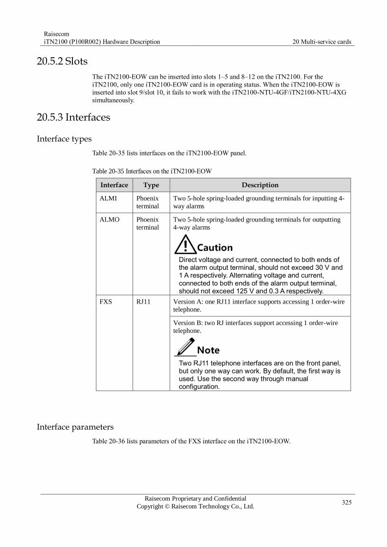
Raisecom
iTN2100 (P100R002) Hardware Description 20 Multi-service cards
Raisecom Proprietary and Confidential
Copyright © Raisecom Technology Co., Ltd. 325
20.5.2 Slots
The iTN2100-EOW can be inserted into slots 1–5 and 8–12 on the iTN2100. For the
iTN2100, only one iTN2100-EOW card is in operating status. When the iTN2100-EOW is
inserted into slot 9/slot 10, it fails to work with the iTN2100-NTU-4GF/iTN2100-NTU-4XG
simultaneously.
20.5.3 Interfaces
Interface types
Table 20-35 lists interfaces on the iTN2100-EOW panel.
Table 20-35 Interfaces on the iTN2100-EOW
Interface parameters
Table 20-36 lists parameters of the FXS interface on the iTN2100-EOW.
Interface Type Description
ALMI Phoenix
terminal
Two 5-hole spring-loaded grounding terminals for inputting 4-
way alarms
ALMO Phoenix
terminal
Two 5-hole spring-loaded grounding terminals for outputting
4-way alarms
Direct voltage and current, connected to both ends of the alarm output terminal, should not exceed 30 V and 1 A respectively. Alternating voltage and current, connected to both ends of the alarm output terminal, should not exceed 125 V and 0.3 A respectively.
FXS RJ11 Version A: one RJ11 interface supports accessing 1 order-wire
telephone.
Version B: two RJ interfaces support accessing 1 order-wire
telephone.
Two RJ11 telephone interfaces are on the front panel, but only one way can work. By default, the first way is used. Use the second way through manual configuration.

Raisecom
iTN2100 (P100R002) Hardware Description 20 Multi-service cards
Raisecom Proprietary and Confidential
Copyright © Raisecom Technology Co., Ltd. 326
Table 20-36 Parameters of the FXS interface on the iTN2100-EOW
Parameter Description
Coding scheme A-law
Bit rate 64 kbit/s
Impedance of audio interface On-hook impedance: 2 MΩ
Off-hook loopback impedance: 200+600 Ω/0.1 μF
Valid transmission bandwidth 300–3400 Hz (600 Ω)
Gain frequency feature RX (A/D) gain range: -3 to +13 dB Default value: 0 dB Step: 0.1 dB TX (D/A) gain range: -13 to +3 dB Default value: -3.5 dB Step: 0.1 dB
Frequency distortion < 0.5 dB (300–3000 Hz)
< 3.0 dB (3000–3400 Hz)
Total distortion (1020 Hz) < 33 dB (0 to -30dBm0)
< 33–22 dB (-30 to -40dBm0)
< 22 dB (-40 to -45dBm0)
Variation of gain with input
level
Δ< 0.5 dB (+3 to -40 dBm0)
Δ< 1.0 dB (-40 to -50 dBm0)
Δ< 3.0 dB (-50 to -55 dBm0)
Degree of unbalance about earth > 40 dB (300–600 Hz)
> 46 dB (600–2400 Hz)
> 41 dB (2400–3400 Hz)
Idle-channel noise > -67 dBm0
Feeding voltage (on-hook) Typical -48 V
Feeding current Typical 20 mA
Ringing current voltage Typical 60 V/30 Hz
Return loss > 12 dB (300–600 Hz)
> 15 dB (600–3400 Hz)
Interface PINs Figure 1-1 and Table 20-37 describe ALM interface PINs of the iTN2100-EOW.

Raisecom
iTN2100 (P100R002) Hardware Description 20 Multi-service cards
Raisecom Proprietary and Confidential
Copyright © Raisecom Technology Co., Ltd. 327
Figure 1-1 ALM interface PINs of the iTN2100-EOW
Table 20-37 ALM interface PINs of the iTN2100-EOW
Interface PIN I/O Definition
ALMI 1 IN Alarm input 1+
2 IN Alarm input 1-
3 GND Undefined
4 IN Alarm input 2+
5 IN Alarm input 2-
ALMO 1 OUT Alarm output 1+
2 OUT Alarm output 1-
3 GND Undefined
4 OUT Alarm output 2+
5 OUT Alarm output 2-
Table 20-38 describes FXS interface PINs of the iTN2100-EOW. Each RJ11 interface outputs 4-way voice services.
Table 20-38 FXS interface PINs of the iTN2100-EOW
RJ11 interface RJ11 PIN Line name Description
1 – Undefined
2 Tip Voice access
3 Ring
4 – Undefined
20.5.4 LEDs
Table 20-39 lists LEDs on the iTN2100-EOW panel.

Raisecom
iTN2100 (P100R002) Hardware Description 20 Multi-service cards
Raisecom Proprietary and Confidential
Copyright © Raisecom Technology Co., Ltd. 328
Table 20-39 LEDs on the iTN2100-EOW panel
LED Status Description
PWR Green Power LED
Green: the power supply is normal. Off: the power supply is abnormal.
SYS Green Working LED
Green: the card crashes, is configured improperly, or
fails. Off: the MCU is working improperly. Blinking green: the card is working properly.
IN_USE Green
Voice channel usage status LED
Green: the voice channel is being used or occupied, such
as in off-hook (outputting signaling), ringing (inputting
signaling), and talking modes. Off: the voice channel is idle. Blinking green: the card is being discovered in topology
or being updated.
CONFERENCE Green
Conference mode LED
Green: the card is in conference mode. Off: the conference mode is idle.
1.1.2 DIP switch
N/A
1.1.3 Specifications
Table 20-40 lists specifications of the iTN2100-EOW.
Table 20-40 Specifications of the iTN2100-EOW
Parameter Value
Dimensions 25 mm (width) × 232 mm (depth) × 240 mm (height)
Weight 0.35 kg
Maximum power
consumption
3 W

Raisecom
iTN2100 (P100R002) Hardware Description 20 Multi-service cards
Raisecom Proprietary and Confidential
Copyright © Raisecom Technology Co., Ltd. 329
20.6 OPCOM3500E-10E&M
20.6.1 Functions and appearance
Panel Function
The OPCOM3500E-10E&M is a 10-way audio access card. It provides the following
functions:
Provide 10 RJ45 E&M interfaces. Each interface supports 1 way of 64 kbit/s E&M
services. Support configuring the signaling type to I, II, III, IV, V, or POS through the jumper. By
default, it is V. Support 4working modes: normal mode, unidirectional broadcast mode, bidirectional
broadcast mode, and conference mode. By default, it works in normal mode. – Normal mode: point-to-point communication – Unidirectional mode: in this mode, all remote devices can receive information
broadcasted by the CO device but cannot communicate with each other. You can
configure up to 10 interfaces on this card as the broadcast interface. Each interface
supports up to 30 ways of broadcast. A member cannot attend multiple broadcast groups. – Bidirectional mode: in this mode, all remote devices can receive information broadcasted
by the CO device but cannot communicate with each other; only one remote device can
be specified to communicate with the CO device. You can configure up to 10 interfaces
on this card as the bidirectional broadcast interface. Each interface supports up to 30
ways of broadcast. A member cannot attend multiple broadcast groups. – Conference mode: in this mode, any device in a conference group can communicate with
other members. You can configure up to 8 independent teleconferences on this card.
Each teleconference supports up to 20 members. A member cannot attend join multiple
teleconferences. Occupy 2 E1 timeslots on the backplane. When it works in normal mode, E&M interfaces
1–10 correspond to TS1–TS10 of No. 1 E1 on the backplane. In broadcast mode or
conference mode, the default point-to-point cross connection is deleted, and the member in
the broadcast group or conference group can be mapped to 45 timeslots of 2 E1s on the
backplane for transmission of voice services. Support configuring the wiring mode to 2-wire or 4-wire. By default, it is 4-wire. Support configuring the signaling mode through software:
– Support original signaling and reverse signaling. By default, it is original signaling. – Support signaling occupation a-bit and b-bit. By default, it is a-bit.
Support configurable gain: – Rx D/A gain ranges from -3 to +27 dB. – Tx D/A gain ranges from -13 to +7 dB. – By default, the gain is 0 dB. – The step is 0.1 dB.
Support configuring analog audio to conduct internal loopback and external loopback
(supported in 4-wire mode only); support E&M signaling to conduct internal loopback. Support viewing signaling status.
20.6.2 Slots
The OPCOM3500E-10E&M can be inserted into slots 1–5 and 8–12 on the iTN2100.

Raisecom
iTN2100 (P100R002) Hardware Description 20 Multi-service cards
Raisecom Proprietary and Confidential
Copyright © Raisecom Technology Co., Ltd. 330
20.6.3 Interfaces
Interface type
Table 20-41 lists interfaces on the 10E&M card.
Table 20-41 Interfaces on the 10E&M card
Name Type Description
1–10 RJ45 Each interface accesses 1 way of E&M voice services.
Interface parameter
Table 20-42 lists parameters of the interface on the 10E&M card.
Table 20-42 Parameters of the interface on the 10E&M card
Parameter Description
Coding scheme A-law
Bit rate 64 kbit/s
Audio port impedance 2000 kΩ during on-hook
600+200//0.1 Ω during off-hook
Effective transmission
bandwidth
300–3400 Hz/600 Ω
Gain frequency features The Rx (A/D) gain ranges from -3 dB to 27 dB. The default
value is controlled by an internal jumper. Its step is 0.1 dB.
The Tx (D/A) gain ranges from -17 dB to 8 dB. The default
value is controlled by an internal jumper. Its step is 0.1 dB.
Frequency distortion 300–3000 Hz; < 0.5 dB
3000–3400 Hz; < 3.0 dB
Total distortion (1020
Hz)
0 to -30 dBm0; < 33 dB
-30 to -40 dBm0; < (33–22) dB
-40 to -45 dBm0; < 22 dB
Gain change according to
level
+3 to -40 dBm0; ∆ < 0.5 dB
-40 to -50 dBm0; ∆ < 1.0 dB
-50 to -55 dBm0; ∆ < 3.0 dB
Degree of unbalance
about earth
300–600 Hz: > 40 dB
600–2400 Hz: > 46 dB
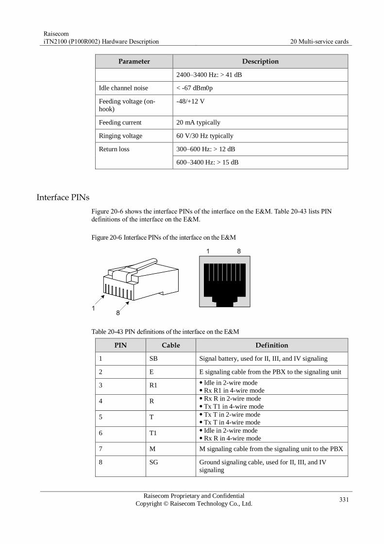
Raisecom
iTN2100 (P100R002) Hardware Description 20 Multi-service cards
Raisecom Proprietary and Confidential
Copyright © Raisecom Technology Co., Ltd. 331
Parameter Description
2400–3400 Hz: > 41 dB
Idle channel noise < -67 dBm0p
Feeding voltage (on-
hook)
-48/+12 V
Feeding current 20 mA typically
Ringing voltage 60 V/30 Hz typically
Return loss 300–600 Hz: > 12 dB
600–3400 Hz: > 15 dB
Interface PINs
Figure 20-6 shows the interface PINs of the interface on the E&M. Table 20-43 lists PIN
definitions of the interface on the E&M.
Figure 20-6 Interface PINs of the interface on the E&M
Table 20-43 PIN definitions of the interface on the E&M
PIN Cable Definition
1 SB Signal battery, used for II, III, and IV signaling
2 E E signaling cable from the PBX to the signaling unit
3 R1 Idle in 2-wire mode Rx R1 in 4-wire mode
4 R Rx R in 2-wire mode Tx T1 in 4-wire mode
5 T Tx T in 2-wire mode Tx T in 4-wire mode
6 T1 Idle in 2-wire mode Rx R in 4-wire mode
7 M M signaling cable from the signaling unit to the PBX
8 SG Ground signaling cable, used for II, III, and IV
signaling

Raisecom
iTN2100 (P100R002) Hardware Description 20 Multi-service cards
Raisecom Proprietary and Confidential
Copyright © Raisecom Technology Co., Ltd. 332
The E&M signaling is used to indicate the on-hook or off-hook status of the telephone. It
transmits the corresponding status through the wiring mode of the E wire and M wire. Table
20-44 lists types of E&M signaling.
The OPCOM3500E-10E&M supports configuring the type of E&M signaling of the voice interface through the jumper on the card.
Each voice interface can be configured to support I, II, III, IV, V, or POS signaling.
By default, the signaling type of the voice interface is V.
The signaling types of the PBX and E&M must be the same.
The POS signaling mode is a special positive signaling mode, with +12 V voltage. In this
mode, the OPCOM3500E-10E&M sends signaling to the PBX through grounding the SG PIN. PIN 2 (E) is reserved for grounding, so it cannot be used.
Table 20-44 Types of E&M signaling
Signaling type Description
I Usually used in North American areas
II Seldom used
III Usually used in the traditional telephone center
IV Seldom used
V Usually used in areas except North America
POS Usually used in air traffic control system and military items
Figure 20-7 shows the signaling type of the OPCOM3500E-10E&M.
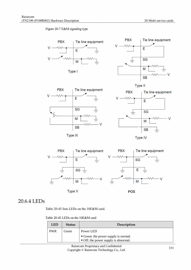
Raisecom
iTN2100 (P100R002) Hardware Description 20 Multi-service cards
Raisecom Proprietary and Confidential
Copyright © Raisecom Technology Co., Ltd. 333
Figure 20-7 E&M signaling type
20.6.4 LEDs
Table 20-45 lists LEDs on the 10E&M card.
Table 20-45 LEDs on the 10E&M card
LED Status Description
PWR Green Power LED
Green: the power supply is normal. Off: the power supply is abnormal.

Raisecom
iTN2100 (P100R002) Hardware Description 20 Multi-service cards
Raisecom Proprietary and Confidential
Copyright © Raisecom Technology Co., Ltd. 334
LED Status Description
SYS Green System status LED
Green: the system is working improperly. Off: the system is working improperly. Blinking green: the system is working properly.
1–10 Green
Yellow
E&M signaling status LED
Green: E signaling Yellow: M signaling On: the corresponding channel is receiving the E or M signaling. Off: the corresponding channel is idle.
20.6.5 Specifications
Table 20-46 lists specifications of the OPCOM3500E-10E&M.
Table 20-46 Specifications of the OPCOM3500E-10E&M
Parameter Description
Dimensions 25 mm (Width) × 225 mm (Depth) × 240 mm (Height)
Weight 0.45 kg
Power consumption < 5 W
20.6.6 Cables
The OPCOM3500E-10E&M uses the common twisted pair cable with the RJ45 connector,
which you need to make it by yourself. For PIN definitions of the interface, see Table 20-43.

Raisecom
iTN2100 (P100R002) Hardware Description 21 Service aggregation cards
Raisecom Proprietary and Confidential
Copyright © Raisecom Technology Co., Ltd. 335
21 Service aggregation cards
This chapter describes the service aggregation cards of the iTN2100, including the following
sections:
iTN2100-Gb
iTN2100-8SU-S
iTN2100-4SU-D

Raisecom
iTN2100 (P100R002) Hardware Description 21 Service aggregation cards
Raisecom Proprietary and Confidential
Copyright © Raisecom Technology Co., Ltd. 336
21.1 iTN2100-Gb
21.1.1 Appearance and functions
Appearance Function
The iTN2100-Gb can realize single-fiber bidirectional transmission of 4
ways of optical signals through wavelength conversion and multiplexing/ de-multiplexing.
Realize single-fiber bidirectional transparent transmission of 4 ways of
optical signals through the Coarse Wavelength Division Multiplexing
(CWDM) technology. Support point-to-point transmission, being used in a pair. Realize wavelength conversion and multiplexing/de-multiplexing of 4
ways of optical signals on a card. Provide the SFP interface at the client side, supporting SFP modules
with various transmission distances. Support hot swapping of SFP modules and DDM of SFP optical
modules. Realize Re-amplifying and Re-shaping (2R) on 10 Mbit/s–1.25 Gbit/s
optical signals and realize Re-amplifying, Re-shaping, and Re-timing
(3R) on optical signals with standard rate (1000BASE-X, 100BASE-
FX, STM-4, and STM-1) by the iTN2100-Gb (A). Realize Re-amplifying and Re-shaping (2R) on 10 Mbit/s–2.66 Gbit/s
optical signals and realize Re-amplifying, Re-shaping, and Re-timing
(3R) on optical signals with standard rate (1000BASE-X, 100BASE-
FX, STM-16, STM-4, and STM-1) by the iTN2100-Gb (B). Support ALS by line-side optical interfaces. Support failover, realizing failover from line side to client side and
from client side to client side (the peer device). Support hot swapping.
Except for card name printed on the panel, all models of the iTN2100-Gb (A) and the ones of the iTN2100-Gb (B) are identical. This guide takes the iTN2100-Gb-S for an example. Models of the iTN2100-Gb (A): iTN2100-Gb-S, iTN2100-Gb-S-
R, iTN2100-Gb-L, and iTN2100-Gb-L-R Models of the iTN2100-Gb (B): iTN2100-48-S and iTN2100-48-
S-R
21.1.2 Slots
The iTN2100-Gb can be inserted into slots 1–5 and 8–12 on the iTN2100.

Raisecom
iTN2100 (P100R002) Hardware Description 21 Service aggregation cards
Raisecom Proprietary and Confidential
Copyright © Raisecom Technology Co., Ltd. 337
21.1.3 Interfaces
Interface types
There are 5 interfaces on the iTN2100-Gb panel, as listed in Table 21-1.
Table 21-1 Interfaces on the iTN2100-Gb panel
Interface Type Description
CLIENT 1–4 SFP interface Client-side interface Connector type: LC/PC Available module: SFP optical module and SFP
electrical module Optical transmission media: single-mode fiber and
multi-mode fiber Electrical transmission media: Cat5 twisted-pair cable
LINE Flange Line-side interface (single fiber CWDM interface) Connector type: LC/PC Optical transmission media: single-mode fiber
No special requirements on fiber connection sequence. We recommend
connecting client-side fiber first and then connecting line-side fiber. The iTN2100-Gb optical interface is a LC/PC interface. It should be connected
by the fiber jumper of the LC/PC connector. For the iTN2100-Gb, we recommend using the 2R mode to provide service
quickly. You can configure the mode through the DIP switch on the card. By default, it is 2R mode.
For the iTN2100-Gb, the operating temperature should range from -15 to +45°C.
Interface metrics
We recommend using Raisecom SFP modules. SFP modules, which are not authenticated by Raisecom, may cause communication error or card faults.
Client-side interface metrics
Client-side interfaces support various SFP modules. Table 21-2 and Table 21-3 describe these
SFP modules.

Raisecom
iTN2100 (P100R002) Hardware Description 21 Service aggregation cards
Raisecom Proprietary and Confidential
Copyright © Raisecom Technology Co., Ltd. 338
Table 21-2 Client-side interface metrics (optical modules)
Series Model Central Tx wavelength
(nm)
Tx optical power (dBm)
Overload optical power (dBm)
Rx sensitivity
(dBm)
Transmission distance (Km)
USFP-Gb USFP-Gb/M-D-R 850 -9.5 to -
3
> 0 < -17 0.55
USFP-Gb/S1-D-R 1310 -10 to -
3
> -3 < -21 15
USFP-Gb/LH1-D-R 1310 -4 to 0 > -3 < -21 40
USFP-Gb/S2-D-R 1550 -3 to +2 > -3 < -21 60
USFP-Gb/ZX-D-R 1550 -2 to +3 > -3 < -22 80
USFP-Gb/S3-D-R 1550 -3 to +2 > -9 < -30 80
USFP-Gb/EX-D-R 1550 0 to +5 > -9 < -31 120
USFP-Gb/SS13-D-R 1310 -10 to -
3
> -3 < -21 15
USFP-Gb/SS15-D-R 1550 -10 to -
3
> -3 < -21 15
USFP-Gb/SS24-D-R 1490 -3 to +2 > -3 < -21 40
USFP-Gb/SS25-D-R 1550 -3 to +2 > -3 < -21 40
USFP-Gb/SS34-D-R 1490 -2 to +3 > -9 < -30 80
USFP-Gb/SS35-D-R 1550 -2 to +3 > -9 < -30 80
CSFP-Gb CSFP-Gb/S/xx-D-R
(xx = 47, 49, 51, 53,
55, 57, 59, 61)
1471, 1491,
1511, 1531,
1551, 1571,
1591, 1611
-2 to +3 > -3 < -22 40
CSFP-Gb/L/xx-D-R
(xx = 47, 49, 51, 53, 55, 57, 59, 61)
1471, 1491,
1511, 1531,
1551, 1571,
1591, 1611
-3 to +2 > -9 < -30 80
USFP-48 USFP-48/M-D-R 850 -9.5 to -
3
> 0 < -17 0.3
USFP-48/S1-D-R 1310 -5 to 0 > -3 < -18 15
USFP-48/S2-D-R 1550 -2 to +3 > -3 < -18 40
USFP-48/S3-D-R 1550 -2 to +3 > -9 < -28 80
USFP-48/SS13-D-R 1310 -5 to 0 > -3 < -18 15
USFP-48/SS15-D-R 1550 -5 to 0 > -3 < -18 15
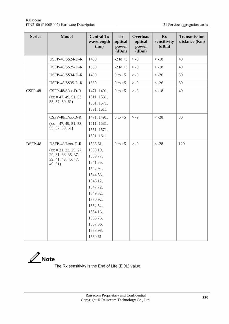
Raisecom
iTN2100 (P100R002) Hardware Description 21 Service aggregation cards
Raisecom Proprietary and Confidential
Copyright © Raisecom Technology Co., Ltd. 339
Series Model Central Tx wavelength
(nm)
Tx optical power (dBm)
Overload optical power (dBm)
Rx sensitivity
(dBm)
Transmission distance (Km)
USFP-48/SS24-D-R 1490 -2 to +3 > -3 < -18 40
USFP-48/SS25-D-R 1550 -2 to +3 > -3 < -18 40
USFP-48/SS34-D-R 1490 0 to +5 > -9 < -26 80
USFP-48/SS35-D-R 1550 0 to +5 > -9 < -26 80
CSFP-48 CSFP-48/S/xx-D-R
(xx = 47, 49, 51, 53,
55, 57, 59, 61)
1471, 1491,
1511, 1531,
1551, 1571,
1591, 1611
0 to +5 > -3 < -18 40
CSFP-48/L/xx-D-R
(xx = 47, 49, 51, 53, 55, 57, 59, 61)
1471, 1491,
1511, 1531,
1551, 1571,
1591, 1611
0 to +5 > -9 < -28 80
DSFP-48 DSFP-48/L/xx-D-R
(xx = 21, 23, 25, 27,
29, 31, 33, 35, 37,
39, 41, 43, 45, 47,
49, 51)
1536.61,
1538.19,
1539.77,
1541.35,
1542.94,
1544.53,
1546.12,
1547.72,
1549.32,
1550.92,
1552.52,
1554.13,
1555.75,
1557.36,
1558.98,
1560.61
0 to +5 > -9 < -28 120
The Rx sensitivity is the End of Life (EOL) value.

Raisecom
iTN2100 (P100R002) Hardware Description 21 Service aggregation cards
Raisecom Proprietary and Confidential
Copyright © Raisecom Technology Co., Ltd. 340
Table 21-3 Client-side interface metrics (electrical modules)
Model Rate Data interface Auto-negotiation
Transmission distance (m)
USFP-GE/AN-R 10, 100, or 1000 Mbit/s 1000Mbit/s SGMII Enabled 100
USFP-GE-R 1000 Mbit/s 1000Mbit/s Serdes Disabled 100
USFP-FE/AN-R 10 or 100 Mbit/s 100Mbit/s Serdes Enabled 100
Line-side interface metrics
Line-side interface metrics vary on the iTN2100 cards. Table 21-4 lists line-side interface
metrics.
Table 21-4 Line-side interface metrics
Version Model Tx wavelength
(nm)
Rx wavelength
(nm)
Single-wavelength Tx optical
power (dBm)
Single-wavelength Rx power
(dBm)
Transmission distance (Km)
A iTN2100-Gb-
S
1471, 1511,
1551, 1591
1491, 1531,
1571,1611
-4 to +2 -20 to -2 40
iTN2100-Gb-
S-R
1491, 1531,
1571,1611
1471, 1511,
1551, 1591
-4 to +2 -20 to -2 40
iTN2100-Gb-
L
1471, 1511,
1551, 1591
1491, 1531,
1571,1611
-4 to +2 -28 to -8 80
iTN2100-Gb-
L-R
1491, 1531,
1571,1611
1471, 1511,
1551, 1591
-4 to +2 -28 to -8 80
B iTN2100-48-
S
1471, 1511,
1551, 1591
1491, 1531,
1571,1611
-2 to +4 -16 to -2 40
iTN2100-48-
S-R
1491, 1531,
1571,1611
1471, 1511,
1551, 1591
-2 to +4 -16 to -2 40
The single-wavelength Rx power is the EOL value.
21.1.4 LEDs
There are 18 LEDs on the iTN2100-Gb panel, as listed in Table 21-5.
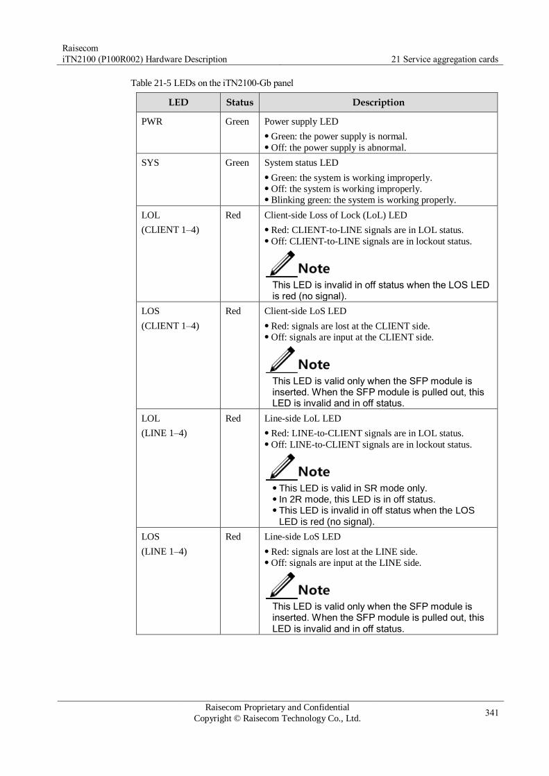
Raisecom
iTN2100 (P100R002) Hardware Description 21 Service aggregation cards
Raisecom Proprietary and Confidential
Copyright © Raisecom Technology Co., Ltd. 341
Table 21-5 LEDs on the iTN2100-Gb panel
LED Status Description
PWR Green Power supply LED
Green: the power supply is normal. Off: the power supply is abnormal.
SYS Green System status LED
Green: the system is working improperly. Off: the system is working improperly. Blinking green: the system is working properly.
LOL
(CLIENT 1–4)
Red Client-side Loss of Lock (LoL) LED
Red: CLIENT-to-LINE signals are in LOL status. Off: CLIENT-to-LINE signals are in lockout status.
This LED is invalid in off status when the LOS LED is red (no signal).
LOS
(CLIENT 1–4)
Red Client-side LoS LED
Red: signals are lost at the CLIENT side. Off: signals are input at the CLIENT side.
This LED is valid only when the SFP module is inserted. When the SFP module is pulled out, this LED is invalid and in off status.
LOL
(LINE 1–4)
Red Line-side LoL LED
Red: LINE-to-CLIENT signals are in LOL status. Off: LINE-to-CLIENT signals are in lockout status.
This LED is valid in SR mode only. In 2R mode, this LED is in off status. This LED is invalid in off status when the LOS
LED is red (no signal).
LOS
(LINE 1–4)
Red Line-side LoS LED
Red: signals are lost at the LINE side. Off: signals are input at the LINE side.
This LED is valid only when the SFP module is inserted. When the SFP module is pulled out, this LED is invalid and in off status.

Raisecom
iTN2100 (P100R002) Hardware Description 21 Service aggregation cards
Raisecom Proprietary and Confidential
Copyright © Raisecom Technology Co., Ltd. 342
21.1.5 DIP switches
Functions of DIP switches
Definition on the DIP switch of the iTN2100-Gb (A) and iTN2100-Gb (B) is identical. SW2,
SW3, SW4, and SW5 are used to configure client-side interfaces 1–4 respectively. Each DIP
switch has 8 BITs and related BITs have the identical functions. Table 21-6 lists BITs 1–8 of
the DIP switch.
Table 21-6 BITs 1–8 of the DIP switch
BIT Status Description Default value
1 ON Enable failover. OFF
OFF Disable failover.
2 ON Enable ALS. OFF
OFF Disable ALS.
3 Reserved OFF
4 ON Configure 2R mode and disable CDR. ON
OFF Configure 3R mode and enable CDR.
5 ON Configure the rate manually. OFF
OFF Configure rate auto-negotiation.
6–8 OFF/OFF/OFF Configure the rate to 1000 Mbit/s
Ethernet.
OFF/OFF/OFF
ON/OFF/OFF Configure the rate to 100 Mbit/s
Ethernet.
OFF/ON/OFF Configure the rate to STM-4.
OFF/ON/ON Configure the rate to STM-1.
Other status Reserved
By default, BITs 1–8 of SW2, SW3, SW4, and SW5 are both configured to OFF.
It means that failover and ALS are disabled and the card works in 2R mode (with CDR being disabled).
Configurations on DIP switches are valid when they are powered on. After configurations on DIP switches are changes, power them again to make new configurations valid.
When BIT 4 is configured to ON, BITs 5–8 are invalid. When BITs 4 and 5 are configured to OFF, BITs 6–8 are invalid. When BIT 4 is configured to OFF and BIT 5 is configured to ON, BITs 6–8 are
valid.

Raisecom
iTN2100 (P100R002) Hardware Description 21 Service aggregation cards
Raisecom Proprietary and Confidential
Copyright © Raisecom Technology Co., Ltd. 343
Before configuring DIP switching, you should confirm the attenuation value of the fiber, ensuring the Rx power of the line-side optical interfaces is in the specified range. For details, see Table 21-2 Client-side interface metrics (optical modules), Table 21-3 Client-side interface metrics (electrical modules), and Table 21-4 Line-side interface metrics.
Configurations on DIP switches
Table 21-7 describes configurations on DIP switches of the iTN2100-Gb (A).
Table 21-7 Configurations on client-side interfaces of the iTN2100-Gb (A)
Client-side signal
SFP module DIP switch
Configuration Recommended configuration
STM-4
Optical signals
USFP-Gb series SFP optical
modules
FFFNFFFF 2R mode –
FFFFNFNF 3R mode + manual +
STM-4
Recommended
Better jitter performance
STM-1
Optical signals
USFP-Gb series SFP optical
modules
FFFNFFFF 2R mode –
FFFFNFNN 3R mode + manual +
STM-1
Recommended
Better jitter performance
1000BASE-X
Optical signals
USFP-Gb series SFP optical
modules
FFFNFFFF 2R mode Recommended
FFFFNFFF 3R mode + manual +
1000BASE-X
Better jitter
performance
100BASE-X
Optical signals
USFP-Gb series SFP optical
modules
FFFNFFFF 2R mode Recommended
FFFFNNFF 3R mode + manual +
100BASE-X
Better jitter
performance
1000BASE-T
Electrical
signals
USFP-GE series SFP
electrical modules USFP-GE/AN series SFP
electrical modules
FFFNFFFF 2R mode Recommended
FFFFNFFF 3R mode + manual +
1000BASE-T
Better jitter
performance
100BASE-T
Electrical signals
USFP-GE/AN series SFP
electrical modules USFP-FE/AN series SFP
electrical modules
FFFNFFFF 2R mode Recommended
FFFFNNFF 3R mode + manual +
100BASE-T
Better jitter
performance
10BASE-T
Electrical signals
USFP-GE/AN series SFP
electrical modules USFP-FE/AN series SFP
electrical modules
FFFNFFFF 2R mode Recommended
Optical signals
with other rates
USFP-Gb series SFP optical
modules
FFFNFFFF 2R mode Recommended

Raisecom
iTN2100 (P100R002) Hardware Description 21 Service aggregation cards
Raisecom Proprietary and Confidential
Copyright © Raisecom Technology Co., Ltd. 344
In DIP switch column of Table 21-7, N refers to ON and F refers to OFF. Configurations through the NView NNM system have higher priorities then the
ones configured through DIP switches. When no configuration is performed through the NView NNM system, DIP switch configurations are valid. Otherwise, configurations through the NView NNM system take effect.
The iTN2100-Gb cards must be used in pair. In addition, configurations on related interfaces of the 2 card must be identical.
SFP electrical modules do not support failover and ALS. For better transmission performance, we recommend using the 2R mode.
Table 21-8 describes configurations on DIP switches of the iTN2100-Gb (B).
Table 21-8 Configurations on client-side interfaces of the iTN2100-Gb (B)
Client-side signal
SFP module DIP switch
Configuration Recommended configuration
STM-16
Optical signal
USFP-48 series SFP optical
modules
FFFNFFFF 2R mode –
FFFFNFFN 3R mode + manual +
STM-16
Recommended
Better jitter performance
STM-4
Optical signal
USFP-48 series SFP optical
modules USFP-Gb series SFP optical
modules
FFFNFFFF 2R mode –
FFFFNFNF 3R mode + manual +
STM-4
Recommended
Better jitter performance
STM-1
Optical signal
USFP-48 series SFP optical
modules USFP-Gb series SFP optical
modules
FFFNFFFF 2R mode –
FFFFNFNN 33R mode + manual +
STM-1
Recommended
Better jitter
performance
1000BASE-X
Optical signal
USFP-48 series SFP optical
modules USFP-Gb series SFP optical
modules
FFFNFFFF 2R mode Recommended
FFFFNFFF 3R mode + manual +
GE
Better jitter
performance
100BASE-X
Optical signal
USFP-48 series SFP optical
modules USFP-Gb series SFP optical
modules
FFFNFFFF 2R mode Recommended
FFFFNNFF 3R mode + manual +
FE
Better jitter
performance
1000BASE-T
Electrical signal
USFP-GE series SFP electrical
modules USFP-GE/AN series SFP
electrical modules
FFFNFFFF 2R mode Recommended
FFFFNFFF 3R mode + manual +
GE
Better jitter
performance
100BASE-T
Electrical signal
USFP-GE/AN series SFP
electrical modules
FFFNFFFF 2R mode Recommended
FFFFNFFF 3R mode + manual +
GE
Better jitter
performance
USFP-FE/AN series SFP FFFNFFFF 2R mode Recommended
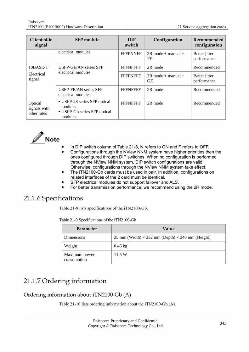
Raisecom
iTN2100 (P100R002) Hardware Description 21 Service aggregation cards
Raisecom Proprietary and Confidential
Copyright © Raisecom Technology Co., Ltd. 345
Client-side signal
SFP module DIP switch
Configuration Recommended configuration
electrical modules FFFFNNFF 3R mode + manual +
FE
Better jitter
performance
10BASE-T
Electrical signal
USFP-GE/AN series SFP
electrical modules
FFFNFFFF 2R mode Recommended
FFFFNFFF 3R mode + manual +
GE
Better jitter
performance
USFP-FE/AN series SFP
electrical modules
FFFNFFFF 2R mode Recommended
Optical
signals with other rates
USFP-48 series SFP optical
modules USFP-Gb series SFP optical
modules
FFFNFFFF 2R mode Recommended
In DIP switch column of Table 21-8, N refers to ON and F refers to OFF. Configurations through the NView NNM system have higher priorities then the
ones configured through DIP switches. When no configuration is performed through the NView NNM system, DIP switch configurations are valid. Otherwise, configurations through the NView NNM system take effect.
The iTN2100-Gb cards must be used in pair. In addition, configurations on related interfaces of the 2 card must be identical.
SFP electrical modules do not support failover and ALS. For better transmission performance, we recommend using the 2R mode.
21.1.6 Specifications
Table 21-9 lists specifications of the iTN2100-Gb.
Table 21-9 Specifications of the iTN2100-Gb
Parameter Value
Dimensions 25 mm (Width) × 232 mm (Depth) × 240 mm (Height)
Weight 0.46 kg
Maximum power
consumption
11.5 W
21.1.7 Ordering information
Ordering information about iTN2100-Gb (A)
Table 21-10 lists ordering information about the iTN2100-Gb (A).

Raisecom
iTN2100 (P100R002) Hardware Description 21 Service aggregation cards
Raisecom Proprietary and Confidential
Copyright © Raisecom Technology Co., Ltd. 346
Table 21-10 Ordering information about the iTN2100-Gb (A)
Model Hardware version Description Remark
iTN2100-Gb-S A.00 Four ways of single-fiber bidirectional
CWDM terminal multiplexing card Applied to short-/long-distance
transmission under 1.25 Gbit/s S: short-distance and left S-R: short-distance and right L: long-distance and left L-R: long-distance and right
These 2 cards must
be used in pair. iTN2100-Gb-S-R
iTN2100-Gb-L These 2 cards must
be used in pair. iTN2100-Gb-L-
R
Ordering information about iTN2100-Gb (B)
Table 21-11 lists ordering information about the iTN2100-Gb (B).
Table 21-11 Ordering information about the iTN2100-Gb (B)
Model Hardware version Description Remark
iTN2100-48-S B.00 Four ways of single-fiber bidirectional
CWDM terminal multiplexing card Applied to short-distance transmission
under 2.66 Gbit/s S: short-distance and left S-R: short-distance and right
These 2 cards must
be used in pair. iTN2100-48-S-R
Ordering information about SFP modules
The following SFP modules are available for the iTN2100-Gb (A):
1000BASE-X optical module
1000BASE-T electrical module
10/100/1000BASE-T auto-negotiation electrical module
10/100BASE-T auto-negotiation electrical module
The following SFP modules are available for the iTN2100-Gb (B):
1000BASE-X optical module
1000BASE-T electrical module
10/100/1000BASE-T auto-negotiation electrical module
10/100BASE-T auto-negotiation electrical module
2.5Gbit/s optical module
Table 21-12 lists ordering information about SFP modules.
Table 21-12 Ordering information about SFP modules
Type Wavelength (nm) Model
1000BASE-X Tx wavelength: 850 nm USFP-Gb/M-D-R

Raisecom
iTN2100 (P100R002) Hardware Description 21 Service aggregation cards
Raisecom Proprietary and Confidential
Copyright © Raisecom Technology Co., Ltd. 347
Type Wavelength (nm) Model
(1.25 Gbit/s) Tx wavelength: 1310 nm USFP-Gb/S1-D-R
USFP-Gb/LH1-D-R
Tx wavelength: 1550 nm USFP-Gb/S2-D-R
USFP-Gb/ZX-D-R
USFP-Gb/S3-D-R
USFP-Gb/EX-D-R
Tx wavelength: 1310 nm
Rx wavelength: 1550 nm
USFP-Gb/SS13-D-R
USFP-Gb/SS15-D-R
USFP-Gb/SS24-D-R
USFP-Gb/SS25-D-R
USFP-Gb/SS34-D-R
USFP-Gb/SS35-D-R
Tx wavelength: 1471 nm, 1491 nm,
1511 nm, 1531 nm, 1551 nm, 1571
nm, 1591 nm, and 1611 nm, relating to different xx values
CSFP-Gb/S/xx-D-R
(xx = 47, 49, 51, 53, 55, 57, 59, 61)
CSFP-Gb/L/xx-D-R
(xx = 47, 49, 51, 53, 55, 57, 59, 61)
2.5 Gbit/s Tx wavelength: 850 nm USFP-48/M-D-R
Tx wavelength: 1310 nm USFP-48/S1-D-R
Tx wavelength: 1550 nm USFP-48/S2-D-R
Tx wavelength: 1550 nm USFP-48/S3-D-R
Tx wavelength: 1310 nm
Rx wavelength: 1550nm
USFP-48/SS13-D-R
Tx wavelength: 1490 nm
Rx wavelength: 1550nm
USFP-48/SS24-D-R
USFP-48/SS34-D-R
Tx wavelength: 1550 nm
Rx wavelength: 1490nm
USFP-48/SS25-D-R
USFP-48/SS35-D-R
Tx wavelength: 1471 nm, 1491 nm,
1511 nm, 1531 nm, 1551 nm, 1571
nm, 1591 nm, and 1611 nm, relating to different xx values
CSFP-48/S/xx-D-R
(xx = 47, 49, 51, 53, 55, 57,
59, 61)
CSFP-48/L/xx-D-R
(xx = 47, 49, 51, 53, 55, 57, 59, 61)
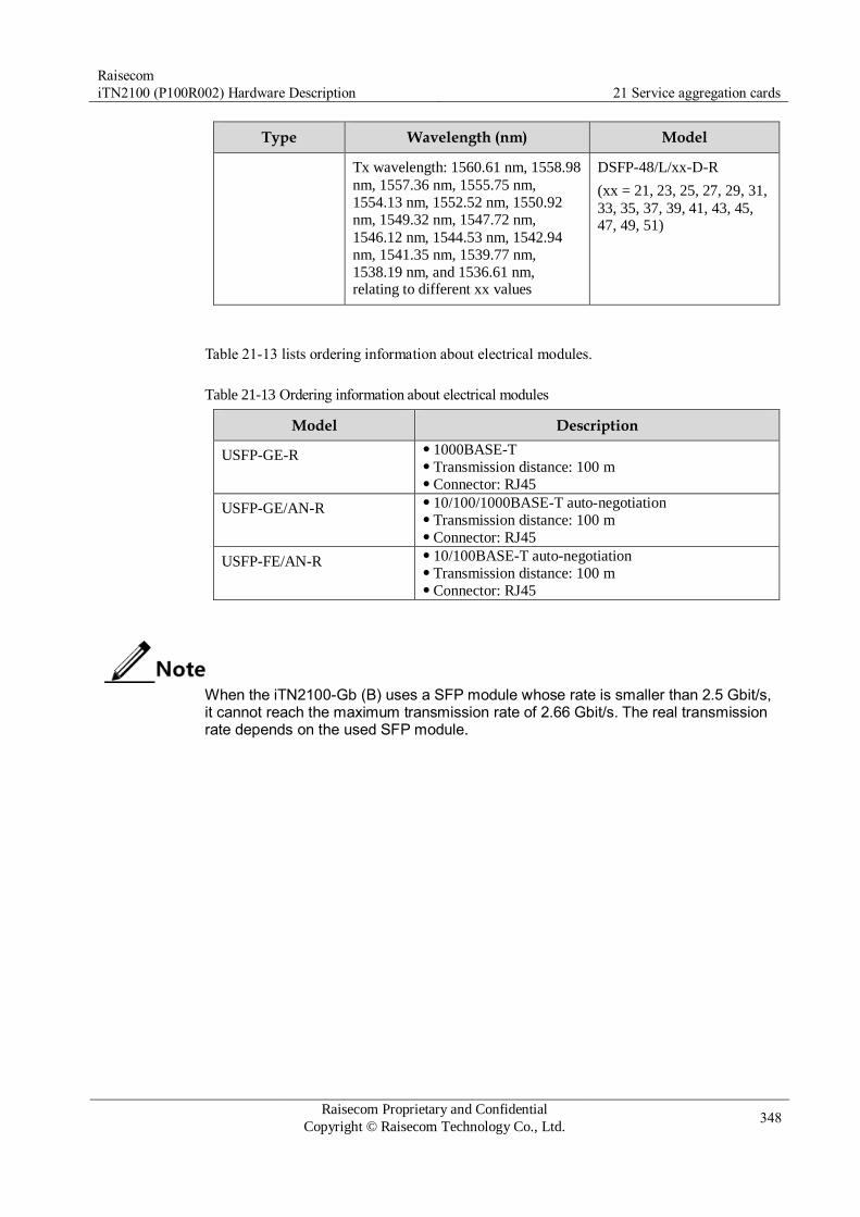
Raisecom
iTN2100 (P100R002) Hardware Description 21 Service aggregation cards
Raisecom Proprietary and Confidential
Copyright © Raisecom Technology Co., Ltd. 348
Type Wavelength (nm) Model
Tx wavelength: 1560.61 nm, 1558.98
nm, 1557.36 nm, 1555.75 nm,
1554.13 nm, 1552.52 nm, 1550.92
nm, 1549.32 nm, 1547.72 nm,
1546.12 nm, 1544.53 nm, 1542.94
nm, 1541.35 nm, 1539.77 nm,
1538.19 nm, and 1536.61 nm, relating to different xx values
DSFP-48/L/xx-D-R
(xx = 21, 23, 25, 27, 29, 31,
33, 35, 37, 39, 41, 43, 45, 47, 49, 51)
Table 21-13 lists ordering information about electrical modules.
Table 21-13 Ordering information about electrical modules
Model Description
USFP-GE-R 1000BASE-T Transmission distance: 100 m Connector: RJ45
USFP-GE/AN-R 10/100/1000BASE-T auto-negotiation Transmission distance: 100 m Connector: RJ45
USFP-FE/AN-R 10/100BASE-T auto-negotiation Transmission distance: 100 m Connector: RJ45
When the iTN2100-Gb (B) uses a SFP module whose rate is smaller than 2.5 Gbit/s, it cannot reach the maximum transmission rate of 2.66 Gbit/s. The real transmission rate depends on the used SFP module.

Raisecom
iTN2100 (P100R002) Hardware Description 21 Service aggregation cards
Raisecom Proprietary and Confidential
Copyright © Raisecom Technology Co., Ltd. 349
21.2 iTN2100-8SU-S
21.2.1 Appearance and functions
Appearance Function
The iTN2100-8SU-S card can be used to multiplex or de-multiplex 8
CWDM wavelength optical signals. The 8-wavelength CWDM system
can efficiently use the bandwidth of the fiber to prevent laying fibers
repeatedly. This helps save costs. The 8 wavelength channels are 1471
nm, 1491 nm, 1511 nm, 1531 nm, 1551 nm, 1571 nm, 1591 nm, and 1611 nm.
Support multiplexing/de-multiplexing 8 CWDM standard wavelength
channels (1471 nm, 1491 nm, 1511 nm, 1531 nm, 1551 nm, 1571 nm,
1591 nm, and 1611 nm). Each wavelength channel can be used to
multiplexing/de-multiplexing optical signals. Be applied to dual-fiber and single-fiber CWDM network, providing
flexible networking applications. Plug and play. The card is available for services after being inserted
into 6-U chassis and being properly connected with fibers, without
being configured. Work properly after power off. The internal passive optical module in
the card works properly after the card is powered off. Therefore,
ensure that the card can finish multiplexing/de-multiplexing of optical
wavelength. Support the NView NNM system, helping view card configurations. Support transmitting services transparently, bringing no limit on the
rate and frame format of the accessed optical signals. Consume less power, without being configured with the fan.
21.2.2 Slots
The iTN2100-8SU-S can be inserted into slots 1–5 and 8–12 on the iTN2100.

Raisecom
iTN2100 (P100R002) Hardware Description 21 Service aggregation cards
Raisecom Proprietary and Confidential
Copyright © Raisecom Technology Co., Ltd. 350
21.2.3 Interfaces
There are 9 interfaces on the iTN2100-8SU-S panel, as listed in Table 21-14.
Table 21-14 interfaces on the iTN2100-8SU-S panel
Interface Type Description
LINE SC/PC connector Line-side interface Optical transmission media: single-mode fiber
1471 SC/PC connector Client-side interface Optical transmission media: single-mode fiber Wavelength: 1471 nm
1491 SC/PC connector Client-side interface Optical transmission media: single-mode fiber Wavelength: 1491 nm
1511 SC/PC connector Client-side interface Optical transmission media: single-mode fiber Wavelength: 1511 nm
1531 SC/PC connector Client-side interface Optical transmission media: single-mode fiber Wavelength: 1531 nm
1551 SC/PC connector Client-side interface Optical transmission media: single-mode fiber Wavelength: 1551 nm
1571 SC/PC connector Client-side interface Optical transmission media: single-mode fiber Wavelength: 1571 nm
1591 SC/PC connector Client-side interface Optical transmission media: single-mode fiber Wavelength: 1591 nm
1611 SC/PC connector Client-side interface Optical transmission media: single-mode fiber Wavelength: 1611 nm
21.2.4 LEDs
There are 2 LEDs on the iTN2100-8SU-S panel, as listed in Table 21-15.
Table 21-15 LEDs on the iTN2100-8SU-S panel
LED Status Description
PWR Green Power supply LED
Green: the power supply is normal. Off: the power supply is abnormal.
SYS Green System status LED
Green: the system is working improperly. Off: the system is working improperly. Blinking green: the system is working properly.
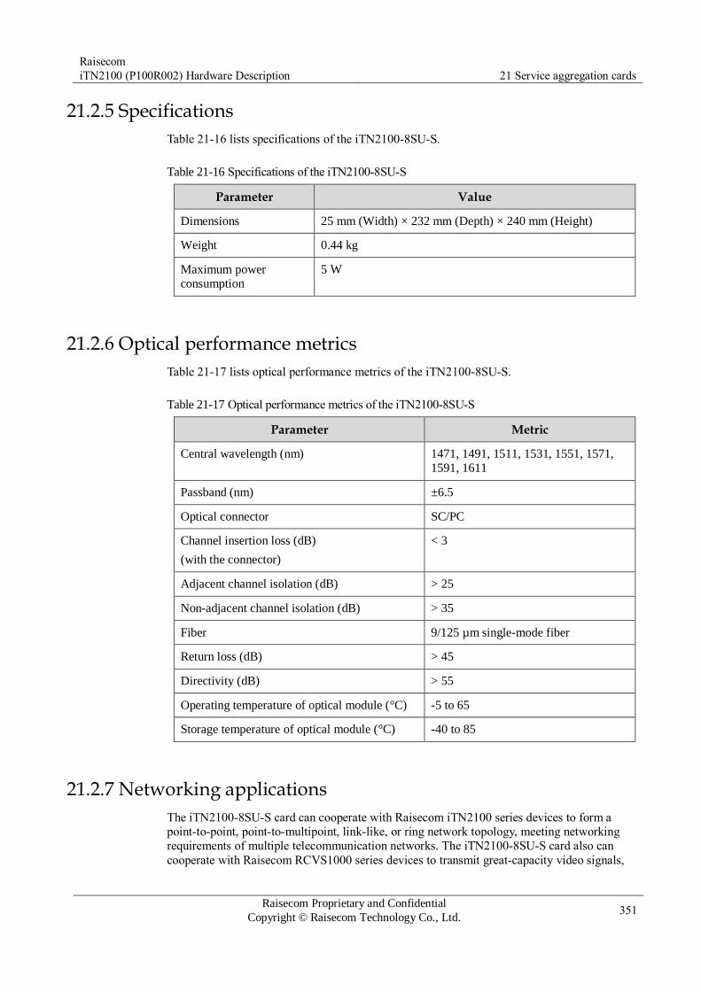
Raisecom
iTN2100 (P100R002) Hardware Description 21 Service aggregation cards
Raisecom Proprietary and Confidential
Copyright © Raisecom Technology Co., Ltd. 351
21.2.5 Specifications
Table 21-16 lists specifications of the iTN2100-8SU-S.
Table 21-16 Specifications of the iTN2100-8SU-S
Parameter Value
Dimensions 25 mm (Width) × 232 mm (Depth) × 240 mm (Height)
Weight 0.44 kg
Maximum power
consumption
5 W
21.2.6 Optical performance metrics
Table 21-17 lists optical performance metrics of the iTN2100-8SU-S.
Table 21-17 Optical performance metrics of the iTN2100-8SU-S
Parameter Metric
Central wavelength (nm) 1471, 1491, 1511, 1531, 1551, 1571,
1591, 1611
Passband (nm) ±6.5
Optical connector SC/PC
Channel insertion loss (dB)
(with the connector)
< 3
Adjacent channel isolation (dB) > 25
Non-adjacent channel isolation (dB) > 35
Fiber 9/125 µm single-mode fiber
Return loss (dB) > 45
Directivity (dB) > 55
Operating temperature of optical module (°C) -5 to 65
Storage temperature of optical module (°C) -40 to 85
21.2.7 Networking applications
The iTN2100-8SU-S card can cooperate with Raisecom iTN2100 series devices to form a
point-to-point, point-to-multipoint, link-like, or ring network topology, meeting networking
requirements of multiple telecommunication networks. The iTN2100-8SU-S card also can
cooperate with Raisecom RCVS1000 series devices to transmit great-capacity video signals,

Raisecom
iTN2100 (P100R002) Hardware Description 21 Service aggregation cards
Raisecom Proprietary and Confidential
Copyright © Raisecom Technology Co., Ltd. 352
audio signals, unidirectional and bidirectional data signals, and Ethernet data services through
a fiber simultaneously.
Point-to-point networking application
Node A multiplexes optical signals of 8 wavelength channels at the client side and transmits
the multiplexed signals to Node B. After receiving optical signals, Node B de-multiplexes
these signals and then sends them out. In opposite direction, Node B multiplexes optical
signals of 8 wavelength channels at the client side and transmits the multiplexed signals to
Node A. After receiving optical signals, Node A de-multiplexes these signals and then sends
them out. In this mode, the iTN2100-8SU-S can be used to transmit services between Node A
and Node B.
Figure 21-1 shows a point-to-point networking application with the iTN2100-8SU-S.
Figure 21-1 Point-to-point networking application with the iTN2100-8SU-S
OADM ring network
At the local, the iTN2100-8SU-S multiplexes optical signals of 8 wavelength channels and
provides routing protection by establishing an Optical Add/Drop Multiplexer (OADM) ring
network. Access points A–D can perform bidirectional add/drop multiplexing on 2 ways of
optical signals. In this mode, the iTN2100-8SU-S provides a point-to-point communication
router between any 2 access points. In addition, it facilitates upgrade and expansion.
Figure 21-2 shows an OADM ring network with the iTN2100-8SU-S.

Raisecom
iTN2100 (P100R002) Hardware Description 21 Service aggregation cards
Raisecom Proprietary and Confidential
Copyright © Raisecom Technology Co., Ltd. 353
Figure 21-2 OADM ring network with the iTN2100-8SU-S
21.2.8 Ordering information
Table 21-18 lists ordering information about the iTN2100-8SU-S.
Table 21-18 Ordering information about the iTN2100-8SU-S
Model Hardware version Description
iTN2100-8SU-S A.10 Eight-wavelength CWDM multiplexing/de-
multiplexing card

Raisecom
iTN2100 (P100R002) Hardware Description 21 Service aggregation cards
Raisecom Proprietary and Confidential
Copyright © Raisecom Technology Co., Ltd. 354
21.3 iTN2100-4SU-D
21.3.1 Appearance and functions
Appearance Function
The iTN2100-4SU-D is a 4 way of dual-fiber CWDM multiplexing/de-
multiplexing card. It can realize bidirectional multiplexing transmission
of 4 CWDM wavelength optical signals in 2 fibers. The iTN2100-4SU-
D can efficiently use the bandwidth of the fiber to prevent laying fibers
repeatedly. This helps save costs.
Support multiplexing/de-multiplexing 4 CWDM standard wavelength
channels (1511 nm, 1531 nm, 1551 nm, and 1571 nm). Support plug and play. The card is available for services after being
inserted into 6-U chassis and being properly connected with fibers. Work properly after being powered off. The internal passive optical
module in the card works properly after the card is powered off.
Therefore, ensure that the card realize wavelength division
multiplexing. Support transmitting services transparently. It can be used to access
data services with any rate and access emulation services such as video
service. Support Raisecom NView NNM system.
21.3.2 Slots
The iTN2100-4SU-D can be inserted into slots 1–5 and 8–12 on the iTN2100.
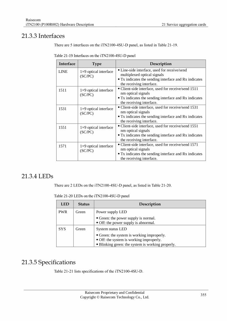
Raisecom
iTN2100 (P100R002) Hardware Description 21 Service aggregation cards
Raisecom Proprietary and Confidential
Copyright © Raisecom Technology Co., Ltd. 355
21.3.3 Interfaces
There are 5 interfaces on the iTN2100-4SU-D panel, as listed in Table 21-19.
Table 21-19 Interfaces on the iTN2100-4SU-D panel
Interface Type Description
LINE 1×9 optical interface
(SC/PC)
Line-side interface, used for receive/send
multiplexed optical signals Tx indicates the sending interface and Rx indicates
the receiving interface.
1511 1×9 optical interface
(SC/PC)
Client-side interface, used for receive/send 1511
nm optical signals Tx indicates the sending interface and Rx indicates
the receiving interface.
1531 1×9 optical interface
(SC/PC)
Client-side interface, used for receive/send 1531
nm optical signals Tx indicates the sending interface and Rx indicates
the receiving interface.
1551 1×9 optical interface
(SC/PC)
Client-side interface, used for receive/send 1551
nm optical signals Tx indicates the sending interface and Rx indicates
the receiving interface.
1571 1×9 optical interface
(SC/PC)
Client-side interface, used for receive/send 1571
nm optical signals Tx indicates the sending interface and Rx indicates
the receiving interface.
21.3.4 LEDs
There are 2 LEDs on the iTN2100-4SU-D panel, as listed in Table 21-20.
Table 21-20 LEDs on the iTN2100-4SU-D panel
LED Status Description
PWR Green Power supply LED
Green: the power supply is normal. Off: the power supply is abnormal.
SYS Green System status LED
Green: the system is working improperly. Off: the system is working improperly. Blinking green: the system is working properly.
21.3.5 Specifications
Table 21-21 lists specifications of the iTN2100-4SU-D.

Raisecom
iTN2100 (P100R002) Hardware Description 21 Service aggregation cards
Raisecom Proprietary and Confidential
Copyright © Raisecom Technology Co., Ltd. 356
Table 21-21 Specifications of the iTN2100-4SU-D
Parameter Value
Dimensions 25 mm (Width) × 232 mm (Depth) × 240 mm (Height)
Weight 0.44 kg
Maximum power
consumption
5 W
21.3.6 Optical performance metrics
Table 21-22 lists optical performance metrics of the iTN2100-4SU-D.
Table 21-22 Optical performance metrics of the iTN2100-4SU-D
Parameter Metric
Central wavelength (nm) 1511, 1531, 1551, 1571
Passband (nm) ±6.5
Channel insertion loss (dB)
(with the connector)
< 2
Adjacent channel isolation (dB) > 25
Non-adjacent channel isolation (dB) > 35
Fiber 9/125 µm single-mode fiber
Return loss (dB) > 45
Directivity (dB) > 55
Operating temperature of optical module (°C) -5 to 65
Storage temperature of optical module (°C) -40 to 85
21.3.7 Networking applications
Point-to-point networking application
Device A multiplexes optical signals of 4 wavelength channels (1511 nm, 1531 nm, 1551 nm,
and 1571 nm) at the client side and transmits the multiplexed signals to Device B. After
receiving optical signals, Device B de-multiplexes these signals and then sends them out. In
opposite direction, Device B multiplexes optical signals of 4 wavelength channels at the client
side and transmits the multiplexed signals to Device A. After receiving optical signals, Device
A de-multiplexes these signals and then sends them out.
Figure 21-3 shows a point-to-point networking application with the iTN2100-4SU-D.

Raisecom
iTN2100 (P100R002) Hardware Description 21 Service aggregation cards
Raisecom Proprietary and Confidential
Copyright © Raisecom Technology Co., Ltd. 357
Figure 21-3 Point-to-point networking application with the iTN2100-4SU-D
OADM ring network
At the local, the iTN2100-4SU-D multiplexes optical signals of 4 wavelength channels (1511
nm, 1531 nm, 1551 nm, and 1571 nm) and provides routing protection by establishing an
OADM ring network. Access points A–D can perform bidirectional add/drop multiplexing on
1 way of optical signals. In this mode, the iTN2100-4SU-D provides a point-to-point
communication router between any 2 access points. In addition, it facilitates upgrade and
expansion.
Figure 21-4 shows an OADM ring network with the iTN2100-4SU-D.
Figure 21-4 OADM ring network with the iTN2100-4SU-D
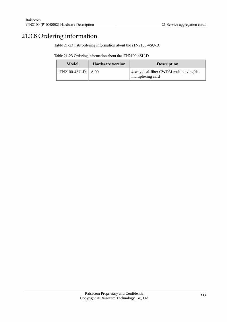
Raisecom
iTN2100 (P100R002) Hardware Description 21 Service aggregation cards
Raisecom Proprietary and Confidential
Copyright © Raisecom Technology Co., Ltd. 358
21.3.8 Ordering information
Table 21-23 lists ordering information about the iTN2100-4SU-D.
Table 21-23 Ordering information about the iTN2100-4SU-D
Model Hardware version Description
iTN2100-4SU-D A.00 4-way dual-fiber CWDM multiplexing/de-
multiplexing card

Raisecom
iTN2100 (P100R002) Hardware Description 22 Teleprotection
Raisecom Proprietary and Confidential
Copyright © Raisecom Technology Co., Ltd. 359
22 Teleprotection
This chapter describes the teleprotection card used by the iTN2100, including the following
section:
OPCOM3500E-TP

Raisecom
iTN2100 (P100R002) Hardware Description 22 Teleprotection
Raisecom Proprietary and Confidential
Copyright © Raisecom Technology Co., Ltd. 360
22.1 OPCOM3500E-TP
22.1.1 Functions and appearance
Panel Function
The OPCOM3500E-TP is used to access services of the teleprotection
device and provides the following functions:
Support accessing and transmitting services of teleprotection devices
based on C37.94 standard. The services are cross-connected through
the backplane, and then are multiplexed to the transport network
through the aggregation card. Support capacity compression. You can configure cross connection
according to the N value of service bandwidth (N×64 kbit/s, with N
ranging from 1 to 12 defined by C37.94 standard). Each service
occupies only 1+N 64 kbit/s timeslot instead of the whole E1 when it is
multiplexed. Support integrating the capacity of data on multiple
optical interfaces during transmission. For example, timeslots occupied
by 4 optical interfaces are multiplexed to one E1 or one VC12 of the
aggregation card through cross connection. Support four C37.94 service optical interfaces. The optical interface
supports being used independently or configured into protection pairs.
When 64 kbit/s cross connection is configured, services of optical
interfaces 1–4 correspond to No. 1–4 ways of E1 resources on the
OPCOM3500E-TP. Support optical interface 1+1 protection. Support configuring up to 2
protection pairs: optical interfaces 1 and 2 work in pairs; optical
interfaces 3 and 4 work in pairs. Each optical interface supports clock data recovery and ALS. Support detecting and processing LOS, Yellow (remote alarm
indication), and All Ones alarms (payload of services is all 1) defined
by the C37.94. Support internal and external loopback on optical interfaces. Support 1 embedded BERT. For any way of C37.94 services, support
inserting bit errors to service payload at the side of optical interface or
backplane for test. Support software online upgrade. Support being interconnected with devices of other vendors compliant
with the C37.94 standard.
The bandwidth of C37.94 services of the teleprotection device is fixed to 2.048
Mbit/s. The N value determines the number of payload bytes used in each frame.

Raisecom
iTN2100 (P100R002) Hardware Description 22 Teleprotection
Raisecom Proprietary and Confidential
Copyright © Raisecom Technology Co., Ltd. 361
When N is smaller than 12, data of the used bytes are invalid. The capacity compression feature makes the services only occupy 1+N 64 kbit/s timeslots. One 64 kbit/s timeslot transmits the value of N; and N 64 kbit/s timeslots transmit valid service data.
When C37.94 services are multiplexed to line-side E1, support PCM30, PCM30&CRC, PCM31, and PCM31&CRC only instead of unframed E1.
Buttons, DIP switches, or jumpers are not provided on the card for configurations.
22.1.2 Slots
The OPCOM3500E-TP can be inserted into the slots 1–5 and 8–12 on the iTN2100
22.1.3 Interfaces
Interface type
Table 22-1 lists interfaces on the OPCOM3500E-TP.
Table 22-1 Interfaces on OPCOM3500E-TP
Interface Type Description
1–4 TX/RX Multi-mode dual fiber
ST (namely, BFOC/2.5) female interface
4 C37.94 service Rx/Tx interfaces Each way of services uses 1 Tx interface
and 1 Rx interface (Tx indicates output
while Rx indicates input).
Interface parameter
The ST interface complies with the C37.94 and BFOC/2.5 standards.
Table 22-2 list parameters of the ST interface.
Table 22-2 Parameters of the ST interface
Parameter Description
Interface type Multi-mode dual fiber ST (namely, BFOC/2.5) female
interface
Typical loss 0.3 dB
Pluggable times < 0.3dB: 1000 times
Temperature stability -40 to 75°C: incremental loss < 0.3 dB
Axial load 35 lb
Service bandwidth N×64 kbit/s; N = 1–12
Clock frequency 2048 kbit/s (±100 ppm)
Jitter Output: ±50ns (±0.1 UI) Input tolerance: ±100ns
Wander ±250ns (±0.5 UI)

Raisecom
iTN2100 (P100R002) Hardware Description 22 Teleprotection
Raisecom Proprietary and Confidential
Copyright © Raisecom Technology Co., Ltd. 362
Parameter Description
Output level Average optical power of 50 μm fiber: -23.0 to -11.0 dBm Average optical power of 62.5μm fiber: -19.0 to -11.0 dBm Optical signal in ON status indicates logical 1; logical 1
level which is smaller than 10% indicates logical 0.
Center emission
wavelength
830±40 nm
Rx sensitivity BER < 1.0E-9 (namely, no bit error): the average optical
power is -28 dBm.
Fiber 850 nm multi-mode fiber; 50 or 62.5 μm
Maximum transmission
distance (depending on link signal attenuation)
2–4 km
Lightning protection
level
Contact discharge: ±8 kV Air discharge: ±15 kV
22.1.4 LEDs
Table 22-3 lists LEDs on the OPCOM3500E-TP.
Table 22-3 LEDs on OPCOM3500E-TP
LED Status Description
PWR Green Power LED
Green: the power supply is normal. Off: the power supply is abnormal.
SYS Green System status LED
Green: the system is working improperly. Off: the system is working improperly. Blinking green: the system is working properly.
ALM/SYNC/TST
1–4
Red Green Yellow
C37.94 optical interfaces 1–4 status LED. In normal
operation conditions, the LED is green.
Red: ALM status. Red indicates LOS occurs on the
local optical interface or local signals are not
synchronized; blinking red indicates remote LOS. Green: SNYC status. Green indicates that local signals
have been synchronized. Yellow: TST status. It is reserved.
22.1.5 Specifications
Table 22-4 lists specifications of the OPCOM3500E-TP.
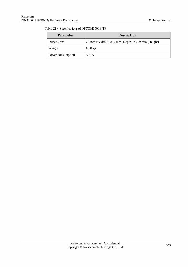
Raisecom
iTN2100 (P100R002) Hardware Description 22 Teleprotection
Raisecom Proprietary and Confidential
Copyright © Raisecom Technology Co., Ltd. 363
Table 22-4 Specifications of OPCOM3500E-TP
Parameter Description
Dimensions 25 mm (Width) × 232 mm (Depth) × 240 mm (Height)
Weight 0.38 kg
Power consumption < 5 W

Raisecom
iTN2100 (P100R002) Hardware Description 23 64K access
Raisecom Proprietary and Confidential
Copyright © Raisecom Technology Co., Ltd. 364
23 64K access
This chapter describes the 64K access card used by the iTN2100, including the following
section:
16C64K

Raisecom
iTN2100 (P100R002) Hardware Description 23 64K access
Raisecom Proprietary and Confidential
Copyright © Raisecom Technology Co., Ltd. 365
23.1 16C64K
23.1.1 Functions and appearance
Panel Function
The 16C64K is a 16-way codirectional 64 kbit/s data service card. It
transmits 16 ways of codirectional 64 kbit/s data to the cross connection
card through the backplane for cross connection. It has the following functions:
Provide 16 codirectional 64 kbit/s data interfaces which are
independent from each other. Support fixed bandwidth of 64 kbit/s on interfaces. These 16
interfaces use TS1–TS16 respectively. Support the test of channels embedded with the BERT. The BERT
can be concurrently conducted on only one interface while other
interfaces are transmitting services. Support channel loopback, including internal and external loopback. Support EMC and overcurrent protection. Support masking codirectional 64 kbit/s LOS/AIS alarms and
tributary alarms.
23.1.2 Slots
The OPCOM3500E-16C64K can be inserted into the slots 1–5 and 8–12 on the iTN2100.

Raisecom
iTN2100 (P100R002) Hardware Description 23 64K access
Raisecom Proprietary and Confidential
Copyright © Raisecom Technology Co., Ltd. 366
23.1.3 Interfaces
Interface type
Table 23-1 lists interfaces on the OPCOM3500E-16C64K.
Table 23-1 Interfaces on the OPCOM3500E-16C64K
Name Type Description
1/2, 3/4, 5/6, 7/8, 9/10, 11/12,
13/14, 15/16
RJ45 interface Each RJ45 interface transmits 2 ways
of codirectional 64 kbit/s data.
Interface parameter
Table 23-2 lists parameters of the OPCOM3500E-16C64K interface.
Table 23-2 Parameters of the OPCOM3500E-16C64K interface
Parameter Description
Connector type RJ45
Interface type Codirectional 64 kbit/s
Frame format Unframed
Line coding Codirectional coding
Transmission distance 300 m, 24AWG
Impedence 120 Ω (balanced)
Baud 64 kbit/s
Standard ITU-T G.703 compliant
Interface PINs
Table 23-3 lists PIN definitions on the OPCOM3500E-16C64K interface.
Table 23-3 PIN definitions on the OPCOM3500E-16C64K interface
Interface figure PIN 64K signal name
1 TD1+
2 TD1-
3 RD2+
4 RD1+
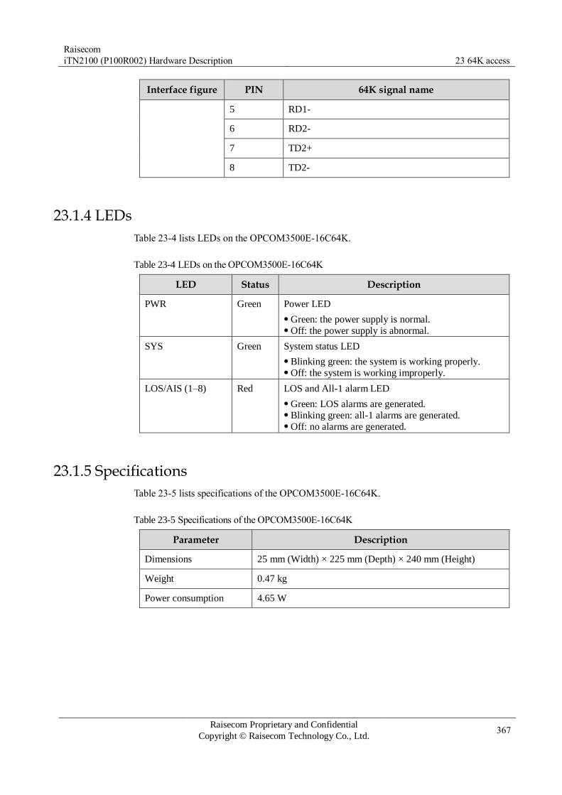
Raisecom
iTN2100 (P100R002) Hardware Description 23 64K access
Raisecom Proprietary and Confidential
Copyright © Raisecom Technology Co., Ltd. 367
Interface figure PIN 64K signal name
5 RD1-
6 RD2-
7 TD2+
8 TD2-
23.1.4 LEDs
Table 23-4 lists LEDs on the OPCOM3500E-16C64K.
Table 23-4 LEDs on the OPCOM3500E-16C64K
LED Status Description
PWR Green Power LED
Green: the power supply is normal. Off: the power supply is abnormal.
SYS Green System status LED
Blinking green: the system is working properly. Off: the system is working improperly.
LOS/AIS (1–8) Red LOS and All-1 alarm LED
Green: LOS alarms are generated. Blinking green: all-1 alarms are generated. Off: no alarms are generated.
23.1.5 Specifications
Table 23-5 lists specifications of the OPCOM3500E-16C64K.
Table 23-5 Specifications of the OPCOM3500E-16C64K
Parameter Description
Dimensions 25 mm (Width) × 225 mm (Depth) × 240 mm (Height)
Weight 0.47 kg
Power consumption 4.65 W

Raisecom
iTN2100 (P100R002) Hardware Description 24 Cables
Raisecom Proprietary and Confidential
Copyright © Raisecom Technology Co., Ltd. 368
24 Cables
This chapter describes cables used by the iTN2100, including the following sections:
Fibers
Ethernet cable
Configuration cable
DC power cable
AC power cable
Alarm cable
E1-CC3 cable
E1-RJ45 cable
E1-DB37 cable
E1-SCSI100 cable
V24-HDB26 cable
V35-HDB26 cable
MUL-HDB26 cable
Audio cable
24.1 Fibers
24.1.1 Connectors
Table 24-1 lists fiber connectors.
Table 24-1 Fiber connectors
Local connector Remote connector Fiber
LC/PC LC/PC 2 mm single-mode fiber
2 mm multi-mode fiber
FC/PC 2 mm single-mode fiber
2 mm multi-mode fiber
SC/PC 2 mm single-mode fiber
2 mm multi-mode fiber
SC/PC LC/PC 2 mm single-mode fiber
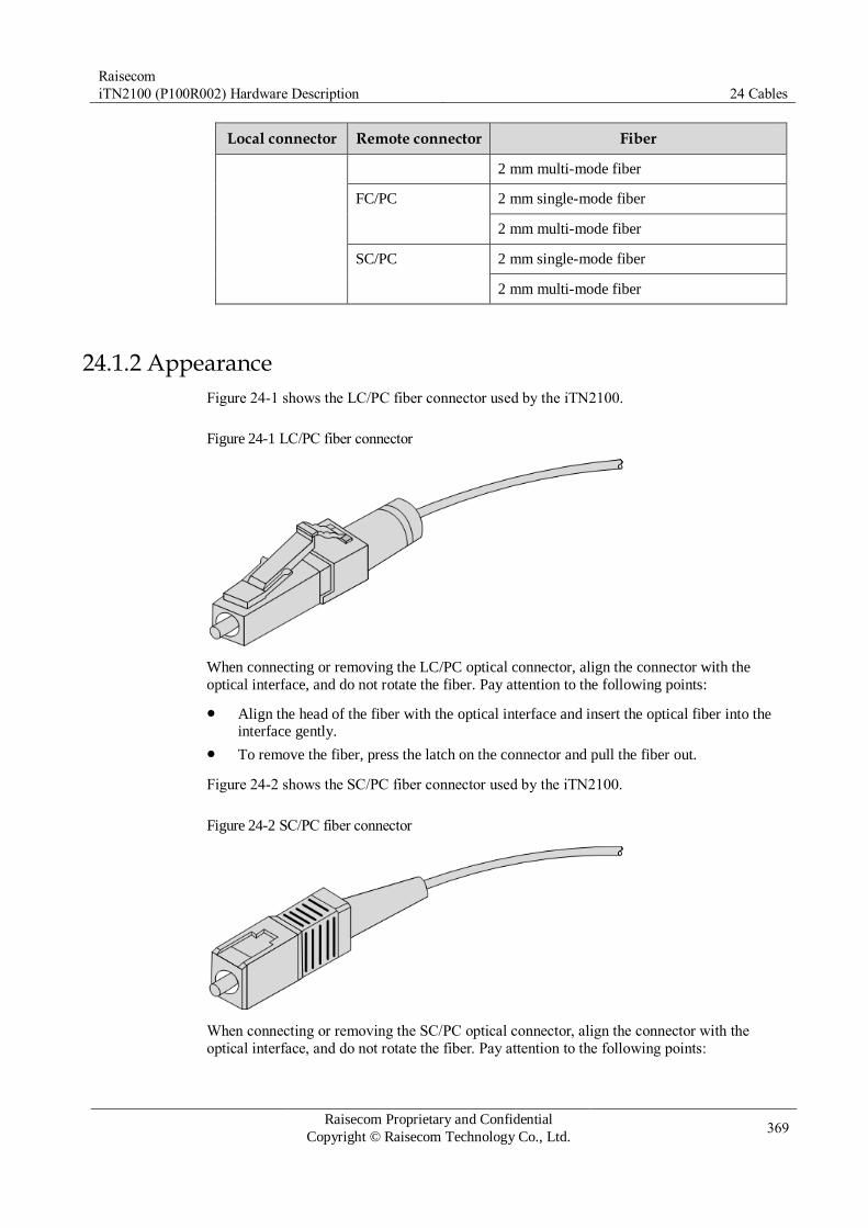
Raisecom
iTN2100 (P100R002) Hardware Description 24 Cables
Raisecom Proprietary and Confidential
Copyright © Raisecom Technology Co., Ltd. 369
Local connector Remote connector Fiber
2 mm multi-mode fiber
FC/PC 2 mm single-mode fiber
2 mm multi-mode fiber
SC/PC 2 mm single-mode fiber
2 mm multi-mode fiber
24.1.2 Appearance
Figure 24-1 shows the LC/PC fiber connector used by the iTN2100.
Figure 24-1 LC/PC fiber connector
When connecting or removing the LC/PC optical connector, align the connector with the
optical interface, and do not rotate the fiber. Pay attention to the following points:
Align the head of the fiber with the optical interface and insert the optical fiber into the interface gently.
To remove the fiber, press the latch on the connector and pull the fiber out.
Figure 24-2 shows the SC/PC fiber connector used by the iTN2100.
Figure 24-2 SC/PC fiber connector
When connecting or removing the SC/PC optical connector, align the connector with the
optical interface, and do not rotate the fiber. Pay attention to the following points:
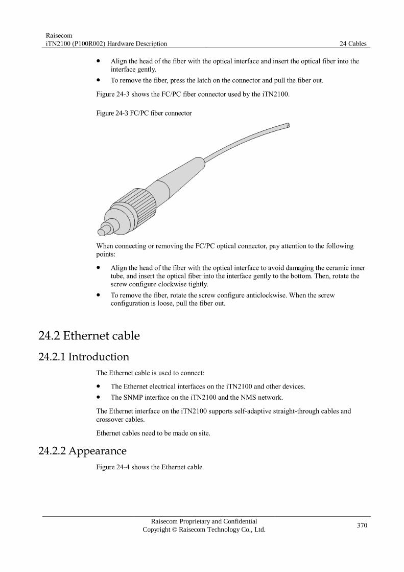
Raisecom
iTN2100 (P100R002) Hardware Description 24 Cables
Raisecom Proprietary and Confidential
Copyright © Raisecom Technology Co., Ltd. 370
Align the head of the fiber with the optical interface and insert the optical fiber into the
interface gently.
To remove the fiber, press the latch on the connector and pull the fiber out.
Figure 24-3 shows the FC/PC fiber connector used by the iTN2100.
Figure 24-3 FC/PC fiber connector
When connecting or removing the FC/PC optical connector, pay attention to the following
points:
Align the head of the fiber with the optical interface to avoid damaging the ceramic inner
tube, and insert the optical fiber into the interface gently to the bottom. Then, rotate the
screw configure clockwise tightly.
To remove the fiber, rotate the screw configure anticlockwise. When the screw configuration is loose, pull the fiber out.
24.2 Ethernet cable
24.2.1 Introduction
The Ethernet cable is used to connect:
The Ethernet electrical interfaces on the iTN2100 and other devices.
The SNMP interface on the iTN2100 and the NMS network.
The Ethernet interface on the iTN2100 supports self-adaptive straight-through cables and
crossover cables.
Ethernet cables need to be made on site.
24.2.2 Appearance
Figure 24-4 shows the Ethernet cable.

Raisecom
iTN2100 (P100R002) Hardware Description 24 Cables
Raisecom Proprietary and Confidential
Copyright © Raisecom Technology Co., Ltd. 371
Figure 24-4 Ethernet cable
24.2.3 Technical specifications
The Ethernet cables have two types:
Straight-through cable: used to connect devices of different types, such as a PC and a switch/switch and router.
Crossover cable: used to connect devices of the same type, such as between 2
PCs/switches/routers, or between a PC and a router (they are divided into the same group)
Table 24-2 lists the wiring of EIA/TIA 568A and EIA/TIA 568B standards.
Table 24-2 Wiring of EIA/TIA 568A and EIA/TIA 568B standards
Connector 1(RJ45) EIA/TIA 568A Connector 2(RJ45) EIA/TIA 568B
PIN 1 White/Green PIN 1 White/Orange
PIN 2 Green PIN 2 Orange
PIN 3 White/Orange PIN 3 White/Green
PIN 4 Blue PIN 4 Blue
PIN 5 White/Blue PIN 5 White/Blue
PIN 6 Orange PIN 6 Green
PIN 7 White/Brown PIN 7 White/Brown
PIN 8 Brown PIN 8 Brown
Straight-through cable
Both 2 RJ45 connectors of the straight-through cable use the same wiring. Generally, they
follow the EIA/TIA 568B standard.
Figure 24-5 shows the wiring of the straight-through cable.

Raisecom
iTN2100 (P100R002) Hardware Description 24 Cables
Raisecom Proprietary and Confidential
Copyright © Raisecom Technology Co., Ltd. 372
Figure 24-5 Wiring of the straight-through cable
Crossover cable
The wiring for 100 Mbit/s crossover cable is different from that of 1000 Mbit/s crossover
cable.
One RJ45 connector of the 100 Mbit/s crossover cable follows EIA/TIA 568A standard; the
other RJ45 connector follows EIA/TIA 568B standard wiring. Figure 24-6 shows the wiring
of the 100 Mbit/s crossover cable.
Figure 24-6 Wiring of the 100 Mbit/s crossover cable

Raisecom
iTN2100 (P100R002) Hardware Description 24 Cables
Raisecom Proprietary and Confidential
Copyright © Raisecom Technology Co., Ltd. 373
The 1000 Mbit/s crossover cable uses all 8 PINs. The crossover is PIN 1 to PIN 3, PIN 2 to
PIN 6, PIN 4 to PIN 7, and PIN 5 to PIN 8, as shown in Figure 24-7.
Figure 24-7 Wiring of the 1000 Mbit/s crossover cable
Raisecom provides the straight-through cable and 100 Mbit/s crossover cable which are
different in name only. The straight-through cable is named as CBL-ETH-RJ45/RJ45-D while
the crossover cable is named as CBL-ETH-RJ45/RJ45-X-D
Table 24-3 lists technical specifications of the Ethernet cable.
Table 24-3 Technical specifications of the Ethernet cable
Parameter Description
Color Dark grey
Model Cat5 or better UTP cable (UTP-5/UTP-5e) or STP
Connector RJ45 connector
Number of cores 8
Length The letter D indicates the length, which is customized. For example,
if the customer requires 2-meter cables, they are named CBL-ETH-RJ45/RJ45-2m.

Raisecom
iTN2100 (P100R002) Hardware Description 24 Cables
Raisecom Proprietary and Confidential
Copyright © Raisecom Technology Co., Ltd. 374
24.3 Configuration cable
24.3.1 Introduction
The configuration cable is used to connect the Console interface on the iTN2100 to the RS-
232 serial interface on the console for transmitting configuration data signals. The
maintenance console can debug and maintain the iTN2100 locally through the Console
interface.
The configuration cable is a 4-core unshielded cable, with connectors as below:
RJ45 connector: connected the Console interface
DB9 female connector: connected to the serial interface on the maintenance console
24.3.2 Appearance
Figure 24-8 shows the configuration cable.
Figure 24-8 Configuration cable
24.3.3 Wiring
Figure 24-9 shows the wiring of the configuration cable.
Figure 24-9 Wiring of the configuration cable
24.3.4 Technical specifications
Table 24-4 lists technical specifications of the configurable cable.

Raisecom
iTN2100 (P100R002) Hardware Description 24 Cables
Raisecom Proprietary and Confidential
Copyright © Raisecom Technology Co., Ltd. 375
Table 24-4 Technical specifications of the configurable cable
Parameter Description
Name CBL-RS232-DB9F/RJ45-2m/RoHS
Type Cat 3 UTP
Connector RJ45 connector DB9 female connector
Length 2 m
24.4 DC power cable
24.4.1 Appearance
Figure 24-10 shows the DC power cable.
Figure 24-10 DC power cable
24.4.2 Technical specifications
Table 24-5 lists technical specifications of the DC power cable.
Table 24-5 Technical specifications of the DC power cable
Parameter Description
Name POL-DC-DSUB(30)/C-2.0mm2-D/RoHS
Connector A DSUB power connector-welding wire-3-core
(hole+PIN+hole)
Positive wire +vin, red, 4mm diameter
Ground cable PGND, yellow/green, 4mm diameter
Negative wire -vin, black, 4mm diameter
Rated voltage 300/500 VDC
Insulation and voltage
resistance (electric cable)
AC1500V, 5min
Authentication CCC

Raisecom
iTN2100 (P100R002) Hardware Description 24 Cables
Raisecom Proprietary and Confidential
Copyright © Raisecom Technology Co., Ltd. 376
Parameter Description
RoHS Comply with RoHS.
Length Length is customized. The cable length is D.
24.5 AC power cable The iTN2100 uses different AC power supply cables in different countries or regions. The
cable length delivered with the iTN2100 is 1.5 m. You can order other cables with different
lengths if required.
24.5.1 POL-AC-European-3-pin/receptacle-0.75mm2-D/RoHS
Appearance
The AC power cable which meets European standard is composed of a European standard 3-
pin plug and a receptacle, as shown in Figure 24-11.
Figure 24-11 European AC power cable
Technical specifications
Figure 24-6 lists technical specifications of the European AC power cable.
Table 24-6 Technical specifications of the European AC power cable
Parameter Description
Name POL-AC-European-3-pin/receptacle-0.75mm2-1.5m/RoHS
Connector European 3-pin plug Receptacle IEC60320-C13
Color Outer Black (PVC insulating layer)
Inner Blue (N), brown (L), and yellow/green strip (E)
Conducting wire 3×0.75mm2
Length The letter D in "POL-AC-European-3-pin/receptacle-0.75mm2-
1.5m/RoHS" indicates the cable length and can be customized. For
example, the customer requires a 1.5-m cable, and you can name the cable POL-AC-European-3-pin/receptacle-0.75mm2-1.5m/RoHS.
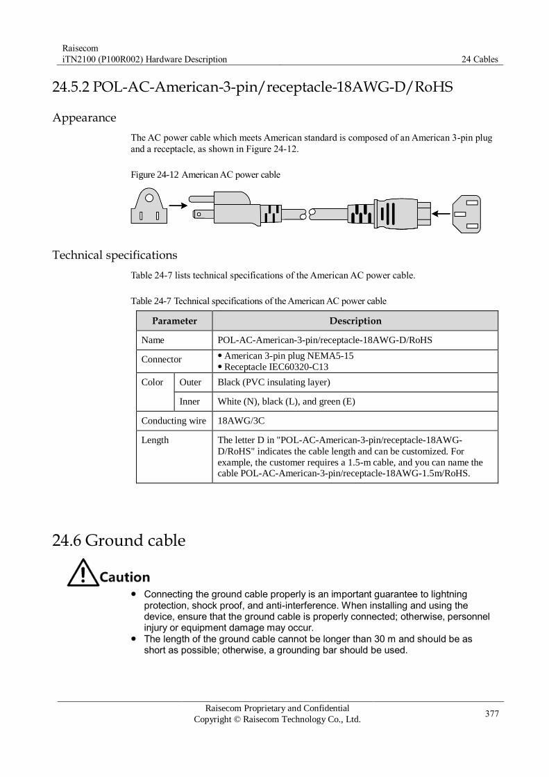
Raisecom
iTN2100 (P100R002) Hardware Description 24 Cables
Raisecom Proprietary and Confidential
Copyright © Raisecom Technology Co., Ltd. 377
24.5.2 POL-AC-American-3-pin/receptacle-18AWG-D/RoHS
Appearance
The AC power cable which meets American standard is composed of an American 3-pin plug
and a receptacle, as shown in Figure 24-12.
Figure 24-12 American AC power cable
Technical specifications
Table 24-7 lists technical specifications of the American AC power cable.
Table 24-7 Technical specifications of the American AC power cable
Parameter Description
Name POL-AC-American-3-pin/receptacle-18AWG-D/RoHS
Connector American 3-pin plug NEMA5-15 Receptacle IEC60320-C13
Color Outer Black (PVC insulating layer)
Inner White (N), black (L), and green (E)
Conducting wire 18AWG/3C
Length The letter D in "POL-AC-American-3-pin/receptacle-18AWG-
D/RoHS" indicates the cable length and can be customized. For
example, the customer requires a 1.5-m cable, and you can name the cable POL-AC-American-3-pin/receptacle-18AWG-1.5m/RoHS.
24.6 Ground cable
Connecting the ground cable properly is an important guarantee to lightning
protection, shock proof, and anti-interference. When installing and using the device, ensure that the ground cable is properly connected; otherwise, personnel injury or equipment damage may occur.
The length of the ground cable cannot be longer than 30 m and should be as short as possible; otherwise, a grounding bar should be used.

Raisecom
iTN2100 (P100R002) Hardware Description 24 Cables
Raisecom Proprietary and Confidential
Copyright © Raisecom Technology Co., Ltd. 378
24.6.1 Introduction
The ground cable is used to ground the iTN2100. Ground screws are on the panel of the
iTN2100. Connect one end of the ground cable to the OT terminal and then use the ground
screws to fix them, and connect the other end of the cable to the ground.
24.6.2 Appearance
The ground cable is composed of the ground terminal and conducting wire. The ground
terminal is usually an OT terminal. The conducting wire is a yellow/green copper soft flame-
retardant conducting wire. Figure 24-13 and Figure 24-14 show the ground cable and OT
terminal.
Figure 24-13 Ground cable
1 Stripped end (connected to the OT
terminal or grounding bar) 2 Conducting wire
3 Insulating sheath 4 OT terminal
Figure 24-14 OT terminal
1 Inner radius of
soldering lug 2 Inner radius of sheath 3
Thickness of soldering
terminal
24.6.3 Technical specifications
Table 24-8 lists technical specifications of the ground cable of the iTN2100.

Raisecom
iTN2100 (P100R002) Hardware Description 24 Cables
Raisecom Proprietary and Confidential
Copyright © Raisecom Technology Co., Ltd. 379
Table 24-8 Technical specifications of the ground cable
Parameter Description
Model PIL-ground cable-Φ4-D/RoHS
Standard Comply with the UL standard and meet RoHS requirements.
Conducting wire Yellow/Green multi-strand copper-core conducting wire 16
AWG (1×1.25 mm2)
Meet UL1007 or UL1005 requirements.
Stripped end 10 mm long and plated with tin
Length of conducting
wire
70mm, 105mm, or customized length, the letter D in "PIL-
ground cable-Φ4-D/ RoHS" indicates the cable length and is
customized. For example, the customer requires a 2-m cable,
and you can name the cable PIL-ground cable-Φ4-
200mm/RoHS.
Table 24-9 lists technical specifications of the OT terminal.
Table 24-9 Technical specifications of the OT terminal
Parameter Description
Model Protective grounding round-pressed terminal (M4)/ RoHS
Technical specifications 4.3 soldering lug Inner radius of soldering lug: 4 mm Outer radius of soldering lug: ≤ 8 mm Inner radius of sheath: 2.1 mm Thickness of soldering lug: ≥ 0.6 mm
Cross-sectional area of
the conducting wire
16–15 AWG (1.2–1.5 mm2)
The OT terminal is delivered with the iTN2100 but the ground cable is not
delivered. If you need the power cable, make it on site according to technical specifications.
The length of the ground cable cannot be longer than 30 m and should be as short as possible; otherwise, a grounding bar should be used.
24.7 Alarm cable
24.7.1 Introduction
The alarm cable is used to connect alarm terminals to other devices for inputting or outputting
alarm signals. The alarm terminal of the iTN2100 is a 4-hole spring terminal.

Raisecom
iTN2100 (P100R002) Hardware Description 24 Cables
Raisecom Proprietary and Confidential
Copyright © Raisecom Technology Co., Ltd. 380
24.7.2 PIN definitions
Figure 24-15 shows PINs of the alarm terminal.
You can connect the alarm cable based on PINs of the alarm terminal described in Table 24-
10.
Figure 24-15 PINs of the alarm terminal
Table 24-10 PIN definitions of the alarm terminal
PIN Definition Description
1 OUT Cooperate with each other to output 1 way of alarm signals.
When an alarm signal is output, the device connects PIN 1 and
PIN 2 through the internal relay. When no alarm is output, PIN 1 and PIN 2 are disconnected.
2
3 IN Cooperate with each other to input 1 way of alarm signals. The
device detects the connection status of PIN 3 and PIN 4. If it is in closure state, it indicates that there is alarm signal input. 4 GND
24.8 E1-CC3 cable
24.8.1 Introduction
The front panel of the OPCOM3500E-2STM1/4-M provides two CC3 interfaces for inputting
and outputting clock signals.
The front panel of the OPCOM3500E-3DS3/E3 provides three pairs of CC3 interfaces for
inputting and outputting DS3/E3 services.
24.8.2 Appearance
Figure 24-16 shows the E1-CC3 cable.
Figure 24-16 E1-CC3 cable

Raisecom
iTN2100 (P100R002) Hardware Description 24 Cables
Raisecom Proprietary and Confidential
Copyright © Raisecom Technology Co., Ltd. 381
24.8.3 Technical specifications
Table 24-11 lists technical specifications of the E1-CC3 cable.
Table 24-11 Technical specifications of the E1-CC3 cable
Parameter Description
Name CBL-E1-CC3/BNCF
Connector CC3 female connector, BNC female connector
Type 1C+B coaxial cable
24.9 E1-RJ45 cable
24.9.1 Introduction
E1-RJ45 cables are used to connect E1 balanced interfaces of the iTN2100 to other devices
for accessing E1 services. Table 24-12 lists E1-RJ45 cables available for the card of the
iTN2100.
The iTN2100-CES-16E1T1-BL provides RJ45 E1 interfaces. Each RJ45 E1 interface is
connected by the E1-RJ45 cable to transmit 2 ways of E1 signals.
Table 24-12 E1-RJ45 cables available for the card of the iTN2100
Card Cable
iTN2100-CES-16E1T1-BL CBL-E1-RJ45/RJ45
CBL-E1-RJ45/2RJ45
The E1-RJ45 cable is not delivered with the iTN2100. You can make it on site as required. The appearance and wiring of E1-RJ45 cables described in this section are used as reference only.
24.9.2 CBL-E1-RJ45/RJ45
Appearance
Figure 24-17 shows the CBL-E1-RJ45/RJ45.
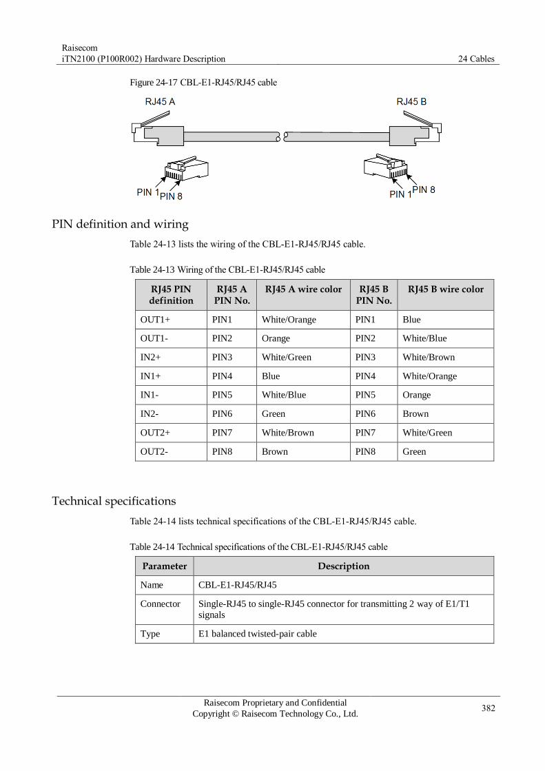
Raisecom
iTN2100 (P100R002) Hardware Description 24 Cables
Raisecom Proprietary and Confidential
Copyright © Raisecom Technology Co., Ltd. 382
Figure 24-17 CBL-E1-RJ45/RJ45 cable
PIN definition and wiring
Table 24-13 lists the wiring of the CBL-E1-RJ45/RJ45 cable.
Table 24-13 Wiring of the CBL-E1-RJ45/RJ45 cable
RJ45 PIN definition
RJ45 A PIN No.
RJ45 A wire color RJ45 B PIN No.
RJ45 B wire color
OUT1+ PIN1 White/Orange PIN1 Blue
OUT1- PIN2 Orange PIN2 White/Blue
IN2+ PIN3 White/Green PIN3 White/Brown
IN1+ PIN4 Blue PIN4 White/Orange
IN1- PIN5 White/Blue PIN5 Orange
IN2- PIN6 Green PIN6 Brown
OUT2+ PIN7 White/Brown PIN7 White/Green
OUT2- PIN8 Brown PIN8 Green
Technical specifications
Table 24-14 lists technical specifications of the CBL-E1-RJ45/RJ45 cable.
Table 24-14 Technical specifications of the CBL-E1-RJ45/RJ45 cable
Parameter Description
Name CBL-E1-RJ45/RJ45
Connector Single-RJ45 to single-RJ45 connector for transmitting 2 way of E1/T1
signals
Type E1 balanced twisted-pair cable
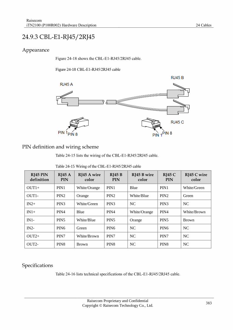
Raisecom
iTN2100 (P100R002) Hardware Description 24 Cables
Raisecom Proprietary and Confidential
Copyright © Raisecom Technology Co., Ltd. 383
24.9.3 CBL-E1-RJ45/2RJ45
Appearance
Figure 24-18 shows the CBL-E1-RJ45/2RJ45 cable.
Figure 24-18 CBL-E1-RJ45/2RJ45 cable
PIN definition and wiring scheme
Table 24-15 lists the wiring of the CBL-E1-RJ45/2RJ45 cable.
Table 24-15 Wiring of the CBL-E1-RJ45/2RJ45 cable
RJ45 PIN definition
RJ45 A PIN
RJ45 A wire color
RJ45 B PIN
RJ45 B wire color
RJ45 C PIN
RJ45 C wire color
OUT1+ PIN1 White/Orange PIN1 Blue PIN1 White/Green
OUT1- PIN2 Orange PIN2 White/Blue PIN2 Green
IN2+ PIN3 White/Green PIN3 NC PIN3 NC
IN1+ PIN4 Blue PIN4 White/Orange PIN4 White/Brown
IN1- PIN5 White/Blue PIN5 Orange PIN5 Brown
IN2- PIN6 Green PIN6 NC PIN6 NC
OUT2+ PIN7 White/Brown PIN7 NC PIN7 NC
OUT2- PIN8 Brown PIN8 NC PIN8 NC
Specifications
Table 24-16 lists technical specifications of the CBL-E1-RJ45/2RJ45 cable.

Raisecom
iTN2100 (P100R002) Hardware Description 24 Cables
Raisecom Proprietary and Confidential
Copyright © Raisecom Technology Co., Ltd. 384
Table 24-16 Technical specifications of the CBL-E1-RJ45/2RJ45 cable
Parameter Description
Name CBL-E1-RJ45/2RJ45
Connector Single-RJ45 to dual-RJ45 connectors
The end with a single RJ45 connector is connected to the E1 interface of
the TDMoP card for carrying 2 ways of signals. The end with 2 RJ45 connectors is connected to E1 interfaces of the
TDM device for carrying 1 way of signals separately.
Type E1 balanced twisted-pair cable
24.10 E1-DB37 cable
24.10.1 Introduction
The E1-DB37 cable is used to connect the DB37 male connector of the iTN2100 and other
devices to transmit E1 services.
Table 24-17 lists relations between the E1-DB37 cable and the card on the iTN2100.
Table 24-17 Relations between the E1-DB37 cable and the card on the iTN2100
Card Cable
OPCOM3500E-EOPS-8E1
OPCOM3500E-16E1
iTN2100-CES-16E1T1
CBL-E1-DB37F (40)/16NC
CBL-E1-DB37F/16BNCF
CBL-E1-DB37F/16BNCM
CBL-E1-DB37F (40)/16CC3F
OPCOM3500E-16E1-BL CBL-E1-DB37F/8RJ45
24.10.2 CBL-E1-DB37F (40)/16NC
Appearance
Figure 24-19 shows the CBL-E1-DB37F (40)/16NC cable.

Raisecom
iTN2100 (P100R002) Hardware Description 24 Cables
Raisecom Proprietary and Confidential
Copyright © Raisecom Technology Co., Ltd. 385
Figure 24-19 CBL-E1-DB37F (40)/16NC cable
Technical specifications
Table 24-18 lists technical specifications of the CBL-E1-DB37F (40)/16NC cable.
Table 24-18 Technical specifications of the CBL-E1-DB37F (40)/16NC cable
Parameter Description
Name CBL-E1-DB37F(40)/16NC
Connector DB37 female connector
Type 75-ohm 16-core coaxial cable
PIN definitions
Table 24-19 lists definitions of PINs on the CBL-E1-DB37F (40)/16NC cable.

Raisecom
iTN2100 (P100R002) Hardware Description 24 Cables
Raisecom Proprietary and Confidential
Copyright © Raisecom Technology Co., Ltd. 386
Table 24-19 Definitions of PINs on the CBL-E1-DB37F (40)/16NC cable
PIN Definition Mark PIN Definition Mark
1 – – 20 – –
2 – – 21 IN1+ RX1
3 OUT1- TX1 22 IN1-
4 OUT1+ 23 IN2+ RX2
5 OUT2- TX2 24 IN2-
6 OUT2+ 25 IN3+ RX3
7 OUT3- TX3 26 IN3-
8 OUT3+ 27 IN4+ RX4
9 OUT4- TX4 28 IN4-
10 OUT4+ 29 IN5+ RX5
11 OUT5- TX5 30 IN5-
12 OUT5+ 31 IN6+ RX6
13 OUT6- TX6 32 IN6-
14 OUT6+ 33 IN7+ RX7
15 OUT7- TX7 34 IN7-
16 OUT7+ 35 IN8+ RX8
17 OUT8- TX8 36 IN8-
18 OUT8+ 37 – –
19 – –
The PIN marked "+" is connected to the core of the coaxial cable. The PIN marked "-" is connected to the shielding layer of the coaxial cable.
24.10.3 CBL-E1-DB37F/16BNCF
Appearance
Figure 24-20 shows the CBL-E1-DB37F/16BNCF cable.

Raisecom
iTN2100 (P100R002) Hardware Description 24 Cables
Raisecom Proprietary and Confidential
Copyright © Raisecom Technology Co., Ltd. 387
Figure 24-20 CBL-E1-DB37F/16BNCF cable
Technical specifications
Table 24-20 lists technical specifications of the CBL-E1-DB37F/16BNCF cable.
Table 24-20 Technical specifications of the CBL-E1-DB37F/16BNCF cable
Parameter Description
Name CBL-E1-DB37F/16BNCF
Connector DB37 female connector, or BNC female connector
Type 75-ohm 16-core coaxial cable
24.10.4 CBL-E1-DB37F/16BNCM
Appearance
Figure 24-21 shows the CBL-E1-DB37F/16BNCM cable.
Figure 24-21 CBL-E1-DB37F/16BNCM cable
Technical specifications
Table 24-21 lists technical specifications of the CBL-E1-DB37F/16BNCM cable.

Raisecom
iTN2100 (P100R002) Hardware Description 24 Cables
Raisecom Proprietary and Confidential
Copyright © Raisecom Technology Co., Ltd. 388
Table 24-21 CBL-E1-DB37F/16BNCM cable
Parameter Description
Name CBL-E1-DB37F/16BNCM
Connector DB37 female connector, or BNC male connector
Type 75-ohm 16-core coaxial cable
24.10.5 CBL-E1-DB37F/8RJ45
Appearance
Figure 24-22 shows the CBL-E1-DB37F/8RJ45 cable.
Figure 24-22 CBL-E1-DB37F/8RJ45 cable
Technical specifications
Table 24-22 lists technical specifications of the CBL-E1-DB37F/8RJ45 cable.
Table 24-22 Technical specifications of the CBL-E1-DB37F/8RJ45
Parameter Description
Name CBL-E1-DB37F/8RJ45
Connector DB37 female connector, or RJ45 connector
Type 2P unshielded Cat 5 cable

Raisecom
iTN2100 (P100R002) Hardware Description 24 Cables
Raisecom Proprietary and Confidential
Copyright © Raisecom Technology Co., Ltd. 389
24.10.6 CBL-E1-DB37F (40)/16CC3F
Appearance
Figure 24-23 shows the CBL-E1-DB37F (40)/16CC3F cable.
Figure 24-23 CBL-E1-DB37F (40)/16CC3F cable
Technical specifications
Table 24-23 Technical specifications of the CBL-E1-DB37F (40)/16CC3F cable
Parameter Description
Name CBL-E1-DB37F (40)/16CC3F
Connector DB37 female connector, or CC3 female connector
Type 75-ohm 16-core coaxial cable
24.11 E1-SCSI100 cable
24.11.1 Introduction
The E1-SCSI100 cable is used to connect the SCSI female connector (100 PINs) of the
iTN2100 and other devices to transmit E1 services.
Table 24-24 lists relations between the E1-SCSI100 cable and the card on the iTN2100.
Table 24-24 Relations between the E1-SCSI100 cable and the card on the iTN2100
Card Cable
OPCOM3500E-32E1
OPCOM3500E-32E1-BL
(unbalanced interface)
CBL-E1-SCSI100M (40)/32BNCF
CBL-E1-SCSI100M (40)/32BNCM
OPCOM3500E-32E1-BL
(balanced interface)
CBL-E1-SCSI100M (40)/16RJ45
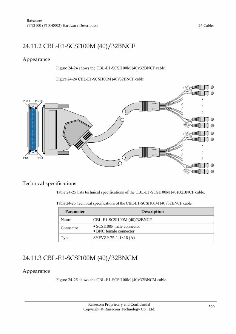
Raisecom
iTN2100 (P100R002) Hardware Description 24 Cables
Raisecom Proprietary and Confidential
Copyright © Raisecom Technology Co., Ltd. 390
24.11.2 CBL-E1-SCSI100M (40)/32BNCF
Appearance
Figure 24-24 shows the CBL-E1-SCSI100M (40)/32BNCF cable.
Figure 24-24 CBL-E1-SCSI100M (40)/32BNCF cable
Technical specifications
Table 24-25 lists technical specifications of the CBL-E1-SCSI100M (40)/32BNCF cable.
Table 24-25 Technical specifications of the CBL-E1-SCSI100M (40)/32BNCF cable
Parameter Description
Name CBL-E1-SCSI100M (40)/32BNCF
Connector SCSI100P male connector BNC female connector
Type SYFVZP-75-1-1×16 (A)
24.11.3 CBL-E1-SCSI100M (40)/32BNCM
Appearance
Figure 24-25 shows the CBL-E1-SCSI100M (40)/32BNCM cable.

Raisecom
iTN2100 (P100R002) Hardware Description 24 Cables
Raisecom Proprietary and Confidential
Copyright © Raisecom Technology Co., Ltd. 391
Figure 24-25 CBL-E1-SCSI100M (40)/32BNCM cable
Technical specifications
Table 24-26 lists technical specifications of the CBL-E1-SCSI100M (40)/32BNCM cable.
Table 24-26 Technical specifications of the CBL-E1-SCSI100M (40)/32BNCM cable
Parameter Description
Name CBL-E1-SCSI100M (40)/32BNCM
Connector SCSI100P male connector BNC male connector
Type SYFVZP-75-1-1×16 (A)
24.11.4 CBL-E1-SCSI100M (40)/16RJ45
Appearance
Figure 24-26 shows the CBL-E1-SCSI100M (40)/16RJ45 cable.
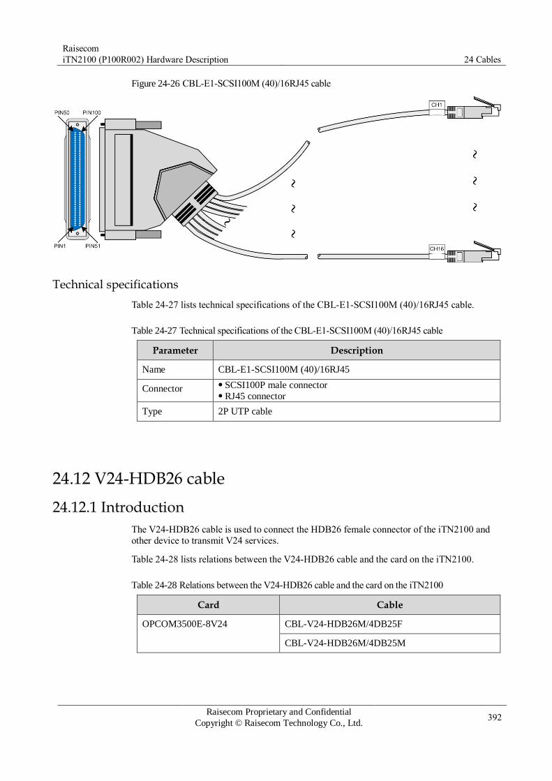
Raisecom
iTN2100 (P100R002) Hardware Description 24 Cables
Raisecom Proprietary and Confidential
Copyright © Raisecom Technology Co., Ltd. 392
Figure 24-26 CBL-E1-SCSI100M (40)/16RJ45 cable
Technical specifications
Table 24-27 lists technical specifications of the CBL-E1-SCSI100M (40)/16RJ45 cable.
Table 24-27 Technical specifications of the CBL-E1-SCSI100M (40)/16RJ45 cable
Parameter Description
Name CBL-E1-SCSI100M (40)/16RJ45
Connector SCSI100P male connector RJ45 connector
Type 2P UTP cable
24.12 V24-HDB26 cable
24.12.1 Introduction
The V24-HDB26 cable is used to connect the HDB26 female connector of the iTN2100 and
other device to transmit V24 services.
Table 24-28 lists relations between the V24-HDB26 cable and the card on the iTN2100.
Table 24-28 Relations between the V24-HDB26 cable and the card on the iTN2100
Card Cable
OPCOM3500E-8V24 CBL-V24-HDB26M/4DB25F
CBL-V24-HDB26M/4DB25M
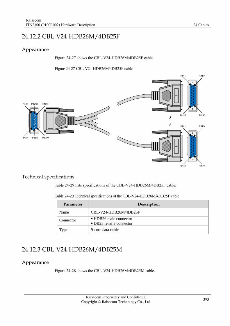
Raisecom
iTN2100 (P100R002) Hardware Description 24 Cables
Raisecom Proprietary and Confidential
Copyright © Raisecom Technology Co., Ltd. 393
24.12.2 CBL-V24-HDB26M/4DB25F
Appearance
Figure 24-27 shows the CBL-V24-HDB26M/4DB25F cable.
Figure 24-27 CBL-V24-HDB26M/4DB25F cable
Technical specifications
Table 24-29 lists specifications of the CBL-V24-HDB26M/4DB25F cable.
Table 24-29 Technical specifications of the CBL-V24-HDB26M/4DB25F cable
Parameter Description
Name CBL-V24-HDB26M/4DB25F
Connector HDB26 male connector DB25 female connector
Type 9-core data cable
24.12.3 CBL-V24-HDB26M/4DB25M
Appearance
Figure 24-28 shows the CBL-V24-HDB26M/4DB25M cable.
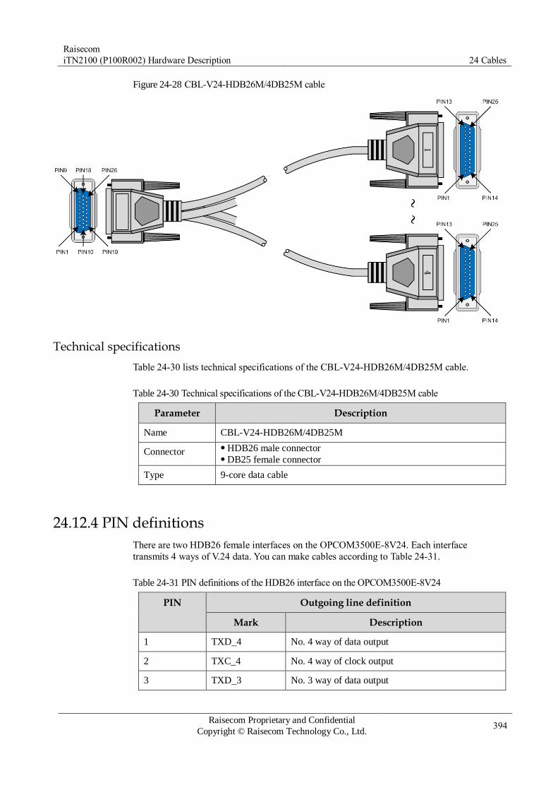
Raisecom
iTN2100 (P100R002) Hardware Description 24 Cables
Raisecom Proprietary and Confidential
Copyright © Raisecom Technology Co., Ltd. 394
Figure 24-28 CBL-V24-HDB26M/4DB25M cable
Technical specifications
Table 24-30 lists technical specifications of the CBL-V24-HDB26M/4DB25M cable.
Table 24-30 Technical specifications of the CBL-V24-HDB26M/4DB25M cable
Parameter Description
Name CBL-V24-HDB26M/4DB25M
Connector HDB26 male connector DB25 female connector
Type 9-core data cable
24.12.4 PIN definitions
There are two HDB26 female interfaces on the OPCOM3500E-8V24. Each interface
transmits 4 ways of V.24 data. You can make cables according to Table 24-31.
Table 24-31 PIN definitions of the HDB26 interface on the OPCOM3500E-8V24
PIN Outgoing line definition
Mark Description
1 TXD_4 No. 4 way of data output
2 TXC_4 No. 4 way of clock output
3 TXD_3 No. 3 way of data output

Raisecom
iTN2100 (P100R002) Hardware Description 24 Cables
Raisecom Proprietary and Confidential
Copyright © Raisecom Technology Co., Ltd. 395
PIN Outgoing line definition
Mark Description
4 TXC_3 No. 3 way of clock output
5 TXD_2 No. 2 way of data output
6 TXC_2 No. 2 way of clock output
7 TXD_1 No. 1 way of data output
8 TXC_1 No. 1 way of clock output
9, 10 NC Idle
11 RXD_4 No. 4 way of data input
12 RXC_4 No. 4 way of clock input
13 RXD_3 No. 3 way of data input
14 RXC_3 No. 3 way of clock input
15 RXD_2 No. 2 way of data input
16 RXC_2 No. 2 way of clock input
17 RXD_1 No. 1 way of data input
18 RXC_1 No. 1 way of clock input
19–26 GND Grounding
24.13 V35-HDB26 cable
24.13.1 Introduction
The V35-HDB26 cable is used to connect the HDB26 female connector and other devices to
transmit V.35 services. The unshielded cable is used on V.35 interface card to ensure lightning
protection.
Table 24-32 lists relations between the V35-HDB26 cable and the card on the iTN2100.
Table 24-32 Relations between the V35-HDB26 cable and the card on the iTN2100
Card Cable
OPCOM3500E-8V35 CBL-V35-HDB26M/2M34F (unshielded cable)
CBL-V35-HDB26M/2M34M (unshielded cable)

Raisecom
iTN2100 (P100R002) Hardware Description 24 Cables
Raisecom Proprietary and Confidential
Copyright © Raisecom Technology Co., Ltd. 396
24.13.2 CBL-V35-HDB26M/2M34F
Appearance
Figure 24-29 shows the CBL-V35-HDB26M/2M34F cable.
Figure 24-29 CBL-V35-HDB26M/2M34F cable
Technical specifications
Table 24-33 lists technical specifications of the CBL-V35-HDB26M/2M34F cable.
Table 24-33 Technical specifications of the CBL-V35-HDB26M/2M34F cable
Parameter Description
Name CBL-V35-HDB26M/2M34F
Connector HDB26 male connector M34 female connector
Type 9.5P+1+B+AL cable
24.13.3 PIN definitions
There are four HDB26 female interfaces on the OPCOM3500E-8V35. Each interface
transmits 2 ways of V.35 data. You can make cables according to Table 24-34.
Table 24-34 PIN definitions of the HDB26 interface on the OPCOM3500E-8V35
PIN Outgoing line definition for No. 1 way of V.35 data
Outgoing line definition for No. 2 way of V.35 data
1 PGND
2 TD (A)
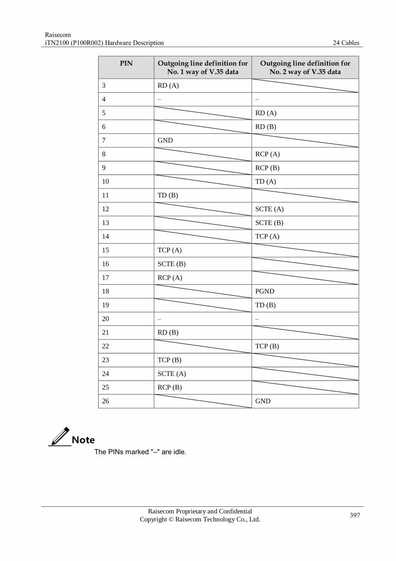
Raisecom
iTN2100 (P100R002) Hardware Description 24 Cables
Raisecom Proprietary and Confidential
Copyright © Raisecom Technology Co., Ltd. 397
PIN Outgoing line definition for No. 1 way of V.35 data
Outgoing line definition for No. 2 way of V.35 data
3 RD (A)
4 – –
5 RD (A)
6 RD (B)
7 GND
8 RCP (A)
9 RCP (B)
10 TD (A)
11 TD (B)
12 SCTE (A)
13 SCTE (B)
14 TCP (A)
15 TCP (A)
16 SCTE (B)
17 RCP (A)
18 PGND
19 TD (B)
20 – –
21 RD (B)
22 TCP (B)
23 TCP (B)
24 SCTE (A)
25 RCP (B)
26 GND
The PINs marked "–" are idle.

Raisecom
iTN2100 (P100R002) Hardware Description 24 Cables
Raisecom Proprietary and Confidential
Copyright © Raisecom Technology Co., Ltd. 398
24.14 MUL-HDB26 cable
24.14.1 Introduction
The MUL-HDB26 cable is used to connect the HDB26 female connector and other devices to
transmit MULTI services.
Table 24-35 lists relations between the MUL-HDB26 cable and the card on the iTN2100.
Table 24-35 Relations between the MUL-HDB26 cable and the card on the iTN2100
Card Cable
OPCOM3500E-MULTI CBL-MUL-HDB26M/NC
CBL-MUL-HDB26M (40)/NC
OPCOM3500E-12MT CBL-MUL-HDB26M (40)/NC
OPCOM3500E-8MT CBL-MUL-HDB26M (40)/NC
24.14.2 CBL-MUL-HDB26M/NC
Appearance
Figure 24-30 shows the CBL-MUL-HDB26M/NC cable.
Figure 24-30 CBL-MUL-HDB26M/NC cable
Technical specifications
Table 24-36 lists technical specifications of the CBL-MUL-HDB26M/NC cable.
Table 24-36 Technical specifications of the CBL-MUL-HDB26M/NC cable
Parameter Description
Name CBL-MUL-HDB26M/NC
Connector HDB26 male connector
Description HDB26 male connector to 4-way NC E&M cable. The cable length
can be customized: 2.5 m/5 m/10 m/15 m/25 m.

Raisecom
iTN2100 (P100R002) Hardware Description 24 Cables
Raisecom Proprietary and Confidential
Copyright © Raisecom Technology Co., Ltd. 399
Color patterns
Table 24-37 lists color patterns of the CBL-MUL-HDB26M/NC cable.
Table 24-37 Color patterns of the CBL-MUL-HDB26M/NC cable
HDB26M HDB26M PIN definition
Line color Pair color
1 TXD-8 Blue/White White
11 RXD-8 White/Blue
2 TXD-7 Orange/White
12 RXD-7 White/Orange
20 GND7 Brown/White
White/Brown
3 TXD-6 Green/White
13 RXD-6 White/Green
21 GND6 Grey/White
White/Grey
4 TXD-5 Grey/Red Red
14 RXD-5 Red/Grey
5 TXD-4 Brown/Red
15 RXD-4 Red/Brown
6 TXD-3 Orange/Red
16 RXD-3 Red/Orange
7 TXD-2 Green/Red
17 RXD-2 Red/Green
8 TXD-1 Blue/Red
18 RXD-1 Red/Blue
22 GND5 Grey/Black Black
Black/Grey
23 GND4 Brown/Black
Black/Brown
24 GND3 Orange/Black
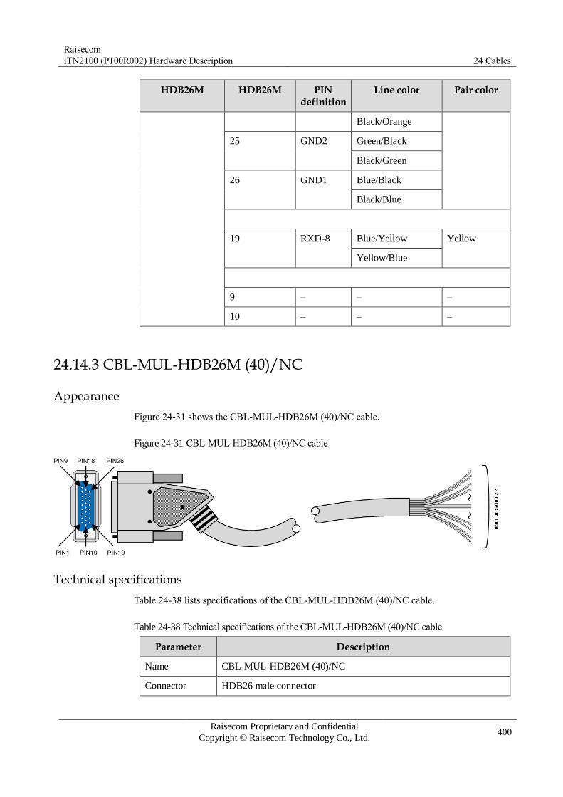
Raisecom
iTN2100 (P100R002) Hardware Description 24 Cables
Raisecom Proprietary and Confidential
Copyright © Raisecom Technology Co., Ltd. 400
HDB26M HDB26M PIN definition
Line color Pair color
Black/Orange
25 GND2 Green/Black
Black/Green
26 GND1 Blue/Black
Black/Blue
19 RXD-8 Blue/Yellow Yellow
Yellow/Blue
9 – – –
10 – – –
24.14.3 CBL-MUL-HDB26M (40)/NC
Appearance
Figure 24-31 shows the CBL-MUL-HDB26M (40)/NC cable.
Figure 24-31 CBL-MUL-HDB26M (40)/NC cable
Technical specifications
Table 24-38 lists specifications of the CBL-MUL-HDB26M (40)/NC cable.
Table 24-38 Technical specifications of the CBL-MUL-HDB26M (40)/NC cable
Parameter Description
Name CBL-MUL-HDB26M (40)/NC
Connector HDB26 male connector

Raisecom
iTN2100 (P100R002) Hardware Description 24 Cables
Raisecom Proprietary and Confidential
Copyright © Raisecom Technology Co., Ltd. 401
Parameter Description
Description (Angled) HDB26 male connector to 4 way of NC E&M cable. The
cable length can be customized: 2.5 m/5 m/10 m/15 m/25 m. (Angled) HDB26 male connector to 8 way of NC E&M cable. The
cable length can be customized: 2.5 m/5 m/10 m/15 m/25 m.
Color patterns
Table 24-39 lists color patterns of the CBL-MUL-HDB26M (40)/NC cable.
Table 24-39 Color patterns of the CBL-MUL-HDB26M (40)/NC cable
HDB26M PIN PIN definition
Line color Secondary color
Primary color
7 CH-01A White background
and blue ring
Blue White
17 CH-01B Blue background and
white ring
8 CH-02A White background
and orange ring
Orange
18 CH-02B Orange background
and white ring
25 CH-03A White background
and green ring
Green
26 CH-03B Green background
and white ring
5 CH-04A White background
and brown ring
Brown
15 CH-04B Brown background
and white ring
6 CH-05A White background
and grey ring
Grey
16 CH-05B Grey background and
white ring
23 CH-06A Red background and
blue ring
Blue Red
24 CH-06B Blue background and
red ring
3 CH-07A Red background and
orange ring
Orange

Raisecom
iTN2100 (P100R002) Hardware Description 24 Cables
Raisecom Proprietary and Confidential
Copyright © Raisecom Technology Co., Ltd. 402
HDB26M PIN PIN definition
Line color Secondary color
Primary color
13 CH-07B Orange background
and red ring
4 CH-08A Red background and
green ring
Green
14 CH-08B Green background
and red ring
21 CH-09A Red background and
brown ring
Brown
22 CH-09B Brown background
and red ring
1 CH-10A Red background and
grey ring
Grey
11 CH-10B Grey background and
red ring
2 CH-11A Black background and
blue ring
Blue Black
12 CH-11B Blue background and
black ring
19 CH-12A Black background and
orange ring
Orange
20 CH-12B Orange background
and black ring
9 CH-13A Black background and
orange ring
Green
10 CH-13B Orange background
and black ring
HDB26 shell
K1 Black background and brown ring
Brown
Brown background
and black ring
HDB26
shell
K2 Black background and
grey ring
Grey
Grey background and
black ring
HDB26
shell
K3 Black background and
yellow ring
Blue Yellow

Raisecom
iTN2100 (P100R002) Hardware Description 24 Cables
Raisecom Proprietary and Confidential
Copyright © Raisecom Technology Co., Ltd. 403
HDB26M PIN PIN definition
Line color Secondary color
Primary color
Yellow background
and black ring
24.15 Audio cable
24.15.1 Introduction
The audio cable is used to connect the DB37 male interface of the iTN2100 and other devices
to transmit voice services.
Table 24-40 lists relations between the audio cable and the card on the iTN2100.
Table 24-40 Relations between the VOICE-DB37F cable and the card on the iTN2100
Card Cable
OPCOM3500E-Audio CBL-VOICE-DB37F/NC-D
24.15.2 CBL-VOICE-DB37F/NC-D
Appearance
Figure 24-32 shows the CBL-VOICE-DB37F/NC-D cable.
Figure 24-32 CBL-VOICE-DB37F/NC-D cable
Technical specifications
Table 24-41 Technical specifications of the CBL-VOICE-DB37F/NC-D cable
Parameter Description
Name CBL-VOICE-DB37F/NC-D

Raisecom
iTN2100 (P100R002) Hardware Description 24 Cables
Raisecom Proprietary and Confidential
Copyright © Raisecom Technology Co., Ltd. 404
Parameter Description
Connector DB37 female connector
Description M37 female connector to NC audio cable. The cable length can be
customized: 2.5/5/10/15/25 m
Color patterns
Table 24-42 lists color patterns of the CBL-VOICE-DB37F/NC-D cable.
Table 24-42 Color patterns of the CBL-VOICE-DB37F/NC-D cable
DB37F PIN PIN definition Line color Pair color
3 CHANN1+ Blue/White White
21 CHANN1- White/Blue
4 CHANN2+ Green/White
22 CHANN2- White/Green
5 CHANN3+ Orange/White
23 CHANN3- White/Orange
6 CHANN4+ Brown/White
24 CHANN4- White/Brown
7 CHANN5+ Grey/White
25 CHANN5- White/Grey
8 CHANN6+ Blue/Red Red
26 CHANN6- Red/Blue
9 CHANN7+ Green/Red
27 CHANN7- Red/Green
10 CHANN8+ Orange/Red
28 CHANN8- Red/Orange
11 CHANN9+ Brown/Red
29 CHANN9- Red/Brown
12 CHANN10+ Grey/Red
30 CHANN10- Red/Grey
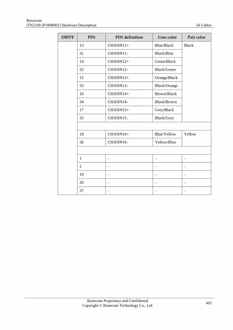
Raisecom
iTN2100 (P100R002) Hardware Description 24 Cables
Raisecom Proprietary and Confidential
Copyright © Raisecom Technology Co., Ltd. 405
DB37F PIN PIN definition Line color Pair color
13 CHANN11+ Blue/Black Black
31 CHANN11- Black/Blue
14 CHANN12+ Green/Black
32 CHANN12- Black/Green
15 CHANN13+ Orange/Black
33 CHANN13- Black/Orange
16 CHANN14+ Brown/Black
34 CHANN14- Black/Brown
17 CHANN15+ Grey/Black
35 CHANN15- Black/Grey
18 CHANN16+ Blue/Yellow Yellow
36 CHANN16- Yellow/Blue
1 – – –
2 – – –
19 – – –
20 – – –
37 – – –

Raisecom
iTN2100 (P100R002) Hardware Description 25 Appendix
Raisecom Proprietary and Confidential
Copyright © Raisecom Technology Co., Ltd. 406
25 Appendix
This chapter lists terms, acronyms, and abbreviations involved in this guide.
Power consumption of optical/electrical modules
Metrics of SFP optical modules
Parameters of XFP optical modules
Wiring
Terms
Acronyms and abbreviations
25.1 Power consumption of optical/electrical modules
25.1.1 SFP modules
Table 25-1 lists the power consumption of Raisecom SFP modules.
Table 25-1 Power consumption of SFP modules
Model Maximum power consumption (W)
CSFP-Gb/L/xx-D-R
CSFP-48/L/xx-D-R
DSFP-48/L/xx-D-R
USFP-FE/AN-R
USFP-Gb/EX-D-R
USFP-GE-R
USFP-GE/AN-R
USFP-48/S3-D-R
USFP-48/SS3x-D-R
1.32
Other modules 0.66

Raisecom
iTN2100 (P100R002) Hardware Description 25 Appendix
Raisecom Proprietary and Confidential
Copyright © Raisecom Technology Co., Ltd. 407
25.1.2 XFP modules
Table 25-2 lists the power consumption of Raisecom XFP modules.
Table 25-2 Power consumption of Raisecom XFP modules
Type Model Maximum power consumption (W)
CXFP All modules 3.5
DXFP All modules 3.5
UXFP UXFP-192/M 1.5
UXFP-192/S1 2.5
UXFP-192/S2
UXFP-192/S3
3.5
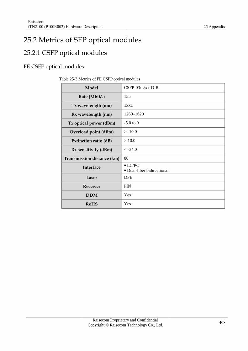
Raisecom
iTN2100 (P100R002) Hardware Description 25 Appendix
Raisecom Proprietary and Confidential
Copyright © Raisecom Technology Co., Ltd. 408
25.2 Metrics of SFP optical modules
25.2.1 CSFP optical modules
FE CSFP optical modules
Table 25-3 Metrics of FE CSFP optical modules
Model CSFP-03/L/xx-D-R
Rate (Mbit/s) 155
Tx wavelength (nm) 1xx1
Rx wavelength (nm) 1260–1620
Tx optical power (dBm) -5.0 to 0
Overload point (dBm) > -10.0
Extinction ratio (dB) > 10.0
Rx sensitivity (dBm) < -34.0
Transmission distance (km) 80
Interface LC/PC Dual-fiber bidirectional
Laser DFB
Receiver PIN
DDM Yes
RoHS Yes
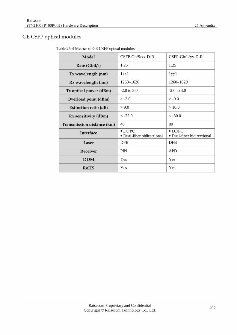
Raisecom
iTN2100 (P100R002) Hardware Description 25 Appendix
Raisecom Proprietary and Confidential
Copyright © Raisecom Technology Co., Ltd. 409
GE CSFP optical modules
Table 25-4 Metrics of GE CSFP optical modules
Model CSFP-Gb/S/xx-D-R CSFP-Gb/L/yy-D-R
Rate (Gbit/s) 1.25 1.25
Tx wavelength (nm) 1xx1 1yy1
Rx wavelength (nm) 1260–1620 1260–1620
Tx optical power (dBm) -2.0 to 3.0 -2.0 to 3.0
Overload point (dBm) > -3.0 > -9.0
Extinction ratio (dB) > 9.0 > 10.0
Rx sensitivity (dBm) < -22.0 < -30.0
Transmission distance (km) 40 80
Interface LC/PC Dual-fiber bidirectional
LC/PC Dual-fiber bidirectional
Laser DFB DFB
Receiver PIN APD
DDM Yes Yes
RoHS Yes Yes
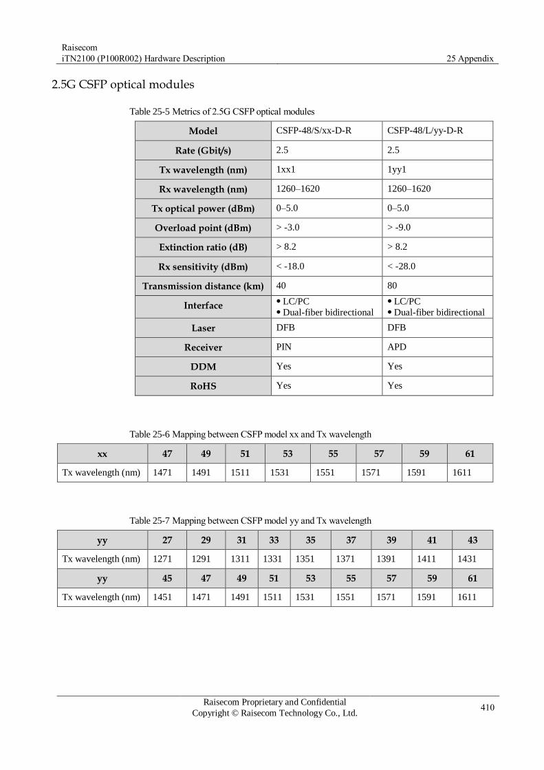
Raisecom
iTN2100 (P100R002) Hardware Description 25 Appendix
Raisecom Proprietary and Confidential
Copyright © Raisecom Technology Co., Ltd. 410
2.5G CSFP optical modules
Table 25-5 Metrics of 2.5G CSFP optical modules
Model CSFP-48/S/xx-D-R CSFP-48/L/yy-D-R
Rate (Gbit/s) 2.5 2.5
Tx wavelength (nm) 1xx1 1yy1
Rx wavelength (nm) 1260–1620 1260–1620
Tx optical power (dBm) 0–5.0 0–5.0
Overload point (dBm) > -3.0 > -9.0
Extinction ratio (dB) > 8.2 > 8.2
Rx sensitivity (dBm) < -18.0 < -28.0
Transmission distance (km) 40 80
Interface LC/PC Dual-fiber bidirectional
LC/PC Dual-fiber bidirectional
Laser DFB DFB
Receiver PIN APD
DDM Yes Yes
RoHS Yes Yes
Table 25-6 Mapping between CSFP model xx and Tx wavelength
xx 47 49 51 53 55 57 59 61
Tx wavelength (nm) 1471 1491 1511 1531 1551 1571 1591 1611
Table 25-7 Mapping between CSFP model yy and Tx wavelength
yy 27 29 31 33 35 37 39 41 43
Tx wavelength (nm) 1271 1291 1311 1331 1351 1371 1391 1411 1431
yy 45 47 49 51 53 55 57 59 61
Tx wavelength (nm) 1451 1471 1491 1511 1531 1551 1571 1591 1611
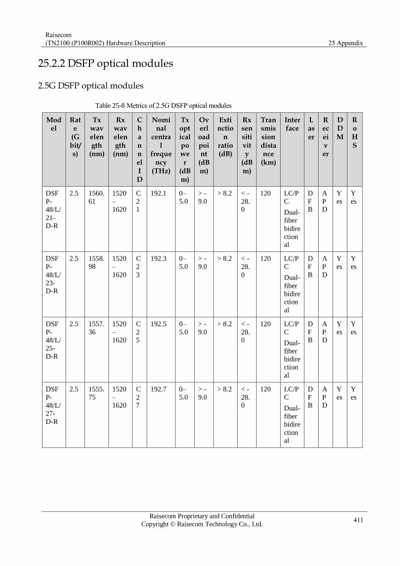
Raisecom
iTN2100 (P100R002) Hardware Description 25 Appendix
Raisecom Proprietary and Confidential
Copyright © Raisecom Technology Co., Ltd. 411
25.2.2 DSFP optical modules
2.5G DSFP optical modules
Table 25-8 Metrics of 2.5G DSFP optical modules
Model
Rate
(Gbit/s)
Tx wavelength
(nm)
Rx wavelength
(nm)
Channel ID
Nominal
central
frequency
(THz)
Tx optical power
(dBm)
Overload point
(dBm)
Extinctio
n ratio (dB)
Rx sensitivity
(dBm)
Transmission distance
(km)
Interface
Laser
Receiver
DDM
RoHS
DSF
P-
48/L/
21-D-R
2.5 1560.
61
1520
–1620
C
21
192.1 0–
5.0
> -
9.0 > 8.2 < -
28.0
120 LC/P
C
Dual-
fiber
bidire
ctional
D
FB
A
PD
Y
es
Y
es
DSF
P-
48/L/
23-D-R
2.5 1558.
98
1520
–
1620
C
2
3
192.3 0–
5.0
> -
9.0 > 8.2 < -
28.
0
120 LC/P
C
Dual-
fiber
bidire
ction
al
D
F
B
A
P
D
Y
es
Y
es
DSF
P-
48/L/
25-
D-R
2.5 1557.
36
1520
–1620
C
25
192.5 0–
5.0
> -
9.0 > 8.2 < -
28.0
120 LC/P
C
Dual-
fiber
bidire
ction
al
D
FB
A
PD
Y
es
Y
es
DSF
P-
48/L/
27-
D-R
2.5 1555.
75
1520
–1620
C
27
192.7 0–
5.0
> -
9.0 > 8.2 < -
28.0
120 LC/P
C
Dual-
fiber
bidire
ctional
D
FB
A
PD
Y
es
Y
es

Raisecom
iTN2100 (P100R002) Hardware Description 25 Appendix
Raisecom Proprietary and Confidential
Copyright © Raisecom Technology Co., Ltd. 412
Model
Rate
(Gbit/s)
Tx wavelength
(nm)
Rx wavelength
(nm)
Channel ID
Nominal
central
frequency
(THz)
Tx optical power
(dBm)
Overload point
(dBm)
Extinctio
n ratio (dB)
Rx sensitivity
(dBm)
Transmission distance
(km)
Interface
Laser
Receiver
DDM
RoHS
DSF
P-
48/L/
29-
D-R
2.5 1554.
13
1520
–1620
C
29
192.9 0–
5.0
> -
9.0 > 8.2 < -
28.0
120 LC/P
C
Dual-
fiber
bidire
ctional
D
FB
A
PD
Y
es
Y
es
DSF
P-
48/L/
31-D-R
2.5 1552.
52
1520
–1620
C
31
193.1 0–
5.0
> -
9.0 > 8.2 < -
28.0
120 LC/P
C
Dual-
fiber
bidire
ctional
D
FB
A
PD
Y
es
Y
es
DSF
P-
48/L/
33-D-R
2.5 1550.
92
1520
–
1620
C
3
3
193.3 0–
5.0
> -
9.0 > 8.2 < -
28.
0
120 LC/P
C
Dual-
fiber
bidire
ctional
D
F
B
A
P
D
Y
es
Y
es
DSF
P-
48/L/
35-D-R
2.5 1549.
32
1520
–1620
C
35
193.5 0–
5.0
> -
9.0 > 8.2 < -
28.0
120 LC/P
C
Dual-
fiber
bidire
ction
al
D
FB
A
PD
Y
es
Y
es
DSF
P-
48/L/
37-
D-R
2.5 1547.
72
1520
–1620
C
37
193.7 0–
5.0
> -
9.0 > 8.2 < -
28.0
120 LC/P
C
Dual-
fiber
bidire
ctional
D
FB
A
PD
Y
es
Y
es

Raisecom
iTN2100 (P100R002) Hardware Description 25 Appendix
Raisecom Proprietary and Confidential
Copyright © Raisecom Technology Co., Ltd. 413
Model
Rate
(Gbit/s)
Tx wavelength
(nm)
Rx wavelength
(nm)
Channel ID
Nominal
central
frequency
(THz)
Tx optical power
(dBm)
Overload point
(dBm)
Extinctio
n ratio (dB)
Rx sensitivity
(dBm)
Transmission distance
(km)
Interface
Laser
Receiver
DDM
RoHS
DSF
P-
48/L/
39-
D-R
2.5 1546.
12
1520
–1620
C
39
193.9 0–
5.0
> -
9.0 > 8.2 < -
28.0
120 LC/P
C
Dual-
fiber
bidire
ctional
D
FB
A
PD
Y
es
Y
es
DSF
P-
48/L/
41-D-R
2.5 1544.
53
1520
–
1620
C
4
1
194.1 0–
5.0
> -
9.0 > 8.2 < -
28.
0
120 LC/P
C
Dual-
fiber
bidire
ction
al
D
F
B
A
P
D
Y
es
Y
es
DSF
P-
48/L/
43-
D-R
2.5 1542.
94
1520
–1620
C
43
194.3 0–
5.0
> -
9.0 > 8.2 < -
28.0
120 LC/P
C
Dual-
fiber
bidire
ctional
D
FB
A
PD
Y
es
Y
es
DSF
P-
48/L/
45-
D-R
2.5 1541.
35
1520
–1620
C
45
194.5 0–
5.0
> -
9.0 > 8.2 < -
28.0
120 LC/P
C
Dual-
fiber
bidire
ctional
D
FB
A
PD
Y
es
Y
es
DSF
P-
48/L/
47-D-R
2.5 1539.
77
1520
–1620
C
47
194.7 0–
5.0
> -
9.0 > 8.2 < -
28.0
120 LC/P
C
Dual-
fiber
bidire
ctional
D
FB
A
PD
Y
es
Y
es

Raisecom
iTN2100 (P100R002) Hardware Description 25 Appendix
Raisecom Proprietary and Confidential
Copyright © Raisecom Technology Co., Ltd. 414
Model
Rate
(Gbit/s)
Tx wavelength
(nm)
Rx wavelength
(nm)
Channel ID
Nominal
central
frequency
(THz)
Tx optical power
(dBm)
Overload point
(dBm)
Extinctio
n ratio (dB)
Rx sensitivity
(dBm)
Transmission distance
(km)
Interface
Laser
Receiver
DDM
RoHS
DSF
P-
48/L/
49-
D-R
2.5 1538.
19
1520
–1620
C
49
194.9 0–
5.0
> -
9.0 > 8.2 < -
28.0
120 LC/P
C
Dual-
fiber
bidire
ctional
D
FB
A
PD
Y
es
Y
es
DSF
P-
48/L/
51-D-R
2.5 1536.
61
1520
–1620
C
51
195.1 0–
5.0
> -
9.0 > 8.2 < -
28.0
120 LC/P
C
Dual-
fiber
bidire
ctional
D
FB
A
PD
Y
es
Y
es

Raisecom
iTN2100 (P100R002) Hardware Description 25 Appendix
Raisecom Proprietary and Confidential
Copyright © Raisecom Technology Co., Ltd. 415
25.2.3 GSFP optical modules
Table 25-9 Parameters of GSFP optical modules
Model GSFP-PX20DM-R GSFP-PX20DM-
RI
GSFP-CLBDM-R GSFP-CLCDM-R
Rate (Gbit/s) Uplink: 1.244 Downlink: 1.244
Uplink: 1.244 Downlink: 1.244
Uplink: 1.244 Downlink:
2.488
Uplink: 1.244 Downlink: 2.488
Tx wavelength (nm) 1490 1490 1490 1490
Rx wavelength (nm) 1260–1360 1260–1360 1260–1360 1280–1360
Tx optical power (dBm)
2.5–7.0 2.5–7.0 1.5–5.0 3.0–7.0
Overload point (dBm)
> -6.0 > -6.0 > -8.0 > -12.0
Extinction ratio (dB) > 9.0 > 9.0 > 8.2 > 8.2
Rx sensitivity (dBm) < -30.0 < -30.0 < -28.0 < -30.0
Mode SM SM SM SM
Transmission distance (km)
20 20 20 60
Interface SC/PC Single-fiber
bidirectional
SC/PC Single-fiber
bidirectional
SC/PC Single-fiber
bidirectional
SC/PC Single-fiber
bidirectional
Laser DFB DFB DFB DFB
Receiver PIN DFB DFB DFB
DDM Yes Yes Yes Yes
RoHS Yes Yes Yes Yes

Raisecom
iTN2100 (P100R002) Hardware Description 25 Appendix
Raisecom Proprietary and Confidential
Copyright © Raisecom Technology Co., Ltd. 416
25.2.4 TSFP optical modules
FE TSFP optical modules
Table 25-10 Parameters of FE TSFP optical modules
Model TSFP-03/DS15-3
Rate (Mbit/s) 155
Tx wavelength (nm) 1550
Rx wavelength (nm) 1260–1360
Tx optical power (dBm) -14.0 to -8.0
Overload point (dBm) > -8.0
Extinction ratio (dB) > 8.2
Rx sensitivity (dBm) < -28.0
Mode SM
Transmission distance (km) 15
Interface LC/PC Single-fiber bidirectional
Laser FP
Receiver PIN
DDM Yes
RoHS Yes

Raisecom
iTN2100 (P100R002) Hardware Description 25 Appendix
Raisecom Proprietary and Confidential
Copyright © Raisecom Technology Co., Ltd. 417
GE TSFP optical modules
Table 25-11 Parameters of GE TSFP optical modules
Model TSFP-Gb/DS14-3
Rate (Gbit/s) 1.25
Tx wavelength (nm) 1490
Rx wavelength (nm) 1260–1360
Tx optical power (dBm) -10.0 to -3.0
Overload point (dBm) > -3.0
Extinction ratio (dB) > 9.0
Rx sensitivity (dBm) < -21.0
Mode SM
Transmission distance (km) 15
Interface LC/PC Single-fiber bidirectional
Laser DFB
Receiver PIN
DDM Yes
RoHS Yes

Raisecom
iTN2100 (P100R002) Hardware Description 25 Appendix
Raisecom Proprietary and Confidential
Copyright © Raisecom Technology Co., Ltd. 418
25.2.5 USFP optical modules
FF USFP optical modules
Table 25-12 Parameters of FE USFP optical modules
Model Rate
(Mbit/s)
Tx wavelength (nm)
Rx wavelength (nm
)
Tx optical power
(dBm)
Overload
point
(dBm)
Extinction
ratio
(dB)
Rx sensitivity
(dBm)
Mode
Transmission distance (km)
Interface
Laser
Receiver
DDM
RoHS
USFP-
03/M-D-R
155 131
0
1270
–1380
-
20.
0 to
-
10.0
> -
10.0
>
10.0
< -
29.0
M
M
2 LC/PC
Dual-
fiber
bidirectional
LE
D
PIN Yes Yes
USFP-
03/S1-D-R
155 131
0
1260
–1620
-
15.
0 to -8.0
> -
8.0 >
10.0
< -
34.0
SM 15 LC/PC
Dual-
fiber
bidirectional
FP PIN Yes Yes
USFP-
03/S2-D-
R
155 131
0
1260
–
1620
-5.0
to 0
> -
8.0 >
8.2
< -
34.
0
SM 40 LC/PC
Dual-
fiber
bidirectional
DF
B/F
P
PIN Yes Yes
USFP-
03/S3-D-R
155 155
0
1260
–1620
-5.0
to 0
> -
10.0
>
10.0
< -
34.0
SM 80 LC/PC
Dual-
fiber
bidirec
tional
DF
B
PIN Yes Yes
USFP-
03/SS13-D-R
155 131
0
1480
–1580
-
15.
0 to -8.0
> -
8.0 >
8.2
< -
28.0
SM 15 LC/PC
Single-
fiber
bidirectional
FP/
DFB
PIN Yes Yes
USFP-
03/SS15-
D-R
155 155
0
1260
–
1360
-
15.
0 to -8.0
> -
8.0 >
8.2
< -
28.
0
SM 15 LC/PC
Single-
fiber
bidirectional
FP/
DF
B
PIN Yes Yes

Raisecom
iTN2100 (P100R002) Hardware Description 25 Appendix
Raisecom Proprietary and Confidential
Copyright © Raisecom Technology Co., Ltd. 419
Model Rate
(Mbit/s)
Tx wavelength (nm)
Rx wavelength (nm
)
Tx optical power
(dBm)
Overload
point
(dBm)
Extinction
ratio
(dB)
Rx sensitivity
(dBm)
Mode
Transmission distance (km)
Interface
Laser
Receiver
DDM
RoHS
USFP-
03/SS23-
D-R
155 131
0
1500
–
1580
-5.0
to 0
> -
8.0 >
8.2
< -
32.
0
SM 40 LC/PC
Single-
fiber
bidirectional
FP/
DF
B
PIN Yes Yes
USFP-
03/SS25-D-R
155 155
0
1270
–1350
-5.0
to 0
> -
8.0 >
8.2
< -
32.0
SM 40 LC/PC
Single-
fiber
bidirec
tional
FP/
DFB
PIN Yes Yes
USFP-
03/SS34-D-R
155 149
0
1530
–1580
-3.0
to 2.0
> -
8.0 >
8.2
< -
32.0
SM 80 LC/PC
Single-
fiber
bidirectional
FP/
DFB
PIN Yes Yes
USFP-
03/SS35-D-R
155 155
0
1470
–1510
-3.0
to 2.0
> -
8.0 >
8.2
< -
32.0
SM 80 LC/PC
Single-
fiber
bidirec
tional
FP/
DFB
PIN Yes Yes

Raisecom
iTN2100 (P100R002) Hardware Description 25 Appendix
Raisecom Proprietary and Confidential
Copyright © Raisecom Technology Co., Ltd. 420
GE USFP optical modules
Table 25-13 Parameters of GE USFP optical modules
Model Rate
(Gbit/s)
Tx wavelength (nm)
Rx wavelength (nm
)
Channel ID
Nominal central frequency (THz)
Tx optical power
(dBm)
Overload
point
(dBm)
Mode
Transmission distance (km)
Interface
Laser
Receiver
DDM
RoHS
USFP-
Gb/M-D-R
1.25 850 830–
870
-9.5
to -3.0
> 0 >
9.0
< -
17.0
M
M
0.5
5
LC/PC
Dual-
fiber
bidirectional
VC
SEL
PIN Yes Yes
USFP-
Gb/S1-D-
R
1.25 131
0
1260
–
1620
-
10.
0 to -3.0
> -
3.0 >
9.0
< -
21.
0
SM 15 LC/PC
Dual-
fiber
bidirectional
FP PIN Yes Yes
USFP-
Gb/LH1-D-R
1.25 131
0
1260
–1620
-4.0
to 0
> -
3.0 >
9.0
< -
21.0
SM 40 LC/PC
Dual-
fiber
bidirec
tional
DF
B
PIN Yes Yes
USFP-
Gb/S2-D-R
1.25 155
0
1260
–1620
-3.0
to 2.0
> -
3.0 >
9.0
< -
21.0
SM 60 LC/PC
Dual-
fiber
bidirectional
DF
B
PIN Yes Yes
USFP-
Gb/ZX-D-
R
1.25 155
0
1260
–
1620
-2.0
to
3.0
> -
3.0 >
9.0
< -
22.
0
SM 80 LC/PC
Dual-
fiber
bidirectional
DF
B
PIN Yes Yes
USFP-
Gb/S3-D-R
1.25 155
0
1260
–1620
-3.0
to 2.0
> -
9.0 >
9.0
< -
30.0
SM 80 LC/PC
Dual-
fiber
bidirectional
DF
B
AP
D
Yes Yes
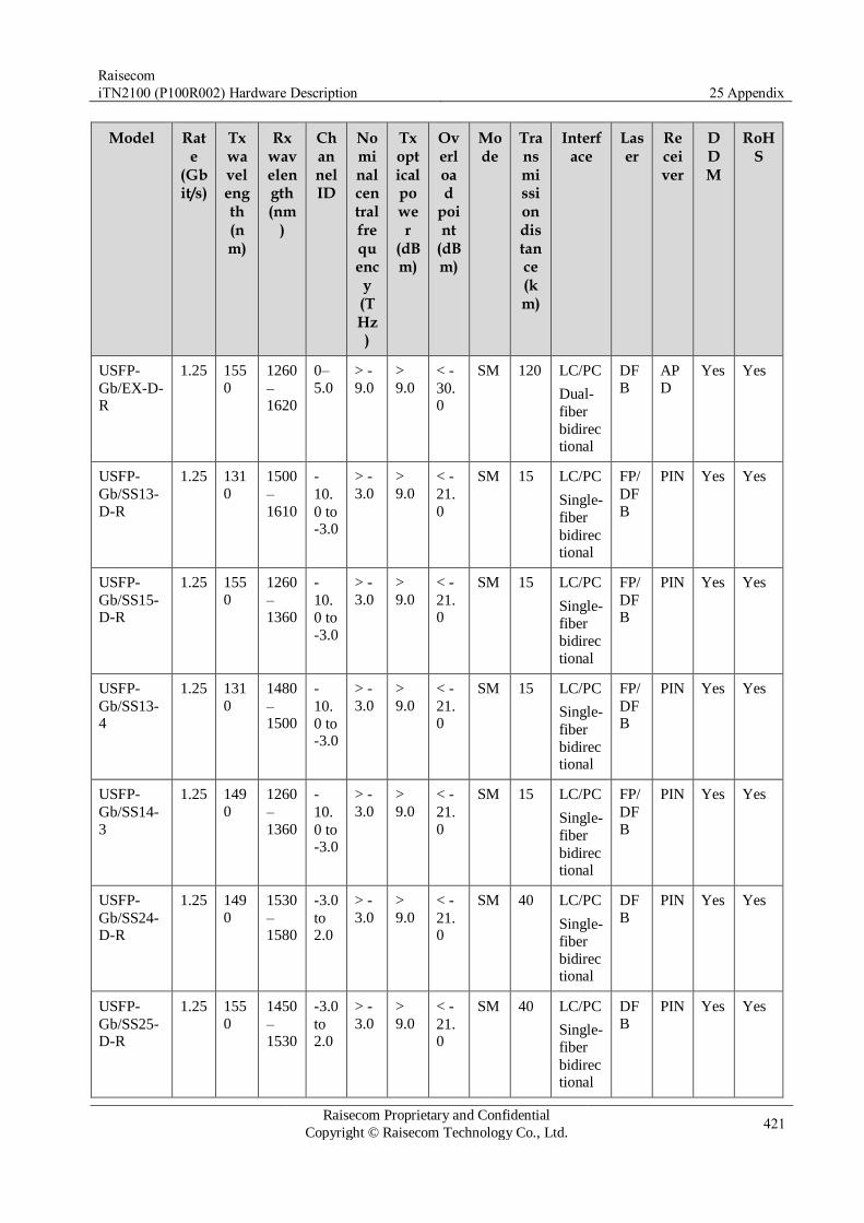
Raisecom
iTN2100 (P100R002) Hardware Description 25 Appendix
Raisecom Proprietary and Confidential
Copyright © Raisecom Technology Co., Ltd. 421
Model Rate
(Gbit/s)
Tx wavelength (nm)
Rx wavelength (nm
)
Channel ID
Nominal central frequency (THz)
Tx optical power
(dBm)
Overload
point
(dBm)
Mode
Transmission distance (km)
Interface
Laser
Receiver
DDM
RoHS
USFP-
Gb/EX-D-R
1.25 155
0
1260
–1620
0–
5.0
> -
9.0 >
9.0
< -
30.0
SM 120 LC/PC
Dual-
fiber
bidirectional
DF
B
AP
D
Yes Yes
USFP-
Gb/SS13-
D-R
1.25 131
0
1500
–
1610
-
10.
0 to -3.0
> -
3.0 >
9.0
< -
21.
0
SM 15 LC/PC
Single-
fiber
bidirectional
FP/
DF
B
PIN Yes Yes
USFP-
Gb/SS15-D-R
1.25 155
0
1260
–1360
-
10.
0 to
-3.0
> -
3.0 >
9.0
< -
21.0
SM 15 LC/PC
Single-
fiber
bidirec
tional
FP/
DFB
PIN Yes Yes
USFP-
Gb/SS13-4
1.25 131
0
1480
–1500
-
10.
0 to -3.0
> -
3.0 >
9.0
< -
21.0
SM 15 LC/PC
Single-
fiber
bidirectional
FP/
DFB
PIN Yes Yes
USFP-
Gb/SS14-
3
1.25 149
0
1260
–
1360
-
10.
0 to -3.0
> -
3.0 >
9.0
< -
21.
0
SM 15 LC/PC
Single-
fiber
bidirectional
FP/
DF
B
PIN Yes Yes
USFP-
Gb/SS24-D-R
1.25 149
0
1530
–1580
-3.0
to 2.0
> -
3.0 >
9.0
< -
21.0
SM 40 LC/PC
Single-
fiber
bidirectional
DF
B
PIN Yes Yes
USFP-
Gb/SS25-D-R
1.25 155
0
1450
–1530
-3.0
to 2.0
> -
3.0 >
9.0
< -
21.0
SM 40 LC/PC
Single-
fiber
bidirectional
DF
B
PIN Yes Yes

Raisecom
iTN2100 (P100R002) Hardware Description 25 Appendix
Raisecom Proprietary and Confidential
Copyright © Raisecom Technology Co., Ltd. 422
Model Rate
(Gbit/s)
Tx wavelength (nm)
Rx wavelength (nm
)
Channel ID
Nominal central frequency (THz)
Tx optical power
(dBm)
Overload
point
(dBm)
Mode
Transmission distance (km)
Interface
Laser
Receiver
DDM
RoHS
USFP-
Gb/SS34-D-R
1.25 149
0
1530
–1580
-2.0
to 3.0
> -
9.0 >
9.0
< -
30.0
SM 80 LC/PC
Single-
fiber
bidirectional
DF
B
AP
D
Yes Yes
USFP-
Gb/SS35-
D-R
1.25 155
0
1450
–
1510
-2.0
to
3.0
> -
9.0 >
9.0
< -
30.
0
SM 80 LC/PC
Single-
fiber
bidirectional
DF
B
AP
D
Yes Yes
2.5G USFP optical modules
Table 25-14 Parameters of 2.5G USFP optical modules
Model Rate
(Gbit/s)
Tx wavelength (nm)
Rx wavelength (nm
)
Channel ID
Nominal central frequency (THz)
Tx optical power
(dBm)
Overload
point
(dBm)
Mode
Transmission distance (km)
Interface
Laser
Receiver
DDM
RoHS
USFP-
48/M-D-R
2.5 850 830–
870
-9.5
to -3.0
> 0 >
8.2
< -
17.0
M
M
0.3 LC/PC
Dual-
fiber
bidirectional
VC
SEL
PIN Yes Yes

Raisecom
iTN2100 (P100R002) Hardware Description 25 Appendix
Raisecom Proprietary and Confidential
Copyright © Raisecom Technology Co., Ltd. 423
Model Rate
(Gbit/s)
Tx wavelength (nm)
Rx wavelength (nm
)
Channel ID
Nominal central frequency (THz)
Tx optical power
(dBm)
Overload
point
(dBm)
Mode
Transmission distance (km)
Interface
Laser
Receiver
DDM
RoHS
USFP-
48/S1-D-R
2.5 131
0
1260
–1610
-5.0
to 0
> -
3.0 >
8.2
< -
18.0
SM 15 LC/PC
Dual-
fiber
bidirectional
DF
B
PIN Yes Yes
USFP-
48/S2-D-
R
2.5 155
0
1260
–
1610
-2.0
to
3.0
> -
3.0 >
8.2
< -
18.
0
SM 40 LC/PC
Dual-
fiber
bidirectional
DF
B
PIN Yes Yes
USFP-
48/S3-D-R
2.5 155
0
1260
–1610
-2.0
to 3.0
> -
9.0 >
8.2
< -
28.0
SM 80 LC/PC
Dual-
fiber
bidirec
tional
DF
B
AP
D
Yes Yes
USFP-
48/SS13-D-R
2.5 131
0
1480
–1580
-5.0
to 0
> -
3.0 >
8.2
< -
18.0
SM 15 LC/PC
Single-
fiber
bidirectional
DF
B
PIN Yes Yes
USFP-
48/SS15-
D-R
2.5 155
0
1260
–
1360
-5.0
to 0
> -
3.0 >
8.2
< -
18.
0
SM 15 LC/PC
Single-
fiber
bidirectional
DF
B
PIN Yes Yes
USFP-
48/SS24-D-R
2.5 149
0
1530
–1580
-2.0
to 3.0
> -
3.0 >
8.2
< -
18.0
SM 40 LC/PC
Single-
fiber
bidirectional
DF
B
PIN Yes Yes
USFP-
48/SS25-D-R
2.5 155
0
1470
–1510
-2.0
to 3.0
> -
3.0 >
8.2
< -
18.0
SM 40 LC/PC
Single-
fiber
bidirectional
DF
B
PIN Yes Yes

Raisecom
iTN2100 (P100R002) Hardware Description 25 Appendix
Raisecom Proprietary and Confidential
Copyright © Raisecom Technology Co., Ltd. 424
Model Rate
(Gbit/s)
Tx wavelength (nm)
Rx wavelength (nm
)
Channel ID
Nominal central frequency (THz)
Tx optical power
(dBm)
Overload
point
(dBm)
Mode
Transmission distance (km)
Interface
Laser
Receiver
DDM
RoHS
USFP-
48/SS34-D-R
2.5 149
0
1530
–1570
0–
5.0
> -
9.0 >
8.2
< -
26.0
SM 80 LC/PC
Single-
fiber
bidirectional
DF
B
AP
D
Yes Yes
USFP-
48/SS35-
D-R
2.5 155
0
1470
–
1510
0–
5.0
> -
9.0 >
8.2
< -
26.
0
SM 80 LC/PC
Single-
fiber
bidirectional
DF
B
AP
D
Yes Yes
25.2.6 USFP electrical module
FE USFP electrical module
Table 25-15 Parameters of FE USFP electrical module
Model Rate (Mbit/s)
Transmission distance (m)
Remark
USFP-FE/AN-R 125 100 10/100BASE-T Auto-negotiation is enabled. SerDes interface Compliant with RoHS
GE USFP electrical modules
Table 25-16 Parameters of GE USFP electrical module
Model Rate (Gbit/s)
Transmission distance (m)
Remark
USFP-GE-R 1.25 100 1000BASE-T Auto-negotiation is disabled. SerDes interface Compliant with RoHS
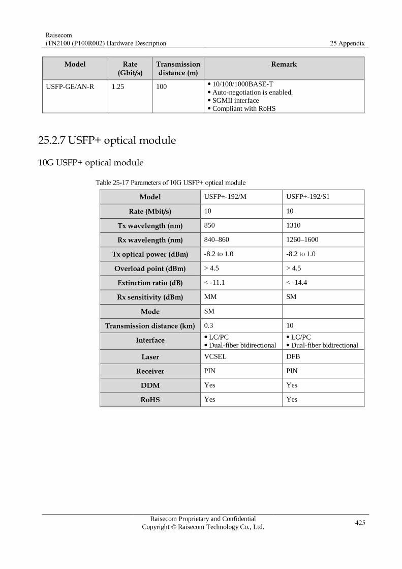
Raisecom
iTN2100 (P100R002) Hardware Description 25 Appendix
Raisecom Proprietary and Confidential
Copyright © Raisecom Technology Co., Ltd. 425
Model Rate (Gbit/s)
Transmission distance (m)
Remark
USFP-GE/AN-R 1.25 100 10/100/1000BASE-T Auto-negotiation is enabled. SGMII interface Compliant with RoHS
25.2.7 USFP+ optical module
10G USFP+ optical module
Table 25-17 Parameters of 10G USFP+ optical module
Model USFP+-192/M USFP+-192/S1
Rate (Mbit/s) 10 10
Tx wavelength (nm) 850 1310
Rx wavelength (nm) 840–860 1260–1600
Tx optical power (dBm) -8.2 to 1.0 -8.2 to 1.0
Overload point (dBm) > 4.5 > 4.5
Extinction ratio (dB) < -11.1 < -14.4
Rx sensitivity (dBm) MM SM
Mode SM
Transmission distance (km) 0.3 10
Interface LC/PC Dual-fiber bidirectional
LC/PC Dual-fiber bidirectional
Laser VCSEL DFB
Receiver PIN PIN
DDM Yes Yes
RoHS Yes Yes
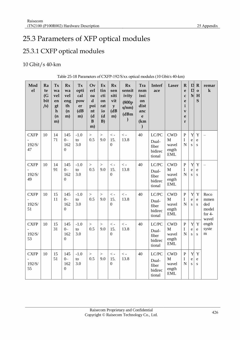
Raisecom
iTN2100 (P100R002) Hardware Description 25 Appendix
Raisecom Proprietary and Confidential
Copyright © Raisecom Technology Co., Ltd. 426
25.3 Parameters of XFP optical modules
25.3.1 CXFP optical modules
10 Gbit/s 40-km
Table 25-18 Parameters of CXFP-192/S/xx optical modules (10 Gbit/s 40-km)
Model
Rate (Gbit/s)
Tx wavelength (nm)
Rx wavelength (nm)
Tx optical
power
(dBm)
Overload
point (dB
m)
Extinction ratio (dB)
Rx sensitivity
(dBm)
Rx sensitivity
(800ps/nm)
(dBm)
Transmission
distanc
e (km
)
Interface
Laser Receiver
DDM
RoHS
remark
CXFP
-
192/S/
47
10 14
71
145
0–
162
0
-1.0
to 3.0
>
0.5 >
9.0
< -
15.0
< -
13.8
40 LC/PC
Dual-
fiber
bidirec
tional
CWD
M
wavel
ength EML
P
IN
Y
es
Y
es
–
CXFP
-
192/S/49
10 14
91
145
0–
1620
-1.0
to 3.0
>
0.5 >
9.0
< -
15.0
< -
13.8
40 LC/PC
Dual-
fiber
bidirectional
CWD
M
wavel
ength
EML
P
IN
Y
es
Y
es
–
CXFP
-
192/S/51
10 15
11
145
0–
1620
-1.0
to
3.0
>
0.5 >
9.0
< -
15.
0
< -
13.8
40 LC/PC
Dual-
fiber
bidirectional
CWD
M
wavel
ength EML
P
I
N
Y
e
s
Y
e
s
Reco
mmen
ded
model
for 4-
wavel
ength
syste
m
CXFP
-
192/S/53
10 15
31
145
0–
1620
-1.0
to
3.0
>
0.5 >
9.0
< -
15.
0
< -
13.8
40 LC/PC
Dual-
fiber
bidirec
tional
CWD
M
wavel
ength EML
P
I
N
Y
e
s
Y
e
s
CXFP
-
192/S/
55
10 15
51
145
0–
162
0
-1.0
to 3.0
>
0.5 >
9.0
< -
15.0
< -
13.8
40 LC/PC
Dual-
fiber
bidirec
tional
CWD
M
wavel
ength EML
P
IN
Y
es
Y
es

Raisecom
iTN2100 (P100R002) Hardware Description 25 Appendix
Raisecom Proprietary and Confidential
Copyright © Raisecom Technology Co., Ltd. 427
Model
Rate (Gbit/s)
Tx wavelength (nm)
Rx wavelength (nm)
Tx optical
power
(dBm)
Overload
point (dB
m)
Extinction ratio (dB)
Rx sensitivity
(dBm)
Rx sensitivity
(800ps/nm)
(dBm)
Transmission
distanc
e (km
)
Interface
Laser Receiver
DDM
RoHS
remark
CXFP
-
192/S/57
10 15
71
145
0–
1620
-1.0
to 3.0
>
0.5 >
9.0
< -
15.0
< -
13.8
40 LC/PC
Dual-
fiber
bidirectional
CWD
M
wavel
ength
EML
P
IN
Y
es
Y
es
CXFP
-
192/S/59
10 15
91
145
0–
1620
-1.0
to 3.0
>
0.5 >
9.0
< -
15.0
< -
13.8
40 LC/PC
Dual-
fiber
bidirectional
CWD
M
wavel
ength EML
P
IN
Y
es
Y
es
–
CXFP
-
192/S/61
10 16
11
145
0–
1620
-1.0
to
3.0
>
0.5 >
9.0
< -
15.
0
< -
13.8
40 LC/PC
Dual-
fiber
bidirectional
CWD
M
wavel
ength EML
P
I
N
Y
e
s
Y
e
s
–
10 Gbit/s 80-km/70-km
Table 25-19 Parameters of CXFP-192/L/xx optical modules (10 Gbit/s 80-km/70-km)
Model
Rate (Gbit/s)
Tx wavelength (nm)
Rx wavelength (nm)
Tx optical power
(dBm)
Overload point
(dBm)
Extinction
ratio
(dB)
Rx sensitivity
(dBm)
Rx sensitivity
(1600 ps/nm)
(dBm)
Trans
mission
distanc
e (km
)
Interface
Laser
Receiver
DDM
RoHS
Remark
CXFP
-
192/L/47
10 14
71
145
0–
1620
-1.0
to
4.0
> -
7.0 >
9.0
< -
24.
0
< -
21.0
80 LC/P
C
Dual-
fiber
bidire
ctional
CWD
M
wave
lengt
h EML
A
P
D
Y
es
Y
es
–
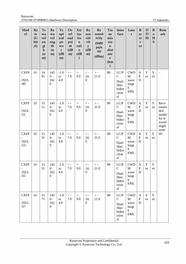
Raisecom
iTN2100 (P100R002) Hardware Description 25 Appendix
Raisecom Proprietary and Confidential
Copyright © Raisecom Technology Co., Ltd. 428
Model
Rate (Gbit/s)
Tx wavelength (nm)
Rx wavelength (nm)
Tx optical power
(dBm)
Overload point
(dBm)
Extinction
ratio
(dB)
Rx sensitivity
(dBm)
Rx sensitivity
(1600 ps/nm)
(dBm)
Trans
mission
distanc
e (km
)
Interface
Laser
Receiver
DDM
RoHS
Remark
CXFP
-
192/L/49
10 14
91
145
0–
1620
-1.0
to 4.0
> -
7.0 >
9.0
< -
24.0
< -
21.0
80 LC/P
C
Dual-
fiber
bidire
ction
al
CWD
M
wave
lengt
h
EML
A
PD
Y
es
Y
es
–
CXFP
-
192/L
/51
10 15
11
145
0–
162
0
-1.0
to 4.0
> -
7.0 >
9.0
< -
24.0
< -
21.0
80 LC/P
C
Dual-
fiber
bidire
ctional
CWD
M
wave
lengt
h EML
A
PD
Y
es
Y
es
Reco
mmen
ded
model
for 4-
wavel
ength
systems CXFP
-
192/L/53
10 15
31
145
0–
1620
-1.0
to
4.0
> -
7.0 >
9.0
< -
24.
0
< -
21.0
80 LC/P
C
Dual-
fiber
bidire
ctional
CWD
M
wave
lengt
h
EML
A
P
D
Y
es
Y
es
CXFP
-
192/L/55
10 15
51
145
0–
1620
-1.0
to 4.0
> -
7.0 >
9.0
< -
24.0
< -
21.0
80 LC/P
C
Dual-
fiber
bidire
ctional
CWD
M
wave
lengt
h EML
A
PD
Y
es
Y
es
CXFP
-
192/L
/57
10 15
71
145
0–
162
0
-1.0
to 4.0
> -
7.0 >
9.0
< -
24.0
< -
21.0
80 LC/P
C
Dual-
fiber
bidire
ctional
CWD
M
wave
lengt
h EML
A
PD
Y
es
Y
es

Raisecom
iTN2100 (P100R002) Hardware Description 25 Appendix
Raisecom Proprietary and Confidential
Copyright © Raisecom Technology Co., Ltd. 429
Model
Rate (Gbit/s)
Tx wavelength (nm)
Rx wavelength (nm)
Tx optical power
(dBm)
Overload point
(dBm)
Extinction
ratio
(dB)
Rx sensitivity
(dBm)
Rx sensitivity
(1600 ps/nm)
(dBm)
Trans
mission
distanc
e (km
)
Interface
Laser
Receiver
DDM
RoHS
Remark
CXFP
-
192/L/59
10 15
91
145
0–
1620
-1.0
to 4.0
> -
7.0 >
9.0
< -
23.0
< -
21.0
70 LC/P
C
Dual-
fiber
bidire
ction
al
CWD
M
wave
lengt
h
EML
A
PD
Y
es
Y
es
Not
recom
mend
ed
model
for
syste
ms
under
8-
wavel
ength
CXFP
-
192/L
/61
10 16
11
145
0–
162
0
-1.0
to 4.0
> -
7.0 >
9.0
< -
23.0
< -
21.0
70 LC/P
C
Dual-
fiber
bidire
ctional
CWD
M
wave
lengt
h EML
A
PD
Y
es
Y
es
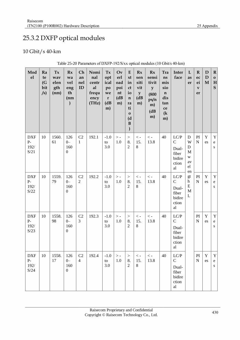
Raisecom
iTN2100 (P100R002) Hardware Description 25 Appendix
Raisecom Proprietary and Confidential
Copyright © Raisecom Technology Co., Ltd. 430
25.3.2 DXFP optical modules
10 Gbit/s 40-km
Table 25-20 Parameters of DXFP-192/S/xx optical modules (10 Gbit/s 40-km)
Model
Rate (Gbit/s)
Tx wavelength
(nm)
Rx wavelength
(nm)
Channel ID
Nominal
central
frequency
(THz)
Tx optical power
(dBm)
Overload point
(dBm)
Extinction ratio (dB)
Rx sensitivity
(dBm)
Rx sensitivit
y
(800ps/nm)
(dBm)
Trans
mission
distance (km)
Interface
Laser
Receiver
DDM
RoHS
DXF
P-
192/S/21
10 1560.
61
126
0–
1600
C2
1
192.1 -1.0
to
3.0
> -
1.0 >
8.
2
< -
15.
8
< -
13.8
40 LC/P
C
Dual-
fiber
bidire
ction
al
D
W
D
M
w
av
el
en
gt
h
E
M
L
PI
N
Y
es
Y
e
s
DXF
P-
192/S/22
10 1559.
79
126
0–
1600
C2
2
192.2 -1.0
to 3.0
> -
1.0 >
8.2
< -
15.8
< -
13.8
40 LC/P
C
Dual-
fiber
bidire
ctional
PI
N
Y
es
Y
es
DXF
P-
192/
S/23
10 1558.
98
126
0–
160
0
C2
3
192.3 -1.0
to 3.0
> -
1.0 >
8.2
< -
15.8
< -
13.8
40 LC/P
C
Dual-
fiber
bidire
ctional
PI
N
Y
es
Y
es
DXF
P-
192/S/24
10 1558.
17
126
0–
1600
C2
4
192.4 -1.0
to
3.0
> -
1.0 >
8.
2
< -
15.
8
< -
13.8
40 LC/P
C
Dual-
fiber
bidire
ction
al
PI
N
Y
es
Y
e
s

Raisecom
iTN2100 (P100R002) Hardware Description 25 Appendix
Raisecom Proprietary and Confidential
Copyright © Raisecom Technology Co., Ltd. 431
Model
Rate (Gbit/s)
Tx wavelength
(nm)
Rx wavelength
(nm)
Channel ID
Nominal
central
frequency
(THz)
Tx optical power
(dBm)
Overload point
(dBm)
Extinction ratio (dB)
Rx sensitivity
(dBm)
Rx sensitivit
y
(800ps/nm)
(dBm)
Trans
mission
distance (km)
Interface
Laser
Receiver
DDM
RoHS
DXF
P-
192/
S/25
10 1557.
36
126
0–
160
0
C2
5
192.5 -1.0
to 3.0
> -
1.0 >
8.2
< -
15.8
< -
13.8
40 LC/P
C
Dual-
fiber
bidire
ctional
PI
N
Y
es
Y
es
DXF
P-
192/S/26
10 1556.
55
126
0–
1600
C2
6
192.6 -1.0
to
3.0
> -
1.0 >
8.
2
< -
15.
8
< -
13.8
40 LC/P
C
Dual-
fiber
bidire
ction
al
PI
N
Y
es
Y
e
s
DXF
P-
192/S/27
10 1555.
75
126
0–
1600
C2
7
192.7 -1.0
to 3.0
> -
1.0 >
8.2
< -
15.8
< -
13.8
40 LC/P
C
Dual-
fiber
bidire
ctional
PI
N
Y
es
Y
es
DXF
P-
192/
S/28
10 1554.
94
126
0–
160
0
C2
8
192.8 -1.0
to 3.0
> -
1.0 >
8.2
< -
15.8
< -
13.8
40 LC/P
C
Dual-
fiber
bidire
ctional
PI
N
Y
es
Y
es
DXF
P-
192/S/29
10 1554.13
126
0–
1600
C29
192.9 -1.0
to
3.0
> -1.0
>
8.
2
< -
15.
8
< -13.8
40 LC/PC
Dual-
fiber
bidire
ction
al
PIN
Yes
Y
e
s

Raisecom
iTN2100 (P100R002) Hardware Description 25 Appendix
Raisecom Proprietary and Confidential
Copyright © Raisecom Technology Co., Ltd. 432
Model
Rate (Gbit/s)
Tx wavelength
(nm)
Rx wavelength
(nm)
Channel ID
Nominal
central
frequency
(THz)
Tx optical power
(dBm)
Overload point
(dBm)
Extinction ratio (dB)
Rx sensitivity
(dBm)
Rx sensitivit
y
(800ps/nm)
(dBm)
Trans
mission
distance (km)
Interface
Laser
Receiver
DDM
RoHS
DXF
P-
192/
S/30
10 1553.
33
126
0–
160
0
C3
0
193.0 -1.0
to 3.0
> -
1.0 >
8.2
< -
15.8
< -
13.8
40 LC/P
C
Dual-
fiber
bidire
ctional
PI
N
Y
es
Y
es
DXF
P-
192/S/31
10 1552.
52
126
0–
1600
C3
1
193.1 -1.0
to
3.0
> -
1.0 >
8.
2
< -
15.
8
< -
13.8
40 LC/P
C
Dual-
fiber
bidire
ction
al
PI
N
Y
es
Y
e
s
DXF
P-
192/S/32
10 1551.
72
126
0–
1600
C3
2
193.2 -1.0
to 3.0
> -
1.0 >
8.2
< -
15.8
< -
13.8
40 LC/P
C
Dual-
fiber
bidire
ctional
PI
N
Y
es
Y
es
DXF
P-
192/
S/33
10 1550.
92
126
0–
160
0
C3
3
193.3 -1.0
to 3.0
> -
1.0 >
8.2
< -
15.8
< -
13.8
40 LC/P
C
Dual-
fiber
bidire
ctional
PI
N
Y
es
Y
es
DXF
P-
192/S/34
10 1550.12
126
0–
1600
C34
193.4 -1.0
to
3.0
> -1.0
>
8.
2
< -
15.
8
< -13.8
40 LC/PC
Dual-
fiber
bidire
ction
al
PIN
Yes
Y
e
s

Raisecom
iTN2100 (P100R002) Hardware Description 25 Appendix
Raisecom Proprietary and Confidential
Copyright © Raisecom Technology Co., Ltd. 433
Model
Rate (Gbit/s)
Tx wavelength
(nm)
Rx wavelength
(nm)
Channel ID
Nominal
central
frequency
(THz)
Tx optical power
(dBm)
Overload point
(dBm)
Extinction ratio (dB)
Rx sensitivity
(dBm)
Rx sensitivit
y
(800ps/nm)
(dBm)
Trans
mission
distance (km)
Interface
Laser
Receiver
DDM
RoHS
DXF
P-
192/
S/35
10 1549.
32
126
0–
160
0
C3
5
193.5 -1.0
to 3.0
> -
1.0 >
8.2
< -
15.8
< -
13.8
40 LC/P
C
Dual-
fiber
bidire
ctional
PI
N
Y
es
Y
es
DXF
P-
192/S/36
10 1548.
51
126
0–
1600
C3
6
193.6 -1.0
to
3.0
> -
1.0 >
8.
2
< -
15.
8
< -
13.8
40 LC/P
C
Dual-
fiber
bidire
ction
al
PI
N
Y
es
Y
e
s
DXF
P-
192/S/37
10 1547.
72
126
0–
1600
C3
7
193.7 -1.0
to 3.0
> -
1.0 >
8.2
< -
15.8
< -
13.8
40 LC/P
C
Dual-
fiber
bidire
ctional
PI
N
Y
es
Y
es
DXF
P-
192/
S/38
10 1546.
92
126
0–
160
0
C3
8
193.8 -1.0
to 3.0
> -
1.0 >
8.2
< -
15.8
< -
13.8
40 LC/P
C
Dual-
fiber
bidire
ctional
PI
N
Y
es
Y
es
DXF
P-
192/S/39
10 1546.12
126
0–
1600
C39
193.9 -1.0
to
3.0
> -1.0
>
8.
2
< -
15.
8
< -13.8
40 LC/PC
Dual-
fiber
bidire
ction
al
PIN
Yes
Y
e
s

Raisecom
iTN2100 (P100R002) Hardware Description 25 Appendix
Raisecom Proprietary and Confidential
Copyright © Raisecom Technology Co., Ltd. 434
Model
Rate (Gbit/s)
Tx wavelength
(nm)
Rx wavelength
(nm)
Channel ID
Nominal
central
frequency
(THz)
Tx optical power
(dBm)
Overload point
(dBm)
Extinction ratio (dB)
Rx sensitivity
(dBm)
Rx sensitivit
y
(800ps/nm)
(dBm)
Trans
mission
distance (km)
Interface
Laser
Receiver
DDM
RoHS
DXF
P-
192/
S/40
10 1545.
32
126
0–
160
0
C4
0
194.0 -1.0
to 3.0
> -
1.0 >
8.2
< -
15.8
< -
13.8
40 LC/P
C
Dual-
fiber
bidire
ctional
PI
N
Y
es
Y
es
DXF
P-
192/S/41
10 1544.
53
126
0–
1600
C4
1
194.1 -1.0
to
3.0
> -
1.0 >
8.
2
< -
15.
8
< -
13.8
40 LC/P
C
Dual-
fiber
bidire
ction
al
PI
N
Y
es
Y
e
s
DXF
P-
192/S/42
10 1543.
73
126
0–
1600
C4
2
194.2 -1.0
to 3.0
> -
1.0 >
8.2
< -
15.8
< -
13.8
40 LC/P
C
Dual-
fiber
bidire
ctional
PI
N
Y
es
Y
es
DXF
P-
192/
S/43
10 1542.
94
126
0–
160
0
C4
3
194.3 -1.0
to 3.0
> -
1.0 >
8.2
< -
15.8
< -
13.8
40 LC/P
C
Dual-
fiber
bidire
ctional
PI
N
Y
es
Y
es
DXF
P-
192/S/44
10 1542.14
126
0–
1600
C44
194.4 -1.0
to
3.0
> -1.0
>
8.
2
< -
15.
8
< -13.8
40 LC/PC
Dual-
fiber
bidire
ction
al
PIN
Yes
Y
e
s
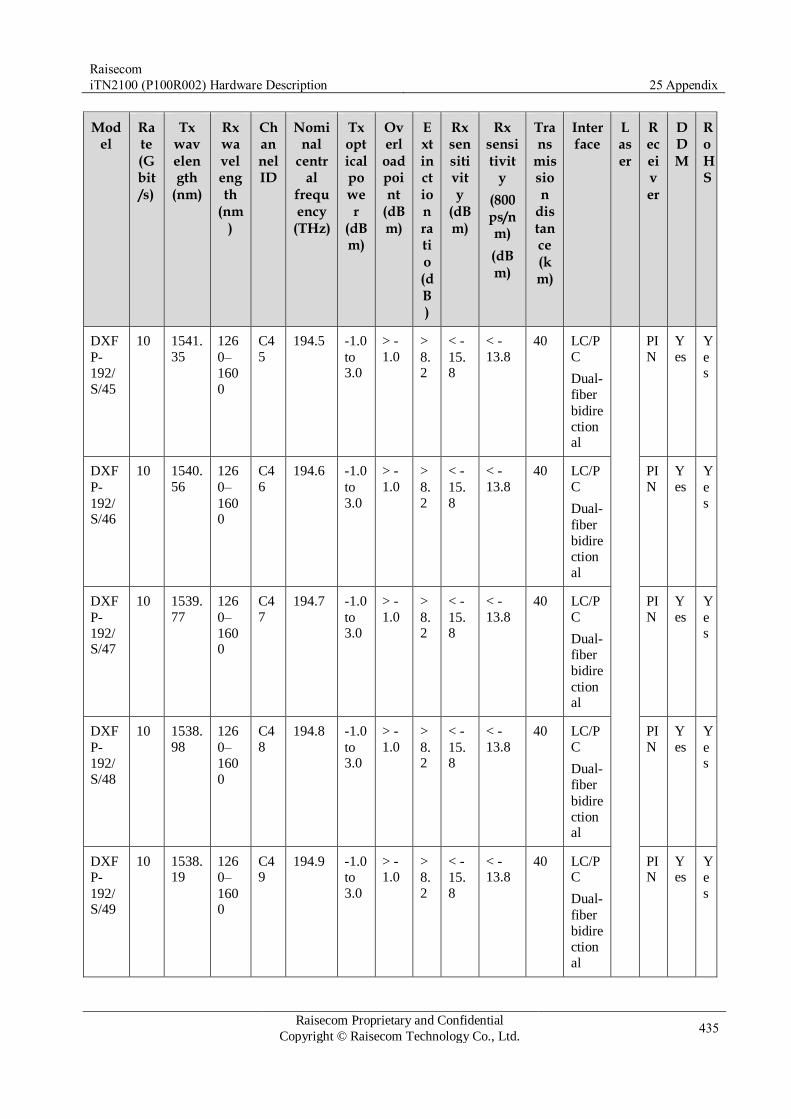
Raisecom
iTN2100 (P100R002) Hardware Description 25 Appendix
Raisecom Proprietary and Confidential
Copyright © Raisecom Technology Co., Ltd. 435
Model
Rate (Gbit/s)
Tx wavelength
(nm)
Rx wavelength
(nm)
Channel ID
Nominal
central
frequency
(THz)
Tx optical power
(dBm)
Overload point
(dBm)
Extinction ratio (dB)
Rx sensitivity
(dBm)
Rx sensitivit
y
(800ps/nm)
(dBm)
Trans
mission
distance (km)
Interface
Laser
Receiver
DDM
RoHS
DXF
P-
192/
S/45
10 1541.
35
126
0–
160
0
C4
5
194.5 -1.0
to 3.0
> -
1.0 >
8.2
< -
15.8
< -
13.8
40 LC/P
C
Dual-
fiber
bidire
ctional
PI
N
Y
es
Y
es
DXF
P-
192/S/46
10 1540.
56
126
0–
1600
C4
6
194.6 -1.0
to
3.0
> -
1.0 >
8.
2
< -
15.
8
< -
13.8
40 LC/P
C
Dual-
fiber
bidire
ction
al
PI
N
Y
es
Y
e
s
DXF
P-
192/S/47
10 1539.
77
126
0–
1600
C4
7
194.7 -1.0
to 3.0
> -
1.0 >
8.2
< -
15.8
< -
13.8
40 LC/P
C
Dual-
fiber
bidire
ctional
PI
N
Y
es
Y
es
DXF
P-
192/
S/48
10 1538.
98
126
0–
160
0
C4
8
194.8 -1.0
to 3.0
> -
1.0 >
8.2
< -
15.8
< -
13.8
40 LC/P
C
Dual-
fiber
bidire
ctional
PI
N
Y
es
Y
es
DXF
P-
192/S/49
10 1538.19
126
0–
1600
C49
194.9 -1.0
to
3.0
> -1.0
>
8.
2
< -
15.
8
< -13.8
40 LC/PC
Dual-
fiber
bidire
ction
al
PIN
Yes
Y
e
s

Raisecom
iTN2100 (P100R002) Hardware Description 25 Appendix
Raisecom Proprietary and Confidential
Copyright © Raisecom Technology Co., Ltd. 436
Model
Rate (Gbit/s)
Tx wavelength
(nm)
Rx wavelength
(nm)
Channel ID
Nominal
central
frequency
(THz)
Tx optical power
(dBm)
Overload point
(dBm)
Extinction ratio (dB)
Rx sensitivity
(dBm)
Rx sensitivit
y
(800ps/nm)
(dBm)
Trans
mission
distance (km)
Interface
Laser
Receiver
DDM
RoHS
DXF
P-
192/
S/50
10 1537.
40
126
0–
160
0
C5
0
195.0 -1.0
to 3.0
> -
1.0 >
8.2
< -
15.8
< -
13.8
40 LC/P
C
Dual-
fiber
bidire
ctional
PI
N
Y
es
Y
es
DXF
P-
192/S/51
10 1536.
61
126
0–
1600
C5
1
195.1 -1.0
to
3.0
> -
1.0 >
8.
2
< -
15.
8
< -
13.8
40 LC/P
C
Dual-
fiber
bidire
ction
al
PI
N
Y
es
Y
e
s
DXF
P-
192/S/52
10 1535.
82
126
0–
1600
C5
2
195.2 -1.0
to 3.0
> -
1.0 >
8.2
< -
15.8
< -
13.8
40 LC/P
C
Dual-
fiber
bidire
ctional
PI
N
Y
es
Y
es
DXF
P-
192/
S/53
10 1535.
04
126
0–
160
0
C5
3
195.3 -1.0
to 3.0
> -
1.0 >
8.2
< -
15.8
< -
13.8
40 LC/P
C
Dual-
fiber
bidire
ctional
PI
N
Y
es
Y
es
DXF
P-
192/S/54
10 1534.25
126
0–
1600
C54
195.4 -1.0
to
3.0
> -1.0
>
8.
2
< -
15.
8
< -13.8
40 LC/PC
Dual-
fiber
bidire
ction
al
PIN
Yes
Y
e
s

Raisecom
iTN2100 (P100R002) Hardware Description 25 Appendix
Raisecom Proprietary and Confidential
Copyright © Raisecom Technology Co., Ltd. 437
Model
Rate (Gbit/s)
Tx wavelength
(nm)
Rx wavelength
(nm)
Channel ID
Nominal
central
frequency
(THz)
Tx optical power
(dBm)
Overload point
(dBm)
Extinction ratio (dB)
Rx sensitivity
(dBm)
Rx sensitivit
y
(800ps/nm)
(dBm)
Trans
mission
distance (km)
Interface
Laser
Receiver
DDM
RoHS
DXF
P-
192/
S/55
10 1533.
47
126
0–
160
0
C5
5
195.5 -1.0
to 3.0
> -
1.0 >
8.2
< -
15.8
< -
13.8
40 LC/P
C
Dual-
fiber
bidire
ctional
PI
N
Y
es
Y
es
DXF
P-
192/S/56
10 1532.
68
126
0–
1600
C5
6
195.6 -1.0
to
3.0
> -
1.0 >
8.
2
< -
15.
8
< -
13.8
40 LC/P
C
Dual-
fiber
bidire
ction
al
PI
N
Y
es
Y
e
s
DXF
P-
192/S/57
10 1531.
90
126
0–
1600
C5
7
195.7 -1.0
to 3.0
> -
1.0 >
8.2
< -
15.8
< -
13.8
40 LC/P
C
Dual-
fiber
bidire
ctional
PI
N
Y
es
Y
es
DXF
P-
192/
S/58
10 1531.
12
126
0–
160
0
C5
8
195.8 -1.0
to 3.0
> -
1.0 >
8.2
< -
15.8
< -
13.8
40 LC/P
C
Dual-
fiber
bidire
ctional
PI
N
Y
es
Y
es
DXF
P-
192/S/59
10 1530.33
126
0–
1600
C59
195.9 -1.0
to
3.0
> -1.0
>
8.
2
< -
15.
8
< -13.8
40 LC/PC
Dual-
fiber
bidire
ction
al
PIN
Yes
Y
e
s
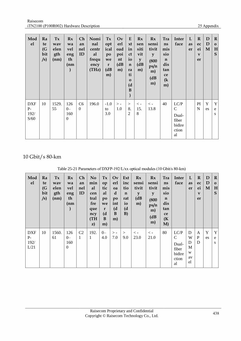
Raisecom
iTN2100 (P100R002) Hardware Description 25 Appendix
Raisecom Proprietary and Confidential
Copyright © Raisecom Technology Co., Ltd. 438
Model
Rate (Gbit/s)
Tx wavelength
(nm)
Rx wavelength
(nm)
Channel ID
Nominal
central
frequency
(THz)
Tx optical power
(dBm)
Overload point
(dBm)
Extinction ratio (dB)
Rx sensitivity
(dBm)
Rx sensitivit
y
(800ps/nm)
(dBm)
Trans
mission
distance (km)
Interface
Laser
Receiver
DDM
RoHS
DXF
P-
192/
S/60
10 1529.
55
126
0–
160
0
C6
0
196.0 -1.0
to 3.0
> -
1.0 >
8.2
< -
15.8
< -
13.8
40 LC/P
C
Dual-
fiber
bidire
ctional
PI
N
Y
es
Y
es
10 Gbit/s 80-km
Table 25-21 Parameters of DXFP-192/L/xx optical modules (10 Gbit/s 80-km)
Model
Rate (Gbit/s)
Tx wavelength
(nm)
Rx wavelength
(nm)
Channel ID
Nominal
central frequency (THz)
Tx optical power
(dB
m)
Overload
point (dB
m)
Extinction
ratio (dB)
Rx sensitivit
y (dBm)
Rx sensitivit
y
(800ps/nm)
(dBm)
Trans
mission
distance (KM)
Interface
Laser
Receiver
DDM
RoHS
DXF
P-
192/L/21
10 1560.
61
126
0–
1600
C2
1
192.
1
0–
4.0
> -
7.0 >
9.0
< -
23.0
< -
21.0
80 LC/P
C
Dual-
fiber
bidire
ction
al
D
W
D
M
w
av
el
A
PD
Y
es
Y
es

Raisecom
iTN2100 (P100R002) Hardware Description 25 Appendix
Raisecom Proprietary and Confidential
Copyright © Raisecom Technology Co., Ltd. 439
Model
Rate (Gbit/s)
Tx wavelength
(nm)
Rx wavelength
(nm)
Channel ID
Nominal
central frequency (THz)
Tx optical power
(dB
m)
Overload
point (dB
m)
Extinction
ratio (dB)
Rx sensitivit
y (dBm)
Rx sensitivit
y
(800ps/nm)
(dBm)
Trans
mission
distance (KM)
Interface
Laser
Receiver
DDM
RoHS
DXF
P-
192/L/22
10 1559.
79
126
0–
1600
C2
2
192.
2
0–
4.0
> -
7.0 >
9.0
< -
23.0
< -
21.0
80 LC/P
C
Dual-
fiber
bidire
ction
al
en
gt
h
E
ML
A
PD
Y
es
Y
es
DXF
P-
192/
L/23
10 1558.
98
126
0–
160
0
C2
3
192.
3
0–
4.0
> -
7.0 >
9.0
< -
23.0
< -
21.0
80 LC/P
C
Dual-
fiber
bidire
ctional
A
PD
Y
es
Y
es
DXF
P-
192/L/24
10 1558.
17
126
0–
1600
C2
4
192.
4
0–
4.0
> -
7.0 >
9.0
< -
23.0
< -
21.0
80 LC/P
C
Dual-
fiber
bidire
ctional
A
P
D
Y
es
Y
e
s
DXF
P-
192/L/25
10 1557.
36
126
0–
1600
C2
5
192.
5
0–
4.0
> -
7.0 >
9.0
< -
23.0
< -
21.0
80 LC/P
C
Dual-
fiber
bidire
ctional
A
PD
Y
es
Y
es
DXF
P-
192/
L/26
10 1556.
55
126
0–
160
0
C2
6
192.
6
0–
4.0
> -
7.0 >
9.0
< -
23.0
< -
21.0
80 LC/P
C
Dual-
fiber
bidire
ctional
A
PD
Y
es
Y
es
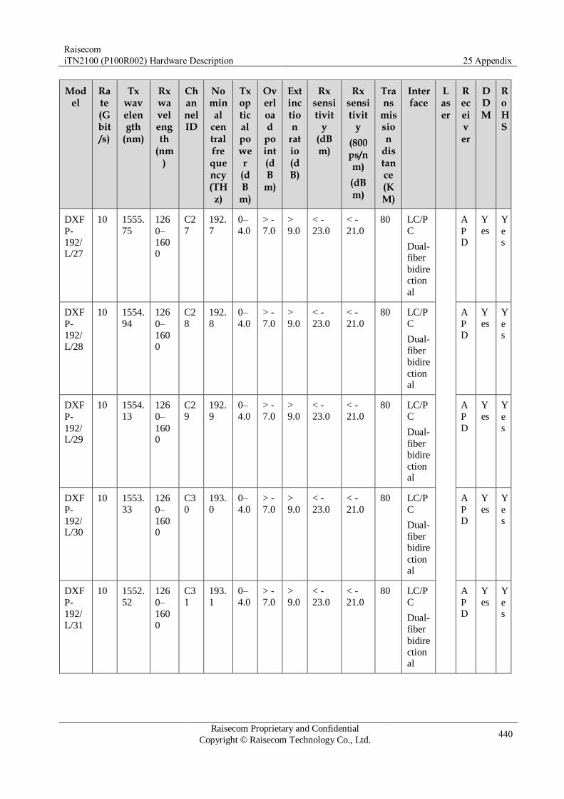
Raisecom
iTN2100 (P100R002) Hardware Description 25 Appendix
Raisecom Proprietary and Confidential
Copyright © Raisecom Technology Co., Ltd. 440
Model
Rate (Gbit/s)
Tx wavelength
(nm)
Rx wavelength
(nm)
Channel ID
Nominal
central frequency (THz)
Tx optical power
(dB
m)
Overload
point (dB
m)
Extinction
ratio (dB)
Rx sensitivit
y (dBm)
Rx sensitivit
y
(800ps/nm)
(dBm)
Trans
mission
distance (KM)
Interface
Laser
Receiver
DDM
RoHS
DXF
P-
192/L/27
10 1555.
75
126
0–
1600
C2
7
192.
7
0–
4.0
> -
7.0 >
9.0
< -
23.0
< -
21.0
80 LC/P
C
Dual-
fiber
bidire
ction
al
A
PD
Y
es
Y
es
DXF
P-
192/
L/28
10 1554.
94
126
0–
160
0
C2
8
192.
8
0–
4.0
> -
7.0 >
9.0
< -
23.0
< -
21.0
80 LC/P
C
Dual-
fiber
bidire
ctional
A
PD
Y
es
Y
es
DXF
P-
192/L/29
10 1554.
13
126
0–
1600
C2
9
192.
9
0–
4.0
> -
7.0 >
9.0
< -
23.0
< -
21.0
80 LC/P
C
Dual-
fiber
bidire
ctional
A
P
D
Y
es
Y
e
s
DXF
P-
192/L/30
10 1553.
33
126
0–
1600
C3
0
193.
0
0–
4.0
> -
7.0 >
9.0
< -
23.0
< -
21.0
80 LC/P
C
Dual-
fiber
bidire
ctional
A
PD
Y
es
Y
es
DXF
P-
192/
L/31
10 1552.
52
126
0–
160
0
C3
1
193.
1
0–
4.0
> -
7.0 >
9.0
< -
23.0
< -
21.0
80 LC/P
C
Dual-
fiber
bidire
ctional
A
PD
Y
es
Y
es

Raisecom
iTN2100 (P100R002) Hardware Description 25 Appendix
Raisecom Proprietary and Confidential
Copyright © Raisecom Technology Co., Ltd. 441
Model
Rate (Gbit/s)
Tx wavelength
(nm)
Rx wavelength
(nm)
Channel ID
Nominal
central frequency (THz)
Tx optical power
(dB
m)
Overload
point (dB
m)
Extinction
ratio (dB)
Rx sensitivit
y (dBm)
Rx sensitivit
y
(800ps/nm)
(dBm)
Trans
mission
distance (KM)
Interface
Laser
Receiver
DDM
RoHS
DXF
P-
192/L/32
10 1551.
72
126
0–
1600
C3
2
193.
2
0–
4.0
> -
7.0 >
9.0
< -
23.0
< -
21.0
80 LC/P
C
Dual-
fiber
bidire
ction
al
A
PD
Y
es
Y
es
DXF
P-
192/
L/33
10 1550.
92
126
0–
160
0
C3
3
193.
3
0–
4.0
> -
7.0 >
9.0
< -
23.0
< -
21.0
80 LC/P
C
Dual-
fiber
bidire
ctional
A
PD
Y
es
Y
es
DXF
P-
192/L/34
10 1550.
12
126
0–
1600
C3
4
193.
4
0–
4.0
> -
7.0 >
9.0
< -
23.0
< -
21.0
80 LC/P
C
Dual-
fiber
bidire
ctional
A
P
D
Y
es
Y
e
s
DXF
P-
192/L/35
10 1549.
32
126
0–
1600
C3
5
193.
5
0–
4.0
> -
7.0 >
9.0
< -
23.0
< -
21.0
80 LC/P
C
Dual-
fiber
bidire
ctional
A
PD
Y
es
Y
es
DXF
P-
192/
L/36
10 1548.
51
126
0–
160
0
C3
6
193.
6
0–
4.0
> -
7.0 >
9.0
< -
23.0
< -
21.0
80 LC/P
C
Dual-
fiber
bidire
ctional
A
PD
Y
es
Y
es

Raisecom
iTN2100 (P100R002) Hardware Description 25 Appendix
Raisecom Proprietary and Confidential
Copyright © Raisecom Technology Co., Ltd. 442
Model
Rate (Gbit/s)
Tx wavelength
(nm)
Rx wavelength
(nm)
Channel ID
Nominal
central frequency (THz)
Tx optical power
(dB
m)
Overload
point (dB
m)
Extinction
ratio (dB)
Rx sensitivit
y (dBm)
Rx sensitivit
y
(800ps/nm)
(dBm)
Trans
mission
distance (KM)
Interface
Laser
Receiver
DDM
RoHS
DXF
P-
192/L/37
10 1547.
72
126
0–
1600
C3
7
193.
7
0–
4.0
> -
7.0 >
9.0
< -
23.0
< -
21.0
80 LC/P
C
Dual-
fiber
bidire
ction
al
A
PD
Y
es
Y
es
DXF
P-
192/
L/38
10 1546.
92
126
0–
160
0
C3
8
193.
8
0–
4.0
> -
7.0 >
9.0
< -
23.0
< -
21.0
80 LC/P
C
Dual-
fiber
bidire
ctional
A
PD
Y
es
Y
es
DXF
P-
192/L/39
10 1546.
12
126
0–
1600
C3
9
193.
9
0–
4.0
> -
7.0 >
9.0
< -
23.0
< -
21.0
80 LC/P
C
Dual-
fiber
bidire
ctional
A
P
D
Y
es
Y
e
s
DXF
P-
192/L/40
10 1545.
32
126
0–
1600
C4
0
194.
0
0–
4.0
> -
7.0 >
9.0
< -
23.0
< -
21.0
80 LC/P
C
Dual-
fiber
bidire
ctional
A
PD
Y
es
Y
es
DXF
P-
192/
L/41
10 1544.
53
126
0–
160
0
C4
1
194.
1
0–
4.0
> -
7.0 >
9.0
< -
23.0
< -
21.0
80 LC/P
C
Dual-
fiber
bidire
ctional
A
PD
Y
es
Y
es

Raisecom
iTN2100 (P100R002) Hardware Description 25 Appendix
Raisecom Proprietary and Confidential
Copyright © Raisecom Technology Co., Ltd. 443
Model
Rate (Gbit/s)
Tx wavelength
(nm)
Rx wavelength
(nm)
Channel ID
Nominal
central frequency (THz)
Tx optical power
(dB
m)
Overload
point (dB
m)
Extinction
ratio (dB)
Rx sensitivit
y (dBm)
Rx sensitivit
y
(800ps/nm)
(dBm)
Trans
mission
distance (KM)
Interface
Laser
Receiver
DDM
RoHS
DXF
P-
192/L/42
10 1543.
73
126
0–
1600
C4
2
194.
2
0–
4.0
> -
7.0 >
9.0
< -
23.0
< -
21.0
80 LC/P
C
Dual-
fiber
bidire
ction
al
A
PD
Y
es
Y
es
DXF
P-
192/
L/43
10 1542.
94
126
0–
160
0
C4
3
194.
3
0–
4.0
> -
7.0 >
9.0
< -
23.0
< -
21.0
80 LC/P
C
Dual-
fiber
bidire
ctional
A
PD
Y
es
Y
es
DXF
P-
192/L/44
10 1542.
14
126
0–
1600
C4
4
194.
4
0–
4.0
> -
7.0 >
9.0
< -
23.0
< -
21.0
80 LC/P
C
Dual-
fiber
bidire
ctional
A
P
D
Y
es
Y
e
s
DXF
P-
192/L/45
10 1541.
35
126
0–
1600
C4
5
194.
5
0–
4.0
> -
7.0 >
9.0
< -
23.0
< -
21.0
80 LC/P
C
Dual-
fiber
bidire
ctional
A
PD
Y
es
Y
es
DXF
P-
192/
L/46
10 1540.
56
126
0–
160
0
C4
6
194.
6
0–
4.0
> -
7.0 >
9.0
< -
23.0
< -
21.0
80 LC/P
C
Dual-
fiber
bidire
ctional
A
PD
Y
es
Y
es

Raisecom
iTN2100 (P100R002) Hardware Description 25 Appendix
Raisecom Proprietary and Confidential
Copyright © Raisecom Technology Co., Ltd. 444
Model
Rate (Gbit/s)
Tx wavelength
(nm)
Rx wavelength
(nm)
Channel ID
Nominal
central frequency (THz)
Tx optical power
(dB
m)
Overload
point (dB
m)
Extinction
ratio (dB)
Rx sensitivit
y (dBm)
Rx sensitivit
y
(800ps/nm)
(dBm)
Trans
mission
distance (KM)
Interface
Laser
Receiver
DDM
RoHS
DXF
P-
192/L/47
10 1539.
77
126
0–
1600
C4
7
194.
7
0–
4.0
> -
7.0 >
9.0
< -
23.0
< -
21.0
80 LC/P
C
Dual-
fiber
bidire
ction
al
A
PD
Y
es
Y
es
DXF
P-
192/
L/48
10 1538.
98
126
0–
160
0
C4
8
194.
8
0–
4.0
> -
7.0 >
9.0
< -
23.0
< -
21.0
80 LC/P
C
Dual-
fiber
bidire
ctional
A
PD
Y
es
Y
es
DXF
P-
192/L/49
10 1538.
19
126
0–
1600
C4
9
194.
9
0–
4.0
> -
7.0 >
9.0
< -
23.0
< -
21.0
80 LC/P
C
Dual-
fiber
bidire
ctional
A
P
D
Y
es
Y
e
s
DXF
P-
192/L/50
10 1537.
40
126
0–
1600
C5
0
195.
0
0–
4.0
> -
7.0 >
9.0
< -
23.0
< -
21.0
80 LC/P
C
Dual-
fiber
bidire
ctional
A
PD
Y
es
Y
es
DXF
P-
192/
L/51
10 1536.
61
126
0–
160
0
C5
1
195.
1
0–
4.0
> -
7.0 >
9.0
< -
23.0
< -
21.0
80 LC/P
C
Dual-
fiber
bidire
ctional
A
PD
Y
es
Y
es

Raisecom
iTN2100 (P100R002) Hardware Description 25 Appendix
Raisecom Proprietary and Confidential
Copyright © Raisecom Technology Co., Ltd. 445
Model
Rate (Gbit/s)
Tx wavelength
(nm)
Rx wavelength
(nm)
Channel ID
Nominal
central frequency (THz)
Tx optical power
(dB
m)
Overload
point (dB
m)
Extinction
ratio (dB)
Rx sensitivit
y (dBm)
Rx sensitivit
y
(800ps/nm)
(dBm)
Trans
mission
distance (KM)
Interface
Laser
Receiver
DDM
RoHS
DXF
P-
192/L/52
10 1535.
82
126
0–
1600
C5
2
195.
2
0–
4.0
> -
7.0 >
9.0
< -
23.0
< -
21.0
80 LC/P
C
Dual-
fiber
bidire
ction
al
A
PD
Y
es
Y
es
DXF
P-
192/
L/53
10 1535.
04
126
0–
160
0
C5
3
195.
3
0–
4.0
> -
7.0 >
9.0
< -
23.0
< -
21.0
80 LC/P
C
Dual-
fiber
bidire
ctional
A
PD
Y
es
Y
es
DXF
P-
192/L/54
10 1534.
25
126
0–
1600
C5
4
195.
4
0–
4.0
> -
7.0 >
9.0
< -
23.0
< -
21.0
80 LC/P
C
Dual-
fiber
bidire
ctional
A
P
D
Y
es
Y
e
s
DXF
P-
192/L/55
10 1533.
47
126
0–
1600
C5
5
195.
5
0–
4.0
> -
7.0 >
9.0
< -
23.0
< -
21.0
80 LC/P
C
Dual-
fiber
bidire
ctional
A
PD
Y
es
Y
es
DXF
P-
192/
L/56
10 1532.
68
126
0–
160
0
C5
6
195.
6
0–
4.0
> -
7.0 >
9.0
< -
23.0
< -
21.0
80 LC/P
C
Dual-
fiber
bidire
ctional
A
PD
Y
es
Y
es

Raisecom
iTN2100 (P100R002) Hardware Description 25 Appendix
Raisecom Proprietary and Confidential
Copyright © Raisecom Technology Co., Ltd. 446
Model
Rate (Gbit/s)
Tx wavelength
(nm)
Rx wavelength
(nm)
Channel ID
Nominal
central frequency (THz)
Tx optical power
(dB
m)
Overload
point (dB
m)
Extinction
ratio (dB)
Rx sensitivit
y (dBm)
Rx sensitivit
y
(800ps/nm)
(dBm)
Trans
mission
distance (KM)
Interface
Laser
Receiver
DDM
RoHS
DXF
P-
192/L/57
10 1531.
90
126
0–
1600
C5
7
195.
7
0–
4.0
> -
7.0 >
9.0
< -
23.0
< -
21.0
80 LC/P
C
Dual-
fiber
bidire
ction
al
A
PD
Y
es
Y
es
DXF
P-
192/
L/58
10 1531.
12
126
0–
160
0
C5
8
195.
8
0–
4.0
> -
7.0 >
9.0
< -
23.0
< -
21.0
80 LC/P
C
Dual-
fiber
bidire
ctional
A
PD
Y
es
Y
es
DXF
P-
192/L/59
10 1530.
33
126
0–
1600
C5
9
195.
9
0–
4.0
> -
7.0 >
9.0
< -
23.0
< -
21.0
80 LC/P
C
Dual-
fiber
bidire
ctional
A
P
D
Y
es
Y
e
s
DXF
P-
192/L/60
10 1529.
55
126
0–
1600
C6
0
196.
0
0–
4.0
> -
7.0 >
9.0
< -
23.0
< -
21.0
80 LC/P
C
Dual-
fiber
bidire
ctional
A
PD
Y
es
Y
es

Raisecom
iTN2100 (P100R002) Hardware Description 25 Appendix
Raisecom Proprietary and Confidential
Copyright © Raisecom Technology Co., Ltd. 447
25.3.3 UXFP optical modules
10G UXFP optical modules
Table 25-22 Parameters of 10G UXFP modules
Model UXFP-192/M UXFP-192/S1 UXFP-192/S2 UXFP-192/S3
Rate (Gbit/s) 10 10 10 10
Tx wavelength (nm) 850 1310 1550 1550
Rx wavelength (nm) 840–860 1200–1600 1200–1600 1200–1600
Tx optical power (dBm) -7.3 to -1.0 -6.0 to -1.0 -1.0 to 2.0 0–4.0
Overload point (dBm) > -1.0 > 0.5 > -1 > -9
Extinction ratio (dB) > 3.0 > 6.0 > 8.2 > 9.0
Rx sensitivity (dBm) < -9.9 < -14.4 < -15.8 < -24.0
Rx sensitivity (800ps/nm) (dBm) – – < -13.8 –
Rx sensitivity (1600ps/nm) (dBm) – – – < -22.0
Mode MM SM SM SM
Transmission distance (km) 0.3 10 40 80
Interface SC/PC Dual-fiber
bidirectional
SC/PC Dual-fiber
bidirectional
SC/PC Dual-fiber
bidirectional
SC/PC Dual-fiber
bidirectional
Laser VCSEL DFB EML EML
Receiver PIN PIN PIN APD
DDM Yes Yes Yes Yes
RoHS Yes Yes Yes Yes
25.4 Wiring When you order the device, we recommend ordering corresponding cables together. When
you need to make cables by yourself due to cable faults, follow this section.
25.4.1 CBL-E1-SCSI100M(40)/16RJ45
Figure SCSI100M PIN Signal RJ45 PIN Description
SCSI100M 100 - 2 RX1
99 + 1
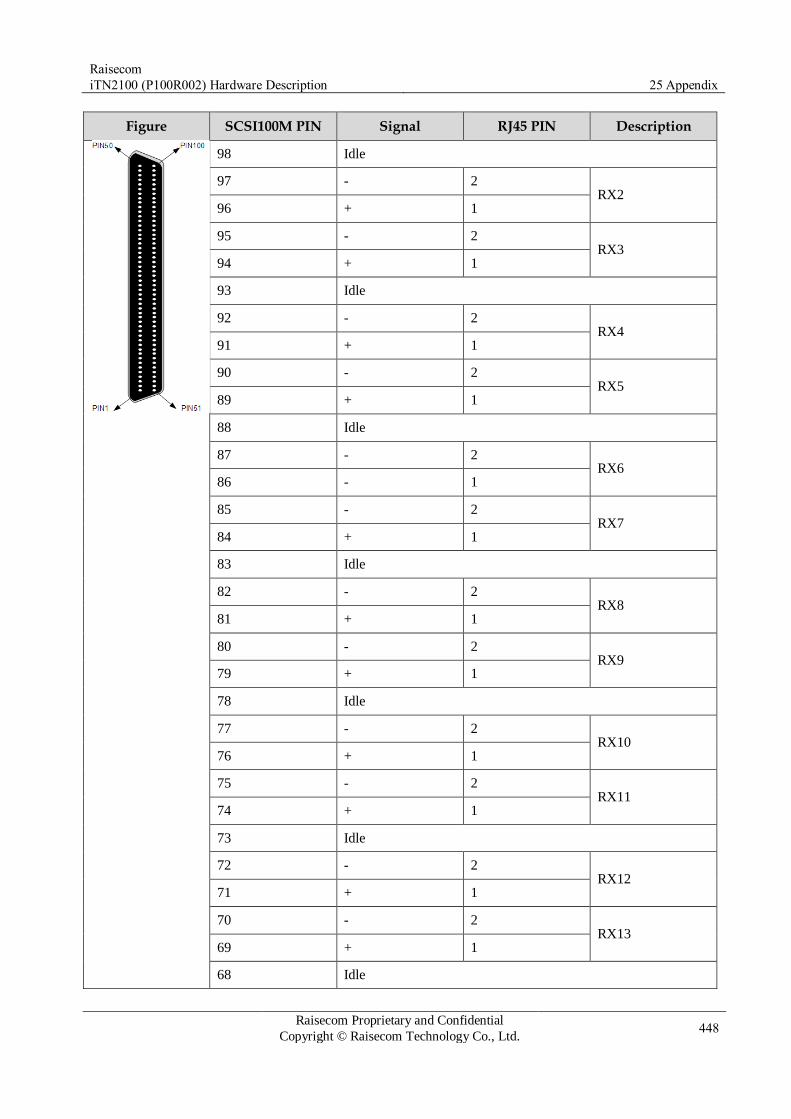
Raisecom
iTN2100 (P100R002) Hardware Description 25 Appendix
Raisecom Proprietary and Confidential
Copyright © Raisecom Technology Co., Ltd. 448
Figure SCSI100M PIN Signal RJ45 PIN Description
98 Idle
97 - 2 RX2
96 + 1
95 - 2 RX3
94 + 1
93 Idle
92 - 2 RX4
91 + 1
90 - 2 RX5
89 + 1
88 Idle
87 - 2 RX6
86 - 1
85 - 2 RX7
84 + 1
83 Idle
82 - 2 RX8
81 + 1
80 - 2 RX9
79 + 1
78 Idle
77 - 2 RX10
76 + 1
75 - 2 RX11
74 + 1
73 Idle
72 - 2 RX12
71 + 1
70 - 2 RX13
69 + 1
68 Idle

Raisecom
iTN2100 (P100R002) Hardware Description 25 Appendix
Raisecom Proprietary and Confidential
Copyright © Raisecom Technology Co., Ltd. 449
Figure SCSI100M PIN Signal RJ45 PIN Description
67 - 2 RX14
66 + 1
65 - 2 RX15
64 + 1
63 Idle
62 - 2 RX16
61 + 1
60–51 Idle
50 - 5 TX1
49 + 4
48 Idle
47 - 5 TX2
46 + 4
45 - 5 TX3
44 + 4
43 Idle
42 - 5 TX4
41 + 4
40 - 5 TX5
39 + 4
38 Idle
37 - 5 TX6
36 + 4
35 - 5 TX7
34 + 4
33 Idle
32 - 5 TX8
31 + 4
30 - 5 TX9
29 + 4
28 Idle

Raisecom
iTN2100 (P100R002) Hardware Description 25 Appendix
Raisecom Proprietary and Confidential
Copyright © Raisecom Technology Co., Ltd. 450
Figure SCSI100M PIN Signal RJ45 PIN Description
27 - 5 TX10
26 + 4
25 - 5 TX11
24 + 4
23 Idle
22 - 5 TX12
21 + 4
20 - 5 TX13
19 + 4
18 Idle
17 - 5 TX14
16 + 4
15 - 5 TX15
14 + 4
13 Idle
12 - 5 TX16
11 + 4
1–10 Idle
It is connected to the core of coaxial cables if marked plus (+); namely, the PIN is
welded with the core of the coaxial cable. It is connected to the shielding layer of coaxial cables if marked hyphen (-);
namely, the PIN is welded with the shielding layer of the coaxial cable. Each group of TX and RX provides 1 way of services. For example, TX1 and RX1
provide 1 way of services.
25.4.2 CBL-E1-SCSI100M(40)/32NC
Figure SCSI100M PIN Signal RJ45 PIN Description
SCSI100M 100 - 2 RX1
99 + 1
98 Ground
97 - 2 RX2
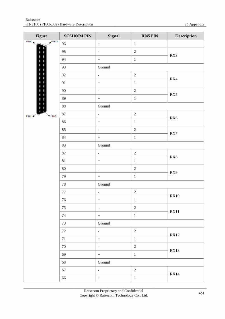
Raisecom
iTN2100 (P100R002) Hardware Description 25 Appendix
Raisecom Proprietary and Confidential
Copyright © Raisecom Technology Co., Ltd. 451
Figure SCSI100M PIN Signal RJ45 PIN Description
96 + 1
95 - 2 RX3
94 + 1
93 Ground
92 - 2 RX4
91 + 1
90 - 2 RX5
89 + 1
88 Ground
87 - 2 RX6
86 + 1
85 - 2 RX7
84 + 1
83 Ground
82 - 2 RX8
81 + 1
80 - 2 RX9
79 + 1
78 Ground
77 - 2 RX10
76 + 1
75 - 2 RX11
74 + 1
73 Ground
72 - 2 RX12
71 + 1
70 - 2 RX13
69 + 1
68 Ground
67 - 2 RX14
66 + 1
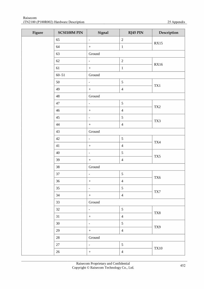
Raisecom
iTN2100 (P100R002) Hardware Description 25 Appendix
Raisecom Proprietary and Confidential
Copyright © Raisecom Technology Co., Ltd. 452
Figure SCSI100M PIN Signal RJ45 PIN Description
65 - 2 RX15
64 + 1
63 Ground
62 - 2 RX16
61 + 1
60–51 Ground
50 - 5 TX1
49 + 4
48 Ground
47 - 5 TX2
46 + 4
45 - 5 TX3
44 + 4
43 Ground
42 - 5 TX4
41 + 4
40 - 5 TX5
39 + 4
38 Ground
37 - 5 TX6
36 + 4
35 - 5 TX7
34 + 4
33 Ground
32 - 5 TX8
31 + 4
30 - 5 TX9
29 + 4
28 Ground
27 - 5 TX10
26 + 4
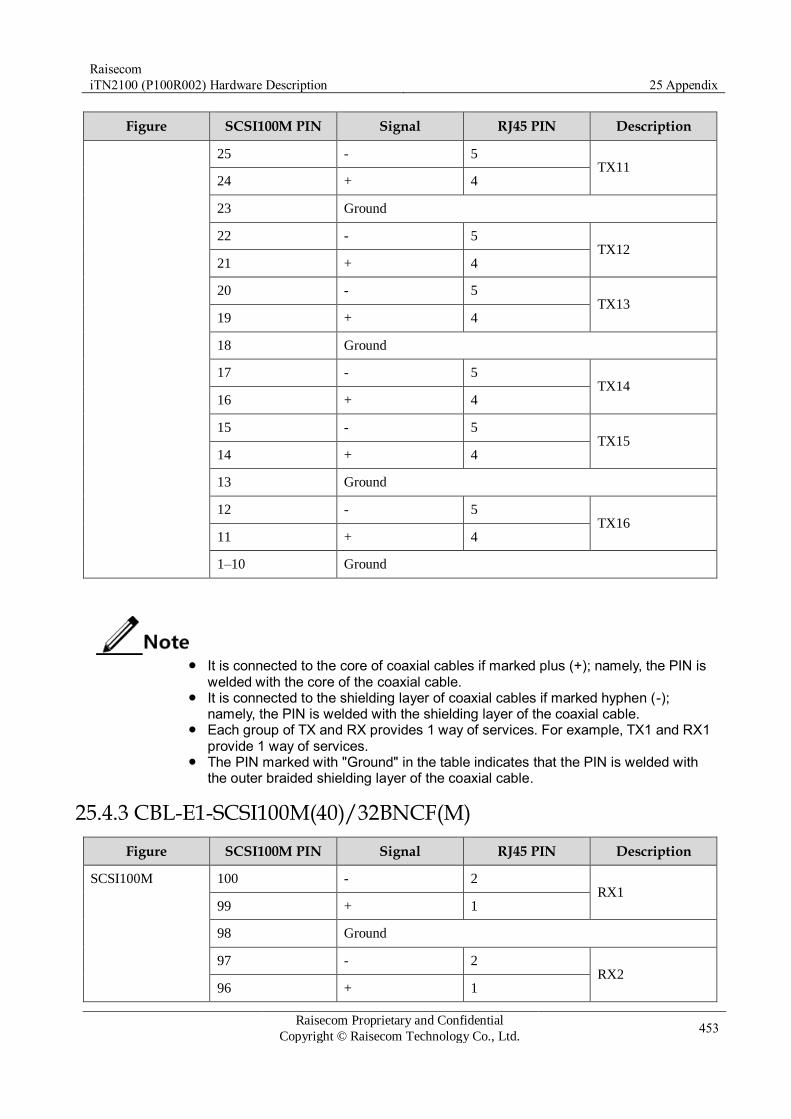
Raisecom
iTN2100 (P100R002) Hardware Description 25 Appendix
Raisecom Proprietary and Confidential
Copyright © Raisecom Technology Co., Ltd. 453
Figure SCSI100M PIN Signal RJ45 PIN Description
25 - 5 TX11
24 + 4
23 Ground
22 - 5 TX12
21 + 4
20 - 5 TX13
19 + 4
18 Ground
17 - 5 TX14
16 + 4
15 - 5 TX15
14 + 4
13 Ground
12 - 5 TX16
11 + 4
1–10 Ground
It is connected to the core of coaxial cables if marked plus (+); namely, the PIN is
welded with the core of the coaxial cable. It is connected to the shielding layer of coaxial cables if marked hyphen (-);
namely, the PIN is welded with the shielding layer of the coaxial cable. Each group of TX and RX provides 1 way of services. For example, TX1 and RX1
provide 1 way of services. The PIN marked with "Ground" in the table indicates that the PIN is welded with
the outer braided shielding layer of the coaxial cable.
25.4.3 CBL-E1-SCSI100M(40)/32BNCF(M)
Figure SCSI100M PIN Signal RJ45 PIN Description
SCSI100M 100 - 2 RX1
99 + 1
98 Ground
97 - 2 RX2
96 + 1

Raisecom
iTN2100 (P100R002) Hardware Description 25 Appendix
Raisecom Proprietary and Confidential
Copyright © Raisecom Technology Co., Ltd. 454
Figure SCSI100M PIN Signal RJ45 PIN Description
95 - 2 RX3
94 + 1
93 Ground
92 - 2 RX4
91 + 1
90 - 2 RX5
89 + 1
88 Ground
87 - 2 RX6
86 + 1
85 - 2 RX7
84 + 1
83 Ground
82 - 2 RX8
81 + 1
80 - 2 RX9
79 + 1
78 Ground
77 - 2 RX10
76 + 1
75 - 2 RX11
74 + 1
73 Ground
72 - 2 RX12
71 + 1
70 - 2 RX13
69 + 1
68 Ground
67 - 2 RX14
66 + 1
65 - 2 RX15

Raisecom
iTN2100 (P100R002) Hardware Description 25 Appendix
Raisecom Proprietary and Confidential
Copyright © Raisecom Technology Co., Ltd. 455
Figure SCSI100M PIN Signal RJ45 PIN Description
64 + 1
63 Ground
62 - 2 RX16
61 + 1
60–51 Ground
50 - 5 TX1
49 + 4
48 Ground
47 - 5 TX2
46 + 4
45 - 5 TX3
44 + 4
43 Ground
42 - 5 TX4
41 + 4
40 - 5 TX5
39 + 4
38 Ground
37 - 5 TX6
36 + 4
35 - 5 TX7
34 + 4
33 Ground
32 - 5 TX8
31 + 4
30 - 5 TX9
29 + 4
28 Ground
27 - 5 TX10
26 + 4
25 - 5 TX11

Raisecom
iTN2100 (P100R002) Hardware Description 25 Appendix
Raisecom Proprietary and Confidential
Copyright © Raisecom Technology Co., Ltd. 456
Figure SCSI100M PIN Signal RJ45 PIN Description
24 + 4
23 Ground
22 - 5 TX12
21 + 4
20 - 5 TX13
19 + 4
18 Ground
17 - 5 TX14
16 + 4
15 - 5 TX15
14 + 4
13 Ground
12 - 5 TX16
11 + 4
1–10 Ground
It is connected to the core of coaxial cables if marked plus (+); namely, the PIN is
welded with the core of the coaxial cable. It is connected to the shielding layer of coaxial cables if marked hyphen (-);
namely, the PIN is welded with the shielding layer of the coaxial cable. Each group of TX and RX provides 1 way of services. For example, TX1 and RX1
provide 1 way of services. The PIN marked with "Ground" in the table indicates that the PIN is welded with
the outer braided shielding layer of the coaxial cable.
25.4.4 CBL-E1-DB37F/16BNCF
Figure PIN Signal Definition Chanel
DB37F 3 OUT1- TX1
Channel 1 4 OUT1+
21 IN1+ RX1
22 IN1-
5 OUT2- TX2 Channel 2
6 OUT2+

Raisecom
iTN2100 (P100R002) Hardware Description 25 Appendix
Raisecom Proprietary and Confidential
Copyright © Raisecom Technology Co., Ltd. 457
Figure PIN Signal Definition Chanel
23 IN2+ RX2
24 IN2-
7 OUT3- TX3
Channel 3 8 OUT3+
25 IN3+ RX3
26 IN3-
9 OUT4- TX4
Channel 4 10 OUT4+
27 IN4+ RX4
28 IN4-
11 OUT5- TX5
Channel 5 12 OUT5+
29 IN5+ RX5
30 IN5-
13 OUT6- TX6
Channel 6 14 OUT6+
31 IN6+ RX6
32 IN6-
15 OUT7- TX7
Channel 7 16 OUT7+
33 IN7+ RX7
34 IN7-
17 OUT8- TX8
Channel 8 18 OUT8+
35 IN8+ RX8
36 IN8-
It is connected to the core of coaxial cables if marked plus (+); namely, the PIN is
welded with the core of the coaxial cable. It is connected to the shielding layer of coaxial cables if marked hyphen (-);
namely, the PIN is welded with the shielding layer of the coaxial cable.

Raisecom
iTN2100 (P100R002) Hardware Description 25 Appendix
Raisecom Proprietary and Confidential
Copyright © Raisecom Technology Co., Ltd. 458
The wiring is also applicable to the CBL-E1-DB37F/16BNCM.
25.4.5 CBL-E1-DB37F/8RJ45
Figure DB37F PIN RJ45 PIN Signal Definition Channel
DB37F
RJ45
3 5 OUT1- TX1
Channel 1 4 4 OUT1+
21 2 IN1+ RX1
22 1 IN1-
5 5 OUT2- TX2
Channel 2 6 4 OUT2+
23 2 IN2+ RX2
24 1 IN2-
7 5 OUT3- TX3
Channel 3 8 4 OUT3+
25 2 IN3+ RX3
26 1 IN3-
9 5 OUT4- TX4
Channel 4 10 4 OUT4+
27 2 IN4+ RX4
28 1 IN4-
11 5 OUT5- TX5
Channel 5 12 4 OUT5+
29 2 IN5+ RX5
30 1 IN5-
13 5 OUT6- TX6
Channel 6 14 4 OUT6+
31 2 IN6+ RX6
32 1 IN6-
15 5 OUT7- TX7
Channel 7 16 4 OUT7+
33 2 IN7+ RX7
34 1 IN7-
17 5 OUT8- TX8 Channel 8
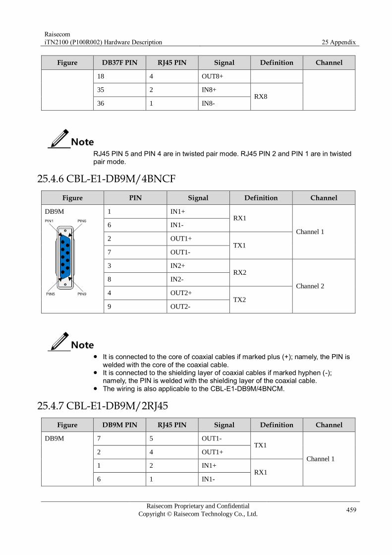
Raisecom
iTN2100 (P100R002) Hardware Description 25 Appendix
Raisecom Proprietary and Confidential
Copyright © Raisecom Technology Co., Ltd. 459
Figure DB37F PIN RJ45 PIN Signal Definition Channel
18 4 OUT8+
35 2 IN8+ RX8
36 1 IN8-
RJ45 PIN 5 and PIN 4 are in twisted pair mode. RJ45 PIN 2 and PIN 1 are in twisted pair mode.
25.4.6 CBL-E1-DB9M/4BNCF
Figure PIN Signal Definition Channel
DB9M
1 IN1+ RX1
Channel 1 6 IN1-
2 OUT1+ TX1
7 OUT1-
3 IN2+ RX2
Channel 2 8 IN2-
4 OUT2+ TX2
9 OUT2-
It is connected to the core of coaxial cables if marked plus (+); namely, the PIN is
welded with the core of the coaxial cable. It is connected to the shielding layer of coaxial cables if marked hyphen (-);
namely, the PIN is welded with the shielding layer of the coaxial cable. The wiring is also applicable to the CBL-E1-DB9M/4BNCM.
25.4.7 CBL-E1-DB9M/2RJ45
Figure DB9M PIN RJ45 PIN Signal Definition Channel
DB9M 7 5 OUT1- TX1
Channel 1 2 4 OUT1+
1 2 IN1+ RX1
6 1 IN1-

Raisecom
iTN2100 (P100R002) Hardware Description 25 Appendix
Raisecom Proprietary and Confidential
Copyright © Raisecom Technology Co., Ltd. 460
Figure DB9M PIN RJ45 PIN Signal Definition Channel
RJ45
9 5 OUT2- TX2
Channel 2
4 4 OUT2+
3 2 IN2+
RX2
8 1 IN2-
RJ45 PIN 5 and PIN 4 are in twisted pair mode. RJ45 PIN 2 and PIN 1 are in twisted pair mode.
25.4.8 CBL-VOICE-SCSI50M(40)/NC
Figure PIN Cable color E&M Channel
Description
SCSI50M
1 White background
with blue loop
Channel 1
Audio RX A in 4-wire mode Idle in 2-wire mode
2 Blue background
with white loop
Audio RX B in 4-wire mode Idle in 2-wire mode
26 White background
with orange loop
Audio TX A in 4-wire mode Audio TX/RX A in 2-wire mode
27 Orange background
with white loop
Audio TX B in 4-wire mode Audio TX/RX B in 2-wire mode
3 White background
with green loop
M signaling cable
4 Green background
with white loop
E signaling cable
28 White background
with brown loop
Channel 2
Audio RX A in 4-wire mode Idle in 2-wire mode
29 Brown background
with white loop
Audio RX B in 4-wire mode Idle in 2-wire mode
5 White background
with grey loop
Audio TX A in 4-wire mode Audio TX/RX A in 2-wire mode
6 Grey background with white loop
Audio TX B in 4-wire mode Audio TX/RX B in 2-wire mode

Raisecom
iTN2100 (P100R002) Hardware Description 25 Appendix
Raisecom Proprietary and Confidential
Copyright © Raisecom Technology Co., Ltd. 461
Figure PIN Cable color E&M Channel
Description
30 Red background
with blue loop
M signaling cable
31 Blue background
with red loop
E signaling cable
7 Red background
with orange loop
Channel 3
Audio RX A in 4-wire mode Idle in 2-wire mode
8 Orange background
with red loop
Audio RX B in 4-wire mode Idle in 2-wire mode
32 Red background
with green loop
Audio TX A in 4-wire mode Audio TX/RX A in 2-wire mode
33 Green background
with red loop
Audio TX B in 4-wire mode Audio TX/RX B in 2-wire mode
9 Red background
with brown loop
M signaling cable
10 Brown background
with red loop
E signaling cable
34 Red background
with grey loop
Channel 4
Audio RX A in 4-wire mode Idle in 2-wire mode
35 Grey background
with red loop
Audio RX B in 4-wire mode Idle in 2-wire mode
11 Black background
with blue loop
Audio TX A in 4-wire mode Audio TX/RX A in 2-wire mode
12 Blue background
with black loop
Audio TX B in 4-wire mode Audio TX/RX B in 2-wire mode
36 Black background
with orange loop
M signaling cable
37 Orange background
with black loop
E signaling cable
13 Black background
with green loop
Channel 5
Audio RX A in 4-wire mode Idle in 2-wire mode
14 Green background
with black loop
Audio RX B in 4-wire mode Idle in 2-wire mode
38 Black background
with brown loop
Audio TX A in 4-wire mode Audio TX/RX A in 2-wire mode
39 Brown background
with black loop
Audio TX B in 4-wire mode Audio TX/RX B in 2-wire mode
15 Black background
with grey loop
M signaling cable
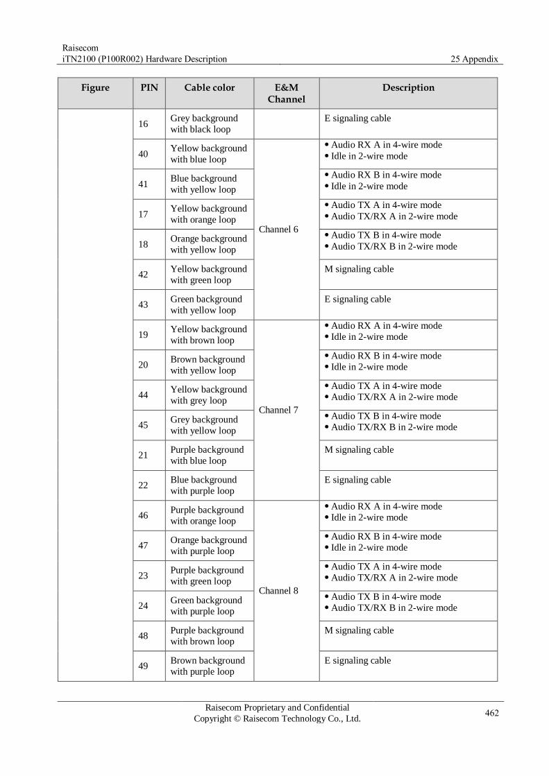
Raisecom
iTN2100 (P100R002) Hardware Description 25 Appendix
Raisecom Proprietary and Confidential
Copyright © Raisecom Technology Co., Ltd. 462
Figure PIN Cable color E&M Channel
Description
16 Grey background
with black loop
E signaling cable
40 Yellow background
with blue loop
Channel 6
Audio RX A in 4-wire mode Idle in 2-wire mode
41 Blue background
with yellow loop
Audio RX B in 4-wire mode Idle in 2-wire mode
17 Yellow background
with orange loop
Audio TX A in 4-wire mode Audio TX/RX A in 2-wire mode
18 Orange background
with yellow loop
Audio TX B in 4-wire mode Audio TX/RX B in 2-wire mode
42 Yellow background
with green loop
M signaling cable
43 Green background
with yellow loop
E signaling cable
19 Yellow background
with brown loop
Channel 7
Audio RX A in 4-wire mode Idle in 2-wire mode
20 Brown background
with yellow loop
Audio RX B in 4-wire mode Idle in 2-wire mode
44 Yellow background
with grey loop
Audio TX A in 4-wire mode Audio TX/RX A in 2-wire mode
45 Grey background
with yellow loop
Audio TX B in 4-wire mode Audio TX/RX B in 2-wire mode
21 Purple background
with blue loop
M signaling cable
22 Blue background
with purple loop
E signaling cable
46 Purple background
with orange loop
Channel 8
Audio RX A in 4-wire mode Idle in 2-wire mode
47 Orange background
with purple loop
Audio RX B in 4-wire mode Idle in 2-wire mode
23 Purple background
with green loop
Audio TX A in 4-wire mode Audio TX/RX A in 2-wire mode
24 Green background
with purple loop
Audio TX B in 4-wire mode Audio TX/RX B in 2-wire mode
48 Purple background
with brown loop
M signaling cable
49 Brown background
with purple loop
E signaling cable

Raisecom
iTN2100 (P100R002) Hardware Description 25 Appendix
Raisecom Proprietary and Confidential
Copyright © Raisecom Technology Co., Ltd. 463
Figure PIN Cable color E&M Channel
Description
25 Purple background
with grey loop – Idle
50 Grey background
with purple loop – Idle
The cable supports up to 8 E&M channels.
25.4.9 CBL-EM-HDB26M/NC
Figure PIN Cable color E&M Channel
Description
HDB26M
7 White background
with blue loop
Channel 1
Audio RX A in 4-wire mode Idle in 2-wire mode
17 Blue background
with white loop
Audio RX B in 4-wire mode Idle in 2-wire mode
8 White background
with orange loop
Audio TX A in 4-wire mode Audio TX/RX A in 2-wire mode
18 Orange background
with white loop
Audio TX B in 4-wire mode Audio TX/RX B in 2-wire mode
25 White background
with green loop
M signaling cable
26 Green background
with white loop
E signaling cable
5 White background
with brown loop
Channel 2
Audio RX A in 4-wire mode Idle in 2-wire mode
15 Brown background
with white loop
Audio RX B in 4-wire mode Idle in 2-wire mode
6 White background
with grey loop
Audio TX A in 4-wire mode Audio TX/RX A in 2-wire mode
16 Grey background
with white loop
Audio TX B in 4-wire mode Audio TX/RX B in 2-wire mode
23 Red background
with blue loop
M signaling cable
24 Blue background
with red loop
E signaling cable
3 Red background with orange loop
Channel 3 Audio RX A in 4-wire mode Idle in 2-wire mode

Raisecom
iTN2100 (P100R002) Hardware Description 25 Appendix
Raisecom Proprietary and Confidential
Copyright © Raisecom Technology Co., Ltd. 464
Figure PIN Cable color E&M Channel
Description
13 Orange background
with red loop
Audio RX B in 4-wire mode Idle in 2-wire mode
4 Red background
with green loop
Audio TX A in 4-wire mode Audio TX/RX A in 2-wire mode
14 Green background
with red loop
Audio TX B in 4-wire mode Audio TX/RX B in 2-wire mode
21 Red background
with brown loop
M signaling cable
22 Brown background
with red loop
E signaling cable
1 Red background
with grey loop
Channel 4
Audio RX A in 4-wire mode Idle in 2-wire mode
11 Grey background
with red loop
Audio RX B in 4-wire mode Idle in 2-wire mode
2 Black background
with blue loop
Audio TX A in 4-wire mode Audio TX/RX A in 2-wire mode
12 Blue background
with black loop
Audio TX B in 4-wire mode Audio TX/RX B in 2-wire mode
19 Black background
with orange loop
M signaling cable
20 Orange background
with black loop
E signaling cable
9 Black background
with green loop
- Idle
10 Green background
with black loop
- Idle
25.4.10 CBL-V35-HDB26M/2M34F
Figure HDB26 PIN
M34 PIN
(Channel 1)
Definition
(Channel 1)
M34 PIN
(Channel 2)
Definition
(Channel 2)
HDB26M 1 A PGND – –
2 P TD (A) – –
3 R RD (A) – –
4 – – – –
5 – – R RD (A)
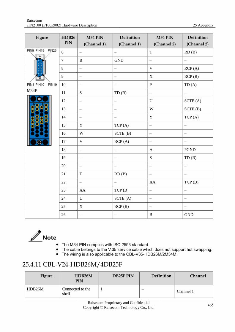
Raisecom
iTN2100 (P100R002) Hardware Description 25 Appendix
Raisecom Proprietary and Confidential
Copyright © Raisecom Technology Co., Ltd. 465
Figure HDB26 PIN
M34 PIN
(Channel 1)
Definition
(Channel 1)
M34 PIN
(Channel 2)
Definition
(Channel 2)
M34F
6 – – T RD (B)
7 B GND – –
8 – – V RCP (A)
9 – – X RCP (B)
10 – – P TD (A)
11 S TD (B) – –
12 – – U SCTE (A)
13 – – W SCTE (B)
14 – – Y TCP (A)
15 Y TCP (A) – –
16 W SCTE (B) – –
17 V RCP (A) – –
18 – – A PGND
19 – – S TD (B)
20 – – – –
21 T RD (B) – –
22 – – AA TCP (B)
23 AA TCP (B) – –
24 U SCTE (A) – –
25 X RCP (B) – –
26 – – B GND
The M34 PIN complies with ISO 2593 standard. The cable belongs to the V.35 service cable which does not support hot swapping. The wiring is also applicable to the CBL-V35-HDB26M/2M34M.
25.4.11 CBL-V24-HDB26M/4DB25F
Figure HDB26M PIN
DB25F PIN Definition Channel
HDB26M Connected to the shell
1 – Channel 1
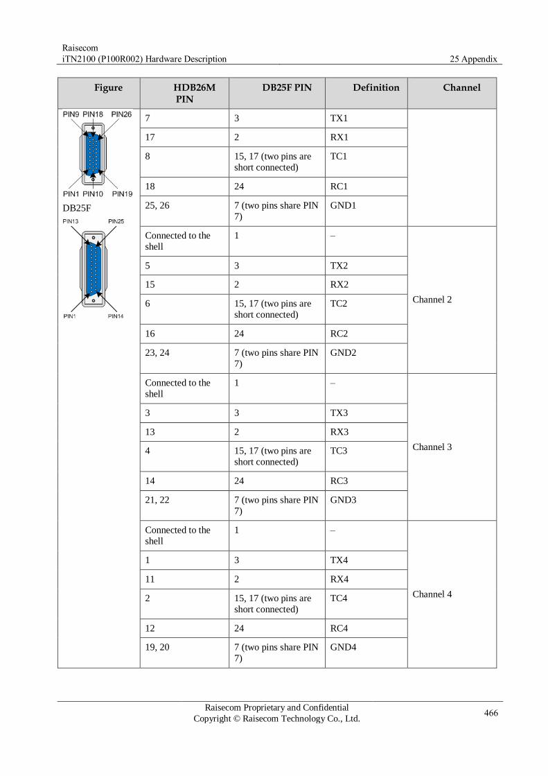
Raisecom
iTN2100 (P100R002) Hardware Description 25 Appendix
Raisecom Proprietary and Confidential
Copyright © Raisecom Technology Co., Ltd. 466
Figure HDB26M PIN
DB25F PIN Definition Channel
DB25F
7 3 TX1
17 2 RX1
8 15, 17 (two pins are
short connected)
TC1
18 24 RC1
25, 26 7 (two pins share PIN
7)
GND1
Connected to the
shell
1 –
Channel 2
5 3 TX2
15 2 RX2
6 15, 17 (two pins are
short connected)
TC2
16 24 RC2
23, 24 7 (two pins share PIN
7)
GND2
Connected to the
shell
1 –
Channel 3
3 3 TX3
13 2 RX3
4 15, 17 (two pins are
short connected)
TC3
14 24 RC3
21, 22 7 (two pins share PIN
7)
GND3
Connected to the
shell
1 –
Channel 4
1 3 TX4
11 2 RX4
2 15, 17 (two pins are
short connected)
TC4
12 24 RC4
19, 20 7 (two pins share PIN
7)
GND4

Raisecom
iTN2100 (P100R002) Hardware Description 25 Appendix
Raisecom Proprietary and Confidential
Copyright © Raisecom Technology Co., Ltd. 467
The wiring is also applicable to the CBL-V24-HDB26M/4DB25M.
25.5 Terms
1
1+1 protection
A 1+1 protection architecture has one normal traffic signal, one
working transport entity, one protection transport entity, and a permanent bridge.
At the source end, the normal traffic signal is permanently bridged
to both the working and the protection transport entities. At the
sink end, the normal traffic signal is selected from the better of the two transport entities.
Due to the permanent bridging, the 1+1 protection architecture does not allow an unprotected extra traffic signal to be provided.
100BASE-T
A FE standard for twisted-pair cables. Fast Ethernet refers to any
network that supports transmission rate of 100Mbits/s. The Fast
Ethernet is 10 times faster than 10BaseT, and inherits frame
format, MAC addressing scheme, MTU, and so on. Fast Ethernet is
extended from the IEEE 802.3 standard, and it uses the following
three types of transmission media: 100BASE-T4: 4 pairs of phone
twisted-pair cables 100BASE-TX: 2 pairs of data twisted-pair cables 100BASE-FX: 2-core optical fibers.
2R Re-amplifying, Re-shaping
3R Re-amplifying, Re-shaping, Re-timing
A
Automatic Laser
Shutdown (ALS)
The technology that is used for automatically shutting down the
laser to avoid the maintenance and operation risks when the fiber is pulled out or the output power is over great.
Auto-negotiation
The interface automatically chooses the rate and duplex mode
according to the result of negotiation. The auto-negotiation process
is: the interface adapts its rate and duplex mode to the highest
performance according to the peer interface, that is, both ends of
the link adopt the highest rate and duplex mode they both support after auto-negotiation.
B
Bracket Small parts at both sides of the chassis, used to install the chassis
into the cabinet
C

Raisecom
iTN2100 (P100R002) Hardware Description 25 Appendix
Raisecom Proprietary and Confidential
Copyright © Raisecom Technology Co., Ltd. 468
Card
An electronic module, composed of the chip and other electronic
components installed on a flat and hard Printed Circuit Board
(PCB). The PCB has conductive circuits for connecting these components.
F
Failover
Failover provides an interface linkage scheme, extending the range
of link backup. Through monitoring upstream links and
synchronizing downstream links, faults of the upstream device can
be transferred quickly to the downstream device, and
primary/backup switching is triggered. In this way, it avoids traffic
loss because the downstream device does not sense faults of the
upstream link.
Frame It is a data transmission unit, composed of several parts, each of
which has different functions.
Full duplex In a communication link, both parties can receive and send data
concurrently.
G
Ground cable
The cable to connect the device to ground, usually a yellow/green
coaxial cable. Connecting the ground cable properly is an
important guarantee to lightning protection, anti-electric shock, and anti-interference.
H
Half duplex In a communication link, both parties can receive or send data at a
time.
I
Institute of
Electrical and
Electronics
Engineers (IEEE)
A professional society serving electrical engineers through its
publications, conferences, and standards development activities.
The body responsible for the Ethernet 802.3 and wireless LAN
802.11 specifications.
ITU-T International Telecommunication Union Telecommunication
Standardization Sector
L
Label Symbols for cable, chassis, and warnings
Loopback It is the process that a signal is sent out and then sent back to the
sender. It is used to detect and analyze potential faults in a ring
network.

Raisecom
iTN2100 (P100R002) Hardware Description 25 Appendix
Raisecom Proprietary and Confidential
Copyright © Raisecom Technology Co., Ltd. 469
M
Multi-mode fiber In this fiber, multi-mode optical signals are transmitted.
Multiplexer The device to multiplex multiple tributary signals to several
bearing channels
Multiplex Section
Protection (MSP)
MSP is based on multiplex sections. Whether to perform switching
depends on the quality of multiplex section signals. Switching is
initiated by the APS protocol carried by the Multiplex Section
Overhead (MSOH). If a multiplex section fails, service signals of
the whole STM-N are switched to the backup channel.
R
RS232
It is an Asynchronous Transfer Mode (ATM), which does not
contain hand-shaking signals. It can carry on point-to-point
communication with RS232 and RS422 of other stations, featuring
transparent transmission, with a maximum rate of 19.2 kbit/s.
Generally, the form of RS232 interface is DB9 or DB25.
S
Single-mode fiber In this fiber, single-mode optical signals are transmitted.
T
Timeslot Time is divided into periodical frames. Each frame is divided into
multiple timeslots. Each timeslot is a communication channel which can be assigned to a user.
U
U Unit of dimensions, short for unit. It takes 44.45 mm as a basic
unit, namely, 1 U = 44.45 mm
25.6 Acronyms and abbreviations
2
2R Re-amplifying and Re-shaping
3
3R Re-amplifying, Re-shaping, and Re-timing

Raisecom
iTN2100 (P100R002) Hardware Description 25 Appendix
Raisecom Proprietary and Confidential
Copyright © Raisecom Technology Co., Ltd. 470
A
ACL Access Control List
AIS Alarm Indication Signal
ALS Automatic Laser Shutdown
AWG American Wire Gauge
B
BPDU Bridge Protocol Data Unit
C
CFM Connectivity Fault Management
CWDM Coarse Wavelength Division Multiplexing
D
DCC Data Communication Channel
DCE Data Connection Equipment
DTE Data Terminal Equipment
E
EMC Electromagnetic Compatibility
EOL End of Life
EOP Ethernet Over Plesynchronous Digital Hierarchy
EOS Ethernet Over SynchronousDigital Hierarchy
F
FE Fast Ethernet
G
G.SHDSL G.Single-pair High Speed Digital Subscriber Line
GE Gigabit Ethernet
GFP Generic Framing Procedure
H

Raisecom
iTN2100 (P100R002) Hardware Description 25 Appendix
Raisecom Proprietary and Confidential
Copyright © Raisecom Technology Co., Ltd. 471
HDB3 High Density Bipolar of Order 3 Code
I
IEC International Electrotechnical Commission
L
LACP Link Aggregation Control Protocol
LCAS Link capacity adjustment scheme
LSP Label Switching Path
M
MAC Medium Access Control
MPLS Multi-Protocol Label Switching
N
NRZ Non Return to Zero
O
OADM Optical Add/Drop Multiplexer
OAM Operation, Maintenance, and Management
P
PDH Plesiochronous Digital Hierarchy
PTN Packet Transport Network
PWE3 Pseudo-Wire Emulation Edge to Edge
Q
QinQ 802.1Q in 802.1Q
QoS Quality of Service
R
RH Relative Humidity
RMON Remote Network Monitoring

Raisecom
iTN2100 (P100R002) Hardware Description 25 Appendix
Raisecom Proprietary and Confidential
Copyright © Raisecom Technology Co., Ltd. 472
S
SDH Synchronous Digital Hierarchy
SFP Small Form-factor Pluggable
SLA Service Level Agreement
SNMP Simple Network Management Protocol
STM-N Synchronous Transport Module Level-N
T
TDM Time Division Multiplex
V
VC Virtual Container
VCC Virtual Channel Connection
VLAN Virtual LAN
VPLS Virtual Private Lan Service

Address: Raisecom Building, No. 11, East Area, No. 10 Block, East Xibeiwang Road, Haidian
District, Beijing, P.R.China Postal code: 100094 Tel: +86-10-82883305
Fax: 8610-82883056 http://www.raisecom.com Email: [email protected]