Flow stress from microstructures of mylonites: example and current assessment
Upload
khangminh22Category
view
3download
0
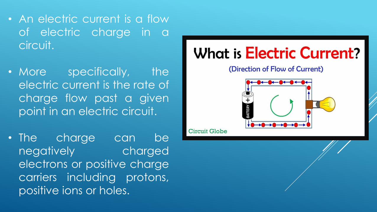
• An electric current is a flow
of electric charge in a
circuit.
• More specifically, the
electric current is the rate of
charge flow past a given
point in an electric circuit.
• The charge can be
negatively charged
electrons or positive charge
carriers including protons,
positive ions or holes.
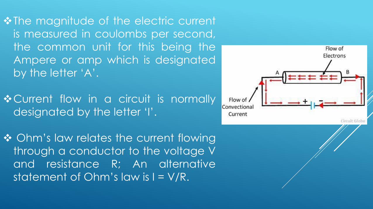
❖The magnitude of the electric current
is measured in coulombs per second,
the common unit for this being the
Ampere or amp which is designated
by the letter ‘A’.
❖Current flow in a circuit is normally
designated by the letter ‘I’.
❖ Ohm’s law relates the current flowing
through a conductor to the voltage V
and resistance R; An alternative
statement of Ohm’s law is I = V/R.
❖ The moving particles are called charge carriers, which may be
one of several types of particles, depending on the conductor.
❖ In electric circuits the charge carriers are often electrons
moving through a wire.
❖ In semiconductors they can be electrons or holes.
❖ In an electrolyte the charge carriers are ions, while in plasma,
an ionized gas, electric current is formed by both electrons and
ions.
❖ Electric current is measured using a device called an ammeter.
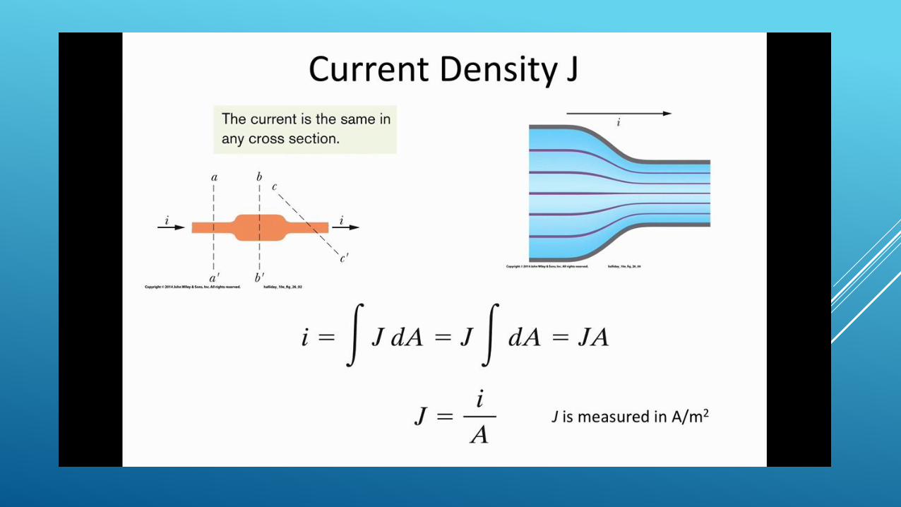
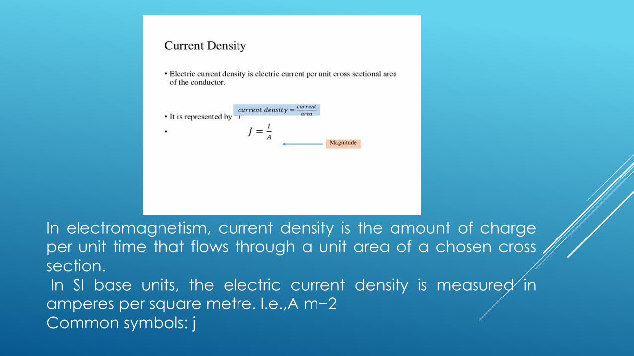
In electromagnetism, current density is the amount of charge
per unit time that flows through a unit area of a chosen cross
section.
In SI base units, the electric current density is measured in
amperes per square metre. I.e.,A m−2
Common symbols: j
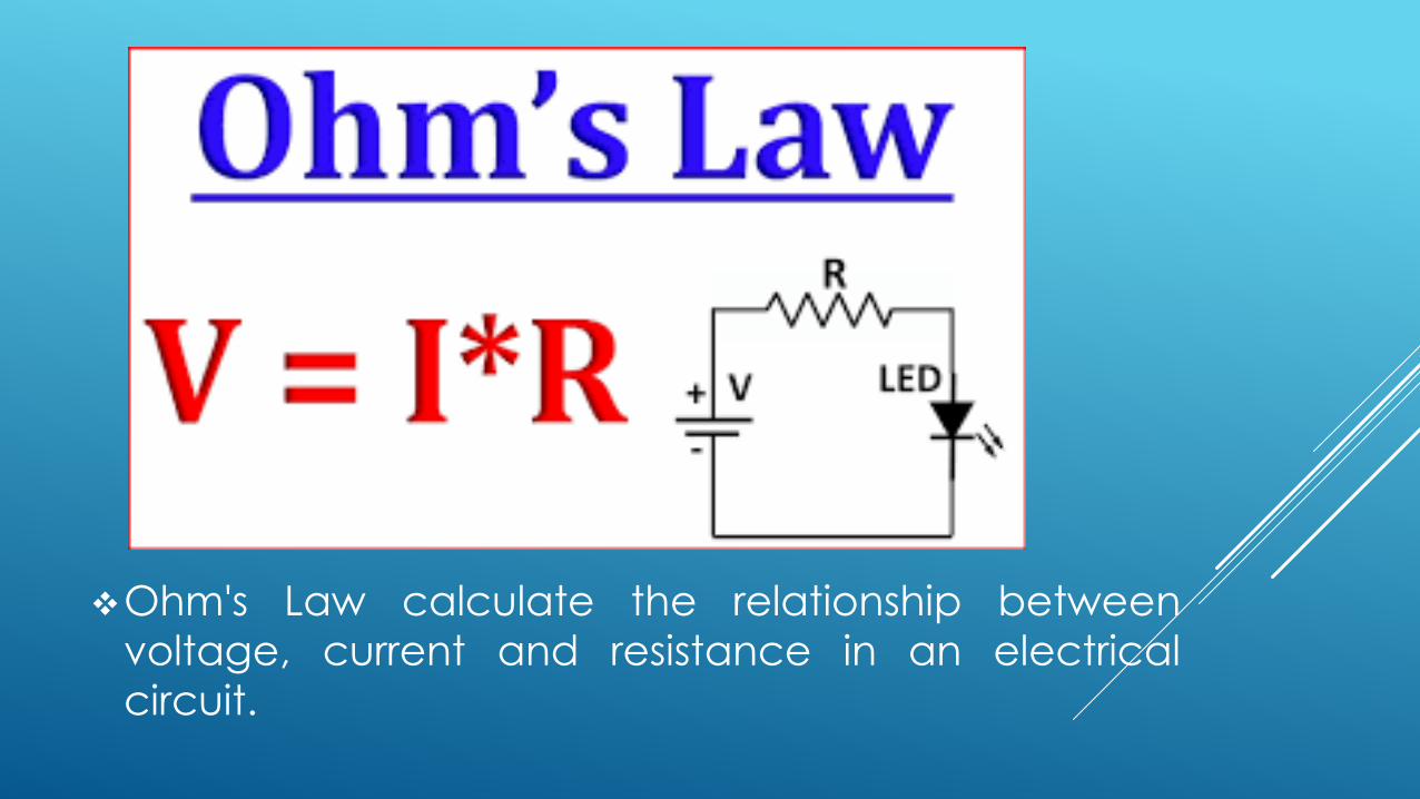
❖Ohm's Law calculate the relationship between
voltage, current and resistance in an electrical
circuit.
❖Ohm's law states that the current through a conductor
between two points is directly proportional to the voltage
across the two points.
❖where I is the current through the conductor in units of
amperes,
V is the voltage measured across the conductor in units
of volts,
and R is the resistance of the conductor in units of ohms.
❖ R in this relation is constant, independent of the current.
Electrical resistivity and Conductivity
Is a fundamental property of a material that quantifies how
strongly it resists or conducts electric current.
A low resistivity indicates a material that readily allows electric
current.
Resistivity is commonly represented by the Greek letter ρ (rho).
The SI unit of electrical resistivity is the ohm-meter (Ω⋅m).
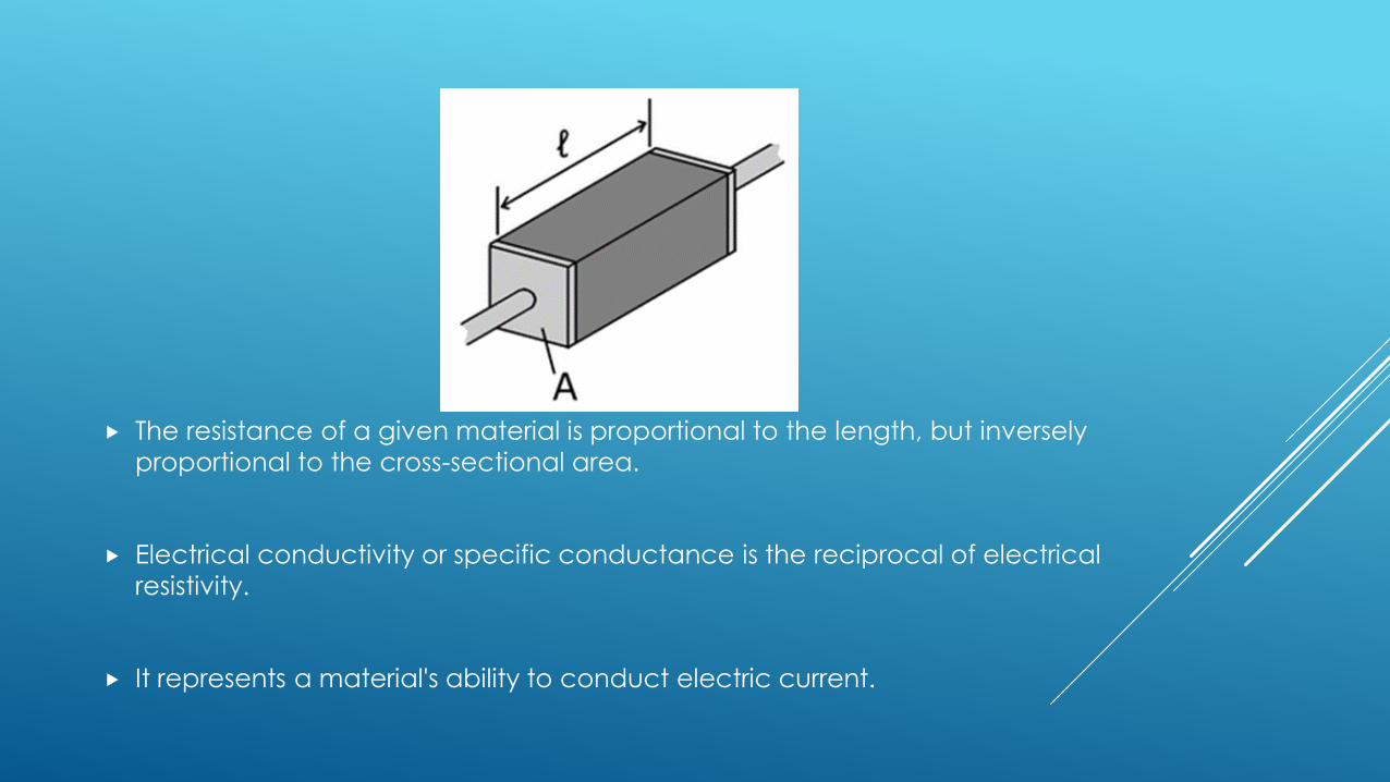
The resistance of a given material is proportional to the length, but inversely
proportional to the cross-sectional area.
Electrical conductivity or specific conductance is the reciprocal of electrical
resistivity.
It represents a material's ability to conduct electric current.
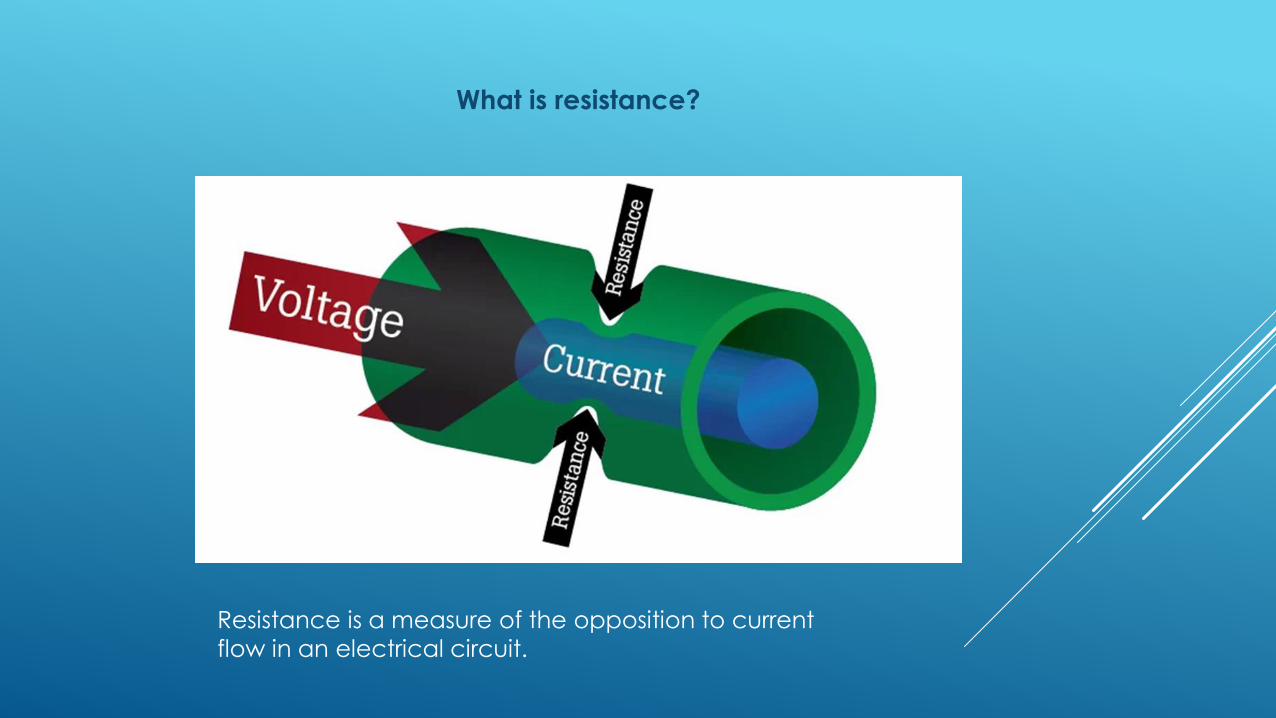
What is resistance?
Resistance is a measure of the opposition to current
flow in an electrical circuit.
Conductors: Materials that offer very little resistance where electrons can move easily. Examples: silver, copper, gold and aluminum.
Insulators: Materials that present high resistance and restrict the flow of
electrons. Examples: Rubber, paper, glass, wood and plastic.
Resistance measurements are normally taken to indicate the condition of a
component or a circuit.
The higher the resistance, the lower the current flow.
The lower the resistance, the higher the current flow.
Resistors in Series
A resistor is used to convert a voltage to a current or a
current to a voltage, but by correctly adjusting its value a
different weighting can be placed onto the converted
current and/or the voltage allowing it to be used in voltage
reference circuits and applications.
Individual resistors can be connected together in either a
series connection, a parallel connection or combinations of
both series and parallel, to produce more complex resistor
networks whose equivalent resistance is the mathematical
combination of the individual resistors connected together.

Resistors are said to be connected in series when they aredaisy chained together in a single line resulting in a commoncurrent flowing through them.
Since all the current flowing through the first resistor has noother way to go it must also pass through the second resistorand the third and so on.
Then, resistors in series have a Common Current flowingthrough them as the current that flows through one resistormust also flow through the others as it can only take one path.
Then the amount of current that flows through a set of resistorsin series will be the same at all points in a series resistor network
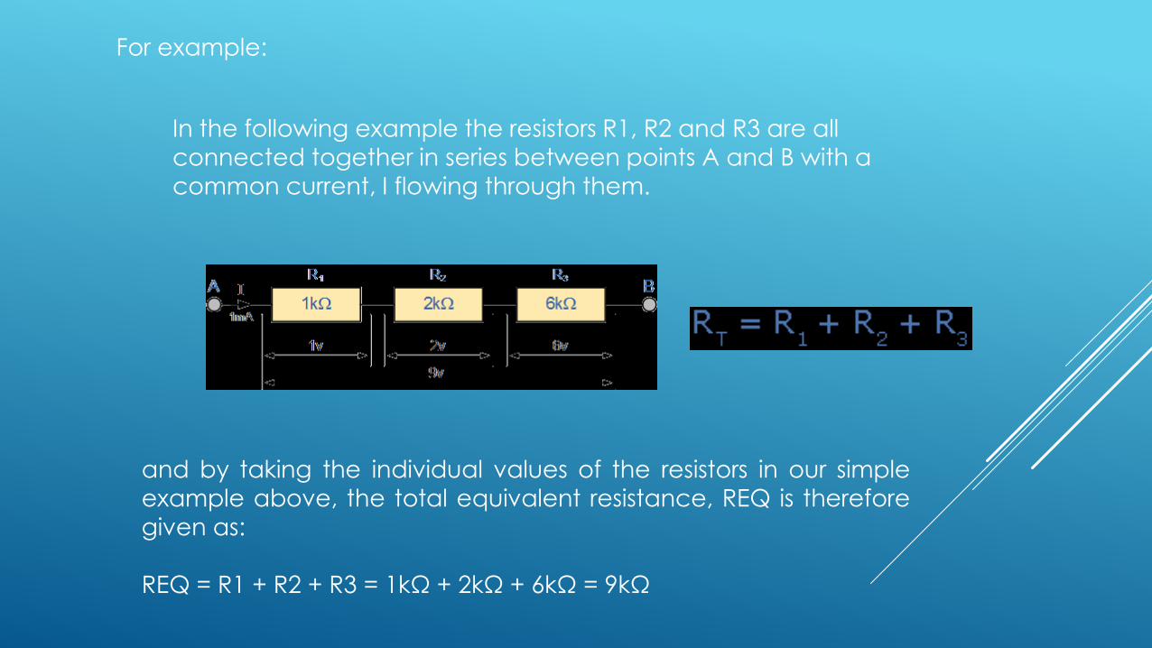
and by taking the individual values of the resistors in our simple
example above, the total equivalent resistance, REQ is thereforegiven as:
REQ = R1 + R2 + R3 = 1kΩ + 2kΩ + 6kΩ = 9kΩ
For example:
In the following example the resistors R1, R2 and R3 are all
connected together in series between points A and B with a
common current, I flowing through them.
Resistors in Parallel
Resistors are said to be connected together in parallel when both oftheir terminals are respectively connected to each terminal of theother resistor or resistors.
Since there are multiple paths for the supply current to flow through,the current may not be the same through all the branches in theparallel network.
the voltage drop across all of the resistors in a parallel resistive networkIS the same.
Resistors in Parallel have a Common Voltage across them and this istrue for all parallel connected elements.
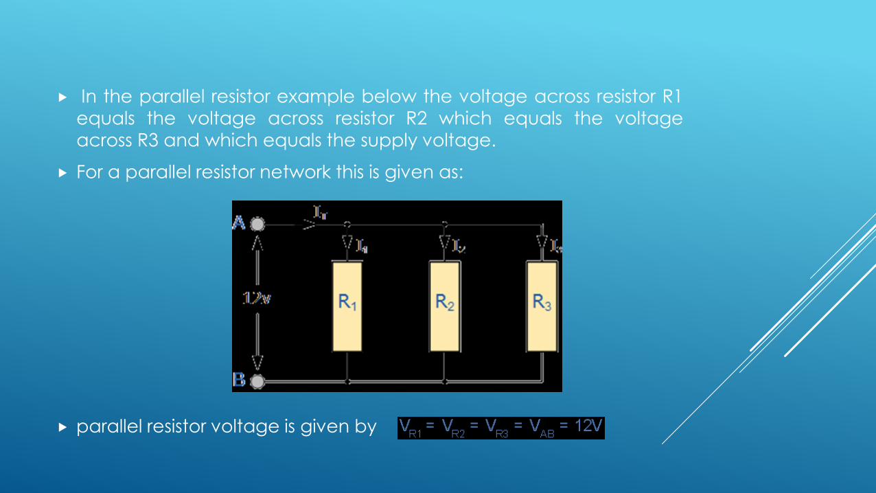
In the parallel resistor example below the voltage across resistor R1
equals the voltage across resistor R2 which equals the voltage
across R3 and which equals the supply voltage.
For a parallel resistor network this is given as:
parallel resistor voltage is given by
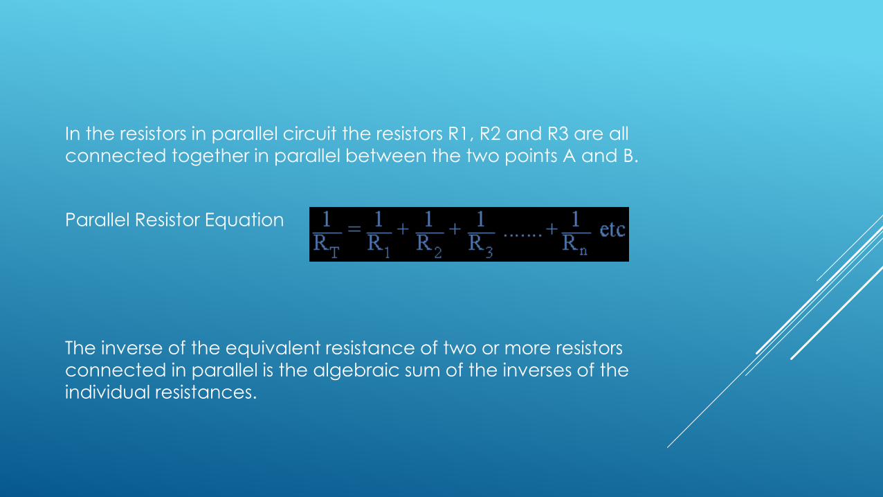
In the resistors in parallel circuit the resistors R1, R2 and R3 are all
connected together in parallel between the two points A and B.
Parallel Resistor Equation
The inverse of the equivalent resistance of two or more resistors connected in parallel is the algebraic sum of the inverses of the
individual resistances.
Kirchhoff's Laws
Kirchhoff's laws quantify how current flowsthrough a circuit and how voltage variesaround a loop in a circuit.
Kirchhoff's current law (1st Law) states that
The current flowing into a node (or a junction)must be equal to the current flowing out of it.
This is a consequence of charge conservation.
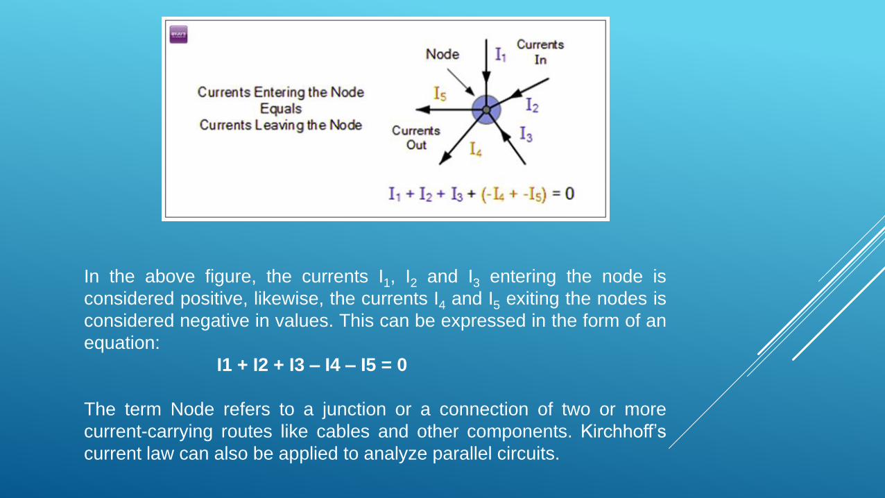
In the above figure, the currents I1, I2 and I3 entering the node is
considered positive, likewise, the currents I4 and I5 exiting the nodes is
considered negative in values. This can be expressed in the form of an
equation:
I1 + I2 + I3 – I4 – I5 = 0
The term Node refers to a junction or a connection of two or more
current-carrying routes like cables and other components. Kirchhoff’s
current law can also be applied to analyze parallel circuits.
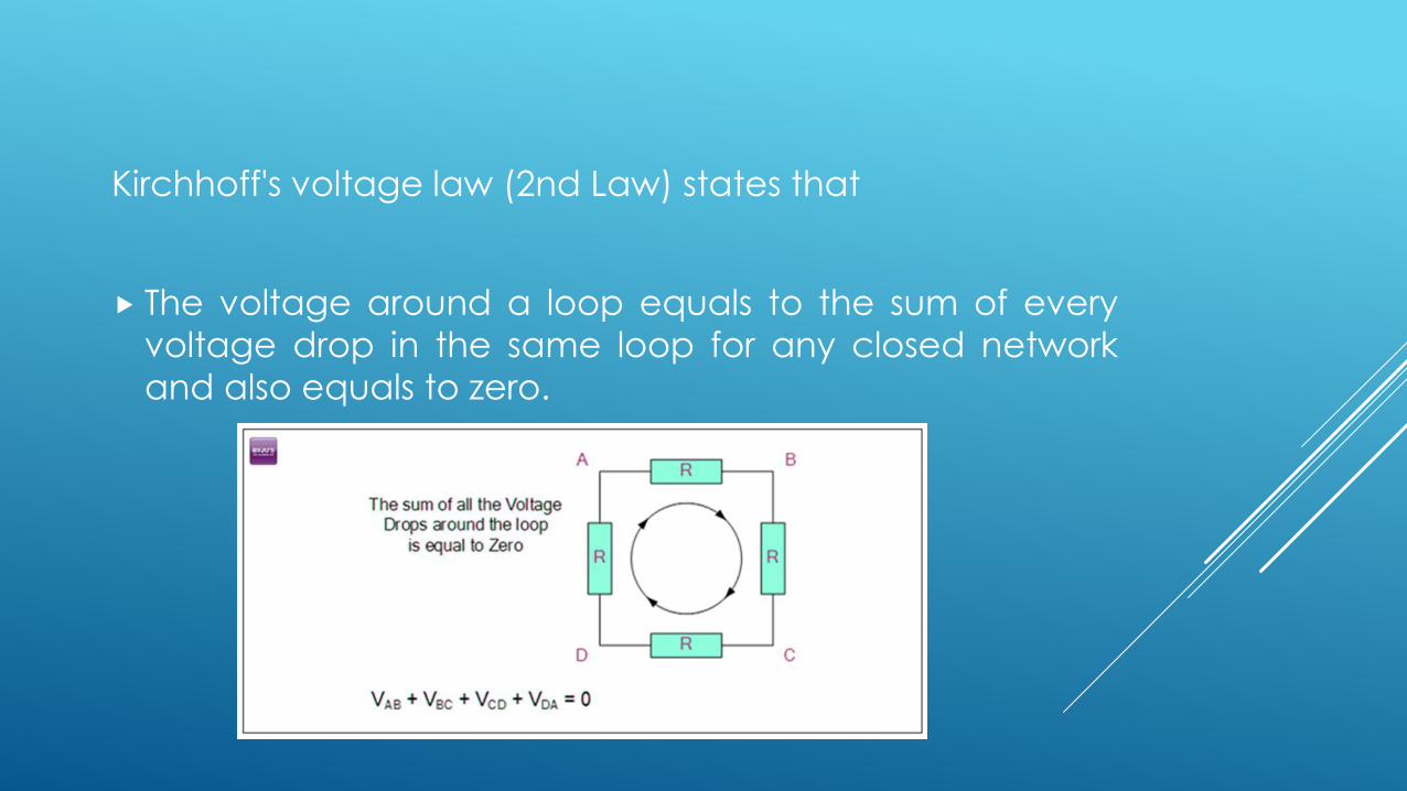
Kirchhoff's voltage law (2nd Law) states that
The voltage around a loop equals to the sum of every
voltage drop in the same loop for any closed network
and also equals to zero.
This law is a consequence of both charge conservation
and the conservation of energy.
When you begin at any point of the loop and continue
in the same direction, note the voltage drops in all the
direction either negative or positive and return to the
same point.
It is essential to maintain the direction either
counterclockwise or clockwise; else the final voltage
value will not be equal to zero.
Faraday’s Laws of Electromagnetic Induction
Faraday’s Laws of Electromagnetic Induction consists of two
laws.
The first law describes the induction of emf in a conductor and
the second law quantifies the emf produced in the conductor.
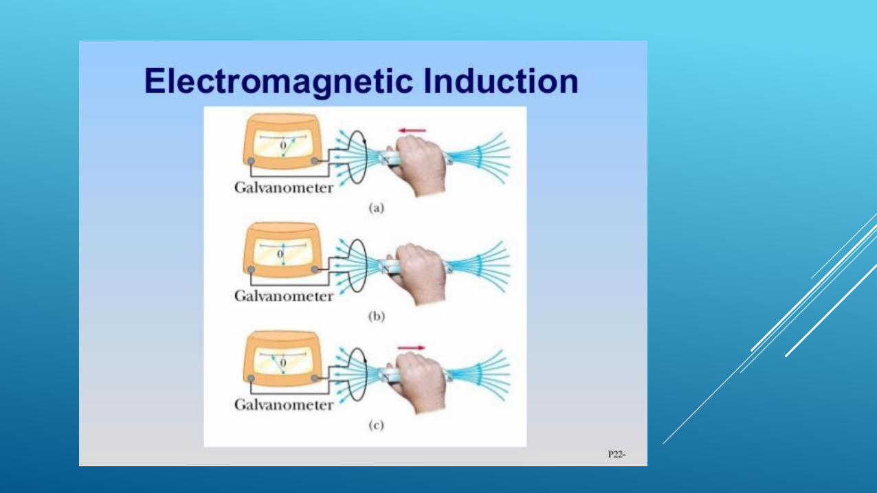
Faraday’s First Law of Electromagnetic Induction:
Whenever a conductor is placed in a varying magnetic field, an
electromotive force is induced.
If the conductor circuit is closed, a current is induced which is called induced current.
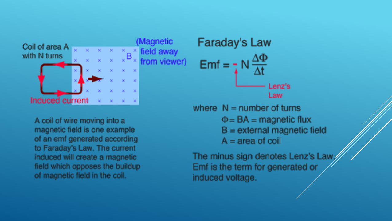
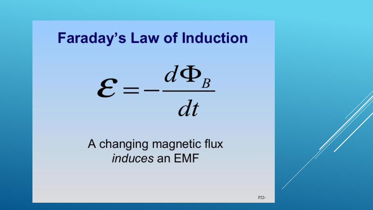
Faraday’s Second Law of Electromagnetic Induction
Faraday’s second law of electromagnetic induction states that
The induced emf in a coil is equal to the rate of change of flux
linkage.
The flux is the product of the number of turns in the coil and the
flux associated with the coil. The formula of Faraday’s law is given
below:
ε=−NΔϕ/Δt
Where, ε is the electromotive force
Φ is the magnetic flux
N is the number of turns
The negative sign indicates that the direction of the induced emfand change in the direction of magnetic fields have opposite
signs.


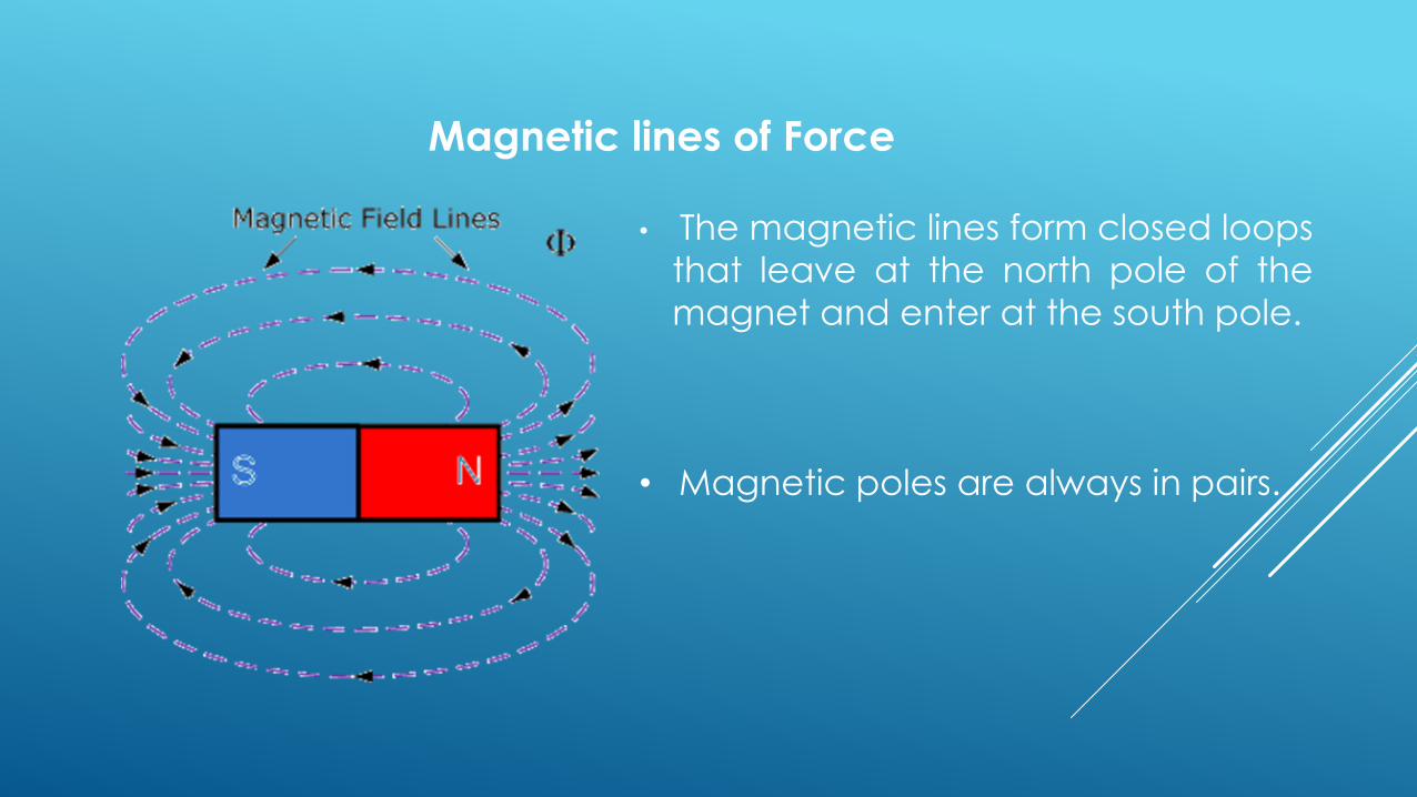
Magnetic lines of Force
• The magnetic lines form closed loops
that leave at the north pole of the
magnet and enter at the south pole.
• Magnetic poles are always in pairs.

Magnetic lines of Force
Lines of force NEVER cross.
Lines of force are CONTINUOUS.
Lines of force always form individual CLOSED LOOPS around the
magnet.
Lines of force have a definite DIRECTION from North to South.
Lines of force that are close together indicate a STRONG
magnetic field.
Lines of force that are farther apart indicate a WEAK magnetic
field.
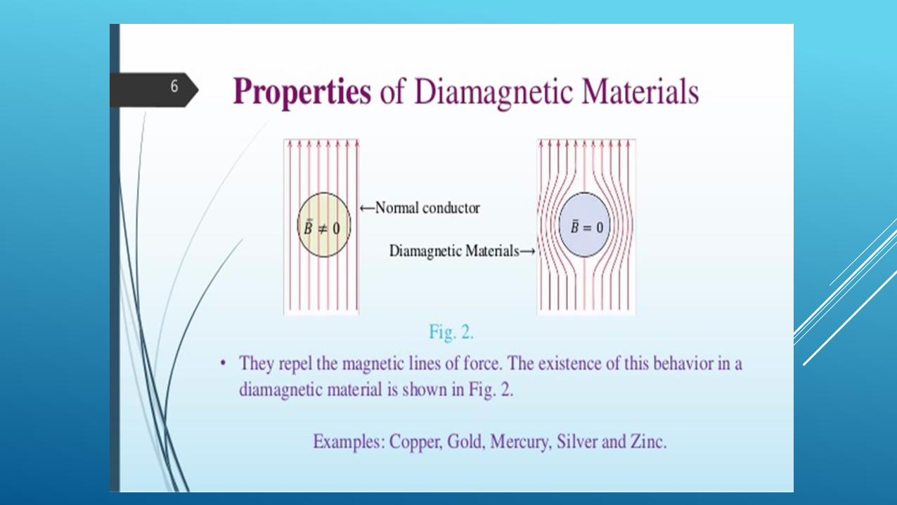
Magnetic forces attract and repel like electric forces and
when two lines of force are brought close together the
interaction between the two magnetic fields causes one of
two things to occur:
1. – When adjacent poles are the same, (north-north or
south-south) they REPEL each other.
2. – When adjacent poles are not the same, (north-south or
south-north) they ATTRACT each other.

Copyright © 2022 FDOKUMEN