An assessment of coherent coupling through radiation fields in time varying slab waveguides
19
Opt Quant Electron (2007) 39:533–551 DOI 10.1007/s11082-007-9104-6 An assessment of coherent coupling through radiation fields in time varying slab waveguides E. V. Bekker · A. Vukovic · P. Sewell · T. M. Benson · N. K. Sakhnenko · A. G. Nerukh Received: 17 November 2006 / Accepted: 13 May 2007 / Published online: 7 July 2007 © Springer Science+Business Media, LLC 2007 Abstract This paper presents an analytical methodology for analysing two-dimensional, dielectric slab waveguides where the guiding region is subject to abrupt and arbitrary tempo- ral changes in permittivity. The methodology solves Maxwell’s equations in the frequency domain and recovers the solutions for the guided and radiation fields in the time domain using the Laplace transformation (LT). Explicit separation of the complete field solution into a set of guided modes and a radiation field continuum provides a clearer insight into the transient effects present in time-varying dielectric waveguides. In particular, the method is used to assess and quantify the impact of coherent radiation field coupling for arbitrary time variation of the waveguide permittivity. Keywords Time-domain analysis · Time-varying media · Radiation field · Coherent coupling 1 Introduction Many modern applications in quantum electronics, quantum computing and optical technology rely on the interaction of electromagnetic waves and media with time-varying, nonlinear and/or anisotropic parameters. In particular, such interactions are increasingly used for pulse generation, reshaping, filtering, modulation and amplification (Chi et al. 2001; Kuo and Ren 1993; Hagness et al. 1996). In practice, temporal variation of a material’s refractive index can be caused by an external source current or field source. For many applications the frequency of the external source is much lower than that of the signal, which permits the signal behaviour to be modelled using a slowly varying envelope to incorporate the effects of E. V. Bekker · A. Vukovic (B ) · P. Sewell · T. M. Benson George Green Institute for Electromagnetics Research, University of Nottingham, University Park, Nottingham NG7 2RD, UK e-mail: [email protected] N. K. Sakhnenko · A. G. Nerukh Kharkov National University of Radio Electronics, 14 Lenin Ave, Kharkov 61166, Ukraine 123
-
Upload
nottingham -
Category
Documents
-
view
0 -
download
0
Transcript of An assessment of coherent coupling through radiation fields in time varying slab waveguides

Opt Quant Electron (2007) 39:533–551DOI 10.1007/s11082-007-9104-6
An assessment of coherent coupling through radiationfields in time varying slab waveguides
E. V. Bekker · A. Vukovic · P. Sewell · T. M. Benson ·N. K. Sakhnenko · A. G. Nerukh
Received: 17 November 2006 / Accepted: 13 May 2007 / Published online: 7 July 2007© Springer Science+Business Media, LLC 2007
Abstract This paper presents an analytical methodology for analysing two-dimensional,dielectric slab waveguides where the guiding region is subject to abrupt and arbitrary tempo-ral changes in permittivity. The methodology solves Maxwell’s equations in the frequencydomain and recovers the solutions for the guided and radiation fields in the time domainusing the Laplace transformation (LT). Explicit separation of the complete field solution intoa set of guided modes and a radiation field continuum provides a clearer insight into thetransient effects present in time-varying dielectric waveguides. In particular, the method isused to assess and quantify the impact of coherent radiation field coupling for arbitrary timevariation of the waveguide permittivity.
Keywords Time-domain analysis · Time-varying media · Radiation field ·Coherent coupling
1 Introduction
Many modern applications in quantum electronics, quantum computing and opticaltechnology rely on the interaction of electromagnetic waves and media with time-varying,nonlinear and/or anisotropic parameters. In particular, such interactions are increasingly usedfor pulse generation, reshaping, filtering, modulation and amplification (Chi et al. 2001; Kuoand Ren 1993; Hagness et al. 1996). In practice, temporal variation of a material’s refractiveindex can be caused by an external source current or field source. For many applications thefrequency of the external source is much lower than that of the signal, which permits thesignal behaviour to be modelled using a slowly varying envelope to incorporate the effects of
E. V. Bekker · A. Vukovic (B) · P. Sewell · T. M. BensonGeorge Green Institute for Electromagnetics Research, University of Nottingham, University Park,Nottingham NG7 2RD, UKe-mail: [email protected]
N. K. Sakhnenko · A. G. NerukhKharkov National University of Radio Electronics, 14 Lenin Ave, Kharkov 61166, Ukraine
123

534 E. V. Bekker et al.
the time-varying material (Masoudi et al. 1995; Vukovic et al. 2006). For example, modernmodulators typically use an external 40 GHz microwave signal whilst the frequency of thepropagating optical signal is of the order of THz. However, the steadily increasing demandfor higher bit rates requires the use of higher modulation frequencies and recently, multiplequantum wells (MQWs) driven by terahertz fields have been investigated both analyticallyand experimentally for this purpose (Carter et al. 2005; Maslov and Citrin 2002). At such highmodulation and switching speeds, those modelling approaches based upon the slowly vary-ing envelope paradigm such as the Finite Difference Beam Propagation Method (FD-BPM)(Masoudi et al. 1995), are less appropriate and hence more rigorous modelling techniquesneed to be used. In particular, transient effects cannot be neglected with such high modulationrates and need to be properly accounted for.
Whilst transient effects in time-varying homogenous media undergoing abrupt or arbi-trarily parameter variations (Morgenthaler 1958; Felsen and Whitman 1970; Fante 1971) arewell understood, the study of two-dimensional (2D) and three-dimensional (3D) dielectricwaveguide geometries is considerably more difficult due to the presence of the dielectricboundaries. Although the analytical study of transient effects in closed time-varying metal-lic waveguides is already well documented (Karbowiak 1957), the analysis of time-varyingdielectric media with open boundaries has only been analytically performed for a few specialcases.
General purpose and flexible time-domain numerical methods, such as the Finite Dif-ference Time Domain (FDTD) method (Taflove and Hagness 2000), are easy to implementfor such problems, but are computationally demanding and restricted to the study of par-ticular examples; they do not permit detailed analytical investigation and identification ofthe underlying mechanisms involved. Specifically, such numerical methods do not explicitlydistinguish the radiation and guided mode fields.
Semi-analytical (SA) approaches have also been reported, but these often rely on theslowly varying envelope approximation (Masoudi et al. 1995; Vukovic et al. 2006), and aretherefore limited to those cases with small and slowly varying changes in the material proper-ties. Similarly, and in common with mode matching techniques, the dominance of the guidedmodes is often assumed and the radiation field is either neglected or approximated, whichintroduces a notable source of inaccuracy when rapidly varying material parameters causesignificant transients.
Focusing upon more analytical methods, an integral equation method based upon Volterraequations has been formulated for the special case of a plane wave incident on a time-varyingdielectric slab (Fedotov et al. 2003; Nerukh et al. 2004a), and subsequently for time-varyingslab dielectric waveguides whose guiding layer changes its properties due to material non-linearity (Nerukh et al. 2004b). More recently, such Volterra integral formulations have beenused to successfully model switching effects in 2D micro-cavities (Sakhnenko et al. 2006).This integral equation method solves Maxwell’s equations in the frequency domain and theninverts the solution to the time-domain by means of the Laplace transform. Laplace transfor-mation techniques have already been used for the study of moving, time-varying, dispersiveand plasma media but the medium is often assumed to be spatially unbounded, to have asimple boundary and typically the variables and parameters only vary in one spatial dimen-sion (Kalluri 1999). For the study of time-varying media, the Laplace transformation (LT)methodology has to date been reported for plane wave incidence on time-varying dielectricslabs (Nerukh et al. 2004b) and more recently for transients in circular cavities (Sakhnenkoet al. 2006).
This paper first outlines a LT technique for studying fast electromagnetic transients inslab dielectric waveguides whose guiding layer experiences an abrupt temporal change in
123

Assessment of coherent coupling through radiation fields 535
refractive index in response to an external source. The Laplace transform is applied directlyto the wave equation for time-varying media and by applying the continuity conditions forthe electric displacement vector, D, at the temporal discontinuity, the solution for the field inthe waveguide is obtained in the frequency domain. The use of the inverse Laplace transformand the residue theorem provides a closed form solution in terms of forward and backwardpropagating guided and radiation fields. The methodology is general in that it can includeboth ideal and absorptive dielectric waveguides.
Subsequently, the paper extends the methodology to the case of time-varying dielectricslab waveguides whose core refractive index varies continuously and which is approximatedby a sequence of incremental piecewise constant steps. The methodology for abrupt changesis applied to each step index change and the resulting scattered fields are propagated untilthe next temporal material transition. As the initial field at each material step now comprisesboth guided and radiation fields, the method is applied for each of these different initial fieldsand their results superimposed to obtain the total guided and radiation field scattered. Theability of the method to explicitly separate the radiation and guided fields is then specif-ically exploited to quantitatively assess the coherent coupling of the radiation and guidedmode fields in arbitrary time-varying waveguides; a physical mechanism which is typicallyignored in time domain modelling and has been shown to be important when modellingnon-uniform waveguides in frequency domain (Marciniak and Jaskorzynska 1995).
The methodology presented here assumes that all material variations occur simultaneouslyalong the entire length of the slab waveguide, denoted by the z-direction, an assumption,which is valid when short waveguides are employed, for example, for lumped RF modula-tors. Although this is an acceptable compromise at this stage in order to gain an improvedunderstanding of time-varying slab waveguides, it does appear possible, albeit nontrivially,to further extend the approach to remove this assumption and thus deal with travelling waveeffects.
The paper is organized as follows: the next section outlines the theory for a slab dielec-tric waveguide whose core experiences abrupt parameter change in response to an externalsource. The method is then extended to include the case of a continuously varying corerefractive index. Section 3.1 discuses the solution for the abrupt change of the waveguidecore refractive index. The analysis is done for a wide range of refractive index steps. Wherepossible the results obtained are compared with the classical mode matching method. Section3.2 verifies the methodology for the arbitrary time-varying refractive index for the simplecase of time-varying homogenous media for which analytical results exist. The results forthe time-varying slab waveguide are compared against those from existing numerical andSA methods (Vukovic et al. 2006) and the convergence and accuracy of the method are dis-cussed. Finally, the contribution of the radiation field to the total field transients is assessedand quantified for a range of practical terahertz applications.
For simplicity the paper will focus on TE polarization, although the case of TM polariza-tion follows in a similar manner.
2 Theory
This section outlines the theoretical basis for the transient analysis of slab dielectricwaveguides where the refractive index of the core experiences an abrupt change in its materialparameters. The methodology is then extended to include any arbitrary time-varying corerefractive index.
123

536 E. V. Bekker et al.
d
z
ynclad
nclad nclad
nclad
nc2nc1 x
t < t t > t
Fig. 1 Schematic diagram of the slab waveguide core switching and associated coordinate system
2.1 Formulation and solution for the case of an abrupt change of the waveguide corerefractive index
The schematic representation of the slab dielectric waveguide, considered in this paper, whichis considered to be non-magnetic, is shown in Fig. 1. The coordinate origin is positioned at themidpoint of the guiding layer and the waveguide has a core of thickness d whose refractiveindex abruptly changes from nc1 to nc2 at time t = t ′ whilst the cladding refractive indexremains unchanged at nclad . As stated above, it is assumed that the switching of the corerefractive index occurs simultaneously throughout the core.
The 2D TE wave equation for time-varying material is
∂2 Ex
∂y2 + ∂2 Ex
∂z2 = 1
c2
∂2 (εEx )
∂t2 (1)
where c = 1/√
εo µo is the speed of light in vacuum, and z is the propagation direction.For clarity of presentation it is assumed here that for t < t ′ the initial field is the fun-
damental guided mode, although any other assumption is equally valid. Thus the field isexpressed as
Ex0(y, z, t < t ′) = E0(y)e− jβz+ jω0t , (2)
where β is the modal propagation constant, ω0 the angular frequency and E0(y) the TEtransverse field profile defined in the core and in cladding as, (Snyder and Love 1983),
E0(y) =
⎧⎪⎨
⎪⎩
1N0
cos(u0 y)
cos(
u0d2
) , |y| ≤ d2
1N0
exp(−w0|y|)exp
(−w0
d2
) , |y| ≥ d2
(3)
where u0 and w0 are the initial transverse wave numbers, which are found from the corre-sponding transcendental characteristic equation as, (Snyder and Love 1983),
u0 =√
(ω0
c
)2n2
c1 − β2, w0 =√
β2 − (ω0c
)2n2
clad, (4)
and the normalizing factor N0 is defined as N0 =√∫
E0(y)E∗0 (y)dy, where ‘*’ denotes
complex conjugate.It is well known that a monochromatic electromagnetic field in a time-varying medium
subject to an abrupt change in parameters preserves both its wavenumber and its field patternbut that the frequency of the field is transformed. These temporally scattered fields are to be
123

Assessment of coherent coupling through radiation fields 537
distinguished from spatial reflections that cause changes in the wavenumber and preserve thefrequency of the electromagnetic field.
The Laplace transform is applied directly to the wave Eq. 1 and continuity of the elec-tric displacement vector D is enforced at the temporal discontinuity t = t ′, (Nerukh et al.2001). Defining Lu
co and Luclad to be the Laplace transformed fields in the core and cladding
instantaneously after the change in the core refractive index, this yields(
−β2 − u21 − n2
c2
c2 p2
)
Luco (p) + n2
c1
c2 (p + jω0) pEo(y)e− jβz+ jω0t ′ = 0 |y| ≤ d
2(5)
(
−β2 + w21 − n2
clad
c2 p2
)
Luclad (p) + n2
clad
c2 (p + jω0) Eo(y)e− jβz+ jω0t ′ = 0 |y| ≥ d
2
(6)
Adopting the evolutionary approach presented in (Nerukh et al. 1997), the complete tran-sient solution can be explicitly defined as a superposition of Lu
co and Luclad and the waves that
are subsequently spatially reflected from the waveguide boundaries. The complete transientsolution in the core Lco and in the cladding Lclad for t > t ′ is thus given by
Lco(p) = Luco (p) + Lb
co (p) = n2c1 (p + jω0)
n2c2 p2 + ω2
0n2c1
E0 (y) e− jβz+ jω0t ′ + A (p) cos(u p y
)(7)
Lclad (p) = Luclad (p) + Lb
clad (p) = 1
p − jω0E0 (y) e− jβz+ jω0t ′ + B (p) exp
(−wp y)
(8)
where the superscripts u and b denote the instant ‘unbounded’ and the ‘bounded’ fields, andthe coefficients u p and wp are defined as:
u p =√
− ( pc
)2n2
c2 − β2 wp =√
β2 + ( pc
)2n2
clad
The modal coefficients A(p) and B(p) are found by enforcing the correct spatial boundaryconditions on the field, L , and its derivative ∂L/∂y on the core–cladding interfaces whichresults in
A(p) =
(1
p− jω0
(wp − w0
) − n2c1(p+ jω0)
n2c2 p2−ω2
0n2c1
(wp − u0 tan(u0d)
))
1N0
e− jβz+ jω0t ′
(wp − u p tan
(u p
d2
))cos
(u p
d2
) (9)
B(p) =
(1
p− jω0
(u p tan
(d2 u p
)− w0
)− n2
c1(p+ jω0)
n2c2 p2+ω2
0n2c1
(u p tan
(u p
d2
)−u0 tan(u0d)
))1
N0e− jβz+ jω0t ′
(wp − u p tan
(u p
d2
))exp
(−wp
d2
) .
At this stage, it is emphasised that is the presence of the bounded field contributions thatdistinguish this analysis from that in a homogenous space.
It can be seen that Eqs. 7–9 possess poles and branch cut singularities along the imaginaryaxis in the complex p plane. Physically, these poles embody the steady state-solution whereasthe branch cuts only contribute to the transient solution. Simple pole singularities exist at
123

538 E. V. Bekker et al.
p = ± jω0nc1/nc2 and p = jω0 and at a finite number of values (p = ± jωn , n = 1, . . .N )
defined as the solutions of the transcendental equation
wp − u p tan
(
u pd
2
)
= 0. (10)
Solutions of Eq. 10 physically correspond to the frequencies of the guided modes. The branchcut singularities occur at p = ∓ jcβ/nc2 and p = ∓ jcβ/nclad .
The time domain electromagnetic field at t > t ′ is obtained by applying the inverse Laplacetransform to Eqs. 7, 8. Detailed investigation of the integrals in Eq. 11 shows that the contri-bution of the branch point singularities at p = ∓ jcβ/nc2 is zero and the only contribution tothe radiation field arises from the branch point singularities at p = ∓ jcβ/nclad . Thereforethe complete time domain solution comprises a sum over the residues and an integral alongthe branch cuts
Ex1 (t) = 1
j2π
c+ j∞∫
c− j∞L(p)ept dp
=∑
m
Res[L(p)ept ]
p=pm− 1
j2π
± jcβ/nclad−δ∫
± j∞Lbept dp (11)
where Res[] denotes the pole residues from which the steady state guided mode amplitudesare found and the integral represents the radiation field which will be referred to as RadiationField Integral (RFI). In Eq. 11 δ is a positive number.
Figure 2 shows the integration contour and the residues of Eqs. 7, 8. Numerical values ofthe residues are shown for the case of d = 2 µm, nclad = 1.495, nc1 = 1.5 and nc2 = 1.51.The initial field is the fundamental guided mode at the operating wavelength λ = 1.15 µm.For non-absorptive waveguides the pole and branch singularities are located on the imaginaryaxis of the complex p-plane, as shown. For lossy waveguides the poles and branch singulari-ties are displaced to the 1st and 3rd quadrants of the complex p-plane. The poles and branchpoint singularities in the upper and lower halves of the complex p plane are associated withtransmitted and reflected guided and radiation fields respectively with the branch cuts beingtaken along the imaginary axis.
Evaluation of Eq. 11 allows the total field to be expressed as a superposition of forwardand backward propagating guided and radiation fields:
Ex1 (t) =∑
n
(Tn + Rn) Exne jωn(t−t ′) + RF IT + RF IR (12)
where RF IT and RF IR denote forward and backward propagating radiation fields evaluatednumerically and Tn and Rn are the amplitudes of the transmitted and reflected guided fieldsrespectively. The appearance of radiation waves in time-varying slab waveguides has alsobeen shown in (Nerukh et al. 2004a). The amplitudes of the guided modes for t > t ′ arefound from the residues in (11) and are explicitly
Tn =NnN0
(1
ω0−ωn− n2
c1(ωn+ω0)
n2c1ω
20−n2
c2ω2n
)
(wn − w0) e− jβz+ jω0t ′
ωn
(n2
clad/c2
wn+ n2
c2/c2
untan(und) + n2
c2
( d2
)/c2 sec2 und)
) ,
123

Assessment of coherent coupling through radiation fields 539
-1.00E+013 -5.00E+012 0.00E+000 5.00E+012 1.00E+013
1.63E+015
1.64E+015
1.65E+015
Imaginary part of p
Rea
lpar
t of
p
-1.65E+015
-1.64E+015
-1.63E+015
[IV][III]
[II] [I]
"unbounded" singularityTE
0 mode singularity
0 singularity
branch singularity
"unbounded" singularity
TE0 mode singularity
0 singularity
branch singularityR
eal part of p
--
+ +
Fig. 2 Singularities and integration path in the complex p plane for nc1 = 1.5, nc2 = 1.51, nclad = 1.495,d = 2 µm and λ = 1.15 µm
Rn = −NnN0
(1
ωn+ω0− n2
c1(ω0−ωn)
n2c1ω
20−n2
c2ω2n
)
(wn − w1) e− jβz+ jω0t ′
ωn
(n2
clad/c2
wn+ n2
c2/c2
untan(und) + n2
c2
( d2
)/c2 sec2 und)
) , (13)
where un and wn are the transverse wave numbers for the waveguide modes of frequencyωn generated at t = t ′ and Nn is the normalization constant of each mode defined by Eq. 3.The solution given in Eqs. 12, 13 is the set of guided modes and the continuum of radiationmodes, which form a complete orthogonal basis set for the boundary problem.
2.2 Algorithm for the arbitrary time varying core refractive index
Having analysed the scattering by an abrupt change in material parameters, this sectionextends the approach to permit transient analysis of time-varying slab waveguides where thecore refractive index varies arbitrarily over a time interval T . The methodology proposed inthis paper is based upon the assumption that the continuous time variation of the refractiveindex is approximated by M piecewise steps of duration �T , as shown schematically inFig. 3. At a discrete set of time points the core refractive index undergoes an instantaneouschange of �n = nc(i+1) − nci . The value is then maintained for the following time interval�T , as shown in Fig. 3.
The field in each time interval, i = 1, M is represented as a superposition of transmittedand reflected guided modes and radiation fields as in Eq. 12,
Eix (t) =
∑
n
(T i
n + Rin
)Ei
xne jωn(t−t ′) + RF I iT + RF I i
R (14)
where T in and Ri
n and RF I iT and RF I i
R are the local amplitudes of the transmitted andreflected guided fields and the local radiation field integrals given in Eq. 11, respectively.
The algorithm proceeds as follows. The initial field for t < t ′ is again considered tobe the fundamental guided mode and the scattered fields are evaluated using the proceduredescribed in Section 2.1. Each of the components of this scattered field, characterised by T i
n
123

540 E. V. Bekker et al.
i+1
…
ii-1
T
t=t +T timet=t
TRefractiveindex
nc1
nc2
Fig. 3 Schematic representation of the time-varying refractive index and its discretisation
and Rin , RF I i
T and RF I iR is then allowed to evolve in time for an interval �T , which then
provides the initial field for evaluating the fields scattered from the second abrupt step. Thisprocess is then repeated over the full time interval of the simulation. It is noted that from thesecond abrupt change onward, the analysis of Section 2.1 is applied separately for each of thefour components of the initial field and the results superimposed to yield the total scatteredfield. Thus each field component in time interval (i-1) will contribute to all field componentsin time step i . Specifically,
Tn(T i−1j ) =
Nin
Ni−1j
(
1ωi−1
j −ωin
− n2c1(ω
in + ωi−1
j )
n2c1
(ωi−1
j
)2−n2c2(ω
in)
2
)(wi
n − wi−1j
)e jωi−1
j �t ′
ωin
(n2
clad/c2
win
+ n2c2/c2
uin
tan(uind) + n2
c2
( d2
)/c2 sec2 ui
nd)
) T i−1j ,
Rn(T i−1j ) = −
Nin
Ni−1j
(
1ωi
n +ωi−1j
− n2c1(ω
i−1j −ωi
n)
n2c1
(ωi−1
j
)2−n2c2(ω
in)
2
)(wi
n − wi−1j
)e jωi−1
j �t ′
ωin
(n2
clad/c2
win
+ n2c2/c2
untan(ui
nd) + n2c2
( d2
)/c2 sec2 ui
nd)
) T i−1j
(15)
where T i−1j represents the amplitude of the transmitted guided mode j in the interval
(i − 1)�T . The contribution of the reflected guided field to the transmitted and reflectedguided fields is found in a similar manner as are the radiation fields. These fields are thenpropagated as e− jβz± jωi �T to the next temporal discontinuity.
When the radiation fields are considered as incident on the next step, the Laplace transformof Eq. 11 is applied to each component of the radiation field, which results in a 2D Laplacetransform. Numerically, the Laplace transform is evaluated as a finite sum.
3 Results
In this section the solution for time-varying slab waveguides is considered. As analyticalresults for slab waveguides undergoing abrupt temporal changes are not available, the resultsare compared with those from the classical mode matching method which neglects the radi-ation field coupling.
123

Assessment of coherent coupling through radiation fields 541
1.0 1.5 2.0 2.5 3.0 3.5
1.62
1.63
1.64
1.65 c /nclad
21 cco n/n
0
TE1 eigen
mode frequency
TE0 fundamental
mode frequency
Imag
inar
y pa
rt o
f p,
[fs
-1]
Characteristic frequency, V2
Fig. 4 Pole singularities that contribute to the field solution as a function of the characteristic frequency att > 0
The methodology for slab waveguides undergoing arbitrary temporal changes is first val-idated for the simple case of time-varying homogenous media for which analytical resultsare available. Results for time-varying slab waveguides are further compared against resultsfrom the existing SA method (Vukovic et al. 2006) and the convergence and accuracy of themethod are discussed. Finally, the impact of the radiation field to the total field transients isassessed and quantified for a range of practical applications.
3.1 Results for abrupt change of the core refractive index
The slab waveguide considered has a core thickness d = 2 µm, cladding refractive indexnclad = 1.495 and initial core refractive index nc1 = 1.5. The waveguide is excited byits symmetric guided mode for t < t ′ with an operating wavelength of λ = 1.15 µm.Figure 4 shows the location of the singularities for a range of characteristic frequenciesV2 = kd(nc2 − nclad)−1/2 which corresponds to the core refractive index being switched toa new value in the range of 1.497 < nc2 < 1.65.
Figure 4 shows that the location of the simple pole singularity p = jωo and the branchsingularity p = ∓ jcβ/nclad are fixed by the initial electromagnetic field at the start of thesimulation and it is observed that the pole singularity ω = ω0nc1/nc2 physically correspondsto the solution for the case of plane wave excitation of a homogeneous medium. Also shownin the graph are the new frequencies of the symmetric guided TE0 and TE2 modes which areexcited for t ≥ t ′, noting that the cutoff frequency of the TE2 mode concurs with (Snyderand Love 1983). The three singularities in Fig. 4 cross when nc2 = nc1 and so no change isactually taking place.
In order to verify the guided field solutions provided Eqs. 12, 13, a mode matchingapproach is used to obtain the amplitudes of the reflected and incident guided fields at thetemporal discontinuity by enforcing the continuity of D and ∂ D/∂t at t = t ′, and using the
mode orthogonality∫ ∞−∞ Exi Ex j dx =
{δi j
0. This approach gives the amplitudes of trans-
mitted and reflected fields as
123

542 E. V. Bekker et al.
0.00 0.02 0.04 0.06 0.080.70
0.75
0.80
0.85
0.90
0.95
1.00
1.05
n
Tra
nsm
itted
gui
ded
mod
e po
wer
-0.00050
-0.00025
0.00000
0.00025
0.00050
Reflected guided m
ode power
Fig. 5 Comparison of the power of the transmitted and reflected fields obtained using the Laplace Technique(dotted line) and the mode matching method (solid line). The waveguide parameters are: nc1 = 1.5, d = 2 µm,nclad = 1.485 and λ = 1.25 µm
Tn = 1
2
(
1 + ω0
ωn
) ∫n2
1 (y) E∗xn (y) Ex0 (y)dy
∫n2
2 (y) E∗xn(y)Exn(y)dy
Rn = 1
2
(
1 − ω0
ωn
) ∫n2
1 (y) E∗xn (y) Ex0 (y)dy
∫n2
2 (y) E∗xn (y) Exn (y) dy
. (16)
where n1 and n2 represent waveguide refractive index profile before and after the temporalchange respectively, Ex0 is the initial field distribution for t < t ′ and Exn represents the modessupported by the waveguide for t > t ′. It is stressed that only the guided modes supported bythe waveguide are included in this analysis.
Figure 5 compares power in the total transmitted and reflected fields obtained using themode matching method and the Laplace Technique as a function of core refractive index step�n = nc2 − nc1. The waveguide parameters are that of Fig. 4 with the initial core refractiveindex nc1 = 1.5. The power of the initial field wave is normalized to 1. Figure 5 shows verygood agreement between the analytical solution of Eq. 13 (dotted lines) and the mode match-ing solution of Eq. 16 (solid lines). The slight discrepancy between the methods increases as�n increases and this is attributed to stronger excitation of the radiation field which is onlyaccounted for in the Laplace Technique.
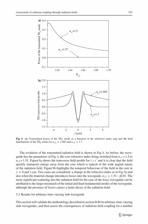
Excitation of the higher order TE2 mode is presented in Fig. 6. Two initial waveguideswith core refractive indices of nc1 = 1.5 and nc1 = 1.57 are considered, all other parametersbeing as for Fig. 4. As expected higher refractive index changes enhance the scattering fromthe initial fundamental mode into the higher order mode. For reference, Fig. 6b shows thetransverse profiles of the TE2 mode, which is leaky for nc2 = 1.605 and strongly confined inthe core for nc2 = 1.7.
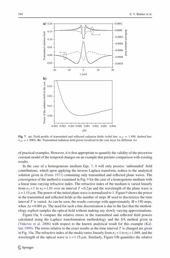
Results for the radiation field obtained from the RFI integrals of Eq. 11 are presentedin Fig. 7. The transverse distribution of the transmitted and reflected radiation fields gener-ated by switching the core refractive index from nc1 = 1.5 to nc2 = 1.499 and nc2 = 1.5005respectively, are shown, all other parameters being as for Fig. 4. Consistent with the previ-ous observations, it is clear that the scattering into the radiation field is stronger for largerrefractive index changes. Fig. 7b quantifies the power of the radiation field localized in thewaveguide core for different temporal changes. It can be seen that the percentage of theradiation power in the core is small and that it increases for higher temporal changes �n.
123
Assessment of coherent coupling through radiation fields 543
1.62 1.64 1.66 1.68 1.70-0.1
0.0
0.1
0.2
0.3
0.4
nc1
=1.57
nc1
=1.5
nc2
Pow
er o
f th
e tr
ansm
itted
TE
2 mod
e
a)
-4 -2 0 2 4-1.5
-1.0
-0.5
0.0
0.5
1.0
1.5
2.0
nc2
=1.7
nc2
=1.605
TE
2 tr
ansv
erse
fie
ld p
rofi
le
y [ m]
b)
Fig. 6 (a) Transmitted power of the TE2 mode as a function of the refractive index step and (b) fielddistributions of the TE2 mode for nc2 = 1.605 and nc2 = 1.7
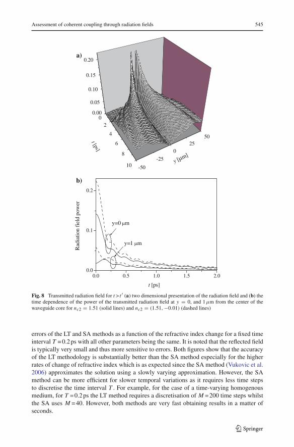
The evolution of the transmitted radiation field is shown in Fig. 8. As before, the wave-guide has the parameters of Fig. 4, the core refractive index being switched from nc1 = 1.5 tonc2 = 1.51. Figure 8a shows the transverse field profile for t > t ′ and it is clear that the fieldquickly transports energy away from the core which is typical of the wide angled natureof the radiation field. Figure 8b highlights the temporal behaviour of the field in the core aty = 0 and 1µm. Two cases are considered: a change in the refractive index as in Fig. 8a andalso when the material change introduces losses into the waveguide, nc2 = 1.51− j0.01. Themore significant scattering into the radiation field for the case of the lossy waveguide can beattributed to the larger mismatch of the initial and final fundamental modes of the waveguide,although the presence of losses causes a faster decay of the radiation field.
3.2 Results for arbitrary time-varying slab waveguide
This section will validate the methodology described in section II.B for arbitrary time-varyingslab waveguides, and then assess the consequences of radiation field coupling for a number
123
544 E. V. Bekker et al.
-20 -10 0 10 20
-0.05
0.00
0.05
0.10
0.15
0.20
y [ m]
Tra
nsm
itted
rad
iatio
n fi
eld
-0.0010
-0.0008
-0.0006
-0.0004
-0.0002
0.0000
0.0002
Reflected radiation field
a)
b)
0.0040.0030.0020.0010.000-0.001-0.002-0.003
0.00
0.01
0.02
0.03
Pow
er o
f th
e ra
diat
ion
fiel
d in
the
core
n
Fig. 7 (a): Field profile of transmitted and reflected radiation fields (solid line: nc2 = 1.499, dashed line:nc2 = 1.5005; (b): Transmitted radiation field power localized in the core layer for different �n
of practical examples. However, it is first appropriate to quantify the validity of the piecewiseconstant model of the temporal changes on an example that permits comparison with existingresults.
In the case of a homogeneous medium Eqs. 7, 8 will only possess ‘unbounded’ fieldcontributions, which upon applying the inverse Laplace transform, reduce to the analyticalsolution given in (Fante 1971) containing only transmitted and reflected plane waves. Theconvergence of the method is examined in Fig. 9 for the case of a homogenous medium witha linear time-varying refractive index. The refractive index of the medium is varied linearlyfrom n1 = 1 to n2 = 1.01 over an interval T = 0.2 ps and the wavelength of the plane wave isλ= 1.15µm. The power of the initial plane wave is normalized to 1. Figure 9 shows the powerin the transmitted and reflected fields as the number of steps M used to discretisize the timeinterval T is varied. As can be seen, the results converge with approximately M = 150 steps,when �t = 0.001 ps. The need for such a fine discretisation is due to the fact that the method-ology explicit samples the optical field without making any slowly varying approximations.
Figure 10a, b compare the relative errors in the transmitted and reflected field powerscalculated using the Laplace transformation methodology and the SA method given in(Vukovic et al. 2006) with respect to the known analytical result for this example (Kal-luri 1999). The errors relative to the exact results as the time interval T is changed are givenin Fig. 10a. The refractive index of the media varies linearly from n1 = 1 to n2 = 1.049, and thewavelength of the optical wave is λ= 1.15µm. Similarly, Figure 10b quantifies the relative
123
Assessment of coherent coupling through radiation fields 545
02
4
6
8
10
0.00
0.05
0.10
0.15
0.20
-50
-25
025
50
y [ m]
t [ps]
a)
0.0 0.5 1.0 1.5 2.00.0
0.1
0.2
y=1 m
y=0 m
Rad
iatio
n fi
eld
pow
er
t [ps]
b)
Fig. 8 Transmitted radiation field for t > t ′ (a) two dimensional presentation of the radiation field and (b) thetime dependence of the power of the transmitted radiation field at y = 0, and 1µm from the center of thewaveguide core for nc2 = 1.51 (solid lines) and nc2 = (1.51,−0.01) (dashed lines)
errors of the LT and SA methods as a function of the refractive index change for a fixed timeinterval T = 0.2 ps with all other parameters being the same. It is noted that the reflected fieldis typically very small and thus more sensitive to errors. Both figures show that the accuracyof the LT methodology is substantially better than the SA method especially for the higherrates of change of refractive index which is as expected since the SA method (Vukovic et al.2006) approximates the solution using a slowly varying approximation. However, the SAmethod can be more efficient for slower temporal variations as it requires less time stepsto discretise the time interval T . For example, for the case of a time-varying homogenousmedium, for T = 0.2 ps the LT method requires a discretisation of M = 200 time steps whilstthe SA uses M = 40. However, both methods are very fast obtaining results in a matter ofseconds.
123

546 E. V. Bekker et al.
0 100 200 300 400 5000.97056
0.97057
0.97058
0.97059
0.97060
0.97061
Number of time steps M
Tra
nsm
itted
pow
er
-0.00001
0.00000
0.00001
0.00002
0.00003
Reflected pow
er
Fig. 9 Convergence of the transmitted and the reflected field power with number of time steps M used todiscretisize time interval T
0 1 2 3 4 5
1E-7
1E-6
1E-5
1E-4
1E-3
0.01
0.1
Transmitted field, LT
Reflected field, LT
Transmitted field, SA
Reflected field, SA
Rel
ativ
e er
ror
T [ps]
a)
0.000 0.005 0.010 0.015 0.0201E-8
1E-7
1E-6
1E-5
1E-4
1E-3
0.01
0.1
LT
SA
n
Rel
ativ
e E
rror
b)
Fig. 10 (a) Relative errors of transmitted and reflected field powers obtained using the LT and the SA methodwith respect to known analytical values for time-varying homogeneous media and depending on (a) the timeinterval T and (b) refractive index change �n. Solid lines represent the relative error of the transmitted fieldand dashed lines represent the relative error of the reflected field
123
Assessment of coherent coupling through radiation fields 547
0.005 0.010 0.015 0.0201E-7
1E-6
1E-5
1E-4
1E-3
0.01
0.1
Transmitted Field
Reflected Field
ncore2
Rel
ativ
e di
scre
panc
y
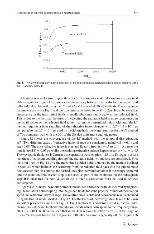
Fig. 11 Relative discrepancy in the amplitudes of the transmitted and reflected guided modes obtained usingthe LT and SA methods
Attention is now focussed upon the effect of continuous material variations in practicalslab waveguides. Figure 11 examines the discrepancy between the results for transmitted andreflected fields obtained using the LT and SA (Vukovic et al. 2006) methods. The waveguideparameters are as for Fig. 4 and the time interval is taken to be T = 0.2 ps. It can be seen thatdiscrepancy in the transmitted fields is small, albeit more noticeable in the reflected field.This is due to the fact that the error of neglecting the radiation field is more pronounced inthe small values of the reflected field rather than in the transmitted fields. Although the LTmethod requires a finer sampling of the refractive index changes with �T = 1.3×10⁻⁴ pscompared to the �T = 10−2 ps used by the SA method, the overall runtime for the LT methodof 70 s compares well with the 60 s of the SA due to its more analytic nature.
Figure 12 shows the convergence of the LT method with the temporal discretisation,�T . Two different cases of refractive index change are considered, namely �n = 0.01 and�n = 0.05. The core refractive index is changed linearly from nc1 = 1.5 to nc1 + �n over thetime interval T = 0.05 ps, whilst the cladding refractive index is kept constant at nclad = 1.495The waveguide thickness is 2µm and the operating wavelength is 1.15µm. To begin to assessthe effect of coherent coupling through the radiation field, two models are considered. Firstthe solid lines on Fig. 12 give the transmitted guided fields obtained by the method outlinedin Sect. 2.2 which includes the scattering from the radiation field back into the guided modefields at each step. In contrast, the dashed lines give the values obtained if the energy scatteredinto the radiation field at each step is not used as part of the excitation on the subsequentstep. It is clear that for both values of �n a finer discretisation must be used to achieveconvergence.
Figure 13a, b shows the relative error in transmitted and reflected fields incurred by neglect-ing the radiation field coupling into the guided fields for same practical values of modulationspeed and refractive index change. The relative error is obtained between the results obtainedusing the two LT models tested in Fig. 12. The thickness of the waveguide is taken to be 2µmand other parameters are as for Fig. 11. Fig. 13a plots this error for a fixed refractive indexchange �n = 0.05 and terahertz modulation speeds which correspond to the frequency range300 GHz −10 THz. It can be seen that in the THz region the relative error is in the range of0.3%–2% whereas for the GHz region (<300 GHz) the error is typically <0.3%. Figure 13b
123

548 E. V. Bekker et al.
3.35463E-4 9.11882E-4 0.002480.88
0.90
0.92
0.94
0.96
0.98
1.00
nc2
=1.51
nc2
=1.55
Gui
ded
tran
smitt
ed f
ield
T [ps]
Fig. 12 Convergence of the transmitted guided field when coupling of the radiation field is included (solidline) and neglected (dotted line) at each subsequent step
0.0 0.5 1.0 1.5 2.0 2.5 3.0 3.50.000
0.003
0.006
0.009
0.012
0.015
0.018
0.021
0.024
0.027
Reflected
Transmitted
n=0.05
Rel
ativ
e E
rror
T [ps]
a)
0.01 0.02 0.03 0.04 0.05 0.06
0.000
0.002
0.004
0.006
0.008
0.010
0.012
0.014
T=1 ps
Reflected
Transmitted
Rel
ativ
e E
rror
n
b)
Fig. 13 Relative error induced by neglecting the radiation field coupling into the guided mode
123
Assessment of coherent coupling through radiation fields 549
-4
-2
0
2
4
-0.5 0 0.5 1.0
t [ps]
y [
m]
00.031250.062500.093750.12500.15630.18750.21880.25000.28130.31250.34380.37500.40630.43750.46880.50000.53130.56250.59380.62500.65630.68750.71880.75000.78130.81250.84380.87500.90630.93750.96881.000a)
-4
-2
0
2
4
-0.5 0 0.5 1.0
time [ps]
Y [
m]
00.034380.068750.10310.13750.17190.20620.24060.27500.30940.34370.37810.41250.44690.48120.51560.55000.58440.61880.65310.68750.72190.75630.79060.82500.85940.89380.92810.96250.99691.0311.0661.100b)
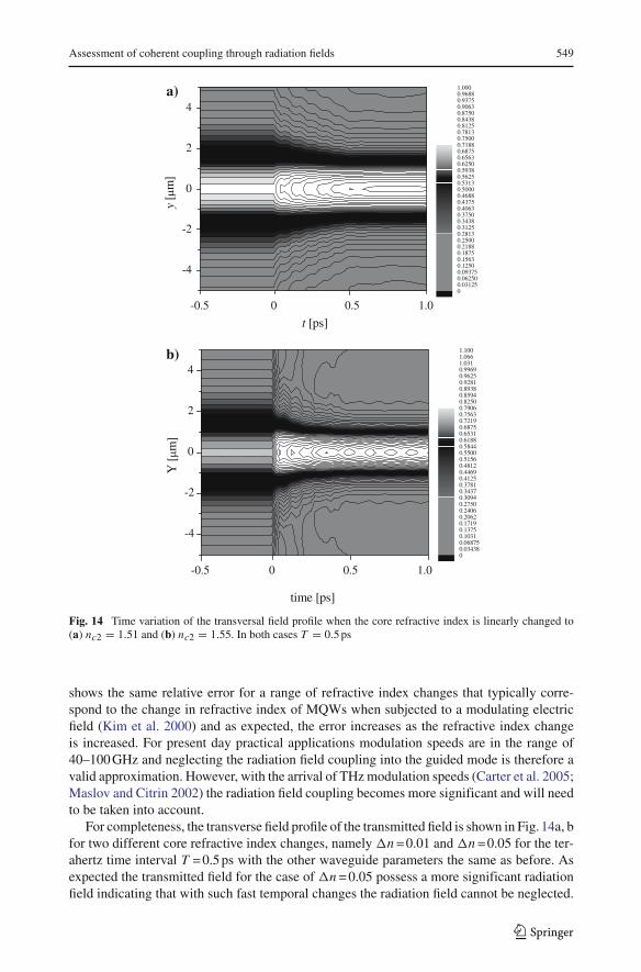
Fig. 14 Time variation of the transversal field profile when the core refractive index is linearly changed to(a) nc2 = 1.51 and (b) nc2 = 1.55. In both cases T = 0.5 ps
shows the same relative error for a range of refractive index changes that typically corre-spond to the change in refractive index of MQWs when subjected to a modulating electricfield (Kim et al. 2000) and as expected, the error increases as the refractive index changeis increased. For present day practical applications modulation speeds are in the range of40–100 GHz and neglecting the radiation field coupling into the guided mode is therefore avalid approximation. However, with the arrival of THz modulation speeds (Carter et al. 2005;Maslov and Citrin 2002) the radiation field coupling becomes more significant and will needto be taken into account.
For completeness, the transverse field profile of the transmitted field is shown in Fig. 14a, bfor two different core refractive index changes, namely �n = 0.01 and �n = 0.05 for the ter-ahertz time interval T = 0.5 ps with the other waveguide parameters the same as before. Asexpected the transmitted field for the case of �n = 0.05 possess a more significant radiationfield indicating that with such fast temporal changes the radiation field cannot be neglected.
123
550 E. V. Bekker et al.
4 Conclusion
An analytic method based upon the Laplace transform is presented for modelling slab dielec-tric waveguides whose core refractive index abruptly changes its value. Results for a widerange of dielectric waveguides are discussed and validated using the mode matching methodand asymptotic solutions. It is shown that the method accurately describes the transient fieldrepresenting it as a complete set of guided and radiation modes.
The methodology has then been extended to include an arbitrary time varying core refrac-tive index which is approximated in a piecewise constant manner. The methodology forarbitrary varying slab dielectric waveguide is verified for the simpler case of a time-varyinghomogeneous medium and also against existing SA results for time varying slab waveguides.The impact of the radiation field in this approach has been quantified and carefully consideredand it has been shown that for fast changes that characterize terahertz modulation fields theimpact of the radiation field needs to be taken into account. The analytic nature of the pro-posed methodology offers physical insight into the problem, fast simulations and is applicableto a wide range of dielectric waveguides.
Acknowledgements This work is supported by the Engineering and Physical Sciences Research CouncilGrant GR/S34038/01.
References
Carter, S.G., Birkedal, V., Wang, C.S., Caldren, L.A., Maslov, A.V., Shevrin, M.S.: Quantum cohrence in anoptical modulator. Science 310, 651–653 (2005)
Chi, J.W.D., Chao, C.L., Rao, M.K.: Time-domain large-signal investigation on nonlinear interactions betweenan optical pulse and semiconductor waveguides. J. Quant. Elect. 37, 1329–1336 (2001)
Fante, R.: Transmission of electromagnetic waves into time-varying media. IEEE Trans. Antenn. Propag. AP-19, 417–424 (1971)
Fedotov, F.V., Nerukh, A.G., Benson, T.M., Sewell, P.: Investigation of electromagnetic field in a layer withtime-varying medium by volterra integral equation method. J. Lightwave Technol. 21, 305–314 (2003)
Felsen, L.B., Whitman, G.M.: Wave propagation in time-varying media. IEEE Trans Antenn. Propag. AP-18, 242–253 (1970)
Hagness, S.C., Joseph, R.M., Taflove, A.: Subpicosecond electrodynamics of distributed Bragg reflector mi-crolasers: Results from finite difference time domain simulations. Radio Sci. 31, 931–942 (1996)
Kalluri, D.K.: Electromagnetics of Complex Media: Frequency Shifting by a Transient Magnetoplasma. CRCPress LLC (1999)
Karbowiak, A.E.: Propagation of transients waveguides. Proc. IEEE (London) 104C, 339–349 (1957).Kim, Y., Lee, H., Lee, J., Han, J., Oh, T.W., Jeong, J.: Chirp characteristics of 10 Gb/s electroabsorption
modulator integrated DFB Lasers. IEEE J. Quant. Elect. 36, 900–908 (2000)Kuo, S., Ren, A.: Experimental study of wave propagation through a rapidly created plasma. IEEE Trans.
Plasma Sci. 2, 53–56 (1993)Marciniak, M., Jaskorzynska, B.: Radiation field propagation in low-contrast single-mode optical
waveguides. Opt. Quant. Elect. 27, 977–985 (1995)Maslov, V., Citrin, D.S.: Mutual transparency of coherent laser beams through a terahertz-field-driven quantum
well. J. Opt. Soc. Am. B 19, 1905–1909 (2002)Masoudi, H.M., Arnold, J.M.: Modeling second-order nonlinear effects in optical waveguides using a parallel-
processing beam propagation method. IEEE J. Quant. Elect. 31, 2107–2113 (1995)Morgenthaler, F.R.: Velocity Modulation of Electromagnetic Waves. IRE Trans. Microw. Theory
MIT-6, 167–172 (1958)Nerukh, A., Scherbatko, I., Nerukh, D.: Using evolutionary recursion to solve and electromagnetic problem
with time-varying parameters. Microw. Opt. Technol. Let. 14, 31–36 (1997).Nerukh, A.G., Scherbatko, L.V., Marciniak, M.: Electromagnetics of Modulated Media with Application to
Photonics. National Institute of Telecommunications, Warsaw (2001)
123

Assessment of coherent coupling through radiation fields 551
Nerukh, A.G., Fedotov, F.V., Benson, T.M., Sewell, P.: Analytic-numerical approach to non-linear problemsin dielectric waveguides. Opt. Quant. Elect. 36, 67–85 (2004a)
Nerukh, A.G., Sewell, P., Benson, T.M.: Volterra integral equations for nonstatinary electromagnetic processesin time-varying dielectric waveguides. J. Lightwave Technol. 22, 1408–1419 (2004b)
Sakhnenko, N.K., Benson, T.M., Sewell, P., Nerukh, A.G.: Transient Transformation of whispering galleryresonator modes due to time variations in dielectric permitivity. Opt. Quant. Elect. 38, 71–81 (2006)
Snyder, A.W., Love, J.D.: Optical Waveguide Theory. Chapman & Hall (1983)Taflove, A., Hagness, S.C.: Computation Electrodynamics: The Finite Difference Time-Domain
Method. Artech House Inc., Boston & London (2000)Vukovic, A., Bekker, E.V., Sewell, P., Benson, T.M.: Efficient time domain modeling of Rib waveguide RF
modulators. J. Lightwave Technol. 24, 5044–5053 (2006)
123