An 802.11k Compliant Framework for Cooperative Handoff in Wireless Networks
14
Hindawi Publishing Corporation EURASIP Journal on Wireless Communications and Networking Volume 2009, Article ID 350643, 14 pages doi:10.1155/2009/350643 Research Article An 802.11k Compliant Framework for Cooperative Handoff in Wireless Networks George Athanasiou, 1 Thanasis Korakis, 2 and Leandros Tassiulas 1 1 Department of Computer and Communications Engineering, University of Thessaly, 37 Glavani Street 382 21 Volos, Greece 2 Department of Electrical and Computer Engineering, Polytechnic University, 5 Metrotech Center, Brooklyn, NY 11201, USA Correspondence should be addressed to George Athanasiou, [email protected] Received 17 November 2008; Revised 16 February 2009; Accepted 9 July 2009 Recommended by Wei Li In IEEE 802.11-based wireless networks, the stations (STAs) are associated with the available access points (APs) and communicate through them. In traditional handoff schemes, the STAs get information about the active APs in their neighborhood by scanning the available channels and listening to transmitted beacons. This paper proposes an 802.11k compliant framework for cooperative handoff where the STAs are informed about the active APs by exchanging information with neighboring STAs. Besides, the APs share useful information that can be used by the STAs in a handoff process. In this way, we minimize the delay of the scanning procedure. We evaluate the performance of our mechanisms through OPNET simulations. We demonstrate that our scheme reduces the scanning delay up to 92%. Consequently, our system is more capable in meeting the needs of QoS-sensitive applications. Copyright © 2009 George Athanasiou et al. This is an open access article distributed under the Creative Commons Attribution License, which permits unrestricted use, distribution, and reproduction in any medium, provided the original work is properly cited. 1. Introduction The IEEE 802.11 [1] wireless local area networks (WLANs) were originally designed to give a solution to the significant problem of tangled cables of the end user devices. The stations (STAs) are wirelessly connected to the available access points (APs) and the APs are connected to a wired backbone network. The evolution of these networks include mesh networks where a wireless backbone is set up in order to support end-to-end wireless user communication [2]. No matter whether the backbone is wired or wireless, the STAs must somehow associate with an AP in order to get network connection. During the handoff procedure, a STA must scan all the available channels for a specific period of time in order to be aware of all the active APs in the neighborhood. Then, it must decide which AP is the optimal for the handoff following some optimization criteria and start a negotiation with this AP in order to become part of the network. The described procedure introduces significant delays. Under the existing technology, the STA must spend enough time in each channel in order to be sure that it is aware of all the available APs that operate in the specific channel. Moreover, it must repeat this process for all available chan- nels. The average scanning delay is 250–500 msec (depending on the 802.11 hardware that is used) [3]. These delays generate a significant problem in the association procedure. The situation is even worse if we consider that the same schemes are used in the handoff phase. Ideally, in a handoff scenario we would like the STA to move from one cell to the other seamlessly. It is obvious that this is impossible with the existing technology due to the delays we described earlier. In this paper we propose a cooperative handoff frame- work that can be applied in both WLANs and wireless mesh networks, and speeds up the basic handoff procedure. The scheme is independent from the underlying associa- tion/handoff decision protocol that is used in the network. In this framework we utilize mechanisms for information sharing and radio measurement defined by 802.11k [4]. The STAs that initialize a handoff procedure take advantage of 802.11k-based mechanisms and cooperate with neighboring STAs/APs in order to exchange significant information. In this way we avoid sequential channel scanning and AP probing. The main outcome of our framework is that it
-
Upload
independent -
Category
Documents
-
view
0 -
download
0
Transcript of An 802.11k Compliant Framework for Cooperative Handoff in Wireless Networks

Hindawi Publishing CorporationEURASIP Journal on Wireless Communications and NetworkingVolume 2009, Article ID 350643, 14 pagesdoi:10.1155/2009/350643
Research Article
An 802.11k Compliant Framework forCooperative Handoff in Wireless Networks
George Athanasiou,1 Thanasis Korakis,2 and Leandros Tassiulas1
1 Department of Computer and Communications Engineering, University of Thessaly, 37 Glavani Street 382 21 Volos, Greece2 Department of Electrical and Computer Engineering, Polytechnic University, 5 Metrotech Center, Brooklyn, NY 11201, USA
Correspondence should be addressed to George Athanasiou, [email protected]
Received 17 November 2008; Revised 16 February 2009; Accepted 9 July 2009
Recommended by Wei Li
In IEEE 802.11-based wireless networks, the stations (STAs) are associated with the available access points (APs) and communicatethrough them. In traditional handoff schemes, the STAs get information about the active APs in their neighborhood by scanningthe available channels and listening to transmitted beacons. This paper proposes an 802.11k compliant framework for cooperativehandoff where the STAs are informed about the active APs by exchanging information with neighboring STAs. Besides, theAPs share useful information that can be used by the STAs in a handoff process. In this way, we minimize the delay of thescanning procedure. We evaluate the performance of our mechanisms through OPNET simulations. We demonstrate that ourscheme reduces the scanning delay up to 92%. Consequently, our system is more capable in meeting the needs of QoS-sensitiveapplications.
Copyright © 2009 George Athanasiou et al. This is an open access article distributed under the Creative Commons AttributionLicense, which permits unrestricted use, distribution, and reproduction in any medium, provided the original work is properlycited.
1. Introduction
The IEEE 802.11 [1] wireless local area networks (WLANs)were originally designed to give a solution to the significantproblem of tangled cables of the end user devices. Thestations (STAs) are wirelessly connected to the availableaccess points (APs) and the APs are connected to a wiredbackbone network. The evolution of these networks includemesh networks where a wireless backbone is set up in order tosupport end-to-end wireless user communication [2].
No matter whether the backbone is wired or wireless,the STAs must somehow associate with an AP in order toget network connection. During the handoff procedure, aSTA must scan all the available channels for a specific periodof time in order to be aware of all the active APs in theneighborhood. Then, it must decide which AP is the optimalfor the handoff following some optimization criteria andstart a negotiation with this AP in order to become part ofthe network.
The described procedure introduces significant delays.Under the existing technology, the STA must spend enoughtime in each channel in order to be sure that it is aware
of all the available APs that operate in the specific channel.Moreover, it must repeat this process for all available chan-nels. The average scanning delay is 250–500 msec (dependingon the 802.11 hardware that is used) [3]. These delaysgenerate a significant problem in the association procedure.The situation is even worse if we consider that the sameschemes are used in the handoff phase. Ideally, in a handoffscenario we would like the STA to move from one cell to theother seamlessly. It is obvious that this is impossible with theexisting technology due to the delays we described earlier.
In this paper we propose a cooperative handoff frame-work that can be applied in both WLANs and wirelessmesh networks, and speeds up the basic handoff procedure.The scheme is independent from the underlying associa-tion/handoff decision protocol that is used in the network.In this framework we utilize mechanisms for informationsharing and radio measurement defined by 802.11k [4]. TheSTAs that initialize a handoff procedure take advantage of802.11k-based mechanisms and cooperate with neighboringSTAs/APs in order to exchange significant information. Inthis way we avoid sequential channel scanning and APprobing. The main outcome of our framework is that it

2 EURASIP Journal on Wireless Communications and Networking
eliminates the delays that are introduced in the systemduring the 802.11-based scanning/probe phases. Therefore,it efficiently supports seamless STAs handoff from one cell toanother.
The rest of the paper is organized as follows. InSection 2 we present a brief background and the state ofthe art. Section 3 presents in detail our 802.11k compliantcooperative handoff framework. In Section 4, we describe theevaluation results of the proposed mechanisms. Finally, inSection 5 we conclude and we pave the way for our futureresearch directions.
2. Background and Related Work
IEEE 802.11 defines association/handoff procedures basedon Received Signal Strength Report Indicator (RSSRI) mea-surements. The unassociated STAs or the STAs that aretrying to reassociate with a new AP, initialize a scanningprocess to find the available APs that are placed nearby.During this scanning process, the STAs sequentially switchto the available operational frequencies in order to probethe APs and receive their information. They measure theRSSRI values of each AP and associate with the AP that hasthe highest RSSRI value (the strongest received signal). Theauthentication process follows.
Several studies have proven that the RSSRI-based asso-ciation/handoff mechanism can lead to poor network per-formance while the networks resources are not utilizedefficiently [3, 5]. Therefore, the research community focuseson designing new association/handoff methodologies thatwill provide better resource utilization in the network. Inour previous work [6] we have introduced new dynamicassociation and reassociation procedures that use the notionof the “airtime cost” in making association/handoff decisions.This metric reflects the uplink/downlink channel conditionsand the traffic load in the network. The cross-layer extensionof this mechanism takes into consideration the routing-based information from the mesh backbone. Consequently,the STAs are based on this information to optimize theirassociation/handoff decision.
In [7], the authors study a new STA association policythat guarantees network-wide max-min fair bandwidthallocation in the network. The system presented in [5]ensures fairness and QoS provisioning in WLANs withmultiple APs. The work in [8] proposes an improved clientassociation and a fair resource sharing policy in 802.11wireless networks. In [9], the authors propose an associationscheme that takes into account the channel conditions(the channel information is implicitly provided by 802.11h[10] specifications). In [11] the problem of optimal userassociation to the available APs is formulated as a utilitymaximization problem. The work in [12] proposes a newmechanism where the traffic is split among the availableAPs in the network and the throughput is maximizedby constructing a fluid model of user population that ismultihomed by the available APs in the network.
The papers mentioned above study optimal STA associ-ation mechanisms in the network. On the other hand, a lot
of attention has been given in reducing the delays introducedduring the association/handoff procedure. The authors in [3]describe in detail the main factors that cause those delays.
(i) Probe or scanning delay. During the first step inthe association/handoff procedure that is determinedby 802.11 a STA have to scan for available APs:(a) passively, by listening to their beacon frames or(b) actively, by probing the APs. These are timeconsuming procedures since the STA must scan allthe available channels (12 for 802.11a) in orderto find active APs. Furthermore, the STA has tofollow the beacon intervals for data synchronizationreasons. Scanning delay constitutes a major portionof the handoff delay.
(ii) Association/Handoff delay. When a STA associateswith an AP, it has to exchange association frames withthis AP. Similarly, when a STA moves from an AP toa new AP, it has to exchange reassociation frames withthe new AP.
(iii) Authentication delay. A STA has to exchange authenti-cation frames in order to be authenticated by the newAP.
The following approaches attempt to reduce those delaysand they are closely related to our work in this paper.The authors in [3] propose a technique to eliminate theprobe phase delay of the association process. The work in[13] proposes a selective scanning algorithm and a cachingmechanism in order to reduce the delay introduced by thescanning phase. Selective scanning uses a channel maskand therefore the STAs scan a small subset of the availablechannels (using this channel mask). In particular, when aSTA scans APs, a new channel mask is built based on thecurrent scanning status. In the next handoff, during the scan-ning process, this channel mask will be used. Consequently,only a well-selected subset of channels will be scanned.In [14], the authors formulate the association problemusing neighbor and nonoverlap graphs. In [15], multipleradios are used in order to implement more effective/fasthandoff mechanisms. Management frame synchronizationis the basic part in the proposed mechanism presentedin [16] while monitoring of the wireless communicationlinks is the basic component of the proposed handoffmechanism in [17]. In [18], the authors present a proactiveassociation scheme based on a distributed cache structurethat speeds up the association procedure. Another approachthat reduces the handoff delay is proposed in [19]. Inthis work the channel scanning is performed proactivelyand smart triggers reduce service disruption time in thesystem. The authors in [20] present a new mesh networkarchitecture called SMesh. In this architecture they providefast handoff procedures. In [21], the authors design client-driven handoff techniques that support vehicular mobilityin multihop wireless mesh networks. In their work, they usechannel quality measurements in the handoff decisions andthey employ mechanisms to control handoff frequency. Aninteresting approach called Cooperative Roaming (CR) isproposed in [22]. This work is very relevant to our work,

EURASIP Journal on Wireless Communications and Networking 3
ElementID
LengthMeasurement
token Measurementreport mode
Measurementtype
Measurementreport
11111 VariableOctets:
Figure 1: Measurement report element.
while the authors introduce cooperation in order to performlayer 2 handoff, layer 3 handoff, and authentication. In theirapproach the STAs subscribe to multicast groups in order tospread useful information in the network. Our work focusesespecially on mesh networking deployments, where a largenumber of clients must be supported and the provided QoSshould be high. In these highly congested environmentsmulticast communication is inefficient. Consequently, in ourwork we follow a different approach in which we utilize802.11k measurement techniques that are adaptively appliedin mesh deployments and can be applied in WLANs too.Finally, in [23] there is an interesting study of different fasthandoff mechanisms.
Our work in this paper eliminates the delays in thefirst part of the handoff procedures (scanning and probingdelays). It is worth mentioning that in our 802.11k compliantclient-based framework the STAs “govern” the handoff pro-cedures. This differentiates our work from other approachesin literature (like in [20]) where the APs are the responsibleentities for the execution of the association/handoff proce-dures.
3. A Cooperative Handoff Framework
In this section, we present a 802.11k compliant frameworkfor cooperative handoff. The main contribution of thisscheme is the provisioning of fast handoff procedures thattake full advantage of the cooperation between STAs and APsin the network. The underlying association/handoff decisionprotocol can utilize the capabilities of this framework andimprove its performance. The proposed framework focuseson wireless mesh networks where the APs communicatethrough a wireless backbone network, but it can be appliedin multicell wireless networks (WLANs) where the inter-APs communication can be supported through their wiredconnections.
3.1. IEEE 802.11k Framework. IEEE 802.11k [4] is a RadioResource Management standard that provides measurementinformation for APs and STAs in the network. In partic-ular, 802.11k determines Radio Measurement mechanismsthat enable STAs/APs to observe and gather data aboutthe radio link performance and the radio environment.There are special Radio Measurement periods where theSTAs/APs execute these procedures in order to get informedabout the communication conditions in their neighborhood.During those Radio Measurement periods the STAs/APsswitch to a control channel in order to communicate andshare information. Our cooperative framework exploits thecapabilities of the 802.11k-based mechanisms and provides
efficient handoff procedures. In what follows, we describetwo mechanisms that are utilized in our framework.
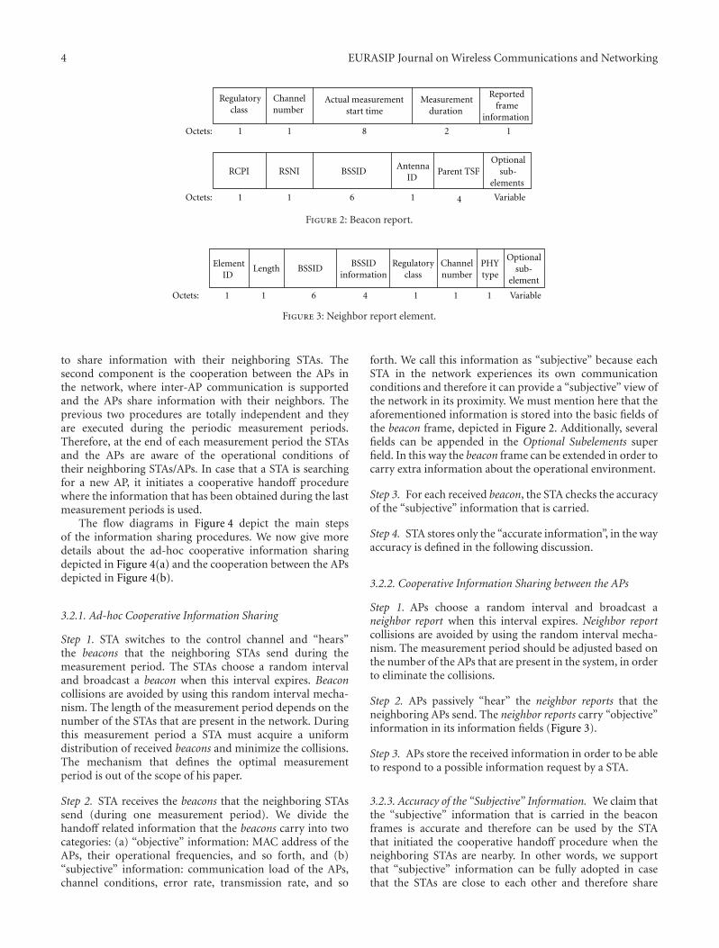
(i) Beacon report. A STA can receive a beacon report fromthe neighboring STAs in order to be aware of thecommunication conditions in its neighborhood. TheSTA can operate in an active way and broadcast a bea-con request to the neighboring STAs. Afterwards theSTA waits for a specific period (measurement period)in order to receive beacons from the neighboringSTAs. In addition, a STA can operate in a passive wayby listening to beacons that neighboring STAs sendduring the measurement periods. Beacon in its pureform carries information about the operating APsin the neighborhood, their communication channels,BSSID, and so forth. We must mention that 802.11kspecifies measurement periods but it does not definethe way to adjust their duration and how frequentthey are initiated. Figure 1 depicts the general formatof the measurement report defined in 802.11k stan-dard [4], which contains the beacon report (inside theMeasurement Report field). Beacon report is depictedin Figure 2. More information about the details ofthe fields that are present in the beacon report can beobtained in [4].
(ii) Neighbor report. In this request/response mechanisma STA/AP can request information about the neigh-boring APs. Neighbor report supports communica-tion and information exchange between APs in thenetwork (this is not supported in beacon report).According to 802.11k a STA/AP can initiate a neighborreport process and send a neighbor request to theneighboring APs. The APs that “hear” this requestreact by sending a neighbor report that containsinformation stored in their Management Informa-tion Base (MIB). In addition, the APs can behave ina passive way during a neighbor report process. Inother words during the measurement period all theAPs in the network broadcast neighbor reports thatcontain information stored in their MIB. Therefore,an AP can “hear” the reports of its neighboringAPs without initiating a request/response procedure.Figure 3 depicts the neighbor report element asdefined in 802.11k [4].
3.2. Proposed Framework. In our framework we supportinformation sharing between the STAs and the APs in thenetwork, based on the aforementioned mechanisms that aredefined in 802.11k. The first component in our frameworkis the ad-hoc cooperative procedure that STAs use in order
4 EURASIP Journal on Wireless Communications and Networking
Regulatoryclass
Channelnumber
Actual measurement start time
Measurementduration
Reportedframe
information
81 1 2 1
RCPI RSNI BSSIDAntenna
ID Parent TSF
Optionalsub-
elements
Variable
Octets:
61 1 1 4Octets:
Figure 2: Beacon report.
ElementID
Length BSSIDBSSID
informationRegulatory
classChannelnumber
PHYtype
Optionalsub-
element
Octets: 1 1 46 1 1 1 Variable
Figure 3: Neighbor report element.
to share information with their neighboring STAs. Thesecond component is the cooperation between the APs inthe network, where inter-AP communication is supportedand the APs share information with their neighbors. Theprevious two procedures are totally independent and theyare executed during the periodic measurement periods.Therefore, at the end of each measurement period the STAsand the APs are aware of the operational conditions oftheir neighboring STAs/APs. In case that a STA is searchingfor a new AP, it initiates a cooperative handoff procedurewhere the information that has been obtained during the lastmeasurement periods is used.
The flow diagrams in Figure 4 depict the main stepsof the information sharing procedures. We now give moredetails about the ad-hoc cooperative information sharingdepicted in Figure 4(a) and the cooperation between the APsdepicted in Figure 4(b).
3.2.1. Ad-hoc Cooperative Information Sharing
Step 1. STA switches to the control channel and “hears”the beacons that the neighboring STAs send during themeasurement period. The STAs choose a random intervaland broadcast a beacon when this interval expires. Beaconcollisions are avoided by using this random interval mecha-nism. The length of the measurement period depends on thenumber of the STAs that are present in the network. Duringthis measurement period a STA must acquire a uniformdistribution of received beacons and minimize the collisions.The mechanism that defines the optimal measurementperiod is out of the scope of his paper.
Step 2. STA receives the beacons that the neighboring STAssend (during one measurement period). We divide thehandoff related information that the beacons carry into twocategories: (a) “objective” information: MAC address of theAPs, their operational frequencies, and so forth, and (b)“subjective” information: communication load of the APs,channel conditions, error rate, transmission rate, and so
forth. We call this information as “subjective” because eachSTA in the network experiences its own communicationconditions and therefore it can provide a “subjective” view ofthe network in its proximity. We must mention here that theaforementioned information is stored into the basic fields ofthe beacon frame, depicted in Figure 2. Additionally, severalfields can be appended in the Optional Subelements superfield. In this way the beacon frame can be extended in order tocarry extra information about the operational environment.
Step 3. For each received beacon, the STA checks the accuracyof the “subjective” information that is carried.
Step 4. STA stores only the “accurate information”, in the wayaccuracy is defined in the following discussion.
3.2.2. Cooperative Information Sharing between the APs
Step 1. APs choose a random interval and broadcast aneighbor report when this interval expires. Neighbor reportcollisions are avoided by using the random interval mecha-nism. The measurement period should be adjusted based onthe number of the APs that are present in the system, in orderto eliminate the collisions.
Step 2. APs passively “hear” the neighbor reports that theneighboring APs send. The neighbor reports carry “objective”information in its information fields (Figure 3).
Step 3. APs store the received information in order to be ableto respond to a possible information request by a STA.
3.2.3. Accuracy of the “Subjective” Information. We claim thatthe “subjective” information that is carried in the beaconframes is accurate and therefore can be used by the STAthat initiated the cooperative handoff procedure when theneighboring STAs are nearby. In other words, we supportthat “subjective” information can be fully adopted in casethat the STAs are close to each other and therefore share

EURASIP Journal on Wireless Communications and Networking 5
For each neighboring STAcheck: is the received
information accurate?
Measurement periodstarts
Yes
No
STA has obtainedinformation about its
neighboring STA
Store information
STA receives thebeacons from theneighboring STAsusing the control
channel
More beacons?Yes
No
(a) Ad-hoc cooperative information sharing
Measurement periodstarts
Iner-APcommunication starts
APs broadcast aneighbor report to its
neighboring APs
APs has obtainedinformation about its
neighboring APs
(b) Cooperation betweenthe APs
Figure 4: Cooperative information sharing during the measurement periods.
similar communication conditions with each of the availableAPs. An easy way to estimate the location/distance of theneighboring STAs is to measure the Received Signal StrengthIndicator (RSSI) value of the transmitted signal. In order toestimate the distance from the RSSI value we use free spacepropagation model (line of sight) for simplicity reasons. Inindoor environments this model is not precise but is stillcapable to approximate the STAs location. In free spacepropagation the RSSI is determined as
Pr(d) = P0 − 20 log10
(4πdl
)dBm, (1)
where P0 = 30 dBm (theoretically the maximum transmis-sion power in 802.11), and l = (3 ∗ 108 m/s)/2.4 GHz.Figure 5 depicts the relationship between RSSI and thedistance of the STA that transmits the measured signal. Inorder to measure the information accuracy, we determinean RSSI threshold TRSSI . Besides, we can deal with theRSSI fluctuations that occur in real-time deployments, bymeasuring the mean RSSI value of the signal transmittedby a STA (we use a short window to calculate the meanRSSI value). We assume here that the STAs/APs use the sametransmission power and there is no power control in the
system (pure 802.11 operation). This assumption arises sincewe use a constant threshold TRSSI in our system. However,this is not necessary because we can include the transmis-sion power into the transmitted packet and therefore thethreshold TRSSI can be adapted accordingly. Furthermore, weclaim that the received information is accurate in case thatthe mean RSSI value of the transmitted signal is higher thanthe predefined TRSSI . In particular, RSSI helps us estimatinghow far the STAs/APs that transmit are and TRSSI gives usthe ability to receive accurate information from the STAs/APsthat are close (and therefore it is possible that they face thesame channel conditions). In our experiments (simulationenvironment) we have seen that the higher TRSSI values weobtain, the more accurate this information is. TRSSI dependson the conditions of each system. Therefore, the systemmanager must adjust the threshold value according to theoperational conditions (indoor or outdoor environment).
We must mention here that it is difficult to predict theradio propagation especially in indoor environments, due topropagation effects (scattering, diffraction, reflection, etc.)and the variability of the environment [24]. Consequently,the accuracy of the RSSI-based distance estimation mayvary in these environments. In our framework we have

6 EURASIP Journal on Wireless Communications and Networking
0 2 4 6 8 10 12 14 16 18 20
Distance (m)
RSS
I (d
Bm
)
−35
−30
−25
−20
−15
−10
−5
0
5
10
15
20
−40
Figure 5: RSSI versus distance (free propagation).
used the simple approach based on the received signal, inorder to provide a baseline of the framework. Since we donot focus on the way we will choose the criteria for theapproximation of the nodes “locality”, the simple algorithmof using RSSI provide a lightweight system solution. Handoffis a time-critical procedure and therefore, it must be executedseamlessly and avoiding the effects of additional delays.The accuracy of the RSSI-based distance estimator can beimproved in case that we use more sophisticated techniques[25, 26].
The communication between the APs is totally “orthog-onal” to the communication between the STAs. In particular,in multicell WLANs the APs communicate through theirwired connections and in wireless mesh networks the APs usethe wireless backhaul to communicate. Especially in wirelessmesh networks the APs can be equipped with a secondinterface for the backhaul communication (based on thenetwork architecture) or use separate channels. Therefore,we can claim that the cooperative information sharingbetween the APs is performed independently and in parallelwith the ad-hoc cooperative information sharing during themeasurement periods.
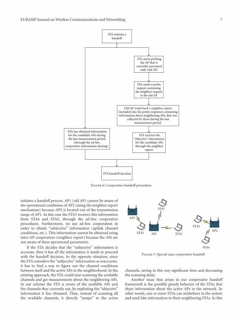
The main part of our framework is the cooperativehandoff mechanism that uses the information obtained fromthe previous procedures and provides seamless handoffsin the network. The flow diagram in Figure 6 depicts thebasic steps that are executed during a cooperative handoffprocedure. We describe in detail the main steps of thismechanism.
3.2.4. Cooperative Handoff
Step 1. STA realizes that it must find a new AP (based onthe underlying association/handoff decision protocol) andinitiates a handoff procedure. So, it sends a neighbor reportrequest to the AP (old AP) that is currently associated with.The neighbor report request can be imported to the proberequest frame that the STA sends in order to probe an AP
and receive useful information (in 802.11-based scanningprocedure).
Step 2. Old AP sends back a merged neighbor report tothe STA. The merged neighbor report contains informationabout its neighboring APs, which has been obtained duringthe last measurement period. In particular, the mergedneighbor report use several information fields that are partof the Optional Subelements super field (Figure 3) and carryinformation for each neighboring AP. The merged neighborreport can be incorporated into the probe response framethat the AP sends back to the STA during the 802.11-based scanning process. Neighbor report contains similarinformation to beacon report. The main difference here is thatthe neighbor report contains additional information about“objective” characteristics of the new APs (that the STAreceives through the old AP).
Step 3. STA comes up with a handoff decision basedon the underlying association/handoff decision protocolthat is applied in the network using (a) the informationobtained during the Step 2, and (b) the information for theneighboring APs that the STA has obtained through the ad-hoc cooperative information sharing procedure, that wasexecuted during the last measurement period. We must makeclear here that in our framework every STA that initiates ahandoff procedure uses both types of information (a) and(b) to come up with a handoff decision.
An important observation here is that our cooperativehandoff mechanism gathers handoff information during aprobe request (the neighbor report request is incorporatedinto the probe request) and a probe response (the mergedneighbor report is incorporated into the probe response)exchange between the STA and the AP. The traditional802.11-based scanning process wastes approximately thesame time in scanning just one channel, since each STAmust keep listening to a channel for a constant time inorder to hear all the beacons that are transmitted by theneighboring APs and then scan the next channel. Therefore,our mechanism is much faster in gathering the informationthat the STAs need and the added overhead is quite small (lessthan an 802.11-based one-channel scanning). In addition,the communication between the APs can be independentlyexecuted (during the measurement periods) from a handoffprocedure. In this way the information from the neighboringAPs (to the old AP) will be immediately available to the STA,when a cooperative handoff procedure is executed.
The ad-hoc cooperative information sharing plays animportant role in our framework since there are situationswhere the old AP cannot be aware of the operational condi-tions of all the candidate APs for association. In a mesh envi-ronment the APs communicate over a wireless backhaul net-work and a candidate AP could be placed out of the transmis-sion range of the old AP. Besides, in multicell environmentsa candidate AP could lose connection with the old AP or itcould belong to another subnetwork where the communica-tion with the old AP is impossible. For example in Figure 7we assume that STA3 is currently associated with AP1 and it
EURASIP Journal on Wireless Communications and Networking 7
STA initiates ahandoff
STA handoff decision
STA sends a proberequest containing
the neighbor request to the old AP
Old AP sends back a neighbor report (included into the probe response) containing information about neighboring APs, that was
collected by them during the last measurement period
STA receives the“objective” information
for the candidate APs through the neighbor
report
STA has obtained informationfor the candidate APs during the last measurement period
(through the ad-hoc cooperative information sharing)
STA starts probingthe AP that is
currently associated with (old AP)
Figure 6: Cooperative handoff procedure.
initiates a handoff process. AP1 (old AP) cannot be aware ofthe operational conditions of AP2 (using the neighbor reportmechanism) because AP2 is located out of the transmissionrange of AP1. In this case the STA3 receives this informationfrom STA4 and STA5, through the ad-hoc cooperativeprocedures. Furthermore, we use ad-hoc cooperation inorder to obtain “subjective” information (uplink channelconditions, etc.). This information cannot be obtained usinginter-AP cooperation (neighbor report) because the APs arenot aware of these operational parameters.
If the STA decides that the “subjective” information isaccurate, then it has all the information it needs to proceedwith the handoff decision. In the opposite situation, sincethe STA considers the “subjective” information as inaccurate,it has to find a way to figure out the channel conditionsbetween itself and the active APs in the neighborhood. In theexisting approach, the STA could start scanning the availablechannels and get measurements about the neighboring APs.In our scheme the STA is aware of the available APs andthe channels they currently use, by exploiting the “objective”information it has obtained. Thus, instead of scanning allthe available channels, it directly “jumps” to the active
AP1 STA3
CISCO AIRONET 350 SERIES
WIRELESS ACCESS POINT
AP3
STA4
STA1
CISCO AIRONET 350 SERIES
WIRELESS ACCESS POINT
CISCO AIRONET 350 SERIES
WIRELESS ACCESS POINT
AP2STA2
STA5
Figure 7: Special case: cooperative handoff.
channels, saving in this way significant time and decreasingthe scanning delay.
Another issue that arises in our cooperative handoffframework is the possible greedy behavior of the STAs thatshare information about the active APs in the network. Inother words, one or more STAs can misbehave in the systemand send fake information to their neighboring STAs. In this

8 EURASIP Journal on Wireless Communications and Networking
5 1015 20 25 30
35 40
0200
400500
6008005.5
6
7
8
9
10×10−3
Measurement period duration (ms) Measurment interval (ms)
Del
ay (
s)
Figure 8: Optimal interval values for the measurement periods(STAs and APs follow these intervals).
way our cooperative handoff framework does not performeffectively since it does not have the correct information.Our scheme assumes that a trusted information exchange hasbeen established in the network. The issue of the trustworthyamong the stations is out of the scope of this paper and it canbe achieved using authentication techniques.
Before ending this section we must note that in ourcooperative framework we use a separate control channel forinformation exchange. An interesting approach would be toequip the STAs with a second communication interface forinformation exchange. In other words, we could keep the firstinterface for data communication and the second for channelscanning and control information sharing. This approachwould gain in performance since we would avoid controlchannel switching delays. However, this is not a realisticscenario while most end user devices are not equippedtoday with a second interface (cost reasons, etc.). This isthe main reason that leads us to choose control channelcommunication in our framework. Nevertheless, this couldbe an additional option in our framework.
4. System Evaluation
We have implemented our cooperative handoff frameworkusing OPNET [27]. Our mechanisms were built on topof the IEEE 802.11 standard in order to achieve backwardcompatibility. We have modified the main control frames(beacon, probe frames) in order to simulate the basicmeasurement mechanisms that are introduced by 802.11kand incorporate the appropriate information in them. Thelight modifications that we have introduced in the basicfunctionality of the IEEE 802.11 standard do not affect theperformance of the network. In our simulation study wecompare our framework to the scheme proposed in [13] andto 802.11. The work in [13] proposes a selective scanningalgorithm and a caching mechanism in order to reduce thedelay introduced by the scanning phase.
As far as the overhead and the communication costare concerned, it is true that our cooperative mechanismsintroduce an overhead in the performance of the networksince now the STAs/APs have to switch to the control channel(in a periodic basis) in order to gather handoff informationfrom the neighbors. Besides, several control frames must betransmitted during the periodic 802.11k-based measurementperiods in the network. However, our framework does notintroduce higher overheads and communication costs ascompared to 802.11k. As we have mentioned, our schemeis built on top of the main mechanisms determined by the802.11k standard and it is fully compliant with it. Moreinformation about the performance of the 802.11k standardcan be obtained in [28]. Our simulation study takes intoaccount the communication costs and the extra delays thatare present in our framework, during the execution of ourmechanisms. The simulation results declare that our cooper-ative handoff framework gains in performance as comparedto other schemes. The main reason for this improvement isthat in our framework we avoid unavailing channel scanning.Besides, the information sharing that is introduced betweenthe STAs/APs during the measurement periods provideseamless handoffs in the network, avoiding in this way largedelays and traffic interruptions. In more detail, the overheadthat our mechanisms add is approximately similar to theoverhead added by the one channel scanning procedurewhich is significantly smaller than the original overhead(in 802.11-based handoff procedure), which is equal to thistime multiplied by the number of the channels that arescanned (more details will be given later in this section).Therefore, the main outcome of this work is that the numberof the scanned channels is significantly reduced (comparedto 802.11 channel scanning).
As described before, 802.11k introduces mechanisms forinformation exchange during a period called measurementperiod. In our scheme STAs use these mechanisms in orderto collect information related to the available APs in theirneighborhood. The duration of the measurement period aswell as how frequent the period is initiated is not defined bythe standard. In order to study how the measurement periodaffects the performance of our mechanism and the overheadthat is introduced, we run several experiments on a multicellwireless network of 5 partially overlapped cells and 65 STAs(we give more details about the simulation environmentin the following subsection). Figure 8 depicts the averagetransmission delay (average delay of all transmissions in thesystem) in the system as the measurement period (x axis)and the measurement intervals (y axis) change. As we cansee in this figure the more often the measurements are takenplace, the more accurate is the information that is exchanged.However, the overhead increases due to frequent informationexchange in the network and the average transmission delayis getting higher. The average transmission delay is increasedtoo, when the frequency of the measurements is increased(measurement interval). Our system is not able to obtain “upto date” information during a cooperative handoff procedureand therefore the performance of the handoff mechanismdecreases. Additionally, large measurement periods increasesignificantly the overhead too. On the other hand, when

EURASIP Journal on Wireless Communications and Networking 9
2 4 6 8 10 12 14 16 18 200
2
4
6
8
10
12
14
16
18
20
Real distance (m)
Est
imat
ed d
ista
nce
bas
ed o
n R
SSI
(m)
Figure 9: RSSI based distance estimation accuracy.
we use very small measurement periods, our mechanismdoes not “have the time” to take into account the “upto date” information that is carried in the control frames.Consequently, the average transmission delay increases. InFigure 8 we can observe that the optimal system operation(minimum transmission delay) is achieved when the mea-surement period lasts for 20 ms and it is initiated every500 ms (we use these values in our simulation study). Wemust mention here that the aforementioned values resultedfrom our simulation study. The duration of the measurementperiod and its periodicity is a system designer decision.Therefore, the system designer must adapt the measurementperiod to the properties of the system.
Figure 9 depicts the accuracy of the RSSI based distanceestimation used in our system. We observe that the estimateddistance is close enough to the real distance of STAs/APs thattransmit.
4.1. The Multicell Scenario. We first study a multicell 802.11gnetwork that consists of five partially overlapping cells.In such simple topologies we can control the parametersof our system and therefore we can have a clear view ofthe performance of the proposed protocols. The STAs areuniformly distributed (at random) in the network and theirdata frames are transmitted at 1024 kbps (we consider CBRtraffic). We vary the number of source/destination pairs inorder to vary the overall load. The source and destinationnodes are chosen randomly among the nodes in the network.We compare the performance of the basic 802.11-basedhandoff mechanism to the performance of our 802.11kcompliant cooperative handoff framework as the communi-cation interference changes during the network operation.In order to effectively evaluate the performance of ourframework we consider two cases: (a) the communicationload is represented by the number of STAs that are associatedwith an AP, and (b) the communication load is representedby the airtime metric introduced in our previous work [6](the measured communication load in (a) and (b) is usedas described in our cooperative procedures). In particular,
the airtime cost of STA i ∈ Ua, where Ua is the set of STAsassociated with AP a, is
Cia =
[Oca + Op +
Bt
ri
]1
1− eipt, (2)
where Oca is the channel access overhead, Op is the protocoloverhead and Bt is the number of bits in the test frame.Some representative values (in 802.11 g networks) for theseconstants are Oca = 335μs, Op = 364μs and Bt = 8224 bits.The input parameters ri and ept are the bit rate in Mbs, andthe frame error rate for the test frame size Bt, respectively.More information about this metric and the underlyingassociation/handoff decision mechanism can be obtained in[6]. It is clear that in the second case we take into accountchannel quality information (error rate and transmissionrate), which are qualitative measurements, contrary to thefirst case where we just take into account the number of theassociated STAs.
In the first simulation scenario we support 65 STAs(uniformly distributed at random) in the multicell network.We measure the handoff delays in the system when ourcooperative mechanism is applied in comparison to theselective scanning algorithm proposed in [13] and to 802.11.In particular, we measure the delay of each handoff thatis present in our system (x axis represents the handoffnumber) and we calculate the average handoff delay values.In order to evaluate the performance of our mechanismswe consider both stationary STAs and mobile STAs. Weuse random waypoint mobility model, where the velocity ischosen randomly between 1 and 20 m/s. Figures 10(a), 10(b),and 10(c) depict the handoff delays during the pure 802.11-based handoff mechanism execution, the selective scanningalgorithm application and our scheme. In this scenario theSTAs are stationary. In order to vary the channel conditionswe add interference generating jammers that are periodicallyactive in our system. When jammers are active, they contin-uously transmit jamming packets that cause interference. Inthis way we force the stationary STAs to handoff to a new AP,where interference is limited. Selective scanning improves theperformance of the 802.11-based handoff mechanism usinga channel mask, scanning in this way a small subset of theavailable channels. It is clear that our system achieves lowerhandoff delays due to the fact that prehandoff information isobtained rapidly (without scanning). In Figures 11(a), 11(c)and 11(b) we observe the handoff delays in a network thatsupports random STA mobility. The outcome is similar to theprevious experiment. The proposed framework achieve quitelower handoff delays. Table 1 compares the average handoffdelays between 802.11, the selective scanning algorithm, andour cooperative framework. An important outcome is thatour mechanisms improve the 802.11-based handoff delayby approximately 89% when we have stationary STAs and92% when we support mobile STAs in our system. Weallegate that this significant delay improvement will playan important role in the improvement of the end-to-endnetwork performance. More details about this claim will beprovided in the remaining section.
During our second simulation scenario the number ofthe associated STAs in the network increases from 5 to 65

10 EURASIP Journal on Wireless Communications and Networking
5 10 15 20 25 30 35 40 45 500
50
100
150
200
250
300
Handoff number
Del
ay (
ms)
(a) 802.11 performance
5 10 15 20 25 30 35 40 45 500
50
100
150
200
250
300
Handoff number
Del
ay (
ms)
(b) Selective scanning performance
5 10 15 20 25 30 35 40 45 500
50
100
150
200
250
300
Handoff number
Del
ay (
ms)
(c) Cooperative framework performance
Figure 10: Handoff delays with stationary STAs.
5 10 15 20 25 30 35 40 45 500
50
100
150
200
250
300
350
400
450
Handoff number
Del
ay (
ms)
(a) 802.11 performance
5 10 15 20 25 30 35 40 45 500
50
100
150
200
250
300
350
400
450
Handoff number
Del
ay (
ms)
(b) Selective scanning performance
5 10 15 20 25 30 35 40 45 500
50
100
150
200
250
300
350
400
450
Handoff number
Del
ay (
ms)
(c) Cooperative framework performance
Figure 11: Handoff delays with mobile STAs.

EURASIP Journal on Wireless Communications and Networking 11
5 10 15 20 25 30 35 40 45 50 55 60 650
1
2
3
4
5
6
Number of stations
Th
rou
ghpu
t (M
bps)
(a) Average throughput
0
0.02
0.04
0.06
0.08
0.1
0.12
0.14
Del
ay (
s)
5 10 15 20 25 30 35 40 45 50 55 60 65
Number of stations
(b) Average transmission delay
0
1000
2000
3000
4000
5000
6000
Dro
pped
dat
a (b
its/
s)
802.11CoopHandoff (number of stations)CoopHandoff (airtime)
5 10 15 20 25 30 35 40 45 50 55 60 65
Number of stations
(c) Average dropped data
Figure 12: Simulation results for the multicell scenario.
Table 1: Average Handoff delays.
Stationary STAs Mobile STAs
802.11 191 ms 303.39 ms
Selective scanning 120.96 ms 171.6 ms
CoopHandoff 20.73 ms 22.69 ms
Selective scanning improvement 36.67% 43.44%
CoopHandoff improvement 89.14% 92.52%
(STAs are uniformly placed in the network). We measure thenetwork throughput, the average transmission delay, and thedata dropping. These measurements are representative andreflect the system performance under different operationalconditions. In order to effectively evaluate the performanceof our cooperative framework we consider two cases. Theunderline association decision mechanisms use: (a) thenumber of STAs as the load metric and (b) the airtime costas the load metric. In particular, the association decisionmechanisms avoid overloaded APs using these metrics(where the number of the associated STAs is large in the firstcase, and in the second case where the cumulative airtimecost in the cell is high).
Figure 12(a) depicts the network throughput as thenumber of the associated STAs in the network increases. Wecompare the throughput values that are achieved during theexecution of the basic 802.11-based handoff scheme and ourcooperative framework. It is clear that the highest through-put values are achieved when we apply our cooperativehandoff mechanisms since they speed up the handoff pro-cedure. Airtime mechanism achieves the best performancebecause it takes into account channel quality information forboth uplink and downlink communication and so it uses amore representative load metric than in the case we considerthe number of STAs. In low load conditions, we observea quite small throughput improvement when we use theproposed mechanisms. In high load conditions, throughputincrease is higher. The maximum throughput improvementthat is achieved by our cooperative handoff mechanism isapproximately 55% (when we have 65 associated STAs). Itis important to notice that the 802.11 network throughput isstabilized when we have 45 associated STAs in the network.This means that after this point the provided QoS in thenetwork is getting worse as the number of the STAs inthe network increases. On the other hand, our cooperativeframework expands the network capabilities and maximizesthe network throughput in presence of 65 associated STAs inthe network.
In Figure 12(b) we observe the average transmissiondelay in the network. It is clear that in low load networkoperation, the average transmission delay of 802.11 is quitesmall and close to the average delay that is achieved by ourcooperative mechanisms. When the number of the associatedSTAs increases over 35 the average delay of 802.11 is gettingextremely high. In contrary, our cooperative mechanismsprovide an additional performance improvement to theairtime mechanism and keep the transmission delay in lowlevel. The 802.11-based handoff policy is quite static and

12 EURASIP Journal on Wireless Communications and Networking
2 4 6 8 10 12 14 16 18 20 22 240
1
2
3
4
5
6
7
8
9×10⁻³
Number of sessions
VoI
P c
lien
t ac
cess
del
ay (
s)
(a) Average client access delay
0
5
10
15
20
25
30
35
AP
acc
ess
dela
y (s
)
2 4 6 8 10 12 14 16 18 20 22 24
Number of sessions
×10−4
(b) Average AP access delay
0
0.01
0.02
0.03
0.04
0.05
0.06
0.07
0.08
0.09
En
d-to
-en
d de
lay
(s)
2 4 6 8 10 12 14 16 18 20 22 24
Number of sessions
802.11CoopHandoff (number of stations)CoopHandoff (airtime)
(c) Average end-to-end delay
0
200
400
600
800
1000
1200
1400
1600
1800
Dro
pped
dat
a (b
its/
s)
2 4 6 8 10 12 14 16 18 20 22 24
Number of sessions
802.11CoopHandoff (number of stations)CoopHandoff (airtime)
(d) Average dropped data
Figure 13: Average delays and dropped data in VoIP.
that causes some cells to be overloaded while the numberof the associated STAs increases. Our approach providesfast dynamic reassociations/handoffs in order to keep abalanced network operation. The high 802.11 scanningdelays are avoided as our cooperative mechanism “grants”the appropriate information to the STAs that are trying toreassociate with new APs.
Figure 12(c) depicts the amount of packets dropped dueto channel errors and collisions in the communication. As wecan see, our mechanisms achieve lower number of droppedpackets. The sophisticated channel quality based associationpolicies that are introduced by the airtime mechanismand our fast cooperative reassociation procedures providea balanced network operation. STAs that face poor channelconditions and high number of dropped packets, perform
fast handoffs in order to improve the network efficiency whilethe underling airtime association mechanism optimizes theSTAs handoff decision.
4.2. The Mesh Network Scenario. In order to measure theend-to-end network performance, we study the applicationof the proposed mechanisms in an 802.11-based wirelessmesh network. We simulated a wireless mesh network inthe OPNET simulation environment. The wireless routersthat are provided by the OPNET wireless module are partof the backhaul network. The peripheral routers serve asAPs as well. In our simulation we use 6 peripheral routers(mesh APs) and 4 backhaul routers (mesh Points). Weimplemented RM-AODV that is introduced by 802.11s [29]standard and we applied this routing protocol at the mesh

EURASIP Journal on Wireless Communications and Networking 13
backhaul (we can apply any QoS-aware routing protocol atthe mesh backhaul in order to evaluate our framework). TheSTAs are uniformly distributed (at random) in the wirelessmesh network. For the communication between the wirelessrouters in the backhaul network, we use the physical model ofIEEE 802.11a OFDM physical layer. The supported physicalrate is 12 Mbps. The STAs are associated with the availableperipheral APs. We simulated a VoIP application in the802.11-based wireless mesh network, which is a QoS sensitiveapplication. In our simulations we uniformly placed severalVoIP clients in the network. We run different simulationscenarios where we varied the number of the VoIP sessionsthat are supported in parallel.
First of all we measured the average local client accessdelay in the network. In practice, this delay reflects the timethat the packet is generated until it leaves the client interface.The number of the sessions that are supported in parallelincreases from 2 to 24. Figure 13(a) depicts the average VoIPclient access delay. Our cooperative mechanism (with theairtime metric) achieves lower client access delays in thenetwork. Consequently, our cooperative framework providesfast handoff procedures and keeps the client access delayin low level. The traditional 802.11 operation overloads thenetwork and therefore increases significantly the access delayof the clients. In high load conditions, the delay improvementthat is introduced by our mechanism is very high.
Figure 13(b) depicts the average local AP access delay inthe network. This delay is the time passed from the arrivalof a VoIP packet at the AP until the moment that it is eithersuccessfully transmitted over the wireless mesh network ordropped. As we see we get similar results to those of theclient access delay. In pure 802.11 the overloaded APs (inhigh load conditions) have a lot of traffic to forward tothe mesh backhaul network. The main consequence is thatthe VoIP packets have to wait for a long time to be trans-mitted by the APs, introducing in this way high AP accessdelays.
In Figure 13(c) we observe the average end-to-end delayin the VoIP packet transmission. The end-to-end delay isaffected by the previous two kinds of delays that we havedescribed and the routing delay that is introduced in thebackhaul network. In our cooperative framework we achievelow end-to-end delays in the network. Especially in theairtime mechanism operation the delay improvement isvery high. This improvement is true due to the fast VoIPclients/APs access in the network and the fast handoff thatis provided. We allegate that the most interesting result isdepicted in Figure 13(c), where the pure 802.11 operationcan support at most 14 sessions in parallel while ourcooperative framework supports 24 sessions. Therefore, wehave a network performance improvement of approximately66%.
The last figure (Figure 13(d)) depicts the dropped pack-ets during the operation of the mesh network. Channelerrors and packet collisions are the main reasons for thispacket dropping. In 802.11 the number of dropped packetsis high. Our proposed mechanisms decrease this number andmanage to keep it low even in high load conditions.
Concluding this section we summarize the key achieve-ments of our cooperative framework that are highlighted inour evaluation study:
(i) adaptability of the measurement mechanisms definedin 802.11k
(ii) lower handoff delays, compared to 802.11 and toselective scanning approach
(iii) seamless mobility management in the network
(iv) efficient scalability and network performance inwireless multicell environments
(v) support of QoS-sensitive applications in dynamicwireless mesh environments.
5. Conclusions
In this paper we propose a new handoff framework thatintroduces cooperation between STAs/APs. Our cooperativeframework is compliant to 802.11k and it utilizes informa-tion exchange and measurement mechanisms that are speci-fied in the standard in order to eliminate the scanning/probedelays in the handoff process. The proposed mechanismswork independently of the underling association/handoffprocedures and therefore they can be applied in combinationto any association/handoff protocol. Besides, the proposedmechanisms in this framework can be applied to 802.11-based WLANs and wireless mesh networks. Our maincontributions in the current research field are
(i) an 802.11k compliant cooperative handoff frame-work for wireless networks
(ii) two cooperative schemes that take full advantage ofthe mechanisms that 802.11k provides
(iii) extensive simulation experiments where we supportQoS sensitive applications. We evaluate the perfor-mance of our framework by applying different under-lying handoff decision protocols and we measure theperformance improvement that is achieved.
Our future directions include the implementation ofthese mechanisms using Linux open source drivers and theevaluation of our system in real conditions.
References
[1] IEEE 802.11, “Wireless LAN medium access control (MAC)and physical layer (PHY) specifications,” ANSI/IEEE Std802.11, 1999 Edition.
[2] I. F. Akyildiz, X. Wang, and W. Wang, “Wireless meshnetworks: a survey,” Computer Networks, vol. 47, no. 4, pp.445–487, 2005.
[3] A. Mishra, M. Shin, and W. Arbaugh, “An empirical analysisof the IEEE 802.11 MAC layer handoff process,” ACMSIGCOMM Computer Communication Review, vol. 33, no. 2,pp. 93–102, 2003.
[4] IEEE 802.11 WG, “Wireless medium access control (MAC)and physical layer (PHY) specifications: specification for radioresource measurement, IEEE 802.11k/D3.0,” New York, NY,USA: The Institute of Electrical and Electronics Engineers,Inc., October 2005.
14 EURASIP Journal on Wireless Communications and Networking
[5] Y Bejerano and R. Bhatia, “Mifi: a framework for fairness andQoS assurance in current IEEE 802.11 networks with multipleaccess points,” in Proceedings of the Annual Joint Conferenceof the IEEE Computer and Communications Societies (INFO-COM ’04), Hong Kong, 2004.
[6] G. Athanasiou, T. Korakis, O. Ercetin, and L. Tassiulas,“Dynamic cross-layer association in 802.11-based meshnetworks,” in Proceedings of the Annual Joint Confer-ence of the IEEE Computer and Communications Societies(INFOCOM ’07), pp. 2090–2098, Anhcorage, Alaska, USA,May 2007.
[7] Y. Bejerano, S. Han, and L. Li, “Fairness and load balancingin wireless lans using association control,” in Proceedings ofthe Annual International Conference on Mobile Computing andNetworking (MOBICOM ’04), Philadelphia, Pa, USA, 2004.
[8] B. Kauffmann, F. Baccelli, A. Chaintreau, V. Mhatre, K. Papa-giannaki, and C. Diot, “Measurement-based self organizationof interfering 802.11 wireless access netwroks,” in Proceedingsof the Annual Joint Conference of the IEEE Computer and Com-munications Societies (INFOCOM ’07), Anhcorage, Alaska,USA, May 2007.
[9] T. Korakis, O. Ercetin, S. Krishnamurthy, L. Tassiulas, andS. Tripathi, “Link quality based association mechanism inIEEE 802.11h compliant wireless LANs,” in Proceedings ofthe Workshop on Resource Allocation in Wireless Networks(RAWNET ’05), April 2005.
[10] IEEE 802.11h, “Wireless LAN medium access control (MAC)and physical layer (PHY) specifications: spectrum and trans-mit power management extentions in the 5 GHz band inEurope”.
[11] A. Kumar and V. Kumar, “Optimal association of stations andAPs in an IEEE 802.11 WLAN,” in Proceedings of the NationalConference on Communications (NCC ’05), IIT, Kharagpur,India, January 2005.
[12] S. Shakkottai, E. Altman, and A. Kumar, “The case for non-cooperative multihoming of users to access points in IEEE802.11 WLANs,” in Proceedings of the 25th Annual Conferenceof the IEEE Computer and Communications Societies (INFO-COM ’06), Barcelona, Spain, April 2006.
[13] S. Shin, A. G. Forte, A. S. Rawat, and H. Schulzrinne, “Reduc-ing MAC layer handoff latency in IEEE 802.11 wireless LANs,”in Proceedings of the 2nd International Workshop on MobilityManagement and Wireless Access Protocols (MobiWac’04), pp.19–26, ACM, 2004.
[14] M. Shin, A. Mishra, and W. A. Arbaugh, “Improving thelatency of 802.11 hand-offs using neighbor graphs,” in Pro-ceedings of the 2nd International Conference on Mobile Systems,Applications and Services (MobiSys’04), pp. 70–83, New York,NY, USA, June 2004.
[15] V. Brik, A. Mishra, and S. Banerjee, “Eliminating handofflatencies in 802.11 WLANs using multiple radios: appli-cations, experience, and evaluation,” in Proceedings of theInternet Measurement Conference (IMC ’05), ACM/USENIX,October 2005.
[16] I. Ramani and S. Savage, “SyncScan: practical fast handoff for802.11 infrastructure networks,” in Proceedings of the AnnualJoint Conference of the IEEE Computer and CommunicationsSocieties (INFOCOM ’05), vol. 1, pp. 675–684, March 2005.
[17] V. Mhatre and K. Papagiannaki, “Using smart triggers forimproved performance in 802.11 networks,” in Proceedings ofthe 4th International Conference on Mobile Systems, Applica-tions and Services (MobiSys ’06), pp. 246–259, June 2006.
[18] A. Mishra, M. Shin, and W. Arbaugh, “Context caching usingneighbor graphs for fast handoffs in a wireless network,”in Proceedings of the Annual Joint Conference of the IEEEComputer and Communications Societies (INFOCOM ’04), pp.351–361, Hong Kong, March 2004.
[19] H. Wu, K. Tan, Y. Zhang, and Q. Zhang, “Proactive scan:fast handoff with smart triggers for 802.11 wireless LAN,”in Proceedings of the Annual Joint Conference of the IEEEComputer and Communications Societies (INFOCOM ’07),Anhcorage, Alaska, USA, May 2007.
[20] Y. Amir, C. Danilov, M. Hilsdale, R. Musaloiu-Elefteri, and N.Rivera, “Fast handoff for seamless wireless mesh networks,”in Proceedings of the 4th International Conference on MobileSystems, Applications and Services (MobiSys ’06), pp. 83–95,ACM, Uppsala, Sweden, June 2006.
[21] A. Giannoulis, M. Fiore, and E. W. Knightly, “Supportingvehicular mobility in urban multi-hop wireless networks,” inProceedings of the International Conference on Mobile Systems,Applications and Services (MobiSys ’08), ACM, 2008.
[22] A. G. Forte and H. Schulzrinne, “Cooperation betweenstations in wireless networks,” in Proceedings of the Interna-tional Conference on Network Protocols (ICNP’07), pp. 31–40,Beijing, China, October 2007.
[23] S. Pack, J. Choi, T. Kwon, and Y. Choi, “Fast handoff supportin IEEE 802.11 wireless networks,” in Proceedings of the IEEECommunications Surveys & Tutorials (CST ’06), August 2006.
[24] K. Pahlavan and P. Krishnamurthy, Principles of WirelessNetworks: A Unified Approach, Prentice Hall PTR, UpperSaddle River, NJ, USA, 2002.
[25] P. Bahl and V. N. Padmanabhan, “RADAR: an in-buildingRF-based user location and tracking system,” in Proceedingsof the Annual Joint Conference of the IEEE Computer andCommunications Societies (INFOCOM ’00), Tel-Aviv, Israel,2000.
[26] K. Kaemarungsi and P. Krishnamurthy, “Modeling of indoorpositioning systems based on location fingerprinting,” in Pro-ceedings of the Annual Joint Conference of the IEEE Computerand Communications Societies (INFOCOM ’04), Hong Kong,2004.
[27] OPNET, http://www.opnet.com, Radio/Wireless Models.
[28] S. Mangold, Z. Zhong, G. R. Hiertz, and B. Walke, “IEEE802.11e/802.11k wireless LAN spectrum awareness for dis-tributed resource sharing. Special issue on emerging WLANtechnologies and applications,” in Wireless Communicationsand Mobile Computing, John Wiley & Sons, New York, NY,USA, 2004.
[29] IEEE 802.11s, “Wireless LAN medium access control (MAC)and physical layer (PHY) specifications: simple efficientextensible mesh (SEE-Mesh) proposal”.