Design of compliant mechanisms by structural optimization ...
278
This document is downloaded from DR‑NTU (https://dr.ntu.edu.sg) Nanyang Technological University, Singapore. Design of compliant mechanisms by structural optimization using genetic algorithms. Wang, Nian Feng 2008 Wang, N. F. (2008). Design of compliant mechanisms by structural optimization using genetic algorithms. Doctoral thesis, Nanyang Technological University, Singapore. https://hdl.handle.net/10356/5597 https://doi.org/10.32657/10356/5597 Nanyang Technological University Downloaded on 29 Mar 2022 18:19:17 SGT
-
Upload
khangminh22 -
Category
Documents
-
view
1 -
download
0
Transcript of Design of compliant mechanisms by structural optimization ...

This document is downloaded from DR‑NTU (https://dr.ntu.edu.sg)Nanyang Technological University, Singapore.
Design of compliant mechanisms by structuraloptimization using genetic algorithms.
Wang, Nian Feng
2008
Wang, N. F. (2008). Design of compliant mechanisms by structural optimization usinggenetic algorithms. Doctoral thesis, Nanyang Technological University, Singapore.
https://hdl.handle.net/10356/5597
https://doi.org/10.32657/10356/5597
Nanyang Technological University
Downloaded on 29 Mar 2022 18:19:17 SGT

DE
SIG
N O
F CO
MP
LIANT M
EC
HAN
ISM
S B
Y S
TRU
CTU
RAL
OP
TIMIZA
TION
US
ING
GEN
ETIC
ALG
OR
ITHM
S
DESIGN OF COMPLIANT MECHANISMS BY
STRUCTURAL OPTIMIZATION USING GENETIC ALGORITHMS
W
AN
G N
IAN
FEN
G
WANG NIAN FENG
SCHOOL OF MECHANICAL & AEROSPACE ENGINEERING 2008 2008
ATTENTION: The Singapore Copyright Act applies to the use of this document. Nanyang Technological University Library
Design of Compliant Mechanisms by Structural Optimization Using Genetic Algorithms
Wang Nian Feng
School of Mechanical & Aerospace Engineering
A thesis submitted to the Nanyang Technological University in fulfilment of the requirement for the degree of
Doctor of Philosophy
2008
ATTENTION: The Singapore Copyright Act applies to the use of this document. Nanyang Technological University Library

Abstract
Compliantmechanisms are single-piece jointless structures that use elastic deformation as
a means to achieve motion. They have many advantages compared to conventional rigid-
link mechanisms especially when the applications are in the micro-dimensional scale.
Compliant mechanisms show good potential in MEMS/NEMS applications because these
devices are manufactured on the sub-millimeter scale and therefore complex joints should
best be avoided. In particular, compliant micro-grippers can be used for manipulation
and assembly of electronic and optical micro-components, as well as for biological
samples as in single cell manipulation, positioning and isolation. The use of mechanical
micro-grippers that securely grip and transport objects to the desired location is also
advantageous because it avoids optical or electrical interference with the object which
may be a problem with other technologies such as optical tweezers, etc. The objective in
this work is to design compliant mechanisms named grip-and-move manipulators that
can grip an object and convey it from one point to another. Such a mechanism has
useful applications in MEMS and various automation devices, but it is relatively complex
because the relationship between their geometry and their elastic behavior can be highly
complex and non-linear. The synthesis of such a mechanism is to be achieved by a
structural optimization approach based on a genetic algorithm and a special representation
scheme for defining the structural geometry upon a finite element grid.
In this work a morphological geometric representation scheme is coupled with a
genetic algorithm to perform topology and shape optimization. It uses arrangements
of ‘skeleton’ and ‘flesh’ to define structural geometry in a way that facilitates the
transmission of topological/shape characteristics across generations in the evolutionary
process and will not render any geometrically undesirable features such as disconnected
‘floating’ segments of material, ‘checkerboard’ patterns or single-node hinge connections
I
ATTENTION: The Singapore Copyright Act applies to the use of this document. Nanyang Technological University Library

Abstract
betweenelements. Furthermore, variability of the topology in the optimization process
is enhanced by incorporating the ability to vary the connectivity of the curves used
for defining the skeleton. As for the optimization process, a novel approach has been
incorporated into the genetic algorithm to treat the relatively more important and/or
challenging objectives as constraints whose ideal values will be adaptively changed
(improved) during the evolutionary procedure. This helps to direct and focus the genetic
search towards regions of interest in the objective space, thus is a useful and intuitive way
for specifying the user’s preference and/or for tackling the harder objectives. In addition,
to improve on the optimum results and convergence speed the genetic algorithm is
hybridized with a local search strategy in which a novel constrained tournament selection
is used as a single objective function.
The optimization procedure and a large-displacement non-linear FE analysis have
been implemented through a C++ program. Before the developed genetic algorithm is
relied upon for solving actual compliant mechanism problem, the performance is tested
and tuned by some suitable and newly developed test problems. These test problems
emulate structural topology optimization without the need for computationally costly
structural analysis, with the aim of arriving at some optimal geometries. Such test
problems referred to as ‘Target Matching Problems’ with conflicting/non-conflicting
objectives are constructed. Two types of grip-and-move manipulators have been
conceptualized based on the use of path generating compliant mechanisms. Two identical
symmetric path-generating mechanisms can be used to construct the first kind of grip-
and-move manipulator which can grip a work piece and convey it to anywhere along a
fixed path. And a second type of compliant grip-and-move manipulator employs two
identical path generating mechanisms with two degrees-of-freedom so that it can grip a
workpiece and move it to anywhere within its working area instead of a line path. The
design problems for these mechanisms have been formulated and then solved using the
program, and several alternative manipulator designs have been realized and evaluated.
The results are encouraging and some areas of future work are recommended.
II
ATTENTION: The Singapore Copyright Act applies to the use of this document. Nanyang Technological University Library

Acknowledgements
The author expresses his thanks and gratitude to his supervisor Associate Professor Tai
Kang for his advice and guidance in all aspects of the author’s research work.
I would also like to thank Nanyang Technological University for research scholarship
and the excellent research environment.
Appreciation is due to staff of CANES for their assistance and support, especially Mr.
Teo, Mr. Chesda, and Mr. Chia.
I would also like to express my thanks to my friends, Dr. Ren Ji, Dr. Che Faxing,
Keif, Sashi, Dr. Zhao Xin, and Dr. Mao Rong Hai, for their helpful discussions.
I am indebted to my family members, especially to my parents and my wife for their
patience and encouragement.
III
ATTENTION: The Singapore Copyright Act applies to the use of this document. Nanyang Technological University Library

Contents
Abstract I
Acknowledgments III
Table of Contents IV
List of Figures VIII
List of Tables XIV
List of Abbreviation and Symbols XV
1 INTRODUCTION 1
1.1 BACKGROUND . . . . . . . . . . . . . . . . . . . . . . . . . . . . . . 1
1.1.1 Introduction to Compliant Mechanisms . . . . . . . . . . . . . . 1
1.1.2 Advantages and Disadvantages of Compliant Mechanisms . . . . 2
1.1.3 Application of Compliant Mechanisms . . . . . . . . . . . . . . 3
1.1.4 Current Need for Compliant Mechanisms Development . . . . . . 5
1.1.5 Introduction to Design Methods . . . . . . . . . . . . . . . . . . 6
1.2 OBJECTIVES OF THIS RESEARCH . . . . . . . . . . . . . . . . . . . 7
1.3 SCOPE . . . . . . . . . . . . . . . . . . . . . . . . . . . . . . . . . . . 7
1.4 ORGANIZATION OF THESIS . . . . . . . . . . . . . . . . . . . . . . . 9
2 LITERATURE REVIEW 10
2.1 DIFFERENT TYPES OF COMPLIANT
MECHANISMS . . . . . . . . . . . . . . . . . . . . . . . . . . . . . . . 10
2.1.1 Smooth Output Mechanisms . . . . . . . . . . . . . . . . . . . . 10
2.1.2 Non-smooth Output Mechanisms . . . . . . . . . . . . . . . . . 18
2.1.3 Recent Advances in Compliant Mechanisms . . . . . . . . . . . 20
2.2 METHODS USED TO DESIGN COMPLIANT MECHANISMS . . . . . 26
2.2.1 Kinematics Approach . . . . . . . . . . . . . . . . . . . . . . . . 26
2.2.2 Topology Optimization Method . . . . . . . . . . . . . . . . . . 29
2.2.3 Genetic Algorithm . . . . . . . . . . . . . . . . . . . . . . . . . 34
IV
ATTENTION: The Singapore Copyright Act applies to the use of this document. Nanyang Technological University Library

Contents
3 NONLINEAR FINITE ELEMENT ANALYSIS 48
3.1 INTRODUCTION . . . . . . . . . . . . . . . . . . . . . . . . . . . . . 48
3.2 CONSTITUTIVE EQUATION . . . . . . . . . . . . . . . . . . . . . . . 48
3.3 FINITE ELEMENT FORMULATION . . . . . . . . . . . . . . . . . . . 50
3.4 PROCEDURES FOR EQUILIBRIUM SOLUTION . . . . . . . . . . . . 54
3.5 TEST PROBLEM . . . . . . . . . . . . . . . . . . . . . . . . . . . . . . 58
3.5.1 Problem Description . . . . . . . . . . . . . . . . . . . . . . . . 58
3.5.2 Results . . . . . . . . . . . . . . . . . . . . . . . . . . . . . . . 58
4 DESIGN OF GRIP-AND-MOVE MANIPULATORS USING SYMMETRIC
PATH GENERATING MECHANISMS 61
4.1 SYMMETRIC PATH GENERATING
MECHANISM . . . . . . . . . . . . . . . . . . . . . . . . . . . . . . . 61
4.2 FORMULATION . . . . . . . . . . . . . . . . . . . . . . . . . . . . . . 63
4.2.1 Symmetric Path Objective . . . . . . . . . . . . . . . . . . . . . 64
4.2.2 Geometric Advantage Objective . . . . . . . . . . . . . . . . . . 65
4.2.3 Combined Objective . . . . . . . . . . . . . . . . . . . . . . . . 66
4.2.4 Stress Constraint . . . . . . . . . . . . . . . . . . . . . . . . . . 66
4.3 MORPHOLOGICAL REPRESENTATION OF STRUCTURE
GEOMETRY . . . . . . . . . . . . . . . . . . . . . . . . . . . . . . . . 67
4.4 MULTICRITERION GENETIC ALGORITHM . . . . . . . . . . . . . . 74
4.4.1 Pareto Ranking . . . . . . . . . . . . . . . . . . . . . . . . . . . 75
4.4.2 Selection Probability . . . . . . . . . . . . . . . . . . . . . . . . 75
4.4.3 Adaptive Niche Count . . . . . . . . . . . . . . . . . . . . . . . 76
4.4.4 Non-overlapping Constraint Satisfaction . . . . . . . . . . . . . . 76
4.4.5 Prescribed Number of Well-spread Solutions on a Front . . . . . 77
4.4.6 Best Set of Prescribed Number of Solutions in a Population . . . 78
4.4.7 Overall Algorithm . . . . . . . . . . . . . . . . . . . . . . . . . 79
4.5 RESULTS . . . . . . . . . . . . . . . . . . . . . . . . . . . . . . . . . . 79
4.5.1 Run 1 . . . . . . . . . . . . . . . . . . . . . . . . . . . . . . . . 80
4.5.2 Run 2 . . . . . . . . . . . . . . . . . . . . . . . . . . . . . . . . 91
4.5.3 Run 3 . . . . . . . . . . . . . . . . . . . . . . . . . . . . . . . . 99
4.6 DISCUSSION . . . . . . . . . . . . . . . . . . . . . . . . . . . . . . . . 107
5 IMPROVED METHODOLOGY 109
5.1 ENHANCED GEOMETRIC REPRESENTATION
SCHEME FOR STRUCTURAL TOPOLOGY
OPTIMIZATION . . . . . . . . . . . . . . . . . . . . . . . . . . . . . . 109
5.1.1 Enhanced Morphological Representation of Geometry . . . . . . 110
5.1.2 Chromosome Encoding . . . . . . . . . . . . . . . . . . . . . . . 112
V
ATTENTION: The Singapore Copyright Act applies to the use of this document. Nanyang Technological University Library

Contents
5.1.3 Genetic Operators . . . . . . . . . . . . . . . . . . . . . . . . . 113
5.2 MULTIOBJECTIVE OPTIMIZATION BY A
GENETIC ALGORITHM . . . . . . . . . . . . . . . . . . . . . . . . . 119
5.2.1 Adaptive Constraint . . . . . . . . . . . . . . . . . . . . . . . . 120
5.2.2 Local Search . . . . . . . . . . . . . . . . . . . . . . . . . . . . 127
6 TEST PROBLEMS 133
6.1 INTRODUCTION . . . . . . . . . . . . . . . . . . . . . . . . . . . . . 133
6.2 TARGET MATCHING PROBLEM 1 (WITH NON-CONFLICTING
OBJECTIVES) . . . . . . . . . . . . . . . . . . . . . . . . . . . . . . . 135
6.2.1 Formulation . . . . . . . . . . . . . . . . . . . . . . . . . . . . . 135
6.2.2 Results . . . . . . . . . . . . . . . . . . . . . . . . . . . . . . . 140
6.2.3 Results of Variants of Local Search Methodology . . . . . . . . . 153
6.2.4 Discussion . . . . . . . . . . . . . . . . . . . . . . . . . . . . . 154
6.3 TARGET MATCHING PROBLEM 2 (WITH CONFLICTING
OBJECTIVES) . . . . . . . . . . . . . . . . . . . . . . . . . . . . . . . 155
6.3.1 Formulation . . . . . . . . . . . . . . . . . . . . . . . . . . . . . 155
6.3.2 Results . . . . . . . . . . . . . . . . . . . . . . . . . . . . . . . 158
6.4 TARGET MATCHING PROBLEM 3 (WITH CONFLICTING
OBJECTIVES) . . . . . . . . . . . . . . . . . . . . . . . . . . . . . . . 166
6.4.1 Formulation . . . . . . . . . . . . . . . . . . . . . . . . . . . . . 166
6.4.2 Results . . . . . . . . . . . . . . . . . . . . . . . . . . . . . . . 169
6.5 TARGET MATCHING PROBLEM 4 (WITH CONFLICTING
OBJECTIVES) . . . . . . . . . . . . . . . . . . . . . . . . . . . . . . . 177
6.5.1 Formulation . . . . . . . . . . . . . . . . . . . . . . . . . . . . . 177
6.5.2 Results . . . . . . . . . . . . . . . . . . . . . . . . . . . . . . . 179
7 DESIGN OF GRIP-AND-MOVE MANIPULATORS USING 2-DOF
MECHANISMS 187
7.1 2-DOF PATH GENERATING MECHANISM . . . . . . . . . . . . . . . 187
7.2 FORMULATION . . . . . . . . . . . . . . . . . . . . . . . . . . . . . . 188
7.2.1 Output Area Objective . . . . . . . . . . . . . . . . . . . . . . . 189
7.2.2 Distance Objective . . . . . . . . . . . . . . . . . . . . . . . . . 191
7.2.3 GA Constraints . . . . . . . . . . . . . . . . . . . . . . . . . . . 192
7.3 RESULTS . . . . . . . . . . . . . . . . . . . . . . . . . . . . . . . . . . 193
7.3.1 Run 1 . . . . . . . . . . . . . . . . . . . . . . . . . . . . . . . . 194
7.3.2 Run 2 . . . . . . . . . . . . . . . . . . . . . . . . . . . . . . . . 207
7.3.3 Run 3 . . . . . . . . . . . . . . . . . . . . . . . . . . . . . . . . 220
7.4 DISCUSSIONS AND CONCLUDING REMARKS . . . . . . . . . . . . 228
VI
ATTENTION: The Singapore Copyright Act applies to the use of this document. Nanyang Technological University Library

Contents
8 CONCLUSION AND FUTURE WORK 230
8.1 CONCLUSION . . . . . . . . . . . . . . . . . . . . . . . . . . . . . . . 230
8.1.1 Formulation and Development of the Nonlinear FEM Program . . 230
8.1.2 Enhanced Morphological Geometry Representation . . . . . . . . 231
8.1.3 Handling Objectives as Adaptive Constraints for Multiobjective
Structural Optimization . . . . . . . . . . . . . . . . . . . . . . . 231
8.1.4 Use of a Hybrid Strategy to Improve Search for the True Optimal
Solution . . . . . . . . . . . . . . . . . . . . . . . . . . . . . . . 232
8.1.5 Design of Test Problems with Conflicting/Non-conflicting
Objectives . . . . . . . . . . . . . . . . . . . . . . . . . . . . . . 232
8.1.6 Design of Grip-and-move manipulators Using Symmetric Path-
generating Mechanisms . . . . . . . . . . . . . . . . . . . . . . 233
8.1.7 Design of Grip-and-move manipulators Using 2-DOF Compliant
Mechanisms . . . . . . . . . . . . . . . . . . . . . . . . . . . . 234
8.2 ORIGINAL CONTRIBUTIONS ARISING FROM THIS WORK . . . . 234
8.3 RECOMMENDATIONS FOR FUTURE WORK . . . . . . . . . . . . . 235
8.3.1 Control of Mechanisms . . . . . . . . . . . . . . . . . . . . . . . 235
8.3.2 Edge Smoothening and Reanalysis of Structure . . . . . . . . . . 236
8.3.3 Guidelines to Selecting Parameters and Setting Their Limits . . . 236
References 237
VII
ATTENTION: The Singapore Copyright Act applies to the use of this document. Nanyang Technological University Library
List of Figures
1.1 Comparison of a rigid-body gripper with a compliant gripper. . . . . . . . 2
2.1 Design domain of a gripper. . . . . . . . . . . . . . . . . . . . . . . . . . 11
2.2 A planar compliant gripper and and its corresponding kinematic sketch. . 11
2.3 (a) Aluminium design of compliant gripper and (b) its deformed
configuration. . . . . . . . . . . . . . . . . . . . . . . . . . . . . . . . . 12
2.4 Microgripper. . . . . . . . . . . . . . . . . . . . . . . . . . . . . . . . . 12
2.5 Design domain of a compliant push-clamp. . . . . . . . . . . . . . . . . 13
2.6 (a) Compliant push-clamp; (b) Compliant pull-clamp. . . . . . . . . . . . 13
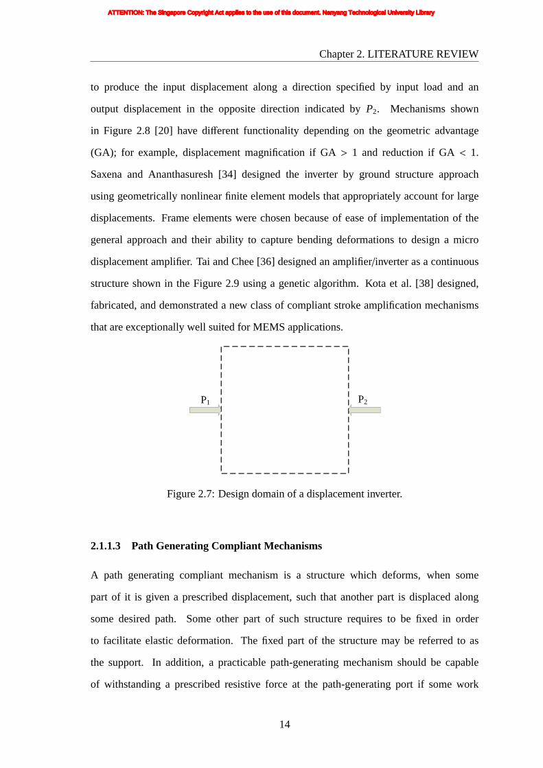
2.7 Design domain of a displacement inverter. . . . . . . . . . . . . . . . . . 14
2.8 Optimal solution and deformation of displacement inverters. . . . . . . . 15
2.9 Displacement amplifier mechanism. . . . . . . . . . . . . . . . . . . . . 15
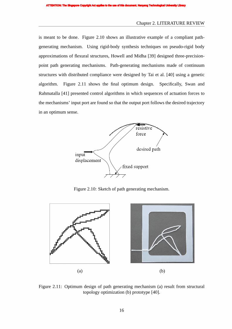
2.10 Sketch of path generating mechanism. . . . . . . . . . . . . . . . . . . . 16
2.11 Optimum design of path generating mechanism (a) result from structural
topology optimization (b) prototype. . . . . . . . . . . . . . . . . . . . . 16
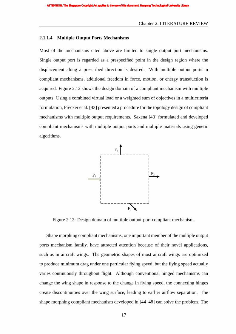
2.12 Design domain of multiple output-port compliant mechanism. . . . . . . 17
2.13 Optimum design of shape morphing compliant mechanisms. . . . . . . . 18
2.14 Gripper mechanism that (a) holds and (b) releases/places workpiece and
exhibits snap-through behavior. . . . . . . . . . . . . . . . . . . . . . . . 19
2.15 A polypropylene prototype of the grasp and pull gripper design. . . . . . 20
2.16 Optimal topology: (a) optimal mechanism based on linear theory; (b)
complete gripper design and elements under compression and tension;
(c) optimal mechanism based on nonlinear theory; (d) complete gripper
design and elements under compression and tension. . . . . . . . . . . . 21
2.17 Design domain of 2-DOF mechanism. . . . . . . . . . . . . . . . . . . . 24
2.18 Two-input two-output compliant mechanism. . . . . . . . . . . . . . . . 24
2.19 (a) Design domain for a 2-DOF micro-scanner, (b) Topology optimized
actuator composed of Nickel, and (c) Topology optimized 2-DOF actuator
composed of Nickel and a material with half the Young’s modulus and
half the thermal conductivity of Nickel. . . . . . . . . . . . . . . . . . . 24
2.20 Conceptual design of a 2-DOF compliant mechanism. . . . . . . . . . . . 25
2.21 Two-axis planar compliant mechanism design. . . . . . . . . . . . . . . . 25
2.22 Truss ground structure. . . . . . . . . . . . . . . . . . . . . . . . . . . . 31
2.23 A unit cell of a microstructure. . . . . . . . . . . . . . . . . . . . . . . . 32
VIII
ATTENTION: The Singapore Copyright Act applies to the use of this document. Nanyang Technological University Library
List of Figures
2.24 (a) Surface and the x-y plane; (b) Partition of design domain. . . . . . . . 34
2.25 Mapping from chromosome into topology: (a) corresponding binary
values and (b) resulting topology. . . . . . . . . . . . . . . . . . . . . . . 35
3.1 Mechanism with boundary conditions. . . . . . . . . . . . . . . . . . . . 59
3.2 Comparison between ABAQUS and newly developed program. . . . . . . 60
4.1 Sketch of a grip-and-move manipulator. . . . . . . . . . . . . . . . . . . 62
4.2 Design space for symmetric path mechanism. . . . . . . . . . . . . . . . 63
4.3 Deviation between the left and right halves of path. . . . . . . . . . . . . 64
4.4 Definition of structural geometry by morphological scheme. . . . . . . . 69
4.5 Thickness of ‘Flesh’ added to skeleton elements. . . . . . . . . . . . . . 70
4.6 Chromosome code . . . . . . . . . . . . . . . . . . . . . . . . . . . . . 71
4.7 Some examples of crossover loops. . . . . . . . . . . . . . . . . . . . . . 72
4.8 Example of crossover operation. . . . . . . . . . . . . . . . . . . . . . . 72
4.9 Mutation operation. . . . . . . . . . . . . . . . . . . . . . . . . . . . . . 73
4.10 Crowding distance calculation. . . . . . . . . . . . . . . . . . . . . . . . 77
4.11 Three non-dominated solutions at 500th generation. . . . . . . . . . . . . 81
4.12 Chromosome code of the optimal result with best combined objective. . . 82
4.13 Input/output/control points and Bezier curves of the optimal result with
best combined objective. . . . . . . . . . . . . . . . . . . . . . . . . . . 82
4.14 Compliant grip-and-move manipulator (a) arrangement (b) prototype (c)
symmetric paths from the FE analysis and prototype (Run 1). . . . . . . . 84
4.15 Sample solutions from the initial (randomly generated) population. . . . . 85
4.16 Best feasible solutions from sample intermediate generations. . . . . . . . 86
4.17 History of the best path objective (fpath). . . . . . . . . . . . . . . . . . . 87
4.18 History of the best combined objective (fcom). . . . . . . . . . . . . . . . 87
4.19 History of the best GA objective (fGA). . . . . . . . . . . . . . . . . . . . 88
4.20 Plot of non-dominated solutions and elites at some sample generations. . . 89
4.21 Plot of cumulative non-dominated front up to some sample generations. . 90
4.22 Three non-dominated solutions at 500th generation. . . . . . . . . . . . . 91
4.23 Chromosome code of the optimal result with best combined objective. . . 92
4.24 Input/output/control points and Bezier curves of the optimal result with
best combined objective. . . . . . . . . . . . . . . . . . . . . . . . . . . 92
4.25 Compliant grip-and-move manipulator (a) arrangement (b) prototype (c)
symmetric paths from the FE analysis and prototype (Run 2). . . . . . . . 93
4.26 Sample solutions from the initial (randomly generated) population. . . . . 93
4.27 Best feasible solutions from sample intermediate generations. . . . . . . . 94
4.28 History of the best path objective (fpath). . . . . . . . . . . . . . . . . . . 95
4.29 History of the best combined objective (fcom). . . . . . . . . . . . . . . . 95
IX
ATTENTION: The Singapore Copyright Act applies to the use of this document. Nanyang Technological University Library

List of Figures
4.30 History of the best GA objective (fGA). . . . . . . . . . . . . . . . . . . . 96
4.31 Plot of non-dominated solutions and elites at some sample generations. . . 97
4.32 Comparison of non-dominated fronts between Run 3 and Run 2. . . . . . 98
4.33 Three non-dominated solutions at 500th generation. . . . . . . . . . . . . 99
4.34 Chromosome code of the optimal result with best combined objective. . . 100
4.35 Input/output/control points and Bezier curves of the optimal result with
best combined objective. . . . . . . . . . . . . . . . . . . . . . . . . . . 100
4.36 Compliant grip-and-move manipulator (a) arrangement (b) prototype (c)
symmetric paths from the FE analysis and prototype (Run 3). . . . . . . . 101
4.37 Sample solutions from the initial (randomly generated) population. . . . . 101
4.38 Best feasible solutions from sample intermediate generations. . . . . . . . 102
4.39 History of the best path objective (fpath). . . . . . . . . . . . . . . . . . . 103
4.40 History of the best combined objective (fcom). . . . . . . . . . . . . . . . 103
4.41 History of the best GA objective (fGA). . . . . . . . . . . . . . . . . . . . 104
4.42 Plot of non-dominated solutions and elites at some sample generations. . . 105
4.43 Plot of cumulative non-dominated front up to some sample generations. . 106
5.1 Definition of structural geometry by morphological scheme. . . . . . . . 111
5.2 Chromosome code. . . . . . . . . . . . . . . . . . . . . . . . . . . . . . 112
5.3 Chromosome codes of crossover operation between parents. . . . . . . . 115
5.4 Outcome of crossover operation between parents. . . . . . . . . . . . . . 116
5.5 Mutation operation of on/off state. . . . . . . . . . . . . . . . . . . . . . 119
5.6 Non-dominated sets obtained using different algorithms. . . . . . . . . . 121
5.7 Non-dominated set far from the preferred portion of Pareto-optimal front. 121
5.8 The adaptive constraint method for conflicting objectives. . . . . . . . . . 123
5.9 The adaptive constraint method for Non-conflicting objectives. . . . . . . 124
5.10 Generation update mechanism. . . . . . . . . . . . . . . . . . . . . . . . 131
6.1 Design Space. . . . . . . . . . . . . . . . . . . . . . . . . . . . . . . . . 136
6.2 Target geometry. . . . . . . . . . . . . . . . . . . . . . . . . . . . . . . 137
6.3 Formulation of Target Matching Problem 1 with Non-conflicting Objectives.137
6.4 Other optimal solutions of the multimodal Target Matching Problem 1. . . 139
6.5 The solution space for Target Matching Problem 1. . . . . . . . . . . . . 140
6.6 Two solutions at 500th generation. . . . . . . . . . . . . . . . . . . . . . 141
6.7 Chromosome code of the results of Figure 6.6. . . . . . . . . . . . . . . . 142
6.8 Input/output/control points and Bezier curves of Figure 6.6. . . . . . . . . 143
6.9 Sample solutions from the initial (randomly generated) population. . . . . 144
6.10 Best feasible solutions from sample intermediate generations. . . . . . . . 144
6.11 History of the best distance objective. . . . . . . . . . . . . . . . . . . . 145
6.12 History of the best material objective. . . . . . . . . . . . . . . . . . . . 146
X
ATTENTION: The Singapore Copyright Act applies to the use of this document. Nanyang Technological University Library

List of Figures
6.13 Plot of cumulative non-dominated front up to some sample generations. . 146
6.14 Two solutions at 300th generation. . . . . . . . . . . . . . . . . . . . . . 147
6.15 Chromosome code of the results of Figure 6.14. . . . . . . . . . . . . . . 148
6.16 Input/output/control points and Bezier curves of Figure 6.14. . . . . . . . 149
6.17 Sample solutions from the initial (randomly generated) population. . . . . 149
6.18 Best feasible solutions from sample intermediate generations. . . . . . . . 150
6.19 History of the best distance objective. . . . . . . . . . . . . . . . . . . . 151
6.20 History of the best material objective. . . . . . . . . . . . . . . . . . . . 151
6.21 Plot of cumulative non-dominated front up to some sample generations. . 152
6.22 Target geometry. . . . . . . . . . . . . . . . . . . . . . . . . . . . . . . 157
6.23 Formulation of Target Matching Problem 2 with Conflicting Objectives. . 157
6.24 The solution space for Target Matching Problem 2. . . . . . . . . . . . . 158
6.25 Non-dominated solutions from 300 generations. . . . . . . . . . . . . . . 160
6.26 Chromosome code of the results of Figure 6.25 (a) and (b) respectively. . 161
6.27 Input/output/control points and Bezier curves of Figure 6.25. . . . . . . . 162
6.28 Sample solutions from the initial (randomly generated) population. . . . . 162
6.29 Best feasible solutions from sample intermediate generations. . . . . . . . 163
6.30 History of the best void objective. . . . . . . . . . . . . . . . . . . . . . 164
6.31 History of the best material objective. . . . . . . . . . . . . . . . . . . . 164
6.32 Plot of non-dominated solutions and elites at some sample generations. . . 165
6.33 Plot of cumulative non-dominated front up to some sample generations. . 166
6.34 Design space. . . . . . . . . . . . . . . . . . . . . . . . . . . . . . . . . 167
6.35 Target geometry. . . . . . . . . . . . . . . . . . . . . . . . . . . . . . . 168
6.36 Formulation of Target Matching Problem 3 with Conflicting Objectives. . 168
6.37 The solution space for Target Matching Problem 3. . . . . . . . . . . . . 169
6.38 Non-dominated solutions from 300 generations. . . . . . . . . . . . . . . 171
6.39 Chromosome code of the results of Figure 6.38 (a) and (b) respectively. . 172
6.40 Input/output/control points and Bezier curves of Figure 6.38 (a) and (b)
respectively. . . . . . . . . . . . . . . . . . . . . . . . . . . . . . . . . . 173
6.41 Sample solutions from the initial (randomly generated) population. . . . . 173
6.42 Best feasible solutions from sample intermediate generations. . . . . . . . 174
6.43 History of the best void objective. . . . . . . . . . . . . . . . . . . . . . 175
6.44 History of the best material objective. . . . . . . . . . . . . . . . . . . . 175
6.45 Plot of non-dominated solutions and elites at some sample generations. . . 176
6.46 Plot of cumulative non-dominated front up to some sample generations. . 176
6.47 Target geometry. . . . . . . . . . . . . . . . . . . . . . . . . . . . . . . 178
6.48 Formulation of Target Matching Problem 4 with Conflicting Objectives. . 178
6.49 The solution space for Target Matching Problem 4. . . . . . . . . . . . . 179
6.50 Non-dominated solutions from 300 generations. . . . . . . . . . . . . . . 181
XI
ATTENTION: The Singapore Copyright Act applies to the use of this document. Nanyang Technological University Library
List of Figures
6.51 Chromosome code of the results of Figure 6.50 (a) and (b) respectively. . 182
6.52 Input/output/control points and Bezier curves of Figure 6.50 (a) and (b)
respectively.. . . . . . . . . . . . . . . . . . . . . . . . . . . . . . . . . 183
6.53 Sample solutions from the initial (randomly generated) population. . . . . 183
6.54 Best feasible solutions from sample intermediate generations. . . . . . . . 184
6.55 History of the best void objective. . . . . . . . . . . . . . . . . . . . . . 185
6.56 History of the best material objective. . . . . . . . . . . . . . . . . . . . 185
6.57 Plot of non-dominated solutions and elites at some sample generations . . 186
6.58 Plot of cumulative non-dominated front up to some sample generations. . 186
7.1 Sketch of a manipulator. . . . . . . . . . . . . . . . . . . . . . . . . . . 188
7.2 Design space. . . . . . . . . . . . . . . . . . . . . . . . . . . . . . . . . 189
7.3 Output area calculation. . . . . . . . . . . . . . . . . . . . . . . . . . . . 190
7.4 Unfavorable output area. . . . . . . . . . . . . . . . . . . . . . . . . . . 190
7.5 Geometric Advantage calculation. . . . . . . . . . . . . . . . . . . . . . 192
7.6 Three non-dominated solutions at 500th generation. . . . . . . . . . . . . 195
7.7 Chromosome code of the optimal result of Figure 7.6 (a) and (b)
respectively. . . . . . . . . . . . . . . . . . . . . . . . . . . . . . . . . . 196
7.8 Input/output/control points and Bezier curves of Figure 7.6 (a) and (b)
respectively. . . . . . . . . . . . . . . . . . . . . . . . . . . . . . . . . . 197
7.9 Compliant grip-and-move manipulator – design with best area objective
(Run 1). . . . . . . . . . . . . . . . . . . . . . . . . . . . . . . . . . . . 199
7.10 View of compliant grip-and-move manipulator (long distance output). . . 200
7.11 View of compliant grip-and-move manipulator (big overlapped area). . . . 200
7.12 Compliant grip-and-move manipulator – design with median area and
distance objective (Run 1). . . . . . . . . . . . . . . . . . . . . . . . . . 201
7.13 View of compliant grip-and-move manipulator. . . . . . . . . . . . . . . 202
7.14 Sample solutions from the initial (randomly generated) population. . . . . 203
7.15 Best feasible solutions from sample intermediate generations. . . . . . . . 204
7.16 History of the best area objective (farea). . . . . . . . . . . . . . . . . . . 205
7.17 History of the best distance objective (fd). . . . . . . . . . . . . . . . . . 205
7.18 Plot of non-dominated solutions and elites at some sample generations. . . 206
7.19 Plot of cumulative non-dominated front up to some sample generations. . 206
7.20 Three non-dominated solutions at 500th generation. . . . . . . . . . . . . 207
7.21 Chromosome code of the optimal result of Figure 7.20 (a) and (b)
respectively. . . . . . . . . . . . . . . . . . . . . . . . . . . . . . . . . . 209
7.22 Input/output/control points and Bezier curves of Figure 7.20 (a) and (b)
respectively. . . . . . . . . . . . . . . . . . . . . . . . . . . . . . . . . . 210
XII
ATTENTION: The Singapore Copyright Act applies to the use of this document. Nanyang Technological University Library

List of Figures
7.23 Compliant grip-and-move manipulator – design with best area objective
(Run 2). . . . . . . . . . . . . . . . . . . . . . . . . . . . . . . . . . . . 211
7.24 View of compliant grip-and-move manipulator. . . . . . . . . . . . . . . 212
7.25 Compliant grip-and-move manipulator – design with the median area and
distance objective (Run 2). . . . . . . . . . . . . . . . . . . . . . . . . . 214
7.26 View of compliant grip-and-move manipulator (long distance output). . . 215
7.27 View of compliant grip-and-move manipulator (big overlapped area). . . . 215
7.28 Sample solutions from the initial (randomly generated) population. . . . . 216
7.29 Best feasible solutions from sample intermediate generations. . . . . . . . 217
7.30 History of the best area objective (farea). . . . . . . . . . . . . . . . . . . 218
7.31 History of the best distance objective (fd). . . . . . . . . . . . . . . . . . 218
7.32 Plot of non-dominated solutions and elites at some sample generations. . . 219
7.33 Plot of cumulative non-dominated front up to some sample generations. . 219
7.34 Three non-dominated solutions at 500th generation. . . . . . . . . . . . . 220
7.35 Chromosome code of the optimal result of Figure 7.34 (a). . . . . . . . . 221
7.36 Input/output/control points and Bezier curves of Figure 7.34 . . . . . . . 221
7.37 Compliant grip-and-move manipulator – design with best area objective
(Run 3). . . . . . . . . . . . . . . . . . . . . . . . . . . . . . . . . . . . 223
7.38 View of compliant grip-and-move manipulator. . . . . . . . . . . . . . . 224
7.39 Sample solutions from the initial (randomly generated) population. . . . . 224
7.40 Best feasible solutions from sample intermediate generations. . . . . . . . 225
7.41 History of the best area objective (farea). . . . . . . . . . . . . . . . . . . 226
7.42 History of the best distance objective (fd). . . . . . . . . . . . . . . . . . 226
7.43 Plot of non-dominated solutions and elites at some sample generations. . . 227
7.44 Plot of cumulative non-dominated front up to some sample generations. . 227
XIII
ATTENTION: The Singapore Copyright Act applies to the use of this document. Nanyang Technological University Library

List of Tables
2.1 Benchmarked Flexible Translational Joints . . . . . . . . . . . . . . . . . 28
2.2 Benchmarked Flexible revolute Joints . . . . . . . . . . . . . . . . . . . 28
3.1 Elastic Moduli Transformation Relations for Conversion Between Plane
Stress and Plane Strain Problems . . . . . . . . . . . . . . . . . . . . . . 56
3.2 Comparison Result . . . . . . . . . . . . . . . . . . . . . . . . . . . . . 59
6.1 Simulation Results of 8 Trials of Each Strategy . . . . . . . . . . . . . . 154
XIV
ATTENTION: The Singapore Copyright Act applies to the use of this document. Nanyang Technological University Library

List of Abbreviation and Symbols
MEMS Micro Electro Mechanical Systems
DOF Degree of Freedom
CCM Contact-aided Compliant Mechanism
ESO evolutionary structural optimization
EA evolutionary algorithm
GA Geometric Advantage
FEM Finite Element Method
E Young’s modulus
ν Poisson’s ratio
B strain-displacement matrix
D elasticity matrix
a displacement vector
N shape function matrix
S the second Piola-Kirchhoff stress tensor
E Green-Lagrange strain tensor
b0 body force vector
q0 traction force vector
F deformation gradient matrix
σy Yield stress
XV
ATTENTION: The Singapore Copyright Act applies to the use of this document. Nanyang Technological University Library
Chapter 1
INTRODUCTION
In this chapter, the title of the thesis is explained. Compliant mechanisms are introduced
and compared with conventional mechanisms. The chapter also explains objectives and
scope of the present work. At the end, organization of the thesis is given.
1.1 BACKGROUND
1.1.1 Introduction to Compliant Mechanisms
Compliant mechanisms are flexible structures that deliver a desired motion by undergoing
elastic deformation, as opposed to the rigid body motions of conventional mechanisms.
Like a rigid-body mechanism, a compliant mechanism also transfers force and/or energy
from a source to an output. Unlike rigid-link mechanisms, compliant mechanisms gain at
least some of their mobility through the deflection of flexible members instead of through
rigid links and movable joints. A comparison of simple gripping mechanisms is shown
in Figure 1.1. The rigid-body gripper consists of rigid links and permits relative motion
between its rigid links, while a compliant gripper gains its mobility through a flexural
pivot. The input force is transferred to the output port and some energy is stored in the
form of strain energy in the flexible members. Note that if the entire device was rigid, it
would have no mobility and it would be a structure.
In the natural world, flexibility provides a multidimensional world of opportunities for
designing structures that change shape in highly useful ways. The natural world is full of
“compliant mechanisms”. Look at the ears of cattle, which in some cases can be used to
1
ATTENTION: The Singapore Copyright Act applies to the use of this document. Nanyang Technological University Library

Chapter1. INTRODUCTION
input force/displacement
output force/displacement rigid links
movable rigid joint
input force/displacement
output force/displacement
flexible member
flexural pivot
Rigid-body Mechanism (Gripper)
input force/displacement
input force/displacement
Compliant Mechanism (Gripper)
Figure1.1: Comparison of a rigid-body gripper with a compliant gripper.
drive away flies for them. Muscles pull on cartilage, and then twist the ears to flap as they
want. However, the engineering world has traditionally limited itself to rigid structures
and mechanisms. Even in cases where the compliance or adaptability of a structure is
needed, rigid elements and actuators are employed to simulate compliance.
1.1.2 Advantages and Disadvantages of Compliant Mechanisms
When compliance is included as a preferred effect, they offer distinct advantages over
conventional rigid-link mechanisms. The following is a list of some of the advantages
and disadvantages of compliant mechanisms [1–3].
Advantages of compliant systems:
i Reduction in number of parts: unlike their rigid-link mechanism counterparts,
compliant mechanisms can be designed as single-piece entities without joints.
ii Easier to manufacture because little or no assembly is required.
2
ATTENTION: The Singapore Copyright Act applies to the use of this document. Nanyang Technological University Library

Chapter1. INTRODUCTION
iii Elimination of joint friction, need for lubrication, and backlash due to joint
clearances
iv Can efficiently take advantage of modern actuators, such as piezoelectric, shape-
memory alloy, electro-thermal, electrostatic, fluid pressure, and electromagnetic
actuators
v Can create motions for shape changing structures not possible with conventional
‘rigid’ devices
vi Scalable: successful compliant systems have been implemented in the micro, meso,
and macro scales
vii Materials friendly: can be used with virtually any highly resilient material,
including steel, aluminum, high-strain nickel-titanium alloys, polysilicon, delrin,
ABS, polypropylene etc.
viii No need for restoring springs or pin-clevis hinges - potential for weight reduction
Disadvantages of compliant systems:
i Limited to applications with finite (often small) rotations and displacements
ii Functionality can be affected by external loads
iii Fatigue, hysteresis, and creep can limit performance and/or durability
iv Difficult to design because the relationship between their geometry and their elastic
behavior is highly complex and non-linear.
1.1.3 Application of Compliant Mechanisms
As such, compliant mechanisms have many advantages compared to conventional rigid-
link mechanisms and so can be created as a replacement for their rigid-link counterparts.
Although engineered compliant mechanisms/systems have been used for over a century
3
ATTENTION: The Singapore Copyright Act applies to the use of this document. Nanyang Technological University Library

Chapter1. INTRODUCTION
in specialized applications, recent advances in synthesis and modelling tools have
enabled the practical use of this technology beyond academic research and specialized
applications.
The applications of compliant mechanisms are varied and practically unlimited.
Any device that uses springs, joints or pins can be a potential benefactor of compliant
mechanisms. A variety of devices could be made cheaper or easier with flexible parts.
Things like grippers, pliers, clamp, crimper, displacement inverters/amplifiers, logic
gates, switches, clutches and robot arms can be designed and manufactured.
Compliant mechanisms are useful in applications both in the macro domain and
in the micro domain, for instance, for high precision manipulation stages, instruments
for minimally invasive surgery, and Micro-Electro-Mechanical Systems (MEMS). The
combination of structural stiffness and flexibility allows compliant mechanisms to replace
rigid connections effectively in a number of applications [4–9], including:
i Medical devices: As compliant mechanisms are closer to the natural world, they
can be used to mimic a lot of natural things. For example, compliant mechanisms
offer a low-cost alternative for joints in prosthetic and physical therapy devices.
In addition, compliant mechanisms can duplicate the rotational movement and
flexibility of a natural joint by providing resistance that is similar to human limbs.
Good shock absorption also helps to provide a more natural feel. Compliant
mechanisms with differing degree-of-freedom (DOF) can be developed to simulate
several physical joints including the knee, hip, and ankle.
ii Robotics: Robots perform an array of tasks in numerous industry applications.
Compliant mechanisms can provide robotic arms and end-of-arm tooling with
sufficient flexibility to move in any direction and rotate about any axis while
compressing and absorbing any misalignment. This enables robots to mimic human
capabilities used in manipulating objects and can help prevent damage to precision
components during assembly operations.
iii Bumper systems: Manufacturers and insurers alike recognize that energy
4
ATTENTION: The Singapore Copyright Act applies to the use of this document. Nanyang Technological University Library

Chapter1. INTRODUCTION
absorptionis a key design criterion for vehicle bumper systems. The shock
absorption properties provided by compliant mechanisms facilitate safe and cost-
effective bumper system designs. With shock absorption properties, compliant
mechanisms are an effective, low-cost replacement for the polypropylene foams
and plastic honeycombs frequently used for energy absorption.
iv Commercial and industrial equipment: windshield wiper, aerosol can and sporting
goods and recreational equipment like training shoes, skates and bindings, etc.
v MEMS/NEMS: Compliant mechanisms show great potential especially in
MEMS/NEMS applications because MEMS/NEMS devices are manufactured
on the sub-millimeter scale and therefore cannot contain any complex joints.
MEMS are small, compliant devices for mechanical and electrical applications.
BioMEMS is an enabling MEMS technology for ever-greater functionality and cost
reduction in smaller devices for biomedical applications, such as improved medical
diagnostics and therapies.
1.1.4 Current Need for Compliant Mechanisms Development
Now, compliant mechanisms thrive with introduction of materials with superior properties
and development of micro-mechanisms such as MEMS, bio-MEMS, NEMS. In particular,
compliant micro-grippers can be used for manipulation and assembly of electronic and
optical micro-components, as well as for biological samples as in single cell manipulation,
positioning and isolation. The use of mechanical micro-grippers that securely grip and
transport objects to the desired location is also advantageous because it avoids optical or
electrical interference with the object which may be a problem with other technologies
such as optical tweezers, etc.
Compliant mechanisms have been designed at Brigham Young University, University
of Michigan, Technical University of Denmark, Compliant Mechanisms Design and
Optimization Laboratory - George Washington University, University of Pennsylvania,
Optimal Design of Adaptive Compliant Structures Lab - Penn State University, the
5
ATTENTION: The Singapore Copyright Act applies to the use of this document. Nanyang Technological University Library

Chapter1. INTRODUCTION
NationalCreative Research Initiatives Center for Multi-scale Design and Computational
Modelling and Design Laboratory of the Chinese University of Hong Kong. In NTU
(Nanyang Technology University), much work is being done to realize the strong potential
of optimization technology by applying it in compliant mechanism design.
Most of the mechanisms developed so far are one DOF mechanisms and the output
displacements are small. They can only do simple work such as gripping. In that case,
the compliant mechanisms are more like compliant structures than mechanisms. The
simplicity of the output and the range of the output limits the application. Some multi-
DOF compliant mechanisms, such as Nanomanipulator and MEMS Nanopositioner, are
developed by heuristic approaches. To realize the full potential of compliant mechanisms,
more complicated multi-DOF mechanisms can be designed, but only by using systematic
design synthesis methods.
1.1.5 Introduction to Design Methods
Compliant mechanical devices can provide distinct advantages over conventional rigid-
link devices, but including compliance complicates the design process. Engineers have
not yet fully utilized this concept of intentional compliance in design, partly due to a
lack of systematic design methods. In order to design a compliant mechanism for a
particular task, it is necessary to determine a suitable structural form, i.e., topology, shape,
and size of the material using a systematic synthesis method. Two main approaches
have been developed for systematic synthesis and design of compliant mechanisms, a
kinematic approach and a topology optimization approach. The kinematic approach is
useful for modelling and analysis of lumped or partially compliant mechanisms. The
topology optimization approach predicts a compliant mechanism form based on the input-
output force deflection requirements. Optimization methods based on genetic algorithms
have recently been applied to various structural problems, and have demonstrated the
potential to overcome many of the problems associated with gradient based methods.
Genetic algorithm is a powerful technique for search and optimization problems, and are
6
ATTENTION: The Singapore Copyright Act applies to the use of this document. Nanyang Technological University Library

Chapter1. INTRODUCTION
particularlyuseful in the optimization of compliant mechanisms.
1.2 OBJECTIVES OF THIS RESEARCH
Gripping and moving objects are the important functions in assembly and manipulating
tasks typically accomplished by robots. But these conventional mechanisms are expensive
and complicated. Also, compliant manipulators are necessary if small/micro size desired.
Realizing these two functions within a single compliant mechanism will be attractive
and promising. The objective of this research is to formulate the design problem of
designing compliant mechanisms exhibiting both gripping and moving behavior (i.e. grip-
and-move manipulators), and to design these mechanisms through a process of structural
optimization.
The specific research objectives include:
i To develop enhanced morphological geometry representation representing the
structural geometry of a compliant mechanism.
ii To incorporate into the genetic algorithm an optimization-level decision-making
technique to integrate the user’s preference and hybridize it with a local search (LS)
strategy to improve its efficiency.
iii To develop suitable test problems to test and tune genetic algorithm.
iv To design two conceptually different types of grip-and-move manipulators by
structure topology optimization, one can grip a work piece and convey it to
anywhere on the desired line path while the other can grip a workpiece and convey
it to anywhere within its two-dimensional working area.
1.3 SCOPE
This work will look into various aspects in the development of a methodology to automate
the process of designing grip-and-move manipulators. The scope of the work involves the
7
ATTENTION: The Singapore Copyright Act applies to the use of this document. Nanyang Technological University Library

Chapter1. INTRODUCTION
following:
i In this work, the performance characteristics of every design would be computed
by a large-displacement non-linear finite element analysis of the designed structure,
and the finite element method and the overall optimization procedure would be
implemented on a C++ program.
ii The structural geometry of a compliant mechanism would be represented by using
a morphological representation scheme which encodes the geometry as a graph
having design variables at its vertices. This graph would be used as a chromosome
for the reproduction operations. Enhanced geometry representation schemes for
defining the geometry of the design structures would increase the representation
variability.
iii As for the optimization process, a novel approach would be incorporated into the
genetic algorithm to treat the relatively more challenging objectives as constraints
whose ideal values will be adaptively changed (improved) during the evolutionary
procedure. This helps to direct and focus the genetic search towards regions of
interest in the objective space, thus is a useful and intuitive way for specifying
the user’s preference and/or for tackling the harder objectives since the mechanism
design problem is a computationally challenging problem.
iv A test problem emulating structural topology optimization that does not need finite
element structural analysis is to be formulated. Such test problems referred to as
‘Target Matching Problems’ with conflicting/non-conflicting objectives would be
constructed to test and tune the genetic algorithm for solving the actual mechanism
design problem.
v Two conceptually different types of grip and move compliant mechanisms are to
be designed by developing the appropriate design problem formulation for them.
New optimization criteria for designing compliant grip-and-move manipulators
would be formulated. Two identical symmetric path-generating mechanisms can
8
ATTENTION: The Singapore Copyright Act applies to the use of this document. Nanyang Technological University Library

Chapter1. INTRODUCTION
bearranged to construct a grip-and-move manipulator which can grip a work piece
and convey it to anywhere on the desired line path. And a second type of compliant
grip-and-move manipulators by the employment of two identical path generating
mechanisms with two degrees-of-freedom can grip a workpiece and convey it to
anywhere within its two-dimensional working area. Prototypes made from the
designs optimized in a 100 by 100mm square design space would be fabricated. The
prototypes would be actuated to effect the deformation, and the displacements of the
output point would be measured and plotted for comparison with the displacement
path obtained via the FE analysis.
1.4 ORGANIZATION OF THESIS
The thesis starts with the present chapter, which introduces compliant mechanism
and compares it with conventional (rigid-body) mechanisms. Topology optimization
as a design approach has also been introduced in this chapter. In Chapter 2, the
previous literature pertaining to compliant mechanism and optimization method is
presented. Nonlinear formulations of the geometrically nonlinear finite element analysis
are documented in Chapter 3. Chapter 4 demonstrates the automatic design of a compliant
grip-and-move manipulator using a previously proposed genetic algorithm coupled with a
morphological representation for defining and encoding the structural geometry variables.
It presents a novel idea to integrate grip and move behavior in one simple mechanism.
The enhanced morphological representation of structural design geometry is explained
in Chapter 5. It also explains a new developed genetic algorithm. Chapter 6 focuses on
testing and tuning of the optimization methodology using “Target Matching Problems”.
Chapter 7 is an attempt to design compliant grip-and-move manipulators with two
path generating mechanisms of 2-DOF each. A list of recommended topics for future
investigations is provided in Chapter 8 and it concludes the work presented.
9
ATTENTION: The Singapore Copyright Act applies to the use of this document. Nanyang Technological University Library
Chapter 2
LITERATURE REVIEW
Compliant mechanisms and methods used to design compliant mechanisms are reviewed
in this chapter. Different types of compliant mechanisms are classified according to their
output. Recent advances in compliant mechanisms are briefly described. Methods used to
design compliant mechanisms, kinematic method and topology optimization method, are
investigated. The chapter also provides an extensive discussion on application of genetic
algorithm to topology optimization and on the principles of constrained multiobjective
optimization.
2.1 DIFFERENT TYPES OF COMPLIANT
MECHANISMS
Compliant mechanisms are single-piece jointless structures that use compliance (i.e.
elastic deformation) as a means to achieve motion. As mentioned in Chapter 1, compliant
mechanisms are scalable, so the mechanisms listed below are suitable for micro, meso,
and macro scales. And here they are classified according to their output.
2.1.1 Smooth Output Mechanisms
2.1.1.1 Grippers/Clamps/Crimpers/Pliers
Grippers, pliers, crimping and clamping mechanisms are mostly one input one output
mechanisms. Their difference lies in the direction of Input/Output (I/O). Their output,
force or displacement, is smooth. Among them, grippers are the most studied because
of their highly successful application. Figure 2.1 shows the design domain of a gripper
10
ATTENTION: The Singapore Copyright Act applies to the use of this document. Nanyang Technological University Library

Chapter2. LITERATURE REVIEW
wherespecifications are as indicated.
P1
F1
F2
Figure2.1: Design domain of a gripper.
Based on the kinematic method, Tsai at al. [10] designed a planar compliant
microgripper as shown in Figure 2.2. Flexure-based grippers are also found in [11–14]
for different applications. A novel compliant robotic grasper constructed using polymer-
based shape deposition manufacturing was created in [14]. Joints are formed by
elastomeric flexures and actuator and sensor components are embedded in tough rigid
polymers. The result is a robot gripper with the functionality of conventional metal
prototypes for grasping in unstructured environments but with robustness properties that
allow for large forces occurring due to inadvertent contact. Shih and Lin [15] integrated
the analytic single-axis flexure hinge with topology optimization as a second-stage design
process to obtain optimum flexure configuration and location for promoting the overall
performance of a compliant microgripper.
Figure2.2: A planar compliant gripper and and its corresponding kinematic sketch [10].
11
ATTENTION: The Singapore Copyright Act applies to the use of this document. Nanyang Technological University Library

Chapter2. LITERATURE REVIEW
Basedon topology optimization method, grippers have been created in [16–22]. A
sparse, hinge-free, aluminium designs of grippers designed by Rahmatalla and Swan [21]
is shown in Figure 2.3. Microgripper [23–30] is of great interest when manipulating
small objects such as electronic devices or small cells for biological applications and
minimally invasive surgery. Such grippers must have high accuracy in micropositioning,
a large stroke to grasp different objects, and be able to exploit electrostatic forces in order
to avoid high power consumption. Figure 2.4 shows a microgripper optimized by the
building block method [30] and its rigid body counterpart. One of the major problems in
the left microgripper is the use of pin joints. A single-piece, compliant structure shown
on the right could avoid such problems.
Figure 2.3: (a) Aluminium design of compliant gripper and (b) its deformedconfiguration [21].
Figure2.4: Microgripper [30].
Compliant clamps, crimpers, and pliers are reported in [2,31–35]. The design domain
12
ATTENTION: The Singapore Copyright Act applies to the use of this document. Nanyang Technological University Library

Chapter2. LITERATURE REVIEW
of a push-clamp is sketched in Figure 2.5 where the mechanism is subject to a vertical
squeezing load at the upper and lower right corners. The output port is shown where an
output force is desired. Pull-clamp is similar to push-clamp, except that the input force is
a pulling force. Figure 2.6 shows the clamp developed by Wang et al. [31].
Fout
Fin
Fin
Figure2.5: Design domain of a compliant push-clamp.
(a) (b)
Figure2.6: (a) Compliant push-clamp; (b) Compliant pull-clamp [31].
2.1.1.2 Displacement Inverters/Amplifiers
An important design problem in compliant mechanisms is the design of displacement
amplifier/inverter. A displacement amplifier can convert the small input displacement
of a actuator to a larger output displacement. A displacement inverter is a mechanism
used to change the direction of actuating displacement. Inverter mechanisms have been
created in [2, 16–18, 20–22, 31, 32, 34, 36–38]. Figure 2.7 shows the design domain
where specifications are as indicated. When the input loadP1 is applied, it is required
13
ATTENTION: The Singapore Copyright Act applies to the use of this document. Nanyang Technological University Library
Chapter2. LITERATURE REVIEW
to produce the input displacement along a direction specified by input load and an
output displacement in the opposite direction indicated byP2. Mechanisms shown
in Figure 2.8 [20] have different functionality depending on the geometric advantage
(GA); for example, displacement magnification if GA> 1 and reduction if GA< 1.
Saxena and Ananthasuresh [34] designed the inverter by ground structure approach
using geometrically nonlinear finite element models that appropriately account for large
displacements. Frame elements were chosen because of ease of implementation of the
general approach and their ability to capture bending deformations to design a micro
displacement amplifier. Tai and Chee [36] designed an amplifier/inverter as a continuous
structure shown in the Figure 2.9 using a genetic algorithm. Kota et al. [38] designed,
fabricated, and demonstrated a new class of compliant stroke amplification mechanisms
that are exceptionally well suited for MEMS applications.
P1 P2
Figure2.7: Design domain of a displacement inverter.
2.1.1.3 Path Generating Compliant Mechanisms
A path generating compliant mechanism is a structure which deforms, when some
part of it is given a prescribed displacement, such that another part is displaced along
some desired path. Some other part of such structure requires to be fixed in order
to facilitate elastic deformation. The fixed part of the structure may be referred to as
the support. In addition, a practicable path-generating mechanism should be capable
of withstanding a prescribed resistive force at the path-generating port if some work
14
ATTENTION: The Singapore Copyright Act applies to the use of this document. Nanyang Technological University Library

Chapter2. LITERATURE REVIEW
Figure2.8: Optimal solution and deformation of displacement inverters [20].
Figure2.9: Displacement amplifier mechanism [36].
15
ATTENTION: The Singapore Copyright Act applies to the use of this document. Nanyang Technological University Library
Chapter2. LITERATURE REVIEW
is meant to be done. Figure 2.10 shows an illustrative example of a compliant path-
generating mechanism. Using rigid-body synthesis techniques on pseudo-rigid body
approximations of flexural structures, Howell and Midha [39] designed three-precision-
point path generating mechanisms. Path-generating mechanisms made of continuum
structures with distributed compliance were designed by Tai et al. [40] using a genetic
algorithm. Figure 2.11 shows the final optimum design. Specifically, Swan and
Rahmatalla [41] presented control algorithms in which sequences of actuation forces to
the mechanisms’ input port are found so that the output port follows the desired trajectory
in an optimum sense.
Figure2.10: Sketch of path generating mechanism.
(a) (b)
Figure2.11: Optimum design of path generating mechanism (a) result from structuraltopology optimization (b) prototype [40].
16
ATTENTION: The Singapore Copyright Act applies to the use of this document. Nanyang Technological University Library
Chapter2. LITERATURE REVIEW
2.1.1.4 Multiple Output Ports Mechanisms
Most of the mechanisms cited above are limited to single output port mechanisms.
Single output port is regarded as a prespecified point in the design region where the
displacement along a prescribed direction is desired. With multiple output ports in
compliant mechanisms, additional freedom in force, motion, or energy transduction is
acquired. Figure 2.12 shows the design domain of a compliant mechanism with multiple
outputs. Using a combined virtual load or a weighted sum of objectives in a multicriteria
formulation, Frecker et al. [42] presented a procedure for the topology design of compliant
mechanisms with multiple output requirements. Saxena [43] formulated and developed
compliant mechanisms with multiple output ports and multiple materials using genetic
algorithms.
P1
F1
F2
F3
Figure2.12: Design domain of multiple output-port compliant mechanism.
Shape morphing compliant mechanisms, one important member of the multiple output
ports mechanism family, have attracted attention because of their novel applications,
such as in aircraft wings. The geometric shapes of most aircraft wings are optimized
to produce minimum drag under one particular flying speed, but the flying speed actually
varies continuously throughout flight. Although conventional hinged mechanisms can
change the wing shape in response to the change in flying speed, the connecting hinges
create discontinuities over the wing surface, leading to earlier airflow separation. The
shape morphing compliant mechanism developed in [44–48] can solve the problem. The
17
ATTENTION: The Singapore Copyright Act applies to the use of this document. Nanyang Technological University Library

Chapter2. LITERATURE REVIEW
synthesisof shape morphing compliant mechanism is inherently different from the typical
single output design problems, due to the multiple output ports along the morphing
boundary. For situations emphasizing the shape difference, Lu and Kota [49] use a
modified Fourier Transformation instead of least square error to characterize and compare
the curves. Incorporating a binary ground structure representation, they developed
a genetic algorithm-based synthesis approach [50] and ‘load path representation’
method [51] to systematically design shape morphing compliant mechanisms. Figure 2.13
shows an illustrative example of a shape morphing compliant mechanism.
Optimized compliant mechanism using a target curve as the reference shape
InitialTargetdeformed
160
140
120
100
80
60
40
20
0
0 10 20 30 40 50 60 70 80 90 100
Figure2.13: Optimum design of shape morphing compliant mechanisms [50].
2.1.2 Non-smooth Output Mechanisms
Mostly available single-body compliant mechanisms can only generate smooth output
paths and smooth force-deflection curves with continuous input forces if buckling and
sudden changes in the constitutive properties of the material are not permitted. This
is a direct consequence of the continuous nature of the displacements in the elastic
continuum. In contrast, the vast variety of nonsmooth motions possible with rigid-
body jointed mechanisms is well known. In order to endow compliant mechanisms with
similar capabilities, bistable mechanisms and contact-aided compliant mechanisms are
introduced.
18
ATTENTION: The Singapore Copyright Act applies to the use of this document. Nanyang Technological University Library

Chapter2. LITERATURE REVIEW
2.1.2.1 Bistable Mechanisms
Bistable mechanisms make up a class of mechanisms which have two stable equilibrium
states within their range of motion. They require no power input to remain stable at
each equilibrium state. Because of their unique behavior, compliant members seem a
particularly efficient way to design bistable mechanisms. The structures in Figure 2.14
experience large configuration changes due to elevated load levels. It holds a workpiece
(denoted by the circle) then releases/places the workpiece (at the position denoted by the
square) after experiencing snap-through behavior. Design of bistable mechanisms require
more computational effort, demand more attention to their formulation, and are more
prone to computational difficulties than compliant mechanisms previously encountered.
Structures that exhibit snap-through behavior and behave like mechanisms were designed
in [52–57]. Such bistable structures are particularly attractive for actuation and sensing
applications, such as optical switches.
Figure 2.14: Gripper mechanism that (a) holds and (b) releases/places workpiece andexhibits snap-through behavior [53].
2.1.2.2 Contact-aided Mechanisms
A contact-aided compliant mechanism (CCM), which is a single-body elastic continuum,
uses intermittent contacts in addition to elastic deformation to transmit forces and
motion. It was done through intermittent contact between different parts of the elastic
body or with a rigid surface. Mankame and Ananthasuresh [58–60] designed such
19
ATTENTION: The Singapore Copyright Act applies to the use of this document. Nanyang Technological University Library

Chapter2. LITERATURE REVIEW
compliantmechanisms. Figure 2.15 presents a grasp and pull gripper realized with CCM.
Mechanical implementations of logic gates, which are the basic building blocks of digital
computation, have attracted renewed interest in the wake of increasing sophistication
achieved by microfabrication processes and the need for radiation-resistant secure
computing resources. Ananthasuresh et al. [35, 59] designed the AND and OR logic
gates with the concept of CCM.
Figure2.15: A polypropylene prototype of the grasp and pull gripper design in its original(left) and deformed (right) configurations [59].
2.1.3 Recent Advances in Compliant Mechanisms
Continuum topology optimization methods for compliant mechanisms have more recently
been extended to include geometrical non-linearity, multi materials, multi-physics, and
multi-degrees of freedom.
2.1.3.1 Geometrical Nonlinear Analysis
Optimal design methods that use continuum mechanics models are capable of generating
suitable topology, shape, and dimensions of compliant mechanisms for desired
specifications. A linear elastic response is assumed in most structural topology
optimization problems. While this assumption is valid for a wide variety of problems,
synthesis procedures that use linear elastic finite element models are not quantitatively
20
ATTENTION: The Singapore Copyright Act applies to the use of this document. Nanyang Technological University Library

Chapter2. LITERATURE REVIEW
accuratefor large displacement situations and structures using nonlinear materials. Also,
design specifications involving nonlinear force-deflection characteristics and generation
of a curved path for the output port cannot be realized with linear models. Buhl et
al. [61] used nonlinear analysis for stiffness optimization of a snap-through mechanism, a
compliant force inverter and path-generation mechanisms. Gea and his coworkers [62,63]
studied the stiffness optimization of geometrically nonlinear structure. Bruns and
Tortorelli [64] optimized the nonlinear elastic structures and compliant mechanisms
with MMA optimization algorithm. The benefits of using nonlinear methods for
large deformation problems have been illustrated by using some design examples and
comparing results from a nonlinear implementation of the optimization procedure with a
linear scheme [19, 65–68]. A significant improvement is reported in the optimal design
obtained using the non-linear analysis. Figure 2.16 plots the optimal topologies of a
mechanical gripper in their initial and deformed configurations that are obtained from
linear and non-linear analysis.
(a)
(d)(c)
(b)
Figure 2.16: Optimal topology: (a) optimal mechanism based on linear theory; (b)complete gripper design and elements under compression and tension; (c) optimalmechanism based on nonlinear theory; (d) complete gripper design and elements under
compression and tension. [19].
21
ATTENTION: The Singapore Copyright Act applies to the use of this document. Nanyang Technological University Library

Chapter2. LITERATURE REVIEW
2.1.3.2 Multi-materials
Only few papers have appeared on topology optimization of structures composed of more
than one material. But design of such structures is a good option to design compliant
mechanisms to be flexible and strong. The first motivation is that, using two or more
materials, it is possible to obtain large deformations without exceeding the strengths of the
materials. The second motivation for pursuing two-material compliant mechanism design
is the emergence of manufacturing methods that are capable of producing heterogeneous
parts without assembly and with strong inter-material interfaces. The third motivation
is to mimic Nature’s compliant designs that are usually made up of rigid and flexible
materials.
Yin and Ananthasuresh [69, 70] proposed a new material interpolation model, called
the peak function model, using a linear combination of normal distribution functions.
This model makes it easy to include multiple materials in the design without increasing
the design variables. The numerical examples are the two-phase, three-phase, and four-
phase materials where void is treated as one material. Sigmund [71, 72] reported an
automated method for the synthesis of multi-material, multi-degree-of-freedom micro
actuators. Buehler et al. [73] used a homogenization approach to find and use effective
material properties for the limiting case of an infinitely small microstructure. Wang et
al. [31, 74] proposed a level-set method for designing monolithic compliant mechanisms
made of multiple materials as an optimization of continuum heterogeneous structures.
2.1.3.3 Multi-physics
The phrase ‘multiple physics’ is here used to cover topology design where several physical
phenomena are involved in the problem statement, thus covering situations where, for
example, elastic, thermal and electromagnetic analyses are involved. When modelling
such situations, the basic concept of topology design provides a general framework
for computations, but here the initial obstacle is the need for interpolation of not only
stiffness but also other physical properties. Examples of thermo-elastic problems can
22
ATTENTION: The Singapore Copyright Act applies to the use of this document. Nanyang Technological University Library

Chapter2. LITERATURE REVIEW
be found in [71, 72, 75–77]. Unconventional actuation schemes, such as piezoelectric,
electrostatic, and shape-memory alloys (SMAs), seem to exhibit certain limitations in
terms of power density, stroke length, bandwidth, etc., when one attempts to employ
them directly to an application. Integrating them with mechanical transmission elements
so that the integrated actuator-transmission system matches the load characteristics of
the application can enhance the utility of such unconventional actuators. Kota et al. [78]
presented a systematic method of designing such unconventional mechanisms.
2.1.3.4 Multi DOF
Compliant mechanisms gain some or all their motion from the deflections of flexible
members. The concept of DOF is used to help obtain a preliminary design which may
then be optimized, and characterizes flexible-link mechanism. Reyes Rodriguez [79]
studied the evolution of well-known degrees of freedom equations. By degrees of freedom
is meant the number of independent inputs required to determinate the position of the
mechanism with respect to the ground. Compared to one-DOF compliant mechanisms,
the multi-DOF compliant mechanisms are much more complicated not only because of
the coupling of the output freedom and the control part but the formulation. Few papers
studied topology optimization of compliant mechanisms which have more than one degree
of freedom.
In order to design compliant mechanisms with multiple DOF, the optimization of one-
DOF compliant mechanism must be extended. The selection of additional constraints and
objective functions may vary from problem to problem. Figure 2.17 shows the design
domain of 2-DOF mechanism where specifications are as indicated. Larsen at el. [16]
first designed a 2-DOF compliant mechanism. Figure 2.18 (a) shows the design where
a horizontal input force (mid left edge) results in a horizontal movement of the output
point and a vertical input force (mid lower side) results in a vertical movement of the
output point. Figure 2.18 (b) has the opposite output behavior compared to Figure 2.18
(a). Figure 2.18 (c) is the manufacturing model of Figure 2.18 (b). Sigmund [71, 72, 75]
23
ATTENTION: The Singapore Copyright Act applies to the use of this document. Nanyang Technological University Library

Chapter2. LITERATURE REVIEW
reportedan automated method for the synthesis of multi-material, multi-DOF micro
actuators. Electrical driven actuators were designed as shown in Figure 2.19.
P1
P2
U2
U1
Figure2.17: Design domain of 2-DOF mechanism.
(a) (c)(b)
Figure2.18: Two-input two-output compliant mechanism [16].
(a) (c)(b)
Figure 2.19: (a) Design domain for a 2-DOF micro-scanner, (b) Topology optimizedactuator composed of Nickel, and (c) topology optimized 2-DOF actuator composed ofNickel and a material with half the Young’s modulus and half the thermal conductivity of
Nickel. [71].
Bernardoni et al. [80] designed a two-output DOF compliant mechanism based on
24
ATTENTION: The Singapore Copyright Act applies to the use of this document. Nanyang Technological University Library

Chapter2. LITERATURE REVIEW
thebuilding blocks method using genetic algorithm. The conceptual design is shown in
Figure 2.20.
Figure2.20: Conceptual design of a 2-DOF compliant mechanism [80].
Awtar [81] presented a group of flexural mechanisms that are based on parallel elasto-
kinematics. Figure 2.21 illustrates the two-DOF planar mechanism. The design presented
here makes unique use of known flexural units and novel geometric symmetry to minimize
or even completely eliminate actuator cross-sensitivity, and parasitic coupling between
the two axes. Furthermore, these mechanisms are enhanced to produce out-of-plane
motion, in addition to the in-plane translations. Thus, the resulting flexural mechanisms
are compact, error-free and can provide multiple decoupled DOF.
Figure2.21: Two-axis planar compliant mechanism design [81].
25
ATTENTION: The Singapore Copyright Act applies to the use of this document. Nanyang Technological University Library

Chapter2. LITERATURE REVIEW
2.2 METHODS USED TO DESIGN COMPLIANT
MECHANISMS
There are two major systematic approaches in compliant mechanism synthesis:
kinematics approach, and structural optimization approach. In the first approach, the
initial design is inspired by traditional kinematic synthesis of rigid-body mechanisms. A
known compliant topology is represented and synthesized using a rigid-body linkage with
joint springs and is called the pseudo-rigid-body model. In the second approach, structural
topology optimization methods have been extended to the synthesis of compliant
mechanisms. It focuses on the determination of the topology, shape and size of the
mechanisms.
2.2.1 Kinematics Approach
In this method, a compliant mechanism is first simplified as a Pseudo-Rigid-Body-
Model. The model thus unifies compliant mechanism and rigid-body mechanism
theory by providing a method of modelling the nonlinear deflection of flexible beams.
This method of modelling allows well-established rigid-body analysis methods to be
used in the analysis of compliant mechanisms [1]. Typically, analytical models were
used for displacement and stiffness calculations of compliant mechanisms [82]. Finite
element analysis of compliant mechanisms can also be utilized [83–85] to determine the
mechanical properties.
Elastic deformations of materials have been utilized to generate useful motions in
numerous mechanisms for certain special advantages, but until mid-1960s such flexure
generated mobility was largely confined to small angular rotations between stiff members
by means of a flexure hinge – a short and thin metallic strip or a small “necked” down
region of a thick blank of material – that provides a rotational DOF similar to that at a
conventional pin joint. As opposed to such flexure at joints, generating mobility through
elastic deformations of links by replacing one or more links in a conventional kinematic
26
ATTENTION: The Singapore Copyright Act applies to the use of this document. Nanyang Technological University Library

Chapter2. LITERATURE REVIEW
chainwith slender flexible members was first suggested by Burns and Crossley [86], and
this resulted in a special class of mechanisms called flexible link mechanisms. Early work
on flexible link mechanisms consisted of four-bar chains made up of one or two flexible
members. Since the late 1980s the scope of mechanisms utilizing flexure has broadened
tremendously embracing mechanisms with a variety of complex topologies. Today, this
method has been widely applied to design grippers [10], bistable mechanisms [87],
smart wing [88], compliant mechanisms for commercial products [89], microleverage
mechanisms [90], and dynamic model of compliant mechanisms [91]. Kota et al. [92–96]
used tape springs, newly designed flexible joints and torsion springs modelling to design
compliant mechanisms and presented an instant center approach.
The flexible joints design is the crucial part of design based on kinematic approach.
In the last 50 years, many flexible joints have been researched and developed, most of
which are considered one of two varieties: notch-type joints (see Table 2.1(b-d) and
Table 2.2(a)) and leaf springs (see Table 2.1(a) and Table 2.2(b-i)) [97]. Notch-type
flexible joints were first analyzed by Paros and Weisbord [98] and have since become well
understood by many researchers and designers. These joints have been applied by Howell
and Midha [39] to develop the field of pseudo-rigid-body compliant mechanisms. Leaf
springs can be used in a variety of ways to create revolute joints, as shown in Table 2.2(b-
e). Leaf springs can also provide the most generic flexible translational joint, composed of
sets of parallel flexible beams. Kota at al. [94,97] proposed a new compliant translational
joint shown in Table 2.1(e) and a new compliant revolute joint shown in Table 2.2(j), and
used them to design compliant parallel kinematic machines.
27
ATTENTION: The Singapore Copyright Act applies to the use of this document. Nanyang Technological University Library

Chapter2. LITERATURE REVIEW
Table 2.1: Benchmarked Flexible Translational Joints [97]
(a) (b) (c)
(d) (e)
Table 2.2: Benchmarked Flexible revolute Joints [97]
(a) (b) (c) (d)
(e) (f) (g) (h)
(i) (j)
28
ATTENTION: The Singapore Copyright Act applies to the use of this document. Nanyang Technological University Library

Chapter2. LITERATURE REVIEW
2.2.2 Topology Optimization Method
However, flexural pivot-based compliant designs obtained by kinematic approach are not
useful in most applications when large displacements and/or high strength are desired.
Ideally, compliant designs should distribute flexibility uniformly throughout the structure
rather than limiting it to a few pivots [99]. To guarantee distributed compliant topologies
instead of lumped compliant designs, topology optimization can be used in the compliant
designs. Bringing the application of structural optimization to the field of mechanism
synthesis, Ananthasuresh [3] approached compliant mechanism design from a structural
viewpoint, using topology optimization methods. Topology optimization refers to optimal
design problems where the performance of a structure or component is optimized through
a variation of its topology. For discrete structures, the topology design variables can be
the number of bars or trusses and the arrangement of these bars or trusses. For continuum
structures the topology design variables can be the number of holes in the structure or the
connectivity of the domain such that the structure may be simply or multiply connected.
Topology optimization is viewed as a material distribution or arrangement problem. A
topology optimization approach is advantageous because it does not require a rigid-link
mechanism configuration as a starting point, and can be used to design single-piece fully
compliant mechanisms. Bendsoe and Sigmund [100] provided a comprehensive review
of the current state of the art regarding structural and mechanism design by topology
optimization.
Topology optimization has been widely studied over the last three decades due to
the natural desire of engineers to build artifacts and structures that not just satisfy their
functional requirements, but also perform those functions in an optimal way. Soto [4]
presented a review of the application of topology optimization: minimizing compliance,
maximizing eigenvalues of free vibration problems, forced vibration problems, optimum
damped systems [101], stiffest structure including thermal loads, structural topology for
heat conductivity, optimum composite structures [102], material microstructure design,
compliant mechanisms, design for damage, contact problems, topology optimization
29
ATTENTION: The Singapore Copyright Act applies to the use of this document. Nanyang Technological University Library

Chapter2. LITERATURE REVIEW
with nonlinear material, topology optimization with geometric nonlinearity, topology
optimization for kinetic optimization for kinetic energy absorption. Chen et al. [5]
highlighted the current research which employs topology optimization to find the
optimal configuration of various smart structures and microstructures, specifically,
pressure actuated compliant mechanisms, flextensional transducers, and porous material
microstructures with unusual thermoelastic properties. Focusing on piezoelectric ceramic
actuators, Frecker [7] reviewed the current work in development of design methodologies
and application of formal optimization methods to the design of smart structures and
actuators. Bendsoe [6] gave a brief introduction to some of the methods used in
topology design of continuum structures and to their use for the design of materials and
mechanisms.
The main algorithms implemented for structural topology optimization include:
• ground structure approach
• homogenization method
• evolutionary structure optimization method
• level set method
• genetic algorithm
2.2.2.1 Ground Structure Approach
Among the most popular techniques of topology and shape design optimization for
discrete structures is the ground structure approach. In this method, structure is described
as one where a ground structure using truss- or frame-like representation scheme defines
the discrete version of structural universe, and from which an optimal structure is
derived. The typical domain is shown in Figure 2.22. Starting from highly connected
structures, the uneconomical links (whose cross-sectional area are below the threshold
value) are eliminated during optimization. The ground structure approach was first
proposed by Dorn et al. [103], where duality was used to formulate the optimal topology
30
ATTENTION: The Singapore Copyright Act applies to the use of this document. Nanyang Technological University Library

Chapter2. LITERATURE REVIEW
problem(minimal weight subject to stress constraints) as a linear programming problem.
Optimization of truss-structures for finding optimal cross-sectional size, topology, and
configuration of 2-D and 3-D trusses to achieve minimum weight is carried out using
real-coded genetic algorithms [104]. As the ground structure approach is essentially a
sizing optimization procedure for discrete structures, the resulting designs obtained are
frame-like structures. There are two difficulties with the ground structure approach: (1)
overlapped bars and (2) computation is formidable when the number of truss bars is large.
Figure2.22: Truss ground structure.
2.2.2.2 Homogenization Method
As an approach to topology optimization in structural design, the homogenization method
was introduced by Bendsoe and Kikuchi [105]. Nishiwaki et al. [106, 107] applied this
method to the design of compliant mechanisms. In this method, the optimization problem
consists of finding the optimum design through the optimum distribution of porosity.
Consider the unit cell of a microstructure shown in Figure 2.23. For simplicity, a two-
dimensional problem is considered. It is assumed that this microstructure is formed inside
an empty rectangle in a unit cell, whereα, β, andθ are regarded as the design variables.
In order to develop a complete void, bothα andβ should be 1, whereasα andβ should be
0 for solid material. The variableθ represents the rotation of the unit cell. If porosity is
below some threshold value, porous medium is generated. In this sense, “solid” material
that will make up the structure is optimally distributed in a specified region.
31
ATTENTION: The Singapore Copyright Act applies to the use of this document. Nanyang Technological University Library

Chapter2. LITERATURE REVIEW
Figure2.23: A unit cell of a microstructure [106].
Both in ground structure approach and in the homogenization method, structure
geometry is parameterized by continuous variables. The usage of continuous design
variables is meant to convert the topology optimization from a discrete optimization
problem into a continuous optimization problem. This continuous optimization problem
can then be handled by classical optimization techniques which are employed to relate
these design variables to the material property so that FE method can be used to analyze
the structure. However, as continuity in the variables results in a ‘fuzzy’ representation
of material distribution with intermediate zones somewhere in between solid and void,
the final useful optimal geometry is usually obtained through imposing some filtering
schemes or built-in penalizations, or with some interpretation via threshold values.
2.2.2.3 Evolutionary Structural Optimization Method
Based on a different approach, the Evolutionary Structural Optimization (ESO)
method [108–112] starts by creating an initial design and performing an FE analysis
on it. ESO methods include (a) hard-kill [113] and (b) soft-kill [114] methods. The
original concept of ESO method is to gradually remove lowly stressed elements not
needed from the structure after each finite element analysis. Hence starting from a dense
ground mesh, the topology of the resulting design is gradually improved to achieve the
optimal design based on the removal of elements through a lengthy solution procedure.
Another analysis is performed and the whole procedure is repeated iteratively until some
32
ATTENTION: The Singapore Copyright Act applies to the use of this document. Nanyang Technological University Library

Chapter2. LITERATURE REVIEW
terminatingcriteria are met. A fundamental potential drawback of this method is the
strong dependence of the solution on the ground mesh from which it is evolved and on
the sequence of the element removal. The approach is thus not guaranteed to arrive at
anywhere close to the actual optimum, and different rules will have to be developed for
different optimization objective functions. Zhou and Rozvany [115] showed on a simple
test example that ESO’s rejection criteria may result in a highly nonoptimal design. For
example, the existence of a certain element, say EA, may render another element EB to
be inefficient, thus EB is removed. When EA is also removed in a later iteration after
proving to be inefficient in the new situation, this may make the presence of element EB
desirable. However, the basic ESO method has no mechanism by which to reintroduce
EB to the structure. Although the capability to add or reinstate elements has recently been
added to the ESO method through the Bidirectional Evolutionary Structural Optimization
(BESO) method [116, 117], this addition is still restricted to previous element positions
or to the area/volume predefined by the ground mesh.
2.2.2.4 Level Set Method
Level-set based methods for structural design define another class of methods. In these
methods the level set model which was originally devised by Osher and Sethian [118]
is introduced for an implicit representation of the structural boundary [31, 119–124].
The boundary is evolved by moving the level-set interfaces with a velocity given by
optimization conditions and thereafter changes the topology. The models eliminate
the conventional use of discrete elements and provides efficient and stable computation
schemes. The concept of domain partition is illustrated in Figure 2.24.
It has been shown that the level-set method offers several benefits which are well
suited to structural optimization. First, it allows simple treatment of complex topological
changes, as the boundaries can freely break apart or merge together. Second, a level-
set model is a region-based representation with explicit boundary description. This
is in contrast to the “raster” geometric models of the homogenization-based methods.
33
ATTENTION: The Singapore Copyright Act applies to the use of this document. Nanyang Technological University Library
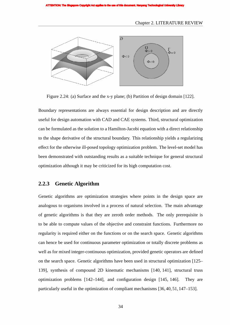
Chapter2. LITERATURE REVIEW
Figure2.24: (a) Surface and the x-y plane; (b) Partition of design domain [122].
Boundary representations are always essential for design description and are directly
useful for design automation with CAD and CAE systems. Third, structural optimization
can be formulated as the solution to a Hamilton-Jacobi equation with a direct relationship
to the shape derivative of the structural boundary. This relationship yields a regularizing
effect for the otherwise ill-posed topology optimization problem. The level-set model has
been demonstrated with outstanding results as a suitable technique for general structural
optimization although it may be criticized for its high computation cost.
2.2.3 Genetic Algorithm
Genetic algorithms are optimization strategies where points in the design space are
analogous to organisms involved in a process of natural selection. The main advantage
of genetic algorithms is that they are zeroth order methods. The only prerequisite is
to be able to compute values of the objective and constraint functions. Furthermore no
regularity is required either on the functions or on the search space. Genetic algorithms
can hence be used for continuous parameter optimization or totally discrete problems as
well as for mixed integer-continuous optimization, provided genetic operators are defined
on the search space. Genetic algorithms have been used in structural optimization [125–
139], synthesis of compound 2D kinematic mechanisms [140, 141], structural truss
optimization problems [142–144], and configuration design [145, 146]. They are
particularly useful in the optimization of compliant mechanisms [36,40,51,147–153].
34
ATTENTION: The Singapore Copyright Act applies to the use of this document. Nanyang Technological University Library

Chapter2. LITERATURE REVIEW
2.2.3.1 Representation Schemes
For success in solving topology optimization problems, genetic algorithms rely greatly on
the structural geometry representation scheme used. Quite a few representation schemes
coupled with genetic algorithms have been proposed. The genetic algorithm approach
for structural optimization illustrated by Jakiela and his coworkers [154, 155] directly
addressed the discrete nature of the problem by treating it with a discrete optimization
method. The strategy of discretizing the design space is used, with all the finite
elements forming a one-dimensional binary-coded bit-string chromosome denoting 0 for
an element if it is to be empty space and 1 if it is part of the structure, as shown by
an example in Figure 2.25. The states of the individual elements define the distribution
of material and void within the design space and therefore establish the topology. The
genetic algorithm is applied over many generations, and each generation is a population
of many individual designs, to attain the optimum chromosome string and hence structure.
1 1
1 1
1
1 1
1 1
1 1
1
1
1 1
1
1 1
1 1
1 1 1 1 1 1 1 1 1 1 1 1
1 1
1 1
1 1
1 1
1 1
1 1
1 1
1 1
1 1
1 1
1 1
1 1
0 0 0 0 0 0 0 0
0 0 0 0
0 0 0 0
0 0 0 0
0 0 0 0
0 0 0 0
0 0 0 0
0 0 0 0
0 0 0 0
0 0 0 0
0 0 0 0
0 0 0 0
0 0 0 0
0 0 0 0
0 0 0 0
0 0 0 0
0 0 0 0
0 0 0 0
0 0
0 0
0 0
0 0
0 0
0 0
0 0
0 0
0 0
0 0 0 0
0 0
0
0
0
0
00
00
(a) (b)
Figure2.25: Mapping from chromosome into topology: (a) corresponding binary valuesand (b) resulting topology.
In Schoenauer and his coworkers’ genetic algorithm [131,132,156,157], the structure
design domain is represented by a two-dimensional bit-array chromosome. However,
the resulting chromosome may lead to structures with checkerboard patterns (alternating
elements of material and void) and ‘floating’ elements (elements ‘floating’ in space
and not connected to the main structural body). Such designs may be invalid or
impractical, but the chromosome representation allows for them. It is not efficient
because expensive computing resources have to be spent analyzing these undesirable
35
ATTENTION: The Singapore Copyright Act applies to the use of this document. Nanyang Technological University Library

Chapter2. LITERATURE REVIEW
designsin the genetic algorithm. Alternatively a “repair” scheme [158] is needed to
detect and alter those checkerboard and ‘floating’ patterns as and when they arise out
of the crossover and mutation operations. This may, however, corrupt the transmission of
genetic characteristics across the generations.
To address the above shortcomings, Akin and Arjona-Baez [159] converted
checkerboard pattern elements to truss members and merged single node connected pairs
to a single truss member. Jang et al. [160] solved the numerical instability characterized
by checkerboard patterns when non-conforming four-node finite elements are employed.
Li et al. [161] presented an effective smoothing algorithm in terms of the surrounding
element’s reference factors. Luh and Chueh [162] used immune algorithm to tackle this
problem.
Tai and Chee [163] developed a morphological geometric representation scheme and
the corresponding chromosome encoding. This scheme is based on the study of the
structure of living organisms (morphology), and specifically it simulates the anatomical
description of vertebrates. This scheme has been successfully applied to obtain the
optimum topology/shape design of some structures and compliant mechanisms (Tai et
al. [36, 150, 164, 165]). In this morphological representation scheme, a structure is
characterized by a set of I/O regions. For a valid structural design, all I/O regions must be
connected to one another in order to form one single connected load-bearing structure.
Zhou and Ting [166] introduced the spanning tree theory to the topological synthesis
of compliant mechanisms, in which spanning trees connect all the vertices together using
a minimum number of edges. A valid topology is regarded as a network connecting input,
output, support, and intermediate nodes, which contains at least one spanning tree among
the introduced nodes. Yang and Soh [167] established a mapping scheme between the
kind of point-labelled parse trees and the node-element-labelled diagrams employed in
the analysis of structures. Cervera and Trevelyan [168, 169] used non-uniform rational
B-splines (NURBS) to define the geometry of the component. NURBS-based internal
cavities was created to accomplish topology changes. The optimum topologies evolve
36
ATTENTION: The Singapore Copyright Act applies to the use of this document. Nanyang Technological University Library

Chapter2. LITERATURE REVIEW
allowing cavities to merge between each other and to their closest outer boundary.
2.2.3.2 Exploration/Exploitation
Genetic algorithm efficacy is determined by the exploration/exploitation balance kept
throughout the run. When this balance is disproportionate, the premature convergence
problem will probably appear. A way to deal with the exploration/exploitation equilibrium
in genetic algorithms is by means of two main factors that control the evolution: selection
pressure and population diversity. A high selection pressure implies a quick loss of
population diversity, because of the excessive focus of the evolutionary search on the
best members of the population. On the contrary, the maintenance of population diversity
can neutralize the effects of an excessive selection pressure. Most parameters that are
used to adjust the strategies of an evolutionary search are indeed indirect terms of tuning
selection pressure, population diversity and elite strategy.
Due to its independence of the actual search space and its impact on the
exploration/exploitation tradeoff, selection is an important operator in any kind of genetic
algorithm. Back [170] quantitatively compared important selection operators with respect
to their selective pressure. The comparison clarifies that only a few really different and
useful selection operators exist: roulette wheel selection (in combination with a scaling
method), linear ranking, tournament selection, and (µ,λ)-selection (respectively (µ+λ)-
selection). In order to determine the possibility of being selected, genetic algorithms
consider the fitness of an individual compared to the fitness of the total population.
Affenzeller and Wagner [171] introduced a new generic selection strategy where an
offspring is compared not only to the total population. Additionally, in a second selection
step, it is compared to its own parents.
Population size influences the population diversity a lot. In the exploratory task of
the algorithm, larger population sizes are associated with not just lower convergence
speed of the algorithm, but also with lesser premature stagnation of the population. Small
population sizes can lead to premature stagnation, and their lack of population diversity
37
ATTENTION: The Singapore Copyright Act applies to the use of this document. Nanyang Technological University Library

Chapter2. LITERATURE REVIEW
have to be corrected with other operators that increase it, such as higher mutation rates
or the reinitialization operator. The reinitialization operator suggested in [172] created
a new starting population after the stagnation of the genetic algorithm in which the best
individual of the prior population is inserted. Thus, this individual provides the knowledge
obtained with the initial run and simultaneously the new randomly created individuals
contribute to the population diversity; in this way, a further continuation in the evolution
is allowed.
Elitism has always been a major influence on the population diversity. Elitism is
especially beneficial in the presence of multiple objectives and the use of elitism speeds
up convergence to the Pareto set [173]. The danger of premature convergence caused
by elitism can be suppressed when the elite set contains a number of diverse solutions.
As opposed to single-objective optimization, the question of elitism becomes even more
complicated with multiobjective optimization genetic algorithm. Elitism ensures the best
feasible solution is always carried forward to the next generation. This also eliminates the
need of searching back through history to locate the best feasible solutions. Regardless
whether a genetic algorithm uses elitism or not, it is common practice in the single
objective case to keep track of the best solution found during the run off-line. This
solution can be seen as the best approximation of the (unknown) optimum in reach, given
the information produced by the algorithm. The multi-objective analogue is to store all
solutions that are not dominated by any other solution found during the run. This archive
then represents the best approximation of the true Pareto set available. Thus, to supply
an archive of nondominated solutions is a sensible extension that helps to exploit the
produced information. Of course, if the archive is only used as a store, the behavior of the
genetic algorithm will not change.
2.2.3.3 Objective Handling
Genetic algorithm is a robust optimization tool that can be used to solve a wide
range of problems in engineering design inherently involve optimizing multiple non-
38
ATTENTION: The Singapore Copyright Act applies to the use of this document. Nanyang Technological University Library

Chapter2. LITERATURE REVIEW
commensurableand often conflicting objectives and criteria that reflect various design
specifications and constraints. A considerable amount of research on objective handing
techniques that incorporate objective functions into the fitness function of design
candidates have been carried out (good summaries are given in [174–177]). Deb [178]
provided an extensive discussion on the principles of multi-objective optimization and on
a number of classical approaches. And Coello and Lamont [179] presented an extensive
variety of multi-objective problems across diverse disciplines, along with statistical
solutions using multi-objective evolutionary algorithms.
The appoach of combining objectives into a single function is normally denominated
aggregating functions and it has many formulations based on different utility functions.
Weighted sum method, weighted min-max method, exponential weighted criterion and
weighted product method can be tailored to solve multiobjective problems directly. Hajela
and Lin [180] used a variable set of weights to arrive at a set of solutions. Ishibuchi and
Murata [181] introduced a combination of weighted-sum-based evolutionary algorithm
(EA) by the use of random weights. In these methods, additional parameters are required
for sharing, mating restrictions and weights.
Schaffer [182] came up with the concept of a Vector Evaluated Genetic Algorithm
(VEGA) for multiobjective problems. VEGA is based on evaluation of objectives
separately in different subpopulations followed by a migration scheme. Each objective
is improved separately in different subpopulations and hence a large number of
subpopulations are necessary in the presence of many objectives. The main strength of
this approach is its simplicity. But a fitness evaluation mechanism that is based on a
linear combination of the objectives will fail to generate Pareto optimal solutions for non-
convex search spaces regardless of weights used. Fourman [183] ranked the objectives
in order of importance and used a selection scheme based on lexicographic ordering.
This approach is able to search the non-convex search spaces. Its main problem is that
it will tend to favor certain objectives when many are present in the problem and this
will make the population converge to a particular part of the Pareto front rather than to
39
ATTENTION: The Singapore Copyright Act applies to the use of this document. Nanyang Technological University Library

Chapter2. LITERATURE REVIEW
delineateit completely. Lis and Eiben [184] proposed a multisexual genetic algorithm
that is based on multiparent crossover to arrive at a set of Pareto optimal solutions.
However the main weakness of this approach is that as the number of objectives increases,
many subpopulations and panmictic crossover will become more inefficient, because more
parents are needed to generate a child. Mimicing the process of natural selection, the
proposed genetic algorithm [185–187] realizes the situation of habitat segregation, i.e., a
principle of coexistence. A set of solutions spread across the Pareto set in the objective
space are obtained.
Goldberg [172] proposed the idea of using Pareto-based fitness assignment to solve
the problems of Schaffer’s VEGA approach. Equal probabilities of reproduction are
assigned to all non-dominated individuals in the population. Fonseca and Flemming [188]
describes a rank-based fitness assignment method for Multiple Objective Genetic
Algorithms (MOGA). At the end of the ranking process there are a number of solutions
with the same rank. To distribute the points evenly over the Pareto optimal region, they
used a niche-formulation. Horn et al. [189] introduced a Niched Pareto Genetic Algorithm
(NPGA) based on tournament selection and Pareto dominance. Instead of limiting the
comparison to two individuals, a number of other individuals in the population was used
to help determine dominance. The success of the algorithm is largely dependent on the
number as a small size will result in a few non-dominated points in the population whereas
a large size will result in premature convergence. Srinivas and Deb [190] proposed Non-
dominated Sorting Genetic Algorithm (NSGA) based on several layers of classifications
of individuals. A dummy fitness function using a non-dominated sorting procedure makes
it computationally inferior. It also requires the sharing parameter as an additional input.
Deb et at. [191] proposed NSGAII, a revised version of the NSGA, to eliminate the
drawbacks of NSGA by the use of elitism and a crowded comparison operator that keep
diversity without specifying any additional parameters. Zitzler et al. [192] introduced the
Strength Pareto EA (SPEA) that combines several features of previous multiobjective
EAs in a unique manner. It stores non-dominated solutions externally in a second,
40
ATTENTION: The Singapore Copyright Act applies to the use of this document. Nanyang Technological University Library

Chapter2. LITERATURE REVIEW
continuouslyupdated population and evaluates an individual’s fitness dependent on the
number of external non-dominated points that dominate it. A clustering technique is used
to control the size of the elite set. Knowles and Corne [193] introduced an evolution
scheme for multiobjective optimization problems, called the Pareto Archived Evolution
Strategy (PAES). This algorithm uses evolution strategy (ES) as the baseline algorithm.
A crowding procedure to maintain diversity is proposed that divides objective space in
a recursive manner and restricts the maximum number of occupants in each grid. The
‘plus’ strategy and continuous update of an elite population with better solutions ensures
elitism. The common weakness of NSGAII, SPEA and PAES is that they perform niching
on the objective value space instead of on the parameter values. Deb [194,195] illustrated
omni-optimizer which is an extension of NSGAII, in which both decision-variable space
and objective niching are performed.
Theε-constraint method is a mathematical programming technique, which transforms
a multiobjective optimization problem into several constrained single-objective problems.
This method has not been used too often in evolutionary computation, due to the fact
that it does not generate a set of non-dominated solutions in a single run, as most
genetic algorithms do. Ranjithan et al. [196, 197] proposed the constraint method-based
evolutionary algorithm (CMEA). The algorithm is based upon underlying concepts in
the theε-constraint method. Pareto optimality is achieved implicitly via a constraint
approach, and convergence is enhanced by using beneficial seeding of the initial
population. Becerra and Coello Coello [198] explored the use of theε-constraint method
hybridized with an efficient single-objective optimizer.
2.2.3.4 Constraint Handling
Many optimization problems involve inequality and/or equality constraints and are thus
posed as constrained optimization problems. In trying to solve constrained optimization
problems using genetic algorithms or classical optimization methods, Meseguer et
al. [199] reviewed existing approaches to model and solve overconstrained problems.
41
ATTENTION: The Singapore Copyright Act applies to the use of this document. Nanyang Technological University Library

Chapter2. LITERATURE REVIEW
Michalewicz and Schoenauer [200] provided a comprehensive review on constraints
handling EAs, while Lagaros et al. [201] investigated the efficiency of various EAs when
applied to large-scale constrained structural sizing optimization problems.
Based on intuition, Coello Coello and Christiansen [202] proposed a way that
discarded any solutions that violates any of the constraints. This naive approach may
have difficulty in finding a feasible solution. Another simple way of solving a constrained
optimization problem is restricting or repairing the search to the feasible region [203,204].
Penalty functions using static [190], dynamic or adaptive concepts [200] have been widely
used and are quite popular. Deb [205] proposed a constraint handling method which
is also based on the penalty function approach but does not require the prescription
of any penalty parameter. The idea of using the Pareto dominance relation to handle
constraints was originally suggested by Fonseca and Fleming [206, 207] back in 1995.
Based on Pareto ranking and VEGA, Surry and Radcliffe [208] proposed Constrained
Optimization by Multiple Objective Genetic Algorithm (COMOGA). This method takes
a dual perspective, considering a constrained optimization problem sometimes as a
constraint satisfaction problem, and sometimes as an unconstrained optimization problem.
Coello Coello et al. proposed some constraints handling methodology by treating them as
objectives [209], and using a dominance-based selection scheme [210]. Summanwar et
al. [211] treated the constraints as objective functions and handles them using the concept
of Pareto dominance. Ray et al. [212] suggested a more elaborate constraint handling
technique referred to as the Ray-Tai-Seow’s Method in [178]. A non-dominated check of
the constraint violations is made instead of simply adding them together. Venkatraman
and Yen [213] introduced a two-phase framework to handle constraints. In the first phase,
the objective function is completely disregarded and the constrained optimization problem
is treated as a constraint satisfaction problem. After that, the simultaneous optimization
of the objective function and the satisfaction of the constraint function are treated as a
biobjective optimization.
42
ATTENTION: The Singapore Copyright Act applies to the use of this document. Nanyang Technological University Library

Chapter2. LITERATURE REVIEW
2.2.3.5 Decision Making Technique
Very often real-world applications involve several (multiple) objectives. In principle,
multiobjective optimization is very different from the single-objective optimization. In
single objective optimization, one attempts to obtain the best design or decision, which
is usually the global minimum or the global maximum depending on the optimization
problem. In the case of multiple objectives, there may not exist one solution which is best
(global minimum or maximum) with respect to all objectives. Typically there exists a set
of solutions which are superior to the rest of solutions in the search space when all the
objectives are considered but are inferior to other solutions in the space in one or more
objectives. But how to obtain a particular solution which meets the user’s needs from these
individuals in multiobjective problem is a tricky issue especially when the objectives are
conflicting with one another. Therefore, at some stage of the problem solving process, the
decision maker (DM) has to articulate his/her preferences about the objectives. Following
a classification by Deb [178], the decision-making techniques are categorized into two
types: post-optimal techniques and optimization-level techniques.
A post-optimal technique may use a genetic algorithm to produce as many different
Pareto optimal solutions as possible, and then some higher-level decision-making
considerations are used to choose a solution. In general, post-optimal techniques are
most convenient, since they do not require the user to interact with the process, and the
DM can delay any choice until the alternatives are known. Unfortunately, searching for
all Pareto optimal solutions is a difficult and time-consuming process. Besides, in some
cases only some interesting regions in the Pareto front are desired. Generally the DM has
some intuition about it, and this information should be used during the search.
Recently, some optimization-level approaches have been published aimed at focusing
the search towards interesting regions as defined by the DM. Deb [214] uses goal
programming techniques and allows the DM to define a goal (a single desired combination
of characteristics) towards which the search is directed. Although this seems very
appealing to a DM, the effect of such a goal on the search process is difficult to assess
43
ATTENTION: The Singapore Copyright Act applies to the use of this document. Nanyang Technological University Library

Chapter2. LITERATURE REVIEW
when the Pareto optimal front is not known. The goal of the problem is not easy
to specify. If a goal is set that lies within the feasible region, it hinders search to
even better solutions; if it lies too far away from the feasible region, it has basically
no effect at all. Parmee et al. [215] suggested a weighted dominance principle. The
weighted vector could be either specified directly by user, or it can be calculated from
personal preferences that help the user to work in more qualitative terms. Branke et
al. [216] proposed the Guided Multiobjective Evolutionary Algorithm (G-MOEA). The
DM specifies maximal and minimal acceptable weightings for one criterion over the other,
and use these to guide the EA towards pareto-optimal solutions within these boundaries.
Coelho and Bouillard [217] tackled preferences in EAs by integrating an inference engine
within the EA to repair the individuals violating the user-defined rules. Shimizu [218]
proposed an intelligence supported approach using neural networks that extends the
hybrid genetic algorithm to derive the best-compromise solution. Fuzzy logic integrated
genetic algorithms incorporating expert knowledge and experience [219–221] are also
proposed to increase the performance of genetic algorithm.
Recently, Deb et al. [222,223] and Thiele et al. [224] suggested reference point based
evolutionary multi-objective optimization (EMO) procedures which require the decision-
maker to specify one or more reference points and the task of an EMO is, not to find
the entire Pareto-optimal frontier, but to find a portion of the Pareto-optimal front which
solves an achievement scalarizing function. Deb and Kumar embedded in a NSGAII
procedure the light beam search strategy for finding a preferred set of Pareto-optimal
solutions [225], and reference direction method for finding a single preferred efficient
solution [226].
2.2.3.6 Local Search
Genetic algorithms have amply demonstrated their success to arrive at optimal solutions
for design optimization problems in engineering. However, the performance of genetic
algorithms on some multiobjective optimization problems was overshadowed by that of
44
ATTENTION: The Singapore Copyright Act applies to the use of this document. Nanyang Technological University Library

Chapter2. LITERATURE REVIEW
neighborhoodsearch algorithms (e.g., evolution strategy, simulated annealing (SA), tabu
search (TS), and hybrid algorithms of genetic algorithms and local search).
Evolution strategies use real-vectors as coding representation, and primarily mutation
and selection as search operators. Knowles and Corne [227] proposed the Pareto Archived
Evolution Strategy (PAES), a local search algorithm for multi-objective evolutionary
problems. A (1+ 1) evolution strategy is applied, using only mutation on a single parent
to create a single offspring. PAES is intended as a baseline approach and may serve
well in some real-world applications when local search seems superior to or competitive
with population-based methods. Combining the local search method of (1+1)-PAES
with the use of a population and crossover, the memetic algorithm, M-PAES [193], was
suggested. The performance of M-PAES is reported to be superior to (1+1)-PAES for
all test problems and to the strength Pareto evolutionary algorithm (SPEA) for some
problems.
SA is a generic probabilistic meta-algorithm for the global optimization problem.
Serafini [228] proposed and investigated modifications to simulated annealing in order to
tackle the multiobjective case. Several alternative criteria for the probability of accepting
are considered. Following Serafini, Ulungu et al. [229] developed the so-called MOSA
(Multiobjective Simulated Annealing) method which used a different approach to building
up the approximation to the Pareto set. MOSA method works by executing separate runs
of SA and archiving all of the non-dominated solutions found. The method uses a number
of predefined weight vectors defining a set of weighted linear utility functions. Czyzak
and Jaszkiewicz [230] proposed a population-based version of Serafini’s SA, Pareto
Simulated Annealing algorithm (PSA). The algorithm uses a population of solutions and
tries to improve them all in parallel, at the same time encourage them to spread out in
the objective space. William Begg and Liu [231, 232] proposed a novel hybrid method
combining sequential linear programming with simulated annealing and demonstrated its
effectiveness.
Tabu Search as a local search technique which is closest to the intuitive idea of ‘tabu’
45
ATTENTION: The Singapore Copyright Act applies to the use of this document. Nanyang Technological University Library

Chapter2. LITERATURE REVIEW
and mainly implemented in the so-called ‘tabu lists’ is guided by the use of adaptive
or flexible memory structures. The variety of the tools and search principles introduced
and described by Glover et al. [233, 234] is such that TS can be considered as a general
framework for heuristic search. Hansen [235] suggested Multiple Objective Tabu Search
method (MOTS) with the idea of adaptively setting the weight vectors of individuals in
a population, as used in PSA. MOTS works with a set of current solutions which are
optimized towards the non-dominated frontier while at the same time seek to disperse
over the frontier. It uses an adaptive population size based on the current nondominance
rank of each member of the population. A tabu-enhanced genetic algorithm approach
proposed in [236] combined the strengths of genetic algorithms and TS to realize a hybrid
approach for optimal assembly process planning and success was reported.
In recent years, hybrid genetic algorithms have become more homogeneous and some
great successes have been reported in the optimization of a variety of classical hard
optimization problems. Hybrid algorithms of genetic algorithms and those neighborhood
search algorithms were proposed to improve the search ability of genetic algorithms.
Ishibuchi and Murata [237] proposed a Multiple Objective Genetic Local Search
(MOGLS) algorithm. The algorithm uses a weighted sum of multiple objectives as a
fitness function. A local search procedure is applied to the new solution produced by
crossover and mutation operations to maximize its fitness value. Addressing the high
computation time spent by local search, the local search part is modified, and combined
with SPEA algorithms [238] and NSGAII [239]. The balance between genetic search
and local search through computer simulations were examined. Jaszkiewicz [240, 241]
suggested an algorithm called Random Directions Multiple Objective Local Search (RD-
MOGLS), and compared a slight variant called the Pareto Memetic Algorithm (PMA)
with other well-known algorithms. In all of these algorithms, the basic idea is simple: a
local search is applied to new offsprings generated (by crossover or mutation), and the
improved offspring then competes with the population for survival to the next generation.
In some hybrid algorithms, local search is used only when the execution of genetic
46
ATTENTION: The Singapore Copyright Act applies to the use of this document. Nanyang Technological University Library

Chapter2. LITERATURE REVIEW
algorithmsis terminated. Deb and Goel [242] applied local search to final solutions
obtained by genetic algorithms for decreasing the number of non-dominated solutions
(i.e., for decreasing the variety of final solutions).
47
ATTENTION: The Singapore Copyright Act applies to the use of this document. Nanyang Technological University Library
Chapter 3
NONLINEAR FINITE ELEMENT
ANALYSIS
3.1 INTRODUCTION
Compliant mechanisms are generally operating in large deformation ranges. For large
displacements/rotation, non-linear analysis is necessary whereas linear analysis will
be inaccurate and lead the topology optimization procedure towards spurious resulting
designs (Pedersen et al. [17], and Gea and Luo [62]). In this chapter, general large
deformation problems are formulated. The virtual work principle based nonlinear
formulation is constructed in a total Lagrangian description. Effective stress and strain
are expressed in terms of 2nd Piola-Kirchhoff stress tensor and Green-Lagrange strain
tensor, and constitutive equation is derived from the relation between the effective stress
and strain. More details can be found in [243,244].
3.2 CONSTITUTIVE EQUATION
The virtual work principle is constructed in a total Lagrangian description. The equations
presented here are based on [243,244]. The virtual work form of the equilibrium equation
with respect to timet + ∆t can be written as
∫
V0δETSdV=
∫
V0δaTb0dV +
∫
A0δaT q0dA (3.1)
whereE is Green-Lagrange strain tensor,S is the second Piola-Kirchhoff stress tensor,δa
is the virtual displacement imposed on the configuration,b0 andq0 are the body force on
48
ATTENTION: The Singapore Copyright Act applies to the use of this document. Nanyang Technological University Library

Chapter3. NONLINEAR FINITE ELEMENT ANALYSIS
the whole domainV0 and the traction on the natural boundaryA0, respectively. All the
variables in Equation 3.1 are with reference to the initial configuration at timet + ∆t.
E = E + ∆E (3.2)
S = S+ ∆S (3.3)
a = a + ∆a (3.4)
At times t andt + ∆t, the Green-Lagrange strain tensors are respectively
Ei j =12
(∂aj
∂Xi+∂ai
∂Xj+∂ak
∂Xi
∂ak
∂Xj
)(3.5)
and
Ei j =12
(∂aj
∂Xi+∂ai
∂Xj+∂ak
∂Xi
∂ak
∂Xj
)(3.6)
whereXi, Xj arethe space coordinates.
Substituting 3.4 into 3.6 leads to
Ei j = 12
[∂∂Xi
(aj + ∆aj) + ∂∂X j
(ai + ∆ai) + ∂∂Xi
(ak + ∆ak) ∂∂X j
(ak + ∆ak)]
= 12
(∂a j
∂Xi+
∂ai
∂X j+
∂ak
∂Xi
∂ak
∂X j
)+
12
(∂∆ai
∂X j+
∂∆a j
∂Xi
)+ 1
2
(∂ak
∂Xi
∂∆ak
∂X j+ ∂∆ak
∂Xi
∂ak
∂X j
)+ 1
2
(∂∆ak
∂Xi
∂∆ak
∂X j
)
= Ei j + ∆EL0i j + ∆EL1
i j + ∆ENi j
(3.7)
Subtracting 3.5 from 3.7, the increment of the Green-Lagrange strain tensor can be
decomposed into linear and nonlinear parts as
∆Ei j = ∆ELi j + ∆EN
i j = ∆EL0i j + ∆EL1
i j + ∆ENi j (3.8)
where
∆EL0i j =
12
(∂∆ai
∂Xj+∂∆aj
∂Xi
)(3.9)
49
ATTENTION: The Singapore Copyright Act applies to the use of this document. Nanyang Technological University Library

Chapter3. NONLINEAR FINITE ELEMENT ANALYSIS
∆EL1i j =
12
(∂ak
∂Xi
∂∆ak
∂Xj+∂∆ak
∂Xi
∂ak
∂Xj
)(3.10)
∆ENi j =
12∂∆ak
∂Xi
∂∆ak
∂Xj(3.11)
All the above equations are of continuous form, and so they have to be transformed
into a finite element formulation.
3.3 FINITE ELEMENT FORMULATION
Before further formulation work is expressed, some of the definitions are given below. For
2-D space,X1, X2 are thex, y coordinates respectively. The displacement can be written
asa = [ u v ]T . N is the shape function matrix. For 4-noded quadrilateral element,N is
given as
N =
N1 0 N2 0 N3 0 N4 0
0 N1 0 N2 0 N3 0 N4
(3.12)
The deformation gradient matrixF is written as
F =
∂u∂x + 1 ∂u
∂y
∂v∂x
∂v∂y + 1
=
NP∑i=1
∂Ni
∂x ui + 1NP∑i=1
∂Ni
∂y ui
NP∑i=1
∂Ni
∂x vi
NP∑i=1
∂Ni
∂y vi + 1
(3.13)
where NP is the number of nodes in the element, and for the 4-noded quadrilateral
element,NP = 4.
Substituting∆a = N∆a(e) into equation 3.9, 3.10 and 3.11, these equations can be
rewritten in the matrix and scalar format as
∆EL0 = L∆a = LN∆a(e) = BL0∆a(e) (3.14)
∆EL1 =12
A∆θ +12
∆Aθ = AG∆a(e) = BL1∆a(e) (3.15)
50
ATTENTION: The Singapore Copyright Act applies to the use of this document. Nanyang Technological University Library

Chapter3. NONLINEAR FINITE ELEMENT ANALYSIS
∆EN =12
∆A∆θ =12
∆AG∆θ = BN∆θ (3.16)
where
L =
∂∂x 0
0 ∂∂y
∂∂y
∂∂x
(3.17)
A =
∂aT
∂x 0
0 ∂aT
∂y
∂aT
∂y∂aT
∂x
=
F11− 1 F12 0 0
0 0 F21 F22− 1
F21 F22− 1 F11− 1 F12
(3.18)
∆A =
∂∆aT
∂x 0
0 ∂∆aT
∂y
∂∆aT
∂y∂∆aT
∂x
(3.19)
θ =
∂a∂x
∂a∂y
(3.20)
∆θ =
∂∆a∂x
∂∆a∂y
= H∆a = HN∆a(e) = G∆a(e) (3.21)
In Equation 3.21,
H =
I ∂∂x
I ∂∂y
=
∂∂x 0
0 ∂∂x
∂∂y 0
0 ∂∂y
(3.22)
For quadrilateral elements, substituting Equation 3.22 and the shape functions into
51
ATTENTION: The Singapore Copyright Act applies to the use of this document. Nanyang Technological University Library
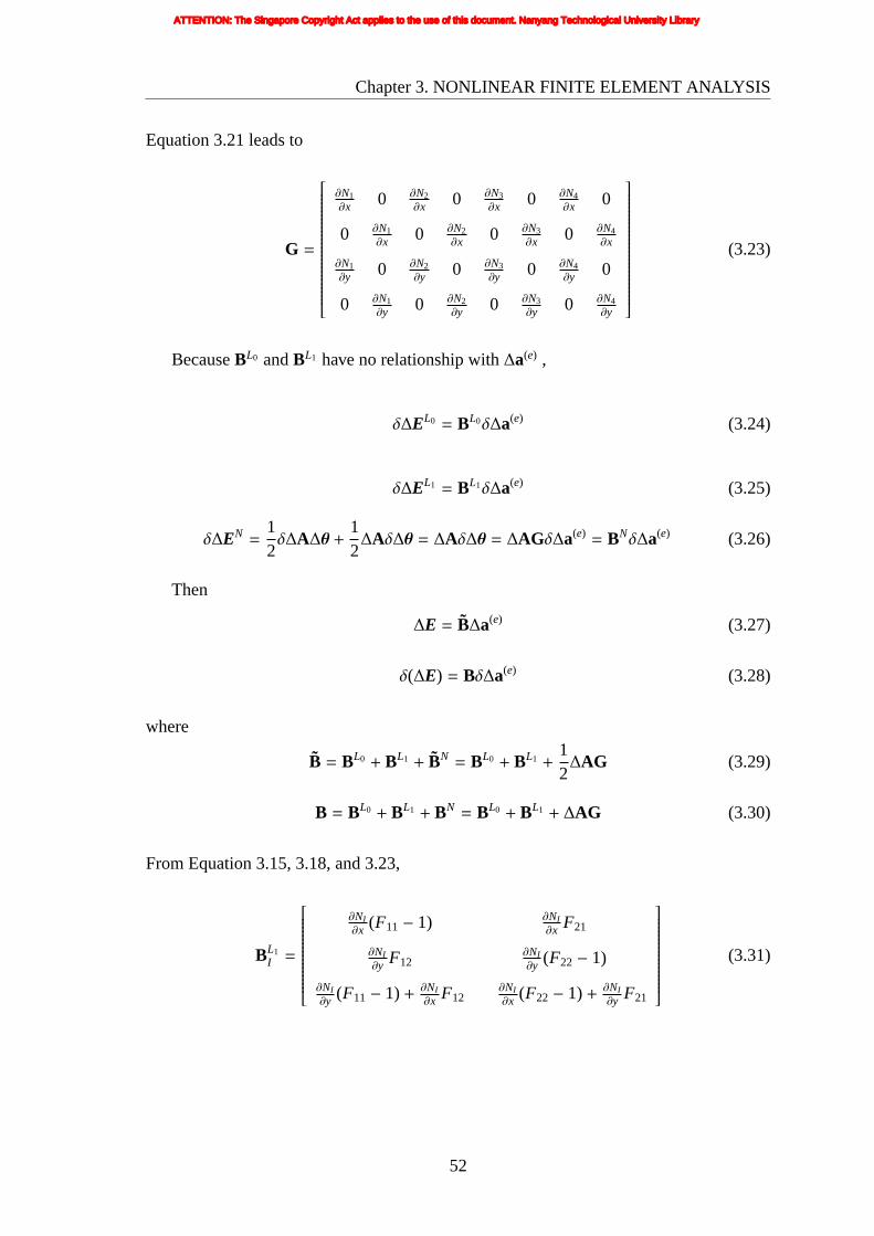
Chapter3. NONLINEAR FINITE ELEMENT ANALYSIS
Equation3.21 leads to
G =
∂N1∂x 0 ∂N2
∂x 0 ∂N3∂x 0 ∂N4
∂x 0
0 ∂N1∂x 0 ∂N2
∂x 0 ∂N3∂x 0 ∂N4
∂x
∂N1∂y 0 ∂N2
∂y 0 ∂N3∂y 0 ∂N4
∂y 0
0 ∂N1∂y 0 ∂N2
∂y 0 ∂N3∂y 0 ∂N4
∂y
(3.23)
BecauseBL0 andBL1 have no relationship with∆a(e) ,
δ∆EL0 = BL0δ∆a(e) (3.24)
δ∆EL1 = BL1δ∆a(e) (3.25)
δ∆EN =12δ∆A∆θ +
12
∆Aδ∆θ = ∆Aδ∆θ = ∆AGδ∆a(e) = BNδ∆a(e) (3.26)
Then
∆E = B∆a(e) (3.27)
δ(∆E) = Bδ∆a(e) (3.28)
where
B = BL0 + BL1 + BN = BL0 + BL1 +12
∆AG (3.29)
B = BL0 + BL1 + BN = BL0 + BL1 + ∆AG (3.30)
From Equation 3.15, 3.18, and 3.23,
BL1I =
∂NI∂x (F11− 1) ∂NI
∂x F21
∂NI∂y F12
∂NI∂y (F22− 1)
∂NI∂y (F11− 1) + ∂NI
∂x F12∂NI∂x (F22− 1) + ∂NI
∂y F21
(3.31)
52
ATTENTION: The Singapore Copyright Act applies to the use of this document. Nanyang Technological University Library

Chapter3. NONLINEAR FINITE ELEMENT ANALYSIS
and
BL0I =
∂NI∂x 0
0 ∂NI∂y
∂NI∂y
∂NI∂x
(3.32)
whereI=1, 2, 3 and 4.
Substituting
δa = δ(∆a) = Nδ∆a(e)
δE = δ(∆E) = Bδ∆a(e)(3.33)
into equation 3.1, the following is obtained
∫
V0BTSdV=
∫
V0NTb0dV +
∫
A0NT q0dA (3.34)
In this work the body forceb0 is set to 0. So with the Equation 3.3 and 3.30, the balance
equation in incremental form can be written as
ψ(∆a(e)) =
∫
V0BT∆SdV+
∫
V0(BN)TSdV+
∫
V0(BL0 + BL1)TSdV−
∫
A0NT q0dA (3.35)
With the equation
(BN)TS = GT∆ATS = GTM∆θ = GTMG∆a(e) = GTMG∆a(e) (3.36)
where
M =
S11 0 S12 0
0 S11 0 S12
S12 0 S22 0
0 S12 0 S22
(3.37)
53
ATTENTION: The Singapore Copyright Act applies to the use of this document. Nanyang Technological University Library

Chapter3. NONLINEAR FINITE ELEMENT ANALYSIS
M =
S11 S12 0 0
S21 S22 0 0
0 0 S11 S12
0 0 S21 S22
(3.38)
G =
∂N1∂x 0 ∂N2
∂x 0 ∂N3∂x 0 ∂N4
∂x 0
∂N1∂y 0 ∂N2
∂y 0 ∂N3∂y 0 ∂N4
∂y 0
0 ∂N1∂x 0 ∂N2
∂x 0 ∂N3∂x 0 ∂N4
∂x
0 ∂N1∂y 0 ∂N2
∂y 0 ∂N3∂y 0 ∂N4
∂y
(3.39)
thefollowing equation can be obtained
∫
V0(BN)TSdV=
(∫
V0GTMGdV
)∆a(e) =
(∫
V0GTMGdV
)∆a(e) (3.40)
Then the system balance equation 3.35 can be rewritten as
ψ(∆a(e)) =
∫
V0BT∆SdV+ KS∆a(e) + RS −
∫
A0NT q0dA = 0 (3.41)
where
KS =
∫
V0GTMGdV =
∫
V0GTMGdV (3.42)
RS =
∫
V0(BL0 + BL1)TSdV (3.43)
3.4 PROCEDURES FOR EQUILIBRIUM SOLUTION
When the nonlinear Equation 3.41 is to be solved, the linearization of it is the first step.
And it includes geometric and physical aspects. In this work, the material is linear, so
the focus is on the geometric non-linearity. The strain-displacement matrixB can be
linearized withBL0 + BL1.
54
ATTENTION: The Singapore Copyright Act applies to the use of this document. Nanyang Technological University Library
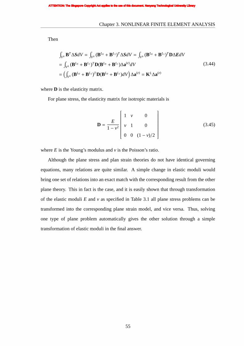
Chapter3. NONLINEAR FINITE ELEMENT ANALYSIS
Then
∫V0 BT∆SdV =
∫V0 (BL0 + BL1)T∆SdV=
∫V0 (BL0 + BL1)TD∆EdV
=∫
V0 (BL0 + BL1)TD(BL0 + BL1)∆a(e)dV
=(∫
V0 (BL0 + BL1)TD(BL0 + BL1)dV)∆a(e) = K L∆a(e)
(3.44)
whereD is the elasticity matrix.
For plane stress, the elasticity matrix for isotropic materials is
D =E
1− v2
1 v 0
v 1 0
0 0 (1− v)/2
(3.45)
whereE is the Young’s modulus andv is the Poisson’s ratio.
Although the plane stress and plan strain theories do not have identical governing
equations, many relations are quite similar. A simple change in elastic moduli would
bring one set of relations into an exact match with the corresponding result from the other
plane theory. This in fact is the case, and it is easily shown that through transformation
of the elastic moduliE andv as specified in Table 3.1 all plane stress problems can be
transformed into the corresponding plane strain model, and vice versa. Thus, solving
one type of plane problem automatically gives the other solution through a simple
transformation of elastic moduli in the final answer.
55
ATTENTION: The Singapore Copyright Act applies to the use of this document. Nanyang Technological University Library
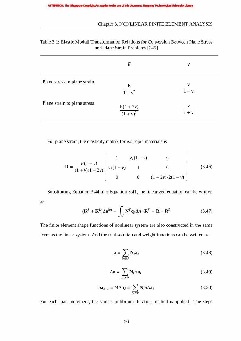
Chapter3. NONLINEAR FINITE ELEMENT ANALYSIS
Table 3.1: Elastic Moduli Transformation Relations for Conversion Between Plane Stressand Plane Strain Problems [245]
E v
Planestress to plane strainE
1− v2
v1− v
Planestrain to plane stressE(1+ 2v)
(1 + v)2
v1 + v
For plane strain, the elasticity matrix for isotropic materials is
D =E(1− v)
(1 + v)(1− 2v)
1 v/(1− v) 0
v/(1− v) 1 0
0 0 (1− 2v)/2(1− v)
(3.46)
Substituting Equation 3.44 into Equation 3.41, the linearized equation can be written
as
(KS + K L)∆a(e) =
∫
A0NT q0dA−RS = R − RS (3.47)
The finite element shape functions of nonlinear system are also constructed in the same
form as the linear system. And the trial solution and weight functions can be written as
a =∑
I∈NP
NIaI (3.48)
∆a =∑
I∈NP
NI∆aI (3.49)
δan+1 = δ(∆a) =∑
I∈NP
NIδ∆aI (3.50)
For each load increment, the same equilibrium iteration method is applied. The steps
56
ATTENTION: The Singapore Copyright Act applies to the use of this document. Nanyang Technological University Library

Chapter3. NONLINEAR FINITE ELEMENT ANALYSIS
involved are given as follows:
1. Initial conditions: incremental loading stepn = 0. Calculatea0 using the linear
solution method.
2. Newton iterations for loading incrementn + 1.
(a) Iterationi = 1;
(b) Calculate the deformation gradient matrixF;
(c) Calculate variablesSnew, Enew, ;
(d) Compute the out-of-balanceR − RSload,K = K L + KS and usingF, Snew ;
(e) Solve the incremental solution∆a by enforcing essential boundary conditions;
(f) an+1 = anew+ ∆a
(g) Check for convergence; if it is not converged,i= i +1, go to step (b).
3. Check incremental step; if the end of the analysis is not reached, remesh, and let
n = n + 1, go to step 2.
For the present incremental-iterative solution technique, a convergence criterion based
on the incremental displacement is used. This criterion requires the calculation of a norm
‖ε‖2 =
√√1
ND
ND∑
k=1
∣∣∣∣∣∣∆δk
δmaxk
∣∣∣∣∣∣2
< τc (3.51)
whereND is the total number of degrees of freedom,∆δk is the change in the nodal
variable componentk during the current iteration cycle,δmaxk is the largest displacement
component of the corresponding component, andτc is the convergence tolerance which is
in the range of(0,10−6
)in this work.
In actual computations, it is found that convergence can be achieved usually within
six iterations.
57
ATTENTION: The Singapore Copyright Act applies to the use of this document. Nanyang Technological University Library

Chapter3. NONLINEAR FINITE ELEMENT ANALYSIS
3.5 TEST PROBLEM
A program that implements both the linear and non-linear finite element method was
developed in C++. The large displacement (geometric nonlinear) plane stress static
finite element analysis can be performed using the program. The type of finite elements
developed is 4-noded plane stress element. To demonstrate the performance of this
program in the analyses of solid mechanics problems, a simple example problem is
presented here. This problem is from the previous work done by Prasad [246]. It is
for testing the accuracy and the speed of the newly developed program for solving the
nonlinear systems. The verification of the proposed computational strategy is performed
by comparison with results obtained from the commercial FE software ABAQUS.
3.5.1 Problem Description
For comparison of speed and accuracy in nonlinear analysis, a compliant mechanism
shown in Figure 3.1 was tested. The material assumed is polypropylene with Young’s
modulus of 1150MPa and Poisson’s ratio of 0.4. The boundary conditions are as follows:
i Support: Nodes that lie in the bottom of the mechanism are fixed as shown in
Figure 3.1.
ii Loading: The input displacement is 18.205mm and the loading node lies in the left
boundary as shown in Figure 3.1.
3.5.2 Results
The newly developed program was run in the Windows XP sp2 environment of a PC (hp
workstation xw4200). ABAQUS was run in that PC as well as in the IRIX 6.5 environment
of SGI Origin 2000 Server. The time spent on nonlinear analysis by the newly developed
program, ABAQUS in the same enviroment and ABAQUS in the IRIX of SGI Origin
2000 is 27, 6.7 and 43.8 seconds. The deformed shapes of the mechanism are shown in
Figure 3.2.
58
ATTENTION: The Singapore Copyright Act applies to the use of this document. Nanyang Technological University Library

Chapter3. NONLINEAR FINITE ELEMENT ANALYSIS
output point
Figure3.1: Mechanism with boundary conditions.
In Figure 3.2(a) and Figure 3.2(b), the undeformed geometries are shown by their
mesh while the deformed shapes in their final positions are shown by their the boundary
outlines only. The paths of the output point obtained by ABAQUS and newly developed
program are drawn in Figure 3.2(c). As can be seen, the difference in the results is small.
Further analysis is given in Table 3.2, whereuloading is the displacement of loading node
in x direction, vloading is the displacement of loading node iny direction, uoutput is the
displacement of output point inx direction,voutput is the displacement of output point in
y direction, andσpeak−von−Mises is the peak von Mises stress (which occurs in the support
element). Good agreement between them is observed.
Table 3.2: Comparison ResultABAQUS newly developed program percentagedifference
uloading 18.205 18.205 –vloading 26.766 28.445 6.27%uoutput 32.377 34.399 6.25%voutput -14.465 -14.936 3.26%
σpeak−von−Mises 30827938 31562900 2.38%
59
ATTENTION: The Singapore Copyright Act applies to the use of this document. Nanyang Technological University Library

Chapter3. NONLINEAR FINITE ELEMENT ANALYSIS
(a)deformed and undeformed shapesfrom ABAQUS
(b) deformed and undeformed shapesfrom newly developed program
output x-displacement (m)
outp
uty-
disp
lace
men
t(m
)
0 0.01 0.02 0.03
-0.01
-0.005
0ABAQUSnewly developed program
(c) path of output point
Figure 3.2: Comparison between ABAQUS and newly developed program.
60
ATTENTION: The Singapore Copyright Act applies to the use of this document. Nanyang Technological University Library

Chapter 4
DESIGN OF GRIP-AND-MOVE
MANIPULATORS USING
SYMMETRIC PATH GENERATING
MECHANISMS
This chapter demonstrates the automatic design of compliant grip-and-move
manipulators by topology and shape optimization using genetic algorithms. It presents a
novel idea to integrate grip and move behavior in one simple mechanism. The manipulator
is composed of two identical symmetric path generating compliant mechanisms so that
it can grip an object and convey it from one point to another. The synthesis of such
a mechanism is accomplished by formulating the problem as a structural optimization
problem with multiple objectives and a constraint to achieve the desired behavior of the
manipulator.
4.1 SYMMETRIC PATH GENERATING
MECHANISM
In this work, a symmetric path generating mechanism refers to a mechanism that generates
an output path that is symmetric about some line of symmetry [247]. Both the path and
the location of the line of symmetry are not predefined. In other words, the shape of the
path itself is not fixed in advance, so the desire is basically for the path to be symmetric.
The path is also desired to be as long as possible in order to extend its working range.
An illustration of a grip-and-move manipulator consisting of two identical symmetric
path generating mechanisms is given in Figure 4.1. The two mechanisms are placed at
61
ATTENTION: The Singapore Copyright Act applies to the use of this document. Nanyang Technological University Library

Chapter4. DESIGN OF GRIP-AND-MOVE MANIPULATORS USING SYMMETRICPATH GENERATING MECHANISMS
eitherside of a line of symmetry such that each is a ‘mirror image’ of the other across
that line. That line is also the same line of symmetry for the symmetric path, so that
the output point of one mechanism will be able to touch the output point of the other
mechanism anywhere along the path when some amount of input displacement is applied
to one or both mechanisms. Each shape in solid lines is the undeformed shape of one of
the mechanisms. The dashed lines show the possible deformed shape of the structure after
some large displacement due to the input load. The two compliant mechanisms work like
two fingers of a manipulator. It can grip a workpiece and, because the path is symmetric,
the grip can be maintained anywhere along the path and so the workpiece can be conveyed
to any point along the path.
symmetric path
input load
fixed support
input load
workpiece
Figure4.1: Sketch of a grip-and-move manipulator.
The path generating mechanism has to be able to produce a symmetric path, and be
flexible enough to describe approximately the desired path that is relatively long, and
at the same time keep input displacement and stresses within allowable limits. In other
words, the best path generating mechanism would (i) be able to describe a path as close
to symmetric as possible, (ii) have GA (Geometric Advantage) as large as possible, i.e.
62
ATTENTION: The Singapore Copyright Act applies to the use of this document. Nanyang Technological University Library

Chapter4. DESIGN OF GRIP-AND-MOVE MANIPULATORS USING SYMMETRICPATH GENERATING MECHANISMS
output displacement as large as possible while input displacement (which is a design
variable) is as small as possible, and (iii) have stresses within allowable limits.
4.2 FORMULATION
The design problem can be defined with the help of Figure 4.2. The design space is a
100 by 100mm square. The dashed lines mark the design space which is the allowable
space within which the structural design must lie and cannot exceed. The support point
is the part of the structure that is supported (restrained, with zero displacement) while the
loading point is where some specified load (input displacement) is applied to deform the
structure. The output point is the point on the structure where the desired output behavior
is attained. The positions of these I/O points are variable but confined to the boundaries
(the support point is positioned anywhere along the bottom boundary while the loading
point is positioned anywhere along the four boundaries, and the output point is positioned
anywhere along the bottom, right, or top boundary). This arrangement will allow the
design to take on all possible configurations of the relative positions of the I/O points.
100 mm
100
mm
y
load
ing
support and/or loading and/or output
x
load
ing
and/
or o
utpu
t
loading and/or output
Figure4.2: Design space for symmetric path mechanism.
The synthesis of such a path generating compliant mechanism is accomplished by
63
ATTENTION: The Singapore Copyright Act applies to the use of this document. Nanyang Technological University Library

Chapter4. DESIGN OF GRIP-AND-MOVE MANIPULATORS USING SYMMETRICPATH GENERATING MECHANISMS
formulatingthe problem as a structural optimization problem with three objectives and a
constraint to achieve the desired behavior of the manipulator.
4.2.1 Symmetric Path Objective
The aim here is to produce a mechanism which generates a path that is symmetric.
Symmetry can be measured by dividing the mechanism’s path into two halves by a line
of symmetry, and then evaluating the difference between the two halves separated by the
line. As shown in Figure 4.3, they′ axis is the line of symmetry. To evaluate how similar
the left half and the right half of the path are, the average deviation (error) between the
two parts is evaluated. In Figure 4.3, the left half can be assumed as the desired path, and
then the right half is assumed as the actual path. The actual path is divided inton segments
(wheren is the number of analysis steps for the left half of the output displacement, i.e.
the displacement steps as computed via the finite element analysis of the structure).
x
y
initial output point position
final positionactual path
x0xn x1...
"mirror image" of left halfd0
d1
dn
y'
Figure4.3: Deviation between the left and right halves of path.
The average deviationds ave weighted according to the analysis step sizes is given by
ds ave =
n+1∑
i=1
(di−1 + di
2
)
xi−1n∑
j=0xj
=
1
2n∑
j=0x j
n+1∑
i=1
(di−1 + di)xi−1 (4.1)
64
ATTENTION: The Singapore Copyright Act applies to the use of this document. Nanyang Technological University Library

Chapter4. DESIGN OF GRIP-AND-MOVE MANIPULATORS USING SYMMETRICPATH GENERATING MECHANISMS
wheredi (with dn+1 = 0) are the distances between corresponding points of the desired
path and actual path.xi are thex distances between two consecutive points on the actual
path as shown in Figure 4.3.
To have a fair comparison between different length scales, the deviation should be
weighted according to the length of the paths. Hence the objective function is formulated
as:
Minimize fpath =ds ave
l0=
1
2(n∑
j=0xj)
2
n+1∑
i=1
(di−1 + di)xi−1 (4.2)
wherel0 is the actualx distance of the right half.
4.2.2 Geometric Advantage Objective
The aim here is to maximize flexibility or compliance of the structure. Maximum
flexibility can be posed as maximization of the deflection at a specified point along
a specified direction. The intent here is to maximize deflection of the output point.
However, when the input displacement is a variable, maximization of the ratio of the
output deflection (in a specified direction) to the input displacement is more useful as it
improves the efficiency of the mechanism. This ratio can be called Geometric Advantage
(GA). The GA objective (fGA) depends only on the initial state and the final state of
the structure. Here, the initial state is the undeformed shape while the final state is the
deformed shape when load is applied. The finite element analysis gives the position of
each node of deformed shape with respect to its position in the undeformed shape. If
r in = xini + yinj is the position vector of the loading point andr out = xouti + youtj is the
position vector of the output point’s final position with respect to its initial position, then
the GA objective is given by
Minimize fGA = − rout · uout
r in · uin= − (xouti + youtj) · uout
(xini + yinj) · uin(4.3)
65
ATTENTION: The Singapore Copyright Act applies to the use of this document. Nanyang Technological University Library

Chapter4. DESIGN OF GRIP-AND-MOVE MANIPULATORS USING SYMMETRICPATH GENERATING MECHANISMS
whereuin is the unit inward normal vector orthogonal to the loading boundary, anduout is
the unit outward normal vector orthogonal to the output boundary. For instance,uin = i
anduout = −j will be used in equation 4.3 if the loading point is positioned at the left
boundary of the design space, and the output point is positioned at the bottom boundary.
4.2.3 Combined Objective
As investigated in Section 2.2.3.5, following a classification by Deb [178], the
decision-making techniques are categorized into two types: post-optimal techniques and
optimization-level techniques. Recently, some optimization-level approaches have been
published aimed at focusing the search towards interesting regions as defined by the
Decision Maker. Here a post-optimal technique is suggested. In order to constitute a
grip-and-move manipulator, the symmetric path generating mechanisms should have good
path and GA objective at the same time. Some initial trials which only use two conflicting
objectives show that it is harder to obtain solutions with both good path and GA objective.
The solutions obtained separated into two parts, one part with good path objective but bad
GA objective, and the other part vice versa. Based on these useful experiences, a third
(combined) objective is added to the problem formulation to direct the search towards
mechanisms good in both objectives. The combined objective has two parts, one part to
improve the path objective and the other part to improve GA objective. These two parts
are combined together by scaling them with the ideal objective values, 0.0001 for path
objective (fpath) and -5 for the GA objective (fGA), respectively. The weighted vector can
help the user to work in more qualitative terms. The combined objective function is given
by:
Minimize fcom =fpath
0.0001− 5
fGA
4.2.4 Stress Constraint
A constraint on the maximum stress in the mechanism (to hinder fatigue or failure) is
important in the synthesis of compliant mechanisms. In [32,248], local failure conditions
66
ATTENTION: The Singapore Copyright Act applies to the use of this document. Nanyang Technological University Library

Chapter4. DESIGN OF GRIP-AND-MOVE MANIPULATORS USING SYMMETRICPATH GENERATING MECHANISMS
relating to stress constraints are incorporated in topology optimization algorithms to
obtain compliant and strong designs and deal with the so-called ‘singularity’ phenomenon
of stress constraints in topology design.
The constraint on the peak von Mises stress may be expressed as
σpeak−von−Mises≤ σy (4.4)
whereσpeak−von−Mises is the peak von Mises stress andσy is the tensile yield strength of
the material. A dimensionless expression for the stress constraint may be written as
gstress=σpeak−von−Mises− σy
σy≤ 0 (4.5)
Hence the multicriterion genetic algorithm is run with three objectives (the two actual
objectives and one combined objective), and one constraint i.e. the stress constraint.
4.3 MORPHOLOGICAL REPRESENTATION OF
STRUCTURE GEOMETRY
For the design optimization, the geometry of any structure is defined by the morphological
representation scheme developed by Tai et al. [40, 151]. The scheme uses arrangements
of skeleton and surrounding material to define structural geometry in a way that
facilitates the transmission of topological/shape characteristics across generations in
the evolutionary process, and will not render any undesirable design features such as
disconnected segments, checkerboard patterns or single-node hinge connections. And any
chromosome-encoded design generated by the evolutionary procedure can be translated
into an FE model of the structure according to the morphological representation.
In this morphological representation scheme, a structure is characterized by a set of
I/O points (the support and loading points are considered as input points). While it is
still unknown how the rest of the design space will be occupied by the structure, the I/O
67
ATTENTION: The Singapore Copyright Act applies to the use of this document. Nanyang Technological University Library

Chapter4. DESIGN OF GRIP-AND-MOVE MANIPULATORS USING SYMMETRICPATH GENERATING MECHANISMS
pointsmust exist somewhere because any structure must have parts which interact with its
surroundings by way of at least one support and one loading point. Figure 4.4(a) shows
an example problem defined with three I/O locations : one support, one loading and one
output location, each made up of one element in black. For a valid structural design, all
I/O points must be connected to one another (either directly or indirectly) in order to form
one single connected load bearing structure. Three connecting curves in the illustration
of Figure 4.4(b) are used such that there is one connecting curve between any two points
(i.e. every I/O point is directly connected to the other two), with each curve defined by
three control points. Hence this representation scheme is based on specifying connecting
curves joining one point to another. Each curve is a Bezier curve defined by its start and
end points plus a number of control points in between. The primary criterion for choosing
a Bezier curve is that the design variables of it cause smooth variations in the shape of
a compliant segment. The number of variables is small enough but able to cover a large
design space of shapes. By moving the control points, a wide variety of curves that span a
large design space of shapes can be obtained. Another interesting property of the Bezier
curves is that the curve always lies inside the convex hull of the control polygon. This is
attractive from the viewpoint of applying constraints to restrict the curves to prescribed
geometric domain. It is also simpler to use when compared to more sophisticated B-
splines [33,164]. The position vectorr of any given point on the Bezier curve is given by
the following general equation:
r = r(u) =
n∑
k=0
n!k!(n − k)!
uk(1− u)n−kr k (4.6)
whereu is the intrinsic parameter (one-dimensional coordinate) that varies from 0 to 1
along the curve,n − 1 is the number of control points,r 0 is the position vector of the
start point,r n is the position vector of the end point andr k for k = 1 to n − 1 are the
control points. The benefit of Bezier curves is the ease of computation, stability at the
lower degrees of control points. Generally, use as few control points as possible. Too
many points make it hard to get a smooth, flowing line on a long curve. Too few points
68
ATTENTION: The Singapore Copyright Act applies to the use of this document. Nanyang Technological University Library

Chapter4. DESIGN OF GRIP-AND-MOVE MANIPULATORS USING SYMMETRICPATH GENERATING MECHANISMS
restrictthe possible path the curve can follow. The curve may be assumed to be made of
n parametrically equal segments. For example, if there are only two control points, the
first of the three segments of the curve would be the part of the curve where 0≤ u ≤ 13
, the second segment would be where13 ≤ u ≤ 2
3 andthe third segment would be where
23 ≤ u ≤ 1.
I/O points
Curve 1Curve 2Curve 3control points of curve 1control points of curve 2control points of curve 3I/O points
(a)FE discretization of design space (I/Oelement marked in black)
(b) Connecting I/O elements with Beziercurves
(c) Skeleton made up of elements alongcurves
(d) Surrounding elements added toskeleton to form final structure
Figure 4.4: Definition of structural geometry by morphological scheme.
The set of elements through which each curve passes form the ‘skeleton’ connecting
69
ATTENTION: The Singapore Copyright Act applies to the use of this document. Nanyang Technological University Library

Chapter4. DESIGN OF GRIP-AND-MOVE MANIPULATORS USING SYMMETRICPATH GENERATING MECHANISMS
the two points (Figure 4.4(c)). Some of the elements surrounding the skeleton are then
included to fill up the structure to its final form (Figure 4.4(d)). These additional elements
represent the ‘flesh’ around the skeleton. And the union of all skeleton, flesh and I/O
elements constitute the structure while all other elements remain as the surrounding
empty space. The number of flesh elements to be added is determined by a thickness
value, which is a variable tied to every parametric segment of a curve. This is done by
considering each skeleton element in turn and adding an all-round layer of elements to it
(Figure 4.5), with the layer thickness according to the thickness value which can range
from zero to some prescribed (integer) maximum which is 3 in Figure 4.4(d).
thickness = 0
thickness = 1
thickness = 2skeleton element
'flesh' element
and so on ...
Figure4.5: Thickness of ‘Flesh’ added to skeleton elements.
In order to use a genetic algorithm for the optimization, the topological/shape
representation variables have to be configured as a chromosome code. Hence the
structural geometry in Figure 4.4(d) can be encoded as a chromosome in the form of a
graph as shown in Figure 4.6. Each vertex of the graph holds a design variable, and the
vertices are connected by edges depicted by the line segments in Figure 4.6. The vertices
and edges here are the terminology as used in graph theory. Each start, control or end
point of a Bezier curve is at the centre of the element containing it, therefore its location
is actually referenced by the element number. This necessitates a numbering scheme for
uniquely labelling each element in the mesh, and in this work, the elements are simply
numbered in order from left to right along each row, and row by row from bottom to
top. It can be seen from the vertices of the graph that each curve is defined by control
70
ATTENTION: The Singapore Copyright Act applies to the use of this document. Nanyang Technological University Library

Chapter4. DESIGN OF GRIP-AND-MOVE MANIPULATORS USING SYMMETRICPATH GENERATING MECHANISMS
pointsalternating with thickness values. As shown in Figure 4.6, for every curve defined
by three control points, there will be four thickness values. With four thickness values,
the curve will correspondingly be divided parametrically into four segments with each
segment having its thickness determined by the respective thickness value.
50
2051
element number of input/output point
element number of control point
thickness value
curve 3
curv
e 2
2499
0 22032289
22422
0 0
curve 10
1065
1225
1312
3
1
0
0
2132
971
84
1
0
2
Figure4.6: Chromosome code
The variables are cast into the chromosome code which is in the form of a connected
graph with the same configuration/connectivity as the Bezier curves. The topology/shape
emerges from the interaction among the curves and their respective thicknesses. Slight
changes in some thickness values or small shifts in control point positions can lead to
topological changes with entire openings (holes) created or destroyed. It is a versatile
geometric representation which can define a wide variety of topological and shape
configurations, using only a fairly small number of variables. In fact, the geometric
complexity achievable in the design can be controlled by the designer by choosing the
number of control points to be used for each curve (the larger the number of points the
higher the order of the curve). However, it is clear that the greater the complexity, the
larger the number of design variables and so the larger the optimization problem.
The most important operation in a genetic algorithm procedure is the crossover
operation and in this work, a crossover operator is devised to work by randomly
71
ATTENTION: The Singapore Copyright Act applies to the use of this document. Nanyang Technological University Library
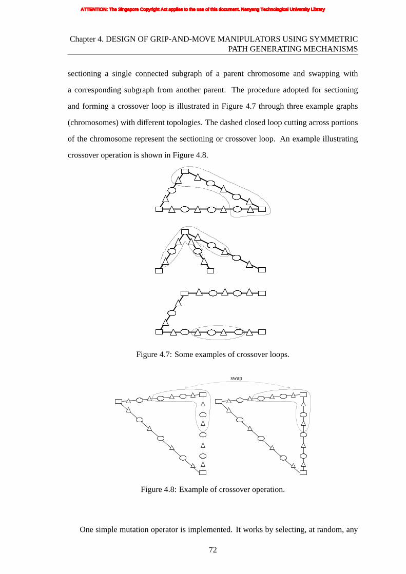
Chapter4. DESIGN OF GRIP-AND-MOVE MANIPULATORS USING SYMMETRICPATH GENERATING MECHANISMS
sectioninga single connected subgraph of a parent chromosome and swapping with
a corresponding subgraph from another parent. The procedure adopted for sectioning
and forming a crossover loop is illustrated in Figure 4.7 through three example graphs
(chromosomes) with different topologies. The dashed closed loop cutting across portions
of the chromosome represent the sectioning or crossover loop. An example illustrating
crossover operation is shown in Figure 4.8.
Figure4.7: Some examples of crossover loops.
swap
Figure4.8: Example of crossover operation.
One simple mutation operator is implemented. It works by selecting, at random, any
72
ATTENTION: The Singapore Copyright Act applies to the use of this document. Nanyang Technological University Library

Chapter4. DESIGN OF GRIP-AND-MOVE MANIPULATORS USING SYMMETRICPATH GENERATING MECHANISMS
vertex on the graph and altering its value to another randomly generated value within
the allowable range. Figures 4.9 shows examples of mutation of the structure from
Figure 4.9(a) where one I/O point (Figures 4.9(b)), one control point (Figures 4.9(c)),
and one thickness value (Figures 4.9(d)) is randomly changed, respectively.
(a)Before mutation (b) Mutation of I/O point
(c) Mutation of control point (d) Mutation of thickness value
Figure 4.9: Mutation operation.
73
ATTENTION: The Singapore Copyright Act applies to the use of this document. Nanyang Technological University Library

Chapter4. DESIGN OF GRIP-AND-MOVE MANIPULATORS USING SYMMETRICPATH GENERATING MECHANISMS
4.4 MULTICRITERION GENETIC ALGORITHM
The genetic algorithm used for the multiobjective optimization in the present work
is fundamentally based on Ray et al. [212]. This is a multiobjective algorithm with
constraint handling, based on maintaining separate non-domination (Pareto) rankings for
objectives and constraints satisfaction, thus enabling an intelligent selection of solutions
for cooperative mating which eliminates the need to prescribe penalty function parameters
usually required for constraint handling. Pareto ranking, selection probability, adaptive
niche count and non-overlapping constraint satisfaction given in the following sections
are based on the algorithms and implementations from [212] and Prasad’s thesis [246].
A general constrained multiobjective optimization problem (in the minimization
sense) is formulated as:
Minimize f(x) =[f1(x) f2(x) · · · fm(x)
]
subject to gj(x) ≤ 0, j = 1,2, · · · ,qhk(x) = 0, k = 1,2, · · · , r
(4.7)
where f is a vector ofm objectives andx = [x1 x2 · · · xn] is the vector ofn design
variables.
The objective matrixO for a population ofM solutions is presented as:
O =
f11 f12 · · · f1m
f21 f22 · · · f2m
......
. . ....
fM1 fM2 · · · fMm
(4.8)
where fi j is the j-th objective value of thei-th solution.
74
ATTENTION: The Singapore Copyright Act applies to the use of this document. Nanyang Technological University Library

Chapter4. DESIGN OF GRIP-AND-MOVE MANIPULATORS USING SYMMETRICPATH GENERATING MECHANISMS
Theconstraint matrixC for a population ofM solutions is presented as:
C =
C11 C12 · · · C1s
C21 C22 · · · C2s
......
. . ....
CM1 CM2 · · · CMs
(4.9)
wheres = q + r andCi j is the j-th constraint value of thei-th solution.
A combined matrixCOM is a combination of the objective and constraint matrices:
COM = [O C] (4.10)
4.4.1 Pareto Ranking
From a population ofM solutions, all non-dominated solutions are assigned a rank of
1. The rank 1 individuals are removed from the population and the new set of non-
dominated solutions is assigned a rank of 2. The process is continued until every solution
in the population is assigned a rank. A rank of 1 based on objective or constraint indicates
that the solution is non-dominated. The Pareto rank of each solution in the population
computed based on the objective matrixO is stored in a vectorRankObj . Similarly,
the Pareto rank of each solution in the population computed based on the constraint
matrix C or the combined matrixCOM is stored in the vectorRankCon or RankCom,
respectively.
Solutions with same Pareto ranking belong to the same front. The front having rankk
individuals may be called thek-th front of the solution space, e.g., the front having rank
1 individuals may be called the 1st front.
4.4.2 Selection Probability
An individual is selected using the roulette wheel selection scheme. The probability of
selection of an individual is based on the vectorsRankObj or RankCon and denoted as
75
ATTENTION: The Singapore Copyright Act applies to the use of this document. Nanyang Technological University Library

Chapter4. DESIGN OF GRIP-AND-MOVE MANIPULATORS USING SYMMETRICPATH GENERATING MECHANISMS
ProbObj or ProbCon, respectively. As an example, the vectorProbObj is computed as
follows:
The vectorRankObj with element values varying from 1 toPmax is transformed to a
fitness vectorFitObj with elements varying fromPmax to 1 using a linear scaling (Pmax
denotes the rank of the worst solution). The probability of selectionProbObj of an
individual is then computed based on this fitness vectorFitObj . Thus, the areas of the
individual sectors on the roulette wheel correspond to the fitness vectorFitObj .
4.4.3 Adaptive Niche Count
Adaptive niche count of a given solution is the number of solutions in the given population
(with a population size ofM) which are within the average distance metric in the design-
parameter-space. It is computed as follows:
Step 1: Seti = 1
Step 2: If i is more thanM, then go toStep 8
Step 3: In the normalized design-parameter-space, compute the the Euclidean distance
betweeni-th solution and all the otherM - 1 solutions
Step 4: Compute the average Euclidean distance
Step 5: Count the number of solutions that are within the average distance
Step 6: i = i + 1
Step 7: Go toStep 2
Step 8: Stop
Out of two given solutions, a solution with a smaller niche count physically means
that there are fewer number of solutions in its neighborhood. Such a solution is preferred
over the other in order to maintain diversity in the population.
4.4.4 Non-overlapping Constraint Satisfaction
The concept of non-overlapping constraint satisfaction is based on the philosophy that
a solution is allowed to mate with another solution if one complements the other
76
ATTENTION: The Singapore Copyright Act applies to the use of this document. Nanyang Technological University Library
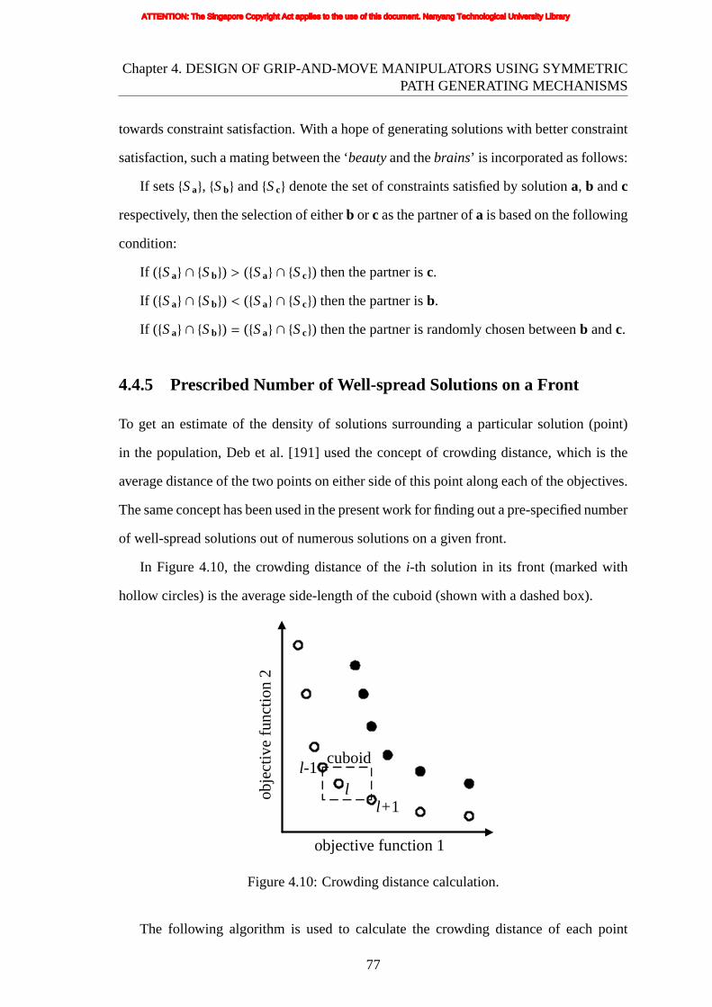
Chapter4. DESIGN OF GRIP-AND-MOVE MANIPULATORS USING SYMMETRICPATH GENERATING MECHANISMS
towards constraint satisfaction. With a hope of generating solutions with better constraint
satisfaction, such a mating between the ‘beautyand thebrains’ is incorporated as follows:
If sets{Sa}, {Sb} and{Sc} denote the set of constraints satisfied by solutiona, b andc
respectively, then the selection of eitherb or c as the partner ofa is based on the following
condition:
If ( {Sa} ∩ {Sb}) > ({Sa} ∩ {Sc}) then the partner isc.
If ( {Sa} ∩ {Sb}) < ({Sa} ∩ {Sc}) then the partner isb.
If ( {Sa} ∩ {Sb}) = ({Sa} ∩ {Sc}) then the partner is randomly chosen betweenb andc.
4.4.5 Prescribed Number of Well-spread Solutions on a Front
To get an estimate of the density of solutions surrounding a particular solution (point)
in the population, Deb et al. [191] used the concept of crowding distance, which is the
average distance of the two points on either side of this point along each of the objectives.
The same concept has been used in the present work for finding out a pre-specified number
of well-spread solutions out of numerous solutions on a given front.
In Figure 4.10, the crowding distance of thei-th solution in its front (marked with
hollow circles) is the average side-length of the cuboid (shown with a dashed box).
objective function 1
obje
ctiv
e fu
nctio
n 2
cuboidl-1
l+1l
Figure4.10: Crowding distance calculation.
The following algorithm is used to calculate the crowding distance of each point
77
ATTENTION: The Singapore Copyright Act applies to the use of this document. Nanyang Technological University Library

Chapter4. DESIGN OF GRIP-AND-MOVE MANIPULATORS USING SYMMETRICPATH GENERATING MECHANISMS
(solution)in the setI:
Step 1: DetermineMI = number of solutions inI
Step 2: Initialize crowding distance for every solution, i.e. for eachl, setI [l ]distance = 0
Step 3: Seti = 1
Step 4: Sort I with respect to thei-th objective, i.e.I = Sort(I, i)
Step 5: Set I [1]distance = I [MI ]distance = ∞ (infinity), so that boundary points are
always selected
Step 6: CalculateI [l ]distance= I [l ]distance+I [l+1]i−I [l−1]iI [MI ] i−I [1] i
for l = 2 to (MI − 1), whereI [l ] i
refers to thei-th objective function value of thel-th individual in the set I.
Step 7: i = i + 1
Step 8: If i is less than or equal to total number of objective functionsm, then go to
Step 4
Step 9: Stop
This concept has also been used for selecting the best set of a prescribed number of
solutions on a given front.
4.4.6 Best Set of Prescribed Number of Solutions in a Population
If there areNf fronts in the solution space;M1, M2, M3,. . . , MNf are the number of
solutions on the 1st, 2nd, 3rd,. . ., Nf -th front, respectively;I1, I2, I3, . . ., INf are the
corresponding sets of solutions on the 1st, 2nd, 3rd,. . ., Nf -th front, respectively;M0 = 0
and I0 = φ (null set), then the best setIbest of Mprescribed number of solutions can be
determined as follows:
Step 1: Determinek such thatk∑
i=0Mi < Mprescribed≤
k+1∑i=0
Mi
Step 2: Ibest =k⋃
i=0I i
Step 3: Mremaining = Mprescribed−k∑
i=0Mi
Step 4:Iremaining= set ofMremainingnumber of well-spread solutions on (k + 1)-th front
based on method described in Section 4.4.5
Step 5: Ibest = Ibest⋃
Iremaining
78
ATTENTION: The Singapore Copyright Act applies to the use of this document. Nanyang Technological University Library

Chapter4. DESIGN OF GRIP-AND-MOVE MANIPULATORS USING SYMMETRICPATH GENERATING MECHANISMS
Step6: Stop
4.4.7 Overall Algorithm
The overall algorithm for getting a set of Pareto optimal solutions is given below:
Step 1: Generate random initial population P of sizeM.
Step 2: Evaluate objective as well as constraint functions for each individual in P.
Step 3: Compute Pareto Ranking based on objective space, constraint space, and the
combined objectives and constraints space respectively to yieldRankObj , RankCon and
RankCom.
Step 4: Select elite individuals. If the individuals with rank 1 (based onRankObj ) are
less thanncarryover in number, then put all of them into the new population P′. Else select
ncarryover number of well-spread solutions out of all the rank 1 individuals (as explained in
Section 4.4.5) and put them into the new population P′. Elite individuals carried from the
previous generation preserve the values of their objective and constraint functions.
Step 5: Ifn is the number of decision variables, the bestn number of solutions in
the population (based onRankCom) is selected according to the method described in
Section 4.4.6 and mutated and then put into new population P′.
Step 6: Crossover.
Step 7: If a prescribed stopping condition is satisfied, end the algorithm. Otherwise,
return toStep 2.
4.5 RESULTS
The multiobjective genetic algorithm procedure was implemented through a C++
program running in the Windows XP SP2 environment of a PC (hp workstation xw4200).
The material assumed for the structure is polypropylene because of its ductility and
high strength-to-modulus ratio – properties which are advantageous to applications in
compliant mechanisms. The Young’s modulus assumed is 1150MPa with Poisson’s ratio
79
ATTENTION: The Singapore Copyright Act applies to the use of this document. Nanyang Technological University Library

Chapter4. DESIGN OF GRIP-AND-MOVE MANIPULATORS USING SYMMETRICPATH GENERATING MECHANISMS
of 0.4 and the yield strength of polypropylene is about 33MPa.
Wherever the loading point is located, an input displacement of any magnitude
between 10mm and 25mm is to be applied in the direction perpendicular to the boundary
(with displacement parallel to the boundary unrestrained). The lower bound of input
displacement (viz. 10mm) is based on past experience that (i) achieving a long symmetric
path with 10mm of input displacement is difficult, and (ii) meeting the stress constraint
with an input displacement less than 10mm is easy, and as a result initial generations
(having high number of infeasible solutions) favor such small input displacements to the
extent that it becomes difficult to maintain diversity in the population with respect to the
input displacement. The upper bound of input displacement (viz. 25mm) is based on past
experience that (i) achieving a long symmetric path with 25mm of input displacement is
easy, and (ii) meeting the stress constraint with an input displacement more than 25mm is
difficult.
4.5.1 Run 1
In this run, three Bezier curves are used such that there is one connecting curve between
any two points, with each curve defined by three control points. All thickness values are
allowed to vary between the minimum value 0 and maximum value 3.
The optimization was run for 500 generations (with a population size of 100 per
generation), by the end of which 45,007 objective function evaluations (finite element
analyses) have been performed. The total (wall-clock) time consumed for 500 generations
is 598,809s. Three of the solutions at the end of 500 generations are shown in Figure 4.11.
Figure 4.11(a) shows the solution with the best path objective, whereas Figure 4.11(c)
shows the solution with the best GA objective. The solution with the best combined
objective is shown in Figure 4.11(b); it has path objective better than the solution in (c)
and GA objective better than the solution in (a).
The design variable values for the solution with the best combined objective, which
corresponds to Figure 4.11(b), is given in Figure 4.12. The input/output/control points
80
ATTENTION: The Singapore Copyright Act applies to the use of this document. Nanyang Technological University Library
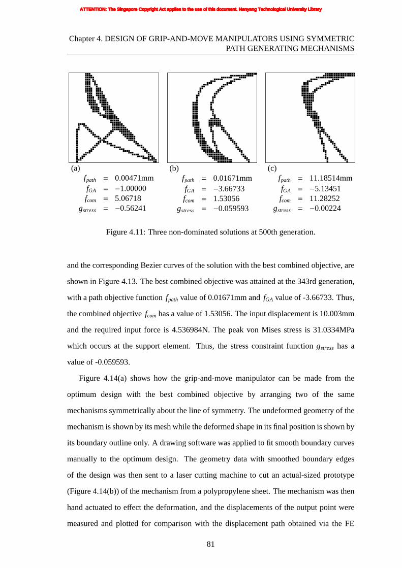
Chapter4. DESIGN OF GRIP-AND-MOVE MANIPULATORS USING SYMMETRICPATH GENERATING MECHANISMS
(a)fpath = 0.00471mmfGA = −1.00000fcom = 5.06718
gstress = −0.56241
(b)fpath = 0.01671mmfGA = −3.66733fcom = 1.53056
gstress = −0.059593
(c)fpath = 11.18514mmfGA = −5.13451fcom = 11.28252
gstress = −0.00224
Figure 4.11: Three non-dominated solutions at 500th generation.
and the corresponding Bezier curves of the solution with the best combined objective, are
shown in Figure 4.13. The best combined objective was attained at the 343rd generation,
with a path objective functionfpath value of 0.01671mm andfGA value of -3.66733. Thus,
the combined objectivefcom has a value of 1.53056. The input displacement is 10.003mm
and the required input force is 4.536984N. The peak von Mises stress is 31.0334MPa
which occurs at the support element. Thus, the stress constraint functiongstress has a
value of -0.059593.
Figure 4.14(a) shows how the grip-and-move manipulator can be made from the
optimum design with the best combined objective by arranging two of the same
mechanisms symmetrically about the line of symmetry. The undeformed geometry of the
mechanism is shown by its mesh while the deformed shape in its final position is shown by
its boundary outline only. A drawing software was applied to fit smooth boundary curves
manually to the optimum design. The geometry data with smoothed boundary edges
of the design was then sent to a laser cutting machine to cut an actual-sized prototype
(Figure 4.14(b)) of the mechanism from a polypropylene sheet. The mechanism was then
hand actuated to effect the deformation, and the displacements of the output point were
measured and plotted for comparison with the displacement path obtained via the FE
81
ATTENTION: The Singapore Copyright Act applies to the use of this document. Nanyang Technological University Library

Chapter4. DESIGN OF GRIP-AND-MOVE MANIPULATORS USING SYMMETRICPATH GENERATING MECHANISMS
2500
35
element number of input/output point
element number of control point
thickness value
curve 3
curv
e 2
46
0 4201429
17681
0 0
curve 11
355
2172
2256
1
0
0
0
1375
638
2003
0
0
0
Figure4.12: Chromosome code of the optimal result with best combined objective.
Curve 1Curve 2Curve 3control points of curve 1control points of curve 2control points of curve 3I/O points
Figure4.13: Input/output/control points and Bezier curves of the optimal result with bestcombined objective.
82
ATTENTION: The Singapore Copyright Act applies to the use of this document. Nanyang Technological University Library
Chapter4. DESIGN OF GRIP-AND-MOVE MANIPULATORS USING SYMMETRICPATH GENERATING MECHANISMS
analysis(from the optimization run) shown on the plot of Figure 4.14(c).
Figure 4.15 and Figure 4.16 provide a glimpse of the evolution history by a sampling
of the solutions obtained at the respectively indicated generations. Figure 4.15 shows
three solutions in the initial population with their corresponding objective/constraint
function values. Figure 4.16 (a)-(i) show the best feasible solutions (with their
corresponding objective/constraint values) achieved up to the respectively indicated
generations 50, 100, and 300. At every indicated generation, one solution with best path
objective, one with best GA objective, and one with best combined objective are given.
Figure 4.17 shows plots of the best path objective (fpath), the corresponding solution’s
GA objective (fGA) and the corresponding solution’s combined objective (fcom) versus
generation number.fpath, fGA and fcom values on the plot corresponding to any particular
generation number belong to that generation’s non-dominated feasible solution having the
best path objective.
Figure 4.18 shows plots of the best combined objective (fcom), the corresponding
solution’s path objective (fpath) and the corresponding solution’s GA objective (fGA)
versus generation number.fpath, fGA and fcom values on the plot corresponding to any
particular generation number belong to that generation’s non-dominated feasible solution
having the best combined objective.
Figure 4.19 shows plots of the best GA objective (fGA), the corresponding solution’s
path objective (fpath) and the corresponding solution’s combined objective (fcom) versus
generation number.fpath, fGA and fcom values on the plot corresponding to any particular
generation number belong to that generation’s non-dominated feasible solution having the
best GA objective.
Figure 4.20 shows a plot in objective space, where solid shape markers have been
used to denote the feasible non-dominated solutions at any particular sample generation.
Hollow shape markers of the corresponding same shape have been used for showing any
elites at that generation. At any particular generation, the elites are a subset of the feasible
non-dominated solutions (as the elites are basically the feasible non-dominated solutions
83
ATTENTION: The Singapore Copyright Act applies to the use of this document. Nanyang Technological University Library
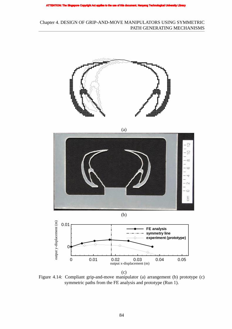
Chapter4. DESIGN OF GRIP-AND-MOVE MANIPULATORS USING SYMMETRICPATH GENERATING MECHANISMS
(a)
(b)
output x-displacement (m)
outp
uty-
disp
lace
men
t(m
)
0 0.01 0.02 0.03 0.04 0.05
0
0.01FE analysissymmetry lineexperiment (prototype)
(c)Figure 4.14: Compliant grip-and-move manipulator (a) arrangement (b) prototype (c)
symmetric paths from the FE analysis and prototype (Run 1).
84
ATTENTION: The Singapore Copyright Act applies to the use of this document. Nanyang Technological University Library

Chapter4. DESIGN OF GRIP-AND-MOVE MANIPULATORS USING SYMMETRICPATH GENERATING MECHANISMS
(a)fpath = 0.02270776mmfGA = −0.1250213fcom = 267.0708
gstress = 0.2073545
(b)fpath = 0.06666687mmfGA = −0.3535463fcom = 680.8112
gstress = 3.101273
(c)fpath = 0.1373693mmfGA = −0.07025242fcom = 1444.865
gstress = −0.3716121
Figure 4.15: Sample solutions from the initial (randomly generated) population.
which have been selected to be carried forward to the next generation) and therefore,
every elite (hollow marker) coincides with one of the feasible non-dominated solutions
(solid markers) in the plot.
Figure 4.21 shows a plot of the cumulative non-dominated front up to some sample
generations. The solutions shown in Figure 4.20 are non-dominated among all the
solutions in the population at the indicated generation, whereas solutions shown in
Figure 4.21 are non-dominated among all the solutions accumulated from past generations
up till the indicated generation. Thus, the plot in Figure 4.20 is with respect to a single
particular generation, whereas the plot in Figure 4.21 is with respect to all the generations
up to the particular generation (inclusive). As not all of the feasible non-dominated
solutions are carried forward to the next generation, it is possible that a solution which
has appeared in Figure 4.20 is missing from Figure 4.21.
85
ATTENTION: The Singapore Copyright Act applies to the use of this document. Nanyang Technological University Library

Chapter4. DESIGN OF GRIP-AND-MOVE MANIPULATORS USING SYMMETRICPATH GENERATING MECHANISMS
(a)generation 50 (bestfpath)fpath = 0.008249mmfGA = −1.000000fcom = 5.082493
gstress = −0.580000
(b) generation 50 (bestfcom)fpath = 0.009537mmfGA = −2.203029fcom = 2.364968
gstress = −0.326115
(c) generation 50 (bestfGA)fpath = 14.34104mmfGA = −4.424253fcom = 144.5405
gstress = −0.170294
(d) generation 100 (bestfpath)fpath = 0.007875mmfGA = −1.000000fcom = 5.078746
gstress = −0.579233
(e) generation 100 (bestfcom)fpath = 0.009535mmfGA = −2.341837fcom = 2.230425
gstress = −0.322706
(f) generation 100 (bestfGA)fpath = 10.01274mmfGA = −4.711177fcom = 101.1887
gstress = −0.082342
(g) generation 300 (bestfpath)fpath = 0.006719mmfGA = −1.000000fcom = 5.067187
gstress = −0.562412
(h) generation 300 (bestfcom)fpath = 0.021785mmfGA = −2.905988fcom = 1.938438
gstress = −0.105182
(i) generation 300 (bestfGA)fpath = 10.92996mmfGA = −5.022153fcom = 110.2952
gstress = −0.004788
Figure 4.16: Best feasible solutions from sample intermediate generations.
86
ATTENTION: The Singapore Copyright Act applies to the use of this document. Nanyang Technological University Library

Chapter4. DESIGN OF GRIP-AND-MOVE MANIPULATORS USING SYMMETRICPATH GENERATING MECHANISMS
generation number
path
obje
ctiv
e
GA
obje
ctiv
e
Co
mbi
ned
obj
ectiv
e
0 100 200 300 400 500-0.001
0
0.001
0.002
0.003
0.004
0.005
0.006
-6
-5
-4
-3
-2
-1
0
0
10
20
30
40
50
60
70path objecitveGA objectivecombined objective
Figure4.17: History of the best path objective (fpath).
generation number
path
obje
ctiv
e
GA
obje
ctiv
e
Co
mbi
ned
obj
ectiv
e
0 100 200 300 400 500-0.001
0
0.001
0.002
0.003
0.004
0.005
0.006
-6
-5
-4
-3
-2
-1
0
0
10
20
30
40
50
60
70path objecitveGA objectivecombined objective
Figure4.18: History of the best combined objective (fcom).
87
ATTENTION: The Singapore Copyright Act applies to the use of this document. Nanyang Technological University Library

Chapter4. DESIGN OF GRIP-AND-MOVE MANIPULATORS USING SYMMETRICPATH GENERATING MECHANISMS
generation number
path
obje
ctiv
e
GA
obje
ctiv
e
Co
mbi
ned
obj
ectiv
e
0 100 200 300 400 500-0.02
-0.01
0
0.01
0.02
0.03
0.04
-6
-5
-4
-3
-2
-1
0
100
150
200
250
300
350
400path objecitveGA objectivecombined objective
Figure4.19: History of the best GA objective (fGA).
88
ATTENTION: The Singapore Copyright Act applies to the use of this document. Nanyang Technological University Library

Chapter4. DESIGN OF GRIP-AND-MOVE MANIPULATORS USING SYMMETRICPATH GENERATING MECHANISMS
path objective
0
0.005
0.01
0.015
GA objective
-5.5-5
-4.5-4
-3.5-3
-2.5-2
-1.5-1
-0.5
com
bine
dob
ject
ive
0
50
100
150
generation 50 elitegeneration 100 elitegeneration 300 elitegeneration 500 elitegeneration 50 non-dominatedgeneration 100 non-dominatedgeneration 300 non-dominatedgeneration 500 non-dominated
path objective
GA
obje
ctiv
e
0 0.005 0.01 0.015-5.5
-5
-4.5
-4
-3.5
-3
-2.5
-2
-1.5
-1
-0.5generation 50 elitegeneration 100 elitegeneration 300 elitegeneration 500 elitegeneration 50 non-dominatedgeneration 100 non-dominatedgeneration 300 non-dominatedgeneration 500 non-dominated
(a) three dimensional plot (b) GA objective versus path objective
path objective
com
bine
dob
ject
ive
0 0.005 0.01 0.0150
50
100
150generation 50 elitegeneration 100 elitegeneration 300 elitegeneration 500 elitegeneration 50 non-dominatedgeneration 100 non-dominatedgeneration 300 non-dominatedgeneration 500 non-dominated
GA objective
com
bine
dob
ject
ive
-5 -4 -3 -2 -10
50
100
150 generation 50 elitegeneration 100 elitegeneration 300 elitegeneration 500 elitegeneration 50 non-dominatedgeneration 100 non-dominatedgeneration 300 non-dominatedgeneration 500 non-dominated
(c) combined objective versus pathobjective
(d) combined objective versus GA objective
Figure 4.20: Plot of non-dominated solutions and elites at some sample generations.
89
ATTENTION: The Singapore Copyright Act applies to the use of this document. Nanyang Technological University Library

Chapter4. DESIGN OF GRIP-AND-MOVE MANIPULATORS USING SYMMETRICPATH GENERATING MECHANISMS
path objective
0
0.005
0.01
0.015
GA objective
-5.5-5
-4.5-4
-3.5-3
-2.5-2
-1.5-1
-0.5
com
bine
dob
ject
ive
0
50
100
150
generation 50generation 100generation 300generation 500
path objective
GA
obje
ctiv
e
0 0.005 0.01 0.015-5.5
-5
-4.5
-4
-3.5
-3
-2.5
-2
-1.5
-1
-0.5generation 50generation 100generation 300generation 500
(a) three dimensional plot (b) GA objective versus path objective
path objective
com
bin
edo
bjec
tive
0 0.005 0.01 0.0150
50
100
150generation 50generation 100generation 300generation 500
GA objective
com
bin
edo
bjec
tive
-5 -4 -3 -2 -10
50
100
150 generation 50generation 100generation 300generation 500
(c) combined objective versus pathobjective
(d) combined objective versus GA objective
Figure 4.21: Plot of cumulative non-dominated front up to some sample generations.
90
ATTENTION: The Singapore Copyright Act applies to the use of this document. Nanyang Technological University Library

Chapter4. DESIGN OF GRIP-AND-MOVE MANIPULATORS USING SYMMETRICPATH GENERATING MECHANISMS
4.5.2 Run 2
The algorithm has been rerun for the problem while keeping all the parameters exactly
same as those used in Run1 (Section 4.5.1) except that the thickness values are allowed
to vary between the minimum value 0 and maximum value 1.
The optimization was run for 500 generations (with a population size of 100 per
generation), by the end of which 45,732 objective function evaluations (finite element
analyses) have been performed. The total (wall-clock) time consumed for 500 generations
is 600,972s. Three of the solutions at the end of 500 generations are shown in Figure 4.22.
Figure 4.22(a) shows the solution with the best path objective, whereas Figure 4.22(c)
shows the solution with the best GA objective. The solution with the best combined
objective is shown in Figure 4.22(b); it has path objective better than the solution in (c)
and GA objective better than the solution in (a).
(a)fpath = 0.000632mmfGA = −1.059573fcom = 4.725202
gstress = −0.548439
(b)fpath = 0.069004mmfGA = −3.582873fcom = 2.085569
gstress = −0.011275
(c)fpath = 8.257592mmfGA = −5.300459fcom = 83.51923
gstress = −0.017873
Figure 4.22: Three non-dominated solutions at 500th generation.
The design variable values for the solution with the best combined objective, which
corresponds to Figure 4.22(b), is given in Figure 4.23. The input/output/control points
and the corresponding Bezier curves of the solution with the best combined objective, are
shown in Figure 4.24. The best combined objective was attained at the 327th generation,
91
ATTENTION: The Singapore Copyright Act applies to the use of this document. Nanyang Technological University Library

Chapter4. DESIGN OF GRIP-AND-MOVE MANIPULATORS USING SYMMETRICPATH GENERATING MECHANISMS
with a path objective functionfpath value of 0.069004mm andfGA value of -3.582873.
Thus, the combined objectivefcom has a value of 2.085569. The input displacement
is 10.323mm and the required input force is 3.815800N. The peak von Mises stress is
29.4739MPa which occurs at the support element. Thus, the stress constraint function
gstresshas a value of -0.011275.
1
651
element number of input/output point
element number of control point
thickness value
curve 1
curv
e 2
50
1 22062197
20001
0 0
curve 30
1914
836
1405
0
0
0
0
2379
100
2360
0
1
0
Figure4.23: Chromosome code of the optimal result with best combined objective.
Curve 1Curve 2Curve 3control points of curve 1control points of curve 2control points of curve 3I/O points
Figure4.24: Input/output/control points and Bezier curves of the optimal result with bestcombined objective.
92
ATTENTION: The Singapore Copyright Act applies to the use of this document. Nanyang Technological University Library

Chapter4. DESIGN OF GRIP-AND-MOVE MANIPULATORS USING SYMMETRICPATH GENERATING MECHANISMS
Following the same sequence and format of results/plots shown in Run 1, the rest of
the corresponding set of results from Run 2 are shown in Figures 4.25 to 4.32.
output x-displacement (m)
outp
uty-
disp
lace
men
t(m
)
0 0.01
-0.04
-0.03
-0.02
-0.01
0
0.01FE analysissymmetry lineexperiment(prototype)
(a) (b) (c)
Figure 4.25: Compliant grip-and-move manipulator (a) arrangement (b) prototype (c)symmetric paths from the FE analysis and prototype (Run 2).
(a)fpath = 36.31704mmfGA = −1.725885fcom = 366.0675
gstress = 2.006973
(b)fpath = 6.842308mmfGA = −1.000000fcom = 73.42308
gstress = 4.661424
(c)fpath = 21.04265mmfGA = −1.000000fcom = 215.4265
gstress = −0.7087606
Figure 4.26: Sample solutions from the initial (randomly generated) population.
93
ATTENTION: The Singapore Copyright Act applies to the use of this document. Nanyang Technological University Library

Chapter4. DESIGN OF GRIP-AND-MOVE MANIPULATORS USING SYMMETRICPATH GENERATING MECHANISMS
(a)generation 50 (bestfpath)fpath = 0.004474mmfGA = −1.073141fcom = 4.703963
gstress = −0.538985
(b) generation 50 (bestfcom)fpath = 0.015542mmfGA = −2.246461fcom = 2.381142
gstress = −0.052891
(c) generation 50 (bestfGA)fpath = 8.407965mmfGA = −4.233554fcom = 85.26069
gstress = −0.025118
(d) generation 100 (bestfpath)fpath = 0.000632mmfGA = −1.059573fcom = 4.725202
gstress = −0.548439
(e) generation 100 (bestfcom)fpath = 0.012993mmfGA = −2.295722fcom = 2.307893
gstress = −0.143776
(f) generation 100 (bestfGA)fpath = 8.157165mmfGA = −4.908389fcom = 82.59032
gstress = −0.125000
(g) generation 300 (bestfpath)fpath = 0.000632mmfGA = −1.059573fcom = 4.725202
gstress = −0.548439
(h) generation 300 (bestfcom)fpath = 0.010914mmfGA = −2.459769fcom = 2.141849
gstress = −0.159164
(i) generation 300 (bestfGA)fpath = 8.225757mmfGA = −5.275247fcom = 83.20539
gstress = −0.022373
Figure 4.27: Best feasible solutions from sample intermediate generations.
94
ATTENTION: The Singapore Copyright Act applies to the use of this document. Nanyang Technological University Library

Chapter4. DESIGN OF GRIP-AND-MOVE MANIPULATORS USING SYMMETRICPATH GENERATING MECHANISMS
generation number
path
obje
ctiv
e
GA
obje
ctiv
e
Co
mbi
ned
obj
ectiv
e
0 100 200 300 400 500
0
0.002
0.004
0.006
0.008
0.01
-6
-5
-4
-3
-2
-1
0
-20
0
20
40
60
80
100
120path objecitveGA objectivecombined objective
Figure4.28: History of the best path objective (fpath).
generation number
path
obje
ctiv
e
GA
obje
ctiv
e
Co
mbi
ned
obj
ectiv
e
0 100 200 300 400 500
0
0.002
0.004
0.006
0.008
0.01
-6
-5
-4
-3
-2
-1
0
-20
0
20
40
60
80
100
120path objecitveGA objectivecombined objective
Figure4.29: History of the best combined objective (fcom).
95
ATTENTION: The Singapore Copyright Act applies to the use of this document. Nanyang Technological University Library

Chapter4. DESIGN OF GRIP-AND-MOVE MANIPULATORS USING SYMMETRICPATH GENERATING MECHANISMS
generation number
path
obje
ctiv
e
GA
obje
ctiv
e
Co
mbi
ned
obj
ectiv
e
0 100 200 300 400 500-0.01
0
0.01
0.02
0.03
-6
-5
-4
-3
-2
-1
0
0
50
100
150
200
250
300path objecitveGA objectivecombined objective
Figure4.30: History of the best GA objective (fGA).
96
ATTENTION: The Singapore Copyright Act applies to the use of this document. Nanyang Technological University Library

Chapter4. DESIGN OF GRIP-AND-MOVE MANIPULATORS USING SYMMETRICPATH GENERATING MECHANISMS
path objective
00.002
0.0040.006
0.008
GA objective
-5.5-5
-4.5-4
-3.5-3
-2.5-2
-1.5-1
com
bine
dob
ject
ive
0
20
40
60
80
generation 50 elitegeneration 100 elitegeneration 300 elitegeneration 500 elitegeneration 50 non-dominatedgeneration 100 non-dominatedgeneration 300 non-dominatedgeneration 500 non-dominated
path objective
GA
obje
ctiv
e
0 0.002 0.004 0.006 0.008-5.5
-5
-4.5
-4
-3.5
-3
-2.5
-2
-1.5
-1
(a) three dimensional plot (b) GA objective versus path objective
path objective
com
bin
edo
bjec
tive
0 0.002 0.004 0.006 0.0080
20
40
60
80
GA objective
com
bin
edo
bjec
tive
-5.5 -5 -4.5 -4 -3.5 -3 -2.5 -2 -1.5 -10
20
40
60
80
(c) combined objective versus pathobjective
(d) combined objective versus GA objective
Figure 4.31: Plot of non-dominated solutions and elites at some sample generations.
97
ATTENTION: The Singapore Copyright Act applies to the use of this document. Nanyang Technological University Library

Chapter4. DESIGN OF GRIP-AND-MOVE MANIPULATORS USING SYMMETRICPATH GENERATING MECHANISMS
path objective
00.002
0.0040.006
0.008
GA objective
-5.5-5
-4.5-4
-3.5-3
-2.5-2
-1.5-1
com
bine
dob
ject
ive
0
20
40
60
80
generation 50generation 100generation 300generation 500
path objective
GA
obje
ctiv
e
0 0.002 0.004 0.006 0.008-5.5
-5
-4.5
-4
-3.5
-3
-2.5
-2
-1.5
-1
(a) three dimensional plot (b) GA objective versus path objective
path objective
com
bin
edo
bjec
tive
0 0.002 0.004 0.006 0.0080
20
40
60
80
GA objective
com
bin
edo
bjec
tive
-5 -4 -3 -2 -10
20
40
60
80
(c) combined objective versus pathobjective
(d) combined objective versus GA objective
Figure 4.32: Comparison of non-dominated fronts between Run 3 and Run 2.
98
ATTENTION: The Singapore Copyright Act applies to the use of this document. Nanyang Technological University Library

Chapter4. DESIGN OF GRIP-AND-MOVE MANIPULATORS USING SYMMETRICPATH GENERATING MECHANISMS
4.5.3 Run 3
The algorithm has been rerun for the problem while keeping all the parameters exactly
same as those used in Run 2 (Section 4.5.2) except that only two connecting Bezier curves
are used such that there is one connecting curve joining support point to loading point,
and one curve joining output point to loading point. The output point is therefore not
connected to the support point directly.
The optimization was run for 500 generations (with a population size of 100 per
generation), by the end of which 44,310 objective function evaluations (finite element
analyses) have been performed. The total (wall-clock) time consumed for 500 generations
is 314,380s. Three of the solutions at the end of 500 generations are shown in Figure 4.33.
Figure 4.33(a) shows the solution with the best path objective, whereas Figure 4.33(c)
shows the solution with the best GA objective. The solution with the best combined
objective is shown in Figure 4.33(b); it has path objective better than the solution in (c)
and GA objective better than the solution in (a).
(a)fpath = 0.035019mmfGA = −1.498805fcom = 3.686183
gstress = −0.865970
(b)fpath = 0.066679mmfGA = −3.705614fcom = 2.016093
gstress = −0.073918
(c)fpath = 8.189631mmfGA = −8.122116fcom = 82.51192
gstress = −0.084879
Figure 4.33: Three non-dominated solutions at 500th generation.
The design variable values for the solution with the best combined objective, which
corresponds to Figure 4.33(b), is given in Figure 4.34. The input/output/control points
99
ATTENTION: The Singapore Copyright Act applies to the use of this document. Nanyang Technological University Library
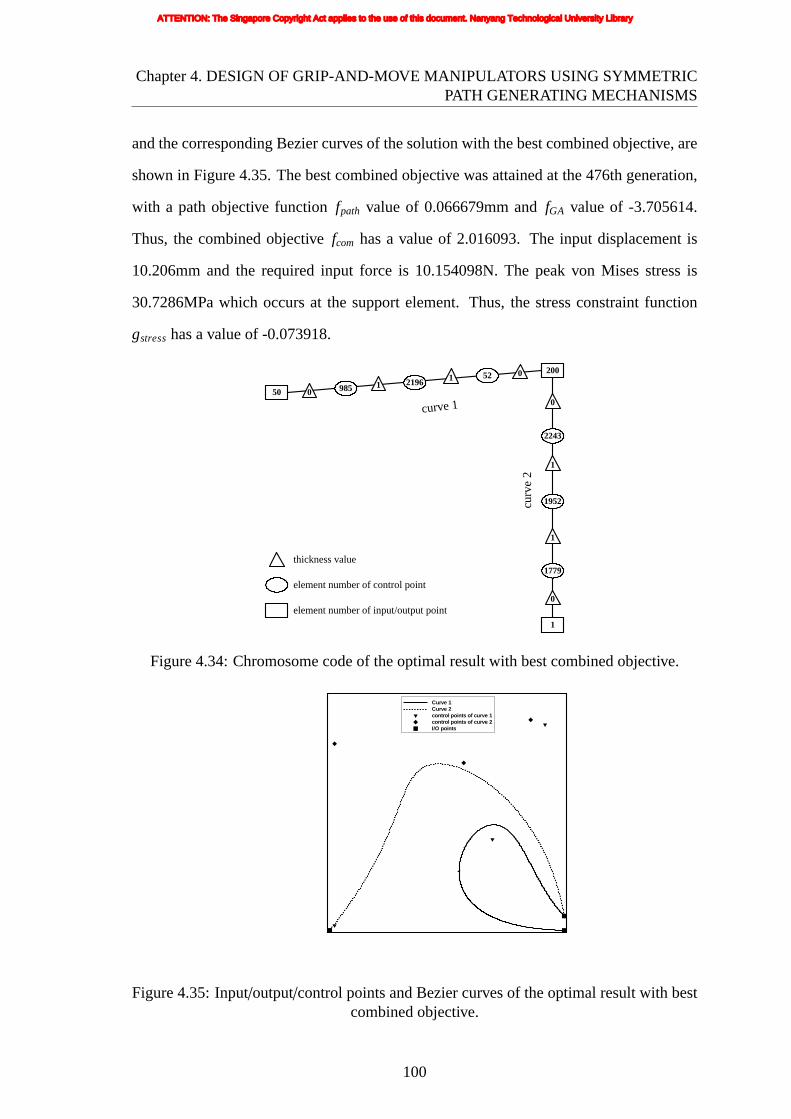
Chapter4. DESIGN OF GRIP-AND-MOVE MANIPULATORS USING SYMMETRICPATH GENERATING MECHANISMS
andthe corresponding Bezier curves of the solution with the best combined objective, are
shown in Figure 4.35. The best combined objective was attained at the 476th generation,
with a path objective functionfpath value of 0.066679mm andfGA value of -3.705614.
Thus, the combined objectivefcom has a value of 2.016093. The input displacement is
10.206mm and the required input force is 10.154098N. The peak von Mises stress is
30.7286MPa which occurs at the support element. Thus, the stress constraint function
gstresshas a value of -0.073918.
1
50
element number of input/output point
element number of control point
thickness value
curv
e 2
200
0 9852196
521
1 0
curve 1 0
2243
1952
1779
1
1
0
Figure4.34: Chromosome code of the optimal result with best combined objective.
Curve 1Curve 2control points of curve 1control points of curve 2I/O points
Figure4.35: Input/output/control points and Bezier curves of the optimal result with bestcombined objective.
100
ATTENTION: The Singapore Copyright Act applies to the use of this document. Nanyang Technological University Library

Chapter4. DESIGN OF GRIP-AND-MOVE MANIPULATORS USING SYMMETRICPATH GENERATING MECHANISMS
Following the same sequence and format of results/plots shown in Run 2, the rest of
the corresponding set of results from Run 3 are shown in Figures 4.36 to 4.43.
output x-displacement (m)
outp
uty-
disp
lace
men
t(m
)
-0.01 0 0.01 0.02
-0.07
-0.06
-0.05
-0.04
-0.03
-0.02
-0.01
0
0.01FE analysissymmetry lineexperiment(prototype)
(a) (b) (c)
Figure 4.36: Compliant grip-and-move manipulator (a) arrangement (b) prototype (c)symmetric paths from the FE analysis and prototype (Run 3).
(a)fpath = 6.857259mmfGA = −0.021987fcom = 295.9809
gstress = −0.337252
(b)fpath = 20.99958mmfGA = −0.815885fcom = 21.61241
gstress = −0.748091
(c)fpath = 31.81053mmfGA = −2.683608fcom = 319.9685
gstress = −0.025576
Figure 4.37: Sample solutions from the initial (randomly generated) population.
101
ATTENTION: The Singapore Copyright Act applies to the use of this document. Nanyang Technological University Library

Chapter4. DESIGN OF GRIP-AND-MOVE MANIPULATORS USING SYMMETRICPATH GENERATING MECHANISMS
(a)generation 50 (bestfpath)fpath = 0.080278mmfGA = −1.779921fcom = 3.611895
gstress = −0.548130
(b) generation 50 (bestfcom)fpath = 0.080278mmfGA = −1.779921fcom = 3.611895
gstress = −0.548130
(c) generation 50 (bestfGA)fpath = 8.040815mmfGA = −5.721136fcom = 81.28210
gstress = −0.054500
(d) generation 100 (bestfpath)fpath = 0.080278mmfGA = −1.779921fcom = 3.611895
gstress = −0.548130
(e) generation 100 (bestfcom)fpath = 0.188723mmfGA = −3.581011fcom = 3.283481
gstress = −0.051782
(f) generation 100 (bestfGA)fpath = 9.418611mmfGA = −7.100627fcom = 94.89027
gstress = −0.137679
(g) generation 300 (bestfpath)fpath = 0.035877mmfGA = −1.497864fcom = 3.696858
gstress = −0.866052
(h) generation 300 (bestfcom)fpath = 0.066679mmfGA = −3.705614fcom = 2.016093
gstress = −0.739182
(i) generation 300 (bestfGA)fpath = 8.247529mmfGA = −8.062355fcom = 83.09545
gstress = −0.073085
Figure 4.38: Best feasible solutions from sample intermediate generations.
102
ATTENTION: The Singapore Copyright Act applies to the use of this document. Nanyang Technological University Library

Chapter4. DESIGN OF GRIP-AND-MOVE MANIPULATORS USING SYMMETRICPATH GENERATING MECHANISMS
generation number
path
obje
ctiv
e
GA
obje
ctiv
e
Co
mbi
ned
obj
ectiv
e
0 100 200 300 400 500-0.002
0
0.002
0.004
0.006
-9
-8
-7
-6
-5
-4
-3
-2
-1
0
-100
0
100
200
300
400
500path objecitveGA objectivecombined objective
Figure4.39: History of the best path objective (fpath).
generation number
path
obje
ctiv
e
GA
obje
ctiv
e
Co
mbi
ned
obj
ectiv
e
0 100 200 300 400 500-0.002
0
0.002
0.004
0.006
-9
-8
-7
-6
-5
-4
-3
-2
-1
0
0
10
20
30
40
50
60
70path objecitveGA objectivecombined objective
Figure4.40: History of the best combined objective (fcom).
103
ATTENTION: The Singapore Copyright Act applies to the use of this document. Nanyang Technological University Library

Chapter4. DESIGN OF GRIP-AND-MOVE MANIPULATORS USING SYMMETRICPATH GENERATING MECHANISMS
generation number
path
obje
ctiv
e
GA
obje
ctiv
e
Co
mbi
ned
obj
ectiv
e
0 100 200 300 400 5000
0.01
0.02
0.03
0.04
0.05
0.06
-9
-8
-7
-6
-5
-4
-3
-2
-1
0
-100
-50
0
50
100
150
200
250path objecitveGA objectivecombined objective
Figure4.41: History of the best GA objective (fGA).
104
ATTENTION: The Singapore Copyright Act applies to the use of this document. Nanyang Technological University Library
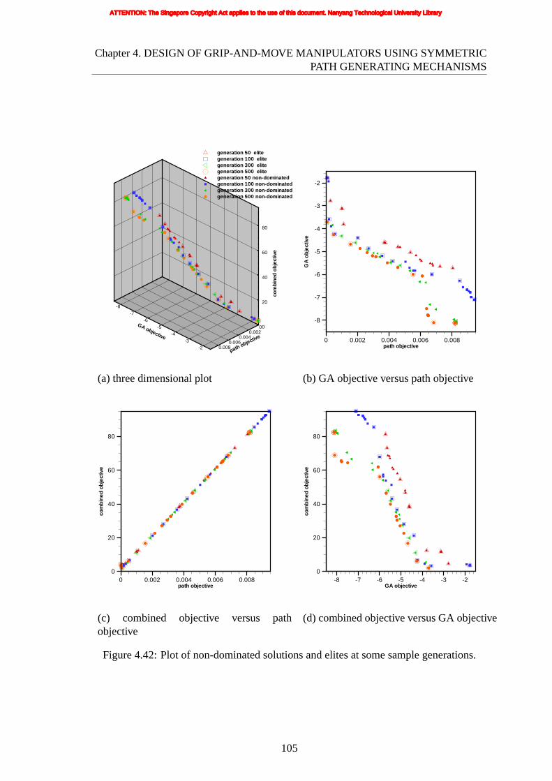
Chapter4. DESIGN OF GRIP-AND-MOVE MANIPULATORS USING SYMMETRICPATH GENERATING MECHANISMS
path objective
00.002
0.0040.006
0.008
GA objective
-8-7
-6-5
-4-3
-2
com
bine
dob
ject
ive
0
20
40
60
80
generation 50 elitegeneration 100 elitegeneration 300 elitegeneration 500 elitegeneration 50 non-dominatedgeneration 100 non-dominatedgeneration 300 non-dominatedgeneration 500 non-dominated
path objective
GA
obje
ctiv
e
0 0.002 0.004 0.006 0.008
-8
-7
-6
-5
-4
-3
-2
(a) three dimensional plot (b) GA objective versus path objective
path objective
com
bin
edo
bjec
tive
0 0.002 0.004 0.006 0.0080
20
40
60
80
GA objective
com
bin
edo
bjec
tive
-8 -7 -6 -5 -4 -3 -20
20
40
60
80
(c) combined objective versus pathobjective
(d) combined objective versus GA objective
Figure 4.42: Plot of non-dominated solutions and elites at some sample generations.
105
ATTENTION: The Singapore Copyright Act applies to the use of this document. Nanyang Technological University Library
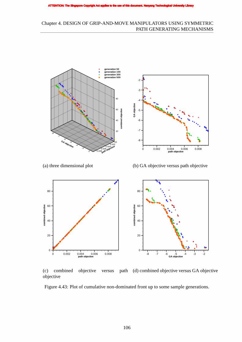
Chapter4. DESIGN OF GRIP-AND-MOVE MANIPULATORS USING SYMMETRICPATH GENERATING MECHANISMS
path objective
00.002
0.0040.006
0.008
GA objective
-8-7
-6-5
-4-3
-2
com
bine
dob
ject
ive
0
20
40
60
80
generation 50generation 100generation 300generation 500
path objective
GA
obje
ctiv
e
0 0.002 0.004 0.006 0.008
-8
-7
-6
-5
-4
-3
-2
(a) three dimensional plot (b) GA objective versus path objective
path objective
com
bin
edo
bjec
tive
0 0.002 0.004 0.006 0.0080
20
40
60
80
GA objective
com
bin
edo
bjec
tive
-8 -7 -6 -5 -4 -3 -20
20
40
60
80
(c) combined objective versus pathobjective
(d) combined objective versus GA objective
Figure 4.43: Plot of cumulative non-dominated front up to some sample generations.
106
ATTENTION: The Singapore Copyright Act applies to the use of this document. Nanyang Technological University Library

Chapter4. DESIGN OF GRIP-AND-MOVE MANIPULATORS USING SYMMETRICPATH GENERATING MECHANISMS
4.6 DISCUSSION
Unlike compliant mechanisms such as grippers, crimping/clamping mechanisms and
displacement inverters/amplifiers, the most important objective of a symmetric path
generating compliant mechanism is to minimize the path objective function which
quantifies the error between the actual and the desired paths. Although generating
a path correctly is of utmost importance for a symmetric path generating compliant
mechanism, improvement in the flexibility of the mechanism without deteriorating the
path objective is also desirable. Keeping this in mind, a second objective, the GA
objective, has been devised and used so that the flexibility of the mechanism is also
maximized simultaneously.
As can be seen from the result, the path produced by the optimum design (with the
best combined objective) is very close to being symmetric. The GA attained in the best
combined objective result is also fairly good while the mechanism with the best path
objective or the best GA objective are not so good because of their other objective values.
However, the absolute length of the path generated by the optimum design is relatively
short compared to the size of the structure. Future work needs to be done to improve the
length of the path with respect to the size of the structure in order to extend the working
range of the manipulator.
As shown in the plots, the (experimental) measured paths are not as close to the desired
symmetric curves as suggested by the FE results. Results from Run 1 are fairly close,
while Run 3 prototype result is quite far from FE analysis. However the (experiment)
path of the Run 3 prototype can simply be re-oriented to make it more symmetric, and
hence the orientation/position of the two mechanisms of Run 3 can be adjusted and the
line of symmetry rearranged to construct a grip-and-move manipulator. Unlike results
from Run 1 and Run 3, the experimental path produced by the prototype of Run 2 is
not very symmetric. The first possible reason for the difference between design and its
corresponding prototype is the shape change after smoothening the jagged-edge structure.
The second possible reason is inaccuracies in the experimental measurement. And the
107
ATTENTION: The Singapore Copyright Act applies to the use of this document. Nanyang Technological University Library

Chapter4. DESIGN OF GRIP-AND-MOVE MANIPULATORS USING SYMMETRICPATH GENERATING MECHANISMS
third possible reason is that although numerical simulation results can predict mechanism
properties, they may not be expected to be very accurate.
108
ATTENTION: The Singapore Copyright Act applies to the use of this document. Nanyang Technological University Library

Chapter 5
IMPROVED METHODOLOGY
5.1 ENHANCED GEOMETRIC REPRESENTATION
SCHEME FOR STRUCTURAL TOPOLOGY
OPTIMIZATION
The enhanced geometry representation scheme is the same as that described in Chapter 4
except that, in the enhanced scheme, the connectivities and the number of curves used
are made variable and to be optimized in the evolutionary procedure. In the original
scheme described in Chapter 4, the connectivity and number of curves used are defined
by the designer in advance and thereafter remain fixed throughout the optimization. As
the symmetric path mechanism described in Chapter 4 is one-DOF mechanism, it has
only one input point which together with the support point and output point forms a
total of three I/O points. With three I/O points, it is not difficult for the designer to
prescribe an intuitively suitable connectivity and number of curves since there are only a
total of four possible valid connectivities (assuming only one connecting curve between
any two points). However, for creating the second type of grip-and-move manipulator to
be described later in Chapter 7, 2-DOF mechanisms are to be designed with two input
points and hence a total of four I/O points. This means that a minimum number of three
curves are needed for a valid connectivity of the four I/O points, and a maximum of six
curves will give full connectivity. Hence there is a large number of permutation (a total
of 38 possible valid connectivities) and it becomes difficult for the designer to intuitively
prescribe one that is likely the best connectivity. This is thus the motivation behind the
development of the enhanced morphological scheme which maintains full connectivities
109
ATTENTION: The Singapore Copyright Act applies to the use of this document. Nanyang Technological University Library

Chapter5. IMPROVED METHODOLOGY
(6 curves) in the chromosome code but whichever of the curves are actually used will be
selected (optimized) through the evolutionary procedure.
5.1.1 Enhanced Morphological Representation of Geometry
The structural geometry representation scheme developed here is an enhancement of the
morphological representation scheme introduced in Section 4.3 which is referred to here
as the old method [249]. Figure 5.1(a) shows an example problem defined with four I/O
locations, each made up of one element in black. The positions of these are variable
but sometimes may be confined to only the boundary (as in this example illustration)
depending on the problem requirements. Six connecting curves in the illustration of
Figure 5.1(b), three of which are active and three of which are inactive, are used such
that there is one connecting curve between any two points (i.e. every I/O point is directly
connected to the other three). Before continuing, it is important to make a clear distinction
between theactiveandinactivecurves. The active curves are the curves which are in the
‘on’ state. The structure is generated based only on the active curves. Although the
inactive curves, which are in the ‘off’ state, temporarily contribute nothing to the current
structure, they are still very important in subsequent generations because they may be
turned ‘on’ later through the crossover or mutation operations. In Figure 5.1(b), the active
curves are marked with thick lines and the inactive with thin dotted lines. The connectivity
of the I/O points is based on all connecting active curves joining one point to another. And
this connectivity can be varied by altering the states of curves. In this example, a total
of 38 distinct and valid connectivities of the 4 I/O points can be defined while the old
method which specifies a fixed connectivity can only define 1 connectivity. Each curve is
a Bezier curve defined by the position vectorr:
r = r(u) = sn∑
k=0
n!k!(n − k)!
uk(1− u)n−kr k (5.1)
wheres is the state of current curve whose value is 0 when inactive or 1 when active while
all the other parameters are defined exactly the same as those used in the old method.
110
ATTENTION: The Singapore Copyright Act applies to the use of this document. Nanyang Technological University Library

Chapter5. IMPROVED METHODOLOGY
I/O points
curve1curve2curve3curve4curve5curve6control points of curve 1control points of curve 2control points of curve 3I/O points
(a)FE discretization of design space (I/Oelement marked in black)
(b) Connecting I/O elements with Beziercurves
(c) Skeleton made up of elements alongcurves
(d) Surrounding elements added toskeleton to form final structure
Figure 5.1: Definition of structural geometry by morphological scheme.
111
ATTENTION: The Singapore Copyright Act applies to the use of this document. Nanyang Technological University Library

Chapter5. IMPROVED METHODOLOGY
5.1.2 Chromosome Encoding
As in the old method, the structural geometry in Figure 5.1(d) can be encoded as a
chromosome in the form of a graph as shown in Figure 5.2. For identification purpose, the
active curves are shown by solid lines and the inactive curves are represented by dotted
lines. The design variables (the element numbers of those elements in which the I/O points
and the Bezier curve control points are located, and the thickness values) are defined in
exactly the same way as in the old method. However, a new design variable, the curve
states, is introduced. Altering the curve states can vary the connectivity of the I/O regions,
and therefore the representation scheme can automatically decide the connectivity. The
resulting scheme therefore increases the variability of the connectivity of the curves and
hence the variability of the structure topology.
element number of input/output point
element number of control point
thickness value
1 1874 2041 15972 2 1
curve 3
0
1814
2474
880
0
2
0
curve 1
1
2163
1829
671
2
0
0
curv
e 2
1
788
778
1121
0
2
0
curv
e 4
2
993
1053
2357
1
1
3
33
2480
1
2283
1451
1779
2
0
1
17511550
curve 5
curv
e 6
Figure5.2: Chromosome code.
112
ATTENTION: The Singapore Copyright Act applies to the use of this document. Nanyang Technological University Library

Chapter5. IMPROVED METHODOLOGY
5.1.3 Genetic Operators
5.1.3.1 Crossover
An example illustrating the crossover operation is shown in Figure 5.3. The closed loop,
which is shown in both Figure 5.3(a) and Figure 5.3(b), cutting across portions of the
chromosomes represent the sectioning or crossover loop. Applying the same crossover
loop to any given pair of parent chromosomes and swapping the subgraph contained
within the loop will produce two children. After such a crossover operation, it is possible
that part of a curve in the child chromosome is inherited from an active curve of one
parent, while the other part is inherited from an inactive curve of the other parent. In such
a situation, it is necessary to determine whether that curve in the child chromosome should
be considered active or inactive. This is decided by whether the ‘on’ or ‘off’ variables
dominate the curve, i.e. if the number of ‘on’ variables is more than the ‘off’ variables,
then the curve is active; otherwise it is inactive. This always works and there will never
be a tie because the total number of variables in a curve (the control point variables
and the thickness variables) is always an odd number. As a result, the connectivities
of the two child chromosomes generated can be different from their parents, as shown in
Figure 5.3(c) and (d).
The outcome of this crossover operation is demonstrated in an example (Figure 5.4)
through the crossover of two parents, and it can be seen that geometric characteristics from
both parents are recombined in each child. In other words, each resulting child inherits
geometric characteristics and connectivity from both parents. And the advantages of the
representation (such as no checkerboard patterns and single-node hinge connections) are
maintained in the offspring.
Furthermore, the child chromosome may become invalid after the crossover if the
active curves do not form a connected graph, which in turn may not define a single
connected structure. In other words, for this crossover operator, the preservation of
connectivity is not guaranteed. The way this problem is overcome is by simply discarding
any child chromosome that is invalid. Determining whether a chromosome (graph) is
113
ATTENTION: The Singapore Copyright Act applies to the use of this document. Nanyang Technological University Library
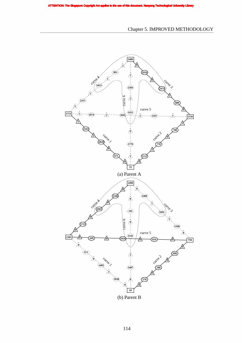
Chapter5. IMPROVED METHODOLOGY
1 1874 2041 15972 2 1
curve 3
0
1814
2474
880
0
2
0
curve 1
1
2163
1829
671
2
0
0
curv
e 2
1
788
778
1121
0
2
0
curv
e 4
2
993
1053
2357
1
1
3
33
2480
1
2283
1451
1779
2
0
1
17511550
curve 5
curv
e 6
(a)Parent A
0 449 1054 6240 0 0
curve 3
0
2469
1691
1108
1
2
0
curve 1
0
971
1405
1838
0
1
0
curv
e 2
0
698
388
570
0
0
0
curv
e 4
0
1566
1665
1723
0
0
0
18
2490
0
195
1541
1487
0
2
0
1201750
curve 5
curv
e 6
(b) Parent B
114
ATTENTION: The Singapore Copyright Act applies to the use of this document. Nanyang Technological University Library

Chapter5. IMPROVED METHODOLOGY
1 1874 2041 15972 2 1
curve 3
880
2
0
curve 1
1
2163
1829
671
2
0
0
curv
e 2
1
788
778
1121
0
2
0
curv
e 4
2357
3
33
1779
0
1
17511550
curve 5
0
2469
1691
1
0
1566
1665
0
2490
0
195
1541
0
curv
e 6
1
(c) Child 1
curv
e 6
0 449 1054 6240 0 0
curve 3
1108
2
0
curve 1
0
971
1405
1838
0
1
0
curv
e 2
0
698
388
570
0
0
0
curv
e 4
1723
0
0
18
1487
2
0
1201750
curve 5
0
1814
2474
0
2
993
1053
1
2480
1
2283
1451
2
(d) Child 2
Figure 5.3: Chromosome codes of crossover operation between parents.
115
ATTENTION: The Singapore Copyright Act applies to the use of this document. Nanyang Technological University Library

Chapter5. IMPROVED METHODOLOGY
(a)Parent A (b) Parent B
(c) Child 1 (d) Child 2
Figure 5.4: Outcome of crossover operation between parents.
116
ATTENTION: The Singapore Copyright Act applies to the use of this document. Nanyang Technological University Library

Chapter5. IMPROVED METHODOLOGY
connectedor not can be done efficiently via a Breath First Search (BFS) method [250].
5.1.3.2 Mutation
The mutation operator devised for this chromosome encoding works by applying a
mutation probability to every vertex of the graph to determine whether that vertex is
to be mutated, and if it is to be mutated, then alter the value in that vertex to a
randomly generated value (within the allowable range) or changing the on/off states of the
selected curves. This means that under the mutation operation, the positions of selected
input/output/control points, thickness values or on/off states of curves in a chromosome
are changed randomly. Mutation of the state is simple, which is altering the state of
curves. When the selected curve is active, it will be inactive after mutation. If the selected
curve is inactive, it will be active after mutation. An example illustrating this operation is
shown in Figure 5.5.
As in the crossover operation, the child chromosome may become invalid after
mutation because the active curves may no longer define a connected graph. The way
to overcome this problem is again to discard the child chromosome if it is invalid.
117
ATTENTION: The Singapore Copyright Act applies to the use of this document. Nanyang Technological University Library

Chapter5. IMPROVED METHODOLOGY
curv
e 6
0 449 1054 6240 0 0
curve 3
1108
0
0
curve 1
0
971
1405
1838
0
0
0
curv
e 2
0
698
388
570
0
0
0
curv
e 4
1723
0
0
18
1487
2
0
1201750
curve 5
0
1814
2474
0
2
993
1053
1
2480
1
2283
1451
2
(a)Before mutation
curv
e 6
0 449 1054 6240 0 0
curve 3
1108
0
0
curve 1
0
971
1405
1838
0
0
0
curv
e 2
0
698
388
570
0
0
0
curv
e 4
1723
0
0
18
1487
2
0
1201750
curve 5
0
1814
2474
0
2
993
1053
1
2480
1
2283
1451
2
(b) After mutation
118
ATTENTION: The Singapore Copyright Act applies to the use of this document. Nanyang Technological University Library

Chapter5. IMPROVED METHODOLOGY
(c) Before mutation (d) After mutation
Figure 5.5: Mutation operation of on/off state.
5.2 MULTIOBJECTIVE OPTIMIZATION BY A
GENETIC ALGORITHM
The newly proposed multiobjective genetic algorithm is the same as described in
Chapter 4 but modified to incorporate a optimization-level decision-making technique
to integrate the user’s preference [251] and hybridize with a local search (LS) strategy to
improve its efficiency [252]. The novel approach (adaptive constraint) treats the relatively
more important and/or challenging objectives as constraints whose ideal values will be
adaptively changed (improved) during the evolutionary procedure. This helps to direct
and focus the genetic search towards regions of interest in the objective space, thus is a
useful and intuitive way for specifying the user’s preference and/or for tackling the harder
objectives.
119
ATTENTION: The Singapore Copyright Act applies to the use of this document. Nanyang Technological University Library

Chapter5. IMPROVED METHODOLOGY
5.2.1 Adaptive Constraint
Very often design optimization problems involve multiple objectives. Although it
is difficult to evaluate the importance of the various objectives quantitatively during
the conceptual/preliminary stages of the design process, usually qualitative statements
about the locations of interesting regions in the objective space can be made. This
section presents a novel, simple and intuitive way to integrate the user’s preference
into the genetic algorithm. This approach treats relatively more important objectives as
adaptive constraints whose ideal values will be adaptively changed (improved) during the
evolutionary procedure. Such changes will affect the region feasibility of the objective
space which results in the variation of problem type (unconstrained problem, moderately
constrained problem or highly constrained problem). As the selection criteria for mating
partner depends on the type of problem in the algorithm used here, more selection pressure
is put on adaptive constraints. The proposed algorithm efficiently guides the population
towards the (preferred) region of interest, allowing a faster convergence and a better
coverage of the preferred area of the Pareto optimal front based on the relative importance
of the objectives. Furthermore, by defining the harder or more challenging objectives
as adaptive constraints, this approach will also be helpful for guiding and focusing the
population and search towards improving those objectives.
As shown in Figure 5.6, if the region nearer thef1 axis (with lower values off2) is of
interest (preferred), i.e. the left portion as demarcated by the boundary line, it is obvious
that the non-dominated set 2 marked with circles is better than the non-dominated set 1
marked with triangles. And non-dominated set 2 is almost similar to non-dominated set 3
in the region of interest. If non-dominated set 2 can be obtained faster than non-dominated
set 3, then it is preferred over non-dominated set 3 because of its lower computational cost.
The optimization technique presented here will direct the solutions towards a preferred
Pareto-optimal region. Hence the approach presented will be useful for solving the type
of problems represented in Figure 5.7 where it may be easy to obtain a non-dominated set
far from the preferred region of interest especially when some of the objectives can easily
120
ATTENTION: The Singapore Copyright Act applies to the use of this document. Nanyang Technological University Library

Chapter5. IMPROVED METHODOLOGY
f1
f2
non-dominated set 1
non-dominated set 2
non-dominated set 3
Figure5.6: Non-dominated sets obtained using different algorithms.
reach their optimal values while others cannot. A straightforward evolutionary procedure
will not have the ability to escape from this easy part and the true Pareto front cannot be
obtained. But the method proposed in this work can help overcome such difficulties.
f1
f2
Figure5.7: Non-dominated set far from the preferred portion of Pareto-optimal front.
The formulation of the algorithm is similar to theε-Constraint method proposed
in [253]. Following from the multiobjective problem shown in Equation 4.7, the problem
here is reformulated by keeping some of the objectives and constraining the rest of the
objectives within prescribed values which are adaptively improved over the generations.
121
ATTENTION: The Singapore Copyright Act applies to the use of this document. Nanyang Technological University Library

Chapter5. IMPROVED METHODOLOGY
Themodified problem is as follows:
Minimize f(x) =[f1(x) f2(x) · · · fp(x)
]
subject to fi(x) − Fi ≤ 0, i = p + 1, p + 2, · · ·mgj(x) ≤ 0, j = 1,2, · · · ,qhk(x) = 0, k = 1,2, · · · , r
(5.2)
wherep is the number of the original objectives which are kept as objectives.
In the above formulation, the parameterFi represents a tentative ideal value of the
correspondingi-th objective. It will be automatically updated in the evolution process
according to the mechanism described in Section 5.2.1.2.fi(x) − Fi will be treated as a
constraint which is called an adaptive constraint in this work. Then the objective matrix
(shown in Equation 4.8) will be reduced to:
O′=
f11 f12 · · · f1p
f21 f22 · · · f2p
......
. . ....
fM1 fM2 · · · fMp
(5.3)
And the constraint matrix (shown in Equation 4.9) and combined matrix (shown in
Equation 4.10) are rewritten as:
C′ =
[Ca C
](5.4)
COM ′ =
[O′ C′
]=
[O′ Ca C
](5.5)
where
Ca=
f1(p+1) − F(p+1) f1(p+2) − F(p+2) · · · f1m− Fm
f2(p+1) − F(p+1) f2(p+2) − F(p+2) · · · f2m− Fm
......
. . ....
fM(p+1) − F(p+1) fM(p+2) − F(p+2) · · · fMm− Fm
(5.6)
Figure 5.8 shows some scenarios with differentF2 values for a problem with two
122
ATTENTION: The Singapore Copyright Act applies to the use of this document. Nanyang Technological University Library

Chapter5. IMPROVED METHODOLOGY
conflictingobjectivesf1 and f2 where f2 is converted into an adaptive constraint. Initially,
a large valueF(1)2 is used which make almost the whole objective space feasible. No
pressure is put in the selection process. After some generations, when the number of
feasible solutions reaches a prescribed number, the value ofF2 is updated toF(2)2 . The
resulting problem with this constraint value divides the original feasible objective space
into two portions. The right portion,f2(x)−F(2)2 > 0, becomes the infeasible region. Then
the elitist and selection strategy will put some pressure on the subsequent evolution. In
this way, theF2 value will be updated (reduced) in steps until it reaches its ideal minimum
value. Figure 5.8 also gives a glimpse of the progress of the non-dominated set towards
the real Pareto front.
f1
f2... (1)
2F(2)2F( )
2nF
Figure5.8: The adaptive constraint method for conflicting objectives.
For problem with non-conflicting objectives as shown in Figure 5.9, the process is
similar to the previous one. The difference between them is that the Pareto front will
converge to an optimal point at last. Figure 5.9 also gives a glimpse of the non-dominated
set progressing towards the optimal point.
5.2.1.1 Elitism
At every generation, all the feasible individuals are separated from the rest in the
population. Pareto ranking of these feasible individuals is separately computed among
123
ATTENTION: The Singapore Copyright Act applies to the use of this document. Nanyang Technological University Library

Chapter5. IMPROVED METHODOLOGY
f1
f2... (1)
2F(2)2F( )
2nF
Figure5.9: The adaptive constraint method for Non-conflicting objectives.
themselves based only on objectives and the resulting rank 1 individuals (non-dominated
front) are carried forward to next generation. This ensures the best feasible solution is
always carried forward to the next generation. This also eliminates the need of searching
back through history to locate the best feasible solutions. In this algorithm, another non-
dominated front obtained from individuals which are partially feasible is also considered
as elite solutions. Partially feasible individuals are those that satisfy the normal constraints
but do not satisfy the adaptive constraints.
Two limits have been imposed on the number of elite feasible solutions (denoted as
ncarryover) and elite partially feasible solutions (denoted asnpcarryover) being carried forward
to the next generation. If the number of elite feasible solutions or partially feasible
solutions exceeds a prescribed number, then only the prescribed number of well-spread
solutions are carried forward.
5.2.1.2 Updating of Ideal Values
Let any solution that satisfies all the normal constraints as well as thei-th adaptive
constraint be referred to as ani-th feasible solution. If the number of such solutions is
more thanMi in number, select onlyMi number of well-spread solutions, and update the
124
ATTENTION: The Singapore Copyright Act applies to the use of this document. Nanyang Technological University Library

Chapter5. IMPROVED METHODOLOGY
tentative ideal value of the corresponding adaptive constraint according to the following:
F(k+1)i = F(k)
i +1Mi
Mi∑
j=1
( f ji − F(k)i ) =
1Mi
Mi∑
j=1
f ji (5.7)
whereF(k+1)i is the new value after update, andF(k)
i is the current one. The process can be
controlled withMi. When a small value is used, the evolutionary process will put more
selection pressure to the corresponding adaptive constraint.
5.2.1.3 Proposed Algorithm
The algorithm for getting a set of Pareto optimal solutions is given below:
Step 1: Generate random initial population P of sizeM.
Step 2: Evaluate objective as well as constraint functions for each individual in P.
(Individuals carried forward without any change from the previous generation to the
current generation preserve the values of their objective and constraint functions.)
Step 3: Seti equal top + 1.
Step 4: If the number ofi-th feasible individuals in the population P is less thanMi,
then go to step 5. Else compute newFi value, and update the corresponding adaptive
constraint.
Step 5: Seti = i + 1. If i is less thanm, then go toStep 4.
Step 6: ComputeFeasRatio= (Number of feasible solutions in the population P)/ M.
Step 7: Compute Pareto Ranking based onO′ matrix to yield a vectorRankObjN ′.
Step 8: Compute Pareto Ranking based on[
O′ Ca
]matrix to yield a vector
RankObj ′.
Step 9: Compute Pareto Ranking based onC′ matrix to yield a vectorRankCon′.
Step 10: Compute Pareto Ranking based onCOM ′ matrix to yield a vector
RankCom′.
Step 11: Calculate the selection probablity based onO′ matrix to yield a vector
ProbObj ′. Calculate the selection probablity based onC′ matrix to yield a vector
ProbCon′.
125
ATTENTION: The Singapore Copyright Act applies to the use of this document. Nanyang Technological University Library
Chapter5. IMPROVED METHODOLOGY
Step12: If the individuals with rank 1 (based onRankObjN ′) are less thanncarryover
in number, then put all of them into the new population P′. Else selectncarryover number
of well-spread solutions out of all the rank 1 individuals and put them into the new
population P′.
Step 13: If the individuals with rank 1 (based onRankObj ′) are less thannpcarryover in
number, then put all of them into the new population P′. Else selectnpcarryover number
of well-spread solutions out of all the rank 1 individuals and put them into the new
population P′.
Step 14: If n is the number of decision variables, the bestn number of solutions in
the population (based onRankCom′) is selected. This is so that a mutation operation
(without crossover) can be applied to a single different decision variable in each of the
n different solutions, such that each of the variables will be mutated exactly once among
thosen number of solutions. Thesen number of mutated solutions are then put into the
new population P′.
Step 15: If the new population P′ is not full, then doStep 16to Step 24, else go toStep
25.
Step 16: Generate a random numberRandomNoA. If RandomNoA < FeasRatiothen
select an individuala based onProbObj ′; else select an individuala based onProbCon′.
Step 17: Generate a random numberRandomNoB. If RandomNoB < FeasRatiothen
select an individualb based onProbObj ′; else select an individualb based onProbCon′.
Step 18: Generate a random numberRandomNoC. If RandomNoC < FeasRatiothen
select an individualc based onProbObj ′; else select an individualc based onProbCon′.
Step 19: If b andc are both feasible, then ifRankOb j′b < RankOb j′c, thend = b else
d = c.
Step 20: If b andc are both infeasible, then ifRankCon′b < RankCon′c, thend = b else
d = c.
Step 21: If b is feasible andc is infeasible,d = b.
Step 22: If c is feasible andb is infeasible,d = c.
126
ATTENTION: The Singapore Copyright Act applies to the use of this document. Nanyang Technological University Library

Chapter5. IMPROVED METHODOLOGY
Step23: Matea with d. Mutate the children depending on the mutation probability.
Put the children into the new population P′.
Step 24: Go toStep 15.
Step 25: To eliminate duplication of solution within P′, remove solutions which are
identical to any other member of P′. After this, if number of individuals in P′ is less than
M, then go toStep 15.
Step 26: If number of individuals in P′ is more thanM, then drop the newest
individual(s) from P′ so that number of individuals in P′ becomeM.
Step 27: If maximum number of generations is reached, then stop; else set P= P′ and
go toStep 2.
5.2.2 Local Search
The Genetic Algorithm is a potent multiobjective optimization method, and the
effectiveness of hybridizing it with local search (LS) has recently been reported in the
literature (as discussed in Chapter 2). In this work, the proposed hybrid algorithm
integrates a simple local search strategy with the algorithm presented in Section 5.2.1. A
novel constrained tournament selection is used as a single objective function in the local
search strategy. The selection is utilized to determine whether a new solution generated in
the local search process will survive. The Hooke and Jeeves method is applied to decide
the search path. Good initial solutions, the solutions to be mutated, are chosen for local
search.
5.2.2.1 Tournament Selection for Local Search
Since a local search strategy requires a tournament selection between an initial solution
and its neighboring solution, a comparison strategy is needed. For multi-objective
optimization without constraints, a single objective function converted from multiple
objectives can be used. For constrained optimization, constraint handling mechanisms
should be given first. In most applications, penalty functions using static [190], dynamic
127
ATTENTION: The Singapore Copyright Act applies to the use of this document. Nanyang Technological University Library

Chapter5. IMPROVED METHODOLOGY
or adaptive concepts [200] have been widely used and are quite popular. The major
problem is the need for specifying the right value for penalty parameters in advance. The
method from Ray et al. [212] incorporates a Pareto ranking of the constraint violations
and so does not involve any aggregation of objectives or constraints and thus the problem
of scaling does not arise. Note that Pareto ranking is not well suited for hybridization
with local search. When Pareto ranking is used, the current solutionx is replaced with its
neighboring solutiony (i.e., the local search move fromx to y is accepted) only wheny
dominatesx (i.e.,y is better thanx). That is, the local search move is rejected whenx and
y are non-dominated with respect to each other. However, change of the rank of a given
solution may require significant changes of the objective/constraint values, and so, many
local moves will not improve the rank. The main difficulty with using the Pareto ranking
approach is that the movable area of the current solution by local search is very small.
Deb [205] proposed a constraint handling method which is also based on the penalty
function approach but does not require the prescription of any penalty parameter. The
main idea of this method is to use a tournament selection operator and to apply a set of
criteria in the selection process:
1. Any feasible solution is preferred to any infeasible solution.
2. Between two feasible solutions, the one having better objective function value is
preferred.
3. Between two infeasible solutions, the one having smaller constraint violation is
preferred.
According to these criteria, the constrained optimization can be constructed as
f (x) =
f (x) if x ∈ F
fmax + vio(x) otherwise(5.8)
where f (x) is the artificial unconstrained objective function,F the feasible region of
the design domain,fmax the objective function value of the worst feasible solution in
128
ATTENTION: The Singapore Copyright Act applies to the use of this document. Nanyang Technological University Library

Chapter5. IMPROVED METHODOLOGY
the population, andvio(x) the summation of all the violated constraint function values.
However, this approach is only suitable for single-objective constrained optimization
problem if no further handling mechanisms for multiple objectives are given. Andvio(x)
as summation of constraint values cannot reflect the real relative comparison between
them because of different orders of magnitude among the constraints.
Extending the basic idea of Deb’s method, a technique combining Pareto ranking
and weighted sum is suggested for the local search selection process. There are only 3
combinations for the two solutions: both feasible, both infeasible, and one feasible and the
other infeasible. The main idea of the technique is to use a tournament selection operator
and to apply a set of criteria in the selection process. Any feasible solution is preferred
to any infeasible solution. When both solutions are feasible, Pareto ranking based on
objectives is calculated. The one with smaller rank value is preferred. If the situation still
ties, a more sophisticated acceptance rule is used for handling the situation. The fitness
function of the solutionx is calculated by the following weighted sum of themobjectives:
f (x) = w1 f1(x) + w2 f2(x) + · · · + wm fm(x) (5.9)
where f (x) is a combined objective andw1,w2, · · · ,wm are nonnegative weights for the
objectives set according to different orders of magnitude among them. Constant weight
values are used in this work to fix the search direction based on user’s preference. The
solution with a smallerf (x) will survive. When both solutions are infeasible, Pareto
ranking based on constraints is calculated. The one with smaller rank value is preferred.
If the rank is same, the one with better fitness value survives. The selection criteria can
be described as below to decide whether a current solutionx should be replaced by a
neighboring solutiony:
1. If x is infeasible andy is feasible, replace the current solutionx with y (i.e., let
x = y).
2. If both x and y are feasible, then ifRankOb jy < RankOb jx, thenx = y, else if
129
ATTENTION: The Singapore Copyright Act applies to the use of this document. Nanyang Technological University Library

Chapter5. IMPROVED METHODOLOGY
RankOb jy = RankOb jx and f (y) < f (x), thenx = y.
3. If both x andy are infeasible, then ifRankCony < RankConx, thenx = y, else if
RankOb jy = RankOb jx and f (y) < f (x), thenx = y.
To obtain dominance rank value, such asRankOb jy, RankOb jx, RankCony, or
RankConx, there is a procedure for maintaining a finite sized archive of solutions.
The solutions in the archive are representative of solutions found by the algorithm as
it searches the space. The solutions in the archive serve as a comparison set to aid
in estimating the dominance rank of new candidate solutions. For the constrained
optimization, two archives are required. One is used for Pareto ranking of objectives,
consisting of a prescribed number of well-spread best objective solutions, and the other
for Pareto ranking of constraints, consisting of a prescribed number of well-spread best
constraint solutions. In this work, the comparison set is the whole solution space of the
last generation. This makes the local search phase partially independent of the global
search performed by the algorithm as a whole.
5.2.2.2 Selection of Initial Solutions
Local search applied to all solutions in the current population in the algorithm is
inefficient, as is shown in [238]. In the proposed algorithm, the computation time spent
by local search can be decreased by applying local search to only selected solutions. If
n is the number of decision variables, the bestn number of solutions from the current
population (based on Pareto ranking) is selected. This is so that a mutation operation
(without crossover) and local search can be applied to a single different decision variable
in each of then different solutions, such that each of the variables will be mutated and
locally searched exactly once among thosen number of solutions. Thesen number
of mutated solutions after local search are then put into the next population P′. It is
also possible to probabilistically apply local search to offspring solutions obtained from
crossover. This may somewhat degrade the inherent advantage of local search: simplicity.
Thus the local search procedure in crossover offspring is not implemented. The generation
130
ATTENTION: The Singapore Copyright Act applies to the use of this document. Nanyang Technological University Library
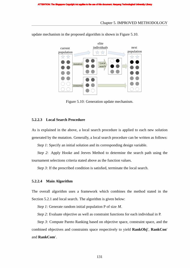
Chapter5. IMPROVED METHODOLOGY
updatemechanism in the proposed algorithm is shown in Figure 5.10.
mutation
crossover
Local search
current population
elite individuals next
population
Figure5.10: Generation update mechanism.
5.2.2.3 Local Search Procedure
As is explained in the above, a local search procedure is applied to each new solution
generated by the mutation. Generally, a local search procedure can be written as follows:
Step 1: Specify an initial solution and its corresponding design variable.
Step 2: Apply Hooke and Jeeves Method to determine the search path using the
tournament selections criteria stated above as the function values.
Step 3: If the prescribed condition is satisfied, terminate the local search.
5.2.2.4 Main Algorithm
The overall algorithm uses a framework which combines the method stated in the
Section 5.2.1 and local search. The algorithm is given below:
Step 1: Generate random initial population P of sizeM.
Step 2: Evaluate objective as well as constraint functions for each individual in P.
Step 3: Compute Pareto Ranking based on objective space, constraint space, and the
combined objectives and constraints space respectively to yieldRankObj ′, RankCon′
andRankCom′.
131
ATTENTION: The Singapore Copyright Act applies to the use of this document. Nanyang Technological University Library

Chapter5. IMPROVED METHODOLOGY
Step4: Select elite individuals. Elite individuals carried from the previous generation
preserve the values of their objective and constraint functions.
Step 5: Selectn good individuals from P, mutate and apply local search procedure,
then put them into new population P′.
Step 6: Crossover.
Step 7: If a prescribed stopping condition is satisfied, end the algorithm. Otherwise,
return toStep 2.
132
ATTENTION: The Singapore Copyright Act applies to the use of this document. Nanyang Technological University Library

Chapter 6
TEST PROBLEMS
6.1 INTRODUCTION
Before a genetic algorithm is relied upon for solving a problem with unknown solutions, it
is important that the performance of the genetic algorithm be tested and tuned by using it
to solve a problem with known solutions. Various kinds of test problems [178, 254–256]
had been found for testing multi-objective genetic algorithms. They were created with
different characteristics, including the dimensionality of the problem, number of local
optima, number of active constraints at the optimum, topology of the feasible search
space, etc. However, all of these test problems have well-defined objectives/constraints
expressed as mathematical functions of decision variables and therefore may not be ideal
for evaluating the performance of a genetic algorithm intended to solve problems where
the objectives/constraints cannot be expressed explicitly in terms of the decision variables.
In essence, a genetic algorithm is typically customized to tackle a certain type of problem
and therefore ‘general-purpose’ test problems may not correctly evaluate the performance
of the customized genetic algorithm. The test problem should, therefore, ideally suit (or
be customized to) the genetic algorithm being used.
In numerous real-life problems, objectives/constraints cannot be expressed
mathematically in terms of decision variables. One of such real-life problems is structural
topology optimization, where a procedure (structure geometry representation scheme)
first transforms decision variables into the true geometry of the designed structure and
then finite element analysis of the designed structure is carried out for evaluating the
objectives/constraints. The genetic algorithm solving such problems may have special
chromosome encoding to suit the structure geometry representation used and there
133
ATTENTION: The Singapore Copyright Act applies to the use of this document. Nanyang Technological University Library

Chapter6. TEST PROBLEMS
may also be specially devised reproduction operators to suit the chromosome encoding
used. As such, the structure geometry representation scheme, the chromosome encoding
and the reproduction operators introduce additional characteristics to the search space
and, therefore, they are very critical to the performance of the genetic algorithm.
The test problem for such genetic algorithms, therefore, must use the same structure
geometry representation scheme, chromosome encoding and reproduction operators. The
conventional test problems found in literature cannot make use of the genetic algorithm’s
integral procedures such as structure geometry representation scheme and therefore they
are not suitable for testing such genetic algorithms.
Ideally, the test problem should emulate the main problem to be solved. The test
problem should be computationally inexpensive so that it can be run many times for
the genetic algorithm parameters to be changed or experimented with and the effect
thereof can be studied for the purpose of fine-tuning the genetic algorithm. However,
the main problem in the present work, being a structural topology optimization problem,
requires structural analysis which consumes a great deal of time. Taking the running
time into consideration, the test problem needs to be designed without any need for
structural analysis. A test problem emulating structural topology optimization does not
necessarily need structural analysis as the main aim of topology optimization is to arrive
at an optimal structural geometry. Without using structural analysis, if a genetic algorithm
is successfully tested to be capable of converging the solutions to any arbitrary but
predefined and valid ‘target’ structural geometry, then it may be inferred that the genetic
algorithm would be able to converge design solutions to the optimal structural topology
when solving an actual topology optimization problem. Based on this inference, a test
problem can be designed such that simple geometry-based (rather than structural analysis
based) objectives/constraints help design solutions converge towards the predefined target
geometry. This type of test problem may be termed as “Target Matching Problem”,
which is capable of using exactly the same genetic algorithm (including structural
geometry representation scheme, chromosome encoding and reproduction operators) as
134
ATTENTION: The Singapore Copyright Act applies to the use of this document. Nanyang Technological University Library

Chapter6. TEST PROBLEMS
thatintended for solving the actual topology optimization problem.
6.2 TARGET MATCHING PROBLEM 1 (WITH NON-
CONFLICTING OBJECTIVES)
6.2.1 Formulation
The test problem used here was first developed in [151]. It is a simple and useful
test problem for verifying the performance of the representation scheme and proposed
methodology.
The test problem makes use of the original design space shown in Figure 6.1, and
has one support point, two loading points and one output point. The problem does not
represent a structural analysis problem, but the original terms ‘support’, ‘loading’ and
‘output’ have still been used for ease of reference. The positions of these I/O points
are variable but confined to the boundary (the support point is positioned anywhere
along the bottom boundary while the loading point 1 is positioned anywhere along the
left boundary, loading point 2 and the output point are positioned anywhere along the
right boundary). Six Bezier curves are used such that there is one connecting curve
between any two points in accordance with the morphological geometry representation
scheme proposed in Chapter 5. In this problem, the target geometry is as shown in
Figure 6.2. The aim is therefore to evolve structures that match as closely as possible
this target geometry. The problem presented here is more difficult than the original
problem described in [151], since there is one additional loading point that may introduce
unwanted segments/elements in the geometry. Any unwanted segments/elements will
make the geometry more complex and not easy to converge to the target. To form the
target geometry, this loading point needs to coincide with the output point as shown in
Figure 6.2.
This ‘target’ shape can be achieved with the following two objectives and two
constraints: distance objective, material objective, forbidden area constraint and
135
ATTENTION: The Singapore Copyright Act applies to the use of this document. Nanyang Technological University Library

Chapter6. TEST PROBLEMS
load
ing
poin
t 1
support
load
ing
poin
t 2/
outp
ut p
oint
Figure6.1: Design Space.
prescribed area constraint. Such a problem is defined with the help of Figure 6.3. The
distance objective to be minimized is given by
fdistance= dl + ds (6.1)
wheredl is the centroid-to-centroid Euclidean distance between the actual loading point
1 and the desired support point;ds is the centroid-to-centroid Euclidean distance between
the desired support point and the actual support point.
The material objective to be minimized is given by
fmaterial =
n∑
i=1
xi (6.2)
wherexi is the material density of thei-th element in the design space, with a value of
either 0 or 1 to represent that the element is either void or material (solid), respectively.
n is the total number of elements in the discretized design space. In other words, this
objective function is defined as the summation of the material density of all elements in
the current geometry. As this problem is solved using the adaptive constraint method, this
objective is set as the adaptive constraint because initial trials show that it is harder to
converge to the true optimum for this objective than for the distance objective.
136
ATTENTION: The Singapore Copyright Act applies to the use of this document. Nanyang Technological University Library

Chapter6. TEST PROBLEMS
Figure6.2: Target geometry.
ds
dl
actual loading point 1
desired support point
actual support point
Figure6.3: Formulation of Target Matching Problem 1 with Non-conflicting Objectives.
137
ATTENTION: The Singapore Copyright Act applies to the use of this document. Nanyang Technological University Library

Chapter6. TEST PROBLEMS
Theforbidden area constraint can be written as
gf orbidden =
nf∑
i=1
yi ≤ 0 (6.3)
whereyi is the material density of thei-th element in the forbidden area, with a value of
either 0 or 1 to represent that the element is either void or material (solid), respectively.
nf is the total number of elements in the forbidden area. In other words, the summation of
the material density of elements in the forbidden area is required to be less than or equal
to zero.
The prescribed area constraint can be written as
gprescribed= np −np∑
i=1
zi ≤ 0 (6.4)
wherezi is the material density of thei-th element in the prescribed area, with a value of
either 0 or 1 to represent that the element is either void or material (solid), respectively.
np is the total number of elements in the prescribed area. In other words, the summation
of the material density of elements in the prescribed area is required to be more than or
equal to the total number of elements in that area.
There are 5 equally optimal locations for the output point and each of them results in
a slightly different geometry. These five (slightly) distinct shapes have the same values of
objective/constraint functions (viz.fdistance= 49.5; fmaterial = 142;gf orbidden = 0; gprescribed
= 0) and therefore this test problem has multi-modal solutions. The test problem was
intentionally designed as multi-modal so that the capability of the genetic algorithm in
maintaining diversity could also be tested. One of the 5 target geometry shapes is shown
in Figure 6.2. The other four target geometry shapes are shown in Figure 6.4.
Figure 6.5 shows the objective space, in some part of which solutions are definitely
infeasible and the other part in which solutions may be feasible or infeasible. The solid
dot represents the Pareto optimal point. Note that although Figure 6.5 shows the objective
space and feasible/infeasible region as continuous region, the objective space is in actual
138
ATTENTION: The Singapore Copyright Act applies to the use of this document. Nanyang Technological University Library

Chapter6. TEST PROBLEMS
1 5040302010
50
40
30
20
10
11
1 5040302010
50
40
30
20
10
11
(a)Model A (b) Model B
1 5040302010
50
40
30
20
10
11
1 5040302010
50
40
30
20
10
11
(c) Model C (d) Model D
Figure 6.4: Other optimal solutions of the multimodal Target Matching Problem 1.
139
ATTENTION: The Singapore Copyright Act applies to the use of this document. Nanyang Technological University Library

Chapter6. TEST PROBLEMS
fact discrete because the objective functions are discrete-valued.
fmaterial50
36
73.8
2500
49.5
96.8
1514
infeasible
feasibe/infeasible
142
fdistance
99
Figure6.5: The solution space for Target Matching Problem 1.
6.2.2 Results
6.2.2.1 Run 1
In this target matching problem, six Bezier curves are used such that there is one
connecting curve between any two I/O points, with each curve defined by three control
points. All thickness values are allowed to vary between the minimum value 0 and
maximum value 3. There are a total of 52 design variables.
The genetic algorithm was run to solve the test problem with the following set of
evolutionary parameters:
(a) Population size: 200
(b) Normal mutation rate: 10% of those children formed by crossover
(c) Maximum number of feasible elites: 5% of population size
(d) Maximum number of partially feasible elites: 5% of population size
The optimization was run for 500 generations, by the end of which 95,007 objective
function evaluations have been performed. The total (wall-clock) time consumed for
running the genetic algorithm for 500 generations was 33580 seconds.
140
ATTENTION: The Singapore Copyright Act applies to the use of this document. Nanyang Technological University Library

Chapter6. TEST PROBLEMS
Two of the solutions at the end of 500 generations are shown in Figure 6.6.
Figure 6.6(a) shows the solution with best material objective but not best distance
objective. Figure 6.6(b) shows the solution with both the best distance objective and
best material objective. Its geometry exactly matches one of the optimal solutions as
shown in Figure 6.4(a). This optimal result was attained at the 482nd generation, with
a distance objective (fdistance) value of 49.5 and material objective (fmaterial) value of 142.
The corresponding value of either of the constraint functions (i.e.gf orbiddenandgprescribed)
is 0, asgf orbiddenandgprescribedare exactly 0 for all feasible solutions.
(a)
fdistance = 50.5fmaterial = 142
(b)
fdistance = 49.5fmaterial = 142
Figure 6.6: Two solutions at 500th generation.
The design variable values of the Figure 6.6(a) and (b) are shown in Figure 6.7(a) and
(b), respectively. The input/output/control points and the corresponding Bezier curves of
the Figure 6.6(a) and (b) are shown in Figure 6.8(a) and (b), respectively. Only curves 2,
3 and 5 are active and connected together to generate the target shape.
141
ATTENTION: The Singapore Copyright Act applies to the use of this document. Nanyang Technological University Library

Chapter6. TEST PROBLEMS
curv
e 6
0 1848 1495 19382 0 0
curve 3
1778
0
0
curve 1
2
1761
1887
1480
0
0
1
curv
e 2
0
1779
1693
2237
0
0
0
curv
e 4
1016
0
1
38
186
3
1
17011850
curve 5
0
1787
1722
0
2
1915
2149
2
1850
0
2451
348
3
(a)
curv
e 6
0 1848 1495 19382 0 0
curve 3
1778
0
0
curve 1
2
1761
1887
1480
0
0
1
curv
e 2
0
1779
1788
2338
0
0
0
curv
e 4
1016
0
1
37
186
3
1
17011850
curve 5
0
1888
1722
0
2
1915
2149
2
1850
0
2451
348
3
(b)
Figure6.7: Chromosome code of the results of Figure 6.6.
142
ATTENTION: The Singapore Copyright Act applies to the use of this document. Nanyang Technological University Library

Chapter6. TEST PROBLEMS
curve1curve2curve3curve4curve5curve6control points of curve 2control points of curve 3control points of curve 5I/O points
curve1curve2curve3curve4curve5curve6control points of curve 2control points of curve 3control points of curve 5I/O points
(a) (b)
Figure6.8: Input/output/control points and Bezier curves of Figure 6.6.
Figure 6.9 and Figure 6.10 provide a glimpse of the evolution history by a sampling
of the solutions obtained at the respectively indicated generations. Figure 6.9 shows
three solutions in the initial population with their corresponding objective/constraint
function values. Figure 6.10 (a)-(e) show the best feasible solutions (with their
corresponding objective values) achieved up to the respectively indicated generations.
The corresponding value of either of the constraint functions (i.e.gf orbiddenandgprescribed)
is 0. Two solutions at generation 50 are given, one with best distance objective and the
other with best material objective.
Figure 6.11 shows plots of the best distance objective (fdistance) and the corresponding
solution’s material objective (fmaterial) versus generation number.fdistance and fmaterial
values on the plot corresponding to any particular generation number belong to that
generation’s non-dominated feasible solution having the best distance objective. The
corresponding value of either of the constraint functions (i.e.gf orbidden and gprescribed)
is 0. The plot starts at generation number 9, as until this generation there is no feasible
143
ATTENTION: The Singapore Copyright Act applies to the use of this document. Nanyang Technological University Library

Chapter6. TEST PROBLEMS
(a)fdistance = 77.4fmaterial = 552
gf orbidden = 365gprescribed = 64
(b)fdistance = 78.6fmaterial = 688
gf orbidden = 310gprescribed = 75
(c)fdistance = 57.3fmaterial = 585
gf orbidden = 190gprescribed = 31
Figure 6.9: Sample solutions from the initial (randomly generated) population.
(a)generation 20
fdistance = 56.6fmaterial = 243
(b) generation 50 (bestfdistance)
fdistance = 51.5fmaterial = 186
(c) generation 50 (bestfmaterial)
fdistance = 52.2fmaterial = 173
(d) generation 100
fdistance = 51.5fmaterial = 163
(e) generation 300
fdistance = 50.5fmaterial = 142
Figure 6.10: Best feasible solutions from sample intermediate generations.
144
ATTENTION: The Singapore Copyright Act applies to the use of this document. Nanyang Technological University Library
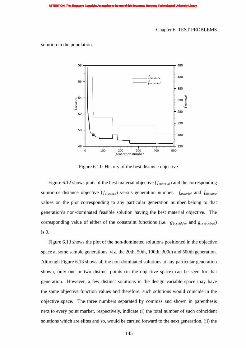
Chapter6. TEST PROBLEMS
solutionin the population.
generation number0 100 200 300 400 500
48
50
52
54
56
58
130
180
230
280
330
380
430
480
fdistancef
material
f dis
tanc
e
f mat
eria
l
Figure6.11: History of the best distance objective.
Figure 6.12 shows plots of the best material objective (fmaterial) and the corresponding
solution’s distance objective (fdistance) versus generation number.fmaterial and fdistance
values on the plot corresponding to any particular generation number belong to that
generation’s non-dominated feasible solution having the best material objective. The
corresponding value of either of the constraint functions (i.e.gf orbidden and gprescribed)
is 0.
Figure 6.13 shows the plot of the non-dominated solutions positioned in the objective
space at some sample generations, viz. the 20th, 50th, 100th, 300th and 500th generation.
Although Figure 6.13 shows all the non-dominated solutions at any particular generation
shown, only one or two distinct points (in the objective space) can be seen for that
generation. However, a few distinct solutions in the design variable space may have
the same objective function values and therefore, such solutions would coincide in the
objective space. The three numbers separated by commas and shown in parenthesis
next to every point marker, respectively, indicate (i) the total number of such coincident
solutions which are elites and so, would be carried forward to the next generation, (ii) the
145
ATTENTION: The Singapore Copyright Act applies to the use of this document. Nanyang Technological University Library

Chapter6. TEST PROBLEMS
0 100 200 300 400 50048
50
52
54
56
58
130
180
230
280
330
380
430
480
f
distance
mat
eria
l
f
generation number
dist
ance
f
fmaterial
Figure6.12: History of the best material objective.
number of such coincident solutions which are non-dominated among all the solutions
in the population at the indicated generation, and (iii) the number of such coincident
solutions which are non-dominated among all the solutions accumulated from the past
generations up till the indicated generation (inclusive).
50 52 54 56 58 60 62 64120
140
160
180
200
220
240
260
generation 20generation 50generation 100generation 300generation 500
(1,1,1)
(2,2,2)
(1,1,1)
(2,2,2)
(2,2,2)
(1,1,1)
(10,13,103)
fdistance
f mat
eria
l
Figure6.13: Plot of cumulative non-dominated front up to some sample generations.
146
ATTENTION: The Singapore Copyright Act applies to the use of this document. Nanyang Technological University Library
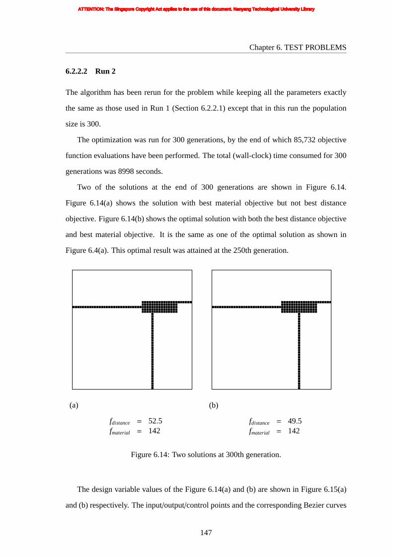
Chapter6. TEST PROBLEMS
6.2.2.2 Run 2
The algorithm has been rerun for the problem while keeping all the parameters exactly
the same as those used in Run 1 (Section 6.2.2.1) except that in this run the population
size is 300.
The optimization was run for 300 generations, by the end of which 85,732 objective
function evaluations have been performed. The total (wall-clock) time consumed for 300
generations was 8998 seconds.
Two of the solutions at the end of 300 generations are shown in Figure 6.14.
Figure 6.14(a) shows the solution with best material objective but not best distance
objective. Figure 6.14(b) shows the optimal solution with both the best distance objective
and best material objective. It is the same as one of the optimal solution as shown in
Figure 6.4(a). This optimal result was attained at the 250th generation.
(a)
fdistance = 52.5fmaterial = 142
(b)
fdistance = 49.5fmaterial = 142
Figure 6.14: Two solutions at 300th generation.
The design variable values of the Figure 6.14(a) and (b) are shown in Figure 6.15(a)
and (b) respectively. The input/output/control points and the corresponding Bezier curves
147
ATTENTION: The Singapore Copyright Act applies to the use of this document. Nanyang Technological University Library

Chapter6. TEST PROBLEMS
of the Figure 6.14(a) and (b) are shown in Figure 6.16(a) and (b) respectively. Only curves
3, 5 and 6 are active and connected together to generate the target shape.
curv
e 6
0 1850 1399 19861 0 0
curve 3
1762
2
0
curve 1
1
2035
2500
294
0
3
0
curv
e 2
0
1007
549
128
1
0
1
curv
e 4
1798
3
1
33
2182
0
0
17011850
curve 5
0
1944
1541
0
0
1382
665
3
1850
0
1671
1987
0
(a)
curv
e 6
0 1850 1400 19861 0 0
curve 3
1762
2
0
curve 1
1
2035
2500
294
3
0
0
curv
e 2
0
1007
549
128
1
0
1
curv
e 4
1798
3
1
37
2188
0
0
17011850
curve 5
0
1946
1541
0
0
1382
665
3
1850
0
1669
1990
0
(b)
Figure6.15: Chromosome code of the results of Figure 6.14.
148
ATTENTION: The Singapore Copyright Act applies to the use of this document. Nanyang Technological University Library

Chapter6. TEST PROBLEMS
curve1curve2curve3curve4curve5curve6control points of curve 3control points of curve 5control points of curve 6I/O points
curve1curve2curve3curve4curve5curve6control points of curve 3control points of curve 5control points of curve 6I/O points
(a) (b)
Figure6.16: Input/output/control points and Bezier curves of Figure 6.14.
Following the same sequence and format of results/plots shown in Run 1, the rest of
the corresponding set of results from Run 2 are shown in Figures 6.17 to 6.21. Note that
in Figure 6.19, the plot starts at generation number 5.
(a)fdistance = 70.1fmaterial = 756
gf orbidden = 353gprescribed = 40
(b)fdistance = 54.8fmaterial = 719
gf orbidden = 326gprescribed = 6
(c)fdistance = 46.7fmaterial = 765
gf orbidden = 268gprescribed = 48
Figure 6.17: Sample solutions from the initial (randomly generated) population.
149
ATTENTION: The Singapore Copyright Act applies to the use of this document. Nanyang Technological University Library

Chapter6. TEST PROBLEMS
(a) generation 20 (bestfmaterial)
fdistance = 63.4fmaterial = 224
(b) generation 20 (bestfdistance)
fdistance = 53.3fmaterial = 358
(c) generation 50 (bestfmaterial)
fdistance = 54.9fmaterial = 172
(d) generation 50 (bestfdistance)
fdistance = 51.9fmaterial = 236
(e) generation 100 (bestfmaterial)
fdistance = 53.9fmaterial = 167
(f) generation 100 (bestfdistance)
fdistance = 51.9fmaterial = 217
(g) generation 200 (bestfmaterial)
fdistance = 54.2fmaterial = 143
(h) generation 200 (bestfdistance)
fdistance = 51.2fmaterial = 167
Figure 6.18: Best feasible solutions from sample intermediate generations.
150
ATTENTION: The Singapore Copyright Act applies to the use of this document. Nanyang Technological University Library

Chapter6. TEST PROBLEMS
generation number0 50 100 150 200 250 300
40
44
48
52
56
60
64
100
300
500
700
900
1100
1300
fdistancef
material
f dis
tanc
e
f mat
eria
l
Figure6.19: History of the best distance objective.
generation number0 50 100 150 200 250 300
40
44
48
52
56
60
64
100
300
500
700
900
1100
1300
fdistancef
material
f dis
tanc
e
f mat
eria
l
Figure6.20: History of the best material objective.
151
ATTENTION: The Singapore Copyright Act applies to the use of this document. Nanyang Technological University Library

Chapter6. TEST PROBLEMS
50 55 60 65100
150
200
250
300
350
400
generation 20generation 50generation 100generation 200generation 300
(2,2,6)
(1,1,1)
(2,2,2)
(11,20,29)
(2,2,2)
(2,2,2)
(1,1,1)
(2,2,2)
(2,2,2)
(1,1,1)
(1,1,1)
(1,1,1)(2,3,4)(7,7,7)
(10,19,88)
fdistance
mat
eria
lf
Figure6.21: Plot of cumulative non-dominated front up to some sample generations.
152
ATTENTION: The Singapore Copyright Act applies to the use of this document. Nanyang Technological University Library

Chapter6. TEST PROBLEMS
6.2.3 Results of Variants of Local Search Methodology
A few variants of the local search methodology can be implemented. They are tested
in computational experiments using this target matching problem. The results from
these variants are then compared to results obtained from the proposed local search
methodology. In this section, these variants of the hybrid algorithm are briefly described
as follows:
6.2.3.1 Local Search Applied Only on Final Generation
In this case, local search is used only after the genetic algorithm is terminated, i.e. after
the final generation is obtained. Local search is applied to every variable of the final elite
solutions (and not just the mutation variable as in the proposed local search). It is referred
to as the “final elites method” in this experiment.
6.2.3.2 Initializing Local Search When a Better Solution is Generated by Mutation
When a solution with better performance is obtained from the mutation, local search is
initialized with the new solution. The basic idea of this variant is simply that the mutation
has found a local search direction in which a high probability for improvement has been
demonstrated. More exploitation in this direction is therefore worthwhile. It is referred to
as the “search better method” in this experiment.
6.2.3.3 Local Search Only in the Start Stage
In the start stage, there is more scope for the individuals to be improved and so better
results are expected to appear easily. In this experiment, the local search will be executed
in the first 100 of 1000 generations. It is referred to as the “start stage method” in this
experiment.
153
ATTENTION: The Singapore Copyright Act applies to the use of this document. Nanyang Technological University Library

Chapter6. TEST PROBLEMS
6.2.3.4 Comparison of performance
A comparison of the performance of the variants in target matching problem 1 with
nonconflicting objectives is shown in Table 6.1.
Table 6.1: Simulation Results of 8 Trials of Each Strategy
method generationexpended
number ofevaluations
numberof trials in whichoptimal solution obtained
proposedmethod 289 11,206 3final elites method 1000 19,032 0searchbetter method 1000 20,418 0startstage method 690 15,807 1without local search 1000 18,530 0
In the table, “generation expended” means the average number of generations
expended to obtain the optimal solution. If the method used can not arrive at the optimal
solution, the number will be 1000 in this experiment. “number of evaluations” refers to the
average number of function evaluations executed before obtaining the optimal solution.
If the method used can not arrive at the optimal solution, then it refers to the total number
of all the evaluations performed up to the final generation.
6.2.4 Discussion
An efficient morphological geometry representation that includes variable connectivity
has been presented in Chapter 4. The multicriterion target matching problem with
nonconflicting objectives has been formulated and solved to demonstrate the validity of
the morphological geometry representation method and proposed algorithm. Two runs
can both arrive at the optimal point, so the performance here is better than that of [246]
in which the exact optimal point was not reached. And the two optimal individuals
shown in Section 6.2.2 have different design variables and connectivity. It shows that the
representation scheme facilitates the transmission of topological and shape characteristics
across generations in the evolutionary process and amplify the representation variability.
154
ATTENTION: The Singapore Copyright Act applies to the use of this document. Nanyang Technological University Library

Chapter6. TEST PROBLEMS
As can be seen in Table 6.1, the proposed methodology gives the best result. It can
produce the optimal results and require fewer function evaluations. Local search in the
start stage also outperforms that without local search. When local search is applied
to the elite solutions of the final generation, no better results can be obtained. This
may be because the number of variables is too large in the target matching problem.
The Hooke-Jeeves method is not very suitable for defining neighborhood solutions for
a problem with many variables. Another possible reason is that local search applied
to the final elite solutions will have little effect because they are already the local or
global optimal and hence cannot be easily improved by local search. Local search
initialized only when a better solution is obtained by mutation almost does not have any
contribution to the search. This may be because function evaluations performed by the
local search are a very small fraction of all the evaluations executed. Simulation results
of the target matching problem indicate that the hybrid algorithm outperforms the multi-
objective method without genetic local search when the implementation of local search
is appropriate. The proposed tournament constrained selection method works well. It is
also shown that the hybridization can improve the convergence speed.
6.3 TARGET MATCHING PROBLEM 2 (WITH
CONFLICTING OBJECTIVES)
6.3.1 Formulation
The present problem is similar to Target Matching Problem 1 solved in Section 6.2, except
that the prescribed area constraint is now turned into an objective, which means that the
prescribed area is no longer strictly enforced but can instead be any shape depending on
how well the objective is optimized.
In this problem, the target geometry is as shown in Figure 6.22. This ‘Target Matching
Problem’ is defined with the following two objectives and four constraints: minimization
of the number of void elements in the prescribed area (referred to as the void objective),
155
ATTENTION: The Singapore Copyright Act applies to the use of this document. Nanyang Technological University Library

Chapter6. TEST PROBLEMS
material objective, forbidden area constraint and three distance constraints. Such a
problem is defined with the help of Figure 6.23.
The void objective to be minimized is given by
fvoid = np −np∑
i=1
vi (6.5)
wherevi is the material density of thei-th element in the prescribed area.np is the total
number of elements in the prescribed area. In other words, this objective function is
defined to maximize the number of solid elements in the prescribed area.
The material objectivefmaterial is exactly the same as that in Target Matching Problem
1, and here it is also set as the adaptive constraint. Note that this objective is conflicting
with the void objective which is intended to maximize the number of solid elements
within the prescribed area. Abbass and Deb [257] suggested such procedures to introduce
diversity.
The forbidden area constraintgf orbidden is also exactly the same as that in Target
Matching Problem 1.
The distance constraints are given by
gl = dl ≤ 0
gs = ds ≤ 0
go = do ≤ 0
(6.6)
wheredl is the distance between the actual loading point 1 and the desired loading point 1;
ds is the distance between the desired support point and the actual support point;do is the
distance between the desired output point and the actual output point. These distances are
computed by simply taking the difference between the corresponding element numbers
because the element number difference is directly proportional to the distance along the
design space boundaries.
Figure 6.24 shows the feasible region of the objective space. The points on the line
segment from point (58,84) to (0,142) represent the Pareto optimal solutions.
156
ATTENTION: The Singapore Copyright Act applies to the use of this document. Nanyang Technological University Library

Chapter6. TEST PROBLEMS
prescribed area
1 5040302010
50
40
30
20
10
11
Figure6.22: Target geometry.
Figure6.23: Formulation of Target Matching Problem 2 with Conflicting Objectives.
157
ATTENTION: The Singapore Copyright Act applies to the use of this document. Nanyang Technological University Library

Chapter6. TEST PROBLEMS
84
0 58
1514
142
fvoid
(58,84)
(0,142)
fmaterial
Figure6.24: The solution space for Target Matching Problem 2.
6.3.2 Results
In this target matching problem, six Bezier curves are used such that there is one
connecting curve between any two I/O points, with each curve defined by three control
points. All thickness values are allowed to vary between the minimum value 0 and
maximum value 3. The genetic algorithm was run to solve the test problem with the
following set of evolutionary parameters:
(a) Population size: 200
(b) Normal mutation rate: 10% of those children formed by crossover
(c) Maximum number of feasible elites: 5% of population size
(d) Maximum number of partially feasible elites: 5% of population size
The optimization was run for 300 generations, by the end of which 87,367 objective
function evaluations have been performed. The total (wall-clock) time consumed for 300
generations was 9032 seconds.
Nine of the non-dominated solutions (with their corresponding objective values) at
the end of 300 generations are shown in Figure 6.25. The corresponding values of all
of the constraint functions (i.e.gf orbidden, gl, gs, andgo) are 0, asgf orbidden, gl, gs, and
go are exactly 0 for all feasible solutions. Figures 6.25(a) and (b) show the two optimal
extreme point solutions. Figure 6.25(a) has the best material objective but the worst void
158
ATTENTION: The Singapore Copyright Act applies to the use of this document. Nanyang Technological University Library

Chapter6. TEST PROBLEMS
objective while Figure 6.25(b) has the best void objective but the worst material objective.
Figures 6.25 (d), (e) and (i) are non-dominated solutions but not the true Pareto optimal
solutions.
The design variable values of Figures 6.25(a) and (b) are shown in Figure 6.26(a) and
(b), respectively. The input/output/control points and the corresponding Bezier curves of
Figure 6.25(a) and (b) are shown in Figure 6.27(a) and (b), respectively. Only curves 2, 3
and 4 are active and connected together to generate the target shape.
Figure 6.28 and Figure 6.29 provide a glimpse of the evolution history by a sampling
of the solutions obtained at the respectively indicated generations. Figure 6.28 shows
three solutions in the initial population with their corresponding objective/constraint
function values. Figure 6.29 (a)-(i) show the best feasible solutions (with their
corresponding objective values) achieved up to the respectively indicated generations
20, 50, 100, and 200. The corresponding values of all of the constraint functions (i.e.
gf orbidden, gl, gs, andgo) are 0. At every indicated generation, one solution with best
material objective and one with best void objective are given. One solution in the 200th
generation with median material and void objective is given in Figure 6.29(h). The term
‘median’ is used here to simply refer to an intermediate solution between the two extreme
point solutions of the best void and best material objectives, and does not refer to a precise
median solution among the non-dominated solutions.
Figure 6.30 shows plots of the best void objective (fvoid) and the corresponding
solution’s material objective (fmaterial) versus generation number. The plot starts at
generation number 10, as until this generation there is no feasible solution in the
population. Figure 6.31 shows plots of the best material objective (fmaterial) and the
corresponding solution’s distance objective (fvoid) versus generation number.
Figure 6.32 shows a plot in objective space, where solid shape markers have been
used to denote the feasible non-dominated solutions at any particular sample generation,
viz. the 20th, 50th, 100th, 200th and 300th generation. Hollow shape markers of the
corresponding same shape have been used for showing any elites at that generation. At
159
ATTENTION: The Singapore Copyright Act applies to the use of this document. Nanyang Technological University Library

Chapter6. TEST PROBLEMS
(a)fvoid = 58
fmaterial = 84
(b)fvoid = 0
fmaterial = 142
(c)fvoid = 24
fmaterial = 118
(d)fvoid = 15
fmaterial = 135
(e)fvoid = 8
fmaterial = 140
(f)fvoid = 32
fmaterial = 110
(g)fvoid = 46
fmaterial = 96
(h)fvoid = 41
fmaterial = 101
(i)fvoid = 56
fmaterial = 87
Figure 6.25: Non-dominated solutions from 300 generations.
160
ATTENTION: The Singapore Copyright Act applies to the use of this document. Nanyang Technological University Library
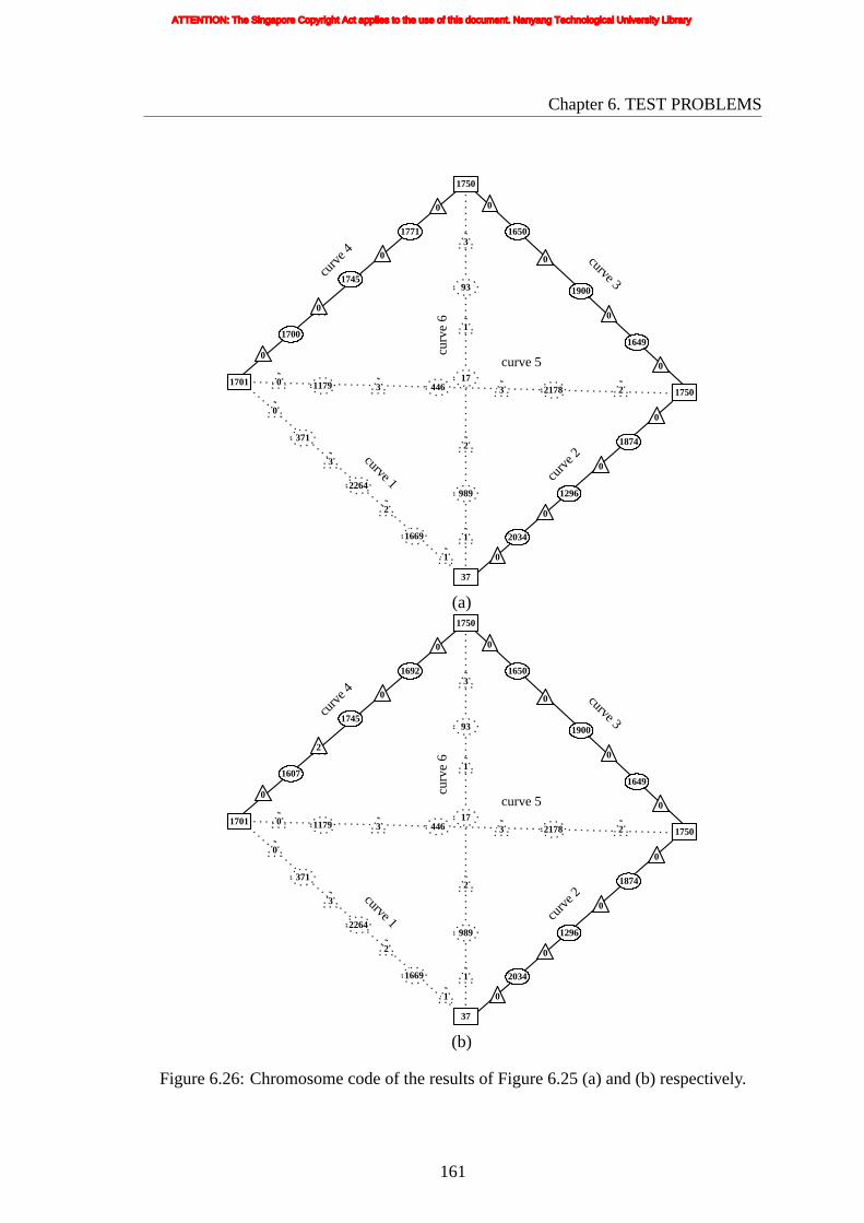
Chapter6. TEST PROBLEMS
curv
e 6
0 1179 446 21783 3 2
curve 3
1649
0
0
curve 1
0
371
2264
1669
3
2
1
curv
e 2
0
1874
1296
2034
0
0
0
curv
e 4
1700
0
0
37
989
2
1
17011750
curve 5
0
1650
1900
0
0
1771
1745
0
1750
3
93
17
1
(a)
curv
e 6
0 1179 446 21783 3 2
curve 3
1649
0
0
curve 1
0
371
2264
1669
3
2
1
curv
e 2
0
1874
1296
2034
0
0
0
curv
e 4
1607
2
0
37
989
2
1
17011750
curve 5
0
1650
1900
0
0
1692
1745
0
1750
3
93
17
1
(b)
Figure6.26: Chromosome code of the results of Figure 6.25 (a) and (b) respectively.
161
ATTENTION: The Singapore Copyright Act applies to the use of this document. Nanyang Technological University Library

Chapter6. TEST PROBLEMS
curve1curve2curve3curve4curve5curve6control points of curve 2control points of curve 3control points of curve 4I/O points
curve1curve2curve3curve4curve5curve6control points of curve 2control points of curve 3control points of curve 4I/O points
(a) (b)
Figure6.27: Input/output/control points and Bezier curves of Figure 6.25.
(a)fvoid = 75
fmaterial = 852gf orbidden = 415
gl = 34gs = 650go = 1450
(b)fvoid = 73
fmaterial = 637gf orbidden = 168
gl = 5gs = 60go = 1500
(c)fvoid = 28
fmaterial = 980gf orbidden = 403
gl = 10gs = 1250go = 0
Figure 6.28: Sample solutions from the initial (randomly generated) population.
162
ATTENTION: The Singapore Copyright Act applies to the use of this document. Nanyang Technological University Library
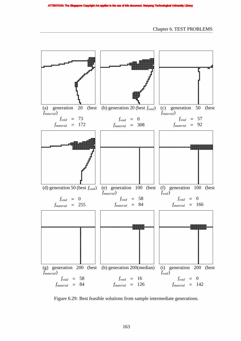
Chapter6. TEST PROBLEMS
(a) generation 20 (bestfmaterial)
fvoid = 73fmaterial = 172
(b) generation 20 (bestfvoid)
fvoid = 0fmaterial = 308
(c) generation 50 (bestfmaterial)
fvoid = 57fmaterial = 92
(d) generation 50 (bestfvoid)
fvoid = 0fmaterial = 255
(e) generation 100 (bestfmaterial)
fvoid = 58fmaterial = 84
(f) generation 100 (bestfvoid)
fvoid = 0fmaterial = 166
(g) generation 200 (bestfmaterial)
fvoid = 58fmaterial = 84
(h) generation 200(median)
fvoid = 16fmaterial = 126
(i) generation 200 (bestfvoid)
fvoid = 0fmaterial = 142
Figure 6.29: Best feasible solutions from sample intermediate generations.
163
ATTENTION: The Singapore Copyright Act applies to the use of this document. Nanyang Technological University Library

Chapter6. TEST PROBLEMS
generation number0 50 100 150 200 250 300
-10
0
10
20
30
40
50
60
70
80
0
100
200
300
400
fmaterial
fvoidf vo
id
f mat
eria
l
Figure6.30: History of the best void objective.
0 50 100 150 200 250 300-10
0
10
20
30
40
50
60
70
80
0
100
200
300
400
fmaterial
void
f
generation number
voidf
mat
eria
lf
Figure6.31: History of the best material objective.
164
ATTENTION: The Singapore Copyright Act applies to the use of this document. Nanyang Technological University Library

Chapter6. TEST PROBLEMS
any particular generation, the elites are a subset of the feasible non-dominated solutions
(as the elites are basically the feasible non-dominated solutions which have been selected
to be carried forward to the next generation) and therefore, every elite (hollow marker)
coincides with one of the feasible non-dominated solutions (solid markers) in the plot.
0 20 40 60 80
100
150
200
250
300
generation 20 non-dominatedgeneration 50 non-dominatedgeneration 100 non-dominatedgeneration 200 non-dominatedgeneration 300 non-dominatedgeneration 20 elitegeneration 50 elitegeneration 100 elitegeneration 200 elitegeneration 300 elite
f void
mat
eria
lf
Figure6.32: Plot of non-dominated solutions and elites at some sample generations.
Figure 6.33 shows a plot of the cumulative non-dominated front up to some sample
generations. The solutions shown in Figure 6.32 are non-dominated among all the
solutions in the population at the indicated generation, whereas solutions shown in
Figure 6.33 are non-dominated among all the solutions accumulated from past generations
up till the indicated generation. Thus, the plot in Figure 6.32 is with respect to a single
particular generation, whereas the plot in Figure 6.33 is with respect to all the generations
up to the particular generation (inclusive). As not all of the feasible non-dominated
solutions are carried forward to the next generation, it is possible that a solution which
has appeared in Figure 6.32 is missing from Figure 6.33.
165
ATTENTION: The Singapore Copyright Act applies to the use of this document. Nanyang Technological University Library

Chapter6. TEST PROBLEMS
0 20 40 60 80
100
150
200
250
300
generation 20generation 50generation 100generation 200generation 300
f void
mat
eria
lf
Figure6.33: Plot of cumulative non-dominated front up to some sample generations.
6.4 TARGET MATCHING PROBLEM 3 (WITH
CONFLICTING OBJECTIVES)
6.4.1 Formulation
The formulation in this present problem is quite similar to Target Matching Problem 2
solved in Section 6.3, but the target geometry is configured differently. The problem to be
solved here is defined by the design space as shown in Figure 6.34. There is one support,
two loading points and one output point. The position of the output point is variable
but confined to the right boundary as shown in Figure 6.34 while the support point is
confined to the bottom left quadrant (shaded area) of the design space. The loading point
1 can be anywhere along the left boundary while the loading point 2 can be anywhere
along the bottom or top boundary. In this problem, the target geometry is as shown in
Figure 6.35. As in Target Matching Problem 2, the prescribed area can be any shape
depending on how well thefvoid objective is optimized. This problem is formulated to test
and tune the parameters of the proposed algorithm that eventually will be used for solving
166
ATTENTION: The Singapore Copyright Act applies to the use of this document. Nanyang Technological University Library

Chapter6. TEST PROBLEMS
the 2-DOF compliant mechanism design problem, by configuring the design space (the
arrangements of the output, support and loading points) and number of objective and
constraint functions to match that of the actual mechanism problem.
outp
ut p
oint
support point
load
poi
nt 1
load point 2
load point 2
Figure6.34: Design space.
This problem is defined with the following two objectives and four constraints: the
void objective, material objective, forbidden area constraint and three distance constraints.
Such a problem is defined with the help of Figure 6.36. The void objective, material
objective and forbidden area constraint are all defined exactly the same as that in Target
Matching Problem 2 (except that the location of the prescribed and forbidden area are now
different). Note that, again, the material objective is conflicting with the void objective
which is intended to maximize the number of solid elements within the prescribed area.
And the material objective is, again, set as the adaptive constraint.
The distance constraints are given by
gl1 = dl1 ≤ 0
gl2 = dl2 ≤ 0
go = do ≤ 0
(6.7)
wheredl1 is the distance between the actual loading point 1 and the desired loading point
167
ATTENTION: The Singapore Copyright Act applies to the use of this document. Nanyang Technological University Library

Chapter6. TEST PROBLEMS
pre
scri
bed
area
30
20
10
1
40
20
50
30 5040 50101
Figure6.35: Target geometry.
d l
d o
actual loading point 1
desired output point
actual output point
desired loading point 1
dsactual loading
point 2 desired loading
point 2
Figure6.36: Formulation of Target Matching Problem 3 with Conflicting Objectives.
168
ATTENTION: The Singapore Copyright Act applies to the use of this document. Nanyang Technological University Library

Chapter6. TEST PROBLEMS
1; dl2 is the distance between the actual loading point 2 and the desired loading point 2;
do is the distance between the desired output point and the actual output point.
Figure 6.37 shows the feasible region of objective space. The points on the line
segment from point (70,80) to (0,150) represent the Pareto optimal solutions.
80
0 70
1510
150
fvoid
(70,80)
(0,150)
fmaterial
Figure6.37: The solution space for Target Matching Problem 3.
6.4.2 Results
In this target matching problem, six Bezier curves are used such that there is one
connecting curve between any two I/O points, with each curve defined by three control
points. All thickness values are allowed to vary between the minimum value 0 and
maximum value 3.
The genetic algorithm was run to solve the test problem with the following set of
evolutionary parameters:
(a) Population size: 200
(b) Normal mutation rate: 10% of those children formed by crossover
(c) Maximum number of feasible elites: 5% of population size
(d) Maximum number of partially feasible elites: 5% of population size
The optimization was run for 300 generations, by the end of which 86,396 objective
function evaluations have been performed. The total (wall-clock) time consumed for 300
169
ATTENTION: The Singapore Copyright Act applies to the use of this document. Nanyang Technological University Library

Chapter6. TEST PROBLEMS
generationswas 8790 seconds.
Nine of the non-dominated solutions (with their corresponding objective values) at
the end of 300 generations are shown in Figure 6.38. The corresponding values of all
of the constraint functions (i.e.gf orbidden, gl1, gl2, andgo) are 0, asgf orbidden, gl1, gl2, and
go are exactly 0 for all feasible solutions. Figures 6.38(a) and (b) show the two non-
dominated extreme point solutions. Figure 6.38(a) (Pareto extreme point solution) has the
best material objective but the worst void objective while Figure 6.38(b) has the best void
objective but the worst material objective. Figures 6.38 (b) and (c) are non-dominated
solutions but not true Pareto optimal solutions.
Following the same sequence and format of results/plots shown in Target Matching
Problem 2, the rest of the corresponding set of results from Target Matching Problem 3
are shown in Figures 6.39 to 6.46. Note that in Figure 6.42, only one feasible solution
has been obtained in generation 20, and that in Figure 6.43, the plot starts at generation
number 20.
170
ATTENTION: The Singapore Copyright Act applies to the use of this document. Nanyang Technological University Library
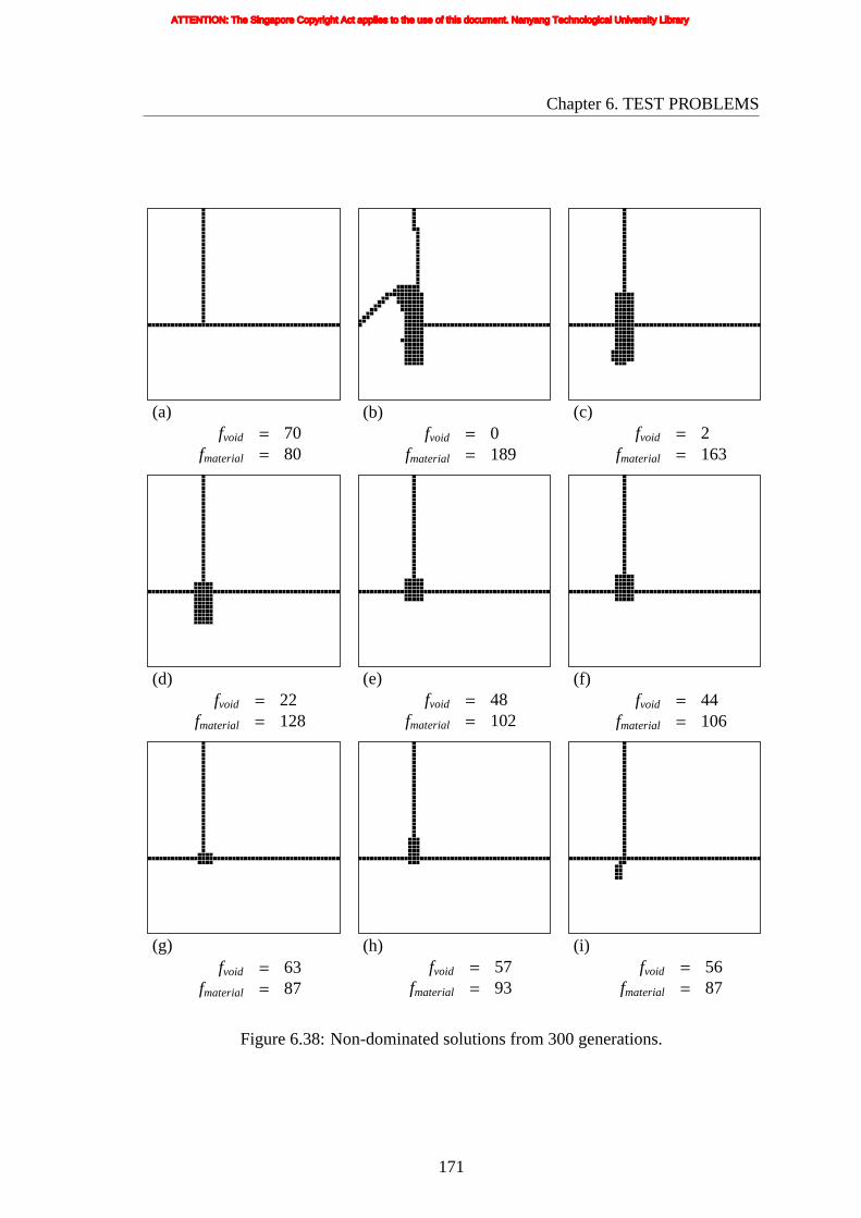
Chapter6. TEST PROBLEMS
(a)fvoid = 70
fmaterial = 80
(b)fvoid = 0
fmaterial = 189
(c)fvoid = 2
fmaterial = 163
(d)fvoid = 22
fmaterial = 128
(e)fvoid = 48
fmaterial = 102
(f)fvoid = 44
fmaterial = 106
(g)fvoid = 63
fmaterial = 87
(h)fvoid = 57
fmaterial = 93
(i)fvoid = 56
fmaterial = 87
Figure 6.38: Non-dominated solutions from 300 generations.
171
ATTENTION: The Singapore Copyright Act applies to the use of this document. Nanyang Technological University Library

Chapter6. TEST PROBLEMS
curv
e 6
1 389 1711 22403 0 2
curve 3
209
2
1
curve 1
0
861
1112
917
0
0
0
curv
e 2
0
925
1107
868
0
0
0
curv
e 4
2458
0
1
966
1013
0
0
9511000
curve 5
3
2348
1916
0
0
2105
1799
3
2465
0
1115
817
0
(a)
curv
e 6
1 389 1711 22403 0 2
curve 3
209
2
1
curve 1
0
2373
11
969
2
2
0
curv
e 2
0
874
1158
823
0
0
0
curv
e 4
2458
0
1
762
871
2
0
9511000
curve 5
3
2348
1916
0
0
2105
1799
3
2465
0
420
107
0
(b)
Figure6.39: Chromosome code of the results of Figure 6.38 (a) and (b) respectively.
172
ATTENTION: The Singapore Copyright Act applies to the use of this document. Nanyang Technological University Library
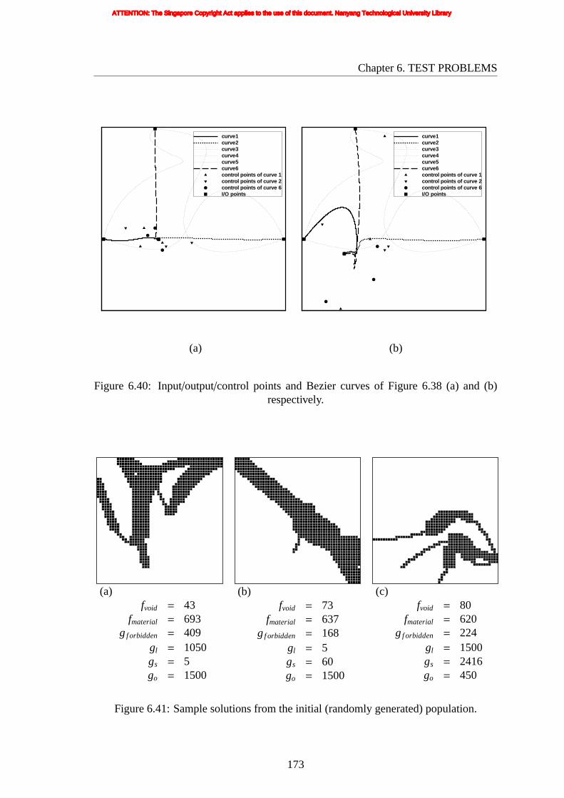
Chapter6. TEST PROBLEMS
curve1curve2curve3curve4curve5curve6control points of curve 1control points of curve 2control points of curve 6I/O points
curve1curve2curve3curve4curve5curve6control points of curve 1control points of curve 2control points of curve 6I/O points
(a) (b)
Figure 6.40: Input/output/control points and Bezier curves of Figure 6.38 (a) and (b)respectively.
(a)fvoid = 43
fmaterial = 693gf orbidden = 409
gl = 1050gs = 5go = 1500
(b)fvoid = 73
fmaterial = 637gf orbidden = 168
gl = 5gs = 60go = 1500
(c)fvoid = 80
fmaterial = 620gf orbidden = 224
gl = 1500gs = 2416go = 450
Figure 6.41: Sample solutions from the initial (randomly generated) population.
173
ATTENTION: The Singapore Copyright Act applies to the use of this document. Nanyang Technological University Library

Chapter6. TEST PROBLEMS
(a)generation 20
fvoid = 31fmaterial = 229
(b) generation 50 (bestfmaterial)
fvoid = 65fmaterial = 93
(c) generation 50 (bestfvoid)
fvoid = 15fmaterial = 178
(d) generation 100 (bestfmaterial)
fvoid = 64fmaterial = 90
(e) generation 100 (median)
fvoid = 53fmaterial = 103
(f) generation 100 (bestfvoid)
fvoid = 4fmaterial = 209
(g) generation 200 (bestfmaterial)
fvoid = 64fmaterial = 86
(h) generation 200 (median)
fvoid = 44fmaterial = 106
(i) generation 200 (bestfvoid)
fvoid = 0fmaterial = 200
Figure 6.42: Best feasible solutions from sample intermediate generations.
174
ATTENTION: The Singapore Copyright Act applies to the use of this document. Nanyang Technological University Library

Chapter6. TEST PROBLEMS
generation number0 50 100 150 200 250 300
-10
0
10
20
30
40
50
60
70
80
90
100
50
100
150
200
250
300
350
fmaterial
fvoidf vo
id
f mat
eria
l
Figure6.43: History of the best void objective.
0 50 100 150 200 250 300-10
0
10
20
30
40
50
60
70
80
90
100
50
100
150
200
250
300
350
fmaterial
void
f
generation number
voidf
mat
eria
lf
Figure6.44: History of the best material objective.
175
ATTENTION: The Singapore Copyright Act applies to the use of this document. Nanyang Technological University Library

Chapter6. TEST PROBLEMS
0 20 40 60 80
100
150
200
250generation 20 non-dominatedgeneration 50 non-dominatedgeneration 100 non-dominatedgeneration 200 non-dominatedgeneration 300 non-dominatedgeneration 20 elitegeneration 50 elitegeneration 100 elitegeneration 200 elitegeneration 300 elite
f void
mat
eria
lf
Figure6.45: Plot of non-dominated solutions and elites at some sample generations.
0 20 40 60 80
100
150
200
250
generation 20generation 50generation 100generation 200generation 300
f void
mat
eria
lf
Figure6.46: Plot of cumulative non-dominated front up to some sample generations.
176
ATTENTION: The Singapore Copyright Act applies to the use of this document. Nanyang Technological University Library

Chapter6. TEST PROBLEMS
6.5 TARGET MATCHING PROBLEM 4 (WITH
CONFLICTING OBJECTIVES)
6.5.1 Formulation
The formulation in the present problem is partly similar to Target Matching Problem 3
solved in Section 6.4, but the target geometry is configured differently. The problem to be
solved is defined by the same design space as shown in Figure 6.34, with one support,
two loading points and one output point. In this problem, the target geometry is as
shown in Figure 6.47. As with Target Matching Problem 3, this problem is formulated to
test and tune the parameters of the proposed algorithm for solving the 2-DOF compliant
mechanism design problem.
This problem is defined with the following two objectives and four constraints: the
void objective, the material objective, and four forbidden area constraints. Such a problem
is defined with the help of Figure 6.48.
The void objective and material objective are defined exactly the same way as in Target
Matching Problem 3, and hence they are again in conflict with each other. The material
objective is also set as the adaptive constraint.
However, unlike Target Matching Problem 3 where there is one forbidden area
constraint and three distance constraints, here all four constraints are forbidden area
constraints. The four forbidden area constraints are given by
g1 =n1∑i=1
yi ≤ 0
g2 =n2∑i=1
yi ≤ 0
g3 =n3∑i=1
yi ≤ 0
g4 =n4∑i=1
yi ≤ 0
(6.8)
whereyi is the material density of thei-th element in the respective forbidden area.n1, n2,
n3, n4 are the total number of elements in forbidden area 1, 2, 3, and 4, respectively. In
177
ATTENTION: The Singapore Copyright Act applies to the use of this document. Nanyang Technological University Library
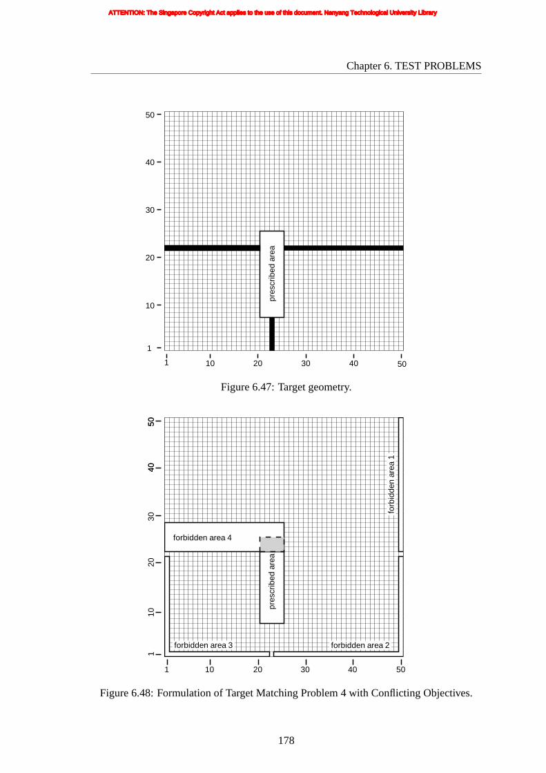
Chapter6. TEST PROBLEMS
pres
crib
edar
ea
1 5040302010
50
40
30
20
10
1
Figure6.47: Target geometry.
forbidden area 4
pres
crib
edar
ea
forbidden area 3
forb
idde
nar
ea1
forbidden area 2
50
50
1050
4050
4020
301
30 40201 10
Figure6.48: Formulation of Target Matching Problem 4 with Conflicting Objectives.
178
ATTENTION: The Singapore Copyright Act applies to the use of this document. Nanyang Technological University Library
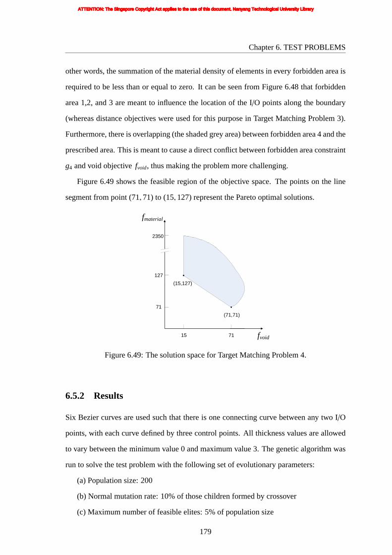
Chapter6. TEST PROBLEMS
otherwords, the summation of the material density of elements in every forbidden area is
required to be less than or equal to zero. It can be seen from Figure 6.48 that forbidden
area 1,2, and 3 are meant to influence the location of the I/O points along the boundary
(whereas distance objectives were used for this purpose in Target Matching Problem 3).
Furthermore, there is overlapping (the shaded grey area) between forbidden area 4 and the
prescribed area. This is meant to cause a direct conflict between forbidden area constraint
g4 and void objectivefvoid, thus making the problem more challenging.
Figure 6.49 shows the feasible region of the objective space. The points on the line
segment from point (71,71) to (15,127) represent the Pareto optimal solutions.
fmaterial
71
15 71
2350
127
fvoid
(71,71)
(15,127)
Figure6.49: The solution space for Target Matching Problem 4.
6.5.2 Results
Six Bezier curves are used such that there is one connecting curve between any two I/O
points, with each curve defined by three control points. All thickness values are allowed
to vary between the minimum value 0 and maximum value 3. The genetic algorithm was
run to solve the test problem with the following set of evolutionary parameters:
(a) Population size: 200
(b) Normal mutation rate: 10% of those children formed by crossover
(c) Maximum number of feasible elites: 5% of population size
179
ATTENTION: The Singapore Copyright Act applies to the use of this document. Nanyang Technological University Library

Chapter6. TEST PROBLEMS
(d) Maximum number of partially feasible elites: 5% of population size
The optimization was run for 300 generations, by the end of which 85,673 objective
function evaluations have been performed. The total (wall-clock) time consumed for
running the genetic algorithm for 300 generations was 10099 seconds.
Nine of the non-dominated solutions (with their corresponding objective values) at the
end of 300 generations are shown in Figure 6.50. The corresponding values of all of the
constraint functions (i.e.g1, g2, g3, andg4) are 0, asg1, g2, g3, andg4 are exactly 0 for
all feasible solutions. Figures 6.50(a) and (b) show the two non-dominated extreme point
solutions. Figure 6.50(a) has the best material objective but the worst void objective while
Figure 6.50(b) (Pareto extreme point solution) has the best void objective but the worst
material objective. Figures 6.50 (d) is a non-dominated solution but not a true Pareto
optimal solution.
Following the same sequence and format of results/plots shown in Target Matching
Problem 3, the rest of the corresponding set of results from Target Matching Problem 4
are shown in Figures 6.51 to 6.58. Note that in Figure 6.55, the plot starts at generation
number 13.
180
ATTENTION: The Singapore Copyright Act applies to the use of this document. Nanyang Technological University Library

Chapter6. TEST PROBLEMS
(a)fvoid = 68
fmaterial = 74
(b)fvoid = 15
fmaterial = 127
(c)fvoid = 44
fmaterial = 98
(d)fvoid = 31
fmaterial = 112
(e)fvoid = 25
fmaterial = 117
(f)fvoid = 38
fmaterial = 104
(g)fvoid = 58
fmaterial = 84
(h)fvoid = 19
fmaterial = 123
(i)fvoid = 63
fmaterial = 79
Figure 6.50: Non-dominated solutions from 300 generations.
181
ATTENTION: The Singapore Copyright Act applies to the use of this document. Nanyang Technological University Library

Chapter6. TEST PROBLEMS
curv
e 6
0 295 1041 111 1 0
curve 3
876
0
1
curve 1
0
980
1271
722
0
0
0
curv
e 2
0
1133
1035
1267
0
0
0
curv
e 4
961
2
0
674
1119
0
0
10511100
curve 5
1
287
1773
1
3
1997
1129
3
23
0
1123
79
0
(a)
curv
e 6
0 295 1041 111 1 0
curve 3
876
0
1
curve 1
0
983
1271
623
0
2
0
curv
e 2
0
1133
1035
1267
0
0
0
curv
e 4
961
2
0
674
1219
0
0
10511100
curve 5
1
287
1773
1
3
1997
1129
3
23
0
972
25
2
(b)
Figure6.51: Chromosome code of the results of Figure 6.50 (a) and (b) respectively.
182
ATTENTION: The Singapore Copyright Act applies to the use of this document. Nanyang Technological University Library

Chapter6. TEST PROBLEMS
curve1curve2curve3curve4curve5curve6control points of curve 1control points of curve 2control points of curve 6I/O points
curve1curve2curve3curve4curve5curve6control points of curve 1control points of curve 2control points of curve 6I/O points
(a) (b)
Figure 6.52: Input/output/control points and Bezier curves of Figure 6.50 (a) and (b)respectively..
(a)fvoid = 0
fmaterial = 667h1 = 0h2 = 4h3 = 13h4 = 75
(b)fvoid = 31
fmaterial = 792h1 = 0h2 = 7h3 = 0h4 = 96
(c)fvoid = 29
fmaterial = 483h1 = 8h2 = 1h3 = 1h4 = 118
Figure 6.53: Sample solutions from the initial (randomly generated) population.
183
ATTENTION: The Singapore Copyright Act applies to the use of this document. Nanyang Technological University Library

Chapter6. TEST PROBLEMS
(a) generation 20 (bestfmaterial)
fvoid = 78fmaterial = 148
(b) generation 20 (bestfvoid)
fvoid = 40fmaterial = 326
(c) generation 50 (bestfmaterial)
fvoid = 64fmaterial = 81
(d) generation 50 (bestfvoid)
fvoid = 27fmaterial = 179
(e) generation 100 (bestfmaterial)
fvoid = 68fmaterial = 74
(f) generation 100 (bestfvoid)
fvoid = 15fmaterial = 143
(g) generation 200 (bestfmaterial)
fvoid = 53fmaterial = 89
(h) generation 200 (median)
fvoid = 22fmaterial = 120
(i) generation 200 (bestfvoid)
fvoid = 15fmaterial = 127
Figure 6.54: Best feasible solutions from sample intermediate generations.
184
ATTENTION: The Singapore Copyright Act applies to the use of this document. Nanyang Technological University Library
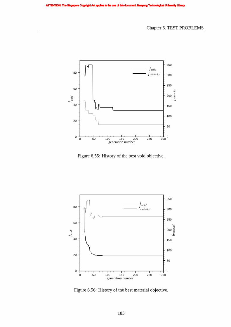
Chapter6. TEST PROBLEMS
generation number0 50 100 150 200 250 300
0
20
40
60
80
0
50
100
150
200
250
300
350
fmaterial
fvoidf vo
id
f mat
eria
l
Figure6.55: History of the best void objective.
0 50 100 150 200 250 3000
20
40
60
80
0
50
100
150
200
250
300
350
fmaterial
void
f
generation number
voidf
mat
eria
lf
Figure6.56: History of the best material objective.
185
ATTENTION: The Singapore Copyright Act applies to the use of this document. Nanyang Technological University Library

Chapter6. TEST PROBLEMS
15 35 55 75 95
100
150
200
250
300
350
400generation 20 non-dominatedgeneration 50 non-dominatedgeneration 100 non-dominatedgeneration 200 non-dominatedgeneration 300 non-dominatedgeneration 20 elitegeneration 50 elitegeneration 100 elitegeneration 200 elitegeneration 300 elite
f void
mat
eria
lf
Figure6.57: Plot of non-dominated solutions and elites at some sample generations
15 35 55 75 95
100
150
200
250
300
350
400generation 20generation 50generation 100generation 200generation 300
f void
mat
eria
lf
Figure6.58: Plot of cumulative non-dominated front up to some sample generations.
186
ATTENTION: The Singapore Copyright Act applies to the use of this document. Nanyang Technological University Library
Chapter 7
DESIGN OF GRIP-AND-MOVE
MANIPULATORS USING 2-DOF
MECHANISMS
This chapter demonstrate the design of compliant grip-and-move manipulators with
two identical path generating mechanisms of 2-DOF each. These two 2-DOF path
generating compliant mechanisms work like two fingers so that they can grip an object
and convey it from one point to another within the working area.
7.1 2-DOF PATH GENERATING MECHANISM
In this work, a 2-DOF path generating mechanism which has two loading points refers
to a mechanism that generates an output area within which the mechanism can reach
anywhere. But the output area is not predefined. In other words, the shape and size of
the output area itself is not specified in advance, so the desire is basically for a big output
area. The path is also desired to be as long as possible in order to extend its working range
in one direction. An illustration of a manipulator consisting of two identical 2-DOF path
generating mechanisms is given in Figure 7.1. Each shape in solid lines is the undeformed
shape of one of the mechanisms. The dashed lines show the possible deformed shape of
the structure after some large displacement due to the input load. The two compliant
mechanisms work like two fingers of a manipulator. It can grip a workpiece and the grip
can be maintained anywhere within its working area. The working area is the overlapped
area of the two compliant mechanisms’ output areas. The workpiece can be conveyed to
any point within the working area.
Hence the path generating mechanism has to be flexible enough to describe
187
ATTENTION: The Singapore Copyright Act applies to the use of this document. Nanyang Technological University Library

Chapter7. DESIGN OF GRIP-AND-MOVE MANIPULATORS USING 2-DOFMECHANISMS
working area
input load
fixed support
input load
input load
fixed support
input load
output area
workpiece
Figure7.1: Sketch of a manipulator.
approximately an area that is relatively large and a path that is relatively long and at the
same time keep input displacement and stresses within allowable limits. In other words,
the best path generating mechanism would (i) be able to generate an appropriate output
area as large as possible, (ii) have output distance in some direction as long as possible,
and (iii) have stresses within allowable limits.
7.2 FORMULATION
The synthesis of such a compliant mechanism is accomplished by formulating the
problem as a structural optimization problem with multiple objectives and constraints to
achieve the desired behavior of the manipulator. The problem to be solved is defined by
the design space shown in Figure 7.2. The design space is exactly the same as that used in
design of symmetric path generating mechanisms (Section 4.2) except that configurations
of the I/O points are different.
188
ATTENTION: The Singapore Copyright Act applies to the use of this document. Nanyang Technological University Library

Chapter7. DESIGN OF GRIP-AND-MOVE MANIPULATORS USING 2-DOFMECHANISMS
100 mm
100
mm
y
outp
ut p
oint
x
support point
load
poi
nt 1
load point 2
load point 2
Figure7.2: Design space.
7.2.1 Output Area Objective
The aim here is to produce a mechanism which generates an output area as large as
possible. There are two ways to apply the loads. And correspondingly, there are two
approaches to calculate the output area approximately. One area calculation approach
is illustrated in Figure 7.3(a). Three loading cases are applied in total: input load1 and
input load2 are applied separately and respectively on loading point 1 and loading point
2 of the undeformed shape of the mechanism, and input load12 is applied on the loading
point 2 of the deformed shape under input load1. As shown in Figure 7.3(a), P1i , where
i = 0,1, · · · n, marks the output path when input load1 is applied. n is the number of
analysis steps in the nonlinear finite element analysis, which is 5 in this illustration figure.
Similarly, P12i , wherei = 0,1, · · · n, marks the output path when input load12 is applied.
P10 and P2
0, the start point when input load1 and input load2 are applied respectively, is
the output point of the mechanism when it is undeformed. P120 , the start point when
input load12 is applied, is the end point of the path generated by input load1. The areas of
the 10 small triangles shown in the figure are summed up to evaluate the total output area.
The other area calculation method is illustrated in Figure 7.3(b). Similarly, three load
189
ATTENTION: The Singapore Copyright Act applies to the use of this document. Nanyang Technological University Library
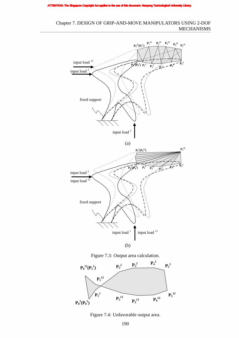
Chapter7. DESIGN OF GRIP-AND-MOVE MANIPULATORS USING 2-DOFMECHANISMS
fixed support
input load 1
input load 2
input load 12
P12
P22
P32 P4
2 P52
P012(P5
1)P1
12 P212 P3
12P4
12P5
12
P02(P0
1)
(a)
fixed support
input load 1
input load 2
input load 12
P52
P512
P02(P0
1)
input load 12
P51(P0
12)
P12
P22
P32 P4
2
(b)
Figure7.3: Output area calculation.
P12
P22 P3
2 P42
P52
P012(P5
1)
P112
P212
P312 P4
12P5
12
P02(P0
1)
Figure7.4: Unfavorable output area.
190
ATTENTION: The Singapore Copyright Act applies to the use of this document. Nanyang Technological University Library

Chapter7. DESIGN OF GRIP-AND-MOVE MANIPULATORS USING 2-DOFMECHANISMS
casesare applied separately: input load1, input load2 and input load12. The difference
lies in the input load12. Unlike the previous case, as shown in this figure, input load12
is applied on loading point 1 as well as loading point 2 of the undeformed structure
simultaneously. The areas of 10 small triangles shown in the figure are summed up to
evaluate the total output area.
If two paths generated by the three loading applications intersect each other as shown
in Figure 7.4, the area objective is set to a small value such as 0. This situation is not
desirable because it becomes harder for the two mechanisms to be coordinated to produce
a large working area. The area objective for maximization of area may be given by:
Minimize farea = −N∑
i=1
Ai (7.1)
whereN is the number of small triangles andAi is the area ofi-th triangle.
7.2.2 Distance Objective
To ease the arrangement of the two compliant mechanisms and to maximize flexibility,
maximizing the deflection of the output point in thex direction is desirable. If
rout = xouti + youtj is the position vector of the output point’s final position with respect
to its initial position, then distancedx can be given by
dx = rout · uout = (xouti + youtj) · i = xout (7.2)
whereuout = i has been used in Equation 7.2 because deflection of output point in thex
direction is of main interest.
In the design of the grip-and-move manipulators, a large ratio of output range to size
of the mechanism is desired. The size of the mechanism is estimated by the rectangular
area enveloping the mechanism, which is represented byArea. Accounting for thisArea,
191
ATTENTION: The Singapore Copyright Act applies to the use of this document. Nanyang Technological University Library

Chapter7. DESIGN OF GRIP-AND-MOVE MANIPULATORS USING 2-DOFMECHANISMS
thedistance objective for maximization of distance may be given by:
Minimize fd = −dx/Area (7.3)
This objective is set as the adaptive constraint because distance inx-direction is
desirable and harder to achieve than the output area objective.
7.2.3 GA Constraints
To avoid unfavorable characteristics of the output area and to improve the chance of
obtaining a big working area, constraints are put on the geometric advantages (GA) for all
loading cases. The input and output displacements for the three loading cases are shown
in Figure 7.5. The GA depends only on the initial and the final states of the structure. If
fixed support
input load 1
input load 2
input load 12
rin1
rin12
rin2
rout1
rout2
rout12
Figure7.5: Geometric Advantage calculation.
r in is the position vector of the loading point andr out is the position vector of the output
point’s final position with respect to its initial position, then GA is given by
GA =|r out||r in| sgn(rout · uin) (7.4)
192
ATTENTION: The Singapore Copyright Act applies to the use of this document. Nanyang Technological University Library

Chapter7. DESIGN OF GRIP-AND-MOVE MANIPULATORS USING 2-DOFMECHANISMS
whereuin is the unit inward vector orthogonal to the loading boundary and functionsgn
defines the sign of the dot product of the two vectors,rout anduin. In this application,
there are three GAs pertaining to the three load cases,GA1, GA2 andGA12 corresponding
to input load1, input load2, and input load12, respectively. Using Equation 7.4,
GA1 =|r1
out||r1
in| sgn(r1out · u1in)
GA2 =|r2
out||r2
in| sgn(r2out · u2in)
GA12 =|r12
out||r12
in | sgn(r12out · u12
in )
(7.5)
Inequalityconstraints are imposed on the GAs as follows:
gGA1 = GA1l −GA1 ≤ 0
gGA2 = GA2l −GA2 ≤ 0
gGA12 = GA12l −GA12 ≤ 0
(7.6)
whereGA1l , GA2
l andGA12l are the prescribed lower bounds of the corresponding GA
values and are all set to 1 in this application.
Hence the multicriterion genetic algorithm is run with two objectives (the area
objective and distance objective) and four constraints, i.e. the three GA constraints and
the same stress constraint as that defined for the symmetric path generating mechanism
problem (Section 4.2.4).
7.3 RESULTS
The newly developed program runs in the windows XP sp2 environment of a PC (hp
workstation xw4200). The material assumed for the structure is polypropylene with the
same material properties as that in the symmetric path mechanism (Section 4.5).
Wherever the two loading points are located, an input displacement of a fixed value
10mm is to be applied in the direction perpendicular to the boundary (with displacement
parallel to the boundary unrestrained). The displacement value is fixed to facilitate the
193
ATTENTION: The Singapore Copyright Act applies to the use of this document. Nanyang Technological University Library

Chapter7. DESIGN OF GRIP-AND-MOVE MANIPULATORS USING 2-DOFMECHANISMS
comparisonbetween results. The input displacement (viz. 10mm) is based on past
experience that (i) achieving a long path with input displacement less than 10mm is
difficult, and (ii) meeting the stress constraint with an input displacement less than 10mm
is easy. There is a increase in computational complexity due to multiple FEM applications
for each individual compared to symmetric path generating mechanism solved in Chapter
4.
7.3.1 Run 1
In this problem, six Bezier curves are used such that there is one connecting curve between
any two I/O points, with each curve defined by three control points. All thickness values
are 0 in this run. And the displacement inputs (i.e. the three loading cases) are applied as
shown in Figure 7.3(a).
The optimization was run for 500 generations (with a population size of 200 per
generation), by the end of which 92,178 objective function evaluations (finite element
analyses) have been performed. The total (wall-clock) time consumed for 500 generations
is 1,524,519 seconds. Three of the solutions at the end of 500 generations are shown in
Figure 7.6. Figure 7.6(a) shows the solution with the best area objective (farea), whereas
Figure 7.6(c) shows the solution with the best distance objective (fd). The solution with
a median area and distance objective is shown in Figure 7.6(b); it has distance objective
better than the solution in (a) and area objective better than the solution in (c).
The design variable values for the solution with the best area objective, which
corresponds to Figure 7.6(a), is given in Figure 7.7(a). The input/output/control points
and the corresponding Bezier curves of the solution are shown in Figure 7.8(a). This
solution was attained at the 419th generation, with an area objective functionfarea value of
0.809527 and a distance objectivefd value of -0.428200. The required input forces for the
three loading cases are 6.587444N, 8.058245N, and 6.083709N, respectively. The peak
von Mises stress which occurs at the support element is 29.1514MPa under input load12.
Thus, the stress constraint functiongstresshas a value of -0.116624.
194
ATTENTION: The Singapore Copyright Act applies to the use of this document. Nanyang Technological University Library

Chapter7. DESIGN OF GRIP-AND-MOVE MANIPULATORS USING 2-DOFMECHANISMS
(a)best farea
farea = 0.809527fd = −0.428200
gGA1 = −2.018913gGA2 = −0.396774gGA12 = −3.237181gstress = −0.116624
(b) medianfarea = 1.289689
fd = −3.101400gGA1 = −0.008230gGA2 = −0.470124gGA12 = −1.700125gstress = −0.078921
(c) bestfdfarea = 1.945503
fd = −7.479558gGA1 = −1.957910gGA2 = −2.949215gGA12 = −0.145941gstress = −0.060248
Figure 7.6: Three non-dominated solutions at 500th generation.
The design variable values for the solution with the median area and distance
objective, which corresponds to Figure 7.6(b), is given in Figure 7.7(b). The
input/output/control points and the corresponding Bezier curves of the solution are shown
in Figure 7.8(b). This solution was attained at the 479th generation, with an area
objective functionfarea value of 1.289689 and a distance objectivefd value of -3.01400.
The required input forces for the three loading cases are 6.408932N, 8.215698N, and
3.098382N, respectively. The peak von Mises stress is 30.3956MPa which occurs at
support element. Thus, the stress constraint functiongstresshas a value of -0.078921.
In Figure 7.9(a), the undeformed geometry of the optimum design with the best area
objective is shown by its mesh while the deformed shapes in their final positions are
shown by their boundary outlines only. The output paths from the FE analysis and
prototype are specified in Figure 7.9(b). Figure 7.9(c) and (g) show two possible ways
in which a grip-and-move manipulator can be made by arranging two of the identical
mechanisms symmetrically, based on the paths determined from the FE analysis. The
arrangement shown in Figure 7.9(c) can achieve a long distance output while that shown in
195
ATTENTION: The Singapore Copyright Act applies to the use of this document. Nanyang Technological University Library

Chapter7. DESIGN OF GRIP-AND-MOVE MANIPULATORS USING 2-DOFMECHANISMS
curv
e 6
0 2462 297 7580 0 0
curve 3
1873
0
0
curve 1
0
1888
2205
235
0
0
0
curv
e 2
0
770
2291
480
0
0
0
curv
e 4
1125
0
0
52
746
0
0
7512500
curve 5
0
1896
1550
0
0
897
215
0
28
0
111
831
0
(a)
curv
e 6
0 852 2440 7100 0 0
curve 3
1441
0
0
curve 1
0
1888
1166
2203
0
0
0
curv
e 2
0
297
2291
480
0
0
0
curv
e 4
1125
0
0
52
746
0
0
7512500
curve 5
0
1896
49
0
0
897
215
0
28
0
111
1142
0
(b)
Figure7.7: Chromosome code of the optimal result of Figure 7.6 (a) and (b) respectively.
196
ATTENTION: The Singapore Copyright Act applies to the use of this document. Nanyang Technological University Library

Chapter7. DESIGN OF GRIP-AND-MOVE MANIPULATORS USING 2-DOFMECHANISMS
curve1curve2curve3curve4curve5curve6control points of curve 4control points of curve 5control points of curve 6I/O points
curve1curve2curve3curve4curve5curve6control points of curve 4control points of curve 5control points of curve 6I/O points
(a) (b)
Figure 7.8: Input/output/control points and Bezier curves of Figure 7.6 (a) and (b)respectively.
Figure 7.9(e) can achieve a big working area. The prototypes fabricated of the structures
shown in Figure 7.9(c) and (e) are presented in Figure 7.9(d) and (f), respectively. The
grip-and-move manipulators shown in Figure 7.9(d) and (f) can grip an object and move
it anywhere within the overlapped area as presented in Figure 7.10 and Figure 7.11,
respectively. The output path (area) is drew on black paper and the two mechanisms
are manually push toward each other at three or four positions.
In Figure 7.12(a), the undeformed geometry of the optimum design with the median
area and distance objective is shown by its mesh while the deformed shapes in their
final positions are shown by their boundary outlines only. The output paths from the FE
analysis and prototype are specified in Figure 7.12(b). Figure 7.12(c) shows one possible
way in which the grip-and-move manipulator can be made by arranging two of the same
mechanisms symmetrically. The prototype is presented in Figure 7.12(d). The grip-and-
move manipulator can grip an object and move it anywhere within the overlapped area as
shown in Figure 7.13.
197
ATTENTION: The Singapore Copyright Act applies to the use of this document. Nanyang Technological University Library

Chapter7. DESIGN OF GRIP-AND-MOVE MANIPULATORS USING 2-DOFMECHANISMS
-0.04 -0.02 0 0.02 0.04
-0.04
-0.02
0
0.02
0.04
experiment (prototype)
FE analysis
(a) undeformed shape and deformedshapes
(b) output path (area)
(c) arrangement of compliant grip-and-move manipulator (long distance output)
(d) prototype of compliant grip-and-move manipulator (long distance output)
198
ATTENTION: The Singapore Copyright Act applies to the use of this document. Nanyang Technological University Library

Chapter7. DESIGN OF GRIP-AND-MOVE MANIPULATORS USING 2-DOFMECHANISMS
(e)arrangement of compliant grip-and-move manipulator (big overlapped area)
(f) prototype of compliant grip-and-move manipulator (big overlapped area)
Figure 7.9: Compliant grip-and-move manipulator – design with best area objective (Run1).
199
ATTENTION: The Singapore Copyright Act applies to the use of this document. Nanyang Technological University Library

Chapter7. DESIGN OF GRIP-AND-MOVE MANIPULATORS USING 2-DOFMECHANISMS
(a)gripping position 1 (b) gripping position 2
(c) gripping position 3 (d) gripping position 4
Figure 7.10: View of compliant grip-and-move manipulator (long distance output).
(a)gripping position 1 (b) gripping position 2
(c) gripping position 3 (d) gripping position 4
Figure 7.11: View of compliant grip-and-move manipulator (big overlapped area).
200
ATTENTION: The Singapore Copyright Act applies to the use of this document. Nanyang Technological University Library

Chapter7. DESIGN OF GRIP-AND-MOVE MANIPULATORS USING 2-DOFMECHANISMS
-0.04 -0.02 0 0.02 0.04
-0.02
0
0.02
0.04
0.06
experiment (prototype)
FE analysis
(a) undeformed shape and deformedshapes
(b) output path (area)
(c) arrangement of compliant grip-and-move manipulator
(d) prototype of compliant grip-and-move manipulator
Figure 7.12: Compliant grip-and-move manipulator – design with median area anddistance objective (Run 1).
201
ATTENTION: The Singapore Copyright Act applies to the use of this document. Nanyang Technological University Library

Chapter7. DESIGN OF GRIP-AND-MOVE MANIPULATORS USING 2-DOFMECHANISMS
(a)gripping position 1 (b) gripping position 2
(c) gripping position 3
Figure 7.13: View of compliant grip-and-move manipulator.
Figure 7.14 and Figure 7.15 provide a glimpse of the evolution history by a sampling
of the solutions obtained at the respectively indicated generations. Figure 7.14 shows
three solutions in the initial population with their corresponding objective/constraint
function values. Figure 7.15 (a)-(i) show the best feasible solutions (with their
corresponding objective/constraint values) achieved up to the respectively indicated
generations 50, 100, and 300. At every indicated generation, one solution with best
area objective, one with best distance objective, and one with median area and distance
objective are given.
Figure 7.16 shows a plot of the best area objective (farea) and the corresponding
solution’s distance objective (fd) versus generation number.farea and fd values on the
plot corresponding to any particular generation number belong to that generation’s non-
dominated feasible solution having the best area objective. The plot starts at generation
number 3, as until this generation there is no feasible solution in the population.
Figure 7.17 shows plots of the best distance objective (fd) and the corresponding
solution’s area objective (farea) versus generation number.farea and fd values on the
plot corresponding to any particular generation number belong to that generation’s non-
202
ATTENTION: The Singapore Copyright Act applies to the use of this document. Nanyang Technological University Library

Chapter7. DESIGN OF GRIP-AND-MOVE MANIPULATORS USING 2-DOFMECHANISMS
(a)farea = 20.19919
fd = −1.423714gGA1 = −0.507896gGA2 = −0.207947gGA12 = 0.674944gstress = −0.604797
(b)farea = 10.07677
fd = −0.715200gGA1 = −0.398349gGA2 = −0.336454gGA12 = 0.519912gstress = −0.423976
(c)farea = 185.9337
fd = 0.031200gGA1 = −0.275389gGA2 = −0.399726gGA12 = 1.448412gstress = −0.477915
Figure 7.14: Sample solutions from the initial (randomly generated) population.
dominated feasible solution having the best distance objective.
Figure 7.18 shows a plot in objective space, where solid shape markers have been used
to denote the feasible non-dominated solutions at any particular sample generation, viz.
the 50th, 100th, 300th and 500th generation. Hollow shape markers of the corresponding
same shape have been used for showing any elites at that generation. At any particular
generation, the elites are a subset of the feasible non-dominated solutions (as the elites
are basically the feasible non-dominated solutions which have been selected to be carried
forward to the next generation) and therefore, every elite (hollow marker) coincides with
one of the feasible non-dominated solutions (solid markers) in the plot.
Figure 7.19 shows a plot of the cumulative non-dominated front up to some sample
generations. The solutions shown in Figure 7.18 are non-dominated among all the
solutions in the population at the indicated generation, whereas solutions shown in
Figure 7.19 are non-dominated among all the solutions accumulated from past generations
up till the indicated generation. Thus, the plot in Figure 7.18 is with respect to a single
particular generation, whereas the plot in Figure 7.19 is with respect to all the generations
203
ATTENTION: The Singapore Copyright Act applies to the use of this document. Nanyang Technological University Library

Chapter7. DESIGN OF GRIP-AND-MOVE MANIPULATORS USING 2-DOFMECHANISMS
(a)generation 50 (bestfarea)farea = 1.783480
fd = −2.009300gGA1 = −0.539096gGA2 = −0.565577gGA12 = −1.198448gstress = −0.275946
(b) generation 50 (median)farea = 2.420505
fd = −2.272500gGA1 = −0.365676gGA2 = −0.176200gGA12 = −0.546244gstress = −0.574933
(c) generation 50 (bestfd)farea = 2.634967
fd = −5.165658gGA1 = −1.604748gGA2 = −2.196263gGA12 = −0.141070gstress = −0.041539
(d) generation 100 (bestfarea)farea = 1.118655
fd = −1.297600gGA1 = −1.360331gGA2 = −0.291034gGA12 = −2.229377gstress = −0.236191
(e) generation 100 (median)farea = 1.782687
fd = −2.880800gGA1 = −0.075161gGA2 = −0.369890gGA12 = −0.944367gstress = −0.466273
(f) generation 100 (bestfd)farea = 2.439652
fd = −5.530526gGA1 = −1.626112gGA2 = −2.293025gGA12 = −0.134420gstress = −0.055139
(g) generation 300 (bestfarea)farea = 0.809527
fd = −0.428200gGA1 = −2.018913gGA2 = −0.396774gGA12 = −3.237189gstress = −0.116624
(h) generation 300 (median)farea = 1.427160
fd = −3.092800gGA1 = −0.006160gGA2 = −0.385054gGA12 = −1.738061gstress = −0.176549
(i) generation 300 (bestfd)farea = 1.867675
fd = −6.916666gGA1 = −1.704472gGA2 = −3.015117gGA12 = −0.103375gstress = −0.002967
Figure 7.15: Best feasible solutions from sample intermediate generations.
204
ATTENTION: The Singapore Copyright Act applies to the use of this document. Nanyang Technological University Library

Chapter7. DESIGN OF GRIP-AND-MOVE MANIPULATORS USING 2-DOFMECHANISMS
generation number
area
obj
ectiv
e
dis
tanc
eo
bjec
tive
0 100 200 300 400 5000
2000
4000
6000
8000
-4
-2
0
2
4
area objective
distance objective
Figure7.16: History of the best area objective (farea).
generation number
area
obj
ectiv
e
dis
tanc
eo
bjec
tive
0 100 200 300 400 5000
2000
4000
6000
8000
-12
-10
-8
-6
-4
-2
0
area objective
distance objective
Figure7.17: History of the best distance objective (fd).
205
ATTENTION: The Singapore Copyright Act applies to the use of this document. Nanyang Technological University Library

Chapter7. DESIGN OF GRIP-AND-MOVE MANIPULATORS USING 2-DOFMECHANISMS
up to the particular generation (inclusive). As not all of the feasible non-dominated
solutions are carried forward to the next generation, it is possible that a solution which
has appeared in Figure 7.18 is missing from Figure 7.19.
area objective
dist
ance
obje
ctiv
e
1000 1500 2000 2500 3000-8
-6
-4
-2
0
generation 50 elitegeneration 100 elitegeneration 300 elitegeneration 500 elitegeneration 50 non-dominatedgeneration 100 non-dominatedgeneration 300 non-dominatedgeneration 500 non-dominated
Figure7.18: Plot of non-dominated solutions and elites at some sample generations.
area objective
dis
tanc
eo
bjec
tive
1000 1500 2000 2500 3000-8
-6
-4
-2
0
generation 50generation 100generation 300generation 500
Figure7.19: Plot of cumulative non-dominated front up to some sample generations.
206
ATTENTION: The Singapore Copyright Act applies to the use of this document. Nanyang Technological University Library
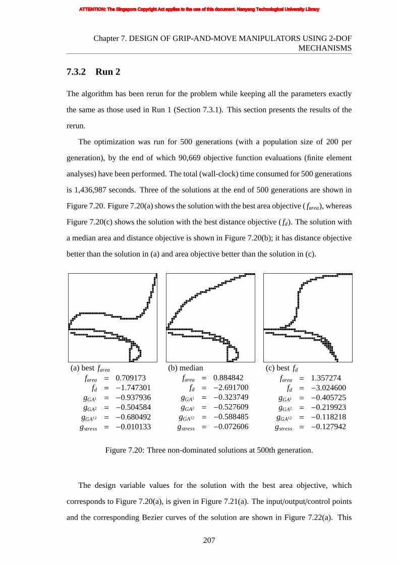
Chapter7. DESIGN OF GRIP-AND-MOVE MANIPULATORS USING 2-DOFMECHANISMS
7.3.2 Run 2
The algorithm has been rerun for the problem while keeping all the parameters exactly
the same as those used in Run 1 (Section 7.3.1). This section presents the results of the
rerun.
The optimization was run for 500 generations (with a population size of 200 per
generation), by the end of which 90,669 objective function evaluations (finite element
analyses) have been performed. The total (wall-clock) time consumed for 500 generations
is 1,436,987 seconds. Three of the solutions at the end of 500 generations are shown in
Figure 7.20. Figure 7.20(a) shows the solution with the best area objective (farea), whereas
Figure 7.20(c) shows the solution with the best distance objective (fd). The solution with
a median area and distance objective is shown in Figure 7.20(b); it has distance objective
better than the solution in (a) and area objective better than the solution in (c).
(a)best farea
farea = 0.709173fd = −1.747301
gGA1 = −0.937936gGA2 = −0.504584gGA12 = −0.680492gstress = −0.010133
(b) medianfarea = 0.884842
fd = −2.691700gGA1 = −0.323749gGA2 = −0.527609gGA12 = −0.588485gstress = −0.072606
(c) bestfdfarea = 1.357274
fd = −3.024600gGA1 = −0.405725gGA2 = −0.219923gGA12 = −0.118218gstress = −0.127942
Figure 7.20: Three non-dominated solutions at 500th generation.
The design variable values for the solution with the best area objective, which
corresponds to Figure 7.20(a), is given in Figure 7.21(a). The input/output/control points
and the corresponding Bezier curves of the solution are shown in Figure 7.22(a). This
207
ATTENTION: The Singapore Copyright Act applies to the use of this document. Nanyang Technological University Library
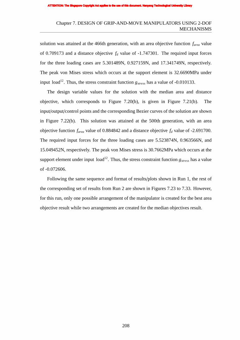
Chapter7. DESIGN OF GRIP-AND-MOVE MANIPULATORS USING 2-DOFMECHANISMS
solutionwas attained at the 466th generation, with an area objective functionfarea value
of 0.709173 and a distance objectivefd value of -1.747301. The required input forces
for the three loading cases are 5.301489N, 0.927159N, and 17.341749N, respectively.
The peak von Mises stress which occurs at the support element is 32.6690MPa under
input load12. Thus, the stress constraint functiongstresshas a value of -0.010133.
The design variable values for the solution with the median area and distance
objective, which corresponds to Figure 7.20(b), is given in Figure 7.21(b). The
input/output/control points and the corresponding Bezier curves of the solution are shown
in Figure 7.22(b). This solution was attained at the 500th generation, with an area
objective functionfarea value of 0.884842 and a distance objectivefd value of -2.691700.
The required input forces for the three loading cases are 5.523874N, 0.963566N, and
15.049452N, respectively. The peak von Mises stress is 30.7662MPa which occurs at the
support element under input load12. Thus, the stress constraint functiongstresshas a value
of -0.072606.
Following the same sequence and format of results/plots shown in Run 1, the rest of
the corresponding set of results from Run 2 are shown in Figures 7.23 to 7.33. However,
for this run, only one possible arrangement of the manipulator is created for the best area
objective result while two arrangements are created for the median objectives result.
208
ATTENTION: The Singapore Copyright Act applies to the use of this document. Nanyang Technological University Library

Chapter7. DESIGN OF GRIP-AND-MOVE MANIPULATORS USING 2-DOFMECHANISMS
curv
e 6
0 1953 1091 5910 0 0
curve 3
1443
0
0
curve 1
0
1887
623
498
0
0
0
curv
e 2
0
1328
2168
440
0
0
0
curv
e 4
1035
0
0
802
572
0
0
9012500
curve 5
0
92
1856
0
0
933
47
0
35
0
149
938
0
(a)
curv
e 6
0 2468 1626 24830 0 0
curve 3
1443
0
0
curve 1
0
1887
517
498
0
0
0
curv
e 2
0
1328
2168
440
0
0
0
curv
e 4
1035
0
0
802
612
0
0
9012500
curve 5
0
92
1856
0
0
933
93
0
35
0
100
938
0
(b)
Figure 7.21: Chromosome code of the optimal result of Figure 7.20 (a) and (b)respectively.
209
ATTENTION: The Singapore Copyright Act applies to the use of this document. Nanyang Technological University Library

Chapter7. DESIGN OF GRIP-AND-MOVE MANIPULATORS USING 2-DOFMECHANISMS
curve1curve2curve3curve4curve5curve6control points of curve 4control points of curve 5control points of curve 6I/O points
curve1curve2curve3curve4curve5curve6control points of curve 4control points of curve 5control points of curve 6I/O points
(a) (b)
Figure 7.22: Input/output/control points and Bezier curves of Figure 7.20 (a) and (b)respectively.
210
ATTENTION: The Singapore Copyright Act applies to the use of this document. Nanyang Technological University Library

Chapter7. DESIGN OF GRIP-AND-MOVE MANIPULATORS USING 2-DOFMECHANISMS
-0.02 0 0.02 0.04 0.06
-0.04
-0.02
0
0.02
0.04
experiment (prototype)
FE analysis
(a) undeformed shape and deformedshapes
(b) output path (area)
(c) arrangement of compliant grip-and-move manipulator
(d) prototype of compliant grip-and-move manipulator
Figure 7.23: Compliant grip-and-move manipulator – design with best area objective(Run 2).
211
ATTENTION: The Singapore Copyright Act applies to the use of this document. Nanyang Technological University Library

Chapter7. DESIGN OF GRIP-AND-MOVE MANIPULATORS USING 2-DOFMECHANISMS
(a)gripping position 1 (b) gripping position 2
(c) gripping position 3
Figure 7.24: View of compliant grip-and-move manipulator.
212
ATTENTION: The Singapore Copyright Act applies to the use of this document. Nanyang Technological University Library

Chapter7. DESIGN OF GRIP-AND-MOVE MANIPULATORS USING 2-DOFMECHANISMS
-0.02 -0.01 0 0.01 0.02 0.03 0.04 0.05 0.06
-0.04
-0.03
-0.02
-0.01
0
0.01
0.02
0.03
experiment (prototype)
FE analysis
(a) undeformed shape and deformedshapes
(b) output path (area)
(c) arrangement of compliant grip-and-move manipulator (long distance output)
(d) prototype of compliant grip-and-move manipulator (long distance output)
213
ATTENTION: The Singapore Copyright Act applies to the use of this document. Nanyang Technological University Library
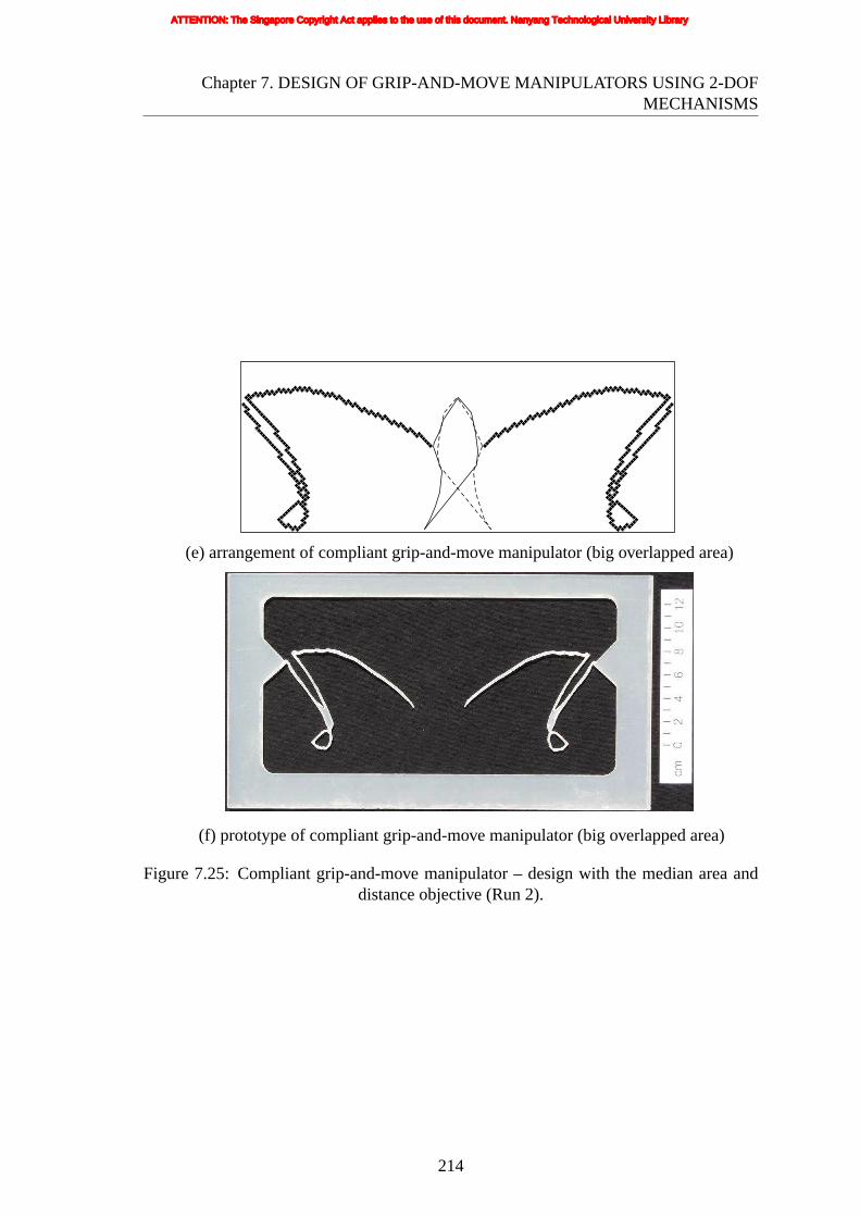
Chapter7. DESIGN OF GRIP-AND-MOVE MANIPULATORS USING 2-DOFMECHANISMS
(e)arrangement of compliant grip-and-move manipulator (big overlapped area)
(f) prototype of compliant grip-and-move manipulator (big overlapped area)
Figure 7.25: Compliant grip-and-move manipulator – design with the median area anddistance objective (Run 2).
214
ATTENTION: The Singapore Copyright Act applies to the use of this document. Nanyang Technological University Library

Chapter7. DESIGN OF GRIP-AND-MOVE MANIPULATORS USING 2-DOFMECHANISMS
(a)gripping position 1 (b) gripping position 2
(c) gripping position 3
Figure 7.26: View of compliant grip-and-move manipulator (long distance output).
(a)gripping position 1 (b) gripping position 2
(c) gripping position 3
Figure 7.27: View of compliant grip-and-move manipulator (big overlapped area).
215
ATTENTION: The Singapore Copyright Act applies to the use of this document. Nanyang Technological University Library
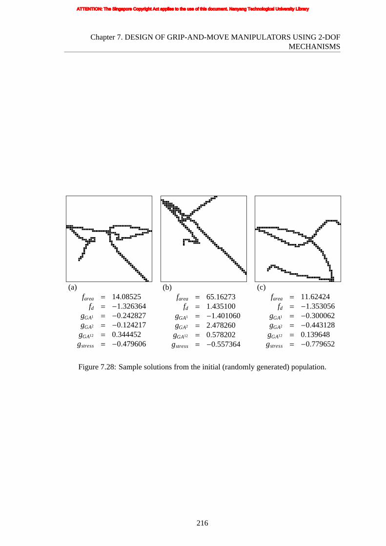
Chapter7. DESIGN OF GRIP-AND-MOVE MANIPULATORS USING 2-DOFMECHANISMS
(a)farea = 14.08525
fd = −1.326364gGA1 = −0.242827gGA2 = −0.124217gGA12 = 0.344452gstress = −0.479606
(b)farea = 65.16273
fd = 1.435100gGA1 = −1.401060gGA2 = 2.478260gGA12 = 0.578202gstress = −0.557364
(c)farea = 11.62424
fd = −1.353056gGA1 = −0.300062gGA2 = −0.443128gGA12 = 0.139648gstress = −0.779652
Figure 7.28: Sample solutions from the initial (randomly generated) population.
216
ATTENTION: The Singapore Copyright Act applies to the use of this document. Nanyang Technological University Library

Chapter7. DESIGN OF GRIP-AND-MOVE MANIPULATORS USING 2-DOFMECHANISMS
(a)generation 50 (bestfarea)farea = 1.488175
fd = −2.276200gGA1 = −0.390179gGA2 = −0.313614gGA12 = −1.189272gstress = −0.036182
(b) generation 50 (median)farea = 2.662622
fd = −2.364592gGA1 = −0.178472gGA2 = −0.114970gGA12 = −0.345744gstress = −0.743022
(c) generation 50 (bestfd)farea = 2.672736
fd = −2.368571gGA1 = −0.174810gGA2 = −0.115435gGA12 = −0.342068gstress = −0.743043
(d) generation 100 (bestfarea)farea = 1.114645
fd = −1.539400gGA1 = −0.984020gGA2 = −0.075372gGA12 = −0.895971gstress = −0.378776
(e) generation 100 (median)farea = 1.605988
fd = −2.589299gGA1 = −0.239462gGA2 = −0.094377gGA12 = −0.578268gstress = −0.504597
(f) generation 100 (bestfd)farea = 2.030747
fd = −2.850300gGA1 = −0.012316gGA2 = −0.098599gGA12 = −0.445527gstress = −0.581997
(g) generation 300 (bestfarea)farea = 0.785424
fd = −2.309400gGA1 = −0.601450gGA2 = −0.537047gGA12 = −0.699508gstress = −0.075388
(h) generation 300 (median)farea = 0.997397
fd = −2.879400gGA1 = −0.135998gGA2 = −0.546193gGA12 = −0.609645gstress = −0.174155
(i) generation 300 (bestfd)farea = 1.357274
fd = −3.02460gGA1 = −0.040572gGA2 = −0.219923gGA12 = −0.118218gstress = −0.127942
Figure 7.29: Best feasible solutions from sample intermediate generations.
217
ATTENTION: The Singapore Copyright Act applies to the use of this document. Nanyang Technological University Library

Chapter7. DESIGN OF GRIP-AND-MOVE MANIPULATORS USING 2-DOFMECHANISMS
generation number
area
obj
ectiv
e
dis
tanc
eo
bjec
tive
0 100 200 300 400 5000
2000
4000
6000
8000
10000
-5
-4
-3
-2
-1
0
area objective
distance objective
Figure7.30: History of the best area objective (farea).
generation number
area
obj
ectiv
e
dis
tanc
eo
bjec
tive
0 100 200 300 400 5000
2000
4000
6000
8000
10000
-5
-4
-3
-2
-1
0
area objective
distance objective
Figure7.31: History of the best distance objective (fd).
218
ATTENTION: The Singapore Copyright Act applies to the use of this document. Nanyang Technological University Library

Chapter7. DESIGN OF GRIP-AND-MOVE MANIPULATORS USING 2-DOFMECHANISMS
area objective
dist
ance
obje
ctiv
e
500 1000 1500 2000 2500 3000
-3
-2.5
-2
-1.5generation 50 elitegeneration 100 elitegeneration 300 elitegeneration 500 elitegeneration 50 non-dominatedgeneration 100 non-dominatedgeneration 300 non-dominatedgeneration 500 non-dominated
Figure7.32: Plot of non-dominated solutions and elites at some sample generations.
area objective
dis
tanc
eo
bjec
tive
500 1000 1500 2000 2500 3000
-3
-2.5
-2
-1.5
generation 50generation 100generation 300generation 500
Figure7.33: Plot of cumulative non-dominated front up to some sample generations.
219
ATTENTION: The Singapore Copyright Act applies to the use of this document. Nanyang Technological University Library

Chapter7. DESIGN OF GRIP-AND-MOVE MANIPULATORS USING 2-DOFMECHANISMS
7.3.3 Run 3
The algorithm has been rerun for the problem while keeping all the parameters exactly the
same as those used in Run 1 (Section 7.3.1) except that the displacement inputs (the three
loading cases) are applied as shown in Figure 7.3(b) instead of that shown in Figure 7.3(a).
This section presents the results of the rerun.
The optimization was run for 500 generations (with a population size of 200 per
generation), by the end of which 85,975 objective function evaluations (finite element
analyses) have been performed. The total (wall-clock) time consumed for 500 generations
is 1,334,176 seconds. Three of the solutions at the end of 500 generations are shown in
Figure 7.34. Figure 7.34(a) shows the solution with the best area objective (farea), whereas
Figure 7.34(c) shows the solution with the best distance objective (fd). The solution with
a median area and distance objective is shown in Figure 7.34(b); it has distance objective
better than the solution in (a) and area objective better than the solution in (c).
(a)best farea
farea = 0.705716fd = −3.568600
gGA1 = −0.021639gGA2 = −5.485259gGA12 = −0.119126gstress = −0.073570
(b) medianfarea = 1.414933
fd = −4.990512gGA1 = −0.825035gGA2 = −0.974831gGA12 = −0.538063gstress = −0.017773
(c) bestfdfarea = 1.982241
fd = −6.753421gGA1 = −0.680699gGA2 = −3.694779gGA12 = −0.332398gstress = −0.030739
Figure 7.34: Three non-dominated solutions at 500th generation.
The design variable values for the solution with the best area objective, which
corresponds to Figure 7.34(a), is given in Figure 7.35(a). The input/output/control points
and the corresponding Bezier curves of the solution are shown in Figure 7.36(a). This
220
ATTENTION: The Singapore Copyright Act applies to the use of this document. Nanyang Technological University Library
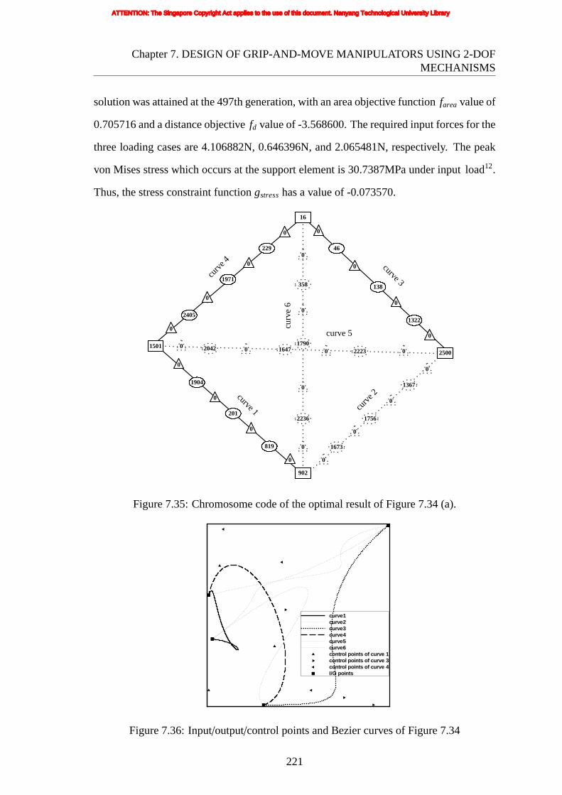
Chapter7. DESIGN OF GRIP-AND-MOVE MANIPULATORS USING 2-DOFMECHANISMS
solutionwas attained at the 497th generation, with an area objective functionfarea value of
0.705716 and a distance objectivefd value of -3.568600. The required input forces for the
three loading cases are 4.106882N, 0.646396N, and 2.065481N, respectively. The peak
von Mises stress which occurs at the support element is 30.7387MPa under input load12.
Thus, the stress constraint functiongstresshas a value of -0.073570.
curv
e 6
0 2042 1647 22230 0 0
curve 3
1322
0
0
curve 1
0
1904
201
819
0
0
0
curv
e 2
0
1367
1756
1673
0
0
0
curv
e 4
2405
0
0
902
2236
0
0
15012500
curve 5
0
46
138
0
0
229
1971
0
16
0
358
1790
0
Figure7.35: Chromosome code of the optimal result of Figure 7.34 (a).
curve1curve2curve3curve4curve5curve6control points of curve 1control points of curve 3control points of curve 4I/O points
Figure7.36: Input/output/control points and Bezier curves of Figure 7.34
221
ATTENTION: The Singapore Copyright Act applies to the use of this document. Nanyang Technological University Library
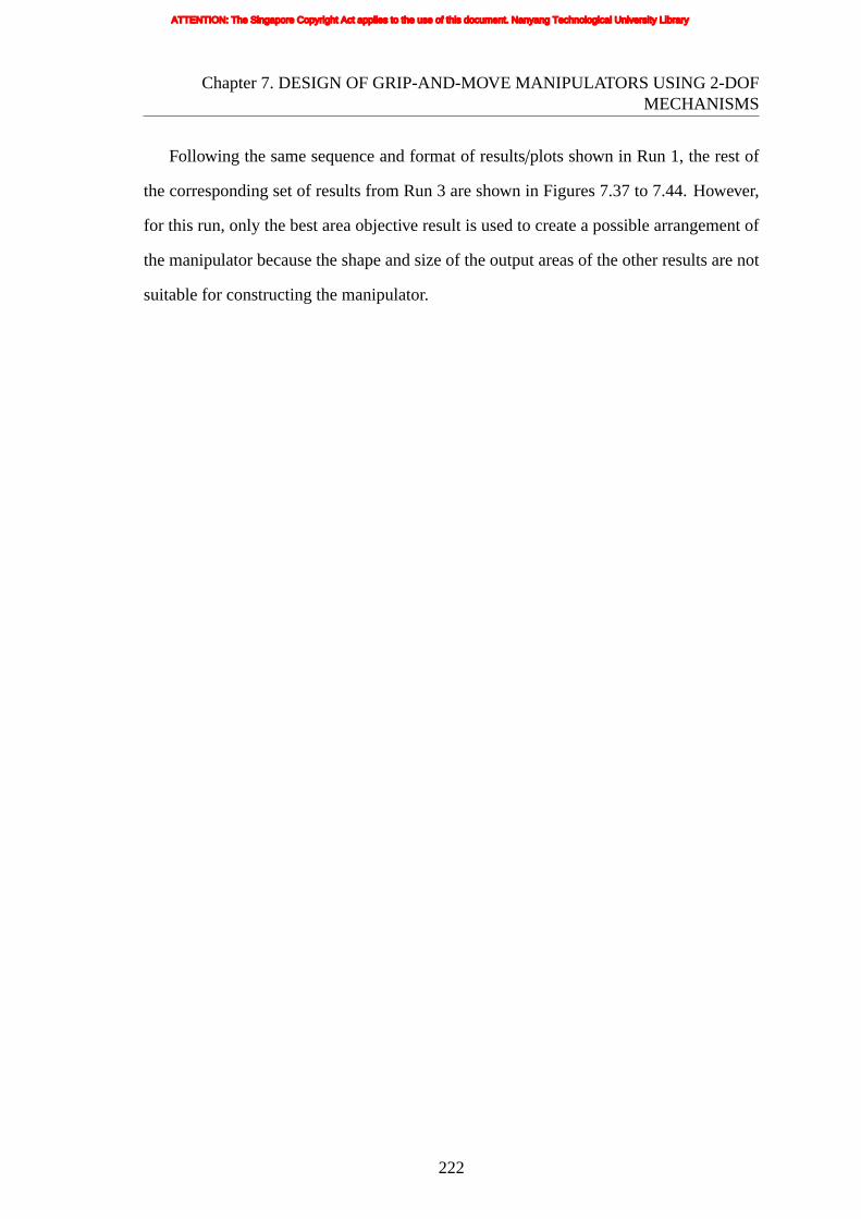
Chapter7. DESIGN OF GRIP-AND-MOVE MANIPULATORS USING 2-DOFMECHANISMS
Following the same sequence and format of results/plots shown in Run 1, the rest of
the corresponding set of results from Run 3 are shown in Figures 7.37 to 7.44. However,
for this run, only the best area objective result is used to create a possible arrangement of
the manipulator because the shape and size of the output areas of the other results are not
suitable for constructing the manipulator.
222
ATTENTION: The Singapore Copyright Act applies to the use of this document. Nanyang Technological University Library

Chapter7. DESIGN OF GRIP-AND-MOVE MANIPULATORS USING 2-DOFMECHANISMS
-0.01 0 0.01 0.02 0.03 0.04 0.05 0.06 0.07-0.06
-0.05
-0.04
-0.03
-0.02
-0.01
0
0.01
0.02
experiment(prototype)
FE analysis
(a) undeformed shape and deformedshapes
(b) output path (area)
(c) arrangement of compliant grip-and-move manipulator
(d) prototype of compliant grip-and-move manipulator
Figure 7.37: Compliant grip-and-move manipulator – design with best area objective(Run 3).
223
ATTENTION: The Singapore Copyright Act applies to the use of this document. Nanyang Technological University Library

Chapter7. DESIGN OF GRIP-AND-MOVE MANIPULATORS USING 2-DOFMECHANISMS
(a)gripping position 1 (b) gripping position 2
(c) gripping position 3 (d) gripping position 4
Figure 7.38: View of compliant grip-and-move manipulator.
(a)farea = 135.5465
fd = −0.952917gGA1 = −0.803565gGA2 = −0.948983gGA12 = 0.027181gstress = −0.543224
(b)farea = 54.18495
fd = 2.204667gGA1 = −1.384034gGA2 = 0.943914gGA12 = 0.945412gstress = −0.873115
(c)farea = 1588.576
fd = 0.262949gGA1 = −0.871113gGA2 = −0.992352gGA12 = 0.078364gstress = −0.167303
Figure 7.39: Sample solutions from the initial (randomly generated) population.
224
ATTENTION: The Singapore Copyright Act applies to the use of this document. Nanyang Technological University Library

Chapter7. DESIGN OF GRIP-AND-MOVE MANIPULATORS USING 2-DOFMECHANISMS
(a)generation 50 (bestfarea)farea = 1.090379
fd = −1.921334gGA1 = −0.605131gGA2 = −4.152685gGA12 = −0.237501gstress = −0.130370
(b) generation 50 (median)farea = 2.307479
fd = −4.499605gGA1 = −0.790043gGA2 = −0.964206gGA12 = −0.486028gstress = −0.167782
(c) generation 50 (bestfd)farea = 2.754752
fd = −5.033625gGA1 = −0.665001gGA2 = −1.953728gGA12 = −0.279748gstress = −0.298879
(d) generation 100 (bestfarea)farea = 0.851900
fd = −2.493000gGA1 = −0.359589gGA2 = −4.959738gGA12 = −0.228789gstress = −0.002867
(e) generation 100 (median)farea = 1.476534
fd = −3.722838gGA1 = −0.150653gGA2 = −2.709665gGA12 = −0.071715gstress = −0.029970
(f) generation 100 (bestfd)farea = 2.368123
fd = −5.534375gGA1 = −0.614004gGA2 = −2.235676gGA12 = −0.262166gstress = −0.141706
(g) generation 300 (bestfarea)farea = 0.851890
fd = −2.323951gGA1 = −0.359589gGA2 = −4.959738gGA12 = −0.228789gstress = −0.002867
(h) generation 300 (median)farea = 1.385728
fd = −3.810513gGA1 = −0.795321gGA2 = −1.214299gGA12 = −0.367803gstress = −0.019012
(i) generation 300 (bestfd)farea = 1.923389
fd = −6.395732gGA1 = −0.624682gGA2 = −3.661673gGA12 = −0.293524gstress = −0.193418
Figure 7.40: Best feasible solutions from sample intermediate generations.
225
ATTENTION: The Singapore Copyright Act applies to the use of this document. Nanyang Technological University Library

Chapter7. DESIGN OF GRIP-AND-MOVE MANIPULATORS USING 2-DOFMECHANISMS
generation number
area
obj
ectiv
e
dis
tanc
eo
bjec
tive
0 100 200 300 400 5000
2000
4000
6000
8000
10000
-5
-4
-3
-2
-1
0
1
area objective
distance objective
Figure7.41: History of the best area objective (farea).
generation number
area
obj
ectiv
e
dis
tanc
eo
bjec
tive
0 100 200 300 400 5000
2000
4000
6000
8000
10000
-12
-10
-8
-6
-4
-2
0
area objective
distance objective
Figure7.42: History of the best distance objective (fd).
226
ATTENTION: The Singapore Copyright Act applies to the use of this document. Nanyang Technological University Library

Chapter7. DESIGN OF GRIP-AND-MOVE MANIPULATORS USING 2-DOFMECHANISMS
area objective
dist
ance
obje
ctiv
e
500 1000 1500 2000 2500 3000-8
-6
-4
-2
0generation 50 elitegeneration 100 elitegeneration 300 elitegeneration 500 elitegeneration 50 non-dominatedgeneration 100 non-dominatedgeneration 300 non-dominatedgeneration 500 non-dominated
Figure7.43: Plot of non-dominated solutions and elites at some sample generations.
area objective
dis
tanc
eo
bjec
tive
500 1000 1500 2000 2500 3000-8
-6
-4
-2
0
generation 50generation 100generation 300generation 500
Figure7.44: Plot of cumulative non-dominated front up to some sample generations.
227
ATTENTION: The Singapore Copyright Act applies to the use of this document. Nanyang Technological University Library

Chapter7. DESIGN OF GRIP-AND-MOVE MANIPULATORS USING 2-DOFMECHANISMS
7.4 DISCUSSIONS AND CONCLUDING REMARKS
A formulation of compliant mechanism design is presented and seven grip-and-move
manipulators composed of the design mechanisms have been created. The synthesis of
such a compliant mechanism is done by solving the problem as a structural optimization
problem with multiple objectives and constraints to achieve the desired behaviour of
the manipulator. The most important objective of a two d-o-f mechanism design is
to maximize the output area. Generating an area itself requires great compliance
or flexibility and therefore, minimizing only area objective automatically leads to
considerable compliance or thinning of the structure. Although generating a big output
area is of utmost importance for a two d-o-f mechanism, a big working area is the
final target based on the arrangement of two identical mechanisms. Keeping this in
mind, a secondary objective, viz. the distance objective, and three GA constraints have
been devised and used. Such mechanisms can be seen as a flexure-hinged displacement
amplifier. As can be seen in Section 7.3, gripping movement is essentially performed
by loading point pulling on mechanism that articulate at support point, which defines a
functioning lever system. The manipulator is provided with a two lever system mounted
on the support point which is a pivotal member. The support point is in a corner position
in response to actuation of the two loading points to assist the grip-and-move behavior of
the manipulator. A first flexure arm has a longitudinal axis and connects to the support
point, a second flexure arm has a vertical axis, and the support point defines a virtual
pivot point. The loading points are near the support point. With such an arrangement,
displacements of loading points are amplified and then hopefully, the output area will be
amplified also.
From the results shown above, the working area is the overlapped area instead of the
output area formulated above. But the output area is being used as an estimate of the
potential working area. The working area can be large only if the output area is large,
and a large output area value gives the grip-and-move manipulator a bigger chance of
generating a big working area.
228
ATTENTION: The Singapore Copyright Act applies to the use of this document. Nanyang Technological University Library

Chapter7. DESIGN OF GRIP-AND-MOVE MANIPULATORS USING 2-DOFMECHANISMS
As can be seen from the result, the working area produced by the optimum design is
relatively large considering the small displacement input. However, large portions of the
output area are wasted because they do not contribute to the working area. Future work
needs to be done to improve the working area with respect to the size of output area of
the structure in order to extend the working range of the manipulator.
As shown in the plots, the (experimental) measured paths (areas) of the prototypes
are not very close to those of their corresponding optimum designs. Results from
Run 1 with best area objective and results from Run 3 are fairly close, while Run 1
with best median area and distance objective and Run 2 prototype results are quite far
from FE analysis. However the experimental areas of the Run 1 prototype (with best
median area and distance objective) can simply be re-oriented, and hence the position
of the two mechanisms can be adjusted to construct a grip-and-move manipulator.
Unlike results from Run 1 and Run 3, the prototypes of Run 2 are not easy to be
arranged to produce a large working area. For the difference between designs and their
corresponding prototypes, some accumulative errors will contribute a lot to the simulation
and measurement inaccuracies besides the factors listed in Section 4.6 for symmetric path
generating mechanisms. The paths (areas) for 2-DOF mechanisms are more complex
especially when the displacement inputs (the three loading cases) are applied as shown
in Figure 7.3(a). For this loading case, input load12 is applied on the loading point 2
of the deformed shape under input load1, hence some accumulative errors will occur.
The matching of deflections between experiment and computation has been shown in
Figure 7.9(b), 7.12(b), 7.23(b), 7.25(b), 7.37(b). Stress has been, and still is, a difficult
thing to measure, and the measure result is appropriate and inaccurate. At the same time,
in this thesis, a constraint on the maximum stress in the mechanism is to hinder fatigue or
failure. Major concern about it, however, is qualitative. So the exact value of stress is not
as useful as the deflections.
229
ATTENTION: The Singapore Copyright Act applies to the use of this document. Nanyang Technological University Library

Chapter 8
CONCLUSION AND FUTURE WORK
This chapter concludes the work presented in this thesis. Conclusions are drawn from
the previous chapters. It also states the intended future work.
8.1 CONCLUSION
8.1.1 Formulation and Development of the Nonlinear FEM Program
A nonlinear formulation is presented for large deformation problems. The virtual work
principle-based nonlinear formulation is constructed in a total Lagrangian description. In
order to consider large deformation, effective stress and strain are expressed in terms of the
2nd Piola-Kirchhoff stress tensor and Green-Lagrange strain tensor, and the constitutive
equation is derived from the relation between the effective stress and strain. 4-noded
quadrilateral isoparametric plane stress element is used for modelling and development
of the FEA program. The newly developed program produces fairly similar results as the
ABAQUS software when doing non-linear analysis. It is then integrated with the genetic
algorithm to perform the structural optimization. This makes the whole program more
portable as it does not have to depend on the time-sharing of the system and availability of
any license for a commercial FE software. Moreover, it is possible to run the optimization
on a personal computer. Comparing with the solution speed of the previous work [246]
solved by ABAQUS on a SGI server, a lot of time can be saved when the same genetic
algorithm problem is solved.
230
ATTENTION: The Singapore Copyright Act applies to the use of this document. Nanyang Technological University Library

Chapter8. CONCLUSION AND FUTURE WORK
8.1.2 Enhanced Morphological Geometry Representation
An enhanced morphological geometry representation that includes variable connectivity
has been presented in this thesis. It uses arrangements of ‘skeleton’ and ‘flesh’ to
define structural geometry in a way that facilitates the transmission of topological/shape
characteristics across generations in the evolutionary process and will not render any
geometrically undesirable features such as disconnected ‘floating’ segments of material,
‘checkerboard’ patterns or single-node hinge connections between elements. As the
number of I/O points increases, there is a large number of possible valid connectivities
and it becomes difficult for the designer to intuitively prescribe one that is likely the best
connectivity. In the enhanced scheme, the connectivities and the number of curves used
are made variable and to be optimized in the evolutionary procedure. Full connectivities
are maintained in the chromosome code but whichever of the curves are actually used will
be selected through the evolutionary procedure and hence the connectivity of the curves
used for defining the skeleton can be varied. The resulting scheme therefore increases
the variability of the connectivity of the curves and hence the variability of the structure
topology. But the resulting designs obtained are jagged-edge structures due to the finite
element discretization/grid. Future work needs to be done to smoothen the boundaries.
8.1.3 Handling Objectives as Adaptive Constraints for
Multiobjective Structural Optimization
This thesis presents a novel, simple and intuitive way to integrate the user’s preference
into the genetic algorithm. This approach treats relatively more important objectives as
adaptive constraints whose ideal values will be adaptively changed (improved) during
the optimization procedure. Such changes can help direct and focus the search towards
preferred regions of the objective space by a variation of the problem type (unconstrained
problem, moderately constrained problem or highly constrained problem). As the
selection criteria for mating partner depends on the type of problem in the algorithm
used here, more selection pressure is put on adaptive constraints. The proposed algorithm
231
ATTENTION: The Singapore Copyright Act applies to the use of this document. Nanyang Technological University Library

Chapter8. CONCLUSION AND FUTURE WORK
efficiently guides the population towards the (preferred) region of interest, allowing a
faster convergence and a better coverage of the preferred area of the Pareto optimal front
based on the relative importance of the objectives.
8.1.4 Use of a Hybrid Strategy to Improve Search for the True
Optimal Solution
Use of a genetic algorithm alone may be effective in approximately locating the global
optimum but it is usually not efficient in trying to reach the exact optimum accurately. It
is therefore more efficient to incorporate a form of local search to ensure finding the true-
optimal solutions. For this purpose, a hybrid strategy can be used in which each solution
obtained from the genetic algorithm procedure can be further improved (modified) by
using a secondary (local) optimization/search process. A novel constrained tournament
selection is used as a single objective function in the local search strategy. This selection
is utilized to determine whether a new solution generated in the local search process will
survive. Hooke and Jeeves method is applied to decide on the search path. However the
major problem of approach used in local search is the need for specifying the right value
for weight parameters in advance. And the values usually can not reflect the real relative
comparison between them.
8.1.5 Design of Test Problems with Conflicting/Non-conflicting
Objectives
The genetic algorithm has been tested and tuned by running it on one old and three
newly-devised mutltiobjective and constrained test problems called “Target-Matching
Problems”. These test problems with conflicting objectives or non-conflicting objectives
are most suitable for the genetic algorithm being employed in this work as it makes
use of the genetic algorithm’s integral procedures such as the morphological geometry
representation scheme, associated chromosome encoding and reproduction operators,
232
ATTENTION: The Singapore Copyright Act applies to the use of this document. Nanyang Technological University Library

Chapter8. CONCLUSION AND FUTURE WORK
etc. The genetic algorithm was run for the test problem and the solutions successfully
converged to the ‘target geometry’. The best set of the genetic algorithm parameters,
which was deduced from the various runs of the algorithm for solving the test problems,
was then used for solving the actual mechanism problem.
8.1.6 Design of Grip-and-move manipulators Using Symmetric Path-
generating Mechanisms
A compliant grip-and-move manipulator design problem has been conceptualized and
formulated by the employment of two identical symmetric path generating mechanisms.
These two symmetric path generating mechanisms work like two fingers so that they
can grip an object and convey it from one point to another. The topology/shape design
optimization methodology has been applied to automatically synthesize a symmetric path
generating compliant mechanism which produces a desired symmetric output path. The
genetic algorithm treats the problem as a discrete multiobjective constrained optimization
problem. The most important objective of a symmetric path generating compliant
mechanism is to minimize the path objective function which quantifies the error between
the actual and the desired paths. Although generating a path correctly is of utmost
importance for such a mechanism, improvement in the flexibility of the mechanism
without deteriorating the path objective is also desirable. Keeping this in mind, a second
objective, the geometric advantage objective, has been devised and used so that the
flexibility of the mechanism is also maximized simultaneously. As can be seen from
the results, the path produced by the selected optimum designs are very close to being
symmetric. The geometric advantage attained in the symmetric path problem is also fairly
good. However, the absolute length of the path generated by the mechanism is relatively
short compared to the mechanism’s size. And the (experimental) measured paths are not
as close to the desired symmetric curves as suggested by the FE results.
233
ATTENTION: The Singapore Copyright Act applies to the use of this document. Nanyang Technological University Library
Chapter8. CONCLUSION AND FUTURE WORK
8.1.7 Design of Grip-and-move manipulators Using 2-DOF
Compliant Mechanisms
Another compliant grip-and-move manipulator problem has been conceptualized and
formulated by the employment of two identical 2-DOF path generating mechanisms.
As described in Chapter 4, two identical symmetric path-generating mechanisms can be
combined as a grip-and-move manipulator which can grip something and travel over some
distance, but it can only travel along a specific path. For a more general mechanism, it will
likely require two DOF with two inputs. In this work, a formulation for such a compliant
mechanism design has been created. The synthesis of such a compliant mechanism
is achieved by solving the problem as a structural optimization problem with multiple
objectives and constraints to achieve the desired behaviour of the manipulator. From
the results shown, the working area is the overlapped area between the two mechanisms
instead of the output area of each mechanism. But the output area can be used to estimate
the working area. The working area can be large only if the output area is large. And
a large output area gives the grip-and-move manipulator more likelihood of achieving
a large working area. As can be seen from the result, the working area produced by the
optimum design is large considering the small displacement input, although it is relatively
small compared to the output area of each mechanism as much of the output area is not
usable and hence wasted. Future work needs to be done to improve the working area with
respect to the size of output area of the structure in order to extend the working range of
the manipulator.
8.2 ORIGINAL CONTRIBUTIONS ARISING FROM
THIS WORK
To the best of the author’s knowledge, a compliant mechanism that can grip and move
an object from one point to some other desired point (within its working range) has not
been designed/created before. The applications of this mechanism will be significant in
234
ATTENTION: The Singapore Copyright Act applies to the use of this document. Nanyang Technological University Library

Chapter8. CONCLUSION AND FUTURE WORK
thefields of MEMS, robotics and various automation tasks. In this work, the development
of the methodology to design such a mechanism has given rise to various contributions
including:
i New formulation of optimization criteria for designing grip-and-move manipulators
by the employment of two identical symmetric path generating mechanisms.
ii Enhanced geometry representation schemes for defining the geometry of the design
structures to increase the representation variability.
iii Implementation of a hybrid genetic algorithm incorporating an adaptive constraint
concept to improve its performance and efficiency.
iv Construction of test problems with conflicting/non-conflicting objectives to test and
tune the genetic algorithm for solving the actual mechanism design problem
v New formulations of optimization criteria for designing compliant grip-and-move
manipulators by the employment of two path generating mechanisms with two
degrees-of-freedom, two input points and multiple objectives/criteria.
8.3 RECOMMENDATIONS FOR FUTURE WORK
8.3.1 Control of Mechanisms
To be able to grip and convey an object from one point to another, the resultant compliant
mechanism must be paired up with another identical mechanism. To ensure the output
ports from the two mechanisms can meet and grip, the control of the inputs for each
of the two mechanisms must be coordinated. This is probably best accomplished
after fabricating the mechanism such that the input-output behavior is more accurately
determined and then the orientation of the two mechanisms can be adjusted accordingly.
235
ATTENTION: The Singapore Copyright Act applies to the use of this document. Nanyang Technological University Library
Chapter8. CONCLUSION AND FUTURE WORK
8.3.2 Edge Smoothening and Reanalysis of Structure
The resulting designs obtained are jagged-edge structures due to the finite element
discretization/grid. Therefore future work that needs to be done include the
implementation of some form of curve-fitting or smoothing techniques to parameterize
the structural boundaries. After smoothening of the boundaries, finite element analysis
of the smoothed structure may be carried out so that the final values (closer to the actual
fabricated mechanism) of the objective and constraint functions can be computed.
Alternatively, the need for smoothening of the boundaries can be avoided by
developing the morphological representation scheme to directly generate smooth
boundary structures and then have the geometry discretized by some automatic FE
meshing facility. This will result in another advantage and that is the morphological
geometry representation scheme or the design variables will not be mesh dependant.
However, this approach is feasible only if reliable and efficient automatic meshing can
always be achieved.
8.3.3 Guidelines to Selecting Parameters and Setting Their Limits
In the present methodology, the number of I/O points and their allowable positions, lower
and upper bounds of the thickness variables, and the number of control points are required
to be prescribed. The shape of the optimal design depends on these parameters and,
therefore, a wrong choice of parameters (for example, the number and positioning of
the support points) may result in poor convergence of the problem. As an alternative,
a method can be developed to determine the number of I/O points, the position of the
support points, etc.
236
ATTENTION: The Singapore Copyright Act applies to the use of this document. Nanyang Technological University Library

References
[1] L.L. Howell. Compliant Mechanisms. John Wiley, 2001.
[2] O. Sigmund. On the design of compliant mechanisms using topology optimization.
Mechanics of Structures and Machines, 25(4):493–524, 1997.
[3] G.K. Ananthasuresh.A new design paradigm for micro-electro-mechanical systems
and investigations on the compliant mechanisms synthesis. Phd thesis, University
of Michigan, USA, 1994.
[4] Ciro A. Soto. Structural topology optimization: From minimizing compliance
to maximizing energy absorption.International Journal of Vehicle Design, 25(1-
2):142–163, 2001.
[5] Bing-Chung Chen, E. C. N. Silva, and Noboru Kikuchi. Advances in computational
design and optimization with application to MEMS.International Journal for
Numerical Methods in Engineering, 52(1-2):23–62, 2001.
[6] Martin P. Bendsoe. Recent developments in topology design of materials and
mechanisms. InESAIM: Proceedings, 2002.
[7] Mary I. Frecker. Recent advances in optimization of smart structures and actuators.
Journal of Intelligent Material Systems and Structures, 14(4-5):207–216, 2003.
[8] T. Moulton and G.K. Ananthasuresh. Micromechanical devices with embedded
electro-thermal-compliant actuation.Sensors and Actuators A (Physical), A90(1-
2):38–48, 2001.
[9] Tanakorn Tantanawat, Zhe Li, and Sridhar Kota. Application of compliant
mechanisms to active vibration isolation systems. InASME Design Engineering
Technical Conferences and Computers and Information in Engineering
Conference, volume 2B, pages 1165–1172, Salt Lake City, UT, United States, Sep
28-Oct 2 2004.
[10] Ying-Chien Tsai, Sio Hou Lei, and Hendra Sudin. Design and analysis of planar
compliant microgripper based on kinematic approach.J. Micromech. Microeng.,
15:143–156, 2005.
237
ATTENTION: The Singapore Copyright Act applies to the use of this document. Nanyang Technological University Library

References
[11] Wenjie Chen and Wei Lin. Design of a flexure-based gripper used in optical fiber
handling. In2004 IEEE Conference on Robotics, Automation and Mechatronics,
pages 83–88, Singapore, Dec 1-3 2004.
[12] A.M. Bertetto and M. Ruggiu. A two degree of freedom gripper actuated by SMA
with flexure hinges.Journal of Robotic Systems, 20(11):649–657, 2003.
[13] M. Goldfarb and N. Celanovic. A flexure-based gripper for small-scale
manipulation.Robotica, 17:181–187, 1999.
[14] A.M. Dollar and R.D. Howe. A robust compliant grasper via shape deposition
manufacturing.IEEE/ASME Transactions on Mechatronics, 11(2):154–161, 2006.
[15] C. J. Shih and C. F. Lin. A two-stage topological optimum design for monolithic
compliant microgripper integrated with flexure hinges.Journal of Physics:
Conference Series, 34:840–846, 2006.
[16] U.D. Larsen, O. Signund, and S. Bouwsta. Design and fabrication of compliant
micromechanisms and structures with negative Poisson’s ratio.Journal of
Microelectromechanical Systems, 6(2):99–106, 1997.
[17] C.B.W. Pedersen, T. Buhl, and O. Sigmund. Topology synthesis of large-
displacement compliant mechanisms.International Journal for Numerical
Methods in Engineering, 50(12):2683–2705, 2001.
[18] G.H. Yoon, Y.Y. Kim, M.P. Bendsoe, and O. Sigmund. Hinge-free topology
optimization with embedded translation-invariant differentiable wavelet shrinkage.
Structural and Multidisciplinary Optimization, 27(3):139–150, 2004.
[19] Jinyong Joo and Sridhar Kota. Topological synthesis of compliant mechanisms
using nonlinear beam elements.Mechanics Based Design of Structures and
Machines, 32(1):17–38, 2004.
[20] Seungjae Min and Younggi Kim. Topology optimization of compliant mechanism
with geometrical advantage. InThird International Symposium on Speed-up and
Service Technology for Railway and MAGLEV Systems (STECH’03), volume 47,
pages 610–615, Tokyo, Japan, 19-22 Aug. 2003.
[21] S. Rahmatalla and C. C. Swan. Sparse monolithic compliant mechanisms using
continuum structural topology optimization.International Journal for Numerical
Methods in Engineering, 62(12):1579–1605, 2005.
[22] T. Buhl. Simultaneous topology optimization of structure and supports.Structural
and Multidisciplinary Optimization, 23(5):336–346, 2002.
238
ATTENTION: The Singapore Copyright Act applies to the use of this document. Nanyang Technological University Library
References
[23] Young Seok Oh, Woo Ho Lee, Harry E. Stephanou, and George D. Skidmore.
Design, optimization, and experiments of compliant microgripper. In2003 ASME
International Mechanical Engineering Congress and Exposition, volume 5, pages
345–350, Washington, DC, United States, Nov 15-21 2003.
[24] E.V. Bordatchev and S.K. Nikumb. Microgripper: Design, finite element analysis
and laser microfabrication. InProceedings International Conference on MEMS,
NANO and Smart Systems, pages 308–313, Banff, Alta., Canada, 20-23 July 2003.
[25] Y. Haddab, N. Chaillet, and A. Bourjault. A microgripper using smart piezoelectric
actuators. InProceedings of 2000 IEEE/RSJ International Conference on
Intelligent Robots and Systems, volume 1, pages 659–664, 2000.
[26] N. Chronis and L. P. Lee. Electrothermally activated SU-8 microgripper for
single cell manipulation in solution.Journal of Microelectromechanical Systems,
14(4):857–863, 2005.
[27] Shawn Canfield, Ben Edinger, Mary Frecker, and Gary Koopmann. Design of
piezoelectric inchworm actuator and compliant end-effector for minimally invasive
surgery.Proceedings of the 1999 Smart Structures and Materials - Smart Structures
and Integrated Systems, 3668(2):835–843, Mar 1-Mar 4 1999.
[28] M.I. Frecker, K.M. Powell, and R. Haluck. Design of a multifunctional compliant
instrument for minimally invasive surgery.ASME Journal of Biomechanical
Engineering, 127(6):990–993, 2005.
[29] S. Kota, K.-J. Lu, Z. Kreiner, B. Trease, J. Arenas, and J. Geiger. Design
and application of compliant mechanisms for surgical tools.ASME Journal of
Biomechanical Engineering, 127(6):981–989, 2005.
[30] Paul Bernardoni, Alain Riwan, Hellie Tsitsiris, Olivier Millet, Lionel Buchaillot,
Stephane Regnier, and Philippe Bidaud. From the mechanical analysis of a
polyarticulated microgripper to the design of a compliant microgripper. InSmart
Structures and Materials 2004 - Modeling, Signal Processing, and Control, San
Diego, CA, United States, 21-23 Aug, 2004.
[31] Michael Yu Wang, Shikui Chen, Xiaoming Wang, and Yulin Mei. Design
of multimaterial compliant mechanisms using level-set methods.Journal of
Mechanical Design, Transactions of the ASME, 127(5):941–956, 2005.
[32] A. Saxena and G. Ananthasuresh. Topology optimization of compliant mechanisms
with strength considerations.Mechanics of Structures and Machines, 29(2):199,
2001.
239
ATTENTION: The Singapore Copyright Act applies to the use of this document. Nanyang Technological University Library

References
[33] D. Xu and G. K. Ananthasuresh. Freeform skeletal shape optimization of compliant
mechanisms.Journal of Mechanical Design, 125(2):253–261, 2003.
[34] A. Saxena and G. K. Ananthasuresh. Topology synthesis of compliant mechanisms
for nonlinear force-deflection and curved path specifications.Journal of
Mechanical Design, 123(1):33–42, 2001.
[35] A. Saxena and G.K. Ananthasuresh. On an optimal property of compliant
topologies.Structural and Multidisciplinary Optimization, 19(1):36–49, 2000.
[36] K. Tai and T. H. Chee. Design of structures and compliant mechanisms by
evolutionary optimization of morphological representations of topology.Journal
of Mechanical Design, 122(4):560–566, 2000.
[37] Smita Bharti and Mary I. Frecker. Optimal design and experimental
characterization of a compliant mechanism piezoelectric actuator for inertially
stabilized rifle.Journal of Intelligent Material Systems and Structures, 15(2):93–
106, 2004.
[38] S. Kota, J. Hetrick, Zhe Li, S. Rodgers, and T. Krygowski. Synthesizing high-
performance compliant stroke amplification systems for MEMS. InProceedings
IEEE Thirteenth Annual International Conference on Micro Electro Mechanical
Systems, pages 164–169, Miyazaki, Japan, 23-27 Jan. 2000.
[39] L.L. Howell and A. Midha. Design of compliant mechanisms with small-length
flexural pivots.Journal of Mechanical Design, 166(1):280–290, 1994.
[40] K. Tai and S. Akhtar. Structural topology optimization using a genetic
algorithm with a morphological geometric representation scheme.Structural and
Multidisciplinary Optimization, 30(2):113–127, 2005.
[41] Colby C. Swan and Salam F. Rahmatalla. Topological design and control of
path-following compliant mechanisms. InCollection of Technical Papers - 10th
AIAA/ISSMO Multidisciplinary Analysis and Optimization Conference, volume 4,
pages 2430–2442, Albany, NY, United States, Aug 30-Sep 1 2004.
[42] M. Frecker, N. Kikuchi, and S. Kota. Topology optimization of compliant
mechanisms with multiple outputs.Structural and Multidisciplinary Optimization,
17(4):269–278, 1999.
[43] A. Saxena. Topology design of large displacement compliant mechanisms with
multiple materials and multiple output ports.Structural and Multidisciplinary
Optimization, 30(6):477–490, 2005.
240
ATTENTION: The Singapore Copyright Act applies to the use of this document. Nanyang Technological University Library
References
[44] Brian R. Jones, William A. Crossley, and Anastasios S. Lyrintzis. Aerodynamic
and aeroacoustic optimization of rotorcraft airfoils via a parallel genetic algorithm.
Journal of Aircraft, 37(6):1088 – 1096, 2000.
[45] Thomas Buhl. Compliant mechanism design for adaptive trailing edge flaps. InXXI
International Congress of Theoretical and Applied Mechanics, Warsaw, Poland,
2004.
[46] L.F. Campanile. Initial thoughts on weight penalty effects in shape-adaptable
systems. Journal of Intelligent Material Systems and Structures, 16(1):47–56,
2005.
[47] L.F. Campanile, R. Keimer, and E.J. Breitbach. The “fish-mouth” actuator: Design
issues and test results.Journal of Intelligent Material Systems and Structures,
15(9-10):711–719, 2004.
[48] N. Srinivasa and R. Ross. An automated approach to design shape morphing
strategies for reconfigurable surfaces. InSmart Structures and Materials 2005:
Modeling, Signal Processing, and Control, volume 5757, pages 164–171, San
Diego, CA, USA, 7 March 2005.
[49] Kerr-Jia Lu and Sridhar Kota. Design of compliant mechanisms for morphing
structural shapes. Journal of Intelligent Material Systems and Structures,
14(6):379–391, 2003.
[50] K.-J. Lu and S. Kota. Compliant mechanism synthesis for shape-change
applications: preliminary results. InSmart Structures and Materials 2002:
Modeling, Signal Processing, and Control, Proceedings of the SPIE, volume 4693,
pages 161–172, San Diego, CA, USA, 18-21 March 2002.
[51] Kerr-Jia Lu and Sridhar Kota. An effective method of synthesizing compliant
adaptive structures using load path representation.Journal of Intelligent Material
Systems and Structures, 16(4):307–317, 2005.
[52] T.E. Bruns, O. Sigmund, and D.A. Tortorelli. Numerical methods for the topology
optimization of structures that exhibit snap-through.International Journal for
Numerical Methods in Engineering, 55(10):1215–1237, 2002.
[53] T. E. Bruns and O. Sigmund. Toward the topology design of mechanisms that
exhibit snap-through behavior.Computer Methods in Applied Mechanics and
Engineering, 193(36-38):3973–4000, 2004.
[54] Jin Qiu, J.H. Lang, and A.H. Slocum. A curved-beam bistable mechanism.Journal
of Microelectromechanical Systems, 13(2):137–146, 2004.
241
ATTENTION: The Singapore Copyright Act applies to the use of this document. Nanyang Technological University Library

References
[55] M.S. Baker and L.L. Howell. On-chip actuation of an in-plane compliant bistable
micro-mechanism.Journal of Microelectromechanical Systems, 11(5):566–573,
2002.
[56] N.D. Masters and L.L. Howell. A self-retracting fully compliant bistable
micromechanism. Journal of Microelectromechanical Systems, 12(3):273–280,
2003.
[57] T. Gomm, L.L. Howell, and R.H. Selfridge. In-plane linear displacement bistable
microrelay. Journal of Micromechanics and Microengineering, 12(3):257–64,
2002.
[58] N.D. Mankame and G.K. Ananthasuresh. Topology optimization of contact-aided
compliant mechanisms with smoothened contact modeling. InProceedings of the
ISSMO International Conference on Multi-disciplinary Optimization, Goa, India,
2003.
[59] Nilesh D. Mankame and G. K. Ananthasuresh. Topology optimization for synthesis
of contact-aided compliant mechanisms using regularized contact modeling.
Computers and Structures, 82(15-16):1267–1290, 2004.
[60] N.D. Mankame and G.K. Ananthasuresh. A novel compliant mechanism for
converting reciprocating translation into enclosing curved paths.ASME Journal
of Mechanical Design, 126(4):667–72, 2004.
[61] T. Buhl, C.B.W. Pedersen, and O. Sigmund. Stiffness design of geometrically
nonlinear structures using topology optimization.Structural and Multidisciplinary
Optimization, 19(2):93–104, 2000.
[62] Hae Chang Gea and Jianhui Luo. Topology optimization of structures with
geometrical nonlinearities. Computers and Structures, 79(20-21):1977–1985,
2001.
[63] Daeyoon Jung and Hae Chang Gea. Topology optimization of nonlinear structures.
Finite Elements in Analysis and Design, 40(11):1417–1427, 2004.
[64] T.E. Bruns and D.A. Tortorelli. Topology optimization of non-linear elastic
structures and compliant mechanisms.Computer Methods in Applied Mechanics
and Engineering, 190(26-27):3443–3459, 2001.
[65] Jinyong Joo, Sridhar Kota, and Noboru Kikuchi. Topological synthesis of
compliant mechanisms using linear beam elements.Mechanics of Structures and
Machines, 28(4):245, 2000.
242
ATTENTION: The Singapore Copyright Act applies to the use of this document. Nanyang Technological University Library

References
[66] Jinyong Joo, Sridhar Kota, and Noboru Kikuchi. Large deformation behavior of
compliant mechanisms. In2001 ASME Design Engineering Technical Conference
and Computers and Information in Engineering Conference, volume 2, pages 709–
714, Pittsburgh, PA, United States, Sep 9-12 2001.
[67] Zhen-Yu Liu, Dong-Ming Guo, and J.G. Korvink. Topology optimization for stable
non-linear structures. InInternational Conference on Micro and Nano Systems
2002 (ICMNS 2002), volume 3, pages 589–593, Kunming, China, 11-14 Aug.
2002.
[68] S. Cho, H. Jung, and Y. Yang. Topology optimization of geometrically nonlinear
structures for compliant mechanism design. In9th AIAA/ISSMO Symposium on
Multidisciplinary Analysis and Optimization, Atlanta, Georgia, 2002.
[69] L. Yin and G.K. Ananthasuresh. Topology optimization of compliant mechanisms
with multiple materials using a peak function material interpolation scheme.
Structural and Multidisciplinary Optimization, 23(1):49–62, 2001.
[70] Luzhong Yin and G. K. Ananthasuresh. A novel topology design scheme for the
multi-physics problems of electro-thermally actuated compliant micromechanisms.
Sensors and Actuators A: Physical, 97-98:599–609, 2002.
[71] O. Sigmund. Systematic design and optimization of multi-material, multi-degree-
of-freedom micro actuators. InTechnical Proceedings of the 2000 International
Conference on Modeling and Simulation of Microsystems, pages 36 – 39, 2000.
[72] O. Sigmund. Design of multiphysics actuators using topology optimization -
part II: Two-material structures.Computer Methods in Applied Mechanics and
Engineering, 190(49-50):6605–6627, 2001.
[73] Markus J. Buehler, Bernhard Bettig, and Gordon G. Parker. Topology optimization
of smart structures using a homogenization approach.Journal of Intelligent
Material Systems and Structures, 15(8):655–667, 2004.
[74] Michael Yu Wang and Xiaoming Wang. “Color” level sets: a multi-phase method
for structural topology optimization with multiple materials.Computer Methods in
Applied Mechanics and Engineering, 193(6-8):469–496, 2004.
[75] O. Sigmund. Design of multiphysics actuators using topology optimization -
part I: One-material structures.Computer Methods in Applied Mechanics and
Engineering, 190(49-50):6577–6604, 2001.
[76] J. Jonsmann, O. Sigmund, and S. Bouwstra. Compliant electro-thermal
microactuators. InIEEE Proceeding of MEMS (MEMS’99), pages 588–593, 1999.
243
ATTENTION: The Singapore Copyright Act applies to the use of this document. Nanyang Technological University Library
References
[77] N.D. Mankame and G.K. Ananthasuresh. Topology synthesis of electrothermal
compliant mechanisms using line elements.Structural and Multidisciplinary
Optimization, 26(3):209–218, 2004.
[78] S. Kota, J. Hetrick, Z. Li, and L. Saggere. Tailoring unconventional actuators
using compliant transmissions: design methods and applications.IEEE/ASME
Transactions on Mechatronics, 4(4):396–408, 1999.
[79] B. Reyes Rodriguez. Study of the degrees of freedom equations in the compliant
mechanism design. InProceedings of the Second International Symposium on
Environmentally Conscious Design and Inverse Manufacturing (EcoDesign 2001),
pages 202–207, 2001.
[80] P. Bernardoni, P. Bidaud, C. Bidard, and F. Gosselin. A new compliant mechanism
design methodology based on flexible building blocks. InSmart Structures and
Materials 2004. Modelings, Signal Processing, and Control, Proceedings of the
SPIE, volume 5383, pages 244–254, San Deigo, CA, USA, 15-18 March 2004.
[81] S. Awtar. Analysis and Synthesis of Parallel Kinematic XY Flexure Mechanisms.
Phd thesis, Massachusetts Institute of Technology, USA, 2004.
[82] Nicolae Lobontiu and Ephrahim Garcia. Analytical model of displacement
amplification and stiffness optimization for a class of flexure-based compliant
mechanisms.Computers and Structures, 81(32):2797–2810, 2003.
[83] Nicolae Lobontiu and Ephrahim Garcia. Circular-hinge line element for finite
element analysis of compliant mechanisms.Journal of Mechanical Design,
127(4):766–773, 2005.
[84] Shilong Zhang and Ernest D. Fasse. A finite-element-based method to determine
the spatial stiffness properties of a notch hinge.Journal of Mechanical Design,
123(1):141–147, 2001.
[85] B. Zettl, W. Szyszkowski, and W.J. Zhang. On systematic errors of two-
dimensional finite element modeling of right circular planar flexure hinges.ASME
Journal of Mechanical Design, 127(4):782–787, 2005.
[86] R.H. Burns and F.R.E. Crossley. Kinetostatic synthesis of flexible link mechanisms.
In ASME Meeting Mech-36, page 7, Oct 5-9 1968.
[87] D.L. Wilcox and L.L. Howell. Fully compliant tensural bistable micromechanisms
(FTBM). Journal of Microelectromechanical Systems, 14(6):1223–1235, 2005.
244
ATTENTION: The Singapore Copyright Act applies to the use of this document. Nanyang Technological University Library

References
[88] JonathanD. Bartley-Cho, Donny P. Wang, Christopher A. Martin, Jayanth N.
Kudva, and Mark N. West. Development of high-rate, adaptive trailing edge control
surface for the smart wing phase 2 wind tunnel model.Journal of Intelligent
Material Systems and Structures, 15(4):279–291, 2004.
[89] Christopher A. Mattson, Larry L. Howell, and Spencer P. Magleby. Development
of commercially viable compliant mechanisms using the pseudo-rigid-body model:
Case studies of parallel mechanisms.Journal of Intelligent Material Systems and
Structures, 15(3):195–202, 2004.
[90] X.-P.S. Su and H.S. Yang. Two-stage compliant microleverage mechanism
optimization in a resonant accelerometer.Structural and Multidisciplinary
Optimization, 22(4):328–336, 2001.
[91] Yue-Qing Yu, Larry L. Howell, Craig Lusk, Ying Yue, and Mao-Gen He.
Dynamic modeling of compliant mechanisms based on the pseudo-rigid-body
model. Journal of Mechanical Design, Transactions of the ASME, 127(4):760–
765, 2005.
[92] L. Saggere and S. Kota. Synthesis of planar, compliant four-bar mechanisms
for compliant-segment motion generation.Journal of Mechanical Design,
123(4):535–541, 2001.
[93] Christine Vehar, Sridhar Kota, and Robert Dennis. Closed-loop tape
springs as fully compliant mechanisms -preliminary investigations. InASME
Design Engineering Technical Conferences and Computers and Information
in Engineering Conference, volume 2B of Proceedings of the ASME Design
Engineering Technical Conference, pages 1023–1032, Salt Lake City, UT, United
States, Sep 28-Oct 2 2004.
[94] Yong-Mo Moon and Sridhar Kota. Design of compliant parallel kinematic
machines. In27th Biennial Mechanisms and Robotics Conference, volume 5A of
Proceedings of the ASME Design Engineering Technical Conference, pages 35–41,
Montreal, Que., Canada, Sep 29-Oct 2 2002.
[95] Charles J. Kim, Sridhar Kota, and Yong-Mo Moon. An instant center approach
toward the conceptual design of compliant mechanisms.Journal of Mechanical
Design, Transactions of the ASME, 128(3):542–550, 2006.
[96] Charles Kim and Sridhar Kota. Design of a novel compliant transmission for
secondary microactuators in disk drives. In27th Biennial Mechanisms and
Robotics Conference, volume 5A ofProceedings of the ASME Design Engineering
Technical Conference, pages 77–83, Montreal, Que., Canada, Sep 29-Oct 2 2002.
245
ATTENTION: The Singapore Copyright Act applies to the use of this document. Nanyang Technological University Library
References
[97] Yong-Mo Moon, Brian Patrick Trease, and Sridhar Kota. Design of large-
displacement compliant joints. In27th Biennial Mechanisms and Robotics
Conference, volume 5A ofProceedings of the ASME Design Engineering Technical
Conference, pages 65–76, Montreal, Que., Canada, Sep 29-Oct 2 2002.
[98] J.M. Paros and L. Weisbord. How to design flexure hinges.Machine Design,
37(27):151–156, 1965.
[99] Luzhong Yin and G.K. Ananthasuresh. Design of distributed compliant
mechanisms.Mechanics Based Design of Structures and Machines, 31(2):151–
179, 2003.
[100] M.P. Bendsoe and O. Sigmund.Topology Optimization: Theory, Methods and
Applications. Springer, 2003.
[101] Ting-Yu Chen and Bo Ping Wang. Optimum design of nonproportionally damped
structures using method of optimality criterion.AIAA Journal, 32(2):415 – 417,
1994.
[102] Ping Wang Bo and P. Costin, Daniel. Optimum design of a composite structure
with three types of manufacturing constraints.AIAA Journal, 30(6):1667 – 1669,
1992.
[103] W.S. Dorn, R.E. Gomory, and H.J Greenberg. Automatic design of optimal
structures.Journal de Mecanique, 3:25–52, 1964.
[104] K. Deb and S. Gulati. Design of truss-structures for minimum weight using genetic
algorithms.Finite Elements in Analysis and Design, 37(5):447 – 465, 2001.
[105] M.P. Bendsoe and N. Kikuchi. Generating optimal topologies in structural design
using a homogenization method.Computer Methods Applied Mechanics and
Engineering, 71:197–224, 1988.
[106] S. Nishiwaki, M.I. Frecker, S. Min, and N. Kikuchi. Topology optimization of
compliant mechanisms using the homogenization method.International Journal
for Numerical Methods in Engineering, 42(3):535–559, 1998.
[107] Y. Li, K. Saitou, and N. Kikuchi. Topology optimization of thermally actuated
compliant mechanisms considering time-transient effect. Finite Elements in
Analysis and Design, 40(11):1317 – 1331, 2004.
[108] E. Atrek. SHAPE: A program for shape optimization of continuum structures.
In Computer Aided Optimum Design of Structures: Applications, pages 135–144,
Southampton, 1989.
246
ATTENTION: The Singapore Copyright Act applies to the use of this document. Nanyang Technological University Library

References
[109] D.M. Russell and S.P. Manoochehri. A two dimensional rule-based shape synthesis
method.Advances in Design Automation, 2:217–223, 1989.
[110] Y.M. Xie and G.P. Steven. A simple evolutionary procedure for structural
optimization.Computers and Structures, 49(5):885–896, 1993.
[111] H. Harasaki and J.S. Arora. A new class of evolutionary methods based on the
concept of transferred force for structural design.Structural and Multidisciplinary
Optimization, 22(1):35–56, 2001.
[112] G. Marckmann, P. Bettess, and B. Peseux. Self designing structures: a new
evolutionary rule for thickness distribution in 2D problems.Communications in
Numerical Methods in Engineering, 18(10):743–755, 2002.
[113] E. Hinton and J. Sienz. Fully stressed topological design of structures using an
evolutionary procedure.Engineering Computations (Swansea, Wales), 12(3):229–
244, 1995.
[114] A. Baumgartner, L. Harzheim, and C. Mattheck. SKO (soft kill option): the
biological way to find an optimum structure topology.International Journal of
Fatigue, 14(6):387–393, 1992.
[115] M. Zhou and G.I.N. Rozvany. On the validity of ESO type methods in topology
optimization.Structural and Multidisciplinary Optimization, 21(1):80–83, 2001.
[116] O.M. Querin, G.P. Steven, and Y.M. Xie. Evolutionary structural optimisation
(ESO) using a bidirectional algorithm.Engineering Computations, 15(8):1031–
1048, 1998.
[117] T. E. Bruns and D. A. Tortorelli. An element removal and reintroduction
strategy for the topology optimization of structures and compliant mechanisms.
International Journal for Numerical Methods in Engineering, 57(10):1413–1430,
2003.
[118] S. Osher and J.A. Sethian. Front propagating with curvature-dependent speed:
Algorithms based on Hamilton-Jacobi formulations.Journal of Computational
Physics, 79(1):12–49, 1988.
[119] G. Allaire, F. Jouve, and A.M. Toader. Structural optimization using sensitivity
analysis and a level-set method.Journal of Computational Physics, 194(1):363–
393, 2004.
[120] G. Allaire, F. de Gournay, F. Jouve, and A.M. Toader. Structural optimization using
topological and shape sensitivity via a level set method.Control and Cybernetics,
34(1):59–80, 2005.
247
ATTENTION: The Singapore Copyright Act applies to the use of this document. Nanyang Technological University Library

References
[121] MichaelYu Wang, Xiaoming Wang, and Dongming Guo. A level set method for
structural topology optimization.Computer Methods in Applied Mechanics and
Engineering, 192(1-2):227–246, 2003.
[122] Qi Xia, Michael Yu Wang, Shengyin Wang, and Shikui Chen. Semi-Lagrange
method for level-set-based structural topology and shape optimization.Structural
and Multidisciplinary Optimization, 31(6):419–429, 2006.
[123] Stanley J. Osher and Fadil Santosa. Level set methods for optimization
problems involving geometry and constraints: I. frequencies of a two-density
inhomogeneous drum.Journal of Computational Physics, 171(1):272–288, 2001.
[124] T. Belytschko, S. P. Xiao, and C. Parimi. Topology optimization with implicit
functions and regularization.International Journal for Numerical Methods in
Engineering, 57(8):1177–1196, 2003.
[125] Soon Yu Woon, Liyong Tong, O.M. Querin, and G.P. Steven. Effective optimisation
of continuum topologies through a multi-GA system.Computer Methods in
Applied Mechanics and Engineering, 194(30-33):3416–3437, 2005.
[126] Masataka Yoshimura, Shinji Nishiwaki, and Kazuhiro Izui. A multiple cross-
sectional shape optimization method for automotive body frames.Journal of
Mechanical Design, Transactions of the ASME, 127(1):49–57, 2005.
[127] F. Cappello and A. Mancuso. A genetic algorithm for combined topology and
shape optimisations.Computer-Aided Design, 35(8):761–769, 2003.
[128] A. Rietz and J. Petersson. Simultaneous shape and thickness optimization.
Structural and Multidisciplinary Optimization, 23(1):14–23, 2001.
[129] Chee Kiong Soh and Yaowen Yang. Genetic programming-based approach for
structural optimization.Journal of Computing in Civil Engineering, 14(1):31–37,
2000.
[130] Eric Sandgren and T.M. Cameron. Robust design optimization of structures
through consideration of variation.Computers and Structures, 80(20-21):1605–
1613, 2002.
[131] David W. Fanjoy and William A. Crossley. Topology design of planar cross-
sections with a genetic algorithm: Part 1 - overcoming the obstacles.Engineering
Optimization, 34(1):33 – 48, 2002.
[132] David W. Fanjoy and William A. Crossley. Topology design of planar cross-
sections with a genetic algorithm: Part 2 - bending, torsion and combined loading
applications.Engineering Optimization, 34(1):49 – 64, 2002.
248
ATTENTION: The Singapore Copyright Act applies to the use of this document. Nanyang Technological University Library
References
[133] J.F. Aguilar Madeira, H. Rodrigues, and Heitor Pina. Multi-objective optimization
of structures topology by genetic algorithms.Advances in Engineering Software,
36(1):21–28, 2005.
[134] S. Vaez-Zadeh and A.R. Ghasemi. Design optimization of permanent magnet
synchronous motors for high torque capability and low magnet volume.Electric
Power Systems Research, 74(2):307–313, 2005.
[135] A.M. Raich and J. Ghaboussi. Evolving structural design solutions using
an implicit redundant genetic algorithm. Structural and Multidisciplinary
Optimization, 20(3):222–231, 2000.
[136] Mark J. Jakiela, Colin Chapman, James Duda, Adenike Adewuya, and Kazuhiro
Saitou. Continuum structural topology design with genetic algorithms.Computer
Methods in Applied Mechanics and Engineering, 186(2-4):339–356, 2000.
[137] Hatem Hamda, Francois Jouve, Evelyne Lutton, Marc Schoenauer, and Michele
Sebag. Compact unstructured representations for evolutionary design.Applied
Intelligence, 16(2):139–155, 2002.
[138] S.Y. Wang and K. Tai. Graph representation for structural topology optimization
using genetic algorithms.Computers and Structures, 82(20-21):1609–1622, 2004.
[139] S.Y. Wang and K. Tai. Structural topology design optimization using genetic
algorithms with a bit-array representation.Computer Methods in Applied
Mechanics and Engineering, 194(36-38):3749–3770, 2005.
[140] Hod Lipson. How to draw a straight line using a GP: Benchmarking evolutionary
design against 19th century kinematic synthesis. In2004 Genetic and Evolutionary
Computation Conference. Seattle, Washington, USA, June 26-30, 2004.
[141] Y. Liu and J. McPhee. Automated type synthesis of planar mechanisms using
numeric optimization with genetic algorithms.Journal of Mechanical Design,
127(5):910–916, 2005.
[142] I.A. Azid, A.S.K. Kwan, and K.N. Seetharamu. An evolutionary approach for
layout optimization of a three-dimensional truss.Structural and Multidisciplinary
Optimization, 24(4):333–337, 2002.
[143] Charles Camp, Shahram Pezeshk, and Guozhong Cao. Optimized design of
two-dimensional structures using a genetic algorithm.Journal of Structural
Engineering, 124(5):551–559, 1998.
249
ATTENTION: The Singapore Copyright Act applies to the use of this document. Nanyang Technological University Library

References
[144] Young Mook Yun and Byung Hun Kim. Optimum design of plane steel frame
structures using second-order inelastic analysis and a genetic algorithm.Journal
of Structural Engineering, 131(12):1820–1831, 2005.
[145] P. M. Grignon and G. M. Fadel. A GA based configuration design optimization
method.Journal of Mechanical Design, 126(1):6–15, 2004.
[146] D. Chen, T. Aoki, N. Homma, T. Terasaki, and T. Higuchi. Graph-based
evolutionary design of arithmetic circuits.IEEE Transactions on Evolutionary
Computation, 6(1):86–100, 2002.
[147] R. Parsons and S.L. Canfield. Developing genetic programming techniques for the
design of compliant mechanisms.Structural and Multidisciplinary Optimization,
24(1):78–86, 2002.
[148] Anupam Saxena. Synthesis of compliant mechanisms for path generation using
genetic algorithm.Journal of Mechanical Design, 127(4):745–752, 2005.
[149] Kerr-Jia Lu and S. Kota. Topology and dimensional synthesis of compliant
mechanisms using discrete optimization.ASME Journal of Mechanical Design,
128(5):1080–1091, 2006.
[150] Kang Tai, Guang Yu Cui, and Tapabrata Ray. Design synthesis of path generating
compliant mechanisms by evolutionary optimization of topology and shape.ASME
Journal of Mechanical Design, 124(3):492–500, 2002.
[151] K. Tai and J. Prasad. Multiobjective topology optimization using a genetic
algorithm and a morphological representation of geometry. Inthe 6th World
Congress on Structural and Multidisciplinary Optimization, Rio de Janeiro, Brazil,
30 May - 3 June 2005. paper no.1711.
[152] D. Sharma, K. Deb, and N. N. Kishore. Evolving path generation compliant
mechanisms (PGCM) using local-search based multi-objective genetic algorithm.
In International Conference on Trends in Product Life Cycle, Modeling, Simulation
and Synthesis PLMSS, pages 227–238, December 2006.
[153] K. Tai and J. Prasad. Target-matching test problem for multiobjective
topology optimization using genetic algorithms.Structural and Multidisciplinary
Optimization, 2007. (in press).
[154] C.D. Chapman, K. Saitou, and M.J. Jakiela. Genetic algorithms as an approach
to configuration and topology design.Journal of Mechanical Design, 116:1005–
1012, 1994.
250
ATTENTION: The Singapore Copyright Act applies to the use of this document. Nanyang Technological University Library

References
[155] C.D. Chapman and M.J. Jakiela. Genetic algorithm-based structural topology
design with compliance and topology simplification considerations.Journal of
Mechanical Design, 118:89–98, 1996.
[156] Couro Kane, Francois Jouve, and Marc Schoenauer. Structural topology
optimization in linear and nonlinear elasticity using genetic algorithms. In
Proceedings of the 1995 ASME Design Engineering Technical Conferences,
volume 82, pages 385–392, Boston, MA, USA, Sep 17-20 1995.
[157] C. Kane and M. Schoenauer. Topological optimum design using genetic
algorithms. InControl and Cybernetics, Special Issue on Optimum Design,
volume 25, pages 1059–1088, 1996.
[158] J. Aguilar Madeira, H. C. Rodrigues, and H. Pina. Multiobjective topology
optimization of structures using genetic algorithms with chromosome repairing.
Structural and Multidisciplinary Optimization, 32(1):31–39, 2006.
[159] J.E. Akin and J. Arjona-Baez. Enhancing structural topology optimization.
Engineering Computations: Int J for Computer-Aided Engineering, 18:663–675,
2001.
[160] Gang-Won Jang, Je Hyun Jeong, Yoon Young Kim, Dongwoo Sheen, Chunjae
Park, and Myoung-Nyoun Kim. Checkerboard-free topology optimization using
non-conforming finite elements.International Journal for Numerical Methods in
Engineering, 57(12):1717–1735, 2003.
[161] Q. Li, G.P. Steven, and Y.M. Xie. A simple checkerboard suppression algorithm
for evolutionary structural optimization. Structural and Multidisciplinary
Optimization, 22(3):230–239, 2001.
[162] G. C. Luh and C. H. Chueh. Multi-modal topological optimization of structure
using immune algorithm. Computer Methods in Applied Mechanics and
Engineering, 193(36-38):4035–4055, 2004.
[163] K. Tai and T.H. Chee. Genetic algorithm with structural morphology representation
for topology design optimization. InMechanics in Design - Proceedings of the 2nd
International Conference on Mechanics in Design, pages 827–836, Nottingham,
Nottingham Trent University, 1998.
[164] S. Akhtar, K. Tai, and J. Prasad. Topology optimization of compliant mechanisms
using evolutionary algorithm with design geometry encoded as a graph. Inthe
2002 ASME International Design Engineering Technical Conferences, Montreal,
Canada, 29 September - 2 October 2002.
251
ATTENTION: The Singapore Copyright Act applies to the use of this document. Nanyang Technological University Library

References
[165] GuangYu Cui, Kang Tai, and Bo Ping Wang. Topology optimization for maximum
natural frequency using simulated annealing and morphological representation.
AIAA Journal, 40(3):586 – 589, 2002.
[166] Hong Zhou and Kwun-Lon Ting. Topological synthesis of compliant mechanisms
using spanning tree theory.Journal of Mechanical Design, Transactions of the
ASME, 127(4):753–759, 2005.
[167] Yaowen Yang and Chee Kiong Soh. Automated optimum design of structures using
genetic programming.Computers and Structures, 80(18-19):1537–1546, 2002.
[168] J. Trevelyan and E. Cervera. Evolutionary structural optimisation based on
boundary representation of NURBS. Part I: 2D algorithms.Computers and
Structures, 83(23-24):1902–16, 2005.
[169] E. Cervera and J. Trevelyan. Evolutionary structural optimisation based on
boundary representation of NURBS. Part II: 3D algorithms.Computers and
Structures, 83(23-24):1917–1929, 2005.
[170] T. Back. Selective pressure in evolutionary algorithms: a characterization
of selection mechanisms. InProceedings of the First IEEE Conference on
Evolutionary Computation, IEEE World Congress on Computational Intelligence,
pages 57–62 vol.1, 1994.
[171] Michael Affenzeller and Stefan Wagner. A self-adaptive model for selective
pressure handling within the theory of genetic algorithms. InComputer Aided
Systems Theory - EUROCAST 2003, Lecture Notes in Computer Science 2809,
pages 384–393, Springer Verlag, Berlin, 2003.
[172] D. E. Goldberg. Genetic Algorithms in Search, Optimization, and Machine
Learning. Addison-Wesley, 1989.
[173] M. Laumanns, E. Zitzler, and L. Thiele. A unified model for multi-objective
evolutionary algorithms with elitism. InProceedings of the 2000 Congress on
Evolutionary Computation, volume 1, pages 46–53, 2000.
[174] C.M. Fonseca and P.J. Fleming. An overview of evolutionary algorithms in
multiobjective optimization.Evolutionary Computation, 3(1):1–16, 1995.
[175] R.T. Marler and J.S. Arora. Survey of multi-objective optimization methods for
engineering.Structural and Multidisciplinary Optimization, 26(6):369–395, 2004.
[176] M.M. Raghuwanshi and O.G. Kakde. Survey on multiobjective evolutionary and
real coded genetic algorithms. InThe 8th Asia Pacific Symposium on Intelligent
and Evolutionary Systems, Cairns, Australia, 2004.
252
ATTENTION: The Singapore Copyright Act applies to the use of this document. Nanyang Technological University Library

References
[177] R. Kicinger, T. Arciszewski, and K. De Jong. Evolutionary computation and
structural design: A survey of the state-of-the-art.Computers and Structures,
83(23-24):1943–1978, 2005.
[178] K. Deb. Multi-objective optimization using evolutionary algorithms. John Wiley
and Sons, Chichester, UK, 2001.
[179] C. A. C. Coello and G. B. Lamont.Applications of multi-objective evolutionary
algorithms. World Scientific, ISBN 981-256-106-4, 2004.
[180] P. Hajela and C. Y. Lin. Genetic search strategies in multicriterion optimal design.
Structural and Multidisciplinary Optimization, 4(2):99–107, 1992.
[181] H. Ishibuchi and T. Murata. Multi-objective genetic local search algorithm. In
Proceedings of IEEE International Conference on Evolutionary Computation,
pages 119–124, 1996.
[182] J. D. Schaffer. Multiple objective optimization with vector evaluated genetic
algorithms. InGenetic Algorithms and their Applications: Proceedings of the
First International Conference on Genetic Algorithms, pages 93–100, Lawrence
Erlbaum, 1985.
[183] M. P. Fourman. Compaction of symbolic layout using genetic algorithm. InProc.
2nd Int. Conf. Genetic Algorithms, pages 141–153, 1985.
[184] J. Lis and A.E. Eiben. A multi-sexual genetic algorithm for multiobjective
optimization. InIEEE International Conference on Evolutionary Computation,
pages 59–64, 1997.
[185] Pierre Grignon and Georges M. Fadel. Multiobjective optimization by iterative
genetic algorithm. InProceedings of DETC’99 – ASME Design Engineering
Technical Conferences, page 11, Las Vegas, Nevada, 1999.
[186] M.A. Potter and K.A. de Jong. Cooperative coevolution: an architecture for
evolving coadapted subcomponents.Evolutionary Computation, 8(1):1–29, 2000.
[187] K. Tagawa, N. Wakabayashi, K. Kanesign, and H. Haneda. A new genetic
algorithm based on anti-darwinism for multi-objective part-tool grouping problem.
In Proceedings of the 2000 IEEE International Symposium on Industrial
Electronics, volume 2, pages 782–787, 2000.
[188] C.M. Fonseca and P.J. Fleming. Genetic algorithms for multiobjective
optimization: Formulation, discussion and generalization. InGenetic Algorithms:
Proceedings of the Fifth International Conference, pages 416–423, 1993.
253
ATTENTION: The Singapore Copyright Act applies to the use of this document. Nanyang Technological University Library

References
[189] J. Horn, N. Nafpliotis, and D.E. Goldberg. A niched pareto genetic algorithm
for multiobjective optimization. InProceedings of the First IEEE Conference on
Evolutionary Computation, pages 82–87 vol.1, 1994.
[190] N. Srinivas and K. Deb. Multiobjective optimization using nondominated sorting
in genetic algorithms.Evolutionary Computation, 2(3):221–248, 1994.
[191] K. Deb, A. Pratap, S. Agarwal, and T. Meyarivan. A fast and elitist multiobjective
genetic algorithm: NSGA-II.IEEE Transactions on Evolutionary Computation,
6(2):182–197, 2002.
[192] E. Zitzler, K. Deb, and L. Thiele. Comparison of multiobjective evolutionary
algorithms: empirical results.Evolutionary Computation, 8(2):173–195, 2000.
[193] J.D. Knowles and D.W. Corne. Approximating the nondominated front using
the Pareto archived evolution strategy.Evolutionary Computation, 8(2):149–172,
2000.
[194] K. Deb and S. Tiwari. Omni-optimizer: A generic evolutionary algorithm for single
and multi-objective optimization.European Journal of Operational Research,
185(3):1062 – 1087, 2008.
[195] K. Deb and S. Tiwari. Omni-optimizer: a procedure for single and multi-
objective optimization. InProceedings of the Third International Conference
on Evolutionary Multi-Criterion Optimization (EMO-2005), pages 47 – 61,
Guanajuato, Mexico, 2005.
[196] S.R. Ranjithan, S.K. Chetan, and H.K. Dakshina. Constraint method-based
evolutionary algorithm (CMEA) for multiobjective optimization. InFirst
International Conference on Evolutionary Multi-Criterion Optimization, pages
299–313, Zurich, Switzerland, 7-9 March 2001.
[197] Sujay V. Kumar and S. Ranji Ranjithan. Evaluation of the constraint method-
based evolutionary algorithm (CMEA) for a three-objective problem. InGECCO
’02: Proceedings of the Genetic and Evolutionary Computation Conference, pages
431–438, San Francisco, CA, USA, 2002.
[198] Ricardo Landa Becerra and Carlos A. Coello Coello. Solving hard multiobjective
optimization problems usingε-constraint with cultured differential evolution. In
the 9th International Conference on Parallel Problem Solving from Nature (PPSN
IX), pages 543–552, Reykjavik, Iceland, Sep 9-13 2006.
[199] P. Meseguer, N. Bouhmala, T. Bouzoubaa, M. Irgens, and M. Sanchez. Current
approaches for solving over-constrained problems.Constraints, 8:9–39, 2003.
254
ATTENTION: The Singapore Copyright Act applies to the use of this document. Nanyang Technological University Library

References
[200] Zbigniew Michalewicz and Marc Schoenauer. Evolutionary algorithms for
constrained parameter optimization problems.Evolutionary Computation, 4(1):1,
1996.
[201] Nikolaos D. Lagaros, Manolis Papadrakakis, and George Kokossalakis. Structural
optimization using evolutionary algorithms.Computers and Structures, 80(7-
8):571–589, 2002.
[202] C.A. Coello Coello and A.D. Christiansen. MOSES: A multiobjective optimization
tool for engineering design.Engineering optimization, 31(3):337–368, 1999.
[203] Zbigniew Michalewicz. Genetic algorithms+ data structures= evolution
programs (3rd ed.). Springer-Verlag, London, UK, 1996.
[204] A. Amirjanov. A changing range genetic algorithm.International Journal for
Numerical Methods in Engineering, 61(15):2660–2674, 2004.
[205] K. Deb. An efficient constraint handling method for genetic algorithms.Computer
Methods in Applied Mechanics and Engineering, 186(2-4):311–338, 2000.
[206] C.M. Fonseca and P.J. Fleming. Multiobjective optimization and multiple
constraint handling with evolutionary algorithms–Part I: unified formulation.IEEE
Trans. Syst. Man Cybern. A, Syst. Humans (USA), 28(1):26 – 37, 1998.
[207] C.M. Fonseca.Multiobjective Genetic Algorithms with Applications to Control
Engineering Problems. Phd thesis, Department of Automatic Control and Systems
Engineering, University of Sheffield, Sheffield, UK, 1995.
[208] P. D. Surry and J. Radcliffe. The COMOGA method: constrained optimisation
by multi-objective genetic algorithms.Control and Cybernetics, 26(3):391–412,
1997.
[209] C. A. Coello Coello. Treating constraints as objectives for single-objective
evolutionary optimization.Engineering Optimization, 32(3):275–308, 2000.
[210] C.A. Coello Coello and E. Mezura-Montes. Handling constraints in genetic
algorithms using dominance-based tournaments. InAdaptive Computing in Design
and Manufacture V, pages 273–284. 2002.
[211] V. S. Summanwar, V. K. Jayaraman, B. D. Kulkarni, H. S. Kusumakar, K. Gupta,
and J. Rajesh. Solution of constrained optimization problems by multi-objective
genetic algorithm. Computers and Chemical Engineering, 26(10):1481–1492,
2002.
255
ATTENTION: The Singapore Copyright Act applies to the use of this document. Nanyang Technological University Library
References
[212] T. Ray, K. Tai, and K.C. Seow. Multiobjective design optimization by an
evolutionary algorithm.Engineering Optimization, 33(4):399–424, 2001.
[213] S. Venkatraman and G.G. Yen. A generic framework for constrained optimization
using genetic algorithms. IEEE Transactions on Evolutionary Computation,
9(4):424–435, 2005.
[214] K. Deb. Solving goal programming problems using multi-objective genetic
algorithms. InProceedings of the 1999 Congress on Evolutionary Computation,
volume 1, page 84, 1999.
[215] I.C. Parmee, A.H. Watson, D. Cvetkovic, and C.R. Bonham. Multiobjective
satisfaction within an interactive evolutionary design environment.Evolutionary
Computation, 8(2):197, 2000.
[216] J. Branke, T. Kauler, and H. Schmeck. Guiding multi-objective evolutionary
algorithms towards interesting regions. Technical Report 399, Institute AIFB,
University of Karlsruhe, Germany, 2000.
[217] R. Filomeno Coelho and Ph. Bouillard. A multicriteria evolutionary algorithm
for mechanical design optimization with expert rules.International Journal for
Numerical Methods in Engineering, 62(4):516–536, 2005.
[218] Yoshiaki Shimizu. Multi-objective optimization for site location problems through
hybrid genetic algorithm with neural networks.Journal of Chemical Engineering
of Japan, 32(1):51–58, 1999.
[219] Yaowen Yang and Chee Kiong Soh. Fuzzy logic integrated genetic programming
for optimization and design. Journal of Computing in Civil Engineering,
14(4):249–254, 2000.
[220] T. Kiyota, Y. Tsuji, and E. Kondo. An interactive fuzzy satisficing approach using
genetic algorithm for multi-objective problems. InJoint 9th IFSA World Congress
and 20th NAFIPS International Conference, volume 2, pages 757–762, 2001.
[221] H. Ishibuchi and T. Nakaskima. Three-objective optimization in linguistic
function approximation. InProceedings of the 2001 Congress on Evolutionary
Computation, volume 1, pages 340–347, 2001.
[222] K. Deb and J. Sundar. Reference point based multi-objective optimization using
evolutionary algorithms. InGECCO ’06: Proceedings of the 8th annual conference
on Genetic and evolutionary computation, pages 635–642, Seattle, Washington,
USA, 2006.
256
ATTENTION: The Singapore Copyright Act applies to the use of this document. Nanyang Technological University Library

References
[223] K. Deb, J. Sundar, N. Uday, and S. Chaudhuri. Reference point based multi-
objective optimization using evolutionary algorithms.International Journal of
Computational Intelligence Research, 2(6):273–286, 2006.
[224] L. Thiele, K. Miettinen, P. Korhonen, and J. Molina. A. A preference-based
interactive evolutionary algorithm for multiobjective optimization. Helsinki School
of Economics Technical Report Number W-412. Helsingin School of Economics,
Helsingin Kauppakorkeakoulu, Finland, 2007.
[225] K. Deb and A. Kumar. Light beam search based multi-objective optimization
using evolutionary algorithms. InIEEE Congress on Evolutionary Computation,
Singapore, 25–28 September 2007.
[226] K. Deb and A. Kumar. Interactive evolutionary multi-objective optimization and
decision-making using reference direction method. InGECCO ’07: Proceedings
of the 9th annual conference on Genetic and evolutionary computation, pages 781–
788, London, England, 2007.
[227] J. D. Knowles and D. W. Corne. Local search, multiobjective optimization and the
pareto archived evolution strategy. InProceedings of Third Australia-Japan Joint
Workshop on Intelligent and Evolutionary Systems, pages 209–216, Ashikaga,
Japan, 1999.
[228] Paolo Serafini. Simulated annealing for multiple objective optimization problems.
In Proceedings of the Tenth International Conference on Multiple Criteria Decision
Making: Expand and Enrich the Domains of Thinking and Application, volume 1,
pages 283–294, Berlin, 1994.
[229] E. Ulungu, J. Teghaem, P. Fortemps, and D. Tuyttens. MOSA method: a tool for
solving multiobjective combinatorial decision problems.Journal of multi-criteria
decision analysis, 8:221–236, 1999.
[230] Piotr Czyzak and Adrezej Jaszkiewicz. Pareto simulated annealing-a metaheuristic
technique for multiple-objective combinatorial optimization.Journal of Multi-
Criteria Decision Analysis, 7(1):34–47, 1998.
[231] Xiaojian Liu and D.W. Begg. On simultaneous optimisation of smart structures. I.
theory.Computer Methods in Applied Mechanics and Engineering, 184(1):15–24,
2000.
[232] David William Begg and Xiaojian Liu. On simultaneous optimization of smart
structures - part II: Algorithms and examples.Computer Methods in Applied
Mechanics and Engineering, 184(1):25–37, 2000.
257
ATTENTION: The Singapore Copyright Act applies to the use of this document. Nanyang Technological University Library

References
[233] FredGlover. Tabu search– Part I.ORSA Journal on Computing, 1(3):190, 1989.
[234] Fred Glover. Tabu search– Part II.ORSA Journal on Computing, 2(1):4, 1990.
[235] Michael Pilegaard Hansen. Tabu search for multiobjective optimization: MOTS.
In Proceedings of the 13th International Conference on Multiple Criteria Decision
Making (MCDM’97), Cape Town, South Africa, 1997.
[236] J. R. Li, L. P. Khoo, and S. B. Tor. A tabu-enhanced genetic algorithm approach for
assembly process planning.Journal of Intelligent Manufacturing, 14(2):197–208,
2003.
[237] H. Ishibuchi and T. Murata. A multi-objective genetic local search algorithm and
its application to flowshop scheduling.IEEE Transactions on Systems, Man and
Cybernetics, Part C, 28(3):392–403, 1998.
[238] H. Ishibuchi, T. Yoshida, and T. Murata. Balance between genetic search and
local search in hybrid evolutionary multi-criterion optimization algorithms. In
Proceedings of the Genetic and Evolutionary Computation Conference, pages
1301–1308, 2002.
[239] Hisao Ishibuchi and Kaname Narukawa.Some Issues on the Implementation
of Local Search in Evolutionary Multiobjective Optimization. Lecture Notes in
Computer Science : Genetic and Evolutionary Computation. 2004.
[240] A. Jaszkiewicz. Genetic local search for multi-objective combinatorial
optimization.European Journal of Operational Research, 137(1):50–71, 2002.
[241] A. Jaszkiewicz. Do multiple-objective metaheuristics deliver on their promises-
a computational experiment on the set-covering problem.IEEE Transactions on
Evolutionary Computation, 7(2):133–143, 2003.
[242] Kalyanmoy Deb and Tushar Goel. A hybrid multi-objective evolutionary approach
to engineering shape design. InEMO 2001 : evolutionary multi-criterion
optimization, Zurich, 2001.
[243] K.H. Huebner, E.A. Thornton, and T.G. Byrom.The Finite Element Method for
Engineers. John Wiley, 3rd edition edition, 1995.
[244] K.J. Bathe.Finite Element Procedures. Prentice Hall, 1996.
[245] Martin H. Sadd. Elasticity: Theory, Applications, and Numerics. Materials &
Mechanical. Academic Press, 2004.
258
ATTENTION: The Singapore Copyright Act applies to the use of this document. Nanyang Technological University Library
References
[246] J. Prasad. Design of Compliant Mechanisms by Evolutionary Optimization of
Topology and Shape. M.eng. thesis, Nanyang Techonology University, Singapore,
2003.
[247] N. Wang and K. Tai. A structural optimization problem formulation for design
of compliant gripper using a genetic algorithm. InECCM-2006–III European
Conference on Computational Mechanics: Solids, Structures and Coupled
Problems in Engineering, Lisbon, Portugal, 5–9 June 2006.
[248] P. Duysinx and M. P. Bendsoe. Topology optimization of continuum structures
with local stress constraints.International Journal for Numerical Methods in
Engineering, 43(8):1453–1478, 1998.
[249] K. Tai and N.F. Wang. An enhanced chromosome encoding and morphological
representation of geometry for structural topology optimization using ga. In
IEEE Congress on Evolutionary Computation, Singapore, 25–28 September 2007.
accepted for presentation.
[250] G. Chartrand.Graphs and digraphs. Chapman & Hall/CRC, 2005.
[251] N.F. Wang and K. Tai. Handling objectives as adaptive constraints for
multiobjective structural optimization. InIEEE Congress on Evolutionary
Computation, Singapore, 25–28 September 2007. accepted for presentation.
[252] N.F. Wang and K. Tai. A hybrid genetic algorithm for multiobjective structural
optimization. InIEEE Congress on Evolutionary Computation, Singapore, 25–28
September 2007. accepted for presentation.
[253] Y.Y. Haimes, L.S. Lasdon, and D.A. Wismer. On a bicriterion formulation of
the problems of integrated system identification and system optimization.IEEE
Transactions on Systems, Man and Cybernetics, 1(3):296 – 297, 1971.
[254] M. Schmidt and Z. Michalewicz. Test-case generator tcg-2 for nonlinear parameter
optimisation. InProceedings of the 2000 Congress on Evolutionary Computation,
pages 728–735. 2000.
[255] Z. Michalewicz, K. Deb, M. Schmidt, and T. Stidsen. Test-case generator for
nonlinear continuous parameter optimization techniques.IEEE Transactions on
Evolutionary Computation, 4(3):197–215, 2000.
[256] E.T. Martin, R.A. Hassan, and W.A. Crossley. Comparing the N-branch genetic
algorithm and the multi-objective genetic algorithm.AIAA Journal, 42(7):1495 –
1500, 2004.
259
ATTENTION: The Singapore Copyright Act applies to the use of this document. Nanyang Technological University Library

References
[257] H.A. Abbass and K. Deb. Searching under multi-evolutionary pressures. In
EMO-2003: Second International Conference on Evolutionary Multi-Criterion
Optimization, pages 391–404, Faro, Portugal, 2003.
260
ATTENTION: The Singapore Copyright Act applies to the use of this document. Nanyang Technological University Library