American Society of Mechanical Engineers - CERES
27
American Society of Mechanical Engineers ASME Accepted Manuscript Repository Institutional Repository Cover Sheet Cranfield Collection of E-Research - CERES ASME Paper Title: Modelling deformation of corroded buried steel pipes and design of protective measure Authors: Alvan H. Wordu, Kong Fah Tee, Mahmood Shafiee ASME Journal Title: Journal of Pressure Vessel Technology Volume/Issue: Vol. 142, Iss. 1. 2020, Paper No: PVT‐19‐1077_ _______________ Date of Publication (VOR* Online) 18 October 2019_____ ASME Digital Collection URL: https://asmedigitalcollection.asme.org/pressurevesseltech/article/142/1/011801/1047015/Modeling- Deformation-of-Corroded-Buried-Steel DOI: https://doi.org/10.1115/1.4045025 *VOR (version of record)
-
Upload
khangminh22 -
Category
Documents
-
view
4 -
download
0
Transcript of American Society of Mechanical Engineers - CERES

American Society of
Mechanical Engineers
ASME Accepted Manuscript Repository
Institutional Repository Cover Sheet
Cranfield Collection of E-Research - CERES
ASME Paper Title: Modelling deformation of corroded buried steel pipes and design of protective measure
Authors: Alvan H. Wordu, Kong Fah Tee, Mahmood Shafiee
ASME Journal Title: Journal of Pressure Vessel Technology
Volume/Issue: Vol. 142, Iss. 1. 2020, Paper No: PVT‐19‐1077________________
Date of Publication (VOR* Online) 18 October 2019_____
ASME Digital Collection URL:
https://asmedigitalcollection.asme.org/pressurevesseltech/article/142/1/011801/1047015/Modeling-
Deformation-of-Corroded-Buried-Steel
DOI: https://doi.org/10.1115/1.4045025
*VOR (version of record)

1
Modelling Deformation of Corroded Buried Steel Pipes and Design of
Protective Measure
Alvan H. Wordu1, Kong Fah Tee1*, Mahmood Shafiee2
1School of Engineering, University of Greenwich, Kent ME4 4TB, UK
2Department of Energy and Power, Cranfield University, Bedfordshire MK43 0AL, UK
ABSTRACT
Corrosion damage is reported to be one of the leading causes of steel pipeline failure causing
significant financial losses to operators and damage to the surrounding environment. As part
of a rising confrontation to pipeline integrity management, researchers are continuously
seeking better ways to assist on how to identify, assess and prevent such incidents. Thus, there
is a crucial need to establish a connection between assessment of pipeline condition and its
structural stability. To achieve this, a 3-dimensional FE model is developed. The effects of
geometry parameters such as defect thickness and spread angle are considered. Results show
that thicker pipelines with corrosion groove perform better structurally than slender
equivalents. The impact of corrosion damage is assessed to be significant on pipe stability with
pipelines experiencing higher displacement and wall stresses with increasing defect depth and
spread angle. A protective measure has been proposed using the buried pipes bedding system.
The most critical spread angle is at 60 degrees for unprotected pipe sections and 90 degrees for
bedded protected sections.
KEYWORDS: Corrosion; Buried Steel Pipelines; Deflection; Finite Element Modelling;
Pipe Wall Thickness
*To whom correspondence should be addressed. Email: [email protected]
1. INTRODUCTION
Predicting structural failure in buried facilities is typically a complex task. This is as a result of
the unseen conditions and nonlinearity interacting behaviour between buried structure and its
soil environment, which in countless cases are highly random [1]. Among these concealed
facilities, flexible pipelines are crucial. This is due to their enormous benefits, as they assist in
Acc
epte
d M
anusc
ript N
ot C
opye
dited
Journal of Pressure Vessel Technology. Received April 22, 2019;
Accepted manuscript posted October 2, 2019. doi:10.1115/1.4045025
Copyright (c) 2019 by ASME
li2106
Text Box
Volume 142, Issue 1, February 2020, Article number 011801
li2106
Text Box
Published by The American Society of Mechanical Engineers. This is the Author Accepted Manuscript issued with:Creative Commons Attribution License (CC BY). The final published version is available online at DOI:10.1115/1.4045025. Please refer to any applicable publisher terms of use.
2
providing a convenient and safe medium for transporting water, fossil fuels and other
hydrocarbon compounds from the source of manufacture to where they are consumed [2-7].
However, due to the lengthy nature of pipelines, burying in the ground is a common practice
and seems to be a more viable option as the surrounding soil provides protection to the pipeline
from third party and other factors that could easily damage them. The backfilled earth also
offers additional reinforcement to support the pipe walls from easily collapsing against
overburden earth and passing traffic loads. Steel pipelines could easily fail when exposed to
defects. The burying approach which conceal pipelines also make inspections difficult and
expensive in the future to examine their structural wall conditions for possibility of
deterioration. The number of aging buried pipelines in operation is expected to increase
significantly every year, with growing number of corrosion damage related incidents [8-9]. The
economic loss due to pipeline failure which arise from excessive deflection may be huge and
hazardous. The safety assessment and accident prevention of buried pipelines is a difficult
engineering problem, which relates to different factors like geotechnics and pipe material.
Essentially, buried pipeline failure under vertical loading conditions results from large plastic
deformation. When the stress level in the buried pipeline exceeds its limit of load bearing
capacity, the pipeline will leak and fail. How to estimate the limit of deflection of buried
corroded pipeline under vertical loading condition plays an important role in guiding the
theoretical design and safety evaluation of buried pipelines [10].
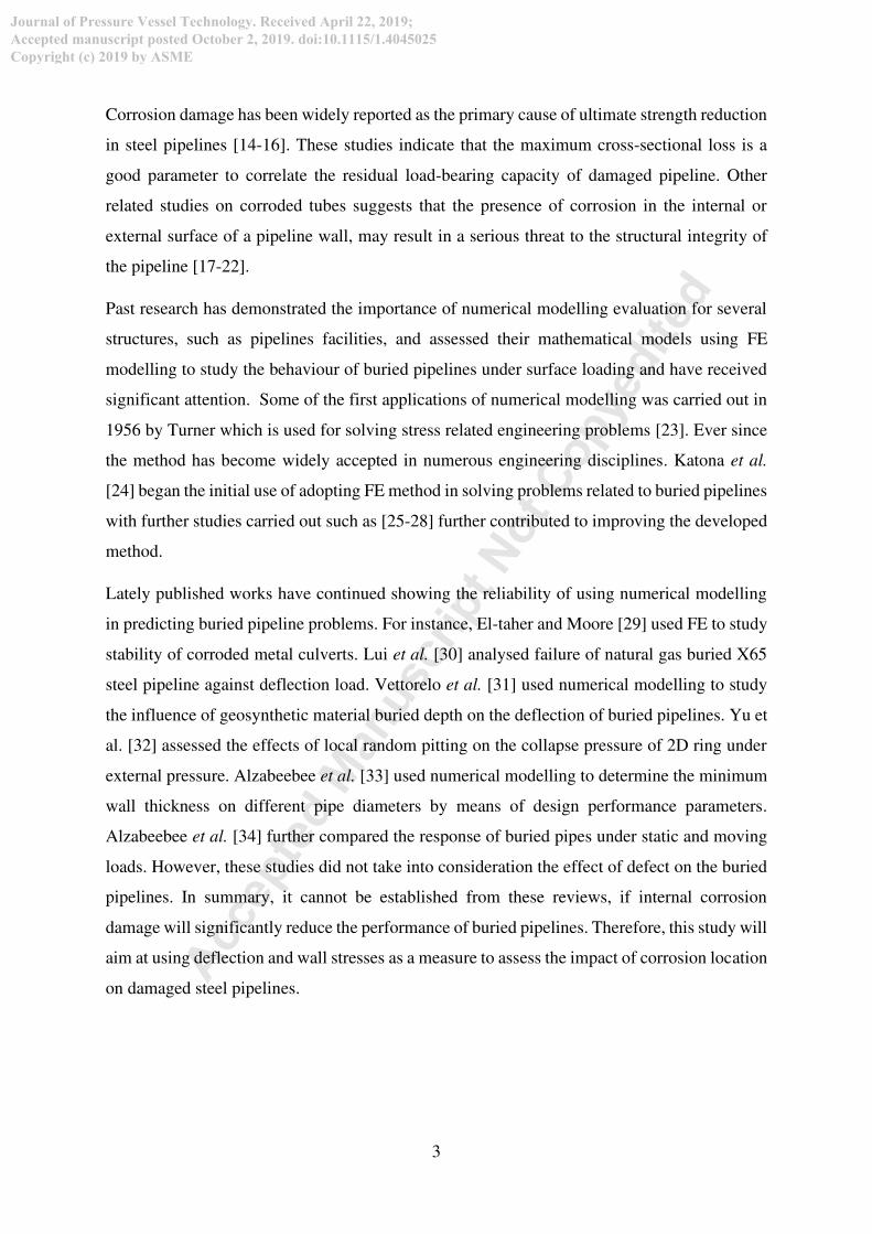
Corrosion causes damage to metal components through a process of chemical or
electrochemical reaction between the pipeline and its environment. The process initiates a
reaction and cause the metal to be eaten away while producing oxides or other compounds over
a small or large surface area. The reaction is continued and eventually causes the metal
component to lose wall thickness over time, which can carry on until the metal is dissolved
completely. The common types of corrosion found on steel pipes can be classified into these
forms; uniform, galvanic, crevice, pitting, inter-granular, selective leaching, erosion corrosion
and stress corrosion cracking (SCC) [11-12]. Buried steel pipeline in this category will
typically become structurally weakened owing to an addition of imposed deformation that can
be linked with the development of excessive deflection, high stresses and strains in critical
locations, which might be well above the elastic range of the pipeline wall material leading to
inevitable collapse failure [13].
Acc
epte
d M
anusc
ript N
ot C
opye
dited
Journal of Pressure Vessel Technology. Received April 22, 2019;
Accepted manuscript posted October 2, 2019. doi:10.1115/1.4045025
Copyright (c) 2019 by ASME
3
Corrosion damage has been widely reported as the primary cause of ultimate strength reduction
in steel pipelines [14-16]. These studies indicate that the maximum cross-sectional loss is a
good parameter to correlate the residual load-bearing capacity of damaged pipeline. Other
related studies on corroded tubes suggests that the presence of corrosion in the internal or
external surface of a pipeline wall, may result in a serious threat to the structural integrity of
the pipeline [17-22].
Past research has demonstrated the importance of numerical modelling evaluation for several
structures, such as pipelines facilities, and assessed their mathematical models using FE
modelling to study the behaviour of buried pipelines under surface loading and have received
significant attention. Some of the first applications of numerical modelling was carried out in
1956 by Turner which is used for solving stress related engineering problems [23]. Ever since
the method has become widely accepted in numerous engineering disciplines. Katona et al.
[24] began the initial use of adopting FE method in solving problems related to buried pipelines
with further studies carried out such as [25-28] further contributed to improving the developed
method.
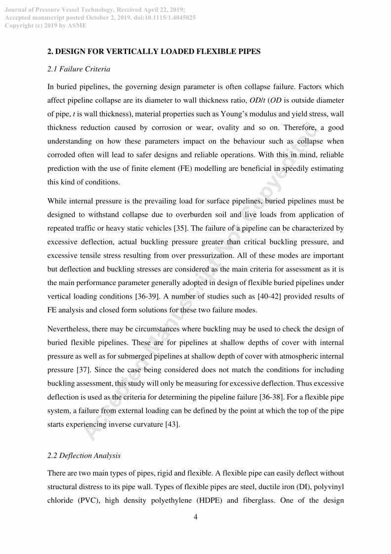
Lately published works have continued showing the reliability of using numerical modelling
in predicting buried pipeline problems. For instance, El-taher and Moore [29] used FE to study
stability of corroded metal culverts. Lui et al. [30] analysed failure of natural gas buried X65
steel pipeline against deflection load. Vettorelo et al. [31] used numerical modelling to study
the influence of geosynthetic material buried depth on the deflection of buried pipelines. Yu et
al. [32] assessed the effects of local random pitting on the collapse pressure of 2D ring under
external pressure. Alzabeebee et al. [33] used numerical modelling to determine the minimum
wall thickness on different pipe diameters by means of design performance parameters.
Alzabeebee et al. [34] further compared the response of buried pipes under static and moving
loads. However, these studies did not take into consideration the effect of defect on the buried
pipelines. In summary, it cannot be established from these reviews, if internal corrosion
damage will significantly reduce the performance of buried pipelines. Therefore, this study will
aim at using deflection and wall stresses as a measure to assess the impact of corrosion location
on damaged steel pipelines.
Acc
epte
d M
anusc
ript N
ot C
opye
dited
Journal of Pressure Vessel Technology. Received April 22, 2019;
Accepted manuscript posted October 2, 2019. doi:10.1115/1.4045025
Copyright (c) 2019 by ASME
4
2. DESIGN FOR VERTICALLY LOADED FLEXIBLE PIPES
2.1 Failure Criteria
In buried pipelines, the governing design parameter is often collapse failure. Factors which
affect pipeline collapse are its diameter to wall thickness ratio, OD/t (OD is outside diameter
of pipe, t is wall thickness), material properties such as Young’s modulus and yield stress, wall
thickness reduction caused by corrosion or wear, ovality and so on. Therefore, a good
understanding on how these parameters impact on the behaviour such as collapse when
corroded often will lead to safer designs and reliable operations. With this in mind, reliable
prediction with the use of finite element (FE) modelling are beneficial in speedily estimating
this kind of conditions.
While internal pressure is the prevailing load for surface pipelines, buried pipelines must be
designed to withstand collapse due to overburden soil and live loads from application of
repeated traffic or heavy static vehicles [35]. The failure of a pipeline can be characterized by
excessive deflection, actual buckling pressure greater than critical buckling pressure, and
excessive tensile stress resulting from over pressurization. All of these modes are important
but deflection and buckling stresses are considered as the main criteria for assessment as it is
the main performance parameter generally adopted in design of flexible buried pipelines under
vertical loading conditions [36-39]. A number of studies such as [40-42] provided results of
FE analysis and closed form solutions for these two failure modes.
Nevertheless, there may be circumstances where buckling may be used to check the design of
buried flexible pipelines. These are for pipelines at shallow depths of cover with internal
pressure as well as for submerged pipelines at shallow depth of cover with atmospheric internal
pressure [37]. Since the case being considered does not match the conditions for including
buckling assessment, this study will only be measuring for excessive deflection. Thus excessive
deflection is used as the criteria for determining the pipeline failure [36-38]. For a flexible pipe
system, a failure from external loading can be defined by the point at which the top of the pipe
starts experiencing inverse curvature [43].
2.2 Deflection Analysis
There are two main types of pipes, rigid and flexible. A flexible pipe can easily deflect without
structural distress to its pipe wall. Types of flexible pipes are steel, ductile iron (DI), polyvinyl
chloride (PVC), high density polyethylene (HDPE) and fiberglass. One of the design
Acc
epte
d M
anusc
ript N
ot C
opye
dited
Journal of Pressure Vessel Technology. Received April 22, 2019;
Accepted manuscript posted October 2, 2019. doi:10.1115/1.4045025
Copyright (c) 2019 by ASME

5
considerations for flexible pipe is the deflection of the pipe due to dead and live loads on the
pipe. The conventional design procedure demands that the geometric details of the buried
pipeline should certify some performance limit; where the predicted deflection should be
within tolerable limits. For steel pipes, the critical or allowable deflection (∆𝑦𝑐𝑟) is taken as 2%
of pipe diameter [44-46].
The deflection of flexible pipe can be measured in terms of the vertical decrease, ΔY (or
horizontal increase, ΔX) to the original pipe diameter, OD. Flexible pipes will ideally deflect
in an elliptical configuration. This deflection is needed to mobilize the lateral soil support, and
to combine with the inherent pipe strength to support the load on the pipe. The load hypothesis
assumes the parabolic distribution of passive horizontal pressure on the sides of the buried pipe
as shown in Fig. 1. The load on a buried pipe is created by backfill soil placed over the top of
the pipe and any surcharge or live load on the backfill surface over the pipe. Flexible pipe is
designed to transmit the load on the pipe to the soil at the sides of the pipe. As the load on the
pipe increases, the vertical diameter of the pipe decreases, and the horizontal diameter
increases. The increase in horizontal diameter is resisted by the stiffness of the soil at the sides
of the pipe.
In design of structural members, the strain or deformation of an element of the material being
used can be determined from the ratio of the load or the stress on the member to its modulus of
elasticity (strain = stress/modulus of elasticity). Currently, there are various methods for
estimating pipe deflection and various parameters for each method. Some of the fundamental
analytical solutions used in practice to measure the deflection of buried flexible pipeline are
presented below. These closed form solutions were developed many years back and adopted
across the pipeline industry.
Acc
epte
d M
anusc
ript N
ot C
opye
dited
Journal of Pressure Vessel Technology. Received April 22, 2019;
Accepted manuscript posted October 2, 2019. doi:10.1115/1.4045025
Copyright (c) 2019 by ASME

6
Figure 1. Theoretical Load Distribution in Buried Flexible Pipe Deflection.
2.2.1 Iowa equation
Spangler [47] developed the following semi-empirical equation based on the modified Iowa
formula for calculating the deflection ΔX, of buried flexible pipe-soil systems under earth load.
ΔX = DL𝐾𝐵𝑊𝑐(𝐸𝐼 𝑅3⁄ )+0.061E* (1)
where DL = deflection lag factor; KB= bedding constant; and 𝑊𝑐 = Marston’s load i.e. the
vertical load per unit length. The expression EpI/R3 represents the pipes stiffness, where the
following terms E, I and R represent modulus of elasticity, moment of inertia of wall cross
section per unit length of pipe and mean radius of pipe, respectively. The soil stiffness is
represented in terms of 0.061E*, where E* is the modulus of soil reaction.
2.2.2 McGrath’s equation
This solution takes into account the effect of hoop compression and effect of bending moment
in its deflection equation. Here, deflection ∆𝑦 is expressed in percentage as:
∆𝑦𝐷 (%) = [ 𝑞(𝐸𝑃. 𝐴𝑃𝑅 + 0.57𝑀𝑆) + 𝐾𝐵. 𝑞. 𝐷𝐿(𝐸𝑃. 𝐼𝑅3 + 0.061𝑀𝑆)] 𝑋100 (2)
Acc
epte
d M
anusc
ript N
ot C
opye
dited
Journal of Pressure Vessel Technology. Received April 22, 2019;
Accepted manuscript posted October 2, 2019. doi:10.1115/1.4045025
Copyright (c) 2019 by ASME

7
where q=vertical stress on pipes crown; KB = bedding factor; DL= deflection lag factor;
EP=modulus of elasticity of pipe; AP=area of pipe per unit length; R=pipe radius and
MS=modulus of soil reaction.
2.2.3 BS EN 1295:1 equation
According to BS EN 1295:1 [48], the actual deflection in terms of vertical decrease of buried
flexible pipe ∆𝑦 can be evaluated using the Eq. (3):
∆𝑦= 𝐾𝐵(𝐷𝐿𝑤𝑐 + 𝑃𝑠)(8𝐸𝑝𝐼𝐷3 + 0.061𝐸∗) (3)
where
𝑃𝑆 = 𝑊𝑆𝐼𝐹𝐿1𝐿2 (4)
𝑊𝑐 = 𝛾𝑠𝐻 (5)
D = Di+2c (6)
𝐸∗ = 𝑘∗𝐸𝑠(1 − 𝑣𝑠)(1 + 𝑣𝑠)(1 − 2𝑣𝑠) (7)
𝐼𝐹 = 1.0 𝑓𝑜𝑟 (𝐻 ≥ 0.9𝑚 𝐿1 = 0.253 + 1.75𝐻 𝐿2 = 0.51 + 1.75𝐻: For (0.6m < H < 0.76m) 𝐿2 = 13.31 + 1.75𝐻/1.8: For (H > 0.76m)
From the above solution, 𝐾𝐵= deflection coefficient; the loads exerted on the pipe system are
governed by the expression DLWC+Ps, where 𝐷𝐿= deflection lag factor; 𝑊𝑐= soil load, and
Ps=live load. Further expressions include: Ep = modulus of elasticity of pipe material; I=
moment of inertia; D = mean diameter; E*= modulus of soil reaction; 𝑊𝑠=traffic load; IF
=impact factor; 𝐿1and 𝐿2=load width parallel and perpendicular to travel direction; 𝛾𝑠 = unit
weight of soil; H = height of soil; Di =inside diameter; c= distance from inside diameter to
neutral axis; Es = modulus of soil; and K* = numerical value which depends on poison’s ratio
of soil, vs.
Acc
epte
d M
anusc
ript N
ot C
opye
dited
Journal of Pressure Vessel Technology. Received April 22, 2019;
Accepted manuscript posted October 2, 2019. doi:10.1115/1.4045025
Copyright (c) 2019 by ASME

8
3. METHODOLOGY
3.1 Numerical Model
The structural behaviour of vertically loaded buried pipe can be modelled by two popular
methods: three-dimensional solid mechanics; or the specialised beam element for pipe and
Winker springs for soil boundary. The use of Winkler type soil models is shown to have
significant limitations. This is because, the reaction of the springs are restricted in a way that
displacement is in one direction and unable to account for the effect of loading direction.
Despite studies have shown the special beam approach involves less computational power, the
three dimensional solid mechanics method was adopted in this study as it represents a more
realistic behaviour of the physical interaction between soil and buried structure [49-50]. The
model was developed in the framework of COMSOL Multiphysics software to simulate
behaviour and deformation of soil in a way to allow the pipe performance criteria get evaluated
with good level of accuracy. This was achieved by integrating the pipe domain along with the
surrounding soil domains using appropriate boundary conditions and very well refined meshing
distributions. The model was developed in two pipeline categories, one without defect (intact
or healthy pipe) and the second with corrosion. The healthy pipe model was set up to serve as
a calibrator for the damaged buried pipeline model.
3.2 Model Setup
Figure 2. Schematic diagram for model profile
W=15m
H=1
0m
50kPa
1.8m Hb
OD
Native Soil
Pipe
Backfill
Bed
50kPa
L=15m
0.3m
(a) Front (b) Side Acc
epte
d M
anusc
ript N
ot C
opye
dited
Journal of Pressure Vessel Technology. Received April 22, 2019;
Accepted manuscript posted October 2, 2019. doi:10.1115/1.4045025
Copyright (c) 2019 by ASME

9
Figure 3. FE model with coupled domains
To model buried pipelines, there is a need to adopt a suitable geometry and appropriate material
properties. The model was established after carrying out careful review of past studies relating
to the numerical modelling on vertically loaded buried pipelines [36-38]. These studies adopted
a narrow trench condition where the pipeline is installed in an excavated trench that is
comparatively narrow, such that the vertical load on the pipeline wall is reduced by the adjacent
soil prisms. Figure 2 shows the idealised representation for the developed model with profile
length (L), width (W) and depth (H) of 15m, 15m and 10m. A uniformly distributed vehicular
load of 50kPa is assumed to be acting on the top of the backfill soil domain with a buried
pipeline of wall thickness and outside diameter of 6mm and 1400mm, respectively. The
pipeline is position within the backfill soil at a depth (Hb) of 3.4m and is supported on a
concrete bed foundation of 0.3m thickness which is typically used for such buried conditions.
Figure 3 shows four of the coupled domains in the model considered for a typical buried
pipeline condition. These are consisting of a pipeline domain and three geo-mechanical
material blocks; backfill, bed and native soil. The entire profile is coupled and analysed as
reduced quarter linear elastic problem, to allow for reduced savings in computational time.
Mechanical properties from Table 1 [37] are assigned to the respective domains.
Backfill
Native
Soil
Acc
epte
d M
anusc
ript N
ot C
opye
dited
Journal of Pressure Vessel Technology. Received April 22, 2019;
Accepted manuscript posted October 2, 2019. doi:10.1115/1.4045025
Copyright (c) 2019 by ASME

10
Table 1. Mechanical Properties of Soil and Pipe
Material properties Pipe Native soil Backfill Bed
Unit weight (γ) 78.5 kN/m3 20 kN/m3 16 kN/m3 23 kN/m3
Elastic modulus 2.15 x 10¹¹ Pa 6.77 x 10⁶ Pa 2.39 x 10⁶ Pa 25 x 109 Pa
Poison’s ratio (ʋ) 0.30 0.34 0.21 0.20
3.3 Modelling of Pipeline Corrosion
Pipeline corrosion is modelled by material removal from the inner surrounding face of the
pipeline wall. This is then coupled with the geometric domains consisting backfill, concrete
bed and native soil. Figure 4 shows uniformly corroded pipeline section with internal damaged
groove at pipes invert. The thickness of damaged pipe wall section (t - t1) is subtracted from
that of the total wall thickness (t). The geometry of the pipe containing defect and position is
further described by other parameters such as pipe length (L), defect depth (t1) and spread angle
(Q). This configuration is considered among the best conventional method to adopt when
representing steel pipeline with uniform corrosion damage.
Figure 4. Pipeline and defect geometric parameters.
L
R
(t-t1)
Q
t
Acc
epte
d M
anusc
ript N
ot C
opye
dited
Journal of Pressure Vessel Technology. Received April 22, 2019;
Accepted manuscript posted October 2, 2019. doi:10.1115/1.4045025
Copyright (c) 2019 by ASME
11
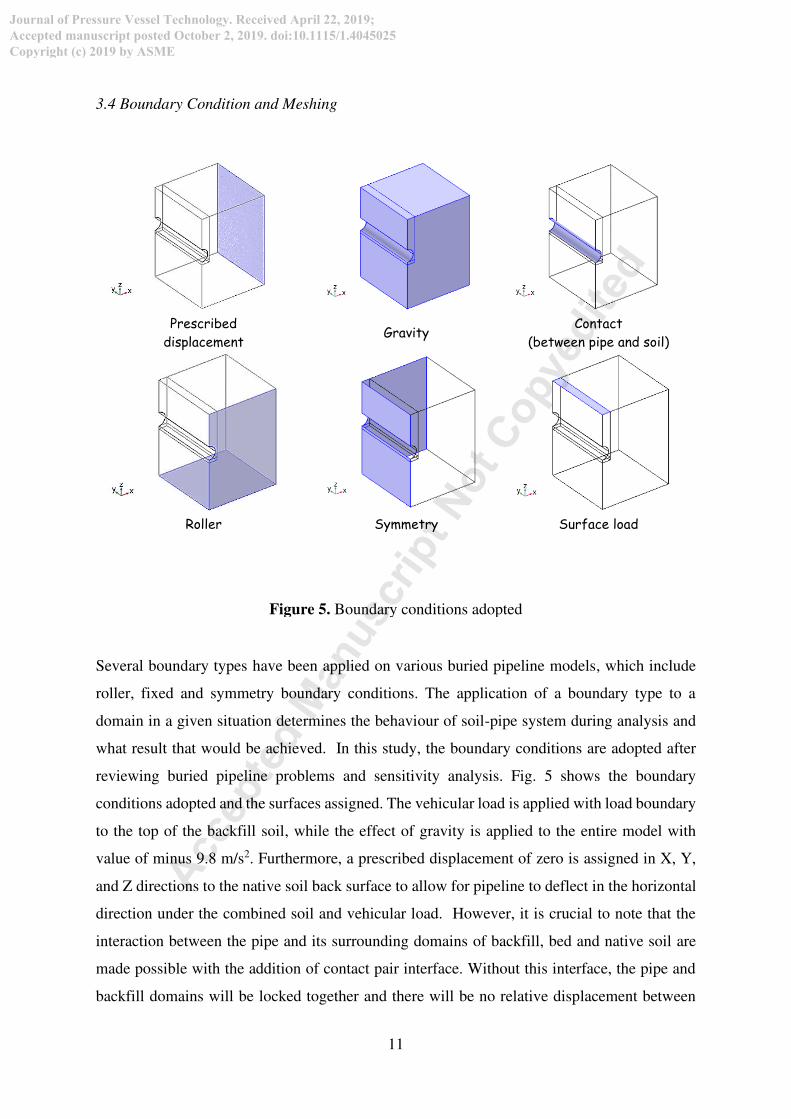
3.4 Boundary Condition and Meshing
Prescribed
displacement Gravity
Contact
(between pipe and soil)
Roller Symmetry Surface load
Figure 5. Boundary conditions adopted
Several boundary types have been applied on various buried pipeline models, which include
roller, fixed and symmetry boundary conditions. The application of a boundary type to a
domain in a given situation determines the behaviour of soil-pipe system during analysis and
what result that would be achieved. In this study, the boundary conditions are adopted after
reviewing buried pipeline problems and sensitivity analysis. Fig. 5 shows the boundary
conditions adopted and the surfaces assigned. The vehicular load is applied with load boundary
to the top of the backfill soil, while the effect of gravity is applied to the entire model with
value of minus 9.8 m/s2. Furthermore, a prescribed displacement of zero is assigned in X, Y,
and Z directions to the native soil back surface to allow for pipeline to deflect in the horizontal
direction under the combined soil and vehicular load. However, it is crucial to note that the
interaction between the pipe and its surrounding domains of backfill, bed and native soil are
made possible with the addition of contact pair interface. Without this interface, the pipe and
backfill domains will be locked together and there will be no relative displacement between
Acc
epte
d M
anusc
ript N
ot C
opye
dited
Journal of Pressure Vessel Technology. Received April 22, 2019;
Accepted manuscript posted October 2, 2019. doi:10.1115/1.4045025
Copyright (c) 2019 by ASME

12
the two. The interaction between the pipe and backfill consists of elastic perfectly plastic solid
boundaries. In addition, friction behaviour between the pipe and backfill is added through the
contact pair using friction attribute element. A static friction coefficient of 0.45 is used to
simulate the roughness between pipe and soil, typical of this composition.
Figure 6 shows meshed model with meshing configuration of three meshing sequences adopted
to improve mesh refinement while reducing number meshed elements, to improve result
accuracy and to lower computational time. These are mapped, free triangular and swept mesh
functions. After the completed mesh, a total of 556.9 m3 mesh volume is generated with 1536
number of elements meshed (comprising of 1472 prisms, 64 hexahedra, 1472 triangles, 486
quads, 456 edge element and 34 vertex elements), as well as a minimum element quality of
0.01 and average element quality of 0.8 is achieved.
Figure 6. FE model with mesh distribution.
4. RESULTS AND DISCUSSIONS
4.1 Comparison of FEM results and analytical measurements
The buried pipeline response in terms of measured deflection is predicted using proposed FE
model. The model results are validated against design standards and are presented in Fig. 7.
Acc
epte
d M
anusc
ript N
ot C
opye
dited
Journal of Pressure Vessel Technology. Received April 22, 2019;
Accepted manuscript posted October 2, 2019. doi:10.1115/1.4045025
Copyright (c) 2019 by ASME

13
These results are for intact pipeline condition with various values of wall thicknesses of 6, 9.53,
12.7, 17.48, 23.83, 26.97, 31.75 mm and in all the cases the outer pipeline diameter is
considered as 1.4 m. The results in Fig. 7 show that pipes with slender wall thickness deflect
more than their thicker counterparts as a result in reduction of pipe stiffness. The deflection
results from the proposed model show good agreement and behaviour with the corresponding
design standards. However, there are some little deviation as the proposed FE model solution
is between the BS EN1295:1 and Iowa solutions. This could be as a result of how deflection is
measured in terms of direction. For instance, BS EN 1295:1 design code measures deflection
in vertical decrease while the Iowa and McGrath equations predict deflection in terms of
pipeline horizontal increase. Other factors that could be responsible for this little deviation
might be that the analytical solutions only consider the stiffness provided by one geo-
mechanical material but in the case of the proposed model all the three materials are considered.
According to [51], the Iowa and McGrath solutions have some drawbacks, and their application
is limited to cases in which the pipeline is installed in a relatively uniform soil and does not
include stiffness of the native soil adjacent to the pipeline trench, in this case which is backfill.
Furthermore, due to the over conservative factor of safety factor of BS EN 1295:1, the predicted
deflection values are a little greater than those estimated using the proposed model.
Figure 7. Deflection results of intact buried pipe for proposed model (FEM) and available
design standards
Defl
ect
ion
[mm
]
Wall thickness t [mm]
Acc
epte
d M
anusc
ript N
ot C
opye
dited
Journal of Pressure Vessel Technology. Received April 22, 2019;
Accepted manuscript posted October 2, 2019. doi:10.1115/1.4045025
Copyright (c) 2019 by ASME

14
4.2 Effect of defeat parameters
Parametric studies were conducted using proposed FE model with two defect parameters;
spread angle Q, and defect thickness, t1 (see Fig 4) to study the pipes behaviour. Both
parameters were selected because they form the crucial defect configuration that is responsible
for loss in mass or thickness of the steel pipe due to corrosion. The buried pipe responses were
measured in terms of excessive deflection and elevated stress levels. The model profile remains
the same, with pipe outside diameter, OD = 1.4 m and pipes wall thickness, t varies from 6 mm
to 31.75 mm. The corrosion spread angle, Q = 15o to 120o; and defect thicknesses t1 = 0.8t
which is based on evaluation of the worst state of the pipe deterioration.
Figs. 8 and 9 show the deflection and von Mises stress results from the parametric studies for
the effect of defect spread angle, Q for 15o, 30o, 60o, 90o and 120o. Since the criterion for failure
in this study is based on the critical deflection steel pipes, which is 2% of the pipes outside
diameter, the assumption here is that at displacement above 28 mm, the pipe is assumed to have
gone above safe limit and would be deemed unsatisfactory and prone to failure. Based on this
assumption of failure, it can be seen in Fig. 8, an increase in the defect spread angle results in
an increase in deflection. The pipe structure will deflect excessively when Q grows above 60o
and when the wall thickness is less than 18 mm due to weakened pipe stiffness. However, from
Fig. 9 the pipe reaches a high level of stress above 400 MPa at Q = 60o and 90o.
Figure 8. Deflection for buried pipeline with defect damage at pipes invert for different spread
angles
Wall thickness, t [mm]
Defl
ect
ion
[mm
]
28 mm
Acc
epte
d M
anusc
ript N
ot C
opye
dited
Journal of Pressure Vessel Technology. Received April 22, 2019;
Accepted manuscript posted October 2, 2019. doi:10.1115/1.4045025
Copyright (c) 2019 by ASME

15
Figure 9. von Mises stress for buried pipeline damaged at invert for different spread angles
5. DESIGN OF PROTECTIVE MEASURE
The collapse failure of vertically loaded buried pipelines could be prevented if protective
measures are put in place. This section presents the protective measures that could be designed
to safeguard pipelines from unwanted excessive deflection. Protective measures are designed
to improve service conditions. For buried pipelines, these measures can be grouped into active
defence method or passive ones [49]. The active process involves procedure like reducing the
external load on the pipeline such as lowering the volume of traffic passing through or
restricting certain categories of vehicle loads whereas the passive system encompasses the use
of pipeline monitoring equipment, timely maintenance and overhauling of damaged pipe
sections. Below are two methods of providing protective measure for intact and corroded
buried flexible pipeline sections.
5.1 Internal pressure
Increasing or introducing internal pressure in an un-corroded pipeline has shown to reduce
excessive deflection. This is because the internal pressure acts as an invisible strengthening
mechanism to the pipe wall stiffness. The radial deformation of a buried intact pipeline caused
by internal pressure could resist the deflection produced by external loads. As can be seen in
Fig. 10, there is a clear relationship that increasing the pressure inside the pipe wall lowers the
Wall thickness, t [mm]
Von
Mis
es
stre
ss [
MPa
]
Acc
epte
d M
anusc
ript N
ot C
opye
dited
Journal of Pressure Vessel Technology. Received April 22, 2019;
Accepted manuscript posted October 2, 2019. doi:10.1115/1.4045025
Copyright (c) 2019 by ASME
16
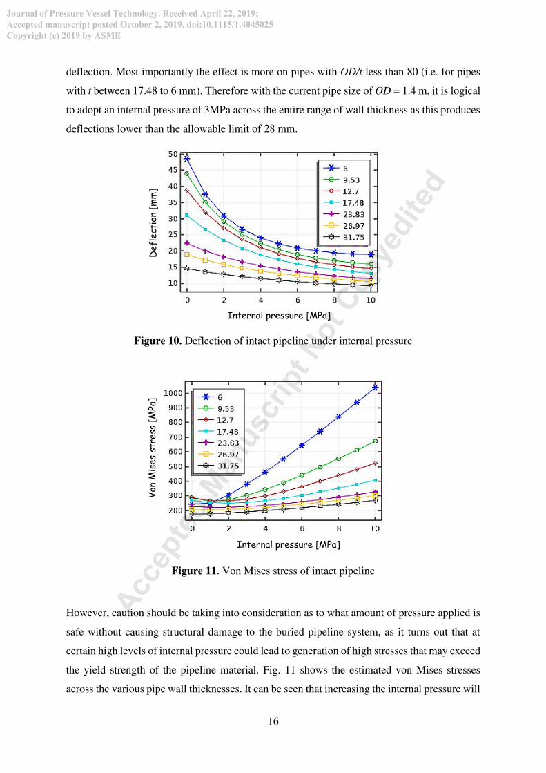
deflection. Most importantly the effect is more on pipes with OD/t less than 80 (i.e. for pipes
with t between 17.48 to 6 mm). Therefore with the current pipe size of OD = 1.4 m, it is logical
to adopt an internal pressure of 3MPa across the entire range of wall thickness as this produces
deflections lower than the allowable limit of 28 mm.
Figure 10. Deflection of intact pipeline under internal pressure
Figure 11. Von Mises stress of intact pipeline
However, caution should be taking into consideration as to what amount of pressure applied is
safe without causing structural damage to the buried pipeline system, as it turns out that at
certain high levels of internal pressure could lead to generation of high stresses that may exceed
the yield strength of the pipeline material. Fig. 11 shows the estimated von Mises stresses
across the various pipe wall thicknesses. It can be seen that increasing the internal pressure will
Defl
ect
ion
[mm
]
Internal pressure [MPa]
Von
Mis
es
stre
ss [
MPa
]
Internal pressure [MPa]
Acc
epte
d M
anusc
ript N
ot C
opye
dited
Journal of Pressure Vessel Technology. Received April 22, 2019;
Accepted manuscript posted October 2, 2019. doi:10.1115/1.4045025
Copyright (c) 2019 by ASME

17
certainly increase the strain on the pipe walls. If a typical case of a steel pipeline is considered
with mechanical properties of yield and ultimate strength corresponding to 411 and 443 MPa
[52] respectively, the safe pressure to operate will be below 4 MPa. Similarly, pipelines with
wall thickness greater than 23.83 mm does not have any significant rise in wall stresses at high
levels in internal pressure.
5.2 Bedding design
Figure 12. Description of protective bed for internally corroded pipeline
The addition of protective measure to buried pipeline design come at an additional cost to the
pipeline operator. Therefore to lower cost while maintaining the desired improvement needed
to keep the pipe system safe even after being exposed to such high level of corrosion damage,
the authors have proposed the use of bedding as a protective measure as shown in Fig. 12. In
this condition, the internal pressure mechanism will not be suitable, because there will be very
high levels of stress concentrations at the damaged locations which may lead to burst failure.
Also the decision is made because the bedding system requires the least attention after
installation and the material volume (length x depth x width) required to support for the pipeline
stability is lesser when compared to backfill and native soil, thereby offering huge savings to
the pipeline operator.
Bedding
height (BH)
BED
Pipe
Acc
epte
d M
anusc
ript N
ot C
opye
dited
Journal of Pressure Vessel Technology. Received April 22, 2019;
Accepted manuscript posted October 2, 2019. doi:10.1115/1.4045025
Copyright (c) 2019 by ASME

18
BH = 0.0875 m BH = 0.175 m
BH = 0.35 m BH = 0.7 m
BH = 1.05 m
Figure 13. Deflections of corroded pipeline (t = 6 mm; t1 = 0.8t; Q = 60o) at different bedding
depths.
Acc
epte
d M
anusc
ript N
ot C
opye
dited
Journal of Pressure Vessel Technology. Received April 22, 2019;
Accepted manuscript posted October 2, 2019. doi:10.1115/1.4045025
Copyright (c) 2019 by ASME

19
BH = 0.0875 m BH = 0.175 m
BH = 0.35 m BH = 0.7 m
BH = 1.05 m
Figure 14. von Mises stresses of corroded pipeline (t = 6 mm; t1 = 0.8t; Q = 60o) for different
bedding depths (BH)
Acc
epte
d M
anusc
ript N
ot C
opye
dited
Journal of Pressure Vessel Technology. Received April 22, 2019;
Accepted manuscript posted October 2, 2019. doi:10.1115/1.4045025
Copyright (c) 2019 by ASME

20
To determine which bedding configuration will be suitable for protective measure in terms of
providing both structural improvement to the damaged pipeline wall and reducing installation
cost, further parametric study were conducted using the proposed damaged model. In addition,
the pipe defect configuration is based on the worst case condition. Here, pipe wall thickness t
= 6 mm, defect depth t1 = 0.8t and Q = 60 degrees. The bedding depth parameters BH 87.5 mm,
175 mm, 350 mm, 700 mm and 1050 mm respectively, are used.
Figure 15. Pipeline response under different bedding depth, BH w.r.t defect spread angle, Q
for t = 23.83 mm and t1 = 0.8t: (a) Displacement and (b) von Mises stress
Spread angle, Q [deg]
Dis
plac
em
ent
[m
m]
Spread angle, Q [deg]
Von
Mis
es
Str
ess
[M
Pa]
(a)
(b)
Acc
epte
d M
anusc
ript N
ot C
opye
dited
Journal of Pressure Vessel Technology. Received April 22, 2019;
Accepted manuscript posted October 2, 2019. doi:10.1115/1.4045025
Copyright (c) 2019 by ASME

21
The responses of the damaged pipe in terms of the deflection and von Mises stresses are
presented in Figs. 13 and 14. These results show different stages of protective bedding depths
for the case of 60 degrees defect spread angle and how the damaged pipeline could be
supported. From these two analyses, it is clear that the bedding depth provides added
reinforcement to the damaged pipe. The pipe deflection tends to reduce with corresponding
increase in bedding depth boundary and is able to provide a safe deflection level at 0.7 and 1.05
m depths. However, the stress level tends to increase with increasing depth up to 0.35 m and
decreases afterwards. The von Mises stress are experienced internally and are within the yield
limit of 411 MPa which is assumed to be within the pipeline tolerable limits of elastic
deformation.
Further studies on effect of different bedding profiles on damaged pipe displacement and von
Mises stress levels are demonstrated in Figure 15 (a) and (b) in relation to defect location for t
= 23.83 mm, which represents a typical thick walled flexible pipe scenario. From Fig. 15(a), it
can be seen that for thicker pipe sections, displacement also increases along increase in defect
spread angle. This is reduced with increasing depth of protection from the bedding boundaries.
Out of five cases studied, two bedding depth configurations (i.e. at depth of 0.7 m and 1.05 m)
actually provide protection for the deeply corroded pipe section way below the tolerable
deflection limit of 28 mm. Other configurations which are less expensive to construct (i.e. at
depth of 0.0875m, 0.175m and 0.35 could only provide adequate protection from excessive
deflections for pipe sections with defect spread angles below 60 degrees. The plot of the von
Mises stress from Fig. 15(b) also indicate the structure could be well secured within its elastic
range with the provision of adequate bedding depth. However all three bedding depth
configurations (i.e. 0.0875m, 0.175m and 0.35m) experience sharp increase in stress
concentration and above the yield limit at some stage of the defect growth. Therefore based on
all the cases considered, the most sustainable configuration would be at bed depths of 0.7m and
1.05 m as these boundaries offers the required safety against excessive deflection and plastic
deformation needed to protect the pipeline for the long duration.
Acc
epte
d M
anusc
ript N
ot C
opye
dited
Journal of Pressure Vessel Technology. Received April 22, 2019;
Accepted manuscript posted October 2, 2019. doi:10.1115/1.4045025
Copyright (c) 2019 by ASME

22
6. CONCLUSIONS
In this study, numerical modelling has been conducted to investigate failure of vertically loaded
buried steel pipeline section with uniform internal corrosion. The pipe failure is quantified in
terms of excessive deflection and plastic deformation. For this purpose a series of 3-
dimensional FE models were developed. The effect of two main defect parameters, depth and
spread angle were evaluated considering worst-case pipeline damage conditions. Subsequently,
the results from the parametric analysis provide details previously limited in the literature and
offer an understanding into the unpredictability behaviour of buried infrastructures. The
findings from this work lead to the following conclusions.
1. Buried pipes with thicker wall sections perform better than their slender counterparts for
both intact and damaged conditions. Failure mechanism is controlled by excessive
deflection and plastic deformation.
2. An increase in spread angle may increase deflection linearly but not necessarily the wall
stress. The wall stresses are found to be stable at spread angles 15, 30 and 120 degrees and
are unstable at locations of 60 and 90 degrees.
3. A bedding protective measure was proposed to accommodate different stages of internal
corrosion damage. The proposed protective bedding configuration is predicted to provide
adequate long time protection when the pipes section maximum deflection is less than 2%
of the outside diameter and von Mises stress is below the yield strength.
4. The protective bed configuration is found to offer most reliable cover for long time
protection at bedding depth of 0.7 m, which corresponds to half the outside pipe diameter.
REFERENCES
1. Tee, K.F., Ebenuwa, A.U., and Zhang, Y. (2018) Fuzzy-based robustness assessment of
buried pipelines, Journal of Pipeline Systems Engineering and Practice, ASCE, 9(1),
06017007.
2. Armaghani, D. J, Faizi, K., Hajihassani, M., Tonnizam Mohamad, E. and Nazir, R. (2015)
Effects of soil reinforcement on uplift resistance of buried pipeline, Measurement, 64, pp.
57–63.
3. González, O., Fraile, A. and Hermanns, L. (2015) A numerical and semi-analytical
comparison for structural analysis of fault-crossing pipelines, Comptes Rendus -
Acc
epte
d M
anusc
ript N
ot C
opye
dited
Journal of Pressure Vessel Technology. Received April 22, 2019;
Accepted manuscript posted October 2, 2019. doi:10.1115/1.4045025
Copyright (c) 2019 by ASME

23
Mecanique, 343(7–8), pp. 397–409.
4. Rahman, M. A. and Taniyama, H. (2015) Analysis of a buried pipeline subjected to fault
displacement: A DEM and FEM study, Soil Dynamics and Earthquake Engineering, 71,
pp. 49–62.
5. Uckan, E., Akbas, B., Shen, J., Rou, W., Paolacci, F. and O’Rourke, M. (2015) A simplified
analysis model for determining the seismic response of buried steel pipes at strike-slip fault
crossings, Soil Dynamics and Earthquake Engineering, 75, pp. 55–65.
6. Ebenuwa, A.U., Tee, K.F. and Zhang, Y. (2016) Structural robustness assessment of
corroded buried pipes, in the WIT Transactions on the Built Environment, 166, Edited by
S.Hernandaz, C.A.Brebbia and W.P. de Wilde, WIT Press, pp. 81-92.
7. Pesinis, K. and Tee, K.F. (2018) Bayesian updating of stochastic process-based models for
corroding gas pipelines based on imperfect inspection information, in the Safety and
Reliability – Safe Societies in a Changing World, Edited by S.Haugen et al, published by
Taylor and Francis Group, pp. 2219-2226.
8. Shafiee, M. & Ayudiani P.S. (2015) Development of a risk-based integrity model for
offshore energy infrastructures - application to oil and gas pipelines, International Journal
of Process Systems Engineering, 3(4), pp. 211–231.
9. Pesinis, K. and Tee, K.F. (2017) Statistical model and structural reliability analysis for
onshore gas transmission pipelines, Engineering Failure Analysis, 82, pp. 1-15.
10. Ebenuwa, A.U., Tee, K.F. (2019) Reliability estimation of buried steel pipes subjected to
seismic effect, Transportation Geotechnics, 20, 100242.
11. Nanan, K. (2018) The 8 Most Common Forms of Metal Corrosion, Corrosionpedia.
12. Tee, K.F., and Pesinis, K. (2017) Reliability prediction for corroding natural gas pipelines,
Tunnelling and Underground Space Technology, 65, pp. 91-105.
13. Khan, L.R. and Tee, K.F. (2016) Risk-cost optimization of buried pipelines using subset
simulation, Journal of Infrastructure Systems, ASCE, 22(2), 04016001.
14. Cronin, D. S. (2000) Assessment of Corrosion Defects in Pipelines, PhD Thesis, University
of Waterloo.
15. Xu, L. (2013) Assessment of corrosion defects on high-strength steel pipelines, University
of Alberta.
16. Ebenuwa, A.U., Tee, K.F. (2019) Fuzzy-based optimised subset simulation for reliability
analysis of engineering structures, Structure and Infrastructure Engineering, 15(3), pp.
413-425.
17. Bueno, A. H. S., Moreira, E. D. and Gomes, J. A. C. P. (2014) Evaluation of stress corrosion
Acc
epte
d M
anusc
ript N
ot C
opye
dited
Journal of Pressure Vessel Technology. Received April 22, 2019;
Accepted manuscript posted October 2, 2019. doi:10.1115/1.4045025
Copyright (c) 2019 by ASME

24
cracking and hydrogen embrittlement in an API grade steel, Engineering Failure Analysis,
36, pp. 423–431.
18. Motta, R. S., Cabral, H. L. D., Afonso, S. M. B., Willmersdorf, R. B., Bouchonneau, N.,
Lyra, P. R. M. and de Andrade, E. Q. (2017) Comparative studies for failure pressure
prediction of corroded pipelines, Engineering Failure Analysis, 81, pp. 178–192.
19. Oh, C. S., Kim, N. H., Kim, Y. J., Baek, J. H., Kim, Y. P. and Kim, W. S. (2011) A finite
element ductile failure simulation method using stress-modified fracture strain model,
Engineering Fracture Mechanics, 78(1), pp. 124–137.
20. Al-Owaisi, S. S., Becker, A. A. and Sun, W. (2016) Analysis of shape and location effects
of closely spaced metal loss defects in pressurised pipes, Engineering Failure Analysis, 68,
pp. 172–186.
21. Xu, W. Z., Li, C. B., Choung, J. and Lee, J. M. (2017) Corroded pipeline failure analysis
using artificial neural network scheme, Advances in Engineering Software, 112, pp. 255–
266.
22. Pesinis, K. and Tee, K.F. (2018) Bayesian analysis of small probability incidents for
corroding energy pipelines, Engineering Structures, 165, pp. 264-277.
23. Watkins, R.K. and Loren, R.A. (2000) Structural Mechanics of Buried Pipes, CRC Press,
444 pages, Boca Raton, Florida.
24. Katona, M., Forrest, J., Odello, R. and Allgood, J. (1976) CANDE-a modern approach for
the structural design and analysis of buried culverts. Federal Highway Administration,
Office of Research and Development, report no. S0648 No. FHWA RD-77-5, Washington
D.C. USA.
25. Duncan, J. M., Byrne, P., Wong, K. S. and Mabry, P. (1980) Strength, Stress-Strain and
Bulk Modulus Parameters for Finite Element Analysis of Stresses and Movements in Soil
Masses, University of California, report no. UCB/GT/80-01, Berkeley, California, USA.
26. Leonards, G. A., Wu, T. H. and Juang C.H. (1981) Predicting Performance of Buried
Conduits, FHWA/IN/JHRP-81/03. Joint Highway Research Project, Indiana Department
of Transportation and Purdue University, West Lafayette, Indiana.
27. Nyby, B. (1981) Finite Element Analysis of Soil-Structure Interaction, Ph.D. Thesis, Utah
State University, Logan, USA.
28. Sharp, K.D, Anderson, L.R, Moser, A.P and Warner, M.J. (1984) Applications of finite
element analysis of FRP pipe performance, Buried Structures Laboratory, Utah State
University, Logan, USA.
29. El-taher, M. and Moore, I. D. (2008) Finite Element Study of Stability of Corroded Metal
Acc
epte
d M
anusc
ript N
ot C
opye
dited
Journal of Pressure Vessel Technology. Received April 22, 2019;
Accepted manuscript posted October 2, 2019. doi:10.1115/1.4045025
Copyright (c) 2019 by ASME
25
Culverts, Transportation Research Board, pp. 157–166.
30. Lui, P., Zhang, B. and Shi, P. (2010) Failure analysis of natural gas buried X65 steel
pipeline under deflection load using finite element method, Materials and Design, 31, pp.
1384–1391.
31. Vettorelo, P.V., Moreno, F.M. and Claria, J.J. (2016) Modelling of Geosynthetic
Reinforced Buried Flexible Pipes, In: 3rd Pan American Conference on Geosynthetics,
Miami, USA, 10–13 April 2016, pp. 1808–1816.
32. Yu, J., Wang, H., Fan, Z. and Yu, Y. (2017) Computation of plastic collapse capacity of
2D ring with random pitting corrosion defect, Thin-Walled Structures, 119, pp. 727–736.
33. Alzabeebee, S., Chapman, D. N. and Faramarzi, A. (2018) A comparative study of the
response of buried pipes under static and moving loads, Transportation Geotechnics, 15,
pp. 39–46.
34. Alzabeebee, S., Chapman, D. N. and Faramarzi, A. (2018) Innovative approach to
determine the minimum wall thickness of flexible buried pipes, Geomechaics and
Engineering, 15(2), pp. 755–767.
35. Hegde, A. M. and Sitharam, T. G. (2015) Experimental and numerical studies on protection
of buried pipelines and underground utilities using geocells, Geotextiles and
Geomembranes, 43(5), pp. 372–381.
36. Zhang, J., Liang, Z., Feng, D., Zhang, C., Xia, C. and Tu, Y. (2016) Response of the buried
steel pipeline caused by perilous rock impact : Parametric study, Journal of Loss Prevention
in the Process Industries, 43, pp. 385–396.
37. Srivastava, A. and Babu, G. L. S. (2011) Deflection and buckling of buried flexible pipe-
soil system in a spatially variable soil profile, Geomechaics and Engineering, 3(3), pp.
169–188.
38. Alzabeebee, S., Jefferson, I., Faramarzi, A. and Chapman, D. (2016) The response of buried
pipes to UK standard traffic loading, Geotechnical Engineering, 170(1), pp. 1–13.
39. Athmani, A., Khemis, A., Hacene-Chaouche, A., Tee, K. F., Ferreira, T. M. and Vicente,
R. (2019) Buckling uncertainty analysis for steel pipelines buried in elastic soil using
FOSM and MCS methods, International Journal of Steel Structures, 19(2), pp. 381-397.
40. Watkins, R.K. and Spangler, M.G. (1958) Some characteristics of the modulus of passive
resistance of soil: A study in similitude, Highway Research Board Proceedings 37, pp.
576–583.
41. Burns, J.Q. and Richards, R.M. (1964) Attenuation of Stresses for Buried Cylinders, In:
Proceedings of the Symposium on Soil Structure Interaction, University of Arizona, pp.
Acc
epte
d M
anusc
ript N
ot C
opye
dited
Journal of Pressure Vessel Technology. Received April 22, 2019;
Accepted manuscript posted October 2, 2019. doi:10.1115/1.4045025
Copyright (c) 2019 by ASME

26
378–392.
42. AASHTO (1994) AASHTO LRFD Bridge Design Specifications, American Association of
State Highway and Transportation Officials, 1st edition, Washington, D.C., USA.
43. Eagle, J. M. (2009) Depth of Burial For PVC Pipe, Technical Bulletin, pp. 1–4.
44. Stephenson, D. (1989) Pipeline design for Water Engineers, Volume 40, 3rd edition,
Elsevier Scientific Publishing Company, New York, USA.
45. Moser, A. and Folkman, S. (2008) Buried Pipe Design, 3rd edition, McGraw Hill, New
York, USA.
46. Tee, K.F., Khan, L.R. and Coolen-Maturi, T. (2015) Application of receiver operating
characteristic curve for pipeline reliability analysis, Journal of Risk and Reliability,
Proceedings of the Institution of Mechanical Engineers, Part O, 229(3), pp. 181-192.
47. Spangler, M.G. (1941) The structural design of flexible culverts, Bulletin 153, Iowa
Engineering Experiment Station, Iowa State College of Agriculture and Mechanic Arts, 84
pages.
48. BS EN 1295-1 (1997) Structural design of buried pipelines under various conditions of
loading Part 1. General requirements, BSI Group, UK.
49. Zhang, J., Liang, Z. and Zhao, G. (2016) Mechanical behaviour analysis of a buried steel
pipeline under ground overload, Engineering Failure Analysis, 63, pp. 131–145.
50. Khemis, A., Hacene-Chaouche, A., Athmani, A. and Tee, K.F. (2016) Uncertainty effects
of soil and structural properties on the buckling of flexible pipes shallowly buried in
Winkler foundation, Structural Engineering and Mechanics, 59(4), pp. 739-759.
51. Masada, T. (2000) Modified Iowa formula for vertical deflection of buried flexible pipe,
Transp. Eng., 125(5), pp. 440–446.
52. Ryu, D. M., Wang, L., Kim, S. K. and Lee, J. M. (2017) Comparative study on deformation
and mechanical behavior of corroded pipe: Part I–Numerical simulation and experimental
investigation under impact load, International Journal of Naval Architecture and Ocean
Engineering, 9(5), pp. 509–524.
Acc
epte
d M
anusc
ript N
ot C
opye
dited
Journal of Pressure Vessel Technology. Received April 22, 2019;
Accepted manuscript posted October 2, 2019. doi:10.1115/1.4045025
Copyright (c) 2019 by ASME