The Institute of Radio Engineers
148
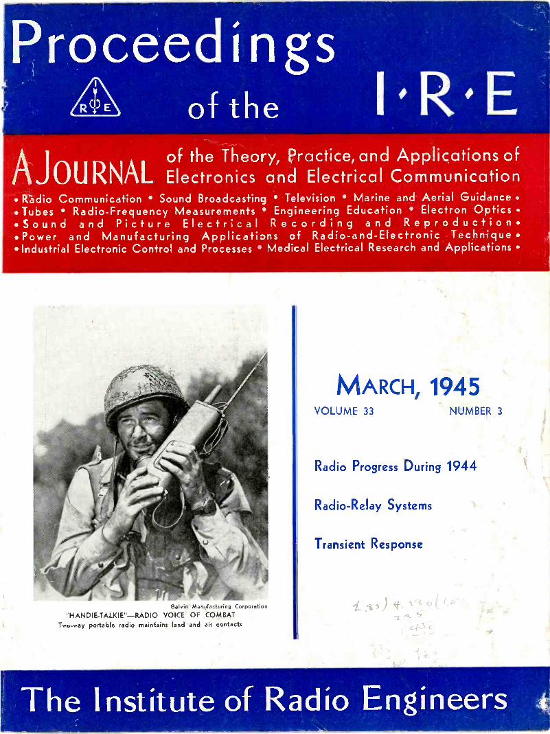
Proceedings of the I R E AJOURNAL, of the Theory, Practice, and Applications of Electronics and Electrical Communication Radio Communication Sound Broadcasting Television Marine and Aerial Guidance Tubes Radio -Frequency Measurements Engineering Education Electron Optics Sound and Picture Electrical Recording and Reproduction Power and Manufacturing Applications of Radio -and -Electronic Technique Industrial Electronic Control and Processes Medical Electrical Research and Applications MARCH, 1945 VOLUME 33 NUMBER 3 Radio Progress During 1944 Radio -Relay Systems Transient Response Galvin Manufacturing Corporation HANDIE-TALKIE"-RADIO VOICE OF COMBAT Tw,-way portable radio maintains land and air contacts The Institute of Radio Engineers
-
Upload
khangminh22 -
Category
Documents
-
view
3 -
download
0
Transcript of The Institute of Radio Engineers
Proceedingsof the I R E
AJOURNAL,of the Theory, Practice, and Applications ofElectronics and Electrical Communication
Radio Communication Sound Broadcasting Television Marine and Aerial Guidance Tubes Radio -Frequency Measurements Engineering Education Electron Optics Sound and Picture Electrical Recording and Reproduction Power and Manufacturing Applications of Radio -and -Electronic Technique Industrial Electronic Control and Processes Medical Electrical Research and Applications
MARCH, 1945VOLUME 33 NUMBER 3
Radio Progress During 1944
Radio -Relay Systems
Transient Response
Galvin Manufacturing CorporationHANDIE-TALKIE"-RADIO VOICE OF COMBAT
Tw,-way portable radio maintains land and air contacts
The Institute of Radio Engineers
WATER AND AIR COOLED
TRANSMITTING AND
RECTIFYING TUBES 4
In the production of Amperex tubes everyconstruction step is carefully watched to in-sure greater operating efficiency and loweroperating costs. Welding, for instance, is donein an inert or reducing atmosphere in speciallydesigned apparatus. This "Amperextra" meansthat there is no oxidation of metal parts. As aconsequence, there is much less liberation ofgas later on in the life of the tube, and a moreconsistent hard vacuum is maintained.
More than 70% of all electro-medical apparatusin this country is equipped with Amperex tubes.More than 40% of the nation's broadcastingstations also specify our products as standardcomponents. There's an Amperex type for everyapplication in every field using transmittingand rectifying tubes. Your inquiries, for pres-ent or peacetime assignments, receive promptattention.
NOTE: Many of our standard tube types are now avail-able through leading radio equipment distributors.
NMPEREX ELECTRONIC CORPORATION79 WASHINGTON STREET BROOKLYN 1, N, Y.Export Division: 13 E. 40th Sf., New York 16 N. Y.. Cables: "Arlab"
NOW IS THE TIME WHEN YOUR DOLLARS COUNT PLEASE SUPPORT THE RED CROSS WAR FUND
BOARD OFDIRECTORS
1945William L. Everitt
PresidentHendrik J. van der Bijl
Vice -PresidentRaymond A. Heising
TreasurerHaraden Pratt
SecretaryAlfred N. Goldsmith
EditorLynde P. Wheeler
Senior Past PresidentHubert M. Turner
Junior Past President1943-1945
Wilmer L. BarrowF. B. Llewellyn
Harold A. Wheeler
1944-1946Raymond F. Guy
Lawrence C. F. HorleWilliam C. White
1945-1947Stuart L. BaileyKeith Henney
Benjamin E. Shackelford1945
E. Finley CarterLewis M. Clement
Ralph A. HackbuschDonald B. Sinclair
William 0. Swinyard
Harold R. ZeamansGeneral Counsel
BOARD OF EDITORS
Alfred N. GoldsmithEditor
Ralph R. BatcherRobert S. BurnapPhilip S. Carter
Lewis M. ClementE. Maurice Deloraine
William G. DowElmer W. EngstromWilliam L. EverittGeorge W. GilmanPeter C. Goldmark
Frederick W. GroverLewis B. HeadrickC. M. Jansky, Jr.
John D. KrausDonald G. Little
Frederick B. LlewellynSamuel S. Mackeown
Edward L. NelsonHarry F. Olson
Harold 0. PetersonGreenleaf W. Pickard
Ralph A. PowersHaraden PrattConan A. PriestHerbert J. Reich
Peter C. SandrettoV. W. Sherman
Lynne C. SmebyE. C. Wente
Harold A. WheelerWilliam C. White
Laurens E. WhittemoreGerald W. Willard
William WilsonCharles J. Young
Vladimir K. Zworykin
Proceedingsof the I R E
Published Monthly by
The Institute of Radio Engineers, Inc.
VOLUME 33 March, 1945 NUMBER 3
Section Meetings Next PageThe Electronics Engineer P R. Mallory 141
Ivan Stoddard Coggeshall 142
Radio Progress During 1944 I R E Technical Committee 143
Radio -Relay -Systems Development by the Radio Corporation ofAmerica C W. Hansell 156
Transient Response.. H. E. Kallmann, R. E. Spencer, and C. P. Singer 169
I.R.E. !Building Fund 196
Institute News and Radio Notes 198
Board of Directors 198
Executive Committee 199
Cedar Rapids Section 200
Correspondence:"Frequency and Phase Modulation,"
D. L. Jaffe and Dale Pollack 200
"Calculator for Directive Arrays" J G. Rountree 202
"Quality -Control Engineering" George W. Purnell 202
"Balanced Amplifiers" Franklin Offner 202
Postwar Radio -and -Electronic Prospects 203
Radio -and -Electronic Wartime Achievements 203Wartime Electronic Developments Hold Peacetime Promise 204Television as Service to the Public 204Looking Ahead to Color and Ultra -High -Frequency Television 205
Television Networks 205
I.R.E. People 206
Books."Engineering Mathematics," by Harry Sohon
Frederick W. Grover 207"Marine Radio Manual," Edited by M. H. Strichartz
C. B. Darcy 208Reproduction of German Scientific and Technical Books 208
Contributors 209
Section Meetings 34A38A52A
MembershipPositions Open
Responsibility for the contents of papers published in the PROCEEDINGS rests upon the authors.Statements made in papers are not binding on the Institute or its members.
Entered as second-class matter October 26. 1927, at the post office at Menaslaa. Wisconsin, underthe Act of February 28, 1925. embodied in Paragraph 4, Section 538 of the Postal Laws and Regulations.Publication office, 450 Ahnaip Street, Menasha. Wisconsin. Executive. editorial, and advertising offices,330 West 42nd Street. New York 18, N. Y. Price, $1.00 a copy. Subscriptions: United States and Canada.$10.00 a year; foreign countries. $11.00 a year. Changes of address (with advance notice of fifteen days)and communications regarding subscriptions and payments should be mailed to the Secretary of theInstitute. at 330 West 42nd Street, New York 18, N. Y. All rights of republication, including translationinto foreign languages, are reserved by the Institute. Abstracts of papers, with mention of their source.may be printed. Requests for republication privileges should be addressed to The Institute of RadioEngineers.
Copyright, 1945, by The Institute of Radio Engineers, Inc.
PAPERS COMMITTEE
Frederick B. LlewellynChairman
Herman A. AffelWilmer L. BarrowHoward A. ChinnJames K. Clapp
Ivan S. CoggeshallMurray G. Crosby
Frederick W. CunninghamRobert B. DomeEnoch B. FerrellDonald G. Fink
H. S. FrazierStanford Goldman
Frederick W. Grover0. B. HansonE. W. Herold
John V. L. HoganFrederick V. Hunt
Harley lamsLoren F. Jones
John G, Kreer, Jr.Emil Labin
Frederick R. LackHugo C. LeuteritzDe Loss K. Martin
Knox McllwainHarry R. Mimno
Ilia E. MouromtseffG. G. Muller
Albert F. MurrayDwight 0. NorthA. F. Pomeroy
Jack R. PoppeleSimon Ramo
Francis X. RettenmeyerSergei A. Schelkunoff
Donald B. SinclairHubert M. Turner
Dayton UlreyKarl S. Van DykeE. K. Van Tassel
John R. WhinneryIrving Wolff
J. Warren WrightHarold R. Zeamans
PAPERSPROCUREMENT
COMMITTEEDorman D. IsraelGeneral Chairman
William L. EverittVice Chairman
GROUP CHAIRMEN
Jesse E. BrownWarren B. BurgessEdward J. Content
Harry DiamondEdward T. DickeyJ. Kelly JohnsonCarl J. MadsenDan H. Moore
James R. NelsonHoward J. TyzzerWilliam C. White
Helen M. StoteAssociate Editor
William C. CoppAdvertising ManagerWilliam B. CowilichAssistant Secretary
THE INSTITUTE OF RADIO ENGINEERSINCORPORATED
SECTIONS MEETINGSATLANTA CHICAGO CLEVELAND DETROITMarch 16 March 16 March 22 March 16
NEW YORK PHILADELPHIA PITTSBURGH PORTLANDApril 4 April 5 April 9 April 9
SECTIONS
ATLANTA-Chairman, Walter Van Nostrand; Secretary,Ivan Miles, 554-14 St., N. W., Atlanta, Ga.
BALTIMORE-Chairman, W. I. Webb; Secretary, H. L.Spencer, Box 6760, Towson 4, Md.
BOSTON-Chairman, C. C. Harris; Secretary, CorwinCrosby, 16 Chauncy St., Cambridge, Mass.
BUENOS AIRES-Chairman, L. C. Simpson; Secretary, I. C.Grant, Venezuela 613, Buenos Aires, Argentina
BUFFALO-NIAGARA-Chairman, A. J. Dybowski; Secre-tary, H. G. Korts, 51 Kinsey Ave., Kenmore, N. Y.
CEDAR RAPIDS-Chairman, F. M. Davis; Secretary,J. A. Green, Collins Radio Co., 855 -35th St., N.E.,Cedar Rapids, Iowa
CHICAGO-Chairman, W. 0. Swinyard; Secretary, A. W.Graf, 135 S. LaSalle St., Chicago 3, III.
CINCINNATI-Chairman, L. M. Clement; Secretary, J. F.Jordan, The Baldwin Co., 1801 Gilbert Ave., Cincinnati 2,Ohio
CLEVELAND-Chairman, H. B. O'Kesoh; Secretary, A. J.Kress, 16911 Valley View Ave., Cleveland 11, Ohio
CONNECTICUT VALLEY-Chairman, R. E. Shea; Secretary,L. A. Reilly, 989 Roosevelt Ave., Springfield, Mass.
DALLAS -FORT WORTH-Chairman, J. D. Mathis; Secre-tary, B. B. Honeycutt, 9025 Roanoak, Dallas 18, Texas
DAYTON-Chairman, G. L. Haller; Secretary, Joseph Gen-eral, 411 E. Bruce Ave., Dayton 5, Ohio
DETROIT-Chairman, R. A. Powers; Secretary, R. R. Barnes,1411 Harvard Ave., Berkley, Mich.
EMPORIUM-Chairman, W. A. Dickinson; Secretary, H. E.Adman, West Creek, R. D. 2, Emporium, Pa.
INDIANAPOLIS-Chairman, H. I. Metz; Secretary, J. D.Colvin, 328 E. 47 St., Indianapolis, Ind.
KANSAS CITY-Chairman, A. P. Stuhrman; Secretary, R. N.White, 4800 Jefferson St., Kansas City, Mo.
LONDON-Chairman, G. A. Woonton; Secretary, RobertWilton, No. 5 Radio School, Royal Canadian Air Force,Clinton, Ont., Canada
LOS ANGELESMarch 19
WASHINGTONApril 9
LOS ANGELES-Chairman, R. C. Moody; Secretary, R. G.Denechaud, Blue Network Co., 6285 Sunset Blvd.,Hollywood 28, Calif.
MONTREAL-Chairman, F. S. Howes; Secretary, J. A.Campbell, Northern Electric Co., Ltd., 1261 Shearer St.,Montreal, Que., Canada
NEW YORK-Chairman, G. B. Hoadley; Secretary, J. T.Cimorelli, RCA Manufacturing Co., Harrison, N. J.
OTTAWA-Acting Secretary, L. F. Millett, 33 Regent St.,Ottawa, Ont., Canada
PHILADELPHIA-Chairman, T. A. Smith; Secretary, P. M.Craig, Philco Corp., Philadelphia 34, Pa.
PITTSBURGH-Chairman, T. C. Kenny; Secretary, R. KCrooks, Box 2038, Pittsburgh 30, Pa.
PORTLAND-Chairman, F. H. McCann; Secretary, KennethJohnson, 5212 N.E. 73 St., Portland, Ore.
ROCHESTER-Chairman, G. R. Town; Secretary, A. E.Newlon, Research Dept., Stromberg-Carlson Co., Roches-ter 3, N. Y.
ST. LOUIS-Chairman, N. B. Fowler; Secretary, C. H. Meyer,KFUO, 801 DeMun Ave., St. Louis, Mo.
SAN DIEGO-Chairman, E. B. Robinson; Secretary, ClydeTirrell, United States Navy Radio and Sound Laboratory,San Diego 52, Calif.
SAN FRANCISCO-Chairman, David Packard; Secretary,William Barclay, Stanford University, Palo Alto, Calif.
SEATTLE-Chairman, G. L. Hoard; Secretary, K. A. Moore,5102 Findley St., Seattle 8, Wash.
TORONTO-Chairman, E. 0, Swan; Secretary, AlexanderBow, Copper Wire Products, Ltd., 137 Roncesvalles Ave.,Toronto, Ont., Canada
TWIN CITIES-Chairman, H. S. McCartney; Secretary,C. W. Engelman, 4648 Chowen Ave. S., Minneapolis 10,Minn.
WASHINGTON-Chairman, H. A. Burroughs; Secretary,L. C. Smeby, 4801 Connecticut Ave., N.W., Washington,D. C.
WILLIAMSPORT-Chairman, H. E. Smithgall, Jr.; Secre-tary, K. E. Carl, Williamsport Technical Institute, Wil-liamsport, Pa.
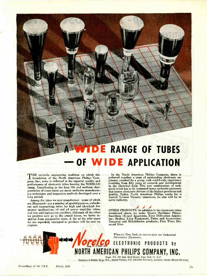
L RANGE OF TUBES
OF WIDE APPLICATIONHE enviable engineering tradition on which the
1 foundation of the North American Philips Com-pany, Inc., rests, is reflected in the superior quality andperformance of electronic tubes bearing the NORELCOstamp. Contributing to the long life and uniform char-acteristics of these tubes are many exclusive manufactur-ing techniques and inspection methods developed over along period.
Among the types we now manufacture-some of whichare illustrated-are a number of special-purpose, cathode-ray and transmitting tubes for high and ultra -high fre-quency applications, r -f and a -f power amplifier tubes,and low- and high -power rectifiers. Although all the tubeswe produce now go to the armed forces, we invite in-quiries from prospective users. A list of the tube typeswe are especially equipped to produce will be sent onrequest.
NO*
In the North American Philips Company, there isgathered together a team of outstanding electronic en-gineers, coached by a group with world-wide experienceresulting from fifty years of research and developmentin the electrical field. This new combination of tech-nical talent has at its command many exclusive processesthat insure electronic devices of the highest precision andquality. Today, North American Philips works for aUnited Nations Victory; tomorrow, its aim will be toserve industry.
.A Jf J1OTHER PRODUCTS: In addition to the electronic tubesmentioned above we make Quartz Oscillator Plates;Searchray (X-ray) Apparatus, X-ray Diffraction Appara-tus; Medical X-ray Equipment, Tubes and Accessories;Tungsten and Molybdenum products; Fine Wire; Dia-mond Dies.
OretWhen in New York, be sure to visit our IndustrialElectronics Showroom.
ro0 ELECTRONIC PRODUCTS by
NORTH AMERICAN PHILIPS COMPANY, INC.
Proceedings of the I.R.E. March, 1945
Dept. F-3, 100 East 42nd Street, New York 17, N.Y.Factories in Dobbs Ferry, N.Y., Mount Vernon, N.Y. (Metalix Division); Lewiston, Maine (Elmet Division)
3A
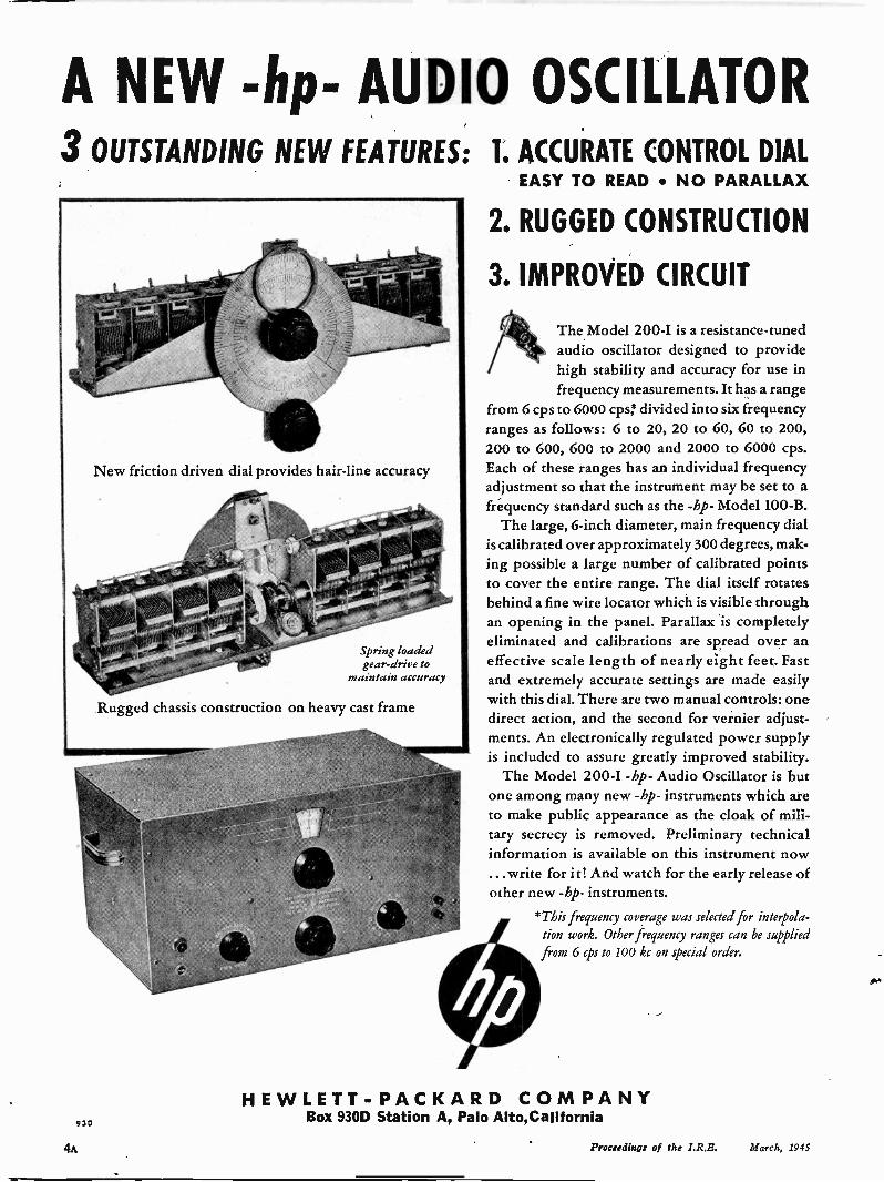
A NEW -hp- AUDIO OSCILLATOR3 OUTSTANDING NEW FEATURES: 1. ACCURATE CONTROL DIAL
9 3 0
41)New friction driven dial provides hair -line accuracy
Spring loadedgear -drive to
maintain accuracy
Rugged chassis construction on heavy cast frame
EASY TO READ NO PARALLAX
2. RUGGED CONSTRUCTION
3. IMPROVED CIRCUIT
The Model 200-I is a resistance -tunedaudio oscillator designed to providehigh stability and accuracy for use infrequency measurements. It has a range
from 6 cps to 6000 cps: divided into six frequencyranges as follows: 6 to 20, 20 to 60, 60 to 200,200 to 600, 600 to 2000 and 2000 to 6000 cps.Each of these ranges has an individual frequencyadjustment so that the instrument may be set to afrequency standard such as the -hp- Model 100-B.
The large, 6 -inch diameter, main frequency dialis calibrated over approximately 300 degrees, mak-ing possible a large number of calibrated pointsto cover the entire range. The dial itself rotatesbehind a fine wire locator which is visible throughan opening in the panel. Parallax is completelyeliminated and calibrations are spread over aneffective scale length of nearly eight feet. Fastand extremely accurate settings are made easilywith this dial. There are two manual controls: onedirect action, and the second for vernier adjust-ments. An electronically regulated power supplyis included to assure greatly improved stability.
The Model 200-1 -hp- Audio Oscillator is butone among many new -hp- instruments which areto make public appearance as the cloak of mili-tary secrecy is removed. Preliminary technicalinformation is available on this instrument now...write for it! And watch for the early release ofother new -hp- instruments.
0*This frequency coverage was selected for interpola-
tion work. Other frequency ranges can be suppliedfrom 6 cps to 100 kc on special order.
HEWLETT-PACKARD COMPANYBox 930D Station A, Palo Alto,California
4A Proceedings of the I.R.B. March, 1945

If you want the job done right
A group of Hytron engineers decided in1938 that to get those ideal tubes for "ham"radio - they must build them themselves.Combining years of experience in tubemanufacture with exact knowledge of thetube characteristics desired, they went towork.
First they concentrated their efforts.Low and medium power types were mostneeded by the majority of hams. Hytronwas equipped to make them. Graduallythe engineers translated ideals into a com-prehensive line-v-h-f triodes and pentodes,low and medium mu triodes, instant -heat-ing r. f. beam tetrodes, and sub -miniatures.
01.011.1EXCLUSIVE
Hams themselves, the engineers knewtheir brain children would be given theworks. They built the tubes rugged; ratedthem conservatively. And did the amateurgo for them! The v -h -f types - HY75,HY114B, HY615 - soon became acceptedstandards. Today's WEBS operators usethem almost exclusively.
Performance in the proving ground ofamateur radio was the proof of the pudding.You will find Hytron transmitting andspecial purpose tubes in war and civilianjobs of all kinds. Like the BANTAM GTand BANTAM JR., they are popular be-cause they are built right for the job.
MANUFACTUREROF RADIO RECEIVING
TWITS
SALEM AND N WBrApSS
BUY ANOTHER WAR BONDProceedings of the I.R.E. March, 1945 5A
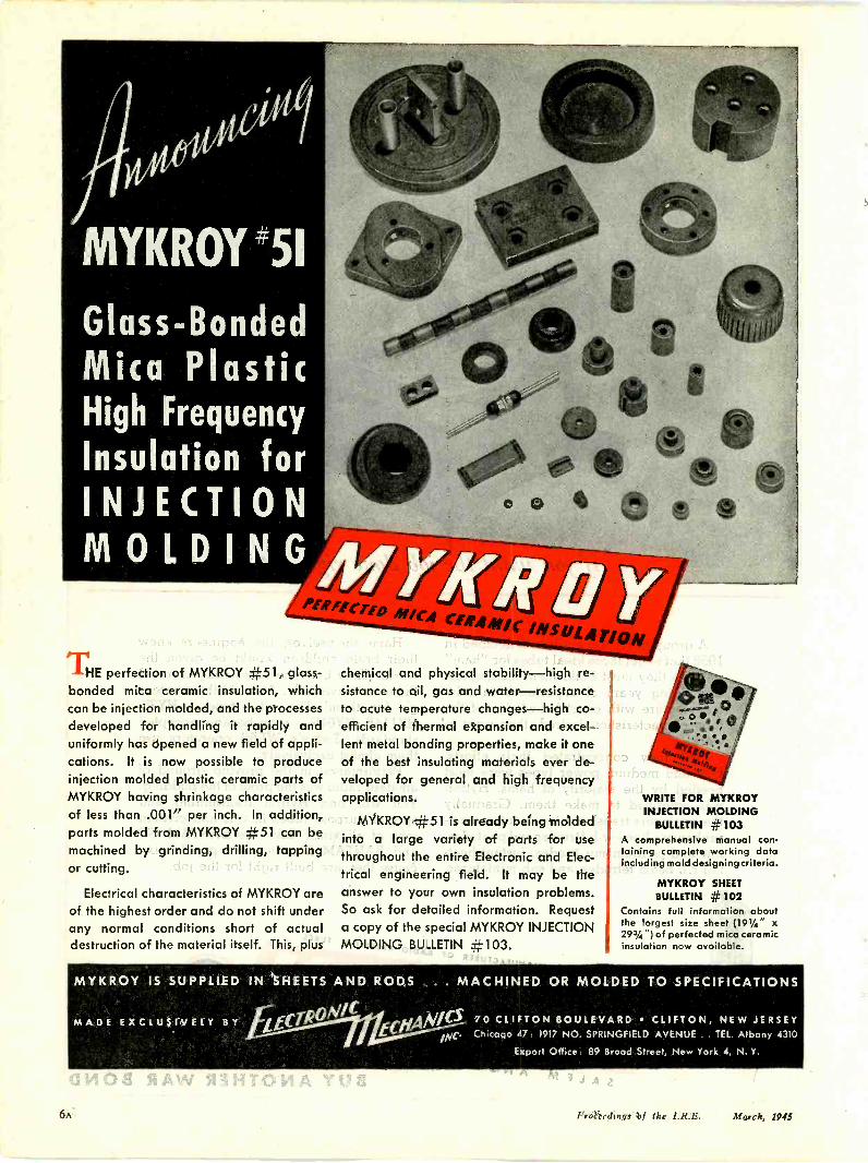
MYKROY '51
Glass -BondedMica PlasticHigh Frequency
Insulation forINJECTIONMOLDING
THE perfection of MYKROY #51, glass -bonded mica ceramic insulation, whichcan be injection molded, and the processesdeveloped for handling it rapidly anduniformly has opened a new field of appli-cations. It is now possible to produceinjection molded plastic ceramic parts ofMYKROY having shrinkage characteristicsof less than .001" per inch. In addition,parts molded from MYKROY #51 can bemachined by grinding, drilling, tappingor cutting.
Electrical characteristics of MYKROY areof the highest order and do not shift underany normal conditions short of actualdestruction of the material itself. This, plus
chemical and physical stability-high re-sistance to oil, gas and water-resistanceto acute temperature changes-high co-efficient of thermal expansion and excel-lent metal bonding properties, make it oneof the best insulating materials ever de-veloped for general and high frequencyapplications.
MYKROY #51 is already being moldedinto a large variety of parts for usethroughout the entire Electronic and Elec-trical engineering field. It may be theanswer to your own insulation problems.So ask for detailed information. Requesta copy of the special MYKROY INJECTIONMOLDING BULLETIN #103.
WRITE FOR MYKROYINJECTION MOLDING
BULLETIN # 103A comprehensive manual con-taining complete working dataincluding mold designing criteria.
MYKROY SHEETBULLETIN # 102
Contains full information aboutthe largest size sheet (19'/4" x293/4") of perfected mica ceramicinsulation now available.
MYKROY IS SUPPLIED IN SHEETS AND RODS ... MACHINED OR MOLDED TO SPECIFICATIONS
MADE EXCLUSIVELY BY igloo` ECHANICS 70 CLIFTON BOULEVARD CLIFTON, NEW JERSEYmc. Chicago 47: 1917 NO. SPRINGFIELD AVENUE . . TEL. Albany 4310
Export Office. 89 Brood Street, New York 4, N. Y.
6A Proceedings of lice 1.R.E. March, 1945

A.
VIP-DEPINPARIE-b1111 ...HOUR AFTER HOUR!
You can tell just by looking at it-this tube is builtto I -a -s -t.
This new air-cooled Westinghouse PliotronNo. WL473 is small, compact and designed espe-cially for dielectric and induction heating. It is ex-tremely economical in operation, having the lowestcost per R.F. kilowatt hour of any tube in its classon the market today.
For technical data or any other information on thePliotron No. WL473 or any Westinghouse Elec-
tronic Tube, consult your nearest WestinghouseOffice or write to Westinghouse Electric & Manu-facturing Company, Electronic Tube Division,Bloomfield, New Jersey.
estin housePLANTS IN 25 CITIES OFFICES EVERYWHERE
aieveie7eZProceedings of the I.R.E. March, 1945 7A
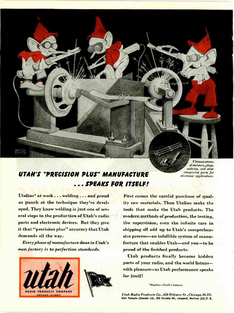
UTAH'S "PRECISION PLUS" MANUFACTURE
... SPEAKS FOR ITSELF!
Utalins* at work . . . welding . . . and proudas punch at the technique they've devel-oped. They know welding is just one of sev-eral steps in the production of Utah's radioparts and electronic devices. But they giveit that "precision plus" accuracy that Utahdemands all the way.
Every phase of manufacture done in Utah'sown factory is to perfection standards.
RADIO PRODUCTS COMPANYCNICAGO. ILLINOIS
itreous enam-el resistors, plugs,
switches, and othercomponent parts for
electronic applications.
First comes the careful purchase of qual-ity raw materials. Then Utalins make thetools that make the Utah products. Themodern methods of production, the testing,the supervision, even the infinite care inshipping all add up to Utah's comprehen-sive process-an infallible system of manu-facture that enables Utah-and you-to beproud of the finished products.
Utah products finally become hiddenparts of your radio, and the world listens-with pleasure-as Utah performance speaksfor itself!
Utalins-Utahs helpers
Utah Radio Products Co., 820 Orleans St.,Chicago 10, 111.
Utah Products (Canada) Ltd.. 300 Chambly Rd., Longueull, Montreal (23) P. Q.
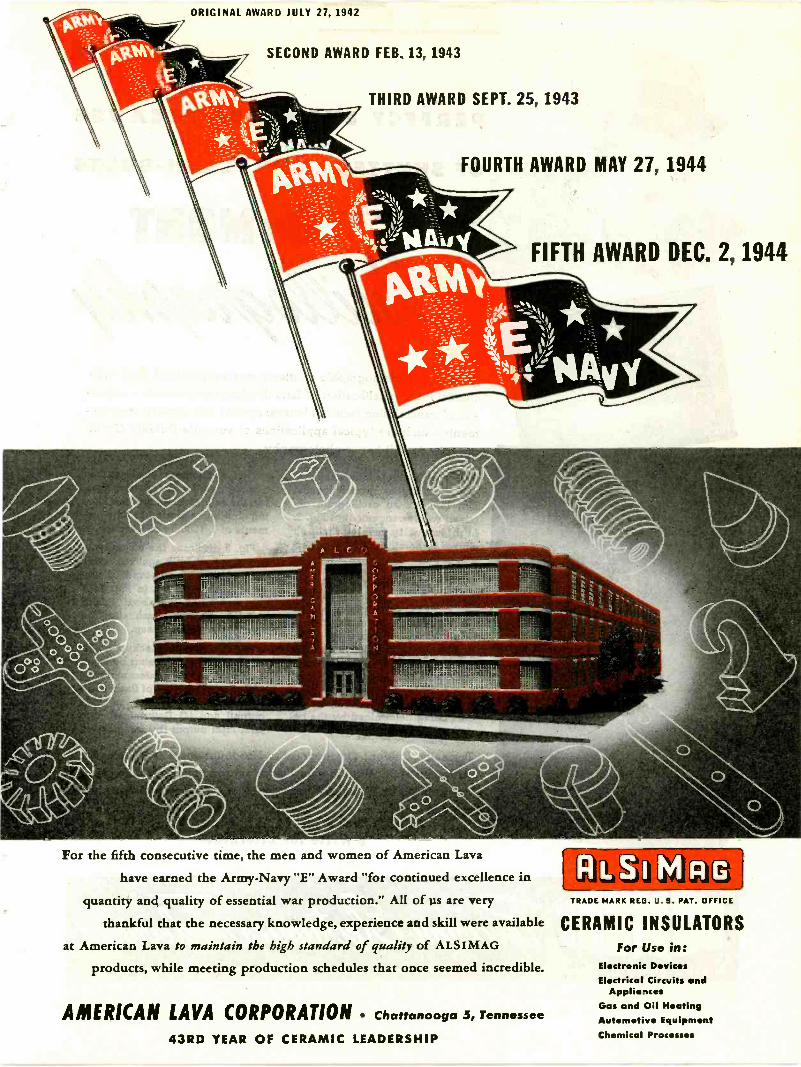
ORIGINAL AWARD JULY 27, 1942
SECOND AWARD FEB. 13, 1943
THIRD AWARD SEPT. 25, 1943
FOURTH AWARD MAY 27, 1944
FIFTH AWARD DEC. 2, 1944
For the fifth consecutive time, the men and women of American Lava
have earned the Army -Navy "E" Award "for continued excellence in
quantity and quality of essential war production." All of us are very
thankful that the necessary knowledge, experience and skill were available
at American Lava to maintain the high standard of quality of ALSIMAG
products, while meeting production schedules that once seemed incredible.
AMERICAN LAVA CORPORATION Chattanooga 5, Tennessee
43RD YEAR OF CERAMIC LEADERSHIP
ELLA I MrRiG1TRADE MARK REG. U.S. PAT. OFFICE
CERAMIC INSULATORSFor Use in:
Electronic DevicesElectrical Circuits and
AppliancesGas and Oil HeatingAutomotive EquipmentChemical Pro

PERFECT EXPOSURE BECAUSE
OF SHUTTERS AND FLASH -BULBS
CHECKED BY Du MONT
Testing of photographic shutters: measurements of flash -bulbcharacteristics; calibration of lens diaphragm openings; compari-son of transmission factor of lenses; opacity and density measure-ments - such are typical applications of versatile DuMoni Oscill-ography to still better photography.
Typical of this technique is the pre-cise checking of shutter speeds.Fig. 1 shows an oscillogram ob-tained with arrangement in Fig. 2.Light intensity passing throughshutter is directly plotted as a func-tion of time.
When shutter opens, light fromneon lamp falls on photo -cell. Bothcell and neon lamp operate on D.C.Output from photo -cell directly, orD.C. amplified if necessary, is ap-plied to vertical deflection platesof cathode-ray tube. A timing wavemodulates the cathode-ray beam,so that plot appears as dotted line.the distance between two adjacentdots being determined by the pe-riod of the timing wave.
This oscillogram discloses theelapsed time for the opening shut-ter, the full opening, and the clos-ing shutter, calibrated in time ele-ments of 1/ 1000ths of a second.
Fig. 3 discloses the characteris-tics of a flash -bulb again in termsof 1 /1000ths of a second. Equip-ment used is shown in Fig. 4. Arelay, delayed for about 1/30thsecond, starts the flash after thestart of the single sweep.
This flash -bulb checkup deter-mines: (1) Time elapsing betweenclosing of battery contact and startof flash; (2) Duration of flash itself;(3) Measurement of peak luminousoutput; and (4) Determination oftotal light output (by integration).
Typically DuMoni Oscillography. No doubt there is an equallyimportant application in your laboratory, on your production line,or out in the field. Submit your problem for our suggestions andengineering help.
I Write for Literature* ALLEN B DUMONT LABORATORIES. INC
Feco'tem eicaexemz4K41-towALLEN B. DUMONT LABORATORIES, INC., PASSAIC, NEW JERSEY CABLE ADDRESS: WESPEXLIN, NEW YORK
1O. Proceedings of the March, 1945

TEST00110
with these versatileWESTON
Test Instruments,
The Direct-Reading,
Self -ContainedINSULATION
TESTER(MODEL 796)
This compact direct-reading resistancetestereliminates hand cranking and thus makes leak-age testing a simple one-man job especially inunaccessable
places. Tests up to 200 megohmsat test potentialof 350 to 500
volts d -c; although,the current at terminals is only a few micro-amperes. Operatesfrom long life, light-weightbatteries. There are no vibrators
to replace.Ranges: 0-20-300full scale; 0-.5-5megohms center scale. Size 8" x 91/4" x 8".
/ith production currently runningslightly ahead of war requirements, alimited numbe'r of the popular WESTONtest instruments shown herewith are avail-able and are offered subject to prior sale.Orders can be placed direct, or with theWESTON representative in your vicinity.Literature available from...WESTON Elec-trical Instrument Corporation, 578 Fre-linghuysen Avenue, Newark 5, New Jersey.
MONINSTRUMENTS
Proceedings of the I.R.E. March, 1945 11A
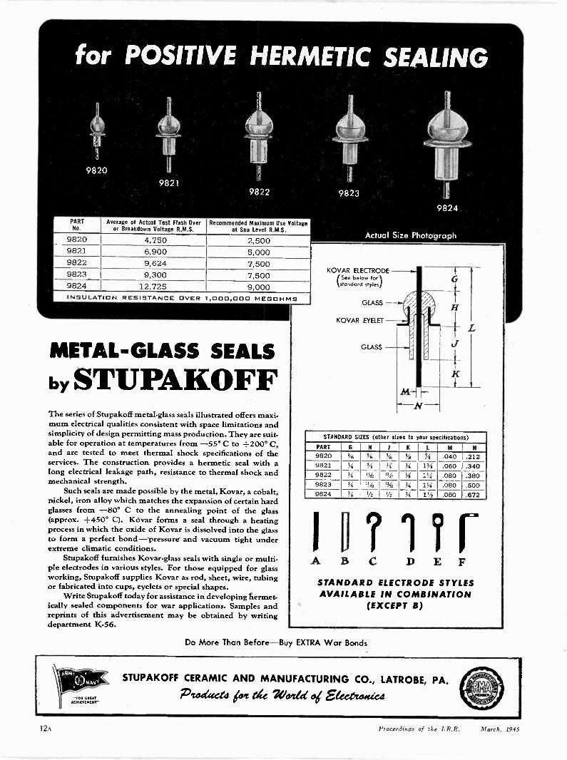
for POSITIVE HERMETIC SEALING
PART
Ii
9820
Average of Actual i VNo. or Breakdown Voltage R.M.S. at Sea Level R.M.S.
9820-
4,750 2,5009821 6,900 5,0009822 9,624 7,5009823 9,300 7,5009824 12,725 9,000INSULATION RESISTANCE OVER 1,000,000 MEGOHMS
METAL -GLASS SEALS
by STUPAKOFFThe series of Stupakoff metal -glass seals illustrated offers maxi-mum electrical qualities consistent with space limitations andsimplicity of design permitting mass production. They are suit-able for operation at temperatures from -55° C to +200° C,and are tested to meet thermal shock specifications of theservices. The construction provides a hermetic seal with along electrical leakage path, resistance to thermal shock andmechanical strength.
Such seals are made possible by the metal, Kovar, a cobalt,nickel, iron alloy which matches the expansion of certain hardglasses from -80° C to the annealing point of the glass(approx. +450° C). Kovar forms a seal through a heatingprocess in which the oxide of Kovar is dissolved into the glassto form a perfect bond - pressure and vacuum tight underextreme climatic conditions.
Stupakoff furnishes Kovar-glass seals with single or multi-ple electrodes in various styles. For those equipped for glassworking, Stupakoff supplies Kovar as rod, sheet, wire, tubingor fabricated into cups, eyelets or special shapes.
Write Stupakoff today for assistance in developing hermet-ically sealed components for war applications. Samples andreprints of this advertisement may be obtained by writingdepartment K-56.
Actual Size Photograph
KOVAR ELECTRODE(See below for)
standard styles
GLASS
KOVAR EYELET
GLASS
STANDARD SIZES (other sizes to your specifications)
PART Gli.11( L M N
9820 56 .3fs ire, .i"6 'Ai
13/8
.040 .2129821 VI '.41 Li Si' .060 .3409822 '4 '1.42 Ifit Si' 2.q .080 .3809823 ii li., % ii, 11/4 .080 .5009824 51 1/2 1/2 ',4 1% .080 .672
A BC D E F
STANDARD ELECTRODE STYLESAVAILABLE IN COMBINATION
(EXCEPT B)
Do More Than Before-Buy EXTRA War Bonds
STUPAKOFF CERAMIC AND MANUFACTURING CO., LATROBE, PA.
Pt.:144dd Liar lice Venice od Eleet,tooted"
12A Proceedings of the I.R.E. 11,,.r h. 194
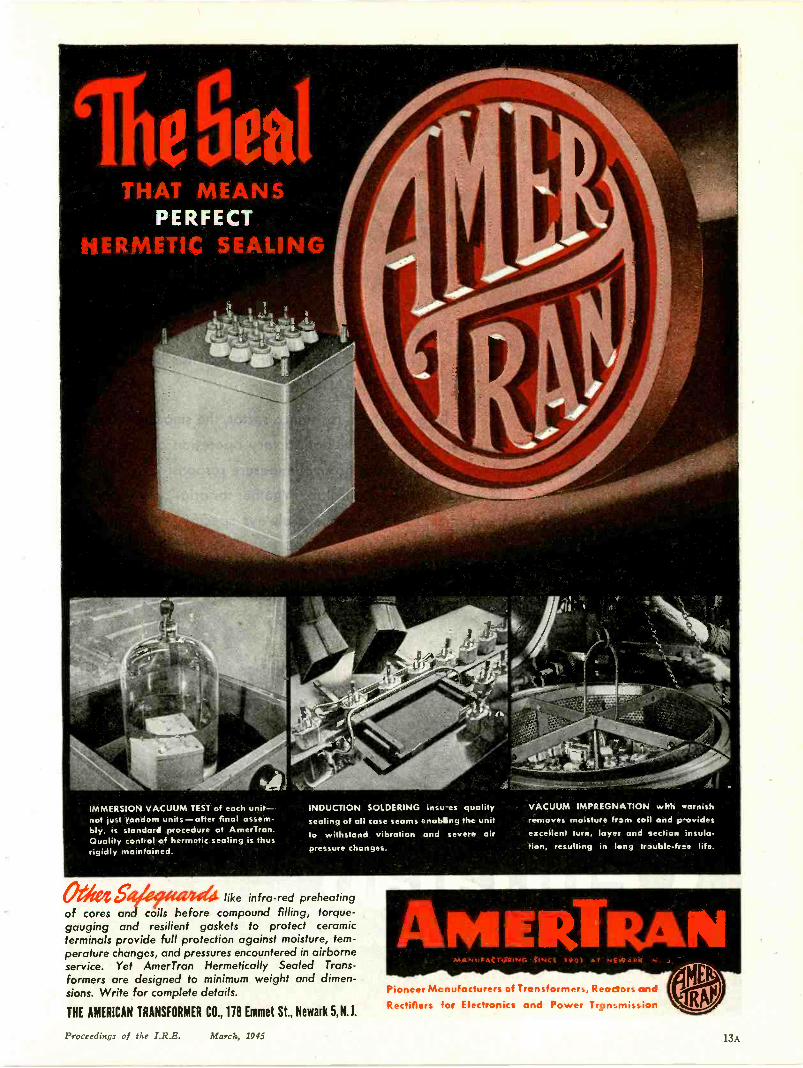
THAT MEANSPERFECT
HERMETIC .ic.ALING
IMMERSION VACUUM TEST of each unit-not just random units-after final assem-bly, is standard procedure at AmerTran.Quality control of hermetic sealing is thusrigidly maintained.
Otitea
INDUCTION SOLDERING insu -es qualitysealing of all case seams enabing the unitto withstand vibration and severe air
pressure changes.
like infra -red preheatingof cores and coils before compound filling, torque -gauging and resilient gaskets to protect ceramicterminals provide full protection against moisture, tem-perature changes, and pressures encountered in airborneservice. Yet AmerTran Hermetically Sealed Trans-formers are designed to minimum weight and dimen-sions. Write for complete details.
THE AMERICAN TRANSFORMER CO., 118 Emmet St., Newark 5, N.J.
VACUUM IMPREGNATION with oarnishremoves moisture frxrri coil and p-ovidesexcellent turn, layer and section insula-tion, resulting in long trauble-free life.
Pioneer Mcnufoctures of Transformers, Reactors and
Rectifiers 'or Electronics and Power Transmission
Proceedings of the I.R.E. .'tt. arc h , 1945
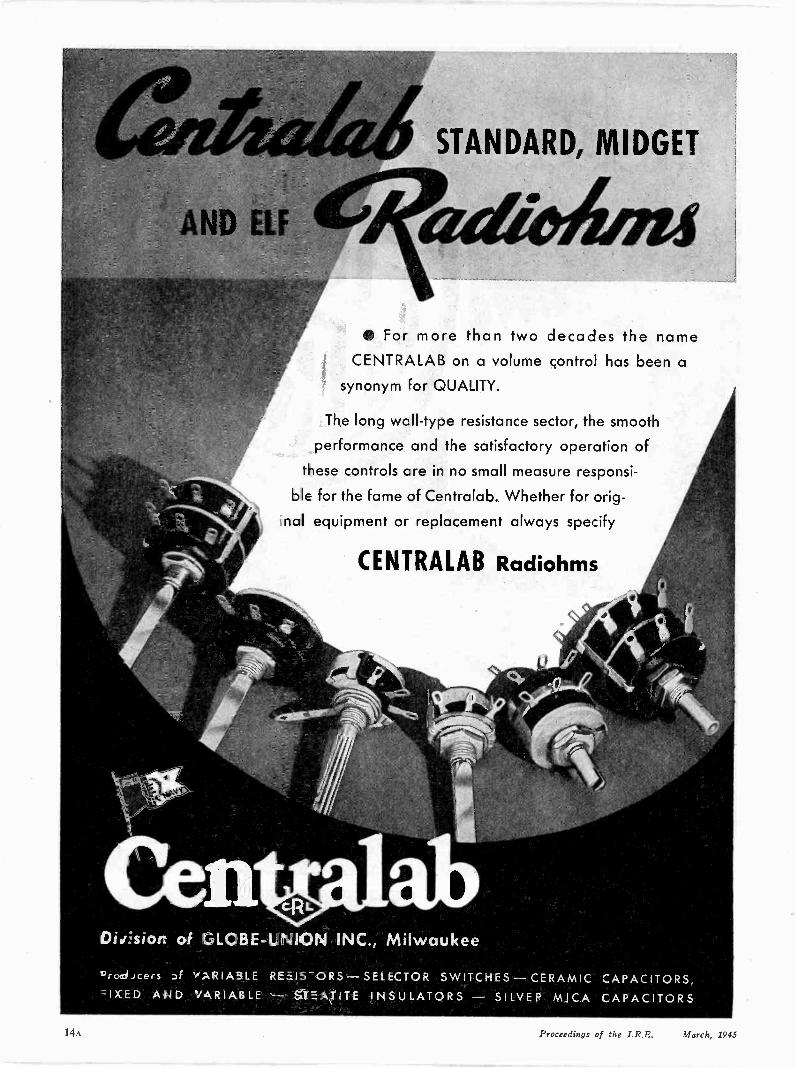
AND ELF
STANDARD, MIDGET
For more than two decades the nameCENTRALAB on a volume control has been a
synonym for QUALITY.
The long wall -type resistance sector, the smooth
performance and the satisfactory operation of
these controls are in no small measure responsi-
ble for the fame of Centralab. Whether for orig-
nal equipment or replacement always specify
CENTRALAB Radiohms
Dir.'siort of GLOBE -UNION INC., Milwaukee
'rodicers Df v'ARIA3LE REEIS-ORS - SELECTOR SWITCHES CERAMIC CAPACITORS,"zIXED AND /ARIABLE - STEATITE INSULATORS -SILVERMICA CAPACITORS
14A Proceedings of the I.R.E. March., 1945

After ADOLPH aid TOJO are
The rig he left behind is due for a big change when
GI Joe comes home. War experience has been an
"eye opener" for him. From chassis to sky wire
many pre-war Ham outfits will undergo a major al-
teration and amazing technical advances will be put
into practice. Stimulated by training and experi-
ence gained in the armed services thousands of new
enthusiasts will swell the ranks of amateur radio.
When the gang goes back on the air again,
CQ'ing, SS or DX; UNITED will be ready to serve the
Amateur with war -perfected Transmitting Tubes.
Since 1934 UNITED has specialized in engineer-
ing, designing and building Transmitting Tubes that
set the Quality Staidard for the entire Radio Indus-
try. When performance counts UNITED Tubes pro-
vide a maximum of electronic efficiency-plus a
long and dependable life. Accept nothing less than
UNITED quality for your own tube requirements.
Order direct or from your electronic parts jobber.
MASTERPIECE OF SKILLED HANDS
TEMELECTRONICS COMPANYNEWARK, 2 "9 NEW JERSEY
Transmitting Tubes EXCLUSIVELY Since 1934
Proceedings of the I.R.E. March, 1945 15A
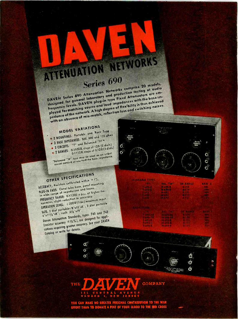
Series 690DAVEN Series 690 Attenuation Networks comprise 20 m3dels,designed for general laboratory and production testing at audiofrequency levels. DAVEN plug-in type Fixed Attenuators are em-ployed for matching source and load impedances with the base im-pedance of the network. A high degree of flex;bility is thus achievedwith an absence of mis-match, reflection loss and switching noises.
MODEL VARIATIONS 2 MOUNTINGS: Portable and Rack Typo
* 3 BASE IMPEDANCES: 500, 600 and 135 ohms
2 CIRCUITS: "T" and Balanced "H"4 2 RANGES: 0-110DB, steps of 1DB (2 dials)
0-111DB, steps of 0.1013 (3 dials)
'Balanced "tr type may be used as on Unbal-anced network of one-half the base impedance.
OTHER SPECIFICATIONSACCURACY:, Resistors calibrated within
PLUG-IN PADS: Octal tube base, panel mounting,in wide range of impedances and losses,
FREQUENCY RANGE: 0-17,000 c.p.s.; at higher fre-quencies, slight reduction in accuracy.
OPERATION LEVEL: = 20DB (0.6w) maximum input.
SIZE: 2 dial portable: 5-x10iix5"; 3 dial portable6i.x111/2"x5; rack: 31/2-C19-.
Doyen Attenuation Standards, types 740 and 742
(resistor accuracy 1/2%), are designed for appli-
cations requiring greater accuracy. See your DAVEN
Catalog or write for details.
THEDAVCOMPANYSi CENTRAL
AVENUENEWARRNEW
YOU CAN MAKENO GREATER
YOU
PERSO
TO THE WAR
EFFORTTHAN TO DONATE A PINTNAL CONTRIBUTION
OF YOURBLOOD
TO THERID CROSS

JUSTOFF
THEPRESS
HARAC TER 1ST.*SING DIAGRA
Receivor TubesTransmits,' T
:Cathode Roy TT ITU T ION CHAR
TubesCondensers
ittOTOTUBE DAANSFORMER DANDENSER DA
SISTOR DAT[OR CODE
ORMULAicon War S
The new ELECTRONIC ENGI-NEER'S REFERENCE MANUALnow makes available to the practicalengineer all the essential up-to-the-minute facts about electron tubesand related parts. More than 900types of Receiving, Transmitting,Cathode -Ray and Photo Tubes aredescribed-with physical specifica-tions, characteristics, typical operat-
_ng conditions, basing diagrams,war -time substitution chart and otherdata. All this and more in one handyquick -reference book of 146 pagesthat you can tuck in your pocket.Note ring binding which makes thepages lie fiat when book is open.Price $1.00. For copies writeNational Union Radio Corporation,Newark 2, New Jersey.
Proceedings of the I.R.E. March, 1945 17A

COLLINS ENGINEERING AND MAC TUBES
achieve outstanding results
COLLINS Type 2310.11 Nervy TON)
Multi -frequency transmitter
Output CW-5 KW; Output 'Phone -3 KW100% modulated with a pair of Eimac 450TLtubes in class "B" audio; continuous coveragefrom 2 MC to 18.1 MC with 11 preset channelsin that range and complete manual coveragethroughout whole range. Capable of completelyunattended re -note control operation and of Al,A2 and A3 type emission. Audio characteristics:plus or minus three DB from 150 to 3,500 cycles.Total harmonic distortion less than 10%. Thetransmitter can be terminated into a 50 to 1,200pure resistive load at zero degrees chase angle.70
to 850 ohm load at plus or minus 45 degrees and100 to 600 ohms at plus or minus 60 degrees.
Write for. your copy oElectronic Telisis -a 64page booklet fully illus-trated - covering funda-mentals of Electronicsand many of its impor-tant applications. Writ-ten in layman's language.
This Collins type 231D-11 (Navy TDH) radio transmitteris an outstanding demonstration of the value of capableengineering coupled with the intelligent choice and useof vacuum tubes.
It is the latest of a series of Collins Autotune, quick shifttransmitters which were originally introduced in 1939,and which use Eimac tubes in the important sockets. Inthe 231D-11, two Eimac 750TL tubes in parallel makeup the power amplifier, while a pair of Eimac 450TLtubes in class "B" are used as modulators for voice andMCW emission.
Mr. F. M. Davis, General Manager of the Collins Engi-neering Division, says: "Eimac tubes have been found tobe reliable, rugged and capable of withstanding the severeoverloads encountered during equipment tests, withoutdamage." Statements like this, coming from such men asMr. Davis, offer proof that Eimac tubes are first choice ofleading engineers throughout the world.
Follow the leaders to
rusts
Eimac has received
*ARMY. NAVY "E" AWARDS
for production efficiency
San Bruno 5, Salt Lake City 3
EITEl-McCUU.OUGH, Inc., 956 San Mateo Ave., San Bruno, Calif.Plants located at: San Bruno,California and Salt Lake City, Utah
Export Agents: Fralar & Hansen, 301 Clay Street, San Francisco 11, California, U. S. A.

70 TypesPLUGS & CONNECTORSSIGNAL CORPS NAVY SPECIFICATIONS
Types: P L
50-A 61 74 114 150
54 62 76 119 159
55 63 77 120 160
56 64 104 124 291-A
58 65 108 125 354
59 67 109 127
60 68 112 149
56 65 56 65
59 67 59 67
60 74 60 74
61 76 61 76
62 77 62 77
63 104 63 104
64 64
56 64
59 65
60 74
61 76
62 77
63 104
N A F1136-1 No. 212938-1
Other Designs to Order
FOR VICTORYRemler is equipped for the mass production of many types of
radio and electronic devices from humble plugs and connectors
to complete sound amplifying and transmitting systems. In-
genious production techniques contribute to Remler precision,
reduce costs and speed up deliveries. The Axis is on the run
and final Victory is in sight. Let us help you finish the job.
Wire or telephone if we can be of assistance
REMLER COMPANY, LTD. 2101 Bryant St. San Francisco, 10, Calif.
REMLERSINCE 1918
Onnounciny S Communication 25ui2ment
Proceedings of the I.R.E. March, 1945 19A
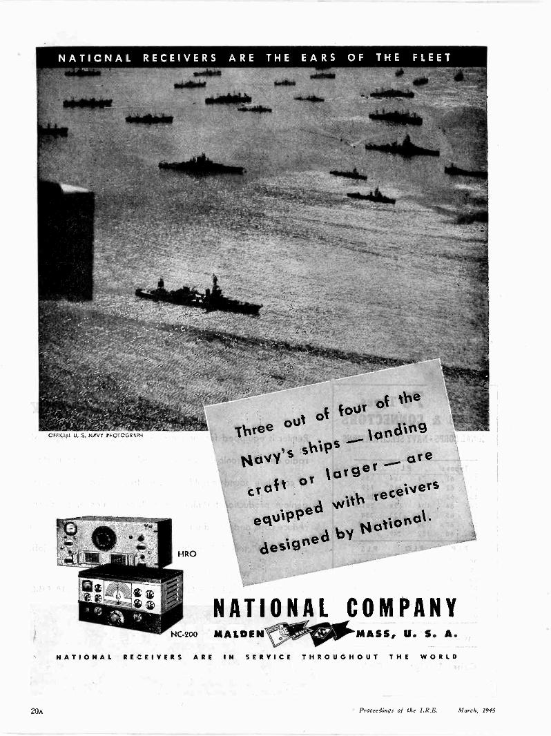
OFFICIAL U. S. NAVY 111-0TOGR4PH 'Threeout of four ot the
Navy'sships ---- waling
largercroft or
--- ore
equippedvdith receivers
onal
designedby Nati.
NATIONAL COMPANYNC -200 MALDEN
NATIONAL RECEIVERS ARE
MASS, U. S. A.
IN SERVICE THROUGHOUT THE WORLD
20A Proceedings of the I.R.E. March, 1945

DO YOU NEED A CRYSTAL BAIL?
THEREare timesin the lives of all good engineers
when a crystal ball would come in mighty handy.
We know because we've had many a problem where
it looked like aid from the occult was the only solu-
tion. Instead, we found that sound engineeringplus
the outstandingphysical properties of Coming's
electrical glasses usuallysupplied the answers.
These same glass qualities are ready to help you
produce better postwar electronic products. Which
1. High dielectric strength-highresistivity-lowdo you need?
power factor-widerange of dielectric constants-
low losses at all frequencies.
CORNINGmeans
Research in Glass
2. permanent herraetic seals against gas, oil and
water betweenglass and metal or glass and glass.
3. Commercialfatzrication to the fine tolerances of
precision metal working.
4. Corning's metallizing process produces metal
areas of fixed and exact specification,permanently
bonded to glass. * * *
Write us about your problems. We'd be interested
seeing if glass can help you. Address Electronic
Sales Dept., P -3, Bulb and TubingDivision, Co
in see
Glass Works,Ccrning, N. Y.
40 ElectronicOlassware
"PYREX", "VYCOR" and "CORNING" are registered trade -marks and indicate manufacture by Corning Class Works, Corning, N. Y.
Proceedings of the I.R.E. March, 1995 21
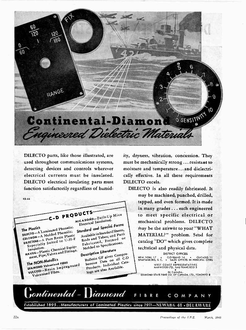
Continental-Diamon10tee 2eGieVade
DILECTO parts, like those illustrated, areused throughout communications systems,detecting devices and controls whereverelectrical currents must be insulated.DILECTO electrical insulating parts mustfunction satisfactorily regardless of humid -
KB -44
C-0 PRODUCTS
The Plastics
MICABOND-Built-Up
Mica
ElectricalInsulation.
CELORON--AMolded Phenolic. Standard
and SpecialForms
DILECTO--ALatnittatecl
Phenolic.
EspeciallySuited to 1.3-11-f
AvailableinStandard
Sheets,
Insulation
Rods and Tubes;and Parts
DILECTENE-A
Resin Plastic
14AVEG-PlasticChemical
Equip-fabricated, Formed
or
ment,Pipe,Valves
and f ittiugs.Molded to Specifications.
The NON-Metallics
DescriptiveLiterature
logs are also Available.DIAMOND
Is FIBREBulletin
GI2 givesCornpre-
VULCOIDR.esinImpregnated
pensive Data on all C -D
'VulcanizedFibre.
Products.Individual
Cata-
Cowibien,kri= n 4g/into/nal
SENSIVI\
ity, dryness, vibration, concussion. Theymust be mechanically strong ... resistant tomoisture and temperature... and dielectri-cally effective. In all these requirementsDILECTO excels.
DILECTO is also readily fabricated. Itmay be machined, punched, drilled,tapped, and even formed. It is madein many grades ... each engineeredto meet specific electrical ormechanical problems. DILECTOmay be the answer to your "WHATMATERIAL?" problem. Send forcatalog "DO" which gives completetechnical and physical data.
DISTRICT OFFICESNEW YORK 17 CLEVELAND 14 CHICAGO 11SPARTANBURG, S. C. SALES OFFICES IN PRINCIPAL CITIES
WEST COAST REPRESENTATIVESMARWOOD LTD., SAN FRANCISCO 3
IN CANADA.DIAMOND STATE FIBRE CO. OF CANADA, LTD., TORONTO 8
FIBRE COMPANYEstablished 1895.. Manufacturers of Laminated Plastics since 1911-NEWARK 48 . DELAWARE
22A Proceedings of the I.R.E. March, 1945
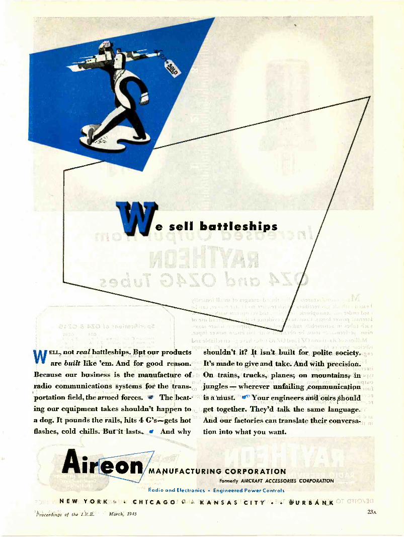
e sell battleships
WELL, not real battleships. But our productsare built like 'em. And for good reason.
Because our business is the manufacture ofradio communications systems for the trans-portation field, the armed forces. fe The beat-ing our equipment takes shouldn't happen toa dog. It pounds the rails, hits 4 G's-gets hotflashes, cold chills. But it lasts. E And why
Aireon
shouldn't it? It isn't built for polite society.It's made to give and take. And with precision.On trains, trucks, planes; on mountains, injungles - wherever unfailing communicationis a must. of Your engineers and ours shouldget together. They'd talk the same language.And our factories can translate their conversa-tion into what you want.
MANUFACTURING CORPORATIONFormerly AIRCRAFT ACCESSORIES CORPORATION
Radio and Electronics Engineered Power Controls
NEW YORK CHICAGO KANSAS CITY BURBANKProceedings of the I.R.E. March, 1945 23A

Increased Output fromRAYTHEON
OZ4 and OZ4G TubesMany manufacturers realize the advantages of small ionically
heated cathode gas rectifiers which require no heater power, can beused under any atmospheric condition, and yet operate with very lowinternal power losses. Convincing evidence is the widespread use ofsuch tubes in automobile radios and other equipment where maxi-mum performance must be obtained with minimum power input.
Millions of Raytheon OZ4 and OZ4G tubes have given reliable andefficient service in such equipment . . . service which will promptengineers to incorporate them in numerous postwar products.
First developed by Raytheon as a refinement of the BH to obtaininternal drops comparable to the larger directly heated cathodetypes, these tubes are now further improved to the point where theoutput rating has been increased from 75 ma to 90 ma whenfunctioning as a full wave rectifier. Hence, it can be used toadvantage in supplying the extra "B" drain imposed by largerreceivers or low -power mobile transmitters.
The OZ4 and OZ4G are examples of Raytheon's ability to designand produce better tubes . . . tubes which will be in great demandin the postwar radio and electronics industry.
RAYTHEONRADIO RECEIVING TUBE DIVISIONNewton, Mass. Los Angeles New York Chicago Atlanta
Specifications of OZ4 & OZ4GOZ4 OZ4G
Maximum Overall Length 2-5/8 in. 2-5/8 in.Maximum Seated Height 2-1/16 in. 2-1/16 in.Maximum Diameter 1-5/16 in. 1-3/64 in.
Typical Operation Ratings as a Full WaveCondenser Input Rectifier:
Heater Power NoneMinimum DC Output Current 30 maMaximum DC Output Current 90 maMaximum Peak Anode Current 270 maMinimum Starting Voltage-
Peak (P to K) 320 voltsAverage Dynamic Voltage Drop 24 voltsMaximum Peak Inverse Voltage 880 volts
All Four DivisionsHove Been Awarded
Army -Navy "E"with Stars
Listen to"MEET YOUR NAVY"Every Saturday Night
ENTIRE BLUE NETWORKCoast -to -Coast
181 Stations
DEVOTED TO RESEARCH AND THE MANUFACTURE OF TUBES AND EQUIPMENT FOR THE NEW ERA OF ELECTRONICS
24A Proceeding: of the I.R.E. March, 1945

A BASICALLY NEW IDEA IN TRANSMITTERS...
PLUS ALL THE EXTRAS OF SPECIAL
WESTINGHOUSE RESEARCH FOR FM
* For harmonics sip t,30 kc/s at f 75 4.cesswing, distortion is lessthan 1.55,, rms for mcch._lating frequencies be-tween 50 and 15,000 zps.
0.)
-A4-"
WestinghousePLANE IN 25 CITIES . , . OFFICES EVERYWHERE
Here in a smartly -styled package is a basically newapproach to FM transmitter design ... com.3ined withall the performance extras of special Westinghouseresearch for frequency modu a tion.
Built in 1, 3, 10 and 50 kw ratings, this new designprovides direct generation of the modulated carrierby a simple and straightforward circuit. Frequencycorrections are independent 3f critical tuning. Dis-tortion is low.*
Metal -plate rectifiers-first introduced by West-inghouse for high -voltage, high -current AM applica-tions virtually eliminate outages caused by rectifier(tube) failures. Space and cooling requirements arereduced, operating costs are lowered.
Your nearest Westinghouse office has completedetails of this new triumph in FM transmitterdesign in booklet B-3529. Cr write WestinghouseElectric & Manufacturing Ccmpany, Radio Division,Baltimore, Maryland. J-08103
XXV RADIO'S 25TH ANNIVERSARY KDKA
Proceedings oif the I.R.E. March, 1945 25A
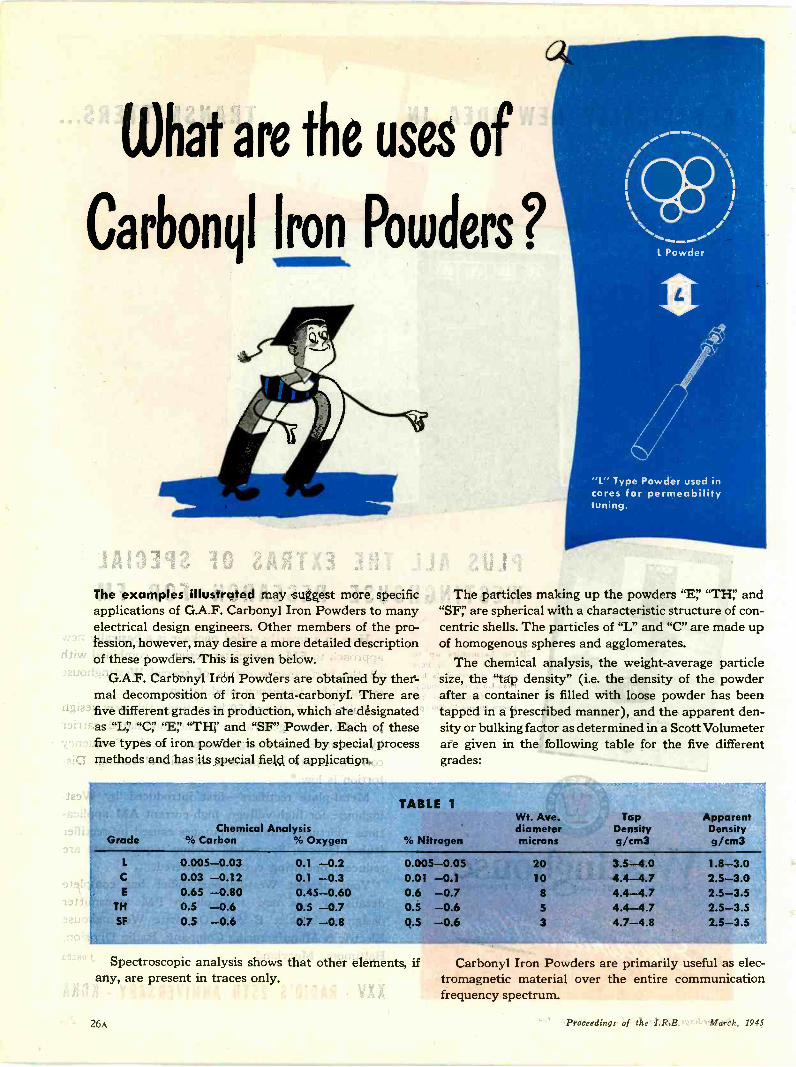
What are the uses of
Carbonyl Iron Powders?
The examples illustrated may suggest more specificapplications of G.A.F. Carbonyl Iron Powders to manyelectrical design engineers. Other members of the pro-fession, however, may desire a more detailed descriptionof these powders. This is given below.
G.A.F. Carbonyl Iron Powders are obtained by ther-mal decomposition of iron penta-carbonyl. There arefive different grades in production, which are designatedas "L'' "C;' "E' and "SF" Powder. Each of thesefive types of iron powder is obtained by special processmethods and has its special field of application.
1,,
"L" Type Powder used incores for permeabilitytuning.
The particles making up the powders "E,' "TH:' and"SF,' are spherical with a characteristic structure of con-centric shells. The particles of "L" and "C" are made upof homogenous spheres and agglomerates.
The chemical analysis, the weight -average particlesize, the "tap density" (i.e. the density of the powderafter a container is filled with loose powder has beentapped in a prescribed manner), and the apparent den-sity or bulking factor as determined in a Scott Volumeterare given in the following table for the five differentgrades:
GradeChemical Analysis
% Carbon % Oxygen
TABLE 1
% Nitrogen
Wt. Ave.diametermicrons
TapDensityg/cm3
ApparentDensityg/cm3
L 0.005-0.03 0.1 -0.2 0.005-0.05 20 3.5-4.0 1.8-3.0C 0.03 -0.12 0.1 -0.3 0.01 -0.1 10 4.4-4.7 2.5-3.0E 0.65 -0.80 0.45-0.60 0.6 -0.7 8 4.4-4.7 2.5-3.5
TH 0.5 -0.6 0.5 -0.7 0.5 -0.6 5 4.4-4.7 2.5-3.5SF 0.5 -0.6 0.7 -0.8 0.5 -0.6 3 4.7-4.8 2.5-3.5
Spectroscopic analysis shows that other elements, ifany, are present in traces only.
Carbonyl Iron Powders are primarily useful as elec-tromagnetic material over the entire communicationfrequency spectrum.
26A Proceedings of the I.R.E. March, 1945
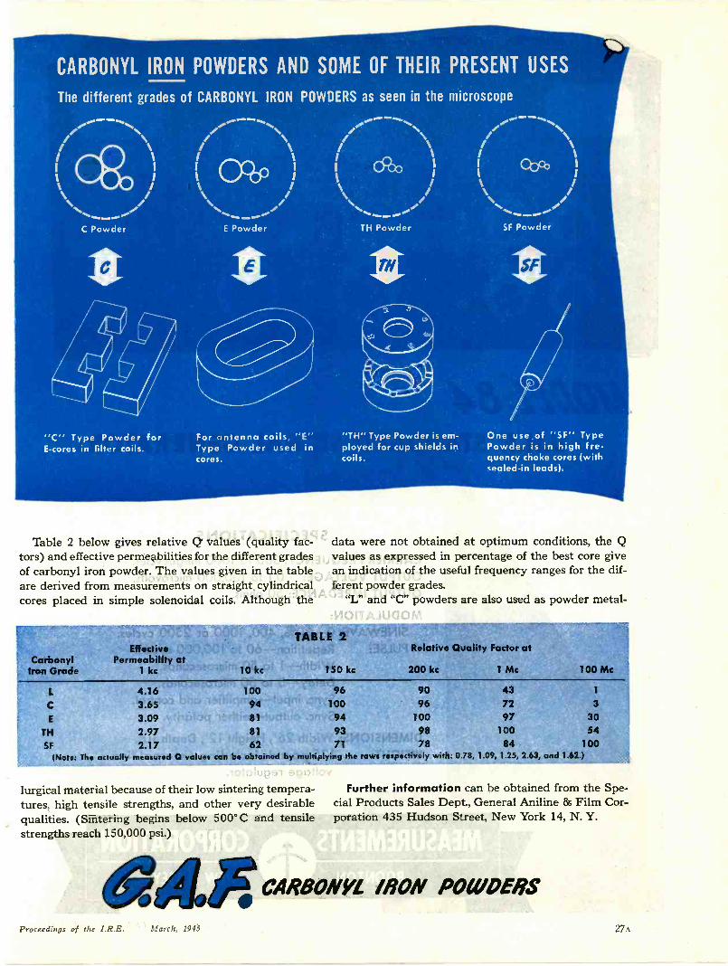
CARBONYL IRON POWDERS AND SOME OF THEIR PRESENT USES
The different grades of CARBONYL IRON POWDERS as seen in the microscope
/0**Th%
/ \i iI I
I/
C Powder
II
"C" Type Powder forE -cores in filter coils.
E Powder
II
mo.
Cbcb I
...._ ....-..../I N. I
---.....
For antenna coils, "E"Type Powder used incores.
TH Powder SF Powder
II
"TH" Type Powder is em-ployed for cup shields incoils.
One use.of "SF" TypePowder is in high fre-quency choke cores (withsealed -in leads).
Table 2 below gives relative Q values (quality fac-tors) and effective permeabilities for the different gradesof carbonyl iron powder. The values given in the tableare derived from measurements on straight cylindricalcores placed in simple solenoidal coils. Although the
data were not obtained at optimum conditions, the Qvalues as expressed in percentage of the best core givean indication of the useful frequency ranges for the dif-ferent powder grades.
"L" and "C" powders are also used as powder metal -
CarbonylIron Grade
EffedivePermeability at
1 kc 10 kc
TABLE 2'344#4'
150 kc
Relative Quality Factor at
200 kc 1 Mc 100 Mc
L
C
E
TH
SF
4.163.653.092.972.17
100 9694 100
81 94
81 93
9096
10098
437297
100
62 71 78 84
3
3054
100(Note: The actually measured Q values can be obtained by multiplying the rows respectively with: 0.78, 1.09, 1.25, 2.63, and 1.62.)
lurgical material because of their low sintering tempera-tures, high tensile strengths, and other very desirablequalities. (Sintering begins below 500° C and tensilestrengths reach 150,000 psi)
&LE
Further information can be obtained from the Spe-cial Products Sales Dept., General Aniline & Film Cor-poration 435 Hudson Street, New York 14, N. Y.
CARBONYL IRON POIIVERS
Proceedings of the I.R.E. March, 1945 27A
%.)
JI
..1
iZt
4
.4.1.111
STANDARD SIGNAL GENERATORMODEL 84 SERIAL 89
MEASUREMENTS CORPORATION8Ctit-1ON NEW JERSEY
at.10[ .11A r.fir
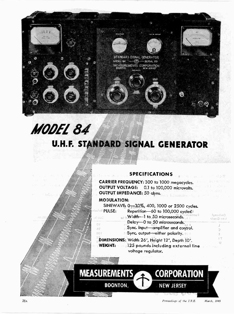
MODEL 81U.H.F. STANDARD SIGNAL GENERATOR
SPECIFICATIONS
CARRIER FREQUENCY: 300 to 1000 megacycles.OUTPUT VOLTAGE: 0.1 to 100,000 microvolts.OUTPUT IMPEDANCE: 50 ohms.
MODULATION:SINEWAVE: 0-30%, 400, 1000 or 2500 cycles.PULSE: Repetition -60 to 100,000 cycles.
Width -1 to 50 microseconds.Delay -0 to 50 microseconds.Sync. input-amplifier and control.Sync- output-either polarity.
DIMENSIONS: Width 26", Height 12", Depth 10".WEIGHT: 125 pounds including external line
voltage regulator.
28A Proceedings of the I.R.C. March, 1 c1
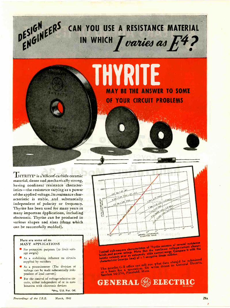
R5 CAN YOU USE A RESISTANCE MATERIAL
Off5001 IN WHICH/mg/tem alp
THYRITE* is a silicon -carbide ceramicmaterial, dense and mechanically strong,having nonlinear resistance character-istics-the resistance varying as a powerof the applied voltage. Its resistance char-acteristic is stable, and substantiallyindependent of polarity or frequency.Thyrite has been used for many years inmany important applications, includingelectronic. Thyrite can be produced invarious shapes and sizes (those whichcan be successfully molded).
Here are some of itsMANY APPLICATIONS
For protective purposes (to limit volt-age surges)
As a stabilizing influence on circuitssupplied by rectifiers
As a potentiometer (The division ofvoltage can be made substantially inde-pendent of load current)
For the control of voltage -selective cir-cuits, either independent of or in com-bination with electronic devices
'Reg. U.S. Pat. Off.
HYRITWER TO SOME
OF YOUR CIRCUIT PROBLEMS
Typical volt-amperec ara of Thyrite resistors of severs res stance
levels and powerratings. Note that the nonlinear
voltage -current charac-
teristicextends over an extremely
aide cunent range.Comport it with the
characteristic(orange
line) of 1-megohnt linter resistor.
The nearest G -E office can tell you what data should be submitte
as a basis for a quotation. Orss
write direct to General Electric.
16450, Pittsfield, Ma .
GENERA E.LECTR,,
Proceedings of the I.R.E. March, 1945 29A
5 YEARS AHEAD OF ITS TIME
1 1/4 ;IN,,, /7 '',,
r
- +4..n r.S N. _.... k , 1.-i . e.446',,,,, . MO.
VI I Qux I A< . 4k / '\1 ililb , 111* '*, 84 'S. Ii4 r- "\ /,'' / \ .
%. i. .....). i .'
4C44'- -- 4 -.... V 0N. ,,,,
1V <
27;8 to143 lacCovers old and new FM bands
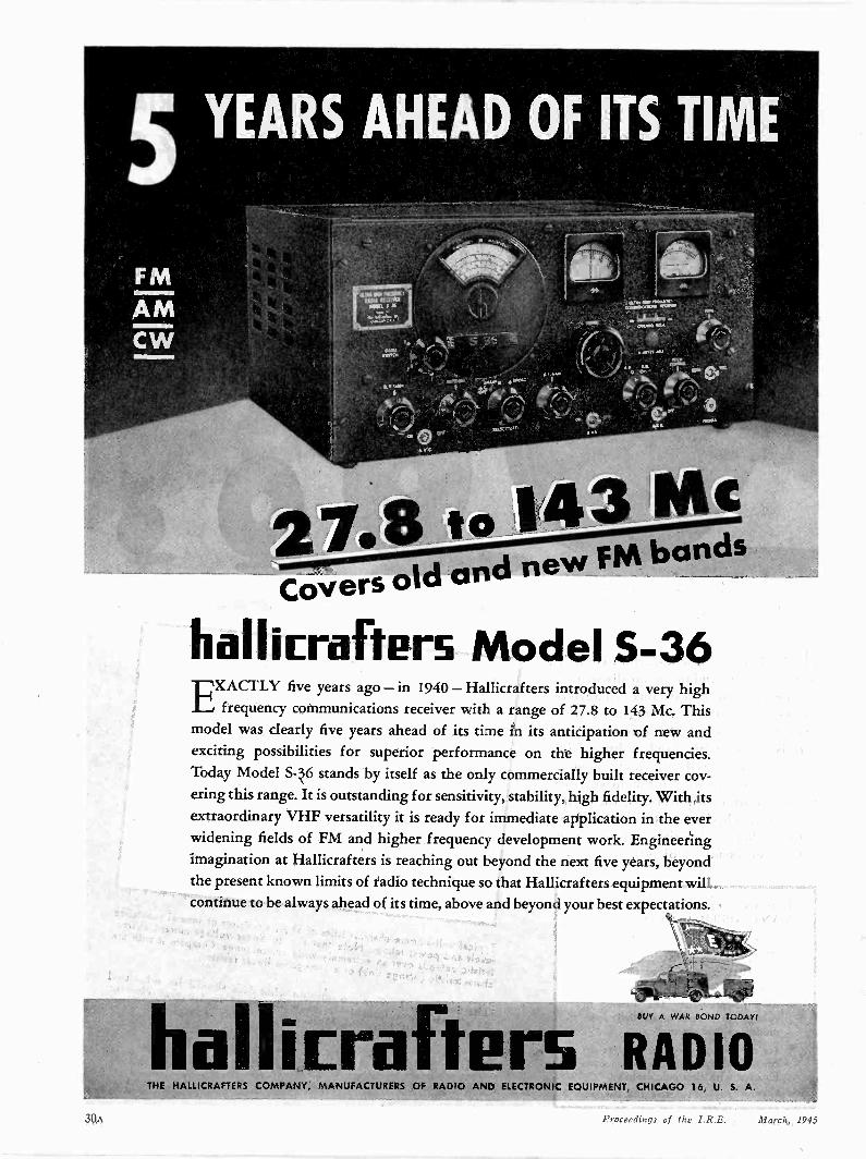
hallirafters Model 5-36EXACTLY five years ago - in 1940 - Hallicrafters introduced a very high
frequency communications receiver with a range of 27.8 to 143 Mc. Thismodel was dearly five years ahead of its time in its anticipation of new andexciting possibilities for superior performance on the higher frequencies.Today Model S-36 stands by itself as the only commercially built receiver cov-ering this range. It is outstanding for sensitivity, stability, high fidelity. With itsextraordinary VHF versatility it is ready for immediate application in the everwidening fields of FM and higher frequency development work. Engineeringimagination at Hallicrafters is reaching out beyond the next five years, beyondthe present known limits of radio technique so that Hallicrafters equipment willcontinue to be always ahead of its time, above and beyond your best expectations.
halliEra teBUY A WAR BOND TODAY!
RADIOTHE HALLICRAFTERS COMPANY, MANUFACTURERS OF RADIO AND ELECTRONIC EQUIPMENT, CHICAGO 16, U. S. A.
Proceedings of the I.R.E. March, 1945

A STATEMENT OF POLICY
TO THE EQUIPMENT MANUFACTURER
CONCERNING 94astotaezeut7ede4,
WE at Heintz and Kaufman Ltd. be-lieve that equipment manufactur-
ers, many of whom are making theirlong-range plans now, will be interestedin the policies for the standardizationand stabilization of tube types whichhave been established for Gammatrons.These policies merit considerationwhen designing equipment either formilitary or civilian use.
Practically all tubes now sold to theGovernment must conform to specifi-cations covering electrical standardsand physical dimensions.
We are heartily in favor of the Sig-nal Corps and Bureau of Ships jointstandardization of electronic compon-ent parts. The good work of the RadioManufacturers Association likewise de-serves the highest commendation. Webelieve that the Joint Army and Navy
BUY WARBONDS
Specifications for Vacuum Tubes("JAN specs") will be accepted volun-tarily by tube manufacturers as post-war commercial standards, since theyoffer many advantages to the equip-ment manufacturer.
All H & K Gammatrons when againmanufactured for commercial use willconform to the rigid physical and elec-trical specifications now required by"JAN specs."
Thus when you design equipmentaround Gammatron tubes you can besure that neither electrical nor physicalchanges in these tubes will make re-design of equipment necessary, or re-placement difficult.
We plan to tell you more about ourstandardization and development poli-cies in future advertisements. So pleasebe on the watch for them each month.
HEINTZ AND KAUFMAN LTD.SOUTH SAN FRANCISCO CALIFORNIA
famottletoo 7cele4-
Proceedings of the I.R.E. March, 1995 31A
Siinply base your designs on RCA
Preferred -Type Tubes which, in a 411
year, dropped more than 13% in Rice.
Not only have prices been lowered by the Preferted-TypeProgram but the quality of the tubes as been irupovod. dueto longer production runs and increased skill sf worIcers.
How the preferred -type idea started
,Long before 'Pearl Harbor, RCA found that despite the hundreds of differentreceiving -tube being manufactured, almost every possible circuit require-ment could be satisfied by a lisr of less than 50 tube types.
Moreover, by limiting the number of types being manufactured, it would bepossible to realize tremendous savings in warehousing, distribution, test equip-ment, and Dther factors affecting cost.
The plan was promoted amcng equipment designers who, quick to see theodvaitages of fewer tube types, cooperated wholeheartedly to make theFrs...fe-red--ype. Program a success.
When the war broke out, the Army and Navy adopted the Preferred -Typeidea and established a list of their own, including many tubes already on RCA'sP afeired-/ ype list. Military equipment was designed almost exclusively aroundArmy -Navy Preferred -Type Tubes. This forward -looking policy simplified militarytube stocks and insured speedy replacements on the fighting fronts.
hich RCA tubes are preferred types
By substantial indication of prefererce, designersthemselves - not RCA - determine which tubes arePrefer -ed Types.
Because the list of Preferred Types(rietal,miniatureand gloss) is still rather fluid, it is advisable to checkwith us before your final decisions are made regard-ing an, specific tube. Write to Depart-nent 62-28P,RCA, Harrison, N. J.
TM fountain -head of modernTubs development is RCA. RADIO CORPORATION CF AMERICA
RCA VICTCR DIVISICN CA AC EV, N. J.
32A ProceecEngs of tLe I R.E. March, 1945
The contacts between the leaders in the electronic and communication in-dustry and the engineers in this field have become increasingly close under thestress of war conditions and promise to become even closer during the postwarperiod. Accordingly the thoughts of the industrialists are of primary interestand stimulation to the engineers, and are accordingly presented in these pagesas guest editorials, in the form in which they are received. There follows such amessage from the President of P. R. Mallory and Company, Incorporated.
The Editor
The Electronics EngineerP. R. MALLORY
For more than thirty years my time, to a very large degree, has been spent in dealing with engineers-young andold alike.
For the most part these men have been identified with electronics and metallurgy and many of them have shownoutstanding creative abilities.
Among them have been exceptional men and among them, too, have been men for whom I have developed thegreatest respect as well as close bonds of friendship.
Therefore, I welcome this opportunity of briefly setting forth some of my views to the members of the I.R.E. atthis time.
If there is one thing this war has demonstrated it is the resourcefulness and basic quality of the American engineer.The phenomenal record accomplished by industry is to a major degree the result of the even more phenomenal recordof its engineers.
In every field of war equipment the engineer under intense pressure has created new devices-new answers to press-ing problems-as they have arisen as a result of war experience. The record of all industries is replete with dramaticevidence of outstanding engineering accomplishment.
Perhaps in no field have these results been so outstanding as in the field of electronics-our youngest industry,manned largely by "young engineers". These men, some of whom are veteran engineers of our radio industry andothers only recently released from technical schools, have presented a fresh and dynamic approach to the new chal-lenging problems of each day. Certainly no industry has left such an impress on so many different aspects of this globalwar-on the ground, in the air and under and on the sea.
You electronic engineers who read these words, know far better than do I the revolutionary results of these accom-plishments. Suffice it to say here that they have altered in our favor the entire complexion of this war. They havegiven our forces a superiority of performance that has a profound effect on tactics and strategy.
Is it too much to anticipate that similarly they will greatly affect our peace time lives; that they will sustain thisgreat new industry that already is an employer of hundreds of thousands of workers? I think not.
In peace, progress comes more slowly. However, modern scientific progress has accelerated the laws of change to aremarkable degree. Even before the stimulation of this war, changes were being effected ina few years which formerlywould have required a generation.
In electronics we may look forward to a period of intense development and orderly and substantial accomplish-ments, affecting all phases of industry, transcending anything we can now visualize. Mr. James H. McGraw, Jr.recently stated, "The future of the electronics industry is limited only by man's imagination." George S. Armstrong andCo., Inc., in a recent booklet on the electronics industry, estimated the war growth of this industry as perhaps thirteentimes its prewar volume. Of this at least a $1,000,000,000 annual volume should be retained in the postwar era.
Surely this industry presents a challenging opportunity to engineers.As a result of the war time accomplishments of our engineers I look for a new and enhanced respect for the en-
gineering profession as a decisive factor in our industrial society. All too frequently in times past the engineer has felthimself at a disadvantage compared to the commercial man in recognition of their respective contributions to industry'sgrowth. Many reasons for this discrimination may be suggested. One unquestionably is that engineersare often trainedto deal more with things than with men. This is a weakness that our engineering schools must strive to correct.
Never forget that this new recognition of engineering, won through splendid achievement, also presents its chal-lenge. Engineers to hold their position must be broad -gauged, well-rounded men who not only understand mathematicalbut human equations as well.
The future opportunity for the well-balanced electronics engineer looks to me to be brilliant indeed. Nevertheless,it is still only an opportunity. Performance will be required to lift the unusual man above his fellow engineers. Thefield is wide open. The search of management for men who can accept responsibility is just as active as ever.
March, 1945 Proceedings of the I.R.E. 141
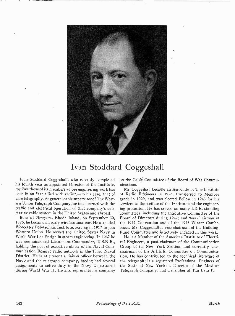
Ivan Stoddard CoggeshallIvan Stoddard Coggeshall, who recently completed
his fourth year as appointed Director of the Institute,typifies those of its members whose engineering work hasbeen in an "art allied with radio",-in his case, that ofwire telegraphy. As general cable supervisor of The West-ern Union Telegraph Company, he is concerned with thetraffic and electrical operation of that company's sub-marine cable system in the United States and abroad.
Born at Newport, Rhode Island, on September 30,1896, he became an early wireless amateur. He attendedWorcester Polytechnic Institute, leaving in 1917 to joinWestern Union. He served the United States Navy inWorld War I as Ensign in steam engineering. In 1937 hewas commissioned Lieutenant -Commander, U.S.N. R.,holding the post of executive officer of the Naval Com-munication Reserve radio network in the Third NavalDistrict. He is at present a liaison officer between theNavy and the telegraph company, having had severalassignments to active duty in the Navy Departmentduring World War II. He also represents his company
on the Cable Committee of the Board of War Commu-nications.
Mr. Coggeshall became an Associate of The Instituteof Radio Engineers in 1926, transferred to Membergrade in 1929, and was elected Fellow in 1943 for hisservices to the welfare of the Institute and the engineer-ing profession. He has served on many I.R.E. standingcommittees, including the Executive Committee of theBoard of Directors during 1942; and was chairman ofthe 1942 Convention and of the 1943 Winter Confer-ences. Mr. Coggeshall is vice-chairman of the Building -Fund Committee and is actively engaged in this work.
He is a Member of the American Institute of Electri-cal Engineers, a past -chairman of the CommunicationGroup of its New York Section, and currently vice-chairman of the A.I.E.E. Committee on Communica-tion. He has contributed to the technical literature ofthe telegraph; is a registered Professional Engineer ofthe State of New York; a Director of the MexicanTelegraph Company; and a member of Tau Beta Pi.
142 Proceedings of the I.R.E. March

Radio Progress During 1944*Introduction
AS IN 1943, the efforts of the radio industry werealmost exclusively devoted to the development,production, and application of techniques, de-
vices, and systems for the conduct of the war. Whilethe details of technical activities of necessity continuedto be shrouded in secrecy, the results of military opera-tions reflected the tremendous contribution of the radioindustry to the prosecution of the war.
The commercial radio services continued to functionon a wartime basis or were suspended for the durationof the war. In general, man power and critical materialsavailable for commercial services were reduced to thoserequired for necessary operation and maintenance.
A limited amount of research and development di-rected toward new commercial services was authorizedby the Federal Communications Commission in theUnited States but the attendant use of critical materialsand man power was secondary to wartime needs. Oneof the services of prominence in postwar planning ispoint-to-point radio relaying, utilizing frequencies in the1900 to 12,000 megacycle range.
During the year 1944, the radio industry in the UnitedStates had occasion to reconsider all existing frequencyallocations and systems standards, and also to considerfuture allocations and standards for all new radio serv-ices. The year witnessed the intensive and thoroughstudy of all phases of frequency allocation by the radioindustry through the agency of the Radio TechnicalPlanning Board, which had been formed under the jointsponsorship of the Radio Manufacturers Associationand the Institute of Radio Engineers, and which sub-stantially completed its organization during 1943. TheBoard was charged with the responsibility of studyingall technical phases of radio and formulating technicalrecommendations for pertinent system standards andfrequency allocations for the entire radio -frequencyspectrum. It had prepared reports covering a large partof its program by October, 1944.
From September 28 to November 4, 1944, the Fed-eral Communications Commission in the United Statesheld hearings of vital interest to all existing and pro-posed radio services. The purpose of the hearings wasto obtain technical data and recommendations on thesubject of frequency allocations from all interested per-sons or organizations, as a prelude not only to domesticreallocation of all radio frequencies but also to theformulation of proposals for international treaties cover-ing all radio frequencies of international interest. Duringthese hearings, the Radio Technical Planning Board re-
* Decimal classification: R090. Original manuscript received bythe Institute, January 11, 1945. This report is based on materialfrom the 1944 Annual Review Committee of The Institute of RadioEn?ineers, as co-ordinated and edited by Laurens E. Whittemore,Keith Henney, and I. S. Coggeshall.
ported its findings and recommendations to the Com-mission. The technical decisions which result from thesehearings are expected to have a considerable influenceon future radio progress in the United States.
TransmittersDuring 1944, the Standard Frequency Broadcast
Service of the United States National Bureau of Stand-ards was expanded to the following schedule:
2.5 megacycles 7 P.M. to 1 kilowatt 440 -cycle mod -9 A.M., E.W.T.
5 megacycles contin-uous
10 megacyclesuous
15 megacycles 7 A.M.
to 7 P.M., E.W.T.
ulation10 kilowatts 440- and 4000 -
cycle modulationcontin- 10 kilowatts 440- and 4000 -
cycle modulation10 kilowatts 440- and 4000 -
cycle modulation
All transmissions include a 5 -millisecond pulse at inter-vals of precisely 1 second, each consisting of five 1 -milli-second pulses. This pulse is omitted on the 59th secondof each minute. Audio -frequency transmission is inter-rupted for one minute beginning on the hour and eachfive minutes thereafter. The accuracy of all radio andaudio frequencies is better than one part in 10,000,000.Instructions for reception and utilization of this serviceare available upon request, in the Bureau's Letter Circu-lar, "Methods of using standard frequencies broadcastby radio."
(1) National Bureau of Standards, "Standard frequency broadcastservice," PROC. I.R.E., vol. 32, pp. 175-176; March, 1944.Revision of above material, PROC. I.R.E., vol. 32, pp. 493-494;August, 1944.
The probability of increased postwar application ofgrounded -grid, cathode -input amplifiers for medium orhigher frequencies is reflected in performance analysespublished in 1944. They show that, in addition to thegreater stability obtainable from the cathode -input am-plifier, compared with the grid -input type, a reductionin input noise is obtainable under prescribed conditions.
(2) M. C. Jones, "Grounded -grid radio -frequency voltage ampli-fiers," PROC. I.R.E., vol. 32, pp. 423-429; July, 1944.
(3) Milton Dishal, "Theoretical gain and signal-to-noise ratio ofthe grounded -grid amplifier at ultra -high frequencies," PROC.I.R.E., vol. 32, pp. 276-284; May, 1944.
A new station location or Z -marker antenna systemwas described which possesses marked advantages overpresently used systems. It consists of two spaced -dipolearrays, crossed at right angles to each other and excitedin quadrature time phase. The antenna is simple, sturdy,and stable under all weather conditions. The markerzone is narrower and the altitude range may be doublethat of existing equipment.
(4) J. C. Hromada, "The development of a new station location orZ -marker antenna system," PROC. I.R.E., vol. 32, pp. 454-463 ; August, 1944.
1945 Proceedings of the I.R.E. 143

144 Proceedings of the I.R.E. March
TABLE I frequency was used in a control circuit, provided withRADIO BROADCAST STATIONS FOR alma LICENSES AND CONSTRUCTION PERMITSISSUED BY THE FEDERAL COMMUNICATIONS COMMISSION WERE a safety relay to shut down the transmitter if the fre-OUTSTANDING ON DECEMBER 31, 1944
Class of Broadcast StationNumber
ofLicenses
Number ofConstruction
PermitsStandard 919 24Commercial high -frequency (frequency -modulation) 46 7Experimental high -frequency (including 1 station
operating under 'special authorization" and 2 sta-tions operating under 'temporary class 2" licenses)
5
Commercial television 6 3Experimental television 10 10International 31 5Facsimile 3Noncommercial educational S 5Developmental for frequency modulation and televi-
sion10
An increasingly large number of applications for con-struction permits for frequency -modulation broadcaststations continued to be submitted to the Federal Com-munication Commission as a result of the announcementof its policy to accept such applications for considerationwhen relaxation of wartime limitations makes it possi-ble. All existing frequency -modulation broadcast sta-tions have continued to operate, although such operation,in most cases, has been on restricted schedules. The in-terest shown in frequency modulation broadcastingduring the war years is an indication that this servicewill rapidly expand in the postwar years.
Frequency ModulationCurtailed publication of knowledge of developments
in frequency modulation is, of course, to be expected inview of the war. This was especially true during theyear 1944, in spite of the increased use of the frequency-modulation principle in materiel of war. Notwithstand-ing, there were some published contributions to the fieldrelating to equipment and circuit developments.
A paper, published in 1943 but not reported in lastyear's Review, on the history and development of fre-quency modulation, should not go unnoticed. It pointedout that the first patent using the frequency -modulationprinciple as appled to code signals was filed in 1902.At that time the system employed a spark gap insteadof the electronic tubes of the present, but the methodof modulating a carrier frequency in accordance with asignal was essentially the same. That the field has notmushroomed can be observed in the number of patentsissued to June 1, 1943, namely, 392, of which about90 per cent were concerned with frequency modulation,and about 10 per cent with phase modulation. Com-plete listings of existing frequency -modulation stations,both commercial and experimental, and of stationsplanned for the near future, were included in this paper.
(5) Raymond F. Guy, "F -M and U -H -F," Communications, vol.23, pp. 30, 32, 34-36; August, 1943.
Problems encountered in the design, development andoperation of automatic and semiautomatic studio -to-transmitter links in the range above 260 megacycleswere discussed in several papers. A feature of the trans-mitters employed in link service was drift compensation,whereby an upper harmonic of a crystal -controlled
quency-stability network did not properly correct thefrequency. Receivers designed for studio -link servicewere in general described as of fixed -frequency, crystal-
controlled, and drift -compensated. The input stagesusually employed "acorn" tubes. Antennas describedwere conventional, two horizontally polarized, colineararrays.
(6) Paul Dillion, "A 337 -Mc F -M studio -station link," Electronics,vol. 17, pp. 104-107; March, 1944.
(7) W. R. David, "F -M studio -to -transmitter links," Communica-tions, vol. 23, pp. 15-19, 89; December, 1943.
The planning of an ultra -high -frequency communica-tions system for mobile operation was considered intwo papers, one concerned with a state-wide police sys-tem and the other with a transportation system. Theplanning of a complete communications program mustinclude budget considerations, studies of methods ofcommunications, fixed- and mobile -station problems,and maintenance. The three -year -old MassachusettsState Police System was described.
The streetcars and busses in Chicago are aided insmooth operation under emergency conditions by low -
power mobile phase -modulated transmitters and re-ceivers installed in some 50 cars. Receivers designed forthis service make use of a squelch circuit, to block outnoise and make the loudspeaker inoperative exceptwhen signals are received.
(8) John A. Doremus, "Planning a U -H -F communications sys-tem," Electronics, vol. 16, pp. 96-101, 178, 180; September,1943.
(9) Beverly Dudley, "P -M communication system for Chicagosurface lines," Electronics, vol. 17, pp. 102-106, 238, 240, 242,244, 246, 248-249; January, 1944.
One of the first installations of frequency -modulationcommunication for power -line carrier work was com-pleted this past year. This system used power -line carrierfrequencies of from 50 kilocycles to 150 kilocycles, witheach carrier channel about 6 kilocycles wide. The devia-tion ratio was 1:1 for 3000 cycles, with 100 per cent mod-ulation. It was pointed out that the 3000 -cycle shift of a50 -kilocycle carrier (6 per cent) is comparable with the75 -kilocycle shift about the 4.3 -megacycle intermediatefrequency (2 per cent) as usually used in the frequency -modulation broadcast receivers.(10) "F -M Carrier telephony for 230-kv lines," Electronics, vol. 17,
pp. 106-109; December, 1944.
In line with the above -mentioned application of fre-quency modulation was its use in transoceanic facsimiletransmission. Using a frequency range of 1600 to 2000cycles for the half -tone range, it was possible to obtainpictures with finer detail and better half -tone qualitythan those obtained by using earlier methods. Fadingand multipath effects were minimized, since the use ofa subcarrier frequency appeared as the equivalent of alinear amplitude -variation system which functioned in-dependently of signal -level fluctuations. A paper wasalso published on the application of frequency modula-tion to wire -line telegraphy.
1945 Radio Progress During 1944 145
(11) W. H. Bliss, "Use of subcarrier frequency modulation in com-munication systems," PROC. I.R.E., vol. 31, pp. 419-423;August, 1943.
(12) F. B. Bramhall, "Carrier telegraph systems," Ekc. Eng.,vol. 63, pp. 283-286; August, 1944.
Circuit applications of frequency modulation wereconsidered in several papers. One of these discussed thebasic theory of a coupled -circuit frequency modulatorusing a condenser microphone to vary the reactance ofan oscillator tank circuit, to operate at 40 megacycles.The variable reactance was transferred across an air -core transformer, resulting in a frequency change of15 kilocycles. It was thought possible to secure a fre-quency shift of 80 kilocycles by this method.
The cathode -follower circuit was applied to a react-ance -tube modulator. In this circuit the necessary phaseshift to the grid of a reactance tube was obtained, sincethe output of the reactance tube was fed into a cathodefollower, and then to the oscillator which was to bemodulated.
A method for frequency -modulating a resistance -
capacitance oscillator was treated. Here a tube acted asone of the frequency -controlling elements. This circuitwas said to follow square -wave signals quite precisely;hence, it could be conveniently utilized in facsimiletransmission. Design curves for the construction of sucha modulator were given.
A synchronized oscillator used as a limiter in a re-ceiver was described. Such an oscillator stage followedthe intermediate -frequency amplifier and was syn-chronized to a subharmonic of the intermediate -fre-quency signal. This circuit resulted in improved voltagegain, adjacent -channel selectivity, and amplitude -limit-ing action. The theory of synchronized oscillators andthe advantages of such system were outlined in thepaper.(13) Elwin J. O'Brien. "A coupled -circuit frequency modulator,
PROC. I.R.E., vol. 32, pp. 348-350; June, 1944.(14) F. Butler, "Reactance -valve frequency modulator," Wireless
Eng., vol. 20, p. 539; November, 1943.(15) Maurice Artzt, "Frequency modulation of resistance -capaci-
tance oscillators," PRoc. I.R.E., vol. 32, pp. 409-414; July,1944.
(16) C. W. Carnahan and H. P. Kalmus, "Synchronized oscillatorsas F -M receiver limiters," Electronics, vol. 17, pp. 108-111,332, 334, 336, 338, 340, 342; August, 1944.
A phonograph pickup was described in which theneedle itself formed part of a capacitor connected acrossthe tank circuit of a conventional high -frequency oscilla-tor. The "needle weight" could be reduced to to 1ounce. Because of the construction of the pickup andthe motion of the needle, there was automatic volumeexpansion, the amount of which could be regulated bythe angle of the needle. The oscillator itself was mountedin the tone arm or pickup arm. Radiation took placefrom the oscillator tank circuit, the signal being pickedup by a conventional frequency -modulation receivertuned to some frequency not commercially used.(17) B. F. Miessner, "Frequency -modulation phonograph pickup,"
Electronics, vol. 17, pp. 132-133; November, 1944.
No review of frequency modulation would, of course,be complete without the mention of the work done by
Panel 5 of the Radio Technical Planning Board. Oneof the most important of their reports dealt with fre-quency standards of frequency allocation in the postwarworld. Among its recommendations, the Panel proposedthat: (1) frequency modulation is best suited for very -
high -frequency broadcasting; (2) the frequency -modu-lation broadcast band should be from 41 to 56 mega-cycles including 75 channels; (3) each broadcast channelshould have a width of 200 kilocycles, allowing 75 kilo-cycles as maximum frequency swing, with a 15 -kilocyclemaximum audio -frequency band width; and (4) hori-zontal polarization should be employed for antenna ra-diation.
(18) Radio Technical Planning Board, Panel 6, "Report on stand-ards and frequency allocations for postwar F -M broadcasting,"RTPB; June 1, 1944.
(19) "RTPB on F -M," Electronics, vol. 17, p. 125; November, 1944.(20) "A report on the FCC frequency allocation hearing," Elec-
tronics, vol. 17, pp. 92-97; December, 1944.
The following additional papers have appeared relat-ing to frequency modulation:
(21) G. Cudell, "Experiments with amplitude and frequency modu-lation," Hochfrequenz. and Elektroakustik, vol. 59, pp. 66-70;March, 1942.
(22) B. Dudley, "Postwar FM and television," Electronics, vol. 16,pp. 94-97, 190-191; November, 1943.
(23) K. R. Sturley, "The phase discriminator. Its use as frequencyconvertor for FM reception," Wireless Eng., vol. 21, pp. 72-78;February, 1944.
(24) W. Stliblein, "Measurement of the characteristics of fre-quency -modulation oscillations," Elek. Nach. Tech., vol. 20,No. 4, pp. 102-111; 1943; Bull. Ass. Suisse Elec., vol. 35, pp.100-102; February 23, 1944.
(25) A. D. Mayo, Jr. and C. W. Sumner, "FM distortion in moun-tainous terrain," QST, vol. 28, pp. 34-36; March, 1944.
(26) F. M. Colebrook, "A note on frequency modulation with par-ticular reference to standard -signal generators," Wireless Eng.,vol. 21, pp. 112-115; March, 1944.
(27) D. A. Bell, "Transient response in frequency modulation,"Phil. Mag., vol. 35, pp. 143-158; March, 1944.
(28) A: Block, "Modulation theory," Jour. I.E.E. (London), vol. 91,part 3, 1-42; March, 1944.
(29) R. A. Gordon,G` "German VHF command set," Electronics,vol. 17, pp. 132-134, 300; April, 1944.
(30) S. Helt, "F -M and A -M transmitter analysis," Communica-tions, vol. 24, pp. 36, 85-88; July, 1944.
Radio ReceiversRadio engineers and manufacturers who, before the
war, were concerned solely with broadcast receivers,have been engaged in the development and manufactureof all types of electronic equipment, in all frequencyranges, for the armed forces. These equipments are ofsturdy mechanical design and have components of pre-dominantly high quality. A great deal of attention hasbeen 'given to the conversion and utilization of criticalmaterials, to life tests, and to the protection of compo-nents from humidity, high and low temperatures,fungus, and rough handling.
(31) R. Proskauer, "Fungus -proofing procedure," Electronics, vol.17, pp. 92-93 and 224, 229, 232; June, 1944.
(32) C. W. Martel and J. W. Greer, "Joint Army -Navy tubestandardization program," PROC. I.R.E., vol. 32, pp. 430-434;July, 1944.
Articles in the technical literature on receivers havereported some work which was largely under.way beforethe war. Among the papers on ultra -high -frequencytechnique applicable to receivers, are the following:
146 Proceedings of the I.R.E. March
(33) E. W. Herold, "The operation of frequency converters andmixers for superheterodyne reception," PROC. I.R.E., vol. 30,pp. 84-103; February, 1942.
(34) B. Dudley, "U.H.F. technique, Part III, U.H.F. reception andreceivers," Electronics, vol. 15, pp. 51-55; April, 1942. (Hasextensive bibliography.)
(35) E. W. Herold and L. Malter, "Some aspects of radio receptionat ultra -high frequency," PROC. I.R.E., vol. 31, Part I, pp. 423-438; August, 1943; Part II, pp. 491-500; September, 1943;Part III, pp. 501-510; September, 1943; Part IV, pp. 567-575;October, 1943; Part V, pp. 575-582; October, 1943.
Grounded -grid amplifiers for ultra -high -frequencypostwar receivers are among the possibilities.
(36) M. C. Jones, "Grounded -grid radio -frequency voltage ampli-fiers," PROC. I.R.E., vol. 32, pp. 423-429; July, 1944.
The superregenerative receiver has had renewed at-tention, including possible application to frequenCy-modulation receivers.
(37) H. P. Kalmus, "Some notes on superregeneration with particu-lar emphasis on its possibilities for frequency modulation,"PROC. I.R.E., vol. 32, pp. 591-600; October, 1944.
Considerable attention has been paid to input sys-tems of receivers, including transmission lines, waveguides, and antennas, and also the noise voltages inthese systems.
(38) R. King and C. W. Harrison, Jr., "The receiving antenna,"PROC. I.R.E., vol. 32, pp. 18-34; January, 1944.
(39) C. W. Harrison, Jr., and R. King, The receiving antenna in aplane -polarized field of arbitrary orientation," PROC. I.R.E.,vol. 32, pp. 35-49; January, 1944.
(40) H. T. Friis, "Noise figures of radio receivers," PRoc. I.R.E.,vol. 32, pp. 419-422; July, 1944.
(41) C. W. Frick and S. W. Zimmerman, "Radio -noise filters ap-plied to aircraft," Trans. A.I.E.E. (Elec. Eng., September,1943), vol. 62, pp. 590-595; September, 1943.
(42) Fred Foulon, "Radio noise elimination in all -metal aircraft,"Trans. A.I.E.E. (Elec. Eng.), vol. 62, pp. 877-891; 1943 (Sup-plement).
(43) G. Weinstein, H. H. Howell, G. P. Lowe, and B. J. Winter,"Radio -noise elimination in military aircraft," Trans. A.I.E.E.(Elec. Eng., November, 1944), vol. 63, pp. 793-795; November,1944.T. B. Owen, "Very -high -frequency radio -noise elimination,"Trans. A.I.E.E. (Elec. Eng., December, 1944), vol. 63, pp. 949-954; December, 1944.
Increase in the use of home receivers for frequency -modulated waves appears to be a major trend for thepostwar period, although the exact frequency range inwhich expanded operation will take place is yet to bedetermined.
(45) J. E. Brown, "Frequency -modulation -and its postwar future,"Electronics, vol. 17, pp. 94-99, 262; June, 1944.
Developments for receivers for frequency -modulatedwaves, which may be disclosed, include synchronizedoscillators for eliminating amplitude modulation.
(46) G. L. Beers, "RCA super -F -M uses locked -in oscillator," Elec-tronic Ind., vol. 3, pp. 76-78, 228, 230, 232, 234, 236; Novem-ber, 1944; PROC. I.R.E., vol. 32, pp. 730-737; December, 1944.
The demand for special receivers and communicationssystems for amplitude -modulated, frequency -modu-lated, and phase -modulated waves, applicable to rail-roads, busses, taxicabs, forest service, and other mobileand point-to-point applications, has increased.
(47) H. K. Lawson and L. M. Belleville, "Mobile 30-40 Mc receiverfor the U. S. Forest Service," Electronics, vol. 15, pp. 22-25,98-99; January, 1942.
(48) W. S. Halstead, "Electronic communication for trains," Elec-tronics, vol. 17, pp. 102-107, 262, 264, 266, 268, 270, 272, 274;August, 1944.
(44)
(49) L. 0. Grondahl and P. N. Bossart, "Train communication,"Trans. A.I.E.E. (Elec. Eng., July, 1943), vol. 62, pp. 493-500;July, 1943.
A great deal of work on standardization for postwarreceivers has been done in the panel meetings of theradio Technical Planning Board.
(50) W. R. G. Baker, "Planning tomorrow's electronic highways,"Gen. Elec. Rev., vol. 47, pp. 15-21; June, 1944.
ElectronicsAdvanced Developments
The advent of war greatly stimulated interest in cer-tain aspects of electronics. A need for standardizationsoon became apparent, but the limitations imposed bymilitary security made it impossible to care for this needthrough the usual I.R.E. committees. In 1943, a specialsubcommittee of the Electronics Committee, called theSubcommittee on Advanced Developments, was formedwith membership restricted to men engaged in develop-ments related to the needs of the Armed Forces of theUnited States. Approvals were obtained for the person-nel and objectives of the Committee from the propersecurity officers of the United States Army and Navyand from the Vacuum -Tube Development Committeeof the National Defense Research Committee. The Sub-committee on Advanced Developments was actively atwork during 1944. While the results of its deliberationsmust remain unrevealed until security restrictions havebeen lifted, it can be stated that considerable progresswas made toward the standardization of definitions,symbols, and test methods in the ultra -high -frequencyelectronic field.
Large High -Vacuum TubesInteresting descriptions of several developmental
tubes for use in the upper ultra -high -frequency band arefound in the 1944 literature, exclusively in translationfrom or in reference to foreign language literature. Onesuch tube is a magnetron of a special design suitable forgenerating power of several hundred watts in the deci-meter- and centimeter -wave band. Another tube is ametal triode for operation in the same frequency band,having a flat circular structure of electrodes very closelyspaced and each constituting an integral part of thegrid -anode or the grid -cathode transmission line. Thethird design is called "Resotank" and uses cavity resona-tors instead of Lecher transmission lines, tube electrodesalso being integral parts of the cavity resonators.
(51) N. F. Alekseev and D. D. Malairoff, "Generation of high -power oscillations with magnetrons in the centimeter band,"PROC. I.R.E., vol. 32, pp. 136-139; March, 1944.
(52) N. D. Deviatkov, M. D. Gurevich, and N. K. Khokhlov, "Ametal triode for ultra -high -frequency operation," PROC.I.R.E., vol. 32, pp. 253-256; May, 1944.
(53) W. Dallenbach, "On the first model type HB 14 of a 'Reso-tank,'" (Cavity resonator valve for a fixed wavelength of 14centimeters), Hochfrequenz. and .Elektroakustik, vol. 61, pp.161-163; June, 1943. Abstract: 1472reless Eng., vol. 21, pp. 84-85;February, 1944.
Continuation of the strong trend toward improve-ment and development of high -frequency high -power

1945 Radio Progress During 1944 147
tubes for industrial heating of metal products was ob-served. At the present time, the high -frequency powerused in industrial projects in the United States exceedsby far the total high -frequency power used in broadcasttransmitters.
Power tubes capable of operating in the megacycleband up to several hundred megacycles with outputpower up to several kilowatts have been designed, andnew tubes have been developed for uses in many impor-tant processes of heating dielectrics, such as plywood,rubber, plastics, etc., for bonding together, drying, ormolding them.
In the field of broadcasting with both amplitudemodulation and frequency modulation, there was atrend toward replacing water cooling by forced -air cool-ing on large tubes with external anodes.
In the ultra -high -frequency radio communicationfield, there was a tendency toward designing tetrodes,with outputs up to several kilowatts, which could beoperated without neutralization up to 100 megacyclesand which required extremely low driving power. Also,pentodes up to 350 watts with high "figures of merit"were developed for telephone communications systemsusing carrier -on -cable and carrier -over -coaxial lines. Inaddition 50- to 350 -watt triodes and pentodes werebuilt for ultra -high -frequency operation in multiplexradio communication systems, in which extremely highfidelity is of prime importance for prevention of inter -
modulation.(54) S. B. Ingram, "Recent electronic -tube developments in tele-
phone systems," presented the National Electronics Confer-ence, Chicago, Ill., October, 1944.
Considerable important work was done in improvingand developing materials and processes for buildinghigh -power tubes, especially their grids, with a view toreducing primary and also secondary emission under themost strenuous operating conditions.
Extensive study and experimenting were carried ontoward improvement of emission, from and increasinglife of oxide -coated and thoriated-tungsten cathodes.
Small High -Vacuum Tubes
There was no material change in tube requirementsduring the year 1944. There was a trend to 28 -volt plateand screen -grid operation in equipment with batterieswith regulated supplies of this voltage. The RadioManufacturers Association type 6AJ5 was introducedas a radio -frequency pentode particularly for this opera-tion in addition to the previously announced 28D7output tube. In addition, 28 -volt ratings were estab-lished on several existing tube types.
(55) W. R. Jones, "28 -volt operation of_ radio tubes," presented,Rochester Fall Meeting, Rochester, N. Y., November 8,1943.(Sylvania News, vol. 10, November, 1943.)
(56) "High D -C voltages from a low -voltage oscillator," Radio, vol.28, pp. 31-33; March, 1944.
(57) C. R. Hammond, E. Kohler, and W. J. Lattin, "28 -volt opera-tion of receiving tubes," Electronics, vol. 17, pp. 116-119, 379;August, 1944.
Articles describing new tubes have begun to appear.
High-transconductance tubes with flat cathodes and flatgrids were described. An electronic tube which com-mutates by magnetic beam deflection was also described.
(58) "'Lighthouse' tube," Science News Letters, vol. 46, p. 115;August 19,1944.
(59) E. F. Peterson and E. D. McArthur, "The lighthouse tube;pioneer ultra -high -frequency development," presented, Na-
. tional Electronics Conference, Chicago, Ill., October, 1944.(60) A. M. Skellet, "The magnetically -focused radial beam vacuum
tube," Bell Sys. Tech. Jour., vol. 23, pp. 190-202; April, 1944.
An analysis of the advantages of grounded -grid opera-tion of amplifier tubes was published. Tubes with shield-ing especially arranged for such operation have beenannounced as the Radio Manufacturers Associationtypes 708A and 6J4.
(61) Milton Dishal, "Theoretical gain and signal-to-noise ratio ofthe grounded -grid amplifier at ultra -high frequencies," PRoc.I.R.E., vol. 32, pp. 276-284; May, 1944.
A fundamental contribution on vacuum -tube -networktheory at high frequencies was published. Two articleswere published giving new formulas on vacuum -tubedesign which should be more useful for the design ofgrids for closely spaced tubes than previously existingformulas.
(62) F. B. Llewellyn and L. C. Peterson, "Vacuum -tube networks,"PROC. I.R.E., vol. 32, pp. 144-166; March, 1944.
(63) H. Herne, "Valve amplification factor," Wireless Eng., vol. 21,pp. 59-64; February, 1944.
(64) F. W. Gundlach, "Calculation of grid control in electronicvalves by means of an equivalent representation," Arch. furElektrotech., vol. 37, pp. 463-477; October 31,1943. (Abstract:Wireless Eng., vol. 21, p. 294; June, 1944.)
Cathode -Ray Tubes and Television Tubes
During the year 1944, a few new types of cathode-raytubes were developed. Improvements were made in thepeliormance, and production volume was increased formost of the tube types previously standardized. TheCathode -Ray -Tube Committee of the Radio Manufac-turers Association in the United States continued itsactivity in industry coordination of standardization oftest methods and recommendation for specifications tothe Government.
The major improvements in cathode-ray tubes weresharper focus, higher light output, and higher deflectionsensitivity. A number of important papers were pub-lished on electron -beam deflection, electron optics,improved electron microscopes, extended application ofelectron microscopes in varied fields of research wherethe high -resolution capabilities of this instrument pro-vides important new information; also on new phosphorsfor cathode-ray tubes, improved oscilloscopes extendingthe field of application of cathode-ray tubes, and the useof reflection optics with cathode-ray tubes to providelarger and brighter television pictures. A comprehensivepaper on negative ions in cathode-ray tubes was pub-lished in Europe in the latter part of 1943.
(65) J. H. 0. Harries, "Deflected electron beams," Wireless Eng.,pp. 267-277; June, 1944.
(66) J. R. Pierce, "Limiting stable current in electron beams in thepresence of ions," Jour. Appl. Phys., vol. 15, pp. 721-726;October, 1944.
(67) Kurt Schlesinger, "A mechanical theory of electron -image for-mation," PROC. I.R.E., vol. 32, pp. 483-493; August, 1944.
148 Proceedings of the I.R.E. March
(68) H. W. Leverenz, "Phosphors versus the periodic system of theelements," PROC. I.R.E., vol. 32, pp. 256-263; May, 1944.
(69) L. Marton and R. G. E. Hutter, "Optical constants of a mag-netic -type electron microscope, " PRoc. I.R.E., vol. 32, pp.546-552; September, 1944.
(70) R. C. Williams and R. W. G. Wyckoff, "The thickness of elec-tron microscopic object," Jour. Appl. Phys., vol. 15, pp. 712-716; October, 1944.
(71) V. K. Zworykin and J. Hillier, "A compact high resolvingpower electron microscope," Jour. Appl. Phys., vol. 14, pp.658-673; December, 1943.
(72) L. Marton and R. G. E. Hutter, "The transmission type ofelectron microscope and its optics," PROC. I.R.E., vol. 32, pp.3-12; January, 1944.
(73) Rudolph Feldt, "Photographing patterns on cathode-raytubes, Electronics, vol. 17, pp. 130-137, 262, 264, 266;February, 1944.
(74) C. S. Barrett, "The electron microscope in metallurgical re-search," Jour. Appl. Phys., vol. 15, pp. 691-696; October, 1944.
(75) E. H. Bartelink, "Wide band oscilloscope," Electronics, vol. 17,pp. 122-125; February, 1944.
(76) H. Atwood, Jr. and R. P. Owen, "Oscilloscope for pulse stud-ies," Electronics, vol. 17, pp. 110-114; December, 1944.
(77) I. G. Maloff and D. W. Epstein, "Reflective optics in projec-tion television," Electronics, vol. 17, pp. 98-105; December,1944.
(78) H. Schaefer and W. Walther, "Negative ions in cathode-raytubes and their relation to the mechanism of emission fromoxide -coated cathodes," Zeit. fur Phys., vol. 121, pp. 679-701;October 1, 1943.
Phototubes
During the past year there was little published in thefield of phototubes which would indicate any majorwork devoted to the study of basic photoelectric effects.A few papers appeared continuing previous work on acaesium -antimony -type photosurface. There was con-siderable interest shown in the application of phototubes,particularly the electron multiplier, to scientific instru-ments such as the spectrograph where it would appearthat phototubes may become a competitor of the photo-graphic plate. Considerable effort has been devoted tothe co-ordination of the various types of phototubesmanufactured by the several companies. A method .ofdefining the response of phototubes in terms of thespectral characteristics was established in which severaldifferent classes of spectral surfaces have been defined.
(79) M. F. Hasler and H. W. Dietert, "Direct reading instrumentfor spectro-chemical analysis," Jour. Opt. Soc. Amer., vol. 33,p. 687; December, 1943. (Abstract)
(80) E. A. Boettner and G. P. Brewington, "The application ofmultiplier phototubes to quantitive spectrochemical analysis,"Jour. Opt. Soc. Amer., pp. 6-11; January, 1944.
(81) R. J. Pfister, "Spectrophotometric experiments with an ultra-violet multiplier photo -tube," Jour. Opt. Soc. Amer., vol. 33,p. 689; December, 1943. (Abstract)
(82) "Photoelectric timer controls X-ray film exposure," Elec-tronics, vol. 16, pp. 178, 180, 182, 184, 186; July, 1943.
Gas -Filled Tubes
The following significant papers relating to gas -filledtubes were published during the year 1944:(83) H. C. Steiner, J. L. Zehner, and H. E. Zuvers, "Pentode
ignitron for electronic power converters," Trans. A .I.E.E.(Ekc. Eng., October, 1944), vol. 63, pp. 693-697; October,1944.
(84) E. F. W. Alexanderson and E. L. Phillipi, "History and de-velopment of electronic power converter," Trans. A .I.E.E.(Ekc. Eng., September, 1944), vol. 63, pp. 654-657; Septem-ber, 1944.
(85) H. L. Kellogg, C. C. Herskind, "The testing of mercury -arcrectifiers," Trans. A.I.E.E. (Ekc. Eng., December, 1943), vol.62, pp. 765-773; December, 1943.
(86) C. C. Herskind, "Rectifier circuit duty," Trans. A.I.E.E.(Elec. Eng., March, 1944), vol. 63, pp. 123-128; March, 1944.
(87) E. F. Christensen and M. M. Morack, "Operation of rectifiersunder unbalanced conditions," Trans. A.I.E.E. (Ekc. Eng.,September, 1944), vol. 63, pp. 628-631; September, 1944.
(88) H. L. Palmer and H. H. Leigh, "Inverter action on reversingof thyratron motor control," Trans. A.I.E.E. (Elec. Eng.,April, 1944), vol. 63, pp. 175-184; April, 1944.
(89) P. T. Chinn and E. E. Moyer, "A graphical analysis of thevoltage and current wave forms of controlled rectifier circuits,"Trans. A.I.E.E. (Ekc. Eng., July, 1944), vol. 63, pp. 501-508;July, 1944.
(90) W. C. White, "Mercury arc rectifier, brief early history," Gen.Ekc. Rev., pp. 9-13; June, 1944.
TelevisionAs a result of the continued requirements of the
Armed Forces for engineering and technical personnel,and for radio equipment, television activity remainedat a relatively low level during 1944. All televisionbroadcasters who were active in 1943 continued to pro-vide limited program service during 1944; in some in-stances considerable increases in power output and otherimprovements in equipment were made. As in the pre-ceding year, no new home television receivers weremanufactured.
Published results of technical investigations in tele-vision during the year 1944 were very few. They in-cluded a study of field reception of the three televisiontransmitters in the New York area with special emphasison the multipath phenomena. There was also a shortdescription of a new color -television cathode-ray picturetube in which either two or three separate color phos-phors are excited by individual electron beams. Certainstudies in wide -band amplifiers were also published.Finally, there was considerable interest in the use ofSchmidt optical systems for projection television. Thesesystems use a thin aspherical lens to correct the aberra-tion of a large spherical mirror; and in recent applica-tions, the correcting lenses have been of moulded plastic.
(91) A. B. Dumont and T. T. Goldsmith, Jr., "Television broadcastcoverage," PRoc. I.R.E., vol. 32, pp. 192-205; April, 1944.
(92) "Baird telechrome," Wireless World, vol. 50, pp. 316-317;October, 1944.
(93) "Electronic colour television," Electronic Eng., vol. 17, pp. 140-141; September, 1944.
(94) W. R. MacLean, "Ultimate bandwidths in high -gain, multi-stage video amplifiers," PROC. I.R.E., vol. 32, pp. 12-15;January, 1944.
(95) A. B. Bereskin, "Improved high -frequency compensation forwide -band amplifiers," PROC. I.R.E., vol. 32, pp. 608-611;October, 1944.
(96) D. Weighton, "Performance of coupled and staggered circuitsin wide -band amplifiers," Wireless Eng., vol. 21, pp. 468-477;October, 1944.
(97) I. G. Maloff and D. W. Epstein, "Reflective optics in projec-tion television," Electronics, vol. 17, pp. 98-105; December,1944.
A television relay station was opened at Mount Rose,New Jersey, providing a high -frequency line -of -sightroute between New York and Philadelphia over whichtelevision programs originating in New York were trans-mitted to a television station in Philadelphia from whichthey were rebroadcast. -
Demonstrations were made of a flat -faced cathode-ray tube for television receivers having the followingcharacteristics: (1) a plane surface to minimize reflec-tions from stray light, (2) substantially increased usefularea as compared with the size of the tube, (3) improved

1945 Radio Progress During 1944 149
contrast as the result of limitation on the effect of straylight from the phosphor on the unlighted portions of thephosphor, and (4) a trap for filtering out the negativeions which are destructive to cathode-ray screens.
Probably the most important technical work in tele-vision during the year was that involved in the activityof the Radio Technical Planning Board. One of thePanels of the Board was charged with the responsibilityof making recommendations with respect to both stand-ards and frequency allocations for postwar television.In order to discharge this responsibility adequately, alarge number of engineers and scientists from all partsof industry, as well as from various government researchorganizations, took part in the deliberations of thePanels.
The first major question facing the Panel was whetherto recommend that commercial television should be re-leased immediately after the war, which would requirethat it go ahead on substantially the present allocatedchannels, or to recommend that the existing televisionsystem should be scrapped in favor of new standards tobe utilized in a higher portion of the radio -frequencyspectrum. After considerable deliberation, it was decidedto recommend that immediate commercialization oftelevision should be encouraged on substantially thepresent channels and that some higher -frequency chan-nels should be set aside for research and developmentand eventual commercialization, if and when standardscould be adopted.
The Panel then reviewed the existing standards witha view to arriving at a single consistent system whichwould allow the maximum freedom of receiver design,and which would assure that the standards would beworkable on all channels set aside for commercial opera-tion. Various alternative standards were deleted andsome minor changes were made so as to provide a singleconsistent set of standards for all transmitters. ThePanel also proposed standards and frequency assign-ments for relay and network operations. The Panelrecommended the use, for commercial operation, of aset of channels between 50 and approximately 300 mega-cycles. The recommendations of the Panel with respectto frequency allocations were then reviewed by theFrequency Allocation Panel of the Radio TechnicalPlanning Board, which found it necessary to cut thefrequency range of commercial channels to approxi-mately 60 to 220 megacycles, and which suggested thepossibility of geographical channel sharing between tele-vision and other services. The recommendations werepresented to the Federal Communications Commissionat the frequency allocation hearings held from Septem-ber to November, 1944, referred to above.
The Television Broadcasters Association, organized inthe United States early in the year, held its First AnnualConference in New York, in December, 1944. The con-ference sessions brought together many persons con-tributing to the technical, manufacturing, programming,and commercial aspects of television. Awards were made
in recognition of technical contributions to this field.The following additional papers relating to television
appeared during the year:(98) D. L. Shapiro, "The graphical design of cathode -output ampli-
fiers," PROC. I.R.E., vol. 32, pp. 263-268; May, 1944.M. Dishal, "Theoretical gain and signal-to-noise ratio of thegrounded -grid amplifier at ultra -high frequencies," PROC.I.R.E., vol. 32, pp. 276-284; May, 1944.
(100) I. G. Maloff, 'Electron bombardment in television tubes,"Electronics, vol. 17, pp. 108-111, 327-331; January, 1944.
(101) E. H. Bartelink, "Wide -band oscilloscope," Electronics, vol. 17,pp. 122-125; February, 1944.
(102) R. W. Crane, "Influence of feedback on source impedance,"Electronics, vol. 17, pp. 122-123; September, 1944.
(103) "Technical plan for post-war television," Electronics, vol. 17,pp. 92-97, 164, 168, 172; August, 1944.
(104) H. A. Cook and H. Moss, "Visual alignment of wide -band I -Famplifiers," Electronics, vol. 17, pp. 130-133; October, 1944.
(105) G. Parr, "Review of progress in colour television," Jour. Telev.Soc., vol. 3, no. 10, pp. 251-256.
(106) P. Nagy, "Some observations relating to reports of colour tele-vision in America," Jour. Telev. Soc., vol. 3, no. 10, pp. 257-261.
(107) B. J. Edwards, "A survey of the problems of post war televi-sion," Jour. Telev. Soc., vol. 4, no. 1, pp. 10-12.
(108) P. Nagy, "The signal converter and its application to televi-sion," Telev. Soc., vol. 4, no. 2, pp. 26-35, discussion, pp.35-36, 47-48.
(109) L. H. Bedford, "Picture definition," Jour. Telev. Soc., vol. 4,No. 2, pp. 37-40.
(110) "Television without scanning" (Description of the Craig sys-tem of television), Jour. Telev. Soc., vol. 4, no. 2, pp. 46-47.
(111) "Standards for television," Wireless World, vol. 50, p. 1; Janu-ary, 1944.
(112) R. W. Hallows, "Television survey, "Wireless World, vol. 50,pp. 166-169; June, 1944.
(113) K. I. Jones and D. A. Bell, "U.H.F. and post-war broadcast-ing," Electronic Eng., vol. 16, pp. 320-323; January, 1944.
(114) N. Hendry, "Photography of cathode ray tube traces," Elec-tronic Eng., vol. 16, pp. 324-326; January, 1944.
(115) J. M. A. Lenihan, "Pulse generation," Electronic Eng., vol. 16,pp. 408-411; March, 1944.
(116) W. Muller, "Using cathode coupling," Electronic Ind., vol. 3,pp. 106-107, 196; August, 1944.
(117) W. A. Stewart, "High speed time bases," Electronic Ind., vol. 3,pp. 112-113, 176, 178, 180, 182, 184; August, 1944.
(118) W. E. Moulic, "Simplified pulse generator," Electronic Ind.,vol. 3, pp. 84-85, 224; September, 1944.
(119) W. Cooper, "Television production as viewed by a motionpicture producer," Jour. Soc. Mot. Pic. Eng., vol. 43, pp. 73-79;August, 1944.
(120) W. C. Miner, "Television production as viewed by a radiobroadcaster," Jour. Soc. Mot. Pic. Eng., vol. 43, pp. 79-85;August, 1944.
(121) R. E. Farnham, "Appraisal of illuminants for television studiolighting," Jour. Soc. Mot. Pic. Eng., vol. 43, p. 378; disc., pp.85-92; November, 1944.
(99)
FacsimileThe volume of radiophoto traffic increased greatly
during 1944, as was well evidenced by the large numberof pictures carried in the newspapers. These were re-ceived from all parts of the world over both governmentand commercial systems. The quantity of terminalequipment and operating facilities required for thisexpansion occupied the attention of both manufacturingand service companies, and consequently there was alimit to the amount of effort available for new develop-ments. Nevertheless, there was a trend toward fasterspeed of transmission, as reflected by the success beingobtained with 100 revolution -per -minute drum speedson long-distance radio circuits. In general, this resultedfrom better modulation techniques;' still further im-provement may be expected in this direction.
150 Proceedings of the I.R.E. March
The wirephoto companies maintained their nationalpicture service for newspaper use. Also, the handling ofmessages by facsimile increased. Special telefacsimilecircuits were set up between Oakland and San Fran-cisco, and between Washington and New York, andequipment was furnished to the Signal Corps for useabroad. A considerable growth in this class of facsimileoperation is expected in the postwar period.
The Armed Forces, in addition to their operation ofradiophoto services, extended the other uses of bothpage and tape facsimile. In page operation, conventionaldirect -recording papers have been substituted for photo-graphic methods where speed of handling was of pri-mary importance, and where black -and -white record-ing was adequate. The Army Air Forces Weather Wingoperated several facsimile wire networks for the dis-semination of weather maps to Air Transport Commanddeparture points. Weather maps were transmitted froma central control point every four hours to the satelliteswithin the network. Duplicate copies of the facsimilemap received at a satellite were made, so that a copycould be given to the pilot just prior to his departure.Tape facsimile was used chiefly in radio communicationwith military vehicles; it was used to a less extent as asubstitute for printing telegraphs where only low-graderadio circuits are available.
In the laboratories there was an increased interest inelectrolytic recording, and several machines were builtwhich promise practical recording speeds many timesfaster than those now in use. The possibilities have beenrecognized for several purposes-poslice radio, for ex-ample-and postwar plans are being made in whichspecial transmission circuits are proposed, such as radiorelays, to accommodate the wide modulation band whichwill be required. Facsimile techniques were applied inseveral cases to the recording of data other than actualfacsimile signals.
The co-operative work forming one of the Panels ofthe Radio Technical Planning Board dealt With thechannel requirements of the various services and madea start toward standardizing the operating parametersof the terminal equipments and the modulation methods.(122) C. H. Hatch, "Radiophoto; pictures from foreign fronts are
now seen in newspapers on the same day as shot," Radio News,vol. 31, p. 218; February, 1944.
(123) F. W. Reichelderfer, "Weather maps for radio broadcast,"Radio News, vol. 31, pp. 21-23; April, 1944.
(124) M. Artzt, "Frequency modulation of resistance -capacitanceoscillators," PROC. I.R.E., vol. 32, pp. 409-414; July, 1944.
(125) F. C. Collings and C. J. Young, "RCA facsimile equipment,"FM and Television, vol. 4, pp. 18-22 and 75; July, 1944.
(126) "Orders by air," Business Week, p. 32; August 26,1944.(127) "Rock Island tests facsimile and carrier telephone on moving
train," Railroad Age, vol. 117, p. 355; August 26,1944.(128) Milton Alden, "Suiting facsimile designs to service needs,"
FM and Television, vol. 4, pp. 32-40; September, 1944.(129) R. M. Sprague, "Frequency -shift radiotelegraph and teletype
system," Electronics, vol. 17, pp. 126-131; November, 1944.
PiezoelectricityRecent fundamental research in piezoelectricity has
centered mainly around the phosphates and arsenates
of potassium and ammonium. Crystals of these sub-stances, together with Rochelle salt and a few saltsisomorphous with Rochelle salt, are called the "Seig-nette-electrics." It has been known since the work ofBusch at ZUrich in 1938 that crystals of KH2PO4,KH2AsO4, NH4H2PO4, and NH4H2AsO4, have dielectricanomalies somewhat similar to those of Rochelle salt.In contrast to Rochelle salt, their abnormal behavior isfound at liquid -air temperatures; moreover, these fourcrystals are all tetragonal, and the anomalies occur onlywhen the electric field is parallel to the Z axis.
Following is a brief sketch of the results and conclu-sions arrived at by the Zurich investigators (see refer-ences to papers in the Helvetica Physica Acta). The upperCurie points are, approximately, for KH2PO4, 122 de-grees Kelvin; for KH2AsO4, 96 degrees Kelvin; forNH4H2PQ4, 148 degrees Kelvin; and for NH4H2AsO4,216 degrees Kelvin. At these temperatures, just as withRochelle salt, the dielectric constant rises to a very highvalue, while the coercive force approaches zero. Thereis a spontaneous polarization below the upper Curiepoint, but not above it. From experimental results onthe spontaneous Kerr effect, hysteresis loops at differenttemperatures, and the dependence of the specific heatson temperature, the conclusion was reached that thespontaneous polarization persists at all temperaturesbelow the upper Curie point. Whereas in Rochelle saltthere is a lower Curie point, at which the spontaneouspolarization and coercive force disappear while the di-electric constant rises to a sharp maximum, no sucheffect was observed with the phosphates and arsenates,nor was there an anomaly in the specific heat at anytemperature below the upper Curie point, at least downto 7 degrees Kelvin ; at the upper Curie point, theanomaly in the specific heat is very pronounced. Itappears, therefore, that these salts do not have a secondcritical temperature that can properly be called a lowerCurie point. Only for KH2PO4 have the piezoelectricconstants been measured (by Ludy). With regard tothe specific heats, it should be stated that the most re-liable values are probably those obtained by Stephensonand his associates. In fact, the values of the Curie tem-peratures for NH4H2PO4 and NH4H2AsO4 quoted aboveare based on their thermal measurements.
Observations were also made on potassium deuteriumphosphate, KD2PO4, in which H is replaced by heavyhydrogen, D. The results were similar to those withKH2PO4, the most striking difference being a muchhigher Curie point, namely 213 degrees Kelvin.
In general it was found that these phosphates andarsenates have piezoelectric and elastic properties inter-mediate between those of quartz and Rochelle salt. Theyhave much higher melting points than Rochelle salt, andthe fact that at ordinary temperatures they are so farremoved from their Curie points is an advantage thatwill be appreciated by all users of Rochelle salt. As theZurich investigators pointed out, one or other of thesesalts is likely to find many practical uses. At present,
1945 Radio Progress During 1944 151
there seems to be no prospect, however, that cuts canbe found with low temperature coefficients of frequency,or that resonators made from these salts will be as stableas those from quartz.
Noteworthy progress was made in the development ofquartz plates and associated circuits for oscillators andfilters. The low -frequency MT and NT cuts used forfilters and oscillators were described by Mason andSykes. The difficulty in making a quartz plate controlan oscillating circuit while vibrating in a thickness modeat a very -high overtone was overcome by Mason andFair. By placing the quartz in a bridge circuit betweengrid and filament, they obtained crystal -stabilized oscilla-tions at frequencies as high as 197 megacycles per second.
Since the last annual report, five more chapters haveappeared in the series of lectures by members of thestaff at the Bell Telephone Laboratories on the tech-nique of quartz and on the vibrational modes of thiscrystal. Somewhat related to the subjects treated inthese lectures was a paper by Ekstein on free vibrationsin anisotropic bodies, and one by Holton on the testingof quartz by an etch method.
REFERENCES
(130) A. von Arx and W. Bantle, "Polarization and specific heat ofKH2PO4," Hely. Phys. Acta, vol. 16 (No. 3), pp. 211-214;1943.
(131) A. von Arx and W. Bantle, "The converse piezoelectric effectin KH2PO4," Hely. Phys. Ada, vol. 16, no. 5, pp. 416-418;1943.
(132) W. Bantle, "The specific heat of Seignette-electric substances.Dielectric measurements on KD2PO4 crystals," Hely. Phys.Ada, vol 15, no. 4, pp. 373-404; 1942.
(133) W. Bantle, "Artificial crystals of KH2PO4 as frequency stabi-lizers," Hely. Phys. Ada, vol. 16 , no. 3, pp. 207-209; 1943.
(134) W. Bantle, G. Busch, B. Lauterburg, and P. Scherrer, "Thespontaneous Kerr effect in KH2PO4 and KH2As04 crystals,"Hely. Phys. Ada, vol. 15, no. 4, pp. 324-325; 1942.
(135) W. Bantle and C. Caflisch, "The piezoelectric effect of theKH2PO4 crystal, akin to Rochelle salt," Hely. Phys. Ada, vol.16, no. 3, pp. 235-250; 1943.
(136) W. Bantle and W. Ludy, "The elastic properties of Seignette-electric substances," Hely. Phys. Acta, vol. 15, pp. 325-327;1942.
(137) W. Bantle, B. Matthias, and P. Scherrer, "The dependence ofpiezoelectric resonant frequencies of the Seignette-electrics onfield strength," Hely. Phys. Ada, vol. 16, no. 3, pp. 209-211;1943.
(138) H. Ekstein, "Free vibrations of anisotropic bodies," Phys. Rev.,vol. 66, pp. 108-118; September 1 and 15,1944.
(139) R. M. C. Greenidge, "The mounting and fabrication of platedquartz crystal units," Bell Sys. Tech. Jour., vol. 23, pp. 234-259; July, 1944.
(140) G. J. Holton, "Rodometric examination of quartz crystals,"Electronics, vol. 17, pp. 114-117, 252, 254; May, 1944.
(141) W. Ludy, "Effect of temperature. on the dynamic -elastic be-haviour of substances like Rochelle salt," Hely. Phys. Ada,vol. 15, no. 6, pp. 527-552.; 1942.
(142) W. P. Mason and R. A. Sykes, "Low frequency quartz -crystalcuts having low temperature coefficients," PROC. I.R.E., vol.32, pp. 208-215; April, 1944.
(143) B. Matthias, "On the piezoelectric AE -effect in the Seignette-electrics," Hely. Phys. Ada, vol. 16, no. 2, pp. 99-135;1943.
(144) B. Matthias and P. Scherrer, "Crystal band pass filters,"Hely. Phys. Acta, vol. 16, no. 5, pp. 432-434; 1943.
(145) H. J. McSkimin, "Theoretical analysis of modes of vibrationfor isotropic rectangular plates having all surfaces free," BellSys. Tech. Jour., vol. 23, pp. 151-177; April, 1944.
(146) M. de Quervain and B. Zwicker, "Observations of the elemen-tary electric domains in the Seignette-electrics," Hely. Phys.Ada, vol. 16, no. 3, pp. 216-218; 1943.
(147) C. C. Stephenson and H. E. Adams, "The heat capacity of
ammonium dihydrogen arsenate from 15 to 300°K. The anom-aly at the Curie temperature," Jour. Amer. Chem. Soc., vol. 66,pp. 1409-1412; August, 1944.
(148) C. C. Stephenson and J. G. Hooley, "The heat capacity of po-tassium dihydrogen phosphate from 15 to 300°K. The anomalyat the. Curie temperature," Jour. Amer. Chem. Soc., vol. 66,pp. 1397-1401; August, 1944.
(149) C. C. Stephenson and A. C. Zettlemoyer, "The heat capacityof KH2As04 from 15 to 300°K. The anomaly at the Curie tem-perature," Jour. Amer. Chem. Soc., vol. 66, pp. 1402-1405;August, 1944.
(150) C. C. Stephenson and A. C. Zettlemoyer, "The heat capacityof ammonium dihydrogen phosphate from 15 to 300°K. Theanomaly at the Curie temperature," Jour. Amer. Chem. Soc.,vol. 66, pp. 1405-1408; August, 1944.
(151) R. A. Sykes, "Modes of motion in quartz crystals, the effects ofcoupling and methods of design," Bell Sys. Tech. Jour., vol. 23,pp. 52-96; January, 1944.
(152) R. A. Sykes, "Principles of mounting quartz plates," Bell. Sys.Tech. Jour., vol. 23, pp. 178-189; April, 1944.
(153) S. Tolansky, "Topography of a quartz crystal face," Nature,vol. 153, pp. 195-196; February 12,1944.
(154) G. W. Willard, "Inspecting and determining the axis orienta-tion of quartz crystals," Bell. Lab. Rec., vol. 22, pp. 320-326;March, 1944.
(155) G. W. Willard, "Use of the etch technique for determiningorientation and twinning in quartz crystals," Bell. Sys. Tech.Jour., vol. 23, pp. 11-51; January, 1944.
(156) B. Zwicker and P. Scherrer, "Electro-optical behavior ofKH2PO4 and KD2PO4 crystals," Hely. Phys. Ada, vol. 16, no.3, pp. 214-216; 1943.
ElectroacousticsDuring 1944, as in the years immediately preceding
it, the needs of the Armed Forces for electroacousticdevices designed specifically to meet their requirements,together with the limitations on the use of materials forinstruments intended for nonmilitary applications, hada great influence on the trend of development in thefield of electroacoustics.
Some new microphones and sound -reproducing de-vices and combinations thereof were announced as beingavailable for commercial applications. These includedoffice and factory announcing and intercommunicatingsystems, hearing aids, electric megaphones, outdoor an-nouncing systems, etc. In general, they represented spe-cific designs not involving new basic types or principles.Among them were those described in the following refer-ences:(157) H. F. Olson, "Polydirectional microphone," PROC. I.R.E., vol.
32, pp. 77-82; February, 1944.(158) M. Bank, "Pin -pointing inter -tower communications," Tel. and
Tel. Age, vol. 62, pp. 19,28-29; March, 1944.(159) H. F. Olson, "The action of a direct radiator loudspeaker with
a non-linear cone suspension system," Jour. Acous. Soc. Amer.,vol. 16, pp. 1-4, July, 1944. "New multi -cellular speaker,"Radio, vol. 28, p. 60; August, 1944.
(160) "Duo -directional sound reproducer announced by Executone,Inc.," Steel, vol. 114, p. 132; April 17,1944.
(161) 4. B. Lansing, "The duplex speaker," International Projection-ist, vol. 19, pp. 14-15, 30; October, 1944.
(162) "Design of electronic megaphone," Electronics, vol. 17, pp. 200,204, 209; May, 1944.
(163) "Sound amplification by air modulation," Electronic Ind., vol.3, pp. 84-87, 228; November, 1944.
(164) P. E. Sabine, "Acoustical amplification by hearing aids," Jour.Acous. Soc. Amer., vol. 16, pp. 38-44; July, 1944.
(165) R. W. Carlisle and A. B. Mundel, "Practical hearing aid meas-urements," Jour. Acous. Soc. Amer., vol. 16, pp. 45-51; July,1944.
(166) F. M. Grossman and C. T. Molloy, "Acoustic sound filtrationand hearing aids," Jour. Acous. Soc. Amer., vol. 16, pp. 52-59;July, 1944.
(167) W. W. Hanson, "Baffle effect of the human body on the re-sponse of a hearing aid," Jour. Acous. Soc. Amer., vol. 16, pp.60-62; July, 1944.
152 Proceedings of the I.R.E. March
(168) C. J. Le Bel, "Pressure and field response of the ear in hearingaid performance determination," Jour. Acous. Soc. Amer., vol.16, pp. 63-67; July, 1944.
A few of the electroacoustic devices designed for useby the armed forces were also described. These includedthose referred to in the following:(169) "Bell Telephone designs a 'salad bowl' speaker," Radio and
Telev. Weekly, vol. 57, p. 16; May 3, 1944.(170) H. Gernsback, "Surrender speaker," Radio Craft, vol. 16, pp.
80, 128; November, 1944.
Several different recorder -reproducer equipments wereannounced. They were intended principally for record-ing speech sounds with the possibility of reproducingthem directly after recording. Some of them were ca-pable of an hour or more of continuous recording.(171) "Sound recording. Magnetic wire recorder," Telephony, vol
126, pp. 20-21; June 10, 1944.(172) D. W. Aldons, "Magnetic recording," Electrician, vol. 133, pp.
138-140; August 18, 1944.(173) R. Blain, "Sound recording. Amertype recordgraph," Teleph-
ony, vol. 126, p. 22; February 19, 1944.(174) "Cellophane tape sound recorder capable of up to 8 hours of
recording and automatic playback," Communications, vol. 24,pp. 85, 106; February, 1944.
(175) M. C. Selby, "Investigation of magnetic tape recorders,"Electronics, vol. 17, pp. 133-135, 302; May, 1944.
A paper appeared treating with the acoustic designand treatment of sound studios.(176) E. J. Content and L. Green, Jr., "Acoustical design and treat-
ment for speech broadcasting studios." PRoc. I. R. E., vol. 32,pp. 72-77; February, 1944.
Information regarding the sound room at RCA's newlaboratory also appeared :(177) H. F. Olson, "Acoustic laboratory in the new RCA laboratory,"
Jour. Acous. Soc. Amer., vol. 15, pp. 96-102; October, 1943.(178) "Free field sound room," Electronics, vol. 17, pp. 148-150;
April, 1944.
Although it is likely that information regarding someof the special electroacoustic devices developed for theArmed Forces will be withheld from the public evenafter hostilities cease, it is reasonable to assume thatafter the war a considerable amount of previously un-available material will be released for publication, andthat it will have a substantial influence on postwar de-signs and applications in the field of electroacoustics.
Radio Wave PropagationWith the impetus of the war, knowledge of radio wave
propagation has increased enormously. While the publi-cation of many of the most startling advances willnecessarily be withheld until after the war, much newinformation has already become available in the pub-lished literature during the years 1942-1944.Books
The following books contain sections which makeavailable in compact form recent information on radio -wave propagation, including propagation in wave guidesand by transmission lines:(179) J. G. Brainerd and others, "Ultra -High -Frequency Techniques,"
D. Van Nostrand Company, Inc., New York, N. Y.; 1942.(180) S. Ramo and J. R. Whinnery, "Fields and Waves in Modern
Radio," John Wiley and Sons, New York, N. Y.; 1944.
(181) R. I. Sarbacher and W. A. Edson, "Hyper and Ultra-High Fre-quency Engineering," John Wiley and Sons, New York, N. Y.;1943.
(182) S. A. Schelkunoff, "Electromagnetic Waves," D. Van NostrandCompany, Inc., New York, N. Y.; 1943.
(183) J. C. Slater, "Microwave Transmission," McGraw-Hill BookCompany, New York, N. Y., 1941.
(184) T. W. Bennington, "Radio Waves and the Ionosphere," Iliffeand Sons, Ltd., London, England, 1943.
(185) H. R. L. Lamont, "Wave Guides," Methuen and Co., London,England, 1942.
Ionosphere
Quantitative studies of the ionoshere were con-tinued. With increasing ranges of ekperimental dataavailable over a complete sunspot cycle, the theoriesof wave behavior in the various layers were improved.Thus for one layer, correlations were studied betweengeographical and geomagnetic latitude and critical fre-quency, time of occurrence of critical -frequency ex-tremes, variation of layer heights and thickness, lack ofcorrelation between ionization and sunrise, and time ofday of maximum ionization. The titles of the paperslisted below indicate the specific natures of the investi-gations.(186) N. Alam and S. R. Khastgir, "The dielectric constant of ionized
air in a discharge tube in the range of wavelengths: 80 cm. -1500 cm.," Indian Jour. Phys., vol. 17, pp. 204-215; August,1943.
(187) E. V. Appleton, "A simple method of demonstrating the circu-lar polarization of ionospherically reflected radio waves," Na-ture, vol. 151, p. 250; February 27, 1943.
(188) "Exploring the ionosphere. Progress over a complete eleven -year cycle," (Notes on lecture by Appleton) Wireless World,vol. 49, pp. 182-183; ,June, 1943.
(189) W. Becker, "The oblique incidencewaves on the ionosphere," Hochfrequenz. und Elektroakustik,vol. 62, pp. 137-148; November, 1943.
(190) T. W. Bennington, "Long-distance short-wave transmission.Simplified explanation of the behavior of obliquely incidentwaves," Wireless World, vol. 49, pp. 297-300; October, 1943.
(191) H. G. Booker, "Height of maximum electron -density in theionosphere," Terr. Magnetism, vol. 47, p. 173; June, 1942.
(192) 0. Burkard, "The seasonal height and ionization variations ofthe F2 layer," Hochfrequenz. und Elektroakustik, vol. 60, pp. 87-96; October, 1942.
(193) 0. Burkard, "Reply to note of Michel" (Theory of the F$layer), Hochfrequenz. und Elektroakustik, vol. 62, p. 159; No-vember, 1943.
(194) S. P. Chakravarti, "A note on field strength of Delhi 3 andDelhi 4 at Calcutta during the solar eclipse of September 21,1941," PROC. I.R.E., vol. 31, pp. 269-270; June, 1943. Correc-tion, PRoc. I.R.E., vol. 31, p. 643; November, 1943.
(195) T. L. Eckersley, "Holes in the ionosphere and magneticstorms," Nature, vol. 150, p. 177; August 8, 1942. (Letter tothe Editor.)
(196) E. H. Felix, "The use of field -intensity measurements for com-mercial -coverage evaluation," PRoc. I.R.E., vol. 32, pp. 381-393; July, 1944.
(197) K. Forsterling, "On the propagation of electromagnetic wavesin a magnetized medium, for vertical incidence," Hochfrequenz.und Elektroakustik, vol. 59, pp. 10-22; January, 1942.
(198) J. Gauzit, "On the origin of the ionospheric E layer," ComptesRendus, vol. 217, pp. 179-181; August, 1943.
(199) S. N. Ghosh, "A comparison of the variations of night -skyluminescence and of region -F electron density at night," Sci.and Culture (Calcutta), vol. 9, pp. 170-172; October, 1943.
(200) V. L. Ginsburg, "On the reflection of an electromagnetic im-pulse from the heaviside layer," Jour. Phys. (U.S.S.R.), vol. 6,Nos. 3/4, pp. 167-174; 1942.
(201) G. Goubau, "Reciprocity of wave propagation through mag-netically doubly refracting media," Hochfrequenz. und Elektro-akustik, vol. 60, pp. 155-160; December, 1942.
(202) G. Leithauser, "Intensity of the light of the night sky: mag-netic disturbances: behavior of the F2 layer," Funktech.Monatshefte (No. 3), pp. 29-33; March, 1942.
(203) G. Michel, "On the theory of the Fs layer: remark on Burkard'spaper, 'The seasonal height and ionization variations of the F2layer'," Hochfr . and Etektroakustik, vol. 62, pp. 157-159;November, 194
1945 Radio Progress During 1944 153
(204) R. Penndorf, "What do spectrum -analytical investigations sayas the constitution of the upper atmosphere?" Gerlands Belt-rdge z. Geophysik, vol. 59, No. 2, pp. 175-190; 1942.
(205) M. R. Rao, "Measurement of the angle of down -coming wavesfrom Indian regional short-wave stations,' Indian Jour. Phys.,vol. 16, pp. 347-367; December, 1942.
(206) 0. E. H. Rydbeck, "The reflection of electromagnetic wavesfrom a parabolic friction -free ionized layer," Jour. Appl. Phys.,vol. 13, pp. 577-581; September, 1942.
(207) 0. E. H. Rydbeck, "Chalmers Ionospheric Observatory, Gote-borg, Sweden," Terr. Magnetism, vol. 47, pp. 215-218; Sep-tember, 1942.
(208) 0. E. H. Rydbeck, "Further notes on the electron density dis-tribution of the upper ionosphere," Phil. Mag., vol. 34, pp.130-139; February, 1943.
(209) A. Vassy and F. Vassy, "Temperature and origin of the D re-gion of the ionosphere," Comptes Rendus, vol. 214, no. 6, p.282; 1942.
(210) K. Venkataraman, "Radio fade-outs in February and March,1942," Current Sci., vol. 11, pp. 185-186; May, 1942.
(211) M. Waldmeier, "Simultaneous disturbances in the sun, in ter-restrial magnetism, and in the ionosphere," Naturwiss, vol. 30,p. 260; April 24,1942.
(212) M. Waldmeier, "Ionospheric determination of UV -intensitiesof solar radiation in the region 700-900 A," Hely. Phys.Acta, vol. 17, pp. 168-180; Month, 1944.
(213) H. W. Wells, 'Earth's magnetic field and actual heights inionosphere," Terr. Magnetism, vol. 47, pp. 75-79; March, 1942.
(214) H. W. Wells, "Effects of solar activity on the ionosphere andradio communications," Paoc. I.R.E., vol. 31, pp. 147-157;April, 1943.
Troposphere
Propagation studies in the troposphere on wave-lengths ranging from 8 meters down to a few millimeterswere reported in the papers listed. Topics surveyed in-clude atmospheric bending of the direct wave; reflec-tions from atmospheric discontinuities; air masses;fronts and occlusions; signal -strength decreases and in-creases associated with pressure, clouds, rain, and fog;relative magnitudes of cloud and ground scatter.(215) M. Adam, "The applications of centimetric electromagnetic
waves," Genie Civil, vol. '119, pp. 56-59; January 31/February7,1942.
(216) T. W. Bennington, "Wireless and weather. Exploration byultra -short-wave reflections," Wireless World, vol. 50, pp. 146-149; May, 1944.
(217) A. G. Clavier and V. Altovsky, "The simultaneous use of twonew techniques in radio -communication. Centimeter electro-magnetic waves and frequency modulation." (Includes discus-sion of "anormal" propagation.) Bull. Soc. Franc. Elec., vol. 4,no. 35; March, 1944.
(218) P. Dillon, "A 337-mc (frequency -modulated) studio -stationlink," Electronics, vol. 17, pp. 104-107; March, 1944.
(219) F. C. C. Engineering Department, "Report on VHF fieldstrength measurements, 1943-1944," Exhibit 4 at frequencyallocation hearing, before Federal Communications Commis-sion (Docket 6651), September 28,1944.
(220) T. L. Eckersley, G. Millington, and J. W. Cox, "Ground andcloud scatter of electromagnetic radiation," Nature, vol. 153,p. 341; March 18,1944.
(221) H. H. Klinger, "On undamped millimetric waves," Funktech.Monatshefte, no. 2, pp. 23-25; February, 1942.
(222) M. McCaig, "The absorption of infra -red radiation by water -vapour and carbon -dioxide," Phil. Mag., vol. 34, pp. 321-342;May, 1943.
(223) R. L. Smith -Rose and A. C. Stickland, "A study of propagationover the ultra -short-wave radio link between Guernsey andEngland on wavelengths of 5 and 8 metres (60 and 37.5Mc./s.)," Jour. I.E.E. (London), vol. 90, pt. 3, pp. 12-19; disc.pp. 20-25; March, 1943.
Effect of Ground Shape and Properties on SpacePropagation
A number of papers on propagation over nonhomo-geneous ground and over a ground -sea -air junctionappeared. In the former,' the theory and practice ofmeasuring average ground characteristics and using
these results to compute attenuation by means of a gen-eralized Sommerfeld-"numerical"-distance formula weredeveloped. The advantages of horizontal polarizationfor transmission over hills were brought out.(224) J. Grosskopf, "On the Zenneck rotating field in the ground -
wave field of a transmitter," Hochfrequenz. und Elektroakustik,vol. 59, pp. 72-78; March, 1942.
(225) J. Grosskopf, "The radiation field of a vertical transmittingdipole over stratified ground," Hochfrequens. und Elektroakus-tik, vol. 60, pp. 136-141; November, 1942.
(226) J. Grosskopf, "The propagation of electromagnetic waves overinhomogeneous ground," Hochfrequenz. und Elektroakustik, vol.62, pp. 103-110; October, 1943.
(227) J. Grosskopf and K. Vogt, "On the measurement of groundconductivity," Teleg.-Ferns-und Funk -Tech., vol. 31, pp. 22-23 ; January, 1942.
(228) J. Grosskopf and K. Vogt, "The measurement of the electricrotating field in the near field of a transmitter," Hochfrequenz.und Elektroakustik, vol. 59, pp. 70-72; March, 1942.
(229) J. Grosskopf and K. Vogt, "Propagation measurements overinhomogeneous ground," Hochfrequenz. und Elektroakustikvol. 60, pp. 97-99; October, 1942.
(230) J. Grosskopf and K. Vogt, "The relation between the 'effec-tive' ground conductivity and the attenuation of propagation,"Hochfrequenz. und Elektroakustik, vol. 62, pp. 14-15; July,1943.
(231) J. Grosskopf and K. Vogt, "The Zenneck rotating field in theneighbourhood of reradiators," Teleg.-Ferns-und Funk -Tech.,vol. 32, pp. 102-104; May, 1943.
(232) G. A. Griinberg, "Theory of the coastal refraction of electro-magnetic waves," Jour. Phys. (U.S.S.R.), vol. 6, No. 5, p. 185;1942.
(233) G. A. Granberg, "Suggestions for a theory of the coastal re-fraction," Phys. Rev., vol. 63, pp. 185-189; March 1 and 15,1943.
(234) B. F. Howell, Jr., "Some effects of geologic structure on radioreception," Geophysics, vol. 8, pp. 165-176; 1943.
(235) J. S. McPetrie and J. A. Saxton, "Diffraction of ultra -shortradio waves," Nature, vol. 150, p. 292; September 5,1942.
(236) W. Pfister, "Remark on Grosskopf and Vogt's paper, 'Themeasurement of electrical conductivity for stratified ground',"Hochfrequenz. und Elektroakustik, vol. 59, pp. 118-119; April,1942.
Propagation of Radio Waves through the EarthStudies of the electrical characteristics of various soils
and rocks were extended not only because of their influ-ence on radio wave propagation over their surfaces, butalso because of direct interest in transmission throughlayers of earth. Several of the topics reported on were :frequency characteristics; "electrolytic -condenser" con-ditions in soils; the effect of rain on dry soils; attenua-tion of certain types of rock; and the elimination of in-terfacial reflections.(237) H. N. Evjen, "Utility of the electric methods in geophysical
exploration," Geophysics, vol. 8, pp. 146-156; 1943.(238) V. Fritsch, "Some facts on the propagation of Hertzian waves
in geological conductors," Hochfrequenz. und Elektroakustik,vol. 62, pp. 50-59; August, 1943.
(239) E. Lob, "The dielectric constant and loss angle of dry and wetsand for centimetric waves," Hochfrequenz. und Elektroakustik,vol. 61, pp. 35-38; February, 1943.
(240) H. Lowy, "Electric determination of film -volume and filmdensity, Phil. Mag., vol. 33, pp. 772-774; October, 1942.
(241) J. S. McPetrie and J. A. Saxton, "The determination of theelectrical properties of soil at a wavelength of 5 metres," Jour.I.E.E. (London), vol. 90, pt. 3, pp. 33-35; March, 1943.
(242) D. Silverman and D. Sheffet, Note on the transmission ofradio waves through the earth," Geophysics, vol. 7, pp. 406-413; 1942.
General Theory and Experiments on Propagation inVarious MediaAdvances were made in general studies of electromag-
netic waves in media with gradually varying parametersand with discontinuities. The lumped approximation to
154 Proceedings of the I.R.E. Mara
distributed field problems in several dimensions wasexamined. Propagation in metals, and in moderately ab-sorbing media, and the relative group velocities of radioand light waves were topics which received more atten-tion.(243) A. Bronwell, "Transmission -line analogies of plane electro-
magnetic -wave reflections," PROC. I.R.E., vol. 32, pp. 233-241; April, 1944.
(244) W. Dlillenbach, "The reciprocity theorem of the electromag-netic field," Arch. far Ekktrotech., vol. 36, pp. 153-165; March31; correction p. 572; September 30, 1942.
(245) P. Dive, "Ellipsoidal propagation of electromagnetic waves,"Comptes Rendus, vol. 214, pp. 612-615; 1942.
(246) J. Grosskopf and K. Vogt, "Polarization measurements in thefield of a horizontal transmitting dipole," Hochfrequenz. undElektroakustik, vol. 62, pp. 131-133; November, 1943.
(247) F. J. Kerr, "Refractive indices of gases at high -radio fre-quencies," Proc. Phys. Soc. (London), vol. 55, pp. 92-98;March 1, 1943.
(248) G. Klages, "The dispersion of ultra -short waves in polar liquidswith more than one relaxation time," Phys. Zeit., vol. 43, pp.151-166; May 20, 1942.
(249) G. Kron, "Equivalent circuits to represent the electromagneticfield equations," Phys. Rev., vol. 64, pp. 126-128; August 1 and15, 1943.
(250) G. Kron, "Equivalent circuit of the field equations of Maxwell-I," PROC. I.R.E., vol. 32, pp. 289-299; May, 1944.
(251) M. Kruger, "The theory of the spherical wave excited at afinite distance from a plane separating two media for finiteindexes of refraction," Zeit fur Physik, vol. 121, pp. 377-437;August 10, 1943.
(252) B. Liebowitz, "Development of electromagnetic theory fornon -homogeneous spaces," Phys. Rev., vol. 64, pp. 294-301;November 1 and 15, 1943.
(253) H. Ott, "Reflection and refraction of spherical waves; second -order effects," Ann. der Phys., vol. 41, pp. 443-466; July 8,1942.
(254) M. E. Rose, "The specular reflection of plane wave pulses inmedia of continuously variable refractive properties," Phys.Rev., vol. 63, pp. 111-120; February 1 and 15, 1943.
(255) 0. Schriever, "A clear presentation of the theory of the in -homogeneous plane wave," Hochfrequenz. und Ekktroakustik,vol. 60, pp. 100-104; October, 1942.
(256) R. L. Smith -Rose, "Research work on the speed of wirelesswaves," Electrician, vol. 129, pp. 415-418; October 16, 1942.
(257) R. L. Smith -Rose, "The speed of travel of wireless waves."(Part of address before The Wireless Section of the British In-stitution of Electrical Engineers.) Jour. I.E.E. (London), vol.90, pt. 3, pp. 2-11; March, 1943.
(258) H. A. Wheeler, "Formulas for the skin effect," PROC. I.R.E.,vol. 30, pp. 412-424; September, 1942.
(259) J. R. Whinnery, "Skin effect formulas," Electronics, vol. 15,pp. 44-48; February, 1942.
(260) J. R. Whinnery and S. Ramo, "A new approach to the solutionof high -frequency field problems," PROC. I.R.E., vol. 32, pp.284-288; May, 1944.
Propagation of Astronomical NoiseNoise from stars continued to be of interest to radio
engineers as well as to astronomers, as progress wasmade in this field.(261) V. Hardung, "Radio disturbances as astronomical research
aids," Bull. Ass. Suisse Elec., vol. 34, pp. 348-350; June 16;pp. 371-374; June 30, 1943.
Parallel -Wire Transmission LinesAdvances in this domain were principally concerned
with a more precise and convenient treatment of higher -frequency effects. To bring out the approximations in-volved in the classical engineering approach, moreemphasis was placed on starting with the Maxwellfield equations. Interest also centered on the expressionof characteristics in terms appropriate to higher -fre-quency measuring techniques.(262) A. Bloch, "Parallel transmission lines. The relation between
their mutual inductance and mutual capacitances," WirelessEng., vol. 21, pp. 280-281; June, 1944.
(263) F. M. Colebrook, "Transmission line theory in terms of propa-gation characteristics and reflection coefficients," WirelessEng., vol. 21, pp. 167-174; April, 1944.
(264) E. U. Condon, "Principles of micro -wave radio," Rev. Mod.Phys., vol. 14, pp. 341-389; October, 1942.
(265) S. Frankel, "Characteristic impedance of parallel wires inrectangular troughs," PROC. I.R.E., vol. 30, pp. 182-190; April,1942.
(266) M. Fuchs, "Intercoupled transmission lines at radio fre-quencies," Elec. Commun., vol. 21, No. 4, pp. 248-256; 1944.
(267) G. B. Hoadley, "An analysis of R -F transmission lines," Com-munications, vol. 23, pp. 22, 24-26, 28, 50, 52; February, 1943.
(268) E. A. Laport, "Open -wire radio -frequency transmission lines,"PROC. I.R.E., vol. 31, pp. 271-280; June, 1943.
(269) H. Meinke, "Electrically 'smooth' constructional elements ofconcentric lines at high frequencies," Hochfrequenz. und Elek-troakustik, vol. 61, pp. 145-151; May, 1943.
(270) R. F. Proctor, "High -frequency resistance of plated conduc-tors," Wireless Eng., vol. 20, pp. 56-65; February, 1943.
(271) P. M. Smith, "An improved transmission line calculator,"Electronics, vol. 17, pp. 130-133, 318, 320, 322, 324-325; Janu-ary, 1944.
(272) K. Spangenberg, "Propagation constant and characteristic im-pedance of high loss transmission lines," Electronics, vol. 15, pp.57-58; August, 1942.
Coaxial Transmission Lines
More precise treatment of standard types of coaxialline; properties of ribbon inner -conductor lines; andmore precise investigation of the effects of discontinui-ties and their spacing in coaxial lines were among thesubjects reported.(273) B. Dwight, "Reactance and skin effect of concentric tubular
conductors," Trans. A.I.E.E. (Elec. Eng., July, 1942), vol. 61,pp. 513-518; July, 1942.
(274) C. C. Eaglesfield, "Characteristic impedance of transmissionlines," Wireless Eng., vol. 21, pp. 222-226; May, 1944.
(275) W. Magnus and F. Oberhettinger, "The calculation of the char-acteristic impedance of a ribbon conductor in an outer con-ductor of circular or rectangular cross section," Arch. furElektrotech., vol. 37, pp. 380-390; 1943.
(276) E. Muller, "The 'effective' dielectric properties of concentriclines with discontinuous dielectric," Tekg.- Ferns.- und Funk-Tech., vol. 32, pp. 1-12; January, 1943.
(277) J. R. Whinnery and H. W. Jamieson, "Equivalent circuits fordiscontinuities in transmission lines," PROC. I.R.E., vol. 32,pp. 98-114; February, 1944.
Cylindrical Wave Guides
Many advances were published on the propagation ofwaves through the interior of hollow metal cylindersand, in addition, one paper reported new results on di-electric wave guides. One book, mentioned at the be-ginning of this report, put scattered information onthese types of wave guide in a compact form. Of greatestinterest, as evidenced by the amount of new work re-ported, has been the study of propagation in hollowmetal cylinders containing one or more layers of dielec-trics. Instructive comparison was made between thetransmission properties of hollow metal cylinders andcoaxial guides. More precise investigations of the trans-mission characteristics were reported for known typesof hollow metal cylinders as well as for new types.Effects of bends, discontinuities and branching also re-ceived more careful treatment.(278) H. Buchholz, "The hollow conductor of circular -form cross-
section with laminated dielectric insert," Ann. der Phys., vol.43, pp. 313-368; October 23, 1943.
(279) V. I. Bunimovich, "The propagation of electromagnetic wavesalong parallel conducting planes," Jour. Tech. Phys. (U.S.S.R.),vol. 10, pp. 1541-1550; 1940..
(280) Chang -Pen Hsa, "Transmission theory of concentric lines,"Jour. Math. and Phys., vol. 21, pp. 43-51; March, 1942.

1945 Radio Progress During 1944 155
(281) Chang -Pen Hsti, "Transmission theory of a cylindrical hollowtube guide," Jour. Math. and Phys., vol. 21, pp. 23-42; March,1942.
(282) R. Courtel, "On the perturbation of proper -value problem bymodification of the boundaries. Case of propagation of electro-magnetic waves in cylindrical guides," Comptes Rendus, vol.217, pp. 261-263; 1943.
(283) H. T. Flint and L. Pincherle, "The impedance of hollow waveguides," Proc. Phys. Soc. (London), vol. 55, pp. 329-338; July1, 1943.
(284) H. Gutton and J. Ortusi, "Measurement of the electric field inthe interior of an electromagnetic guide," Comptes Rendus, vol.217, pp. 18-20; July, 1943.
(285) J. Kemp, "Wave guides in electrical communication," Jour.I.E.E. (London), vol. 90, pt. 3, pp. 90-114; September, 1943.
(286) E. Ledinegg, "The field -line diagram of the magnetic mode ofoscillation in the cylindrical guide of circular cross section,"Hochfrequenz. und Ekktroakustik, vol. 62, pp. 38-44; August,1943.
(287) E. G. Linder, "Attenuation of electromagnetic fields in pipessmaller than the critical size," PRoC. I.R.E., vol. 30, pp. 554-556; December, 1942.
(288) K. F. Lindman, "The propagation of electric waves through ametallic tube and between two parallel metallic plates," Zeit.fur Tech. Phys., vol. 23, no. 4, pp. 95-100; 1942.
(289) L. Pincherle, °Reflexion and transmission by absorbing dielec-trics of electromagnetic waves in hollow tubes," Phil. Mag.,vol. 34, pp. 521-532; August, 1943.
(290) L. Pincherle, "Electromagnetic waves in metal tubes filledlongitudinally with two dielectrics," Phys. Rev., vol. 66, pp.118-130; September 1 and 15, 1944.
(291) K. Riess, "Electromagnetic waves in a bent pipe of rectangu-lar cross section," Quart. Appi. Math., vol. 1, pp. 328-333;January, 1944.
(292) H. Samulon, "On the question of distortions in metallic waveguides," Bull. Ass. Suisse Elec., vol. 33, pp. 518-522; Septem-ber 23, 1942.
(293) S. A. Schelkunoff, "Impedance concept in wave guides," Quart.Appl. Math., vol. 2, pp. 1-15; April, 1944.
(294) S. A. Schelkunoff, On waves in bent pipes," Quart. Appi.Math., vol. 2, pp. 171-172; July, 1944.
(295) K. E. Slevogt, "On the propagation of ultra -short waves on adielectric conductor," Hochfrequens. und Ekktroakustik, vol. 59,pp. 1-10; January, 1942.
(296) G. C. Southworth, "Beyond the ultra -short waves," PROC.I.R.E., vol. 31, pp. 319-330; July, 1943.
(297) R. D. Spence and C. P. Wells, "The propagation of electro-magnetic waves in parabolic pipes," Phys. Rev., vol. 62, pp.58-62; July 1 and 15, 1942.
(298) E. M. Studentkov, "Propagation of electromagnetic waves inbranched hollow -pipe lines," Jour. Phys. (U.S.S.R.), vol. 8,pp. 308-309; 1943.
Nonuniform GuidesOne contribution to the general theory of nonuniform
lines appeared.(299) K. W. Wagner, "The theory of nonuniform lines," Arch. far
Elektrotech., vol. 36, pp. 69-96; February 28, 1942.
Tapered and Eccentric Coaxial Transmission Lines
Progress was made in the study of the propagationand admittance characteristics of various types of moreelaborate coaxial lines. Several reports appeared on ec-centric lines of square as well as circular cross section.Others were on tapered -characteristic coaxial cables, in-cluding the type in which the taper is produced by useof a spiral inner conductor of varying pitch.(300) W. J. Barclay and K. Spangenberg, "Graph of impedance of
eccentric conductor cable," Electronics, vol. 15, p. 50; Febru-ary, 1942.
(301) G. H. Brown, "Impedance determinations of eccentric lines,"Electronics, vol. 15, p. 49; February, 1942.
(302) S. Frankel, "Characteristic functions of transmission lines,"Communications, vol. 23, pp. 32, 34-35; March, 1943,
(303) H. Kaden, "The design calculations for coaxial cable withspirally wound conductors," Tekg.-Ferns.-und Funk -Tech.,vol. 32, pp. 195-202; 1943.
(304) E. Keutner, "High -frequency cable with varying characteristicimpedance," Zeit. fur Fernmeldetech., vol. 25, pp. 17-18;1944.
StandardsTWO I.R.E. Standards on Radio Wave Propagation,
"Measuring Methods," and "Definitions of Terms,"were issued as Part III of the July, 1942 (vol. 30), PRO-CEEDINGS. Progress was made on revision of these stand-ards which will incorporate changes occasioned byrecent advances in the subject. A set of standards onwave -guide terminology was approved and will soon beissued.
SymbolsPublication during 1944 of two Approved American
Standards marked the culmination of several years'progress toward the standardization of the graphicalsymbols used in radio engineering. The adoption of com-promise symbols in these standards eliminated theprevious confusion resulting from the use of identicalsymbols by the radio engineer and the power engineerfor different circuit components.
Continued work directed toward the general adoptionof standard letter symbols for electrical quantities wascarried on during the year by the engineering societiesand associations.
American Standards Association, Standard Z32.5, "Graphicalsymbols for telephone, telegraph, and radio use," 1944.American Standards Association, Standard Z32.10, "Graphicalsymbols for electronic devices," 1944.
AcknowledgmentThis summary of progress generally covers, for the
subjects dealt with, the period up to about the first ofNovemb'er, 1944. As in the case of recent annual re-views, it is limited to material which has appeared invarious books and periodicals in the United States andcertain other countries, and which appropriately can bepublished under present circumstances. The materialhas been prepared by members of the 1944 Annual Re-view Committee of the Institute of Radio Engineers,edited and co-ordinated by Laurens E. Whittemore,Keith Henney, and I. S. Coggeshall.
The other members of the Annual Review Committeefor 1944 and the committees of the Institute of whichthey are chairmen are as follows:
AntennasElectronicsRadio Wave PropagationPiezoelectricityFrequency ModulationRadio ReceiversCircuits CommitteeRadio TransmittersTelevisionElectroacousticsSymbolsStandardsFacsimile
Andrew AlfordR. S. BurnapC. R. BurrowsW. G. CadyC. C. ChambersL. F. CurtisE. A. GuilleminR. F. GuyI. J. KaarG. G. MullerE. W. SchaferH. A. WheelerC. J. YoungThe chairmen of the above committees wish to
acknowledge the assistance given them in many easesby individual members of the committees.
Radio -Relay -Systems Development by theRadio Corporation of America*
C. W. HANSELLt, SENIOR MEMBER, I.R.E.
Summary-Now that television is ready to provide a newAmerican industry there is need for a nationwide network to dis-tribute the programs. This network may handle many auxiliaryservices. Radio relays offer a promising means for establishing thenetwork.
Twenty years of RCA radio -relay development made it possible,in 1940, to demonstrate a system for automatic relaying of thepresent standard television. It operated on frequencies near 500megacycles, used frequency modulation with amplitude limiting inrepeaters, and included a repeater retransmitting the waves on thesame frequency as they were received.
The problems of relay -system design are reviewed and formulas,based on reasonable assumptions, are given for calculating the re-quired repeater gain, the output power, and required antenna heightsfor various spacings between repeaters and for various frequencies.These indicate that the largest spacings for which adequate antennaheight can be provided, and the highest frequencies up to some un-determined limit, result in least over-all repeater gain. Preliminarycost analysis indicates optimum repeater spacings will be 35 to 45miles.
A striking characteristic of radio -relay systems is that they re-quire much less repeater gain than existing coaxial -cable installationswhen both are adjusted to accommodate the present standardtelevision modulation bands. This difference will be increased if thestandards are raised.
Experimental data on cross couplings between antenna systems,an important factor in relay systems, and practical expedients forminimizing them are given.
It is proposed that minimum frequency bandwidths of 15 mega-cycles should be allowed for relay channels designed to carry thepresent standard television and it is pointed out that each band maybe used over and over, not only in geographically separated areas buteven for a number of channels in and out of the same city. Thismultiple use of frequency bands, and the great value to the public oftelevision networks, justifies generous assignments of frequencyspace, and promises a great future for radio relaying.
INTRODUCTION'
F TELEVISION and its auxiliary services are to ex-pand rapidly, so as to provide a new American in-dustry, and a source of large-scale employment after
the war, we must have the means to carry programsfrom city to city over nationwide distributing networks.
For years forward -looking research, invention, anddevelopment have been directed toward making it pos-sible to provide these networks, and the need to providethem is almost upon us.
Two lines of approach, one through development ofcoaxial cables and repeaters, and one through develop-ment of radio relays, have been followed. The present
* Decimal classification: R480 X R583. Original manuscript re-ceived by the Institute, September 12, 1944. Presented, NationalElectronics Conference, October 5, 1944 (the Chicago Section of TheInstitute of Radio Engineers was one of the sponsors of the NationalElectronics Conference). This paper is an enlargement of materialpresented to Panel 9 of the Radio Technical Planning Board onMarch 16, 1944.
t RCA Laboratories, Rocky Point, L. I., New York.I M. E. Streiby, 'Coaxial cable system for television transmis-
sion," Bell Sys. Tech. Jour., vol. 17, pp. 438-457; July, 1938.
paper is intended to outline work done by the RadioCorporation of America, on the development of radio -relay systems.
HISTORICAL
RCA has now been engaged in radio -relay develop-ment for more than 20 years. In the course of that de-velopment the radio carrier frequencies used have in-creased from 182 kilocycles to 500 megacycles and themodulation bands have increased from 2000 cycles to 4megacycles. The type of service has comprised relayingof telegraph signals, international broadcast programs,facsimile, and television. It has included five years' ex-perience with an unattended radio -relay system in com-mercial service between New York and Philadelphia.
1. 182 -Kilocycle Relay for Transoceanic Telegraph SignalsIn 1923 RCA began the development of a radio -relay
station at Belfast, Maine. Its purpose was to interceptlong -wave transoceanic telegraph signals at a locationwhere directional reception would reduce interferencefrom summer lightning storms and to relay the inter-cepted signals on another frequency to the Riverheadreceiving station for transfer to New York. The relaytransmitter was designed to handle several telegraphsignals simultaneously. It used single-sideband modula-tion with a carrier at 182 kilocycles and provided peakpower of a few kilowatts. This station was operated ex-perimentally for about a year, until it was replaced witha commercial receiving station connected with NewYork through wire lines.
2. 3 -Megacycle Relay for Transoceanic Broadcast Pro-grams
In 1924 a supplementary relay transmitter was com-pleted at Belfast to operate on frequencies near 3 mega-cycles, with a maximum power output of about 250watts. This transmitter is of incidental -historical inter-est because it is believed to be the second transmitter inthe world equipped for piezoelectric quartz -crystal fre-quency control, the first having been an assembly ofunits in the laboratory of Professor George H. Pierceat Harvard. It was the first crystal -controlled transmit-ter put to any practical use. It is also of interest becauseit relayed the first broadcast programs brought fromLondon to New York for rebroadcasting here. For RCAit marked the beginning of short-wave equipment de-velopment and propagation tests which, in combinationwith the work of others, resulted in the present world-wide networks for international radio communication?
2 H. H. Beverage, C. W. Hansell, and H. 0. Peterson, "Radioplant of R.C.A. Communications, Inc.," Trans. A.I.E.E. (Elec.Eng., March, 1933), vol. 52, pp. 75-82; March, 1933.
156 Proceedings of the I.R.E. March, 1945

Hansell: Radio -Relay Systems 157
3. 80 -Megacycle New York -to -Camden Television Relays
In the meantime RCA and its associated companiescarried forward a program of development designed tocreate a system of television. Eventually this programhad made enough progress to justify the creation of anexperimental television -broadcast station at the EmpireState Building in New York City, and it had become ap-parent that television networks for carrying programsfrom city to city would be required.
In 1932 RCA and the National Broadcasting Com-pany, in co-operation with General Electric and West-inghouse undertook the development of a relay stationto carry experimental television from New York toCamden, New Jersey. It was demonstrated successfullyin 1933. At that time television had reached the pointwhere 120 lines per frame could be used, which requireda modulation band of about 250,000 cycles.
The relay station was located at Arney's Mount, nearMount Holly, New Jersey. For reception of signals fromthe Empire State Building it used a broadside array ofdipoles, with a reflector, mounted on a 165 -foot steeltower, and for transmission used a resistance -terminatedV antenna on 70 -foot wooden poles. Most of the amplifi-cation in the repeater was done at an intermediate radiofrequency so that modulation -frequency currents ap-peared at only one point in the transmitter.
Fig. 1-Locations of radio -relay systems described in this paper.
The Arney's Mount repeater had only a short periodof usefulness, for experimental purposes, because atabout that time electronic methods of television werebeing field-tested, and the quality of the television im-ages improved so rapidly with corresponding increasesin bandwidth that the repeater very soon was entirelyinadequate. It was foreseen that television relayingwould have to be done at far higher frequencies thancould be utilized at the time and that a long-range pro-gram of vacuum tube and equipment developmentwould be necessary.
3 E. W. Engstrom, R. D. Kell, A. V. Bedford, M. A. Trainer,R. S. Holmes, W. L. Carlson, W. A. Tolson and Charles J. Young,"An experimental television system," PROC. I.R.E., vol. 22, pp. 1241-1294; November, 1934.
4. 100 -Megacycle Unattended Relay System between NewYork and Philadelphia4.6
A long-range program of television -relay developmentwas begun but, in the meantime, an unattended auto-matic radio -relay system for two-way multiplexed tele-graph printer and facsimile communication betweenNew York and Philadelphia was undertaken in 1934.This relay system used two repeaters, in each direction,one at Arney's Mount and one at the RCA transoceanicstation at New Brunswick, New Jersey. It operated ina range of frequencies near 100 megacycles and providedfor a modulation range up to 20,000 or 30,000 cycles.
The system was placed in operation in 1936 and wasa regular part of RCA facilities on the circuits fromNew York to Philadelphia, Baltimore, and Washingtonuntil the Federal Communications Commission orderedit shut down soon after the beginning of the war. Itsapproximately 5 years of continuous unattended opera-tion gave us some valuable experience and provided aservice of greater reliability than had been obtainedwith cable pairs over the same circuit. It proved thatradio relaying with fully automatic, unattended repeat-ers is practical.
5. 500 -Megacycle Television -Relay Demonstrations' -9
By the end of 1939 enough progress had been made inthe development of new vacuum tubes for use at veryhigh frequencies, and in the development of radio re-peaters and relay stations that 450- to 500 -megacycleexperimental radio -relay stations had been establishedon Long Island, at Hauppauge, and at the Laboratorynear the transoceanic transmitting station at RockyPoint. By means of these repeaters, television signalsbroadcast from the Empire State Building were pickedup at Hauppauge and relayed automatically throughRocky Point to a terminal receiver in the Laboratorynear the transoceanic receiving station at Riverhead.This relay system was designed to accommodate thefull modulation bandwidth permitted by the presenttelevision standards.
It employed frequency modulation of the radio carriercurrent as a result of which the technical problems weresimplified. It became possible to use simple amplitudelimiting to control power levels in the system and theinherently nonlinear response characteristics of vacuum
4 H. H. Beverage, "The New York -Philadelphia ultra -high -fre-quency facsimile relay system," RCA Rev., vol. 1, pp. 15-31; July,1936.
6 J. Ernest Smith, Fred H. Kroger, and R. W. George, "Practicalapplication of an ultra -high -frequency radio -relay circuit," PROC.I.R.E., vol. 26, pp. 1311-1326; November, 1938.
6 Andrew V. Haeff and Leon S. Nergaard, "A wide -band induc-tive -output amplifier," PROC. I.R.E., vol. 28, pp. 126-130; March,1940.
7 H. M. Wagner and W. R. Ferris, "The orbital beam secondary -electron multiplier for ultra -high -frequency amplification," PRoc.I.R.E., vol. 29, pp. 598-602; November, 1941.
8 F. H. Kroger, Bertram Trevor, and J. Ernest Smith, "A 500 -megacycle radio -relay distribution system for television," RCA Rev.,vol. 5, pp. 31-50; July, 1940.
9 I. G. Maloff and W. A. Tolson, "A résumé of the technical as-pects of RCA theatre television," RCA Rev., vol. 6, pp. 5-11; July,1941.

158 Proceedings of the I.R.E. March
tubes were reduced to a smaller factor in the productionof distortion.
Late in 1940 a third relay station was established atthe former site of NBC broadcast station WEAF atBellmore, Long Island, and a terminal receiving stationwas set up at the RCA Building in New York. Thismade it possible to relay from Hauppauge back intoNew York and many demonstrations of relaying weremade, in 1940 and 1941, including demonstrations fortlie Federal Communications Commission and NationalTelevision System Committee.
These demonstrations should some day have muchhistoric interest because they comprised all the elementsof a complete television broadcast service includingstudio programs, programs brought from a distance byradio relay, and by coaxial cable, broadcasting of pro-grams to home receivers, and showing of programs on alarge screen in a theater.
1932-33 MT ARNEY REPEATER
Osc Osc PA
FMHET AMPH SS BM
/939 - 41 LONG ISLAND REPEATER
AMP. I
IDEAL REPEATER
Fig. 2-Experimental repeaters and ideal repeater.
An important part of these tests was the demonstra-tion of radio relaying with a repeater so designed andadjusted that the input and output carrier frequencieswere equal.
PRESENT STATUS OF RADIO -RELAY DEVELOPMENT
Before the development of radio -relay systems suit-able for television had been interrupted by the war, theinitial and most difficult pioneering work had been ac-complished and the technical basis laid for a great na-tion-wide system of radio relays capable of providingnot only television networks but many other importantservices. Many detail problems, such as must be solvedin establishing any new service, still remained, but itcould be stated with confidence that there were no in-superable technical obstacles remaining to prevent theestablishment of a successful radio -relay service.
The range of frequencies which will be used for relay-ing is so high that it has become possible to utilize eachfrequency channel over and over again, not only over cir-
cuits which are spaced apart geographically but even,with some limitations, for a number of circuits in andout of the same city. It is this possibility of using thesame frequency band over and over again which justi-fies the assignment of wide -channel bands to televisionrelay systems and which promises a great future forradio relays.
PATH OF REFLECTED RAPASSUMED Is WAVE LENGTH
LONGER PLAN DIRECT RAY
--------
H= h. *haL'
hi Y;07
DEES x0omtreas
DIVET RAY
EARTH SURFACE WITH RADIUS INCREASED ToALLOW FOR REFRACTION OF WAVES
AXE EARTH SURFACE
0. -RADIUS Of EARTH
Fig. 3-Radio-relay space circuit, vector addition of direct and re-flected waves for various efficiencies of reflection, and antennaheights for equivalent of free -space propagation.
A striking characteristic of properly designed radio -relay systems operated on frequencies above 500 mega-cycles is that they require much less amplification in agiven distance than the concentric -cable systems, whenboth are required to meet the present and future televi-sion -modulation -bandwidth requirements.
As television broadcasting moves to the higher -fre-quency portions of the spectrum and as it becomes pos-sible to include color, it is natural that the bandwidthrequired for transmission will be increased, and it then
es0 0 MC_O
0
1--
D ID 20 -10
;LE
I0 20 dOL-DISTANCEDETWEEN REPEATERS -ANL
Fig. 4-Ratio of transmitted -to -received power for equivalent ofshort dipole antennas in free space.
seems probable that radio relaying will receive greaterrecognition as the most promising means, technicallyand economically, for the distribution of television pro-grams.
A fortunate circumstance is that, in establishing aradio -relay system, a major portion of the cost is repre-sented by sites and towers and that no developmentswhich can be foreseen at present will destroy the value
by I
a
. 4- j0 ..MC -,
AI
,
...,
G1-1;°.DIAMETER OF REFLECTOR IN METERS -o
Fig. 5-Power gain per hop due to antenna directivity as comparedwith short dipoles.
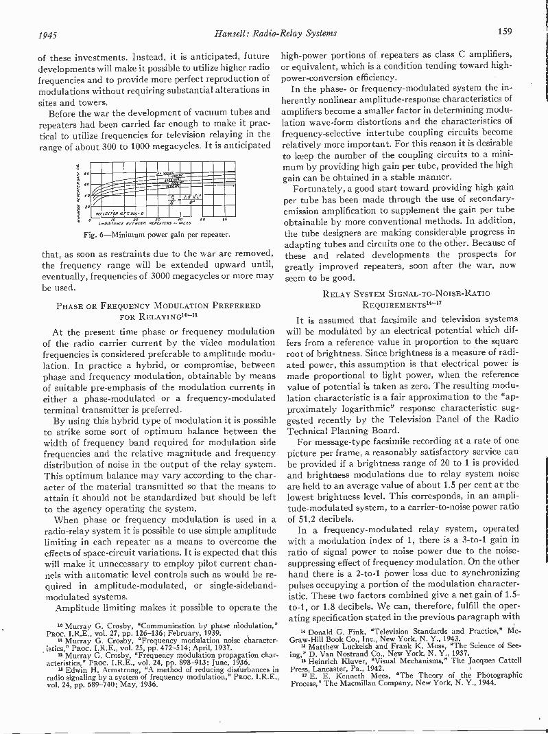
1945 Hansell: Radio -Relay Systems 159
of these investments. Instead, it is anticipated, futuredevelopments will make it possible to utilize higher radiofrequencies and to provide more perfect reproduction ofmodulations without requiring substantial alterations insites and towers.
Before the war the development of vacuum tubes andrepeaters had been carried far enough to make it prac-tical to utilize frequencies for television relaying in therange of about 300 to 1000 megacycles. It is anticipated
' rX'e
--.1,
qZS
RiTLECTOR /OFT 01 -00 JO JO 40
LwOISTANCE BETWEEN REPEATERS -MILESSO fo
Fig. 6-Minimum power gain per repeater.
that, as soon as restraints due to the war are removed,the frequency range will be extended upward until,eventually, frequencies of 3000 megacycles or more maybe used.
PHASE OR FREQUENCY MODULATION PREFERREDFOR RELAYING1°-13
At the present time phase or frequency modulationof the radio carrier current by the video modulationfrequencies is considered preferable to amplitude modu-lation. In practice a hybrid, or compromise, betweenphase and frequency modulation, obtainable by meansof suitable pre -emphasis of the modulation currents ineither a phase -modulated or a frequency -modulatedterminal transmitter is preferred.
By using this hybrid type of modulation it is possibleto strike some sort of optimum balance between thewidth of frequency band required for modulation sidefrequencies and the relative magnitude and frequencydistribution of noise in the output of the relay system.This optimum balance may vary according to the char-acter of the material transmitted so that the means toattain it should not be standardized but should be leftto the agency operating the system.
When phase or frequency modulation is used in aradio -relay system it is possible to use simple amplitudelimiting in each repeater as a means to overcome theeffects of space -circuit variations. It is expected that thiswill make it unnecessary to employ pilot current chan-nels with automatic level controls such as would be re-quired in amplitude -modulated, or single-sideband-modulated systems.
Amplitude limiting makes it possible to operate the
10 Murray G. Crosby, "Communication by phase modulation,"PRoc. I.R.E., vol. 27, pp. 126-136; February, 1939.
" Murray G. Crosby, "Frequency modulation noise character-istics," PROC. I.R.E., vol. 25, pp. 472-514; April, 1937.
12 Murray G. Crosby, "Frequency modulation propagation char-acteristics," PROC. I.R.E., vol. 24, pp. 898-913; June, 1936.
" Edwin H. Armstrong, "A method of reducing disturbances inradio signaling by a system of frequency modulation," PROC. I.R.E.,vol. 24, pp. 689-740; May, 1936.
high -power portions of repeaters as class C amplifiers,or equivalent, which is a condition tending toward high -power -conversion efficiency.
In the phase- or frequency -modulated system the in-herently nonlinear amplitude -response characteristics ofamplifiers become a smaller factor in determining modu-lation wave -form distortions and the characteristics offrequency -selective intertube coupling circuits becomerelatively more important. For this reason it is desirableto keep the number of the coupling circuits to a mini-mum by providing high gain per tube, provided the highgain can be obtained in a stable manner.
Fortunately, a good start toward providing high gainper tube has been made through the use of secondary -emission amplification to supplement the gain per tubeobtainable by more conventional methods. In addition,the tube designers are making considerable progress inadapting tubes and circuits one to the other. Because ofthese and related developments the prospects forgreatly improved repeaters, soon after the war, nowseem to be good.
RELAY SYSTEM SIGNAL -TO -NOISE -RATIO
REQUIREMENTS"-'7
It is assumed that facsimile and television systemswill be modulated by an electrical potential which dif-fers from a reference value in proportion to the squareroot of brightness. Since brightness is a measure of radi-ated power, this assumption is that electrical power ismade proportional to light power, when the referencevalue of potential is taken as zero. The resulting modu-lation characteristic is a fair approximation to the "ap-proximately logarithmic" response characteristic sug-gested recently by the Television Panel of the RadioTechnical Planning Board.
For message -type facsimile recording at a rate of onepicture per frame, a reasonably satisfactory service canbe provided if a brightness range of 20 to 1 is providedand brightness modulations due to relay system noiseare held to an average value of about 1.5 per cent at thelowest brightness level. This corresponds, in an ampli-tude -modulated system, to a carrier -to -noise power ratioof 51.2 decibels.
In a frequency -modulated relay system, operatedwith a modulation index of 1, there is a 3 -to -1 gain inratio of signal power to noise power due to the noise -suppressing effect of frequency modulation. On the otherhand there is a 2 -to -1 power loss due to synchronizingpulses occupying a portion of the modulation character-istic. These two factors combined give a net gain of 1.5 -to -1, or 1.8 decibels. We can, therefore, fulfill the oper-ating specification stated in the previous paragraph with
" Donald G. Fink, "Television Standards and Practice," Mc-Graw-Hill Book Co., Inc., New York, N. Y., 1943.
" Matthew Luckeish and Frank K. Moss, "The Science of See-ing," D. Van Nostrand Co., New York, N. Y., 1937.
14 Heinrich Kluver, "Visual Mechanisms," The Jacques CattellPress, Lancaster, Pa., 1942.
17 E. E. Kenneth Mees, "The Theory of the PhotographicProcess," The Macmillan Company, New York, N. Y., 1944.
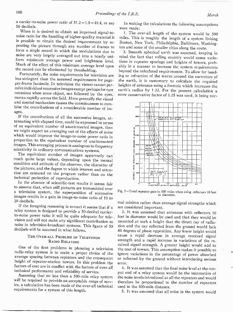
160 Proceedings of the I.R.E. March
a carrier -to -noise power ratio of 51.2 -1.8 = 49.4, or say50 decibels.
When it is desired to obtain an improved signal-to-noise ratio for the handling of higher -quality material itis possible to obtain the desired improvement by re-peating the picture through any number of frames toform a single record in which the modulations due tonoise are very largely averaged out into a nearly uni-form minimum average power and brightness level.Much of the effect of this minimum average level uponthe record can be eliminated by thresholding.
Fortunately, the noise requirements for television areless stringent than the assumed requirements for page-per -frame facsimile. In television the viewer cannot per-ceive individual successive images except perhaps for rareoccasions when some object, not followed by the eyes,moves rapidly across the field. More generally the visualand mental mechanism causes the consciousness to com-bine the contributions of a considerable number of im-ages.
If the contributions of all the successive images, at-tenuating with elapsed time, could be expressed in termsof an equivalent number of unattenuated images, thenwe might expect an averaging out of the effects of noisewhich would improve the image-to -noise power ratio inproportion to the equivalent number of unattenuatedimages. This averaging process is analogous to frequencyselectivity in ordinary communications systems.
The equivalent number of images apparently canreach quite large values, depending upon the mentalcondition and attitude of the observer, the character ofthe pictures, and the degree to which interest and atten-tion are centered on the program rather than on thetechnical perfection of reproduction.
In the absence of scientific -test results it seems fairto assume that, when still pictures are transmitted overa television system, the superposition of successiveimages results in a gain in image -to -noise ratio of 10 to20 decibels.
If the foregoing reasoning is correct it seems that if arelay system is designed to provide a 50 -decibel carrier -to -noise power ratio it will be quite adequate for tele-vision and will not make any significant contribution tonoise in television -broadcast systems. This figure of 50decibels will be assumed in what follows.
THE OVER-ALL PROBLEM OF TELEVISIONRADIO RELAYING
One of the first problems in planning a televisionradio -relay system is to make a proper choice of theaverage spacing between repeaters and the consequentheight of repeater -station towers. In this problem thefactors of cost are in conflict with the factors of over-alltechnical performance and reliability of service.
Assuming that no less than a 500 -mile relay systemwill be required to provide an acceptable range of serv-ice, a calculation has been made of the over-all technicalrequirements for a system of this length.
In making the calculations the following assumptionswere made:
1. The over-all length of the system would be 500miles. This is roughly the length of a system linkingBoston, New York, Philadelphia, Baltimore, Washing-ton and some of the smaller cities along the route.
2. Smooth spherical earth was assumed, keeping inmind the fact that rolling country would cause varia-tions in repeater spacings and heights of towers, prob-ably in a manner to increase the system requirementsbeyond the calculated requirements. To allow for bend-ing or refraction of the waves around the curvature ofthe earth, it is customary to calculate the requiredheights of antennas using a formula which increases theearth's radius by 1.33. For the present calculation amore conservative factor of 1.25 was used, it being nor -
3000
MOO
1400
.1.11000
H
1/600
" o
80
11. 40
r I
l1
111
500REDUCED
MC WITH70
REFLECTORSsrr DIAMETER
,
A
\
\500
1000
MC ti,MC
s\
2000 MC4 000 MC
I, ,
0000 MC ,"......
MIMMIlil.:'er08 ,Y
I/0 10 JO 40 50
BIS TANCE BETWEEN REPEATERS -MILES
Fig. 7-Total repeater gain in 500 miles when using reflectors 10 feetin diameter.
mal minima rather than average signal strengths whichare considered important.
3. It was assumed that antennas with reflectors 10feet in diameter would be used and that they would bemounted at such a height that the direct ray of radia-tion and the ray reflected from the ground would lack60 degrees of phase opposition. Any lower height wouldcause a rapid decrease in average received signalstrength and a rapid increase in variations of the re-ceived signal strength. A greater height would add tothe cost of towers. This assumption makes it possible toignore variations in the percentage of power absorbedor reflected by the ground without introducing seriouserror.
4. It was assumed that the final noise level at the out-put end of a relay system would be the summation ofthe noise levels introduced at all the repeaters and wouldtherefore be proportional to the number of repeatersused in the 500 -mile distance.
5. It was assumed that all noise in the system would
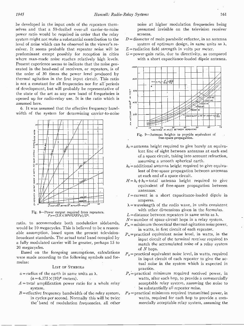
1945 Hansen: Radio -Relay Systems 161
be developed in the input ends of the repeaters them-selves and that a 50 -decibel over-all carrier -to -noisepower ratio would be required in order that the relaysystem might not make a substantial contribution to thelevel of noise which can be observed in the viewer's re-ceiver. It seems probable that repeater noise will bepredominant except possibly for reception in citieswhere man-made noise reaches relatively high levels.Present experience seems to indicate that the noise gen-erated in the head -end of receivers, or repeaters, is ofthe order of 30 times the power level produced bythermal agitation in the first input circuit. This ratiois not a constant for all frequencies nor for all periodsof development, but will probably be representative ofthe state of the art as any new band of frequencies isopened up for radio -relay use. It is the ratio which isassumed here.
6. It was assumed that the effective frequency band-width of the system for determining carrier -to -noise
40
2 JO
40
z
/0
a
0
Fig.
LAOISTANU BETWEEN
PC
MC
4 0 JPEATER-AI LCS
O 40
8-Power output required from repeaters.Pr= (2.8 X 106X2L2NPp)/D4.
ratio, to accommodate both modulation sidebands,would be 10 megacycles. This is believed to be a reason-able assumption, based upon the present television -broadcast standards. The actual total band occupied bya fully modulated carrier will be greater, perhaps 15 to20 megacycles.
Based on the foregoing assumptions, calculationswere made according to the following symbols and for-mulas:
LIST OF SYMBOLS
a =radius of the earth in same units as X.(a = 6.375 X (10)° meters).
A = total amplification power ratio for a whole relaysystem.
B = effective frequency bandwidth of the relay system,in cycles per second. Normally this will be twicethe' band of modulation frequencies, all other
noise at higher modulation frequencies beingpresumed invisible on the television receiverscreens.
D = diameter of main parabolic reflector, in an antennasystem of optimum design, in same units as X.
E =radiation field strength in volts per meter.G= power -gain ratio, due to directivity, as compared
with a short capacitance -loaded dipole antenna.
000
6 00
600
400
?do
/#"" h41', ' 6.42r
: ,
,4,,, )56 5,4.000 MC
............". ......4,00miO0c0 MC
'wow
---"--eouivw.ENT LINE OP steNr-h,-÷.
---------..---
_.--- ..--,
/0 20 JO 40 50DISTANCE IN NILES BETWEEN REPEATERS
Fig. 9-Antenna heights to provide equivalent offree -space propagalion.
h,= antenna height required to give barely an equiva-lent line of sight between antennas at each endof a space circuit, taking into account refraction,assuming a smooth spherical earth.
h2= additional antenna height required to give equiva-lent of free -space propagation between antennasat each end of a space circuit.
H= hi+ h2= total' antenna height required to giveequivalent of free -space propagation betweenantennas.
/= current in a short capacitance -loaded dipole inamperes.
X =wavelength of the radio wave, in units consistentwith other dimensions given in the formulas.
L = distance between repeaters in same units as X.N= number of space -circuit hops in a relay system.
Pm = minimum theoretical thermal -agitation noise power,in watts, in first circuit of each repeater.
P = practical equivalent noise level, in watts, in theinput circuit of the terminal receiver required tomatch the accumulated noise of a relay systemof N hops.
P= practical equivalent noise level, in watts, requiredin input circuit of each repeater to give the ac-tual noise in the system which is expected inpractice.
P,= practical minimum required received power, inwatts, after each hop, to provide a commerciallyacceptable relay system, assuming the noise tobe substantially all repeater noise.
PT = practical minimum required transmitted power, inwatts, required for each hop to provide a com-mercially acceptable relay system, assuming the
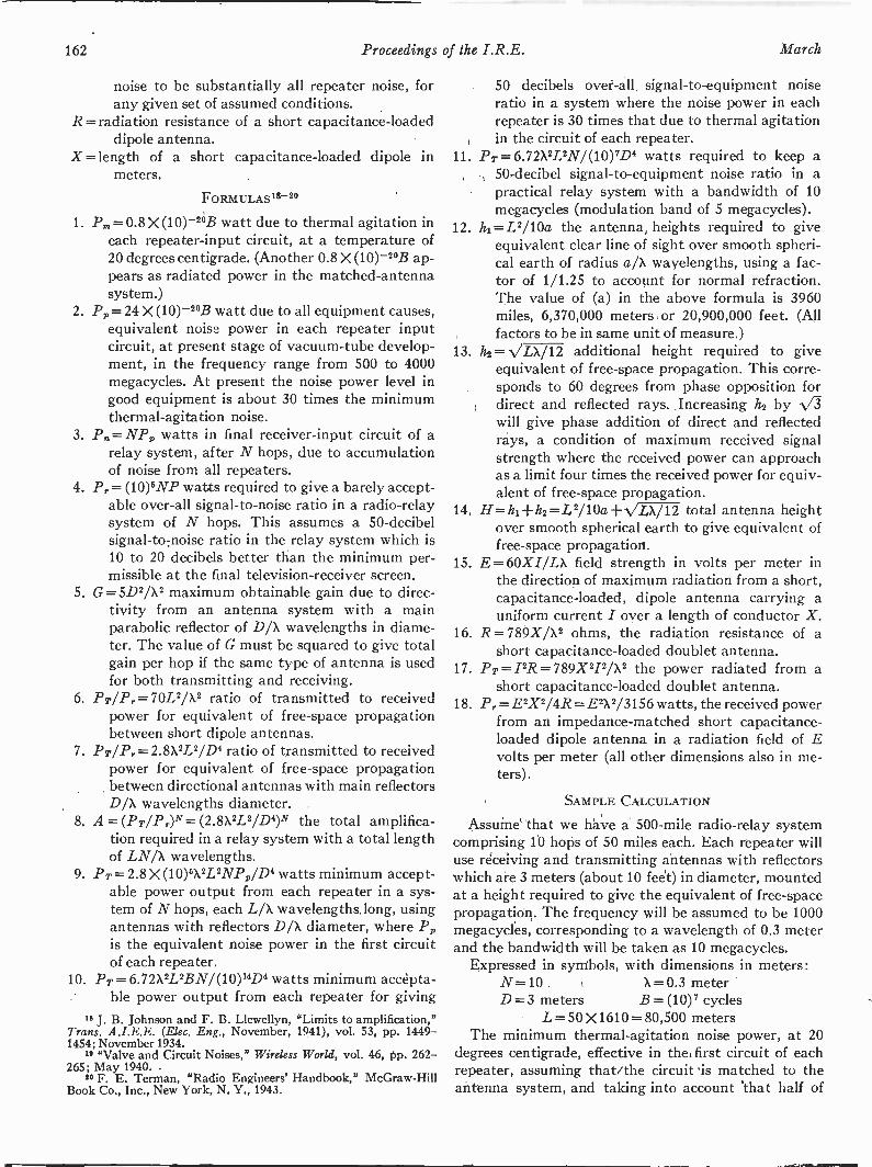
162 Proceedings of the I.R.E. March
noise to be substantially all repeater noise, forany given set of assumed conditions.
R= radiation resistance of a short capacitance -loadeddipole antenna.
X= length of a short capacitance -loaded dipole inmeters.
FORMULAS 18-2°
1. P.= 0.8 X (10)-2°B watt due to thermal agitation ineach repeater -input circuit, at a temperature of20 degrees centigrade. (Another 0.8 X (10)-20B ap-pears as radiated power in the matched -antennasystem.)
2. Pp = 24 X (10)-20B watt due to all equipment causes,equivalent noise power in each repeater inputcircuit, at present stage of vacuum -tube develop-ment, in the frequency range from 500 to 4000megacycles. At present the noise power level ingood equipment is about 30 times the minimumthermal -agitation noise.
3. P.=NP, watts in final receiver -input circuit of arelay system, after N hops, due to accumulationof noise from all repeaters.
4. Pr = (10)5NP watts required to give a barely accept-able over-all signal-to-noise ratio in a radio -relaysystem of N hops. This assumes a 50 -decibelsignal-to-noise ratio in the relay system which is10 to 20 decibels better than the minimum per-missible at the final television -receiver screen.
5. G=5D2/X2 maximum obtainable gain due to direc-tivity from an antenna system with a mainparabolic reflector of D/X wavelengths in diame-ter. The value of G must be squared to give totalgain per hop if the same type of antenna is usedfor both transmitting and receiving.
6. PT/Pr= 70L2/X2 ratio of transmitted to receivedpower for equivalent of free -space propagationbetween short dipole antennas.
7. Pr/Pr = 2.8X2L2/D4 ratio of transmitted to receivedpower for equivalent of free -space propagationbetween directional antennas with main reflectorsD/X wavelengths diameter.
8. A=(PT/PON= (2.8X2L2/D4)N the total amplifica-tion required in a relay system with a total lengthof LN/X wavelengths.
9. Pr = 2.8 X (10)5X2L2Np D4p/ watts minimum accept-able power output from each repeater in a sys-tem of N hops, each L/X wavelengths long, usingantennas with reflectors D/X diameter, where Ppis the equivalent noise power in the first circuitof each repeater.
10. PT= 6.72X2L2BN/(10)1.4D4 watts minimum accepta-ble power output from each repeater for giving
18 J. B. Johnson and F. B. Llewellyn, "Limits to amplification,"Trans. A.I.E.E. (Elec. Eng., November, 1941), vol. 53, pp. 1449-1454; November 1934.
1* "Valve and Circuit Noises," Wireless World, vol. 46, pp. 262-265; May 1940.
20 F. E. Terman, "Radio Engineers' Handbook," McGraw-HillBook Co., Inc., New York, N. Y., 1943.
11.
50 decibels over-all, signal -to -equipment noiseratio in a system where the noise power in eachrepeater is 30 times that due to thermal agitationin the circuit of each repeater.
PT=6.72X2L2N1(10)7D4 watts required to keep a50 -decibel signal -to -equipment noise ratio in apractical relay system with a bandwidth of 10megacycles (modulation band of 5 megacycles).
12. hi =L2/10a the antenna heights required to giveequivalent clear line of sight over smooth spheri-cal earth of radius a/X wavelengths, using a fac-tor of 1/1.25 to account for normal refraction.The value of (a) in the above formula is 3960miles, 6,370,000 meters or 20,900,000 feet. (Allfactors to be in same unit of measure.)
13. 1z2= VLX/12 additional height required to giveequivalent of free -space propagation. This corre-sponds to 60 degrees from phase opposition fordirect and reflected rays. Increasing 14 by N/73will give phase addition of direct and reflectedrays, a condition of maximum received signalstrength where the received power can approachas a limit four times the received power for equiv-alent of free -space propagation.
14. H= h1-Fh2=L2/10a+VLX/12 total antenna heightover smooth spherical earth to give equivalent offree -space propagation.
15. E = 60XI/LX field strength in volts per meter inthe direction of maximum radiation from a short,capacitance -loaded, dipole antenna carrying auniform current I over a length of conductor X.
16. R = 789X/X2 ohms, the radiation resistance ofshort capacitance -loaded doublet antenna.
17. pr=i2R=789x2p,x2/ the power radiated fromshort capacitance -loaded doublet antenna.
18. Pr=E2x2/4R=E2X2/3156 watts, the received powerfrom an impedance -matched short capacitance -loaded dipole antenna in a radiation field of Evolts per meter (all other dimensions also in me-ters).
a
a
SAMPLE CALCULATION
Assume that we have a 500 -mile radio -relay systemcomprising 10 hops of 50 miles each. Each repeater willuse receiving and transmitting antennas with reflectorswhich are 3 meters (about 10 feet) in diameter, mountedat a height required to give the equivalent of free -spacepropagation. The frequency will be assumed to be 1000megacycles, corresponding to a wavelength of 0.3 meterand the bandwidth will be taken as 10 megacycles.
Expressed in symbols, with dimensions in meters :N=10 X = 0.3 meterD= 3 meters B= (10)7 cycles
L= 50 X1610 = 80,500 metersThe minimum thermal -agitation noise power, at 20
degrees centigrade, effective in the first circuit of eachrepeater, assuming that the circuit 'is matched to theantenna system, and taking into account that half of
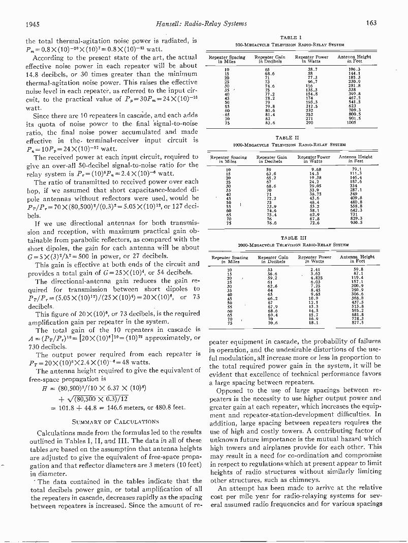
1945 Hansell: Radio -Relay Systems 163
the total thermal -agitation noise power is radiated, is-P, = 0.8 X (10)-20 A (10)2= 0.8 X (10)-" watt.
According to the present state of the art, the actualeffective noise power in each repeater will be about14.8 decibels, or 30 times greater than the minimumthermal -agitation noise power. This raises the effectivenoise level in each repeater, as referred to the input cir-cuit, to the practical value of Pp=30P,=24 X (10)-"watt.
Since there are 10 repeaters in cascade, and each addsits quota of noise power to the final signal-to-noiseratio, the final noise power accumulated and madeeffective in the terminal -receiver input circuit isPp=10P= 24 X (10)-" watt.
The received power at each input circuit, required togive an over-all 50 -decibel signal-to-noise ratio for therelay system is P,.=(10)5P=2.4 X (10)-41 watt.
The ratio of transmitted to received power over eachhop, if we assumed that short capacitance -loaded di-pole antennas without reflectors were used, would be
= 70 X (80,500)2/(0.3)2= 5.05 X (10)12, or 127 deci-bels.
If we use directional antennas for both transmis-sion and reception, with maximum practical gain ob-tainable from parabolic reflectors, as compared with theshort dipoles, the gain for each antenna will be aboutG=5 X (3)2/X2= 500 in power, or 27 decibels.
This gain is effective at both ends of the circuit andprovides a total gain of G=25 X (10)4, or 54 decibels.
The directional -antenna gain reduces the gain re-quired for transmission between short dipoles toPT/Pr = (5.05 X (10)1R)/(25 X (10)4) = 20 X (10)°, or 73
decibels.This figure of 20 X (10)°, or 73 decibels, is the required
amplification gain per repeater in the system.The total gain of the 10 repeaters in cascade is
A (pr/pr)lo= [20 X (10)11° = (10)" approximately, or730 decibels.
The output power required from each repeater isPT= 20 X(10)6X2.4 X(10)-°= 48 watts.
The antenna height required to give the equivalent offree -space propagation is
H = (80,500)2/(10 X 6.37 X (10)4)
+ V(80,500 X 0.3)/12= 101.8 + 44.8 = 146.6 meters, or 480.8 feet.
SUMMARY OF CALCULATIONS
Calculations made from the formulas led to the resultsoutlined in Tables I, II, and III. The data in all of thesetables are based on the assumption that antenna heightsare adjusted to give the equivalent of free -space propa-gation and that reflector diameters are 3 meters (10 feet)in diameter.' The data contained in the tables indicate that the
total decibels power gain, or total amplification of allthe repeaters in cascade, decreases rapidly as the spacingbetween repeaters is increased. Since the amount of re -
TABLE I
500 -MEGACYCLE TELEVISION RADIO -RELAY SYSTEM
Repeater Spacingin Miles
Repeater Gainin Decibels
Repeater Powerin Watts
Antenna Heightin Feet
10 65 38.7 106.3
15 68.6 58 144.120 71 77.3 185.325 73 96.7 230.930 74.6 116 281.835 75 135.3 33840 77.2 154.8 399.845so
78.279
174193.3
467.5541.5
55 79.8 212.5 62360 80.6 232 709.365 81.4 252 800.570 82 271 901.575 82.6 290 1005
TABLE II
I000 -MEGACYCLE TELEVISION RADIO -RELAY SYSTEM
Repeater Spacing Repeater Gain Repeater Power Antenna Heightin Miles in Decibels in Watts in Feet
10 59 9.68 79.1
IS 62.6 14.5 111.3
20 65.2 19.38 146.425 67 24.2 187.630 68.6 29.05 23435 70 33.9 287.140 71 38.75 34945 72.2 43.6 409.850 73 48.4 480.8SS 73.9 53.2 558.860 74.6 58.1 642.365 75.4 62.9 731
70 76 67.8 829.375 76.6 72.6 930.5
TABLE III
2000 -MEGACYCLE TELEVISION RADIO -RELAY SYSTEM
Repeater Spacingin Miles
Repeater Gainin Decibels
Repeater Powerin Watts
Antenna Heightin Feet
10 53 2.41 59.815 56.6 3.62 87.120 59.2 4.825 119.425 61 6.03 157.1
30 62.6 7.25 200.935 64 8.45 250.940 65 9.65 306.64550
66.267
10.912.1
368.8437.5
5$ 67.9 13.3 513.860 68.6 14.5 S9S.265 69.4 15.7 681.870 70 16.9 778.375 70.6 18.1 877.5
peater equipment in cascade, the probability of failuresin operation, and the undesirable distortions of the use-ful modulation, all increase more or less in proportion tothe total required power gain in the system, it will beevident that excellence of technical performance favorsa large spacing between repeaters.
Opposed to the use of large spacings between re-peaters is the necessity to use higher output power andgreater gain at each repeater, which increases the equip-ment and repeater -station -development difficulties. Inaddition, large spacing between repeaters requires theuse of high and costly towers. A contributing factor ofunknown future importance is the mutual hazard whichhigh towers and airplanes provide for each other. Thismay result in a need for co-ordination and compromisein respect to regulations which at present appear to limitheights of radio structures without similarly limitingother structures, such as chimneys.
An attempt has been made to arrive at the relativecost per mile year for radio -relaying systems for sev-eral assumed radio frequencies and for various spacings
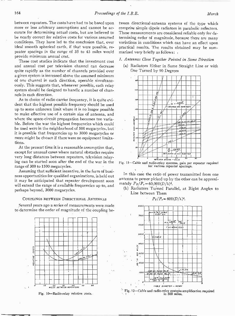
164 Proceedings of the I.R.E. March
between repeaters. The costs have had to be based uponmore or less arbitrary assumptions and cannot be ac-curate for determining actual costs, but are believed tobe nearly correct for relative costs for various assumedconditions. They have led to the conclusion that, overideal smooth spherical earth, if that were possible, re-peater spacings in the range of 35 to 45 miles wouldprovide minimum annual cost.
These cost studies indicate that the investment costand annual cost per television channel can decreasequite rapidly as the number of channels provided overa given system is increased above the assumed minimumof one channel in each direction, operable simultane-ously. This suggests that, whenever possible, each relaysystem should be designed to handle a number of chan-nels in each direction.
As to choice of radio carrier frequency, it is quite evi-dent that the highest possible frequency should be usedup to some unknown limit where it is no longer possibleto make effective use of a certain size of antenna, andwhere the space -circuit propagation becomes too varia-ble. Before the war the highest frequencies which couldbe used were in the neighborhood of 500 megacycles, butit is possible that frequencies up to 3000 megacycles ormore might be chosen if there were no equipment limita-tions.
At the present time it is a reasonable assumption that,except for unusual cases where natural obstacles requirevery long distances between repeaters, television relay-ing can be started soon after the end of the war in therange of 300 to 1500 megacycles.
Assuming that sufficient incentive, in the form of busi-ness opportunities for qualified organizations, is held outit may be anticipated that repeater development soonwill extend the range of available frequencies up to, andperhaps beyond, 3000 megacycles.
COUPLINGS BETWEEN DIRECTIONAL ANTENNAS
Several years ago a series of measurements were madeto determine the order of magnitude of the coupling be -
5i
51
c 5r
0 10 20 JO 10 50MILES BETWEEN REPEATERS
60
Fig. 10-Radio-relay relative costs.
tween directional -antenna systems of the type whichcomprise simple dipole radiators in parabolic reflectors.These measurements are considered reliable only for de-termining order of magnitude, because there are manyvariations in conditions which can have an effect uponpractical results. The results obtained may be sum-marized very briefly as follows:
1. Antennas Close Together Pointed in Same Direction
(a) Radiators Either in Same Straight Line or withOne Turned by 90 Degrees
MO
/10
110
100
60
.! 40
ZO
I
I /0
X.I.63V7
',ASSUMED0
SMC DAMS WIDTH
1051411111....110510115
ii1
-....6164111111
a A e
000 N
4 -01,711ffer1111,7411111.111.1mom1111.1111.11111111111111.'-
11111
'4 --.....ViIF" Arv--
411111111/ 2_L g
1
2 2 xze
/0I
D'REFLECTOR FEET DIAMETER
I
S /0 IS 10 15REPEATER SPACING -MILES
Fig. 11-Cable and radio -relay systems, gain per repeater requiredfor various repeater spacings.
In this case the ratio of power transmitted from oneantenna to power picked up by the other can be approxi-mately PT/Pr= 60,000(D/X)4.
(b) Radiators Turned Parallel, at Right Angles toLine between Them
PT/Pr = 600 (D/X)4.
8000
7000
6000
5000
1000
:7:3000
2,12000
/000
0
-.---A ;250TAg77LE
P IiiDeALE--0
F 5 MEGACYCLES
CABLE
- -IP AL -75-_DIA
- -'c.R R4:4204EAL-6;1A7,- ,74To5"
IAV z Dex.'9)
CABLE DIAMETER - INC/ES
Fig. 12-Cable and radio -relay systems amplification requiredin 500 miles.
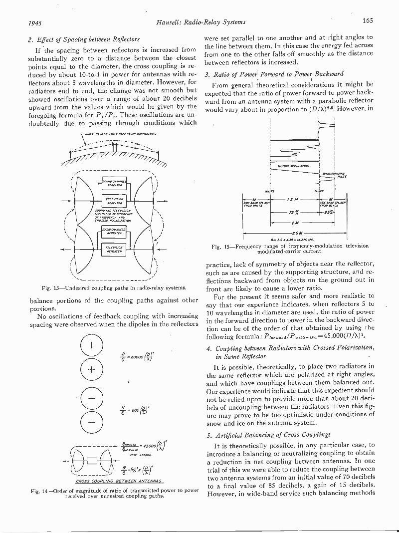
1945 Hansell: Radio -Relay Systems 165
Z. Effect of Spacing between Reflectors
If the spacing between reflectors is increased fromsubstantially zero to a distance between the closestpoints equal to the diameter, the cross coupling is re-duced by about 10 -to -1 in power for antennas with re-flectors about 5 wavelengths in diameter. However, forradiators end to end, the change was not smooth butshowed oscillations over a range of about 20 decibelsupward from the values which would be given by theforegoing formula for Pr/P,.. These oscillations are un-doubtedly due to passing through conditions which
\RISES TO MOD ABOVE TREE SPACE PROPAGATION
-------
0'1111""m
SOUND AND TA-LEVIS ONSEPARATED BY ONTRENCEOF FRGOVENEY ANDCROSSED POLARIZATION
Fig. 13-Undesired coupling paths in radio -relay systems.
balance portions of the coupling paths against otherportions.
No oscillations of feedback coupling with increasingspacing were observed when the dipoles in the reflectors
= 60000 p_)4
-= 6001(,2-1
FORWAFORWARD
45004)iRD
vE RV APPRO
1-40)5)( (*).
CROSS COUPL /NG BETWEEN ANTENNAS
Fig. 14-Order of magnitude of ratio of transmitted power to powerreceived over undesired coupling paths.
were set parallel to one another and at right angles tothe line between them. In this case the energy fed acrossfrom one to the other falls off smoothly as the distancebetween reflectors is increased.
3. Ratio of Power Forward to Power Backward
From general theoretical considerations it might beexpected that the ratio of power forward to power back-ward from an antenna system with a parabolic reflectorwould vary about in proportion to (D/X) 2'5. However, in
DENTE
1..-MSIDI IMO TIM ASNPROM IGNITE
5.5 M
133.5 A' 4 T5 .,14.873 MC.
Fig. 15-Frequency range of frequency -modulation televisionmodulated -carrier current.
practice, lack of symmetry of objects near the reflector,such as are caused by the supporting structure, and re-flections backward from objects on the ground out infront are likely to cause a lower ratio.
For the present it seems safer and more realistic tosay that our experience indicates, when reflectors 5 to10 wavelengths in diameter are used, the ratio of powerin the forward direction to power in the backward direc-tion can be of the order of that obtained by using thefollowing formula: P- forward/Pb so kward = 45 ,000 (D/X) 2.
4. Coupling between Radiators with Crossed Polarization,in Same Reflector
It is possible, theoretically, to place two radiators inthe same reflector which are polarized at right angles,and which have couplings between them balanced out.Our experience would indicate that this expedient shouldnot be relied upon to provide more than about 20 deci-bels of uncoupling between the radiators. Even this fig-ure may prove to be too optimistic under conditions ofsnow and ice on the antenna system.
5. Artificial Balancing of Cross Couplings
It is theoretically possible, in any particular case, tointroduce a balancing or neutralizing coupling to obtaina reduction in net coupling between antennas. In onetrial of this we were able to reduce the coupling betweentwo antenna systems from an initial value of 70 decibelsto a final value of 85 decibels, a gain of 15 decibels.However, in wide -band service such balancing methods

166 Proceedings of the I.R.E. March
may prove difficult and complicated because there prob-ably will be a variety of component coupling paths ofdifferent length and time delay, each of which wouldrequire its own balancing path. In the experimental trialmentioned above it was found that there were a numberof relatively short paths and other paths correspondingto distances down to the ground and back over the sup-porting structure, or out to near -by reflecting objects andback.
In any practical case it would seem that, if artificialbalancing is used, it must be done with care to provideproper time delays and, at least until it is covered by
300-1000
/000 -2000
2000-3000
3000 -4 000
GUARD BANDS
BROADCAST
F1-1-11-11-11-1
F,01-1 7 7Fl n
J010 nTHEATRE
300-1000 B0 I
1000-1000
1000-3000
3000-4000
B0 80
80 I JO
00 I 40
Fig. 16-Suggested minimum channel spacings for any one relaysystem-megacycles.
more experience, should not be relied upon for improve-ments of more than 10 to 20 decibels.
6. Polarization Discrimination over Long Distances
Insufficient information is available to indicate towhat degree differences in polarization may be reliedupon to discriminate between channels working in thesame direction over the same space circuit. Our experi-ence indicates only that such discrimination may be ofsubstantial aid, but only tests for long periods over ac-tual operating circuits can give us information as to howmuch discrimination can be relied on. As a conservativeand very preliminary guess we might place the figure atabout 10 decibels.
7. Coupling Between Antennas with Reflectors Pointed inOpposite Directions
The coupling between antennas in reflectors pointedin nearly opposite directions is more subject to the con-ditions under which they are mounted than is the coup-ling in the other cases considered. In general it shouldbe possible, by using all the available technical ex-pedients, to count on a reduction of coupling to aboutPr/Pr = (10)5X (D/X)4.
This would indicate that, by using reflectors 10 wave-lengths or more in diameter it will generally be possible
to receive and retransmit without shift of carrier fre-quency in the repeater.
However, this matter of relaying without shift of car-rier frequency, while it has been demonstrated in one ofour relay experiments, is a matter which should receivemore experimental development. All we can say withcertainty at present is that we are confident that it canbe done in most instances and that higher radio fre-quencies and large antennas will help to make it possi-ble.
BANDWIDTHS REQUIRED FOR TELEVISION RELAYINGINTENDED TO SERVE PRESENT STANDARD
TELEVISION -BROADCAST STATIONS
The present television -broadcast standards providefor modulation frequencies ranging from 0 to about4.25 megacycles.
In a relay system it is considered essential to transmitthe zero or very low -frequency components of the modu-lation so that the synchronizing pulses may occupy afixed range of the modulation characteristic. Otherwise,variations in image background level may modulate thewave form and amplitude of the synchronizing pulses ina manner to detract from the quality of reproducedimages. This +means that the highest frequency modula-tions of the frequency -modulated carrier current will besuperimposed upon a carrier frequency which can varybetween the values set for the black -and -white levels.This requires that the radio -frequency bandwidth beequal to twice the highest modulation frequency plusthe range of frequency lying between the black -and -white levels.
According to the present standards, the difference be-tween the black -and -white levels occupies about 75 percent of the modulation characteristic. Therefore, if weso design the modulator that it can produce plus andminus 4.25 megacycles frequency deviation at any mod-ulating frequency from 0 to 4.25 megacycles, then theminimum band required for a frequency -modulatedradio -relay system, to match the present standards, willbe B= (2 X4.25) X 1.75 = 14.9 megacycles.
From this we may conclude that the nominal band-width allowed for a television -relay channel should be atleast 15 megacycles.
In practice, a larger frequency band is desirable topermit some increase in quality and reduction in noise,to help guarantee that the relay system will not be asubstantial factor in detracting from the quality of serv-ice from the broadcast stations which it serves.
It is therefore suggested that relay channels toserve the present standard television -broadcast stationsshould be allowed a nominal channel band of 20 mega-cycles.
BANDWIDTHS REQUIRED FOR RELAY SYSTEMS TOSERVE TELEVISION IN THEATERS
It now appears that future needs of theater tele-vision will call for an increase in the picture resolution
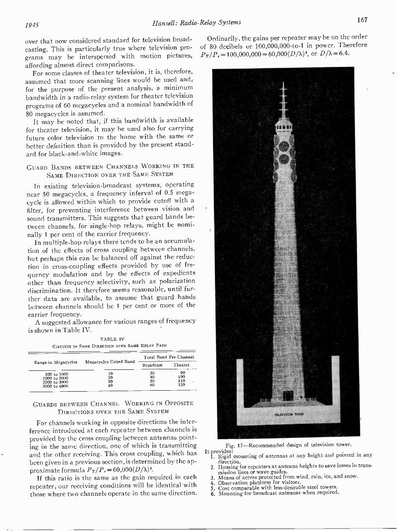
1945 Hansell: Radio -Relay Systems 167
over that now considered standard for television broad-casting. This is particularly true where television pro-grams may be interspersed with motion pictures,affording almost direct comparisons.
For some classes of theater television, it is, therefore,assumed that more scanning lines would be used and,for the purpose of the present analysis, a minimumbandwidth in a radio -relay system for theater televisionprograms of 60 megacycles and a nominal bandwidth of80 megacycles is assumed.
It may be noted that, if this bandwidth is availablefor theater television, it may be used also for carryingfuture color television to the home with the same orbetter definition than is provided by the present stand-ard for black -and -white images.
GUARD BANDS BETWEEN CHANNELS WORKING IN THESAME DIRECTION OVER THE SAME SYSTEM
In existing television -broadcast systems, operatingnear 50 megacycles, a frequency interval of 0.5 mega-cycle is allowed within which to provide cutoff with afilter, for preventing interference between vision andsound transmitters. This suggests that guard bands be-tween channels, for single -hop relays, might be nomi-nally 1 per cent of the carrier frequency.
In multiple -hop relays there tends to be an accumula-tion of the effects of cross coupling between channels,but perhaps this can be balanced off against the reduc-tion in cross -coupling effects provided by use of fre-quency modulation and by the effects of expedientsother than frequency selectivity, such as polarizationdiscrimination. It therefore seems reasonable, until fur-ther data are available, to assume that guard bandsbetween channels should be 1 per cent or more of thecarrier frequency.
A suggested allowance for various ranges of frequencyis shown in Table IV.
TABLE IVCIRCUITS IN SAME DIRECTION OVER SAME RELAY PATH
Range in Megacycles Megacycles Guard BandTotal Band Per Channel
Broadcast Theater
300 to 1000 10 30 901000 to 2000 20 40 1002000 to 3000 30 50 1103000 to 4000 40 60 120
GUARDS BETWEEN CHANNEL WORKING IN OPPOSITEDIRECTIONS OVER THE SAME SYSTEM
For channels working in opposite directions the inter-ference introduced at each repeater between channels isprovided by the cross coupling between antennas point-ing in the same direction, one of which is transmittingand the other receiving. This cross coupling, which hasbeen given in a previous section, is determined by the ap-proximate formula PT/Pr = 60,000(D/X)4.
If this ratio is the same as the gain required in eachrepeater, our receiving conditions will be identical withthose where two channels operate in the same direction.
Ordinarily, the gains per repeater may be on the orderof 80 decibels or 100,000,000 -to -1 in power. ThereforePr/Pr= 100,000,000 = 60,000(D/X)4, or D/X = 6.4.
Fig. 17-Recommended design of television tower.It provides:
1. Rigid mounting of antennas at any height and pointed in anydirection.
2. Housing for repeaters at antenna heights to save losses in trans-mission lines or wave guides.
3. Means of access protected from wind, rain, ice, and snow.4. Observation platform for visitors.5. Cost comparable with less -desirable steel towers.6. Mounting for broadcast antennas when required.

168 Proceedings of the I.R.E.
From this we conclude that the spacing between chan-nels going in opposite directions may be the same asthat between channels going in the same direction pro-vided the reflectors for the antennas are 6.5 wavelengthsor more in diameter, in a system engineered as outlinedin the early part of this paper.
PROBABLE FUTURE USES FOR RADIO -RELAY SYSTEMS
Since the only justification for investing large sums ofmoney in radio -relay systems, and for becoming in-volved in the toils of technical development, businesspromotion, and government regulation, is the usefulnessof the systems, it may be appropriate to consider whatsome of the uses may be.
Radio relays have such outstanding technical andeconomic advantages for the distribution of televisionthat, eventually, they should be regarded as essentialfor this service. However, the costs for adequate radio -relay systems are substantial and, unless the costs ofrelay -station sites, towers, and facilities can be spreadover a number of channels and services, they may be soburdensome as to delay the, initial spread of televisionservice.
In holding unit costs down it is essential that the relaystations be designed and utilized to provide several tele-vision channels, all utilizing the same towers. It is alsoessential that the investment and operating expenses beshared with as many secondary services as possible.
In general, relay stations will occupy the highestpoints and provide the highest towers in each commu-nity. They are, therefore, the natural choice for locationof radio broadcast stations. By combining relaying andbroadcasting, where this is possible, both can benefit.
High towers, occupying the highest points, are naturalgathering places for pleasure seekers and the curious. Inmany cases, observation platforms at the top of thetowers, television theaters, restaurants and other enter-tainment facilities may be provided to give a greaterpublic service and to help in paying the costs.
One of the most natural secondary services, from atechnical standpoint, will be that of facsimile communi-cation, by which is meant the transmission of any sortof picture or message which is to be recorded at the re-ceiving end as a copy of the original. An adequate tele-vision -radio -relay circuit has a potential speed of trans-mission of 108,000 pages per hour.
There are as many uses for facsimile service as thereare for the existing telegraph and mail services. It is ameans for giving the service with far greater speed andless effort. Soon, for example, it could provide a nation-wide newspaper delivery faster than papers can now beprinted. Newspaper publishers then will no longer bedependent upon the slow and inefficient type of delivery
service which was already in use when printing was in-vented.
There is another probably important use for futureradio -relay systems which is closely related to thestruggle just beginning to obtain the use of frequenciesabove 30 megacycles. It is that of providing radio serv-ices to airplanes.
As the number of airplanes in flight increases, the de-mands for radio service will increase to such a degreethat it will be unreasonable to provide radio frequenciesand facilities so that all of the airplanes flying over landmay communicate by radio over long distances. Fur-thermore, as the speed and efficiency of airplanes hasincreased, it has become more unreasonable to provideeither large protruding antennas, or powerful equip-ment, needed to operate on the frequencies required toreach large distances.
Looking ahead it seems inevitable that much of thecommunication with aircraft must be limited to shortdistances and carried out on higher frequencies withsmaller equipment and without protruding antennas.This will require a large number of ground stations,spread out along the air routes. Substantially thesesame routes will be followed by the radio -relaysystems,and the radio -relay stations are natural sites for airlineradio ground stations.
The railroads, long-distance bus and truck lines, andportions of the traveling public have communicationsneeds similar in character to those of the airlines, andradio -relay systems might very well contribute to thefulfillment of these needs.
Radio relays may, of course, be used for long-distancemultiplex telephone communication, particularly for thedistribution of sound broadcast programs. Sound ac-companying television obviously should pass over theradio relays so that its handling may be properly co-ordinated and so that vision and sound will be subjectto equal time delays.
Finally, there is a growing need for means to intercon-nect a variety of newly developed business machines sothat manufacturing, transportation, and merchandisingorganizations, and the public they serve, may benefitfrom the advantages of decentralized and widespreadoperations, with centralized management and control.
With all the pent-up new needs, and the apparentability of radio -relay systems to fill these needs, what isnow needed most to make radio relaying a great newAmerican industry is a more general understanding of itsvalue; a well-defined and stable licensing policy; a re-laxation of restraints which dampen the hope of expan-sion and profit and which discourage joint action bythose in need of relay service; and a few good promoterswho have caught the vision.

Transient Response*HEINZ E. KALLMANNt, SENIOR MEMBER, I.R.E. AND ROLF E. SPENCERL
WITH MATHEMATICAL APPENDIX BY CHARLES P. SINGERS
Summary-Numerous accurately calculated transient -responsecurves are presented, allowing comparison as well as design of singleand cascaded stages of electrical and ideal networks. Transient re-sponse, taken as the criterion for the quality of television amplifiers,is valued according to.(1) transition time T, from 0.1 to 0.9 of thefinal height, measured in radians of the nominal cutoff frequency;(2) amount (and duration and frequency) of the overshoot (or recoil)in per cent of height. To allow correlation with the amplitude andphase response, these are also plotted for many cases.
Section I deals with the transient response of single filters, pro-ceeding from the shunt -peaking coil and the series -peaking coil (asrepresentative for the staggered circuits and for band passes incarrier amplification) to filters without and with m -derived section.Their relative efficiency FI=CR/T, and their overshoot are given fornumerous values of Q=1/R-/L/C, thus supplying design data formany cases. It is shown which, if any, improvements are possiblewith complicated filters and that flat time response and steadilydropping amplitude response correspond to the most desirable tran-sient response. The use of low-pass filters as carrier amplifiers isdiscussed.
Section II describes the deterioration of transients in cascades ofequal or different, electrical or ideal, filter systems. It is shown thattransients tend to take on certain ultimate shapes after passagethrough many stages of phase -true filters. A stretch modulus a isderived which gives the increase in T, each time the number ofstages is doubled; s is 1.41 for all filters in which the overshoot issmall and neither rising nor decreasing in repetition; s <1.41 for allfilters in which the overshoot grows; s >1.41 when the shape of thetransient is progressively rounded. The total gain Vai is shown topass through an early maximum and then to decrease if stages areadded but the overall value of Tr is maintained. The amount of thisloss caused by large numbers n of coupling circuits is plotted fromVtoti/V:= n-42. These considerable losses may be reduced byinsertion of "cathode -follower" stages and by the use of staggeredcircuits in carrier amplification in preference to band-pass systems.
Section HI describes a family of ideal transitions of uniformstretch, their even cases corresponding to ideal filters with flat timeresponse and steadily dropping amplitude response, and representingthe ultimate shapes of transients in filter cascades. These transitionsmaintain their shape when cascaded and stretch uniformly with astretch modulus s = n Vi for the nth case. Their first member, n = 2,s= 1.41 is identical with the ERF function which has no overshoot,their last member n = co, 8=1, is the Si function, known as thetransient response of the low-pass filter with infinitely sharp cutoff.Intermediate cases and their combinations supply a ready means topredict s from the cutoff steepness of the amplitude response if thetime response is assumed to be corrected. The amplitude response ofa television channel with which to obtain the most suitable shape oftransient response for a given bandwidth is derived; the effects offurther bandwidth trimming is shown.
In Section IV, various procedures are demonstrated to synthesizewell -shaped transient -response curves by cascading simple electricalfilters and, in more complicated cascades, by manipulating the time -delay response, e.g., by addition of a phase -correcting stage.
* Decimal classification: R143 X R363.1. Original manuscript re-ceived by the Institute, June 4, 1940; revised manuscript received,July 11, 1944. Presented, Fourteenth Annual Convention, New York,N. Y., September 23, 1939.
t Radiation Laboratory, Massachusetts Institute of Technology,Cambridge 39, Massachusetts; formerly, Electric and Musical Indus-tries, Ltd., Hayes, Middlesex, England.
$ Electric and Musical Industries, Ltd., Hayes, Middlesex, Eng-land.
INTRODUCTION
THE criterion for the quality of a television ampli-fier is its transient response, but little is knownabout the factors which contribute to the steep-
ness and shape of transients and about their deteriora-tion in the passage through electrical filters. Such knowl-edge, including quantitative details, must form the basisof any efficient filter design.
In this paper, we have aimed at picturing the kineticsof transients in filters, i.e., the sudden discharge of en-ergy into condensers, through coils and resistances, andwe have only as a second line of attack resorted toFourier analysis and the resulting amplitude response ofthe filters. All curves shown are based on calculations,most equations being worked out with the aid of Heavi-side calculus. The analysis involved some very intricatemathematical problems, for the solution of which we aremuch indebted to C. P. Singer. A survey of the mathe-matical procedure is given in Appendix I. Some of thecurves for two amplifier stages and all curves for morestages have been obtained by numerical point-to-pointintegration and differentiation; this process increasesthe possible error from 0.01 to about 0.02 (more, in a fewparticularly complex cases).
The transient -response curves for the various types offilters described are calculated on the assumption thatthe filters are in circuit between amplifying tubes, andthat the rapidity of response required is so great that thetube -anode impedance may be neglected in comparisonwith the necessarily low load impedances. In these cir-cumstances the tube may conveniently be regarded as acurrent generator, yielding a current g,,, V5, rather thanas a voltage generator. All the filter -circuit diagrams aredrawn with these assumptions; they all assume a currentsource feeding the input terminals, and the transientcurves represent the voltage at the output terminalsarising either from a unit (infinitely steep) step of cur-rent at the input terminals, or a unit -voltage step ap-plied to the grid of a tube the anode of which is connectedto the input terminals of the filter. The response isgenerally characterized by an initial time delay, andfinite transition time, followed by transient oscillationswhich cause some overshoot above the final value andpossibly continue to oscillate for a few cycles, with theangular frequency w,.. The transition time is the mostimportant characterization of a filter. To leave out ofconsideration the rarely important tailing at the begin-ning and at the end of the transition, the specific transi-tion time Tr of a filter is here defined as the time withinwhich its response rises from the value 0.1 to the value0.9. For an ideally straight transition this would be 80
March, 1945 Proceedings of the I.R.E. 169
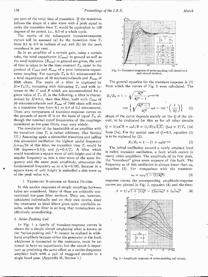
170 Proceedings of the I.R.E. March
per cent of the total time of transition. If the transitionfollows the shape of a sine wave with a peak equal tounity the transition, time T,. would be equivalent to 108degrees of its period, i.e., 0.3 of a whole cycle.
The merits of the subsequent transient -responsecurves will be assessed (a) by the transition time 7',.from 0.1 to 0.9 in radials of wot; and (b) by the peakovershoot in per cent.
As in an amplifier of a certain gain, using a certaintube, the total capacitance (Coto) to ground as well asthe total resistance (Rtotai) to ground are given, the unitof time is taken to be the time constant To, equal to theproduct of Ctotal and Rtotai of a pure resistance -capaci-tance coupling. For example. To is 0.1 microsecond fora total capacitance of 50 micromicrofarads and Rtotal of2000 ohms. The merit of a filter is expressed byH=To/T,., increasing with de'creasing T,., and with in-crease in the C and R which are accommodated for agiven value of T,.. If, in the following, a filter is charac-terized by H=0.5, then this filter, built with Ctoto of50 micromicrofarads and Rtoto of 2000 ohms will resultin a transition time from 0.1 to 0.9 of 0.2 microsecond.Thus, any comparison of transient -response curves onthe grounds of merit H is on the basis of equal To, al-though the nominal cutoff frequencies of the couplings,considered as low-pass filters, may vary widely.
The correlation of the bandwidth of an amplifier withits transition time T,. is rather arbitrary. (See SectionIII.) Assuming again a sinusoidal transition and callingthis sinusoidal oscillation the highest useful frequencyfo=w0/ 27r of this filter, its transition time Tr would be108 degrees = 0.3/fo and fo=-0.3/T,.. A filter whichwould transform a square wave of unit height and of theangular frequency coo into a sine. wave of the same fre-quency and the same peak amplitude, attenuates thefundamental frequency wo to 7r/47-0.785, because in asquare wave of unit height is embodied a sine wave cooof the peak value 4/7r.
I. TRANSIENT RESPONSE OF SINGLE FILTERS
In this section responses of simple couplings betweentubes are considered. Many of these are evidently con-ventional low-pass filter sections. They are, however,calculated individually and on their own merits, sincethe treatment as ideal filters gives quite unreliable re-sults, unless the filter is so long that terminations areeffectively nonreflecting.
1. Series -Peaking Coil
In Fig. 1 a family of transient -response curves isshown for a simple circuit employing what is known asthe "series -peaking coil." It cannot be realized in wide-
band amplifiers because either the generator or the load,whichever is connected to the resistance, must be as-sumed to have no capacitance; but the circuit is impor-tant as producing the same effect as a carrier -frequencyamplifier built with a pair of staggered circuits or asingle band pass. (Appendix II, Section 1.)
6
.6
4
2
00
1J.
t-22
1] " L
6 QBEEE 64707 minsp 64
OMNI 631.121511 59
52
Fig. 1-Transient response of series -peaking coil circuit to aunit step of current.
The general equation for the transient response is (1)from which the curves of Fig. 1 were calculated. The
Ed& = 1 -4Q2
4Q2- 1 e-wot/2Q
cos { 4/4Q2 - 1 coot - (-1Q
)1 (1)4422 2
shape of the curve depends mainly on the Q of the cir-cuit, to be evaluated for this as for all other circuits
Q = 1/woCR = woL/R = (1/R)1/L/C; Qwot = T/To (la)
from (la). For the special case of Q=0.5, equation (1)is to be replaced by (2).
Ei/Eo = 1 - (1 + coot)e-woe (2)
The initial oscillation around a newly attained levelis called transient oscillation, a fault which occurs inmany video amplifiers. The amplitude of its first peak,the "overshoot" gives some measure of this fault. Thefrequency co, of this oscillation is always lower than wo,equation (3). For comparison with the transient-
= coo -V1 - (1/4Q2) (3)
response curves the corresponding amplitude -responsecurves are plotted in Fig. 2, equation (4) and the time -
A = 1/V1 + (1/Q2 - 2)(w/w0)2 (0-V(004
14
L2
MMOOMMEM MMMMMMM 'MilXMOMMONMAIGIOEMMOUNIUMOMOMMUMMOMMIROMWOMMOMOMIMMEMOMmunimfitmommumnal MMMMM&MMOMMEMOM,MEMOMMUUMMOKOOMMOMMOOMM MMMMM ffBOMOMOMMIIMOVAIMPEVI4immussominvAsnmombimmadmmimemplownermmummomaOMMOMMOMPOlg2 MMMMM MOOMMAMMOMMOtmemmapmzmoommoommianualimmem,oar _ . .amommeammummEnsmm
MOMMOMWOMOOMritiilaZiniallinglitainglillPOMMOMMOMMOOMMICMPRIMOMMMEOMMEOMOMMOMON041100.MODOMOMMOMMIMMMMM111OMMOIMWONOMMEMOMniMMIOMMORMOZM7WOM
OIS
NMOCOMOI .MWMOSZOILMOMMOMMOMOMOMMW4AMOMMW MMMMMM EIONOMOMMEMOMMOMMOMMECOM l ommoblimaOM 0111110.1QM
MO 7:71-. MOMMMOXIMMMOONO105MO MMOMMIMOM60MOCMW2!MO =MEMO MMMMMMMM W.19MOOM T EMMOMEMMOMOMMOMb
EMMA M I MMMMMMMM MIMO012NIMOMMUMMOIMMO MMMMMMMMMM MOMMEMOMOMMIMMOMMOMMO MMMMMMMMMMM MEMO
12 14 l 1p
02.
Fig. 2-Amplitude response of series -peaking coil circuit.
(4)
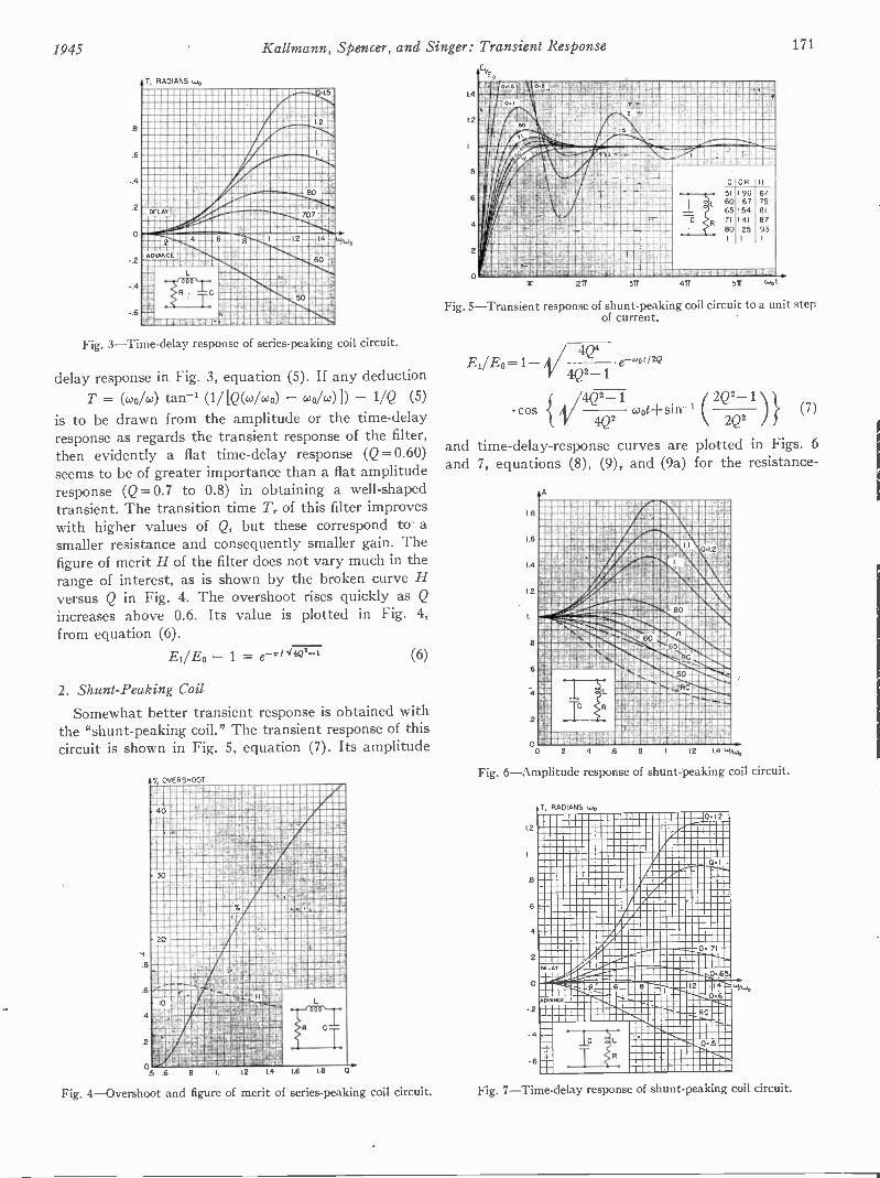
1945 Kallmann, Spencer, and Singer: Transient Response 171
7, RADIANS t..).
.a..4451g4SOO MMMMM mommommummommonmmmmbizim
SNOWSOMOSOMOOMOSSINOMMOSOU SNOWmmmmmmmmmmmmmmmmm OOMMOOMSSUICSOMOMMOMO mmmmm MOMOUSPWOOIOSMOWS mmmmm SONOMOSOMEOW M MM ESMOOSINIISSOOMOMMMOOMSOMOMMUMA NIOSOOEb
M MMMaSSEWON,AP54
MOINESSEOWOOMOOW=IOWA
MS MMMMMM OMMOOMSOOSIONONSE OMMO MMMMM ONNOMONOSINP ..11MOS ElOMMEMOMMMO MM A MM 'OMMEMMINia- NMemmommommerAmmilmmemmmemmammMOONSI/MISIBI.
walOssigsdaspihmmmommommomminea.legmmum
leiri.'"..11/11:111111:111:gt
11=311101101as r musimmaemamig
mmmgcMM,
ADVANCE
SOOMSASONMONNSOMMRMOMMOVONWOONO
-
MeVMOMS lib,
Fig. 3-Time-delay response of series -peaking coil circuit.
delay response in Fig. 3, equation (5). If any deductionT = ((kilo)) tan-' (1/[Q(0)/wo) - wo/(0)]) - 1/Q (5)
is to be drawn from the amplitude or the time -delayresponse as regards the transient response of the filter,then evidently a flat time -delay response (Q=0.60)seems to be of greater importance than a flat amplituderesponse (Q= 0.7 to 0.8) in obtaining a well -shapedtransient. The transition time T7 of this filter improveswith higher values of Q, but these correspond to asmaller resistance and consequently smaller gain. Thefigure of merit H of the filter does not vary much in therange of interest, as is shown by the broken curve Hversus Q in Fig. 4. The overshoot rises quickly as Q
increases above 0.6. Its value is plotted in Fig. 4,from equation (6).
El/E0 - 1 = e --*/44Q2-1 (6)
2. Shunt -Peaking CoilSomewhat better transient response is obtained with
the "shunt -peaking coil." The transient response of thiscircuit is shown in Fig. 5, equation (7). Its amplitude
% OVERSHOOTAS MOMNS MMMMMM mcammmommemommemmommaim1911111,11126Amommummrammm
mumaalng""millNI se DESIMMIII DIMA MMMMM
MIMIEMPIPMEMIMItalinitIIIIIIII16:1M7MMEISIIIIzm mippimmgcmiscpurummsMM MMUMEIMMOOMANWA.MCCON rwarmom IIMIIIIIMIIIngaingilm milliiinglaTalgraffarallMom mommmummmummgmummerunamm
OSOISOOOMINSMSSOWASOOMOPEOPROMOMSOS mommmemmelimmommomammmommmoSOO MOMOMMOOMOMOMOOMOSOONMUOPMEMS MMMMM gammermommmummmompommmSOSOMOMAMESORKONOWN MMMMMM SOMESOMOSMEMOOOMFOMSESOMO MMMMM SEISM
MOOMMEMOSASSMOUSSMOOMOMMOMPisommunsmommummumm MMMMMM minOMUSSAMAINNom
MOM NVIIMMIMMMEMMMUMWMA;V Digg NIS311111111111111am SAIIII11111:111121:111MN MNINKM4=IMMINNNIIMM
RIMMACNNZYMMMOIN8112013,1101MMW.r.WNOVMMRN;ALMNIMMUM
7911UMNfiliM291-3,...349MIENMNMMEMMAWMAd.'&rfMNAMPM,vaammirdemmiksvmbmpasmam4V@WW,JENA71,:,11.N1USINLIM-41N14,W apffmruotcum
i4LAWE3.O1I01-11".41i,HME
,-Tr
.5 .6 12
Fig. 4-Overshoot and figure of merit of series -peaking coil circuit.
E.
1.4
1.2
2A 37r
-
Frri
51
606571
80
1.1si
C R
196167154141
125
1
1i
6775
81
87931
411 511 wot
Fig. 5-Transient response of shunt -peaking coil circuit to a unit stepof current.
EI/JEc=1-- V 4244Q2_ e -.0/2Q
cos V4424242-2 1 woti-sin-t 2Q22Q-2 1 )} (7)
and time -delay -response curves are plotted in Figs. 6and 7, equations (8), (9), and (9a) for the resistance -
12
111111111114111q1likIII
muguannisimput _.411,,,m_virmtimilMMUSIMMIN1 UNIOCZW!SAM,4900M110 6I SMMOIMmUNNUAWAKNOUC014MimmAi. NNMOmEHMAmWNRAVOINENNIM64I4CAW44A059,cTN9A.7. AM:McommMeggmmmuccm4,,imrsv4,monimnemnmememmparmaum.41mumgemmmoieOUSM1N,0400,FREAAINIAVAn0.8114AIZNIM112nyvawmaareauumftsmarwaaomeiimmeisa4AvompilowgwagmmesmwasktioMAIA4110,446- .....q4M,MAHOINNWOmold
1M40P4LINIMM42211:214ftim.isOm.i'me4160.4121ROMOOSIONMENSommtimorkm.Am.mmminEmOrmmimmAmmrommgozmomail!mgmw.w .quimmitegMlfild3v1,4/.,!AiNiii,4COr....811181N.MMilIINNIMMEMAMIUMAVAUMI.40.0 WOIS&NmlSM
migummompumm momiimpaAa pommelcmmenummomm umm..momir.m. 1111117.4
NUMMONMMMIZOMWACCIDX.911
ESWM
41119b."211 50 1129.M.751!!
MMUM 1i PI RcNINilES -1---.
NMMMMO
li
12 I4
Fig. 6-Amplitude response of shunt -peaking coil circuit.
1.2
.8
6
4
2
0
-2
-4
-6
0 2 4 .6 8
7, RADIANS ,.lo0.12
0 71 -
DELAY_....,
..p.,..t..7.76_-_81,,2.2
ADVANCE
...-1 ...... 4._ Re
0..65,
I 4 - wA,0.6-
c 0.5
Fig. 7-Time-delay response of shunt -peaking coil circuit.
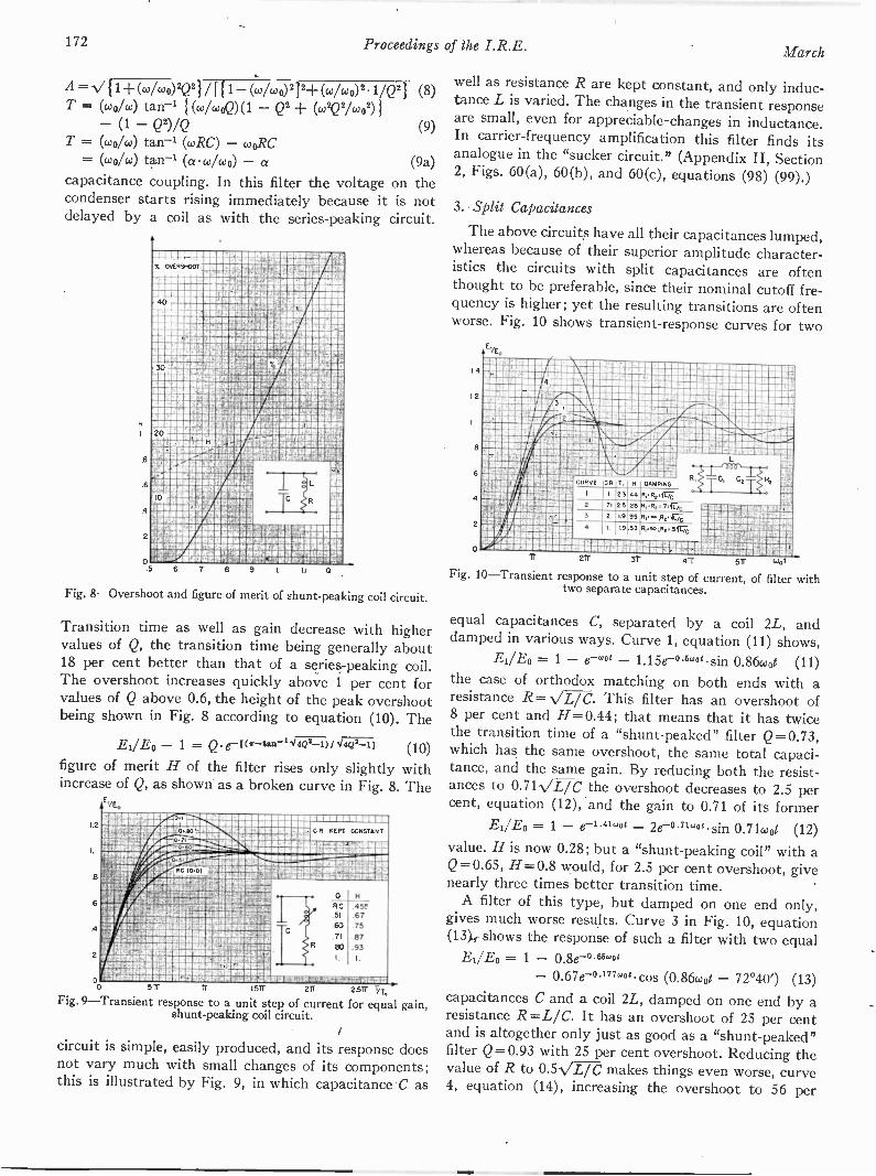
172 Proceedings of the I.R.E. March
A= Vil+Ww0V2)/[11-(c0/04)2]2+(colcoo)Z 1/Q2) (8)T = (coo/co) tan-' { (4,00,2)(1 - Q' + (04221,002)}
- (1 - Q2)/Q (9)T = (coo/w) tan-' (wRC) - woRC
= (04M (aco/w0) -a (9a)capacitance coupling. In this filter the voltage on thecondenser starts rising immediately because it is notdelayed by a coil as with the series -peaking circuit.
6
4
O5 6 7 8 9 0
I
Fig. 8-Overshoot and figure of merit of shunt -peaking coil circuit.
Transition time as well as gain decrease with highervalues of Q, the transition time being generally about18 per cent better than that of a series -peaking coil.The overshoot increases quickly above 1 per cent forvalues of Q above 0.6, the height of the peak overshootbeing shown in Fig. 8 according to equation (10). The
EdEo - 1 = Q e-tor-tain-144/43-1)014Q2-11 (10)figure of merit H of the filter rises only slightly withincrease of Q, as shown' as a broken curve in Fig. 8. The
o 5 Tr Tr 1.5Tf -2II._.. 2 57 T/TFig. 9-Transient response to a unit step of current for equal gain,
shunt -peaking coil circuit.
circuit is simple, easily produced, and its response doesnot vary much with small changes of its components;this is illustrated by Fig. 9, in which capacitance C as
well as resistance R are kept constant, and only induc-tance L is varied. The changes in the transient responseare small, even for appreciable changes in inductance.In carrier -frequency amplification this filter finds itsanalogue in the "sucker circuit." (Appendix II, Section2, Figs. 60(a), 60(b), and 60(c), equations (98) (99).)
3. Split Capacitances
The above circuits have all their capacitances lumped,whereas because of their superior amplitude character-istics the circuits with split capacitances are oftenthought to be preferable, since their nominal cutoff fre-quency is higher; yet the resulting transitions are oftenworse. Fig. 10 shows transient -response curves for two
EYE.
4
2
0
r.
-L-T 111.1 lM1 I fi '1144:21r air 57
Fig. 10-Transient response to a unit step of current, of filter withtwo separate capacitances.
equal capacitances C, separated by a coil 2L, anddamped in various ways. Curve 1, equation (11) shows,
Ei/E13 = 1 - e-wo - 1.15e-05wotsin 0.86wot (11)the case of orthodox matching on both ends with aresistance R=-VIW. This filter has an overshoot of8 per cent and H=0.44; that means that it has twicethe transition time of a "shunt -peaked" filter Q=0.73,which has the same overshoot, the same total capaci-tance, and the same gain. By reducing both the resist-ances to 0.7WL/C the overshoot decreases to 2.5 percent, equation (12), and the gain to 0.71 of its former
Ei/E0 = 1 - e-1.41wot 2e-071wog sin 0.71coot (12)value. H is now 0.28; but a "shunt -peaking coil" with aQ=0.65, H=0.8 would, for 2.5 per cent overshoot, givenearly three times better transition time.
A filter of this type, but damped on one end only,gives much worse results. Curve 3 in Fig. 10, equation(13),, shows the response of such a filter with two equal
El/E0 = 1 - 0.8e o.Moot
- 0.67e-0177"ogcos (0.86coot - 72°40') (13)capacitances C and a coil 2L, damped on one end by aresistance R=L/C. It has an overshoot of 25 per centand is altogether only just as good as a "shunt -peaked"filter Q=0.93 with 25 per cent overshoot. Reducing thevalue of R to 0.5VETe makes things even worse, curve4, equation (14), increasing the overshoot to 56 per

1945 Kallmann, Spencer, and Singer: Transient Response 173
Ei/E0 = 1 - 0.178e--1 54'ot
- 0.97e-oinwo t cos (0.745woi - 34°) (14)
cent, and being otherwise considerably inferior to ashunt -peaked circuit of 56 per cent overshoot. It canbe shown quite generally for this type of filter thatoptimum damping of the overshoot is obtained, if thedamping is evenly distributed between both ends, sothat the products C and R at each end are just equal.
The physical explanation is found in that eachresistance is simultaneously acting as a shunt dampingfor the nearer half section and as a series damping forthe remote half section. The resistance should be smallfor the first, but large for the second purpose, and theuse of equal time constants CR on both ends yields theoptimum compromise.
The attempt to improve filters by splitting theircapacitances in two having so far failed, it remained toobserve the effect of splitting the capacitances in evensmaller fragments. Fig. 11 shows the response of a low -
8
.6
4
2
/E.
2 T20
CURVE CR141 32
2 1-41 32LP -1 1 1
21.
H
4444
T .
1 11111 1 1 11-1111121T 31T 4R 5r ..4,t
`MI
Fig. 11-Transient response to a unit step of current, of filter withthree separate capacitances.
pass filter consisting of four equal half sections LC,damped at both ends, equation (15). It can be shownE1/E0 = 1 - (1.36wot 0.14)e-"1wo 1.32e-1.1wo
- 0.47e-"wo cos (0.79wot + 17°45') (15)
that the value of R = 0.707VW gives the least over-shoot which is still 9 per cent. For comparison theresponse of a low-pass filter built in two half sectionslike the filter 1 in Fig. 10 is shown as the dotted curve 2,stretched to accommodate the same total capacitanceand the same resistance, giving therefore the same gain.The transition time and overshoot are exactly the same,H= 0.44, and the only difference due to the furthersplitting of capacitances is that the transient oscillationsare of somewhat higher frequency, but less well damped.A single shunt -peaking circuit with 8 per cent overshootwould be nearly twice as effective, H=0.87.
If we consider these particular types of circuits in-cluding split capacitances, we see that they carry re-sistance loads directly across capacitances, whereas thisdoes not occur in the case of the series- and shunt -
peaking filters. These particular split- and lumped -
capacitance circuits may, in fact, be considered asexamples of mid -shunt- and mid -series -terminated filtersrespectively. From some points of view it is unfair tocompare examples from the different classes, but it must
be noticed that a lumped -capacitance (half -section)version of the mid -shunt -terminated filter would haveno meaning, in that an inductance is left in series with aload of presumed infinite impedance. To make a faircomparison of the effect of splitting capacitances with-out changing the type of the termination, the good per-formance of the shunt -peaking circuits led us to applythe same form of termination to a low-pass filter withsplit capacitances. Curve 1 of Fig. 12 is the result of
/E.
oo
CURVE CR T, R DAMPING
R,. 002 262 34 63 4,.3 2 82 3.57 79 SHUNT PEAK.
ISO COIL0..63
21T 3ir 41r wot
Fig. 1 2 -T ra nsient response to a unit step of current, of improvedfilter with two separate capacitances.
using two capacitances 2C, separated by a coil 2L andeach terminated by a coil L in series with the optimumresistance R=1.41-VL/C, equation (16). The overshootE1/.& = 1 - (0.34coot 0.99)e-0.71woe
0.53e-0.16wot cos (0.79coot + 82°30') (16)
of 16 per cent is high, but can be damped out withoutloss in gain by a resistance 2R across the coil 2L. Theresulting filter is represented in curve 2 of Fig. 12,equation (17). This is a very straight curve with 2 perE1/.& = 1 - (0.31wot 1.05)e-0.71"4" + 0.12e-1.06,ot
- 0.666-039wol cos (0.75wot + 75°) (17)
cent overshoot, and is the first curve which has beenfound to be better than the shunt -peaking filter; theimprovement is, however, very small, H=0.83. Thecompeting shunt -peaked filter Q = 0.63, H= 0.79 isshown for comparison as a dotted line, curve 3. Thereis no reason to expect a better transition time by stillfurther splitting the total capacitance. Indeed, thecomparative behavior of these last-mentioned filtersappears to allow the deduction of a few general rules:
(a) Splitting capacitances within a certain type offour -terminal filter does not appreciably increase themerit H, although it increases the frequency of thetransient oscillations. The cutoff frequency of each halfsection is doubled for the same total capacitance, butthe passage through several sections flattens the pulseby trickle feeding from one section to the next. It willbe shown later on that. Tr increases by about 1.41 eachtime the number of such sections, each with unchangedcapacitance, is doubled, which nullifies the expectedimprovement. This holds true insofar as the couplingbetween the sections is negligible, and therefore, is notapplicable to the extreme case of distributed induct-ance and capacitance of a real cable.
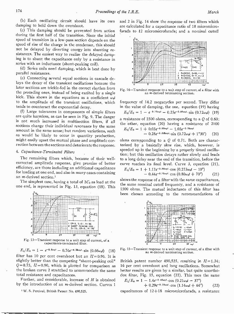
174 Proceedings of the I.R.E. March
(b) Each oscillating circuit should have its owndamping to hold, down the overshoot.
(c) This damping should be prevented from actionduring the first half of the transition. Since the initialspeed of transition in a low-pass section depends on thespeed of rise of the charge in the condenser, this shouldnot be delayed by diverting energy into shunting re-sistances. The easiest way to realize the delayed damp-ing is to shunt the capacitance only by a resistance inseries with an inductance (shunt -peaking coil).
(d) Series coils need damping, which is best done byparallel resistances.
(e) Connecting several equal sections in cascade de-lays the decay of the transient oscillations because thelater sections are trickle -fed in the correct rhythm fromthe preceding ones, instead of being excited by a singlekick. This shows in the equations as a coefficient wotto the amplitude of the transient oscillations, whichtends to counteract the exponential decay.
(f) Large tolerances in components of simple filtersare quite harmless, as can be seen in Fig. 9. The dangeris not much increased in multisection filters, if allsections change their individual resonance by the sameamount in the same sense; but random variations, suchas would be likely to occur in quantity production,might easily upset the mutual phase and amplitude cor-rection between the sections and deteriorate the response.
4. Capacitance -Terminated Filters
The remaining filters which, because of their well-
corrected amplitude response, give promise of betterefficiency, are those including an additional capacitancefor loading at one end, and also in many cases containingan m -derived section.'
The simplest case, having a total of 2Co as load at theone end, is represented in Fig. 13, equation (18). This
6
.4
2
E.
- .1.......-..
:2 Iol.
/O-=
I
....1-1-._
,...
I
1I. CR3. Tr 31 H 962 SHUNT PEAKING COIL.
E('. 0.75; CR3; H. 90
d -LLII11111111_11111arr 4W Ulot
Fig. 13-Transient response to a unit step of current, of acapacitance -terminated filter.
EI/Eo = 1 - e-o Iwo - 0.76e-°25wo0 sin (0.66wo0 (18)filter has 10 per cent overshoot but an H=0.96. It isslightly better than the competing "shunt -peaking coil"Q= 0.75, H= 0.90, which is plotted for comparison asthe broken curve 2 stretched to accommodate the sametotal resistance and capacitances.
Further, and considerable, increase of H is obtainedby the introduction of an m -derived section. Curves 1
1 W. S. Percival, British Patent No. 490,525.
and 2 in Fig. 14 show the response of two filters whichare calculated for a capacitance ratio of 18 micromicro-farads to 12 micromicrofarads; and a nominal cutoff
U7NAMISIEMMVMMESEMMOMIMMICIMMUMWMOWACIMOMMEMEMU.IfiKAWSOPMEWIRMIMAPMMOMMUMMMEMMMAXMMAIMMEIPMPAM
04011T31111W"NSIIIIIIIIIMIATILT1smsrammgmemommirimmomammim -46...maimpoppici,ommmo201111diaNIUMIllimg=soimmaummilatill.MOIMMIOMMMIMU A -...mmwmasmansommummoMMUMMAMMAMMMMAINIMMIMUF MMMMMMM MMIKINAWW112.4SMGMEMAMMCMWAP MMMMM MAIMS4MHICIANIMAEMMEGISIMM MMMM MMMOCISTIMEMMAWMEMMEMMIMUMMWMommommonmma MMMMMM is.mmmeWMIPPGAMMAWAMMMIGIUMMEWANOMW2MIMMM I Rmon. 0.62,,,,Nsimarvjammiummomma MMMMM 2 R.210011,0,71im.1.2aillrY4 MMMMM
3 R.150011. Hol.34WM MMMMM MMMMMM MIIMMMLEMUMWMMM41".o MMMMMMMMMM M M MM MaGIMMAMMIMMO
0 2W 311 411 wot
Fig. 14-Transient response to a unit step of current, of a filter withan m -derived terminating section.
frequency of 14.2 megacycles per second. They differin the value of damping, the one, equation (19) havingEao 1 - e-0.18coo0 0.25e-°09"0 sin (0.72wot) (19)
a resistance of 2500 ohms, corresponding to a Q of 0.60;the other, equation (20) having a resistance of 2100
El/E0 = 1 + 0.03e-°96°30' - 1.02e-°24wo- 0.28e -°°95w0' sin (0.72(11ot + 1°30') (20)
ohms corresponding to a Q of 0.71. Both are charac-terized by a basically slow rise, which, however, isspeeded up in the beginning by a properly timed oscilla-tion; but this oscillation decays rather slowly and leadsto a long delay near the end of the transition, before thecurve reaches its final level. Curve 3, equation (21),
= 1 + 1.17e-08"0 cos (0.273coot - 10°)- 0.44e-°""og cos (0.80coot + 70°) (21)
shows the response of a filter with the same capacitances,the same nominal cutoff frequency, and a resistance of1500 ohms. The mutual inductance of this filter hasbeen chosen according to the recommendations of
B
6
4
2
EvE.
-1,---i-4--P-1-
r.....^_._1_,.7"4-_
! 1-
1
,
...,
- -., . Co Osf
' ..._,
I to 14214G ... 21pHCi ,epot 1....5.3_All,
cii::::n1 u II
;-r--r- ,---1-,.-1- ---. _i__I .
2 SHUNT PEAKING COIL0.60 SAME C P
, t _1..._' IiI.I, I.- 1 I I I- l_
00 1T 211 31T 4.1
Fig. 15-Transient response to a unit step of current, of a filter withan m -derived terminating section.
British patent number 490,525, resulting in H=1.34;16 per cent overshoot and long oscillations. Somewhatbetter results are given by a similar, but quite unortho-dox filter, Fig. 15, equation (22). This uses the same
El/E0 = 1 - 1.4e-°46"ot cos (0.21coot - 37°)+ 0.29e-029wo cos (1.14coot + 64°) (22)
capacitances of 12+18 micromicrofarads, a resistance

1945 Kallmann, Spencer, and Singer: Transient Response 175
of 1500 ohms, but coil values, found experimentally, ofL1=21 microhenries, L2 =13 microhenries, and M=5.25microhenries. This response curve is of the same typebut reaches its final level sooner. Because of the longdelay near 0.9 of the final value, the curve does notlend itself to a just assessment by a single figure. Thecurve of the competing shunt -peaked filter is thereforeplotted as a dotted line. It has a Q of 0.6, an H=0.75,and a 1 per cent overshoot. Its slope over most of thetransition time is about 1.6 times inferior. Coil capaci-tances and damping resistances across one or both coilsof this type of filter may somewhat affect its response.In fact, the losses of the coils are bound to damp theoscillation more than is visible in the plotted curve.But there is no reason to expect considerable changesin the shape or the speed of the transient response of thistype of filter, i.e., a slow rise with a superimposeddamped oscillation, which is timed to hold down its toeand to lift its top.
5. Low -Pass Filters as Carrier AmplifiersLow-pass filters are sometimes used for tie amplifica-
tion of a carrier and both side bands. This case is not tobe confused with that of the analogue band-pass filtersfor carrier amplification, as described in Appendix II,whose response is substantially symmetrical around thecarrier frequency.
No simple conclusion can be drawn from the transientresponse of a low-pass filter regarding its merits as acarrier amplifier. As the filter type represented in Figs.14 and 15 is sometimes used for this purpose it may serveas a suitable example of how to deal with such cases.Fig. 16, equations (23 and 24), shows the amplitude andtime response of the filter underlying Fig. 15. Both theamplitude response and the time response of this filterappear to be reasonably steady in the range from0.25 coo to 0.75 coo. The frequency 0.50 coo may thus bechosen as that of a carrier which is modulated with bothsidebands up to a maximum modulation frequency0.25 coo and thus occupies the band from 0.25 coo to0.75 coo.
The assessment of merits of a filter for carrier ampli-fication is exact only in the cases -where the curve for thegain and the curve for the envelope time response aresymmetrical around the carrier frequency, thus indicat-ing exact equality of distortion of the upper and lowersideband. For slight assymmetry it is, however, permis-sible with negligible error to take the average bylumping the amplitude and phase distortion, respec-tively, of the upper and the lower sideband.
The gain response in Fig. 16 varies in the frequencyrange occupied between 0.93 and 0.77, being 0.80 atthe carrier frequency 0.50 coo. The gain of the upperand lower sideband may thus safely be lumped. Thebroken curve on Fig. 16 shows the resulting averagegain A of the modulation frequencies co. rising from0.80 for zero frequency to 0.84 at com = 0.25 coo. This gainresponse may be considered as sufficiently flat.
A similar consideration applies to the envelope timeresponse. It must be understood that in the case ofcarrier -frequency amplification the "envelope timeresponse" is not identical with the "time response" of thefilter as applicable for modulation -frequency amplifica-tion. The "time response" represents the time afterwhich each frequency co arrives at the output of thefilter, relative to the time of arrival of zero frequency.
T
+.2
ma. MMMMM MAMMAMAIRMANSMAMAMMAMPAAMMWSWIAMMAMMMIMMOMMAAMMii&Un4JAMMEMMIAOMMEMMEWMAMIPOMMAMBMiArMIAMI "... AMITUOMPAOMMAMMmammamlamma.,..- A 7SMAMMOMMAW
MMItrreAMANADM'S
ASMOMMAMmm kMEMIMMC.;
AMMAMMAMMACu 7::::MM
MIOMWFWV
Vtlit.0...mmmes
AMMO MAMN'gam MMMMM aummnaam . WMSAMMAIMAR MMMMMM AM ,
1161911111151111111Wm MMMM W. MM AMMAMMAIIIII
1:1111110MIMAMMEMEMMA
AMM MMMMM sammaamaimmaaamum MMMMMM mammcm.mall
LAY T N RADIANS Loc,
4-
Fig. 16 -Amplitude and time -delay response of a filter with anm -derived terminating section. Filter values as in Fig. 15.
This is plotted as time response in Fig. 16, equation(24). This time response is applicable if the filter isused for video frequencies, showing the amount of theirrespective advance or delay. But in carrier -frequencyamplification matters are somewhat more complicated,in that the various modulation frequencies co, appearon the output as beats between the carrier frequencyand the various sideband frequencies. These beatstravel not with the velocity of the waves themselves,but with what is known as group velocity. The relativetime of arrival of these beats at the output terminal ofthe filter is not described by T = 0/co but T,=4/dco.This envelope time delay T, is plotted in Fig. 17, equa-tion (25). Constant value (a horizontal line) would bethe ideal envelope -time -response curve. And again, onlywhen the response curve is symmetrical around thevalue of the carrier frequency, is the distortion identicalfor both sidebands and thus can be simply assessed. But
1 + 1.18(4coo)2
A 11/ [1 - 6.14 (4(00)2 ± 3.4(4(0012 -I- [4 (0/coo - 4.85(404)12
4 .4(00 - 4.85(4(.00)3T = coo/co/ tan -2
1 - 6.14(4coo)2 + 3.4(0,/w0)4tan -1 (1.09 4(00) 1 - 2.91
do 4 ± 10(4(00)2 - 11.1(4(.004 + 16.5(4(00)1 1.09
do) [1 - 6.14(w/w0)2 + 3.4(w/wo)4]2 + [4. w/wo - 4.85(w/wo)aP 1 + 1.18(0)1(002
(23)
(24)
(25)
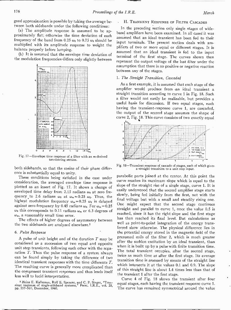
176 Proceedings of the I.R.E. March
good approximation is possible by taking the average be-tween both sidebands under the following conditions:
(a) The amplitude response is assumed to be ap-proximately flat; otherwise the time deviation of eachfrequency of the band from 0.25 coo to 0.75 Wo should bemultiplied with its amplitude response to weight thebalance properly before lumping.
(b) It is assumed that the envelope time deviation ofthe modulation frequencies differs only slightly between
2
RADIANS w0
I. E AMPLIFIER,
WITH GAMER
AT .5 JG
-1-
I-
.1 .s W
0 .2 4 .6 .8 I 1.2 1.4
Fig. 17-Envelope time response of a filter with an m -derivedterminating section.
both sidebands, so that the cosine of their phase differ-ence is substantially equal to unity.
These conditions being satisfied in the case underconsideration, the averaged envelope time response isplotted as an insert of Fig. 17. It shows a change ofenveloped time delay from 2.15 radians coo at zero fre-quency to 2.6 radians coo at co,. = 0.25 coo. Thus, thehighest modulation frequency co,= 0.25 coo is delayedagainst zero frequency by 0.45 radians coo. For co,. =0.25coo this corresponds to 0.11 radians co. or 6.3 degrees ofco a reasonably small time error.
The effects of higher degrees of asymmetry betweenthe two sidebands are analyzed elsewhere.2
6. Pulse Response
A pulse of unit height and of the duration T may beconsidered as a succession of two equal and oppositeunit step transients, following each other with the sepa-ration T. Thus the pulse response of a system alwayscan be found simply by taking the difference of twoidentical transient responses with the time difference T.The resulting curve is generally more complicated thanthe component transient responses and thus lends itselfless well to lucid interpretation.
2 Heinz E. Kallmann, Rolf E. Spencer, and C. P. Singer, "Tran-sient response of single-sideband systems," PRoc. I.R.E., vol. 28,pp. 557-561; December, 1940.
II. TRANSIENT RESPONSE OF FILTER CASCADES
In the preceding section only single stages of wide -
band amplifiers have been examined. In all cases it wasassumed that an ideal transient has been fed to theirinput terminals. The present section deals with am-plifiers of two or more equal or different stages. It isassumed that an ideal transient is fed to the inputterminal of the first stage. The curves shown thenrepresent the output voltage of the last filter under theassumption that there is no positive or negative reactionbetween any of the stages.
1. The Straight Transition, Cascaded
As a first example, it is assumed that each stage of theamplifier would produce from .an ideal transient astraight transition according to curve 1 in Fig. 18. Sucha filter would not easily be realizable, but provides auseful basis for discussion. If two equal stages, eachhaving the transient -response curve 1, are cascaded,the output of the second stage assumes the shape ofcurve 2, Fig. 18. This curve consists of two exactly equal
Ent
IMO rAllii ma mum Rimrisounamme, dammisinraurammonoungnmezderifinvirmi ,ntr-eumumsraiurannuraimarraneumommeri a
ILFIPA'iniziranrAmMIONIZArIIClagErrEINIME AMES BIZ NM!Nyman spaya ram =pm
I ONE STAGE, y1E TAG STAGES, T,..4 FOUR STAGES,
T, I 95S. EIGHT STAGES,
7, 2/0 2 3 4
Fig. 18-Transient response of cascade of stages, each of which givesa straight transition to a unit step input.
parabolic parts joined at the center. At this point thecurve reaches its maximum slope which is equal to theslope of the straight rise of a single stage, curve 1. It iseasily understood that the second amplifier stage startsslowly, being fed initially from the first, not with thefinal voltage but with a small and steadily rising one.One might expect that the second stage continuesstraight and parallel to curve 1, once the value 0.5 isreached, since it has the right slope and the first stagehas then reached its final level. But calculations aswell as point-to-point integration of the energy trans-ferred show otherwise. The physical difference lies inthe potential energy stored in the magnetic field of thepresumed coils of the filter 2, which is much greaterafter the sudden excitation by an ideal transient, thanwhen it is built up by a pulse with finite transition time.The total transient occupies, after the second stage,twice as much time as after the first stage. Its averagetransition time is assessed by means of the straight linewhich intersects it at the values 0.1 and 0.9. The slopeof this straight line is about 1.4 times less than that ofthe transient 1 after the first stage.
Curve 4 of Fig. 18 shows the transient after fourequal stages, each having the transient response curve 1.The curve has remained symmetrical around the value
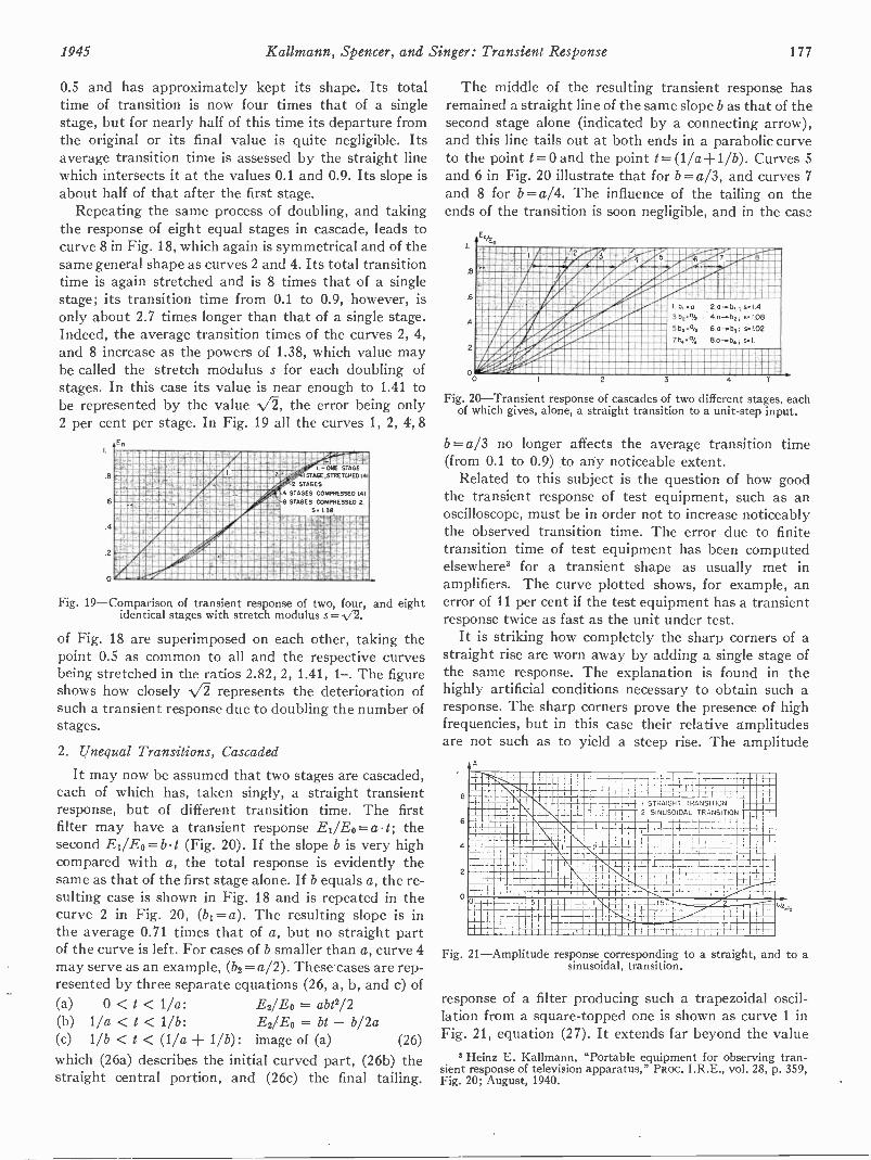
1945 Kallmann, Spencer, and Singer: Transient Response 177
0.5 and has approximately kept its shape. Its totaltime of transition is now four times that of a singlestage, but for nearly half of this time its departure fromthe original or its final value is quite negligible. Itsaverage transition time is assessed by the straight linewhich intersects it at the values 0.1 and 0.9. Its slope isabout half of that after the first stage.
Repeating the same process of doubling, and takingthe response of eight equal stages in cascade, leads tocurve 8 in Fig. 18, which again is symmetrical and of thesame general shape as curves 2 and 4. Its total transitiontime is again stretched and is 8 times that of a singlestage; its transition time from 0.1 to 0.9, however, isonly about 2.7 times longer than that of a single stage.Indeed, the average transition times of the curves 2, 4,and 8 increase as the powers of 1.38, which value maybe called the stretch modulus s for each doubling ofstages. In this case its value is near enough to 1.41 tobe represented by the value the error being only2 per cent per stage. In Fig. 19 all the curves 1, 2, 4, 8
ER
DICIMINIMMIS61111PIPIMMIIMM4MIlitilEms MMMMMMM i441Ect,k11.111111113101PIMMIED1143116144MMMM1011111111EFrEOPIIIIIIININIMIWAISOMMINVIIMMIENIP' I - ONE STAGE
NIANE.NuturcHED,41AMPOIrinITEEMORMirAFININMEMEErNEVIrint419111E.11111UFWEMZIESEICEPV-- 2 STAGESinialigeiMINIGIVilifilKOSEERIMAILINV,;.,1 4 STAGES COMPRESSED 141.1111.10150TIMILWAMINIIIRENIEr ANN 8 STAGES COMPRESSED 2.MZEIMS11111111111121F4E11311181610P MM M111111MallIMEMIUMNIMEIMMINI MMM MM GEE S 1.3E
riMEENNIS MMMMMMM MMMMM 112115 atuisima111111111161 MMMMM MMMM
MMMMM 4111111M4ISNIMMIVIIIMMVSMIIIMIllW.1.1111111WIIIIIIIIIIIMAM111111111111111101121EININC432MIMMIN
MMMMM 11111.1191INEISISEPIACEillill15VISIIIIIVI1111111111M/V:d4U111111111ENIMMIIIIMIPMPENMEAMINIIIIIISdmingrammehir _1411111111511111SERINCR3101235511117MMI51111111111111111CIEr4114111111MMIMAIIIIIIIMMINIIRMIIMMIUM211115EURMIlainata
'411PENRYIIIIIIMIMMINIIIINIOINIIIMIIIN512131111111eIN(0ECWWIENNIP
Fig. 19-Comparison of transient response of two, four, and eightidentical stages with stretch modulus s = N/2.
of Fig. 18 are superimposed on each other, taking thepoint 0.5 as common to all and the respective curvesbeing stretched in the ratios 2.82, 2, 1.41, 1-. The figureshows how closely 72 represents the deterioration ofsuch a transient response due to doubling the number ofstages.
2. Unequal Transitions, Cascaded
It may now be assumed that two stages are cascaded,each of which has, taken singly, a straight transientresponse, but of different transition time. The firstfilter may have a transient response Ei/Eo=at; thesecond Ei/E0=bt (Fig. 20). If the slope b is very highcompared with a, the total response is evidently thesame as that of the first stage alone. If b equals a, the re-sulting case is shown in Fig. 18 and is repeated in thecurve 2 in Fig. 20, (bi =a). The resulting slope is inthe average 0.71 times that of a, but no straight partof the curve is left. For cases of b smaller than a, curve 4may serve as an example, (b2 = a/2). These cases are rep-resented by three separate equations (26, a, b, and c) of(a) 0 < t< 1/a: E2/E0 = abt2/2(b) 1/a < t < 1/b: E2/E0 = bt - b/2a(c) 1/b <1 < (1/a 1/b): image of (a) (26)
which (26a) describes the initial curved part, (26b) thestraight central portion, and (26c) the final tailing.
The middle of the resulting transient response hasremained a straight line of the same slope b as that of thesecond stage alone (indicated by a connecting arrow),and this line tails out at both ends in a parabolic curveto the point t=0 and the point t= (1/a+ 1 /b). Curves 5and 6 in Fig. 20 illustrate that for b = a/3, and curves 7and 8 for b=a/4. The influence of the tailing on theends of the transition is soon negligible, and in the case
4
2
E.
2 3r. 4 5
s.1434.04 e.108
s.102
71404 s I
002 3 4
Fig. 20-Transient response of cascades of two different stages, eachof which gives, alone, a straight transition to a unit -step input.
b= a/3 no longer affects the average transition time(from 0.1 to 0.9) to any noticeable extent.
Related to this subject is the question of how goodthe transient response of test equipment, such as anoscilloscope, must be in order not to increase noticeablythe observed transition time. The error due to finitetransition time of test equipment has been computedelsewhere' for a transient shape as usually met inamplifiers. The curve plotted shows, for example, anerror of 11 per cent if the test equipment has a transientresponse twice as fast as the unit under test.
It is striking how completely the sharp corners of astraight rise are worn away by adding a single stage ofthe same response. The explanation is found in thehighly artificial conditions necessary to obtain such aresponse. The sharp corners prove the presence of highfrequencies, but in this case their relative amplitudesare not such as to yield a steep rise. The amplitude
6
4
2
A
'-__.
Nib.. ti [;;TI,l'ItiI___I®CM..
-4- 1'1STRAIGHT TRANSITION TT4 7--- ' t+-
-1.---2 SINUSOIDAL TRANSITION
;
71-4._.
1
,
;__ -i. --1 1 11- ,--
i_!..-2-r- 7 '1- I -I-
]I Li_ _
-!--
11146116Ti I. ' 1- 1 12.111M II 14- .
1.
1 't1 1 t -I- j,t7i ; f; r -L1-1
Fig. 21-Amplitude response corresponding to a straight, and to asinusoidal, transition.
response of a filter producing such a trapezoidal oscil-lation from a square -topped one is shown as curve 1 inFig. 21, equation (27). It extends far beyond the value
3 Heinz E. Kallmann, "Portable equipment for observing tran-sient response of television apparatus," Paoc. I.R.E., vol. 28, p. 359,Fig. 20; August, 1940.
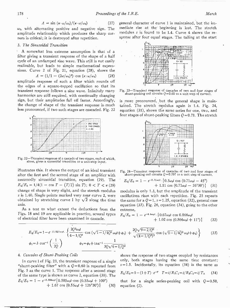
178 Proceedings of the I.R.E. March
A = sin (2-01/coo)/(1rcolwo) (27)
wo, with alternating positive and negative sign. Theamplitude relationship which produces the sharp cor-ners is critical; it is destroyed after repetition.
3. The Sinusoidal Transition
A somewhat less extreme assumption is that of afilter giving a transient response of the shape of a halfcycle of an undamped sine wave. This still is not easilyrealizable, but leads to simple mathematical expres-sions. Curve 2 of Fig. 21, equation (28), shows the
A = (1/1 - (10/0J0)2) cos (1-.0)/wo) (28)
amplitude response of such a filter which rounds offthe edges of a square -topped oscillation so that itstransient response follows a sine wave. Infinitely manyharmonics are still required, with continually changingsign, but their amplitudes fall off faster. Accordingly,the change of shape of the transient response is .muchless pronounced, if two such stages are cascaded. Fig. 22
4
2
0 mo
"1-
T AAMI mei
MENMI!mmi
I ONE STAGE
2 TWO STAGES
s 1.40
r
Fig. 22-Transient response of a cascade of two stages, each of which,alone, gives a sinusoidal transition to a unit -step input.
illustrates this. It shows the output of an ideal transientafter the first and the second stage of an amplifier withassumedly sinusoidal transition, equation (29). TheE2/E0 = 1/4(1 - cos T - (T/2) sin T); 0 < T < r (29)change of shape is very slight, and the stretch moduluss is 1.40. Single points marked very near curve 2, wereobtained by stretching curve 1 by -0 along the timeaxis.
As a test to what extent the deductions from theFigs. 18 and 19 are applicable in practice, several typesof electrical filter have been examined in cascade.
E2/E0= 1-e-(112Q)woi
¢i=3 cos'---
general character of curve 1 is maintained, but the im-mediate rise at the beginning is lost. The stretchmodulus s is found to be 1.4. Curve 4 shows the re-sponse after four equal stages. The tailing at the start
Efl,E.
I.
.6
4
2
o
_L_
4 iTiOES'4 142
0 60
1,2 4, STAGES
1 1. 1-111111 I211 1...t
Fig. 23-Transient response of cascades of two and four stages ofshunt -peaking coil circuits Q=0.60 to a unit step of current.
is more pronounced, but the general shape is main-tained. The stretch modulus again is 1.4. Fig. 24,equation (31), shows the same series for one, two, andfour stages of shunt -peaking filters Q=0.71. The stretch
.6
.6
2
0Tr 211 311 we
Fig. 24-Transient response of cascades of two and four stages ofshunt -peaking coil circuits Q =0.707 to a unit step of current.
E2/E° = 1 - e-°716'ot 0.5coot cos (0.71wot - 45°)+ 1.11 cos (0.71(001 - 26°30')) (31)
modulus is only 1.3, but the amplitude of the transientoscillations rises with each repetition. Fig. 25 repeatsthe same for a Q=1, s =1.25, equation (32), general caseequation (33). Fig. 26, equation (34), going to the otherextreme,E2/E0 = 1 - e-°5'ot {0.67coot cos 0.866wot
+ 1.02 cos (0.866wot + 11°) (32)
2Q20Jog 2Q -V9 - 2/Q2{4-1/Q2
cos (-V1
2 = I -I- tan -1
1/4Q2 wo1-1-01) cos (N/1 -1/4Q2 (4+02) }V(4 1/Q2)3
1
3Q. /4-1/Q21/Q2
4. Cascades of Shunt -Peaking Coils
In curve 1 of Fig. 23, the transient response of a single"shunt -peaking filter" with a Q =0.60 is repeated fromFig. 5 as the curve 1. The response after a second stageof the same type is shown as curve 2, equation (30). TheE2/E0 = 1 - e-°-232w0t10.58504/ cos (0.5504t + 100°)
+ 1.67 cos (0.55coot 126°30') (30)
(33)
shows the response of two stages coupled by resistancesonly, both stages having the same time constant;s =1.5. Incidentally, its equation (34) is the same as
E2/E0= 1- (1+ T) e -T T=1/ RiCi=t/R2C2=t/To (34)
that for a single series -peaking coil with Q =0.50,equation (2).

1945 Kallmann, Spencer, and Singer: Transient Response 179
5. Cascades of Equal and Different Series -Peaking Coils.
Similar curves are shown in Fig. 27 for one, two,(equation (35), general equation (36)) or four stages ofE2/E0 = 1 - e-°235'0' { 4.15 cos (0.55wot - 76°)
- 1.6404 cos (0.55coot 33°30') } (35)
series -peaking filters Q = 0.60, the stretch modulus being1.42; and in Fig. 28, equation (37), for one and two such
E2/E 0 = 1 - e-(1/2Q)(40tcos (N/1 - 1/4Q2 coot - 41)
cos 4)12coot
cos (N/1 - 1/4Q2 coot + ck2)4- 1/Q2JJJ
3/Q - 1/2Q3tan ch =
(4 - 1/Q2)V1 - 1/4Q2
12
8
6
4
2
0
En/
cos 4)2 = 1/2Q (36)
isnux
I ne"
0
11
0 I
I;2 STAGES 0.1
1Tr 211 3TT ubt
Fig. 25 -Transient response of cascades of two and four stages ofshunt -peaking coil circuits Q=1 to a unit step of current.
EWE() = 1 - e-°714'01 {2.24 cos (0.71wot - 63°30')- coot cos (0.71coot 45°)1 (37)
filters with Q=0.71, the stretch modulus being 1.41.Fig. 29 shows the combination of two stages with
different Q in cascade, equation (38). The one has a Qof 0.63, the other of 0.80, equation (39). The total gain
E2/Eo = 1 - 1/[2(p - q)s./1 - p2] e-Pw" cos (N/1 - p2 coot + 01)
- 1/[2(q - p)V1 - q2] e -q.01 cos (-/1 - q2 coot + 4)2)p = 1/2Q1 = sin-, (1 - 2p2)q = 1/2Q2 4)2= sin -2 (1 - 2q2) (38)
E2/E0 = 1 3.67e-0uwot cos (0.78coot + 12°45')- 4.75e-°80wo1 cos (0.60wat - 16°20') (39)
................",...........,11118112111188111 MMMM PS7.0811111111118P=o1111111011fINERVIIIIRSIIIRMInk ...-1111118112291181.11V WHYR...1 nWESiMMEEMME r5INE 4.1.3Emamsw-Arn mrAmmom110111-11L9Menn1111211111" 77UNIIIMAELICLII :r 1 -
IVAIWAMIIIIIIII I, 2 STAGES RC.;murdg..r.nelunfifIFFAMMINIMINIMINIIIWW.1111.81111111111111.11EINFIMMIIIHI MMMM 11111
FRIBUNIIIMMIZIENIMIMINE
811182110
571 11 ISA 1%;
Fig. 26 -Transient response of a cascade of two resistance-
is the same as that of two stages of Q= 0.71, and so toa high degree is the resulting response.
6. The Butterworth System
Among the many possible cascades of series -peakingcoils, those based on the Butterworth system are ofspecial interest.' This system prescribes the values of Q
En,
mllllmmll M MMM ,....ea:Inv619EM 81119111!"sq issismagessaiwornimenMER111811112118, 281111111811881NEr1,8111111Wv". WNW11r 1A-liS'FA191911809KRIWAPIIIISMV.1
1111/11r4NOW
IIITA,UEF1F2412,1Arill RIME8alidl.13V42241811811118111211842a5212ii1111
12128111821811.1221.11113112812179111'61811ESIMIRE'llidEAIN/468011111111111121111=111101102111811ilterdrilillEfin1718,111M118111118181,1111816MIEWIMPURril MMMMMakeirainsisag ammianacgutenn
illtmormannimmer18121/1124EF.'4611111511118118/Pril MMMMM-sanrmirsgimenalirA MMMMM MEMSIIMAINIV181811 MMMM 11 91®11111.212111 ' .1 11.18121811816BNIIIMIINmantrammemaimameassagemmunimmassamunizzeswiaria MMMMM MMMMM 2218881)8111E111311311iRffiglIMMINIIIfrMr48"BPIRIIP!.7418111111141111818,111111121111.81111AMINCEial MMMMMM
0 STAGES, 0..60 , S 142
27r 371* air wot
Fig. 27 -Transient response of cascades of two and four stages ofseries -peaking coil circuits Q=-0.60 to a unit step of current.
for each of any number of series -peaking coils in cascade,so that the over-all amplitude response of the result-ing low-pass filter becomes as flat as possible. It isequally applicable to cascades of pairs of symmetricallystaggered circuits or band passes for carrier amplifica-tion as explained in Appendix II, Section 1. Moreover,a series -peaking filter may be replaced by a cascade of ashunt -peaking filter and a stage with a matched re-
t8/
0 it 27r wot
Fig. 28 -Transient response of a cascade of two stages with series-peaking coil circuits Q.=0.71 to a unit step of current.
sistance-capacitance coupling, according to AppendixIV. Thus this system serves very well in many caseswhere a flat amplitude response is desired.
En0
0..80 0..63
11 27r 37r wot
Fig. 29 -Transient response of two stages with series -peaking coilcircuits, the one Q = 0.63, the other Q = 0.80 to a unit step of current..
4 S. Butterworth, "On the theory of filter amplifiers," Exp. Wire -capacitance -filter coupled stages to a unit step of current. less and Wireless Eng., London, vol. 7, pp. 536-541; October, 1930.
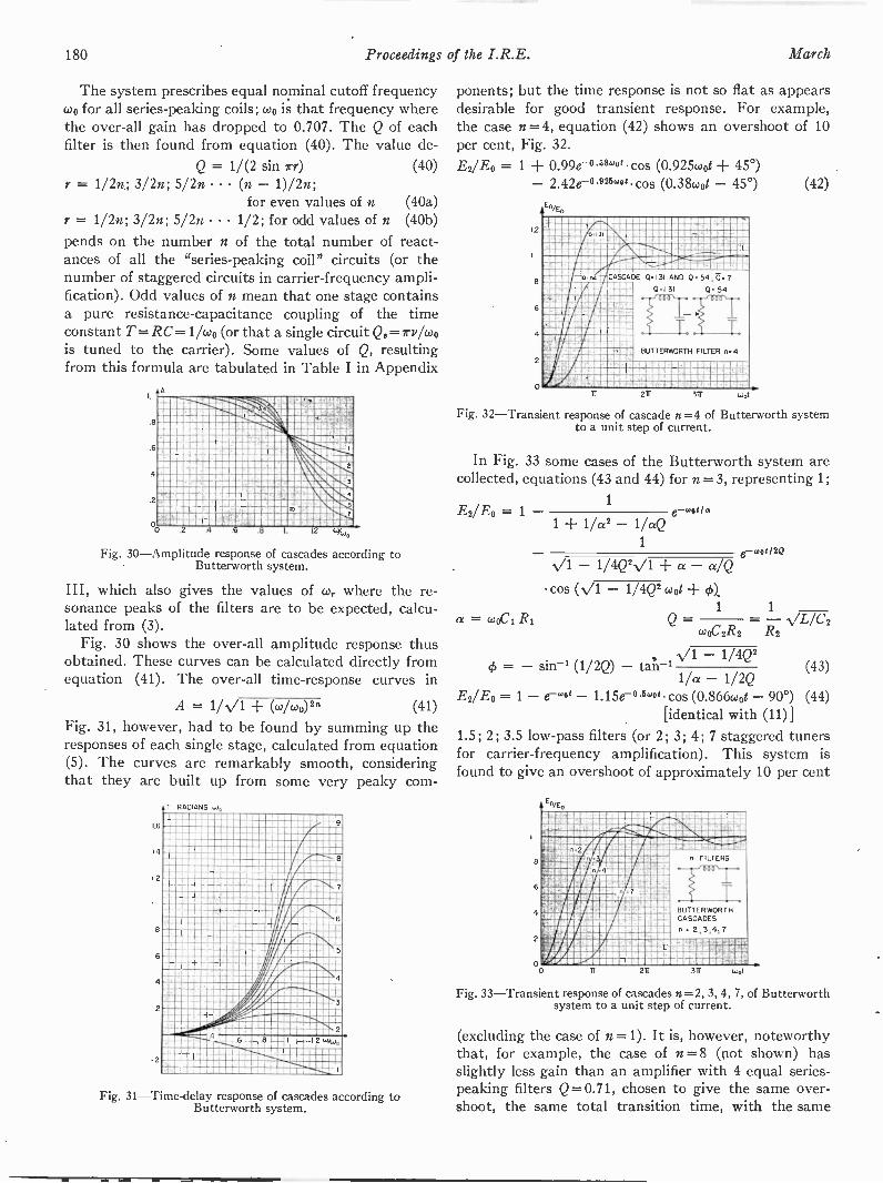
180 Proceedings of the I.R.E. March
The system prescribes equal nominal cutoff frequencycoo for all series -peaking coils; coo is that frequency wherethe over-all gain has dropped to Q.707. The Q of eachfilter is then found from equation (40). The value de -
Q = 1/(2 sin irr) (40)r = 1/2n; 3/2n; 5/2n (n - 1)/2n;
for even values of n (40a)r = 1/2n; 3/2n; 5/2n 1/2; for odd values of n (40b)
pends on the number n of the total number of react-ances of all the "series -peaking coil" circuits (or thenumber of staggered circuits in carrier -frequency ampli-fication). Odd values of n mean that one stage containsa pure resistance -capacitance coupling of the timeconstant T =RC= 1/cdo (or that a single circuit Q.=z-vlok,is tuned to the carrier). Some values of Q, resultingfrom this formula are tabulated in Table I in Appendix
1.
AIN%
weatwa=m-=MAWofMEM"Milalltiti2
limanagMb.co
12 uy,:"
Fig. 30-Amprtude response of cascades according toButterworth system.
III, which also gives the values of co,. where the re-sonance peaks of the filters are to be expected, calcu-lated from (3).
Fig. 30 shows the over-all amplitude response thusobtained. These curves can be calculated directly fromequation (41). The over-all time -response curves in
A = 1/.0 + (w/w°)" (41)
Fig. 31, however, had to be found by summing up theresponses of each single stage, calculated from equation(5). The curves are remarkably smooth, consideringthat they are built up from some very peaky corn -
Fig. 31-Time-delay response of cascades according toButterworth system.
ponents; but the time response is not so flat as appearsdesirable for good transient response. For example,the case n = 4, equation (42) shows an overshoot of 10per cent, Fig. 32.E2/E0 = 1 + 0.99e-"wot cos (0.925wot + 45°)
- 2.42e-0222wot cos (0.38coot - 45°) (42)En/E.
1.2
8
6
4
2
0
CASCADE 0.131 AND 0 54;171 7
0.1.31 O. 54I
BUTTERWORTH FILTER n 4
34 b
Fig. 32-Transient response of cascade n =4 of Butterworth systemto a unit step of current.
In Fig. 33 some cases of the Butterworth system arecollected, equations (43 and 44) for n = 3, representing 1;
1E2/.E0 = 1 contia
1 + 1/a2 - 1/aQ1
ewou2QN/1 - 1/4Q2 -V1 + a - a/Q
a = cosCi R1
cos (N/1 - 1/4Q2 coot + (1))..1 1
\a /c2W0 -,2R2 R2
V1 - 1/4Q2= - sin -1 (1/2Q) - tan-'1/a - 1/2Q
(43)
E2/Er3 = 1 - 1.15e-0.Bwot cos (0.866coot - 90°) (44)[identical with (11)]
1.5; 2; 3.5 low-pass filters (or 2; 3; 4; 7 staggered tunersfor carrier -frequency amplification). This system isfound to give an overshoot of approximately 10 per cent
8
6
4
2
oo
;n4
2 22
T
, FILTERS
BUTTERWORTHCASCADES
n 2,3,4;7
viar317 (4t
Fig. 33-Transient response of cascades n =2, 3, 4, 7, of Butterworthsystem to a unit step of current.
(excluding the case of n =1). It is, however, noteworthythat, for example, the case of n =8 (not shown) hasslightly less gain than an amplifier with 4 equal series -peaking filters Q= 0.71, chosen to give the same over-shoot, the same total transition time, with the same
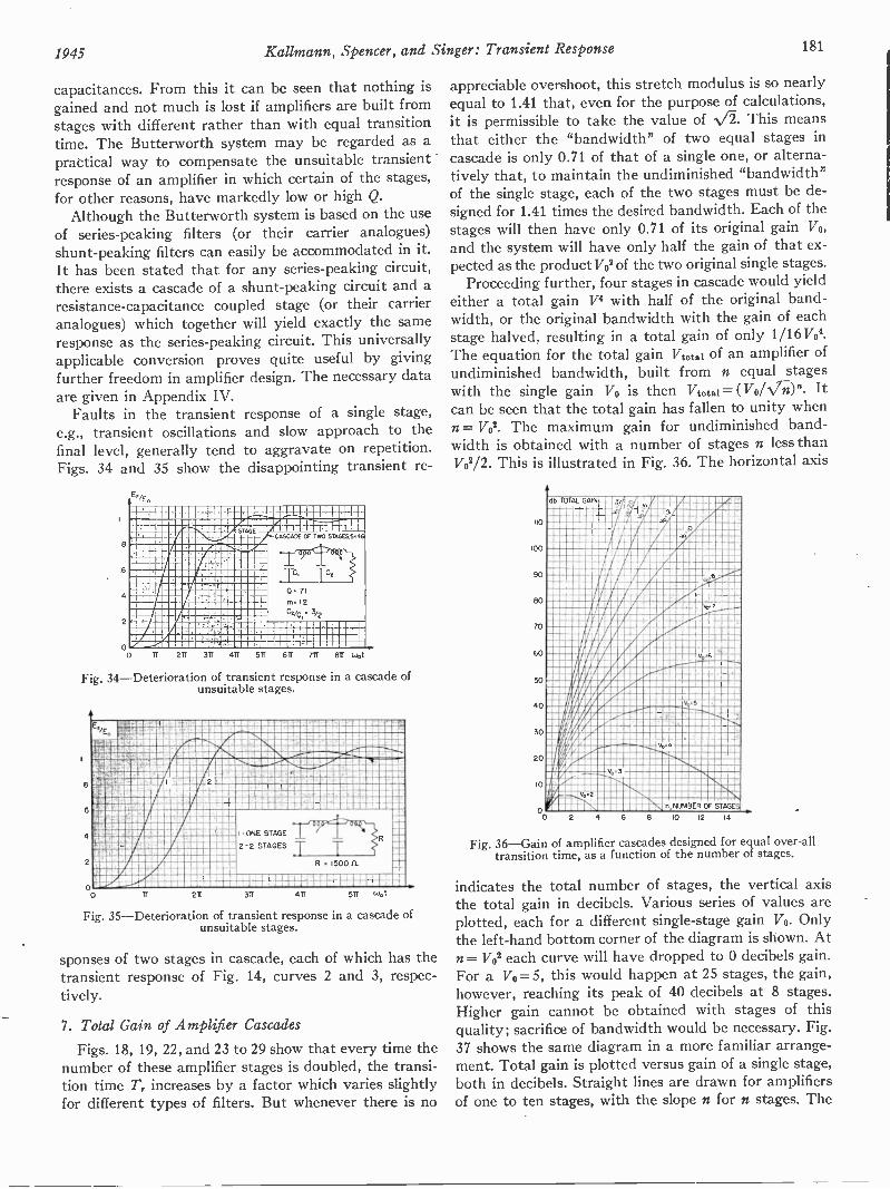
1945 Kallmann, Spencer, and Singer: Transient Response 181
capacitances. From this it can be seen that nothing isgained and not much is lost if amplifiers are built fromstages with different rather than with equal transitiontime. The Butterworth system may be regarded as apractical way to compensate the unsuitable transientresponse of an amplifier in which certain of the stages,for other reasons, have markedly low or high Q.
Although the Butterworth system is based on the useof series -peaking filters (or their carrier analogues)shunt -peaking filters can easily be accommodated in it.It has been stated that for any series -peaking circuit,there exists a cascade of a shunt -peaking circuit and aresistance -capacitance coupled stage (or their carrieranalogues) which together will yield exactly the sameresponse as the series -peaking circuit. This universallyapplicable conversion proves quite useful by givingfurther freedom in amplifier design. The necessary dataOre given in Appendix IV.
Faults in the transient response of a single stage,e.g., transient oscillations and slow approach to thefinal level, generally tend to aggravate on repetition.Figs. 34 and 35 show the disappointing transient re-
E2/E0
MIIIMMI OM MEWME MMMMM
LWMBE RIM.
MMENMEAMMIMMMINIENOMMUMMWMEMMUMMEMOMMEM
ONOMMEMMUMMOMMOMMIEffiMENNIMIMIAMMUMMMOIONEMMEDUMMEMMIESEMMEMMEMME
MIRIMERNIOURIMEnreallL9n 311 411 511 611 7T1 81'4.5;3
Fig. 34-Deterioration of transient response in a cascade ofunsuitable stages.
8
6
4
2
MN
mirwrA. L,MR 11WWWMitaMMN.w.Zmil
"NM "immmmino6"7"VIVATIMAMMEIMINAAWO9164111111111111PINIMEMMINIMIAMEMMIMM
161:1011111=111.CU r I Enli===.Mil
1- ONE STAGE
2-2 STAGES
-r--424
117
oo211 311 411
R 150011
511 (Jot
TT
Fig. 35-Deterioration of transient response in a cascade ofunsuitable stages.
sponses of two stages in cascade, each of which has thetransient response of Fig. 14, curves 2 and 3, respec-tively.
7. Total Gain of Amplifier Cascades
Figs. 18, 19, 22, and 23 to 29 show that every time thenumber of these amplifier stages is doubled, the transi-tion time Tr increases by a factor which varies slightlyfor different types of filters. But whenever there is no
appreciable overshoot, this stretch modulus is so nearlyequal to 1.41 that, even for the purpose of calculations,it is permissible to take the value of N/2. This meansthat either the "bandwidth" of two equal stages incascade is only 0.71 of that of a single one, or alterna-tively that, to maintain the undiminished "bandwidth"of the single stage, each of the two stages must be de-signed for 1.41 times the desired bandwidth. Each of thestages will then have only 0.71 of its original gain Vo,and the system will have only half the gain of that ex-pected as the product Vol ofthe two original single stages.
Proceeding further, four stages in cascade would yieldeither a total gain V4 with half of the original band-width, or the original bandwidth with the gain of eachstage halved, resulting in a total gain of only 1/16VO4.The equation for the total gain Vtotal of an amplifier ofundiminished bandwidth, built from n equal stageswith the single gain Vo is then Vtotal = ( VoVN/Tt)". Itcan be seen that the total gain has fallen to unity whenn= V02. The maximum gain for undiminished band-width is obtained with a number of stages n less thanV02/2. This is illustrated in Fig. 36. The horizontal axis
110
100
90
80
70
60
50
40
20
lb TOTAL GAIN -4 A 2mi nii a16.112L r_ar..24Ai :ran MM MMMrimmMENI Al INMEMM
havillINNMPIIIunnwriproun.:24,....
Imoranniminnuravadu
1110N4NIMIONIIumanaLlaqum
inuommtoo pillumaill1111Willgall_ lismillIllii
orpoomodiNuipinsineiraz:P89.Empriiripeollionimpubo. /.44N4.... ....... ... ma
mummramII A11111111111117111ffnmmmumLON v, 1111011111111
Rii --- llill 1 '' IliV0.2
n, NUMBER OF ST
2 4 6 8 10 12 14
Fig. 36-Gain of amplifier cascades designed for equal over-alltransition time, as a function of the number of stages.
indicates the total number of stages, the vertical axisthe total gain in decibels. Various series of values areplotted, each for a different single -stage gain Vo. Onlythe left-hand bottom corner of the diagram is shown. Atn = V02 each curve will have dropped to 0 decibels gain.For a V0=5, this would happen at 25 stages, the gain,however, reaching its peak of 40 decibels at 8 stages.Higher gain cannot be obtained with stages of thisquality; sacrifice of bandwidth would be necessary. Fig.37 shows the same diagram in a more familiar arrange-ment. Total gain is plotted versus gain of a single stage,both in decibels. Straight lines are drawn for amplifiersof one to ten stages, with the slope n for n stages. The
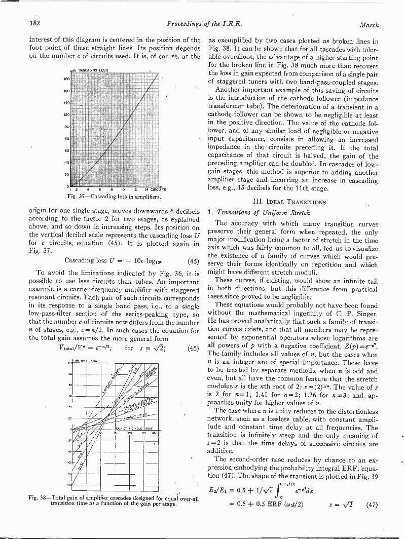
182 Proceedings of the I.R.E. March
interest of this diagram is centered in the position of thefoot point of these straight lines. Its position dependson the number c of circuits used. It is, of course, at the
180
160
140
120
100
80
60
40
20
02 4 6 8 10 M 14 CIRCUITS
Fig. 37-Cascading loss in amp ifiers.
NG LOSS
samitimullawarmallail
db CA
EMORMMOV041SagIgMbWMVMAMIAMOMMAM5d4RMOIMeAtiAMe%_111-124idOMMAIMMIMMWAMMMATIMWSWIMMOROLva414111ANTIMMMORWMMMCIAMMIWUKEMIMMIWNWMOIMEMOIMIRMIMMI.MALASMAIME.WA0UMMMMWM MMOMOMM4 symen6Ani4mvimpisrAvla
pleamemmmtvomacsBiRiinAmPAmaggMMEIMMIMMMOBNMSVVVAMMWSMEMMIMill24211NAMMMOMMIAMENCIIMAKEMMEMDAMSIMMONIKaMMIOLUMAMMIMANMAMMISbiMMIIMMIMPAIMIMMMEMMAIMMIMMIIMMEMAI
L4,31MAMOMS,NUOMMOM4MMMICOMMEMMOMM1:7;21MAAMMWSLIMtr4W.PMEMMOMMIOMMUMMOMw.aumnimmeAmarammammimmaimmsWWWIMM2OMM1WAMEMMO9MMMEMEMIND41/51:11a0.giglaggil=11Jr4111112/21,,21121,%712TFAIOpfENM MMMMMM'ifAmmwowitn,,var4wr,aim MAIM=
'1720;4#11;0110W0011116iMallirsoupwasasammuallamirmA1,,AryorsJemalsammismilli
Wa1tl 2,A44M6mmy.FFE6.i Mc N UU2
origin for one single stage, moves downwards 6 decibelsaccording to the factor 2 for two stages, as explainedabove, and so down in increasing steps. Its position onthe vertical decibel scale represents the cascading loss Ufor c circuits, equation (45). It is plotted again inFig. 37.
Cascading loss U = - 10c logioc (45)
To avoid the limitations indicated by Fig. 36, it ispossible to use less circuits than tubes. An importantexample is a carrier -frequency amplifier with staggeredresonant circuits. Each pair of such circuits correspondsin its response to a single band pass, i.e., to a singlelow -pass -filter section of the series -peaking type, sothat the number c of circuits now differs from the numbern of stages, e.g., c =n/2. In such cases the equation forthe total gain assumes the more general form
= 6.-11/2;Vtotal/V" for s = (46)
12
so
EirBey
pry, c,A
,.2.0:.01 ,,ir
A '00400 MG'"/
.-.1 -'''f GAIN OF A SINGLE STAGE
. 15 20 25 db
40
20
20
-6C
400
Fig. 38-Total gain of amplifier cascades designed for equal over-alltransition time as a function of the gain per stage.
as exemplified by two cases plotted as broken lines inFig. 38. It can be shown that for all cascades with toler-able overshoot, the advantage of a higher starting pointfor the broken line in Fig. 38 much more than recoversthe loss in gain expected from comparison of a single pairof staggered tuners with two band -pass -coupled stages.
Another important example of this saving of circuitsis the introduction of the cathode follower (impedancetransformer tube). The deterioration of a transient in acathode follower can be shown to be negligible at leastin the positive direction. The value of the cathode fol-lower, and of any similar load of negligible or negativeinput capacitance, consists in allowing an increasedimpedance in the circuits preceding it. If the totalcapacitance of that circuit is halved, the gain of thepreceding amplifier can be doubled. In cascades of low-
gain stages, this method is superior to adding anotheramplifier stage and incurring an increase in cascadingloss, e.g., 15 decibels for the 11th stage.
III. IDEAL TRANSITIONS
1. Transitions of Uniform Stretch
The accuracy with which many transition curvespreserve their general form when repeated, the onlymajor modification being a factor of stretch in the timeaxis which was fairly common to all, led us to visualizethe existence of a family of curves which would pre-serve their forms identically on repetition and whichmight have different stretch moduli.
These curves, if existing, would show an infinite tailin both directions, but this difference from practicalcases since proved to be negligible.
These equations would probably not have been foundwithout the mathematical ingenuity of C. P. Singer.He has proved analytically that such a family of transi-tion curves exists, and that all members may be repre-sented by exponential operators whose logarithms areall powers of p with a negative coefficient, Z(p)=e-P".The family includes all values of n, but the cases whenn is an integer are of special importance. These haveto be treated by separate methods, when n is odd andeven, but all have the common feature that the stretchmodulus s is the nth root of 2; s= (2)11*. The value of sis 2 for n=1; 1.41 for n=2; 1.26 for n=3; and ap-proaches unity for higher values of n.
The case where n is unity reduces to the distortionlessnetwork, such as a lossless cable, with constant ampli-tude and constant time delay at all frequencies. Thetransition is infinitely steep and the only meaning ofs =2 is that the time delays of successive circuits areadditive.
The second -order case reduces by chance to an ex-pression embodying the probability integral ERF, 'equa-tion (47). The shape of the transient is plotted in Fig. 39
E2/E1 = 0.5 + 1/NAr-fcuot/2
e--22dxo
= 0.5 + 0.5 ERF (coot/2) s = 1/2 (47)

1945 Kallmann, Spencer, and Singer: Transient Response 183
together with a verification of the stretch moduluss =1.41. A sinusoidal transition plotted for comparisonshows that the difference is negligible, except very closeto 0 and 1, where the error is unimportant. Moreover,the amplitude response of this transition, which isplotted as curve 2 in Fig. 40, is not very different from
En
ruiMal :=16111F12=1=170111MIliMMUM1161 MINIMMMIMMMV=NNMN /i. WM MIN1%11=1 ANIMIATIM
MIMI dant=ffiN=1:111=
MIAMIMOM AIM NU
MIMMIMMIIMIlrlf/AMIll NO MIMMINIMMMIMIIMiiminginumorpm IIMIIIIMMMIIIIMMIMIIIMMINIMW:MOIMialM IIMMIIIMINIMI1611MMEM'AM,WAIIIMII 61111M1M11111MIENVAIrArallEill MIIIIIIMMIMIIIIMEoussr-,wzo,Asommon WINIMINIIMINAIIMI-6 -4 6 RADIANS 14
Fig. 39-Uniform-stretch transition, second order.
that of the sinusoidal transition, Fig. 21, curve 2, asregards content of higher harmonics. The second -ordercase is, furthermore, not very unlike a repeated straightrise, Fig. 18, and is quite generally representative oftransitions with zero or negligible overshoot and ap-proximately symmetrical shape (e.g., Figs. 23 and 27).This gives the mathematical verification that all filtersgiving this shape of transition can be expected to have astretch modulus of approximately 1.41.
No further cases, with the exception of the infinite,reduce to known integrals. In general, the cases of oddintegers represent filters whose amplitude response isunity to infinity, but whose phase twists steadily, reach -
8
6
4
2
00 5 15 2
....4]
1 . ' ',- ,
T' t-1 -V' -i=t -F11 ;-1 f- 1-
2ND ORDER UST, S.. 9.
4TH ORDER UST, S. 1 19
6 0.1En
4 -!- T --
. --- --4-\
-t-1 TT- + : 6TH ORDER UST; S 112
::- '-t' - -I:1
co ORDER UST. S. I
-I--2 4 UST HYBRID, SIill Rs1,26
i 2-:--.- EffiklEliMir:4- 1
-1---1' ! - IIIIMMik .1 11
E+--1-MEM
11E811tr -, - _ _
-i------H- -1 -i--1---, . '-44 _
Fig. 40-Amplitude responses, corresponding to even ordersof uniform -stretch transitions.
ing 90 degrees in the region of the nominal cutoff fre-quency. Their general equation is (48). The particular
E2/E1 = 0.5 + 1/ir f (1/y) sin (woty - y")dy
s = n = odd integer (48)
E2/El = 0.5 + 1/r f (1/y) sin (woty - Ady
s = NY2 = 1.26 (49)
case of n =3, equation (49) is plotted by numericalintegration process in Fig. 41. In general, the odd casesare unsymmetrical transitions; they have considerableand maintained transient oscillations, which graduallydiminish from 25 per cent overshoot for n=3 to 9 percent in the infinite case. For n = 3 the stretch modulus s
st
decreases to 1.26, a tendency which was observed incurves of similar shape (Figs. 24 and 25). However,its otherwise unsuitable shape is a typical result of
E.
al4MWS4414111111 , Ma91111.111E911 L2 =akBMW
MEM M -MI11111MIMIIIMIIIMilll AMORE NIMIIIIISMIIMMENIIIIMIIMI 1g
6. - li
MM 111761/:MINMM111.111111111 4111111k
AMS1111111111111 -MM 111611111-
8111-ommda A190.397
Pgriu
s YE 1.26
-6 -4 -2 0 2 4 6 8 10 uot
Fig. 41-Uniform-stretch transition, third order.
making the amplitude response very flat without regardfor the phase response. Fig. 35 showed a remarkablesuccess of this procedure and therefore closely resembledthe curve of Fig. 41.
The general equation for the even cases is given as
E2/El = 0.5 + 1/ir (e -v"/ y) sin (ywot)dy
s = V2; n = even integer (50)
(50). All these cases represent filters with identicallyconstant time delay and an amplitude response which,with higher orders, falls off more and more steeply atthe cutoff frequency, Fig. 40.
There was no overshoot in the case of the secondorder, Fig. 39, but all others have a slight overshoot,which rises from 5 per cent for n = 4, to 7 per cent forn = 6, and to 9 per cent for the infinite case. The over -swing is followed by 0.5 per cent underswing for n=4,1.5 per cent for n=6, rising to 4 per cent in the infinitecase. The cases n=4; 6; infinity are plotted in Fig. 42,equations (51), (52), and (53).
E2/Ei = 0.5 + 1/7 f (r-v4/Y)
E2/E1 = 0.5 + 1/7 f (e-vi/Y)
sin (ywot)dy
s = 1.19 (51)
sin (ywot)dy;
s = = 1.12 (52)woe
E2/El = 0.5 + 1/irf (sin x/x)dx0
= 0.5 + (1/7r)Si(wot); s = 1 (53)
All even cases are strictly symmetrical, an initialrecoil of the transition corresponding to the overshoot.Such recoil is not observed on the more familiar filtersbut actually appears as soon as their phase response isimproved. The amount of the recoil and overshoot is thesame for any number of repetitions of such filters andis in all practical cases small enough, and decays soquickly, that it. is easily compensated by a single filtern=2 (or the corresponding electronic focus of televisioncameras or cathode-ray tubes). The recoil is preceded,
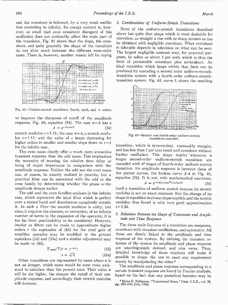
184 Proceedings of the I.R.E. March
and the overshoot is followed, by a very weak oscilla-tion stretching to infinity. Its energy content is, how-ever, so small that even consistent disregard of thisoscillation does not noticeably affect the main part ofthe transition. Fig. 42 shows that the slope, the over-shoot, and quite generally the shape of the transitiondo not alter much between the different even -ordercases. There is, however, another reason.left for trying
as
ME EllInidICIIOU IOU al
as allannalaajeragnaIMENME 911' aMaanlIPPOS
,AilliammilliannaLLIMIssanlanafaiifilas-,,A-'- 4 ° 1 2 nallalliCala
afinannotaralCalaninanalantalanat
2ND ORDER UST; S S. fE4TH ORDER UST; S. ti -2-
6TH ORDER UST; S ICE
co ORDER UST; S I
Fig. 42-Uniform-stretch transitions, fourth, sixth, and 00 orders.
to improve the sharpness of cutoff of the amplituderesponse, Fig. 40, equation (54). The case n = 4 has a
A = e--(wIwor (54)
stretch modulus s=1.19; the case n = 6, a stretch modu-lus s=1.12; and the value of s keeps decreasing forhigher orders in smaller and smaller steps down to s =1for the infinite case.
The even cases clearly offer a much more attractivetransient response than the odd cases. This emphasizesthe necessity of treating the relative time delay asbeing of major importance in comparison with theamplitude response. Neither the odd nor the even casescan, of course, be exactly realized in practice, but apractical filter can be associated with the odd or theeven family by determining whether the phase or theamplitude decays earlier.
The odd and the even families coalesce in the infinitecase, which represents the ideal filter which is perfectover a stated band and deteriorates completely outsideit. In such a filter-the stretch modulus is unity, butsince it requires the absence, or correction, of an infinitenumber of terms in the expansion of the operator, it istoo far from practicability to be considered. However,insofar as filters can be made to approximate higherorders r the expression of (45) for the total gain ofamplifier cascades may be modified to the generalequations (55) and (55a) and a similar adjustment maybe made to (46).
Vtotal/VOn =
S =
(55)
(55a)
Other transitions are represented by cases where n isnot an integer, which cases would be even more awk-ward to calculate than the present ones. Their value nwill be the higher, the sharper the cutoff of their am-plitude response, and accordingly their stretch moduluswill decrease.
2. Combinations of Uniform -Stretch Transitions
None of the uniform -stretch transitions describedabove has quite that shape which is most desirable fortelevision, as straight a rise with as sharp corners as canbe obtained with negligible overshoot. What overshootis tolerable depends in television on what can be seen.The largest negligible contrast may, for practical pur-poses, be taken as about 2 per cent, which is thus thelimit of permissible overshoot plus undershoot. Anideal transition which keeps within that limit can beproduced by cascading a second order uniform -stretch -
transition system with a fourth order uniform -stretch -transition system. Fig. 43, curve 3, shows the resulting
En/E.
744--
6
A
00 -
%2
I uST,S CORD ORDER
+ 2-UST,FOURTM ORDER
3-CASCAOE OFANO 2
(GENERAL CASE:
DEW ORDER4TH ORDER(
a.
10i-11- 12 :rid 14t7 RM'SM6Io
Fig. 43-Second- and fourth -order uniform -stretchtransitions cascaded.
transition, which is symmetrical, reasonably straight,and has less than 2 per cent recoil and overshoot withoutfurther oscillation. This shape results whenever nstages second -order uniform -stretch transition arecascaded with n' stages of fourth -order uniform -stretchtransition. Its amplitude response is between those ofthe parent curves, the broken curve 2-4 in Fig. 40,equation (56). It is not, with mathematical exactness,
A = e--0.5((.1.0i2+(wi.0)41 (56)itself a transition of uniform stretch because its stretchmodulus is not an exact constant. But the change of its.shape in repetition is almost imperceptible and the stretchmodulus thus found is with very good approximations =1.26.
3. Relations Between the Shape of Transients and Ampli-tude and Time Response
The three main features of a transition are steepness,overshoot with transient oscillations, and symmetry. Allthose are closely linked to the amplitude and timeresponse of the system. By defining the transient re-sponse of the system its amplitude and phase responseare unambiguously defined, and vice versa. Thus,detailed knowledge of these relations will make itpossible to shape the one to meet any requirementmerely by manipulating the other.'
The amplitude and phase response corresponding to acertain transient response are found by Fourier analysis,based on the fact that any periodical function may be
I Heinz E. Kallmann, "Transversal filters," PRoc. I.R.E., vol. 28,pp. 302-310; July, 1940.
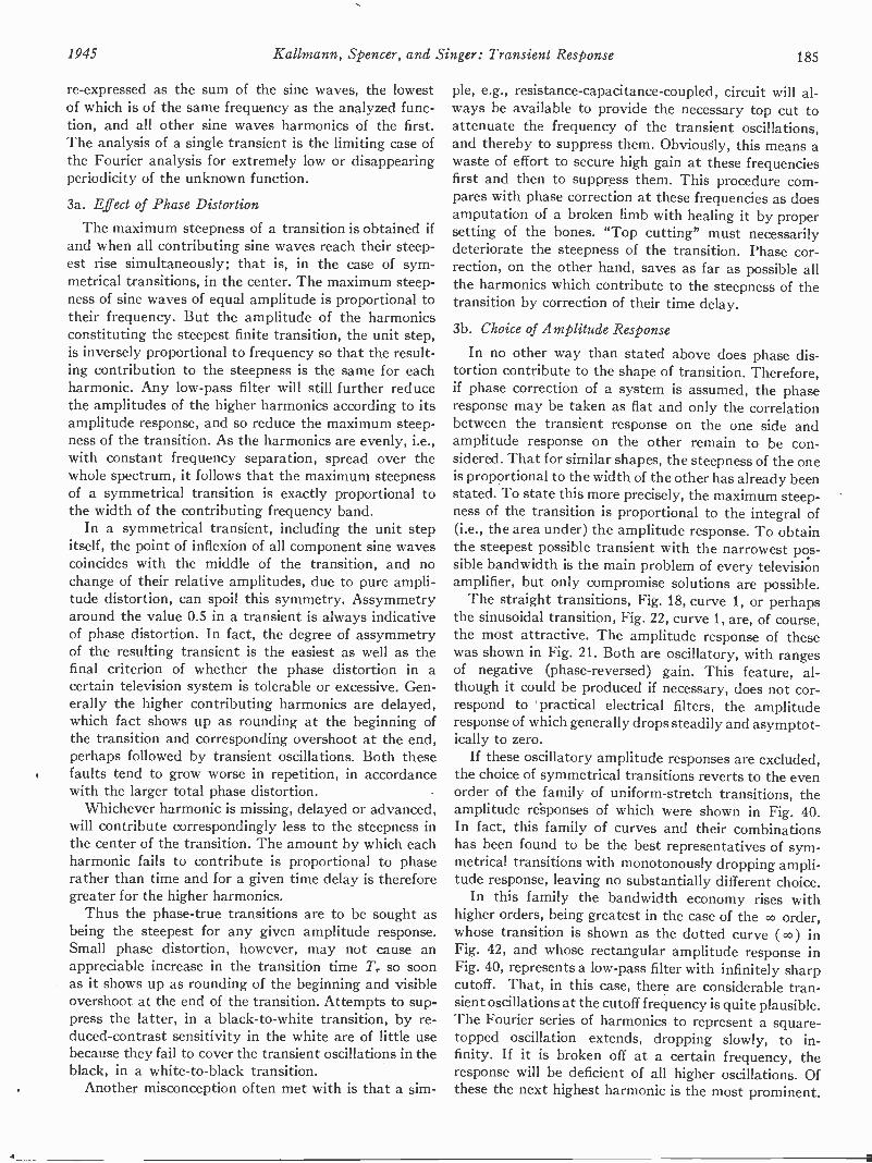
1945 Kallmann, Spencer, and Singer: Transient Response 185
re -expressed as the sum of the sine waves, the lowestof which is of the same frequency as the analyzed func-tion, and all other sine waves harmonics of the first.The analysis of a single transient is the limiting case ofthe Fourier analysis for extremely low or disappearingperiodicity of the unknown function.
3a. Effect of Phase Distortion
The maximum steepness of a transition is obtained ifand when all contributing sine waves reach their steep-est rise simultaneously; that is, in the case of sym-metrical transitions, in the center. The maximum steep-ness of sine waves of equal amplitude is proportional totheir frequency. But the amplitude of the harmonicsconstituting the steepest finite transition, the unit step,is inversely proportional to frequency so that the result-ing contribution to the steepness is the same for eachharmonic. Any low-pass filter will still further reducethe amplitudes of the higher harmonics according to itsamplitude response, and so reduce the maximum steep-ness of the transition. As the harmonics are evenly, i.e.,with constant frequency separation, spread over thewhole spectrum, it follows that the maximum steepnessof a symmetrical transition is exactly proportional tothe width of the contributing frequency band.
In a symmetrical transient, including the unit stepitself, the point of inflexion of all component sine wavescoincides with the middle of the transition, and nochange of their relative amplitudes, due to pure ampli-tude distortion, can spoil this symmetry. Assymmetryaround the value 0.5 in a transient is always indicativeof phase distortion. In fact, the degree of assymmetryof the resulting transient is the easiest as well as thefinal criterion of whether the phase distortion in acertain television system is tolerable or excessive. Gen-erally the higher contributing harmonics are delayed,which fact shows up as rounding at the beginning ofthe transition and corresponding overshoot at the end,perhaps followed by transient oscillations. Both thesefaults tend to grow worse in repetition, in accordancewith the larger total phase distortion.
Whichever harmonic is missing, delayed or advanced,will contribute correspondingly less to the steepness inthe center of the transition. The amount by which eachharmonic fails to contribute is proportional to phaserather than time and for a given time delay is thereforegreater for the higher harmonics.
Thus the phase -true transitions are to be sought asbeing the steepest for any given amplitude response.Small phase distortion, however, may not cause anappreciable increase in the transition time Tr so soonas it shows up as rounding of the beginning and visibleovershoot at the end of the transition. Attempts to sup-press the latter, in a black -to -white transition, by re-duced -contrast sensitivity in the white are of little usebecause they fail to cover the transient oscillations in theblack, in a white -to -black transition.
Another misconception often met with is that a sim-
ple, e.g., resistance -capacitance -coupled, circuit will al-ways be available to provide the necessary top cut toattenuate the frequency of the transient oscillations,and thereby to suppress them. Obviously, this means awaste of effort to secure high gain at these frequenciesfirst and then to suppress them. This procedure com-pares with phase correction at these frequencies as doesamputation of a broken limb with healing it by propersetting of the bones. "Top cutting" must necessarilydeteriorate the steepness of the transition. Phase cor-rection, on the other hand, saves as far as possible allthe harmonics which contribute to the steepness of thetransition by correction of their time delay.
3b. Choice of Amplitude Response
In no other way than stated above does phase dis-tortion contribute to the shape of transition. Therefore,if phase correction of a system is assumed, the phaseresponse may be taken as flat and only the correlationbetween the transient response on the one side andamplitude response on the other remain to be con-sidered. That for similar shapes, the steepness of the oneis proportional to the width of the other has already beenstated. To state this more precisely, the maximum steep-ness of the transition is proportional to the integral of(i.e., the area under) the amplitude response. To obtainthe steepest possible transient with the narrowest pos-sible bandwidth is the main problem of every televisionamplifier, but only compromise solutions are possible.
The straight transitions, Fig. 18, curve 1, or perhapsthe sinusoidal transition, Fig. 22, curve 1, are, of course,the most attractive. The amplitude response of thesewas shown in Fig. 21. Both are oscillatory, with rangesof negative (phase -reversed) gain. This feature, al-though it could be produced if necessary, does not cor-respond to practical electrical filters, the amplituderesponse of which generally drops steadily and asymptot-ically to zero.
If these oscillatory amplitude responses are excluded,the choice of symmetrical transitions reverts to the evenorder of the family of uniform -stretch transitions, theamplitude responses of which were shown in Fig. 40.In fact, this family of curves and their combinationshas been found to be the best representatives of sym-metrical transitions with monotonously dropping ampli-tude response, leaving no substantially different choice.
In this family the bandwidth economy rises withhigher orders, being greatest in the case of the 00 order,whose transition is shown as the dotted curve (00) inFig. 42, and whose rectangular amplitude response inFig. 40, represents a low-pass filter with infinitely sharpcutoff. That, in this case, there are considerable tran-sient oscillations at the cutoff frequency is quite plausible.The Fourier series of harmonics to represent a square -topped oscillation extends, dropping slowly, to in-finity. If it is broken off at a certain frequency, theresponse will be deficient of all higher oscillations. Ofthese the next highest harmonic is the most prominent.
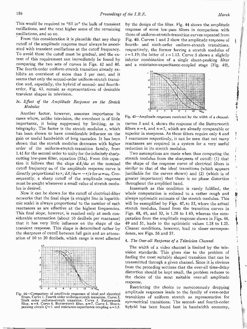
186 Proceedings of the I.R.E. March
This would be required to "fill in" the bulk of transientoscillations, and the next higher some of the remainingoscillations, and so on.
From this consideration it is plausible that any sharpcutoff of the amplitude response must always be associ-ated with transient oscillations at the cutoff frequency.To avoid these the cutoff must be gradual, and the ex-tent of this requirement can immediately be found bycomparing the two sets of curves in Figs. 42 and 40.The fourth -order uniform -stretch transition already ex-hibits an overshoot of more than 5 per cent, and itseems that only the second -order uniform -stretch transi-tion and, especially, the hybrid of second- and fourth-order, Fig. 43, remain as representatives of desirabletransient shapes in television.
3c. Effect of the Amplitude Response on the StretchModulus
Another factor, however, assumes importance incases where, unlike television, the overshoot is of littleimportance, it being suppressed by limiting, as intelegraphy. The factor is the stretch modulus s, whichhas been shown to have considerable influence on thegain or useful bandwidth of long cascades. It has beenshown that the stretch modulus decreases with higherorder of the uniform -stretch -transition family, from1.41 for the second order to unity for the infinitely sharp-
cutting low-pass filter, equation (55a). From this equa-tion it follows that the slope dA/dw at the nominalcutoff frequency coo of the amplitude response curve isdirectly proportional to r; dA/dw = -r/e for co =coo. Con-sequently, a sharp cutoff of the amplitude responsemust be sought whenever a small value of stretch modu-lus is desired.
Now it can be shown for the cutoff of electrical -filternetworks that the final slope (a straight line in logarith-mic scale) is always proportional to the number of suchreactances as are effective at the highest frequencies.This final slope, however, is reached only at such con-siderable attenuation (about 10 decibels per reactance)that it has very little influence on the shape of thetransient response. This shape is determined rather bythe sharpness of cutoff between full gain and an attenu-ation of 10 to 20 decibels, which range is most affected
A
.6
.6
.4
2
002 4 .6 .8 L 12 i 4
Fig. 44-Comparison of amplitude responses of ideal and electricalfilters. Curve 1. Fourth order uniform -stretch transition. Curve 2.Sixth order uniform -stretch transition. Curve 3. Butterworthfilter, n=4. Curve 4. Butterworth filter, n=7. Curve 5. Shunt -peaking circuit Q=1 and resistance -capacitance coupling a =1.5.
by the design of the filter. Fig. 44 shows the amplituderesponse of some low-pass filters in comparison withthose of uniform -stretch -transition curves repeated fromFig. 40. Curves 1 and 2 show the amplitude response offourth- and sixth -order uniform -stretch transitions,respectively, the former having a stretch modulus ofs =1.19; the latter of s =1.12. Curve 5 shows a slightlyinferior combination of a single shunt -peaking filterand a resistance -capacitance -coupled stage (Fig. 49),
Wimm..7.7MAWAMMAIRIMMEMINIUMMUMMUIEhnonnaotionnsinnsennsrmennwwwnnwnvrgalsvermainn MMMMM IMUFVE6faMIM klh,
ROMMEMNUMNINDRMUMMMMMM OrLIMILIVImiannannesockanymennismnmanneinsinnen. ilvAnnansionspnanik
U nisU11
canumannuonnen, 11 n .11111
mninnnannernemok
IONIMEWPAgnidNIUMIOMPW4RMWMINVITVON:ld2MENOOMMMORWIROCV7CffgeWWII OOMMINAMMINOSAMPAVAP%IMAM00014UMM KffiliMaW5411KNVftOMONU Will~Filt11411EW,PiAiiREMUMEMERWM3OWNSOOMMMILLMV0awernsinmsmannaonmmon, M ,., MMM En..1..4,T'MOMMINIWWWWW2MMIEWINOWNWIN
2
Fig. 45-Amplitude responses restricted by the width of a channel.
curves 3 and 4, shows the response of the Butterworthfilters n = 4, and n=7, which are already comparable orsuperior in steepness. As these filters require only 4 and7 reactances respectively, it can be seen that not manyreactances are required in a system for a very usefulreduction in its stretch modulus.
Two assumptions are made when thus computing thestretch modulus from the sharpness of cutoff: (1) thatthe shape of the response curve of electrical filters issimilar to that of the ideal transitions (which appearsjustifiable for the curves shown) and (2) (which is ofgreater importance) that there is no phase distortionthroughout the amplified band.
Inasmuch as this condition is rarely fulfilled, thewhole computation is reduced to a rather rough andalways optimistic estimate of the stretch modulus. Thiswill be exemplified by Figs. 47 to 52, where the actualstretch modulus, found from the transition curves inFigs. 48, 49, and 52, is 1.26 to 1.40, whereas the com-putation from the amplitude response shown in Figs. 46,49 and 51, leads to the optimistic values 1.18 to 1.25.Cleaner conditions, however, lead to closer correspon-dence, see Figs. 56 and 57.
4. The Over-all Response of a Television Channel
The width of a video channel is limited by the tele-vision standards. This gives rise to the problem offinding the most suitably shaped transition that can betransmitted through a given channel. Since it is obviousfrom the preceding sections that the over-all time -delaydistortion should be kept small, the problem reduces tothe choice of the most suitable over-all amplituderesponse.
Restricting the choice to monotonously droppingamplitude responses leads to the family of even -ordertransitions of uniform stretch as representative forsymmetrical transitions. The second- and fourth -orderhybrid has been found best in bandwidth economy,

1945 Kallmann, Spencer, and Singer: Transient Response 187
without excessive overshoot. It remains, then, to bedetermined where its amplitude response has fallen farenough to be broken off without serious harm to thetransient response.
ED
mm miLmmom mmWILMERAMMVPIIMNIL RIVIPMP,AP"liral NI=10 VIM
m Amrmemilmmiums
miMMNI
3
4
3
4
3
0-T RADIANS 14,
Fig. 46-Distortion oCtransient response due to restricted width ofa channel.
6
.6
4
.2
A
A
DELAY TIN RADIANS c.o.
GAIN
Fig. 47-Amplitude and time -delay response of a cascade of shunt -peaking coil circuit Q=1.2 and resistance -capacitance circuit a =2.
The amplitude response of the second- and fourth -order uniform -stretch transition is shown again as curve1 in Fig. 45, the transient response as the broken curve 1in Fig. 46. It may be decided to suppress all frequenciesabove coo, that is, to break off the amplitude responsewhere it has dropped to 0.37 as shown by curve 2 inFig. 45, equation (57). The corresponding experiment
0
A = e-°51(61/0,0)11-(0400)4+(cd/c00)9
1
1
.4 I i
1 1 +-I I .,
2 24--
1
I. CASCADE 0.12 AND CC 22 CURVE REPEATED; S -126
,..., 1,..:9, '!6f 26,. : Pl.,ti!
it 21T 311. wot
(57)
Fig. 48-Transient response of a cascade of shunt -peaking coil circuitQ=1.2 and resistance -capacitance circuit a = 2 to a unit step ofcurrent.
with transients is to cascade the second- and fourth -order uniform -stretch transition with an co order uni-form -stretch transition whose amplitude response cutsoff sharply at coo. The result is shown in Fig. 46 as curve2. This has 3.5 per cent overshoot followed by 1 per centunderswing, and the transition time T,. has increasedby 5 per cent. If this is considered tolerable, furthertrimming may be done by suppressing all frequencies
a
--...........Ill iiim.ppennWt.. !AVM 1OVERALL GANG
maiOUMUMnalannkNll111111111/:11111110""
1/21111111FAImmill MMMMMMM 'm
IMINCRININNIUM6Pg
1114OPOBBME
JSIIMMOMMMOMMISMOM
LIII11111111' RIIII1I'll 11111
o
DELAY T IN RADIANS Wo
Fig. 49-Amplitude and time -delay response of a cascade of shunt -peaking coil circuit Q =1.0 and resistance -capacitance circuita =1.5.
6
4
2
2
rti
'11- CITAT
I CASCADE 0.1 AND CC .1.5
2 CURVE I REPEATED S.126
- ki0o r zr 31r w.
Fig. 50 --Transient response of a cascade of shunt -peaking coil circuitQ =1.0 and resistance -capacitance circuit a =1.5 to a unit stepof current.
T A...rmelmmmummrw,A4sirAmmmmIlmmmmalmomm.rommompioNNimumammmommummmW4MOMMEMOm.7.144441J,NOEOZIWZmnr.ITMILMMLINEMENAMsnqXCMPMEMEMINENMNSIUMMMOIMIARMOPSOWINNIMMS
UMUMPEMDT4ASUIGUg mmomommimmum"1411:112P110211' "'Vmst
1111111Mmml4wEgiam7P/ERALLGAIN
mammies mamxzevz1vam 1g
ilmmemmmmommAffl
tra.mg."120NOIMMUMN,WAV 7R.WJIalti7smommmemmma 14,4MMULCAMNI
magmniummvuumaiwurommummommicomtillIIIIRCOMMAIIMICIC:11111,021MAINUM11131111EMS:w' 111111111111111111:31IMINIPPIIIKBOISIMINOtmillwmagumgmmap.- -.14...
Efilifliiiiitiii..... AI ME....... ...............ireammommmLesummommgivammummmammxammimommftwaommammaxmommommmmmTWOMMmUMMUNI~YARIMMXIMOMMINAREN
'544W4gaglifillin.nimmp.ammgmmompommemtpraiNammommma: iSMOMOMMOCM,g4WOMMIIMENU14~01N,MRNUMNA
MINIMIMOSMMEMNallimIL,g5, 00,AMMEMO.WMWEISPOMMZUMMEMNAOSIAMOUNWIROMMfflMOROIMUIRKENNMEM
4211111112041511INIM:
Fig. 51-Amplitude and time -delay response of a cascade of shunt -peaking coil circuit Q=1.0 and resistance -capacitance circuit a =2.
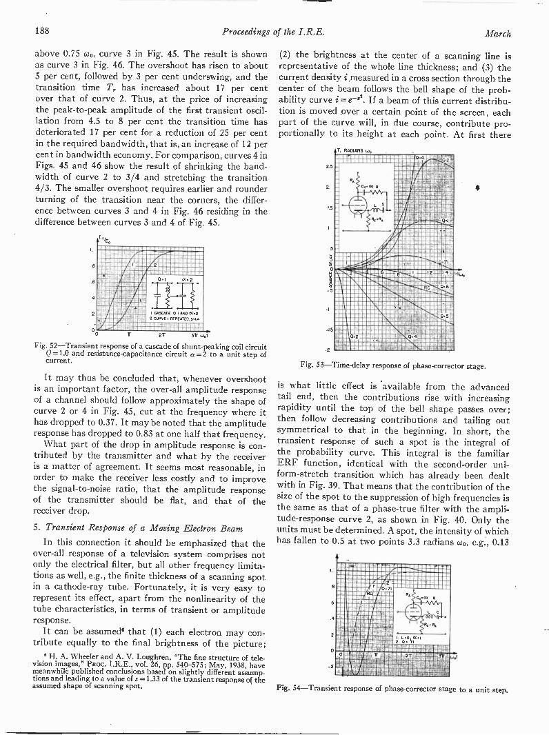
188 Proceedings of the I.R.E. March
above 0.75 coo, curve 3 in Fig. 45. The result is shownas curve 3 in Fig. 46. The overshoot has risen to about5 per cent, followed by 3 per cent underswing, and thetransition time Tr has increased about 17 per centover that of curve 2. Thus, at the price of increasingthe peak -to -peak amplitude of the first transient oscil-lation from 4.5 to 8 per cent the transition time hasdeteriorated 17 per cent for a reduction of 25 per centin the required bandwidth, that is, an increase of 12 percent in bandwidth economy. For comparison, curves 4 inFigs. 45 and 46 show the result of shrinking the band-width of curve 2 to 3/4 and stretching the transition4/3. The smaller overshoot requires earlier and rounderturning of the transition near the corners, the differ-ence between curves 3 and 4 in Fig. 46 residing in thedifference between curves 3 and 4 of Fig. 45.
MOM NOEMMEMOMONME"Agg111101MK INIMMOMMIMMOV' MMONEMMUMME
plummummimmmmummammarm
0
CASCADE 0.1 AND OC22 CURVE REPEATED; S.i.4
MOM7 211- vir
Fig. 52-Transient response of a cascade of shunt -peaking coil circuitQ=1.0 and resistance -capacitance circuit a = 2 to a unit step ofcurrent.
It may thus be concluded that, whenever overshootis an important factor, the over-all amplitude responseof a channel should follow approximately the shape ofcurve 2 or 4 in Fig. 45, cut at the frequency where ithas dropped to 0.37. It may be noted that the amplituderesponse has dropped to 0.83 at one half that frequency.
What part of the drop in amplitude response is con-tributed by the transmitter and what by the receiveris a matter of agreement. It seems most reasonable, inorder to make the receiver less costly and to improvethe signal-to-noise ratio, that the amplitude responseof the transmitter should be flat, and that of thereceiver drop.
5. Transient Response of a Moving Electron Beam
In this connection it should be emphasized that theover-all response of a television system comprises notonly the electrical filter, but all other frequency limita-tions as well, e.g., the finite thickness of a scanning spotin a cathode-ray tube. Fortunately, it is very easy torepresent its effect, apart from the nonlinearity of thetube characteristics, in terms of transient or amplituderesponse.
It can be assumed° that (1) each electron may con-tribute equally to the final brightness of the picture;
6 H. A. Wheeler and A. V. Loughren, "The fine structure of tele-vision images," PRoc. I.R.E., vol. 26, pp. 540-575; May, 1938, havemeanwhile published conclusions based on slightly different assump-tions and leading to a value of s.=1.33 of the transient response of theassumed shape of scanning spot.
(2) the brightness at the center of a scanning line isrepresentative of the whole line thickness; and (3) thecurrent density i measured in a cross section through thecenter of the beam follows the bell shape of the prob-ability curve i =e -x2. If a beam of this current distribu-tion is moved ever a certain point of the screen, eachpart of the curve will, in due course, contribute pro-portionally to its height at each point. At first there
T. RADIANS
2.5
1.5
0
1.5
ESIMMIUWAIMM@WOWUMMIUMWEILWILIN111
MMEMIWAMMORMIM§spamrumgymmainenEkKONAPO.17WARRINEMMEYNKM154611IMMO144ficifiAntailliIIINOWOMIligURE
EMI!OWL2371POMMO WENmmemmomao,v,d,L2:2:04141ww!Ai" "413111ifammismomummis
.. ,rrrrrrrorrrn.0Amum..m.m.mmomm
mIIIIIIIIERECNINIMIllg mmmmmm menarmima
gatii711911130rr 91103116g1
IIIIIIIIi m
IIRMIIIII1S mm 11111:6011111111IIVIIIIII ll SI l 11111111110
OMMUMMEMONOWSPEMNSWKNUMWWW4,PFMMWMUMEMOMENRIM54TMVM
response of phase -corrector stage.
is what little effect is 'available from the advancedtail end, then the contributions rise with increasingrapidity until the top of the bell shape passes over;then follow decreasing contributions and tailing outsymmetrical to that in the beginning. In short, thetransient response of such a spot is the integral ofthe probability curve. This integral is the familiarERF function, identical with the second -order uni-form -stretch transition which has already been dealtwith in Fig. 39. That means that the contribution of thesize of the spot to the suppression of high frequencies isthe same as that of a phase -true filter with the ampli-tude -response curve 2, as shown in Fig. 40. Only theunits must be determined. A spot, the intensity of whichhas fallen to 0.5 at two points 3.3 radians coo, e.g., 0.13
I.
8
6
.4
2
0
Fig. 54-Transient response of phase -corrector stage to a unit step.
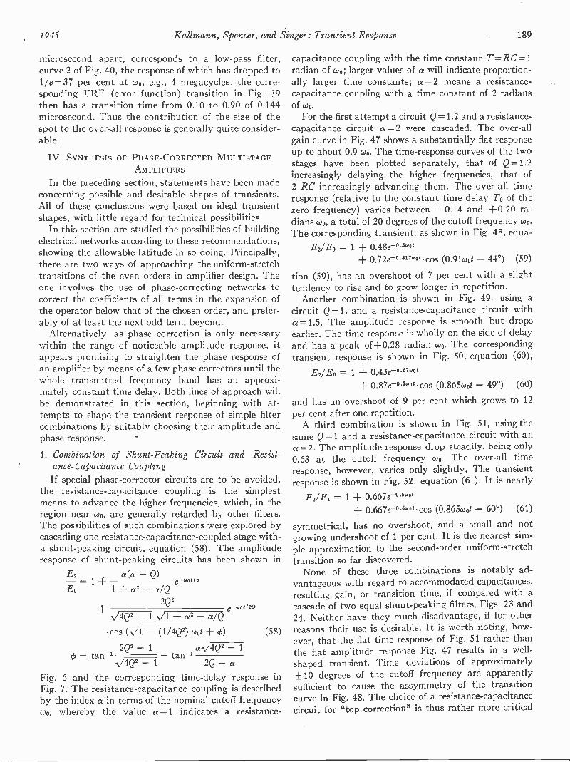
1945 Kallmann, Spencer, and Singer: Transient Response 189
microsecond apart, corresponds to a low-pass filter,curve 2 of Fig. 40, the response of which has dropped to1/e =37 per cent at coo, e.g., 4 megacycles; the corre-sponding ERF (error function) transition in Fig. 39then has a transition time from 0.10 to 0.90 of 0.144microsecond. Thus the contribution of the size of thespot to the over-all response is generally quite consider-able.
IV. SYNTHESIS OF PHASE -CORRECTED MULTISTAGEAMPLIFIERS
In the preceding section, statements have been madeconcerning possible and desirable shapes of transients.All of these conclusions were based on ideal transientshapes, with little regard for technical possibilities.
In this section are studied the possibilities of buildingelectrical networks according to these recommendations,showing the allowable latitude in so doing. Principally,there are two ways of approaching the uniform -stretchtransitions of the even orders in amplifier design. Theone involves the use of phase -correcting networks tocorrect the coefficients of all terms in the expansion ofthe operator below that of the chosen order, and prefer-ably of at least the next odd term beyond.
Alternatively, as phase correction is only necessarywithin the range of noticeable amplitude response, itappears promising to straighten the phase response ofan amplifier by means of a few phase correctors until thewhole transmitted frequency band has an approxi-mately constant time delay. Both lines of approach willbe demonstrated in this section, beginning with at-tempts to shape the transient response of simple filtercombinations by suitably choosing their amplitude andphase response.
1. Combination of Shunt -Peaking Circuit and Resist-ance -Capacitance CouplingIf special phase -corrector circuits are to be avoided,
the resistance -capacitance coupling is the simplestmeans to advance the higher frequencies, which, in theregion near coo, are generally retarded by other filters.The possibilities of such combinations were explored bycascading one resistance -capacitance -coupled stage with -a shunt -peaking circuit, equation (58). The amplituderesponse of shunt -peaking circuits has been shown in
E2 ce(a -Q)-= 1 4- e-wog/aEo 1 ± a2 - a/Q
2Q2cone/2Qv4(22 - 1 vi a2 a/Q
cos (-V1 - (1/4Q2) coot + (58)
2Q2 - 1 a.v4Q2 1
4, = tan -1 tan -1,v4(22 _ 1 2Q- aFig. 6 and the corresponding time -delay response in
Fig. 7. The resistance -capacitance coupling is described
by the index a in terms of the nominal cutoff frequencycoo, whereby the value a =1 indicates a resistance -
capacitance coupling with the time constant T=RC=1radian of coo; larger values of a will indicate proportion-ally larger time constants; a =2 means a resistance -capacitance coupling with a time constant of 2 radiansof coo.
For the first attempt a circuit Q=1.2 and a resistance -capacitance circuit a=2 were cascaded. The over-allgain curve in Fig. 47 shows a substantially flat responseup to about 0.9 coo. The time -response curves of the twostages have been plotted separately, that of Q =1.2increasingly delaying the higher frequencies, that of2 RC increasingly advancing them. The over-all timeresponse (relative to the constant time delay To of thezero frequency) varies between -0.14 and +0.20 ra-dians coo, a total of 20 degrees of the cutoff frequency coo.The corresponding transient, as shown in Fig. 48, equa-
Ea° = 1 + 0.48e-°5"ot0.72e-o.417.0 .cos (0.91coot - 44°) (59)
tion (59), has an overshoot of 7 per cent with a slighttendency to rise and to grow longer in repetition.
Another combination is shown in Fig. 49, using acircuit Q =1, and a resistance -capacitance circuit witha =1.5. The amplitude response is smooth but dropsearlier. The time response is wholly on the side of delayand has a peak of+0.28 radian coo. The correspondingtransient response is shown in Fig. 50, equation (60),
E2/E0 = 1 ± 0.43e-"7"0+ 0.87e-"wo cos (0.865coot - 49°) (60)
and has an overshoot of 9 per cent which grows to 12per cent after one repetition.
A third combination is shown in Fig. 51, using thesame Q =1 and a resistance -capacitance circuit with ana= 2. The amplitude response drop steadily, being only0.63 at the cutoff frequency coo. The over-all timeresponse, however, varies only slightly. The transientresponse is shown in Fig. 52, equation (61). It is nearly
E2/Ei = 1 + 0.667e-0500+ 0.667e-0 °wo cos (0.865coot - 60°) (61)
symmetrical, has no overshoot, and a small and notgrowing undershoot of 1 per cent. It is the nearest sim-ple approximation to the second -order uniform -stretchtransition so far discovered.
None of these three combinations is notably ad-vantageous with regard to accommodated capacitances,resulting gain, or transition time, if compared with acascade of two equal shunt -peaking filters, Figs. 23 and24. Neither have they much disadvantage, if for otherreasons their use is desirable. It is worth noting, how-ever, that the flat time response of Fig. 51 rather thanthe flat amplitude response Fig. 47 results in a well -shaped transient. Time deviations of approximately±10 degrees of the cutoff frequency are apparentlysufficient to cause the assymmetry of the transitioncurve in Fig. 48. The choice of a resistance -capacitancecircuit for "top correction" is thus rather more critical
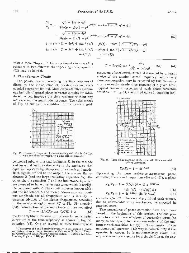
190 Proceedings of the I.R.E. March
E2 V1 - 4pq 4q2
E2- 8Pq(P q) -V1 - p2e-Paq't cos (V1 p2 cool + 4)i)
-V1 - 4pq +e-ewog cos (v'1 - q2 coot -I- 02)
8pq(q - p) -V1 - q2
4)1= sin -1 (1 - 2p2) + tan' - p2/p) + tan -1 [V1 - p2/(2q - p)i= sin-' (1 - 2q2) + tan-' (/1 - q2/q) tan -1 [V1 - q2/ (2p - q)]
= 1/2Q, q = 1/2Qa
than a mere "top cut." For experiments in cascadingstages with two different shunt -peaking coils, equation(62) may be helpful.
2. Phase -Corrector Circuits
The possibilities of correcting the time response offilters by the introduction of resistance -capacitance -
coupled stages are limited. More elaborate filter systemscan be built if special phase -corrector circuits are intro-duced, which improve the time response without anyinfluence on the amplitude response. The tube circuitof Fig. 53 fulfills this condition. It comprises a grid-
8
.6
.4
2
0
2ilr
3R.
0..64
1. SHUNT PEAKING CIRCUI0.64, 5.136
E. SAME AND PHASECORRECTOR IX .114
SCORCH 2 REPEATED, SI ieI
or 4., 371
Fig. 55-Transient response of shunt -peaking coil circuit Q=0.64with one phase correction to a unit step of current.
controlled tube, with a load resistance Re in the cathodeand an equal load resistance RA in the anode, so thatequal and opposite signals appear on cathode and anode.Both signals are fed to the output, the one via the re-sistance R (and the large insulating capacitor Ck), theother via the capacitor C and the inductance L, whichare assumed to have a series resistance which is negligi-ble compared with R. The circuit is better known with-out the inductance L and then produces a constant out-put amplitude for all frequencies with a steadily in-creasing advance of the higher frequencies, accordingto the nearly straight curve RC in Fig. 53, equation(63). Introduction of the inductance L does not affect
T = - (2/wCR)tan-1(wCR) -I- 2 (63)
the flat amplitude response, but allows for more variedcurvature of the time response,7 as shown in Fig. 53,equation (64). One or several of these time -response
7 The curves of Fig. 53 apply identically to the bridged -T phase-correcting network. For a discussion of this, see A. T. Starr, "Electri-cal Circuits and Wave Filters," second edition, J. Pitman and Sons,London, England, 1940, pp. 197-198.
(62)
oT = 2wo/w) tan -'Q[1 -
co
(
/cocd/(00)212/Q (64)
curves may be selected, stretched if needed by differentchoice of the nominal cutoff frequency, and a veryclose compensation may be expected by this means forany reasonably steady time response of a given filter.Typical transient responses of such phase correctorsare shown in Fig. 54, the dotted curve 1, equation (65),
8
6
4
2
0
2
4
6
.8
T. RADIANS
L -1-..... _LI_5 .1--.
. rf-- ',,
.
.- .41110111...1
- -AIM -1-
___ - --, r .TI
--._ . _..
F 3q..-- r --;,tg;
---- 4 , 8 I ---11 - cL
-!BUTTERWORTH FILTER .4 4.--3- . -- E RC PHASECORRECTOR,15 I
- 3 SUM OF 1.2__'\
: 4 PHASE CORRECTOR, 0..71 17 ' ''. L.-
4-5 SUM OF 144 - 6---
-
6 PHASE CORRECTOR, U.S
_/ SUM OF 140 46,Fig. 56-Time-delay response of Butterworth filter n =4 with
phase correction.
El/Eo =1 - IRC (65)representing the pure resistance -capacitance phasecorrector; the curve 2, equations (66) and (67), a phase
EI/E0 = 1 - (4/V4Q2 1) . e- (1/ 2Q)woe
sin (V1 - (1/4Q2) coot (66)El/ED = 1 - 4e-0 "w0i sin (0.71(400 (67)
corrector Q= 0.71. The very sharp initial peak cannot,due to unavoidable stray reactances, be expected inpractical cases.
Two procedures of phase correction have been men-tioned in the beginning of this section. The one pro-ceeds to correct the coefficients of successive terms (asmany as correspond to the chosen order r of the uni-form -stretch -transition family) in the expansion of themathematical operator. This way is possible only if theoperator is known. It is mathematically exact, butrequires as many correctors for a simple filter as for any
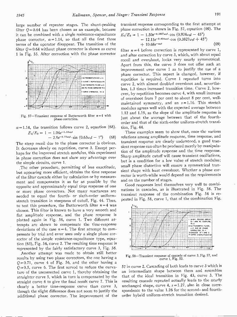
1945 Kallmann, Spencer, and Singer: Transient Response 191
large number of repeater stages. The shunt -peakingfilter Q=0.64 has been chosen as an example, becauseit can be combined with a single resistance -capacitancephase corrector, a =1.14, so that all the first threeterms of the operator disappear. The transition of thefilter Q=0.64 without phase corrector is shown as curve1 in Fig. 55. After correction with the phase corrector
/. gmilmMINCOMM MMMMMM MON MMMM REMEhNmOI 111111131111MEAMMAAIMM MMM M MMM TOW,,IMEMPIAffle. .MIRMANMWREMMISMAMEGRUMMODOMMIWAmaNftmimM-- imp=m1ANANEMNOWASESNMOMAILAIMMEFAMMOIN MIERMAItig,---NOIAMMONAMMUME MM A MM WARM wiltmgmagla111131111AMIM 11giumummusigrwtommolrinir4UOVAMMAPAM AAMMERWRIAMENEUFAUAMOWAMMIUMMEMAAMM MENEM1A2ANK3+AAPMENAVEWOMAIWOMIA 115$relercrrommummomm MMMMM WM UMNACORANWAIEVAUMNUENEMMOUMAUMMENdIAIMUSA3AUMMAIMINMEMENOWASEMOMEN
VICRIMPrilli"."11111:1111110gAgrangMMAMONOWOMOMPAINS M A MMM MEEMMAWErai.4eAMMWORMARI
a mmummornammemmom M A MMM MIAMEMOIMMIKcAMM 410MEMglawarmummomeranummimulamarmummimmemn
11111MOMEM. MMEMOMUNLMOMMM OMAN140221""".44,summEARTOWITANUAll
BuTTERWORTH FILTER
CURVE I REPEATE0,44L26
3 BUTTERWORTH FILTER a
ANO RC PHASE CORRECTOR N.I
4 CURVE 3 REPEATED, !PIM
Fig. 57-Transient response of Butterworth filter n=-4 withphase correction.
a =1.14, the transition follows curve 2, equation (68).
E2/E0 = 1 - 1.04e-1 .1.4c4"
- 2.9e-°-77wo sin (0.63wot - 1°) (68)
The steep recoil due to the phase corrector is obvious.It decreases slowly on repetition, curve 3. Except per-haps for the improved stretch modulus, this experimentin phase correction does not show any advantage overthe simple circuits, curve 1.
,The other procedure, permitting of less exactitude,but appearing more efficient, obtains the time responseof the filter cascade either by calculation or by measure-ment and compensates it as far as possible by theopposite and approximately equal time response of oneor more phase correctors. Not many reactances areneeded to equal the fourth- or sixth -order uniform -stretch transition in steepness of cutoff, Fig. 44. Thus,to test this procedure, the Butterworth filter n =4 waschosen. This filter is known to have a very smooth andflat amplitude response, and the phase response isplotted again in Fig. 56, curve 1. Two different at-tempts are shown to compensate the time -responsedeviations of the case n= 4. The first attempt to com-pensate by trial and error uses only a single phase cor-rector of the simple resistance -capacitance type, equa-tion (63), Fig. 56, curve 2. The resulting time response isrepresented by the fairly satisfactory curve, 3, Fig. 56.
Another attempt was made to obtain still betterresults by using two phase correctors, the one having aQ=0.71, curve 4 of Fig. 56, and the other having aQ= 0.5, curve 6. The first served to reduce the curva-ture of the uncorrected curve 1, thereby obtaining thestraighter curve 5, which in turn is compensated by thestraight curve 6 to give the final result curve 7. This isclearly a better time -response curve than curve 3,though the slight difference does not seem to justify theadditional phase corrector. The improvement of the
transient response corresponding to the first attempt atphase correction is shown in Fig. 57, equation (69). TheE2/E0 = 1 - 1.50e-°3827'ot cos (0.924coot - 45°)
12.15e -0.924840e. cos (0.3827wot + 45°)10.68e -'DO (69)
filter n = 4 before correction is represented by curve 1,and after correction by curve 3, which, with about equalrecoil and overshoot, looks very nearly symmetrical.Apart from this, the curve 3 does not offer such animprovement over curve 1 as to justify the use of aphase corrector. This aspect is changed, however, ifrepetition is required. Curve 1 repeated turns intocurve 2, with almost doubled overshoot and, neverthe-less, 1.3 times increased transition time. Curve 2, how-ever, by repetition becomes curve 4, with small increaseof overshoot from 7 per cent to about 8 per cent, well -maintained symmetry, and an s =1.16. This stretchmodulus agrees well with the expected average between1.12 and 1.19, as the slope of the amplitude response isjust about the average between that of the fourth -order and that of the sixth -order uniform -stretch transi-tion, Fig. 44.
These examples seem to show that, once the variousrelations among amplitude response, time response, andtransient response are clearly understood, a good tran-sient response can often be produced merely by manipula-tion of the amplitude response and the time response.Sharp amplitude cutoff will cause transient oscillations,but is a condition for a low value of stretch modulus;small phase distortion will ensure a symmetrical tran-sient shape with least overshoot. Whether a phase cor-rector is worth -while would depend on the requirementsand on the number of stages.
Good responses lend themselves very well to combi-nations in cascades, as is illustrated in Fig. 58. Thetransient response of the combination Fig. 54 is re-peated in Fig. 58, curve 1, that of the combination Fig.
En,E.
8
6
4t7t
2
0
3
AA MI rMil=Affipp
tr
4
,4
1_
I -SHUNT PEAKING CIRCUIT,01 AND RC COUPLING,0(.2
2-BUTTERWORTH FILTER,n.4 AND RC PHASECORRECTOR, D( I
3 -CASCADE OF I AND 24CURVE 3 REPEATED,S127
Fig. 58-Transient response of cascade of curve 3, Fig. 57, andcurve 1, Fig. 52.
57 in curve 2. Cascading of both leads to curve 3 which isan intermediate shape between them and resemblesthat of the ideal transition in Fig. 43, curve 3. Theresulting cascade repeated actually leads to the nearlyunchanged shape, curve 4, s =1.27, also in close corre-spondence to the value 1.26 for the second- and fourth -order hybrid uniform -stretch transition desired.

192 Proceedings of the I.R.E. March
APPENDIX I
BASIS OF MATHEMATICAL PROCEDURE
1. Heaviside CalculusThe mathematical treatment of physical filters in this
paper is largely based on the principle that, if the vectorratio between the output and the input of a low-passfilter, adjusted to show unit gain at direct current, isexpressed as the quotient of two series of ascendingpowers of jco/coo, then the result of applying a unit stepto the input of that filter is that of an operator of thesame form in which jco/coo is replaced by p =d/d(coot).This operation produces a time curve which is a seriesof exponential terms whose indexes are the product ofcoot with the values of p at which the expression in thedenominator vanishes. This gives a pure exponentialcomponent for each real root, and a damped oscillationfor each conjugate pair of complex roots. Various ex-pressions are available for arriving easily at the coeffi-cients in numerical examples, both in the simple caseand in the case of repeated roots, but though these havebeen used in preparing the examples it would be re-dundant to repeat them here.
In general, the denominator of the expression in p isof the order of the number of reactances in the filter.The numerator is commonly of lower order, and in gen-eral takes its order from the number of reactances whichare not in the direct path from input to output. Thenumerator does not determine the exponents of the timecurve, but enters into the determination of the coeffi-cients, and, for example, may materially affect thephase of a component of damped oscillation. In thecarrier -frequency analogue the order is generally deter-mined by the number of resonant circuits which tunewithin the band which is being considered.
Complete generality of solution is possible only in thecase of a quadratic, i.e., a half section of a standard filter.For higher orders numerical cases can be solved, but theeffect of the variation of one particular impedance can-not be described in general terms unless a natural fac-torization of the denominator occurs. A considerabledegree of insight, however, arises from observation ofthe behavior of the equations, and experience has shownthat the utility of the transient method of filter analysisis not destroyed by these limitations.
Identically the same mathematical procedure is usedin treating phase -correction circuits, which have theirown individual transition curves. In these cases thenumerator is usually of the same order in p as the de-nominator.
2. Mathematical Treatment of Cascaded FiltersThe solution of problems involving feeding a filter,
not with a unit step, but with the output from a pre-ceding filter, varies with the knowledge of the form ofthe operator. If the operators are known, the solutiondepends on the principle that, within the known limits,the output is given by an operator which is the product
of the individual operators. If only the time functionsare known, the superposition principle gives the re-sultant time function by mathematical integration.Finally, if no functions are known, and only the timeplots are available, a process of mechanical integrationand differentiation will yield the combined response, theprocess being based on the form
F2(t) = f a(t - T)b'(T)dT (70)
of the Duhamel integral of the superposition theorem.The same principles apply in the combination of filterswith phase -correction networks.
The result may be approximated by a numerical proc-ess which is simple but may grow tiresome in case ,ofoscillatory responses. To cascade the responses a(t) andb(t) proceed as follows:
1. Divide both transient responses into evenly spacedtime intervals, the same for both curves, beginning attheir first significant departure from zero. The resultwill be the more exact, the smaller the intervals; 15 to 40intervals were used for the curves of this paper.
2. Tabulate, and number consecutively, the averageheight in each interval for both curves; call these valuesal, a2, as, , an; and b1, b2, bs, . . , bn
3. Choose one of the curves, preferably the simplerone, say a(t), and , tabulate the differences betweeneach two successive values: al' = al- 0, a2'=a2 -al,
= a3- a2, , = a. - an-i4. Multiply each value al', a2', a3', , a,,' with
each value bi, b2, b3, , b,,. Write in the first line:El= cti.' bi; in the second line: E2 = a2' bi+ai' b2; inthe third line: E3 = a3' bi-F a2' b2+ b3, and so on tothe last line: E.= a.' b2 -Fan --2' boThe number of 'products thus rises by one for eachsuccessive line.
5. Add up all the products in each line, with attentionto possible negative signs. The sums El to Ey, so ob-tained are then the ordinates of the resulting transient;they are spaced with the same time interval as waschosen for the two original responses.
The idea underlying this procedure is to represent theoutput of the first filter as a sequence of evenly spacedunit steps of the height at', a2', as' and to feed each,when it emerges, to the second filter. The output of thatis then the sum of n transient responses, each of thesame shape b(t) but of a height and delay correspondingto each unit step a'(t).
3. Theory of Transition of Uniform Stretchy
Let MAO be the frequency characteristic (outputvolts E2 to input volts E1) of a network, connected be-tween grid and cathode of a tube of high impedance andnegligible grid -plate capacitance; also let f2(jco) refer toanother network, connected between the anode and thecathode of the same tube.
This section was prepared by Charles P. Singer.
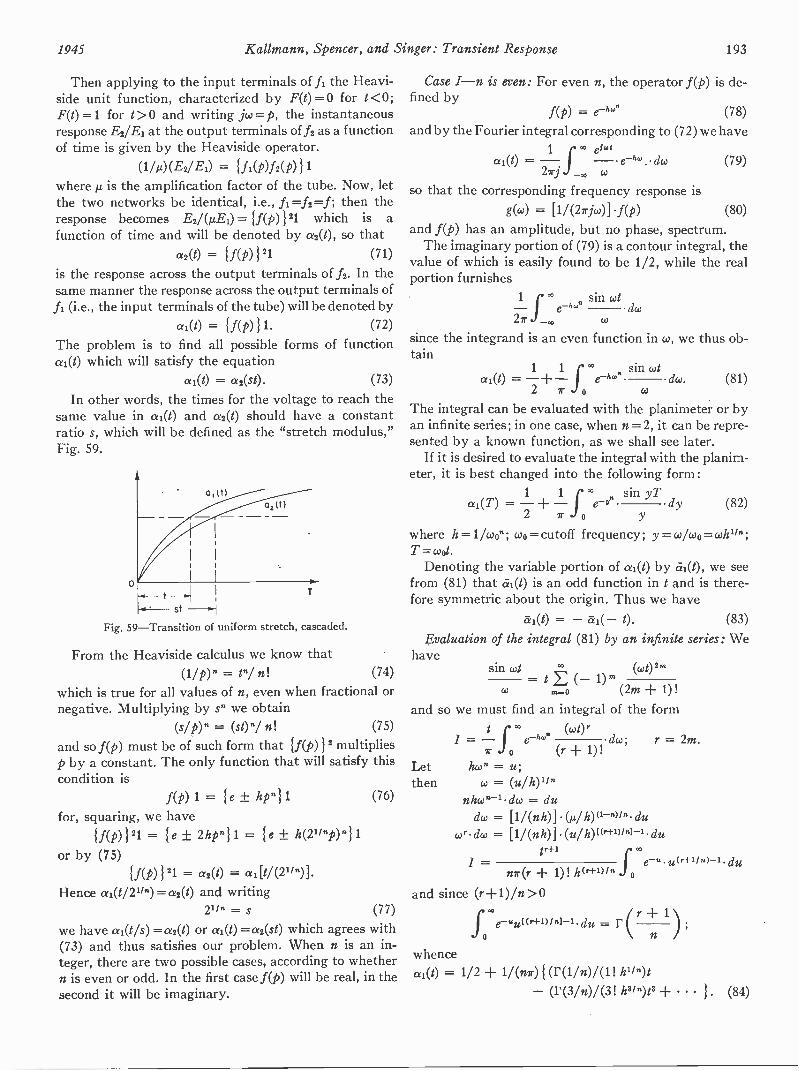
1945 Kallmann, Spencer, and Singer: Transient Response 193
Then applying to the input terminals of fl the Heavi-side unit function, characterized by F(t)= 0 for t <0;F(t)=1 for t> 0 ana writing jw = p, the instantaneousresponse Es/El at the output terminals of f2 as a functionof time is given by the Heaviside operator.
(1/p)(E2/E0 = { fi(p)f2(p)}1where /2 is the amplification factor of the tube. Now, letthe two networks be identical, i.e., A=f2=f; then theresponse becomes E2/(1E1) = (p)121 which is afunction of time and will be denoted by a2(t), so that
= {AP) }21 (71)
is the response across the output terminals of f2. In thesame manner the response across the output terminals offl (i.e., the input terminals of the tube) will be denoted by
al(1) = {AP) } 1.The problem is to find all possibleai(t) which will satisfy the equation
al(1) = a2(s0-
(72)
forms of function
(73)
In other words, the times for the voltage to reach thesame value in ai(t) and a2(t) should have a constantratio s, which will be defined as the "stretch modulus,"Fig. 59.
0, (t)a2(t)
t ,
* ' st
Fig. 59-Transition of uniform stretch, cascaded.
From the Heaviside calculus we know thatOM" = 1"/ n! (74)
which is true for all values of n, even when fractional ornegative. Multiplying by s" we obtain
(s/p) n (st) n! (75)
and so f(p) must be of such form that {f(p)} 2 multipliesp by a constant. The only function that will satisfy thiscondition is
f(p) 1 = le ± 411for, squaring, we have
{f(p)}21 = le ± 2hpn} 1 = ± h(Vinp)11or by (75)
(76)
If(P)121 = as(t) = adt/(21/.)].Hence al(t/21/.)=a2(1) and writing
21in = s (77)
we have «1(1/s) = a2(t) or ai(t) =a2(st) which agrees with(73) and thus satisfies our problem. When n is an in-teger, there are two possible cases, according to whethern is even or odd. In the first case f(p) will be real, in thesecond it will be imaginary.
Case I-n is even: For even n, the operator f(p) is de-fined by
f(p) = (78)
and by the Fourier integral corresponding to (72) we have1 e1'
a (1) = - - e-hw . do) (79)27j co
so that the corresponding frequency response isg(w) = [1/(27jco)] .f(p) (80)
and f(p) has an amplitude, but no phase, spectrum.The imaginary portion of (79) is a contour integral, the
value of which is easily found to be 1/2, while the realportion furnishes
sincetain
1 ' sin cote -h. dco
2r w
the integrand is an even function in w, we thus ob-
1 1 sin cot-Fai(t) = -- e-hw dw. (81)
2 7 o
The integral can be evaluated with the planimeter or byan infinite series; in one case, when n=2, it can be repre-sented by a known function, as we shall see later.
If it is desired to evaluate the integral with the planim-eter, it is best changed into the following form :
1 1 sin yTai(T) = - - ev dy (82)2 7 0
where h=11won; wo= cutoff frequency; y = co/coo = &au";T =coot.
Denoting the variable portion of «1(0 by eci(t), we seefrom (81) that «1(0 is an odd function in t and is there-fore symmetric about the origin. Thus we have
ai(t) = - al(- t). (83)
Evaluation of the integral (81) by an infinite series: Wehave
sin coi (cot) 2 mco
= E (-CO 116, (2m + I)!
and so we must find an integral of the form(cot) r
7 0 (r + I)!hw" =
CO = (u/ h)1/"
nhcon-1 dco = du
= [1/(nit)] (µ/h)(1-")l"duco* dco = [1/(nh)] (u/ du
Letthen
nT(r + 1) ! lt(r+"/" 1.e -u u(r1-'1 n)-' du
and since (r+1)/n>0
r = 2m.
1.e-wut(r+1)1M-1. du = F
ao
Cr n )whence04(0 = 1/2 + 1/(nr)1(r(1/n)/(1! h1/ ")t
- (r(3/n)/(31118b9t3 + 1. (84)

194 Proceedings of the I.R.E. March
Case I-n=2: Here we have
F(1/2) = NAi.
r(3/2) = 1/2r(5/2) = (3 . 1)/(2 . 2) V71- etc.
and so (84) reduces to
1/2 + 1/Vilz - z3/(3.11) z5/(5.2!) - } ,
where z=t/2Vii. But this is the expansion of1/2(1+ERF z), so that
ai(t).-2 = 1/2 { 1 ERF [t/20-1] (85)which function is nonoscillatory.Case II-n is odd: Here it is necessary to define the op-erator f(p) as follows:
f(p) = (86)so that
1 " cai(t) = - - ""`a dc..) (87)27rj co
while the corresponding frequency response isg(w) = 1/(2rjw)f(p)
g(w) = 1/(27(0) I sin luon j cos hco"1 (88)
and f(p) now has a phase, but no amplitude, spectrum.The value of the imaginary portion of (87) is again
1/2, while the real portion furnishes1 sin (cot - kW")
do;27r J , co
integrand is again an even function in w, we
or
since theobtain
1 1 x' sin (cot - lue)01(1) = - -J do. (89)2 7r o co
For n>1 there is no known function that will repre-sent the integral (89) but this can again be evaluatedwith the planimeter, when the appropriate form (see82) is
1 1al(T)
2
sin (yT 37.)- - dy. (90)r yWe can, however, obtain some information concern-
ing the nature of the response curves by general reason-ing. In the first place, it is clear from (89) that theintegral is no longer symmetric about the origin, for
ai(t) # - al(- 1).Furthermore, it follows from the form of the integral(89) that the function 04(0 is oscillatory.
For the purpose of plotting, it is necessary to calcu-late the value of the integral for t= 0. This can easily bedone as follows:
Let (On = ; then ncon-idco=du and/' °° sin (kw") 1
=Jo co it Jo
whence
sin (hu)du = -1
u 2n
ai(t = 0) = 1/2(1 - 1/n). (91)
Case III-n is infinite: This may be regarded as a lirn-
iting case of (81). Hence the integral becomessin (cot)
lim e-hw. do}fo
But urn e--"" =fa-.
(1 for w < 1
1 0 for co > 1and so we have to split the integral as follows:
co
=f0 0 1
The second integral vanishes, whence
= - -1 1 sin (cot)
2 o
do. (92)
ri sin (cot) t sin (cot)
.1 0 w 0 wtBut dco = d(cut)
and so we haveai(t)n.., = 1/2 + 1/7r Si (1). (93)
Also, we again have 61(0 = -in(-t), i.e., the curve issymmetric about the origin.
APPENDIX II
CARRIER ANALOGUE OF LOW-PASS FILTERS
1. The Series -Peaking Circuit
The description of low-pass filters with "series -peaking coil" holds true for carrier -frequency amplifiersbuilt with staggered circuits or with band passes, allthese having the same amplitude, phase, and transientresponse for the modulation. Thus, in any cascade ofamplifiers, any or all networks for video -frequencyamplification may be replaced each by a correspondingnetwork for carrier -frequency amplification and viceversa.
It is assumed that the carrier frequency is so highcompared with the highest modulation frequency, thatthe amplitude- and phase -response curves can be takenas symmetrical. In that case (94), (95), (96), and (97)permit of simple conversion.
Q. = (27v/coNo; 2rv>> wo;Qo = Q of corresponding low-pass filter (94)
= f wo1/(44202 - 1)/4Qo2 (95)Q6 = (2rvicoo)Qo; 2ry >> coo (96)
K = M = 264/(2.7r01/(4Q02 - 1)/ 4012 (97)
Ko = critical coupling = wo/W-2. 7ry) (97a)
For slight assymmetry due to a relatively low carrierfrequency, the average sideband may be representedwith good approximation as the geometric mean be-tween the two sidebands; coof_051.
For cases of considerable assymmetry see Section I,part 5.
2. Sucker Circuit, the Carrier Analogue to the Shunt -Peaking Circuit
At a carrier frequency large compared with the high-est modulation frequency the shunt -peaking circuit,

1945 Kallmann, Spencer, and Singer: Transient Response 195
Fig. 60(a), has its exact analogue in the band-pass"sucker" circuit, Fig. 60(b). This consists, for example,
(a) (b) (c)Fig. 60-The sucker circuit, the carrier -frequency analogue to the
shunt -peaking coil circuit.
of a parallel -tuned circuit, tuned to the carrier fre-quency, shunted by a series -tuned circuit, which, too, istuned to the carrier frequency and thus "sucks" out thepeak of the resonance curve. The component valueswhich are required for the conversion of any shunt-
peaking circuit are given in (98a), (98b), (98c), and(98d) in the assumption that the value of shunt capaci-
Cl = Co (98a)C2 = (4fo2/P2)Co (98b)L1 = 02 / LO (98c)L2 = (1/4) Lo (98d)
tance is unaltered. Since these component values for theseries circuit are inconvenient, the further transforma-tion to (99a), (99b), and (99c) with the corresponding
C3 = loco = (4m2f02/v2) .co; (99a)= ratio of turns; neglecting leakage inductance
L3 = (11M2)L2 = (1/4m2)Lo (99b)R3 = (1/2m2)Ro (99c)
circuit Fig. 60(c), is desirable and has the additionaladvantage that, by suitable choice of turns ratio andcouplings, the inductance L3 can be assimilated as theleakage of L1.
In practice it may be impossible to avoid a resistanceloading across the parallel resonant circuit. So long asthis can be regarded as a minor damping on the circuit,its effect can be compensated by a reduction in the valueof the series resistance.
APPENDIX III
BUTTERWORTH FILTER-STAGGER FREQUENCIESAND DAMPINGS
TABLE I
n corion 00
1 0 RC =1 fiao
2 0.71 0.71
3 0.8650
1.0RC =11w0
4 0.925 1.310.383 0.54
5 0.95 1.610.58 0.610 RC =1/4o0
6 0.965 1.920.71 0.710.26 0.502
7 . 0.976 2.240.783 0.800.436 0.5550 RC =1 /cap
8 0.98 2.560.83 0.900.555 0.600.194 0.51
9 0.99 2.890.865 1.00.645 0.650.345 0.530 RC ...Uwe
APPENDIX IV
CONVERSION OF SHUNT -PEAKING FILTER AND RESIST-ANCE -CAPACITANCE -COUPLED STAGE INTO EQUIVALENT -
SERIES PEAKING FILTER
(1) Let the series -peaking circuit consist of the seriesresistance R., the inductance La, and the capacitance Ca.
(2) Let the components of a shunt -peaking circuit bethe resistance R8, the inductance L, and capacitanceG; and let the amplifier stage containing this shunt -peaking circuit be cascaded with another stage coupledvia the resistance R and the shunt capacitance C.
Then, for equal response of (1) and (2) it is requiredthat:
La L, Re = RpCa C, La/ R, = Lp/R, = CR.
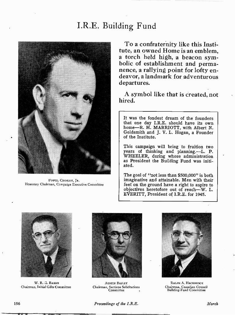
I.R.E. Building Fund
POWEL CROSLEY, JR.Honorary Chairman, Campaign Executive Committee
W. R. G. BAKERChairman, Initial Gifts Committee
To a confraternity like this Insti-tute, an owned Home is an emblem,a torch held high, a beacon sym-bolic of establishment and perma-nence, a rallying point for lofty en-deavor, a landmark for adventurousdepartures.
A symbol like that is created, nothired.
It was the fondest dream of the foundersthat one day I.R.E. should have its ownhome-R. H. MARRIOTT, with Albert N.Goldsmith and J. V. L. Hogan, a Founderof the Institute.
This campaign will bring to fruition twoyears of thinking and planning.-L. P.WHEELER, during whose administrationas President the Building Fund was initi-ated.
The goal of "not less than $500,000" is bothimaginative and attainable. Men with theirfeet on the ground have a right to aspire toobjectives heretofore out of reach-W. L.EVERITT, President of I.R.E. for 1945.
AUSTIN BAILEYChairman, Sections Solicitations
Committee
RALPH A. HACKBUSCHChairman, Canadian Council
Building -Fund Committee
196 Proceedirls of the I.R.E. March
I have a great deal of interest in I.R.E.'splans looking to the acquisition of adequatehousing and will be glad to do anything I canto further the program-FRANK B. JEW-ETT, distinguished telephone engineer;Fellow, I.R.E.
I am gratified that the Building Fund ofI.R.E. is flexible enough to permit the radioengineers' joining in a greater housingscheme of the whole engineering professionat a later time, if and when plans take shape-GANO DUNN, Fellow, I.R.E., Past -President A.I.E.E., Honorary Member,A.S.M.E.
A BROAD PROGRAM
THE souvenir program of the LR.E. 1945 WinterTechnical Meeting carried this significant edi-torial:
"The Building Fund campaign of I.R.E. may proveto be the most cohesive force working in the radio -and -electronic industry in 1945. . . . More engineers willhear about the Institute and discuss its virtues thanever before. Its members will more carefully than everweigh the values to themselves of its tangibles and im-ponderables. . . . The corporations which typify the in-dustry will apply to it their measuring -stick of networth, in terms of its functions of constantly supplyingthem with replenishments of Ideas and Men -with -Ideas."
As the campaign has progressed since its midwinterlaunching, those words have been prophetic. Contribu-tors, both corporate and individual, have recognizedthat when the Institute moves into its new home it rep-resents but the first important step towards a GreaterI.R.E.-that the momentum of the financial campaignitself, the stimulus of the challenge presented, theworth-whileness of the mutual effort, the thrill of recog-nition by friends of the profession, all will sweep theInstitute and its membership on to measure up to thenew opportunities which the electronic arts present. AsDr. L. P. Wheeler said in his address as retiring Presi-dent a year ago: "At the present stage of its develop-ment the Institute may be thought of as having passedthrough its period of adolescence to the realization of ma-ture powers, useful and used in large domains outsidethat of communications." This year, Professor Turner,in his valedictory: "This program of coming into ourown is broader than any building fund. Numerically, amembership of 25,000 is within our grasp during thenext few years."
PROGRESS REPORTED
The Directors, with their foreknowledge of campaignplans, had first opportunity to make individual sub-
scriptions. As reported by Dr. Everitt at the AnnualMeeting: "They gave individually, in amounts rangingfrom $500 down to $100, with several of $300 and $250,and an average of $217. The first two came from Wash-ington, D. C. . . . While the Directors are men of partsthey are not particularly men of means. The thing theydo have is interest in the future of the Institute. Fortu-nately, interest is amenable to stimulation, so that it issomething we can all work on. I hope that, as a result ofpresent or stimulated interest, several individuals willbe discovered during the course of our campaign whowill make a thank -offering of a thousand dollars or moreto the Institute for the part it has played in laying thefoundation of personal fortunes. I believe that, likewiseas a result of interest in I.R.E., hundreds of members,from Fellow to Associate, will match the Directors'range of gifts; and that other hundreds, who must becontent to give less, will subscribe total sums the equiv-alent of a few dollars a month for one year, since ours isa nonrecurring need which must be satisfied within ayear if at all."
Before a day had elapsed following Dr. Everitt's re-port on the Directors' solicitation, Mr. W. 0. Swinyard,chairman of the Chicago Section of I.R.E., reported thefirst corporate gift of $1000. Within a week, Dr. W. R. G.Baker's Initial Gifts Committee was reporting checksreceived in still higher brackets, and the campaign waswell under way.
What helps Headquarters to functionsmoothly, directly helps the Sections. In ad-dition, an adequate building available tomembers visiting New York City will be anasset to the membership in the UnitedStates and throughout the world-L. M.CLEMENT, Cincinnati Section; Director.
I.R.E. knows no more of international boun-daries than radio itself. It deserves supporteverywhere-R. A. HACKBUSCH, Chair-man, Canadian Council.
In my opinion the Building Fund is properlyand legally safeguarded as to its applicationto the intended purposes-H. R. ZEA-MANS, I.R.E. Legal Counsel.
Your campaign has been well timed. Theindustry is poised to take full advantage of abrilliant future-MELVILLE EASTHAM,radio pioneer, former Director and Treas-urer, I.R.E.
1945 Proceedings of the I.R.E. 197
Institute News and Radio Notes
Board of Directors
January 10 Meeting: The final meetingof the 1944 Board of Directors was held onJanuary 10, 1945. Those present were:H. M. Turner, president; W. L. Everitt,president-elect; S. L. Bailey, E. F. Carter,Alfred N. Goldsmith, editor; R. F. Guy,R. A. Heising, treasurer; Keith Henney(guest), F. B. Llewellyn, Haraden Pratt,secretary; H. J. Reich, B. E. Shackelford(guest), H. A. Wheeler, W. C. White, andW. B. Cowilich, assistant secretary.
Executive Committee Actions: The ac-tions of the Executive Committee, taken atits October 31 and November 27, 1944,meetings were ratified.
President Turner: President Turner ex-pressed his appreciation of the co-operationand support received from the Board mem-bers during his presidential term of office.
January 10 Meeting: At the annualmeeting of the Board of Directors for 1945,the following were present: W. L. Everitt,president; S. L. Bailey, W. L. Barrow, E. F.Carter, Alfred N. Goldsmith, editor; R. F.Guy, R. A. Heising, treasurer; Keith Hen-ney, F. B. Llewellyn, Haraden Pratt, secre-tary; B. E. Shackelford, H. M. Turner,H. A. Wheeler, W. C. White, and W. B.Cowilich, assistant secretary.
Committees and Appointments:
Building -Fund: Dr. Shackelford, chair-man of this committee, reported that theorganization and activities of the Building-Fund campaign are progressing satisfac-torily.
The following committees, with thechairman named in each case, have beenorganized as part of the campaign to solicitcontributions from industry and the member-ship, the student and foreign members to becontacted by direct solicitation:
Planning Committee-B. E. Shackel-ford, Chairman
Initial Gifts Committee-W. R. G.Baker, Chairman
Sections Solicitation Committee-Aus-tin Bailey, Chairman
Public Relations Committee-I. S. Cog-geshall, Chairman
Canadian Council-R. A. Hackbusch,Chairman
Special blanks have been provided formaking contributions, and it was statedthat partial payments can be made and thatUnited States Government bonds, at exist-ing value and transferable to corporations,can be donated.
Pledges amounting to $3690 have beenreceived from seventeen Board members,including those present and R. A. Hack-busch, A. F. Van Dyck, and L. P. Wheeler.
The following resolutions, defining theInstitute's policy on the Building Fund,were unanimously adopted, subject to theapproval of the General Counsel:
"WHEREAS, the Institute is engaged inmany activities looking to the advancementof the profession of engineers in the radioand allied fields, and"WHEREAS, many of these activities havebeen and are being carried on solely at theexpense of the membership, but are madeavailable to the profession at large and tothe radio industry without added cost, and"WHEREAS, the Institute is undertakingto raise a Building Fund more properly andeconomically to provide for the housing ofthese activities, and for their regular sup-port:"THEREFORE, be it resolved, that therebe created and monies solicited for a Fundon the following terms and conditions:"(1). The Fund shall be set up as a separate
fund to be known as "The BuildingFund of the Institute of Radio Engi-neers, Incorporated," and shall beconserved by the Investments Com-mittee of the Institute, and such In-vestments Committee may in its dis-cretion deposit the Fund, or any partthereof, in any bank or banks, orsavings institution or institutions,with or without interest, or may in-vest the Fund, or any part thereof, inUnited States Government bonds.
"(2). The Fund shall be applied to the pur-chase or construction of a buildingby and for the Institute, either aloneor in conjunction with other societies,and the improvement, repair, equip-ping, and furnishing thereof, and forproviding for the housing of the gen-eral activities of the Institute, exceptthat if, after three years from the timeof this meeting, the Board does notfind it feasible to purchase or con-struct such a building because suf-ficient funds have not been obtainedor for any other reason, then the Boardmay, by a three-quarter vote, directthat the Fund be discontinued andturned over to the Institute and addedto its general funds.The Board shall appoint three Ad-ministrators of the Fund, to servewithout compensation, one and onlyone of whom shall be a member of theBoard of the Institute, who shall makerecommendations to the Board withrespect to the progress and use of theFund, and no expenditures of theprincipal of the Fund shall be madeby the Institute without the unani-mous approval in writing of the Ad-ministrators. Administrators may re-sign, or be removed by a three-quar-ter vote of the Board members presentat any regular meeting and othersappointed in their places.
"(4). Any income received by the Fundshall be quarter -annually turned overto the Treasurer of the Institute forits general purposes which may in-clude the solicitation and administra-tion of the Fund, the upkeep of anybuilding purchased or constructed forthe Institute as above provided, or the
"(3).
"(5).
rental and upkeep of temporary quar-ters for the use of the Institute.Principal of the Fund may also beused for its solicitation and adminis-tration.The Fund shall be audited annuallyby the same accountants who act forthe Institute and such accountantsshall be paid by the Institute andcopies of such audits shall be furnishedeach Administrator. Financial reportsas to the condition of the Fund shallbe furnished by the InvestmentsCommittee to the Board at its regularmeetings.
"(6). These resolutions may be amended atany time or times by a three-quartervote of the Board but in no event shallthe Fund or the interest therefrombe used for other than the general pur-poses of the Institute."
Unanimous approval was given to themotion that the Building -Fund Committeebe delegated to appoint the three originaladministrators of the Fund, for whom pro-vision is made in the foregoing resolutions.
It was moved to set up the campaignplans in the manner that the back -dues pay-ments of delinquent members, to the near-est and highest $25, and received untilJuly 1, 1945, would be allocated to the Build-ing Fund. The motion was amended in theform given below:
"The campaign plan should be set up ina manner whereby the back -dues pay-ments of delinquent members, upontheir specific requests and until July 1,1945, would be allocated to the BuildingFund."Appointments Committee Report: Presi-
dent Everitt, as chairman of the Appoint-ments Committee, presented the report ofthe committee which had been mailed to the1945 Board members. It was decided toconsider the offices and committees, alongwith the candidate or candidates recom-mended, in the order given herein.
Secretary, Treasurer, and Editor: Onrecommendation of the Appointments Com-mittee, Messrs. Pratt, Heising, and Gold-smith were unanimously reappointed assecretary, treasurer, and editor, respec-tively.
Appointed Directors: The following fivemembers, recommended by the Appoint-ments Committee, were unanimously ap-pointed Directors for 1945:
E. F. Carter R. A. HackbuschL. M. Clement D. B. Sinclair
W. 0. SwinyardExecutive Committee: The Appointments
Committee recommendation of these Boardmembers, to serve on the Executive Com-mittee during 1945, was unanimously ap-proved:
S. L. Bailey W. L. BarrowE. F. Carter
Awards: These members were appointedto the 1945 Awards Committee, as recom-mended by the Appointments Committee:
W. C. White, ChairmanHaraden Pratt, Vice Chairman
198 Proceedings of the I.R.E. March, 1945
Institute News and Radio Notes 199
Austin Bailey D. E. HarnettW. L. Barrow Keith HenneyL. A. du Bridge J. V. L. Hogan
E. W. EngstromConstitution and Laws: On recommenda-
tion of the Appointments Committee, thefollowing members were appointed to the1945 Constitution and Laws Committee:
R. F. Guy, ChairmanAustin Bailey, R. A. HeisingE. F. Carter F. E. TermanI. S. Coggeshall H. R. Zeamans
Nominations: The Appointments Com-mittee recommendation of these members toserve on the 1945 Nominations Committeewas approved:
J. V. L. Hogan, ChairmanH. M. Turner, Vice Chairman
Beverly Dudley C. M. Jansky, Jr.0. B. Hanson R. C. Poulter
W. C. WhiteTellers: The following members, recom-
mended by the Appointments Committee,were appointed to the 1945 Tellers Com-mittee:
G. B. Hoadley, ChairmanEdward J. Content, Vice Chairman
E. B. Boyce Trevor ClarkGeneral Counsel: The reappointment of
Harold R. Zeamans to serve as the Insti-tute's General Counsel during 1945 wasunanimously approved.
Investments: President Everitt and Pro-fessor Turner (alternate for Dr. Cutting)were appointed to the 1945 InvestmentsCommittee.
Technical Committee on Radio Receivers:Upon recommendation of the ExecutiveCommittee, J. A. Worcester was appointedto this technical committee.
Office Organization: President Everittand Chairman S. L. Bailey of the Com-mittee on Office Organization reported onthe activities of the group and on the recom-mendation of the Executive Committee thatGeorge W. Bailey be invited to accept theExecutive Secretaryship of the Institute.
The Executive Committee was author-ized to issue the invitation to Mr. Bailey toaccept this position.
Sections Committee Meeting: ChairmanHeising distributed copies of the "Notice ofAnnual Meeting of the Committee on Sec-tions," being held on January 24, 1945, aspart of the 1945 Winter Technical Meeting,and reviewed the subjects on the agenda forthat meeting. The Board members were in-vited to attend this annual meeting of theSections' representatives.
Postwar Publication Fund: Upon thesuggestion of Chairman Heising of the In-vestments Committee, it was moved totransfer the $20,000, making up this fund,to the custody of the Investments Com-mittee for the purpose of having the suminvested in United States Government se-curities bearing interest, such investmentsto be marked for the "Postwar PublicationFund" account.
American Standards Association: Thequoted changes in Articles 2 and 5 of theASA Constitution, explained in the De-cember 27, 1944, circular from that associa-tion and recommended by the ExecutiveCommittee, were reported by ProfessorTurner and given unanimous approval:
"(1) To remove the limitation of the
work 'to those fields in which engi-neering methods apply' in orderthat the scope be broadened tohandle any standard or standard-ization project which deservesnational recognition regardless ofwhat field it is in.
"(2) To include the consensus principleas one of the basic principles of theAssociation.To authorize the Board to elect notmore than three Members -at -Largeto serve on the Board."
The corresponding letter -ballot will besent to the ASA on that basis.
"(3)
January 23 Meeting: The annual meet-ing of the Board of Directors, begun onJanuary 10, 1945, was resumed on January23, 1945, and the following were present:W. L. Everitt, president; G. W. Bailey(guest), W. L. Barrow, E. F. Carter, AlfredN. Goldsmith, editor; R. F. Guy, R. A.Heising, treasurer; Keith Henney, F. B.Llewellyn, B. E. Shackelford, D. B. Sin-clair, W. 0. Swinyard, H. M. Turner, H. A.Wheeler, L. P. Wheeler, W. C. White, H. R.Zeamans, general counsel (guest); and W. B.Cowilich, assistant secretary.
Office Organization: President Everittannounced that George W. Bailey had ac-cepted the Executive Secretaryship of theInstitute. Mr. Bailey will spend an initialperiod studying the problems of the In-stitute, and thereafter assume his full-timeduties.
Readmission of Former Members: Thefollowing resolution was unanimouslyadopted:
"RESOLVED, that the Board of Direc-tors readmit to the grade of membershippreviously held (or in the Associate gradeif formerly a Junior) those former mem-bers (a) whose menberships terminatedbefore or during 1944 and who pay eithercurrent dues or all dues in arrears, or(b) whose memberships terminate onApril 30, 1945, and who pay dues for1945 at a later date during 1945. Thepayment of a new entrance fee, if suchwould normally be required, is waived.Associates, who formerly had the privi-lege of voting, will be readmitted as non-voting Associates."
SectionsWilliamsport: Mr. H. A. Wheeler re-
ported on the January 3, 1945, letter fromthe Williamsport Section, proposing addi-tional counties for its Section territory.Unanimous approval was given to havingthese counties in Pennsylvania included inthe official Williamsport Section territory:
Pennsylvania CountiesBradford Lycoming NorthumberlandClinton Mifflin SnyderColumbia Montour Sullivan
UnionThe approved counties are within a 60 -mileradius of Williamsport.
Petitioned Constitutional Amendment:President Everitt reviewed this amendmentrelating to Article IV, which was sub-mitted by a petition initiated by H. P.Westman, and which represents a secondplan to increase membership dues. It wasnoted that at the last meeting the Constitu-tion and Laws Committee was "empowered
to decide when the petitioned amendmentshall be submitted to the voting membershipbefore July 1, 1945." The following actionsresulted from the discussion:
Endorsement: It was moved to endorsethis proposed amendment of Article IV,submitted by petition and concerning asecond plan to increase membership dues.
Sections Committee Meeting: It was de-cided to have the Board's endorsement ofthe indicated amendment reported and thatamendment discussed at the annual Sec-tions Committee meeting being held onJanuary 24, 1945.
Section Rebates: The Constitution andLaws Committee was instructed to preparean amendment to the Bylaws Committeefor the purpose of increasing rebates to Sec-tions by the amount of 25 cents a memberin good standing (except Students), the in-crease to be retroactive to January 1,
1945.1945 Budget: The Secretary was in-
structed to revise the 1945 budget to re-flect the amount involved in the previousmotion, relating to the increase in Sectionrebate.
Conferences and Meetings: Mr. H. A.Wheeler reviewed his October 13, 1944, re-port, "Future Co-operation Between IREand National Electronics Conference inChicago." The following actions followedthe discussion of Mr. Wheeler's report:
Local Conferences and Meetings: It wasmoved that the Board adopt the policy ofencouraging local conferences and meetingson specialized technical subjects under spon-sorship of the Sections; that these con-ferences and meetings be held in strict con-cordance with the spirit of governmentalregulations restricting travel; and, that theInstitute headquarters co-operate with theSections in arranging these conferences andmeetings:
1945 Summer Convention: It was unani-mously voted to cancel the Summer Con-vention, scheduled to be held in Montrealduring June, 1945.
Traveling Lecture Series: Mr. Guy re-viewed his letter of December 28, 1944,addressed to President Everitt, describing aplan for a traveling lecture series on tele-vision and frequency modulation for pres-entation among the Sections of the Insti-tute. It was moved to refer the preliminaryplanning on the traveling lecture series pro-posed by Mr. Guy, to the Committee onEducation, with instructions to proceedwith putting the plan into effect as soon asit is feasible to do so. The Committee onEducation was also instructed to work outthe finances, including admission chargesand the disposition of any profit that mayresult.
Executive CommitteeJanuary 9 meeting: The Executive Com-
mittee meeting, held on January 9, 1945, wasattended by H. M. Turner, president; W. L.Everitt, president-elect; S. L. Bailey (guest),Alfred N. Goldsmith, editor; R. A. Heising,treasurer; F. B. Llewellyn, Haraden Pratt,secretary; H. A. Wheeler, and W. B. Cowi-lich, assistant secretary.
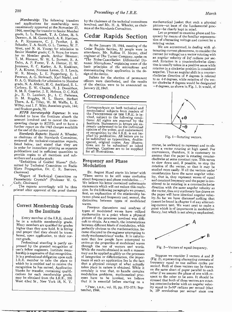
200 Proceedings of the I.R.E. March
Membership: The following transfersand applications for membership wereunanimously approved at the November 27,1944, meeting: for transfer to Senior Membergrade, L. L. Beranek, T. A. Cohen, H. S.Dawson, A. M. Gurewitsch, A. E. Harrison,A. P. Kauzmann, C. J. Penther, J. B.Schaefer, T. A. Smith, G. L. Tawney, W. P.West, and N. H. Young; for admission toSenior Member grade; C. S. Roys; for trans-fer to Member grade, Arthur Bloomer;T. M. Bloomer, W. W. L. Burnett, R. A.Dehn, A. P. Foster, T. A. Hunter, H. W.Jamieson, E. C. Karker, A. R. Keskinen,P. A. Kransz, Norman Lavoo, 0. I. Lewis,W. R. Moody, L. E. Pepperberg, E. L.Petersen, A. G. Skrivseth, Karl Stiefel, andD. A. G. Waldock; for admission to Membergrade, N. A. Abbott, H. G. Auckland, R. L.Carbrey, E. W. Chapin, H. J. Donaldson,R. M. R. Gaarder, J. E. Hobson, 0. C. Keil,Jr., R. D. Lambert, Jr., I. C. Pedersen,D. M. Ruggles, H. L. Shortt, HerbertThorn, A. E. Tilley, W. M. Waffle, L. E.Willey, and I. F. Witt; Associate grade, 144;and Student grade, 70.
RTPB Secretaryship Expense: It wasdecided to have the Institute absorb theamount involved and to cancel the corre-sponding charge to RTPB; and to have afurther report on the 1945 charges availableat the end of the current year.
Standards Reports: Harold A. Wheeler,as chairman of the Standards Committee,reviewed the technical -committee reports,listed below, and stated that they arein order for immediate printing as separatepublications and in sufficient quantities toprovide copies to all members and sub-scribers and a surplus stock:
"Definitions of Guided Waves" (Sub-mitted by Technical Committee on RadioWave Propagation, Dr. C. R. Burrows,Chairman)
"Report of Technical Committee onPiezoelectric Crystals" (Professor W. G.Cady, Chairman)
The reports accordingly will be thusprinted after approval of the proof thereof
Correct Membership Gradein the Institute
Every member of the I.R.E. shouldbe in a suitable membership grade.Many members are qualified for gradeshigher than they now hold. It is fittingand proper that they should be trans-ferred, upon application, to their cor-rect grade.
Professional standing is partly ex-pressed by the granted recognition ofone's fellow engineers. Institute mem-bership is expressive of that recognition.It is a professional obligation upon eachI.R.E. member to take the place towhich he is entitled and to receive therecognition he has earned. Applicationblanks for transfer, containing qualifi-cations for each membership grade,may be obtained from the I.R.E., 330West 42nd St , New York 18, N. Y.
by the chairmen of the technical committeesinvolved, and Mr. H. A. Wheeler, as chair-man of the Standards Committee.
Cedar Rapids SectionAt the January 10, 1944, meeting of the
Cedar Rapids Section, 52 people were inattendance. Mr. Rollins H. Mayer, chiefengineer of The Turner Company, spoke on"The Noise -Cancellation Differential Dy-namic Microphone," explaining some of thebasic principles of the microphone anddemonstrating their application in the de-sign of the device.
Ballots for the election of permanentofficers were distributed, and the resultsof the election were to be announced onJanuary 22, 1945.
Correspondence
Correspondence on both technical andnontechnical subjects from readers ofthe PROCEEDINGS OF THE I.R.E. is in-vited, subject to the following condi-tions: All rights are reserved by theInstitute. Statements in letters are ex-pressly understood to be the individualopinion of the writer, and endorsementor recognition by the I.R.E. is not im-plied by publication. All letters are tobe .submitted as typewritten, double-spaced, original copies. Any illustra-tions are to be submitted as inkeddrawings. Captions are to be suppliedfor all illustrations.
Frequency and PhaseModulation
Dr. August Hund starts his letter'. with"There seems to be still some confusionabout frequency and phase modulation...."We believe his letter contained unfortunatestatements which will not reduce this confu-sion. In the following paragraphs we present,first, an explanation of the relationship be-tween phase and frequency and, second, thedistinction between types of modulatedwaves.
Previous discussions and analyses oftypes of modulated waves have utilizedmathematics to a point where a physicalpicture of the processes involved was diffi-cult to obtain. As a result, the interrelationsbetween different kinds of modulation, whileperfectly obvious to the mathematician, be-came obscured to the engineer attempting tostudy mathematicians' works. It is unfortu-nate that few people have attempted toarrive at the properties of modulated wavesthrough the use of vectors and words.While the results obtained in such a mannermay not be applied as glibly as the processesof integration or differentiation, the impor-tance of such an application lies in the factthat a physical concept of what actuallytakes place in nature is obtained. While itcertainly is true that, to handle complexmodulation problems, mathematical proc-esses have to be invoked, we believethat it is essential before starting on a
PROC. I.R.E., vol. 32, pp. 572-573; Sep-tember, 1944.
mathematical junket that such a physicalpicture-at least of the fundamental proc-esses-be clearly kept in mind.
Let us proceed to examine phase and fre-quency by means of the familiar representa-tion of alternating voltage and current by arotating vector.
We are accustomed, in dealing with al-ternating -current phenomena, to consider thecurrent (or voltage) as a vector rotating withan angular velocity of 27f radians per sec-ond. Rotation in a counterclockwise direc-tion is usually taken in a positive sense whilerotation in a clockwise position is considerednegative. Thus an angular shift in a counter-clockwise direction of B degrees is referredto as +0 degrees, while rotation of the vec-tor clockwise 0 degrees would be designated-0 degrees, as shown in Fig. 1. It would, of
e
Fig. 1-Rotating vectors.
course, be awkward to represent and to ob-serve a vector rotating at high speed. Forconvenience, therefore, it is customary toassume that the paper is rotating counter-clockwise at some constant rate. This servesto slow down and, if possible, to stop therotation of the vector, so that it may bestudied more easily. If all the vectors under 'consideration have the same angular veloc-ity, that is, they represent waves of equaland constant frequency and the paper is con-sidered to be rotating in a counterclockwisedirection with the same angular velocity asthe vector, then any stationary line drawn onthe paper will have identical angular veloc-ity. So far we have discussed nothing thatcannot be found in chapter 1 of any alternat-ing -current text. We want next to make apoint which is of importance in modulationtheory, but which is not always emphasized.
A
Fig. 2-Vectors of equal frequency.
Suppose we consider 2 vectors A and B(Fig. 2), representing alternating currents offrequency equal to one million cycles persecond. Both of these vectors can be drawnon the same sheet of paper parallel to eachother if we assume the phase of one with re-spect to the other to be zero. It should bestressed that both of these vectors are rotat-ing counterclockwise with an angular veloc-ity equal to 21-10° radians per second (thatis, 106 revolutions per second since one

1945 Institute News and Radio Notes 201
revolution is equivalent to 2w radians). Letus ask ourselves how can the phase of cur-rent B be advanced with respect to Al Inorder for this to take place, it will be neces-sary for vector B to rotate faster than vectorA in a counterclockwise direction. To in-crease the angular velocity, we must increasethe frequency. Thus, we see in a qualitativeway that in order to bring about a phasechange a frequency change must take place,
9
f
1,000,002
999,998
of the change in phase is 1 cycle per second.In order that the phase advance 2w radiansin 4 second, vector B will have to rotatefaster than vector A by 2 revolutions persecond or, stating the same thing in termsof frequency, the frequency of B will haveto be 2 cycles higher than that of A. In factthe frequency of B will have to be higherthan that of A by this same 2 cycles persecond at any time during this second. The
A
t (stcomos)
B
1,000,000
Fig. 3-Relation of frequency to phase deviation.
and inversely a frequency change must re-sult in a phase change.
We cannot emphasize this point-phaseand frequency are interdependent-stronglyenough. One cannot be changed withoutchanging the other. Many writers, Dr. Hundis among them, have strayed because, whilethey surely know that phase and frequencyare knotted solidly together, they sometimesignore this principle.
Let us apply this line of reasoning to asimple case of modulation. Consider thephase of current B, as represented by vectorB, to be uniformly increasing at a rate of
FREQUENCY
DEVIATION
(FREQUENCYMODULATION
t
angular velocity of B will have to be2w X 2 radians per second greater than thatof A. When vector B reverses itself androtates clockwise 2w radians in second, thefrequency of B relative to A will have to be2 cycles per second less than 1,000,000. Aplot of the frequency of vector B during thiscycle of phase change is illustrated in Fig.3B. Note that the frequency, Fig. 3B, is theslope of the phase -versus -time plot, Fig. 3A,that is, the frequency is proportional to therate of change of phase. As a matter of fact,from the above, frequency is 1/2r times therate of change of phase.
PHASEMODULATION
MODULATING FREQUENCY
Fig. 4-Pre-emphasis curve.
2 revolutions each second (or, in fancierlanguage, 4s- radians per second). Then atthe end of 4 second, vector B will havemoved in phase relative to A by one revolu-tion (2w radians). Let us further assume thatafter vector B has made this one revolutionits phase instantaneously reverses itself withthe same angular velocity so that it resumesits original position at the end of 1 second.
In Fig. 3A there has been plotted phaseas a function of time. The repetition rate
Now we come to the delicate subject ofdistinguishing frequency from phase modu-lation. Discussions on this distinction arereminiscent of the discussions which usedto take place on the "physical reality of side -bands." We should like to start by givingthe classical definitions, which are incor-rectly stated by Dr. Hund. Much of theconfusion arises from the unfortunate choiceof the terms "frequency" and "phase" backin the 1920's to designate these two types of
modulation. "Frequency modulation" doesnot mean that only the frequency of a waveis being changed, nor does "phase modula-tion" mean that only the phase of a wave isbeing changed. Fundamentally there areonly two classes of modulated waves. First,there is the class in which the amplitude ismodified by the modulating signal and sec-ond, the class in which the angular velocityof the wave is modified. (Sometimes a thirdclass, consisting of combinations of these twoclasses, is added.)
We mention briefly the case of amplitudemodulation. The frequency response of theaudio system is never considered to alter thetype of modulation. Amplitude modulationis amplitude modulation, whether the fre-quency response of the modulating circuitrises, falls off, or is flat.
Consider next the second class of modu-lated waves, the class in which the angularvelocity is changed by the modulating sig-nal. (We are at a loss to select a suitablename for this type of modulation-it hasbeen called angular velocity modulation,generalized frequency modulation, genericfrequency modulation, angle modulation-the prevalent and, we believe, best, usagecalls it simply frequency modulation.) Someof the early writers on the subject felt thatin this case the frequency response of themodulating circuit had a bearing on thecharacteristics of such waves. They gave dif-ferent names, frequency and phase modula-tion, to two types of modulation, identicalexcept for the frequency response of themodulating system. In frequency modula-tion, the frequency excursion is independent'of the frequency of thephase modulation, the frequency excursionis directly proportional to the modulatingfrequency. This is the sole distinction be-tween the terms as they are classically used.In each case both the frequency and thephase of the wave are altered by the modu-lating wave, since, as we have seen, fre-quency cannot be changed without changingphase, and phase cannot be changed withoutchanging frequency.
Present usage is fortunately tending toignore these classical distinctions betweenfrequency and phase modulation. This is be-cause the most widely used angular velocitysystem, the Armstrong system, is neitherclassical frequency nor classical phase modu-lation. In the Armstrong system the highermodulating frequencies are pre -emphasizedat the transmitter somewhat as shown inFig. 4. For low notes the frequency deviationis independent of modulating frequency-classical frequency modulation-while forhigh notes the frequency deviation is di-rectly proportional to modulating frequency,classical phase modulation.
Most writers are now ignoring the spe-cious classical distinction between phase andfrequency modulation, since both are soclose to being the same thing. To maintainan artificial distinction is unnecessary and"frequency modulation" as it is now comingto be used, means any type of angular -veloc-ity modulation. We hope that this trendwill continue.
D. L. JAFFE and DALE POLLACKTempletone Radio Manufacturing
CorporationNew London, Connecticut
202 Proceedings of the I.R.E. March
Calculator for Directive Arrays
With regard to my paper,1 some inquirieshave been received regarding the scaleswhich would have to be added in order toprovide information on the vertical pattern,and it is thought that the following discus-sion may be in order:
The calculator, as described, solves thefollowing formula for the horizontal pattern:
ER=[ET12-1-ET22+2ETIET2 cos (a+kd cos 0)10. (1)
The formula commonly used for the solu-tion of the pattern in both the horizontal andvertical directions is similar to
[Er12+ET2.2+2ETiET2cos (a+kd cos 0 cos 0)11/2 -1(0) (2)
where ER resultant field vector
ET1= 1 =vector representing the fieldof 7'1, the tower producing thelarger vector, if they are unequal
ET2=vector representing the field oftower T2
a -= phasing of T2 with respect to T1kd -= electrical spacing of towers0= vertical angle to the radiation
vector, measured from the hori-zon
0= horizontal angle from .the line oftowers to the radiation vector,measured from the Ty end
f (0) = [cos (A sin 0) -cos A]/ [cos B(1-cos A)]
A =electrical height of towers
All angular measurements are in degrees.In the calculator described and illus-
trated, scales for values of kd ranging from360 to 45 degrees were provided on the fixedbase, and the rotary runner was calibratedaccordingly. The calculator may assist indeveloping the vertical -radiation pattern ifadditional scales of ce for values of kd from45 to 0 degrees are added and the runnerproperly calibrated over this region. Thesecalibration points would be determined inthe same manner as those described in theabove article. With these added scales,the term [ET1s-FET22+2 ETIET2 cos (a+kd cos 0 cos 41) ]1l= of (2), which we maycall f (E), may be solved as follows:
At any desired vertical angle 0, the valueof kd cos 0 may be taken as a new value ofspacing kd'. This value of kd' may be deter-mined by setting the runner to the calibra-tion point (on the kd scale) corresponding tothe angle 4) equal to 0, and measuring thecentral angle from the reference line to thatcalibration point. This measurement may bemade by using the protractor scale inscribedon the outer edge of the rotary element( L a scale). Then the term f(E) may besolved for this value of 0 at all values of 41 byproceeding as in the determination of thehorizontal pattern, using the new value ofspacing kd'. The value of ER is then deter-mined in each case by multiplying f(E) by1(0).
Scales could be provided for the solutionof f(0), but since this is a relatively simpleslide -rule operation, it appears that no greatsaving of time would be made.
1 J. G. Rountree, "A calculator for two -elementdirective arrays." PROC. I.R.E., vol. 32, pp. 760-767;December, 1944.
Incidentally, a typographical error, ap-parently overlooked in the proofreading,appears near the bottom of the second col-umn on page 763, where the term "E2/ET1"appears. This should be "ET2/ET1."
J. G. ROUNTREEP. 0. Box 5238Dallas 2, Texas
Quality -Control Engineering
This department which, although in itsinfancy, is gaining recognition in engineer-ing and will in the future be a "must" toradio and parts manufactures.
Quality -control engineering is made upof several departments, namely, inspectors,testing, statistics, and research. Thereforethis department requires experience of avery broad nature. Since quality controlworks with production, the many problemsthat arise are corrected in assembly.
How it works:
1. InspectionA mechanical inspection system is set
up to inspect a percentage of the daily pro-duction; this may be in the nature of oneunit from every ten units made. This ofcourse depends upon the production rateand units being made. This inspection con-sists of the subassemblies, through to thefinal product, also the packing.
2. TestingA complete over-all test of the final unit
is made on a certain percentage of the dailyproduction; their percentage depends ofcourse on the type of unit and the rate ofproduction. A visual check of the testingof subassemblies are made at various inter-vals. A check as to the performance of testequipment is made. When many tests of thesame kind are made correlation of testequipment is of major importance. Qualitycontrol must have a complete set of equip-ment for making any needed tests on theparticular items being produced. Theseshould be standards.
3. StatisticsA complete report from quality -control
inspection and testing is kept and put intograph form. These graphs show a pictureof the quality of the products being pro-duced. Should the quality decrease thetrouble may be traced and remedied fromthe source.
4. ResearchContinued research is made in an effort
to increase the quality of the items, bothmechanically and electrically. Results arerecorded and sent to engineering.
Conclusion:This department keeps everyone on the
alert from incoming inspection to engineer-ing because of its continued spot checks fromany point; therefore, a high -quality unit isassured.
GEORGE W. PTJRNELLPhilco Radio Corporation
Sandusky, Ohio
Balanced Amplifiers
Several articles1-5 have recently ap-peared on amplifiers employing cancellationof in -phase signals. These include differentialinput amplifiers; direct -current phase in-verters; and resistance -capacitance -coupledpush-pull amplifiers.
In any amplifier having three input ter-minals and/or three output terminals, theinput voltages, el and e2, may be written
= (et - e2)/2 (el e1)/2e2 = - (el - e2)/2 (el e2)/2.
The first term in each case is the differ-ential signal; the second, the "in -phase" sig-nal. If the amplifier does not transmit thein -phase signal, while the amplification ofthe differential signals is Al, t42, the outputvoltages will be
E1 = - e2)/2E2 t42(et - e2)/2 -
In a push-pull amplifier, pi =/.42 =#.4, andthe differential output voltage isµ times thedifferential input. In a phase inverter, e2 =0,but Ey.. -Ey= -µe1/2. In a differential in-put amplifier, which is followed by single -ended stages, 1/2 = 0, and Ei =,11,(ei -e2)/2.
Thus it is seen that all three types ofamplifiers are merely special uses of in -phasesignal degeneration. Perhaps the failure torecognize this fact may in part account forthe frequent republishing, as original, ofseveral of the circuits the writer developedfor this purpose.ci These have been used inmost of the equipment we have built since1936, and because of their apparent wideusefulness were made available to manyworkers in biophysics in private communica-tions, in advance of publication.
Thus the so-called "Toennies" differen-tial input amplifier is merely an applicationof in -phase degeneration by use of a largecathode resistor, where A2 is made zero; i.e.,one output terminal is disregarded.
However, some of the circuits recentlypublished appear to be identical both instructure and function to those the writerhas published, although no reference hasbeen made thereto.
There are several aspects of in -phase de-generation which appear to be misunder-stood. For example, some of the applicationsmade do not appear to recognize the effectof small variations in components. Thewriter hopes to cover these points, as well asseveral new applications, in a forthcomingarticle.
FRANKLIN OFFNEROffner Electronics, Inc.
Chicago, Ill.
1 W. M. Rogers and H. 0. Parrack, 'Electronicapparatus for recording and measuring electrical po-tentials in nerve and muscle," PROC. I.R.E., vol. 32,pp. 738-743 December, 1944.
E. L. tinzton, Electronics. p. 98; March, 1944.Walther Richter, Electronics, p. 112; Novem-
ber, 1943.Paul Traugott. Electronics, p. 132; August,
1943.5 H. 0. Rahm, Electronics, October. 1939.1 S. N. Trevino and Franklin Offner. Rev. Sci.
vol. 11, p. 412; December. 1940.Franklin Offner, Rev. Sci. Instr., vol. 8, p. 20;
January, 1937.

1945 Institute News and Radio Notes 203
Postwar Radio -and -ElectronicProspects
Sounding the keynote at the opening ofthe first National Electi-onic Conference inChicago on October 5, 1944, Ralph R. Beal,assistant to the vice-president in charge ofRCA Laboratories, urgently pleaded thatindustrial research never relinquish the har-monious co-operation with the Army andNavy which has been so closely developedduring the war. Our armor of science mustbe strong, said Mr. Beal. Science, which hashelped in winning of the war, he added, mustcontinue to assist in preserving the peace.
"If our armies, battleships, and bombersare equipped with the latest devices of sci-ence, no nation will be anxious to seek afight," said Mr. Beal. "We know how de-structive the weapons of science have beenin this war. We know what the robot bombhas done; it makes us shudder to know whatmight happen were additional forces of sci-ence harnessed to its deathly wings. I cantell you, without revealing any militarysecrets, that based upon what I have seendeveloped for warfare in the science ofradio -electronics alone, another war wouldbe much more destructive.
"It is my urgent plea that our industrial -research laboratories continue to work hand -in -hand with our Army and Navy in peaceas they have done so magnificently in war.Let us through science put new power be-hind the wings of the Dove of Peace. That isthe new challenge; it is our DUTY. . . .
"We must be quick to recognize that ifscience can be so effective in war, it can beeven more effective in peace. As soon as thiswar is won we must reconvert science fromdestruction to construction and by so doingrehabilitate the world and bring happpinessand new comforts in living to every nationon earth."
Looking ahead, Mr. Beal predicted thatradio -electronic triumphs achieved duringthe war by American research, science, andengineering are clues to revolutionary post-war developments in a wide variety of activi-ties in which the progress and welfare of thenation depend. He said that research inelectronics and vacuum -tube circuits isbringing into use the vast radio spectrumwhich lies in the frequency range from 30 to30,000 megacycles. In his opinion, thesestaticless, nonfading microwaves "may wellbe the means of establishing a new epoch indomestic communications, and ultimatelyhave a profound influence on communica-tions throughout the world.
"The outlook is bright," he continued,"for radio communications services that canconnect automobiles and other conveyanceson land or water into telephone circuits andother communications services. It is withinreason to predict that individual communi-cation sets of the walkie-talkie type willcome into wide use, and may also be con-nected into our national and world-widetelephone circuits."
Radio -and -electronics applications, hereported, have proved indispensable to avia-tion. He told of clearance- and height -measuring apparatus which informs theairman of the character of the terrain overwhich he is flying in darkness or stormy
Paying tribute to radio's wartime achievements, Army and Navy com-munications leaders attended the 25th anniversary dinner of the Radio Cor-poration of America at the Waldorf-Astoria in New Yotk on December 1, 1944.Left to right: Brigadier General Frank E. Stoner, Chief of the Army Com-munications Service; Major General James A. Code, Assistant Chief SignalOfficer, United States Army; Rear Admiral Joseph R. Redman, Director ofNaval Communications; Brigadier General David Sarnoff, Fellow, I.R.E.,and Past Secretary, I.R.E., President of RCA; and Major General H. C.,Ingles, Chief Signal Officer, U. S. A.
weather; he forecast collision -preventioninstruments which will indicate obstructionsand give timely warnings. He predicted thatelectronic means would be utilized in con-trolling aircraft and for connecting the con-trols of planes into guiding radio systemswhich in the postwar era may enable auto-matic flying from one point to another.
Among other electronic developmentshaving promise of great importance, Mr.Beal referred to radiothermics-the fast-growing industrial use of high -frequencypower that generates heat. He foresaw itspeeding industry and making possible manynew products in the postwar period. He saidthat a great deal would be heard in the fu-ture about electronic industrial control.
Throughout his address, Mr. Bealstressed the importance of research and en-gineering in opening new frontiers which hedescribed as vital to create employment andprosperity.
"Reward has come at last to man's in-herent desire and striving to extend hissight beyond its normal limitations," saidMr. Beal. "Electronic television, now on theverge of becoming a great new industry anda service to the public, answers fully ourexpectations. It stands forth as a primeexample of a major achievement of researchand engineering. Into the development ofthis marvel of the age has gone more con-centrated research than into any othermodern development. Television involvesfundamental discoveries dating back almosta century. It has tapped virtually all of thereservoirs of knowledge in radio, chemistry,physics, optics, and electronics.
"Every element, every component of thesystem has required exploration and pio-neering. New principles had to be discoveredin picture -pickup devices, electron optics,electronic amplifiers, radio transmitters, andtransmitting tubes and antennas, and inmethods for synchronizing the transmittedand received pictures. New parts of the radiospectrum had to be explored and harnessed.
Television today jests upon its own solidfoundation of research. It encompassesmany remarkable scientific advances, eachof which in its own right rises as a monumentto the progress of science."
Radio -and -ElectronicWartime Achievements
High tribute to radio's wartime achieve-ments was voiced by speakers, and under-scored by a message from President Roose-velt, at the twenty-fifth anniversary dinnerof the Radio Corporation of America in NewYork on December 2, 1944. The speakersincluded Major General H. C. Ingles, ChiefSignal Officer, United States Army; RearAdmiral Joseph R. Redman, Director ofNaval Communications, and Colonel (nowBrigadier General) David Sarnoff (A'12 -M'14 -F'17), President of the Radio Cor-poration of America.
Addressed to Colonel Sarnoff, the Presi-dential message included the following ex-pressions:
"During these twenty-five years yourcompany has played an important partin achieving pre-eminence for the UnitedStates in radio. I congratulate you person-ally for splended leadership. Your organiza-tion throughout the years has created newwonders and brought into being new servicesin all phases of radio activity for the benefitof the American people and for peopleeverywhere.
"I wish you and all members of theRCA family continued success in pioneering.With television as a new postwar industryof great promise in the fields of employ-ment, entertainment, and education, I knowthat under your guidance and vision RCAwill continue to contribute to the economicand cultural values created by radio.
204 Proceedings of the I.R.E. March
"May the next twenty-five years seeyour fondest dreams in the fascinating worldof radio come true."
General Sarnoff declared that America'sentire radio industry deserved high praisefor record -breaking achievements in supply-ing the fighting forces of the United Nationswith the finest radio -electronic instrumentsof war, equipment so necessary to attainVictory in the increased tempo of battle onthe farfiung fighting fronts.
Addressing the gathering, Major GeneralHarry C. Ingles, Chief Signal Officer, said:
"You have attached your President,Colonel David Sarnoff, to the Signal Corpsfrom time to time as occasion demanded.Colonel Samoff's exceptionally meritoriousconduct in the performance of outstandingservices has gained him the Legion of Meritaward, a decoration which he richly de-served. I can add nothing to the citationgiven to him by the War Department,which said, in part: 'Colonel Sarnoff's out-standing devotion to duty, hl' courage andgreat diplomacy in handling French citizenshave aided materially in overcoming greatdifficulties.' I can assure you that ColonelSarnoff's work in Europe was only one in-stance of his services to the Signal Corps andto the Nation."
Admiral Joseph R. Redman reportedthat advances in radio communications hadmade valuable contributions to the conductof Naval warfare, and, looking to the future,asserted: "I envisage a remarkably efficientand modern international communicationssystem. I can see great central switchboardson which terminate various circuits, eachcircuit operating through filters dividing itinto many channels for all classes of service.I believe the Radio Corporation of Americais alert to these future problems, just as italways has been in the past, arid will not failto retain its leadership in the internationalfield of communications."
In response, General Samoff said inpart,
"It has been America's good fortune toencourage the development of radio inevery field of its activity," he asserted."As a result, this country had a great radioindustry to convert to the production of in-struments of war. The entire industry de-serves high tribute for its record -breakingaccomplishments in supplying the finestradio -electronic apparatus to the UnitedNations.
"Ready to meet the impact of war,America had a world-wide communicationssystem and a broadcasting system second tonone. To operate these vastly expandedradio services, America has thousands ofself -trained amateur and commercial opera-tors who quickly enlisted. Today theseyoung men are in the front lines of com-munication with the Signal Corps; they arein the Navy and Coast Guard, on warships,transports, and aircraft, while thousands ofothers are in the Merchant Marine. Wesalute the radio amateur as an effective con-tributor to America's wartime radio com-munications.
"The unprecedented part that broadcast-ing is playing in this war, in binding to-gether the people of the United Nations, andin bringing in some light to countriesdarkened by dictatorships, can best be real-
ized when one is in the very vortex of it. Ifound myself in such a spot on D Day,June 6, 1944. At an undisclosed location inthe United Kingdom, the news came indirectly from the beaches of Normandy andthat news was broadcast instantaneously toall the world. . . .
"Tomorrow holds the promise of tele-vision and of many other new electronicwonders which will aid our economy, helpmaintain employment, and broaden ourcultural enjoyment. . . .
"Our road ahead is marked by great re-sponsibility and golden opportunity," heconcluded. "The achievements of radio dur-ing the past twenty-five years will begreatly surpassed during the next twenty-five years."
Wartime ElectronicDevelopments HoldPeacetime Promise
Wartime electronic developments, nowat work in military radar equipment, holdrich promise for more than a dozen majorapplications in postwar entertainment andindustry, according to Walter Evans (M'36-SM'43), vice-president of the WestinghouseElectric and Manufacturing Company, incharge of all company radio activities.
Speaking before the Baltimore, Mary-land, Association of Commerce Forum Dis-cussion of Baltimore's Economic Future,Mr. Evans recently painted a bright pictureof wartime developments in the electronicsfield which will serve peacetime Americaafter victory. "Clearly," he declared, "therewill be ample productive capacity to accom-modate the most optimistic estimates."
He pointed out that in the case of theWestinghouse Radio Division alone the out-put of radio and allied electronics appara-tus "has been stepped up 51 times since astate of emergency was first declared."
He recalled that scientific lessons learnedin World War I were responsible, shortlyafter the close of that conflict, for introduc-tion of the vacuum tube, which resulted inradio broadcast methods, talking movies,and other advancements which contributedmuch to the postwar economy of the 20's.Mr. Evans held out even brighter prospectsfor the part electronics will play after thepresent war.
Prominent in these developments will betelevision, of which Mr. Evans said: "It isour considered belief that all of the technicalanswers are on hand for a usable and ac-ceptable television system. This includes theprobability of a reasonably priced receiver,and a practical means of getting showsacross the country by means of radio links,or one of the more recently developed typesof metal conductors."
His list of other industrial applicationsfor which electronics will provide the seven -league boots of accomplishment includes:moulding of plastics; annealing of electricalsteels; bonding of plywood; brazing andwelding; hardening and tempering ofmetals; inspection of sheet metal and cast-
ings for porosity; dynamic balancing; vibra-tion fatigue tests for materials; remotepower -line operation and metering; andhigh-speed X-ray inspection of forgings andcastings. These applications, Mr. Evans said,are not mere dreams of accomplishments tocome at some dim and distant day, but are"ready -for -use applications which have beenproved in the miraculous war production at-tained by American industry."
Electronics, he explained, has come ofage under the stresses of wartime produc-tion, but one little-known circumstance ofthis development is the fact that even beforethe war, engineers were rapidly becomingfamiliar with the marvels made possible bythis new process.
"For example," Mr. Evans pointed out,"even in that day we were baking hams,kiln -drying lumber, curing plastics, dryingmovie films, dehydrating tobacco for export,killing vermin in grain, candy, and food-stuffs, and cementing shoes together withthermoheating-all by the use of elec-tronics."
No appraisal of the future of Americaor the world, Mr. Evans said, can be evenremotely accurate unless we take into con-sideration the vast fields opened by wartimeelectronics developments.
Television as Serviceto the Public
The stage is set and ready, technically,for the beginning of a regular televisionbroadcasting service to the public, E. W.Engstrom (A'25 -M'38 -F'40), research direc-tor of RCA Laboratories, said in the key-note address at the First Annual Conferenceof the Television Broadcasters Associationin New York on December 11, 1944.
The state of readiness of television, as hesees it, is evaluated "in cold engineeringterms," and he added, "Those who feel thattelevision is not ready and should, therefore,be delayed, must obviously not use the sameclear spectacle lenses of engineering ap-praisal through which I so clearly see thissituation."
"Now, as at earlier times, there are thosewho raise their voices in opposition, but to-day the industry in regard to television is asnearly united in its recommendations as it ispractical to expect," said Mr. Engstrom."Those who oppose, speak of the need offurther improvement and refinement and ofthe necessity, therefore, to use channels in ahigher -frequency portion of the radio spec-trum.
"Although they do not say so, the endresult of following their recommendationswould be to delay television for a long time.I have been active in the research and engi-neering development of television for manyyears. I have participated in the planningand the co-ordination during the period ofthe growth of television from research statusto its present-day maturity."
In substantiation of his views, Mr. Eng-strom cited major advances in television re-search and development:
1. Research has been done on very
1945 Institute News and Radio Notes 205
efficient reflective -type optics especiallysuited for television projection. These arenow satisfactory in performance and low-costmanufacturing is assured. Thus we may ex-pect that early postwar production of tele-vision receivers will include projection typesof excellent performance with pictures ade-quately large for home use.
2. Major increases are indicated in sensi-tivity of the iconoscope or camera tube. Re-search on this had progressed to the pointwhere substantial sensitivity gains were insight when war called a halt to televisionwork. The progress made gives promise of asolution to this important phase of televisionbroadcasting. To be able to televise allscenes which may be seen directly will addimmeasurably to the immediacy and spon-taneity of television programs.
3. Progress has been made and experi-ence has been obtained using cable and radiomethods for joining stations together in net-works. We may look forward to a growth ofnetworks suitable for television programs tosupport the growth of television broadcaststations.
"When the presently assigned televisionchannels were allocated by the FederalCommunications Commission, radio manu-facturers were able to supply transmittersfor only a group of channels at the low -frequency end of the band," continued Mr.Engstrom. "The assignment of channels,however, spanned from 50 to 300 megacy-cles. Research began .on transmitter tubesand apparatus, but again the war broughtprogress almost to a standstill. Now, how-ever, the results of this 'slowed -up' researchprogram are beginning to take tangible form.A development transmitter is now undertest giving substantial output power up to300 megacycles. Satisfactory picture trans-mission has been accomplished. Tests underfull-scale field conditions in a metropolitanarea are scheduled to begin soon.
"These major advances over and abovegeneral improvements in techniques broughtabout by war research, and again over andabove an already excellent television status,prewar, promise a most favorable situationfor television. Technically, the stage is setand ready.
"At the war's end we shall need all pos-sible means of employment for those nowengaged in manufacturing and for those whowill return from the Armed Services," saidMr. Engstrom. "We need new things andprincipally those which will add to ourstandard of living.
"The making of television transmittersand receivers, the operation of the broad-cast facilities, the making and the operationof the network facilities; these activitiesshould help to solve the problem of employ-ment for those now in war work and forthose released from the Armed Services. Tele-vision, in its widespread application, willprovide employment for very large numbersof people. We should make a determinedeffort to proceed with television on a broadscale, to proceed without handicaps. Weneed constructive planning and understand-ing co-operation on the part of all parties tomake this effort successful," Mr. Engstromconcluded. "Television can render a servicewhich the public wants and needs, and at thesame time provide employment for many."
Looking Ahead to Color andUltra -High -FrequencyTelevision
At the first annual conference of theTelevision Broadcasters Association in NewYork on December 11, 1944, Dr. Peter C.Goldmark, director of engineering researchand development of the Columbia Broad-casting System discussed the prospects forultra -high -frequency television, both inmonochrome and color. Among his remarkswere the following:
"Much of what has been proposed by theColumbia Broadcasting System for ultra-high -frequency television had already beendeveloped and tried before the war began.As an example, full color television wasbroadcast for the first time in August of1940.1 This was the first time color televisionhad ever been broadcast. Further improve-ments and subsequent field tests in colortelevision, with daily broadcasts over a pe-riod of almost one year, gave CBS and itsassociates the necessary knowledge and as-surance to state that color television is hereto stay.
"Wideband (10 -megacycle) 525 -linestandards, that is, 31,500 -kilocycle scanningfrequency, were developed and tested in theCBS laboratories before the war, and someof the results were published in the PRO-CEEDINGS OF THE I.R.E. What was lackingat that time was the means of modulatingand transmitting such wideband signals withadequate power, and efficient receivers atreasonable cost to receive such transmissions.
"Adequate power now can be produced inthe proposed ultra -high -frequency band fortelevision broadcasting (from 480 to 920megacycles) to permit adequate coverage atthose frequencies. Transmitting tubes andcircuits have been developed to permit mod-ulation with the previously mentioned10 -megacycle video band. A television trans-mitter to handle these new standards, thatis, 735 lines black and white, or 525 lines incolor, has been ordered from the FederalTelephone and Radio Corporation, to be de-livered upon obtaining adequate priorities.
"This transmitter, together with a spe-cial antenna which is omnidirectional in ahorizontal plane, and highly directional in avertical plane, will be installed on top of theChrysler Building in addition to the lower -frequency television transmitter now in op-eration.
"In collaboration with Zenith RadioCorporation, CBS plans to develop televi-sion receivers which will permit tuning overthe entire ultra -high -frequency televisionspectrum and which will be capable of re-ceiving both color and black -and -whitetransmissions.
"Television in the ultra -high -frequencyband carries with it many advantages out-side of the possibility of utilizing widerbands, and thus finer screens, and color.Specifically, it provides twenty-eight 16 -
megacycle channels in a single block, thusfor the first time making nation-wide tele-vision service possible.
Dr. Goldmark continued his analysisalong the following lines:
1 By the CBS television transmitter atop theChrysler Building.
"The all-important problem of multipathreception which now confronts service on thelower frequencies can be attacked in theultra -high frequencies from an angle whichgives hope of appreciably reducing, if notcompletely removing, this very serious con-dition. At present there are few installationsknown in the New York area where, with asingle receiving antenna, all three of the ex-isting television stations can be receivedwithout echoes or ghosts. In making the re-ceiving antennas for the new ultra -high -frequency systems, experience gained inwartime research will be utilized to producea highly directional, comparatively smallarray which automatically can be swung intwo predetermined echo -free positions foreach transmitter simply by tuning the re-ceiver. Alternatively, a number of direc-tional arrays can be switched remotely intothe receiver circuit as the latter is switchedfrom one transmitting station to the other.
"It is true that such antenna arrays asjust described would cost more than the an-tennas used at present on lower -frequencytelevision systems. However, the existingantennas are incapable of eliminating echoes.If one wanted to construct an antenna in thepresent bands with the same directivity asproposed in the ultra -high -frequency bands,the cost and the size would be far in excess ofanything mentioned thus far.
"In conclusion it should be emphasizedthat ultra -high -frequency television is muchnearer than most people realize. Withoutmentioning dates, it is safe to say that beforethe war is over its practicability will havebeen proved."
Television Networks
Syndication of television programs vianetworks will be a necessity in order that thehigh cost of quality programming may bedivided among many stations, Raymond F.Guy (A'25 -M'31 -F'39), NBC radio facilitiesengineer, told 500 members of The Instituteof Radio Engineers at a meeting held inPhiladelphia on December 7, 1944. Otherspeakers at the meeting, held in the audi-torium of the Franklin Institute, were AllenB. DuMont (M'30 -F'31), president of theAllen B. DuMont Laboratories, Inc., andDavid B. Smith (A'35-SM'44), director ofresearch of the Philco Corporation.
Supporting his contention, Mr. Guypointed out that the American public is con-ditioned to good entertainment from motionpictures and that television will be expectedto furnish program material of comparablestature. He recited instances where NBC pre-war dramatic productions through WNBThad required forty hours of rehearsal for onehour of broadcasting. Fifteen hours of theserehearsals were conducted before the televi-sion cameras with substantially a full staff inattendance. He prophesied that the studiostaff required to produce a studio dramaticproduction might consist of a producer, anassistant producer, a scene designer, twostagehands, a sound technician on the micro-phone boom and one on the control console,one person for make-up, three cameratechnicians, one technical director, onecamera dolly operator, an electrician, and a
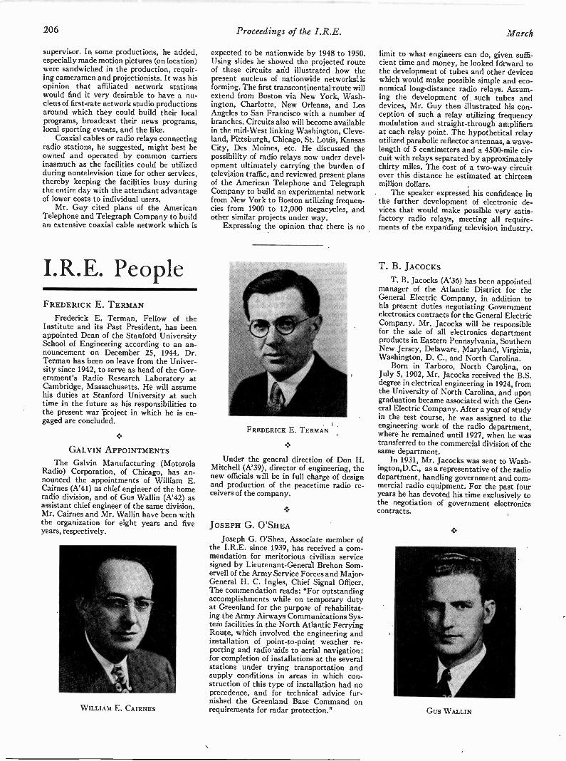
206 Proceedings of the I.R.E. March
supervisor. In some productions, he added,especially made motion pictures (on location)were sandwiched in the production, requir-ing cameramen and projectionists. It was hisopinion that affiliated network stationswould find it very desirable to have a nu-cleus of first -Tate network studio productionsaround which they could build their localprograms, broadcast their news programs,local sporting events, and the like.
Coaxial cables or radio relays connectingradio stations, he suggested, might best beowned and operated by common carriersinasmuch as the facilities could be utilizedduring nontelevision time for other services,thereby keeping the facilities busy duringthe entire day with the attendant advantageof lower costs to individual users.
Mr. Guy cited plans of the AmericanTelephone and Telegraph Company to buildan extensive coaxial cable network which is
I.R.E. PeopleFREDERICK E. TERMAN
Frederick E. Terman, Fellow of theInstitute and its Past President, has beenappointed Dean of the Stanford UniversitySchool of Engineering according to an an-nouncement on December 25, 1944. Dr.Terman has been on leave from the Univer-sity since 1942, to serve as head of the Gov-ernment's Radio Research Laboratory atCambridge, Massachusetts. He will assumehis duties at Stanford University at suchtime in the future as his responsibilities tothe present war project in which he is en-gaged are concluded.
GALVIN APPOINTMENTS
The Galvin Manufacturing (MotorolaRadio) Corporation, of Chicago, has an-nounced the appointments of William E.Cairnes (A'41) as chief engineer of the homeradio division, and of Gus Wallin (A'42) asassistant chief engineer of the same division.Mr. Cairnes and Mr. Wallin have been withthe organization for eight years and fiveyears, respectively.
WILLIAM E. CAIRNES
expected to be nationwide by 1948 to 1950.Using slides he showed the projected routeof these circuits and illustrated how thepresent nucleus of nationwide networks isforming. The first transcontinental route willextend from Boston via New York, Wash-ington, Charlotte, New Orleans, and LosAngeles to San Francisco with a number ofbranches. Circuits also will become availablein the mid -West linking Washington, Cleve-land, Pittsburgh, Chicago, St. Louis, KansasCity, Des Moines, etc. He discussed thepossibility of radio relays now under devel-opment ultimately carrying the burden oftelevision traffic, and reviewed present plansof the American Telephone and TelegraphCompany to build an experimental networkfrom New York to Boston utilizing frequen-cies from 1900 to 12,000 megacycles, andother similar projects under way.
Expressing the opinion that there is no
FREDERICK E. TERMAN
4,
Under the general direction of Don H.Mitchell (A'39), director of engineering, thenew officials will be in full charge of designand production of the peacetime radio re-ceivers of the company.
JOSEPH G. O'SHEA
Joseph G. O'Shea, Associate member ofthe I.R.E. since 1939, has received a com-mendation for meritorious civilian servicesigned by Lieutenant -General Brehon Som-ervell of the Army Service Forces and Major-General H. C. Ingles, Chief Signal Officer.The commendation reads: "For outstandingaccomplishments while on temporary dutyat Greenland for the purpose of rehabilitat-ing the Army Airways Communications Sys-tem facilities in the North Atlantic FerryingRoute, which involved the engineering andinstallation of point-to-point weather re-porting and radio aids to aerial navigation;for completion of installations at the severalstations under trying transportation andsupply conditions in areas in which con-struction of this type of installation had noprecedence, and for technical advice fur-nished the Greenland Base Command onrequirements for radar protection."
limit to what engineers can do, given suffi-cient time and money, he looked forward tothe development of tubes and other deviceswhich would make possible simple and eco-nomical long-distance radio relays. Assum-ing the development of such tubes anddevices, Mr. Guy then illustrated his con-ception of such a relay utilizing frequencymodulation and straight -through amplifiersat each relay point. The hypothetical relayutilized parabolic reflector antennas, a wave-length of 5 centimeters and a 4500 -mile cir-cuit with relays separated by approximatelythirty miles. The cost of a two-way circuitover this distance he estimated at thirteenmillion dollars.
The speaker expressed his confidence inthe further development of electronic de-vices that would make possible very satis-factory radio relays, meeting all require-ments of the expanding television industry.
T. B. JAcocKsT. B. Jacocks (A'36) has been appointed
manager of the Atlantic District for theGeneral Electric Company, in addition tohis present duties negotiating Governmentelectronics contracts for the General ElectricCompany. Mr. Jacocks will be responsiblefor the sale of all electronics departmentproducts in Eastern Pennsylvania, SouthernNew Jersey, Delaware, Maryland, Virginia,Washington, D. C., and North Carolina.
Born in Tarboro, North Carolina, onJuly 5, 1902, Mr. Jacocks received the B.S.degree in electrical engineering in 1924, fromthe University of North Carolina, and upongraduation became associated with the Gen-eral Electric Company. After a year of studyin the test course, he was assigned to theengineering work of the radio department,where he remained until 1927, when he wastransferred to the commercial division of thesame department.
In 1931, Mr. Jacocks was sent to Wash-ington,D.C., as a representative of the radiodepartment, handling government and com-mercial radio equipment. For the past fouryears he has devoted his time exclusively tothe negotiation of government electronicscontracts.
.
Gus WALLIN
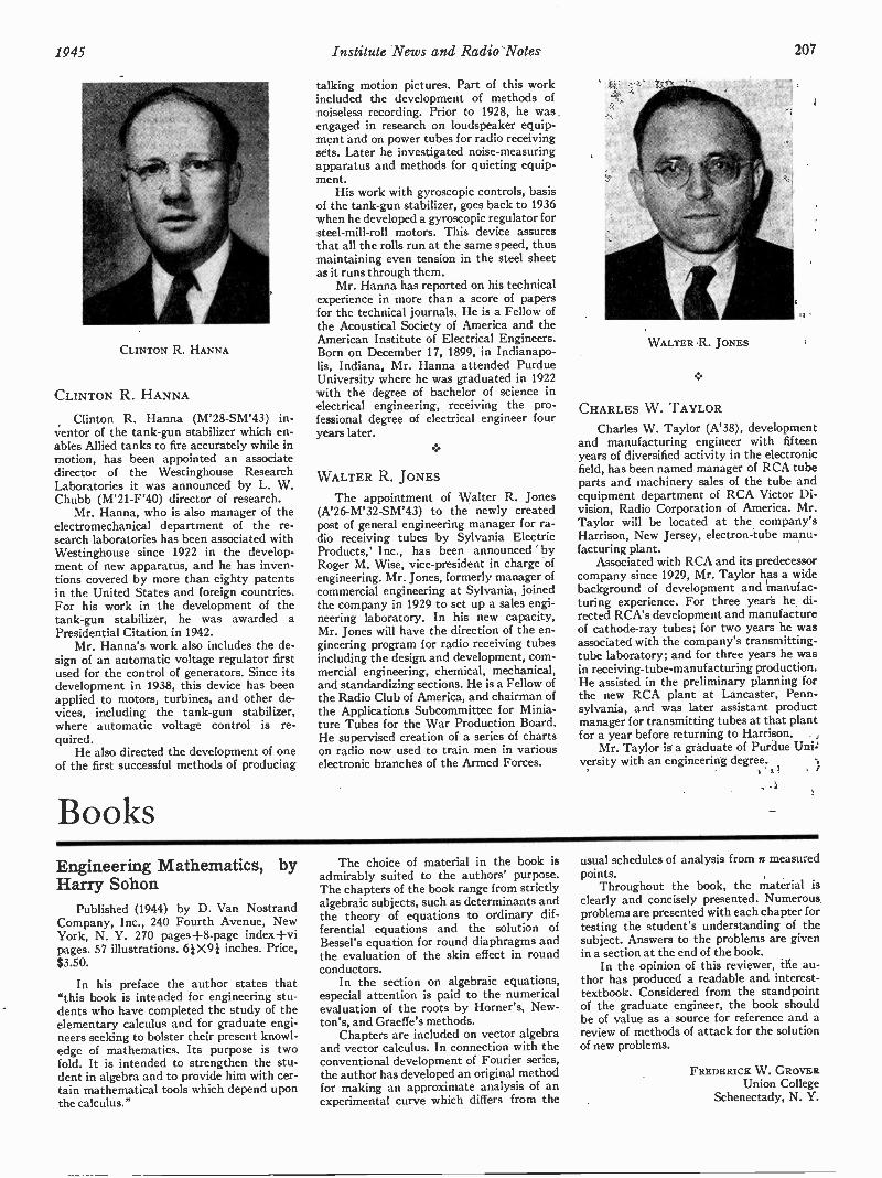
1945 Institute News and Radio Notes 207
CLINTON R. HANNA
CLINTON R. HANNA
Clinton R. Hanna (M'28-SM'43) in-ventor of the tank -gun stabilizer which en-ables Allied tanks to fire accurately while inmotion, has been appointed an associatedirector of the Westinghouse ResearchLaboratories it was announced by L. W.Chubb (M'21 -F'40) director of research.
Mr. Hanna, who is also manager of theelectromechanical department of the re-search laboratories has been associated withWestinghouse since 1922 in the develop-ment of new apparatus, and he has inven-tions covered by more than eighty patentsin the United States and foreign countries.For his work in the development of thetank -gun stabilizer, he was awarded aPresidential Citation in 1942.
Mr. Hanna's work also includes the de-sign of an automatic voltage regulator firstused for the control of generators. Since itsdevelopment in 1938, this device has beenapplied to motors, turbines, and other de-vices, including the tank -gun stabilizer,where automatic voltage control is re-quired.
He also directed the development of oneof the first successful methods of producing
Books
talking motion pictures. Part of this workincluded the development of methods ofnoiseless recording. Prior to 1928, he was .engaged in research on loudspeaker equip-ment and on power tubes for radio receivingsets. Later he investigated noise -measuringapparatus and methods for quieting equip-ment.
His work with gyroscopic controls, basisof the tank -gun stabilizer, goes back to 1936when he developed a gyroscopic regulator forsteel -mill -roll motors. This device assuresthat all the rolls run at the same speed, thusmaintaining even tension in the steel sheetas it runs through them.
Mr. Hanna has reported on his technicalexperience in more than a score of papersfor the technical journals. He is a Fellow ofthe Acoustical Society of America and theAmerican Institute of Electrical Engineers.Born on December 17, 1899, in Indianapo-lis, Indiana, Mr. Hanna attended PurdueUniversity where he was graduated in 1922with the degree of bachelor of science inelectrical engineering, receiving the pro-fessional degree of electrical engineer fouryears later.
WALTER R. JONES
The appointment of Walter R. Jones(A'26-M'32-SM'43) to the newly createdpost of general engineering manager for ra-dio receiving tubes by Sylvania ElectricProducts, Inc., has been announced ' byRoger M. Wise, vice-president in charge ofengineering. Mr. Jones, formerly manager ofcommercial engineering at Sylvania, joinedthe company in 1929 to set up a sales engi-neering laboratory. In his new capacity,Mr. Jones will have the direction of the en-gineering program for radio receiving tubesincluding the design and development, com-mercial engineering, chemical, mechanical,and standardizing sections. He is a Fellow ofthe Radio Club of America, and chairman ofthe Applications Subcommittee for Minia-ture Tubes for the War Production Board.He supervised creation of a series of chartson radio now used to train men in variouselectronic branches of the Armed Forces.
WALTER R. JONES
CHARLES W. TAYLOR
Charles W. Taylor (A'38), developmentand manufacturing engineer with fifteenyears of diversified activity in the electronicfield, has been named manager of RCA tubeparts and machinery sales of the tube andequipment department of RCA Victor Di-vision, Radio Corporation of America. Mr.Taylor will be located at the company'sHarrison, New Jersey, electron -tube manu-facturing plant.
Associated with RCA and its predecessorcompany since 1929, Mr. Taylor has a widebackground of development and manufac-turing experience. For three years he di-rected RCA's development and manufactureof cathode-ray tubes; for two years he wasassociated with the company's transmitting -tube laboratory; and for three years he wasin receiving -tube -manufacturing production.He assisted in the preliminary planning forthe new RCA plant at Lancaster, Penn-sylvania, and was later assistant productmanager for transmitting tubes at that plantfor a year before returning to Harrison.
Mr. Taylor is a graduate of Purdue Unitversity with an engineering degree.
Engineering Mathematics, byHarry Sohon
Published (1944) by D. Van NostrandCompany, Inc., 240 Fourth Avenue, NewYork, N. Y. 270 pages +8 -page indexpages. 57 illustrations. WO} inches. Price,$3.50.
In his preface the author states that"this book is intended for engineering stu-dents who have completed the study of theelementary calculus and for graduate engi-neers seeking to bolster their present knowl-edge of mathematics. Its purpose is twofold. It is intended to strengthen the stu-dent in algebra and to provide him with cer-tain mathematical tools which depend uponthe calculus."
The choice of material in the book isadmirably suited to the authors' purpose.The chapters of the book range from strictlyalgebraic subjects, such as determinants andthe theory of equations to ordinary dif-ferential equations and the solution ofBessel's equation for round diaphragms andthe evaluation of the skin effect in roundconductors.
In the section on algebraic equations,especial attention is paid to the numericalevaluation of the roots by Horner's, New-ton's, and Graeffe's methods.
Chapters are included on vector algebraand vector calculus. In connection with theconventional development of Fourier series,the author has developed an original methodfor making an approximate analysis of anexperimental curve which differs from the
usual schedules of analysis from n measuredpoints.
Throughout the book, the material isclearly and concisely presented. Numerousproblems are presented with each chapter fortesting the student's understanding of thesubject. Answers to the problems are givenin a section at the end of the book.
In the opinion of this reviewer, the au-thor has produced a readable and interest -textbook. Considered from the standpointof the graduate engineer, the book shouldbe of value as a source for reference and areview of methods of attack for the solutionof new problems.
FREDERICK W. GROVERUnion College
Schenectady, N. Y.

208 Proceedings of the I.R.E. March
Marine Radio Manual, Editedby M. H. Strichartz.
Published (1944) by Cornell MaritimePress, 241 W. 23 St., New York 11,N. Y. 505 pages+12-page index+x pages.35 figures. 71X5} inches. Price, $4.00.
As stated by the Honorable SchuylerOtis Bland, Chairman of the House Com-mittee on Merchant Marine and Fisheries,in a Foreword to the above publication,"Marine Radio Manual" is a valuable con-tribution toward furthering the present highstandard of efficiency in the art of radiocommunication.
In compiling and editing numerous datacontained in the manual, Mr. Strichartz hasably covered the subject of maritime radio-telegraph communication from the opera-tor's viewpoint, drawing on his actual sea-going experience and that of other radiomenwith years of service in the art.
Written in the language of the seagoingoperator and covering all phases of operatingroutine, this manual is an excellent brushupfor the old-time operator. Both the radiooperator making his first trip to sea and theoperator with years of sea experience maymake the manual part of their equipmentwith the assurance that information con-tained therein will be of the utmost help inthe efficient performance of their duties.
To the new operator the manual is ofgreat value, as it provides the answers tomany questions which come up in his dailyroutine on shipboard. By giving both a wordand picture description of the various formsused in radio communications, the authorprovides an offset to the lack of commercialoperating experience, which has so oftenhampered the new man in the past.
C. B. DARCYRadiomarine Corporation of America
New York, N. Y.
Reproductions ofGerman Scientific andTechnical Books
A group of facsimile reproductions of re-cent German scientific and technical bookshas been prepared under the auspices of theAlien Property Custodian, and publishedby J. W. Edwards, Ann Arbor, Michigan.Of possible interest to workers in variousportions of the radio field are the followingindividual titles:
CERAMICS
Herman Salmang, "Die physikalischenund chemischen Grundlagen der Keramik."Springer, Berlin, 1933. viii +229 pages.$5.75.
CONDENSERS (ELECTRICITY)
Electric Capacitance; Dielectrics
Georg Straimer, "Der Kondensator inder Fernmeldetechnik." Hirzel, Leipzig,1939. x+229 pages. (Physik und Technik derGegenwart. Abt. Fernmeldetechnik. Bd. 6).$6.00.
Electrolytes-Conductivity
Adolf Guntherschulze and Hans Betz,"Elektrolyt-Kondensatoren. Ihre Entwick-lung, wissenschaftliche Grundlage, Herstel-lung, Messung und Verwendung." Krayn,Berlin, 1937. 178 pages. $6.00.
ELECTRIC AMPLIFIERS
Hans Bartels, "Grundlagen der Ver-starkertechnik." Hirzel, Leipzig, 1942. xii+258 pages. $6.25.
ELECTRIC CONTACTORS
Ragnar Holm, "Die technische Physikder elektrischen Kontakte." Springer, Ber-lin, 1941. x+337 pages. $9.00.
ELECTRIC -CURRENT RECTIFIERS
Karl Maier, "Trockengleichrichter. The-orie, Aufbau und Anwendung." Olden-bourg, Munchen, 1938. 313 pages. $7.20.
Walter Schilling, "Die Wechselrichterund Umrichter, ihre Berechnung und Ar-beitsweise." Oldenbourg, Munchen, 1940.160 pages. $4.00.
ELECTRIC CURRENTS
Alternating
Fritz Vilbig, "Lehrbuch der Hochfre-quenztechnik. Mit 801 Abbildungen." Aka-demische Verlagsgesellschaft, Leipzig, 1937.xix +775 pages. $14.25.
Alternating; Geology, Prospecting
Volker Fritsch, "Messverfahren derFunkmutung." Oldenbourg, Munchen, 1943.220 pages. $5.75.
Measuring
Herbert Lennartz, "Praktische Mess-gerate fur Hoch- und Niederfrequenz."Weidmann, Berlin, 1944. ix +239 pages.$3.50.
ELECTRIC DISCHARGES THROUGH GASES:ELECTRONICS
Joachim Dosse and G. Mierdel, "Derelektrische Strom im Hochvakuum und inGasen; Einfuhrung in die physikalischenGrundlagen." Hirzel, Leipzig, 1943. xii +352pages. (Physik und Technik der Gegenwart.Abt. Fernmeldetechnik Bd. 12). $9.00.
ELECTRIC INSULATORS
Paul Boning, "Elektrische Isolierstoffe.Ihr Verhalten auf Grund der Ionenadsorp-tion an inneren Grenzflachen." Vieweg,Braunschweig, 1938. vi +134 pages. $3.00.
ELECTRIC MEASUREMENTS
Otto Zinke, "Hochfrequenz-Messtech-nik." Hirzel, Leipzig, 1938. xii +233 pages.$6.20.
Measuring Instruments
Paul Martin Pflier, "Elektrische- Mes-sung mechanischer Grossen." 2. erweiterteAufl. Springer, Berlin, 1943. vi +259 pages.$6.50.
ELECTRIC WAVES
Hans Erich Hollmann, "Physik undTechnik der ultrakurzen Wellen." Springer,Berlin, 1936. v. 1: $8.75; v. 2: $7.20; set,$13.50.
Otto Groos, "Einfiihrung in Theorie undTechnik der Dezimeterwellen." Hirzel,Leipzig, 1937. v. 1: x+188 pages. $4.65.
Heinz Richter, "Elektrische Kippschwin-gungen; Wesen und Technik." Hirzel,Leipzig, 1943. x+154 pages. $3.50.
Vacuum Tubes
"Bucherei der Hochfrequenztechnik,"Leipzig, Akad. Verlagsgesellschaft, 1940.$32.25. v. 1: Bruno Beckmann, "Die Aus-breitung der elektromagnetischen Wellen."x +286 pages. $9.65.v. 2: Horst Rothe, "Grundlagen und Kenn-linien der Elektronenrohren." xiv +325pages. $9.50.v. 3: Horst Rothe, "Elektronenrohren alaAnfangsstufenverstarker." xiii +303 pages.$8.60.v. 4: Horst Rothe, "Elektronenrohren altEnd-und Sendverstarker." x +141 pages.$4.50.
ELECTRON EMISSION
Hajo Bruining, "Die Sekundar-Elek-tronen-Emission fester Korper." Springer,Berlin, 1942. vii +126 pages. (TechnischePhysik in Einzeldarstellungen. Bd. 5.)$4.00.
ELECTRON EMISSION OF SOLIDS
Hajo Bruining, "Die Sekunclar-Elektro-nen-Emission fester Korper." Springer,Berlin, 1942. xii +126 pages. (TechnischePhysik in Einzeldarstellungen, Bd. 5.) $6.00.

1945 Contributors 209
ELECTRON MICROSCOPE
Baron Manfred von Ardenne, "Elektro-nen-Vbermikroskopie. Mit einem Titelbild,einer photographischen Tafel und 404 Ab-bildungen." Springer, Berlin, 1940. xvi +393pages. $13.00.
ELECTRON TUBES
Horst Rothe, "Elektronentthren alsSchwingungserzeuger und Gleichrichter."Leipzig, Akad. Verlagsges., 1941. x+210pages. $3.00.
ELECTRONS; VACUUM TUBES
Carl Ramsauer, ed., "Das freie Elektronin Physik und Technik." Springer, Berlin,1940. vii +270 pages. $9.55.
GUMS AND RESINS, SYNTHETIC
Johannes Scheiber, "Chemie und Tech-nologie der ktinstlichen Harze.' Wissen-schaf tl, Stuttgart. Verlagsges., 1943. xix+828 pages. $18.50.
HIGH -FREQUENCY TECHNIC
Fritz Vilbig and J. Zenneck, "Fort-schritte der Hochfrequenztechnik." 2. Aufl.Leipzig, Akad. Verlagsges., 1941. xii +656pages. $23.00.
HYDROGEN -ION CONCENTRATION; ELECTRICMEASUREMENTS
Frans Fuhrmann, "Elektrometrische pH-Messung mit kleinen Losungsmengen."Springer, Wien, 1941. vi +133 pages. $3.00.
OPTICS
Electronic
Ernst Bruche, "Geometrische Elektro-nenoptik. Grundlagen und Anwendungen.Mit einem Titelbild und 403 Abbildungen."Springer, Berlin, 1934. xi +332 pages. $8.00.
Johannes Picht, "Einfiihrung in dieTheorie der Elektronenoptik." Barth, Leip-zig, 1939. viii +197 pages. $4.50.
Electrons: Optical Instruments
Ernst Bruche, "Elektronengerate. Prin-cipien und Systematik." Springer, Berlin,1941. xiv +447 pages. $15.85.
PHOTOELECTRIC CELLS
Helmuth Simon and R. Suhrmann,"Lichtelektrische Zellen und ihre Anwen-dung." Springer, Berlin, 1932. vii +373 pages.$11.00.
PHOTOGRAPHY
"Handbuch der wissenshaftlichen undangewandten Photographie." Springer,Wien.v. 1: "Das photographische Objektiv,' 1932,
ix +399 pages. $15.00.v. 2: "Die photographische Kamera und ihr
Zubehor." 1931. ix +590 pages. $21.60.
PYRO- AND PIEZOELECTRICITY: QUARTZ
Adolf Scheibe, "Piezoelektriziat deQuarzes." Steinkopff, Dresden, 1938. xii+236 pages. (Wissenschaftliche Forschungs-berichte. Naturwiss. Reihe. Bd. 45). $5.75.
RADIATION
Maurice Deribere, "Les Applicationspratiques de la luminescence; fluorescence,phosphorescence, lumiere noire." Dunod,Paris, 1938. xiv +263 pages. $5.00.
RADIO
Hans Gunther (i.e. Walter de Haas),"Schule des Funktechnikers. Ein Hilfsbuchfur der Beruf mit besonderer Beriicksichti-gung der Rundfunk- und Fernsehtechnik."Frankh, Stuttgart, 1941. v. 1: viii +341pages; v. 2: 342 pages; v. 3: 352 pages.$17.50.
Amplifiers; Receivers
Maximilian J. 0. Strutt, "Verstarker undEmpfanger." Springer, Berlin, 1943. xiv+384 pages. (Lehrbuch der drahtlosenNachrichtentechnik. Bd. 4) $11.50.
Antennas
Helmut Bruckmann, "Antennen; ihreTheorie und Technik." Hirzel, Leipzig, 1939.xiv +339 pages. (Physik und Technik derGegenwart. Abt. Fernmeldtechnik, 5.) $8.40.
Apparatus and Supplies; Electric Filters
Richard Feldtkeller, "Einfuhrung in dieTheorie der Rundfunk-Siebschaltungen."Hirzel, Leipzig, 1940. 168 pages. (Physikund technik der Gegenwart Bd. 7.) $3.75.
TELEGRAPH; TELEPHONE; RADIO
Richard Feldtkeller, "Einfiihrung in dieVierpoltheorie der elektrischen Nachrich-tentechnik." 3., verb. Aufl. Hirzel, Leipzig,1943. xi +169 pages. (Physik und Technikder Gegenwart. Abt. Fernmeldetechnik. Bd.2). $3.75.
Wireless; Radio; Television
"Lehrbuch der Drahtlosen Nachrich-tentechnik." Springer, Berlin, 1940. 2 vols.$16.75.
TELEVISION
Fritz Schroter, "Fernsehen. Die neuereEntwicklung insbesondere der deutschenFernsehtechnik. Vortrage von M. vonArdenne, E. Brtiche u.a." Springer, Berlin,1937. vi +260 pages. $8.40.
VACUUM
Gunther Manch, "Vacuumtechnik imLaboratorium." Wagner, Weimar, 1937. 218pages. $5.00.
VACUUM TUBES
Maximilian Julius Otto Strutt, "Mod -erne Mehrgitter-Elektronenrohren. Bau,Arbeitsweise, Eigenschaften, elektrophysi-kalische Grundlagen." 2. verm. und verb.Aufl., Springer, Berlin, 1940. viii +283pages. $5.00.
VACUUM TUBES; METALS
Werner Espe and M. Knoll, "Werkstoff-kunde der Hochvakuumtechnik. Eigen-schaften, Verarbeitung und Verwendungs-technik der Werkstoffe fur Hochvakuum-rohren und gasgef tillte Entladungsgefasse."Springer, Berlin, 1936. viii +386 pages.$15.75.
Contributors
Clarence Weston Hansel! (A '26-M'29-SM'43) was born on January 20, 1898 atMedaryville, Indiana. He received the B.S.degree in electrical engineering from PurdueUniversity, in 1919. In the summer of 1918,
CLARENCE WESTON HANSELL
he took the operations training course ofthe Commonwealth Edison Company inChicago. In the fall of 1918, he was enrolledin the Student Army Training Corps of theU. S. Army, stationed at Purdue University.

210 Proceedings of the I.R.E.
HEINZ E. KALLMANN
From June 1919 to May 1920, he was em-ployed in the test training course of theGeneral Electric Company at Schenectady,N. Y., and during this time was in charge offactory tests on Alexanderson high -fre-quency alternators. From May to Septem-ber, 1920, he was in the radio -engineeringdepartment of the General Electric Com-pany, engaged in testing and placing inservice equipment in RCA transoceanicradio stations.
From September, 1920, until 1929 he wasemployed by the Radio Corporation ofAmerica and was engaged in the develop-
ment, design, and placing in service of radiotransmitting equipment. This work was con-tinued in R.C.A. Communications, Inc.,when that company was formed in 1929.
In 1925, Mr. Hansell founded the RCAradio -transmission laboratory at RockyPoint, Long Island, and has continued asactive head of the laboratory since that time.The laboratory has carried on pioneer workin the development and application ofequipment to operate at higher and higherfrequencies.
Mr. Hansell was a recipient of a NationalModern Pioneers Joint Award of the Na-tional Association of Manufacturers in 1940.He is a member of the American Institute ofElectrical Engineers, Franklin Institute,Electrochemical Society, and the AmericanAssociation for the Advancement of Science.
Heinz E. Kallmann (A'38) was born onMarch 10, 1904, at Berlin, Germany. Hereceived his Ph.D. degree from the Uni-versity of Goettingen in 1929. From 1929to 1934, Dr. Kallmann was a research en-gineer in the laboratories of the C. LorenzA. G., and from 1934 to 1939 he was an en-gineer in the research and design depart-ment of Electric and Musical Industries,Ltd. Since 1939, Dr. Kallmann has been aconsultant in New York City. During 1940,he was a member of the New York Labora-tory Staff of Scophony Television, Ltd. In
R. E. SPENCER
1943, he joined the staff of the RadiationLaboratory, Massachusetts Institute ofTechnology.
Rolf Edmund Spencer was born at Sut-ton, Surrey, England, on April 19, 1908. Hereceived the B.A. degree in mathematicsfrom Oxford University in 1929, and sincethat date Mr. Spencer has been a memberof the designs department of the Electric andMusical Industries, Ltd., at Hayes, Middle-sex, England.
YOUSHOULD
HAVETHIS
CATALOG
ONHAND!
CTCRADIO
and
ELECTRONIC
COMPONENTS
CATALOG
NUMBER100
CAMBRIDGE
THERMIONIC
CORPORATION
CONCORD
AVE.,CAMBRIDGE
38,MASS.
It containscontainscomplete
information
on the newline of C.T.C. Ter-
minalLugs
that are provingto be the best,
fastest,most
economical
routeto firm,
swiftsoldering
terminalposts.
There'sthe interest-
ing factsabout
an Ultra-High
FrequencyI -F Transformer
that'sno
biggerthan
yourthumb
and completeinformation
on C.T.C.X-ray
OrientedCrystals
whichare setting
newstandards
of performance
and longlife.
Youmay
findthe information
in the Catalogvery
usefulto you in
connection
withpresent
or projectedcomponents.
Writefor it
today.AskforC.T.C.
CatalogNumber
100.Noobligation,
ofcourse.
icraystc'is
(4418RIDG
v7Zill*?'
ritE
I, IRAtioNic CORPOR.4r/ON
456 CONCORD "AVENUE CAMBRIDGE 38, MASSAChUserrs
L.kob "
Covers resistance rangeof 1 ohm to 999,999 ohms.
*Each decade dissipatesup to 225 watts. Green -ohms (wire -wound ce-ment -coated power re-sistors) used throughout.Glass insulated wiring.
Six decade switches onsloping panel.
*Maximum current perdecade: 5, 1.5, .5, .15, .05and .005 amp.
*Attractive frosted -graymetal case.Etched black -and - aluminum panel.Dual binding posts forleft- and right-hand duty.
*Grille at bottom andlouvres at side for ade-quate ventilation. Baffleplate protects switchmechanism against in-ternal heat.
*13" long, 81/2" deep, 53"high. Weight, 11 lbs.
* Since its introduction several yearsago, the Clarostat Power ResistorDecade Box has become a "must"among " busy engineers, laboratoryworkers, maintenance men and others.Especially so during the hustle andbustle of war work.
Definitely in a class by itself. There'snothing else just like it. Note that itis a power resistor decade box. Thatmeans the introduction of the correctresistance value for any circuit or ap-plication for use under actual workingconditions, at the mere twist of theknobs. The resistance which providesthe correct operating conditions is thenread directly off the dials. No calcula-tions required. No guesswork. No time-consuming routine. No wonder theClarostat Power Resistor Decade Boxpays for itself in short order.
* Write for literature . . .Descriptive bulletin sent on request. Like-wise literature on controls or resistors in whichyou are particularly interested. Let us quoteon your requirements.
CLAROSTAT MFG. CO., Inc. 285-7 N. bit St., Brooklyn, N.Y.
Anion*'The Manufacture of Quartz Crystals for the
Armed Services." by J. B. Peebles, Pan -ElectronicsLaboratories, Inc.; September 29, 1944.
'War Department Battle Films,' by T. B.Sawyer, United States Army; October 27. 1944.
Discussion on Postwar Engineering Education;November 24, 1944.
BUFFALO -NIAGARA
' The Air Plane," by H. W. Tompkins, CurtissWright Corporation; January 17, 1945.
CEDAR RAPIDS
' The Noise -Cancellation Differential DynamicMicrophones,' by R. H. Mayer, The Turner Com-pany; January 10, 1945.
CHICAGO
'The Engineer's Place in the Scheme of Things.'by R. H. Herrick, Automatic Electric Company;J. E. Brown, Zenith Radio Corporation; A. B.Bronwell. Northwestern University; and J. E.Hobson, Illinois Institute of Technology; November17, 1944.
' Factors Influencing Fidelity in Home Radioand Record Reproduction,' by R. P. Glover, Con-sulting Engineer; B. B. Bauer, Shure Brothers; andH. S. Knowles, Jensen Radio Corporation; Decem-ber 15, 1944.
'Electromagnetic Measurements with StrainGages,' by C. M. Hathaway, Hathaway InstrumentCompany; December 15, 1944.
' Television Developments.' by D. E. Foster,Majestic Radio and Television Corporation; Janu-ary 19. 1945.
'Television Distribution Systems,' by C. W.Hansell, RCA Laboratories; January 19, 1945.
CINCINNATI
'Elimination of Radio Interference in EngineIgnition Systems,' by F. L. Wedig,' Crosley Cor-poration; January 17, 1945.
CLEVELAND
' 1584 Mlles per Hour Flown Remote -Con-trolled," by R. T. Crowell; September 28, 1944.
'Some Present Applications of Radio -FrequencyOscillators to Field of Induction Heating." by J. B.Wadhams, Ohio Crankshaft Company; October:26,1944.
'Magnetic -Tape Transient Recorder. by H. B.Shaper. Brush Development Corporation; Novem-ber 30. 1944.
DALLAS -FORT WORTH
' Radio -Frequency Induction and DielectricHeating," by R. L. Biesele, Jr., Southern MethodistUniversity; January 15, 1945.
Election of Officers; January 15, 1945.
DAYTON
' Radio Plans for Postwar Aviation," by DonStewart, Civil Aeronautics Administration; January18, 1945.
DETROIT
Discussion of Induction Heating of Conductingand Nonconducting Materials, by Howard Boltz.Detroit Edison Company; January 19. 1945.
EMPORIUM
'Molecular Processes in Gas -Discharge Tubes."by J. G. Winans, University of Wisconsin; January15, 1945.
(Continued on page 36A)
34A Proceedings of the I.R.E. March, 1945
$1,000 EDITORIAL AWARDS
ccTo encourage, through publication, the widest possible dis-
semination of electronic engineering information of the great-
est practical value, Caldwell -Clements, Inc., Publisher of
ELECTRONIC INDUSTRIES, announces Awards totalling
$1000 for articles or papers having to do with the application
of electronic principles.
CCThree Awards will be made-a First Award of $600, a Second
Award of $300 and a Third Award of $100-for articles or
papers of outstanding significance that are published in the
Editorial columns of ELECTRONIC INDUSTRIES during
the remainder of the year 1945.
4:( Complete particulars of the Award offer will be found in the
March issue of ELECTRONIC INDUSTRIES. Correspond-
ence with regard to the subject is welcomed by the Editors.
CALDWELL-CLEMENTS, INC.Publisher-ELECTRONIC INDUSTRIES
480 LEXINGTON AVENUE NEW YORK 17, N.Y.
Proceedings of the I.R.E. March, 1945 35A

LINGOVERTICAL
BURR STEELRADIATORS
... nowavailablepromptlyto stations
withnecessarypriority
We are ready now to serve youagain, if you have the properpriority to purchase new equip-ment. In planning your mod-ernization program, be sure toinvestigate the exclusive andsuperior features of the LingoVertical Tubular Steel Radiator.They are available in standardheights -100 to 500 feet. Ordersplaced now can be deliveredwithin a few weeks. Write atonce for details.
Lingo also produces tubular steelpoles for the support of FM,Television and other UHF an-tennas.
Our staff will be pleased to pro-vide you with the complete storyas it applies in your own case.In writing, please give location,power, frequency of station, andindicate radiator height desired.
JOHN E. LINGO & SON, INC.Est. 1897 Camden, New Jersey
(Continued from page 34A)
INDIANAPOLIS
'Unpubiicized Facts About Frequency -Modula-tion Broadcasting.' by Sarkes Tarzian.SonsultingEngineer; December 29, 1944.
KANSAS CITY
'Frequency -Modulation Antennas,' by M. W.Scheldorf, General Electric Company; January 15,1945.
LONDON
' Radio Links Over Land," by S. T. Fisher,Rogers Electronic Tubes; January 11, 1945.
NEW YORK
' Radio -Relay Systems," by C. W. Hansen,RCA Transmission Laboratory; January 3, 1945.
'Electronics and Electronic -Tube Develop-ment," by I. E. Mouromtseff, Westinghouse Elec-tric and Manufacturing Company; January 3. 1945.
'Train Communication,' by J. L. Niesse, NewYork Central System; January 9, 1945.
'Train Communication," by C. N. Kimball,Aircraft Accessories Corporation; January 9, 1945.
"Trends in Receiving -Tube Design and Applica-tion," by Louis Martin, Radio Corporation ofAmerica, January 10, 1945.
' The Lighthouse Tube," by E. F. Petersen,General Electric Company; January 10, 1945.
"Application of Circuit Theory to the Design ofServo Mechanisms." by A. C. Hall, MassachusettsInstitute of Technology; January 17, 1945.
ROCHESTER
'Postwar Radio," by R. H. Manson, Stromberg-Carlson Company, January 16, 1945.
'Wave Concepts in Electricity,' by J. R. Whin-nery, General Electric Company; January 18. 1945.
SAN DIEGO
' Ultra -High -Frequency Propagation Phenom-ena," by August Hund, United States Navy Radioand Sound Laboratory; January 18, 1945.
SEATTLE
'Engineering Education," discussion led byF.7B. Mossman and A. V. Eastman; December 15,1944.
Election of Officers; December 15. 1944.'Recent Developments in the Study of Electric
Arcs,' by C. K. Stedman, Boeing Aircraft Com-pany; January 11. 1945.
TORONTO
'Radio Links for Long -Distance TelephoneService,' by S. T. Fisher, Rogers Electronic Tubes.Ltd.; November 30, 1944.
TWIN CITIES
' Measurements in Disk Recording,' by C. J.Le Bel, Audio Devices; January 9. 1945.
WASHINGTON
' The Lighthouse Tube," by E. F. Peterson,General Electric Company; January 8, 1945.
WILLIAMSPORT
'The Suppressed Carrier Modulator as a Fre-quency Translator.' by F. B. Bramhall, WesternUnion Telegraph Company; January 5, 1945.
36A Proceedings of the I.R.E. March, 1945

NO 5 IN THE IRC NEW PRODUCT PARADE
IRC PRESENTS
I
THE NEW FRWILI AIir
WIRE WOUND RESISTORS
Flat as a flounder, efficient as a standard tubular wire wound .. . and available
right now for essential uses . . . the new Type FRW packs a wealth of features to
recommend it for many limited -space applications.
Five standard sizes, covering the 0.1 to 22,000 ohm range, are now beingbuilt to JAN -R-26 specifications for RW20, RW21, RW22, RW23 and RW24
requirements.
Non-magnetic mounting brackets extending through the resistor allow easy and
economical mounting, aid in uniform heat distribution along the entire length of
the resistor, and serve as conductors to transfer internal heat to the chassis.
FRW's may be mounted vertically or horizontally, either singly or "stacked."Although light in weight, they have exceptional mechanical strength and withstand
severe vibration. They reflect in every detail IRC's traditional high quality.
f0& PER,0
C r-
<4''
IA B 1. 16-°
For more complete detailswrite for FRW engineer-ing data bulletin, now inpreparation.
INTERNATIONAL
RESISTANCE CO.Dept. 10-C
401 NORTH BROAD STREET, PHILADELPHIA 1. PA.
IRC makes more types of resistance units, in more shapes, for more applications than any othermanufacturer in thin world.
NI nu11°11 urn.101
ihr-711111.110-1141111011.,umuur U
was
`7:11189:uk,
111111111111111111
IBYIII111111101
1111111111
1111111111
!::::::::::::!!!!!!!:22!!!!!!!!!!!!!!!!!!!
EH MID
II
ONO. UMROMMWO OO
MEI MI:..11.11::111. :La
mOM
COMING ..COMING1NN::::
mmni;;;741:::1" -;,- ......mniaTtiso:17"7117 .,Now -STA watt -Grade 1-Class. tType FRW*so
mooN.'71111.1131 411". fkisilittorft i Resistors ttfl, .Resistor
WOOSOMB
I Itlttiiit t it
Proceedings of the I.R.E. March, 1945 37A

byALEXANDER McQUEEN
Famous Radio FeatureCommentator
>4 7/6#14,1e4 9act Seem/
HOW DID TESTING START?The women of ancient Rome wereforbidden to drink wine while theirhusbands were away. To check ontheir abstinence, it was the cus-tom for the husband, upon hisreturn, to "taste" the lips of eachwoman in the household. Origin-ally this was called "tasting" buteventually it became known as"TESTING"
... and that's"NOTHING BUT THE TRUTH"
... BUT TODAYFor the exacting measurements and tests required inall phases of radio and electronics, engineers prefer
MONARCHMEASURING TESTING CALIBRATING
Eraquiteft and that's "nothing but the truth,,
2014 N. MAJOR AVE. CHICAGO 39, ILL.
The following admissions and transferswere approved on February 6, 1945:
Transfer to Senior MemberBates, J. F., 2440 Lakeview Ave., Chicago, Ill.DeCola, R., 21 N. Lincoln Ave., Park Ridge, Ill.Gellerup, D. W., WTMJ, 720 E. Capitol Dr., Mil-
waukee, Wis.Henderson, R. A., 901 Eldridge Ave., West Collings-
wood, N. J.Herrnfeld, F. P., Box No. 271, New London, Conn.Jones, C. B., 2321 Grandview Ave., Cleveland, OhioMelloh, A. W., 863 D Ave., Coronado, Calif.Smith, W. M., 79 Ashbrook Ave., Springfield. Mass.Schoenfeld, E., c/o RCA Laboratories, 711 Fifth
Ave., New York, N. Y.Stodola, E. K., Box 215B, RFD No. 2, Neptune.
N. J.Tiedemann, D. P.. 1261 Shearer St., Montreal, Que.,
Canada
Admission to Senior MemberBooker, H. G., Flat 2. Combermere Ave. Rd., Great
Malvern, EnglandBradley, W. E., 219 N. Swarthmore Ave., Swarth-
more, Pa.Breit, G., Ballistic Research Laboratory, Aberdeen
Proving Ground, Md.Hahn, W. C., R.D. 2, Spring Rd., Scotia. N. Y.Samuelson, R. E., 7320 Bennett Ave., Chicago, Ill.Searby, N. H., Ferranti, Ltd., Moston, Manchester,
EnglandSlepian, J., Westinghouse Electric and Manufactur-
ing Company, East Pittsburgh, Pa.
Transfer to MemberAnderson, A. E., 413 Ludlow Ave., Spring Lake,
N. J.Brooke, E. F., 2316 Livingston Ave., Bexley, OhioClark, W. R., 197 Oceanport Ave., Long Branch,
N. J.Coil, N. B., Bowdoin College, Brunswick, Me.Davis, J. W., 4717 Dartford Ave., Baltimore, Md.Elliott, T. A., 5406 Belmont Ave., Dallas, TexasFancy, R. C., 2316 Sherman Ave., Evanston, Ill.Guyer, E. M., 7 W. Fourth St., Corning, N. Y.Herrmann, F. W., 4224 Drew Ave., S., Minneapolis,
Minn.Hudson, W. E., 334 E. Broadway, Louisville, Ky.Klein, W. S., 4510 Russell Ave., Los Angeles, Calif.Ley, Gordon S., 202 Huron Rd., Catonsville, Md.McLennan, M. A., 2217 N. Main St., Dayton, OhioNunner, R. J., 4014 Brooklyn Ave., Seattle, Wash.Ottemiller, W. H., Jr., Box 221, Emporium, Pa.Perkins, T. B., RCA Victor Division, Harrison,
N. J.Pettit, J. M., Radio Research Laboratory, Harvard
University, Cambridge, Mass.Prehn, L. D., 30 Old Glebe Rd., Arlington, Va.Ross, E. 0., 1649 Touhy Ave., Chicago, Ill.Seifert, F. F., Signal Corps Standard Agency, 12
Broad St., Red Bank, N. J.Sheppard, H. S., 195 Broadway, New York, N. Y.Spencer, H. L., 21 W. Pennsylvania Ave., Towson,
Md.Suffield, F. G., 2636 N. Charles St., Baltimore, Md.Tapp, J. E., 115 E. 12th St., Long Beach, Calif.Whiteman, R. A., 6600 N. Bosworth Ave., Chicago,
Ill.Wischmeyer, C. R., Rice Institute, Box 1892,
Houston, Texas
Admission to MemberBowler, G. E., 53 Chesbrough Rd., W. Roxbury,
Mass.Burley, P. B., 135 E. 11th Place, Chicago, Ill.
(Continued on page 42A)
38A Proceedings of the I.R.E. March, 1945

Many Types and Sizesht Resistor
Assure the Rigfor Each Control job
any critical control problems are beingreadily and successfully solved with Ohmite Resistors. That's because
the extensive range of Ohmite types and sizes makes possible analmost endless variety of regular or special units to meet each need best.
Ohmite core sizes range from 21/2" diameter by 20" long to 5/16"diameter by 1" long. Wide selection of stock units are available.
These rugged resistors have proved their worth under toughest oper-ating conditions, in every field of action. Ohmite engineers are gladto help on today's and tomorrow's control problems.
OHMITE MANUFACTURING COMPANY4860 Flournoy Street Chicago 44, U.S.A.
VeR. evtaci NiRHEOSTATS RESISTORS TAP SWITCHES
Fixed Lug" Dividohm "Wire Lead"Corrib"Ferrule
Edison BasePrecisionBracket
Non -Inductive
Send for Catalog and En-gineering Manual No. 40Write on company letter.head for this complete,helpful guide on resistors,rheostats, tap switches.Address OHMITE, 4860Flournoy, Chicago 44.
Proceedings of the I.R.E. March, 1945 39A
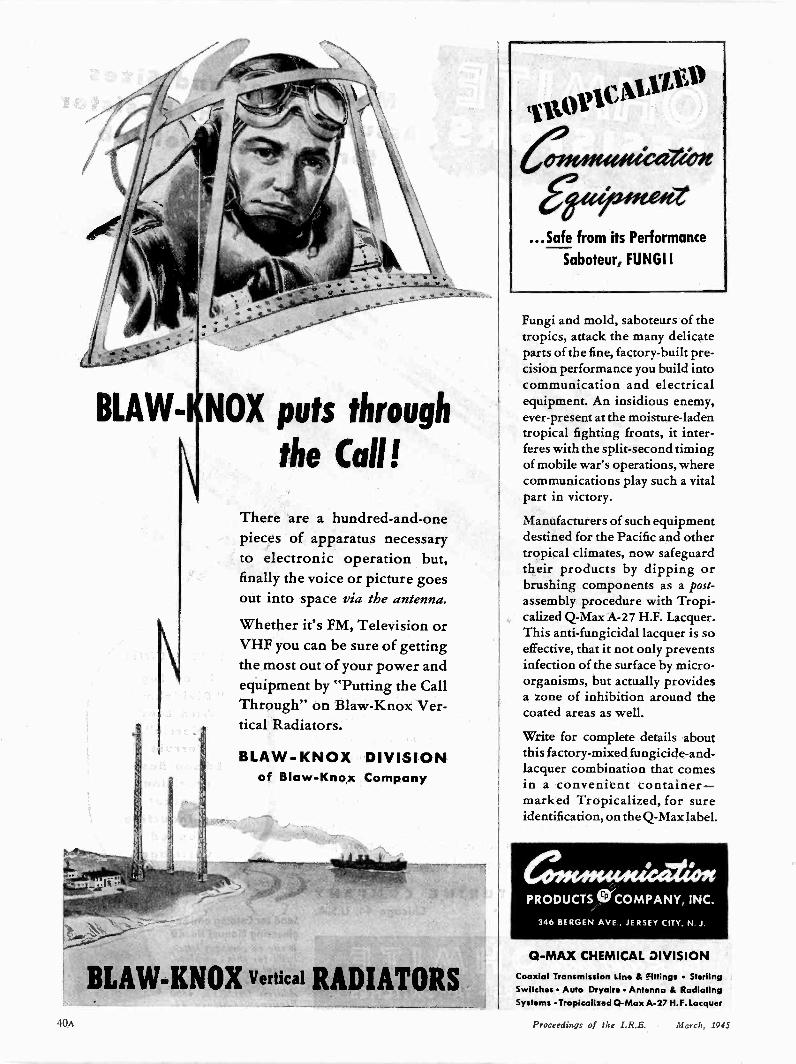
BLAW- NOX puts through
the Call!
There are a hundred -and -onepieces of apparatus necessaryto electronic operation but,finally the voice or picture goesout into space via the antenna.
Whether it's FM, Television orVHF you can be sure of gettingthe most out of your power andequipment by "Putting the CallThrough" on Blaw-Knox Ver-tical Radiators.
BLAW-KNOX DIVISIONof Blaw-Knox Company
BLAW-KNOX vertical RADIATORS
11101.0MAral)
eelleMeadeet
...Safe from its Performance
Saboteur, FUNGI!
Fungi and mold, saboteurs of thetropics, attack the many delicateparts of the fine, factory -built pre-cision performance you build intocommunication and electricalequipment. An insidious enemy,ever-present at the moisture -ladentropical fighting fronts, it inter-feres with the split-second timingof mobile war's operations, wherecommunications play such a vitalpart in victory.
Manufacturers of such equipmentdestined for the Pacific and othertropical climates, now safeguardtheir products by dipping orbrushing components as a post -assembly procedure with Tropi-calized Q -Max A-27 H.F. Lacquer.This anti -fungicidal lacquer is soeffective, that it not only preventsinfection of the surface by micro-organisms, but actually providesa zone of inhibition around thecoated areas as well.
Write for complete details aboutthis factory -mixed fungicide -and -lacquer combination that comesin a convenient container-marked Tropicalized, for sureidentification, on the Q -Max label.
Q -MAX CHEMICAL DIVISION
Coaxial Transmission Line & Fittings SterlingSwitches Auto Dryaire Antenna & RadiatingSystems Tropicalized Q -Max A-27 H. F. Lacquer
10n Proceedings of the I.R.E. March, 1945
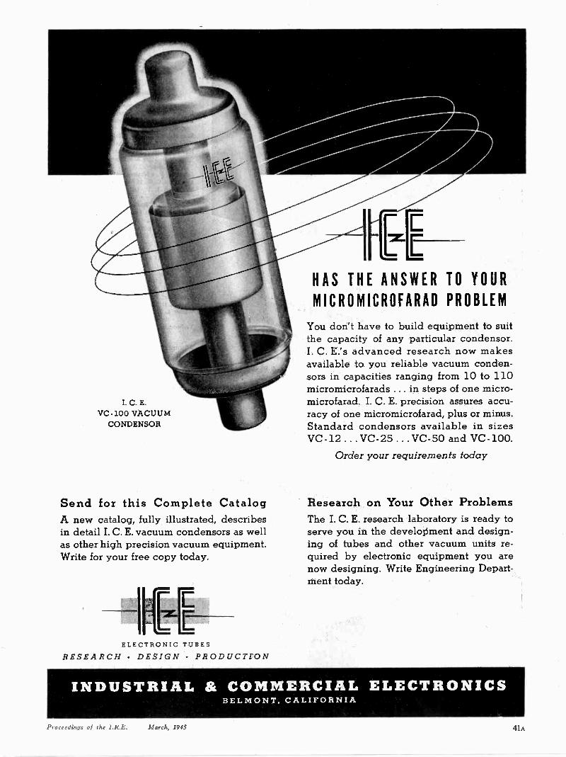
I. C. E.VC -100 VACUUM
CONDENSOR
Send for this Complete CatalogA new catalog, fully illustrated, describesin detail I. C. E. vacuum condensors as wellas other high precision vacuum equipment.Write for your free copy today.
I EEELECTRONIC TUBES
RESEARCH DESIGN PRODUCTION
HAS THE ANSWER TO YOUR
MICROMICROFARAD PROBLEM
You don't have to build equipment to suitthe capacity of any particular condensor.I. C. E.'s advanced research now makesavailable to you reliable vacuum conden-sors in capacities ranging from 10 to 110micromicrofarads ... in steps of one micro-microfarad. I. C. E. precision assures accu-racy of one micromicrofarad, plus or minus.Standard condensors available in sizesVC -12 ...VC -25 ...VC -50 and VC -100.
Order your requirements today
Research on Your Other ProblemsThe I. C. E. research laboratory is ready toserve you in the development and design-ing of tubes and other vacuum units re-quired by electronic equipment you arenow designing. Write Engineering Depart-ment today.
INDUSTRIAL & COMMERCIAL ELECTRONICSBELMONT, CALIFORNIA
Proceedings of the I.R.E. March, 1945 41A
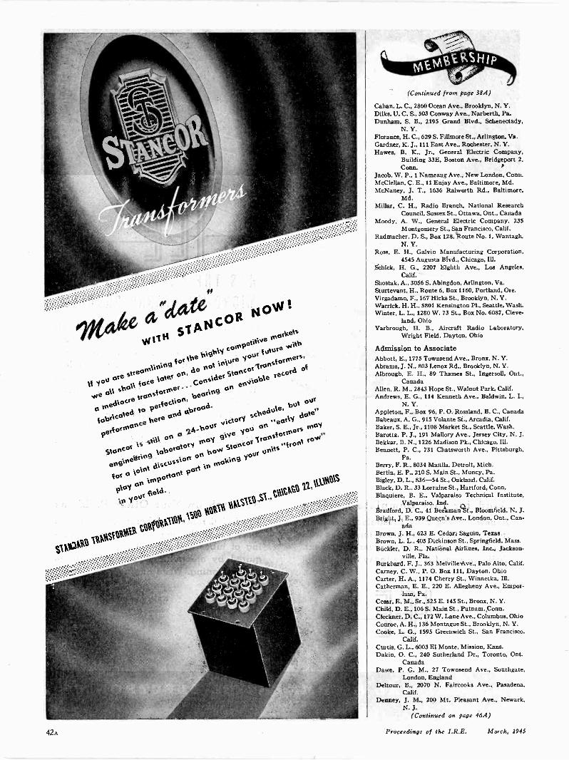
If
vvrvoio slANCORtiloW!
Its,,,t)are sirearnlining
FOr the bigt.dy comp tit
to
vie all sbcd1f ace toter
on, Considernot
in\ ureyour
f utureWith
0 Mediocretransf
erne ...Stancor
Iransforrners,
4obricatedto 1304
ection,bearing
on enviobterecord
of
Stanceis stitt on 0 7.4.-bour
victoryscbedule,
but °Or
performancebete and obroctd
engineeringtaboratory
racsygive
youon " early
date"
i or 0Vto%
discussionon VOW
Stancor1 ransf °roles
May
play an IMportordpart in Molting
your°tills
"frontTOW"
0 V WOfield
(Continued from page 38A)
Cahan, L. C., 2860 Ocean Ave., Brooklyn, N. Y.Dilks, U. C. S.. 503 Conway Ave., Narberth, Pa.Dunham, S. B., 2195 Grand Blvd., Schenectady.
N. Y.Floranoe, H. C., 629 S. Fillmore St., Arlington. Va.Gardner, K. J., ill East Ave.. Rochester, N. Y.Hawes, B. K., Jr., General Electric Company,
Building 33E, Boston Ave., Bridgeport 2.Conn.
Jacob, W. P.. 1 Nameaug Ave.. New London, Conn.McClellan, C. E., 11 Enjay Ave.. Baltimore. Md.McNaney, J. T., 1636 Ralworth Rd., Baltimore,
Md.Millar, C. H., Radio Branch, National Research
Council, Sussex St., Ottawa, Ont., CanadaMoody, A. W., General Electric Company. 235
Montgomery St., San Francisco. Calif.Radmacher, D. S., Box 128, `Route No. 1, Wantagh,
N. Y.Ross, E. H., Galvin Manufacturing Corporation,
4545 Augusta Blvd., Chicago. Ill.Schick, H. G., 2207 Eighth Ave.. Los Angeles,
Calif.Shostak, A., 3056 S. Abingdon, Arlington, Va.Sturtevant, H., Route 6, Box 1160, Portland, Ore.Virgadamo, F., 167 Hicks St., Brooklyn, N. Y.Warrick. H. H., 5801 Kensington P1., Seattle. Wash.Winter, L. L., 1280 W. 73 St., Box No. 6087, Cleve-
land, OhioYarbrough, H. B., Aircraft Radio Laboratory,
Wright Field, Dayton, Ohio
Admission to AssociateAbbott, E., 1775 Townsend Ave., Bronx, N. Y.Abrams, J. N., 803 Lenox Rd., Brooklyn, N. Y.Albrough, E. H., 89 Thames St.. Ingersoll, Ont.,
CanadaAllen, R. M., 2843 Hope St., Walnut Park. Calif.Andrews, E. G., 114 Kenneth Ave., Baldwin, L. I.,
N. Y.Appleton, F., Box 96, P. 0. Rossland, B. C.. CanadaBabeaux, A. G.. 915 Volante St., Arcadia. Calif.Baker, S. E., Jr., 1108 Market St., Seattle, Wash.Barotta, P. J., 191 Mallory Ave., Jersey City, N. J.Bekkar, B. N., 1226 Madison Pk., Chicago. Ill.Bennett. P. C., 731 Chatsworth Ave.. Pittsburgh.
Pa.Berry. F. R.. 8034 Manila, Detroit. Mich.Bertin, E. P., 210 S. Main St., Muncy, Pa.Bigley, D. L., 836-54 St., Oakland, Calif.Black, D. R.. 33 Lorraine St., Hartford, Conn.Blaouiere, B. E., Valparaiso Technical Institute,
Valparaiso, Ind.Bradford. D. C., 41 Beekman St., Bloomfield, N. J.Bright, J. E.. 939 Queen's Ave.. London, Ont., Can-
adaBrown, J. H., 623 E. Cedar, Saguin, TexasBrown, L. L., 405 Dickinson St., Springfield, Mass.Buckler, D. R.. National Airlines, Inc., Jackson-
ville, Fla.Burkhard, F. J., 363 Melville Ave.. Palo Alto, Calif.Carney, C. W., P. 0. Box 111, Dayton. OhioCarter, H. A., 1174 Cherry St., Winnetka, Ill.Catherman, E. E., 220 E. Allegheny Ave., Empor-
ium, Pa.Cesar. E. M., Sr., 525 E. 145 St., Bronx, N. Y.Child. D. E., 106 S. Main St., Putnam, Conn.Cleckner, D. C., 172 W. Lane Ave., Columbus, OhioConroe, A. H., 136 Montague St.. Brooklyn. N. Y.Cooke. L. G.. 1595 Greenwich St., San Francisco,
Calif.Curtis. G. L.. 6003 El Monte, Mission. Kans.Dakin, 0. C., 240 Sutherland Dr., Toronto, Ont.
CanadaDawe, P. G. M., 27 Townsend Ave., Southgate,
London, EnglandDeltour. B., 2070 N. Faircooks Ave., Pasadena,
Calif.Denney, J. M., 200 Mt. Pleasant Ave., Newark.
N. J.(Continued on page 46A)
42A Proceedings of the I.R.E. March, 1945

necticut Telephone & Electric Division . . born ofnearly fifty years of practice and progress. This know-
how isn't confined to our engineering departments,either. Some of our most useful suggestions comestraight from the production lines.
Purchasers of C. T. & E. products benefit fromthis skill and ingenuity ... in better, more advanceddevices, produced fisrer, for less.
KNOW-HOW BEGINS AT HOMESPECIAL tools, ingenious manufacturing devices,and elaborate test equipment which makes delicatemeasurements almost as easy as telling the time . . .
these things seem to interest our visitors particularly.
We are always proud to point out that most of these
aids to swift, precise production were developed by
our own men and women.There's a world of skill and experience at Con -
CATHODE RAY SCREEN TESTERTests a telephone or radio headset for responseover the entire range of audible sound in a matterof seconds, and charts the results on a television -type screen. Developed for our own use by ourown people, this instrument has been a pricelessaid in maintaining high quality and quantity in warproduction for the U. S. Signal Corps and Air Corps.
CONNECTICUT TELEPHONE & ELECTRIC DIVISIONGREAT AMERICAN INDUSTRIES, INC. MERIDEN, CONN.
TELEPHONIC SYSTEMS SIGNALLING EQUIPMENT ELECTRONIC DEVICES ELECTRICAL EQUIPMENTHOSPITAL AND SCHOOL COMMUNICATIONS AND SIGNALLING SYSTEMS IGNITION SYSTEMS
Proceedings of the I.R.E. March, 1945 43A

ors ANDREW SOLUTION
to afri
ANTENNA PROBLEM
9 Faced with a difficult antenna problem,E. H. Andresen, Chief Engineer of Chi-
cago's Board of Education Station WBEZ, calledon ANDREW engineers for a solution. The prob-lem was that of coupling a 70 -ohm unbalancedcoaxial transmission line to the much smallerbalanced impedance of the antenna. Uncer-tainty of the exact value of the antenna impe-dance made the problem difficult, and calledfor some kind of an adjustable coupling device.
ANDREW solved the problem by constructing aquarter wave impedance transforming sectionwith a concentric "bazooka" for the balance con-version. Adjustments were made by varying theaverage dielectric constant in resonant section.
This problem is but one of many that the expe-rienced staff of ANDREW engineers are calledupon to solve. As qualified experts in the fieldof FM, radio and television antenna equipmentANDREW engineers have solved many problemsfor military and broadcast engineers.
FOR THE SOLUTION OF YOUR ANTENNA PROBLEMS. . . FOR THE DESIGNING, ENGINEERING, AND BUILD-ING OF ANTENNA EQUIPMENT . . . CONSULT ANDREW
41*
L
Curve shows standing wavesdetermined by probing electro-static field in "piccolo ' (sectionof transmission line with holesdrilled in outer conductor). Wavycurve represents initial condi-tions before adjustment; straightline shows the final result afteradjustment of matching unit.
363 East 75th Street, Chicago 19, Illinois
Twin -barreled dehydrat-ing unit especially designedfor WBEZ by ANDREW engi-neers. Design permits leav-ing one cartridge in servicewhile the other cartridge isbeing recharged.
THAN TO RECEIVE
To GIVE a beautiful repro-duction of high qualitysound from a low bass re-sponse of 40 cycles up to ahigh frequency range of15,000 cycles plus, will paybroadcasters and manufac-turers of home radio, FMand Television receivingsets. The American public iswilling to give in proportionto what it RECEIVES. That's
why the Duplex, the SPEAK-
ER that REVOLUTIONIZES
the methods of soundREPRODUCTION, was per-fected.
SEND FOR BULLETINS
1210 TAFT BLDG., HOLLYWOOD 28, CALIF.
44A Proceedings of the I.R.E. March, 1945
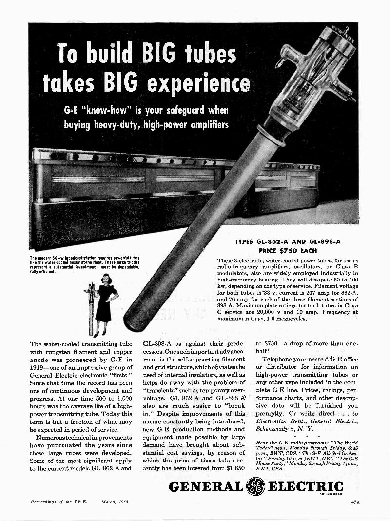
G -E "know-how" is your safeguard when
buying heavy-duty, high -power amplifiers
The modern 50 -kw broadcast station requires powerful tubeslike the water-cooled husky at the right. These large triodesrepresent a substantial Investment-must be dependable,fully efficient.
The water-cooled transmitting tubewith tungsten filament and copperanode was pioneered by G -E in1919-one of an impressive group ofGeneral Electric electronic "firsts."Since that time the record has beenone of continuous development andprogress. At one time 500 to 1,000hours was the average life of a high -power transmitting tube. Today thisterm is but a fraction of what maybe expected in period of service.
Numerous technical improvementshave punctuated the years sincethese large tubes were developed.Some of the most significant applyto the current models GL -862-A and
TYPES GL -862-A AND GL -898-APRICE $750 EACH
These 3 -electrode, water-cooled power tubes, for use asradio -frequency amplifiers, oscillators, or Class Bmodulators, also are widely employed industrially inhigh -frequency heating. They will dissipate 50 to 100kw, depending on the type of service. Filament voltagefor both tubes is 33 v; current is 207 amp for 862-A,and 70 amp for each of the three filament sections of898-A. Maximum plate ratings for both tubes in ClassC service are 20,000 v and 10 amp. Frequency atmaximum ratings, 1.6 megacycles.
GL -898-A as against their prede-cessors. One such important advance-ment is the self-supporting filamentand grid structure, which obviates theneed of internal insulators, as well ashelps do away with the problem of"transients" such as temporary over -voltage. GL -862-A and GL -898-Aalso are much easier to "breakin." Despite improvements of thisnature constantly being introduced,new G -E production methods andequipment made possible by largedemand have brought about sub-stantial cost savings, by reason ofwhich the price of these tubes re-cently has been lowered from $1,650
GENERAL
to $750 -a drop of more than one-half!
Telephone your nearest G -E officeor distributor for information onhigh -power transmitting tubes orany other type included in the com-plete G -E line. Prices, ratings, per-formance charts, and other descrip-tive data will be furnished youpromptly. Or write direct . . . toElectronics Dept., General Electric,Schenectady 5, N. Y.
Hear the G -E radio programs: "The WorldToday" news, Monday through Friday, 6:45p. m., EWT, CBS. "The G -E All -Girl Orches-tra," Sunday 10 p. m., EWT, NBC. "The G -EHouse Party," Monday through Friday 4 p.m.,EWT, CBS.
ELECTRIC161-03.0650
Proceedings of the I.R.E. March, 1945 45A
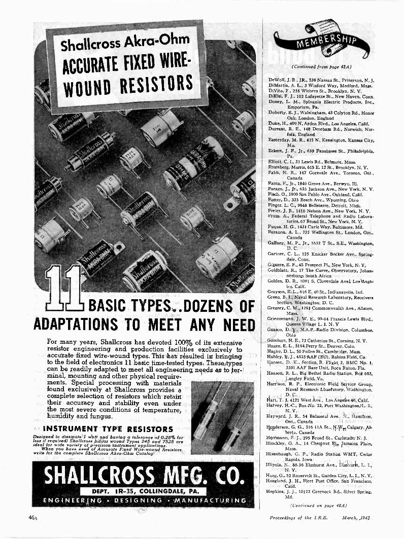
BASIC TYPES..DOZENS OF
ADAPTATIONS TO MEET ANY NEEDFor many years, Shallcross has devoted 100% of its extensiveresistor engineering and production facilities exduswely toaccurate fixed wire -wound types. This has resulted in bringingto the field of electronics 11 basic time -tested types. These typescan be readily adapted to meet all engineering needs as to ter-minal, mounting and other physical require-ments. Special processing with materialsfound exclusively at Shallcross provides acomplete selection of resistors which retaintheir accuracy and stability even underthe most severe conditions of temperature,humidity and fungus.
INSTRUMENT TYPE RESISTORSDesigned to dissipate 1 watt and having a tolerance of 0.25% (orless if required) Shallcross bifilar wound Types 245 and 752.5 areideal for wide variety of precision instrument applications.
When you have need of Accurate Fixed Wire -wound Resistors,write for the complete Shallcross Akra-Ohm Catalog.
SHALL(ROSS MFG. CO.DEPT. IR-35, COLLINGDALE, PA.
ENGINEERING DESIGNING MANUFACTURING
(Continued from page 42A)
DeWolf, J. B., JR., 239 Nassau St., Princeton, N. 3.DiMattia, A. L., 3 Winford Way. Medford. Mass.DiVito, F., 256 Withers St., Brooklyn, N. Y.DiElal, F. J., 102 Lafayette St., New Haven, Conn.Doney, L. M., Sylvania Electric Products, Inc..
Emporium, Pa.Doherty. E. J., Walsingham, 43 Colyton Rd.. Honor
Oak. London. EnglandDuke, H., 409 N. Arden Blvd., Los Angeles, Calif.Durrant. R. E., 148 Derebam Rd., Norwich, Nor-
folk, EnglandEasterday, M. R., 415 N. Kensington, Kansas City,
Mo.Eckert, J. F.. Jr., 639 Fanshawe St.. Philadelphia,
Pa.Elliott. C. I., 31 Lewis Rd., Belmont, Mass.Ettenberg, Morris, 615 E. 12 St., Brooklyn. N. Y.Fabb, N. R., 147 Gorevale Ave.. Toronto, Ont..
CanadaFanta, F., Jr., 1846 Grove Ave.. Berwyn. Ill.Farago, J., Jr., 625 Jackson Ave., New York, N. Y.Fisch. 0.. 3800 San Pablo Ave., Oakland. Calif.Foster, D., 335 Beech Ave., Wyoming, OhioFinger. L. C., 9946 Belleterre, Detroit, Mich.Freier. J. B., 1416 Nelson Ave., New York. N. Y.Frum, A.. Federal Telephone and Radio Labora-
tories, 67 Broad St., New York, N. Y.Fuqua, H. G., 14.31 Curie Way, Baltimore. Md.Furanna. A. L., 732 Wellington St.. London. Ont..
CanadaGaffney, M. P., Jr., 1632 T St., S.E., Washington,
D. C.Gartner, C. L.. 125 Knicker Bocker Ave., Spring-
dale, Conn.Giguere, E. F.. 45 Prospect Pl., New York, N. Y.Goldblatt. R., 17 The Curve, Observatory. Johan-
nesburg, South AfricaGolden, D. R.. 1081 S. Cloverdale Ave.. Los Ange-
les, Calif.Grayson, E. L., 616 E. 40 St., Indianapolis. Ind.Green, B. I. Naval Research Laboratory, Receivers
Section, Washington, D. C.Gregory, C. M., 1291 Commonwealth Ave., Allston,
Mass.Griemsmann, J. W. E.. 90-64 Francis Lewis Blvd.,
Queens Village L. I. N.Guasco, D. V., N.A.F.-Radio Division, Columbus.
OhioGumbart, H. E.. 72 Catherine St., Corning. N. Y.Hagen, E. L.. 5194 Perry St., Denver, Colo.Hagler, D. L.. 50 Follen St.. Cambridge, Mass.Hanley, R. J.. 4525 AAF (BU), Robins Field, Ga.Hansen. D. K., Section B, Flight 2, BMC No. 1,
3501 AAF Base Unit. Boca Raton, Fla.Hanson, R. L., Big Bethel Radio Station, Box 683,
Langley Field, Va.Harrison, R. P., Electronic Field Service Group,
Naval Research Lbaoratory. Washington.D. C.
Hart, T. J. 4121 West Ave., Los Angeles 40, Calif.Harvey, H. C.. Box No. 22. Port Washington, L. I.,
N. Y.Hayward, J. R., 54 Balmoral Ave., N., Hamilton,
Ont., CanadaHenderson, G. G., 316 11A St., N.W.. Calgary. Al-
berta, CanadaHerrmann. P. J., 295 Broad St.. Carlstadt. N. J.Hinckley, G. A., 14 Chestnut Pl.. Jamaica Plain,
Mass.Hixenbaugh, G. P.. Radio Station WMT, Cedar
Rapids, IowaHlipala, N., 88-36 Elmhurst Ave., Elmhurst, L. I.,
N. Y.Hoag, 0., 52 Roosevelt St.. Garden City. L. I., N. Y.Hoagland, J. H., Fleet Post Office, San Francisco,
Calif.Hopkins. J. J., 10122 Greenock Rd., Silver Spring,
Md.
(Continued on page 48A)
46A Proceedings of the I.R.E. March, 1945
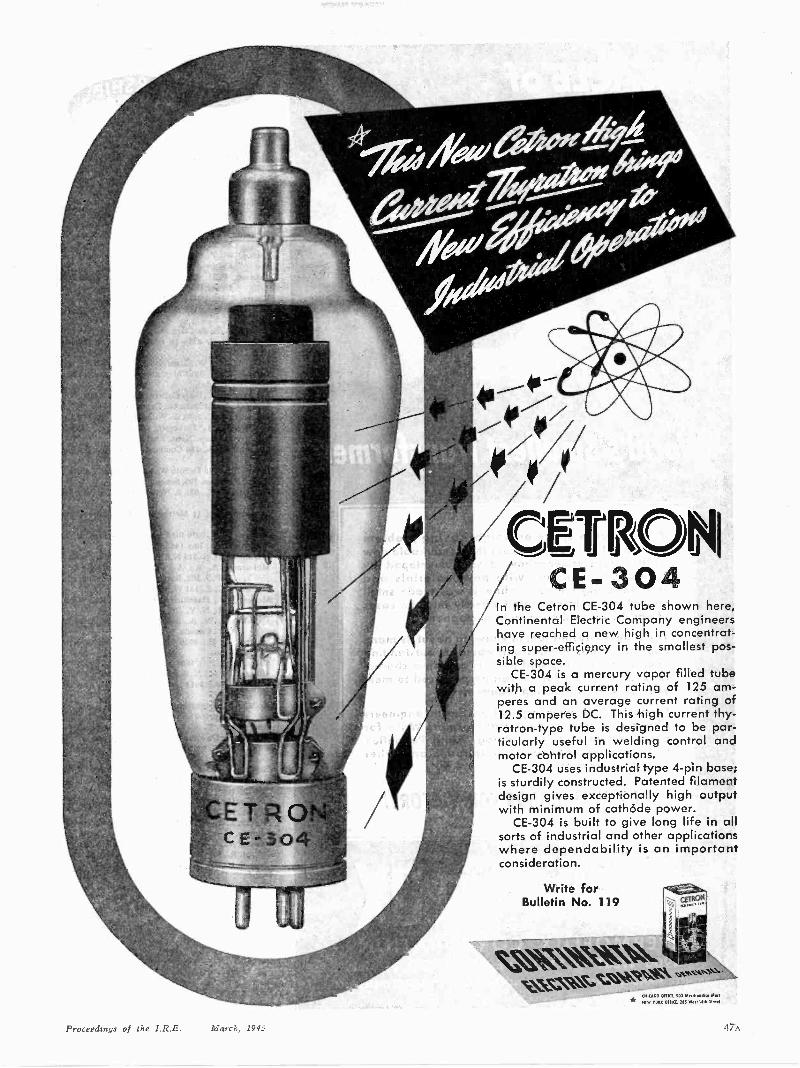
tETE.-304
CETRCE -304
In the Cetron CE -304 tube shown here,Continental Electric Company engineershave reached a new high in concentrat-ing super -efficiency in the smallest pos-sible space.
CE -304 is a mercury vapor filled tubewith a peak current rating of 125 am-peres and an average current rating of12.5 amperes DC. This high current thy-ratron-type tube is designed to be par-ticularly useful in welding control andmotor control applications.
CE -304 uses industrial type 4 -pin base;is sturdily constructed. Patented filamentdesign gives exceptionally high outputwith minimum of cathode power.
CE -304 is built to give long life in allsorts of industrial and other applicationswhere dependability is an importantconsideration.
Write forBulletin No. 119
\,%,\Nss,Vc.NV\W kisti
TirNS:\N;MVVIOW,Cf 761 M1,1,14,
Proceedings of the I.R.E. March, 1945

"World's Smallest Transformer"
If you have a space or weight saving problemyou'll want to know all about this remarkable newmidget tray sformer-how it was developed byPermoflux engineers with new materials andmanufacturing methods-how it was made smallenough to lee incorporated directly into the casesof earphones and hand-held microphones.
You'll be interested too, in knowing about its manyapplication possibilities and about its outstandingoperating efficiency and uniform response charac-teristics. Thii transformer can be produced to meetyour own special design requirements.
Permoflux welcomes inquiry from design engineersabout this new midget transformer. Write forour complet4 technical catalog listing Permofluxtransformers, speakers, headphones and otheracoustical d'svices.
BUY WAR BONDS FOR VICTORY!
PERMOFLUX CORPORATION4900 WEST GRAND AVE., CHICAGO 39, ILL.
PIONEER MANUFACTURERS OF PERMANENT MAGNET DYNAMIC TRANSDUCERS
(Continued from page 46A)
Hopkins, W. L., 70 E 45 St., New York, N. Y.Hornsby. P. L.. 402 Neville St.,Hanford, Calif.Hubbard. T. P., Jr., 624 S. Clinton. Iowa City. IowaHull. R., 226 W. Herman Ave., Dayton.OhioHund, E., Co. 2218, U.S.N.T.C., Great Lakes, Ill.Hungerford. R. S., 13561 Stahelin, Detroit 23.
Mich.Jackson, W. J., 150-44 Freeborn St., Jamaica, L. I.,
N. Y.Jacobs, W. T., 2720 Cudahy St., Walnut Park.
Calif.Johnson, W. H., Jr., 100 E. Manoa Rd.. Brookline,
Upper Darby P. 0.. Pa.Kaiser. E. H.. 1809A N. 21 St., Milwaukee, Wis.Kilian, L. H., 2179 Valentine Ave., New York.
N. Y.Kodera, C. F.. 52 Clark St., Brooklyn, N. Y.Kucera. R. J.. 821-18 St.. S.E., Cedar Rapids.
IowaKulp, A., 4732 W. Congress St., Chicago, Ill.Lalonde, R. P., 3910 Mentana St., Montreal, Que..
CanadaLambert. T. M.,Tufts College, Medford, Mass.Lee. J. J., Jr., 64 Dana St.. Cambridge, Mass.Liana, D. Y. H., 3698 E. Willis St..Detroit. Mich.Leicester. E. J., Parkcroft, 42 Ridgeway, Hayes,
Bromley, Kent, EnglandLoewenthal, M., 186 Commonwealth Ave., Boston,
Mass.Lyons, B.P., 136 DeSoto Way, San Bruno, Calif.Mann, F. E.,Box 795, Sonoma, Calif.Marshall, G. E. , 631 S. Norton Ave., Los Angeles,
Calif.Martinez, C. I., 11 Metropolitan Oval, New York.
N. Y.Masters, W. S., 1039 Bird Ave., Birmingham, Mich.Mattson, C. L., Box 1456. Atlanta, Ga.McAllister, D. E.,315 N.E. 66 Ave.. Portland, Ore.McBurney, A. R., A-7 C.S.T.C., R.C. Signals,
M.P.O. 302, Barriefield, Ont.,CanadaMcCauley, C. E., 131 W. 52 St.. Bayonne. N. J.McFee, J. L., Hazeltine Corporation Little Neck.
L. I.. N. Y.McLaughlin, W. A.. 345 Edmonton St., London,
Ont., CanadaMeiners, W. H., 4920 Thurston Rd., Fort Worth,
TexasMiller, D. C., P.O. 1663. Santa Fe N. M.Miller, L.E., 442 N. Sandusky St., Delaware, OhioMiller, W. B., 1618 Rockwood St., Los Angeles,
Calif.Molla, J. J., Submarine Signal Company, c/o E. A.
Grey, 160 State St.. Boston. Mass.Montgomery. V. A.. Box 114. 40 Stelzear St.. Rivi-
ere Du Loup Station. Quebec. CanadaMorgan, R. E., 1068 Parkwood Blvd., Schenectady.
N. Y.Morrow, G., 2366 Grand Concourse, Bronx, N. Y.Morse. R. L., 4521-15 St., N.E.. Seattle. Washing-
tonMeuller, H.. 100 Thayer St., New York, N. Y.Meuller. P. L., 2511 Hollins St., Baltimore, Md.Murray. L. H., 166 W. 87 St.,New York. N. Y.Neuman, G. J., 516 W. 169 St., New York, N. Y.Newton. A., 67 E. Seventh St., New York, N. Y.Olds, H. R., 1612 Main St., Beech Grove, Ind.Olsen, 0. C.. 617 North Ave.. Dayton, OhioParisi. F. E.. Education Department, Mo. Nine,
Navy Pier, Chicago, Ill.Peters. E. F., 3842 Alvarado Ave., Stockton. Calif.Peterson, 0. L., 2829 Forest View Ave.. Baltimore,
Md.Petry. C. B., 27-14 Morlot Ave., Fairlawn, N. J.Pfeifer, R., 5103 San Rafael Ave., Los Angeles.
Calif.Pierce, E. R., Civil Aeronautics Administration,
Summit, AlaskaPizor, I., 645 West End Ave., New York. N. Y.Puttick, A. W., 974 St. John, Lincoln Park, Mich.
(Continued on page 62A)
48A Proceedings of the I.R.E. March, 1945
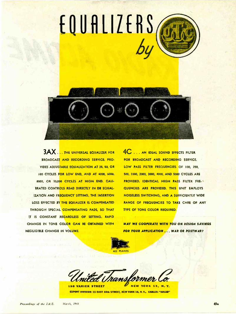
(QURIZERSr\\\
3AX ... THE UNIVERSAL EQUALIZER FOR
BROADCAST AND RECORDING SERVICE. PRO-
VIDES ADJUSTABLE EQUALIZATION AT 25, 50. OR
100 CYCLES FOR LOW END, AND AT 4000, 6000,
8000, OR 10,000 CYCLES AT HIGH END. CALI-
BRATED CONTROLS READ DIRECTLY IN DB EQUAL-
IZATION AND FREQUENCY SETTING. THE INSERTION
LOSS EFFECTED BY THE EQUALIZER IS COMPENSATED
THROUGH SPECIAL COMPENSATING PADS, SO THAT
IT IS CONSTANT REGARDLESS OF SETTING. RAPID
CHANGE IN TONE COLOR CAN BE OBTAINED WITH
NEGLIGIBLE CHANGE IN VOLUME.
4C . . AN IDEAL SOUND EFFECTS FILTER
FOR BROADCAST AND RECORDING SERVICE.
LOW PASS FILTER FREQUENCIES OF 100, 250,
500. 1000, 2000. 3000, 4000, AND 5000 CYCLES ARE
PROVIDED. IDENTICAL HIGH PASS FILTER FRE-'
QUENCIES ARE PROVIDED. THIS UNIT EMPLOYS
NOISELESS SWITCHING, AND A SUFFICIENTLY WIDE
RANGE OF FREQUENCIES TO TAKE CARE OF ANY
TYPE OF TONE COLOR REQUIRED.
MAY WE COOPERATE WITH YOU ON DESIGN SAVINGS
FOR YOUR APPLICATION ... WAR OR POSTWAR?
eA,,a150 VARICK STREET NEW YORK 13, N. Y.
WORT DIVISION: 13 EAST 40th STREET, NEW YORK 111, N. Y.. CABLES: "ARLAW'
Proceedings of the I.R.E. March, 1945 49A
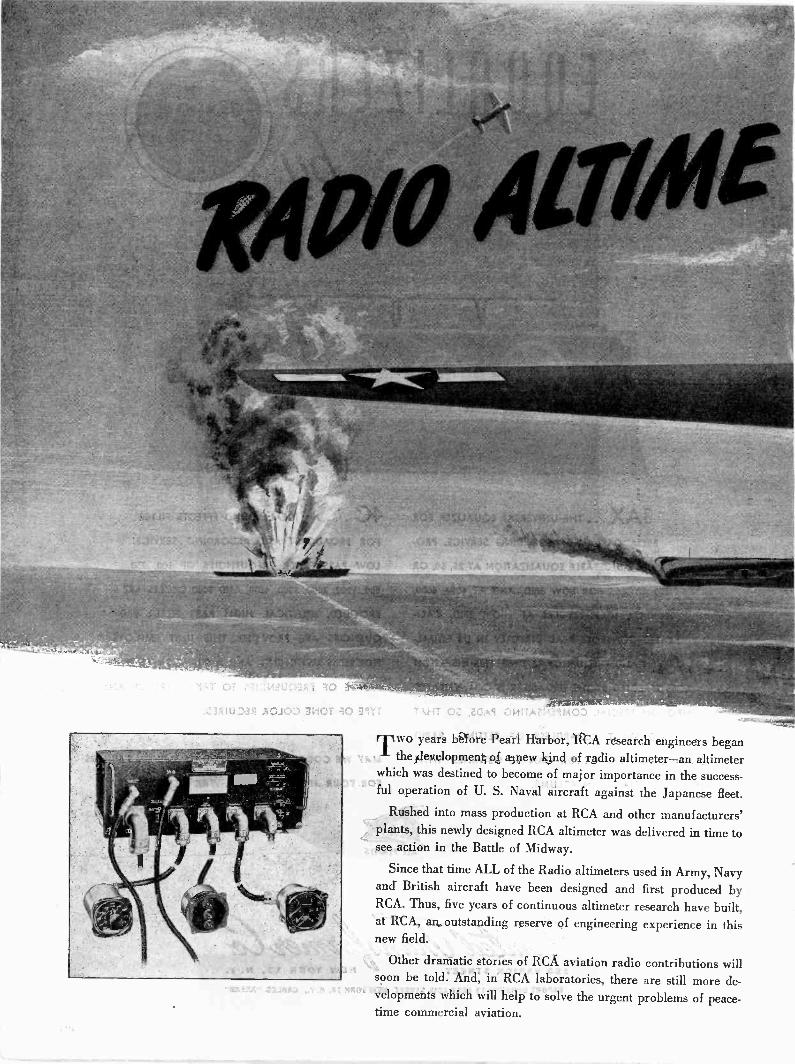
T" years before Pearl Harbor, RCA research engineers beganthe development of a new kind of radio altimeter-an altimeter
which was destined to become of major importance in the success-ful operation of U. S. Naval aircraft against the Japanese fleet.
Rushed into mass production at RCA and other manufacturers'plants, this newly designed RCA altimeter was delivered in time tosee action in the Battle of Midway.
Since that time ALL of the Radio altimeters used in Army, Navyand British aircraft have been designed and first produced byRCA. Thus, five years of continuous altimeter research have built,at RCA, an outstanding reserve of engineering experience in thisnew field.
Other dramatic stories of RCA aviation radio contributions willsoon be told. And, in RCA laboratories, there are still more de-velopments which will help to solve the urgent problems of peace-time commercial aviation.
IrRS by
RADIO CORPORATION OF AMERICARCA VICTOR DIVISION CAMDEN, N. J.

INSTRUMENTENGINEER
WANTED
Engineer needed to develop andapply electronic instruments formeasuring vibrations, strains,pressures and temperatures. Ex-perience with electro-mechanicaldevices desirable. Position ofpermanent nature and at presentconcerned with measurement ofaircraft arid engine character.istics on projects of war urgency.Apply in writing stating educa-tion, experience and salary ex-pected.
Persons now utilized at highestskill in essential industry need notapply as all hiring is done in ac-cordance with Hartford areastabilization plan.
PRATT & WHITNEY AIRCRAFTINSTALLATION
ENGINEERING DEPARTMENTEAST HARTFORD 8, CONNECTICUT
OPPORTUNITY NOW FOR
TECHNICAL ENGINEERS
In Expanding Organizationwith Post War Future
Progressive company locatednear San Francisco has splendidopenings for Engineers with a
degree from a recognized collegein physics, electrical or mechani-cal engineering who have special-ized in electronics or allied fields.
Write, stating qualifications,education, draft status and salaryrequirements. Applicants nowemployed should submit a de-tailed resume of their experiencetogether with an evaluation oftheir present duties.
DALMO VICTOR1414 El Camino RealSan Carlos, California
The following positions of interest to I.R.E.members have been reported as open. Applyin writing. addressing reply to company men-tioned or to BOX No.
The Institute reserves the right to refuse any an-nouncement without giving a reason for the missal.
PROCEEDINGS of the I.R.E330 West 42nd Street, New York II. N.Y.
ELECTRONIC ENGINEERS,PRODUCTION MANAGER
New York corporation is interested in add-ing Junior and Senior Engineers with designand development experience, and a ProductionManager with electronic and mechanical experi-ence.
Salaries, based on experience and capacity,range up to $100 a week for Junior Engineers,and $10,000 a year for Senior Engineers andProduction Manager. Address reply to Box 368.
ELECTRONIC ENGINEER
An engineer is required to head a departmentof industrial electronics in consulting engineer-ing firm. Must have had experience in this field.Salary as well as a share in the profits. Pleasewrite to Box 342 giving detailed information oneducation and experience.
ENGINEERS FOR INDUSTRIALELECTRONICS
Experienced engineers wanted for design andapplication engineering of electronics to indus-try in a consulting engineering firm. Positionoffers unusual opportunity to qualified, reliableand responsible man. Present work will be onwar contracts. Write to Box 343.
ACOUSTICAL ENGINEERAcoustical and electronic engineer for de-
velopment work on electronic musical instru-ments.
Also electronic technician and an electronicdraftsman. Permanent positions in a researchand development laboratory. Write Supersonics,Inc., 231 East 47th Street, New York 17, N.Y.
SALES ENGINEER
Manufacturers -representatives' company inNew England needs a sales engineer, preferablyone residing in Connecticut, with good technicalbackground, pleasant personality, and keen judg-ment in appraising and working out technicaldetails. Past experience in selling not necessary.
Work involved includes calling on industrialaccounts in New England, and discussing engi-neering matters and working out solutions oftechnical problems between customers and manu-facturers.
Position represents an immediate opportunitywith postwar future and pays well. Send repliesto Box 369.
OPPORTUNITIES INPRESENT AND POST-WAR WORK
Senior and Junior graduate engineers withone or more years radio experience wanted byan expanding manufacturing division of anestablished communication company.
Present activities include high- and medium -power transmitters, frequency shifters, other com-munication products for the Navy and designsand models for post-war use.
Engineers with practical experience also re-quired for radio communication plant installa-tion and test in foreign countries.
Phone, call or write stating experience, educa-tion, present salary, etc. Press Wireless, Inc.,Hicksville, L.I., N.Y.; Attention of S. A. Barone,Chief Mfg. Engr.
TELEVISION TECHNICIANS
The Television Laboratories of the ColumbiaBroadcasting System, in New York, need tele-vision technicians. Men having had definite ex-perience in the television field, transmitters, orreceivers, preferred. Excellent opportunity for
(Continued on page 54A)
SENIORELECTRONICENGINEERS
Preferably graduates of com-munication engineering coursesare required for designing, re-ceiving -type electronic equip-ment covering all frequencyranges, and other specializedelectronic apparatus. Design ex-perience necessary and knowl-edge of production is desirable.Excellent post-war opportunities.Salary open. Requirements ur-gent. Proof of citizenship andcertificate of availability arenecessary.
Write giving detailed qualifica-tions and if satisfactory, inter-view will be arranged at our ex-pense.
SUBMARINE SIGNAL CO.Dept. 420
175 State St. Boston, Mass.
Micro -WaveDesign Engineers
An opportunity for radio engineerswho have had extensive experiencein the design of micro -wave ap-paratus. Their services are neededfor long range development pro-gram for the government.
Broadcast ReceiverDesigners
Still other radio engineers withexperience are needed.
Mechanical Engineers fortelephone and radio work-
whose experience fits them to designelectro mechanical devices for productionare also needed.
While the above openings are forsenior men, we do have opportunitiesfor several Junior engineers in thesefields. Interested persons are invited towrite giving full qualifications to theEngineering Personnel Manager.
War Manpower Commission ruleswill be observed.
STROMBERG-CARLSON CO.
ROCHESTER 3, N. Y.
52A Proceedings of the I.R.E. March, 1945
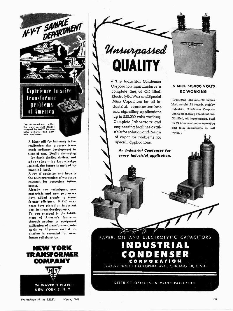
hperience to solvetransformer
proll s
III Imeril a
The illustrated unit typifiesthe many compact designsincepted by N -Y -T for mo-bile, airborne and port-.able equipment.
A bitter pill for humanity is therealization that progress trans-cends ordinary development intime of war. Dually destroying-by death dealing devices, andadvancing - by knowledgegained, the future is molded bymankind itself.A ray of optimism and hope isthe re -interpretation of warborneresearch for peacetime better.ments.Already new techniques, newmaterials and new processeshave added greatly to trans-former efficiency. N -Y -T engi-neers have played an importantpart in these developments.To you engaged in the fulfill-ment of America's future -through product or equipmentutilization of transformers, sole-noids or filters-a cordial in-vitation is extended for near -future collaboration.
NEW YORKTRANSFORMER
COMPANY
QUALITY The Industrial CondenserCorporation manufactures acomplete line, of Oil -filled,Electrolytic,Wax and SpecialMica Capacitors for all in-dustrial, communicationsand signalling applicationsup to 250,000 volts working.Complete laboratory andengineering facilities avail-able for solution and designof capacitor problems forspecial applications.
An Industrial Condenser forevery industrial application.
.5 MFD. 50,000 VOLTSDC WORKING
(Illustrated above) ...28 incheshigh, weight 175 pounds, built by
Industrial Condenser Corpora.tion to meet Navy specifications.
Oil -filled, oil impregnated. Built
for 24 hour continuous operation
and total submersion in saltWater.
INDUSTRIALCONDENSER
CORPORATION72A3 ti5 NORTH CALIFORNIA AVE., CHICAGO 18, U S A
DISTRICT OFFICES IN PRINCIPAL CITIES
Proceedings of the I.R.E. March, 1945 53A
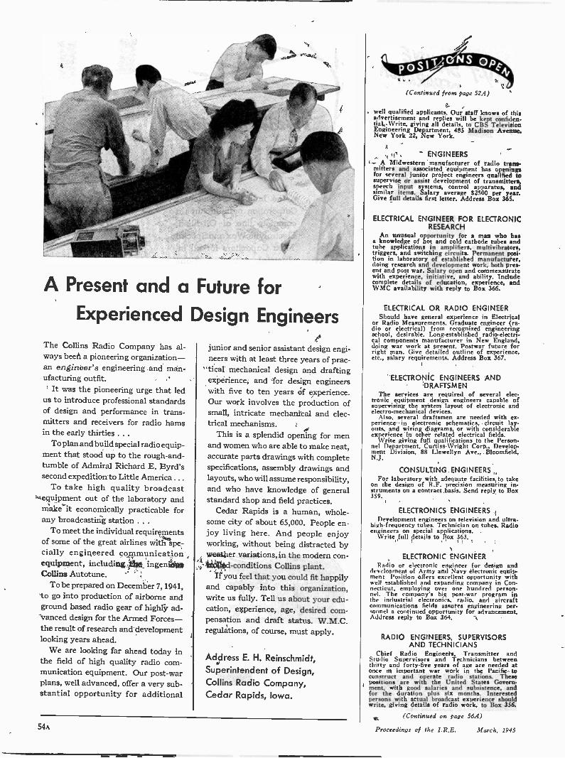
A Present and a Future forExperienced Design Engineers
The Collins Radio Company has al-ways been a pioneering organization-an engineer's engineering and man-ufacturing outfit.
It was the pioneering urge that ledus to introduce professional standardsof design and performance in trans-mitters and receivers for radio hamsin the early thirties . . .
To plan and build special radio equip-ment that stood up to the rough-and-tumble of Admiral Richard E. Byrd'ssecond expedition to Little America . . .
To take high quality broadcastequipment out of the laboratory andmake it economically practicable forany broadcasting station . . .
To meet the individual requirementsof some of the great airlines with spe-cially engineered communicationequipment, including the ingeniousCollins Autotune.
To be prepared on December 7, 1941,to go into production of airborne andground based radio gear of highly ad-vanced design for the Armed Forces-the result of research and developmentlooking years ahead.
We are looking far ahead today inthe field of high quality radio com-munication equipment. Our post-warplans, well advanced, offer a very sub-stantial opportunity for additional
junior and senior assistant design engi-neers with at least three years of prac-tical mechanical design and draftingexperience, and for design engineerswith five to ten years of experience.Our work involves the production ofsmall, intricate mechanical and elec-trical mechanisms.
This is a splendid opening for menand women who are able to make neat,accurate parts drawings with completespecifications, assembly drawings andlayouts, who will assume responsibility,and who have knowledge of generalstandard shop and field practices.
Cedar Rapids is a human, whole-some city of about 65,000. People en-joy living here. And people enjoyworking, without being distracted byweather variations, in the modern con-trolled -conditions Collins plant.
If you feel that you could fit happilyand capably into this organization,write us fully. Tell us about your edu-cation, experience, age, desired com-pensation and draft status. W.M.C.regulations, of course, must apply.
Address E. H. Reinschmidt,Superintendent of Design,Collins Radio Company,Cedar Rapids, Iowa.
(Continued from page 52A)
well qualified applicants. Our staff knows of thisadvertisement and replies will he kept confiden-tial. Write, giving all details, to CBS TelevisionEngineering Department, 485 Madison Avenue,New York 22, New York.
ENGINEERSA Midwestern manufacturer of radio trans-
mitters and associated equipment has openingsfor several junior project engineers qualified tosupervise or assist development of transmitters,speech input systems, control apparatus, andsimilar items. Salary average $2500 per year.Give full details first letter. Address Box 365.
ELECTRICAL ENGINEER FOR ELECTRONICRESEARCH
An unusual opportunity for a man who hasa knowledge of hot and cold cathode tubes andtube applications in amplifiers, multivibrators,triggers, and switching circuits. Permanent posi-tion in laboratory of established manufacturer,doing research and development work, both pres-ent and post war. Salary open and commensuratewith experience, initiative, and ability. Includecomplete details of education, experience, andWMC availability with reply to Box 366.
ELECTRICAL OR RADIO ENGINEERShould have general experience in Electrical
or Radio Measurements. Graduate engineer (ra-dio or electrical) from recognized engineeringschool, desirable. Long-established radio -electri-cal components manufacturer in New England,doing war work at present. Postwar future forright man. Give detailed outline of experience,etc., salary requirements. Address Box 367.
ELECTRONIC ENGINEERS ANDDRAFTSMEN
The services are required of several elec-tronic equipment design engineers capable ofsupervising the system layout of electronic andelectro-mechanical devices.
Also, several draftsmen are needed with ex-perience in electronic schematics, circuit lay-outs, and wiring diagrams, or with considerableexperience in other related electrical fields.
Write giving full qualifications to the Person-nel Department, Curtiss-Wright Corp., Develop-ment Division, 88 Llewellyn Ave., Bloomfield,N.J.
CONSULTING ENGINEERSFor laboratory with adequate facilities to take
on the design of R.F. precision measuring in-struments on a contract basis. Send reply to Box359.
ELECTRONICS ENGINEERSDevelopment engineers on television and ultra-
high -frequency tubes. Technician on tubes. Radioengineers on special applications.
Write full details to Box 363.
ELECTRONIC ENGINEERRadio or electronic engineer for design and
development of Army and Navy electronic equip-ment Position offers excellent opportunity withwell established and expanding company in Con-necticut, employing over one hundred person-nel. The company's big post-war program inthe industrial electronics. radio, and aircraftcommunications fields assures engineering per -sound a continued opportunity for advancement.Address reply to Box 364.
RADIO ENGINEERS, SUPERVISORSAND TECHNICIANS
Chief Radio Engineers, Transmitter andStudio Supervisors and Technicians betweenthirty and forty-five years of age are needed atonce in important war work in the Pacific toconstruct and operate radio stations. Thesepositions are with the United States Govern-ment, with good salaries and subsistence, andfor the duration plus six months. Interestedpersons with actual broadcast experience shouldwrite, giving details of radio work, to Box 356.
(Continued on page 56A)
54A Proceedings of the I.R.E. March, 1945
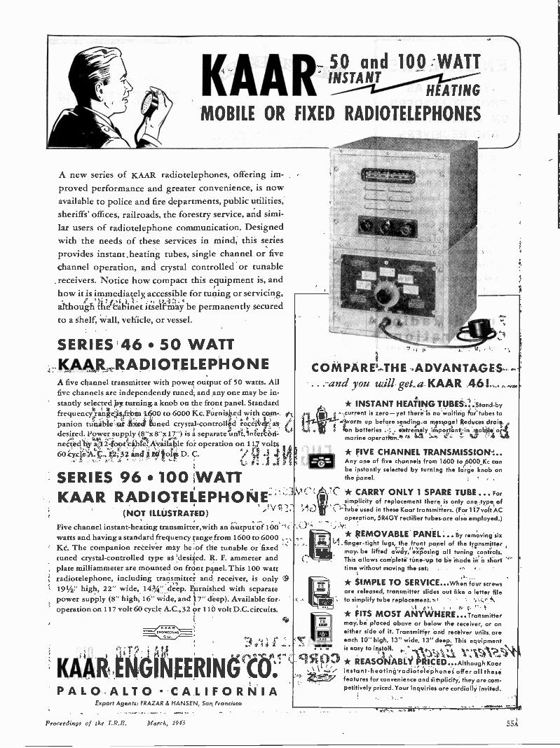
KAAR50 and 100 WATTINSTANT
HEATING
MOBILE OR FIXED RADIOTELEPHONES
A new series of KAAR radiotelephones, offering im-proved performance and greater convenience, is nowavailable to police and fire departments, public utilities,sheriffs' offices, railroads, the forestry service, and simi-lar users of radiotelephone communication. Designedwith the needs of these services in mind, this seriesprovides instant heating tubes, single channel or fivechannel operation, and crystal controlled or tunablereceivers. Notice how compact this equipment is, andhow it is immediately, accessible for tuning or servicing,although the cabinet itself may be permanently securedto a shelf, wall, vehicle, or vessel.
SERIES 46 50 WATTKAAR RADIOTELEPHONEA five channel transmitter with power output of 50 watts. Allfive channels are independently tuned, and any one may be in-stantly selected by turning a knob on the front panel. Standardfrequency range is from 1600 to 6000 Kc. Furnished with com-panion tunable or fixed tuned crystal -controlled receiver asdesired. Power supply (8"x 8"x17") is a separate unit, intercon-nected by a 12 -foot cable. Available for operation on 117 volts60 cycle A. C., 12, 32 and 110 volts D. C.
SERIES 96 100 WATTKAAR RADIOTELEPHONE
(NOT ILLUSTRATED)
Five channel instant -heating transmitter,with an output of 100watts and having a standard frequency range from 1600 to 6000Kc. The companion receiver may be of the tunable or fixedtuned crystal -controlled type as desired. R. F. ammeter andplate milliammeter are mounted on front panel. This 100 wattradiotelephone, including transmitter and receiver, is only191/2:' high, 22" wide, 143A" deep. Furnished with separatepower supply (8" high, 16" wide, and 17" deep). Available -foroperation on 117 volt 60 cycle A.C., 32 or 110 volt D.C. circuits.
==7,
KAAR ENGINEERING CO.PALO ALTO CALIFORNIA
COMPARE THE ADVANTAGESand you will get aKAAR 46!
,
* INSTANT HEATING TUBES...Stand-bycurrent is zero-yet there is no waiting for tubes towarm up before sending a message! Reduces drainon batteries . . . extremely important in mobile ormarine operation.
* FIVE CHANNEL TRANSMISSION ...Any one of five channels from 1600 to 6000 Kc canbe instantly selected by turning the large knob onthe panel.
* CARRY ONLY 1 SPARE TUBE ... Forsimplicity of replacement there is only one type oftube used in these Kaar transmitters. (For 117volt ACoperation, 5R4GY rectifier tubes are also employed.)
* REMOVABLE PANEL... By removing sixfinger -tight lugs, the front panel of the transmittermay be lifted away, exposing all tuning controls.This allows complete tune-up to be made in a shorttime without moving the set.
* SIMPLE TO SERVICE...When four screwsare released, transmitter slides out like a letter fileto simplify tube replacement.
* FITS MOST ANYWHERE...Transmittermay be placed above or below the receiver, or oneither side of it. Transmitter and receiver units areeach 10" high, 13" wide, 13" deep. This equipmentis easy to install.
* REASONABLY PRICED...Although Kaarinstant -heating radiotelephones offer all thesefeatures for convenience and simplicity, they are com-petitively priced. Your inquiries are cordially invited.
Export Agents: FRAZAR & HANSEN, Son Francisco
Proceedings of the I.R.E. March, 1945 55A
ENGINEERSTO SERVE AS
PROJECT LEADERSON TRANSMITTERS
AND RECEIVERS
Must have good engineeringbackground and several years of
broad experience in the radio in-
dustry. Also, a knowledge of
civilian radio requirements will be
valuable when this Company re-
sumes production of high -quality
FM receivers and phonograph
combinations. Write, giving de-
tails of experience and salary ex-
pected, to:
Freed RadioCorporation
ZOO HUDSON STREET NEW YORK CITY
WantedENGINEERS
Radio
*Electrical
Electronic
*Mechanical
*Factory Planning
Materials Handling
Manufacturing Planning
Work in connection with Nie manufacture of wide variety of new and ad ri typesof communications equipment and specialelectronic products.
Apply for write), givinglull qualifications. to:
R.L.D.EMPLOYMENT DEPT.
Western Electric Co,100 CENTRAL AVE., KEARNY, N.J.
'Also: C.A.LLocust St., Haverhill, Mass.
Applicants must comply with WMC regulations
(Continued from page 54A)
RADIO, ELECTRICAL AND MECHANICALENGINEERS
In the development and production of alltypes of radio -receiving and low -power trans-mitting tubes. Excellent post-war opportunitieswith an established company in a field of op-portunities. Apply in person, or write to Per-sonnel Manager of Raytheon ManufacturingCompany, 55 Chapel Street, Newton, Mass.
DESIGNERA central New England manufacturer em-
ploying over 1000 people needs draftsman -design-er on telephone and signaling (mechanical) ap-paratus.
Knowledge of die-casting and plastic applica-tions desirable. WMC regulations prevail. Writeto Box 339.
DEVELOPMENT ENGINEERSMechanical and electrical. Graduate or equiva-
lent training. Required for development work inthe following branches:
1. Electro-mechanical devices communicationsystems. Must be interested in developmentand familiar with magnetic circuits.
2. Measuring and control instruments. Back.ground should be in electrical engineering,including electronics.
Statement of availability required. AddressBox 340.
RADIO -ELECTRONIC ENGINEERSA young progressive radio -electronic firm
needs top-flight men for these key positions:Development engineers.Project engineersEngaged 100% in war work, with excellent
post-war future and possibilities. Our staff knowsof these openings. Write in confidence to Box352.
HELD SERVICE
ENGINEERS
FOR DOMESTIC AND
FOREIGN SERVICE
MUST POSSESS GOOD
KNOWLEDGE OF
RADIO
Essential workers need release
HAZELTINECORPORATION
ia-25 Little Neck ParkwayLittle Neck, Long Island
WANTED:
DESIGN ENGINEERS WITH
TELEVISIONBACKGROUND
FOR GOOD POSITIONS
Here's the dual angle you've been
seeking! Join this growing outfit with
four Southern New England plants in
full-time war work until Victory-then
stay as a key man in our big peace-
time program of Home Radio and Tele-
vision. Experience in Television since
1938 preferred.
MAGUIRE INDUSTRIES, INC.ELECTRONICS DIVISION
342 W. PUTNAM AVE.
GREENWICH, CONN.
RADIO
ENGINEERSThree promising positions areopen to men who want to be as-sociated with a progressive com-pany of established reputationand accomplishments. At presentthere are openings for one seniorengineer and two junior engin-eers. Desire men for work onmilitary projects now who, willbe adaptable to postwar engin-eering. Prefer men with experi-ence in radio receiver or tele-vision laboratory, and with col-lege education in communicationengineering.
Address your communication to
MAJESTIC RADIO
& TELEVISION CORP.2600 W. 50th Street, Chicago 32, Illinois
56A Proceedings of the I.R.E. March, 1945
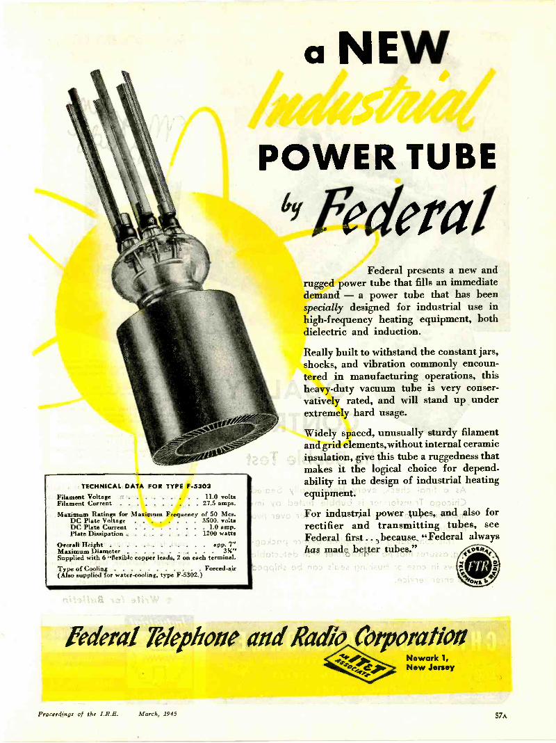
TECHNICAL DATA FOR TYPE F-5303
Filament VoltageFilament Current
11 0 volts27.5 amps.
Maximum Ratings for Maximum Frequency of SO Mcs.DC Plate Voltage 3500. voltsDC Plate Current 1 . 0 amp.Plate Dissipation 1200 watts
Overall Height app. 7"Maximum Diameter 3%"Supplied with 6 "flexible copper leads, 2 on each terminal.
Type of Cooling Forced -air(Also supplied for water-cooling, type F-5302 )
a NEWBiAd#raiidPOWER TUBE
4Y FederalFederal presents a new and
rugged power tube that fills an immediatedemand -a power tube that has beenspecially designed for industrial use inhigh -frequency heating equipment, bothdielectric and induction.
Really built to withstand the constant jars,shocks, and vibration commonly encoun-tered in manufacturing operations, thisheavy-duty vacuum tube is very conser-vatively rated, and will stand up underextremely hard usage.
Widely spaced, unusually sturdy filamentand grid elements,without internal ceramicinsulation, give this tube a ruggedness thatmakes it the logical choice for depend-ability in the design of industrial heatingequipment.
For industrial power tubes, and also forrectifier and transmitting tubes, seeFederal first ... because "Federal alwayshas made better tubes."
federal Telephone and RaSo CorporationNewark 1,New Jersey
Proceedings of the I.R.E. March, 1945 57A
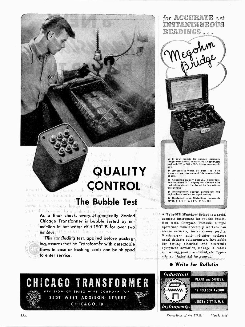
QUALITYCONTROL
The Bubble Test
As a final check, every Hermetically SealedChicago Transformer is bubble tested by im-mersion in hot water at +190° F. for over twominutes.
This concluding test, applied before packag-ing, assures that no Transformer with detectableflaws in case or bushing seals can be shippedto enter service.
CHICAGO TRANSFORMERDIVISION OF ESSEX WIRE CORPORATION
3501 WEST ADDISON STREETCHICAGO, 18
for ACCURATE yetINSTANTANEOIT 1READINGS .
In four models for various resistanceranges from 100.000 ohms to 100.000 megohmsand with 250 or 500 v. D.C. bridge source volt-age. Accurate to within 5% from 1 to 15 onscale. and as close as readable on remainderof scale. Operating entirely from A.C. power line.Self-contained D.C. supply for electron tubeand bridge circuit. Unaffected by line -voltagefluctuations.
Automatically charges condensers andhigh -voltage cables for rapid testing. Hardwood case. Slide -hinge removablecover. 8" L x 7" h. x 53/4" d. 6'4 lbs.
Type MB Megohom Bridge is a rapid,accurate instrument for routine insula-tion tests. Compact. Portable. Simpleoperation: non -laboratory workers cansecure accurate, instantaneous results.Electron -ray null indicator replacesusual delicate galvanometer. Invaluablefor testing electrical and electronicequipment insulation, leakage in cablesand wiring, moisture content, etc. Typic-ally an "Industrial Instrument."
Write for Bulletin
58A Proceedings of the I.R.E. March, 1945

DUSTLESSTOWN, OHIO It's the little things that loom biggest
in the manufacture of delicate electrical
measuring instruments. Little things like
specks of dust or breath condensation
can play havoc with accuracy. That's
why Triplett Instruments are made in
spotless manufacturing departments; why
the air is washed clean, de -humidified and
temperature -controlled; why every step
in their mass production is protected.
As a result Triplett Instruments perform
better, last longer and render greater
service value.
Extra Care in our work puts Extra
Value in your Triplett Instrument.
Triplett44,0
44,"'sin
o:
ELECTRICAL INSTRUMENT CO. BLUFFTON, OHIOProceedings of the I.R.E. March, 1915 59A

NEW SECRETSIn the Temple Laboratories, engineers andtechnicians toil unceasingly to provide newand greater efficiencies for war communica-tions equipment.
Needless to say that out of this constant searchfor betterment comes further discovery,further knowledge - new secrets of devel-opment in the limitless field of electronics.
Temple engineering skill and inventiveness,fostered still further by the stress and strainof war, will contribute richly indeed to theelectronic world of the future.
Electronics Division
TEMPLETONERADIO MFG. CORP.
New London, Conn.
From the product de-signer through to finalassembly and use in
the field, the Eby SpringBinding Post line offerstop service based ondependability.
The spring binding postoffers unique advan-tages that can't beduplicated:
1. No screw cap totighten or comeloose with vibration.
2. Constant, even Aressure on the wire atall times in all posi-tions.
3. Easy one -hand feed-ing of wire into thepost.
4. Corrosion - resistant,long -life springs.
5. Complete range ofsizes, stem lengths,and accessories forevery application.
Replace with Eby SpringBinding Posts - Writetoday.
HUGH H.
EBYI C ORPORATED
18 W. WELTED AVE
PHILADELPHIA, PA.
60.A Proceedings of the I.R.E. March, 1945

RADIO ANDELECTRONICEQUIPMENT
FOR DEPENDABLE PERFORMANCE
*-144,0ow .4.- _ilk
Designed and built by seasonedengineers and skilled craftsmen inlimited volume, COMCO ElectronicEquipment in every way measuresup to highest custom standards.
A VERSATILE LINETransmitters and Receivers areCUSTOMIZED for fine quality andsuperior operating characteristics.
Aeronautical Ground Stations Airport Traffic Control Towers Commercial and Private Aircraft Police, Fire and Public Safety Marine Communications
WRITEI Complete details on request.
COMMUNICATIONSCOMPANY, INC.CORAL GABLES 34, FLORIDA
BLUE PRINT
SERVICEON URGENTLY REQUIRED
RADIO PARTS TUBESELECTRONIC EQUIPMENT
Fro. 800 PagePHON TELETYPE Catalog
.3-1 irert fast wire Available to purr huineBArcla 7 risme, to our agents and engineers18 rel.t7e 17hrerdon "."""Code. RGY-New York Add 13
* OVER 10,000 ITEMS IN STOCKFOR IMMEDIATE DELIVERY!
America's most completeRadio Electronic Si, I House
SUN RADIO& ELECTRONICS CO.212 Fulton Street, New York 7, N. Y.
ea#4.4ed PoweA 104
2/ecda oj SeiwiceVERSATILITY and dependability were paramount whenAlliance designed these efficient motors - Multum in Parvol. . . They are ideal for operating fans, movie projectors, lighthome appliances, toys, switches, motion displays, control systemsand many other applications . . . providingeconomical condensed power for years ofservice.
4ikaoce PlecaioaOur long established standards of precision manu-facturing from highest grade materials are strictlyadhered to in these models to insure long life withoutbreakdowns.
EFFICIENTBoth the new Model "K" Motor and the Model "MS"are the shaded pole induction type - the last word inefficient small motor design. They can be producedin all standard voltages and frequencies with actualmeasured power outputs ranging upwards to 1/100H. P. . . Alliance motors also can be furnished, inquantity, with variations to adapt them to specificapplications.
DEPENDABLEBoth these models uphold the Alliance reputation for all'round dependability. In the busy post-war period,
there will be many "spots"where these Miniature PowerPlants will fit requirements ...Write now for further infor-mation.
Model "MS"- Full SizeMotor Measures
x 2 x 3 Xi"
New Model 'K"-Full SizeMotor Measures
2%8" x 2%" x 3
Remember Alliance!-YOUR ALLY IN WAR AS IN PEACE
Proceedings of the I.R.E. March, .1945 61A
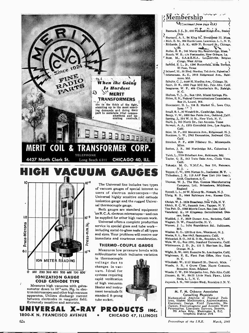
4427 North Clark St.
When the GoingIs Hardest
MERITTRANSFORMERS
are in the thick of the fight,standing up to the most exact-ing demands aed doing theirpart to maintain vital commu-
nications and op-erating controls.
TELEPHONE
Long Beach 6 311 CHICAGO 40, ILL.
HIGH VACUUM GAUGES10
1.0
10-2
10-3
EE
L
10-4
0 100 200 300 400 500 600 100 800IONIZATION GAUGECOLD CATHODE TYPE
Measures high vacuums with galva-nometer down to 10-4 mm. Hg. in elec-tron microscopes and other high vacuumapparatus. Utilizes discharge currentbetween electrodes in magnetic field.Extremely sensitive and accurate.
The Universal line includes two typesof vacuum gauges of special interest tousers of electron microscopes-theUniversal highly sensitive cold cathodeionization gauge and the rugged Univer-sal thermocouple gauge.
Both gauges are standard equipmenton R. C. A. electron microscopes-and canbe supplied for other high vacuum work.
Universal offers a complete productionservice in special glass and tube work-including metal -to -glass seals of all typesand sizes. Your problems will receive ourimmediate and courteous consideration.
THERMO-COUPLE GAUGEMeasures low pressure levels with
millivoltmeter which indicates variationin thermocouplevoltage due tochanges in vac-uum. Ideal forsystems requiringrapid verificationof high vacuums.Heater and instru-ment terminals fitstandard 8 -prongtube socket.
UNIVERSAL X-RAY PRODUCTS INC.1800-K N. FRANCISCO AVENUE CHICAGO 47, ILLINOIS62:1
Membership(Continued from Page 48A)
Rasnack, J. J.. Jr., 692 Pleasant Ridge Ave.. BexleyOhio
Reynard, A. I., 54 King St., Dorchester 22, Mass.Rich, E. M., 104 Hards Lane, Lawrence, L. I., N. Y.Richards, J. A. K., 4829 N. Bernard St., Chicago,
Ill.Roller. E. R., 246 Marcy St., Southbridge, Mass.Roach, W. E., c/o Postmaster, New Orleans. La.Rose, M., S.A.B.E.N.A.. Leopoldville, Belgian
Congo. West AfricaSafford. E. L., Jr., 1206 Butterfield, Mesa Terrace,
El Paso, TexasSchaerf, M., 36 Blvd. Nordau. Tel -Aviv, PalestineScheneman, E. E.. 3916 Ridgewood Ave.. Balti-
more, Md.Schultz. C. J., 6440 N. Nordica Ave., Chicago, Ill.Scott, D. R., 1050 Page Mill Rd., Palo Alto, Calif.Seagraves. W. P., 406 Chamberlain St., Raleigh.
N. C.Shelton, T. J., Jr., Box 1263, Miami Springs, Fla.Shinn, E. N., Federal Communications Commission,
Box 31, Laurel. Md.Shoemaker, H. L., 114 E. Market St., Iowa City,
IowaSmall, B. I., 30 Wendell St., Cambridge, Mass.South, V. W., 3800 San Pablo Ave.. Oakland, Calif.Sprung, J., 254 W. 31 St., New York, N. Y.Stahl, J., 202 North Dr., San Antonio. TexasStewart, A. A., 1523 Greenfield Ave., Los Angeles,
Calif.Stier, M. P., 202 Mountain Ave.. Ridgewood, N. J.Stockton, L. W., 2765 Devonshire, Redwood City.
Calif.Strother, F. P.. 4020 Pillsbury St.. Minneapolis,
Minn.Sutton. J. R., 202 Northridge Rd.. Columbus 2,
OhioTaich, L.. 5709 Ethelbert Ave., Baltimore, Md.Taylor, G. E., 563 Twin Oaks Ave., Chula Vista,
Calif.Tekosky, M. G.. Y.M.C.A., Box 731, Paterson.
N. J.Tepper, C. W., 2701 Norton St.. Rochester, N. Y.Thibodeau, J. E., 113 AAF Base Unit (Air Insp.).
AAB, Charleston, S. C.Thomas, W. J., The Hut. Cosmos Manufacturing
Company. Ltd., Brimadown. Middlesex.England
Tyrrell. L. L., 56 W. Kinney St.. Newark. N. J.Uhrig, R. B.. 1644 Baltimore Ave., Kansas City.
Mo.Uhrich, W. J.. 2528 Broadway. New York, N. Y.Ulrich. E. C. W.. Summit Ave., Tappan. N. Y.Van Pelt. D., 1088 Morris Court. San Jose, Calif.Varadaraj, K., 69 Kingsway, Secunderabad. Dec-
can, IndiaWaddell, J. F., 2029 Durant Ave.. Berkeley. Calif.Wagner, D. W., Franklinville, N. Y.Warner, J. L., 2434 Brambleton Rd., Baltimore,
Md.Weaber. K. G., 120 Stoy Ave., Westmont, N. J.Weeks. R. L., Box 1947, Sacramento. Calif.Weinschel, B. 0., 365 E. 21 St., Brooklyn. N. Y.Weis, W. G., Box 2701. Stanford University. Calif.Whittemore, J. D.. Jr., 131 S. Harrison St.. East
Orange, N. J.Wight, R. W.. 6601 Romaine St.. Los Angeles, Calif.Wightman, E. E., Fleet Post Office. New York,
N. Y.Wikolaski, W., 5112 Maxwell St.. Detroit, Mich.Woods, A. R., 4 Grove Close, Hayes Common,
Bromley, Kent, EnglandWoods, C. W.. 290 Margarita Ave.. Palo Alto, Calif.Zimmer. E. W., 58-25 Little Neck Pkwy., Little
Neck, L. L. N. Y.Zupnick, I. N.. 768 Linden Blvd., Brooklyn 3, N. Y.
M. F. M. Osborne AssociatesConsulting Physicists
Mathematical Analysis of Physical Prob-lems, Higher Mathematics. Approximations.Electronic Design. Fluid Dynamics, Me-chanics. Electromagnetic and Acoustic WavePropagation. Literature Surveys, Reports.
703 Albee Bldg., Washington 5, D.C.Telephone District 2415
Proceedings of the I.R.E. March, 1945
SANTAY wanted to bring the camera into focus, but the ArmedServices said, "Censored"! However, here's another example ofSantay's ability to make simple or intricate SELECTOR
MECHANISMS.Santay possesses the four important factors in producing simple orintricate SELECTOR MECHANISMS; (1) design ability, (2) develop-ment ingenuity, (3) manufacturing facilities, and (4) the desire toserve. In addition, Santay possesses twenty-five years experience indesigning and making tools for the metal working industry.Santa:, continues to produce SELECTOR MECHANISMS now as theywill in times of peace. Should you have a product in which a mechanicalassembly of any kind is involved, may we suggest you investigatethis sAilled precision craftsmanship!
INJECTION MOLDING METAL STAMPING ELECTRO-MECHANICAL ASSEMBLIES
SANTAY CORPORATION 358 NORTH CRAWFORI) AVE., CHICAGO 24, ILLINOISFORMERLY SINKO TOOL 8. MANUFACTURING CO.
REPRESENTATIVES: POTTER 8 DUGAN, INC., 29 WILKESON STREET, BUFFALO 2, NEW. YORK PAUL SEILER, 7779CORTLAND AVENUE, DETROIT 4, MICHIGAN OUEISSER BROS., 108 E. NINTH STREET, INDIANAPOLIS 2, INDIANA
Proceedings of the I.R.E. March, 194.5 63A
RADIO, SOUND andCOMMUNICATIONS
EQUIPMENT
BETTER
PERMANENT MAGNETS
OP"r'N0 1
t?, Q. -
AUTOMOTIVEand AVIATION
EQUIPMENT -
INSTRUMENTS
However advanced your own product -development work may be . . .
however new or revolutionary the permanent magnets you require.. Arnold engineers can be of considerable assistance to you in supply-
ing the proper permanent magnets in volume. They're precision -builtentirely in our own plant, under the closest metallurgical, mechan-ical and magnetic control to assure peak efficiency at the lowest cost.
NEW!Get your c3py of this valuable, up.to-the-mintse manual on the design,
production and applicatior of modern Alnico per-manent magnets. Write us, on your company letter.head, today.
Specialists in the manufacture ofALNICO PERMANENT MAGNETS
THE ARNOLD ENGINEERING COMPANY147 EAST ONTARIO STREET, CHICAGO 11, ILLINOIS
DESIGNED FOR
PEAK
PERFORMANCE
SEALED, ALUMINUM CASEAIR -BORNE TRANSFORMERS
OIL -COOLED, PLATE SUPPLYTRANSFORMERS
AIR-COOLED TRANSFORMERSWITH 10 VOLT SEC. TAPS
THE ACME ELECTRIC & MFG. CO.CUBA, NEW YORK CLYDE, NEW YORK
Aeinli&(0),',_Rzetrtc,
TR ANSFORMERS64A Proceedings of the I.R.E. March, 1945
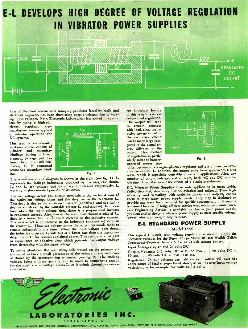
E -L DEVELOPS HIGH DEGREE OF VOLTAGE REGULATION
IN VIBRATOR POWER SUPPLIES
.0;gd,doopever/14444
One of the most serious and annoying problems faced by radio andelectrical engineers has been fluctuating output voltages due to vary-ing input voltages. Now, Electronic Laboratories has solved this prob-lem by using a high -effi-ciency, regulated typetransformer system appliedto vibrator operation forDC systems.
This type of transformer,as shown above, consists ofprimary and secondarywindings having a linearmagnetic leakage path be-tween them. The tank con-denser, C, is connectedacross the secondary wind-ing. Fig. 1
The equivalent circuit diagram is shown at the right (see fig. 1). Lk
represents the leakage inductance provided by the magnetic shunts.Li, and L. are primary and secondary inductances respectively, L.working at the saturated portion of its curve.
The net voltage across the output terminals is the vectorial sum ofthe equivalent voltage input and the drop across the reactance Lk.This drop is due to the condenser current (addative) and the induc-tive current drawn by the saturable reactor L. (subtractive). In opera-tion, when the input voltage rises, there is a proportional increasein condenser current. Also, due to the non-linear characteristics of L.,there is a more than proportional increase in the inductive current.The next effect is an increase in the inductive (subtractive) drop inthe reactor Lk. Thus, the voltage across the output terminals tends toremain substantially the same. When the input voltage goes down,the inductive drop on Lk will fall at a faster rate than the capacativedrop due to C, for reasons explained above. This results in a net gainin capacitance or addative drop which prevents the output voltagefrom decreasing with the input voltage.
To insure absolutely flat regulation, coils wound on the primary areconnected to buck a small percentage of the voltage of the secondaryas shown by the accompanying schematic (see fig. 2). The buckingvoltage, being a linear quantity, can be made to compensate exactlyfor the small rise in voltage across L. as it swings through its satura-tion curve.
A
An important featureof this system is its ex-cellent load regulation.The output will tendto remain constantwith load, since the re-active energy stored inthe secondary circuitcan be made large com-pared to the actual en-ergy delivered at theoutput. This methodof regulation is partic-ularly suited to battery -operated power sup-plies, because it is a high -efficiency regulator and not a losser, as avail-able heretofore. In addition, the output wave form approaches a sinewave, which is especially desirable in certain applications. Also, anynumber of output voltages and currents, both AC and DC, can beobtained from the secondary circuit of a single transformer.E -L Vibrator Power Supplies have wide application in many field=radio, electrical, electronic, marine, aviation and railroad. Their highefficiency and versatility with multiple inputs and outputs, enablethem to meet many power supply needs. They may be designed toprovide any wave form required for specific equipment.. . . Economyis assured because of long, efficient service with minimum maintenance.E -L Engineering Service is available to discuss your power supplyproblem and to design a vibrator power supply to meet specific voltage,power, size and weight requirements.
E -L STANDARD POWER SUPPLYModel 1566
This typical E -L unit, with voltage regulation, is used to supply thenecessary voltages for the Signal Corps Model BC -100 Walkie TalkieTransmitter -Receiver, from a 6, 12, or 24 volt storage battery.Input Voltages: 6, 12 and 24 volts DC.Output Voltages: 140 volts DC at 0-55 ma. . . . 90 volts DC at30 ma. . . . 45 volts DC at 250-550 ma.Regulation: Output voltages are held constant within 5% over theentire range of load changes listed above, as well as over input voltagevariations, as for example, 5.7 volts to 7.5 volts.
LABORATORIES INC.I N D I A N A P O L I S
VIBRATOR POWER SUPPLIES FOR LIGHTING, COMMUNICATIONS, ELECTRIC MOTOR OPERATION ELECTRIC, ELECTRONIC AND OTHER EQUIPMENT
Pig. 2
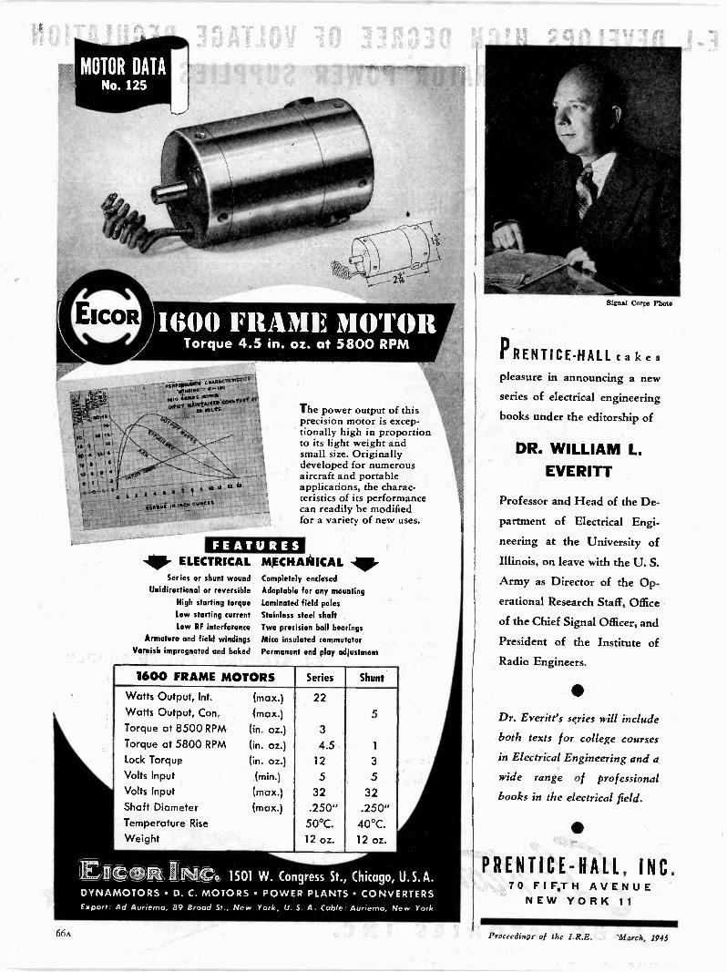
Ewa
sft 7.0 12
is 1.
.25to... e
Torque 4.5 in. oz. at 5800 RPM
C:AP,S.C.SCRIST2CS
IrlYsnaIYIa 'U"SrS171; tbo15,S2.114 AT12115.1 WM.*
2 4 5
1012,21.12IM INCH GUS. S
The power output of thisprecision motor is excep-tionally high in proportionto its light weight andsmall size. Originallydeveloped for numerousaircraft and portableapplications, the charac-teristics of its performancecan readily be modifiedfor a variety of new uses.
FEATURESELECTRICAL
Series er shunt woundUnidirectional or reversible
High starting torquelow starting currentLow RF interference
Armature and field windings
Varnish impregnated and baked
MECHANICAL V.Completely endosed
Adaptable for any mounting
Laminated field poles
Stainless steel shaftTwo precision ball bearings
Mica insulated commutator
Permanent end play adjustment
1600 FRAME MOTORS Series Shunt
Watts Output, Int. (max.) 22Watts Output, Con. (max.) 5Torque at 8500 RPM (in. oz.) 3
Torque at 5800 RPM (in. oz.) 4.5 1
Lock Torque (in. oz.) 12 3
Volts Input (min.) 5 5Volts Input (max.) 32 32Shaft Diameter (max.) .250" .250"Temperature Rise 50°C. 40°C.Weight 12 oz. 12 oz.
EICISOBt IIKC-0 1501 W. Congress St., Chicago, U.S.A.DYNAMOTORS D. C. MOTORS POWER PLANTS CONVERTERSExport Ad Aurlemo, 89 Broad Sr., New York, U. S. A Cable Auroerno, New York
signal Corp Photo
PRENTICE-HALL takespleasure in announcing a new
series of electrical engineering
books under the editorship of
DR. WILLIAM L.EVERITT
Professor and Head of the De-
partment of Electrical Engi-
neering at the University of
Illinois, on leave with the U. S.
Army as Director of the Op-
erational Research Staff, Office
of the Chief Signal Officer, and
President of the Institute ofRadio Engineers.
Dr. Everitt's series will include
both texts for college courses
in Electrical Engineering and a
wide range of professional
books in the electrical field.
PRENTICE-HALL, INC.70 FIFTH AVENUE
NEW YORK 11
66A Proceedings of the I.R.E. March, 1945
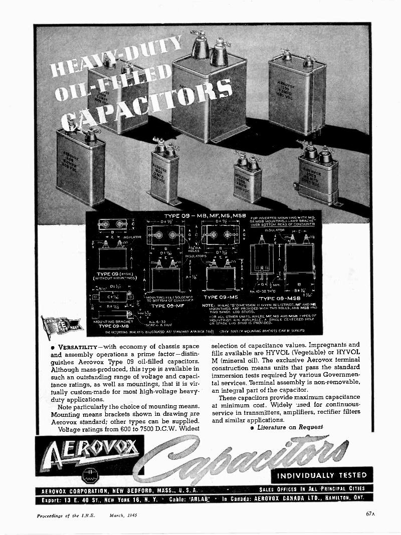
T.-C-41 INSULATORA
TYPE 09 (BASIC)(WITHOUT MOUNTINGS
412"a Ot V, 4.1
BD
E
`MOUNTING FEET SOLDEREDTO BOTTOM OF CONTAINER
-4 8+1/26 'TYPE 09-M rbtif.
4
MOUNTING BRACKET Ne.6- 32TYPE 09 -MB -SCREW ek NUT
I 3116.0.A. I BHOLES
INSUL.ATORS E/
TYPE 09 -MS
FOR INVERTED MOUNTING WITH MS.OR MSB MOUNTING,L:-AMP BRACKENOVER BOTTOM BEAD OF CONTAINER
INSULATOR N___ .1
G fMIN. IF S
N0.10-32 TWO 1/4'
TYPE 09-MSBNOTE: WHERE "G" DIMENSION IS GIVEN IN LISTINGS, NF AND MS
MOUNTINGS ARE PROVIDED WITH TWO HOLES, AND MSB HASTWO SPADE LUG STUDS.FOR 'ALL OTHER UNITS, WHERE MF. MS AND MSB TYPES OF, MOUNTINGS ARE AVAILABLE. A SINGLE CENTERED HOLEGR SPADE LVG STUD' IS PROVIDED.
THE MOUNTING 81ACKITS 111USTRA710 ART tTANDAyn AIN)VOX 711 -IS 11115!.,f MOUNTING 141M1KETS CAN tT 5URr5lfll
VERSATILITY-with economy of chassis spaceand assembly operations a prime factor-distin-guishes Aerovox Type 09 oil -filled capacitors.Although mass-produced, this type is available insuch an outstanding range of voltage and capaci-tance ratings, as well as mountings, that it is vir-tually custom-made for most high -voltage heavy-duty applications.
Note particularly the choice of mounting means.Mounting means brackets shown in drawing areAerovox standard; other types can be supplied.
Voltage ratings from 600 to 7500 D.C.W. Widest
selection of capacitance values. Impregnanfs andfills available are HYVOL (Vegetable) or HYVOLM (mineral oil). The exclusive Aerovox terminalconstruction means units that pass the standardimmersion tests required by various Governmen-tal services. Terminal assembly is non -removable,an integral part of the capacitor.
These capacitors provide maximum capacitanceat minimum cost. Widely used for continuous -service in transmitters, amplifiers, rectifier filtersand similar applications.
Literature on Request
AEROVOX CORPORATION, NEW BEDFORD, MASS., U. S. A.
INDIVIDUALLY TESTED
SALES OFFICES IN AIL PRINCIPAL CITIES
Export: 13 E. 40 ST., NEW YORK 16, N. Y. Cable: 'ARLAB! In Canada: AEROVOX CANADA LTD., HAMILTON, ONT.
Proceedings of the I.R.E. March, 1945 67A
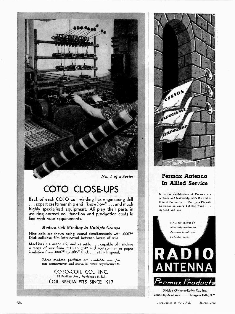
No. 1 of a Series
COTO CLOSE-UPSBack of each COTO coil winding lies engineering skill... expert craftsmanship and "know how" ... and muchhighly specialized equipment. All play their parts inassuing correct coil function and production costs inline with your requirements.
Modern Coil Winding in Multiple GroupsNine coils are shown being wound simultaneously with .0007"thick cellulose film interleaved between layers of wipe.
MacE ines are automatic and versatile ... capable of handlinga range of wire from #18 to #42 and acetate film or paperinsulation from .0007" to .005" thick ... at high speed.
These modern facilities are available now forwar components and essential rated requirements.
COTO-COIL CO., INC.65 Pavilion Ave., Providence 5, R.I.
COIL SPECIALISTS SINCE 1917
Permax AntennaIn Allied Service
It is the combination of Premax ex-perience and leadership, with the visionto meet the needs ... that puts PremaxAntennas on every fighting front . . .
on land and sea.
Write for special de-
tailed information on
Antennas to suit your
particular needs.
RADIOANTENNA
Division Chisholm -Ryder Co., Inc.
4503 Highland Ave. Niagara Falls, N.Y.
68A Proceedings of the I.R.E. March, 1945
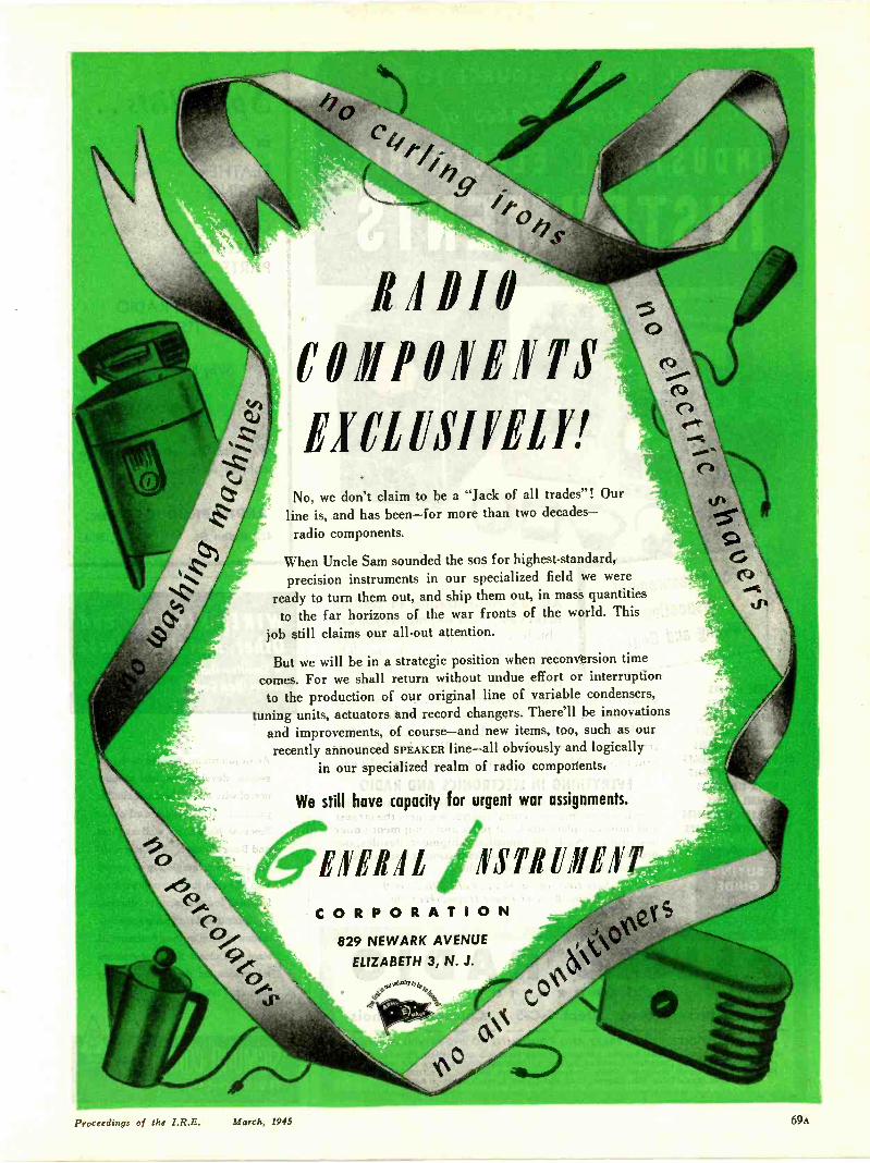
CQ
LIP10COIIIPOTEITS
No, we don't claim to be a "Jack of all trades"! Ourline is, and has been-for more than two decades-radio components.
When Uncle Sam sounded the sos for highest -standard,precision instruments in our specialized field we were
ready to turn them out, and ship them out, in mass quantitiesto the far horizons of the war fronts of the world. This
job still claims our all-out attention.
But we will be in a strategic position when reconversion time
comes. For we shall return without undue effort or interruptionto the production of our original line of variable condensers,
tuning units, actuators and record changers. There'll be innovationsand improvements, of course-and new items, too, such as ourrecently announced SPEAKER line-all obviously and logically
in our specialized realm of radio components.
We still hove capacity for urgent war assignments. I
MUG PSTIIIINEITCORPORATION
829 NEWARK AVENUE
'
6(N°\(4
.06.0y, 04.
ELIZABETH 3, N. J.
4,5% (07 cje`
C;4\
Proceedings of the I.R.E. March, 1945
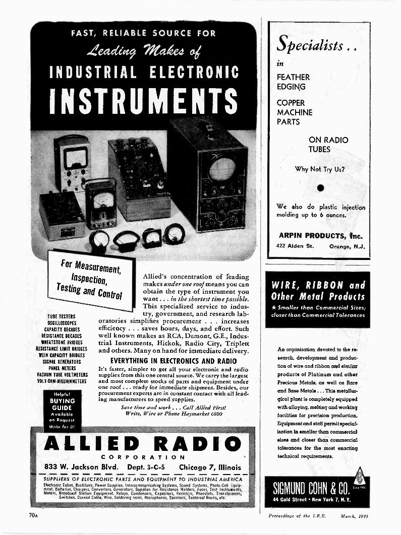
FAST, RELIABLE SOURCE FOR
Zeadeft9 na4edINDUSTRIAL ELECTRONIC
INSTRUMENTS
TUBE TESTERS
OSCILLOSCOPES
CAPACITY DECADES
RESISTANCE DECADES
WHEATSTONE BRIDGES
RESISTANCE LIMIT BRIDGES
WEIN CAPACITY BRIDGES
SIGNAL GENERATORS
PANEL METERS
VACUUM TUBE VOLTMETERS
VOLT-OHM-MILLIAMMETERS
Helpful
BUYINGGUIDEAvailable
on RequestWrite for it!
Allied's concentration of leadingmakes under one roof means you canobtain the type of instrument youwant . . . in the shortest time possible.This specialized service to indus-try, government, and research lab-
oratories simplifies procurement . . . increasesefficiency . . . saves hours, days, and effort. Suchwell known makes as RCA, Dumont, G.E., Indus-trial Instruments, Hickok, Radio City, Triplettand others. Many on hand for immediate delivery.
EVERYTHING IN ELECTRONICS AND RADIOIt's faster, simpler to get all your electronic and radiosupplies from this one central source. We carry the largestand most complete stocks of parts and equipmen: underone roof ... ready for immediate shipment. Besides, ourprocurement experts are in constant contact with all lead-ing manufacturers to speed supplies.
Save time and work . . . Call Allied First!Write, Wire or Phone Haymarket 6800
ALLIED RADIOCORPOR ATION
833 W. Jackson Blvd. Dept. 3-C-5 Chicago 7, IllinoisSUPPLIERS OF ELECTRONIC PARTS AND EQUIPMENT TO INDUSTRIAL AME 2/CAElectronic Tubes, Rectifiers, Power Supplies, Intercommunicating Systems, Sound Systems, Photo -Cell =quip-ment, Batteries, Chargers, Converters, Generators, Supplies for Resistance Welders, Fuses, Test Instruments,Meters, Broadcast Station Equipment, Relays, Condensers, Capacitors, Resistors, Rheostats, Transfoimers,
Switches, Coaxial Cable, Wire, Soldering Irons, Microphones, Speakers; Technical Books, etc.
Specialists . .
in
FEATHEREDGING
COPPER
MACHINEPARTS
ON RADIOTUBES
Why Not Try Us?
We also do plastic injectionmolding up to 6 ounces.
ARPIN PRODUCTS, Inc.422 Alden St. Orange, N.J.
WIRE, RIBBON andOther Metal Products* Smaller than Commercial Sizes;closer than Commercial Tolerances
An organization devoted to the re-
search, development and produc-tion of wire and ribbon and similar
products of Platinum and otherPrecious Metals, as well as Rareand Base Metals ... This metallur-gical plant is completely equipped
with alloying, melting and working
facilities for precision production.
Equipment and staff permit special-
ization in smaller than commercial
sizes and closer than commercialtolerances for the most exactingtechnical requirements.
SIGMUND COHN & CO.44 Gold Street New York 7, N. Y.
e iom
70A Proceedings of the I.R.E. March, 1945

Portrait of a man whono longer cares aboutthe cigarette shortage,the meat shortage ... orgas shortage!ws just a question of time when all We, the management and employeesshortages will be replaced by plenty alike, at Kenyon, are building better-thanks to this boy and to millions transformers than we ever builtlike him, before- and building them faster
Give them a helping hand. for the armed forces.Buy Bonds - Donate Blood.
THE MARK OF EXCELLENCE
KENYON TRANSFORMER CO. In840 BARRY STREET
NEW YORK, U. S. A.
Proceedings of the I.R.E. March, 1945 71A

Pode-Wevt Pleueseiag
An Introduction to ElectronicsSy Raid 9 Vceddera
The enormous potentialities of the relatively newscience of electronics offer many avenues for thepost-war development of new products. Thisbook provides a guide and reference for manu-facturers, research departments and others inter-ested in such developments. It explains as simplyas possible the basic ideas and theories, the exist-ing and potential applications, and the construc-tion of modern electronic devices. Illustrated.
$3.00
PPuterical Teea/tact/Am
Ultra -High -Frequency Radio EngineeringBy IV. L. Emery. "Exceptionally good for courses at the under-graduate level," say teachers about this new book. Contains muchpractical how -to -do -it information; laboratory problems; 2 -colorIllus. $3.25
THE MACMILLAN COMPANY 60 FIFTH AVE. NEW YORK 11
ONLY GATES OFFERS YOU THIS CHOICE of
Model 30 DeLuxe Speech Input Consolefor use as main studio control unit forstations up to 50.000 watts.
SPEECH INPUT CONSOLESHere are two popular examples of how Gates equipment is engi-neered for efficiency and economy to meet the requirements of everytype of station. These two popular studio control units meet everydemand for use as a main studio control unit, as sub -studio controlequipment, for auditorium pick-ups and for large broadcasts suchas symphonies, conventions, etc. You'll find these Gates units inservice all over the world . . . time -proved by dependable service inmore than 100 U.S. broadcasting stations ranging from 250 to 50,000watts.
Wartime restrictions do not allow the sale of new broadcasting equip-ment without priority, therefore, this equipment is presented merelyto acquaint you with Gates' current developments.
Ask About Our Priority Plan for Prompt De-livery When Gates Equipment Is Again Avail-able.
RADIOCOMPANY
Quincy, Illinois, U. S. A.Model 5I -CS Studioette SpeechInput Console for smaller sta-tions and sub -studio operation.
INDEXSection Meetings 34AMembership 38APositions Open 52A
DISPLAY ADVERTISERSAcme Electric & Manufacturing Co. MAAcrovox Corporation 67A
23A6IA70A44A
9A13A
Amperex Electronic Corp. Cover IIAndrew Co. 44A
MA70A
Blaw-Knox Company 40A
Caldwell -Clements Inc. 35ACambridge Thermionic Corp. 33A
I4A58AMA70A54A
Communications Company, Inc. 6IACommunication Products Co., Inc. 40AConnecticut Telephone & Elec. Div. 43AContinental -Diamond Fibre Co. 22AContinental Electric Co. 47ACornell-Dubilier Electric Corp. Cover IIICorning Glass Works 2IACoto -Coil Co., Inc. MA
Dalmo Victor Company 52AThe Daven Company I6ATobe Deutschmann Corp. 73AAllen B. Dumont Labs., Inc. 10A
Aircon Manufacturing Corp.Alliance Mfg. Co.Allied Radio Corp.Alice Lansing Corp.American Lava Corp.American Transformer Co.
Arnold Engineering Co.Arpin Manufacturing Co.
CentralabChicago Transformer Corp.Clarostat Mfg. Co., Inc.Sigmund Cohn & Co.Collins Radio Co.
Hugh H. Eby IncorporatedEicor Inc.
60A66A
Eitel-McCullough, Inc. 18A35A
Electronic Laboratories, Inc. 65AElectronic Mechanics, Inc. 6A
Federal Telephone & Radio Corp. 57A56A
Gates Radio Co. 72AGeneral Aniline & Film Corporation 26A, 27AGeneral Electric Company 29A, 45AGeneral Instrument Corp. 69AGeneral Radio Co. Cover IV
Freed Radio Corporation
Electronic Industries
Hallicrafters CompanyHazeltine Corp.Heintz & Kaufman Ltd.Hewlett-Packard Co.Hytron Corp.Industrial & Commercial ElectronicsIndustrial Condenser Corp.Industrial InstrumentsInternational Resistance Co.International Tel. & Tel.
30A56A3IA4A5A
4IA53AMA37A57A
Kaar Engineering Co. SSAKenyon Transformer Co. 7IAJohn E. Lingo & Son, Inc. 36A
Macmillan Co. 72AMaguire Industries, Inc. 56AMajestic Radio & Television Corp. 56AMeasurements Corp. 28AMerit Coil & Transformer Corp. 62AMonarch Mfg. Co. MANational Company 20ANational Union Radio Corp. 17ANew York Transformer Co. 53ANorth American Philips Co., Inc. 3A
Ohmite Mfg. Co.M. F. M. Osborne AssociatesPerrnoflux CorporationPratt & Whitney AircraftPremax ProductsPrentice -Hall Inc.
39A62A
MA52AMA66A
Radio Corp. of America 32A, 50A, 51ARauland Corp. 74ARaytheon Mfg. Co. 24ARemler Co., Ltd. I9ASantay Corp. 63AShallcross Mfg. Co. 46AStandard Transformer Corp. 42AStromberg-Carlson Co. 52AStupakoff Ceramic & Mfg. Co. 12ASubmarine Signal Co. 52ASun Radio & Electronics Co. 61A
Templetone Radio Mfg. Corp. MATriplett Electrical Instrument Co. 59A
United Electronics Co. 15AUnited Transformer Co. 49AUniversal X -Ray Products Inc. 62AUtah Radio Products Co. 8AWeston Electrical Instrument Corp. I IAWestern Electric Co. 56AWestinghouse Electric & Mfg. Co. 7A, 25A
72A Proceedings of the I.R.B. March, 1945
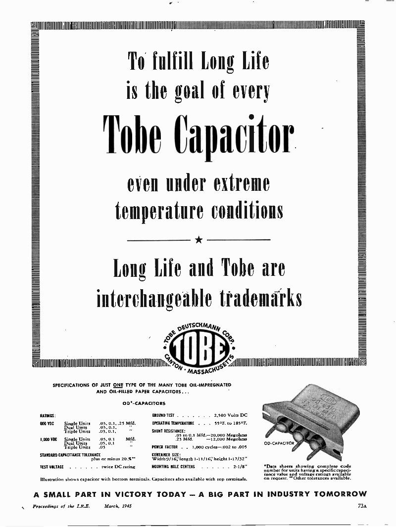
To fulfill Long Life
is the goal of every
lobe Capacitoreven under extreme
temperature condition
Long Life and Tobe are
interchangeable trademarksosoisc.A,v
toas,.,.,,,,,,,,,,...,,,. MAssAC.VW
SPECIFICATIONS OF JUST ONE TYPE OF THE MANY TOBE OIL -IMPREGNATEDAND OIL -FILLED PAPER CAPACITORS ...
OW -CAPACITORS
RATINGS: GROUND TEST 2,500 Volts DC
600 YOU Single Units .05, 0.1, .25 Mfd. OPERATING TEMPERATURE . . 55°F. to 185°F.Dual Units .05, 0.1,Triple Units .05, 0.1, " SHUNT RESISTANCE:
.05 to 0.1 Mfd.-20,000 Megohms1,000 VDU Single Units .05, 0.1 Mfd. .25 Mfd. -12,000 Megohms
Dual Units .05, 0.1Triple Units .05 POWER FACTOR . . 1,000 cycles-.002 to .005
STANDARD CAPACITANCE TOLERANCE CONTAINER SIZE:plus or minus 20.%** Width 9/16;' length 1-11/16 height 1-17/32"
TEST VOLTAGE twice DC rating MOUNTING HOLE CENTERS 2-1/8"
Illustration shows capacitor with bottom terminals. Capacitors also available with top terminals.
OD -CAPACITOR
'Data sheets showing complete codenumber for units having a specific capaci-tance value and voltage ratings availableon request. "Other tolerances available.
==
A SMALL PART IN VICTORY TODAY -A BIG PART IN INDUSTRY TOMORROWProceedings of the I.R.E. March, 1945 73A
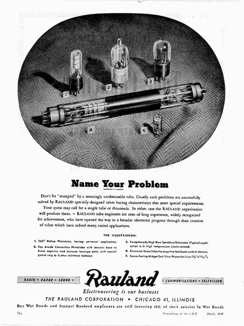
Name Your ProblemDon't be "stumped" by a seemingly unobtainable tube. Usually such problems are successfully
solved by RAULAND specially -designed tubes having characteristics that meet special requirements.Your quest may call for a single tube or thousands. In either case the RAULAND organization
will produce them. RAULAND tube engineers are men of long experience, widely recognizedfor achievement, who have opened the way to a broader electronic progress through their creationof tubes which have solved many, varied applications.
THE ILLUSTRATION:
1. 360° Pickup Phototube, having universal application.
2. Top Anode Connection Phototube with ceramic base tolower capacity and increase leakage path, with specialguard ring to further minimize leakage.
RADIO RADAR
3. Exceptionally High Blue -Sensitive Phototube. (Typical application is in high temperature photo -control).
4. Electronic Beam Tube for negative feedback control devices.
5. Space -Saving Midget End -View Phototube
C01111WINITAT;ONS TELEVISION
Electroneering is our businessTHE RAULAND CORPORATION CHICAGO 41, ILLINOIS
Buy War Bonds and Stamps! Rauland employees
74A
are still investing 10% of their salaries in War BondsProceedings of the I.R.E. March, 1945
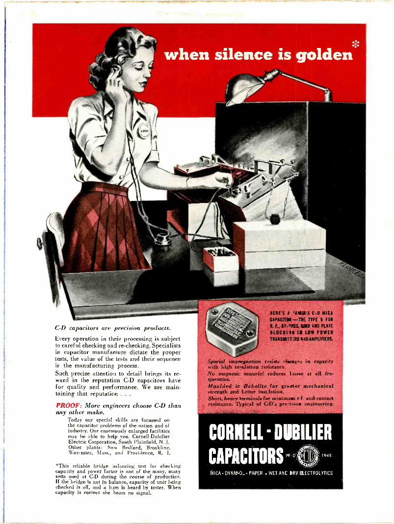
when silence is golden
C -D capacitors are precision products.
Every operation in their processing is subjectto careful checking and re -checking. Specialistsin capacitor manufacture dictate the propertests, the value of the tests and their sequence
the manufacturing process.Such precise attention to detail brings its re-ward in the reputation GD capacitors havefor quality and performance. We are main-taining that reputation . . .
PROOF: More engineers choose C -D thanany other make.
Today our special skills are focussed onthe capacitor problems of the nation and ofindustry. Our enormously enlarged facilitiesmay be able to help you. Cornell-DubilierElectric Corporation, South Plainfield, N. J.Other plants: New Bedford, Brookline,Worcester, Mass., and Providence, R. I.
*This reliable bridge 3alancing test for checkingcapacity and power factor is one of the many, manytests used at C -D during the course of production.If the -bridge is not in balance, capacity of unit beingchecked is off, and a him is heard by tester. Whencapacity is correct she hears no signal.
HERE'S t 441,0ts C -C MICACAPACITOR -DE TYPE 9 FOR
R. F., BY- VSS, CRIB ANC PLATE
BLOCK144 II LOW POWERTRANSMIT '.RS 440 AMPLIFIERS.
Special impnegriation resists change -3 in capacitywith high insulation resistance.No magnetic material reduces yeses at all fre-quencies.Moulded ir. Bakelite for greater mechanicalstrength and letter insulation.Short, heavy !erminals far minirn_aat r f and contactresistance. Typical of C -D's pre -isit.a engineering.
CORNELL - DRIVER
CAPACITORS 19 °1945
MICA DYKANO_ PAPER . WET ANC IRV EtECTROLYTICS

100 to 500 McTHIS NEW oscillator, designed for use as a general-purpose laboratory instrument, uses the new ButterflyCircuit which obviates the difficulty of sliding con-tacts in any part of the circuit and provides a sourceof ultra -high -frequency power sufficient for mostlaboratory measurement needs.
Some of its features are: Dial calibrated directly in megacycles with an accuracy
of 1 per centVernier dial with 100 divisions, covering the tuning rangein 10 turns
Output through a coaxial jack to which is attached a pick-up loop to provide variable coupling to the oscillator
Output of one-half watt with the power supply furnished Output up to one watt at the highest frequency with a 450-
volt power supply, provided certain precautions are takenin the operation of the oscillator
The Type 857-P1 Power Supply furnishes a plate volt-age of 350 volts and filament supply of 2.5 volts for theW. E. Type 316-A tube used in the oscillatorElectron -ray tube incorporated in the power supply toshow oscillator grid current
Type 857-A Oscillator with Type 857-P1 Power Supply $250.00We are in limited production now for high priority war orders; reserva-
tion orders for later deliveries are being accepted.A complete description appears in the G -R Experimenter for November,
1944. If you do not have a copy, write for Bulletin 931.
O
GENERAL RADIO COMPANYCambridge 39, MassachusettsNEW YORK CHICAGO LOS ANGELES