measurement - Engineers Academy
20
MEASUREMENT ECE, EE, EEE, IN ENGINEERING
-
Upload
khangminh22 -
Category
Documents
-
view
0 -
download
0
Transcript of measurement - Engineers Academy
MEASUREMENT
ECE, EE, EEE, IN ENGINEERING

Ph. : 0141-6540910 / 111, +91-8094441777 / 999
Website : www.engineersacademy.org | Email: [email protected]
RRB-JEn&
SSC-JEn
ParsmalMeghwal
(EE)
Lok;Ùk 'kklu foHkkx jkt- ljdkj ¼jktLFkku uxj ikfydk½
lgk;d vfHk;arkRank 39 Rank 45 Rank 46Rank 8
Sukhpal Kaur
Roll No. : 31452341723
Civil : Assistant Engineer
Pratibha Kuri
Roll No. : 11630363603
Civil : Assistant Engineer
Chirag Goyal
Roll No. : 21414346670
Civil : Assistant Engineer
Rahul Kumar Bhatia
Roll No. : 22046373468
Civil : Assistant Engineer
WRD : 2016 Selection
Pooja SharmaCE: WRD-JEn CE: WRD-JEn CE: WRD-JEn CE: WRD-JEn
Sumit Mahar Avinash Ankush Jain Poonam ChandCE: WRD-JEn
Ramavatar LambaRohit GurjarAnil Bishnol Jaidev SolankiDharmendra Singh
CE: WRD-JEn CE: WRD-JEn CE: WRD-JEn CE: WRD-JEn CE: WRD-JEnManish KumarCE: WRD-JEn
vrqY; | EA
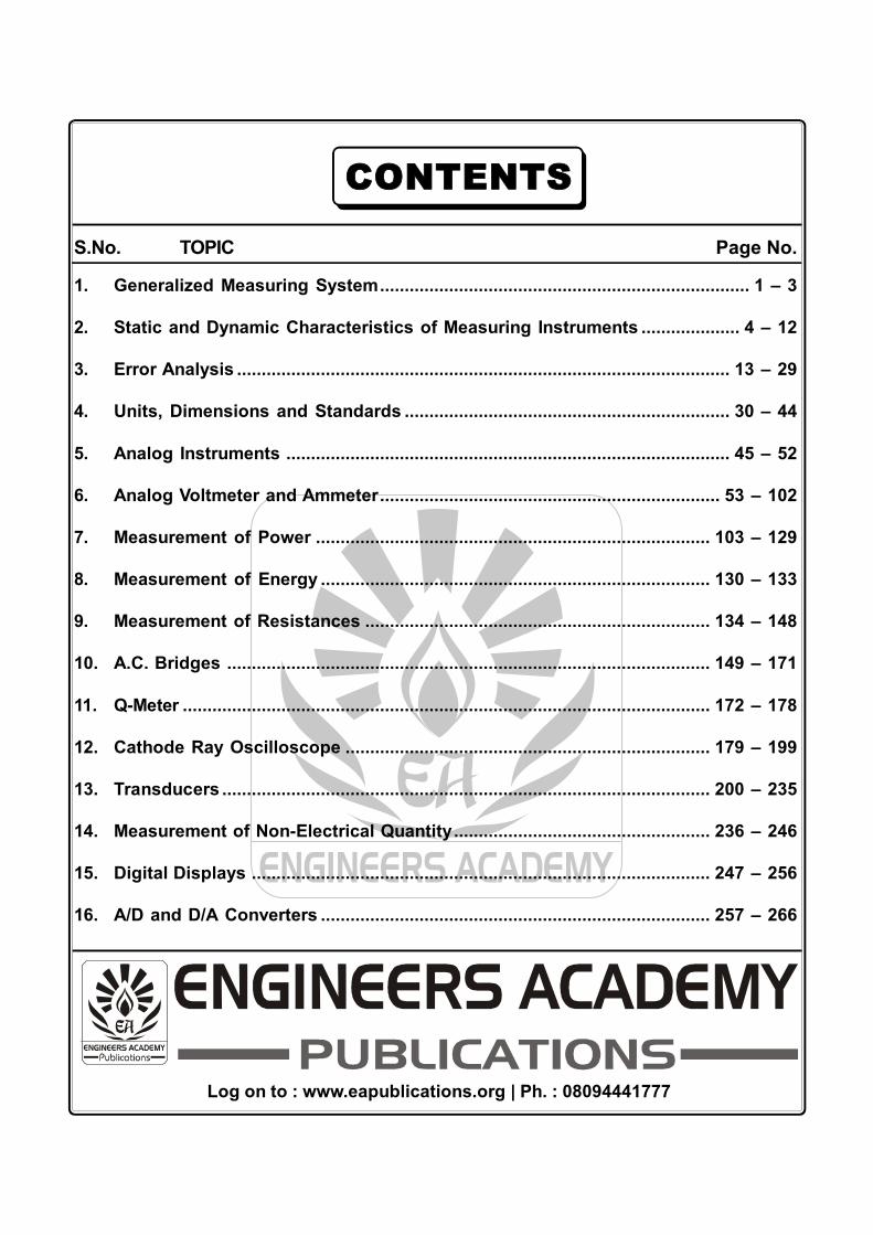
CONTENTS
S.No. TOPIC Page No.
1. Generalized Measuring System........................................................................... 1 – 3
2. Static and Dynamic Characteristics of Measuring Instruments .................... 4 – 12
3. Error Analysis .................................................................................................... 13 – 29
4. Units, Dimensions and Standards .................................................................. 30 – 44
5. Analog Instruments .......................................................................................... 45 – 52
6. Analog Voltmeter and Ammeter..................................................................... 53 – 102
7. Measurement of Power ................................................................................ 103 – 129
8. Measurement of Energy ............................................................................... 130 – 133
9. Measurement of Resistances ...................................................................... 134 – 148
10. A.C. Bridges .................................................................................................. 149 – 171
11. Q-Meter ........................................................................................................... 172 – 178
12. Cathode Ray Oscilloscope .......................................................................... 179 – 199
13. Transducers ................................................................................................... 200 – 235
14. Measurement of Non-Electrical Quantity.................................................... 236 – 246
15. Digital Displays ............................................................................................. 247 – 256
16. A/D and D/A Converters ............................................................................... 257 – 266
Log on to : www.eapublications.org | Ph. : 08094441777

DELHI (+91-7239992777)
KANPUR(+91-7239992111)
AJMER(+91-7737278888)
BHILWARA(+91-9351770644)
JALANDHAR (+91-7589441777)
JAIPUR(+91-8094441999)
JODHPUR(+91-9928665551)
LPU CAMPUS(+91-9465220033)
LUDHIANA(+91-9888928477)
LUCKNOW(+91-7080555455)
PATNA(+91-8434441777)
SIKAR(+91-8094401333)
KOTA(+91-8290256342)
ESE : TOPPER
Ph.: 0141-6540911
Ph.: 0141-6540910
# 100-102 Ram Nagar, Bambala Puliya,Pratap Nagar, Tonk Road Jaipur-33Ph.: 0141-6540911, +91-8094441777
Email: [email protected]: www.engineersacademy.org
1
ENGINEERS ACADEMYGeneralized Measuring SystemsMeasurement
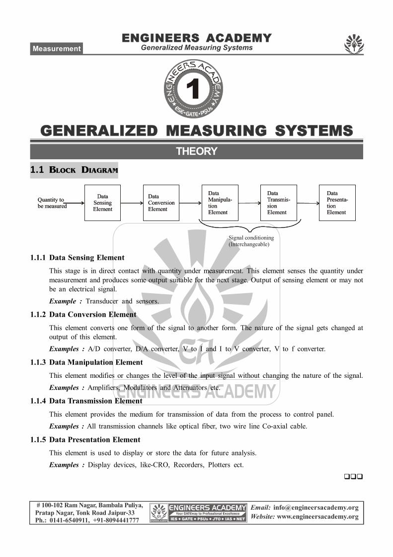
1.1 BLOCK DIAGRAM
DataSensingElement
DataConversionElement
DataManipula-tionElement
DataTransmis-sionElement
DataPresenta-tionElement
Quantity tobe measured
Signal conditioning(Interchangeable)
DataSensingElement
DataConversionElement
DataManipula-tionElement
DataTransmis-sionElement
DataPresenta-tionElement
Quantity tobe measured
1.1.1 Data Sensing ElementThis stage is in direct contact with quantity under measurement. This element senses the quantity undermeasurement and produces some output suitable for the next stage. Output of sensing element or may notbe an electrical signal.
Example : Transducer and sensors.
1.1.2 Data Conversion ElementThis element converts one form of the signal to another form. The nature of the signal gets changed atoutput of this element.Examples : A/D converter, D/A converter, V to I and I to V converter, V to f converter.
1.1.3 Data Manipulation ElementThis element modifies or changes the level of the input signal without changing the nature of the signal.
Examples : Amplifiers, Modulators and Attenuators etc.
1.1.4 Data Transmission ElementThis element provides the medium for transmission of data from the process to control panel.Examples : All transmission channels like optical fiber, two wire line Co-axial cable.
1.1.5 Data Presentation ElementThis element is used to display or store the data for future analysis.Examples : Display devices, like-CRO, Recorders, Plotters ect.
GENERALIZED MEASURING SYSTEMSTHEORY
# 100-102 Ram Nagar, Bambala Puliya,Pratap Nagar, Tonk Road Jaipur-33Ph.: 0141-6540911, +91-8094441777
Email: [email protected]: www.engineersacademy.org
2
ENGINEERS ACADEMYGeneralized Measuring Systems ECE, EE, IN, EEE
1. Some of the functional building blocks of ameasurement system are:Primary sensing element (PSE)Variable conversion element (VCE), or transducerData transmission element (DTE)Variable Manipulation element (VME)Data presentation element (DPE)The correct sequential connection of the functionalbuilding blocks for an electronic pressure gaugewill be(a) PSE, VME, VCE, DPE, DTE(b) PSE, VCE, VME, DTE, DPE(c) DTE, DPE, VCE, PSE, VME(d) PSE, VED, DTE, DPE, VME
2. Which of the following are data representationelements in a generalized measurement system?1. Analog indicator2. Amplifier3. A/D converter4. Digital displaySelect the correct answer using the codes givenbelow:(a) 1 and 2 (b) 1 and 4(c) 2 and 4 (d) 3 and 4
OBJECTIVE QUESTIONS

# 100-102 Ram Nagar, Bambala Puliya,Pratap Nagar, Tonk Road Jaipur-33Ph.: 0141-6540911, +91-8094441777
Email: [email protected]: www.engineersacademy.org
3
ENGINEERS ACADEMYGeneralized Measuring SystemsMeasurement
1. Ans.(b)The correct sequential connection of the functionalbuilding blocks for an electronic pressure gaugewill be:PSE, VCE, VME, DTE, DPE
2. Ans.(b)Data representation elements in a generalizedmeasurement system are1. Analog indicators2. Digital displays3. Magnetic tapes4. High speed camera
ANSWERS AND EXPLANATIONS
4
ENGINEERS ACADEMYStatic & Dynamic Characteristics of Measuring Instruments ECE, EE, IN, EEE
# 100-102 Ram Nagar, Bambala Puliya,Pratap Nagar, Tonk Road Jaipur-33Ph.: 0141-6540911, +91-8094441777
Email: [email protected]: www.engineersacademy.org
2.1 STATIC CHARACTERISTICS
2.1.1 AccuracyIt is the degree of closeness with which measured value approaches true value of quantity undermeasurement. Accuracy is a conformity to truth.
2.1.2 PrecisionIt is the reproducibility of the same result again and again. It is the measure of consistency in the results.Precision is measured with an index called precision index (h). The precision index describes the spreador dispersion of repeated result about a central value.
Note : Displays with higher significant figure have higher precision.Example(a) 105(b) 105.0
(c) 0.00105 × 10⁵
(a) and (c) - have three significant figure.(b) - has four significant figure
So (b) has higher precision.Note(a) Accuracy of an instrument can be improved by re-calibrating the instrument but precision can not
be improved because it is design time characteristic of the instrument.
(b) Precision is prerequisite of accuracy, A highly precised instrument may not be accurate but for highaccuracy instrument must be precised.
2.1.3 SensitivityIt is defined as the change in output of the instrument per unit change in input.
S =o
i
where, q0 is output of instrument and qi is input quantity under measurement.
STATIC & DYNAMIC CHARACTERISTICSOF MEASURING INSTRUEMENTS
THEORY
5
ENGINEERS ACADEMYStatic & Dynamic Characteristics of Measuring InstrumentsMeasurement
# 100-102 Ram Nagar, Bambala Puliya,Pratap Nagar, Tonk Road Jaipur-33Ph.: 0141-6540911, +91-8094441777
Email: [email protected]: www.engineersacademy.org
2.1.4 ResolutionIt is the smallest change in input quantity which can be measured with an instrument. Resolution is alsoknown as discrimination.
1012
14
Note : Resolution of an instrument can be improved by re-calibrating the scale but sensitivity cannot beimproved because it is design-time characteristics.
2.1.5 Dead Zone
It is the range of input of an instrument for which output is zero.
Threshold : The last critical value of input within the dead zone for which output becomes non-zero iscalled threshold. It is the minimum input required to be applied to get the measurable output.
Difference between Resolution and Threshold : Resolution is the minimum change in input which canbe measured where as threshold is the minimum input required to get measurable output.
2.1.6 Reproducibility
It is the degree of closeness with which a given value is repeatedly measured over a specified period oftime. The perfect reproducibility means that the instruments has zero drift from the true value.
Repeatability : It is the degree of closeness with which a reading is repeated again and again in the givenset of reading. Repeatability is the variation in scale reading and is random in nature.
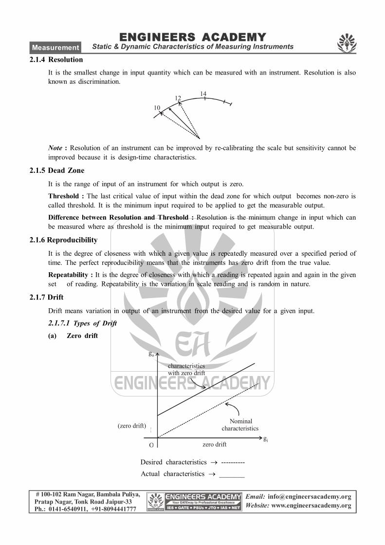
2.1.7 Drift
Drift means variation in output of an instrument from the desired value for a given input.
2.1.7.1 Types of Drift
(a) Zero drift
Nominalcharacteristics
characteristicswith zero drift
(zero drift)
zero drift
go
giO
Desired characteristics ----------Actual characteristics _______
6
ENGINEERS ACADEMYStatic & Dynamic Characteristics of Measuring Instruments ECE, EE, IN, EEE
# 100-102 Ram Nagar, Bambala Puliya,Pratap Nagar, Tonk Road Jaipur-33Ph.: 0141-6540911, +91-8094441777
Email: [email protected]: www.engineersacademy.org
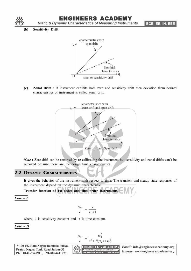
(b) Sensitivity Drift
characteristics with span drift
Nominal characteristics
qo
qispan or sensitivity driftO
(c) Zonal Drift : If instrument exhibits both zero and sensitivity drift then deviation from desiredcharacteristics of instrument is called zonal drift.
characteristics withzero drift and span drift
Nominalcharacteristics
qo
qi
Zero drift and Span drift
Note : Zero drift can be removed by re-calibrating the instrument but sensitivity and zonal drifts can’t beremoved because these are the design time characteristics.
2.2 DYNAMIC CHARACTERISTICS
It gives the behavior of the instrument with respect to time. The transient and steady state responses ofthe instrument depend on the dynamic characteristic.Transfer function of 1st order and Ilnd order instruments.
Case - I
o
i
qq =
ks 1
where, k is sensitivity constant and is time constant.
Case - II
o
i
qq =
2n
2 2n ns 2 s
7
ENGINEERS ACADEMYStatic & Dynamic Characteristics of Measuring InstrumentsMeasurement
# 100-102 Ram Nagar, Bambala Puliya,Pratap Nagar, Tonk Road Jaipur-33Ph.: 0141-6540911, +91-8094441777
Email: [email protected]: www.engineersacademy.org
where, is damping ratio and n is natural undamped frequency.Time constant of underdamped response of instrument,
Note : The dynamic response of indicating type instruments (e.g. Galvanometer) is always under dampedwith damping ratio from 0.7 to 0.8.
Time delay or time lag in case-I order instrument is given by :
Td =1tan
where, is time constant and is frequency.
8
ENGINEERS ACADEMYStatic & Dynamic Characteristics of Measuring Instruments ECE, EE, IN, EEE
# 100-102 Ram Nagar, Bambala Puliya,Pratap Nagar, Tonk Road Jaipur-33Ph.: 0141-6540911, +91-8094441777
Email: [email protected]: www.engineersacademy.org
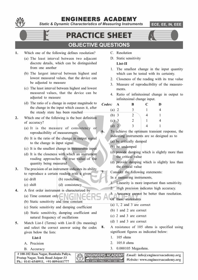
1. Which one of the following defines resolution?(a) The least interval between two adjacent
discrete details, which can be distinguishedfrom one another
(b) The largest interval between highest andlowest measured values, that the device canbe adjusted to measure
(c) The least interval between highest and lowestmeasured values, that the device can beadjusted to measure
(d) The ratio of a change in output magnitude tothe change in the input which causes it, afterthe steady state has been reached
2. Which one of the following is the best definitionof accuracy?(a) It is the measure of consistency or
reproducibility of measurements(b) It is the ratio of the change in output signal
to the change in input signal(c) It is the smallest change in measurable input(d) It is the closeness with which an instrument
reading approaches the true value of thequantity being measured
3. The precision of an instrument indicates its abilityto reproduce a certain reading with a given(a) drift (b) resolution(c) shift (d) consistency
4. A first order instrument is characterized by(a) Time constant only(b) Static sensitivity and time constant(c) Static sensitivity and damping coefficient(d) Static sensitivity, damping coefficient and
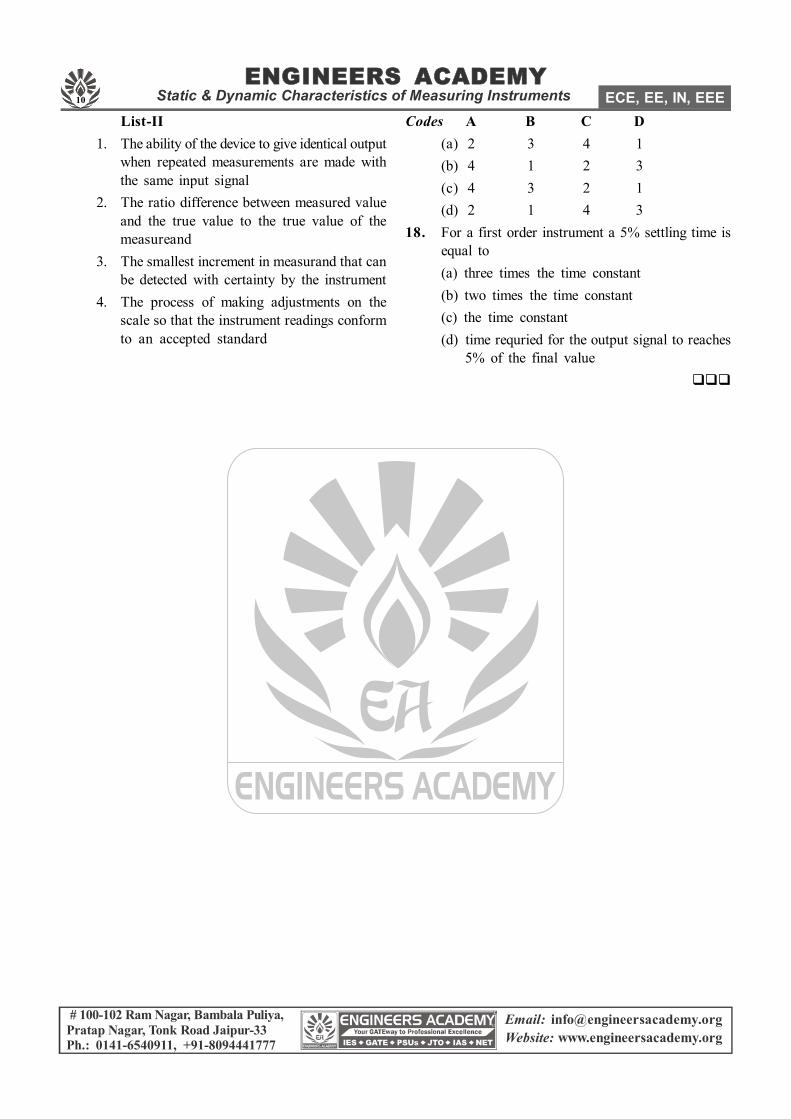
natural frequency of oscillations5. Match List-I (Terms) with List-II (Its meaning)
and select the correct answer using the codesgiven below the lists:
List-IA. PrecisionB. Accuracy
C. ResolutionD. Static sensitivity
List-II1. The smallest change in the input quantity
which can be tested with its certainty.2. Closeness of the reading with its true value3. Measure of reproducibility of the measure-
ments.4. Ratio of infinitesimal change in output to
infinitesimal change input.Codes: A B C D
(a) 2 3 1 4(b) 3 2 4 1(c) 3 2 1 4(d) 2 3 4 1
6. To achieve the optimum transient response, theindicating instruments are so designed as to(a) be critically damped(b) be undamped(c) provide damping which is slightly more than
the critical value(d) provide damping which is slightly less than
the critical value7. Consider the following statements:
In a measuring instruments,1. Linearity is more important than sensitivity.2. High precision indicates high accuracy.3. Accuracy cannot be better than resolution.Of these statements(a) 1, 2 and 3 are correct(b) 1 and 2 are correct(c) 2 and 3 are correct(d) 1 and 3 are correct
8. A resistance of 105 ohms is specified usingsignificant figures as indicated below:1. 105 ohms2. 105.0 ohms3. 0.000105 Megaohms.
OBJECTIVE QUESTIONS
9
ENGINEERS ACADEMYStatic & Dynamic Characteristics of Measuring InstrumentsMeasurement
# 100-102 Ram Nagar, Bambala Puliya,Pratap Nagar, Tonk Road Jaipur-33Ph.: 0141-6540911, +91-8094441777
Email: [email protected]: www.engineersacademy.org
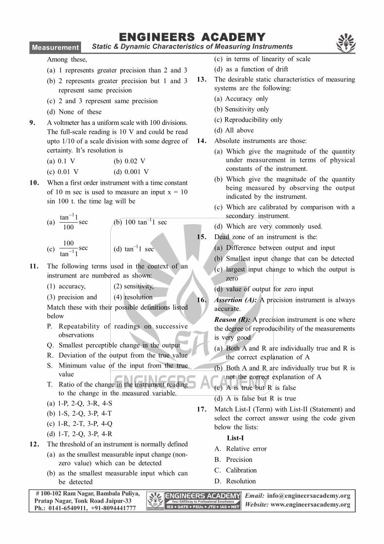
Among these,(a) 1 represents greater precision than 2 and 3(b) 2 represents greater precision but 1 and 3
represent same precision(c) 2 and 3 represent same precision(d) None of these
9. A voltmeter has a uniform scale with 100 divisions.The full-scale reading is 10 V and could be readupto 1/10 of a scale division with some degree ofcertainty. It’s resolution is(a) 0.1 V (b) 0.02 V(c) 0.01 V (d) 0.001 V
10. When a first order instrument with a time constantof 10 m sec is used to measure an input x = 10sin 100 t. the time lag will be
(a) 1tan 1sec
100
(b) 100 tan–11 sec
(c) 1100 sec
tan 1 (d) tan–11 sec
11. The following terms used in the context of aninstrument are numbered as shown:(1) accuracy, (2) sensitivity,(3) precision and (4) resolutionMatch these with their possible definitions listedbelowP. Repeatability of readings on successive
observationsQ. Smallest perceptible change in the outputR. Deviation of the output from the true valueS. Minimum value of the input from the true
valueT. Ratio of the change in the instrument reading
to the change in the measured variable.(a) 1-P, 2-Q, 3-R, 4-S(b) 1-S, 2-Q, 3-P, 4-T(c) 1-R, 2-T, 3-P, 4-Q(d) 1-T, 2-Q, 3-P, 4-R
12. The threshold of an instrument is normally defined(a) as the smallest measurable input change (non-
zero value) which can be detected(b) as the smallest measurable input which can
be detected
(c) in terms of linearity of scale(d) as a function of drift
13. The desirable static characteristics of measuringsystems are the following:(a) Accuracy only(b) Sensitivity only(c) Reproducibility only(d) All above
14. Absolute instruments are those:(a) Which give the magnitude of the quantity
under measurement in terms of physicalconstants of the instrument.
(b) Which give the magnitude of the quantitybeing measured by observing the outputindicated by the instrument.
(c) Which are calibrated by comparison with asecondary instrument.
(d) Which are very commonly used.15. Dead zone of an instrument is the:
(a) Difference between output and input(b) Smallest input change that can be detected(c) largest input change to which the output is
zero(d) value of output for zero input
16. Assertion (A): A precision instrument is alwaysaccurate.Reason (R): A precision instrument is one wherethe degree of reproducibility of the measurementsis very good(a) Both A and R are individually true and R is
the correct explanation of A(b) Both A and R are individually true but R is
not the correct explanation of A(c) A is true but R is false(d) A is false but R is true
17. Match List-I (Term) with List-II (Statement) andselect the correct answer using the code givenbelow the lists: List-IA. Relative errorB. PrecisionC. CalibrationD. Resolution
10
ENGINEERS ACADEMYStatic & Dynamic Characteristics of Measuring Instruments ECE, EE, IN, EEE
# 100-102 Ram Nagar, Bambala Puliya,Pratap Nagar, Tonk Road Jaipur-33Ph.: 0141-6540911, +91-8094441777
Email: [email protected]: www.engineersacademy.org
List-II1. The ability of the device to give identical output
when repeated measurements are made withthe same input signal
2. The ratio difference between measured valueand the true value to the true value of themeasureand
3. The smallest increment in measurand that canbe detected with certainty by the instrument
4. The process of making adjustments on thescale so that the instrument readings conformto an accepted standard
Codes A B C D(a) 2 3 4 1(b) 4 1 2 3(c) 4 3 2 1(d) 2 1 4 3
18. For a first order instrument a 5% settling time isequal to(a) three times the time constant(b) two times the time constant(c) the time constant(d) time requried for the output signal to reaches
5% of the final value
11
ENGINEERS ACADEMYStatic & Dynamic Characteristics of Measuring InstrumentsMeasurement
# 100-102 Ram Nagar, Bambala Puliya,Pratap Nagar, Tonk Road Jaipur-33Ph.: 0141-6540911, +91-8094441777
Email: [email protected]: www.engineersacademy.org
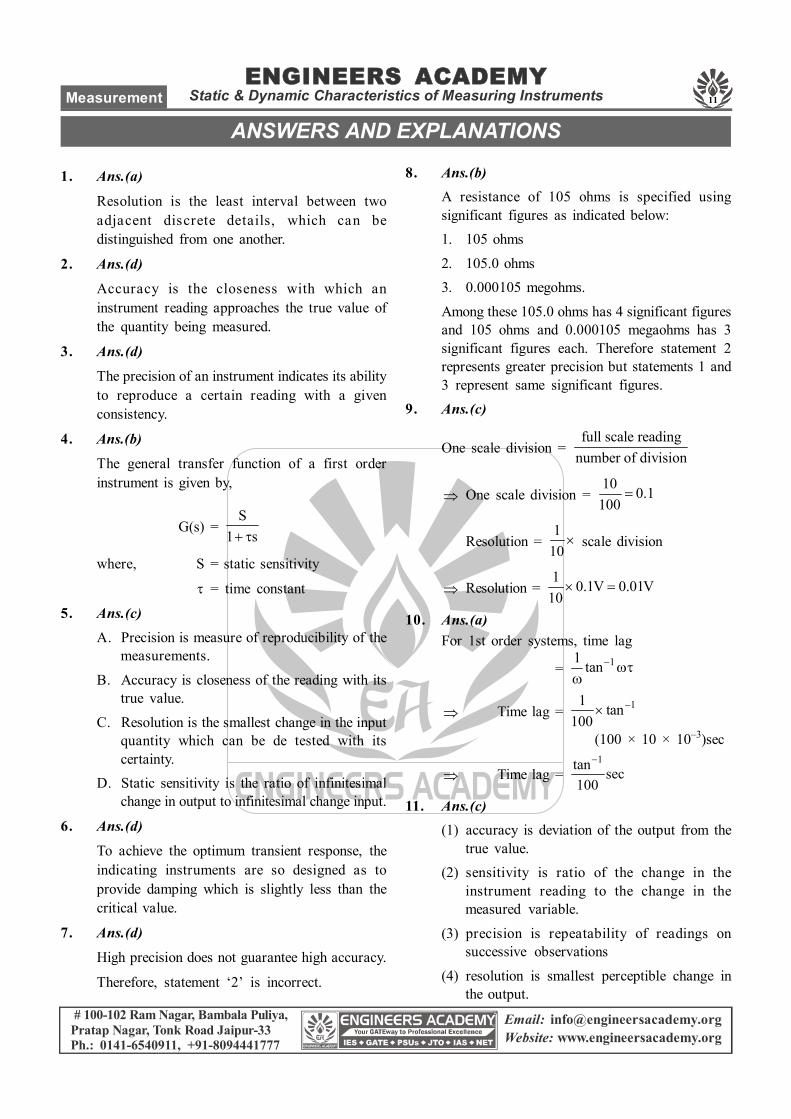
1. Ans.(a)
Resolution is the least interval between twoadjacent discrete details, which can bedistinguished from one another.
2. Ans.(d)
Accuracy is the closeness with which aninstrument reading approaches the true value ofthe quantity being measured.
3. Ans.(d)
The precision of an instrument indicates its abilityto reproduce a certain reading with a givenconsistency.
4. Ans.(b)
The general transfer function of a first orderinstrument is given by,
G(s) = S
1 s
where, S = static sensitivity
= time constant
5. Ans.(c)A. Precision is measure of reproducibility of the
measurements.
B. Accuracy is closeness of the reading with itstrue value.
C. Resolution is the smallest change in the inputquantity which can be de tested with itscertainty.
D. Static sensitivity is the ratio of infinitesimalchange in output to infinitesimal change input.
6. Ans.(d)
To achieve the optimum transient response, theindicating instruments are so designed as toprovide damping which is slightly less than thecritical value.
7. Ans.(d)
High precision does not guarantee high accuracy.
Therefore, statement ‘2’ is incorrect.
8. Ans.(b)A resistance of 105 ohms is specified usingsignificant figures as indicated below:1. 105 ohms
2. 105.0 ohms3. 0.000105 megohms.
Among these 105.0 ohms has 4 significant figuresand 105 ohms and 0.000105 megaohms has 3significant figures each. Therefore statement 2represents greater precision but statements 1 and3 represent same significant figures.
9. Ans.(c)
One scale division = full scale reading
number of division
One scale division = 10 0.1
100
Resolution = 1
10 scale division
Resolution = 1 0.1V 0.01V
10
10. Ans.(a)For 1st order systems, time lag
= 11 tan
Time lag = 11 tan100
(100 × 10 × 10–3)sec
Time lag = 1tan sec
100
11. Ans.(c)(1) accuracy is deviation of the output from the
true value.(2) sensitivity is ratio of the change in the
instrument reading to the change in themeasured variable.
(3) precision is repeatability of readings onsuccessive observations
(4) resolution is smallest perceptible change inthe output.
ANSWERS AND EXPLANATIONS
12
ENGINEERS ACADEMYStatic & Dynamic Characteristics of Measuring Instruments ECE, EE, IN, EEE
# 100-102 Ram Nagar, Bambala Puliya,Pratap Nagar, Tonk Road Jaipur-33Ph.: 0141-6540911, +91-8094441777
Email: [email protected]: www.engineersacademy.org
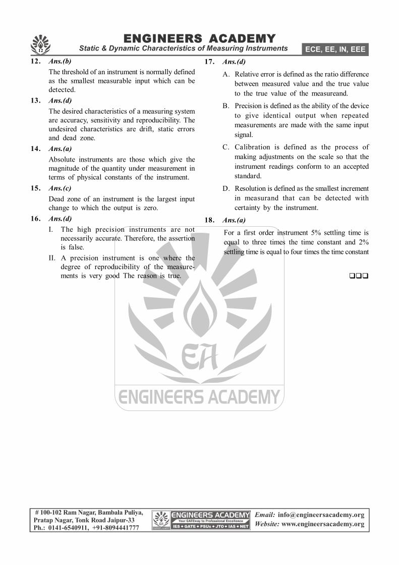
12. Ans.(b)The threshold of an instrument is normally definedas the smallest measurable input which can bedetected.
13. Ans.(d)The desired characteristics of a measuring systemare accuracy, sensitivity and reproducibility. Theundesired characteristics are drift, static errorsand dead zone.
14. Ans.(a)Absolute instruments are those which give themagnitude of the quantity under measurement interms of physical constants of the instrument.
15. Ans.(c)Dead zone of an instrument is the largest inputchange to which the output is zero.
16. Ans.(d)I. The high precision instruments are not
necessarily accurate. Therefore, the assertionis false.
II. A precision instrument is one where thedegree of reproducibility of the measure-ments is very good The reason is true.
17. Ans.(d)
A. Relative error is defined as the ratio differencebetween measured value and the true valueto the true value of the measureand.
B. Precision is defined as the ability of the deviceto give identical output when repeatedmeasurements are made with the same inputsignal.
C. Calibration is defined as the process ofmaking adjustments on the scale so that theinstrument readings conform to an acceptedstandard.
D. Resolution is defined as the smallest incrementin measurand that can be detected withcertainty by the instrument.
18. Ans.(a)
For a first order instrument 5% settling time isequal to three times the time constant and 2%settling time is equal to four times the time constant
13
ENGINEERS ACADEMYError AnalysisMeasurement
# 100-102 Ram Nagar, Bambala Puliya,Pratap Nagar, Tonk Road Jaipur-33Ph.: 0141-6540911, +91-8094441777
Email: [email protected]: www.engineersacademy.org
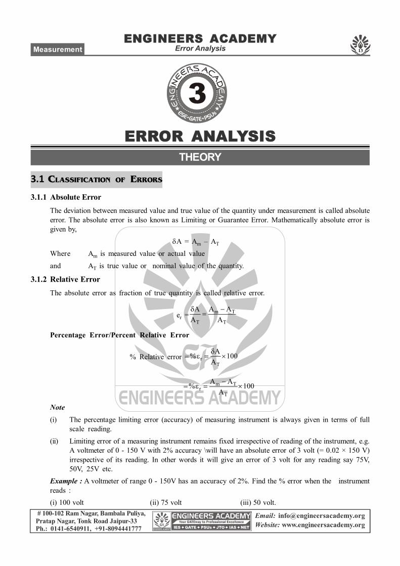
3.1 CLASSIFICATION OF ERRORS
3.1.1 Absolute ErrorThe deviation between measured value and true value of the quantity under measurement is called absoluteerror. The absolute error is also known as Limiting or Guarantee Error. Mathematically absolute error isgiven by,
A = Am – AT
Where Am is measured value or actual value
and AT is true value or nominal value of the quantity.
3.1.2 Relative ErrorThe absolute error as fraction of true quantity is called relative error.
er = m T
T T
A AAA A
Percentage Error/Percent Relative Error
% Relative error = rT
A% 100A
= m Tr
T
A A% 100A
Note(i) The percentage limiting error (accuracy) of measuring instrument is always given in terms of full
scale reading.
(ii) Limiting error of a measuring instrument remains fixed irrespective of reading of the instrument, e.g.A voltmeter of 0 - 150 V with 2% accuracy \will have an absolute error of 3 volt (= 0.02 × 150 V)irrespective of its reading. In other words it will give an error of 3 volt for any reading say 75V,50V, 25V etc.
Example : A voltmeter of range 0 - 150V has an accuracy of 2%. Find the % error when the instrumentreads :(i) 100 volt (ii) 75 volt (iii) 50 volt.
ERROR ANALYSISTHEORY

14
ENGINEERS ACADEMYError Analysis ECE, EE, IN, EEE
# 100-102 Ram Nagar, Bambala Puliya,Pratap Nagar, Tonk Road Jaipur-33Ph.: 0141-6540911, +91-8094441777
Email: [email protected]: www.engineersacademy.org
Solution : Absolute error A = 0.02 × 150A = 3 volt
(i) Error at 100 volt, % error = 3 100 3%100
(ii) Error at 75 volt, % error = 3 100 4%75
(iii) Error at 50 volt, % error = 3 100 6%50
Settling Time(TS) : It is the time required to reach the output with in 2 % to 5 % tolerance band.
Ts = 4t; for 2% band= 3; for 5% band
Note : Percentage error at any reading ‘X’ of an instrument can be given by,
% error at any reading = rFullscale reading (% at fullscale)
X
Errors in reading of voltmeters of above example can be given by,
(i) % error at 100 volt, % r =150 2 3%100
(ii) % error at 75 volt, % r = 150 2 4%75
(iii) % error at 50 volt, % r = 150 2 6%50
3.1.3 Known and Unknown ErrorsKnown Errors :These error can be determined and true value of measured quantity can be determinedby adding the error to the measured value. Known error is always either positive or negative.
Unknown Errors : These errors may have positive or negative sign. Therefore, it can not be determinedexactly but these error are generally given in terms of maximum deviation from true value. For example:A resistance of 100 2 has a maximum deviation of ±2 and the resistance may lie any where inbetween 98 to 102 .
3.2 COMBINATION OF QUANTITIES WITH LIMITING ERRORS
3.2.1 Sum of QuantitiesLet X = X1 + X2 + ...........+ Xn
X = 1 2 n( X X ....... X )
XX
1 2 nX X X.......X X X
XX
1 1 2 2 n n
1 2 n
X X X X X X. . .... .X X X X X X
15
ENGINEERS ACADEMYError AnalysisMeasurement
# 100-102 Ram Nagar, Bambala Puliya,Pratap Nagar, Tonk Road Jaipur-33Ph.: 0141-6540911, +91-8094441777
Email: [email protected]: www.engineersacademy.org
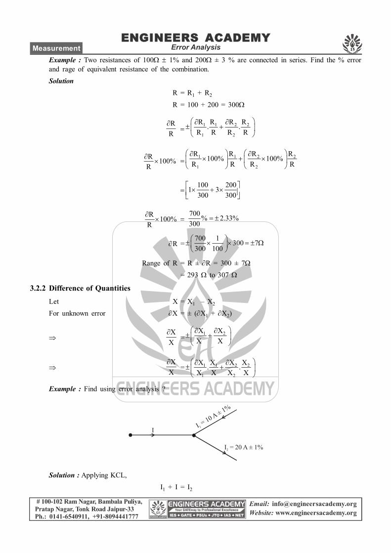
Example : Two resistances of 100 1% and 200 ± 3 % are connected in series. Find the % errorand rage of equivalent resistance of the combination.Solution
R = R1 + R2
R = 100 + 200 = 300
RR
1 1 2 2
1 2
R R R R. .R R R R
R 100%R
1 1 2 2
1 2
R R R R100% 100%R R R R
100 2001 3300 300
R 100%R
700 % 2.33%300
R =700 1 300 7300 100
Range of R = R ± R = 300 ± 7= 293 to 307
3.2.2 Difference of QuantitiesLet X = X1 – X2
For unknown error X = ± (X1 + X2)
XX
=1 2X X
X X
XX
= 1 1 2 2
1 2
X X X X. .X X X X
Example : Find using error analysis ?
I = 10 A ± 1%
1I
I = 20 A ± 1%2
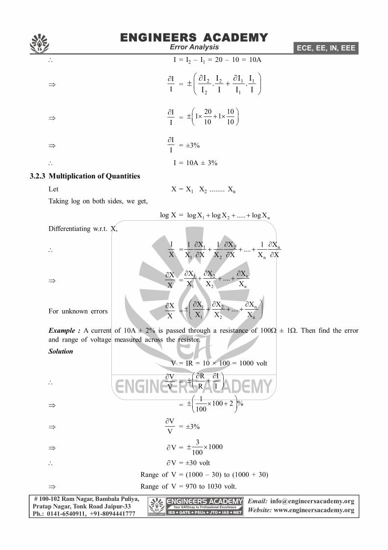
Solution : Applying KCL,I1 + I = I2
16
ENGINEERS ACADEMYError Analysis ECE, EE, IN, EEE
# 100-102 Ram Nagar, Bambala Puliya,Pratap Nagar, Tonk Road Jaipur-33Ph.: 0141-6540911, +91-8094441777
Email: [email protected]: www.engineersacademy.org
I = I2 – I1 = 20 – 10 = 10A
II
= 2 2 1 1
2 1
I I I I. .I I I I
II
= 20 101 110 10
II
= ±3%
I = 10A ± 3%
3.2.3 Multiplication of QuantitiesLet X = X1 X2 ........ Xn
Taking log on both sides, we get,
log X = 1 2 nlog X log X ..... log X
Differentiating w.r.t. X,
lX
= 1 2 n
1 2 n
X X Xl l l....X X X X X X
XX
=1 2 n
1 2 n
X X X....X X X
For unknown errorsXX
=1 2 n
1 2 n
X X X....X X X
Example : A current of 10A ± 2% is passed through a resistance of 100 ± 1. Then find the errorand range of voltage measured across the resistor.Solution
V = IR = 10 × 100 = 1000 volt
VV
= R IR I
= 1 100 2 %
100
VV
= ±3%
V = 3 1000
100
V = ±30 voltRange of V = (1000 – 30) to (1000 + 30)
Range of V = 970 to 1030 volt.