Applied mechanics for engineers
744
.11111
-
Upload
khangminh22 -
Category
Documents
-
view
0 -
download
0
Transcript of Applied mechanics for engineers

.11111


BY J. DUNCAN, Wh. Ex.
APPLIED MECHANICS FOR BEGINNERS. Globe
8vo. 35. 6d.
STEAM AND OTHER ENGINES. Globe 8vo. 6s.
MECHANICS AND HEAT. Crown 8vo. 55.
AN INTRODUCTION TO ENGINEERING DRAW-ING. Crown 8vo. 45.
BY J. DUNCAN, Wh. Ex., and
S. G. STARLING, B.Sc.
A TEXT-BOOK OF PHYSICS FOR THE USE OFSTUDENTS OF SCIENCE AND ENGINEERING.Illustrated. Extra crown 8vo, i8s. Also in Parts :
Dynamics, 6s. ; Heat, Light, and Sound, 7s. 6d. ;
Magnetism and Electricity, 55. ; Heat, 45. 6d. ; Light
and Sound, 45. 6d. ; Heat and Light, 6s.
LONDON: MACMILLAN & CO., LTD.

APPLIED MECHANICS FOR ENGINEERS

MACMILLAN AND CO,. LIMITED
LONDON BOMBAY CALCUTTA MADRASMELBOURNE
THE MACMILLAN COMPANYNEW YORK BOSTON CHICAGO
DALLAS SAN FRANCISCO
THE MACMILLAN CO. OF CANADA, LTD.
TORONTO

APPLIED MECHANICSFOR ENGINEERS
BY
J. DUNCAN, WH.EX., M.I.MECH.E.
HEAD OF THE DEPARTMENT OF ENGINEERING AT THE WEST HAM MUNICIPAL COLLEGE
AUTHOR OF 'APPLIED MECHANICS FOR BEGINNERS,' 'STEAM AND OTHER ENGINES,'
'MECHANICS AND HEAT,' ETC.
JOINT AUTHOR OF 'TEXT-BOOK OF PHYSICS*
MACMILLAN AND CO. LIMITED
ST. MARTIN'S STREET, LONDON
1926

COPYRIGHT
First Edition, 1913.
Reprinted 1920, 1922, 1926.
PRINTED IN GREAT BRITAIN

PREFACE
THE author's object in writing this book has been to provide a
practical statement of the principles of Mechanics. The arrangement
adopted is similar to that of his Applied Mechanics for Beginners.
Great pains have been taken to make the treatment adequate ; prin-
ciples have been illustrated by numerous fully worked-out examples,
and exercises for home or class work have been provided at the ends
of the chapters. The working out of typical exercises must be done
by every student of Mechanics, but the mere ability to solve examina-
tion questions is not the only service the study of Applied Mechanics
can render the Engineer. The problems met with in actual engineer-
ing practice often differ greatly from the text-book form of exercise,
and the student of Mechanics, in addition to a sound knowledge of
principles, must learn to appreciate the assumptions involved and the
consequent limitations which arise in their practical applications.
Consequently, the student must be provided with frequent oppor-tunities for performing suitable experiments under workshop condi-
tions. In the mechanical laboratory he must come into touch with
practical problems, and there learn to test and apply his knowledge of
principles, and in this work he should have the assistance of a teacher
and the criticism of fellow-students. But if the whole value of such
laboratory work is to be secured, no slip-shod working out of results
must be tolerated. In recognition of the supreme importance of the
experience gained in the laboratory, many suitable experiments have
been described, and these have been arranged on p. xi to provide a
connected course of practical work. The nature and scope of the
apparatus available in different laboratories vary greatly, and some of
the experiments included are given as suggestions only, so as to be
applicable to any form of machine or instrument.
Students using the book must have a knowledge of Algebra up to
quadratic equations, and of Trigonometry to the simple properties of
triangles. They should be acquainted also with about half-a dozen
677095

vi PREFACE
rules of the Calculus, and these are given in Chapter I. Students
able to integrate xndx, and to differentiate #", sin#, and cosx, will be
able to understand practically the whole volume.
Though no particular examination syllabus has been followed, the
book should be of service to students preparing for University degreesin Engineering, for the examinations of the Institutions of Civil
Engineers and of Mechanical Engineers, and for the higher examina-
tions of the Board of Education and the City and Guilds of London
Institute.
Exercises marked B.E. are from recent examination papers of the
Board of Education, and are reprinted by permission of the Con-
troller of H.M. Stationery Office; those marked I.C.E. are taken
from recent examination papers of the Institution of Civil Engineers,
and are reprinted by permission of the publishers, Messrs. W. Clowes
& Sons. Exercises marked L.U. are reprinted, with permission, from
recent examination papers for B.Sc. (Eng.) of London University.
It is impossible to give in a book of moderate size a complete state-
ment of all subjects of Applied Mechanics. For fuller information on
special matters the student is referred to separate treatises;the names
of some of these are noted in the text, and the author takes the
opportunity of acknowledging his own indebtedness to them, especially
to Strength of Materials> by Sir J. A. Ewing (Cambridge University
Press), and to Machine Design^ by Prof. W. C. Unwin (Longmans).Sir Richard Gregory and Mr. A. T. Simmons have read the proofs,
and to their expert knowledge of books and book production the
author owes a heavy debt of gratitude. Thanks are also due to Mr.
L. Wyld, B.Sc., Assistant Lecturer at West Ham Institute, who has
read the proofs and checked the whole of the mathematical work and
the answers to the exercises ;it is hoped that his care has had the
effect of reducing the number of errors to a minimum.
The apparatus represented in Figs. 706, 707 and 715 is made by
Mr. A. Macklow-Smith, Queen Anne's Chambers, Westminster, and
the illustrations have been reproduced from working drawings kindly
supplied by him. The illustration of a chain (Fig. 585) is inserted
by permission of Messrs. Hans Renold, Ltd. The Tables of
Logarithms and Trigonometrical Ratios are reprinted from Mr. F.
Castle's Machine Construction and Drawing (Macmillan).
J. DUNCANWEST HAM, September, 1913.

CONTENTS
PART I. MATERIALS AND STRUCTURES.
CHAPTER I.
Introductory Principles-
p. I
CHAPTER II.
Forces Acting at a Point. Parallelogram and Triangle of Forces.
Analytical and Graphical Conditions of Equilibrium for any Systemof Concurrent Forces. Polygon of Forces -
p. 19
CHAPTER III.
Parallel Forces. Principle of Moments. Resultant and Centre of
Parallel Forces. Centre of Gravity. Reactions of the Supports of
Beams. Parallel Forces not in the same Plane - -p. 40
CHAPTER iy.
Properties of Couples. Analytical and Graphical Conditions of Equi-librium of Systems of Forces in the same Plane. Link Polygon
P- 59
CHAPTER V.
Simple Structures. Force Diagrams. Effects of Dead and Wind Loads
P. 77
CHAPTER VI.
Simple Stresses and Strains. Cylindrical and Spherical Shells. Riveted
Joints. Elasticity. Stresses Produced by Change in Temperature.
^Normal, Shear and Oblique Stresses. Stress Figures -p. 93

viii CONTENTS
CHAPTER VII.
Strength of Beams. Bending Moments and Shearing Forces. Neutral
Axis. Moment of Resistance. Modulus of a Beam Section. Beamsof Uniform Strength. Distribution of Shear Stress - -
p. 131
CHAPTER VIII.
Deflection of Beams. Curvature. Slope. Standard Cases of Beams.
Encastre' Beams. Points of Contraflexure. Propped Cantilevers and
Beams. Beams of Uniform Curvature - - - -p. 163
CHAPTER IX.
Beams and Girders. Resilience. Gradual, Sudden and Impulsive Loads.
Working Loads and Stresses. Wind Pressure. Travelling Loads.
Continuous Beams. Bridge Girders. Reinforced Concrete Beams
p. 191
CHAPTER X.
Columns. Euler's, Rankine's and other Formulae for Columns. Effects
of non-Axial Loading. Arches. Suspension Bridges -p. 227
CHAPTER XL
Shafts. Pure Torque. Solid and Hollow Shafts. Torsional Rigidity.
Horse-power Transmitted. Principal Stresses. Combined Bendingand Torque. Helical Springs. Piston Rings. Coach Springs p. 251
CHAPTER XII.
Earth Pressure. Rankine's Theory. Wedge Theory. Retaining Walls
and Foundations p. 279
CHAPTER XIII.
Experimental Work on the Strength and Elastic Properties of Materials
p. 292

CONTENTS ix
PART II. MA CHINES AND HYDRA ULICS.
CHAPTER XIV.
Work. Energy. Power. Machines. Diagrams of Work. Indicated and
Brake Horse-power. Dynamometers. Torsion-meters -p. 325
CHAPTER XV.
Friction. Laws of Friction for Dry and Lubricated Surfaces. Machine
Bearings. Journals and Pivots. Inclined Planes. Screws. Friction
Circle. Friction in Engine Mechanisms - - - .
p. 353
CHAPTER XVI.
Velocity. Acceleration. Velocity and Acceleration Diagrams. Angular
Velocity and Acceleration. Change of Velocity. Motion in a Circle.
Simple Harmonic Motion. Relative Velocity- - -
p. 381
CHAPTER XVII.
Inertia. Absolute Units of Force. Kinetic Energy. Momentum. Im-
pulsive Forces. Centre of Mass. Rotational Inertia. Moments of
Inertia. Kinetic Energy of Rotation. Energy of Rolling Wheels.
Centrifugal Force - -p. 406
CHAPTER XVIII.
Angular Momentum. Gyrostatic Action. Simple Harmonic Vibrations
and Torsional Oscillations. Simple and Compound Pendulums.
Centres of Oscillation and Percussion. Equivalent Dynamical
Systems - - - - - - - - -p. 430
CHAPTER XIX.
Link Mechanisms. Instantaneous Centres. Kinematic Chains. Inertia
Effects in Mechanisms. Klein's Construction. Crank Effort and
Turning Moment Diagrams. Valve Diagrams. Miscellaneous
Mechanisms p. 455
CHAPTER XX.
Flywheels. Governors. Balancing of Rotating and ReciprocatingMasses. Whirling of Shafts - -
p. 494

CONTENTS
CHAPTER XXI.
Transmission of Motion by Belts, Ropes, Chains, and Toothed Wheels.
Epicyclic and other Trains of Wheels. Shaft Couplings p. 526
CHAPTER XXII.
Hydraulic Pressure. Centre of Pressure. Stability of Floating Bodies.
Reservoir Walls. Hydraulic Transmission of Energy. HydraulicPressure Machines. Reciprocating Pumps -
p. 564
CHAPtER XXIII.
Flow of Fluids. Bernoulli's Law. Flow through Orifices and Weirs.
Flow through Pipes. Sudden Enlargements and Contractions.
Bends and Elbows Resistance of Ships -p. 592
CHAPTER XXIV.
Pressures of Jets on Fixed and Moving Vanes. Hydraulic Turbines.
Centrifugal Pumps -p. 625
CHAPTER XXV.
Hydraulic Experiments -p. 663
TABLES
Weights and Specific Gravities - - - -p. 5
Differential Coefficients - -p. 1 1
Integrals-
p. 17
Properties of Sections -
P- 1 5 1
Coefficients for Columns -p. 235
Coefficients of Friction -p. 355
Journal Friction, Oil Bath -p. 356
Moments of Inertia - -p. 415
Useful Constants -p. 68 1
Coefficients of Expansion -p. 682
Strength, etc., of Materials -p. 683
Logarithms -p. 684
Antilogarithms p. 686
Trigonometrical Ratios p. 688
ANSWERS -
p. 689
INDEX p. 710

COURSE OF LABORATORY EXPERIMENTS
INSTRUCTIONS FOR CARRYING OUTLABORATORY WORK
General Instructions. Two Laboratory Note-books are required ;in
one rough notes of the experiments should be made, and in the other a
fair copy of them in ink should be entered.
Before commencing any experiment, make sure that you understand
what its object is, and also the construction of the apparatus and instru-
ments employed.Reasonable care should be exercised in order to avoid damage to
apparatus, and to secure fairly accurate results.
In writing up the results, enter the notes in the following order :
(1) The title of the experiment and the date on which it was
performed.
(2) Sketches and descriptions of any special apparatus or instruments
used.
(3) The object of the experiment.
(4) Dimensions, weights, etc., required for working out the results;
from these values calculate any constants required.
(5) Log of the experiment, entered in tabular form where possible,
together with any remarks necessary.
(6) Work out the results of the experiment and tabulate them where
possible.
(7) Plot any curves required.
(8) Work out any general equations required.
(9) Where possible, state any general conclusions which may be
deduced from the results, and compare the results obtained with those
which may be derived from theory. Account for any discrepancies.
Notes should not be left in the rough form for several days ; it is muchbetter to work out the results and enter them directly after the experimentshave been performed.

3rii COURSE OF LABORATORY EXPERIMENTS
STATICS.
1. Parallelogram of Forces - -----p. 22
2. Forces acting on a Pendulum - - - -p. 29
3. Forces in a Simple Roof Truss -p. 30
4. Forces in a Derrick Crane - - - - - - -P- 33
5. Forces in a Wall Crane p. 34
6. Principle of Moments - ------p. 55
7. Reactions of a Beam - - - - - - -P- 55
8. Centres of Gravity of Sheets p. 56
9. Centre of Gravity of a Solid Body - - -p. 56
10. Equilibrium of Two Equal Opposing Couples-
p. 71
11. Couples acting on a Door -P- 7 1
12. Link Polygon p. 7 1
13. Hanging Cord -p. 72
14. Hanging Chain -p. 73
STRENGTH AND ELASTICITY OF MATERIALS.
15. Elastic Stretching of Wires -p. 292
1 6. Tensile Tests to Rupture on Wires p. 294
17. Torsion Tests on Wires -p. 295
1 8. Extensions of Helical Springs-
p. 296
19. C by Maxwell's Needle -p. 297
20. E by Torsional Oscillations of a Spring-
p. 298
21. C by Longitudinal Vibrations of a Spring p. 298
22. E by Bending a Beam - -p- 3
23. E by Bending a Cantilever and a Beam fixed at Both Ends p. 301
24. Slope of a Cantilever p. 301
Experiments Nos. 25 to 32 require the use of special testing machines
and are included as suggestions. The instructions given in Chap.
XIII. may require modification, depending on the scope and type
of apparatus available.
25. E for Various Materials, by use of an Extensometer - -p. 309
26. Yield Stress and Ultimate Tensile Strength p. 311
27. Bending Tests- - - -
p. 312
28. Shearing Tests P- 3*5
COURSE OF LABORATORY EXPERIMENTS xiii
29. Punching Tests - -p. 316
30. Torsion Tests to Rupture - - -p. 317
31. Elastic Torsion Tests -p. 319
32. Cement, Brick and Stone Tests - -p. 320
FRICTION AND EFFICIENCY IN MACHINES.
33. Efficiency of a Lifting Crab - -p. 329
34- Pulley Blocks -
p. 332
35. Weston's Differential Blocks p. 333
36. a Wheel and Differential Axle -p. 333
37. ,, a set of Helical Blocks -p. 333
38. Friction of a Slider - -p. 375
39. Angle of Sliding Friction - -p. 375
40. Rolling Friction - -p. 375
41. Effect on Friction of Speed of Rubbing -p. 376
42. Friction of a Screw -p. 377
MOTION, ENERGY, ETC.
43. Verification of Law, F =ma - -p. 446
44. Moment of Inertia of a Flywheel - -p. 447
45. Centres of Oscillation and Percussion - -p. 449
46. Centre of Percussion of a Bar - -p. 449
47. Radius of Gyration about an Axis passing through the MassCentre -
p. 449
48. Wheel rolling down an Incline -p. 450
49. Balancing of Rotating Masses -p. 513
HYDRAULICS.
50. Flow through Orifices - -'
p. 665
51. Coefficient of Velocity for a Round Orifice p. 665
52. Flow over Gauge Notches - -p. 666
53. Bernoulli's Law - -p. 667
54. Venturi Meter -p. 668
55. Critical Velocity in a Pipe p. 669

xiv COURSE OF LABORATORY EXPERIMENTS
56. Frictional Resistance in a Pipe-
p. 669
57. Loss of Head at Bends - - -p. 671
58. Loss of Head at an Elbow -p. 672
59. Sudden Enlargements and Contractions in a Pipe- -
p. 672
60. Pressure of a Jet impinging on a Plate -p. 674
61. Horse-Power and Efficiency of a PeHon Wheel - p 675

PART I.
MATERIALS AND STRUCTURES.
CHAPTER I.
INTRODUCTORY PRINCIPLES.
Definition of terms. Applied mechanics treats of those laws
of force and the effects of force upon matter which apply to works
of human art. It will suffice to define matter as anything which
occupies space. Matter exists in many different forms, and can
often be changed from one form to another, but man cannot create
it, nor can he annihilate it. Any given piece of matter, occupyinga definite space, is called a body. Force may exert push or pull
on a body ; force may change or tend to change a body's state of
rest or of motion.
Statics is that part of the subject embracing all questions in
which the forces applied to a body do not produce a disturbance
in its state of rest or motion. When we speak of a body's motion
we mean its motion relative to other bodies. Rest is merely a
relative term;no body, so far as we are aware, is actually at rest
;
but if its position is not changing in relation to other neighbouring
bodies, we say it is at rest. In the same way, when we speak of
a body's motion we mean the change of position which is beingeffected relative to neighbouring bodies. Change of the state of rest
or of motion may be secured by the application of a force or forces,
but if the forces applied are self-equilibrating, i.e. balance amongthemselves, no change of motion will occur. Kinetics includes all
problems in which change of motion occurs as a consequence of
the application of forces.
There is another division of the subject called kinematics. This
division may be defined as the geometry of motion, and has no
reference to the forces which may be required for the productionD.M. A d

MATERIALS AND STRUCTURES
of jhe; moU3n^ .Problems -arise in kinematics such as the curves
described by moving points in a mechanism, and the velocities of
these points at any instant.
Measurement of matter. Matter is measured by the mass, or
quantity of matter, it contains. The standard unit of mass for this
country is the pound mass, which may be denned as the quantity of
matter contained in a certain piece of platinum preserved in the
Exchequer Office. A gallon of water at 62F. has a mass of 10
pounds. In cases where a larger unit is desirable, the ton, contain-
ing 2240 pounds, or the hundredweight, containing 112 pounds,
may be used. Generally speaking, it is best to state results in tons
and decimals of a ton, or in pounds and decimals of a pound.In countries using the metric system, the unit of mass employed
is the gram. This may be defined as the quantity of matter con-
tained in a cubic centimetre of pure water at the temperature of
4C. Where a larger unit is required, the kilogram may be used,
being a mass of 1000 grams.The term density refers to the mass of unit volume of a substance.
Thus, in the British system, the density of water is about 62-5, there
being 62-5 pounds mass in one cubic foot of water. The density of
cast iron in the same system is about 450 pounds per cubic foot.
The density of water in the metric system is i, and of cast iron 7-2,
these numbers giving the mass in grams in one cubic centimetre
of water and cast iron respectively.
Measurement of force. Forces may be measured by com-
parison with the weight of the unit of mass. Thus, the weight of
the one pound mass, or that of the gram, may be taken as units of
force, and as these depend on gravitational effort they are referred
to as gravitational units of force. The attraction exerted by the
earth in producing the effect known as the weight of a body varies
in different latitudes, hence gravitational units of force have the
disadvantage of possessing variable magnitudes. The variation can
be disregarded in many engineering calculations, as it affects the
result to a very small extent only. Other practical gravitational units
of force are the weight of one ton (2240 Ib.) and the weight of
a kilogram (1000 grams or 2-2 Ib. nearly).
An absolute unit of force does not vary, as it is defined in relation
to the invariable units of mass, length and time belonging to the
system. In the British system, the absolute unit of force is called
the poundai, and has such a magnitude that, if it acts on one poundmass, assumed to be perfectly free to move, for one second, it will

INTRODUCTORY PRINCIPLES
produce a velocity of one foot per second. The metric absolute
unit of force is the dyne, and will produce a velocity of one centi-
metre per second if it acts for one second on a gram mass which
is perfectly free to move. The poundal is equal roughly to the
weight of half-an-ounce, or, accurately, it is equal to - Ib. weight,o
g being the rate at which a body falling freely increases its speed.
For all parts of Britain g may be taken as 32-2 in feet and second
units, or 981 in centimetre and second units. On this basis, the
dyne will be - gram weight, or 981 dynes equal one gram weight
nearly.*
Newton's laws of motion. In connection with the above
definitions, it is useful to study the laws of motion laid down byNewton. These laws form the basis of all principles in mechanics,
and are three in number.
First law. Every body continues in its state of rest or of uniform
motion in a straight line except in so far as it is compelled by forces
to change that state.
Second law. Change of momentum is proportional to the applied
force, and takes place in the direction in which the force acts.
Third law. To every action there is always an equal and contrary
reaction; or, the mutual actions of any two bodies are always equal
and oppositely directed.
The first law expresses what is called the inertia of a body, i.e. that
property whereby it resists any effort made to change either the
magnitude of its velocity or the direction of its motion. In the
second law, the term momentum may be here understood to mean
quantity of motion, measured by the product of the body's mass
and velocity. The law expresses the observed facts that changein the magnitude of the velocity of a given body is proportional
to the force applied, and change in the direction of motion takes
place in the line of the force. The third law also expresses
observed facts. It is impossible to apply a single force; there
must always be an equal opposite force. One end of a string
cannot be pulled unless an equal opposite pull be applied to the
other end. If the body used be free to move and an effort be
applied, the velocity will change continuously and the inertia of
the body provides the resistance equal and opposite to the force
applied.
Experimental measurement of mass and force. Masses maybe compared by means of a common balance (Fig. i). In this

MATERIALS AND STRUCTURES
FIG. i. Common balance.
appliance, a beam AB, pivoted at its centre, will become horizontal,
or will describe small equal angles on each side of the horizontal
when equal forces are applied at A and B. Such equal forces will
arise when bodies C and D, having equal
masses, are placed in the pans. This
follows as a consequence of the fact that
equal masses have equal weights at the
same part of the earth's surface. Further,
no matter at what part of the earth the
balance is used, it will always indicate
equal masses. It therefore follows that such a balance could not
be used to indicate the variation of a body's weight in different
places.
Spring balances (Fig. 2) may be used to measure forces byobservation of the extensions produced in a spring. As equalmasses have equal weights, such balances will indicate
the same scale reading for equal masses, but as it is the ^)weight of the body which produces the extension of
the spring, and as it is known that the extension is
proportional to the force applied, it follows that changeof weight, such as would be produced by taking the
balance to another part of the earth's surface, will be
evidenced by a different scale reading. As has been
already mentioned, such difference is very small. Spring
balances are generally calibrated in a vertical position,
as shown in Fig. 2, and will not indicate quite the same
force when the balance is used in an inclined or inverted
position. This is owing to zero on the scale beingmarked for the spring extension corresponding to the
weights of the parts of the balance suspended from the
spring, but no load on the hook or scale pan. Con-
sequently the zero will change if the balance is used
in any position other than that shown.
Specific gravity. The specific gravity of a substance is the
weight of a given volume of the substance as compared with the
weight of an equal volume of pure water. Specific gravities are
usually measured at a temperature of 60 Fahrenheit.
Let V = volume of a given body in cubic feet,
FIG. 2. Springbalance.
p = specific gravity of material,
W = weight of body in Ib.

MATHEMATICAL FORMULAE
Then
Hence
= 62-5V Ib. weight if the material is water,
= 62-5V/> Ib. weight for the given substance.
W62-5V
This expression enables the specific gravity of a given body to be
found roughly by first weighing it, then calculating its volume from
the measured dimensions.
The following table gives the weights and specific gravities of
some common substances :
WEIGHTS AND SPECIFIC GRAVITIES.
Material.

MATERIALS AND STRUCTURES
Parallelogram ;area = one side x perpendicular distance from that
side to the opposite one.
Any irregular figure bounded by straight lines; split it up into
triangles, find the area of each separately and take the sum.
Trapezoid; area = half the sum of
the end ordinates x the base.
A trapezoidal figure having equalintervals (Fig. 3) ;
area = a ( -- + h^ + hz + h \
Simpson's rule for the area bounded by a curve (Fig. 4) ; take anodd number (say 7) of equidistant ordinates ;
then
FIG. 3. Trapezoidal figure.
area = -(h^ + 4/i.2 + + h^
N G
FIG. 4. Illustration of Simpson's rule.
7
Circle, radius r, diameter d\ area = 7jv2 =-.
4
(Circumference = 2irr = ird.}
Parabola, vertex at O (Fig. 5) ; area OBC =\ib.
Cylinder, diameter d, length /; area of curvedsurface = irdl.
Sphere, diameter d, radius r\ area of curvedsurface= ?r^2 = ^-rrr
2.
Cone\ area of curved surface = circumferenceof base x
-|slant height.
Determination of volumes.
Cube, edge s\ volume =s3 .
Cylinder or prism, having its ends perpendicular g
to its axis; volume = area of one end x length of
cylinder or prism.
Sphere, radius /; volume = ^Trr3
.
B"V
BH... ..$....*<,
FIG. 5. Area of a paia-bola.
Cone or pyramid', volume = area of base x \ perpendicular height.
TRIGONOMETRY.
A degree is the angle subtended at the centre of a circle by an arc
of TrlTrth of the circumference.

MATHEMATICAL FORMULAE
A radian is the angle subtended at the centre of a circle by an arc
equal to the radius of the circle.
There are 2ir radians in a complete circle, hence
27r radians = 360 degrees.
|TT =270TT =180
|TT= 90
Let / be the length of arc subtended by an angle, and let r be the
radius of the circle, both in the same units;then angle = - radians.
Trigonometrical ratios. In Fig. 6 let OB revolve anti-clockwise
about O, and let it stop successively in positions OP1} OP2 , OP3 ,
OP4 ;the angles described by OB are said to be as follows :
P^B, in the first quadrant COB.P
2OB, in the second quadrant COA.
P3OB (greater than 180), in the third quadrant AOD.
P4OB (greater than 270), in the fourth quadrant BOD.
Drop perpendiculars such as PjM^ from each position of P on to
AB. OP is always regarded as positive ; OM is positive if on the
right and negative if on the left of O ;PM is positive if above and
negative if below AB.
Name ofratio.

8 MATERIALS AND STRUCTURES
Figs. 6 and 7 show clearly both the sign and the varying values
of these ratios, and enable the following table to be deduced :

MATHEMATICAL FORMULAE
If the angles of a triangle are A, B and C, and the sides oppositethese angles are a, b and c respectively, the following relations hold :
a = b cos C + c cos B.
a b c
sin A sinB sinC*
a2 = ft + c1 - 2bc cos A.
ALGEBRA.
Solution of simple simultaneous equations. If the given equations are
'i. (O* ()
then # = ^M ^-r->
Solution of a quadratic equation. If
ax2 + bx + c= o,
then x20,
CALCULUS.
Differential calculus. Let AB (Fig. 8) represent the relation
of two quantities x and y which are connected in some definite
T O M, Ma X
FIG. 8. Graphic illustration of a differential coefficient.
manner. Consider two points Pland P
2on AB separated by a
short distance PjP2 ; then
*2 ;
P2M
2 =j2.
The difference between the abscissae OMj and OM2will be

10 MATERIALS AND STRUCTURES
(x2-
XT), and may be written 8x, the symbol S signifying" the
difference in"
; similarly with the ordinates PjMj and P2M
2. Hence
8x = x2- x
l= MjM2
= PjK.
fy=y-2-yi = ?2K>.
The ratio of these will be
^ =^2-^l = P2K
Sx x2-x
l PjK*
The value of this ratio depends on the proximity of P! and P2
.
If these points are taken indefinitely close together, the ratio tends
to take a definite value which depends on the given relationship of
x and y. This value is called a differential coefficient, and serves
to measure the rate of growth ofy with x.
If Pj and P2 are very close together, PjP2
is practically a straight
line, and we have p T/-
|J= tanP2
P1K.
If Pj and P2are indefinitely close together, PjP2
is in the direction
of the tangent PjT drawn to touch the curve at Pl ;
in this case Sy
and Sx are written dy and dx, and the final value of the ratio is
For example, suppose a graph such as AB in Fig. 8 to have been plotted
from the equation, y=-xi. (i)
Then y+8y=(x+ Sx?= X*+ 2X,8x+ (8x)*........................... (2)
Taking the difference between (2) and (i) gives
Now (&r)2
is the square of a quantity which ultimately becomes very
small, and therefore becomes negligible. Hence we may write
~"............................................
Suppose, as another example, we take
y= ax\ ........................................(4)
when a is a constant. It will be evident, on repeating the above process,
that
thus giving the rule that any constant factor appears unaltered in
the value of the differential coefficient.

MATHEMATICAL FORMULAE
Take now the following equation :
y = x* + a (6)
The effect of the addition of a constant a to the right-hand side
of (i) is simply to raise the graph to a higher level above OX in
Fig. 8 ; its shape will be exactly as before, and hence the tangent at
any point will make the same angle with OX. Therefore the
differential coefficient will have the same value as (3), viz.
^-2Xdx~
2X (7)
It will also be clear that, if the equation is
then dy-j-
= 2ax.dx
.(8)
(9)
The rule may be expressed that a constant quantity added to the
right-hand side disappears from the differential coefficient.
The following differential coefficients are useful; the methods of
obtaining them may be studied in any book dealing with the calculus.
The symbol e represents the base of the Naperian or hyperbolic
system of logarithms, viz. 2-71828.
DIFFERENTIAL COEFFICIENTS.
yxn

12 MATERIALS AND STRUCTURES
terms each depending on x, then the differential coefficient is the sumof the differential coefficients of the terms taken separately. Thus :
y = ax* + bx1
To differentiate the product of a number of factors, each of which
depends on x, multiply the differential coefficient of each factor byall the other factors and take the sum. Thus :
dy . ,~ = zx sm x + x2 cos x.dx
To differentiate a fraction in which both numerator and denomi-
nator depend on x, proceed thus :
diff. coeff. of numerator x denominator
dy _ - diff. coeff. of denominator x numerator
dx square of denominator
EXAMPLE. Let j/=^^.sin*
The differential coefficient of the numerator is 2;r and that of the
denominator is cos .*, hence, by the above rule :
dy _ ix sin x - x2 cos xdx sin2x
Supposing we have to find the differential coefficient of
it should be noticed that the given expression, viz. the cube of sin x,
depends on another function of x. The rule to be followed is to
differentiate the expression as given, viz. (sin#)3,the result being
3 (sin #)2
; then multiply this result by the differential coefficient of
the function on which the given expression depends, viz. sin x, for
which the differential coefficient is cos x.
Hence, -r-= 3 (sin x}2 cos x
dx= 3 sin2x cos x.
In successive differentiation, the differential coefficient of the given
function is taken as a new function of x and its differential coefficient
is found; the latter is called the second differential coefficient, and is
written ^. The operation may be repeated as many times as may
be necessary.

MATHEMATICAL FORMULAE 13
EXAMPLE. Let
The maximum value of a given function of x may often be found
by application of the following simple method. It will be noted that,
in Fig. 8, at the point in AB for which y has its maximum value,
the tangent to the curve is parallel to OX, and hence -2. for this
point will be zero. The rule therefore is, take the differential
coefficient and equate to zero; this will give the value of x corre-
sponding to the maximum value of y. By inserting this value of xin the given equation connecting x andj^, the maximum value of ymay be found. Thus :
Let jj/=sin;tr,
-^-= cos.r=o for the maximum value
Now when cos^r= o, x is either 90 or 270, i.e. or *- radians, hence
Maximum value of y=sin- or sin^.2 2
As the numerical value of sin - is unity, it follows that the maximumvalue ofy is also unity.
As another example, take
y=ax-x\
then,-j-=a-2x=0',
/. x- for the maximum value ofy.
Maximum value of y= =244Integral calculus. In this branch of mathematics, rules are
formed for the addition of the indefinitely small portions into which
a quantity may be imagined to be divided. In Fig. 9, OA and OBare two distances measured along the same straight line from O.
Let these be a and b respectively, then the length of AB will be
AB = -tf ....(i)
The line AB might be measured also by the process of dividing it

MATERIALS AND STRUCTURES
up into a large number of small portions 8xl9
8x2 ,
8xs , etc. The
total length of AB will then be
AB = 8xt + 8x
2 + 8xB + etc.
= b-a, from (i) (2)
The symbol 2 orJ (sigma) is used to denote the phrase "the
algebraic sum of," and if any expression follows the symbol 2, it is
FIG. 9.
understood to be one only of a number of terms which are all of the
same type. Thus, 2&r means "the algebraic sum of all terms of
which 8x is given as a type." If we write 2*, it is to be understood
that we are to begin taking small portions, such as Sx-^, at a distance
a from the origin, and to finish at a distance b. Hence we maywrite (2\ fyx = b-a (3)
In Fig. 10 is shown another example. As before, OA a and
OB =, and the figure ABCD is constructed by making AD = a
and BC =^, both being perpen-
dicular to OB. The area of the
figure ABCD may be calculated
by deducting the area of the
triangle OAD from that of the
triangle OBC. Thus :
Area of ABCD=
(b x \b} -(ay. \d)
_&2 a2
~2. 2'
Alternatively, the area may be
estimated by cutting the figure
into strips, such as the one shown
shaded. It is evident from the
construction that its height y is
equal to x; let 8x be its breadth, then
Area of the strip= x . 8x (5)
Any similar strip will have a similar expression for its area, hence
Total area of the strips= I^x 8x (6)
OrJA |
~4 -
FIG. 10.
__L

MATHEMATICAL FORMULAE 15
The area stated in (5) is taken as that of a rectangle, and hence
omits a small triangle at the top of the strip. If, however, the strips
be taken indefinitely narrow, these triangles will practically vanish,
and the area expressed in (6) will be the area of ABCD. Hencefrom (6) and (4), p a2
fy.dx----............................ (7)
In mathematical books, it is shown that if x is raised to a power n
in equation (7), n having any value except-
i, then the result is as
follows : An+I _ an+l^>x".dx = - ...................... (8)n -f i
If n is -i, then the result may be shown to be
, ,
_!:,."."--. 2j*-'.,& = 2jf -log, ...................... (9)
If n is zero, then #= i, and we have
^b
axdx = ^b
a dx =b
-^ = b-a................... (10)
The above are examples of definite integrals, taken between given
limits a and b the sum may be stated in an indefinite manner,
leaving the limits to be inserted afterwards. Thus :
It is also shown in mathematics that a constant term c should be
added to the result. The value of c depends on the conditions of
the problem, and can be found usually from the data. The com-
plete solution of (n) would thus be-
fm ..................... (I2\
dxSimilarly, 2 =
\ogex + <:. ..................... (13)oc
If a constant factor is given on the left-hand side, it will appearunaltered on the right-hand side. Thus :
x*a \-c.
3
If a number of terms be given, the result will be obtained by
applying the rules to each term separately and then summing for
the total. Thus :

16 MATERIALS AND STRUCTURES
The rules (8), (9), (12) and (13) should be learned thoroughly.
Some examples are given.
EXAMPLE i. Find the area of the triangle given in Fig. 11.
Taking a narrow strip parallel to the base and at a distance y from O,let the breadth of the strip be 8y and
*its length b.
*^ Area of the strip= b . 8y.
KT b VNow ==; ;
FIG. ii. Area of a triangle.
.'. area of the strip=
jj .y 8y.
Any other similar strip will have a
similar expression for its area, hence
Total area=2"u
_B/H_2
_o_2 \
~H\2 2)
=BH2
EXAMPLE 2. Find the volume of a cone of height H and radius of
base R (Fig. 12).
In this case take a thin slice parallel to the base ;let the radius of the
slice be r and its thickness h . Then
Volume of the slice= 7rr2 . S/i.
Now rR~H
volume of the slice=
Any other similar slice will have a similar
expression for its volume, 'henceFIG. 12. Volume of a cone..
Total volume^
R2 H 3
No constant of integration need be added in either of these examples.
Instances where a constant is necessary will occur later.

MATHEMATICAL FORMULAE
The following table of indefinite integrals is given here for reference.
INTEGRALS.
r *+!/ r*tt //r~

1 8 MATERIALS AND STRUCTURES
coefficient for the curve at P ; compare this result with that obtained byx^ dv
differentiation ofy= 2x-- and putting x\^ in the expression for -*-.
How do you account for the discrepancy, if any ?
6. Take the equation y= (^-x)x. Find the value of x for which yattains its maximum value, and find also the maximum value ofy. Checkyour result by plotting a graph from the equation.
7. Write down the indefinite integrals of the following :
(a) ycWx. (d) (2x*+ cos x)dx.. dO
8. Find the value of the following expression when Rt= i2 inches and
R2= 6 inches. No constant of integration is required.'
9. Find the value of the following expression when 6 = 4 inches andH = 8 inches. No constant of integration is required.

V
CHAPTER II.
FORCES ACTING AT A POINT.
Representation of a force. Any force is specified completelywhen we are given the following particulars : (a) its magnitude, (b) its
point of application, (c) its line of direction, (d) its sense, i.e. to state
whether the force is pushing or pulling at the point of application.A straight line may be employed to represent a given force, for it
may be drawn of any length, and so represent to a given scale the
magnitude of the force. The end of the line shows the point of applica-
tion, the direction of the line gives the direction, and an arrow pointon the line will indicate the sense of the force. Thus a pull of 5 Ib.
acting at a point O in a body (Fig. 13) at 45 to the horizontal
would be completely represented by a line OA,of length 2 1" to a scale of J" to a Ib., and an
arrow point as shown. OA is called a vector ; any
physical quantity for which a line of direction must
be stated in order to have a complete specifica-
tion is called a vector quantity. Other quantities,
such as mass and volume, into which the idea of FJG. 13. Representa-tion of a force,
direction does not enter, are called scalar quantities.
The expression "force acting at a point" must not be taken
literally. No material is so hard that it would not be penetrated byeven a very small force applied to it at a mathematical point. Whatis meant is that the force may be imagined to be concentrated at the
point in question without thereby affecting the condition of the bodyas a whole.
Forces acting in the same straight line. A body is said to
be in equilibrium if the forces applied to it balance one another.
Thus, if two equal and opposite pulls P, P (Fig. 14) be applied at a
point O in a body, both in the same straight line, they will evidentlybalance one another, and the body will be in equilibrium.
Examples of this principle occur in ties, and in struts and columns-

20 MATERIALS AND STRUCTURES
Ties are those parts of a structure intended to be under pull (Fig. 15),
struts and columns are those parts intended to be under push (Fig. 16).
These parts remain at rest under the action of the equal and opposite
forces applied in the same straight line.
It is impossible for a single force to act alone. To every force there
must be an equal and opposite force, or what is exactly equivalent to
an equal and opposite force. The term reaction is often used to
distinguish the resistance offered by bodies to which a given body is
FIG. 14. Two equalopposite forces.
500 to.
SOOlb.
FIG. 15. Equilibriumof a tie.
500 Ib.
^50011.FIG. 16. Equilibrium
of a column.
connected when forces are applied to the latter body. An exampleof the use of the term will be found in the reactions of the piers
supporting a bridge girder. Loads applied to the girder are balanced
by the reactions of the piers.
If several forces in the same straight line act at a point, the point
will be in equilibrium if the sum of the forces of one sense is equal to
the sum of those of opposite sense. Calling those forces of one
sense positive and those of opposite sense negative, the condition
may be expressed by stating that the algebraic sum of the given
forces must be zero. Thus, the forces P15P
2 ,P
3 ,etc. (Fig. 17), will
balance, providedP
1 + Pf -Pt-P4-Pi*aor, 2P = o,
the interpretation being that the algebraic sum of all the forces of
which one only is given as a type immediately after the symbol 2
must be equal to zero.
Suppose in a given case it is found that the algebraic sum of the
given forces is not zero. We may infer from this that a single force
may be substituted for the given forces without altering the effect.
Thus, in Fig. 18, calling forces of sense from A towards B positive,
we have 2 + 3 + 5 _8-i=+i.The given forces can be replaced by a single force of i Ib. weight of
sense from A towards B. The single force which may be substituted

FORCES ACTING AT A POINT 21
for a given system of forces without altering the effect on the body is
called the Resultant of the system. To find the resultant R of the
system we have been considering above, we have
The resultant R may be balanced by applying an equal opposite
force in the same straight line, and, since R is equivalent to the given
system of forces, the same force would also balance the given system.
FIG. 17. Forces in the same straight line. FIG. 1 8.
Any force which balances a given system of forces is called the
equilibrant of the system. Thus, the equilibrant E of the systemshown in Fig. 18 is a force of i Ib. weight of sense from Btowards A.
Two intersecting forces. To find the resultant of two intersecting
forces, the following construction may be employed. Let P and Qbe two pulls applied to a nail at O (Fig. 19 (a)); their joint
tendency will be to carry the nail upwards to the right, and the
resultant must produce exactly the same tendency. Set off, in the
direction in which P acts, OA, to some suitable scale, equal to P,
(a)
FIG. 19. Resultant and equilibrant of two intersecting forces.
and OB, to the same scale, equal to Q and in the direction in which
Q acts. Complete the parallelogram OACB, and draw its diagonalOC. This diagonal will represent R completely, the magnitude beingmeasured by the length of OC to the same scale. The method is
called the parallelogram of forces. P and Q are called components
of R.
As R is equivalent in its effects to P and Q jointly, we may applyeither P and Q together, or R alone, without altering the effect on the

22 MATERIALS AND STRUCTURES
nail. This may be expressed by stating that the resultant may be
substituted for the components, or vice versa.
Substituting R for P and Q (Fig. 19 (<)), we may balance R by
applying an equilibrant E = R as shown. Again, replacing R by Pand Q (Fig. 1 9 (<r) ),
it will be evident that P, Q and E are in
equilibrium.
Experimental verification. The most satisfactory proof that the
engineering student can have of the truth of the parallelogram of
forces is experimental.
EXPT. i. Parallelogram of forces. In Fig. 20 is shown a boardattached to a wall and having three pulleys A, B and C capable of
FIG. 20. Apparatus for demonstrating the parallelogram of forces.
being clamped to any part of the edge of the board. These pulleysshould run very easily. Pin a sheet of drawing paper to the board.
Clamp the pulleys A and B in any given positions. Tie two silk
cords to a split key ring, pass a bradawl through the ring into the
board at O, and lead the cords over the pulleys at A and B. Theends of the cords should have scale pans attached, in which weights
may be placed. Thus, known forces P and Q are applied to the ringat O. Take care in noting these forces that the weight of the scale
pan is added to the weight you have placed in it. Mark carefully the
directions of P and Q on the paper, and find their resultant R bymeans of the parallelogram Qabc. Produce the line of R, and bymeans of a third cord tied to the ring apply a force E equal to R,
bringing the cord exactly into the line of R by using the pulley Cclamped to the proper position on the board. Note that the proper
weight to place in the scale pan is E less the weight of the scale pan,so that weight and scale pan together equal E. If the method of
construction is correct, the bradawl may be withdrawn without the
ring altering its position.

FORCES ACTING AT A POINT
In general it will be found that, after the bradawl is removed, the
ring may be made to take up positions some little distance from O.
This is due to the friction of the pulleys and to the stiffness of the
cords bending round the pulleys, giving forces which cannot easily
be taken into account in the above construction.
Notice that, before attempting to apply the parallelogram of forces,
both given forces must be made to act either towards or from the point of
application. Thus, given P' pushing and Q pulling at O (Fig. 21),
the tendency will be to carry O downwards to the right. Substitute
P = P', pulling at O for P'; complete the parallelogram OACB, when
OC will give the resultant R.
It will also be noticed that any one of the forces P, Q and E
(Fig. 19 (c)) will be equal and opposite to the resultant of the other
two if the three forces are in equilibrium.
Rectangular components of a force. Very frequently it becomes
useful in a given problem to deal with the components of a given
FIG. 2i. Parallelogram offerees appliedto a push and a pull.
FIG. 22. Rectangular componentsof a force.
force instead of using the force itself. These components are
generally taken along two lines at 90 intersecting on the line of the
given force. Thus, given P acting at O (Fig. 22), and two lines OAand OB at 90 intersecting at O, and in the same plane as P. The
components will be found by making OC equal to P, and completing
the parallelogram of forces OBCA, which in this case is a rectangle.
S equal to OB and T equal to OA will be the rectangular com-
ponents of P.
The following will be seen easily from the geometry of the figure :

24 MATERIALS AND STRUCTURES
Also, let the angle COA = a; then
OA^i
= COS a,
OA = OC . cos a;
/. T=P.cosa.
AC .
?^ = sin a,Again, oc= OC.sina,= P.sina.
Triangle of forces. It will now be understood that the conditions
which must be fulfilled in order that three forces whose lines inter-
sect may be in equilibrium are : (a) the forces must all be in the
same plane, i.e. uniplanar ; (b} their lines must intersect in the same
point; (c) any one of them must be equal and opposite to the
resultant of the other two forces.
Condition (c) may be stated in another manner. In Fig. 23, P and
Q have a resultant R, found by the parallelogram of forces OACB.A force E has been applied equal and
opposite to R as shown; hence the
forces E, P and Q are in equilibrium.
The following relation evidently holds :
R : Q : P = OC : OB : OA.
Note the order in which the letters
of the lines have been written ; thus,
R is represented by OC, not by CO,the order being so chosen as to show
the sense of the force. Now E is equal to R, and OA is equal to
BC ; hence we may write
E:Q:P = CO:OB:BC,OC having been altered to CO so as to give the proper sense to E.
Expressed in words, the proportion states that the three forces in
equilibrium axe proportional respectively to the sides of a triangle taken in
order. The triangle OBC in Fig. 23 may be drawn anywhere on
the paper, and is called the triangle of forces for the forces E, Q, P.
EXAMPLE i. Given three uniplanar forces P, Q, S' (Fig. 24) acting at
O ; test for their equilibrium.
Using a convenient scale of force, draw ab, be and ca' parallel and pro-
portional respectively to the forces P, Q and S'. If the given forces are in
equilibrium, the lines so drawn will form a closed triangle. In Fig. 24,
FIG. 23.

FORCES ACTING AT A POINT
it will be noticed that there is a gap aaf
. S' will therefore not equilibrate
P and Q, but may be made to do so if it is redrawn as S, parallel and
proportional to ca, the closing line of the triangle abc.
FIG. 24. Triangle offerees. FIG. 25. Triangle of forces applied to
a push and a pull.
EXAMPLE 2. Given two forces P and Q (Fig. 25) acting at O;find
their equilibrant.
It will be observed that, in applying the triangle of forces, there is no
necessity for first making both the given forces pushes or pulls, providedattention is paid to drawing the sides of the triangle in proper order.
Thus, draw ab to represent P and be to represent Q ; then ca will repre-
sent the equilibrant, which should now be drawn as E acting at O, parallel
and proportional to ca and of sense shown by the order of the letters ca.
Note carefully that the problem is not finished until E has been appliedon the drawing acting at the proper place O.
EXAMPLE 3. Three given forces are known to be in equilibrium
(Fig. 26 (a) ) ;draw the triangle offerees.
This example is given to illustrate a con-
venient method of lettering the forces called
Bow's Notation. This method will be found to
simplify many of the problems which have
to be discussed, and consists in giving letters
to the spaces instead of to the forces. In
Fig. 2,6(0) this plan has been carried out by
calling the space between the 4 Ib. and the
2 Ib. A, that between the 2 Ib. and the 3 Ib. B,
and the remaining space C. Starting, say,
in space A and crossing over into space B,
a line AB (Fig. 26()) is drawn parallel and
proportional to the force crossed, and the
letters are so placed that their order A to B represents the sense of that
force. Now cross from space B into space C, and draw BC to represent
completely the force crossed. Finish the construction by crossing from
(a)
(b)
tion of Bow'slotation.
ApplicatiNotation

26 MATERIALS AND STRUCTURES
space C into space A, when CA in Fig. 26 (b) will represent the third force
completely.
Examining these diagrams, it will be observed that a complete rotation
round the point of application has been performed in Fig. 26 (#), and that
there has been no reversal of the direction of rotation. Also that, in
Fig. 2.6(b\ if the same order of rotation be followed out, the sides correctly
represent the senses of the various forces. Either sense of rotation maybe used in proceeding round the point of application, clockwise or anti-
clockwise, but once started there must be no reversal.
Relation of forces and angles. In Fig. 27 (a) there are three
given forces in equilibrium, viz., P, Q and S, and in Fig. 27^) is
shown the triangle of forces for them. From what has been said
above, we may write
P:Q:S = AB:BC:CA.
It is shown in trigonometry that the sides of any triangle are pro-
portional to the sines of the opposite angles. Hence, in Fig. 2 7 (/),
AB : BC : CA = sin y : sin a : sin ft
or, P : Q : S = sin y : sin a : sin ft
Q
A-/' / fa.)X--..C' *
FIG. 27, Relation offerees and angles.
It will be noticed in Fig. 2 7 (a), as shown by dotted lines, that a, ft
y are respectively the angles between the produced directions of
S and P, P and Q, and Q and S ; also that the angles or spaces
denoted by A, B and C in the same figure are the supplements of
these angles. As the sine of any angle is equal to the sine of its
supplement, we have, in Fig. 2 7 (a),
P : Q : S = sin C : sin A : sin B.
We infer from this that each force is proportional to the sine of the
angle between the other two forces.
Any number of uniplanar forces acting at a point. The net
effect of such a system of forces may be found by taking componentsof each force along two rectangular axes which meet in the point of
intersection and are in the same plane as the given forces. It is best,

FORCES ACTING AT A POINT 27
in order to comply with the usual trigonometrical conventions
regarding the algebraic signs of sines and cosines, to arrange the
forces to be either all pulls or all pushes.
In Fig. 28, Pj, P2 ,
P3and P
4 are the given forces acting at O,
and OX and OY are two rectangular axes. The angles of direction
Sifld^t
FIG. 28. System of uniplanar forces acting at a point.
of the forces are stated with reference to OX as a1?
a2 ,
ag and a
4.
Taking components along OX and OY, we have :
Components along OX, PTcos a
x ,P
2cos a
2 ,P
3cos a
3 ,P
4 cos a4 .
Components along OY, Pjsinaj, P2sina
2 ,P
3sina
3 ,P
4 sina4 .
Paying attention to the algebraic signs of these, it will be observed
that components acting along OX towards
the right are positive, and those acting'
towards the left are negative ; also, of the
components acting along OY, those acting
upwards are positive, while those acting
downwards are negative. Each of these
sets of components may have a resultant, O rRx
A
or they may be in equilibrium. Suppose FIG. 29. Resultant of the systemrr shown in Fig. 28.
each to have a resultant, and denote
that along OX by Rx ,also that along OY by RY ; then
P! cos a1+ P2
cos a2 + P3 cos a
3 + P4 cos a4= Rx ,
P! sin aj + P2sin a
2 + P3sin a
3 + P4 sin a4= RY .
Using the abbreviated system of writing these, we have
2Pcosa = R (i)
(a)
The system being now reduced to two forces Rx and RY acting in
lines at 90 to each other, we have for the resultant (Fig. 29),
(3)

28 MATERIALS AND STRUCTURES
Also, tanaCA = OBOA~OARy
(4)
It may so happen that either Rx or Rv may be zero, in which case
the resultant of the system is a force acting along either OX or OY,
depending upon which of the forces is zero. For equilibrium of the
given system both Rx and RY must be zero. This condition maybe written 2Pcosa = o, (5)
2Psina = o; (6)
a pair of simultaneous equations which will serve for the solution
of any problem connected with the equilibrium of any system of
uniplanar forces acting at a point.
Graphical solution. A graphical solution of the same problem
may be obtained by repeated application of the parallelogram of
forces. Thus, given P, Q, S and T acting
at O (Fig. 30). First find Rj of P and S,
then R2 of Q and T by applications of the
parallelogram of forces. The resultant R is
found by a third application of the parallelo-
gram, as shown. A better solution is
obtained by repeated application of the
triangle of forces.
In Fig. 31(0), four forces P, Q, S and Tare given. To ascertain the net effect of the
system, first find the equilibrant Ej of P and
Q by the triangle of forces ABC (Fig. 31 (^)). Elreversed in sense
will give RI} the resultant of P and Q, and is so shown in Fig. 31(0),
and is represented by AC in Fig. 3i(^). Now find the equilibrantB
p
FIG. 31. Resultant by application of the triangle offerees.
E2of Rj and S by means of the triangle of forces ACD (Fig. 31
E2 reversed gives R
2 ,the resultant of R
xand S, and hence the
resultant of P, Q and S. R2 will be represented in Fig. 3 1 (b} by

FORCES ACTING AT A POINT
AD. R2 and T being the only forces remaining in Fig. 31(0),
their resultant R will be found from the triangle of forces ADA'
(Fig. 3i(^)), which gives their equilibrant E3 , represented by A'A,
and on reversal gives R.
It will be noticed that, had the given forces been in equilibrium,
E3 would have been zero, and A' would have coincided with A.
This case is shown in Fig. 32, giving a closed polygon ABCD, the
sides of which, taken in order, represent respectively the given forces.
We therefore infer that a given system of uniplanar forces acting at a
point will be in equilibrium, provided a closed polygon can be drawn which
shall have its sides respectively parallel and proportional to the given forces
taken in order. Should the polygon not close, then the line requiredin order to close it will represent the equilibrant of the given forces,
and, the sense being reversed, the same line will give the resultant
of the given system. The figure ABCD (Fig. 32^)) is called the
B
FIG. 32. Polygon of forces.
polygon of forces for the given forces. Note, as before, that no problemcan be regarded as completed until R or E, as the case may require,
is actually shown on the drawing acting at its proper place O.
EXPT. 2. Pendulum. Fig. 33(0) shows a pendulum consisting of
a heavy bob at A suspended by a cord attached at B and having a
spring balance at F. Another cord is attached to A and is led
horizontally to E, where it is fastened. A spring balance at Denables the pull to be read. Find the pulls T and P of the springbalances F and D respectively when A is at gradually increased
distances x from the vertical. Check these by calculation as shown
below, and plot P and x.
Since P, W and T are respectively horizontal, vertical and alongAB, it follows that ABC is the triangle of forces for them. Hence
-,
/I
Wtana. (0

MATERIALS AND STRUCTURES
Also,TAB/
Wseca
FIG. 33. Experiment on a pendulum.
Measure /, also x and h, for each position of the bob, and calculate
P and T by inserting the required quantities in (i) and (2).
Tabulate thus : Weight of bob in Ib. =W =
Length of AB in inches = /=
x inches.

FORCES ACTING AT A POINT
Compression spring balances D and E and an ordinary springbalance F enable the forces in the various parts to be measured.C is pivoted by two pointed set screws, p LBSas shown in the end elevation, and a
roller at A, also shown in end elevation,
permits the span of the truss to bealtered by adjusting the length of the
cord AC. A weight W is hung from B.
Set up the apparatus, and observe the
push in each rafter AB and CB, and also
the pull in the tie AC. Measure andnote the lengths AB, BC and AC whenthe load is on. Repeat the experiment,
using different weights and spans, beingcareful in each case to note the altered
dimensions of the parts. Compare each
set of readings with those found by appli-cation of the triangle of forces, as shownbelow.
Make an outline drawing of the truss
to scale (Fig. 36 (a)). If the truss is symmetrical, each rafter will
give equal pushes, say P lb., to the joints at B, A and C. The tie
will apply equal forces T, T at A and C. The reactions of the
supports, Rj and R2 , may be assumed to be vertical. Considering
2-0 3-0 4-0 5-0FT.
FIG. 34. Graph of P and x for a
pendulum.
FIG. 35. Experimental roof truss.
the forces acting at the point B, which is in equilibrium, and settingoff ab to represent W (Fig. 36 ()), and ac and be parallel respectivelyto AB and BC, we have the triangle of forces abc for P, W and Pacting at B. Now ca represents P acting at B, and ac may betaken to represent P of opposite sense acting at A. Draw cd
parallel to AC. Then the triangle acd is the triangle of forces for
P, Rj and T acting at A. In the same way bed is the triangle offorces for P, R2 and T acting at C. Therefore,
The results for P and T as obtained from the diagram will agreefairly well with those obtained from the spring balances, provided due

MATERIALS AND STRUCTURES
allowance be made for the effects of the weights of the various partsbefore the application of W. To do this, remove W and note the
readings of the balances. These readings should be deducted from
FIG. 36. Forces in a simple roof truss.
those taken after W is applied, when the corrected results will showthe forces in the parts due to the application ofW alone. The results
should be tabulated thus :
Lengths in inches.

FORCES ACTING AT A POINT 33
EXPT. 4. Derrick crane. A derrick crane model is shown in
Fig. 38, consisting of a post AB firmly fixed to a base board which
W
FIG. 38. Model derrick crane.
is screwed to a table ; a jib AC has a pointed end at A bearing in a
cup recess, a pulley at C and a compression spring balance at D. Atie BC supports the jib and is of adjustable length ;
a spring balance
for measuring the pull is inserted at F. The weight is supported
by a cord led over the pulley at C and attached to one of the
screw-eyes on the post. The inclination of the jib may be altered
by adjusting the length of BC, and the inclinations of EC and BCmay be changed by making use of different screw-eyes.
FIG. 39. Forces in a derrick crane.
Find the push in the jib and the pull in the tie for different values
of W and different dimensions of the apparatus by observing the
spring balances. Check the results by means of the polygon of
forces.
The methods are similar to those adopted for the roof truss
(p. 30). It may be assumed that the pulley at C merely changesthe direction of the cord without altering the force in it. Hence

34 MATERIALS AND STRUCTURES
p =W (Fig. 39 (a) ).The polygon of forces is shown in Fig.
in which w _ ^A n _ ,j
The observed and graphical results should be compared in tabular
form as before :
Lengths in inches.
FORCES ACTING AT A POINT 35
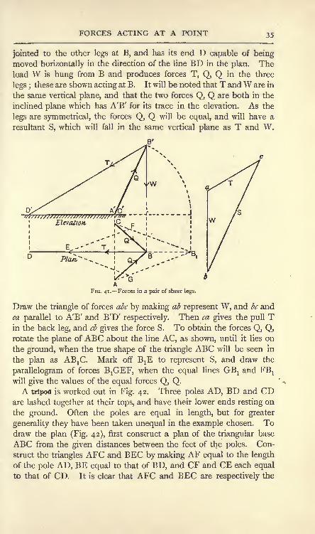
jointed to the other legs at B, and has its end D capable of beingmoved horizontally in the direction of the line BD in the plan. Theload W is hung from B and produces forces T, Q, Q in the three
legs ;these are shown acting at B. It will be noted that T andW are in
the same vertical plane, and that the two forces Q, Q are both in the
inclined plane which has A'B' for its trace in the elevation. As the
legs are symmetrical, the forces Q, Q will be equal, and will have a
resultant S, which will fall in the same vertical plane as T and W.
FIG. 41. Forces in a pair of sheer legs.
Draw the triangle of forces abc by making ab represent W, and be and
ca parallel to A'B' and B'D' respectively. Then ca gives the pull Tin the back leg, and cb gives the force S. To obtain the forces Q, Q,rotate the plane of ABC about the line AC, as shown, until it lies on
the ground, when the true shape of the triangle ABC will be seen in
the plan as ABjC. Mark off BXE to represent S, and draw the
parallelogram of forces BjGEF, when the equal lines GBj and FBX
will give the values of the equal forces Q, Q.A tripod is worked out in Fig. 42. Three poles AD, BD and CD
are lashed together at their tops, and have their lower ends resting on
the ground. Often the poles are equal in length, but for greater
generality they have been taken unequal in the example chosen. Todraw the plan (Fig. 42), first construct a plan of the triangular base
ABC from the given distances between the feet of the poles. Con-
struct the triangles AFC and EEC by making AF equal to the length
of the pole AD, BE equal to that of BD, and CF and CE each equal
to that of CD. It is clear that AFC and BEC are respectively the

MATERIALS AND STRUCTURES
true shapes of ADC and BDC when rotated about the lines AC and
BC respectively, so as to lie on the ground. To find the position of
D in the plan, draw FD and ED intersecting at D and perpendicular
respectively to AC and BC.
Let a weight W be hung from D, and let P, Q and S be the forces
in the legs acting at D. P and W will be in the same vertical plane,
and may be balanced by a third force Z applied in the same vertical
plane and also contained by the plane of ADC. The line of Z in
the plan will be *DG, obtained by producing BD. To obtain a true
FIG. 42. Forces in a tripod.
view of the forces P, W and Z, take an elevation on the ground line
xy, which is parallel to BD ;in this elevation, B'D' is the true length
of the pole BD. The lines of P and Z are shown by B'D' and
G'D' in this view (Fig. 42). W will be perpendicular to xy, and
by making D'b equal to W and drawing the parallelogram D'abc,
the values of P and Z will be given by #D' and cD' respectively.
To obtain Q and S, we have in the plan their lines lying on the
ground at AF and CF, and GF will be the line of Z. Make Fe equal
to Z and construct the parallelogram Ydef, when Q and S will be
given by d and /F respectively.
EXERCISES ON CHAPTER II.
1. Two pulls are applied to a point, one of 4 Ib. and the other of 9 Ib.
Find graphically the magnitude and direction of the resultant when the
forces are inclined to each other at angles of (a) 30, (&) 45, (c) 120.
Check your results by calculation.
2. Answer Question i, supposing the 4 Ib. force to be a push.

EXERCISES ON CHAPTER II. 37
3. A pull P of 5 Ib. and another force Q of unknown magnitude act
at 90. They are balanced by a force of 7 Ib. Find the magnitude of Q.
4. Answer Question 3, supposing P and Q .
intersect at 45.
5. A bent lever (Fig. 43) has its arms at ^p90 and is pivoted at C. AC = 1 5 inches, BC = 6
inches. A force P of 35 Ib. is applied at Aat 1 5 to the horizontal, and another Q is appliedat B at 20 to the vertical. Find the magnitudeof Q and the magnitude and direction of the
reaction at C required to balance P and Q.
6. A body weighing 24 Ib. is kept at rest
on an incline which makes 40 with the hori-
zontal by a force P which is parallel to the
plane (Fig. 44). Assume that the reaction R FIG. 43 .
of the plane is at 90 to its surface, and find P.
7. Answer Question 6, supposing P to be horizontal.
8. Four loaded bars meet at a joint as shown (Fig. 45). P and Q are
in the same horizontal line;T and W are in the same vertical ;
S makes
FIG. 44.
45 with P. Given that
and T.I5 tons, W=I2 tons, S= 6 tons, find Q
9. Lines are drawn from the centre O of a hexagon to each of the
corners A, B, C, D, E, F. Forces are applied in these lines as follows :
From O to A, 6 Ib.;from B to O, 2 Ib. ;
from C to O, 8 Ib.;from O to
D, 12 Ib.;from E to O, 7 Ib.
;from F to O, 3 Ib. Find the resultant.
10. Two equal bars AC and BC are hinged at C (Fig. 46). A and Bare capable of moving in guides in the straight line AB. A constant
force P of 40 Ib. is applied at C in a direction at 90 to AB, and is
balanced by equal forces Q, Q applied at A and B in the line AB.Calculate the values of Q when the angle ACB has values as follows :
170, 172, 174, 176, 178, 179, 1 80. Plot Q and the angle ACB from
your results. (The arrangement is called a toggle joint.)
11. Five forces meet at a point O as shown (Fig. 47), and are in
equilibrium. In the front elevation, P, Q and S are in the plane of the
paper and T is at 45 to the plane of the paper ; Q makes 135 with S.
In the side elevation T and V are in the plane of the paper. V is per-
pendicular to the plane containing P, Q and S, and T makes 45 with V.
Given Q = 4o tons, T= 25 tons, find P, S and V.

MATERIALS AND STRUCTURES
12. In a hinged structure, pieces BO and CO meet at the hinge O, anda force of 2 tons acts upon O in the direction AO. The angle AOB is
115, BOC is 15 and the angle AOC is 130 ; find the forces in the two
pieces and say whether they are struts or ties. (B.E.)
FIG. 46.
fruntElevation, Side.'Elevation,.
FIG. 47.
13. There is a triangular roof truss ABC;AC is horizontal, the angle
BCA is 25 and BAC is 55 ;there is a vertical load of 5 tons at B.
What are the compressive forces in BA and BC? What are the vertical
supporting forces at A and C ? What is the tensile force in AC ? Findthese answers in any way you please. (B.E.)
14. Each of the legs of a pair of sheer legs is 45 feet long ; they are
spread out 23 feet at their base. The length of the back stay is 60 feet.
If a load of 40 tons is being lifted at a distance of 15 feet, measured in a
perpendicular line from the line joining the feet of the two legs, find the
forces in the legs and in the backstay due to this load. (It may beassumed that the load is simply hung from the top of the legs.) (B.E.)
15. A tripod has the following dimensions : The apex point is O, andthe lengths of the three legs AO, BO and CO are respectively 18-0 feet,
17-5 feet and 16 feet. The lengths of the sides of the triangle formed bythe feet AB, BC and CA are 9-0 feet, 9-5 feet and 10 feet respectively.Find graphically, or in any other way, the forces which act down each legof the tripod when a load of 10 tons is suspended from it. (B.E.)
16. If a rigid body be acted on by two non-parallel forces whose pointsof application are different and be kept at rest by a third force, how mustthis third force act, and what must be its magnitude ? A straight lightrod xyz is pivoted freely at x, and the point y is attached to a pin -z/,
vertically above JT, by a light cord; xy is 3 feet, xv is 4 feet, yv is 2 feet,
yz is 2 feet;from z is hung a weight of 30 Ib. Find graphically the
tension in the cord. (I.C.E.)
17. If three non-parallel forces are in equilibrium, prove that their lines
of action must be concurrent. A uniform plank AB has length 6 feet and
weight 80 pounds and is inclined at 40 to the vertical. Its lower end Ais hinged to a support, while a light chain is fastened to a ring four feet
vertically above A and to a point on the plank five feet from A. Find
graphically, or otherwise, the tension in the chain and the magnitude anddirection of the action of the hinge at A. (The weight of AB may beconcentrated at the centre of the plank.) (L.U.)
18. Three cylinders, A, B and C, alike in all respects, are arrangedas follows : A and B rest on a horizontal table and their curved surfaces
touch one another. C rests on the top, its curved surface being in
contact with both A and B. Each cylinder weighs 6 Ib. Find, bycalculation, the mutual pressure between C and A, also what minimum

EXERCISES ON CHAPTER II. 39
horizontal forces must be applied to A and B, passing through their
axes, in order to preserve equilibrium. Frictional effects are to be
disregarded.
19. Three similar spheres rest on a horizontal table and are in
contact with each other. A fourth sphere, similar to the others, rests
on the top of the three spheres. Each sphere weighs 10 Ib. Find the
pressure communicated by the top sphere to each of the other three
spheres. Neglect frictional effects.

CHAPTER III.
PARALLEL FORCES.
Parallel forces. Confining ourselves for the present to two forces
only, there are two cases to be considered, viz. forces of like sense
and forces of unlike sense. To find the resultant of two parallel
forces P and Q (Fig. 48 (a) )of like sense, the following method may be
employed. Let the given forces act at 90 to a rod, at the points Aand B respectively. The equilibrium of the rod will not be dis-
, / 4 .S a
3 /BR /
/ *
'k
FIG. 48. Resultant of two parallel forces.
turbed by the application of equal opposite forces S, S, applied in
the line of the rod at A and B. By means of the parallelogram of
forces A&tt, find Rxof P and S acting at A
;and by means of the
parallelogram of forces B<?/#, find R2
of Q and S acting at B.
Produce the lines of Rj and R2until they intersect at O, and let R
T
and R2act at O. Apply the parallelogram of forces Qhkg to find R
of Rj and R2
. R will clearly be the resultant of P and Q, and will
balance P and Q if its sense be reversed. By measurement it will
be found that R is equal to the sum of P and Q.The resultant of two parallel forces of unlike sense may be found
by the same process. The construction is shown for two such
PARALLEL FORCES 41
forces, P and Q, in Fig. 48 (b) ; the lettering of this diagram corre-
sponds with that of Fig. 48 (a), and may be followed without further
explanation. If the diagram be measured, it will be found that R is
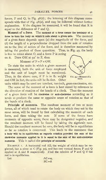
equal to the difference of P and Q.Moment of a force. The moment of a force means the tendency of a
force to turn the body on which it acts about a given axis. The momentof a given force depends upon (a) the magnitude of the force, and
(b) the length of a perpendicular dropped from the axis of rotation
on to the line of action of the force, and is therefore measured by
taking the product of these quantities. Thus, in Fig. 49, the bodyis free to rotate about O, and a force P is acting
on it. Draw OM at 90 to P, then
Moment of P = P x OM.To state the units in which a given moment
is measured, both the unit of force employedand the unit of length must be mentioned.
Thus, in the above case, if P is in Ib. weight FIG. 49. Moment of a
and OM in feet, the units will be Ib.-feet. Other
units which may be used are ton-foot, ton-inch, gram-centimetre, etc.
The sense of the moment of a force is best stated by reference to
the direction of rotation of the hands of a clock. Thus the momentof a given force will be clockwise or anti-clockwise according as it
tends to produce the same or opposite sense of rotation as that of
the hands of a clock.
Principle of moments. The resultant moment of two or more
forces, all of which tend to rotate the body on which they act in the
same sense, will be found by first calculating the moment of each
force, and then taking the sum If some of the forces have
moments of opposite sense, these may be designated negative, and
the resultant moment will be found by taking the algebraic sum.
Should the resultant moment be zero, the body will be in equilibrium
so far as rotation is concerned. This leads to the statement that
a body will be in equilibrium as regards rotation provided the sum of the
clockwise moments applied to it is equal to the sum of the anti-clockwise
moments. This is called the principle of moments.
EXAMPLE i. A horizontal rod AB, the weight of which may be ne-
glected, has a pivot at C (Fig. 50), and has two vertical forces P and Qapplied at A and B respectively. Find the relation of P and Q if the
rod is in equilibrium.Let AC=#,

42 MATERIALS AND STRUCTURES
Taking moments about C,
clockwise moment = anti-clockwise moment,
_Q a
It will be seen from this result that the forces are inversely propor-tional to the segments into which the rod is divided by the pivot. It will
also be evident that the equilibrant of P and Q acts through C.
AC~~ B k- ------ 6
FIG. 50. FIG. 51.
EXAMPLE 2. A horizontal rod BC, the weight of which may be ne-
glected, has a pivot at C, and has two vertical forces P and Q of unlike
sense applied at A and B respectively (Fig. 51). Find the relation of
P and Q if the rod is balanced.
Let AC = #,
BC =&
Taking moments about C,
Q *Again we may say that each force is proportional to the distance of
the other force from the pivot, and that the equilibrant of P and Q acts
through C.
EXAMPLE 3. A horizontal rod AB, the weight of which may be ne-
glected, has a weight W applied at C and is
,. . supported at A and B, the reactions P and Q~*~ ~
being vertical (Fig. 52). Find P and Q.B
Let AB = ,,
then BC =/-.Taking moments about B,
Px/=W(/-) + (Q*o),
P=(^)W (i)
Taking moments about A,
a= (Qx/) + (Pxo),
W (2)

PARALLEL FORCES 43
It is of interest to find the sum of P and Q, using their values as found
above ;thus (l-a\ a
=W-ji-~+^
=w.
Resultant of two parallel forces. Examining the results of these
examples together with what has been said regarding two parallel
forces on p. 40, we may state that the resultant of two parallel forces
has the following properties :
(1) The resultant is equal to the sum or diflerenee of the given forces
according as they are of like or unlike sense.
(2) The resultant is parallel to the given forces and acts nearer to the
larger ; it falls between the given forces if these are of like sense and outside
the larger force if of unlike sense.
(3) The perpendicular distances from the line of the resultant to the
given forces are inversely proportional to the given forces.
We may state properties (i) and (3) algebraically :
R=PQ, (i)
!= (=0
A special case. The resultant of two equal parallel forces of
opposite sense (Fig. 53) cannot be determined from these equations.
Here Q is equal to P, hence
R=P-P=c
FlG. 53. A couple.
These results show that no single force can
form the resultant of such given forces, and we may infer from this
that the resultant effect is to produce rotation solely. The name
couple is given to this system.
Eesultant of a number of parallel forces. In Fig. 54 is shown a
horizontal rod AB acted on by a number of parallel vertical forces
W15W
2 ,W
3 ,P and Q. For the rod to be in equilibrium under the
action of these forces, the following conditions must be complied with :
(i) the forces must not produce any vertical movement, either upwards

44 MATERIALS AND STRUCTURES
or downwards : (2) they must not produce any rotational movement, either
clockwise or anti-clockwise.
The first condition will be satisfied provided the sum of the
upward forces is equal to that of the downward forces ; hence
The second condition will be satisfied if, on taking momentsabout any point such as A, the sum of the clockwise moments is
equal to that of the anti-clockwise moments, hence
W& +W2*
2 4-W3*
3- Pa + Qb.
Supposing that it is found that the sum of the downward forces is
not equal to that of the upward forces, then the rod may be equilibrated
by application of a force E equal and opposite to the difference of
these sums; thus E = (
Wl +W2 +W3)
-(P + Q).
1

PARALLEL FORCES 45
EXAMPLE i. Four parallel forces act on a rod AB as shown (Fig. 55 (a)).
Find their resultant.
R=2P=2+5+7+3=^7 lb., of sense downward.
Taking moments about A, we have
feet.
=92,
.l 7lb.i 3/&1.
lh----j
---x ---'->[ ;
f-2-x ; fR i
------s'-- '------ --u ---------6
------ ^J
7'
X 1***"
3^

46 MATERIALS AND STRUCTURES
To check the work we have
2765 + 1-484 = 2 + 1 +|+|,4-249=4-25,
results which agree within the limits of accuracy of the answers found for
P and Q.
I J5-Y2fonj|
Y^fcn
I t"" I f""1
16 -*
2 tons

PARALLEL FORCES 47
orWFG
.
Q
.(2)
FIG. 57. Beam carrying one load ; reactions found graphically.
Hence FG represents P to the same scale that CE represents W.
The value of Q may be found from
Q = W-P.
Or, by using the same construction, Q may be found by makingDH equal to W, joining CH cutting FG in K, when FK gives the
value of Q (Fig. 57).
FIG. 58. Graphical solution of P for a beam carrying several loads.
If the beam carries several loads (Fig. 58), the construction for Pshould be carried out for each load as indicated ;
the total sum of the

48 MATERIALS AND STRUCTURES
intercepts will give the value of P. Q may be found by means of a
similar construction carried out for the other end of the beam, and
the result may be checked by comparing the sum of P and Q with
the sum of the given loads.
Centre of parallel forces. Let two parallel forces P and Q act on
a rod AB (Fig. 59). Their resultant R will divide AB in the pro-
portion P:Q = BC:AC (i)
Let the lines of P and Q be rotated to new positions P', Q',
without altering the magnitudes. Through C draw DCE perpen-dicular to P' and Q'. Then R', the resultant of P' and Q', will
divide DE in inverse proportion to P' and Q'. Inspection of Fig.
59 will show that the triangles ACD and BCE are similar, hence
EC:DC=BC:AC= P:Q
from (i). It therefore follows that R' passes through the same point
C. This point is called the centre of the parallel forces P and Q.
E
\

PARALLEL FORCES 49
weights of the composite particles. The name centre of gravity is
given to this pointCentre of gravity by calculation. The general method of calcu-
lation will be understood by reference to Fig. 61. The body is
supposed to be a thin sheet of material. Take two coordinate axes
FIG. 61. Centre of gravity of a thin sheet.
OX and OY. First let OX be horizontal; the weights of the
particles being called ze/j,w
2 ,ze>
3 , etc., and their coordinates
)' (^3^3)' etc -> we nave5 by taking moments about O,
+ etc.) x = wl
or,
It is evident that 2w gives the total weight W of the sheet, hence
Now turn the sheet round until OY is horizontal; the lines of
direction of the weights will be parallel to OX, and, by takingmoments about O, we have
+ etc)y =
Draw a line parallel to OX, and at a distance y from it, andanother parallel to OY at a distance x
; the intersection of these
gives the centre of gravity G.
D.M,

50 MATERIALS AND STRUCTURES
The position of the centre of gravity in certain simple cases maybe seen by inspection. Thus for a slender straight rod or wire, it lies
at the middle of the length. In a square or rectangular plate Glies at the intersection of the diagonals.
A circular plate has G at its geometrical centre. The position of
G in a triangular plate may be found by first imagining it to be cut
into thin strips parallel to BC (Fig. 62).
The centre of gravity of each strip will lie
at its centre of length ;hence all these
centres will lie in DA, where D is the
centre of BC, and hence DA contains
the centre of gravity of the plate. In the
same way, by taking strips parallel to AB,the centre of gravity will lie in CE, where
E is the centre of AB. Hence G lies at
FIG. 62. Centre of gravity of a the intersection of DA and CE, and ittriangle. . .
is easy to show by geometry that DG is
one-third of DA. Hence the rule that G lies one-third up the line
joining the centre of one side to the opposite corner.
Advantage is taken of a knowledge of the position of G in thin
plates having simple outlines in applying equations (i) and (2) above.
The following examples will illustrate the method.
EXAMPLE i. Find the centre of gravity of the thin uniform plate shown
in Fig. 63.
Take axes OX and OY as shown and let the weight of the plate per
square inch of surface be iv. For convenience of calculation the plate is
divided into three rectangles as shown, the respective centres of gravity
being G1? G2 and G3 . Taking moments about OY, we have
7/{(6x i) + (8x i) + (3>< i)}*=w(6x i x a)+w(8'x i
- 26-5x= SI 7
=1^56
inches.
Again, taking moments about OX, we have
=5-8 inches.
EXAMPLE 2. A circular plate (Fig. 64) 12 inches diameter has a hole
3 inches diameter. The distance between the centre A of the plate andthe centre B of the hole is 2 inches. Find the centre of gravity.

PARALLEL FORCES
Take AB produced as OX, and take OY tangential to the circumference
of the plate. It is evident that G lies in OX. Taking moments about
OY, we may say that the moment of the plate as made is equal to that of
YI
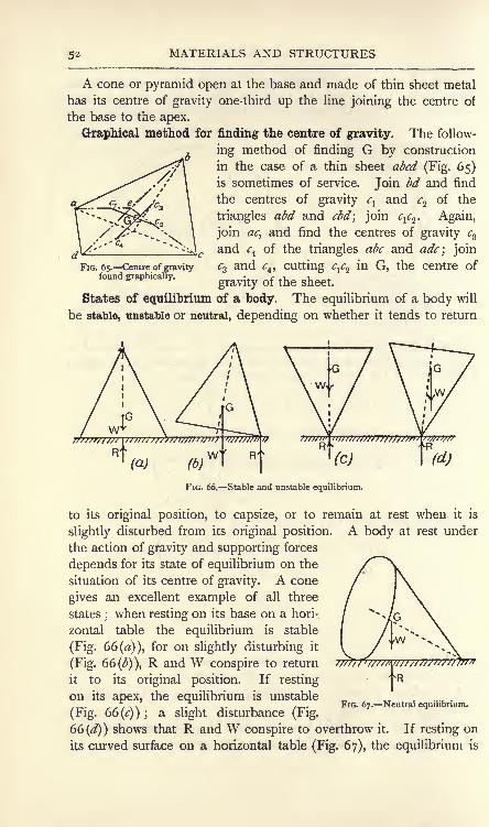
MATERIALS AND STRUCTURES
A cone or pyramid open at the base and made of thin sheet metal
has its centre of gravity one-third up the line joining the centre of
the base to the apex.
Graphical method for finding the centre of gravity. The follow-
ing method of finding G by construction
in the case of a thin sheet abed (Fig. 65)is sometimes of service. Join bd and find
the centres of gravity ^ and c^ of the
triangles abd and cbd; join <y2. Again,
join ac, and find the centres of gravity cz
and c of the triangles abc and adc\ join
FIG. 65. Centre of gravity c% and c, cutting cfa in G, the centre offound graphically. ^^ Qf^ ^^
States of equilibrium of a body. The equilibrium of a body will
be stable, unstable or neutral, depending on whether it tends to return
(a) (d)
FIG. 66. Stable and unstable equilibrium.
to its original position, to capsize, or to remain at rest when it is
slightly disturbed from its original position. A body at rest under
the action of gravity and supporting forces
depends for its state of equilibrium on the
situation of its centre of gravity. A cone
gives an excellent example of all three
states ;when resting on its base on a hori-
zontal table the equilibrium is stable
(Fig. 66 (a)), for on slightly disturbing it
(Fig. 66 ()), R and W conspire to return
it to its original position. If resting fR
on its apex, the equilibrium is unstable/T-- ~/ V\ v i ^ j- . i /-r-
FIG. 67. Neutral equilibrium.
(Fig. 66 (c) ) ; a slight disturbance (r ig.
66 (^)) shows that R and W conspire to overthrow it. If resting on
its curved surface on a horizontal table (Fig. 67), the equilibrium is

PARALLEL FORCES 53
neutral, for, no matter what the position may be, R and W act in
the same vertical line, and so balance.
Reactions of the supports of a beam. In calculating the moment
of the weight of a given body about a given axis, we may imagine
that the whole weight is concentrated at the centre of gravity. This
enables us to deal with problems on beams carrying distributed loads.
The following example will make the method clear.
EXAMPLE. A beam is supported at A and B (Fig. 68). The section
of the beam is uniform and its weight is 200 Ib. per foot run. It carries
*i
,, Of
!.~4'--Ji 10
FIG. 68. Reactions of the supports of a beam.
a load of 500 Ib. per foot run uniformly distributed over 9 feet of the
length as shown. Find P and Q.
The centre of gravity of the beam lies at Glat a distance of 7 feet
from B. G2 is the centre of gravity of the distributed load, and lies at
9^ feet from B.
Total weight of beam=W!= 200 x 14= 2800 Ib.
Total weight of load =W2= 500 x 9 =4500 Ib.
Apply Wj at Gj and W2 at G2 ,and take moments about B to find P :
P=(2800x7)+ (45
10
= 6235 Ib.
Again, take moments about A to find Q :
(2800 x 3)+ (4500 x^)10
= 106 Ib.
Checking the results, we have
62354-1065 = 2800+ 4500,
7300-7300.
Parallel forces not in the same plane. In Fig. 69 are shown four
bodies, one at each corner of the horizontal square ABCD. The
weights of these bodies act vertically downwards, and hence are not
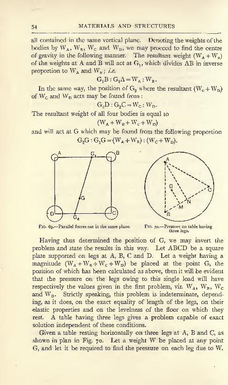
54 MATERIALS AND STRUCTURES
all contained in the same vertical plane. Denoting the weights of the
bodies by WA ,WB ,
Wc and WD ,we may proceed to find the centre
of gravity in the following manner. The resultant weight (WA +WB)
of the weights at A and B will act at Gl ,which divides AB in inverse
proportion to WA and WB ;i.e.
G1E:G
1A =WA :W*.
In the same way, the position of G2 where the resultant (Wc +WD)
ofWc and WD acts may be found from :
G2D:G2C =WC :WD .
The resultant weight of all four bodies is equal to
and will act at G which may be found from the following proportion
G2G : G,G = (WA +WB) :(Wc +WD).
FIG. 69. Parallel forces not in the same plane. FIG. 70. Pressure on table havingthree legs.
Having thus determined the position of G, we may invert the
problem and state the results in this way. Let ABCD be a square
plate supported on legs at A, B, C and D. Let a weight having a
magnitude (WA +WB +Wc +WD)be placed at the point G, the
position of which has been calculated as above, then it will be evident
that the pressure on the legs owing to this single load will have
respectively the values given in the first problem, viz. WA ,WB ,
Wc
and WD . Strictly speaking, this problem is indeterminate, depend-
ing, as it does, on the exact equality of length of the legs, on their
elastic properties and on the levelness of the floor on which theyrest. A table having three legs gives a problem capable of exact
solution independent of these conditions.
Given a table resting horizontally on three legs at A, B and C, as
shown in plan in Fig. 70. Let a weight W be placed at any point
G, and let it be required to find the pressure on each leg due to W.

PARALLEL FORCES 55
It will be noticed that if one of the legs, say A, be lifted slightly, the
table will rotate in a vertical plane about the line BC. This indicates
that the pressure on A may be calculated by taking moments about
BC. Draw GM and AN perpendicular to BC, and let PA be the
reaction of the leg A ; then,
PA xAN =WxGM,
In the same way, PB may be
found by taking moments about
AC, and Pc by taking moments
about AB. The results may be
checked from
EXPT. 6. Principle of moments.
Fig. 7 1 shows a wooden disc which
is free to rotate about its centre
on a screw driven into a wall
board. Attach cords to various points on the face of the disc and
apply different forces by means of weights as shown. Let the disc
come to rest under the action of these forces, and test the truth of
the principle of moments by calculating the sum of the clockwise
moments and also that of the anti-clockwise moments.
EXPT. 7. Reactions of a beam. Fig. 72 shows an apparatus con-
sisting of a wooden beam supported by means of two hanging spring
FIG. 71. Apparatus for illustrating the
principle of moments.
n
FIG. 72. Apparatus for determining the reactions of a beam.
balances. Apply various loads and calculate the reactions of the
supports. Make allowance for the weight of the beam and also

MATERIALS AND STRUCTURES
for any distributed loads by concentrating them at their respectivecentres of gravity. Repeat the experiment with altered loads and
different positions of the points of support. Makea table showing in each case the calculated
reactions and also those read from the springbalances.
EXPT. 8. Centre of gravity of sheets. Thecentre of gravity of a thin sheet may be found byhanging it from a fixed support by means of a
cord AB (Fig. 73) ;the cord extends downwards
and has a small weight W, thus serving as a
plumb-line. Mark the direction AC on the sheet
and then repeat the operation by hanging the
sheet from D, marking the new vertical DE. Gwill be the point of intersection of AC and DE.
Carry out this experiment for the sheets of metal
or millboard supplied.
EXPT. 9. Centre of gravity of a solid body. The centre of gravityof a body such as a connecting rod (Fig. 74) may be found bybalancing it on a knife edge, which may be arranged easily by use
of V blocks and a square bar of steel. G will lie vertically over
OwFIG. 73. Experiment
on the centre of gravityof a sheet.
<r
''/'////S/////
FIG. 74. Experiment on the centre of gravity of a solid body.
the knife edge when the rod is balanced. Carry out this experimenton the bodies supplied, in each case making a sketch of the body and
recording on the sketch the dimensions necessary for indicating the
position of G.
EXERCISES ON CHAPTER III.
1. A uniform horizontal rod AB is pivoted at its centre C, and carries
a load of 12 Ib. at D and another of 20 Ib. at E. D and E are on
opposite sides of C, CD and CE being 8 inches and 12 inches respectively.If balance has to be restored by means of a 14 Ib. weight, find where it
must be placed. What will be the reaction of the pivot ?
2. A rod AB carries loads of 3 Ib., 7 Ib. and 10 Ib. at distances of 2
inches, 9 inches and 15 inches respectively from A. 'Find the point at
which the rod will balance. Neglect the weight of the rod.
3. Fig. 75 shows an arrangement of a right-angled bent lever ABCcarrying a load of 40 Ib. AB and BC are 12 inches and 3 inches respec-
tively and AB is horizontal. C is connected by a horizontal link CE to a

EXERCISES ON CHAPTER III. 57
vertical lever DF, which is pivoted at D. DF and DE are 15 inches
and 3 inches respectively. The arrangement is balanced by a cord FGpassing over a pulley at G and carrying a load W. Find W, neglectingthe weights of the various parts and also friction.
4. A lever safety valve for a steam boiler has the following dimensions :
Diameter of valve, 3 inches;distance from fulcrum to valve centre, 4^
inches; weight of valve and its attachment to the lever, 4^ Ib
; distance
from fulcrum to centre of gravity of the lever, 14 inches ; weight of
lever, 7 Ib. The weight on the end of the lever is 90 Ib. Find its
distance from the fulcrum if the valve is to open with a steam pressureof 70 Ib. per square inch.
5. A uniform beam 20 feet long weighs i| tons, and is supported at
its ends A and B. A uniformly distributed load of ^ ton per foot run
extends over 10 feet of the length measured from A, and a concentrated
load of 3 tons rests at a point 4 feet from B. Find the reactions of the
supports by calculation.
40/6.FIG. 75-
6. A beam 18 feet span carries loads of 2 tons, 4 tons and 8 tons at
distances measured from one support of 3 feet, 8 feet and 12 feet respec-
tively. Find graphically the reactions of the supports. Neglect the weightof the beam.
7. A uniform beam weighs 2 tons and is 24 feet long. It is supportedat a point A 6 feet from one end, and at another point B 4 feet from the
other end. There is a concentrated load of i tons at each end andanother of 3 tons at the middle of the beam. Find the reactions of the
supports by calculation.
8. Three weights of 4 Ib., 8 Ib. and 12 Ib. respectively are placed at
the corners A, B and C of an equilateral triangle of 2 feet side. Find the
centre of gravity.
9. A letter L is cut out of thin cardboard. Height, 3 inches ;
breadth, 2 inches;width of material, inch. Find the centre of gravity.
10. A solid pyramid has a square base of 3 inches edge and is
5 inches high. It rests on its base on a board, one end of which maybe raised. The edges of the base of the pyramid are parallel to the
edges of the board, and slipping is prevented by means of a thin strip

58 MATERIALS AND STRUCTURES
nailed across the board. Find, by drawing or otherwise, the angle whichthe board makes with the horizontal when the pyramid just tips over.
11. A flat equilateral triangular plate of 4 feet side is supported horizon-
tally by three legs, one at each corner. A vertical force of 112 pounds is
applied to the plate at a point which is distant 3 feet from one leg and1 8 inches from another. Determine the compressive force in each leg
produced by this load. (B.E.)
12. A scale-pan of a balance with unequal arms is weighted in such a
way that the beam is horizontal when no masses are placed in the pans.A body when placed in the two pans successively is balanced by masses
P and Q in the opposite pans. Prove that its mass is \/PQ. (L.U.)
13. A horizontal platform is supported on three piers ABC forming a
triangle in plan. AB = 6 feet; AC = 8 feet
;BC = 8 feet. The centre of
gravity of the platform and load carried is distant 5 feet from A and4 feet from B. Find the proportion of the load carried by each of the
three piers. Show that, if there were four piers instead of three, the
reactions could not be determined without further information (I.C.E.)

CHAPTER IV.
PROPERTIES OF COUPLES. SYSTEMS OF UNIPLANARFORCES.
Moment of a couple. Consider the couple formed by the equal
forces Pj and P2 (Fig. 76). Let d be the perpendicular distance, or
arm, between the lines of the forces.
It may be shown, by taking momentsin succession about several points A,
B, C, D, that the moment of the couple
is the same about any point in its plane,
and is given by Pd.
Thus, taking moments about A, we
have
Moment of the couple=
(Pj X o)-(P2
X d) FlG ?6i_A couple has the same momentr> j / \ about any point in its plane.
--tV*' ..................Wthe negative sign indicating an anti-clockwise moment.
Taking moments about B, we have
Moment of the couple = (P2x o)
-(Pj x d)
Taking moments about C gives
Moment of the couple = -(Pl
x a)- P
2(d- a)
--V ....... .................. (3)
Taking moments about D, we have
Moment of the couple = (P2x V)
- Pl (d+ b]
= -Pi* ........................... (4)
As the forces are equal, the four results are identical, thus provingthe proposition.
Equilibrant of a couple. It has been seen (p. 43) that no single
force can be the resultant of a couple, hence no single force can

6o MATERIALS AND STRUCTURES
equilibrate a couple. It will now be shown that another couple of
equal opposite moment applied in the same plane, or in a parallel plane,
will balance a given couple.
In Fig. 77 are shown two couples, one having equal forces Pland
P2 ,and the other couple having equal forces Qx
and Q2. Produce
the lines of these forces to intersect
at A, B, C and D, and let a and b be
the arms of the P and Q couples
respectively. From A draw AM and
AN perpendicular to Pland Qx
re-
spectively. Then AM =a, and AN = b.
The triangles AMC and AND are
similar, hence
AC:AM = AD:AN,AC:AD=AM:AN
~*W (i)
Now if the couples have equal moments, we have
FIG. 77. Two equal opposing couplesare in equilibrium.
or Q:P = a: (2)
Hence, AC and AD may be taken to represent Q and P respec-
tively to some scale of force.
As ACBD is a parallelogram, it follows that the resultant of P,
and Qj acting at B will be R = AB.
Also the resultant R2of P
2and Q2 acting at A will be
R2= BA.
c
FIG. 78. Equal opposing couples in parallel planes are in equilibrium.
As R! and R2are equal, opposite, and in the same straight line,
they balance; hence, the given couples are in equilibrium. We

PROPERTIES OF COUPLES 61
may therefore state that couples of equal opposite moment acting
in the same plane are in equilibrium, and either couple may be
said to be the equilibrant of the other couple.
In Fig. 78 is shown a rectangular block having equal forces Px
and P2 applied to its vertical front edges AD and CB, and other
equal forces Pland P
2 applied to the vertical back edges FG and
HE. Let these forces be all equal, when the block will have a pair
of equal opposite couples acting in parallel planes. That these
couples balance may be seen by taking the resultant Rx
of the
forces Pj, Pj, and also the resultant R2of the other equal pair
P2 ,
P2
. These resultants are equal and opposite and act in the
same straight line, and hence are in equilibrium.
Eesultant of a couple. We have now seen that a couple can be
balanced by the application in the same plane, or in a parallel plane,
of a second couple having an equal opposite moment. Supposingthe forces of the second couple to be reversed in sense, it is evident
1
FIG. 79. Single-handed tap wrench. FIG. 80. Double-handed tap wrench.
that the effect of this couple on the body will be identical with that
of the first couple. We may say now that either couple is the resultant
of the other, i.e. the effect on the body as a whole will be the same,
no matter which couple be applied to it.
This proposition may be stated in a different way, viz. a couple
may be moved from any given position to another position in the same
plane or in a parallel plane, without thereby altering its effect on the body
as a whole.
Owing to the equality of the forces forming a couple, the applica-
tion of a couple to any body will not tend to move it in any
direction, but will merely tend to set up rotation. For example,in tapping a hole, the use of a single-handed tap wrench (Fig. 79)
will tend to bend the tap and to spoil the thread ;a double-handed
wrench enables a couple to be applied giving pure rotation to the
tap (Fig. 80). It is evident that the same turning effort may be

62 MATERIALS AND STRUCTURES
obtained by means of small forces and a large arm, or by larger
forces and a smaller arm, a fact which we may state as follows : The
forces of a couple may be altered in magnitude provided the arm be altered
so as to make the moment the same as at first.
The case of a ship having screw propellers affords an example of
the balancing of couples in parallel planes. Referring to Fig. 81,
couples are applied to the shaft at A by the engines and, neglecting
the friction of the bearings, these couples are balanced by an equal
opposite couple produced by the resistance of the water acting on
*n A
FIG. 8 1. Screw propeller shaft.
the propeller at E. The planes of these couples are perpendicular
to that of the paper and hence are parallel. The distance of Afrom E is immaterial so far as the equilibrium of the couples is
concerned;nor does the diameter of the propeller affect the problem
of equilibrium.
The law that every force must have an equal opposite force maynow be extended by asserting that it is impossible for a couple to act
alone ; there must always be an equal opposite couple acting in the same
plane, or in a parallel plane.
Substitution of a force and couple for a given force. In Fig. 82
is shown a body having a force Pj applied at A. We will supposethat it would be more convenient to
have the force applied at another point
B. Apply equal opposite forces P2 ,
P2 ,
to B, each equal to Pxand in a
line parallel to PT ; these will be self-
balancing and will therefore not affect
the equilibrium of the body. Let d be
the perpendicular distance between Pjand P
2 . Pj and the equal downwardforce P9 at B form a COUple, the moment FIG. 82. Transference of a force to a
. line parallel to the given line of action.
of which is P2</; this couple may be
moved to any convenient situation in the plane, leaving the upwardforce P
2at B. A given force is therefore equivalent to a parallel equal
force of like sense together with a couple having a moment obtained as above.

PROPERTIES OF COUPLES
Substitution of a force for a given force and a given couple.
In Fig. 83 we have given a force P acting at A, together with a
couple Q, Q, having an arm d.
The moment of the couple is Q</.p'
Alter the forces of the couple so
that each new force P', P' is equal
to P, the new arm a being such that
Apply the new couple so that
one of its forces acts at A, in the
Same line as P, and in the Opposite FIG. 83. Reduction of a given force and
sense. These forces balance at A,:ouple to a single f
leaving a single force P' acting at a perpendicular distance a from
the given force P.
EXAMPLE i. A single-handed tap wrench has a force of 30 Ib. applied
at a distance of 15 inches from the axis of the tap (Fig. 84). The centre
line of the wrench is at a height of 5 inches above the face of the work
being tapped. Find the moment of the couple acting on the tap and also
the moment of the force tending to bend the tap.
Transferring P from A to B gives a force P acting at B, together with
a couple having a moment given by
Moment of couple= P x AB= 30 x 15=450 Ib.-inches.
The force P acting at B tends to bend the tap about C. To calculate
its moment we have
Moment of P = PxBC= 30 x 5
= 150 Ib.-inches.
FIG. 84. FIG. 85.
EXAMPLE 2. A bent lever ACB (Fig. 85) is pivoted at C, and hasforces P and Q applied at A and B respectively. Find the resultant
turning moment on the lever and also the resultant force on the pivot.
The solution may be obtained by drawing the lever to scale. Transfer

64 MATERIALS AND STRUCTURES
P and Q to C as shown, giving forces P'= P and Q'=Q acting at C,
together with a clockwise couple Q x CN and an anti-clockwise coupleP x CM, CN and CM being perpendicular to Q and P respectively. Theresultant turning moment may be calculated by taking the algebraic sumof the couples, thus
Turning moment= (Q x CN) - (P x CM).
This moment will be clockwise if the result is positive.
To obtain the resultant force on the pivot, apply the parallelogram of
forces as shown to find the resultant of P' and Q' acting at C. R givesthe required force.
Equilibrium of a system of uniplanar forces. Any system of forces
acting in the same plane will be in equilibrium provided (a) there is
no tendency to produce translational movement, 0) there is no tendency to
rotate the body. These conditions may be tested either by mathe-
matical equations or by graphical methods. To obtain the necessary
equations we may proceed as follows.
In Fig. 86, four forces PI}
P2 ,
P3 ,
P4 ,are given acting in the
plane of the paper at A, B, C and D respectively. Take any two
Y
FIG. 86. A system of uniplanar forces.
rectangular axes OX and OY in the same plane and take componentsof each force parallel to these axes. Calling the angles made bythe forces with OX <x
15a2 ,
ag and a
4 ,the components will be
(see p. 23) :
Components parallel to OX : Plcos a
lfP
2cos a
2 ,P
3cos <x
3 ,P
4 cos a4 .
Components parallel to OY : Pj sin alfP
2sin a
2 ,P3 sin a
3 ,P
4 sin a4
.
These components may be substituted for the given forces. Now

SYSTEMS OF UNIPLANAR FORCES 65
transfer each component so that it acts at O instead of in its given
position. This transference will necessitate the introduction of a
couple for each component transferred. Let xland yl
be the
coordinates of A, and describe similarly the coordinates of B, Cand D. The couples required by the transference of the componentsof P! will be (Px
cos c^)^ and (Pj sin a,)*, ;the other couples may be
written in the same manner, giving
Couples parallel to OX :
(PjCOSa^jj, (P2COSa
2)^2 , (P3 COSa3)j3 , (P4COSa4)j4 .
Couples parallel to OY :
(Pjsinaj)^, (P2sina
2)#2 , (P3sina
3)^3 , (P4 sina4)#4.
The couples parallel to OX may be reduced to a single resultant
couple by adding their moments algebraically. Similarly, those
parallel to OY may be reduced to a single couple, giving
Resultant couple parallel to OX = 2(P cos a)y.
Resultant couple parallel to OY = 2(Psina)#.
Fig. 87 shows the reduction of the given system so far as we have
proceeded, which now consists of a number of forces acting in OX
p* 6Ut *+ Couple* Z(Pcos)y.P3 sin 3
<-P, 5171 OC,
*Couf>le~
FIG. 87. A system equivalent to that in Fig. 86.
and OY, together with two couples. For equilibrium, there must be
no tendency to produce movement in a direction parallel to OY,hence the algebraic sum of the forces in OY must be zero. This
condition may be written :
2P sin a = o(i )
At the same time there must be no tendency to produce movementin a direction parallel to OX ; hence the algebraic sum of the forces
in OX must be zero, a condition which may be written :
2Pcosa = o (2)D.M. E

MATERIALS AND STRUCTURES
Further, there must be no tendency to produce rotation, a condition
which may be secured provided (i) each of the couples is zero, in
which case2(Psina)a; + 2(Pcosa)j = o
;
or, (ii)the couples may be of equal moment and of opposite sense of
rotation, in which case their algebraic sum will again be zero. Hence
the complete condition of no rotational tendency may be written :
2(Psina)# + 2(Pcosa)^ = o (3)
These equations (i), (2) and (3) being fulfilled simultaneously serve
as tests for the equilibrium of any system of uniplanar forces. Alittle judgment must be exercised in the selection of the coordinate
axes OX and OY in any particular problem so as to simplify the
subsequent calculations.
EXAMPLE. A roof truss, 20 feet span, 5 feet rise (Fig. 88), has a
resultant wind pressure of 2000 Ib. acting at C, the centre of the right-
f

THE LINK POLYGON 67
the components of Q parallel to BX and BY respectively. Then, fromthe equations of equilibrium, we have
2Psina=o; hence, P + Qv-V= o,
or P + Q v = i79olb...................(i)
2Pcosa= o; hence, QH H=o,or QH = 89 5 Ib.....................(2)
2(P sin a);tr+2(P cos a)y=o ; hence, (P x 20)- (V x 5)
- (H x 2$)=o.
It will be noted that the last equation is obtained by taking the algebraicsum of the moments of all the forces about B, Reducing it, we have
2oP = (1790x5)+ (895x2^),
(3)
Substitution of this value of P in (i) gives
559'4+Qv=i79o,
Qv=i23<>6 Ib................................ (4)
To find Q, we have Q = v/QH2
= ^2311000= i2olb..................................(5)
To find the angle a which Q makes with the vertical, we have
2Qv
895
1230-6
=0727 ;
'.= 36 I' (6)
Graphical solution by the link polygon. A convenient method of
determining graphically the equilibrant of a system of uniplanar forces
will now be explained. It is required to find the equilibrant of the
given forces PltP
2 and P3 (Fig. 89 (a)). Take any point A on the line
of P1} and proceed to balance P
1 by the application of any pair of
forces / tand /2 intersecting at A. The triangle of forces abQ
(Fig. 89 (^)), in which
pi Pz'-p^ab'.bQ'.Qa,
will determine the magnitudes of/tand /2
. Imagine p land /2 to
be applied at A (Fig. 89 (a) ) through the medium of bars, or links,
one of which, AB, is extended to a point B on the line of action of
P2
. To equilibrate this link, it must exert a pull/2at B equal and
opposite to the pull it gives to A.
The forces f> and P2 acting at B may be equilibrated by the

68 MATERIALS AND STRUCTURES
application of a third force /3 at B, /3 being found in direction and
magnitude from the triangle offerees Qbc (Fig. 89^)), in which
A :P2
:A = ^ : ^ : ^-
Let /3 be applied at B (Fig. 89(0)) by means of a link BC,
intersecting P3 at C and exerting at C a force equal and opposite to
that which it exerts on B.
The forces /3 and P3 acting at C are now equilibrated by means of
a force /4 applied at C, /4 being found from the triangle of forces
CW, in which /8 : P3 :/4= O* : *rf : dO.
Let the force /4 be applied at C by means of a link, and let this link
and that in which placts intersect at D. Each link will exert a force
at D equal and opposite to that which it communicates to A and C
FIG. 89. Graphical solution by the link polygon.
respectively. The forcespl and/4thus acting at D may be equilibrated
by means of a third force E applied at D, E being found from the
triangle of forces Qda, in which
It will now be seen, by reference to Fig. 89 (a), that each of the given
forces is balanced, that the closed link polygon ABCD is in equilibrium,
and that the force E is also balanced. It therefore follows that the forces
Pj, P2 ,P3 and E are in equilibrium.
Reference to Fig. 89 (b) will show that abed constitutes a closed polygon
of forces for Plf P2 ,P
3and E, and that the lines drawn from O to a,
,c and */are parallel respectively to the links in Fig. Sg(a). As we
had a liberty of choice of the directions of the first two links, viz. DAand AB, and as these directions, once chosen, settled the position of

THE LINK POLYGON
the point O in Fig. 89 (/;), we infer that the position ofO is immaterial,
the only effect of varying its position being to change somewhat the
shape of the link polygon without altering the final value or position
of E. It should also be noted that each link in Fig. 89 (a) is parallel
to the line from O in Fig. 89 (b) which falls between the sides of the
force polygon representing the two forces connected by the link in
Fig. 89 (a). Thus, AB in Fig. 89 (a) is parallel to Ob in Fig. 89 (b\ the
latter falling between ab and be which represent Pland P2 respectively.
In practice, Bow's notation is employed. Some examples are givento illustrate the method.
EXAMPLE i. Given three forces of 3 tons, 4 tons and 2 tons respectively,find their equilibrant (Fig. 9o(fl)).
The principles on which the solution is based are, as has been found
above, (a) the force polygon must close, (b) the link polygon must close.
E-3 25 tons
(a) c < "i
FIG. 90. An application of the link polygon.
Naming the spaces A, B and C, and placing D provisionally near to the
force of 2 tons, draw the force polygon ABCD (Fig. 90 (<)). The closingline DA gives the direction, sense and magnitude of the equilibrant. Tofind its proper position, take any pole O (Fig. 90 ()), and join O to the
corners A, B, C, D of the force polygon. Choose any point a on the line
of the 3 tons force. In space A draw a line ad, of indefinite length,
parallel to OA in Fig. 90 (b). In space B draw a line ab parallel to OB;
and, in space C a line be parallel to OC. From c draw a line parallel to
OD to intersect that drawn from a in the point d. Then E passes throughd, and may now be shown completely in Fig. 90 (a).
EXAMPLE 2. Four forces are given in Fig. 91 (a); find their resultant.
The method employed consists in first finding the equilibrant and then
reversing its sense. This example is of slightly greater :omplication, but
the working does not differ from that illustrated above. In Fig. 91 (b)
ABCDE is the force polygon, the closing side EA represents the equili-
brant, hence AE represents the resultant. The position of the equilibrantis found by drawing the link polygon abcde, having its sides parallel to
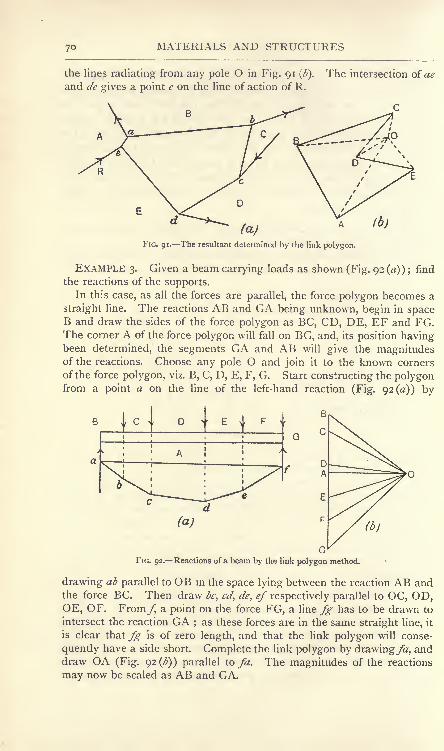
MATERIALS AND STRUCTURES
the lines radiating from any pole O in Fig. 91 (
and de gives a point e on the line of action of R.
The intersection of ae
FIG. 91. The resultant determined by the link polygon.
EXAMPLE 3. Given a beam carrying loads as shown (Fig. 92 (rt)); find
the reactions of the supports.In this case, as all the forces are parallel, the force polygon becomes a
straight line. The reactions AB and GA being unknown, begin in spaceB and draw the sides of the force polygon as BC, CD, DE, EF and FG.The corner A of the force polygon will fall on BG, and, its position havingbeen determined, the segments GA and AB will give the magnitudesof the reactions. Choose any pole O and join it to the known corners
of the force polygon, viz. B, C, D, E, F, G. Start constructing the polygonfrom a point a on the line of the left-hand reaction (Fig. 92(0:)) by
\c
I I M
(b)
FIG. 92. Reactions of a beam by the link polygon method.
drawing ab parallel to OB m the space lying between the reaction AB andthe force BC. Then draw be, od, de, ef respectively parallel to OC, OD,OE, OF. Fromyj a point on the force FG, a line fg has to be drawn to
intersect the reaction GA ; as these forces are in the same straight line, it
is clear that fg is of zero length, and that the link polygon will conse-
quently have a side short. Complete the link polygon by drawing^, anddraw OA (Fig. 92^)) parallel to fa. The magnitudes of the reactions
may now be scaled as AB and GA.

EXPERIMENTS ON COUPLES
EXPT. io, Equilibrium of two equal opposing couples. In Fig. 93 is
shown a rod AB hung by a string attached at A and also to a fixed
support at C. By means of cords, pulleys and weights, apply two
equal, opposite and parallel forces P, P, and also another pair Q, Q.
Adjust the values so that the following equation is satisfied :
PxDE = Q-xFG.
Note that the rod remains at rest under the action of these forces.
Repeat the experiment, inclining the parallel forces P, P, at anyangle to the horizontal, and inclining the parallel forces Q, Q, to a
different angle, but arranging that the moment of the P, P, couple is
equal to that of the Q, Q, couple. Note whether the rod is balanced
under the action of these couples.
Apply the P, P, couple only, and ascertain by actual trial whether
it is possible to balance the rod in its vertical position as shown in
the figure by application of any single force.
FIG. 93. An experiment on couples.
Plan of cord at B
FIG. 94. Couples acting on a door.
EXPT. ii. Couples acting on a door. Fig. 94 shows a board which
may be taken as a model of a door hung on two hinges. Theequal forces W and P form a couple, which is balanced by the equalopposing couple Q, Q. Weigh the board, measure a and b, andcalculate Q from
Apply the forces as shown and note whether the door is in
equilibrium.
EXPT. 12. Link polygon. Fig. 95 (a) shows a polygon ABCDEAmade of light cord and having forces P, Q, S, T and V applied as
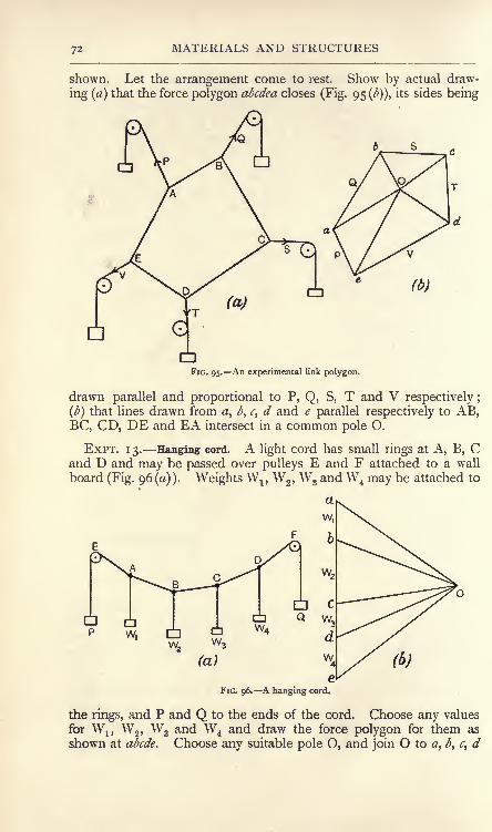
MATERIALS AND STRUCTURES
shown. Let the arrangement come to rest. Show by actual draw-
ing (a) that the force polygon abcdea closes (Fig. 95 (<)), its sides being
(b)
FIG. 95. An experimental link polygon.
drawn parallel and proportional to P, Q, S, T and V respectively ;
(b] that lines drawn from 0, b, c, d and e parallel respectively to AB,BC, CD, DE and EA intersect in a common pole O.
EXPT. 13. Hanging cord. A light cord has small rings at A, B, Cand U and may be passed over pulleys E and F attached to a wall
board (Fig. 96(0)). Weights WT ,W
2 ,W
3and W4 may be attached to
a
w,
6
FIG. 96. A hanging cord.
the rings, and P and Q to the ends of the cord. Choose any values
for W1?W
2 ,W
3 and W4and draw the force polygon for them as
shown at abcde. Choose any suitable pole O, and join O to a, b, c, d

HANGING CORDS AND CHAINS 73
and e. Oa and Oe will give the magnitudes of P and Q respectively.Fix the ring at A to the board by means of a bradawl or pin \
fix the
pulley at E so that the direction of the cord AE is parallel to Oa;
fix the ring at B by means of a pin so that the direction of the cordAB is parallel to CM. Fix also the other rings C and D, and the
pulley at F so that the directions of BC, CD and DF are parallel to
<rO, dO and eO respectively. Apply the selected weights W1?W
2 ,W
3
and W4 ,and also weights P and Q of magnitude given by Oa and
Oe. Remove the bradawls and ascertain if the cord remains in
equilibrium.
EXPT. 14. Hanging chain. Fig. 97 (a) shows a short chain ACB in
equilibrium under the action of forces VT ,V
2 ,H
Tand H2 applied by
means of cords, pulleys and weights. Find these forces by calcula-
tion, as indicated below, first weighing the chain, and apply them as
shown in the figure so as to test for the equilibrium of the chain.
FIG. 97. Equilibrium of a hanging chain.
Let D = the proposed dip or deflection of the chain in inches.
S = the span AB in inches.
It should be noted that D should not be too large when comparedwith S. Both may be measured conveniently by first stretching the
chain between the two marked positions A and B on the wall boardand then taking the required dimensions. It is assumed that A andB are on the same level. I
Imagine the chain to be cut at its centre C, and consider the
equilibrium of the right-hand half (Fig. 97 (b)). The weight of the
whole chain being W lb., the weight of the half considered will be
^W and will act at the centre of gravity G, which may be assumedg
to be at -horizontally from B provided D is not too large. As a
chain can only pull, the force H at C must be horizontal. Hencethe portion BC is at rest under the action of two equal opposing

74 MATERIALS AND STRUCTURES
couples, one formed by the equal forces V2and |W and the other
by the equal forces H and H 2. Hence
V iw (j\v2 2 \ /
H xD =JWx,4'
WS
and
or 00
EXERCISES ON CHAPTER IV.
1. A wooden gate weighs 100 lb., and has its centre of gravity situated
21 inches from the vertical axis of the hinges. The hinges are 24 inches
apart vertically, and the vertical reaction required to balance the gate is
shared equally between them. Calculate the magnitude and direction of
the reaction of each hinge and show both reactions in a diagram.
2. A square plate of 2 feet edge has forces of 2, 3, 4 and 5 lb. appliedas shown (Fig. 98). Find the force required in order to balance the
plate.
3. A plate having the shape of an equilateral triangle of 3 feet edgehas forces of i, 2 and 3 lb. applied as shown (Fig. 99). Find the resultant
force on the plate.
,2
4 3
FIG. 98. FIG. 99.
4. Suppose the plate in Question 3 to have equal forces of 2 lb. each
applied along the edges in the same manner as before. What must be
done in order to keep the plate in equilibrium ?
5. A uniform beam 12 feet span and 18 inches deep weighs 900 lb.
A load of 2 tons is applied to the top surface
at 3 feet from the right-hand support at an
angle of 45 to the horizontal (Fig. 100).
Suppose the left-hand reaction to be vertical,
and calculate the reactions of the supports.
6. A beam AB rests against walls at Aand B (Fig. 101). Vertical loads of 400 lb.
and 600 lb. trisect the beam. Suppose the
reaction at A to be horizontal, and calculate the reactions at A and B.
Neglect the weight of the beam.
FIG. 100.

EXERCISES ON CHAPTER IV. 75
7. A triangular frame 15 feet span and 5 feet high (Fig. 102) carries
loads of 400 Ib. bisecting AC, 600 Ib. at C and 800 Ib. bisecting BC at
right angles. The reaction at B is vertical. Find the reactions of the
supports by calculation.
FIG. loi.
8. Prove that two couples of equal opposing moment, acting in thesame plane, balance.
9. Show how a force acting at a given point may be moved to another
point not in the original line of the force. Prove the method to becorrect.
10. Choose any three forces not meeting at a point and not parallel to
one another. Show how we can find, graphically, their resultant or their
equilibrant. (B.E.)
11. Answer Question 10 in a manner suitable for calculation.
600/4
fFIG. 102.
12. A number of forces act in a plane and do not meet in a point.
Treating them graphically, what is the condition of equilibrium ? Prove
your statement to be correct. (You are expected to choose more thanthree forces.) (B.E.)
13. A uniform chain weighs 4 Ib., and is hung from two points on the
same level. The span is 4 feet and the central dip is 6 inches. Calculate
the pulls at the ends of the chain, and show the directions of the chain at
the ends.

76 MATERIALS AND STRUCTURES
14. A beam AB of 24 feet span is supported at the ends, and carries
vertical loads of 1-5, 2, 3 and 4-5 tons at distances of 3, 6, 12 and 18 feet
from the support at A. Use the link polygon method and find the reactions
of the supports.
15. Answer Question 6 by construction.
16. Answer Question 7 by construction.
17. ABCD is a square of 2-inch side, BD being a diagonal. A force
of 50 Ib. acts along BC from B towards C ;a force of 80 Ib. acts along CD
from C towards D; and a force of 6p Ib. acts along DB from D towards
B. Replace these forces by two equivalent forces, one of which acts at Aalong the line AD. Find the magnitude of both these forces and the line
and direction of the second. (I.C.E.)
18. Prove that any system of coplanar forces may be replaced by a
single force acting at any assigned point and a couple. Forces of I, 2, 3,
4 Ib. weight act along the sides of a square taken in order. Find a pointsuch that the forces may be replaced by a single force acting at that
point. (L.U.)

CHAPTER V.
SIMPLE STRUCTURES.
Some definitions. A structure is an arrangement of various parts
constructed in such a manner that no relative motion (other than the
small amounts due to the straining of the parts) takes place when the
structure is loaded. The simple framed structures considered in this
chapter consist of bars assumed to be connected by pin joints and
(a) (b) (c)
FIG. 103. Classes of structures : (a) deficient, () simply firm, (c) redundant.
carrying loads applied at these joints. The bars under these conditions
will be subjected to simple push or pull in the direction of their
lengths, and our object will be to determine the magnitude of the
force in each bar, and also whether the bar is under push or pull.
Structures may be deficient, simply firm, or redundant. Deficient
structures are really mechanisms, that is, the parts are capable of
considerable relative motion. Fig. 103 (a) shows an example of a
deficient structure, consisting of four bars connected by pin joints.
The arrangement may be made simply firm by the introduction of a
single diagonal bar (Fig 103 (^)), and will now be capable of preserving
its shape under the load. The introduction .of a second diagonal bar
(Fig. 1 03 (r) ) produces a redundant structure. In redundant structures,
the length of any bar cannot be altered without either a correspond-
ing alteration in the lengths of other bars of the structure, or the
production of forces in the other b^rs. Good workmanship is
essential in redundant structures to ensure the accurate fitting
together of all parts, otheiwise some of the bars may require to be

MATERIALS AND STRUCTURES
(a) (b)FIG. 104. Effect of stiff joints.
IS)
forced into position. Unequal heating causes unequal expansionin redundant structures, and therefore introduces forces in the
various parts.
In simply firm structures, which form the subject of this chapter,the length of any part may be altered without thereby producing
forces in the other parts. Con-
sequently, the effects of unequal
expansion are absent. A redundant
structure may be converted into a
simply firm structure by droppingout one or more of the redundant
elements, or parts. Redundancy maybe produced by stiff joints. For
example, if the square in Fig. 103(0) i made with one stiff joint
(Fig. 104(0)), the structure will now be simply firm. Two stiff
joints (Fig. 104^)) will produce a redundant structure having one
redundant element; three and four stiff joints in this example give
structures of two and three elements of redundancy respectively.
Conditions of equilibrium. In solving problems concerning any
structure, we may separate the forces ino two groups, external andinternal. The external forces include all forces applied as loads, or
reactions, to the structure. Obviously these forces, acting on the
structure as a whole, must be in equilibrium independently of the shapeof the structure, or of the form or arrangement of its parts. This con-
sideration enables us to apply the principles of the foregoing chapters to
such problems as the determination of the reactions of the supports.
The internal forces include the pushes, or pulls, to which the various
bars are subjected when the external forces are applied to the
structure. Not only is the structure as a whole in equilibrium, but
any bar, or any combination of selected bars in it, must be in
equilibrium under the action of any external loads applied to the
parts considered, together with the internal forces acting in the selected
parts. Usually a joint is selected, when the principle just stated
enables us to say that the forces acting at this joint, including external
forces, if any, as well as the pushes or pulls of the bars meeting at
the joint, are in equilibrium. Hence, the forces in these bars maybe found by an application of the polygon of forces.
It should be remembered in applying the polygon of forces that
the solution depends on there being not more than two unknowns;
these may be either the magnitudes or the directions of two forces, or
one magnitude and one direction. In cases where the forces do not

SIMPLE STRUCTURES 79
all intersect at one point, there are three conditions of equilibrium to
satisfy, and hence there may be three unknowns.
The methods of obtaining the reactions have been explained fully in
the preceding chapters ;hence in some of the following cases the con-
structions, or calculations, for finding the reactions have been omitted.
Simple roof truss. Fig. 105 (a) shows a simple roof truss consist-
ing of five bars. There are three loads applied as shown, together
1000/6
(at
FIG. 105. A roof truss for small spans.
TABLE OF FORCES.

8o MATERIALS AND STRUCTURES
Selecting the joint at the left-hand support, there are four forces, two
of which are completely known, and other two of which the directions
alone are known, viz. the forces CF and FA. Hence the polygon of
forces can be drawn. In Fig. 105 ()), proceeding clockwise round
the joint, AB and BC have been already drawn; draw CF parallel to
the rafter and AF parallel to the tie-bar; these lines intersect in F and
give the closed polygon of forces ABCFA. The force in the rafter maybe scaled from CF and that in the tie-bar from FA. Taking these
lines in order in relation to the joint under consideration, the sense of
the force in the rafter in Fig. 105 (a) is CF in Fig. 105 (b), and hence
is a push ; that in the tie-bar has a sense FA, and hence is a pull.
Proceeding now to the top joint of the truss, we see that there are
two unknowns, viz. the magnitudes of the forces in GF and DG,hence this joint may be solved by drawing the polygon of forces
FCDGF(Fig. io5(J)).
Taking now the joint at the right-hand support, and drawing the
polygon of forces GDEAG, we find that the closing line AG has its
position fixed already on the diagram. This fact provides a check
on the accuracy of the whole of the preceding graphical work;
if on
joining AG in Fig. 105 (<), it is found that this line is not parallel
to the right-hand rafter, some error has occurred, and in order to
eliminate it the work must be repeated.
Rule for push or pull. The method of determining whether a bar
is under push or pull may be simplified somewhat by developing the
following rule from the principle explained above.
Select any bar such as FG;choose the joint at one end of it, say
the lower;cross the bar in the same sense of rotation in relation to
this joint as was chosen in drawing the force diagrams in this case
clockwise;name the spaces in this order, viz. FG. FG in Fig. 105 (b)
gives the sense of the force acting at the lower joint. As the force is
upwards, the bar is pulling.
It makes no difference in the application of the rule which end of
the bar is selected. For example, choosing the top joint of the same
bar and crossing it again clockwise as regards the upper end, the
order is GF. GF in Fig. 105 (b) is downwards, hence the bar is
pulling at the top joint.
It is desirable to indicate on the drawing of the truss which bars
are under push and which under pull. Probably the best way of
doing this is to thicken the lines of the bars under push. If the whole
line is thickened, the direction of the bar will be lost, hence, as shown
in Fig. 105 (), a short piece at each end is left thin.

SIMPLE STRUCTURES 8 1
A tabular statement of the forces in the bars should be made in
the manner indicated on p. 79.
Another form of roof truss. Fig. io6(a) shows a common type of
roof truss carrying symmetrical loads. There will be no difficulty in
1000 Lb
500/6
1000/6
FIG. 106. Forces in a common type of roof truss ; weights only considered.
TABLE OF FORCES.
Name of part.
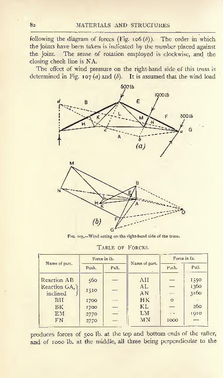
82 MATERIALS AND STRUCTURES
following the diagram of forces (Fig. 1 06 (/;)). The order in which
the joints have been taken is indicated by the number placed againstthe joint. The sense of rotation employed is clockwise, and the
closing check line is NA.The effect of wind pressure on the right-hand side of this truss is
determined in Fig. 107 (a) and (6). It is assumed that the wind load
500 to
iqooto
ft)
FIG. 107. Wind acting on the right-hand side of the truss.
TABLE OF FORCES.
Name of part.

SIMPLE STRUCTURES 83
rafter. As an example of the use of the link polygon, the reactions
of the supports have been determined by this method. The left-hand
reaction has been assumed to be vertical when that of the right-hand
support will be inclined. Wind pressure only has been taken account
of in the working. It will be noted that there are three unknownelements in the reactions, viz. the magnitude of the left-hand reaction
and both the magnitude and direction of the right-hand reaction. In
fact, all that is known of the latter reaction is that it acts through the
point a. Now, in drawing the link polygon, one link must fall between
this reaction and the force FG. As the line of the reaction is unknown,it will be impossible to draw this link unless the artifice is adoptedof starting the drawing of the link polygon at the point a. The effect
of this will be that the link in question will have zero length.
First draw as much of the external force polygon as possible ; this
is shown by BEFG in the force diagram. A will lie in the vertical
through B as the reaction AB is vertical. Taking a convenient pole
O and joining OB, OE, OF and OG, we start drawing the link poly-
gon by making ab (Fig. 107 (<z)), which falls between FG and EF,
parallel to OF. be falls between EF and BE, and is made parallel to
OE. cd falls between BE and AB, and is made parallel to OB.The link parallel to OG is omitted, as it is of zero length, coinciding
with a. Hence the closing line is da; drawing OA parallel to ad to
intersect the vertical through B in A gives the left-hand reaction as
AB and the right-hand reaction as GA.The remainder of the diagram giving the internal forces is worked
out in the usual manner, NA being the closing line.
An application of the method of graphical moments. The effect
of wind pressure on the left-hand side of this truss is determined in
Fig. 1 08. The student will have noted, in applying the link polygonto the problem of finding the reactions, that the lines of the polygonhave a tendency to obscure the drawing of the truss. In the case
now before us, the method of graphical moments (p. 46) is employedand involves the drawing of very few lines on the truss. The resultant
of the three wind loads has been taken as a single force of 2000 Ib.
applied at c. Join ab, and with centre b and radius be describe an arc
cutting ab in d. Make ae equal to 2000 Ib. to scale ; join be and
draw df perpendicular to ab and cutting be inf. Draw fg parallel to
aby when ga will be the vertical component of the right-hand reaction.
The horizontal component of this reaction will be equal and opposite
to the horizontal component of the force of 2000 Ib. acting at c.
Draw the triangle of forces dm, and make ha equal to me; the

84 MATERIALS AND STRUCTURES
right-hand reaction will be the resultant ka of the components
represented by ga and ha.
The external force polygon (Fig. io8(^)) may now be drawn
I
500/6
(b)
FIG. 108. Wind acting on the left-hand side of the truss.
TABLE OF FORCES.
Name of part.

SIMPLE STRUCTURES
FIG. 109. Combined dead and wind loads on the truss.
TABLE OF FORCES.
Name of part.

.86 MATERIALS AND STRUCTURES
for the three wind loads and the two reactions, and is shown byABCDEA. The internal force diagram is completed as before.
Notice that when the wind blows on the right-hand side, no force is
induced thereby in HK, and when acting on the left-hand side there
is no force in MN. This arises from the fact that there is no external
load at the joint in the two cases respectively. Two forces acting in
the same straight line, as is the case in the two parts of the rafter,
balance, and it is impossible to apply a single inclined force at the
point of action without disturbing the equilibrium.
The total force in any bar of the frame due to the dead loads,
i.e. the weights of the parts of the truss, and to the wind pressure
jointly may now be determined by adding the results for the dead
load (Fig. 1 06) and either those of Fig. 107 or of Fig. 108 dependingon whether the wind is blowing on the right- or left-hand side.
Combined dead load and wind pressure. As a further example of
another method of obtaining the reactions, a diagram has been drawn
in Fig. 109 for the combined dead loads and wind load on the right-
hand side. The two forces acting at each joint of the right hand
rafter have been combined by the parallelogram of forces, and the
resultant used as a single force at each joint (Fig. 109 (a)).
To find the reactions of the supports, we may take advantage of
the principle that the external forces balance independently of the
arrangement of the parts of the truss. Hence, any other convenient
arrangement may be substituted for that given without disturbing the
values of the reactions. The substituted frame chosen is sketched
in Fig. 109 (b}. It will be seen that it is possible to determine all the
forces in its parts without first determining the reactions. Thus,
starting at the top joint i, where there are two unknowns only, we
obtain DE/fc in the force diagram (Fig. 109^)). Proceeding to
joint 2, we obtain EF/#;at joint 3, CD/i/m is obtained, and at joint
4 we obtain BOzA, thus determining the point A on the force
polygon, and hence the reactions AB and GA.The internal force diagrams for the given arrangement of bars may
now be proceeded with, the closing line being NA. It will be
observed that the greater part of the lines drawn in the force diagramfor the substituted frame are required for the actual frame, hence
there has been but little wasted work.
Another form of structure. In Fig. 110(0) is shown a structure
intended to carry a load at its upper end. Since there is but one
vertical load, the reactions of the foundation must reduce to one
vertical upward force equal to the load applied. Hence, the polygon

SIMPLE STRUCTURES
for the external forces is completed by drawing AB downwards and
BA upwards. It will be noted in this example that it is not necessary
to determine the actual reactions of the foundations before finding
the forces in the parts. A start can be made at the joint i, as there
are only two unknowns there. The order of solution of the other
joints is indicated by the numerals. In drawing the various polygons
2
FIG. no. A braced frame.
TABLE OF FORCES.
Name of part.

88 MATERIALS AND STRUCTURES
given loading. There would, of course, be a force in this bar if an
inclined load were applied to the frame, or if there were a side effort
caused by wind pressure.
A larger roof truss. In Fig. 1 1 1 is shown a roof truss of a larger
type and having a different arrangement of parts from those dealt
FIG. in. A larger roof truss.
with previously. This case presents no difficulties, and is included
as an example which the student can work out for himself.
The roof truss shown in Fig. 112(0} presents a difficulty which
arises frequently. The external force polygon is drawn easily, but
(b)iraoo
FIG. ii2. A more difficult example of truss.
in drawing the force polygon for the internal forces it will be found
that it is impossible to proceed with the drawing after solving point i.
All other points such as 2 and 3 have more than two unknowns,hence the solution cannot be obtained by application of the ordinary
methods. We may proceed by either of two methods.

EXERCISES ON CHAPTER V. 89
(a) It will make no difference whatever in the forces in the remaining
part of the truss if we imagine the left-hand portion (shown shaded in
Fig. 112 (<$))to be solid. Separating this portion as shown, we may
calculate T, the force in the bar AP, by taking moments about point 6.
Thus, taking the loads as shown, let the half-span be 15 feet and let
the perpendicular from point 6 to the line of T be 7-5 feet, then
(Tx7-5)+ (4oox 5)+ (4oox io) + (2oox I5)=i2oox 15.
_ 1 8,000- 2000 - 4000 - 3000
7-5
_9ooo~~r$= 1200 lb.
Having found T, the number of unknowns at the point 3
(Fig. 112 (a) ),will now be found to be two only, hence this point
may be solved. The solution for points 2, 5, 4, 6 may now be
obtained in the usual manner.
(b) It will make no difference whatever in the force in the bar APif, instead of imagining the triangular portion above considered to be
solid, we imagine it to have a different interior arrangement of bars.
Thus, in Fig. 1 1 2 (c} is shown this portion with a new arrangementof bars substituted for that given. The force diagram for this
substituted frame may be drawn as in Fig. 112 (d), and stopped
directly the force in AP is found. The original arrangement of bars
is now restored and the force diagram completed in the usual
manner. The result for the force in AP is found graphically in
Fig. 112 (d) to be 1200 lb.
This method must be applied with caution. Care must be taken
to ensure that the substituted arrangement of bars does nothingwhatever to alter the force in the bar considered, viz. AP in
Fig. 112(0).
EXERCISES ON CHAPTER V.
In each of these exercises the forces should be tabulated, distinguishing
carefully push and pull members.'
JOO/f
400/6.
E
FIG. 113.
1. Find the forces in all the bars of the roof truss shown in Fig. 113.The bars AF, FG, GH and HA are equal.

MATERIALS AND STRUCTURES
2. Find the forces in all the bars of the truss given in Fig. 1 14. Theloads are in Ib. units.
3. Find the forces in the roof truss shown in Fig. 106 ; apply the
same loads, with the exception of that at the centre of the right-hand
rafter, which in this case is 2000 Ib. Span 24 feet, rise 6 feet, rise of tie-
bar i foot. Each rafter is bisected perpendicularly by the inclined strut.
800800 800
600
300
4. Find the forces in all the members of the truss shown in Fig. 1 1 5.
The loads are in Ib. units.
5. Take again the roof truss given in Question i. Remove all the
loads and apply wind loads of 400 Ib. at each end of the right-hand rafter,
acting at right angles to the rafter. Find the forces in all the parts dueto wind only. The left-hand reaction is vertical.
6. Answer Question 5, supposing that the wind loads are applied to
the left-hand rafter only. The left-hand reaction is vertical.
7. From the results obtained in answering Questions i, 5 and 6, con-
struct a table showing the maximum and minimum forces in each bar dueto dead load and wind pressure combined.
8. Find the forces in all the bars of the roof truss given in Fig. 116.
The loads are in Ib. units.
600
600 600
9. A roof truss similar to Fig. 1 1 1 has a span of 30 feet ; the rise is
8 feet and the height of the central horizontal part of the tie bar abovethe supports is 18 inches. If the truss carries a symmetrically distributed
load of 4 tons, find the force in AO by calculation.
10. In the roof truss given in Question 8, in addition to the stated
loads, there are wind loads of 400, 800, 800 and 400 Ib. applied at the
joints of the right-hand rafter and perpendicular to the rafter. The left-
hand reaction is vertical. Find the reactions of the supports, using the
link polygon.

EXERCISES ON CHAPTER V.
11. Answer Question 10 by application of the substituted framemethod.
12. Answer Question 10 by calculation.
13. In Question 10 find the forces in all the parts due to combined deadload and wind pressure.
14. A loaded Warren girder is shown in Fig. 117. Find the forces in
all the members. The loads are in Ib. units.
1000 1000
500 500
FIG. 117.
15. A frame secured to a vertical wall has dimensions as shown in
Fig. 118. The bars AD, AF, AH and AL are each 5 feet in length.Find the forces in all the parts produced bv the load of I ton.
\ton
2*--^ 20
FIG. 118.
16. Answer Question 15 if the load is moved horizontally so as to be
vertically over the middle joint of the top member of the frame.
17. Part of a pin-jointed frame, shown in Fig. 119, is loaded with avertical dead load of 10,000 pounds and a normal wind pressure of 15,000

MATERIALS AND STRUCTURES
pounds, both being taken as uniformly distributed along AB. The sup-porting forces P, Q and R are shown by dotted lines. Find these forcesand the forces in the bars which meet at C, indicating the struts
and ties. (L.U.)
2 tons
18. A frame is loaded with 2 tons and supported as shown in Fig. 120.
Find the reactions at A and D and the forces in the members, indicatingwhich are struts and which are ties. (I.C.E.)

CHAPTER VI.
SIMPLE STRESSES AND STRAINS.
Stress. If any section in a loaded body be taken, it will be found
in general that the part of the body which lies on one side of the
section is communicating forces across the section to the other part,
and is itself experiencing equal opposite forces. The name stress is
given to these mutual actions. The stress is described as tensile or
pull if the effect is to pull the portions of the body apart, compressive
or push if they are being pushed together, and shearing or tangential if
the tendency is to cause one portion of the body to slide on the
other portion.
The stress is said to be distributed uniformly in cases where all
small equal areas experience equal loads. Stress is measured by
stating the force per unit area, the result being described as unitai
stress, or stress intensity, or often simply as the stress. In the case of
a uniform distribution of stress, the stress intensity will be found by
dividing the total force by the area over which it is distributed.
Should the stress vary from point to point, its intensity at any point
may be stated by considering that the forces acting on a very small
area embracing that point will show a very small variation and maybe taken as uniformly distributed. Thus, if a be a very small portion
of the area and/ the load on it, the stress intensity on a will be//.Units of stress employed in practice are pounds or tons per square
inch or per square foot, or in the metric system, grams or kilograms
per square centimetre. One atmosphere is sometimes used as a unit,
being a stress of 14-7 Ib. per square inch ; it is useful to remember
that a stress of one kilogram per square centimetre is roughly equalto one atmosphere.*
*i kilogram per square centimetre = 2-205 Mb. Per -r square inch
0-45
= 14-19 Ib. per square inch.

94 MATERIALS AND STRUCTURES
EXAMPLE i. A bar of circular cross-section 2 inches in diameter is
pulled with a force of 12 tons at each end. Find the tensile stress.
Area of cross-section= = 3-1416 sq. inches.
Tensile stress intensity =area
12
3-1416
= 3-82 tons per square inch.
EXAMPLE 2. Suppose the same bar to be in two portions connected
by means of a knuckle joint having a pin i| inches in diameter (Fig. 121),
and calculate the intensity of shearing stress on the pin.
12 tons
FIG. 121.
It will be observed that the pin would have to shear at two sections
for the joint to fracture by failure of the pin, hence :
7ZY/2
Area under shear stress= x 24
=3-53 square inches.
Shear stress intensity=--area
12
~^S3= 3-39 tons per square inch.
Stresses in shells. A shell is a vessel constructed of plates the
thickness of which is small compared with the overall dimensions of
the vessel, for example, a boiler of the cylindrical type. Such
vessels have generally to withstand internal fluid pressure, and the
plates are put under tensile stress thereby. Owing to the thinness
of the plates, the stress on any section may be considered to be
distributed uniformly.
Taking a cylindrical shell (Fig. 122) in which there are no stays
passing from end to end,

STRESSES IN SHELLS 95
Let d= diameter of shell, inches,
/ = fluid pressure, pounds per square inch,
t= thickness of plate, inches,
P = total pressure on each end of vessel, then

MATERIALS AND STRUCTURES
There will be no difference experienced in the equilibrium of the
ring if we imagine it to be filled up to the level of AB with cement
(Fig. 124). The pressure on the surface of the cement will be
perpendicular to AB, and the resultant force due to this will be
Q =p x area of surface of AB
FIG. 124. Resultant pressure on hahof the ring.
FIG. 125. Stresses at A and B.
R and Q now preserve the equilibrium of the ring, and must
therefore be equal, hence R =pd.
Imagine the material at A and B to be cut, and consider the equi-
librium of the top half of the ring (Fig. 125). Forces T, T at A and
B will be required, and are produced in the uncut shell by tensile
stress at A and B. For equilibrium, wehave R = 2T,
T = - = ^.2 2
Also,
Stress intensity at A or B x t x i = T;
.'. stress intensity on longitudinal section
= ^- Ib. per square inch.
Comparison of these results will show that
the stress on a longitudinal section is double
that on a circumferential section, a fact which
explains why the longitudinal joints in boilers
are made much stronger than the circum-
ferential joints.
A spherical shell may be worked out in a
similar man-ner. Let the shell be filled up to the level of a horizontal
diameter AB with cement (Fig. 126), then
Sectional Plan
FIG. 126. Stresses in a sphericalshell.

RIVETED JOINTS 9?
The complete cross-section at AB is a ring of diameter d andthickness /, and is under tensile stress of intensity given by
Tensile stress intensity x area of cross-section = R,-D
.'. Tensile stress intensity= -r
trdt
= Ib. per square inch.
As before, p = fluid pressure in Ib. per square inch,
d= diameter of sphere in inches,
/ = thickness of plate in inches.
It will be noted that the stress intensity in a spherical shell is the
same as that on the circumferential sections of a cylindrical shell of
the same diameter and thickness, and subjected to the same fluid
pressure. It will also be observed that a spherical shell is self-staying
on account of the fact that its shape does not tend to alter whenit is exposed to the internal fluid pressure. The same is true for
the cylindrical portion of an ordinary boiler shell, but the flat end
plates are liable to be bulged outwards unless supported or stayedin some effectual manner.
Riveted joints. Plates may be connected permanently by means
of riveted joints. In lap joints the edges of the plates overlap
(Figs. 131 and 132) and are connected by one or two rows of
rivets ;in butt joints the plates are brought together edge to edge
(Figs. 133 and 134) and cover plates pass along the seam on both
sides or on one side only. As the strength of the joint dependsto a considerable extent on the workshop methods employed, it is
necessary to make brief reference to these methods.
Excepting in the case of very thin plates and small rivets, the rivets
are heated before being inserted in the holes and are closed by the
use of hand or pneumatic hammers, or by a hydraulic riveting machine.
Owing to the great pressure exerted in the latter method, the rivets
generally fill the hole better when finished and the plates are held
together more firmly. In either method, the cooling of the rivet and
consequent longitudinal contraction assist largely in binding the plates
together, while at the same time the rivet is put under pull stress of
an uncertain amount.
P.M. G

98 MATERIALS AND STRUCTURES
Rivet holes may be punched or drilled. Punching injures the
metal by overstraining the material round the hole, a defect which
may be remedied by annealing, or by punching the hole about -^ inch
smaller than the proper diameter, and then enlarging it to the size
required with a reamer, thus getting rid of the
overstrained material. The plates are punched
separately, hence there is difficulty in ensuring
that the holes shall come exactly opposite one
r*?[another when the plates are brought together;
'-.4 drilling is effected with the plates together in
'p.-.d-y position, and this method is to be preferred as
FIG. i27.-stress on agiving fair holes, as well as producing no injury
to the plates. Punched holes may be broughtfair by bolting the plates together before reamering.
There is a lower limit to the diameter of hole which may be
punched in a plate of given thickness, depending on the value of the
stress under which the punch will crush.
Let d= diameter of hole, inches (Fig. 127),
/ = thickness of plate, inches,
q = shearing stress of material of plate, in tons per square inch.
p = crushing stress of material of punch, in tons per square inch.
Area under shear stress = trd x /.
Force P required to shear the material = qtr dt.
Push stress on punch = P -5
Equating this to / will give the limiting value of d, thus
.
P
p for the material of the punch, tool steel, is about four times the
value of q for mild steel, hence, the condition that the punch is on
the point of crushing is ^_ t
showing that the minimum diameter of hole which may be punchedis equal to the thickness of the plate. If d is less than /, / must
have a value greater than \q for punching to be possible.

RIVETED JOINTS 99
Riveted joints should not be designed so as to load the rivets by
tension, as the heads are not reliable under pull. The loading should
be of the nature of pull or push along the direction of the plates, thus
putting the rivets under shear stress. Lap joints (Fig. 128) and butt
joints having a single cover plate (Fig. 129) are put under a bending
FIG. 128. FIG. 129.
action by reason of the forces being in parallel lines. Butt joints
having double cover plates (Figs. 133 and 134) are free from this
objection. In lap joints, the rivets will sustain equal shearing forces
whether the plates be under pull or push ;in butt joints under push,
the forces will be communicated from plate to plate along the edges
in contact without putting the rivets under shear stress at all, provided
the fitting is perfect. The cover plates and rivets in this case serve
only to prevent the plates getting out of the same plane. For these
reasons, both compression and tension members are best fitted with
butt joints having double cover plates.
Methods of failure of riveted joints. These may be described byreference to Fig. 1 30, showing a single riveted lap joint.
(a) If the hole is situated too near
the edge of the plate, the material may
open out as at A during punching, or byreason of the bursting pressure exercised
by the hot, soft rivet while being closed.
To prevent this happening, the distance
from the centre of the hole to the edge of
the plate should not be less than 1-5 times
the diameter of the rivet.
(^) The material of the plate may crush
at B owing to the rivet being too large
in diameter. When the joint is loaded the
rivet bears on one half of the cylindrical
surface of the hole, producing a bearing
stress which is calculated by dividing the
load on the rivet by the "projected area
"
of the hole, the latter being calculated by taking the product of the
diameter of the hole and the thickness of the plate. In girder work,
the design of the riveted joints has to be based sometimes on the
FIG. 130. Methods of failure of
riveted joints.

100 MATERIALS AND STRUCTURES
safe bearing stress; this stress ranges from 7 to 10 tons per squareinch in practice.
(<r) One of the plates may give way by tearing along the line CD.
(d) The rivets may shear at EF.
The most economical joint would be equally ready to fail by all
four ways simultaneously. It is impossible to calculate (a) from first
principles, but expressions giving the relations of the various quantities
may be found by equalising the resistances of the joint to crushing,
tearing and shearing. It is customary in this country to neglect the
increase in strength owing to the frictional resistance to the plates
sliding on one another. The precise conditions for any riveted joint
cannot be stated definitely, hence empirical rules, or rules which are
partly empirical, are often employed in practice.
Lap joints. Lap joints may be single or double riveted ;it is rarely
the case that there are more than two rows of rivets. The pitch is
the distance from centre to centre of the rivets measured along the
row. The strength of the joint may be considered by taking a strip
equal in breadth to the pitch, as the conclusions arrived at for this
piece may be assumed to be true for the entire joint.
Let p = pitch of the rivets, inches;
d= diameter of the rivets, inches;
t= thickness of the plates, inches;
y~= the ultimate tensile strength of
the plates, tons per square inch;
fg= the ultimate shearing strength of
the rivet, tons per square inch;
fb = the bearing stress, tons per
square inch of projected area,
when the joint is on the point
of failing by crushing.
FIG. 131. Strength of a single-riveted
lap joint.
We have, for a single riveted lap joint (Fig. 131) :
Least area of plate section under pull= (p- d}ty
Resistance of joint to tearing =ft(p d)t tons............. (i)
Area of rivet section under shear
Resistance of joint to shearing =/ - tons................... ( 2 )
4
Projected area = dt,
Resistance of joint to crushing =fydt tons.................... (3)

RIVETED JOINTS , v- I '*ta\
Equating (i), (2) and (3) gives :
Taking
d-/ft
(4)- .........................
JS
The diameter of the rivet may be found from this relation, and the
pitch may then be calculated from
P = ('l*SJi "-) + <*. v5)
In double riveted lap joints there will be two rivet sections per
;_iM^

MATERIALS AND STRUCTURES
Butt joints. The strength of butt joints may be calculated in a
similar manner; it will be observed (Fig. 133) that, with two cover

RIVETED JOINTS 103
Data from experiments. The ultimate tensile strength of iron
plates may vary from 21 to 26 tons per square inch, and for steel
plates may vary from 27 to 32 tons per square inch. Iron and steel
rivets have an ultimate shearing strength of about 23 tons per squareinch. Owing to the difficulty of stating precisely what the actual
conditions are in a finished riveted joint, these stresses should be
used with caution. Experiments on actual joints with iron plates
and iron rivets show that the ratio fg/ft,is nearly i for drilled holes,
and from 1-2 to 1-3 for punched holes which have been neither
annealed nor reamered. For steel plates and steel rivets the values
of the ratio appear to be about 0-75 for drilled holes and about 0-9 for
punched holes neither annealed nor reamered. For either reamered
or annealed punched holes the values are about the same as for
drilled holes. Breakdown in experimental joints by crushing appearsto take place for ratios of fb/fs of about 1-7 for rivets in single shear
and about 2-35 for rivets in double shear. Provision against crush-
ing is often made by employment of an empirical rule for the
diameter of the rivet. A good practical rule is
</=I-2>/7 tO I-4A//.
When this rule is used, the diameter of the rivet is calculated
first, and the pitch is then determined by equating the resistances
to tearing and shearing. Afterwards, the bearing stress should be
calculated in order to ascertain that its value is not excessive.
In riveted joints designed under the Board of Trade rules, rivets
under double shear are allowed if rivet sections per rivet only ;this
is owing to the probability of the rivets not all bearing equally. This
rule is often disregarded in other joints.*
Efficiency of riveted joints. The efficiency of a riveted joint is
the ratio of its actual strength to that of the solid plate. To calculate
the efficiency, the ratios of the strength of the joint against tearing,
shearing and crushing to the strength of the solid plate should be
calculated separately, and the lowest value taken as the efficiency
of the joint. It will be evident that all three ratios will be equal if
the joint has been designed for equality of rupture by each of the
three ways of failure, and the efficiency may be obtained then byconsideration of the tearing resistance only.
Resistance of joint to tearing= (P~ d)tft-
Resistance of solid plate to tearing =ptft .
* For a full discussion of riveted joints, see Machine Design, Part I., by Prof.
W. C. Unwin (Longmans, 1909).

104 MATERIALS AND STRUCTURES
P
EXAMPLE i. A double riveted butt joint with double cover plates is
used to connect steel plates of 0-5 inch thickness;the holes are to be
drilled. Find the diameter of the rivets from the empirical rule (p. 103),
and also the pitch of the rivets, taking
= | inch, nearly.
</ (p. 102)
= (3-142 x 075 x ()2 x 2) + 1
= 4^ inches, nearly.
EXAMPLE 2. Calculate the efficiency of the above joint.
Efficiency =^-7
^4-5-0-8754-5
=0-805= 80-5 per cent.
Or the efficiency may be calculated by considering the resistance to
shearing. Thus :
Area per pitch under shear stress = 4-
Strength against shearing= 7r</2/s
.
Efficiency against shearing = 7rd'2fs -rfltft
nP fs=Pt
'
ft.
^3-142x49x0-754-5x0-5x64
= 0-802
= 80-2 per cent.
EXAMPLE 3. Calculate the bearing stress in the above joint when
carrying a load which produces a stress of 4 tons per square inch in the
solid plate.Area of solid plate per pitch pt
= 4-5x0-5=
2-25 sq. inches.
Load per pitch ^4x2-2 5
= 9 tons.

RIVETED JOINTS 105
This load is carried on the bearing surface of two rivets; hence :
Projected bearing surface per rivet= dr
/.
Bearing stress =-^__9
2x0-875 X0'5
= 10-3 tons per sq. inch.
EXAMPLE 4. Two plates forming a tie-bar have to be connected end
to end by a butt joint having double cover straps (Fig. 135). Each plate
A, C. t,
o o o oo 60006000
o o o o
o o o o oo
o o o o
B 1 D 1 F 1
FIG. 135. Riveted joint for a tie-bar.
is 10 inches wide and f inch thick;the rivets are f inch in diameter.
The stresses allowed are 6 tons per square inch pull, 4 tons per squareinch shearing, and 10 tons per square inch bearing. Find the numberof rivets required.
Sectional area of each plate =iox =7-5 square inches.
Area abstracted by one rivet hole at the section AB = | x 1= 0-56 sq. in.
Net sectional area of plate at AB = 7-5 -0-56= 6-94 square inches.
Total safe pull on the plate= 6-94x6 = 41 -64 tons.
Sectional area of one rivet=4
TT(t* 22
7X4x r= 0-442 sq. in,
Allowing if rivet sections for rivets under double shear, we have
Shearing resistance of one rivet=o-442 x 1-75 X4= 3-09 tons.
Projected area of one rivet =|x 1=0-56 square inch.
Bearing resistance of one rivet = o-56x 10= 5-6 tons.
As the shearing resistance is lower than the bearing resistance, the
shearing resistance must be taken in calculating the number of rivets
required. Let N be the number of rivets on each side of the joint ;then
Total safe pull on the plate= total shearing resistance of the rivets,
41-64 = N X3-09,
N = I4 rivets.
To obtain a good arrangement of rivets, 15 rivets have been placed oneach side of the joint in Fig. 135.
io6 MATERIALS AND STRUCTURES
At the section AB, the safe load which can be applied is that calculated
above as 41-64 tons. At CD, the tearing strength of the plate is less
than at AB, but to this must be added the resistance of the rivet on the
left-hand side of CD, as this rivet would have to shear simultaneouslywith the plate tearing at CD for the joint to fail in this way.
Sectional area of plate at CD = 7-5 -(2 xo-56)= 6-38 square inches.
Resistance to tearing at CD = 6-38x6= 38-28 tons.
Adding the shearing resistance of one rivet to this, we have
Safe load with reference to the section CD = 38-28 4-3-09= 41-37 tons.
Considering the section EF, the three rivets on the left-hand side of
EF would have to shear simultaneously with the plate tearing.
Resistance to tearing at EF = { 7-5-
(3 x 0-56) }6= 34-92 tons.
Shearing resistance of three rivets = 3 x 3-09= 9-27 tons.
Safe load with reference to the section EF = 44-19 tons.
It is evident that the safe load with reference to any other section on
the right-hand side of EF will have a greater value than that for the
section EF. The minimum safe load is that calculated for the section
CD, viz. 41-37 tons, which accordingly is the safe load which the joint
will carry.
Strain. Strain refers to the alterations of form or dimensions
which occur when a body is loaded or subjected to stress. Thus a
pulled or pushed bar is found to have become longer or shorter after
the load is applied, and is said to have longitudinal strain. This kind
of strain is measured by taking the ratio of the change in length to
the original length.
Let L = original length of bar,
= alteration in length, both in the same units.
Longitudinal strain = =-.
Volumetric strain occurs when a body is subjected to uniform fluid
pressure over the whole of its exposed surfaces. The volume will be
changed somewhat under these conditions, and the volumetric strain
is measured by taking the ratio of the change in volume to the
original volume.
Let V =original volume of body,
v = change in volume, both in the same units.
i)
Volumetric strain = =-=.
V
Shearing strain occurs when a body is subjected to shear stress.
Such a stress is distinguished from the other two just mentioned in

TYPES OF STRAIN 107
that it produces a change in the shape of the body, while pull, push,
and hydrostatic stress produce no such change. We may obtain an
idea of what happens by holding one cover ot a thick book firmly
on the table and applying a shearing force to the top cover (Fig. 136).
The change in shape is evidenced by the square originally pencilled
**.,. .p.,?.?
FIG. 136. Shearing strain illustrated
by a book.
f
FIG. 137. Measurement of
shearing strain.
on the end of the book becoming a rhombus. A solid bodywould behave in the same manner under similar conditions of load-
ing, only, of course, in a minor degree (Fig. 137). The shearing
strain is measured by stating the angle in radians through which the
vertical edge has rotated on application of the shearing stress.
Shearing strain = radians (Fig. 137).
For metals 6 is always very small, and it is often sufficiently
accurate to write, referring to Fig. 137:
Shearing strain = 0,
BE'
~BC*
Transverse strain. When a bar is pulled or pushed, not only is
its length altered, but also its transverse dimensions. Thus a pulled
bar becomes thinner, while a pushed bar becomes thicker. Such
alterations are referred to as transverse strains and are measured in
the same manner as longitudinal strains, viz. by taking the ratio of
the alteration in transverse dimension to the original transverse
dimension.
H = a transverse dimension of the bar,
h the change in H when the bar is loaded.
h
Let
Transverse strain =H*
For any given material, such as a metal, experiment shows that

io8 MATERIALS AND STRUCTURES
there is a definite ratio of longitudinal to transverse strain, rangingfrom 3 to 4 for common metals.
Let a = longitudinal strain,
b = transverse strain,
a
m-j.
The value of m depends on the kind of material;
its reciprocal
is called Poisson's ratio. Values of this ratio for common materialsmare tabulated on p. 683.
Elasticity. Elasticity is that property of matter by virtue of which
a body endeavours to return to its original form and dimensions
when strained, the recovery taking place when the disturbing forces
are removed. Strain takes place while the loads are being appliedto a body, hence mechanical work (see p. 325) is expended in pro-
ducing strain, and is stored up, partly at any rate, in the body.The elasticity of any material is regarded as being perfect, providedthe recovery of the original form and dimensions is perfect on
removal of the loads, and provided also that the energy given out
during recovery equals that expended while the body was beingstrained.
The elasticity of a large number of materials is practically perfect
provided they are not stressed beyond a certain limit, which dependson the kind of material and also on the nature of the stress applied.
If loaded beyond this elastic limit of stress, the recovery of original
form and dimensions is incomplete and the body is said to have
acquired permanent set.
Further, experiment shows that the strains are proportional to the
stresses producing them provided that the elastic limit is not exceeded.
This law was first discovered by Hooke, and bears his name.
Most materials show slight divergencies from Hooke's law, but it is
adhered to so closely in the case of common metals as to justify the
assumption of its truth for nearly all practical purposes.
Modulus of elasticity. Assuming Hooke's law to be true, and
selecting any elastic material to which loads may be applied.
Let / = the stress,
s = the strain produced by /.
Then p varies as s up to the elastic limit, hence the quantity will
be constant for that material up to the elastic limit. The term
modulus of elasticity is given lo this quantity. The value of the

ELASTIC MODULI 109
modulus of elasticity depends firstly on the nature of the material,
and in the second place on the nature of the stress. For any givenmaterial there are three moduli of elasticity which should be under-
stood. In each case the measurement is made by taking
Modulus of elasticity= .
The units of this expression will be governed by the unit of stress
employed, as strain is simply a ratio.
Young's modulus for a pushed or pulled bar is obtained by dividing
the push or pull stress intensity on a cross section at 90 to the axis
of the bar by the longitudinal strain.
Let P = force of push or pull applied to the bar,
A = area of the cross section,
L = original length of the bar,
= change of length of the bar,
both the latter being in the same units.
Then, writing E for Young's modulus,
E =stress
strain
* **A '
L Ae'
The bulk modulus belongs to the case of a body subjected to hydro-static stress, which produces volumetric strain.
Let / = the hydrostatic stress intensity,
V the original volume of the body,
v = the change in volume,
both the latter being in the same units.
Then, writing K for the bulk modulus,
The rigidity modulus refers to the case of a body under shearing
stress, and consequently changing its shape by shearing strain.
Let q = the shearing stress intensity,
6 = the shearing strain, in radians.
Then, writing C for the rigidity modulus,
The most convenient units to employ for the elastic moduli are
tons or Ib. per square inch in the British system, and kilograms per

no MATERIALS AND STRUCTURES
square centimetre in the metric system. A table of values will be
found on p. 683.
Strains in a cylindrical boiler shell. It has been seen (p. 96)that the stresses in a cylindrical boiler shell on longitudinal seams
and on circumferential seams are in the ratio of two to one. Supposethat in consequence of these stresses the circumference becomes
greater by a small amount e. Let d be the original diameter of the
shell, then the original length of the circumference will be ird, andthe circumferential strain will be :
Circumferential strain7T/
Also, new length of the circumference = ird+ e;
.'. new length of the diameter -.
7T
Hence, change in the diameter = - d
d+--d7T
to
strain in the direction of a diameter
(2)
Comparison of (i) and (2) shows that the diametral and circum-
ferential strains are equal.
-6
\P (d) (b)
FIG. 138. Strains in a boiler shell.
To obtain the circumferential strain, let / and \p be the stresses
on the longitudinal and circumferential seams respectively. If /were to act alone (Fig. 138 (a)), the circumferential strain would be
a (extension) and the transverse strain would be b (contraction).
If \p were to act alone (Fig. 138^)), the longitudinal strain would
be \a (extension) and the circumferential strain would be \b

STRAINS IN SHELLS in
(contraction). Hence, when both stresses act together, the strains
produced will be :
Circumferential strain = a -\b...................... (3)
Longitudinal strain = \a- b....... ............... (4)
Or, since m ^ ^'
m
And Circumferential strain = a ---2 m
Longitudinal strain = -a -
-, \
(6)
2 mi
Suppose m be taken equal to 4, then
Circumferential strain = a(i - ^)
,
=l (7)
Longitudinal strain = a (^-j)
=> (8)
Reference to Fig. 1 38 (a) shows that
E-*a
or =g (9)
vHence : Circumferential strain = \ ^. (10)O Ji
Longitudinal strain = - ^ ( ll )
4 &
ExAMPtE. A boiler shell 7 feet in diameter and 30 feet long is tested
by hydraulic pressure (cold water) up to a stress of 6 tons per square inch
on the longitudinal seams. Take = 13,500 tons per square inch andm= 4, and find how much water will escape when a test cock on the topof the boiler is opened. Neglect any bulging of the ends.
[To answer this question, calculate the increase in volume of the shell
while the pressure is being applied.]
Circumferential strain= | x Tg f jo=
The diametral strain is equal to this;hence :
Change in diameter =(7 x 12) x ^-
=0-0327 inch.
Final diameter of shell = 84-0327 inches.

112 MATERIALS AND STRUCTURES
Let JL) and d be the final and original diameters;then
Increase in cross-sectional area of the water =-(D 2 -</2)
= - x 0-0327 x 2 x 84 nearly4
= 4-32 square inches.
.. increase in volume due to increase in sectional area = 4-32 x 360= 1555 cub. in,
Again, Longitudinal strain= J x Tsf(Rj=
2TIW/. change in length of the shell = 30 x 12 x ^7000
= 0-04 inch.
Sectional area of the water = - x 842(nearly)
4= 5542 sq. inches.
.*. increase in volume due to increase in length =0-04x5 542= 222 cubic inches.
Total increase in volume = 1550+ 222
= 1777 cubic inches.
The change in volume which occurs when charging cylinders for
holding compressed gases is sometimes taken as a test of the
soundness of the material of which the cylinder is constructed.
The test is made by having the cylinder immersed in water contained
in a closed vessel fitted with an external glass tube connected to the
water space. In charging, the expansion of the cylinder will displace
some of the water, which will therefore rise in the glass tube. Anincrease in volume of more than a prescribed limit, as indicated by the
tube reading, affords evidence of defects in the material of the cylinder.
Stresses in thick cylinders. In Fig. 139 (a) is shown a cylinder of
considerable thickness under external and internal fluid pressures.
Let push stresses be denoted positive, and let the external pressure
be greater than the internal pressure. Consider a ring of unit length,
having an inner radius r and outer radius (r + 8r) (Fig. 139 (<)). Let
the radial stress on its inner surface be /, and let that on the outer
surface be (p + Sp). The resultants of these stresses on the half ring
(Fig. 139 (r)) will beP
1 =p x 2r (see p. 96),
The resultant P of Pxand P
2 is
P = P2-P
1
= (/ + 8p) x 2 (r + 8r) -p x zr.

STRENGTH OF THICK CYLINDERS
Let / be the tangential, or hoop stress on the ring ; the area over
which this stress is distributed is 8r x i,and there are two horizontal
sections, one at A and one at B (Fig. 139 (<:)) ; hence,
or /. 8r=pr+r.8p+#.8r+8p.8r-pr
by neglecting the product of the small quantities 8p and Sr.
P* i P+$P
(i)
FIG. 139. Stresses in a thick cylinder.
Another equation may be formed by consideration of the strains
in the axial direction produced by p and f all over the cylinder. It
may be assumed that cross sections of the cylinder remain planewhen the fluid stress is applied, i.e. all fibres parallel to the axis of
the cylinder lying between two cross sections change their lengths to
the same extent. Hence the assumption that the axial strains are
equal all over the cylinder.
Axial strain produced by/ =-,
As both/ and/are push stresses, both of these strains are exten
sions, and the total axial strain will be
+ = a constant,';V '
!
or p +/= a constant.
Taking 20, for the value of the constant, this gives
p+f=2d (2)
D.M.

H 4 MATERIALS AND STRUCTURES
From (2), f=2a-p.
(i), (2a-p)Sr=r.8p+p.Sr,2a . r p . 8r=r. Sp+p . Sr,
2a.8r=r.8p+2p.Sr.
Multiply each side of this equation by r, giving
2ar . &r = r2 . 8p + 2pr . Sr,
or in the limit, when 8r becomes very small,
2ar=**- + 2pr.dr
The right-hand side is the differential coefficient of (pr*), i.e.
Hence, d(pr&)= 2ar . dr.
Integrate, giving prz = ar2 + c.
f = * + ? ................................. (3)
and /= 20, -p
= - ................................ (4)
The solution of any particular problem may be obtained from (3)
and (4) by first determining a and c from the given conditions.
Take the ordinary case of a cylinder having an internal fluid pressure
pi, the external pressure being regarded as zero (Fig. 140). We have
p=pi when r=Rij /. A = +^72
................ (5)
Hence,
p = o when r=R ;."
P .2D 2
n .2
Substitution of these values in (4) gives
/_ _%:__ ioA R 2 -R,2 ^Ro^Ri2 '^
,
R-2
\

TEMPERATURE STRESSES
This equation gives the hoop tension at any radius r; the maximum
hoop tension will occur where r has its smallest value, i.e. at the
inner skin, where r=Ri. Hence,
AT f R*2/ .
RO!
Maximum /= /trs =r-w i +
It will be noticed from equation (8) that the maximum hooptension is always greater than the internal fluid
stress pi, independently of the thickness of the
cylinder ; hence, it is impossible to design a
solid cylinder to withstand a fluid pressure
greater than a certain value for a given material.
The difficulty may be overcome by shrinking
one cylinder on the top of another, or by
winding wire under strong tension over the
outside of the cylinder. The effect is to putFlG> 14 *
the inner parts under initial push hoop stress, and gives a distribution
of stress more nearly uniform when the fluid pressure is applied.
Stresses produced by change in temperature. If a metal bar be
heated, its length will increase by an amount proportional to the
increase in temperature, and to a coefficient, the value of which
depends on the kind of material;this is on the assumption that the
bar is permitted to expand freely.
Let L = the original length, in inches ;
/ = the rise in temperature ;
= the coefficient of expansion, i.e. the change in length
per unit length produced by a rise in temperature
of one degree.
Then, change in length= L/e
;
new length of the bar = L + Lfc
(0
Suppose that the bar is now cooled to its original temperature, and
that forces are applied to its ends so as to prevent it from returning
to its original length. Evidently these forces will have the same
value as those which would be required to produce an elastic
extension L/ in the bar had its original temperature been kept
unaltered.

n6 MATERIALS AND STRUCTURES
Let P = the total force required in tons.
A = the cross sectional area in square inches.
pp = the stress produced by P in tons per square inch.
E = Young's modulus in tons per square inch.
Then Longitudinal strain = =fc.
Ais >
P = EA/tons, .............................. (2)
p E/ tons per square inch............. (3)
EXAMPLE. If the bar be of steel for which =13,500 tons per square
inch, and if the rise in temperature be 100 F., find the stress in the
material under the conditions expressed above. Take= 0-000007,
J>=Et= 13,500 x 100 x 0-000007= 9-45 tons per square inch.
Suppose now that the bar be heated and at the same time held
rigidly between abutments which prevent entirely any change in the
length. These conditions may be imagined as follows : first allow the
bar to expand freely on heating ; then apply forces to the ends and
let these be sufficient to compress the bar back to its original length.
Length of the bar before applying the forces = L(i
Change in length produced by P = L/e.
Elastic strain produced by P =
i + U
Now E= p.-
stram
E/e, x
rz (4)
The denominator will be nearly unity, as U is usually very small;
hence, (4) will have the same value nearly as (3).
Effects produced by unequal heating. Fig. 141 illustrates three
bars A, B and C attached to rigid cross pieces D and E;E is fixed

TEMPERATURE STRESSES 117
and D may rise or fall freely. B is centrally situated between A andC ;
A and C have equal sectional areas and B may have a different
sectional area. All three bars are of the same material.
If all three bars be at the same tempera-
ture at first, and if they be raised throughthe same range of temperature, all will
attempt to expand equally in the direction
of length, and no stress will be producedin any of them. Suppose, however, that Bis raised to a certain temperature and that
A and C are both raised to the same
higher temperature, then B attempts to
expand to a smaller extent than A and C.
The cross pieces D and E will compel all
three to come to the same length ; hence,
B will be under pull and A and C will be FIG. 141. stresses due to unequal
under push. This is indicated in the figure
by the forces P and Q. As no force whatever is required from the
outside in order to balance the arrangement under the altered
conditions of temperature, it follows that
1> = 2Q (i)
Let the equal sectional areas of A and C be denoted by xand
the sectional area of B by a2 ; then
V

I IS MATERIALS AND STRUCTURES
First assume that all three bars expand freely ;then
Extension of A = extension of C =L/^.
Extension of B = L^.New length of A or C = L(i + ^)
= ^L,where ^ = i + ^e.
New length of B = L(i + tzc)
where A2= i
Let the bars now be compelled to come to the same final lengthLF by application of the forces P and Q.
Shortening of A or C produced by Q = ^L -L,..
Extension of B produced by P = LF- ^
2L.
Strain of A or C
Strain
Hence, for A or C,
And for B,
Lp
or
As the ratio of pland p>2 is known from (2), this result may be
used for calculating LF ,the final distance between the cross pieces;
substitution in (3) and (4) will then give the values of/j and/2.
EXAMPLE. Take the following data for the arrangement shown in
Fig. 141 and calculate the final distance between the cross pieces, also the
stress in each mild steel bar.
#!= i square inch. . L=ioo inches.
a%=3 square inches. -30,000,000 Ib. per sq. inch.
/i=iooF. = 0-000007.

REINFORCED CONCRETE COLUMNS
AlSO,
From (5),
whence
;= i 4- ( ioo x 0-000007) :
:= I + (50 x 0-000007) =
iL= 1-0007 x ioo =100-07.A2L= 1-00035 x 100= 100-035.
3-002 1 _ 1 00-07- LF
2-0007
I -0007.
LF- 100-035'
LF= 100-04899.
(Note, as the changes of length are calculated by taking the differences;n the lengths of the bars, it is necessary in examples of this kind to use a
larger number of significant figures than that employed usually.)
From (3), 30,000,000 :
whence p l-.
From (4), 30,000,000=^2
whence
100-07'* l
100-07-
100-04899'= 6298 Ib. per square inch.
100-035
100-04899- 100-035'= 4195 Ib. per square inch.
These stresses have the calculated ratio of 1-5.
This problem may be varied by using bars of
different materials and raising the temperaturesof all to the same extent. The differences in
the elastic moduli will produce a similar effect
to that caused by unequal heating, and the
calculation is effected in a similar manner,
making use of the proper values of the co-
efficients of expansion and of the elastic moduli.
Reinforced concrete column. In Fig. 142 is
shown a concrete column reinforced by steel
bars arranged as shown in the plan. Appli-
cation of an axial load to the column will cause
both steel and concrete to shorten to the same
extent;
as the lengths of both are equal, it
follows that the strains are also equal. Usingthe suffixes c and s to denote the concrete and
steel respectively, lets _ s
FIG. 142. Reinforced con-crete column.
Then
the strains in the direction of the
length of the column.
fs andfc= the stresses in Ib. per square inch.
Eg and Ec= Young's moduli in Ib. per square inch.
A8 and Ac= the sectional areas in square inches.
T? _f* /T\

126 iMATEJEUALS AND STRUCTURES
Dividing (i) by (2), we have
E* = S* fc
EC fc S8
The ratio of Es to Ec varies somewhat;the average value of 1 5 is
usually taken. With this value, equation (3) shows that the stress in
the steel will always be 15 times that in the concrete irrespective of the
relation of the sectional areas of the concrete and steel. If 500 Ib.
per square inch be taken as a safe stress for the concrete, then the
stress in the steel will be 7500 Ib. per square inch.
Suppose VV to be the load in Ib. applied to the column;then
..................... (4)
a result which enables the safe load to be calculated if the sectional
areas of the steel and concrete are given.
The stresses produced in other composite bars under push or pull
are calculated in a similar manner, making use of the proper values
of Young's modulus. Such bars may take the form of a steel rod
cased in some alloy such as gun-metal, or the arrangement may be
as illustrated in Fig. 141, with A and C of one material and B of a
different material. A central load applied to the top cross piece 1)
will produce equal strains in all the bars, and the stresses will thus be
proportional to the values of Young's modulus for the materials of
the bars.
Classification of stresses. Stresses may be either normal or tan-
gential ; oblique stress is compounded of normal and tangential stresses.
Stress is purely normal when its lines of direction are perpendicularto the surface over which it is distributed. Normal stresses may be
either tensile or compressive. Stress is tangential or shearing when
FIG. 143. Stress in a tie-bar.
its lines of direction coincide with the surface over which it is
distributed. Oblique stress may have its lines of direction inclined
at any angle between o and 90 to the surface over which it is
distributed. Normal tensile stress occurs in any section AB of a tie-
bar subjected to axial pulls (Fig. 143), the section being perpendicular

RELATIONS OF STRESSES 121
FIG. 144. Stressin a column.
to the axis of the bar. The stress in this case will be uniformlydistributed except for sections near the ends of the bar, and its
intensity will be given byP
p = : .f area of section ABNormal compressive stress will be found on any
horizontal section AB of a vertical column (Fig. 144)
carrying a weight W. If the line of W coincides with
the axis of the column, the stress will be uniformly
distributed and of intensity given by
W* ~
area of section AB'
Relation of oblique stress with normal and
tangential components. Let ABCD (Fig. 145) represent the eleva-
tion of a cube of unit edge, the top face being subjected to normal
stress pn and also to tangential stress pi. On the supposition that
these stresses are uniformly distributed,
we may substitute resultant forces PNand PT , acting at the centre O of the
top face, in a plane parallel to that
of the paper, the values of PN and P,
being pn and pt as the face is of unit
area. The resultant of PN and PTwill be
R =VPN2 + PT2,
and will act at an angle 6 to the
normal, the tangent of which is
FIG. 145. Relation of stresses. tan " = ^
Now R may be taken to be the resultant of an infinite number of
forces having the same direction as R,
and uniformly distributed over the topface of the cube (Fig. 146), these forces
constituting an oblique stress r, the value
of which will beFIG. 146.
Rarea of top face
(0

122 MATERIALS AND STRUCTURES
Other useful relations deduced easily from the figure are :
pt = r . sin 0, (3)
(4)Pn
The angle is defined as the angle of obliquity of the stress.
Some examples of oblique stress. A useful method of determiningthe stresses on any section of a loaded body consists in first imaginingthat the body has been actually cut at the given section. One portion
only of the body is then taken, and the resultant forces are determined
which must be applied to the section in order to produce equilibrium
in this portion. The stresses and their distribution may then be found.
Consider a column carrying a load P, the line of which coincides
with the axis of the column (Fig. 147 (a)). Let the column be cut at
a section AB and consider the upper portion (Fig. 147 (^)). For
equilibrium, a resultant force P' = P must be applied in the same line
as P. This will give rise to a stress which will be seen afterwards
to be uniformly distributed over AB. Let the area of the section
AB be S;then p
Stress intensity on AB=/=^ (i)o
(a)
, ,
tffltttIP'
(b)
B
FIG. 147. Normal and shear stresses in a column.
Supposing the column to be cut along CD (Fig. 147 (a)), the angle
between AB and CD being 0. Considering the equilibrium of the
top portion (Fig. 147 (<:)), we see that a resultant force P' = P must be
applied in the same line as P. P' will give rise to an oblique stress
uniformly distributed over the section CD;
let ON be drawn normal
to the section, when it will be evident that the angle between P' and
ON, which is the angle of obliquity, is equal to 0. To find the
stress intensity, we haveP'
Stress intensity=A= ? = 7^7^-J 2 area of section CD

STRESSES IN COLUMNS AND TIES 123
Now cos 6;
cos 6'
area of section ABarea of section CD
.'. area of section CD =
. = p, ^ S
'
cos
P'= .COS0
=/.cos (2)
The intensity of the oblique stress on CD is therefore equal to the
stress intensity on AB multiplied by the cosine of the angle between
the two sections.
It is of interest to determine the components of / normal and
tangential to CD (Figs. 147 (c) and (d}}. From equations (2) and (3),
p. 122, we have/n =A cos0, (3)
/=/ sin0 (4)
By substituting the value of / from equation (2) above, we obtain
1 11 / *
^"^ ' \j/
/=/.sin0cos0 (6)
PnHO
0-8
O6
0-4
0-2
30 60 90
Q degreesFIG. 148. Variation ot normal stress in a column.
It will be easily seen, from equation (5), that pn has its maximumvalue when is zero, the value being then p and the section ABin Fig. 147 (a). The value of pn diminishes as is increased, beingzero when = 90. Equation (6) may be written as
^ = i/.sin20, (7)
an equation which shows that t>t has zero value when is zero, and
that the value is again zero when is 90. The maximum value will

I24 MATERIALS AND STRUCTURES
occur when 26 is 90, the value of the sine being then unity; will
then be 45, and the value of/ will be
Maximum value ofpt= \p (8)
The fact that the section at 45 to the axis of the column has
maximum intensity of shearing stress explains the reason why some
Pt0-5
040-3
02O-l
30 60
A C
906
degreesFIG. 149. Variation of shear stress in a column.
materials, such as brick, stone or cement under compression, fracture
along planes at 45 instead of simply crushing. Such materials are
comparatively weak under shearing.
The curves in Figs. 148 and 149 have
been plotted from equations (5) and
(6), taking the maximum value of pnas i ton per square inch, and illustrate
the way in which pn and pi vary,
Ift depending on the angle at which the"
section is taken.__^ ; ___.. " r ^P ^ p' The case of a rod under axial pulls
I,
- ft) may be worked out in a similar
manner and the results will be iden-
P P .s tical, with the substitution of normal
^\+-^*epull stress for the normal push stress
~~oS~^Jk
~*p' which occurs in the column. Fig. 150
_Sr^~ (c) illustrates this case, and as it is
lettered to correspond with the column
D diagrams there will be no difficulty in
rfa^Pn tracing the connection.
-<-l "V'S Stresses which are not uniformlyH K T*^^>^
I TJ; (d\distributed. A varying stress may be
realised by considering a horizontal
surface ABC (Fig. 151), having a
number of slender vertical heavy rods
of varying heights standing on it. Some of these rods are shownin the figure. The effect on the surface ABC, which is supposed to
Flu 150. Normal and shear stresses in
a tie-bar.

STRESS FIGURES 125
FIG. 151. Representation of a
varying stress.
be covered entirely by the rods, will be to produce stress of varying
intensity. There is, however, no difficulty in seeing that the resultant
force on ABC will be the total weight of
the rods, and that the line of the resultant
force must pass through the centre of gravity
of the whole of the rods taken together.
We may deduce from this that, if a stress
figure be drawn for a given section by
erecting ordinates at all points of the
section, of length to scale to represent
the intensity of normal stress at each point,
the resultant force will pass through the
centre of volume of the stress figure. The magnitude of the resultant
force may be found thus :
Let / = stress intensity at a given point,
&z = a small area surrounding this point.
Then Resultant force = ^p . Sa, (i)
the summation being taken all over the section.
Equation (i) may be interpreted as meaning the volume of the'
stress figure, stress intensities being used for ordinates and square
inches or other convenient units for units of area.
EXAMPLE. A rectangular surface ABCD is subjected to normal
stress, which varies uniformly from zero along AD to 4 tons per squareinch along BC (Fig. 152). AB is 4"
and BC is 3". Find the resultant force,
and show where it acts.
The stress figure will be drawn in this
case by erecting ordinates BE and CF,each to scale, representing 4 tons per
square inch. Join EF, AE and DF,thus giving a stress figure of wedge
shape. To find the magnitude of the
resultant force, calculate the volume of
the wedge by multiplying the area ofFIG. 152. A uniformly varying stress.
the base by the ordinate of average height, viz. 2 tons per square inch.
Resultant force=R=4X3X2Thus,
The centre of volume of the wedge will lie vertically over a point O,
found by the intersection of two lines GH and KL, G and H bisecting
respectively AD and BC, and KB and LC being one-third of AB and CDrespectively. R will then pass through O as shown.

126 MATERIALS AND STRUCTURES
It will be clear that, in the case of a uniform normal stress, the
centre of volume of the stress figure lies in the normal drawn from the
centre of area of the section. It therefore follows that, if a resultant
normal force acts through the centre of area of a given section, a
stress which will be distributed uniformly over the section will result.
In drawing stress figures, a useful convention is to draw the stress
figure standing on one side of the section, for those parts of the section
which are subjected to push stress, while pull stresses are represented
by a stress figure standing on the other side of the section.
Shearing stress. In Fig. i53(#) is shown a rectangular plate
ABCD having shearing stress pt distributed over its top edge. Let
(a) (b)'
FIG. 153- A plate under shearing stress.
H Pt
the thickness of the plate from front to back be unity, then the total
force along AB will be P=/,xAB (i)
Substituting P as shown in Fig. 153^), the plate may be
equilibrated horizontally by the application along CD of an equal
opposite force P;as P, P form a couple, equilibrium is completed by
the application of equal opposite forces Q, Q along the edges AD and
BC respectively, these forming a couple of moment equal and oppo-site to that of the first couple. For equilibrium we have
Px AD = Qx AB (2)
Let all these forces be produced from shearing stresses applied to
the edges of the plate (Fig. 153 (r)), and let qt be the shearing stress
which gives rise to Q, so that
Q =#xAD (3)
Substituting in (2), we have
pt x AB x AD =qt x AD x AB,or pt = qt (4)
For the general equilibrium of the plate it is therefore necessary that
equal shearing stresses be applied to all four edges.
Take any section EF of the plate as now stressed (Fig. 153^")),
and consider the equilibrium of the portion ABFE (Fig. 154). From
what has been said it will be seen by inspection of Fig. 154 that a

SHEARING STRESSES 127
shearing stress.// must act along FE. Again, take another section
GH (Fig. 153 (c)), and consider the equilibrium of the portion AGHI)(Fig. 155). Inspection shows that a shearing stress /< must act along
FIG. 154.
GH. We conclude that if any rectangular block be subjected to
shearing stresses, such stresses must be equal on all four edges, and
there will be an equal shearing stress on any section which is parallel
to any edge of the block.
Cube under shear stress. For simplicity, consider a cube of unit
edge, the elevation of which is ABCD (Fig. 156). Let shearingstresses pt be applied as shown to those
faces of the cube which are perpendicularto the paper. To find the stress on the
diagonal section AC, cut the cube and
consider the portion ABC (Fig. 157).
The stresses along AB and CB produceforces /, pt9 acting at B; these will have
a resultant r, acting at 45 to AB, and
hence perpendicular to AC. The mag-nitude of r will be
/=/. N/2.
If r be produced it will evidently cut the diagonal AC at its middle
point O, and may be balanced by an equal opposite force r applied
at O as shown. Now r may be considered to be the resultant of a
normal stress pn uniformly distributed over the diagonal section AC,the intensity of this stress being
FIG. 156. Cube under shearstress.
_AB.x/
=Pt-
This result shows that the diagonal AC is subjected to a normal
pull stress of intensity equal to the given shearing stress. In the
same way, by considering the portion ABD (Fig. 158), we may show

128 MATERIALS AND STRUCTURES
that the diagonal BD is subjected to a normal push stress /w of inten-
sity also equal to the given shearing stress.
Supposing we have a rectangular plate ABCD (Fig. 159) having
shearing stresses pt applied to its edges. Consider any square portion
FIG. 157. The diagonal AC is under purenormal pull stress.
FIG. 158. The diagonal BD is under purenormal push stress.
abed having its edges parallel to the sides of the rectangle. We have
already seen that these edges have equal shearing stresses pt acting
on them. Hence the diagonal
sections of the square have normal
pull stress on ac and normal pushstress on &d, the intensity of each of
these being//;. We therefore infer
that any section of the plate at 45to an edge will have normal stress of
push or pull acting on it of intensity
equal to the given shearing stress,
intersecting at 90, and having purely
'/J
'
FIG. 159. Stresses in a rectangular plate.
Two sections of a bodynormal stresses acting on them, are called principal axes of stress ; the
stresses are called principal stresses.
[For laboratory experiments on stress and strain, see Chapter XIII.]
EXERCISES ON CHAPTER VI.
Find the diameter if1. A round rod has to carry a pull of 15 tons,
the safe stress is 6 tons per square inch.
2. A short hollow cast-iron column is 6 inches in external and 4^ inches
in internal diameter. Calculate the safe load if the stress allowed is
7 tons per square inch.
3. Plates 0-5 inch thick are to be connected by a double-riveted lap
joint. Find the principal dimensions of the joint. Take d= \-2*Jt : /=6,/s= 5,/6= 10, in tons per square inch. Find the efficiency of the joint.

EXERCISES ON CHAPTER VI. 129
4. Answer Question 3 for a double-riveted butt joint with two cover-
straps. The plates are | inch thick. Allow 1-75 rivet sections per rivet
under shear.
5. Two plates, each 16 inches by 0-5 inch thick, are to be connected
by a butt joint having two cover-straps. The joint is to be under pull.Take stresses as given in Question 3, and find the required number ofrivets
|-inch in diameter. What would be the safe load for the joint ?
6. A cylindrical boiler shell is 7-5 feet in diameter;
the workingpressure is 150 Ib. per square inch. If the efficiency of the longitudinalriveted joint is 75 per cent., find the thickness of the plate for a safe stress
of 5 tons per square inch. What will be the stress on a longitudinalsection of the plate at some distance from the joint ? Find also the stress
on a circumferential section of the plate.
7. A spherical vessel, 6 feet in diameter, is subjected to an internal
gaseous pressure of 120 Ib. per square inch. Find the thickness of plate
required for a joint efficiency of 70 per cent, and a safe stress of 12,000 Ib.
per square inch.
8. A steel bar, 6 inches wide, 0-5 inch thick and 30 feet long, carries a
pull of 1 8 tons. Find the extension in length and the contractions in
width and thickness when the load is applied. Take E = 13,500 tons persquare inch and m= y^.
9. A vertical square plate of steel, 6 feet edge and 0-75 inch thick, has
shearing forces of 200 tons acting along each edge. Suppose the lower
edge to be horizontal and to be fixed rigidly, what will be the horizontal
movement of the top edge when the load is applied ? Take C = 5500 tons
per square inch.
10. A cylinder for storing compressed oxygen under a pressure of 120
atmospheres is 3 feet long and 5 inches diameter; the thickness of the
steel plate of which it is constructed is | inch. Find the alterations in
diameter and length when the cylinder is being charged, and hence find
the change in cubic capacity of the cylinder. Take = 13,000 tons persquare inch and 7/2= 4.
11. A rod of brass 4 feet long and 0-5 inch diameter is cooled from1 50 F. to 60 F. Find what forces are required in order to prevent anychange in the length. Take = 5700 tons per square inch and the
coefficient of expansion = 0-00001.
12. A steel boiler tube is 1 5 feet long, 3 inches internal diameter and is
made of metal 0-3 inch thick. Supposing that half its natural expansiondue to a range of temperature of 240 F. is prevented, what forces will the
tube exert in the direction of its length ? What will be the stress in thetube ? Take E = 13,500 tons per square inch and = 0-000007.
13. A tube of copper i 5 inch bore and 4 feet long, of metal o- 1 inch thick,has an internal steel rod 0-5 inch diameter, having swelled ends to whichthe tube is brazed. Suppose there to be no self-stressing at first, what will bethe stresses in the copper and in the steel if both are raised in temperatureto an extent of 100 F. ? Take Es= 13,500 and Ec= 62oo tons per squareinch
;coefficient of expansion of steel = 0-000007 and ofcopper= 0-0000096.
14. A reinforced concrete column has a square section of 15 inches
edge, and has four reinforcement bars of steel 1-5 inches diameter. Findthe safe load if the stress in the concrete is 500 Ib. per square inch. Howmuch of this load is carried by the steel ? Take the ratio of Young'smodulus for the steel and for the concrete to be 15.
D.M. I

1 30 MATERIALS AND STRUCTURES
15. A tie bar has a rectangular section 4 inches by 1-5 inches, andcarries a pull of 30 tons. Find the normal and tangential stresses on
sections making angles of o, 30, 45, 60 and 90 with the axis of the
bar. Plot curves showing the relation of the stresses and angles.
16. Draw the stress figure for a rectangular section 30 feet by i foot;
there is a normal push stress of 4 tons per square foot at one short edge,and the stress varies uniformly to a normal push stress of 0-5 ton per
square foot at the opposite edge. What is the resultant force on the
section ? Show where it acts.
17. A ferro-concrete column is 14 inches square in cross section;the
main reinforcement consists of four longitudinal 2-inch diameter round
steel rods, one rod being placed close to each angle of the cross section.
The value of E (Young's modulus) for the steel is 29,000,000 Ib. per squareinch and for the concrete 3,000,000 Ib. per square inch. If a gross com-
pressive load of 60 tons is supported by this column, what is the gross load
and the compressive stress per square inch in (a) the concrete, (b} the
reinforcing bars ? (B.E.)
18- A column which carries a load of 300,000 Ib. rests on a foundation
whose area is 10 square feet ;find the normal and tangential components
of the stress on a plane in the foundation, whose inclination to the
horizontal is 15. Find also the inclination of the plane on which the
tangential stress is a maximum, and calculate this maximum value. (L.U.)
19. The London Building Act, 1909, allows stresses in steel of 5^ tons
per square inch in shear and 1 1 tons per square inch of bearing area, but
limits the shearing strength of a rivet in double shear to 1-75 times that of
a like rivet in single shear. Prepare a table of rivet strengths, with these
stresses, for i-inch rivets in single and double shear with plates of f inch,
| inch, | inch, f inch and f inch in thickness. (I.C.E.)
20. A cylinder, 8 inches external and 4 inches internal diameter, has an
internal fluid pressure of 2000 Ib. per square inch. Find the maximumand minimum hoop tensions.

CHAPTER VII.
STRENGTH OF BEAMS.
Some definitions. Beams are parts of a structure, usually supported
horizontally, for the purpose of carrying loads applied transversely to
their lengths. The term beam or joist is understood generally to refer
to a structure of moderate size and constructed of one piece of
material, such as the timber beams or joists used for supporting
floors, or rolled steel beams also often used for floors. Beams of
larger size and constructed of several parts secured together are
called girders.
Any beam will bend when loaded, owing to the strains which take
place in the material. If straight initially, it will take the shape of
some curve ;if curved initially, it will alter its curvature. The theory
of the strength and stiffness of beams may be developed from the
fundamental principles that (a) the beam as a whole is in equilibrium
under the action of the external forces, which term embraces the
applied loads and the reactions of the supports ; (b) any portion of
the beam lying between two sections is in
equilibrium under the action of any external
forces applied to that portion, together with
the stresses communicated across the sections
from the other parts of the beam.
Pure bending occurs when the following
conditions are complied with, (a) There
must be no resultant push or pull along the
beam due to the action of the external forces ;
this condition will be realised in the case
of a horizontal beam carrying vertical loads
and so supported that the reactions are
vertical, (b) The external forces must be all
applied in the plane in which the beam bends.T . -ii-i T FIG. 160. Unsymmetrical and111 Connection With the latter Condition, It symmetrical angle sections.
(a)

132 MATERIALS AND STRUCTURES
may be explained here that it does not follow necessarily that a
beam carrying vertical loads will bend in a vertical plane. Side or
horizontal bending as well as vertical bending will occur if the beamsection be not symmetrical about a vertical line passing through the
(e)
FIG. 161. -Examples of symmetrical and unsymmetrical sections.
w

BENDING MOMENTS AND SHEARING FORCES 133
FIG. 163. Shearing tendency in a loadedbeam.
cuts been made in the upper portion (Fig. 162 (c)), it is clear that these
would tend to close on loading the beam. We are therefore justified
in concluding that longitudinal fibres situated in the lower portion
of this beam are under pull, while
those lying in the upper portion are
under push.
Again, it will be evident that if a
vertical section AB be taken( Fig. 1 63),
there is a tendency for the left-hand
portion to slide upwards and for the
right-hand portion to slide downwards,
indicating that th^re must be shear stresses acting on the section.
Bending moment and shearing force. Let the beam shown in
Fig. 164 (a) be cut at any section AB, and consider the problem of
restoration to equilibrium of the left-hand portion (Fig. 164 (b) ).In
general, the external forces will not be in equilibrium unaided, hence
stresses will be required at the section AB. Whatever may be the
magnitudes and directions of these stresses, they may be resolved into
components along and perpendicular to AB, and their resultant
forces X, Y and S substituted for the
actual stresses. The problem maynow be solved by application of the
equations (p. 64), denoting horizontal
and vertical forces by the suffixes x
and y respectively :
SP.-o, (i)
2Py=
o, (2)
= o (3)
K _K

134 MATERIALS AND STRUCTURES
second term clearly refers to the resultant moment of the external
forces applied to the portion of the beam considered (notice S has
no moment about this axis) ;the first term refers to the moment of
the couple produced by the equal forces X and Y. The equation
shows that these moments must be equal. The resultant moment of
the external forces is termed the bending moment, and the moment of
the couple is termed the moment of resistance.
Equation (3) may thus be read :
Bending moment at AB = moment of resistance at AB.
It will be evident, since the forces X, Y and S are communicated
as stresses from the right-hand portion to the left-hand portion of the
beam, and hence are mutual interactions, that their values would be
unaltered had the calculation been performed by considering the
right-hand portion of the beam instead of the left-hand portion.
Hence the bending moment and shearing force at any section maybe calculated from the loads and reactions applied to either portion of
the beam. If the calculations be made for both portions the results
should agree, thus affording a check on the accuracy of the work.
Rules for bending moment and shearing force. The bendingmoment at any section of a beam means the tendency to rotate either
portion of the beam about that section, and is calculated by taking
FIG. 165. Positive and negative bending. FIG. 166. Positive and negative shear.
the algebraic sum of the moments about the section of all the forces
acting either on one or other portion of the beam.
The shearing force at any section of a beam means the tendency
of one portion of the beam to slide on the other portion, and is
calculated by taking the algebraic sum of all the forces acting
either on one or other portion of the beam.
It is usual to call bending moments positive when the tendency is
to cause the beam to become convex downwards, as in Fig. 165 (a).
Fig. 165^) shows a case of negative bending moment. Shearing
forces are denoted as positive if the tendency to slide is that shown
in Fig. 1 66 (a), and negative if that in Fig. 166 (b).

BENDING MOMENTS AND SHEARING FORCES 135
Bending-moment and shearing-force diagrams. Such diagrams
are often required in the solution of beam and girder problems, and
may be drawn by first calculating the values of the bending moments
and shearing forces at a sufficient number of sections of the given
beam. A horizontal datum line is chosen of length to scale to
represent the length of the beam ;the calculated values are then set
I ton per foot length
rrr

136 MATERIALS AND STRUCTURES
To do this, first calculate the bending moments and shearing forces at
sections 2 feet apart throughout the length of the beam. The reaction of
each support will be 10 tons. Sample calculations are given below for the
section 6 feet from the left-hand support, together with a complete table
of the results from which the diagrams in Fig. 167^) and (d) have been
plotted. As the loading is continuous, it is evident that both the bendingmoment and shearing force vary continuously ;
hence neither diagramshows any break or sudden change in direction.
For section 6 (Fig. 167 (b)\
Bending moment = (iox6)-(6x 3)
= 60-18= 42 ton-feet, positive.
Shearing force = 10 6
= 4 tons, positive.
Section.

BENDING MOMENTS AND SHEARING FORCES
change sign to negative, and will increase numerically to - Q at E.
The section at which zero shearing force occirrs may be determined
w
+

133 MATERIALS AND STRUCTURES
We infer from this result, that the section of zero shear divides the
load into segments which are
inversely proportional to the
segments into which the centre
of gravity of the load divides
the beam. The shearing-force
diagram for this case is shown
in Fig. 169 (I)}).
In solving problems of this
character, it is usually sufficient
to state the shearing forces on
each side of the load given as
FIG. ^.-Shearing force at a load. Concentrated.
EXAMPLE. Draw the bending-moment and shearing-force diagramsfor the beam shown in Fig. 170 (<*).
2 tons
Shearing Forces
5 tons
1*5 tons per foot
* * 10
20i
16-
12
61
4
P-ltttom
Ton- ft.(a)
Bending Moments
Feet
-16-
-20
-24
Jons
5-
(b)
-5
S'hearing Forces
I0
FIG. 170. Bending moment and shearing force diagrams for a loaded beam.

BENDING MOMENTS AND SHEARING FORCES 139
Sections at 2-feet intervals have been chosen, and the calculations havebeen made in each case by considering the left-hand portion. Clockwise
moments have been considered as positive and anti-clockwise as negative,thus giving the proper sign for the results of the bending-moment calcu-
lations. Forces acting upwards have been taken as positive and down-ward forces as negative, giving the proper sign for the shearing-forceresults. The calculations are given in the table, and the diagrams havebeen plotted from the results as shown in Fig. ijo(b} and (c). Tworesults are given for the shearing force at the 6-feet and the 1 2-feet
sections;
the first is that immediately to the left of the section, the
second is that just to the right of the section. The shearing force at
16 feet from P is that immediately to the left of the 5-ton load.
BENDING MOMENTS AND SHEARING FORCES FOR A LOADED BEAM.
Distanceof sectionfrom P,
feet.

140 MATERIALS AND STRUCTURES
Now AB represents the reaction P;hence AB x de represents the
moment of P about the section at Wv i.e. represents the bendingmoment at Wr Therefore the ordinate d'e of the link polygon, when
multiplied by the horizontal polar distance O'A, gives the bendingmoment at Wj.
In the same way, from the similar triangles c'fb' and DAO' we mayshow that c'fy. O'A represents the bending moment at W
2. Therefore,
the link polygon drfc'b' is the bending-moment diagram for the
whole beam.
To obtain the scale of the diagram, it will be noted that both d'e
and AB in (i) above should be measured to the scale of force used
in drawing the force diagram, Fig. 171 (b); also, both de and O'A
-- -cc
FIG. 171. Bending-moment diagram by the link polygon method.
should be measured to the scale of length used in drawing the beamin Fig. 171 (a). Let these scales be/ tons per inch height of DB in
Fig. 171 (b) and / feet per inch length in Fig. 171 (a). Then, if anyordinate y of Fig. 171(^0 be measured in inches, and if O'A be
measured also in inches, the bending moment at the section of the
beam vertically above y will be given byMx =y. O'A .//ton-feet (2)
Another useful graphical method of obtaining the bending-moment
diagram is illustrated in Figs. 172 (a) and (b). A base line OA is
selected of length equal to that of the beam. Choosing a convenient
scale of moments, AB is set off equal to PL, and is divided at E by
setting off BE equal to W^. The remainder EA of BA will
evidently be equal to W2o2 ,
as is shown by the equation of moments
about the right-hand support, viz. :
(i)

BENDING MOMENTS AND SHEARING FORCES 141
Join OB cutting the vertical through Wlin C
; join CE cutting W2
produced in F; join FA. Then OCFA is the bending-momentdiagram for the complete beam.
w,
,, ,G A
(&)
FIG. 172. Bending-moment diagram by the method of graphical moments.
To prove this, take any ordinate y1. From similar triangles, we
have A"R M*
AB.x,.
Now AB = P x L and OA = L; hence
that is, y1 represents the moment of P about the section of the beam
vertically over yl ; hence OCD is the bending-moment diagram for
the portion of the beam lying between P and W1
. In the same way,it may be shown that yz represents the moment of W
1 about the
section vertically overj3 ; y2 represents the moment of P about the
same section, and has the opposite sign to that ofW1 ;
hence (yz -ys )
is the bending moment for this section. Similarly (y4 y6 y$) is the
bending moment for the section vertically over jy4 .
In applying either of these graphical methods to the case of
distributed loads, these loads may be cut up into portions of short
length and the weight of each concentrated at its centre of gravity.
The result will give a nearly equivalent system of concentrated loads.

142 MATERIALS AND STRUCTURES
Bending of a beam. Suppose we have a beam consisting of a
number of planks of equal lengths laid one on the other, and sup-
ported at the ends. A load W, applied at the centre of the span, will
cause all the planks to bend in a similar fashion, and, as their lengths
will remain equal, the planks will overlap at the ends as shown
(Fig. 173 (a) ). Strapping the planks firmly together will prevent this
FIG. 173 (). Plank beam. FIG. 173 (). Strapped plank beam.
occurring, and the beam will now bend as a whole, the ends of the
planks remaining in one plane (Fig. 173 (b) ).The upper planks have
become shorter and the lower planks longer ; hence, one intermediate
plank will be unaltered in length. Assuming the middle plank to
remain the same length as at first, it is clear that all planks above
the middle must have become shorter, and all below the middle,
longer than at first. It will also be evident that the change of
length, and consequently the longitudinal strain, of any plank will
depend on its distance above or below the middle, being greater as
the distance is increased.
For ordinary practical beams, it is assumed that no section is
warped when loads are applied ;thus transverse sections which were
plane in the unloaded beam remain plane when the loads are applied.
While this assumption is justified on appeal to experiment, it must be
noted that it is no longer true if the
beam has been loaded excessively
so that the elastic limit of the
material has been exceeded.
Some important definitions. In
Fig. 174 is shown a portion of an
unloaded beam. We have seen already that there will be one
longitudinal section which will not suffer change of length when the
beam is loaded; let NL represent this section, which is called the
neutral lamina. Any plane transverse section, such as AB or CD,will intersect the neutral lamina in a straight line, which is shown byNA in the cross section; this line is called the neutral axis of the
section.
Longitudinal strains. In Fig. 175 (a) is shown a portion of a bent
beam. Two adjacent and originally parallel sections AB and CD
tFIG.
B D
174. Neutral axis of a beam section.

STRAINS AND STRESSES IN BEAMS 143
have been altered in position by the bending to A'B' and C'D'. ab
is any longitudinal fibre parallel to the neutral lamina NL, and has
been changed in length from ab to ab',the change being one of
shortening if ab lies on the concave side of NL and of extension if
ab lies on the convex side. The actual change of length is made upof the two pieces aa and bb'. It is clear from the geometry of the
B' B D
FIG. 175. Longitudinal strains and stresses in a beam.
figure that the combined length of these pieces will be proportional
to the distance of ab from NL;thus :
(aa' + bb'} : (AA' + CC) = Ea : EA.
The strain of ab will be given by
aa + bb'Strain of ab =
Also, Strain of AC =
ab
AA' + CC'
ACNow all fibres lying between AB and CD were originally of equal
lengths, viz. EF;hence their strains are proportional simply to their
changes in length, and hence to the distances of the fibres from NL.
We may therefore write, taking y and m to be the distances respec-
tively of ab and AC from NL :
Strain of ab : strain of AC y : m,
strain of any fibreor -T. r -,
Jc ^pp-
= a constant.distance of fibre from NL
Longitudinal stresses. Changes of length of any fibre must have
been brought about by longitudinal stresses of push or pull, depend-
ing upon whether shortening or extension has been produced. Thus
ab' in Fig. 175 (a) must be under longitudinal push ; any fibre lying
on the convex side of NL will be under longitudinal pull. Assumingthe elastic limit not to be exceeded, these stresses will be proportional
to the strains. Hence, from what has been said above regarding
the strains, the longitudinal stress on any fibre will be proportional
to its distance from NL.

144 MATERIALS AND STRUCTURES
Let
Then
f= longitudinal stress on A'C' (Fig. 175 (^)),
P 5>
or m ya constant.
The student will observe that fibres under longitudinal push stress
not only shorten, but also expand laterally, while those under pull
stress contract laterally. The ordinary theory of beams assumes that
such lateral changes take place freely, the justification being that
calculations based on the ordinary theory agree
very closely with experimental results. The effect
of the lateral changes on the section of a beam bent
convex downwards will be understood by reference
to Fig. 176, in which the lateral contractions of the
lower fibres and the lateral expansions of those
above the neutral lamina have the effect shown of
causing the cross section apparently to be bent
convex upwards, i.e. in the opposite sense to that of the length of the
beam. The transverse curvature is called anticlastic, and may be
observed very well if a rubber beam be experimented upon. Theinterference of anticlastic bending with the ordinary theory of beams
will be most marked with'a very broad beam of little depth, a strip of
clock spring, for example.Moment of resistance. Knowing the nature of the distribution of
the stresses over the cross section, we may now proceed to find an
FIG. 176. Anticlastic
curvature.
FIG. 177. Moment of resistance of a beam.
expression for the moment of resistance. Referring to Fig. 177,
showing a part side elevation and section of a loaded beam under
pure bending, let a be the cross-sectional area of any fibre.
Stress on a =p.
Now p '.f=y' m
;

MOMENTS OF RESISTANCE 145
Also, Force on a =pa = fa
The force on any other fibre would be obtained in a similar
manner, and, as these forces will be both push and pull when taken
over the whole section, we may obtain the resultant force by
summing algebraically. Thus :
Resultant force on section ^ aym J
The factor 2ay simply means the moment of area of the whole
section about NA, and, as in pure bending there is no resultant
force along the length of the beam, we may equate equation (3)
to zero. Now i- will not be zero ;hence
m?ay = o...................... (4)
This latter result can only be true provided NA, the axis about
which moments of area are to be taken, passes through the centre
of area of the section and is perpendicular to the plane of bending.
Hence, we have a simple rule for the position of the neutral axis of
any section. The methods of finding the centres of gravity of thin
sheets, discussed in Chapter III., may be applied.
Again, taking moments about NA, and using equation (2) for the
force on a, we have
Moment of the force on a = ay xym
.
A similar expression would give the moment of the force on anyother fibre, and it will be noticed that all such moments will have the
same sign independent of that ofy, as they has been squared in each
case. The total moment may be obtained by summation, thus :
Total moment of resistance = 20y2.................. (6)wi
In this result, ^ay2may be termed the second moment of area of the
section, thus distinguishing it from the first moment, which would be
?ay. The name moment of inertia is applied more commonly to Say2
.
arising on account of its similarity to the expression used in cal-
culating the moment of inertia of a thin plate.
D.M. K

146 MATERIALS AND STRUCTURES
The moments of inertia of many simple sections may be calculated
easily by application of the methods of the integral calculus. Rolled
sections are dealt with more easily by a graphical process, which will
be explained later. Writing INA for the moment of inertia of the
section with reference to the neutral axis, and making use of what has
been said on p. 134, we have
Bending moment = moment of resistance,
or
This expression may be applied by first calculating the bending
moment at the given section of the beam. It is useful to choose mas the greatest ordinate of the section, using NA as a datum line,
when/ which is the stress on the fibre at a distance m from NA, will
be the maximum value of the stress on the section. An example will
render the method clear.
EXAMPLE. A beam of i2-feet span carries a uniformly distributed
load of 0-5 ton per foot run, together
Jnt
with a load of 2 tons at 3 feet fromnS K ton per foot one end (Fig. 178). Given that the
moment of inertia of the rectangular
section is 180 in inch units, find the
greatest stress on the section at the
FIG. 178.middle of the span, which is 10 inches
deep.
To find the reactions, take moments about B (Fig. 178) :
Total distributed load =6 tons.
= =4' tons.
As a check, take moments about A :
Qx i2 = (6
42 =3-5 tons.
= 8 ton s = total load.
Now find the bending moment at C, thus :
Mc= (Px6)-(2X 3)-(3X 3)
= 27-6-9= 12 ton-feet
= 144 ton-inches.
Or Mc= (Qx6)-(3 x 3)
= 21-9= 12 ton-feet, as before.

MODULI OF BEAM SECTIONS 147
Again, taking m = 5 inches, we have
i44= -180,
/.= 5 X U4
J1 80
= 4 tons per square inch.
In solving beam problems it is advisable to take all dimensions for
bending moments and resisting moments in inches.
Modulus of a beam section. The modulus of a beam section
may be denned as the quantity by which the stress intensity at unit
distance from the neutral axis must be multiplied in order to givethe moment of resistance of the section. Taking the equation,
Moment of resistance = INA ,
let y be unity, and let/xbe the stress corresponding to this value ofj>.
Then Moment of resistance =/xINA
=AZi>where Z
lis a modulus of the section.
Another modulus may be obtained by making use of the maximumstress form of the equation for the strength of a beam, viz.
Moment of resistance = INAm
where Z is the modulus of the section, and is found from
r7 _ INAf_i-
.
mThe latter is the more useful form of modulus in practice ;
its
value differs numerically from that of Z1
. It will be noted that only
sections which are symmetrical above and below the neutral axis
will have equal values of m and / for tension and compression.Such sections have one value only for the modulus, all others havingtwo values, one corresponding to the maximum tensile stress, the
other to the maximum compression stress.
Let ft= maximum tensile stress,
mt = distance of/ from the neutral axis,
fc= maximum compressive stress,
mc= distance offc from the neutral axis.

148 MATERIALS AND STRUCTURES
Then, since the bending moment M at any section equals the
moment of resistance at that section, we may write
M -
where Z = INA/*0* is the tension modulus.
Also, M =^INA
where Zc= INA/wc is the compression modulus.
These results may be written
M
from which it may be inferred that the given safe stresses in tension
and compression respectively must not be exceeded by the values
obtained by dividing the bending moment at any section by the
tension or compression modulus of the section.
Graphical method of finding the neutral axis and moment of
inertia of a section. Advantage is taken of the fact that the neutral
axis passes through the
centre of area of the sec-
tion. To illustrate the
method, reference is made
to Fig. 179, in which is
given an irregular figure,
and it is required to draw
a line through the centre
of area parallel to OX,and also to find the
1 moment of inertia of the
~x figure about OX.Draw any convenient
\\

POSITION OF THE NEUTRAL AXIS 149
Draw cd parallel to OX through the highest point on the figure ;
draw ac and bd parallel to OY and join cQ and dO, cutting ab in e
and /respectively. Then, from similar triangles, we nave
or
Substituting in (i) givesH
Moment of area of strip= . ef. 8y.y
= ef.Sy.H................... (3)
Now (ef. By) is the area of the strip ef; hence, if the whole section
were cut into strips such as ab, and the construction repeated for
each strip, the total moment of area would be given by the sum of
the areas of the reduced strips such as ^multiplied by the constant
factor H. In practice, a few breadths only are taken;the reduced
breadth for each is found by application of the above construction,
and a fair curve is drawn through the ends. The area inclosed bythis curve when multiplied by H will give the moment of area about
OX of the given figure. Now the moment of area may also be
found by taking the product of the area of the given figure and the
distance of its centre of area from OX.Let A
x= the area of the given figure, in square inches.
A2= the area of the reduced figure, in square inches.
Then
y = the distance of the centre of area from OX, in inches.
H = the height of the figure, in inches.
-iiO TT / \
T-H (4)
Fig. 1 80 shows the appli-
cation of this method to a Tsection. The area A
Tof the
section and the shaded area
A2of the reduced figure were
found by use of a planimeter.
The neutral axis NA is drawn
parallel to OX and at a dis-
tance y from it. FIG. 180. Neutral axis of a T section.

150 MATERIALS AND STRUCTURES
Referring again to Fig. 179, draw eg and fa parallel to OY, and join
and hO, cutting ab in m and respectively. Then, from
similar triangles : ^ Hmn~ y
9
ormn y
.'. ef=mn. I
Now, from the definition,
IGX of strip #^ = area of strip xj/2
H(from (2), p. 149)
H . mn . . Sy . yy
(from (5) above)
(6)
Again, (mn . Sy) is the area of the strip mn ; hence the total momentof inertia may be obtained by multiplying the sum of the areas of all
,such strips by the constant
factor H2. Choose a number
of strips and repeat the con-
struction on each, thus finding
a number of points such as
m and n. Draw a fair curve
through them, when its area
A3 , multiplied by H2
,will give
the total moment of inertia.
The moment of inertia of
the same T section is worked
out in Fig. 181. Greater
accuracy is secured by using the neutral axis instead of OX in
Fig. 1 80, thus producing two reduced figures, one for the originalarea above NA and another for that below NA.
Let
A3
' = shaded area of reduced figure above NA, in square inches.
A3
" = shaded area of reduced figure below NA, in square inches.
Hj = height above NA, in inches.
H2=height below NA, in inches.
Then,Total moment of inertia about NA = A
Z'H\ + A3"H2
2 (7)
FIG. 181. Moment of inertia about NA of a T section.

PROPERTIES OF SECTIONS
PROPERTIES OF SECTIONS.
Name of
section.
Rectangle
Square
Square
Box
I on side
Cruciform
Circle
Hollowcircle
Section.
IH...H
4-i<
I
U---B->|
T-T
uifi/T*- ~0
e
Area.
BD
BD-^
BD-
2B/ + ^/
_/l
7TR2
Distance ofNA frombottom.
I
^'
4B
BD3
12
BD3-^3
12
12
(BD2-^2)2
7rR_4
4
D2
12
12
BD3 -
BD3 -
I2(2D/-/2)
I
R2
4

152 MATERIALS AND STRUCTURES
Radius of gyration. The radius of gyration of a section may be
defined thus : Let k be such a quantity that the product of the area Aof the section and k^ is equal to the moment of inertia of the section
with reference to a given axis;thus :
Then k is called the radius of gyration of the section with reference
to the stated axis. The square of its value may be found in any givencase by first ascertaining the moment of inertia and then dividing bythe area of the section. There are many cases where the use of k in
preference to I is advantageous in the working of problems.Some commonly occurring sections and their properties are given
in the Table, p. 151. No fillets or tapers have been taken into account
in the tabulated results, which will therefore be of service in obtaining
approximate solutions only in the case of ordinary practical sections.
A rule, by use of which may be calculated the moment of inertia
about an axis OX parallel to another axis CX passing through the
centre of area, is expressed in the equation
where A is the area of the section and d is the distance between the
parallel axes.
Proportional laws for the strength of beams. Suppose we have
two beams of rectangular sections, both supported at the ends and
carrying central loads, but of differing dimensions, the following
equations will hold for the sections at the middle of the span :
4 m1
]
\d^ 12
... 2 f^d*W>=
3 LTIn the same way,
Hence
If the beams are made of the same material, the safe stress/xwill
be equal to/2 ,and we may write
Measuring the strengths of the beams by the central loads which they
can carry safely, we may state this result as follows : The strengths of

BEAMS OF I SECTION 153
beams of rectangular sections and of the same material are propor-tional to their breadths, to the squares of their depths, and are
inversely proportional to their lengths.
Proportional laws for beams of other sections may be obtained in
a similar manner. Thus the strengths of solid circular sections
are proportional to the cubes of the diameters, and are inversely
proportional to the lengths.
Approximate calculation for beams of I section. The following
simple method is often used and has sufficient accuracy for manypractical purposes. Fig. 182
shows the section and part
side elevation of a rolled
beam of I section. The
approximate moment of re-
sistance is obtained by con-
sidering the maximum stress
K----6
r(a.) (b)
FIG. 182. Approximate moment of resistance for abeam of I section.
intensity f due to bendingto be distributed uniformlyover the flanges only, the
web being neglected excepting for its resistance to shearing. Thewidth of each flange being b and the thickness /, the total stress Pon each flange will be obtained by taking the product of/ and the
flange area.
Thus: P=/&/.
Assuming each force P to act as though concentrated at the centre
of area of the flange (Fig. 182 (ti)\ and that the distance between the
centres is d, the moment of the couple formed by P, P, will give the
moment of resistance. Thus :
Moment of resistance = d
This method may be used with fair results for rolled sections, and is
used more extensively for built-up girders. To obtain the area of
flange required at any section in such girders, the bending momentat the section is first calculated. Let this be M ; then
M =fbtd
=fd x area of flange ;
.'. area of flange=-^
In order to secure the most economical results in built-up girders,
f should be constant throughout the girder. This result may be

154 MATERIALS AND STRUCTURES
obtained by either of two methods : (a) d may be made proportionalto M, in which case the area of the flange will be uniform throughoutthe length ; (ti)
d may be constant and also the breadth b of the
flanges; in this case the thickness of the flanges is increased by
using two or more plates riveted together and extending along a
portion of the length of the girder, more plates being used where the
bending moment is greatest.
It may be shown that, in beams of I section, the distribution of
shear stress is practically uniform over the web\ hence, if S is the
shearing force in tons and Aw is the area of the web in square inches,
then gShearing stress = q = tons per square inch.
AM;
Beams of uniform strength. A beam is said to have uniform
strength when the maximum stress intensity is the same for all
cross sections. Considering the equation
M = ^I,m
/=Mf,m and I depend on the dimensions and shape of the section, and if
these are constant throughout the beam, the only condition under
which uniform maximum stress intensity f will occur is that M must
be constant. Uniform bending moment may be produced in a por-
tion of a beam by the application of couples. For example, if Pand W be equal in the carriage axle shown on p. 186, then the
bending moment throughout CD will be equal to the moment of
the couple W x BD, and hence will be constant.
More usually M is not constant, in which case uniform f may be
obtained by varying the section in such a manner that M -- is
constant.
EXAMPLE i. In Fig. 183, let AB be a cantilever carrying a load W at
B. Supposing that the cantilever has a rectangular section of uniform
depth d) what must be the profile in the plan in order that uniform
strength may be obtained ?
dHere m = -,
.}b&~I2 '
m 6

BEAMS OF UNIFORM STRENGTH 155
Again, the bending moment at any section distant x from B is
or
For uniform strength, M-r-= a constant;
6.*. Wx . -7-75
= a constant.bdl
-,=& constant ;
/. b=xx a constant.
The required profile in the plan will therefore be triangular (Fig. 183).
U
FIG. 183. FIG. 184.
EXAMPLE 2. Supposing in Example i that the breadth had been
uniform, and that it is required to find the profile in the elevation for
uniform strength. As before, we have (Fig. 184)
W;r. -7-75= a constant ;
:.-y2= a constant,
*/2=.rxa constant,
or d= *Jx x a constant.
Hence the profile is parabolic (Fig. 184).
EXAMPLE 3. Suppose in Example I that the load is uniformly dis-
tributed and that the breadth is uniform.
Find the profile in the elevation for uniform . w Per unit length
strength (Fig. 185).
hence iw^r2T-F,
= a constant,bet
2-
or-Tg= a constant
;
:.d=xx a constant.FIG. 185.
The profile in the elevation is therefore triangular (Fig. 185).

156 MATERIALS AND STRUCTURES
Other cases the student may work out easily for himself. It should
be noted that, for practical reasons, the profile is often modified
somewhat from that given byG (. AC ^ /2 H calculation.
Distribution of the shearing
stress over a beam section.
In Fig. 1 86, AB and CD are
two cross sections of a loaded
uniform beam, separated by a
small distance &r. Let the
shearing force at AB be S and
FIG. 186. Stress figures due to bending.let and M
2be the bend-
ing moments at AB and CDrespectively ; also, let M
2be greater than Mr Whatever may be the
numerical value of the bending moment at AB, that at CD will be
greater by an amount equal to the moment of S about any point on
CD. Hence, M -M =S Sx d)
This result will not be affected by any load which the beam may be
carrying on AC, as the distance Sx is supposed to be taken of too
small a value to permit either the magnitude of the load, or its arm
in taking moments about any point on CD, to attain an appreciable
value. The reader is here reminded again that all loads must be
distributed over a definite area;hence no concentrated load can be
applied to AC.
Owing to the bending moments Mj and M2 ,
there will be pushstresses yj and f% at A and C respectively. Let EF be a portion of
the neutral layer and let m be the distance EA or FC ;then
MT = I, (2),* X /
.(3)
As I and m have the same value for both sections, and since M2
is
greater than M15/2
will be greater than /j . The stress figures will be
AEG and CFH for the portions of the sections AE and CF respec-
tively. It is clear that there will be a resultant force acting on CFwhich will be greater than that acting on AE ;
hence the net tendencywill be to push the block AEFC towards the left. This block is
shown separately in Fig. 187 in order that the question of restoring its
equilibrium may be examined.

DISTRIBUTION OF SHEAR STRESS 157
When the block forms a part of the beam it is clear that the only
place where horizontal stresses may be applied in order to balance
the resultants ~Fland F
2is the horizontal section EF. Let Q be
the total force produced by these stresses; then, for equilibrium,
Q = F2-F
X (4)
Q
I
i
...*.
FIG. 187. Equilibrium of the block AEFC. FIG. 188. Cross section of the block.
To find the values of F2 and Yl ,
let a be a small portion of the
sectional area of AE (Fig. 188) situated at a distance y from the
neutral axis and let p be the stress on a;then
m y
or,
Also, Force on a =pa = ^
- '^ ' 4.', total force on AE =
m
or
where A is the area of the portion of the section lying above the
neutral axis, and Y is the distance of its centre of area from the
neutral axis. AY will be the moment of area about the neutral axis
of that portion of the section lying above the neutral axis. In the
same way :
F = -4\Y (6)m
Hence,
m m (7)

158 MATERIALS AND STRUCTURES
Now, from (2) and (3),
and t^ = 2.m I
Substitution of these in (7) gives
AV-^.(M.-M,)................ (8)
AVHence, from (i), Q*=FJeS.to................... (9)
Let b be the breadth of the section at NA (Fig. 188) ; then the area
of the horizontal section over which Q is distributed is (8x x b) ; hence,from (9), Q
Shear stress on EF = F-^TSx .b
SAY
This expression gives the intensity of shearing stress along the
neutral layer ;it also gives the shearing stress at points on the vertical
sections AB and CD (Fig. 186) lying on the neutral axis. This maybe understood by considering the thin rectangular block EFF'E'
(Fig. 187); if there is a shear stress q on its lower face, there must
be equal shear stresses on all its faces perpendicular to the
paper (p. 126).
UV (Fig. 189) is another horizontal section of the block AEFC.The shearing stress on this section arises from the fact that the stress
figure CHXV for CV has a
greater volume than the stress
figure AGWU for AU. Thedetermination of the intensity
of shear stress on this section,
FIG. i89.-Shear stresses at U and V. an^ hence at the points Uand V on the vertical sections,
is proceeded with in the same manner as has been detailed above.
AY in equation (5) will now mean the moment of area about the
neutral axis of that portion of the section which lies above UV.b will be the breadth at U and V, and the final result will be
SAY
where I, as before, is the moment of inertia of the whole section.

DISTRIBUTION OF SHEAR STRESS 159
The student will observe that if there is no variation in the bending
moment, i.e. if M is constant, between two sections of a beam, there
can be no shearing force and hence no shear stress on the sections.
EXAMPLE. A beam has a rectangular section 4 inches broad and
12 inches deep, and has a shearing force of 6000 Ib. (Fig. 190). Find the
-*-
6"

i6o MATERIALS AND STRUCTURES
These values have been used in constructing the diagram BCD(Fig. 190), the horizontal breadths of which show the shearing stress at
any point of the section. The diagram is parabolic in outline. Fig. 191
shows the diagram of shear stress distribution for an I section. The
FIG. 191. Distribution of shear stress on an I section.
quantities required for drawing it may be calculated by the same method.
The result indicates the justification of ignoring the flanges and assumingthat the web supplies the whole of the shearing resistance by means of a
uniform shear stress (p. 154).
EXERCISES ON CHAPTER VII.
1. A beam 2o-feet span, supported at its ends, carries a load of 4 tons
at the centre, another of 6 tons at 4 feet from one end, and a third load of
2 tons at 6 feet from the other end. Calculate the bending moments and
shearing forces at each load, and draw the diagrams of bending momentand shearing force.
2. A beam AB, 16 feet long, rests on a support at A and on another
support at C, which is four feet from B. The beam carries a uniformlydistributed load of 0-5 ton per foot run, together with a load of 4 tons at
6 feet from A and another of two tons at C. Calculate the bendingmoments and shearing forces at intervals of 2 feet, and draw diagramsof bending moment and shearing force.
3. A beam AB, lo-feet span, supported at its ends, carries a distri-
buted load which varies uniformly from 100 Ib. per inch run at A to
200 Ib. per inch run at B. Find the bending moments and shearing forces
at intervals of 2 feet, and draw diagrams of bending moment and shearingforce.
4. Making use of a graphical method, draw the bending-momentdiagram for the beam given in Question i. State the scale clearly.
5. Draw the bending-moment diagram for the beam given in
Question 2, using a graphical method. Give the scale of your diagram.
6. Find by calculation the neutral axis of a T section 4^ inches broad,
5 inches deep, metal ^ inch thick. Neglect any fillets.
7. A cast-iron beam has an I section, in which the top flange is
3 inches broad, the bottom flange is 7 inches broad and the depth is
10 inches over all. The metal has a uniform thickness of 0-75 inch.
Neglect fillets and calculate the position of the neutral axis.

EXERCISES ON CHAPTER VII. 161
8. Draw the section given in Question 6 as it would be made in
practice. Find the neutral axis and moment of inertia, using a graphicalmethod.
9. Answer Question 7 in the manner directed in Question 8, givingthe neutral axis the moment of inertia.
10. A timber beam of rectangular section, 3 inches broad by 9 inches
deep by 12-feet span, carries a uniformly distributed load. Find the loadif the stress due to bending is limited to 400 Ib. per square inch.
11. A flat steel bar, section 2 inches by I inch, is 20 feet long, and is
stored in a rack in which the two supports are each 4 feet from the end of
the bar. Find the stress due to bending (a) at the middle of the length of
the bar, (b) at the supports. Suppose the bar to be resting on its edge, whatwould be these stresses ? Take the weight of the material to be 0-28 Ib.
per cubic inch.
12. A beam of I section 10 inches deep, 6 inches wide, thickness of
flanges | inch, thickness of web | inch, has a span of 1 5 feet and rests onthe supports. If a load of 2 tons is carried at the centre, find the
maximum stress due to bending (a) by an approximate method, (b) byfirst calculating the moment of inertia. Assuming the shearing force to
be carried by the web and to be distributed uniformly, find the shear stress
on the web. Neglect the weight of the beam.
13. A pipe 24 inches internal diameter is constructed of mild steel plate
| inch thick, and is full of water; the ends are closed by blank flanges.
If the pipe is supported at its ends, find the maximum span if the stress
due to bending is not to exceed 5 tons per square inch. Take the weightof steel to be 0-28 Ib. per cubic inch and of water to be 62-5 Ib. per cubicfoot.
14. A timber beam of rectangular section, supported at its ends, carries
a uniformly distributed load, and has been made to a certain drawing.Another timber beam has been made to the same drawing by simplyaltering the scale, so that span, breadth and depth are each multiplied bya constant factor n. Suppose both beams to be able to carry the samemaximum stress due to bending, what will be the ratio of the uniformlydistributed loads which may be applied ?
15. A cast-iron bar of rectangular section is used as a beam of 3-feet
span, supported at the ends, and carries a central load of 3000 Ib. Thestress due to bending is not to exceed 1-5 tons per square inch. The baris to have uniform strength, (a) Draw the profile in the elevation if the
breadth is uniform and equal to 1-5 inches, (b) Suppose the depth to beuniform and equal to 3 inches, draw the profile in the plan.
16. Take the data of Question 10, and find the maximum shearingstress in the beam.
17. A beam of I section, 10 inches deep, 5 inches
wide, metal | inch thick, has a maximum shear stress
at a certain section of I ton per. square inch. Find theshear stress at places i, 2, 3, 4 and 4| inches from theneutral axis. Plot a shear-stress diagram.
18. How is the section-modulus and radius of gyrationof a section of a bar obtained, and how is this appliedwhen ascertaining the strength of a beam ? Calculatethe section-modulus and radius of gyration of the section
given in Fig. 192 about the axis YY. (I.C.E.)D.M. L

162 MATERIALS AND STRUCTURES
19. A girder AB, 25 feet long, carries three loads of 6, 1 1 and 7 tons
respectively, placed at distances of 7, 16 and 21 feet from the end A.
Find the reactions at either end and the bending moment at the centre.
(I.C.E.)
20. Fig. 193 represents a station roof, the centre pillars being 25 feet
apart. The dead load can be taken as evenly distributed over the roof,
I (on
2 tons
\ ton
and of magnitude 15 Ib. per square foot of projected plan area. Thewind pressure is to be taken as shown. Find the magnitude and direction
of the resultant force on the roof, and give the bending moment at the base
of the pillar. (L.U.)

CHAPTER VIII.
DEFLECTION OF BEAMS.
Curve assumed by a loaded beam. Any beam when loaded will
bend ;if the neutral lamina is straight, as seen in elevation in the
unloaded beam, it will assume some curve when the loads are
applied; any initial curvature of the neutral lamina will be altered
FIG. 194. Curve of a beam supported at ends and loaded at middle.
to a new curvature on applying the loads. A useful way of studyingthe curves of a loaded beam is to employ a thin steel knitting
needle; this may be laid on a sheet of drawing paper and "loaded"
by means of drawing pins pushed into the board. Figs. 194-196show some curves produced in this way.
Examining Fig. 196, which represents the curve of a cantilever
carrying a load at its free end, and taking two points P and Px lying
95. Curve of a beam overhanging the supports.
close together, two normals drawn from P and Pl
will intersect in
O. It is evident that a short piece PPj of the curve could be drawn
as a circular arc struck from O as centre with radius OP. If P and
Pxare taken very close together, O is called the centre of curvature for
the curve at P, and OP = R is called the radius of curvature. It can

i64 MATERIALS AND STRUCTURES
be seen readily in Fig. 196 that the radii of curvature for points near
A are smaller than for others near B. In fact, as we shall see
FIG. 196. Curve of a cantilever loaded at the free end.
presently, the radius of curvature at any place is inversely proportional
to the bending moment at that place.
Curvature is a term used by mathematicians to express the rate of
change of direction of a curve. Referring to Fig. 197, and taking
points P and P: lying close together, O will be the centre of curvature
and R = OP. Draw tangents PT and
PjTj . The direction of the curve at Pis along PT, and that at P
xis along PjTj ;
the change of direction between P and Pjwill be the angle a in the figure. It will
be evident that the angle PjOP is equal
to,and stating its value in radians,
_ PPi
FIG. 197. Curvature. &-p
The rate of change of direction may be expressed by dividing the
change in direction by the distance PPj along the curve in which the
change is effected;hence
Curvature = rate of change of direction = =5-"i
RxPPx
i
R'

CURVATURE OF BEAMS 165
FIG. 198. Slope and deflection of a cantilever.
Curvature at a given point may therefore be stated as being the
reciprocal of the radius of curvature. The units for curvature will
be change of direction in radians per foot, or per inch, length of the
curve according as R is in feet or inches.
It will be understood that, for ordinary beams which are straight
when unloaded, the radius of cur-
vature at any place when the
beam is loaded will be very large
and that the curvature will be
very small.
Fig. 198 shows again the curve
AB' of a loaded cantilever.
Taking any point P on the curve and drawing a tangent PT, the
angle i which PT makes with the original direction AB is called
the slope at P;
i should be stated in radians. P is at a distance ybelow AB, andjy is called the deflection at P. For our purposes it
is sufficient to be able to state R, i and y for any point.
Curvature of a beam. Fig. 199 shows a portion of a loaded beam.
Two cross sections occupying originally the positions AB and CDhave been strained to A'B' and CD'.
Assuming that they lie close together, the
point of intersection O will be the centre
of curvature for the portion EF of the
neutral lamina. Bisecting EF in M and
joining OM cutting AC in K, we have
similar triangles OME and EAA'. Hence,
using a similar method to that on p. 143,
EM AA'
or
MOAKR
EA !
AA'"3m
8' B D DFIG. 199. Curvature of a beam.
^ _
R~ AK' m .(i)
Again,
Also,
Strain of AK AA'AK'
strain of AK'
strain <>t\\K

1 66 MATERIALS AND STRUCTURES
Substituting in (i), we have
! =/ -R E
'
m
Again,
NA
_ ABSubstituting in (2) gives R
=ET~ ...............................w
We see therefore that the curvature at any place on the neutral
lamina is proportional to the bending moment and inversely pro-
portional to the moment of inertia of the section at that place.
Mathematical expressions for the slope and curvature of a curve,
such as that shown in Fig. 198, are :
RlDlI \dxj j
.(5)
dy means the change in deflection as we pass along the beam bya small amount dx. For curves which are very flat, and hence for
all beams, equation (5) simplifies by the denominator becoming
unity; thus T &yR=^ (6)
dly _ MAB . ,
Hence, from (3) and (6), ^2~ ElNA' W
Slopes and deflections may be calculated from (7) by first evaluat-
ing the bending moment ; integration of both sides will then give
the slope ;further integration of both sides will give the deflection.
The method is rather complicated, excepting in cases where the
conditions of loading and supporting are simple.
The following examples of an easier method are given as leading
to a graphical solution which is simple in its application. It will be
assumed that the bending is pure and that the beam is of uniform
section unless the contrary be stated;the latter assumption is made
in order that I NA may be constant throughout the length of the beam.
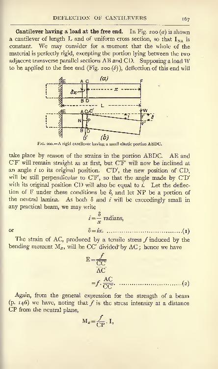
DEFLECTION OF CANTILEVERS 167
Cantilever having a load at the free end. In Fig. 200 (a) is showna cantilever of length L and of uniform cross section, so that I NA is
constant. We may consider for a moment that the whole of the
material is perfectly rigid, excepting the portion lying between the two
adjacent transverse parallel sections AB and CD. Supposing a loadWto be applied to the free end (Fig. 200 (b)\ deflection of this end will
FIG. 200. A rigid cantilever having a small elastic portion ABDC.
take place by reason of the strains in the portion ABDC. AE andCF' will remain straight as at first, but C'F will now be inclined at
an angle i to its original position. CD', the new position of CD,will be still perpendicular to C'F, so that the angle made by CD'with its original position CD will also be equal to i. Let the deflec-
tion of F under these conditions be 8, and let NP be a portion of
the neutral lamina. As both 8 and i will be exceedingly small in
any practical beam, we may write
. 8 ..2 = radians,
oc
or 8 = ix (i)
The strain of AC, produced by a tensile stress / induced by the
bending moment M^, will be CC divided' by AC ; hence we have
(*)
ACAC
'CC'Again, from the general expression for the strength of a beam
(p. 146) we have, noting that / is the stress intensity at a distance
CP from the neutral plane,
" =/~*n *

1 68 MATERIALS AND STRUCTURES
or<^r
f=CP ^ t*' J T" \O/
Substitution in (2) givesW* AC
p --r'ccCP
2 =
I WX.SXr i
W^.S^c
El
WHence, from (i),
8 = ~.x^.8x (5)
Had any other portion been taken similar in properties to ABCD,we should have obtained a similar expression for the deflection due
to its strains. Hence the total deflection A of F will be obtained by
integrating (5) between the limits x = o and x = L.
W
WL"
The slope /max at the end F may be obtained by integrating result
(4), which gives the slope produced by the strains of the small portion
ABDC of the cantilever.
W
WL2, N
radians............................ (7)
Cantilever having a distributed load. The case of a uniform
cantilever having a uniformly distributed load w per unit length
may be worked out in a similar manner, the only difference being
that wx*
M* =-2-
Inserting this value in place of Wx in (4) and (5) gives
. wx2 .Sx v

DEFLECTION OF BEAMS 169
Integrating (9) to obtain A, we have
A _~ Wfa
8EI''
The slope at the free end may be obtained from (8).
.(10)
wl*6EI'
Beam having a load at the middle. The results now obtained
enable the case of a uniform beam simply supported at its ends to
be solved easily by considering the beam as a double cantilever
held fixed at the middle of the span and deflected upwards by the
reactions W at each end (Fig. 201). It is evident that the deflection
FIG. 201. Deflection of a simply-supported beam carrying a central load.
of C below AB will be equal to the elevation of A and B above the
horizontal line through C when the beam is loaded. Hence, using
the result obtained in (6) above, we have, by writing JW for W and
^LforL'
A ^W.(L)3
3EI
WL3, x=
48ET <I2
>
The slope at the ends may be obtained similarly from (7).
*max=2*EI
WL2
T6EI'
Beam having a uniformly distributed load. This case (Fig. 202 (a) )
may be regarded also as a double cantilever fixed at the middle of
the span. The loading will consist of a downward load \wL, on

I 7o MATERIALS AND STRUCTURES
each half span together with a concentrated upward load of \wL at
each free end. The solution may be derived from the results already
obtained by use of the axiom that the resultant deflection and slope
of a beam under a combined system of loads will be the algebraic
sum of those produced by each load taken separately.
W per unitUngth, Q
I(a)
FIG. 202. Deflection of a simply-supported beam carrying a uniformly distributed load.
In Fig. 202 (b] the effect of the distributed load may be examined.
Let Aj be the downward deflection of the ends, when we have, bysubstitution in (10),
, ,
~i28EI'
Fig. 202 (c) shows the effect of the reactions considered alone in
producing an upward deflection A2. From (6) we have
3EI
The resultant upward deflection A at the supports, and hence the
downward deflection at the middle of the span under the proposed
loading, will be A = A - A
I28EI
384'
El' .(16)

DEFLECTION OF BEAMS 171
Due to the distributed load there will be a downward slope at the
supports the value of which, t\, may be obtained from (u).
The upward reactions will produce an upward slope z'2 ,
obtained
from W-. _>L(JL)2
2EI
<">
Combining these results, we have for the slope zmax at the supports :
*max = *2~~
*1
ze/L3
i6EI 48EI
-24 EI
Graphical solution. The method of obtaining the slope and
deflection at the free end of a uniform cantilever, employed on p. 167,
may be extended in such a manner as to enable the slope and
deflection in more complicated cases to be found graphically.
Referring to Fig. 203 (a), the slope i caused by a portion ACDBbeing elastic, while the remainder of the cantilever is supposed to
be rigid, is equal to the angle CPC', and will be given by
Now CC divided by AC is the strain of AC caused by the stress/;
hence,
AC
or CC' = -
E
Substituting this value in (i) gives
(a)

1 72 MATERIALS AND STRUCTURES
Again, from the general expression for the strength of a beam,
we have /
M J TAB~~
-"-NA)
or/ M,m (4)
Inserting this in (3) gives
2 =EL (5)
ri
L.
Let the diagram HKL (Fig. 203 (^)) be the bending-moment
diagram for the cantilever. It
will be clear that the product
MAB &e is the area of the shaded
strip of the diagram. Hence
we may say that the change of
slope i produced by the elastic -
bending of the portion between
AB and CD is given by the
area of the strip of the bending-moment diagram lying under
BD multiplied by the constant
iConsider now the whole
FIG. 203. Graphical method of deducing slopeand deflection.
cantilever to be elastic, then,
the slope at E being zero, it
follows that the slope at AB will
be the sum of the areas of all
strips between HL and QR
multiplied by ,or
Slope at AB = z'AB = area HQRL xEL .(6)
In cases where the bending-moment diagram has a simple outline,
it may be possible to calculate the required area, otherwise it will be
necessary to use a planimeter. If the area has been found in square
inches, the result should be corrected by multiplying by the scale in
inch-tons per inch used in setting out the ordinates such as QR, and
by further multiplying by the scale in inches per inch used in setting
out the abscissae such as HQ ;E should be taken in tons per square
inch, and INA in inch units.

DEFLECTION OF BEAMS 173
HK being divided at a convenient number of points, the slope at
each point may be found by the above method and a diagram drawn
showing the slope at all parts of the cantilever by means of plottingthe results and drawing a fair curve through them (Fig. 203 (<:)).
Again, referring to Fig. 203 (a), let y be the deflection at a point S,
distant z from C, owing to the elasticity of ACDB. Then
z*
or y = iz.
Now, i is given by the area of the shaded strip in the bending-
moment diagram multiplied by -; hence,
y =tpj
x area of shaded strip x z.
That is to say, the increment y of the total deflection at S caused
by the elasticity of ACDB is given by the moment about S of the
shaded strip of the bending-moment diagram multiplied by =TJ
To obtain the total deflection 3 at S, we must therefore evaluate the
moment of area of HTVL about T (Fig. 20$ (ft)) and multiply the
result by gj , paying regard to the scales in the manner already
noted. Repeating the same operation in order to obtain the deflec-
tion at several sections, data will be obtained from which the
deflection curve (Fig. 203 (d)) may be drawn.
Some applications of the graphical method. Taking again the
case of a uniform cantilever carrying a load W at its free end (p. 167),
and referring to Fig. 204, we have
slope at P = ip = area CFGD x =
The maximum slope will be at B, and may be obtained by writing
x = o.
WL2v

174 MATERIALS AND STRUCTURES
To obtain the deflection at P, we have
8P = moment about F of area CFGD x =^rLl
= (moment of CFHD - moment of DGH)^
The maximum deflection will occur at B, and may be obtained by
writing x = o.
W
The case of a uniform beam simply supported at both ends and
carrying a central load may be worked out in a similar manner, and
is left as an exercise for the student.
AW per unit length
FIG. 204.204. Graphical method appliedcantilever loaded at the free end.
FIG. 205. Graphical method applied to acantilever uniformly loaded.
A uniform cantilever carrying a uniformly distributed load w per unit
length may be worked out easily so far as its maximum slope
and deflection are concerned. The bending-moment diagram is
parabolic (Fig. 205), and it may be noted that its area is one-third of
the area of the circumscribing rectangle, i.e. one-third of CD multi-
plied by CE, and that its centre of area G is distant horizontally
three-quarters of CE from E.

DEFLECTION OF BEAMS 175
Hence,
L j_2
'
3
'
El
~6E! <5)
AB = moment about E of area CED x =|-
L 3, j_a TI H
Also,
^8EI <6>
In the case of a uniform beam supported at both ends, and carrying
a uniformly distributed load (Fig. 206), the bending-moment diagram
k L . >J
; Wper unit Length \
D(b)
FIG. 206. Uniformly loaded beam.
is also parabolic. The maximum bending-moment occurs at the
middle of the span, and is given byze/L2FK =8
The slopes at A and B will be equal, and may be found by apply-
ing the rule to the area KFE, noting that the slope at the middle
will be zero.
*'A= 4 = area KFE x ==
rL.1
= - area of circumscribing rectangle x ^=
L i
8'
2 "El

1 76 MATERIALS AND STRUCTURES
Noting that the centre of area G of KFE is at a horizontal distance
|FE from E, we have, reckoning the deflection of A or B upwardsfrom the middle,
AA = AB = moment of area KFE about E x =^=
L 5LT'8l
i
El
__384 El .(8)
A

ENCASTRE BEAMS 177
be obtained by taking the algebraic sum of these moments for that
section.
Fig. 209 (a) gives the bending-moment diagram for a beam simply
supported and carrying a central load W. Its ordinates give the
(b)
FIG. 208. Component curves of anencastre beam.
FIG. 209. Component bending momentdiagrams for an encastre beam.
positive bending moments at any section of the beam under con-
sideration due to W alone. Fig. 209^) shows the uniform negative
bending moments due to the fixing of the ends. These diagrams
may be combined as shown in Fig. 210 (a), when the shaded portions,
which show the algebraic sum of the component diagrams, will give
the resultant bending moments for the beam.
The maximum bending moment due to W alone is represented byWL
ch in Fig. 210(0), and is of value --4
To obtain the values of MA and MB ,
represented by ad and fa, we have the
consideration that the slopes at D and E
(see Fig. 207 (<:)) are zero. Hence the
areas of the bending-moment diagram
adf and fern (Fig. 210(0) must be equal,
because the slope at the centre is given
by their algebraic sum, and this must
be zero for zero slope. For a similar
reason the areas cmg and geb are equal ;
FlG-,?
I0--Resuitant bending momentdiagram for an encastre beam.
hence it is easily seen from the figure
that the triangular area acb must be equal to the rectangular area
adeb. Thus, hm must be one-half of he, giving
It will also be obvious from Fig. 210(0) that the points /and g,D.M. M

1 78 MATERIALS AND STRUCTURES
Kwtit
8'
2 4 8 2 4 i2/ El
where the resultant bending moments are of zero value, must lie at
one-quarter span.
The deflection upwards of E above F (Fig. 207 (<:)) may be obtained
by taking the algebraic sum of the moments about e of the areas
cmgaxid. geb (Fig. 210(6)), and dividing the result by El. This will
give the central deflection A of the beam.
A = (moment of area cmg - moment of area geb)^i L 5L\ /WL i L
8 2 4 12
i WL3, ,
"192 El'
An encastre* beam of uniform section carrying a uniformly distributed load
(Fig. 2 1 1 (a) ) may be worked out in a similar manner. The parabolic
curve afcgb (Fig. 211(6)) re-
presents the bending-moment a w per unit Length Bdiagram for a beam simply sup- ^
ported at the ends and carrying L.|w per unit length. The maxi-
mum bending moment will
occur at the middle of the span,T 9
and is represented by ch^-.
The rectangle adeb represents
the uniform bending moment
due to the fixing in the walls.
The shaded area gives the resultant bending-moment diagram.
Here, as in the last case, there is zero slope at A, C and B;hence
the areas adf, fcm, cmg and geb are equal ; consequently the parabolic
area afcgb must be equal to the rectangular area adeb, giving
2
FIG. 211. An encastre beam uniformly loaded.
(i)
The bending moment at C will be given by
-MA
; Z/L2
24

ENCASTRE BEAMS 179
Thus, we see that the bending moment at the walls is double that
at the middle of the span.
To obtain the deflection at C, we must find the algebraic sum of
the moments about h of the areas cmg and geb, or, since the result
will be the same if the moment of the area mgbh be added to each,
the calculation may be simplified by taking the algebraic sum of the
moments about h of the areas chbg and hmeb. Hence,
Ac = (moment of area chbg- moment of area hmeb) El
K23L 3
8 2 8/ 12 2 EI
ze;L4\ i
96 J El
/-\
384 EI'
The distance of/and g, the points of zero bending moment, from
d and e respectively will be equal, and may be found by obtaining an
expression for the bending moment at a distance x from the wall and
then equating this to zero. Thus,
MS = MA-bending moment at x for a beam
simply supported
12
fwL zvx2\I _ yy__ \
*Af
V 2 2 /
i
12 2 2
Equating this to zero gives
x2 Lx L2
or
2
= 0-2 1 iL or o-ySSL (4)
Hence the points of zero bending moment lie at 0-21 iL from each
wall.

i8o MATERIALS AND STRUCTURES
Points of contraflexure. The two last cases considered provide
examples of beams in which the curvature is partly convex down-
wards and elsewhere convex upwards. The centres of curvature for
a portion of the length of the beam lie on the upper side, and for
other portions lie on the lower side. Points on a beam where the
curvature changes from convex upwards to convex downwards, i.e,
where the centre of curvature changes from one side of the beamto the other, are called points of contraflexure. Curvature which is
convex downwards may be called positive, and that which is convex
upwards may be considered negative. The curvature changes sign
at points of contraflexure, and hence must have zero value at such
points.
Considering the equation (p. 166),
~ i MCurvature = ^ = ^,R H/l
it is evident that, for the curvature to be zero, M must be zero. Apoint of contraflexure may hence be defined as a point of zero
bending moment. Such points occur at quarter span for an encastre
beam carrying a single load
Bat the middle of the span
(p. 176) and at 0-2uL from
, , the walls in the case of a
L Jiw uniformly distributed load
W per unit Length B (p. T 78). It should be noted
777/f77777///////////////////////w ^ that encastre beams differ
from beams which are simply
supported at both ends in that
one or both supports in theFIG. 212. Encastre beams.
latter may suffer sinkage when
the load is applied, or by reason of some alteration in the foundation
conditions, without thereby affecting the distribution of bending
moment along the beam. No such alteration in either of the walls
fixing the ends of an encastre beam can occur without affecting the
bending moments on the beam. For example, if the encastre beam in
Fig. 212(0) should for any reason become loose in the holes in the wall,
so that the fixing couples MA and M B disappear, the bending-moment
diagram will change from that shown in Fig. 210(0) to that for a simply
supported beam, and the maximum bending moment, and consequently
the maximum stress due to bending, will be doubled. In the case
of a uniform load (Fig. 2 1 2(l>) )
such an alteration in the wall fixings
would produce a change in the maximum bending moment from

PROPPED CANTILEVERS 181
fr-A"* 7 *-^"*fn\ .

182 MATERIALS AND STRUCTURES
of the cantilever under the action of the distributed load would be
given by w\j ,
1=8El (P ' I75 ^ W
Now suppose that the distributed load is removed and that the
prop is applied and pushed upwards until a deflection at B of the
same magnitude as\ is obtained
(Fig. 2 14 (<:)). The upward de-
flection A2thus produced by the
force P exerted by the prop will
PT 3
-(p. 174)-
(d)FIG. 214. Propped cantilever.
be
If both P and the distributed
load be applied simultaneously,p*.i_ 2
the levels will be the same at
both A and B (Fig. 2 14 (</)), for
Aj and A2are equal and opposite.
Hence,PL3 wL4 WL3
where W is the total distributed load.
3EI
Hence,
8EI SET*
(3)
The bending moment at any section C may be calculated now :
<7/?l'V%2
(4)
Points of contraflexure may be found by equating Mc to zero
(p. 180). Thus, wx2
- = o.
Zero is one value of x satisfying this equation, hence B is a point
of contraflexure. To obtain the other point, we have
WX--- =o,
or * = JL............................... (5)
The bending-moment diagram is shown in Fig. 215 (a). The bend-
ing moment at the wall may be found by writing x = L in (4), giving
.(6)

BEAM HAVING THREE SUPPORTS 183
To obtain the bending moment at fL from B, we have, from (4),
It will be understood that
any vertical displacement of
the prop, whether by reason
of sinkage of the foundations
or by changes in temperature,will alter the bending moment,and hence the stresses through-out the cantilever. The shear-
ing-force diagram is given in
Fig. 215 (b) ; the values of the
(7)
Bending Moments,
fa)
Shearing Forces
wFIG. 215. Bending moment and shearing-force
diagrams for a propped cantilever.
shearing force are -f fW at the wall and - fW at the prop.
The case of a beam resting on three supports at A, B and C is
illustrated in Fig. 2 1 6 (a). The supports at A and B alone are
W per unit length
rWLBendingX *SMoments \\T-*
ShearingForces
FIG. 216. A beam resting on three supports.
sufficient for the equilibrium of the beam ; hence, in this case also, the
reactions, bending moments, and stresses depend on the levels of the
supports being preserved.

1 84 MATERIALS AND STRUCTURES
Suppose the supports to divide the beam into two equal spans and
that the supports are all at the same level. If the support at C be
removed (Fig. 2 1 6 (b) ),there will be a deflection A
xat C given by
Replace the support at C by pushing upwards until the level is
restored (Fig. 2i6(r)). The upward deflection A2 produced by Pc
will be given by p T 3
Clearly Axand A
2 are equal. Hence,
PCL35
48EI~384 El '
Pc-fwL= |W, ..................................(3)
where W is the total load.
It will be evident that PA and PB are equal. Hence,
PA = PB =&W........................... (4)
The bending moment at D may be found from
wx(5)
Points of contraflexure occur where MD is zero;to find these, we
have *
The value zero for x satisfies this equation ; hence, A is one point
and, from symmetry, B is another point of contraflexure. To obtain
others, wxT\^L - =
o,
* = |L.................................. (6)
Points of contraflexure therefore occur at f L from A and also at
an equal distance from B. The complete bending-moment diagramis given in Fig. 2i6(</) and the shearing-force diagram appears in
Fig. 2 1 6 (e).
The beam here discussed is a simple illustration of continuous
beams, t.e. beams continuous over several spans and resting on several
supports.

BEAMS OF UNIFORM CURVATURE 185
Beams of uniform curvature. Considering again the equation
it will be remembered that it has been assumed that the moment of
inertia is uniform in all the cases considered. This is the case very
often in practice ;for example, beams of comparatively short span
generally consist of a rolled steel beam or of two or more similar
beams placed side by side. When we consider larger beams, wefind that the section in general is not uniform, but is varied so as to
produce more nearly a beam of uniform strength (p. 154). Theabove equation may be modified so as to include a great numberof such cases. Thus,
M =^I (p. 146);
L= = _L f* R El El' m
Abeam of uniform strength is one having uniform maximum stress f.
This may be secured by having constant depth and varying the breadth,
in which case m will be constant. In equation (i) above, the right-
hand side will contain nothing but constants, and therefore ^ will_K
be constant. Such a beam will have constant radius of curvature,
and hence will bend into the arc of a circle. In other cases of
built-up plate girders having parallel flanges, the breadth is constant,
and uniformity in f is secured by adjusting the thickness of the
flanges, the number of flange plates becoming greater towards the
middle of the span. Assuming that this variation of flange thickness
does not alter the depth sensibly, we have a constant value of m, and
the girder will have constant curvature.
Constant curvature may also occur in a beam of uniform section.
To obtain such a result, M must be constant in the equation
JL_MR~ET
This condition may be brought about by the loads and reactions
being applied in the form of two equal opposing couples. A carriage
axle is a common example (Fig. 217). Here AC = BD; equal
loads W, W are applied at A and B, and the wheel reactions P, P at

1 86 MATERIALS AND STRUCTURES
C and D will be each equal to W. The portion CD of the axle will
therefore have uniform bending moment, given by
MCD =WxAC,and hence will bend into the arc of a circle. The curvature in the
wB
TP p tFIG. 217. A carriage axle.
overhanging portions AC and BD will vary, following the law for the
cantilever worked out on p. 167.
In Fig. 218 AB is a beam of length L bent into a circular curve
ACB. Drawing the diameter EODC perpendicular to the chord AB,and remembering that the deflec-
tion will be very small in practice
we have, by application of the
principle that the products of the
segments of two intersecting chords
in a circle are equal,
EDxDC =ADxDB,or, very nearly,
2RxDC =(|L)2
;
hence the deflection DC at the
middle will be
FIG. 218. Beam bent into a circular curve. \J\^> = TTFr-
Substituting -^y for ^ in this result gives
It will also be evident that the inclination of the tangents at A and
B will be equal to the angle AOC. Expressing this in radians so as
to obtain the slope at A and B, we have
AC LAO 2R
ML2fiT

STRESS AND DEFLECTION IN BEAMS 187
Relation of stress and deflection. In all the cases of deflection
which have been considered, it will be noted that the expression for
the maximum deflection has the form
WL3
where c is a numerical coefficient, the value of which depends on the
circumstances of the case. Hence we may write,
Taking the general equation for the strength of a beam (p. 146),
it will be noted that M is always proportional to WL, and that m is
always proportional to d, the overall depth of the beam. Hence,from (2), ,
.
a
Substitution of this in (i) gives
/L2-
Hence, in beams constructed of the same material, for which Ewill be constant, we may state that the maximum deflection will be
directly proportional to the square of the length and inversely pro-
portional to the depth when the beams are carrying loads which
produce the same maximum value off.
EXAMPLE. A steel bar of rectangular section is supported at its ends
and carries a central load. The ratio of maximum deflection to span is
not to exceed -%$$ ; the maximum stress is not to exceed 5 tons per squareinch. Find the ratio of span to depth if E = 13,500 tons per square inch.

1 88 MATERIALS AND STRUCTURES
WL / T 2/1T~
=P I== ~^ ;
8(2)
Hence, from (i), A=^ .^jL
1
YT7*
6E A
EXERCISES ON CHAPTER VIII.
1. A bar of steel of square section, 2 inches edge, is used as a canti-
lever, projecting 24 inches beyond the support, and has a load of 400 Ib.
at its free end. Find the values of the radius of curvature for sections at
3 inches intervals throughout the length. Plot R and the length of the
cantilever. E = 13,500 tons per square inch.
2. Find the slope and deflection at the free end of the cantilever givenin Question i.
3. A beam of I section, 8 inches deep, 4-5 inches wide, metal 0-5 inch
thick, is simply supported on a span of 10 feet and carries a central load
of 1-5 tons. Calculate the maximum deflection and also the slope at the
ends. What will be the radius of curvature at the middle of the span ?
Take =13,500 tons per square inch.
4. Answer Question 3, supposing that the beam carries only a uniformlydistributed load of 2 tons.
5. An encastrd beam of I section has its ends fixed into walls 12 feet
apart. The depth is 12 inches, and I is 50 in inch units. If the stress is
limited to 5 tons per square inch, what central load would be safe ?
Draw the diagrams of bending moment and shearing force.
6. Answer Question 5, supposing that the load is to be distributed
uniformly.
7. Calculate the deflections at the middle of the span for the beams
given in Questions 5 and 6.
8. A cantilever projects 8 feet from a wall and carries a load of
1-5 tons at 4 feet from the wall and another load of 075 ton at the free
end. Draw the diagrams of bending moment, slope and -deflection, in
each case giving the scale of the diagram. State the values of the slopeand deflection at the free end. Take 1 = 350 in inch units and E= 13,500tons per square inch.
9. Calculate the uniform bending moment which must be applied to a
bar of steel of 0-25 inch in diameter in order to make it bend into the arc

EXERCISES ON CHAPTER VIII. 189
of a circle of 20 feet radius. = 30,000,000 Ib. per square inch. If thebar is 5 feet in length, what will be the deflection at its centre ?
10. A girder is 40 feet span by 4 feet deep, and rests on its supports.The uniformly distributed load produces a maximum stress due to bendingof 5 tons per square inch. Find the deflection at the middle of the span.
=13,500 tons per square inch.
11. Supposing the girder given in Question 10 to have uniform flangestress of 5 tons per square inch, what will be its radius of curvature ?
Calculate the deflection at the centre.
12. A cantilever of uniform section is built securely into a wall, and its
outer end just touches a prop when there is no load. The cantilever is
8 feet long, and carries a uniformly distributed load of 1000 Ib. per foot
length. Find the reaction of the prop, and draw the diagrams of bendingmoment and shearing force ; give the calculations required for these.
13. A beam 40 feet in length rests on three supports A, C and B at the
same level ; the supports divide the beam into two equal spans. If there
is a uniformly distributed load of 1-5 tons per foot length, find the reactions
of the supports, and draw the diagrams of bending moments and shearingforce, showing the necessary calculations.
14. A piece of flat steel has to be bent round a drum 5 feet in diameter;
what is the maximum thickness which the strip can be made so that there
shall be no permanent deformation when it is removed from the drum ?
The steel has an elastic limit of 14 tons per square inch. E= 14,000 tons
per square inch. (I.C.E.)
15. Three rolled steel joists 6 inches deep are placed side by side
spanning an opening of 10 feet;the moment of inertia of the two outer
joists is 20 and that of the inner one 44 inch-units. A central load of
5 tons is so placed as to deflect each of the three joists equally ;state the
amount of the load carried by each joist and the maximum unit stress (i.e.
stress in tons per square inch) in the centre joist only. (I.C.E.)
16. A beam is firmly built into a wall at one end, and rests freely at its
other end on a vertical column whose centre line is distant 8 feet from the
wall. The beam supports a wall, whose weight added to that of the beamitself is equivalent to a uniformly distributed load of 3200 Ib. per foot run
of the beam. Find (a) the total load supported by the column ; (b} the
bending moment and shear force at the section of the beam adjoining the
wall; (c) the position of the point of zero bending moment. Sketch
complete bending moment and shear diagrams. (B.E.)
17. A rectangular timber beam, supported at the ends, is of uniformsection from end to end, and it carries a uniformly distributed load. If
the working intensity of stress in the wood is not to exceed 2000 Ib. per
square inch, and if the modulus of elasticity of the wood is 1,700,000 Ib. per
square inch, determine the ratio of the depth of cross-section of beam to
span of beam in order that the deflection may not exceed 5^th
part of the
span. (B.E.)
18. A horizontal beam, span 25 feet, is fixed at the ends. It carries acentral load of 5 tons, and loads of 2 tons each at 5 feet from the ends.
Determine the maximum bending moment, the bending moment at the
centre of the span and the position of the points of contraflexure ;sketch
also a diagram of shear force. (L.U.)

Igo MATERIALS AND STRUCTURES
19. A floor, carrying a uniformly distributed load of 2 cwt. per squarefoot over a span of 20 feet, is proposed to be carried by either : (a) I joists,10 inches deep ; area, 12-35 square inches ; I (maximum), 212 inch-units
;
pitch, 4 feet. Or, () I joists, 12 inches deep ; area, 15-9 square inches ;
I (maximum), 375 inch-units; pitch, 6 feet. Compare these two pro-
positions by rinding the ratio of strengths, deflections and total weights of
girders. Find the maximum skin stress in case (a). (L.U.)
20. A uniform beam, 30 feet long, fixed at the ends, has a load of
20 tons spread uniformly along it. It has also two loads of 3 tons, each
hung from points which are 10 feet from the ends. What is the bendingmoment everywhere, and what is its greatest value ? (B.E.)
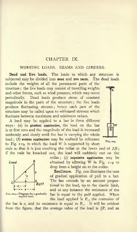
CHAPTER IX.
WORKING LOADS. BEAMS AND GIRDERS.
Dead and live loads. The loads to which any structure is
subjected may be divided into dead and live loads. The dead loads
include the weights of all the permanent parts of the
structure;the live loads may consist of travelling weights
and other forces, such as wind pressure, which may occur
periodically. Dead loads produce stress of constant
magnitude in the parts of the structure; the live loads
produce fluctuating stresses; hence each part of the
structure may be called upon to withstand stresses which
fluctuate between maximum and minimum values.
A load may be applied to a bar in three different
ways : (a) in gradual application, the load on the bar
is at first zero and the magnitude of the load is increased
uniformly and slowly until the bar is carrying the whole
load ; (b) sudden application may be realised by reference
to Fig. 219, in which the load W is supported by short
rods so that it is just touching the collar at the lower end of AB ;
if the rods be knocked out, the load will suddenly rest on the
collar; (c) impulsive application may be
obtained by allowing W in Fig. 219 to
drop from a height on to the collar.
Eesilience. Fig. 220 illustrates the case
of gradual application of pull to a bar.
The bar extends by an amount propor-tional to the load, up to the elastic limit,
and at any instance the resistance of the
applied. When
FIG. 219.
Load
; Ext ?
* e
FIG.
220,-DiagramJora gradually oar [s equal to th
the load applied is P19 the extension of
the bar is eland its resistance is equal to Pr It will be evident
from the figure, that the average value of the load is IP, and as

192 MATERIALS AND STRUCTURES
this force acts through a distance e, the work done will be given bythe product of these quantities (p. 325).
Work done in stretching the bar = ^P^ (i)
As the resistance of the bar is at all times equal to the pull, it
follows that the energy stored in the bar will be equal to |P<?.
Let a ^e sectional area of the bar in square inches.
P = the final pull in tons.
p/= = the stress produced by P in tons per square inch.
L = the original length of the bar in inches.
e = the extension produced by P in inches.
E = Young's modulus in tons per square inch.
P LThen a" 7'
* = = /-
Also, P = fl/
Substituting these values in (i) gives :
Energy stored in the bar =|/"./^
f2
=L^p inch-tons (2)
This quantity is called the resilience of the bar. The resilience of
the material is stated usually as the energy which can be stored in
a cubic inch when stressed up to the elastic limit. This may be
obtained from (2) by taking f to be the elastic limit stress and
noting that aL is the volume of the bar in cubic inches. Hence
f2
Resilience =j=
inch-tons per cubic inch.
Load suddenly applied. If the load be applied suddenly as in
Fig. 219, and if the bar extends by an amount e, gravity is doing work
on W throughout this extension. Hence,
Work done on W = We inch-tons.
This work may be represented by the rectangular diagram OKLM(Fig. 221), in which OK represents W and OM represents e. The
resistance offered by the bar during the extension still follows the
same law as before, i.e. at first the resistance is zero and it gradually
increases, being proportional to the extension up to the elastic limit

IMPULSIVE LOADS 193
, ,
This may be represented by the triangular diagram OMQ. At PNthe resistance of the bar and the weight of the load are equal, but
extension does not stop here, since more work has been done by
gravity than can be stored in the rod. Extension will go on until
the work done by gravity has been stored
entirely in the rod, i.e. until the area
OKLM is equal to the area OMQ.This will occur evidently when OM is
equal to twice OP, or when MQ is
twice OK. Now, had W been applied
gradually, the stretch would have been o P M Ext?OP; hence the Sudden application Of FIG. 221. Diagram for a load applied
W has produced a stretch double of
this amount. Also PN would have been the final resistance of the
bar had W been applied gradually; hence the sudden applicationhas produced a resistance of twice this magnitude, and therefore
also a stress equal to double of that which would have occurred
with gradual application.
The conditions are not attained easily in practice, but the effects
of live loads in producing stress are often taken account of by
estimating what the stress would be had the load been applied
gradually and then taking double this stress as that which the partwill be called upon to carry.
Impulsive application of a load. In an impulsive application,
let W be dropped from a height H inches (Fig. 219). Then
Total work done by gravity= W(H + *) inch-tons.
Extension will go on until the whole of this work is stored in the
bar. From equation (2) (p. 192), we have
ft(i \ j ip^2E
Hence, aL~Energy stored in the
If e is small compared with H, as is the case generally, then
2EWH
Working stresses. The stresses which may occur in any part of a
structure are estimated by first calculating the stress produced by the
dead load. Separate calculations are then made in order to determine
D.M.

194 MATERIALS AND STRUCTURES
the stress produced by the live loads. The stress in the part under
consideration will then fluctuate between known limits, and it remains
to determine what ought to be the safe stress permitted in the part.
The determination may be based on the known breaking strength of
the material by taking the working stress as a fraction of the ultimate
strength. The reciprocal of this fraction is called a factor of safety,
and its value depends on the kind of material and the nature of the
loads. Thus, for wrought iron and steel, the factor of safety maybe 3 for a dead load, 5 for a stress which does not change from pull
to push, 8 for a stress which alternates from a certain pull to an
equal push and 12 for parts subjected to shock. Somewhat higher
factors may be taken for cast iron and for timber, as these materials
are less trustworthy.
It may be noted here that a load which a piece of material may
carry for an indefinite time, if applied steadily, will ultimately cause
fracture if it is applied and removed many times. The effect is more
marked if the load be alternated, i.e. applied first as a pull and then
as a push, in the manner in which the piston rod of a steam engine is
loaded. The experiments of Bauschinger, Wohler, Stanton and
others, on the effects of repeatedly applied and alternating loads
show that the strength to resist an indefinite number of repetitions
depends on the range of stress rather than on the actual values of
the maximum and minimum stresses.
The following rule has been deduced by Unwin* from the results
of Wohler's experiments, and applies to cases of varying stresses.
Let fg the breaking strength of the material in tons per square
inch under a load applied gradually,
/j= the breaking strength of the same material in tons per
square inch when subjected to a variable load which
fluctuates from,/j
to /2and is repeated an indefinite
number of times. Let this be of the same kind (push or
pull) as/s .
/2= the lower limit, in tons per square inch, to which the
material is subjected, + if /2is of the same kind as
/! and/*,- if/2 is of the opposite kind.
r=/1 -/2 = the range of stress.
Then Unwin's formula is
(0
*Machine Design, Part I. Prof. W. C. Unwin. (Longmans, 1909.)

WORKING LOADS 195
n has the value 1-5 for wrought iron and mild steel. From
equation (i), we have
or
win which the negative sign has been disregarded. Equation (2) gives
a dead-load stress yS which would produce, when applied steadily to
the member, the same effect as the actual fluctuating stresses.
If each side of (2) be multiplied by the sectional area of the bar,
the stresses in the equation become total forces on the bar. Using
capital letters to represent the total forces corresponding to the
stressesfst rand/j, we have
Equivalent stea dy load = F = ~ . ... (3)
The Launhardt-Weyrauch formula also takes account of stress varia-
tion. Let Fj and F2
tons be the maximum and minimum forces
to which the bar may be subjected, and \etfs tons per square inch
be the breaking strength of the material under a gradually appliedstress. Then
Breaking stress = ^fs ( i + - ^ Jtons per square inch..... (4)
Applying a factor of safety of 3 to this, we have
Working stress =ifi\
T + ~ ^ )tons per square inch..... (5)
EXAMPLE. A certain bar in a structure carries a pull of 80 tons dueto the dead load ; the live load produces forces in the same bar varyingfrom 20 tons pull to 40 tons push. Find the working stress and the cross-
sectional area of the bar. The breaking strength of the material under a
gradually applied pull is 30 tons per square inch.
First Method. By doubling the live load pull and adding the result
to the dead load pull, we have
Equivalent dead load = 80+ (2 x 20) =120 tons.
Taking 9 tons per square inch as the working stress, we have
Sectional area of bar= 15 =13-3 sq. inches.

IQ6 MATERIALS AND STRUCTURES
Second Method. By Unwin's formula (3),
R = 6o tons.
F1= 8o+ 2o=ioo tons
n=i'$.
o-i j ji j (1-5 x 60)W(?x 3600)+ 4(100 -30)2Equivalent dead load=^
= 128 tons.
Again using 9 tons per square inch as the working stress, we have
Sectional area of bar= 1 & = 14-2 sq. inches.
Third Method. By the Launhardt-Weyrauch formula (5), we have
fs= 30 tons per square inch.*
^
F1= 8o+ 2o=ioo tons pull.
F2=8o~4O= 4o tons pull.
Working stress = f x 30(1 + /<&)
= 8 tons per square inch.
F, 100Cross-sectional area=
g= ~o~
= I25 square inches.
Wind pressure. If wind pressure be treated as a live load, then
30 Ib. per square foot of vertical surface may be assumed to be the
maximum. If treated as a dead load, then pressures up to 55 Ib.
per square foot of vertical surface may be taken. Stanton's experi-
ments at the National Physical Laboratory give, for small plates,
p 0-0027V2 Ib. per square foot,
or, for large plates,
/^o-oo32V2 Ib. per square foot,
where V is the velocity of the wind in miles per hour. Hutton's
formula may be used in calculating the normal pressure on inclined
surfaces.
Let p the pressure in Ib. per square foot on a surface perpen-
dicular to the direction of the wind.
/n = the normal pressure in Ib. per square foot on a surface
inclined at an angle to the direction of the wind.
Then Hutton's formula gives
where a is a coefficient depending on the value of 0. Values of a

TRAVELLING LOADS 197
corresponding to different values of have been plotted in Fig. 222,
and the value of a appropriate to any given surface may be taken
from the curve.
a.
1-2
10
0-8
0-6
0-4
O2
10* 20' 30' 40* 50* 60* 70* 80* 90*
FIG. 222. Values of a in Mutton's formula.
1
1

igS MATERIALS AND STRUCTURES
Then, taking moments about B, we have
Let W be on the right-hand side of D as shown in Fig. 2 23 (
Then the bending moment at D will be
Hence, as x diminishes, i.e. as W travels towards the left and so
approaches the section D, the bending moment at D increases.
Now let W be on the left-hand side of D as shown in Fig. 223 (ti).
Writing down the bending moment at D, we have
MD-Pa-W(a-)
(3)
This result indicates that as x diminishes, i.e. as W, still travelling
towards the left, recedes from the section D, the bending moment
at D is becoming smaller. Therefore, the greatest bending moment
which the section D will be called upon to resist will occur when Wis immediately over the section. The value of this bending moment
may be obtained by writing x = a in either (2) or (3) above, giving
Maximum bending moment M n = i - -r
If a be varied so as to obtain the maximum bending momentsfor other sections of the beam, and if the results of calculation
from equation (4) be plotted, a parabolic curve will be obtained
(Fig. 223 (c)), the ordinates of which will show the maximum bendingmoment for all sections of the beam. The centre section C is
called upon to resist a bending moment -. It will, of course, be4
understood that the values shown by the ordinates in Fig. 223 (c) are
not attained simultaneously. The diagram must be interpreted as
indicating that the bending moment at any section, say D, is zero

TRAVELLING LOADS 199
when W is off the beam, and increases gradually as W travels
towards the section;the maximum value MD is attained when W
reaches the section.
The shearing force at D, when W occupies any position on the
beam lying on the right of D, will be positive and equal to P;
hence, from (i),
(5)
This result shows that the shearing force increases as x diminishes,
i.e. as W approaches the section D from the right.
Taking W in a position on the left of D, the shearing force will
be negative, and will be given by
We infer from this result that the negative shearing force at Ddiminishes as x becomes smaller, i.e. as W recedes from the section
and approaches the left-hand support.
The inferences from this discussion are that the shearing force
at any section attains a maximum positive value when W lies close
to the right-hand side of the section, that it becomes zero as Wcrosses the section, and attains a maximum negative value when
W lies close to the left-hand side of the section. To obtain
the values of these shearing forces, write x = a in equations (5) and
(6), giving
Maximum positive shearing force SD = 1 1 - =-JW.......... (7)
Maximum negative shearing force SD = - y W............... (8)L/
Varying a so as to obtain values of the shearing forces for other
sections and plotting the values so found (Fig. 223 (d}\ we obtain two
sloping straight lines. This diagram must be interpreted as follows :
the shearing force at any section is zero when W is off the beam ;
as W travels along the beam from right to left, the shearing force
at any section D is positive and increases gradually, until the
maximum value DE is attained when W is on the point of arriving
at the section. As W crosses the section, the shearing force becomes
negative and attains the maximum value DF when W reaches the
other side of the section.

206 MATERIALS AND STRUCTURES
W per unit Length
Uniform travelling load. In Fig. 224 (a) is illustrated the case
of a beam AB simply supported at A and B and subjected to a
uniform load w per unit length. Taking the load of sufficient
length to cover the whole span,
it will be evident that the maxi-
mum bending moment at anysection will occur when the
beam is loaded fully, i.e. when
the whole span is covered bythe load. The bending-moment
diagram will therefore be para-
bolic (Fig. 224^)) and of maxi-FIG. 224. Beam carrying a uniform travelling
load ; maximum bending-moment diagram. mum height8
In Fig. 224 (a) the nose E of the load is advancing towards a given
section D. The shearing force at D is positive and is equal to P;
hence it increases as E approaches D. When E has crossed to the
other side of D (Fig. 225 (a)), the shearing force is P diminished bythe portion of the load lying between D and E. This shearing
force will be less than that
existing at D when the nose
is vertically over D, for Pwill then have a certain
value, and this value will
be increased in Fig. 225 (a)
by a fraction only of the
portion of the load lying
between D and E;as the
whole of the latter must be
deducted from P in calcu-
lating the shearing force in
Fig. 225 (a), it follows that
the positive shearing force
at D in Fig. 225 (a) is
diminishing. Hence the maximum positive shearing force at anysection occurs when the whole of the part of the beam lying to
the right of the section is covered by the load, the end of the load
being vertically over the section. In the same manner it maybe shown that the maximum negative shearing force at any section
occurs when the part of the beam lying on the left of the section
is covered by the load (Fig. 225
FIG. 225. Beam carrying a uniform travelling load ;
maximum shearing-force diagram.

DEAD AND TRAVELLING LOADS 201
To obtain the values of these shearing forces, first let the load
cover DB (Fig. 225 (a)) and take moments about B;
.'. maximum positive shearing force SD = P =-j- (L
-a)
2....... (9)2 1 v
Now let the load cover AD (Fig. 225 (0)) and take moments
about A ;
QLa
wa-2
wa2
Hence, Maximum negative shearing force SD = Q^ j_/
Variation of a in (9) and (10) so as to obtain values for other
sections will evidently produce two parabolic curves when plotted
(Fig. 2 25 (<:)). The interpretation of this diagram is similar to that
of Fig. 223 (d)). The end ordinates are of magnitudes z#L.
Combined dead and travelling loads. If, in addition to the
travelling or live loads, the dead loads be considered, diagrams of
bending moments and shearing
forces may be drawn separately < f\for the latter. Combined dia-
grams of bending moments and
shearing forces may then be con-
structed by adding algebraically
the corresponding ordinates of
the diagrams. This has been
done in Fig. 226 for a uniformlydistributed dead load and a
single rolling load.
In Fig. 226(0), ACB is the
bending-moment diagram for the
dead load and ADB is that for
the live load;AEB is the com-
bined diagram. In Fig. 226(<r),
FGKH is the shearing-force
diagram for the dead load;FGL
and FGM are the shear diagramsfor the live load; FGKRN is
P 1G. 226. Diagrams for a beam carrying a deadthe shear diagram lor the com- load and a ingi rolling load.

202 MATERIALS AND STRUCTURES
bined loads, and shows the shearing force on any section lying close
to the left of the live load ; GFHTQ is a similar diagram for sections
lying close to the right of the live load. The construction consists in
making FN = FH + FL and joining NK ;also make GQ =GK +GM
and join QH. Zero shearing force occurs at T and at R. Sections
lying between F and T are subjected to positive shear only,
those lying between R and G have negative shearing force only ;
sections lying between T and R have to resist both kinds of shearingforce.
Maximum bending moments for a non-uniform travelling load.
In designing bridge girders, it is necessary sometimes to consider the
IB.
FIG. 227. Bending-moment diagrams for a system of rolling loads.
effects of a non-uniform travelling load. Fig. 227 illustrates a con-
venient method; bending-moment diagrams for the girder when the
load is occupying several given positions are obtained first ; from these
diagrams the maximum bending moment at any section is determined.
AB is the girder resting on supports at A and B;sections at E, D
and C divide the girder into four equal bays. Three loads Wj ,W
2
and W3
at fixed distances apart have been chosen, but it will be
understood that the method applies to any number of loads.
First let Wlbe vertically over B, and let the distances of W
2and
W3 from A be a and b respectively.
Take moments about A and set these off along AN, which is
drawn at right angles to AB.
Moment of Wl= WjL, represented by AF.
W2=W
,FH.
W =WJ HN.

TRAVELLING LOADS 203
Let Q! be the reaction at B, then the sum of the above moments
is equal to the moment of QTabout A ;
hence the moment of Qjabout A is represented by AN.
Join BF and produce the line of W2to cut BF in G. Join GH
and produce the line of W3
to cut GH in K. Join KN and also
BN. Draw the vertical ESTUV.From the laws of proportion applied to similar triangles, the fol-
lowing statements may be made :
Moment of Qj about E = EV.
Wx
E = ES.
W2
E = ST.
W3
E = TU.
Now, by taking moments about E, we have
Bending moment at E = moment of Qj- moment of W
l
- moment of VV2- moment of W8
= EV - ES - ST - TU= uv.
In the same way MD =WX and MC= YZ. Hence the bending-
moment diagram for the given position of the loads is the shaded
diagram in Fig. 227.
To obtain the bending-moment diagram when Wl
is vertically over
the section C, instead of moving the loads, leave them in their
original position and shift the girder towards the right until C is
vertically under Wj. The end B will then be at B2and A will
coincide with the original position of E. The reaction Q2 at B2will
be obtained by taking moments about E, giving
Q2x B
2E = moment of W
x + moment of W2 + moment of W
3
= EU.
Join UB.2 ,when it will follow, by similar reasoning to that already
employed, that the bending-moment diagram for Wj over C is
B2BGKWUB
2.
Similarly, when Wx
is at D, the diagram of bending moments will
be B3B.jBGKWB3 ;
also when Wj is at E, the bending-moment
diagram will be B4B
8B
2BGYB4
.
Measure these diagrams so as to obtain from each the bendingmoments at E, D and C. If these are tabulated, there will be no

204 MATERIALS AND STRUCTURES
difficulty in obtaining the maximum value of the bending moment at
each section by inspection of the table.
Position ofload Wj.

CONTINUOUS BEAMS 205
two segments AB and BC taken as cut at A, B and C, and simply
resting on the supports. Then, as has been shown for an encastre
beam (p. 176), the difference between the bending-moment diagrams,shown shaded, will be the bending-moment diagram for the portionABC of the continuous beam.
It is evident that the solution will depend on the determination of
MA ,MB and Mc . To determine these, we have the principle that
if all the supports are at the same level, then the deflections at A, Band C must be zero, whatever may be the changes in deflection
occurring in the spans. Hence, taking moments of area about A,the moment of ADEB must equal that of AGB
;also taking moments
of area about C, the moment of BEFC must equal that of BHC.
Taking moments about A, and remembering that the parabolic
area is two-thirds that of the circumscribing rectangle, we have
2 Wl?,
L , , 7 /l /,, r \l\ 2 7
-. ^L ./1
.-1 =MA/] ^
+ (M B -M A)^--/1 .
It will be noted that the right-hand side has been obtained by
splitting ADEB into a rectangle of height AD and base AB, and
a triangle of height (BE - AD) and base equal to AB. The equationis reduced as follows :
^M^ + JMB/i ............................... (l)
Taking moments about C in the same manner, we have
2 Wlz 4 /2 , ,4 2
3' ^4.-= Mc4- + (MB -Mc)---4,
= JMC4 + JMB4 ............................... (2)Add (i) and (2) :
(/i
3 + /a8
)= JMAA + iMB (I, + 4) + JMc/2 ,
24
or (/13 + 4
3
)= MA/1 + 2M B (/1 + 4) + Mc4 ................... (3)
4
Should the spans be carrying uniformly distributed loads of
different values, let wland w.
2be the loads per unit length on AB
and BC respectively. Then (i) and (2) will become7H 7 3
24=*MA/1 + ptB/1 ,

206 MATERIALS AND STRUCTURES
Adding these and reducing as before gives
(4)
Equations (3) and (4) are cases of Clapeyron's theorem of three
moments. By use of these, an equation may be written down for
any three successive supports of a continuous beam. If there are
n supports, there will be (n-
2) equations ; other two equations mayalso be written from the data supplied for the ends of the beam.
Thus, if the beam simply rests on the support at each end, the
bending moments at these supports will be zero, and the other
equations will be sufficient in order to obtain the complete solution.
i ton per foot
A
Tons16
12
84
-4-8-12
-16FIG. 229. A continuous beam having three spans.
EXAMPLE i. A continuous beam rests on four supports on the same
level and carries loads as shown in Fig. 229. Find the bending moments
at the supports.
Equation (4) applied to A, B and C givesx i
3\ /i - X203N

CONTINUOUS BEAMS 207
Also, MA = o;
.'. 422 + 3000= 7oM B + 2oM c ............................(i)
Equation (4) applied to B, C and D gives
Also, MD= O;
/. 3000+ 375 =2oMB+6oMc ............................ (2)
From (i) and (2), 2ioM B+6oMc= 10,266,
MB= 6\3 ton-feet.
From (2),
6oMc = 2649,
Mc = 44-i5 ton-feet.
EXAMPLE 2. Find the reactions of the supports of the beam given in
Example i.
To find RA, write down an expression for the bending moment at B,
obtained by calculating the moments about B of the forces acting on AB.
56-25-
1 5RA= 36-3,
RA= i-33 tons.
In the same way, RB may be found by writing down an expression for
Me, taking moments about C of all the forces acting on ABC.
306-25 + 200 - (1-33 x 35)- 2oRB =44-i5,
RB= 20-77 tons.
To find RC, take moments about D of all the forces acting on the beam.
506-25 +45o-(45xi-33)-(3ox 20-77) -ioRc = o,
ioRc = 273-25,
Rc = 27-32 tons.
Also, RA + RB + Re + RD = the total load on the beam,
Ro = 52-5 -(1-33 + 20-77 + 27-32)
= 3-08 tons.
In order to check the accuracy, calculate RD by taking moments about
C of the forces acting on CD.
(1-5 x 10 x 1o )-(R D x io)
=Mc =44-i5,
ioRD = 30-85,
RD = 3.08 tons.

208 MATERIALS AND STRUCTURES
EXAMPLE 3. Draw the diagrams of bending moment and shearingforce.
S on the right of A= + RA = + 1-33 tons.
S on the left of B = RA - (0-5 x 15)= i-33-7-5 = -6vi7 tons.
S on the right of B = RA+ RB -(o-5 x 15)= i -33 + 2077 - 7- 5
= + U-6 tons.
S on the left of C = RA+ R B -(o-5 X35)-(i X2o)=
1.33 + 20-77-17.5-20= -
15-4 tons.
S on the right of C = RA+R B + RC - 17-5-20=
1-33 + 2077 + 27.32-37-5= + 11-92 tons.
S on the left of D = - RD= -3-08 tons.
The shearing force varies uniformly between the supports ;the com-
plete shearing-force diagram is given in Fig. 229 (c).
The following quantities, together with the bending moments at the
supports, are required for the bending-moment diagram. They are
obtained by calculating the bending moments at the middle of each span,
assuming that the beam is cut at B and C.
,. 'Zfi/i2 0-5XI5XI5
Bending moment at the centre of A.B = ~ =. -QJ J
o o
= 14-06 ton-feet.
Bending moment at the centre of BC=^^= 1 '
5 * 2 X 2
o o
=7j
ton-feet.
Bending moment at the centre of CD= |3 =
5o o
= 18-75 ton-feet.
The bending-moment diagram is given in Fig. 229 (b\ and is drawn bymaking BE and CF equal to MB and Me respectively and joining AE,EF and FD. GH, KL and MN are then set up from the centres of AB,BC and CD, and are made equal to 14-06, 75 and 18-75 ton-feet respec-
tively. The curves AGB, BKC and CMD are parabolic. The difference
of these diagrams, shown shaded, is the bending-moment diagram for
the beam. Points of contraflexure (p. 180) occur at O, P, Q and R, as
the bending moments are zero there.
Plate girders. Plate girders are used instead of rolled I sections
when the dimensions of the girder become large. Such girders con-
sist of top and bottom flange plates (Fig. 231) and a web plate
secured to the flanges by riveted angles. The flange plates, as maybe observed in Fig. 230, increase in number towards the middle of

PLATE GIRDERS 209
the span, where the bending moment is large. The web plate is
generally of uniform thickness in girders of comparatively small span ;
in very large girders, in which the web is built of several plates
placed end to end, the plates near the supports may be made thicker
than those at the middle, thus making allowance for the larger
shearing forces near the supports. In calculating the dimensions of
Flo. 230. Side elevation of a plate girder.
the parts, it is customary to assume that the flanges supply the whole
of the resistance to bending and that the web supplies the whole of
the resistance to shearing. The web is liable to buckling, and
requires to be stiffened at intervals. For this purpose vertical
stiffeners are riveted to the web plate at intervals as shown in
Fig. 230 ;these are of closer pitch near the supports, and may be
constructed of angles as in Fig. 231, or may be of T section.
The method of finding the principal dimensions may be understood
by study of the following example :
EXAMPLE. A plate girder of 30 feet span with parallel flanges has to
carry a uniformly distributed dead load of 2 tons per foot length, including
the weight of the girder. Find the principal dimensions.
Taking the depth as ^jth of the span gives a depth of 2-5 feet. The
breadths of the flanges may be BVh f the span, giving 10-5 inches
for this dimension.
The total load will be 60 tons. The maximum bending moment will be
WL 60x30Mmax =--Q-= ^-= 225 ton-feet.o o
Taking working stresses of 7 tons per square inch pull and 6 tons per
square inch push, the sectional areas of the flanges at the centre of
the span may be found. Let these be At and Ac square inches for the
bottom and top flanges respectively. The moment of resistance of the
section to bending will be 7At x the depth of the girder, or 6AC x the depth,
according as the bottom or the top flange is considered. Equating these
to the bending moment at the centre of the span gives
?A t x 2^= 225,
At = --=12-85 square inches.17-5
2
6Ac x 2^=225,225
Ac *== 15 square inches.^
D.M. O

210 MATERIALS AND STRUCTURES
I0i"x|"
FIG. 231. Section of a plate girder.
It will be noted, from inspection of the section given in Fig. 231, that two
rivet holes occur in each flange. In the case of the flange under push, it maybe assumed that the rivets fill the holes
|- rivets_ perfectly and that no compensation is
necessary. In the case of the flange
under pull the sectional area of the two
rivet holes must be deducted from the
total sectional area of the flange plates.
The rivets in the present example may be
taken as f" in diameter;
it is not customaryto exceed this dimension to any extent on
account of the difficulty of closing larger
rivets by hand, as has sometimes to be
done during erection. The sectional area
of the horizontal limbs of the angles used
for securing the flange plates to the web
plate may be included in the flange area. Angles 3^" x 3^" x ^" are used
in the present case.
Taking the bottom flange first, in which the rivet hole allowance must
be made, we have
Net area of the horizontal limbs of two angles = 2(3^-})^=
2-75 square inches.
Using plates f" thick,
Net area of one plate 10-5" x %" (io-$-
1-5)!=
3-375 square inches.
If three such plates are used, Net area = 3 x 3-375= 10-125 square inches.
Adding this to the area provided by the angles, we have
Sectional area supplied in bottom flange = 2- 7 5 + 10-125= 12-875 square inches.
This is slightly in excess of the area actually required, viz. 12-85 square
inches, and may thus be adopted with safety.
Considering now the top flange, which is under push, and using
the same dimensions of angles and also the same thickness of plates,
we have
Area of the horizontal limbs of two angles= 2 x 3^ x \=
3-5 square inches.
Area of one plate, 10-5" x"= 3-94 square inches.
Area of three plates= 11-84 square inches.
Total flange area = 3- 5 + 1 1 -84
= 15-34 square inches.
The area actually required is 15 square inches;hence the assumed
dimensions may be adopted.

PLATE GIRDERS 211
The method of finding the lengths of the flange plates may be under-
stood by reference to Fig. 232. The bending-moment diagram for the
girder is drawn on a base AB, and is also redrawn inverted. The momentof resistance of the angle limbs is calculated, and also the moment of
resistance of each plate separately, making allowance for rivet holes in
the cases of those under pull. These are set off vertically from AB and
horizontal lines ruled. The angles and the plates adjacent to the webmust run the whole length of the girder. The other plates may stop at
Ton-feet.250
200
150
Upper flange
Plate N?2
100-
50
A
50-
100-
150-
200
Plate NI
Angle
Angle
Plate N? i
Plate N2
Plate N.3
25QJ Lower flangeFIG. 232. Construction for obtaining the flange-plate lengths in a plate girder.
the points where their moment-of-resistance lines cut the bending-moment diagram, but are made a little longer in order that the riveting
at the ends of the plates may be carried out properly.
The thickness of the web plate may be found on the assumption that
the shearing force is distributed uniformly over the section of the web.
Assuming a shearing stress of 6 tons per square inch and taking a section
close up to either support where the shearing force is a maximum and
attains the value of 30 tons, the area required will be
Sectional area of web =^ =5 square inches.
For a plate 30 inches deep this would give a thickness of o5o= inch.
To guard against the effects of rusting, no plate should be less than
;4inch thick ; further, buckling has to be considered
;hence the web may
be taken as 2 inch thick

212 MATERIALS AND STRUCTURES
The stiffeners should have a pitch not exceeding the depth of the girder,
and the pitch may be halved near the supports.
To find the pitch of the rivets connecting the flanges to the web, taking
a section near the end of the girder, the shearing force is 30 tons, and as
the girder is 2-5 feet deep this will be equivalent to an average shearing
force of 304-2-5 = 12 tons per foot. Now the shearing force per foot of
vertical section must be equal to the shearing force per foot of horizontal
section (p. 126) ;hence the resistance which must be provided by the
rivets will be 12 tons per horizontal foot.
Taking rivets | inch in diameter, a shearing stress of 6 tons per squareinch and a bearing stress of 10 tons per square inch, we have
Bearing resistance of a f inch rivet in a f inch plate=
| x |x 10
= 2-81 tons.
Shearing resistance, under double shear= if x x 6
= 4-64 tons.
Hence the bearing resistance must be taken.
12Number of rivets per foot= ~- = 4 ;
2 fo I
.'. pitch = 3 inches.
As the shearing force diminishes for sections taken nearer to the centre
of the span, the pitch may be increased towards the centre. It is, how-
ever, undesirable that the pitch should change too frequently. To find
the section at which the pitch may be changed to 6 inches is equivalent
to finding the section at which the shearing force is half the maximum,viz. 1 5 tons. This will occur evidently at quarter span ;
hence the middle
1 5 feet of the girder may have a rivet pitch of 6 inches.
Parallel braced bridge girder. Fig. 233 shows in outline a bridge
constructed of two Pratt girders A and B, one on each side of the
FIG. 233. Bridge having two Pratt girders.
bridge ;the roadway is supported by cross girders C which are
attached to the main girders at the lower panel points a, b, d,f, etc.,
and transmit the road loads W15W
2 ,W
3 , etc., to the girders at these
points. The main girders each consist of two parallel booms, con-
nected by inclined web bracings and vertical bars. The forces in
the various parts of the girders are found generally by calculation
in the following manner.

BRIDGE GIRDERS 213
Forces in the top boom. Consider the bar ce (Fig. 233) ;if this bar
were dropped out, the portion acd would rotate about d. Takemoments about d of all the forces acting on
acd which is shown separately in Fig. 234.
Tce is the force in ce; W3 has zero moment.
(Tce x D) + (Wlx ad) + (W2
x bd) = P x ad,
or Tce x D = (P x ad)- (Wx
x ad)- (W2
x bd).
The right-hand side of this expresses the
bending moment at d\ writing this as the equation gives
r~r* J-TJ-f-6
(')
In the same way,
And
There is no necessity for calculating the forces in the bars on the
other side of k, as, with symmetrical loading, it is evident that the
forces will repeat themselves.
Forces in the bottom boom. It is evident that, as there are onlyhorizontal and vertical forces at the joint b (Fig. 233), the force in
ab will be equal to that in bd. If the bar bd be dropped out, then
the portion abc will rotate about c. Taking moments about c of
all the forces acting on abc (Fig. 235), we have
(T6d x D) + (Wl xat) = Px ab,
wb T
bdW B
FIG. 235.
D
Hence,
dropped out (Fig. 233), adec will rotate about e (Fig. 236).
(Tv x D) + (Wj x ad) + (W2x bd) = P x
*/,
T,// x D - (P x ^) -(Wj x ^)
- (W2x ^)

214 MATERIALS AND STRUCTURES
J D"' ">'
In the same way, T/yt=-^.
Forces in the inclined braces. Considering the bar ae (Fig. 233),
evidently the horizontal component of the force in it will
be balanced by the force in abd. Let be the angle of
inclination of the brace to the horizontal (Fig. 237). Then
Tad Tac COS 0,
or Tac = Tad sec (4)
In the same way, the horizontal component of the FT~j
force in cd is balanced by the forces in bd and df
-Tw =
cd
(Fig. 238). Hence,bd df
FIG. 238.
or Ted = (Tc//- TM) sec ..................... (5)'
In the same manner, Te/= (T//t-
T,//) sec
The force in gh requires special treatment. If the forces in ghand hm be both resolved vertically, the sum will be
equal to W5 (Fig. 239). Hence,
WTgh = *. cosec0 (7)
FIG. 239. 2
Forces in the vertical bars. The only force possible in be is the
load W2 applied at its lower end (Fig. 233). There can be no force
in hkyas there is no load at its upper end. Consider
the bar de\ the force in this bar is balanced by the ir
vertical component of the force in the inclined brace
ef which is connected to its top. Hence (Fig. 240), FIG. 240.
In the same way, T/r/
= T(Jtt
sin 0.
The forces in the various members due to the dead load may be

BRIDGE GIRDERS 215
found also by graphical methods,
for the girder under discussion.
P'ig. 241 shows the force diagram
M ly/N

216 MATERIALS AND STRUCTURES
the shearing force in the panel will be equal to the left-hand
reaction P, P being calculated from the loads applied to the selected
panel points. The force in the bar may then be found from the
product P cosec 6. The maximum forces in the end bars ac and qr
(Fig. 233) may be found by resolving vertically and horizontally the
forces at a and r when the span is wholly covered by the live load.
It will be noted that corresponding bars on each side of the
middle of the span, such as cd and tiq^ undergo reversal from pull to
push, owing to the condition that the live load may run on to the
girder from either end of the bridge. In general it will be found,
when the dead-load forces are combined with the live-load forces,
that the inclined bars near the ends of the girder have forces fluctu-
ating between maximum and minimum pulls, and that a few only
near the middle of the span undergo actual reversal from pull to
push. It is customary to design the inclined bars in such girders
to withstand pull only, and to counterbrace those panels in which
the inclined bars suffer reversal from pull to push as shown by the
results of the calculations indicated above. Counterbracing is
shown by dotted lines in the two centre panels of the girder shown
in Fig. 233. It is assumed that the counterbraces fk and kl take
as pulls the forces which would otherwise have to be carried as
pushes by gh and km.
Having found the maximum forces which may occur in the
inclined bars due to the live load, the forces in the verticals maybe found by considering the upper panel points c, e, g, etc. (Fig. 233).
The force in any vertical bar will be equal to the vertical componentof the force in the inclined bar which is connected to the same upper
panel point.
Bridge girder of varying depth. The principles underlying the
solution of a bridge girder of varying depth may be understood by
qFIG. 242. Bridge girder of varying depth.
reference to Fig. 242. A single load W is alone considered, and
P and Q are calculated first.
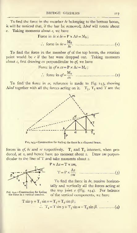
BRIDGE GIRDERS 217
To find the force in the member be belonging to the bottom boom,it will be noticed that, if the bar be removed, Kbed will rotate about
e. Taking moments about e, we have
Force in be x be = P x Kb = M& ;
. . force in vc=^.be (I)
To find the force in the member ef of the top boom, the rotatiop
point would be c if the bar were dropped out. Taking momentsabout c, first drawing ex perpendicular to ef, we have
Force in efx cx= P x Ac= Mc ;
.'. force in ef=c
(2)
To find the force in ce, reference is made to Fig. 243, showinghbed together with all the forces acting on it. 1\ ,
T2and T are the
FIG. 243. Construction for finding the force in a diagonal brace.
forces in ef, be and ec respectively. Tl and T2 intersect, when pro-
duced, at z, and hence have no moment about z. Draw zm perpen-dicular to the line of T and take moments about z.
P x Az = T x zm,
zm (3)
To find the force in be, resolve horizon-
tally and vertically all the forces acting at
FIG. ^--Construction for findingthe tOP J mt '
(Fig' 244)- For balance
the force in a vertical member. of the Vertical Components, W6 haVC
T sin 7 + T! sin a = T4 + T3
sin ft
T3 sin/2 (4)

218 MATERIALS AND STRUCTURES
Double Warren girder. As an example of another method of
solution, consider the double Warren girder shown in Fig. 245 (a).
The girder may be taken as made up of two component girders
shown separately in Figs. 245 (b} and (c\ each carrying the loads which
hang, in the complete girder, from panel points belonging to the
component girder. Each component girder should be solved
separately. The force in any member of the complete girder may.then be found by adding algebraically the forces in the corresponding
bars of the component girders.
FIG. 245. Double Warren girder and the component girders.
Assume that the bracing is at 45, as is often the case in this
type of girder ;also that the proportion of each load which is borne
by each support takes the shortest route between the panel point and
the support. Consider Wx (Fig. 245 (b)) ; |Wa
is supported at & and
-J-Wj is supported at n. The iWj arrives atg after traversing ha as pull
and ag as push, thus producing forces -fWjv/2 pull in ah and W1
push in ag. The -J-Wj arrives at n after traversing /zras pull, cl as
push, le as pull and en as push, and proauces forces equal to
iWlN/2 in each of these bars.
In the same manner, W3 arrives at n by producing sW3 \/2 pull in
le and fW3 \/2 push in en;also |W3 arrives at^by producing |W3 \/2
pull in le, |W3 s/2 push in c/t, |-W3 v/2 pull in ha and ?W3 push in ag.

REINFORCED CONCRETE BEAMS 219
The total forces in these bars in Fig. 245 (/;) may be found now by
adding algebraically the results calculated for each. The forces in
the boom members are best found by calculation from the bendingmoments in the manner described on p. 213. It will be noted that
there are no forces in gh, e/Sindfti.
The solution of the other component girder (Fig. 245 (<r))is obtained
in a similar manner. The force in any member such as be in
Fig. 245 (a) will be found by adding algebraically the forces in ac
(Fig. 245 (b)) and bd (Fig. 245 (c)).
In girders of the double Warren type containing a large numberof panels and uniformly loaded, the assumption may be made that
the inclined bars in any panel share equally the shearing force in
that panel. This assumption should not be made if the number of
panels is small, as it then leads to absurd results.
If vertical bars bh, ck, etc., be added to the girder shown in
Fig. 245 (a), it may be assumed that each vertical bar transfers
one half the load applied at the lower panel point to the upper
panel point, and the solution may then be obtained in the same
manner as before, with the vertical bars left out.
Reinforced concrete beams. In Fig. 246 (a) is shown the section of a
concrete beam having steel reinforcement bars near the bottom edge.
k 6
T"xdM 4

220 MATERIALS AND STRUCTURES
and BOE, the horizontal breadths of which show the strain at any
point.
Let sc be the maximum strain in the concrete under compression,
represented by AC (Fig. 246 (<)), and let ss , represented by DF, be
the strain in the steel. Let d be the depth of the beam measured
from the top to the centre of the reinforcement bars, and let xd be
the distance of the neutral axis from the top. Then
**- xd x/ r \
sg (i-x)J~i-xLet cc be the push stress in the concrete corresponding to the
strain sc and connected with it by
E - CcEc~V
where Ec is Young's modulus for the concrete. Also let tK be the
pull stress in the steel corresponding to the strain s^ the connection
being fiEs=v
where E6 is Young's modulus for the steel. Then
E6. _ t^ f^. _ ^ ^_
Ec
~ss cc
~cc
'
ss
The ratio of -^, denoted by m, is rather variable owing to theEc
nature of concrete ;the average value of 15 is taken in practice ;
hence the above result may be written
*. *.s ........
( )cc (XT*)
It is customary to allow safe stresses of 600 Ib. per square inch
push in the concrete and 16,000 Ib. per square inch pull in the
steel. Suppose that the section is so proportioned as to secure that
these values occur simultaneously on a certain load being applied.
Then, from (3), l6j000 x
~~6oo~" F^ =I5 '
whence ^ = -^ = 0-36...................... (4)
A section so designed is referred to generally as an economic
section.
In estimating the strength of the section to resist bending, it is

REINFORCED CONCRETE BEAMS 221
usual to disregard the stresses in that portion of the concrete lying
below the neutral axis, and hence under pull stress. It follows that
the stress diagram for the section will resemble that shown shaded in
Fig. 246 (<r),in which push stress on the concrete is proportional to the
distance from the neutral axis, cc being the maximum value, and the
stress tg on the steel is assumed to be distributed uniformly over
the steel. These stresses will give rise to equal resultant forces Cand T on the concrete and steel respectively (Fig. 246 (</)), equalbecause there is no resultant force along the length of the beam.
Let p be the ratio of the area of the steel to the rectangular area
bd (Fig. 246 ()), and let A,9 be the total sectional area of the steel bars
in square inches. Then As= pbd, (5)
and T = tsp&d. (6)
Also, Area of the concrete under push = bxd (Fig. 246 (a)).
Average push stress in the concrete = |^c .
Total push in the concrete = C = \c(bxd. (7)
Also T = C;
or tsp
I Hi* (8)
I , 1 ^^)<fr m ^)) (9>
If the beam is of the economic section, then x is 036 from (4), and
(9) becomes, = 0-00675= 0-675 percent (10)
To obtain the moment of resistance to bending, we must calcu-
late the moment of the couple formed by T and C. C acts at a
distance \xd from the top : hence the distance between C and T is
Hence, Moment of resistance = Cd( i - J#), (1 1
)
or =Td(i-x) (12)
From (7) and (n), we have
Moment of resistance = ^dbxd^ (i - \x\ (13)
or, from (6) and (12),
Moment of resistance -f8 pbd'2(\
-i.r) (14)

222 MATERIALS AND STRUCTURES
FIG. 247.- Reinforced concrete T beam, NA below the
Reinforced concrete T beams are much used. There are two
cases, one in which the neutral axis falls below the slab (Fig. 247 (a))
and the other in which the
neutral axis falls within
the slab (Fig. 248(0)). As
the concrete under pull is
neglected, the stress diagramfor the latter (Fig. 248^))is identical with that for a
beam of rectangular section
(Fig. 246 (<:)); hence all the
results already found applyto this case. In the former
case (Fig. 247 ()), it is
customary to disregard the shaded area, representing a small portionof the concrete under push. The stress diagram will then take the
form shown in Fig. 247 (/;),
and the equations become some-
what altered.
It should be noted that re-
inforced concrete buildings are
practically monolithic; columns,
beams and floors are so con-
structed as to form one piece.
Hence all such beams must be
regarded as fixed at the ends. It has been shown already (p. 177)
that in such beams the bending moment reverses in sense near
the walls ; hence the top sides of the beams near the walls will be
under pull, and some of the reinforcement bars should be brought
diagonally upwards and run near the top of the section over the
supports.
EXAMPLE i. A reinforced concrete beam is 9 inches wide, and is to
have a moment of resistance of 200,000 Ib.-inches. The stresses of 600 Ib.
per square inch on the concrete and 16,000 Ib. per square inch on the steel
are to be attained simultaneously. Ratio of elastic moduli = 15. Find
the depth of the beam and also the sectional area of steel required and
the position of the neutral axis.
FIG. 248. Reinforced concrete T beam, NAwithin the slab.
From (10),
From (4),
From (13),
0675 per cent.

REINFORCED CONCRETE BEAMS 223
2 X 2OO,CXX)
0-36x9x600(1 -0-12)=
15-3 inches.
Distance from the top to the neutral axis
=^=0-36 x 15-3
=5-51 inches.
Sectional area of steel =A =/>&j?
= 0-00675 XQX 15-3
=0-93 square inch.
EXAMPLE 2. A reinforced concrete beam 9 inches wide by 18 inches
deep has three steel reinforcement bars, each 075 inch in diameter.
Find the position of the neutral axis and the moment of resistance.
Neither of the stresses of 600 Ib. per square inch for the concrete and
16,000 Ib. per square inch for the steel may be exceeded. Take the ratio
of E to 0=15.
Sectional area of steel= A,= 3 x gg= 3X22X94 4x7x16
=1-33 square inches.
From (3), ^^^ .................................(0
Also, T= C;
Equating (i) and (2) above, we have
I5(i-,r)= 8ur
x 1-33'
19-95 -19.95^=
8 ix* + 1 9'95-r -19-95=0;whence ;tr =0-387.
Distance of the neutral axis from the top=^=0-387 x 18
= 6-96 inches.
or /
Suppose ts be taken as 16,000. Then
16,000cc=
-g- -=673 Ib. per square inch,

224 MATERIALS AND STRUCTURES
a value inadmissible by the data. Take, therefore, cc as 600 it), per
square inch, giving/s = 6oox 23-8
= 14,280 Ib. per square inch,
and cc= 600 Ib. per square inch.
From (14),
Moment of resistance = tspbd*( i-$x)
= 14,280 x 1-33 XI8(I-^2?7)= 298,000 Ib.-inches.
EXAMPLES ON CHAPTER IX.
1. A steel bar is 20 feet long and has a sectional area of 4 squareinches. Find the work done while a pull of 24 tons is applied gradually.Take = 13,500 tons per square inch. Find also the energy stored in acubic inch of the bar.
2. Suppose, in Question i, that the load is applied suddenly, andcalculate the maximum stress produced. What will be the momentaryextension of the bar ?
3. It is found that a steady load of 400 Ib. resting at the middle of abeam produces a deflection at the centre of o-oi inch. What central
deflection would be produced by a load of 100 Ib. dropped on to themiddle of the beam from a height of 16 inches ?
4. A certain steel bar in a girder carries a constant pull of 20 tons
owing to the dead load. The live load produces in the same bar forces
which range from 60 tons pull to 10 tons push. Find the working stress
and the sectional area of the bar. Take ultimate tensile strength = 30 tons
per square inch.
5. A single load of 10 tons rolls along a girder of 30 feet span. Drawcurves showing the maximum bending moments and shearing forces at
every section. State the scales.
6. Answer Question 5 for a uniformly distributed travelling load of 1-5
tons per foot length which may cover the whole span.
7. Supposing that the girder in Question 5 is uniform in section and
weighs 8 tons. Draw the diagrams of M and S for the dead load. Thencombine these diagrams with those already drawn for the single rollingload in order to show the effects of combined live and dead loads.
8. A girder of 40 feet span is traversed by three concentrated loads of
6 tons each at 7 feet centres, followed at an interval of 6 feet by a
uniformly distributed load of 0-5 ton per foot. Find graphically the
maximum bending moments at sections of the girder taken at 5 feet
intervals. The load may run on to the girder from either end.
9. A continuous beam of length 50 feet rests on four supports on the
same level. The left-hand span is 20 feet and the others are 1 5 feet each.
The left-hand span carries a uniform load of 2 tons per foot, the other

EXERCISES ON CHAPTER IX. 225
spans carry uniform loads of I ton per foot. Find the bending momentsat the supports.
10. In Question 9, find the reactions of the supports.
11. In Question 9, draw diagrams of bending moments and shearingforces for the complete beam. State the scales.
12. A plate girder 24 feet span, 2 feet deep, flanges 10 inches wide,carries a uniformly distributed load of 45 tons. The angle sections are
3' 5 x 3'5 x *5 m inches. Take stresses as follows : pull, 7 tons per squareinch
; push, 6 tons per square inch; shearing, 6 tons per square inch
;
bearing, 10 tons per square inch. Find the sectional area of each flange ;
state the number and thickness of plates required for each flange at the
middle of the span. What thickness of web plate would be suitable?If the rivets are 075 inch in diameter, what will be the pitch of those nearthe ends of the girder ?
13. In Question 12, find the length of each plate in (a) the top flange,
() the bottom flange.
14. A Pratt girder (Fig. 241) 48 feet span has 6 equal bays of 8 feet
each. The bracing bars make angles of 45 with the horizontal. Thereis a uniform dead load of i ton per foot length. Find the forces in the
horizontal top and bottom bars of the two central bays ;also those in
the two inclined bars nearest to one support. Find also the force in the
vertical bar second from one support.
15. In Question 14 a uniform live load of 1-25 tons per foot travels
along the girder. Find the maximum forces it will produce in the samebars. The load is long enough to cover the whole girder.
16. A model reinforced concrete beam 3-5 inches wide by 4-25 inches
deep from the top to the centre of the reinforcement has to be made so
that stresses of 600 and 16,000 Ib. per square inch will occur in the con-crete and in the steel respectively. Taking the ratio of the elastic modulias 15, find the percentage of reinforcement required, the sectional area of
the steel, the position of the neutral axis and the moment of resistance of
the section.
17. A reinforced concrete beam of rectangular section 12 inches wide
by 1 8 inches deep has three steel reinforcement bars each 1-25 inches in
diameter. Find the position of the neutral axis and the moment of
resistance. Stresses of 600 and 16,000 Ib. per square inch respectivelyfor the concrete and steel must not be exceeded. Take the ratio of the
elastic moduli as 15.
18. Experiments upon some wrought-iron bars showed that a per-manent set was taken when the bars were strained to a degree greaterthan that produced by a stress of 20,000 Ib. per square inch, but not whenstrained to a less degree. At that point the average strain was 0-0006
foot per foot of length ;what was the resilience of this quality of iron in
foot-pounds per square inch section per foot of length ? (I.C.E.)
19. An iron bar 10 feet long having = 14,000 tons per square inch
and a limit of elasticity= 14 tons per square inch is subjected to shocks of
a total value of 224 foot-pounds. The bar is not to have any permanentset produced in it, this being guaranteed by the adoption of a factor of
safety of 2. Find the required sectional area of the bar. (I.C.E.)

226 MATERIALS AND STRUCTURES
20. A vertical steel rod, 10 feet long, the cross section or which is
i square inch, is fixed at its upper end and has a collar at its lower end.An annular weight of 300 Ib. is allowed to fall through a height of
3 inches upon this collar. Determine the maximum intensity of stress
produced in the steel rod if Young's modulus is 12,500 tons per squareinch. (B.E.)
21. Two bars, A and B, of circular section and the same material, are
each 1 6 inches long. A is I inch in diameter for 4 inches of its lengthand 2 inches in diameter for the remainder
;B is i inch in diameter for
12 inches of its length and 2 inches in diameter for the remainder. Areceives an axial blow which produces a maximum stress in it of 10 tons
per square inch. Calculate the maximum stress produced by the sameblow on B. How much more energy can B absorb in this way than Awithout exceeding a given stress within the elastic limit of the material. ?
(L.U.)
22. A double Warren girder (Fig. 245) is 50 feet span and 10 feet deepand has five equal bays of 10 feet each. It is supported at the endsand carries a load of 12 tons at each of the four lower panel points(48 tons in all). Find the forces in the members. State the assumptionsmade. (L.U.)

CHAPTER X.
COLUMNS. ARCHES.
Ties and struts. Those portions of a structure which are intended
to be under pull are called ties; parts under push are called struts,
or columns. Columns are usually vertical pieces intended to carry
weights. There is an essential difference which modifies greatly the
method of calculating the strengths of ties and struts;a loaded tie
exhibits no tendency to bend if it is straight originally, and will tend
to become straight if originally curved. A strut, if originally curved,will have its curvature increased
by application of the load, and, P /- 9r^\
P
if straight at first, may very easily
be under such conditions of load-FlG> 2^_A straight tie>
ing as will produce bending; want
of uniformity in the elastic properties of the material may producea similar effect.
A straight tie AB is shown in Fig. 249, loaded with pulls P, P,
applied in the axis of the bar. It is evident there is no tendency to
bend the tie, and any cross section CD, at 90 to the axis of the bar,
will have a uniformly distributed
pull stress. A bent tie bar ABis shown in Fig. 250(0). Thenature of the stresses on CD maybe understood by considering the
equilibrium of one half of the bar
(c) (Fig. 250 (^)). It will be observed
that there is a bending couple of
FIG. 25o.-Bent ties and struts.clockwise moment ?d
;this is
balanced by the moment of resist-
ance at the section CD, the latter being represented by the forces
Q, Q. It is apparent that the bending couple IV is endeavouringto straighten the bar.

228 MATERIALS AND STRUCTURES
Had a strut of similar shape been chosen, the forces acting on one
half of it would be as shown in Fig. 250 (c}. Here the couple Pd is
anti-clockwise, and tends to produce further bending.In each of these cases there will be two kinds of stresses on the
section CD : (a) a stress of uniform distribution due to the axial
force P'; (<) a stress due to the bending couple, varying from a
maximum push stress at one edge to a maximum pull stress at the
opposite edge. An initially straight strut which has been allowed to
bend under the load will have a similar stress distribution. It maybe taken that the effects of bending may be disregarded in axially
loaded straight ties, but must be taken account of in all struts.
Euler's formula for long columns. This formula may be deduced
by considering the bending of a long flexible column of uniform
cross section and carrying a load applied
axially. If such a column is perfectly straight
to begin with, and there are no inequalities
in the elastic properties of the material, the
application of an axial load will not tend to
bend the column. On increasing the load,
a certain critical load is reached, the mag-nitude of which depends on the method of
fixing the ends of the column; under this
load the material of the column becomes
elastically unstable. This condition is evi-
denced by the column refusing to spring back
if slightly deflected from the vertical, while
it does so readily for loads lower than the
critical load. The slightest increase in the
FIG. 251. Euler's theory of load beyond the critical value will cause a
small deflection imparted to the column to
increase without limit, and the column collapses. It will be evident
from what has been said regarding the conditions to be realised, that
it is not possible to obtain a column of such ideal material and
construction as will show perfect agreement under test with Euler's
result. But the formula is of service in enabling other more
practical formulae to be devised.
Considering a long column AB (Fig. 251(0)) of uniform cross
section and length L. Let both ends be rounded, or pivoted, in such
a manner that, if bending does occur, the column will assume a
curve resembling a bow (Fig.25i (<)). The effect of a load P applied
at A in producing stresses at any section D will be understood by
(a)

COLUMNS 229
shifting P from A to D as shown by P'; the section at D will
evidently be under an axial load P' = P producing uniform stress,
together with a couple of moment Py. The couple gives a bendingmoment, and the effect of this alone is considered in the following ;
the stress at D caused by the axial load P' is disregarded, as it is
small compared with that produced by the bending moment in the
case of a long column. The maximum bending moment will be
found at the middle section C, at which the maximum value of j,
viz. A (Fig. 251 ()), occurs, and will be given by
Maximum bending moment = MC = PA (i)
Taking the equation for the curvature of a beam (p. 166), we have
for the curvature at D :
i M
pSince will be constant for a given load on a given column,
we may write i
It may be shown readily that a curve, plotted so that its ordinates
y (Fig. 252) are the sines of the angles a represented by its
JH TT radians
FIG. 252. Curve of sines.
abscissae, possesses the same property, viz. the curvature at any
point is directly proportional to the ordinate j>= sina. It may
thus be inferred that the curve of the bent column is a curve of sines
to some scale. The scales of x and y may be stated by taking the
origin at A (Fig. 251 (<)), when AB = L will represent TT radians,
AE =-|L will represent \K radians; also CE = A will represent
sin-= i, and y will represent the sine of an angle AF, which will
have a value -- IT. Hence,!_/
A X 7T
y : A = sin TT : sin -,
~:
* (4)

230 MATERIALS AND STRUCTURES
It can be shown that, if a curve be given by an equation show-
ing the relation of y and x, the curvature at any point may be
d^vobtained by finding the second differential coefficient, viz.
, pro-doc
vided that the curvature is not too great. Application of this
process to equation (4) will lead to a result which may be equatedto that of equation (2) above. Thus,
dy A TT TT
~r = A T ' cos T~dx L L
2
=-pJ- (from 4) ..................... (5)
This gives the curvature at D (Fig. 251 (b}\ viz. . The negativeRD
sign may be disregarded, as its only significance has reference to the
position of the centre of curvature. Equating (2) and (5), we have
P 7T2- y _ i>
Ely L2>
It is important to note that y cancels, giving
P__7^El L2 '
P =^..................................... (6)
This is Euler's formula for a long column having both ends
rounded. The meaning to be attached to the deflection y disappear-
ing from the final result is that no deflection will occur until a
certain load P given by (6) is applied. When the load attains
this value, any small deflection will increase indefinitely with the
consequent collapse of the column.
A more general way of writing Euler's formula is
...................................
where / is a function of the length L of the column. The value of /
depends on the method of fixing the ends, a point which we now
proceed to examine.

COLUMNS 231
Effect of fixing the ends of columns. In the case of the columndiscussed in finding Euler's formula, the ends were taken as rounded
and the column bent as a whole. There was no bending moment at
the ends, and these may be looked upon as points of contraflexure
(p. 1 80). Fixing the ends will produce a stiffer and consequently
stronger column. This may be taken account of in the formula by
writing, instead of L, the length of the column, the distance /
v-JL
FIG. 253. Various methods of end-fixing in columns.
between the points of contraflexure in the actual curve of the
bent column. Some cases are noted below; reference is made to
Fig- 253.
CASE A. Both ends rounded. This is the case examined above;
/=L.
CASE B. Both ends fixed and so controlled that the forces P, Premain in the same vertical line. Here /= ^L.CASE C. One end (the lower) fixed
;the other end guided so
that the forces P, P remain in the same vertical, but the column is
otherwise free at this end to take up any direction. In this case
/=o-7L.CASE D. Both ends are fixed so that the directions at the ends
of the curve of the column remain vertical, but one end is free to
move horizontally relative to the other end, so that the forces P, Pare not in the same vertical when the column bends. Only one
point of contraflexure will occur in the column itself; the position of
the second point may be seen by producing the curve of the column
downwards (shown dotted in Fig. 253 D). In this case /=L.

232 MATERIALS AND STRUCTURES
CASE E. One end fixed, the other end perfectly free. In this
case, the free end is a point of contraflexure. The second point
may be obtained by producing the curve of the column downwards.
Here /= iL.
Using Euler's formula, it will be noticed that, as / has to be
squared, the effect of fixing both ends of the column as in Case B will
be to give the column four times the strength of the same column
having both ends rounded.
Curve illustrating Euler's formula. Euler's formula may be
modified by writing
where A is the sectional area of the column and k is the least radius
of gyration of the section, i.e. k is taken with reference to that axis
containing the centre of the area of the section
for which I has the minimum possible value.
It is evident that the column will bend in a
plane perpendicular to this axis. Two instances
are given in Fig. 254 (a) and (b) ;in each of
these OX is the axis perpendicular to the
plane of bending, and k should be taken with
respect to OX. Inserting this expression for I
in equation (7), (p. 230), we have
Let /= #L, where n is a coefficient dependingon the method of fixing the ends. Then
p? *EA/*y# \L/
FIG. 254. Plane of bendingin columns. Or
2E
The left-hand side of this expresses the collapsing load p per unit
of sectional area. Hence, 2 i7 / 7, \ 2
/-^F(f) (8)\Li/
This will be in tons per square inch, provided the following units
are employed :
E = Young's modulus, in tons per square inch.
k = the least radius of gyration, in inch units.
L = the length of the column, in inches.

COLUMNS 233
In columns of a given material and having a stated method ofop
fixing the ends, the quantity ^ will be constant ; hence / may be
calculated for different ratios of L to k, and a curve may be plotted
from the results. Fig.r .,, Collapsing load
gives such a curve for mildTon/per ^ Ln ^
steel struts having both ends 250
hinged. In this case = i
and E has been taken as 200
13,500 tons per square inch.
It will be noticed from 150
Fig. 255 that, for small ratios
of L to /&, the collapsing stress 100
obtained is absurd. Onlywhen the ratio is large is 50
a reasonable value obtained.
This leads to the conclusion
that agreement of Euler's for-50 100 150 200 250
Ratio
with practical results Of FlG - 255. Euler's curve for mild steel struts, bothends hinged.
tests should be looked for
only in the case of struts which are very long as compared with the
cross-sectional dimensions.
Ewing's composite formula. Sir J. A. Ewing has suggested a
composite formula made up of the crushing strength of a very short
block together with the elastic instability load of a very long column,both composed of the same material as the actual column.
Let ft = the crushing strength of a short block, in tons per squareinch.
P!= the crushing load, in tons, applied axially.
A = the area over which Px is distributed, in square inches.
Then Pi=/cA (i)
Let P2= the elastic instability load of a long column, in tons;
the column having the same sectional area A as the
short block.
Then7T2EI
2~
/2
Combining these in accordance with Ewing's method gives the
following formula for P, the collapsing load of the ordinary practical
column when loaded axially : f .
P-.
/C,, (3)
7T2EI

231 MATERIALS AND STRUCTURES
This formula has the advantage of being continuous, and does not
give an absurd result for a column of any practical length. If / is
very short, the second term in the denominator becomes very small,
and may be disregarded. The formula then reduces to the expression
(i) for the crushing load of a short block. If / is very long, the
formula reduces to Euler's formula by neglecting the unimportantterms.
Rankine's formula for columns. This formula is the one in most
frequent practical use. It is practically the same as Ewing's, althoughin a slightly altered form. Thus,
P-
fcA
Now, I may be written as I =
where A is the sectional area and k is the least radius of gyration.
Hence,
/CA~
It is apparent that J/= will be constant for a given material, andTT^hi
may be written c, the value of which is to be determined by experi-
ments on the collapsing strength of columns. Hence,
This is Rankine's form of the formula, and gives the total collapsing
load on the column. The collapsing load per square unit of sectional
area will be given by P
This will be in tons per square inch, providedfc is in tons per
square inch and / and k are in inch units. It is assumed that the

COLUMNS 235
column is of uniform section and is loaded axially. The least value
of k should be chosen as in the case of the Euler formula, and the
value of / is the same as in the cases given on p. 231 for various methodsof fixing the ends. Values of fe and c are given in the table below
;
a suitable factor of safety should be applied in order to obtain the
safe load :
COEFFICIENTS IN RANKINE'S FORMULA.
Material.

236 MATERIALS AND STRUCTURES
k under 40, and mild steel demands the smallest sectional area for
ratios of L to k above 40. Wrought iron would require a smaller
sectional area than cast iron for ratios of L to k over 65.
Breaking Load
Tons per ay in.
Sale load
Tons per of In.
6
Ss

COLUMNS 237
OX is greater than that for the I section, and hence would give a
greater load for the box section.
Secondary flexure in columns. Professor Lilly has pointed out
that columns constructed of thin plates are liable to fail by secondary
flexure, i.e. the column may not fail by bending as a whole, but bythe material buckling over a short length. Lilly has made manyexperiments in support of his views, and has proposed a formula in
which account is taken of the ratio of the thickness of the plate to
the radius of gyration. Further experimentalwork is required in order to settle the values
of the experimental factors involved.
Recent tests made at the University of
Illinois on built-up columns indicate that the
stress distribution may be very erratic;
especially in the neighbourhood of riveted
joints. It is admitted that our knowledge of
the strength of columns, struts and com-
pression members generally is far from being
complete. At present, most designers rely
on the Rankine formula coupled with a
liberal factor of safety.
Effect of a non-axial load. In Fig. 259 (a)
is shown a column the axis of which is AB,i.e. AB passes through the centres of area of
all horizontal sections of the column. Aload P is applied at C at a distance a from
the axis. P may be moved from C to Aprovided a couple of moment Pa is applied.
We have now an axial load P' = P togetherwith a couple Pa which will give a uniform
bending moment at all horizontal sections
of the column. Let A be the area of the
section, then P' will produce a uniformlydistributed push stress ^ given by

238 MATERIALS AND STRUCTURES
Then, using the equation (p. 146)
M = ^I,m
we have Pa = ^l=^-l.
Tin / x
Whence p t= ....................................... (2)
Pam c , .
and C=~~.....................................
The stress due to the bending moment will vary uniformly between
these values, being zero at OX. The stress figure for the direct
stress combined with the bending stress may be drawn as shown in
Fig. 259 (r), where HKML shows the uniformly distributed stress/!and MNRQL shows the varying stress due to the bending moment.The resultant stress figure is shaded, and shows that the maximum
push stress occurs at the edge FG (Fig. 259 ()), and is given by
Maximum push stress =pl +pc ................... (4)
In the case shown there will be no stress at S (Fig. 259^)); the
portion SK will be under push stress, and SH will be under pull
stress, the maximum value of the latter occurring at the edge DE(Fig. 259 (I})) and given by
Maximum pull stress =pt~Pi ................... (5)
The presence of pull stress in a metal column is permissible, but
is objectionable in a column of stone, brick, or other construction in
which the jointing of the blocks of material is not considered to be
trustworthy under pull. The extreme limit of stress distribution in
such cases is taken usually to be zero stress at one edge and
increasing gradually to a maximum push stress at the opposite edge.
Taking a rectangular section (Fig. 260 (a)) of dimensions b and d,
the values of mc and m t will be equal ; hence pc and pt will also be
equal, and the stress figure (Fig. 260(/;)) shows that the condition
of no pull stress is
A-A = ........................................... (6)
Also'
and
6Pa

COLUMNS 239
Hence,6Pa PM2 bd
or -(9)

240 MATERIALS AND STRUCTURES
Here /=2L= 36o inches. */c= 36 tons per square inch.
r 9 i= = - inch units. =-7
K
37x7= 27-5 tons.
EXAMPLE 3. Taking a factor of safety of 5, find the diameter of a solid
mild-steel strut 6 feet long to carry safely a load of 3 tons. Both ends
are rounded.
Let d= diameter of strut in inches.
Then &= = ^ inch units.4 16
/=L= 72 inches. yc= 2i-4 tons per square inch.
A=V- C=7^'
Also, Collapsing load= P = 3X5 = i5 tons.
15=
or
i6-8i^4 - i$d'2 - 165-9=0 ;
whence d=1^9
inches.
Straight-line formula. Very fair approximation to the strength of
a strut may be obtained by use of a straight-line formula, i.e. one for
which the graph is a straight line, and the calculations required in
designing a strut to fulfil given conditions become much simpler.
The usual form of such formulae is

ARCHES 241
where fc is the safe stress per square inch of sectional area of the
column, /is the safe stress for a short block of the same material andc is a coefficient depending on the material, and ranging in value from
0-005 for mild steel and wrought iron to 0-008 for cast iron and timber.
Arches. In Fig. 261 (a) is shown a number of loads W1}W
2 , etc.,
supported by an arrangement of links ABCDE, forming part of a
link polygon. The construction necessary to determine the directions
of the links is given in Fig. 261 (b) and has been explained on p. 67.
|w. jw +w -I
Aj-tyJ
FIG. 261. Principle of the arch.
The thrusts in the links are T1?T
2 , etc., and may be scaled from the
lines radiating from O. OF = P and NO = Q give the forces requiredto maintain the links in position. Instead of links we might have
employed blocks (Fig. 261(<:)), drawing the joints ab, cd, ef, etc., per-
pendicular to the lines of P, Tland T
2 respectively. The arrange-
ment now gives an arch such as might be constructed in masonry or
brickwork. The original link polygon is called the line of resistance
of the arch;the forces acting at the joints of the blocks will have
the same values PltT
1?T
2 , etc., as in the link polygon.
The best arrangement would be produced by having the line -of
resistance passing through the centre of each joint and perpendicularto the joint Such would give a uniform distribution of stress over the
joints, and there would be no tendency for any block to slide on its
neighbours. Generally, it is not possible to secure these conditions,
but it is usual to endeavour to satisfy the following conditions :
(i) The line of resistance is arranged to come within the middle
third of each joint ;this secures that there will be no tendency for
the joints to open out either at the top or the bottom (p. 239).
D.M. Q

242 MATERIALS AND STRUCTURES
FIG. 262. Stress at an arch joint.
(2) The stress on the joint produced by the forces P, T1?T
2 , etc.,
is limited to a value which can be carried safely by the material.
(3) The line of resistance should not be inclined to the normal to
the joint at an angle greater than the limiting angle of resistance
(see p. 363) ;this secures that there shall be no slip, independently
of any binding effect owing to the mortar.
Condition (2) above may be understood more clearly by reference
to Fig. 262, in which are shown two of the blocks in equilibrium
under the action of W1}W
2 ,P
and T2
. T2 may be split into
components Tj and S, normal
and tangential respectively to
the section ef. If T:acts at the
centre of the joint, a uniformly
distributed normal stress will be
produced. Otherwise, as ex-
plained for a column on p. 237,
a varying normal stress will act
on the section and may be represented by the stress figure efhg.
The maximum stress p^ is limited to a safe value depending on the
material of the blocks.
Reference to Fig. 261 (b) will show that the horizontal component of
any of the forces PI} Q,r
l\, T2 , etc., is given by OR = H. H is called
the horizontal thrust of the arch, and is constant throughout a given
arch carrying given vertical loads.
It will be understood that the link polygon ABCDE (Fig. 261(0))
may have a greater or smaller vertical height depending on the position
chosen for the pole O in Fig. 261 (b). The effect of this on the arch
will be to give it a greater rise if O is nearer FN in Fig. 261 (b) ;H
will be diminished thereby. Hence, an arch of given span and
carrying given loads will have the horizontal thrust diminished by
increasing the rise.
Metal arches. From what has been said regarding the line of
resistance falling within the middle third of the joints, it will be clear
that the bending moment at any section of a masonry arch is limited
to a small quantity only. The rule is unnecessary in the case of metal
arches, as these are capable of withstanding large bending moments.
Metal arches are of three principal types : (a) arches continuous
from abutment to abutment, and firmly anchored to the abutments
or springings; (b) arches continuous throughout their length, but
hinged at the abutments by means of pin joints ; (c) arches having

ARCHES 243
(a)
pin joints at the abutments, and also a pin joint at the crown. These
types are shown in outline in Fig. 263 (a), (b) and (c}.
In the types (a) and (b) difficulties arise in the solution by reason
of the inability of the arch to change its shape freely in order to
accommodate changes in dimensions
due to elastic strains of the metal, or to
changes in temperature. In type (a),
both the span and the directions of
the tangents to the arch at the abut-
ments are unaltered when the arch is
under strain. In type (b) the direc-
tions of the tangents at the abutments
may alter, but the span remains con-
stant. In type (c) the arch may rise
freely at the crown to accommodate any strains of the metal;hence
this type is not liable to being self-stressed, nor can changes in
temperature produce any stresses in the metal. Type (c) alone is
considered here.
Three-pin arch. In Fig. 264 (a) is shown an arch having pins Aand B at the abutments, or springings, and one at the crown C. A
w
FIG. 264. Three-pin arch.
single load W is being supported and all other weights are dis-
regarded meanwhile. Let TA and TB be the abutment reactions.
Acting on the arch are three external forces only, viz. W, TA and
TB ,and these are in equilibrium; hence their lines must meet at a
point. Further, there will be two forces only acting on the portion

244 MATERIALS AND STRUCTURES
AC, viz TA and a reaction Tc at C coming from the right-hand
portion of the arch ; these forces are in equilibrium, and must there-
fore act in the same straight line AC (Fig. 264 (/)). It follows that
the line of TA in Fig. 264 (a) is AC, and production of AC to cut the
line of W in D will give the point where TB must also intersect W;
therefore T B acts in the line BD. The equilibrium of the right-hand
portion CB is indicated in Fig. 264 (c).Tc (now reversed in sense),
TB and W intersect at D and are in equilibrium. Both TA and TB
may be found from the parallelogram of forces \)abc.
It may be noted that W (Fig. 264(0)) might be supported by means
of straight rods, or links, AD and BD jointed at A, D and B, and
that these rods would be under thrust only. ADB is usually termed
the linear arch. Again, if W were supported by a beam simply resting
on supports at A and B, then ADB would be the bending-moment
diagram for the beam to a scale in which the bending moment at
E is represented by DE.
The bending moment at any section of the arch may be found in
the following manner. Let AB (Fig. 265) be a transverse section of
an arch, let OX be the centre line of the arch,
i.e. the line containing the centres of area of
all transverse sections, and let OX intersect
AB at C. Draw DC vertically to meet theT"T
linear arch at D. The thrust T in the linear
arch at D will act in the direction of the
tangent DE to the linear arch at D, and maybe transferred to C as shown by T' = T,
provided a couple of moment T x CE be
applied, CE being perpendicular to DE.The moment of this couple is the bending
FIG. 265. Bending moment, .
thrust and shear at a section moment at AB;
the normal thrust and
shearing forces at AB may be obtained by re-
solving T' into components respectively normal and tangential to AB.
A convenient manner of expressing the bending moment may be
obtained : Resolve T at D into horizontal and vertical componentsH and V by means of the triangle of forces DFE (Fig. 265). The
triangles EFD and DEC are similar; hence
T_DE_DCH=FD
=CE ;
:. TxCE = HxDC.Now, since the linear arch is also the link polygon for the given
loads, H is constant for any point in the arch (p. 242). Hence the

ARCHES 245
intercepts DC (measured to the same scale as that used in drawingthe arch), when multiplied by the constant horizontal thrust H, will
give the bending moment at AB. It will be noted that DC 'is the
vertical intercept between the arch centre line OX and the linear
arch ; hence the area between these will represent the bending-moment diagram for the arch.
The bending-moment diagram for the arch in Fig. 264 (a) is
shaded. H may be found by first obtaining TA or TB and then
taking the horizontal component. It will be noted that the diagramfor AC falls below the arch centre line AFC ;
the inference is that
this portion of the arch is under negative bending. Reference to
Fig. 264^) will render this point more clear; the forces TA and Tc
tend to increase the curvature of AC. The bending-moment diagramfor CGB falls above the centre line
; CGB is under positive bendingand will have its curvature diminished on application of the load.
The following directions will be of service in dealing with more
complicated loading ; reference is made to Fig. 266, in which ACBis the arch centre line.
FIG. 266. Bending moments and reactions for a three-pin arch.
Consider a simply supported beam having the same span as the arch
and carrying the same loads. Draw the bending-moment diagramADEB for this beam, using any convenient scale. The arch has
zero bending moment at A, C and B;hence the linear arch may be
obtained by redrawing ADEB so that it passes through A, C and B.
To do this, reduce all the ordinates of ADEB in the ratio of CF to
EF, giving the linear arch AGCKB. The shaded area will be the
bending-moment diagram for the arch. To obtain its scale, CFrepresents MF ,
the bending moment at F for the simply supportedbeam
;hence the scale of the shaded area is found by equating CF
to this bending moment.

246 MATERIALS AND STRUCTURES
The horizontal thrust H may be found from
MF = HxCF,
orCF'
CF being measured to the scale used in drawing the arch. TA and
TB may be found by compounding with H the reactions P and Qfor the simply supported beam at A and B respectively.
Suspension bridges. A simple type of suspension bridge is shown
in Fig. 267, in which the roadway FG is supported by means of two
FIG. 267. Suspension bridge.
chains AB, one on each side of the bridge. The chains pass over
rollers or sliding pieces on the tops of towers at A and B and are
anchored securely at D and E. Suspending bars connected to the
chain support the weight of the roadway.
Assuming that the weight of the roadway is distributed uniformly
and that the weight of the chain is small by comparison, also that
the roadway is fairly flexible, the tensions at the points B and C
may be found as shown in Fig. 268. The portion of the chain
(a)
FIG. 268. Tensions at B and C in a suspension bridge chain.
hanging between B and C will support one quarter of the whole
weight of the bridge, and this may be concentrated at its centre ot
gravity. The horizontal pull H at C passes through the line of |\V at
G;T
,the pull at B, must pass through the same point. The triangle
of forces abc (Fig. 268 (<)) will then give the values of H and T .
Let w (Fig. 269 (a)) be the load communicated by each suspenderto the chain. T and H in this figure are the pulls at B and C
respectively. To obtain the directions of the chain throughout, the

SUSPENSION BRIDGES 247
pull in ab, together with H, supports the load carried by the four
suspenders passing through fr, <r,d and e. The resultant of the four
loads will intersect H at their centre Glt and the. pull in ab must
pass through the same point, thus determining the direction of ab.
FIG. 269. Shape of a suspension bridge chain.
be will pass through G2 ,the point in which the resultant force in the
suspenders c, d and e intersects the line of H. Similarly cd passes
through G3 and de completes the half-chain. If a curve were drawn
to touch the lines ab, be, etc., its shape would be parabolic, owing to
the geometrical property involved in the above construction.
It will be evident that abcde is a link polygon capable of supportingthe given loads. The pull in any link may be found from the force
diagram (Fig. 269^)).The effect of a load passing along the bridge may be observed by
inspection of Fig. 270. As both chain and roadway are flexible, the
A
FIG. 270. Effect of a load on a suspension bridge.
chain alters in shape as shown. To avoid this undesirable effect,
the roadway may be stiffened by the insertion of stiffening girders.
The best type of such girders consists of two on each side of the road-
way (Fig. 2 7 1 (a ) ),connected at the middle C by a hinge and also
having hinges at the piers of the bridge, D and F. Girders of this
type are free to rise or fall at the middle of the span and thus avoid
any complications of stress which would result from any alteration in
the length of the chain owing to changes of temperature or stretching.
To understand the effect of a live load W on the chain in Fig. 271 (a\it should be noted that the chain will alter its curve to a very small
extent only, owing to the action of the stiffening girders; anyalteration will be due to the elastic strains. Supposing the chain

248 MATERIALS AND STRUCTURES
to be parabolic initially, ancj to remain parabolic, it follows that the
effect of W on the chain must be the same as would be produced by
equal pulls in all the suspenders, this being the condition under
which alone will the chain assume a parabolic curve. Hence, if
Wthere be N suspending rods, the pull in each will be . The forces
acting on the left-hand stiffening girder will be as shown in Fig. 271 (b);
A B
VV W W W WN IN IN IN IN
J I -r-{ w w w w wTP *W (b) tN tN tN tN tN-
fc (c)FIG. 271. Stiffening girders for a suspension bridge.
those acting on the right-hand girder are indicated in Fig. 271 (c). It
will be noted that a reaction P from the left-hand abutment togetherwith another Q communicated through the pin at C from the right-
hand girder are required for the equilibrium of the left-hand girder.
The right-hand girder requires holding down against the pulls of the
suspending rods ; hence the reactions Q and S act downwards.
Knowing the loads, these reactions can be calculated, and the
diagrams of bending moments and shearing forces for the girders
may be drawn by application of methods already described.
The length of parabolic chain required for a suspension bridge
may be calculated approximately from the following formula :
Let- L = the half length of the chain, in feet.
S = the span, in feet.
D = the dip, in feet.
Then L =f+ i
EXERCISES ON CHAPTER X.
1. Calculate the elastic instability load by Euler's formula for a bar of
mild steel 10 feet long and 0-5 inch in diameter, fixed at both ends.
Take = 13,500 tons per square inch.
2. A mild-steel tube i-i inches in external diameter and i-o inchinternal diameter and 8 feet long is used as a strut, having both ends
hinged. What would be the collapsing load by Euler's formula?= 13,500 tons per square inch.

EXERCISES ON CHAPTER X. 249
3. A series of struts, having both ends rounded, have ratios of L to kof 40, 60, 80, etc., up to 200. Calculate the collapsing loads per squareinch of sectional area, using Euler's formula, and plot these loads with the
ratios of L to k. =13,000 tons per square inch.
4. Answer Question 3 if both ends are fixed.
5. Find the breaking load of the strut given in Question i by applica-tion of Rankine's formula. Take the coefficients from the table on p. 235.
6. A solid mild-steel strut 2 inches diameter is 6 feet high. UseRankine's formula and find the safe axial load if both ends are rounded.Factor of safety
=5.
7. A wrought-iron tube is 4 inches in external diameter, and is madeof metal 0-25 inch thick. It is used as a column 8 feet high, and has bothends fixed. Find the breaking load by use of Rankine's formula.
8. A rolled I section of mild steel, flanges 5 inches wide, depth9 inches, metal 0-6 inch thick, is used as a strut 10 feet long, having oneend fixed and the other end perfectly free. Find the safe axial load byRankine's formula, taking a factor of safety of 6.
9. A solid strut of mild steel is 1-5 inches in diameter and has bothends fixed. Find the length for which the breaking loads by Rankineand by Euler will be equal. Take E = 13,500 tons per square inch.
10. The column given in Question 8 carries a load of one ton at thecentre of area of one flange. Calculate the maximum and minimumstresses, and draw a stress diagram for a horizontal cross section of thecolumn.
11. Take the tube given in Question 7 and calculate at what distancefrom the axis a load may be applied without thereby producing tensile
stress.
12. A semicircular arch of 4 feet radius, hinged at the crown and
springings, carries a uniform load of 500 Ib. per horizontal foot. Drawthe bending-moment diagram. State from the diagram the maximumbending moment.
13. The centre line of a three-pinned arch is a circular arc; the
horizontal distance from springing to springing is 150 feet and the rise is
15 feet. There is a uniformly distributed load of 0-5 ton per horizontal
foot together with concentrated loads of 10, 15 and 5 tons at horizontal
distances from one springing of 20, 40 and 60 feet respectively. Drawthe bending-moment diagram and state its scale ; find the horizontal thrust
and the reactions at the springings.
14. A suspension bridge is 100 feet span and the chains have a dip of12 feet. Suppose the uniform load on one chain to be 500 Ib. perhorizontal foot, and find the maximum and minimum pulls in the chain.
15. Find the length of chain required for the bridge in Question' 14.
Suppose the chain were to stretch 0-25 inch, what will be the change in
the dip ?
16. A hollow cast-iron column, 12 inches in external diameter, 10 inchesin internal diameter and 8 feet long, is subjected to a direct compressiveload of 40 tons. A bracket bolted to the side of the column supports theend of a girder, which transmits to the bracket a load of 5 tons. The line
of action of this load maybe assumed to be 12 inches from the axis of the
column. Find the maximum and minimum stresses in a cross section of
the column due to these loads. (B.E.)

250 MATERIALS AND STRUCTURES
17. A horizontal link of rectangular section 4 inches deep and 2 inchesthick is subjected to tension, the load being P tons. The line of action ofthe load is in the central plane of the thickness and 2-25 inches from thebottom face of the link, (a) Find the load P if the greatest tensile stress
in the straight part of the link is 6 tons per square inch, (b) If the tensile
stress on a cross section of the link varies uniformly from 6 tons persquare inch at the top to 2 tons per square inch at the bottom, find P andthe position of its line of action. (L.U.)
x joist 1?.A. hollow cylindrical steel strut has to be
-iJ
designed for the following conditions : Length 6 feet,
16*6/015^axial load 12 tons, ratio of internal to external
diameter 0-8, factor of safety 10. Determine the
necessary external diameter of the strut and the
thickness of the metal if the ends of the strut are
firmly built in. Use the Rankine formula, takingf2i tons per square inch, and a for rounded8 x6joist
19. Find the radii of gyration of a column con-
sisting of three steel rolled joists, riveted together as shown in the sketch
(Fig. 272), their properties being

CHAPTER XL
SHAFTS. SPRINGS.
Twisting moment on a shaft. A shaft is a piece used for the
transmission by rotation of motion and power. A moment tendingto rotate the shaft is communicated at one place and is transmitted,
by stresses in the material of the shaft, to the desired place. Con-
sidering a shaft AB (Fig. 273 ()), having one end A fixed rigidly, and
FIG. 273. Twisting moments on shafts.
having an arm BC mounted at the other end. The effect of a force
P applied at C may be examined by applying equal and opposite
forces P' and P", each equal and parallel to P, at B so as to act
through the axis of the shaft. These forces equilibrate and con-
sequently do not interfere with P. The system now consists of a
couple formed by the forces P and P", the sole tendency of which
will be to rotate the shaft about its axis, together with a force P',
the tendency of which will be to bend the shaft. The shaft as a
whole would be equilibrated by the application of forces (not shown
in the figure) at the rigid connection at A.
A shaft is said to be under pure twist when there is no tendency to
bend it, nor to produce push or pull in the direction of its axis. The
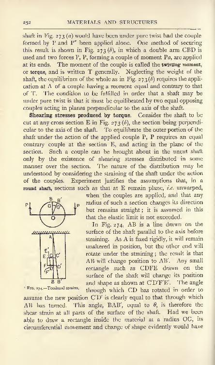
252 MATERIALS AND STRUCTURES
shaft in Fig. 273 (a) would have been under pure twist had the coupleformed by P and P" been applied alone. One method of securing
this result is shown in Fig. 273^), in which a double arm CBD is
used and two forces P, P, forming a couple of moment Pa, are applied
at its ends. The moment of the couple is called the twisting moment,
or torque, and is written T generally. Neglecting the weight of the
shaft, the equilibrium of the whole as in Fig. 273^) requires the appli-
cation at A of a couple having a moment equal and contrary to that
of T. The condition to be fulfilled in order that a shaft may be
under pure twist is that it must be equilibrated by two equal opposing
couples acting in planes perpendicular to the axis of the shaft.
Shearing stresses produced by torque. Consider the shaft to be
cut at any cross section E in Fig. 273 (^), the section being perpendi-
cular to the axis of the shaft. To equilibrate the outer portion of the
shaft under the action of the applied couple P, P requires an equal
contrary couple at the section E, and acting in the plane of the
section. Such a couple can be brought about in the uncut shaft
only by the existence of shearing stresses distributed in some
manner over the section. The nature of the distribution may be
understood by considering the straining of the shaft under the action
of the couples. Experiment justifies the assumptions that, in a
round shaft, sections such as that at E remain plane, i.e. unwarped,
when the couples are applied, and that anyradius of such a section changes its direction
but remains straight ;it is assumed in this
that the elastic limit is not exceeded.
In Fig. 274, AB is a line drawn on the
surface of the shaft parallel to the axis before
straining. As A is fixed rigidly, it will remain
unaltered in position, but the other end will
rotate under the straining ;the result is that
AB will change position to AB'. Any small
rectangle such as CDFE drawn on the
surface of the shaft will change its position
and shape as shown at C'D'F'E'. The angle
through which CD has rotated in order to
assume the new position CD' is clearly equal to that through which
AB has turned. This angle, BAB', equal to 0, is therefore the
shear strain at all parts of the surface of the shaft. Had we been
able to draw a rectangle inside the material at a radius OG, its
circumferential movement and change of shape evidently would have
B B
FIG. 274. Torsional strains.

SHAFTS253
crossbeen proportional to its radius. Thus, on the outer end
section, G would move to G' and B to B', and we have ,
GG':BB' = OG:OB.We may therefore state that, since the shear strain at any point on
a cross section of the shaft is proportional to the radius, the shear
stress at that point will also be proportional to the radius, providedthe elastic limit is not exceeded. It will also be
evident that the shear stress at any point on a cross
section will have a direction perpendicular to the
radius of the point.
Moment of resistance to torsion. In Fig. 275is shown a cross section of a shaft under pure twist.
Consider a small area a.
Let R = radius of shaft, in inches;
r= radius of a, in inches;
pt intensity of stress at outer skin, in Ib. or
tons per square inch;
pt = intensity of stress on a.
Then /':/ = r:R,
FIG. 275.
and Force on a =ta = =.
R _,=|. fl,*.
Taking the sum of such moments all over the section, we have
pt _pt vrR4
R loz ~R' 2
= Ib.- or ton-inches.
Moment of force on a about
Total moment =
This expression is called the moment of resistance
to torsion for a solid round shaft. The case of
a hollow round shaft of external radius Rxand
internal radius R9 (Fig. 276) would be worked out
similarly, with the substitution of limits R2and Rj
for o and R in the integration. Thus,
^ , t> o
Total moment = %-2 at* =^K R2 K
._ or ton-inches.

254 MATERIALS AND STRUCTURES
B B'
Any question regarding the safe strength of a round shaft under
pure twist may be solved by equating the given torque to the proper
expression for the moment of resistance to torsion. It will be clear
that a hollow. shaft will have a greater strength than a solid one
of the same weight. Apart from the practical
consideration that the boring of an axial hole
may lead to the detection of otherwise un-
suspected flaws in the material, there are the
considerations that the intensity of shear stress,
as well as the arm for taking moments, are
small near the axis in a solid shaft, so
that material near the axis is being employed
unprofitably.
Torsional rigidity of a round shaft. It is
often of importance to estimate the angle throughwhich one end of a shaft will twist relatively
to the other end briefly the angle of torsion.B B'
FIG. 277. Angle of twist Referring to Fig. 277, one end of the shaftof a shaft.
'
being fixed rigidly, the other end rotates througha small angle BOB', denoted by a, on application of a torque T, andthe shear strain is given by the angle BAB', equal to radians.
Taking the expression for the modulus of rigidity (p. 109), viz.
Pt
we
i/
may substitute for pt and as follows :
-(0
2
2T(*)
Again,BB' , . _.=
6, in radians
or
Also,BB'
or
a, m radians;
' = BO.a;
BO R-(3)
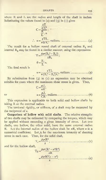
SHAFTS 255
where R and L are the radius and length of the shaft in inches.
Substituting the values found in (2) and (3) in (i) gives
2T
2TLradians
The result for a hollow round shaft of external radius Rxand
internal R2 may be found in a similar manner, using the expressions
The final result is
2TL
By substitution from (3) in (i) an expression may be obtained
suitable for cases where the maximum shear stress is given. Thus,
P AL-iR'
or a = t,radians............................... (6)CK
This expression is applicable to both solid and hollow shafts by
taking R as the external radius.
The torsional rigidity, or stiffness, of a shaft may be measured bythe reciprocal of a.
Comparison of hollow with solid shafts. The relative strengths
of two shafts may be estimated by comparing the torques, which maybe applied without exceeding a given intensity of stress. Let two
shafts, one hollow, the other solid, have the same external radius
R. Let the internal radius of the hollow shaft be R, where n is a
numerical coefficient. Let/ be the maximum intensity of shearing
stress in each case. Then, for the solid shaft,
(i)
and for the hollow shaft,
_/t7T(R*-*R*)2R
^)

256 MATERIALS AND STRUCTURES
Hence, =i-^4.................................... (3)is
For example, if the internal radius of the hollow shaft is one-third
of the external radius, n J, and
= 881'
Comparison may also be made of the strength of a hollow with
a solid shaft having the same cross-sectional area, i,e, having the
same weight per unit length. We have, for the solid shaft,
(4)
and for the hollow shaft, TA
Putting R2= ^R
15 gives
_
2
Also, as the cross-sectional areas are equal,
Hence>
.-. R^R^i-w2); ............................ (6)
RL _i_R2 i-ri>'
(7)V I - W
TA T j_ IFor example, if n = ^,
=-' =V-1-18.

SHAFTS 257
Thin tube under torsion. In the case of a thin tube under torsion
it may be assumed that the shearing stress is distributed uniformly.
Let pt= stress intensity, Ib. per sq. inch,
R = mean radius of tube, inches,
/= thickness of the tube walls, inch.
Then Cross-sectional area =27TR/*,
Total shearing force =Moment of this force =Moment of resistance to torsion = 2TrR2^, Ib.-inches.
Horse-power transmitted by shafting. Formulae connecting the
horse-power (see p. 326) with the dimensions of the shaft and its
speed are based on the average torque transmitted, and should there-
fore be used with caution. The maximum torque, on which will
depend the maximum intensity of shearing stress, may exceed the
average torque considerably, leading to a result for the diameter of
the shaft which may be much too small.
Considering a solid round shaft under pure twist, let
T = torque transmitted, Ib.-inches ;
R = radius of shaft, inches;
pt = maximum shear stress, Ib. per sq. inch;
N = revolutions per min.
TThen Work per revolution = . 2ir (p. 339)
Now
.'. work per revolution =12
Work per minute =12
. . H.P. =12 x 33,000
40,081"
EXAMPLE. Find the horse-power which may be transmitted by a
shaft 2 inches in diameter at 180 revolutions per minute. The maximumshearing stress is 10,000 Ib. per square inch.
_^R3N _ 10,000 x i x 1 80H 'P
'~4o,o8i~
40,081
=45 nearly.
D.M. R

258 MATERIALS AND STRUCTURES
.Equation (i) above may be altered so as to give the diameter of
shaft required for a given power. Thus,
40,081 x H.P.
orx 40,081 x H.P.
D = a coefficient x
A common value of the coefficient is about 3-3 for steel shafts.
Principal stresses for pure torque. In Fig. 278 is shown a shaft
FIG. 278. Principal stresses for pure torque.
under pure torque. A small square abcd^ having its edges ab and cd
parallel to the axis of the shaft, has been sketched on the surface.
Each edge of the square will be subjected to shearing stresses of
magnitude pt\ hence the diagonals ac and bd have purely normal pull
and push stresses respectively, the magnitude being also/* (p. 128).
These diagonals are therefore principal axes of stress, and the
stresses on them are the principal stresses for the case of the shaft
being under pure torque. If the diagonals be produced round the
shaft surface, it is evident that they will form helices having an
inclination of 45 to the shaft axis.
A shaft made of material weak under pull, and strong under both
shear and push, would fracture along the helix of which ac forms a
part. This fact may be illustrated by means of a stick of blackboard
chalk;on applying opposite couples by the fingers to the ends of
the chalk, the fracture will be found to follow very closely a helix of
45 inclination. Pure bending applied to the chalk will cause it to

PRINCIPAL STRESSES 259
fracture across a section at 90 to the axis; it is therefore evident
that bending and torque simultaneously applied will cause fracture
to take place on some section intermediate between 45 and 90.A shaft made of cast iron would behave in a similar manner to the
stick of chalk, as the stress properties are similar.
Shafts made of ductile material, such as mild steel, behave in a
different way. Fracture under pure torque takes place across a
section at 90 to the axis, as the strength under pull and also under
push is higher than that under shear. It may be shown that materials
loaded in a complex manner have sections mutually perpendicular
on which the stress is purely normal, i.e. the stresses are principal
stresses. There is also a particular section which has a shearing
stress greater than that on any other section. There is strong
evidence for believing that brittle materials break down when the
principal stress of tension reaches a certain value depending on
the material; many ductile materials break down, or yield, when
the maximum shearing stress reaches a certain value.
More general case of principal stresses. Let AB and BC be
two sections of a body intersecting at 90 at B (Fig. 279 (a)). Let
r.AC1 r. A C cos Q
FIG. 279. Principal stresses and axes.
AB and BC have normal stresses pland /2 respectively, and let each
be subjected to equal shearing stresses pt. Let AC represent a third
section of the body, cutting AB at an angle 0, and let the stress
r on AC be purely normal. The wedge ABC will be in equilibrium
under the action of these stresses, and it is required to determine
from this condition the values of and of r. AC and r will then be
a principal axis of stress and a principal stress respectively. For
simplicity, let the thickness of the wedge from front to back be
unity.
Due to the given stresses /15 /2 and/*, the faces AB and BC will
have resultant forces acting as shown in Fig. 279(^). The forces

260 MATERIALS AND STRUCTURES
pi . AB and /2. BC will act at the centres of AB and BC respec-
tively. The forces p t . AB and p t . BC will act along AB and BCrespectively. Due to r, a normal force r . AC will act at the centre
of AC and will have an inclination to the vertical equal to 6. Henceits vertical and horizontal components will be r . AC . cos and
r. AC . sin respectively. For equilibrium of the wedge, the sumof the vertical upward forces must be equal to the sum of the vertical
downward forces;also the sum of the horizontal forces acting towards
the left must be equal to the sum of those acting towards the right.
The algebraic expressions for these conditions are :
r. AC. cos (9=^. AB+^.BC................... (i)
7-.AC.sin6>=/2 .BC+/,.AB................... (2)
To simplify (i), divide by AC, giving
AB BC
=pl. cos +pt . sin 0.
Divide this by cos 0, giving
*=/!+/. tan0...................... (3)
Equation (2) may be simplified in a similar manner by dividing
first by AC and then by sin &, giving
>'=A+A- cot<9...................... (4)
Equations (3) and (4) are simultaneous equations, from which the
values of r and may be obtained by the ordinary rules of algebra ;
thus, as the right-hand sicfes are equal, we have
/!+/,. tan 0=/2 +/t. cot 6>,
or /! -/2 =pt (cot 6 - tan 0)
= 2pt . COt 20,
or cot20= 2............................... (5)
Again, writing equations (3) and (4) thus,
r-^/, tan 0, ........................... (6)
r-Sz =f t cotO, ........................... (7)
and taking products, we have
(r-AX^-AHA2......................... (8)
The solution of this quadratic equation may be obtained in the
usual manner, giving

PRINCIPAL STRESSES 261
The two roots of r in (9) indicate two principal stresses; also
equation (5) gives two values of 20 differing by 180 for which the
cotangents are equal, and hence indicates two sections differing by
90. The determination of which root of r acts on one section or
the other may be obtained by inserting one of the calculated values
of r in either (6) or (7) ;the resulting value of tan 6 or cot will
indicate the particular section on which this value of r acts.
In the above, both p and p* have been taken as pulls ;if either
or both be pushes, the sign of p land p.2 or both should be reversed
in (5) and (9). A positive value for r indicates pull and a negative
value indicates push. If any of the given stresses plt p% or pt be
absent in the data, write zero where these missing values occur in
the equations found above.
For example, taking a cube having shearing stressespt only (p. 127),
Pi=
o,A = o.
Equation (5) gives cot 20 = = o;
.'. 20 = 90 or 270,
= 45 or 135./ T-g
Equation (9) gives r = ^
=pt.
The principal axes are therefore the diagonals of the cube, and
the principal stresses are a push and a pull each equal to the givenshear stress, thus agreeing with the results already obtained in a
different manner.
Stress on a section inclined to the principal axes. Having deter-
mined the principal axes of stress and the principal stresses, the
stresses on other sections may be found by the following construction.
Reference is made to Fig. 280.
Let OA and OB be the principal axes of stress (Fig. 280(0)), and
let OA=/! and OB=/2be the stresses acting on the sections OB
and OA respectively. To find the stress acting on any other section
OK, carry out the following construction. With centre O and radii
OA and OB describe circles;draw ON perpendicular to OK, cutting
these circles in N and E respectively. Draw NC parallel to OB,and also ED parallel to OA and cutting NC in D. Join OD ;
ODwill represent the stress p acting on OK.To prove this, draw EF parallel to OB, and let the angle KOB,
which is equal to the angle NOA, be called 0. Due to p there will

262 MATERIALS AND STRUCTURES
be an oblique stress of magnitude plcos 6 acting on OK (p. 121
).
OCNow cos is given by ^- in the diagram and ON is equal to p^ to
scale;hence OC represents the oblique stress. Again, due to /2
there will be an oblique stress of magnitude /2cos (90
-6) =/2
sin
p-p
acting on OK. But sin 6 is given by ^, and OE is equal to /2to
scale ; hence the latter oblique stress is given by EF, which is equal
to CD. The resultant of these oblique stresses, represented by OCand CD respectively, will be OD, which accordingly gives the stress
p on OK. The construction employed for finding D is a well known
7" A
- '
fa)
FIG. 280. Ellipse of stress.
method of finding points on the circumference of an ellipse having
OA and OB for its semi axes. The ellipse is shown in Fig. 280 (a),
and is called the ellipse of stress.
Both principal stresses have been taken as pulls in the above con-
struction. Had one been a push, as/j (Fig. 280(//)), and the other a
pull, then the construction is modified by producing ND to cut the
remote circumference of the ellipse as shown.
Maximum shearing stress. An important fact depends on the
noting that the angle EDN (Figs. 280(0) and (&)) is 90, and that there-
fore D lies always on the circumference of a circle having EN for its
diameter. The radius of this circle will be |(ON - OE) = \(p\ -/2)
for principal stresses of the same kind (Fig. 280 (a)); and will be
J(ON + OE) = (/1 +/2)for unlike principal stresses (Fig. 2 So (/)).
The stress / may be resolved into normal and shear stresses in each
case (Fig. 281 (a) and (/;)),indicated by OG and OH respectively. It
will be clear that the maximum possible value of the shear stress in

MAXIMUM SHEARING STRESSES 263
both cases is represented by the radius of the circle having EN for
diameter; hence, for like stresses,
Maximum shear stress = \(p^ -/2)> (T)
and for unlike stresses,
Maximum shear stress = \(p\+/2) (2)
FIG. 281. Normal and shearing stresses.
These equations require further examination. Both (i) and (2)
refer to sections taken perpendicular to the paper, and give the
maximum shearing stresses for such sections. Fig. 282 (a) shows a
bar under axial pull stress p land transverse pull stress /2 , both
stresses in (a) being in the plane
of the paper. The principal
axes of stress are OX and OY;
the maximum shearing stress
for sections perpendicular to the
paper in (a) will be \ (pl -/2)-
Examine now Fig. 282 (), show- '
ing a side elevation of the bar;
/>2acts perpendicular to the
plane of the paper, and it will
uli
* wF'G. 282. Maximum shear stress in a bar under
longitudinal and transverse pulls.
be evident that the section AB,at 45 to the axis, has a shearing
stress of magnitude J/x acting
on it (p. 124). Hence AB is
the section of the bar which carries a shearing stress greater in
magnitude than that on any other section.
It will be noted therefore that with like principal stresses, e.g. the
longitudinal and circumferential stresses in a boiler shell, the greater
principal stress alone determines the value of the maximum shearing

264 MATERIALS AND STRUCTURES
stress, and the latter has a value equal to one-half of the greater
principal stress. In the case of unlike principal stresses the maximumshear stress must be calculated from J (p l +/2)-
The points above noted are of importance in dealing with crank
shafts and other cases where the combinations of loading give rise to
unlike principal stresses. The experimental work of Guest andothers shows that elastic break-down occurs when the shearing stress
attains a certain value in many ductile materials, as has been noted
already, and the results above discussed enable us to determine the
relation of the maximum shear stress to the loading.
Shaft under combined bending and torsion. An example of this
kind of loading will be found in any crank shaft. Considering a
solid shaft :
Let M = the maximum bending moment on the shaft, in Ib.-ifiches ;
T = the maximum torque, in Ib.-inches ;
R = the radius of the shaft, in inches.
It is understood that M and T occur both at the same cross
section. The stresses due to these may be found from :
M4
A7TR3
or,
or, pi =2T
Reference to Fig. 283, in which a rectangle abed has been sketched
on the shaft surface, shows that pzis
absent. The principal stresses may be
calculated from equation (9) (p. 260) :
m
(3)
FIG. 283.- Shaft under combined
This result indicates unlike principal
stresses, as the quantity under the squareroot sign is greater than/j
2.
In the Rankine hypothesis, the maximum
principal stress is the criterion of break-down,
and this assumption may be applied to
brittle materials. The Rankine equation
Taking thetorque and bending. may be ODtained as follows.
larger principal stress, viz.

SHAFTS 265
and substituting from (i) and (2), we have'
or
The left-hand side of this result has the same form as the ex-
pression for the moment of resistance of a shaft to torsion ; the only
difference lies in the fact that r is a. push or pull stress, whereas, in
the torque expression, a shear stress appears. It may be said that
if a pure torque Te were applied to the shaft, of magnitude given
by (4), a shear stress would be produced thereby equal in magnitudeto the maximum principal stress. Hence,
T, =MWM* + T2............................ (5)
The result is convenient for practical use, and is usually referred
to as Rankine's formula.
If the maximum shear stress be taken as determining the point of
failure, the reduction is as follows :
From equation (3) (p. 264), remembering that one value of r is
push and the other pull :
Also, Maximum shearing stress = q= ---
2
(6)
Inserting the values of/j and ft in terms of M and T, we have

266 MATERIALS AND STRUCTURES
Let Te be a torque which, if applied alone, would produce a shear
stress equal to q. Then
(7)
It will be noted that this expression gives an equivalent twisting
moment of smaller value than that permitted by the Rankine
equation (5).
Springs. Springs are pieces intended to take a large amount of
strain, and are used for minimising the effects of shocks, for storing
energy, and for measuring forces. The load on any spring is kept well
within the elastic limit; hence the change of
length, or the distortion, of the spring will be
proportional to the load applied. Springs vary
in form, depending on the purpose for which they
are intended;a few common forms are discussed
below.
Helical springs. Helical springs are made by
coiling a rod or wire of the material, generally
steel, into a helix. If the spring is to be under
pul^ the coils of the unstrained spring are made
so as to lie close together; open-coiled helical
springs are necessary in cases where the load is
to be applied as a push, causing the spring to
become shorter. Reference is made to Fig. 284,
which shows a close-coiled helical spring under pull, and made of
material having a round section. It may be assumed that the effect
of the load is to put the material of the spring under pure torsion.
Bending is also present, and must be taken into account in open-
coiled springs, but is small enough to be disregarded in the close-
coiled spring under consideration.
Let P = load applied, Ib.;
R = the mean radius of the helix, inches;
r = the radius of the section, inches.
Any cross section of the wire will be sub-
jected to a torque given by
T = PR Ib.-inches (i)
Consider a short piece of the helix lying
between two cross sections AB and CD(Fig. 285), and imagine AB to be fixed rigidly.
Let F be the centre of the section CD,and take a horizontal radius which, when FIG. 285.
FIG. 284. Helical spring
F D

SPRINGS 267
produced, cuts the axis of the spring at O. The effect of the torquewill be to cause CD to twist through an angle relative to AB, andFO will rotate into the position FO', the point O undergoing a
deflection OO'. Let the mean length of the portion considered
be /; then the angle of twist may be written from the equationfor that of a shaft (p. 255).
2T/ 2PR/
A'
'
Again, a =
Now OO' gives the extension of the spring along its axis owing to
the straining of the small portion considered. The total extension
will be the sum of the quantities such as OO' for the whole length of
material in the helix, and can be obtained by writing the total length
of wire instead of / in (20). In the case of a close-coiled spring the
total length will be given with sufficient accuracy by multiplying the
mean circumference of the helix by the number of complete turns N.
Length of wire in helix = 2?rRN (3)
2PR2
Hence, Total extension of spring= ~ j. 2?rRN
4PR3NO4
8PD3N
-(4)
-(5)
where D = mean diameter of helix, inches;
d= diameter of wire, inches;
P = load applied, in Ib.;
C = the modulus of rigidity, Ib. per square inch ;
N = number of complete coils.
The result shows, as had been anticipated, that the extension is
proportional to the load applied.
An equation connecting the shearing stress with the extension maybe obtained from (4). Thus,
Total extension of spring=
.4

26B MATERIALS AND STRUCTURES
Now PR =T=(p. 253).
Hence, Total extension =
This result enables the maximum extension to be found for a
given spring when a given safe shear stress pt Ib. per square inch must
not be exceeded.
Beginning with no load on the spring, the gradual application of
a load P Ib., producing an extension e inches, will require the per-
formance of a quantity of work given by (see p. 325)
Work done = average force x e
= JPxe.
Inserting the value of e given in (6), we have
.
This work is stored in the extended spring, and represents the
energy which can be given out when the spring is recovering its
original length, on the assumption of perfect elastic qualities.
The above formulae, being based on those for a shaft of round
section, should be used only for helical springs made of round wire.
A formula which may be used for the extension of a spring of square
section, having sides equal to s inches, is
Extension of spring =44
4........... . ................ (8)
V^O
Helical spring under torsion. Helical springs are loaded occa-
sionally under torsion in the manner indicated in Fig. 286, where a
spring AB is subjected to equal opposing couples by means of forces
applied to arms attached to the ends of the spring. It is evident that
the material of the coil is subjected to bending and that the torque
produced by the couples is balanced at any cross section of the wire
by the moment of resistance of that section to bending. The. neutral

SPRINGS 269
axis of any cross section will be parallel to the axis of the helix
(Fig. 287). Further, the change of curvature of the helix produced
by the application of the torque will follow the same law as that for
a beam (p. 166).
'ofjielix
FIG. 286. Helical spring under torsion.
Let T = Pa = torque applied, Ib.-inches;
R! = initial mean radius of helix, inches;
R2= final mean radius of helix, inches ;
Nj = initial number of complete coils in helix ;
N2= final number of complete coils in helix
;
L = length of wire in helix, inches;
INA = moment of inertia of section of wire, inch units.
Then Initial curvature = =r- .
Final curvature ==^-.K
2
Suppose that the tendency is to increase the number of coils,
then R 2will be less than Rr
Change of curvature produced by T = ^--^-.K2 KJ
By use of the equation,
Change of curvature = ^F (p. 166),Hi-LiMA
we haveI I
RT>9 Kl
LNA
TEIV
-(0
Again, assuming that the coils lie fairly close together, we have
for the length of the helix,
L=2irR1N
1
Hence,2?rN
1
L '
2irN

270 MATERIALS AND STRUCTURES
Substituting these values in (i) gives
2?rN 27rN T_TT ~TT~EI
This expression gives the angle as a fraction of a revolution throughwhich B will rotate relative to A when the torque is applied (Fig 286).To obtain the angle of twist in degrees we have
TLAngle of twist = 360
(3)NA
It will be noted from this result that the angle of twist is pro-
portional to the torque, a property which leads to the use of springs
of this type in certain cases, for example, the hair spring controlling
the escapement of a chronometer. The use of such a spring permits
the balance wheel to alter its angle of swing somewhat without
altering the time in which it vibrates. The same kind of spring is
often used for controlling the movement of the drum in engine
indicators, as its property produces a more even stretching of the
string driving the drum, and in consequence a less erratic distortion
of the diagram drawn on the paper surrounding the drum.
The maximum torque which may be applied without exceeding a
stated stress,^ may be found as in a beam (p. 146) from
T-S 1- <4>
These results may be applied to helical springs under torsion and
made of wire having circular, square or rectangular sections.
Piston rings. Spring rings are often usfed for the purpose of the
prevention of leakage past the piston in steam, gas and oil engines.A common way of making spring rings of moderate size is to turn a
ring of uniform section, making the diameter somewhat larger than
that of the cylinder. A piece is then cut out of the ring sufficient
to allow the ring to be sprung into the cylinder, when the ends will
come together. Cast iron is often used as the material. In this
method of manufacture, the ring does not take a truly circular formwhen sprung to the diameter of the cylinder, and does not exert a
uniform pressure all round the cylinder wall. To secure uniformityin the pressure and a truly circular shape, the thickness of the ringmust be varied. The breadth will of course be uniform, as the ringfits accurately a groove turned in the piston.

SPRINGS 271
Fig. 288 (a) shows a piston ring of varying thickness ; the split is
situated at C, and the ring as drawn has been sprung into a cylinderso that the gap at C is closed. The ring is subjected to a uniform
radial pressure as shown.
Let </=the diameter of the cylinder, inches;
p = the pressure in Ib. per square inch of rubbing surface ;
b = the breadth of the ring, inches;
/AB = the thickness of the ring at AB, diametrically opposite
C, in inches.
x-6 -H
FIG. 288. Piston ring giving uniform bearing pressure.
The half ring on the right-hand side between A and C is undersimilar conditions of loading to those of a boiler shell (p. 95).
Hence, we may write for the resultant force on it :
Pr /lx'v
4 ttx
This force will produce a bending moment on AB of amount
The relation of the maximum stress f at AB and the thickness of
the ring there will be given by
MAB=-(seep. 152),
,
ff AB
./.(0

272 MATERIALS AND STRUCTURES
The relation between the thickness at any other section and that
at AB may be found from the consideration that the ring is to be
circular both before and after springing it into the cylinder. Hencethe change of curvature all round it will be uniform. Now,
MChange of curvature =
^y,
and, since E is constant for a given material, it follows that for
uniform change in curvature
y = a constant......................... (2)
To obtain the bending moment at any section such as DE, con-
sider the portion of the ring lying between C and DE (Fig. 288 ()).
Join CD, and let the angle COD be a. The resultant pressure P2
acting on the arc CD may be found in the following way. A solid
piece of the same breadth of the ring, viz. b, bounded by the chord
and arc CD will be in equilibrium if subjected to hydrostatic stress/.
The resultant pressure R on the chord produced by the hydrostaticstress is
and this must be equal and opposite to P2
. Hence,
Again, MDE = P2x DF = *pb x DF2
.
Also, DF = DO sin Ja = |</sin Ja ;
1OL
.'. MDE = 2p& sin2-4 2
(3)
Also, 1 = ................................... (4)12
Hence, substituting the values of (3) and (4) in (2), we have
-
- = a constant,btDE
12
or, since p, b and d are constant for a given ring under a given pressure,
*t\.
3= a constant (5)

SPRINGS , 273
For the section AB, a is 180, and sin|a will be unity. Hence,
2 sin2 90" _ i
Ts =7a ~/3~~
*DE *AH 'AB
(6)
This result enables the thickness of any section to be calculated
after first having determined the thickness at AB.
Carriage spring. Carriage springs are constructed of a number of
plates of gradually diminishing length, clamped together at the
L 4,Cj*
-a: J 1
FIG. 289. Carriage spring.
middle and loaded as shown in Fig. 289. Generally the strips
have the same breadth and thickness. The material will be under
bending.Let P = the load in lb., applied at each end ;
L = the distance between the loads, inches ;
N = the number of strips ;
b the breadth of each strip, inches;
t= the thickness of each strip, inches.
The maximum bending moment will occur at the middle section
AB, and will be given by
MAB = -|PLlb.-inches.
This bending moment will be balanced by the total moment of
resistance obtained by adding together the moments of resistance
of all the strips. Assuming that each strip touches the strip immedi-
ately above it throughout its whole length, both before and after
loading, it follows that all the strips will experience equal changes in.
P.M. s

274 MATERIALS AND STRUCTURES
curvature on the spring being loaded. Considering the curvature
at AB, we have
bending moment on stripChange of curvature of any strip
=.,
_ moment of resistance of strip
El
= a constant for all the strips.
Hence, as E and I are both constant, it follows that all the strips
have equal moments of resistance.
Let f- maximum stress on any strip at the section AB,Ib. per square inch.
f] /2
Then, Moment of resistance of each strip= ~~,
fbfiTotal moment of resistance at AB = N *y - Ib.-inches.
6
Hence, MAB =N-, ........................... (i)
, PLor '
=
The profile of the spring in the elevation may be arranged so as to
secure that this value of the maximum stress on any strip shall be
constant throughout its length. Considering any section CD, let the
number of strips be NCD . Then, from (i),
* =
If/ is constant, the only variables in this expression will be x and
NCD- Hence, NCD c *, .................................... (4)
or, the number of strips and hence the depth of the spring vary as
the distance from the end. The
""^^ ^*"^profile in the elevation will there-
^^^^^^ fore be triangular (Fig. 290).
FIG. 29o.-Ideal profile of a carriage spring. .As this is an awkward shape tp
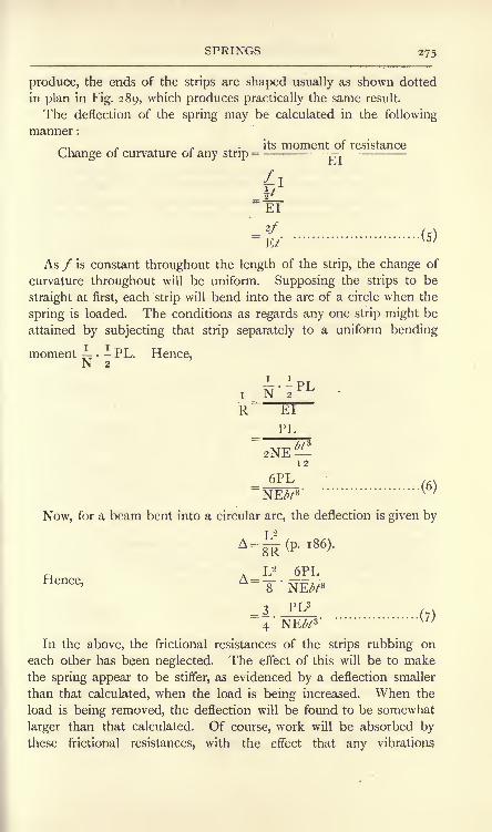
SPRINGS 275
produce, the ends of the strips are shaped usually as shown dotted
in plan in Fig. 289, which produces practically the same result.
The deflection of the spring may be calculated in the following
manner :
its moment of resistanceChange of curvature of any strip
= rT
_El
As / is constant throughout the length of the strip, the change of
curvature throughout will be uniform. Supposing the strips to be
straight at first, each strip will bend into the arc of a circle when the
spring is loaded. The conditions as regards any one strip might be
attained by subjecting that strip separately to a uniform bending
moment :- PL. Hence,N 2
v'
Now, for a beam bent into a circular arc, the deflection is given by
Hence,
4
In the above, the frictional resistances of the strips rubbing on
each other has been neglected. The effect of this will be to makethe spring appear to be stiffer, as evidenced by a deflection smaller
than that calculated, when the load is being increased. When the
load is being removed, the deflection will be found to be somewhat
larger than that calculated. Of course, work will be absorbed bythese frictional resistances, with the effect that any vibrations

276 MATERIALS AND STRUCTURES
communicated to the spring by impulsive forces, or shock, will die
out more rapidly than would be the case with a spring formed out
of a single piece of material.
EXERCISES ON CHAPTER XI.
1. A mild-steel shaft is 6 inches diameter. If the safe shear stress
allowed is 10,000 Ib. per square inch, what torque may be applied ?
2. Find the diameter of a solid round shaft of mild steel to transmit a
torque of 12,000 Ib.-inches with a safe shear stress of 9000 Ib. per squareinch.
3. A hollow shaft has an outside diameter of 18 inches and an inside
diameter of 6 inches. Calculate the torque for a safe shear stress of 4-5tons per square inch.
4. A solid shaft has the same weight and the same length as the shaft
given in Question 3 and is made of similar material. Calculate the safe
torque which may be applied. Give the value of the ratio Torque for
the hollow shaft : torque for the solid shaft.
5. What torque may be applied to a tube 3 inches in external diameter,of metal 0-125 mcn thick, if the stress is not to exceed 10,000 Ib. per squareinch ?
6. The shaft given in Question I is 60 feet in length. What will bethe angle of twist when the maximum permissible torque is applied ? TakeC = 13,000,000 Ib. per square inch.
7. Find the angle of twist for the shaft given in Question 3 when the
shear stress is 4-5 tons per square inch. The shaft is 100 feet in length.Take C = 55oo tons per square inch.
8. What horse-power may be transmitted by a solid shaft 3 inches in
diameter at 120 revolutions per minute ? The shear stress is 8000 Ib. per
square inch.
9. What diameter of steel shaft is required in order to transmit
20 horse-power at 250 revolutions per minute?
10. AB and BC are two sections of a body meeting at 90. Normal
pull stresses of 5 and 4 tons per square inch act on AB and BC respec-
tively. Shearing stresses of 3 tons per square inch act from A towards Band from C towards B. Find the principal stresses and the principal axes
of stress. Draw a diagram showing the axes and stresses.
11. Answer Question 10 if the normal stress of 5 tons per square inch
on AB is a push.
12. A mild-steel shaft 3 inches in diameter has a bending moment of
4000 Ib.-inches together with a twisting moment of 6000 Ib.-inches.
Calculate the following : (a) The equivalent torque according to Rankine ;
(b} the equivalent torque on the maximum shear stress hypothesis ; (c) the
maximum and minimum principal stresses ; (d] the maximum shearingstress.
13. Supposing that a constant bending moment of 4000 Ib.-inches be
applied to a shaft 3 inches in diameter, what torque may be applied if
the maximum shear stress is limited to 10,000 Ib. per square inch?

EXERCISES ON CHAPTER XI. 277
14. A cylindrical boiler is 7 feet in diameter and is made of plates 0-5inch thick. The steam pressure is 100 Ib. per square inch, (a) Find the
stresses on longitudinal and circumferential sections;also the stresses on
sections at 30, 45 and 60 degrees to the axis. (A) What is the maximumshear stress on the plate ?
15. A helical spring is made of round steel wire 0-25 inch in diameter.The mean radius of the helix is 1-25 inches
;number of complete
turns 120; the spring is close-coiled. Take C= 12,000,000 Ib. per square
inch, and find the pull required to extend the spring one inch.
16. A helical spring, material of circular section, has to extend i inch
with a pull of 50 Ib. The mean radius of the helix is 2 inches, and the
length of the helical part of the spring is one foot. Assume that the coils
are close together, and find the diameter of the wire. C = 12,000,000 Ib.
per square inch.
17. Suppose that the spring given in Question 1 5 is put under torsion
by couples applied at its ends. Find the torque required to twist the
spring through one radian. = 30,000,000 Ib. per square inch.
18. A helical spring is made of steel of square section, 0-3 inch edge,close-coiled. The mean radius of the helix is one inch, and there are
20 complete turns. Take C = 12,000,000 Ib. per square inch, and find the
pull required to extend the spring one inch.
19. A piston ring for a cylinder 24 inches in diameter has to give auniform pressure of 2 Ib. per square inch of rubbing surface. Find the
maximum thickness of the ring if the stress is not to exceed 6000 Ib. persquare inch. Find also the thickness at a section 90 from the split.
20. A carriage spring of length 30 inches is made of steel plates
2-5 inches wide by 0-25 inch thick. Find the number of plates
required to carry a central load of 800 Ib. if the maximum stress is limited
to 12 tons per square inch. Find the deflection under this load if
E = 30,000,000 Ib. per square inch.
21. A load is applied to the crank fixed to a wrought-iron shaft 6 inches
diameter and 20 feet long, which twists the ends to the extent of 2;
assuming the modulus of transverse elasticity (or coefficient of rigidity) to
be 4000 tons per square inch, what is the extreme fibre-stress? (I.C.E.)
22. A closely-coiled spiral spring has 24 coils;the mean diameter of
the coil is 4 inches and the diameter of the wire from which the spring is
made is 0-5 inch. Determine the axial load which will elongate this
spring 6 inches if the modulus of rigidity is 12,000,000 Ib. per square inch.
(B.E.)
23. A hollow steel shaft is to be used to transmit 1000 H.P. at 90revolutions per minute
;the internal diameter of the shaft is to be f of
the external diameter. The maximum twisting moment exceeds the
mean by 20 per cent. If the maximum intensity of shear stress is not to
exceed 4-5 tons per square inch, find the external diameter of the shaft.
24. At a certain point in a loaded body the principal stresses are a
tension of 5 tons per square inch and a pressure of 3 tons per square inch,
the latter acting in a horizontal direction. Another load is then appliedto the body, giving rise to a second stress system, the principal com-
ponents of which at the same point are a tension of 3 tons per square

278 MATERIALS AND STRUCTURE
inch and a pressure of 4 tons per square inch, the latter acting at an
angle of 40 to the horizontal. Find the magnitudes and directions of
the principal stresses of the resultant stress system. There is no stress
at right angles to the plane of the paper. (B.E.)
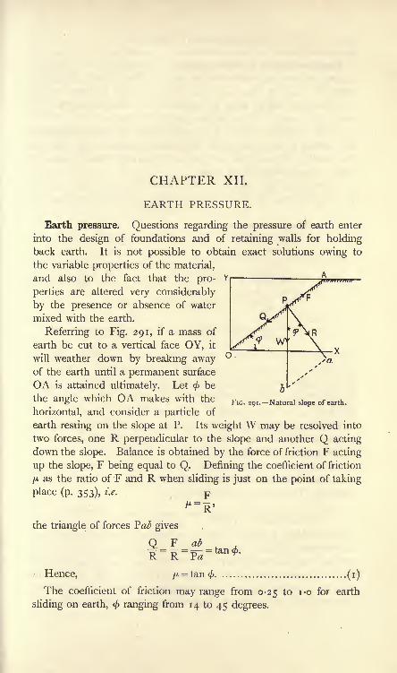
CHAPTER XII.
EARTH PRESSURE.
Earth pressure. Questions regarding the pressure of earth enter
into the design of foundations and of retaining walls for holdingback earth. It is not possible to obtain exact solutions owing to
the variable properties of the material,
and also to the fact that the pro-
perties are altered very considerably
by the presence or absence of water
mixed with the earth.
Referring to Fig. 291, if a mass of
earth be cut to a vertical face OY, it
will weather down by breaking awayof the earth until a permanent surface
OA is attained ultimately. Let < be
the angle which OA makes with the
horizontal, and consider a particle of
earth resting on the slope at P. Its weight W may be resolved into
two forces, one R perpendicular to the slope and another Q acting
down the slope. Balance is obtained by the force of friction F acting
up the slope, F being equal to Q. Defining the coefficient of friction
/A as the ratio of F and R when sliding is just on the point of taking
place (p. 353), i.e. F
FIG. 291. Natural slope of earth.
ab
the triangle of forces Pal? gives
Q=F
Hence, ^
The coefficient of friction may range from 0-25 to i-o for earth
sliding on earth, < ranging from 14 to 45 degrees.
(i)

MATERIALS AND STRUCTURES
Rankine's theory of earth pressure. The effect of the weight Wresting on the slope OA is to produce a stress on OA having an
angle of obliquity equal toc/> when sliding is just possible. < may
be called the natural angle of repose of the earth; sliding will not
occur if the angle of slope has any value less than<f>.
In the Rankine theory, it is asumed that the shearing effects at
any section in the earth follow the ordinary frictional laws, and that
the obliquity of stress on any section of the earth cannot exceed the
natural angle of repose of the earth.
Referring to Fig. 292, AB is the horizontal earth surface and abed
is a small rectangular block of earth having its top and bottom faces
B
FIG. 292. Conjugate stresses, earth FIG. 293. Conjugate stresses, earthsurface level. surface sloping.
horizontal. Let the area of the top face be one square foot, let y be
the depth below the surface and let w be the weight of the earth in
Ib. per cubic foot. The stress /j on the top face will be produced
by the weight of the superincumbent column of earth, and will be
given by p i= wy ib. per square foot (2)
The stress /2 acting on the vertical faces must be determined
from the relation mentioned above, viz.</>
must not be exceeded on
any section of the block.
In Fig. 293 the earth surface is sloping at an angle a to the
horizontal, and ab and cd are at the same slope, be and ad being
vertical. The stress p lwill be given by
p, = ? + = = wy cos a Ib. per square foot (*)area of top face ab
It is evident that/!,/, acting on ab and cd respectively balance
each other, neglecting the weight of the block ;hence /2
and /2 must
balance independently, and must therefore act in the same straight
line. It therefore follows that/2must be parallel to ab. /, parallel to
be and/2 parallel to ab are called conjugate stresses. /2is determined
by the same consideration as before, viz. $ must not be exceeded.

EARTH PRESSURE 281
In Fig. 294, OA and OB represent principal stresses p^ and
respectively, and the construction is shown for obtaining the stress
on a section OK (p. 261). ONis perpendicular to OK, NP and
MP are parallel respectively to
the principal axes of stress OBand OA, and PO is the stress
on OK. P lies always on the
circumference of the circle de-
scribed on MN as diameter.
The angle of obliquity of/ as
shown is PON; the maximum
angle of obliquity will occur
when OP is tangential to the
circle NPM as shown by OT.
The angle COT will correspondwith the value of
<$>in earthwork problems.
CT
*+*From Fig. 294, we have
=AzA (4)A+APressure on retaining walls by Rankine's theory. The foregoing
principles may be applied to give a simple graphical solution for the
Yearth pressure on retaining
walls. In Fig. 295 XY is
the vertical earth face of a
retaining wall, the earth sur-
face being horizontal and level
with the top of the wall.
Produce the horizontal base
of the wall and select a
point O on it. Draw OAX p2
E O"
T>t D vertically and make it equal
FIG. 295. Earth pressure on a wall, earth surface tO /j = Z#H lb. per Square
foot. Draw OT, making the
angle <f> with OA. Find, by trial, a circle having its centre Cin OA, to pass through A and to touch OT. This circle will cut
OA in B, and will correspond to the circle NPM in Fig. 294.

282 MATERIALS AND STRUCTURES
Make OD equal to OB, and DO will represent the other principal
stress p.2 . The stress /2will be transmitted horizontally through the
earth along OX, and an equal stress p.2 will be produced on the
wall at X. Make XE equal to /2 ,and join YE. The stress diagram
for the face of the wall will be YXE. The average stress will be
J/2 ,and if one foot length of wall be taken, the total pressure P
P will act at a point JH from the foot of the wall.
Fig. 296 illustrates the procedure if the earth surface is surcharged,
or inclined to the horizontal, at an angle a. Draw XO parallel to
the earth surface. Draw
OA vertically, and make
OA equal to p l= wH cos a
(p. 280). Draw OM per-
pendicular to XO, and
draw also OT, making the
angle < with OM. Find,
by trial, a circle having its
centre C in OM, to pass
through A and to touch
OT. This circle cuts OMin M and B, and will
correspond to the circle
FIG. 296.-Earth pressure on a wall, earth surface sur- NPM in Fig. 294. Join
MA and BA ; these will
correspond with NP and PM in Fig. 294; hence the principal
axes of stress will be parallel to MA and BA respectively, and the
principal stresses will be represented by OM and OB respectively.
Draw OD and OE parallel respectively to BA and AM;make
OD equal to OM and OE equal to OB. The ellipse of stress
passes through D and E, and cuts XO produced in F. Hence FOis the value of /2
. The quarter DFE alone of the ellipse need be
drawn.
Draw the stress diagram for the wall by making XG equal to /2
and joining GY. The average stress will be \p^ and for one foot
length of wall we have p _ \p^nP acts parallel to the earth surface, and is at a height JH above
the foot of the wall.
If the earth surface be not surcharged, a simple formula may be
obtained for the stress on the wall at any depth :

EARTH PRESSURE 283
Let pl= wh~\he earth pressure on a horizontal foot at a
depth h feet.
p^= the pressure on the wall at the same depth.
Then, from equation (4), p. 281,
A+A
i - sin</> 2/
And
i - sin </>=--r j O^.i + sm </>
If the earth surface is surcharged at an angle to the horizontal
equal to <, then p l= wh cos
</>,and it may be shown that the other
conjugate stress, /2 ,is equal to p^ and acts on the wall at an angle </>
to the horizontal.
If the angle of surcharge is a, the following equation may be used
in order to find the value of :
.
wh cos aCOS a - v/CGS2a - COSW- ---
-^ \-COS a + >/COS
2a - COS2<J
Wedge theory of earth pressure. Let AB (Fig. 297) be the
vertical face of a retaining wall, and let AC be the surface of the
earth;also let BC be a plane
making the angle < with the
horizontal. Considering the
wedge of earth BAC, imaginethat its particles are cemented
together so as to form a solid
body. Under this condition,
the wedge would just rest
without slipping on the in-
clined plane BC if the wall
were removed ; in other
words, so far as the wedge-P.
. . . . . FIG. 297. Wedge theory of earth pressure on a wall.
BAG is concerned, there is
no pressure on the wall. Again, considering an indefinitely thin
wedge ABA', at rest between the plane BA' and the wall, as its
weight is negligible, there will be no -pressure on the wall. Hencethe pressure on the wall, being zero for the inclined planes BC

284 MATERIALS AND STRUCTURES
and BA', will attain a maximum value for some plane such as BDlying between BC and BA'. If the wall were removed, the earth
would break away at once along the section BD and the wedge ABDwould fall, subsequently weathering would remove the wedge DBC.
BD is called the plane of rupture ;the force acting on the wall may
be obtained by considering the weight of ABD and the reaction
of the earth lying under the section BD.
The force P which the earth communicates to the wall may be
assumed to be horizontal, thus ignoring any friction between the
C

EARTH PRESSURE 285
Let DK be called x. Then
W = o;BC(AL-*) (2)
DK xAlso, tan = ==BK BC - KG '
and KC = DKcot(<-a)= X COt (<
-a).
*Y*
Hence, tan Q =^^ TT-
\...................... (3)BC - x cot
(<-
a)
Substitute the values of (2) and (3) in (i), giving
p_i,. TJP (AL x)x /
^-
The whole of the quantities involved in this expression, with the
exception of x, are constant for a given wall, the earth having a
known value for < and a given slope at the surface. The maximumvalue of P may be found by differentiating the right-hand side and
equating the result to zero. Thus,
d f AL.x-x* }
dx (VC-xcot(<j>-a))
_ (AL -2x) {BC - x cot (<
-a)} + (AL .x - x*) cot (ft
-a)
{BC-*COt(</>-a)}2This will be zero when the numerator is zero. Hence,
AL . BC - AL . x cot(<#>
- a) - 2x . BC + 2X2 cot(<
-a)
= - AL . x cot(<
-a) + x* cot
(<-
a),
AL.BC-2#.BC = - x2 cot(<
-a),
AL . BC - *BC = x . BC - *2 cot(<f>
-a)
By reference to Fig. 298, it will be noticed that this may be written
or 2AABC - 2ABDC = 2ADKB,or ABAD =ADKB .(5)
The condition for the maximum value of P is therefore that the areaof the triangle BAD should be equal to the area of the triangle DKB.From (i), P = Wtan0
=w . A BAD . tan 9
(6)

286 MATERIALS AND STRUCTURES
Graphical solutions by the wedge theory. The following geo-
metrical constructions may be used for the determination of x :
CASE i. Earth surface level with the top of the wall. Reference is
made to Fig. 299. Draw BC making the angle < with the horizontal.
Draw BE perpendicular to BC and cutting the earth surface produced
FIG. 299. Graphical solution, wedge theory, earth surface level.
in E. Make EF equal to EA. Then BF is equal to x. Draw FDparallel to BC and join BD; BD will be the plane of rupture. P will
be found by measuring BF = x to the same scale as that used in draw-
ing the wall and inserting the value in (6). Apply P horizontally at
^H from the base.
CASE 2. Earth surface surcharged at an angle a. Draw BC (Fig. 300)
making the angle </>with the horizontal. Draw BE perpendicular to
FIG. 300. Graphical solution, wedge theory, earth surcharged,
BC and cutting the earth surface produced in E. On BE describe a
semicircle, and draw AF perpendicular to BE. Make EG equal to
EF;then BG is equal to x. Draw GD parallel to BC and join DB ;
DB will be the plane of rupture. Calculate the value of P and applyit as in Case i.

EARTH PRESSURE 287
CASE 3. Earth surface surcharged at the angle </>.
BE perpendicular to the earth surface and
cutting it produced in E. Then BE is
equal to x. P is calculated and appliedas before.
CASE 4. Earth surface surcharged at an
angle a and friction between the earth and
Draw BC (Fig. 302)the horizontal to cut
in C. On BC as
a semicircle. Make
In Fig. 301, draw
the wall considered.
at the angle < to
the earth surface
diameter describe FIG. 301. Earth surface surchargedat
<f>, wedge theory.AD equal to AB, and draw DE per-
pendicular to BC. Make BF equal to BE, and draw FG parallel to
AD. Make FK equal to FG. Join BG. Then the pressure P on one
foot length of the wall is equal to the weight of the prism of earth
FIG. 302. Wedge theory ; solution when friction of earth on wall is taken account of.
having an area in square feet equal to the area FGK and a length of
one foot. P will act at JH from the base of the wall, and will be
inclined at an angle <\> to the horizontal. The plane of rupture is BG.It is assumed in the last case that the value of < is the same for
earth sliding upon earth and for earth sliding upon masonry.
Distribution of normal pressure on the base of the wall. Havingfound P by application of one of the above methods, the resultant
pressure on the base of the wall may be found in the manner shown
in Fig. 303. W is the weight of one foot length of the wall, acting
vertically through its centre of gravity G. P and W intersect at O,

288 MATERIALS AND STRUCTURES
and R is their resultant. For stability, R should pass within the
middle third DE of the base of the wall (p. 259).
FIG. 303. Resultant pressure on wall
base.
FIG. 304. Distribution of normalstress on the wall base.
In Fig. 304, F is the point in which R intersects the base of the
wall, and O is the middle of the base. R may be resolved into two
forces, Rv and RH ',the latter produces shearing stress on the base,
having a somewhat indefinite distribution ;the former produces
normal stress. To determine the latter, shift Rv from F to O, and
apply a compensating couple Rv x FO = M. Rv acting at O will
produce a uniform normal stress p^ of value given by
p, = fv
.. ,= = lb. per square foot.^ area of wall base BC
M will produce a stress which will vary from a push /2 at C to an
equal pull /2at B. These may be found from
M hm I,
where m is |BC and I is the moment of inertia of i foot length
of the wall base taken with reference to the axis passing through Oand perpendicular to the plane of the paper.
i x BC3
12
Hence, Rv x FO =-%m^ 1 2
6RV .FOA- BCA stress diagram CBED is drawn in Fig. 304, in which
CD = A+A> and BE=A-A>-

EARTH PRESSURE . 289
w>

290 MATERIALS AND STRUCTURES
the point of heaving up. The actual depth of the foundation maybe obtained by application of a factor of safety.
D may be found by calculation from equation (4), p. 281. Thus,
i - sin</> 2/2
_ /i -sin</>\P*P\
\^ + sm< y'
Also, sin 4>
-sin^
Again,
sin MVx
, .
: 5 ,from (2) ;+ sin </>/
z^ ze/ \i
W /i -sin<^)\2
>. AB\i^^y (4)i + sin </>/
EXAMPLE. A wall carries a weight of 800 tons. The area of the foot
of the wall is 200 square feet. Find the minimum depth of foundation if
the weight of the earth is 1 20 Ib. per cubic foot and if</>
is 30.
bl= =4 tons per square foot.
-sinew
120
= 8- feet.
EXERCISES ON CHAPTER XII.
1. Given principal stresses of 6 tons and 3 tons per square foot, both
pushes, find the angle of greatest obliquity of stress.
2. A retaining wall for earth, 12 feet high, has its earth face vertical.
The surface of the earth is horizontal and is level with the top of the wall.
Find the total force per foot length on the wall by Rankine's theory, takingthe weight of the earth as 1 10 Ib. per cubic foot and < as 40.
3. Answer Question 2 if the earth surface is surcharged at 20 to the
horizontal.

EXERCISES ON CHAPTER XII. 291
4. Answer Question 2 by application of the wedge theory.
5. Answer Question 3 by application of the wedge theory.
6. Answer Question 3 by the wedge theory, taking account of the
friction between the earth and the wall. It may be assumed that <
has the same value for earth sliding on earth and for earth sliding on
masonry.
7. A masonry retaining wall for earth has its earth face vertical, andthe earth is surcharged at an angle of 30 to the horizontal. The wall
is 9 feet high, 2 feet broad at the top, and 5 feet broad at the base. Theearth weighs 1 10 Ib. per cubic foot and < is 30. Find the total earth
pressure on the wall by the wedge theory.
8. In Question 7, the masonry weighs 120 Ib. per cubic foot. Find theresultant pressure on the horizontal base of the wall. Does it pass within
the middle third of the base ? Find the maximum and minimum normalstresses on the base, and draw a diagram showing the distribution ofnormal stress.
9. A wall and the load which it carries produce a stress of 3 tons persquare foot on the earth underneath the wall. If the weight of earth is
1 10 Ib. per cubic foot and if</>
is 35, find the minimum depth of thefoundation below the surface of the earth.
10. A brick wall 25 feet high, of uniform thickness and weighing I2olb.
per cubic foot, has to withstand a wind pressure of 56 Ib. per square foot.
What must be the thickness of the wall in order to satisfy the conditionthat there shall be no tension in any joint of the brickwork ? (I.C.E.)
11. Concrete exerts on earth at the bottom of a trench a downwardpressure of 2 tons per square foot ; the earth weighs 130 Ib. per cubic foot
and its angle of repose (in Rankine's theory) is 30 ;what is the least safe
depth below the earth's natural surface of the bottom of the concrete ?
Why are we unable to make much practical use of the theory of earth
pressure? (B.E.)
12. A concrete retaining wall is trapezoidal in cross section, 24 feet
high ; thickness at top, 3 feet;at base, 10 feet
;the back face, which is
subjected to earth pressure, being vertical. The wall is not surcharged.If the concrete weighs 140 Ib. per cubic foot, the earth-filling behind thewall 125 Ib. per cubic foot, and if the angle of repose of the earth is
22 degrees, investigate the stability of the wall. (B.E.)
13. Give the assumptions upon which Rankine's theory of earth pres-sure is based. Show that the intensity of horizontal pressure on a
retaining wall at a depth d feet below the horizontal earth surface is
i sin <f> ,
where w is the weight of I cubic foot of earth and < is the angle of
repose of the earth. A practical rule takes the pressure as equivalentto that given by a fluid weighing 20 Ib. per cubic foot. Find the angle of
repose corresponding to this, assuming iv equals 100 Ib. per cubic'foot.
(L.U.)

CHAPTER XIII.
TESTING OF MATERIALS.
Wires under pull. A simple apparatus is illustrated in Fig. 306and will enable the elastic properties of wires under pull to be studied.
Two wires, A and B, are hung from the same
support, which should be fixed to the wall as highas possible in order that long wires may be used.
One wire, B, is permanent and carries a fixed load
WT ,
in order to keep it taut. The other wire, A,
is that under test, and may be changed readily for
another of different material. The test wire maybe loaded with gradually increasing weights W.The extension is measured by means of a vernier
D, clamped to the test wire and moving over a
scale E, which is clamped to the permanent wire.
The arrangement of two wires prevents any droop-
ing of the support being measured as an extension
of the wire.
EXPT. 15. Elastic stretching of wires. See that
the wires are free from kinks. Measure the
FIG. 306. Apparatus for length L in inches from C to the vernier. Measureson wires. ^ diameter of the wjre gtate the material of
the wire and also whatever is known of its treatment before it cameinto your hands. Apply gradually increasing loads to the wire A,and read the vernier after the application of each load. Stop the
test when it becomes- evident that the extensions are increasing more
rapidly than the loads. Tabulate the readings thus :
TENSION TEST ON A WIRE.
Load, Ib.

TESTING OF MATERIALS 293
Plot the loads in column i as ordinates and the correspondingextensions in column 3 as abscissae (Fig. 307). It will be found that
a straight line will pass through mostof the points between O and a pointA, after which the line turns towardsthe right. The point A indicates the
*"
break-down of Hooke's law.
Let Wj = load in Ib. at A in Fig. 307. w,
!
*/=the diameter of the wire in
inches.
Then,
Stress at elastic break-downW
1
~i^
OL^ Extension
. per square inch.FIG. 307. Graph of a tensile test
on a wire.
Select a point P on the straight line OA (Fig. 307), and measureW
2and e from the diagram.
Let W2= load in Ib. at P,
= extension in inches at P,
L = length of test wire in inches.
rp,, T7 . stress W LThen, Young's modulus = E = r-= , fe
-strain \ird* e
Several wires of different material should betested in a similar manner.
In Fig. 308 is shown in outline a simple form
of machine for testing wires to breaking; the
machine is fitted with an arrangement whereby an
autographic diagram is produced, i.e. a diagram is
drawn by the apparatus showing the loads and
corresponding extensions.
AB is the test wire, fixed at A and carrying a
receptacle B at its lower end. The load is
applied by means of lead shot, stored in another
receptacle C, which is fitted with an orifice and
a control shutter at its lower end;D is a shoot
for guiding the shot into B. C is hung from a
helical spring E, which is extended when C is full
and shortens uniformly as the weight is removed
by the shot running out of C. A cord F is
attached to E, passes round a guide pulley andFIG. 308.-Apparatus aiso two or three times round a drum G, and
for testing wires to
rupture. has a small weight H attached in order to keep

294 MATERIALS AND STRUCTURES
it tight. A piece of paper is wrapped round G, and circumferential
movements of this paper will be proportional to the load removed
from C and applied to the test wire. A small guided frame carrying
a pencil is attached to the test wire at P;vertical movements of the
pencil will indicate the extensions of the portion of test wire between
A and P. In action, a curve is drawn on the paper which shows
loads horizontally and extensions vertically.
EXPT. 1 6. Tensile test to rupture. Arrange the apparatus andfit the test wire
jsee that all the arrangements are working properly.
Draw the lines of zero extension and zero
load by rotating the drum for the first
and by moving the pencil frame vertically
for the second. Measure the diameter of
the test wire and the length from A to P.
Allow the shot to run into B until the
test wire breaks. To obtain the breaking
load, weigh the receptacle B together with
its contents.
Let W = breaking load in lb.,
d= diameter of the wire in inches.
WBreaking stress = -.
-
2lb. per square inch of original cross-
i 7sectional area.
Load
Extension
FIG. 309. Autographic record ofa test on copper wire.
Then,
In Fig. 309 is given a reproduction of a
diagram after removal from a machine of this
kind. The scale of loads may be found byplacing different weights in C and observing the
resulting movements of the paper on the drum.The diagram shown is for copper wire, and the
point of elastic break-down may be stated
roughly from it.
Experiments should be made on several
wires of different materials, such as copper,brass and iron.
Wires under torsion. Apparatus by means
of which may be measured the angle of twist
produced in a wire by a given torque is illus-
trated in Fig. 310. AB is a test wire, firmly
fixed at A to a rigid clamp and carrying a heavy
cylinder at B. The cylinder serves to keep the
wire tight, and also provides means of apply-
ing the torque. The torque must be applied FIG. 310. Apparatus for
as a couple in order to avoid bending, and is torsion tests on wires.

TESTING OF MATERIALS 295
produced by means of cords wound round B; these cords pass over
guide pulleys, and carry equal weights Wxand W2 at the ends.
Pointers C and I) are clamped to the wire, and move as the wire
twists over fixed graduated scales E and F. The angle of twist
produced in the portion CD of the wire is thus indicated.
EXPT. 17. Torsion test on wires. Arrange the apparatus as shown.
State the material of the wire;measure its diameter d and the length
L between the pointers C and D, both in inches. Measure also the
diameter D of the cylinder B, in inches. Apply gradually increasing
loads, and read the scales E and F after each load is applied. Tabu-late the readings.
EXPERIMENT ON TWISTING.
Load,W!=Wa> Ib.

296 MATERIALS AND STRUCTURES
Helical springs under pull. The extensions of a helical spring
under pull may be investigated by use of the apparatus illustrated in
Fig. 312. A is the spring under test;
it is hung from a hook at the
top of a stand. A graduated scale B is hungfrom the spring, and carries a hook on which
loads W may be placed. The vertical move-
ments of the scale indicate the extensions of
the spring, and are read by means of a telescope
atC.
EXPT. 1 8. Extensions of helical springs.
Make a helical spring by coiling round a round
bar, or mandril, some wire for which youhave found C previously, as directed on p. 295.Test this spring under gradually increasing
loads, noting the extension produced by each
load. Plot loads and extensions ;these should
give a straight line if the extensions are pro-
portional to the loads. Select a point on the
plotted line, and read the load W Ib. andthe corresponding extension e inches.
LetD = the mean diameter of the helix, inches
;
*/=the diameter of the wire, inches;
N = the number of complete turns in the
helix.
FIG. 312. Apparatus for
testing helical springs.
Then, from equation (5), p. 267,
8WD3N
Or C =8WI)3N
Ib. per square inch.
Calculate the value of C from this equation, and compare it with
the value of C found by the direct method of applying torque.
Other springs made of wire of circular section are supplied. Makesimilar experiments, and find the value of C for each spring.
Springs of material having a square section are also supplied. If
the side of the square is s in inches, find the numerical values of the
coefficient c for each spring by inserting experimental values in the
following equation : WD3N
Maxwell's needle. A useful piece of apparatus for making vibra-
tional experiments on wires is the Maxwell's needle shown in
Fig. 313 (a). The wire AB is fixed firmly at A and is clamped at B

TESTING OF MATERIALS 297
lel

298 MATERIALS AND STRUCTURES
Torsional oscillations of a helical spring. Maxwell's needle maybe used for determining the value of Young's modulus for a wire of
given material. The wire is first wound into a helical spring and
arranged as shown in Fig. 3 1 3 (), where C is the Maxwell's needle.
Take the same symbols as before, with the addition of the following :
R = the mean radius of the helix, in inches.
N = the number of complete turns in the helix.
E = Young's modulus, in Ib. per square inch.
Then E
EXPT. 20. Determination of E by torsional oscillations of a spring.
Twist the needle through a small horizontal angle, taking care not
to raise or lower it while doing so. On being released, it will
execute torsional oscillations. Ascertain the times as before for the
loaded tubes in the outer position and also in the inner position.
Measure the dimensions required, and calculate E from the above
equation. No correction is required for the mass of the spring in
this experiment.
Longitudinal vibrations of a helical spring. Using the same
apparatus, illustrated in Fig. 313^), the value of the modulus of
rigidity may be found for the material of the spring. The spring,
loaded with the needle, is pulled downwards a little and released ;
it will then execute vibrations vertically.
Let /=time in seconds to execute one vibration from the
lowest position and back to the starting-point.
M = the mass of the needle, or other load, hung on + one-
third the mass of the spring, in pounds.
N = the number of complete turns in the helix.
R = the mean radius of the helix, in inches.
</=the diameter of the wire, in inches.
C = the modulus of rigidity, Ib. per square inch.
Then C =6-*3
EXPT. 21. Determination of C by longitudinal vibrations of a spring.
Use a spring made of wire which has been tested already for the
value of C by the direct method of torque (p. 295), and also by the
method of torsional oscillations (p. 297). Find C for the material
by application of the method described above, and compare the
results by the three methods.
The direct determination of Poisson's ratio, ,and also of the
m

TESTING OF MATERIALS 299
bulk modulus K for a material presents considerable difficulty.
These may be calculated easily from the known experimental values
of E and C by use of the following relations :
i E-2CPoisson's ratio = - = ^ .
EC
m
Bulk modulus = K =3(3C-E)
Take the results for E and C which you have obtained for wires of
the same material, and calculate and K for each material.M
EXAMPLE. A series of tests on steel wires gave average values as
follows := 13,500 and = 5500 tons per square inch. Find the values
of Poisson's ratio and of the bulk modulus.
=E-2C2C
_ 13,500- i i,ooo_
K=
11,000
EC
i
41
3(3C-E)
n,t;oox 5 coo=-T r= 825o tons per sq. inch.3(3x5500-13,500) i-
Elastic bending of beams. The apparatus shown in Fig. 314 is
capable of giving very accurate experimental results on the elastic
FIG. 314. Apparatus for elastic bending of beams.
bending of beams. The test beam A rests on steel knife-edges
supported by blocks B, B. The blocks may be bolted at any distance
apart on a lathe bed C. The load W is applied by means of a
shackle D having a steel knife-edge which rests on the beam. The
piece E, carried by the shackle, is pierced by a hole which is covered

300 MATERIALS AND STRUCTURES
by a piece of transparent celluloid having a fine line ruled on it.
This line is observed through a micrometer microscope F, and will
travel over the eyepiece scale as the beam deflects. The value of a
scale division of the eyepiece scale may be ascertained by use of a
scale engraved on the vertical pillar of the microscope ;a rack and
pinion movement permits of vertical movement of the microscope upor down the pillar.
For testing beams fixed at the ends, the knife-edges at B, B are
removed;these are merely dropped into V grooves on the top of the
blocks. The test beam now rests on the top of the blocks (Fig. 315),
and is held down firmly at each end by a strong cast-iron cap and
four studs.
The angle of slope at any position of the beam may be measured
by means of the arrangement shown in Fig. 316. A is a small three-
Pic. 315. Test beam fixed at ends. FIG. 316. Apparatus for measuringthe slope of a beam.
legged stool carrying a mirror and rests on the test beam. B is a
reading telescope having a hair line in the eyepiece, and is used to
observe the reading of a scale C reflected to the telescope by the
aid of the mirror at A.
The apparatus may be used for a large number of experiments ;
the following indicates some of the more simple.
EXPT. 22. Take a bar of mild steel of rectangular section about2 inches x i inch and about 3-5 feet in length. Arrange it as a beamsimply supported on a span of 3 feet and loaded at the centre of the
span. Apply gradually increasing loads, and measure the deflection
at the centre of the span after the application of each load. Verifythese readings by removing the loads, one at a time, and observingthe deflections after the removal of each load. Tabulate these
readings, and plot loads and deflections. If the resulting diagram is
a straight line, then the deflections of the beam are proportional to
the load. Select a point on the plotted line, and note the load W Ib.
and corresponding deflection A inches ; also let L be the span in
inches. Calculate the value of Young's modulus for the material,
using the equation given on p. 169, viz.:
.
48EI

TESTING OF MATERIALS 301
For the given section, breadth B and depth D, both in inches,
T _ BD3 -
1 - j
or
WL3
=
E =WL3
ABI)Ib. per square inch.
EXPT. 23. Use the same piece of material (a) as a cantilever, (ft)
as a beam fixed at both ends. In each case measure the deflections
for loads gradually increased and gradually diminished. Plot the
results and determine Young's modulus, making use of the following
equation for case (a) :
WI 3
WL3
For case (b) use A =7^I ^P ' I?8^
Compare the values of E obtained by the three methods employed.
EXPT. 24. Arrange a test bar as a cantilever (Fig. 317). Let the
load be applied at B, and arrange the three-legged mirror stool at C,
FIG. 317. Slope of a cantilever.
a scale divided decimally in inches at D, and a reading telescope at E.
On loading the cantilever a certain angle of slope will occur at B;
as there is no load, and consequently no bending moment betweenB and C, whatever slope exists at B will occur uniformly between Band C. Hence the slope measured at C will be the slope at the
point of application of B. The slope at B may be calculated from
WL,2
*B = =yradians (p. 168).
If the piece of material used in the previous bending experimentsis employed in this experiment, E is known, and hence iB may becalculated for any given load. To verify the calculation, observe the
scale readings for gradually increasing and gradually diminishingloads ; plot the results, and select from the diagram the value of /B
corresponding to the value ofW used in the calculation.

302 MATERIALS AND STRUCTURES
In reducing the scale readings to radians, it must be noted that if
the mirror at C tilts through an angle /, the ray of light CD will
travel through an angle of magnitude 22. Let a be the change of
scale reading due to an increment of load, and let b be the distance
from the mirror to the scale, both in inches. The angle turned
through by the ray CD will be
DCD' = -. radian;
o
..
t = r radian.2b
Ten-ton testing machine. In Fig. 318 is shown in outline the
principal parts of a testing machine constructed by Messrs. Joshua
FIG. 318. Ten-ton Buckton testing machine.
Buckton to the design of Mr. J. H. Wicksteed. As illustrated, the
machine is arranged for applying pull. The test piece, AB, is held
by grips in two crossheads C and D;D is guided by the main column
E of the machine, and may be drawn downwards by means of a screw
F and a wheel G ; the latter serves as a nut for F, and is preventedfrom moving vertically. The rotation of G is effected by gearing and
belt drive from some source of power; open and crossed belts permitof either direction of rotation being given to G. The belts are under
the control of the operator by means of striking gear. The uppercrosshead C is hung from a knife-edge H fixed in the beam K. The

TESTING OF MATERIALS 303
beam is supported by a knife-edge L resting on the top of the
column E. Its movement in a vertical plane is limited by spring-
buffer stops M and N. A counter-poise P can be moved along the
beam by means of a screw and hand-wheel under the control of the
operator until the pull transmitted through the test piece to the beamis equilibrated. The magnitude of the pull is shown by the position
of the counterpoise in relation to a scale of pounds which is attached
to the beam.
For applying push to the test piece, the machine is modified as
shown in Fig. 319. The specimen AB is placed between crossheads
,01 FIG. 321. Shearingdevice.
FIG. 319. Arrangement FIG. 320. Arrangement for bendingfor applying push. tests.
FIG. 322. Punchingdevice.
Q and R, the former being connected to the screw F and the latter
being hung from the beam.
In carrying out bending tests, arrangements are made as shown in
Fig. 320. The test beam AB rests on supports T, V, which in turn
are carried by a beam S secured to the crosshead R. The weighing
beam on the machine thus supports the beam under test. A central
load is applied by means of a ram attached to the crosshead Q and
drawn downwards by means of the screw F.
Simple shearing tests are carried out by means of the appliance
illustrated in Fig. 321. The piece X may slide inside W; the test
piece AB is pushed into cylindrical steel dies carried by W ;X has
another steel die which bears on the central portion of the test piece.

304 MATERIALS AND STRUCTURES
The machine is arranged for pull as in Fig. 318; W is attached to Cand X to D. On operating the machine, the test piece is put under
double shear under much the same conditions as a rivet in a
double-strapped butt-joint (p. 102).
Fig. 322 shows an appliance which may be used for
npunching tests. The upper block a can move vertically
relative to the lower block b, and is guided by pins c
and d. a carries a punch Y and b has a die Z.
AB is the test piece. The machine is arranged for
compression as shown in Fig. 319, and the punching
appliance is placed between the crossheads Q and R.
. The same machine may be used for torsion tests,
but it will be found more convenient to have a
separate torsion machine. One such is described onFIG. 323.-Flat 6
test piece. P' 6 1 u -
A flat bar tension test piece is shown in Fig. 323.
The enlarged ends ensure that fracture shall not take place in
the grips. Fig. 324 shows the pair of steel wedge grips used for
holding each end of this test piece. The grips have serrated
faces for gripping securely the specimen. Round test pieces maybe gripped in a similar manner, but a better plan is to have each
B , , C
FIG. 324. Wedge grips. FIG. 325. Spherical seatedscrewed grip.
FIG. 326. Grip for
brittle materials.
end of the specimen A screwed into a holder B (Fig. 325) ;the
holder has a nut C resting in a spherical seat formed in D, and
permits of better alignment of the specimen in the machine than is
possible with wedge grips. Both patterns of grip are used for ductile
materials.
For holding hard non-ductile materials like cast iron, the holder
shown in Fig. 326 is employed. The specimen A is round, and has
each end enlarged as shown at B. A split nut C screwed into the
holder D supports A.

TESTING OF MATERIALS 305
The arrangement shown in Fig. 327 will be found to give satis-
factory working in compression tests. The ends of the specimen ABare screwed into holders C and D. Hardsteel balls are placed at E and F in conical
depressions, and enable the load to be applied
very nearly axially.
Columns made of cycle tubes provide a
large range of useful tests. The arrangementwhen both ends are rounded is shown in
Fig. 328. Conical hard steel plugs C andD are inserted in the ends of the tube ABand bear on hard steel seats E and F. It
will be found useful to carry out a series of
tests on specimens having a range of ratios
of L to k. The breaking loads for these
should be plotted in the manner described
on p. 235. Great care should be taken in
order to secure initial straightness, and the
load should be applied as smoothly as .possible
in order to avoid shocks which would pre-
cipitate rupture.
Autographic recorder. The autographic
B
FIG. 327. Test piece arrangedfor compression.
/////tVf////i
ft?
recorder fitted to the machine in the laboratory at West Ham was
designed by Professor Barr of Glasgow University, and is shown in
I
outline in Fig. 329. AB is the test piece under pull,
and has two clamps D and E attached to it at a
measured distance apart. A cord F is attached to D,
passes over a pulley at E and thence to a drum C.
Any extension of the test piece between D and Ewill be shown by rotation of the drum. The drum Chas a paper wrapped round it on which the diagramof loads and extensions is drawn by a pencil G.
Horizontal distances on this paper will represent
extensions of the portion DE of the test piece.
The pencil G is given vertical movements propor-
tional to the load on the specimen by means of
the following mechanism. The counterpoise of the
machine is driven along the beam by means of the
operating wheel H and gearing connected to the
spindle K. The same spindle is connected also by gear wheels L to
a screwed spindle M, on which is threaded a guided frame N carryingD.M. u
^AFIG. 328. Tubular
test column.

3 6 MATERIALS AND STRUCTURES
the pencil G. Vertical movements of the pencil will therefore be
reduced copies of horizontal movements of the counterpoise, and
thus will represent to scale the load on the specimen.In testing ductile materials there are generally two points where
the piece stretches so rapidly that the beam of the machine is certain
to drop on to the lower buffer-stop; these are the yield point and
the part of the test where local contraction is occurring preparatory to
fracture. Should the beam drop on the buffer-stop, a portion of the
H
FIG. 329. Autographic recorder.
diagram will be lost, as the load on the specimen is no longer re-
presented by the position of the counterpoise on the beam. Toobtain the complete diagram, a special spring Q is suspended from
the end column of the machine (Fig. 329). Adjustable lock nuts
are provided at R, and a bracket S is fixed to the end of the machine
beam P.
As the beam descends, S will come into contact with R and
the spring Q will extend, thus removing some of the load from
the test piece. The movement of the beam while extending Q is
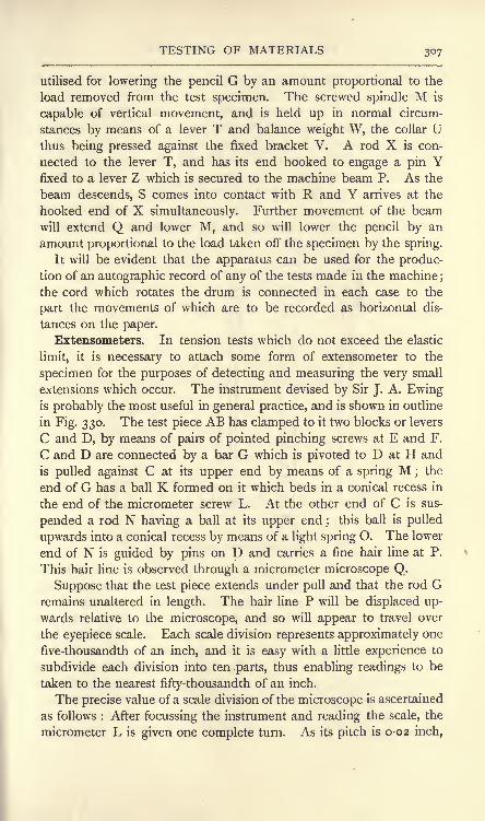
TESTING OF MATERIALS 307
utilised for lowering the pencil G by an amount proportional to the
load removed from the test specimen. The screwed spindle M is
capable of vertical movement, and is held up in normal circum-
stances by means of a lever T and balance weight W, the collar Uthus being pressed against the fixed bracket V. A rod X is con-
nected to the lever T, and has its end hooked to engage a pin Yfixed to a lever Z which is secured to the machine beam P. As the
beam descends, S comes into contact with R and Y arrives at the
hooked end of X simultaneously. Further movement of the beamwill extend Q and lower M, and so will lower the pencil by an
amount proportional to the load taken off the specimen by the spring.
It will be evident that the apparatus can be used for the produc-tion of an autographic record of any of the tests made in the machine;the cord which rotates the drum is connected in each case to the
part the movements of which are to be recorded as horizontal dis-
tances on the paper.
Extensometers. In tension tests which do not exceed the elastic
limit, it is necessary to attach some form of extensometer to the
specimen for the purposes of detecting and measuring the very small
extensions which occur. The instrument devised by Sir J. A. Ewingis probably the most useful in general practice, and is shown in outline
in Fig. 330. The test piece AB has clamped to it two blocks or levers
C and D, by means of pairs of pointed pinching screws at E and F.
C and D are connected by a bar G which is pivoted to D at H and
is pulled against C at its upper end by means of a spring M ; the
end of G has a ball K formed on it which beds in a conical recess in
the end of the micrometer screw L. At the other end of C is sus-
pended a rod N having a ball at its upper end;
this ball is pulled
upwards into a conical recess by means of a light spring O. The lower
end of N is guided by pins on D and carries a fine hair line at P.
This hair line is observed through a micrometer microscope Q.
Suppose that the test piece extends under pull and that the rod Gremains unaltered in length. The hair line P will be displaced up-
wards relative to the microscope, and so will appear to travel over
the eyepiece scale. Each scale division represents approximately one
five-thousandth of an inch, and it is easy with a little experience to
subdivide each division into ten parts, thus enabling readings to be
taken to the nearest fifty-thousandth of an inch.
The precise value of a scale division of the microscope is ascertained
as follows : After focussing the instrument and reading the scale, the
micrometer L is given one complete turn. As its pitch is 0-02 inch,

308 MATERIALS AND STRUCTURES
the effect is to change the length of G by this amount. The arms of
the lever C on either side of the specimen are equal ;hence P will be
moved relative to the microscope by 0-02 inch. The microscopescale is read again, and the difference between this and the original
reading corresponds to a movement of P of 0-02 inch. Nowin use, G remains unaltered in length, and the movement of P is
produced by the extension of the specimen ;the effect of the levers
is to produce a movement at P equal to double the extension of the
specimen. Accordingly o-oi inch extension of the specimen will
produce a movement of 0-02 inch at P. Hence the scale divisions
D
B
FIG. 330. Ewing's extensometer.
movement in the microscope found as directed above correspond to
o-o i inch extension. Once focussed and calibrated, the instrument
requires no further adjustment during the test unless the extension is
sufficiently large to run the risk of moving the hair line beyond the
limit of the microscope scale. In this event, it may be brought to a
working position again by giving the micrometer L one turn, when
the test will proceed as before. The loads are applied best in equal
increments, and the reading of the microscope taken after application
of each increment. The following record of a tensile test may assist
in indicating the methods of noting the observations and of reducing
the results :

TESTING OF MATERIALS 309
TENSILE TEST ON A MILD-STEEL SPECIMEN.
Laboratory No. A, M.S., 14.10.10.Form of test piece ; round, with swelled ends ;
ends rough turned
to 0-75 inch diameter; body turned and polished. A length of
10 inches of the body was marked off at i inch intervals by light
centre punch dots.
Diameter of specimen, 0-445 inch-
Area of cross section, 0-1556 inch.
Elastic test with Ewing's extensometer.
CALIBRATION OF INSTRUMENT.
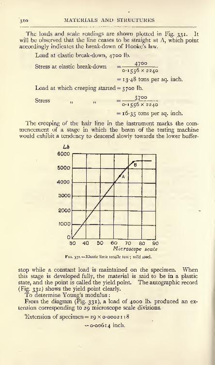
3io MATERIALS AND STRUCTURES
The loads and scale readings are shown plotted in Fig. 331. It
will be observed that the line ceases to be straight at A, which point
accordingly indicates the break-down of Hooke's law.
Load at elastic break-down, 4700 Ib.
Stress at elastic break-down =0-1556 x 2240
= 13-48 tons per sq. inch.
Load at which creeping started = 5700 Ib.
5700
0-1556 x 2240
=16-35 tons Per sc
l-i
Stress
The creeping of the hair line in the instrument marks the com-mencement of a stage in which the beam of the testing machinewould exhibit a tendency to descend slowly towards the lower buffer-
Lb6000
5000
4000
3000
2000
1000

TESTING OF MATERIALS
Gauge points of extensometer are 8 inches apart.
. 0-00614Strain = = 0-000768.o
Stress = -^^-=2 5, 7oo Ib. per sq. inch.
Young's modulus = E = = 33,500,000 Ib. per sq. inch.000700
= 14,900 tons per sq. inch.
Test to maximum load. The extensometer being removed, the
autographic recorder was connected to the specimen at 10 inch
gauge points, and the load was increased from zero until the test
piece began to form a neck preparatory to breaking. The resulting
diagram is shown in Fig. 332, and gives the yield load as 6600 Ib.
From this we calculate
Yield stress =-z = 18-93 tons Per SQ- mcn -
0-1556 x 2240
The maximum load which the specimen could carry was 9600 Ib.
Hence,
Breaking stress9600
0-1556 x 224027-5 tons per sq. inch.
The autographic record (Fig. 332) shows an interesting point
regarding the effects of overstrain (i.e. straining beyond the yield
point) on the elastic properties of
the material. After the specimen -L,b.
had been stretched 1-2 inches on
4000
2000
10000-
a length of 10 inches, the load
was removed. Reapplication of 8000-
the load ca.used the diagram to
rise from zero along a practically 6000-
straight line until the former
curve was reached again at a
load of about 9500 Ib. Yielding
along the curve then continued
as before. The overstraining hadhardened the material and raised
the yield load from 6600 Ib. to
about 9500 Ib., i.e. only slightly
below the ultimate load.
The test piece was removed from the machine and the lengths of
the intervals between the centre punch dots were measured ;also the
diameters at each dot. From these the curves in Fig. 333 were
plotted. It will be noted that both extensions and diameters vary
considerably, and illustrate the necessity for stating the distance
between the gauge points as well as the percentage extension of a
IQ 2'0 3 :
Inches
FIG. 332. Autographic record ; mild steel
under tension.

312 MATERIALS AND STRUCTURES
test piece. A good method is to measure the total extension on a
length of 10 inches, also the extension on the 2 inches interval
0-38
039-
040-
041
Inch,.
FIG. 333. Dimensions of a mild steel specimen after a tension test.
which includes the fracture ;the difference between these will be
the general extension on the remaining 8 inches of the specimen.These extensions, expressed as per-
centages, give useful information re-
garding the ductility of the material.
Another measure of the ductility maybe obtained by measuring the cross-
sectional area of the fracture. Theloss in area may be found from this
measurement, and may be expressedas a percentage of the original sectional
area.
Fig. 334, copied from the autographic
record of a specimen of Delta metal
under pull, is given as illustrating
totally different characteristics from the
mild-steel diagram shown in Fig. 332.
In particular, the absence of any yield
point will be noticed.
Bending tests. The records given
in Figs. 335 and 336 illustrate an
instructive test made on a mild-steel bar having a span of 36
inches, breadth 2-01 inches and depth 2-015 inches. The bar was
05 l-O 1-5 Inches
FIG. 334. Autographic record ; Deltametal under tension.

TESTING OF MATERIALS 313
arranged as shown in Fig. 320 and bent by application of a central
load until the deflection was 2-6 inches. The record (Fig. 335)shows that yielding was reached at about 7200 Ib. The test was
arrested at about 2-1 inch deflection, and the load brought to zero
and then reapplied ; the diagram shows that the new yield load is
about 9000 Ib.
Then the load was removed entirely and the bar turned over;central loading was applied again so as to straighten the bar. The
diagram given in Fig. 336 shows the result. There is practically no
part of this test where the elastic law is followed, a fact which will
be understood readily when it is realised that the bar came out of
the former test badly overstrained both on its compression side and
10 20 s-o
InchefFIG. 335. Mild steel bar under bending ;
first test.
1-0 2-0 3-0
inchesFIG. 336. Mild steel bar under bending ;
second test.
on its tensile side, and, in the effort to recover some of the deflection
imposed on it, the material became self-stressed throughout. Thesecond test began therefore with the material in a complicated state
of stress. This test was also arrested at about 2-2 inch deflection.
On reapplication of the load, a yield load of about 10,000 Ib. will be
observed in the diagram. Had the bar been annealed after straighten-
ing, it is probable that a diagram somewhat resembling Fig. 335 for
the first test would be obtained. The tendency of the annealing is
to remove self-stressing from the material.
Fig. 337 has been copied from the autographic record obtained in
testing a cast-iron bar under bending. The bar was rectangular in
section, 2 inches wide and i^V inches deep, span 20 inches. Ruptureoccurred with a central load of 3200 Ib., the maximum deflection
recorded being 0-2 inch. It will be noted that the load and

314 MATERIALS AND STRUCTURES
deflection remain approximately proportional up to fracture. Thecontrast of the ductile and brittle materials is rendered clear by
inspection of Figs. 335 and 337. The mild-steel bar could not be
broken by bending ;the cast-iron bar could take a very small
deflection only.
The usual test for timber is by bending under similar conditions
to those noted above. The specimens should be of as large size
as is possible, then the effect of any local flaws such as shakes and
knots will not be emphasised, as would be the case with a smaller
specimen containing the same flaws. In Fig. 338 are given copies of
2000
o 0-2 04- InchFIG. 337. Cast-iron test bar under bending.
W Ib
12000
8000
4000-
Yellow deal
Teak
Oak
10 20 InchesDeflection
FIG. 338. Bending tests on timber.
records of bending tests on yellow deal, teak and oak. The yellow
deal specimen was arranged with the annual rings nearly horizontal,
and failed by shearing horizontally along the fibres and round the
annual rings. The dimensions and results are given in the following
table:
BENDING TESTS ON THREE TIMBER SPECIMENS.
Material.

TESTING OF MATERIALS 315
due to bending would have if Hooke's elastic law were followed
throughout. For a beam of rectangular section supported at the
ends and having the load applied at the middle of the span, the
calculation will be as follows :
Let W = maximum load, in Ibs.
L = the span, in inches.
b = the breadth, in inches.
^=the depth, in inches.
Then
WL4
m
L\d 12
and Coefficient of rupture =/= --r-^.
Shearing tests. Autographic records of two shearing tests carried
out in the apparatus de-
scribed on p. 303 are givenin Figs. 339 and 340. Theformer is for a mild-steel
specimen and the latter is
for a specimen of gun-metal. It should be noted
that pure shear is not ob-
tained with this apparatus,
the specimen being under
bending as well as shearing.
In Older to minimise the
bending effect, the speci-
mens should be turned to
fit the bored holes in the
dies. The results of the
tests are given below.
4000
FIG. 339. Mild steel under
shearing.
0'5 InchFIG. 340. Gun-metal
under shearing.
SHEARING TESTS.
Material.

MATERIALS AND STRUCTURES
Punching tests. In punching a hole in a piece of material,
the action of the punch is first to increase the pressure on the
material until the plastic stage is reached;
in this stage, some of the metal flows from
under the punch into the surrounding plate,
the plate immediately under the punch be-
coming thinner. This effect continues until,
partly by the increasing force on the punchand partly by the diminishing thickness of
the plate, the rupturing shear stress on the
material is attained and a wad is pushed out.
The following results of a punching test maybe of interest; the autographic record is
given in Fig. 341.
PUNCHING TEST ON A WROUGHT-!RONPLATE.
O'-l 0'2 /rich
4000-
FIG. 341. Punching test on
wrought iron.
Thickness of the plate= 0-265 mcn -
Diameter of the wad punched out = 0-38inch.
Area under shear stress = ^dt=^ xo-38xo-265= 0-317 square inch.
Maximum load on the punch = 15,750 Ib.
r 5>75Maximum shearing stress 22-2 tons per sq. inch.0-317 x 2240
Thickness of the plate round the hole after punching = 0-268 inch.
Thickness of the wad = 0-2 5 7 inch.
Loss of thickness of material in the wad = 0-008 inch.
Gain of thickness of material round the hole = 0-003 inch.
Total work done in punching the hole, represented by the area of
the autographic record, is about 810 inch-lb.
Avery torsion machine. An outline diagram of this machine is
given in Fig. 342, where AB is the test piece. The end B is con-
nected to a worm wheel C, which may be rotated by means of a
worm D and hand wheel E. The wheel C has 90 teeth ;hence each
quarter turn of the hand wheel twists the specimen through one
degree. The torque is measured by means of a system of levers
FG, MK and NP, connected to the end A of the specimen. NPcarries a counterpoise Q, which may be run along the lever by means
of a screw and hand wheel, and shows the torque by its position
relative to a scale attached to the lever. The scale reads from zero
to 1000 Ib.-inches: to obtain higher torque the counterpoise is run
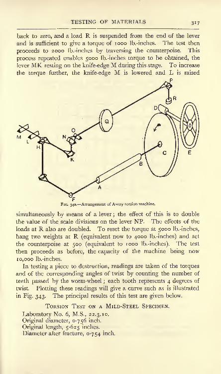
TESTING OF MATERIALS 317
back to zero, and a load R is suspended from the end of the lever
and is sufficient to give a torque of 1000 Ib.-inches. The test then
proceeds to 2000 Ib.-inches by traversing the counterpoise. This
process repeated enables 5000 Ib.-inches torque to be obtained, the
lever MK resting on the knife-edge M during this stage. To increase
the torque further, the knife-edge M is lowered and L is raised
P
FFIG. 342. Arrangement of Avery torsion machine.
simultaneously by means of a lever ;the effect of this is to double
the value of the scale divisions on the lever NP. The effects of the
loads at R also are doubled. To reset the torque at 5000 Ib.-inches,
hang two weights at R (equivalent now to 4000 Ib.-inches) and set
the counterpoise at 500 (equivalent to 1000 Ib.-inches). The test
then proceeds as before, the capacity of the machine being now
10,000 Ib.-inches.
In testing a piece to destruction, readings are taken of the torques
and of the corresponding angles of twist by counting the number of
teeth passed by the worm-wheel;each tooth represents 4 degrees of
twist. Plotting these readings will give a curve such as is illustrated
in Fig. 343. The principal results of this test are given below.
TORSION TEST ON A MILD-STEEL SPECIMEN.
Laboratory No. 6, M.S., 22.3.10.
Original diameter, 0-756 inch.
Original length, 5-625 inches.
Diameter after fracture, 0-754 inch.

MATERIALS AND STRUCTURES
Length after fracture, 5-750 inches.
Yield torque, estimated by the dropping of the beam, 2000
Ib.-inches.
Breaking torque, 6400 Ib.-inches.
Angle of twist at yield, 3-5 degrees on 5-75 inches length.
Angle of twist at breaking, 1896 degrees on 5-75 inches length.Mean torque, from diagram, 5650 Ib.-inches.
Total work done in fracturing specimen, 187,000 inch-lb.
Work done per cubic inch of material, 74,200 inch-lb.
Lb- inches7000
5000
4000
3000
8000
1000
400 800 1200 1600 2000
DegreesFIG. 343. Graph of a torsion test on mild steel.
The form of the test specimen is indicated at AB in Fig. 344 ; the
same diagram also illustrates an appliance whereby angles of twist
G
FIG. 3<v. Apparatus for measuring angles of twist within the elastic limit.
within the elastic limit may be measured. C and D are two pieces
of wrought-iron steam tube turned and bored at L to an easy fit.

TESTING OF MATERIALS 319

320 MATERIALS AND STRUCTURES
The total work done up to the elastic limit will be found by takingthe product of the mean torque and the angle of twist, and is 30-3inch-lb.
To obtain the resilience, i.e. the work done per cubic inch of
material, divide the total work by the volume of the specimenbetween the gauge points. The result is 9-3 inch-lb.
Cement testing. Portland cement is made by mixing chalk and
fine clay in certain proportions, burning the mixture at a clinkering
temperature, and finely grinding the resulting product. Cement of
this kind is much used for making concrete for constructional pur-
poses. Concrete consists of an aggregate of clean broken stones,
etc., to which sufficient clean sand is added to fill completely the
voids between the stones. A quantity of Portland cement is inti-
mately mixed with these, sufficient to coat the surface of every stone
and every particle of sand with cement. Water is added, and the
whole is mixed thoroughly in order to produce a plastic mass, which is
rammed into moulds prepared to give the required structural shape.
The qualities which Portland cement should possess have been
laid down by the Engineering Standards Committee, and the tests
should be carried out in accordance with the terms of their specifica-
tion,1 a copy of which should be in the hands of the experimenter.
The fineness to which the cement has been ground is of great
importance, and is tested by means of sieves, one having 5776 holes
per square inch and another having 32,400 holes per square inch.
These sieves are made in a special way of wire having standard
diameters in terms of the specification. The residue left on the first
sieve should not exceed 3 per cent., and on the latter 18 per cent.
The specific gravity of the cement is taken now in place of
weighing the cement in bulk. This may be ascertained by use of a
specific gravity bottle having a graduated stem and containing a
measured quantity of turpentine (cement will not set in turpentine).
A measured weight W of cement is introduced into the bottle,
and its volume V may be observed from the rise in level of the
turpentine in the stem of the bottle. Then
where w is the weight of a cubic unit of water and p is the specific
gravity of the cement. The specific gravity should be not less than
3-15 for cement freshly burned and ground. 3-10 is permitted at a
period not less than four weeks after grinding.
1 British Standard Specificationfor Portland Cement, Crosby, Lockwood & Son.
Revised 1910.

TESTING OF MATERIALS 321
The strength of cement is determined usually by means of tensile
tests, although cement in practice is generally under compression.Tensile tests may be carried out in a comparatively small machine,while compression tests require a machine capable of exerting great
pressure. When compression tests are made, the test briquettes are
generally cubical ; briquettes for tensile tests are prepared in moulds
having a shape in accordance with that laid down in the standard
specification. Considerable experience is required in order satisfac-
torily to gauge or mix the cement intended for test briquettes. The
quantity of water to be used depends on the kind of cement, and
greatly influences the strength of the cement. The student can
test this easily by preparing several briquettes having water per-
centages of from 1 8 to 25, and testing these for tensile strength.
The moulds should rest on an iron plate while being filled; no
severe mechanical ramming should be necessary if the correct per-
centage of water has been used. During the first 24 hours after
filling, a damp cloth should be placed over the moulds. The
briquettes are removed from the moulds then and placed in clean
water until the strength test is carried out. The temperature
throughout should be near 60 Fah. The tensile strength of neat
cement briquettes (i.e. briquettes made of cement alone, without sand
or other material) at 7 days from gauging should not be less than
400 Ib. per square inch. Briquettes consisting of one part by weightof cement to three parts by weight of Leighton Buzzard sand, preparedin accordance with the terms of the standard specification, should
have a tensile strength of 150 Ib. per square inch at 7 days after
gauging.
The setting time is tested by means of a standard needle having a
flat point one millimetre square and having a total weight of 300
grams. The cement 'is taken as set when the application of the
needle fails to make an impression.
The soundness of the cement is tested by the Le Chatelier method.
A cylindrical mould having an axial split and furnished with two
long pointers is filled with cement, as directed in the standard
specification. This is kept in water for 24 hours, and then the
distance between the ends of the pointers is measured. The mould
and. cement are then boiled for 6 hours and allowed to cool. The
distance is measured again, and the increase should not exceed a
stated amount.
Cubical cement and concrete blocks, bricks and stones are tested
under compression. It is best to prepare the top and bottom
P.M. X

322 MATERIALS AND STRUCTURES
surfaces by smoothly coating them with plaster of Paris in order to
give level parallel surfaces for the testing machine plates to bear
upon. Generally, the fracture is by shearing on planes roughly at
45 to the horizontal. Broken cement compression briquettes
generally resemble two square based pyramids standing apex on apex.
EXERCISES ON CHAPTER XIII.
1. The following is the experimental record of a test on a specimen of
cast iron. The object of the experiment was to determine the compres-sion value of E for the material : Ewing's extensometer was employed.The specimen was turned and polished.
Diameter of specimen, 0-474 inch; gauge points, 8 inches
;calibration
of extensometer, i scale division= j^ inch.
Load, Ib.

EXERCISES ON CHAPTER XIII. 323
a length of 2 inches, including the fracture, 0-3 inch;diameter at fracture,
0-479 inch. Reduce these observations, following the procedure indicatedon p. 311.
4. A mild-steel bar of square section 2 inches x 2 inches was arrangedas a beam of 60 inches span, simply supported ;
the load was applied at
the middle of the span, and the deflections at the load were measured bymeans of a micrometer microscope, the calibration of which gave one
eyepiece-scale division =0-065 mm - The following observations weretaken :
Load, Ib.

324 MATERIALS AND STRUCTURES
reinforcement, thirteen horizontal lacings of iron wire, 0-067 inch diameter,about 2 inches pitch. Concrete mixture, cement 7 lb., granite chips 14 lb.,
water 3 lb. The column was made in a wooden mould, removed five daysafter making and tested fourteen days after making ;
it was kept dampthroughout this time.
Observations taken : Hooke's law broke down sensibly at 9000 lb. load;
8000 lb. load shortened the column to the extent of 0-0154 inch;
the
column ruptured when the load reached 20,670 lb.
Taking 7/2=15, find the stress in the steel and in the concrete whenHooke's law broke down. Assuming the elastic laws to hold up to
rupture, find these stresses at rupture. What is the value of E for the
complete column ?
8. The following observations were made during a torsion test on a
mild-steel specimen : Diameter of specimen, 0-714 inch; gauge points of
strain indicator, 7-81 inches ;calibration of indicator, one scale division
= 0-04 degree twist.
Torque, lb. -inches

PART II.
MACHINES AND HYDRAULICS.
CHAPTER XIV.
WORK, ENERGY, POWER, SIMPLE MACHINES.
Work. Work is said to be done by a force when it acts through a
distance. If a body A (Fig. 346) is at rest under the action of two
equal forces P and R, no work is being done by either force;
if the
body is moving with constant speed towards the right, work is beingdone by P against the resistance R. Work is measured by the pro-
duct of the magnitude of the force and the distance through which it
acts, the latter being measured along, or parallel to, the line of the
force. In the case of a car travelling along a level road (Fig. 347) no
W
FIG. 346. FIG. 347. FIG. 348.
work is done by the weight W, nor by the reactions of the ground, as
none of these forces advance through any distance in the directions of
their lines of action. Work is done by the weight of the car in
descending an incline (Fig. 348). If the total height of descent is H,then the work done by W will be WH. Or, the solution may be
obtained by resolving W into components P and Q respectively,
parallel and at right angles to the incline. Q does no work while the
car is descending ;P does work to the amount P x AB.
The unit of work in general use in this country is the foot-pound,
and is performed when a force of one pound weight acts through a
distance of one foot. The foot-ton, inch-pound, and inch-ton are

326 MACHINES AND HYDRAULICS
used occasionally. Metric units of work are the gram-centimetre,
the kilogram-centimetre and the kilogram-metre.
Energy. Energy means capability of doing work, and is measured
by stating the units of work capable of being performed. There are
many different forms of energy, such as potential energy, said to be
possessed by a raised body in virtue of the fact that its weight mayperform work while the body is descending ;
kinetic energy, which a
body possesses when in motion and gives up while coming to rest;
elastic energy, possessed by a body under strain and given out while
coming back to its original form or dimensions ;heat energy, which a
body may give up in cooling to a lower temperature ;chemical energy,
which may be present in a substance owing to its constituents being
capable of combining in such a way as to liberate energy in the form
of heat; electrical energy, possessed by a body by virtue of its
electric potential being higher than that of surrounding bodies.
Conservation of energy. The experience of all observers shows
that the following general law is true : Energy cannot be created nor
destroyed, but can be converted from one form into another form. This law
is known as the conservation of energy. If no waste of energy were to
occur during the conversion, a given quantity of energy in one form
could be converted into an equal quantity in a different form. Exact
equality never is obtained in practice ;there is always waste, some-
times to a very large extent. For example, in converting the energy
available in coal into mechanical work by means of a steam boiler
and engine, it is common to find wasted 90 per cent, of the energy
available, only 10 per cent, appearing in the desired form.
In measuring heat energy, the British thermal unit may be used,
one such unit being the quantity of heat required to raise the tem-
perature of one pound of water through one degree Fahrenheit. The
pound-calorie unit is likely to be used more extensively- in future,
and is the quantity of heat required to raise the temperature of one
pound of water through one degree Centigrade. The experiments of
Dr. Joule and others show that an expenditure of 778 foot-pounds
of energy will produce one British thermal unit; 1400 foot-pounds is
the energy equivalent to a pound-calorie unit. Mechanical energy
may be converted into heat without very large waste occurring (for
example, in mechanically stirring water), but the reverse operation is
always accompanied with great waste.
Power. Power means rate of doing work. The British unit of
power is the horse-power, and is developed when work is being done
at the rate of 33,000 foot-pounds per minute. The horse-power in

MACHINES 327
any given case may be calculated by dividing by 33,000 the work
done per minute in foot-pounds.
The electrical power unit is the watt, and is the rate of workingwhen an electric current of one ampere flows from one point of
a conductor to another, the potential difference between the points
being one volt. The product of amperes and volts gives watts.
746 watts are equivalent to the mechanical horse-power. When the
amperes and volts are stated, we have
amperes x voltsMechanical horse-power
746The Board of Trade unit of electrical energy is- one kilowatt main-
tained for one hour. One horse-power maintained for one hour
would produce 33,000 x 60 or 1,980,000 foot-pounds. The kilowatt-
hour would therefore produce energy given by
Energy = 1,980,000 x -Vrrr
= 2,654,000 foot-pounds.
Machines. A machine is an arrangement designed for the purposeof taking in energy in some definite form, modifying it, and delivering
it in a form more suitable for the purposein view. Machines for raising weights are
arranged conveniently in most mechanical
laboratories, and experiments on such are
very instructive. Fig. 349 shows, in outline,
a small crab which may be taken as a type
of such machines. A loadW Ib. is suspendedfrom a cord wrapped round a drum, and is
raised by the action of another load P Ib.
attached to a cord coiled round an operating
wheel. The wheel and drum are connected
by means of toothed wheels, so that P descends as W ascends.
The velocity ratio of such a machine is defined as the ratio of the
distance moved by P while W ascends a measured distance. Let Hand h be these distances respectively in inches (Fig. 349) ; they maybe measured direct in the machine. Then
TT
Velocity ratio = V = -- r(
i)
Let P be so adjusted that it will descend with steady speed on
being started by hand, thus raising a load W. The mechanical
advantage of the machine is defined by
Mechanical advantage = -= (2)
FIG. 349. Outline diagram of
an experimental crab.

328 MACHINES AND HYDRAULICS
By the principle of the conservation of energy, if no waste of
energy occurs in the machine, the work done by P would be equalto the work done on the load. Suppose, in these circumstances,
that the same working force P is employed, a larger load W1Ib. could
be raised than would be the case in the actual machine. W1 may be
calculated as follows :
Work done by P = work done on W1 ,
PH^Wj/z,
Wl= P - = PV
= P x the velocity ratio............. (3)
The effect of frictional and other sources of waste in the actual
machine has been to diminish the load from W1to W. Hence,
Effect of friction = F = Wj - W-FV-W............................ (4)
Efficiency of machines. The energy supplied to the machine is
PH inch-lb. ^Fig. 349), the energy actually given out by the machine
is Wh inch-lb. The efficiency of the machine is denned by
. energy given outEfficiency = p =-
energy supplied
__PH~PV
_ mechanical advantage
velocity ratio
The efficiency thus stated will be always less than unity. Efficiency
is often given as a percentage, obtained by multiplying the result
given in (5) by 100. 100 per cent, efficiency could be obtained only
under the condition of no energy being wasted in the machine, a
condition impossible to attain in practice.
From equation (3), we have
w,,pH,
A result which shows that the mechanical advantage of an ideal
machine having no waste of energy is equal to the velocity ratio.
For machines of the type described above, the following equation
may be stated :
Energy supplied = energy given out + energy wasted in the machine.

MACHINES 329
Occasionally machines have to be considered in which there are
internal springs or other devices for storing energy. In such cases
the equation becomes :
Energy supplied= energy given out + energy stored in the machine
+ energy wasted in the machine.
A machine is said to be running light when no energy is being
given out. If no energy is being stored in a machine running light,
then the energy supplied must be sufficient to make good the energywasted in overcoming the resistances in the machine.
Reversal of machines. A machine in which the frictional re-
sistances are small may reverse if P is removed. To investigate this
point, consider the machine when W i being raised (Fig. 349) :
Energy supplied= PH,
Energy given out = W/,
Energy wasted =PH-W> (7)
Now let P be removed and let the conditions be such that W is
just able to reverse the machine. Let W descend through a height h.
1 hen Energy supplied and wasted in the machine = Vfh (8)
Assuming that this waste has the same
value as when W is being raised, we
have, from (7) and (8),
FIG. 350. A small lifting crab.
W* i
Or, Efficiency = p^y= -
Hence, when W is being raised, the
efficiency will be 50 per cent, for reversal
to be possible if P is removed. Anyvalue of the efficiency exceeding 50 per
cent, would be accompanied by the
same effect.
The following record of tests on a lifting crab will serve as a
model for carrying out experiments on laboratory machines.
EXPERIMENT ON A SMALL LIFTING CRAB.
Date of test, loth February, 1911.
The machine used was constructed by students in the workshopsof the West Ham Technical Institute. Its general arrangement in"single-gear
"is shown in Fig. 350. A weight W is suspended from

330 MACHINES AND HYDRAULICS
a cord wrapped round a drum A. Motion is communicated to A bymeans of toothed wheels B and C ; these are of gun-metal with
machine-cut teeth. Energy is supplied by a descending weight P,which is attached to a cord wrapped round a wheel D.
The object of the experiments was the determination of the
mechanical advantage and efficiency for various loads.
By direct measurement of the distances moved by P and W, the
velocity ratio was found to be = 8-78.The weight of the hook from which W was suspended is 1-75 Ib.
The weight of the scale pan in which were placed the weights
making up P is 0-665 Ib.
The machine having been first oiled, the weights W and P were
adjusted so as to secure descent of P with steady speed. Theresults obtained are given below.
RECORD OF EXPERIMENTS AND RESULTS.
.w'tincluding
weight of hook.
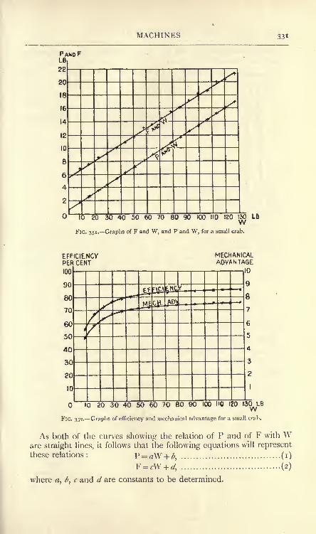
MACHINES 331
PALB

332 MACHINES AND HYDRAULICS
Select two points on the PW graph, and read the correspondingvalues of P and W.
P= 3-5 Ib. when W= 22-7 Ib.
P=i6-olb. when W=i2o-olb.
Hence, from (i), 3.5= 22-7^ + ^,
16= i2oa + l>.
Solving these simultaneous equations, we obtain
= 0-128,
^ = 0-64;
Similarly,
When F= 8 Ib., W= 20 Ib.
WhenF=i81b., W=ioolb.
Hence, from (2), 8= 2oc + d,
1 8 = i ooc + d.
The solution of these gives
;= 0-125,
FIG. 353. Pulleyblocks.
Hence, F = o-i25W + 5'5 (4)
Suppose the machine to be running light, then
W =o, and the corresponding values of P and F obtained from
(3) and (4) are p = .64 ft.,
F= 5.
5 lb.
The interpretation is that a force of 0-64 Ib. is required to workthe machine when running light, and that, if there
were no frictional waste, a load of 5-5 Ib. could beraised by this force.
Hoisting tackle. The fact that the mechanical
advantage of a machine, neglecting friction, is equalto the velocity ratio, enables the latter to be cal-
culated easily in cases of hoisting tackle. A few
such appliances, which may be found in most
laboratories, are here given.
In the pulley-block arrangement shown in Fig. 353,
let n be the number of ropes leading from the
lower to the upper block. Neglecting friction,
ith
each of these ropes will support- of W, and this
will also be the value of P. Hence,
W_W_ TWV
-p- "TIT" ^* FIG. 354- Weston's* differential blocks.

MACHINES 333
A set of Western's differential blocks is shown in outline in Fig. 354 ;
the upper block has two pulleys of different diameters, and a chain,
shown dotted, is used. The links of the chain passing round these
pulleys engage with recesses which prevent slipping. Neglecting
friction, each of the chains A and B will support JW. Takingmoments about the centre C of the upper pulleys, and calling the
radii R and r respectively, we have
!\V x CD = (P x CF) + (|W x CE),
Instead of R and r, the number of links which can be fitted round
B
WFRONT ELEVATION END ELEVATION
FIG. 355. Wheel and differential axle. FIG. 356. Helical blocks.
the circumferences of the pulleys may be used : evidently these will
be numbers proportional to R and r.
The wheel and differential axle (Fig. 355) is a similar contrivance,
but has a separate pulley A for receiving the hoisting rope. Taking
moments as before, we have
y.-W =p
A set of helical blocks is shown in outline in Fig. 356. A is

334 MACHINES AND HYDRAULICS
operated by hand by means of a hanging endless chain and rotates
a worm B, which in turn advances the worm wheel C one tooth for
each revolution of A. If there be nc teeth on C, then A will rotate
nc times for one revolution of C, and P will advance a distance
CLA ,which is equal to nc times the length of the number of links
of the hanging chain which will pass once round A. The chain
sustaining the load W is fixed at E to the upper block, passes round
F, and then is led round D, which has recesses fitting the links in
order to prevent slipping. Let LD be the length of the number
of links which will pass once round D. Then in one revolution of
D, W will be raised through a height equal to4LD . Hence,
EXPTS. 33 to 37. Experiments on the hoisting appliances de-
scribed above should be carried out and the results reduced bymethods similar to those explained for a small crab on p. 329.
Diagram of work. Since work is measured by the product of
force and distance, it follows that the area of a diagram in which
ordinates represent force and abscissae represent distances will
p
Oi. -D -JFIG. 357. Diagram of workdone by a uniform force.
o oFIG. 358. Diagram of workdone by a varying force.
represent the work done. A uniform force P pounds acting througha distance D feet does work which may be represented by the area
of a rectangle (Fig. 357). To obtain the scale of the diagram :
Let i inch height represent p Ib.;
i inch length represent d feet.
Then one square inch of area will represent pd foot-pounds of
work. If the area of the rectangle is A square inches, then
Work done =pdK foot-lb.
In the case of a varying force, the work diagram is drawn by
setting off ordinates to represent the magnitude of the force at
different intervals of the distance acted through (Fig. 358). A fair
curve drawn through the tops of the ordinates will enable the force
to be measured at any stage of the distance. The work done is the
product of the average force and the distance, and as the average

DIAGRAMS OF WORK 335
force is given, to scale, by the average height of the diagram, and
the distance, to scale, b^ the length of the diagram, we have, as
before, the work done represented by the area of the diagram.
Using the same symbols as before, one square inch of area represents
pd foot-pounds of work, and the total work done will be given by
Work done=dA foot-lb.
The area A may be measured by means of a planimeter, or by use
of any convenient mensuration rule (p. 6).
The case of hoisting at steady speed a load from a deep pit is of
interest (Fig. 359). Let Wl
Ib. be the weight of the cage and load,
and let W2 Ib. be the total weight of the vertical rope when the cage
is at the bottom, a depth of H feet. At first the pull P Ib. required
at the top of the rope will be (Wl+W2)
Ib. P will diminish gradually
FIG. 359. Diagram of workdone in hoisting a load.
FIG. 360. Work done in raisinga body.
as the cage ascends, and will become equal to \Vlwhen the cage
is at the top. The work diagram for hoisting the cage and load alone
is a rectangle ABCD, BC and AB representing Wj and H respec-
tively ;the diagram for hoisting the rope alone is DCE, in which
W2
is represented by CE. From the diagrams, we have
Total work done = (W
l + 1W2)H foot-lb.
Work done in elevating a body. It will be shown now that the
work done in raising vertically a given body may be calculated by
concentrating the total weight at the centre of gravity. Referring to
Fig. 360, let ze^, z#2 , etc., be the weights of the small particles of
which the body is composed, and let h^ //2 , etc., be their initial

336 MACHINES AND HYDRAULICS
heights above ground level, and let //, /*2 ', etc., be their final
heights. ThenWork done on w
l=w
l (h-{-
h-^
and Work done on w^ w^(h^-h^^ etc.
Hence,
Total work done = (w^ +w^ + etc.)-(wji^ +w2
/i2 + etc.)
FIG. 361. Thomson indicator.
Let G and G' be the initial and final positions of the centre of
gravity of the body, situated respectively at heights H and H', and
let W be the total weight of the body. ThenWH' = 2ze/#(P- 49)
and

INDICATED HORSE-POWER 337
Hence, Total work done = WH' -WH= W(H'-H).
Therefore the total work done in raising a body may be calculated
by taking the product of the weight of the body and the vertical
height through which the centre of gravity has been raised. This
method is equivalent to concentrating the total weight at the centre
of gravity.
Indicated work and horse-power. An indicator is an instrument
used in obtaining a diagram of work done in the cylinder of an
engine. The essential parts of an indicator are shown in Fig. 361.
A small cylinder A is fitted with a piston B, which is controlled by a
helical spring C. Connection is made at D to the engine cylinder ;
E is a stop cock. The piston B is connected by means of a piston
rod to a lever system having a pencil fixed at P;the function of the
lever system is to guide P in a straight vertical line, and to give it an
enlarged copy of the motion of the piston B. As the spring follows
Hooke's law, it follows that the movement of P will represent a
definite pressure in pounds per square inch for each inch of vertical
travel. The pencil moves over a piece of paper wrapped round a
drum F. The drum is rotated in one direction by means of a cord
G, and is brought back again by means of an internal spring. Thecord G is actuated by some reciprocat-
ing part of the engine which gives it
a reduced copy of the motion of the
engine piston. Hence a diagram will be
drawn on the paper showing pressures
in the engine cylinder by its ordinates,*
L
and distances travelled by the engine FIG. 362.-Work done during the
piston by its abscissae (Fig. 362). Thecurve abc is for the forward travel of the piston, actuated by the
steam or other pressure, and the curve cde is for the backward travel,
and shows the exhaust.
The work done during the stroke may be found by first obtaining
the average height of the diagram inclosed by the curves in inches
and multiplying this by the scale of pressure ;the result gives the
average pressure on the piston in pounds per square inch.
Let A = the effective area of the piston, in square inches.
L = the length of the stroke, in feet.
pm = the average pressure, in Ib. per square inch,
Then Work done per stroke =/mAL foot-lb.
P.M. Y
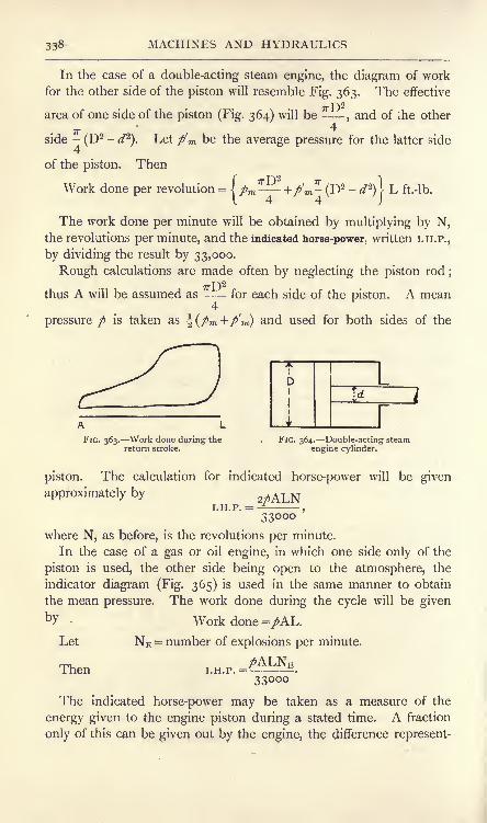
338 MACHINES AND HYDRAULICS
In the case of a double-acting steam engine, the diagram of work
for the other side of the piston will resemble Fig. 363. The effective
T^\2
area of one side of the piston (Fig. 364) will be -,and of the other
IT4
side -(D
2 -d^\ Let p'm be the average pressure for the latter side
4
of the piston. Then
Work done per revolution = (/m +/m -(I)
2 - </2)) L ft.-lb.144 J
The work done per minute will be obtained by multiplying by N,the revolutions per minute, and the indicated horse-power, written I.H.P.,
by dividing the result by 33,000.
Rough calculations are made often by neglecting the piston rod;T-J2
thus A will be assumed as -- for each side of the piston. A mean4
pressure / is taken as \(pm,+p'ni) and used for both sides of the
FIG. 363. Work done during thereturn stroke.
Id
rFIG. 364. Double-acting steam
engine cylinder.
piston. The calculation for indicated horse-power will be given
approximately by 2MLNI.H.P. = -^
,
33000
where N, as before, is the revolutions per minute.
In the case of a gas or oil engine, in which one side only of the
piston is used, the other side being open to the atmosphere, the
indicator diagram (Fig. 365) is used in the same manner to obtain
the mean pressure. The work done during the cycle will be givenby Work done =/AL.
Let NE = number of explosions per minute.
Then ,.H.P.=-^k33000
The indicated horse-power may be taken as a measure of the
energy given to the engine piston during a stated time. A fraction
only of this can be given out by the engine, the difference represent-
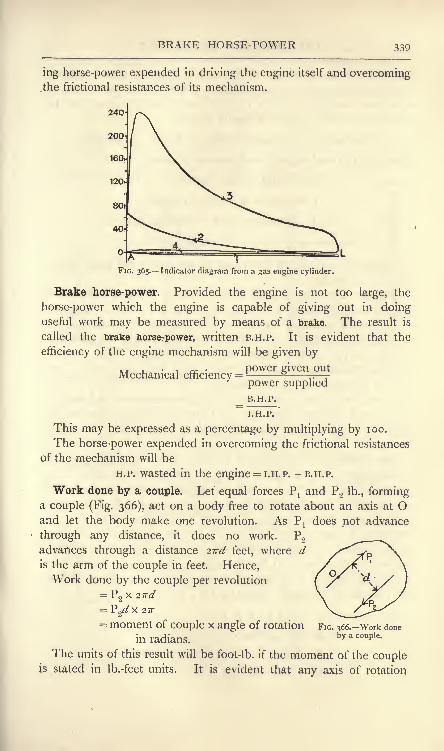
BRAKE HORSE-POWER 339
ing horse-power expended in driving the engine itself and overcomingthe fractional resistances of its mechanism.
FIG. 365. Indicator diagram from a gas engine cylinder.
Brake horse-power. Provided the engine is not too large, the
horse-power which the engine is capable of giving out in doinguseful work may be measured by means of a brake. The result is
called the brake horse-power, written B.H.P. It is evident that the
efficiency of the engine mechanism will be given by
a. . power given outMechanical efficiency
= rr -
power supplied
B.H.P.
I.H.P.
This may be expressed as a percentage by multiplying by 100.
The horse-power expended in overcoming the frictional resistances
of the mechanism will be
H.P. wasted in the engine = I.H.P. -B.H.P.
Work done by a couple. Let equal forces Pland P
2 lb., forminga couple (Fig. 366), act on a body free to rotate about an axis at Oand let the body make one revolution. As P
]does not advance
through any distance, it does no work. P2
advances through a distance 2ird feet, where dis the arm of the couple in feet. Hence,Work done by the couple per revolution
= Po x 2ird
27T
FIG. 366. Work doneby a couple.
= moment of couple x angle of rotation
in radians.
The units of this result will be foot-lb. if the moment of the coupleis stated in Ib.-feet units. It is evident that any axis of rotation

340 MACHINES AND HYDRAULICS
perpendicular to the plane of the couple may be chosen without
altering the numerical result, because a couple has the same momentabout any point in its plane (p. 59). Since the work done will be
proportional to the angle of rotation, we have
Work done = (moment of couple in Ib.-feet x a) foot-lb.,
where a is the total angle turned through in radians.
Let N = revolutions per minute,
T = moment of couple, in Ib.-feet.
Then Angle of rotation = 2?rN radians per minute ;
Work done per minute = T x 2?rN foot.-lb.
Advantage is taken of this result in estimating the brake horse-
power of an engine.
Brakes. In the more usual form of brakes, frictional resistance is
applied to the flywheel of the engine by means of a band. Rotation
of the band is prevented by means of pulls applied by dead weights,
or by spring balances. From the observed values of the pulls, the
moment of the applied couple may be calculated. This, together
with the revolutions per minute, enables the work done per minute
and the horse-power to be calculated.
As the work done against the frictional resistance of the band is
transformed into heat, and thus will cause the temperature of the
wheel to rise, it is often necessary to adopt some means of cooling
the wheel.
Rope brakes. A simple form of brake is shown in Fig. 367, and
consists of two ropes passed round the wheel and prevented from
slipping off sideways by means of wooden brake blocks, four of which
are shown. A dead weight W is applied to one end of the ropes
and a spring balance applies a force P to the other end. The net
resistance to rotation will be (W -P), and this constitutes one force
of the couple. The other equal force is Q, and arises from a pressure
applied to the wheel shaft by its bearings. The forces W and P are
applied at a radius R, measured to the centre of the rope. Hence,
the moment of the couple applied is (W -P)R.
Let W = dead load, in Ib.
P = spring balance pull, in Ib.
R = radius to the rope centre in feet.
N = revolutions per min.

ROPE BRAKES 341
Then Work done per revolution = (W -P)R . 2ir foot-lb.
min. =(W -
P) 27rRN foot-lb.
(W-P)27rRNBrake horse-power = .
33000
In using a brake of this pattern, it is advisable to have W attached
by a loose rope to an eyebolt fixed to the floor. This device will
prevent any accident should the brake jam or seize.
Section ofwheel rim
FIG. 367. Simple rope brake. FIG. 368. Rope brake for small powers.
In cases when the power is small, it may be better to pass the
ropes round half the circumference of the wheel only (Fig. 368),
using a spring balance at each end. The brake horse-power may be
calculated from
(P1-P
2)27rRN
B.H.P. = V *.
33000
This plan has an advantage in the fact that
both spring balances are assisting to sustain the
weight of the wheel, and thus partially relieve
the shaft bearings of pressure. Hence there
will be lower frictional resistances in the engineand a slightly improved mechanical efficiency.
A leather strap may be substituted for ropesin this kind of brake.
Cooling of the wheel may be effected by
having its rim of channel section (Fig. 369) and
running cold water in through a pipe A having a regulating valve.
Centrifugal action maintains the water in the rim recess, provided
FIG. 369. Arrangement for
cooling the brake wheel.
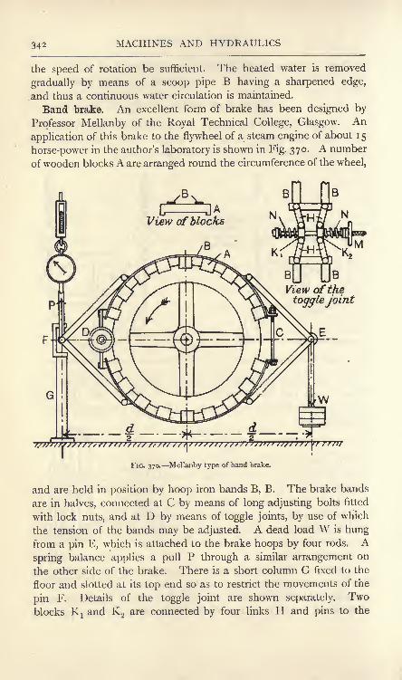
34* MACHINES AND HYDRAULICS
the speed of rotation be sufficient. The heated water is removed
gradually by means of a scoop pipe B having a sharpened edge,
.and thus a continuous water circulation is maintained.
Band brake. An excellent form of brake has been designed by
Professor Mellanby of the Royal Technical College, Glasgow. An
application of this brake to the flywheel of a steam engine of about 1 5
horse-power in the author's laboratory is shown in Fig. 370. A number
of wooden blocks A are arranged round the circumference of the wheel,
B
View of the
togglejoint
FIG. 370. Mellanby type of band brake.
and are held in position by hoop iron bands B, B. The brake bands
are in halves, connected at C by means of long adjusting bolts fitted
with lock nuts, and at D by means of toggle joints, by use of which
the tension of the bands may be adjusted. A dead load W is hungfrom a pin E, which is attached to the brake hoops by four rods. Aspring balance applies a pull P through a similar arrangement on
the other side of the brake. There is a short column G fixed to the
floor and slotted at its top end so as to restrict the movements of the
pin F. Details of the toggle joint are shown separately. Twoblocks Kj and K
2are connected by four links H and pins to the

HIGH-SPEED BRAKE 343
brake bands B. The blocks Kj and K2 may be made to approach one
another and thus shorten the brake bands by means of the long bolt
and the hand wheel M;a feather key in K
x prevents rotation of the
bolt. Helical springs N, N assist the adjustment,
In use, P and W are adjusted very easily so as to be equal. Hence
a pure couple is applied to the wheel, and the shaft bearings are
relieved of carrying any of the dead load W. The toggle-joint
adjustment is very good, and enables the frictional resistance of this
particular brake to be adjusted within very fine limits. In the ori-
ginal large form, a dash-pot is introduced at G to subdue oscillations
of the brake. This has not been found necessary in the smaller
brake used by the author.
It will be noted that both P and W offer resistance to rotation.
Let d= horizontal distance between P and W in feet.
Then B.H.P. =33000 33000
provided P and W are adjusted so as to be equal. If they are not
exactly equal, then their mean, J(W + P), should be taken, giving
B.H.P. =33000
33000
FIG. 371. Brake for high speeds of rotation.
High-speed brake. In Fig. 371 is shown a brake for high speedsof rotation. The brake wheel consists of a flanged wheel mounted

344 MACHINES AND HYDRAULICS
on the second motion shaft of a De Laval steam turbine, and runs
at 3750 revolutions per minute. The brake blocks A, A are made of
Wood, and are pressed to the wheel by means of two bolts B, B fitted
with wing nuts and helical springs C, C, the latter rendering it easy
to adjust and maintain the desired pressure, A steel band 1) is fixed
to the brake blocks, and serves to keep the parts together whenthe brake is removed and also for the application of the loads W
x
and W2. The whole contrivance is balanced when Wj and W
2 are
removed (leaving the suspending rods F, F in position); hence the
effective force is (W l- W
2)Ib. at a radius R feet.
(W,- W2)2jrRNB.H.P. =- 3 .
33000
Other methods of estimating effective horse-power. Hydraulicbrakes have been used for fairly high powers. The principle of
such brakes is to fit a badly designed centrifugal pump to the
engine shaft. The pump wheel and casing are so constructed as
to set up violent eddies in the water, with the result that there is
considerable resistance opposed to rotation of the wheel. The pumpcasing is capable of rotating with the wheel, but is prevented from so
doing by an attached lever and dead weight. The moment of this
weight gives the couple required for the estimation of the energy
absorbed. Brakes of this type were introduced by Professor Osborne
Reynolds, and in his hands served not only for determining the horse-
power of the engine, but also for the determination of the mechanical
equivalent of heat. The latter experiment was carried out by
observing the quantity and rise of temperature of the water passed
through the brake in a given time.
The brake or effective horse-power of very large engines cannot be
determined experimentally by use of a brake. If electrical generators
are being driven, a close estimation may be made from the electrical
energy delivered from the generator, making allowance for electrical
and mechanical waste in the machine.
In electrical installations driven by steam turbines, the electrical
horse-power alone can be measured, as no indicator diagrams can be
obtained from turbines.
Shaft horse-power. Where turbines are adopted on board ships
for driving the propellers, the shaft horse-power is measured, and corre-
sponds to the brake horse-power. The method consists in measuring
the angle of twist in a test length of the propeller shafting by means
of a torsion-meter. The test length is calibrated carefully before
being placed on board, and should be re-calibrated at intervals, so

SHAFT HORSE-POWER 345
that a curve is available showing the moment of the couple required
to produce a given angle of twist. The turning moment on the shaft
is obtained from the angle of twist indicated by the torsion-meter.
Let T = turning moment, in Ib.-feet.
N = revolutions per min.
TX 27TNThen Shaft horse-power =
33000
Shaft calibration In Fig. 372 is shown the method employedat the Thames Iron Works engine department for calibrating the
M
P
Pf
FIG. 372. Arrangement for calibrating a shaft for shaft horse-power.
test length of shaft;
the view is a plan. The shaft AB has
flanged ends solid with the shaft, and is bolted at A to a
very rigid bracket C;a bearing at D supports the other end. A
beam EF is bolted to the end B of the shaft, and couples maybe applied by means of the upward pull of a 5 -ton Denison
weigher at E, and the equal downward force applied by placing
weights in a skip hung from F. GH, KL and MN are balanced
arms fixed to the shaft, and have verniers and scales at the ends
H, L and N which serve to measure the angle of twist inde-
pendently of the torsion-meter. The arm GH is bolted to the
flange at A, and indicates any yielding of the bracket C or of the fix-
ing of the shaft to the bracket. The difference of the readings at L

346 MACHINES AND HYDRAULICS
and N will give the angle of twist of the shaft between the arms KLand MN, and will not be affected by any yielding of the bracket or
other fixings.
The torsion-meter is fixed to the shaft at OP, and is of the
Hopkinson-Thring type ;the lamp and scale are situated at Q. In
Fig. 373 is shown the arrangement of the torsion-meter. C is a
sleeve made in halves and clamped to the shaft AB, which it grips at
its left-hand end. D is a collar, also made in halves, and clamped to
the shaft. The angle through which C twists relative to D is
measured by means of a small mirror at E. The mirror may rotate
slightly about a radial axis on the collar D, and is controlled by a
short rod attached to the sleeve
C at F. A ray of light from the
lamp H is reflected and changedin direction horizontally by the
mirror. Two mirrors are used
at E, placed back to back, and
the ray is reflected to the scale
when E arrives at the top and
also when it is at the bottom;
I
1
1
1
1
1
1
J
1
t
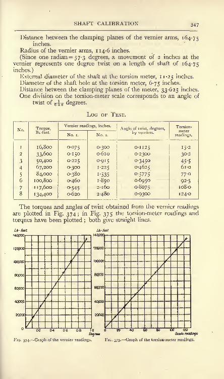
SHAFT CALIBRATION 347
Distance between the clamping planes of the vernier arms, 164-75inches.
Radius of the vernier arms, 114-6 inches.
(Since one radian = 5 7-3 degrees, a movement of 2 inches at the
vernier represents one degree twist on a length of shaft of 164-75
inches.)External diameter of the shaft at the torsion meter, 11-25 inches.
Diameter of the shaft hole at the torsion meter, 6-75 inches.
Distance between the clamping planes of the meter, 33-625 inches.
One division on the torsion-meter scale corresponds to an angle of
twist of -- degrees.
LOG OF TEST.
No.

348 MACHINES AND HYDRAULICS
To check the meter readings, the modulus of rigidity is calculated
(a) from the vernier readings, (b) from the meter readings.
(a) The torque at No. 6 is 100800 x 12 = 1,209,600 Ib.-inches, and
gives an angle of twist of 0-6950 degree = 0-012 13 radian. Using
equation (5) (p. 255) for the angle of twist of a hollow shaft, viz.
2TLa =
/T. d T) 4\r- radians, (i)
and modifying it to suit the case of a shaft of three different external
radii Ra , R&, Rc ,and corresponding lengths La , L&, Lc ,
the same
torque being applied throughout, we have
2TLC
or
4
Lc 1
e4 - R2
4JRa
4 - R24
R&4 - R2
4
= 2X 12096001" 6 24-75,
T 34 "I~TT x 0-01213 [>i25
4 -3-375
4
s-6874 -
3-375' 5-625^-3'375
4J
= 11,774,000 lb. per square inch.
(b) The torque at No. 6 is 1,209,600 Ib.-inches, and gives a scale
reading on the meter of 92-5. Hence,
a =638
* 92 '
5 *5^3
= '00253 radian>
From (i), C
2 x 1209600 x 33-625
~7r(5-6254
3'3754
)x 0-00253
= 11,742,000 lb. per square inch.
The agreement of these values of C is close enough testimony to
the accuracy of the meter. To obtain the shaft horse-power constant,
we have ^ XTou r u T X 27rNShaft horse-power = ,
33000
where T is the torque in Ib.-feet and N is the revolutions per minute.
At No. 6, the torque is 100,800 Ib.-feet and the meter reading is
92-5 scale divisions. Hence,100800
Torque for one scale division = -92-5
= 1090 Ib.-feet.

TRANSMISSION DYNAMOMETERS 349
Let the meter reading be n scale divisions. Then
T= logon Ib.-feet.
109072 x 27rN
33000"i#N
4-82
Hence, Shaft horse-power =
EXAMPLE. At the steam trial of the vessel to which this shaft was
fitted, the mean meter reading was 98 scale divisions at 300 revolutions
per minute. Find the shaft horse-power.
Shaft horse-power= - N4-02
Transmission dynamometers are sometimes used for estimating
the horse-power required to drive a given machine. The principle of
the Froude or Thorneycroft dynamometer is shown
in Fig. 376. A is a pulley on the line shaft;B is
a pulley on a shaft connected to the machine to be
driven. A drives B by means of a belt passing
round pulleys C and D which are mounted on a
frame pivoted at F. When power is being trans-
mitted, the pulls Tj, Tj of the belt are greater than
T2 ,T
2 ; hence a force P applied to the frame at Gis necessary in order to preserve equilibrium. Takingmoments about F, we have
P x GF = (2TXx FC) -
(2T2x FD).
The arms FC and FD are usually equal. Hence,
PxGF = 2FC(T1-T
2),
or
FIG. 376. Froude or
Thorneycroft dyna-mometer.
Let
Then
R = the radius of pulley B in feet.
N = revs, per min. of pulley B.
(T 1-T
2) 27rRNH.P. = * * K .
33000
The more usual method now adopted is to drive the machinedirect by means of an electro-motor and measure the electrical
horse-power consumed.

350 MACHINES AND HYDRAULICS
EXERCISES ON CHAPTER XIV.
1. Calculate what useful work is done in pumping 1000 gallons of
water to a height of 60 feet. If this work is done in 25 minutes, what
horse-power is being developed? Suppose that the efficiency of the
pumping arrangements is 55 per cent., and find what horse-power must be
supplied.
2. A load of 4000 Ib. is raised at steady speed from the bottom of a,
shaft 360 feet deep by means of a rope weighing 10 Ib. per yard. Calcu-late the total work done, and draw a diagram of work.
3. A loaded truck has a total weight of 15 tons. The frictional
resistances amount to 12 Ib. per ton. Calculate the work done in haulingit a distance of half a mile (a) on a level track, (b) up an incline of
i in 80.
4. Find the price in pence per 1000 foot-lb. of energy purchased in
the following cases :
(a) Coal, of heating value 15,000 British thermal units per pound, at
16 shillings per ton.
(b) Petroleum, of heating value 19,500 British thermal units per pound,at lod. per gallon weighing 8-2 Ib.
(c) Gas, of heating value 520 British thermal units per cubic foot, at
2-25 shillings per 1000 cubic feet.
(d} Electricity, at i-$d. per Board of Trade unit.
5. In a machine used for hoisting a load the velocity ratio is 45, andit is found that a load of 180 Ib. can be raised steadily by application of a
force of 12 Ib. Find the mechanical advantage, effect of friction and the
efficiency. Would there be any danger of reversal if the force of 12 Ib.
were removed ?
6. A load of 1200 Ib. is raised by means of a rope provided with an
arrangement for indicating the pull at any instant. The following obser-
vations were made :
Height above ground, 1
feet J

EXERCISES ON CHAPTER XIV. 351
10. In Question 9 a torsion-meter is fitted to a shaft at points 6 feet
apart. Taking C to be 5500 tons per square inch, what angle of twist, in
degrees, will be indicated by the instrument ?
11. In calibrating a propeller shaft by use of the apparatus illustrated
in Fig. 372, the following observations were made : External and internal
diameters of the hollow shaft, 7 inches and 4-017 inches respectively ;
distance between the clamping planes of the vernier arms, 51 inches;
distance between the clamping planes of the torsion-meter, 25-5 inches;
radius of the vernier arms, 105 inches. 24,000 divisions on the meter scale
correspond to an angle of twist of i radian.
Test No.

352 MACHINES AND HYDRAULICS
16. An electrometer lifts 80 tons of grain 100 feet high ;the electric
energy costs 40 pence at the rate of 2 pence per unit. How much electric
energy is used ? What is the efficiency of the lifting arrangements ?
(B.E.)

P^1
>tA.F
CHAPTER XV.
FRICTION
Definitions. When two bodies are pressed together it will be
found that there is a resistance offered to the sliding of one upon the
other. This resistance is called the force of friction. The force which
friction offers always acts contrary to the direction of motion of the
body, or, if the body is at rest, the force tends to prevent motion.
Let two bodies A and B (Fig. 377 (a)) be pressed together so that
the mutual pressure perpendicular to the surfaces in contact is R. Let
B be fixed, and let a force P,
parallel to the surfaces in>[,R
contact, be applied. If P is Anot large enough to produce //)//////! ;// .
sliding, or, if sliding with BjR ^/AI!
R
steady speed takes place, B '*'
will apply to A a frictional
force F equal and opposite to P (Fig. 37 7 ()). The force F mayhave any value lower than a certain maximum, which depends on the
magnitude of R and on the nature and condition of the surfaces in
contact. If P is less than the maximum value of F, sliding will
not occur; sliding will be on the point of occurring when P is
equal to the maximum possible value of F. It is found that the
frictional resistance offered after steady sliding conditions have been
attained is less than that offered when the body is on the point
of sliding.
Let YS= frictional resistance in Ib. when the body is on the
point of sliding.
Ffc = frictional resistance in Ib. when steady sliding has
been attained.
R = perpendicular pressure in Ib. between the surfaces
in contact.
D.M. z

354 MACHINES AND HYDRAULICS
Then
are called respectively the static and kinetic coefficients of friction.
Friction of dry surfaces. For dry clean surfaces, experimentsshow that the following laws are complied with approximately :
The force of friction is practically proportional to the perpendicular
pressure between the surfaces in contact, and is independent of the extent
of such surfaces and of the speed of rubbing, if moderate. Another wayof expressing the same laws is to say that for two given bodies, the
kinetic coefficient of friction is practically constant for moderate pressures
and speeds. It is very difficult to secure any consistent experimental
results on the static coefficient of friction;
it is roughly constant for
two given bodies.
The value of the coefficient of friction in any given case dependson the nature of the materials, especially on the hardness and ability
to take on a smooth regular surface, and on the state of the rubbingsurfaces as regards cleanliness. Rubbing surfaces are made usually
of fair shape and are well fitted to one another. If clean and dry, a
film of air may be present between the surfaces and prevent actual
contact. Pressure and working may squeeze this film out, and the
bodies will then adhere strongly together, or seize. Seizing takes
place more rapidly with bodies of the same than with those of
different materials.
Considerable increase in the speed of rubbing and also heating of
the bodies tend to lower the value of the coefficient of friction. For
this reason, the frictional force produced by the application of the
brakes to the wheels of a locomotive running at high speed is higher
during the first few seconds than is ultimately the case after the
temperature has risen owing to the conversion of mechanical work
into heat. The coefficient rises again when the speed becomes very
slow, and may become sufficiently high to cause the wheels to skid
just before stopping. The coefficient of friction for light pressures
on large areas is a little greater than for heavy pressures on small
areas.
The value of the coefficient of friction to be expected in any given
case cannot be predicted with accuracy on account of the erratic
nature of the conditions. The following table gives average values
only; experimental results will often show considerable variance
with the tabular values.

LAWS OF FRICTION 355
COEFFICIENTS OF FRICTION.
AVERAGE VALUES.
Metal on metal, dry, 0-2 ; oiled continuously, 0-05.
Metal on wood, dry, 0-6; greasy, 0-2.
Wood on wood, dry, 0-2 to 0-5 ; greasy, o-i.
Hemp ropes on metal, dry, 0-25; greasy, 0-15.
Leather belts on iron pulleys, 0-3 to 0-5.
Leather on wood, 0-3 to 0-5.
Stone on stone, 07.Wood on stone, 0-6.
Metal on stone, 0-5.
Fluid friction. For liquids such as water and oils flowing in a
pipe, the following laws are followed approximately :
The Motional resistance is independent of the pressure to which the
liquid is subjected, and is proportional to the extent of the surface wetted
by the liquid.
The resistance is very small at slow speeds ; below a certain critical speedthe motion of the liquid is steady and the resistance is proportional to the
speed; at speeds above this, the liquid breaks up into eddies, and the
resistance is proportional approximately to the square of the speed.
The critical speed depends on the nature of the liquid and on its tem-
perature. Rise of temperature of the liquid diminishes the resistance.
The resistance is independent of the material of which the pipe or channel
is made, but the wetted surface should be smooth ; rough surfaces increase
the resistance.
Friction in machine bearings. The frictional laws for lubricated
machine bearings are intermediate between those for liquids and for
dry surfaces. The ideal bearing would have a film of oil of uniform
thickness, and would run at constant temperature. There would beno metallic contact anywhere, and the resistance would be that of
metal rubbing on oil. In such a bearing, the laws of liquid friction
would be followed, and the resistance would be independent of the
load and proportional to the speed of rubbing. In ordinary bearingsthe resistances experienced depend on the success which is achieved
in getting the oil into the bearing and in preserving the oil film;
the working load is kept sufficiently low to avoid the danger of the
film being squeezed out and seizing occurring.Friction of journals. The value of the coefficient of friction to
be expected in any given case depends largely on the method of
lubrication. In Beauchamp Tower's* experiments, one methodof lubrication adopted was to have an oil bath under the journal
*Proc. Inst. Mechanical Engineers, 1883 and 1884.

356 MACHINES AND HYDRAULICS
(Fig. 378). Remarkably steady conditions were obtained, and it was
found that the coefficient of friction could be expressed by
c-Jv (v
^ =-7-'
<0
where c is a coefficient the value of which depends on the kind of
lubricant used, v is the speed of rubbing in feet per second, / is the
pressure per square inch of projected area of the journal.
Let
FIG. 378. Oil bath lubrication. FIG. 379. Projected area of a journal.
P = the total load on the bearing, in Ib.
d= diameter of bearing, in inches.
L = length of bearing, in inches (Fig. 379).
Projected area of bearing =Then
p=z Ib. per sq. inch ...... (2)d Li
The following table gives some of Tower's results :
JOURNAL FRICTION, OIL-BATH LUBRICATION.
Lubricant.

FRICTION OF JOURNALS 357
It will be noted in (i) above that the coefficient of friction is
inversely proportional to /, and hence is independent of the total
pressure P on the bearing with oil-bath lubrication. It also follows
that the frictional resistance of the bearing will be constant for all
working loads, and will vary as the square root of the speed. Thus,
referring to Fig. 380 :
Let F = the frictional resistance of the bearing, Ib.
P = the load on the bearing, Ib.
Then, from (i) and (2) above
F F fjv
............ ................................. (3)
an expression which is independent of P.
With less perfect systems of lubrication, there is a tendency for the
oil film to be broken partially, and higher coefficients of friction are
obtained. In some cases the coefficient mayreach values from 0-03 to 0-08.
Heating of journals. Work is done against
the frictional resistance and is converted into
heat. Referring to Fig. 380, in which D is the
diameter of the journal in feet, we have
Work done in one revolution = /xPTrD foot-lb.
T T\XT r A. iu FIG. 380. Friction of a
per minute = /xP?rDN foot-lb.,J
journal.
where N is the number of revolutions per minute.
Heat produced =^
British thermal units per minute.
This heat is dissipated by conduction and radiation, but the
temperature of the bearing will rise during the early period of
running. At higher temperatures the oil possesses lower viscosity,
i.e. it flows more easily and offers less resistance to rubbing; hence
less work will be done, and consequently less heat will be producedas the temperature rises. The tendency is therefore to attain a steady
temperature, in which condition the heat developed will be exactly
balanced by the heat carried away by conduction and radiation. It
must be noted, however, that the lower viscosity possessed by the
oil at the higher temperatures increases its liability to be squeezedout
; hence, if steady conditions are to be attained, the load must not
be too great and the oil must be of suitable quality. 100 Fahrenheit
may be regarded as a safe limit of temperature under full working

358 MACHINES AND HYDRAULICS
load. Occasionally the bearings are made hollow, and a water
circulation is provided in order to keep the temperature low. Bearing
pressures up to 3000 Ib. per square inch are used, depending on the
nature of the materials, method of lubrication, means of cooling,
speed of rubbing, and on the consideration of whether the load
always pushes on one side of the bearing or is alternately push and
pull. Forced lubrication is often used, the oil being supplied under
pressure to the bearings by means of a pump.*
Friction of a flat pivot. The case of a flat pivot or foot-step
bearing (Fig. 381) may be worked on the assumption that the
coefficient of friction /* is constant for all parts of the rubbing surface;
the resultant frictional force F will then be found from
If it is assumed that the distribution of bearing pressure is uniform,we have p
Load per unit
FIG. 381. Flat pivot bearing. FIG. 382.
Consider a narrow ring (Fig. 382) having a radius r and a breadth 6>.
Area of the ring= 2irr . &>.
Load on the ring=-^ 27rr - *
Frictional force on the ring=
-=sf?. r. o>.
R2
2?
Moment of this force =-^-
'
To obtain the total moment, this expression should be integratedover the whole rubbing surface
;thus :
2 p fR 2 p R3Total frictional moment ^^oT 1
r^- r~~w^ '
Jo o
=SR.A*P (0= Fx|R (i')
* An excellent discussion of the theory of lubrication and design of machine bear-
ings will be found in Machine Design, Part I., by Prof. W. C. Unwin. Longmans,
1909.

FRICTION OF PIVOTS 359
It is seen thus that the resultant frictional resistance F may betaken to act at a radius equal to two-thirds the radius of the bearing.The frictional moment of a flat pivot may also be solved on the
assumption that the wear is uniform and is proportional to the
product pv, where / is the bearing pressure in Ib. per square inch
and v is the speed of rubbing at any given part of the rubbingsurfaces. Thus, pv = a constant.
Also the velocity v at any point varies as the radius r. Hence,
pr= & constant = a say ;
Considering the narrow ring (Fig. 382) :
Load on the ring =/. 2irr. Sr= 2ira . &r.
Friction on the ring=
27r//^ .r.
Integrating over the whole rubbing surface, we have
fR
Total frictional resistance = F = 2^^a . I drJo
=27T/AflR (2)
Again,
Moment of the friction on the ring= 2ir^ . r. 8r.
The total moment will be obtained by integration of this expressionover the whole rubbing surface
;thus :
fR R2
Total moment of friction =27r/xa .1 r.dr 2ir^a .
Jo 2
=TT/ZtfR2
= FxlR(from( 2 )) (3)
= i/*PR (30
It is probable that the actual value of the moment of friction will
fall between the limits expressed in (i') and (3).
In the case of a collar (Fig. 383), no great error will be made byassuming that F acts at the mean radius i(Rj + R2 ). Hence,
Moment of F = -|/*P(R 1 + R 2)Ib. inches (4)
Tower's experiments on collar friction show that ft is independentboth of speed and pressure unless the pressure I
pis very small. The average value of /* found \ ^.was 0-036. The bearing pressure should not J
[
L
exceed 50 Ib. per square inch. i
|*"R
i
Tower also experimented with a flat pivot _^a
bearing 3 inches in diameter. If Tower's
results obtained lor the moments of friction
be reduced from equation (i),
thus : i
> i
= moment of F x >
FIG. 383. Collar bearings.
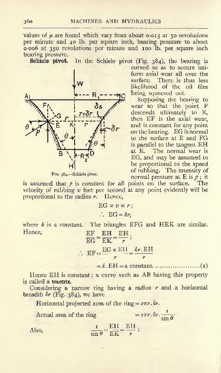
36o MACHINES AND HYDRAULICS
values of /A are found which vary from about 0-015 at 5 revolutions
per minute and 40 Ib. per square inch, bearing pressure to about0-006 at 350 revolutions per minute and 100 Ib. per square inch
bearing pressure.Schiele pivot. In the Schiele pivot (Fig. 384), the bearing is
curved so as to secure uni-
form axial wear all over the
surface. There is thus less
likelihood of the oil film
being squeezed out.
Supposing the bearing to
wear so that the point Fdescends ultimately to E,then EF is the axial wear,and is constant for any pointon the bearing. EG is normalto the surface at E and FGis parallel to the tangent EHat E. The normal wear is
EG, and may be assumed to
be proportional to the speedof rubbing. The intensity of
normal pressure at E is p ;it
is assumed that p is constant for all points on the surface. The
velocity of rubbing v feet per second at any point evidently will be
proportional to the radius r. Hence,
EG oc v oc r;
where k is a constant. The triangles EFG and HEK are similar.
Hence, EF_EH_EH.EG~EK~ r
;
EGxEH Jr.EH. . xLr = =
r r
= /.EH =a constant (i)
Hence EH is constant;a curve such as AB having this property
is called a tractrix.
Considering a narrow ring having a radius r and a horizontal
breadth 8r (Fig. 384), we have
Horizontal projected area of the ring= 2irr. Sr.
Actual area of the ring= 2irr.&r.
sin<9
Also,sin
EHEK
EH .
r

ROLLING FRICTION 361
Actual area of the ring= 21?. r. EH.
Normal pressure on the ring=/x 27r.8r.EH (2)
Friction on the ring= 27r.pn.8r. EH.
Moment of this friction =2-n-p^. EH . r. Br.
Total moment of friction = 27r/^EH I r.drJRS
A .,-jR^-R,2
= 27T^/xEH1
-R22). ...(3)
Again, (2) gives
Normal pressure on the ring=
2?r/.EH ,8r.
The vertical component of this = 2irp. EH. Br. sin
= 2Trp.r.r. ............... (4)
The sum of the vertical components for all the rings composingthe curved surface of the bearing will be equal to W. Hence,
fRi r.dr
-R22) (5)
Substitution of this in (3) gives
Total moment of friction = /*W. EH (6)
The Schiele pivot is not much used in practice on account of the
difficulty of manufacture.
Rolling friction. In rolling friction, such as that of a wheel or
roller travelling on a flat surface, the frictional resistances are roughly
proportional to the load and inversely proportional to the radius of
the wheel or roller. The resistance also depends on the hardness of
the materials, and is comparatively small for very hard surfaces. In
ball bearings, both balls and ball races are made of hardened steel ;
the races are best made concave, to a radius about 0-66 the diameter
of the balls. This plan both reduces the resistance and enables a
heavier load to be carried. In such bearings, the value of /* is
practically constant through wide ranges of speeds and loads; 0-0015
is an average value.
Fig. 385 shows a heavy pattern of ball bearing made by The
Hoffmann Co. and applied to a shackle B for holding one end of a

362 MACHINES AND HYDRAULICS
test piece A undergoing both tension and torsion. The test piece is
screwed to the shackle, the end of which is furnished with a nut C,
which rests on the top ball race D.
The bottom ball race E has its lower
face made spherical to fit the corre-
sponding spherical bottom of the cupF. This arrangement permits the test
piece to accommodate itself to anywant of alignment. A cage G madeof two thin plates, secured together bymeans of four distance pieces, holds
the balls in position and prevents them
from coming into contact with one
another;the cage also prevents any of
the balls being lost when the bearingis taken to pieces. A similar bearingis applied to the other end of the test
piece. The moment of friction is very
small;with a tensile load of four tons
and a test piece i inch in diameter,
it is possible to rotate the whole by
simply gripping the test piece with one
hand.
Resultant reaction between twoPlan of CageF,a.38s.-Hoffmann thrust ball bearing.
g
block A resting on a horizontal table BC. The weight W of the
block will be constant, and will act in a line perpendicular to BC
(b)
FIG. 386. Reactions at the surfaces in contact.
Let a horizontal force P1be applied to the block ;
Pland W have a
resultant Rx
. For equilibrium, the table must exert a resultant force

ANGLES OF FRICTION 363
on the block equal and opposite to Rj and in the same straight line ;
let this force be E15 cutting BC in I). E
x may be resolved into two
forces, one Q perpendicular to BC and the other Fx along BC. Let
</>!be the angle which E
xmakes with GD. Then
F HG
Now, when Px
is zero, <j and hence tan <^ will also be zero, and
Q will act in the same line as W. <x
will increase as Pl increases,
and will reach a maximum value when the block is on the point of
slipping. It is evident that Q will always be equal to W. Let<J> be
the value of the angle when the block slips, and let F be the corre-
sponding value of the frictional force. Then
-pCoefficient of friction = /A
= = tan <.
There will be two values of tan</> corresponding to the static and
kinetic coefficients of friction respectively. When the block is on the
point of sliding, < is called the friction angle or the limiting angle of
resistance;when steady sliding is occurring, < is lower in value, and
may be termed the angle of sliding friction.
It is evident from Fig. 386 (a) that P1and Fj are always equal
(assuming no sliding, or sliding with steady speed), so also are
W and Q. These forces form couples having equal opposing
moments, and so balance the block. The force
Q acting at D will give rise to normal stress of
a distribution as shown by the stress figure in
Fig. 386 (b). The action is partially to relieve
the pressure near the right-hand edge of the
block and to increase it near the left-hand edge.
With a sufficiently large value of /x, and by
applying P at a large enough height above the
table, the block can be made to overturn instead f'T
of sliding. The condition of overturning may ' /
also be stated by reference to Fig. 387. Here FIG. 387 .-Condition that
. ,a block may overturn.
the resultant R of P and W may fall outside the
base AB before sliding begins. Hence E, which must act on AB,cannot get into the same line as R, and the block will overturn.
For overturning to be impossible, R must fall within AB.
EXAMPLE. A wall of rectangular section 2 feet thick is subjected to a
uniform normal pressure on one side of 50 Ib. per square foot (Fig. 388).
Taking the weight of material as 150 Ib. per cubic foot and /A=O7, find

MACHINES AND HYDRAULICS
whether sliding at the base is possible. For what height of wall would
overturning just occur ?
Consider a portion of wall one foot in length, and let H feet be the
height. Then
W= 2H x i5o= 3OoH Ib. per foot run,
F*-i
i
w
= 2ioH Ib. per foot run.
This result represents the maximum possible
value of F.
Again, P= 5oH Ib. per foot run.
Hence, as P will always be much less than the
maximum frictional resistance possible, the wallFIG. 388.-Stability of a w ju nQt ^^
When overturning is just possible, the resultant
of P and W will act through O, and the moments of P and W about Cwill be equal. Taking moments about O, we have
Moment of P 5oH x = Ib.-feet.
Moment of W=3ooH x i = 3ooH Ib.-feet.
Equating these moments gives
H = r2 feet.
Friction on inclined planes. In Fig. 389 (a) is shown a block of
weight W Ib. sliding steadily up a plane of inclination a to the
FIG. 389. Friction on an incline ; P horizontal.
horizontal, under the action of a horizontal force P Ib. Draw ANperpendicular to the plane ;
then the angle between W and AN is
equal to a. Draw AC making with AN an angle < equal to the
angle of sliding friction ; the resultant reaction R of the plane will
act in the line CA. The relation of P to W is deduced from the
triangle of forces ABC.

FRICTION ON INCLINED PLANES
or
P _ tan a + tan <
W ~i - tan a tan <k
P =
(P. 8),
i - /A tan a/
The case of the block sliding down is shown in Fig. 389 ().R acts at an angle <f>
to AN, but on the other side of it.
P"D/~'-DV^ / , x
...(I)
Here
P _ tan <j>- tan a
W ~i+ tan a tan </>'
p_w/>-tanaY+ /Uana/
It will be noted in the last case, that if<f>
is less than a, the blockwill slide down without the necessity for the application of a force P.
Rest is just possible, unaided, if a is equal to the limiting angleof resistance.
When P is applied parallel to the incline, the forces are as shownin Fig. 390 (a) and (<). For sliding up (Fig. 390 (a)), we have
P EC = sin BAGW~AB~sin ACB
sin (a -f ft) _ sin a cos <ft 4- cos a sin (ft~sin (90
-<f>)
~cos
<j>
= sin a + cos a tan <;
FIG. 390. Friction on an incline ;P parallel to the incline.
For sliding down (Fig. 390 ()), we have
P _ EC _ sin BAGW~AB~sinACB
sin (<-
a) sin cos a - cos < sin a
sin (90-
<f>)
= tan(f)cos a - sin a ;
P =W (/* cos a - sin a).
cos
(4)

366 MACHINES AND HYDRAULICS
Friction of a screw. The results for a block on an inclined planeand acted on by a horizontal force may be applied to a square threadedscrew. Such a screw may be regarded as an inclined plane wrappedround a cylinder. In Fig. 391 are shown two successive positionsA and B of a block of weight W Ib. being pushed up such an inclined
FIG. 391. Inclined plane wrappedround a cylinder.
1
FIG. 392. Friction ofa square threadedscrew.
plane by means of a horizontal force P Ib. In the actual mechanism,the load is applied over a considerable portion of the surface of the
incline (Fig. 392), and P may be assumed to act at the mean radius
R inches of the screw. Let p inches be the pitch of the screw, andlet one turn of the thread be developed as shown in Fig. 393.
^_ p~27rR
Using equation (i), p. 365, we have, for raising W,
P-wf tanct +/*\\i -/A tan a/
'T / /P ___/7ru+/^
=w 27rR
I -
FIG. 393. Development of one turn of ascrew thread.
27TR,
For lowering the load, P in Fig. 393 will be reversed in direction
usually, and equation (2), p. 365, should be used :
i + /x tan\
a/

FRICTION OF SCREWS 367
If p = tan a, or if 27rR/z =ptP will be zero, and the load will be
on the point of running down unaided. Running down with
continually increasing speed may occur if tan a is less than /*, and
may be prevented by application of a force P given by (2) aboveand applied in the same sense as for raising the load. If rotation
of the screw is produced by means of a force Q Ib. applied to a
spanner at a radius L inches, the nut being fixed, we have
= PR,
p (3)
The above solution is applicable to the case of a screw-jack
(Fig. 411), the friction of the screw alone enters into the problem.The efficiency of such an arrangement may be calculated by con,
sidering the screw to make one revolution in raising the load. Then
^ r/. . Work done on WEfficiency
=
Also,
.'. Efficiency=
Substituting for W/P from equation (i) above, we have
,- . / 2?rR pli<\ p / x
Efficiency=
(
~-) -*-=; (4)
V/+27TR/V 27TR
If n be the ratio of the mean circumference 2?rR to the pitch /,so that 2?rR ==
np) equation (4) may be written :
Efficiency=
p + npp. n
l
EXAMPLE. In a certain square threaded screw, n=io and ^=0125.Find the efficiency while raising a load.
10-0-125
=0-44= 44 per cent.
In tightening a nut on a bolt (Fig. 394), not only has the momentof the friction of the screw to be considered, but also the friction
between the nut and the part against which it is being rotated.

368 MACHINES AND HYDRAULICS
Let Rxbe the mean radius of the bearing surface in inches and W Ib.
be the pull on the bolt. Then
Moment of F = /xWRj Ib.-inches (6)
FIG. 394. Friction of a nut. FIG. 395. Friction of a V thread.
Let P Ib. be the frictional resistance of the screw, found from
equation (i), p. 366, and let R be the mean radius of the threads.
Then QL = /xWR1 + PR (7)
In V threaded screws (Fig. 395), the pressure between the bearingsurfaces of the nut and the bolt threads is increased. If W is the
load, it should be resolved into a force S perpendicular to the thread
section and another horizontal force. ThenW
s-w
, o 7)
COS/5
where /? is half the angle of the V. All the results found for squarethreaded screws may be used for V threaded screws by writing
fi sec /3 instead of/x.
in the equations.
Friction circle for a journal. It is useful to consider the friction
of a journal A resting on a loosely fitting bearing B (Fig. 396(0)).
I I
FIG. 396. Friction of a loose bearing.
If there is no rotation, the load W on the journal will be balanced
by an equal opposite reaction Q applied by the bearing. Let a

FRICTION CIRCLE 369
couple of moment T be applied to the journal, of sufficient magni-tude to produce steady rotation in the direction shown (Fig. 396 (b) ).
The journal will roll up the bearing until the place of contact is,
at which steady slipping will occur. The condition which fixes the
position of b is that the vertical force Q acting at b must make an
angle <f>with the normal ab, <f> being the angle of sliding friction. Q
and W being still equal, form a couple of moment W x fa, and this
couple balances T, the couple applied. Hence,
be,
be .= tan <P=
, very nearly ;
ac ab J J 'Also,
(I)
This will be in Ib.-feet if r is in feet and W is in Ib.
It will be noted that Q is tangential to a small circle of radius f,
drawn with centre a. This circle is called the friction circle, and its
radius is equal to be. Hence,Radius of friction circle =/= r tan < very nearly
= nr feet, (2)
where ft= tan <, is the coefficient of friction,
r= radius of journal in feet.
The same result is true for a closely fitting bearing (Fig. 397).
Here R Ib. is the resultant reaction of the bearing, the componentsof which are Q, the resultant vertical reaction and F the resultant
frictional force. R acts at an angle </> to Q for the direction of
rotation as shown, or on the other side of Q for i
the contrary direction of rotation In either
case, R is tangential to the friction circle, and
gives a moment R/ Ib.-feet opposing rotation.
To obtain the work done, we have
Frictional couple = R/ Ib.-feet,
Work done in one revolution = R/x 2?r foot-lb.
Let N = revolutions per minute.
Then Work done per minute = 27rNR/foot-lb.,
, 27TNR/H.P. wasted = -
33000The value of R is given actually by FIG. 397.-Friction circle
a bearing.
but as the coefficient of friction and hence the frictional resistance is
very small for well lubricated journals, no great error is made by
taking R equal to Q, the load on the journal.
D.M. 2 A

MACHINES AND HYDRAULICS
EXAMPLE i. In a machine for raising a load W the load is suspendedfrom a rope wound round a drum A, 8 inches in diameter, to the ropecentre (Fig. 398). The axle on which the drum is fixed has journals
1-5 inches in diameter, and is rotated by a toothed
wheel B, 18 inches in diameter, to which a force
P is applied. Find the mechanical advantageand efficiency of the machine, taking the co-
efficient of friction of the bearings to be o-i and
W to be a load of 500 Ib.
Neglecting friction, and taking moments about
the centre of the drum, we have
W x 4 = P x 9,
W 9-p=7= 2 '2 5 (0
FIG. 398. Friction of a simplemachine. (2)
Taking account of friction, and assuming that R is equal sensibly to
(P-f-W), we have, by taking moments about the centre of the drum,
Also,
inch.
.'. 2000+ (P+ 500)
Hence,
p^ 2037-5x40357
= 228-3 Ib. -
W 500Mechanical advantage =-5- = -^-Qr 220-3
(3)
(4)
Let the drum make one revolution. ThenWork done by P = Px;r. 18 inch-lb.
Work done on W=W x TT . 8 inch-lb.
, . 87rW 8x500Efficiency-^- i
=0-97= 97 per cent............................ (5)
EXAMPLE 2. The mechanism shown in Fig. 399 consists of a crank OAfixed to a shaft having OZ for its axis of rotation. The crank is driven in
the direction of rotation shown, by means of a slotted bar B ; a block C
may slide in the slot, and has a hole to receive the crank pin. The force
P pushes during the stroke from right to left, and pulls during the return
stroke. Show by drawing how the turning moment on the crank, as
modified by friction, may be obtained. Give the construction for each
quadrant, assuming /x tan <> is the same for both block and pin.

FRICTION IN A SLOTTED-BAR MECHANISM 371
In answering this question it is essential to remember that the force
which the block gives to the crank pin must be tangential to the friction
circle, and must act so as to oppose the motion of rotation of the pin.
PLANFIG. 399. Crank and slotted-bar mechanism.
Further, the force which the slotted bar gives to the block must act at an
angle <f>to the normal, and must be applied so as to oppose the sliding
motion of the block. For ordinary values of the coefficient of friction
these forces, shown by R in Fig. 400, will be very nearly equal to P.
M _.-
FIG. 400. Friction of the block and crank pin in Fig. 399.
The constructions required are shown in Fig. 400 (a) to (d}. In the first
and fourth quadrants (a) and (d} the block is sliding upwards, and in the

372 MACHINES AND HYDRAULICS
second and third quadrants (b) and (c) it is sliding downwards. In each
case the turning moment is RxOM, OM being drawn perpendicular to
R from O, the centre of the crank shaft.
Friction of the crank pin and the crosshead pin. Figs. 401 (a)
and (b) show the application of the friction circle method to the
determination of the line of thrust along a connecting rod, whenaccount is taken of the friction at the crank pin and the crosshead
pin. The diameters of the friction circles at A and B are calculated
and the circles drawn. The line of thrust Q will be a common
tangent to these circles for any given crank position. Draw OMperpendicular to the line of Q; the turning moment on the crank will
be Q x OM. No difficulty will be experienced in choosing the line
of Q if it is remembered that the frictional moments at A and B both
tend to reduce the turning moment on the crank; hence the common
tangent which gives the line of Q must be so drawn as to make OM
S'3-
FIG. 401. Friction of the crank pin and crosshead pin in a crank and connecting rodmechanism.
a minimum. Thus, in Fig. 401 (a), Q touches the top of the circle at
A and the bottom of that at B; in Fig. 401 (b\ Q touches the bottom
of both circles. The change in the line of Q from the top to the
bottom of the circle at A takes place when the crank makes 90 with
the centre line OA ;in this position, the connecting rod makes its
maximum angle with the centre line OA and has no angular motion
for an instant, i.e. at this point the crosshead pin is not rubbing in its
bearing. The solution for other positions is given at Q' in Figs. 401
(a) and (b).
In Fig. 401 (b), it will be noted that, as B' approaches the inner
dead point, the line of Q' will pass through O. In this position there
is no turning moment oh the crank. Further, the crank must rotate
through a small angle beyond the dead point before the line of Q will
pass above O. There will, therefore, be a small crank angle near
each dead point in which there will be no turning moment tending to
rotate the crank in the direction of rotation of the crank shaft. These
angles may be determined approximately as follows: In Fig. 402, O is
the crank shaft centre and A is the crosshead pin at the end of the

FRICTION IN A CRANK AND CONNECTING ROD 373
stroke. Draw the friction circle at A;draw the lines of Q and Q'
touching the circle at A and passing through O. Draw the friction
FIG. 402. Angle of zero turning moment due to friction at the crank and crosshead pins ;
inner dead point.
circles at B and B', touching the lines of Q and Q' ; then BOB' is the
angle within which there is zero turning moment near the inner dead
B
FIG. 403. Angle of zero turning moment due to friction at the crank and crosshead pins ;
outer dead point.
point. The construction for the outer dead point is given in Fig.
403, and will be followed readily.
Friction of the crank-shaft bearings. The loads producingfrictional resistances at the crank-shaft bearings include the weightof the shaft and its attachments, belt
pulls or other forces due to the driving
of machinery and a reaction owingto the thrust of the connecting rod.
Considering the latter alone, and
referring to Fig. 404, Q is the thrust
of the connecting rod, making allow-
ance for the friction of the crosshead
pin and the crank pin as illustrated
in Fig. 401 (a). A force Q', equal,
opposite and parallel to Q is applied by the crank-shaft bearing to
the shaft, Q and Q' together forming a couple which causes the shaft
FIG. 404. Friction of the crank-shaft
bearings.

374 MACHINES AND HYDRAULICS
to rotate. During rotation, Q' will be tangential to the friction circle
for the shaft and is so shown in Fig. 404. Draw OM perpendicular
to Q and cutting the shaft friction circle at O'. The effective turning
moment will be Q x O'M, and has been diminished by an amount
Q x OO' by reason of the friction produced by Q in the shaft bearings.
Near the dead points, the effect of the friction at the crosshead pin,
crank pin and crank-shaft bearings is that there will be a small angle
embracing each dead point within which no force, however great,
along the piston rod will cause the shaft to rotate if at rest. These
FIG. 405. Dead angle at inner dead point.
angles are called dead angles and are shown at BOB' in Figs. 405 and
406. The construction is similar to that in Figs. 401 (a) and (b\
with the addition of the friction circle at O for the crank-shaft
bearings. The lines of the forces Q and Q' are tangential to the
friction circles at A and O, and the friction circles at B and B' are
drawn to touch the lines of the forces, produced if necessary.
FIG. 406. Dead angle at outer dead point.
The student will note that the dead angles so found take account
only of the friction at the crank-shaft bearings produced by the
thrust of the connecting rod. If at rest, the crank shaft will not
commence rotation until the turning moment Q x O'M (Fig. 404) is
large enough to overcome the resisting moment due to the total
.friction at the crank-shaft bearings together with the resistances
offered by any machinery to be driven.
Experiments on friction. Experiments have been described in
Chapter XIV., in which the general effect of friction in the complete
machine was one of the factors to be determined. The following
additional experiments may be performed usefully.

EXPERIMENTS ON FRICTION 375
EXPT. 38. Friction of a slider. AB is a wooden board or flat pieceof metal having its top surface brought horizontal by means of a spiritlevel (Fig. 407). A slider C, of wood or metal, may be drawn alongAB by means of a horizontal force P applied by using a cord, pulleyand scale pan. The uppersurface of AB and the undersurface of C should be clean
and dry. Weigh the slider Cand also the scale pan. R is
the perpendicular reaction of
the surfaces in contact, andis equal to the weight of the
P
1

376 MACHINES AND HYDRAULICS
having bearings constructed to reduce friction as much as possible.The board should be levelled carefully, and the tractive effort P
required to draw the carriage steadily along should be found for
different loads on the carriage. It is useful to have three or four
different roads for the carriage to run on; these may be of plate glass,
SH
FIG. 409. Apparatus for rolling friction.
metal, wood and rubber. The effect of the varying degrees of hard-
ness should be contrasted by comparing the results for the different
roads, and this may be done easily by plotting tractive effort and load
for each road on the same sheet of squared paper.
EXPT. 41. Effect of speed of rubbing. In Fig. 410, A is a wheel
which may be rotated at different speeds by some source of power.B is a block which is pressed on the rim of the wheel by means of a
shackle C and a load D. The block B is restrained from rotation
FIG. 410. Apparatus for investigating the
effect of speed of rubbing.
FIG. 411. Experimental screw-jack.
by a cord and another load at E. The perpendicular pressurebetween the block and the wheel will be the weight of the block,
together with those of the shackle, scale pan and load. The force
of friction will be nearly equal to the combined weights of the scale
pan and load at E. Hence /* may be determined for different speedsof rubbing. It will be observed that the friction is greater on
starting with both wheel and block cold, and diminishes after a few
seconds as the rubbing parts become warm. The experiment should
be repeated with blocks of different materials.

TESTING OF LUBRICANTS 377
EXPT. 42. Friction of a screw. The screw-jack shown in Fig. 411may be experimented on in the same manner as that explained in
Chapter XIV. for other types of lifting machines.
Testing of lubricants. The mechanical testing of lubricants is
performed usually by feeding the lubricant into a test bearing, which
may be loaded and run at varying speeds. Provision is made for
measuring the torque required to rotate the shaft and also for
measuring the temperature of the oil. There are many different
forms of machine. One which has given useful information in the
hands of Messrs. W. W. F. Pullen and W. T. Finlay at the South-
western Polytechnic* is shown in Fig. 412. A shaft AB is loaded
FIG. 412. Pullen's machine for testing lubricants.
with two equal flywheels C and D; the central enlarged portion of
the shaft runs in a bearing and is lubricated by means of a loose
ring G, which hangs freely on the shaft and dips into an oil bath;
the ring revolves slowly as the shaft rotates. The oil leaving the
bearing is spun off by collars F, F fixed to the shaft and having several
sharp edges to prevent the oil travelling axially along the shaft ; the
oil is thus returned to the oil bath and is used again. K is a gaugetube indicating the quantity of oil in the bath. The temperature of
the oil is controlled by a U tube H, through which water may be
circulated. A gas flame in the space J under the bath can be used
to raise the temperature of the oil. The temperature is measured
by a thermometer suspended in the oil. The machine is direct
driven by an electromotor arranged as shown in Fig. 413. Themotor A has its bearings supported by rollers B, C and D, and is
*Proc. Inst. Meek. Eng., 1909.

378 MACHINES AND HYDRAULICS
therefore free to rock about its axis. A balance weight is fitted at E,and a counterpoise F serves to measure the torque. The shaft
runs in the direction of the arrow, and the rotor of the machine
applies a torque of oppositesense to the stator; this torqueis balanced by the counter-
poise, and is equal to the
torque required to drive the
oil-testing machine. This
type of machine is very useful
for testing oils under steadyload and under different con-
ditions as regards speed andFIG. 413. Arrangement of electromotor for diiving
Pullen's machine. temperature.
EXERCISES ON CHAPTER XV.
1. A shaft journal is 4 inches in diameter and has a load of 4000 Ib.
If the coefficient of friction is 0-06, find the torque resisting the motion.Calculate also the energy absorbed in foot-lb. per minute in overcomingfriction
; to what heat in B.T.U. is this energy equivalent ? The shaftrevolves 150 times per minute.
2. A vertical shaft is supported on a flat pivot bearing 2 inches in
diameter and carries a load of 150 Ib. The shaft revolves 300 times
per minute. Take ^=0-03, and calculate the moment of the frictional
resistance, (a) assuming that the distribution of bearing pressure is uniform,(b] assuming that the wear is uniform. In each case calculate the horse-
power absorbed by the pivot.
3. The thrust of a propeller shaft is taken by 6 collars, 12 inches
diameter, the rubbing surface inner diameter being 8 inches. The shaftruns at 120 revolutions per minute. Take /x
=o-o5, the bearing pressure
60 Ib. per square inch of rubbing surface, and find the horse-powerabsorbed by the bearing.
4. A block weighing W Ib. is dragged along a level table by a forceP Ib. acting at an angle 6 to the horizontal. The coefficient of friction
may be taken of constant value 0-25. Obtain the values in terms of W,(a) of P, (b) of the work done in dragging the block a distance of one foot.
Give the results when 6 is o, 15, 30, 45, 60, and 75 degrees. Plot graphsshowing the relation of P and 0, and also the relation of the work doneby P and 6.
5. A block weighing W Ib. is pushed up an incline, making an anglewith the horizontal. The coefficient of friction has a constant value of
0-25. Find in terms ofW (a) the values of the force P Ib., parallel to the
incline, (&) the work done in raising the block through a vertical height ofone foot. Give the results for 6 equal to o, 15, 30, 45, 60, 75 and 90degrees. Plot graphs for each case, (a) and (^

EXERCISES ON CHAPTER XV. 379
6. Answer Question 5 if P is horizontal. What is the value of 6 whenP becomes infinitely great ?
7. In a screw-jack the pitch of the square threaded screw is 0-5 inch
and the mean diameter is 2 inches. The force exerted on the bar used in
turning the screw is applied at a radius of 21 inches. Find this force if
a load of 3 tons is being raised. Take ^=0-2. What is the efficiency of
this machine ?
8. With the screw-jack given in Question 7, find the force required at
the end of the bar in order to lower the load of 3 tons.
9. Show that the horizontal force required to move a weight W up a
plane whose slope is i is W % ,where fi is the coefficient of friction.
A right- and left-hand square-threaded screw (pitch 0-25 inch, meandiameter of thread I inch) is used as a strainer. Find the couple requiredto tighten against a pull of looo Ib. ^=0-15. (I.C.E.)
10. In a i -inch Whitworth bolt and nut take the dimensions as
follows : pitch, 0-125 inch; angle of the V thread, 60 degrees ;
meandiameter of the thread, 0-8 inch
;mean radius of the bearing surface of
the nut, 0-9 inch. Take the coefficient of friction to be 0-2 for both the
screw and the nut. Find the force required at the end of a spanner15 inches long in order to obtain a pull of 1000 Ib. on the bolt.
11. A horizontal lever, instead of having a knife edge as a fulcrum, is
pivoted on a pin 2 inches in diameter. The arms of the lever are 8 inches
and 5 feet respectively. The coefficient of friction for the pin is 0-2.
What load at the end of the short arm can be raised by a vertical pull ofloo Ib. at the end of the long arm ? (B.E.)
12. The arms of a bent lever ACS are at right angles to one another;
AC is 12 inches long and is horizontal ; BC is 27 inches long, and B is
vertically above C. The lever may turn on a fixed shaft 3 inches in
diameter at C. A load of 2000 Ib. is hung from A. Find what horizontal
force is required at B (a) if A is ascending, (b) if A is descending. Takethe coefficient of friction for the shaft to be o-i.
13. In the mechanism shown in Fig. 399, the crank OA is 6 inches
long and has anti-clockwise rotation;the crank pin at A is 2 inches in
diameter and the width of the slot in the bar is 2-75 inches. Take the
force P as constant and equal to 1000 Ib.;find the turning moment on
the crank in each of the four positions when the crank makes 45 degreeswith the line of P, (a) neglecting friction, (b) taking account of friction.
The coefficient of friction for all rubbing surfaces may be taken as o-i.
14. In the crank and connecting-rod mechanism of an ordinary steam-
engine, the crank and connecting-rod are 7 inches and 30 inches longrespectively. The diameter of the crank pin is 3-5 inches and that of
the crosshead pin is 3 inches. When the crank has travelled 45 degreesfrom the inner dead point the total force urging the crosshead is
3000 Ib. Find the turning moment on the crank for this position, taking/z for the crank pin and crosshead pin to be 0-06. Find both angles in
which there is zero turning moment on the crank.
15. Determine an expression for the work absorbed per minute in
overcoming the friction of a collar bearing. State the assumptions made

380 MACHINES AND HYDRAULICS
in deriving the formula. The thrust in a shaft is taken by 8 collars
26 inches external diameter, the diameter of the shaft between the collars
being 17 inches. The thrust pressure is 60 lb.- per square inch, thecoefficient of friction is 0-04, and the speed of the shaft is 90 revolutions
per minute. Find the horse-power absorbed by the friction of the thrust
bearing. (L.U.)

CHAPTER XVI.
VELOCITY. ACCELERATION.
Velocity. The Velocity of a body may be defined as the rate at
which the body is changing its position. The four elements which
enter into a body's velocity are : (a) the distance travelled, (b, the
time taken to travel this distance, (c) the direction in which the bodyis moving, (d) the sense along the line of direction ; the sense may be
described as positive or negative. A body having uniform velocity will
travel equal distances in equal intervals of time, and the velocity
may be calculated by dividing the distance by the time. In the
case of varying velocity, the result of this calculation will be the
average velocity of the body.The units of time employed are the mean solar second, minute, or
hour. The unit of distance may be the foot, mile, centimetre, metre
or kilometre. Common units of velocity are the foot per second, the
mile per hour, the centimetre per second, and the kilometre per hour.
Let s = distance travelled in feet,
t= time taken, in seconds,
v = the velocity.
Then v = - feet per second.
This will be the velocity at any instant if the rate of travelling is
uniform, and will give the average velocity if the rate is varying.
Distance-time diagrams. In Fig. 414, the distances travelled bya given body have been set off as ordinates on a time base. Thus
iA is the distance travelled during the first second of the motion,
26 is the distance travelled in the first two seconds, and so on. 6Fis the total distance travelled in 6 seconds. Drawing AG, BH, CK,etc., horizontally, it is evident that BG is the distance travelled
between the end of the first second and the beginning of the third,
CH is the distance travelled during the third second, DK, EL and
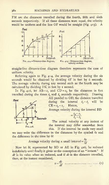
MACHINES AND HYDRAULICS
FM are the distances travelled during the fourth, fifth and sixth
seconds respectively. If all these distances were equal, the velocity
would be uniform and the line OF would be straight (Fig. 415). A
FIG. 414. Distance-time diagram.
4 5 ^Seconds
FIG. 415. Distance-time diagram,velocity uniform.
straight-line distance-time diagram therefore represents the case of
uniform velocity.
Referring again to Fig. 414, the average velocity during the six
seconds would be obtained by dividing 6F in feet by 6 seconds.
The average velocity during any second such as the fourth may be
calculated by dividing DK in feet by i second.
In Fig. 416, let AB = 5>
1and CD = J
2be the distances in feet
travelled during the times t^ and /2 seconds respectively. Drawing
AE parallel to OD, the distance travelled
during the interval /2 ~^i will be
CE = s2- s
l. Hence,
Average velocity during the interval BD
Feet
Sa
SecondsThe actual velocity at any instant of
the interval may differ somewhat from
this. If the interval be made very small
we may write the difference in the distances by the symbol 8s and
the difference in the time by 8t.
Average velocity during a small interval =^-.
Now let S/, represented by BD or AE in Fig. 416, be reduced
indefinitely until finally it gives us the conception of an "instant." If
dt is its value when so reduced, and if ds is the distance travelled,
then, at the instant considered,ds v

VELOCITY 383
The velocity of a body at any instant may be described as the
distance which would be travelled during the next second had the
velocity possessed at the instant considered remained uniform.
The mathematical calculation involved in (i) above is performed
by use of the rules of the differential calculus (p. 9).
EXAMPLE. Suppose the equation connecting s and / for the motion of
a given body to be _ ! ,2
where a is a constant. Find the velocity at any instant.
ds d
= at.
If the time up to the required instant be inseited in this result, the
velocity at that instant will be obtained.
In dealing with a moving point in a machine the space-time
diagram may be drawn by setting out the mechanism in a number
of positions differing by equal intervals of time, and then measuringthe distances travelled by the point in question. The average
velocity over each of the intervals may be obtained very closely
from the diagram.
EXAMPLE i. A rigid bar AB, 3-1 feet in length, moves so that one
end A is always in OX (Fig. 417), and the other end B is always in OY,which is perpendicular to OX. A is
at first 3 feet from O and travels to
O in 6 seconds with uniform velocity.
Draw the space-time diagram for B.
Divide AO into six equal intervals
as shown. A will traverse each
interval in one second.
Velocity of A (uniform)= 1=0-5 foot per sec.
Find the positions of B for each
position of A ;these are numbered
i', 2', 3', etc. to correspond with the
numbering of the positions of A.
Measure Bi', 62', 63', etc.; these X
will be the distances travelled by Bin I, 2 and 3 seconds respectively.
FIG. 417. A rigid bar AB ; A moves in OX ;
B moves in OY.
Choose suitable scales and draw the space-time diagram (Fig. 418), by
setting off the distances travelled by B up to the stated times. The
numbering i', 2', 3', etc. in this diagram agrees with that in Fig. 417.

MACHINES AND HYDRAULICS
EXAMPLE 2. Find from Fig. 418 the average velocity of B for each
interval of time and draw a velocity-time diagram.The average velocity during the third second may be obtained by
dividing H3' in feet by 0-5 second. It is preferable to measure 33' and
Feet
20

ACCELERATION 385
SecondsFIG. 419. Velocity-time diagram for the point B
in Fig. 417.
while its base represents the time to scale. The area of the diagramis its average height multiplied by its base and therefore representsthe distance travelled. Toobtain the scale: Feetper sec.
Let
i inch of height represent v
feet per second,
i inch of length represent /
seconds.
Theni square inch of area repre-
sents vt feet.
Hence, the area of the velo-
city-time diagram, in square
inches, multiplied by vt will give the distance travelled.
Acceleration. Acceleration means rate of change of velocity ;it is
measured by dividing the change in velocity by the time in which
the change is effected. The change in velocity may be either positiveor negative, depending on whether the velocity is increasing or
diminishing, and the accelera-
tion will have the same sign.
If the change in velocity is
stated in feet per second, and
if the time in which the changetakes place is stated in seconds,
__ then the units of the accelera-
tion will be feet per second persecond.
Acceleration may be studied
from the velocity-time diagram.
Fig. 420 shows such a diagramin which a velocity z/
xoccurs at the end of a time /
xand a velocity
v2
at the end of /2 ;
these velocities are represented by AB andCD respectively. The change in velocity an increase in this
case is DE.
Change in velocity= v* - v
l.
Time in which this change is effected = /2-
.'. Acceleration during the interval AC
This expression will be strictly correct if the gain in velocity is
D.M. 2 B
Velocity
FIG. 420. Deduction of acceleration from avelocity-time diagram.

386 MACHINES AND HYDRAULICS
acquired uniformly throughout the interval, in which case BD would
be straight. If BD is curved, then the value given by (i) will be the
average acceleration over the interval. The acceleration at anyinstant may be calculated by diminishing /
2-^ indefinitely, when
dvAcceleration = a = .
at<*)
Feet per sec
2 -ix
In the interval FH (Fig. 420), the change in velocity is a decrease,
shown by GL. If the acceleration at A is positive, that at F will be
negative. At M, where the tan-
gent to the curve is horizontal,
there is no change in the
velocity over an indefinitely
small interval of time, and
hence there is no acceleration.
An acceleration-time diagram
may be deduced from the
velocity-time diagram by the
method already applied in
Example 2, p. 384, for obtain-
ing a velocity-time diagram from a space-time diagram. The average
acceleration over any interval is set out as an ordinate at the middle
of the interval.
EXAMPLE. Taking the data of Example i, p. 383, and the velocity-
time diagram (Fig. 421, redrawn from Fig. 419) from Example 2, p. 384.
draw an acceleration-time diagram.The tabular form of calculation may be adopted as follows :
SecondsFIG. 421. Velocity-time diagram for the point B
in Fig. 417.
Interval No.

ACCELERATION 387
The last column is plotted at the middle of the intervals as shown in
Fig. 422, and a fair curve is drawn through the plotted points, thus
obtaining the acceleration-time diagram.
6 Seconds
-1-0-
Feet per sec.persec.
FIG. 422. Acceleration-time diagram for the point B in Fig. 417.
If the distance travelled is given by an equation connecting s and
/, the acceleration may be found by two successive differentiations.
Thus : Let -
where c is a constant. Thends
dv
The indices in simply indicate that s has been differentiated
twice with respect to / (p. 12).
Equations for uniform acceleration. Reference is made to Figs.
423 and 424, the former showing the velocity-time diagram for a
VetoedVelocity
k -------\Time
FIG. 423. Velocity-time diagram,starting from rest.
FIG. 424. Velocity-time diagram,starting with velocity z>j.
body starting from rest; Fig. 424 shows the diagram if the body starts
with a given velocity vl ; in both cases the acceleration is uniform.

388 MACHINES AND HYDRAULICS
Starting from rest (Fig. 423) :
Let v = the velocity in feet per second,
/= the time in seconds taken to acquire ,
s = the distance travelled, in feet,
a = the acceleration, feet per sec. per sec.
By definition, a = ->
or, v = at...........................................(i )
s = the average velocity x t;
'. s = Jvt........................................... (2)
Or, s = the area of the diagram= / x ^v t x \at (from (
i) ) ;
'. - = JaA ....................................... (3)
From(i), / = -
v2 v2
Inserting this in (3), s = \a-^=
;
.'. v2 = 2as........................................... (4)
Starting with a velocity i\ (Fig. 424) :
Let ^ and v.2= the initial and final velocities respectively
in feet per second,
/=the time in seconds in which v\ increases
to2 ,
s = the distance travelled, in feet,
a = the acceleration, in feet per sec. per sec.
Then v2-v
l= &t........................................... (5)
s = the average velocity x /
Or, s = the area of the diagram=rectangle OCDA + triangle CDB
= !/+(/x JDB).
Also, BD = /;
/. B = v1t+Jat2.................................. (7)
From (5), ;= -

TRIANGLE OF VELOCITIES AND ACCELERATIONS 389
Inserting this in (6), s =
(8)
The case of a body falling under the action of gravity is one of
nearly uniform acceleration. The acceleration would be quite
constant, but for the resistance offered by the atmosphere, and for
the fact that a body weighs less when at a height above the surface
of the earth. The symbol g is used to denote the acceleration of a
body falling freely, that is, neglecting atmospheric resistances. Thevalue of g varies to a small extent, being about 32-088 feet per second
per second at the equator and about 32-252 at the poles. The value
32-2 may be taken for all parts of the British Isles. The equationsfound above may be modified to suit a body falling freely, by writing
g instead of a, and the height h feet instead of s.
Composition and resolution of velocities and accelerations. Agiven velocity is a vector quantity and may be represented in the
B a
FIG. 425. Triangle and parallelogram of velocities.
same manner as a force by a straight line having an arrow point.
Hence problems involving the resolution or composition of velocities
may be solved in the same way as for forces by the application of the
triangle or polygon of velocities.
Let a point A have component velocities Vxand V
2in the plane
of the paper (Fig. 425). The resultant velocity may be found from
the triangle abc in which ab represents V]5be represents V2
and ac
gives the resultant velocity V which should be shown applied at A.
A parallelogram of velocities, ABDC, may be used by making AB = Vl
and AC =V2 ;
the diagonal AD gives the resultant velocity.
Rectangular components of a given velocity V (Fig. 426) along two
axes OX and OY may be calculated from
V^ =V cos a,
Vy -Vsina.

390 MACHINES AND HYDRAULICS
EXAMPLE. A body slides down an incline of 30 (Fig. 427) with a
velocity of 10 feet per second. Find the horizontal and vertical com-
ponents of its velocity.
V/i=V cos 30 = 10 x -$ = 8-66 feet per sec.
Vv= Vsin 30= 10x^ = 5 feet per sec.
It will be understood that, as acceleration has magnitude, direction
and sense, this quantity can be represented also by a straight line
FIG. 426. Rectangular componentsof a velocity.
FIG. 427.
having an arrow point. Problems involving the composition and
resolution of accelerations may be solved by use of the same con-
structions as for velocities.
EXAMPLE. A body slides down an inclined plane with an acceleration
a feet per second per second (Fig. 428). If the plane makes an angle a
to the horizontal, find the component accelerations () normal to the plane,
(b} vertical.
Make OA to represent a to scale and draw the
parallelogram of accelerations OBAC, OB beingnormal to the plane and OC being vertical. The
angle OBA will be equal to a. Hence,
and
OBOA
= C ta'
Normal acceleration = an = a cot a.
OC
FIG. 428.
OA= cosec a,Also,
and Vertical acceleration =av= acosec a.
The relation of an and av is given by
=^rr^
= cos a;
.'. an =avCQsa.
Angular velocity. When a body is rotating about a fixed axis,
the radius of any point in the body turns through a definite anglein unit time. The term angular velocity is given to the rate of

ANGULAR VELOCITY 39i
describing angles, and may be measured in revolutions per minute
or per second, or, more conveniently for the purposes of calculation,
in radians per second ; the symbol to is taken usually to denote the
latter.
Since there are 2-rr radians in a complete revolution, the connection
between <o and N, the revolutions per minute, will be'
N TrNto = 27r = radians per second.
60 30
Let a line OA (Fig. 429) have uniform speed of rotation in the
plane of the paper about O as centre. The point A will have a
uniform linear velocity v feet per second in
the circumference of a circle;
let r be the
radius of the circle in feet. It is evident
that the length of the arc described by Ain one second will be v feet, and the angle
subtended by this arc will be - radians. OA
turns through this angle in one second, hence
its angular velocity is
v FIG. 429. Relation of angular= - radians per second. and linear velocities.
It will be noticed that the linear velocities of other points in the
line OA will be proportional to their radii, hence such velocities will
be unequal. The same numerical result will be obtained for the
angular velocity by dividing the linear velocity of any point by its
radius. It is obvious that, under given conditions of speed of
rotation, all radii of a body turn through equal angles per second,
hence only one numerical result is possible for the angular velocity.
Equations of angular motion. In uniform angular velocity equal
angles are described in equal intervals of time. The total angle a
described by a rotating line in a time / seconds will be, if the angular
velocity is uniform, a = wtradians .
If the angular velocity varies, the body is said to have angular
acceleration. Angular acceleration is measured in radians per second
per second and is written 6. Suppose a line to start from rest with
a uniform angular acceleration 0, its angular velocity at the end of t
seconds will be w = 0t? mdians per second (j)
The average angular velocity will be |o>, hence the total angle
described will be a= i_wt ^

MACHINES AND HYDRAULICS
Substituting for <o from (i) gives
=4 2............................... (3)a
Again, from(i), /=^,
.'. / 2 =^-
Substituting this value in (3), we obtain
.'2 = 20a................................... (4)
It will be observed that the above results are similar to those givenon p. 388 for rectilinear motion with the substitution of w for v, and# for a. Making these substitutions, we may obtain the corresponding
equations for angular motion when the body has an initial angular
velocity <orW2
-Wl= 0t.................................. (5)
*-? = **................................... (8)
The relation between the linear acceleration of a point in a revolvingline and the angular acceleration of the line will be given by
6 = - radians per sec. per sec., ..................... (9)
where a = linear acceleration of A (Fig. 429) in feet per sec. per sec.,
r= radius of A in feet.
Denning the angular velocity of a rotating line as its rate of
describing angles, and its angular acceleration as the rate of changeof angular velocity, suppose a line to describe a small angle So, in
an interval of time S/. The average angular velocity during the
interval will be *
w" =rIf Sa be taken indefinitely small and written da, the time dt in
which it is traversed will be our conception of an instant, and the
angular velocity at this instant will be
da, . .
If the angular velocity alters by a small amount Sw during an
interval of time S/, then
Average angular acceleration = 8a = --

ANGULAR VELOCITY 393
If these be reduced indefinitely, the result will give the angularacceleration at the instant considered, viz.,
The results (10) and (n) are suitable for application of the rules
of the differential calculus (p. 9).
EXAMPLE i. An engine starts from rest and acquires a speed of
300 revolutions per minute in 40 seconds from the start. What has been
its angular acceleration ?
300(0=4 -277=107?
60
= 31-41 radians per sec.
=w= 3J^41/ 40
=0-785 radian per sec. per sec.
EXAMPLE 2. The driving wheel of a locomotive is 6 feet in diameter.
Assuming no slipping between the wheel and the rail, what is the angular
velocity of the wheel when the engine is running at 60 miles per hour.
Velocity of engine = - = 88 feet per sec.
As the distance travelled in one second is 88 feet, we may find the
revolutions per second of the wheel by imagining 88 feet of rail to be
wrapped round the circumference of the wheel.
OQNumber of turns= -, ;
ird
88x7 ,
.'. Revolutions per sec. =----^A-by.22x6
(0 = 4-67x277
= 29-33 radians per sec.
Or the following method may be used. Referring to Fig. 430, if there
is no slipping, the point A on the rim of the wheel is in contact with the
rail for an instant and is therefore at rest. Hence the whole wheel is
rotating about A for an instant. The angular velocity will therefore be
ivenb>'velocity of O= --JL
oo= 29-33 radians per sec.
EXAMPLE 3. Using the data of Example 2 and referring to Fig. 431,
find the velocities of the points on the rim of the wheel marked B, C and
D, supposing no slipping.

394 MACHINES AND HYDRAULICS
In answering this, it will be assumed that the whole wheel is rotating
about A for an instant, and that the velocity of any point is proportional
FIG. 430. Angular velocityof a rolling wheel.
FIG. 431. Velocities of points in
a rolling wheel.
to the radius of that point frgm A as centre and has a direction perpen-dicular to that radius.
The angular velocities of AB, AC and AD are equal and are given bythe angular velocity of OA in Fig. 430, viz.
00 = 29-33 radians per sec.
Also, 'Z/^wR ;
*
2>B= 29-33 xAB_= 29-33 X3V/2= 124-4 feet per sec.
?/c = 29-33 x AC= 29-33x6= 176 feet per sec.
^D = 29-33 x AD= 29-33x3^2= 124-4 feet per sec.
Angular velocity and acceleration diagrams. Diagrams showingthe angle traversed, the angular velocity, and the angular acceleration,
all three on bases representing time may be drawn by the same methods
as have been explained on pp. 381-387 for linear velocities, etc.
The angle traversed is treated in the same manner as the distance
travelled and an angle-time diagram is drawn. The angular-velocity
diagram is then deduced from the angle-time diagram and an angular-
velocity-time diagram is drawn. The angular-acceleration-time
diagram may then be deduced from the angular-velocity-time diagram.
Velocity changed in direction. Hitherto the acceleration due to
changes in the magnitude of a body's velocity alone have been con-
sidered. There may be also changes effected in the direction of the
velocity, and such will give rise to accelerations.

MOTION IN A CIRCLE 395
Let a point move along a straight line AB (Fig. 432 (a)) with a
velocity TJI ;
on reaching the point B, let the point move along BCwith a velocity v
2. To determine the change in velocity which has
taken place at B, the following method may be used. Stop the
point on reaching B by applying a velocity equal and opposite to v^ ;
this is represented by DB in the figure. The point now being at
rest can be dispatched along any line with any velocity ;to comply
with the given conditions, give it a velocity v<> in the line BC, repre-
sented by EB in the figure. The total change in velocity has com-
ponents represented by DB and EB;hence the parallelogram BDFE
gives FB = vc as the resultant or total change in velocity.
FIG. 432. Velocity changed in direction.
A convenient construction is shown in Fig. 432 (&). Take any point
O, and draw OA and OC to represent completely vland v.-, respec-
tively. Then the change in velocity will be AC = vc . The sense of
the change in velocity may be found from the rule that it is directed
from the end A of the initial velocity toivards the end C of the final
velocity (Fig. 432 (/;)).
For reasons that will be apparent later, it is not possible to make a
body take a sudden change in velocity ;the transition from AB to
BC in Fig. 432 (a) will take place along some curve, such as GHK.This makes no difference in the construction for finding the total
change in velocity. Suppose that the body takes / seconds to pass
from G to K along the curve, then this gives the time taken to effect
the total change in velocity vc - Hence,7)
Resultant acceleration =-y,
and has the same direction and sense as vc .
Motion in a circle. A small body moving in the circumference of
a circle with uniform velocity v is continually changing the direction
of its velocity. At any point of the circumference the direction of
the velocity will be along the tangent ; at P1 (Fig. 433 (a)) the velocity
will be #j=
v, and at P2 the velocity will be z>
2= v. To obtain the
change in velocity between P1and P
2 ,draw the triangle OAB

396 MACHINES AND HYDRAULICS
(Fig. 433 (<)). AB = vc will be the change in velocity, and is shown in
Fig. 433 (a) passing through the point C where v and u2intersect. It is
y.
(b)
FIG. 433. Motion in a circular path.
evident that if vc be produced it will pass through O l ,the centre of
the circle, and this will be the case no matter what may be the
positions chosen for Pland P
2. The acceleration due to vc will also
pass through Or The follow
ing method may be used to
obtain the acceleration.
Referring to Fig. 434, in
p which a point P is moving in
the circumference of a circle of
radius R with uniform velocity
v. At Pj the velocity vl
is
along the tangent, and its hori-
zontal and vertical componentswill be #! sin a
xand v^ cos a
t
respectively, where a, is the
angle OP lmakes with the hori-
zontal diameter AB. SimilarlyFIG. 434. Acceleration of a point moving in the
circumference of a circle.
at P2 ,
the components will be
V2sin a
2and v.
2cos a
2 respectively. As vl= v.
2=
v, we have
Change in horizontal velocity= v sin a
2- v sin a
l
= V (sin a.,- sin a
T )
OP2
OPl
=|.P,K. (0

MOTION IN A CIRCLE 397
Again, the time, /, taken to pass from Pj to P2
will be the time in
which this change in velocity has been effected, and may be cal-
culated from p ptf= Vf
t
Hence, Horizontal acceleration of P = -
v2 P2K=
R' pV &)
Ifctj
and a2 are very nearly equal, the angle P!OP2
will be verysmall and the arc P
XP
2will be a straight line practically. The angle
PjP2K will be equal to ar Hence,
P2K =
.*. horizontal acceleration of P = =? cosctj (4)
This acceleration will be directed always towards the vertical
diameter NS, as the sign of the acceleration will be the same as that
of cos a.
Let P be at A. Then a = o, cosa= i, and the acceleration will be
""' (5)
and will be directed along AO. As any reference diameter mighthave been taken instead of AB, it follows that for any position of P,
the acceleration towards the centre of the circle will be given by (5).
The result will be in feet per second per second if
v = the velocity in feet per second,
R = the radius of the circle in feet.
The acceleration may be stated in terms of the angular velocity by
writing vto =
,or v = wR.R
From (5), tf = L=:o,2R............................ (6)
EXAMPLE i. A motor car is travelling at 20 miles per hour round a
curve of 600 feet radius. What is the acceleration towards the centre of
thecircle?
z/2 88 x 88 ,
#= --= -. = 1-434 feet per sec. per sec.R 3x3x600 -^

MACHINES AND HYDRAULICS
EXAMPLE 2. What is the acceleration, towards the centre, of a point
on the rim of a wheel 4 feet diameter and running at 300 revolutions perminute ?
<o =^ x 27r = IOTT radians per second,
a = w'2R = loo x Y x Y x 2
= 1975 feet per sec. per sec.
Simple harmonic motion. In Fig. 435, the point P travels in the
circumference of the circle ANBS with uniform velocity v. DrawingPM perpendicular to the diameter AB, it will be noticed that M, the
projection of P on AB, will vibrate in AB as P rotates. The velocity
and acceleration of M at any instant will be the horizontal com-
ponents of the velocity and acceleration of P, viz.
a =wRsina, (i)
a = =. cos a = a>2R cos a, (2}K
where R is the radius of the circle.
The vibratory motion of M is called simple harmonic motion. Oneof its properties is that the acceleration is directed always towards
the middle point O of the vibration. Again, since cos a =-y^-,
and
is therefore proportional to OM, the acceleration is proportional to
N VV
FIG. 435. The motion of M is
simple harmonic.FIG. 436. Acceleration diagram for M,
on a space base.
OM, the distance of M at any instant from the middle of the
vibration. When M is at A, the acceleration is proportional to OAand is positive, i.e. directed towards the left
;when M is at B, the
acceleration has the same value, but is directed towards the right and
js negative. M has no acceleration when at O. An acceleration
diagram may be drawn by erecting ordinates AA' and BB', each
equal to R, on the diameter AB and joining A'B' (Fig. 436). Any

SIMPLE HARMONIC MOTION 399
ordinate MC will then give the acceleration for the position M. Thescale of this diagram is obtained from the consideration that when Pis at A (Fig. 435), cos a = i and a = a>
2R; hence the scale is such
that AA' = o>'2R. As the diagram has been drawn on a distance, not
a time, base, it may be called a distance-acceleration diagram.
The velocity of M at any instant is proportional to sin a. NowPM
sina = -(Fig. 435), and is therefore proportional to PM
; hence
the velocity is proportional to PM. When M is at A the velocityis zero, and has also zero value at B. Maximum velocity is attained
at O, when V = z/. The circle in Fig. 435 is a velocity diagram on a
distance base AB, as any ordinate PM will give the velocity of M at
the instant considered, the scale being such that ON represents v.
V is positive, i.e. towards the left, if PM is above AB, and negativeif PM is below AB.
Velocity-time and acceleration-time diagrams may be drawn by
noting that, as the velocity of P in Fig. 435 is uniform, equal angleswill be described by OP in equal times. Divide the circle into
twelve equal angles of 30 each, and calculate V = v sin a, and also
a = R COS a * r ea k Pos^^on f p - Set off a base of angles from
o to 360 (Fig. 437), and erect ordinates having the calculated values
FIG. 437. Velocity-time and acceleration-time diagrams for simple harmonic motion.
V and a. The base represents angles or time to different scales;the
scale of time is such that the total. length of the base line representsthe time of one revolution of OP in Fig. 435.
Fig- 399 (p- 371) shows a well-known mechanism, used in pumps,which realises simple harmonic motion. The slotted bar has a
sliding block, in which is bored a hole to receive the crank pin.
The vertical components of the velocity and acceleration of the crank

4oo MACHINES AND HYDRAULICS
pin .are thus eliminated, and the horizontal components alone are
communicated to the piston rods.
The time of a complete vibration in simple harmonic motion from
A to B and back again (Fig. 435) may be estimated from the fact
that it will be equal to that of a complete revolution of P.
Let T = the time of one vibration in seconds.
v = the velocity of P, in feet per second.
R = the radius of the circle = the amplitude of the
vibration, in feet.
Then z;T = 27rR,
T = 2:r ...................................... (3)
27T / v
,.............................. (4)
o>
where w is the angular velocity of OP in radians per second.
EXAMPLE. A point is describing simple harmonic vibrations in a line
4 feet long. Its velocity at the instant of passing through the centre of
the line is 12 feet per second. What is the time of a complete vibration ?
V
where R is 2 feet and v is 12 feet per second. Hence,
2X22X27 x 12
=1-05 seconds.
Change in angular velocity. A given angular velocity may be
represented by means of a vector in the following manner. In
Fig. 438 (a) is shown a wheel rotating about an axis OA with an
angular velocity w. A person situated on the right-hand side sees
the wheel rotating in the clockwise direction, and may represent
the angular velocity by drawing a line OA perpendicular to the
plane of rotation of the wheel and on the same side of this plane
as the person is situated. OA is made, to scale, of length to
represent o>. A person situated on the left-hand side will see the
wheel rotating in the anti-clockwise direction, and may represent
the angular velocity by means of a perpendicular to the plane of
rotation drawn on the opposite side of this plane. Both observers
will thus agree in erecting the perpendicular on the same side of the
plane of rotation. The perpendicular represents the magnitude and
direction of rotation of an angular velocity in a plane perpendicular to

CHANGE IN ANGULAR VELOCITY 401
the line, and will thus obey the same laws as a vector. Two or more
component angular velocities represented in this way may be dealt
with and their resultant found by means of a triangle or polygon of
velocities.
In Fig. 438 (a) the wheel is revolving in a vertical plane ;at
the same time its axis is revolving in a horizontal plane as indicated
by the arrows at the ends of the axis. A plan of the wheel is givenin Fig. 438 (b) ; OA represents the angular velocity of the wheel at
one instant, and OA' represents its angular velocity after a short
interval of time during which the wheel has turned horizontally into
the position indicated by dotted lines. Since OA and OA' represent
the initial and final angular velocities respectively, it follows, by the
same reasoning as for linear velocity (p. 395), that the change in
FIG. 438. Change in angularvelocity.
FIG. 439. Change in angular velocityby method of linear velocities.
angular velocity is represented by AA'. The actual change in angular
velocity takes place in a plane perpendicular to AA', i.e. a vertical
plane in the given case, and is anti-clockwise to an observer situated
at B.
It may be of assistance to the student to consider the problem from
the point of view of linear velocities. In Fig. 439 (a) is given a planof the wheel. OA represents v
ltthe initial velocity of a point on the
top of the wheel ; OA' represents the final velocity v.2 of the point on
the top of the wheel; AA' represents vc ,the change in velocity of
this point. In the same way BB' represents vc ,the change in linear
velocity of a point at the bottom of the wheel. Fig. 439 (b) shows
these changes in linear velocity in their proper positions, and indicates
that a change in angular velocity is taking place in a vertical plane
containing the axis of the wheel.
D.M. 2 c

402 MACHINES AND HYDRAULICS
In Fig. 440 OA represents o>, the angular velocity of the wheel. It
will be evident that the successive additions of small changes in
angular velocity such as that represented by AA' will cause A to
describe a complete circle. The total changein angular velocity during one rotation of the
wheel axis in the horizontal plane will be the
circumference of the circle, and will be given by
Change in angular velocity= 27r<o.
If this result be divided by the time taken byA in describing the complete circle, i.e. the time
in which the wheel axis makes one completerotation in the horizontal plane, the result will
give the angular acceleration. It is evident that the angular accelera-
tion will take place in the same plane as that in which the change in
angular velocity occurs, viz. a vertical plane containing the wheel axis.
Relative velocity. The relative velocity of two bodies may be defined as
the velocity which an observer situated on one of them would perceive in the
other. An observer in one of two trains, moving side by side with
equal velocities of the same sense, would perceive no velocity in the
other and would therefore say that the relative velocity is zero. If
the train carrying the observer has a velocity of 30 miles per hour,
and the other, one of 35 miles per hour, he will see the other train
moving past him at a rate of 5 miles per hour, which velocity he
FIG. 440. Plan of the wheelshown in Fig. 438.
(a)VB (b>
FIG. 441. Velocity of B relative to A.
would call the relative velocity of the trains. Had the trains been
moving in opposite directions, the relative velocity would be 65 miles
per hour. A stream of water moving at 8 feet per second reaching a
water wheel, the buckets of which are moving away from the stream
at 6 feet per second, will enter the buckets with a relative velocity of
2 feet per second.
If two bodies A and B have velocities as shown at VA and VB
(Fig. 441 (a)), their relative velocity may be obtained in the following

EXERCISES ON CHAPTER XVI. 43
manner. Stop A by giving both A and B a velocity VA equal and
opposite to that originally possessed by A ;this artifice will not alter
their relative velocities. B has now component velocities VB andVA ,
the resultant of which is VR . As A is at rest, the velocity of Brelative to A will be VR .
In Fig. 442, B has been brought to rest by giving both A and B a
velocity V B equal and opposite to that originally possessed by B.
The resultant velocity of A will nowbe VR , and, as B is at rest, this will be
the velocity of A relative to B.
It will be clear that VR in Fig. 441 (a)
is equal and opposite to VR in Fig. 442,
showing that the velocity of B relative
to A is equal and opposite to the
velocity of A relative to B. A
FIG. 442. Velocity of A relative to B.
A convenient construction is givenin Fig. 441 (b). From any point O draw OA and OB to represent
respectively VA and VB ,both being placed so that the senses are
away from O. Then AB represents the relative velocity of sense
from A towards B if the velocity of B relative to A is required,
and of opposite sense if the velocity of A relative to B is required.
EXERCISES ON CHAPTER XVI.
1. In a crank and connecting-rod mechanism, the crank is i foot andthe connecting rod is 4 feet in length. The line of stroke of the cross-
head pin passes through the axis of the crank shaft. Find, by drawing,the distances of the crosshead from the beginning of the stroke for crankintervals of 30 throughout the revolution. Plot a distance-time diagram."
2. Use the data obtained in the solution of Question i, and calculatethe mean velocity of the crosshead for each interval. The crank rotates
uniformly at 180 revolutions per minute. Draw a velocity-time diagram.
3. Using the results of Question 2, calculate the mean accelerationfor each interval. Plot an acceleration-time diagram.
4. Answer Questions i, 2 and 3 for the case in which the line ofstroke of the crosshead passes the axis of the crank shaft at a distance of6 inches.
5. The distance between two stations is 1-6 miles. A locomotive,
starting from one station, gives the train an acceleration of 25 miles perhour in 0-5 minute until the speed reaches 30 miles per hour. This speedis maintained until brakes are applied and the train is brought to rest at
the second station under a negative acceleration of 3 feet per second
per second. Find the time taken to perform the journey.

404 MACHINES AND HYDRAULICS
6. The distance travelled by a body is given in feet by the equation,y=o-02/ 2+ 3, / being the time in seconds from the start. Find the
distance travelled, the velocity and the acceleration at the end of
4 seconds, starting from rest.
7. A body, falling freely under the action of gravity, passes two
points 30 feet apart vertically in 0-2 second. From what height abovethe higher point did it start to fall ?
8. A body is thrown upwards from the foot of a cliff 40 feet high andreaches a height of 12 feet above the cliff. It finally alights on the cliff
top. Find the total time of the flight and the initial velocity.
9. A body slides down a plane inclined at 10 degrees to the horizontal
under the action of gravity. What is the acceleration in the direction of
the motion, neglecting frictional effects ? Suppose the body to start from
rest, what will be the velocity after it has travelled 1 2 feet ?
10. A boat is steered across a river 100 yards wide in such a way that,
if there were no current, its line of motion would be at 90 degrees to the
banks. Actually it reaches a point 40 yards further down stream, andtakes 3 minutes to cross. What is the speed of the current ?
11. A pistol fires a bullet with a velocity of 1000 feet per second.
Suppose it to be fired by a person in a train travelling at 60 miles per
hour, (a) forward in the line of the motion of the train, (fr) backward
along the same line, (c) in a line parallel to the partitions of the com-
partments, and calculate in each case the resultant velocity of the bullet.
12. A wheel slows from 120 to no revolutions per minute. What has
been the change in angular velocity in radians per second ? If the
change took place in 2 minutes, find the angular acceleration.
13. A wheel starts from rest and acquires a speed of 150 revolutions
per minute in 30 seconds. Find the angular acceleration and the revolu-
tions made by the wheel while getting up speed.
14. Starting from rest, a wheel 2 feet in diameter rolls without
slipping through a distance of 40 yards in 8 seconds. Find the angularacceleration and the angular velocity at the end of the given time. Plot
an angular velocity-time diagram.
15. Water travels along a horizontal pipe with a uniform speed of
4 feet per second. The pipe changes direction to the extent of 30 degrees.Find the change in the velocity of the water.
16. A wheel 12 inches in diameter revolves 18,000 times per minute.
Find the central acceleration of a point on the rim.
17. Calculate the central acceleration of a train running at 50 miles
per hour round a curve having a radius of 0-75 mile.
18. A point describes simple harmonic vibrations in a line 2 feet long.The time of one complete vibration is 0-3 second. Find the maximumvelocity.
19. A wheel revolves in a vertical plane 300 times per minute. The
plane keeps vertical, but rotates through an angle of 90. Find the changein angular velocity, and show it in a diagram. If the change took placein 2-5 seconds, find the angular acceleration.

EXERCISES ON CHAPTER XVI. 405
20. A carriage wheel is 4 feet in diameter and is travelling at 6 miles
per hour. What is the velocity of a point at the top of the wheel relative
to (cz) a person seated in the carriage, (b} a person standing on the ground.Answer the same regarding a point at the bottom of the wheel.
21. A railway line A crosses another B by means of a bridge, the
angle of intersection, as seen in the plan, being 30 degrees. A train
on A is approaching the point of intersection with a velocity of 40miles per hour and another train on B is receding from the intersection,on the same side of it, with a velocity of 20 miles per hour. Find the
relative velocity of the trains.
22. A particle moves with simple harmonic motion;show that its
time of complete oscillation is independent of the amplitude of its motion.
The amplitude of the motion is 5 feet and the complete time of oscillation
is 4 seconds ;find the time occupied by the particle in passing between
points which are distant 4 feet and 2 feet from the centre of force and are
on the same side of it. (L.U.)
23. At midnight a vessel A was 40 miles due N. of a vessel B;A
steamed 20 miles per hour on a S.W. course and B 12 miles per hourdue W. They can exchange signals when 10 miles apart. When can
they begin to signal, and how long can they continue ? (I.C.E.)

CHAPTER XVII
INERTIA.
Inertia. Inertia is that property of matter by virtue of which a
body tends to preserve its state of rest or of uniform velocity in a
straight line, and offers resistance to any change being made in the
velocity possessed by it at any instant, whether the change be one of
magnitude or of direction of velocity. Hence, in order to effect anysuch change, it will be necessary to employ force to overcome the
inertia of the body. There will be no resultant force acting on any
body which is travelling with uniform velocity in a straight line;
in
such a case the external forces, if any, applied to the body are in
equilibrium. The existence of acceleration in a body implies the
presence of a resultant external force, and this force must be appliedin the line of, and must have the same sense as the proposedacceleration.
The estimation of the magnitude of the force required to producea given acceleration may be obtained from an experimental law. All
bodies at the same place fall freely with the same acceleration g.
Now their weights are proportional to their masses, and as these
weights are the resultant forces producing acceleration, it follows that
the force required to produce a given acceleration is proportional to
the mass of the body. It may also be shown by experiment that the
force required to produce acceleration in a body of given mass is
proportional to the acceleration. Hence, we have the law that the
force required is proportional jointly to the body's mass and accelera-
tion, and consequently will be measured by the product of the
mass and the acceleration.
From the case of a body falling freely we know that a force of i Ib.
weight acting on a mass of i pound gives an acceleration of g feet
per second per second. It follows that the algebraic statement of
the above law will be
P = Ib. weight, (i)

INERTIA 407
where m = the mass of the body in pounds,a = its acceleration in feet per sec. per sec.
The result of the calculation by use of equation (i) will vary to a
small extent depending on the value ofg at the particular place. Anabsolute unit of force may be employed which does not vary, and is
denned as the force required to give unit acceleration to a body
having unit mass. The British absolute unit of force is the poundal,
and is the force that would give an acceleration of one foot persecond per second to a body free to move and having a mass of one
pound. The metric absolute unit is the dyne ; a force of one dyne
acting on a body free to move and of mass one gram would producean acceleration of one centimetre per second per second. Usingthese units, equation (i) becomes
F = ma, in absolute units, (2)
the result being in poundals, or dynes, respectively if
m = the mass of the body in pounds, or grams,a = its acceleration in feet, or centimetres per sec. per sec.
The weight of a body expressed in absolute units will be given byW = mg (3)
Also, a force stated in poundals or dynes may be converted into
Ib. weight or grams weight by dividing by the proper value of g,
which may be taken as 32-2 feet per second per second in the
British system, or as 981 centimetres per second per second in the
metric system, for all parts of the British Isles.
In using the above equations, it must be understood clearly that
each side of the equation represents a force;
the left-hand side
represents the resultant force applied to the body from the outside;
the right-hand side represents the force due to the collective resist-
ance of all the particles of the body to any change being made in
the velocity. The whole equation expresses the equality of these
forces. The student would do well to recall again the fact that a
force cannot act alone;there must always be an equal opposite force,
and if the latter is not wholly supplied by some resistance given byan outside agency such as friction, etc., it must be supplied in part
by the inertia of the body. Equality of the forces is an invariable
law.
EXAMPLE i. A train has a mass of 200 tons. If frictional resistances
amount to 12 Ib. weight per ton, what steady pull must the locomotive
exert in order to increase the speed on a level road from 20 to 40 miles
per hour, the change to take place in i^ minutes ?

MACHINES AND HYDRAULICS
Let
Then
Also,
T = pull required, in Ib. weight units.
F = total frictional resistance, Ib. weight.
P = resultant force producing acceleration, Ib.
weight.
r>_T T? __"**JL 1 JT "
F = 200 x 1 2 = 2400 Ib. weight.
(I)
, . ., . . ZU X kJOU OO ,.
Initial velocity = -7 ^ = feet per sec.7 60x60 3
Final velocity = feet per sec.
/i;6 88\Acceleration = <2 = l-rQO
\ 3 3 /
= foot per sec. per sec.270
Substituting these values in (i) gives200 x 2240 x 88
32-2 x 2707-2400=
= 6935 Ib. weight.
EXAMPLE 2. The mass of a train is 250 tons and frictional resistances
amount to 1 1 Ib. weight per ton. The speedon reaching the top of an incline of i in 80
is 30 miles per hour, and the train runs
down with steam shut off. If the incline is
is 0-5 mile long, what will be the speed at
the bottom ?
Referring to Fig. 443, the weight of the
train, W, may be resolved into two forces Tand R respectively, parallel and perpendicular to the incline. Let a be
the angle made by the incline with the horizontal. Then
T =W sin a=W tan a, very nearly,
= 250 x 2240 x^j= 7000 Ib. weight.
Also, Friction = F = 25ox 11=2750 Ib. weight.
P =T-F= 7000-2750= 4250 Ib. weight.
ma .
Also,
Again, Initial velocity= v
a = 1^ = 4250x32-2m 250x2240
= 0-244 foot per sec. per sec.
30 x 528060x60 44 feet per sec.

KINETIC ENERGY 409
And 2/2a - v^= 2as (p. 389) ;
.-. Z/22 - (44X44)= 2X0-244X^-2,
feet per sec.
38-8 miles per hour.
Kinetic energy. In Fig. 444 is shown a body of mass m poundsable to move freely. Let the body be at rest at A and let a force
P Ib.-weight be applied, in consequence of which the body moveswith continually increasing velocity to B, a horizontal distance of
s feet. Work wall be done by P
against the resistance due to the
inertia of the body.p
Work done by P = Pjfoot-lb. '*- ..... ~ 5 ...... *'
As there has been no externalFlGl ^-Kinetic energy of a body.
resistances of any kind, it follows that the whole of the work done
by P will be stored in the body at B in the form of kinetic energy.Let v feet per second be the velocity at B, and let a be the accelera-
tion in feet per second per second.
Then P = Ib. weight.
,2
Also, s = feet (p. 388).
Hence, Work done by P =-- or,g 2a
cy
Kinetic energy of body = foot-lb............................... (i)2g
Note that the velocity is squared in this result, hence its sign,
positive or negative, is immaterial. The interpretation of this is that
kinetic energy is not a directed, or vector, quantity, and a bodymoving in any direction will have kinetic energy which may becalculated by use of the expression found above. The kinetic energy
may be expressed in absolute units by omitting g.9
Kinetic energy = - foot-poundals................... (2)
EXAMPLE i. A railway truck of mass 20 tons moving at 6 feet persecond comes into collision with buffer stops and is brought to rest in adistance of 9 inches. What has been the average resistance of the
buffers? mtf 2ox6x6Kinetic energy=-=
^- = 1 1 1 8 foot-tons.
2g 04-4

4 io MACHINES AND HYDRAULICS
Let P = the average resistance in tons weight.
Then, Work done against P = P x ^ foot-tons.
Hence, Px^=u-i8,ii-i8x 12
9= 14-9 tons weight.
Average forces calculated in this manner are described sometimes as
space-average forces.
EXAMPLE 2. A vessel of mass 10,000 tons and having a speed of
30 feet per second is slowed to 10 feet per second in travelling a distance
of 3000 feet. Calculate the average resistance to the motion.
Here we have. , . . mi>? mv>?
Change in kinetic energy =-^-----r,
"v> **<S
10,000
= 124,100 foot-tons.
Let P = the average resistance in tons weight.
Then, Work done against P = P x 3000 foot-tons.
Hence, 3000 P = 1 24, 100,
P =4jj37
tons weight.
Momentum. The momentum of a body in motion is measured bythe product of its mass and velocity. The units will be stated by
giving the units of mass and velocity employed ; thus, if the poundand the foot-second units are employed, then
Momentum = mv pound-foot-seconds.
Suppose a body of mass m pounds, free to move, to be acted on
by a force P Ib. weight during a time / seconds, and that the body is
at rest at first. An acceleration a feet per second per second will be
produced, such that p w<2.
=Ib. weight........................ (i)
Since P acts for a time / seconds, the velocity of the body at the end
of this time will be
v = at feet per second (p. 388) ;
i)
.'. a - feet per second per second.

MOMENTUM 411
And from (i), by substitution,
mvP Ib. weight (2)
Now mv is the momentum possessed by the body at the end of
the time t seconds, consequently- will be the momentum it acquires
each second, i.e. the rate of change of momentum. Hence, the
force in Ib. weight generating momentum will be numerically equal to the
rate of change of momentum in pound-foot-second units divided by g.
Or, we may write F = poundals, (3)t
showing that the force in absolute units is equal to the rate of changeof momentum.
Suppose equal forces P, P, to act during the same interval of time
on two bodies A and B, free to move and initially at rest. Let the
masses be mA and mE respectively, and let VA and VB be the velocities
acquired at the end of the time /.
From (2) above, P = A A,for the body A;
5
,for the body B
;
<s*
*A^A= ^B_B
g* g*
It may be stated therefore that equal forces, acting during the same time,
generate equal momenta irrespective of the masses of the bodies.
Impulsive forces. Supposing a body in motion to possess a
momentum mv, which is abstracted by the body encountering a
uniform resistance P. If this is accomplished in / seconds, then
P =gt
It will be noticed that if / becomes very small, P will become very
large, and is then said to be impulsive. If P be not uniform, its
average value may be found from the above equation. In the case
of impulsive action, P is called the average force of the blow.
Change of momentum. Momentum depends on the velocity of
a body, and, since velocity has direction, momentum will also be a
directed quality and so can be represented by a vector. Momentumdiffers in this respect from kinetic energy which depends on v2
-

412 MACHINES AND HYDRAULICS
Change of momentum must be estimated always by taking the
change in the body's velocity, paying attention to both magnitudeand direction. Having found the magnitude and direction of the
change in momentum, the force required may be calculated and will
act in the same line of direction.
EXAMPLE i. A locomotive picks up a supply of water from a long
trough laid between the rails (Fig. 445) while travelling at 40 miles perhour. Suppose the speed to remain un-
altered, what additional resistance is offered
if 5 tons of water be picked up in 50seconds ?
The water in the trough has no momen-tum ; after it is picked up it has the same
velocity as the train, hence
p_mv_ 5x40x5280FIG. 445. Locomotive picking up gt $2-2 X 50 X 60 X 60
water. .= 0-182 ton weight.
EXAMPLE 2. A gun discharges 350 bullets per minute, each of mass
0-025 pound, with a velocity of 2000 feet per second. Neglecting the masscf the powder gases, find the backward force on the gun.
Mass of bullets ejected per second = -|^**5
=0-146 pound.
Momentum generated per second
Force required to eject the bullets
Momentum generated per second =0-146 x 2000 pound-foot-sec.
0-146 x 2000
32-2
= 9*07 Ib. weight.
It is evident that the backward force acting on the gun will be equal to
the force required to eject the bullets, viz. 9-07 Ib. weight.
EXAMPLE 3. A hammer head of mass 2 pounds and having a velocity
of 24 feet per second is brought to rest in 0-005 second. Find the averageforce of the blow. m7j 2 x 24~
gt "32-2x0-005
= 298 Ib. weight.
Average forces calculated in this manner are described sometimes as
time-average forces.
Centre of mass. It will be understood that every particle in a
body offers resistance, due to its inertia, to any attempted changein its velocity. In Fig. 446 is shown a body travelling in a straight
line towards the left and having an acceleration a. There beingno rotation of the body, every particle will experience the same

ROTATIONAL INERTIA 413
acceleration a. Calling the masses of the particles mv ;#.,, etc.,
the resultant resistance will be
R = m^a + rn^a + m^a -f etc.
This force will act through the centre C of the parallel forces
m^ m.2a, etc. (p. 48), a centre which is called the centre of mass of
the body. It may be assumed for all practical purposes that the
centre of mass and the centre of gravity of a body coincide.
Let C be the centre cf mass of a body (Fig. 447), and let Racting through C be the resultant inertia resistance. The resultant
external force F producing acceleration must clearly act in the same
straight line as R if there is to be no rotation of the body. Hence,we have the principle that if the external forces acting on a body free to
FIG. 446 Centre of mass of a body. FIG. 447.
move are to produce no rotation, their resultant must pass through the
centre of mass of the body. The truth of this may be tested easily by
laying a pencil on the table and flicking it with the finger nail. Animpulse applied near the end will cause the pencil to fly off rotating
as it goes ;an impulse applied through the centre will produce no
rotation.
Eotational inertia. In Fig. 448 is shown a body which is capable
of turning freely about an axis OZ perpendicular to the plane of the
paper. In order to produce rotation, without
tendency to displace or translate the body, a
couple must be applied. Let the two forces
P, P, form a couple, one of the forces being
applied at the axis, and let the forces rotate
with the body so that a constant momentis exerted. The forces being in Ib. weightand the arm D being in feet, the moment F'G. 448.-Rotationai inertia,
will be T = PD Ib.-feet (i)
As the body is free to rotate, the only resistance which will be
opposed to the couple must be due to the inertia of the body
causing it to endeavour to rotate with uniform angular velocity. For
inertia resistance to be possible there must be angular acceleration,

414 MACHINES AND HYDRAULICS
consequently each particle of the body will have a linear acceleration
in the direction of its path of motion.
Considering one such particle m1 pound at radius r^ feet
;its
linear acceleration will be a^ feet per sec. per sec., and the resistance
which the particle will offer is
/^^Ib. weight.(*>
Now, flj=
Or-L ,
where 0is the angular acceleration in radians per sec. per sec. (p. 392).
.
To obtain the moment of this resistance, multiply p l by r^ giving
m+QrfMoment of resistance of particle =/1^
1=
Ai\
= --Vi 2................ (2)
Now had any other particle been chosen, a similar expression for
its moment of resistance would result. Hence
Total moment of resistance due to inertia of body
=;r2W, ................................. (3)o
the summation being taken throughout the body. The quantity
2mr2may be called the second moment of mass, or more commonly,
the moment of inertia of the body, written I. Using a suffix OZ to
indicate the axis about which moments must be taken, (3) becomesn
Total moment of resistance = - Ioz................. ,. . (4)
o
Clearly this moment must be equal to the moment of the couple
applied to the body. Hence equating (i) and (4) we have
T = PD =^ ............................... (5)s
If the couple is measured in absolute units, say L poundal-feet,
(5) becomes L = IOZ ....... , ............................. (6)
The analogy between this equation and the corresponding one for
rectilinear motion may be noted;
viz.
F = ma..................................... (7)
In (7) a force appears on the left hand side, and in (6) the moment
of a force;in (7) the product of mass and linear acceleration are on

MOMENTS OF INERTIA 4*5
the right hand side, and in (6) the product of second moment of
mass or moment of inertia and angular acceleration.
The following common cases of moments of inertia may be noted
MOMENTS OF INERTIA.
The results are all in pound-(foot)2 units if the mass M is taken in
pounds and the linear dimensions in feet.
I. A slender uniform rod.
(a) Axis OX parallel to rod and at a distance D from it (Fig. 449).
iox=MD2.
(b} Axis OX perpendicular to rod through one end (Fig. 450).
ML2
(c) Axis OX perpendicular to rod through its centre of gravity
(Fig. 451). ML2

4*6 MACHINES AND HYDRAULICS
(e) Axis OZ through one corner and perpendicular to plate
(Fig- 454).
i = M(H^ B2)
3
(f) Axis GZ through the centre of gravity and perpendicular to
plate (Fig. 454). M(H2 + B2)
fcr '-^-III. A thick uniform plate.
(a) Axis OY coinciding with one edge (Fig. 455).
= M(B2
J1T2
)
3
(b) Axis GZ parallel to OY and passing through the centre of
gravity (Fig. 455).
M(B2 + T2)L
12

MOMENTS OF INERTIA 417
V. A thin circular plate having a concentric hole.
(a) Axis OX forming any diameter of the plate (Fig. 457).
M(R1
2 + R22)
~T(I))
Axis OZ passing through the centre and perpendicular to
the plate (Fig. 457).
Ioz =
FIG. 457.
VI. A solid cylinder.
Axis OX coinciding with axis of cylinder.
MR2
lox-
VII. A hollow concentric cylinder.
Axis OX coinciding with axis of cylinder.
M(R1
2 + R22)
Iox=2
VIII. A solid sphere.
Axis OX forming any diameter.
2MR2
IQX-
The following rules are useful in calculating moments of inertia.
(a) Given Iox and I y for a thin uniform plate, to find IOZt OZbeing perpendicular to the plane containing OX and OY :
IQZ = Iox + IOY-
(b) Given IGX for a thin uniform plate, GX being an axis passing
through the centre of gravity, to find I x> OX being parallel to GXat a distance D : Iox = JGX + MD2
.
(c) Routh's rule : If a body is symmetrical about three axes
which are mutually perpendicular, the moment of inertia about one
axis is equal to the mass of the body multiplied by the sum of the
squares of the other two semi-axes and divided by 3, 4, or 5 accordingas the body is rectangular, elliptical or ellipsoidal.
D.M. 2 D

4i8 MACHINES AND HYDRAULICS
EXAMPLE i. A rectangular plate, as shown in Fig. 455, is symmetricalabout GZ and other two axes passing through G, and parallel to B and Trespectively.
IGZ12
EXAMPLE 2. A solid cylinder (special case of an elliptical body) is
symmetrical about the axis of the cylinder OX and about other two axes
forming diameters at 90 and passing through the centre of gravityof the cylinder. Hence :
Iox= M(R2+R2
)
EXAMPLE 3. A solid sphere is symmetrical about any three diameters
which are mutually perpendicular. Hence, about one diameter, OX :
M(R2 + R2) 2MR2
Iox=
The radius of gyration of a body is defined as a quantity k such that,
if its square be multiplied by the mass of the
body, the result gives the moment of inertia of
the body about a given axis. Taking the case
of a solid cylinder as an example, the momentof inertia about OZ, the axis of the cylinder, is
MR2
Let
Then
l
=, or ***,
/a
FIG. 458. An experimentalflywheel.
which gives the value of the radius of
for this particular axis.
EXAMPLE i. A flywheel has a moment of inertia of 8000 in pound and
foot units, and is brought from rest to a speed of 180 revolutions perminute in 25 seconds. What average couple must have acted ?
Final angular velocity= w=-j
X27r = 6ir radians per sec.
Angular acceleration =0= - = radians per sec. per sec.
T== =*m^ =l8? ib._feetg 25x32-2
EXAMPLE 2. In a laboratory experiment, a flywheel of mass 100 poundsand radius of gyration 1-25 feet (Fig. 458) is mounted so that it may be
rotated by a falling weight attached to a cord wrapped round the wheel
axle. Neglect friction and find what will be the accelerations if a body
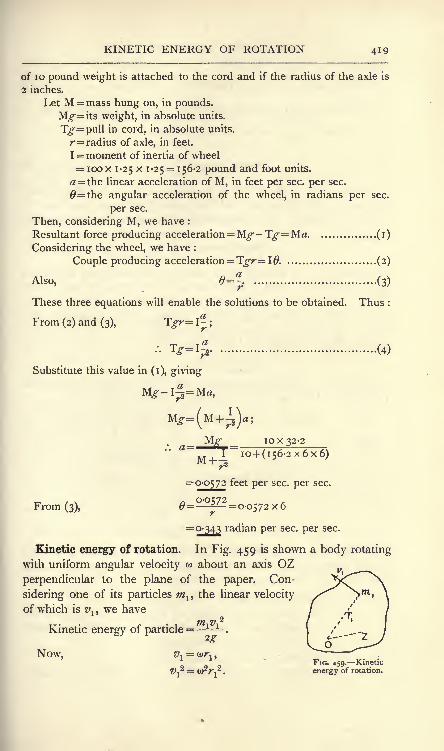
KINETIC ENERGY OF ROTATION 419
of 10 pound weight is attached to the cord and if the radius of the axle is
2 inches.
Let M = mass hung on, in pounds.
Mg-\ts weight, in absolute units.
T-=pull in cord, in absolute units.
r= radius of axle, in feet.
I =moment of inertia of wheel= ioox 1-25 x 1-25
= 156-2 pound and foot units.
= the linear acceleration of M, in feet per sec. per sec.
0=the angular acceleration of the wheel, in radians per sec.
per sec.
Then, considering M, we have :
Resultant force producing acceleration= Mg-Tg-=Ma (i)
Considering the wheel, we have :
Couple producing acceleration = Tgr= 10 (2)
Also, e=-r
. (3)
These three equations will enable the solutions to be obtained. Thus :
From (2) and (3), Tgr\- ;
.'. 1g-\% (4)
Substitute this value in (i), giving
T a
10x32-2Mg-"", .
I
~~
io+ (i56-2 x6x6)
=0-0572 feet per sec. per sec.
From (3),= =0-0572x6
=0-343 radian per sec. per sec.
Kinetic energy of rotation. In Fig. 459 is shown a body rotating
with uniform angular velocity w about an axis OZperpendicular to the plane of the paper. Con-
sidering one of its particles mlythe linear velocity
of which is vl ,we have
Kinetic energy of particle= 1 1
.
Now, vi= <*>rlt
FIG. 459. Kinetic
1)-^= (D f] . energy of rotation.

420 MACHINES AND HYDRAULICS
to2
Hence, Kinetic energy of particle= m^ (i)
A similar expression would result for any other particle, hence
o>2
Total kinetic energy of body = 2mr2, or,
Kinetic energy = Ioz (2)
In using this equation with o> in radians per second, g should be in
feet per second per second and I in pound-(foot)2 units to obtain the
result in foot-lb. The corresponding equation for foot-poundals
would be W2
Kinetic energy = - Ioz (3)
EXAMPLE i. A flywheel has a mass of 5000 pound and a radius of
gyration of 4 feet. Find its kinetic energy at 1 50 revolutions per minute.
o>= 1^> . 27r= 5?r radians per sec. per sec.
I = M/ 2= 5000 x 1 6 = 80,000 pound-(foot)2.
o>2
T 25 x?r2 x 80,000Kinetic energy= I= z
"2.g 64-4
;oo foot-lb.
EXAMPLE 2. The above flywheel slows from 150 to 148 revolutions
per minute. Find the energy which has been abstracted.
Change in kinetic energy=^--
^j=
(o^2 - o>2
2).
Also, &!=
57T,
o>2= W.27r = 4-93377;
/. Energy abstracted= (<DI- a>2)(a>1 + o>2)
= 8160 foot-lb.
Energy of a rolling wheel. The total kinetic energy of a wheel
rolling along a road will be made up of kinetic energy of rotation
together with kinetic energy of translation.
Let o> = the angular velocity, radians per sec.
v the linear velocity in feet per sec. of the carriage to which
the wheel is attached (this will also be the velocity
of the centre of the wheel).
M = the mass of the wheel in pounds.k its radius of gyration, in feet, with reference to the axle.

ENERGY OF ROLLING WHEELS 421
Then, Kinetic energy of rotation = - = foot-lb.
Kinetic energy of translation =-- foot-lb.
<o2!
Total kinetic energy =--1
-- .............. (i)2.T 2g
Again, if there be no slipping between the wheel and the road, we
have (p. 393) v................................. (j)
-K
where R is the radius of the wheel in feet.
Substituting in(i),we obtain, for perfect rolling :
_ . . . . v*M& Mv*Total kinetic energy = =^ +- 2
2g
Energy of a wheel rolling down an inclined plane. The
principle of the conservation of energy may be applied to the case
of a body rolling down an inclined plane (Fig. 460). In rolling from
A to B, the body descends through a vertical height H feet ; hence,
if M is the mass in pounds,Work done by gravity
= M^H foot-poundals.............. (i)
Assuming that none of this is wasted,
the total kinetic energy at B will be
equal to the same quantity. The energyat B is made up of translational kinetic
energy owing to the linear velocity v feet
per second of the mass centre and of
rotational kinetic energy owing to the FIG. 460. Energy of a wheel rolling. , . . , down an incline.
angular velocity w radians per second.
Hence, Total energy at B = (- + Iozjfoot-poundals, ....... (2)
I z being the moment of inertia in pound and feet units about the
axis of rotation passing through the mass centre of the body.
Equating (i) and (2), we have
Writing M> 2 for I z> this will give
Mz/2 eo2
------- +
or ^H = J(^ + o,2#)......................... (3)

422 MACHINES AND HYDRAULICS
If there is no slipping between the wheel and the plane, we have
v=
where R is the radius of the body in feet.
Hence,
or
(4)
Motion of a wheel rolling down an incline. The followingway of regarding the same problem should be studied. Fig. 461
Couple FR
Q =My.
coset
Mg.cosa
FIG. 461. Forces acting on a wheel rolling down an incline.
shows a body rolling down a plane inclined at an angle a to thehorizontal. The weight M^ may be resolved into two forces respec-tively parallel to and at right angles to the plane ;
these will be
M^sina and M^cosa. The normal reaction Q of the plane will
be equal to M^cosa. If there is no friction, all these forces act
through the mass centre O, and there will be no rotation, i.e. the
body will slip down the plane without any rolling. Suppose that
a maximum frictional force F may act between the plane and the
body and that /A is the coefficient of friction, then
F = fJ<Mg cos a.
To investigate the effect of F, transfer it to the mass centre O as
shown and apply an anti-clockwise couple of magnitude FR. Then
P = Resultant force at O acting down the plane
= Mg sin a - F= M^sin a - /xM^cos a.

WHEEL ROLLING DOWN AN INCLINE 423
Let a be the linear acceleration of O down the plane. Then
or M^-(sin a -/x cos a)
= M#,
.'. a=g(sma -/x cos a)................... (5)
Also, owing to the couple FR, an angular acceleration 6 will be
produced, to be obtained from
M/fc2
If the rolling is perfect, i.e. no slip, we have
9- a
Hence, from (5) and (6),
g /. v wRcosa
^- (sin a-
/z cos a) =g' I
'
uR2 cos aSin a -
[JLCOS a = ! -; ,
Sina = /xcosa(-^
tan a . .
~A2 "*" ^
This expresses the minimum value of the coefficient of friction
consistent with perfect rolling. Ass'uming that the rolling is perfect,the value of the linear acceleration a may be calculated as follows :
From (6), p cos a = = ^
a & /0 \
Substituting this value in (5) gives
..'sin a. . a

424 MACHINES AND HYDRAULICS
Suppose that the body starts from rest at A (Fig. 462) and rolls
^ to B. The linear velocity v of the mass' A
centre at B may be calculated thus,
FIG. 462.
?. 388).
Also, y-= sin a
; or, L
Hsin a
Inserting the value of a from (9), we have
2^ sin a H 2^-H1r = W~ =
Z5 J
* sin a kz
I +R2
I+R2
Comparison of (4) with (10) will show that the same result hasbeen obtained by both methods.
EXAMPLE. In a laboratory experiment, a small steel ball was allowedto roll down a plane of length 6 feet and inclination i 40'. The averagetime taken (six experiments) was 4-25 seconds. Compare the experimentaland calculated accelerations of the ball.
To obtain the experimental acceleration, we have
s=\a^where s is the length of the incline and t is the time of descent. Hence,
_2_ 2x6*
1
~72~4.25X4-25= 0-664 feet per sec. per sec.
To calculate the acceleration, take equation (9), p. 423.
For a ball,
Hence,
=f x 32-2 x 0-02908
=0-669 feet per sec. per sec.
The experimental and calculated accelerations differ by about three-
quarters of one per cent.; the agreement is good.

CENTRIFUGAL FORCE 425
Centrifugal force. It has been shown (p. 397) that, when a small
body moves in the circumference of a circle of radius R feet with
uniform velocity v feet per second (Fig. 463), there is a constant
acceleration towards the centre of the circle given by
a =^-
feet per sec. per sec.
To produce this acceleration requires the application of a uniform
force P, also continually directed towards the centre of the circle,
and given by maor.
g
ft. weight (i)
This force overcomes the inertia of the body, which would other-
wise pursue a straight line path, and may be called the central force.
FIG. 463. Central and centri- FIG. 464. Resultant
fugal forces. centrifugal force.
It is resisted by an equal and opposite force Q (Fig. 463), produced
by the inertia of the body. Q is called the centrifugal force.
Expressed in terms of the angular velocity w radians per second,
--. ,
2
p = .mR lb. weight................... (2)
A large body rotating about an axis may be considered as beingmade of a large number of small bodies
;for each of these, rf/g will
be the same, hence the total central force will be2
P = ~(W
1R
1 + W2R
2 + W3R
3 + etC')'
o
The quantity inside the brackets would have the same numerical
value if the whole mass were concentrated at the centre of mass.
Let M = mass of whole body, in pounds,Y = radius of the centre of mass, in feet (Fig. 464).

426 MACHINES AND HYDRAULICS
-(3)Then P = Q = MY lb. weightg
= 2MY poundals (3')
It follows from this result that if a body rotates about an axis
passing through its centre of mass (in which case Y = o), there will be
no resultant pull on the axis due to centrifugal action. There maybe a disturbance set up if the body is not symmetrical about an axis
at right angles to the axis of rotation, and passing through the centre
of mass. For example, in Fig. 465 is shown a rod rotating about an
FIG. 465. An unsymmetrical load produces rocking couples.
axis GX, G being the centre of mass. The rod is not symmetrical
about GY, hence, considering the halves separately, there will be
centrifugal forces as shown by Q, Q, forming a couple tending to
bring the rod into the axis GY. If this tendency is to be balanced,
forces S, S, forming an equal opposite couple must be applied by the
bearings. These forces will, of course, rotate with the rod and
produce what is called a rocking couple. In Fig. 466 is shown a
FIG. 466. A balanced
symmetrical body.
FIG. 467. Balancing a piece of
work in a lathe.
body symmetrical about GY and consequently having neither rocking
couple nor resultant centrifugal force.
In Fig. 467 is shown the face plate of a turning lathe with a piece
of work B attached to the face plate by means of an angle plate C.

EFFECTS OF CENTRIFUGAL FORCE 427
-ThL"^-- R ---
To the other side of the face plate is attached a balance weight
which is adjusted until there is no tendency to rotate the spindle
of the lathe from any position of rest, i.e. the centre of gravity
of the whole falls on the axis of rotation. This is called static
balancing and will serve very well for low speeds. It will be
observed, however, that the bodies attached to the face plate are not
symmetrical. Gland G2 ,
the centres
of gravity of the work and of the balance
weight, are not in the same vertical
line, hence the centrifugal forces Px
and P2 , being equal, form a rocking
couple which will set up troublesome
vibrations if the speed be increased.
The effect may be reduced by havingthe balance weight further from the
face of the plate.
In Fig 468 is shown a motor car travelling in a curved path. To
prevent side slipping, the road is banked up to such an extent that
the resultant Q of the centrifugal force and the weight falls perpen-
dicularly to the road surface.
Let M = mass of car, in pounds.
v = its speed, in feet per sec.
R = radius of curve, in feet.
FIG. 468. Section of a bankedmotor track.
Then, Weight of car = M^ poundals.
Centrifugal force = -=r- poundals.
Also, ABG is the triangle of forces. Hence,
Centrifugal force _ M^2_ v2
_ AB
Now,
Weight of car
ABBG
EG
= tan a,
and a is also the angle which the section of the road surface makeswith the horizontal
; hence,
Railway tracks are also banked up in a similar manner;the super-
elevation of the outer rail prevents the flanges of the outer wheels
grinding against the rail in rounding a curve.

428 MACHINES AND HYDRAULICS
EXERCISES ON CHAPTER XVII.
1. A body of mass 200 pounds has an acceleration of 150 feet persecond per second at a given instant. Calculate the resistance due to
the inertia of the body.
2. A resultant force of 1220 dynes acts on a body of mass 1-25 grams.Calculate the acceleration in cm. per sec. per sec.
3. A train has a mass of 250 tons, and starts with an acceleration of
i-i feet per second per second. Frictional resistances amount to n Ib.
weight per ton. Find the pull which the locomotive must exert.
4. A body slides down a plane inclined at 20 degrees to the horizontal.
The coefficient of friction is o-i;find the acceleration and the time taken
to travel the first 20 feet.
5. A load of 10 pounds is attached to a cord which exerts a steadyupward pull less than 10 Ib. weight. Starting from rest, the load is foundto descend 6 feet vertically in 4 seconds. Find the pull in the cord.
6. A shot has a mass of 20 pounds and a speed of 1500 feet persecond. Find its kinetic energy in foot-tons. Supposing an obstacle to
be encountered and that the shot is brought to rest in a distance of
12 feet, what is the average resistance?
7. Calculate the momentum of the shot given in Question 6. Supposethat the shot had been brought to rest in 0-02 second, and calculate the
average resistance.
8. A man stands on a small truck mounted on wheels which are
practically frictionless. If the man jumps off at the rear end, what will
happen to the truck ? Take the masses of the man and the truck to be
150 and 200 pounds respectively, and assume that the man is travellingat 8 feet per second immediately he has left the truck.
9. A jet of water delivers 50 pounds of water per second with a
velocity of 35 feet per second. The jet strikes a plate which is fixed with
its plane at 90 degrees to the jet. Find the pressure on the plate.
n 10. Suppose in Question 9 that the plate had been curved in such
v a manner that the jet slides on to it and has the direction of its velocityon leaving the plate inclined at 90 degrees to its original direction. Findthe change in velocity, and hence find the pressure on the plate.
11. A wheel has a moment of inertia of 10,000 in pound and feet units,and is brought from rest to 200 revolutions per minute in 25 seconds.
Calculate what steady couple must have acted on it.
12. An iron plate 4 feet high, 2 feet wide and 2 inches thick is hingedat a vertical edge. Calculate its moment of inertia about the axis of the
hinges. Take the density of iron to be 480 pounds per cubic foot.
13. Find the moment of inertia about the axis of rotation of a hollow
shaft 20 inches external and 8 inches internal diameter by 60 feet long.Take the density as given iri Question 12.
14. A solid ball of cast iron is 12 inches in diameter ; density of metal
450 pounds per cubic foot. Find the moment of inertia about an axis
which touches the surface of the ball.

EXERCISES ON CHAPTER XVII. 429
15. Referring to Question 5 : The upper part of the cord is wrappedround a drum 6 inches diameter measured to the cord centre, and a
flywheel is attached to the same shaft as the drum. Find the momentof inertia of the flywheel.
16. A solid disc of cast iron is 4 feet in diameter and 6 inches thick,and rotates about an axis at 90 degrees to its plane and passing throughits centre. For the density, see Question 14. Speed 150 revolutions perminute. Find the radius of gyration and the kinetic energy of the disc.
17. If the disc given in Question 16 slows to 140 revolutions perminute, how much energy will be given up ?
18. Suppose that the disc given in Question 16 were to roll without
slip down an incline of I in 10, what would be the linear acceleration ofits centre ?
19. A blade of a small steam turbine has a mass of 0-05 pound andrevolves in the circumference of a circle 8 inches in diameter 24,000 times
per minute. Find the centrifugal force.
20. An oval track for motor cycles has a minimum radius of 80 yards,and has to be banked to suit a maximum speed of 65 miles per hour.Find the slope of the cross section at the places where the minimumradii occur.
21. A tramcar weighs 12 tons complete. Each of the axles with its
wheels, etc., weighs 0-5 ton, and has a radius of gyration of I foot. Thediameter of the wheel tread is 3 feet, and the car is travelling at 12 miles
per hour. Find (a) the energy of translation of the car; (b) the energy
of rotation of the two axles; (c) the total kinetic energy of the vehicle.
(B.E.)22. Prove the formula for the acceleration of a point moving with
uniform speed in a circle. Find in direction and magnitude the force
required to compel a body weighing 10 Ib. to move in a curved path, theradius of curvature at the point considered being 20 feet, the velocity ofthe body 40 feet per second, and the acceleration in its path 48 feet persecond per second. (I.C.E.)
23. A motor car, whose resistance to motion on the level is supposedto be the same at all speeds, has been running steadily on the level at
20 miles per hour; it now gets into a rise of i in 12. What is themaximum length of this rising road which may be traversed by the carwithout changing gear ? (B.E.)
24. A train weighing 300 tons, travelling at 60 miles per hour down a
slope of i in no, with steam shut off, has the brakes applied and stops in
450 yards. Find the space-average of the retarding force in tons exerted
by the brakes;
if the time that elapses between the putting on of thebrakes and the moment of stopping is 36 seconds, find the time-averageof the retarding force in tons. (I.C.E.)

CHAPTER XVIII.
INERTIA CONTINUED.
Angular momentum. The angular momentum or moment of momentum
of a particle may be defined by reference to Fig. 469. A particle of
mass m pounds revolving in a circle of r feet in
n radius has a linear velocity of v feet per second
'r/" \ at any instant in the direction of the tangent.
/ / \ Hence its linear momentum at any instant will be
i -t****2 Linear momentum of particle= mv,
t O i ,
;
' and v = ur\
\ / .'. Linear momentum of particle= umr. (i)
v ^ -'' The moment of this about OZ (Fig. 469) mayFIG. 469 -Angular mo- be obtained by multiplying by r> the result being
called the moment of momentum, or angularmomentum of the particle.
Angular momentum of particle= umr2
(2)
A body having many particles would have a similar expression for
each. Hence, vAngular momentum of a body = vtLmr1
I. (3)
Consider now a body free to rotate about a fixed axis, and,
starting from rest, acted on by a constant couple T Ib.-feet. Theconstant angular acceleration being 0, we have, as in equation (5)
P- 4H, T ^IOZ
Let T act during a time / seconds, then the angular velocity w at
the end of this time will be(j)
w = 0t, or, 9 = -.
Hence, T =" *
Ib.-feet, (4)gt
orL^^'poundals-feet (5)

r.YKOSTATIC ACTION 431
Now, (ol (}7 is the angular momentum acquired in the time /seconds,
hence <oloz// will be the gain of angular momentum per second.
We may therefore state that the couple in Ib.-feet acting on a body free
to rotate about a fixed axis is numerically equal to the rate of change of
angular momentum divided by g ; or, omitting g, the couple will be in
poundal-feet. This statement should be compared with those for
linear momentum given on p. 411.
It will be evident that the applied couple must be acting in the
plane of rotation of the body ;should this not be the case, then
rectangular components of the couple should be taken, and. that
component which is in the plane of rotation used in applying
equation (4).
Gyrostatic action. In Fig. 470 is shown a cycle wheel suspended
by means of a long cord attached at C to one end of the bearing pin.
n
i-Q w.
FIG. 470. A cycle wheel showinggyrostatic action.
FIG 471. Angular velocities ofthe wheel shown in Fig. 470.
If the wheel be at rest, it cannot maintain the position shown without
assistance, but, if set revolving, it will be found to be capable of
maintaining its plane of revolution vertical. It will be noticed,
however, that the wheel spindle slowly revolves in azimuth, i.e. in
a horizontal plane ;the vertical plane of revolution of the wheel will,
of course, be always perpendicular to the wheel axis. The effect is
owing to the action of the couple formed by the equal forces T, the
pull of the cord, and Mg, the weight of the wheel. This couple acts
in a vertical plane containing the wheel axis, and will produce
changes in the angular velocity of the wheel ; these changes must
occur in the plane containing the couple.In Fig. 471 is shown a plan of the wheel
;as it is revolving clock-
wise when viewed from the right hand side, Oa may be drawn to

432 MACHINES AND HYDRAULICS
represent w, the angular velocity of the wheel in its present position.
The couple acting is clockwise when viewed from the front side,
hence ab will represent the change of angular velocity occurring in
a brief interval of time (p. 401). Hence the angular velocity of the
wheel at the end of the interval will be represented by Ob. Thevertical plane of revolution of the wheel will turn from the position
OA to OA' during the interval, and the wheel spindle which
occupied the position Oa at first will revolve clockwise when viewed
from above.
Let L = the couple applied, poundal-feet.
I = the moment of inertia of the wheel about its axis, poundand foot units.
Wj= the angular velocity of the wheel about its axis, radians
per second.
co2= the angular velocity of the wheel axis in the horizontal
plane, radians per second.
/=the time in which the axis makes a complete revolution in
the horizontal plane, seconds.
Then, in one horizontal revolution of the axis, change in angular
velocity of the wheel = 2Tro>r (p. 402.)
Also, L- *I. (p. 414.)
Also, = 27T
In Figs. 470 and 471,
L = M^xCO;R
or (*)
where CO is the horizontal distance
between the centre of gravity of the
wheel and the suspending cord.
; ; Gyrostatic action in motor cars.
FIG. 472. Gyrostatic action in an ordinary In Fig. 472 IS shown a motor Car
travelling round a curve;
when
looked at from the front, the engine flywheel has a clockwise angular
velocity. Let OA represent the angular velocity of the flywheel
when the car is in the position shown, and let OB represent the

GYROSTATIC ACTION 433
angular velocity after a short interval of time; then the change in
angular velocity will be represented by AB, and indicates that a
clockwise couple must be acting on the car as seen in the side
elevation. This couple can come only from the reactions of the
ground, hence the front wheels are exerting a greater pressure andthe back wheels a smaller pressure than when the car is running in
a straight line. If the car is turning towards the right instead of
towards the left, there will be an increase in pressure on the back
wheels and a, diminution in pressure on the front wheels; the
student should make a diagram of this case for himself.
Let P = the change in pressure on each axle of the car, in poundals.
Wj= the angular velocity of the engine, in radians per second.
I = the moment of inertia of the revolving parts of the engine,in pound and foot units.
V = the velocity of the car, in feet per second.
R = the radius of the curve, in feet.
w2= V/R = the angular velocity in azimuth of the engine shaft,
radians per second.
D the distance, centre to centre of the wheel axles, in feet
Then, \ Couple acting =
P =~Fyp- poundals
-Jg height
In Fig. 473 is shown a car having a wheel at O rotating in a
<f QJ
FIG. 473. Gyrostatic action of a revolving wheel in a car.
vertical plane parallel to the planes of revolution of the back wheels
of the car. In the side elevation the wheel rotates clockwise;the car
D.M. 2 K

434 MACHINES AND HYDRAULICS
is shown in plan turning towards the right. Oa will represent the
initial angular velocity of the wheel, Qb represents the angular velocity
after a brief interval, and ab represents the change in angular
velocity during this interval. Viewed from the front of the car,
the change in angular velocity is anti-clockwise, hence an anti-clock-
wise couple P, P, must act on the wheel in a vertical plane con-
taining the wheel axis. This will give rise to an equal opposite
couple Q, Q, acting on the car, and will cause the wheels at AA to
exert greater pressure on the ground and those at BB to tend
to lift. It will be noted that in this case both centrifugal force and
gyrostatic action conspire to upset the car. If the wheel at O be
made to rotate anti clockwise, the gyrostatic couple will have the
opposite sense to that in Fig. 473, and will tend to equilibrate the
effects of centrifugal force on the car. The student should sketch
the diagram for this case, and also for the case of the car turning
towards the left.
Further points regarding gyrostatic action. A wheel revolving
in a given plane may be shifted to any parallel plane without any
FIG. 474. An experimental gyrostat.
gyrostatic action being evidenced. This is in consequence of such a
change in position being unaccompanied by any change in the
angular velocity of the wheel ;hence there is no change in angular

GYROSTATIC ACTION 435
momentum, and therefore no couple is required. A couple is
required in every case where the new plane of revolution is inclined
to the initial plane.
In Fig. 474 is shown a common form of gyrostat by use of which
useful information regarding the behaviour of gyrostats may be
obtained. The revolving wheel A rotates on a spindle BC, the
bearings of which at B and C are formed in a ring which has freedom
to rotate about an axis DE. The ring has bearings at D and E in
another semicircular ring DFE, which has freedom to rotate about
the vertical axis FG. The spindle FG is dropped into a vertical
hole in a heavy stand. The effect of a weight W hung from C will
be to cause the axis BC to rotate in a horizontal plane, accompanied,of course, by the whole frame
;the direction of this rotation, as
viewed from above, will be either clockwise or anti-clockwise, depend-
ing on the direction of rotation of the wheel.
It will be noted that the original vertical plane of rotation gradu-
ally becomes inclined to the vertical as the motion goes on. This is
owing to the action of a horizontal couple actingon the frame, and produced by the frictional
resistance offered by the stand to the rotation
of the spindle FG. In Fig. 475 an elevation of
the wheel is shown, rotating in the vertical planeOA. Oa represents the angular- velocity of the
wheel;ab represents the change in angular velocity
in a given interval of time in the horizontal plane
containing the wheel axis, and produced by the frictional couple.Qb is the altered angular velocity of the wheel at the end of the
interval. The wheel will now be rotating in the plane OA', per-
pendicular to Ob and inclined at an angle AOA' to the vertical.
While the wheel is rotating, if the free motion of the semi-circular
ring DFE be impeded by application of a finger, it will be noted that
the wheel turns over. This effect is precisely the same as the effect of
the frictional couple, only it is more marked, as the horizontal couple
produced by the finger is larger than that produced by the friction.
If DFE be held forcibly from rotating, the wheel will assumea horizontal plane of rotation instantly. In fact, the wheel is only
capable of exerting a couple which will equilibrate the couple applied
by means of W, provided its motion in azimuth is allowed to take
place freely.
Schlick's anti-rolling gyrostat. Fig. 476 illustrates in outline
the method used by Schlick for reducing the rolling of a ship

436 MACHINES AND HYDRAULICS
among waves. The view is a cross section of the ship ;A is a
heavy wheel revolving in a horizontal plane about the axis BCThe frame in which the wheel rotates can rock about a hori-
zontal axis DE, which works in bearings secured to the ship's
frames. DE is perpendicular to the direc-
tion of length of the ship. When the ship
B rolls, the axis DE is forced out of the hori-
zontal, and the axis BC will be inclined
by either B or C coming out of the paper.
A couple, applied by vertical forces acting
at D and E, is required to give the wheel
FIG. 476. Schiick's anti-rolling frame this motion, and an equal oppositegyrostat. .
n.
couple acts on the ship, tending to give
to it a motion opposite to the rolling motion. In consequence of
this reaction on the ship, the rolling effect is made much smaller.
Freedom of motion about DE must be provided, otherwise the wheel
is incapable, as has been shown above, of offering any resistance to
rolling.
There are many other applications of the principle of the gyrostat,
such as in the gyro-compass used on board ships, in the Brennan
monorail cars, and in steering torpedoes.
Simple harmonic vibrations. It has been shown (p. 398) that a
body, in describing simple harmonic vibrations, possesses at anyinstant an acceleration directed towards the centre of the vibration,
and proportional to the distance of the body from the centre of the
vibration. A force will be necessary in order to produce this acceler-
ation, and the force will evidently follow the same law as the
acceleration, i.e. it will be constantly directed
towards the centre of the vibration, and K--R----
+{
will be proportional to the distance of the_i 9 <F
*
body from the centre. B O m A
(
InFig._
477 a body of mass m poundsFir" 477\^^harmonic
vibrates with simple harmonic motion in the
line AB. Let v feet per second be the velocity when the body is
passing through the centre O, then the accelerations at A and B will be
2,2
ai=f ^ feet per second per second,
R being the length of OA in feet (p. 397).
Let Fj be the force in poundals required at A and B, then
= -=r- poundals............................ (i)

SIMPLE HARMONIC VIBRATIONS 437
Supposing the body to be situated at C, its acceleration a may befound from ^_OC_OC
<^~OA~ll'
OC.. a = ai .
Also, the force F required to produce the acceleration may befound from jr QC OC
F!
=OA
=^: ;
. F _ F OC_^ OC*' R
~R
'
Rmv^ ~~=~RZ~ poundals (2)
Suppose OC to be one foot, and that /x represents the value of the
force required when the body is at this distance from O, then
JiTP undals (3)
The time of one complete vibration from A to B and back to A is
given by (p. 400) RT = 27T .
V
From (3), -*-=;
. R Im
Substitution of this value gives
T = 2irA/ seconds (5)
EXAMPLE. A body of mass 2 pounds executes simple harmonic
vibrations. When at a distance of 3 inches from the centre of the
vibration, a force of 0-4 Ib. weight is acting on it. Find the time of
vibration.
The force required at a distance of one foot from the centre will be
four times that required at 3 inches. Hence,
fji= 0-4 x 4= i -6 Ib. weight= i -6 g poundals.
2X22Hence>
1-238 seconds.

438 MACHINES AND HYDRAULICS
Simple harmonic torsional oscillations. A body will execute
simple harmonic torsional oscillations if it is under the influence of a
couple which varies as the angle described by the body from the
mean position, the couple having a sense of rotation always tendingto restore the body to the mean position. Thus, a body secured to
the lower end of a vertical wire, the upper end of which is fixed
rigidly, will hang, when at rest, in a position which may be described
as the mean position. As has been explained on pp. 255 and 295, if the
wire be twisted by rotation of the body, it will exert a couple which will
be proportional to the angle of twist;
this couple will be constantly
endeavouring to restore the body to the mean position, hence the
body will describe simple harmonic torsional oscillations. The time
of vibration may be deduced by analogy from equation (5), p. 437,
showing the time of simple harmonic rectilinear vibrations;
the
moment of inertia of the body about the wire axis must be substituted
for m, and the couple acting at unit angle (one radian) from the mean
position must be substituted for /x. Thus
Let M = the mass of the body, in pounds.
k = its radius of gyration about the axis of vibration, in
feet.
I = M/fc2 = the moment of inertia about the same axis, in poundand foot units.
A = the couple acting at one radian displacement from the
mean position, in poundal-feet.
T = the time elapsing between successive passages of the
body through the same position.
Then, T = 2^
VMk2
2-n-A / seconds.A
EXAMPLE. A flywheel having a mass of 1000 pounds and a radius of
gyration of 2 feet, is fixed to the end of a shaft 4 feet long and 3 inches in
diameter. It has been found from a separate calculation that the shaft
has an angle of twist of 0-0005 radian when a torque of 1000 Ib.-inches is
applied. Find the time of a free torsional oscillation. Take ^-=32-2.The term "
free"indicates that the frictional effects of the bearings and
of the atmosphere are to be disregarded.
= looo x 2 x 2 = 4000 pound and foot units.

SIMPLE PENDULUM 439
The angle of twist is proportional to the torque, and if this were true upto one radian, we have
Torque at one radian _ i.
looo "0-0005'
.'. Torque at one radian =0-0005
= 2,000,000 Ib.-inches ;
= 2,000,000 Xg12
= 5)3^7,000 poundal-feet.
Hence,
= 44 J~ 4ocx
7 ^5>367,<
Suppose n to be the number of torsional oscillations per minute;then
60=
o-i7is
If this shaft were driven by means of an engine connected to a
crank fixed to the shaft at the end remote from the flywheel, and if
the shaft were to have a speed of 350 revolutions per minute, the
engine would be delivering impulses to the shaft which would keeptime with the free oscillations of the shaft. In
these circumstances, the angle of oscillation would
rapidly increase in magnitude. As the stress in
the shaft is proportional to the angle of twist, a
very large stress would be produced and the shaft
would be in danger of breaking. A somewhat
higher or lower speed of revolution is necessary
in order to avoid these effects;
in no case should
the impulses given to the shaft synchronise with
the free torsional oscillations.V tTli
The simple pendulum. A simple pendulum maybe realised by suspending a small heavy body at FIG. 478.-A simple
the end of a very light thread and allowing it to
vibrate through small angles under the action of gravity. In Fig. 478the body at B is under the action of its weight mg and the pull Tof the thread. The resultant of these forces is F, a force which

440 MACHINES AND HYDRAULICS
is urging the body towards the vertical. The triangle of forces
will be ABD, and we have
JF = BDmg~A&
T7BD
F = m? --T-.=r-or
Now, if the angle BAD is kept very small, AC and AD will be
very nearly equal. Let L be the length of the thread in feet;then
F = w<r =-^-BD. ...(i)
Hence we may say that F is proportional to BD. For very small
angles of swing BD and BC coincide practically, therefore the bodywill execute simple harmonic vibrations under the action of a force Fwhich varies as the distance from the vertical through A. To obtain
the value of/*, the force at unit distance, make BD equal to one foot
in(i); then
poundals.
Now, =(p. 437)
EXAMPLE. Find the time of vibration of a simple pendulum of length
4 feet at a place where g is 32 feet persecond per second.
2X22
7
= 2-222 seconds.
The compound pendulum. Anybody vibrating about an axis under the
action of gravity and having dimensions
which do not comply with those re-
quired for a simple pendulum may be
called a compound pendulum. In
Fig. 479 (a) is shown a compoundpendulum consisting of a body vibrating
FIG. 479. A compound pendulum andan equivalent simple pendulum.

COMPOUND PENDULUM 441
about A. G is the centre of mass of the body, and the line AGmakes an angle a with the vertical passing through A in the position
under consideration. In Fig. 479 (b} is shown a simple pendulumCD vibrating about C ;
at the instant considered CD makes the
same angle a with the vertical passing through C. Both pendulumswill execute small vibrations in the same time provided that their
angular accelerations in the given positions are equal.
Considering the compound pendulum,Let M = its mass, in pounds.
Y = the distance AG, in feet.
IA = M^A = its moment of inertia about A, in pound andfoot units.
1= the angular acceleration in radians per sec. per sec.
in the given position.
r~, n couple applied M^ x GBInen "\
=~^r
= -2
IA M/ A
_"x GAsina . .
~~# '^A
Considering now the simple pendulum,Let m = its mass, in pounds.
L = its length, in feet.
Ic = wL2 = its moment of inertia about C, in pound andfoot units.
2= its angular acceleration in radians per sec. per sec. in
the given position.
Then couple applied
mgx DE _g x DC sin a
L2
LTo comply with the required conditions, we have
.
N
.(3)

442 MACHINES AND HYDRAULICS
The length L of the corresponding simple pendulum may be
calculated from this result, and hence the time of vibration of both
pendulums may be found. If AG be produced to Z (Fig. 479 (#)),
making AZ equal to L, the point so found is called the centre of
oscillation. The centre of oscillation may be denned as the point at
which the whole mass of a compound pendulum may be concen-
trated without thereby altering the time of vibration.
Centre of percussion. If a body is capable of rotating freely
about a fixed axis, it will be found that, in general, a blow delivered
to the body will produce an impulse on the axis.
There is, however, one point in the body at which
a blow will produce no impulse on the axis;
this
point is called the centre of percussion.
In Fig. 480, C is the axis about which the body
may turn freely and G is the centre of mass. Let
an impulse F be delivered to the body at a point Z.
The effects of F may be examined by transferring
F to the centre of mass, applying at the same time
a clockwise couple of moment F x GZ. The force
F acting at G will produce pure translation, and
if the mass of the body is M pounds, every point in it will have an
acceleration alfeet per second per second, found from
FIG. 480. Centre of
percussion.
or MIn particular, C will have this acceleration a^ towards the left.
Further, the couple F x GZ will produce a clockwise angularacceleration 6. found from T? v r-y
ya JT X \J/_J
~~IG~~*
where IG is the moment of inertia of the body about an axis passing
through G and parallel to the axis at C.
moment of inertia, we haveFxGZ
:~
Writing M/ G for this
As a consequence of this angular acceleration, C will have a linear
acceleration a2
feet per second per second towards the right, to be
found from a.,= x CGF x GZ x CG

EQUIVALENT DYNAMICAL SYSTEMS 443
If there is to be no impulse on the axis at C, there must be
equality of atand
2. Hence,
F = FxGZxCG
GZxCGor i= -
z ;
kG
.'. c = GZxCG (3)
Also, Ic= Ic + M . CG2
, (p. 417.)2 o
.*. G = c-CG 2(4)
Also, GZ = CZ-CG (5)
Substituting these values in (3) gives :
/C -CG2 = (CZ-CG)CG,
Comparison of this result with that found for the position of the
centre of oscillation (p. 441, equation (3)), indicates that the centre
of percussion of a body coincides with the centre of oscillation.
Reduction of a given body to an equivalent dynamical system.
It is often convenient to substitute for a given body two separatebodies connected by means of
an imaginary rigid rod, and
arranged in such a way that the
substituted bodies behave under
the action of any force or forces
in exactly the same manner as
the given body. In Fig. 481 (a) (ft-)-.
/
is shown a body of mass M, /L\
and having its centre of mass atFlG> 48l._Equivalent dynamical system.
G ; Fig. 48 1(I))
shows an equi-
valent system, consisting of two bodies at A' and B', having masses
mland m
2 respectively, and having their centre of mass at G'. Aand B in Fig. 481 (a) correspond with A' and B'. The conditions
of equivalence may be stated as follows :
(i) The mass M must be equal to the sum of m^ and m2 ,and the
points G and G' must divide AB and A'B' respectively in the same
proportion. A force applied at G or at G' will then produce pure

444 MACHINES AND HYDRAULICS
translation with equal accelerations in the given body or in the
substituted system. Hence,m
1+ m2
= 'Mt (i)
mlx AG = #z
2x BG,
or m^a = mj) (2)
(2) The moment of inertia of the given body about any axis pass-
ing through its centre of mass must be the same as the moment of
inertia of the substituted system about a similarly situated axis.
This condition ensures that the given body and the substituted
system shall possess equal angular accelerations when acted on by
equal couples. Hence,m
ld2 + m i>P = Ukl (3)
These equations may be reduced as follows :
b aFrom (2), m^-m^ m
2=
~lm
\-
Substituting these in (i) gives :
m1 + -rm l
= M;
M M
Also,-
-J-s
M Ma
a
Inserting these values in (3), we have
or
.' ab =& (6)
The required equivalent system may thus be obtained by first
selecting a. b may then be calculated from (6), having first deter-
mined the value of G . m^ and m% may now be calculated from (4)
and (5).

EQUIVALENT DYNAMICAL SYSTEMS 445
EXAMPLE. A connecting rod (Fig. 482) 4 feet long has its centre of
mass G at 2-8 feet from the small end. The mass of the rod is 200
u 3-5
m,
<Prb*?-
------- a ------*
FIG. 482. Equivalent dynamical system for a connecting rod.
pounds, and an equivalent system is required in which one of the two
masses is to be situated at the small end. k*G is 2 in foot units. Find the
system.Here a is 2-8 feet
; hence, from (6),
/From (4),
From (5),
=0714 foot
200 X 0-7 14 200 X 0-7 14
3-514
= 40-6 pounds.
Ma
200X2-8
3-5I4
= 159-4 pounds.
If it is desired to give the body shown in Fig. 481 (a) any assigned
motion, the forces required may be obtained as follows : Find the
linear accelerations at A and B, both in direction and magnitude ;
let these be aland a
2 respectively. In Fig. 481 (<), showing the
equivalent system, mland m
2will have accelerations
<Zjand a
2
respectively, and forces will be required acting in the lines of these
accelerations, and given by
both in absolute units. The same forces applied at A and B respec-
tively in Fig. 481 (a) will give the proposed motion to the body.

446 MACHINES AND HYDRAULICS
EXPT. 43. The law F = ma may be verified roughly by means of
the apparatus illustrated in Fig. 483. A and B are two similar scale
pans connected to a fine cord C which passes over two aluminium
pulleys D and E. A cord Cj ,of the same kind as C, is attached to
the bottom of each pan, and compensates for the
extra weight of cord on the B side of the pulleys.A fall of about 10 feet should be arranged for
the scale pans.Place equal masses in the scale pans, and
find by trial what additional mass placed in Awill cause it to descend with uniform velocitywhen given a start. Any additional mass placedin A will now give A an acceleration downwardsand B an equal acceleration upwards. Let Ahave a total fall of H feet, and make several
experiments without changing the masses,
noting the time in seconds for each descent bymeans of a stop-watch. Take the average time/ seconds and calculate the acceleration a, from
FIG. 483. Apparatus for TTverifying the law F = ma. a
l=~^
feet per S6C. per S6C(
I)
The acceleration should also be calculated as follows :
Let Ms= mass of each scale pan, pounds.
Mw = the equal masses added, pounds.Me
= the additional mass in A required to secure uniform
velocity, pounds.Ma = mass added to A for the purpose of producing
acceleration, pounds.
The total mass to which acceleration has been given, neglectingthe cord and pulleys, is
The force F which has produced the acceleration is the weightof Ma ,
i.e. Mag in poundals. Hence,
or Mag= {2(MS + M lo) + M + Ma}a2 ,
feet er sec ' sec........
This value should agree fairly well with that experimentally foundand given by 1
in equation (i).
Repeat the experiment two or three times with different masses.

MOMENT OF INERTIA OF A FLYWHEEL 447
EXPT. 44. To find the moment of inertia of a small flywheel by the
method of a falling load. The apparatus used consists of a small
flywheel (Fig. 458, p. 418) having a drum on its shaft and capable of
being rotated by means of a cord wrapped round the drum, and
having a scale pan containing a load attached to its end. The cord
is attached to the drum in such a manner that it drops off when the
scale pan reaches the floor.
Allow the scale pan to descend slowly through a measured height,and note the number of revolutions made by the wheel during this
operation. Wind up the scale pan to the same height, place a load
in it, then allow the wheel to start unaided, at the same moment
starting a stop-watch. Stop the watch at the instant the scale panreaches the floor, and note the time of descent. Allow the wheel to
go on revolving until friction brings it to rest, and note the total
number of revolutions which it makes from start to stop.
Let ml= the mass of the scale pan, in pounds.
m% = the mass placed in the scale pan, in pounds.M = m
l + m2= the total falling mass, in pounds.
H = the height of fall of the scale pan, in feet.
^=the time of fall, in seconds.
Nx= number of revolutions made by the wheel during the fall.
N2= the total number of revolutions from start to stop.
The total work done by gravity will be M^H foot-poundals, and,
up to the instant that the scale pan is on the point of touching the
floor, this work has been expended as follows: (a) in giving kinetic
energy to the falling mass M; (b) in overcoming frictional resistances;
(f) in giving kinetic energy to the wheel. If v be the velocity of Mwhen the scale pan arrives at the floor, the average velocity of
descent will be \v feet per second. Hence,
2H ,. . v = feet per second.
. Mv* M 4H2
. . Kinetic energy acquired by M =- = ~-
2MH2f=
-g-
foot-poundals.
The difference between Mc H and the kinetic energy acquired by
the falling mass M represents the energy reaching the drum, and is
expended in overcoming friction and in giving kinetic energy to
the wheel.2MH2
Energy reaching the drum = M^H -2
MHf --2~ ) foQt;-poundals
.

448 MACHINES AND HYDRAULICS
Ultimately, the whole of this energy is dissipated in overcomingfrictional resistances throughout the entire motion of the wheel, i.e.
in N2 revolutions. Assuming that the frictional waste per revolution
is constant, we have
Energy wasted per revolution = MHuf- -rj- J-f- N
2 ,
Energy wasted while M is falling= MH(^- ^- j^
1foot-poundals.
Y t /JN 2
Let E = the kinetic energy possessed by the wheel at the instant
the scale pan reaches the floor.
rp, ,-, ATTT/ 2H\ ,,/ 2HXN,Then E =MH- -- - MHg- .J
-- 1
foot-poundals
N
The angular velocity of the wheel at the instant the scale panreaches the floor may be calculated as follows :
Revolutions described in / seconds = N\= average revs, per sec. x t\
.'. Average revolutions per sec. = -.
2N,And, maximum revolutions per sec. = -
;
2N.". Maximum angular velocity of wheel = w= 1. 2^
47rN1
,.= ^ 1 radians per sec.
Now,o
Maximum kinetic energy of the wheel = I = E foot-lb. ;
MH _ 2 -N/ foot units.
The experiment should be repeated several times with different
masses m2and with different heights of fall H
;the values of I
should be calculated for each experiment and the mean value taken.

CENTRE OF OSCILLATION 449
EXPT. 45. To find the centre of oscillation, or the centre of percussion,
of a given body. A connecting rod has been selected as a useful
example (Fig. 484). The rod AB is suspended from a knife edgeconsisting of a square bar of tool steel
CD, passing through the hole in theG
small end and resting on V blocks at
E and F. The rod can vibrate nowin the same plane as that in which it
will vibrate when built into the engine.GH is a simple pendulum consistingof a small heavy bob and a light cord.
Cause both rod and simple pendulumto execute small vibrations, starting
both together at the end of a swing.
Adjust the length of GH until both
vibrate in the same time. MeasureGH and mark a point on the con-
necting rod at this length from its axis
of vibration. This will give the centre
of oscillation or percussion when the
rod is vibrating about the upper edgeof the tool steel bar.
EXPT. 46. Take a uniform bar of metal about 3 feet long and of
section about i inch by f inch. Referring to p. 443, it will be seen
that the centre of percussion Z for this bar will be at a distance from
C given by
B BFIG. 484. Centre of oscillation by
experiment.
Let L be the length of the bar. Then
Mark clearly the position of Z on the bar;allow the bar to hang
vertically, using a finger and thumb at C. Use another short bar
and strike the bar sharply at different points. The absence of anyjar on the fingers when the bar is struck at Z will be observed
readily, and gives confirmation of the calculated position of Z.
EXPT. 47. To find the radius. of gyration of a given body about an axis
passing through its centre of mass. In Fig. 485 is shown a flywheel
arranged in the same manner as the connecting rod in Fig. 484.Find the length of the corresponding simple pendulum as directed
previously, being careful to cause the flywheel to vibrate in the same
plane as that in which it will rotate subsequently. Measure BK, the
distance from the axis of vibration to the centre of mass of the wheel.
Weigh the wheel in order to estimate its mass.
D.M. 2 F

450 MACHINES AND HYDRAULICS
Taking equation (3), p. 441, and applying it to the present case,
we have ,2
where
Hence,
Now,
L= GH, in feet;
Y = BK, in feet;
B = the radius of gyration about B, in feet.
4-LY.IK = IB -MY2
,
or
/&K = s/Y(L- Y) feet (i)
G
<>
FIG. 485. Radius of gyration of a flywheel by experiment.
The moment of inertia of the wheel about its axis of rotation
willbeIK = M/= MY(L -
Y) pound and foot units. . . .(2)
This experiment therefore provides a means of finding the data
required for estimating the kinetic energy and the rotational inertia
of a given flywheel.
EXPT. 48. To find the velocity acquired by a wheel in rolling down an
incline. In Fig. 486 is shown a long incline AB consisting of two
angle bars with a gap between them. The angle bars are pivoted to
a bracket at A, and a prop at F enables the angle of inclination to
be altered.
The wheel D has a spindle projecting on each side of the wheel,and has a collar E on each side secured by a nut to the spindle.The collars are coned slightly for the purpose of keeping the wheel
centrally in the gap as it rolls down and to prevent the wheel from
rubbing on the angles. A fixed stop is fitted at C. The object of
the arrangement is to increase the time taken in rolling down the
incline.

EXERCISES ON CHAPTER XVIII. 451
First determine the square of the radius of gyration of the wheeland its attachments about the axis of the spindle, by the method
explained in the last experiment. Let this be & in foot units.
FIG. 486. Apparatus for investigating the motion of a wheel rolling down an incline.
Set the incline to a suitable angle by means of the prop. Measurethe difference in level between the centre of the wheel spindle whenin the starting position and when in the stopping position ;
let this beH feet. Measure also the distance travelled, parallel to the incline,
by the wheel centre;
let this be L feet. Let the wheel start unaided,and note the time taken in rolling down ; let this be / seconds. Letthe linear velocity of the wheel centre at the instant of arriving at
the bottom be v feet per second. Then
L= the average velocity x /
2L.'. v = feet per second......................... (i)
Taking equation (4), p. 422, and writing r instead of R, where ris the mean radius of the collars E in feet,
v= /-75
feet per second. * ...... . ........ (2)
(i) and (2) are expressions for the velocity found by entirely
independent methods, and the results obtained from them should
agree. Give the results for v by both methods; repeat the experi-
ment, using different angles of inclination and collars having adifferent diameter.
EXERCISES ON CHAPTER XVIII.
1. A wheel has a moment of inertia of 24,000 in pound and foot units,and runs at 90 revolutions per minute. Find its moment of momentum.Suppose that the speed changes to 88 revolutions per minute in 0-5 second,what couple must have acted ?
2. A wheel has a moment of inertia of 20 in pound and foot units,and has a speed of 90 revolutions per minute
;the plane of revolution is
vertical. The wheel is mounted so that its axis is capable of turning in ahorizontal plane (i.e. in azimuth). The axis is found to have an angular

452 MACHINES AND HYDRAULICS
velocity of - radian per second in azimuth. Calculate the couple10
acting. Show the couple and the directions of both angular velocities
clearly in a diagram.
3. A cycle wheel has a mass of 5 pounds and its radius of gyration is
one foot. It is suspended as shown in Fig. 470, the distance betweenthe suspending cord and the mass centre being 2-5 inches. The wheel is
spun and revolves with its plane vertical 120 times per minute. Findthe angular velocity in azimuth.
4. A body having a mass of 12 pounds vibrates in a straight line 18
inches long with simple harmonic motion. The time of one completevibration is 0-25 second. Find what force must act on it at the end of
each stroke and the velocity at the middle of the stroke.
5. A small wheel having a moment of inertia of 0-4 in pound and foot
units has its plane horizontal and is attached firmly at its centre to a
vertical steel wire, the top end of which is fixed to a rigid bracket. Thewheel can execute torsional oscillations under the control of the wire.
The wire is 0-06 inch in diameter and 36 inches long, and its modulus of
rigidity is known to be 11,000,000 Ib. per square inch. Find the time
of one complete oscillation.
6. A thin disc 24 inches in diameter can execute small vibrations underthe influence of gravity about a horizontal axis at 90 degrees to the planeof the disc and bisecting a radius. Find the length of the equivalent
simple pendulum and the time of one complete vibration.
7. A thin uniform steel rod 3 feet long hangs freely from its top end.
Find the centre of percussion.
8. A uniform bar of mild steel, section 2 inches by I inch, 4 feet long,has masses of 4 and 2 pounds attached at distances of I foot and 3-5 feet
respectively from one end. Take the density of the bar to be 0-28 poundper cubic inch. Find the mass centre and the moment of inertia aboutan axis at 90 degrees to the flat face of the bar and passing through the
mass centre.
9. Take the system given in Question 8 and reduce it to an equivalent
dynamic system having a mass situated at the end of the bar adjacentto the given 2 pound mass.
10. Take the equivalent dynamic system found in answer to Question9. A force of 100 Ib. weight is applied at 90 degrees to the bar (a) at the
mass centre, (^) at 3 inches from the mass centre. Find, in each case,the translational acceleration of the mass centre and the angular acceler-
ation, if any, of the bar.
11. Explain what is meant by moment of momentum. Calculate the
moment of momentum of a body weighing 300 Ib. rotating at 1250 revolu-
tions per minute, the radius of gyration of the body about the axis of
rotation being 1-7 foot. What property is measured by rate of change of
moment of momentum ? (I.C.E.)
12. A body of 40 pounds hangs from a spiral spring, which it elongates
2-5 inches. The body is then pulled down a short distance and let go.Determine the number of complete oscillations the body will make perminute, assuming that the weight of the spring is 20 Ib. (B.E.)

EXERCISES ON CHAPTER XVIII. 453
13. A body weighing 161 Ib. has a simple harmonic motion, the total
length of one swing being 2 feet;the periodic time is i second. Make a
1
diagram showing its velocity and another showing its acceleration at
every point of its path. What force is giving to the body this motion ?
What is its greatest value ? (B.E.)
14. A heavy circular disc is supported on a shaft 3 inches in diameter,carried on roller bearings ;
a cord is wrapped round the shaft. It is
found by experiment that a weight of 6 Ib. suspended from this cord is
just sufficient to overcome the friction of the roller bearings and maintaina uniform speed of rotation of the disc. When a weight of 30 Ib. is
suspended from the cord, it is found that this weight descends vertically
14 feet in 2 seconds of time. Determine the moment of inertia of thedisc in pound-foot
2 units. Neglect the inertia of shaft and cord, andassume that the speed of rotation of the disc increases at a uniform rate
in the second experiment. (B.E.)
15. Obtain the magnitude and position of the single force which whenapplied perpendicularly to the axis of a uniform bar (48 inches long,
weighing 200 Ib.) will give it a translational acceleration of 40 feet persecond per second and a rotational acceleration of 10 radians per second
per second. (I.C.E.)
16. In a hoisting gear a load of 300 Ib. is attached to a rope woundround a drum, the diameter to the centre of the rope being 4 feet. Abrake drum is attached to the rope drum and fitted with a band brake.The combined weight of the two drums is 720 Ib., and the radius of
gyration of the two together is 20 inches. The weight starts from rest
and attains a speed of 10 feet per second. The brake is then applied andthe speed is maintained constant until the load reaches 20 feet from the
bottom, when the brake is tightened so as to give uniform retardationuntil the load comes to rest. The total descent is 100 feet, find the timetaken for the descent and the tension in the rope during slowing. (I.C.E.)
17. Show that the natural period of vertical oscillation of a load
supported by a spring is the same as the period of a simple pendulumwhose length is equal to the static deflection of the spring due to the load.
When a carriage underframe and body are mounted on the springs,these are observed to deflect i^ inch. Calculate the time of a vertical
oscillation. (I.C.E.)
18. Show that a body having plane motion may be represented by twomasses supposed concentrated at points. A rocking lever (mass 600 pounds)has a radius of gyration about its centre of gravity of 18 inches, and thecentre of gravity is distant 6 inches from the axis round which the lever
rocks. Find the magnitude of the equivalent masses if one is supposedto be concentrated at the axis, and find also the distance of the othermass from the axis. Find the torque required to give the lever anacceleration of 10 radians per second per second. (L.U.)
19. The revolving parts of a motor car engine rotate clockwise whenlooked at from the front of the car, and have a moment of inertia of 400in pound and foot units. The car is being steered in a circular path of
400 feet radius at 12 miles per hour, and the engine runs at Sop revolutions
per minute, (a) What are the effects on the steering and driving axles dueto gyroscopic action ? The distance between these axles is 8 feet, (b}
Suppose the car to be turned and driven in the reverse direction over thesame curve at the same speed, what will be the effects on the axles ? (L.U.)

454 MACHINES AND HYDRAULICS
20. A hollow circular cylinder, of mass M, can rotate freely about anexternal generator, which is horizontal. Its cross-section consists ofconcentric circles of radii 3 and 5 feet. Show that its moment of inertia
about the fixed generator is 42 M units, and find the least angular velocitywith which the cylinder must be started when it is in equilibrium, so that
it may just make a complete revolution. (L.U.)

CHAPTER XIX.
x B
LINK MECHANISMS.
Link mechanisms. Links are used for transmitting motion fromone point to another in a mechanism. In any complete mechanism
containing links, usually each
part is constrained so as to
move always over the same path /
in the same definite manner;f
the whole may then be defined \
as a kinematic chain. The slider-
crank-chain is a well known
example of complete restraint
(Fig. 487) here the crank CB revolves about an axis C and forms
one link in the chain;the connecting rod AB is connected to the
crank at B, hence this end of the rod revolves about the centre C ;
its other end A is constrained by the sliding block D and slotted
frame E so as to move always in a straight line.
Fig. 488 (a) shows a case of incomplete restraint ; there are two
cranks AB and CD, capable of rotation about A and C respectively,
FIG. 487. Slider-crank-chain.
FIG. 488. Examples of incompletely and completely restrained mechanisms.
and connected by two links BE and DE, jointed at E. It is impossibleto make any calculations in a case such as this. Complete restraint
may be secured by having a block at the joint E and guiding it to
move in a definite line (Fig. 488 ()) ; the addition of another crank
GF and a connecting rod FE will secure definite motion for every

456 MACHINES AND HYDRAULICS
part of the mechanism. In cases of complete restraint, problems
regarding the path, velocity and acceleration of any point may be
solved, and calculations made regarding the effects of inertia in pro-
ducing stresses in the parts and in modifying the forces given to the
mechanism by outside agencies.
The path of any point in a mechanism is found best by drawingthe mechanism in several different positions and marking in each
the position of the point under consideration;a fair curve may be
drawn through these points and will give the desired path. The path
FIG. 489. Path of a point in a connecting-rod,
i'
of a point D in the connecting rod of a slider-crank-chain is shown in
Fig. 489 as an illustration of the method. A simple method of
obtaining velocity and acceleration diagrams has been given in
Chapter XVI.;some special methods will now be examined.
Velocity of any point in a rotating body. In Fig. 490 is shown a
body rotating about an axis at C which is perpendicular to the planeof the paper. The direction of the
velocity of any point, such as A or B,
will be perpendicular to the radius.
To calculate the velocity of B, if the
\ velocity of A is given, let the body\ make one revolution ; then
|Distance travelled by A = 2ir . CA.
i Distance travelled by B = 2?r . CB.
i As these distances are travelled in' the same time, we have
V2= 27T.CB~27T
FIG. 490. Velocities of points in a
rotating body.
This result shows that the velocities of different points in a body having
motion of rotation only are proportional to the radii.

INSTANTANEOUS CENTRE 457
Possible velocities in a link. Let AB be a rigid rod or link
(Fig. 491), and let A have a velocity VA at a given instant. VA will
have components VA cos a and VA sin a along and perpendicular to the
rod respectively. Let B have a velocity VB at the same instant, the
components of VB in the same directions will be VB cos/2 and
VB sin/3. As the rod is rigid, i.e. cannot bend or alter its length, it
follows that VB cos ft and VA cos a must be equal, otherwise the rod
is becoming shorter or longer. The other component of the velocity
of B may be of any magnitude and of either sense along BY. Theresult may be expressed by saying that the velocity of B relative to A, or
of A relative to B must be perpendicular to the line AB.
I 9CT-i
-,
FlG. 491. Possible velocities of theends of a link.
FIG. 492. Instantaneous centreof a link.
Instantaneous centre. The relations of the velocities of the ends
of the rod AB may be examined by the following method, which is
suitable for graphical solutions. Reference is made to Fig. 492.
Here the velocity of A is along VA ,but for an instant it might be
imagined that A is rotating about any centre in AI which is perpen-dicular to VA ;
this will not alter the direction of the velocity, which
will still be along VA . In the same way, we may imagine that B is
rotating about any centre in BI for an instant, Bl being perpendicularto VB . Hence I, the point of intersection of AI and BI may be
looked upon as a centre about which both A and B are rotating for
an instant, and is called the instantaneous centre. We have, therefore,
=VB BI*
The application of this method to a crank and connecting- rod is
shown in Fig. 493 (a). Given the velocity of B, equal to VB ,to find
the velocity of A draw AI perpendicular to VA ,i.e. to AC, and also

458 MACHINES AND HYDRAULICS
produce CB, which is perpendicular to VB ,to cut AI in I. Then
y* IAVB IB'
A more convenient construction is to produce, if necessary, the line
of the connecting rod AB to cut CN in Z. The triangles IAB and
CBZ are similar. Hence,
CZ_IA_XACB~IB~VB
'
CZ=^.VA.
V B
If the crank is rotating with uniform angular velocity, VB will be
constant and CZ may be taken to represent the velocity of A to a
scale in which VB is represented by CB, the length of the crank. It
is evident that VA is zero when the crank pin is at either L or R;
360Y 270* /ISO*
FIG. 493. Velocity diagram for the point A, deduced by the instantaneous centre method.
also, when the crank is at 90* to LR, Z coincides with N, and CZwill be equal to the crank, therefore VA and V B will be equal.
Fig. 493 (b) shows a velocity-time curve for A, drawn by setting off
the values of CZ on a base of equal crank angles.
Four-bar chain. Fig. 494 shows an example of a double crank and
connecting rod. Two cranks, one AB, revolving about A, and another
CD, revolving about C, are connected by a link BD;
the frame
forms the fourth bar of the chain. For the position shown, I is the
instantaneous centre, obtained by producing BA and CD. As before
VD_IDVB IB*
If VB is given, VD may be found from this construction, and the
angular velocity of CD may be calculated from
Angular velocity of CD =7-In Fig. 495 is shown another pair of cranks AB revolving about A,

FOUR-BAR CHAIN 459
and CD revolving about C ;BD is the connecting link, and I is its
instantaneous centre. As before
VB_IB . ,
VD"IP'o>j= the angular velocity of AB,
o>2= the angular velocity of CD.
VB = o>1 .AB,
VD = <o2 .CD.
(Q1 .AB_VB _IB
w2 .CD~VD ~ID'
IB CD , x
ID 'AS < (2)
Let
Then
Hence,
a D
rFIG. 494. A four-bar chain.
V..VFIG. 495. Angular velocities in a
four-bar chain.
Produce DB and CA to meet in Z, and \nark the angles a, ft,6
and < as shown ; then, in the triangle ZAB,
and, in the triangle ZCD,ZC sin (
180- a) _ sina
ZD"
sin~~
sin'
AB ZC sin a sin^>Hence, ZD' ZA~sin6>' sin^'
. ZC _ sin a sin <ftZD
" ZA~sin' sin^' AB'
Now, in the triangle IBD, sin a/sin ft= IB/ID; and in the triangle
ZCD, sin <ft/sin6 = CD/ZD. Hence,
ZC_IB CD ZDZA~ID' ZD' AB
.
ID AB

460 MACHINES AND HYDRAULICS
Therefore, from (2) and (3),
Wl ZC'f
*2
=ZA <4>
The result shows that the angular velocities of AB and CD are inversely
proportional to the segments in which CA is divided toy DB produced.
Wheel and racks. As a further example of the use of the instan-
taneous centre, Fig. 496 (a) shows a wheel between two racks. If the
wheel is moving towards the left with a velocity Vc ,and if the rack
AD is fixed, then A will be the instantaneous centre of the wheel.
Hence, VR BA_VC ~CA
_~
showing that the velocity of the top rack is twice that of -the centre
of the wheel.
If the racks are moving as shown in Fig. 496 (b\ then I may be
found from the given values of VA and VB ;thus
ZA = IAVB IB'
Having found the position of I, the velocity Vc of the centre of
the wheel may be calculated from
W (b)
FIG. 496. Wheel and racks. FIG. 497. Scott-Russell parallel motion.
Parallel motions. By the term parallel motion is meant an
arrangement for constraining a point to move in a straight line. In
the Scott-Russell parallel motion (Fig. 497), .a link AP has one end Aguided so as to move in the straight line AB. Another link BC is
pivoted at B, and is connected by a pin to the centre C of AP.
AC = CP=: BC, hence P, B and A will always lie on a semicircle
which has AP for diameter. The angle ABP will always be 90, and
hence P will move in a straight ^vertical line passing through B.

PARALLEL MOTIONS 461
It will be noted that the instantaneous centre for AP is at the
intersection of BC produced and AI drawn perpendicular to AB.
Further, from the geometry of the figure, P will lie always on a
horizontal line drawn from I, and will, therefore, be moving vertically
in any position of the mechanism. This confirms the result alreadynoted.
In practice it is often convenient to guide A as shown in Fig. 498.
The short arc in which A now moves interferes with the straight line
motion of P to a small extent only.
This modification of the Scott-
Russell parallel motion is used
sometimes in indicators for guiding
the pencil in a straight line. The
arrangement permits of P havinga magnified copy of the motion of
the piston G. The instantaneous
centre I for AP is the point of
intersection of DA and BC when
produced, and IP, drawn hori-
zontally through I, gives the position
of P on the link AP. Joining AB,it will be seen that the triangles
ABC and ICP are nearly similar. Also AC and 1C are nearly equal
for all practicable 'positions of the mechanism. Hence,
IC = BCCP AC'
AC = BCCP AC'
AC2
FIG. 498. Parallel motion for anindicator.
or
CP =BC '
a result which enables CP to be calculated when AC and BC are
given.
In the Watt parallel motion (Fig. 499), two equal links AB and
DC are pivoted at A and D respectively, and connected by a
third link BC. It is evident that movement of the mechanism
will cause B and C to deviate to the left and right respectively ;
hence P, the centre of BC, will move in a straight vertical line
for a considerable distance. If the movement of the mechanism
continues, P will describe a curve resembling a rough figure eight
(the lemniscate).

462 MACHINES AND HYDRAULICS
In Fig. 500 is shown a Watt parallel motion in which AB and DCare not equal. I will be the point of intersection of AB and DC,
FIG. 499. Watt parallel motion ; equal arms. FIG. 500. Watt parallel motion
unequal arms.
and P may be found by drawing IP horizontally from I. From
the geometry of the figure, it may be shown that
BP:PC = CD:AB.
In Fig. 501 is shown the arrangement of Watt's parallel motion
used in beam engines. AB and DC are
equal, and P, the centre of BC, moves in a
straight vertical line. DC is extended to E,
CE being equal to DC, and bars EF and
FB are added so as to form a parallelogram
CEFB. EF will then be double of CP, and
F, P and D will lie in a straight line always.
FD will be double of PD, consequently, if
P is moving in a straight vertical line, so also
will F. In the engine, F and P serve to guide the ends of the low
pressure and high pressure piston rods respectively.
Inertia effects in a mechanism. In investigating problems re-
garding the forces or turning moments which may be delivered by a
machine, it is often necessary to consider the effects of the inertia
of the parts of the machine. The following case of a slotted bar
mechanism (Fig. 502) giving simple harmonic motion to a piston Ashould be studied. Frictional effects have been considered already
partly (p. 371), and are disregarded here.
Fig. 502 (a) is a diagram showing the effective pressure on the
piston throughout the stroke ; any ordinate such as p^ gives the
difference in pressure on the two sides of the piston at the momentconsidered. Hence, the net force P urging the piston towards the
left is 7TY/2
P=/!--lb. weight,

INERTIA EFFECTS IN MECHANISMS 463
where d is the diameter of the cylinder in inches and plis the
pressure in pounds per square inch.
But for the inertia of the piston, piston rod, and slotted bar, the
whole of this force would be transmitted to the crank pin. These
parts will all have equal accelerations in this mechanism.
Let M = mass of reciprocating parts, pounds.a = their acceleration, feet per sec. per sec.
Then the force required to overcome inertia will be
^ Ma ., . .
F = Ib. weight.<5
The force Q actually reaching the crank pin in the positionconsidered will be given by
Q = P-FMa
The acceleration a may be found for any position by the method
(c)
360* 270 180' 90
FIG. 502. Diagrams for a slotted bar mechanism, taking account of inertia.
explained on p. 398. Fig. 502 (b) is a diagram in which the
ordinates/2 , etc., have been calculated from
.
S 4
These ordinates will then represent the forces required to over-
come inertia per square inch of piston area. The scales used in
Fig. 502 (b} are the same as for Fig. 502 (a), hence a combined
diagram (Fig. 502 (c)) may be drawn by simply adding the ordinates

464 MACHINES AND HYDRAULICS
algebraically, the result showing ^, the force per square inch of
piston area which is transmitted to the crank pin.
The turning moment on the crank pin will be
T = QxOM,where OM is perpendicular to the line of Q. A polar turning-moment
diagram may be drawn by producing the crank OB and making BCequal to T to a convenient scale. This being done for a number
of crank angles, a fair curve drawn through the ends will give the
required diagram. Or a turning-moment diagram may be drawn as
in Fig. 502 (d) by using a base of equal crank angles and setting off
the values of T at the chosen angles.
Locomotive side rod. In Fig. 503, A and C are the centres of
two driving wheels of a locomotive;the equal cranks AB and CD
I, 'a
FIG. 503. Motion of a locomotive side rod.
are connected by the side rod BD. The velocities VB and VD for
the given position may be found by taking Ixand I
2as the instan-
taneous centres of the wheels, assuming that there is no slipping
between the wheels and the rails. VA and Vc will be equal to the
velocity of the locomotive. Hence,
VR LB IjBt T A Aor
Also,IjDI2C
The velocities of B and D being equal in all respects, it follows
that the velocity of any point in the side rod will be equal to that
of B or D;thus VG is equal to VB or VD .
Assuming that the speed of the locomotive is constant, and that
the consequent angular velocity of each wheel is w radians per

LOCOMOTIVE SIDE ROD 465
second, the accelerations of B and D will be unaltered if we
imagine that the wheels rotate with an angular velocity w, and that
their centres remain fixed in position. B and D will therefore have
accelerations directed towards A and C respectively, and of amountw2R feet per second per second, R being the crank radius in feet.
These accelerations are equal in all respects ; hence the acceleration
of any point in the rod will have an equal value and will have the
same direction.
Since the side rod is always moving parallel to the rail and has no
angular motion, the resultant force required to give it its motion
must act through its centre of mass, and must be in the same line as
the acceleration of the mass centre. If the rod is uniform, the
centre of mass G will bisect BD;
let M be the mass of the rod in
pounds, then the resultant force Rx required to overcome the inertia
of the rod will be Mw2R- , .
Ib. weight.
Obviously Rj is the resultant of two equal and parallel forces, one
acting at each crank pin.
The force RI}
reversed in sense, gives the effect of the inertia
resistance of the rod on the wheel bearings at A and C. It is
evident that there will be a lifting
effort when the side rod is in its
highest position (Fig. 504^)), and
an additional pressure on the rails
when the rod is in its lowest position
(Fig. 504 (a)). Rj acts towards the
right (Fig. 504^)), or towards the
left (Fig. 504 (d} ), when the cranks
are horizontal.
Fig. 504 also indicates the effect
of Rj in producing a transverse load
on the rod. For a uniform rod, Rx
is the resultant of an inertia load
which has a uniform distribution per
unit length of the rod, and in this
respect resembles the weight W of
the rod. As will be Seen by inspec
tion of Figs. 504 (a) and (^), R Tand
W conspire when the rod is in the lowest position, and are opposedwhen the rod is in its highest position. The maximum bending
D.M. 2 G
*>.-
* * *%
D t*
i I A
!%>*' tw (d;>r?
FIG. 504. Inertia effects in a locomotiveside rod.

466 MACHINES AND HYDRAULICS
effect on the rod will, therefore, occur in the position shown in
Fig. 504 (a). If W is the weight of the rod in lb., the total uniformly
distributed load producing bending moment will be
Total distributed load = Rx+W
M<o2R ...= +W lb. weight.&
The calculation of the maximum bending moment and stresses
produced by this may be performed by the methods explained in
Chapter VII.
Crank and connecting rod. The inertia of the moving parts in
the crank and connecting rod mechanism produces effects similar to
those in the slotted bar mechanism (p. 462), but the problem is
somewhat more complicated owing to the oblique action of the
connecting rod. In the slotted bar mechanism, the piston has
simple harmonic vibrations, and hence has equal accelerations when
at equal distances from the centre of the stroke;the connecting rod
causes the accelerations to be unequal to an extent which is more
marked if the connecting rod is short. A very long rod produces
nearly equal accelerations, a rod of infinite length would give simple
harmonic motion;hence the name infinite connecting rod mechanism
sometimes given to the slotted bar arrangement. Further, the piston,
piston rod and crosshead have straight-line motion, and hence are
dealt with easily, while the connecting rod has one end moving in
a straight line and the other end in a circle. For simplicity, it is
customary to treat the rod in two parts, a fraction, say one-half, of its
mass being assumed to be concentrated at the centre of the crank pin
and rotating with it, while the remainder of the mass is assumed to
move in a straight line with the crosshead. The mass of the recipro-
cating parts will then include the piston, piston rod, crosshead and
the assigned part of the connecting rod, and this mass will require
forces in order to overcome its inertia.
The acceleration diagram may be drawn by the method described
for another mechanism on p. 386. The work may be made more
accurate by first drawing a velocity-time diagram for the piston bythe instantaneous centre method (p. 458) ;
then the average accelera-
tions over equal intervals may be calculated, and the results set off at
the centres of the intervals. .Or Klein's construction may be used as
follows to obtain an acceleration diagram direct on a base repre-
senting the stroke.
Klein's construction. In Fig. 505 is shown a crank CB ot radius

KLEIN'S CONSTRUCTION 467
R feet and a connecting rod AB in a given position. On AB as
diameter describe a circle ; produce AB, if necessary, to cut NSin Z; describe another circle with centre B and radius BZ, cutting
FIG. 505. Klein's construction for the acceleration of the piston.
the first circle in D and E. Join DE, cutting AB in F and ACin K, producing DE if necessary. Then, as will be proved later,
KC represents the acceleration of the piston to a scale in which thevl
central acceleration of B, viz. ^ is represented by BC. It is assumed
usually that B is moving with uniform velocity v feet per second.
FIG. 506. Klein's construction, crank in second quadrant.
The construction should be repeated for crank angles differing by30 ;
KC should be measured for each position, and the results set
off as at AL on a base GH, which represents the stroke of the
piston. The acceleration diagram is obtained by drawing a fair
curve through the ordinals, and is shown at GMLPH. Fig. 506shows the construction when the crank is in the second quadrant,
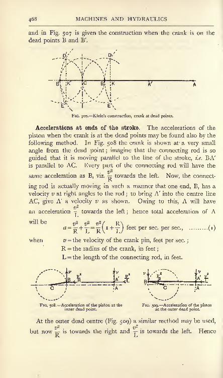
468 MACHINES AND HYDRAULICS
and in Fig. 507 is given the construction when the crank is on the
dead points B and B'.
D

TURNING MOMENT 469
the resultant acceleration of A will be towards the right, and will be
given by ^ tf & ( R\ .
* =g- L=RVL/ feet Persec Per sec
These results, (i) and (2), are of service in making preliminary
calculations of the accelerations of the piston when at the ends of
the stroke.
The effective force Q acting on the crosshead in the line of the
stroke may be estimated now.
Let d=i\\Q diameter of the cylinder, in inches.
pl= the effective pressure on the piston at a given position,
Ib. per square inch.
M = the mass of the reciprocating parts, including the
assigned part of the connecting rod, pounds.
flj= their acceleration in the given position.
Then Q=A^-Ma ib . weight.................................... (3)4 <5 .
Turning moment. The turning moment produced by Q may be
calculated as follows, reference being made to Fig. 510 and friction
FIG. 510. Turning moment on the crank.
being neglected. I is the instantaneous centre for the given position,
from which it appears that rotation of the rod round I is produced
by Q and resisted by the crank pin with a force S. Hence,
QxIA = SxIB,
|i ;>;;;;:;s=Qra (4)
Produce AB to cut CN in Z; then the triangles ABI and BZCare similar. Hence, IA CZ CZ
IB=BC
=1T
Substitution in (4) gives CZ .

470 MACHINES AND HYDRAULICS
S is the reaction of the crank pin, and, if reversed, will be the
crank effort given by the connecting rod to the crank pin. Hence,
Turning moment = T = S x R~CZ .
= Q.CZ (6)
This result will be in Ib.-feet if Q is in Ib.-weight units and CZ is
measured in feet to the same scale as that used in drawing the
mechanism.
With the alterations and additions noted above, the method of
obtaining a turning moment diagram used on p. 463 may be employed.
360* 180*
FIG. 511. Diagrams for a slider-crank-chain, taking account of inertia.
The various diagrams required are shown in Fig. 511, and will be
followed readily.
General effects of inertia. The student will observe that the
general effect of the inertia of the moving parts is to produce a
more uniform turning moment on the crank. During the early
part of the stroke, the gaseous pressure on the piston is high, but is
absorbed partly in accelerating the moving parts, hence the turningmoment is smaller
;later in the stroke, the gaseous pressure is low,
but the moving parts are losing velocity now, and their inertia assists
the gaseous pressure in making the turning moment larger.
Greater uniformity in the turning moment may be obtained by
having two or more cylinders with pistons operating on separate
cranks. If there are two cylinders, the cranks are placed generally

MOTION OF THE CONNECTING ROD 471
at 90 to each other;in the case of three cylinders, the cranks are
generally at 120; with a larger number of cranks, the precise crank
angles cannot be stated, as other considerations are involved. Usually
an attempt is made in such cases to
produce a self-balanced machine,
i,e. one in which the inertia effects
balance one another without pro-
ducing disturbances in the frame or
foundation.
Turning moment diagrams are
given in Fig. 512 for two cylinders
similar to the case illustrated in
Fig. 511. The cranks are at 90,and the turning moment diagramsfor each crank separately are shown
by ABCDA and EFGHE ;these
are displaced relatively to each other
by 90. Summing the corresponding ordinates, the combined
turning moment diagram is HKBLFMDNH. Greater uniformity
has been obtained, and there is no point where the turning point
is zero.
Further points regarding the motion of the connecting rod. It
has been explained that, for positions near the dead points, the
motion of the connecting rod may be assumed to be compounded of
FIG. 512. Turning moment diagram fot
two cranks at 90.
FIG. 513. Analysis of the motion of a connecting rod.
a motion of translation together with another motion of rotation
round the crank pin (p. 468). The same assumptions may be madewhen the rod is in any other position (Fig. 513). The first of these

472 MACHINES AND HYDRAULICS
motions would cause the rod always to move parallel to the centre
line AC, and it would occupy the position A'B when the crank is at
CB ;the latter motion produces the effect of rotating the rod into its
proper position AB. Owing to the first of these component motions,all points in the rod will possess the same velocity and acceleration as the
crank pin B;in this respect, the motion is precisely the same as that
of the side rod of a locomotive (p. 464). The acceleration thus pro-
V2
duced at A will be _?, and may be represented by the length of theR
crank BC. Hence,
or VB = BCxR = BC2...................... (i)
The point A will possess other accelerations owing to the com-
ponent motion of rotation of the rod about B;
in consequence of
this angular motion, A will have a variable velocity v in a direction
at right angles to the rod. The value of v will depend on the posi-
tion of the crank, and hence will be undergoing change in most
positions of the mechanism. Owing to this, there will be an acceler-
ation of A in the line of z>, i.e. at right angles to the connecting rod.
Further, A will possess the ordinary central acceleration towards B, of
v2-
magnitude given by =-. Hence in all A possesses three component.L/
accelerations, and the resultant of these must have a direction coinciding
with that of AC.
To find an expression for #, reference is made to Fig. 513, show-
ing I, the instantaneous centre of the rod. The angular velocity of
V vthe rod will be
,and will be given also by T
-. Hence,J..D LJ
*_VBL IB'
Also,
v1i V2
Central acceleration of A towards B = y-= ^ ' f^^2
\-i !_/ IJj
-SBT Vl...................... (3)
Referring to Fig. 514, showing Klein's construction together with

MOTION OF THE CONNECTING ROD 473
the position of I, join BD and DA. The triangles BFD and BDAare similar. Hence, -gp -g^
BD=AB'
BD2
or BF =AB'
Also, by the construction, BD is equal to BZ, and AB is equal to
L. Hence,
\
FIG. 514. Proof of Klein's construction.
Again, the triangles BCZ and IAB are similar. Hence,
BZ AB , LBC~ IB~IB ;
LxBCBZ =
From (4),
IB
L2 .BC2i BC2 x L
"L=
IB S IB2
(5)
Comparison of (3) and (5) will show that FB represents the
central acceleration of A towards B to the same scale in which BCV2
represents 5.
The resultant acceleration of A along AC may be found now bymeans of a polygon of accelerations. In Fig. 514, FB is the central
V2
acceleration of A towards B ; BC is the component -=5 the com-ix.
ponent acceleration at 90 to the rod owing to variation in v is

474 MACHINES AND HYDRAULICS
represented by KF, and the closing line KC gives the resultant accelera-
tion of A along AC. It will be noted that this result proves the truth
of Klein's construction.
Since KF gives the linear acceleration of A in the direction at 90to that of the rod, it follows that the angular acceleration of the rod
will be given by
Angular acceleration of the connecting rod = -= (6)LJ
Acceleration image of the connecting rod. In Fig. 5 1 5 KF and
FB have been copied from Fig. 514. The resultant of these
FK;. 515. Acceleration image of a connecting rod.
accelerations will be KB, the closing line of the triangle of accelera-
tions FBK. The acceleration of A along AC may be taken to be the
resultant of the accelerations KB and BC, and is represented by the
closing line of the triangle of accelerations KBC. Consider anyother point in the connecting rod, such as G. Its velocity at 90to the rod, and hence its accelerations, owing to the rod rotating
about B, will be simply proportional to BG, that is,
acceleration of G : acceleration of A = BG : BA.
Draw.GH parallel to AC, and cutting KB in H;then
Acceleration of G : acceleration of A = BH : BK.
Now KB represents the resultant of the two component accelera-
tions of A which are respectively along and at 90 to AB hence H.B
will represent the resultant of the similar components of G. The
component acceleration of G, owing to B rotating about C, remains
V2
of unaltered value -^, and is represented by BC. Hence the re-Jx
resultant acceleration of G will be the closing line HC of the triangle
of accelerations HBC. The resultant acceleration of any other point in
the rod may be found in a similar manner by drawing a line from the point
parallel to AC to cut KB, and joining the point so found on KB to C. Onaccount of this property of KB it is called usually the acceleration
image of the connecting rod.

INERTIA OF THE CONNECTING ROD 475
Eesultant force required to give acceleration to the connecting
rod. In Fig. 516, let G be the mass centre of the connecting rod.
FIG. 516. Resultant force required to overcome the inertia of the connecting rod.
The acceleration of G is HC, and might be produced by a force Racting at G in a line parallel to HC. The magnitude of R, if the
rod has a mass M pounds, will be
M . HC , V .. V. / \R= - Ib. weight (i)>
This force would not produce any angular acceleration in the
connecting rod on account of its line of action passing through the
mass centre of the rod. In order to obtain the actual motion of
the rod, which includes angular acceleration in most positions, R will
require to be shifted from G, thereby giving a couple which will
produce the required angular acceleration. A convenient way is to
use an equivalent dynamic system by substituting two masses, ml
and m2 pounds (Fig. 517), for the actual mass of the rod. One of
'
/T5N Gm
c 'B \T T 9/"*
^i
FIG. 517. A dynamical system equivalent to the connecting rod.
these, m l , may be situated at the centre of the crosshead pin A, at a
distance a from G;the other mass, m.2 ,
will be at a distance b on
the other side of G. For this arrangement to be equivalent to the
actual rod, the following conditions must be complied with (p. 444) :
ml + m2
= M. (2)
m^a = m.J) (3)
^2 +^2 = M>G .
(4)

MACHINES AND HYDRAULICS
kc is the radius of gyration of the connecting rod about an axis
passing through G and parallel to the crank shaft. The solution of
these equations gives a& = A*G9................................... (5)
* =f.................................... (6)
From this result b may be calculated when a and kG are known;
the masses mLand m
2 may be determined then from equations (2)
and (3).
Reference may be made now to Fig. 516, which shows the crank
and connecting rod, the latter being represented by the equivalent
masses mland m
2. To accelerate m
1 requires a force RT acting in
the line of the acceleration of A, viz. AC. To accelerate m2 requires
a force R2 acting in the line of the acceleration of D
;this line may be
found by drawing DE parallel to AC and cutting BK in E;
the
acceleration of D will be represented then by EC. R2
will be
parallel to EC, and cuts the line of Rj produced in F. Hence the
resultant of Rtand R2 ,
which will be the resultant force R required
to accelerate the rod, must pass through F. The line of R will be
parallel to the acceleration of the mass centre G, viz. HC, and the
magnitude of R will be given by equation (i) (p. 475). The couple
giving angular acceleration to the connecting rod will be R x GM,GM being the perpendicular from G to the line of R.
Reactions on the engine frame produced by the inertia of the
connecting rod. In Fig. 518, R is the resultant force required to
D
FIG. 518. Components of R at the crank and crosshead pins.
overcome the inertia of the connecting rod in the given position.
R is actually the resultant of two forces, one of which, P, is applied
by the guide bar to the pin at A;the other force, Q, is applied to
the rod at B by the crank pin. If the friction of the slipper be
neglected, P will act at right angles to AC, and its line will intersect

INERTIA OF THE CONNECTING ROD 477
the line of R at D ; hence Q also acts through D. . The magnitudes
of P and Q may be determined by drawing the parallelogram of
forces DGEF, in which DE is made equal to R, and P and Q will
be represented by DG and DF respectively. The reaction on the
guide bar at A will be obtained by reversing the sense of P (Fig. 519) ;
in the same diagram, the reaction on the crank pin is shown by
reversing the sense of Q.
The force Q in Fig. 519 is equivalent to an equal and parallel
force Q, of the same sense, acting at C together with a couple ot
moment Q x CH, CH being perpendicular to the line of Q. Q
FIG. 519. Reactions of the engine frame due to the inertia of the connecting rod.
acting at C produces a pressure on the main bearing and hence on
the engine frame;the couple Q x CH modifies the turning moment
on the crank.
Bending moment on the connecting rod produced by its inertia.
Assuming that the inertia effects on the connecting rod will be
FIG. 520. Transverse inertia load on the connecting rod.
greatest when the crank and connecting rod are at 90 to each other,
the bending-moment diagram may be drawn as follows : In Fig. 520

478 MACHINES AND HYDRAULICS
ABC is 90, and- BD is the acceleration image of the rod. Theacceleration of B will be towards C and will be o>
2R feet per second
per second, where w is the angular velocity of the crank in radians
per second and R is the radius of the crank in feet. The acceleration
of A will be represented by DC, and its component perpendicularto AB will be found by drawing DE perpendicular to CB. CEwill be the required component. Neglecting the very small acceler-
ation represented by CE, the acceleration of any point on the
connecting rod may be found by making BF perpendicular to ABand equal to o>
2R and by joining FA. The acceleration normal to
AB of any point H in the rod will be represented by HK, perpen-dicular to AB.
Let m be the mass of the rod in pounds per inch length at H;
then the transverse inertia load on the rod at H will be
Inertia load per inch length= - Ib. weight,
cb
HK being measured to the acceleration scale in feet per second persecond. A similar calculation should be made for a number of
FIG. 521. Bending moment diagram produced by the inertia load on the connecting rod.
points on the rod;the calculations are somewhat simpler in the case
of a rod of uniform cross section, and in other caset may sometimes
be simplified by taking m to be the average mass per inch length.
A load curve is constructed then by drawing AB (Fig. 521 (a)) to
represent the length of the rod and setting off the calculated loads
per inch at the various points chosen, as at PQ, Considering the
portion BP, the average load per inch will be |(BN + PQ) and the
load on BP will beWl = l(BN-r-PQ)BP.

SLIDE-VALVE GEAR 479
Wj will act through tfie centre of area of BNQP. Carrying out
the same process for the other portions of the rod, we obtain the
equivalent system of concentrated loads W1?W
2 ,W
3 ,etc. The
bending-moment diagram may be drawn now by the link polygon
method (p. 140) ,the construction being shown in Fig. 521 (fi) and (c).
Simple slide-valve gear. In ordinary reciprocating engines, the
valve employed to distribute the steam to each end of the cylinder
consists of an inverted rectangular box V (Fig. 522), which slides on
VlL^vC^&x<^^css>s
Bi
FIG. 522. Simple slide-valve for a steam engine.
a flat face formed on the cylinder. Two steam passages, or ports Sj
and S2 ,
lead to each end of the cylinder, and another E leads to the
atmosphere or to the condenser. Movement of the valve to the
right will permit steam to flow through Sxinto the left-hand side of
the cylinder, and at the same time permits the steam in the right-hand
side to flow out through S2and E. Movement of the valve to the
left will admit steam to the right-hand side through S2 ,
and will
permit exhaust from the left-hand side through Sxand E.
CD is the centre line of the valve and AB is the centre line of the
cylinder ports ;the valve is in its mid-position when these lines are
coincident vertically. In this position, the valve generally laps over
the edge of the ports ;/ is called the outside lap, and gives an earlier
cut-off than if there were no outside lap ;el
is called positive inside
lap ;if the inside lap is made as shown at e% it is called negative ;
the inside lap determines the point at which the exhaust steam is
stopped from flowing out of the cylinder. Cut-off of the steam supplyis effected when some fraction of the piston stroke has been com-
pleted; the remainder of the stroke is then completed under the
expansive action of the steam. Closing of the exhaust is effected
before the end of the return stroke in ordsr to entrap some of the

480 MACHINES AND HYDRAULICS
exhaust steam in the cylinder ;this is compressed by the returning
piston, and acts as a cushion in bringing it to rest. To understand
the complete distribution of the steam, it is necessary that the
displacement of the valve from its mid-position should be knownfor any given crank position, and hence for any piston position.
The slide valve is driven generally by means of an eccentric, con-
sisting of a disc A secured to the crank shaft B and revolving with it
(Fig. 523). The hole in the disc is bored at a small distance from
FIG. 523. Eccentric driving a slide valve.
the centre of the disc. A strap C surrounds the disc and is connected
by an eccentric rod DE to the valve rod EF. The eccentric is
equivalent to a crank having a radius equal to the distance from the
centre of the shaft to the centre of the disc. This radius is generally
very small compared with the length of the connecting rod; hence it
may be assumed that the motion of the valve is simply harmonic.
Let the circle ABCD (Fig. 524) represent the path described bythe centre of the eccentric, which is rotating in the direction of the
arrow. AC may be taken to represent
the travel of the valve, which will be
in its mid-position O when the eccentric
is at OB or at OD. Assuming simpleharmonic motion, when the eccentric
is in any position, such as OE, if EMand EN are perpendicular to AC and
to BD respectively, OM or NE will be
the displacement of the valve. If the
angle separating the eccentric and
the crank be EOK, then OK will be
the corresponding crank position
Since the valve displacement towards the right must be equal to / at
admission, if OL, equal to /, be measured and LEXdrawn perpen-
dicular to AC, OEj will be the position of the eccentric at admission.
By setting off the angle EjOKj equal to EOK, the position of the
crank at admission OKX may be found. Producing EjL to E
2will

VALVE DIAGRAMS 481
determine the eccentric position OE2
at cut-off. Release and
cushioning are controlled by the inner edge of the valve. MakeOQ equal to e, measuring it to the left of O if positive and to the
right if negative, and draw E3QE4 perpendicular to AC ; OE
3 andOE4
will be the eccentric positions at release and cushioning
respectively. In each case, the corresponding crank position maybe obtained by setting back angles equal to EOK.
Valve diagrams are based on the idea of obtaining direct the
displacement of the valve by merely drawing the crank in any given
position. In the Reuleaux valve diagram (Fig. 525), OSj and OS2
are the crank positions at admission and
cut-off; it is evident that the angle S-f>S2
in this figure is equal to EjOEg in Fig. 524.
Hence DjDg, parallel to S^, will cor-
respond to BD in Fig. 524, and the valve
displacement for any crank position OKwill be KN, which is drawn perpendicularto DjDg, and hence corresponds to ENin Fig. 524. Draw 8^2 and E^ parallel FlG. 525.^~~x^ diagt3im .
to DjDo and at distances from it equalto / and e respectively. Then, of the total displacement KN, SN is
equal to the outside lap, and hence KS will be the amount by which
the valve edge has opened the port to steam. Similarly, at OK',K'N' will be the displacement on the left of the mid position and EK'will be the amount by which the inner edge of the valve has
uncovered the port to exhaust. At admission and cut-off, the
crank will be at OSland OS2 respectively, as has been used in the
construction;in these positions the port opening is zero. At release
and cushioning the crank will be at OE2and OE
l respectively, because
in these positions the exhaust opening will be zero.
There are many other types of valve diagrams ; any standard text
book may be consulted for the principles on which they are based.*
Component eccentrics for a valve gear. In Fig. 526 (a), OC is
the crank on the dead centre and OE is the corresponding eccentric
position ;the angle EOV is called the angle of advance and is denoted
by a. Suppose that, instead of using OE, component eccentrics OVand OH are employed, these being found by drawing EV and EHrespectively parallel and at right angles to CO. It is to be under-
stood that the actual motion of the valve is to be obtained by adding* A complete discussion is given in Valves and Valve Gear Mechanisms,
by Prof. W. E. Dalby ; (Arnold).
D.M. 2 H

482 MACHINES AND HYDRAULICS
together the displacement produced by the component eccentric OHand that produced by OV. OV and OH are called the 90 and the
1 80 components respectively, and are given by
OV = OE cos a.
OH = OEsina.
In Fig. 526(^)5 the crank has moved through an angle 6 from the
dead point. We have
Displacement produced by OE = OM = OE sin (a + 0)
= OE sin a cos 6 + OE cos a sin 6.
Displacement produced by OV = ON = OV sin = OE cos a sin 6.
Displacement produced by OH = ON' = OH cos 6 = OE sin a cos 6.
Sum of displacements produced by OH and OV = OE sin a cos
+ OE cos a sin 0.
Hence the resultant displacement produced by the componenteccentrics is equal to that produced by the actual eccentric.
Let OH and OV be written a and b respectively ;then
Displacement of the valve = a cos + ^sin B (i)
FIG. 526. Component eccentrics. , , m .
a and b are both constant in a simple valve motion having a single
eccentric. In many cases of more complicated valve gears the
motion of the valve may be represented approximately by an
equation of form similar to (i), showing that the valve may be
imagined to derive its motion from a single eccentric acting direct on
the valve.
Hackworth valve gear. An example is shown in Fig. 527 of a
Hackworth valve gear: BC is the crank and AB is the connectingrod. The eccentric CE is at 180 to the crank and is connectedto a rod EF, the end F of which may slide on a guide GH.GH is pivoted at K, and the angle /3 which it makes with CK may

HACKWORTH VALVE GEAR 483
be adjusted by hand. Alterations in the cut-off and reversal of the
direction of motion of the engine are effected by altering /?. Thevalve rod LN is connected to EF at L.
FIG. 527. Hackworth valve gear.
The displacements of the valve will be very nearly equal to the
displacement of L vertically.
Let r= the radius of the eccentric.
</=LF. Then
Displacement of E vertically from CK = r cos 9.
If F were to move in the straight line CK, the displacement of Lvertically owing to the above displacement of E would be
Vertical displacement of L = - r cos 6......................... (i )
Again,Displacement of E horizontally from AC = r sin 0.
In Fig. 528 CP represents this displacement, and F is supposed to
be connected direct to P. KQ will be very nearly equal to CP.

484 MACHINES AND HYDRAULICS
Hence,
r sin 6 tan /?.
Hence, Vertical displacement of L = -. r sin 6 tan ,8 . (
2)
FIG. 528. Approximations in the motions in the Hackworth valve gear.
To obtain the total displacement of L, take the sum of (i) and (2),
noting that the result of (2) may be either positive or negative, de-
pending on the setting of the guide bar HG. Thus
Displacement of L = (- Acos 9 ft- rte,n/3}sin& (3)
The result shows that the radii of the component eccentrics are
Radius of the 1 80 component eccentric = a = ~r. (4)
Radius of the 90 component eccentric = b = r tan /?. ... (5)
The first of these, a, is evidently constant. The other, /;, dependson the value of /?. To obtain the maximum value of b take the
maximum values of /3, positive and
negative, and hence of tan/:?, andobtain the numerical value of (4)and (5). In Fig. 529 CY is made
equal to the 180 component eccentric
a, and CX and CX' are respectively
equal to the maximum positive and
negative values of the 90 componenteccentric b. The centre of the re-
sultant eccentric will lie on E'YE,drawn parallel to XX', for all settings of the guide bar GH. Its
limiting positions will be CE and CE' respectively. The resultant
eccentric for any other setting of the guide bar may be obtained bycalculating CX" from (5) ;
the resultant eccentric will then be CE".The motion of the valve may be obtained thus for any setting of
the guide bar GH by connecting it direct to the resultant eccentric
found in this manner. E'YE in Fig. 529 is called the characteristic
line of the gear.
FIG. 529. Characteristic line for theHackworth valve gear.

OSCILLATING ENGINE MECHANISM 485
Oscillating engine mechanism. This mechanism is illustrated in
Fig. 530 (a) ; a crank BC revolves about B, and the cylinder is
capable of oscillating about an axis or trunnion at A. There is no
connecting rod ; the piston rod is connected direct to the crank pin
as shown. In Fig. 530 (ft)is shown a slider crank chain, in which the
FIG. 530. Oscillating engine mechanism.
crank BC revolves about C and A moves in the straight line AC.
Comparison of (a) and (ft)will show that (a) has been produced
from (ft) by an inversion of the mechanism. In(ft),
AB is capable of
swinging about AC, while in (a) AB is fixed and AC is capable of
swinging about AB.
In Fig. 530 (<r),let the lengths of AB and BC be denoted by L and
R respectively in feet, and let the velocity of the crank pin be uni-
formly equal to v feet per second. The- angular velocity of the
crank pin will be given by
w1
=: radians per second.
To obtain the angular velocity of the cylinder, resolve v into
velocities respectively along and perpendicular to AC by means of
the parallelogram CEFB. CD = V will be the component per-
pendicular to AC. It is evident that the angular velocities of the

486 MACHINES AND HYDRAULICS
cylinder and of the piston rod AC about A will be equal. Hence the
angular velocity of the cylinder is
Vto2= ^ radians per second (2)ALx
Draw BG perpendicular to AC and GH parallel to BC;
the
triangles BCA and HGA will be similar. Hence,
CA^BA^ LCG~BH~BH ;
Substitution in (2) gives
BH
V.BHW2 ~L.CG*
Again, the triangles BGC and FDC are similar. Hence,
CG^CD^VCB CF v '
V V.-. CG= --R = .
V(Wj
Substitute this value in (3), giving
-(3)
V.BHwj
BHL V
(4)
This result shows that the angular velocity of the cylinder is repre-
sented by BH to a scale in which the angular velocity of the crank
pin is represented by the constant length L.
The cylinder has zero angular velocity in the
two positions in which the crank and piston rod
are at right angles. For positions of the crank
below these, the cylinder is swinging towards
the right, and its angular velocity may be called
positive ;for crank positions above the zero
positions, the angular velocity will be of op-
posite sense, and may be described as negative.
A polar diagram of angular velocity (Fig. 531)
may be drawn by carrying out the construction
for crank angles differing by 30. BH (Fig.
530 (<:))is measured for each position and set
FIG. 531. Angular velocity off from C along the radius BC, towards B for
%. f r " sdllatingnegative and away from B for positive values.

QUICK-RETURN MOTIONS 487
The points D and E may be found by describing a circle on AB as
diameter;the angles BEA and BDA will then be each 90. At G
and F the angular velocities of the cylinder will be v/AG and vjAF
respectively.
Examining Fig. 531, it will be noted that the crank, rotating
uniformly, takes a longer time to traverse the arc DOE than it does
to traverse the arc EFD. Hence the average angular velocity of the
cylinder towards the left will be less than that towards the right. In-
spection of the angular-velocity diagram will illustrate the same point.
Quick-return motions. Advantage is taken of these facts in the
quick-return motion fitted sometimes to shaping machines (Fig. 532).
FIG. 532. Quick-return motion for a shaping machine.
The tool G cuts the work H on the stroke towards the right only,
and it is advantageous that this cutting stroke should be executed
at a slower speed than that of the idle return stroke. The tool is
fixed to a sliding ram F, guided so as to move horizontally. F is
connected by a short link ED to the top of a slotted bar AD, which
may oscillate about A. AD is driven by means of a uniformly-
rotating crank BC, the crank pin of which engages a block at Cwhich may slide in the slot of AD. The tool will be at the ends of
its travel when BC is in the positions BK and BL, both of which are
at 90 to AD (Fig. 533).
Neglecting the effect of the obliquity of DE (Fig. 532), the travel
of the tool may be found thus
Half travel of tool = DO (Fig. 533).

MACHINES AND HYDRAULICS
A1 DO ADA1S
' BK=AB>. BK.AD AD
~AB~=AB'
R'
ADand Travel of tool = d= 2-^ . R,
AJo
where R is the radius of the crank BC.
FIG. 533. Quick-return motion ; mechanism at the ends of the travel.
The average speed on the cutting and return strokes may becalculated by first finding the times taken by the crank to traverse
the arcs LMK and KNL respectively.
Let T = time of i revolution of crank, in seconds.
/c = time to traverse arc LMK, in seconds.
/r = time to traverse arc KNL, in seconds.
Then tc : tr : T = arc LMK : arc KNL : 2:rR.
arc LMK27TR
_arc KNL~~Also, Average cutting speed = -
.
*c
dAverage return speed = -.
IT
The maximum cutting and return speeds may be obtained easilyfrom Figs. 534 (d) and (ft) respectively.

QUICK-RETURN MOTIONS 489
Vc AD AD
And
A
(a) (b)
FIG. 534. Quick-return motion ; maximum cutting and return speeds.
The Whitworth quick-return motion (Fig. 535) is produced byanother inversion of the slider-crank-chain. A slotted link CDrevolves on an axis at C, and is connected to the ram of the shapingmachine by the rod DK. Motion is given to CD by means of a
crank AB revolving round an axis at B;
its crank pin A has a block
FIG. 536. Outline of Whitworth quick-return motion.
itFIG. 535.^ Whitworth quick-return motion.
bearing which slides in the slot of CD. Inspection of the outline
diagram (Fig. 536) will show that BC is the crank in the slider-crank-

490 MACHINES AND HYDRAULICS
chain, and now is fixed;AB was formerly the connecting rod, and
ACD was the line of stroke.
The travel of the tool will be twice CD, and the tool will be at the
ends of the stroke when CD is passing through its horizontal positionsCE and CF. The arc through which BA turns during the cuttingstroke is FHE, and the arc during the return stroke is EGF. Theaverage speeds may be calculated in the same manner as for the
quick-return motion discussed above. The maximum speed duringthe cutting stroke will occur when A is at H, and that during the
return stroke will occur when A is at G.
Let v = velocity of A, assumed uniform.
Vc = maximum cutting velocity.
VR = maximum return velocity.
TU Vc CD _, CD, xThen = ^^, or, Vc =->v (i)CH'
Also, or,CD
V.v CG'
Comparison of (i) and (2) shows that
VC :VR = CG:CH.Cams. Cams are employed when the reciprocating motion to be
given to the end of a rod or lever is of an irregular character. In
Fig. 537 (a) the rod OA reciprocates vertically in the line OA, and is
;A
FIG. 537. Two examples of cams.
driven by a disc B fixed to a revolving shaft C. The rim of B is
shaped so as to give the required motion to the rod. In Fig. 537 (/>)
is shown another example, in which the direction of motion of OAdoes not pass through the axis of the shaft C.

EXERCISES ON CHAPTER XIX. 491
The outline of the cam in Fig. 537 (a) is drawn by setting off equal
angles oCi, iC2, 2C3, etc., and marking off the distances along OA,
through which the rod is to travel while the cam is describing these
equal angles. The points of division on OA are then brought to the
corresponding radii by means of arcs described with C as centre.
The outline in Fig. 537 (ft)is obtained by first drawing a circle with
centre C and touching the line AO produced. Tangents are then
drawn to this circle at equal angular intervals, and the distances
along OA to be described during each of these intervals are brought
to the corresponding tangent by means of arcs drawn with centre C.
EXERCISES ON CHAPTER XIX.
1. A link AB, 2 feet long, is horizontal at a given instant and is
moving in a vertical plane. The velocity of the left-hand end A is lofeet
per second upwards to the right at 45 degrees to AB. The velocity of Brelative to A is 4 feet per second downwards. Find the actual velocityof B.
2. In Question i, find the instantaneous centre of the rod and the
velocity of the centre of the link.
3. In a crank and connecting-rod mechanism, the crank CB is i foot
long and the connecting rod AB is 4 feet long. The velocity of the
crank pin B is uniform and equal to 10 feet per second. Divide the
crank circle into intervals of 30 degrees, and find the velocity of the cross-
head A for each of the crank positions so determined. Draw diagramsof velocity for a complete revolution (a) on a time base, (b) on a spacebase, of length to represent twice the stroke of the crosshead.
4. In a double crank and connecting rod (four-bar chain) the cranks
are AB, 1-5 feet long, and CD, 2-5 feet long; the connecting link BCis 2 feet long ;
the bar AD is fixed and is 2-25 feet long. B has a linear
velocity of 2 feet per second. For the position in which AB makes60 degrees with AD, find (a) the angular velocity of AB, (b) the velocityof C, (c) the angular velocity of DC. Use the instantaneous centre
method, and check the result for (c) by the ratio given on p. 460.
5. A four-bar chain has cranks AB and DC 2 and 175 feet long
respectively ;the connecting link BC is 1-5 feet long and the bar AD is-
fixed horizontally and is 1-5 feet long. The cranks are crossed. Drawthe mechanism when AB makes 45 degrees with AD, and find a point Ein the link BC (produced if necessary) which is moving in a vertical
direction in this position of the mechanism.
6. In the parallel motion shown in Fig. 498, AC is i inch and BCis inch long. The line joining AB is horizontal and ijj
inch long.- ADis 1-5 inch long and is vertical when AC is horizontal. Find the lengthof CF, and confirm the result by drawing for the positions when ACmakes 15 degrees with AB.
7. In the mechanism shown in Fig. 502, the crank is 3 inches longand has a uniform speed of 60 revolutions per minute. The mass of the

492 MACHINES AND HYDRAULICS
reciprocating parts is 80 pounds. Find the forces in Ib. weight required to
overcome inertia for crank positions differing by 30 degrees throughout the
revolution. Plot these forces on a base line representing twice the stroke.
8. In Question 7 the steam cylinder driving the mechanism is
5 inches in diameter ; the net pressure of the steam urging the pistonis 50 Ib. per square inch up to half stroke, and is 35, 24 and 20 Ib. per
square inch at 0-6, 0-8 and the end of the stroke respectively. Draw the
pressure diagram, and find the turning moment on the crank for each
position given in Question 7, making allowance for inertia. Draw the
turning-moment diagram.
9. Two parallel shafts, 30 inches axis to axis, have each a crank6 inches long connected by a uniform steel rod 30 inches long, 2 inches
deep and i inch wide. The shafts are driven at equal speeds. Take the
density of steel to be 0-28 pound per cubic inch, and find the maximumupward and downward forces due to the inertia and weight of the rodwhen the speed is 150 revolutions per minute.
10. In Question 9, the stress due to bending of the rod is limited to
10,000 Ib. per square inch. What is the maximum permissible speed of
the shafts in revolutions per minute ?
11. Take the data of Question 3 and find the acceleration of the
crosshead in the line of the stroke when the crank has travelled
60 degrees from the inner dead point. Do this by use of Klein's con-struction. Calculate also the accelerations when the crosshead is at
each end of the stroke. The mass of the reciprocating parts is
500 pounds ;calculate the forces required to overcome their inertia in
these positions.
12. In Question 11, the total effective steam pressure on the pistonwhen the crank is 60 degrees from the inner dead point is 9000 Ib.
What will be the turning moment on the crank, (a) neglecting inertia,
(&) taking account of inertia ?
13. With the data of Question 3, find the acceleration image of the
connecting rod when the crank is at 90 degrees to the connecting rod,and hence find the acceleration of the centre of the rod.
14. In Question 13, take the connecting rod to be of uniform section
and of mass 3 pounds per inch length. Find the resultant force whichmust act on the rod in order to overcome its inertia.
15. Draw the bending-moment diagram for the connecting rod as givenin Question 14, and state the value of the maximum bending moment.
16. In an oscillating-engine mechanism, the crank is 2 feet long andmakes 50 revolutions per minute. The distance between the centre ofthe crank shaft and the cylinder trunnion is 5 feet. Find the angularvelocity of the cylinder when the crank is passing each dead point.Answer the same when the crank is at 45 degrees from the outer dead
point.
17. In Question 16, if the crank rotates clockwise, find the time of
swing of the cylinder (a) from left to right, (b) from right to left. Cal-
culate the angle through which the cylinder oscillates.
18. The axis of a vertical rod passes through the axis of a horizontal
shaft when produced downwards. The rod has a roller I inch diameter

EXERCISES ON CHAPTER XIX. 493
at its lower end and is driven vertically by a cam fixed to the shaft. Theminimum radius of the cam is 2 inches, and it gives simple harmonicmotion to the rod during the upward travel of 2 inches, followed by a
period of rest while the shaft rotates through 45 degrees. The downwardtravel is simple harmonic. Draw the outline of the cam.
19. Answer Question 18, supposing that the axis of the rod passes
0-5 inch from the shaft axis when produced.
20. Describe the character of the straining actions to which the
coupling-rod of a locomotive engine is subject, and sketch an appropriateform of transverse section. In a locomotive having driving wheels of
6 feet 6 inches diameter, the coupling-rod is 8 feet long between its
centres, and is attached to cranks of I foot radius. Suppose the locomo-tive to travel at 60 miles an hour, and the weight W of the coupling-rodto be uniformly distributed along the 8 feet of its length, estimate the
maximum bending moment to which it will be subjected. (I.C.E.)
21. Describe, without proof, a construction for determining the
acceleration of the slider in the slider-crank mechanism. Apply the
construction to find the acceleration of the piston of an ordinary direct-
acting engine when the crank is 30 from the inner dead centre. Lengthof crank, 8 inches. Length of connecting rod, 36 inches. Speed of
crank shaft, 200 revolutions per minute. State the answer in feet persecond per second. (L.U.)
22. In a slider-crank chain AB is the connecting rod, 30 inches long,BC the crank and AC the horizontal line of stroke. In AB producedbeyond B a point P is taken, BP being 18 inches. If the locus of Pis an approximately vertical straight line, while AB travels through anglesfrom o to 30 with the line of stroke, find a suitable length for BC. Aload of 2000 pounds at P acts at right angles to the line of stroke
;find
the pressure on the crosshead required to equilibrate, and find also the
thrusts on the guides and crank when BAG = 30. (L.U.)
23. In a four-bar chain ABCD, AB is the driving, CD the driven
crank, and BC the coupler, DA being fixed. BC, produced if necessary,cuts AD in P. Show that the ratio of the angular velocity of CD to that
of AB is PA/PD. Draw the velocity diagram for this chain when AB,BC, CD and DA are i, 6, 3 and 7 feet respectively, the angle BAD being90 and AB and CD being on the same side of AD. If the velocity of Bis i foot per second, find the velocity of C, and check by using the ratio
given above. (L.U.)
24. A simple slide valve driven by an eccentric has a travel of 5 inches.
The cut-off is at of the stroke of the piston, and the release takes placeat | of the stroke. The lead is J inch. Assuming that the valve and
piston have simple harmonic motions, find the outside and inside lapsof the valve and the position of the piston when compression begins.
(L.U.)
25. A connecting rod is 5 feet long and 5 inches in diameter, assumeduniform throughout its length. Stroke of piston, 2 feet 6 inches.
Revolutions per minute, 180. Weight of material, 480 Ib. per cubic foot.
When the crank angle is 60 measured from the inner dead centre, drawthe load and bending-moment curves on the connecting rod due to its
inertia, and state the value of the maximum bending moment. (L.U.)

CHAPTER XX.
FLYWHEELS. GOVERNORS.
Fluctuations in angular velocity. It frequently is the case that
it is important to secure uniformity of angular velocity in some shaft
belonging to a machine. This condition is usually very desirable in
engines supplying motive power. In such cases there may be two
kinds of disturbance owing to lack of equality in the rates of supplyof energy to the engine and of abstraction of energy for driving
purposes. In any machine we have the following equation (p. 328)for the balance of energies during a stated time :
Energy supplied= energy abstracted + energy wasted in the machine.
Suppose the energy supplied exceeds that required in order to
satisfy the above equation, then the machine must be increasing
its speed, as the excess energy must be disposed of, and the onlymethod available is by the storage of additional kinetic energy in the
parts of the machine. The converse will be the case if the energy
supplied falls below that required in order to satisfy the equation.
For simplicity, suppose the moment of resistance to rotation of
the engine shaft, supplied by the machinery to be driven, to be
uniform. There will be a demand then for a constant amount of
energy during each revolution of the shaft. But the rate of supplyof energy to the shaft is never uniform, depending as it does on the
turning-moment diagram (p. 470), which may show great lack of
uniformity. The result would be evidenced in rapid alterations in
the angular velocity of the shaft, a jerky action which it is the
function of the flywheel to remedy. This the flywheel does by storing
the excess energy in the kinetic form, and its large moment of inertia
enables it to do so with comparatively small changes in its speed.It is evident that, if the energy supplied during the revolution is
exactly sufficient to satisfy the equation, the angular velocity of the
flywheel at the end of the revolution will be equal to that at the

FLYWHEELS 495
beginning, i.e. there is no net gain or loss of speed despite inter-
mediate small fluctuations.
A second kind of variation in the angular velocity may occur
during a period extending over several revolutions of the shaft.
This would be owing to the supply of working fluid to the engine
being too la-rge or not enough, and would be evidenced by a steadyrise or fall in the speed of rotation. The flywheel alone is incom-
petent to deal with this matter, which must be remedied by a
contrivance called a governor. The governor is driven by the
engine, and is constructed so that the relative positions of its parts
alter with change of speed. These movements may be made to
operate valves which control the supply of working fluid, and thus
the shaft is kept rotating at a speed which may vary only slightly
above and below the mean speed. Absolute steadiness of speedcannot be attained, for change of speed must occur before the
governor will move into another position, and so operate the control
valve.
Kinetic energy of a flywheel. Some calculations regarding the
capacity for energy of a given wheel and of its change of angular
velocity in giving up a stated amount of energy will be found on
p. 420.
Let I = the moment of inertia of the wheel, pound and foot units.
<o = its angular velocity, in radians per second.
o>2
Then Kinetic energy of wheel = I foot-lb................ (i)
Let the wheel change its speed from Nj to N2 revolutions per
minute. Theno 9
Change in kinetic energy = L I 2_ j
Al Nl
AlSO, (0, = ^. 27T = -
60 30
TT. Hence,
3030I /7T
2NChange in kinetic energy = (
--l
2g\ 900
-^-
= 0-00548 (Nj2 - N
22) foot-lb. . . .( 2)
<b
Again, the kinetic energy at any speed N revolutions per minute
varies as N2; hence, if M be the kinetic energy at one revolution per

496 MACHINES AND HYDRAULICS
minute, the kinetic energy at N revolutions per minute will beMN 2
. Hence, the change in kinetic energy in passing from Nj to N,,
revolutions per minute may be written :
Change in kinetic energy = M(Nj2 - N2
'
J)............. (3)
The fluctuation in speed of the wheel may be defined as (N\- N
2),
and the coefficient of fluctuation of speed is taken as the ratio which the
fluctuation in speed bears to the mean speed. It is sufficiently
accurate to write
Mean speed = J(Nj + N2).
N NHence, Coefficient of fluctuation of speed = -j-r^f
-In practice, values of the coefficient of fluctuation of speed are
found varying from 0-05 to 0-008 depending on the type of
machinery.Dimensions of an engine flywheel. In estimating the dimensions
of a flywheel for an engine, sufficient information must be given or
assumed to enable the fluctuation of energy during a complete cycleto be ascertained. The process consists in reducing the drivingeffort on the piston to a tangential force acting on the crank pin,
making proper allowance for the inertia of the reciprocating parts of
the engine. A crank-effort diagram showing the values of this force
throughout a cycle is drawn. Another diagram is drawn on the same
base, showing the driving resistances to be overcome reduced to
another tangential force acting at the crank pin. Comparison of
these diagrams will enable the fluctuation of energy to be obtained.
The turning-moment diagram may be used in order to calculate R,the tangential force acting on the crank pin. Thus,
T = RxBC,
where BC is the length of the crank in feet and T is the turningmoment in Ib.-feet.
Values of R for a steam engine having a single cylinder are set off
in Fig. 538 on a base having a length equal to the circumference
of the crank-pin circle. The resulting crank-effort diagram OCBDAshows the work done on the crank pin per revolution, neglectingfriction.
The whole of the work done on the crank pin is utilised in
overcoming (a) frictional resistances in the engine, (b) the external
resistances which are opposed by the machinery being driven.

FLYWHEELS 497
Assuming both of these to be uniform when reduced to a tangential
force at the crank pin, it is evident that both will be taken account
of by constructing a rectangular diagram OEFA of height equal to
the average height of the crank-effort diagram. This rectangle will
express graphically the equality of energy supplied and energyabstracted during the revolution. The driving effort and the resist-
ance to be overcome are equal at G, H, K and L.
F Q
A L K B H GOFIG. 538. Fluctuation in energy in a steam engine.
Consider the portions of the diagram showing the energies while
the crank pin travels through the arc represented by GH. Work is
done on the crank to an amount represented by the area GMCNH,and the work abstracted is represented by the area GMNH. Hence,
surplus work, represented by the area MCN, has been done, with
the result that the flywheel will have its angular velocity increased
while the crank is passing from G to H.
In the same way, while the crank is passing from H to K, energy
represented by the sum of the areas HNB and BPK has been givento the crank and energy represented by the rectangle HNPK has
been abstracted. Insufficient energy, represented by the area NBP,has been supplied during this interval and the flywheel will be
decreasing its angular velocity. Hence, maximum speed will occur
when the crank is at H and minimum speed when the crank is at K.
Assuming that the speeds of the flywheel at G and K are equal, it
follows that the excess energy represented by MCN will be equal to
the deficient energy NBP, and it may be said that the energy repre-
sented by the area MCN has been given to the flywheel and taken
away again while the crank is passing from G to K. The fluctuation
of energy is therefore given by either of the equal areas MCN or
NBP. In the same way, the area PDQ is equal to the sum of the
areas QAF and EMO, and represents the fluctuation of energy
during the remainder of the revolution.
The coefficient of fluctuation of energy may be defined as the ratio of
the maximum fluctuation in energy to the total work done in one
cycle, the cycle occupying one revolution in a steam engine andtwo revolutions in an internal combustion engine working on the
four-stroke cycle.
P.M. 2 1

498 MACHINES AND HYDRAULICS
Let E = the area MCN, expressed in foot-lb., representing
the maximum fluctuation.
a>!and CD.,
= the angular velocities of the flywheel at H and Krespectively, in radians per sec.
I = the moment of inertia of the wheel, in pound and
foot units.
Then*g *g
i(<V-<^) = E...................... ........... (i)
Let a>2=
TztOp
where n is a fraction expressing the minimum permissible ratio of to2
to w,. Then T- / o o o\ T-^-W-a-VHE.
or I- ( 2 \A o / .-)\..................... \*t
u*(i-n2)
The moment of inertia which the flywheel must possess may be
calculated from this equation.
Centrifugal tension in flywheels. In Fig. 539 is shown the rim
of a revolving flywheel, the other parts of the wheel being disregarded
in what follows. The centrifugal forces produce radial loads on the
FIG. 539. Rim of a revolving flywheel. FIG. 540.
rim of a kind similar to those produced by internal pressure on a
cylindrical shell (p. 94).
Let v = the velocity of the rim, in feet per second.
r = the mean radius of the rim, in feet.
m = the mass of the rim, in pounds per foot circumference.
Then Centrifugal force per foot circumference = Ib.

GOVERNORS 499
The resultant centrifugal force for half the wheel, corresponding to
x d) in the cylindrical shell, will be
mv'1 2ml)1nR= X2r = - Ib.& g
Let a = sectional area of the rim, in sq. inches.
f/= tensile stress on
,Ib. per sq. inch.
Then, assuming q to be distributed uniformly,
R = 2qa (Fig. 540),
or --- = 2qa,
mv' ,, . ,= Ib. per sq. inch.
Let p = the density of the material, in pounds per cubic foot.
Then m = px i x ---pounds per foot circumference,
144
pav1
=and
or - Ib. per sq. inch.................................. (i)J 44A
r
This result shows that the stress due to centrifugal force is inde-
pendent of the sectional area of the rim and of the radius of the
wheel. Equation (i) may be written
(2)
We may deduce from this result that, for a given material havinga density />, there is a maximum speed of rim corresponding to a safe
stress q for the material in question, and that this speed is independentof the dimensions of the wheel.
Governors. In Fig 541 is shown a simple type of governor such
as was used by James Watt for controlling the speed of steam engines.
Two heavy revolving masses Aland A
2 are suspended by links AjBand A
2B to the upper end of a shaft BF ; the joints at B permit of
Aland A2 moving outwards or inwards in circular arcs. Another
pair of links AlC
land A9C2 connect A
land A2
to a sleeve D, which
will move upwards if A1and A2 move, to a larger radius. The sleeve
is connected by means of a bent lever, pivoted at G, and a rod Hto a throttle valve K, which is situated in the pipe supplying steam

500 MACHINES AND HYDRAULICS
to the engine and controls the supply of steam. The shaft BF is
driven by the engine by means of bevel wheels at F, and hence the
masses A1and A
2 will revolve
about the axis of BF. Theaction of the centrifugal force,
the weight, and the pull of the
links on each revolving mass,
will cause the mass to take upa definite radius depending on
the engine speed. The working
positions of the revolving masses
are settled by the considera-
tions that when they are at the
extreme outer or inner working
radius, the throttle valve should
be closed completely or opened
fully respectively. Each of these
radii will correspond to a definite
speed of rotation, and the enginecontrolled by the governor will
be capable of a range of speedbetween these limits. In order
that the range of speed should not be too great, the difference
between the extreme working radii of the revolving masses should
not be too large.
In Fig. 542, three forms of simple governor are shown in outline;
these differ merely in the position of the point of suspension of the
FIG. 541. Simple unloaded governor.
(c)
FIG. 542. Forms of simple governors.
upper links. In (a\ the joint B is on the axis of rotation;in
(/;), the
joints B xand B
2 are outside the axis, and are situated at the ends of
a short cross piece ^E 2 which is fixed to the shaft; the same
arrangement is used in (*), but the links are open in (b) and are

GOVERNORS 501
crossed in (c). The following argument applies equally to each of
these cases :
Let w = the angular velocity of the governor shaft, in radians
per sec.
m = t\\Q mass of either Alor A
2 ,in pounds.
r=the radius in feet of the revolving masses, correspondingto (o.
h = the height in feet of the cone of revolution described bythe links and shown by YB in (a) and by YO in (b)
and (c).
T = the pull in each link.
Considering one revolving mass, it will be in equilibrium under
the action of three forces, viz. its weight mg poundals, the centrifugal
force u2mr poundals, and the pull T. It is evident that AjYB in (a)
and AjYO in(ff)
and (c) will be the triangle of forces for these
forces in equilibrium. Hence,
F r taPmr r= T> or>
* = 7mg h mg h
and h = .................................... (i')(0-
This result neglects the effects of the mass of the link and also
friction, and shows that the height is independent of the weight of
the revolving masses.
Such governors can be used for low speeds only. For example,if (o = 47r radians per second, corresponding to 120 revolutions per
minute, h would be 0-2 foot nearly, a height which is not practicable.
Running at low speeds, comparatively small forces will be available
for operating the throttle valve unless the revolving masses are made
heavy. Accordingly, simple governors usually have revolving masses
of large dimensions, and are run at speeds rarely exceeding 60
revolutions per minute.
Loaded governor. The speed may be increased and the revolving
masses kept small by the addition of a load on the sleeve (Fig.
543 (a)). If M be the mass of this load, half its weight M^ will be
carried by each pin Cj and C2
. Cj is in equilibrium under the
action of the three forces JMjf, the pull P in C1A
1and a horizontal
force Q supplied by the sleeve (Fig. 543 (&)). The pull P is trans-
mitted to Aj by the link, and applies a force P to the revolving

502 MACHINES AND HYDRAULICS
mass which may be resolved into a vertical force ^M^ and a
horizontal force Q. If all four links be equal, the triangle of forces
AjDjCj will give 1M> O = h r
where h and rare equal respectively to BY and ATY in Fig. 543 (a).
Hence, Q
(ft) (b)
FIG. 543. Loaded Porter governor.
The revolving mass Al
is now subjected to three forces, viz. T, the
resultant (F- Q) of the centrifugal force F and Q, and the resultant
(mg+ Mg) of the weights (Fig. 543 (a)). AjBY will be the triangle
of forces. Hence,
F-Q_ *h!
or
m ()
mmm (2")
Comparison of these results with equations (i) and (i') for the
simple governor will show that, for the same value of w, h in the loaded
governor will be greater than that for the simple governor in the
r /M + m\ratio of - -
).m /

EFFECT OF THE GOVERNOR ARMS 503
Equation (2") for the loaded governor shows that h will be made
larger or smaller by an increase or diminution of M without alteration
in the values of m and to. The arrangement therefore admits of
adjustment of the working radii of the revolving masses by means of
varying the load.
Frictional effects in the governor mechanism may be taken into account
by the artifice of eliminating the frictional forces and applying instead
a force to the sleeve, which will have the same effect. This force
must be applied always of sense opposite to that of the direction of
motion of the sleeve. The effect might be produced by imagininga mass M F pounds to be added to the load M if the sleeve is rising,
and to be abstracted if the sleeve is falling. Equation (2) then
becomes : ^MF ^ g_/MMF \g>m )h \ m ) 1i
the positive sign being used if the sleeve is rising or attempting to
rise, and the negative sign if the sleeve is falling or attempting to fall.
Two extreme values of h may thus be calculated from (3), indi-
cating that, owing to friction, the governor may remain at any height
intermediate between these extreme values while running at a given
steady speed w. The effect on the engine is to permit some variation
in speed to occur before the governor will begin to respond by
altering its height.
Effect of the governor arms. In Fig. 544, AB is a rod hinged at
A and rotating about the vertical axis AK. Centrifugal force and
gravity will compel the rod to assume an angle a to the vertical, the
value of a depending on the speed of rotation. Steady conditions
will be obtained when the total moment of gravity about A is equalto the total moment of the centrifugal force. Consider a small
portion of the mass of the rod at P, and let the rod be uniform.
Let m = the mass of the small portion, in pounds.
r = the radius of the small portion, in feet.
y = its distance from A, in feet.
M = the total mass of the rod, in pounds.
Y = the distance of the centre of mass G from A in feet.
L = the length of the rod, in feet.
R = the radius of B, in feet.
H = the vertical height of A over B, in feet.

MACHINES AND HYDRAULICS
Then, taking moments about A of the forces acting on the small
P9rtion, we havemg x Np = m^r x AN?
(i)or mgxysma ma2}' sin a xycos ,
g , my = (o cos a . my.The total moments for the whole rod will be obtained by
integrating both sides of this equation,
giving
g my = w2 cos ai:
= (o'2 cosal
where IA is the moment of inertia of
the rod with respect to A, viz. 4ML2
(p. 415). Hence,
.(2)
( R jj
FIG. 544. A revolving uniform load.
This result determines the requiredrelation of a and w for a given uniform
rod.
In the actual governor the arm is constrained by the action of the
revolving mass to rotate at an angle to the vertical, differing fromthat given for a free arm in (2) above. In this
case, the moment of the weight of the arm may becalculated still as above by imagining that the whole
;
arm is concentrated at the centre of gravity. Themoment of the centrifugal force may be calculated -
by first imagining that the whole arm is concentratedat the centre of mass and calculating the centrifugalforce f produced thereby. Then find the positionoff (Fig. 545) in order that its moment may agree with the integratedresult of the right-hand side of (i). Thus,
R fL
Moment off=fx = Mw2 x = w2 sin a cos a I my2
= w2 sin a cos a -..--
3
,,R H ML2, _,. x= 0,2_ . __ . ___
; (See Fig. 544)
2MR RHM
. . or x = or -5
2 32TJx Trri (3)

EFFECT OF THE GOVERNOR ARMS 505
Effect of the arms in a loaded governor. This result may be
applied to a loaded Porter governor having equal arms (Fig. 546 (#)).
mg is the weight of each arm, and in the case of AB is equivalent to
a force \mg at A and an equal force at B (Fig. 546 ()). /for each
arm is equivalent to a force f/ acting at B, together with a force yacting at the vertical spindle AC. The mass of the revolving mass
being M, its weight will be M,^ and the centrifugal force will be
FIG. 546. Forces in a loaded Porter governor, including effects due to the arms.
Mw2 R. The mass of the load is L, and half its weight, viz.
will be borne by the right-hand arms as shown. The forces at A are
balanced direct by the reactions of the -pin securing AB to the
spindle at A. The force J/ at C is balanced by the reaction on the
sleeve produced by the spindle. Draw CD perpendicular to AC,and produce AB to cut CD at D (Fig. 546 ()).Take moments about D of the remaining forces, remembering
that /=ww2 .
(MVR
0)2(M
)R 2 R,
or
}H =
/Mi V (4)
Stability of a governor. Considering one revolving mass of a
governor, the centrifugal force is given by
(i)

5<>6 MACHINES AND HYDRAULICS
Suppose a> to be increased by a small amount Sw, and that, in con-
sequence, r increases by 8r and F by 8F. For the new positionwe have
m(^r-\- 2wr. &w -f- w2. 8rJ, (2)
by neglecting the square of 6w, and also the term involving the pro-duct of the small quantities Sw and 8r. Subtraction of (2) and (i)
gives8 = m(2(ur. Sa> + w2
. 8r) (3)
Dividing (3) by (i), we have
8F 2<D) = 2 H ,
10 r
orSto 8
(4)
If 8(D is an increase in angular velocity, the left-hand side is posi-
tive;hence
-prmust be greater than
,i.e. the rate of increase of
the centrifugal force must be greater than the rate of increase of the
Bradius. The result expressesthe condition of stability in a
governor, i.e. the moving to a
definite new radius and remain-
ing there when the revolving
masses suffer a change in speed.
An interesting example of a
governor which exhibits neutral
equilibrium is produced byFIG. 547. Parabolic governor.
arranging that the revolving masses move about . B in parabolic
instead of circular arcs (Fig. 547). Here the pull of the link on
A is supplied by a normal pressure T given by the guide. Hencewe have, as before,
or,
mg
KNow h BY is the subnormal to the dotted parabola, and it is
known from geometry that the subnormal to a given parabola is
constant; hence h is constant, and therefore w must also be constant.

HARTNELL GOVERNOR 507
A governor of this type is isochronous, i.e. it will run at one speed
only if friction be absent, and any change from this speed will send
the revolving masses immediately to one or other extreme end of the
range.
The question of sensitiveness of a governor is allied closely to its
stability. The change of radius for a given fractional change in
speed is large in a sensitive governor, but if too large, as in the para-
bolic governor, the stability may disappear.
Hartnell governor. In the spring loaded Hartnell governor (Fig.
548), the revolving masses Aland A
2are supported by bent
levers, which are pivoted at Bxand B
2on
pins supported by a bracket (not shown in
the illustration) which is fixed to and driven
by the shaft. A spring E bearing on a sleeve
1) presses downwards the ends CjC2of the
bent levers. The revolving masses travel a
small distance only from the verticals passing
through Bj and B2 ;
hence the effect of their
weights in exercising control may be neglected.
Supposing, for simplicity, that AlE
land BjCj
are equal, then, by taking moments about Bj, we see that the
centrifugal force F acting on Ax
will be equal to one-half of the
total force 2Q exerted by the spring. Provided that the adjustment
of the spring is correct, this governor will possess great sensitiveness,
but easily may be made unstable.
Suppose that the revolving masses are displaced from r^ to a
slightly greater radius r^ without changing the angular velocity u>, the
centrifugal force will be increased to F + SF, and Q will be increased
to Q + SQ, owing to the additional compression of the spring.
Assuming that these forces are equal, we have
or
B,
FIG. 548. Hartnell governor.
o,v2= Q +
Also, initially, mvrr^ Q ;
.'. m>'2
(r.2-r
l )= SQ.
Hence, Q '
<V_SQ
The condition, therefore, that the governor may remain in the
new position with the speed unaltered is that the rate of increase of

508 MACHINES AND HYDRAULICS
the force in the spring is equal to the rate of increase of the radius
of the revolving masses. This condition may be secured by adjustingthe spring; but as the stability of the governor then would be
neutral, the practical adjustment is made so as to disagree with the
condition above expressed.
Effort of a governor. Suppose that the speed of a governor is
increased from<0j
to w.2 ,and that the sleeve is held so as to prevent
outward movement of the revolving masses. There will be additional
centrifugal force, and consequently an effort will be exerted on the
sleeve which may be utilised in overcoming the resistance offered bythe control valve mechanism. It is evident that the effort will
diminish if outward movement of the revolving masses be permitted,
and will attain zero value when they reach the position correspondingwith the new speed of rotation. The effort of the governor may be
defined as the average effort exerted on the sleeve during a given
change of speed executed in the manner described above, and maybe taken as 0-5 of the maximum effort.
Taking a simple governor (p. 501) for which
if P is the maximum effort in lb., it may be imagined that P is
produced by the weight of a load M, arranged as in the loaded
governor (p. 502). Hence,w
22 =
(--U
(2)
Hence, from (i) and (2),=
o>22 -
Wl2_
MH^?V (3)
Let P = weight of M, in lb.
w = weight of m, in lb.
Then_ /w.S-wA /a>
22 \
P =(-* l -
)w =
( -\ - i I w.\ w, / VWj
2/
Let Wo = wwj ,
so that n expresses the fractional change in speed. Then
P =( -i)w\ <v
= (2 -i)W ;
.". effort of a simple governor = 4- (n2 -
i)ze/lb.................... (4)

BALANCING 59
In the case of a loaded governor (p. 502), P may be taken as being
equivalent to the weight of an additional mass Ml applied to M.
Similar reasoning to that employed for the simple governor will give
<5)
where w and W are the weights of one revolving mass and of the
load respectively in lb.
Balancing. The complete treatment of the principles of balancing
the moving parts of an engine or other machine is beyond the scopeof this book. * Reference will be made to some
of the easier principles.
Two rotating bodies may be made to balance
each other if both have their centres of mass
in the same plane which is perpendicular to the
axis of rotation, and if the centre of mass of
the combined bodies is in the axis of rotation
(p. 426).
Thus, in Fig. 549, mland m., will balance,
provided the forces F, F are equal and are in
the same straight line. This will be the case
if m-[r1= m
zr.2and if the line joining G1
and G.2
passes through the axis at right angles.
Three revolving bodies may balance, provided the resultant centri-
fugal force of two of them, Fland F
3in Fig. 550, is equal and
opposite to the centrifugal force, F2 ,of the other. It is thus evident
FIG. 549. Balance of tworevolving bodies.
FIG. 550. Balance of three revolving bodies.
that all three centres of mass must be contained by the same plane
*For a complete discussion on this subject, the student is referred to The
Balancing of Engines, by Prof. W. E. Dalby ; (Arnold).

5io MACHINES AND HYDRAULICS
which also contains the axis of rotation, and that the bodies must be
disposed as shown in Fig. 550.
Taking dimensions as indicated in Fig. 550,
F1+ F3
= F2
................................. (i)
and F1 1
= F3#3............................... (2)
These equations indicate the conditions of equilibrium to be
fulfilled, and may be reduced thus :
From (i),
to2w
1r1+ w2w
3r3= to
2/02?2 ,
or m^ + m3r3=m^r* ............................ (3)
This result shows that the centre of mass of the combined bodies
falls on the axis of rotation.
From (2),iD
2mlrla
l= <t)
2msr3a3J
or 0^0! = vyz3............................. (4)
This equation secures that there shall be no rocking couple set up.
In this case, there are two equations, (3) and (4), and eight quantities
involved ;hence six of these must be given or assumed.
The balancing of four or more revolving masses is capable of
many solutions, and graphical or semi-graphical methods are best.
Locomotive balancing. As an illustration of the method bymeans of which the balancing of four revolving masses may becarried out, the following example of a locomotive should be studied.
Equal masses m^ and m are given (Fig. 551), rotating at equalradii r, r, and symmetrically disposed in relation to the wheels Aand B in the planes of which balance weights are to be placed.The term " balance weights
"is used to denote bodies which must be
attached to the mechanism for the purpose of obtaining balance.
a is the distance of m^ from A and of mzfrom B
; $ is the distance
of mlfrom B and of m.
2from A.
Balance the centrifugal force of ml separately by attaching balance
weights to A and B at the same radius r;
if these balance weightsbe represented by A
land Bj respectively, their masses will be
given by A^K^m, ........
'
......................... (,)
and Ajfl^B/............................... (2)
i i,
From which, Al= ^
-T) \, ,x
and Bi=ri>
............................... (4)
In the same way, balance F2 by attaching balance weights to A
and B at the same radius r. Let these be A2 and B
2 respectively.Then it is evident from symmetry that A
land B
2are equal ;
also A2

LOCOMOTIVE BALANCING
is equal to Bx
. These balance weights are shown in the elevations
of the wheels in Fig. 551 ;the views are taken in the directions of
the arrows c and d shown in the plan. Find the centres of gravityof AjA2
and also of BTB
2 by joining their centres and dividing the
distances in GA and G so that
and
Elev? of B
FIG. 551. Balancing in an inside cylinder locomotive.
Now, since Al+ B
x= m
land Bj
= A2 ,
it follows that Al + A2
= ml ,
and for a similar reason B1+ B
2= w
2. Hence, if instead of A
ltA
2 ,
Bp B2 ,
a mass equal to mlbe placed at GA ,
and if another equal to
m.2be placed at G B ,
the four masses will be in balance. Or the
ordinary practical solution may be obtained by applying balance
weights having their centres of mass in OGA and OG B produced.Let MA and M B be their masses respectively. Then balance will be
secured if MA x KAO = mlx GAO
and M B x K BO = m.2x GBO.
MA and M B will be equal, provided their radii KAO and K BO are
equal.
Graphical solution of balancing problems. This solution dependson the principles that the centrifugal forces must not produce (a) a
resultant force; () a resultant couple. Reference is made to
Fig- 55 2 -

512 MACHINES AND HYDRAULICS
Since the angular velocities of all the bodies are equal, the centri-
fugal forces Fj, F2 , etc., may be represented by the products m^r^w
2r.2 ,
etc. Each force, such as Flt lies in a plane which also con-
tains the axis of rotation, and may be moved along this plane until
it comes into a reference plane OZ which is perpendicular to the
axis of rotation. To leave matters unaltered, with Fl acting in OZ,
a couple must be applied in the plane containing Fxand the axis of
rotation; the moment of this couple will be L1= F
1a
1 ,where a
xis
the distance of the plane of rotation of F1from the reference plane.
z

BALANCING OF ROTATING MASSES 513
attention must be paid to the data. The polygon of forces will be
impossible or insoluble if there be less or more than two unknown
quantities. These may be the magnitudes of two of the forces, or
the direction of two forces, or one magnitude and one direction.
Similarly, the polygon of couples requires two unknowns, viz. the
magnitudes of two couples, or the directions of two axes, or one
magnitude and one direction.
Apparatus for testing balance. The above solution may be
applied to any number of revolving masses exceeding three in
number. A convenient apparatus for testing its truth is illustrated
in Fig. 553. A wooden frame is
slung from a support by three
chains and carries a shaft havingfour discs. Various weights maybe attached to the discs, which
may be placed at any angle rela-
tive to one another and may be
fixed at any place on the length
of the shaft. The shaft is driven
by means of a small electro-motor
also carried by the frame. If the
revolving masses are in balance,
no vibration of the frame will
occur when the machine is
running. A problem worked out
on paper therefore can be tested
easily. Another interesting point FIG. 553. Apparatus for experiments on the
n j i_ . i balancing of revolving bodies.illustrated by this apparatus maybe noticed as the speed rises
;if there be want of balance, violent
vibrations will occur at a certain speed, viz. that speed at which
the natural period of oscillation of the whole apparatus is equal to
the speed of rotation of the shaft.
EXPT. 49. The following data will serve to illustrate one of the
many problems which may arise. Let there be four revolving
masses, mlm
3 ,m all known and of values selected from the
weights supplied with the apparatus. Let the radii be equal. Thenm
lt mz ,m
sand m may be taken to represent F
15F
2 ,F3 and F4
respectively. Assume the directions of Fland F
2 ,and find, by the
polygon of forces, the remaining two directions. This will also
settle the directions of all the axes of couples, and, as there must bestill two unknowns, assume values for a^ and a
2in Fig. 552, and
find the remaining axes by use of the polygon of couples.
VM. 2 K

514 MACHINES AND HYDRAULICS
The values taken to represent the couples may be m-^a^ m^a^ etc.,
as the radii are equal. The polygon gives the values of mBa3 and
#/4 4 ,
and aB and #4 may be found by dividing these by m3 and m4
respectively. Having worked out the solution on paper, arrange the
apparatus in accordance with your solution, and then test by actually
running it.
Balance of reciprocating masses.
is shown a set of four balanced rotating masses,
fi
Referring to Fig. 554, in which
Wo, wio and m A .
[t]m
FIG. 554. Components of the centrifugal forces in a set of four balanced revolving bodies.
the balance will not be affected if we imagine F1? F2 ,
F3 and F4 to
be resolved horizontally and vertically. It will be evident now that
the horizontal components must
balance independently, and so
also must the vertical com-
ponents.
Let the masses be removedand arranged so that they maybe driven in vertical lines bymeans of cranks taking the places
of the discs, and connected byrods of length sufficient to givethe masses practically simpleharmonic motion (Fig. 555). It
is evident that we have got rid
FIG. 555. The bodies in Fig. 554 arranged as simply of the horizontal COm-reciprocatmg masses. r J
ponents of the forces FltF
2 , etc.,
and retained the vertical components. Hence, if the masses werein balance in their original positions on the discs, the forces
due to their inertia will also be in balance when the same massesvibrate in the manner illustrated in Fig. 555 with simple harmonic
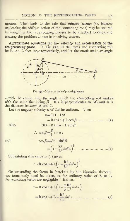
MOTION OF THE RECIPROCATING PARTS 515
motion. This leads to the rule that primary balance (i.e. balance
neglecting the oblique action of the connecting rods) may be secured
by imagining the reciprocating masses to be attached to discs, and
treating the problem as one in revolving masses.
Approximate equations for the velocity and acceleration of the
reciprocating parts. In Fig. 556, let the crank and connecting rodbe R and L feet long respectively, and let the crank make an angle
,-r wi-'H5

516 MACHINES AND HYDRAULICS
To obtain the velocity of A in the direction of AC, differentiate xwith respect to the time, giving
dx d& R2. da
.. da.
Also, ^ = w
and 2 sin a cos a = sin 2 a.
dx . . wR2.
Hence, VA = = - wR sin a -- - sin 2a................... (4)dt 2 .L/
From this equation, the velocity of A may be calculated for anycrank position. To obtain the acceleration of A in the line of AC,differentiate (4) with respect to the time, giving
da co
9T> w2R2
= - cofK COS a --- COS 2<x...... , ............ (5)
The acceleration of A may be calculated from this equation for
any crank angle. Let M be the mass of the reciprocating parts.
Then the force required in order to overcome their inertia when the
crank is at an angle a is
MV2R2
P= -Mw2Rcosa- cos 20,................... (6)I j
Suppose that the mass M is concentrated at the crank-pin centre B
I / (Fig- 55?)- Then the central forceI VMU^R required will be Mo>2
R, and the
_ _ , fid/ component of this force parallel to"
Mw*RcoscL t*16 centre nne AC will be Mw2R cos a.
Evidently this is equal to the first
term of (6). The factor cos 2 a in
tne second term, having reference to
/ an angle 2 a, which will be double of
/ the crank angle in all crank positions,*"- -*' may be interpreted by reference to
FIG. 557. Equivalent imaginary primary an imaginary crank rotating at twice
the angular velocity of the real crank,
i.e. o> for the imaginary crank would be equal to 2w. Hence,
4
Therefore the second term in (6) becomes
'-jCOS2a = ^ COS 2a ..(7)

PRIMARY AND SECONDARY BALANCING 517
Let a mass equal to M be concentrated at a crank radius r
(Fig. 558), set at an angle 2 a and rotatingwith angular velocity w . Then
Central force = Mo> V. - _>__^ ,.2oi \Component of this force parallel to the
a; r^ _^s^_ A_ .\_
line of stroke = M<o V cos 2 a.^ y
If this be made equal to (7), we have \ /Mw 2R2-
j.
4L secondary mass.
wMto VcOS2<X =- - cos 20tj FlG 558. Equivalent imaginary
or r = .................................................. (8)4L
Hence the second term in equation (6) would be produced by a
mass M equal to that of the reciprocating parts, concentrated at
R 2
a crank radius, its crank rotating at an angular velocity double
4-L
that of the engine crank and making an angle with CA in Fig. 556double of that made by the engine crank. The complete equivalent
system is shown in Fig. 559, where CB is the real crank and CD is
the imaginary crank. The balancing of the effects of M at B is
Mti/Rcosa
FIG. 559. Effects of the reciprocating masses produced by an imaginary revolving system.
called primary balancing, and balancing the effects of M at D is called
secondary balancing. The disturbances produced in the direction of
the line of the stroke, if no attempt at balancing is made, may be
calculated easily from the first term of equation (6) for primary
disturbances and from the second term of the same equation for
secondary disturbances. It will be understood, of course, that, if
the disturbances on the engine frame are being calculated, the senses
of the forces shown in Fig. 559 must be reversed.
EXAMPLE. A horizontal engine, stroke 2 feet, mass of reciprocating
parts 300 pounds, has a speed of 240 revolutions per minute. Find the

MACHINES AND HYDRAULICS
primary and secondary disturbances on the frame when the crank is at o,
45> 9j 1 3S arjd 1 80 from the inner dead point. The connecting rod is
4 feet long.
Primary disturbance : Pl= cos a Ib. weight.
T- . 27r = 87r radians per sec.
300 X 6ATT2 X I= cos a
5880 cos a Ib. weight.
a

WHIRLING OF SHAFTS 510
Whirling of shafts. In Fig. 560 is shown a vertical shaft ABrunning in swivel bearings at A and B
;these bearings do not in any
way restrain the directions of the shaft axis
at A and B; hence, bending of the shaft
will correspond to the case of a'
^am simply
supported at the ends. A heavy wheel is
mounted on the shaft midway between the
bearings, and it is assumed that its centre
of mass C does not fall quite in the shaft
axis. The effects of centrifugal force maybe examined as follows :
Let M = the mass of the wheel, in pounds.R = the distance in feet of the centre
of mass of the wheel from the
shaft axis.
A = the deflection produced by cen-
trifugal force, in feet.
w = the angular velocity, in radians
per sec.
L = the length of the shaft, in inches.
I = the moment of inertia, or secondmoment of area, of the shaft
section about a diameter, inch
units.
E = Young's modulus, Ib. per sq. inch.FlG" s6 -WSng of a loaded
Centrifugal force = P
Also,PL3
Mo>2(R + A)
S
inches (p. i
Ib. weight
PL3
--feet,
576EI
andL3
Equating (i) and (2), we have
L3
or Mw2L3R =
.
- a>2ML3A
It is evident that a critical speed will occur when the denominatorof this fraction becomes zero
;the deflection will become very large

520 MACHINES AND HYDRAULICS
then, and the shaft is said to whirl. To obtain this speed, we have
If the shaft is of steel, this equation will reduce to the followingform by using the usual values of the coefficients :
o>= 746000^^ ...................... (5)
If the wheel in Fig. 560 be removed, the plain shaft will whirl, but
at a much higher speed of revolution. The effect is owing to some-
what similar conditions to those which produce elastic instability in a
long strut (p. 228), viz. want of perfect straightness and of perfect
uniformity in elastic properties. Any slight deflection will be in-
creased indefinitely when the whirling speed is attained.
-*- K
fb)
FIG. 561. Whirling of a uniform shaft having swivel bearings.
Fig. 561 (a) shows a uniform shaft in swivel bearings at A and Band deflected to the curve ACB by whirling.
Let m = the mass in pounds per inch length.
L = the length of the shaft, in inches.
y = the radius in inches at P, distant x inches from O.
A = the maximum radius OC, in inches,
w = the angular velocity, in radians per second.
F'= the centrifugal force at any point, in Ib. weight per inch
length.
M = the bending moment at any section, in Ib. -inches.
I = the moment of inertia of the shaft section, in inch units.
E = Young's modulus, in Ib. weight per square inch.
g= acceleration due to gravitation, inches per second persecond.

WHIRLING OF SHAFTS 521
Then, at P, F = Ib. weight per inch length; ...(i)<b
.'. Focj.
This result indicates that the curve in Fig. 561 (a) not only repre-
sents the deflection, but also the load per unit length to another
scale. Hence, we may write
F-y,where c is a numerical coefficient rectifying the scale.
Now, if the coordinates y and x refer to a given deflection curve,
the second differential coefficients, when plotted, will represent a
curve of bending moments, and the fourth differential coefficients
will represent a curve of loads which would produce the given deflec-
tion curve. Hence, in the present case,
From this expression, the shape of the deflection curve has to be
obtained, and may be inferred to be a curve of cosines. Thus, take
the equation ,jy= cos and obtain the fourth differential coefficient :
y = cos; -j-
= - sin 6 -= = _ Cos 6 -~ = sin; -^-
= cos 0.' dx dx* dx* dx^
Therefore, in the curve representing the equation y = cos 0,
d*y-~ = cos 9 =y.dx*
In Fig. 561 (a\ there is zero deflection at A and B and maximumdeflection at C. Hence the corresponding cosine curve (Fig. 561 (/>))
7T 7T
will have the origin at O, OE and CD will represent +- and -
respectively (for which the cosines are zero), and OG will representcos 0=1. HK, corresponding to y in Fig. 561 (), will representcos 0, where is the angle represented by OH, corresponding to x in
Fig. 561 (a). From the diagrams, we have
0- x 7r _ 7r
r-L'2-L*-.
y cos TT
Also, TT = - - = cos x;A coso L '
Obtaining the fourth differential coefficient of this,
d^V . 7T4
7T
(3)
,,
(4)

522 MACHINES AND HYDRAULICS
d^y MN W'
=>
AISO, ^ =F ;
.-. g=... (V)
Hence, from (i) and (5),
*= ~^; ... (6)
dx^ EI^-
Equating (4) and (6),2 4
= A, cos^-^. ...(7)
This equation is true for any corresponding values of y and x,
Take the value x o, when7T
COS -,T = COS O = I
and = A.
. 7T4
Hence, = A ...................................... (8 )
The deflection cancels from both sides of this equation, indicatingthat a critical speed w has been attained, and giving the result
<
This result expresses the whirling speed. If the bearings restrain
axially the directions of the shaft at A and B (Fig. 561 (#)), then it
may be shown that the whirling speed is given by' 2
EXERCISES ON CHAPTER XX.
1. Find the M of a flywheel which, when running at 200 revolutions
per minute, will increase its speed by i per cent, while storing 5000foot-lb. of energy.
2. A solid disc of cast iron, density 450 pounds per cubic foot, is
8 inches in diameter by 2 inches thick and runs at 2500 revolutions perminute. What percentage increase in speed will occur if it is called uponto store an additional 200 foot-lb. of energy ?

EXERCISES ON CHAPTER XX. 523
3. A cast-iron flywheel is 30 feet in mean diameter. The safe tensile
stress is 2000 Ib. per square inch. Find the maximum permissible speedof revolution of the wheel. Take the density as 450 pounds per cubic foot.
4. A mild-steel hoop is 18 inches in mean diameter and the elastic
limit of the material is 18 tons per square inch. At what speed of revolu-tion would permanent damage begin to occur ? Take the density as 480pounds per cubic foot.
5. M/Tiat is the limit to the velocity of the rim of an ordinary flywheel?Does it depend on the diameter? Prove your statements (B.E.)
6. In the manufacture of a large drum for a steam turbine a hollow,red-hot steel billet is, at a high gpeed, rolled between internal andexternal rollers, which effect a gradual increase of diameter and diminu-tion of thickness. Show that the intensity of the tangential stress ofthe material of the drum remains constant during the rolling operation,assuming a constant speed of the rollers. Determine the limiting speedof the rollers to keep the tensile stress within i ton per square inch.
(Weight of steel, 485 Ib. per cubic foot.) (I.C.E.)
7. The indicated horse-power of a steam engine is 100 ; the meancrank shaft speed is 200 revolutions per minute. The energy to betaken up by the flywheel of the engine between its minimum and maxi-mum speeds is 10 per cent, of the work done in the cylinders per revolu-tion of the crank shaft. If the radius of gyration of the flywheel is 2 feet
6 inches, determine its weight in order that the total fluctuation of speedmay not exceed 2 per cent, of the mean speed. (L.U.)
8. Show from first principles that two flywheels of the same dimensionsbut of materials of different densities will have equal kinetic energieswhen run at the speeds which give equal hoop stresses. Calculate thekinetic energy stored per pound of rim in a cast-iron flywheel, when the
hoop stress is 800 pounds per square inch. Cast iron weighs 450 poundsper cubic foot. (L.U.)
9. In a simple Watt governor, the height of the cone of revolution is
4 inches. What is the speed in revolutions per minute ?
10. A Porter governor has revolving masses of 2 pounds each. Thearms are all equal and 8 inches long. If the height of the cone of revolution
is to be 5 inches at 180 revolutions per minute, find the dead load
required.
11. In Question 10, the throttle valve is full open when the height is
5-5 inches and closed entirely when the height is 4-5 inches. Find the
limits of speed of revolution controlled by the governor. State the
total variation in speed as a percentage of the mean speed of 180 revolu-
tions per minute.
12. A uniform rod 8 inches long, mass 4 pounds, is hinged at its upperend to a vertical axis of revolution. Find the speed at which the armwill describe a-cone of semi -vertical angle 45 degrees. Supposing this
speed to be doubled without alteration in the position of the rod, what
controlling couple must be applied to the rod ?
13. The mass of each of the balls of a spring-loaded governorarranged as in Fig. 548 is 5 pounds. When the radius of the balls is
6 inches the governor makes 250 revolutions per minute. Find the total

524 MACHINES AND HYDRAULICS
compressive force in the spring, and, neglecting friction, find the stiffness,i.e. the force per inch compression, of the spring that the governor maybe isochronous. Show that the effect of friction would be to make the
governor stable. (L.U.)
14. A Porter governor has equal links 10 inches long, each ball weighs5 pounds and the load is 25 pounds. When the ball radius is 6 inchesthe valve is full open, and when the radius is 7-5 inches the valve is
closed. Find the maximum speed and the range of speed. .If themaximum speed is to be increased 20 per cent, by an addition to the
load, find what addition is required. (L.U.)
15. Three bodies of 2, 3 and 5 pounds mass respectively revolve at
equal radii round a horizontal axis. The axial distance between theouter pair of bodies is 18 inches. Arrange the bodies so that they shall bein balance.
16. The four weights ivlt o/2 ,-ze/3 ,
w4 (Fig. 562) rotate in one planeabout an axis, their magnitudes and the radii at which they act being
given in the table :
Weight.

EXERCISES ON CHAPTER XX. 525
that produced in the line of stroke by an equal mass placed at the crank
pin. An engine has three cylinders A, B and C whose axes are parallel.The axis of B is at a distance a from the axis of A and a distance c fromthe axis of C. The mass of the reciprocating parts of B is M. Assumingthat all the pistons have harmonic motion and the same length of stroke,show how the cranks on the crank shaft must be placed, and find themasses of the reciprocating parts of A and C in order that all the
reciprocating parts may be completely balanced. (L.U.)
21. A four-cylinder vertical engine, cranks at right angles, has its
cranks equally spaced between the bearings, the pitch being4>. Taken from the left, the order is A, B, C, D. Therevolving mass for each cylinder is M
tand the reciprocating
mass M 2 ,and the speed is w radians per second. The
crank radius is r and the connecting-rod length /. Examine Dthe primary and secondary balance, forces and coupleswhen (a) the cranks are as shown in Fig. 563, (b} the cranks Care at 45 degrees to the line of stroke. (L.U.) FIG. 563.
22. A vertical steel shaft i inch in diameter runs in swivel bearings 36inches centre to centre. A wheel of mass 20 pounds is mounted at the
centre of the shaft, and its centre of mass is at a small distance from the
shaft axis. At what speed of revolution will whirling occur? TakeE = 30,000,000 Ib. per square inch.
23. A steel shaft 2 inches in diameter runs in swivel bearings 9 feet
centre to centre. At what speed will whirling occur ? Take = 30,000,000Ib. per square inch and the density 0-28 pound per cubic inch..
24. Answer Question 24 if the bearings constrain the directions of theshaft at its ends.
25. In Question 23, the speed of the shaft is 600 revolutions perminute. Find the limiting distance centre to centre of the bearings.

CHAPTER XXI.
TRANSMISSION OF MOTION BY BELTS, ROPES, CHAINSAND TOOTHED WHEELS.
Driving by belt. Motion may be transmitted from one shaft to
another by means of a belt running on the rims of pulleys which are
fixed to the shafts. The driving effort is transmitted from the belt
to the pulley by the agency of the frictional resistance to slipping of
the belt on the pulley. A will drive B in the same direction of
rotation if the belt is open (Fig. 564), and in the opposite direction
if the belt is crossed (Fig. 565). In the latter case, each portion of
FIG. 564. Open belt. FIG. 565. Crossed belt.
the belt is given a half turn in order that the same side of the
material may bear against the rims of both A and B. In these
diagrams the shafts are parallel, and both pulleys are arranged so that
their planes of revolution coincide;
if this condition be not attended
to, the belt will not remain on the
pulleys. It is customary also to
round slightly the rims of the pulleys
(Fig. 566), with a view to enable
the belt to ride on the centre of the
rim; the action will be understood
by reference to Fig. 567, which
shows the exaggerated case of two
frusta of cones placed base to base.
The belt, in bedding down on the conical surface, bends as shown;
consequently the points a and a will be higher up the cone than b
FIG. 566. FIG. 567.

DRIVING BY BELTS 527
and //, which came into contact a little before a and a. Hencethe belt will climb to the highest part and remain there.
It will be evident that the part of the belt which is advancingtowards the pulley must be moving in the same plane as that in
which the pulley is rotating. The part receding from the pulley maydo so in a plane which does not coincide with the plane of rotation.
Advantage is taken of these conditions in the case of two shafts
having directions at right angles (Fig. 568). A is so arranged on
the lower shaft that the part C of the belt leaving it is moving in the
plane in which B rotates; similarly B is so arranged that the portion
D of the belt leaves B in the same plane as that in which A is
rotating. The belt will ride safely on both pulleys, provided that
the directions of rotation are not reversed at any time. Reversal of
FIG. 568. Two shafts at 90 connectedby a belt.
FIG. 569. Use of jockey pulleys.
direction must be preceded by a rearrangement of the pulleys. Thedistance between the shafts should not be small enough to render
excessive the angle at which the belt leaves the pulleys.
In Fig. 569 is shown an arrangement in which A drives B bymeans of a belt which is guided into the proper planes by jockey
pulleys running freely at C and D.
Velocity ratio of belt pulleys. A certain amount of slipping is
always present in belt driving ;in the best cases there may be i to 2
per cent, of the motion of the driven pulley lost in slipping. Thebelt usually comes off the pulleys if the slip exceeds 10 per cent.
Neglecting slipping, it will be evident that the speed of the belt will
be equal to the speeds of the rims of both pulleys. Referring to
Fig. 57>

528 MACHINES AND HYDRAULICS
Let DA = the diameter of A, in feet.
DB = the diameter of B, in feet.
V = the velocity of the belt, in feet per minute.
NA = revolutions per minute of A.
NB = revolutions per minute of B.
Then, Distance travelled by rim of each pulley = V feet per minute.
-^rv
N VB ~7rDB
and - = -.FIG. 570. Velocity ratio of belt
pulleys.
Hence the speeds of revolution are inversely proportional to the
diameters of the pulleys.
Strictly speaking, the diameters should be measured to the mean
thickness of the belt, i.e. the thickness of the belt should be added
to DA and DB . The presence of slip usually renders this correction
an unnecessary refinement.
In Fig. 571, A is an engine pulley driving a line shaft pulley B;a countershaft has a pulley D driven from a pulley C on the line
FIG. 571. A belt pulley arrangement.
shaft;a machine pulley F is driven from the countershaft puiiey E,
Assuming that there is no slip,
NB = D_A. N = D_A NNA DB' '!>*
N=Pc. - N = DCNc P ' D VD
c 'Also,

DRIVING BY BELTS

530 MACHINES AND HYDRAULICS
Resolve T into components along and at right angles to/; these
will be T sin JSa and T cos JSa respectively. In the same manner,
T + ST will have components (T + ST)sinJSa and (T + ST)cosSa
(a) (b)
FIG. 572. Friction of a belt on a pulley.
respectively along the same lines. The sum of the components
along / must be equal to /, hence
/ = T sin JSa + (T + 8T) sin J8a
= (2T + 8T) sin J8a.
Neglecting the products of small quantities, this reduces to
Again, the difference between the sine of a very small angle and
its radian measure is infinitesimal. Hence,
p = 2T . |8a
= T.8a........................................... (i)
Let the coefficient of friction be /*. Then
Frictional resistance of arc CD =/*/
= /xT.Sa............. (2)
This frictional resistance must be equal to the difference in the
components of T and T + 8T taken at right angles to /, hence
/xT . Ba = (T + 6T) cos JSa- T cos JSa
= 8TcosiSa.
The angle J8a being very small, its cosine may be taken as unity
and the equation reduces to
(3)

FRICTION OF BELTS
In the limit, writing da. and dTT, and integrating both sides, wehave ,T^T ,*
-T/M d^JTo L Jo
or(3')
This equation may be written
-(4)
_^ _ fHO- pfpr~r\
C1 Vx *
T~ = a constant.AD
FIG. 573. Tensions in the belt at
different parts of the arc of contact.
where e is the base of the hyperbolic logarithms (p. n).The physical meaning of this equation may be understood by
dividing the total arc of contact into a number of equal arcs AB, BC,CD, etc. (Fig. 573). Let each arc sub-
tend an angle a at the centre, and let the
tensions in the belt at B, C, D, etc., be
denoted by TB ,Tc ,
TD ,etc. Equation
(4) above applies to each arc. Hence,
T11 = MO.
T*- nr~"* T1
B AC A D
As the right-hand side is constant in
each of these expressions, the ratios of
the tensions will be constant, i.e.
T1= TB
TB Tc
Hence, if the value of the constant for a given angle is known, the
ratio of the tensions for any angle when slipping is about to occur
may be calculated easily.
EXAMPLE i. A rope is coiled round a fixed drum over an arc of
contact of 90. It is found that slipping occurs when the ratio of the
pulls is f . Find the ratio of the pulls for an arc of contact of 270.
To = T9o = Ilso= 3.
TISO T27o 4
T> !iTi80 T27o
T0= 27
T270 64'
EXAMPLE 2. A leather belt laps 180 round a cast-iron pulley.
Taking ft =0-5, calculate the pull on the slack side when slipping is about
to occur, if the pull on the tight side is 300 Ib.
-no
OO
'=2 X 3 X 3,444or,

532 MACHINES AND HYDRAULICS
log*1 =^= o-57r= 1-5708 ;
Here 6 1 80 = TT radians. Hence,
1
or T2=_= 2.4 .
4-01
Horse-power transmitted by a belt. It will be observed that the
diameter of the pulley does not enter into the expression for the
ratios of the pulls of a belt or rope. For example, in the last result,
the pulls would be 300 Ib. and 62-4 Ib. when the belt is embracinga pulley 3 feet in diameter or 6 feet in diameter, provided the arc of
contact is 180 in each case. Some other cause must be looked for
to explain the known fact that a belt which constantly slips on a
certain drive may be remedied by substituting pulleys of larger
diameter on both shafts, keeping the ratio of the diameters as at first
so as not to alter the speeds of the shafts. The explanation lies
in the fact that the belt is now running at a higher
speed, and will therefore do the same work per
minute, or will transmit the same horse-power, with
a smaller difference in pulls. Thus,
Let Tj = pull on tight side, Ib.
T2=
pull on slack side, Ib.
V =velocity of belt in feet per minute.
Considering the driven pulley (Fig. 574), Tlis
urging it to turn and T2
is tending to prevent rotation;hence the
net driving force is (Tl- T
2 ).
Work done per minute = (Tl-T
2)V foot-lb.
(T T )VHorse-power transmitted = * -- ...................... (i)
33,000
Now let V be increased to V2feet per minute by the substitution
of larger pulleys running at the same revolutions per minute. The
horse-power transmitted being the same as at first, we have
(T1-T
2)V_(T/-T2QV2
33,000 33>
where T/ and T2
'
denoted the altered pulls in the belt. This gives
(T^T^V-Ciy-T^V,............. . ........ (2)
As V2 is greater than V, it follows that (T/
- T2')
must be less
than (Tj-Tg). Hence there is now less frictional resistance to
slipping called for, and consequently the risk of slipping is reduced.

DRIVING BY ROPES 533
Equation (i) above for the horse-power may be written in terms of
the maximum pull Tj in the belt. Thus,
' T -*2-
Substituting in (i) gives
Horse-power transmitted =
(3)
33,000
From this equation the dimensions of a belt suitable for trans-
mitting a given horse-power may be obtained. The strength of a
belt is stated in pounds per inch of width generally.
Let b = width of belt in inches.
p = safe pull per inch width of belt.
Then Tl ----pb
and Horse- (5)
The width b may be calculated from this result when the other
quantities involved are given.
Driving by rope. Ropes of cotton, hemp, manila or steel wire
may be used for transmitting motion. In such cases the rims of the
pulleys are grooved to receive the ropes. The section of a pulley
FIG. 575. Section of the rim of a ropepulley.
FIG. 576. Pressures on the
groove of a rope pulley.
rim suitable for ropes of cotton or similar material is given in
Fig. 575. The ropes bear on the sides of the wedge-shaped grooves,
thus increasing the frictional resistance to slipping. In Fig. 576,
Let a = half the angle of the wedge.
p = the normal force on a small arc of the rim, in Ib.
ju.= the coefficient of friction.

534 MACHINES AND HYDRAULICS
Then / will be equal to the sum of the vertical components of
the normal pressures q, q on the sides of the groove. Hence,
p=2q sin a,
q = \p cosec a.................................. (i)
Now the frictional resistance to sliding on the small arc considered is
f= 2^q = 2\*\p cosec a
=p ,fjicosec a................................. (2)
Had the case been that of a flat belt on an ordinary pulley, the
frictional resistance would be /x/. Hence, the results already
obtained for flat belts may be used for ropes which bear on the sides
of the groove by writing ft cosec a instead of /x. Thus, from equation
(4), p. 531, and equation (4), p. 533, we have
In the case of wire ropes, the rope should not bear on the sides of
the groove, as it would suffer injury thereby. Fig. 577 shows a
suitable form of rim, in which the rope beds on the bottom of the
groove ;it is found advantageous to line the bottom of the groove
FIG. 577. Section of a wire
rope pulley.
FIG. 578. Section of an idle
pulley for a wire rope.
with leather, with a view of increasing the frictional resistance.
Where the ropes are very long, idle bearer pulleys may be used at
intervals to support the ropes. These run loose on their bearings,
and may have rims of a section shown in Fig. 578.
The equations for a flat belt apply without alteration to the case of
a wire rope bedding on the bottom of the groove.
Centrifugal tension in belts and ropes. The portion of a belt or
rope which laps on the pulley is subject to centrifugal forces when
the belt is running (Fig. 579).

BELT STRIKING GEARS 535
Let m = the mass of the belt per foot run, in pounds.
v = the velocity of the belt, in feet per sec.
r = radius, in feet, to the centre of the belt.
Then the centrifugal force per foot length of arc will be given by
/= Ib. weight.gr
These radial forces will have a
resultant R directed towards the
left in Fig. 579, and will be balanced
by tensions T, T in the belt, which
are in addition to those required
for driving purposes. The case isv
... .... FIG. 579. Centrifugal tension in a belt.
analogous to a boiler shell sub-
jected to internal pressure, and may be solved by the method givenon pp. 95 and 96. R=/X 2r
mV* 21HV1., . ,
. 2r= - Ib. weightgr g
Also, 2T = R;
.*. T = - Ib. weight.
For leather belts, m may be taken as
m = o4A pounds per foot run,
where A is the cross-sectional area of the belt in square inches.
The general effects of centrifugal force are to increase the pulls in
the belt, and also to reduce partially the radial pressures on the rim
of the pulley. As the latter are relied on for the production of the
frictional driving effort, it follows that excessive slipping will occur at
speeds which are too high, and the power transmitted will be reduced
thereby.
Belt striking gears. The intermittent motion required for driving
many classes of machines may be obtained by means of two pulleys
on the countershaft driving the machine. In Fig. 580 a pulley A on
the main or line shaft drives a countershaft having two pulleys, one
Bj running loosely on the countershaft and the other B2fixed to the
shaft. The belt may be moved from one pulley to the other bymeans of forks C, C, which loosely embrace the belt. The forks are
operated by a sliding bar D and a handle E, carried to a suitable
position for the operator. The pulley A is made specially wide, so

536 MACHINES AND HYDRAULICS
as to permit the belt to ride on either Bj or B2 ;
in the former case,
the countershaft and machine will be at rest.
FIG. 580. Belt striking gear.
Another arrangement is shown in Fig. 581. The countershaft Bhas two loose pulleys Lj_ and L
2 ,and also a pulley F fixed to the
shaft. There are two belts, one D open and one E crossed;these
are operated by the belt-striking forks and bar shown at C. Nomotion will be transmitted to the countershaft if both belts are on
the loose pulleys, and motion in either one or the other direction will
n

DRIVING BY CHAINS 537
The length of belt required enters into the question of stepped
cones, as the belt has to fit any corresponding pair without alteration
being made in its length. For a crossed belt it may be shown that
the sum of the diameters of any corresponding pulleys should be
constant for the whole set. With an open belt there is a small
divergence from this rule, which becomes negligible if the distance
between the shafts is large compared with the pulley diameters ;such
is usually the case.
Transmission of motion by chains. In cases where the driving
effort is too large to be transmitted by a belt or rope, or where
slipping is inadmissible, chains may be used in combination with
toothed or sprocket wheels. A few patterns of suitable chains are
given in Fig. 583. (a) is a block chain in which a number of small
(a)
(b)
FIG. 583. Types of driving chains. FIG. 584. Sprocket wheel for chain driving,
showing the effect produced by the chain
stretching.
blocks are connected by pairs of links and riveted pins. Chains of
this pattern are used for conveyors, as the carriers are attached
readily to the blocks. () is a similar pattern, but made entirely of
links,(c) is a better form, and works more easily. The inner links
are connected by a tube riveted over at its ends, and a roller runs
on the tube;the outer links are connected by a pin passing through
the tube and riveted over at its ends.
A sprocket wheel is shown in Fig. 584. The centres of the chain
pins lie at the corners of a polygon having sides equal to the pitch pof the chain. The driving force P may act at radii which will varyfrom Rj to R
2 ,and thus cause variations in the turning moment and

533 MACHINES AND HYDRAULICS
in the velocity ratio. These variations will be small, provided the
number of teeth on the sprocket wheel be sufficiently large.
The form of the teeth may be constructed by first drawing semi-
circles of radius r equal to that of the chain pin, or roller. Usingradii slightly smaller than (p-r) and centres nearly coinciding with
the adjacent pin centres, the sides of the teeth may be drawn. Thesewill be such as to enable the chain to leave the wheel at the topwithout the pin or roller touching the face of the tooth.
In general there is practically no pull on the slack side of a chain;
hence, the work done per minute is given by the product of P andthe velocity of the chain in feet per minute. The chain is liable to
stretching of the links and to wear at the pins, both of which tend to
increase the pitch. The effect of this will be ultimately that the top
pin, or roller alone, as is shown in Fig. 584, will be bearing against
its tooth, and this tooth accordingly will carry the whole load. The
FIG. 585. Renold's silent chain.
effect is manifest in the chain grinding on the teeth, thus introducing
additional frictional resistance and also wearing the teeth. These
effects may be obviated somewhat by using a roller chain, and by
making the spaces between the teeth wider than the diameter of the
chain pin or roller. Increase in the pitch is provided for perfectly
in the Renold's silent chain. The links are of the form shown in
Fig. 585 ; any increase in the pitch, caused by wear or stretching,
has simply the effect of causing the links to ride on the teeth at a
larger radius from the centre of the wheel. Speeds of 1250 feet per
minute and horse-powers up to 500 have been attained with these
chains.
Friction gearing. In cases where the shafts are close enough
together, motion may be communicated from one to the other by
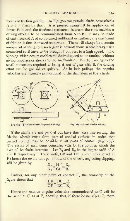
FRICTION GEARING 539
means of friction gearing. In Fig. 586 two parallel shafts have wheels
A and B fixed on them ;A is pressed against B by application of
forces P, P, and the frictional resistance between the rims enables a
driving effort F to be communicated from A to B. B may be made
of cast iron and A of compressed millboard or leather;the coefficient
of friction is thus increased somewhat. There will always be a certain
amount of slipping, but such gear is advantageous where heavy parts
connected to B have to be brought from rest to a high speed. The
slipping which occurs enables the desired speed to be attained without
giving impulses or shocks to the mechanism. Further, owing to the
small movement required to bring A out of gear with B, the driving
effort can be got rid of quickly. As in belt pulleys, the angular
velocities are inversely proportional to the diameters of the wheels.
UFIG. 586. Friction wheels for parallel shafts.
X-R,--:.
FIG. 587. Bevel friction wheels.
If the shafts are not parallel but have their axes intersecting, the
friction wheels must form part of conical surfaces in order that
perfect rolling may be possible at all parts of contact (Fig. 587).
The vertex of each cone coincides with O, the point in which the
axes of the shafts intersect. Let Rxand R2 be the largest radii of A
and B respectively. These radii, GF and HF, come into contact at
F;hence the revolutions per minute of the wheels, neglecting slipping,
will be given by N^ RF R^
N;=GF
=RV
Further, for any other point of contact C, the geometry of the
figure shows that Rp -^^ -^
GF=EC
=~Ri'
Hence the relative angular velocities communicated at C will be
the same at C as at F, showing that, if there be no slip at F, there

540 MACHINES AND HYDRAULICS
will be no slip anywhere, i.e. the rolling will be perfect. Wheels of
this kind are called bevel wheels.
Driving by toothed wheels. Motion lost by reason of slipping maybe eliminated entirely by the addition of teeth to the rims of friction
wheels. Fig. 588 shows two toothed wheels in gear; the original
friction wheels are shown dotted,
and come into contact at a point
on the line joining the centres
of the wheels. This point is
called the pitch point, and the
circles are called pitch circles.
The length of the arc on the
pitch circle between the centres
of an adjacent pair of teeth is
called the circular pitch of the
teeth. It is evident that the
pitch must be the same for both wheels. For practical purposes,
the diametral pitch is used often, and is the result of dividing the
diameter of the wheel by the number of teeth.
FIG. 588. Toothed wheels in gear.
Let
Then
D = the diameter of the wheel.
n = the number of teeth.
p = the circular pitch.
pd = the diametral pitch.
or
Also,
Unless otherwise specified, the term "pitch"
will be taken to mean the circular pitch.
Referring to Fig. 589, other definitions are
as follows : The portion EFGC of the tooth
which lies outside the pitch circle is called the addendum;dotted circle FGL is the addendum circle
;the working sides of the
tooth at EF and CG are called faces. The portion EHKG which
lies within the pitch circle is called the root of the tooth ;the dotted
circle HKM is the root circle; the working sides EH and CK are
called flanks. EC is the thickness of the tooth and CD is the width
of the space between the teeth.
FIG. 589. Proportions of
wheel teeth.
the

DRIVING BY TOOTHED WHEELS 541
Ordinary proportions of teeth may be stated. Reference is madeto Fig. 589, and p is the circular pitch.
Thickness of tooth = 0-48^.
Space between teeth = o-52/.
Total length of tooth = (a + )= 0-7^.
Length of addendum = a = o-$p.
Length of root = b = o-^p.
Width of tooth = 2p to 3\p.
These proportions allow of a clearance equal to 0-04^ between
the thickness of the tooth and the space into which it enters on the
other wheel; also a clearance of o-ip between the point of the tooth
and the bottom of the space. With accurate machine-cut teeth, these
clearances are often made smaller.
Power transmitted by toothed wheels. Let P Ib. be the driving
effort applied to a toothed wheel tangential to the pitch circle, and
let R feet be the radius of the pitch circle. In one revolution, work
will be done equal to 2?rRP foot-lb. If the wheel makes N revolu-
tions per minute, we have
Work done per minute = 2?rRPN.
27TRPNHorse-power transmitted
33000'
p _ 33000 x horse-power27TRN
If the horse-power be given, P may be calculated, and hence the
dimensions of the tooth may be estimated in order that sufficient
strength may be secured. It is best to use the rules of proportional
strength. Suppose it is known that a certain wheel made of a
given material has transmitted a force Pj successfully, and that
the width, length and thickness of its teeth are ^, /jand t
} respec-
tively. The connection of these dimensions with those of the teeth
of another wheel of the same material which has to transmit a
force P2will be given by (p. 152)
It has been assumed here that Paand P
2are applied at the extreme
point of the tooth, as in practice might be the case by accident.
Also that the whole of the driving effort may act possibly on one
tooth.

542 MACHINES AND HYDRAULICS
Angular velocity ratio of toothed wheels. It is evident from
Fig- 590 that two toothed wheels in gear revolve in oppositedirections
;also that the speeds of the circumferences of the pitch
circles will be equal. Hence, NA_DBNB DA
'
Also,
Number of teeth on A = nA ='**
-;
f
Number of teeth on B = nE = -\
D R ;ZR
FIG. 590. Angular velocity ratio oftoothed wheels. and = "2.
N B nA
Hence, the revolutions per minute are inversely proportional to the
numbers of teeth. It will be obvious, from what has been said on
p. 539 regarding friction bevel wheels, that the same rule applies also
to such wheels.
If the wheels A and B are required to revolve in the same direction,
an idle wheel C may be interposed (Fig. 591). Since the velocities
FIG. 591. Use of an idle wheel. FIG. 592. Two idle wheels.
of all three pitch circle circumferences must be equal, it follows that
there will be no change in the angular-velocity ratio of A and B.
Hence, N
Any number of idle wheels (Fig. 592) may be inserted without
affecting the angular-velocity ratio of A and B.
Trains of wheels. Fig. 593 shows a train of toothed wheels. In
this case we have :
N R
Also,
p' NC
NE = ND ;
^C N_Br
J NA
NC=NB .

TRAINS OF WHEELS 543
Hence,
or
NE Nc NA
NFNA
nv
B
PLANFIG. 593. Train of wheels.
If F, D and B be called drivers, and E, C and A followers, the
above result gives us the rule that the angular-velocity ratio of the
first and last wheels in the train is equal
to the product of the numbers of teeth on
the followers divided by the product of
the numbers of teeth on the drivers.
Fig. 594 shows the gearing wheels
used in the Wolseley motor cars for
enabling the car to run at different
speeds. The shaft AB is driven bythe engine, and has a wheel C fixed
to it and gearing always with a wheel
G on the secondary shaft EF. Whenthe clutch between the engine and
AB is "in," the secondary shaft EFwill be revolving. H, K and L are wheels of different sizes mounted
on, and revolving with, EF. The shaft RS is connected at S to the
road wheel axle by means of gearing
not shown in Fig. 594 ;this shaft
runs freely in the hollow shaft AB,and is made square between R and
S. M, N, P and Q are wheels which
may slide on the square shaft RS,and are under the control of the
driver by means of an arrangementof interlocking bars (not shown in
the figure). The wheel C is hollow,
and is furnished with internal teeth
at D. M may be slid into C, and,
when so situated, AB will drive RSdirect, the secondary shaft EF then
running idle. Other speeds may be
obtained by withdrawing M from Cand gearing N with H, or P with
K, or Q with L. The lever system
FIG. S94.-Gear wheels for a motor car. for sliding the wheels is SO devised

544 MACHINES AND HYDRAULICS
FIG. 595. Bevel wheels.
as to prevent two pairs of wheels being in gear simultaneously.Reversal of the car is obtained by sliding idle wheels (not shown in
the figure) on another secondary shaft.
Bevel wheels. If the directions of the shaft axes intersect, it has
been shown (p. 539) that cones may be used for driving; hence
conical pitch surfaces are em-
ployed for toothed wheels on
intersecting shafts. In Fig.
595, the axes of the shafts
intersect at O, and OAB and
OBC are the conical pitch
surfaces. The dimensions
are settled from the relation
NOD = BCNOE AB'
To obtain the shape of
the teeth, ADB and EECare other conical surfaces
obtained by drawing BD and BE perpendicular to OB. Theseconical surfaces are developed by describing arcs BF and BG, usingD and E respectively as centres. The teeth may then be drawn onthese arcs as pitch circles by ordinary methods. The teeth are
tapered along the conical surfaces AOB and BOC, 'and finally vanish
at O; hence portions only of the conical surfaces are used, shownin the figure at BKHC and BKLA.
Mitre wheels are bevel wheels of equal size on shafts meeting at
90, and are used in cases where the shafts are to have equal speedsof rotation.
In Fig. 596 is shown an example of the use of mitre wheels. Ais a continuously revolving shaft having a mitre wheel B fixed to it,
and driving other two mitre wheels C and D which run loose on the
shaft EF. Each of the mitre wheels C and D has projecting claws onits inner face, which may engage with the claws of a clutch G. Gmay slide on the shaft, and has a long feather key which compels it
to rotate with the shaft;a pivoted lever H enables the clutch to be
operated. In the position shown no motion will be communicatedto the shaft EF
; motion of either sense of rotation may be obtained
by causing G to engage with either C or D;the arrows indicate the
directions of rotation. The arrangement thus provides for inter-
mittent motion and for reversal.
Fie. 597 illustrates a common type of differential gearing used for the

DIFFERENTIAL GEARING 545
driving axle of a motor car. A toothed wheel A, shown in section,
runs loose on the axle EF, and has two bevel wheels B, B mounted on
radial spindles. EF is the axle to which the road wheels are attached,
FIG. 596. Arrangement for intermittent motion and for reversal.
and is made in two pieces. A bevel wheel C is fixed to the portion
E, and another bevel wheel D is fixed to F; C and D gear with the
bevel wheels B, B. The wheel A is driven by the engine, and, if
both road wheels are rotating at the same speed, the wheels B, B
M
FIG. 597. Differential gear for a motor car. FIG. 598. Milne's-Daimler differential gear.
will not rotate on their spindles. In rounding a curve, the inner
road wheel must rotate at a lower speed than the outer wheel, and
this difference in speed is permitted by the bevel wheels B, BD.M. 2 M

546 MACHINES AND HYDRAULICS
rotating on their spindles. It will be evident that, if C were held
fixed, D would rotate at twice its former speed.
Fig. 598 shows the application of the same arrangement in the
Milne's-Daimler differential gear.* AB is a shaft driven by the
engine and carries mitre wheels D, D, running loose on cross
spindles C, C. These wheels gear into mitre wheels E and K at
the inner ends of sleeves which run loose on AB, thus permitting
differential motion to the sleeves. F and L are bevel wheels at the
outer ends of the sleeves, and gear with wheels G and M fixed
respectively to the halves H and N of the road-wheel axle.
Epicyclic trains of wheels. In trains of this kind there is usually
one fixed wheel A (Fig. 599) i.e. A does not rotate together with
one or more wheels mounted on an
,153.jcn. P
-go, arm D which may rotate about the
centre of A. The solution of such
trains may be obtained by the
following method. Imagine the
whole set of wheels to be locked
and that the bracket carrying Ais free to rotate. Give the whole
arrangement one rotation in the
clockwise direction, then, keepingthe arm fixed in position, apply
a correction by giving A one revolution in the anti-clockwise
direction. Calling clockwise rotation positive, the process may be
tabulated thus :
PLAN
FIG. 599. An epicyclic train of wheels.
Part

EPICYCLIC REDUCING GEARS 547
Epicyclic reducing gears. In Fig. 600, showing an arrangementfor reducing the speed of rotation, the wheel D is fixed and has
internal teeth ;E is an arm fixed
to the shaft F, and carries two
wheels B and C fixed together
so as to revolve as one wheel.
C gears with the internal teeth
of D, and B is driven by a
wheel A. It will be noted that,
if D drives C with the arm Efixed, both wheels will have the
same sense of rotation. Thesolution is as follows : FIG. 600. Speed reduction gear.
Part -

MACHINES AND HYDRAULICS
correction operation with AB and C fixed, D being an idle wheel
during this operation. Supposing E to be a fixed wheel, the solution
will be as follows :
Part -
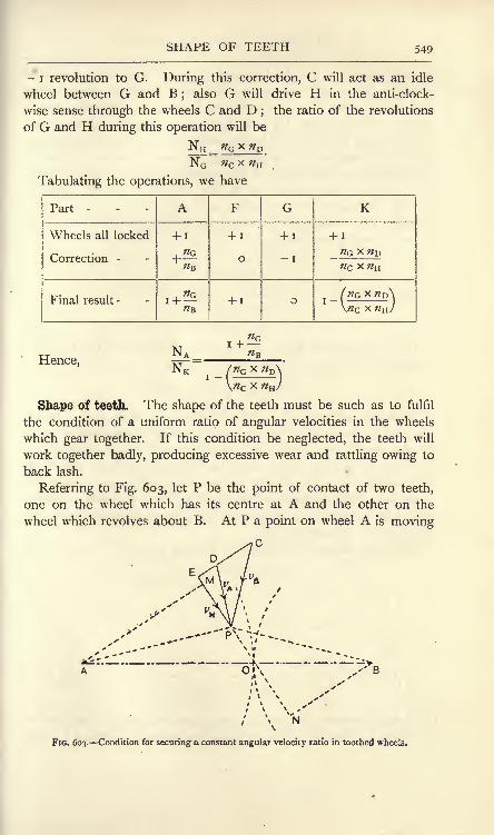
SHAPE OF TEETH 549
- i revolution to G. During this correction, C will act as an idle
wheel between G and B;
also G will drive H in the anti-clock-
wise sense through the wheels C and D;
the ratio of the revolutions
of G and H during this operation will be
Tabulating the operations, we have
Part -

550 MACHINES AND HYDRAULICS
at right angles to AP, and a point on wheel B is moving at right
angles to BP. Let VA and VR be these velocities, represented by DPand CP respectively. Let PO be the direction of a common normal
to the tooth surfaces at P ;it is clear that, if contact is to be main-
tained, and if there is to be no interpenetration of the teeth on A and
B, the components of z/A and VB along PO must be equal. ResolvingVB along and at right angles to PO by means of the triangle CEP, the
equal normal components of z>A and z>B will be represented byEP = z/N . Produce the line of #N ,
and draw AM and BN perpen-dicular to #N . Then, if WA and <OB are the angular velocities of the
wheels A and B respectively,
WA = J/N BN = BNo>B AM z>N AM'
Again, from the similar triangles AMO and BNO,BN = BO = (oA
AM~AO~<oB>
If O be selected as the pitch point, the ratio BO/AO will be
constant, as O is then a fixed point. Hence,WA BO RB=
-r-pr= =r = a constant.
O>B AO RA
Thus, the condition to be fulfilled in order to maintain a constant
angular-velocity ratio is that the common normal at any point of contact
of two teeth must pass through the pitch point. Theoretically, for a
given design of tooth on one wheel, the teeth on the other wheel maybe shaped so as to enable the common normal to comply with this
condition. In practice, however, cycloidal teeth and involute teeth
alone are used, and, in modern machine-cut wheels, the teeth are
generally of the involute form.
Cycloidal teeth. The cycloid is a curve traced by a point P on
FIG. 604. A cycloid.
the circumference of a circle which may roll along a straight line
(Fig. 604). In any given position, the point of contact I is the

CYCLOIDAL TEETH
instantaneous centre for the rolling wheel ;hence the direction of the
cycloidal curve at P is perpendicular to IP ; therefore the normal at
P passes through the point of contact I.
If the rolling circle having a centre Q (Fig. 605) rolls on the
circumference of another circle having A for centre, an epicycloid ODwill be traced. If the rolling circle rolls on the inside of the circum-
ference' of the circle, a hypocycloid OE will be traced (Fig. 605). In
FIG. 605. Epicycloid and hypocycloid.
the epicycloid, if N\ is the point of contact of the circles, and Pj is the
corresponding position of the tracing point, it will be clear that
the direction of the epicycloidal curve at Pl
is at right angles to NjPj,
as Nj will be the instantaneous centre of the rolling circle in the
given position. Hence N^ is the normal to the curve at Pr For
similar reasons, N2is the instantaneous centre of the rolling circle
FIG. 606. Mechanical construction of an epicycloid.
when the tracing point is at P2on the hypocycloidal curve, and N2
P2
is the normal to the hypocycloid at P2
.
In Fig. 606 is shown a useful way of producing an epicycloid. The
wheel A and the rolling circle revolve about fixed centres at A and C,

552 MACHINES AND HYDRAULICS
and drive one another in the same manner as friction wheels but with-
out slip, A piece of paper D is fixed to the wheel A and revolves
with it, and a pencil P on the
rolling circle bears on the paper.
The result is the epicycloid P P.
It is evident that the normal at
P passes through the pitch point
O. In Fig. 607 is shown a
similar method of drawing a
hypocycloid by means of another
wheel having its centre at B,
and the same rolling circle
revolving about a fixed centre
C. A piece of paper attached
to B will have drawn on it a
hypocycloid P 'P. If there has
been no slip, in each of these
figures the arcs OP and OP,on the wheels and on the
rolling circles respectively, will
be equal. Let the arcs OP in each figure be equal, and imaginethat the two figures are superposed, so that the wheels A and Bcome into contact at the pitch point O (Fig. 608). The arcs OPon the rolling circles in Figs. 606 and 607 will also be equal, and
the points P will coincide in Fig. 608. OP will now be simul-
FIG. 607. Mechanical construction of a
hypocycloid.
FIG. 608. The constructions of Figs. 606 and 607 superposed.
taneously the normal to the epicycloid and also to the hypocycloid,
and these curves will be in contact at P. Therefore the curves complywith the condition that the common normal must pass through the

CYCLOIDAL TEETH 553
pitch point, and thus may be used for the faces of the teeth on A, and
for the flanks of the teeth on B. The flanks of the teeth on A and
the faces of those on B may be produced in the same manner. It is
evidently essential that the same rolling circle must be used both for
the faces of A and for the flanks of B ; the rolling circle used for the
flanks of A and for the faces of B may be of the same or of another
diameter. It should be noted that the hypocycloid becomes a
straight line, forming a diameter of the wheel if the rolling circle has
a diameter equal to the wheel radius;hence the flanks of the teeth
would be radial lines. Any larger diameter of rolling circle would
produce teeth thin and weak at the roots. In designing a set of
wheels, the rolling circle should not have a diameter larger than the
radius of the smallest wheel of the set.
Path of contact. From Figs. 606, 607 and 608, it will be evident
that P and P' on the cycloidal curves were initially in contact at O,and that the point of contact has travelled along the arc OP of the
rolling circle. Contact will cease when the circumference of the
tolling circle passes outside the addendum circle. In Fig. 609, EFG
ps
v, ty
-UL 1M I" To IF T B
FIG. 609. Path of contact in cycloidal teeth.
and LMN are parts of the addendum circles of the wheels A and B
respectively. These intersect the rolling circles at P and Q respec-
tively ;hence the complete path of contact is POQ, and is formed of
two circular arcs.
In Fig. 610 two teeth are just starting contact at P. The point Cwill be in contact when it reaches O, and the arc CO on the pitch
circle is called the arc of approach. In the same figure, two teeth are
just finishing contact at Q ;E was in contact when passing through
O, and OE is called the arc of recess. PO and OQ are called the
paths of approach and of recess respectively. Let the arc OF be equal

554 MACHINES AND HYDRAULICS
to the arc OE. Then COF is the length of arc which passes the
pitch point while a tooth on A remains in contact with one on B, and
FIG. 610. Arcs and paths of approach and recess.
may be called the axe of contact. If the condition is to be fulfilled
that two pairs of teeth are to be in contact always, the arc of contact
should be twice the pitch.
Involute teeth. Fig. 611 shows an involute P P4
to a circular
curve PQOfii ',the curve may be drawn by wrapping a string round
the circular curve and having a tracing
pencil attached at its end P . On the
string being unwrapped, the pencil will
trace out the involute P P4 . It is evident
that the string, in any position such as
O2P
2 ,is perpendicular to the direction of
motion of the pencil ;O
2is therefore the
instantaneous centre of the string O2P
2
and O2P
2is normal to the involute at P
2.
In Fig. 612 is shown a mechanical method of drawing an involute
to the circle having A for its centre. Let a crossed belt be passed
FIG. 611. Involute to a circle.
FIG. 612. Mechanical construction of an involute to the circle having centre at A.
round two wheels revolving about A and B respectively, and let a pieceof paper be fastened to wheel A and revolve with it. A tracing

INVOLUTE TEETH 555
pencil secured to the belt at P will draw an involute on the paper.
It is evident that CP, the normal to the involute at P, passes always
through a point O on AB, and the two parts of the belt intersect in
the same point. An involute to the wheel B may be drawn in a
similar manner (Fig. 613) by securing the paper to wheel B. The
FIG. 613. Mechanical construction ot an involute to the circle having centre at B.
normal at P' passes through the same point O. If the diagrams
(Figs. 612 and 613) be superposed so that P and P' coincide, it is
evident that the two involute curves fulfil the condition that the
common normal passes through a fixed point O, which accordingly
may be taken for the pitch point of a pair of wheels having teeth
shaped to the involute curves.
Let v be the velocity of the belt. Then, in Fig. 612,
WA v DB DB- =
-r-p, .= -r-^ = a constant.
W B AC v AC
Also, from the similar triangles AOC and BOD,DB = BOAC~AO ;
Hence the radii AC and DB of the generating circles should be
inversely proportional to the angular velocities of the wheels.
It is clear that part of the straight line CD (Fig. 612) will be
the path of contact. Practical considerations rule that this line
should make about 15 with the common tangent to the pitch circles
at O (Fig. 614). The intersections P and Q of CD with the
addendum circles of the wheels will determine the length PQ of
the path of contact.
Using the same pair of generating circles connected by a belt as in

556 MACHINES AND HYDRAULICS
Fig. 612, the same involute curves will be produced irrespective of the
distance AB separating the wheel centres. As the resulting teeth will
be of the same shape as at first, it follows that the distance apart of a
To A
to
Fio. 615. An involute rack.
FIG. 614. Path of contact in involute teeth.
pair of involute toothed wheels may be varied to a small extent
without interfering with their correct working. This may be advan-
tageous for taking up back lash.
If one of the two wheels in gear becomes of infinitely large radius,
Athe case of a rack is obtained
(Fig. 615). The pitch line CD is
straight, and the involute is a straight
line perpendicular to the line of
contact OA. Hence the sides of
the teeth in involute racks are straight lines.
Helical and screw gearing. Greater smoothness of running maybe obtained by using wheels possessing several sets of teeth (Fig. 616),
each set stepped back a little from the adjacent set on one side. If
the steps are made indefinitely narrow (Fig. 617), we obtain a helical
wheel. Single helical wheels would produce axial thrusts on the
shafts, and this objection is obviated, as is indicated in Fig. 617, by
employing double helical teeth sloping in opposite ways. Such
wheels, with machine-cut teeth, run with remarkable smoothness,

HELICAL GEARING 557
and are equally suitable for low and high speeds of running and for
heavy loads. When the speed is high, it is best to run the wheels in
an oil bath.
A pair of screw wheels is shown diagrammatically in Fig. 618. The
cylindrical pitch surfaces of two wheels A and B touch at O. CD
FIG. 616. Stepped teeth. FIG. 617. Double helical teeth.
and EF are the axes of A and B respectively. Imagine a sheet of
paper having a straight line GOH drawn on it to be placed between
the cylinders. If the paper is wrapped round A, GOH will map
FIG. 618. Pair of screw wheels.
out a helix, and, if wrapped round B, a corresponding helix will be
described by GOH. These helices define the shape of screw teeth ;
the other teeth may be produced by having a number of lines parallel
to GOH and drawn on the sheet of paper. In Fig. 619 GOH and
ed show two of these lines. The perpendicular distance Qb separating
these lines is called the divided normal pitch, and is evidently the

558 MACHINES AND HYDRAULICS
same for both wheels A and B. Oa, measured along the circum-
ference of A, and Or, measured along the circumference of B, are
called divided circumferential pitches ; it will be clear that these pitches
must divide evenly into the circumferences of A and B respectively.*
FIG. 619. Pitches in a screw wheel. FIG. 620. Pawl and ratchet wheel.
Ratchet wheels. In Fig. 620, a wheel A is to have intermittent
motion to be derived from an arm B which vibrates about the axis
of A. A pawl C is pivoted to B, and will
engage the teeth of A when B is movinganti-clockwise
;the pawl slips over the teeth
of A when B is moving clockwise. Clockwise
rotation of A may be prevented by a pawl Dpivoted to some fixed part of the machine.
It will be noted that lost motion to the extent
of one tooth may occur between A and B;
this may be reduced by means of a second
pawl E pivoted to B. The possible lost motion
will now be half the former amount. In cycle
free wheels, several pawls are often fitted so as
to reduce lost motion to a minimum.
Couplings for shafts. The Oldham coupling
is illustrated in Fig. 621. A flanged couplingA is fixed to a shaft B, and has a groove cut
in its face. Another similar coupling C is fixed
to the shaft D. The axes of the shafts Band D are parallel. A plate E is interposedbetween the faces of these couplings, and has
a projection on each side which is a sliding
FIG. 621.- Oldham coupling, fit in the grooves ; the projections are at 90 to
* For a complete discussion on toothed wheels, see Machine Design, Part /.,
by Prof. W. C. Unwin. Longmans, 1909.

HOOKE'S COUPLING 559
each other. One shaft can thus drive the other, and as the grooveswill always make 90 with each other, the shafts will have equal
angular velocities in all positions.
Hooke's coupling is illustrated in Fig. 622, and is used for con-
necting shafts in which the axes OA and OB intersect, but are not
necessarily in the same straight
line. The end of each shaft is
formed with a jaw, and the con-
nection is made by means of a
cross C, which is free to swivel on
the set-screws D. The arrange-
ment is shown in outline inFIG. 622. Hooke's coupling.
Fig. 623, in which the ends of the arms OC and OC1? attached to the
shaft A (Fig. 623 ()), rotate in the circle YC'XQ' (Fig. 623(0));the ends of the arms OD and OD15
attached to the shaft B (Fig.
623^)), also rotate in a circular path, but this path projects as an
ellipse YjXYg (Fig. 623 (a)) owing to the inclination of the shaft
axes OA and OB.
Suppose OC rotates from OY to OC' through an angle 6 (Fig.
623 (a)), and that the shafts OA and OB are in the same straight line.
Then OD would rotate through an equal angle from OX and Dwould be situated at D", OD" being at 90 to OC'. If OB makesan angle a with OA (Fig. 623 (/;)),
then D will occupy a position on
FIG. 623. Diagram of a Hooke's coupling.
the ellipse, obtained by rotating the cross about C'C/ (Fig. 623 (a)) ;
this operation will cause D" to move at 90 to C'OC/, and gives the
position of D as D' on the ellipse, i.e. OC' and OD' are still at 90.The angle XOD' is not the true magnitude of the angle through

560 MACHINES AND HYDRAULICS
which OD' has rotated from OX ;the true angle may be obtained by
drawing D'E parallel to OY, cutting the circle at E;XOE = < will
then be the angle from OX through which OD rotates while OCrotates through an angle from OY. Produce ED' to cut OX in M,and let a be the angle between the directions of OD and OC
Xas
seen in Fig. 623 (ft).Then
D'M = ME cos a.
D'M MEAlso, =OM =
OM COS
= tan<j> cos a,
tan , x
or tan</>=- ..................................... (i)cos a
This gives the relation of <f> and 6. The relation of the angularvelocities of A and B may be obtained by differentiating both sides
of (i) with respect to time. Thus,
, d$ cosasec2 dd sec2 dOcpr*(h - =_ __ =_ _9
dt COS2a dt COS a dt
d$> dd .
Now, O>B=^p
and u>A = ,
sec2
sec2
<DA SCC2</>COS a
Now, sec2< = i + tan2<
tan2
WBWA
COS a
COS a
COS a
cos26/(i
- sin2a)
COS a
i - sin2a cos2^
This ratio will have maxima values when cos2is a maximum ;
this will occur when cos 6 is + i or i, i.e. when 6 is o or 180.
The minimum value of the ratio will occur when cos2 has its
minimum value ;this occurs when cos is o, i.e. when 6 is 90 or

EXERCISES ON CHAPTER XXI. 561
270. Equality in the angular velocities occurs when the numeratorand denominator in (2) are equal, giving
i - sin2 cos'2 = cos a,
sin'2a cos'J# = i
- cos a,
2f) _
cos<9= . = ......................... (3)
The student will find it a useful exercise to plot values of the ratio
of WB to WA for values of from o to 360.
EXERCISES ON CHAPTER XXI.
1. An engine runs at 200 revolutions per minute and drives a line
shaft by means of a belt. The engine pulley is 24 inches diameter andthe line-shaft pulley is 20 inches diameter. A dynamo is driven from a
pulley 36 inches diameter on the line shaft by a belt running on a pulley8 inches diameter on the dynamo shaft. Find the speeds of the line shaft
and of the dynamo (a) if there is no slip, (b) if there is 5 per cent, slip at
each belt.
2. A line shaft runs at 150 revolutions per minute. A machine has
to be driven at 1800 revolutions per minute by belts from the line shaft ;
the pulley on the machine is 6 inches in diameter. In this particular case
it is not desirable to use pulleys exceeding 36 inches or less than 6 inches
in diameter, and it may be assumed that there will be 4 per cent, slip at
each belt. Sketch a suitable arrangement giving the diameters of the
pulleys and the speeds of any counter shafts employed.
3. A belt laps 180 degrees round a pulley rim. The larger pull
applied is 400 Ib. and the coefficient of friction is 0-5. Find the smaller
pull, T2 ,when slipping just occurs. Find also the pull in the belt at
intervals of 30 degrees round the half-circumference of the pulley, and
plot these on a base representing angles.
4. A rope is wound three times round a rough post, and one end of
the rope is pulled with a force of 20 Ib. If the coefficient of friction
between the rope and the post is 0-35, what pull at the other end of the
rope would cause it to slip round the post? (B.E.)
5. Find, from the following data, what width of leather belt is neededto transmit 25 horse-power to a certain machine : (a) Diameter of belt
pulley, 30 inches, (b) The belt is in contact with ^ of the circumferenceof the pulley, (c) Revolutions of pulley per minute, 150. (d) Coefficient
of friction between belt and pulley 0-22. (e) Safe maximum tension perinch width of belt, 80 Ib. (B.E.)
6. A factory engine develops 400 horse-power, which is transmitted
to the line shafting in the various mill floors by 20 hemp ropes. Find, fromthe following data, the maximum tension in any one of the ropes, if they
P,M, 2 N
562 MACHINES AND HYDRAULICS
all transmit an equal share of the total power : (a) Diameter of groovedflywheel on which ropes work, 20 feet. (&} Angle of groove, 60 degrees.
(c) Angle of contact of ropes with flywheel rim, 240 degrees, (d)Coefficient of friction, 0-18. (e) Revolutions of flywheel per minute, 80.
(B.E.)
7. A compressor is driven by a gas engine of 18 indicated horse-
power, running at 240 revolutions per minute, by means of a belt 0-5 inch
thick from the engine pulley, which is i foot in diameter. The com-
pressor is double-acting, mean pressure 50 Ib. per square inch, cylinderdiameter 8 inches, stroke 14 inches. If the mechanical efficiency of the
engine is 82 per cent., of the compressor 86 per cent., and if the slip of
the belt is 5 per cent., find the maximum speed at which the compressorcan be run and the minimum diameter of the pulley fitted to it. (L.U.)
8. A rope drives a grooved pulley, the speed of the rope being 5000feet per minute. Find the horse-power transmitted by the rope from the
following data : ^=0-25 ; angle of groove 45 ; angle of lap 200; weight
of rope per foot run 0-28 pound ;maximum permissible tension in the
rope 200 pounds. (You are expected to make allowance for centrifugaleffects on the rope.) (L.U.)
9. A machine demands 6 horse-power, and is driven by means of a
spur wheel 18 inches in diameter and running at 150 revolutions perminute. Find the tangential driving effort on the teeth of the spur wheel.
10. In a turning lathe, the slide-rest holding the tool is driven by a
leading screw having 3 threads per inch. It is desired to cut a screw of
1 8 threads per inch. Give suitable numbers of teeth for a wheel train
connecting the lathe mandrel to the leading screw.
11. A watch is wound up at the same time each night and the main
spring spindle receives 3-5 turns during the winding. What is the velocityratio of the train of wheels connecting the hour hand with the main spring
spindle ? What is the velocity ratio of the train connecting the minutehand with the hour hand? Give suitable numbers of teeth. for the latter
train, no wheels to have more than 36 nor less than 8 teeth.
12. The driving wheels of a motor car are 3-5 feet in diameter, andthe engine runs at a constant speed of 900 revolutions per minute. Findthe velocity ratios of wheel trains suitable for car speeds of 20, 12 and 5
miles per hour respectively.
13. Sketch and discuss the use of a differential gear (a) as a suitable
means of connecting the driving wheels on a motor car, (b} as a speed-
reducing gear : show how to calculate the speed ratio. (L.U.)
14. In the epicyclic train shown in Fig. 600, the wheels have teeth
as follows: D, 48; B, 10; C, 12
; A, 30. If F makes one clockwise
revolution, find the revolutions of A.
15. In the gear shown in Fig. 601, the numbers of teeth are : D, 40 ;
E, 20; G, 40. If E is fixed, find the revolutions of G for one clockwise
revolution of A. Answer the same if E is driven at the rate of 3 anti-
clockwise revolutions for one clockwise revolution of A.
16. In the Humpage gear illustrated in Fig. 602, the wheels have teeth
as follows : B, 25 ; C, 30 ; G, 45. Calculate the numbers of teeth on Dand H, so that the ratio of the rotational speed of A to that of K is 56 : =;.
(L.U.)

EXERCISES ON CHAPTER XXI. 563
17. State and prove the geometrical condition which must be satisfied
in order that a pair of spur wheels may gear together with a constant
angular-velocity ratio. (I.C.E.)
18. The centres of two spur wheels in gear with one another are12 inches apart. One wheel has 40 teeth, and the other has 20 teeth.
Neglecting friction, the line of pressure between the teeth in gear makesa constant angle of 75 with the line of centres. The teeth are designedso that the path of contact of a pair of teeth in gear is 2 inches long, andis bisected by the line of centres. Draw full-size a side elevation of twoteeth in gear. (L.U.)
19. The axes of two shafts intersect at an angle of 1 50. The shafts
are connected by a Hooke's coupling. On a straight base 8 inches long,
representing 360, draw a curve whose ordinates represent the angularvelocity of the driven shaft for one revolution, the angular velocity of the
driving shaft being constant and represented by an ordinate 2 inches long.
(L.U.)

CHAPTER XXII.
HYDRAULIC PRESSURE. HYDRAULIC MACHINES.
Some properties of fluids. A fluid may be defined as a substance
which cannot offer permanent resistance to forces which tend to change its
shape. Fluids are either liquid or gaseous ; gases possess the
property of indefinite expansion. Liquids alter their bulk but
slightly under pressure, and such small changes may be disregarded
usually. Gases exist either as vapours or as so-called perfect gases ;
the perfect gas was supposed to exist as a gas under all conditions of
pressure and temperature ;but it is now well known that all gases
can be liquefied by great pressure and cold. A vapour may be
defined as a gas near its liquefying point, and a perfect gas as the
same substance far removed from its liquefying point.
Liquids are said to be mobile when they change their shape very
easily ;chloroform is an example showing great mobility, a property
which renders it useful for delicate spirit levels. Viscous liquids are
those which change their shape with difficulty ; examples of such are
cylinder oil and treacle.
Change of shape of a body always occurs as a consequence of the
application of shearing stresses. A rectangular block under the
action of equal push stresses on all its faces will have its volume
diminished, but will remain rectangular; shearing stresses applied
to the block would alter its shape (p. 107). Hence, if shearing
stresses be applied to a fluid, change of shape of the fluid will go on
continuously during the application of the stresses, i.e. the fluid will
be in motion. Conversely, if the fluid is at rest, there cannot be any
shearing stresses acting on it ; the stresses must be normal at all parts.
Frictional forces always occur as tangential or shearing forces, and
hence must be absent from any fluid at rest.
The principal liquid in use in hydraulics is water, and it. will be
understood that water is being referred to in the following sections
unless some other liquid is specified,
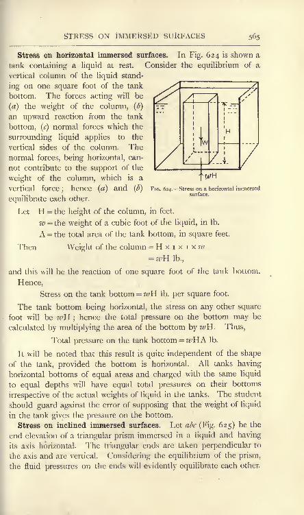
STRESS ON IMMERSED SURFACES 565
X

566 MACHINES AND HYDRAULICS
If the sides of the prism be taken to be very small, then the weight of
the prism may be disregarded, and the fluid stresses/, q and r, acting on
ab, be and ca respectively, may be assumed to be distributed uniformly
FIG. 625. Stress on inclined immersed surfaces.
over the faces of the prism. Let the length of the prism be unity,
when the resultant forces on the three faces will be given by
P =p . ab.
For equilibrium of the prism, these forces must balance. It will
be noted that P, Q and R meet at the centre of the circle passing
through a, b and c, and hence comply with the condition that the
three forces must pass through the same point. ABC (Fig. 625) is
the triangle of forces, in which AB, BC and CA represent P, Q and
R respectively. As these sides are drawn perpendicular to ab, be
and ca respectively, the triangles ABC and abc are similar. Hence,
P:Q:R=/-.a:?. &:*-. <ra ..................... (i)
= AB : BC : CA ....................... (2)
= ab : be : ca........................ (3)
From (i) and (3),
p . ab : q . be : r . ca = ab : be : ca;
.'. p = q = r.
We may say therefore that the fluid stresses on the faces of the
prism are equal. Considering the limiting case of the end elevation
of the prism being reduced practically to a point by reason of the
sides being taken indefinitely small, the law may be stated thus :
The stress at a point in a fluid is the same on all planes passing through
that point, or fluids transmit stresses equally in all directions. We have
already seen that the stress on a horizontal plane is ze>H Ib. per

TOTAL FLUID PRESSURE 567
square foot, and it follows that the stress at a point H feet deep on
any plane will be given by the same expression.
It will be noted that the stress at any point is proportional to the
depth, and hence varies uniformly from zero value at the free surface
of the liquid, i.e. the surface exposedto the atmosphere. Stress diagrams
may be employed with advantage ;
such a diagram is given in Fig. 626
for the water stresses on each side of
a lock gate having differing depths of
water on the two sides. The stress at
B will be/1= ?^H
1and that at E will
be/2=wH
2 ,and these are represented
by CB and FE respectively. The
complete stress diagrams are ABC and
DEF, and their breadths will give the stress at any depth. The
term stress at a point in a fluid may be defined as the pressure which
would be exerted on unit area embracing that point if the stresses were
distributed uniformly.
Total pressure on an immersed surface. In Fig. 627 (a) and (ft)
are shown front and end elevations of immersed surfaces, the former
being vertical and the latter inclined. The method of finding the
F D; E B o.
FIG. 626. Stresses on a lock gate.
FIG. 627. Total pressure on immersed surfaces.
total pressure applies equally to both surfaces. Consider a small
area a at a depth y. The stress on a will be
p = ivy
and Force on a = wya
The total force on the surface may be found by integrating this
expression over the whole area. Thus,
Total force w^ay.
If the total area is A square feet and the depth of the centre of
area is Y feet, then 2aj' = AY (pp. 49 and 145). Hence,
Total force =>wAY Ib.

568 MACHINES AND HYDRAULICS
The expression wY is the stress at a depth Y, and may be defined
as the average stress on the immersed surface. Hence the rule :
To find the total pressure on an immersed surface multiply the average
stress (which will be found at the centre of area) by the total area.
It will be noted that the force acting on the small area a, givenabove as wya, will have the same value in the case of the whole
surface being curved. The rule for the total pressure is therefore not
confined to flat surfaces, but may be applied to any immersed surface.
Distinction should be made between the terms total pressure and
resultant pressure. The latter term refers to the resultant of all the
fluid stresses acting on a surface, and is obtained by resolving
these stresses along chosen axes and then reducing by the methods
explained in Chapter IV. Usually the operation is simple; for
example, the resultant pressure on any vessel containing a liquid is
evidently equal to the weight of the contained liquid. A method of
dealing with the resultant pressure on floating or immersed bodies
will be explained below.
EXAMPLE i. A cylindrical tank, diameter 7 feet, contains water to a
depth of 4 feet. The bottom is horizontal. Calculate the total pressureand the resultant pressure on the wetted surface. Take 62-5 Ib. percubic foot for the weight of water.
Total pressure on the bottom wAiy
i
ir<P= 62-5 x X4
= 62-5x(27*x Y)X4
= 9625 Ib.
Total pressure on the curved surface =wA2Y2
=62-5 X(?JY/X4)X2
= 62-5 x(2T- x;x4)x2
= ii,ooo Ib.
Total pressure on the wetted surface= 962 5 + 1 1,000= 20,625 Ib.
The stresses on the curved surface will equilibrate each other;hence
the resultant pressure is simply the total pressure on the bottom, or
Resultant pressure= 9625 Ib.
EXAMPLE 2. A spherical vessel 3^- feet in diameter is sunk in sea
water, its centre being at a depth of 40 feet. Calculate the total pressureon its surface. Sea water weighs 64 Ib. per cubic foot.
Total pressure =wAY= 64 x 47rr
2 x 40= 64 x 4 x
272 x J x
|x 40
= 98,560 Ib.

RESULTANT FLUID PRESSURE 569
Resultant pressure on a floating or immersed body. When a
body is floating at rest in a fluid which is also at rest, it is subjected
to two resultant forces its weight and the resultant fluid pressure
on its surfaces. The weight is a downward vertical force acting
through G, the centre of gravity of the body (Fig. 628 (a)). Theresultant fluid pressure balances W, and therefore must be an
upward vertical force R = W, and must act in the same straight line
with W. R is due to the buoyant effect of the fluid, and is called
the buoyancy.
Imagine for a moment that the surrounding fluid becomes solid,
and so can preserve its shape, and let the body be removed, leaving
a cavity which it fits exactly (Fig. 628 (<)). Let this cavity be filled
with the fluid, and let the surrounding fluid return again to its original
condition. The pressures on the fluid now filling the cavity will be
identical with those which acted on the body, and the effect will be
V 5
W ()FIG. 628. Resultant pressure on a floating body.
the same the weight of the fluid will be supported. Hence the
weights of the fluid filling the cavity and of the body must be equal,
as each is equal to R, the resultant pressure of the surrounding fluid.
Further, R must act through the centre of gravity of the fluid filling
the cavity ;this centre is called the centre of buoyancy, and from
what has been said it will be clear that the centre of buoyancy B
(Fig. 628 (/>)) and G (Fig. 628 (a)) must be in the same vertical line.
We may state, therefore, that when a body is floating at rest in still fluid,
the weight of the body is equal to the weight of the fluid displaced, and that
the centres of gravity of the body and of the displaced fluid are both in the
same vertical line.
A ship floating at rest in still water, a submarine boat wholly
immersed and at rest, and a balloon preserving constant elevation
are examples of this principle. In each case it will be noted that
the resultant pressure of the surrounding fluid is equal to the weightof the body, and acts vertically upwards through the centre of
gravity of the body.

570 MACHINES AND HYDRAULICS
A body wholly immersed will experience a resultant upward fluid
pressure equal to the weight of the fluid displaced ;it follows that,
to maintain the equilibrium of the body, an upward or a downwardforce will be required, depending on whether the weight of the bodyor the weight of the fluid displaced is the greater. Fig. 629 (a)
illustrates the former case;W is the weight of the body, B is the
buoyancy, and, W being greater than B,
an upward force P is required given by
P + B-W.r \ i Fig. 629 (b) shows the case of B being
^*"T*-'^ T"~ greater than W, when a downward force
P is required, given byfWf
FIG. 629. Equilibrium of immersed The specific gravity of a Substance IS
defined as its weight in air as comparedwith the weight of an equal volume of pure water, usually taken at a
temperature of 60 F.
Let W8= weight of a given substance in air.
Ww = weight of an equal volume of water.
WThen Specific gravity p =W w
and Ww = '-.
P
It therefore follows that we may calculate the buoyancy of a solid
body wholly immersed in pure water by dividing the weight of the
body by the specific gravity of its material. This principle may be
applied to find the specific gravity of a given substance which is
heavier than water. In Fig. 629 (a), let P be measured by suspendingthe body by means of a fine wire or cord from a balance
;also
weigh the body in air to find Ws . Then
Also,
Since (Ws-P) is the apparent loss of weight of the body when
immersed in water, we may state that the specific gravity of a body is

CENTRE OE PRESSURE 571
equal to the weight of the body in air divided by its apparent loss of weight
when immersed in water.
Centre of pressure. In Fig. 630 (a) is shown a flat vertical plate
immersed in a liquid. R is the resultant pressure acting on one
side of the plate and passes through a point C, which is denned as
the centre of pressure. The position vertically of C may be found
J.'if-5
R
fa)FIG. 630. Centre of pressure.
by taking moments about OX, the line in which the plate producedcuts the surface of the liquid. Considering a small area a at a depth
y, we have Pressure on a = way,
Moment of this pressure= way1
.
Integration of this will give the total moment. Thus,
Total moment = w^ay2.
Now 2#y2
is the second moment of area or moment of inertia
(p. 145) of the surface of the plate about OX and may be written
lox or A/ 2,where A is the area of the plate and k is the radius of
gyration about OX. Hence,
Total moment = whk2(i)
Again, if D be the depth of the centre of pressure,
R = ze/AY
and Moment of R = z#AYD (2)
Hence, from (i) and (2),
a/AYD
D =f... ..-(3)
Both k and Y should be taken in foot units, when D will be in the
same units.
The case of an inclined surface is shown in Fig. 630 (/>).If $ is
the angle of inclination to the horizontal, it may be shown that
D = sin2, (4)

572 MACHINES AND HYDRAULICS
where k is the radius of gyration about OX, the line in which the
plate cuts the surface of the water, and Y is the vertical depth of
the centre of area.
In practical examples, usually the position of C horizontally maybe easily determined from the symmetry of the plate.
EXAMPLE. A dock gate is 60 feet wide and has water on one side to a
depth of 24 feet. Find the centre of pressure.
Let b = the breadth of the wetted surface.
</=the depth
Then Iox= J- = bd '-;
:. &= .
Also.
=5 x 24= 1 6 feet.
The centre of pressure is therefore at a depth of 16 feet, and lies in
the central vertical of the gate.
Stability of a floating body. A body floating at rest in a still
liquid will be in stable equilibrium when, if rotated through a small
vertical angle, it experiences a resultant couple tending to return it to
(a)
R-wTFIG. 631. Stability of a floating body.
the original position ;the equilibrium will be unstable if the resultant
couple has a moment tending to increase the angle of rotation. In
Figs. 631 (a) and (/^).are shown floating bodies which have been
disturbed slightly from their positions of equilibrium : the weight, in
each case, is a vertical force W, acting through the centre of gravity G ;
the buoyancy in each case is a vertical force R = W, acting through
the centre of buoyancy B. It will be observed that in Fig. 631 (a) a
couple is formed by R and W tending to restore the body to its
original position ;the equilibrium in the original position is therefore

STABILITY OF A FLOATING BODY 573
stable. In Fig. 63 r(/>) the couple tends to increase the angle through
which the body has been turned, and the equilibrium in the original
position is therefore unstable. A floating ball would be in neutral
equilibrium.
It will be noticed that the line of R cuts the original vertical
through G in a point M, which lies above G in Fig. 631 (a) and below
G in Fig. 631 (l>). Clearly the sense of rotation of the couple formed
by R and W is determined by consideration of the position of M above
or below G;the couple will be of righting moment if M is above G,
and of upsetting moment if M is below G. The point M is called
the metacentre. The metacentre is of importance in calculations
regarding the stability of ships ; generally the naval architect finds
the metacentre for transverse angles of displacement, which affects
questions of the ship rolling, and also the metacentre for longitudinal
angles of displacement, which affects questions of the ship pitching.
In Fig. 632, G is the centre of gravity and B is the centre of
buoyancy of a body floating at
rest in still water. G and Bin
must fall in the same vertical,
and the conditions of equili-brium are satisfied by the re-
sultant water pressure R beingequal to W, the weight of the
body, both forces falling in
the same straight line BG.To test for stability, the bodyis rotated through a verysmall angle 6, which, in order
to avoid complication in the
figure, has been secured byrotating the water plane fromits original position ab into
the position db'
. G will remainunaltered in position, and Bwill move to B' in consequenceof the body now being immersed
deeper on the right-hand side.
The weight of the body is nowW' =W and acts through G in
a direction perpendicular to
ab';
the resultant pressure of
the water will be R' =W = W,acting through B' and also perpendicular to ab'.
BG produced in the metacentre M.
"*
Plan
FIG. 632. Metacentric height for a floating vessel.
R' produced cuts

574 MACHINES AND HYDRAULICS
As we assume that W and W are equal, it follows that the weightof the wedge l>Cb\ which has been added to the volume of water
displaced, must be equal to that of the wedge aCa, which has beentaken away. In the plan of the plane of flotation ab (Fig. 632),small areas a and a trace out arcs / and /' as seen in the elevation.
Volume swept by a = al.
NOW,l-=e-,
Hence, Volume swept by a = axO.
Weight of this = waxO, .............^ ........... (i)
w being the weight of the water per cubic unit.
The total weight of both wedges must be zero from what has been
said, and may be obtained by integrating (i) over the whole planeof flotation.
Total weight of wedges = ivB^ax = 0.
Hence, ^ax = 0.
This shows that the axis CZ in the plan must pass through the
centre of area of the plane of flotation.
The resultant effect of the altered distribution of displacementwill be found by calculating the total moment of weight of both
wedges about CZ.From (i), weight of the small volume = wOax.
Moment of this about CZ =
Total moment of both wedges =
= U>OICZ ................ (2)
In this result, Icz is the second moment of area of the plane of
flotation about CZ.
Now, if R' be brought back to its original position R, we see that
the effect of the altered distribution of displacement will be the
couple, of moment R x BB', which must be supplied in consequenceof the shift.
Moment of couple = R x BB' =W x BB'.
Now,
:. BB' = 6>xBM.
.*. moment 01 couple =Wx 6 x BM........................ (3)
Hence, from (2) and (3),
(4)

STABILITY OF A FLOATING BODY 575
Let V = volume of water displaced by the body.
Then W = 70V,
or V =w
Substituting in (4), we have
BM =^Z
. ....(5)
Writing AJt*cz for Icz ,we obtain a well-known equation for BM,
EM =^' ..-(6)
From Fig. 632, we have
GM will be positive if M falls above G, in which case we have
stable equilibrium ;the equilibrium will be unstable if G falls below
M, leading to a negative value of GM.It will be noticed that the completion of the calculation depends
on a knowledge of the position of the centre of gravity of the body.In the case of a body of simple outline and homogeneous in structure,
this point is determined easily, but, in the case of a ship, is obtained
only by long and laborious calculation. The calculations for
A/&CZ and for V required in equation (6), and also for the position of
B, are carried out easily for a ship-shape body, and the result may be
applied to the finished ship, in an experimental determination of the
centre of gravity. This is effected by moving weights on board so as
to produce a small angle of heel, which is measured carefully bymeans of long plumb lines suspended in the holds. From a
knowledge of the positions of M and B, together with the moment of
the weights which have been moved and the angle of heel producedby this movement, the position of G is calculated easily. Thus,
referring to Fig. 632, let the line of W cut BB' in N and draw GQperpendicular to B'M.
Let w = the weight moved, in tons.
d= the distance through which the weight is moved, in feet.
6 the angle of heel produced by moving w, in radians-
Then Capsizing moment due to moving w = wd ton-feet.
Righting moment = R' x B'N
=WxGQ=W x GM x B.
Hence, W x GM x 6 = wd,
wd

57 MACHINES AND HYDRAULICS
The author is indebted to Mr. E. L. Attwood, Member of the
Royal Corps of Naval Constructors, for the following example of a
recent inclining experiment on a large ship.
EXAMPLE. Draught of ship, forward, 24' 4".
Draught of ship, aft, 26' 2\".
These dimensions correspond to a displacement of 15,357 tons, and a
position of the transverse metacentre of 6-76 feet above the load water-
line of the ship. 100 tons of ballast was used, arranged on the upper
deck, in four lots of 25 tons each. The following measurements were
taken by means of pendulums 20 feet in length, one forward, one aft :
Weight moved,
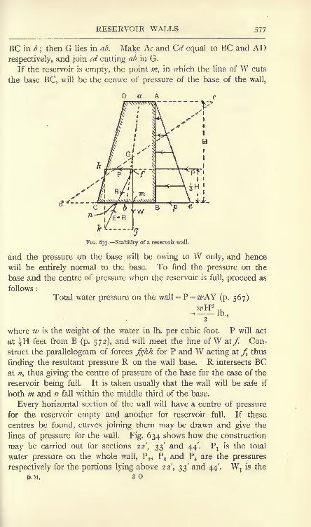
RESERVOIR WALLS 577
BC in b;then G lies in ab. Make Kc and G/ equal to BC and AD
respectively, and join cd cutting ab in G.
If the reservoir is empty, the point m, in which the line of W cuts
the base BC, will be the centre of pressure of the base of the wall,
D a A
FIG. 633. Stability of a reservoir wall.
and the pressure on the base will be owing to W only, and hence
will be entirely normal to the base. To find the pressure on the
base and the centre of pressure when the reservoir is full, proceed as
follows :
Total water pressure on the wall = P = z#AY (p. 567)
where w is the weight of the water in Ib. per cubic foot. P will act
at JH feet from B (p. 572), and will meet the line of W &tf. Con-
struct the parallelogram of forces fgkh for P and W acting at /, thus
finding the resultant pressure R on the wall base. R intersects BCat n, thus giving the centre of pressure of the base for the case of the
reservoir being full. It is taken usually that the wall will be safe if
both m and n fall within the middle third of the base.
Every horizontal section of the wall will have a centre of pressure
for the reservoir empty and another for reservoir full. If these
centres be found, curves joining them may be drawn and give the
lines of pressure for the wall. Fig. 634 shows how the construction
may be carried out for sections 22', 33' and 44'. Px
is the total
water pressure on the whole wall, P2 ,
P3 and P4 are the pressures
respectively for the portions lying above 22', 33' and 44'. W^ is the
P.M, 2 o

578 MACHINES AND HYDRAULICS
total weight, and W2 ,W
3 and W4are the weights corresponding to
P2 ,P
3 and P4
. The centres of gravity GI} G2 ,G3
and G4are found
D
B
FIG. 634. Lines of pressure for a reservoir wall.
as before, and the lines of weight passing vertically through them
give mltm
2 ,m
Band m4 on the line of pressure for reservoir empty.
D u a s ARj of Pj and W
lis found by
means of the triangle of
forces, and a line drawn from
the point of intersection of
Pj and Wj parallel to Rx ,and
cutting BC inj gives a point
on the line of pressure for
reservoir full. The triangles
of forces for the remainingforces are shown, and enable
points ;z2 , n^ and n
4to be
found similarly. The lines
of pressure have been drawn
separately in Fig. 635 for the
sake of clearness. In Fig. 635uv and st inclose the middle
thirds of all sections, and the
FIG. 63S.-Lines of pressure, reservoir full and empty. lines of pressure an^ and am^

WORK DONE BY FLUID PRESSURE 579
fall throughout within the middle thirds. The student will note that
the upper ends of the lines of pressure bisect AD in a.
Work done by a fluid under pressure. Work may be done by a
fluid, either liquid or gaseous, by allowing it to exert pressure on a
piston which may move in a cylinder. In
Fig. 636,
Let D = the diameter of the cylinder,
in feet.
L = the length of the stroke, in feet.
P = the pressure of the fluid, in
Ib. per square foot.
-*

MACHINES AND HYDRAULICS
the form of having the crank of variable throw; the strokes of the
pistons will then vary to correspond. The crank adjustment may be
effected either by means of a governor or by means of an automatic
spring coupling between the engine and the machine to be driven.
If a gas is used in the cylinder in Fig. 636, advantage may be
taken of its expansive property by cutting off the supply after the
piston has moved a short distance and allowing the remainder of the
stroke to be completed under the continually diminishing pressure of
the gas. In Fig. 638 is plotted
a curve AB, showing the relation
of pressure (vertical) and volume
(horizontal) while a gas is ex-
panding and doing work. Usuallythe law of the curve AB takes
the form
_ v _ Ix PVn = a constant,
V
. v"*^- -Jwhere P is the pressure of the gas
2in Ib. per square foot measured
FIG. 638. Work done by an expanding gas.from zero. On this basis the
pressure of the atmosphere is about 14-7 Ib. per square inch or
2116 Ib. per square foot. V is the volume in cubic feet, n is an
index which depends on the conditions under which the expansion is
performed. If the temperature is preserved constant, then Boyle's
law is being followed, n is unity, and the expansion law will be
PV = a constant \
n usually lies between i and 1-5.
The work done may be found from the area of the diagram under
AB in Fig. 638. Thus, assuming Boyle's law to be followed and
taking a narrow strip EF, for which the pressure is P, the volume Vand the increase in volume represented by the breadth of the strip is
8V, we haveArea of the strip
= P . 8V.
Now, from Boyle's law, PV = P1V
1 ;
SVHence, Area of the strip
= PjVa
Total area under AB = PlV
l I
-y-j
,". work done = PjVj log,,^ foot-lb.

HYDRAULIC TRANSMISSION OF ENERGY 581
If the expansion law is PVn = a constant, we have, in the samemanner : Area of the strip
= P . 8V.
Also, PV = P1V
1
' 1
,
P Vp_ rlv
l
v*8V
Hence, Area of the strip= PjV^
1
Total area under ABPWV= PjV^ ^~
Remembering that P1V
1
n = P2V
2n
,the above becomes, by multi-
plication, p V - P VWork done = l YI 2 2
foot-lb.n - i
Hydraulic transmission of energy. In Fig. 639 A and C are two
cylinders charged fully with water, and connected by a pipe E.
B and D are plungers or rams fitted to cylinders,
and carrying loads P and W. Owing to the
practical incompressibility of water, any descent
of B will produce an ascent of D, and hence workdone on P may be transmitted by the medium of
the moving water under pressure, and be givenout in the form of work done on W. The con-
necting pipe E may be of any length. In practice,
A represents a set of power-driven pumps, which supply water undera pressure of 700 to 1000 Ib. per square inch. A pipe system distri-
butes the water over the district to be supplied, and D may be taken
to represent one of the machines to be operated. The principal
appliances required in a hydraulic power distribution plant are
shown diagrammatically in Fig. 640. A is one of the power-driven
pumps supplying water to the pipe line BC. A safety valve is placedat D. E is an accumulator consisting of a large cylinder fitted with
a loaded ram, and connected to the pipe line; its function is to
absorb energy by raising the weight if the machines are stopped andthe pumps are still working ;
it also assists in preserving a steady
pressure of water. A stop valve F is under the control of the
consumer, and another safety valve is placed at G in order to guard
against damage to his pipes and machines. H, H represent two of
the machines being driven; each is fitted with a control valve K,

582 MACHINES AND HYDRAULICS
K, for the use of the operator. Usually the exhaust water from the
machines is collected and passed through a meter, where it is
measured for the purposes of charging for power.
FIG. 640. Diagram of a hydraulic installation.
Referring again to Fig. 639, let d1and d^ be the diameter of B and
D respectively in inches, and let p be the water pressure in Ib. per
square inch ; also let W and P be measured in Ib. Then, neglecting
friction : ^d 2
P = l
-p,
Hence, 5~==
;^2*A (t-i
This gives the mechanical advantage of the arrangement neglecting
friction. If P descends one inch, then the volume of water delivered
from A into C will be cubic inches. To accommodate this
volume in C, D will rise a height h inches say, and the additional7
volume in D will be h cubic inches.4
Hence,rc , tr-i*- h = Li4 4
Now i -h is the velocity ratio of the arrangement. Hence,d^
Velocity ratio = -h'
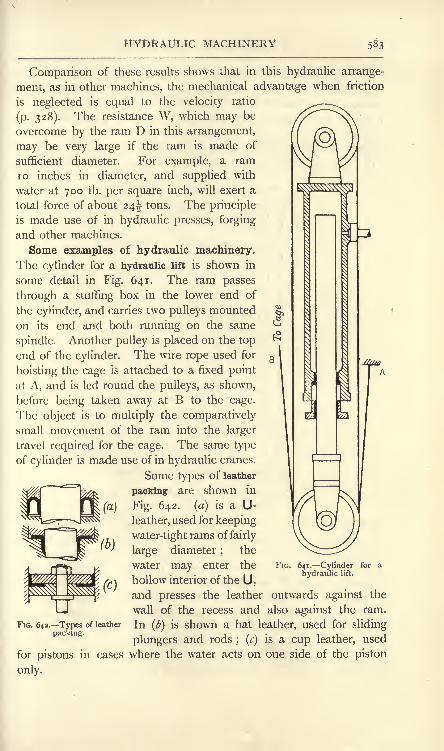
HYDRAULIC MACHINERY 583
Comparison of these results shows that in this hydraulic arrange-
ment, as in other machines, the mechanical advantage when friction
is neglected is equal to the velocity ratio
(p. 328). The resistance W, which may be
overcome by the ram T) in this arrangement,
may be very large if the ram is made of
sufficient diameter. For example, a ram
10 inches in diameter, and supplied with
water at 700 Ib. per square inch, will exert a
total force of about 24^ tons. The principle
is made use of in hydraulic presses, forging
and other machines.
Some examples of hydraulic machinery.
The cylinder for a hydraulic lift is shown in
some detail in Fig. 641. The ram passes
through a stuffing box in the lower end of
the cylinder, and carries two pulleys mounted
on its end and both running on the same
spindle. Another pulley is placed on the top
end of the cylinder. The wire rope used for
hoisting the cage is attached to a fixed point
at A, and is led round the pulleys, as shown,
before being taken away at B to the cage.
The object is to multiply the comparatively
small movement of the ram into the larger
travel required for the cage. The same type
of cylinder is made use of in hydraulic cranes.
Some types of leather
packing are shown in
Fig. 642. (a) is a U-
leather, used for keeping
water-tight rams of fairly
large diameter ;the
water may enter the
hollow interior of the U,and presses the leather outwards against the
wall of the recess and also against the ram.
FIG. 642. Types of leather In (b] is shown a hat leather, used for slidingpacking. i i / \ ' 11
plungers and rods; (c) is a cup leather, used
for pistons in cases where the water acts on one side of the piston
only.
FIG. 641. Cylinder for a
hydraulic lift.

MACHINES AND HYDRAULICS
A simple hydraulic accumulator is illustrated in Fig. 643. The ram
A is fixed to the base plate, and the cylinder B is loaded with a
number of cast-iron plates and may move vertically. A tail rod C is
fixed to the cylinder, and serves as a guide. Water enters the
cylinder by way of an axial hole bored through the ram. When the
cylinder is nearing the top of its lift, it raises the end U of the lever
DE;the movement of this lever is transmitted to the belt-striking
n.
FIG. 643. Hydraulic accumulator.
gear on the pump, or to the throttle of the pump engine, and so stops
the pump. A spring F pulls the levers back to working position
when permitted by the descent of the accumulator, and so starts the
pump again. The following simple calculations may be made
regarding hydraulic accumulators :
Let //=the diameter of the ram, in inches.
/ = the water pressure, in Ib. per square inch.
W = the total accumulator load, in Ib.
H = the height of lift, in inches.72
Then W=/ x - -Ib., neglecting friction.
4

HYDRAULIC MACHINERY 585
When the accumulator is"up," the volume of water stored will be
70
Volume stored = H cubic inches.4
Also, Energy stored =WH inch-lb.
Occasionally it occurs that a hydraulic machine requires a greater
pressure of water than that supplied in the mains, and an intensifier
is used in order to secure this. In Fig. 644 a cylinder A has a
hollow ram B which passes through its right-hand end. A fixed
FIG. 644. Hydraulic intensifier.
hollow ram C passes into the interior of B as shown. Low-pressurewater is supplied at D, and water of a higher pressure is dischargedat E.
Let /j= the lower pressure, in Ib. per square inch.
p.2= higher
dl= the external diameter of B, in inches.
d^ the external diameter of C, in inches.
Then, neglecting friction,
or
A 42
With a ratio of diameters of 2 to i, the supply pressure of 700 Ib.
per square inch may be intensified to 2800 Ib. per square inch,
neglecting friction. Valve arrangements are provided for enablingthe lower pressure to be used in the machine, and at the momentwhen the higher-pressure water is required, low-pressure water is
admitted to A in the intensifier, and at the same time the machine is
connected to E.
Pumps. Fig. 645 shows a hydraulic pump suitable for supplyingwater for operating hydraulic machines. A cylinder A is fitted with

586 MACHINES AND HYDRAULICS
a piston B operated by a plunger rod C. Water enters the cylinderat D, and is prevented from flowing back by the suction valve E.
G is a discharge valve opening to the discharge branch H, and F is a
passage connecting the right-hand side of the piston to the discharge.
The valves E and G are cushioned on lifting against rubber discs,
separated by metal washers;the piston packing consists of two cup
leathers. The action is as follows : Suppose the piston to be moving
FIG. 645. Hydraulic pump.
towards the right as shown;E is open and G is closed. WT
ater will
flow into the pump through E, and will fill the space vacated bythe receding piston ;
at the same time, the water on the right-hand
side of the piston is being forced into the discharge pipe through F.
If the diameters of the piston and of the plunger rod are d^ and d^
respectively, and if the stroke is L inches, then the volume dischargedfrom the right-hand side of the piston during this stroke will be
f--t__~a-)L cubic inches.\ 4 4 /
Now let the piston be moving towards the left;E will be closed
and G will open, and the water on the left-hand side of the piston
will be discharged through G. The volume so discharged will be7 2
L cubic inches, but a portion of this only will be sent into the
discharge pipe, the remainder finding its way through F to the right-
hand side of the piston ; the amount so passing through F will be
( )L cubic inches
;hence the volume discharged from the
\ 4 4 /
pump during this stroke will be
\ 4 4 /L cubic inches.

RECIPROCATING PUMPS 587
The pump is thus double-acting, i.e. water is discharged during both
strokes. For equality of discharge, we have
V 4
or
Ln t*-o= i.
4 / 4
^l2 ~ 42 =
^22
'
This result may be expressed also by stating that the sectional area
of the plunger rod should be half that of the piston.
Fig. 646 illustrates a type of bucket pump used in raising water from
a lower to a higher level. The piston or bucket is shown ascending,and water is passing into the cylinder Athrough B and the suction valve C. Thewater already on the top of the bucket is
being discharged through the discharge valve
F and the passage G. During this stroke, the
bucket valve is closed. On the downward
stroke, the suction and discharge valves C and
F both close, and the bucket valve opens, per-
mitting water to pass from the lower to the
upper side of the bucket. It is not absolutely
necessary to have a discharge valve F in this
type of pump, but, if fitted, it serves as a
check on the suction valve during the down-
ward stroke of the bucket. This pump is
single-acting.
In Fig. 647 is shown a single-acting plunger
pump. On the upward stroke of the plunger
B, water enters the pump through the suction
valve C, and is delivered, during the downward
stroke, through the discharge valve D. E is an air vessel, the
function of which is to get rid of shocks. The water coming from
the pump flows partly into the air vessel, during the early part of the
discharge stroke, and compresses the air contained therein; during
the later part of the discharge stroke, and also possibly during part of
the suction stroke, the pressure of the compressed air drives some
of the water out of the air vessel into the discharge pipe. The accele-
ration required to be given to the column of water in the discharge
pipe in starting it into motion is lowered by the action of the air
vessel, and hence the force required is also lowered, and shock is
FIG. 646. Bucket pump.

588 MACHINES AND HYDRAULICS
avoided entirely. The cushion of compressed air is also beneficial
in quietly closing the discharge valve at the end of the stroke without
depending on any backward movement of the mass of water in the
discharge pipe; thus hammering of the valve is avoided. The air
FIG. 647. Boiler feed pump. FIG. 648. Combined plunger andbucket pump.
vessel should be situated always as close as possible to the discharge
valve. The type of pump illustrated is much used for forcing the
feed water into steam boilers.
Fig. 648 illustrates a combined plunger and bucket pump. During the
downward stroke, the suction valve C is closed, and the bucket valve
D is open; the plunger E is thus operating in discharging water

EXERCISES ON CHAPTER XXII. 589
through F. During the upward stroke, the bucket valve D is closed
and the suction valve C opens. Fresh water thus flows into the
cylinder A from B, and the water already on the top of the bucket is
discharged through F. As is the case in the pump shown in
Fig. 645, the area of the plunger should be one-half that of the
bucket for equality of discharge on the two strokes.
Pumps may be placed at some height above the supply water, and
in this case depend on the pressure of the atmosphere acting on the
supply water and forcing it up the suction pipe into the partial
vacuum created by the action of the pump bucket or plunger. Themaximum possible height through which the atmospheric pressure
will raise water thus is about 34 feet; from 25 to 30 feet is the
greatest practical height.
EXERCISES ON CHAPTER XXII.
1. A rectangular tank is 4 feet long, 3 feet wide and 2 feet deep.Find the total pressures on the bottom, on one side and on one end whenthe tank is full of oil which weighs 50 Ib. per cubic foot.
2. A tank 10 feet long has a horizontal bottom 4 feet wide. The endsof the tank are vertical, and both the sides are inclined at 45 to the
horizontal. Water is contained to a depth of 6 feet. Find the total
pressures on the bottom, on one side and on one end. Take 2^= 62-5 Ib.
per cubic foot.
3. A dock gate is 80 feet wide and has sea water to a depth of 30 feet
on one side and 9 feet on the other side. Find the total pressure on eachside of the gate, and show the lines of action. Find also the resultant
force on the gate, and show its position. Take 1^= 64 Ib. per cubic foot.
4. A tank is in the form of an inverted cone, 6 feet diameter at the
top and 4 feet vertical depth. When full of oil having a specific gravity
0-8, find the weight of the contained oil and the total pressure on the
curved surface of the tank.
5. A rectangular opening in a reservoir wall is 4 feet high and 3 feet
wide, and has its top edge 20 feet below the water level. Find the total
water pressure on the door or gate closing the opening, and find also the
centre of pressure.
6. A rectangular pontoon 100 feet long and 30 feet wide has a draughtin fresh water of 8 feet (i.e. the bottom of the pontoon is 8 feet below the
surface of the water). Find the weight of the pontoon. Supposing the
weight to remain unaltered^ and the pontoon to be floating in sea water,what will be the draught? For fresh water 2/= 62'5, and for sea water
ze/=64 Ib. per cubic foot.
7. The weight of a submarine is 200 tons, and it lies damaged andfull of water at the bottom of the sea. Supposing the specific gravity of
its material to be 7-8, find what total pull must be exerted by the liftingchains in order to raise the vessel from the bottom. Take 1^= 64 Ib. percubic foot.

$90 MACHINES AND HYDRAULICS
8. For the pontoon in Question 6, when floating in fresh water, find
the heights of the transverse and longitudinal metacentres above thecentre of buoyancy.
9. The pontoon in Question 8 carries a crane, and is hoisting a load
which produces a transverse capsizing moment of 200 ton-feet. Calculatethe angle of heel. It may be assumed that the centre of gravity of the
complete pontoon is 0-5 foot below the surface level of the fresh water.
10. A retaining wall for water is triangular in section and has the
wetted surface vertical. The height is 30 feet and the breadth of the
base is 25 feet. Fresh water has its surface level 3 feet below the top of
the wall. The weight of the material is 140 Ib. per cubic foot. Take onefoot length of wall and find the resultant force acting on the base.
Answer the same if the reservoir is empty. Do these forces fall within
the middle third of the base ?
11. Answer Question 10 for sections at 3 feet, 10 feet and 20 feet fromthe top of the wall, using graphical methods so far as is possible. Plot
the lines of pressure for the reservoir full and empty.
12. Water is supplied by a hydraulic company at a pressure of 700 Ib.
per square inch, and is charged at the rate of 18 pence per thousand
gallons. How much water must be used in an hour to obtain one horse-
power, and what would be the cost ? Neglect waste.
13. A single-acting hydraulic engine has three rams, each 3^ inches
diameter by 6 inches stroke. The effective mean water pressure on the
rams is 120 Ib. per square inch, and the engine runs at 90 revolutions perminute. Neglect all sources of waste and calculate the horse-power. If
the efficiency is 65 per cent., what is the useful horse-power ?
14. 2 cubic feet of air at an absolute pressure of 80 Ib. per square inch
are expanded in a cylinder until the volume is 5 cubic feet. Assumingthat the law PV= a constant is obeyed, calculate what work is done.
15. Answer Question 14 if the law of expansion is PV 1-41 = a constant.
16. A hydraulic accumulator has a ram 7 inches in diameter and the
lift is 12 feet. If the water pressure is to be 700 Ib. per square inch, find
the weight required. How much water is stored when the accumulator is
up ? Find also the energy stored.
17. In the hydraulic lift cylinder shown in Fig. 641, find the velocityratio if there are three rope pulleys on the ram end and two pulleys onthe cylinder top. Suppose the ram to be 4 inches diameter and that the
water pressure is 700 Ib. per square inch, and calculate the pull on the
cage rope, neglecting frictional waste. What is the pull if the total
efficiency is 65 per cent. ? What stroke of ram is required for a total cagelift of 60 feet ?
18. A hydraulic pump, similar to that shown in Fig. 645, has a piston
4-25 inches and a plunger rod of 3 inches in diameter ; the stroke is
1 8 inches. If the pump makes 60 double strokes per minute, how muchwater will be delivered, neglecting waste ? If the water pressure is 750 Ib.
per square inch, find the force which must be applied to the rod (a] whenthe piston is moving towards the valves, (&) when the piston is moving in
the contrary direction, assuming the pressure on the suction side to be
15 Ib. per square inch. Neglect friction.

EXERCISES ON CHAPTER XXII. 591
19. A bucket pump (Fig. 646) has to raise 400 gallons of water perminute to a height of 30 feet. If the pump makes 30 double strokes (one
up and one down) per minute, and if the length of the stroke is 1-5 times
ftie diameter of the bucket, find the stroke and the bucket diameter,
neglecting waste. Calculate the useful work done per minute, and, if the
efficiency is 60 per cent., find the horse-power required.
20. A boiler feed pump has a plunger 3 inches in diameter. Thedelivery pipe leading to the boiler is 40 feet in length and 3 inches in
diameter. The pressure in the boiler is 100 Ib. per square inch. Thereis no air vessel. Supposing that the acceleration of the plunger at the
beginning of the stroke (the water in the delivery pipe being then at rest)to be 90 feet per second per second, what total force must be exerted bythe plunger in order to start the water into motion ? If a perfect-actingair vessel were fitted, what total force would be required ?
21. In finding the total force in the axial direction which a fluid
exercises upon a piston or ram, we calculate from the cross section of the
cylinder or ram ; why is the actual shape of the face of the piston or endof the ram of no importance ? (B.E.)
22. A vertical flap closes the end of a pipe 2 feet in diameter; the
pressure at the centre of the pipe is equal to a head of 10 feet of water.Find the total pressure on the valve in pounds. (You may neglect the
atmospheric pressure.) (B.E.)
23. The ram of a vertical accumulator is 4 inches in diameter; the
cylinder is 6 inches in internal diameter and 50 feet high. The ramcarries a total load of 5 tons. Find the water pressure, in Ib. per squareinch, at the top and bottom of the cylinder. (B.E.)
24. Determine the depth from the surface of the centre of pressure ona rectangular sluice valve, 6 feet long and 3 feet wide. The centre of thevalve is at a depth of 8 feet below the surface of the water, and the valvelies in a plane inclined at an angle of 30 degrees to the horizontal, withone of the long edges of the valve parallel to the surface of the water.
(B.E.)
25. A horizontal channel of V section, whose sides are inclined at 45,is closed at the end by a vertical partition. The water-surface has awidth of 4 feet, and consequently a maximum depth of 2 feet. Calculatethe total hydrostatic pressure upon the partition and the height of thecentre of pressure. (I.C.E.)
26. Define metacentric height. A vessel has a length of 150 feetbetween perpendiculars and a beam of 28 feet. The mean load draft insea water is 1 1 feet, and the coefficient of fineness, or ratio between the
product of length, breadth and draft and the displacement volume is 0-47.The second moment of the load water-plane about its fore and aft axis is
63 per cent, of the moment of the circumscribing rectangle about thesame axis. The centre of buoyancy is situated 3-95 feet below the water-line. If the transverse metacentric height is to be limited to 3-62 feet,determine the distance from the centre of gravity to the water-line.
'
(L.U.)
27. A masonry dam with vertical water face is 20 feet high and 13 feetwide at the bottom, sloping gradually till it is 6 feet wide at the top. Thewater reaches 2 feet from the top. Draw the line of thrust throughout thedam. Specific gravity of masonry, 2-25. (L.U.)

CHAPTER XXIII.
HYDRAULICS. FLOW OF FLUIDS.
Fluid friction. We have seen already that there can be no friction
in any fluid at rest;considerable frictional resistances exist, however,
when the fluid is in motion. For liquids, the laws of fluid friction, as
deduced from experimental evidence, have been mentioned in
Chap. XV., and are stated again for reference as follows :
(a) The resistance is proportional to the extent of the surface
wetted by the liquid.
(b) The resistance is independent of the material of which the
boundary is made, but depends on the roughness of its surface.
(c) The resistance is independent of the pressure to which the
liquid is subjected.
(d) Rise of temperature of the liquid diminishes the resistance.
(e) At slow speeds the resistance is very small.
(f) Below a certain critical speed, the resistance is proportional to
the speed ;at speeds above this, the resistance is proportional to some
power, approximately the square, of the speed.
The critical speed depends on the liquid used and its temperature.
Below this speed the motion of the liquid is steady, the particles
moving in stream lines; above it, the liquid breaks up into eddies.
As the flow of water is the most important case in practice, we will
confine attention to this liquid.
Kinds of energy of flowing water. Neglecting effects due to
changes of temperature and of volume, we may state that the total
energy of a particle of water is made up of (a) potential energy,
(b) pressure energy, (c) kinetic energy. The potential energy will
be proportional to the elevation of the particle above some datum
level ; the kinetic energy will be proportional to the square of the
velocity of the particle. The pressure energy requires some fuller
explanation.

ENERGY OF FLOWING WATER 593
In Fig. 649 is shown a cylinder fitted with a piston and suppliedwith water from an overhead tank, in which the level is maintained
constant. If the piston is allowed to move outwards slowly, workwill be done by the water pressure on the
piston overcoming the external resistance
acting on the other side of the piston or on
the piston rod.
Let P = fluid stress on piston, in Ib. per
square foot.
A = area of piston, in square feet.
L = the distance piston is moved, in
feet. FIG. 649. Pressure energy of
Then Work done = PAL foot-lb.
In performing this work, a volume AL cubic feet of water has been
admitted to the cylinder, and the work has been done at the expenseof the energy of this water. The work done per cubic foot of water
may be found by dividing the above result by AL, giving
Work done per cubic foot of water = P foot-lb.
Let w = weight of one cubic foot of water in Ib.
Then = volume of one Ib. of water.wP
Hence, Work done per Ib. of water = foot-lb.wIt has been assumed that there has been no waste of energy;
ptherefore represents the whole energy available in one pound of
water due to its pressure. We may say therefore that water at rest
and under pressure possesses energy due to its pressure to the
pamount of foot-lb. per pound of water.
wTransformations of energy in flowing water. In Fig. 650 is
shown two tanks at different levels, and connected by a pipe so
that water may flow from the upper into the lower tank. OX is
an arbitrary datum level. Considering a pound of water at A and
assuming it to be at rest, there will be no kinetic energy; it will,
however, possess HA foot-lb. of potential energy owing to its elevation
HA feet above OX. The water, being exposed to atmospheric
pressure Pa Ib. per square foot, will also possess pressure energy to
pthe amount of foot-lb. per pound. Hence,w
Total energy at A =^HA + -
jft.-lb. per Ib. of water.
D.M. 2 P

594 MACHINES AND HYDRAULICS
It is reasonable to suppose that the bulk of the water in the uppertank is at rest, only a portion near the pipe entrance, mapped out
by the dotted curve abc (Fig. 650), will possess any considerable
velocity. Hence, at B, a pound of water will have potential energypHB foot-lb., together with pressure energy -- foot-lb. owing to its
absolute pressure PB Ib. per square foot. Therefore,
(P \H B -r-
Jft.-lb. per Ib. of water.
FIG. 650. Transformation of energy of flowing water.
Consider now a pound of water at C, having acquired a velocity of
#c feet per second, under pressure Pc Ib. per square foot and at an
elevation Hc above OX. The total energy will be given by
Total energy at C =(HC +^ +~] ft.-lb. per Ib. of water.
In the same way, a pound of water at D will have a total energy
given by
Total energy at D = (HD + + ft.-lb. per Ib. of water.
At the surface level E in the lower, tank, the water may be assumedto be at rest again, and also exposed to atmospheric pressure. Thetotal energy here will be
Total energy at E = HE + ft.-lb. per Ib. of water.
We may now trace the transformations of energy which have taken
place during the passage of the water from A to E. It may beassumed that a pound of water moves from A to B very slowly, and

BERNOULLI'S LAW 595
arrives without any appreciable diminution of energy, since the
frictional resistances will be very small. Hence,
Total energy at A = total energy at B,
or HA + = H B + ^.w wThe water has given up potential energy represented by (HA - HB)
ft.-lb. per pound, and has acquired an equal amount of pressure energy
(P
P \^___^\ ft.-lb. per pound.
During the passage from B to C, considerable velocity has been
acquired, and hence the frictional resistance will produce correspond-
ing waste of energy. In passing along the pipe from C to D there
will be further frictional waste of energy. If these sources of waste
be disregarded we may apply the principle of the conservation of
energy in asserting that the total energies at B, C and D are equal.
Hence,Total energy at C = total energy at D,
c + +W 2g W 2g
This equation is the algebraic expression of Bernoulli's law, which
asserts that if there be no waste of energy, the total energy of water flowing
from one place to another remains constant. Calculations may be madeon this assumption, and then corrections can be applied in order to
account for known sources of waste.
Referring again to Fig. 650, the water leaving the pipe and enteringthe lower tank will produce surging of the water in this tank, accom-
panied by a considerable waste of energy. The total waste of energyin the complete passage from A to E may be estimated by taking the
difference in total energies at these places. Thus,
Total waste of energy = (HA +~)-(HE +^
= (HA - HE)ft.-lb. per lb. of water.
It will be noted that (HA - HE)is simply the difference in surface
levels of the water in the two tanks, H feet say (Fig. 650). Hence, in
the case before us, the total waste of energy per pound of water is
represented by H foot-lb.
Venturi water meter. In Fig. 651 is shown a straight horizontal
pipe, which converges from A to B and then enlarges again betweenB and C. As the pipe is horizontal, there will be no change in the
potential energy of the water flowing through it ; there will, however,

596 MACHINES AND HYDRAULICS
be interchanges of pressure and kinetic energies, and if pressure
gauges be fitted as shown so that the pressure heads may be measured,it is possible to calculate the velocity of flow, and hence the quantityof water flowing, from a knowledge of the pipe diameters.
A CFIG. 651. Principle of the Venturi meter.
The same quantity of water, Q cubic feet, will pass all sections of
the pipe per second. If the sectional areas be Al ,A
2 and A3 squarefeet at A, B and C respectively, and if the velocities v
l9 v2 and v3 be
measured in feet per second, we have
Q =v^Aj = z/
2A
2= #
3A
3 (i)
Applying Bernoulli's law and neglecting any frictional waste, wehave ,,2 -.2 ,7, 2
2g 2g 2g
H1?H
2and H
3 being the pressure heads in feet.
If the pipe diameters at A and C are equal, as is usually the case,
vland vz
will be equal, and Hland H 3
will also be equal, neglectingfriction. Using the first two terms of (2),
From (i),
Hence,
or
H1~ H2= 2
2g
l'

STREAM LINE MOTION 597
Practically, the quantity flowing differs somewhat from the result
calculated from equation (3). A coefficient, the value of which is
approximately 0-98, may be used for multiplying the right-hand
side of (3). Small Venturi meters used in laboratories for testing
purposes usually require calibration, especially for low heads and
velocities.
Steady motion. Steady motion of a fluid may be denned as that
state of motion when all particles passing through any fixed pointarrive at the point with the same velocity, both as regards magnitudeand direction. Thus, in steady motion, the particles will be
travelling in lines or filaments either straight or curved, these
filaments being called stream lines. For example, if a fine jet of
coloured water be injected into a mass of water moving with steady
motion, the coloured water will follow the stream line which passes
through the point of injection, and will
move unbroken through the mass of
water, giving a coloured band which
will be straight or curved depending on
the circumstances of the flow, but will
appear to remain fixed in position.
A fluid can only move in straight
stream lines provided there is no resul-
tant force acting on the boundary of
the filament in a direction perpendiculartO that of the motion of the filament. FIG. 652. Transverse pressures on. i r -11 j i curved stream lines.
Any such force will produce a change in
the direction of the motion, and the path of the filament will be
curved, the resultant force being found on the convex side of the
filament (Fig. 652).
In a mass of fluid moving in curved stream lines, each stream
line communicates pressures to the adjacent stream lines and is
itself reacted on. As the concave side of any stream line is in
contact with the convex side of the adjacent stream line, the pressure
on the concave side ab of the first will be equal to that on the convex
side ab of the second; let this pressure be p (Fig. 652 (a)). The
pressure on the concave side cd will be less than / by an amount S/,
and that on ef will be greater than / by another small amount /.
Applying the same reasoning to all stream lines in a body of fluid
moving steadily in a curved path (Fig. 652 (&)), we see that the
pressure p^ on the convex boundary ab will diminish gradually across
the stream, attaining a lower value /2at the concave boundary cd.

598 MACHINES AND HYDRAULICS
Discharge from an orifice. One of the simplest cases of the flow of
water is found in a jet discharged through a small sharp-edged circular
hole in a thin plate. In Fig. 653such a hole is formed in the
vertical side of a tank, WL beingthe free surface
steady head Horifice de. OX
level, giving a
feet over the
may be taken
as a datum level. At A, a poundof water being at rest will have
a total energy given by
FIG. 653. Discharge throughorifice.
Pa being, as before, the atmo-
spheric pressure in Ib. per squarea sharp-edged foot, and w the weight of the
water in Ib. per cubic foot.
Passing to a point B on the same level as the centre of the orifice,
some of the potential energy possessed at A will have been converted
into pressure energy, giving a total energy at B of
T? TT,
r B^B = -tl B + - (2)
As the motion of a particle passing from A to B will be very
slow, it is reasonable to suppose that frictional losses may be
disregarded. Hence,
or
Again,
EA=EB ,
Paw
w wor H = HA -H B ......................... (3)
This equation simply expresses the fact that the superatmospheric
pressure head at B is H.
Assuming that the motion inside the region of important velocity,
abC) is stream line, we may state that a particle situated at />, level
with the centre of the orifice, will move along a straight horizontal
stream line and so pass out ; particles crossing the boundary abc at
other points will approach the orifice in curved stream lines. Clearly
the sharp edges of the orifice de cannot produce a sudden change in

DISCHARGE FROM ORIFICES 599
the direction of any stream line;hence the curvature will be main-
tained for some distance after the plane of the orifice has been
passed. This leads to contraction of the issuing jet, and such
contraction will not be complete until a section CD has been
reached;
this section is called the contracted vein.
In the body of water between de and CD, the stream lines are
convex towards the axis of the jet ;hence there must be resultant
fluid pressures acting transversely to each stream line and directed
outwards towards the boundary of the jet. As the boundary is
exposed to atmospheric pressure /a ,it follows that superatmospheric
pressure, of values gradually increasing towards the axis of the jet,
will be found in the interior of the jet, the maximum pressure
occurring at the axis. From CD onwards the stream lines will be
parallel ;hence the water in the jet beyond CD will be under
uniform pressure equal to Pa ,and will possess pressure energy
pgiven by ft.-lb. per pound.wThe velocity of any particle has been increased gradually in passing
from the boundary abc to the section CD, and hence the particle has
been acquiring kinetic energy gradually, this being obtained at the
expense of its other kinds of energy. For example, a pound of water
at b has had its superatmospheric pressure energy, H foot-lb, changedinto an equal quantity of kinetic energy (neglecting frictional losses)
while passing from b to CD. The conversion is completed on arriving
at CD, and hence we find the maximum velocity at this section.
Supposing V feet per second to be the velocity of the jet at CD,then the total energy per pound of water at CD will be
ECD =HCD + + ...................... (4)
Applying Bernoulli's law and neglecting frictional effects, the total
energies at A and CD will be equal. Hence,
v2
.'. HA -HCD = ,
H=5..................................... (5)
This equation may be written
or V = v/^H............................... (6)

600 MACHINES AND HYDRAULICS
The actual velocity at CD will be somewhat less than V, due to
waste of energy in overcoming frictional resistances in the flow
between abc and CD.
Experimentally it is found that the actual velocity Va is about
o-97V, this number being called the coefficient of velocity, written cv .
Hence,V =W^H............................... (7)
The quantity of water discharged can be obtained, provided we
know the area of the section CD. For a small round orifice this will
be about 0-64 of the area of the orifice;
this number is called the
coefficient of contraction, written cc .
Let Q = the quantity discharged per second, in cubic feet.
A = the area of the orifice, in square feet.
H = the head over the centre of the orifice, in feet.
Then
(8)
In this result, ca c^v is called the coefficient of discharge. For a
round orifice its value will be
^ = 0-64 x 0-97
= 0-62.
The discharge from a small round sharp-edged orifice therefore will
be given by Q ^ .62A^/^H cubic feet per second.
If the orifice is situated in the tank bottom so that the jet dis-
charges vertically downwards (Fig. 654), contraction does not cease
at CD. This is owing to the potentiald & energy of the water in the falling jet con-
tinually diminishing; hence the kinetic energy,
and therefore the velocity, must be increasing
continually. In a steady jet (prior to its
breaking up into drops) the same quantity of
water passes each section per second, and there-FlG ' 6
inTtlhnkrpbot
dt5m
orifice fore the area of the Jet must be diminishing
as the jet recedes from the orifice. Theapproximate velocity at any section may be estimated from
v <rv\2^H,where H is the head measured from the free surface level in the tank
to the section considered.

DISCHARGE FROM ORIFICES 601
Contraction of the jet after passing the orifice may be got rid of bymeans of a trumpet orifice (Fig. 655). In this case the discharge is
estimated by applying a coefficient of velocity only.
Thus, Q = ^A\/^H.Flow of a gas through an orifice. Assuming that
the pressure in the reservoir containing the gas is
only slightly greater than the pressure in the spaceinto which the jet of gas is discharged, and that
there is no change in temperature, there will be FIG. 655. Trumpet
very little change in the weight of the gas per cubic
foot, and the flow through the orifice may be estimated in the same
manner as for a liquid.
Let ijl
= the velocity in the reservoir.
#2= the maximum velocity of the jet, in feet per second.
pl= the pressure in the reservoir, in Ib. per square foot.
/2= the pressure in the space which the jet enters, in Ib.
per square foot.
w = the weight of a cubic foot of the gas, in Ib., under the
conditions existing in the reservoir.
A = the area of the orifice, in square feet.
Then A,n_A
Hence, applying a coefficient of discharge C<z, we have
cubic feet per sec.wExperiments show that for circular sharp-edged orifices discharging
air, the value of ca is in the neighbourhood of 0-6.
Reaction of a jet. In Fig. 656 is shown a tank mounted on
wheels and discharging water through a trumpetorifice in one side. The issuing water has
acquired momentum in passing out of the
orifice, and a resultant force acting towards
the right on the water in the mouthpiece is
required in order to produce this change of
FIG. 656. Reaction of a jet.momentum. There must also be an equal
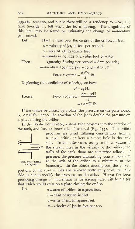
602 MACHINES AND HYDRAULICS
opposite reaction, and hence there will be a tendency to move the
tank towards the left when the jet is flowing. The magnitude of
this force may be found by estimating the change of momentum
per second.
Let H = the head over the centre of the orifice, in feet.
v velocity of jet, in feet per second.
A = area of jet, in square feet.
w = mass in pounds of a cubic foot of water.
Then Quantity flowing per second = Avw pounds ;
.'. momentum acquired per second = Avw . v.
Force required =- Ib.
Neglecting the coefficient of velocity, we have
,, . , Aw . 2gYLHence, Force required =--
Ib.
If the orifice be closed by a plate, the pressure on the plate would
be AwH Ib.;hence the reaction of the jet is double the pressure on
a plate closing the orifice.
In the Borda mouthpiece, a short tube projects into the interior of
the tank, and has its inner edge sharpened (Fig. 657). This orifice
I produces an effect differing considerably from a
trumpet orifice or from a simple hole in the tank
C'' side. In the latter cases, owing to the curvature of
--+ v the stream lines in the vicinity of the orifice, the
walls of the tank there are somewhat relieved of
pressure, the pressure diminishing from a maximum
FIG. 657 . Borda at the axis of the orifice to a minimum at themouthpiece.
boundary. In the Borda mouthpiece, the curved
portions of the stream lines are removed sufficiently from the tank
side as not to modify the pressures on the sides. Hence, the force
producing change of momentum in the issuing water will be simply
that which would exist on a plate closing the orifice.
L61 A = area of orifice, in square feet.
H = head of water, in feet.
a = area of jet, in square feet.
v = velocity of jet, in feet per sec.

PRINCIPLE OF SIMILAR FLOW 603
Then Force producing change of momentum = wHA Ib.
Quantity flowing per second = wav pounds ;
Change of momentum per second =
wav2.,
. . reaction of jet= Ib.
o
__ wav2
Hence, wHA =
Neglecting the coefficient of velocity, we have
or A =20,
= JA.
This mouthpiece has therefore a coefficient of contraction of 0-5.
Thomson's principle of similar flow. Prof. James Thomson's
principle of similarity is of importance in dealing with the flow
through orifices and over weirs;
it may be stated as follows.
Supposing we have a drawing of a vessel containing a frictionless
liquid up to a fixed level, and that the liquid is flowing out throughan orifice, the stream lines being shown on the drawing. The
principle states that this drawing will serve for the discharge from
any similar vessel containing the same liquid, the vessel havingbeen constructed by merely altering the scale of the drawing; the
stream lines in the similar vessel will also have the form shown in
the original drawing to the altered scale. Further,
Let d any linear dimension on the drawing.
v = velocity of flow at any point.
a = sectional area of a stream line at this point.
q = discharge through this stream line.
Then v oc rf
and a oc d"2.
Also, q = va\
A convenient linear dimension to choose is the head of liquid Hfrom the point considered up to the free surface level. Then

604 MACHINES AND HYDRAULICS
Gauge notches. A gauge notch is a device used for measuringthe quantity of water flowing along a stream. The stream is
dammed by vertical boards, and a notch is cut in the dam to
permit the water to flow through. The usual form is triangular
(Fig. 658) or rectangular (Fig. 659). In the case of a triangular notch,
it will be evident that the streams flowing through the notch will be
FIG. 658. Triangular gauge notch.
similar, whatever may be the head;hence Thomson's principle may
be applied to any filament such as ab. Thus,
where a is an experimental coefficient.
The same expression will serve for any other filament in the
stream. Hence the total quantity flowing will be given by
(i)
The value of a for a notch having an angle of 90 may be taken
as 2-635 ;if H be measured in feet, we have for such a notch :
_5
Q = 2-635H2 cubic feet per second.
Care must be taken in measuring H ;this must be the head from
the bottom of the notch to the level of still water. As the water in
the stream approaching the notch is increasing its velocity, its kinetic
energy is increasing, and consequently its potential energy is dim-
inishing. Hence there will be a gradual fall of surface level in the
water in the vicinity of the notch. The still water level will be
found at some distance from the notch.
The water flowing over a rectangular notch under different heads
will not present the same similarity which would exist in a triangular
notch in the same circumstances. Reference to Fig. 659 shows
that the water may be divided into three portions, one in the middle

GAUGE NOTCHES 605
of the notch, in which the stream lines as seen in front elevation are
moving parallel and vertically, together with two side portions in
which the water is moving partly inwards, due to the contraction
produced by the sharp vertical edges of the notch. The breadth of
the middle portion evidently will increase if
the quantity of water flowing diminishes byreason of a reduction in head. Hence the
lack of similarity when the entire section of
the stream is considered.
The side contracted portions may be got
rid of by having sides fitted on the up-
stream face. In Fig. 660 (a) and (b) such
a notch is shown discharging water under a
head Hxin (a) and under a smaller head H
2
in (b}. Let the whole section in (a) be
divided into Nj portions by vertical sections,
and let that of (b} be divided in the same
manner into N2 portions. The discharges through all the portions
in (a) will be equal, as will also be the discharges through all the
portions in (b). Further, any one portion in (a) will be similar
to any one portion in (b) provided the following proportion is
complied with: ^ . >r =H . u( 2 )
}-"-L --
K L --
FIG 659. Rectangular gaugenotch having two side contrac-
tions.
I II I I II I II JH
(b)
FIG. 660. Rectangular gauge notches having both side contractions suppressed.
Let q^ and g.2 be the discharges per portion in (a) and (
respectively. Then, by Thomson's principle of similarity, we have
or (3)

6o6 MACHINES AND HYDRAULICS
The total discharges Q! and Q2in (a] and (b) respectively may be
obtained by multiplying qland ^2 by N\ and N
2 respectively. Hence,
H
3
H\ 2
(from (2) and (3) above)
(4)
It is therefore apparent that Q varies as H 2 in a notch of this type,
and is also proportional to the width L. Hence,
Q = 'iLHf
(5)
where ^ is an experimental coefficient.
Suppose that, in the rectangular notch shown in Fig. 659, the
relation of L and H is such that there is no central portion showing
parallel flow, the side contracted portions filling the whole section of
the stream. It is evident that this drawing would serve for a notch
of this type, having any dimensions by merely altering the scale.
Hence, Thomson's principle of similarity may be applied at once,
and we may write
Q = '2H* (6)
Consider now the notch shown in Fig. 659, having side contractions.
Let LI be the width of the middle portion which
is unaffected by the contractions, and let L2 be
the width of each side contracted portion. L,,
will depend upon H, and may be written #H,where a is a constant. If there be n side
contracted portions,
LJ= L - L
2
= L -
FIG. 661. Rectangulargauge notch with one side
contraction suppressed.
!*- L --*
The values of n will be 2, i and o in the
notches shown in Figs. 659, 66 1 and 660
respectively ;the value may be greater than 2
if the notch is divided into several portions by means of vertical
posts.
From (5) above,3
Flow through the middle portion^LjH 2
^(7)

PITOT TUBE 607
From (6), Flow through each side portion ccH2
;
.'. flow through n side portions = nc2H
Hence, Total flow = ^(L-
<r15
a and r2 being constant coefficients, this result may be simplified
by using other coefficients a and ft giving
Total flow -o(L-/3H)H*...................... (8)
This is the Francis or Lowell formula. Experiments show that
the value of a is 3-33, and that of j3 is o-i. L and H being in feet,
we have3^
Total flow in cubic feet per second = 3*33(L- o-i^H)H
2. ...(9)
Pitot tube. The Pitot tube may be used for determining the
velocity of flow in a stream; the principle may be understood by
reference to Fig. 662. A, B and
C are similar tubes, each having a
small hole at the end of the hori-
zontal limb. A points up stream,
C points down stream and B is at
right angles to the stream. Onaccount of impact, the head shown
in A will be greater than in B or
C ;a certain amount of suction
occurs in C, and B will show the pressure head nearly. Experimentshows that, if h^, h
zand h% are the heads in feet shown by A, B and
C respectively, and if v is the velocity of the stream in feet per
second, then 2,2h\- h
i= - very nearly....................... (i)
h>AABCFIG. 662. Pitot tubes.
Also, i- hs= very nearly
In Fig. 662, the gauges are supposed to be inserted in a pipe,
with the mouths of the tubes in the axis of the pipe. If the velocity
be calculated from (2), the result will be the maximum velocity in the
pipe ;the velocity diminishes near the boundary of the pipe and the
average velocity may be taken as 0-84 of the calculated result for the
maximum velocity.

6o8 MACHINES AND HYDRAULICS
Flow through a uniform pipe. Let A and B (Fig. 663) be two
tanks or reservoirs connected by a pipe of uniform bore throughwhich the water is flowing from A into B. Let the free surface
levels at a and b be preserved at constant heights Ha and H&
respectively above the datum level OX, and let the difference
in levels be H = (Ha - H&) feet. The diminution in energy of a
pound of water in passing from a to b will be H foot-lb. (p. 595),
and this quantity represents the total energy wasted per pound
of water.
FIG. 663. Flow through a uniform pipe.
The wasted energy is made up of three quantities :
(a) The kinetic energy possessed by the water flowing in the pipe
is wasted when the water enters B by the production of surging and
eddies. It may be noted that, as the pipe is uniform in bore and is
assumed to be filled completely throughout its length, the velocity,
and hence the kinetic energy of the water, will be constant while it is
in the pipe.
(b) The water entering the pipe from A loses energy by the
production of eddies in the pipe, especially if the pipe entrance
is sharp-edged.
(c) Energy is wasted in overcoming frictional resistances to motion
in the pipe.
Of these sources of waste, (a) and (b) are of importance in a
short pipe, but become negligible by comparison with (c) in a pipe
of great length.
If a number of glass tubes be inserted in the top of the pipe,
it will be found that the water stands in these tubes at levels as
shown at c, d, e and / (Fig. 663). These heights above the pipe
indicate the pressure heads of the water in the pipe. A line joining
cdef is called the hydraulic gradient. The slope of the hydraulic
gradient between two points, c and / say, measured by dividing the
difference in level of c and^/j say h feet, by the total length of

FLOW THROUGH PIPES 609
the pipe between m and ;/, say L feet, is called the virtual slope
of the pipe, and is written /. Hence,
. h , .
"-L................................... (I)
Note that, in measuring the virtual slope, the actual length of
the pipe, whether straight or curved, must be taken.
\Ve have the following expressions for the total energy of one
pound of water at m and n.
Let Hw = elevation of m over OX in feet.
Hn = ,, n,, ,,
Pm = pressure at m, in Ib. per square foot.
* =55 ft, ,, ,, ,,
cm = height of column at m, in feet.
fn= 55 55 , 5)
w = weight of one cubic foot of water.
v the constant velocity, in feet per sec.
Then
Total energy per Ib. of water at m = Hw + - '"
+ -'-
......... ....... (2)
P v2
Total energy per Ib. of water at n = Hn + +
; ................ (3)
.'. reduction of energy between m and n
= h foot-lb. per Ib. of water. . . .(4)
This reduction is clearly owing to frictional resistances havingto be overcome in the pipe between m and ;/. Hence we may write,
from (i)
:
Virtual slope of a pipe = head lost in overcoming frictional
resistances divided by the total length of the pipe.
In Fig. 664 (a) and (b) are shown the forms of the hydraulic
gradient ab and a'b' for a bell-mouthed and for a sharp-edgedentrance respectively. The more rapid drop near the entrance
in both is owing to some of the pressure head being utilised in
giving velocity to the water entering the pipe, and is complicatedfurther in (b) by the contraction and eddies set up by the sharp*
^M. 2 Q

6ro MACHINES AND HYDRAULICS
edged entrance. In a very long pipe, the drop at entrance maybe disregarded, and the virtual slope may be measured by dividing
(a) (b)
FIG. 664. Hydraulic gradients for bell-mouthed and sharp-edged entrances.
the difference in free surface levels in the two reservoirs by the
total length of the pipe.
Frictional resistance in a uniform pipe. Consider a uniform
horizontal pipe (Fig. 665) in which water is flowing steadily with
velocity v feet per second. As both the velocity and the elevation
over datum level are constant, it follows that the water will possess
constant kinetic energy and also constant potential energy ;the
b : \d \de
/,/,//, ,,,,/,,//,/,////,,~,,,,~ /,,~x
FIG. 665. Frictional resistance in a uniform horizontal pipe.
pressure energy alone will show variation. Let the portion of water
between cross sections ab and cd flow until ab reaches cd, and cd
reaches cd';
let / feet be the length of ac=cc. During this
movement, the energy required to overcome frictional resistances
will be obtained at the expense of the pressure energy of the water,
which accordingly will show a diminution. The pressure at cd will
therefore be less than that at ab.
Let Area of section of stream = A square feet.
Wetted perimeter of pipe = B feet.
Weight of water per cubic foot = w Ib.
Pressure at ab per square foot = P Ib.
Pressure at cd per square foot = (P-SP) Ib.
Frictional resistance per square foot
of wetted surface = F Ib,

FLOW THROUGH PIPES 6n
Then
Net pressure urging the water along the pipe = P -(P
-SP)
= SP lb. per sq. foot.
Hence,Resultant pressure acting on abdc = SP . A lb.
Work done through a length / feet = SP . A/ foot-lb. ( i)
Again,
Total frictional resistance on abdc=H? x wetted surface
= FB/lb.
Work done against this resistance = FB/2foot-lb. ...(2)
Equating (i) and (2), we have
SP.A/=FB/2(3)
In this equation, the whole weight of water in the portion abdc has
been included. To reduce it to the form for one pound of water,
divide each side by the weight of water in abdc. Thus,
Weight of abdc=Alw lb.
SP . Ac _ FB/2
-~Afa>'Hence, from (3),
--ob...................... (4)w AwffiP
Now - - is the pressure energy lost by one pound of water in
flowing through a distance / feet along the pipe. The pressure headh' feet lost will therefore be
w
It will be noted that this quantity is simply proportional to the
length /. If the pipe has a total length L feet, the total pressurehead lost will be given by
eet......................... (6)Aw
The hydraulic mean depth of a pipe or channel is defined as the
result of dividing the cross-sectional area of the stream by the wetted
perimeter. The idea is obtained by substitution of a stream of
rectangular section for the actual stream. The breadth being B and

612 MACHINES AND HYDRAULICS
the depth being made equal to the hydraulic mean depth ;, the
cross-sectional area will remain unaltered, and we have
orA m
Substitution of this in (6) gives
(7)
mw .(8)
The case of a sloping pipe may be examined by reference to
Fig. 666. The pipe is still of uniform cross section, and the water
FIG. 666. Frictional resistance in a sloping uniform pipe.
X
will therefore possess uniform velocity and also uniform kinetic
energy, provided the bore of the pipe is filled completely everywhere
with water. Hence,
(P v*\Hj + +
jft.-lb. per Ib. of water.
Total energy at r^=H + +)
ft.-lb. per Ib. of water.w
Energy expended in overcoming frictional resistances
P
or,
= h feet, (9)
an equation having the same form as (8) above for a horizontal pipe.
The result may be written in terms of the virtual slope, giving
___L mw
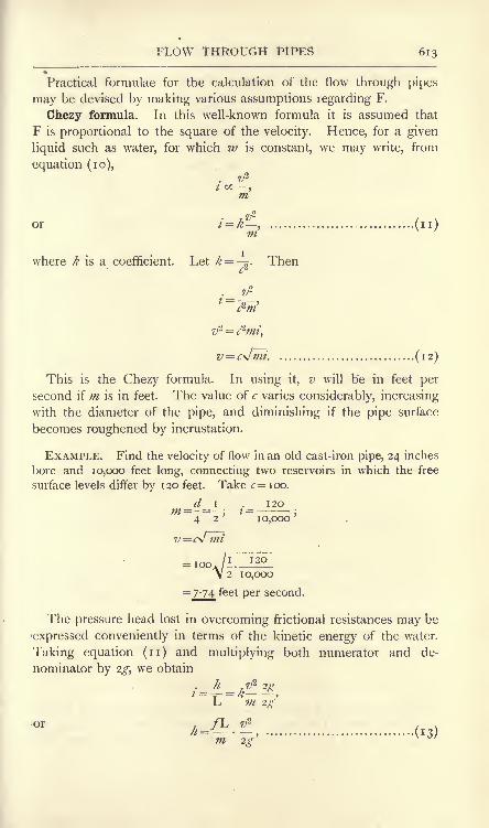
FLOW THROUGH PIPES 613
9
Practical formulae for the calculation of the flow through pipes
may be devised by making various assumptions regarding F.
Chezy formula. In this well-known formula it is assumed that
F is proportional to the square of the velocity. Hence, for a given
liquid such as water, for which w is constant, we may write, from
equation (10),. v*t a -,m
7 ,2
or /=>&, (n)m
where k is a coefficient. Let k =,-. Then
c1
v = cJmi. (12)
This is the Chezy formula. In using it, v will be in feet per
second if m is in feet. The value of c varies considerably, increasing
with the diameter of the pipe, and diminishing if the pipe surface
becomes roughened by incrustation.
EXAMPLE. Find the velocity of flow in an old cast-iron pipe, 24 inches
bore and 10,000 feet long, connecting two reservoirs in which the free
surface levels differ by 120 feet. Take c 100.
d i 120m - -
4 2'
10,000'
c^J mi
20
2 IO,OOO
= 7'74 feet per second.
The pressure head lost in overcoming frictional resistances may be
expressed conveniently in terms of the kinetic energy of the water.
Taking equation (n) and multiplying both numerator and de-
nominator by 2g, we obtain
t ^- = k"<s
,L m 2$
-or /L v1
^ = - -' (r 3)

614 MACHINES AND HYDRAULICS
in which the coefficient f is written instead of 2kg. To obtain the
relation of /with the coefficient c in equation (12), we may proceedas follows :
v = c*jmi ;
= -^-.c-m
Equating this result to the right-hand side of (13) gives
m . 2g
An equation suitable for a round pipe running full bore may be
obtained from (13). Thus,
area of sectionHydraulic mean depth = m = =
-.
wetted penmeteLer
= -?- + ir<i=-,4 4
where d is the diameter of the pipe. Hence, from (13),
m 2g
;(is)2g
In using equations (13) and (15) h, L, m and d should be in feet,
v in feet per second, and "
may be taken as 32-2. In choosing values
of c and /it is safer to assume that the pipe is encrusted, or will be
very soon after it is put into service.
Darcy formula. The experiments of Darcy show that the value
of/in equation (15) can be expressed in the form
In this formula d is the diameter of the pipe in feet, and a and b
are coefficients. For clean pipes, a may be taken as 0-005
b as 12} for old pipes, the values are o-oi and 12 respectively.

FLOW THROUGH PIPES 615
Inserting these values in (16), we have
For clean pipes, /=o-oo5(iH---^j......................... (17)
For old pipes, /~=o-oi (i + ......................... (18)^
Values of /calculated thus may be used in equation (15). As has
been stated already, it is better to employ the value off for old or
encrusted pipes, and inserting this in (15) gives
i \L v2
0-01d 2g
EXAMPLE. A pipe 18 inches in diameter and 4 miles long connects
two reservoirs, in which the difference in level is 200 feet. Find the
velocity of flow and the quantity discharged per hour.
Inserting the given quantities in (19), we have
/ i \4 x 4 x ^280 v'L
200= 0-01 i + -)-
- *- -7\ 12 x I-5/ 1-5 64-4
/ i 19 i6x528o\ <--- X -Z X ---->-- 7/
Vioo 18 I-X6-/5x64-4
feet per second.
Cross-sectional area of stream = =~s x I '5 X I- 5
= 1-77 square feet.
Volume flowing per hour= 177 x 4-65 x 3600= 29,600 cubic feet
= 185,000 gallons.
Flow through a pipe having two different diameters. In
Fig. 667 (a) are shown two pipes of different diameters joined in
|f LI L 2 $
d 2
(a)
t L 1
<b)
FIG. 667. Flow through a pipe having two different diameters.
series. The length L of a pipe of uniform diameter d (Fig. 667 (f] ),
which would discharge the same quantity per second, may be foundin the following manner.

616 MACHINES AND HYDRAULICS
The virtual slope of the separate parts of (a) will be given by
". total loss of head in (a)= /i = h
l+ h^
z'jLj + 22L
2 ...................... (20)
From(1 3) above, ^ =&> - ^
-*. ..........................<>d\
2Sand a corresponding expression for 7i
2. Assuming that f has the
same value for both portions of the pipe in Fig. 667 (a),
.()!.j
Z' "2 ^tV /
Assuming that the uniform pipe in Fig. 667 (It) will have the sametotal loss of head and the same value of/ then
Total loss of head in () = *2l. (23)
Equating (22) and (23) gives
4/Ld
j 22 x,
or =-JUL +-^-2_
........................... ...... (24)rf ^1 ^2
Let Q be the quantity flowing per second in both (a) and (<). Then
Q
(^\2
/ ^\2
^j^and pa*^ Jo
................ (25)
Inserting these values in (24) gives

IMPACT OF INELASTIC BODIES 617
If the value chosen for d be the same as dlt we may write
EXAMPLE. Two pipes are arranged in series, the first being i foot
in diameter and 1000 feet long and the second pipe being 9 inches in
diameter and 50x3 feet long. Find the length of an equivalent pipe of
diameter 12 inches.
/I2\5
From (27), L=iooo+(j 500
= loco+ 2 107 = 3107 feet.
Impact of inelastic bodies. When two inelastic bodies collide,
deformation will occur during the impact, and, as there will be no
effort whatever to recover the original shapes, the bodies will moveon together after the impact as one body.
In Fig. 668 (a) a body having a mass mland a velocity z\ is
travelling in the same straight line as another body having a massm.
2and a velocity v%.
After m1has overtaken m m2
m2 and impact is com- i i
plete, the bodies will *
move as shown at(fr) and
'-' '
will possess a commonfa) (b)
velocity v. During im-FlG> 668._Impact of inelastic bodies .
pact, it is evident that
equal forces have acted forwards on m2 and backwards on m
ltand
these forces have acted during the same interval of time ;hence the
total change of momentum during impact will be zero (p. 411), or we
may say that the total momentum before collision is equal to the total
momentum after collision. Hence,
Energy will be wasted during the collision, and the amount of this
may be calculated as follows :
-n r ' .- 22 ,x
Before impact, total energy =l
-^-+ 2 2
................ (3)
AT (After impact, total energy = -
(mf)^ + *2?'2\
V m}+ m,, J
+ m2g(m l
4- w,)
,,

6i8 MACHINES AND HYDRAULICS
Subtracting (4) from (3) gives
Energy wasted =
2g(ml+ m
2)
(5)
Now (vl
- v2)
is the relative velocity of the two bodies. Hence,
Energy wasted =nff(^ ^^ \
x tne sQuare of the relative velocity.
For example, a jet of water falls into a pool of water (Fig. 669)with velocity relative to the earth or pool of v feet per second.
FIG. 669.
Consider a mass m^ pounds of water in the jet; this will be verysmall as compared with the mass m
2of the water in the pool, backed
as it is by the mass of the earth. In this case,
T-,
Energy wasted = .
2g(ml
That is, the energy wasted is simply the kinetic energy of the
water in the jet.
Waste of energy at a sudden enlargement in a pipe. This case is
illustrated in Fig. 670. Water flowing from the small into the larger
pipe has its velocity diminished from v\ to v.2and mingles with the
water already in the larger pipe. Eddies will be set up in the
water as indicated in the illustration, and there will be a waste of
energy produced in a somewhat similar manner to the case of one

SUDDEN ENLARGEMENTS AND CONTRACTIONS 619
body overtaking another which has been discussed above. Therelative velocity, will be (z^
-z>2),
and the waste of energy will be
given by
Energy wasted = -&- ft.-lb. per pound of water.
FIG. 670. A sudden enlargement in a pipe
St. Venant calculates the wasted energy by adding to the above
1. 1 ^92
result - -^-.
9 *gWaste of energy at a sudden contraction in a pipe. Referring to
Fig. 671, the water flows in the larger pipe with velocity vlt and will
contract as shown at cd on entering the smaller pipe. The velocity
v at cd will be greater than vl ; hence, up to this section, the water
has not overtaken any water moving in front of it, and therefore
FIG. 671. Sudden contraction in a pipe.
there has been no impact and consequently no waste of energy from
this cause between ab and cd. Between cd and ef, the velocity of
the water is diminishing again, and ic will therefore be between these
sections that waste of energy will occur. Hence,
Energy wasted =*
'-%- ft.-lb. per pound of water.
If a value for the coefficient of contraction be assumed, it becomes
possible to calculate v. Thus, let the sectional areas of the stream
at cd and ef be A and A2 square feet respectively, and let cc be the
coefficient of contraction. Then

62C MACHINES AND HYDRAULICS
The quantities of water flowing through cd and ef per second
will be equal. Hence,
.'. energy wasted =
/T \ 2
^/2=(
- i)
ft.-lb. per pound of water.Vc / 2g
The coefficient is not well known;the waste of energy at the pipe
entrance from a reservoir or tank, if sharp-edged, may be taken as
v2
Waste of energy = 0-5 ft.-lb. per pound of water,
where v is the velocity in the pipe in feet per second.
Energy is wasted also in pipe lines at bends and elbows. This is
a subject for experimental investigation, see, pp. 671 and 672, and
there is not much definite information available. The energy thus
wasted is small compared with the frictional waste in a long pipe line.
Resistance of ships. The principal causes of resistance to the
passage of a ship through water are (a) the friction of the wetted
surface, (&) the formation of waves owing to the vessel pushing the
water laterally near the bow, and the return of the water near the
stern to fill the space left by the vessel, (c) the formation of
eddies, owing principally to swirls set up in the water closing in at
the stern.
The first of these, viz. skin friction, may be taken as proportional
to the area of the wetted surface and to the square of the speed.
Wave formation resistances may be taken to be proportional to the
sixth power of the speed. Eddy resistances are proportional to
the area of the wetted skin and to the square of the speed.
The relation of the resistances of a ship and of those of a scale
model of the ship may be deduced from these laws. Let the scales
be such that any linear dimension of the ship is D times the corre-
sponding dimension of the model. Then if A* and Aw are the wetted
surfaces of the ship and model respectively, we have
A,:Am =D2:i (i)

RESISTANCE OF SHIPS 621
The frictional resistances will be given by
Fm =/AmV,2
H ,
where f is a coefficient which may be assumed to have the same
value for both ship and model, and V.s. and Vm . are the speeds of the
ship and model respectively. We may write
T
<s As /V,\a
r =T-'(v~)'m "01 \ v m/
or, from (i),= D2
(^-Y
The relation of the wave-forming resistances may be written
The relation of the eddy-forming resistances will be
2
(4)in/
VA 2
Now, supposing D =( Y7
1), or Vt=VwV/D)
the results (2), (3)in
and (4) may be written
Fw
T^' * * *
\ / /
That is, the relation of each of the three kinds of resistance is
proportional to I)3 ; hence their sum, which gives the total resistance,
will also be proportional to D3. The law has been expressed by
Mr. Froude as follows, and is known by his name : If the ship be
D times the linear dimensions of the model, and if at the speedsv
i>V
2 ,V
3 , etc., the measured resistances of the model are R15R
2 ,R
3 ,
etc., then for speeds VlV/D, V2\/D, V3\/D, etc., of the ship, the
resistances will be D8R1?D3R
2 ,D3R
3 ,etc. The speeds of the model
and of the ship so related are called corresponding speeds.

622 MACHINES AND HYDRAULICS
EXERCISES ON CHAPTER XXIII.
1. A straight horizontal pipe 6 inches in diameter gradually becomes2 inches in diameter, and then diverges again to 6 inches diameter.Water is flowing steadily through it with a velocity of 4 feet per secondin the larger portions. Find the velocity in the throat of the pipe, andhence calculate the difference in pressures at the largest and smallestsections of the pipe, neglecting friction.
2. In a pipe having the same dimensions as that in Question i, thedifference in head is observed to be 4 feet of water at a certain velocityof flow. Calculate the flow of water in cubic feet per second, neglectingfriction.
3. Water is discharged through a circular sharp-edged orifice i inchin diameter in the vertical side of a tank. The water-level in the tank is
3 feet above the level of the centre of the orifice. Calculate the dischargein cubic feet per second and also in gallons per hour.
4. Answer Question 3 if a trumpet mouthpiece is fitted giving a jet1 inch in diameter. Take the coefficient of velocity to be 0-95.
5. A circular sharp-edged orifice is situated in a tank bottom and
discharges a jet vertically downwards. The water level in the tank is
2 feet above the plane of the orifice. Calculate the velocity at a section
of the jet 6 inches below the plane of the orifice, neglecting friction.
6. A reservoir contains air at a pressure of 157 Ib. per square inch
absolute, and one pound weight of it may be taken to occupy a volume of
13 cubic feet. The air is being discharged through a sharp-edged orifice
2 inches in diameter into the atmosphere, the pressure of which is 14-7 Ib.
per square inch. Calculate the flow in cubic feet per second.
7. A jet of water is discharged from a trumpet orifice 3 inches in
diameter under a head of 200 feet. Calculate the reaction of the jet in Ib.,
neglecting any reduction in velocity owing to friction.
8. Taking the coefficient of velocity to be 0-96, calculate the flow in
cubic feet per second through a Borda mouthpiece 2 inches in diameterunder a head of 10 feet.
9. Water is flowing over a triangular gauge notch of 90 under a
head of 10 inches. Calculate the flow in gallons per hour.
10." A rectangular gauge notch has a width of 2 feet, and water is
flowing through it under a head of 6 inches. Calculate the flow in cubic
feet per second, (a) for two side contractions, (b] for one side contraction,
(c] for no side contractions.
11. Calculate the virtual slope of a pipe 2-5 miles long connecting two
reservoirs, in which the difference in levels is 35 feet.
12. A circular pipe 4 feet in diameter is running half full of water.
Find the hydraulic mean depth.
13. Use the Chezy formula to calculate the velocity of flow for a pipe
30 inches diameter and 10 miles long connecting two reservoirs, for whichthe fall in level is 150 feet. Take <r=io5. Calculate also the quantityflowing per day of 24 hours.

EXERCISES ON CHAPTER XXIII. 623
14. Suppose in Question 13 that a sluice valve in the pipe close to the
lower reservoir is closed partially and that it is found that water rises in
a tube connected to the pipe side of the valve to a level 40 feet below the
water level in the upper reservoir. Calculate the velocity of flow, usingc=ioo.
15. Use the Darcy formula to calculate the velocity of flow and the
discharge in cubic feet per second in a pipe 24 inches in diameter and
having a virtual slope of o-oi. Give the answers both for a new pipe andfor an old one.
16. A pipe 1 8 inches in diameter and 2 miles long is connected to asecond pipe 15 inches in diameter and 0-5 mile long. Find the length of
an equivalent pipe of diameter 18 inches.
17. A pipe is enlarged suddenly from 4 inches to 6 inches diameter.
The velocity of flow in the smaller portion is 4 feet per second. Calculate
the energy wasted per pound of water.
18. Suppose in Question 17 that the direction of flow is reversed ancl
that the velocity in the smaller portion of the pipe is still 4 feet per second.
Calculate the energy wasted per pound of water, assuming that the
coefficient of contraction is 0-7.
19. Describe, with a sketch, the Venturi water meter, and state the
principle of its action. (B.E.)
20. A particle of water is at a place A, where the pressure is o, its
height above datum is 50 feet, its velocity is 5 feet per second, and it finds
its way without friction to a place B, where the pressure is o and heightabove datum 30 feet. What is its velocity at B ? (B.E.)
21. A particle of air flows without friction. Its pressure p (in Ib. persquare foot) and its speed v (in feet per second) may both alter, but thesum 7,2 p
2g Wremains constant. If w is the average weight of a cubic foot of air, g is
32-2. At a place A, p is i-i atmospheres and i> is o;a particle finds its
way from A to B. At B the pressure is i atmosphere ; what is the speedat B ? Take w as 0-075 Ib. per cubic foot. (B.E.)
22. A fan drives air vertically downwards through a horizontal circular
opening 8 feet in diameter and so exerts a lifting force of 200 Ib. Whatis the average downward velocity of the air in the opening? Theweight of I cubic foot of the air is 0-08 Ib. (B.E.)
23. A pipe, \\ inches in diameter, is enlarged gradually to 3 inches in
diameter; the pipe has a falling gradient of i in 15. At the pointwhere the diameter begins to enlarge, the velocity of flow is 4 feet persecond and the pressure is 30 Ib. per square inch. Find the velocity and
pressure in the 3 inch portion of the pipe at a point distant 45 feet,measured along the horizontal from the point where the enlargementbegan. Neglect all frictional losses. (B.E.)
24. A Venturi meter is fitted on to a 5o-inch diameter main. Thediameter of the throat of the meter is 20 inches. It is found that at acertain instant the pressure in the main at the point of entry to the meteris equal to a head of 1 10 feet of water, and in the throat of the meter it is
equal to a head of 97 feet of water. How many gallons of water is this
5o-inch main delivering per hour under these conditions ? (B.E.)

624 MACHINES AND HYDRAULICS
25. Froude's law of corresponding speeds, which is used in model
experiments upon ships, applies also to flying machines. A certain flyingmachine is to be constructed, weighing 2 tons and travelling at 100miles per hour. The model is y^ full size. Find its weight and corre-
sponding speed. (See p. 621 for Froude's law.) (B.E.)
26. In the horizontal floor of a tank, in which the water is 3 feet deepand in which the water-surface is 15 square feet in area, a sharp-edgedcircular orifice 2 inches in diameter is opened. In what time will the
water-level in the tank sink I inch, if there be no supply of water to the
tank? In answering make no attempt at correction for the time spentin starting the flow, that is, upon initial acceleration of the mass of the
first parts of the flow. (I.C.E.)
27. Water flows down a sloping pipe (running full) from a point wherethe velocity is 10 feet per second and the pressure 15 Ib. per square inch
absolute to a point 100 feet lower, where the pipe diameter is three timesas- great. Calculate the pressure at this point, neglecting losses. (I.C.E.)
28. A straight pipe of circular section is 400 feet long and 4 inches
internal diameter. Its down gradient is I in 200. It discharges full-bore
into the atmosphere at the level of the lower end of the pipe, and draws
by a bell mouth from a reservoir with 12 feet head of water over the
mouth of the pipe. The gradient of the frictional loss of head in the pipeis 000012 times the square of the velocity divided by the mean hydraulic
depth, the units being feet and seconds. Find the linear velocity
through the pipe and the discharge in gallons per hour. (I.C.E.)
29. A pipe of circular section of 30 inch diameter has a fall of 16 feet
in a straight run of 2000 feet. In the formula for loss of head in feet perfoot run i =ft/*/m, its coefficient is 0-00009, the units being feet and seconds.
What volumetric flow in cubic feet per second must there be throughthis pipe to maintain throughout its length the level of the water at the
centre of the circular section? (I.C.E.)
30. State the nature of the losses that occur when a stream of water in
a pipe running full encounters, (a) a sudden enlargement, (b) a suddencontraction of the channel area. A surface condenser contains 530 tubes
9 ft. 3 in. long and 0-65 inch internal diameter, through which 450 gallonsof water are pumped per minute. The water flows through half the
number of tubes and then back again through the other half. Calculate
the total loss of head in the condenser, assuming that the coefficient of
contraction at entrance to the tubes is 0-59 and/=o-oo7. What horse-
power is required to force the water through the condenser? (L.U.)
31. Two reservoirs are connected by a straight pipe i mile long. Forthe first half of its length the pipe is 6 inches diameter ; its diameter is
then suddenly reduced to 3 inches. The surface of the water in the
upper reservoir is 100 feet above that in the lower. Tabulate the losses
of head which occur, including that at a sharp-edged entry, and determinethe flow in gallons per minute. (Assume /=o-oi). (L U.)
32. A Venturi meter is placed in a horizontal 6 inch pipe, the diameter
of the throat being 2 inches. If the difference of head is equivalent to
10 inches of mercury, find the flow in gallons per minute, and the
velocities. Assume the coefficient of the meter to be |-oq (L.U.)

CHAPTER XXIV.
HYDRAULICS. PRESSURES OF JETS.CENTRIFUGAL PUMPS.
TURBINES.
Pressure caused by a jet impinging on a fixed plate. A jet of
water impinging on a fixed plate or vane will arrive at the plate with
a certain velocity, and will leave the plate with a velocity changed in
direction and also reduced in magnitude, owing to friction andeddies. Disregarding the latter, we may examine the examplesshown in Fig. 672. The pressure in each case may be found by first
-v,
(a) () (c) '(d)
FIG. 672. Pressures of jets on plates ; impact cases.
estimating the change in velocity, and hence the change of momentum
per second. The jet section is assumed to be A square feet, and ^is the velocity of the jet in feet per second.
(a) The jet impinges on a plate fixed at 90 to the axis of the jet.
The water spreads and leaves the plate tangentially in all directions.
Hence the whole of vlhas been eliminated.
Mass of water reaching plate per second = Av-^w pounds.
Change of momentum per second = Awv-f
A.WV-? .,
Piessure on plate= Ib.
o
(&) The plate is fixed at an angle to the axis of the jet. As in
(a\ the water will spread and leave the plate tangentially in all
directions. The change in velocity will be the component of v^
perpendicular to the plate, viz. v^ sin 0.
D.M. 2 R

626 MACHINES AND HYDRAULICS
Mass of water reaching plate per second = Av-^w pounds.
Change of momentum per second = Avlzw
1sin C
= Awv-f sin 6.
AwvSPressure on plate
= Lsin6>
Ib.
(c) The jet impinges on a hemispherical cup fixed so as to opposethe jet axially. The leaving water will be directed backwards with a
velocity equal to v^. Hence the total change in velocity will be 2VrMass of water reaching plate per second = Av-^v pounds.
Change of momentum per second =
Pressure on plate =g
.,
Ib.
(d) A similar cup to that in case (c\ but the tangent at the cupexit makes an angle 6 with the jet. The total change in velocitywill be (#! + v
lcos 0).
Mass of water reaching plate per second = Av-pv pounds.
Change of momentum per second = A1o/( 1 + ^ cos 0)
= Awv1
2(i + COS0).
Awv-? , ,
Pressure on plate=-
(i + cos #).
In each of the above cases there has been impact, which may be
eliminated by the device of so shaping the vane as to allow of the jet
sliding on to it, i.e. the jet enters the vane tangentially. Fig. 673
-*,
FIG. 673. Pressures of jets on plates ; impact eliminated.
(e\ (/) and (g) are examples. The pressures in the cases of (e) and
(/) will be given by the same expression as that found in case (c),
viz -
2Aaw18
1KPressure on plate= Ib.
(g) Here the water enters a curved vane with a velocity v\ andleaves it with an equal velocity #/ (neglecting friction). The changein velocity is found from the diagram OAB, in which OA represents v
l
and OB represents #/. AB will give the change in velocity vc . Letbe the angle between the entering and leaving jets. Then the angle
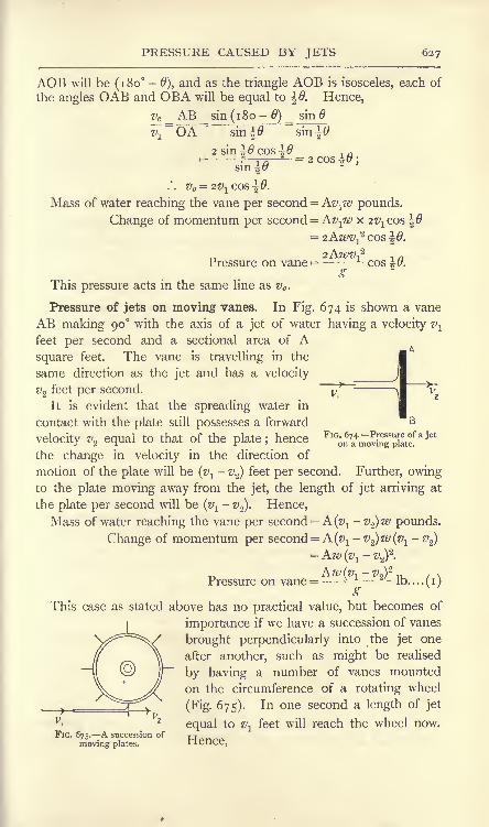
PRESSURE CAUSED BY JETS 627
AOB will be (180-
0), and as the triangle AOB is isosceles, each of
the angles OAB and OBA will be equal to \Q. Hence,
PC_ AB_sin(i8o-0) = sin
sin^0 "sinitf
2 sin 9 cos \0
sin
.*. Vc=
2^j COS \B.
Mass of water reaching the vane per second = Av^w pounds.
Change of momentum per second = Av-flv x 2V1cos
COS Q.
- , nPressure on vane =-*- cos |#.<b
This pressure acts in the same line as vc .
Pressure of jets on moving vanes. In Fig. 674 is shown a vane
AB making 90 with the axis of a jet of water having a velocity v^
feet per second and a sectional area of Asquare feet. The vane is travelling in the
same direction as the jet and has a velocity
v2feet per second.
It is evident that the spreading water in
contact with the plate still possesses a forward
velocity z>2 equal to that of the plate ;_hence
the change in velocity in the direction of
motion of the plate will be (^ - V2)
feet per second. Further, owingto the plate moving away from the jet, the length of jet arriving at
the plate per second will be (z^- #
2). Hence,
Mass of water reaching the vane per second =A(^ v^)w pounds.
Change of momentum per second = A(v1- v^w(v^ - v
2)
= Aw (v1- #
2)2
.
AW(VI-VJJ* 1U / NPressure on vane =-i-J-
lb....(i)o
This case as stated above has no practical value, but becomes of
importance if we have a succession of vanes
brought perpendicularly into the jet one
after another, such as might be realised
by having a number of vanes mounted
on the circumference of a rotating wheel
(Fig. 675). In one second a length of jet
equal to vl
feet will reach the wheel now.FIG. 675. A succession of
moving plates.

628 MACHINES AND HYDRAULICS
Mass reaching wheel per second = Av-^w pounds.
Change of momentum = Kv^v(v^- v
2).
Pressure on vanes = P = (^-v^v^ Ib......... (2)
Work will be done on the wheel by P to the amount of Pv2 foot-lb.
per second, or
Work done per second = (^-
z>2) v-p2 ft.-lb.......... (3)o
The efficiency of the arrangement may be found by evaluating the
energy available in the jet. Since Av-pu pounds of water reach the
wheel per second with a velocity v19
T _. ., , . . Av^wv-!2
Kinetic energy available per second = * -
_,-- . work doneHence. Efficiency =
energy supplied
Aw , v
(^i-PaWa
Aw
(5)v?
With a constant supply of water, the work done may be varied by
varying the velocity v2of the vanes.
Using (3), the work done per second will be greatest when
(Vi-vz)ViV2attains its maximum value. Assuming a steady velocity
of supply, #! will be constant, and maximum work will occur when
(^i"^2)^2 nas its maximum value. To obtain this value, differentiate
(z/!-
z>2)#2
and equate the result to zero, giving
or ty*fa (6)
The efficiency under these conditions may be obtained by substi-
tution in (5), giving
Maximum efficiency = ^ -
v-f
= J = 50 per cent (7)
In connection with hydraulic machines, the term hydraulic efficiency
is employed often, and may be denned thus : Let H = the energy

PONCELET WHEEL 629
supplied per pound of water, and let h = the energy carried away in
the water leaving the machine. ThenTT 7.
Hydraulic efficiency=
If it is known that there are hydraulic losses in the machine which
produce a waste of hf foot-lb. of energy per Ib. of water, then
H - h - hfHHydraulic efficiency
Poncelet wheel blade. An efficiency much better than that
possible with a flat vane can be obtained by using vanes suitably
curved. Thus, in Fig. 676, ABis one of a number of vanes
attached to the circumference of
a revolving wheel and receiving
a jet of water at A. The velocity
of the jet being Vi and that of
the vane at A being Vi, the
relative velocity may be obtained
from the parallelogram ADEC,in which DA represents -Viand CA represents Vi. The
diagonal EA then gives the
relative velocity vr . If the tan-
gent to the vane at A coincides
with EA, the water will slide onFIG. 676. Blade of a Poncelet water wheel.
to the vane without impact, and
hence there will be no wasted energy owing to shock, a waste which
must occur with the vane shown in Fig. 675.
The water travels round the curve of the vane, preserving unaltered
its relative velocity vr . At the point of exit, B, therefore it will
possess velocities represented by BF = v and BG =V ,the latter
being the velocity of the vane at B relative to the earth. The
absolute velocity v of the leaving water may be found by completing
the parallelogram BGHF, giving v BH.Since the water enters with the velocity Vi and leaves with a
velocity v09 the change of velocity may be found by making CKequal and parallel to BH, when AK = z/c will be the change in
velocity. The resultant pressure P on the vane will be in a line
parallel to ve ,and may be estimated by taking the change in
momentum per second.

630 MACHINES AND HYDRAULICS
v zThe energy supplied per pound of water in the jet is foot-lb.
;
2~
assuming the pressure throughout the stream to be constant and
equal to that of the atmosphere, and disregarding any change in
potential energy, the energy carried away in the water leaving the
v 2
vane will be foot-lb. per pound. The difference between these, viz.
(1)2
_<D
2\-i,
2g 'i, may be converted into work done on the wheel. This
v*difference would be if v were zero, i.e. if vr and V were equal,
*g
opposite, and in the same straight line;in this case the whole of the
energy supplied would be converted into mechanical work, and the
efficiency would be TOO per cent. This, of course, neglects frictional
losses and the inevitable lashing of the water, which must occur as
the vanes successively enter the jet. In the Poncelet water wheel,
constructed after this method, an efficiency of nearly 70 per cent.
has been obtained.
Pelton wheel. In the Pelton wheel (Fig. 677), the vanes are similar
to those shown in Fig. 673 (/ ).Let the velocities of the jet and of
the vane be v^ and V respectively, and
let the shape of the vane be such as to
cause the direction of the leaving water
to be parallel to the entering jet ; usually
#2is not quite parallel to v
lt the blade
being shaped so as to throw the leaving
water clear of the entering jet as shown
in Fig. 677.
Relative velocity of entering jet and
vane = v^- V. This relative velocity will
be preserved unaltered as the water
FIG. 677 . Action in a Pelton wheel, travels round the curved vane. At exit,
the water will have therefore a velocity
(v\~V) towards the left, together with a velocity V towards the right,
and its absolute velocity will be
v2= V-(vl -V) = 2V-v
1.
As the initial velocity is vlt we have
Change in velocity=
v-^- #2

WATER WHEELS 631
Mass of water reaching the wheel per second =
Change in momentum per second = wAvlx 2 (vl
-V).
_ 2Wh.V^ (V,- V) .,
Pressure on vane = P = - ID.
gWork done on the wheel per second = PV
Assuming a constant velocity of supply, vl9 the work done will have
a maximum value when V( 1 V) is a maximum. Differentiating
and equating to zero, we have
Substitution of this value in (2) gives
Maximum work per second =
(3)
^A^.^JLft.-lb.L
2g
Since wAv-^ is the mass of water reaching the wheel per second,it follows from (4) that the whole of the kinetic energy available
in the jet has been converted into work done on the wheel, i.e.
the efficiency in these circumstances is TOO per cent. Actual
efficiencies of from 70 to 90 per cent, have been obtained.
The hydraulic efficiency may be obtained by dividing the result
given in (2) for the work done per second by the energy suppliedin the jet. Thus,
Hydraulic efficiencyff
1- V)
S
This will become unity when
v-jjvOther types of water wheels, in
which gravity plays the most im-
portant part, have been much used.
In the over-shot water wheel (Fig. 678),
the water is led to the top of the
wheel, and there partially fills a
number of buckets fixed to the
wheel. The weight of these descend-
ing buckets enables work to be done
on the wheel. In the breast-shot FIG. 678. Over-shot water wheel.

632 MACHINES AND HYDRAULICS
wheel, the water enters the buckets on a level about the same as that
of the wheel centre. The Poncelet wheel is an improved form of
under-shot wheel.
Hydraulic turbines. A hydraulic turbine is a machine in which the
energy of a supply of water is converted into mechanical work by
passage of the water through a wheel furnished with blades or vanes.
In general, the action consists of causing the water to whirl before it
enters the wheel. In this condition it possesses angular momentum,and the function of the wheel blades is to abstract this angular
momentum and to discharge the water without whirl. A couple will
thus act on the revolving wheel (p. 430), and will produce mechanical
work.
Turbines may be classed generally as impulse turbines and reaction
or pressure turbines. In impulse turbines, the energy of the water is
practically entirely in the kinetic form before the water enters the
wheel, a result obtained by reduction of the pressure head to that of
the atmosphere and by giving the water a corresponding velocity.
In reaction turbines, the energy of the water at the wheel entrance is
partly in the pressure form and partly kinetic.
Turbines may be classed further with reference to the principal
direction of flow of the water. In axial-flow turbines, the flow is
parallel to the axis of rotation of the wheel;in inward-flow turbines,
the flow is radial towards the wheel centre ;in outward-flow turbines,
the flow is radial from the centre to the circumference of the wheel ;
in mixed-flow turbines, the flow is partly radial and partly axial.
The energy available in a given stream or river depends on the
quantity of water flowing per second and on the height of the
available fall.
Let W = flow of water per second, in pounds.H =
height of fall, in feet.
E = the efficiency of the turbine, all sources of waste beingincluded.
Then Energy available =WH foot-lb. per second.
Energy produced by the turbine =WHE foot-lb. per second.
H.P. delivered by the turbine = .
55o
If a given horse-power has to be delivered by the turbine, then the
quantity of water which must be passed through the wheel will be
given by 550 x H.P.W = JJpounds per second.

IMPULSE TURBINES 633
The turbine must be proportioned so as to permit of this quantity
of water being dealt with per second. If the efficiency is not known
with precision, a value of from 70 to 75 per cent, may be assumed.
The general conditions of efficiency in any hydraulic turbine include
the entrance of the water into the wheel without shock, and its
leaving the wheel without whirl and with as little residual velocity as
possible. Further, the guide passages and the passages through the
wheel must be shaped so as to offer the minimum frictional and
eddy-forming resistance to the flow of water.
Impulse turbines. The Girard turbine shown in outline in Fig. 679is an example of an impulse turbine. The water-supply flows from a
FIG. 679. Action of a Girard impulse turbine.
chamber AA through a ring of guide orifices BB. These orifices are
furnished with guide blades which cause the water to leave the orifices
with whirling velocity. The water then passes through a revolvingwheel CC fixed to a vertical shaft DD, and is discharged into the tail
water EE. The wheel passages are furnished with blades havingsuch a shape as to abstract the velocity of whirl from the water. The
guide passages BB run full of water, and at their discharge edges the
pressure of the water is equal to that of the atmosphere. The main-
tenance of atmospheric pressure in the wheel passages is obtained (a)
by having thin streams of water on the concave sides of the blades
only, (b) by having side openings in the wheel as shown at EE in
Fig. 680;these openings permit of free access of air to the streams of
water passing through the wheel.
It will be evident that the wheel of a turbine of this type must be
situated above the level of the tail water, so as to permit of the access
of air. If h feet is the height of the lower edges of the guide

634 MACHINES AND HYDRAULICS
orifices above the tail water (Fig. 679), then the head available for
giving velocity to the water at these edges will be (H -h) feet, where
H is the difference in levels of the supply and the tail water.
+ ' D
FIG. 680. Blades of an axial-flow impulse turbine.
Assuming a coefficient of velocity of 0-95, we have for the velocity
Vi of the water leaving the guide blade :
Vi = Q-g^2g(H-h) (i)
In Fig. 680, AB and CD are the guide blade and the wheel blade
respectively. Let a be the angle to the horizontal made by the
tangent to the guide blade at B. Vi will have horizontal and vertical
components, represented by Wi = da and Ui = ba respectively in
Fig. 68 1 (a\ the parallelogram of velocities being abed. Hence,
U{ = vl sin a, (2)
Z'i = >i COS a, (3)
Let V be the circumferential velocity of the wheel at its mean
radius. Then the relative velocity Vri of the inlet water and the wheel
I
FIG. 681. Velocity diagrams for an axial-flow impulse turbine.
maybe found by making ea represent -V (Fig. 68 1 (a)) and com-
pleting the parallelogram of velocities aefc; fa then represents VH.
Let be the angle whichfa makes with the horizontal. Then the
angle with the horizontal made by the tangent to the wheel blade at

IMPULSE TURBINES 635
C (Fig. 680) should be made equal to 6;the inlet water will then
slide on to the wheel blade without shock. Referring again to
Fig. 68 1 (a), we have
Also,=
Ui ba
'. Vri= UiCOSecO............................... (5)
The relative velocity remains unchanged in magnitude by passageover the wheel blades ; hence, at the exit D of the blade (Fig. 680),
the water will have an absolute velocity v,which is the resultant of
component velocities vro = Vri and V, the mean circumferential velocity
of the wheel at the outlet. In Fig. 68 1 (b\ make kl= V, draw kmvertical (as is required for the condition of no whirl at the outlet),
and describe an arc with centre / and radius Im = vro ;the parallelo-
gram of velocities for the exit water will then be klmn. vro is at an
angle < to the horizontal, and the tangent to the wheel blade at D(Fig. 680) should be at the same angle. In Fig. 68 1 (b\ we have
V kl= = cos $.vro Im
kl Vcos < =
-j= ................................. (6)Im vro
v km .
Also,= j = sin
</> ;vro Im
.'. V = Vro Sm (f>= Vri SU1 < ...................... (7)
Having found a, and <, the guide and wheel blades may be
constructed by drawing easy curves tangential to these directions.
Since the pressure at D (Fig. 680) is atmospheric, we may write
Total energy carried away by one pound of exit water = ft.-lb.
o
Total energy available in the fall, per pound of water = H ft.-lb.
Hence the hydraulic efficiency, i.e. the efficiency disregarding all
sources of waste excepting the energy carried away in the leaving
water, is given by V(?rl --
2 ^*
Hydraulic efficiency=
77-^-................... (8)

636 MACHINES AND HYDRAULICS
EXAMPLE. Taking practical values as follows :
find the other velocities and angles of an axial-flow impulse turbine.
Find also the hydraulic efficiency.
From (i) and (2), sina=^*=^ =0-474 J
/. a= 29 nearly.
From (3), wi= -z/i cos a= (0-95 x o-<
From (4),
From (5),
n Wi-V 0-83-0-15= = *- -0735;0-45ui
cot
.'. 0=54 nearly.
i= Vro= Ui COSCC 8
From (6), cos <= = =0-898 ;
/. < = 26 nearly.
v = vri sin<f>=
(o- 5 5 7 x 0-438)
7/0= 0-24 V^H", we have, from (8),
HHydraulic efficiency =
From (7),
Taking
ig H-0-0576HH^" H
=0-9424= 94 per cent, nearly.
The actual efficiency after all sources of waste are taken account of in
this type of turbine is about 75 per cent.
Impulse wheel passages. It will be noted from the above examplethat the ratio u . .4 r
= ^-=1-84.V 0-244
Now Ui is the component velocity of the water entering the wheel
taken at 90 to the inlet surfaces of the wheel;the quantity of water
flowing into the wheel will be given by
Qi = UiAi cubic feet per second,
where A* is the total inlet surface in square feet.
Again v is the leaving velocity of the water, perpendicular to the

IMPULSE TURBINES 637
exit surfaces of the wheel;
hence the quantity of water leaving
the wheel will be
Qo = v A cubic feet per second,
A being the exit surface in square feet.
It is evident that Qi and Q must be equal. Hence,
orA Ui
In practice, this increase of outlet surface is obtained by splaying
the wheel passages as shown in the section in Fig. 680. If Q, the
quantity of water in cubic feet per second which must be passed
through the wheel, be known, the dimensions of wheel required
may be calculated from
ji.^f/f) 2 "D 2\ / f\\
where Rxand R
2feet are the external and internal radii respectively
of the wheel at the inlet surface. A correction must be applied to
this for the area abstracted owing to the thickness of the wheel blades
at entry.
Work done and horse-power developed. In Fig. 682 is shown
roughly the actual path, or the path relative to the earth, of a particle
of water passing along the
guide blade AB and then
pursuing the curve CPDthrough the wheel. At any
point P, the resultant velocity
v of the water is made up of
components w in the direc-
tion of the motion of the
wheel, and u in a direction
parallel to the axis of rota
tion. The water enters the
wheel with a velocity Vi at
an angle a; to the inlet
surface, and leaves with a
velocity v making an anglea with the outlet surface,
and outlet respectively will be
FIG. 682. Change of angular momentum in anaxial-flow turbine.
The whirl components at the inlet

638 MACHINES AND HYDRAULICS
Let R = the mean radius of the wheel, in feet.
V = the circumferential velocity of the wheel at its mean
radius, in feet per second.
Vo) = = the angular velocity of the wheel, in radians per
second.
W = the flow of water passing through the wheel per
second, in pounds.
Then, considering the momentum of the water in the direction
of motion of the wheel, we have
Momentum of one pound of water at the inlet = i xwi = Vi cos c^.
,, ,, ,, outlet = i x w =-v coso. .
Angular momentum per Ib. of water at the inlet = R^ cos c^.
outlet = Rz> cosa .
Change in angular momentum per Ib. of water
= R(#i cos a;- v cos a
).
Total change in angular momentum per second
= WR(#; COS a;- V COS <X
).
Couple required to effect this change (p. 431)
=WR (vj cos a.j- v cos a
)
gWork done per second by this couple
WR(7'i COS a-i- V COS a )
^
If v is parallel to the axis of the wheel, as is required by the
condition of no whirl at the outlet, then' r*os ex
*
Work done per second on the wheel = ft.-lb. ...(10)
j /NH.P. developed = .......... (n)-
In this result, no allowance has been made for wasted energy
while the water is passing through the wheel, nor for the frictional
waste in the wheel bearings, etc.
Regulation of the power developed in this type of turbine is
effected by means of gates or sluices, which close as many as may be
required of the guide orifices.

REACTION TURBINES 639
Fig. 683 shows in outline part of an outward flow impulse turbine
suitable for high falls. The water flows from a passage A throughnozzles B, and thence through the wheel
passages. As before, the water flows in
streams along the concave sides of the wheel
blades, and the pressure is kept equal to
that of the atmosphere by means of side
openings.
Reaction turbines. The Jonval turbine
may be taken as an example of an axial-flow
reaction turbine, and is shown in outline in
Fig. 684. The water flows from AA througha ring of guide orifices BB, and thence
through the wheel passages CC. Both guide
passages and wheel passages run full of water, and the turbine wheel
may be below the level of the tail water, as shown. Hence the
I
I 'I
I
FIG. 684. Action in a Jonval reaction turbine.
whole head H is available in this type of turbine. For greater
accessibility, the turbine may be inclosed in a casing and placedabove the level of the tail water
;the whole head H will be available
still if the discharge from the turbine casing is arranged through a
suction tube which has its mouth opening below the level of the
tail water. The suction tube must run full bore.
The diagrams showing the velocities of the water and the anglesof the guide and wheel blades are given in Figs. 685 (a) and (b}.
The constructions are the same as for the axial-flow impulse turbine
already described (p. 634), and the diagrams are lettered in the same

640 MACHINES AND HYDRAULICS
manner. The guide and wheel blades are shown separately in
Fig. 686.
FIG. 685. Velocity diagrams for an axial-flow reaction turbine.
Pressure variation in an axial-flow reaction wheel. In this type
the inlet and discharge areas of the wheel are equal ;hence the inlet
and outlet velocities of flow Ui and u in Fig. 685 (a) and (b) are equal.
It will be evident therefore from these diagrams that the relative
velocity at the outlet, vro represented by kn, must be considerably
larger than the relative velocity at the inlet, vri represented by fa.
D D
FIG. 686. Blades of an axial-flow reaction turbine.
In Fig. 687, CPD is the wheel blade, and EPF shows approximatelythe path of the water through the wheel, the discharge velocity
u = v at F being axial. At any point P, the actual velocity v of the
water is made up of a constant component V, equal to the circum-
ferential velocity of the wheel and a component vr tangential to the
blade, and increasing from a value vri at the inlet to vro at the outlet.
In consequence of this increase in velocity, there will be a decrease
in pressure from the inlet to the outlet.
Let OX be taken as a datum level, the top of the wheel being at

REACTION TURBINES 641
an elevation hw above OX, and apply Bernoulli's equation, neglectingfriction. Let Pi and P be the pressures in Ib. per square foot at the
FIG. 687. Pressure variation in an axial-flow reaction wheel.
inlet and outlet respectively, and let w be the weight of a cubic foot
of water. Then
.W 2g IV 2g
Let hi and h be the pressure heads corresponding to P, and
P respectively. Then the above equation may be written :
2 2
or (i)
(hi- h
] represents the portion of the total available head H, which
is utilised in overcoming the pressure resistance in the wheel ; the
remainder of H may be used for giving the velocity vt to the water at
the discharge edge of the guide blade. In Fig. 685 (I))
As may be seen from inspection of Fig. 685 (a), no great error will
be made by assuming that HI and Vn are equal. Hence,
^arly.
We may therefore write (i),
hi- h =
P.M.
V2
= --/^ nearly.
2 S

642 MACHINES AND HYDRAULICS
Hence the head available for producing the velocity Vi is given by
Velocity head = H -(hi- h
)
(3)
And ^ = A/'V2
Practical values for the velocities are
u = Ui= O'i&\/2glrL feet per second.
V = o-64\/2^H feet per second.
#i = o-7s/2-H to 0-8 \/2-H feet per second.
The relations of the velocities and angles may be deduced from
Fig. 685 (a) and (b\ giving equations similar to those already found
for the Girard turbine (p. 635). If there is no whirl at the outlet,
the work done per second and the horse-power may be found in the
same manner as for the impulse turbine, and will lead to equationssimilar to (10) and (n) (p. 638).
Work done per second on the wheel = - foot-lb (4)>
i , ,
H.P. developed =- ...................... (5)55 <?^
"V^7/
Also, Work done per Ib. of water = *foot-lb.
Energy available per Ib. of water = H foot-lb. ;
.". hydraulic efficiency=-^~ ......................... (6)
Inward-flow reaction. turbine. The Thomson turbine, of which an
outline diagram is given in Fig. 688, is an example of the inward-flow
reaction type. The water enters a large casing furnished with guide
blades, which cause the water to whirl as it moves towards the centre
of the casing. The water flows through the wheel, and is discharged
through central orifices which open sideways. Velocity diagrams are
given in Fig. 689, and a part cross section of the wheel is shown also
in this illustration. AB is one of the guide blades, and the water is
delivered from it at B with a velocity Vi . By means of the parallelo-
gram of velocities Bd^, Vi is resolved into a radial component Ui and
a tangential component wi. The guide blade at B is tangential to
<rB, which makes an angle a with </B, the latter being tangential to
the inlet surface of the wheel at C. The circumferential velocity of

REACTION TURBINES 643
the wheel at C is Vi ; by making eC to represent- V; and completing
the parallelogram <?/^C, the relative velocity vr i is found and is repre-
FIG. 688. Thomson inward-flow reaction turbine.
sented by /C, making an angle 9 with Cd. The wheel blade CD is
drawn so as to be tangential to/C at C.
At the wheel blade outlet D, the water possesses a velocity vnrelative to the blade, together with a velocity V ,
the latter being the
FIG. 689. Velocity diagrams for an inward-flow reaction wheel.
circumferential velocity of the wheel at D. The resultant of these
will give v,the absolute velocity of the water discharged from the
wheel. To meet the condition of no whirl at the wheel outlet, v

644 MACHINES AND HYPRAULICS
should be radial. Draw Dm radial and equal to z>,make /D equal
to V and complete the parallelogram \)lmn;vro will be given then
by D, making an angle </> with the tangent /D to the wheel at D.
The wheel blade at D should be made tangential to riD.
The dimensions of a wheel of this type are determined from the
required flow of water and the area of the outlet passages required to
accommodate this flow. In Fig. 689, let
Ri and R = the inlet and outlet radii respectively, in feet.
Bi and B = breadths
Then, since the velocity of the water perpendicular to the exit
circumference of the wheel is %, we have
Flow of water = v x 27rR B cubic feet per second.
It is usual to have the same values for the radial components of
the inlet and outlet water ; hence ^ and V will be equal. Now, HI is
the velocity of the water perpendicular to the wheel inlet surface.
Hence,Flow of water = ui x 27rR$Bf
= v x 27rR^B$ cubic feet per second.
As the inlet and outlet flows must be equal, it follows that
or
It is advantageous in the Thomson turbine to make R$ double of
RO ;hence B will be double of B$. In making the above calcula-
tions of the flow of water, no allowance has been made for the area
abstracted by reason of the thickness of the wheel blades. Thewheel shown in section in Fig. 689 is double, and has two side
discharge orifices at the centre, each of radius R; assuming that the
velocity of the water through these is v,we have
Flow of water = v x- 27rR 2 cubic feet per second,
a result which enables R,and hence the other wheel dimensions, to
be calculated when v is known.
Variation of pressure in a radial-flow reaction wheel. It will be
noted from the diagrams of velocity in Fig. 689 that the outlet
relative velocity vro is considerably larger than the inlet relative
velocity Vn. Hence, as explained on p. 640, there will be a fall in
pressure as the water passes through the wheel, the fall being given by
v2 -v2
.
Fall in pressure due to the change in relative velocity= feet.

REACTION TURBINES 645
There is also centrifugal action on the water which is passing
through the wheel, the effect being also to cause the inlet pressure to
be greater than the outlet pressure.
In Fig. 690, the actual path of the water through the wheel is
BPE, and CD is the wheel blade. At any point P, the absolute
velocity v of the water may be resolved into components vr tangential
to the blade, and V in the direction of motion of the wheel. The
magnitude of V will be proportional to the wheel radius at P, and the
-h.
(b)
FIG. 690. Pressure variation in a radial-flow
reaction wheel.
DjH
F
fr. R
FIG. 691.- Pressure variation in a
whirling tube.
centrifugal effects owing to V may be examined by reference to
Fig. 691 (a). ABCD is a closed tube full of water and rotates with
angular velocity w about a vertical axis XY. The cross section of
the water is taken as one square foot in area, and the radii are
measured in feet. At any radius /*, the pressure on the section EFmay be found from the general equation :
(p. 425)-
In the present case,
M = mass of water in AEFD= i y.rxw pounds.
Hence, lb. per square foot.

646 MACHINES AND HYDRAULICS
Now, the circumferential velocity of the tube at radius r is given by
WV'. . r =- Ib. per square foot.
Let h be the pressure head corresponding to P. Then
, P v* .
h = = feet.W 2g
At sections BC and GH, where the circumferential velocities are
TJIand z>
2 respectively, the pressure heads will be
v 2 v 2
h~ = feet, /L = -2- feet.
2<T 2g
The difference in pressure heads at BC and GH will be
2 - 2_
feet.
In Fig. 691 (/;),h and r have been plotted; it is evident that, as
h varies as z/2,and v varies as r, the shape of the curve is parabolic.
Application of this result to the radial flow turbine (Fig. 690) gives
for the difference in pressure caused by centrifugal action
Taking account of the change in pressure head due to the changein relative velocity, we have for the total difference in pressure heads
at inlet and outlet 9V-2 Vn2 V V -
This expression gives the portion of the total available head Hwhich is required in order to overcome the pressure in the wheel
;
the remainder is available for giving the velocity Vi to the water
leaving the guide blade. The result is applicable to both inward and
outward radial-flow turbines.
It will be noticed that any increase in the speed of rotation of the
/V -2 - V 2\wheel will cause (- M to increase, and hence the difference in
the pressures at the inlet and the outlet also will increase. In
inward-flow turbines, the effect of this increase in pressure will be to
diminish the flow of water through the wheel;
the water is held
back, as it were, by the increase in centrifugal force. Now, a
diminished flow of water results in less power being developed, and
thus will tend to lower the speed of the wheel; hence inward-flow

REACTION TURBINES 647
turbines are to a certain extent self-governing. In the Thomson
wheel, advantage is taken of the self-regulating centrifugal action by
making the outer diameter of the wheel double of the inner diameter.
In outward-flow turbines, the centrifugal action causes an increase
in flow if the speed of rotation of the wheel becomes greater, and
thus is entirely opposed to self-regulation. For this reason, outward-
flow turbines have the wheel diameters at outlet and inlet more
nearly equal ;the outer diameter in practice may be from 1-2 to
1-25 times the inner diameter. Practical values of the velocities
may be as follows :
Ui = u = o- 1 25N/2H feet per second.
V$ = o-66<x/2H feet per second.
Vi= o-73\/2-H feet per second.
Efficiencies in practice of from 75 to 80 per cent, "have been
obtained with Thomson turbines.
Power developed in radial-flow reaction wheels. Let Wi and
w be the inlet and outlet velocities of whirl respectively, and consider
one pound of water passing through the wheel.
Angular momentum of inlet water = w^i .
outlet =w R .
Change in angular momentum per pound of water = w,Ri -ze/ R .
Let W be the flow of water in pounds per second. Then
Total change in angular momentum, per second = W(wiRi - w R).
W(o/iRi- w R ) .,
Couple acting on the wheel = -^- Ib.-feet.
A
Work done by this couple =w
(Wi^ W R )o> ft.-lb. per sec.
H.P. developed =
If there is no whirl at the outlet, w will be zero, and w may be
, W^R; V;H.P. developed = - =-
55Ar R*
V-written ~. Hence,
w-V-Also, Work done per pound of water = l 1
ft.-lb. per sec,

648 MACHINES AND HYDRAULICS
If H is the total fall available, then in each pound of water suppliedthere is energy represented by H foot-lb. Hence,
Hydraulic efficiency= ^ .
These results are applicable to both inward and outward-flow
turbines.HD
A
s^
FIG. 692. Section of an outward-flow reaction wheel.
Outward-flow reaction turbine. A part section of an outward-
flow turbine is given in Fig. 692. The water flows through
FIG. 693. Velocity diagrams for an outward-flow reaction wheel.
a passage A furnished with guide blades, and passes throughthe wheel C, which has blades at B. In this wheel, the passages
at B are divided into three
compartments by means of
horizontal partitions, the effect
being to produce three wheels.
Regulation of the power is
effected by means of a cylin-
drical gate* or sluice, shown in
section at D, and capable of
vertical movement. By adjust-
ing D, one, two or all of the
wheel compartments may be
used, thus giving considerableFIG. 694. -Blades for an outward-flow reaction variation ill the DOWCr.
turbine.

CENTRIFUGAL PUMPS 649
The velocity diagrams are given in Fig. 693 (a) and (), and the
guides and wheel blades are shown separately in Fig. 694. These
diagrams are lettered to correspond with those already given, and will
be understood readily. The following practical values may be
assumed: -^feet per second.
feet per second.
^= 0-6 N/2^H feet per second.
Centrifugal pumps. Water may be raised from a lower to a higherlevel by means of a centrifugal pump, in which the water flows
through a revolving wheel driven from some
source of power ;the function of the wheel is
to impart additional energy to the water, andthis is converted into potential energy by
allowing the water to flow up a discharge
pipe into an elevated reservoir. The general
arrangement will be understood by reference
to Fig. 695, in which the wheel is situated at
B and takes its supply of water from A.
The water is discharged at C into a pipe which
opens at D into a tank E. A back-pressurevalve at A prevents the water flowing back
into the lower tank when the wheel is at rest.
The pump may be situated below the level of
the supply water, or above this level, as shownin Fig. 695 ;
in the latter case, the pressure of
the atmosphere causes a flow up the pipe AB.Before any centrifugal pump will start dis-
charging, it must be charged fully with water.
In Fig. 696 is shown a centrifugal pumpin more detail
;water enters at A, and is led
to central orifices situated on both sides of the ^'^nHfogafp^p***
wheel B. The wheel is furnished with curved
blades, and is driven in the contra-clockwise direction. The water
is discharged at the outer circumference of the wheel into a chamber
C;the discharge pipe is connected to this chamber at D. The
action is very similar to that of a reversed inward-flow reaction
turbine, and the theory is also similar.
Velocity diagrams for a centrifugal pump. Velocity diagrams are
given in Fig. 697. At the inlet edge A of the wheel blade AB, the
absolute velocity vi of the inlet water may be assumed to be radial,

6.5 MACHINES AND HYDRAULICS
and hence is equal to //;. The circumferential velocity of the wheel
at A is Vj ;if <:A be made equal to - Vj and tangential to the circum-
ference at A, and aA drawn radial and equal to v^ then the diagonalbh. will represent the relative velocity of the water and the wheel
blade at the inlet. The tangent to the blade at A should coincide
with ^A in order that the water may enter the wheel without shock.
FIG. 696. Sections of a centrifugal pump.
Let Q = flow of water through the wheel, in cubic feet
per second,
i and R = the inlet and outlet radii respectively of the
wheel, in feet.
^ and B = the inlet and outlet widths respectively of the
wheel, in feet.
Q = 2irRiBi//i
= 2;rR^B^ for radial velocity of inlet ( i)
The wheel is made less in breadth at the outlet surface usually, and
as the same quantity Q is discharged, we have
Q=
Then
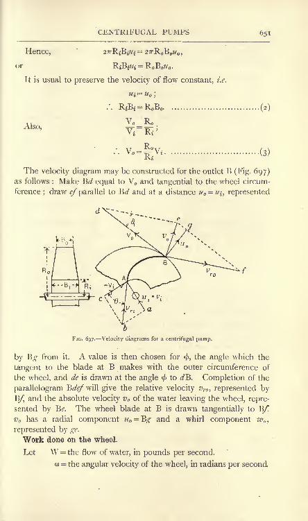
CENTRIFUGAL PUMPS 651
Hence, = 27rR B ^
or
It is usual to preserve the velocity of flow constant, i.e.
Ui = u;
(2)
Also,
R,(3)
The velocity diagram may be constructed for the outlet B (Fig. 697)as follows : Make B</ equal to V and tangential to the wheel circum-
ference ; draw <?/" parallel to B</ and at a distance u =Ui, represented
FIG. 697. Velocity diagrams for a centrifugal pump.
by Eg from it. A value is then chosen for <, the angle which the
tangent to the blade at B makes with the outer circumference of
the wheel, and de is drawn at the angle <f>to </B. Completion of the
parallelogram B^/will give the relative velocity vro , represented by
B/j and the absolute velocity v of the water leaving the wheel, repre-
sented by B<?. The wheel blade at B is drawn tangentially to B/!
vn has a radial component u = ^g and a whirl component w,
represented by ge.
Work done on the wheel.
Let W = the flow of water, in pounds per second.
w = the angular velocity of the wheel, in radians per second.
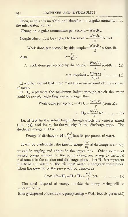
652 MACHINES AND HYDRAULICS
Then, as there is no whirl, and therefore no angular momentum in
the inlet water, we have
Change in angular momentum per second = Wz; R .
Couple which must be applied to the wheel = - Ib.-feet.
o
Work done per second by this couple = - w foot.-lb.
Also,
Ww V.'. work done per second by the couple = - foot-lb. ...(4)
<b
H.P. required = . ...(5)55*-
It will be noticed that these results take no account of any sources
of waste.
If Hm represents the maximum height through which the water
could be raised, neglecting wasted energy, then
Work done per second =WHm = W(from 4) ;
<b
(6)
Let H feet be the actual height through which the water is raised
(Fig. 695), and let VD be the velocity in the discharge pipe. The
discharge energy at D will be
v 2
Energy of discharge = H + -^ foot-lb. per pound of water.
It will be evident that the kinetic energy at discharge is entirely
wasted in surging and eddies in the upper tank. Other sources of
wasted energy external to the pump casing are owing to frictional
resistances in the suction and discharge pipes. Let HF feet represent
the head equivalent to the frictional waste of energy in these pipes.
Then the gross lift of the pump will be denned as
Gross lift = HG = H + HF +^ feet.................. (7)
The total disposal of energy outside the pump casing will be
represented by
Energy disposed of outside the pump casing=WHG foot-lb. per sec. (8)

CENTRIFUGAL PUMPS 653
The ratio of this quantity to the work done per second in the
wheel, given by (4), is the hydraulic efficiency of the pump. Hence,for radial flow at the wheel inlet, we have
Hydraulic efficiency= EH =WHG
-Ww V = ..........(9 )
Within the wheel casing, in addition to frictional waste in the
passages, there is waste from shock due to the velocity v at the
wheel exit being greater than the velocity #D in the discharge
pipe. It is rarely the case that any effective means are taken for
ensuring that v shall diminish to VD in such a manner as to producean effective increase in the pressure head. More usually the waste is
complete, and the pressure head at the connection of the discharge
pipe to the wheel case is equal to that at the exit circumference of
the wheel. As has been noted already, the kinetic energy of the
water in the discharge pipe is wasted entirely in the upper tank;
it
therefore follows that the waste, in addition to that due to friction,
will be the whole kinetic energy of the water leaving the wheel exit,
Vo2
viz. -- foot-lb. per pound, and the maximum height of lift given in
(6) will be reduced to this extent.
Again, a centrifugal pump, having been designed for a constant
speed of rotation and for a given flow of water, will have a definite
angle 6 (Fig. 697) for the wheel blade at the entrance A. If any
change be made in the speed of the wheel or in the velocity of flow,
the fixed angle will not suit the altered conditions, and there will
be waste of energy by reason of shock at A. Further, the assumptionof radial velocity of the entering water is approximate only, as there
are no guides in the central orifices of the wheel to ensure constant
direction in the flow of water.
In obtaining the actual efficiency EA of the whole arrangement, the
energy wasted in overcoming the frictional resistances of the wheel
bearings also must be considered. Taking, as before, a flow of Wpounds per second raised through an actual height H feet, we have
Useful work done =WH foot-lb. per sec.
The energy which must be supplied to the pump shaft will be
given by >
WHEnergy supplied to pump = -= foot-lb. per sec.......... (10)
^A
WHHorse-power required to drive the pump = --=- ................... (
1 1)

654 MACHINES AND HYDRAULICS
Variation in pressure in the wheel. The change in pressure head
of the water passing through the wheel may be deduced in the same
manner as for the inward-flow turbine discussed on p. 644. Referring
to Fig. 697, it will be noted that the centrifugal action is to cause
the pressure . to increase in flowing from A to B;vro being greater
than Vrij there will be a decrease in pressure owing to the change in
relative velocity. Hence, the total difference in pressure heads at
A and B respectively will be
2 -feet. .(12)
The changes of pressure which occur in the whirling mass of water
passing through the wheel and casing of a centrifugal pump may be
studied in more detail. In Fig.
698 is shown a tank A containing
a pump wheel B, which may be
rotated by means of a shaft and a
pulley at C. Water may flow into
the wheel through the pipe D.
Suppose that the wheel is revolving
at a given speed, sufficiently large
to cause the water to rise to the
level EF, and to remain constant
at this level. No more water will
flow into the wheel; the water
contained in the wheel passages
will whirl with the wheel, and the
water in the tank will be at rest, save for the frictional drag givento it by the revolving wheel. As there is no flow, the changesin pressure head inside the wheel will be owing entirely to centri-
fugal action, and these will follow the law already explained on p. 645.The pressure heads are shown by the shaded diagrams abed and
a'b'c'd';
if the water were whirled in a revolving open cup instead of
in the wheel, the form of the vertical section of its surface would be
that of the curves ad and dd\ and the state of motion is called
a forced vortex. It will be noted from what has been said on p. 645that the condition for a forced vortex is that the whole of the whirling
water possesses the same angular velocity.
The conditions illustrated in Fig. 698 are realised in a centrifugal
pump often if the speed of the wheel be insufficient to cause the
water to reach the level of the mouth of the discharge pipe. In such
FIG. 698. Pressure variation in a revolvingwheel : no flow of water.

FREE VORTEX 655
a case, there is, of course, no flow, and hence no work is done other
than that against frictional resistances.
Free vortex. A free vortex may be produced easily by rilling
with water a circular vessel having a central plug, stirring the water
and then drawing the plug. The shapeassumed by the water will be found
to resemble that shown in Fig. 699,
which has been plotted from calculated
results. In such a vortex, the condition
is that although interchanges of kinetic,
pressure, and potential energies maytake place freely throughout the mass
of water, the total energy per pound of
water remains constant.
FIG. 699. A free vortex.
In Fig. 700 (), AB is a portion of
the surface of a free vortex. At anypoint P, at a distance y feet from the
free surface level OX, and at radius
x feet from the axis of the vortex, the resultant R of the centrifugalforce F and the weight W of a particle of water must cut the surface
of the vortex normally. This is owing to the fact that the surface at
P is exposed to the pressure of the atmosphere, which is a force
acting normally on the surface.
B 6
FIG. 700. Forces acting in a free vortex.
Consider a mass of m pounds of water at P. The centrifugal force
F will be poundals, where v is the velocity of whirl in feet peroc
second;the weight W will be mg poundals. Hence,
W mg gxF
~~
mzfi~v2
'
x
Now, owing to the change of potential energy into kinetic energy

656 MACHINES AND HYDRAULICS
caused by the water descending through a height y at constant atmos-
pheric pressure, we have V2 _ 2gy.
. W gx x'
"F=2^
=2/
In Fig. 700 (I)} another point P' has been taken very close to P;
y is increased now by a small amount Sy, represented by P'd, and xis diminished by a corresponding small amount (
-8x), represented
by Pd. The triangles aPc in Fig. 700 (a) and dP'P in Fig. 700 (b)
are similar. Hence, W ac Pd
or ^- = .
Let Sx and 8y become very small, and integrate both sides, giving
i (dy (dx
*jy=~J^'
where c is a constant to be determined by the given conditions.
The result may be written i c
ora
y= ^'where a is an arbitrary constant.
\'J. 701. A free vortex formed outside a revolving wheel.

FREE VORTEX 657
In Fig. 701, water is discharged from a rotating wheel into a
circular tank, and allowed to form a free vortex. If H is the heightin feet of the free surface level above the whee\ centre, R the radius
of the wheel in feet and V its rim velocity in feet per second, then
orV2
H = .
Hence, from (2),
or a =V2R2
Hence, equation (2) becomes, in this case,
V2R2y= (3)
This is the equation used in plotting the vortices shown in
Figs. 699 and 701.
In Fig. 702 is shown a wheel A surrounded by a chamber B,
which is open to an ordinary volute chamber C. The water whirled
FIG. 702. Pressure variation in a wheel having a whirlpool chamber.
out of the wheel moves through the chamber B in spiral stream lines,
and the changes in pressure follow the free vortex law approximately.
This is shown in the pressure diagrams by the curves cd and cd\
D.M. 2T

658 MACHINES AND HYDRAULICS
The water in the wheel itself follows the forced vortex law approxi-
mately, shown by the curves de and d'e '. The chamber B, called
the whirlpool chamber, was suggested by Prof. James Thomson;
it
has not been used to any great extent in practice on account of the
very large dimensions required if the chamber is to be effective in
permitting the changes from kinetic to pressure energy to be effected
gradually.*
High lift centrifugal pumps. The lift which can be obtained byuse of an ordinary centrifugal pump is limited by the speed at which
the wheel can be run without exceeding safe limits of stress in the
material. By the use of several wheels in series, so that the water
leaving one wheel is delivered to the next wheel of the series, almost
any lift can be obtained. Fig. 703 shows such a pump constructed
FIG. 703. Multiple-wheel centrifugal pump for high lifts.
by Messrs. Mather & Platt, for the purpose of mine drainage.! Thereare seven wheels in series, the first being that on the right-hand endof the shaft. This pump is capable of delivering 2500 gallons perminute to a height of 2000 feet when running at 1450 revolutions
per minute, and absorbs over 1900 horse-power at the spindle.Students desirous of further information in hydraulics are referred
to the following standard works :
(a) Hydraulics, Prof. A. H. Gibson (Constable); (b) Hydraulics,Prof. W. C. Unwin (Black) ; (c) Hydraulics, F. C. Lea (Arnold).
*See "Experiments on the Efficiency of Centrifugal Pumps," by Dr. Stanton.
Proc. Inst. Meek. Eng., 1903, p. 726.
t" The Evolution of the Turbine Pump
"; Hopkinson & Chorlton. Proc. Inst.
Mech. Eng., January 1912.

EXERCISES ON CHAPTER XXIV. 659
EXERCISES ON CHAPTER XXIV.
1. A jet of water having a sectional area of 0-5 square inch andmoving with a velocity of 40 feet per second impinges on a fixed flat plate.Find the pressure on the plate when the jet makes angles of o, 30, 45,60 and 90 with it. Plot a diagram showing the relation of pressure andangles.
2. The jet of water in Question I slides tangentially on to a fixed vane.Find the pressures on the following vanes, given that the tangents to thevanes at the leaving edges make angles with the jet of o, 30, 60, 90,120, 150, 1 80. Plot a diagram showing the relation of pressures andangles.
3. A jet of water issues horizontally from a trumpet orifice one inchdiameter under a head of 4 feet. It impinges normally on a flat plate ;
calculate the pressure on the plate (a) when the plate is receding from theorifice with a velocity of 2 feet per second, (ft) when the plate is approachingthe orifice with a velocity of 2 feet per second.
4. In Question 3, calculate the work done in each case. Under whatconditions of plate velocity would there be zero work done ? Sketch a
diagram showing approximately the work done between the limitingvelocities of plate (a) equal to and of the same sense as the velocity of the
jet, (b] equal to and of opposite sense to that of the jet.
5. An overshot water wheel is supplied with 2 cubic feet of water persecond. If the fall available is 30 feet and if the efficiency is 60 per cent,what horse-power will be developed ?
6. In an undershot water wheel, the water is supplied under a head of
3 feet and passes through a sluice 4 feet in width and 6 inches in height.Calculate the flow through the sluice, taking the coefficient of dischargeto be 0-6. Hence calculate the horse-power developed by the wheel if the
efficiency is 40 per cent.
7. In a Poncelet water wheel, the velocity of the jet is 25 feet persecond and the velocity of the rim of the wheel is 15 feet per second. If
the direction of the jet makes an angle of 15 with the tangent to thewheel circumference at the entrance, what angle should the tip of the
wheel vane make with the same tangent ?
8. In a Poncelet water wheel, the velocity and direction of the jet are
the same as those given in Question 7. The tip of the wheel vane makesan angle of 28 with the tangent to the wheel circumference. Find thecircumferential velocity of the wheel.
9. A wheel 3 feet in diameter makes 250 revolutions per minute andhas radial vanes. Water flows through the wheel from the outside to
the centre, and has a radial component of 6 feet per second at the inlet.
If shock is to be avoided, find and show in a diagram the direction angleof the entering water.
10. A Pelton wheel is 30 inches in mean diameter and is supplied withwater under a head of 1500 feet. If the jet is i inch in diameter, find thebest speed in revolutions per minute of the wheel and also the horse-powerdeveloped if the efficiency is 80 per cent.

66o MACHINES AND HYDRAULICS
11. In a Girard axial-flow impulse turbine having a horizontal wheel,the internal and external diameters of the wheel at the inlet are 33 and 39inches respectively, the mean diameter being 36 inches. The total
available fall is 20 feet and the delivery edges of the guide vanes are
1 8 inches above the tail race.
(a) Find the velocity of the water leaving the delivery edges of the
guide vanes, taking the coefficient of velocity as 0-95.
() The axial component of the velocity (a) is to be 0-45 of the result
you have found in (a). Find the angle made by the tips of the guideblades with the horizontal at the mean diameter.
(c) Calculate the flow of water through the wheel in Ib. per second,
neglecting the sectional area abstracted by the guide and wheel vanes.
(d) What is the total energy per second available in the fall? If
the efficiency of the wheel is 75 per cent., what is its probable horse-
power ?
(e) The mean circumferential velocity of the wheel is to be 0-5 of the
velocity calculated in (a\ and the water leaves the wheel with axial
velocity only. The relative velocities at inlet and outlet are equal. Findthe angles to the horizontal of the vanes at the mean wheel circumferenceat inlet and outlet respectively. Draw the curve of the vane. Find also
the speed of the wheel in revolutions per minute.
(f) Find the absolute velocity of the leaving water, and hence calculate
the hydraulic efficiency.
(g) From (b\ find the velocity of whirl of the entering water.
Assuming no whirl at the outlet, calculate the couple in Ib.-feet acting onthe wheel, the work done by this couple in foot-lb. per second and the
horse-power developed by it.
12. In an axial-flow reaction turbine having a horizontal wheel, the
mean circumference velocity V of the wheel vane is 16 feet per second,the inlet velocity Vi of the water is 18 feet per second and the axial com-
ponents HI and u of the velocity of the water at inlet and outlet are each
equal to 4-5 feet per second. The water is discharged from the wheelwithout whirl. Find the angle of the guide blade
;also the angles of the
wheel vane at inlet and outlet. Find the relative velocities vri and vr<> at
inlet and outlet, and calculate the change in pressure head in the wheel
passages if the depth of the wheel is 8 inches.
13. If a plate is inserted in a stream of fluid and held at right anglesto the direction of the stream, the total pressure on it is equal to the
momentum per second which would pass through its area if the platewere absent, multiplied by a factor which, for the present purpose, may betaken to be 0-65. Find the pressure upon a plate 4 feet square due to a
steady wind of 20 miles per hour. (One cubic foot of air weighs 0-08 Ib.)
(B.E.)
14. The radial vanes of an under-shot water wheel are acted upon bywater moving at a velocity of 45 feet per second. If the quantity of water
which reaches the wheel per second is 2 cubic feet, and if the vanesof the wheel are moving at a velocity of 22-5 feet per second, find
(a) the pressure of the water on the vanes, () the theoretical efficiencyof the wheel and (c) the horse-power the wheel is capable of developing.
(B.E.)
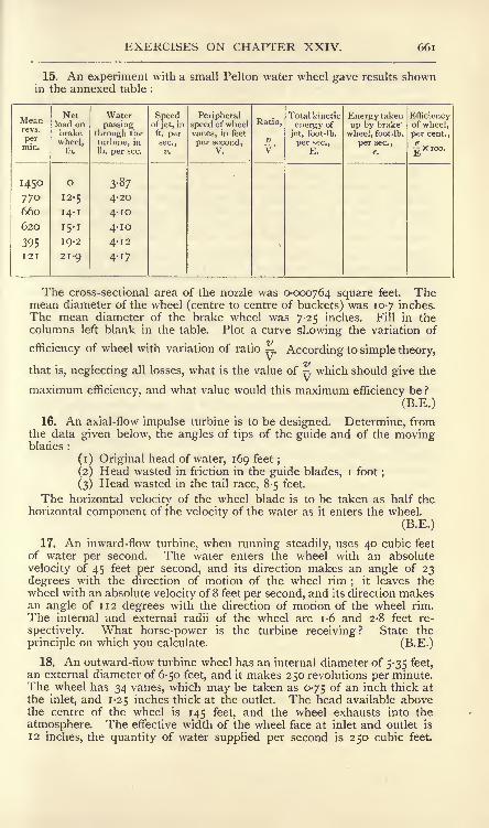
EXERCISES ON CHAPTER XXIV. 661
15. An experiment with a small Pelton water wheel gave results shownin the annexed table :
Meanrevs.
permin.

662 MACHINES AND HYDRAULICS
Determine the angles of the tips of the vanes at inlet and outlet, so thatthe water shall leave the wheel radially. You may neglect all friction
losses. (B.E.)
19. The wheel of a centrifugal pump is delivering very little water;show
in a curve how the pressure varies from inside the wheel to a pointsome distance outside the rim. Show this when there is a considerable
delivery of water. Draw the shape of the vane of the wheel. (B.E.)
20. The radial speed of the water in the wheel of a centrifugal pump is
6 feet per second; the vanes are directed backwards at an angle of 35
degrees to the rim; what is the real velocity of the water relatively to the
vanes ? What is the component of this which is tangential to the rim ?
When the water has left the wheel, what is its velocity in the tangentialdirection if the rim of the wheel moves at 20 feet per second ? (B.E.)
21. The rim of a turbine is travelling at 60 feet per second;200 Ib. of
fluid enter the wheel per second with a velocity of 70 feet per second in
the tangential direction, leaving it at the same radius with no velocity in
the direction of the wheel's motion. Find the momentum lost per second
by the fluid, and calculate the horse-power given to the turbine. (I.C.E.)
22. In an inward-flow turbine the speed of the wheel at inlet is 0-6577 ;
the velocity of flow, assumed constant throughout, is 0-15^; the outer
radius is twice the inner radius, and the flow at outlet is radial. v= *Jigh,where h is the head above the turbine centre. Find, in terms of h, the
centrifugal head in the turbine, the velocity at inlet and the hydraulicefficiency. (L.U.)
23. A Pelton wheel runs at 900 revs, per min., its diameter being d feet.
750 gallons of water per minute are supplied from a hydraulic main at
250 Ib. per sq. in at the nozzle. Find the actual horse-power, allowing areasonable efficiency for the wheel. Find also a suitable value for d.
Sketch the form of bucket and shape of nozzle you would use, showinghow the sectional area of the jet may be varied. (L.U.)

CHAPTER XXV.
HYDRAULIC EXPERIMENTS.
Hydraulic experiments. -Most laboratories equipped for applied
mechanics now possess apparatus suitable for carrying out experi-
ments in hydraulics. Generally speaking, these are on a small
scale; to carry out experimental hydraulics on a practical scale
requires very costly apparatus occupying much space ; owing to the
nature of the experiments, it is best to have a separate laboratory
entirely if completeness is aimed at. In this section, the experi-
ments described are on a small scale usually, and are such as mayfind a place in any mechanical laboratory with great benefit to
the student. It must be borne in mind however, that the ex-
perimental results obtained by such apparatus cannot agree well
with those given by larger apparatus. For example, the results
for the flow through a drawn copper tube 0-5 inch in diameter
could scarcely be compared with those for a cast-iron or steel
water main 48 inches in diameter. This, however, does not detract
seriously from the educational value of the experiments, and the
student has the satisfaction of having the whole apparatus under
his own control without the necessity for a multitude of assistants.
Apparatus for some general hydraulic experiments. In Fig. 704is shown apparatus in a compact form for enabling experiments to be
made on the flow of water through orifices and over gauge notches,
and also on the power and efficiency of a small Pelton wheel. Ais a closed vessel supplied with water from a pipe B having a
regulating valve C. The pipe B inside the vessel has its lower end
plugged, and is perforated with a number of small holes. This
portion is surrounded by a gauze cage, which has the effect of
stilling most of the eddies in the entering water. In cases where
the head in the ordinary water main is insufficient for experimental
purposes, a pump may be used for delivering water under pressure
into A. In the author's laboratory, the pressure of supply may

664 MACHINES AND HYDRAULICS
be 100 Ib. per square inch. Any head up to this limit may be
obtained in the vessel A by regulating the valve C, and this head will
be maintained steadily by the action of the air cushion in the upper
part of A. If very low heads are required, an air valve D is opened,thus reducing the pressure on the surface of the water in A to that of
the atmosphere. The head is measured then by means of a glass
tube gauge EF, which is connected to A near the top and bottom.
For higher pressures, the pressure gauge G is used ;this is graduated
in feet of water.
FIG. 704. General arrangement of hydraulic apparatus.
For experiments on the flow through orifices, a flange J is secured
to the tank A, and brass plates having various orifices may be bolted
to it. The discharged jet is caught by a baffle plate K, and is
directed by it into the trough L, and thence into the measuringtank M. The latter tank has a small compartment at one side, and
the water may be directed into this or into the larger compartmentas required, by means of a swinging shoot N. Each compartmenthas a plug and waste pipe, and the larger holds a known quantity of
water when the surface is level with the point of the hook OA small Pelton wheel is situated at P, and is connected by
means of a pipe to the tank A and has a regulating cock Q.The exhaust water is led by a pipe R into the trough L
;baffle
plates S, S, and a wire gauze screen T get rid of any turbulence
and ensure that the water will flow quietly in the left-hand portion of

HYDRAULIC EXPERIMENTS 665
L. The Pelton wheel is fitted with a brake and a revolution
counter for the horse-power estimations.
The left-hand end of the trough L is fitted with a gauge notch V,
which may be exchanged for others of different types. The head of
water in L may be measured by means of the hook gauge U, which
consists of a graduated rod having a hook at its lower end and sliding
vertically in a fixed tube.
EXPT. 50. Flow through various orifices. Shut the cock Q, fix the
required orifice at J and arrange the shoot N so as to discharge the
water into the smaller compartment of M. Plug the larger com-
partment, which should be quite empty, and adjust the valve C so
as to secure steady conditions at the required head. When steadi-
ness has been secured, switch N over so as to discharge into the
larger compartment of M, and note the time. When M is full up to
O, again note the time, and record the duration of the test. The
experiment may be repeated by switching the water into the smaller
compartment, and then emptying the larger, which may be donewithout any interference with the actual flow from the orifice. Themean time of the two experiments should be taken. Several ex-
periments should be made under different heads, and the results
tabulated as follows :
EXPERIMENT ON THE DISCHARGE FROM AN ORIFICE.
No. of
Expt.

666 MACHINES AND HYDRAULICS
diameter in small scale experiments. The following method may beused to determine roughly the coefficient of velocity, and the coeffi-
cient of contraction may be calculated then from the known coefficient
of discharge.Use a circular orifice under low head, which should be maintained
very steady. The curve of the jet is shown at APB in Fig. 705, andthe dimensions H and D should
be measured carefully. The ori-
fice is at A. At any point P onthe curve, the actual velocity v
l
will be tangential to the curve,and will have horizontal andvertical components vx and vy
respectively. It may be assumedthat vx is equal to v, the velocitywith which the water leaves the
orifice, and that vy follows the law of a body falling freely. Hence,if d and h are the coordinates of P, and t is the time taken to flow
from A to P, we have
d=vt. ...................................... (i)
FIG. 705.- Curve of a jet of water.
If HJ is the head under which the water leaves the orifice, then
v =
Hence (i) becomes
and
Division of (3) by (2) gives
</2 /2 X
(3)
h
This result will be true for all points on the curve. Applying it
to B, we have 1Y2
Hor
D2
4H.H'
(5)
The experiment should be performed for three or four values of
H1 ,
and D and H measured for each. The values of cv calculated
from each set of measurements should agree fairly well.
EXPT. 52. Flow over gauge notches. Close the orifices at J
(Fig. 704) by means of a blank flange. Secure the wheel of the
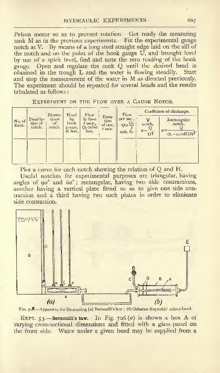
HYDRAULIC EXPERIMENTS 667
Pelton motor so as to prevent rotation. Get ready the measuringtank M as in the previous experiments. Fix the experimental gaugenotch at V. By means of a long steel straight edge laid on the sill of
the notch and on the point of the hook gauge U, and brought level
by use of a spirit level, find and note the zero reading of the hook
gauge. Open and regulate the cock Q until the desired head is
obtained in the trough L and the water is flowing steadily. Start
and stop the measurement of the water in M as directed previously.The experiment should be repeated for several heads and the results
tabulated as follows :
EXPERIMENT ON THE FLOW OVER A GAUGE NOTCH.
No. of
Expt.

668 MACHINES AND HYDRAULICS
tank B fitted with a glass tube gauge C. Other three tube gaugesare connected to A, and show the pressure heads at a, b and c. Asthe box A is horizontal, there will be no change in potential energy ;
hence, neglecting friction, the sum of the pressure and kinetic
energies at a, I) and c will be equal. Thus,
(l)
2 7 . 2
= ^ + ,............
2g 2g 2g
where ha ,hb and he are the heads in feet and va , Vb and ve are the
velocities in feet per second at a, b and c respectively.ha ,
hb and hc are given by the observed heads in the glass tube.
Find the quantity of water flowing per second by measuring the timetaken to discharge a given quantity ;
let this be Q cubic feet persecond. Measure the cross-sectional areas A
, A&, Ac ,in square
feet, at a, b and c respectively. As the same quantity passes eachsection per second, we have
.QA;
Substitution in (i) gives
Q2
Insert the observed quantities in equation (2) and note the
divergence from strict equality in the results.
EXPT. 54. The Venturi meter. A small meter of this type is
illustrated in Fig. 707. The axis of the meter is arranged horizontallyin order that the potential energy of the water may remain constant.
Section CD
FIG. 707. Sections of a Venturi meter.
The difference in pressure heads at the sections AB and CD is
measured by means of glass tube gauges containing water or bymeans of a glass U-tube containing mercury. The meter is con-
nected at E to a water supply, and the discharge pipe, connected
to the meter at F, should have a regulating valve fitted. Dischargetakes place into a measuring tank or into a trough fitted with a gaugenotch. To make an experiment, maintain steady the pressure-headdifference as shown by the tube gauge, and measure the flow in cubic

HYDRAULIC EXPERIMENTS 669
feet per second. Apply your results to equation (3) (p. 596), andso ascertain the value of the coefficient which must be applied to the
right-hand side. Repeat the experiment with several different rates
of flow, and obtain the coefficient for each. Plot curves showing
(a) the relation of the flow in cubic feet per second and the pressure-
head difference in feet; (b) the relation of the coefficient and the
pressure-head difference in feet.
EXPT. 55. Tne critical velocity in a pipe. Prof. Osborne Reynoldshas shown that, when water flows in a pipe, the motion may be
steady, i.e. free from eddies, or unsteady, i.e. sinuous or broken up in
eddies. The critical speed is that at which the flow ceases to be
steady; at higher speeds the water is broken up into eddies. In
Fig. 706 (b) is illustrated a simple form of Reynolds' experiment,which serves to illustrate the point. A test tube of glass, A, havinga bell-mouthed entrance, is inclosed in a larger closed glass tube Band discharges into a sink. B is supplied with water from a pipe Chaving a regulating valve ;
two gauze screens D serve to preventturbulence in B. A small vessel E contains a coloured liquid (redink serves well), and has a small glass tube which enters B and
discharges a fine band of coloured liquid into the bell mouth of A.
At low velocities of flow through A, it will be found that the coloured
band will travel unbroken throughout A. If the velocity be increased
slowly, it will be found that the stream becomes broken up at a
certain velocity, thus showing the presence of eddies.
Reynolds also investigated the laws of resistance for these different
methods of flow, and found that the resistance varied as the speed at
speeds below the critical value. At speeds higher than the critical
value, the resistance varies as some power of the speed, approximatelythe square.
FIG. 708. Apparatus for investigating frictional resistances in a pipe.
EXPT. 56 Frictional resistances in a pipe. The apparatus illustrated
in Fig. 708 consists of a straight pipe AB of as nearly uniform bore as
is possible (solid drawn copper or brass does well for a small scale
experiment), connected to a tap at A and discharging into a

670 MACHINES AND HYDRAULICS
FIG. 709. Section of
pressuregauge connec-
measuring vessel C. The pipe is arranged horizontally, and is con-
nected at D and E by means of rubber tubing to two open-toppedglass tubes F and G. A scale permits the levels of the water in
the glass tubes to be observed. The connectionsat D and E are shown in more detail in Fig. 709.A collar having a recess inside is soldered to the
pipe, and has three screw plugs and a nozzle for
connecting the rubber tube. Four very small
holes, two of which are shown in Fig. 709, are
bored through the pipe so as to connect the recess
in the collar to the interior of the pipe ; care
should be taken that no arras is left round these
j^ Qn ^ innef ^ Qf ^ pipe ^ ^^rises to heights in the glass tubes proportional to
the pressures at D and E, and the difference in these heights givesthe loss in pressure head due to frictional resistances.
Measure the diameter of the pipe ;this may be done by use of a
taper gauge inserted into the pipe end, or by filling a measured
length of pipe with water and removing the water to be weighed ;its
volume may then be found and the diameter of the pipe may becalculated. Measure also the length of the pipe between the small
holes at D and E. Turn on the water gently, and adjust the flow
until steady conditions are attained with the desired difference in
levels in the glass tubes. Care must be taken to get rid of air fromthe pressure gauge tube connections. At a noted time, turn the
discharge into the measuring vessel and note the time taken to
discharge a measured quantity of water. Repeat and take the
average of the two times. Repeat the experiment several times,
using different velocities of flow, and note the difference in headsand the times of flow for each. Tabulate these as follows :
EXPERIMENT ON THE FRICTIONAL RESISTANCES IN A PIPE.
No. of
Expt.

HYDRAULIC EXPERIMENTS 671
It is useful to experiment on two pipes of different diameters.
Very fair results may be obtained by use of solid drawn copper tubes
of | inch and f inch diameters on a length L of 5 feet.
EXPT. 57. Loss of head at bends. The apparatus is shown in
Fig. 710. The right-angled bendAB is supplied with water at Afrom a tap and discharges into a
measuring vessel C. Collars similar
to that in Fig. 709 are soldered
at the beginning and end of the
curved part, and are connected to
two glass tubes. The difference in
level shows the loss in head. The
pipe is arranged horizontally in
order that there shall be no changein the potential energy of the water.
Measure the bore of the pipeand the radius of the bend, andfind the flow in the same manneras that used in the previous ex-
periment. Do this for several
different velocities of flow, andtabulate. A coefficient for the head lost may be found from
, v*h = c ,
FIG. 710. Apparatus for measuring the loss
of head at a bend.
or
This result expresses the head lost in terms of the kinetic energyof the flowing water.
EXPERIMENT ON THE HEAD LOST AT A BEND.
No.of Expt.

672 MACHINES AND HYDRAULICS
EXPT. 58 Loss of head at an elbow. This experiment is carried
out in the same general manner as for a bend. If the pipe ABC(Fig. 711) is cut from a piece similar to that usedin finding the frictional loss in a straight pipe, the
frictional lossh-^
feet per inch length of pipe will
be known. Measure AB and BC along the pipeA C^O axis in inches, and let the sum be /. Then the
frictional loss apart from shock loss at the elbowwill be h^l feet. This should be deducted fromthe difference in head shown in the tube gauges,and the result will then be the shock loss. The
calculations in reducing the results are similar to those for the bend,and the value of c is found in the same way.
EXPT. 59. Losses at sudden enlargements and contractions in a pipe.
The apparatus shown in Fig. 712 consists of a pipe AB having bothends plugged and smaller pipes AC and BD fitted to the plugs.Water is supplied at D and is discharged into a measuring vessel at
FIG. 711.
FIG. 712. Apparatus for measuring the losses at sudden enlargements and contractions.
C. There is thus a sudden enlargement at B and a sudden con-
traction at A. The pressure heads are measured at E, F, G, H, Kand L
;collars resembling that in Fig. 709 are fitted at these places
and are connected to six glass tubes having graduated scales. The
following record of an actual experiment will illustrate the method of
recording and reducing the results.
The pipe diameters were found by filling a measured length of
pipe with water, and the areas ATand A
2of the sections of the small
and the large pipe respectively were calculated then. These were
found to be Aj = 0-000331 and A2= 0-00386 square feet. The pipe
lengths are given in Fig. 713.

HYDRAULIC EXPERIMENTS 673
OBSERVED QUANTITIES.
No.of
Test.

674 MACHINES AND HYDRAULICS
SUDDEN CONTRACTION.

HYDRAULIC EXPERIMENTS 675
tube C and a graduated scale. The head is maintained constant
during the experiment. The jet impinges on a plate D, which is
screwed to the end of a balance beam E. Equilibrium of E is
secured by moving the counterpoise F. G is a cylinder of transparent
celluloid, arranged so as to catch the waste water and deliver it
into a sink.
In making an experiment, it is best to proceed as follows. Place
a known weight, say 0-2 lb., centrally on the plate D, and move the
counterpoise until balance is restored. Remove the weight andturn on the jet, gradually increasing the head until equilibriumof the balance beam is restored. The pressure on the plate will
now be 0-2 lb., and the head H from the surface level in the tank
to the level of the plate should be noted. The experimentshould be repeated for several different pressures, and also for
several plates.
It is useful to have a flat plate, a hemispherical cup and a cuphaving a tip angle of 45. Equations for these are given on pp. 625and 626, and the experimental values of the pressures should be
compared with the calculated values.
The flow of water reaching the plate per second should be found
by a separate series of tests on the tank orifice. This series should
cover the range of heads used in the above experiments, and should be
carried out in the same manner as for the discharge from an orifice.
From the results of this series,
Let M = mass of water discharged under a head h^ feet, in poundsper sec.
//!= the head over the plane of the orifice, in feet.
h^= the height from the plate to the orifice, in feet.
v = the velocity of the water reaching the plate, in feet per sec.
Then K = /^1 + ^
2.
Also v = x/2-H, nearly.
Momentum reaching the plate per second Mv
This result will take the place of (Av^w) in the equations given on
pp. 625 and 626, and will enable the pressures on the various platesto be calculated.
EXPT. 6 1. Horse-power and efficiency of a Pelton wheel. Fig. 715illustrates a small Pelton wheel specially constructed for experimentalwork. There is one nozzle only, and the supply of water is controlled
by means of a needle valve. The buckets are of the Doble type,
shaped to receive the jet with as little shock as possible, and cut
away at the entrance edge as shown in the side elevation, in order

676 MACHINES AND HYDRAULICS
that the bucket entering the jet may do so with the minimumdisturbance. The exhaust water is discharged from the lower partof the casing into a trough having a gauge notch, thus enabling the
water consumption to be measured.
The brake horse-power is measured by a simple pattern of band
brake, consisting of a band lapped round half the circumference
of the brake wheel;
the ends of the band are connected to a
pivoted wooden lever which is under the control of a springbalance. A revolution counter driven by the shaft enables the
HZH
FIG. 715. An experimental Pelton wheel.
wheel speed to be measured. Provision is made for running water
into the interior of the brake wheel should it show any tendency to
become hot.
The supply water may be taken from an overhead tank, or from a
tank similar to that in Fig. 704. In the former case, the head H feet
may be measured from the constant surface level in the tank to the
level of the jet ; each pound of water leaving the nozzle will possessH foot-lb. of energy, neglecting the frictional waste in the pipe andnozzle.
'
In the latter case, the head H feet in the tank (Fig. 704)
may be measured by means of a pressure gauge, and, as the water in
the tank is practically at rest, this head will represent the energy
supplied to the wheel per pound of water, again neglecting friction in
the pipe connecting the tank to the wheel casing as well as the friction
of the nozzle.
Sometimes the arrangement consists of a power-driven centrifugal
pump, which delivers water to the nozzle of the Pelton wheel without
any tank intervening. In this case, the pressure head Hxfeet of the
supply water may be measured by means of a pressure gauge con-
nected to the supply pipe. From a knowledge of the diameter of the
pipe at the point of connection of the gauge and also of the flow of
water, the velocity v feet per second may be calculated, and hence

HYDRAULIC EXPERIMENTS 677
2
the kinetic energy foot-lb. per pound of water may be found.2
Suppose also that the point of connection of the gauge is h feet abovethe nozzle level. The total energy of supply will then be
H = pressure energy -f kinetic energy + potential energy
= fH1H \-h\ foot-lb. per pound of water.
Constants required in reducing the results of the tests are the
radius Rj feet from the centre of the wheel to the axis of the jet, andthe radius from the wheel centre R
2 feet at which the brake springbalance exerts its pull. We also have
Velocity of the jet= V
x= 0-93 to o-95\/2^H feet per sec.
Let N be the revolutions per minute. Then
Velocity of the bucket = V2= ^ feet per sec.
oo
If the brake is of the type shown in Fig. 715, and if the springbalance is exerting a pull P lb., then
P x 2?rR9 x NB.H.P. = .
33000
Let W = the flow in pounds per minute.
Then Energy available in the supply water =WH foot-lb. per min.
WHHorse-power supplied
=33000
. . B.H.P.Actual efficiency
=
To make a series of tests, maintain constant the head of the supplywater and keep constant the setting of the needle valve; the flow
will then be constant, as indicated by the gauge notch readings.Put a given load on the brake and read the revolution counter
every minute for, say, five minutes. This completes one test. Alter
the brake load and again note the revolutions;
this process should
be repeated until information has been obtained regarding the
revolutions per minute corresponding to brake loads ranging from
zero up to a load which nearly stops the wheel from rotating. A

678 MACHINES AND HYDRAULICS
new series of tests can then be made by altering the head of the
supply water. The results should be tabulated as follows :
TESTS ON A PELTON WHEEL.
No.of
Test.

EXERCISES ON CHAPTER XXV. 679
6. The following measurements were made in calibration tests on asmall Venturi meter : Diameter of tube, 0-75 inch
;diameter at throat,
0-375 inch.
Total
discharge,gallons.

68o MACHINES AND HYDRAULICS
90 degrees to the jet ; B, a hemispherical cup, the jet discharging into its
centre ; C, a cup having its sides at 45 degrees to the horizontal, the jet
discharging into its centre. The following observations were taken :

TABLES.
Useful Constants.
i inch =2-54 centimetres = 25-4 millimetres,
i metre =39*37 inches.
5 280 feet =i mile.
6 feet = i fathom.
I Gimlets chain =66 feet.
80 Gunter's chains = i mile.
i kilometre =0-621 mile.
I square inch =6-45 square centimetres.
I square metre =1550 square inches.
i cubic inch = 16-39 cubic centimetres.
i cubic metre =61,025 cubic inches= 1-308 cubic yards.
i litre = 1000 cubic centimetres = 1-762 pint.
i gallon =0-1605 cubic foot = 4- 541 litres.
i bushel =1-284 cubic feet.
i radian =57-3 degrees.
TT =3-1416.
i knot = 6080 feet per hour.
60 miles per hour= i mile per minute = 88 feet per second.
The value of^ at London = 32- 182 feet per sec. per sec.
One pound avoirdupois = 7000 grains = 45 3-6 grams.One kilogram = 2-205 pounds.One gallon of pure water at 62 F. weighs 10 Ib.
One cubic foot of pure water at 62 F. weighs 62-3 Ib.
Weight of i pound in London = 445,000 dynes.
One cubic foot of air at o C. and i atmosphere pressure weighs 0-0807 Ib.
One cubic foot of hydrogen at o C. and i atmosphere pressure weighs0-00559 Ib.
i atmosphere =14-7 Ib. per square inch.
= 2116 Ib. per square foot
= io6 dynes per square centimetre nearly.

682 MACHINES AND HYDRAULICS
I kilogram per square centimetre = 14-22 Ib. per square inch.
A column of mercury 760 millimetres (= 30 inches) high produces at
its base a pressure of i atmosphere.A column of water 2-3 feet high produces at its base a pressure of
i Ib. per sq. inch.
i foot-lb. =1-3562 x io7ergs.
I metre-kilogram =7-235 foot-lb.
i horse-power = 33,000 foot-lb. per minute= 746 watts.
i horse-power-hour= 33,000x60 foot-lb.
Volts x amperes = watts.
i electrical unit = 1000 watt-hours.
i B.T.U. = f Ib.-degree-Cent, unit
= 252 gram-calories.
Absolute temperature T= /
Jou,e's equivalent. unit .
To convert common into Napierian or hyperbolic logarithms, multiplyby 2-3026.
The base of the Napierian logarithms is =2-7183.
Table of Coefficients of Linear Expansion.
(These are given as the increase in length which a bar of unit length
undergoes when heated through one degree Fahrenheit.)
Steel alloyed with 36 % nickel - 0-000000483
Wrought iron and mild steel - - 0-00000673Cast iron - 0-0000063
Copper - 0-0000096Zinc 0-0000162
Brass -0-0000105
Phosphor bronze - 0-0000107

STRENGTH AND ELASTICITY OF MATERIALS 683

684 LOGARITHMS
LOGARITHMS.

LOGARITHMS 685
LOGARITHMS.

686 ANTILOGARITHMS
ANTILOGARITHMS.

ANTILOGARITHMS 687
ANTILOGARITHMS.

688 TRIGONOMETRICAL TABLE
TRIGONOMETRICAL TABLE.
Angle.

ANSWERS.
Chapter I. Page 17.
1. 19,500 Ib. 2. 4400 square feet. 3. 1200 square feet.
4. (a) i$x\ (b) 6*- 35^.
(c) 2 cos x + 3 sin x. (d) 2sinxcosx-2cosx smx = o.
(e) 3sin2^cosjtr-3cos
2jrsina;. (/) 3 sec2x + sin x.
5. i. 6. x=2;y=4.
(d) ^3 + sinjf. (e) o-4log,0.
8 - 1 = 30,550- 9 - 1 = 1707.
Chapter II. Page 36.
1. (a) 12-6 Ib. weight at 9 6' to the* 9 Ib. force.
(b) 12-15 13 27'
(c) 7-8 26 21'
2. (a) 5-87 -19 54'
(b) 6-77 -24 35'
(0 1 1-5 -17 30'
3. 4-9 Ib. weight. 4. 2-5 Ib. weight.
5. 90-1 Ib. weight ; 112 Ib. weight at 34 36' to AC.
6. 15-43 Ib. weight. 7. 20-14 Ib. weight.
8. Q= 19-24 tons weight ;T = 776 tons weight. 9. I Ib. weight from O to D.
Angles, degrees

690 ANSWERS
15. Push in AO=i-57 tons weight; push in BO = 0-59 ton weight; push in
CO = 8-17 tons weight.
16. 25 Ib. weight.
17. 38-8 Ib. weight pull ; 86-8 Ib. weight push at 26 40' to the vertical.
18. 3-464 Ib. weight ; 1-732 Ib. weight. 19. 4-08 Ib. weight.
Chapter III. Page 56.
1. 10-29 inches from C, on the same side as D ; 46 Ib. weight.
2. 10-95 inches from A. 3. 45-3 Ib. 4. 23-46 inches.
5. Reaction at A= 4-975 tons weight ; reaction at 6 = 4-275 tons weight.
6. 6-55 tons weight ; 7-44 tons weight.
7. Reaction at A= 4-571 tons ; reaction at 6 = 3-429 tons.
8. Measure CD = io inches along CB ; draw 00 = 3-464 inches at 90 to CB ,
G is the centre of gravity.
9. .* =0-583 inches; j/= 1-083 inches. 10- 50 12'.
11. 30-5 Ib. ; 64-2 Ib. ; 17-3 Ib. 13. A, O-I54\V; B, 0-402W ; C, 0-444W.
Chapter IV. Page 74.
1. Top hinge, R= 100 Ib., acting upwards away from the gate at 29 48' to thehorizontal ; bottom hinge, R=ioo Ib., acting upwards towards the gate at
29 48' to the horizontal.
2. E= 2-828 Ib., acting downwards towards the right, at an angle of 45 to the
horizontal and at a perpendicular distance of 3-535 feet from the left lowercorner of the square and to the left of it.
8. R=i-732 Ib., acting downwards towards the left, at an angle of 30 to thehorizontal and at a perpendicular distance of 1-5 feet from the right-handend of the base.
4. An anti-clockwise couple of 5-196 Ib.-feet must be applied.
5. Vertical reaction = 1638 Ib.; inclined reaction = 3992 Ib. acting at 37 30' to
the horizontal.
6. Reaction at A= 711-1 Ib. ; reaction at B= 1227 Ib. at 54 35' to the horizontal.
7. Reaction at 6 = 825-9 Ib.; reaction at A= 950 Ib. at 62 8' to the horizontal.
13. 4-47 Ib. at 26 34' to the horizontal.
14. Reaction at A= 5-44 tons ; reaction at 6= 5-56 tons.
17. 42-42 Ib. acting along DA from D towards A; 62-5 Ib. at C, downwardstowards the left at an angle of 36 54' to BC.
18. Let s= side of square; point required is outside the square, at distances s
from the 4 Ib. force and 0-55 from the 3 Ib. force.
Chapter V. Page 89.
1. See Fig. 716 (p. 691). 2. See Fig. 717 (p. 691). 3. See Fig. 718 (p. 692).
4. See Fig. 7 19 (p. 692). 5. See Fig. 720 (p. 693). 6. See Fig. 721 (p. 693).
8. See Fig. 722 (p. 694). 9. 2-308 tons.
10. The link polygon solution is shown in Fig. 723 (p. 695) ; reaction AB = 2400 Ib. ;
reaction KA= 3440 Ib.
11. The substituted frame solution is shown in Fig. 723 (p. 695) ; reactionA6 = 2400 Ib.; reaction KA= 344O Ib.
12. Reaction A6 = 247i Ib. ; reaction KA= 343O Ib.

ANSWERS 691

602 ANSWERS
CO

ANSWERS 693
400 Ib
B
Member

694 ANSWERS
600 1 b
600 Ib.
Member

ANSWERS 695
COr-1 \ /^

696 ANSWERS
1000 lb. 1000 Ib. 1000 lb.
F
Member

ANSWERS 697
13. See Fig. 723 (p. 695). 14. See Fig. 724 (p. 696).
15, 16. See Fig. 725 (p. 696).
17. Q=IIOO Ib. pull; P=I2,35O Ib. push; R= 14,300 Ib. push. Taking the
bars in order from the bottom, the forces are : 21,000 Ib. pull ; 9700 Ib.
push ; 10,500 Ib. push ; 21,000 pull.
18. AB, i -02 tons push; BC, 0-2 ton push; CD, 0-9 ton push; DA, 0-57 ton
pull ; AC, 0-46 ton push.
10.
11.
13.
14.
15.
16.
17.
18.
19.
Chapter VI. Page 128.
1-78 inches. 2. 867 tons.
d= - inch; /=2- inches; efficiency= 69-6 per cent; bearing stress = 6-88
tons per sq. inch.
d= 11-
inches ; / = 4T7
g-inches ; efficiency
= 74-7 per cent. ; bearing stress = 8-83
tons per sq. inch.
n rivets on each side of the joint ; 45-37 tons.
jf inch ; 3-71 tons per sq. inch ; 1-85 tons per sq. inch. 7. 0-257 inch.
Extension in length = 0-16 inch ; contraction in width = 0-000763 inch ; contrac-
tion in thickness = 0-0000636 inch.
0-0485 inch.
Change in diameter = 0-001768 inch; change in length = 0-003635 inch ; changein volume = 0-57 1 2 cubic inch.
Pulls of I -008 tons. 12. Pushes of 35-2 tons ; 11-32 tons per sq. inch.
In the copper, 0-739 ton per sq. inch ; in the steel, 1-895 tons Per S(l-
incn -
i6i,99olb. ; 53,025 Ib.
6, degrees
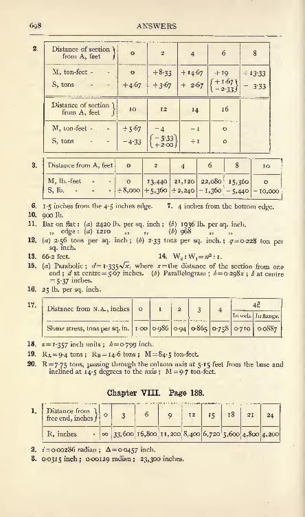
6g8 ANSWERS
Distance of section )

ANSWERS 699
4. 0-0429 inch ; o-OO 1 148 radian; 34,950 inches.
5. 2-314 tons ; M at centre = +41-7 ton-inches ; M at ends = -41-7 ton-inches ;
S for left half of beam= + 1-157 tons ; S for right half= -1-157 tons.
6. 3-472 tons; M at centre = 20-85 ton-inches ; M at ends = 41 -7 ton-inches;S at left end = + 1-736 tons ; S at right end= -
1-736 tons ; S at centre O.
7. 0-055 inch; 0-0415 inch. 8. A = 0-0761 inch ; 2=0-001096 radian.
9. 23-9 Ib. -inches ; 1-875 inches. 10- 0-3704 inch.
11. 64,800 inches ; 0-444 inch.
12. 3000 Ib. ; M at wall= - 8000 Ib.-feet ;maximum positive M=45oo Ib.-feet ;
points of contraflexure are at the free end and at 6 feet from the free end ;
S at free end = - 3000 Ib. ; S at wall= + 5000 Ib.
13. PA = P]3=ii'25 tons; PC 37'5 tons; the points of contraflexure occur at
5 feet on each side of C ; maximum positive M = 42-2 ton-feet ; maximumnegative M (at C) = -
75 ton -feet ; SA= + 1 1-25 tons ; S close to C on the
left= -18-75 tons ; S close to C on the right= + 18-75 tons J SB= -
11-25tons.
14. 0-06 inch.
15. 1-19 tons on each outer beam ; 2-62 tons on inner beam ; 5-36 tons per sq. inch.
16. (a) 9600 Ib.; (b) 25,600 Ib.-feet; 16,000 Ib. ; (c) 2 feet from the wall.
17. 1:8-16.
18. Maximum M (at ends)= -23-625 ton-feet ;
M at centre = + 17-625 ton-feet ;
points of contraflexure at 5-45 feet from each end.
19. W:W6=i-i65; _/":/&= 0-984; Aa:A&=i-i8; maximum ^= 5-66 tons
per sq. inch.
20. At x feet from one end, M = (i3jr-^2-7o) ton-feet for the end portions;
M = (iOjr-^2-4o) ton-feet for the centre portion; maximum M is at
the ends and is 70 ton-feet.
Chapter IX. Page 224.
1-28 inch-tons ; 0-00133 inch-ton per cubic inch.
12 tons per sq. inch ; 0-213 inch. 3. 0-57 inch.inch
4. 7-083 tons per sq. inch ; 11-29 sq. inches.
5. Maximum M (at centre) = 75 ton-feet ; maximum S (at ends)= 10 tons.
6. ,, ,,= 168-7 ton-feet ; ,, =22-5 tons.
7. Maximum combined M=iO5 ton-feet; at the left end, S varies from +14to +4 tons ; at the right end, S varies from -
14 to -4 tons ; the central
16-67 feet has shearing forces of both kinds.
Distance of section from!one end, feet - -
J

700 ANSWERS
12. A = 9-64 sq. inches; Ac= 11-25 S(l- inches; two plates in tension flange,
eachYfl-"
thick;two plates in compression flange, inner plate -^" thick,
outer plate |-"thick ; web plate
"thick ; pitch of rivets, 3 inches.
13. Moments of resistance : Compression flange : angles, 39*6 ton-feet;
Ist
plate,
50-5 ton-feet; 2nd plate, 45-6 ton -feet ; total, 1357 ton-feet. Tension
flange : angles, 36-4 ton-feet ;Ist
plate, 51*4 ton-feet ; 2nd plate, 54-0 ton-
feet ; total, 141-8 ton-feet.
14. Central bars, upper boom, 36 tons push ; central bars, lower boom, 32 tons
pull ; inclined bar nearest support, 28-28 tons push ; inclined bar secondfrom support, 16-97 tons Pu^ > vertical bar second from support, 4 tons push.
15. 45 tons push ; 40 tons pull ; 42-42 tons ; 23-57 tons pull ;10 tons push.
16. p= 0-675 Per cent. ; As= 0-1004 sq. inch ; N.A. is 1-53 inches from the top ;
M=6oo8 Ib. -inches.
17. N.A. is 9-07 inches from the top; use stresses Cc = 6oo, 4= 8865 Ib. per
sq. inch; M = 489,ooo Ib.-inches.
18. 6 foot-lb. 19. 5-72 sq. inches.
20. 9-13 tons per sq. inch. 21. 7-33 tons per sq. inch ; 1-86.
22. + denotes push ;- denotes pull.
Panel No.

ANSWERS 701
Chapter XI. Page 276.
1. 35, 300 lb. -feet. 2. 1-89 inches. 3. 5090 ton -inches.
4. 4320 ton-inches ; 1-179. 5. 16,240 lb. -inches. 6. 10-58 degrees.
7. 6-25 degrees. 8. 80-7. 9. 1-42 inches.
10. 7-54 tons per sq. inch pull on a section at 40 16' to AB ;
1-46 ,, ,, 130 16' .
11. 4-905 tons per sq. inch pull on a section at 73 9' to AB;
5-905 ,, push ,, 163 9' .
12. (a) 11,210 lb. -inches; (6) 7210 lb. inches ; (c) 2110 lb. per sq. inch push:605 lb. per sq. inch pull ; (d) 1357 lb. per sq. inch.
13. 52,800 lb. -inches.
14. (a) Angle with axis, degrees

702 ANSWERS
7. At elastic break-down, Ce= 68o Ib. per sq. inch; Cs= 10,200 Ib. per sq. inchat rupture, 60=1564 Ib. per sq. inch; 65= 23,420 Ib. per sq. inch
1,385,000 Ib. per sq. inch.
5120 tons per sq. inch ; 7-5 tons per sq. inch ; 6-19 inch-lb. per cubic inch.
10. 12,220 tons per sq. inch.
12. 839 tons per sq. inch ; -?.
8.
9. 2880 tons per sq. inch.
11. 4860 tons per sq. inch.
Chapter XIV. Page 350.
1. 600,000 foot-lb. ; 0727 ; 1-32. 2. 1,656,000 foot-lb.
3. 475,200 foot-lb. ; 1,584,000 foot-lb.
4. 0-00000735^; o-oooo8o4</; 0-0000667^; 0-000565^.5. 15 ; 360 Ib. ; 33-33 per cent. ;
no. 6. 142,400 foot-lb.
8. in-4jb. 9. 26, 250 Ib. -feet. 10. 0-828 degree.
7. 823 H.P.
TestNo.

ANSWERS 703
7. 91 Ib. ; 28 per cent. 8. 38-5 Ib.
9. 232 Ib. -inches. 10. 19-57!^
11. 730 Ib. 12. (a) 900 Ib. ; () 875 Ib.
13. (a) 4242 Ib. -inches ; (b] 3660 Ib. -inches.
14. 16,860 Ib. -inches ; inner angle 2 ; outer angle 2-2. 15'. 89-6.
1, 2 and 3.
Chapter XVI. Page 403.
Crank angle,degrees.

704 ANSWERS
5. 217-4 seconds.
6. 3-32 feet ; 0-16 feet per sec. ; 0-04 feet per sec. per sec.
7. 334 feet. 8. 2-66 seconds ; 57-8 feet per sec.
9. 5-59 feet per sec. per sec. ; 11-56 feet per sec. 10. 0-667 feet per sec.
11. 1088 feet per sec. ; 912 feet per sec. ; 1003-8 feet per sec. at 84 58' to the
line of motion of the train.
12. i -047 radian per sec. ; 0-0087 radian per sec. per sec.
13. 0-5236 radian per sec. per sec. ; 37-5 revolutions.
14. 3-75 radians per sec. per sec. ; 30 radians per sec.
15. 2-07 feet per sec. at 105 to original direction.
16. 1,778,000 feet per sec. per sec. 17. 1-358 feet per sec. per sec.
18. 20-94 feet per sec. 19. 49-5 radians per sec. ; 19-8 radians per sec. per sec.
20. (a) 8-8 feet per sec. forwards ; 8-8 feet per sec. backwards ; (b) 17-6 feet persec. forwards ; o.
21. 58-2 miles per hour at 20 to B. 22. 0-328 second.
23. 2 h. ii m. A.M. to 3 h. 16-9 m. A.M.
Chapter XVII. Page 428.
1. 932 lb. weight. 2. 976 cms. per sec. per sec
3. 977 tons weight. 4. 7-99 feet per sec. per sec. ; 2-237 seconds.
5. 9-767 lb. weight. 6. 3 1 2 foot-tons ; 26 tons weight.
7. 13-38 ton -foot-second ;20-8 tons weight.
8. Truck has a velocity of 6 feet per sec. in direction opposite to that of the man.
9. 54-4 lb. weight.
10. 49-5 feet per sec. ; 76-9 lb. weight ; both at 135 to direction of jet.
11. 260 lb. -feet. 12. 860 pounds and feet units.
13. 9-49 tons and feet units. 14. 82-5 pounds and feet units.
15. 26-2 pounds and feet units. 16. 1-414 feet; 9-7 foot-tons.
17. 1-25 foot-tons. 18. 2-147 feet per sec. per sec.
19. 3270 lb. weight. 20. 49 29'.
21. (a) 57-8 foot-tons ; (b) 2-138 foot-tons ; (c) 59-94 foot-tons.
22. 28-9 lb. weight, at 59 to the tangent.
23. 1 60- 1 feet. 24. 29-4 tons weight ; 25-5 tons weight.
Chapter XVIII. Page 451.
1. 226, 100 pound-foot-sec. ; 312 lb. -feet.
2. 1-84 Ib.-feet. 3. 0-533 radian per sec.
4. 176-4 lb. weight ; 18-85 feet per sec. 5. 3-9 second.
6. i -5 feet; 1-36 second. 7. 2 feet from the top end.
8. 0-97 foot from the 4 pound mass ; 44-42 pound and foot units.
9. 8-1 pounds at end of bar; 24-78 pounds at 2-694 feet from the 8-1 pound
mass.
10. (a) 98 feet per sec. per sec. (b) 98 feet per sec. per sec. ; 18-1 radians persec. per sec.
11. 113,500 poun 1-foot-sec. 12. no.
15. 198 lb. weight. 14. 1-255 pound and foot units-

ANSWERS 705
15. 248 lb'. weight at 4 inches from the mass centre.
16. 12-41 seconds ; 323 lb. weight. 17. 0-392 second.
18. 540 pounds at axis ; 60 pounds at 5 feet from axis and on same side of it as
the centre of gravity ; 465-8 Ib.-feet.
19. (a) Car turning towards the right, front axle relieved by 5-725 lb. weight,back axle loaded to same extent ; (b) car turning towards the left, the
former forces are reversed.
20. 0-69 \/- radians per sec.
Chapter XIX. Page 491.
1. 7-7 feet per sec., upwards to right at 23 28' to AB produced.
2. 87 feet per sec., upwards to right at 35 40' to AB.
Crank angle, degrees

7o6 ANSWERS
12. i o- 1 radians per sec. ; 2-816 lb. -feet.
13. 106-6 lb. weight ; 17-76 Ib. weight per inch compression.
14. 179 revs, per min.; 17 revs, per min. ; 13-3 lb. weight. 15. See Fig. 726.
I
5 lb
-J
*> 3 to
FIG. 726.
16. 6-6 pounds at I foot radius ; 90 lb. weight.
17. Angles made with the direction of the force at A : C, 166
E, 30 ; 14-7 lb. weight.
18. 332 pounds making 159 with the adjacent crank.
19. 5-15 tons; angles with No. I crank: No. 2 crank, 144-6; No. 3 crank,
255-6 ;No. 4 crank, 55-5.
20. Cranks A and C diametrically opposite crank B ; mass of A =f _,^ M ;
mass of C = -, r M.
D, 235 ;
'(a + c)
(*+e)
21. (a] Revolving masses: let Fj = ^-^; forces balance; resultant couple
= 2Fx/v/2 in a plane at 45 to the vertical. Reciprocating masses : let
F2= -
; primary forces balance ; primary couple = F2 x 2p ; secondary
forces balance ; secondary couple = F2x - x 2p.
(b) Revolving masses: forces balance; resultant couple = 2lp>^2 in the
horizontal plane. Reciprocating masses : primary forces balance ; primary
couples balance ;no secondary forces ;
no secondary couple.
22. 1635 revs - Per mm - 23. 822 revs, per min.
24. 1870 revs, per min. 25. 126-2 inches.
Chapter XXI. Page 561.
1. (a) 240 and 1080 revs, per min. (b} 228 and 974-7 revs, per min.
2. One countershaft. 36 inch pulley on line shaft ; 9 inch and 19-5 inch pulleyson countershaft ; countershaft runs at 576 revs, per min.
3. T = 8-ilb. ;
11.
12.
Angle, degrees-

ANSWERS 707
19.

708 ANSWERS
15. 7-85 feet per sec. ; 24-65 cubic feet per sec. ; 5-56 feet per sec. ; 17-45 cubic
feet per sec.
16. 3-244 miles. 17. 0-0767 foot-lb.
20. 36-2 feet per sec. 21. 426 feet per sec.
i foot per sec. ; 31-4 Ib. per sq. inch. 24.
1-094 Ib. ; 25 miles per hour. 26.
23.
25.
27.
29.
31.
9.
10.
11.
12.
13
15.
18. 0-046 foot-lb.
22. 40 feet per sec.
1,440,000 gallons per hour.
6-69 seconds.
59 Ib. per sq. inch. 28. 5 feet per sec. ; 9800 gallons per hour.
18-3 cubic feet per sec. 30. 0-74 foot ; o-ioi H.P.
Frictional loss in the 6 inch pipe- - = 3-03 feet head.
t> 3- =96-96
Loss at pipe entrance - = 0-0071 ,,
,, the contraction = 0-0257 ,,
Kinetic energy wasted in the lower reservoir = 0-0572 ,,
100-080070-6 gallons per mm. - ^~
222 gallons per min. ; 3-02 feet per sec. ; 27-18 feet per sec.
Chapter XXIV. Page 659.
Angle, degrees

ANSWERS 709
16. 26 26'; 45 * 8'. 17. iSoH.p. 18. 73; 9 52'.
20. 10-46 feet per sec. ; 8-57 feet per sec. ; 1 1 -43 feet per sec
21. 14,000 pound-foot-sec. ; 47-411.?.
22. 0-3169^; 6-i5\^; 97-7 per cent. 23. 98-2 H.P.; 1-91 feet.
Chapter XXV. Page 678.
1. 0-608. 2. 0-964. 3. 0-53; 0-52.
4. 2-52; 2-51. 5. 3-226; 3-17.
6. Difference in heads,feet of water.

INDEX.
Absolute units of force, 2, 407.Acceleration, 385 ; and force, Law
for, 406, 446 ; Angular, 391 ; atan instant, 386 ; Central, 397due to change of direction, 395due to gravitation, 389 ; Equations for uniform, 387 ; image,474 ; of the piston, 467 ; -spacediagrams, 399, 467 ;
-time dia-
grams, 386, 399.Accelerations at ends of stroke, 468 ;
Composition and resolution of,
390-Accumulator, Hydraulic, 584.Air-vessel, 587.
Amplitude of vibration, 400.
Angle of advance, 481 ; of obliquityof stress, 122 ; of repose of
earth, Natural, 280 ; of resist-
ance, Limiting, 363 ;of sliding
friction, 363, 375 ;of torsion,
254 ; of twist, 318.
Angular, acceleration, 391 ; andlinear velocity, Relation of, 391 ;
momentum, 430 ; motion, Equa-tions of, 391.
Angular velocity, 390 ;at an instant,
392 ; diagrams* 394 ; Change in,
400 ; Fluctuations in, 494 ; Re-
presentation of, 400.Anticlastic curvature, 144.Arch, Linear, 244 ; Three-pin, 243.Arches, 241-246 ; Bending-moment
diagrams for, 245 ; Bending-moment, shear and thrust in,
244 ; Horizontal thrust in, 242,
246 ; Line of resistance in, 241 ;
Masonry, 241 ; Metal, 242 ;Re-
actions in, 246 ; Stresses in
joints of, 242.Areas, Determination of, 5.
Autographic recorders, 293, 305 ;
records, 294, 311, 312, 313, 314,
315, 3i6.
Avery torsion machine, 316Azimuth, Motion in, 431.
Balances, 4.
Balancing, 509-518 ; Apparatusfor testing, 513 ; Primary, 515,517 ; problems solved graphi-cally, 511 ; of locomotives, 510;of reciprocating masses, 514 ; of
revolving masses, 426, 509 ; Se-
condary, 517 ; Static, 427.Ball bearings, 361.Barr's autographic recorder, 305.Beam sections, Modulus of, 147.Beams, Bending in, 142 ; Bending-moment diagrams, 135, 139,
140 ; Bending-moment diagramsby calculation, 135 ; Bending-moment diagrams by graphicalmoments, 140 ; Bending-momentdiagrams by link polygon, 139 ;
Bending moments and shearingforces in, 133 ; Continuous, 204 ;
Curvature in, 163, 165 ; Deflec-
tion of, 163 ; Determination of
moment of resistance in, 144 ;
Elastic bending of, 299 ; Encas-tre, 176 ; Experiments on, 299,
312 ; four typical cases of, 137 ;
Graphical solution of slope anddeflection in, 171-173 ; Longi-tudinal strains in, 142 ; Longi-tudinal stresses in, 143 ;
Momentof resistance in, 134, 144 ; Natureof stresses in, 132 ; Neutral axis
in, 142 ; of I section, Strength of,
153 ;of uniform curvature, 185 ;
of uniform strength, 154-156;Proportional laws of strength of,
152 ;Pure bending in, 131 ;
Propped, 183 ; Reactions of, 46,
47. 53 55 IReinforced concrete,
219 ; Relations of slope andcurvature in, 166 ; Shearing
INDEX 712
force at a concentrated load,
136 ; Shearing force diagrams,135 ; Slope and deflection in
simply supported, 169-171, 175 ;
Stresses due to bending in,
146.Belt, Driving by, 526-533 ; Friction
of a, 529 ; Length of, 537 ; pulleyarrangement, 528 ; striking gears,
Belt pulleys, Effects of changingdiameter of, 532 ; Velocity ratio
of, 527, 529.Belts, Centrifugal tension in, 535 ;
Horse-power transmitted by,532 ; Open and crossed, 526 ;
Slip of, 527.
Bending moment, diagram for a
connecting rod, 478 ;in beams,
133 ; on a side rod, 465 ; Pointsof zero, 181.
Bending of a beam, 131, 142.
Bending test, Record of reversed,
312 ; tests, 303, 312.Bends, Loss of head at, 671.Bernoulli's law, 595, 667.Bevel wheels, Friction, 539 ; toothed,
Blow, Average force of a, 411.Borda mouthpiece, 602.Bow's Notation, 25, 69.
Brake, Band, 342 ; High-speed.,343 ; Hydraulic, 344.
Brakes, 34-344 ; Rope, 340.Brake-wheels, Cooling of, 341.Bridge girders, 212-219.Bridges, Suspension, 246.Bucket pump, 587.Buffer-stops, Average resistance in,
409.Bulk modulus, 109, 299.Bulk modulus from experimental
data, 299.
Buoyancy, 569.
Calculus, 9.
Cams, 490.Cantilevers, Propped, 181 ; Slopeand deflection in, 167-169, 173-
Carriage springs, 273.Cast iron, Records of tests on, 313.Cement, Composition of, 320 ; Fine-
ness of, 320 ; Setting time of,,
321 ; Soundness of, 321 ; Speci-fic gravity of, 320 ; Strength of,.
321 ; testing, 320.Central force, 425.Centre, Instantaneous, 457.
Centre of gravity, by calculation,
49-51 ; by experiment, 56 ; gra-
phically, 52 ;of a floating body,
575-Centre, of mass, 412 ;
of parallelforces, 48 ; of pressure, 571.
Centrifugal force, 425.
Centrifugal pumps, 649-658 ; Grosslift in, 652 ; Hydraulic efficiencyof, 653 ; Multiple wheel, 658 ;
Variation of pressur? in, 654 ;
Velocities in, 649 ; Work doneon, 651.
Centrifugal tension in belts, 534.Chain, Tension in a hanging, 73.
Chains, Transmission of motion by,
537 ; Types of driving, 537, 538 ;
Work transmitted by, 538.
Chezy formula for pipes, 613.Circle, Motion in a, 395.Circular bending, 186.
Clapeyron's theorem of three mo-ments, 206.
Coach springs, 273.Coefficient, of discharge, 600, 665 ;
of rupture, 314 ; of velocity, 600,
665.Coefficients, of expansion, 115, 682 ;
of friction, 354, 355.Collars, Friction of, 359.Collision, Waste of energy during,
617.Columns, 227-241 ; Euler's curve
for, 232 ; Euler's formula for
long, 228 ; Ewing's formula for,
233 ; Fixing the ends of, 231 ;
Gordon's formula for, 236 ; Leastradius of gyration in, 232 ;
Maximum shear stress in, 124 ;
Non-axial loads on, 237 ; Ran-kine's formula for, 234 ; Rein-forced concrete, 119 ; Secondaryflexure in, 237 ; Straight-lineformula for, 240 ; Stresses on
oblique sections of, 122 ; Tableof coefficients for, 235 ; Tests on,
SOS-
Components of a force, 21.
Compression tests on cement, brick
and stone, 321.Concrete, composition of, 320.
Conjugate stresses, 280.
Connecting rod, Acceleration imageof, 474 ; Bending-moment dueto inertia on, 477 ;
Inertia re-
actions due to the, 476 ; Infinite,
466 ; Motion of, 471 ; Resultantforce on the, 475.
Constants, Useful, 681.

INDEX
Continuous beams, 204-208.Contractions in test pieces, Lateral,
312.Contraflexure, Points of, 180 ;
in
columns, Points of, 231.Couple, and I of a body, Relation
of, 414 ; and rate of change of
angular momentum, 431 ; de-
nned, 43 ; Equilibrant of a, 59,
71 ; Moment of a, 59 ; Resultantof a, 61 ; Work done by a, 339.
Couples, Properties of, 59 ; Rock-ing, 426.
Couplings for shafts, 558.Crab, Experiment on a, 329.Crank-effort, 470 ; diagram, 496.Crank pin, Friction of a, 371 .
Crank shaft bearings, Friction in,
373-Crank, Turning moment on, 469-
471.
Creeping in test pieces, 310, 319.Crosshead pin, Friction of a, 372.Curvature, 164 ; in beams, Anti-
clastic, 144 ; in columns, 229 ;
Uniform, 185.
Cycloid, 550.
Cylinders, Thick, 112.
Darcy formula for pipes, 614.Dead angles, 374.Deflection and stress, Relation of,
187.Deflection in beams, Measurement
of, 299 ;of beams, 163.
Delta metal, Record of tensile
test on, 312.Density, 2.
Derrick Crane, Forces in a, 33.Differential, Calculus, 9 ; co-effi-
cients, Table of, n.Differential gearing for motor cars,
545-Distance-time diagrams, 381, 383.
Dynamical systems, Equivalent,443-445, 475.
Earth pressure, 279-290 ;Ran-
kine's theory of, 280 ; Wedgetheory of, 283.
Eccentric, 480.Eccentrics, Component, 481, 484.Efficiency of a screw, 367 ;
of
machines, 328.Elastic break-down, Points of, 310,
319.Elastic limit, 108
; changed byoverstraining, 311, 313.
Elasticity, 108.
Elbows, Loss of head at, 672.Electrical horse-power, 344.Electromotor arranged as a dyna-
mometer, 378.Ellipse of stress, 262, 281.
Encastre beams, 176-181.Energies of flowing water, 593.
Energy, 326 ; Chemical, 326 ; Con-servation of, 326 ; Elastic, 326 ;
Electrical, 326 ; Fluctuations in,
494, 496 ; Heat, 326 ; Hydraulictransmission of, 581 ; Kinetic,
326, 409, 419 ; of a rolling wheel,
420 ; Potential, 326 ; transfor-
mations in flowing water, 593.
Epicyclic reducing gears, 547-549 ;
trains of wheels, 546-545.
Epicycloid, 551.
Equations of equilibrium of uni-
planar forces, 65.
Equilibrant, denned, 21 ;of any
uniplanar forces, 64 ; of forces
in the same straight line, 21 ;
of two intersecting forces, 22, 25 ;
of uniplanar forces, at a point ;
29.
Equilibrium of forces in parallel
planes, 512.
Equilibrium, States of, 52.Euler's formula for columns, 228.
Ewing's extensometer, 307 ;for-
mula for columns, 233.
Expansion, Coefficient of, 115; of
a gas, Work done during, 580 ;
Stresses due to, 115.Extensions in test pieces, 311.Extensometers, 307.
Factors of safety, 194.
Falling body, Equations for a, 389.Feed pump, 588.
Flywheel, Dimensions of, 496 ; Ex-
perimental, 418 ;Kinetic energy
of, 495 ; M of a, 495 ;Moment
of inertia of, 447 ; Necessarymoment of inertia of a, 499 ; andshaft, Torsional oscillations of,
438.
Flywheels, 418, 420, 494-499 ; Cen-
trifugal tension in, 498.
Flange stress, 153.
Floating bodies, Centre of gravityof. 575 ; Pressure on, 569 ; Sta-
bility of, 572-576.Fluctuation in energy, Coefficient
of, 497.Fluid friction, 355, 592.Fluid pressure, Resultant, 568 ;
Total, 567 ;Work done by, 579-

INDEX 713
Fluid, Stresses in a, 565 ; stress
diagrams, 567 ; stress, Equalityof transmission of, 566.
Fluids, Normal stresses in, 564 ;
Properties of, 564.Force, Absolute units of, 407 ;
Centrifugal, 425 ; diagrams, 79-
89 ; Definition of, i; Measure-
ment of, 2, 3 ;Moment of a, 41 ;
Rectangular components of a,
23 ; Representation of a, 19 ;
Space-average of a, 410 ; sys-tems in parallel planes, 512 ;
Time-average of a, 412 ; Units
of, 2.
Forces, acting at a point, 19-36-;
(
External and Internal, 78 ; Im-
pulsive, 411 ;in the same
straight line, 19 ; Parallel, 40 ;
Parallelogram of, 21, 22 ; Poly-gon of, 28 ; Systems of uniplanar,64 ; Systems' of uniplanar con-
current, 26 ; Triangle of, 24.Foundations by Rankine's theory,
289.Four-bar chain, 458.Friction, 353 ; angles, 363 ; circle
for journals, 368 ; Coefficients
of, 354. 355. 356 ; Effect of speedof rubbing on, 354, 355, 376 ;
gearing, 538 ; in fluids, 592 ;
in machine bearings, 355 ; in
screws, 366 ; of a slider, 375 ;
of belts, 529 ; of collars, 359 ; of
dry surfaces, 354 ; of flat pivots,
358 ;of fluids, 355 ; of journals,
355-358, 368 ; on inclined planes,364 ; Rolling, 361, 375.
Froude dynamometer, 349.Froude's law, 621.
Gas jet from an orifice, 601.
Gauge notch, Rectangular, 604 ;
Triangular, 604.
Gauge notches, 604-607, 666.Girard turbine, 633.Girders, Parallel braced bridge, 212 ;
Plate, 208 ; of varying depth,Bridge, 216 ; Warren, 218.
Gordon's formula for columns, 236.Governor arms, Effect of, 503-505.Governor, Effort of a, 508 ; Hart-
nell, 507 ; Isochronous, 507 ;
Parabolic, 506 ; Sensitiveness of
a, 507 ; Stability of a, 505 ;
Watt, 499.Governors, 495, 499-509 ; Friction
in, 503 ; Loaded or Porter, 501 ;
Simple forms of, 500.
Gravitational units of force, 2.
Gravity, 2 ; Specific, 4, 570.Gun-metal, Records of tests on, 315.
Gyration, Radius of, 151, 152, 418,
449.Gyrostat, Effect of friction in, 435 ;
Model, 434 ; Schlick's anti-roll-
ing, 435 ; wheel, Change of
velocity in a, 401.
Gyrostatic action, 431-436 ; couple,432.
Hanging cords, 72.
Heating, Stresses due to unequal,116.
Helical blocks, 333.Helical gearing, 556.
Hoisting tackle, 332.
Hopkinson-Thring torsion-meter,
346 -
Hooke's coupling, 559.Hooke's law, 108.
Horse-power, 326 ; Brake, 339 ;
Indicated, 337 ; Shaft, 344 ;
transmitted by belts, 532 ; trans-mitted by ropes, 534 ; transmit-ted by shafting, 257 ; transmitted
by toothed wheels, 541.Humpage gear, 548.Hutton's formula for wind pres-
sure, 196.
Hydraulic, accumulator, 584 ; effi-
ciency, 628 ; engine, 579 ; ex-
periments, 663 ; gradient of a
pipe, 608; intensifier, 585 ; lift,
583 ; mean depth, 611 ; powerinstallation, 582 ; press, 583 ;
pump, 585 ; transmission of
energy, 581.
Hydraulic turbine, Axial-flow im-
pulse, 633-638 ; Axial-flow re-
action, 639 ; Inward-flow re-
action, 642 ; Outward-flow im-
pulse, 639 ; Outward-flow re-
action, 648.
Hydraulic turbines, 632-649 ; Im-pulse, 632-639 ; Pressure varia-tion in, 640, 644 ; Reaction, 639-649.
Hypocycloid, 551.
Idle wheels, 542.Impact of inelastic bodies, 617.
Impulsive forces, 411.
Impulsive loads, 193.Incline, Acceleration on an, 390 ;
Train running down an, 408 ;
Wheel rolling down an, 421-424,450.

714 INDEX
Inclined planes, Friction on, 364.Indicated work and power, 337.Indicator, 337 ; diagrams, 337-339 ;
parallel motion, 336, 461.Inertia, 3, 406-454 ; reactions onan engine frame, 476, 518 ; Re-sistance due to, 407 ; Rotational,
4 J 3-
Integral calculus, 13.
Integrals, Table of, 17.
Intensifier, Hydraulic, 585Instantaneous centre, 457.Introductory principles, i.
Jet, Path of a, 666 ; Work done bya, 628.
Jets, Pressure of impinging, 625-629, 674 ; Reaction of, 60 1.
Jonval turbine, 639.
Joule's mechanical equivalent of
heat, 326.
Journals, Friction of, 355-358, 368 ;
Heating of, 357 ; Horse-powerwasted in, 369.
Kinematic chains, 455.Kinematics, Definition of, I .
Kinetic energy, 409 ;of rotation,
419.Kinetics, Definition of, i.
Klein's construction, 466, 473.
Lap of a valve, 479.Launhardt-Weyrauch formula, 195.Leather packings, Hydraulic, 583.Le Chatelier cement test, 321.Lever, Bent, 63.
Lift, Hydraulic, 583.Link, mechanisms, 455 ; polygon,
67-70, 82 ;Possible velocities in
a, 457-Live load forces in bridge girders,
215.Load, A single travelling, 197 ;
Auniform travelling, 200.
Loads, Alternating and varying,
194 ; applied gradually, 191 ;
applied impulsively, 193 ; ap-plied suddenly, 192 ; Combineddead and travelling, 201 ; Deadand live, 191 ;
in columns, Non-axial, 237 ;
Non-uniform travel-
ling, 203 ; Working, 191.Lock gate, Stresses on a, 567.Locomotive, balancing, 510 ; pick-
ing up water, 412 ;side rod, 464.
Logarithms, 684-687.Lubricants, testing of, 377.
Mass, Centre of, 412 ; Measurementof, 3 ; Units of, 2.
Materials, Testing of, 292-322.Mathematical formulae, 5.
Matter, Definition of, i; Measure-
ment of, 2.
Maxwell's needle, 296.Machines, Effect of friction in, 328 ;
Efficiency of, 328 ; Equationsfor, 332 ; Mechanical advantageof, 327 ; Reversal of, 329 ;
Velocity ratio of, 327, 328, 332,333, 334-
Mechanical advantage, 327.Mechanical efficiency, 339.Mechanisms, Accelerations in, 463 ;
Inertia effects in, 462 ; Paths in,
456 ; Velocities in, 456.Mellanby brake, 342.Mensuration, 5.
Metacentre, 573.Middle-third rule, 239.Milne's-Daimler differential gear,
546.Mitre wheels, 544.Moduli of elasticity, 683 ; Relations
of, 299.Modulus, of beam sections, 147 ;
of elasticity, 108; of rigidity by
direct torsion, 295, 319, 346-349 ;
of rigidity by Maxwell's needle,
297 ; of rigidity by pullingsprings, 296 ;
of rigidity byvibrations of springs, 298.
Moment, of a force, 41 ; of inertia,
145 , 414 ; of inertia found
graphically, 150 ; of resistancein beams, 134 ;
of resistance to
torsion, 253.Momenta generated by equal forces,
411.Moments, Method of graphical, 46
47, 83 ; of inertia, Rules for, 417of inertia, Table of, 415 ;
Prin
ciple of, 41, 55.
Momentum, 3, 410 ; Angular, 430Change of, 411 ; Moment of
430; Rate of change of, 411Rate of change of angular, 431Representation by a vector,
411.Motion, Average resistance during
change of, 410.Motion equations for uniform ac-
celeration, 388.Motion in a circle, 395.Motion, Newton's laws of, 3 ; Simple
harmonic, 398.Motor car, Gear wheels of a, 543.

INDEX
Motor cars, Gyrostatic action in,
432.Motor track, Banked, 427.
Neutral axis, 142 ; found graphi-
cally, 148 ; Position of, 145.Neutral lamina, 142.Newton's laws of motion, 3.
Oblique stress, 122.
Oldham coupling, 558.Orifice Discharge of a gas from an,
60 1 in a thin horizontal plate,600 in a thin vertical plate,
598 Trumpet, 601.
Orifices, Discharge from, 598-603,
665.
Oscillating engine, 485.Oscillation, Centre of, 442, 449.Oscillations, Simple harmonic tor-
sional, 438.
Overstraining, 311.
Overturning, Conditions of, 363.
Parabolic chain, Length of, 248.Parallel forces, 40 ; Centre of, 48 ;
not in the same plane, 53 ; Re-sultant of any number of, 43.
Parallel motions, 460-462.Parallelogram, of forces, 21, 22 ; of
velocities, 389.Paths in mechanisms, 456.Pelton wheel, 630, 675.Pendulum, Compound, 440 ; Corre-
sponding simple, 442 ; Forcesin a, 29 ; Simple, 439.
Percussion, Centre of, 442, 449.Permanent set, 108.
Pipe, Critical velocity in a, 592, 669 ;
entrances, 609 ;Flow through
a uniform, 608, 669.
Pipes, Friction in uniform, 610,
669 ;Effect of change of dia-
meter in, 615 ;Flow through,
608-620 ;Sudden contractions
in, 619, 674 ; Sudden enlarge-ments in, 618, 672.
Piston rings, 270.Pitot tubes, 607.Pivots, Friction of flat, 358.Pivot, Schiele, 360.Plate girders, 208-212.
Plates, Pressures of jets on fixed,
625 ;Pressures of jets on moving,
627.
Plunger and bucket pump, 588.
Plunger pump, 587.Poisson's ratio, 108, 299, 683.
Polygon, of axes of couples, 512 ;
of forces, 28, 29.Poncelet Wheel, 629.Portland cement, 320.Power, 326 ; Electrical units oi
327-Press, Hydraulic, 583.Pressure energy of fluids, 593.Pressure of a fluid, 567.
Principal axes, Stress on sectionsinclined to, 261.
Principal stresses and axes, 259.
Principal stresses, for pure torque,258 ;
for simple shear, 128.
Properties of materials, 683.
Properties of sections, Table of, 151.
Propped cantilevers and beams,181-184.
Pulley blocks, 332.
Pulleys, for belts, 526 ; Jockey,527-
Pull tests, 302, 309.Pull, Wires under, 292.
Pumps, Centrifugal, 649-658 ; Re-
ciprocating, 585-589.Punching rivet holes, 98.
Punching tests, 304, 316.Pure bending of a beam, 131.Pure twist, 251.Push or pull in a structural mem-
ber, Rule for, 80.
Push tests, 303, 305.
Quadratic equations, Solution of, 9.
Quick-return motions, 487-490.
Rack, Involute, 556.Racks, Wheel between, 460.Radius of gyration, 152, 418.Rankine's, formula for columns,
234 ; formula for combined tor-
sion and bending, 265 ; hypo-thesis for shafts, 264 ; theoryof earth pressure, 280
; theory of
foundations, 289.Ratchet wheels, 558.Reaction defined, 20.
Reactions of a beam, 46 ; by link
polygon, 70.
Reciprocating masses, Inertia of,
466.
Reciprocating parts, Equations of
motion of, 515 ; Equivalentrevolving system, 517.
Rectangular components of a force,
23-
Reducing gears, Epicyclic, 547'549-Reinforced concrete, beams, 219-
224 ; columns, 119.

7i6 INDEX
Relative velocities in a link, 457.Relative velocity, 402.Renold's silent chain, 538.Resilience, 191 ; under torsion, 320.Reservoir wall, Lines of pressure in
a, 5?8.Resistance of ships, 620.
Resultant, denned, 21 ; of forces at
a point, 27, 28 ; of forces in
the same straight line, 21 ;of
parallel forces, 40, 43 ; of twointersecting forces, 21, 24 ;
re-
action between two bodies, 362.
Retaining walls, for earth, Graphicalsolutions of, 281, 286 ;
Ran-kine's theory of, 281 ; Wedgetheory of, 283 ; for water, 576-579 ; Pressures on base of, 287.
Reuleaux valve diagram, 481.
Reversing gear, Belt, 536 ; bymitre wheels, 544.
Rigidity modulus, 109.Riveted butt joints, 102.
Riveted joints, 97-106 ; Efficiencyof, 103 ; Methods of failure of,
99.Riveted lap joints, 100 ; tie-bar
joint, 105.
Rivets, Rule for diameter of, 103.
Rocking couples, 426.Roof trusses, Calculations of re-
actions of, 66 ; Forces in, 30, 79-89.
Rope pulleys, 533, 534.
Ropes, Centrifugal tension in, 535 ;
Driving by, 533.
Rotating body, Velocity of anypoint in a, 456.
Rotational inertia, 413.Rotation, Kinetic energy of, 419.Routh's rule for I, 417.
Rupture, Coefficient of, 314.
Scalar quantities denned, 19.Schiele pivot, 360.Scott-Russell parallel motion, 460.Screw gearing, 557.Screw jack, 377.Screws, Efficiency of, 367 ; Friction
in, 366.Second moment of area, 145.Sections of beams, Symmetricaland unsymmetrical, 132.
Sections, Properties of, 151.
Shaft-horse-power, 344.Shafts, 251-266 ; Calibration of,
345-349 ; Comparison of hollowand solid, 255 ; Couplings for,
558 ; Distribution of shear
stress in, 252 ; Horse-powertransmitted by, 257 ; Maximumshear stress formula for, 266 ;
Moment of resistance to torsion
in, 253 ; Principal stresses in,
258 ; Pure torque in, 252 ; Ran-kine's formula for, 265 ; Stiffness
of hollow round, 255 ; Stiffnessof solid round, 254 ; Strengthof hollow round, 253 ; Strengthof solid round, 253 ; Twistingmoment on, 251 ; under com-bined bending and torsion, 264 ;
Whirling of, 519-522.Shaping machine gears, 487-490.Shear stresses, in a cube, 127 ; in a
rectangular plate, 126 ; producedby torque, 252.
Shearing force in beams, 133.
Shearing stress, in beams, Distri-
bution of, 156-160 ; on inclined
sections, maximum, 262.
Shearing tests, 303, 315.Sheer legs, Forces in a. pair of, 34.Shells, Stresses in cylindrical, 94 ;
Stresses in spherical, 96.
Ships, Resistance of, 620.
Side contractions in gauge notches,
605.Similar flow in fluids, 603.
Simple harmonic, motion, 398 ;
vibrations, 436.Simultaneous equations, Solution
of, 9.
Slider-crank chain, 455, 456, 457 ;
Friction in a, 372 ; Inertia in the,
466.Slide-valve gear, 479.
Slope and deflection, Experimentalrelations of, 301.
Slope in beams, 165 ; Measurementof, 300.
Slotted-bar and crank, Friction in
a, 370 ; Inertia of, 462 ; Velocityand acceleration in a, 399.
Space, velocity, time, Relations of,
387-
Specific gravity, 4, 570.
Speed, Coefficient of fluctuation
in, 496 ; cones, 536 ; Fluctuation
in, 496.
Spring rings, 270.
Springs, 266-276 ; carriage, 273 ;
Longitudinal vibrations of, 298 ;
Torsional oscillations of, 298 ;
under pull, 266, 296 ;under
torsion, 268.
Sprocket Wheels, 537.
Stability of floating bodies, 572-576.

INDEX 717
Stanton's formulae for wind pres-sure, 196.
States of equilibrium, 52.
Statics, Definition of, i.
Steady motion of a fluid, 592, 597.Steam-distribution diagram, 480.Steel, Records of tests on, 309, 312,
315. 3i7-
Stiffening girders, 247.
Straight-line formula for columns,240.
Stream lines, 597.Strain, 106 ; Longitudinal, Volu-
metric and Shearing, 106; Trans-
verse, 107.Strains in a cylindrical shell, no-
112.
Strength, of beams, 131 ; of wires,Ultimate tensile, 294 ; under
pull, Ultimate, 311 ; under
punching, Ultimate, 316 ; undershear, Ultimate, 315 ; undertorsion, Ultimate, 318 .
Stress and deflection, Relation of,
187.Stress, Bearing, 99 ; Components
of, 121 ; Ellipse of, 262; figures,
125 ; Maximum angle of obli-
quity of, 281 ; Principal axes
of, 128, 259 ; produced by fluids,
565 ; Tensile, compressive andshearing, 93 ; Units of, 93.
Stresses and strains, Simple, 93.Stresses, Classification of, 120 ;
Conjugate, 280 ; having a vary-ing distribution, 124 ; in shells,
94 ; in thick cylinders, 112 ;
Normal, tangential, oblique, 120 ;
Principal, 128, 259 ; producedby change in temperature, 115 ;
Relation of, 121 ; Working, 193.Structures, Conditions of equili-brium in, 78 ; Classification of,
77 ; Simple, 77.Substituted frames, 89.Substitution, of a force and couple
for a given force, 62; of a force
for a given force and couple, 63.
Super-elevation of outer rail, 427.Suspension bridges, 246 ; Stiffen-
ing girders for, 247.Systems of uniplanar forces, 64 ;
acting at a point, 26.
Table legs, Forces in, 54.Teeth, Cycloidal, 550 ; Involute,
554 ; Path of contact of, 553,555 ; Proportions of wheel, 541 ;
Shape of, 549 : Strength of wheel,
541 ; of wheels, 540, 541, 549-558.
I ensile strength, Ultimate, 311.
Testing, of materials, 292 ; machineaccessories, 303-308 ; machineBuckton's, 302 ; machine for
torsion, 316.Test pieces, Forms of, 304, 305, 318.Thomson's principle of similar flow,
603 ; turbine, 642.Tie-bar joint, 105.Tie, Bent, 227.Ties and Struts, 227.Ties, Stresses on oblique sections
of, 124.Timber, Records of tests on, 314.Time of vibration, 400.Toothed wheels, Condition of uni-
form angular velocity in, 549 ;
Driving by, 540 ; Power trans-
mitted by, 541 ; Velocity ratio
of, 542 ; Trains of, 542.
Torques, Equivalent, 265, 266.
Torsion, Angle of, 254 ; -meter, 344,
346 ; Moment of resistance to,
253> 257 > tests, 317 ;Thin tube
under, 257 ;Wires under, 294.
Torsional, oscillations of springs,298 ; oscillations of wires, 297 ;
rigidity, 254 ; strains, Measure-ment of, 318.
Towers' experiments on friction,
355-Tractrix, 360.Trains of wheels, 542-549.Translation, Conditions of pure, 413.Transmission dynamometers, 349.Travelling load on a suspension
bridge, 247.
Travelling loads, 197-204.Triangle of forces, 24 ; Relation
of forces and angles, 26.
Trigonometrical ratios, 688.
Trigonometry, 6.
Tripod, Forces in a, 35.
Turbines, Horse-power developedin, 637, 647 ; Hydraulic, 632-649 ; Work done in, 637.
Turning moment diagrams, 464,470.
Turning moments modified byfriction, 370, 372-374.
Turning moment on crank, 469.Twist, Pure, 251.
Uniplanar concurrent forces, Equa-tions for, 27.
Unwin's formula for varying loads.

7 i8 INDEX
Valve diagrams, 481.Valve, Equation for motion of a,
482.
Valve-gear, 479 ; characteristic line
for a, 484 ; Hackworth, 482.Vector quantities denned, 19.
Velocities, Composition and resolu-
tion of, 389 ; in a link, 457 ;in
a rotating body, 456 ; Parallelo-
gram and triangle of, 389.
Velocity, 381 ; at an instant, 382 ;
changed in direction, 394 ; ratio
in machines, 327, 328 ; Relative,
402 ; -space diagram, 399 ;
-time diagrams, 384, 399 ; Units
of, 381.Venturi water meter, 595, 668.
Vibrations, Simple harmonic, 436 ;
Time of, 437, 438, 400, 440.Virtual slope of a pipe, 609.
Viscosity of lubricants, 357.Volumes, Determination of, 6.
Vortex, Forced, 654 ; Free, 655.
Wall crane, Forces in a, 34.
Walls, for earth, Retaining, 281 ;
Stability of, 363.Warren girders, 218.
Water wheels, Types of, 631.Watt parallel motion, 461.
Wedge theory of earth pressure,
283.
Weight in absolute units, 407.
Weights and Specific Gravities,Table of, 5.
Weston's differential blocks, 333.
Wheel and axle, Friction in a,
37-Wheel and differential axle, 333.Wheel and racks, 460.Wheel, Energy of a rolling, 420.Wheels, Motion of rolling, 393 ;
Toothed, 54-558.Whirling, of a loaded shaft, 519 ;
of unloaded shafts, 520.
Whirlpool chamber, Pressure varia-
tion in a, 657 .
Whitworth quick-return motion,
489.Wind pressure, 82-86, 196.
Wires, Torsional oscillations of, 297 ;
under pull, 292 ; under torsion,
294-Work, 325 ; Diagrams of, 334 ;
done by a couple, 339 ; done bya jet ; 628 ; done in an enginecylinder, 337 ;
done in elevatinga body, 335 ;
done in hoistinga load" and rope, 335 ;
done in
punching, 316 ;done in twisting
a test specimen, 318 ;Units of,
325-
Working loads, 191-197.Wrought iron, Records of tests on,
316.
Yield, point, 310, 318 ; stress, 311.
Young's modulus, 109 ; by bend-
ing, Determination of, 300 ; bytorsional oscillations, Determina-tion of, 298 ; by direct pull,
Determination of, 293, 310.
PRINTED IN GREAT BRITAIN BY ROBERT MACl.EHOSK AND CO. LTD.
THE UNIVERSITY PRESS, GLASGOW.

WORKS BY J. DUNCAN, Wn.Ex., M.I.MECH.E.
Steam and Other EnginesGlobe &vo. Price 6s.
Nature. "Mr. Duncan's book is an admirable little work which
students in the early part of a course on mechanical engineering will
greatly appreciate, for it is well and clearly written, and covers a wide
range of modem practice."
Mechanics and HeatCroivn &vo. Price 55.
Education. "The author has been most successful in the execution
of his plan. Within the space of 360 pages he has furnished the
student with a valuable store of information, clearly set forth and
skilfully arranged. Well-chosen illustrations abound throughout the.
book, and a set of useful tables is appended."
Applied Mechanics for BeginnersGlobe Sv0. Price 35. 6d.
School World. "The book is well arranged and suitable to the wantsof teachers and students."
Nature. " Can be confidently recommended."
An Introduction to Engineering
DrawingCrown Sv0. Price, 4^.
Nature. " The book covers much ground in its 158 pages. It is very
clearly written, and the publishers' part, in so far as concerns the typeand diagrams, is quite perfect. For the purpose of familiarising the
budding engineer with the elements of machines and structures the
author has produced a most excellent book."
LONDON: MACMILLAN AND CO., LTD.

BY J. DUNCAN, WH.Ex., M.I.MECH.E., AND
S. G. STARLING, B.Sc., A.R.C.Sc.
A TEXT-BOOK OF PHYSICSFor the use of Students of Science
and Engineering.
Illustrated. Ex. crown Svo. iSs.
Also in parts :
Dynamics, - - 6s. od.
Heat, Light, and Sound, - - -73. 6d.
Magnetism and Electricity.-
55. od.
Heat, -43. 6d.
Light and Sound, -45. 6d.
Heat and Light,- - - 6s. od.
SOME PRESS OPINIONS.
Nature. "Engineering students too often look upon physics as
little more than a necessary evil, and a book that connects the
scientific aspects of the subject with its modern practical applica-tions fills a real need. The authors of this volume one an engineerand the other a physicist are to be congratulated on the careful
way in which they have accomplished this task. . . . The treatment
is lucid and up-to-date. . . . The book is most satisfactory, andshould make a strong appeal to all engineering students."
Engineering."Admirably fitted to its purpose."
Oxford Magazine. "A book that should prove most useful to
those who are studying physics with a view to engineering."
Mechanical World. " A text-book of physics which is deservingof unqualified praise."
LONDON : MACMILLAN AND CO., LTD.


THIS BOOK IS DUE ON THE LAST DATESTAMPED BELOW
AN INITIAL FINE OF 25 CENTSWILL BE ASSESSED FOR FAILURE TO RETURNTHIS BOOK ON THE DATE DUE. THE PENALTYWILL INCREASE TO SO CENTS ON THE FOURTHDAY AND TO $1.OO ON THE SEVENTH DAYOVERDUE.
APR 26 1934
YC 199'52
UNIVERSITY OF CALIFORNIA LIBRARY

i