ENGINEERS ACADEMY
12
ENGINEERS ACADEMY Email : info @ engineersacademy.org Website : www.engineersacademy.org # 100-102, Ram Nagar, Bambala Puliya Pratap Nagar, Tonk Road, Jaipur-33 Ph.: 0141-6540911, +91-8094441777 EE : Electrical Machines Transformers | 59 1. Two transformers of the same type, using the same grade of iron and conductor materials, are designed to work at the same flux and current densities; but the linear dimensions of one are two times those of the other in all respects. The ratio of KVA of the two transformers closely equals : (a) 16 (b) 8 (c) 4 (d) 2 2. When a transformer winding suffers a short-circuit, the adjoining turns of the same winding experience: (a) an attractive force (b) a repulsive force (c) no force (d) none of the above 3. Supply to one terminal of a -Y connected three-phase core type transformer which is on no-load, fails. Assuming magnetic circuit symmetry, voltages on the secondary side will be : (a) 230, 230, 115 (b) 230, 115, 115 (c) 345, 115, 115 (d) 345, 0, 345 4. Auto-transformer is used in transmission and distribution : (a) when operator is not available (b) when iron losses are to be reduced (c) when efficiency considerations can be ignored (d) when the transformation ratio is small 5. Keeping in view the requirement of parallel operation, which of the 3-phase connections given below are possible? (a) delta-delta to delta-star (b) delta-delta to star-delta (c) star-star to delta-star (d) delta-star to star-delta 6. The laws of electromagnetic induction (Faraday’s and Lenz’s law) are summarized in the following equation (a) e = iR (b) di e L dt (c) d e dt (d) none of these 7. The efficiency of a 100 KVA transformer is 0.98 at full as well as at half load. For this transformer at full load the copper loss. (a) is less than core loss. (b) is equal to core loss. (c) is more than core loss (d) none of the above 8. The magnetising current in a transformer is rich in : (a) 3 rd harmonic (b) 5 th harmonic (c) 7 th harmonic (d) 13 th harmonic 9. In a constant voltage transformer (CVT), the output voltage remains constant due to : (a) capacitor (b) input inductor (c) saturation (d) tapped windings 10. If an ac voltage wave is corrupted with an arbitrary number of harmonics, then the overall voltage waveform differs from its fundamental frequency component in terms of : (a) only the peak values (b) only the rms values (c) only the average values (d) all the three measures (peak, rms and average values) 11. A 220/440 V, 50 KVA single phase transformer operates on 220 V, 40 Hz supply with secondary winding. Then : (a) the eddy current loss and hysteresis loss of the transformer decrease (b) the eddy current loss and hysteresis loss of the transformer increase (c) the hysteresis loss of the transformer increases while eddy current loss remains the same (d) the hysteresis loss remains the same whereas eddy current loss decreases QUESTION BANK
-
Upload
khangminh22 -
Category
Documents
-
view
0 -
download
0
Transcript of ENGINEERS ACADEMY

ENGINEERS ACADEMY
Email : info @ engineersacademy.orgWebsite : www.engineersacademy.org
# 100-102, Ram Nagar, Bambala PuliyaPratap Nagar, Tonk Road, Jaipur-33Ph.: 0141-6540911, +91-8094441777
EE : Electrical Machines Transformers | 59
1. Two transformers of the same type, using thesame grade of iron and conductor materials, aredesigned to work at the same flux and currentdensities; but the linear dimensions of one are twotimes those of the other in all respects. The ratioof KVA of the two transformers closely equals :(a) 16 (b) 8(c) 4 (d) 2
2. When a transformer winding suffers a short-circuit,the adjoining turns of the same winding experience:(a) an attractive force (b) a repulsive force(c) no force (d) none of the above
3. Supply to one terminal of a -Y connectedthree-phase core type transformer which is onno-load, fails. Assuming magnetic circuit symmetry,voltages on the secondary side will be :(a) 230, 230, 115 (b) 230, 115, 115(c) 345, 115, 115 (d) 345, 0, 345
4. Auto-transformer is used in transmission anddistribution :(a) when operator is not available(b) when iron losses are to be reduced(c) when efficiency considerations can be ignored(d) when the transformation ratio is small
5. Keeping in view the requirement of paralleloperation, which of the 3-phase connections givenbelow are possible?(a) delta-delta to delta-star(b) delta-delta to star-delta(c) star-star to delta-star(d) delta-star to star-delta
6. The laws of electromagnetic induction (Faraday’sand Lenz’s law) are summarized in the followingequation
(a) e = iR (b)die Ldt
(c)dedt
(d) none of these
7. The efficiency of a 100 KVA transformer is 0.98at full as well as at half load. For this transformerat full load the copper loss.
(a) is less than core loss.
(b) is equal to core loss.
(c) is more than core loss
(d) none of the above
8. The magnetising current in a transformer is richin :
(a) 3rd harmonic (b) 5th harmonic
(c) 7th harmonic (d) 13th harmonic
9. In a constant voltage transformer (CVT), theoutput voltage remains constant due to :
(a) capacitor (b) input inductor
(c) saturation (d) tapped windings
10. If an ac voltage wave is corrupted with anarbitrary number of harmonics, then the overallvoltage waveform differs from its fundamentalfrequency component in terms of :
(a) only the peak values
(b) only the rms values
(c) only the average values
(d) all the three measures (peak, rms andaverage values)
11. A 220/440 V, 50 KVA single phase transformeroperates on 220 V, 40 Hz supply with secondarywinding. Then :(a) the eddy current loss and hysteresis loss of
the transformer decrease(b) the eddy current loss and hysteresis loss of
the transformer increase(c) the hysteresis loss of the transformer
increases while eddy current loss remainsthe same
(d) the hysteresis loss remains the samewhereas eddy current loss decreases
QUESTION BANK
60 | Transformers Junior EngineerENGINEERS ACADEMY
Email : info @ engineersacademy.orgWebsite : www.engineersacademy.org
# 100-102, Ram Nagar, Bambala PuliyaPratap Nagar, Tonk Road, Jaipur-33Ph.: 0141-6540911, +91-8094441777
12. The low voltage winding of a 400/230V, 1-phase,50 Hz transformer is to be connected to a 25 Hz,the supply voltage should be :(a) 230 V (b) 460 V(c) 115 V (d) 65 V
13. A 50 Hz transformer having equal hysteresis andeddy current losses at rated excitation is operatedat 45 Hz at 90% of its rated voltage. Comparedto rated operating point the core losses underthis condition :(a) reduce by 10% (b) reduce by 19%(c) reduce by 14.5% (d) remain unchanged
14. A 10 KVA, 400V/200V single phase transformerwith 10% impedance draws a steady short circuitline current of :
(a) 50A (b) 150A
(c) 250A (d) 350A
15. A 400V/100V, 10 KVA two winding transformeris reconnected as an auto transformer across asuitable voltage source. The maximum rating ofsuch an arrangement could be :
(a) 50 KVA (b) 15 KVA
(c) 12.5 KVA (d) 8.75 KVA
16. A 10 KVA, 400V/200V, single phase transformerwith a percentage resistance of 3% andpercentage reactance of 6% is supplying a currentof 50A to a resistive load. The value of the loadvoltage is :
(a) 194 V (b) 390 V
(c) 192 V (d) 196 V
17. A 20-turn iron-cored inductor is connected to a100V, 50Hz source. The maximum flux density inthe core is 1Wb/m2. The cross-sectional area ofthe core is :
(a) 0.152m2 (b) 0.345m2
(c) 0.0225m2 (d) 0.56m2
18. A 220/220 volts, 50Hz transformer has a core fluxdensity of 1Wb/m2, find its flux density in Wb/m2
when connected to 110 volts, 25Hz supply :
(a) 0.25 (b) 1.00
(c) 4.00 (d) zero
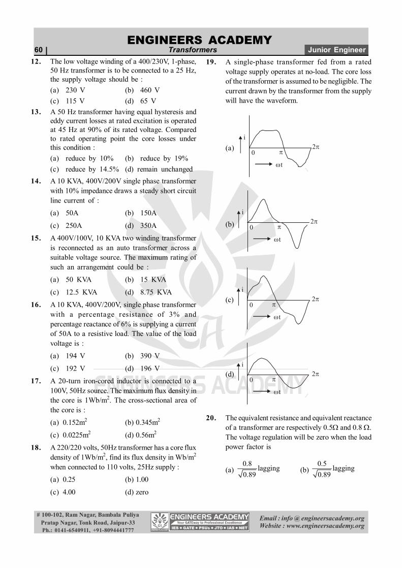
19. A single-phase transformer fed from a ratedvoltage supply operates at no-load. The core lossof the transformer is assumed to be negligible. Thecurrent drawn by the transformer from the supplywill have the waveform.
(a)i
0
t
(b)
i
0
t
(c) i
0
t
(d) i
0
t
20. The equivalent resistance and equivalent reactanceof a transformer are respectively 0.5 and 0.8 .The voltage regulation will be zero when the loadpower factor is
(a) 0.8 lagging0.89 (b)
0.5 lagging0.89
ENGINEERS ACADEMY
Email : info @ engineersacademy.orgWebsite : www.engineersacademy.org
# 100-102, Ram Nagar, Bambala PuliyaPratap Nagar, Tonk Road, Jaipur-33Ph.: 0141-6540911, +91-8094441777
EE : Electrical Machines Transformers | 61
(c)0.5 leading0.89 (d)
0.8 leading0.89
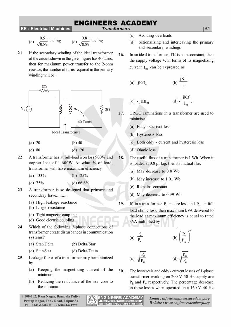
21. If the secondary winding of the ideal transformerof the circuit shown in the given figure has 40 turns,then for maximum power transfer to the 2-ohmresistor, the number of turns required in the primarywinding will be :
8
Vg 2
Ideal Transformer
40 Turns
(a) 20 (b) 40
(c) 80 (d) 120
22. A transformer has at full-load iron loss 900W andcopper loss of 1,600W. At what % of load,transformer will have maximum efficiency
(a) 133% (b) 125%
(c) 75% (d) 66.6%23. A transformer is so designed that primary and
secondary have..........(a) High leakage reactance(b) Large resistance
(c) Tight magnetic coupling(d) Good electric coupling
24. Which of the following 3-phase connections oftransformer create disturbances in communicationsystems?(a) Star/Delta (b) Delta/Star(c) Star/Star (d) Delta/Delta
25. Leakage fluxes of a transformer may be minimizedby(a) Keeping the magnetizing current of the
minimum(b) Reducing the reluctance of the iron core to
the minimum
(c) Avoiding overloads(d) Setionalizing and interleaving the primary
and secondary windings
26. In an ideal transformer, if K is some constant, thenthe supply voltage V, in terms of its magnetizingcurrent mI can be expressed as
(a) mjKfI (b)m
jK.fI
(c) - mjKfI (d) - m
jK.fI .
27. CRGO laminations in a transformer are used tominimise :
(a) Eddy - Current loss
(b) Hysteresis loss
(c) Both eddy - current and hysteresis loss
(d) Ohmic loss
28. The useful flux of a transformer is 1 Wb. When itis loaded at 0.8 pf lag, then its mutual flux
(a) May decrease to 0.8 Wb
(b) May increase to 1.01 Wb
(c) Remains constant
(d) May decrease to 0.99 Wb
29. If, in a transformer cP = core loss and scP = fullload ohmic loss, then maximum kVA delivered tothe load at maximum efficiency is equal to ratedkVA multiplied by
(a)c
sc
PP (b)
2c
sc
PP
(c)c
sc
PP (d)
sc
c
PP
30. The hysteresis and eddy - current losses of 1-phasetransformer working on 200 V, 50 Hz supply arePh and Pe respectively. The percentage decreasein these losses when operated on a 160 V, 40 Hz
62 | Transformers Junior EngineerENGINEERS ACADEMY
Email : info @ engineersacademy.orgWebsite : www.engineersacademy.org
# 100-102, Ram Nagar, Bambala PuliyaPratap Nagar, Tonk Road, Jaipur-33Ph.: 0141-6540911, +91-8094441777
supply would respectively be
(a) 32, 36 (b) 20, 36
(c) 25, 50 (d) 40, 80
31. In a transformer if primary leakage impedance isneglected, then
1. Magnetizing current lags the applied voltageV1 by 900
2. Core loss current lags V1 by 900
3. Exciting current lags V1 by 900
4. Core loss current is in phase with V1
5. Exciting current lags V1 by about 800
6. Magnetizing current statements are
from these the correct statement are
(a) 1, 4, 5 (b) 3, 4, 6
(c) 1 , 4 (d) 1 , 2 , 6
32. A 50 Hz transformer having equal hysteresis andeddy current losses at rated excitation is operatedat 45 Hz at 90% of rated voltage compared to ratedoperating point, the core loss under this condition
(a) reduces by 90 % (b) reduces by 19 %
(c) reduces by 14.5 (d) remains unchanged
33. When compared with power transformer, adistribution transformer has
(a) Low % age impedance and high I2R loss tocore loss ratio
(b) High % age impedance and high I2R loss tocore loss ratio
(c) High % age impedance and low I2R loss tocore loss ratio
(d) Low % age impedance and low I2R loss tocore loss ratio
34. A transformer designed for operation of 60 Hzsupply is worked on 50 Hz supply system withoutchanging its voltage and current ratings. Whencompared with full load efficiency at 60 Hz, thetransformer efficiency on full load at 50 Hz will be
(a) Increase marginally
(b) Increase by a factor of 1.2
(c) remain unaltered
(d) decrease marginally
35. A bank of three identical single phase 250 KVA 11kV / 230 V transformer is used to provide 400VLow tension supply from a 11 kV, 3 phase substationthe effective KVA rating of the bank will be
(a) 250 (b) 250 3
(c) 500 (d) 750
36. when a short circuit test is conducted on a singlephase transformer, 30% of the rated voltage isrequired to allow full load current. The short circuitpower factor is found to be 0.2 . The percentageregulation of UPF is
(a) 30 (b) 29.5
(c) 15 (d) 6
37. A auto transformer has V1, I1 as input quantitiesand V2, I2 as output quantities with V2 < V1 the VAconducted from input to output is
(a) 1 2V I (b) 2 1V I
(c) 1 1 2 2V I V I (d) 1 2 1V V I
38. A auto transformer has V1, I1 as input quantitiesand V2, I2 as output quantities with V2<V1 the VAtransformed from primary to secondary is
(a) 1 2V I (b) 2 1V I
(c) 1 1 2 2V I V I (d) 1 2 1V V I
39. A 400 V / 200 V transformer has a full load voltageregulation of x p.u. at 0.8 pf lagging if thistransformer is used as on auto transformer withvoltage rating 400 V / 600 V or 200 V / 600 V ,then its voltage regulation would be

ENGINEERS ACADEMY
Email : info @ engineersacademy.orgWebsite : www.engineersacademy.org
# 100-102, Ram Nagar, Bambala PuliyaPratap Nagar, Tonk Road, Jaipur-33Ph.: 0141-6540911, +91-8094441777
EE : Electrical Machines Transformers | 63
(a) ,3 3x x
(b)2 ,3 3x x
(c)2 2,3 3x x
(d)2,
3 3x x
40. Which of the following statement are incorrect ?
1. Maximum voltage regulation of transformeroccurs at leading power factor
2. Voltage regulation of a transformer is maximumwhen load power factor (lagging) angle hasthe same value as the angle of equivalentimpedance
3. Voltage regulation of a transformer can benegative at leading power factor.
4. Voltage regulation of a transformer at zeropower factor is always zero.
(a) 1 and 3 (b) 2and 3
(c) 2 and 4 (d) 1 and 4
41. In an auto transformer of voltage ratio V1/V2 andV1 > V2, the fraction of power transferredinductively is
(a)1 2
VV V (b) 2
1
VV
(c) 1 2
1 2
V VV V (d) 1 2
1
V VV
42. A single phase transformers with KVA rating k
has voltage rating of 1
2
VV this transformer can be
connected as an auto transformer to get two
possible voltage ratings of 1 2
2
V VV
and 1 2
1
V VV
the
respective KVA ratings as an auto transformer are
(a) 1 2 1 2
1 2
,V V V V
K KV V
(b) 1 2 1 2
2 1
,V V V V
K KV V
(c) 1 2 1 2
1 2
,V V V V
K KV V
(d) 1 2 1 2
2 2
,V V V V
K KV V
43. Two transformer of identical voltage but of differentcapacities are operating in parallel for satisfactoryload sharing.
(a) Impedance must be equal
(b) per unit impedance must be equal
(c) per unit impedance and X/R ratio must be equal
(d) Impedance and X/R ratio must be equal
44. Two transformer to be operating in parallel havetheir secondary no load emfs Ea for transformer Aand Eb for transformer B. As Ea is somewhat morethen Eb, a circulating current IC is established atno load which tends to
(a) boost both Ea and Eb with Ic = a b
ea eb
E EZ Z
(b) boost Ea and buck Eb with Ic =a b
ea eb
E EZ Z
(c) Buck Ea and boost Eb with Ic =a b
ea eb
E EZ Z
(d) Buck both Ea and Eb with Ic = b a
ea eb
E EZ Z
45. Short circuit test an a single phase transformer gavethe following date
30V at 50 Hz, 20 A Pf = 0.2 lagging
If S.C. test is performed on 30V, 25 Hz, then shortcircuit current
(a) decrease at Pf < 0.2
(b) increases at a P.f. < 0.2
(c) increases at a pf > 0.2
(d) decreases at a pf > 0.2
46. when a transformer winding suffers a short circuit,
64 | Transformers Junior EngineerENGINEERS ACADEMY
Email : info @ engineersacademy.orgWebsite : www.engineersacademy.org
# 100-102, Ram Nagar, Bambala PuliyaPratap Nagar, Tonk Road, Jaipur-33Ph.: 0141-6540911, +91-8094441777
the adjoining turns of the same winding experience.
(a) at attractive force
(b) a repulsive force
(c) no force
(d) May be attractive or repulsive depending uponthe current direction.
47. Transformer maximum efficiency, for a constantload current occurs at
(a) at any pf (b) zero pf leading
(c) zero pf lagging (d) unity pf
48. In a transformer 2 2e er jx equivalent leakage
impedance 2eZ maximum voltage regulation is
equal to
(a) 2er to 2
2
e
e
rZ lagging pf
(b) 2ex to 2
2
e
e
xZ lagging pf
(c) 2eZ to 2
2
e
e
rZ leading pf
(d) 2eZ to 2
2
e
e
rZ lagging pf.
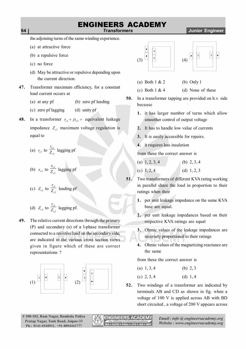
49. The relative current directions through the primary(P) and secondary (s) of a l-phase transformerconnected to a resistive load on the secondary side,are indicated in the various cross section viewsgiven in figure which of these are correctrepresentations ?
(1)X X
(2)X
X
(3)
X
X (4)X X
(a) Both 1 & 2 (b) Only 1
(c) Both 1 & 4 (d) None of these
50. In a transformer tapping are provided on h.v. sidebecause
1. it has larger number of turns which allowsmoother control of output voltage
2. It has to handle low value of currents
3. It is easily accessible for repairs.
4. it requires less insulation
from these the correct answer is
(a) 1, 2, 3, 4 (b) 2, 3, 4
(c) 1, 2, 4 (d) 1, 2, 3
51. Two transformers of different KVA rating workingin parallel share the load in proportion to theirratings when their
1. per unit leakage impedance on the same KVAbase are equal.
2. per unit leakage impedances based on theirrespective KVA ratings are equal
3. Ohmic values of the leakage impedances areinversely proportional to their ratings
4. Ohmic values of the magnetizing reactance arethe same
from these the correct answer is
(a) 1, 3, 4 (b) 2, 3
(c) 2, 3, 4 (d) 1, 4
52. Two windings of a transformer are indicated byterminals AB and CD as shown in fig. when avoltage of 100 V is applied across AB with BDshort circuited , a voltage of 200 V appears across
ENGINEERS ACADEMY
Email : info @ engineersacademy.orgWebsite : www.engineersacademy.org
# 100-102, Ram Nagar, Bambala PuliyaPratap Nagar, Tonk Road, Jaipur-33Ph.: 0141-6540911, +91-8094441777
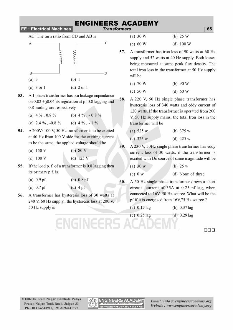
EE : Electrical Machines Transformers | 65AC. The turn ratio from CD and AB isA
B
C
D
(a) 3 (b) 1
(c) 3 or 1 (d) 2 or 1
53. A 1 phase transformer has p.u leakage impendanceon 0.02 + j0.04 its regulation at pf 0.8 lagging and0.8 leading are respectively
(a) 4 % , 0.8 % (b) 4 % , - 0.8 %
(c) 2.4 % , -0.8 % (d) 4 % , - 1 %
54. A 200V/ 100 V, 50 Hz transformer is to be excitedat 40 Hz from 100 V side for the exciting currentto be the same, the applied voltage should be
(a) 150 V (b) 80 V
(c) 100 V (d) 125 V
55. If the load p. f. of a transformer is 0.8 lagging thenits primary p.f. is
(a) 0.9 pf (b) 0.8 pf
(c) 0.7 pf (d) 4 pf
56. A transformer has hysteresis loss of 30 watts at240 V, 60 Hz supply., the hysteresis loss at 200 V,50 Hz supply is
(a) 30 W (b) 25 W
(c) 60 W (d) 100 W
57. A transformer has iron loss of 90 watts at 60 Hzsupply and 52 watts at 40 Hz supply. Both lossesbeing measured at same peak flux density. Thetotal iron loss in the transformer at 50 Hz supplywill be
(a) 70 W (b) 90 W
(c) 50 W (d) 60 W
58. A 220 V, 60 Hz single phase transformer hashysteresis loss of 340 watts and eddy current of120 watts. If the transformer is operated from 200V, 50 Hz supply mains, the total Iron loss in thetransformer will be
(a) 525 w (b) 375 w
(c) 325 w (d) 425 w
59. A 230 V, 50Hz single phase transformer has eddycurrent loss of 30 watts. if the transformer isexcited with Dc source of same magnitude will be
(a) 30 w (b) 25 w
(c) 0 w (d) None of these
60. A 50 Hz single phase transformer draws a shortcircuit current of 35A at 0.25 pf lag, whenconnected to 16V, 50 Hz source. What will be thepf if it is energized from 16V,75 Hz source ?
(a) 0.17 lag (b) 0.37 lag
(c) 0.25 lag (d) 0.29 lag
66 | Transformers Junior EngineerENGINEERS ACADEMY
Email : info @ engineersacademy.orgWebsite : www.engineersacademy.org
# 100-102, Ram Nagar, Bambala PuliyaPratap Nagar, Tonk Road, Jaipur-33Ph.: 0141-6540911, +91-8094441777
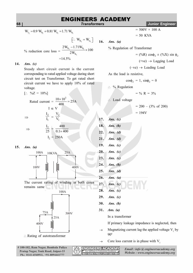
1. Ans. (a)
KVA E I, Given the two Transformers are ofsame current density.
I = J A, where J is current density which is givenas constant.
I A (cross sectional area of conductor)
As the linear dimensions are doubled (radius ofconductor becomes double)
Cross sectional area of conductor becomes 4times and hence the current carrying capability.
2
1
II =
2 1
1 1
A 4A 4A A
E = m n ph4.44 B A f T
E An
[An = net area of core material]
2
1
EE =
2 1
1 1
A 4A 4A A
[ AA2 = 2 2 1 1L b 2L 2b
1 1 14L b 4A ]
2
1
KVAKVA =
2 2
1 1
E IE I
=1 1
1 1
16E I 16E I
2. Ans. (a)
According to Lorentz’s principle, two conductorscarrying current in the same direction willexperience force of attraction and the conductorscarrying current in opposite direction willexperience force of repulsion.
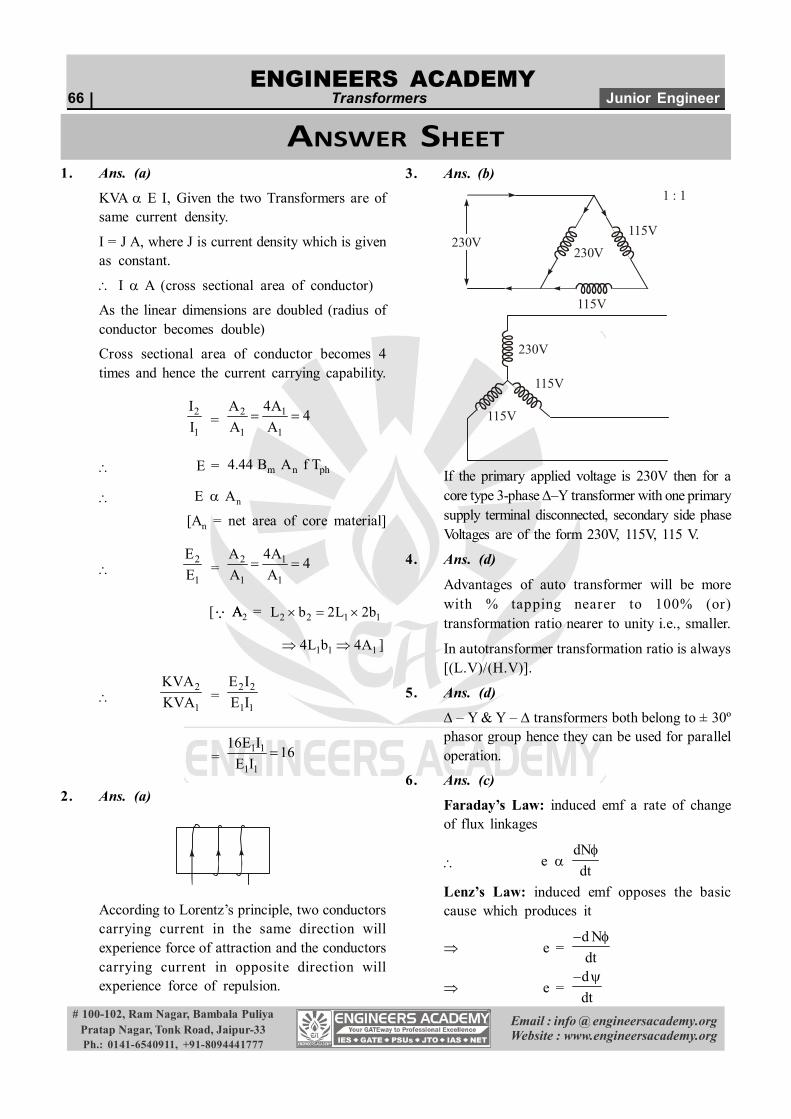
3. Ans. (b)
230V230V
115V
115V
1 : 1
115V
115V
230V
If the primary applied voltage is 230V then for acore type 3-phase –Y transformer with one primarysupply terminal disconnected, secondary side phaseVoltages are of the form 230V, 115V, 115 V.
4. Ans. (d)
Advantages of auto transformer will be morewith % tapping nearer to 100% (or)transformation ratio nearer to unity i.e., smaller.
In autotransformer transformation ratio is always[(L.V)/(H.V)].
5. Ans. (d)
– Y & Y – transformers both belong to ± 30ºphasor group hence they can be used for paralleloperation.
6. Ans. (c)
Faraday’s Law: induced emf a rate of changeof flux linkages
e dNdt
Lenz’s Law: induced emf opposes the basiccause which produces it
e =d Ndt
e =ddt
ANSWER SHEET
ENGINEERS ACADEMY
Email : info @ engineersacademy.orgWebsite : www.engineersacademy.org
# 100-102, Ram Nagar, Bambala PuliyaPratap Nagar, Tonk Road, Jaipur-33Ph.: 0141-6540911, +91-8094441777
EE : Electrical Machines Transformers | 677. Ans. (c)
Efficiency =out
out 1 cu
kVA P.fkVA P.f . W W
Let P.f. = unity,
full load =i cu
100kVA 1100kVA 1 WE W
...(1)
half load =i cu
50kVA 1150kVA 1 W W4
...(2)
Solving (1) & (2)Wcu = 2Wi
8. Ans. (a)To get sinusoidal flux the magnetizing current mustbe a peak wave which is dominant with 3rd
harmonic.9. Ans. (c)
Due to saturation of terminal voltage of constantvoltage transformer maintainted.
10. Ans. (d)If the waveform consists harmonics then its peakvoltage is not same as that of fundamentalfrequency component hence the average and rmsvalues differ.
11. Ans. (c)
Bmax 1Vf constant
hW 1.6maxB f
hW 1.6
1V ff
1.6 0.61V f
As frequency is reduced Hysteresis Lossincreases
We 21V ff
We 21V
eddy current Loss is independent of frequency.[i.e., no change]
12. Ans. (c)
Bmax 1Vf
, as f is reduced the Bmax demand
increases. Hence the magnetising componentcurrent demand increases, which may damagethe Transformer due to increased resultantcurrent.
Hence 1Vf
must be maintained constant.
1
1
Vf =
2
2
Vf
V2 =230 25 115 V50
13. Ans. (c)
Given initially the hysteresis loss 1hw and eddy
current loss 1ew are equal, so
wh1= kh50
we1= ke(50)2
So, wh1= we1
kh50 = ke(50)2
kh = 50 ke
wh2= kh (45)
we2= ke(45)2
Total iron loss
1iW =1 1 1h h hW W 2W
When frequency = 45 Hz & applied voltage =90% of rated voltage
Bmax =
1 1
1 1
V 0.9 V constantf 0.9 f
Wh f, We f2
Wi2 = Wh2 + We2
2hW =
ih0.9W
2eW =1e0.81 W
68 | Transformers Junior EngineerENGINEERS ACADEMY
Email : info @ engineersacademy.orgWebsite : www.engineersacademy.org
# 100-102, Ram Nagar, Bambala PuliyaPratap Nagar, Tonk Road, Jaipur-33Ph.: 0141-6540911, +91-8094441777
2iW =1 1 1h e h0.9 W 0.81 W 1.71 W
1 1h eW W
% reduction core loss =1 1
1
h h
h
2W 1.71W100
2W
=14.5%14. Ans. (c)
Steady short circuit current is the currentcorresponding to rated applied voltage during shortcircuit test on Transformer. To get rated shortcircuit current we have to apply 10% of ratedvoltage.[ %Z = 10%]
Rated current =310 10 25A
400
I V
2
1
II =
2
1
VV
2I25
=400
0.1 400
I2 = 250A
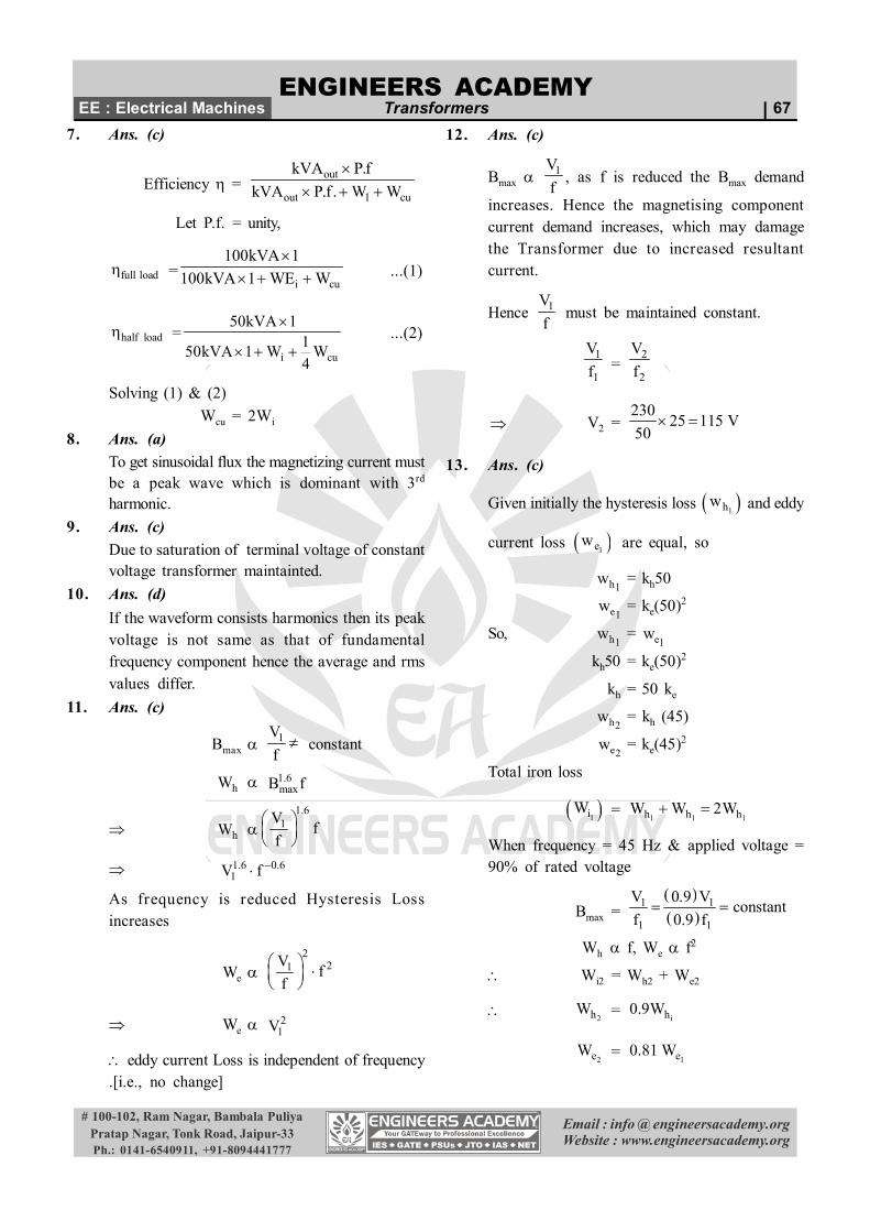
15. Ans. (a)100A 25A10KVA
100V 400V
The current rating of winding in both casesremains same
400V
500V25A
75A
100A
Rating of autotransformer
= 500V × 100 A= 50 KVA
16. Ans. (a)
% Regulation of Transformer
= (%R) cos2 ± (%X) sin 2
(+ve) Lagging Load
(–ve) Leading Load
As the load is resistive,
cos = 1, sin = 0
% Regulation
= % R = 3%
Load voltage
= 200 – (3% of 200)
= 194V
17. Ans. (c)
18. Ans. (b)
22. Ans. (d)
21. Ans. (d)
19. Ans. (c)
20. Ans. (c)
23. Ans. (c)
24. Ans. (b)
25. Ans. (d)
26. Ans. (a)
27. Ans. (c)
28. Ans. (c)
29. Ans. (c)
30. Ans. (b)
31. Ans. (a)
In a transformer
If primary leakage impedance is neglected, then
Magnetizing current lag the applied voltage V1 by900
Core loss current is in phase with V1

ENGINEERS ACADEMY
Email : info @ engineersacademy.orgWebsite : www.engineersacademy.org
# 100-102, Ram Nagar, Bambala PuliyaPratap Nagar, Tonk Road, Jaipur-33Ph.: 0141-6540911, +91-8094441777
EE : Electrical Machines Transformers | 69 Exciting current lags V1 by about 800
32. Ans. (c)
for this case
/V f = constant
Bm = constant2 2
eP f Bm
20.9eP become Pe
1.6hP fBm
20.9e hP become P
here e hP P
core loss reduced 20.9 0.91
2
= 14.5 %
33. Ans. (a)
34. Ans. (d)
Because when frequency is decreased losses willincreases so efficiency reduces.
35. Ans. (d)
36. Ans. (d)
P.u impedance = rated voltage required to allowfull load current = 30 % = 0.3
short circuit power factor = R / Z = 0.2
So,R = 0.3 × 0.2 = 0.06
Voltage regulation 0.06 1 x 0 0.06 6%
37. Ans. (b)
The VA conducted from input to output = V2I1
38. Ans. (d)
The VA transferred from input to output
39. Ans. (d)
Voltage regulation of auto transformer at same
. 1P f X K
where
X = voltage regulation of 2- wdg (transformer)
K = voltage ratio of the auto transformer
40. Ans. (a)
Maximum voltage regulation of a transformeroccurs at lagging power factor.
Voltage regulation of a transformer at zeropower factor is not zero.
41. Ans. (d)
1 2
1
V VV
42. Ans. (a)
1 2 1 2
1 1
,V V V V
K KV V
43. Ans. (c)
Per unit impedance and XR
ratio must be equal.
44. Ans. (c)
45. Ans. (c)
46. Ans. (a)
47. Ans. (d)
48. Ans. (d)2
22
2
ee
e
rZ atZ lagging pf
50. Ans. (a & b)
49. Ans. (d)
In a transformer , tappings are provided on the h.v.side because
it has larger number of turns which allowsmoother control of output voltage
It has to handle low value of current
It is easily accessible for repairs.
51. Ans. (b)
2 , 3
53. Ans. (c)
52. Ans. (b)
% Regulation sinpu puR cos X
4 % , - 0.8 %
70 | Transformers Junior EngineerENGINEERS ACADEMY
Email : info @ engineersacademy.orgWebsite : www.engineersacademy.org
# 100-102, Ram Nagar, Bambala PuliyaPratap Nagar, Tonk Road, Jaipur-33Ph.: 0141-6540911, +91-8094441777
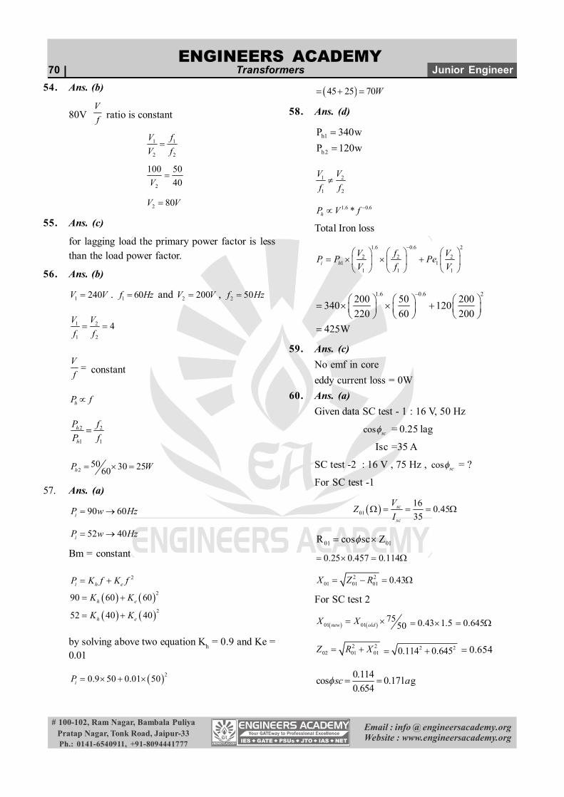
54. Ans. (b)
80V Vf ratio is constant
1 1
2 2
V fV f
2
100 5040V
2 80V V
55. Ans. (c)
for lagging load the primary power factor is lessthan the load power factor.
56. Ans. (b)
1 240V V . 1 60f Hz and 2 200V V , 2 50f Hz
1 2
1 2
4V Vf f
Vf constant
hP f
2 2
1 1
h
h
P fP f
250 30 2560 hP W
57. Ans. (a)
90 60iP w Hz
52 40iP w Hz
Bm = constant
2
2
2
90 60 60
52 40 40
i h e
h e
h e
P K f K f
K K
K K
by solving above two equation Kh = 0.9 and Ke =0.01
20.9 50 0.01 50iP
45 25 70 W
58. Ans. (d)
h1
h2
P 340wP 120w
1 2
1 2
V Vf f
1.6 0.6*hP V f
Total Iron loss
1.6 0.6 2
2 2 21 1
1 1 1i h
V f VP P PeV f V
1.6 0.6 2200 50 200340 120220 60 200
425W
59. Ans. (c)No emf in coreeddy current loss = 0W
60. Ans. (a)Given data SC test - 1 : 16 V, 50 Hz
cos sc = 0.25 lag
Isc =35 A
SC test -2 : 16 V , 75 Hz , cos sc = ?
For SC test -1
0116 0.4535
sc
sc
VZ
I
01 01R cos sc Z
0.25 0.457 0.114
2 201 01 01 0.43X Z R
For SC test 2
01 0175
50new oldX X 0.43 1.5 0.645
2 202 01 01Z R X 2 20.114 0.645 0.654
0.114cos 0.17l g0.654
sc a