AMERICAN INSTITUTE - World Radio History
144
rrLrrJaJT [ rE PUBLISHED MONTHLY BY THE , AMERICAN INSTITUTE OF ELECTRICAL ENG I NE ERS [L.] 33 WEST 39TH ST NEWYORK CITY
-
Upload
khangminh22 -
Category
Documents
-
view
5 -
download
0
Transcript of AMERICAN INSTITUTE - World Radio History

rrLrrJaJT [
rE
PUBLISHED MONTHLY BY THE
,
AMERICAN INSTITUTE OF ELECTRICAL ENG I NE ERS [L.]33 WEST 39TH ST NEWYORK CITY
JOUln AL
American Institute of Electrical Engineers
PUBLISHED MONTHLY BY THE AMERICAN INSTITUTE OF ELECTRICAL ENGINEERS
33 West 39th Street, New York
Subscription. $10.00 per year to United States, Mexico, Cuba, Porto Rico, Hawaii and the Phillipines, $10.50
to Canada and $11.00 to all other Countries. Single copies $1.00.
Entered as matter of the second class at the Post Office. New York, N. Y.. May 10. 1905. under the Act of Congress, March 3, 1879.
Acceptance for mailing at special rate of postage provided for in Section 1103. Act of October 3. 1917. authorized on August 3, 1918.
Vol. XLV AUGUST, 1926 Number 8
TABLE OF CONTENTS
Papers, Discussions, Reports, Etc.
Behavior of Radio Receiving Systems to Signals and to Interference ( Ahiidged), by L..1. Peters
Report of Technical Committee on Research Accuracy Required in the Measurement of Dielee-
t rie Power Factor of Impregnated Paper -Insu- lated cables, by C. F. Hanson Report of the Committee on Electrochemistry and Elect rometallurgy
Uni-Control, High-Frequeney Radio Direction Finders
Some Aspects of the Dielectric Loss Measurement Problem, by B. W. St. Clair
Rural Electrification, by 0. C. Neff Report of Committee on Communication
Can the University Aid Industry? by B. F. Bailey Ductile Arc Welds
Use of the Dynamometer Wattmeter, The (Abridged), by E. S. Lee
circulation of Harmonies in Transformer Circuits, 707 by T. C. Lennox 716 ('usmie Harness of Moving Electricity, The
President's Address), by M. I. Pupil' . .
Oil Engines Reclaim the Desert 719 Report of Committee on Application to Marine
795
s 79
'791 733 737 742 745
746
Work
755
758 761
Discussion at Midwinter Convention Ratings of Electrical Machines as Affected by
Altitude, The, I Fechheimer) 763 Motor Band Losses (Spoone-) 766
Properties of the Single Conductor (Hering) 766 High -Frequency Voltage Test for Insulation of
Rotating Electrical Apparatus, A, (Rylander) 768 Magnetic Hyster..sis Curve, The, (Lippelt).. 77))
Correspondence Transmission Line Sag Calculation... 773
I lumination Items Daylight Electric Sign, A 77 I
Institute and Related Activities
Pacific Coast Convention, Salt Lake City 775 The Annual Convention, White Sulphur Springs 776
Twentieth Anniversary of Illuminating Engineers 778 World Power Conference-Program and Appoint-
ments 779 A. I. E. E. Directors' Meeting 779
Prizes for Papers Awarded in Northeastern District 780
Saskatchewan Section Holds Meeting in Camp 780 Armour Institute and Northwestern University Unite 780
A Request for Decision on Radio Law 780 University of Pennsylvania Creates New Course 781
A Uniform Electrical Ordinance 781 Power Show Reflects Tremendous Advances 781
Westinghouse Awards Educational Scholarships 781 American Engineering Council
Seeks Solution of Broadcasting Problem 781
Proposed Legislation for Division of Safety 's2 Recommendations for Ordnance Reserve Com-
mission 782 Effect of Bus Transportation on Railroads 782
International Mid -Continent Engineering Con- vention 782
Howard N. Potts Medal Award 782 Personal Mention 782
Addresses Wanted 783 Obituary 783
Library Book Notices 784 Past Section and Branch Meetings 786
Engineering Societies Employment Service 787 Membership-Applications, Elections, Transfers,
Etc 788 Officers of A. I. E. E 790
Local Honorary Secretaries 790 Digest of Current Industrial News 792
A REQUEST FOR CHANGE OF ADDRESS must be received at Institute headquarters at least ten days before the date of issue with which it is to take effect. Duplicate copies cannot be sent without charge to replace those issues undelivered through failure to send such advance notice. With your new address be sure to mention the old one, indicating also any change in business connections.
Copyright 1926. By A. I. E. E.
Printed in II. S. A.
Permission is given to reprint any article after its date of publication. provided proper credit is given.

American Institute of Electrical Engineers
COMING MEETINGS
Pacific Coast Convention, Salt Lake City, Utah, Sept. 6-9
MEETINGS OF OTHER SOCIETIES
World Power Conference, Basle, Switzerland, Aug. 3 -Sept.I 8
Illuminating Engineering Society, Spring Lake, N. J., Sept. 7-10
National Electric Light Association
Rocky Mountain Division, Glenwood Springs, Col., Sept. 13-16
New England Division, Poland, Maine, Sept. 20-23

American Institute of Electrical Engineers
COMING MEETINGS
Pacific Coast Convention, Salt Lake City, Utah, Sept. 6-9
MEETINGS OF OTHER SOCIETIES
World Power Conference, Basle, Switzerland, Aug. 31 -Sept. 8
Illuminating Engineering Society, Spring Lake, N. J., Sept. 7-10
National Electric Light Association
Rocky Mountain Division, Glenwood Springs, Col., Sept. 13-16
New England Division, Poland, Maine, Sept. 20-23

American InstituteOF
ofTiii..
Electrical Engmeers....,
PUBLISHED MONTHLY BY THE AMERICAN INSTITUTE OF ELECTRICAL ENGINEERS33 West 39th Street, New York
Subscription. $10.00 per year to United States, Mexico, Cuba. Porto Rico, Hawaii and the Phillipines, $10.50
to Canada and S11.00 to all other Countries. Single copies 51.00.
Entered as matter of the second class at the Post Office, New York, N. Y.. May 10. 1905. under the Act of Congress, March 3, 1879.
Acceptance for mailing at special rate of postage provided for in Section 1103. Act of October 3. 1917. authorized on August 3, 1918.
Vol. XLV NUGI ST, 1926 Number 8
TABLE OF CONTENTSPapers. Discussions, Reports, Etc.
Behavior of Radio Receiving Systems to Signal' Ci-,olat ion of Harni.mics in Transformer Circuits,and to Interference (:Midged1, by L. J. Peters 707 hy T. C. Lennox 755
Report. of Technical Commit tee on Research.. 716 j
Accuracy Required in the 'Measurement of Dielec-Cosmic Harness of Moving Electricity, The
(President's Address), by M. I. Pupin . . . . . . . 758
tric Power Factor of Impregnated Paper-Insu- Oil Engines Reclaim the Desert 761
lated cables, by C. F. Hanson 719 Report of Committee on Application to MarineReport of the Committee on Electrochemistry Work 762
and Electrometallurgy 795 Discussion at Midwinter ConventionUni-Control, High -Frequency Radio Direction Ratings of Electrical Machines as Affected by
Finders 795 Altitude, The, (Fechheimer) 763
Sonic Aspects of the Dielectric Loss Measurement Motor Band Losses (Spoone-) 766
Problem, by B. W. St. Clair 79it Properties of the Single Conductor (Hering) .. 766
Rural Electrification, by G. C. Neff 733High -Frequency Voltage Test for Insulation of
Rotating Electrical Apparatus, A, (Rylander) 768Report of Committee on Communication 737 Magnetic Hyster;sis Curve, The, (Lippelt).... 770Can the University Aid Industry? by B. F. Bailey 742 CorrespendeneeDuctile Arc Welds 745 Transmission Line Sag Calculation... - - 773
I
Use of the Dynamometer Wattmeter, The I lumination Items(Abridged), by E. S. Lee 746 Daylight Electric Sign, A 77 I
Institute and Related ActivitiesPacific Coast Convention, Salt Lake City 775 Proposed Legislation for Division of Safety I '. '
The Annual Convention, White Sulphur Springs.. 776 Recommendations for Ordnance Reserve Corn -Twentieth Anniversary of Illuminating Engineers 778 mission 782
World Power Conference-Program and Appoint- Effect of Bus Transportation on Railroads 782
ments 779 International Mid -Continent Engineering Con -A. I. E. E. Directors' Meeting ' 779Prizes for Papers Awarded in Northeastern
vention 782Howard N. Potts Medal Award 782
District 780 Personal Mention 782Addresses Wanted 783
Saskatchewan Section Holds Meeting in Camp .. 780 Obituary 783Armour Institute and Northwestern University
Unite 780 Library Book Notices 784
A Request for Decision on Radio Law 780 Past Section and Branch Meetings 786
University of Pennsylvania Creates New Course.. 781 Engineering Societies Employment Service 787
A Uniform Electrical Ordinance 781 Membership-Applications, Elections, Transfers,Power Show Reflects Tremendous Advances 781 Etc 788Westinghouse Awards Educational Scholarships .. 781 Officers of A. I. E. E 790American Engineering Council Local Honorary Secretaries . 790
Seeks Solution of Broadcasting Problem 7S1 Digest of Current Industrial News 792
A REQUEST FOR CHANGE OF ADDRESS must be received at Institute headquarters at least ten days before the date of issuewith which it is to take effect. Duplicate copies cannot be sent without charge to replace those issues undelivered through failure tosend such advance notice. With your new address be sure to mention the old one, indicating also any change in business connections.
Copyright 1926. By A. I. E. E.Printed in U. S. A.
Permission is given to reprint any article after its date of publication, provided proper credit is given.

Current Electrical Articles Publishedby Other Societies
National Electric Light Association Bulletin, June 1926
A New Electrical Production Control System, by L. EdererGrowth of the Electric Light and Power Industry under Regulation, byJ. F. -Shaughnessy
Observations on Some Problems of the Electrical Industry, by 0. D. YoungSome Comments on the Economics of Electricity Supply, by S. Insull

Devoted to the
Journal of the A. I. E. E.advancement of the theory and practise of electrical engineering and the allied arts and sciences
Vol. XLV August, 1926 Number 8
Research inPure Science
The National Academy of Sciences is making a strongeffort to raise a national research endowment of$20,000,000 for research in pure science. The commit-tee under which this movement is being fostered isunder the chairmanship of Herbert Hoover and con-tains the names of such well-known scientists and engi-neers as John J. Carty, Frank B. Jewett, Gano Dunn,Robert A. Millikan and Henry S. Pritchett in additionto many names of prominent financiers and executives.Such an endowment will make possible uninterruptedinvestigations in pure science which now are necessarilylimited.
The economic and financial advantages of such re-search cannot be overestimated. Its purpose is toincrease and strengthen American contributions to themathematical, physical and biological sciences by thecreation of a national fund for skilled investigators,who will be selected, by the best qualified authoritiesin the National Academy of Sciences, from among theablest and most productive investigators engaged inpure science research. Appropriations will be madefor a fixed period of years, subject to renewal if circum-stances warrant it.
Such fundamental research as these investigators areengaged in is the foundation upon which modern eco-nomic and industrial progress depend. Without theirefforts the welfare of mankind would materially sufferand industrial development would be at a standstill.
A. I. E. E. Convention AffordsProof of Engineering Competency
Exceedingly well worth while was the annual con-vention of the American Institute of Electrical Engi-neers, held at White Sulphur Springs, West Va., lastweek. The executives of the Institute stressed theimportance of engineering participation in all nationalaffairs. The technical committees made reports whichshowed the status of the art and outlined the develop-ments needed. Several fine technical papers were pre-sented which gave rise to profitable discussions. Themeeting, in short, gave evidence of entire competencyon the part of electrical engineers to meet their respon-sibilities.
The subject of standards received an unusual amountof attention, and it is interesting to note that theAmerican Engineering Standards Committee and the
embryonic International Standards Association owetheir formation to the fact that electrical engineershad shown by their own organizations that standardscould be made and were needed. The A. I. E. E. stand-ards committee and the International ElectrotechnicalCommission can well be proud that they were the origi-nators of standardizing agencies of still broader scope.
Surveyed as a whole, the art of electrical engineeringis well in hand and yet has very great possibilities fordevelopment. The address of Dr. Pupin showed thegreat tasks still to be done before electrical engineerscan rest content. Yet a perspective view of this con-vention gives rise to the conviction that under the ban-ner of the Institute electrical engineers will conquer alldifficul ties.-Electrical World.
Some Leadersof the A. I. E. E.
E. Wilbur Rice, Jr., thirtieth president of the Insti-tute, 1917-1918, was born at La Crosse, Wis., May 6,1862.
Graduating with honors in his class in the CentralHigh School of Philadelphia in 1880, he became assist-ant to Professor Elihu Thomson in the American Elec-tric Company, New Britain, Conn., then newly formedto manufacture arc lighting apparatus under theThomson -Houston patents.
Two years later the American Electric Company wasre -named the Thomson -Houston Electric Company andremoved to Lynn, Mass., Mr. Rice becoming WorksSuperintendent and Consulting Engineer. In that dualcapacity, he built up the technical and manufacturingside of the enterprise.
After the organization of the General Electric Com-pany, Mr. Rice was made chief engineer and chairmanof its Manufacturing Committee, in charge of all engi-neering and manufacturing operations, and in 1896 waselected vice-president. A record of his engineeringactivities thenceforward for a quarter of a century is anintegral part of industrial history in the electrical fieldduring that period-the history of the development oflong distance electrical transmission of energy, distrib-uting systems of polyphase currents, the rotaryconverter, the Curtis type of steam turbine, the tung-sten lamp, and of many other applications now classedas epochal.
In 1903, Mr. Rice received his degree from HarvardUniversity; the degree of D. Sc. in 1906 from Union
705

70liNOTES AN I) (I\I N11.:NTs
College; the degree of Doctor of Engineering in 1918from Rensselaer Polytechnic Institute; and in 1923 thedegree of D. Sc. from the University of Pennsylvania.
Apart from his work as an individual, always valuableand noteworthy in itself, he possessed, to a marked degree,the high qualities of a teacher. An example of hispower to mobilize a high form of human effort and giveit effective use, is the research laboratory at Schenec-tady, with its brilliant personnel and complete and up-to-date equipment for investigation and experiment.Others helped to plan this famous institution, even to agreater extent than he, according to his own testimony,making it what it is, but it was he who supplied the rarecombination of courage and vision required to carry itthrough the early stages of its development.
So conspicuous have been Mr. Rice's activities as anengineer that in the sketches of his career heretoforepublished little has been said of his service as a businessexecutive, particularly before he was chosen presidentof the General Electric Company. To him is due themajor credit for the development in earlier years of theunique factory system of that corporation, with itswide spread departmental units, each having definiteresponsibilities and ample scope for self-expression andachievement, but all so correlated as to make neededcontrol from a central point easy as well as effective.
With an engineer's discernment, as well as a clearperception of social and moral values, he was one ofAmerica's first industrial leaders to see the importanceof that contact which has lately been secured by manycorporations through works council plans. The princi-ple of employe representation was applied by him toestablished procedure, so far as it was then practicable,long before it was publicly enunciated.
Biographies of Mr. Rice refer to his inventive genius.That he has been prolific as an inventor, despite themultitude of administrative duties demanding hisattention, is indicated in part by the fact that there havebeen granted him more than 100 patents.
Besides being past president of the A. I. E. E., he isa member of the Institution of Civil Engineers and theInstitution of Electrical Engineers of Great Britain . amember of the Engineers and University Clubs of NewYork, the University Club of Boston, and The Pilgrims.After the Paris Exposition in 1900, he was createdChevalier of the Legion of Honor, and in 1917 he re-ceived from the Emperor of Japan the decoration of theThird Order of the Rising Sun.
Mr. Rice served as President of the General ElectricCompany for about ten years, relinquishing that officein 1922 and becoming Honorary Chairman of the Boardof Directors.
The writings of Mr. Rice have not been voluminous,as the leisure required for sustained literary work hasnever been his. In a paper presented by him at amemorial service for Steinmetz in October, 1923, thework of that rare genius, from the time that he landedin this country, a penniless immigrant, till his deathshocked the scientific world, was vividly portrayed. A
A
comprehensive review entitled "New Fields of Researchfor Power Development" was prepared by him for theFirst World Power Congress held in London, June 30thto July 12th, 1921.
Artificial I ightFor Plant Growth
Slowed -up moving pictures just taken 1,y Carl Wallenand R. S. Green, New York motion picture cameramen, of a number of different plants grown underelectric light by the Westinghouse Lamp Company,in co-operation with Peter Henderson & Son, seedsmenin their greenhouses in Jersey City, N. J., prove con-clusively that through the use of artificial light plantscan be forced or retarded to conform to a predeterminedschedule. The motion pictures were taken for the pur-pose of registering the exact degree of acceleration in thegrowth of the plants when forced by artificial light, andto determine at which stage of the plant's blossomingthe light has the maximum effect. The pictures showthat the blooming was greatly speeded up, someflowers, such as tulips, for instance, coming from tightbuds to full bloom in less than an hour.
Tests made by Westinghouse engineers some time agoproved that artificial light can be used to stimulate thegrowth of many varieties of plants. At that timephotographic records were made of the progress of theplants, which were grown with a combination of day-light and the added assistance ofseveral hours nightly, but the "still" photographshaving been made at intervals of several days each,they failed to give accurate data, the effect of the lightvarying at different growing stages. The motion pic-tures have been taken with a camera which was slowedup to a predetermined number of pictures per hourthrough the use of gears and a motor, with a rheostat tocontrol the speed.-The Electrical News (Toronto).
Radiation fromCarbon Arcs
Investigating the radiation from the carbon arc is amatter of great importance in the treatment of diseasesby exposure to light, especially sunlight. However,sunlight can not always be obtained, hence the demandfor an artificial source approaching sunlight in itscharacteristics.
An investigation by the Bureau of Standards isbeing made in duplicate: (1) By mapping the ultra-violet spectrum by means of a quartz spectroradiometer,and (2) by measuring the spectral components of thetotal radiation emitted by the arc, by using a thermo-pile and screens which completely absorb certain spec-tral regions and freely transmit others.
The high -intensity arc (120 amperes) has been foundto be closest to the sun in spectral composition. Itemits considerable radiation of wave lengths longerthan 4 p, which are not in the solar beam, but this canbe, eliminated easily by using a window of fused quartz,which absorbs the long infra -red rays.

Abridgment of
Behavior of Radio Receiving Systems to Signalsand to Interference
BY LEO JAMES PETERS'Associate. A. I. E. E.
Synopsis.-This paper develops a point of view and method bymeans of which it is possible to arrive at many of the transienteffects occurring in radio systems by a consideration of steady-stateproperties alone. The scheme is to replace the voltages in radioreceiving systems due to interference and signals by a group of gen-erators having the correct voltages and frequencies. These generatorscan be thought of as having been in the circuit for an indefinitely longtime, so that only the steady-state response of the system need be con-sidered. The generators which replace the voltages induced in anantenna by interrupted continuous wave stations, by spark telegraphstations, by telephone stations and by static are worked out. Thedesirable properties of radio receiving systems for receiving various
types of signals through interference are arrived at and an idealsystem is described which may be used as a standard of reference forjudging the merits of any actual frequency selecting system. It isshown that this ideal system reduces the interference from all sourcesto the smallest possible value which can be obtained in a system whichmakes use of frequency selection to reduce interference. Thepaper thus arrives at the degree to which interference can be miti-gated by frequency -selection methods. In order to illustrate themethod of treating actual systems, calculations are given for a simpleseries receiver. The interference caused by transmitting stations ofvarious types and by static is discussed and the factors determiningsuch interference are pointed out.
Part I. Character of the Signal VoltagesInduced in Antennas and the Desirable
Properties of Frequency SelectionSystems for Receiving the Signals
1. INTRODUCTION AND PURPOSE
THE behavior of a radio receiving system, both tosignals and to interference, depends upon theproperties of the system, in the transient state.
It is very often a difficult problem to arrive at the tran-sient -state properties of a system, whereas the formula-tion of the steady-state properties is a relatively easymatter. It is the purpose of this paper to develop avery simple but effective way of answering some of thequestions which arise in dealing with the effects ofboth signals and interference upon radio receivingsystems when the steady-state properties of the systemare known, or of arriving at the best steady-stateproperties of a system for receiving a given signalthrough interference. The primary purpose of thepaper is to establish a view -point from which to judgethe merits and the limitations of receiving systems,and also to arrive at the interference produced by trans-mitting systems of various types. Since the primarypurpose of the paper is to establish a point of view anda method, only a few problems illustrating the methodare discussed.
The solution for the transient properties of a circuitnetwork can be made to depend upon the steady-statesolution, if the impressed voltage can be representedfrom t = - 0. to t = + 0. as a Fourier integral. Thismethod has been used by Carson, Fry, and the authorfor observing the general behavior of circuits in thetransient state. Carson has used this method to
1. Assistant Professor of Electrical Engineering, the Univer-si ty of Wisconsin.
Presented at the Regional Meeting of District No. 6 of theA. I. E. E., Madison, Wis., May 6-7, 196.
formulate the response to static impulses of those radioreceiving systems in which the principle of frequencyselection is used to reduce interference. Milner hasused the Fourier series expansion to calculate the arrivalcurrent in submarine cables. These general methods,however, lead into fields of mathematics which areunfamiliar to many engineers, but they suggest a verysimple and powerful but less general method of handlingmany problems that arise in radio communication.This paper has a twofold purpose; first, of pointing outthese simple methods with the hope that it may aid ingiving the method the general use its power warrants,and second, to arrive at some interesting and usefulconclusions as to the effects of signals and interferenceupon radio receiving systems.
2. INTRODUCTION TO THE METHOD OF TREATMENT
Fig. 1 shows an alternator delivering a pure sine wavefeeding a transformer on open circuit through a long
TRANSFORMER
860c^ LINE PN
LINE 5
FIG. 1
line, A. Parallel to this line there is another line, B,which may be a telephone circuit. We wish to find theeffect of line A upon line B. As is generally known, thecurrent in line A has the form shown by Fig. 2. Thiscurrent can be broken up into the two sine wavesshown by Fig. 3. One of these sine waves has a fre-quency of 60 cycles per second and an amplitude I.The other has a frequency of 180 cycles per second andan amplitude of 1/4 I. If the mutual inductance be-tween the lines is M, then the voltage induced in the
707

708 PETERS: RADIO RECEIVING SYSTEMS Journal A. 1. E. E.
line B is composed of two parts; one part has a frequencyof 60 cycles per second and an amplitude of 2 r 60 I M,while the other part has a frequency of 180 cycles per
second and an amplitude of 2 r 180 I M. If the
amplitude of the 60 -cycle voltage is represented by E,then the amplitude of the 180 -cycle voltage is 3/4 (E).Then we can forget all about line A if, in line B, weintroduce two alternators, one having a frequency of 60cycles per second and a voltage of E, and the otherhaving a frequency of 180 cycles per second and a
FIG. 2
voltage of 3/4 (E); that is, we can calculate the effect ofline A upon line B by considering only the systemshown by Fig. 4.
The scheme used above for finding the effect of line Aon line B is the one used throughout this paper forfinding the effect of any voltage induced in an antennaupon the receiving system; for example, the voltage isreplaced by a group of alternators having the correctfrequencies and the correct voltages. The receivingsystem will then be represented schematically, as shownby Fig. 5. The generators are assumed to have noimpedance and serve only as a device for fixing the
FIG. 3
attention on a sine wave of voltage having a givenfrequency and amplitude. Use is made of Fourier'sexpansion for obtaining the voltage and frequency ofeach alternator. Since each alternator is assumed tohave been in the circuit for an indefinitely long time,only the steady-state properties of the receiving systemneed be considered.
3. INTERRUPTED CONTINUOUS WAVE TELEGRAPHY
The voltage induced in a receiving antenna by aninterrupted continuous wave transmitter is assumed tohave the form shown schematically by Fig. 6. In thisfigure, 2 T represents the total time interval of a signaland the succeeding space, 2 qT represents the signaltime interval, and 2 pT represents the space timeinterval. In order to simplify the calculations, it willbe assumed that there is a complete number of cycles ofthe operating frequency in the time intervals qT and
pT and that p = q. Under these conditions, if theoperating frequency of the transmitting station has the
value fo =0
2 r , we can arrive at the following
information relative to the generators which replace the
60'^ 00,"
e1iLINE B
FIG. 4
voltage induced in the receiving antenna by an I. C. W.transmitter.
One generator has a frequency equal to the operatingfrequency, fo. This generator has a voltage equal to
E2
. Other generator frequencies in the vicinity of
the operating frequency are:
fn = fo f , n = 1, 3, 5, 7 etc. (1)
The voltage of the generator having the frequency fn is:
EEn (peak value) - n r (2)
These facts are brought out in a striking manner by
LOOP
FIG. 5
RECEIY/116
CANTS
the curve of Fig. 7. This curve is plotted with the ratiosof the absolute value of the generator voltage to E asordinates and with values of n as abscissa. Values of nare used as abscissa in order to make the curve hold
-T
ftqT pT
T-
pT)1 qT >1<,I
TIME
FIG. 6
for all speeds of transmission. To convert the abscissascale to generator frequencies use is made of the relation:
(Gen. freq.) = fo2 Tn
(3)

Aug. 1926 PETERS: RADIO RECEIVING SYSTEMS
At 30 words per minute this relation becomes:(Gen. freq.) = fo + 10 n
at 150 words per minute it becomes(Gen. freq.) = fo + 50 n. (5)
Thus, a generator having a given ratio of voltage to E isfive times as far removed in frequency from the op-erating frequency at a transmitting speed of 150 wordsper minute as at a transmitting speed of 30 words perminute. This fact, as we, shall see later, has an impor-
,-.05
i
iLi
-:377,
I
0
...I. Lai
.0
3
,L
-o.,
I
0 I
.--- '---'*---"'------1 10
...
et _i _iC _it _i _c. .9 -C .2. _ n 1 1 c , ck n a a i/ IQ
Values of n Values of n
FIG. 7-INTERRUPTED C. W. TELEGRAPHY-VARIATION OFGENERATOR VOLTAGE WITH FREQUENCY-GENERATOR FRE-QUENCY
= 10I)
2 Tn = 0, 1, 3, = 5. etc.Jo - 70 at 30 words per min.fo - 350 at 150 words per min.
tant bearing upon the design of the receiving system andalso upon the amount of interference created by thetransmitting station.
The desirable frequency response characteristics ofthe interrupted continuous wave receiving system cannow be obtained. If the system passes currents havingthe operating frequency fo, and eliminates currents of allother frequencies a continuous tone would be heard inthe receivers and the dots and spaces could not bedistinguished from each other; that is, no signals wouldbe received. If the system passes currents of all fre-quencies with the same ease, the high frequency outputwould have the same wave form as the induced voltage,Fig. 6. This latter condition would lead to the dis-tinguishing of the signals, but the system would haveno selectivity against interference. The best circuitthen would be one which passes just enough frequenciesto make the signals distinguishable and eliminates allothers. Let us assume that, in order to make thesignals distinguishable, the receiving system mustrespond freely to all generators having a voltage greaterthan or equal to r decimal parts of the voltage of thegenerator the frequency of which is fo; that is, thesystem must respond freely to all generators having a
r Evoltage equal to or greater than
2. Now the gen-
709
(4) erator with a frequency of fo f 2 T has a voltage
equal to n We therefore write:r
E 2
nor =r
2n,. is the odd number closest to (6)r r
The receiving system, therefore, must pass a band of
rfrequencies wide centered on the frequency fo.
Let us define an ideal receiving system as one whichhas the following properties:
1. A radiation resistance R.2. No wasteful resistance3. Acting as a pure resistance of magnitude 2 R, to
frequencies lying in the range J., ±nr2T .
4. Currents having frequencies lying in the rangegiven by 3 shall be passed on to the detector either witha uniform amplification or without attenuation.
5. Currents of all other frequencies shall be elim-inated before reaching the detector.
A system having the above properties is called anideal system because it represents the best possiblefrequency selection system for receiving I. C. W. signalsthrough interference. This ideal system can be onlyapproximated, more or less imperfectly, in practise;but any actual receiving system, basing its selectivityupon frequency selection, should be made to fulfill theconditions stated as closely as possible.
The band of frequencies which the receiving system
nrmust pass freely is . Now as both n,. and T are
independent of fo, so the band width is independent ofthe operating wave length. nr is also independent ofthe speed of signal transmission, while T varies in-versely as the speed of transmission. Therefore, thefrequency band which the receiving system must trans-mit freely varies directly with the sending speed. Thus,the transmitted band width at 150 words per minutewould be five times as great as at 30 words per minute.
It can be shown that the power available in the wavesis
E'P, =
16 R,
and that the power utilized by the ideal receiver is
(7)

710 1'11'1 Its I( UM) I(I,C1 111 \ I I E.
is 1
s ie,
s - 1, 3, 5
18)
Calculations indicate t hat if n, - 3, the intervals anddots will be easily distinguishable. When n, has thisvalue, the ratio of the power utilized by the ideal re-ceiver to the power available is 0.9.
11'ith the above value of n the ideal system wouldpass freely a band of frequencies lying between ft,- 30
L
INDUCE 0 VOL rA
6mir
Kw. 8
cycles per second and f. + 30 cycles per second at 30words per minute. At 150 words per minute the bandpassed would be between 150 cycles per secondand f + 150 cycles per second.
Let us now consider the simple receiving circuit shownin Fig. 8. This circuit consists of an elevated capacitynetwork, A, a tuning inductance, L, and a detectorwhich has a resistance R.I. The capacitance of the net-work to ground is represented by C. In addition to thedetector resistance the circuit has a wasteful resistance,R., and a radiation resistance, Rr. The induced volt-age is represented by the group of generators, G. Ifthis station is to receive I. C. W. signals, the character-istics of the generators have already been found. Wewish to design the circuit so that it will approach asnearly as possible the ideal receiver described above.
It is, of course, impossible to adjust this circuit sothat it will act as a pure resistance to all of the genera-tors lying in the band n = 0 to n = f n, and toeliminate the currents due to all of the other generators.We will therefore tune it to the frequency fo.
Now the number of cycles by which the nth generator
is removed from fo, is 2 T . It can be shown that
the net reactance of the circuit to the nth generator is:
x = 2 L - T - (9)
Let us now assume that, in order to have the circuitrespond to as few frequencies as possible and still havethe signals discernible, the reactance to the nr generatorshould be equal to R,. From (9) we arrive at
L T, d TRt - 2 - 2 7t -
T, is the time constant of the antenna circuit.
(10)
it
If vr lei tilt. detect If re-.1.1;,ince
and let
ills
112)
113)
then the average pm% 4,r (len \ (-red to the detector is
E pP -
2 k R, II i p [i, N I
ll'(1 -4 if )]fl
- 1, 3, 5 etc.If this circuit is used with the same antenna as the idealcircuit, the power available is again given by Equation(7).
Estimations based upon the shape of the antennacurrent wave and also upon the time constant of thecircuit show that when n, = 3, pi should equal about 2.
If these values are assigned to n, and pi and if p isassigned the best value, ( namely unity,) the ratio of thepower utilized by the simple series receiver to the poweravailable is,
1' ().S(15)
4. Spark Telegraphy. The voltage induced ina receiving antenna by a spark transmitting stationis assumed to have the form shown, schematically, in
Fig. 9. The operating frequency is .10 = 24 In
most spark systems the damping is such that the voltage
T -
Fit, 9
dies very nearly to zero in the interval of time, T,(a 7' > 3). Under these conditions the voltage isrepresented as a function of time during the interval
= - T to t = 0 by the equatione (I) = E E'" .1) sin 1w (1 + T)J
and in the interval I = 0 to / = T bye(t) = Et -'sin w (17)
It can be shown that B. is stated very closely by the
(16)

Aug. 1926 PETERS: RADIO RECEIVING SYSTEMS
equation:2EB = T V
(02 Lfo T fo2 T2
r4 a' 2 n n2
1
n= 0, ± 1, ± 2 . .
In order to present at a glance the way in which thegenerator voltage varies with the frequency in thevicinity of the operating frequency, fo, and the effectof the logarithmic decrement, 5, the number of sparksper second, N and the operating frequency on thisvariation, the curves of Fig. 10 have been drawn. Theabscissa for all curves are values of the difference be-tween the generator frequency and the operatingfrequency ( = n N). Generator frequencies are locatedonly at integral values of n N divided by N. Thusat 1000 sparks per second, one generator has the fre-quency fo and the generators are located on a frequencyscale every 1000 cycles per second above or below fo.At 120 sparks per second generators are located on thefrequency scale at fo and every 120 cycles per secondabove or below fo. For curve (1) 10 = 101 cycles persecond, S = 0.01, a = 3 fo = 106, N = 1000. Theordinates for this curve are values of the ratio of thegenerator voltage to the undamped peak voltage, El,
1 fo TIn this equation the symbols have the followingmeaning:
B is the voltage of the generator with frequency
711
induced in the antenna. ( Ordinates are values of
(18)E,B ). The voltage assigned to the generators falls
differing fromfo by cycles per sec.
.fo is the operating frequency of the spark -transmittingstation.
E and a are defined by Equation (17).co = 2 r foT is the time duration in seconds of each spark.
Let
1N = 7,represent the number of sparks per second.
a= represent the logarithmic decrement.
f0
In terms of these symbols (18) becomes
2 N Eco
B = 1(19)
32 [2 n N n2 N2 12
712 fo foe
The voltage of the generator having a frequency thesame as the operating frequency fo is:
E NE NEB0 =
.= (20)a T a O fo A / N, t
(Bn/E3) VN2
off at a fairly fast rate as the operating frequency isdeparted from. The generator, having a frequencywhich differs by 16,000 cycles per second from theoperating frequency, has a voltage 10 per cent as greatas the voltage of the generator with a frequency equal tothe operating frequency. That is, the energy associatedwith a frequency removed from the operating frequencyby 16,000 cycles per second is one per cent as great asthe energy associated with the operating frequency.This curve also holds good for the conditions fo = 105,N =1000, S = 0.1, a = S fo = 10'. This fact hasan important bearing on the factors which determinethe frequency -energy distribution as will be shown alittle later.
For curve (2) J = 10, N = 1000, 3 = 0.1, a =3 10 = 105. In order to make this curve directly com-parable with curve (1), the ordinates have been takenas values of the generator voltage divided by the un-damped voltage peak induced in the antenna by case(1) when both sets of waves have the same energy perwave train or per spark. That is the ordinates in this
caseB2 aa
A / .
are values of E multiplied by v . This,
curve is much flatter than curve (1) and the generatorwith frequency removed from fo by 16,000 cycles persecond, has a voltage 70 per cent as great as the voltageof the generator whose frequency is fo. This is a strik-ing contrast to -curve (1) for which a = 104.
For curve (3) fo = 101 N2 = 120, 3 = 0.01,a = 10'. The ordinates for this curve are values of
This factor is used in order to
compare this case with case (1) when both waves havethe same energy associated with them. The rate atwhich the generator voltage falls off in this case withthe frequency is about the same as for case 1. Thiscurve is also valid for the conditions fo = 105N = 120, 5 = 0.1, a = 10'.
These curves lead to the conclusion that the factorwhich determines the rate at which the generatorvoltages fall off with the frequency in the vicinity of f0,
is a = 5 fo. The other factors have but little influenceupon the width of the band of frequencies over whichmost of the energy is spread. This is apparent uponexamining equations (18) or (19).
When n is small, the second term in the bracket underthe radical is small compared to the first and may be
*See the discussion of energy relations which follows shortly.tSee the discussion of energy relations which follows shortly.

712PETERS: 11.11)1() RECEIVING SYSTE1114 .11,0rmil .1. I. E. E.
dropped without serious error. We then have forsmall values of it,
ENB=Va2 + 4 7r2 n N2
This equation shows clearly the dependance of the bandwidth upon a, because the larger the value of a thelarger must be the n N product before B differs muchfrom Bo.
The ideal system for receiving spark signals has thesame properties as the ideal system for receivingI. C. W. signals except that the transmitted band widthwill be different. In so far as obtaining a good tone in
11111111111111E , , Ill ll.1,1 um.mil 111.er LI INam tom M UM MIN
IMMEMON m 'iMMENNMENEMPriike. INNIIIRIENillimmaiirtaiir IIIIMIIILI.2MOTMENNEWM° glinialiMINwillESIZZIMIN 0 wilimium....P.IBN
-15,000 -12.000 - 8.000 - 4,000 0 4,000 8,000 12.000 16,000
nN-Generator Frequenv-Operating Frequency
(20a)
FIG. 10-SPARKVERSUS G
LOCATED AT
TELEGRAPHY-GENERATOR FREQUENCYENERATOR VOLTAGE-GENERATOR FREQUENCIES
nNINTEGRAL VALUES OF N
Curve 1.Operating frequency, /0 = 106 -Sparks per second, N1 = 1000Log. Dec., 5, = .01: a 1 = 51 f0 = 104Initial undamped voltage peak .4, induced in antenna. EAlso valid for Jo = 10°, N1 = 1000, 62 = .1, a = 104 A = E
Curve 2.
Jo = 106..,, N1 = 1000. 52 = 0.1,
a 2 = 105, A2 = V6261
E = 3.16 E
Curve 3.Jo =106-, N2 120, al = 0.1,
a, =, 1014 442 = NI E - 2.88 EN2
Also valid lb.Jo = 105, N2 = 120, 52 = 0.1,
= 104, A = 2.88 E
the receivers is concerned, it would suffice to pass onlythe currents of three generators; this would, however,result in the utilizing of only a small portion of theavailable energy. Let us therefore make the bandwide enough to pass the currents of all generatorswith voltage equal to or greater than r decimal parts ofthe voltage of the generator the frequency of which isf 0. From equations (20) and (20a) we than have
Bnr aBo = NZv'a2 + 4 r2 nr2
r (20b)
Since it, must be an integer it is taken as the integerwhich comes the closest to satisfying (20c). N =is then one-half of the transmitted band width.
It can be shown t hat the power available in thedamped waves is:
NP = 1?, /2 =
16 a It, (21)
P as given by (21) represents the power available in thewaves. Since this power varies directly as E2, directlyas N and inversely as a, it is evident that the correctionfactors applied to the curves of Fig. 10 are the properones.
The average power picked up and utilized by the idealreceiver from the waves sent out by a spark transmitteris given by the relation:
n rE2 N2 r 1 1P=a28 R,.
+ 2 a2 4 .7r2 n2 N2 (22)Ln = 1
If the damping exponent, a, of the waves has valueof 101 and if r is taken to be 0.3, then the half bandwidth as given (20c) is:
104fo = nr Ar* - 2 r v11.1- 1 = 5000 (23)
If the number of sparks per second N is 1000, nr = 5and the ratio of the power utilized by the ideal receiverto the power available is 0.82.
If the receiving system consists of a simple seriescircuit, the general discussion given under the I. C. W.case still applies. In the present case, the number ofcycles by which any generator frequency differs fromthe resonant frequency of the system is n N.
If the reactance of the circuit to the frequency 72, Nis to equal OR, we have:
LR,
T,
2 4 r n, N (24)
Equation (24) is analogous to equation (10) of theI. C. W. case and fixes the freely transmitted band.The net reactance now becomes:
(25)
The average power supplied to the detector of the simpleseries receiving circuit by the damped waves is,
P=
-I- 2
(a'. -I- 4 7r2 n2 N2) (1 -I- 02
E2 N2 p [ 1,2 k (1 p)2
1
n2
nr2
(26)
a ,V 1 - 1 (20c) If there are 1000 sparks per second and if a = 104 andnr N = fc =2 7r r2 nr = 5, a = 2 and p = 1 then the ratio of the power

Aug. 1926 PETERS: RADIO RECEIVING SYSTEMS 713
utilized by the simple series receiver to the power avail-able in the waves is:
P 0.6
Pa(27)
Equations (26) and (21) show that for a given trans-mitted band width, the ratio of the power utilized to thepower available becomes smaller as the dampingexponent, a, is increased. This is because the greaterthe value of a the wider is the frequency band overwhich the energy is distributed.
5. TELEPHONY
The voltage of the generators which may be insertedin the receiving system to replace the voltage inducedin the antenna by a radio telephone transmitter cannot be written down in a general equation because itdepends upon the character of the speech or musicwhich is being sent out. The theory of modulationhowever shows that the voltage induced in the antennaof the receiving system has a group of frequencies con-sisting of the carrier frequency, an upper side band, anda lower side band. The carrier frequency is the opera-ting frequency and determines the wave length of thetransmitting station. The upper side band consists ofa group of frequencies havingvalues equal to the carrierfrequency plus the frequencies of the voice or musicalnotes. The lower side band consists of a group offrequencies having values equal to the carrier frequencyminus the frequencies of the voice or musical notes.If the highest musical note of importance is representedby f then, in radio telephony, most of the energy isassociated with a band of frequencies 2 f, cycles wide,centered on the carrier or operating frequency, fo.If only a small portion of the energy is associated withfrequencies outside this band, then we may replace thevoltage induced in the receiving system by a group ofgenerators having frequencies ranging from fo - f,cycles per second to fo fc cycles per second. Thevoltage assigned to a generator having a given fre-quency will depend upon the nature of the speech or themusic which is being received.
The ideal frequency selection system for receivingtelephony will have the same properties as the idealsystem described for the reception of I. C. W. signalswith the exception that it must transmit freely the cur-rents due to all generators having frequencies in theband fo f L cycles per second. This ideal systemwould utilize practically all of the available energy andwould be distortionless. The highest violin note ofmuch importance has a frequency of about 5000 cyclesper second. Therefore, for broadcast reception, itsuffices to take f, equal to 5000 cycles per second andthe ideal receiver must transmit freely a band of fre-quencies 10,000 cycles wide centered -on the operatingfrequency fo.
It is impossible to design the simple series receivingcircuit so that it will have no distortion and maintaingood selectivity against interference. In the amplifying
systems and in the loud speakers used for broadcastreception there is a good deal of distortion and thesimple series circuit need not be freer from distortionthan the rest of the system. The general discussionof the simple series receiver given under the I. C. W.case and the spark ease applies here. If the system is.tuned to the carrier frequency, then, from equation(9), the reactance of the system to the frequency fo
p is given by the relation:x = 4 7rLp (28)
If the reactance of the system to the generator whosefrequency is h t L is 13 Re then (62) may be written as:
x = 9 Rt (29)f
If the r. m. s. value of the voltage of the generator
_ I. C.W.i
30 N'ORDS'
l
'
r i
1 1 SPARKa- 104.a /05.
PIRfc Xi-its f :eis /'419/krfc . 450-
MY , fc-le -5.20X-
a519,,
/..0i "r-
26
24crs=I. t , I
'122-7----20
1.112.
11 13
18
1
4
NI*pc
:2..
vm r10
Telephony4-5000,.
AM
t . 0 fo .-3 -2 -1 0 I 2 3
n fgen-fonr fo
FIG. 11-TRANSMISSION CHARACTERISTICS
having a frequency of fo ± p is Ep the power deliveredto the detector by the telephonic waves is,
P = k R, (1 ± [ + 2 p2
fc2
The average power received from the generator with afrequency of fo t L is:
(30)
E,2 RdppPe = R t2 ± 02)
For distortionless this power should be:
Rte
We may then take, as a measure of the distortion, theratio of P, to Pct. This ratio is,
P, 1D=
pE 2
p 1 ± 42
Pc' =
Pci = 1 + 132
(31)
(32)
(33)
If /3 is taken equal to 2, the highest important voice ormusical note will have one -fifth the energy it should
714 P1e,TERS: ItADIO ECEIV IN( i SYSTEMS .1(Jurna.1 A. I. E. E.
have for distortionless reception. With the distortionas great as it is in the rest of the receiving equipment,this amount will probably not be excessive.
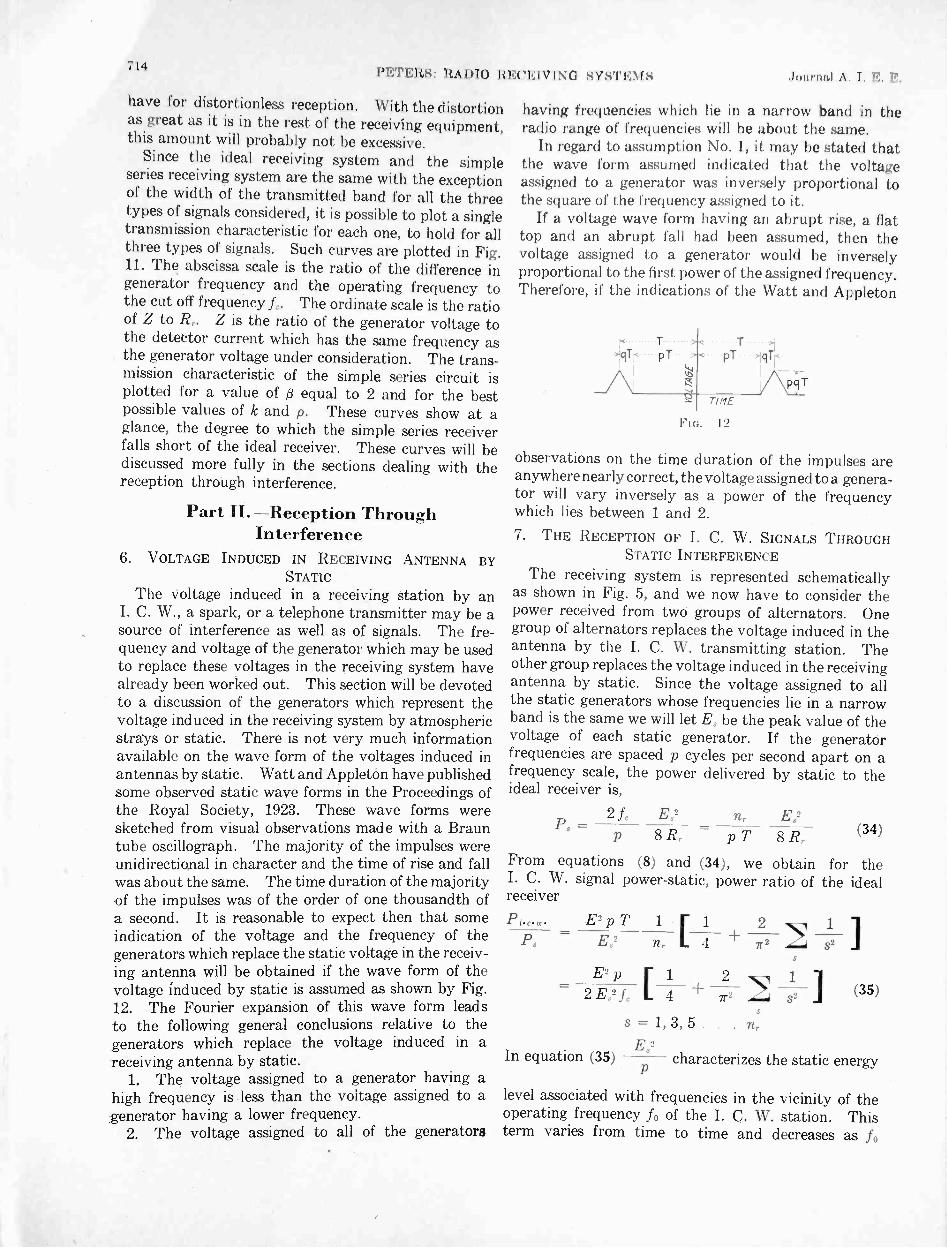
Since the ideal receiving system and the simpleseries receiving system are the same with the exceptionof the width of the transmitted band for all the threetypes of signals considered, it is possible to plot a singletransmission characteristic for each one, to hold for allthree types of signals. Such curves are plotted in Fig.11. The abscissa scale is the ratio of the difference ingenerator frequency and the operating frequency tothe cut off frequency L. The ordinate scale is the ratioof Z to R. Z is the ratio of the generator voltage tothe detector current which has the same frequency asthe generator voltage under consideration. The trans-mission characteristic of the simple series circuit isplotted for a value of (3 equal to 2 and for the bestpossible values of k and p. These curves show at aglance, the degree to which the simple series receiverfalls short of the ideal receiver. These curves will bediscussed more fully in the sections dealing with thereception through interference.
Part II. -Reception ThroughInterference
6. VOLTAGE INDUCED IN RECEIVING ANTENNA BYSTATIC
The voltage induced in a receiving station by anI. C. W., a spark, or a telephone transmitter may be asource of interference as well as of signals. The fre-quency and voltage of the generator which may be usedto replace these voltages in the receiving system havealready been worked out. This section will be devotedto a discussion of the generators which represent thevoltage induced in the receiving system by atmosphericstrays or static. There is not very much informationavailable on the wave form of the voltages induced inantennas by static. Watt and Appleton have publishedsome observed static wave forms in the Proceedings ofthe Royal Society, 1923. These wave forms weresketched from visual observations made with a Brauntube oscillograph. The majority of the impulses wereunidirectional in character and the time of rise and fallwas about the same. The time duration of the majorityof the impulses was of the order of one thousandth ofa second. It is reasonable to expect then that someindication of the voltage and the frequency of thegenerators which replace the static voltage in the receiv-ing antenna will be obtained if the wave form of thevoltage induced by static is assumed as shown by Fig.12. The Fourier expansion of this wave form leadsto the following general conclusions relative to thegenerators which replace the voltage induced in areceiving antenna by static.
1. The voltage assigned to a generator having ahigh frequency is less than the voltage assigned to agenerator having a lower frequency.
2. The voltage assigned to all of the generators
having frequencies which lie in a narrow band in theradio range of frequencies will be about the same.
In regard to assumption No. 1, it may be stated thatthe wave form assumed indicated that the voltageassigned to a generator was inversely proportional tothe square of the frequency assigned to it.
If a voltage wave form having an abrupt rise, a flattop and an abrupt fall had been assumed, then thevoltage assigned to a generator would be inverselyproportional to the first power of the assigned frequency.Therefore, if the indications of the Watt and Appleton
,qTkT.._...T.__,1p T pT )lqTr
(.1
t-7I
TIME
FIG. 12
-pqT
observations on the time duration of the impulses areanywhere nearly correct, the voltage assigned toa genera-tor will vary inversely as a power of the frequencywhich lies between 1 and 2.7. THE RECEPTION OF I. C. W. SIGNALS THROUGH
STATIC INTERFERENCE
The receiving system is represented schematicallyas shown in Fig. 5, and we now have to consider thepower received from two groups of alternators. Onegroup of alternators replaces the voltage induced in theantenna by the I. C. W. transmitting station. Theother group replaces the voltage induced in the receivingantenna by static. Since the voltage assigned to allthe static generators whose frequencies lie in a narrowband is the same we will let E, be the peak value of thevoltage of each static generator. If the generatorfrequencies are spaced p cycles per second apart on afrequency scale, the power delivered by static to theideal receiver is,
P2 fe E82 n,. E82, =p 8 R, = p T 8 R,.
(34)
From equations (8) and (34), we obtain for theI. C. W. signal power -static, power ratio of the idealreceiver
P.K.g.c E2 p T E 1 2 1
= E,2 n L 4 + 2 s2
E2 p 2 1-,K1(35)2 E.2 f, L 4 71-2 s2
s = 1, 3, 5 . . . nrE.2
In equation (35) characterizes the static energy
level associated with frequencies in the vicinity of theoperating frequency fo of the I. C. W. station. Thisterm varies from time to time and decreases as fo

Aug. 1926 PETERS: RADIO RECEIVING SYSTEMS
increases. E2 14
+2 21
s2 characterizesr -
the I. C. W. signal energy level and its distributionover frequencies in the vicinity of fo. The bracketedterm is the same for all I. C. W. stations but E isdependent upon the transmitting station and thetransmission efficiency. T characterizes the speed of
signaling its value decreasing directly with an increasein signaling speed. Thus the high signaling speeds
are more subject to static interference than the lowones. nr alone characterizes the receiving system.For the ideal receiver itr has been assigned the minimumvalue which will permit of the distinguishing of thesignals. Thus the ideal receiver reduces the staticinterference to the lowest possible value that can beobtained with a frequency selecting system.
If the speed of transmission is 30 words per minuteand if nr = 3 we have:
PrE2 p
(0.008)E2.
(36)
At 150 words per minute, the ratio will be one -fifthas large as at 30 words per minute.
The mathematical formulation of the interference inactual receiving systems is left for a future paper, butit can be pointed out that, for the simple series receiver,the best signal -power, static -power ratio is obtainedwhen L is assigned as small a value and 13 as large avalue as possible and yet have the signals distinguish-able. This follows because decreasing d or increasingL permits the generators removed from fo to furnishmore power to the circuit. But as shown by the curveof Fig. 7 the voltage of the signal generators falls offrapidly as their frequency departs from the operatingfrequency whereas it has been shown that the voltageof the static generators remains about the same at allof the frequencies. Therefore, increasing L or decreas-ing 0, that is decreasing the time constant of the circuit,increases the static power faster than the interferentpower. From this it is apparent that the simpleseries receiver described is the best possible one forreceiving through static.
8. THE RECEPTION OF RADIO TELEPHONE SIGNALSTHROUGH STATIC INTERFERENCE
In the section on telephone reception it was shownthat for distortionless reception the ideal receivingsystem must pass a band of frequencies running fromfo - cycles per second to fo fc cycles per second whereL was about 5000 cycles. Under these conditionsthe static power picked up by the system is given byequation (34). Since the ideal system picks up energyonly from generators which have frequencies lyingin the band which must be transmitted, it is evidentthat the ideal system as described is the best possiblefrequency -selection system for receiving telephonemessages through static interference. Since L for tele-phony is 5000 ÷ 30 = 167 times as large as for I. C. W.
715
reception at 30 words per minute, it is evident that 167times as much static energy must be picked up in atelephone receiver as in an I. C. W. receiver.
The extent to which static interference can be reducedby the simple series circuit depends upon the allowabledistortion of speech or music. In plotting the trans-mission characteristic of the simple series circuit givenby Fig. 11, it was assumed that the energy in the 5000 -cycle voice or musical note could be reduced to one -fifthof the value which it should have for distortionlessreception. (3 = 2, f'. = 5000 ,).
9. THE I. C. W. TRANSMITTER AND THE SPARK
TRANSMITTER AS SOURCES OF INTERFERENCE
It has been shown that the voltage induced in areceiving antenna by an I. C. W. transmitter could bereplaced by a group of generators having the correctfrequencies and correct voltages. Any I. C. W. trans-mitting station has generators with frequencies locatedin all frequency bands. It has also been shown that allreceiving systems must transmit a band of frequenciescentered upon the operating frequency of the stationwhose signals it is desired to receive. The receivingsystem must necessarily therefore pick up energy fromall I. C. W. stations which induce a voltage in the receiv-ing antenna. With a given receiving system the energypicked up from an interferent I. C. W. station dependsupon the difference between the operating frequency ofthe interferent station and the operating frequency ofthe correspondent station and the manner in which thevoltage assigned to any generator which replaces theinterferent voltage in the receiving antenna vary withthe frequency assigned to it. The curve of Fig. 7 givesa graphical picture .of the dependance of the voltageassigned to any generator upon the frequency assignedto the generator. For I. C. W. telegraphy at 30 wordsper minute 90 per cent of the energy in the waves isassociated with a band of frequencies 60 cycles widecentered on the operating frequency. At 150 words perminute the band containing 90 per cent of the energy isfive times this wide. We thus come to the conclusionsthat the energy associated with the waves of an I. C. W.transmitter is confined to a narrow band of frequenciesand the width of this band varies directly with the signalspeed. The above statement holds true if the I. C. W.transmitter has no harmonics. If harmonics are pres-ent in the waves sent out by the transmitter, thevoltages assigned to generators having "frequencies inthe vicinity of the harmonic will vary as shown byFig. 7 for the fundamental frequency and any receivingstation having a transmitted band in the vicinity of oneof the harmonics will pick up an appreciable amount ofpower from the transmitter.
The spark transmitter causes much more interferencethan the I. C. W. transmitter. This fact is broughtout in a striking manner if the curves of Fig. 10 arecompared with those of Fig. 7. The voltage assignedto a generator falls off slowly as the frequency departs
716RESKAltell. Journal A. I. E. E.
from the operating frequency. From an examinationof the curves of Fig. 10 and from the discussion ofsection (4) it is evident that the interference caused by aspark station is dependent upon the logarithmic decre-ment times the frequency rather than upon the logarith-mic decrement. If a =afo= 104, 82 per cent of theenergy in the waves is associated with a band of fre-quencies 10,000 cycles wide, centered on the operatingfrequency fo. If a = S fo = 105, then 82 per cent of theenergy is associated with a band of frequencies approxi-mately 100,000 cycles wide, centered on the operatingfrequency. This is in striking contrast to the I. C. W.case where most of the energy is associated with a bandof frequencies 60 to 300 cycles wide. From the abovediscussion it is evident that a station operating at a fre-quency of 106 cycles per second, and having a logarith-mic decrement of 0.01, has its energy spread over thesame band width as a station operating at 105 cycles persecond and having a logarithmic decrement equal to 0.1.
10. GENERAL CONCLUSIONS
With regard to the extent to which interferencecan be mitigated by frequency selecting systemsall sources of interference to radio reception and allsources of signals have a definite frequency spectra andfor convenience we can replace the voltages induced inan antenna by a group of generators having the correctvoltages and frequencies. In order to receive signalsthe receiving system must pass freely the currents dueto all generators having frequencies in a given band.This band is centered on the operating frequency of thestation from which it is desired to receive signals. Thewidth of the band is determined by the class of signals
which it is desired to receive. If the interferent volt-ages have generators with frequencies in this trans-mitted band, the frequency selection system cannoteliminate the currents due to these generators. Sincethe ideal receiver as specified in this paper utilizes themaximum possible power from generators lying withinthe band of frequencies which must be passed andutilizes no power from generators which have frequen-cies outside this band, it is evident that the interferenceobtained in the ideal receiver is the minimum which canbe obtained with frequency selecting systems. Fromthis it is evident that the minimum interference whichis obtainable depends upon the ratio of the voltage ofthe signal generators to the voltage of the interferentgenerators which lie in the transmitted band and uponthe width of the band of frequencies which it is necessaryto transmit. The width of the band of frequencieswhich must be transmitted depends upon the class ofsignals which are to be received. Thus while thenecessary transmitted band width for I. C. W. tele-graphy at 30 words per minute is only 60 cycles, at 150words per minute it is 300 cycles. The necessarytransmitted band width for telephony is about 10,000cycles and the necessary transmitted band width forspark telegraphy varies from 10,000 cycles to 100,000cycles depending upon the product of the logarithmicdecrement times the operating frequency.
The ideal receiving system thus furnishes a criterionby which we can judge of the merits of any actualfrequency selection system for receiving throughinterference. The writer hopes in a future paper toshow how near actual receiving systems of varioustypes approximate the ideal receiver.
ResearchReport of Technical Committee on Research*
J. B. WHITEHEAD, Chairman
To the Board of Directors:
The year just closing has revealed the usual activityin the field of electrical engineering research. Thisactivity extends from laboratory investigations of purelyscientific character, outward to the development ofall equipment, and to the study and improvement ofthe performance of the largest types of machinery andtransmission systems. The importance of scientific
*Committee on Research:John B. Whitehead,Edward Bennett,V. Bush,E. H. Colpitts,E. E. F. Creighton,W. F. Davidson,W. A. Del Mar,
Chairman. Johns HopkinsB. Gherardi,V. Karapetoff,A. E. Kennelly,M. G. Lloyd,F. W. Peek, Jr.,Harold Pender,
University. Baltimore, Md.E. W. Rice, Jr.D. W. Roper,C. H. Sharp,C. E. Skinner,Harold B. Smith,R. W. Sorensen.
Presented at the Annual Convention of the A. I. E. E. atWhite Sulphur Springs, W. Va., June 21-25, 1926.
research to industry in all its branches is now clearlyrecognized. The idea of research is "sold". More-over, it appears to have been a bargain based on goodvalue, for the article sold is in constant use and thereis increasing demand for it. Industrial research labora-tories are numbered by hundreds. Problems demand-ing solution are continually appearing, and there isincreasing need for skilled research workers.
THE NATIONAL RESEARCH ENDOWMENTThere has, however, been one new and striking note
during the year which has immediate bearing on thefuture of engineering research. This is the shifting ofthe emphasis in public discussion from the importance ofapplied and industrial research to the importance ofprotecting and stimulating purely scientific research.Advocates of the value of industrial research have
Aug. 1926 RESEARCH
always pointed to its intimate dependence on a funda-mental scientific basis. Industrial research laboratorieshave realized from their beginnings their dependenceupon trained research workers. Recently, however,Secretary Hoover has pointed out that the tremendousdevelopment of industrial research has resulted in twotendencies which threaten to dry up the sources of
inspiration for research, and to diminish the number ofthose who are fitted to carry it on. The first of theseis the stripping of university laboratories of their men whoare trained in research because of attractive offersfrom industrial laboratories. The second is the greatincrease in university student attendance which hascompelled universities to limit research activities inorder to meet the mere volume demand for elementaryeducation. Recognizing this tendency, SecretaryHoover has placed the weight of his great influenceback of the suggestion of the National Academy ofSciences that a national research endowment be ac-cumulated, whose chief purpose should be the promotionof purely scientific investigation in American universi-ties, the natural nurseries for the training of competentscientific research workers. As a result Herbert Hoover,Elihu Root, Chas. E. Hughes, Owen D. Young, John J.Carty, Wm. H. Welch, and other distinguished asso-ciates are serving as trustees of the National ResearchEndowment, whose purpose is to raise twenty milliondollars to aid American universities in carrying onfundamental research during the next ten years.
This movement is one of the healthiest and mostpromising events in recent years for the further develop-ment and progress of research in all fields of industry.Not only will it tend to conserve the sources of supply ofresearch workers, but it is certain to result in an eleva-tion in the general standards of ability, and in theincrease of researches of scientific value, emanatingnot only from universities but also from industrialresearch laboratories. Industry itself has been quickto recognize the importance of the move, for the heads ofmany great corporations have entered actively into thecampaign to raise the endowment, and it is not unlikelythat industry itself will make substantial contributions.
ELECTRICAL ENGINEERING RESEARCH
Naturally electrical engineering with its rapiddevelopment and expansion, its dependence on physicallaws only uncovered in recent years, is always a heavycontributor in the field of engineering research. Whilethere is no single result of outstanding novelty andimportance, the past year has nevertheless seen manyadvances of interest. The range of problems studiedhas been much the same, but some shifting of emphasisin the various fields may be noted. Thus, for example,in overhead high -voltage transmission, attention hascentered more particularly on analytical studies of theregulation, stability, and power limitations of highlines and large systems. At the same time there hasbeen somewhat less attention than in foregoing yearsto experimental studies, in laboratory and field, of
717
transients, protective apparatus, and high-voltage prob-lems, although these have continued in some measure.The laws of corona, its physical character, and its bear-ing on transmission -line performance are still unansweredquestions, and are therefore receiving some attention.
In the field of electrical machinery the intensivestudy devoted to fuel economy, with the resultingimprovements in steam -power producing machinery,is so striking as to warrant its inclusion here as animportant research activity. More directly in the analy-tical and laboratory class are continued studies of theproblem of the ventilation of large rotating units, and ofthe general relations between temperature and machinerating. Other studies of note are in connection withmachinery and the application of delicate vibratinginstruments to problems of balance, and the like, themathematical similarity between mechanical and elec-trical systems, and the proposal to investigate theformer electrically through the equivalent investigationof the mechanical forces arising in short circuits insynchronous machinery. There haviwbeen fewer papersthan usual on the properties of iron as related to thequestion of core losses.
There has been a continuation of the marked activityin experimental studies in the field of electric communi-cation. Papers have been presented to the Institutereporting studies of the quality, the recording, and thereproducing of sound, on the importance of loadingtelephone circuits, and on new methods of carrier -current transmission. The publications of the BellTelephone Laboratories show an extremely wide rangeof subject of investigation. Some of them are scientificresearch of the purest character, and the range extendsto the experimental development of equipment andmethods for meeting the increasing modern demands forfacility in communication.
Results in the radio field are numerous and important.New tubes are being developed, new circuits devised,and new methods adopted for improvement in alldirections of this highly specialized branch of electricalengineering. Perhaps the most interesting activity hasbeen that of studying the behavior of short-wave trans-mission and the resulting new knowledge that has comeas to the conducting properties of the upper atmosphere.
In the field of electrical measurements, among othernoteworthy advances, may be mentioned the adaptationof the cathode ray oscillograph to the measurement ofvery short -time intervals, simpler and more convenientforms of oscillograph, and a greatly increased attentionto the methods of measurement of dielectric loss atlow -power factor and high voltage.
Studies which lie close to the field of pure physicalresearch, and which may prove to have a practicalbearing, are those in which the cathode stream of elec-trons has been brought through the walls of the tubeinto the surrounding air, the study of atomic hydrogenin its adaptation to arc welding, the obtaining of copperin large crystals showing 13 per cent increase in normal

718ItE814;ARC11 .lottnittl A. I.
conductivity, and the continued study of the structureof crystals by the means of X-rays.DIELECTRICS AND INSULATION
The Committee on Research has continued to devoteits principal attention to the subject of dielectrics andinsulation. It serves as a consulting committee inElectrical Engineering to the National ResearchCouncil. Several of its members are also members ofthe Committee on Electrical Insulation of the Divisionof Engineering and Industrial Research of the NationalResearch Council, the two committees having the samechairman. The program of the Committee on Elec-trical Insulation has been outlined in foregoing reports.During the past year considerable progress has beenmade by the subcommittees in the respective divisions.The Subcommittee on Dielectric Absorption andTheories of Dielectric Behavior has made a reportwhich was also presented at the Midwinter Conventionof the Institute. It is a comprehensive survey ofexisting knowledge of the anomalous properties ofdielectrics and of theories that have been offered inexplanation, and it includes suggestions of directionsin which further experiment will probably result innew knowledge important to the control of the proper-ties of insulation. As a result of this report the Com-mittee on Electrical Insulation is prepared to suggestproblems for investigation and research. It also hopesthat some plan may be worked out whereby joint andcoordinated work of a number of investigators may beundertaken. The report of the subcommittee onDielectric Strength may be expected in the near future.The literature on these subjects is very extensive, andrequires careful reading and discrimination. Themembers of the Committee are giving their servicesvoluntarily and this work of necessity takes a secondaryplace in their busy programs.
The Committee is glad to record continued activityin the experimental investigation of the properties ofinsulating materials of all characters, and believesthat its own interest in this field of study has stimulatedthe interest which lies back of the present activity.During the year there have been presented to theInstitute important papers on gaseous ionization inpaper -insulated cables, on the theory of dielectricabsorption, the measurement of dielectric losses, and amethod for the convenient and quick measurementfor the absorption in commercial insulation. Attentionshould also be called to important contributions fromabroad. A noteworthy paper on high -voltage, impreg-nated -paper cables has appeared in England, and therehave been a number of papers from Germany bearingon the dielectric strength of different materials withspecial reference to the mechanism of the failure ofhigh -voltage insulation.
ORGANIZED RESEARCH
It is a ;conspicuous feature of research activity ingeneral that it is highly organized in industrial labora-
tories, but proceeds practically without organization inuniversity laboratories. This situation is natural.The work in an industrial laboratory is usually directedtowards the solution of particular questions, and if theyare sufficiently important the whole resources of thelaboratory may be diverted to their solution. Inuniversity laboratories individual workers find suchtime as they can for research outside of crowded pro-grams, and usually do research without materialcompensation and only for the love of it.
Considering both extremes it will be seen that thesituation is not particularly conducive to the productionand publication of important results of research. Ina few notable instances industrial research laboratoriesare making substantial efforts in the field of purephysical research, and it is possible to point to resultsof great value emanating from these efforts. Theseexamples are few, however, and on the whole it cannot be said that results of fundamental scientific valueare to be expected in large quantities from laboratoriesin this class. In only a few university laboratories isany considerable proportion of the resources of menand materials devoted to original investigation. Suchas is accomplished usually comes from men who arewilling to sacrifice time outside the educational program,and who are prompted to it solely by the love of it.
An exceptional and promising example of organizedresearch is that being carried out at Harvard, JohnsHopkins, Massachusetts Institute of Technology, andthe University of Wisconsin, on the impregnated-paperinsulation of high -voltage cables. The work is beingdone under the auspices of the Committee onCable Insulation Research of the National Elec-tric Light Association, whose member companieshave subscribed sufficient funds to ensure theactive prosecution of the work. Results of import-ance and value are already beginning to appear.It would appear, then, that the several nationalorganizations which have among their principal pur-poses the encouragement and support of engineeringresearch, might do well to undertake actively the organ-ization of research in university laboratories and theprovision of material support of the necessary experi-enced research workers. The national engineering socie-ties might consider also with propriety, these things aslying among their normal functions. The NationalResearch Endowment is pledged specifically to supportpure scientific research in university laboratories.There are some problems of pure research which mustbe attacked by research engineers, but it appears doubt-ful whether appeal for work in the engineering fieldwill for sometime receive consideration by the NationalResearch Endowment. It is highly desirable, therefore,that engineering foundations interested in researchand the national engineering societies should considerhow the sources of the training of research engineerscan best be conserved, and how activity in engineeringresearch may be encouraged.

Accuracy Required in the Measurementof Dielectric Power Factor of Impregnated Paper-Insulated Cables
BY C. F. HANSON'Member. A. I. E. E.
Synopsis.-7'his paper deals with the effect of errors in the
measurement of power factor upon the usefulness of impregnated
paper -insulated cables. It points to error in the knowledge of the
thermal properties of the cable and the cable duct. The latter erroraffects the usefulness of a cable to such an extent as to permit a
limited error in the power factor without materially reducing the
ilficiency of the cable. This limited error defines the required power -
factor accuracy.
The required power -factor accuracy in general is found to vary
directly with the frequency and the specific inductive capacity
of the insulation, and to increase with the number of cables in aduct bank and the ratio of E2/G, where E is the operating voltage of
the cable in kilovolts and G is the geometric factor. For very high -
voltage single -conductor cables the power -factor accuracy should be
within the order of 0.002.
INTRODUCTION
THE significance of an error in the measurement of
one property of a commodity depends upon thelimitations which that error imposes upon the
usefulness of the commodity. At first hand, it wouldseem that this error should be reduced to as low avalue as possible in order that the commodity may havea maximum usefulness. However, in the measure-ments of other properties of the commodity, errorsexist which also impose limitations. An error in themeasurement of the property, therefore, need not bemade as small as possible, but need be reduced only to avalue which will impose very little additional limita-tions upon the usefulness of the commodity.
icance of an error in the measurement of the dielectricpower factor of impregnated -paper insulated cables.The method of attack lies in an endeavor to compare thepower -factor error with the error existing in the knowl-edge of the thermal properties of the cable. Thiscomparison is based upon the effect of each of theseerrors on cable efficiency. The efficiency of a cable ismeasured by its capacity to carry current.
No economic gain of any consequence can be realizedby reducing power -factor error below a certain limitas long as errors exist in the thermal data of the cableand the cable duct. In other words, for a given ac-curacy in the thermal data, an appreciable gain incable efficiency can be realized by increasing power -factor accuracy only up to a certain limit. This limitof power -factor accuracy can be defined, for the purposeof this paper, as the required power -factor accuracy.
If the accuracy of the thermal data should increase,then the required power -factor accuracy would like-wise increase. To provide for this situation, it isshown how the latter varies with respect to the former.With this information available, the required power -factor accuracy can be determined and then compared
1. Habirshaw Cable and Wire Corporation, Yonkers, NewYork.
Presented at the Regional Meeting of District No. 1 of theA. I. E. E., Niagara Falls, N. Y., May 26-28, 1926.
with the estimated power -factor accuracy obtained inthe measurements. If the estimated accuracy is less
than the required accuracy, then the methods formeasuring power factor should be improved. On theother hand, if the estimated power -factor accuracy is
far in excess of the required, then the accuracy of thethermal data should be increased.
THREE -CONDUCTOR CABLE
The foll"wing formula gives the current-carryingcapacity of a three -conductor cable:
18.08 T TI - - 117 (1)
' R Rgh
This formula is practically the same as formula (24)
given by Simons2. The term Wo1 is the dielectric powerloss in watts per foot of cable at 60 cycles, and is as-sumed, for the sake of simplicity, to originate on thesurface of the conductors.
Wm. is proportional to the power factor cos 0.R = the resistance per conductor in ohms per
1000 ft. at the allowable temperature, To,in deg. cent. ( two per cent is added forcabling).
Tt. = the base temperature of the earth in deg. cent.used as 20 deg. cent.
= thermal resistance between conductors andbase in thermal ohms per foot of cable.
I = current per conductor at the generator end ofthe cable in amperes.
The value of the current I is known with an accuracyof one per cent or better. The temperature, T0, canbe established under laboratory conditions with con-siderable accuracy. When To is established, the valueR becomes known to an accuracy within 2 per cent, theallowance required for manufacturing variation. The
R,,,
2. "Calculation of the Electrical Problems of Transmissionby Underground Cables," Donald M. Simons, The Electric Jour-nal, August, 1925, p. 375. To avoid confusion the author hasused the same symbols as those used by Simons. The firstpublished formula to include WDL was given by Wm. A. Del Marin Harold Pender's "Handbook for Electrical Engineers,"1922 edition, p. 2021.
719

722HANSON: IMPRE(1NATED PA NSt LATE!) Jwirnid A. I.
To 20
TABLE 11
sINuLE-CoNDUCTo It cA111.1.:N
Cable
No.OW. MilsX 10 -3 T U E To Cos 0
11 500 40 8 40 67 0.03512 500 60 9 66 60 0.02913 750 52 10 75 60 0.02914 600 46 10 100 60 0,02915 600 46 10 132 60 0.02016 600 46 10 132 60 0.010
the power -factor error should be based on the conditionthat the error must not affect the current capacity of acable by more than a certain percentage, then evidently,the accuracy of power -factor measurements should in-crease as the value of the power factor increases. Thisreasoning is not valid. Even though a cable of highpower factor should be measured with a higher degreeof accuracy, nothing would be gained in current capac-ity because the equivalent error A TG would not per-mit a gain. The conclusion, therefore, follows that therequired power -factor accuracy cannot be based directlyon a limited change in current capacity.
SINGLE -CONDUCTOR CABLES
A slight modification of Simons' equation (26) forcurrent capacity yields formula (9) :
31.6I= \I To= TG Rim WDL
R R" RthRde
(9)
RaeThe ratio -la is introduced because the skin effectItde
in large conductors becomes appreciable. The termRth, is somewhat different from Rth because in the caseof single -conductor cables the dielectric power loss isnot assumed to originate on the surface of the conductorsbut actually originates in such a location as to cause atemperature drop from conductor to sheath equal toone half the drop it would have if the dielectric powerloss had originated on the surface of the conductor.The value of Rth must be calculated in such a manner asto take into account sheath losses which are of relativelylarge magnitude in single -conductor but negligiblein three -conductor cables. The other terms in formula(9) are the same as those in formula (1).
The ratio of Rac/Rdc is taken from Simons' paper3,p. 369. Rth and Rth' were calculated according to hismethod. However, 500 watts per cm. units were used, inplace of his 850 watts per cm. units, as the heat resistivityof impregnated paper.
By introducing the terms A WDL and A TG in formula(9), the following formula is obtained:
A WDL =
3. Loc. Cit.
A TG(10)
A it, - 60
Ceti Do e2/GA Cos 0
0.931.19
16.8
17.2
0.4090.167
9.49 . 2
5691213
0.00870.00417
0.97 20.4 0.114 8.9 1830 0.002850.81 17.9 .0515 8.7 4130 0.001200.81 17.9 .0296 8.7 7180 0.000740.81 17.9 .0296 8.7 7180 0.00074
Stating A WDI. in terms of A cos 0 and
becomes:
e2
G formula (10)
46.5 LTGo cos 0 =
e (11)21G Rth'
e = voltage to neutral in kilovolts. In single -con-ductor cable it is the voltage from conductor tosheath.
G = Geometric factork = 3.4 and f =60.
0.05
cb 0.04to00
0 0.03cc
O0.02
C)0_ 0.01
0
1 I Cable No. I
1611 12 13 14 15 and.,
IIN.6f . 60
i
JT6
5,
21
2000 44)0
FIG. 3 -POWER FACTOR ERROR IN TERMS OF EQUIVALENTBASE TEMPERATURE ERROR & TG FOR VARIOUS SINGLE -CON-DUCTOR PAPER -INSULATED CABLES
6000 8000
The power -factor error A cos 0, is given in' Table IIwhen A TG = 1, for six different cables when N equals6. The center of each of the three cables on a three-phase circuit was assumed to be at the apex of anequilateral triangle, the sides of which were taken tobe 12 in. long (S = 12). Cables No. 14, No. 15 andNo. 16 each has a hollow core of in. diameter in theconductor. All the cables are assumed to have a singlelead sheath the thickness of which is given as U in64ths of an inch. The thickness of the insulation in64ths of an inch is given as T.
In Fig. 3 the relation of power -factor error, A cos 0,to the ratio e2/G is shown for various values of A TG.

Aug. 1926 HANSON: IMPREGNATED PAPER -INSULATED CABLES
As in three -conductor cables, the power -factor erroris easily obtained for other values of A TG when it isknown for one value of A TG. If i cos 0 equals 0.005when A TG equals unity, then A cos 0 equals 0.01 whenA TG equals 2. The curves show that for high -voltagesingle -conductor cables, the permissible power -factorerror is much less than it was for the three -conductorcables considered in Fig. 1. If the equivalent error
1.00
0.90
-2
11 12 13 16 14 15CABLE NUMBERS
FIG. 4-THE EFFECT OF A CHANGE IN THE BASE TEMPERATUREUPON CURRENT CAPACITY OF SINGLE -CONDUCTOR PAPER -INSULATED CABLES
A TG, in the base temperature is assumed to be 3 deg.cent., then the power -factor error, A cos 0, should notexceed 0.0022. This accuracy would be requiredregardless of what the actual power factor of the cablemay be.
The frequency used in the calculations is 60 cycles.If some other frequency were used, the permissiblepower -factor error would change. Although the exactvariation of dielectric power loss with frequency is notknown, the dielectric power loss may be considered tobe proportional to the frequency within the limits ofcommercial power frequencies. On this basis, thepermissible power -factor error, both for single -con-ductor and three -conductor cables,varies inverselyas thefrequency. In other words, the greater the frequency,the greater should be the power -factor accuracy.
The effect of i TG upon the current capacity ofsingle -conductor cables can be calculated by formula (6).This effect is shown in Fig. 4, when N equals 6 andwhen the basic power factor is that given in Table II.
If N equals some other number, the power -factorerror A cos 0 may be obtained by formula (7). Inthis case
Rth, (N = 6)Q -
Rah'
The values of Q may be considered as follows:N=3 6 9
Q = 1.60 1 ' 0.75
(12)
723
132-Kv. CABLE
Fig. 4 brings out some rather interesting information.Each curve has a sudden break at cable No. 16, conse-quently, cables No. 14 and No. 15 have some prop-erty which is abnormal relative to the other cables.This property is the power factor cos 0. Even thoughcable No. 15 has a power factor which is only 0.02 at60 deg. cent., this power factor value is relatively muchhigher than the power factor 0.029 at 60 deg. cent. is forcable No. 12. Cable No. 15 should have a powerfactor of the order of 0.01 at 60 deg. cent. in order thatthat cable may perform in accordance with experiencewith other cables. The equivalent base temperatureerror A TG, should be low and also the power -factorerror A cos 0. Furthermore, the power factor of thecable and the heat resistance of the cable and the ductline must run very uniform throughout its entire lengthfor satisfactory and economical service.
Fig. 5 shows the power factor-temperature charac-teristic A B-which cable No. 15 may be expected tohave, and characteristic CD for Cable No. 16. Each
0.06
0.05
(7) 0.04a)0
r) 0.03
LU
E 0.02
0.01
40 50 60 70 80TEMPERATURE DEGREES CENTIGRADE
FIG. 5-CABLE NO. 15 WILL HAVE A SHORT LIFE REGARDLESSOF POWER FACTOR ERRORS. AN ERROR OF 0.002 MAY JEOPARD-IZE THE LIFE OF CABLE No. 16
132-kv. cableOne -conductor, 600,000 cir mils3/4 -in. hollow core40/64 -in. insulation
B43
"4".
s,
0-orte
F, ,.,,/ H;
, .4, i'-1/ co
D/ , ..ose
Cb.
"'/ ,' _..../..-
.e...,N . 6f'6, ...--t .
.- C 'E
_./
G
90
of these characteristics was obtained in actual power-factor measurements of finished cables. The dottedline E F is the unstable power factor-temperaturecharacteristic for Cable No. 15 and likewise the dottedline G H is the unstable characteristic for Cable No. 16.
The current capacity of Cable No. 15 is calculated tobe 187 amperes when it is operated with a conductortemperature of 60 deg. cent. and a power factor of0.020 when N equals 6. If this cable had E F in Fig. 5,

724 HANSON: IMPREONATED PAPER -INSULATED CABLES Journal A. I. E. E.
as its power -factor characteristic, it would carry 187amperes at any temperature from 40 to 90 deg. cent. ormore. Nobody knows what temperature the cablewould choose.
The unstable characteristic E F is obtained with theuse of formula (11). Instead of using A cos 0 as apower -factor error, it is used as a power -factor incre-ment. For the term A TG, A To is used because anincrement change in To produces the same effect as anincrement change in TG according to formula (9).Formula (11) then becomes:
A cos 0 46.5 1
A To = e2/G Rem
Formula (13) provides the slope of the characteristicE F. The point, cos 0 = 0.02 and To = 60, on the
0.06
0.05
) 0.0400ct0I6 0.03
00.02
0.01
40 50 60 70. 80TEMPERATURE -DEGREES CENTIGRADE
FIG. 6-ELIMINATION OF POWER FACTOR ERROR AND EQUIVA-LENT BASE TEMPERATURE ERROR MIGHT SAVE CABLE NO. 15.AN EQUIVALENT POWER -FACTOR ERROR OF 0.005 MAY NOTSERIOUSLY IMPAIR THE USE OF CABLE No. 16
(13)
B L
/I-
/ ////
r4.
/
/
///74
,a// NI
e D_/.1/40/-ve cz,
e. /A //
/ e / N=3f- 60e C-,---/(
K/ /M/
90
132-kv. cableOne -conductor, 600,000 cir. mils3/4 -in. hollow core46/64 -in. insulation
characteristic is already known. The characteristicis, therefore, established by a point and the slope. Inthe derivation of the slope the change in the resistanceR due to an increase in temperature is disregarded.The actual power -factor characteristic of Cable No. 15is the curve A B. With a current of 187 amperes flow-ing in this cable, its temperature will rise to 60 deg.cent. Now, if the current should increase slightly to190 amperes, the cable temperature would immediatelyrise indefinitely. Even if the current should drop backto 187 amperes when the temperature has reached 70deg. cent., the temperature would continue to rise any-
way because the cable temperature has passed thecritical point of 68 deg. cent. This temperature isgenerally known as the critical temperature of cumu-lative heating. Cable No. 15 is not suited for 187amperes, because a small error in the thermal data orpower factor of the cable would cause cumulativeheating.
The current capacity of Cable No. 16 is calculated tobe 268 amperes at 60 deg. cent. with a power factor of0.01 when N equals 6. With a current of 268 amperesflowing through it, this cable with its power -factorcharacteristic C D, in Fig. 5, would come up to a tem-perature of 58 deg. cent. provided no power -factorerror exists and that all other cable and duct propertiesare known exactly. If, however, a power -factor errorof 0.002 or an eqUivalent base temperature error of 3deg. cent. exists, the cable would come up to a tem-perature of 63 deg. cent. and stay there as long as noth-ing changes. A little overload for a few hours might,however, seriously jeopardize the life of the cable.
Fig. 6 tells a similar story except that N equals three.The current capacity of each cable at 60 deg. cent. iscalculated to be 303 amperes for Cable No. 15 and 358amperes for Cable No. 16. The power factors are0.020 and 0.010 respectively. Cable No. 15 does notoffer a continuity of service of 303 amperes because asmall error in the power -factor measurement or in theequivalent base temperature might send the tempera-ture up to the point of cumulative heating at 90 deg.cent. Cable No. 16 looks promising for 358 ampereseven though a power -factor error of 0.002 might exist.If in addition to a power -factor error of 0.002, an equiva-lent base temperature error of 4 deg. cent. exists theprobable error of the combination would be of the orderof 0.005. Even with this equivalent error of 0.005 inthe power factor, the cable would probably continue toserve with 358 amperes but no overload should be per-mitted. Under this condition it would operate at65 deg. cent.
For the 132-kv. cable, for operation in a three -cableduct bank, the power -factor error evidently should notexceed 0.002 and the equivalent error in the base tem-perature should not exceed four deg. cent. in order toobtain a cable service similar to that obtained withcables of lower operating voltage.
CONCLUSIONS
A survey of the factors which have a bearing upon theaccuracy required in power -factor measurements showsthat:
1. Power -factor accuracy should be stated as aconstant and not as a percentage. For example, apower factor of 0.05 is accurate within ± 0.005 andnot ± 10 per cent.
2. The power -factor accuracy required increases indirect proportion to the frequency, and also to thespecific inductive capacity of the insulation.
3. The power -factor accuracy required increases as

Aug. 1926 ELECTROCHEMISTRY AND ELECTROMETALLURGY
the number of similar cables in a duct bank increases.4. The required accuracy increases as the ratio
E2/G increases, where E is the operating voltage, inkv.. and G is the geometric factor of the cable.
5. The required power -factor accuracy cannot bedefined by percentage limits in the current -carryingcapacity of a cable.
725
6. The required accuracy is relative to the accuracyobtained in the measurement of the heat resistivityof the insulation, the surface heat resistivity of thelead sheath, the "heating constant" of the cable ductand the base temperature of the earth.
7. For 132-kv. cable the power -factor accuracyshould be of the order 0.002.
Electrochemistry and ElectrometallurgyAnnual Report of the Committee on Electrochemistry and
Electrometallurgy*G. W. VINAL, Chairman
To the Board of Directors:The Committee on Electrochemistry and Electro-
metallurgy of the Institute makes its annual reportdealing primarily with a review of some of the out-standing developments within the field of theCommittee's work. At the beginning of the adminis-trative year the Committee was enlarged to includemembers representing as far as possible the manydiverse fields that are included within the scope ofelectrochemistry and electrometallurgy.
The Committee has endeavored to bring about acloser cooperation between its own work and that ofthe American Electrochemical Society with which itshould be closely identified. The work of our Com-mittee does not overlap that of the ElectrochemicalSociety, and it is apparent that a still greater degreeof cooperation between the two organizations would bevaluables.
In 1925 Mr. F. E. Smith, President of the LondonPhysical Society, advocated the replacement of thepresent international electrical units by the absolutecm. g. sec. units. This is not a new idea, but it is anindication that we are approaching a time when sucha step may be considered possible. The accuracy ofthe electrical standards must keep ahead of the demandsof engineering. Improved facilities and techniquefor performing experiments within the physical labora-tory are making possible a step which is of particularinterest within the field of electrochemistry where thetransformation of energy in its various forms playsan important part.
Committee on Electrochemistry and0. W. Vinal, ChairmanLawrence Addicks,Arthur N. AndersonT. O. Atchison,Farley O. Clark,Safford K. Colby,
F. A. J. Fitzgerald,W. F. Hendry,Walter E. Holland.F. A. Lidbury,Wm. A. Moore,Charles H. Moritz,
Electrometallurgy:
Carl 0. Schluedorberg,Magnus 'Unger,J. B. Whitehead,J. L. Woodbridge,J. L. McK. Yardley.
1. The committee is indebted to 1)r. Fink, Secretary of theAmerican Electrochemical Society, for furnishing certain informa-tion used In this report.
Presented at the Annual Convention of the A. I. E. E., WhiteSulphur Springs, W. Va. June 21-26, IOC.
The international electrical units upon which thefundamental measurements of electrical engineeringare based are defined by standards which are essentiallyelectrochemical. The mercury ohm which serves asthe standard for the measurement of resistance involveschemical and electrochemical processes for purifyingthe materials. The silver voltameter, whose electro-lytic deposits serve to define the ampere, is obviouslyan electrochemical device. The standard cell, whosevoltage has been determined by experiment from theinternational ohm and the international ampere, isessentially a small voltaic cell. Engineers become soaccustomed to dealing with volts and amperes and ohmsthat the fundamental standards for their values aretaken more or less as a matter of course. These funda-mental standards were re -defined by the InternationalConference on Electrical Units and Standards whichmet in London in 1908. They were devised to representas nearly as possible the absolute units based upon thecentimeter, the gram, and the second. It is highlydesirable for reasons that are too obvious to requirerepetition that they should represent these absoluteunits as closely as possible. With the increasingfacilities for experimental work and improved technique,it is now possible to realize by experiment the absolutevalues of the fundamental units with a higher degreeof accuracy than had been obtained prior to 1908.Experimental work is now in progress in the UnitedStates to verify the conclusions of experimenters at thenational laboratories of England and Germany withinthe past few years, which have indicated that themercury ohm does not represent the absolute ohmwith as high a degree of accuracy as was previouslysupposed to be the case. Fifteen years have elapsedsince the international experiments using the silvervoltameter were made. During that time our electricalunits have been carried forward by means of theworking standards of the laboratory, that is to say,the wire -resistance standards and the standard cells.Developments in engineering practise are making itmore than ever important that the fundamental elec-

726ELECTROCHEMISTRY AND ELECTROMETALLUROY
trical standards, maintained with the highest possibledegree of accuracy, should be in accord with our cm. g.sec. system of measurements. Therefore, a differencebetween the value of the international ohm and theabsolute ohm amounting to five parts in 10,000, togetherwith its effect upon the value for the standard cell mustinevitably give rise to serious consideration,
An outstanding development in electrodepositionduring the past year has been made in chromiumplating. Although it has long been known thatchromium could be electrodeposited, it is only withinthe past few years that the conditions for its commercialdeposition have been defined. There are still manyproblems requiring study before its general applicationwill be entirely feasible. There are at least twentylaboratories in the country now engaged in the studyof chromium plating, and while it is not yet in extensiveuse, the indications are that it will soon find many im-portant industrial applications. Chromium is a mate-rial of extreme hardness and is also notable for itsresistance to tarnish and to chemical action. It hasbeen successfully applied to plates used for printingpaper currency at the Bureau of Engraving and Printing,and it has materially increased the useful life of theseplates. It will probably find application also in otherforms of printing where very great numbers of copiesare required. It has been suggested also for use ondies and gages. Although the reflecting power ofchromium is appreciably less than that of silver, itsresistance to tarnish may make it of decided value onreflectors.
In an effort to prevent corrosion, research has beenin progress to improve the quality of nickel platingand eliminate the pits and pores which have been thechief cause of its failure to prevent the corrosion ofunderlying iron or steel.
A process recently developed and known as "gal-vannealing," is said to be an improvement over thefamiliar processes of galvanizing. It is claimed thatthe zinc covering is more uniform and flexible.
The protection of iron by cadmium would not beanticipated from the potential relations of these metalsas usually given. Experiments, as well as actualservice, indicate that cadmium can be used successfullyas a protective material against corrosion of iron andsteel.
Chromium plating, while not affording an absoluteprotection against corrosion unless the deposits areunusually thick, may be used in combination withunderlying coats of copper and nickle, to afford a highdegree of protection. Efforts have also been made todevelop electroplating of simultaneous deposits ofcopper and nickle similar to monel metal. The im-portance of corrosion research to industry in generalis very great and will doubtless assume even greaterimportance.
The progress of electrothermics during the past fewyears has been so rapid that publications of even recent
date often must be used with caution lest they be mis-leading as to present practise in melting andheat -treating furnaces. During the past year, thedevelopment in the use of electricity for heating andindustrial purposes has been rapid, but the idea some-times expressed that all industrial heating processesare potentially valuable outlets for electrical energyhas been considerably modified. In general, engineersare beginning to realize that, while there are manyprocesses which can be done electrically, there is,nevertheless, a choice to be made which dependsupon practical and economical aspects of fuel costsand the present state of manufacturing processes.
Soaking pits, electrically heated by resistors, havebeen found to yield ingots that can be more easily andeconomically rolled in certain plants than similaringots from gas -fired pits.
Results obtained by the use of electric furnaces inthe production of steel, ferro-alloys, and other opera-tions of a similar nature depend very largely on thecontrol of the electrical energy applied to the furnace.The electric furnace is not an inherently efficient pieceof apparatus unless the electric energy is properlyapplied. This means that furnaces should operate insuch a manner that the power is fully utilized withrespect to time factor, load factor, and, when alternatingcurrent is employed, power factor. Aside from themore obvious advantages of high power factor, someelectrochemical operations may be adversely affectedby variations in power factor for reasons that are notat once obvious. Current density often plays an im-portant part in metallurgical operations and when thecontrol of the furnace is accomplished by means ofcurrent regulators, material variations of power inputmay occur. Thus, in operating a three-phase furnace,the variations in power factor during the melting -downperiod may keep the load in a state of unbalance withrespect to the phases. It is sometimes observed thatone electrode heats up unduly without, however,doing its share of the work. The electrical energysupplied is the important factor from a thermodynamicstandpoint in metallurgical operations where a trans-formation of one kind of energy to another occurs.For both economic and metallurgical reasons, thecontrol of the energy input is of important considera-tion. Modifications to meet practical conditions havebeen made in certain plants. Current control has beenreplaced by watt control, and individual motors forshifting the electrodes have been replaced by a hy-draulic system which offers advantages in the accuracywith which an electric balance can be maintainedduring the period of melting. Some furnaces are nowoperating on 98 per cent of the energy supplied to theprimary of the transformers the two per cent loss beingdivided between the transformer, bus -structure, andelectrode holders. The unequal power requirementsduring the various periods of charging, melting, refining,and tapping of steel furnaces have in some cases been

Aug. 1926 ELECTROCHEMISTRY AND ELECTROMETALLURGY
nearly equalized by staggering the operation of agroup of three furnaces, having one transformer unitand one control mechanism. A more continuousload is thus maintained and the labor somewhatdiminished, as measured by the weight of steel producedper man.
Because of the various states of oxidation of the me-tallic constituents of the ferro-alloys and the lossesencountered in the reduction of them, some modificationsin the usual method of charging the furnaces have been
proposed. By very rapidly raising the oxides and re-ducing agents to the reducing temperature, the formationof intermediate oxide states is avoided. This is
applicable to many types of reduction and is ac-complished by a continuous charging of the materialin a small stream into the hottest part of the furnace.
Up to a few years ago, the common practise in brass -rolling mills was to melt brass in crucibles, using coalor oil for heating. These crucibles generally held600 lb., and some held as high as 900 lb of metal.
In the period from 1917 to 1922, the introductionand development of the induction type furnace,particularly in the Naugatuck Valley, met with con-siderable success, as it gave a better control oftemperature for pouring, the metal was better (lesscontamination from gases, etc.), the metal losseswere lower, and the cost of furnace linings was less thanthe equivalent cost of crucibles. These inductionfurnaces are rated 60 to 75 kw., single-phase, 25 or 60cycles, and 220, 440, or 550 volts, and can melt 600 to900 lb. of heat. Pouring temperatures needed for thegeneral run of production requirements are within theworking limits of the lining material used in thesefurnaces. For certain metals, such as nickel, silver,high copper alloys, etc., higher pouring temperaturesare necessary, and difficulty has been experienced withthe present lining materials.
Because of this situation, experiments have beencarried on with a high -frequency induction furnace,and as a result, twelve of the furnaces have just beenput into commercial operation in Waterbury. It isinteresting to note that the first experiments withhigh -frequency furnaces were based on the use of12,000 cycles; standard type generators were notavailable for this frequency, and mercury -arc oscillatorswere used, but these were limited in regard to poweroutput. The experiments referred to above showedthat much lower frequencies could be used. Thehigh -frequency furnaces are rated to 100 -kw. capacity,single-phase, 480 cycles, 1850 volts. For the twelvefurnaces, two special frequency -changer sets, eachrated 600 kw., are used. Because of the low powerfactor at which the furnace operates (10 to 12 per cent),a bank of capacitors, rated approximately 950 kv-a.,is used with each furnace. The resultant power factoras measured at the frequency -changer set, is close tounity.
The construction of the furnace is relatively simple;
727
it consists of a crucible which holds 600 lb. of metal,surrounded by an edge -wound copper coil, togetherwith a blower, this assembly in turn arranged in aframe in such a way as to permit of tilting and pouringthe metal. These furnaces have been in successfuloperation since the first of the year and additionalfurnaces are now being installed elsewhere.
An electric furnace for tempering steel parts andemploying a forced convection, for obtaining uniformtemperature conditions throughout the furnace, hasbeen described recently. Experimental work is againin progress on a zinc furnace which embodies anelectrothermic distillation process.
Other uses for electricity in electrometallurgy thathave been noted recently include the electric heating ofingots after casting to keep the metal fluid and preventpiping. Heating for this purpose takes the form of anarc playing on the top of the ingot.
Also there has been an increasing use of electricityfor annealing purposes, and it is significant that therange of objects which are subjected to an electricannealing process is steadily increasing. Annealingof the non-ferrous metals without oxidation has nowbecome possible. Development of the mechanicaloperation of furnaces for enameling, to. provide acontinuous cycle of operation, is desirable.
Efforts are being made to improve the life of resistorproducts, and developments in the design of somefurnaces to permit making repairs without the necessityof cooling the furnace are significant of possible develop-ment of continuous operation.
In discussing electrical power for chemical plants,it has recently been pointed out that these are notall dependent upon cheap power such as might be ob-tained from a hydroelectric development. Many ofthose which are not thus dependent produce, or couldproduce, cheap power for their own motor drives as aby-product of process steam. Chemical plants may bedifferentiated into those which require large quantitiesof cheap power and those which require large quantitiesof steam. The former include electrochemical andelectrometallurgical plants for electrolytic processesand furnace work, while the latter class include thosewhich require heating at lower temperatures, such asmay be obtained from steam. The tendency at thepresent time in relation to the use of power by chemicalplants has been summarized in the following paragraphs.
Where considerable steam is required for heatingand process work, the chemical plant should generateits own steam at high boiler pressure and then obtainelectrical power for its mechanical drives and electro-lytic circuits from that steam before turning it overas exhaust or bled steam to the processes.
Very highly efficient turbo -generator units of mediumsize are now available.
Where the boiler and prime mover rooms are in closeproximity to the electrolytic cell or tank room, the elec-trolytic power should be generated as d -c. power'
728I I rio '111,:N1 ISTIt1 .1N I) ELI 1.10INIPTALLIJIt(IN Joitrititl . I I I .
Very highly efficient geared d-c. t urbo-generatingunits are now available.
Where appreciable distance intervenes between theboiler and prime mover rooms and the tank house orcell room, or where appreciable steam is not requiredfor heating and process work, so that the electricalpower is purchased, then, in the gteat majority of cases,the best economy will be obtained by converting theelectrolytic power from alternating current by means ofsynchronous converters.
The inefficiency of the motor -generator set as ameans of conversion from alternating current to directcurrent as compared to the transformer synchronousconverter unit, is all the more apparent when theoperating conditions of the plant drop below full -loadconditions.
The power factor of an electrochemical or electro-metallurgical plant is relatively high, owing to the largeproportion the electrolytic load at unity power factorbears to the total motor load. It is, therefore, seldomnecessary to provide power factor corrective meanswithin such plants to bring the overall power factorwithin the usual commercial range.
One of the arguments advanced by those who urgeuse of cheap hydroelectric power for electrochemicaland electrofurnace processes is that these industrialoperations afford very high annual capacity load factor.They are, therefore, a type of user who justifies therelatively high investment per unit of electrical capacitythat is necessary with hydro plants.
Several papers of interest to electrical engineers werepresented at the Chattanooga meeting of the AmericanElectrochemical Society. The feature of the meetingwas a symposium on the relation of the electrochemicalindustry to the production of fertilizers. Recentdevelopments in nitrogen fixation are significant tothe engineer, because the power requirements arechanging as a result of the work of the chemist. Syn-thetic ammonia, which is one of the forms of fixednitrogen, is not supplying a product for fertilizerpurposes as may be generally supposed, but rather isdisplacing ammonia from other sources for refrigerationand chemical use. The arc process for the fixationof nitrogen has found very little use in this country,but research on the atomic states and modes of energytransfer suggest possible new developments in this line.Concentrated fertilizer materials including ammonia,urea, nitric acid, phosphoric acid, and their compounds,were discussed. The power supply and economicsof the situation are only a part of the nitrogen problem.Other factors that vitally affect the electrochemicalside of this industry are the physical characteristicsof the materials produced, their suitability for avariety of crops, transportation charges, and, not least,the reaction of the farmer himself.
The electrical properties of the copper -nickel -manga-nese series of alloys have recently been investigatedwith reference to resistivity, the temperature coefficient,
lie I herinoelectric power against copper antiproperties. A paper describing this work
wa:, Itr,sented before 1.4.cioi loco log of the Elect ro-ellen) ica I Society. I I :-eenis possible that resistancealloys superior to tli(ie now in common Ivo mayheroine available. This is important to the elect rir;dengineer, particularly in connection with instruments.which may be subjected to wide variations in temperature
The development of radio has stimulated the pro-duction of batteries, including both dry batteries andstorage batteries. A new form of caustic -soda batterywhich requires only the addition of water has alsoappeared. The battery industry has watched withsome concern the increasing efforts to provide batteryeliminators for radio sets, but as yet it seems probablethat little of inroads on the battery industry has beenmade. Coincident with this, there has been a markedimprovement in the performance of certain types ofsmall rectifiers. The life of the aluminum rectifierhas been greatly increased and it is now used as oneform of battery eliminator, and, together with severalstorage cells, makes possible the operation of radio setsfrom a -c. power. Also other types of small rectifiers fortrickle charging of storage batteries have been developed.
Chlorine, which is a product of the electrochemicalindustry, was discussed at length in a symposium onthe subject held by the Electrochemical Society at itsrecent meeting in Chicago. Papers included theeconomics of chlorine production, discussion of trans-portation problems, the chemistry of bleaching powder,and other uses for it.
A UNICONTROL HIGH -FREQUENCYRADIO DIRECTION FINDER
The Bureau of Standards was asked to develop forthe United States Coast Guard, a simple type of radiodirection finder which should function on 2100 kc.(143 m). Such a device enables a ship so equipped tolocate another ship readily. A paper under the abovetitle, by F. W. Dunmore, (Scientific Paper No. 525 of theBureau of Standards) describes the development ofsuch a direction finder and its installation on a CoastGuard patrol boat. The direction -finder coil consistsof four turns of ignition cable, wound on a 20 -in. frame.It is installed over the pilot house and rotated frombelow. A tuning unit and coupling transformer havebeen designed so that the direction -finder coil may beused on the ship's receiving set without changing itstuning adjustments, which are locked in the 2100-kc.position. A special form of automatic balancing con-denser, operated by a special cam rotating with thedirection -finder shaft, is incorporated in this instru-ment. Thus a clear minimum may be obtained atall angular positions of the coil without manual opera-tion of the balancing condenser. The controls neces-sary when taking a bearing are in this manner reducedto one-that of rotating the direction -finder coil toobtain the minimum signal.
Some Aspects of the Dielectric Loss MeasurementProblem
BY B. W. ST. CLAIR'Member, A. I. E. E.
Synopsis.-This paper points out some of the difficulties ofmaking accurate power measurements at very low power factors.
It deals with the lack of reference standards of known and constantpower factor, especially for moderate sired samples and at high voltages.
It also points out that a method of measuring an added loss as a
check on a given test outfit's accuracy is not a check at all, althoughit has been used as such in several instances. Reference is made tocalorimetrical methods of Calibrating a testing outfit and to specialforms of resistors that have very low time constant and are suitablefor this class of test work.
POWER measurements at very low power factorsare admittedly quite difficult. The literature of thesubject is quite voluminous, and many schemes,
most of them modifications of two or three fundamentalones, have been proposed and used by various ob-servers. It is not unusual to get widely varyingresults when a given sample is tested by differentmethods in different laboratories. Unfortunately, thereal difficulties of this kind of measurement are not sowidely appreciated by general testing engineers asperhaps they should be. It is the function of thisshort paper to point out some of these difficulties. Noattempt is made however to have it cover the completefield of dielectric measurements.
A most difficult feature of this general problemcenters around the lack of a reference standard of knownloss. For work on very small samples, and at relativelyhigh frequencies, this statement might be challenged.For power frequencies and for apparatus such as cablesand condensers, there is no suitable reference standard,especially when consideration is given to the relativelyhigh voltages under which tests must be made. With-out an adequate reference standard, there can be nodefinite assurance that the results obtained by a giventest set are correct, except as inference can be drawnfrom various auxiliary tests on the equipment or on theapparatus in test.
An air condenser, or an air condenser plus a knownseries resistance, has been repeatedly suggested as asuitable standard. There are two real difficulties inthis suggestion. One is the difficulty of building an aircondenser of adequate size and voltage rating, and theother is in knowing the losses of the condenser orproving the lack of losses at the high voltage necessaryfor tests on finished apparatus. Air condensers of smallsize and for low -voltage ratings have been built, butthey do not lend themselves to either bridge methodsor wattmeter methods on many of our present-dayengineering samples. A number of air condensers de-signed for low loss at moderately high voltages hasbeen built and are in service. Their capacitance,however, is quite low, especially when compared to reel
1. General Electric Co., West Lynn, Mass.Presented at the Regional Meeting of District No. 1 of the
A. I. E. E., Niagara Falls, N. Y., May 26-28,1926.
lengths of cable or to condensers for power -factor cor-rection. It is possible to build up a bridge with an aircondenser as one of the arms, but the results of thebridge tests are still uncertain because of thevery large ratio of the resistance arms necessary if thetest work is on sizable samples and at the more usualvoltages; and also there is no ready means of checkingthe results of distributed capacity and capacity betweenvarious high -voltage parts of the bridge and ground.A complete demonstration of the dependableness of abridge scheme might lie in the interchangeability of thestandard air condenser and the test sample. Atpresent this is almost hopelessly impossible, atleast with samples of moderate size.
Air condensers at present are also inadequate asreference standards for wattmeter methods. If awattmeter is checked against a known air condenser atlow voltages, it cannot be used at high voltages with anyreal assurance that the calibration can be translatedfrom the low -voltage values. The currents thatwould circulate in the windings of wattmeters from aircondensers at low voltage would be very different fromthose from actual cable samples or from static con-densers. A calibration by air condenser is thengenerally carried over to another winding of thedynamometer with no really definite way of provingthat this change can be made without change ofinstrument constants or characteristics, or the calibra-tion is carried over to a much higher voltage withoutassurance that no change has occurred.
Another line of attack has been to eliminate all theknown causes of error and then to attempt to prove theover-all accuracy of the equipment by checking asample and then checking the sample with a known lossadded to it as a series resistance. If the results cor-rected for the known losses were about the same as theresults on the sample alone, the assumption was madethat the measuring outfit gave correct results.
There are several reasons why this is not a depend-able check of the test apparatus. It large changes aremade in the losses, so that the dielectric loss plus theadded losses are large in comparison with the dielectriclosses, the difference is obtained by subtracting twolarge quantities. With only ordinary precision in themeasurement of these large quantities the difference is
729

730 sT. cLAnt: IMBLECTRIC LOSS MEASURNMENT PROBLEM Journal A. 1. E. E.subject to large uncertainties. Unless the change isMade very great there is no check possible because ofcertain peculiarities .of the trigonometric functionsover the range of angles with which this paper deals.
From zero to five deg. the sine and tangent are forthis purpose identical and have a linear relationship tothe angle, thussin X = 0.0174 Xtan X = 0.0174 X (1)
X is expressed in degrees.Now 5 deg. corresponds to a power factor of 8.7 percent which is larger than is usually met in dielectricwork on finished apparatus at power frequencies. The
usual range is from 0.1 per cent to one or two per cent.The phase angle mentioned here is the departure of thecurrent from an exact quadrature position with itsvoltage. Thus, the power factor of the sample isrepresented by the sine of this angle. Because of thelinear characteristics and identity of the tangent andsine functions the addition of resistance to the testsample results in a change of angle proportional to thisresistance and also in a change of power factor pro-portional to this resistance.
If the sample had no loss the phase angle would bezero. If to this ideal capacitance should be added aseries of resistance R, the phase angle of the combina-tion of capacitance and resistance would be
a = tan-' co C R (2)
where
wherew = 2 r frequencyC = capacitance of sampleR = added resistance
The power factor of this group is also w C R, thuspower factor = sin a = tan a = co C R
and the losses in this resistance are equal to12R=EIsina (3)
The normal losses of a condenser -or cable or otherdielectric sample can be considered as due to a seriesresistance added to a pure capacitance. Thus onespeaks of the equivalent series resistance of agiven sample. Its magnitude is such that 12 R losseswould equal the dielectric losses. This resistance isdenoted by RI, so that the phase angle of the sample is
fl = tan -3- w C RI (4)where
R1 is this equivalent resistanceand its power factor is
sins = tan )3 = co CThe addition of resistance R to a sample of equivalent
resistance R1 results in a change of phase angle justequal to what the phase angle would be if the samplehad no loss, that is, if R1 were zero. This can beeasily shown:
'phase angle = w C (R R,) (5)Because of the linear characteristic of the tangentfunction this can be written as
phase angle = tan ' (co C /?) + tan-' (co C RI) (6)The difference between this and equation (2) is
tan-' w C Ri which is equation (4)The wattmeter deflection when the sample is tested
alone isW = E I sin (ft -I- 7) (7)E is applied voltageI is current in the series circuit of the wattmeter7 is the phase displacement of the armature current
of the watt meter from its voltage. The difficulty ofknowing the value of this angle is the chief difficulty insecuring correct results in wattmeter methods at theselow power factors. It is due to several things and maylag or lead its voltage. It is due to the inductance ofthe potential circuit resistance and of the armatureof the wattmeters, to the capacitance currents flowingbetween various parts of the potential circuit andground, and to eddy currents in the wattmeters tructureor windings. The general tendency is to reduce thisangle to as near zero as possible by careful attention tothe set-up of the test equipment. It remains, however,a more or less unknown quantity as the accuratedetermination of the inductance of the resistances ismade only with difficulty and the capacity currentscannot be computed.
Equation (7) for the wattmeter deflection becomesW = E I (sin 3 + sin -y)
(At the small angles which are to be considered, thecosine can be taken as unity.)
When the series resistance R is added to the circuit,the wattmeter deflection becomes
W1 = E I sin (a + 7)which reduces to (8)
WI = E I (sin a + sin ( sin 7)The difference in the two deflections is
W,- W =E/sinawhich is just equivalent to the PR loss in the resistanceR, Equation (3).
Throughout this discussion, I is supposedly un-changed by the addition of R. In practise this is true.At first, if viewed on a non -mathematical basis,this result seems paradoxical. A wattmeter incor-rectly measuring a circuit of unknown loss has a correctincrement to its indications when a known loss is addedto the circuit. If there were no loss (1. e., no phaseangle) in the sample and if the phase angle of thewattmeter potential circuit were zero, the wattmeterwould indicate zero. Its indications are directlyproportional to these angles. Any angle in eithercircuit causes a deflection (positive or negative) that isproportional to the angle. The wattmeter can thenbe thought of as an instrument with an unknown zeropoint and a linear scale. The addition of a knownquantity to the circuits of an instrument of this typeresults in a correct increment of indication withoutaffording a clue to the total quantity being measured
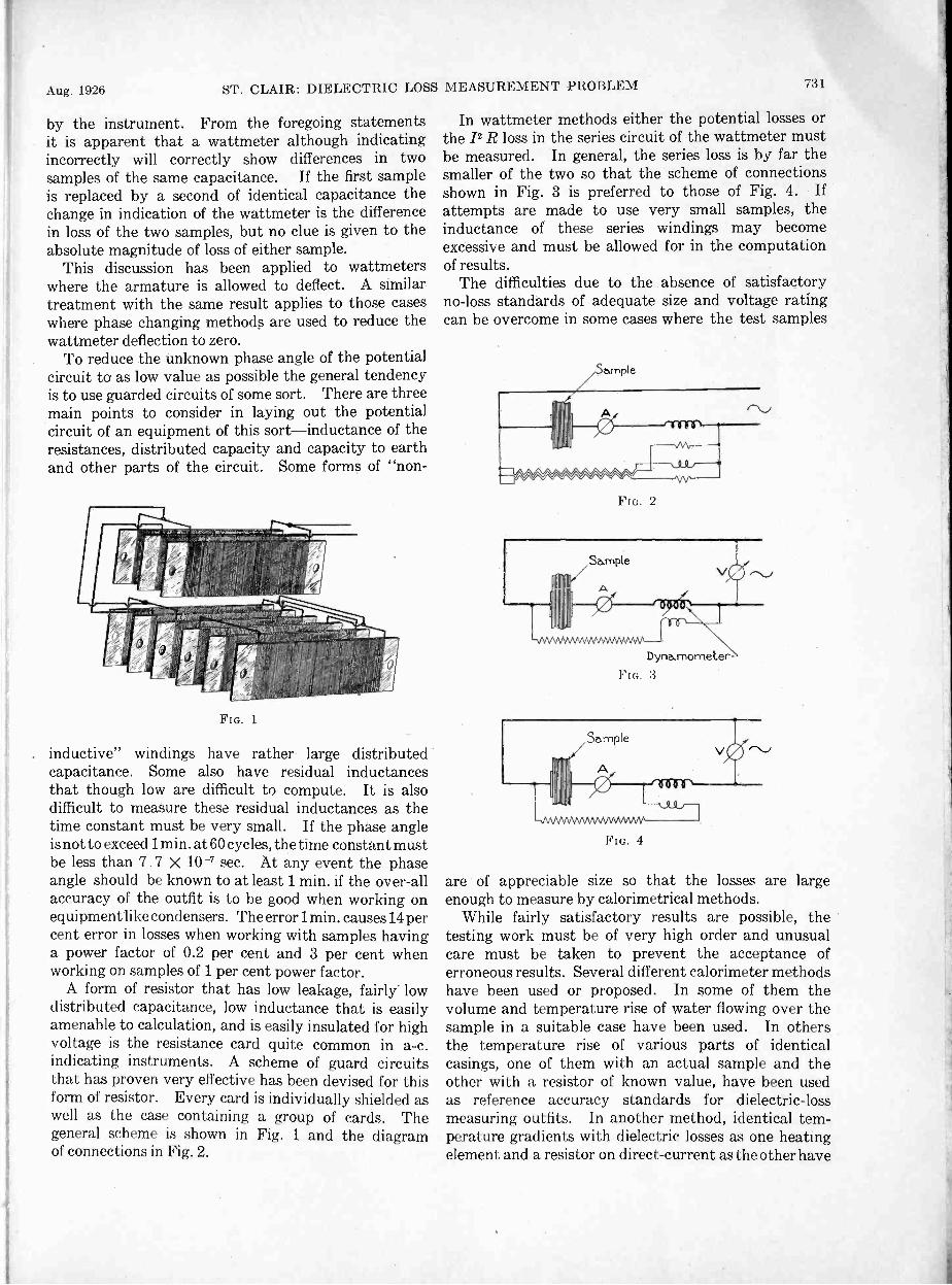
Aug. 1926 ST. CLAIR: DIELECTRIC LOSS MEASUREMENT PROBLEM 731
by the instrument. From the foregoing statementsit is apparent that a wattmeter although indicatingincorrectly will correctly show differences in twosamples of the same capacitance. If the first sampleis replaced by a second of identical capacitance thechange in indication of the wattmeter is the differencein loss of the two samples, but no clue is given to theabsolute magnitude of loss of either sample.
This discussion has been applied to wattmeterswhere the armature is allowed to deflect. A similartreatment with the same result applies to those caseswhere phase changing methods are used to reduce thewattmeter deflection to zero.
To reduce the unknown phase angle of the potentialcircuit to as low value as possible the general tendencyis to use guarded circuits of some sort. There are threemain points to consider in laying out the potentialcircuit of an equipment of this sort-inductance of theresistances, distributed capacity and capacity to earthand other parts of the circuit. Some forms of "non -
r' tifirnmiiitTlypierrworr..mig-orpteallibieopoupistamfpM.VtrinidAiirri
n
FIG. 1
inductive" windings have rather large distributedcapacitance. Some also have residual inductancesthat though low are difficult to compute. It is alsodifficult to measure these residual inductances as thetime constant must be very small. If the phase angleis not to exceed 1 min. at 60 cycles, the time constant mustbe less than 7 . 7 X 10 -7 sec. At any event the phaseangle should be known to at least 1 min. if the over-allaccuracy of the outfit is to he good when working onequipmentlike condensers. The error 1 min. causes 14 percent error in losses when working with samples havinga power factor of 0.2 per cent and 3 per cent whenworking on samples of 1 per cent power factor.
A form of resistor that has low leakage, fairly' lowdistributed capacitance, low inductance that is easilyamenable to calculation, and is easily insulated for highvoltage is the resistance card quite common in a -c.indicating instruments. A scheme of guard circuitsthat has proven very effective has been devised for thisform of resistor. Every card is individually shielded aswell as the case containing a group of cards. Thegeneral scheme is shown in Fig. 1 and the diagramof connections in Fig. 2.
In wattmeter methods either the potential losses orthe 12 R loss in the series circuit of the wattmeter mustbe measured. In general, the series loss is by far thesmaller of the two so that the scheme of connectionsshown in Fig. 3 is preferred to those of Fig. 4. Ifattempts are made to use very small samples, theinductance of these series windings may becomeexcessive and must be allowed for in the computationof results.
The difficulties due to the absence of satisfactoryno -loss standards of adequate size and voltage ratingcan be overcome in some cases where the test samples
FIG. 2
Dyna.mometer
FIG. :3
FIG. 4
are of appreciable size so that the losses are largeenough to measure by calorimetrical methods.
While fairly satisfactory results are possible, thetesting work must be of very high order and unusualcare must be taken to prevent the acceptance oferroneous results. Several different calorimeter methodshave been used or proposed. In some of them thevolume and temperature rise of water flowing over thesample in a suitable case have been used. In othersthe temperature rise of various parts of identicalcasings, one of them with an actual sample and theother with a resistor of known value, have been usedas reference accuracy standards for dielectric -lossmeasuring outfits. In another method, identical tem-perature gradients with dielectric losses as one heatingelement and a resistor on direct -current as the other have

732 ST. DIEU:CITRIC LOSS MEASUR,EMENT PROBLEM Journal A. 1. E. E.been used to demonstrate the accuracy of a testingequipment. This method is somewhat more elaboratethan the others, and in the hands of a careful experi-menter and with sufficiently good temperature condi-tions and thermometers may yield very good results.
A photograph showing a test of this sort under way
FIG. 5-CALORIMETER TESTS ON STATIC CONDENSER DIELECTRICLOSSES
is shown in Fig. 5 and a diagram of the calorimeter isshown in Fig. 6.
The whole equipment was installed in a room the tem-perature variation of which throughout the calorimeterI ests was not greater than 0.2 deg. cent. The temperature
NEMMIME*.
Pump
o
Pt. No.2In Water
No.1
"-Pump
2 ft.
Condenser
No.2 Oi
No.4
2
Water
mmidatelite
velffar:Condense
Pt. No.1In Oil
Pt. No.3
'L --Cork
No.4
FIG. 6
.21C
rise of the water jacket and of the oil above the arbi-trary reference temperature was determined to 0.002deg. cent. This generally required six or eight hours.Immediately, thereafter the condenser was removed
from circuit and resistances that had been built into thesame case were connected to a d -c. circuit. The lossesin these resistances were varied until the same tem-perature distribution was reached.
At this point it was assumed that the a -c. losses andthe d -c. losses were the same. All readings were takenat a distance by telescope to prevent body radiation in-fluencing the thermometers. Accurate speed control ofthe circulating pump was also in effect although thepump did not add appreciable heat to the water streamand the connections were very well lagged to preventundue radiation into the constant temperature room.
Another source of disturbance is the change of waveshape of the current in the test sample. Because of thevery low losses and the relatively large capacitance thetendency is to seriously accentuate any harmonics thatmay be present in the voltage wave.
The higher the harmonic the greater the amplificationof that harmonic in the current wave. The phaseposition of the harmonic will also tend to advance be-yond its normal position in the voltage wave and the
Reactor
FIG. 7
losses due to the harmonics will in general be enhanced.This tends to reduce the leading tendency of the har-monic so that its phase shift is unknown. If the lossesare measured correctly with appreciable wave distor-tion, the results are not those to be expected from sinewave currents of the fundamental frequency andmeasured voltage. This distortion of the wave alsocauses unknown error in the indications because of theunknown amplitude and phase position of these har-monics. A generally useful procedure that obviatesthis trouble is to obtain the required voltage rise byresonance or to use a reactance of very large value inseries with the sample, if resonance is uriadvisable.When the samples are small, resonance or a closeapproach to resonance is impossible or difficult atpower frequencies. A circuit diagram is shown inFig. 7.
In many checks of dielectric loss the shape of thepower -factor curve with voltage is of more interest thanis an exact knowledge of the actual loss. There isfortunately a fairly simple check that can be appliedto a given wattmeter or bridge outfit to show its relativeaccuracy at varying voltages. This test consists in theselection of four samples of identical capacitance andapparent loss. These samples after check at a givenvoltage are connected in series multiple and tested at

Aug. 1926 NEFF: RURAL ELECTRIFICATION
twice the original voltage. This results in applying theoriginal potential to each sample. The combinedcapacitance is equal to each of the original samples.Because of the identity of the samples and the applica-tion of the original test voltage, the power factor of thegroup should be the same as the original four samples,and the measured losses should be just four times theloss of any unit at the original voltage. Thus, with an
733
outfit to work to 2500 volts, a comparison of the relativevoltage errors of the 400- and 800-, the 600- and 1200-,the 800- and 1600-, the 1000- and 2000-, and 1200- and2400 -volt points might be made. If nine identicalsamples were available, a check of the 400- and 1200-,and the 800- and 2400 -voltage errors might be made,using three series multiple grqups and three timesnormal voltage.
Rural ElectrificationBY G. C. NEFF
M,mber, A. I. E. E.
. Synopsis.-This is a paper on rural electrification, discussingsome of the problems connected with this important development. Thepaper points out the effect of power and machinery on the living con-
ditions of the American farm and the part electricity may play. Itdiscusses the things being done by the agricultural and electrical in-dustries to direct and bring about a proper development of this service.
ACCORDING to a report of the United StatesDepartment of Agriculture, in the July 1925 issueof Crops and Markets, the total gross income of the
United States farmers for the year ending June 30, 1925,was approximately twelve billion dollars. This figureincludes the value of food and fuel products producedand consumed on these farms. A 1924 report of theDepartment of Agriculture shows that there are thirtybillion man hours of human energy used annually onthe farms of the United States and this figure does notinclude any time allowance for the work done by the wo-men in the house. If the entire gross income of the farmsof the United States of twelve billion dollars is used topay for these thirty billion man hours the hourly wagewould be 40 cents. From these earnings the farmersmust support and provide for their families, must payall of the operating expenses in connection with theirfarms, must pay taxes on property which has a valueof approximately sixty billion dollars, and must pro-vide interest on this huge amount of money which istied up in farm lands and improvements thereon.
The above statement shows that if the farmers of theUnited States are to be put in a prosperous condition,the hourly wage per worker must be raised. This canbe done by either increasing the income or by main-taining the present income with fewer workers. Ibelieve that the latter can be accomplished through aproper and more liberal use of power and machinery.Due largely to wide distribution of electric power bypublic utility companies, and to the ease with whichthis power can be automatically controlled, it will playa big part in reducing the number of necessary workersand in increasing general farm prosperity.
A study of general conditions shows that a very close1. Vice -President, Wisconsin River Power Co., Madison,
Wis.Presented at the Regional Meeting of District No. 6 of the
A. I. I?. E., Madison, Wis., May 6-7, 1926.
relationship exists between the income of each produc-tive worker and the average amount of mechanicalpower available to the workers. In China, the me-chanical power per worker is very low and the wagesare also very low. The average amount of poweravailable to the factory worker of the United States ishigher than in any other country in the world and like-wise the average wage is higher.
The same relationship holds true in different parts ofour country. Again, the United States AgriculturalDepartment Survey shows that the use of power perfarm worker in certain southern states is much lowerthan in certain northern states, and the income perworker is much less in these southern states than inthe northern states referred to above. It seems, there-fore, 'that if the average income of the worker is to beraised, it must be through increased production perworker and this can only be done with the help of ma-chinery and this calls for power. Therefore, properelectric power supply on the farm is something whichmay have much to do with farm prosperity itself.
While many farms are now and for some years will besupplied with electric service from the individual farmlighting units, general and permanent rural electrifica-tion will be brought about through a further expansionof our electric public utilities which now so efficientlyserve our cities and villages. In fact, this expansionhas begun and about four per cent of the United Statesfarmers are now enjoying central station service. Itmight appear from this that practically nothing hasbeen done by the utility companies in extending electricservice to the farms. To correct this impression, pleaseconsider the following statements. In that part of theUnited States lying between the Alleghany Mountainson the east and the Rocky Mountains on the west areapproximately 100,000 farms receiving central stationservice.
On the average, three farms can be served from one

734NEFF: RURAL ELECTRIFICATION Journal A. I. E. E.
mile of rural line. Therefore, there are located in thismiddle section of the United States approximately33,000 miles of rural lines. If these rural lines were putinto long straight lines, they would extend from Chicagoto Tokio on the west, to Constantinople on the east,to the southern tip of South America on the south, andto the North Pole on 'the north; and there would beenough line miles left over to build a line from New Yorkto San Francisco and back again.
In the more thickly-settled region of the AtlanticCoast and in the region along the Pacific Coast, whereelectric service is used on farms for irrigation purposes,the number of farmers receiving electric service fromcentral station lines is about equal to the number servedin the great middle part of this country. The miles ofline on the coast regions which are devoted to ruralelectric service add greatly to the mileage just described.This shows that an exceedingly large amount of rurallines have been built, that huge amounts of money havebeen spent, and that an appreciable start has been madein this greatly needed development. The fact thatless than four per cent of the farms in this country areserved by such a tremendous mileage of distributionlines clearly demonstrates that to extend adequateelectric service to a large portion of the farms in thiscountry is a task involving huge sums of money. Thisfact is fully appreciated and it is with the completeknowledge that the adoption of a wrong policy ofdevelopment would result in losses very detrimentalboth to agriculture and the utility industry, and whichwould also seriously affect other industries, that a veryextensive plan of study and investigation has been madein which every angle of the extension of service to thefarm and the use of such service is being carefullystudied and analyzed.. This work is being carried on byrepresentatives of agricultural organizations and agri-cultural colleges, by agencies of the National and StateGovernments which have to do with agricultural prob-lems, and by the utility industry and the manufacturersof electrical and agricultural machines and appliances.
This cooperative work is guided by a committeeknown as the Committee on the Relation of Electricityto Agriculture and through its efforts and the excellentcooperation of various state organizations, there havebeen established 17 experimental rural lines in 17 dif-ferent states. These experimental lines really formfield laboratories in which to carry on the study ofrural electric service. By a joint study of this kind itis believed many mistakes will be avoided which wouldotherwise be made and, while some mistakes will prob-ably be made, even with the precautions taken, it isbelieved the major mistakes will be prevented. In themeantime, rural electric service development is goingahead as illustrated by the statistics given above.Thousands of farms are being connected every monthand the rate of increase in connection is growing eachyear.
If rural electric service is to be built on a safe and
permanent basis, it must return a profit to the farmerwho makes use of the service, and also makea proper return to the electric utility which suppliesthe service. While there is much to be learned aboutthis new development, those who have studied it mostare convinced that both of these two conditions can bemet if the development is intelligently directed. Byintelligent direction is meant:
(a) Creation of a new department in electricutility organizations, devoted entirely to the properhandling and solving of all rural electric serviceproblems, and made responsible for the direction ofthe development.
(b) Placing at the head of this new department aman who has had training in agricultural problemsand who is sympathetic toward agriculture.
(c) The development of a fair, simple, workableand complete plan under which lines will be extendedand service supplied.
(d) The development of a rate schedule which willgive the utility proper compensation but which is somade as to encourage increased use by the farmer.
(e) The making of surveys and maps and the collec-tion of such information that the main trunk linesmaybe intelligently laid out to most efficiently serve theentire rural territory before construction work starts.(This will eliminate much rebuilding, overloadedlines, etc.)
(f) Keeping the rural department fully informedon all experimental and research work now beingconducted in agricultural colleges and on the ruralexperimental lines in many states. This will makepossible the most efficient and fullest use of electricservice on the farm.
(g) Close cooperation between this rural depart-ment and farm customers.
(h) A desire on the part of the utility to supplygood and adequate service at lowest cost, and adesire on the part of the farm customer to makefullest profitable use of such service.In the following "Program for Developing Rural
Service" is given a complete plan of operation of a ruraldepartment in one of the large utility companies ofWisconsin. This particular department is headed byan agricultural engineer, a graduate of the WisconsinUniversity, who has had about two years' experiencein giving intensive study to electric service on the farm.
PROGRAM FOR DEVELOPING RURAL SERVICESuccessful development depends upon at least three
essential factors:A. A sound policy of building and financing rural extensions.B. A rate schedule which fosters large use of current by thefarmers.C. A complete understanding of the rural program and
of the reasons underlying its adoption, by every employee whohas any direct or indirect contact with rural customers.I. Planning the Extensions

Aug. 1926 NEFF: RURAL ELECTRIFICATION 735
1. A study of the location of all existing substations at whichrural service lines may originate.
2. Decision as to the location of additional substationsstrategically placed so that the entire territory may be servedto the best advantage.
3. The division of the entire territory into definite ruralservice areas, each to be served by its own substation. Thesize and shape of these areas will depend on the local conditions.
4. A basic plan or map to be followed in the building of ruralservice trunk lines. The first of these lines will normally extendthrough the most thickly -settled areas. These trunk linesshould be planned with a view to serving the entire area ulti-mately, and all building should follow these plans.
Feeders to and stubs from these trunk lines may be built asdevelopment progresses.
II. New Rural Customers1. First, campaign for new rural customers to be made along
existing rural lines, in an effort to bring the average of customersper mile as high as possible.
2. Second, effort to be directed along existing pole lines onwhich it is practicable to string wires for rural service.
3. An intensive canvass of the more promising territoriesto be traversed by the definitely planned rural service trunklines mentioned in Section I.
4. Definitely bringing our new rural policy to the attentionof each existing rural customer, individually, and providing himwith a comparison of rates based on his conditions. This workis to go on at the same time as that mentioned above.
III. Procedure1. In securing new customers along existing lines, the rural
service salesman will proceed as follows:A. Call on prospect; explain rates and advantages of new
rural policy; sign contract in duplicate.B. Leave one copy of contract with prospect and send other
to district office.C. Make "Rural Prospect Report" in duplicate, sending
one copy to local office and other to General office. Thiswill be done whether prospect signs contract or not. Datafor this report will be brought out during sales talk.
D. Make daily report showing calls made, contracts signed,miles of line covered, etc.2. While canvassing the line for new customers, the rural
service salesman will also call on each old customer and givehim the opportunity to change from old to new rates. Theprocedure will be:
A, b, c, and d as above.E. When canvass of line is finished, report length of line,
number of old customers, number of new customers, andnumber of transfers from old to new rate.3. District and local managers and all others working on
rural service extension, but not specifically assigned to thatwork, will follow the same procedure, omitting (d), the dailyreport.
4. In extending rural service along existing transmissionlines, the following procedure will apply:
A. Decision by engineers as to whether or not it is practi-cable to carry a rural distribution circuit on the same poles.
B. Estimate of costs by Engineering Department. Sincethe number of prospects who will become customers is notknown, this estimate should show as separate item:
a. Cost of the line itself without transformers, services,or meters.
b. The cost of supplying service to a customer at somespecified distance from the line, and
c. The amount to be added or subtracted for longeror shorter service lines.C. Canvass of prospects by rural service salesmen, district
or local managers, or others to create interest, and to discover
how many customers may be expected. This makes possiblean estimate of the cost per prospective customer.
D. Contracts and reports as detailed above.5. The location of rural service trunk lines will be made by
the Engineering Department in cooperation with the local repre-sentative and with the Rural Service Department. The loca-tion will depend upon such factors as straightness of roads, treeconditions, villages to be served, lakes, marshes, or rivers to becrossed, density of rural population, soil fertility, farm pros-perity, demand for service, etc. When the location of the pro-posed trunk line has been fixed, procedure will be as shown
above in 1 and 4.
IV. Reports to Rural Service Department1. Daily report of rural service salesman.2. Rural prospect report to be made in duplicate by any
employee who learns of a prospect, one copy to local office, otherto general office, Rural Service Department.
3. Completed canvass of rural line showing changes made.4. Record of proposed location of rural trunk lines with
cost estimate.5. Route all work orders in any way affecting rural customers
through Rural Service Department so that needed data may betaken off. Work order to show names of rural customers to beconnected or disconnected, phase or service to each, and size oftransformer and meter of each. Also estimated contributionto be paid by customer.
6. A complete report by each district manager of currentused and bills paid each month by each rural customer.
V. Better Service1. The closest possible cooperation between Rural Service
Department and the Ripon Experimental Line.2. Study by Rural Service Department of the reports of
all electric farm projects and related articles.3. Securing by Rural Service Department of all possible
information relating to the different types and makes of allmachines which are likely to be operated electrically.
4. Digests of this literature and of manufacturers' datato be supplied by Rural Service Department to district and localmanagers; also tables of electric consumption by differentmachines under various conditions.
5. A careful study of the relation between the appliancesused and the resulting current consumption on the average farm.Data for this will come from the rural prospect reports andmeter cards. This study will be made by the Rural ServiceDepartment and the results will be supplied to all local repre-sentatives.
6. The employment of at least one first-class electricalrepair man who has a thorough knowledge of really good farm-ing practise ; this man to be furnished with a light truck andto travel the rural lines calling on every customer. He willacquaint himself with the needs of the customers, and will seekthe best solutions of the electrical problems of each. He willservice all faulty equipment, explain ways of making fuller use ofelectric service, and will carry bulbs and some of the most com-monly used standard appliances to supply customers who wantthem. He must remember that he is a service man, not a sales-man, and that he only carries merchandise for the convenienceof the customers.
VI. Publicity1. The discovery and fostering of outstanding examples of
the best uses of rural service'in each community. Where goodfarmers can be found to cooperate, each local manager shouldtry to develop electric farms that can be used as object lessons.But this development must not be subsidized.
2. Local managers will place news items in local papers.These will report the addition of new farm customers with brief

736NEFF: RURAL J LM, Journal A. I. E. E.
statements of how each expects to use service, or toll of theintroduction of some novel application, or give definite figureson the performance of some machines, eto.3. A definite and unified campaign of advertising in farmpapers, supplemented by a series of articles explaining thecompany's policy and the results that may be expected fromthe use of electricity.4. Statements of bills as computed under new rates, to besent with regular monthly bills to old rate customers who would
profit by changing to the new rate. Interest on the customers'investment in the line should be included in showing thisadvantage.
A carefully prepared contract form has been drawn upby this company which gives definite rules under whichservice will be extended to new farm customers andother customers living in the country. Under theserules, the utility companies finance the rural lines up toan average cost of $400.00 per farm customer wheneverthe customers agree to comply with certain conditionsdescribed in rules.
This contract gives the schedule of rates used inbilling as shown in the accompanying table.
RATES FOR FARM CUSTOMERS(a) Service Charge
MonthlyTransformer Capacity Required in Kv-a. Service ChargeNot more than 1M $5.50Over 1M and not more than 3 6.00Over 3 and not more than 5 6.60
7.25Over 7 and not more than 10 8.00Over 5 and not more than 7M
If more than two rural customers are served fromone transformer, each of them will be allowed a dis-count on his service charge as follows:
Customers Discount on ServiceServed Charge, Per Cent
3 204 405 50
(b) Energy ChargeFor the first 30 kw -hr. used per month 5 3/ cents per kw -hr.For all in excess of 30 kw -hr. used per
month 3M cents per kw -hr.
A discount of M cent per kw -hr. will be allowed onany bill paid within fourteen days from the daterendered. The rate is made up of a service chargesufficient to cover the fixed costs on the rural extensionand an energy rate covering only generating and cer-tain transmission costs. The energy rate is compara-tively low and if the farm customer increases the use ofenergy very materially the addition to the monthly billwill be relatively small. This rate encourages new usesof electric service by the fa'rmers and brings aboutincreased use with decrease in cost per kw -hr. to thefarmer. All of which is very desirable to both thefarmer and the utility and brings about general satis-faction with the service.
The service charge in this schedule deals almostentirely with the distribution line costs and is basedupon an average investment per distribution line of$400.00 per customer. The service charge is intendedto cover return on the investment, retirement expenses,taxes, operation, and maintenance expenses. Theseexpenses may be considered as more or less fixed ex-penses and do not depend upon the amount of energyconsumed by the customer. Fixed costs on the invest-ment in power plant and transmission line could beincluded in the service charge, but in this contract allof these fixed expenses have been included in the energycharge.
The "energy charge" is low and is based upon theproduction cost plus a certain portion of the fixedcharges in transmission lines and generating stations.In arriving at this cost the rural customer has beengiven the benefit of the system load factory rather thanthe load factor of the farm electric load. This results inlower costs of energy but it is believed that it is the fairway to handle the situation.
The accompanying table shows the kilowatt-hoursused by 1226 farmers served by a Wisconsin company.These farms are largely dairy farms. This table showsthat full use is not being made of electric service on thefarms listed. A number of the farms shown in thetable each use more than 100 kw-hrs. per month andthis demonstrates in a practical way that a large use ofelectric service is possible.
CLASSIFICATION OF RURAL CUSTOMERSBY AVERAGE MONTHLY USE OF ENERGY
Kw -hr. Consumed per Month Number ofCustomers
Per Centof TotalNumber
Less than 10123 1010-19390 3220-29275 2230-39158 1340-4975 650-100
131 11Over 10074 6
Total1226 100
On the various experimental lines previously referredto, the farmers are using from 100 to 500 kw-hrs. permonth and the average is continually increasing.It is believed that farm customers, in three or fouryears, will use on theaverage 150 kw-hrs. per month andif this can be brought about, those who have beenmaking a study of electric service believe that suchservice, sold at any fair rate, will bevery profitable to thefarm customers and at the same time will be a loaddesired by the electric public utility companies. Whenthis condition has been brought about rural electricservice will be established on a sound and profitablebasis, and electric service in the country will be takenas a matter of course, much as it is now in the city.

Electrical Communication*Report of Committee on Communication
H. P. CHARLESWORTH, Chairman
To the Board of Directors:In presenting this report it is the aim of the Com-
mittee on Communication not so much to present acomplete report of all the developments which havebeen made during the last Institute year in the artof electrical communication, but rather to single outthose advances which it is thought will be of greatestinterest to the members of the Institute.
PRINTING TELEGRAPHY '
The year has been marked by a rapid growth in theuse of printing telegraph apparatus by the telegraphcompanies, railroads, news associations for distributingnews items, and by general business concerns in connec-tion with private line business. There is a generaltendency toward the operation of the apparatus athigher speeds, thus increasing the speed requirementsof the line circuits and requiring the use, especiallywith long and complicated circuits, of repeaters whichreform or regenerate the line signals.
Printing telegraphs are now being used in connectionwith switching arrangements, both manual and auto-matic. These arrangements have been found valuablefor sending information from a central location to oneor a number of receiving stations. A recent installationof this type consists of a number of printers controlledby automatic switching apparatus so arranged that anyprinter equipped with a sending keyboard can communi-cate individually with any other printer so equipped,or communicate with a group of receiving-only printers.Dials, similar to those used with telephone instruments,are used at the transmitting stations for setting upany desired operating condition.
The ever widening field of usefulness of printingtelegraphs was illustrated by a paper on ciphering anddeciphering arrangements for secret wire and radiocommunications read by Mr. G. S. Vernam before theMidwinter Convention of the Institute in New Yorklast February.
In the message business of the telegraph companiesthere has been a marked tendency to use tape printersinstead of page printers. To facilitate the subdivision
*Committee on Communication:H. P. Charlesworth. ChairmanF. L. Baer,0. B. Blackwell.L. W. Chubb,Charles E. DavieH. W. Drake,Major P. W. EvaR. D. Evans,E. H. Everit,L. F. Fuller,
Presented atWhite Sulphur
D. H. Gage. Lieut. Corn. B.B.Ralston.S. P. Grace, F. A. Raymond.P. J. Howe. Chester W. Rice.
s. F. H. Kroger, J. K. Roosevelt.N. M. Lash, H. A. Shepard.
ns, Ray H. Manson, John F. Skirrow,R. D. Parker, E. B. Tuttle,H. S. Phelps, F. A. Wolff,
C. A. Wright.the Annual Convention of the A. I. E. E. at
Springs, June 21-25, 1926.
of the tape into single lengths and the attachment ofit to message forms for delivery to customers, effectivecutting and gumming devices have been developed.
In addition to the application of tape printers tothe Multiplex circuits used in trunk line service, a sim-plified combination of such a printer with a keyboardtransmitter is coming into extensive use for branch officecircuits and other short -line service. The applicationof these printers will probably be quite extensive dueto their accuracy, traffic handling capacity, andeconomy. This type of printer is primarily intendedfor single -line operation, affording intermittent single -channel service in both directions. It also lendsitself readily to use on duplexed circuits whenthis method is desirable. Printers of this typehave a field in private offices of patrons where theamount of business handled warrants their use. Main-tenance requirements are few, and the attentionrequired is sufficiently small to make this servicedesirable.
"TICKER" TRANSMISSION
During the past year the automatic tape transmissionsystem for telegraphic tickers was installed and putinto operation at Cleveland, Chicago, Los Angeles,and San Francisco. Long-distance distribution ofticker service was greatly extended from New York,Cleveland, and Chicago.
A particularly note -worthy feature was the establish-ment of telegraph ticker service in important businesscenters on the Pacific Coast which heretofore obtainedmarket quotations only by Morse on brokers' privateleased wires. Full market quotations are now suppliedto Pacific Coast brokers from the New York Stock,New York and New Orleans Cotton Exchanges, andthe Chicago Board of Trade. Provision is also madefor "dropping" the quotations at various cities alongthe route of the main circuit which extends fromChicago to San Francisco via Los Angeles, a wiredistance of 2895 miles. New York stock marketquotations reach the brokers on the Pacific Coast in30 to 45 seconds from the time that they appear onthe tickers in Wall Street.
The system developed for this and similar serviceselsewhere includes modifications of the two -channel,Multiplex printing telegraph apparatus and repeaterssuitable for use on the long lines involved.
The transmitters are controlled by perforated tapessimilar to those used in other automatic telegraphsystems. Instead of the more familiar five -unit code,a six -unit code is employed, the sixth pulse of eachcharacter serving to distinguish between letters and
737

738ELECTRICAL COMMUNICATION Journal A. I. E. E.
figures. The receiving instruments at customers'offices are self-winding tickers of a type already widelyused in Eastern cities.The output of the channel printer system in char-acters per minute per channel is the same as thatobtainable with self-winding ticker systems used onshorter circuits having but one channel.
SUBMARINE TELEGRAPHY
The great success of the new type of submarinetelegraph cable loaded with permalloy that was men-tioned in last year's report has led to the rapid extensionof this type of cable, and during the year five importanttelegraph cables of this type were under construction.The technical features of this type of cable were de-scribed in a paper by Mr. Oliver E. Buckley which waspresented at the Convention last June and which ap-peared in the August JOURNAL.
MACHINE SWITCHING TELEPHONYWith the continued steady growth in the application
throughout the country of machine -switching telephoneapparatus have come further developments in this formof apparatus. In the panel system, which is the typeof system used for large cities, a simplified form oftandem switch has been developed by which, after oneselection at the calling office, the final selection of thecalled office can be made by apparatus located at adistance from the originating office, and used to collecttraffic from a number of offices routed over commongroups of trunks. This results in a material savingin the trunk plant.
A more efficient method of associating a sender withthe calling subscriber has been developed. Thisresults in an appreciable saving in the number ofsenders required, uses more economical apparatus,and reduces the number of types of apparatus requiredin an office.
In the step-by-step system, which is the type usuallyused for the medium and smaller sized cities a line -findersystem has been developed which is similar in principleto that being used with success in panel offices. Thisemploys the same selector that is used in the rest ofthe switching train, effects an improvement in serviceto the subscriber, and lends itself more readily toefficient equipment layout.
A machine -switching tandem system, employingstep-by-step equipment, has been developed for com-pleting toll calls within a 50 -mile radius of any givencentral office area. All calls completed through thissystem are handled directly by the originating operatorover dialing trunks. A tandem system of this kindprobably will find its principal application in areasemploying step-by-step machine -switching equipment.An installation of this type recently has been put intoservice in Los Angeles and serves some 75 centraloffices having a total of approximately 400,000 sub-scribers. The principal new engineering feature of
this systeni is the means which was developed fordialing and signaling over phantom toll lines.
New types of frames for mounting step-by-stepequipment have been developed which take advantageof the ceiling heights ordinarily found in central officebuildings, thus effecting a material reduction in floorspace requirements.
A cordless "B" switchboard has been developed forcompleting calls from manual offices to machine officeswhere the number of manual offices involved makes theuse of dialing devices at the manual offices prohibitivein cost. This switchboard employs new trunkingprinciples which result in very efficient and simplifiedoperating equipment.
TELEPHONE TOLL CABLESAn event of prime importance during the year was
the completion on August 11 of the telephone toll -cable system connecting New York and other AtlanticSeaboard cities with Chicago. This system of cablesruns from Chicago through South Bend, Toledo,Cleveland, Detroit, Pittsburg, and Harrisburg to
utro.ite..141}1/NW
WADklaf ,RAns
104.1112C0
/ 1,111 AMR
10110151,'"
MOAK&
MOO CAVIL MOD%
"
haurt,--- ..*'''1415 cry ia TOOFill 7
W
0.0 hAARISOuP4 rllej....COW.R'L.kt'., "2-4!L%ilii-not, Gana L''' irr
WhOhl.r,- lONCOINAll .."1......
4+ WASf- 4. FALLS
blICA
odo,-.41%
WAN..,SOVA10.1
sodiaLOS,
KOK* Oh
!Mal ATIMOY"liar
fISOUOIASKAGf
- gab bout In 119754. Leonel LEV01.3 Lkee101104.1915K'NN- - - kleSton Prooud hex fee.retort16.', 44 wari Stro,Ilei.LOct Ste ws
LAWFIROI
ranaM
NOR
loM
LEGEND
TOLL CABLE ROUTES IN NORTHEASTERN SECTION OF THECOUNTRY
Philadelphia and New York, connecting with the cablesystem extending from New York to New Haven,Hartford, Springfield, Providence, Worcester, Boston,and Albany, and from Philadelphia to Baltimoreand Washington. Extensions of this cable westwardfrom Chicago carry the toll -cable system to Milwaukee,and by the end of this year the system will extend toPeoria, Springfield, and St. Louis. Numerous shorterbranches carry this network to many other pointsnear the large centers mentioned.
In addition to this very extensive network in thenortheastern part of the country, smaller networksare starting in other parts of the country, notably invarious parts of the Pacific Coast and in Florida. Therapidity of growth of this type of telephone plant isillustrated by the fact that during the year 1925 over1000 miles of toll cable were placed in service, andduring the year 1926 more than 1500 miles will be in-stalled. The map reproduced below shows the routesof the present and proposed toll cables.

Aug. 1926 ELECTRICAL COMMUNICATION 739
The possibility of providing satisfactory telephonetransmission over very long circuits in cable has comeabout through a series of remarkable developments in
telephony which have been discussed from time to timebefore the Institute. During the year the networkmentioned above was the subject of a paper presentedbefore the New York Section in December by Mr.J. J. Pilliod, and was discussed at other sectionmeetings.
The development of toll -cable networks means agreat deal in improving and increasing the servicegiven to the public. Practically the entire countryis subject to severe sleet storms from time to time andtoll cables furnish a means for providing great securityagainst interruption from such storms or other weatherconditions. Furthermore, they furnish a practicalsolution for meeting the very great demands for servicebetween large urban centers of the country. A singlecable contains between 200 and 250 telephone circuitsand would require five or six open -wire toll lineswith former methods of construction, the largest numberof circuits which can be provided by this means; further-more, furnishing means for supplying circuits so liberallyas to give a faster service. As indicative of the increasedfacilities provided, it may be mentioned that theNew York -Chicago toll -cable system contains about510,000 miles of wire, while at the time this project wasstarted, the facilities for serving the correspondingpoints consisted of less than 100,000 miles of openwire.
In last year's report reference was made to certainpapers describing the development of telegraph systemssuitable for use in long telephone cables. The applica-tion of these systems has been considerably extendedduring the past year. The voice -frequency carrier sys-tem is of special interest, since, through the developmentof apparatus for separating to a very high degree cur-rents of different frequencies, it has become possible tooperate 12 independent telegraph circuits over a singletelephone cable circuit, each of the 12 circuits using adifferent frequency ranging from 425 to 2300 cycles persecond. There are now in operation about 25,000channel miles of telegraph circuits operated by thissystem in the telephone cable plant.
RADIO TELEGRAPHY
A new radio telegraphy service between the DutchEast Indies and San Francisco has been established,and a new service from New York to Holland has beenintroduced for handling through traffic from Java.
The work of decreasing the use of spark transmitterswith their corresponding interferences, commencedin 1924, has progressed rapidly to such an extent thatover 150 American merchant ships are now equippedwith tube transmitters.
The use of the radio direction finder for navigation israpidly increasing and has passed the experimental stage.The Great Lakes are leading in this respect, due to the
demonstration of the particular value of this apparatusin the difficult navigation problems inherent in theGreat Lakes.
TRANSATLANTIC RADIO TELEPHONY
The development work which has been in progressduring the past few years on transatlantic radio tele-phony reached a point of considerable interest lastwinter in the attainment of two-way telephonic conver-sations. In the earlier tests, telephonic transmissionhad been but one-way, from the United States toEngland, with the study of transmission of radio waveEin the reverse direction being made by the utilization ofradio telegraph stations in England. Two-way talkingwas made possible the winter of 1925-26 by the completionof a transmitting station by the British General PostOffice. The British radio telephone transmitter is,in general, similar to that employed on the Americanside. Both transmitters are of the carrier -suppression,single -side, band type, which makes the maximum useof the transmission power and which minimizes thefrequency band which is required. Receiving on bothsides is carried out by means of directional receivingantennas of the wave -antenna type. Reception on theAmerican side has been further improved by establish-ing a receiving station at a higher latitude where theatmospheric interference is less, located at Houlton,Maine. The Houlton reception is extended into NewYork by means of wire telephone circuits. Likewise,the voice currents originating in New York are trans-mitted to the Rocky Point transmitting station overwire circuits. Similarly, in England the radio trans-mitting and receiving stations are connected intoLondon by telephone circuits. In this way, an in-tegral two-way circuit is established with New York,and London as the terminals.
The carrying on of two-way talking tests betweenEngland and the United States created much generalinterest and arrangements were made to enable agroup of American Press representatives in New York,and a similar group of English newspaper men inLondon, to participate in the tests by conversing witheach other. These tests represent the first time thatgroups of people have been able to converse with eachother across the Atlantic.
Papers by Messrs. A. A. Oswald, J. C. Schelleng, andR. A. Heising, describing important technical featuresof the apparatus used for transatlantic radio tele-phony were published in the June 1925 Proceedingsof the Institute of Radio Engineers.
RADIO PROPAGATION TESTS
A great deal of activity has been shown in studyingthe properties of the medium, intervening betweentransmitter and receiver, through which the radiowaves must pass. This information is essential beforewe can utilize, to the best advantage, this remarkablebut eccentric medium which nature gives us.
Extensive propagation tests have been reported on

740ELECTRICAL COMMUNICATION Journal A. I. E. E.
long, medium, and short wave lengths, together with alarge amount of theoretical work towards explainingand correlating the apparently contradictory behaviorfound in different parts of the radio spectrum. Thiswork has confirmed the existence of a positive ionizationgradient in the upper atmosphere, postulated independ-ently, many years ago, by Kennelly in this countryand Heaviside in England.
The Naval Research LabOratory published the resultsof experiments which indicate that short waves may, ineffect, hurdle the first few hundred miles of their journeyand be received at a distant point with a much greaterstrength than would be expected from the past ex-perience with long waves. In the range of frequenciesunder exploration (down to about 30 megacycles, or10 meters) the "skipped" distance appears, in general,to increase with increase of transmission frequencyand to be greater at night-time than at day -time.These results have been confirmed by other experi-menters. Theories have been proposed (among others,by Baker and Rice in a paper presented before Mid-winter Convention of the A. I. E. E., 1926) to explainthese phenomena which assume that waves receivedat a distance are deflected downward from some upperionized region of relatively low index of refraction andof low attenuation.
The observed indications of rotation in the plane ofpolarization and directional errors find a qualitativeexplanation when due account is taken of the fact thatthe earth's magnetic field, acting upon the free electrons,will change the velocity of the wave and producerotation. This effect is especially marked in the vicin-ity of 214 meters, which corresponds to the resonantfrequency of an electron in the earth's magnetic field.
Careful investigations of fading and signal distortion,so exasperating to the broadcast listener, have shownthat they are closely related to the high degree of fre-quency selectivity exhibited by the radio medium.
During the total eclipse of January 24, 1925, manyobservations were recorded which further tended toconfirm the recent electron dispersion theory of theradio medium.
An observed variation of signal strength during mag-netic storms is also significant. Here the effect is areduction of the normal signal strength by night andan increase above normal by day.
Increasing use is being made of the short wave rangeof frequencies as is evidenced by the continued increasein the number of short wave licenses issued to commer-cial concerns. Experimental work indicates thepossibility of twenty -four-hour telegraph service withshort waves over distances of several thousands ofmiles. The transmission varies largely with the timeof day, however, one frequency transmitting muchbetter for one period of the day and another frequencyfor another period, so that the use of several wavefrequencies appears to be required to give uniformoperation..
RADIO BROADCASTING
Continued improvement has been made in radiobroadcasting on both the receiving and the transmittingsides. The receiving set improvements are, in general,characterized by better quality of reproduction, whichmeans higher grade amplifiers and better loud speakers;but there is still much to be desired in these respectsin receiving sets as a whole. The fact that the reliable,high -quality service range of the average radio broad-cast transmitting station is relatively short is beingmore generally recognized and is leading to a moreextensive use of long distance wire lines for enablinggood programs to be made available at a number ofwidely separated broadcast stations, and is leading alsoto the use of greater power in transmitting. Asmany as 17 stations, spread over the northeasternquarter of the United States, are nowregularly suppliedfor a portion of their time with programs transmittedover special long-distance wire circuits. A number ofstations are now transmitting with five kw. power, andone station which is capable of transmitting with asmuch as 50 kw. has been established during the year.
Another important improvement in radio trans-mitting stations introduced during the year is the useof master oscillators with piezoelectric frequencycontrol for the purpose of reducing quality distortionin the received signals. In general, there was a consid-erable improvement in the maintenance of the frequencyassignments of broadcast stations, due to a more generalappreciation of the need for frequency stability and tothe efforts of the Radio Inspection Service in checkingup conditions and of the Bureau of Standards in thework of frequency standardization.
The problem which exists in the regulation of radio,in the general public interest particularly in theallocation of wave bands, has been reflected in sub-mitting to Congress several bills designed to strengthenthe Government's control of radio, and by theholding of the Fourth National Radio Conference atWashington during the fall of 1925. This Conferencerecognized the fact that the number of transmissionswhich can be accommodated in the range of frequenciesavailable for broadcasting is definitely limited, andrecommended that the Department of Commerceundertake to limit the number of broadcast stationsto be licensed.
ELECTRICAL TRANSMISSION OF PICTURESThe commercial service for the transmission of pic-tures by wire between New York, Chicago, and San
Francisco, has continued throughout the year. Theresults have been promising and it has been decided toadd five more complete stations to the picture-trans-mission network. This extension should enable athorough test to be made of the commercial demandfor this type of service.
An interesting experiment was conducted for theU. S. Signal Corps, in October 1925, when pictures

Aug. 1926 ELECTRICAL COMMUNICATION 741
yY
were taken from an aeroplane over Fort Leavenworth,Kansas, developed on the plane, dropped by means ofa parachute, and transmitted from Fort Leavenworthto New York, Chicago, and San Francisco, simulta-neously. The entire experiment was so successful thatarmy officers in New York City viewed the picture29% minutes after the snapping of the camera on theplane at Fort Leavenworth, approximately 1500 milesaway by wire. This is an indication of the usefulness oftelephotographs for war purposes.
During the year from March 1925 to 1926, a series oftests of radio transmission pictures has been conductedbetween Carnarvon (Wales), San Francisco, Honolulu,and New York. Specific mention should be made ofthe pictures sent by radio from Honolulu to New Yorkduring the Naval maneuvers of our fleet there in May1925. As a result of the successful completion of thisexperimental work, commercial service has beenestablished between England and New York and alsobetween Hawaii and San Francisco.
INDUCTIVE COORDINATION
Last year, the report of the Committee announcedthe formation of the American Committee on InductiveCoordination, embracing representatives of all wire -using utilities interested in this problem. During theyear, the committee has issued a very complete and ex-tensive bibliography of publications bearing oninductive coordination. This bibliography includesnot only American, but also foreign references and con-tains a total of about 900 items. It is expected to beof great value to all concerned with inductive coordina-tion work. Another item of interest in this field isthe issuance of a report by the joint, general committeeof the National Electric Light Association and the BellTelephone System, covering the principles and practisesadopted by those organizations for the joint use ofwood poles by supply and communication companies.
During the year this joint general committeecontinued its progress in research work on a largenumber of specific problems in inductive coordination.The study of these problems has been facilitated by thedevelopment of improved measuring apparatus andmethods particularly adapted to the wave analysis ofpower -circuit voltages and currents and of inducedvoltages and currents in telephone circuits.
Two papers dealing with the subject of inductiverelations between power -distribution circuits and tele-phone circuits were presented at the Seattle Conventionin September, in connection with a symposium on power-distribution.
TELEPHONE SERVICE FOR THE DEAF
Another interesting telephone development relates toimproved service for deaf people. Many partiallydeaf people, who have difficulty in hearing ordinaryconversations, use the telephone with ease. Others,who are somewhat more deaf, however, have not beenable heretofore to use the telephone. In order to make
the telephone service available in these special cases,apparatus which greatly increases the volume of soundreceived has been developed for the use of deafpeople. Although in cases of extreme deafness, noamplification of sound, however great, makes hearingpossible, this new device makes it possible for manypeople of impaired hearing who would otherwise beunable to use it to obtain telephone service. Theapparatus is designed, of course, only for those havingimpaired hearing.
CHARACTERISTICS OF SPEECH
The work carried on by telephone research engineers,in the study of the characteristics of speech, has con-tinued to produce important and interesting resultswhich have been described in a number of publicationsduring the year. Of particular interest is the .paperpublished in the A. I. E. E. JOURNAL for March 1926,by Messrs. Maxfield and Harrison entitled "Methodsof High Quality Recording in Reproducing of Musicand Speech Based on Telephone Research." Thispaper tells of the application to the improvement ofphonographic reproduction of speech of some of themethods developed in the study of the quality of tele-phone transmission.
LOADING OF TELEPHONE CIRCUITS
The year 1926 marks the completion of the first 25years of the application of loading to telephone circuits,in the form of inductance coils inserts in the line atperiodic intervals. A paper presented by Shaw andFondiller at the Midwinter Convention reviewed theprogress which has been made in this country, in boththe development and application of loading, coveringparticularly, the last 15 years. The outstandingdevelopments in that period are the compressed -powderiron -dust core material, the loading systems for the longtoll cables and the more economical systems for localexchange area trunk circuits. The extent of the appli-cation of loading is indicated by the estimate given inthat paper, of 1,250,000 loading coils in this country, asof January 1, 1926, and by the expectation that thisnumber will be doubled by 1930.
FIRE -ALARM, POLICE -SIGNAL, AND TRAIN -CONTROLSYSTEMS
The National Fire Protection Association has con-tinued its work of standardizing and improvingemergency signalling systems. At its last annual con-vention, completely revised "Regulations for Munic-ipal Fire Alarm Systems" and partially revised"Regulations for Protective Signalling Systems" wereadopted, and work for the further revision of the latterregulations has been carried on throughout the year.
The International Association of Municipal Elec-tricians has continued the compilation and pro-
mulgation of standard specifications for wires andcables for municipal signalling. Important additionswere made to these specifications during the past year.
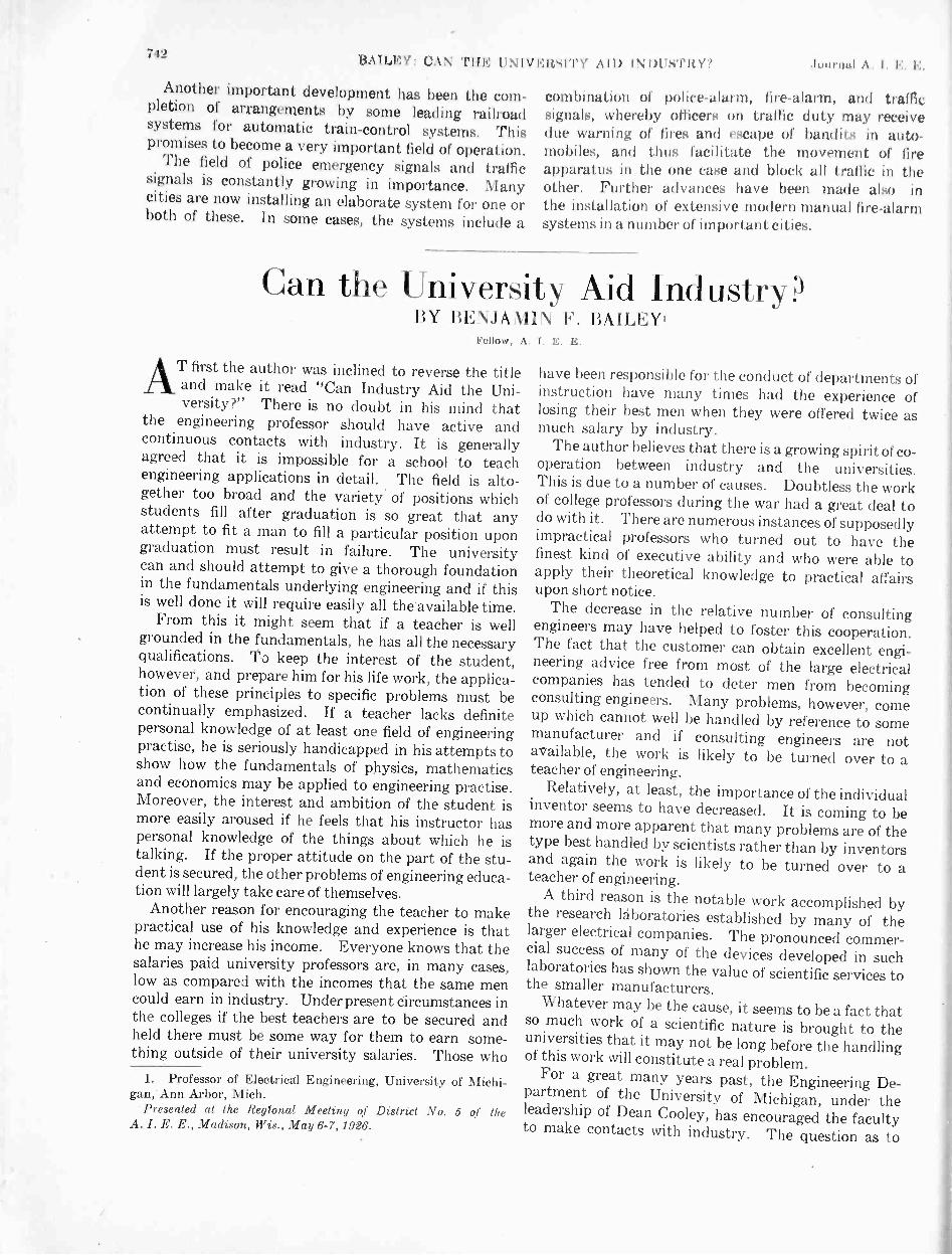
742 BAILEY: C.1N THE INDUSTI117 .bot riot! .\ I I.:, L
Another important development has been the com-pletion of arrangements by some leading railroadsystems for automatic train -control systen is. Thispromises to become a very important field of operation.
The field of police emergency signals and trafficsignals is constantly growing in importance. Manycities are now installing an elaborate system for one orboth of these. In some cases, the systems include a
combination of police -alarm, fire -alarm, and trafficsignal, whereby officers on traffic duty may receivedue warning of fires and escape of bandits in auto-mobiles, and thus facilitate the movement of fireapparatus in the one case and block all traffic in theother. Further advances have been made also inthe installation of extensive modern manual lire -alarmsystems in a number of important cities.
Can the University Aid Industry?BY BENJAMIN F. BAILEY'
Fellow, A. 1. E. E.
AT first the author was inclined to reverse the titleand make it read "Can Industry Aid the Uni-versity?" There is no doubt in his mind that
the engineering professor should have active andcontinuous contacts with industry. It is generallyagreed that it is impossible for a school 'to teachengineering applications in detail. The field is alto-gether too broad and the variety of positions whichstudents fill after graduation is so great that anyattempt to fit a man to fill a particular position upongraduation must result in failure. The universitycan and should attempt to give a thorough foundationin the fundamentals underlying engineering and if thisis well done it will require easily all the'available time.
From this it might seem that if a teacher is wellgrounded in the fundamentals, he has all the necessaryqualifications. To keep the interest of the student,however, and prepare him for his life work, the applica-tion of these principles to specific problems must becontinually emphasized. If a teacher lacks definitepersonal knowledge of at least one field of engineeringpractise, he is seriously handicapped in his attempts toshow how the fundamentals of physics, mathematicsand economics may be applied to engineering practise.Moreover, the interest and ambition of the student ismore easily aroused if he feels that his instructor haspersonal knowledge of the things about which he istalking. If the proper attitude on the part of the stu-dent is secured, the other problems of engineering educa-tion will largely take care of themselves.
Another reason for encouraging the teacher to makepractical use of his knowledge and experience is thathe may increase his income. Everyone knows that thesalaries paid university professors are, in many cases,low as compared with the incomes that the same mencould earn in industry. Under present circumstances inthe colleges if the best teachers are to be secured andheld there must be some way for them to earn some-thing outside of their university salaries. Those who
1. Professor of Electrical Engineering, University of Michi-gan, Ann Arbor, Mich.
Presented at the Regional Meeting of District No. 5 of theA. I. E. E., Madison, Wis., May 6-7, 1926.
have been responsible for the conduct of departments ofinstruction have many times had the experience oflosing their best men when they were offered twice asmuch salary by industry.
The author believes that there is a growing spirit of co-operation between industry and the universities.This is due to a number of causes. Doubtless the workof college professors during the war had a great deal todo with it. There are numerous instances of supposedlyimpractical professors who turned out to have thefinest kind of executive ability and who were able toapply their theoretical knowledge to practical affairsupon short notice.
The decrease in the relative number of consultingengineers may have helped to foster this cooperation.The fact that the customer can obtain excellent engi-neering advice free from most of the large electricalcompanies has tended to deter men from becomingconsulting engineers. Many problems, however, comeup which cannot well be handled by reference to somemanufacturer and if consulting engineers are notavailable, the work is likely to be turned over to ateacher of engineering.
Relatively, at least, the importance of the individualinventor seems to have decreased. It is coming to bemore and more apparent that many problems are of thetype best handled by scientists rather than by inventorsand again the work is likely to be turned over to ateacher of engineering.
A third reason is the notable work accomplished bythe research laboratories established by many of thelarger electrical companies. The pronounced commer-cial success of many of the devices developed in suchlaboratories has shown the value of scientific services tothe smaller manufacturers.
Whatever may be the cause, it seems to be a fact thatso much work of a scientific nature is brought to theuniversities that it may not be long before the handlingof this work will constitute a real problem.
For a great many years past, the Engineering De-partment of the University of Michigan, under theleadership of Dean Cooley, has encouraged the facultyto make contacts with industry. The question as to

Aug. 1926 BAILEY: CAN THE UNIVERSITY AID INDUSTRY?
how far this sort of work should be encouraged was onceraised and the regents of the university passed resolu-tions intended to clarify the situation. These were tothe effect that the faculty of the Department of Engi-neering was encouraged to accept work of the propercharacter to as great an extent as possible withoutinterfering with their regular work of instruction.They were given permission to use their offices and thelaboratory facilities of the university for the carrying onof such work. It was clearly indicated that the workundertaken must be of more than routine character andthat the amount and type of such work must meet withthe approval of the Dean of the department.
The work offered to the university usually falls inone of three classes.
a. Routine tests of materials and apparatusb. Engineering advicec. Research problemsA. Work of the first class has been discouraged, al-
though not entirely prohibited. It frequently happensthat a manufacturer wishes a particular test made andno other agency is prepared to do the work as quicklyor as economically as the university. Not infrequentlythe university is asked to undertake work of this char-acter because an absolutely impartial test is desired.With these facts in view, it does not always seem wiseto refuse work of this character. When it is possible,however, it is turned over to the younger men to whomthe experience is probably
B. The type of work called engineering advice requiresa distinctly higher grade of ability. A number ofprofessors have performed notable services in connectionwith appraisals of railroads, telephone companies andpower plants, by acting as expert witnesses in patentsuits, by advising with municipalities regarding im-portant bridges, roads and other public works, and byacting as consulting engineers to various manufacturingplants, as well as in numerous other ways. Many ofthese contacts have resulted in men being enticed awayfrom the university by the offer of large salaries. Insome cases these men have been lost permanently to theteaching profession; in other cases "leave of absence"for one or two years has been granted and the man haswillingly returned to resume his university duties.
C. A considerable amount of research work has beencarried out also; sometimes this is done for pay at therequest of some manufacturer, but more often is under-taken merely on account of real interest in the work orwith the hope that a good piece of work will result inpromotion. Naturally most of us tend to concentrateon work which is paid for in cash as well as reputation,rather than on that which is paid for in reputation only.Nevertheless, some notable work has been done and iftime were available, it would be interesting to list someof the papers published, dealing with research workaccomplished at the University of Michigan.
Interest in research, particularly in applied research,has been stimulated by the establishment of the
743
Department of Engineering Research in 1920. Somethree or four years prior to this time, a group of engi-neering alumni proposed that the university establishsuch a department, and this was brought to a heada little later by a request from the Michigan Manu-facturers Association. The manufacturers felt verystrongly that such a department would be of distinctassistance to the industries of Michigan and otherstates, and that, in turn, industry might help the uni-versity. These concerns pointed to the large sums ofmoney spent in agricultural research and, while ad-mitting that every penny of this was well spent, insistedthat money might be spent to equally good advantageto aid industry. The department has had a steadygrowth and the amount of work done has increased,until this year it is expected that approximately$100,000 will be paid into this department by industryfor services rendered.
In establishing this department, a large number ofperplexing problems had to be met. One of the firstreferred to the fees which should be charged for workdone. It was universally agreed that the manufacturersrequesting services should pay for them. The persondoing the work receives a compensation approximatelyequal to that which he would receive for the same workdone for the university. In addition an overhead chargeof from 20 to 50 per cent is made to cover, at least partially,the use of laboratories and equipment and the costof shop service, electricity, gas, air or other sources ofenergy.
The question of the character of work to be under-taken also demanded serious consideration. Thepolicy of the department is to discourage routinetests as much as possible. If requests for such workcome in, the inquirer is advised of the existence of com-mercial laboratories capable of doing the work re-quested. If it appears, however, that, fors ome reasonor other, the work cannot be so satisfactorily accom-plished elsewhere, the Department occasionally acceptssuch work. The percentage of tests in which no criticaljudgment is required, however, is very small.
On the other hand, the department fosters work of aresearch character and work in which judgment andengineering experience is definitely required.
The question of patents has proved to be perhaps themost perplexing of all the problems confronting thedepartment, and the policy to be adopted has not yetbeen entirely settled. One proposal made was that if,in the course of a research, patentable inventions weremade, the patent o. patents were to be taken out at theexpense of the university and thrown open to the use ofthe public without charge. To most of the members ofthe department, this did not appear to be a wise policy.It seemed that the manufacturer who supplied thefunds for the investigation and the man who made theinvention both deserved some reward. Since it fur-nished the facilities, the university, was also entitled toconsideration. Moreover, if a patent were thrown

744BAILEY: ('AN THE I IN 1\1.; HSITY .11 I) IN DIISTIO7 Journal A. I. E. E.
open to anyone it is quite likely that no one would useit. The reason, as most engineers know, is that whenan invention has been made, the trouble has juststarted. Almost invariably it is necessary to invest alarge sum of money in developing the invention, puttingit in form for economical manufacture and educatingthe public to use the new product. Since proportionsand designs cannot be protected by patents (to saynothing of the desire aroused by advertising to possessthe new article) a manufacturer might expend largesums in developing an invention and then be at themercy of anyone who wished to steal the results of hisefforts. Under such conditions a meritorious inventionmight never be put to practical use.
It was considered inadvisable also to allow patentstaken out in the course of an investigation to beassigned exclusively to the manufacturer financing thework. An invention made in the course of researchwould be in the nature of a by-product and, in general,would not be expected when the work was started. Itwas thought that if some invention of great value shouldsometime appear, the university might be severelycriticized for allowing it to fall into the hands of a singleindividual or corporation.
The plan tentatively adopted provides that patentsmay be taken out by the inventor with the consent ofthe Board of Regents and at the expense of the personfinancing the investigation. All inventions are to beassigned to the university with the understanding thatthe manufacturer involved will have first considerationin the case of the sale of the patent or the granting oflicenses under it. It is also understood that in case aninvention prove valuable, the inventor may expect toprofit to some extent. A number of patents have beenapplied for but in no case has the point been reachedwhere this problem has had to be frankly faced. Underthe present scheme the manufacturer is obliged to paythe expenses of taking out the patent and has no definiteassurance as to what interest he will have under it.Neither has the inventor any assurance as to whatreturns he may expect.
The actual work of investigation under the De-partment of Engineering Research is carried out verylargely by the teaching staff of the Engineering De-partment. There are, however, a few men who devotetheir entire time to this work. These men hold similarrank to men of the same attainments in the engineeringcollege. The titles used are investigator, associateinvestigator, assistant investigator, research assistant,and assistant.
One of the first questions of policy to be settled whenthe Department was organized was whether or not amanufacturer might obtain data for his exclusivebenefit. It was definitely determined from the firstthat the results of all investigations were to be madeavailable ultimately, but publication is necessarily de-ferred for some time. Within the past year, the depart-ment has begun the publication of a bulletin in which the
results of investigations are available to anyoneinterested.
The department is now undertaking the direction of aMeter Testing Laboratory in the Department ofElectrical Engineering. This is somewhat of an exten-sion of the original scope of the work of the departmentsince the work of checking meters and instruments canhardly be considered as research. This laboratory wasestablished at the request of the Detroit Edison Com-pany and the Consumers Power Company as a con-venience to the Public Utilities of the State. It wasthought that the actual administration could mostreadily be carried out through the Department ofEngineering Research. When this laboratory is inoperation, the Public Utility Companies will be able toobtain prompt tests upon the accuracy of voltmeters,ammeters, wattmeters, current and potential trans-formers, and rotating standard watthour meters.
It is believed that the future work of the Departmentof Engineering Research will lie largely in cooperativeresearch. In Michigan, there area number of industrieseach carried on by a large number of manufacturers.Familiar examples are the furniture industry, the beet -sugar industry, the automobile industry, the paper'industry and many others. In some of these, very littleis done in the way of research, and it would seem thatthe manufacturers could well afford to cooperate to theextent of financing extensive research work. Someprogress has been made in this direction, but naturallyit will require time to interest enough manufacturersin each line to make the scheme a success.
The department also plans, as far as its finances willpermit, to carry out researches in both pure and appliedscience upon its own initiative. A number of problemsimmediately suggest themselves which might well bethe basis of extensive work and which promise amplereturns for the money invested. In the case of some ofthese problems no one manufacturer is sufficientlyinterested to finance the work with the understandingthat all results will be public property. Before verymuch can be done along these lines the departmentwill have to secure more adequate financial support.At present, the State of Michigan spends, yearly, about$250,000 upon agricultural research. Every penny ofthis is undoubtedly justified. The value of the agri-cultural products in the State of Michigan is approxi-mately $600,000,000 per year, but the value of themanufactured products is $3,500,000,000, or nearly sixtimes as much. If engineering research received finan-cial support on the same basis as agricultural researchmay it be seen that there would be approximately$1,500,000 available per year. It is to be hoped thatin the near future this work will come somewherenear to securing the support it deserves.
Some mention of several notable investigationsalready undertaken by the department may be ofinterest.
Natural Lighting. Work has been going on for about

Aug. 1926 BAILEY: CAN THE UNIVERSITY AID INDUSTRY? 745
two years upon the subject of day lighting. Apparentlyvery little had previously been done along this line andthe importance of the work is obvious.
Natural Ventilation. A similar investigation wascarried on to determine the extent to which ventilationoccurs naturally in factory buildings. This isanother subject upon which little or no data wereavailable.
Bearing and Gear Noises. Some very interestingwork has been done upon the sources of noises inmachinery and the methods of measuring noises. A
very ingenious device has been developed by whichquantitative readings of noise may be made and someadvance has been made in locating the source of noisesin roller bearings and gears.
Single -Phase Motors. Work has been carried on forabout three years upon the subject of single-phasemotors, and considerable progress has been made indeveloping a new type of single-phase motor.
Cutting of Metals. A fundamental research is inprogress upon the art of cutting metals with particularreference to milling- cutters. A method has beendeveloped for determining accurately the forces in-volved in action of a single tooth of such a cutter.
Industrial Waste Disposal. This work was under-taken at the request of the City of Flint, where thesubject of waste disposal has assumed greatimportance.
SUMMARY
The writer believes that a distinct advance has beenmade within the last few years in the relations betweenthe University and Industry. It is hoped and believedthat this tendency to cooperate will continue andwill be of great advantage to both parties to thetransaction.
DUCTILE ARC WELDSA step forward in the utilization of the heat of electric
arcs in the joining of metal parts or the building ofmetal structures-another step toward the day when thepounding, noisy riveter will resign in favor of the quietelectric welder for most work-has been taken in thedevelopment of two methods of producing ductilewelds. The one was developed by Dr. Irving Langmuirin the Schenectady research laboratory of the GeneralElectric Company; the other almost simultaneouslyin the Thompson research laboratory of the companyat Lynn, Massachusetts, by Peter Alexander.
In both processes, while the welding is being done, airis excluded from the metal at the joint by means of abath of hydrogen or other suitable gas. The formationof oxides and nitrides which are objectionable, in theweld metal, is thus prevented; the fused metal is asstrong and ductile as the original metal.
Dr. Langmuir's study of lamp filaments in hydrogenwas a theoretical investigation. Now, fifteen yearslater, the results have been applied in a different field-in the development of a new and improved method ofwelding.
Continuing the theoretical investigation, Dr. Lang-muir found that more atomic hydrogen was formed .by
passing a powerful electric arc between tungstenelectrodes in hydrogen at atmospheric pressure. Bydirecting a jet of hydrogen from a small tube into thearc, atomic hydrogen could be blown out of the arc,forming an intensely hot flame of atomic hydrogenburning to molecular form and liberating about halfagain as much heat as does the oxy-hydrogenflame.
By using such a flame of atomic hydrogen, iron canbe welded or melted without contamination by carbon,oxygen or nitrogen. Because of the powerful reducingaction of the atomic hydrogen, alloys containingchromium, aluminum, silicon or manganese, can bewelded without fluxes and without oxidation. Therapidity with which such metals as iron can be meltedexceeds that in the oxy-acetylene flame, so that theprocess promises to be particularly valuable for welding.Either alternating or direct current can be used withthis process.
In testing welds made by this process, the weldedportions have been twisted and bent double withoutcracking or otherwise being injured. Such results havenot been attained with the ordinary arc weld, since suchwelds are usually brittle because of the presenceof nitrides or a thin film of oxide or scale, avoidedin the new process by the presence of thehydrogen.
The process developed in the Lynn laboratory isbased on the utilization of the chemical and physicalproperties of hydrogen and other gases in the molecularstate. This process aims primarily at the prevention ofthe formation of the nitrides and oxides in the arc -deposited metal, which limit the ductility of the usualarc welds.
In this process the arc is struck between the metallicwire or carbon used as one electrode and the plate orwork to be welded used as the other electrode. Thecrater of the arc is always on the work to be welded.The gaseous atmosphere is supplied in the form of astream around the arc. Pure hydrogen, water gas,hydrogen -nitrogen mixtures, anhydrous ammonia,methanol vapor and some other gases can be used,according to the nature of.. the work. The processmakes arc welding more efficient, and suitable for fieldswhich at present are out of its reach. Low -carbonsteel, alloy steels, and most of the non-ferrous alloyscan be welded with success by this process in suitablegaseous mixtures.
From Research Narrative No. 115.
k 1)1. i d g men tt 0f
The Use of the D ynamometer Wattmeterfor Measuring the Diele('I tic Power Loss and
Power Factor of the I nsula Lion of I I iglu -
Tension Lead -Covered CablesWY EVERETI' S. LEE*
Assoclato, A. I.Synopsis.-The use of the dynamometer wattmeter for measuring
the dielectric power loss and power factor of cable and capacitorinsulation is nut new, but dales from about 1890.
Dynamometer wattmeters as available today are suitable formaking these measurements. Care and attention must be given totheir application.
The usual methods of application are:1. Compensated dynamometer wattmeter method, with air
capacitor,2. Inductance variation method (phase -defect compensation
method), with air capacitor,
3. Series resistor owl wallitIqur methIld,,/ lel'N1111111fre Willi
Comparative measI111.1111'141S fif lilt 11 IOSN find powerfactor of cuhle samples lialicab that results are belay (Atoriard Withthe ylla111111111'ler 'PU11111(4(4' whrrrin IIIC 11011111111(' (111)1111110 fromtill' Iron 1'111 III' is within from III Ia 20 per real.
Thert is 11(111.11)r au effective means of slatalariti:ing any measur-ing equipment. Shi,ly 1k1 the calorimeter method for this !mriunieseems ilesirahlt .
INTRODUCTION
pRESENT-day purchase specifications for high-tension lead -covered cables contain clauses lim-iting the values of the dielectric power loss and
power factor of the insulation; these properties musttherefore be measured either on the factory productin reel lengths, or on samples cut therefrom, or onboth as may be specified. The dielectric power lossis the total power consumed in the insulation, and isexpressed in watts. The power factor of the insula-tion is the ratio of the dielectric power loss to theproduct of the voltage across the insulation in voltsand the resulting total current in amperes. The meas-urement of the dielectric power loss and power fac-tor of the insulation therefore involves either (1) themeasurement of the power, voltage, and current fromwhich the power factor may be calculated; (2) themeasurement of the power factor, voltage, and currentfrom which the power may be calculated; or (3) themeasurement of the power and reactive volt-amperesfrom which the power factor may be calculated.
The range of the values to be measured for present-day, single -conductor cables up to 43-kv. rating, con-ductor to sheath, (75-kv. between lines, three-phase),and three -conductor cables up to 33-kv. rating be-tween treated paper -insulated conductors, is shown inthe following:
Values for samples, 10 ft. of leadRange of Impressed Voltage, 5 to 100 kv.Range of Temperature, 20 to 100 deg. cent.Dielectric Power Loss, 0.05 tQ 25 wattsLeading Current Power Factor, 0.002 to 0.10Charging Current, 1.5 to 20 mil -amperes
*General Engineering Laboratory, General Electric Co.,Schenectady, N. Y.
Presented al the Regional Meeting of District No.the A. I. E. E., Niagara Falls, N. Y., May 2648,
1 -Complete with exception of Bibliography publishedpamphlet form of paper.
1 of1926.wiih
746
For factory lengths which frequently extend up to 750ft., the values of dielectric power loss and charging cur-rent are proportionately greater for the same voltage.The values of power factor remain the same.
The measurement of such low values of power andand power factor over a relatively wide range of vol-tages extending to high values is not simple, but re-quires special equipment. The instruments availablefor such measurements are the dynamometer watt -mete! , the electrostatic wattmeter, and a -c. bridges.It is the object of this paper to discuss particularly theuse of the dynamometer wattmeter in making thesemeasurements.
THE DYNAMOMETER WATTMETER
A dynamometer wattmeter is one which dependsfor its action upon the electromagnetic interactionbetween sets of fixed and moving coils, one set beingtraversed by the circuit current (or a current propor-tional to the circuit current) and the other set by acurrent proportional to the circuit potential. Theexternal resistor is usually considered as an integralpart of the instrument potential circuit. Most pres-ent-day wattmeters for switchboard and portable useare of the dynamometer type, the moving coils beingsupported between jeweled bearings. For measure-ments of dielectric power loss in cable insulation wherethe power to be measured is of very low value, asensitive dynamometer wattmeter is used in whichthe moving coils are delicately suspended by a finefilament. The deflections are read from a scale setat some distance from the instrument and traversedby a light beam reflected from a small mirror carriedon the moving system. There are usually two com-plete elements connected in series, one element beingmounted above the other, the upper and lower ele-ments being of opposite polarity thus making the
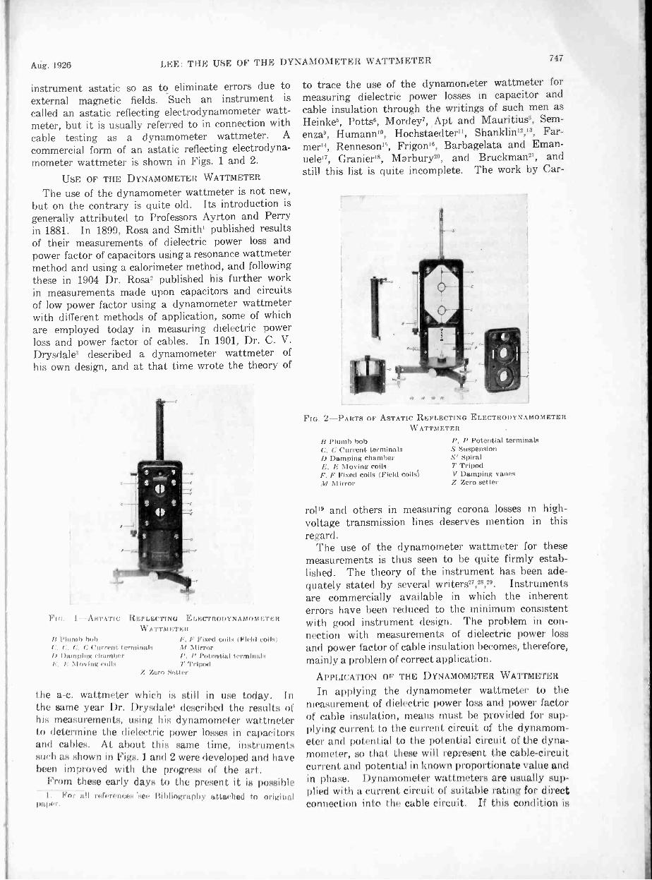
Aug. 1926 LEE: THE USE OF THE DYNAMOMETER WATTMETER
instrument astatic so as to eliminate errors due toexternal magnetic fields. Such an instrument is
called an astatic reflecting electrodynamometer watt-meter, but it is usually referred to in connection withcable testing as a dynamometer wattmeter. A
commercial form of an astatic reflecting electrodyna-mometer wattmeter is shown in Figs. 1 and 2.
USE OF THE DYNAMOMETER WATTMETER
The use of the dynamometer wattmeter is not new,but on the contrary is quite old. Its introduction isgenerally attributed to Professors Ayrton and Perryin 1881. In 1899, Rosa and Smith' published resultsof their measurements of dielectric power loss andpower factor of capacitors using a resonance wattmetermethod and using a calorimeter method, and followingthese in 1904 Dr. Rosa2 published his further workin measurements made upon capacitors and circuitsof low power factor using a dynamometer wattmeterwith different methods of application, some of whichare employed today in measuring dielectric powerloss and power factor of cables. In 1901, Dr. C. V.Drysdale' described a dynamometer wattmeter ofhis own design, and at that time wrote the theory of
FIG. I --A STATIC R EFI,F;("Fl NG ELECTRODYNAMOMETERW ATTM ET Eli
Plumb holtC, C. (:, C current terminalsb !banning ritatnberE, Moving mils
F Fixed roils ( Ield coils)M MirrorI', P Potential terminalsT Tripod
Z Zero Setter
the a -c. wattmeter which is still in use today. Inthe same year Dr. Drysdale' described the results ofhis measurements, using his dynamometer wattmeterto determine the dielectric power losses in capacitorsand cables. At about this same time, instrumentssuch as shown in Figs. l and 2 were developed and havebeen improved with the progress of the art.
From these early days to the present it is possibleall ri.firptices see Bibliogra pliy al I nelital to original
Ili
747
to trace the use of the dynamonAeter wattmeter formeasuring dielectric power losses in capacitor andcable insulation through the writings of such men asHeinke5, Potts6, Mordey7, Apt and Mauritius°, Sem-enza9, Humann'°, Hochstaedter", Shanklin12,13, Far-mer'4, Renneson", Frigon", Barbagelata and Eman-uele'', Granierl°, Marbury2°, and Bruckman21, andstill this list is quite incomplete. The work by Car -
FIG. 2-PARTS OF ASTATIC REFLECTING ELECTRODYNAMOMETERWATTMETER
B Plumb bobC. C Current terminalsD Damping chamberE. F Moving coilsF. F Fixed coils (Field coilsi
Mirror
I', P Potential terminalsS SuspensionS' SpiralT TripodV Damping vanesZ Zero setter
rolls and others in measuring corona losses in high -voltage transmission lines deserves mention in thisregard.
The use of the dynamometer wattmeter for thesemeasurements is thus seen to be quite firmly estab-lished. The theory of the instrument has been ade-quately stated by several writers27,28,20. Instrumentsare commercially available in which the inherenterrors have been reduced to the minimum consistentwith good instrument design. The problem in con-nection with measurements of dielectric power lossand power factor of cable insulation becomes, therefore,mainly a problem of correct application.
APPLICATION OF THE DYNAMOMETER WATTMETER
In applying the dynamometer wattmeter to themeasurement of dielectric power loss and power factorof cable insulation, means must be provided for sup-plying current to the current circuit of the dynamom-eter and potential to the potential circuit of the dyna-mometer, so that these will represent the cable -circuitcurrent, and potential in known proportionate value andin phase. Dynamometer watt meters are usually sup-plied with a current, circuit of suitable rating for directconnection ink, I he cable circuit. If I his condition is

748 1.14]E: THE USE 0I' TuE NANDINIETEU 11'.\'1"1-Alle,TEN Jo r ti I. I':,I
not satisfied and a shunt is required, then compensationmust be made for any difference that may exist be-tween the phase angles of the shunt and the currentcircuit of the dynamometer in addition to the usualcompensation for differences in tempet ature coeffi-cients. On the basis that it is desirable to eliminatecause for compensation wherever possible, it wouldappear that the use of a directly -connected currentcircuit was preferable.
The potential circuit of the dynamometer watt-meter with the usual external resistor is adapted forvoltages up to about 150 volts, so that for measure-ments at higher voltage it becomes immediatelynecessary to arrange for properly applying the highvoltage to the potential circuit of the dynamometerwattmeter in such a way that the power in the high-voltage circuit can be accurately determined. Thoughthis same problem is solved simply and universallyin general instrument practise today by means ofinstrument potential transformers", the applicationof these alone to measurements of dielectric powerloss is not so satisfactory because of the phase -anglecorrection involved at the low power factor of themeasurement23.
In this connection Table I is of interest, for it showsthe maximum allowable departure in phase angle fromthe true value for different percentage errors for dif-ferent values of power factor. Since values of phaseangle for instrument potential transformers are usuallycertified to as being correct within from 3 to 5 minutes,it is reasonable to assume that a departure in phase angleof at least 2 minutes from the, true value may exist.For this condition it is seen that measurements towithin an error of one per cent are not obtainablepractically, to within five per cent are not obtainablefor values of power factor 0.01 and less, and to within10 per cent are not obtainable for values of powerfactor 0.005 and less. It follows, therefore, from thestandpoint of phase angle alone that for the majorityof these measurements the least error that can bereasonably expected will be in the order of 10 per cent.
TABLE I
PowerFactor
Maximum Allowable Departure in Phase Anglefor an Error of
1% I 5% I 10', I 25'', I 50% I 100'cos 0 0 Minutes
0.002 89°53' 0 0.3 0.6 1.6 3.3 70.005 89'43' 0 1 2 4 9 170.01 89°26' 0 2 4 8 17 350.02 88°51' 0.5 4 8 17 35' 700.03 88°17' 1 5 110.05 87° 8' 2 80.10 84°16' 4 19
An additional correction must be made for thephase angle of the potential circuit of the dy namometerwattmeter. Unless the potential circuit is accuratelyshielded, the phase angle is difficult to calculate andmay introduce an additional error in excess of those
shown in Table I. For these reasons, the practise ofcorrecting by calculation has been generally abandoned.
list; OF TI I E AIR CAPACITORCOMPENSATED DYNAMOMETER WATTMETER M ETI I OD
The errors resulting from calculating correctionsand from those causes not readily susceptible to cal-culation can he almost entirely eliminated by the useof a high -voltage capacitor so designed as to have anegligible loss 12' 2l. ", and across which the highvoltage of the circuit may be directly impressed.Such a capacitor is usually one with air as a dielectricthough capacitors with CO2 gas under pressure havebeen used. If the loss in the capacitor is zero, thenwhen the current circuit of the dynamometer watt-meter is connected into the capacitor circuit and vol-tage is impressed across the potential circuit of thewattmeter such as by instrument potential trans-
rTII
A E-
1
.rG
M-18 '
P r.G
3-DIAORANI OF CONNECTIONS FOR COMPENSATED DYNAMOM-ETER WATTMETER METHOD OF MEASURING DIELECTRICPOWER LOSSES IN CABLE SAMPLES.1 Power transformer J Auxiliary series resistorB Instrument potential transformer K Compensating capacitorC Air capacitor G Compensating inductorD High -voltage plate of air capacitor 1 Dynamometer wattmeterF Low -voltage plates of air capacitor .V Potential coils of dynamometerF Cable sample . wattmeterG Guard rings 0 Current coils of dynamometer// External resistor wattmeter
P Potentiometer for calibrating dynamometer wattmeterDotted' lines indicate grounded shielding
former, the dynamometer wattmeter should indicatezero assuming no loss in the current circuit. Itprobably will not do so because of the combined phaseangle of the instrument potential transformer andthe potential circuit of the dynamometer wattmeter,but it may be made to do so by changing the reactanceof the potential circuit until such a result is obtained.The dynamometer wattmeter is thus correctly com-pensated for existing phase -angle differences. Thecapacitor may now be replaced with the cable sampleof the same capacitance, and the resulting deflectionread on the scale of the dynamometer wattmeter.The capacitor and the cable sample are connected tothe circuit at all times. The power in watts is thendirectly calculated from the deflection and the watt -constant as obtained with direct current. This methodis usually referred to as the Compensated Dyna-
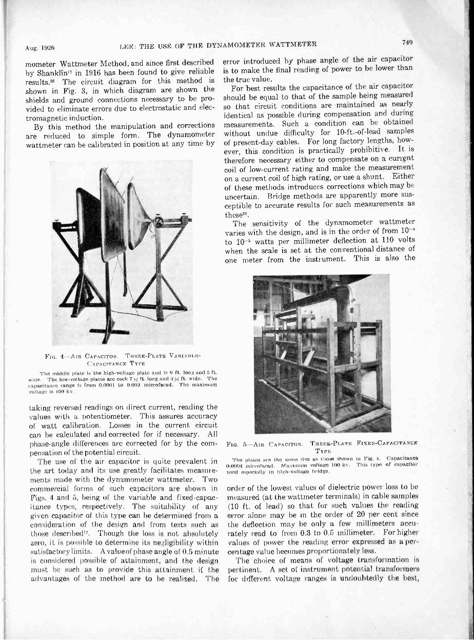
Aug. 1926 LEE: THE USE OF THE DYNAMOMETER WATTMETER 749
mometer Wattmeter Method, and since first describedby Shanklin" in 1916 has been found to give reliableresults.26 The circuit diagram for this method is
shown in Fig. 3, in which diagram are shown theshields and ground connections necessary to be pro-vided to eliminate errors due to electrostatic and elec-
tromagnetic induction.By this method the manipulation and corrections
are reduced to simple form. The dynamo -meterwattmeter can be calibrated in position at any time by
FIG. 4-AIR CAPACITOR. THREE -PLATE VARIABLE -CAPACITANCE TYPE
The middle plate is the high -voltage plate and is 9 ft. long and 5 ft.wide. The low -voltage plates are each 7 x ft. long and 3X ft. wide. Thecapacitance range is from 0.0001 to 0.002 microfarad. The maximumvoltage is 100 kv.
taking reversed readings on direct current, reading thevalues with a potentiometer. This assures accuracyof watt calibration. Losses in the current circuitcan be calculated and corrected for if necessary. Allphase -angle differences are corrected for by the com-pensation of the potential circuit.
The use of the air capacitor is quite prevalent inthe art today and its use greatly facilitates measure-ments made with the dynamometer wattmeter. Twocommercial forms of such capacitors are shown inFigs. 4 and 5, being of the variable and fixed -capac-itance types, respectively. The suitability of anygiven capacitor of this type can be determined from aconsideration of the design and from tests such asthose described". Though the loss is not absolutelyzero, it is possible to determine its negligibility withinsatisfactory limits. A value of phase angle of 0.5 minuteis considered possible of attainment, and the designmust he such as to provide this attainment if theadvantages of the method are to be realized. The
error introduced by phase angle of the air capacitoris to make the final reading of power to be lower thanthe true value.
For best results the capacitance of the air capacitorshould be equal to that of the sample being measuredso that circuit conditions are maintained as nearlyidentical as possible during compensation and duringmeasurements. Such a condition can be obtainedwithout undue difficulty for 10 -ft. -of -lead samplesof present-day cables. For long factory lengths, how-ever, this condition is practically prohibitive. It istherefore necessary either to compensate on a currentcoil of low -current rating and make the measurementon a current coil of high rating, or use a shunt. Eitherof these methods introduces corrections which may be
uncertain. Bridge methods are apparently more sus-ceptible to accurate results for such measurements asthese".
The sensitivity of the dynamometer wattmetervaries with the design, and is in the order of from 10-4to 10-5 watts per millimeter deflection at 110 voltswhen the scale is set at the conventional distance ofone meter from the instrument. This is also the
FIG. 5-AIR THREE -PLATE FIXED -CAPACITANCETYPE
The plates are the same size as those shown in Fig. 4. Capacitance0.0004 microfarad. Maximum voltage 100 kv. This type of capacitorused especially in high -voltage bridge.
CAPACITOR.
order of the lowest values of dielectric power loss to bemeasured (at the wattmeter terminals) in cable samples(10 ft. of lead) so that for such values the readingerror alone may be in the order of 20 per cent sincethe deflection may be only a few millimeters accu-rately read to from 0.3 to 0.5 millimeter. For highervalues of power the reading error expressed as a per-centage value becomes proportionately less.
The choice of means of voltage transformation ispertinent. A set of instrument potential transformersfor different voltage ranges is undoubtedly the best,

750LEE: THE USE OF THE DYNAMOMETER WATTMETER Journal A. I. E. F...
and these are commercially available up to 132 kilo-volts. Ratio transformations obtained with these areindependent of the current in the high -voltage circuit.The use of transformer voltmeter coil, though conve-nient, requires . compensation for every measurement,since the transformation is affected by the current in thehigh -voltage circuit. The same applies to the practiseof taking the potential from the low -voltage side ofthe testing transformer.The effect of the earth's field is eliminated by makingthe dynamometer wattmeter astatic, although thisis hardly necessary when measuring alternating power.Strong external alternating fields such as from high-current circuits or reactors nearby may, however,
seriously affect the dynamometer wattmeter of thereflecting astatic type. Hence, it is quite essentialto see that such external fields are eliminated when thedynamometer wattmeter is in use.
The dynamometer wattmeter accurately summatesthe power due to the like frequencies in voltage andcurrent, and therefore should give the true power re-gardless of wave form. For cable testing, however,where the current circuit of the dynamometer watt-meter is in the cable circuit, and where the potentialcircuit of the dynamometer is. supplied by means whichmay or may not be affected by the cable capacitance,the use of sine wave is highly desirable because of thelow impedance of the cable to higher harmonics whichact to distort the current wave. Also, from the stand-point of voltage measurement, the applied voltageshould be of sine-wave form. The prevalence of theuse of sine -wave generators today for cable testingis largely eliminating the need for worry regardingerrors due to wave form".
INDUCTANCE VARIATION METHODPHASE -DEFECT COMPENSATION METHOD
Another somewhat similar application of the dyna-mometer wattmeter and air capacitof is used wherebywith the capacitor in the circuit the dynamom-eter reading is brought to zero by means of induct-ance in the potential circuit. The cable sample ofsame capacitance is then substituted in the dynamom-eter wattmeter current circuit for the capacitor andthe dynamometer reading is again brought to zero bymeans of the inductance in the potential circuit. Fromthe change in inductance and the resistance of the po-tential circuit, the power factor is calculated.' Thisis frequently referred to as the inductance variationmethod, or the phase -defect compensation method.
SERIES RESISTOR AND WATTMETER METHODA series resistor may be used with the dynamometer
wattmeter in either of two ways. First, it may beused as a substitute for the transformer, the air ca-pacitor still being retained for use in compensatingthe dynamometer wattmeter. In this case the con-ditions of use and possible results would be somewhatsimilar to those when the transformer is used. A
series resistor has also been used instead of the trans-former and air capacitor, connecting the resistordirectly across the high -voltage circuit with the poten-tial circuit of the wattmeter connected either in serieswith it, or in parallel with a portion of it. Such aresistor must be of fixed value, wherein the leakage toground and the reactance are so extremely small asto be negligible. For the higher voltages such a re-sistor is necessarily large and quite expensive, andthe problem of shielding is quite complicated. Bar-bagelata and Emanueli'7 speak of a suitable seriesresistor for such measurements as being costly andcumbersome, and state that it may have a phase -angle correction larger than those being measured.
The use of a water -column series resistor is beingemployed in these and similar measurements by someobservers'''. '9. As used by Barbagelata and Emanu-eli'7 the power factor of the cable insulation beingmeas-ured is obtained by calculation from circuit constants,one of which is the resistance of the water column.A measurement of this value is therefore required undereach condition of use, except at extremely high volt-ages such as 100 kv. and more, where, under certainconditions, the value of R may be eliminated from theequation expressing the result. Where the resistanceof the water column changes frequently and requiresfrequent measurement as in most of the work in our coun-try today, and where circuit constants enter into thecalculation of the result, this method does not appearto be altogether without objection, particularly if theerror due to capacitance of the resistor to ground isconsiderable, as it may be. The authors, however,describe a form of water -column resistor which isclaimed to be free from capacitance error.
In this particular regard the work being done underthe- direction of Professor Ryan19 in measuring coronalosses at high voltages merits consideration, in thata method is given for shielding the water-columnresistor and adjusting it to eliminate errors due tocapacitance. This result is obtained by varying theresistance of the water -column resistor by varyingthe water flow and thus its temperature, the capaci-tance remaining constant. By taking readings ofthe wattmeter for different resistances, the shieldingcan be adjusted to give a zero error.
Some comparative measurements have been madewith this method and with the compensated dyna-mometer wattmeter method the results of which areshown in Figs. 6, 7, 8 and 9. The dynamometerwattmeter with water -column resistor was set up asfirst described19 by Clark and Miller although theinstrument was connected into the ground side of thecircuit and the pail was replaced with a continuoushose connection from the point of high potential downnearly to the drain. This hose was banded at inter-vals and the bands connected to similar bands on theresistor hose to distribute the potential properly.Under these conditions agreement was obtained with

Aug. 1926 LEE: THE USE OF THE DYNAMOMETER WATTMETER
measurements of power factor made with the com-pensated dynamometer method to within 0.004 on thecable sample, Figs. 6 and 7, and within 0.005 on theexperimental capacitor, Figs. 8 and 9, except at thelowest voltage. These departures represent differ-ences from the results obtained with a compensateddynamometer wattmeter method in the order of from20 per cent to 80 per cent.
The later work as reported by Carroli° wherein a
3.0
MININIUSWIM MOM MMINIMMMEMI MOM MINIMMINAMEMEMMEMMIIIIMENAMMIIIMEMEM =NMI
mummommemommummmummimmommommummulmommummommummEmmummommummommommommummommummommummommimmummmommmitammmmomm
10 15 20 25 30 35 40 45 50
KILOVOLTS
FIG. 6-COMPARATIVE MEASUREMENTS OF DIELECTRIC POWERLOSS IN LENGTH OF EXPERIMENTAL THREE -CONDUCTOR CABLE,MEASURING FROM SINGLE-PHASE SUPPLY WITH ONE CONDUCTOR-HIGH- AND THE OTHER TWO CONDUCTORS GROUNDED TOSHEATH
By shielded water column series - resistor :11141 (1Y11:11114111101er watt-
meter method0 By compensated dynamometer wattmeter ttit
salt solution under controlled circulation is used toobtain the necessary control of the resistance of thepotential circuit would also have to be utilized if this
cx
0.02
Es 0.01
0a-
00 5 10 15 20 25 30KILOVOLTS
FIG. 7-COMPARATIVE MEASUREMENTS OF POWER FACTOR OFLENGTH OF EXPERIMENTAL THREE -CONDUCTOR CABLE, MEASUR-ING DIELECTRIC POWER LOSSES FROM SINGLE-PHASE SUPPLYWITH ONE CONDUCTOR "HIGH" AND THE OTHER Two CONDUC-TORS GROUNDED TO SHEATH. SAME CABLE AS IN FIG. 6
By shielded water column series resistor and dynamometer. wattmetermethod
0 By compensated dynamometer wattmeter method
35 40 45 50
method were used for measuring dielectric powerlosses in cable insulation. In making these tests theneed for greater control of the resistance of the po-tential circuit was evident. Short-circuiting one turnof the water -column resistor was tried to obtain thedesired range, but the resulting values obtained as
751
shown in Figs. 8 and 9 show that error was introducedthereby.
While the use of the water -column resistor in meas-urements of dielectric power loss and power factor of
18
16
114
2
00 5 10 15 20 25 30 35KILOVOLTS
-COMPARATIVE .MEASUREMENTS OF DIELECTRIC POWERLoss IN AN EXPERIMENTAL CAPACITOR
O By compensated dynamometer wattmeter method By Shering bridge method' By shielded water column series resistor and dynamometer wattmetermet hod
By shielded water column series resistor and dynamometer wattmetermethod., mit') one turn of series-resistor short-circuited
0.04
0 0.03
u:x 0.02
Lij
0.011Qp
00 5 10 15 20 25 30KILOVOLTS
FIG. 9-COMPARATIVE MEASUREMENTS OF POWER FACTOR OF ANEXPERIMENTAL CAPACITOR. SAME CAPACITOR AS IN FIG. 8
0 By compensated dynamometer wattmeter method. By Shering bridge method. By shielded water column series resistor and dynamometer wattmetermethod' By shielded water column series resistor and dynamometer method.with one turn of series-resistor short-circuited
cables doubtless has merit and warrants further in-vestigation, it does not appear to be inherently moreaccurate than the present established methods, such asthe use of the instrument potential transformer andair capacitor.
RESONANCE WATTMETER METHOD
The resonance wattmeter method as early describedby Rosal and as used recently by Marbury20 formeasuring dielectric power losses and power factorin capacitors has merit, but would doubtless be some-
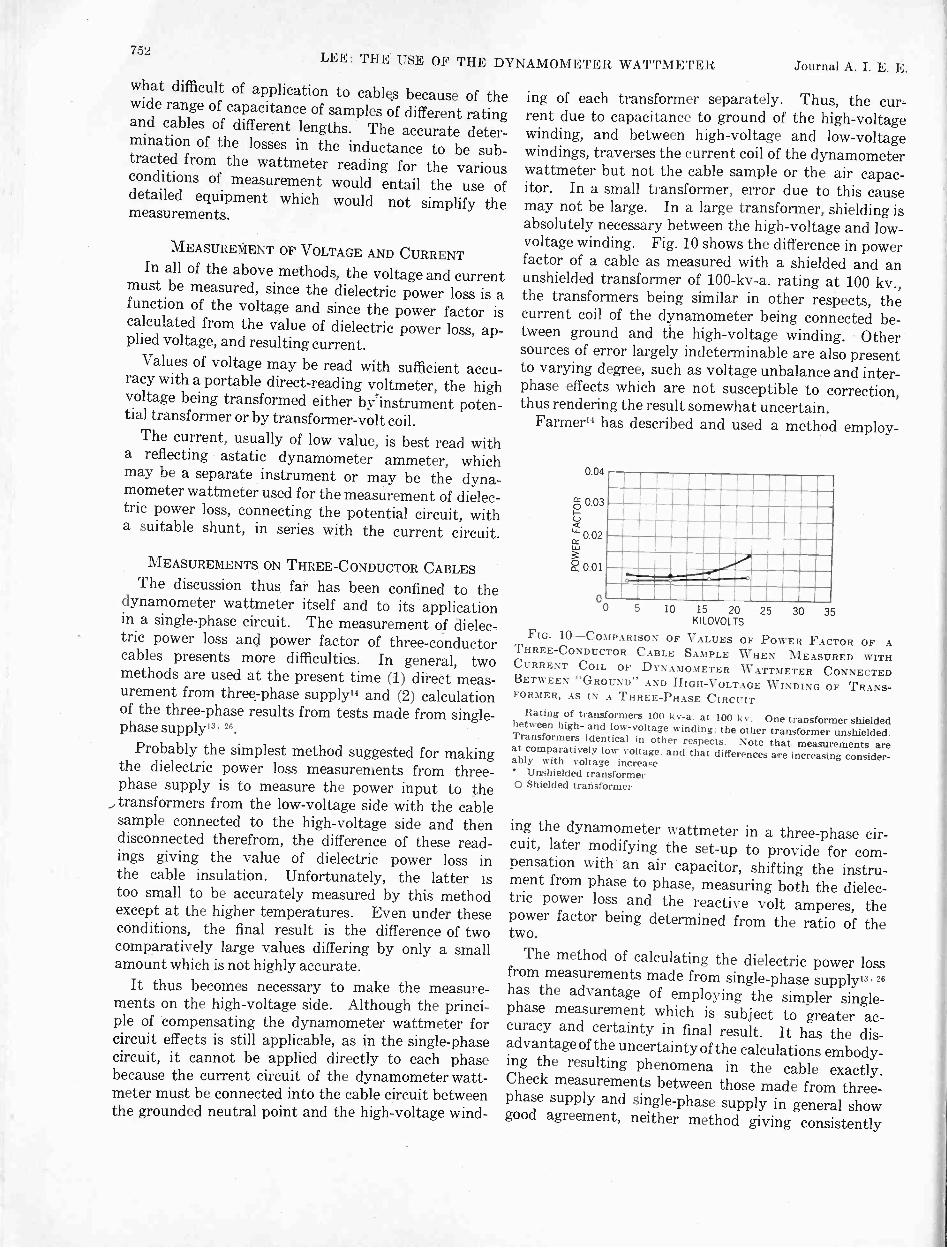
752LEE: THE USE OF THE DYNAMOMETER WATTMETER Journal A. I. E. E.
1what difficult of application to cablqs because of thewide range of capacitance of samples of different ratingand cables of different lengths. The accurate deter-mination of the losses in the inductance to be sub-tracted from the wattmeter reading for the variousconditions of measurement would entail the use ofdetailed equipment which would not simplify themeasurements.
MEASUREMENT OF VOLTAGE AND CURRENTIn all of the above methods, the voltage and current
must be measured, since the dielectric power loss is afunction of the voltage and since the power factor iscalculated from the value of dielectric power loss, ap-plied voltage, and resulting current.
Values of voltage may be read with sufficient accu-racy with a portable direct -reading voltmeter, the highvoltage being transformed either byrinstrument poten-tial transformer or by transformer -volt coil.
The current, usually of low value, is best read witha reflecting astatic dynamometer ammeter, whichmay be a separate instrument or may be the dyna-mometer wattmeter used for the measurement of dielec-tric power loss, connecting the potential circuit, witha suitable shunt, in series with the current circuit.
MEASUREMENTS ON THREE -CONDUCTOR CABLESThe discussion thus far has been confined to the
dynamometer wattmeter itself and to its applicationin a single-phase circuit. The measurement of dielec-tric power loss and power factor of three -conductorcables presents more difficulties. In general, twomethods are used at the present time (1) direct meas-urement from three:phase supply" and (2) calculationof the three-phase results from tests made from single-phase supply13. 26.
Probably the simplest method suggested for makingthe dielectric power loss measurements from three-phase supply is to measure the power input to thetransformers from the low -voltage side with the cablesample connected to the high -voltage side and thendisconnected therefrom, the difference of these read-ings giving the value of dielectric power loss inthe cable insulation. Unfortunately, the latter istoo small to be accurately measured by this methodexcept at the higher temperatures. Even under theseconditions, the final result is the difference of twocomparatively large values differing by only a smallamount which is not highly accurate.
It thus becomes necessary to make the measure-ments on the high -voltage side. Although the princi-ple of compensating the dynamometer wattmeter forcircuit effects is still applicable, as in the single-phasecircuit, it cannot be applied directly to each phasebecause the current circuit of the dynamometer watt-meter must be connected into the cable circuit betweenthe grounded neutral point and the high -voltage wind-
ing of each transformer separately. Thus, the cur-rent due to capacitance to ground of the high -voltagewinding, and between high -voltage and low-voltagewindings, traverses the current coil of the dynamometerwattmeter but not the cable sample or the air capac-itor. In a small transformer, error due to this causemay not be large. In a large transformer, shielding isabsolutely necessary between the high -voltage and low-voltage winding. Fig. 10 shows the difference in powerfactor of a cable as measured with a shielded and anunshielded transformer of 100-kv-a. rating at 100 kv.,the transformers being similar in other respects, thecurrent coil of the dynamometer being connected be-tween ground and the high -voltage winding. Othersources of error largely indeterminable are also presentto varying degree, such as voltage unbalance and inter-phase effects which are not susceptible to correction,thus rendering the result somewhat uncertain.
Farmer" has described and used a method employ-
0.04
g 0.03
'0.02
0.01
00 5 10 15 20
KILOVOLTS25 30 35
FIG. 1.0-COMPARISON OF VALUES OF POWER FACTOR OF ATHREE -CONDUCTOR CABLE SAMPLE WHEN MEASURED WITHCURRENT COIL OF DYNAMOMETER WATTMETER CONNECTEDBETWEEN "GROUND" AND HIGH -VOLTAGE WINDING OF TRANS-FORMER, AS IN A THREE-PHASE CIRCUIT
Rating of transformers 100 kv-a. at 100 kv. One transformer shieldedbetween high- and low -voltage winding: the other transformer unshielded.Transformers identical in other respects. Note that measurements areat comparatively low voltage. and that differences are increasing consider-ably with voltage increase
Unshielded transformer0 Shielded transformer
ing the dynamometer wattmeter in a three-phase cir-cuit, later modifying the set-up to provide for com-pensation with' an air capacitor, shifting the instru-ment from phase to phase, measuring both the dielec-tric power loss and the reactive volt amperes, thepower factor being determined from the ratio of thetwo.
The method of calculating the dielectric power lossfrom measurements made from single-phase supply13. 26has the advantage of employing the simpler single-phase measurement which is subject to greater ac-curacy and certainty in final result. It has the dis-advantage of the uncertaintyof the calculations embody-ing the resulting phenomena in the cable exactly.Check measurements between those made from three-phase supply and single-phase supply in general showgood agreement, neither method giving consistently

Aug. 1926 LEE: THE USE OF THE DYNAMOMETER WATTMETER 753
lower or high values. Farmer" states that the meas-ured value is frequently considerably lower than thecalculated value. Figs. 11 and 12 show comparativeresults in this regard, obtained in two different labora-tories on two different samples of cables cut from the
VOLTS PER MIL (AVERAGE) BETWEEN CONDUCTORS
OA0 20 40 60 80 100
0
0.3
a_
802
2
0.1
00 5 10 15 20 25 30
KILOVOLTS BETWEEN CONDUCTORS
FIG. 11-COMPARATIVE MEASUREMENTS IN Two DIFFERENTLABORATORIES OF DIELECTRIC POWER Loss IN TWO DIFFERENT.CABLE SAMPLES CUT FROM THE SAME LENGTH OF CABLE
Cable rated three -conductor, 500,000 -cm., 9/16 -in. x 5/64 -in. treated -paper insulation, lead -covered
Laboratory A. Sample No. 1. Results calculated from measure-ments made from single-phase power supply by compensated dynamometerwattmeter method0 Laboratory B. Sample No. 2. Results obtained by measurementwith dynamometer wattmeter in a three-phase circuit
VOLTS PER MIL- (AVERAGE)BETWEEN CONDUCTORS
0 20 40 60 80 1000.03
Ix0r.)0.02
ES 0.01
0a_
00 5 10 15 20 25 30KILOVOLTS
FIG. 12-COMPARATIVE MEASUREMENTS IN Two DIFFERENTLABORATORIES OF POWER FACTOR OF Two DIFFERENT CABLESAMPLES CUT FROM THE SAME LENGTH OF CABLE-SAME CABLEAS IN FIG. 11
Laboratory A. Sample No. 1. Results calculated from measure-ments made from single-phase power supply by compensated dynamometerwattmeter method0 Laboratory B. Sample No. 2. Results obtained by measurementwith dynamometer wattmeter in a three-phase circuit
same length. Agreement of power -factor values iswithin from 0.002 to 0.004. The per cent of differencefrom the mean is 20 per cent over the entire range ofvalues. Figs. 13 and 14 show results of similar meas-urements made on the same sample of cable in the
same two laboratories. Agreement of power -factorvalues is within 0.002. The maximum per cent differ-ence from the mean is 20 per cent; remaining valuesshow closer agreement, and at some points actualagreement. On the assumption that the different meth-ods give values subject to approximately the same er-
VOLTS PER MIL (AVERAGE) BETWEEN CONDUCTORS0 10 20 30 40 50 60 70 80 90 100
0.03Ix0(,-,) 0.02
0.010a_
00 10 20 30 40 50 60 70KILOVOLTS
FIG. 13-COMPARATIVE MEASUREMETTS IN TWO DIFFERENTLABORATORIES OF DIELECTRIC POWER LOSS IN THE SAMECABLE SAMPLE
Ca* rated three -conductor, 350,000 -cm., sector, 10 /32 -in. x 5 /32 -in.treated -paper insulation, lead -covered
Laboratory A. Results calculated from measurements made fromsingle-phase power supply by compensated dynamometer wattmetermethodO Laboratory B. Results obtained by measurement with dynamometerwattmeter in a three-phase circuit
VOLTS PER MIL (AVERAGE) BETWEEN CONDUCTORS10 20 30 40 50 60 70 80 90 1000
1.5
1.0
0.5
MEIMER111111111011111M111111111111111111111111111111M11111111111111EM1N11=111111111MEINEMIN11111M1111MNIMIIIIMEIMIIIIMENIMMUMEINIIIIIIM1111111111M11711111111
1111111111111111.11111111MININ11111111E111111MIEFAMMIll
1111111=11111E 'MU
11111MMWM111111111111111=1111111M-Md11111E111111
10 20 30 40 50 60 70KILOVOLTS
FIG. 14-COMPARATIVE MEASUREMENTS IN Two DIFFERENTLABORATORIES OF POWER FACTOR OF THE SAME CABLE SAMPLE-SAME CABLE AS IN FIG. 13
Laboratory A. Results calculated from measurements made fromsingle-phase power supply by compensated dynamometer wattmetermethod0 Laboratory B. Results obtained by measurement with dynamometerwattmeter in a three-phase circuit
rors, these results indicate the departure from thetrue result for both methods to be in the order of from10 to 20 per cent.
ACCURACY OF MEASUREMENT
In the absence of known means for definite compari-son, the accuracy of these measurements must be de-termined in other ways. Comparison of meas-urements made by independent methods is helpful.
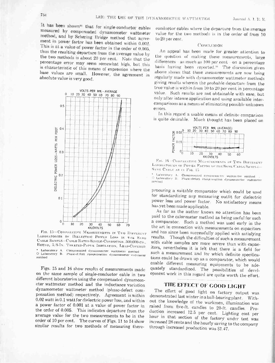
7.1 III', :Till,: I '514, 010 'I' II I.; 1)1 N .1NIO1IKTEll 1'1"1-111.:TI.:1( Ho I \ I. V,
It has been shown" that for single -conductor cablesmeasured by compensated dynamometer wattmetermethod, and by Schering Bridge method that agree-ment in power factor has been obtained within 0.002.This is at a value of power factor in the order of 0.005,thus the resulting departure from the average value bythe two methods is about 20 per cent. Note that thepercentage error may seem somewhat high, but thisis characteristic of this means of expression where thebase values are small. However, the agreement inabsolute value is very good.
0.5
0.4
0.3
0.2
0.1
VOLTSRER MIL-AVERAGE0 10 20 30 40 50 60 70 80 90
oo 10 20 30 40 50 60 70
KILOVOLTS
FIG. 15-COMPARATIVE MEASUREMENTS IN Two DIFFERENTLABORATORIES OF DIELECTRIC POWER LOSS IN THE SAMECABLE SAMPLE-CABLE RATED SINGLE -CONDUCTOR. 500,000 -CM.,ROUND, 5/8 -IN. TREATED -PAPER INSULATION, LEAD-COVERED
Laboratory A. Compensated dynamometer wattmeter method0 Laboratory B. Phase -defect compensation dynamometer wattmetermethod
Figs. 15 and 16 show results of measurements madeon the same sample of single -conductor cable in twodifferent laboratories using the compensated dynamom-eter wattmeter method and the inductance variationdynamometer wattmeter method (phase -defect com-pensation method) respectively. Agreement is within0.02 watt in 0.1 watt for dielectric power loss, and withina power factor of 0.001 at a value of power factor inthe order of 0.005. This indicates departure from theaverage value for the two measurements to be in theorder of 10 per cent. The curves of Figs. 11 to 14 showsimilar results for two methods of measuring there-
conductor cables where the departure II11111 1110 averagevalue for t he two mel hods is in I order of from 10to 20 per cent.
(4)NCIAlsioNAn appeal has been made for greater attention to
the question of making these measurements, largedifferences as much as 100 per cent on a percentagebasis having been reported."" The discussion givenabove shows that these measurements are now beingregularly made with dynamometer wattmeter methodsgiving results wherein the probable departure from thetrue value is within from 10 to 20 per cent in percentagevalue. Such results are not obtainable with ease, hutonly after intense application and using available inter-comparisons as a means of eliminating possible unknownerrors.
In this regard a usable means of definite comparisonis quite desirable. Much thought has been placed on
VOLTS PER MIL (AVERAGE)
0 0.02L.)
- 0.01ce
o 20 30 40 50 60 70 80 90
10 20 30 40 50 60KILOVOLTS
I"ici. Ili -COMPARATIVE MEASU R E IENTS IN TWO DIFFER1..; NTLABORATORIES OF POWER FACTOR IF TOE SAME CABLE SA NIPLE-SAME CABLE AS IN FIG. 15
Laboratory A. Compensated dynamom ter wattmeter method.0 Laboratory B. Phase -defect compensation dynamometer wattmeterm .1 hod
procuring a suitable comparator which could be usedfor standardizing any measuring outfit for dielectricpower loss and power factor. No satisfactory meanshas yet been made applicable.
As far as the author knows no attention has beenpaid to the calorimeter method as being useful for sucha comparator. Such a method was used early in thethe art in connection with measurements on capacitorsand has since been successfully applied with satisfyingresults. Though the difficulties of such a measurementwith cable samples are more severe than with capac-itors, nevertheless it is felt that there is a field forsuch a measurement and for which definite specifica-tions could be drawn up as a comparator, which wouldenable different measuring equipments to be ade-quately standardized. The possibilities of devel-opment work in this regard are quite worth the effort.
THE EFFECT OF GOOD LIGHTThe effect of good light on factory output was
demonstrated last winter in a ball -bearing plant. With-out the knowledge of the workmen, illumination wasraised from five -ft. candles to 20 -ft. candles. Pro-duction increased 12.5 per cent. Lighting cost perhour in that section of the factory under test wasincreased 28 cents and the hourly saving to the companythrough increased production was $1.47.

Circulation of Harmonics in Transformer Circuitsin T. C. LENNOX'
Associate, A. I. E. E.
Synopsis.-The paper describes the manner in which certainseries of harmonic currents may be permitted to flow within a trans-former network. In particular it is shown how the fifth and seventhharmonics of transformer exciting current may be eliminated from
transmission lines. The extent to which the harmonic currentsgenerated in a rectifier may be eliminated from the a -c. lines bymeans of phase multiplication is also indicated.
* * * * *
THE action of a third harmonic of current.or voltagein three-phase a -c. transformers has become familiarto engineers. Very exhaustive studies of the third
harmonic of transformer magnetizing current, inparticular, have been necessary, due to the excessivevoltages that may result in Y -connected, three-phasecircuits where the harmonic of current cannot flow,and to excessive interference with telephone circuitswhen it flows in a grounded neutral circuit.
It has not been so generally appreciated that this isbut one of many similar phenomena that may be en-countered if other harmonics than the third and otherconnections than the simple three-phase,Y, or delta arestudied.
The case of the third harmonic of magnetizing currentin three-phase transformer circuits is reviewed briefly.Here, it is usual to have three transformers or phasesof similar characteristics so that the wave form of themagnetizing current is the same in each phase. Con-sequently, the third harmonic of current will be thesame magnitude in each phase and have the same rela-tion to the fundamental wave.
Bearing this in mind, we may take the case of a three-phase bank, connected in delta on one side and withexcitation applied to this winding. Examining, then,the condition at one corner of the delta, it is found thatthe fundamental waves of exciting current of the twophases differ in phase by 60 deg. The third harmonicsof current having three times the frequency of theirfundamentals will differ in phase by three times 60 deg.,or 180 deg. In other words, they will be equal andopposite and no third harmonic of current will flowfrom the supply circuit.
Next considering the Y connection, it is found thatwhereas at the neutral the fundamental waves are120 deg. apart in phase, and consequently add upalgebraically to zero, the third harmonics are threetimes 120 deg., or 360 deg. apart; or, in other words, areall in the same phase position and consequently add upto three times their average value and must flow intothe neutral line. If no neutral is provided, no thirdharmonic of current can flow and consequently a thirdharmonic of voltage will appear from line to neutralin each phase.
The exciting current of a transformer contains higherodd harmonics,-the fifth, in particular, being quite
1. Transformer Engineering Department, General ElectricCompany, Pittsfield, Mass.
Presented at the Regional Meeting of District No. 1 of theA. I. E. E., Niagara Falls, N. Y., May 26-28, 1926.
prominent although smaller than the third. Theseventh and some higher harmonics, although present,are of negligible amount. Considering these harmonicsat a corner of the delta, the fifth harmonics will differin phase five times 60 deg., or 300 deg. and will conse-quently have a resultant 1.73 times their average value,which must flow in the supply line. Similarly theseventh harmonics differ in phase 420 deg. or, sub-tracting 360 deg., 60 deg. and have a resultant in theline 1.73 times their average value. Similarly, theeleventh, thirteenth, and other odd harmonics notmultiples of three must flow in the line, whereas theninth, fifteenth, and others which are multiples of three,will equalize in the same manner as the third.
At the neutral of a Y connection, the fifth harmonicswill differ in phase five times 120 = 600 deg. or 240 deg.,and consequently will add up to zero the same as thefundamental. Similarly the seventh, eleventh, andother odd harmonics, not multiples of three, will equal-ize and may, therefore, flow in such a circuit without aneutral line. On the other hand, the ninth, fifteenth,and other harmonics which are multiples of three cannotflow.
Consider next the case of a Y -connected bankplaced in multiple with a delta -connected bank, Fig. 1,in which all the phases are identical in characteristics,being different only in the turn ratio as necessary toobtain Y or delta connection. At each corner of thedelta, three currents converge, so that the fundamentalwaves add to a resultant of twice the value of that inthe Y -connected phase and in phase with it.
The third harmonic cannot flow in the Y connectionand will equalize to zero between the two phases of thedelta. A third harmonic of voltage exists from lineto neutral in the Y -connected units, but if they havedelta -connected, secondary windings, the voltage willresult in a triple -frequency current in the delta whichwill reduce the voltage to a practically negligible valuedependent on the impedance of the windings.
As the fifth harmonic can flow in the Y connection,there will be a fifth harmonic in each of the three phasesconverging at the corner of the delta. The delta phasesbeing 30 deg. each way from the Y phase, their fifthharmonics will be 150 deg. out of phase with the fifth inthe Y phase. This will result in the three adding up tozero with no fifth harmonic flowing in the line. Simi-larly with the seventh harmonic, the 30 deg. is multi-plied to 210 deg. and the three equalized to zero. Theninth will act similarly to the third, flowing in the delta,and in the secondary delta of the Y -connected phases.
755

The LENNOX: IWIlLATION OF' HARMONIC 14 IN TltA NSF( )101 IVA 'ITS .1, I. I. E.
For the eleventh harmonic, the 30 deg. becomes 330deg. and the three phases have a relation identical withthat applying to the fundamental, so that the full valueof the eleventh harmonic must flow in the line. Simi -
FIG. 1
larly for thirteenth harmonic the 30 deg. becomes390 deg. and the full value of this harmonic must flowin the line.
Continuing the process, we find that all the odd
FIG. 2
harmonics except the eleventh, thirteenth, twenty-third, twenty-fifth, thirty-fifth, thirty-seventh, andothers of that series will equalize within the network.
This is of some practical interest in connection with
A C
FIG. 3
power transformers or shunt reactors in cases where thefifth harmonic of exciting current may be thought tohave some bearing on telephonic interferences.
By suitably arranging the banks so as to balance deltabanks against Y banks, the fifth and seventh harmonicsof exciting current may be largely eliminated from thelines.
If an analogous connection on a quarter-phase systemconsisting of a cross -square connection is taken, as inFig. 2, it is found that the harmonics of the series3, 5, 11, 13, 19, 21, 27, 29, etc., are equalized while thoseof the series 7, 9, 15, 17, 23, 25, etc., must flow in theline. A secondary square in the cross bank is notneeded unless it is wished to eliminate even harmonics,in which case the second, sixth, tenth, and so on wouldflow in the squares.
An interesting case in this connection is a polyphase
rectifier circuit such as is suitable for use for changingalternating current to direct current. Such a rect ilicrtends to draw current from the a -c. system having awave form approximating the rectangular in shape.This wave consists of a series of odd harmonics themagnitude of which is in inverse ratio to their order,that is, in the familiar Fourier series.
Considering a six -phase ring, Fig. 3, with commutator
I
FIG. 5
FIG. 6
FIG. 7
and brushes or their equivalent arranged to operate insynchronism with the alternating voltage, the currentin the ring will approximate the form shown in Fig. 4.The current in each phase has to reverse while the phaseis short-circuited by the brush. This requires a definitetime and explains the slanted sides in place of the verti-cal sides of a rectangular wave. A series of odd har-monics somewhat similar to that in a rectangular wavewill, nevertheless, be present. If the primary of thetransformer is connected in delta, the third and otherharmonics which are multiples of three will equalize atthe corners and the line current will consequently haveonly the fundamental and the remaining harmonics.
If the number of sides in the polygon is increasedto eight by the use of four separate transformers orphases with the necessary number of windings for thisarrangement and the primaries are connected cross -square (Fig. 2), the harmonics of the series 3, 5, 11, 13,19, 21, etc., are eliminated, leaving the remaining onesin the line.

Aug. 1926 LENNOX: CIRCULATION OF HARMONICS IN TRANSFORMER CIRCUITS 757
If a twelve -sided polygon is used by means of sixsingle-phase transformers or two three-phase trans-formers and Y -delta primaries are used with additionaldelta in the Y phases, all the harmonics except the 11th,13th, 23d, 25th, and others of that series are eliminated.
For a still larger number of phases in a polygon ob-tained by the use of separate transformers or core legs,we cannot obtain a simple primary connection of thekind used above. However, for 24 phases using either12 single-phase or four three-phase transformers, a setof compensating windings placed on the same cores asshown in Fig. 5 could be connected. Here, we have thenecessary Y deltas and cross squares to carry all theharmonics except the 23d, 25th, 47th, 49th, 73d, 75th,
for a polygon having the full number of separate phases.Table I shows the magnitude of the minimum residue
of odd harmonics for polygons of different numbers ofphases, in per cent of the fundamental, for a rectangularwave in the polygon. From this it is evident that theminimum ripple resulting in the a -c. lines in such casesis composed of a series of odd harmonics comprising thenumbers adjacent to the number of phases in the poly-gon and its multiples.
The extent to which this ideal condition may beapproximated in the case of actual designs will dependprincipally upon the reactance of the circuits throughwhich the harmonic currents are required to flow. Inthe arrangements outlined above the primary windings
TABLE IHARMONICS NOT ELIMINATED
SqHeOc12-16-24-48-
1 3 5 7 9 11 13 15 17 19 21 23 25 27 29 31 33 35 37 - - - 47 49 - - -awe 100 33.3 20 14.3 11.1 9.1 7.7 6.67 5.88 5.26 4.76 4.35 4.0 3.7 3.45 3.23 3.03 2.86 2.7 - - - 2.12 2.08 - - -xagon 100 20 14.3 9.1 7.7 5.88 5.26 4.35 4.0 3.45 3.23 2.86 2.7 - - - 2.12 2.08 - - -togon 100 14.3 11.1 6.67 5.88 4.35 4.0 3.23 3.03 - - - 2.12 2.08-Phase 100 9.1 7.7 4.35 4.0 2.86 2.7 - - - 2.12 2.08 - - -Phase 100 6.67 5.88 3.23 3.03 - - - 2.12 2.08 - - -Phase 100 4.35 4.0 - 2.12 2.08 - - -Phase 100 - - - 2.12 2.08-
and others of that series. The three-phase, a -c. con-nection to such an outfit would be made at any threepoints equally spaced around the polygon. In any ofthese polygons, it is possible to double the number ofsymmetrical phases by tapping out the leads as shownin Fig. 6, so as to have all the connection points fall on acircle intersecting the polygon at equgl intervals.Here, the primary or compensating winding will elim-inate only the same series of harmonics as for thesmaller number of phases. However, some of theremaining harmonics are cancelled within the polygon
-/VVV4/1
J
rti
TTTTTTTTTTT
A. C.
Fl G. 8
itself, as for instance, in Fig. 7 which shows a part of a12 -phase connection from a six -phase ring. The currentin B C is 150 deg. from that in B A but flows in coilsB D on the same core. The fifth harmonic will be 750deg. or 30 deg. from that in B A and, together withthat in A E, will have a resultant equal and opposite tothe fifth in A B. Similarly the seventh harmonics willbe 330 deg. out of phase and will neutralize.
As a result, no current of these frequencies will berequired of the primary coils or line and the residue ofharmonics to be taken from the line will be the same as
or compensating windings if used, must have smallleakage reactance between them and the polygon if morethan a few of the lower harmonics are to flow in appre-ciable amount. --1
Transformers for tube rectification are frequentlyconnected in star rather than in a polygon. If there are
FIG. 9
an even number of phases with this arrangement alleven harmonics will cancel. A series of odd harmonicswill remain as in the polygon connection and will beeliminated in the same manner and to the same extent.The use of separate Y -connected banks, connected to-gether by inter -phase transformers, as shown in Fig. 8,will not greatly alter the conditions, the minimumresidue of harmonics from the 12 -phase system shownbeing the 11th, 13th, 23d, 25th, etc., series. The waveforms to be expected in tube rect-ifiers are described insome detail by D. C. Prince, in the General ElectricReview of September, 1924.
To illustrate more clearly the action of the harmoniccurrents, Fig. 9 shows the fundamental and fifthharmonics at the corner of a Y -delta connection whenthe harmonic is in phase with the fundamental at its crest.

The Cosmic I kriless of Moving ElectricityPri-,1(1011CS A(1(11
Itl \1. 1. PI, .N. 1. I..
MOVING ELECTRICITY THE MOTHER 01.' ELEcTiocALENGINEERING
THE Annual Convention brings us together for thepurpose of advancing our knowledge of each otherand of the ideals of our Society. We believe that
our ideals are in harmony with the ideals of Americanscience and American engineering, and, moreover, webelieve that we have a place of honor among thosewhose mission is the cultivation and amplification ofthese ideals. They furnished the motive power for therapid advancement of the science and the art ofelectrical engineering during the last hundred years.The advancement has been very rapid, but, neverthe-less, no other art has a scientific foundation which is sodeep, so broad, and so firm as the foundation of electricalengineering. In no other department of humanknowledge are science and art so closely welded to-gether. These statements, I know, many will consideras somewhat too bold. I shall try to justify them byreferring briefly to the outstanding events in thehistory of the art of electrical engineering and of thescience to which it is welded.
The very meaning of the word engineering impliesan art which guides the activities of physical forcesinto channels of useful service. When the Galileo-
Newton philosophy had disclosed the laws of motion ofterrestrial as well as of celestial bodies, a new universewas revealed to man, a universe of orderly motion ofmatter in obedience to forces acting in accordance withlaws of child -like simplicity. This philosophy sug-gested to the engineer new sources of power and service,and to the natural philosopher a new and apparentlymost comprehensive view of physical phenomena.Some philosophers, thrilled by the beauty of the newknowledge, believed that the whole future history of theuniverse could be foretold by the Galileo -Newtonphilosophy if we only knew at any given moment theconfiguration, the state of motion of every one of itsparts and of the forces acting between these parts.That was the mechanistic view of the universewhich flourished soon after the triumph of Newton'sgreat achievements. These achievements, however,misled some enthusiasts into the belief that all physicalphenomena are reducible to orderly motions of matterunder the action of gravitational forces. But as soon asman had discovered that other processes, not expressiblein terms of motion of matter, formed an essential partof physical phenomena, that belief was abandoned.
Among these processes, the motion of electricitystands foremost. The new universe revealed by our
Delivered at the Annual Convention of the A. I. E. E., WhiteSulphur Springs, W. Va., June 22, 1926.
knowledge of I he motions of electricity appear, to ourimagination :-.1) mgly today that many wouldnot hesitate to rewrite the first sentence of I he book ofGenesis as follows: "In the beginning God said, 'I,etelectricity move, and t he em bryo of the Universe began toform."' Perhaps in a hundred years from now such aglorification of the motion of elect ricity will appear justasextravagant as the old mechanistic view of the universe.There is no doubt, however, that the nineteenth, and thefirst quarter of the twentieth century, will long beremembered as the epoch which revealed to us thehidden powers of electrical motions and their exaltedposition in our present knowledge of the universe.Who could have foretold all this when Stephen Gray,less than two hundred years ago, modestly announcedthat electricity can move any distance over conductorsand that it does move with enormous rapidity? Theworld paid small attention to Gray's great discovery,and it might have continued its indifference if Franklin,instructed by his Leyden jar discharges, had not in-ferred that lightning is a motion of electricity. Gray'smodest terrestrial experiment received from Franklin acelestial illustration which commanded attention,although it was ridiculed by some learned members ofthe Royal Society. The motion of electricity which, inGray's experiment, was detected by a tiny electroscopeassumed a sublime aspect when its flash in the heavensblinded the eye, deafened the ear, and shattered manystable structures of man.
Franklin's discovery of the electrical character oflightning was a great stimulus to the study of themotion of electricity. One may compare it to thestimulus which the Copernicus -Kepler revelation con-cerning the motion of the planets gave to the study ofthe motions of terrestrial bodies which Galileo inaugu-rated. Just as Copernicus and Kepler gave us a Galileoand a Newton, so Gray and Franklin were destined tobe succeeded by an Oersted and a Faraday. But itrequired a Volta to introduce Oersted; it requiredlarge electrical motions to reveal the magnetic forces ofmoving electricity which Oersted discovered.
Prior to Oersted, the engineer moved materialbodies and guided their motions into channels of usefulservice by providing a material connection betweenthe driving and the driven body. Oersted showed thata material body which is the seat of electrical motionscan make other bodies move without a material con-nection between them. The magnetic flux is the in-visible coupling. Oersted's discovery of the magneticfield which accompanies electrical motions promised,therefore, to give birth to a new type of engineering,employing a new type of coupling. This promise was
758

Aug. 1926 PUPIN: COSMIC HARNESS OF MOVING ELECTRICITY 759
one of the great incentives to the advancement of thenew knowledge. The mechanical action of an electric-ally charged body upon other bodies gave a similarpromise, but it failed, and it was destined to fail to makethat promise good. The promise of the Oersted dis-covery blossomed out into a reality more beautiful thanthe fairest dream which prompted that promise. Elec-tricity in motion offered to the engineer a movingforce which proved much more powerful than thatoffered by electricity at rest. The lifting power ofHenry's electromagnets was immeasurably greaterthan the lifting power of the gravitational action of thematerial out of which his electromagnets were made.One can imagine today what an impression that newfact must have made upon the mind of the engineer ofa hundred years ago. Today one can say that electricalengineering is the science and the art which tell us howto make material bodies move by employing an invisibleharness hitching up these bodies to moving electricity.It was born when Oersted made his discovery, but itsgrowth was destined to be slow as long as the Voltaicbattery was the only powerful means of generating andsustaining electrical motions. To Faraday belongs theglory of discovering a new and much more powerfulinstrument than the Voltaic battery. It was hisclear vision which prophesied a reciprocal relation be-tween moving electricity and moving magnetism.The prophesy was probably the offspring of the intuitionwhich suggested that since moving electricity movesmagnets, it is reasonable to expect that moving magnetswill move electricity. This expectation proved correct,and it offered to the engineer an ideally simple andpowerful method of setting electricity in motion. Thepromise of Oersted's discovery to the engineer assumeda new meaning after Faraday's discovery, and electricalengineering began its career which placed it in the ex-alted position it has today among the engineeringsciences. The efforts of the electrical engineer to renderuseful service by hitching up material bodies to movingelectricity resulted in the creation of the dynamo, themotor, the transformer, the telegraph, the telephone,and other epoch-making devices which have revolu-tionized the material conditions of human life. Grate-ful mankind responded with a generous support of thescience which gave birth to and nursed the youngart of electrical engineering and, like a wise mother,gave it its exalted ideals. These ideals are the bond ofunion between electrical engineering of today andits trusty guide, the electrical science. The progressof one brings quickly an equal progress of the other,because hand in hand they always walk together withequal step. One cannot contemplate their statelywalk without recalling to mind the well-knGwn linefrom one of the odes of Horace:
"0 matre pulchra, filia pulchrior!".THE HARNESS OF MOVING ELECTRICITY
The enormous lifting power of electromagnets wasthe great scientific sensation of a hundred years ago.
It excited the lively imagination of Joseph Henry,at that time a young engineer, and he was the first togive it a novel service when he designed the first electro-magnetic telegraph which gave the first real job to theelectrical engineer of a hundred years ago. Theenormous lifting power of the electromagnet furnishedalso a new job to the natural philosopher when it forcedupon him the question: What is the invisible couplingthrough which this force is transmitted from thestationary to the movable part of the electromagnet?Faraday was the first to suggest an answer to thisquestion. His discoveries and visions detected whatone may call an invisible electromagnetic harness towhich all material bodies in the universe are attachedand which is always available to be employed by movingelectricity in useful service. Faraday and Maxwelltaught us that this harness is woven out of the electricaland magnetic tubes of force. Change the electricalelements of this cosmic harness in any part of spaceand its magnetic elements will also be changed inaccordance with Maxwell's extension of Ampere'slaw. Change its magnetic elements and its electricalelements will be changed in accordance with Maxwell'sextension of Faraday's law of electromagnetic induction.It is by these changes that an action is transmitted fromone part of free space to another. A more completeand, at the same time, ideally simple description of theoperation of the invisible harness than that given byMaxwell was unthinkable sixty-one years ago. Itbecame the foundation of the electrical science as wellas of the electrical art, that is, of electrical engineering;it welded the two to each other. Faraday and Maxwellperformed the welding process. Their mode of thoughtappealed to the engineer because it expressed the motionof energy from one part of space to another in terms ofthe action of the invisible coupling between them,furnished by the tubes of force. No elaborate mathe-matical process was required to aid our understandingof this action and yet the Faraday -Maxwell electro-magnetic theory was often accused of being too mathe-matical, because its fundamental laws, mentionedabove, when expressed mathematically were calledMaxwell's equations. This conveyed the idea that thetheory is a mathematical apparatus which cannot beoperated by the mathematical skill of an ordinaryelectrical engineer and therefore of no use to him.Nothing can be more erroneous than this notion.Nothing is more concrete and simple than the Faraday -Maxwell electric and magnetic flux and nothing ismore extensively used by the electrical engineer thanthese fluxes and the simple laws which govern theiractivity. No elaborate mathematical apparatus isnecessary in order to understand that the Faraday-Maxwell science revealed to us the most accurate under-standing of not only the mode of operation of the in-visible coupling in ordinary electrical power generationand transmission, but also in the transmission of radiantenergy from the distant stars to our terrestrial globe.

760 PUPIN: COSMIC HARNESS OF MOVING ELECTRICITY Journal A. I. E. E.
This understanding gave us the first glimpse of thatunity of the universe in which the invisible harness,joining every one of its parts to every other part, isalways ready to transmit service which moving elec-tricity makes available.
Faraday and Maxwell, however, had not spoken thelast word concerning the invisible cosmic coupling.New explorers of the boundless region, revealed by thevisions of Faraday and Maxwell, have delivered and arestill delivering new messages from this region, unfoldingmany of its secrets. What are these secrets and howdoes their unfolding affect the views of the electricalscience and its art, electrical engineering?
Franklin was the first to profess the belief that allelectricity has its origin in material bodies. Faraday'sdiscovery, that to each atomic valency there is attacheda definite electrical charge, gave Franklin's belief amoreintelligible form, which appealed to our imaginationmore and more as the conviction grew stronger, that allchemical reactions are due to the activities of theatomic charges. It was this conviction which suggestedthe name "electron" to the smallest unit of atomiccharges long before its independent individual existencehad been demonstrated by actual experiment. Roent-gen's discovery of the X-ray suggested the hypothesisthat these rays are excited by the impact upon the anodeof tiny projectiles, shot forth with enormous velocitiesfrom the cathode of a high vacuum tube. Experimentproved that these projectiles are the individual elec-trons, the existence of which in the atomic structure hadbeen suggested by Faraday's electrochemical discover-ies; experiment also determined their electrical chargeand inertia. This is the foundation of modern electron-physics and it is so broad that it furnishes new supportto the foundation of the Faraday -Maxwell electro-magnetic theory, to chemistry, astrophysics, meterol-ogy, biology, and, above all, to electrical engineering.It has created a new electrical industry and a new typeof electrical engineering. It is the busy electron in theamplifying vacuum tube which gives life to the radiobroadcasting industry and supplies new problems to theelectrical engineer, the so-called radio engineer; itcarried conviction to those who were inclined to thinkthat the tiny electron was only a fiction of a super-sensitive scientific imagination.
THE ELECTRON, THE PRIMORDIAL UNIT OF POWERGENERATION
The marvelous success of this new electrical industryand of the electrical engineering which guides it,directed our attention to the function of the electronin all electrical power operations. The result is thattoday the electron and its positive partner, the proton,have become the fundamental concepts in the scienceof modern physics and in the art of electrical engineer-ing. The tubes of electrical force between them are theprimordial electrical flux, the fundamental and theonly substance in the web of the cosmic harness.
The relative motion of that primordial flux manifestsitself as the magnetic flux which measures the momen-tum of this relative motion. Relative to what?Relative to the observer who is measuring thatmomentum. A charge moving with the observer hasno momentum relative to the observer and is notaccompanied by a magnetic field which the observercan detect.
Electron -physics made a fundamental contributionto the achievements of Oersted, Faraday and Maxwellwhen it demonstrated the individual existance of theelectron and the proton and pointed out that theelectrical flux, which unites the two, is the primordialflux, the cosmic bond of union between all electronicgranules in the universe. This is the invisible harnessto which all parts of the cosmic space are hitched up.To the electrical engineer who is a disciple of the Faradayschool of thought the electronic granules are unintelli-gible except as local convergencies of the primordialflux. It is the activity of the flux which tells him thestory of energy movement from one part of space toanother and without this energy transference, themotion of the isolated electronic granules would havebut a very small interest for him. He is, it is true,interested in the cosmic processes by which heavieratoms are evolved out of lighter atoms by a suitablegrouping of the electronic granule;, but that whichinterests him incomparably more is the energy libera-ation in these processes and the invisible harness alongwhich the liberated energy is transmitted, destined toperform some useful service in some distant part ofspace. He is also interested in the energy which isstored up in the formation of the atomic nucleus,and how much of it can be made available when thestructure of the nucleus is changed as in radioactivity.
Electron -Physics interpreted in terms of Faraday'svisions and Maxwell's quantitative formulation ofthem suggests to the electrical engineer a universewhich reminds him of a power distribution systemin which there are an endless number of power stationsall interconnected by the primordial flux. Materialbodies, from the smallest atoms to the biggest stars, are,according to this picture of the universe, local aggrega-tions of electronic centers in the all-embracing, primor-dial flux. This cosmic structure, however, is not a staticbut a dynamic one. Every one of its electronic centersis in a state of activity, receiving energy from its busyneighbors and giving it out without cessation orrest. It is pulled by or is pulling at the cosmic harnessto which it is inseparably attached. It is doing itsshare of service in the evolving universe, and how much ofthis service is to benefit man depends upon the manhimself ; upon his science and art of electrical engineer-ing, It is the problem of the electrical engineer totransform the activity of the infinitely numerous, butinfinitely small, electronic toilers in the cosmic powerstations into orderly service for the uplift of the life ofman. He is the coordinator of the restless activity of

Aug. 1926 PUPIN: COSMIC HARNESS. OF MOVING ELECTRICITY 761
these toilers; they follow his bidding as if guided by themagic wand which Faraday and Maxwell and theirdisciples gave him; they are his obedient servants.Here, they heat an electrical furnace and there, theyguide chemical reactions; here they drive the propellersof a battleship, and there they turn the busy wheels ofan industrical plant; here, they speedily carry theweary industrial toiler to his home and there, theymake it cozy and comfortable by their light -givingservice; here, they record the cheerless figures of thestock exchange ticker and there, they carry sweetmelodies and soul stirring language to the millions ofeager listeners on this hopeful continent.
It is a master mind, indeed, that can thus controlthe activity of an infinitely numerous army of toilers.No vulgar rule of the thumb can find a lasting placein the logic of such a mind; its art, is an exact scienceand its science is supported by an art the experienceof which, through many generations, has been testedby methods of measurement of astronomical precision.No vague and hazy notions obscure the lucidity ofthe electrical engineer's operations. The enormouselectrical efforts of his million -kilowatt power stationare just as lucid to him as the feeble efforts of the tinyelectrical power which brings us the wireless messagefrom distant Australia. Both of these efforts are hugein comparison with the efforts of a single electronictoiler in terms of which the electrical engineer canexpress every electrical effort. He knows the numericalvalue of the labor of these tiny workers and he alsoknows that it is their toil by which the lily, withouttoiling or spinning, arrays itself in beauty which farsurpasses Solomon in all his glory. It is their toilwhich promises to the civilization of man a beauty andglory which will far surpass the beauty of the lily.The mission of the electrical engineer is to make thispromise good. In the performance of this mission, hewill keep always in mind the words of St. Luke whoglorified the blessedness of the indolent lily. Theapostle said :
"And seek not ye what ye shall eat, or what ye shalldrink, neither be ye of doubtful mind."
"But rather seek ye the kingdom of God; and allthese things shall be added unto you."
The men who made the science and the art of elec-trical engineering did not seek what they should eat ordrink. But in their thirst and hunger for the eternaltruth they did seek and find, in part at least, thekingdom of God, which resides in the beauty of theirscience and its art, and in the beauty of the universewhich they reveal. That science and its art are thecreation of a new philosophy which we call the phi-losophy of idealism in science. It is the simplestphilosophy ever constructed by the mind of man andrepresents the essence of scientific experience of cen-turies; an experience which was always guided by adefinite motive, a definite mental attitude, and a
definite method of work. The motive was the un-selfish longing for God's eternal truth; the mentalattitude always demanded an open minded and un-prejudiced interpretation of nature's language; themethod of work is that by which our patron saintsGray, Franklin, Volta, Oersted, Ampere, Faraday,Maxwell, Roentgen and their disciples created thescience and the art of electrical engineering.. Thismotive, mental attitude, and method of work is thefirmest foundation of the scientific idealism which isthe idealism of our profession and we have always beenthe leaders in the propagation of its gospel. We werethe earliest apostles who converted the Americanindustries, so that today they worship at the altar ofthe Idealism of Science. We must impress that ideal-ism upon all phases of our national life, in order to assistour nation in the solution of the many complex problemsof modern democracy.
OIL ENGINES RECLAIM THE DESERTIn the waterless desert, where natural power does not
exist, oil engines are developing profitable industryby generating accessible power. A striking example ofthis may be found at Gerlach, Nevada. Here, in thegranite mountains, a rich deposit of rock gypsum wasdiscovered. It was ten miles from the nearest railroadand, being in the heart of the desert, coal was notobtainable. There was neither power, nor water, andthere were no housing facilities. Added to theseobstacles, the climate in the region covers an unusuallywide range of temperature-from as low as 40 deg. belowzero in winter to 115 deg. in summer.
The corporation quarrying the gypsum to makeplaster of various kinds has overcome all these difficul-ties. A great mill has been erected and is runningfull blast, a five -mile aerial conveyor has been provided,a plant railroad has been built, an attractive villagefor the workmen has been constructed, and also,a large power house from which emanates electricpower for manifold purposes. Where once the desertlay silent and untouched, engineering skill has createda busy hive of production-manufacturing one of thegreatest industrial necessities, plaster. The machineryabout the mill is driven by electric motors, the powerbeing generated by three 8 -cylinder 800-h. p. engines,each connected to an electric generator. Owing tothe climate, special open-air construction was used tofacilitate the radiation of heat from the conductors.These 800-h. p. engines use heavy fuel oil and employthe same principleS of fuel injection as the enginesused in the oil -electric locomotives which are attractingso much attention from railroad executives on accountof their economical fuel consumption. Oil enginessuch as these, utilizing a minimum amount of preciouswater, are an available asset in the Nevada desert.The same economy in water applies also to the oil -electric locomotives.

Annual lieportMarine Wm.I.
,(Immiliet, ()II \I C. BRIM )l% Chairman
?'o the Board of Directors:The work of the Committee on Application to Marine
Work for this year has been very largely a continuationof the work of the last year, in connection with thecompiling of the Revised Rules, which we hope will beready for publication during the present summer.
As has been the case in the past several years, thework of this committee has been divided into sections,each in charge of a subcommittee, including propulsion,power apparatus, interior communication, fixtures andfittings, wire and cable, radio, historical, and editing.Each subcommittee prepared revisions of the MarineRules applicable to their work, which revisions werediscussed and approved by the main committee, andafterwards turned over to the editing committee forfinal compiling.
The work of these subcommittees is to be com-mended, especially from the fact that there are manyavenues of thought which needed to be correlated intoa unified final decision by the main committee. Theentire revision is now in the hands of the editing com-mittee, and it is anticipated that it will be ready forpublication very shortly.
At the present time the marine industry is notactive, of course, but due to the fact of more stringentrequirements of insurance, it is very important thatthese Revised Rules may be issued as soon as practi-cable, in order that the United States may have somedefinite standard as a basis.
A. I. E. E. Marine Rules are now accepted as stand-ard, as far as applicable, by the American Bureau ofShipping, and nearly all of the naval architects andshipbuilding companies.
In addition to the work on the Marine Rules as abovementioned, there were several committees consistingof other lines of thought that were allied with themarine work, as follows:
Personnel Committee, working in conjunction withthe Department of Commerce and new commandingofficer in charge of the steamboat inspection service;also working in conjunction with the law officer ofthe Shipping Board. There is considerable optimismthat some .definite results will be obtained in connection
*Committee on Applications to Marine Work:L. C. Brooks, ChairmanH. F. Harvey, Jr.. Vice -ChairmanJ. S. Jones. SecretaryR. A. Beekman, A. Kennedy, Jr.J. F. Clinton, M. A. Libboy,C. S. Gillette, E. B. Merriam.William Hetherington, Jr. W. F. Meschenmoser,H. L. Hibbard, I. H. Osborne,Edward C. Jones, Arthur Parker.
G. A. Pierce,Presented at the Annual Convention of the A. I. E.
White Sulphur Springs, W. Va., June 21-25, 1926.
H. M. Southgate,W. E. That!,C. P. Turner,A. E. Waller,J. L. Wilson,R. L. Witham.
E. at
with the proper n14421011(111 44 electrical engineers onboard ships.
This committee has also given assistance in connec-tion with the Department of Commerce, which isendeavoring to establish a uniform practise in firealarm laws, which is a very important subject in con-nection with marine navigation. This phase of thequestion will include also electrical systems or devicesin the form of automatic steering arrangements,navigating instruments, sounding machines, etc.
In connection with the committee as a whole, it iswith regret that we chronicle the death of W. F. Mes-chenmoser of the Russell & Stoll Company. Mr.Meschenmoser has been for many years an activemember of this committee and chairman of the sub-committee on fixtures and fittings; his work willbe greatly missed in future activities and meetings ofthis committee.
Also, it is reported with keen regret that Mr. MaxwellW. Day, who has been a member of this committeesince its inception has found it necessary to retire fromall business connections, and resigned from the com-mittee early in the year. Mr. Day's personality andvaluable technical experience has been a great asset
through its entire life, and he hasbeen greatly missed.
During the past year one paper has been presentedat the Pacific Coast meeting, on the subject of electricpropulsion. No doubt the coming year will see otherpapers prepared for presentation at some of the Re-gional meetings.
As to the work of the future, it is believed that thework of this committee will be very important in keep-ing these rules up to date, to conform to changes thatdevelop with the advance of time and the developmentof the art. This will apply especially to interior com-munication apparatus, wire and cable, and personnel. Itis also believed that considerable work is possible and de-sirable in connection with standard approval of fittings.
A very important factor in connection with the workof this committee is the cooperation between the workof this committee and other committees covering themanufacture of apparatus and appliances. The .ap-plication to marine work requires certain refinementsand rigid construction not necessary in ordinaryapparatus, and for that reason the work of the MarineCommittee must of necessity cover construction de-tails more than is ordinarily considered the functionof other industrial committees.
In conclusion, the chairman wishes to thank thecommittee as a whole, and the chairman of the sub-committees in particular, for their good work duringpast year, and the results which they have obtained.
762

Aug. 1926 DISCUSSION AT MIDWINTER CONVENTION 763
Discussion at Midwinter ConventionTHE RATINGS OF ELECTRICAL MACHINES AS
AFFECTED BY ALTITUDE'(rEcmi m En
Niw font:, N. Y., FElla tARY 10, 1926R. E. Doherty: The accompanying Fig:. 1 represents a genera-
tor. The cooling air enters at a temperature 7'1. We are con-sidering some spot, N, on the surface. There is a temperature riseof the cooling air which is occasioned by its passing over theheated surface before it. readies the spot in question. Thisbrings the cooling air, the air to which the surface transfer ismade at that spot , up to T2. Then there is a rise or the surfacetemperature above that, which is 7's. There is a still further riseof the copper to T4.
I wish to emphasize that Mr. Feehheimer's equations refer to
some particular spot . 7's is the surface temperature at that spot ,and T, is the copper temperature. The temperature rise(T4 - Ts) is not a function of the barometric pressure. Thetemperature rise (7's - 7'21 is a function of the pressure, varying,let us say, as the 0.75 power. The rise (7'2 - TO is also a func-tion of the barometric pressure, but not the same function as for(T - T2). It varies as the 1.0 power instead of 0.75.
The temperature rise of the surface spot, S, will depend uponthe heat dissipated from it. Mr. Fechheimer's factor k, whichcorresponds to the factor a in the paper= presented by Mr. Carterand myself in 1924, is the fraction of the loss dissipated from thespot or surface which is due to 12 R loss. It should be observedthat this is not the ratio of the copper loss in the machine tothe total losses. There may be spots from which there ispractically no heat due to 12 R loss, and others where all of it
is due to J2 R loss. Hence, the table for k in Appendix II iswithout meaning until it is specified to what surface the valuesapply.
The author brings out the fact that there are two view -pointsfrom which this problem may be treated, which I should state asfollows: One may take the temperature rise at sea level for agiven load, and calculate the increase in temperature rise forthe same load and losses when the machine is operated at altitude.The other is to calculate what reduction in load, and, therefore,losses, is necessary to give the same temperature rise as at sealevel. The author takes the latter view -point; our paper in1924took the former. If correctly done, either gives adequate datafor rules. I found the problem difficult enough without having toworry about the redistribution of losses and the necessary ad-ditional and very questionable assumptions required thereby.Since, however, the author's results check with those we obtainedthe other way, II naturally endorse it on the grounds of Dr.
I. A. I. E. E. JOURNAL, February, 1926, p. 124.2. Effect of Altitude on Temperature Rise, by R. E. Dougherty and
E. S. Carter. TRANS., A. I. E. E., 1924, p. 824.
Kennelly's philosophy. If it is a convenient form of representa-tion, and fits the filets, it is a perfectly good thing to do.
Now as to what Mr. Feehheimer says about my paper: "Inthe paper by Doherty and Carter, the exponent for forced con-vection was found to be 0.73 and to simplify calculations, theyused 0.75. This seems to be correct for the machines for which
they give data in their paper. As we understand their results,the exponent 0.75 takes account of the air rise as well as thesurface transfer. It is felt, however, that their tests are toolimited to warrant us to draw conclusions." He adds also thatthe results were of too complicated a nature to be used as a.basis of engineering rules.
Our paper covered the general ease. Convection, whichis the only factor considered by Mr. Feehheimer, is not thetotal means by which heat is dissipated. Radiation may be adominating factor. There are all grades between predominatingradiation and predominating convection. Certain tests which'I made, gave this figure 0.75, which checked with results onmachines so far as they were available at the time. I still
think it is about right. We took the rise t Ts - 7':) into accountin a term which we called y. The rise 1 T2 - To was accountedfor in the term z. We properly combined the two results and
called that r. We did not lump them, as Mr. Feehheimer has
(lone, into one factor varying as. say, (1.9 power. It depends uponother factors.
Mr. Feehheimer says that our expressions are too complicated.
The phenomenon itself is complicated of course, when thegeneral case is considered. But after obtaining the equationfor the general ease, the specific data applying to a specialease, such as Mr. Feehheimer has treated, may be substituted,and the resulting forms are extremely simple. Our paper gavethese simple forms for various special eases, and the relationfor the present case was a linear relation as simple as Ohm's law;and Mr. Feehheimer's numerical results, as shown in his Fig. 2,are in substantial agreement with ours.
So, his first point that the exponent 0.75 was taken as applyingto hot h temperature rise, I T3 - Ttl and ( T2 - T,), isn't correct.They were not lumped together hut were treated separately,and then logically combined.
Now, as to the point that results given were'too limited for thedrawing of conclusions: t here may be just ificat ionof statement t hatthey are too limited to draw broad conclusions, but I questionhis justification in saying they are too limited to draw anyconclusions. We set up a logical theory under definiteassumptions and then justified the conclusions by experiment.That is sound engineering. If it satisfies all the facts as they areknown, it is reasonable to take the results as applicable withinthe limit of those facts and assumptions. That is just whatwe did. A rational theory was set up, taking into account notmerely the condition of forced convection, but also the generalcase where part is radiation and part convection whichtakes into account the other details which may be thrown outor left in, as conditions may demand.
Then we made certain tests which checked up points on whichexisting data were insufficient, and applied that theory to actualmachines under the conditions of pressure below atmosphere.The results agreed. Other tests were made on an actual machinein the field, first at sea level, then at high altitude. The dataobtained on the machine were not complete, but such as werecomplete were in satisfactory agreement. So upon that basis Iventure to suggest that our results are competent within thelimits we specify.
I wish to say just a word about the several statements thatequations are too complicated for A. I.- E. E. rules. Of coursethey are. An investigation, which of course involves equationsto determine a basis for framing simple rules, is one thing, but

714 Disci %Iii i INTER co's% FATION Journal A. I. K. K.
making !how elulple rules is gnat, into( hot Thu 111,4 tcot uring one mow, Mid our paper In 1921, mantneluiling that one, art' Mich igzit ion, Mr PaAtoli's pro-posal represent, snob simple rides Therefore don't throw IAAresults I here is Mitilition lit I ; olltor%%1-, ion Won't1111V0 anything upon Which to build 11 situp!, rill..
P. L. Alders Au amateur reading Mr. Feelilitiiiner's paperwould probably hr tat with the impression that the effect ofaltitude on rating is greater than it actually is. For instance,Fig. ti Untie:ties that a very large reduction of rating may occur athigh altitudes. But actual machines, designed for use at highaltitudes, would be made with reduced flux densities and lowerno -haul losses than standard machines. Thus, it is more repre-sentative of normal conditions to take the total losses as pro-portional to the kv-a. rating than as a constant plus K times thesquare of the load. With this assumption, the effect of altitudeon rating is reduced to that shown in Figs. 2 and 3 of the paper.
In the second place, the normal ambient temperature fallsabout 5.5 deg. (vitt. for each thousand -meters increase in alti-tude, or by nearly the same amount as the increase in full -loudtemperature rise of a normal machine duo to the reduction ofatmospheric pressure for the same increase in altitude. There-fore, if the cooling air is taken from outside the station, there ispractically no change in rating required by change in altitudein the average ease. Only when open machines designed foruse in heated stations are considered is it necessary to allow forany reduction of rating. And even in these cases the maximumambient temperature to be expected is certainly less than themaximum ambient temperature that may be met in sea -leveloperation, so that here, too, the reduction in rating need not he asgreat as that indicated by Figs. 2 and 3.
E. B. Paxton: I think we should thank Mr. Fechheinierfor pointing out quite clearly the different ways in which thealtitude correction may be taken into account provided there issufficient information to do so. As he has said, the presentA. I. E. E. rule takes into account only the tern-perat ure rise is limited in a test near sea level by the amount of thecorrection for installation at a higher altitude. For this condition,the results that he obtains check, fairly closely, the results obtainedpreviously by Mr. Doherty, as well as the present A. I. E. E. rule.
I think the present A. I. E. E. rule is faulty principally inthat it takes care of that one condition only. It is my opinionthat in a great many cases, a correction is made where it is un-necessary, and that, as Mr. Alger has pointed out, the ambienttemperature will be sufficiently low to offset the correctionnecessary for the altitude.
This matter of correction for altitude would seem to be arelatively unimportant matter considering the many other con-ditions that affect the design and installation of a machine. Forthat very reason, we should be just as sure that any rule which isstandardized does not require corrections unnecessarily as we areto cover the necessary cases.
Along this line, about a year and a half ago, I proposed a rulefor inclusion in the A. I. E. E. Standards which is, I believe,an improvement on the present A. I. E. E. rule, in that it does takeadvantage of a reduction in ambient temperature at the higheraltitudes and covers one of the cases which Mr. Fechheimermentions in his paper. I think we must regard two kinds ofapplications: first, that of a standard machine, and we shouldmake rules which will allow its application under all conditionswhere it may safely be used; second, we must recognize thatthere are conditions where it is necessary to use a special machine.I should like to see the present A. I. E. E. rule extended to allowthe use of machines of standard temperature rise at high alti-tudes, provided the ambient temperature is low enough tocompensate for the increased temperature rise. I am con-vinced that there are many cases where standard machines maybe used safely at the higher altitudes without any correction.
W. F. Dawson: first of all, I want to suggest the probability
of the toishit.iit tviiiiivrtitiiri, at high altitudes riot neeesaartlyLIVIng ill \A 1,1. I !Mil at Wit Ill% 111. I hiSiii, is I i-II PI II of ,41 t titili teat.on it ".-.50-1i. p , 3000 -re% per. min., sv tido idiot', motor whiel: Idesigned anti tontod r,,lifil. four tears ago at our ri.it,iry in Lynn,Tarr., anti rep. it I, -I, that where ttsndt- In the ,under Moonutjesnt an altitude of 11,04in it The amhient temperature during tlusmotintuni lest in imolai i, v,a, 21 5 deg ....fit , whieh eompareaapproxiinatelN 111111 11110 ill till- 1, icifil I ,, I (I eieerne, had that11,0N1. fl ,illitud iii-i-ii iii di. t Ritailimi itgickion, the situation%.% mild but e I, en different, but one must not forget that highaltitudes exist also in tropiral countries.
It seems to ine that the crux of the situation is all ambienttemperature. If Ili, diii,it, .if I Ito 000lnig air, due to greatereh.% tit ion, is lower than standard, its thermal veracity fora givenv"luin it, proprii,,liat, less. The average temperaturedifferenee bet %N eel' inlet and outlet air on self-ventilatts1 turbineit.1,11.t41,ritittiirs at Silt 11% ell V6 ill he bet ii con 15 deg. vent. and 30 deg
At t he end of t he test of the machine to a hint I have just referred,inlet air was 28.7 dog. is lit. and outlet air 45.8 deg. vent., adifference of 17.1 dog. cent .
According to Iii, forninla used in Mr. Feehheimer's paper, thereference -air detisit y au- about 0.0 atmosphere which wouldmean that, at the 11 t/011 -ft. statitin, the temperature rise of the airafter passing through the motor would he 17.1 deg. divided by0.0, or 28.5 deg., an increase of 11.4 deg., and that is slightlymore than tie temperature differences we ordinarily expect.It is unfortunate that, while we used temperature indicators atthe factory, they \%11'c not available at the high elevation; butwe did get a very good chuck oil the field in spite of the fact thatit was rim at the higher current.
In turbine alternators, .ani I this synchronous motor is a tur-bine alternator fitted with a starting vvindingl, one of the majorlosses of the machine is the windage loss. Windage loss will befrom 0.3 to 0.5 of the total. In this particular case, ut sea levelthe total loss passed the machine at its rating, that is,the loss handled I iy the air, was .;7.3 kw. Of that amount, 19.8 kw.was windage. What happened at the higher altitude? The 19.8must be multiplied by 0.6 because the volume is the same athigher all it tide as at t lie lower all it tide, and the windage loss is inproportion to the density of t he air, so 8 kw. of that loss are savedat the higher altitude. That i-: one of the credits of the problem.
The heating by increase in resistance of that field with 93.5amperes at sea level was -10.8 deg. coal., of which 12.7 deg. wasdue to windage loss alone, leaving 28.1 deg. attributable to l' R.The test at higher elevation was run at 100 amperes. If we
multiply that 28.1 byJ.
, we obtain 32.3 deg. That will(be the temperature rise due to copper loss, but the total tempera-ture rise must allow also for the air friction. This will be nolonger 12.7 deg. but. 0.0 of 12.7 deg. = 7.6 deg. Adding thisto 32.3 gives 39.9 deg. as the estimated field rise for the higheraltitude. The value reported from Peru was 40.3 deg. cent.
ally feeling is that the problem does not involve lunch ofmathematics, but judgment combined with experience, and thatit probably reaches its greatest simplicity in turbine alternatorsand similar machines where the air paths are systematicallydirected. The principal difference in temperature rise will bedue to the fact that the ventilating air, because of lower density,will have a higher average temperature at the air-gap and wherethe windings are to be cooled; hence their temperature will becorrespondingly greater.
The fact that the low -density air has a correspondingly lesswindage loss must not be overlooked. The full -load efficiency ofthe motor I have just been discussing was 96.45 percent at sealevel. About 8 kw. of windage loss was saved due to rarefied airat 14,000 ft. altitude, thus bringing the efficiency up to 96.84per cent.

Aug. 1926 DISCUSSION AT MIDWINTER CONVENTION 765
Sometimes it has been possible to apply the principal of thesupercharger to machines which otherwise would have to bederated for operation at high altitudes. It is only necessaryto provide special fans which increase the volume of air tocorrespond with its reduced density and thus insure the sametemperature rise ordinarily obtained at sea level.
H. M. Hobart: I am of the opinion that from a standardiza-tion standpoint this subject will be best straightened out on thebasis that the rating will be the available capacity of the machineat sea level. As Mr. Fechheimer suggested, sometimes you cantake more out of the machine at higher altitudes, and sometimesless, according to the prevailing temperatures. That won'tchange the rating. The rating will be the available capacity atsea level and 40 deg. cent. cooling-air temperature.
G. E. Luke: The present A. I. E. E. rules (1925) for rotatingmotors and generators, (excepting railway motors), cover altitudelimitations as follows:
"Unusual Service Conditions: The use of machines in coolingmediums having temperatures higher than 40 deg. cent. or ataltitudes greater than 1000 meters (3300 ft.) should be con-sidered as special."3
A similar statement is found for air -blast transformers; how-
ever, for self -cooled oil insulated transformers, -the correction is4/10 per cent per 100 meters instead of one per cent. From thewording of the footnote, ("it is provisionally agreed"), it is as-sumed that this correction was subject to doubt.
Both this paper by Mr. Fechheimer and a previous one byMessrs.. Doherty and Carter2 have brought out the fact that thealtitude correction is considerably influenced by the ratio ofcopper -to -core loss and by the temperature gradient throughthe insulation. These factors are of considerable importancewhen temperatures are determined by embedded temperaturedetectors.
On the basis of certain assumptions, all of these factors can be
+20
,-+10
0 0n-10
200
1
"ImerAvg.
1000 2000 3000 4000METERS ALTITUDE
FIG. 2
5000 6000
combined into a group of equations; however, since some of theconstants are factors of design, the equations are not in a suitableform for incorporating in the A. I. E. E. Standards.
In the discussion of the Doherty and Carter paper, Mr. E. B.Paxton suggested a plan whereby the maximum ambient tem-perature for various altitudes could be limited on the basis of asea -level rating. Mr. F. D. Newbury's modification of this plan,I believe, offers a suitable solution for this unusual service con-dition. Naturally, such a simple solution is a compromise andis only approximate. It is warranted due to the very smallper cent of machines operated at altitudes above 1000 meters(3300 ft.) and also to the average decreasing ambient tempera-ture with increasing altitude. The accompanying Fig. 2 showsthe average summer temperature at various altitudes taken nearParis, Brussels, Strassburg, and Munich, as given by the Smith-sonian Physical Tables.
Where machines are to be operated indoors at high altitudeswith ambient temperatures greater than those specified, the con-ditions should be regarded as special and the corresponding rating
3. "For apparatus intended for service at altitudes greater than 1000meters (3300 ft.) it is provisionally agreed that the permissible temperaturerises (to be included in contracts and checked by test at low altitude)shall be less than specified in these standards by 1 per cent of the specifiedrise for each 100 meters (330 ft.) of altitude in excess of 1000 meters(3300 ft.)."
can be specified by the manufacturer as calculated by the methodgiven by Mr. Fechheinier.
C. J. Fechheimer: It would seem that Mr. Doherty hasunderstood me to be critical of the work which he has done. That isfar from my purpose, for I appreciate the value of it. As he haspointed out, I have evidently mis-read one statement in his paper.Since he is considering the temperature rise of the surface abovethe air adjacent to it, and since his results and mine agree, thereis no occasion for further discussion on this point; in fact, it isgratifying to note that we are in agreement.
With the simplified equation (36) in his paper, he takes ac-count only of the surface drop and must then add the air tem-perature rise to it. In general, the air temperature rise is notknown, particularly if it is taken from the entrance of the machineup to a particular point. Consequently, the purchaser of amachine is still considerably in doubt as to how to apply theequations. The method which I use, of taking a mean betweenthe exponent, 1, for the air rise, and the exponent of about 0.75to 0.80 for the surface rise, is not mathematically correct; norwith the possible variations in air temperature rise as comparedwith the surface drop, is it strictly correct to apply the methodwhich I have used. My purpose was to place this complex sub-ject on such a simple basis that the A. I. E. E. Standards Com-mittee could embody it in its rules. Referring to Fig. 2 in mypaper, it will be seen that the influence of the variation from anexponent of 0.75 to 1. is not very great; consequently, taking asan approximation a value of, say, 0.9, the error is not of greatmagnitude. After all, that is all with which we are con-cerned. In the present A. I. E. E. rule, as the total temperaturerise is considered, it is not broken up into its two components,and in my opinion it will be necessary, in any revised rule, tofollow this same practise.
Mr. Doherty refers to the constant k in my paper, which isthe fraction of the loss in the core that is proportional to thesquare of the load at sea -level rating. In making up the tablesin Appendix II, I considered that all the 12 R loss that was in theembedded part was liberated from the core, or from the straightparts of the coils, and that the end windings took care of them-selves so far as dissipating their generated heat. That assump-tion may not be justified, and for accurate solutions, considerationshould be given to the longitudinal heat flow along the copper andthe transverse heat flow through the insulation. That, however,puts the problem entirely out of the range of a practical solution.Fortunately, this factor k disappears when only the temperature -rise ratios are considered. It appears in the equations when theratio of ratings is solved for. After all, those solutions for ratingswill be of value probably only to the designer and not to the pur-chaser of the machines, and the designer can approximate thepercentage of heat generated in the embedded copper which istransmitted longitudinally or transversely. In the long -coremachines, he will not introduce much of error if he considers allof the embedded /2 R loss to be liberated in the straight part.More of error is introduced in the short -core machine.
I confess that I do not understand how Mr. Doherty hasreached the conclusion that I considered only the reductionin load, and not the increase in temperature. Equations (1) and(2) are solutions on the basis of temperature. Equations.(3)to (6) are on the basis of ratings.
It is true that I have considered forced convection only.In the majority of machines in which fans or their equivalentare used, radiation may be excluded, and even free convectionis of little consequence. My paper is not intended to coversuch apparatus as self -cooled transformers or motors whichliberate a large percentage of their heat through the outsidecasing by radiation or free convection. The statement whichI made in my paper, to which Mr. Doherty refers, i. e., that theequations in his paper were complicated, was prompted bysuch equations as (18) and (30), the former covering the generalcase and the latter the case for forced convection. My whole

766 DISCUSSION AT M I !WINTER CONVENTION Journal A. I. E. E.
purpose ill writing the paper in the manner as presented was toplace it in simple form before the members of the Institute.
Mr. Alger states that by reducing the flux densities, the ratingsneed not be reduced. That is undoubtedly so, but in many eases,machines with standard windings will be applied at the higheraltitudes, chiefly to save the expense of making special machines.The other point that Mr. Alger makes in regard to ambienttemperature, would I think, bear further study. While it is truethat we have, from the Bureau of Standards, data on ambienttemperature, and, as Mr. Luke points out in his discussion, fromparts of Europe, a more thorough study of this whole subjectcould be made by the Standards Committee in order to offersuitable recommendations. Undoubtedly, in many cases thelower ambient temperature will practically off-set the loss inrating that would otherwise be occasioned by the lower density.
Mr. Paxton's comments are largely along the same line ofambient temperature. He previously contributed valuablematerial in his discussion of Mr. Doherty's paper, and hissuggestions are worthy of study by those who will participatein the revision of the rules.
The point that Mr. Dawson makes, that the ambient tem-perature at 14,000 -ft. elevation in January was 21.5 deg., isof considerable interest. However, January is summer in SouthAmerica, and the particular locality was not far from the equator.The specific machine upon which he had tests made, i. e., a turboalternator for which the windage loss decreased considerably,is undoubtedly a special case and cannot be treated along withthe general cases. While special fans may be added to increasethe volume and thereby obtain lower temperature rises at thehigher altitude, in general such a scheme is not to be adopted, asit would make the machine so highly specialized that the manufac-turers would seldom go to the expense, nor would the customerwish to pay for it.
Since writing the paper, my attention has been called to arather unusual phenomenon. It is claimed by some of therailway engineers that in a -c. commutator motors, brush -frictionloss decreases with increase in current. It is even claimed thatsome of these commutators run cooler at normal full -load thanthey do at no-load. -I am offering no explanation for the causeof this phenomenon, but, assuming that the statement is correct,the correction for altitude as given for commutators in AppendixIV no longer holds. Not knowing the rate of decrease in brush-friction loss with increase in J2 R loss, it is impossible for me tosuggest a solution to that part of the problem.
One other item of comparatively small importance was notconsidered in the derivation of the equations. With lowerambient temperature, the air density is increased; with increasein density, both the air -temperature rise and the surface dropdecrease. At the higher altitudes, if the ambient temperatureis lower, the rating of the machine is not decreased so much asindicated by the equations. It is believed, however, that thisadditional correction need not be given much consideration.
MOTOR BAND LOSSES'(SPOONER)
NEW YORK, N. Y., FEBRUARY 10, 1926G. E. Luke: In particular I remember one experimental
machine designed for high-speed railway work that gave con-siderable trouble due to the bands coming loose. Some attrib-utedIthis to the high centrifugal stresses; however, later testsproved the trouble to be due to excessive band losses. Carefulinsulation of these bands reduced the stray losses and no moresuch trouble was experienced. After Mr. Spooner had completedhis first tests on band losses I arranged tests on a 50-h. p. railwaymotor. Small thermocouples were soldered to the bands andothers placed on the winding and core. These couples werebrought out to special slip -rings so that the temperature could be
1. A. I. E. E. JOURNAL, January, 1926, p. 14.
dcterminvd with the motor running. In this way tests weremtele with insulated and uninsulated armature bands. Anapprnciable temperat tire difference was found between the twotests. In some cases the uninsula led armature had tempera-tures 10 deg. (mt. higher than that armature with insulatedbands.
Due to the many other losses and factors that must Ise con-trolled, work of this nature must be dont, with a high degree ofaccuracy and requires considerable patienee on the part of theexperimenter. Mr. Spooner has also put the data in such formthat they can be used in determining the losses on other ma-chines of similar design.
J. C. Lincoln: Some years ago, a case of trouble from handsthrowing solder was solved in the following manner: In thisparticular case the machine was an eight -pole machine and thebands, as is customary, were soldered entirely around the arma-ture. The trouble was corrected by placing four strips for hold-ing the wire of the bands together at 00 deg. aroundthe armature and soldering the hands only whe-e thesestrips were placed. This left a north pole and a south polebetween each of the strips and the bands were not soldered be-tween these strips. The total magnetic induction betweenthe bands was zero.
In other words, between each typing strip there was a northpole and south pole and therefore there was no voltage inducedin the bands between each of the tie strips. As the result ofthis change, the machine which had been throwing solder aroundthe bands and giving trouble was corrected entirely.
P. L. Alder: I should like to ask Mr. Spooner if he hasmade a study also of the losses in the binding bands on the endconductors of rotating armatures, and, if so, whether suchlosses are ever large.
Thomas Spooner: Replying to Mr. Alger's questions,we have never investigated systematically the losses occuringin bands which hold the end windings of machines in position.These losses are often appreciable but we have no quantitativedata concerning them.
In the case of Fig. 2 of the paper, the losses there given arefor the unwound armature. If the armature windings had beenin position, as they were for certain later tests, the losses wouldhave been higher, due to eddy currents in the copper.
PROPERTIES OF THE SINGLE CONDUCTOR'(HERING)
NEW YORK, N. Y., FEBRUARY 11, 1926S. L. Quimby: In the classical electromagnetic theory, self-
inductance is specifically defined and invariably calculated as aproperty of a complete electric current circuit. No theory con-sistent with the facts revealed by experiment has yet been de-veloped to make possible the calculation of the self-induct-ance of any portion of a circuit.
I now propose to analyze the two experiments described byDr. Hering and to point out the way in which the energy relationsderived by him differ from those which are in accord with theelectromagnetic theory.
I shall first consider the second of these experiments. Dr.Hering bases his analysis of this upon a theorem ascribed to LordKelvin. This theorem states that if any system of current cir-cuits in which the currents are kept constant by batteries isallowed to alter its configuration, then, of the work done by thebatteries in keeping the currents constant; one-half will appear asincreased magnetic energy of the system of currents and one-half as mechanical work.
Fixing our attention upon Dr. Hering's apparatus, we imaginethat, initially, the weight is locked rigidly in place and furthermorethat the whole conductor is perfectly rigid. A current flowingin this conductor now supplies us with a definite system of
1. A. I. E. E. JOURNAL, January. 1926, p. 31.

Aug. 1926 DISCUSSION AT MIDWINTER CONVENTION 767
current circuits, namely, the very large number of filamentaryconductors into which the finite conductor may be imagined to be
divided. With the weight still locked in place, we now supposethat the conductor is no longer rigid, but elastic. Under theaction of the pinch forces, it will shrink, radially. Its self-inductance will therefore increase by an amount A L, and themagnetic energy of the system will increase by an amount1/2 . A L . i2. At the same time, a certain amount of mechanicalenergy is stored in the elastically strained conductor. Kelvin'stheorem tells us that this energy of elastic strain is preciselyequal to the increased magnetic energy. The radial displace-ment of the material of the conductor accompanying the shrinkinvolves a cutting across the lines of magnetic force in theconductor, and the counter e. m. f. thereby developed accounts forthe work done by the battery in supplying the elastic energy.
This is as far as Kelvin's theorem carries us in our analysis, for,if we now release the weight, it will move and this motion willcause the introduction of new conducting material into the circuit.We no longer have a definite system of conductors to consider butinstead a system which is continually changing through thecontinual introduction of new conductors. Kelvin's theoremcan no more he applied to an analysis of this machine than it couldto an analysis of an ordinary d -c. motor, in which, barringresistance, all the energy supplied by the battery appears asmechanical work and the magnetic energy remains praCticallyconstant; and this for the same reason, since the commutator on ad -c. motor is merely a device for continually introducing newconducting circuits into the system.
The introduction of new mercury into the conducting systeminvolves a radial flow across the lines of force in the conductorand it is easily shown that the work done by the battery againstthe counter e. m. f. thereby developed is precisely equal to themechanical energy acquired by the raised weight.
Dr. Hering's analysis of his first experiment is based upon anassumption which, in the light of the electromagnetic theory,is false. He assumes that if the pinch pressure is allowed toannihilate a fluid -conducting circuit of the type described, thenthe mean pressure, i. e., the pressure at a distance R/ fromthe axis of the conductor, will be constant. This, as the authorshows, is equivalent to the assumption that the current will de-crease linearly with the radius. Calculations based upon theelectromagnetic theory show that under the conditions of theexperiment the variation of the current with the radius of theconductor as it collapses would be given by the expression
I = (log (2 p l/R)l-1where
1/p = log -1 (3/4),and
/ = the length of the conductor.In conclusion it may be observed first, that the classical
electromagnetic theory has never concerned itself with thecalculation of the self-inductance of, nor the energy associatedwith, a unit length or any other portion of a current circuit,and second, that the argument by which the author arrives at hisvalue of these quantities is not consistent with that theory.
A word should be said on behalf of the self-induction formulassupplied by the electromagnetic theory. Where these arecalculated for the simple circuits, of whatever size, referred toby the author, they do not necessarily contain approximations,never involve empirical constants, and are never derived byextrapolation.
The author, if 1 understand him correctly, maintains that theprocess of evaluating the total magnetic energy in a certain spaceby int (grating the Maxwell ian energy density //2/ 87r throughoutthat space, is valid only when the magnetic field is uniform indire ei ion. It seems to me that this criticism lacks weight. Con-sider, for example, a circuit consisting of a straight cylindricalconductor with a return through a concentric cylindrical con-ducting sheath. I doubt very much whether Dr. Hering will deny
that the energy associated with such a current circuit can beobtained correctly by integrating H2/87r throughout the volumeenclosed by the sheath. And yet this is precisely the type offield for which he denies the validity of this procedure. Theargument which he uses in support of his contention is not, inmy opinion, a good one. To adopt one of his own analogies, it isquite true that the pressure at the bottom of a column of brickscannot be obtained by adding together the pressures at thebottoms of successive strata, but the total potential energy of thecolumn most certainly can be calculated by summing up theseparate potential energies of the different strata.
B. A. Behrend (communicated after adjournment): Dr.Hering's paper is a critical review of fundamental electricalprinciples and an attempt is made to call attention to, and suggesta different attitude toward, certain phenomena and experimentswhich in the conventional treatment appear distinctly awkward.
It has been known, of course, to the earnest and profoundstudent, that unipolar or homopolar induction and alliedphenomena strain somewhat the fundamental simplicity ofFaraday's law of induction as given to us in its mathematicalform by Maxwell. But Maxwell and his interpreters were awareof this, as was pointed out forty years ago by Oliver Lodge in his"Modern Views of Electricity." I discussed some of thesedifficulties with Prof. Lodge about 1890 and retain his pencilmemoranda on the subject.
Attempts to compare the fundamental phenomena of elec-tromagnetism to related phenomena in hydrodynamics and thetheory of elasticity have proved useful. Temperature andelectric and magnetic potential and the velocity potential appearas complete mathematical parallels. Lord Kelvin and ProfessorP. G. Tait have established the identity of mathematical con-ditions in St. Venant's torsion problem and a hydrokineticproblem.2 Professor A. E. H. Love has also worked out thehydrodynamical analogy in which the problem of torsion of atwisted prism is compared with that of a frictionless liquid in arotating cylindrical vessel or with liquid circulating with uniformspin in a fixed cylindrical vessel coinciding with the surface of thetwisted prism.3
What I propose to point out here is that a similar completeanalogy exists between the electromagnetic phenomena cited byDr. Hering and the phenomena of torsion of prisms as treatedby de St. Venant. The value of such analogies lies in creatingmental pictures and substituting for unfamiliar problems thoseto which we have grown accustomed.
So far as I understand the Faraday -Maxwell electromagnetictheory and the ideas recently propounded in several papers be-fore the Franklin Institute and this Institute by Dr. Hering, Idaresay that Dr. Hering's views, far from being contradictory of
the conventional theory, give an additional physical interpreta-tion and expound some of the obscurities and difficulties of thetraditional theory. Guided by his own views, Dr. Hering hasmade some valuable inventions which in themselves speak wellfor his point of view, and it seems as though both Bourbon andtyro of our art might well lend an open mind to these papers andto Dr. Hering's interesting and thoughtful experiments.
R. P. Jackson (communicated after adjournment): I wasmuch interested in the statements of Dr. Hering in the FebruaryJOURNAL, page 123, concerning comparisons of the inductanceof a circular circuit with that of a straight conductor of equallength. Some years ago I made an investigation of similarcharacter and came to approximately the same conclusion.
At that time, I was investigating the requirements of conduct-ors to and from lightning arresters. A great deal has boon saidabout the increased impedance of bends and angles in suchconductors and of the necessity of maintaining straight lines oreasy curves and avoiding sharp bends. A little investigation
2. Treatise of Natural Philosophy, by Kelvin and Tait, part It, p. 242.3. A. E. IL Love, Treatise on the Theory of Elasticity, Vol. 1, p. 158
et. seq. ,

7tisDIS('lINSION AT MII)Vv'INTI.:1( coNVENTIoN
demonstrated that as soon Its you begin to curve a conductoraway from a straight lino you begin to reduce its induotaneeper unit length and that a single -turn loop could not possiblyhave as much inductance US the Mlle eoleillehir 11111 ill Itstraight line, far from any return circuit.
This conclusion, of course, does not entirely remove the ob-ject ion to curves and bonds in lightning conductors for the simplereason that a straight line is the shortest distance between twopoints. For that reason, being the shortest conductor, onefollowing a straight line will probably have less inductance thanany other conceivable path would afford.
The presence of necessary angles and bends is harmful onlyin so far as the total length of the conductor is increased and theirharmful effect may be much less than ordinarily assumed, pro-viding, however, the conductor itself is of proper section andshape.
It is apparently more important to avoid single, small cylin-drical conductors than it is to fear convenient and necessarycurves and bends in connection with high frequencies. Whenthere is more than one turn, however, the condition is entirelychanged as the same flux threads through the various turns andthere is the well known approximation, depending on the relativeposition of the turns, for the inductance to increase with thesquare of the number of turns.
(EDITOR'S NOTE: Following the presentation of the paperM. F. Skinker read from an article by Leigh Page, published inthe Journal of the Franklin Institute for February, 1926, page245, which article discussed a former article by Dr. Hering in thesame Journal. Dr. Hering's reply to this is published in theApril issue of that Journal, page 497.)
A HIGH -FREQUENCY VOLTAGE TEST FOR INSULA-TION OF ROTATING ELECTRICAL APPARATUS'
(RYLANDER)
NEW YORK, N. Y., FEBRUARY 11, 1926C. T. Weller: About ten years ago we started to investigate
the effect of high -frequency discharges through the windings ofstandard types of current transformers. This investigationled to the development of the by-pass protector. The outfitdeveloped at that time has proved to be very satisfactory forwork of this nature. Referring to Fig. 2A in Mr. Rylander'spaper, we found the quench -gap to be the most suitable for ourpurpose, the setting being obtained by varying the number ofunits in series. We utilize an adjustable air -core reactance inseries with the test device to vary the frequency in the oscillationcircuit and the voltage across the test device, the total voltagebeing fixed by the setting of the quench gap. We utilize twocrest voltmeters, each consisting of a kenotron and an electro-static voltmeter for measuring voltage and detecting breakdown.One crest voltmeter is connected across the series reactance andthe other across the test device, the test voltage being held onthe latter. In case of breakdown, the voltage across the seriesreactance rises while that across the test device falls. Thechanges in voltage are accompanied by a change in frequency.The approximate frequency is determined by means of a wavemeter coupled inductively to the series reactance. Some diffi-culty has been encountered in arriving at this determination,however, due to harmonies in the oscillation circuit. However,the frequency is not so important with this outfit since the mainreliance is placed on the crest voltmeter. The crest voltmeterhas an advantage over a spark -gap in that it will indicate thecrest value of the voltage at all times during the test. Theoutfit described may be used for testing the insulation of thewindings of a wide variety of apparatus at high frequency.
V. M. Montsinger: The testing of coils between turns bymeans of voltage at high frequencies has been practised foryears by the company with which the speaker is connected.
1. A. I. E. E. JOURNAL, March, 1926, p. 217.
We have used for that purpose damped oscillai ions and fordetectors we have used it telephone reeviVer ited an ammeter.A diagram of I In arrangement for testing with dumped ogeillu;lions of 20,00(1 cycles INT SITOild Is AWN' II in din urconlpanyingillust rat inn.
The charging circuit of I he condenser ( consists of a resistanceR, an inductance L, and a step-up transformer 7'. The trans-former 7' is excited by 111111,1114 of an induction regulator so us toobtain a voltage control of E = 0 to 410 volts from a 220 -volt,60 -cycle supply.
The discharge circuit of the condenser C consists of a spark-gap G and an inductance L1 which also serves the purpose of alinking coil, or excitation coil, of the testing yoke, Y. Thedischarge circuit of the ciindenser has a natural frequency ofabout 20,000 cycles per sec.
The coil X to be tested is placed on the table t in such a mannerthat the coil encircles both the testing yoke Y and the detectoryoke y. Both of these yokes are of split construction so that thecoil may be inserted. Yoke y carries a coil n of only a few turnsconnected to a phone receiver P and to a hot -Wire ammeter A.
When the spark -gap, G, is arcing, the condenser voltage is dis-charged across the linking coil L1 and an oscillating voltage at afrequency of about 20,000 cycles is induced in the coil X undertest. When the coil under test is perfect, or when it withstandsthe induced voltage test, the phone receiver will be silent andthe ammeter will indicate zero.
However, the phone receiver will be noisy and the ammeter
ARRANGEMENT FOR TESTING COILS WITH HIGH -FREQUENCYVOLTAGE
will indicate a deflection when the coil under test is defective orwhen it breaks down during test, because then a short-circuitcurrent in the defective coil will magnetize the detector yoke yand energize its coil n.
A small gap, g, with one terminal grounded is provided forthe protection of the indicating instruments.
One auxiliary turn mounted under the table, encircling thetesting yoke Y and the detector yoke y, may be short-circuitedby the switch s at any time to show whether or not the equipmentis operating satisfactorily.
The voltage per turn induced in the coil under test is directlyproportional to the voltage E impressed on the transformer,provided -that the setting of the spark -gap G is maximum for thedischarge voltage of the condenser.
This testing method offers high induced test voltages perturn at the high frequency of about 20,000 cycles per sec. Thisfrequency does not overheat the insulation because each train ofdamped oscillations, which starts at every half cycle of the supplyfrequency (2 X 60 = 120 times per sec.), lasts a very short timeonly and is followed by a comparatively long period of rest.
Experience has demonstrated that this outfit is a practicalshop method for inducing high voltage between turns. It doesnot require an experienced person to operate it and will not onlydetect weak points of insulation but will give evidence of coronadischarges.
E. S. Lee: Mr. Rylander has described a somewhat modifiedform of a method which, as has been indicated by other speakers,

Aug. 1926 DISCUSSION AT MIDWINTER CONVENTION 769
has been variously used during the past eight or ten years.Where it is desired particularly to obtain a high enough voltagebetween the individual turns of a coil to enable weak spots inthe insulation to be broken down, the use of high -frequencyvoltage is advantageous, as higher voltages are thereby obtainablebetween turns than with the usual methods employing low-frequeney voltage.
It is my understanding that this becomes a comparisonmethod; that is, a coil is selected which is considered a good oneand if the reading on the instrument for other coils approximatesthe reading as given by the good coil, then these coils may beassumed to be suitable and fit for use. If', on the other hand,the reading on the instrument does not closely approach theestablished reading, there is something wrong with the coil andif the voltage is high enough to cause a breakdown of the insula-tion, it will be easily detected.
I should like to ask Mr. Rylander how important it is to main-tain the relative positions of the coil under test and the tuningcoil. If we use this test for more complicated structures, assuggested by Mr. Rylander, how great a factor will be introducedbecause of the relative difficulty of placing the detector coil inabout the same relative position with respect to the coils to betested, since these may be assembled into stators of differentsizes and forms? I believe this condition will have to be takeninto account.
Mr. Rylander's paper quite clearly brings out the manydefects which may occur in the manufacture of the insulation.If it is found that quite a bit of trouble is arising from thesefactors, then such a test as has been described is probablynecessary. If, however, there are no troubles from these, it isa question whether or not such a test ought to be applied. Thisis true particularly because it is not altogether simple to deter-mine the exact voltage distribution in the different turns of thecoil. Mr. Rylander speaks of this in the paragraph in which hesays, "In general, the voltage builds up somewhat on the endcoils." Also, in so far as we do not know definitely the conditionsthat exist in the coils due to surges, we are not absolutely surethat by applying a high -frequency test, we are applying a testthat is comparable to service conditions. It may not necessarilyhave the same characteristics, and we must be sure to have thesame characteristics.
I think that this test must be put in the same category withany other test. In the section entitled Benefits Derived fromHigh -Frequency Testing, Mr. Rylander states many defectswhich this test has shown to exist in the coils which he has tested.I think that Mr. Rylander wishes to bring out that this form oftesting will show that some defect is present, or, if breakdownoccurs, will allow such evidence to remain that the cause of thefailure may be ascertained by visual inspection. Althoughwhere required, the test as indicated is of value, still of itselfit does not show the cause of failure.
G. E. Luke: The A. I. E. E. standardization rules givelimits for test voltages between circuits and grounds, but nothingis said concerning test voltages between turns. The reason forthis omission is that there has been no standard or establishedmethod for conducting this inter -turn dielectric test. Thispaper and the discussions show that the manufacturing compa-nies recognize the importance of this insulation and are developingmeans for testing its factor of safety.
In my experience on dielectric tests of windings there havebeen some puzzling breakdowns between turns; especially do Iremember one series of armatures that gave a high percentage offailures between end connectors. Although the clearance wassmall, the insulation should have withstood a potential of 1000volts or more, but some failed on a low voltage of from 50 to 100.In this particular case, the trouble was due to insufficient dryingof the impregnating varnish or compound. A high -frequencytest, such as described, would reveal such a weakness, whereas,without such a test, the machine would be passed as correct.
Anything we can do to improve the methods for testing insu-lation, particularly that between turns, will be of great value tothe electrical industry.
J. L. Rylander: Mr. Montsinger has described a methodof testing individual coils with induction and the use of highfrequency. I wish to point out that that method of test has nosimilarity in principle to the test described in my paper eitheras to method of applying the voltage or to the method of detectingfailures; and furthermore, it is very limited in its application,as will be explained later. I understand that the test referred toby Mr. Weller and Mr. Lee is the same as that described byMr. Montsinger as regards the method of applying the voltage;and for detecting breakdown, they use a crest voltmeter insteadof the telephone receiver used by.Mr. Montsinger.
With the method described by Mr. Montsinger, the voltage isapplied to the coil under test by "induction," the coil undertest acting as the secondary winding of a transformer. Withthe method described in my paper the high -frequency highvoltage is applied directly to the coils or completed windingsor other apparatus under test, as shown in Figs. 1 to 8 of the paper.
For the method of detection, Messrs. Weller, Montsinger andLee use telephone receivers or Crest voltmeters instead of thewavemeter shown in Fig. 2B of the paper.
The merits of the directly applied, high -voltage high frequencyas compared with the induction method are as follows:
1. It can be applied to completed or partially wound machinesas well as to coils of any type or shape, large or small, armaturecoils, field coils, magnet and other types of coils. The testshown in Mr. Montsinger's diagram is not and cannot be appliedto completed a -c. windings; nor can coils be satisfactorily testedif the coils have a very small or a very large opening into whichthe testing yoke and the detector yoke must pass.
2. Invariably, the cause of any failure can be ascertained.The reason for this is that when a defect occurs, the insulationis burned away only at a small spot between the turns at the defect.With the induction method of test, the result of a defect is thatthe short-circuited turns are heated to a very high temperaturethe full length of the turns, so that the insulation is charred thefull length of these turns as well as on the adjacent turns; and, asa result, the exact location of the defect cannot be determined;and usually the evidence of the cause is destroyed.
3. This directly -applied test corresponds to service conditions.Current flows in the coils or windings and also voltage is im-pressed between the turns, and the high -frequency oscillationscorrespond .to the service surge effects upon any particularwinding.
4. The wavemeter method of detecting failure, as used withthe directly -applied, high -voltage high frequency, is an adequateand most effective method of detecting short circuits and insula-tion breakdown.
Mr. Lee asked about the importance of the location of thewavemeter tuning coil in respect to the coil or more complicatedstructure under test. This is a very important feature. Ourwavemeter readings consist of the frequency as determined bythe inductance and the condenser setting at resonance, and tothe intensity and direction of the transmitted electromagneticfield as shown by the ammeter reading and the distance from thewavemeter tuning coil to the apparatus under test. Therefore,the reading for a defective piece of apparatus is different from thereading for the same apparatus without any defects. However,the point should be brought out that even when there is onlyone piece of apparatus to test, it can be tested and the readingswill indicate whether the winding is satisfactory or whether de-fective. There is no difficulty in placing the tuning coil in thesame relative position with respect to the apparatus under test.Mr. Lee stated that my paper "brings out clearly the manydefects that may occur in the windings." We have foundsince we started this method of test that every one of the defectsmentioned did occur, although we did not know it before.
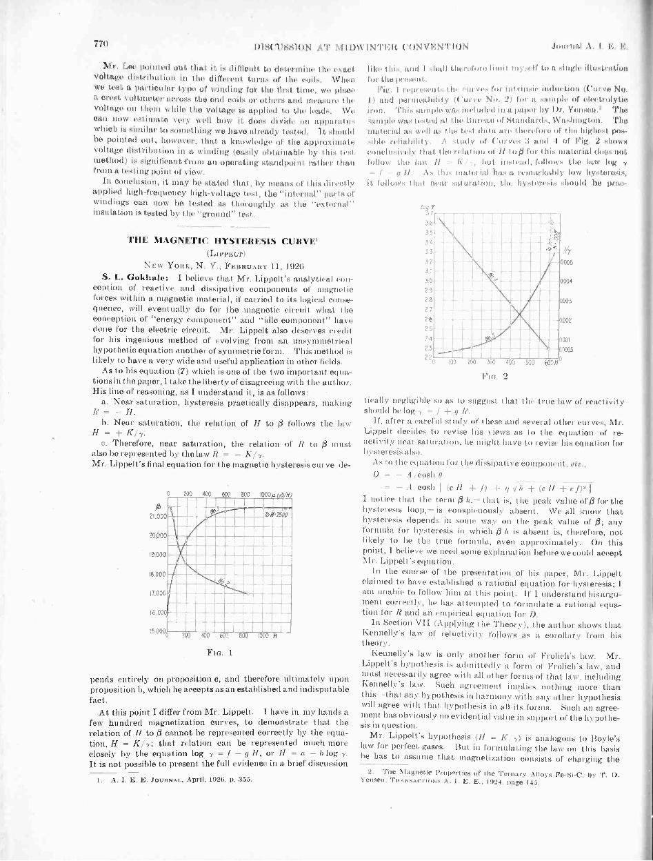
771) DISCUSS! oN .1'1' NI I D INTER 'I'ION Journal I. E. It:.
Mr. Lee pointed otit that it is difficult to determine the exactvoltage distribution in the different turns of the coils. \Vitenwe test 11 OtIrtiuttlar type of winding for the first time, we placea crest \ ',hunger across the end coils or others and measure Ihe
()Huge I hem v hile I he NrolIngt, is applied to I In. lead,. \\ I
eau 110\1' estitilatt very well how it does (livid,' un app;a:,t II,which is similar to something we have already tested. It .114)111(1he pointed out, however, that a knowledge of the appril.11,110,voltage distribution in a winding (easily obtainable 1,\ I his testmethod) is significant from an operating StitO111)01111 ln her thanfrom a testing point of view.
In eonclusion, it may be stated that, by means of I his direct I,vapplied high -frequency high -voltage test, the "internal" parts ofwindings can now be tested as thoroughly as the "external"insulation is tested by the "ground" test,
THE MAGNETIC HYSTERESIS CURVE'(LIPPELT)
NEW YouK, N. Y., FEBRUARY 11, 1926S. L. Gokhale: I believe that Mr. Lippelt's analytical con-
ception of reactive and dissipative components of magneticforces within a magnetic material, if carried to its logical conse-quence, will eventually do for the magnetic circuit, what theconception of "energy component" and "idle component" havedone for the electric circuit. Mr. Lippelt also deserves creditfor his ingenious method of evolving from an unsymmetricalhypothetic equation another of symmetric form. This method islikely to have a very wide and useful application in other fields.
As to his equation (7) which is one of the two important equa-tions in the paper, I take the liberty of disagreeing with the author.His line of reasoning, as I understand it, is as follows:
. a. Near saturation, hysteresis practically disappears, makingR = - H.
b. Near saturation, the relation of H to follows the lawH = K/7.
c. Therefore, near saturation, the relation of R to 0 must.also be represented by the law R = - K17.Mr. Lippelt's final equation for the magnetic hysteresis curve de-
j3?1,000
20.000
19,000
18,000
17,000
16,000
15,000
200 400 600 800 noo 3
FIG. 1
pends entirely on proposition c, and therefore ultimately uponproposition b, which he accepts as an established and indisputablefact.
At this point I differ from Mr. Lippelt. I have in my hands afew hundred magnetization curves, to demonstrate that therelation of H to 0 cannot be represented correctly by the equa-tion, H = KI-y; that relation can be represented much moreclosely by the equation log = f - g H, or H = a - b logIt is not possible to present the full evidence in a brief discussion
1. A. I. E. E. JOURNAL, April, 1026. p. 355.
Ilse this, and I hidlIherel'orelimit in\ ell' Iii a :melt. illustrationfor I he present .
Vig. I 11.1)11.4 'HI' I Iii) I'M.% I) for nlrin)( .111*VO No.I and peritiVill)1111\ ( '11I'VO No. 2) I'M' a SO.Olpil i l'Olytilifirffii. ,a1111)14) H1(111411'11 Ol a paper by \ 111.2 The-;o111,14. alts tested at the Bureau iii standards, Thelikatvrial as %..11 a, I he teal (hint are i of the highest pos-sible .\ stmt\ of ( /Old 1 or Fig. 2 show);eonclusi \ ely I hat I he relai 111 Or II toil for Ihis material (1m,, Dot1.1)110) Ihe law // A but io-tcad, follows the law log .
//. the- material Int, a rentarlothly low hysteresis,it follows ha near sa 'oral ion, Ihe steresis should bo prat -
Flo. 2
deafly negligible so as to suggest that the true law of reactivityshould be log = p R.
If, after a. careful study of these and several other curves, Mr.Lippelt decides to revise his views 1(5 to the equation of re-activity near saturation, he might have to revise his equation forhyst eresis also.
.\s to the equation for the dissipative component,- .1 cosh 0
= - cosh // + q h (c H c
I notice that the term 0 that is, the peak value of 0 for thehysteresis loop,- is conspicuously absent. We all know thathysteresis depends in some way on the peak value of /3; anyformula for hysteresis in which 0 h is absent is, therefore, notlikely to be the true formula, even approximately. On thispoint, I believe we need some explanation before we could acceptAir. Lippelt's equation.
In the course of the presentation of his paper, Mr. Lippeltclaimed to have established a rational equation for hysteresis; Iam unable to follow him at this point. If I understand his argu-ment correctly, he has attempted to formulate a rational equa-tion for I? and an empirical equation for I).
In Section VII (Applying the Theory), the author shows thatKennelly's law of reluctivity follows as a corollary from histheory.
Kennelly's law is only another form of Frolich's law. Mr.Lippelt's hypothesis is admittedly a form of Frolich's law, andmust necessarily agree with all other forms of that law, includingKennelly's law. such agreement implies nothing more thanthis-that any hypothesis in harmony with any other hypothesiswill agree with that hypothesis in all its forms. Such an agree-ment has obviously no evidential value in support of the hypothe-sis in quest ion.
Mr. Lippelt's hypothesis (1I = K 1) is analogous to Boyle'slaw for perfect gases. But in formulating the law on this basishe has to assume that magnetization consists of charging the
2. The Magnetic Prow.rties of the Ternary Alloys Fe -Si -C, by T. D.Yensen. TRANSACTIONS A. I. E. E., 1924, page 145.

Aug. 1926 DISCUSSION AT MIDWINTER CONVENTION 771
molecules with something that is not in the molecules to startwith, riz., the magnetic induction (3. Such an explanation of theequation would therefore he in agreement with Poisson's theory,hut not in agreement with Weber's theory, which is, at present.the generally accepted theory.
TABLE IMAtINETIZATION TESTS ON ELECTROLYTIC IRON
Teat made at the Bureau of Standards --Test Ni. Tern. 418i.i.3. Data forIf and H received through eourtes of Dr. T. I). Yensen. The other
columns of the tahle are obtained by computation.
If
400400073(10
$ s. A /III 1 I.og
000
2
4
A
1 0 111502 0 142304 0 15770
20 0 17020 17000 4500 s54) 0 0002222 3 05.30
100 0 18700 18000 21551 16.6 0 0003450 ! 3 4625
200 0 19900 10700 1740 99 0 0005745 .' 3 2405
400 0 21320 20920 70,41 7,2 3 0 001724 2 7ti3
600 0 21900 21300 200 37, 7, 0 003000 i 2 310
1000 0 22300 21315) 11 21 7, inf.1500 0 23000 21500 0 II 3 inf.2000 0 24.500 21500 0 to 7 tnr2500 0 24000 I 21500 CI t, inf.
Notation: In this ablep
s:s -0 tWheres ..21Atity.p = A 11 (Intrinsic permeabilit)
Hans lippelt: It is obvious that in presenting this paperI did not intend to advance a final and eoneltiai% e treatise onmagnetism. Of the experimental data which I had on hand.only those appertaining to one magnetic cycle of tungsten steelappeared to be best suited for the study. With such funda-mental limitations, it cannot be expected that the results ob-tained and conclusions drawn will ewer all possible cases eof
magnetization. This state of affairs is reflected in Division It).under "Conclusions," by the statement that Equation 7 is hypo -t het ical. At the wile time it should Itt, noted that this equationis rather plausible and is also rooted in well-known law: ofphysics. Mr. Gokhale's apprehension that Equation 7) is
"indisputable" does not awtti to he claimed in the paper.Mr. Ookhale expresses his disagreement in particular with
Equation (71 and rests his point of view on research work of hisown and on premises mentioned under a and h and on a
conclusion, c.
In deriving Equation in, use has been made of the relation
R = - , but it has been used merely as a stepping stone forti
evolving Equation (7), which constitutes the improved form ofthe relation between Rand .
The paper in exploiting the test data makes no use of Mr.
Gokhale's relation c: 1? - , but employs Equation 171
exclusively. The effect will be understood when, for example,both relations are applied to the case of Oh = 13183. the highestvalue of magnetization which the tungsten steel attains in itsmagnetic cycle.
Mr. Gokhale's relation (c) R = -
0.5682 X 10616000 - 13183
- - 202 wrong value
As per Eq. 71 of paper. I? = -16000! - 131832
= - 182 correct valueThe difference amounts to 1 I per cent of the true value.
Referring now to Curves 1, 2, 3, and 4 submitted by Mr.Ookhale, imsential characteristics of those curves, not mentionedyet. should lw stated before making further use of them. Theequation of ('urve 4 is
log = log ( S - Idt = 3.6996 - 0.1)023m X H (d)
from which follows (see also Curves Nos. 4 and 1).
2 X 0.5682 X 106 X 1318 3
forth = 0 = -$ = 5007 and therefore 13 = do = + 16500for II ris-S = 0; = -03 = 1 = 21500 - 1
11 = 0 ) would make , `and log ,,, (= 4.3324
siniultaneolisly ) which is not situated on the straight(1= 0 i line No. 4.
The fact that for II Oa residual magnetization do = + 16500
2.1.0011
11.c00
20000
19 CO)
11 :co of
17..:t:
16.0ce(
ISOIX11
It Me,
11 AV
1: C(C,
mow'co)!
-
it'. coo I
acta I
_ter
cue A
isxo
1.000
0 Ca)
0
I
_-
o 8 § § §
Ft.:. 3
occurs, renders the cited curves unsuitable for comparison withthe hysteresis curve of the paper. Curve 1 looks more like thedescending branch of a hysteresis curve, while Table I showingtest data indicates that the ll-values progressed from 11 = 0 to2500, characterizing it as an ascending branch.
Due correction should be made, because -Weber's theory" alsoimplies that the magnetizing effect of a field H depends on theconfiguration of molecules at the beginning of the process.
On the other hand. if the low hysteresis is to be neglected alto-gether, there should be f3 = 0 for 11 = 0.
Fig. 3 herewith has been drawn up to facilitate, as far aspossible, comparison between Mr. Gokhale's results of researchand the theory of the paper. Curve 1 has been copied from Mr.Gokhale's Fig. 1, and Curve 5 is a magnetization curve com-puted on the basis of Equation (7), or rather Equation 115),which is another form of Equation (7) of the paper. Numericalvalues are given in Table II. K as it appears there is a valueadapted by mathematical trial to Curve 1.
Now inspecting Fig. 3, if, as called for, Curve 1 were dulycorrected to start at. the origin of the system, the two curves1 and 5 would be close together for values of 13 from 0 to about18,000 and from 21,000 to saturation. A difference, however,

772 DISCUSSION AT M IDW INTE It CONVENTION Journal A. I. F.. le,.
1- +11
J K2 + s2 x = -
TABLE 11Comparison of Equation (7) or rather (15) of the paper with Equation (d) of diseusition
- R = 11 K = 0.1205 X 10° S = 2150(10 . 1205 X 166
(0.1205 X 10⁶)2 + 215002 X //2 corresponding to Equation (15)
11 -R 20 60 100 200 400 600 1000 1588ft as per above Equation (15) 16303 19586 20331 20906 21200 21300 21380 21424# as per Equation (d) 17000 17872 18573 1978)) 20925 21300 21477 21499Difference -697 +1714 +1758 +1117 +275 0 -97 -75
is conspicuous for values of /3 from 18,000 to 21,000. Theagreement between the two curves would be better yet, ifCurve 1 would start at a residual magnetization /3 = - #0,e.g., including that amount of hysteresis which exists in theelectrolytic iron under test. In the latter case H would be re-placed by -I? and a conclusive comparison of the two pertinentEquations (d) and (7) could be made. If, then, a need forimprovement of Equation (7) should come into evidence, itmight be taken care of by adding an exponent n, possibly thus
2 K2
k \n.1?7, = - ) X (3 (e)(s2 -02)n 22 132
In this form, the dimensional homogeneity of the equation wouldbe retained. Curve 6 shows the corrective effect of a coefficientn = 0.949 upon Curve 5. Further research work along thelines of the new theory, however, should establish .a term for Rwhich covers all cases of magnetization.
Such a revision of Equation (7), or one similar, should haveonly a limited effect upon the equation for the dissipative com-ponent D, on account of the anticipated near agreement betweenthe curve as per Equation (7) and the graph of the improved term.
Since, however, the molecular friction (and hysteresis) de-pends very much on the material under test, it is to be expectedthat for different materials the D -curves will have differentconfigurations. The many constants in Equations (11) to (14)give quite a great latitude in this respect and should accord toEquations (11) and (14) more than transitional importance.
The quantity Oh does not occur in Equations (11) to (14),because they relate D to H. 13 is very much in evidence inEquations (33), (35), and (36), and in calculations of loss inAppendix III.
The empirical character of the Equations for D is admitted,4. Conclusions drawn from references in Magnetic Induction in Iron
and other Materials, by J. A. Ewing. Third Edition, 1960, D. Van Nos-trand Co., New York.
EFFECT OF HEAT ON MAGNETICSPage 171, Magnetization of Iron at various temperatures, Fig. 77 with
H = 0 to 2.5. Fig. 78 H = 0 to 50, D decreases with increasing tempera -d ft d R >
ture; therefored e
> 0 andd e
0. For large II and ft, em
is approached, hence saturation value goes down. Observe that ft addsto the elongation when within a certain value. Compare Fig. 126. H < 280.
Page 172. Fig. 79, same case, but H = 0.3 = constant: t = 0 to 800
deg. For low temperatures:dDde -< 0 = negative, but D remains too
large. The weak H = 0.3 < D cannot accomplish a parallel alignment ofpolar axes. R therefore remains near zero value. Above 700 deg. D isgetting so small, (D = 0) that under the weak H, alinement of polar axes
d Pis accomplished, involving also d e
> 0 and H = - R, which brings
about further elongation e = F3 (ft), carrying e to critical value em, thusreducing ft . ft = H.
Page 173. Fig. 80 H = 4.0 = constant. Fig. 81 H = 45 = const.Same process as in Fig. 79, but quantitatively different, inasmuch as thestronger field overcomes D at lower temperatures.
Page 176. Magnetization of nickel at various temperatures. Fig. 86H = 0 to 80, 1 held constant at various values t = 13 deg., 245 deg., 284deg., 298 deg., 308 deg.
D abates with rising temperature, which also entails increasing e. As ftgrows larger due to the growing field intensity, D is falling off. e = F3 (0)
but the Curves DI and 1)2 are rational inasmuch as they are theoutgrowth of rational theory.
Section VII (Applying the Theory) was added to showfirst, that by reason of functional appertainment, the magnetiza-tion curve should be referred to Rand not to 11, and secondly, that
1tan T = which was not known before.
Regarding Mr. Gokhale's reference to Weber's theory, ac-cording to which the magnetism is resident in the molecules, thegist of that theory will not be much altered by assuming that themolecules are ordinarily devoid of magnetism, but in magneti-zable materials they can be polarized in one direction only.When magnetized to the extent of /3 = H (for those moleculesthe polar axes of which happen to be parallel to H) and to # < H(for those molecules the polar axes of which are not parallel to H),they tend and begin to aline their axes parallel to the field H andthereby also deflect the molecules from their original -position.In so doing they encounter the friction D. At the same time theflux within them increases in accordance with their "magneticability." Each molecule then represents only a link in one of themany parallel chains constituting the magnetic flux of the circuit.
A further refinement of the theory will have to settle thequestion as to whether the polar axes are rigidly fixed to theirrespective molecules or whether shiftaround them.
As the flux enters the molecules and alignment of the polaraxes takes place, a reaction R is encountered. While mathemat-ical terms are given in the paper for D and R, the writer believeshimself justified in assigning the cause of those forces R and D tothe thermodynamic and mechanical state of the material undertest. Such conclusions are drawn from results of researchpublished by J. A. Ewing.4
adds to the thermal elongation until the critical value is being approached.The greater the elongation by heat, the less elongation e = F3 (ft) is neces-sary to reach the critical value em.
Page 177. Fig. 87, Field kept constant at various values II = 2.5,10, 30, 50; while temperature varies from 0 to 310 deg. Explanations aresimilar to those for Fig. 79.
Page 183. Fig. 89. Bar magnet subjected to heat cycle 8-160-10 deg.Curve shows the abatement of ft with separation of molecules by thermalexpansion. Such separation also permits better alinement of axes ofmolecules, which is reflected in nigher ft values when the magnet cools off.
The recurrence of ft and its stored magnetic energy leaves no other inter-pretation than that heat has been transformed into magnetism directly.This experiment should be repeated with a winding around the magnetand connected to a suitable galvanometer for checking the flow of Coulombsin and out. In that form the outfit would be an apparatus adapted tochange heat into electricity.
EFFECT OF MECHANICAL STRESS UPON MAGNETSPage 204. Fig. 98, Nickel under compression. H varies from 0 to 160
while compressive stress is held constant at various values, e. g., 0, 1.9, 3.5,6.8, 10. 13.8, 19.8 k in2. Rate of magnetization increases with com-pression, e. g., with mutual approachment of molecules.
d p Ha> 0 and numerically larger thand (- e) ( - e) ( - e)
Residual magnetismdD
+ 00 increases with pressure, therefore we have
d (- e) > 0.
Tension applied to nickel has the opposite effect (e = positive). Com-pare Fig. 95 on page 200.
Pages 197, 224, Villary effect:-In iron, when subjected to a weak field, a

Aug. 1926 DISCUSSION AT MIDWINTER CONVENTION 773
Fig. 4 (herewith) shows the development along its axis anda cross section through a rod of magnetizable material. Cer-tain notations are also given which are necessary for furtherexplanations.
The outstanding feature of the aforesaid conclusions is thatmagnetic reaction R, magnetic friction D, and, as a sequel, /3,depend very much on the relative distance between the molecules.There are various forces affecting that distance.
Briefly statedR = F (e, a) (f)D = F2 (e, a) (d)
In general, e. g., if not counteracted otherwise,Separation of molecules (A 1 = el = positive) by ex-
pansion lowers D, (3, R.
r---
Hap.Field
t° Cause off,
/7 =Cause off,
ACTIVE FORCES REACTIVE FORCES
Heat Mechanical force}ca used by heat
:Cr Elastic reaction, the cause of R
H . HarfiH Mechanical force\caused by # f
I f Mechanical external force
FIG. 4
Mutual approach of molecules ( A 1 = a 1 = negative) bycompression increases D, /3, R, each at its own rate.
If counteraction does take place, as, for instance, when me-chanical pressure opposes thermal expansion, the effect upon /3depends upon
dD > dR > dA-de < de
or< de
(h)
dD > dR > d13-da < da or< da
For e, a critical maximum value 5. exists. Wher, en, is exceeded,the effect is similar to that of a large air -gap or a broken magneticchain.
To augment the above equations (f and j), the following twowell-known relations should he
//cited:a = Fa (10r Of 6r Dat = F4 (101 I,)
(k)
(1)
Observing now that e = U E and a 1 = T, G, it is obvious thatR and D depend on the elastic quality of the material.
It is understood, of course, that the two fundamental laws ofthermodynamics also apply. They must he referred to, forinstance, when explaining the change of magnetization throughheat in a permanent magnet. Here they force the conclusionthat heat energy is transformed into magnetic energy.
mechanical tension will cause # to rise; when in a strong field and put undertension, # will decrease.
This Villarl effect in iron seems to indicate that in iron a negativemaximum for a exists. The neutral point between ( - em) and ( Em)occurs when a certain external load Is applied.
Page 243. Fig. 121, Nickel under tension and torsion. Tension alone(Curve c c) separates the molecules and therefore holds # low. Torsionadded brings about lateral compression and a mutual approachment ofmolecules, and also an increase of D, the molecular friction. As soon as IIhas reached a value (12 in Fig. 121) to overcome this larger D, alinement ofpolar axes of molecules takes place "en masse," accompanied by a largoincrease in ft. The molecules remain then In alinement for the descendingbranch, owing to the high value of D, and a high residual magnetism is theresult.
Page 208. Fig. 102. Nickel In (successive) constant fields. // >e 6.0,21.8. 53.5, 118. Pull 0 to 12 X 2.75 k gtm ns2. Separation of mole-cules lowers # and stored magnetic energy. Removal of tension bringsback # and its energy. Case Is similar to bar magnet under influence ofheat, page 183.
CORRESPONDENCETRANSMISSION LINE SAG CALCULATIONS
To the Editor:Referring to the paper on Transmission Line Design,
abstracted in the A. I. E. E. JOURNAL of December 1925,p. 1352, I wish to call attention to an important omis-sion by the author.
When there is wind pressure, the cable of a trans-mission line span lies in an oblique plane and not in avertical one. It still has the shape of a catenary, anddeflections in the direction of the resultant force are inthe oblique plane. If one support is a distance b higherthan the other, the dimension b does not lie in theoblique plane, but in a vertical one.
A new dimension q = b/cos 0 should be taken, whichis the difference between the distances of the twosupports from the horizontal line through the lowestpart of the cable. The dimension q lies in the obliqueplane. The angle 0 is the angle between the obliqueplane and the vertical.
This matter is not a minor correction, but it makes alarge difference. For instance, in the problem withcable loaded, Table VII, of Mr. Smith's paper, b = 179feet and the lowest point of the cable is given as 91.2feet from the lower support, and between the two sup-ports. If the obliqueness of the plane is allowed for,q = 197 feet and the lowest point of the extended cate-nary is outside of the two supports, and 34.5 feet fromthe lower support. The calculated sag is very mate-rially changed.
Since the span is first calculated with a wind load, theabove error affects the succeeding calculations.
It is not necessary to use an approximate calculation,as used by Mr. Smith, for the deflection from the linejoining the supports, since a simple calculation depend-ing directly on the catenary formula can be employed.See the paper on sag calculations by the writer,A. I. E. E. JOURNAL for June 1926, page 564.
H. B. DWIGHT.
To the Editor:Mr. Dwight's letter calls attention to an impor-
tant point, and one which should have been mentionedin the paper.
The reason for not taking into account the angle 0,due to the wind load, was not stated in this paper, butwill be found in the previous paper on TransmissionLine Design, by F. K. Kirsten, A. I. E. E. TRANS-ACTIONS, 1917. In each of these papers the maximumload at freezing temperature was considered in thevertical plane with no wind, but with the assumptionthat the snow accumulation might then result in aloading at least as great as the loading computed for theinclined plane with wind. Since this condition is oneof the two possible maximum sag conditions, it woulddetermine the minimum clearance to ground. Thisassumption, if justified, gi ties an added factor of safety.

774 ILLUMINATION ITEMS Journal A. I. E. E.
If the assumption is not permissible, Mr. Dwight'ssuggestion must be considered. In any case a com-plete investigation might require the consideration ofthe inclined position for clearances between cables.
G. S. SMITH.
ILLUMINATION ITEMSBy Committee on Production and Application of Light
A DAYLIGHT ELECTRIC SIGNMultiplies the Effective Hours of Electrical Advertising
Perhaps the major reason for the popularity ofelectrical advertising is its enormous "brightness"contrasts-its letters of fire drawn out against the darknight sky. Its use and maximum effectiveness havebeen confined chiefly to those hours when there is a darknight sky; and the time clocks, turning the signs offafter the people are abed, are set to turn them on againonly at dusk the next day. While it is true thatduring the evening hours advertising is most effective-when people are most receptive-yet there are daylighthouis when advertisers clamor for attention. Thetheater, with its matinee performances, has emptyseats to fill. The real-estate development, wherebrightest days are best for trade, finds everyonevying for attention. The shopping district storesentice the midday throngs-with as keen competitionfor the attention of all, those who walk or those who
DAYLIGHT SIGN
ride,-as at any other time. Yet, at these hours,the signs brilliant at night become mere painted mes-sages dependent upon such secondary agencies asbeauty, grace, and color to catch and hold the eye.For the filament of the incandescent lamp, althoughvery bright, is small in size, and against the light day-time backgrounds, there is insufficient area of brightnessto command attention.
It is a simple matter, optically, to build up the area ofbrightness and lay images of the brilliant filamentside by side so that, for example, the entire surface ofa letter is given the brightness of the filament itself.Then the brilliant area is large and will attract. Thetraffic signal and the familiar stop signal of the motorcar are examples of such building up of the area ofbrightness to a size at which it competes successfully
with the light of day. And in the "daylight" sign,a large reflector directs an image of the filament to everypoint on the surface of a glass letter, giving it the bright-ness of a line of fire by day.
In obtaining this brightness, the light has been con-centrated into a relatively narrow angle; hence, withinthis angle only is its effectiveness at a maximum.Therefore, such a sign is of greatest value when thecirculation is massed within a relatively narrow viewingangle, and where people approach the sign nearly"head on" for a considerable distance. There aremany such locations,-atop the marquee projectingover the sidewalk, at a dead-end street, on a highwaycurve,-where the new sign might well be used to givea daytime punch.
At night, the sign is effective if dimmed to a muchlower brightness. The brightness used by day wouldfuzz and blur the letters and make them indistinguish-able, even at short distances; in fact the glare would beintolerable. Dimming at night may be easily ac-complished by a time clock that switches to a lowervoltage transformer tap or cuts in a series resistanceif in the direct -current district. Often it will be satis-factory to wire the lamps in two circuits of equalnumbers and wattage, the time clock connecting thehalves in series at a predetermined hour.
The use of color, preferably in the glass letter itself,improves both day and night effect. The lightercolors should be employed in order not to sacrifice the
that compels attention.The first installation of the "daylight" sign was
made on Central Pier, Atlantic City. Here it is sosituated and the direction of the boardwalk is suchthat the letters are visible to people approaching fromafar and over a considerable stretch of boardwalk.It was desired to compel the attention of the passerbyin an inescapable manner, even on the brightest day,and high brightness is an unfailing means to this end.Hence the "daylight" sign was used. Rippled ala-baster glass, with a slightly opalescent case, smoothsout streaks and striations without too great a diffusionof the concentrated beam. Back of each letter is alarge, polished, parabolic reflector, with a 200 -watt,Mazda C lamp so placed that the filament is at thefocus of the reflector. The reflectors are turned at aslight angle so that they aim down the boardwalkapproach. The necessary dimming at night is ac-complished by connecting two groups of lamps of equalwattage, in series, so that each lamp in the letters re-ceives half voltage at night.
When approaching the store from afar down theboardwalk, the effect is striking; even on the brightestdays of ocean sunshine, with the white, glitteringbeach nearby, the more brilliant, sparkling letters ofthe "daylight" sign stand out beyond all surroundingsand compel attention.

Aug. 1926
E.*
limmionniiimmitummtniiiimmommuniumumnimiuminiumniimmimminiminiummommiliminimminuitimm
Pacific Coast Convention, Salt Lake CitySEPTEMBER 6-9
Arrangements are being completed for the 1926 Pacific CoastConvention of the Institute which will be held in Salt Lake City,September 6, 7, 8 and 9, 1926. A special technical program isbeing prepared and the Convention Committee is arranging aseries of events for the entertainment of those who will be inattendance. The convention meetings will be held at HotelUtah. which will also be the headquarters for all other conventionactivities.
Among the wide variety of subjects covered in the technicalpapers will be high -voltage transmission, corona, surge recorders,vacuum switching, fire protection for generators, stability ofalternators, protecting oil tanks against lightning, telephony,mining applications, education, etc. A tentative list of papersis given below.
A visit to Utah at any time of the year is most delightful, andit is particularly so during the early part of. September. It isplanned to hold technical sessions during the forenoons, withafternoons devoted to sightseeing trips to such places as UtahCopper Company open -pit mine at Bingham, where im-mense tonnage of copper ore is mined with electric shovels; tothe Utah Copper Company mills at Magna and Arthur, wherefrom 30,000 to 40,000 tons of ore per day are milled and wherelarge quantities of electric power are used; to the beautifulSaltair resort which is located on Great Salt Lake; to the numer-ous canyons surrounding the city, and to the many notableplaces of historic interest in and about Salt Lake City.
Immediately following the Convention, arrangements will be
INSTITUTE AND RELATED ACTIVITIES
JOURNALOF THE
American -Instituteof Electrical
EngineersPUBLISHED MONTHLY BY THE A. I. E. E.
33 West 39th Street, New YorkUnder the Direction of the Publication Committee
C. C. CHESNEY, PresidentGEORGE A. HAMILTON, F. L. HUTCHINSON,
National Treasurer National Secretary
PUBLICATION COMMITTEELe P. MOREHOUSE. Chairman
F. L. HUTCHINSON E. B. MEYERDONALD McNicot J. H. MonEcaorr
GEORGE R. METCALFE, Editor
Subscription. $10.00 per year to United States, Mexico.Cuba. Porto Rico. Hawaii and the Phillipines; $10.50 to Canadaand $11.00 to all other countries. Single copies $1.00. Volumesbegin with the January issue.
Changes of advertising copy should reach this office by the15th of the month for the issue of the following month.
The Institute is not responsible for the statements andopinions given in the papers and discussions publishedherein. These are the views of individuals to whom they arecredited and are not binding on the membership as a whole.
E
775
made for those interested to visit the various properties whichcomprise the hydroelectric development of Utah Power & LightCompany. One trip of three days' duration will cover the BearLake -Bear River system which is one of the most highly developedhydroelectric projects in the world. Bear Lake, a naturalreservoir about 30 miles long and 9 miles wide, serves as a storageand equalizing reservoir for the entire Bear River system. The
GRACE HYDROELECTRIC PLANT, UTAH POWER & LIGHT CO.
flow of Bear River, below Bear Lake, is maintained practicallyconstant throughout the entire year for power purposes and to thegreat benefit of irrigation projects located along the river. AtBear Lake, a pumping plant is installed to insure water in theriver even during periods of low precipitation and run-off. Forthose who cannot afford the three days necessary to cover theBear Lake -Bear River System, an excursion of one day is planned
ONEIDA HYDROELECTRIC PLANT, UTAH POWER & LIGHT CO.
to the new 30,000 -kw. Cutler Generating Station which will beplaced in operation during the latter part of 1926 and which willbe in excellent condition for inspection and study during theearly part of September.
One item of interest to all electrical engineers will be theceremony in connection with the presentation of the A. I. E. E.Edison Medal to Dr. Harris J. Ryan, Past -President of the In-

776INSTITUTE AND RELATED A(7TIVITI ES Journal A. 1. E. E.
stitute and Professor of Electrical Engineering at StanfordUniversity.
The time of the Salt Lake Convention has been planned to fitin with the convention of the Rocky Mountain Coal MiningInstitute which is to be held in Glenwood Springs immediatelyfollowing the Salt Lake Convention, and also the Annual Meetingof the Colorado Railway Light and Power Association, which isto be held in Colorado Springs during the week following theSalt Lake Convention.
Notices of this Convention will be sent to all Western membersof A. I. E. E., during August. A large attendance is expectedand the Committee gives assurance that the time spent at theSalt Lake Convention will be most profitable.
The committee is composed of the following: C. R. Higson,Chairman; P. P. Ashworth, H. G. Baker, V. L. Board,Brundige, R. J. Corfield, G. S. Covey, John Harisberger, R. A.Hopkins, C. P. Kahler, J. A. Kahn, E. A. Loew, C. A. Malin-owski, J. F. Merrill, E. B. Meyer, H. T. Plumb, R. C. Powell,C. C. Pratt, Paul Ranson, L. W. Ross, John Salberg, H. H.Schoolfield, M. M. Steck, A. Vilstrup, H. B..Waters and B. C. J.Wheatlake.
TENTATIVE LIST OF PAPERS FOR PACIFIC COASTCONVENTION
A New 220-Kv. Transmission Line, C. B. Carlson and H. Michener,Southern California Edison Co.
Effect of Unbalanced Tension in a Long -Span Transmission Lin( ,
by E. S. Healy and A. J. Wright, Electric Bond and ShareCo.
110-Kv. Transmission -Line Construction of The WashingtonWater Power Company, by L. R. Gamble, WashingtonWater Power Co.
The Circle Diagram of a Transmission Network, by F. E. Terman,Stanford University.
MORMON TEMPLE BLOCK, SALT LAKE CITY
The Space Charge That Surrounds a Conductor in Corona, byH. J. Ryan and J. S. Carroll, Stanford University.
Calibration of Lichtenberg Figures, by K. B. McEacluon, GeneralElectric Co.
Vacuum -Switching Experiments at California Institute of Tech-nology, by R. W. Sorensen and H. E. Mendenhall, Cali-fornia Institute of Technology.
Temperature of a Contact and Related Current -InterruptionProblems, by Joseph Slepian, Westinghouse Electric & Mfg.Co.
Fire Protection of A -C. Generators, by J. A. Johnson, Niagara FallsPower Co., and E. J. Burnham, General Electric Co.
Stability Characteristics of A Iternotors, by 0. E. Shirley, GeneralElectric Co.
Synchronizing Power in Synchronous Machines, by H. V. Putman,Westinghouse Electric & Mfg. Co.
Protection of Oil Tanks Against Lightning, by F. W. Peek, Jr.,General Electric Co.
Protecting Oil Tanks Against Lightning, by E. R. Schaeffer,Johns -Manville, Inc. (Informal presentation).
Engineering Education-Its History and Prospects, by H.Henline, Stanford University.
4144:AL iiiii ,11;41"..., IfICJIII4
IIi iiiiii,i ,,,:trl, '',lid
' ,i,u3 , II iiiiikiihillt flith"-f Oiatikelk 2111 ' Ali : a""'"M iirniithiloAt si i. i -isismaerrS /I VS .
1'111 I,
NEW SALTAIR PAVILION, GREAT SALT LAKE
Transcontinental Telephony, by 0. B. Jacobs and H. H. Nance,American Telephone and Telegraph Co.
Carrier -Current Communication on Submarine Cables, by H. W.Hitchcock.? Pacific Telephone and Telegraph Co.
Controlling Insulation Difficulties in the Vicinity of Great SaltLake, by B. F. Howard, Mountain States Telephone Co.
Electrical Practise in Lead -Silver Mines in Utah, by LeonardWilson, Consulting Engineer.
Variable -Voltage Equipment for Electric Power Shovels, by R.W. McNeill, Westinghouse Electric & Manufacturing Co.
The White Sulphur Springs ConventionThe forty-second Annual Convention of the A. I. E. E. con-
vened at the Greenbrier Hotel, White Sulphur Springs, W. Va.,President M. I. Pupin presiding. About 350 members and guestswere in attendance and while it was numerically smaller thanmany of the previous conventions it was of the utmost technicalinterest because of the number of excellent papers and committeereports. The hotel and its surroundings left nothing to be de-sired in the way of entertainments and sports. Following theusual custom at Summer Conventions, the technical sessionswere confined entirely to the mornings, leaving the balance ofthe day open for recreation and social purposes.
CONFERENCE OF SECTION DELEGATES
The first event' of the Annual Convention was the regularannual Conference of Section Delegates held under the auspicesof the Sections Committee at morning and afternoon sessionson Monday, June 21.
Forty-three of the fifty-one Sections were represented byofficially appointed delegates. Five of the Geographical Dis-tricts were also officially represented by their Secretaries oralternates, and there was also present a number of Counsellorsof Student Branches.
The conference, which was also attended by a considerablenumber of officers and officers -elect and other interested members,
Aug. 1926 INSTITUTE AND RELATED ACTIVITIES 777
was presided over by Chairman Harold B. Smith of the SectionsCommittee. The program, which had been prepared in advanceby a special committee and mailed to all the delegates, wasconsidered in detail as follows:
1. Announcements by Professor H. B. Smith, Chairman,Sections Committee.
2: Remarks by President Pupin.3. Remarks by President-elect Chesney.4. Report by National Secretary Hutchinson on results of
previous Sections conferences.5. Public Relations:
(a) Affiliation with Sections of other engineeringsocieties and with other local organizations.
(b) District and National speakers bureau.(c) The relations and service of Secticns to the
community.6. Regional Meetings.7. Other new business.
The latter part of the conference related to organization andactivities of Student Branches and was presided over by DeanC. E. Magnusson of the University of Washington, Seattle, inhis capacity as Chairman of the Committee on Student Branches.
Recommendations were adopted as follows:That a national committee be appointed to study the question
of better public relations.That the speakers bureau be strengthened or extended princi-
pally on the side of popular interpretation of scientific andengineering subjects.
That provision be made, if possible, in the budget for the com-ing year to pay traveling expenses for Student Branch Counsellorsand incoming Student chairmen of all Branches to a Districtmeeting each year; also to pay similar expenses for one delegatefrom each of the Districts to the national convention each year.
That a joint meeting of the Counsellors and incoming Studentchairmen of all Branches in the two Pacific Coast Districts beheld during the Pacific Coast Convention at Salt Lake City,commencing Monday, Sept. 6, 1926.
At the meeting of the Board of Directors held at the Con-vention on June 23, these recommendations were considered andaction favorable to the objects desired was taken.
An abstract of the proceedings of the entire'conferenee, whichincluded discussion upon many other topics in addition to thosereferred to above, is being prepared and will be printed in pam-phlet form and mailed to all delegates in attendance and to allofficers of Sections, Branches, and the national body. Any In-stitute member who is interested may obtain a copy of the pam-phlet without charge upon application to Institute headquarters,New York.
TUESDAY, JUNE 22
Immediately after opening the session on Tuesday morningPresident M. I. Pupin presented his president's address. Inhis address he pictured the relations of the great fundamentaltheories and discoveries of the science of electricity, closingwith a plea for more thorough study of the marvelous propertiesof electricity which we are just now beginning to understand,the behavior of the electron. Dr. Pupin's address is publishedon page 758 of this JOURNAL.
Following the President's address, Cummings C. Chesney,President -Elect, was introduced and he spoke briefly of his ap-preciation of being chosen for the presidency and of his hopes forcarrying on another successful year of the Institute.
President Pupin then announced the winners of the Instituteprizes for papers presented during the year 1925 and presentedto the winning authors their certificates of award and cashprizes. These authors were R. W. Wieseman who won theFirst -Paper Prize and J. H. Cox and J. W. Legg who won theTransmission Prize. A complete account of the awards was
, published in the July issue of the JOURNAL, page 685.
Following the presentation of prizes, Dr. Pupin introducedMr. E. B. Meyer who took the chair and proceeded with thereading of the reports of the Technical Committees six of whichwere presented at this session. In the absence of Dr. Whitehead,Chairman, Dr. Kouwenhoven presented the report of the Re-search Committee. This was followed by the report of theStandards Committee which was presented by Mr. C. E. Skinner.The report of the Instruments and Measurements Committeewas presented by Mr. J. R. Craighead in the absence of ChairmanKnowlton, and Mr. H. P. Charlesworth followed with the reportof the Committee on Communication. The final report of thissession, that of the Committee on the Production and Applica-tion of light, was presented by Chairman P. S. Millar. Chair-man Meyer then declared the reports open for discussion and thefollowing members took part in the discussion which ensued:-W. E. Beaty, S. L. Gokhale, P. S. Millar, H. Goodwin, Jr.,H. M. Hobart, and Dr. H. B. Dwight. At the close of thediscussion the technical session adjourned until Wednesdaymorning.
Tuesday afternoon was devoted to golf, tennis, and other out-door recreations as were all the afternoons during the con-vention. On Tuesday evening an informal reception was heldin the Ball Room of the hotel. In the receiving line werePresident Pupin, President -Elect Chesney, and several otherdistinguished members of the Institute including officers past,present, and elect, together with many lady guests. Followingthe reception dancing was enjoyed with music by a most pleasingorchestra. Incidentally, there was dancing on every eveningof the convention following the other scheduled events.
WEDNESDAY, JUNE 23RD
Two technical sessions were held on Wednesday morning,Session A being held in the Ball Room of the hotel. Mr. E. B.Meyer called the session to order and introduced Mr. H. M.Hobart, Chairman of the Electrical Machinery Committee,who took the chair. Three papers were presented at thissession as follows:-Synchronous Machines, presented in partby R. E. Doherty and continued by C. A. Nickle. The dis-cussion of this paper followed immediately on its presentationand the following men participated: C. A. Adams, P. L. Alger,M. I. Pupin, R. W. Wieseman, R. D. Evans, and H. B. Dwight,with closure by R. E. Doherty. The next paper on the program,Graphical Solution of A -C. Circuits, by F. W. Lee, was presentedby Dr. Kouwenhoven in the absence of the author. Discussionfollowed by M. I. Pupin, W. P. Dobson, C. A. Adams, D. C.Prince, Harold Pender, R. E. Doherty, and C. W. Bates. Thetitle of the third paper on the program was Multiplex Windingsfor D -C Machines and was written by C. C. Nelson. As theauthor was not present the paper was read by Mr. H. B. Dwightand was discussed by W. B. Kouwenhoven, H. B. Dwight,J. L. Burnham, and C. A. Adams.
Session B on Wednesday morning was held in the TudorRoom of the hotel and was presided over by Mr. F. L. Hunt.The first paper to be presented was entitled Remotely ControlledSubstations and was abstracted by its author, W. C. Blackwood.This was discussed by C. M. Gilt, F. B. Johnson, C. Lichtenberg,E. K. Huntington, G. 0. Brown, with closure by Mr. Blackwood.The next paper of the session was entitled The High -SpeedCircuit Breaker in Railway Feeder Networks, by J. W. McNairywho presented it in abstract, following which a written discussionby R. J. Wensley was presented by title. Verbal discussionfollowed by J. J. Linebaugh and C. Lichtenberg. The finalpaper was by Alfred Bredenberg, Jr., and was entitled Regenera-tive Braking for D -C Locomotives. This was abstracted by theauthor. As there was no discussion of this paper the meetingadjourned.
Two of the entertainment features which the ladies particularlyenjoyed were the auto drive on Wednesday afternoon and thecard tournaments on Thursday evening.
778INSTITUTE AND RELATED ACTIVITIES Journal A. 1. E. E.
In the drive on Wednesday, automobiles took a largo partythrough some of the most beautiful mountain and valley scenery,a stop being made at Lewiston for tea.
On Thursday evening both bridge and hearts wore played by alarge number of ladies and men. The winner at each tablereceived a salad bowl as a prize.
STANDARDIZING ORGANIZATIONS DISCUSSED
On Wednesday evening the relations between the Institute,the American Engineering Council and two major standardizingorganizations were outlined by three able speakers. Dr. C. H.Sharp, described the activities of the International Electro-technical Commission. He mentioned the agreements whichhave been reached among various nations and suggested thepossible formation of an international standards association.
L. W. Wallace, executive secretary of the American Engineer-ing Council, told of the work of that organization, particularlyin advocating congressional acts dealing with the Patent Office,Mapping, Muscle Shoals, Salaries of Federal Judges and RadioBroadcasting. The Council has prepared a number of reports onimportant questions including waste in industry, the twelve-hour shift, commercial aviation and accidents and production.
C. E. Skinner, chairman of the American Engineering Stand-ards Committee, told of the objects and work of that body.He mentioned the rules of procedure for making standards whichhave been prepared and pointed out the mutual benefits whichwould result if all standards -making bodies follow these rules asa guide.
The regular meeting of the Board of Directors was held attwo -thirty Wednesday afternoon. A resume of the businesstransacted by the Board will be found elsewhere in this issue.
THURSDAY, JUNE 24THThe session on Thursday morning was presided over by Pro-
gessor H. B. Smith and like the Tuesday morning session wasdevoted entirely to the presentation of Technical Committeereports. All of the reports were presented in abstract and wereas follows: Report of the Committee on Power Transmissionand Distribution, P. H. Thomas, Chairman, presented by P. IT.Chase, Vice -Chairman; Report of the Committee on ProtectiveDevices, E. C. Stone, Chairman, presented by F. L. Hunt,Vice -Chairman; Report of the Committee on Applicationsto Iron and Steel Production, F. B. Crosby, Chairman,presented by A. G. Pierce; Report of the Committee onGeneral Power Application, A. M. MacCutcheon, Chairman,presented by Mr. MacCutcheon; Report of the Committee onApplications to Mining Work, F. L. Stone, Chairman, abstractedby H. A. Winne; Report of the Committee on Applications toMarine Work, L. C. Brooks, Chairman, presented by A. G.Pierce; Report of the Committee on Electrochemistry and Elec-trometallurgy, G. W. Vinal, Chairman, abstracted by Mr. Vinal;and the Report of the Committee on Power Generation, V. E.Alden, Chairman, presented by Mr. Alden. An extended dis-cussion followed which was participated in by W. S. Lee, W. A.Del Mar, R. D. Evans, H. R. Summerhayes, M. I. .Pupin,C. A. Nickle, H. M. Hobart, and R. N. Conwell.
FRIDAY, JUNE 25TH
On Friday morning the last two technical sessions of the Con-vention were held in parallel. Session A was under the chairman-ship of W. A. Del Mar and the first paper to he presented wasThe Mechanism of Breakdown of Dielectrics, by P. H. Hoover.This was discussed by W. F. Davidson, P. L. Alger, R. W. Wiese -man, and in a written discussion by R. W. Atkinson read byE. Kirschner. The second paper presented in Session A wasby D. C. Prince and was entitled Mercury Arc Rectifiers. Thepaper was abstracted by Mr. Prince and discussed by C. P.Osborne, A. H. Mittag, J. A. Cook, D. C. Prince, W. A. Hilde-brand, W. F. Davidson, and R. D. Evans, with closure by A. V.Mershon.
Session B on Friday morning was called to order by Mr. L. W.Morrow who called on Mr. (10khale to abstract his paper onLaw of Magnetization. It was dismissed by .1. It. Craighead,H. Lippelt (by letter), W. L. Upson, and J. E. Jackson, withclosure by Mr. (3okhale. The next paper was entitled SurfaceHeat Transfer in Electric Machines with Forced Air Flow, and wasby G. E. Luke who presented it in abstract. This was discussedby J. L. Burnham with closure by (1. E. Luke. The final paperof the session was on General Theory of the Auto -Transformerwhich was presented by the author, W. L. Upson. This wasdiscussed by J. R. Craighead with closure by Mr. Upson. Thesession then adjourned.
THE GOLF TOURNAMENT
A great many of the men at the meeting participated in thegolf tournament and in addition there was a ladies' putting con-test. The golf tournament, which was played for the MershonTrophy, was very elosly contested. After all other contestantshad been eliminated, Friday afternoon brought a match betweenthe two remaining players, H. C. Don Carlos and W. P. Dobson.Their match however resulted in a tie. Therefore as both ofthese gentlemen reside in Toronto the committee decided thatthey should play off the match later on a Toronto course: Subse-quently this was done and this time Mr. Don Carlos was vic-torious by a score of four up and three to go. Accordingly hisname will be added to the eleven other names already on theMershon Cup. He will not have permanent possession of thecup as it is required that a contestant win this annual tourna-ment twice before he may keep the cup. He received, however, asa permanent prize another handsome cup. Mr. Dobson asrunner-up also received a cup.
The winners of the other features were as follows: N. M.Garland had the low gross score (79). Farley Osgood had thelow net score (63 with 21 handicap). W. S. Lee won the finalof the second flight, and R. F. Gheen was runner-up. P. M:Lincoln won the final of the third flight, while W. B. Kirke wasthe runner-up.
The ladies' putting contest was won by Mrs. N. M. Garland,the prize consisting of a silver vase, and Mrs. H. W. Youngwon a bronze bowl as second prize.
TENNIS TOURNAMENTS
Tennis tournaments,. both singles and doubles, were played.L. B. Chubbuck won the singles tournament and H. B. Dwightwas runner-up. For this Mr. Chubbuck's name will be planedon the Mershon Tennis Trophy and he received a silver cup as apermanent prize. For permanent possession of the MershonCup the same player must win the tournament twice.
The doubles tournament was won by H. R. Summerhayes andE. H. Hubert. The runners-up were P. M. Alger and D. C.Prince.
The annual Convention Committee, the efficient managementof which insured a most successful convention, consisted of thefollowing: Farley Osgood, Chairman, W. R. Collier, W. S. Lee,E. B. Meyer, W. E. Mitchell, A. M. Schoen, H.. B. Smith.
Twentieth Anniversary of IlluminatingEngineers
Marking the founding of the Society in 1906, the TwentiethAnniversary Convention of the Illuminating Engineering Societywill be held at Spring Lake, New Jersey, September 7th to 10thinclusive, when the great advances and developments which havebeen made during the past 20 years in this special field of Engi-neering activity will be fittingly observed. A program of di-versified and comprehensive papers on subjects of great practicalinterest has been arranged by the Committee in charge, Onespecial feature of the program particularly appropriate at thistime will be a session devoted to developments in the art ofillumination which have taken place during this twenty-yearperiod. Another session will be of interest to central -station

Aug. 1926 INSTITUTE AND RELATED ACTIVITIES 779
lighting men and devoted to the presentation and discussion of theLighting Sales Manual, prepared by a joint committee of theIlluminating Engineering Society and the National ElectricLight Association. The manual outlines methods found mostefficient by some of the leading illuminating engineers of thecountry in promoting good lighting by central stations. Central -station lighting men from the leading public utilities are to beinvited to discuss the manual and promote its adoption and use.
The entertainment features of the program have not beenoverlooked, and the hotel, with its surroundings admirablyadapted to provide the recreational features, will repeat thesuccess of previous meetings; golf, bathing in ocean or pool,tennis, country roads to attract the lover of horseback riding,boulevards for the motorist, broad porches overlooking the oceanare but a few of the many attractions. Special features ofentertainment will be provided for the ladies.
World Power ConferenceProgram and Appointments
Topics for discussion at the sectional meeting of the WorldPower Conference to be held in Basle, Switzerland, August 31to September 12, 1926, in which the American Committeeof the conference will participate, include the utilization ofwater power, inland navigation, exchange of electrical energybetween countries, electricity in agriculture and railway electrifi-cation.
This is shown in the technical program of the sectional meetingof the World Power Conference, copies of which have beenreceived by 0. C. Merrill, executive secretary of the FederalPower Commission, Washington, D. C., Member of the Instituteand general chairman of the American Committee.
Beside Mr. Merrill according to a recent. announcement thefollowing American engineers will attend the World Power Con-ference. Prof. A. E. Kennelly and Prof. Harry E. Clifford, of theDepartment of Electrical Engineering, Harvard University; JohnW. Lieb, vice-president, New York Edison Company; Louis Mar-burg, of Marburg Brothers, Inc.; 0. G. Thurlow, chief engineer,Alabama Power Company; Hugh L. Cooper, Consulting Engi-neer; and David B. Rushmore, formerly consulting engineer,General Electric Company.
Following are some of the papers to be presented by theAmerican delegation Committee:
The Economic Relation Between Electrical Energy ProducedHydraulically and Electrical Energy Produced Thermally:Conditions Under Which the Two Systems Can Work Togetherto Advantage, by W. E. Mitchell, Vice -President, Alabama PowerCoMpany, Birmingham, Ala.
Electricity in Agriculture, by Dr. E. A. White, Director,Committee on the Relation of Electricity to Agriculture, Chicago,Illinois.
Railway Electrification, by W. S. Murray, Consulting Engineer,New York City.
National Aspects of the Study of Water Resources, by NathanC. Grover and John C. Hoyt, Geological Survey, Department ofthe Interior.
Utilization of Water Power, and Inland Navigation, by ColonelHugh L. Cooper, Consulting Engineer, New York City.
Exchange of Electrical Energy Between Countries, by ColonelWilliam Kelly, Director of Engineering, National ElectricLight Association (formerly Chief Engineer, Federal PowerCommission).
Up to the present time, twenty-nine countries have agreed totake part in the conference and sixty-five reports have beenreceived. A complete list of the authors and titles of the reports,together with the conditions governing them, may be obtainedfrom the Secretary of the World Power- Conference, (WorldPower Conference, Basle). At the close of the conference, a fullreport, including the discussions, will be published.
The opening meeting of the conference will be held on Tuesday,
August 31st. Tuesday afternoon and Wednesday (Sept. 1st)will be given over to the reports on utilization of hydraulic powerand inland navigation. Thursday and Friday, September 2ndand 3rd, will be occupied with discussions on railway electri-fication and electricity in agriculture.
On Saturday and Sunday (Sept. 4th and 5th), a special train,generously provided by the Swiss Federal Railways, will take theparty to the Gotthard to inspect the electrification works.
Monday and Tuesday, September 6th and 7th, will be givenup to the reports on hydroelectric and thermal power, and theexchange of power between countries. The closing meeting willbe held on Wednesday, September 8th.
Following the conference, a number of visits have been ar-ranged to industrial establishments September 8th and 9th,and from the 10th to the 13th, there will be two somewhat longerexcursions which will enable the visitors to see something of thewonderful scenery of Switzerland. One will be to the Engadine,with Buchs as the objective, whence opportunities will beoffered for further excursions to Austria, Germany, Czecho-Slovakia, Hungary, Norway and Sweden. These will be organ-ized by the National Committees of the countries concerned.The other excursion will include the Bernese Oberland and theWest of Switzerland with the possibility of extended trips toItaly, France, Belgitim and Holland.
Further details regarding the program of the conference andthe excursions may be obtained from the Secretary of the WorldPower Conference.
A. I. E. E. Directors' MeetingThe regular meeting of the Board of Directors of the American
Institute of Electrical Engineers was held at the GreenbrierHotel, White Sulphur Springs, W. Va., on Wednesday, June 23,1926, during the Annual Convention of the Institute.
There were present: President M. I. Pupin, New York;Past -President Farley Osgood, New York; Vice -PresidentsHarold B. Smith, Worcester, Mass.; Edward Bennett, Madison,Wis.; Arthur G. Pierce, Cleveland; W. P. Dobson, Toronto;Managers H. M. Hobart, Schenectady; G. L. Knight, Brooklyn,N. Y.; J. M. Bryant, Austin, Tex.; M. M. Fowler, Chicago;H. A. Kidder, New York; H. P. Charlesworth, New York;National Secretary F. L. Hutchinson, New York. Also, byinvitation, C. H. Sharp, C. E. Skinner (representatives of Stand-ards Committee), and G. 0. Brown (representing Vice -Presi-dent -Elect A. E. Bettis).
The minutes of the Directors' meeting of May 21, 1926, wereapproved as previously circulated.
A report of a meeting of the Board of EXaminers held June 11,was presented and the actions taken at that meeting were ap-proved. Upon the recommendation of the Board of Examiners,the following actions were taken upon pending applications:61 Students were ordered enrolled; 342 applicants were electedto the grade of Associate; 11 applicants were elected to thegrade of Member; 38 applicants were transferred to the gradeof Member; 9 applicants were transferred to the grade ofFellow.
The Board ratified the action of the Finance Committee inapproving for payment, monthly bills amounting to $28,743.86.
The Finance Committee called attention to the fact that, underthe by-laws, traveling expenses are paid for Section delegates tothe Annual Convention covering actual transportation expensesboth ways, including Pullman and meals enroute, but that othertraveling expenses have been authorized on the basis of tencents per mile one way. The committee recommended that alltraveling expenses be placed upon the uniform basis of ten centsper mile one way from the place of residence to the meeting place,excepting that in the case of members, who are appointed torepresent the Institute upon special occasions, actual travelingand hotel expenses shall be paid, upon application. The Board

780 IN8TITI'TE 1!\ ii 1(1.A .1TED 1e "1'11 ITIE8 Ai airfoil A I 1.; I.:,
voted that Ow reeotattletalatioll be adopted, and dirteo d thatSeetion -111 of the I ii.iittite liy-laws Ile amended iteelirding1).
The Finance Committee called attention to Section ''" tit* I IttInstitute constitution, which provides that "upon application,the Board of Directors shall exempt from future annual dues,any Fellow, Member, or Associate who has paid dues fur thirty-five years, or who shall have reached the age of seventy afterhaving paid dues for thirty years," and recommended t hat suelimembers he designated "Members for Life" (in distinct ion frontthe present "Life 'Membership" list, which includes those whocommute their future dues by payment of a single sum as pro-vided in then by-laws). The Board voted that applications forpermanent exemption from further payment of dues receivedhereafter under Section 22 of the eonstitution, be referred tothe Finance Committee, with power; also that all members soexempted in future shall be designated in the Institute records as"Members for Life."
The Committee on Coordination of Institute Activities re-ported that it is desirable to schedule all important meetings ofthe Institute much further in advance than heretofore, some ofthe reasons being the desirability of reserving the necessarymeeting rooms, hotel accommodations, etc., and of avoidingconflicts with the meeting dates of other organizations as far aspossible. Upon the recommendation of the committee, thefollowing schedule of meetings was approved (the first twomeetings had previously been approved by the Board): PacificCoast Convention, Salt Lake City, Septeniber 6-9, 1926; NewYork Regional Meeting, November 11-12, 1926; MidwinterConvention, New York City, beginning Monday, February7, 1927; North. Eastern District Regional Meeting, April orMay 1927 (place to be determined later-Pittsfield, Mass., andother places under consideration); Annual Convention, DetroitSection territory, beginning Monday, June 20, 1927; PacificCoast Convention 1927 (place and date to be decided upon laterby the Pacific Coast membership).
The Committee on Coordination of Institute Activities alsorecommended that, inasmuch as several annual conventionsare now held, the use of the expresiion "Annual Convention ofthe Institute" be discontinued and that ,the three principalannual national conventions be designated as follows: "WinterConvention," "Summer Convention," and -Pacific CoastConvention;" also that the serial numbers applying to the AnnualConventions as held heretofore be continued and applied tothe Summer Convention only. This recommendation was ap-proved by the Board.
Other matters of importance were discussed, reference to whichmay be found in this and future issues of the JOURNAL.
Prizes for Papers Awarded in NortheasternDistrict
Prizes for papers presented during 1925, in the NortheasternDistrict of the Institute, have been awarded by the Prize Com-mittee of that District.
The committee awarded the Best -Paper Prize to K. B. Me-Eachron and E. J. Wade for their paper Studies of Time Lag ofNeedle Gaps. Each author received a certificate of award, and acash prize of $25 was divided between them.
Honorable mention was awarded to I. F. Kinnard and H. T.Faus for their paper Temperature Errors in Induction WatthourMeters, and to R. F. Franklin, for his paper Short -Circuit Currentsof Synchronous Machines.
The First -Paper Prize for the District was awarded jointlyto R. W. Wieseman, for his paper A Two -Speed Salient -PoleSynchronous Motor, and C. A. Nickle, for his paper An Electro-Mechanical Problem Analyzer. A certificate was presented toeach author and a $25 cash prize was divided between them.
Honorable mention was given to F. M. Clark, for his paperEffect of Repeated Voltage Application on Fibrous Insulation, and
J. 11,111,10011, hi, 1,01,,,f , 1111 1.111111,1111A41.1111
S1/41111. 1)111 110 1)1111,1111,1/
The I)1,111,1 111.i/A111I11I '111111.1 1111I I -I, II .11 \1. Liuculn,(Intl,' I it \tit, 'k I -II` .-11111 ; .\ ,Ilan \ Klid/WIt4)111and I I \ Till /1
Saskatchewan Sectiim Hold,( :1111111
A three-day meeting in a tent camp was held by tle kutch-ewat sevi ion on July 8, it and 10, at it:McNutt, Saskatchewan.
-nine tents were erected to aecoltillaulate the one Iola-(111.0 weathers of the Section Mal the invited4 Sashatebewatibranches of the Engineering Institute of Canada and theCanadian Instituteof Mining and NI et allurgy.
Meetings were held in a large marquee erected for the purpose.The following papers were read:
Electrical Di cflopment of South( rn ,tinskalc n wan, by S. R.Parker.
Industrial Ihvvlopunnl of Nati/ her n Su skatche wan , by W. H.(3 reeve.
rest rya, ire Trent /in of of 11. nod , by H. Prettie.Addresses were delivered by Dr. Chas. Outsell, Deputy
Minister of Mines, Ottawa; Professor Hall, of the University ofManitoba; Professor Worcester, of the University of Saskatche-wan; and Mr. Thorn, Chief of the Natural -Resources Branch ofthe Canadian Pacific Railway, Calgary.
On Thursday, July 8th, visitors were the guests of the Townof Estevan, at a complimentary banquet.
The large attendance was recorded in spite of heavy rains theday before the meeting opened, which necessitated many of themembers driving through mud for distances of two and threehundred miles. One much appreciated feature of the meetingwas the low cost of sleeping accommodations, for which eachadult was charged two dollars, while children were taken care ofwithout charge. The novelty of camping out was greatlyenjoyed and all voted the meeting a great success.
14.4.1ing 111 it-
Armour Institute and NorthwesternUniversity to Unite
On June 30, Armour Institute of Technology, at Chicago,brought to a successful close a campaign for raising a mil-lion dollars as a preliminary move in its affiliation withNorthwestern University. Of the million dollars, the alumnisubscribed more than one-third, the balance being made up ofdonations from members of the Armour family, a citizen ofChicago interested in engineering, and several public utilitycorporations.
A further call for $10,000,000, for endowment and buildingsto be erected on the Evanston Campus of Northwestern Uni-versity and on the MeKinlock Campus at Chicago Avenueand the Lake, is being undertaken under the leadership of SamuelInstill, Chairman of the Joint Trustees Committee. The ar-rangement between the t wo institutions allows a five-year periodin which they shall jointly attempt to raise the capital fund.
A Request for Decision on Radio LawThe failure of Congress to complete radio regulation and
the confusing decisions rendered by the Courts on radio laws of1912 have led the Department of Commerce to request an opin-ion from the Attorney General on the whole situation of Depart-mental authority. The most important feature of the matteris in respect to the right to assign, enforce or deny the -use ofspecific wavelengths to individual stations,-the key to the wholeregulation.
Since 1923 the Department has been making such assignmentsin accordance with decision of the Court of Appeals, Districtof Columbia, rendered during that year, on the assumption that,

Aug. 1926 INSTITUTE AND RELATED ACTIVITIES
by the law of 1912, they were under duty to make such assign-ments to prevent interference. Recent decision of the ChicagoCourt, however, cast doubt on this authority. The AttorneyGeneral now likewise disagrees with the construction of the Courtof Appeals, advising that. while each applicant. must designate adefinite wavelength, outside the band between 600 and 1600meters, it is still his prerogative to use other wavelengths atwill. Persons desiring to construct stations must determinefor themselves whether or not there are specific wavelengthsavailable for their use without being subject to interferencefrom other stations. They must simply proceed at their ownrisk.
University of Pennsyl :1 11 I:I Creates NewCourse
The creation of a new graduate course to prepare men forengineering research or for teaching and which will lead to thedegree of Master of Science in Electrical Engineering has been an-nounced by Dr. Harold 'lender, Dean of the Moore Sehmilof Electrical Engineering of the University of Pennsylvania andFellow of the institute.
At the same time, Dean 'lender announced that four graduatefellowships, each of which carries with it free tuition and a cashstipend of Vi00, have been made available to encourage studentswho are properly qualified to add a fifth year to their universitytraining. Applications for the fellowships may be made to theDean of the Moore School.
The course will begin with the academic year of 1926-27,and will include the following subjects; introduetion to math-ematical physics, advanced mat hemat ies for engineers, advancedelectric -circuit theory, electron theory and its engineeringapplications, and a thesis.
Each graduate student will be required to complete an in-dependent and original investigation in some field of electricalengineering. The student will be encouraged to select his ownproblem and must submit monthly reports on the progress ofhis investigation.
Applicant must have completed with credit an undergraduatecourse in electrical engineering substantially equivalent to thatgiven in the Moore School.
A Uniform Electrical OrdinanceA uniform electrical ordinance has been prepared by the
Electrical Manufacturers Council, providing that work donein accordance with the regulations as laid down in the twonational codes shall be prima facie evidence that it is in conform-ity with the most approved methods of construction for safetyto life and property. As the number of municipalities adoptingthis ordinance increases, the inspection situation will becomesimplified accordingly.
This ordinance provides, also, for the adoption of modificationsin the codes as they are made, so that it may be possible tokeep in step with the progress of the codes without the necessityof a detailed local study of each revision. The only subjectsin need of local restudying from time to time are the speciallocal rulings which can either be issued separately in bulletinform or can constitute separate articles of the local ordinanceadopting the codes as its basic article.
The inspector has played an important part in formulation andrevision. He has eliminated from them much that was unde-sirable and is constantly suggesting changes to cover either old,unnoticed or new conditions.
There are two ways in which he may assist-as an individualor as a member of.an inspectors' organization. One of the mostimportant services to be brought about is the general use ofnational codes of American standards.
The Committees in charge of the revision of the codes welcomeconstructive suggestions and criticisms from inspectors as
781
individuals facilitate the acquisition of this knowledge, theNational Fire Protection Association, sponsor for the NationalElectric (Fire) Code, has appointed a field secretary whosebusiness is to keep in personal touch with inspectors and presenttheir views to the Electrical Committee of the Association.
Power Show Reflects Tremendous AdvancesContemplation of the rapidly increasing demand for mechan-
ical power by the industries and homes of the United Statesreveals the secret for its success and leadership as an industrialand commercial nation. Greater and more economical pro-duetion at a smaller expenditure of human energy is the reasonfor its supremacy. Mechanical power as utilized in the auto-mobile and tractor, in the locomotive and steamboat, and asderived from the electric motor in the factory and home, liesat the root of the growth of the country and of the increase in thephysical and spiritual well-being of its people. The tremendousadvanees in the art of generating power to meet the demand areemphasized by the recent announcement by an eastern publicutility of the award of a contract for a steam turbine to generate160,000 kilowatts or more than 210,001) horse power. Thisgigantic machine is 60 per cent larger than the largest turbinepreviously constructed. Compared with the turbines of tenyears ago, it is considered a miracle of the engineering world.. more interesting contrast is called to mind by the opening ofthe Exposition in Philadelphia fifty years ago when, after somespeech -making, President Grant and the Emperor of Brazilstarted the giant Collis:: Engine, generating 1400 horse power,weighing 700 tons, and requiring sixty-five freight cars to deliverin Philadelphia.
To reflect these enormous strides in the mechanical arts andto make them available to the engineering and industrial publicis the important function of the National Exposition of Powerand Mechanical Engineering which is held annually in the GrandCentral Palace in New York City. The Fifth Exposition willbe held from December 6 through 11, 1926, and will fill fourfloors of the Palace with showings of all types of power and heatgenerating, distributing, and using equipment. It will includerefrigerating, heating and ventilating machinery and machinetools and power transmission devices, in addition to the usualimportant exhibits of power plant apparatus. Over 450 exhibit-ors will provide a well-balanced exposition that will have some-thing novel and important for every mechanical engineer andindustrial executive.
The exposition is under the management of Fred W. Payneand Charles F. Roth with offices in the Grand Central Palace.
Westinghouse Awards EducationalScholarships
Four scholarships each of which provides for payment of$500 a year to be applied toward an engineering education havebeen awarded by the Westinghouse Electric and ManufacturingCompany. The winners of the awards, based on the 1926competitive examination given by the Educational Department,are Robert R. Lockwood, an employe of the company and studentin the night school of Carnegie Institute of Technology; WilliamJ. Morlock, a graduate of the McKeesport (Pa.) High School;Frank M. Redman, graduate of Grant High School, Portland,Oregon; and Harry W. Thiemecke, company employe and stu-dent at Carnegie Institute of Technology.
Fifty-two applicants competed for the scholarships whichwere established by the Westinghouse company as a memorialto those of its employes who served in the World War.
Employes, or sons of employes, are eligible for the examina-tions, which are held annually. The awards are granted forone year only but will be continued for the full engineeringcourse if the student meets the academic and other standards

782INSTITUTE AN I) RELATE I) ACI'l V 1T1 Journal A. I. E. K.
of his school. Since the fund was established at the close of thewar, 32 Westinghouse Scholarships have been awarded.
Mr. Lockwood will take up Electrical Engineering at CarnegieInstitute of Technology, Mr. Morlock at Ohio State University,and Mr. Redman at Leland Stanford University. Mr. Thie-mecke will take Ceramic Engineering at Ohio State University.The committee in charge of the awards consists of L. A.Osborne, chairman, and Walter Cary, vice presidents of thecompany, and T. P. Gaylord, Acting Vice President.
.11 !Hi 11111111/111111
AMERICAN ENGINEERING COUNCILN1111111111111111111111111111111111111111111111111111111111101 llllllllll
SEEKS SOLUTION OF BROADCASTING PROBLEMA public service solution of the broadcasting problem issought by the American Engineering Council, according to an-
nouncement made by its president, Dexter S. Kimball, of CornellUniversity.
A committee of investigation will be appointed to examine thewhole situation in an attempt to obviate the "radio chaos"which may affect some 20,000,000 listeners. Dean Kimballasserts that many of the problems are of an engineering natureand that be believes a careful study of them, in an unbiased,broad-minded, and comprehensive way by a special committeechosen for that purpose, will be productive of results beneficialand of convincing form. He states that there are now 540broadcasting stations, at least 200 of which are giving regularprograms of considerable interest to substantial audiences, andapproximately 600 additional applicants still remain, to whombroadcasting licenses have not been granted by the Departmentof Commerce.
PROPOSED LEGISLATION FOR DIVISION OF SAFETYThe House Committee on Labor, on May 21st, 1926, decided to
report favorably upon a bill presented by Representative Rath-bone, of Illinois, proposing legislation for the creation of a Divisionof Safety in the Department of Labor.
The duties of such Division will be to collect statistics on in-dustrial situations involving jeopardized safety, with specialreference to cause, effect and occupational distribution, andpresent them to the Department together with coincidentrecommendations of plans for labor safety and devices for variousapplication to this end.
The -bill provides for the cooperation of all other GovernmentalDepartments interested in this work, and a museum exhibit ofprotective devices for the prevention and control of industrialdisease, both mechanical and physical.
RECOMMENDATIONS FOR ORDNANCE RESERVECOMMISSIONS
As a result of the efforts of American Engineering Council andother Engineering Organizations to assist the Ordnance Depart-ment in recruiting the Reserve Corps, many recommendationshave been received from the field men placed in charge of thiswork. Local leaders in the engineering profession in many caseshave submitted names of prominent engineers who are capableand willing to fill these commissions. These recommendationshave been submitted to the Director of Commissioned Personnelin the Office of the Chief of Ordnance who in turn, will submitthem to the district officers of the Engineer Corps. The menwill then be interviewed preparatory to choosing those bestsuited for appointment.
Effect of Bus Transportation on RailroadsAll common carriers using motor bus transportation have been
called upon by the Interstate Commerce Commission to givecomplete information regarding the operation of their motor busand motor truck lines including, as far as possible, the effect onrailroad traffic or competing motor transportation.
A series of dates have boon set for hearings during July,Angust and September, covorine: 14 eities. 'Plume hearings willhe eonducted by Comm issii,ners Esell and Aitchison andExaminer Fly n 11.
International Mid -ContinentEngineering Convention
The Minnesota Federation of Architectural and EngineeringSocieties will hold an International Mid -Continent EngineeringConvention in Duluth and on the Mesabi Iron Range, August12th, 13th and 14th. The program will include papers descrip-tive of the great iron -mining and transportation industries innorthern Minnesota and Wisconsin and visits to mines, docksand mills. There will be a banquet with speakers of nationalrepute, and other entertainment. Special provision will be madefor entertaining the ladies. The architects and engineers ofCanada and this country are cordially invited. Inquiries shouldbe addressed to W. H. Woodbury, 510 Wolvin Bldg., Duluth,Minn.
The Federation which is planning the convention is composedof a number of engineering and architectural organizations,including the Minnesota Section of the American Institute ofElectrical Engineers.
Howard N. Potts Medal AwardDr. W. D. Coolidge, assistant director of the research labora-
tor- of the General Electric Company and inventor of an X-raytube which bears his name and which is universally used in hospi-tals and laboratories, has been awarded the Howard N. Pottsgold medal for 1926 by the Franklin Institute of Philadelphia.
The medal, to he formally presented by the institute onOctober 20, is "in consideration of -the originality and ingenuityshown in the development of a vacuum tube that has simplifiedand revolutionized the production of X-rays," according to theInstitute's citation.
In accepting the medal, Dr. Coolidge will present a paper onhis new and powerful cathode-ray tube.
O4NIMOINIMMIIIIIIIM1111111111.1.111111 lllll
PERSONAL MENTION.....$$$$$$$$$$$$$.111$$.1.$$$$$$ lllllll $$$$$$$.1.$$$$$$$$$$$$$$$$$$$$$$$$$$$$$$$$$$$$$$1.1 lllll $ llllllll
B. M. HORTER, who had been connected with the Philadelphiaoffice of the Cutler -Hammer Mfg. Co., has been appointedmanager of that company's Boston office.
RALPH B. STEWART, Associate of the Institute and formermember of the United States Patent Office, has opened his ownoffices in Washington, D. C., as Patent Attorney.
WILLIAM H. CAHOON, formerly of Ford, Bacon and Davis,Inc., Engineers, is now connected with George F. Hardy, Con-sulting Engineer, New York City, as electrical engineer.
B. LESTER, Assistant to the Industrial Sales Managerof the Westinghouse Electric and Manufacturing Company,and Member of the Institute, recently removed from EastPittsburgh to New York.
DAVID HALL, a Fellow of the Institute, who has been associatedwith the Westinghouse Electric and Manufacturing Companyat East Pittsburgh, Pa., as power engineer, has been transferredto Los Angeles, as manager of their engineering division for thatdistrict.
F. F. ELZNIC, previously with Charles Cory & Sons Co., Inc.,of this city, has just become president of the Acorn Manufactur-ing Co. and is doing much to increase the capacity of the or-ganization. The Vice President and General Manager is Mr.S. N. Nead, Jr.
B. TIKHONOVITCH, connected with the Engineering Depart-ment of the New York Edison Company, was recentlytransferred to the Electrical Engineering Department as assistantto the designing engineer. Mr. Tikhonovitch has served on

Aug. 1926 INSTITUTE AND RELATED ACTIVITIES
the Generating Station Committee and other Committees ofthe Institute.
JOSEPH N. MAHONEY, Fellow of the Institute and activelyprominent in the electrical field since 1898, has formed newaffiliations with the American Brown Boveri Electric Corporationof New York City as their manager of engineering. Thischange was made by Mr. Mahoney last month, prior to whichtime he had been rendering valuable service as Sales Managerand consulting engineer of the Sperry Gyroscope Company.His scientific labors have embraced work in almost every branchof the engineering profession, for beside joining the Institute in1917, he is as well an active member of the American Society ofCivil Engineers, The American Society of Mechanical Engineers,the American Institute of Mining Engineers, the AmericanElectro-Chemical Society, the Society of Automotive Engineers,and the Brooklyn Chamber of Commerce.
Addresses WantedA list of members whose mail has been returned by the postal
authorities is given below, together with the addresses as theynow appear on the Institute records. Any member knowing thepresent. address of any of these members is requested to com-municate with the Secretary at :33 West 39th St., New York,N.
All members are urged to notify the Institute headquarterspromptly of any change in mailing or business address. thusrelieving the member of needless annoyance and also assuringthe prompt delivery of Institute mail, the accuracy of our mail-ing records, and the elimination of unnecessary expense forpostage and clerical work,1.-Bernard Bider, 4560 N. Central Park. Ave., Chicago, 111.2.-A. F. Buckley, 211 Sherman Ave., New York, N. Y.3.-E. W. Hoover, 1482 E. Stark St., Portland. Ore.4.-M. E. Johnson, 133 Ardsley Road, Schenectady, N. Y.5.-H. A. Katz, 1402 Monadnock Bldg., Chicago, Ill.6.-D. F. McConnell, 402 N. Highland Ave., Pittsburgh, Pa.7.-J. F. Wessel, U. G. & E. E. Corp., 111 Broadway, New York,
N. Y.
ObituaryCharles E. Scribner. a Fellow of the Institute since 1913.
and one of its vice-presidents from 1913 to 1915. died at hissummer home in Jericho, Vt., June 2.5, 1926. Mr. Scribner.who was 68 years of age, had been actively engaged in work inthe electrical field for more than forty years.
Born in New York, he removed very early to Toledo, Ohio,where he was educated in the public schools. In 1876 he went toChicago, taking with him his first invention-an automatictelegraph repeater. A year later he obtained employment withthe Western Electric Manufacturing Company, the name ofwhich was afterward changed to the Western Electric Company.Later he became chief engineer of the company. For 2'2 yearshe served in that capacity, at the end of which time he was madeconsulting engineer for the same concern and remained with themuntil his retirement from active business.
Mr. Scribner was a well-known electrical inventor, havingtaken out almost 500 patents during the course of his activeservice. After the death of Steinmetz, he was credited withholding more patents in the electrical field than any other mansave his friend, Thomas A. Edison, who said of him:
"I had the greatest admiration for Mr. Scribner's imaginativepower and his ability to visualize and anticipate in minutedetail the requirements of the vast technique that has beengradually built up in the electrical industry. Mr. Scribnerwas the most industrious inventor I ever have known. He wasapparently indefatigable and his imagination seemed to beboundless."
Most of his inventions related to telephone apparatus. The
783
first. multiple switchboards to be used commercially on a largescale were of Mr. Scribner's design. The electrical circuitsemployed in intercommunication, switchboards, and signallingapparatus, as devised by him, have been adopted not onlythroughout this country, but. in nearly all countries in the world.
Charles A. Coffin, founder and for thirty years head ofthe General Electric Company as president and chairman of theboard of directors, died Wednesday night, July 14, 1926, athis home in Locust Valley, Long Island. He had been anAssociate of the Institute since 1887.
Mr. Coffin was born in December, 1844. in Somerset County,Maine. and graduated from Bloomfield (Me.) Academy. Hisfirst business was in the shoe and leather industry, but in 1883he became associated with the Thomson -Houston ElectricCompany in Lynn, Mass. In 1892 the Thomson -HoustonElectric Company and the Edison General Electric Company ofNew York were consolidated and Mr. Coffin became president ofI he new General Electric Company. Ile has been called"the greatest organizing genius of the electrical industry inAmerica" and was recognized as one of the greatest singlefactors making for the grow th and development of the use ofelectricity in this country.
During the war Mr. Coffin was active in relief and Red Crosswork and received the French Legion of Honor and the Belgianorder of Leopold I I. Yale. Union, and Bowdoin Colleges con-ferred honorary degrees upon him.
William H. Browne. :3rd, who was elected to the grade ofAsseociate at the April 1926 meeting of the Institute Board ofDirectors, was killed in a railway accident on the 28th of .June.Mr. Bnmne was the son of one of our Associates. William H.Browne, 2nd. of Raleigh N. C. ; he was but twenty-six years ofage and an operator for the NleCollom Geological ExplorationCorp.
Oberlin Smith. a Member of the Institute since 1913, died athis home in Bridgeton. N. J.. on the I8th of July. At the time ofhis death he had been President and principal owner of theF4g-racute Machine 'ompany for more than sixty years.
Mr. Smith was born in Cincinnati on March 22, 1840, and waseducated at the West Jersey Academy, Bridgeton, N. J., and atthe Polytechnic Institute. Philadelphia. At the age of sixteen hebecame an apprentice at the Cum17erland Nail and Iron Works;he next started a small machine shop and from that developed theFerracute Machine Company.
He invented and patented fifty-two presses and dies, many ofthem used by the Government and in the Ford automobileplants. He also made the dies from which Chinese money isstamped.
Mr. Smith was formerly President of the American Society ofMechanical Engineers and the National Geographic Society.He was a member of the American Society of Civil Engineers,the Engineers Club of New York, and the Franklin Institute ofPhiladelphia.
Willis E. Osborne. for several years a resident engineer in theOrient for the Western Electric Company of London, and anAssociate of the Institute, died at his home in Corsicana, Texas,on the 4th of July. Mr. Osborne was born in Pennsylvania in1880 and received his education in that state.
Frank E. Goodnow, an Associate of the Institute since 1917,died in Evanston, Ill., on the 27th of May, after a long illness.He had been connected with the Public Service Company ofNorthern Illinois since 1909. Mr. Goodnow was a graduate ofthe Massachusetts Institute of Technology of the class of 1908.
William Yale Avery, electrical engineer for Gibbs Bros., Inc.,New York City, and for the past six years a Member of theInstitute, died suddenly July 5, 1926. Mr. Avery was bornMarch 30, 1873 and at an early age started his electrical career,studying in the public schools at Providence, R. I., engineeringnight school, Tufts College and taking a special two years'course at Pratt Institute, Brooklyn in further night school work.-

784INSTITUTE A N 1) RE LAT 14;1) A ( Journal A. I. E. E.
He later returned to Tufts College for anot her special electricalcourse. His professional experience embraced a varied andvaluable training for later undertakings; draftsman for Brown &Sharp, Corliss Co., the Brooklyn Navy Yards on electrical shipequipment and installation, ci v ilian in charge of electrical divisionof the Bureau of Equipment, Navy Dept., Washington, D. ('.,followed by work with the Bureau of Steam Engineering, in
palliHNIRINNSINutiimomowniiimixiiiiimiliminutiohiamimon..
connection with ship electrical installations speeifications forparts, purchase, etc. From 1919 to 1920 he was elect Heal engi-neer for the Electro Dynamic ('o., Bayonne, N. .1., handlingnavy, marchati t marine and special motors and generators,inclusive of submarine equipment, etc. At one time Mr. Averywas affiliated also with the Cramp Shipbuilding Co. and I tartan &I Inllingsworth.
1111110111 iiiiii 111111111111111,1111i11.1111.1111.1111 iiiiiiiiiiiii iiiiiii 1 iiiii 1 iiiiiii 1 iiiiiiiiiiiiiiiii 111 iiiiiiiii 11 iiiii 1 iiiii 1 iiiiiiiiiiiiiiiiiiiiiiiiiiiiiiiiiiiiiiiiiiiiii 1111 iiiii 1111 iiiiiiii 1 iiiiiiii 111 iiiiiii 1.,1.1.,.1,.0,1,w
Engineering Societies Library1111.14NI iiiiiiiiiiiiii 1.111101111111111 iiiii 1/111111/1/11111111111111111111111111111111111111111111111,1 iiiiiii 111111111111111111/111iiiii
iiiiiii 1111111111111111 iiiii 111111111.1111111111111 iiiii 11,411111/111111111111111 iiiiiiiiii 11111111111/111111111111111111111/11/11111111 iiiii 111111/111111 iiiiiiiiiiiiiiii IMO
The library is a cooperative activity of the American Institute of Electrical Engineers, the American Society ofCivil Engineers, the American Institute of Mining and Metallurgical Engineers and the American Society of Mechan-ical Engineers. It is administered for these Founder Societies by the United Engineering Society, as a public referencelibrary of engineering and the allied sciences. It contains 150,000 volu)nes and pamphlets and receives currentlymost of the important periodicals in its field. It is housed in the Engineering Societies Building, 29 West Thirty-ninth St., New York.In order to place the resources of the Library at the disposal of those unable to visit it in person, the Library isprepared to furnish lists of references to engineering subjects, copies or translations of articles, and similar assistance.
Charges sufficient to cover the cost of this work are made.The Library maintains a collection of modern technical books which may be rented by members residing in NorthAmerica. A rental of five cents a day, plus transportation, is charged.The Director of the Library will gladly give information concerning charges for the various kinds of service tothose interested. In asking for information, letters should be made as definite as possible, so that the investigator mayunderstand clearly what is desired.The library is open from 9 a. m. to 10 p. m. on all week days except holidays throughout the year except duringJuly and August when the hours are 9 a. m. to 5 p. m.
BOOK NOTICES JUNE 1-30, 1926Unless otherwise specified, books in this list have been pre-
sented by the publishers. The Society does not assume re-sponsibility for any statement made; these are taken from thepreface or the text of the book.
All books listed may be consulted in the Engineering SocietiesLibrary.ARCHITECTURAL CONSTRUCTION, V. 2; An Analysis of the Struc-
tural Design of American Buildings. Book one: WoodConstruction.
By Walter C. Voss, and Edward A. Varney. N. Y., JohnWiley & Sons, 1926. 224 pp., illus., diagrs., tables, 12 x 6 in.,cloth. $6.50.
The aim of the authors is to present the modern practise ofstructural engineering as applied to architectural constructionfrom the viewpoint of both the engineer and the architect. Thepresent book, the first of several analyzing the structural designof buildings, is devoted to wood construction and deals primarilywith mill buildings and the so-called second-class and third-classconstruction, in which more or less inflammable materials areused structurally.
The chapters discuss the design of beams, of floor construction,of roof construction, of columns and of miscellaneous framing.Each principle of design is analyzed, its relation to the entirebuilding and to those architectural and structural details thatcontrol it is studied, and its application shown by illustrativeproblems.BEGINNINGS OF THE NEW YORK CENTRAL RAILROAD.
By Frank Walker Stevens., N. Y., G. P. Putnam's Sons, 1926.x408 pp., illus., ports., map, 9 6 in., cloth. $4.00. (Gift of the
New York Central Railroad Company).A record of the early problems, trials, successes, failures and
growth of the early railroads which were consolidated in 1853to form the New York Central Railroad. The organization andhistory of the ten corporations which were consolidated is given,as it has been recovered from their surviving records, contem-porary publications and letters, and much of interest is given aboutearly matters of transportation, legislative regulation, andequipment. The book appears in the centennial year of theMohawk and Hudson, the first of these roads.CLAY PRODUCTS CYCLOPEDIA AND EQUIPMENT CATALOG. 3rd
edition. 1926. Chicago, Industrial Publications, Inc.,1926. 336 pp., illus., 12 x 9 in., cloth. $3.00.
A combination of reference book and catalog of equipment forthose engaged in making clay products. The text treats of manyphases of manufacture, such as plant construction, power, fuels,conveyors, raw materials, drying, kilns, preparation of clays,molding and glazing. Condensed catalogs of a number of
equipment makers are given. The hook also contains a list oftrade names, statistics, and a list of trade associations.DIVERGENTE UND KONVERGENTE TURBULENTE STROMUNGEN
MIT KLEINEN OFFNUNGSWINKELN.By Fritz Donch. Ber., V. D. I. Verlag, 1926. (Forschung-
sarbeiten auf dem gebiete des Ingenieurwesens. Heft 282).58 pp., diagrs., tables, 10 x 7 in., paper. 7,50 r. m.
This brochure presents the results of another of the series ofinvestigations of fundamental problems in the flow of fluidswhich are being carried of Applied Mechanicsin Gottingen, under Professor Prandtl's direction. Using air anda rectangular pipe with movable walls, the investigator examinedthe details of turbulent flow, especially convergent and divergentflow, from a unified point of view. Formulas are derived and theexperimental results are evaluated.'DIE EDELSTAHLE, Ihre Metallurgische Grundlagen.
By F. Rapatz. Berlin, Julius Springer, 1925. 219 pp., illus.,diagrs., tables, 8 x 5 in., boards. 12,-r. m.
This book aims to be an introduction to the study of alloysteels. The author has especially intended to show whatproperties are necessary for various purposes and what propertiesthe steels now in use have.
After a brief introduction, the author discusses the uses ofalloy steels and the demands made of them, the qualities thatmake for easy working, structure and heat treatment. The vari-ous steels are described and the method of manufacture ex-plained. Methods of testing and imperfections are discussed.ELEKTRISCHE SCHWINGUNGEN, VOI. 1.
By Hermann Rohmann. Ber. u. Lpz., Walter de Gruyter &Co., 1926. 132 pp., 6 x 4 in., cloth. 1,50 r. m.
A revised edition of the first volume of a concise text on electricwaves. After a brief summary of those matters of generalelectrical theory which are important in connection with them,the author discusses waves in condenser circuits, the generationof waves and the methods of measuring and investigating then.By using a terse style and confining himself to the bare essentials,the author has attained a very brief text.ELEMENTARY TREATISE ON STATICALLY INDETERMINATE
STRESSES.By John Ira Parcel and George Alfred Maney. N. Y., John
Wiley & Sons, 1926. 368 pp., diagrs., tables, 9 x 6 in., cloth.$5.00.
Aims to present the fundamental methods of attack on theproblem of indeterminate stresses as clearly as possible and asfully as is consistent with an elementary treatise, and to illustratethe methods by applying them to some common types of indeter-minate structures.
The first three chapters, comprising more than one-third of thebook, give an exposition of the theory of elastic deflections and a

Aug. 1926 INSTITUTE AND RELATED ACTIVITIES
broad treatment of the general problem of indeterminate stresses.Chapters four to seven treat specifically the continuous girder,the rigid frame, the elastic arch, and secondary stresses. Thefinal chapter contains a general discussion of statically indeter-minate construction, a historical review and a good annotatedbibliography.EEVERVERSICREM7NG 'CND BRANDsCHADENADsCliATZUNG BEI
M.AsCHINELLEN FABRIKEINRICHTUNGEN.
13v Felix Moral. Berlin, V. D. I. Verlag. 1926. 102 pp.,
x 6 in., paper. 2,80 r. m. (3,80 r. m. bound.)
A concise practical handbook on factory insurance. Theauthor discusses under -insurance and over -insurance the vari-ous kinds of insurance of plant equipment, special clauses forequipment insurance, the appraisal. of machinery for insuranceand the form of the policy. He also treats of expert appraisalof tire losses and of the determination of damages to machineryby fires.HIGHWAY CURVEs AND EARTHWoRK.
By Thomas F. Hiekerson. N. Y., McGraw-Hill Book Co.,1926. 382 pp., tables, 7 x 4 in., fabrikoid. $3.50.
A handbook on highway location which lays emphasis on thesubject of curves and earthwork, including banking and wideningof pavements. Includes a variety of original tables intended tofacilitate the laying -out of easement spirals. A useful book forthe engineer engaged in the design of modern highways forautomobile traffic.LANDESELEKTRIZITATsWERKE.
By A. Schonberg and E. (flunk, Mun. u. Ber., R. Olden-bourg, 1926. 398 pp., illus., diagrs., maps. II xs in., paper.26.-mk.
A thorough, important discussion of the problem of centralizedproduction and distribution of electrieity, or, in ether words, ofsuperpower systems. The authors pay but little attention tosuch matters as hydraulic machinery, generating equipment, etc..but discuss thoroughly and in detail the broad technical,economic and legal questions involved in unified systems ofgeneration and distribution. The object throughout is to callattention to correct met hods for the economic utilization ofnatural power resources in the most efficient way.
The principles enunciated are illustrated by descriptions ofvarious large German undertakings carried out by the firm ofOskar von Miller, of which the authors are technical managers.LEHRGANG DER SCHALTUNGSSCHEM ATA ELEKTRIScHER STARK-
sTROM-ANLAGEN, vol. 2: Sehlatungsschennita fur Weeh-selst rom-Anlagen.
By J. Teichmuller. Mun. u. Ber., R. Oldenbourg, 1926. 171
pp., plates in pocket, 13 x 9 in., cloth. 22.-mk.A systematic presentation of alternating circuits, intended for
use by students and engineers. Covers the excitation of alter-nators, synchronization, transformer circuits, voltage regula-tion, balancing, converter circuits, meter circuits in single-phaseand triphase plants, control devices and over -loads. Thesecond section of the book gives descriptions and diagrams of thewiring of nineteen actual plants selected to illustrate good cur-rent practise. The diagrams in the book are unusuallysatisfactory.METAL -PLATE WORK; Its Patterns and Their Geometry.
By C. T. Millis. 5th edition. Lond., E. & F. N. Spon; N. Y.,Spon & Chamberlain, 1926. 503 pp., diagrs., 8 x 5 in., cloth.76.
Sets forth a system of geometric construction of the patternsfor sheet -metal work which has been in use for over forty years.By it, nearly all the patterns required may be laid out on onegeometric principle.
The new edition has been rearranged and enlarged.MOVABLE BRIDGES, Vol. 1; Superstructure.
By Otis Ellis Hovey. N. Y., John Wiley & Sons, 1926. 352pp., illus., diagrs., tables, 9 x 6 in., cloth. $6.00.
The first volume of a treatise on the design of movable bridgesand their machinery. This volume, on the superstructure, openswith a brief history of early designs. The author then discussesvarious types of movable bridges, giving statistical informationintended to assist in determining the best type for particularconditions. The simplest and most practical methods of stressanalysis are then discussed briefly, followed by a chapter on
785
elastic deflections. Details of design are then discussed andthere are chapters on rail joints, counterweights and houses foroperators. Appendixes give an analysis of stresses in lenticulardiscs and a new method for designing tread plates for the support-ing and segmental girders of rolling -lift bridges.PHYSICAL CHEMISTRY FOR COLLEGES.
By E. 13. Millard. 2nd edition. N. Y., McGraw-Hill BookCo., 1926. (International chemical series). 458 pp., diagrs.,tables, 8 x 6 in., cloth. $3.50.
Aims to bring before the student certain of the more importantaspects of physical chemistry, together with accurate data that.illustrate the applicability of its laws to the phenomena ob-served in the laboratory. The new edition has been revised andsome portions have been enlarged and rewritten.PRACTICAL PA rEn-M A KING.
By George Clapperton. :3rd edition, revised by R. H. Clap-perton. Lond., ('rushy & Son: N. Y., D. Van Nostrand Co.,1926. 220 pp., illus., 7 x 5 in., cloth. $2.50.
A concise manual for paper -makers, in which much practicaladvice is given on present day methods. The new editionfollows closely the plan of previous ones, but has been changedby omitting obsolete methods and adding new ones, and by theaddition of &serif)t ions of new machinery.
DIE Sell A I.I.TEc II NI K.
By Richard Berger. Braunschweig-, Friedr. Vieweg & Sohn,1926. 115 pp., iliagrs.. 9 x 6 in.. paper. 8,-r. in.
A summary of t he present state of knowledge of acoustics.The monograph is intended to enable those not deeply informedto orient thernsch Ps quickly in this field, and also to point thedirections in which research is needed.:irony of THE WE7,TERN RAit.noyns.
By Robert Edgar Riegel. N. Y., Macmillan Co., 1926.
:345 pp., S x 5 in., cloth. V.50.While there are many books on various phases of the railroad
problem and on particular roads and railroad men, there hasbeen practically no attempt, the author of this work says, tocombine these into a general history of the railroads.present hook is an attempt to do this tor the western roads.
The treatment is economic and social and covers the periodfrom 1S52 to the early years of the present century when, in theview of the author, the western railroad net was completed.A considerable bibliography is included.Survavisiox OF VOCATIONAL EDUCATION OF LESS THAN COLLEGE
(TRADE.
By J. C. Wright and Charles R. Allen. N. Y., John Wiley &Sons, 1926. 415 pp., 8 x 6 in., cloth. $3.00.
This book, by the Director and the Editor of the FederalBoard for Vocational Education, aims to place at the disposal ofprospective and novice supervisors such portions of their ownexperiences as will assist them to improve their work. The topicsdiscussed include the work of administrators and supervisors,qualifications, preparation, and methods of supervision.
UEBER DEN NIARTENsIT.
By H. Hanemann and A. Schrader. Dusseldorf, VerlagStahleisen, 1926. (Mitteilung aus der MetallographischenAbteilung des Eisenhuttenmannischen Laboratoriums derTechnischen Hochsehule zu Berlin). 25 pp., plates, 11 x 8 in.,paper. 6,60 mk.
This brochure presents the results of an investigation ofmartensite undertaken to determine the soundness of a newhypothesis concerning its structure. Martensite, according tothis hypothesis, contains two hitherto unknown phases of theiron -carbon alloys, different from alpha and beta iron. Themethods of investigation and the results are given, with a dis-cussion by various experts.
UNTERSUCHUNG USER DIE GESCHWINDIGKEITSVERTEILIINGTURBULENTEN STROMUNGEN.
By J. Nikuradse. Berlin, V. D. I. Verlag, 1926. (Forschung-sarbeiten auf dem Gebiete des Ingenieurwesens, Heft 281). 44pp., illus., diagrs., tables, 11 x 8 in., paper. 6,-r. m.
Although the distribution of the velocities in turbulent flowis of great importance for its understanding and also for its

786INSTITUTE AN I) RELATE I) ACT I V I TI ES Journal A. 1. E. E.
theoretical investigation, the present research is, the author says,the first undertaken on this point. This work gives the resultsof experiments on the distribution of velocities in closed channelsand also on the surface of open channels.Part one describes experiments on turbulent flow in pipes with
circular, triangular and rectangular sections, giving the apparatusused, the method, and the results. Prandtl's law is derivedfrom the consideration of dimensions, and the degree to whichit corresponds with experimental results is shown.In part two, the distribution of velocities in an open rectangu-lar channel and on its surface is investigated. A comparison
of distribution in open and in closed channels ends the work.
WOliKt41101' OPERATIONS AND LAY -OUTS FOIL ECONOMIC EN(JI-N Nu PRODUCTION.
By Philip Gates. Lond., E. & F. N. Spun; N. Y., Spun &Chamberlain, 1926. 200 pp., illus., dia,grs., t3 x 5 in., cloth.7s (id.
Aims to assist students and workmen to an understanding ofmethods for laying out machine -tool operations so as to ensureprofitable production. The hook deals with both small andheavy work and is illustrated by examples from English orAmerican practise. Practically all the ordinary machine -shopoperations are introduced.
.. n....un.wuuuui 111111111111...
...... .001111.......1111111111111111111111 ..... 110/111111111110.0.1.... ..... .........
Past Section and Branch Meetings1111111111111111111111/1111111111........ ..... ........ . .........
SECTION MEETINGSAkron
Tire Testing by Means of the Sprague Dynamometer, by F. L.Haushalter, B. F. Goodrich Co. The following motionpictures were shown: "The Wizardy of Wireless;" "TheKing of the Rail" and "The Queen of the Waves." April23. Attendance 30.
Radio Waves, by Dr. J. H. Dellinger, Bureau of Standards. Thefollowing officers were elected: Chairman, A. R. Holden;Secretary -Treasurer, H. L. Steinbach. May 7. Attend-ance 300.
CincinnatiAnnual Dinner. The following officers were elected: Chairman,
W. P. Beattie; Secretary -Treasurer, L. J. Gregory. June11. Attendance 36.
ClevelandMental Attitude, by Dr. M. I. Pupin, National President, A. I.
E. E. A dinner preceded the meeting. The followingofficers were elected: Chairman, H. L. Grant; Secretftry-Treasurer, W. E.. McFarland. May 18. Attendance 102.
Detroit -Ann ArborStandard Distribution Systems, by B. L. Huff, Consumers Power
Co., andA -C. Low -Voltage Networks, by H. P. Seelye, The Detroit Edison
Co. May 25. Attendance 125.Traffic Control, by W. L. Potts, Detroit Police Department.
Illustrated with slides. The following officers were elected:Chairman, Harold Cole; Vice -Chairman, A. H. Lovell;Secretary -Treasurer, F. H. Riddle. June 29. Attend-ance 60.
Fort WayneAnnual Banquet. The following officers were elected: Chair-
man, D. W. Merchant; Vice -Chairman, P. 0. Noble;Secretary -Treasurer, C. F. Beyer; Vice -Secretary -Treasurer,R. E. Pumphrey. June 3. Attendance 58.
IthacaIn the Lands of Buddha, by Professor H. B. Smith, Worcester
Polytechnic Institute. The following offices were elected:Chairman, R. F. Chamberlain; Secretary -Treasurer, G. F.Bason. May 14. Attendance 50.
Annual Banquet. Address by Dr. M. I. Pupin, National Presi-dent, A. I. E. E. May 15. Attendance 180.
Lehigh ValleyJapanese Power Systems, by S. Q. Hayes, Westinghouse Electric
and Mfg. Co. Illustrated by moving pictures."Super Superior" Remote -Control Systems, (humorous) by C. F.
Crowder, H. N. Crowder, Jr., Company. Illustrated.A dinner preceded the meeting. May 21. Attendance 125.
MexicoBusiness Meeting. June 10. Attendance 21.
MilwaukeeAutomatic Substations, by Wm. E. Gundlach, The Milwaukee
Elec. Ry. & Lt. Co. A motion picture, entitled "TheStory of Anaconda," was shown. The following officerswere elected: Chairman, H. L. Van Valkenberg; Secretary -Treasurer, P. B. Harwood. June 29. Attendance 55.
MinnesotaPresent -Day Conditions in Mexico, by D. K. Lewis, Twin City
Rapid Transit Co. The following officers were elected:Chairman, S. B. Hood; Secretary, M. E. Todd. June 16.Attendance 62.
SchenectadyAnalysis of Railway Operations, by E. E. Kimball, General
Electric Co. Illustrated with slides and moving picture.May 14. Attendance 300.
Social Meeting. May 22. Attendance 100.Southern Virginia
Industrial Power Plants, by J. L. Jordan, Viscose Corp.;Economy in Bridge Design, by P. A. Blackwell, Virginia Bridge
and Iron Co.;From Trees to Rayon, by Roy Smith, Viscose Corp., andWood Preservation, by J. H. Gibbony, N. & W. Railroad. Joint
meeting with A. S. C. E. and A. S. M. E. May 21. Attend-ance 51.
SpokaneBusiness Meeting. The following officers were elected: Chair-
man, Richard McKay; Vice -Chairman, L. R. Gamble;Secretary -Treasurer, J. B. Fisken. May 21. Attendance 21.
SyracuseBusiness Meeting. The following officers were elected: Chair-
man, C. E. Dorr; Secretary, F. E. Verdin. June 14. At-tendance 10.
Business Methods Applied to City Government, by Mayor C. G.Hanna, and
Echoes of Life, by Dr. J. L. Davis. Annual Dinner of Tech-nology Club and Affiliated Societies. June 14. Attend-ance 320.
WorcesterOperation of the New England Power System, by W. S. Cavanaugh,
New England Power Co. The following officers wereelected: Chairman, C. F. Hood; Vice-Chairman, G. F. Wood-ward; Secretary -Treasurer, F. B. Crosby. June 15. At-tendance 45.
BRANCH MEETINGSRhode Island State College
Illumination of New York Central Railroad, by Mr. Hill. May10. Attendance 14.Carbon Dioxide as A Fire Extinguisher, by Mr. Barash;Construction of Electric Welding Machines, by Mr. Penon, andApplications of the Electric Welding Machine, by Mr. Easter-brooks. May 24. Attendance 12.Business Meeting. The following officers were elected: Chair-man, G. A. Eddy; Secretary, C. Easterbrooks. June 7.Attendance 16.

Aug. 1926 INSTITUTE AND RELATED ACTIVITIES
emilmwrormInant. ,,,,,,,, $.1 llllllll llllll llllllll lllllll 11111111,1111111 llllll 1111 llllllllllll n nnnn.nnnnnnunnnonsmoonnonnennwnnnwnnennnnununntml llllll llllll iiiNt.a,WilrynntHer010111.111111EnY.1111111111111111 lllll I lllll lllllll
Engineering Societies Employment ServiceMegM11.91Ti.,INin.... lllll lllll um, it.111 lllll MAW lllllll llllllllllll llllll llllllll I lllll 1111.1.111011111111,0111.1101 lllll 11111 lllllllll 11111011.1=1111113111111111L11
Under joint management of the national societies of Civil. Mining. Mechanical and Electrical Engineers cooperatingwith the Western Society of Engineers. The service is available only to their membership, and is maintained as a coopera-tive bureau by contributions from the societies and their individual members who are directly benefited.
Offices: -33 West 39th St., New York, N. Y., -W. V. Brown, Manager.63 West Jackson Blv'de., Room 1736. Chicago, Ill., A. K. Krause?, Manager.57 Post St., San Francisco, Calif., N. D. Cook, Manager.
MEN A VAI LA BLE.-Brief announcements will be published without charge but will not be repeated except uponrequests received after an interval of one month. Names and records will remain in the active files of the bureau for aperiod of three months and are renewable upon request. Notices for this Department should be addressed toEMPLOYMENT SERVICE, 33 West 39th Street, New York City, and should be received prior to the 15th ofthe month.
OPPORTUNITIES. -.4 Bulletin of engineering positions available is published weekly and is available tomembers of the Societies concerned at a subscription rate of $3 per quarter, or $10 per annum, payable in advance. Posi-tions not filled promptly as a result of publication in the Bulletin may be announced herein, as formerly.
VOLUNTARY CON T RI BUTIONS.-.4fembers obtaining positions through the medium of this service areinvited to cooperate with the Societies in the financing of the work by nominal contributions made within thirty days afterplacement, on the basis of $10 for all positions paying a salary of 32000 or less per annum; $10 plus one per cent of allamounts in excess of $e000 per annum: temporary positions (of one month or less) three per cent of total salary received.The income contributed by the members, together with the finances appropriated by the four societies named above, willit is hoped, he sufficient not only to maintain, but to increase and extend the service.
REPLIES TO ANNOUNCE 3f EN TS. -Replies to announcements published herein or in the Bulletin, shouldbe addressed to the key number indicated in each case, with a two cent stamp attached for reforwarding, and forwardedto the Employment Service as above. Replies received by the bureau after the positions to which they refer have beenfilled will not be forwarded.
POSITIONS OPENELECTRICAL ENGINEER. with electrical
enzineering degree and at least t hive years' design.test or laboratory experience. Heatbng experiencean advantage. Salary. S45-$65 a week. Applyby letter. Location. Middlewest. X -219C.
GRADUATE ELECTRICAL ENGINEER.experienced in small electric motors, to establishsales department with company manufacturingelectric appliances. Opportunity. Apply byletter, with full details of ate. past employmentand salary, and lowest salary to start. Location.Middlewest. X-117.
ENGINEER. experienced, to handle dis-connecting switch business for electrical apparatusmanufacturer. Man with designing and fielderection experience desired. 'Must be able toconduct correspondence. Opportunity. Applyby letter. Location. Pennsylvania. X -156C.
MEN AVAILABLEELECTRICAL GRADUATE. age 24. single.
desires permanent position engineering work'One year test, one year carrier -current fieldengineering with General Electric Company.Familiar with utilities of the South. C-1391.
EXECUTIVE ENGINEER, electric engineer.or maintenance engineer, electrical engineerwith fourteen years' central station and engineer-ing experience supplemented by consulting,construction and State public service commissionengineering work. Can win and hold the public'sconfidence and handle others efficiently andquietly. Age 42. United States preferred.C-1509.
ELECTRICAL ENGINEER, 28. married.three years' experience in testing, research anddevelopment work on electrical appliances, fouryears' experience in engineering department oflarge public utility, desires position in large manu-facturing company in connection with design ofelectrical apparatus and its application to centralstation systems. Salary $250 a month minimumLocation, Ohio, Pennsylvania, or New Yorkpreferred. 8-4362.
INSTRUCTOR OF MATHEMATICS -MECHANICAL DRAWING. 24, single. Hastutored in mathematics for three years. Hastaught in Friends' School as physical traininginstructor. Available July 15th. Location. NewYork City. C-1514.
GRADUATE INDUSTRIAL ELECTRICAL.ENG I NEER. 27. married. desires position withengineering, manufacturing or construction firm.Seven years' experience in industrial plant engi-neering. Excellent references from former em-ployers and plants in u hich I have installedelectrical equipment. Location. vicinity of NewYork. C-16.16.
ELECTRICAL ENGINEER, engineering andarts graduate with production, scheduling.budgeting. valuation. slime design. operatingand construction experience. Available as as-sistant executive or department head of operatingholding or manufacturing company. Nine years'exp.-Hence. five years utilities and four yearsindustries. Married. age :to. Now with largeutility. Available in two months. 13-9676.
ELECTRICAL ENGINEER. desires positionas operating or distribution engineer. Age 27:married. technical education. Two years G. E.test. three years electrical superintendent of largeindustrial plant. and two years with utility:company u-rving 12.0(X1 customers as distributionengineer. Salary 8225. Available two weeks'notice. B-9399.
SALES ENGINEER. 29. married. desires torepresent manufacturer in Chicago and Middle -western territory. University electrical engineer-ing graduate. Six years' experience selling todealers. jobbers and manufacturers. C-1651.
ASSISTANT EXECUTIVE B. S. and E. E.degree:, five years' well balanced experience in allphases of distribution and power substationsand their commercial aspects. and one year'sexperience in administrative office of manufactur-ing company. Three years in supervisorycapacity. Desires position with electrical com-pany requiring technical. commercial and execu-tive ability. Minimum salary 83600. Locationpreferred, lower Great Lakes States. B-7315.
MANAGER. 37, married, redesign machineryand processes, origination new products. installa-tion new departments, purchase new businesses.installation shop control. Sixteen years' ex-perience large and moderate sized manufacturingplants. Graduate engineer. Employed at presentas departmental manager. Available on onemonth's notice. Location, Wisconsin. C-1050.
HYDROELECTRIC DRAFTING, 28, single,graduate electrical engineer class 1924, desires tomake a start with hydro -electric engineering firmas draftsman. Can produce specimens of work.
Available in ten days. Location preferredChicago. B-SS50.
PROFESSORSHIP in electrical engineeringwanted by graduate of Harvard University withthirteen years' university teaching experience,and live years in addition to numerous summers)in varied practise. Specialist in high voltagetransmission research, theory, design and practise.Important experience with both Westinghouseand G. E. Companies. Age 43. married, excel-lent health. best of references. C -577 -2 -C -I5.
ELECTRICAL ENGINEER AND PHYSI-CIST. 34. graduate several schools, on instructionstaff well known institution for five years. Ex-tensive development experience on apparatus. alsopatent experience. Position in the developmentof electrical instruments desired. Thorough prac-tical and theoretical knowledge of electricity.Location preferred. Philadelphia. B-165.
ASSISTANT EXECUTIVE. well balancedexperience of thirteen years on cost analysisindustrial pr x-essing. commercial statistics, ad-vertising, administrative control. Seven yearswith large company servicing subsidiaries andclients. Public utility experience. Technicalgraduate. married. age 34. Prefers administra-tive or commercial to strictly technical. Loca-tion. New York. New England. Availablereasonable notice. B-9122.
RECENT UNIVERSITY GRADUATEof Marquette University. College of Engi-neering. holding a Professional Degree in Elec-trical Engineering, havingt two years of prac-tical experience in large steel foundry andmanufacturing plant: also several months ofheat -treating and specialty work. After oneweek's notice, anywhere in the U. S. C-1438.
MANUFACTURER'S AGENT, electrical engi-neer having ten years' engineering and sellingexperience in New England desires to representmanufacturer of electrical or allied lines in thisterritory on minimum salary and commissionbasis. Now located with internationally knownelectrical manufacturer. Available two weeks'notice. A-1330.
ELECTRICAL GRADUATE, American bornand educated, English descent, desires foreignservice with some reputable company. Goodpersonality, good appearance, engineering experi-ence, ambitious, and a willing worker, employed atpresent. Only foreign service desired, preferably

788INSTITUTE AN I) RELATED ACT I V ITI ES Journal A. I. E. E.
in Germany, France, Sweden, or some BritishPossession, C-1658.
TECHNICAL GRADUATE, li. S., (l(. E.).Westinghouse Factory training, one year onroad as Service Engineer. Three years as ChiefElectrician for Reclamation Service, WyomingProject, completely in charge of Hydro -Installa-tion and Power Lines, Electrification of clraglines,
shops, etc. Ago 28. Meclutitie and not officeman. Can do all repair work in shop windingbearings, switchboards, etc. liantile men welland have trained crew. Salary 1140 less than$250. Will appreciat 0 correspond neve , C-1680.
INDUSTRIAL ELECTRICAL ENGINEER.technical graduate, 27, completed West Inglems'Engineering graduate student course. Experi-
cue,. In testing and lit the Industrial engineeringtlepartnient 4f the 11'estitighotise Company phisactual experience in the Industry. 1.1eslresposition :IN Industrial Sakti or efficieney and test lugcoginicr. l'o,,s11)111t les tor iolvittierment tiedwhrrc11111ialkr;,utlablIIU ari. rirognIzi./1. Excel-
r.lcryileps can Is. furnished. A vallable unre.t.onahle motive. 11-8015.
.....
.01111101 ....... ...........
MEMBERSHIP Applications, Elections, Transfers, Etc. .....
..... 111111111111111111111111111111111111111111111111111111111111011111111111111111111011.101111$11111111..............m.........m. ..... ..... ..... ..... .1 km. 111.1041.41.11.11.1101 .......1.011111111111,11111/101.1.1..... 10101.0.0...10.000........... 1..10.10.1..........
APPLICATIONS FOR ELECTIONApplications have been received by the Sec-
retary from the following candidates for electionto membership in the Institute. Unless otherwiseindicated, the applicant has applied for admis-sion as an Associate. If the applicant has appliedfor direct admission to a higher grade than Asso-ciate, the grade follows immediately after thename. Any member objecting to the electionof any of these candidates should so inform theSecretary before August 31, 1926.
Berthold, W., New York Rapid Transit Corp.,Brooklyn, N. Y.
Bricker, G. W.. Jr., with H. C. Hopson, Inc.,New York, N. Y.
Broome, G. W., Stevens & Wood, Inc., NewYork, N. Y.(Applicant for re-election.)
Brummal, J. S., Kansas City Telephone Co.,Kansas City, Mo.
Burkhardt, G. E., General Railway Signal Co.,Rochester, N. Y.
Chapman. H. N., Jr., Woodward & TiermanPrinting Co., St. Louis, Mo.
Cook, H. C., Day & Zimmerman. Saxton, Pa.Cooke, L. B., Bell Telephone Laboratories,
New York, N. Y.Copeland, W. T., E. H. Faile & Co., New
N. Y.Covington, P. M.. Electric Light & Water Dept.,
Red Springs, N. C.DeConly, J. C., Consulting Engineer, Los Angeles,
Calif.Denney, L. J., Bell Telephone Co. of Western Pa.,
Pittsburgh, Pa.Eyton, J., Canadian Westinghouse Co., Ltd.,
Montreal, Que., Can.Gardner, W., New York Telephone Co., New
York, N. Y.Gerst, P. E., Commonwealth Edison Co., Chicago,
Ill.Hall, V. E., Elliot Engineering Co., Binghamton,
N. Y.Harris, C. A., Bureau of Reclamation, Emmett,
IdahoHeard, W. L., Bell Telephone Laboratories, Inc.,
New York, N. Y.Hill, L. A., Pacific Tel. & Tel. Co., Spokane,
Wash.Huntington, S. A., (Member), The Syracuse
Lighting Co., Inc., Syracuse, N. Y.Jansson, G. E., (Member), Condit Electrical Mfg.
Co., Boston, Mass.Jennens, W. S., (Member), Utah Power & Light
Co., Salt Lake City, UtahJordan, E. F., City Elec. Inspector, City of
Roanoke, Roanoke, Va.Kegl, Z. J., York Insulated Wire Works, G. E. Co.,
York, Pa.Kent, H. G., Binghamton Light, Heat & Power
Co., Binghamton, N. Y.Kirsch, M. J., Petroleum Heat & Power Co.,
Stamford, Conn.Lemmon, J. A., Diehl Mfg. Co., Elizabeth, N. J.Lenehan, C. V., The New York Edison Co.,
New York, N. Y.Lessman, G., Westinghouse Elec. & Mfg. Co.,
Sharon, Pa.Marrison, W. A., Bell Telephone Laboratories,
New York, N. Y.
McKenzie, M. 'P., Savanah Electric & Power Co.,Savannah, Ga.
Messenger, T. I., Monitor Controller Co., Cleve-land, Ohio
Montgomery, D., Cia. Mexicatut Luz y FuerzaMotriz, Mexico, D. F., Mex,
Moulton, F. E., Clyde River Power Co., Richford,Vt.
Nordhaus, C. H., Grigsby-Grunow-Hinds Co.,Chicago, Ill.
Odermatt, A., American Brown Boveri & Co.,Camden, N. J.
Sanders, W. F., Tallassee Power Co., Badin, N. C.Shortall, W. J., General Electric Co., Schenectady,
N. Y.Siemers, Frederic W., 9610 38th Ave., Corona,
L. I., N. Y.Smith, G. J., Binghamton Light, Heat & Power
Co., Binghamton, N. Y.Sweet, J. W., Virginia Public Service Co., Ron-
cerverte, W. Va.Tanton, F. W., Newfoundland Power & Paper
Co., Deer Lake, NewfoundlandTasker, H. G., The Pacific Tel. & Tel. Co.,
San Francisco, Calif.Tevonian, H. P., Brooklyn Edison Co., Brooklyn,
N. Y.Turner, E. A., (Member), Appalachian Electric
Power Co., Roanoke, Va.Weiss, H. E., Allis-Chalmers Mfg. Co., Salt
Lake City, Utah(Applicant for re-election.)
Weller, G. L., (Member), The Chesapeake &Potomac Tel. Co. & Associated Companies,Washington, D. C.
Wood. G. W., Stevens & Wood, Inc., New York,N. Y.(Applicant for re-election.)
Total 44.
ForeignAyyar, P. N., (Member), Hydro -Electric Surveys.
Chepauk, Madras, IndiaBaker, M. P., Shanghai Municipal Council,
Shahghai, Chinade Camargo, F. F., Compania Paulista de Estrada
de Ferro, Jundiahy, S. Paulo, Brazil, S. A.Gladstone, J. W. B., R. Thomas & Sons Co.,
Liverpool, Ohio; for mail, London, S. E., 23,Eng.
lye'', K. V., Public Works Dept., Triplicane,Madras, India
Jacobs, E., Elec. Dept., Shanghai MunicipalCouncil, Shanghai, China
Pulham, G. B., (Member), Metropolitan -VickersElectrical Co., Ltd., Calcutta, India.
Reddi, C. G., Electrical Engineer, Nungambakam,Madras, S. India
Silvester, L. T., "Italcable" Co., Anzio, Roma,Italy
Soga, M., Keihin Electric Railway Co., Ltd.,Kawasaki City, Kanagawaken, Japan
Svarup, A., Thomason College, Roorkee, U. P.,India
Swarm, S. A., Nottingham Electricity Dept.,Nottingham, Eng.
Venkateswaran, P. S., Tata Hydro-Elec. PowerSupply Co., Bombay, India
Waddell, J. J., (Member), Elec. En.gr.. Borough ofSan Fernando; Trinidad, B. W. I.
VVII)011111, B., (1l CM bet' ). I lilt isli I nsula ledCables, Ltd., Prescot, Lancashire,
Total 13.
RECOMMENDED FOR TRANSPERThe Board of Examiners, at its meetings held
May 17, June 11, and July 26. 1926, recom-mended the following members for transfer tothe grade of membership indicated. Any objec-tion to these transfers should be filed at once withthe National secretary.
To Grade of FellowBOLSER, M. 0., Assistant Electrical Engineer,
Department of Water and Power, City ofLos Angeles, Calif.
CRAFT, EDWARD B., Executive Vice President,Bell Telephone Laboratories, New York,N.Y.
KELLY. WILL 0., Assistant Engineer of Distri-bution, Commonwealth Edison Co., Chicago,Ill.
MAcCirCHEON, A. M., Engineering VicePresident, Reliance Electric and Engine2ringCo., Cleveland, Ohio.
POWELL, ALVIN L., Manager, EngineeringDept., Edison Lamp Works. Harrison, N. J.
SILVER, ARTHUR E., Consulting ElectricalEngineer, Electric Bond & Share Co., NewYork, N. Y.
To Grade of MemberAMBROSE, FREDERIC B., Engineer, Du-
quesne Light Co., Pittsburgh, Pa.BENHAM, C. F., Asst. to General Supt., Great
Western Power Co., San Francisco, Calif.BLACKWELL, EDWARD S., Asst. Supt. of Con-
struction, Div. of Construction & Engineer-ing, Stone & Webster, Inc., Pinehurst, Wash.
BOSTWICK, THOMAS J., Chief ElectricalEngineer, Aluminum Company of America,Pittsburgh. Pa.
BURGER. EMMETT E., Electrical Engineer,General Electric Co., Schenectady, N. Y.
CHUBBUCK, L. B.. Electric Engineer, CanadianWestinghouse Co., Hamilton. Ont.
COLE, GUERNEY H., Section Engineer, M. &P. Engineering Dept., Westinghouse Electric& Mfg. Co., East Pittsburgh, Pa.
CURTIS, EDWARD C., Chief Engineer, CiaCubana de Electricidad, Inc., Havana, Cuba.
DACE, FRED E., Head, Department of Elec-tricity, Bradley Polytechnic Institute, Peoria,Ill.
DOER SCHUK, HERBERT M., Electrical Supt.,Aluminum Co. of America, Niagara Falls,N. Y.
ENSTROM, AXEL F.. Director, RoyalSwedish Institute of Scientific IndustrialResearch, Stockholm, Sweden.
FINNEY, ALFRED C.. Consulting Engineer(Switchboard Practice), General ElectricCo., Schenectady, N. Y.
FOGLER, WILLIAM A., Laboratories Supt.,Philadelphia Electric Co., Philadelphia, Pa.
GARDNER, STERLING M., President & ChiefEngineer, Gardner Electric Mfg. Co.,Emeryville, Calif.
GIBBS, JESSE B., Electrical Engineer, Westing-house Electric & Mfg. Co., Sharon, Pa.

Aug. 1926 INSTITUTE AND RELATED ACTIVITIES 789
GLANCY, ROBERT C.. Chief Engineer. EasternBell Telephone Co. of Pennsylvania. Phila-delphia, Pa.
GRAY. FRED J.. Transmission Engineer,Upstate Territory, New York Telephone Co.,Albany. N. Y.
HALL. JACK H.. Electrical Engineer, EwaPlantation- Co., Ewa. Oahu. T. H.
HALPERIN, HERMAN. Engineer, Common-wealth Edison Co.. Chicago, Ill.
HE N NING SEN, EARLE S., Electrical Engineer,A. C. Engg. Dept., General Electric Co.,Schenectady. N. Y.
HOLLAND. WAYMAN A., Electrical Engineer,Switchboard Dept., General Electrical Co.,Schenectady, N. Y.
JOHNS. ALBERT N.. Consulting Engineer,Los Angeles, Calif.
JOHNSON, CLARENCE N., General Engineer,Westinghouse Electric & Mfg. Co., Phila-delphia, Pa.
KARKER, EARL C.. Instructor in ElectricalEngineering, Mechanics Institute, Rochester,N. Y.
KELMAN, J. N., President & Manager, KelmanElectric & Mfg. Co., Los Angeles, Calif.
KERR, HENRY H., Supt., Electric OperatingDept., Public Service Company of Colorado.Denver, Colo.
KIDDER, JAMES W., Supervising Engineer,New England Tel. & Tel. Co., Boston. Mass.
KORNER, A. J., Consulting Engineer, Stock-holm, Sweden.
LUKE, GEORGE E., Research Engineer,Westinghouse Electric & Mfg. Co., EastPittsburgh, Pa.
LUTZ, ROBERT A., Electrical Engineer,Utilities Power & Light Corp., Chicago, Ill.
MARR, GEORGE M., Manager, Marine Sales,Charles Cory & Son, Inc., New York, N. Y.
MAYER, J. H., Equipment Engineer. PostalTelegraph Cable Co., New York. N. Y.
McCLAIN, JOHN R., Materials & ProcessEngineer, Westinghouse Elec. & Mfg. Co.,Sharon, Pa.
McDONALD. C. G. H., Acting Chief ElectricalEngineer, Victorian Railways, Melbourne,
- Australia.McFARLIN, JOHN R.. Electrical Engineer,
Electric Service Supplies Co., Philadelphia.Pa.
McNEELY, JOHN K., Research Professor ofElectrical Engineering, Iowa State College,Ames, Iowa.
MILLER, GEORGE M.. Supt. Electric Dis-tribution & Construction, Louisville Gas &Electric Co., Louisville, Ky.
NIGH, EDSON R., Supt. Light. & Power, PugetSound Power& Light Co., Bremerton, Wash.
NORRIS, FERRIS W., Asst. Professor of Elec-trical Engineering. University of Nebraska,Lincoln, Neb.
PETERS, ALFRED S., Valuation Engineer,Mountain States Tel. & Tel. Co., Denver,Colo..
PRAGST, ERNEST W., Electrical Engineer,General Electric Co., Schenectady, N. Y.
REYNOLDS. WILLIAM H., Foreman of Elec.Maintenance of Erie Works, General ElectricCo., Erie. Pa.
RICE. CHESTER W., Research Engineer,General Electric Co., Schenectady, N. Y.
RIGGS, ALBERT C.. Supt. Light & Power,Puget Sound Power & Light Co., Bellingham,Wash.
SEIBEL, CHARLES F., Jg., Telephone Engi-neer, Bell Telephone Laboratories, Inc.,New York, N. Y.
SMITH, GLEN H., Engineer. Outside Construc-tion. Department of Lighting, City of Seattle,Wash.
SMITH, J. BRODIE. Vice -President & GeneralManager. Manchester Traction, Light &Power Co., Manchester, N. H.
SNOW, WILBER C., Industrial Power Salesman.Lighting Department. City of Seattle. Wash.
SPRARAGEN, WILLIAM. Secretary. Divisionof Engineering and Industrial Research,National Research Council. New York, N. Y.
SWOBODA. ADOLPH R.. Apparatus Develop-ment Engineer, Bell Telephone Laboratories.New York, N. Y.
TREAT, ROBERT. Section Head, CentralStation Engg. Dept., General Electric Co..Schenectady, N. Y.
TRUMBULL, ARTHUR J., Assistant Engineer,Distribution Department, Brooklyn EdisonCo., Inc., Brooklyn, N. Y.
WAITE, LESLIE 0., Engineer, Stone & Webster,Inc., Boston, Mass.
WALLIS, CHARLES R., Sales Engineer.General Electric Co., Seattle, Wash.
WALTHER, JOHN T., Professor of ElectricalEngineering, Municipal University of Akron,Akron, Ohio.
WARD, RALPH B., Chief, Electrical Bureau.Newark, N. J.
WATKINS, SAMUEL S., Electrical Engineer,Gibbs & Hill, New York, N. Y.
WIESEMAN, Special Designing Engineer, A. C.Engg. Dept., General Electric Co., Schenec-tady, N. Y.
WILSON, HARRY R., Central Station Engi-neering Dept., General Electric Co., Schenec-tady, N. Y.
WOOD, EDWIN D., Electrical Operating Engi-neer, Louisville Gas & Electric Co., Louisville,Ky.
WOODS, GEORGE M., General Engineering.Westinghouse Electric & Mfg. Co., EastPittsburgh, Pa.
WOODSON, J. C., Manager, Industrial HeatingEngineering Dept., Westinghouse Electric &Manufacturing Co., Mansfield, Ohio.
YERXA, RUSSELL A., Electrical Supt.,Dwight P. Robinson & Co., New York, N. Y.

790 INSTITUTE AND RELATED ACTIVITIES .Journal A. I. E. E.
Brooklyn Polytechnic Institute, Brooklyn, N. YBucknell University, Lewisburg, PaCalifornia Institute of Technology, Pasadena, CalifCalifornia, University of, Berkeley, CalifCarnegie Institute of Technology, Pittsburgh. PaCase School of Applied Science, Cleveland, 0Catholic University of America, Washington, D. CCincinnati, University of, Cincinnati, 0Clarkson College of Technology, Potsdam, N. YClemson Agricultural College, Clemson College, S CColorado State Agricultural College, Ft. Collins, ColoColorado, Univerxity of, Boulder, ColoCooper Union, New York, N. YDenver, University of, Denver, ColoDrexel Institute, Philadelphia, Pa
OFFICERS OF A. I. E. E. 1926-1927
M. I. PUPIN
P. M. DOWNINGHERBERT S. SANDSW. E. MITCHELLARTHUR. G. PIERCEW. P. DOBSON
PresidentC. C. CIIESNE.Y
Junior Past PresidentsFARI.EY OSGOOD
Vice -Presidents
WILLIAM M. MCCONAHEYW. K. VANDERPOELH. P. CHARLESWORTIIJOHN B. WHITEHEAD
. M. BRYANT. B. MERRIAM
National TreasurerGEORGE A. HAMILTON
Managers
H. M. HOBARTB. G. JAMIESONGEORGE L. KNIGHTH. H. SCHOOLFIELDA. E. BETTIS
M. M. FOWI.ERH. A. KIDDERE. C. STONEI. E. MOULTROPH. C. DoN CARI.OSF. J. CHESTERMAN
National SecretaryF. L. HUTCHINSON
Honorary SecretaryRALPH W. POPE
LOCAL HONORARY SECRETARIEST. J. Fleming, Calle B. Mitre 519, Buenos Aires, Argentina, S. A.Carroll M. Mauseau, Caixa Postal No. 571, Rio de Ja'iiero, Brazil, S. A.Charles le Maistre, 28 Victoria St., London, S. W. 1, Elgland.A. S. Garfield, 45 Bd. Beausejour, Paris 16 E, France.F. W. Willis, Tata Power Companies, Bombay House, Bombay, India.Guido Semenza, 39 Via Monte Napoleone, Milan, Italy.P. H. Powell, CAterbury College, Christchurch, New Zealand.Axel F. Enstrom, 24a Grefturegatan, Stockholm, Sweden.W. Elsdon-Dew, P. 0. Box 4563, Johannesburg, Transvaal, Africa.
A. I. E. E. COMMITTEESThe list of committees is omitted from this issue, as new appointments are
being made for the administrative year beginning August 1. The new com-mittees will be listed in the September issue.
A. I. E. E. REPRESENTATIONA complete list of A. I. E. E. representatives on various bodies will be published
in the September issue.
NameLIST OF SECTIONS
Chairman SecretaryAkron A. R. Holden
Atlanta
Baltimore
Boston
Chicago
Cincinnati
Cleveland
Columbus
Connecticut
Denver
Detroit -Ann Arbor
Erie
Fort Wayne
Indianapolis -Lafayette
Ithaca
W. E. Gathright
Kouwenhoven
J, W. Kidder
K. A. Auty
W. P. Beattie
H. L. Grant
R. J. B. Feather
A. E. Knowlton
W. H. Edmunds
Harold Cole
F. A. Tennant
D. W. Merchant
H. M. Anthony
R. F. Chamberlain
H. L. Steinbach, Electrical Engi-neering Dept., Goodyear Tire& Rubber Co., Akron, Ohio
W. F. Oliver, Box 2211, Atlanta,Ga.
R. T. Greer, Madison St. Building,Baltimore, Md.
W. H. Colburn, 39 Boylston St.,Boston, Mass.
William Wurth, 1634 Peoples GasBldg., fichigan Ave. at AdamsSt., Chicago, Ill.
L. J. Gregory, Union Gas & Elec-tric Co., Cincinnati, Ohio
W. E. McFarland, 720 Illumina-ting Bldg., Cleveland, Ohio
W. T. Schumaker, 2534 NorthHigh St., Columbus, Ohio
R. G. Warner, Yale University,10 Hillhouse Ave., New Haven,Conn.
R. B: Bonney, Telephone Bldg.,P. 0. Box 960, Denver, Colo.
F. H. Riddle, Champion PorcelainCo., Detroit, Mich.
L. H. Curtis, General Electric Co.,Erie, Pa.
C. F-Beyer, General Electric Co.,Fort Wayne, Ind.
J. D. Bailey, 48 Monument Circle,Indianapolis, Ind.
G. F. Bason, Electrical Engineer-ing Dept., Cornell University,Ithaca, N. Y.
Name and Location
LIST OF
Kansas City
Lehigh Valley
Los Angeles
Lynn
Madison
Mexico
Milwaukee
Minnesota
Nebraska
New York
Niagara Frontier
Oklahoma
Panama
Philadelphia
Pittsburgh
Pittsfield
Portland, Ore.
Providence
Rochester
St. Louis
San Francisco
Saskatchewan
Schenectady
Seattle
Sharon
Southern Virginia
Spokane
Springfield, Mass.
Syracuse
Toledo
Toronto
Urbana
Utah
Vancouver
Washington, D. C.
Worcester
Total .51
BRANCHES
Chairman
E. F. Gehrkens
J. C. Ilenkle
Edwin E. Nelson
R. L. Baldwin S. M. De Camp, 511) DwightBldg., Kansas City, Mo.
W. E. Lloyd, Jr. G. W. Brooks, PennsylvaniaPower & Light Co., Nth &Hamilton Sts., Allentown, Pa.
R. I:. Cunningham L. C. Williams, II. W. HellmanBldg., Los Angeles, Calif.
E. D. Dickinson F. S. Jones, General Electric Co.,
E. J. Kallevang . . Hunt, 1). W. Mead & C. V.L nn, Mass.
HSeastone, State Journal Bldg.,Madison, Wis.
E. F. Lopez H. Larralde, Isabel La Cutolica,33 Mexico. D. F., Mexico
11.L.VzinValkenberg P. B. Harwood, Cutler HammerMfg. Co., Milwaukee, Wis.
S. B. flood M. E. Todd, University of Minne-sota, Minneapolis, Minn.
C. W. 'Uinta(' N. W. Kingsley, 1303 TelephoneBldg., Omaha. Nebr.
E. B. Meyer 0. B. Blackwell, American Tel.& Tel. Co.. 195 Broad way,NewYork, N. Y.
H. B. Alverson A. W. Underhill, Jr., 6011 LafayetteBldg., Buffalo. N. Y.
E. R. Page C. C. Stewart, Oklahoma Gas &Electric Co., Norman, Okla.
L. %V. Parsons I. F. Mcllhenny, Box 413, BalboaHeights, C. Z.
Nathan Shute R. H. Silbert. 2301 Market St.,Philadelphia, Pa.
W. C. Goodwin I). M. Simons, Standard Under-ground Cable Co.. Cor. 17th &Pike Sts., Pittsburgh. Pa.
C. H. Kline, General ElectricCo., Pittsfield, Mass.
J. E. Yates, Gasco Bldg., Portland,Ore.
F. W. Smith, Blackstone ValleyGas & Electric co.. Pawtucket,R. I.
Earl C. Karker J. Rowley Clark, 25 Favor St.,Rochester, N. Y.
W. H. Milian L. N. Van Hook, 3869 Park Ave.,St. Louis, Mo.
R. C. Powell A. G. Jones. 807 Rialto Bldg.,San Francisco, Calif.
S. R. Parker W. P. Brattle, Dept of Telephones,Telephone Bldg., Regina, Sask.
R. E. Doherty R. F. Franklin, Room 301, Bldg.No. 41, General Electric Co.,Schenectady, N. Y.
C. E. Mong, C. R. Wallis, 609 Colman Bldg.,P. 0. Box 1858, Seattle, Wash.
H. L. Cole . L. E. Hill, Westinghouse Elec.& Mfg. Co., Sharon. Pa.
W. S. Rodman J. H. Berry, 1338 RockbridgeAve., Norfolk, Va.
Richard McKay James B. WashingtonWater Power Co., Lincoln &Trent, Spokane, Wash.
L. F. Curtis J. Frank Murray, United ElectricLight Co., 251 Wilbraham Ave.,Springfield, Mass.
C. E. Dorr F. E. Verdin, 615 City Bank Bldg.,Syracuse, N. Y.
A. H. Stebbins Max Neuber, 1257 FernwoodAve., Toledo, Ohio
M. B. Hastings F. F. Ambuhl, Toronto Hydro -Electric System, 226 YongeSt , Toronto, Ontario
J. T. Tykociner L. B. Archer, 308 Electrical Engi-neering Lab.. University ofIllinois, Urbana, Ill.
John Salberg D. L. Brundige, Utah Power &Light Co.. Box 1790, Salt LakeCity, Utah
R. L. Hall C. W. Colvin, B. C. ElectricRailway Co., 425 Carrall St.,Vancouver, B. C. -
C. A. Robinson D. S. Wegg, Elec. EiuipmentDiv. Bureau of Foreign &Domestic Commerce, Washing-ton, D. C.
C. F. Hood F. B. Crosby. Morgan Construc-tion Co.. 15 Belmont St.,Worcester, Mass.
SecretaryCounselor
(Member of Faculty)
Alabama Polytechnic Institute, Auburn. Ala J D. StewartAlabama, University of, University, Ala C.E. RankinArizona, University of, Tucson, Ariz J W. CruseArkansas, University of, Fayetteville, Ark Carroll WalshArmour Institute of Technology, Chicago, Ill M. T. Goetz
F WanpelA. FogelsangerThomas GottierC F. DalzielJ R. PowerC A. BaldwinB. J. KroegerF SanfordW. R. MacGregorB. V. MartinC. 0. NelsonA D. ThomasF H. MillerHarold HensonH. D. Baker
I. L. KnoxSewell St. John
W. H. MannC. W. SchrammJoseph HellerJ. D. JohnsonAlan CaponR. S. BriggsR. 0. PerrineA. B. AndersonJ. E. O'BrienW. C. OsterbrockL. G. CarneyW. H. SudlowD. W. AsayJ. A. SetterH. T. WilhelmAllea OhlsonR. S. Eininger, Jr.
W. W. Hill
Paul ClokeW. B. StelznerD. P. MoretonRobin BeachW. K. RhodesR. W. SorensenT. C. McFarlandB. C. DennisonjH. B. DatesT. J. MacKavanaughW. C. OsterbrockA. R. PowersS. R. Rhodes
W. C. DuVallNorman L. TowleR. E. NyswanderE. 0. Lange

Aug. 1926 INSTITUTE AND RELATED ACTIVITIES
LIST OF BRANCHES-ContinuedName and Location Chairman Secretary
Counselor(Member of Faculty)
Florida, University of, Gainesville, FlaGeorgia School of Technology, Atlanta, GaIdaho, University of, Moscow, IdahoIowa State College, Ames, IowaIowa, University of, Iowa City. Iowa
0. B. TurbyfillW. M. McGrawJ W. GartinP E. Benner
.L. Dimond
R. Theo. LundyF. L. KaesticS. BloreH. J. BiddulphA. C. Boeke
J. M. WeilE. S. HannafordJ. H. JohnsonF. A. FishA. H. Ford
Kansas State College, Manhattan. Kans A M. Young .John Yost C. E. ReidKansas, University of, Lawrence. Kans W. L. Immer H. R. Hilkey G. C. ShaadKentucky, University ef, Lexington, Ky J A. Weingartner C. E. AlbertLafayette College, Easton, Pa A H. Gabert F. G. Keim Morland KingLehigh University, S. Bethlehem, Pa F G. Kear J. H. Shubert J. L. BeaverLewis Institute, Chicago, Ill 0 D. Westerberg R. G. Raymond F. A. RogersMaine, University of, Orono, Me S. B. Coleman H. S. McPhee W. E. Barrows, Jr.Marquette University, Milwaukee, Wis C. H. Legler M. J. Smith J. F. H. Douglas Massachusetts Institute of Technology, Cambridge, Mass Stuart John H. W. Geyer W. H. TimbieMichigan State College, East Lansing Mr. Way Mr. Phelps L. S. FoltzMichigan, University of, Ann Arbor. Mich M. H. Nelson H. R. Stevenson B. F. BaileyMilwaukee, Engineering School of, Milwaukee, Wis S A. Moore B. J. Chromy B. A. BoyceMinnesota, University of, Minneapolis, Minn R. L. Christen A. A. Lee H. KuhlmannMissouri, University of, Columbia, Mo M. P. Weinbach L. Spraragen M. P. WeinbacnMissouri School of Mines and Metallurgy, Rolla, Mo W. J. Maulder R. P. Baumgartner I. H. LovettMontana State College, Bozeman, Mont W. E. Pakala J. A. Thaler J. A. ThalerNebraska, Universit, of, Lincoln, Neb R. Worrest C. J. Madsen F. W. NorrisNevada, University of, Reno, Nev George Fairbrother Cornelius Fort S. G. PalmerNew York, College of the City of, New York, N. Y Harold Wolf T. Leipziger Harry BaumNew York University, New York, N. Y H. U. Hefty Henry Och J. Loring ArnoldNorth Carolina State College, Raleigh, N. C F P. Dickens H. Baum G. C.. CoxNorth Carolina, University of, Chapel Hill H. L. Coe C. M. Lear P. H. DaggettNorth Dakota, University of, University V L. Cox 0. B. Medalen D. R. JenkinsNortheastern University, Boston. Mass W. P. Raffone John L. Clark W. L. SmithNotre Dame, University of, Notre Dame. Ind C. A. Rogge J. T. Burton J. A. CaparoOhio Northern University, Ada, Ohio M. Heft P. W. Wadsworth J. W. GrayOhio State University, Columbus, 0 Lee P. Doyle J. S. Hoddy P. C. CaldwellOhio University, Athens. Ohio N. R. Smith J. E. Quick A. A. AtkinsonOklahoma A. & M. College, Stillwater, Okla W. J. Beckett Lee Rogers Edwin KurtzOklahoma, University of, Norman, Okla 0. B. Brady J. C, Glaze F. G. TappanOregon Agricultural College, Corvallis, Ore F D. Crowther E. F. Reddy F. 0. McMillanPennsylvania State College, State College, Pa F F. Wilkins C. C. Huggler L. A. DoggettPennsylvania, University of, Philadelphia F H. Riordan. Jr. W. H. Hamilton C. D. FawcettPittsburgh, University of, Pittsburgh, Pa S A. Swetonic L. M. Brush H. E. DychePurdue University, Lafayette. Ind A Howard T. B. Holiday A. N. ToppingRensselaer Polytechnic Institute, Troy, N. Y F M. Sebast K. C. Wilsey P. M. SebastRhode Island State College, Kingston, R. I G. A. Eddy C. Easterbrooks Win. Andersonhose Polytechnic Institute, Terre Haute, Ind J H. Utt E. Letsinger - C. C. KnipmeycrRutgers University, New Brunswick, N. J E C. Siddons W. H. Bohlke F. F. ThompsonSouth Dakota State School of Mines, Rapid City, S. D C Allen Harold Eade J. 0. KammermanSouth Dakota, University of, Vermillion. S. D L J. Stverak R. T. Brackett B. B. BrackettSouthern California, University of, Los Angeles. Calif J H. Shideler E. E. Smith C. E. GuseStanford University, Stanford University, Calif A V. Pering J. G. Sharp H. H. HenlineStevens Institute of Technology, Hoboken, N. J D. B. Wesstrom Gene Witham Frank C. StockwellSwarthmore College, Swarthmore, Pa J S. Donal. Jr. R. W. Lafore Lewis Fus.,ellSyracuse University, Syracuse, N. Y K. N. Cook R. H. Watkins C. W. HendersonTennessee, University of, Knoxville. Tenn ,, F. N. Green B. M. Gallaher Charles A. PerkinsTexas A. & M. College, College Station, Texas L H. Cardwell C. A. Altenbern F. C. BoltonTexas, University of, Austin, Tex F W. Langner H. W. Zuch J. A. CorrellUtah, University of, Salt Lake City, Utah F C. Bates C. E. Hoffman J. F. MerrillVirginia Military Institute, Lexington, Va R. P. Williamson M. L. Waring S. W. AndersonVirginia Polytechnic Institute, Blacksburg, Va.. M. R. Staley R. M. Hutcheson Claudius LeeVirginia, University of, University, Va R. C. Small G. L. Lefevre W. S. RodmanWashington, State College of, Pullman, Wash S H. White H. R. Mcahl H. V. CarpenterWashington University, St. Louis, Mo E. B. Kempster, Jr. George Simpson H. G. HakeWashington, University of, Seattle, Wash C M. Murray. Jr. Roy H. Crosby George S. SmithWashington and Lee University, Lexington, Va D. S. McCorkle C. M. Wood R. W. DickeyWest Virginia University, Morgantown, W. Va R W. Beardslee W. F. Davis A. H. FormanWisconsin, University of, Madison, Wis Benj. Teare N. B. Thayer C. M. JanskyWorcester Polytecbnic Institute, Worcester, Mass D. A. Calder C. H. Kauke H. A. MaxfieldWyoming, University of, Laramie, Wyo John Hicks J. 0. Yates G. H. SechristYale University, New Haven, Conn S A. Tucker ..... C. Bailey Charles F. ScottTotal 87
791
792 INSTITUTE AN 1) HI LATE I) ACTIVITIES Journal A. I. E. E.
..........................................0.0.10/ 111....1.111.11.1.0111111111 iiiii 11111111111111111111111111111111.."1111mitiniii5411,.....................m.g................., ..... ......,,.., ...,,,,,,,,.......m.o..11,111111 iiiiiiii Illoollt noil................................................. ....... ..... ......... ...... .......
DIGEST OF CURRENT INDUSTRIAL NEWS..... ..... ..... ..... 1011100/1111111 ....... 1101110110.11/11111,111111 ..... I ...... 111111111111111111111111111111011111111110 ......... MI111111111111
NEW CATALOGUES AND OTHER PUBLICATIONSMailed to interested readers by issuing companies
Control Apparatus.-Booklet, 36 pp., entitled "industry'sElectrical Progress." Describes numerous applications of C-FIequipment for electrical control. The Cutler -Hammer Manu-facturing Co., Milwaukee, Wis.
Motors.-Bulletin 106, 4 pp. Describes direct and alterna-ting -current crane and hoist motors. Bulletin 102, 4 pp.,describes direct -current motors to 150 h. p. NorthwesternManufacturing Company, Milwaukee, Wis.
Marine -Electric Oil Engines.-Booklet, 24 pp. entitled"Marine Oil Engines for Direct and Electric Drive." Attract-ively illustrated with typical installations. Ingersoll-RandCompany, 11 Broadway, New York.
Molybdenum Steel in Ball Bearings.-Booklet, 8 pp.entitled "Mo-lyb-den-um Means More -Life -in -'em" describesthe development and use of molybdenum steel for bearingpurposes. Standard Steel & Bearings, Inc., Plainville, Conn.
Relays.-Bulletin 550, 8 pp. Describes Roller -Smith newtype SR line of relays. These supersede the old Imperial type ofrelays and have many marked advantages over the old type.The scales are longer, the accuracy is much greater and thetorque has been increased several times. The new 7 inchround pattern style of case matches type SA and type SD linesof indicating instruments. The Roller -Smith Company, 12 ParkPlace, New York.
Copperweld Wire.-Bulletin E. D. 502, 6 pp. The economicreasons justifying copperweld guy, messenger and spanwire are set forth by both text and tables in this publication.The claim is made that copperweld wire effects a saving of 90%over the final cost of materials that rust and have to be replaced.Included in the bulletin are sketches showing guying and mes-senger cable construction in standard use. Copperweld SteeCompany, Rankin, Pa.
NOTES OF THE INDUSTRY
Large Orders to Westinghouse.-The WestinghouseElectric & Manufacturing Company has received an order forthe largest horizontal waterwheel generators ever built, consistingof two 45,000 kv-a. units. These will form the No. 1 and No. 2units of the Southern California Edison Company's Big Creek2-A station. The generators will be totally enclosed, and com-plete with suitable direct connected exciters and usual accessories.Their total weight will be about 600,000 lbs. each, the overallwidth and height being approximately 25 feet and 23 feet re-spectively. The length of the generator itself will be about 14feet.
Three of the main generators for the Conowingo developmentnow being undertaken by the Philadelphia Electric Companywill be furnished by the Westinghouse Company. They are ofthe vertical type, rated at 40,000 kv-a. each. In addition, theWestinghouse Company was awarded two 1600 kv-a. verticalwater wheel generators and exciters, the total contract amount-ing to considerably above $1,000,000.
Among other orders recently received is one from the UnionElectric Light and Power Company, McClellan & Junkersfeld,Inc., engineers, for the third section of the Cahokia plant. Thisorder amounts to approximately $200,000 and calls for twenty-two, segregated phase, type 0-33, oil circuit breakers and threesingle pole grounding breakers, with associated control equip-ment, consisting of control desk, and relay and instrumentboards. Eleven of these breakers will be of the type 0-33,3000 ampere, three -pole, and eleven of the 600 ampere, three -pole, type 0-33. The remaining three will consist of type 0-33neutral, 1200 ampere, single pole breakers.
New York Office for Cook Porcelain Insulator Corpora-tion. --The Cook Poteelain Insulator Corporation, Cambridge,Ohio, inantaceturcrs or high-tension insulators, announces theestablishment of a New York , nice eated at 161 Grand Street.Mr. J. 11. Parker, formerly p -,«.i, i«I with the General Porce-lain Company, has been appointed stern sales representative,with headquarters in New York.
First Half of 1926 Brings Increased Business to G-E.-Orders received by the General Electric Company for the firstsix months of 1926 totaled $165,405,720, representing an increaseof 10 per cent over the $150,315,228 booked in the correspondingsix months of 1925, President Gerard Swope has announced.For the three months ending June 30 this year, orders totaled$78,972,062, compared w ith $66,468,992 for the second quarterof 1925, an increase of 19 per cent. In the first six months ofthis year there were 152 working days, including Saturdays,showing General Electric orders received thus far this yearhave been at a rate of better than $1,000,000 per day.
The company will hereafter report its earnings quarterly tothe stockholder,,. The dividend date has been changed fromthe 15th to about the 25th cf the month, and the next quarterlydividend will be payable on or about October 25, 1926, and.will heaccompanied by a statement of orders received and earnings forthe first nine months of this year.
New Factory for Absolute Contactor Company. TheAbsolute Contactor Company has let the contract for theconstruction of its new factory building at Elkhart, Ind. Greatlyincreased plant facilities will enable the company to take care ofits rapidly expanding business. The factory at Beloit, Wis.,will continue in production pending the completion of the newplant.
H. D. Randall Now Sales Manager of G -E Gear Section.-H. D. Randall has been made sales manager of the gear sectionof the industrial department of the General Electric Company.He will have his headquarters at the River Works, West Lynn,Mass. The non-metallic gear business has developed rapidlyduring the last few years and it is expected that under Mr.Randall's direction it will continue to expand.
Kuhlman Electric Company, Bay City, Mich., manu-facturers of power, distribution and street lighting transformers,announces the establishment of a factory office at 3-260 GeneralMotors Building, Detroit. Richard P. Johnson will have chargeof this office.
It is also announced that the Continental Sales & EngineeringCompany, 839 Oliver Bldg., Pittsburgh, Pa., have been appointedKuhlman district representatives. Henry M. Hughes is man-ager of the company.
Largest Synchronous Condensers to be Built.-Syn-chronous condensers of far greater capacity than any everpreviously built are being constructed by the General ElectricCompany for the Southern California Edison Company, forregulating the voltage along the transmission lines which carrypower from remote hydroelectric developments into Los Angeles.Each of the three condensers is rated at 50,000 kv-a., 13,200volts, 50 cycles, 600 revolutions per minute. Two are to beinstalled in the new Lighthipe substation and the other in theEagle Rcck substation. The largest synchronous condenserspreviously constructed by the General Electric Company have acapacity cf 30,000 kilowatts each; condensers of this size are nowbeing used in the Legume Bell and Eagle Rcck substations of thecompany. With the condenser the G -E Company is also sup-plying the necessary transformers. These nine units, three foreach condenser, are of 16,700 kv-a. capacity each, and haveforced coil air pressure cooling. They have 73,000 -volt primaryand 13,000 -volt secondary windings.

ADVERTISING SECTION 1
The careful investor
judges a security
by the history of its performance
KERITEin a half -century of con-tinuous production, hasspun out a record of per-formance that is unequal-led in the history ofinsulated wires and cables.
Kerite is a seasonedsecurity.
THE KERITEWHUi&LAUT COMPANY INc7420 NEW YORK CHICAGO
Piratic mention the JOURNAL of the A. I I . I.

2 DV EliTISI I sl.:( "I'll N Journal A. I. I.:.
Canopy Switch with Bakelite molded base. Made by Roberts Electri( Co., New York.
Improved design and operationThe Roberts Electric Mfg. Co. says that through theuse of Bakelite they have been able to improve the de-sign and produce a switch that operates better thanbefore. Bases molded of other material would oftencrumble before the device was completely assembled.The use of Bakelite eliminated all of the breakage inmanufacturing.
All of these advantages were gained without increasingthe cost of the part. This is but one instance of manywhere the use of Bakelite has improved appearanceand performance at no increase in cost. Write forBooklet 3, "Bakelite Molded," and see if Bakelitedoes not offer opportunities for bettering your ownproduct. Enlist the cooperation of our engineers andresearch laboratories.
BAKELITE CORPORATION247 Park Ave., New York, N. Y. Chicago Office, 636 W. 22nd St.BAKELITE CORPORATION OF CANADA, LTD. 163 Dufferin St., Toronto, Ont.
BAK LITETHE MATERIAL OF A THOUSAND USES
"The registered Trade Mark and Symbol shown above may be used only on products made from rnaterialsmanufactured by Bakelite Corporation. Under the capital "B" is the numerical sign for infinity. or unlimitedquantity It symbolizes the infinite number of present and future uses of Bakehte Corporation's products."
Please mention the JOURNAL of the A. 1. E. E. when writing to advertisers.

Aug. 1926 ADVERTISING SECTION
41024V174137,007/A7A27 .,04r7 ,07, 4 ref" e9, 007
or
A battery of oil fillers with individual driveby ball bearing motors.
Ball Bearing Motors Almost Take Care of Themselves
GOMPAREDto the service re-
quirements and maintenanceexpense of sleeve bearings, the simplenine -month lubrication periods andlong life of electric motors equippedwith New Departure Ball Bearingsare a great saving in many ways.
A survey of the performance of alarge number of electric motors overa period of years shows that-com-pared to sleeve bearings-New De-parture -equipped motors
Save from half to three-quartersof their motor maintenance expense.
-Reduce the cost of re -windingburned -out motors 70%.
-Cut lubricating and inspect-ing costs about 82%.-Save 80% of the cost of. newbearings and 88% of the expenseof installing them."Cutting Costs" is the name of a new booklet
now on the press outlining these worth -whileeconomies. A copy will be mailed you upon request.
The New Departure Manufacturing CompanyDetroit Bristol, Connecticut Chicago
NewDepartureBall Bearings
3
Please mention the JOURNAL of the A. I. E. E. when writing to advertisers.
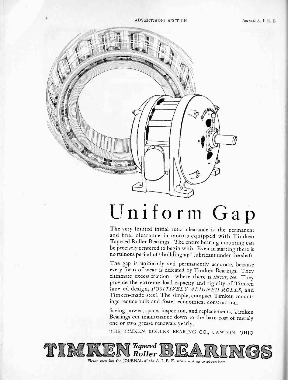
4ADVERTISING SECTION Journal A. I. E. E.
TIM
Uniform GapThe very limited initial rotor clearance is the permanentand final clearance in motors equipped with TimkenTapered Roller Bearings. The entire bearing mounting canbe precisely centered to begin with. Even in starting there isno ruinous period of "building up" lubricant under the shaft.
The gap is uniformly and permanently accurate, becauseevery form of wear is defeated by Timken Bearings. Theyeliminate excess friction-where there is thrust, too. Theyprovide the extreme load capacity and rigidity of Timkentapered design, POSITIVELY ALIGNED ROLLS, andTimken -made steel. The simple, compact Timken mount-ings reduce bulk and foster economical construction.
Saving power, space, inspection, and replacements, TimkenBearings cut maintenance down to the bare cost of merelyone or two grease renewals yearly.THE TIMKEN ROLLER BEARING CO., CANTON, OHIO
TaperedRoller
Please mention the JOURNAL or the A. I. E. E. when writing to advertisers.

Aug. 1926 ADVERTISING SECTION 5
IT is merely a matter of time whenall good motors will have either
ball or roller bearings-simply be-cause motor users will demand theutmost in efficiency and "life."
Meanwhile, motor manufacturers inincreasing numbers are taking ad-vantage of "Precision" characteristicsin the bearings they use:-
"Norma" Precision Ball Bearingsfor the smaller powers and highestspeeds - "Hoffmann" PrecisionRoller Bearings for the larger powers,heavier duties, and all speeds.
N
Write for the Catalogs.
iviill-EVFFMANN BEARINGS V2RIVRATI,Stamford- Connecticut
Ty/
PRECISIVN BALL, RV LLER AND THRUST BEARINGS
E, Cit308104-.E4f.54iffeosnsim
1.4
44 :4 ,
Please mention the JOURNAL of the A. I. E E. when writing to advertisers.

6ADVEICTISIN( I "I'I(N Journal A. I. I
Note t heclean linesof Allis-ChalmersEnclosed Motors. "Attached" partsarc nut needed. The motor housingis really its own seal, containing noopenings but the small covered gaugeaperture. Smallest overall size ismade possible by the use of TimkenTapered Roller Bearings. Their load
capacity reduces shaft length.
CompletelyEnclosed-but notBulky
Bearing capacity is so much greaterthat shaft length averages 15% lessin Allis-Chalmers motors equippedwith Timken Tapered Roller Bear-ings. Applied to enclosed motorsthis means that Timkens verylargely offset the usual increasein size to obtain radiation.
These bearings, free of excess fric-tion, also lend themselves to suchtight enclosure that they neverneed lubrication more than a fewtimes yearly. The entire motor isjust as fully protected in the Allis-Chalmers enclosed type. Solid castend housings are fitted with ma-chined precision. Gone are theold, crude, easily damagedcovers and gaskets.
Clean and compact in design, Allis-
Chalmers enclosed motors withTimken Bearings are permanentlydust tight and moisture -proof,just as they are quite permanentlywear -proof. Friction, thrust, andshock are defeated by the greaterload area of Timkens; by theirtapered design; by their steel -to -
steel rolling motion; and by theimproved starting properties.
Such bearings constantly maintainthe full gap. The rotor also is in-sured by A -C silver brazed bars. Dis-tortion is unknown in A -C cores.Insulation is exclusively processedto last for the life of the motor.And electric steel is used whereverpossible as the foundation of Allis-Chalmers motors. In every type,at every point they beat downmotor costs.
ALLIS-CHALMERS MANUFACTURING CO., MILWAUKEEDistrict Sales Offices in all Principal Cities
Please mention the JOURNAL of the A. I. E. E. when writing to advertisers.

Aug. 1926 ADVERTISING SECTION 7
s10IMO uyg74,
OIL -IMMERSED SLIPRING CONTROLLER
This is an example of EC&M Engineering to meet unusual conditions.This Starter controls a 200 H.P., 220 volt, non -reversing, slip ring motor and
is installed in a steel mill where corrosive gases would affect the ordinary air breakapparatus.
The entire starter is submerged in oil in a welded boiler plate tank with a re-movable cover.
EC&M Oil -immersed Starters are built for slip ring, squirrel cage and syn-chronous motors.
If you require control equipment to stand up under adverse atmospheric con-ditions, consult EC&M.
THE ELECTRIC CONTROLLER & MFG. CO.BIRMINGHAM-BROWNMARX BLDG. PHILADELPHIA-WITHERSPOON BLDG
CHICAGO-CONWAY BLDG. CLEVELAND,OHIO PITTSBURGH-OLIVER BLDG.CINCINNATI-IENATIONAL BANK BLDG SAN FRANCISCO -CALL BUILDINGDETROIT -DIME BANK BLDG. LOSANGELES-THOMAS MACHINERYCO. SEATTLE -570 COLMAN BLDG.NEW YORK -50 CHURCH ST. AMERICAN BANK BLDG. TORONTO -TRADERS BANK BLDG
Please mention the JOURNAL of the A. I. E. E. when writing to advertisers.
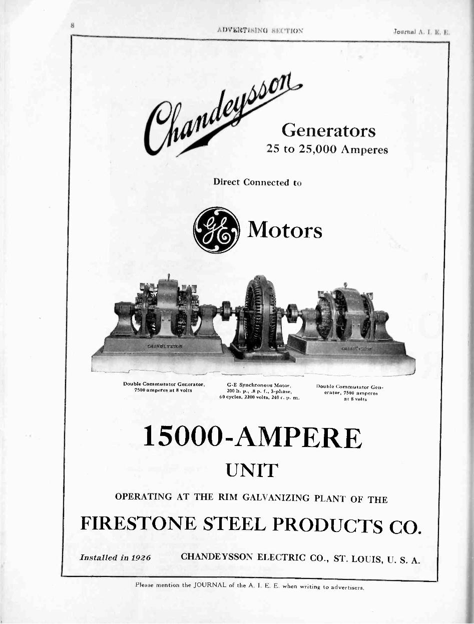
\ 1 \ 1 1; 1 1 II 1,
I
I I I
Double Commutator Generator,7500 amperes at 8 volts
Generators25 to 25,000 Amperes
Direct Connected to
Motors
G -E Synchronous Motor,200 h. p., .8 p. f., 3 -phase,
60 cycles, 2200 volts, 240 r. p. m.
Double Commutator Gen-erator, 7500 amperes
at 8 volts
15000 -AMPEREUNIT
OPERATING AT THE RIM GALVANIZING PLANT OF THE
FIRESTONE STEEL PRODUCTS CO.Installed in 1926 CHANDEYSSON ELECTRIC CO., ST. LOUIS, U. S. A.
Please mention the JOURNAL of the A. I. E. E. when writing to advertisers.

A lig. 1912 6 ADVERTISING SECTION 9
Why tolerate conditions like this?
Why run the risk of interruptions to service, shut-downs for cleaning gener-ators, when with a closedsystem of ventilation ma-chines can be kept perfectlyclean? With the use of aG -E Surface Air Cooler, airthat is clean and dry is re-circulated through thegenerator-the modernmethod, which has beenadopted by practicallyevery leading power com-pany in the country.
Ask your G -E Office for acopy of GEA-226, a bulletinthat gives complete informa-tion covering the design, usesand advantages, and listsmany of the users of G -ESurface Air Coolers.
One section of the G -ESurface Air Cooler 280-1
GENE AL ELECTRICGENERAL ELECTRIC COMPANY, SCHENECTADY, N. Y., SALES Orr! CES IN PRINCIP AL (:ITILS
Please mention the JOURNAL of the A I. E. E. when writing to advertisers.

Journal A. I.
Out wheretrouble maybegin
A thorough knowledge of allproblems of power supply andpower distribution is essen-tial to the successful design ofswitching and control appa-ratus. The wide experience ofthe General Electric Companymakes its engineers particu-larly fitted to design this equip-ment. The vital relation ofthe oil circuit breaker in thedistribution system makes ithighly important that youavail yourself of G -E expe-rience as represented in theexplosion chamber.
Generating equipment is not only valuable-it is vital toyour service, and you do not question the importance of givingit the reliable protection of an explosion -chamber breaker.Public good -will is an asset that is also endangered by serviceinterruptions. Guard it with explosion -chamber breakers byputting them also in the substations where they can confinetrouble to the distribution system-out where trouble is themore likely to begin.
GENEI i
42 1:=1=71, 1Ilt14""it,., #1s ,111
'i
' II! '
ALPlease mention the JOURNAL of the A. I. E. E. when writing to advertisers.

Aug. 1926 ADVERTISING SECTION 11
One type ofExplosion -Chamber
Oil Circuit Breaker
-and where thattrouble is ended
The essentials of successful circuit breaker operation:The arc must be of short durationThe gas formation must be kept smallThe circuit must be broken quicklyBurning of contacts must be minimizedThe oil tanks must not be subjected to excessive
strainInflammable oil must not be thrownExplosive gases generated in the breaker should be
conducted away where they cannot cause trouble-all of which are realized with G -E Breakers havingexplosion and separating chambers, thus assuring thehighest possible interrupting capacity.
ELECTR ICPlease mention the JOURNAL of the A. I. E. E. when writing to advertisers.

Inn rnnl .1. I. E. E.ADVERT ISI N 0 SE("I'l ON
AN OUTDOOR SUBSTATIONof the
Newcastle-upon-Tyne Electric Supply Co., Ltd.
TRANSFORMERSThe
FerrantiFerranti Meter andLimited Transformer
Hollinwood Manufactur-Lancashire ing Co., Ltd.,
26 Noble St.Toronto
Please mention the JOURNAL of the A. I. E. E. when writing to advertisers.

Aug. 1926 ADVERTISING SECTION 13
Dismantled and re-assembledwith the aid of just one tool
UST one tool a screwdriver - is required in dismantlingand re -assembling a Sangamo TypeH Meter single-phase or poly-phase. Metermen appreciate its sim-plicity of construction,ease of adj ust-ment and the facility with whichrepairs, if needed, may be made.
After being completely dismantled,the several electromagnets replacedand the grid with its moving systemput back in position, the calibrationof the meter will be found to be soslightly changed that minor adjust-ments can quickly be made (alsowith screw driver) to set the meterexactly correct.
Type H Meter with registerremoved - accomplished byloosening two latches, no tool
required.
An added advantage lies in the factthat in all types of Sangamo Poly-phase Meters standard single-phasemeter parts are used.This reduces toa minimum the number and varietyof spare parts that have to be keptin stock.
Simplify meter maintenance and re-duce meter -department costs bystandardizing on Sangamo Type HMeters. Their world-wide popular-ity is attested by the fact that everyi6 seconds of every working day aSangamo meter is connected in circuit.
Ask for illustrated Bulletin 20-67 whichgivesadetaileddescriptionofSangamoTypeH Meters, single-phase and polyphase.
SANGAMO ELECTRIC COMPANYSpringfield, Illinois
New York Boston Chicago Birmingham San Francisco Los Angeles
SANGAMO METERS6131-3 FOR EVERY ELECTRICAL NEED
Please mention the JOURNAL of the A. I. E. E. when writing to advertisers.
Type H Meter with coverremoved - accomplished byunscrewing two wing nuts.
Type H Meter with grid re-moved showing magnetic
structure.
The grid is removed by remov-ing three screws. Note ease ofremoval of moving element
and permanent magnets.
Magnet structure completely removedand disassembled.

16A INERT I SI NO SECTION Journal A. I. E. E.
.
Paul Revere Signalevery time you telephone,
Back ofyour
telephone
The signal lamp in Old North Churchflashed its message to Paul Revere. Sothe lamp in a telephone switchboard sig-nals the operator when you lift the re-ceiver off the hook.
This tiny switchboard lamp, with overten million like it, is a vital part of thenation's telephone system-a little thing,but carrying a big responsibility. As yourrepresentative at the telephone exchange
The switchboardlamp, delicate yetrugged. With a fil-ament one -sixthas fine as a humanhair, this lamp is JOwell made that its:good fora hundredyears' service.
it instantly summons the ever alert oper-ator to answer your call.
Making these lamps, millions of themevery year, is one of the many WesternElectric functions. From lamp to switch-board, every one of the 110,000 individ-ual parts must be carefully made and fittedtogether to do its share in the vast tele-phone plant -a manufacturing job un-equalled in diversity and intricacy
SINCE 1 8 8 2 MANUFACTURERS FOR THE BELL SYSTEMPlease mention the JOURNAL of the A. I. E. E. when writing to advertisers.

Aug. 1926 ADVERTISING SECTION IT
p.,C0110 Ps-
kkOLL°41)C1.°1S
fov l-lighVolta is
cr.
LavgeCurroits
AvIv.NsAvAkw-.Ns
1/420Nv..cssi
A 416,, 13 lkoaawS '1'
t tr, Ctittr',Sett t: ttostwak
Stytt
Send for Research Bulletin C-6
ANACONDA HOLLOW CONDUCTORSTHE problem of corona loss has gen-
erally been solved by using a conductorof sufficient diameter to bring this losswithin tolerable limits. This has often in-volved the use of more material in the con-ductor than was otherwise economical.When hemp is introduced as a core to in-crease the diameter, the weight and cost areincreased without compensating increase ofstrength or conductivity.
When galvanized steel is used as a core, con-ductivity is sacrificed to strength, and thedifference in the coefficient of expansion
between the copper and the steel leads tonew difficulties. The hemp core deteriorates,the steel core rusts, and the additional weightin the case of steel necessitates extra strongtowers and foundations.The Anaconda Hollow Conductor reducescorona and resistance losses without thesedrawbacks. This conductor, made entirelyof copper, is durable, light in weight, high intensile strength and conductivity, and maybe easily adapted, by changes in design, tospecial service requirements..May we send you Research Bulletin C-6?
ANACONDA COPPER MINING CO.THE AMERICAN BRASS COMPANY
Rod, Wire and Cable ProductsGeneral Offices: 25 Broadway, New YorkChicago Office: 111 W. Washington St.
ANACONDA COPPERANACONDABRASS BRONZE
Please mention the JOURNAL of the A: I. E. E. when writing to advertisers.

I 8 A DVERTI IN(I SE( !T ION .1 .\ I I:. 1,
Vitrohm Resistor Unitshowing steps in theprocess of manufacture.
1Porcelain like tube.
2Resistive conductor ofpractically zero tempera-ture co -efficient of re-sistivity.
3Connections to terminalleads made under pres-sure while surfaces areclean and bright. Nosolder used.
4Unit is coated with vit-reous enamel and firedat red heat. Enamel fusedso tightly to wire andtube that unit is practi-cally one solidified mass.This promotes rapid con-duction of heat. Firing"ages" resistive conduc-tor.
5Joints sealed in enameleffectively prevent corro-sion and loosening ofparts. No other methodprovides an equally goodjoint.
6Vitreous enamel is themost perfect known in-sulating material. It ismoisture -proof and acidresisting, fully protectingresistive conductoragainst deterioration.
6435-2
Ward LeonarAtlanta-G. P. AtkinsonBaltimore-J. E. PerkinsBoston-W. W. GaskillChicago-Westburg Eng. Co.Cleveland-W. P. Ambos Co.
37-41 South Street
Detroit-C. E. WiseLos Angeles-Elec. Material Co.New Orleans-Bell & SlimmonPhiladelphia-W. Miller Tompkins
L+M-Ex FailureSO many factors can affect
the satisfactory performanceof resistors that labor plus ma-terial minus experience in re-sistor winding is sure to resultin failures in service.
L+M-f-Ex SuccessThe Ward Leonard Electric
Company has thirty-four yearsof specialized experience in re-sistor manufacture. Its Vitrohm(vitreous enamel) constructionhas never been equalled. Mil-lions of Vitrohm units in servicefor many years testify to theirpermanent, unvarying perform-ance.
Vitrohm units are made inmany styles and with differentmountings, both standard andspecial. Let us quote on yourspecifications.
ctric CompanyMount Vernon, N. Y.
St. Louis-G. W. PieksenPittsburgh-W. A. Bittner Co. Montreal-Bishop Sales Corp.San Francisco-Elec. Mat'l Co. Toronto-D. M. Fraser, Ltd.Seattle-T. S. Wood London, Eng.-W. Geipel El Co.
Melbourne and Sydney. Australia-Warburton. Franki, Ltd.
Please mention the JOURNAL of the A. I. E. E. when writing to advertisers.

Aug. 1926 ADVERTISING SECTION
RU -RE - LITE 43. sr I -T- E CIRCUIT BREAKERS
34::,11E1
2
It isn't the name on a CircuitBreaker that makes it good.It's the Circuit Breaker thatmakes the name good. Atrademark is valuable onlybecause of what it represents.
Engineers and executivesalike specify U-RE-LITE be-cause their experience in elec-trical protective devices hasproven U-RE-LITE to be thebest. It is the I -T -E CircuitBreaker in the Steel Box-sure,safe, dependable, fool -proof.And because it is Cutter -madeand Cutter -guaranteed,
U-RE-LITE is right.
THE CUTTER COMPANY-Established in 1888-PHILADELPHIA, PENNSYLVANIAPlease mention the JOURNAL of the A. I. E. E. when writing to advertisers.

20\ 1 )\. I SIMI SE( "I'MN .luurnul A. I. E.
S
A
ULAT1NGPAPERS
0 o F
CABLESTrade Mark "ROTH M I LL"
Made under Highly Specialized Tech-nical and Practical Control resulting inthe Production of Paper CombiningGreatest Mechanical Strength withHighest Insulating Properties
by
TULLIS, RUSSELL & CO., LTD.,HEAD OFFICE AND MILLS
MARKINCH, SCOTLANDCABLES-"TULLIS, MARKINCH"
PAPER MAKERSESTABLISHED 1809
SALES OFFICE1, TUDOR STREET
LONDON, E. C. 4, ENG.CABLES: AUCHMUTY, LONDON
MANCHESTER OFFICE376 CORN EXCHANGE BUILDING
CORPORATION STREETMANCHESTER
Please mention the JOURNAL of the A. I. E. E. when writing to advertisers.

Aug. 1926 ADVERTISING SECTION
MAGNET WIRE AND WINDINGS
fifilfilHi111:A111111M
111111510
III!SE!1111111111111 VINO11111111
"
11111Nc
111111111Will 1111110
A partial view of the immenseDUDLO plants at Fort Wayne
Eastern Office and Warehouse412 Chamber of Commerce Bldg.
NEWARK. N. J,
Western Office274 Brannan St.
SAN FRANCISCO, CAL.
World Headquartersfor Magnet Wire and CoilsThis partial view of the immense Dudlo plant tellsan impressive story of
Capacity Facilities ResourcesProduction Organization Demand
These are possible only through-
Enduring Quality andSupreme Service
The world's largest producers of electrical apparatusin the fields of Ignition, Motors and Generators,
Transformers, Meters, X -Ray, Radio, Telephones,etc., use Dudlo Magnet Wire and Coils-expressingthe universal confidence in which Dudlo productsand service are held.
Manufacturers, large and small, areinvited to use the Dudlo engineeringand experimental departments, whichare maintained for their benefit.
Chicago Office160 N. La Salle St.CHICAGO, ILL.
DUDLO MANUFACTURING CORPORATION FT. WAYNE , IND.Please mention the JOURNAL of the A. I. E. E. when=writing to advertisers.

\DvEwrisiNo sEcrioN Journal \ I I I
Lightning takesthe Quickest Path
If a voltage with a steep wave front is impressedupon a string of insulators, the spark -over pathwhich will be followed is not only a matter ofdistance but of impulse ratio.
Very often on insulator strings equipped with horns,which might clear a 60 cycle arc, the path over theporcelain is faster for a lightning discharge and,consequently, the horns give no protection. A 60cycle test in this connection, therefore, means nothing.
The damage is done in .04 of a micro - second.Only by careful grading of the insulator string bymeans of a Locke Grading Shield can this firstpredatory discharge be kept away from the porcelain.
Tests made with the Lightning Generator Circuithave fully established the need for Grading ShieldEquipment on relatively low voltage transmissionlines, such as from 33 kv. to 100 kv., if the destruc-tive flashover troubles are to be corrected. The de-sign of such equipment is essentially the same asthat furnished on 220 kv. and 132 kv. lines, but oflighter construction.
Write for bulletin on Locke Grading Shield andArcing Horn Equipment.
Locke Insulator CorporationBaltimore, Md.
Factories at Victor, N. Y. and Baltimore, Md.
L ©NEPO R C E LAI N.
SALES OFFICES:Boston, Mass., 84 State St.; New York, N. Y., 120 Broadway ;Victor, N. Y.; Philadelphia, Pa.. 803 Atlantic Bldg.; Dallas,Texas, 1801 -15 North Larmar St. ; Chicago, III., 770 IllinoisMerchants Bank Bldg. , Atlanta, Ga., 414 Red Rock Bldg.; SaltLake City, Utah, 310-314 West Second South St. ; Denver, Colo..819 Seventeenth St.; San Francisco. Cal.. 575 Mission St. ; LosAngeles, Cal., 236 S. Los Angeles St.; Portland, Oregon. 61 FifthSt. North ; Seattle, Wash., 570 First Ave. South.
EXPORT AGENTS:International General Elec. Co., Schenectady, N. Y.
Please menticn the JOURNAL of the A. I. E. E. when writing to advertisers.

Aug. 1926 ADVERTISING SECTION 23
For 15 YearsIn An Iowa Lake
these easily installed Matthews ScrulixAnchors have held fast under water.
Just one of scores of interesting and demonstrativeapplications of the Matthews Scrulix Anchor principleto difficult and critical problems, is indicated in thisinstance. Ease of installation under such conditionsis second only to the everlasting holding power andlife of these amazing anchors. Despite the nature ofbottoms over which erection jobs in all parts of theworld take high lines, bridges, towers and similarvertical work, Matthews Scrulix Anchors are dependedon for positively secure anchorages. Read Bulletin 800.
No CreepageUnder water, in hard pan, loam, shale-whereverunusual anchorage problems occur-Scrulix Anchorsdemonstrate their advantages of absolute rigidity.They do not creep or crawl. Theyhold fast permanently. Madein sevendifferent sizes, Matthews ScrulixAnchors present an easy solutionfor any known anchorage problem.
Multiplied Holding PowerThe Scrulix Anchor Helix is so de-signed that instead of dependingmerely upon the column of earth
56
covering the helix for holding power, it brings intoplay the tremendous weight of hundreds of cubicfeet of earth around it. Under strain the lines of forceradiate from the contour of the anchor helix ata forty-five degree angle. For all ordinary purposesthe use of comparatively small sizes is adequate.
In 5 to 15 MinutesIn less time than it takes to get a hole well started,two men can turn Matthews Scrulix Anchors deepdown under tons of earth without loosening theground above. They come completely assembled, allin one piece, ready to set by simply screwing them intoplace. No moving parts to become lost, or buried unad-justed. One of the simplest operations in erection work.
Learn More About Them NowWrite for our Bulletin 800 coveringin detail the interesting variety ofapplications of this anchoring prin-ciple. It will reveal to you completemastery of anchorage problems asmet during the last twenty years.W. N. MATTHEWS CORPORATION3706 Forest Park Blvd., St. Louis, U. S. A.
4411 Ii VIIIIIhIWIW1W4414111IQqN
ij
,40.vaiiiidduwed,040$441
/
Ask about these Matthews Fuswitches f Matthews Disconnecting Switches ' Matthews Scrulix AnchorsMatthews Adjustable Reel , Matthews Guy Clamps f Matthews Slack Puller Matthews Cable ClampsMatthews Lamp Guards f Matthews Telefault ' Matthews Teleheight , Distributors in all Principal Cities.
MATTH EWSSCRULIX ANCHORS.-1-4"Please mention the JOURNAL of the A. I. E. E. when writing to advertisers.

2 I A 1)V IMIIININ(1 sECTIoN Journal A. I I
Spot the DessertsWhen you see a clean-cut layout such as this23,000 volt bus at the Acme Station of theToledo Edison Company-spot the Dosserts.
In any indoor or outdoor station, in any distri-bution or industrial wiring job where branchesare connected to mains, where straightaway orT's or Y's or deadend connections are modern-spot the Dosserts.
The Dossert 20th Year Book is full of data onefficient connections for wire, cable or rod.
DOSSERT & COMPANY, H. B. LOGAN, President, 242 West 41st St., New York
DOSSERTSPlease mention the JOURNAL of the A. I. E. E. when writing to advertiser:..

Aug. 1926 ADVERTISING SECTION 25
- South's e.tern GIs is i.ie,uic Co - etc! s it,- tCPower Co Birmingham 1.1.-ctric Co - Central A ri;,ona 1.1-,:itt. 8 Power Co -
'ower Co - Arkansas Utilities Co. - Arkansas Cst't ;al Power Co - Arkansas- San Joaquin Light 8 Power Corp - Southern Si.-rras Power Co - Pacific k
;tic Co - Great Western Power Co - Southern Cahlornia Edison Co - San i
1,,slidaiol Gas 8 Electric Co - Cit!. of Los Angeles I .os.-Nngeles Gas Li Etettrac (Power Co - ('its- of San Itranciseo - Public Service Co of Cot,
Western Public Service Co Soul be: tt Colorado Post er Co - he Connecticut Light lr Co - Ehe United Illuminating Co - The Caldornia-Oreyon Power Co -'1:cticut Power Co - Danbury Bcthel Gas LS I lestri.:. Light Co - Potomac'wet: - The Key West Electric Co Miami 1-leetrie Light Is P, e e
rich t'u Is c S.-rs-ice Co Tampa Ilectric Co - is
it stOr-.0 ,ndianaEr. Co - Wah-1,1
ti ice Corp.11).1 (I, Itt 11 Indiana ('as Is Licari,: ( - Indiana I lortric (
., A na Power Co - loo... P ' - coIowa Power 8 I i- i'
Central Kansas i' 7Electric Co - Kentu,ountv Poster 8 L.
,-n Co - 'I he Edis -
Tilison Co - Consult), , ,
'o - Northern States Power Co - Um(..0 - Kansas.City. Power 8 Light Co - t
).., Power Co - Nebraska Power Co - 1 l,.: C3s CO Buffalo General I
limited Electric Light el I., .o ti E - ric C.- Roches
1!-in - tut oI tt no Pul
it 1-1):
n .1.1 ,:1:.; s o 'I he alytOil Power ' i q.lhlCr Lltxtric Co Southwest Power co: Oles o - Patine Power Li Light c:u Portland'.;:ht Co - Pennsylvania Passer 8 Light C,,ylvania Edison Co - Penn Public S:rs ice-,e Light Co - West Penn Power Co.- Els
- New -Orleans Public Service Co - The Tenn Co Eastcrn Texas Electric Co Tc.xas Pit.-vas Public Service -Co - Utah Power 8 Ligh-s - Vermont 1-B-dro-FlectricCorp - Virgin
. ',wet Co - Puget Sound Power Li Light CoWater Power CO.. City of Tacoma Light
- of Railways ti ,I (.0 - Quint,- 8 I
4tu c:r CO - Etti..:i butis CW 1
.
is Water il I '
Spruce. Falls !'
I ting Co - D.'..o... t - - r .. ..Fit - .isinpagni I Letriciti de Vitt-
i It 1 t I l - H.'. Light (i Power CO - Montreal .r,.....),-.: ...., ,.. - k 1 , t f. ra1,01 1-Z.,1:.,..ivt. - Adelaide Electric Supply Co -
, t 1 -. - s I i lIll - lit ,... `. I f , Lro ilectric Dept - Victoria I-',,. it- de I Trinidad Electric Co 'I . '''''"\l'''' Ti -'n 1S Cc -al Co -
ine,,,,, xei'i - ldrotl...:. . -ntese -OM_h ar .3 i_,,;1J:
..io , I r., i i.1 i :..(t:ica - Einiliana di I scrci2i F.lettrica - Soc Met ,S...1, to 1.:rt.....,tc,ca Piemonte - SOCit.1.1 FIctiriciti Alta Italia - I
o".,n,..:'., - h" :who I Lsill,: Railway Co - Dmilo Itlestric Power Co - I i
, itailt- as- Co - 1 it. I Ay° Lleoric 1 ight Co Ltd - Ashburton P ,-,...,. - Au.st.iand Cite Tramways - Southland Illoetric Power 15o.1,Isl. Jo - \'eu, .1gdo L -::-.es Elrktridtcistorsvning - Akershos 1 !.
No:sk !...cl.tlit.k - A S Satidelaldvne - 1(jukanoverforingen - Ti!I3,...2.. - I s;!---.-,-rs t :or % iir.,-s Ltd - Victoria Falls "Fran; Y.fp..
I ,.- ,-.. B,,:kia - C'.1 I IZ:31i,h:.." a ,!C i'! r:,1, l Ti., .cr i'. ,; Co- S..1,, Paul,'" ;
Itnr. t .,, - l. i)i'. 1:,:;1,.tti.)ri Co - C ia (:))1.. d..: Lis ..i ,::.'..it l.11i - 2111,:ik,11 V! t...17. (' :in P 1,,,, - ! ,1 Li, Y T., t; 1 ' ' ...;:,-.1 - Quito 1:ieutic Ligh
,i.%1 Asoriades - North1.;rrocarril...-c de Cat
S
Please mention:the JOURNAL of the A. I. E. E. when writing to advertisers.
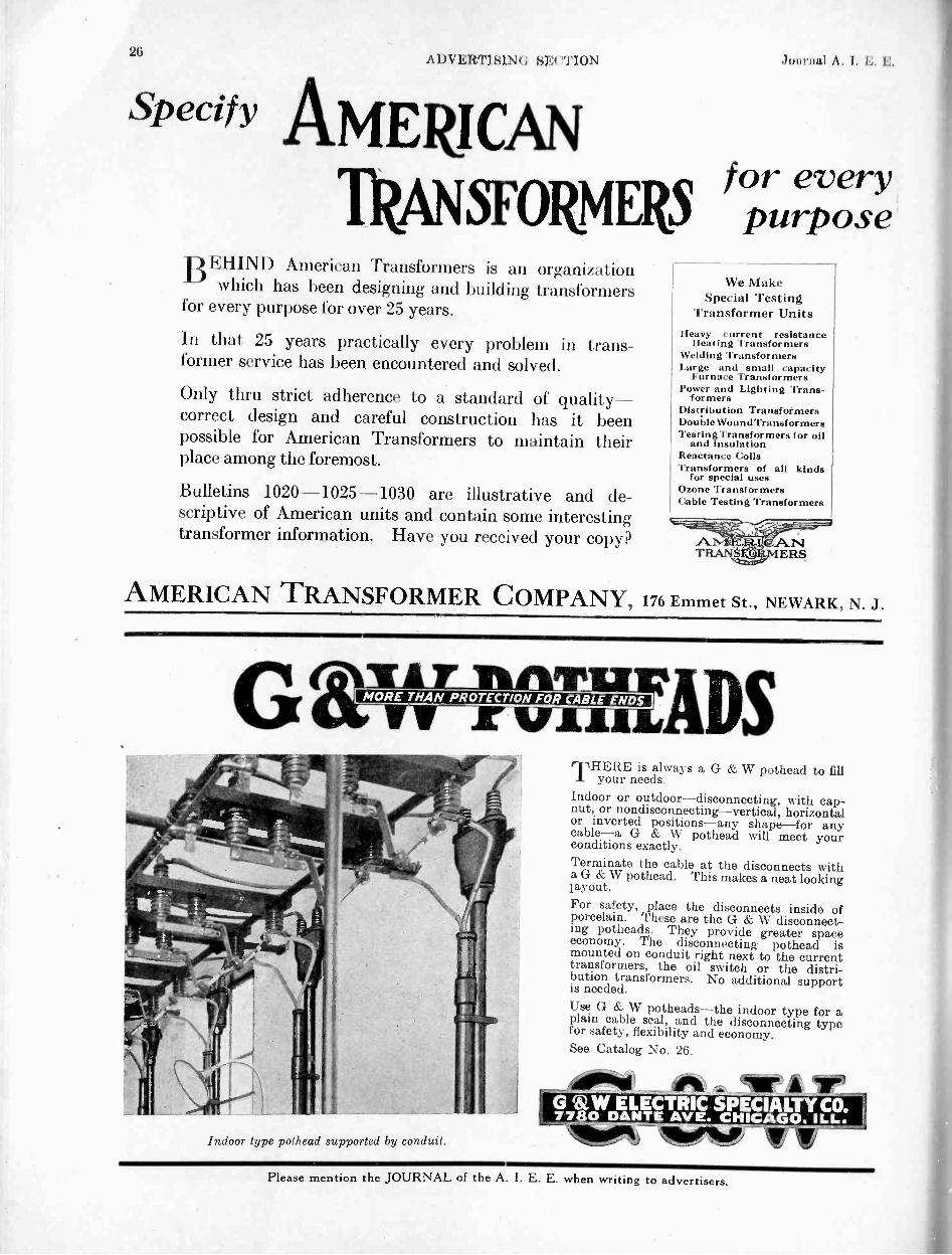
21;ADVERTIS1Nl; si.:( "1'1( IN .lolirmd A. I. F.. E.
Specify AMERICAN
TRANSFORMERSfor everypurpose
BEHIND American Transformers is an organizationwhich has been designing and building transformers
for every purpose for over 25 years.
In that 25 years practically every problem in trans-former service has been encountered and solved.
Only thru strict adherence to a standard of quality-correct design and careful construction has it beenpossible for American Transformers to maintain theirplace among the foremost.
Bulletins 1020-1025-1030 are illustrative and de-scriptive of American units and contain some interestingtransformer information. Have you received your copy?
We MakeSpecial Testing
Transformer UnitsHeavy current resistance
Heating TransformersWelding TransformersLarge and small capacity
Furnace TransformersPower and Lighting Trans-
formersDistribution TransformersDouble Wound Transf ormersTesting Transformers for oil
and insulationReactance CoilsTransformers of all kinds
for special usesOzone TransformersCable Testing Transformers
ANTE) ,uANTRANNSERS
AMERICAN TRANSFORMER COMPANY, 176 Emmet St., NEWARK, N. J.
G r nnfrizzwiRADsr %FLAIL
MORE THAN PROTECTION FOR CABLE ENDS
Indoor type pothead supported by conduit.
THERE is always a G & W pothead to fill04 your needs.Indoor or outdoor-disconnecting, with cap -nut, or nondiseonnecting-vertical, horizontalor inverted positions-any shape-for anycable-a G & W pothead will meet yourconditions exactly.Terminate the cable at the disconnects witha G & W pothead. This makes a neat lookinglayout.For safety, place the disconnects inside ofporcelain. These are the G & W disconnect-ing potheads. They provide greater spaceeconomy. The disconnecting pothead ismounted on conduit right next to the currenttransformers, the oil switch or the distri-bution transformers. No additional supportis needed.Use G & W potheads-the indoor type for aplain cable seal, and the disconnecting typefor safety, flexibility and economy.See Catalog No. 26.
G 6,W ELECTRIC SPECIALTY CO.77 0 DANTE AVE. CHICAGO. ILL.
4014 _!ftirA
vSlieN9 111%__F -V
Please mention the JOURNAL of the A. I. E. E. when writing to advertisers.

Aug. 1926 ADVERTISING SECTION 27
RANKIN SUB -STATIONDUQUESNE LIGHT CO.,PITTSBURGH, PA.
Photograph by courtesy ofPittsburgh Transformer Co.
Showing method of terminatingThree -Conductor Cables by useof STANDARD DOA Terminals withstubs attached and STANDARDThree-way CablA Joint
STANDARD Cable Terminals, in addition to affording insuranceagainst interruptions in service, make for convenience and flexibility
in cable installations. They are supplied for outdoor (DOA) or indoor (DS)service and in single or multi -conductor forms.When desired we furnish single -conductor DOA Terminals with cable stubs of anyrequired length attached by expert jointers in our factory. The STANDARD Three -Way Joint facilitates attaching the stubs to three -conductor cables.We solicit your inquiries in regard to electric cable problems.
Standard Underground Cable Co.BOSTON WASHINGTON CHICAGO KANSAS CITYNEW YORK ATLANTA DETROIT SEATTLEPHILADELPHIA PITTSBURGH ST. LOUIS Los ANGELES
SAN FRANCISCOFOR CANADA: STANDARD UNDERGROUND CABLE CO. OF CANADA, LIMITED, HAMILTON, ONT.
We also manufacture a complete line of Electric Wires and Cables.
Moloney engineers have been identi-fied with the transformer thru all itsstages of development, and have con-tributed many of the refinementsfound in the present day highly per-fected Moloney Transforpers.Write for details.
Moloney Electric CompanyMain Office and Factories
St. Louis, Mo.Saks offices in nil principal cities
Please mention the JOURNAL of the A. I. E. E; when writing to advertisers.

2SADVERTISINO SECTION Journal A. 1 I
The PacentSuperaudioformer No. 27
Pronounced the besttransformer made
IT THOROUGHLY meets the in-creasing requirements for finer
musical values in radio reception.It is handsomely finished in dullbronze-a beautiful transformer forthe finest receivers.
INPUT TYPE NO. 27A, Ratio 3 to 1,Primary Inductance, 124 henrys, designedfor use between any vacuum tubes, andalso with power amplification requirementsin mind. Shielded $7.50. Unshielded $6.00.
Other TypesOUTPUT TYPE No. 27B, Ratio 1 to 1,Inductance 7 henrys. Shielded $7.50.Unshielded $6.00.
CHOKE TYPE No. 29, Inductance 50henrys, (with no superimposed D. C.).Inductance 32 henrys (with 60 m. a.superimposed D. C.). Shielded $6.50.Unshielded $5.00.
Full information on request.
PACENT ELECTRIC CO., INC.91 SEVENTH AVENUE NEW YORK CITY
Canadian Licensed Manufacturer:White Radio Limited, Hamilton, Ont.Manufacturing Licensees for Great Britain
and Ireland:Igranic Electric Co., Ltd., London and
Bedford, England
PercentRADIO ESSENTIALS
Balkite TrickleChargingfor
FIRE ALARMSYSTEMS
Fire alarm systems require by their very naturea positively unfailing source of power. This re-quirement is perfectly met by the BalkiteTrickle Charge System. In this system a Bal-kite Charger is connected to the regular powerline and allowed to charge a storage batterycontinuously at a low rate. It thus automaticallykeeps the battery fully charged at all times.Thereserve power available always in the storagebattery insures operation even in case of failurein the power line. Failure to operate for wantof power is entirely removed.
The typical installation shown above of theBalkite Trickle Charge System was recentlymade by a prominent fire alarm company. TheBalkite Charger was chosen because it is reli-able, free from adjustment, and reduces main-tenance costs. Wherever these qualities are re-quired in a battery charging equipment, theBalkite Charger is rapidly becoming standard.
Balkite Trickle Charging is also adaptableto many other uses, wherever unfailing poweris required. A complete booklet describing thesystem and its operation is available on re-quest. Write for it.
Fansteel Products Company, Inc., North Chicago, Ill
F `__ _!SF aL
Berl iteBattery Chargers
FANSTEEL PRODUCTS COMPANY, Inc., North Chicogo,IllinoisGentlemen: Please send me a copy of Balkite Trickle Charging
Name
Position.
Compam
Address
Please mention the JOURNAL of the A. I. E. E. when writing to advertisers.
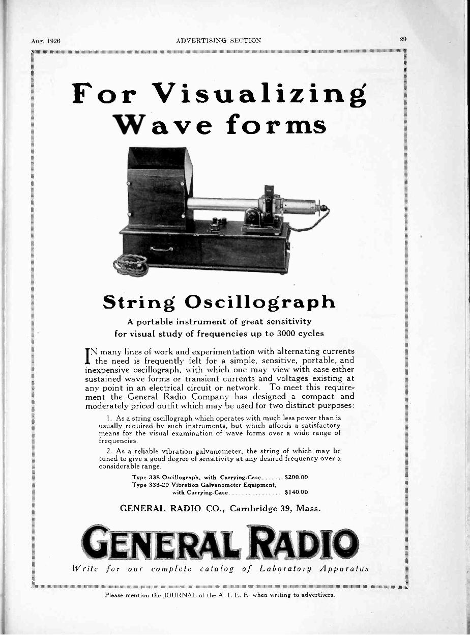
Aug. 1926 ADVERTISING SECTION 29
gg g.E g-E-
0 ag -
g aFor Visualizing II
I
-g.-
-a. Wave forms Eg.
E-E gg E
Eg gE gg g.g EE g
s E-
E E
g
"2EE --
g g-
E- g-
E- 2
E ,c -- -,"-E-
E
g ....,... gg gE gg g
gg
E-
E.String Oscillograph E
EE.
E
g gg g
A portable instrument of great sensitivity g
g- E.
s ' for visual study of frequencies up to 3000 cycles gE.- EE- gg g.
E .-- TN many lines of work and experimentation with alternating currentsg gg I the need is frequently felt for a simple, sensitive, portable, andg inexpensive oscillograph, with which one may view with ease either E
EEg sustained wave forms or transient currents and voltages existing at E
-
g any point in an electrical circuit or network. To meet this require- g
E ment the General Radio Company has designed a compact and g
g moderately priced outfit which may be used for two distinct purposes: gE gEE I. As a string oscillograph which operates with much less power than is gg gg usually required by such instruments, but which affords a satisfactoryg means for the visual examination of wave forms over a wide range ofgg frequencies.g gT.2.. 2. As a reliable vibration galvanometer, the string of which may be f÷:
E tuned to give a good degree of sensitivity at any desired frequency over a ff.
considerable range. -a
Type 338 Oscillograph, with Carrying -Case $200.00Type 338-20 Vibration Galvanometer Equipment,
Eg. -
with Carrying -Case $140.00
g g.Eg GENERAL RADIO CO., Cambridge 39, Mass. g
-g
g g.
g -a
E
I91""'"Th 7-5
, .
E-g
-5 EE: Write for our complete catalog of Laboratory Apparatus gE gg g= =
Please mention the JOURNAL of the A. I. E. E. when writing to advertisers.

3(1 A I)V KItTISINti Journal A. I. l'. I'.,
The final adjustment of the bearingsin any measuring instrument mustbe very carefully done. The sap-phire jewels must be adjusted so thatthe movement is not restricted, sothat there is sufficient play to takecare of expansion effects and at thesame time the bearings must besufficiently close to limit excessiveplay.
The proper measuring instruments forall switchboard requirements---
Synchronizing ofof early machines was by ',waits (.1 lamps. The rotatingLsynchroscope was brought into use quite early however, and has been usedin many installations.The Jewell synchroscope is supplied in a seven inch case and designed to hsimilar in appearance to other switchboard instruments.Synchronism is indicated when the shadow of the pointer on the scale alignswith the center mark.Jewell Switchboard Instrument Cases are of heavy cast iron forming anexcellent magnetic shield. Sturdiness of construction and simplicity of designare noteworthy features. You can come to Jewell for your measuring instru-ment requirements with the greatest confidence in their ability to properly serve.
JEWELL ELECTRICAL INSTRUMENT CO.1650 Walnut Street, Chicago, Ill.
A NEWBulletin
and
a NEWLine of
Relays
The ROLLER SMITH Company hasready for distribution its new BulletinNo. AE -550 covering a new line of relays,
THE TYPE SRThis new Bulletin should be in thehands of every man who is interested inrelays. Send for your copy."Over thirty years' experience is behind ROLLER -SMITH"
MAIN OFFICE12 Park Place, NEW YORK
Offices in principal cities of U. S. A. and Canada.Representatives in Cuba. Aastralia and Japan.
OLLER-SMITH COMPElectrical Measurin and Protective Apparatus
s<-..01111 WORKSBethlehem, Penna.
Check Voltage and Currentat Distribution Centers
Continuous chart records furnished by Bristol's Record-ing Electrical Instruments installed at these importantpoints give accurate and concise information regarding
load distribution. Ab-normal loads, voltagedrop or fluctuation areclearly shown by thecharts, making it possi-ble to correct the trou-ble without delay andbefore annoying com-plaints are receivedfrom consumers.Many leading centralstations depend onBristol's Recording In-struments to keep themposted on the efficiencyof their electrical out-put at the switchboard
as
Recording Voltmeter forWall or Switchboard
well as on conditions existing in the lines. It willpay you well to do likewise.
Ask us for further information.
cbhe 'Bristol Company (Waterbury, Connecticut
BRISTOL S RECORDING"INSTRUMENTS
Please mention the JOURNAL of the A. I. E. E. when writing to advertisers.

Aug. 1926 ADVERTISING SECTION 31
When You BuyCondensers
When you buy condensers-whatdo you demand?
Accuracy! Low Power Factor!Permanent Capacity!
Dubilier condensers meet theserequirements. They are used inpractically all transmitting sta-tions and U. S. Governmentinstallations.Dubilier coupling condensers forpower line telephony are su-preme.
Dubilier consulting engineers arealways at your service-theycan help you too.
4377 Bronx Blvd., New York, N. Y.
DubilierCONDENSER. AND RADIO CORPORATION
LE
:2-
-EL
Faradon Couplings InstalledWhere Available Space Is Limited
Having purchased a carrier equipment thereis no place where an additional expenditureof a given amount can as effectively insurecommunication, as in the purchase of coup-ling condensers. Bulletin 101, completelycovering the subject, sent to Engineers andother operating Officials on request.
Wireless Specialty Apparatus Co.,Jamaica Plain, Boston, Mass.
Please mention the JOURNAL of the
Modernize with
WESTONRECTANGULARS
THE same dependability which has givenWeston its position of authority,
where all electrical measurement devicesare concerned, is built into the WestonRectangular Switchboard line. 41 In ad-dition to their dependable and long-timeeconomy operation, Weston Rectangu-lars are more readable, more easilymounted and less expensive in the useof switchboard space. 411 They enablethe Engineer to increase the size of hisinstallation without increasing theswitchboard space. Weston Rectan-gulars form the only complete line ofA. C. switchboard instruments thatare absolutely uniform in size. gTheyare made as Alternating CurrentAmmeters, Voltmeters and Watt-meters, Re - Active ComponentMeters, Frequency Meters, PowerFactor Meters, Triplex Ammetersand Direct Current Voltmetersand Ammeters. 41 Completetechnical information is con-tained in our Bulletin 1504.
WESTON ELECTRICAL INSTRUMENTCORPORATION
48 Weston Avenue, Newark, N. J.STANDARD THE WORLD OVER
WESTONYloneers since 1888
A. I. E. E. when writing to advertisers.

)
Al)VEItTISINO SE("I'ION .14)IirnaI \ I. I... L.
=1..MA11.
4111111.11.1.1.01111.M Mg
immomiS
=="
OUTDOORLUG
WRITE FORBULLETIN
111111INDYENGINEERING CO.INC10 EAST 43RD STREET NEW YORK
ALL CONNECTORS FORCOPPER TUBING AND CABLE
SELENIUMIii The
Tirex 60% Rubber Armorincreases the
Resistance to Abrasion50%
TIREX Cables have always been protectedby a sheath of the most wear -resisting rub-ber compound known to the art, but nowwith their new Selenium Rubber jacketthey have the toughest and most wear -resisting protective armor ever made. Weartests prove this.
The process of vulcanizing rubber withSelenium was developed in our laboratoriesand is covered by U. S. patents Nos.1,249,272 and 1,364,055. This advance inthe art of rubber compounding increasesthe toughness or wear -resisting qualities ofa rubber compound fifty per cent.
The use of Selenium in rubber com-pounds to increase their wearing qualitiesis as important a development as wererubber sheathed cables, first put on themarket by us a few years ago.
Write for further information.
SIMPLEX WIRE &CABE @MANUFACTURERS
201 DEVONSHIRE ST.. BOSTONCHICAGO SAN FRANCISCO NEW YORK
CLEVELAND SAINT AUGUSTINE
Please mention the JOURNAL of the A. 1. E. E. when writing to advertisers.
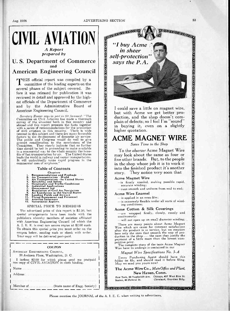
Aug. 1926 ADVERTISING SECTION
CIVIL AVIATIONA Report
prepared by
U. S. Department of Commerceand
American Engineering CouncilTHIS official report was compiled by a
committee of the leading experts on theseveral phases of the subject covered. Be-fore it was released for publication it wasreviewed in detail and approved by the high-est officials of the Department of Commerceand by the Administrative Board ofAmerican Engineering Council.
Secretary Hoover says in part in tht foreword: "TheCommittee on Civil Aviation has made a thoroughsurvey of the situatioir "both in this country andabroad and this report presents the facts togetherwith a series of recommendations for the promotionof civil aviation in this country. There is wideinterest in this subject and there are many favorablefactors to the development of domestic air service.The public and Congress would do well to giveprompt consideration to the conclusions of theCommittee. They clearly indicate that no furthertime should be lost in proceeding to make availablein a commercial way to the whole country the bene-fits of fast transportation by air. Theleads the world in railway and motor transportation.It will undoubtedly make rapid progress in thecommercial uses of airplanes."
Table of ContentsChapters
1. Recommendations and Findings2. Air Transportation-World3. Air Transportation-In United States4. Reliability and Safety5. Geographic and Traffic Conditions6. Industrial Applications7. Government Aid8. Regulation of Civil Air Navigation9. Air Legislation in the United States
10. Landing Fields and Airways11. Flying Equipment and Personnel12. Aviation Insurance13. Investment Aspects.
SPECIAL PRICE TO MEMBERSThe advertised price of this report is $2.50, but
special arrangements have been made with thepublishers whereby members of societies affiliatedwith American Engineering Council (of which theA. I. E. E. is one) can secure copies at $2.00 each.To obtain this special price you must order on thecoupon below, sending cash or check with order.Your copy will be delivered post-paid.
1111a. IMMEM.
COUPONAMERICAN ENGINEERING COUNCIL,
26 Jackson Place, Washington, D. C.I inclose $2.00 for which please send me postpaid
one copy of CIVIL AVIATION in cloth binding.
Name
Address
Member of (State name of Engg. Society)
"I buy Acmein sheer
self-protection"says the P.A.
.0*
I could save a little on magnet wire,but with Acme we get better pro--duction, and the shop doesn't com-plain of defects; so I feel I'm "sound"in buying it, even on a slightlyhigher quotation.
ACME MAGNET WIRESaves Time in the Shop
To the observer Acme Magnet Wiremay look about the same as four orfive other brands. But, to the peoplein the shop whose job it is to work itinto the finished product it's anotherstory. They notice very soon thatAcme Magnet Wire
-is firmly spooled, making possible rapid,accurate winding;
-runs smooth and uniform from end to end;Acme Wire Enamel
-is applied in an even film;-is extremely flexible under all sorts of wind-
ing conditions;Acme Cotton & Silk Coverings
-are wrapped firmly, closely, evenly andcontinuously;-will not open up on small diameter winding;There are many points about Acme Magnet
Wire which are cause for constant satisfactionafter the product is in service, but we mentionhere only the ones that smooth the way of pro-duction in the shop ... the ones that justify thepayment of a little more than the lowest com-petitive price.
The complete story of the tests Acme MagnetWire have to undergo is contained in our
Magnet Wire Specifications No. 3-AEvery Purchasing Agent should have this
folder on file, and should read it before filing.May we send you yours now?
The Acme Wire Co., MainOffice and Plant,New Haven, Conn.
New York, 52 Vanderbilt Ave. Chicago, 427 West Erie St.Boston, 80 Federal St. Cleveland, Guardian Bldg.
33
O
O
1.0....0.-0--C<>--<><>-<>-0--0-<><> -c> <,
Please mention the JOURNAL of the A. I. E. E. when writing to advertisers.

DVERTISINO Jouriml A. 1.
I N EltALLACINSULATING
ftkt COMPOUNDS
For filling Cable Jointsand Potheads
on Highvoltage linesil.safe specification"
High dielectricStren6th Approved
physical
INER,ALLACproperties
CI
ELECTRIC COMPANY1045 Washington Blvd.
CHICAGO ILL.goilliniiiiiiiiiiiiiiiiiiiiiiminiiinimiliiiiiiiiminnimminniminiiiiiiiiiiiiiiiiminumminimmuminin wiiiiimmiluilimmingE E
ATLANTICgg
. INSULATEDOVP/Y/
WIRES E-E
EEE T o 4LINI-
E,,V .47,_.,..:-....., .k 41111ils.' E
E -E
2 RAI ON gE- E
E. E--g 37- Including all types of rubber covered, and rubberg EE covered lead encased wires and cables, bare wire, _g
g magnet wire, and flexible cords.E --ggg &WINSULATEDATLANTIC IRECABLE COMPANYa -E
-f- Rome, N. Y.i111111+1
2--. John A. Roebling's Sons CompanyTrenton, New Jersey
i ELECTRICAL WIRES AND CABLES
-2-
of Highest ConductivityWires are drawn from carefully selected metalsand insulated with the best materials, to insure
long and satisfactory service.
MI 1 1 1 1 1 1 1 1 1 11111 1 1 1 I 1 1 1 1 1 1 1 1 1 1 1 1 1 1 1 1 1 1 1 11111 1 1 1 1 1 1 1 1 1 1 11 III II MS 11111 1 1 1 1 1 1 1 1 1 1 1 1 I 1 1 1 1 1 1 1 1 1 1 11111 1 I 1 1 i 1 1 1 1 1 1 1 1 1 1 1 1 1 1 1 1 1 1 11111 1 1 1 1 I 1 1 1 1 1 1 1 1 1 1 1 1 1 1 1 1 1 1 11111 1 1 11 1 1 1 1 I 1 1 1 1 1 1 1 1 1 1 1 1 1 1 11111 1 1 1 1 1 1 1 1 1 1 1 1 1 1 1 1 0
"AMERICAN BRAND"
Weatherproof Copper Wire and CablesCOST
-AMERICAN BRAND"WE ATH E RPROOF WIRE AND CABLES
HAS HO EQUAL yourself.
American Insulated Wire & Cable Co.954 West 21st Street, Chicago
i1111111111111111111111111111111111111111111111111111111111111111111111111111111111111 1', ,1,1111111111111111111111111111111111111111111111110
,i,,,,=,,,,,,,,,,,,,m,,,,,moomoommi,,,onno.WIRE PRODUCTS 1For Varied Applications
We manufacture many types of wires, cordsE-- and cables for specific uses. Among them are:
Rubber CoveredCovered Wire-Solid Conductor, StrandedConductor, Flexible Conductor, Extra Flexible Conductor.
Lamp Cords, Reinforced Cords, Heater Cord, Brew-ery Cord, Canvasite Cord, Packinghouse Cord, DeckCable, Stage Cable, Border Light Cable, FlexibleArmored Cable, Elevator Lighting Cable, Elevator Oper-ating Cable, Elevator Annunciator Cable. SwitchboardCables, Telephone Wire, Flameproof Wires and Cables,Railway Signal Wires, High Voltage Wires andCables. Automobile Ignition Cables, Automobile Light-ing Cables, Automobile Starting Cables, AutomobileCharging Cables. Moving Picture Machine Cable.
Boston Insulated Wire (. Cable Co.Main Office and Factory:Dorchester District Boston, Mass.
Canadian Branch, Office and Factory, Hamilton, Ont.1 1 1 1 1 1 1 1 1 1 I 1 I 1 1 1 1 1 1 1 1 1 1 1 I 1 1 1 1 1 1 11 1 1 1 1 1 I 1 1 1 1 1 1 1 1 1 1 I 1 1 1 1 1 111111111111111111111111111111111111 11111111111111111111111111111111111111111111111111111111111111111111111111111111111111111111111111111111111Ifii
a===
I RUBBER INSULATED =_11:,I,ECTRICAL
You can buy weatherproofwire cheap, but is it worthwhat it costs?
"American Brand" givesyou more mileage per dollarswith a longer life on the line.
Get a sample and satisfy
= WIRES & CABLESF._
fiend for descriptive circulars
HAZARD MANUFACTURING COMPANYWILKES-BARRE, PENNA.
NEW YORK PITTSBURGH CHICAGODENVER BIRMINGHAM PHILADELPHIA
111111111111111111111111111111111111111111 1 1 1 1 1 I 1 1 1 1 1 1 111111111111111111111111111111111111111111 1 1 1 1 1 1 1 1 1 1 11 111111111111111111111111111111111111111111 1 I 1 1 1 1 1 1 1 I 1 1 1 11111111111111111111111111111111111111g
211111111111111111 1 1 1 1 1 1 1 1 1 1 1 1 1 1 1 1 1 1 1 11111111111111111111111111111111111111111111 11 1 1 1 1 1 1 1 1 1 1 1 1 1 1 1 1 I 1111111111111111111111111111111111111111111 1 1 1 1 1 1 11 11 I 11 I 11 11 I 11111111111111111111111111111111111111g
-..-Popular Research E-
g. -
a --
-f4
I are proving useful 'round the world inmany offices, schools and laboratories. E
= They are interesting home reading, too. s -
Two little books, just pocket size. In each g= book 50 short stories of research, invention, E
g= discovery-footprints of progress. Send a P.
set to your layman friend. The NarrativesE are in language he can read. Introductions
E-by Dr. E. E. Slosson and Dr. M. I. Pupin. gE Only $1.50 for the two volumes, postpaid. gEE ENGINEERING FOUNDATION E.E
E
NARRATIVES
29 West 39th Street New York
Please mention the JOURNAL of the A. I. E. E. when writing to advertisers.

Aug. 1926 ADVERTISING SECTION
The loss from rust in the I tilted States alone,now amounts to more than $300,000,000.00 ayear. The world's annual loss from rust is now inexcess of 1,1-2' billion.
The rusting away of guy and messengerstrands, the high cost of replacement, and thehazard of rapidly decreasing safety factors, havecreated an economic need for a non -rusting wire.
That need is met by
"COPPERWEINGuy and Messenger WireBecause IT DOES NOT RUST
That's the economic reason justifying the useof Copperweld-longer life and protection fromrusting, with a consequent reduction in renewals,labor and maintenance costs.
C qPe Nte: CQ MPA EkVi`wm vmL-
MAIN Orr ICE i MILLS 0000C4 0 O. 124N0iN,so CNUOEN 5T. NEW Y01104 S JE4,E0SON 5T, eNtC440
403 PlaLTO OL04 SA, 00ANCISCO
In Canada: Northern Electric Co.. Ltd.
Sot.'Fotimitunumnininuniumminumatin
There is 'mother "ropy...,made like "COPPE R11't1.1)-
, cr-clod site!"by tile .11.1km Welding Pro, -es,
quiiNGRakyGLASSeINS ULAT ORS
a Tire transparency of Hemingray Glass insulatorsmakes line inspection very simple. The lineman
can tell at a glance whether the insulator is intact or not.El emingray insulators are mechanically and dielectrically
dependable, non -porous and uniform in structure. Theydefy moisture and age.
Send for Bulletin No. 1.HEMINGRAY GLASS COMPANY
Muncie. Indiana
Lapp Insulatorsdo not fail!
LAPP INSULATOR CO., Inc.LE ROY, N. Y.
Sales Re prisettlut fresBlItM INI4II AM. ALA., Industrial Supply Ca. PA Brown -Mars 111.1g.110.sTON. Can ltosen 111 Milk St.CHARLOTTE. N. C J. W. Fraser & Co.. ..... mereial Bank Bldg.C1111' too. Transelectrie Co.. Inc.. MO No. Michigan Are.COM-MRCS. 0.. Eivrtneering )1erchandisIng Syndicate. 600 Joyce Realty BideDALLAs, TEX.. J. K. Webb. 1:41.1 Commerce St.DENVER, The 0. H. Davidson Equipt. Co., MI Tremont St.INDIANAPOLIS, W. D Hamer Co.. Ala Trae. Terminal Bldg.KANSAS ('ITT. MO.. Power Machinerr Co.. 301 Dwight Bldg.Lint ANOELE.1. S. Herbert Lanyon, tin Transportation Bldg.MINNF.APOLIS, J. F. Sumpter Co.. 919 Security Bldg.NEW YORK CITY. Shield Elcetric Co.. 119 Brolulls-ay.l'III1_\DELPHIA. Harris ,t Rutter. Real Estate Trust Bldg.PITTSBCRGII. Ilenrr N. Muller ('o., 39.11 Find National Bank Bldg:SAN ANTONIO. TES.. I.. It. Ita-wArtt, 713 Navarro St_SAN FRANCISCO. S. Herbert lAnron. 509 New Call Bldg.SYDNEY. AUSTRALIA. Chas M. Terry.WELLINGTON. NEW ZEALAND. Jas.. J. Siren C Co.
Specify
"C: bomasQualitr
Insulatorsfor
PermanentlyDependable
SERVICE
THE R. THOMAS & SONS CO.East Liverpool. Ohio
New York Boston Chicago London K
wuuumuumllmnwuumlir
, ' , . ,I1, ri ,111 III i '1111111111111111111111111111'1111111111111111111111111111111111111=
,4-0.,w---
ffilajs) Transmission Line Structures.10.10,Wir41/ Built of High Elastic Limit Steel
4-1.--4,ffr"1 Refined - Rolled - Fabricated - -2
P4Vilt &-"--44;tvicfroffit Galvanized in Our Own Plants F.
,1011XIA tAllE:ff.
firtar1 kV"iriti 4 PACIFIC COAST STEEL CoMPANY =
A t II retiTAMANUFACTURERS OF ,..
=:-;OPEN HEARTH STEEL
... f IrtAV NIg.. ,,:,., STRUCTURAL SHAPES MERCHANT AND REINFORCING BARS
r If 1. _TRANSMISSION TOWERS AND STRUCTURES
Gen`l Office: Rialto Bldg., San Francisco Plants: San Francisco, Portland, Seattle) N.
11111111111111111111IIIIiiiiiiiitiiiiiiiiiimunimmumminiiiimin-
Please mention the JOURNAL of the A. I. E. E. when writing to advertisers.

36A DVERTISINO SECTION Journal A. I. E. E.
"BURKELECT" Moulded Controlead Terminal BlocksBy the use of these Terminal Blocks simplifications in all methods of control wiring circuits are possibleand offer many other advantages which are fully described in Bulletin H-2.
13. BURKE ELECTRIC COMPANYHIGH TENSION EQUIPMENT DIVISION
THE ELEMENTS OF OUR BUSINESSdoNT4(
TRADE -MARKAutomatic Starters Pressure RegulatorsCircuit Breakers Remote SwitchesFloat Switches Speed RegulatorsHand Starters Transfer SwitchesMagnet Switches Valve Control
WRITE FOR CATALOGSundh Electric Company, Newark, N. J.
Branch Offices or Sales Representatives in Principal Cities
ERIE, PA. .=
DUNCAWatthour Meters
Accurateand
DependableWrite for bulletins
DUNCAN ELECTRIC MFG. CO.Model M2. Lafayette, Ind.
ff.
7g"
DuiPlease mention the JOURNAL of the A. I. E. E. when writing to advertisers.
!MODELS"=_ .for
g F.
SALES DEMONSTRATION AND DISPLAY i.1: USE IN LITIGATION E.
g EEE= Experimental Development under Client Supervision=
=m E
MANUFACTURERS' & INVENTORS'
(Smith Building) .2
228 West Broadway, N. Y. City ==Incorporated 1897
momDe LavalOil Purifiers
-protect turbines and Dieselswith cleaner oil and reducelubricating costs.The De Laval Separator Company
165 Broadway, New York600 Jackson Blvd., Chicago
Dz Laval Pacific Company, San FranciscoPeterborough, Ont.
Pittsburgh Transformer CompanyLargest Manufacturers of Transformers exclusively
in the United States
Pittsburgh, Pennsylvania
MANUFACTURING STANDARDS
ELECTRIC CO.

Aug. 1926 ADVERTISING SECTION
"RAINREALMCLAMP
ILADR RUIN`,D LARGE DIAMETER PULL 51140
,. 4.o5inve LOCK ...-COPPER TUBE BLADE
120 KV. GOO AMP. TYPE 13-2
HOOK STICK OPERATED
UNIT TYPE DISCONNECT
ALL STEEL AND IRONPARTS ARE
HOT GALVANIZED
INTERCHANGEABLEINSULATORS
STEEL CHANNEL BASE
CIANN TWITCONNECTION
LUG
A Business -like Practical Way to BuyHigh Tension Equipment
You investigate carefully before you invest your own moneyin a business venture. You may consider many investmentsuntil you decide on the best one. Do you give the same carefulconsideration when you buy high tension equipment? Doyou make sure that the money you spend is buying the bestvalue?
The purchase of high tension equipment is an investment-or should be. An investment in long, trouble -free service.So why not apply the same sane, careful judgment on its pur-chase as you do on the purchase of stocks and bonds.
2400 Block, Fulton St.
Simpler_Stronger
Better-
Installation K -P -F60 KV. Switches,San Joaquin Lt. &Pwr. Corpn., Calif.
K -P -F POLE TOP SWITCHES consist of fewerparts, are more rugged and require less laborand material for installation than any other.Each pole becomes a self-contained unit.Switches are shipped ready to bolt on to cross -arm in place of line insulator.One crossarm supports it. Contacts are farremoved from insulators and a unique deviceprevents sticking or freezing.Send for bulletin K105 containing full details.
K -P -F ELECTRIC CO.855-859 Howard St. San Francisco
rawn11IIunillilliillm11111111l111111111111111111111111111111u1 ifilill11111111111111111I111111111111111111111111111111111111111111111nwEil1111111111111111IIm1111i1111111111111111IIIK
37
FilefAitChicago, Illinois
This PerformanceReport on Air Filters
Will Interest YouThe Midwest -Air Filters in serviceover two years on a turbo -generatorin the Re une Avenue Station of thePittsfield Electric Co., Pittsfield,Mass., have been investigated by anationally known firm of engineers.Their report shows the value of cleanair for electrical equipment, and in-cludes unbiassed) performance andcost data on Midwest Air Filters.
Ask Dept. E to send it.
The background ofthis advertisementshows the face of aMidwest Filter Cell afew days after it wasput in operation onapparently dust -freeair.
El LTERS
011ifillunnumunimmuumumitimumulllillilliwillimuniounuminummunnuniBliwiumunmumumilufflunnumBnoluouiniu numumBIBEIBIBMEBIBBIBIIBIBIIBBIBBMIBBIlltiminnummiiimmuniniimminiiiiiiiiiiimmuimilli1111111ifiliwool.
Em gDisconnecting SwitchesE
3are a vital link in your system of power generation andE t Made in capac-
transmission.E ities of 300 am- The T & M disconnecting switch, bolt type lock, here
peres and up.
.--------°"---
in operation. The locking mechanism is not only extremely----
illustrated, has been developed to safely withstand thesevere short circuits to which such equipment is subjected
reliable, but simple and accessible.You can rely on T & M switches. They are in use on
-....iitz. .----- America's greatest power systems and specified regularlyby the largest engineering organizations. We invite yourinquiries on difficult switch problems. -E
EE
THONER & MARTENS463 Commercial St. BOSTON, MASS.
Specialists in Heavy Duty .4-C and D -C Switches. .r-.
Please mention the JOURNAL of the A. I. E. E. when writing to advertisers.

38ADVERTISING SECTION Journal A. 1. E. E.
Of courseMo -lyb-den-urnincreases the life-
in -'em but keepthis additionalfact in mind-theMo-lyb den-urnballs in an SRBBearing are hot
FORGED.
STANDARD STEEL AND BEARINGSPlainville INCORPORATED Connecticut
I
CLASSIFIEDADVERTISEMENTSRATES. Forty cents per line; minimum charge
based on use of five lines; maximum space cannotexceed twenty lines.Copy should be received by the 15th of themonth, for insertion in the following issue.
WANTED: RADIO TUI-1E PATENTS. The lar-gest exclusive manufacturer of radio tubes in the UnitedStates is ready to assist inventors and persons who haveuseful ideas or patents pertaining to radio tubes. Theseideas can take in processes and construction of 110 voltand other type tubes. This manufacturer has a wellequipped laboratory and the most up-to-date factorywhere all ideas can be brought to a successful conclusion,if at all practical from a manufacturing and merchan-dising standpoint. Satisfactory remuneration will bethe reward for ideas accepted. Address Class -117,JOURNAL of the A. I. E. E.. 33 West 39th St., New York.
WANTED: A. I. E. E. TRANSACTIONS. We wishto purchase American Institute of Electrical EngineersTRANSACTIONS,-complete files or odd volumes, as wellas Faraday Society Transactions and other scientificjournals. B. Login & Son, 29 East 21st St., New York.
E
NEW DIRECTORY OF MEXICAN INDUS-TRIES: Compiled and revised by the Mexican De-partment of Industry, Commerce and Labor,containing 16,000 valuable addresses of all industriesnow operating in the Republic of Mexico. All machin-ery manufacturers, raw material houses, exporters,lumbermen, merchants and bankers should have acopy of this valuable book on Mexican Industries.Order your copy TO -DAY. $10.00 Dollars Post -Paidor remitted C. 0. D. Parcel Post, if desired. Cia.Mexicana de Rotograbado. (Mexican RotogravureCo.) No. 22 Calle Iturbide. Mexico City.
A. I. E. E. STANDARDSTHE following approved STANDARDS are
available in pamphlet form, at the pricesindicated, with a discount of 50% to A. I. E. E.members:
General Principles Upon Which Temperature Limitsare Based in the Rating of Electrical Machinery. (.20):Direct -Current Generators and Motors and Direct -Current Commutator Machines in General. (.40):Alternators, Synchronous Motors and SynchronousMachines in General, (.40); Synchronous Converters,(.40); Induction -Motors and Induction Machines inGeneral, (.40); Direct -Current and Alternating -CurrentFractional Horse Power Motors, (.30); Railway Motors,(.30); Transformers. Induction Regulators and React-ors, (.40): Instrument Transformers, (.30); IndustrialControl Apparatus, (.401: Railway Control and MineLocomotive Control Apparatus, (.40); Oil CircuitBreakers, (.30); Disconnecting and Horn Gap Switches,(.30); Wires and Cables (.40); Telegraphy and Tele-phony, (.30); Storage Batteries (.20); Illumination.(.30); Electric Arc Welding Apparatus, (.40); ElectricResistance Welding Apparatus. (.30): Insulators, (.30);Symbols for Electrical Equipment of Buildings, (.20).
American Institute of Electrical Engineers33 West 39th Street, New York
IPlease mention the JOURNAL of the A.11. E. E.twhen writing to advertisers.

Aug. 1926 ADVERTISING
`the Peak ofSmall MotorPefection
In an organization such as ours we can give individual
attention to every motor we build. Hence it is not sur-
prising that an ever-increasing number of prominentmanufacturers regard MASTER GUARANTEEDMOTORS as the peak of small motor perfection.
THE MASTER ELECTRIC COMPANYLinden and Master Ayes. Dayton, Ohio
STOCKS CARRIED IN PRINCIPAL CITIES
MASTER GUARANTEED MOTORS
y8 TO 7Y2 H.P. MASTER Less than 40°
aaa a=
=THE ff.
E==
PIONEER MANUFACTUREROF
Interpole & Ball BearingMotors
to 1000 H. P. D. C. and A. C.
E.-
ELECTRO DYNAMIC COMPANY
Sales Offices in Principal Cities
Please mention the JOURNAL of the A.
SECTION 39
"They Keep a -Running"
15 Horse Power Century Squirrel-CageInduction Polyphase Motor
For Coal StokersCoal Stokers require a motor that will standrough use. That is why Century Squirrel -cageInduction Polyphase Motors are extensivelyused on this type of equipment, as well as otherapparatus of a similar nature. These motors"Keep -a -Running" because:-
Lateral openings in bearing housingsare equipped with tight -fitting brassdust collars and dust caps which ex-clude dust and dirt from the oil wells.Bearings are of phosphor bronze-thehighest grade bearing material obtain-able - cast from metal heated inelectric furnaces in the Century plant.Bearings are substantially propor-tioned-large enough to withstand thepound of gear drive-accurately ma-chined on all dimensions and providedwith machine -cut figure -8 oil grooves.Armatures are practically indestruct-ible. Heavy conductor bars are brazedinto the channel -section end ring slotsover an area equal to about six timesthe cross-sectional area of the bars.Thorough ventilation is assured bysheet steel fans at the ends of thearmature and - in the larger sizemotors - by the addition of gridventilators forming part of the arma-ture structure.
All constructional features responsible for the "Keep -a -Running" reputation of Century Squirrel -cage InductionPolyphase Motors are fully described in Bulletin No. 38.Send for it today.Century Squirrel -cage Induction Polyphase Motors arebuilt in all standard sizes from Yi to 50 horse power.
Temperature rise not more than 40° Centigrade.
CENTURY ELECTRIC COMPANY1806 Pine,St. St. Louis, Mo.
For More Than 23 Years at St. Louis
to 50 H. P.
Type "S" Ball Bearing Motorwith base and pulley
Established 1880BAYONNE, N. J.
I. E. E. when writing to advertisers.
3-to50H.P.

40ADVEItTISINO SECTION
goomunommuumuntommommommumounionnimmoommummuniummotmomminummommun
That Year in and
ROWANImpedance
Starterfor
SquirrelSquirrel CageInduction
Motors
Year out Service
`1111111111111111 I I I I I I I I I I I I I I I I I 1111111111 I I I I I I I I I I I I I I I I I I I I I I I I I I I I IIIIINIII I I I I I I I I I I I I I I I I I I I I I I I I I I I I I I 111111111 I I I I I I I II I I I I I I I I I I I I I I I I I I I 111111111I mop!' .
TRUMBULL
for years have stood themost exacting tests of scoresof the largest motor,dynamo, generator, andradio builders in the UnitedStates.Our Engineering Depart-ment is at your service.Write us concerning yourrequirements.
THE TRUMBULL STEEL COMPANYWARREN
zr
a
Mills, Laboratories and General Offices
Is yourname on our
.11;9 mailing listfor bulletinsand catalog?
OHIO
.11fitrital A. I. E. E.
Trade "ESCO" Mark
ELECTRIC SPECIALTY CO.Engineers and Manufacturers
F.E2
DESIGN - DEVELOP -- PRODUCE...F. -
EgSmall Motors, Generators, Dynamotors,
Motor Generators, Rotary Converters, Etc.
FOR SPECIAL PURPOSES2gg .Send Us Your Problems
.-
F.-
222 South Street STAMFORD, CONN., U.S.A. 1a
ISlurlevani Electric Moors-
-71
E B. F. STURTEVANT COMPANYHYDE PARK, BOSTON, MASS.
Star Ball Bearing MotorsFor
HardUsage
A. C.and
D. C.
Complete line of standard motors and generators,all sizes up to 75 h. p. and 50 kw. respectively.Our Engineering Department at your service for all special applications
1 STAR ELECTRIC MOTOR CO.NEWARK, NEW JERSEY
mommuunnnuuonnuuuunuuuuuunuumuun
anite\\ \\\.
rushes
--A. C. and D. C.; singleand polyphase-built insizes from small fractionalto 250 horse-power-de-signed to operate under aconstant full load whereuninterrupted service isdemanded.
MorganiteBrush Co., Inc.
519 W. 38th St.New York
Inspections - Tests - ResearchTests may be used by the purchaser for the following purposes:
To determine the quality of competing samples. This enables the purchaseof the best quality for the money,To make sure that shipments comply with specifications, This makes possiblethe assurance to the customer that shipments match buying samples.To furnish an impartial decision in case of disputes between purchaser andmanufacturer.NEW YORK
Testing places the whole buying problem on a sound basis.aIIIIIIIIIII IIIIIIII IIIII IIIIII IIIIIIII III III III IIIIIIIII III IIIIIHI IIIIIIIII IIIIIIII II III HI III II I HIIIII III IIIII I IIIII IIIIIIINI Iilll I IIIIIIII IIIII II III II IIIII II III II III II 1111111 Ilil II IIII I III II 1111111 II 11111111 IIIIIIIIIII IIIII I I I IIII HNI IIIIIIIII IH II III III II II IIIIIIII II IINIIIIII III II II I II IIIII II I II II IIIltlllllllllllllllllllll
IIIIIIIIIIIIIIIIIIIIII IIIIIIII II III III II IIIIII 1111111 1111111 IIIII (IIIIIIIII IIII III FPlease mention the JOURNAL of the A. I. E. E. when writing to advertisers.
ELECTRICALTESTING
LABORATORIES80th Street and East End Ave.
(1)
(2)
(3)
1
Aug. 1926ADVERTISING SECTION
41
JIIIIIIIIIIIIII IIIIIIIIIIII II II II II IIIIII II II II II II II II II II II II II II II I I II IIIIII IIINII II IIIIIIIIIIIIIIIIIIIIIIIIII II II II HIIIIIIII II II IIIIIIIIIIIIIIIIIIIII IIIIIIIIIIIIIIIIIIIIIII IIIIII IIIIII IIIIIIIIIs
Eg_
-4E
=
g.E.
Eg
EE -
gEE.-
E-
a -
gE_=
aE-
EE=
E77-
gE.
=g
g1
=
gE=
=
gE-
,.:INSULATORSg made of=
LAVALava is not subject to variations in
structure and composition.
Lava insulators maintain a fixed relationof their parts under varying conditions.
AMERICAN LAVA CORPORATION27-67 Williamson Street
ChattanoogaManufacturers of Heat Resistant Insulators.
onuilitiiimuliniumminuitiumminisomuumiunimminiuniormiminirmommilitimminuounimimmulimouinitioniniummitirg
"IRVINGTON" PRODUCTS :Black and Yellow
Varnished Cambric
IRVING-TON VARNISH a INSULATOR e-IrvinOton.N.jersey.
Sales Representatives in all principal cities
1111111111111111111111 IIIIIIIIIIIIIIIIIHIIIIIIIIIIIIIIIIIIIIIIIIIIIIIIIIIIIIIIIIIIIIIIIIIIIIII111I I I 1111111111111111111111111111 I I I I I IIIIIIIHIIIIIIIII IIIIHIIIIIIIIIIIII1111111111111110
11 I I H II1111111111111111111111111111 I I I I I I 11111111111111111111111111111 I I I I I I I I I I I I I I I I I I I I I I I H I I I I I I I I I I I I I I I II I I I I I I I111111111111I I111111111I I I I I I I I I I I I I I I I I I I I I I I I I I I I I I I I I I IIII I II II 1111111111111E
Y-26 High -Heat Mica PlateFor High Temperature Insulation
Possesses all the advantages of natural mica for insu-lating heating appliances. Is more economical. partic-ularly when used in the larger units.
Supplied in sheets up to 30" x 42". in thicknesses of ten
Y-26
NEW ENGLAND MICA CO.
mils or over. Can be cut or punched to any form.Send for samples and prices.
Varnished Paper EVarnished Silk
Flexible Varnished TubingInsulating Varnishes and Compounds
"Cellulak" Tubes and Sheets
Tennessee
Waltham 54, Mass.0,,
4.-.
g ''/?q.ti"P'v New York Office - 220 Broadway t--=
ALL FORMS OF MICA FOR ELECTRICAL PURPOSES:-...
--f.
Fmniumuniiiiitinummimmiiimmiumilimmintimimiiimmunininumminuimumniiiimiminininniiiimiumiliniiiiimil
Please mention the JOURNAL of the A. I.
West VirginiaFibre Board
I -NBOARD
For Electrical Insulation
I -N Board has been tested and ap-proved by the Underwriters' Labora-tories for electrical insulation.
This board has a very high tensile anddielectric strength and is being usedsuccessfully by many electrical manu-facturers who are finding it a decidedfactor for economy.
Pulp Products Department
West Virginia Pulp & Paper Company505 Dime Bank Bldg. 200 Fifth Avenue 732 Sherman Street
Detroit. Mich. New York. N.Y. Chicago, Ill.
Makesfine lines
forFiguringCheckingUnderscoringBlueprints,
etc.No.
Blue . . 1206Red. . . 1207Green . 1208Yellow. 1209Purple . 1210Brown . 1212Black. . 1213Orange. 1214White . 1215Light Blue
1216Pink . . 1217Light Green
1218
Trice$1.00per doz.
NIQUETHIN LEADColoredPencils
SOMETHING wantedfor years! A colored
pencil with the same di-ameter lead as in writingpencils; can be sharpenedin a pencil sharpener.An absolute necessityfor making fine lines incolor on charts andplans-something neverachieved before. The 12colors also enable eachexecutive to have hisown Color symbol.
°Adopted byexecutives accountantsdraftsmen photographersartists teachers
useful to everyone
At all dealers, or write us direct
American Lead Pencil Co.204 Fifth Ave., New York
Makers of the famous 'Venus Pencils
E. E. when writing to advei tisers.

I .'\l/ I NiI Ili'.
I I Ilpoi,J1:1,t110
PROFESSIONAL ENGINEERING DIRECTORYFor Consultants in the Fields of Engineering. and Related
bitublishtd 1857
ALEXANDER & DOWELLAttorneys at Law
PATENT, TRADEMARK ANDCOPYRIGHT CASES
902 F Street, N. W. Washington, D. C.
AMBURSEN DAMSHydroelectric Developments
Water Supply and Irrigation DamsDAMS ON DIFFICULT FOUNDATIONS
AMBURSEN CONSTRUCTION CO.Incorporated
Grand Central Terminal, New YorkKansas City, Mo. Atlanta, Ga.
THE AMERICAN APPRAISAL Co.Valuations and Reports
ofPublic utility, industrialand all other properties
Rate Cases Condemnation SuitsReorganizations LiquidationsNEW YORK MILWAUKEE1896 And Principal Cities 1926
W. S. BARSTOW & COMPANYIncorporated
Financial and OperatingManagers of
Public Utilities60 Pine Street New York
BATTEY & KIPPIncorporated
ENGINEERSComplete Industrial Plants
Power Plants & Electrical InstallationsEngineering Reports, Analyses & Appraisals291 South LaSalle Street CHICAGO
BLACK & VEATCHConsulting Engineers
Water, Steam and Electric Power Investiga-tions, Design, Supervision of Construction,
Valuation and Tests.
Mutual Building KANSAS CITY, MO.
BYLLESBYENGINEERING AND MANAGEMENT
CORPORATION
New York
231 S. La Salle StreetCHICAGO
San Francisco
Arts and Scielicet
WALTER G. CLARKConsulting Engineer
Electrical, Mining and IndustrialReports
Supervision of Organization and Arrangemeats for Financing
LOS ANGELES NEW YORK1211 Insurance Exch. Bldg. 40 Wall St.
EDWARD E. CLEMENTFellow A. I. E. E.
Attorney and Expertin Patent Causes
Soliciting, Consultation, Reports,Opinions
McLachlen Bldg. Washington, D. C.700 10th St., N. W.
C. E. CLEWELLConsulting Engineer
Municipal Street Lighting SystemsFactory and Office Lighting
Engineering Bldg. Philadelphia, Pa.39rd and Locust Streets
HAROLD A. DANNE
LIGHT AND POWER
41 PARK ROW NEW YORK
Fellow A. I. E. E Member A. S. M. E.W. N. DICKINSON
Consulting AnalystBUSINESS AND ENGINEERING
PROJECTS ANALYZEDAeolian Hall, 33 W. 42nd St., New York City
DAVID V. FENNESSY
Consulting Power Engineer
MILLS BUILDING EL PASO, TEXAS
FORD, BACON & DAVISIncorporated
ENGINEERS116 Broadway, New York
Philadelphia Chicago San Francisco
FRANK F. FOWLE & CO
Electrical and MechanicalEngineers
MONADNOCK BUILDING CHICAG(
FREYN ENGINEERING COMPANYIndustrial Electric Power
Generation -Application-PurchaseCombustion EngineeringElectric Furnace Installations
CHICAGO PHILADELPHIA310 South Michigan Ave. 1600 Chestnut St.
M. H. GERRY, JR.Consulting Engineer
Electrical Transmission of PowerHydroelectric Developments
Steam and Diesel PlantsIndustrial Applications
1107 Hobart Building San Francisco
L. F. HARZA
HYDRO -ELECTRIC ENGINEER
Monadnock Bldg. Chicago
HOOSIER ENGINEERING CO.
Erectors ofTransmission Lines and Substations
325 South New Jersey StreetINDIANAPOLIS INDIANA
NEVIL MONROE HOPKINSFellow A.1.E.E.
Invention and Patent EngineerComplete Patent Service
25 West 44th Street NEW YORK
Dugald C. JacksonEdward L. Moreland
JACKSON & MORELAND
CONSULTING ENGINEERS91 St. James Ave. Boston, Maas.
THE cost of a card in the Engineering Directoryis $40 per year (12 issues). No larger space
than a 1"x2" box may be used by any one advertiser.
Please mention the JOURNAL of the A. I. E. E. when writing to advertisers.

.\ lig. 1!1'21;.\1)\'EIZ'I'l SIN(1 SECTION
PROFESSIONAL ENGINEERING DIRECTORYFor Consultants in the Fields of Engineering and Related Arts and Sciences
E. S. LINCOLNConsulting Electrical Engineer
Designs Investigations Reports
Electrical Research Laboratory
534 Congress St. PORTLAND, MAINE
MCCLELLAN & JUNKERSFELDIncorporated
Engineering and ConstructionPower Developments-Industrial Plants
Electrifications-ExaminationsReports-Valuations
NEW YORK68 Trinity Place
Chicago St. Louis
W. E. MOORE & CO.Engineers
Plans and Specifications forHydroelectric and Steam Power PlantsIndustrial Plants and Electric Furnaces
Union Bank Building Pittsburgh. Pa.
N. J. NEALL
Consulting Engineerfor
Electrical and Industrial Properties
12 PEARL STREET BOSTON, MASS.
NEILER, RICH & CO.Electrical and Mechanical
EngineersConsulting, Designing and
Supervising
431 So. Dearborn St. - - - Chicago
OPHULS & HILL, Inc.Formerly Ophuls, Hill & McCreery, Inc.
CONSULTING ENGINEERS112-114 WEST 42nd ST.,NEW YORK CITY
Ice Making and RefrigerationInvestigations and Reports
FARLEY OSGOODConsultant
Design, Construction, OperationInter -Connection
ofPUBLIC UTILITIES
National Bank of Commerce BuildingSi Nassau Street, New York, N. Y.
Tel.: Rector 7878 Cable Address: Fargood
Make your name andyour specialized servicefamiliar to the electricalindustry through a card
in theENGINEERING DIRECTORY
PUBLIC SERVICEPRODUCTION COMPANY
Engineers and ConstructorsDesign and Construct: Power Plants,
Transmission Lines, Industrial Plants,Highways, Railroad Shops and Terminals,
Gas Plants, Commercial BuildingsMake: Examinations, Reports and Valuations80 PARK PLACE NEWARK, N. J.
SANDERSON & PORTERENGINEERS
PUBLIC UTILITIES & INDUSTRIALSDesign Construction Management
Examinations Reports Valuations
Chicago New York San Francisco
SARGENT & LITNDYIncorporated
Mechanical and ElectricalEngineers
1412 Edison Bldg., 72 West Adams StreetCHICAGO ILLINOIS
SCOFIELD ENGINEERING CO.Consulting Engineers
Power Stations Gas WorksHydraulic Developments Electric RailwaysExaminations & Reports Valuations
Philadelphia
J. E. SIRRINE & COMPANYEngineers
Textile Mills; Hydro -Electric Develop.ments; Tobacco Products Plants; Cotton,Tobacco and General Warehousing; Indus-trial Housing; Steam Power Plants; Steam
Utilization.Greenville Chattanooga
South Carolina Tennessee
JOHN A. STEVENS
CONSULTING POWER ENGINEER
16 Shattuck StreetLOWELL MASSACHUSETTS
STEVENS & WOODINCORPORATED
Engineers and Constructors120 BROADWAY, NEW YORK
Youngstown, 0.
STONE & WEBSTERIncorporated
Examinations Reports Appraisalson
Industrial and Public ServiceProperties
NEW YORK BOSTON CHICAGO
PERCY H. THOMASConsulting EngineerELECTRIC POWER
Generation - TransmissionApplications
120 BROADWAY NEW YORK
THE U. G. I. CONTRACTING CO.Engineers & Constructors
Power Developments, Industrial Plants, GasPlants, Transmission Systems, Appraisals
Broad & Arch Ste., PHILA., PA.421 Peoples Gas 928 Union TrustBldg., Chicago, Ill. Bldg., Pittsburgh, Pa.
VIELE, BLACKWELL & BUCKEngineers
Designs and ConstructionHydroelectric and Steam Power Plants
Transmission Systems Industrial PlantsReports Appraisals
49 WALL STREET NEW YORK
THE J. G. WHITEENGINEERING CORPORATION
Engineers-ConstructorsOil Refineries and Pipe Lines,
Steam and Water Power Plants,Transmission Systems, Hotels, Apartments,Offices and Industrial Buildings, Railroads43 EXCHANGE PLACE NEW YORK
Rudolf Wildermann, E. E.Dr. 0. K. Zwingenberger
Wildermann & Zwingenberger
PATENT ATTORNEYS
160 Fifth Ave. New York
J. G. WRAY & CO.Engineers
J. G. Wray, Fellow A.I.E.E. Cyrus G. Hill
Utilities and Industrial PropertiesAppraisals Construction Rate SurveysPlans Organization EstimatesFinancial Investigations Management
1217 First National Bank Bldg. ,Chicago
43
-23William M. Stockbridge Victor D. Borst
14.
Patent Lawyers
Please mention the JOURNAL of the A. I. E. E. when writing to advertisers.
STOCKBRIDGE & BORST
41 PARK ROW NEW YORK CITY
To be printed in the following
issue, copy for cards must bereceived by the 20th of the month.

Al)VEItTISIN(1 SK("I'll)ti Journal A. I. I. K.
Classified Advertiser's Index for BuyersManufacturers and agents for machinery and supplies used in the electrical and allied industries.
Note: For reference to the Advertisements see the Alphabetical List of Advertisers on page 60.AIR COMPRESSORS
Allis-Chalmers Mfg. Co., Milwaul. ceGeneral Electric Co., SchenectadyWestern Electric Co., All Principal Cities
AIR COMPRESSOR FILTERSMidwest Air Filters, Inc., Bradford, Pa.
AIR FILTERS, COOLINGMidwest Air Filters, Inc., Bradford, Pa.
AIR WASHERSSturtevant Company, B. F., Boston
ALARMS, TEMPERATURE, PRESSURECory & Son, Inc., Chas., New York
AMMETER COMPENSATING COILSMinerallac Electric Co., Chicago
AMMETER, VOLTMETERS(See INSTRUMENTS, ELECTRICAL )
ANCHORS, GUYMatthews Corp., W. N., St. Louis
ANNUNCIATORS, AUDIO -VISIBLECory & Son, Inc., Chas., New York
BATTERY CHARGING APPARATUSElectric Specialty Co., Stamford, Conn.Fansteel Products Co., Inc., North ChicagoGeneral Electric Co., SchenectadyWard Leonard Electric Co., Mt.Vernon, N. Y.Western Electric Co., All Principal CitiesWestinghouse Elec. & Mfg. Co., E. Pitts-
burghBEARINGS, BALL
New Departure Mfg. Co., The, Bristol, Conn.Norma -Hoffmann Bearings Corp., Stamford,
Conn.Standard Steel & Bearings, Inc., Plainville,
Conn.BEARINGS, ROLLER
Timken Roller Bearing Co., The, Canton, 0.BOXES, FUSE
General Electric Co., SchenectadyMetropolitan Device Corp., Brooklyn, N. Y.Western Electric Co., All Principal CitiesWestinghouse Elec. & Mfg. Co., Pitts-burgh
BOXES, JUNCTIONG & W Elec. Specialty Co., ChicagoMetropolitan Device Corp., Brooklyn, N. Y.Standard Underground Cable Co., Pittsburgh
BRUSHES, COMMUTATORCar bon
Morganite Brush Co., Inc., New YorkNational Carbon Co., Inc., ClevelandWestinghouse Elec. & Mfg. Co., E. Pitts-
burghCopper Graphite
Morganite Brush Co., Inc., New YorkNational Carbon Co., Inc., ClevelandWestinghouse Elec. & Mfg. Co., E. Pitts-
burghBUS BAR FITTINGS
Burndy Engineering Co., Inc., New YorkDelta -Star Electric Co., ChicagoGeneral Electric Co., SchenectadyWestinghouse Elec. & Mfg. Co., E. Pitts-
burghCABLE ACCESSORIES
Delta -Star Electric Co., ChicagoDossert & Co., New YorkG & W Electric Specialty Co., ChicagoGeneral Electric Co., SchenectadyMinerallac Electric Co., ChicagoStandard Underground Cable Co., PittsburghWestern Electric Co., All Principal Cities
CABLESSee WIRES AND CABLES
CABLEWAYSAmerican Steel & Wire Co., ChicagoRoebling's Sons Co., John A., Trenton, N. J.
CAMBRIC, VARNISHEDBelden Mfg. Co., ChicagoIrvington Varnish & Ins. Co., Irvington, N. J.
CARRIER CURRENT TELEPHONE EQUIP-MENT
Dubilier Condenser & Radio Corp., N. Y.Western Electric Co., All Principal CitiesWireless Specialty Apparatus Co., Boston
CIRCUIT BREAKERS.4 ir -Enclosed
Cutter Co., The, PhiladelphiaRoller -Smith Co., New YorkSundh Electric Co., Newark, N. J.Ward Leonard Electric Co., Mt.Vernon, N.Y.Western Electric Co., All Principal Cities
OilCondit Electrical Mfg. Corp., BostonGeneral Electric Co., SchenectadyWestinghouse Elec. & Mfg. Co., E. Pitts-
burghCLAMPS, GUY & CABLE
Burndy Engineering Co., Inc., New YorkMatthews Corp., W. N., St. Louis
COILS, CHOKEBurke Electric Co., Erie, Pa.General Electric Co., SchenectadyWestinghouse Elec. & Mfg. Co., E. Pitts-
burghCOILS, MAGNET
Acme Wire Co., New Haven, Conn.Belden Mfg. Co., ChicagoDudlo Mfg. Corp., Ft. Wayne, Ind.General Electric Co., SchenectadyWestinghouse Elec. & Mfg. Co., E. Pitts-
burgh
CONDENSATION PRODUCTSBakelite Corporation, New York
CONDENSERS, COUPLINGFor Carrier Current Telephone
Dubilier Condenser & Radio Corp., New YorkWireless Specialty Apparatus Co., BostonCONDENSERS, RADIO
Dubilier Condenser & Radio Corp., New YorkGeneral Radio Co., Cambridge, Mass.Pacent Electric Co., New YorkWireless Specialty Apparatus Co., Boston
CONDENSERS, STEAMAllis-Chalmers Mfg. Co., MilwaukeeGeneral Electric Co., SchenectadyWestinghouse Elec. & Mfg. Co., E. Pitts-
burghCONDUIT, UNDERGROUND FIBRE
Western Electric Co., All Principal CitiesCONNECTORS, SOLDERLESS
Dossert & Co., New YorkWestern Electric Co., All Principal CitiesWestinghouse Elec. & Mfg. Co., E. Pitts-
burghCONNECTORS AND TERMINALS
Belden Mfg. Co., ChicagoBurke Electric Co., Erie, Pa.Burndy Engineering Co., Inc., New YorkDossert & Co., New YorkG & W Electric Specialty Co., ChicagoWestern Electric Co., All Principal CitiesWestinghouse Elec. & Mfg. Co., E. Pitts-
burghCONTACTS, TUNGSTEN
Fansteel Products Co., Inc., North ChicagoGeneral Electric Co., Schenectady
CONTROL SYSTEMSWard Leonard Electric Co., Mt. Vernon N. Y.
CONTROLLERSElectric Controller & Mfg. Co., ClevelandGeneral Electric Co., SchenectadyRowan Controller Co., BaltimoreSundh Electric Co., Newark, N. J.Ward Leonard Electric Co., Mt.Vernon, N. Y.Western Electric Co., All Principal CitiesWestinghouse Elec. & Mfg. Co., E. Pitts-
burghCONVERTERS-SYNCHRONOUS
Allis-Chalmers Mfg. Co., MilwaukeeElectric Specialty Co., Stamford, Conn.Wagner Electric Corp., St. LouisWestinghouse Elec. & Mfg. Co., E. Pitts-
burghCOOLING PONDS
Spray Engineering Co., BostonCOPPER CLAD WIRE
Belden Mfg. Co., ChicagoCopperweld Steel Co., Rankin, Pa.Standard Underground Cable Co., PittsburghWestern Electric Co., All Principal Cities
CUT-OUTSCondit Electrical Mfg. Corp., S. BostonGeneral Electric Co., SchenectadyG & W Electric Specialty Co., ChicagoMetropolitan Device Corp., Brooklyn, N. Y.Western Electric Co., All Principal CitiesWestinghouse Elec. & Mfg. Co., E. Pitts-
burghDIMMERS, THEATRE
Ward Leonard Electric Co., Mt.Vernon, N. Y.DYNAMOS
(See GENERATORS AND MOTORS)DYNAMOTORS
Burke Electric Co., Erie, Pa.Electric Specialty Co., Stamford, Conn.
ELECTRIFICATION SUPPLIES, STEAMROAD
General Electric Co., SchenectadyOhio Brass Co., Mansfield, OhioWestinghouse Elec. & Mfg. Co., E. Pitts-
burghENGINEERS, CONSULTING AND CON-
TRACTING(See P
ECTORY)ROFESSIONALENGINEERING
DIRENGINES Gas 8? Gasoline
Allis-Chalmers Mfg. Co., MilwaukeeSturtevant Company, B. F., Boston
OilAllis-Chalmers Mfg. Co., MilwaukeeSturtevant Company, B. F., Boston
SteamAllis-Chalmers Mfg. Co., MilwaukeeSturtevant Company, B. F., Boston
FANS, MOTORCentury Electric Co., St. LouisGeneral Electric Co., SchenectadyStar Electric Motor Co., Newark, N. J.Sturtevant Company, B. F., BostonWestern Electric Co., All Principal CitiesWestinghouse Elec. & Mfg. Co., E. Pitts-
burghFARM LIGHTING GENERATORS
Western Electric Co., All Principal CitiesWestinghouse Elec. & Mfg. Co., E. Pitts-
burgh
FIBREBelden Mfg. Co., Chicago
FIRE PROTECTION APPARATUSKidde & Co., Inc., Walter, New York
FLOW METERSCory & Son, Inc., Chas., New YorkGeneral Electric Co., Schenectady
FURNACES, ELECTRICGeneral Electric Co., SchenectadyWestinghouse Elec. & Mfg. Co., E. Pitts-
burghFUSES Enrlored Refillable
General Eliictric Co., SchenectadyWestern Electric Co., All Principal CitiesWestinghouse Elec. & Mfg. Co., E. Pitts-
burghEnclosed Non- Retina ble
General Electric Co., SchenectadyWestern Electric Co., All Principal Cities
Open LinkGeneral Electric Co., SchenectadyMetropolitan Device Corp., Brooklyn, N. Y.Western Electric Co., All Principal Cities
i gh TensionDelta -Star Electric Co., ChicagoMetropolitan Device Corp., Brooklyn, N. Y.Western Electric Co., All Principal Cities
GEARS, FIBREGeneral Electric Co., SchenectadyNational Vulcanized Fibre Co., Wilmington,
Del.GENERATORS AND MOTORS
Allis-Chalmers Mfg. Co., MilwaukeeBurke Electric Co., Erie, Pa.Century Electric Co., St. LouisChandeysson Electric Co., St. LouisElectric Specialty Co., Stamford, Conn.Electro-Dynamic Co., Bayonne, N. J.General Electric Co., SchenectadyMaster Electric Co., The, Dayton, 0.Star Electric Motor Co., Newark, N. J.Sturtevant Company, B. F., BostonWagner Electric Corp., St. LouisWestern Electric Co., All Principal CitiesWestinghouse Elec. & Mfg. Co., E. Pitts-
burghGENERATING STATION EQUIPMENT
Allis-Chalmers Mfg. Co., MilwaukeeBurke Electric Co., Erie, Pa.General Electric Co., SchenectadyWestern Electric Co., All Principal CitiesWestinghouse Elec. & Mfg. Co., E. Pitts-
burghGROUND RODS
Copperweld Steel Co., Rankin, Pa.Western Electric Co., All Principal Cities
HEADLIGHTSOhio Brass Co., Mansfield, 0.
HEATERS, INDUSTRIALGeneral Electric Co., SchenectadyWestern Electric Co., All Principal CitiesWestinghouse Elec. & Mfg. Co., E. Pitts-
burghINDICATORS, LOAD
Cory & Son, Inc., Chas., New YorkINDICATORS, SPEED
Bristol Co., The, Waterbury, Conn.Roller -Smith Co., New York
INDICATORS, WATER LEVELBristol Co., The, Waterbury, Conn.Cory & Son, Inc., Chas., New York
INSTRUMENTS, ELECTRICALGraphic
Bristol Co., The, Waterbury, Conn.Ferranti, Ltd., London, Eng.Ferranti Meter & Transformer Mfg. Co.,
Ltd., Toronto, Ont.General Electric Co., SchenectadyWestinghouse Elec. & Mfg. Co., E. Pitts-
burghIndicating
Bristol Co., The, Waterbury, Conn.Ferranti, Ltd., London, Eng.Ferranti Meter & Transformer Mfg. Co.,
Ltd., Toronto, Ont.General Electric Co., SchenectadyJewell Elec. Instrument Co., ChicagoRoller -Smith Co., New YorkWestinghouse Elec. & Mfg. Co , E. Pitts-burghWeston Elec. Inst. Corp., Newark, N. J.
IntegratingDuncan Elec. Mfg. Co., Lafayette, Ind.Ferranti, Ltd., London, Eng.Ferranti Meter & Transformer Mfg. Co.,
Ltd., Toronto, Ont.General Electric Co., SchenectadyRoller -Smith Co., New YorkSangamo Elec. Co., Springfield, Ill.Western Electric Co., All Principal CitiesWestinghouse Elec. & Mfg. Co., E. Pitts-
burghRadio
General Radio Co. Cambridge, Mass.Jewell Elec. Instrument Co., Chicago
Repairing and TestingElectrical Testing Laboratories, New YorkJewell Elec. Instrument Co., Chicago
Please mention the JOURNAL of the A. 1. E. E. when writing to advertisers.
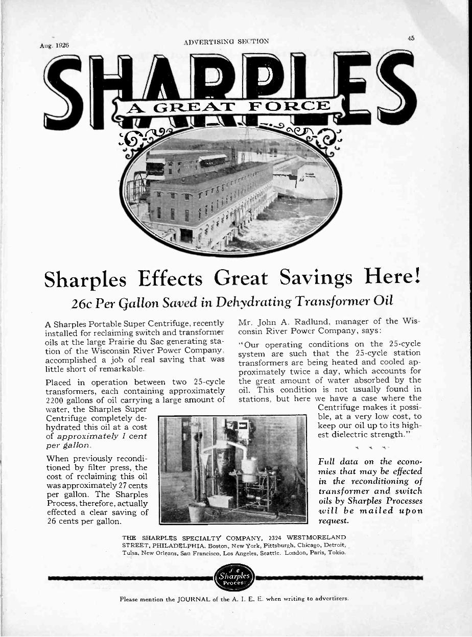
45Aug. 1926
ADVERTISING SECI' I ON
Sharples Effects Great Savings Here!26c Per Gallon Saved in Dehydrating Transformer Oil
A Sharples Portable Super Centrifuge, recentlyinstalled for reclaiming switch and transformeroils at the large Prairie du Sac generating sta-tion of the Wisconsin River Power Company.accomplished a job of real saving that waslittle short of remarkable.Placed in operation between two 25 -cycletransformers, each containing approximately2200 gallons of oil carrying a large amount ofwater, the Sharples SuperCentrifuge completely de-hydrated this oil at a costof approximately 1 centper gallon.When previously recondi-tioned by filter press, thecost of reclaiming this oilwas approximately 27 centsper gallon. The SharplesProcess, therefore, actuallyeffected a clear saving of26 cents per gallon.
THE SHARPLES SPECIALTYSTREET, PHILADELPHIA. Boston, New York, Pittsburgh, Chicago, Detroit,Tulsa, New Orleans, San Francisco, Los Angeles, Seattle. London, Paris, Tokio.
Mr. John A. Radlund, manager of the Wis-consin River Power Company, says:" Our operating conditions on the 25 -cyclesystem are such that the 25 -cycle stationtransformers are being heated and cooled ap-proximately twice a day, which accounts forthe great amount of water absorbed by theoil. This condition is not usually found instations, but here we have a case where the
Centrifuge makes it possi-ble, at a very low cost, tokeep our oil up to its high-est dielectric strength."
Full data on the econo-mies that may be effectedin the reconditioning oftransformer and switchoils by Sharples Processeswill be mailed uponrequest.
COMPANY, 2324 WESTMORELAND
Please mention the JOURNAL of the A. I. E. E. when writing to advertisers.

-16ADVERT' SING SECTION Journal A. f. E. E.
Classified Advertiser's Index for Buyers -ContinuedINSTRUMENTS? ELECTRICAL-Continued
Scientific, Laboratory, TestingGeneral Electric Co., SchenectadyJewell Elec. Instrument Co., ChicagoMetropolitan Device Corp., Brooklyn, N. Y.Roller -Smith Co., New YorkWestern Electric Co., All Principal CitiesWestinghouse Elec. & Mfg. Co., E. Pitts-
burghWeston Elec. Inst. Corp., Newark, N. J.
TelegraphWestern Electric Co., All Principal Cities
INSULATING MATERIALSBoard
West Va. Pulp & Paper Co., New YorkCloth
Acme Wire Co., New Haven, Conn.Irvington Varnish & Ins. Co., Irvington, N.J.Minerallac Electric Co., ChicagoWestinghouse Elec. & Mfg. Co., E. Pitts-
burghComposition
American Lava Corp., ChattanoogaBakelite Corporation,New YorkBelden Mfg. Co., ChicagoWestinghouse Elec. & Mfg Co., E. Pitts-
burghCompounds
Minerallac Electric Co., ChicagoStandard Underground Cable Co., PittsburghWestern Electric Co., All Principal Cities
FibreWest Va. Pulp & Paper Co., New York
LavaAmerican Lava Corp., Chattanooga, Tenn.
MicaNew England Mica Co., Waltham, Mass.
PaperAcme Wire Co., New Haven, Conn.Irvington Varnish & Ins. Co., Irvington, N.J.Tullis, Russell & Co. Ltd., London, Eng.
SilkAcme Wire Co., New Haven, Conn.Irvington Varnish & Ins. Co., Irvington, N.J.
TapeBelden Mfg. Co., ChicagoMinerallac Electric Co., ChicagoOkonite Co., The, Passaic, N. J.Western Electric Co., All Principal CitiesWestinghouse Elec. & Mfg. Co., E. Pitts-
burghVarnishes
Acme Wire Co., New Haven, Conn.General Electric Co., SchenectadyIrvington Varnish & Ins. Co., Irvington, N. J.Minerallac Electric
INSULATORS, HIGH TENSIONComposition
General Electric Co., SchenectadyGlass
Hemingray Glass Co., Muncie, Ind.Porcelain
General Electric Co., SchenectadyLapp Insulator Co., Inc., ReRoy, N. Y.Locke Insulator Corp., BaltimoreOhio Brass Co., Mansfield, 0.Thomas & Sons Co., R., East Liverpool, 0.Western Electric Co., All Principal CitiesWestinghouse Elec. & Mfg. Co., E. Pitts-
burghPost Type
Delta -Star Electric Co., ChicagoINSULATORS, TELEPHONE & TELEGRAPH
Hemingray Glass Co., Muncie, Ind.Western Eletric Co., All Principal Cities
LAMP GUARDSMatthews Corp., W. N., St. LouisWestern Electric Co., All Principal Cities
LAVAAtherican Lava Corp., Chattanooga
LIGHTING FIXTURESCory & Son, Inc., Chas., New York
LIGHTNING' ARRESTERSDelta -Star Electric Co., ChicagoGeneral Electric Co., SchenectadyWestern Electric Co., All Principal CitiesWestinghouse Elec. & Mfg. Co., E. Pitts-
burghLOCOMOTIVES, ELECTRIC
General Electric Co., SchenectadyWestinghouse Elec. & Mfg. Co., E. Pitts-
burghMAGNETIC SEPARATORS
Electric Controller & Mfg. Co., ClevelandMETERS, ELECTRICAL
(SEE INSTRUMENTS, ELECTRICAL)MICA
New England Mica Co., Waltham, Mass.MOLDED INSULATION
Bakelite Corporation, New YorkBelden Mfg. Co., ChicagoBurke Electric Co., Erie, Pa.Westinghouse Elec. & Mfg. Co., E. Pitts-
burghMOLYBDENUM
Fansteel Products Co., Inc., North ChicagoMOTORS
(See GENERATORS AND MOTORS)OHMMETERS
Cory & Son, Inc. Chas., New YorkJewell Elec. Instrument Co. ChicagoRoller -Smith Co., New YorkWeston Elec. Instr. Corp., Newark, N. J.
OIL SEPARATORS & PURIFIERSDeLaval Separator Co., The, New YorkSharpies Specialty Co., The, PhiladelphiaWestinghouse Elec. & Mfg. Co., E. Pitts-burgh
PANEL BOARDS(See SWITCHBOARDS)
PATENT ATTORNEYS(See PROFESSIONAL ENGINEERING
DIRECTORY)PLUGS
Delta -Star Electric Co., ChicagoGeneral Electric Co., SchenectadyWestern Electric Co., All Principal CitiesWestinghouse Elec. & Mfg. Co., E. Pitts-
burghPOLES, STEEL
American Bridge Co., PittsburghPacific Coast Steel Co., San FranciscoWestern Electric Co., All Principal Cities
POLES-TIES, WOODWestern Electric Co., All Principal Cities
POTHEADSG & W Electric Specialty Co., ChicagoStandard Underground Cable Co., PittsburghWestern Electric Co., All Principal Cities
PROTECTIVE DEVICES -
Metropolitan Device Corp., Brooklyn, N. Y.Western Electric Co.. All Principal Cities
PULLERS, SLACKMatthews Corp., W. N., St. Louis
PUMPSAllis-Chalmers Mfg. Co., Milwaukee
PUMPS, SPIRALCramp & Sons Ship & Engine Bldg. Co.,
The Wm., PhiladelphiaRADIO LABORATORY APPARATUS
General Radio Co., Cambridge, Mass.Westinghouse Elec. & Mfg. Co., E. Pitts-
burghRAILWAY SUPPLIES, ELECTRIC
General Electric Co., SchenectadyOhio Brass Co., Mansfield, 0.Western Electric Co., All Principal CitiesWestinghouse Elec. & Mfg. Co., E. Pitts-
burghREACTORS
General Electric Co., SchenectadyMetropolitan Device Corp., Brooklyn, N. Y.
RECTIFIERSFansteel Products Co., Inc., North ChicagoGeneral Electric Co., SchenectadyWestern Electric Co., All Principal CitiesWestinghouse Elec. & Mfg. Co., E. Pitts-
burghREELS, PAYOUT AND TAKEUP
Matthews Corp., W. N., St. LouisREGULATORS; VOLTAGE
Burke Electric Co., Erie, Pa.General Electric Co., SchenectadyWestern Electric Co., All Principal CitiesWestinghouse Elec. & Mfg. Co., E. Pitts-
burghRELAYS
Cory & Son, Inc., Chas., New YorkElectric Controller & Mfg. Co., ClevelandWestinghouse Elec. & Mfg. Co., E. Pitts-
burghRESISTOR UNITS
General Electric Co., SchenectadyWard Leonard Electric Co., Mt. Vernon, N.Y.
RHEOSTATSRiddle, James G., PhiladelphiaGeneral Electric Co., SchenectadySundh Electric Co., Newark, N. J.Ward Leonard Electric Co., Mt. Vernon, N.Y.Western Electric Co., All Principal CitiesWestinghouse Elec. & Mfg. Co., E. Pitts-
burghROPE, WIRE
American Steel & Wire Co., ChicagoRoebling's Sons Co., John A., Trenton, N. J.
SEARCHLIGHTSGeneral Electric Co., SchenectadyWestinghouse Elec. & Mfg. Co., E. Pitts-
burghSHEETS, ELECTRICAL
Trumbull Steel Co., The, Warren, 0.SOCKETS AND RECEPTACLES
General Electric Co., SchenectadyWestern Electric Co., All Principal CitiesWestinghouse Elec. & Mfg. Co., E. Pitts -
SOLENOIDSAcme Wire Co., New Haven, Conn.Belden Mfg. Co., ChicagoDudlo Mfg. Co., Ft. Wayne. Ind.Electric Controller & Mfg. Co., ClevelandGeneral Electric Co., SchenectadySundh Electric Co., Newark, N. J.Ward Leonard Electric Co., Mt.Vernon, N.Y.Westinghouse Elec. & Mfg. Co., E. Pitts-
burghSPRINGS
American Steel & Wire Co., ChicagoSTARTERS, MOTOR
Condit Electrical Mfg. Corp.. BostonElectric Controller & Mfg. Co., ClevelandGeneral Electric Co., SchenectadyRowan Controller Co., Baltimore, Md.Sundh Electric Co., Newark, N. J.Ward Leonard Electric Co., Mt.Vernon, N. Y.Westinghouse Elec. & Mfg. Co., E. Pitts-
burghSTEEL, SHEET & STRIPS
Trumbull Steel Co., The, Warren, 0.
Please mention the JOURNAL of the A. I. E. E. when writing
STOKERS, MECHANICALSturtevant Company, B. F. BostonWestinghouse Elec. & Mfg. Co., E. Pitts-
burghSUB -STATIONS
General Electric Co., SchenectadyWestinghouse Elec. & Mfg. Co., E. Pitts-
burghSWITCHBOARDS
Allis-Chalmers Mfg. Co., MilwaukeeCondit Electrical Mfg. Corp., BostonGeneral Electric Co., SchenectadyMetropolitan Device Corp., Brooklyn, N. Y.Western Electric Co., All Principal CitiesWestinghouse Elec. & Mfg. Co., E. Pitts-
burghSWITCHES Automatic Time
Ferranti, Ltd., London, Eng.Ferranti Meter & Transformer Mfg. Co.,
Ltd., Toronto, Ont.General Electric Co., SchenectadyMinerallac Electric Co., ChicagoSundh Electric Co., Newark, N. J.Westinghouse Elec. & Mfg. Co., E. Pitts-
burghDisconnecting
Burke Electric Co., Erie, Pa.Condit Electrical Mfg. Corp., BostonDelta -Star Electric Co., ChicagoGeneral Electric Co., SchenectadyK -P -F Electric Co., San FranciscoMatthews Corp., W. N., St. LouisThoner & Martens, Boston
FuseGeneral Electric Co., SchenectadyMatthews Corp., W. N., St. LouisMetropolitan Device Corp., Brooklyn, N. Y.Thoner & Martens, Boston
KnifeCondit Electrical Mfg. Corp., BostonElectric Controller & Mfg. Co., ClevelandGeneral Electric Co., SchenectadyMatthews Corp., W. N., St. LouisWestern Electric Co., All Principal CitiesWestinghouse Elec. & Mfg. Co., E. Pitts-
burghMagnetic
Ward Leonard Electric Co., Mt.Vernon. N.Y.Oil
Condit Electrical Mfg. Corp., BostonGeneral Electric Co., SchenectadyWestern Electric Co., All Principal CitiesWestinghouse Elec. & Mfg. Co., E. Pitts-
burghRemote Control
Condit Electrical Mfg. Corp., BostonGeneral Electric Co., SchenectadyRowan Controller Co., BaltimoreSundh Electric Co., Newark, N. J.Western Electric Co., All Principal CitiesWestinghouse Elec. & Mfg. Co., E. Pitts-
burghTANTALUM
Fansteel Products Co., Inc., North ChicagoTELEGRAPH APPARATUS
Western Electric Co., All Principal CitiesTELEPHONE EQUIPMENT
Cory & Son, Inc., Chas., New YorkWestern Electric Co., All Principal Cities
TESTING LABORATORIESElectrical Testing Labs., New York
TOWERS, TRANSMISSIONAmerican Bridge Co., PittsburghPacific Coast Steel Co., San FranciscoWestern Electric Co., All Principal Cities
TRANSFORMERSAllis-Chalmers Mfg. Co.. MilwaukeeAmerican Transformer Co., Newark, N. J.Duncan Elec. Mfg. Co., Lafayette, Ind.Ferranti, Ltd., London, Eng.Ferranti Meter & Transformer Mfg. Co.,
Ltd., Toronto, Ont.General Electric Co., SchenectadyKuhlman Electric Co., Bay City, Mich.Moloney Electric Co., St. LouisPittsburgh Transformer Co., PittsburghWagner Electric Corp., St. LouisWestern Electric Co., All Principal CitiesWestinghouse Elec. & Mfg. Co., E. Pitts-
burghFactory
American Transformer Co., Newark, N. J.Kuhlman Electric Co., Bay City, Mich.Moloney Electric Co., St. LouisPittsburgh Transformer Co., PittsburghWagner Electric Corp., St. LouisWestern Electric Co., All Principal Cities
FurnaceAllis-Chalmers Mfg. Co., MilwaukeeAmerican Transformer Co., Newark, N. J.Moloney Electric Co., St. LouisPittsburgh Transformer Co., Pittsburgh
MeteringAmerican Transformer Co., Newark, N. J.Ferranti, Ltd., London, Eng.Ferranti Meter & Transformer Mfg. Co.,
Ltd., Toronto, Ont.Pittsburgh Transformer Co., Pittsburgh
Mill TypePittsburgh Transformer Co., Pittsburgh
RadioAmerican Transformer Co., Newark, N. J.
Street LightingKuhlman Electric Co., Bay City, Mich.Western Electric Co., All Principal Cities
to advertisers.

Aug. 1926 ADVERTISING SECTION 47
75
Left!-Left!-with machine -like precision every foot and armswings forward as one. Imagine the effect that one man out of stepwould have on that perfect line of march! But it never happens.Each individual does his part exactly right.
The same sort of teamwork from engineer toinspector must be developed to build switchboardsthat are one hundred per cent right. The Conditorganization possesses the facilities to design andbuild the type and size of switchboards that willmeet your exact requirements and the teamwork tomake them as near perfection as humanly possible.
CONDIT ELECTRICAL MFG. CORPORATIONManufacturers of Electrical Protective Devices
Boston. Mass.Abrtfieny Rectiic Company
Sole Distributor for the Dominion of Canada
For safety enclosed switchboards - removabletruck type - benchboards, electrical and manualcontrolled switchboards, get in touch with Condit.
V
*
/ A A r
Please mention the JOURNAL of the A. I. E. E. when _writingto advertisers.
48 ADVERTISING SECTION Journal A. I. E. E.
Fq:
-7.
Science AbstractsALL electrical engineers actively, engaged in the practice of their pro-
fession should subscribe to "Science Abstracts."Published monthly by the Institution of Electrical Engineers, London, in associa-
tion with the Physical Society of London, and with the cooperation of the AmericanInstitute of Electrical Engineers, the American Physical Society and the AmericanElectrochemical Society, they constitute an invaluable reference library.
Through "Science Abstracts" engineers are enabled to keep in touch with engineer-ing progress throughout the world, as one hundred and sixty publications, in variouslanguages, are regularly searched and abstracted. "Science Abstracts" are publishedin two sections, as follows:
"A"-PHYSICS-deals with electricity, magnetism, light,heat, sound, astromony, chemical physics.
"B"-ELECTRICAL ENGINEERING-deals with electricalplant, power transmission, traction, lighting, tele-graphy, telephony, wireless telegraphy, prime movers,engineering materials, electrochemistry.
Through special arrangement, members of the A.I.E.E. Subscriptions should start with the January issue.may subscribe to "Science Abstracts" at the reduced rate The first volume was Issued in 1898. Back numbers areof $5.00 for each section, and $10 for both. Rates to non- available, and further information regarding these can bemembers are $7.50 for each se"tion and $12.50 for both. obtained upon application to Institute headquarters.
American Institute of Electrical Engineers33 West 39th Street, New York
Classified Advertiser's Index forTROLLEY LINE MATERIALS
General Electric Co., SchenectadyOhio Brass Co., Mansfield, 0.Western Electric Co., All Principal CitiesWestinghouse Elec. & Mfg. Co., E. Pitts-
burgliTURBINES, HYDRAULIC
Allis-Chalmers Mfg. Co., MilwaukeeCramp & Sons Ship & Engine Bldg. Co.,
The Wm., PhiladelphiaTURBINES, STEAM
Allis-Chalmers Mfg. Co., MilwaukeeGeneral Electric Co., SchenectadySturtevant Company, B. F., BostonWestern Electric Co., All Principal CitiesWestinghouse Elec. & Mfg. Co., E. Pitts-
burghTURBINE SIGNAL SYSTEMS
Cory & Son, Inc., Chas., New YorkTURBO -GENERATORS
Allis-Chalmers Mfg. Co., MilwaukeeWestinghouse Elec. & Mfg. Co., E. Pitts-
burglrVALVE CONTROL, ELECTRIC
Bristol Company, The, Waterbury, Conn.Cory & Son, Inc., Chas., New York
VALVES, JOHNSON HYDRAULICCramp & Sons Ship & Engine Bldg. Co.,
The Wm., PhiladelphiaVARNISHES, INSULATING
General Electric Co., SchenectadyIrvington Varnish & Ins. Co., Irvington, N. J.Minerallac Electric Co., ChicagoWestinghouse Elec. & Mfg. Co., E. Pitts-
burghWELDING EQUIPMENT, ELECTRICAL
General Electric Co., SchenectadyOhio Brass Co., Mansfield, 0.Westinghouse Elec. & Mfg. Co., E. Pitts-
burghWIRES AND CABLES
Armored CableAmerican Steel & Wire Co., ChicagoAtlantic Ins. Wire & Cable Co., Rome, N. Y.Belden Mfg. Co., ChicagoBoston Ins. Wire & Cable Co., BostonGeneral Electric Co., SchenectadyHazard Manufacturing Co., Wilkes-Barre, Pa.Kerite Ins. Wire & Cable Co., New YorkOkonite Company, The Passaic, N. J.Roebling'r Sons Co., John A., Trenton, N. J.Simplex Wire & Cable Co., BostonStandard Underground Cable Co., PittsburghWestern Electric Co., All Principal Cities
Asbestos CoveredAmerican Steel & Wire Co., ChicagoAtlantic Ins. Wire & Cable Co., Rome, N. Y.Belden Mfg. Co., ChicagoGeneral Electric Co., Schenectady
utom WiveAmerican Steel & Wire Co., ChicagoAtlantic Ins. Wire & Cable Co., Rome, N. Y.Belden Mfg. Co., ChicagoBoston Ins. Wire & Cable Co., BostonGeneral Electric Co., SchenectadyKerite Ins. Wire & Cable Co., New YorkRoebling's Sons Co., John A., Trenton, N. J.Simplex Wire & Cable Co., BostonStandard Underground Cable Co., PittsburghWestern Electric Co., All Principal Cities
Bare CopperAmerican Ins. Wire & Cable Co., ChicagoAmerican Steel & Wire Co., ChicagoAnaconda Copper Mining Co., ChicagoAtlantic Ins. Wire & Cable Co., Rome, N. Y.Belden Mfg. Co., ChicagoCopperweld Steel Co., Rankin, Pa.Hazard Manufacturing Co., Wilkes-Barre, Pa.Roebling's Sons Co., John A., Trenton, N. J.Standard Underground Cable Co., PittsburghWestern Electric Co., All Principal Cities
Copper CladAmerican Steel & Wire Co., ChicagoCopperweld Steel Co., Rankin, Pa.Standard Underground Cable Co., PittsburghWestern Electric Co., All Principal Cities
Flexible CordAmerican Steel & Wire Co., ChicagoAtlantic Ins. Wire & Cable Co., Rome, N. Y.Belden Mfg. Co., ChicagoBoston Ins. Wire & Cable Co., BostonGeneral Electric Co., SchenectadyHazard Manufacturing Co., Wilkes-Barre, Pa.Okonite Company, The, Passaic, N. J.Roebling's Sons Co., John A., Trenton, N. J.Simplex Wire & Cable Co., BostonStandard Underground Cable Co., PittsburghWestern Electric Co., All Principal Cities
FuseAmerican Steel & Wire Co., ChicagoGeneral Electric Co., SchenectadyRoebling's Sons Co., John A., Trenton, N. J.Western Electric Co., All Principal CitiesLead Covered (Paper and Varnished cambric
insulated)American Steel & Wire Co., ChicagoAnaconda Copper Mining Co., ChicagoAtlantic Ins. Wire & Cable Co., Rome, N. Y.
Buyers-ContinuedGeneral Electric Co., SchenectadyHazard Manufacturing Co.,Wilkes-Barre, Pa.Kerite Ins. Wire & Cable Co., New YorkOkonite Company, The, Passaic, N. J.Okonite-Callender Cable Co., The, Inc.,
Passaic, N. J.Roebling's Sons Co., John A., Trenton, N. J.Simplex Wire & Cable Co., BostonStandard Underground Cable Co., PittsburghWestern Electric Co., All Principal Cities
MagnetAmerican Steel & Wire Co., ChicagoAtlantic Ins. Wire & Cable Co., Rome, N. Y.Belden Mfg. Co., ChicagoDudlo Mfg. Corp., Fort Wayne, Ind.General Electric Co., SchenectadyRoebling's Sons Co., John A., Trenton, N. J.Standard Underground Cable Co., PittsburghWestern Electric Co., All Principal Cities
Rubber InsulatedAmerican Steel & Wire Co., ChicagoAtlantic Ins. Wire & Cable Co., Rome, N.Y.Belden Mfg. Co., ChicagoBoston Ins. Wire & Cable Co., BostonGeneral Electric Co., SchenectadyHazard Manufacturing Co., Wilkes-Barre,
Pa.Kerite Ins. Wire & Cable Co., New YorkOkonite Company, The, Passaic, N. J.Roebling's Sons Co., John A., Trenton, N. J.Simplex Wire & Cable Co., BostonStandard Underground Cable Co., PittsburghWestern Electric Co., All Principal Cities
TrolleyAmerican Steel & Wire Co., ChicagoAnaconda Copper Mining Co., ChicagoAtlantic Ins. Wire & Cable Co., Rome, N. Y.Copperweld Steel Co., Rankin, Pa.Roebling's Sons Co., John A., Trenton, N. J.Standard Underground Cable Co., PittsburghWestern Electric Co., All Principal Cities
WeatherproofAmerican Ins. Wire & Cable Co., ChicagoAmerican Steel & Wire Co., ChicagoAnaconda Copper Mining Co., ChicagoAtlantic Ins. Wire & Cable Co., Rome, N. Y.Copperweld Steel Co., Rankin, Pa.General Electric Co., SchenectadyKerite Ins. Wire & Cable Co., New YorkOkonite Company, The, Passaic, N. J.Roebling's Sons Co., John A., Trenton, N. J.Simplex Wire & Cable Co., BostonStandard Underground Cable Co., PittsburghWestern Electric Co., All Principal Cities
Please mention the JOURNAL of the A. I. E. E. when writing to advertisers.

Aug. 1926 ADVERTISING SECTION
American Steel & WireCompany's
A. S.W. Cambric30% Cables
In Boston's Newest Theatrerr HE Metropolitan Theatre, Boston's new and magnificent1 amusement palace, is wired throughout with A. S.W.
30% Wire and Varnished Cambric Cable. Elegantly appointedand beautifully designed, the Metropolitan is the last wordin theatre luxury.
It is significant that for this important construction, thesecables should be specified - one more testimony to the un-questioned quality and character of these superior products.
In many well known buildings throughout the country,these higher grade cables afford increased protection andassurance of continuous satisfactory service. We 'welcomeyour inquiry for detailed information.
CHICAGO ..208 So. La Salle StreetCLEVELAND. Rockefeller BuildingDETROIT Foot of First Street(INCINN .TI Union Trust BuildingMINNEAPOLIS-ST. PAUL
Merchants Nat'l Bk. Bldg. St. Paul
ST. LOUIS E06 Clive StreetKANSAS CITY 417 Grand AvenueOKLAHOMA CITY
First Nat'l Bank Bldg.BIRMINGHAM . Brown -Marx Bldg.MEMPHIS
. . Union and Planters Bank Bldg.
SALES OFFICESNEW YORK 30 Church StreetBOSTON 185 Franklin StreetPITTSBURGH Frick Building
PHILADELPHIA.. Widener radiusATLANTA 101 Marietta Street
WORCESTER 94 Grove Street DALLAS Praetorian Building
BALTIMORE..32 So. Charles Street
BUFFALO 670 Ellicott Street
WILKES-BARRE Miners Ek. Eldg. SALT LAKE CITY. Walker Bk. Bldg.
DENVER . First National Bank Bldg.
UNITED STATES STEEL PRODUCTS COMPANY, San Francisco, Los Angeles, Poreand, Se_ttle
Feasc mention the JOURNAL of the A. I. E. E. when writing to advertisers.
50Jour -mil .1 I I. K.
r,,,s,,.;,,
STEEL
TOWERSand component parts
FOR ELECTRIC TRANSMISSION
AMERICAN BRIDGE COMPANY71 Broadway, New York City
TOWER DEPARTMENTFrick Building, Pittsburgh, Pa.
LE.
Offices in Principal Cities
I8
8
a
F. -
Amin!!!
ALPHABETICAL LIST OF ADVERTISERSPAGE PAGE PAGEAcme Wire Company, The 33 Fansteel Products Company, The 28 Ophuls & Hill, Inc 43Alexander & Dowell 42 Fennessy, David V 42 Osgood, Farley 43Allis-Chalmers Manufacturing Co 6 Ferranti, Limited 12Ambursen Construction Company, Inc 42 Ford, Bacon & Davis, Inc 42 Pacent Electric Company, Inc 28American Appraisal Company, The 42 Fowle & Company, Frank F 42 Pacific Coast Steel Company 35American Bridge Company 50 Freyn Engineering Company 42 Pittsburgh Transformer Company 3GAmerican Insulated Wire & Cable Co 34 Public Service Production Company 43American Lava Corporation 41 G & W Electric Specialty Company 26American Lead Pencil Company 41 General Electric Company 9, 19, 11 Research Narratives 34American Steel & Wire Company 49 General Radio Company 21 Roebling's Sans Company, John A 34American Transformer Company 26 Gerry, M. H., Jr 42 Roller -Smith Company 3)Anaconda Copper Mining Company 17 Rowan Controller Company, The 40Atlantic Insulated Wire & Cable Co 34 Harza, L. F 42
Hazard Manufacturing Company 34 Sanderson & Porter 43Bakelite Corporation 2 Hemingray Glass Company 35 Sangamo Electric Company........13Barstow & Company, Inc., W. S 42 Hoosier Engineering Company 42 Sargent & Lundy, Inc 43Battey & Kipp, Inc 42 Hopkins, Nevi! Monroe 42 Science Abstracts .. 48Belden Manufacturing Company Back Cover Scofield Engineering Company 43Black & Veatch 42 Irvington Varnish & Insulator Company.... 41 Sharpies Specialty Company 4'1Boston Insulated Wire & Cable Co 34Bristol Company, The 30Burke Electric Company 36
Jackson & MorelandJewell Electrical Instrument Company
4230
Simplex Wire & Cable CompanySirrine & Co., J. EStandard Steel & Bearings, Inc ...
324338Burndy Engineering Company, Inc 32
Byllesby Engineering & Management Corp 42 Kerite Insulated Wire & Cable Co., Inc....K -P -F Electric Company 1
37
Standard Underground Cable CompanyStar Electric Motor CompanyStevens, John A
27
43Century Electric Company 39 Kuhlman Electric Company 14. .......
Stevens & Wood, Inc 43Chandeysson Electric Company 8Civil Aviation (A. E. C.) 33Clark, Walter G 42C,assified Advertisements 38
Lapp Insulator Company, IncLincoln, E. SLocke Insulator Corporation
354322
Stockbridge & BorstStone & Webster, IncSturtevant, B. F., CompanySundh Electric Company
43134036Clement, Edward E 42
Clewell, C. E 42Condit Electrical Manufacturing Corp 47Copperweld Steel Company 35Cramp & Sons. S. & E. Bldg. Co., The Wm 51Cutter Company, The. 19
Danne, Harold A 42De Laval Separator Company 36Delta -Star Electric Company 37Dickinson, W. N 42
Manufacturers' & Inventors' Elec. CoMaster Electric Company, TheMatthews Corporation, W. NMcClellan & Junkersfeld, IncMetropolitan Device CorporationMidwest Air Filters, IncMinerallac Electric CompanyMoloney Electric CompanyMoore & Company, W. EMorganite Brush Company, Inc., The
36392343523734274340
Thomas, Percy HThomas & Sans Company, The RThoner & MartensTimken Roller Bearing Company...Trumbull Steel Company, TheTullis, Russell & Co., Ltd
U. G. I. Contracting Company, TheViele, Blackwell & Buck
433537
44020
43
43Dossert & Company 24Dubilier Condenser & Radio Corp 31Dudlo Manufacturing Corporation 21Duncan Electric Manufacturing Co 36
Neall, N. J 43Neiler, Rich & Company 43New Departure Manufacturing Co., The 3New England Mica Company 41
Ward Leonard Electric CompanyWest Va. Pulp & Paper CompanyWestern Electric CompanyWestinghouse Elec. & Mfg. Co
18411615
Electric Controller & Mfg. Co. 7Electric Specialty Company 40Electrical Testing Laboratories 40Electro Dynamic Company 39Engineering Directory 42, 43
Norma -Hoffmann Bearings Corporation.... 5
Ohio Brass Company, The 25Okonite Company, The Inside Back CoverOkonite-Callender Cable Co., Inc., The .... Cover
Weston Electrical Instrument CorpWhite Engineering Corp., The J. GWildermann & ZwingenbergerWireless Specialty Apparatus Company.Wray & Company. J. G
3143433143
(For classified list of Advertisers see pages 44. 46 and 48.)Please mention the JOURNAL of the A. I. E. E. when writing to advertisers.

Aug. 192t A DV ERT I SI NG SECTION Il
I. P. Morris Hydraulic TurbinesThe Wm. Cramp & Sons Ship & Engine Building Co.
Richmond and Norris Streets, PhiladelphiaNew York Office: 100 Broadway Birmingham Office: American I i++'.i
Shop Assembly of Turbine
DIX RIVER PLANTof the
Kentucky Hydro -ElectricCompany
I nst ailed capacity of 33.000 h. p. developed by
Three I. P. Morris TurbinesHead 235 Feet Speed 300 R.P.M.
These units are noteworthy in that they are designed for operation under a wide rangein heads varying from 163 to 235 feet.
With each unit a 102" x 66" type Ai- Johnson Hydraulic Valve is installed to controlthe quantity of water utilized by each turbine.
This project which includes the World's Highest Rockfill Darn, was designed and con-structed by L. F. Harza. Hydro -Electric & Hydraulic Engineer. Chicago.
Designers and builders of the Johnson Hydraulic Valve and the Moody Spiral Pump
ASSOCIATED COMPANIESTHE PELTON WATER WHEEL CO., San Francisco and New York
DOMINION ENGINEERING WORKS, LTD., Montreal, Canadian LicenseesSOCIEDADE ANONYNIA, HILPERT, Rio de Janeiro, Brazilian LicenseesPlease mention the JOURNAL of the A. I. E. E. when writing to advertisers.

ADVEItTlsINCI sl.:("11()N Journal A. I. E. E.
Partly finishedwinding of closewound insu-lated conduc-tor for standardfeeder reactors.
Commonwealth Edison CompanyReorders
Metropolitan Feeder Reactorsfor
Fisk, Quarry, Calumetand Crawford Ave. Stations
INSULATEDFor More Than 14 Years
The necessity of insulating conductorswas recognized when manufacturestarted in about 1910,-and the thou-sands of Metropolitan Current Limit-ing Reactors now in use were madewith insulated conductors.
The illustration above shows partly fin-ished winding of close wound insulatedconductor for standard feeder reactors.
For "short circuit protection" write,
METROPOLITAN DEVICE CORPORATION1250 Atlantic Avenue
BROOKLYN, NEW YORK
winiorAfer
al JIM, 14i.7; "::a.!;";12,S'E7; E E ICE IFF!FE!FE E
FF -.11111111 ;
Porcelain Lined. Indoor Type, CoveredConductor, Current Limiting Reactor
for capacities up to 600 amperes.
r--JH FT
-
Calumet StationCommonwealth Edison Co.
Chicago, Ill.
Please mention the JOURNAL of the A. I. E. E. when writing to advertisers.

Jhe Standard forRubber Insulation
he SERVICEMatches the Product
OKONITE service has grown with the steadily increasing useof Okonite for all purposes electrical. It matches the Product.Users of Okonite products have long had a two -fold assurance ofsatisfaction,- the unquestioned superiority of Okonite insula-tion as demonstrated by its consistent performance record sincefirst put upon the market 47 years ago, and the knowledge thatback of it is a Company Service built to meet every possiblerequirement.In the location of our Branch Offices we have had in mind thegreatest convenience to the buying public geographically, and themost advantageous points for the efficient handling of its needs.Together with our agents in other leading buying centers, theyplace our entire service organization within immediate reach ofusers of Okonite, wherever located,-a chain of Service Posts ex-tending from New York Harbor to the Golden Gate.In Chicago we carry in stock at our Warehouse exceptionally largequantities of Okonite products and have adequate facilities fortaking care of immediate stock shipments from that point.
OKONITE PRODUCTSOkonite Insulated Wires Cables Varnished Cambric CablesOkonite Insulating Tape Okonite CementManson Dundee Friction Tapes Okocord Okoloom
OKONITE-CALLENDER PRODUCTSImpregnated Paper Cables . Super -Tension Cables . Splicing Materials
Backing up Okonite is our Chemical Laboratory, Electrical Research Laboratory,and an Engineering Department competent to assist you in solving any problemyou may have. We freely offer you our facilities and solicit your inquiries.
The Okonite CompanyThe Okonite-Callender Cable Company, Inc.Factories: PASSAIC, N. JSales Offices: New York . Chicago . Pittsburgh . St. Louis .
Birmingham San Francisco . Los AngelesF. D. Lawrence Electric Co., Cincinnati, 0.
Novelty Electric Co., Phila., Pa. Pettingell-Andrews Co., Boston, Mass.Canadian Representatives: Engineering Materials Limited, Montreal
Cuban Representatives: Victor G. Mendoza Co., Havana4p.:1P.41104...
EPP'OP,
IIPPdfr /-i Er;9,
. ilia°On
PATERSON, N. J.AtlantaSeattle
toA to
LOS ANGELES'
los.
SEATTLE

BELDEN MAGNET WIREis made with standard textileinsulations. Where space econ-omy is a vital factor, Belden-amel, Cotenamel or Silk -enamel wires should be used.The Beldenamel coating usedon Beldenamel, Cotenameland Silkenamel wires is pre-pared from the raw materialand applied to the finishedwireentirely under supervision ofBelden engineers. This conti-nuity of supervision from startto finish insures an enamelcoated wire of uniform quality.'The tremendous volume ofBeldenamel, Cotenamel andSilkenamel wires used in radio,X-ray and industrial work is thebest evidence of the enduringquality of these insulated wires.
"Penny Wise and1 Pound Foolish"Especially true of the shop that buys cheap wireto save money but overlooks the cost of complaints
'HERE would be no occasion to.1k. write this message if all users of
magnet wire realized the excessive costof inferior wire. It is true that the pur-chasing department may show attrac-tive savings in magnet wire costs bybuying low cost wire, but what aboutthe high cost of breakdowns in finishedequipment, due to faulty wire, that mustbe adjusted by the sales departmentto satisfy a furious customer?An X-ray machine working in a far-offcountry, on a motor in a big machine, or a
Mail the Couponfor Beldenamel Booklet
relay coil in an important railroad signaldepend on magnet wire for their oper-ation. Their reliability is no greater thanthe reliability of the hidden wire usedin their manufacture.Since the cost of the best wire is but littlemore than that of an inferior wire, whencompared with the final cost of the fin-ished device, it is Penny Wise and PoundFoolish to risk your reputation or in-crease your sales cost by using inferiorwire. When all costs are considered,Belden wire is cheapest.
it Vii.
- -....
,f,t, ......... -...
..,.. -.... ..... -..-.... ......
I0 ..... -......
I :. 01. 41::410, ...' '':....:... .... .....' 0. 4,..... ....----.-
.7, I 0 - . !. , .---
Belden Manufacturing Co.2316B So. Western Avenue,Chicago, Illinois.
Please send us your booklet on Bel-denamel magnet wire containing tech-nical wire data.
Name
Address