
Alaris Capture Pro Software - DDE-ac.in
144
teOWieHIttJ; CONTENTS Page No. Units 1. Introduction to Computer Networics 1-22 23-50 2. The Physical Layer 51-60 3. The Data Link Layer 61-72 4. The Medium Access Sub-Layer 73-92 5. The Network Layer 93-110 6. The Transportation Layer n 1-142 ■ 7. The Application Layer I
-
Upload
khangminh22 -
Category
Documents
-
view
2 -
download
0
Transcript of Alaris Capture Pro Software - DDE-ac.in
teOWieHIttJ;
CONTENTS
Page No.Units
1. Introduction to Computer Networics 1-22
23-502. The Physical Layer
51-603. The Data Link Layer
61-724. The Medium Access Sub-Layer
73-925. The Network Layer
93-1106. The Transportation Layer
n 1-142 ■7. The Application Layer
I
SYLLABUS
C-119 COMPUTER NETWORKS
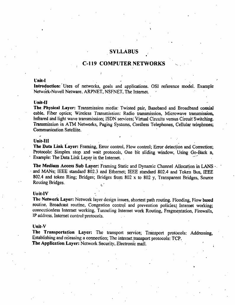
I'nit-IIntroduction: ’ Uses of networks, goals and applications. OSI reference model. Example Network-Novell Netware. ARPNET, NSFNET, The Internet.
UniMIThe. Physical Layer: Transmission media: Twisted pair, Baseband and Broadband cofbcial cable. Fiber optics; Wireless Transmission: Radio transmission, Microwave transmission, Infrared and light wave transmission; ISDN services; Virtual Circuits versus Circuit Switching. Transmission in ATM Networks, Paging Systems, Cordless Telephones, Cellular telephones; Communication Satellite.
UnlMIIThe Data Link Layer: Framing, Error control. Flow control; Error detection and Correction; Protocols: Simplex stop and wait protocols, One bit sliding window. Using Go-Back n. Example: The Data Link Layer in the Internet. ,
The Medium Access Sub Layer: Framing Static and Dynamic Charmel Allocation in LANS ■ and MANs; IEEE standard 802.3 and Ethernet; IEEE standard 802.4 and Token Bus, IEEE 802.4 and token Ring; Bridges; Bridges from 802 x to 802 y, Transparent Bridges, Source Routing Bridges.
Uiiit-IVThe Network Layer: Network layer design issues, shortest path routing. Flooding, Flow based routine. Broadcast routine, Congestion control and prevention policies;' Internet working; connectionless Internet working, Tunneling Internet work Routing, Fragmentation, Firewalls, IP address. Internet controFprolocols.
Unit-VI'he Transportation Layer: The transport service; Transport protocols: Addressing, Establishing and releasing a connection; The inlemetlranqM The Application Layer: Network Security. Electronic mail.
: TCP.i
Imjvduaimto Computer NetworksUNIT 1
NOTESINTRODUCTION TO
COMPUTER NETWORKS
STRUCTURE1.1 Introduction1.2 Uses ofNetworks: Goals and Applications
1.3 OSI Reference Mode
1.4 Novell Netware
1.5 ARPANET ■
1.6 NSFNET
1.7 The Internet
• Summaiy
• Selft Assessment Questions
• Further Readings
Learning ObjectivesAfter going through this unit, students will be able to: -
• know about networking in general.• use networking, know its purpose, and learn how the networking helps us in
working faster and easier.• explain the networking’s various goals and applications.• describe OSI Reference Mode as a technology for connecting various
computers using the networking.• know about Novell Netware as a networking software from Novell Netware.• explain about ARPAN^^T as another networking software.
• know about NSFNET software as another networking software.• describe about the Internet, which is a popular application of Networking.
Self Instructional Material 1
Computer Networks1.1 INTRODUCTION
When more than two computers are connected to each other and sharing information, resources and remote systems then this is called Networking.Technical definitions:
“A network of data processing nodes that are interconnected for the purpose ofdata communication”.
NOTES
‘‘An interconnection of three or more (ommunicating entities”.
Classification of Computer Networks
Network LayerIn this computer networks follow the industry standards of OSI reference model and TCP/IP model. Where as OSI is of seven layers and TCP/IP is defined in five layers.ScaleIt can be classified as;
• Local area network (LAN)• Campus area network (CAN)• Metropolitan area network (MAN)• Wide area network (WAN).• Personal area network (PAN)
Connection MethodThe connection methods available are:
• Ethernet• Power line communication• Wirdess LAN• HomePNA
Functional RelationshipThis exists between the network elements:
• Peer-to-peer• Client-server
/Network Topology 'It is a logical layouts of the network. Topologies are:
• Star network• Ring network• Bus network
2 Self Instructional MUerial
• Tree network• Star-bus network• Mesh network
Introduction to CotrqmUr Netwoiks
ServicesIt provides following services:
• Wireless community network• Server• Storage area networks• Process control networks• Value-added network
NOTES
ProtocolOn network protocols are used as communication language. Several types of protocols are available:
• TCP/IP• Network IPX/SPX
lypes of NetworksFollowing is the list of the most common types of computer networks in order of scale.Personal Area Network (PAN)PAN is used for communication among the personal devices (intrapersonal communication), or for connecting to a higher level network and Internet. The reach of a PAN is typically a few meters.A personal area network (PAN) is used for communication among computer devices. For example,
• Telephones• Personal digital assistants
Personal area networks may be wired with computer buses such as USB and FireWire. A wireless personal area network (WPAN) can also be made possible with network technologies such as IrDA and Bluetooth.Local Area Network (LAN)A network covering a small geographic area, like a home, office, or building. Current LANs are most likely to be based on Ethernet technology. The defining characteristics of LANs, in contrast to WANs (wide area networks), include their much higher data transfer rates, smaller geographic range, and lack of a need for leased telecommunication lines.Campus Area Network (CAN)A network that connects two or more LANs but that is limited to a specific (possibly private) geographical area such as a college campus, industrial complex, or a military
Se^ Iratruaional Material 3
Computer Networks base. A CAN, may be considered a type of MAN (metropolitan area network), but is generally limited to an area that is smaller than a typical MAN.Metropolitan Area Network (MAN) ^
A network that connects two or more Local Area Networks or CANs together but does not extend beyond the boundaries of the immediate town, city, or metropolitan area. Multiple routeis, switches & hubs are conneaed to create a MANWide Area Network (WAN)
A WAN is a data communications network that covers' a relatively broad geographic area and that often uses transmissioii facilities provided by common carriers, such as telephone companies. WAN technologies generally function at the lower three layers of the OSI reference model: the physical layer, the data link layer, and the network layer.Internetwork
Two or more networks or network segments connected using devices that operate at' layer 3 (the ‘network’ layer) of the OSI Basic Reference Model, such as a router. Any interconnection among or between public, private, commercial, industrial, or governmental networks may also be defined as ah internetwork.Internet
A specific internetwork, consisting of a worldwide interconnection of governmental, academic, public, and private networks based upon the Advanced Research Projects Agency Network (ARPANET) developed by ARPA of the U.S. Department of Defense - also home to the World Wide Web (WWW) and referred to as the ‘Internet’ with a capital ‘P to distinguish it from other generic internetworks.Extranet
A network or internetwork that is limited in scope to a single organization or entity but which also has limited connections to the networks of one or more other usually, but not necessarily, trusted organizations or entities (e.g., a company’s custom^ may be provided access to some part of its intranet thusly creating an extranet while at the same time the customers may not be considered ‘trusted’ from a security standpoint). Technically, an extranet may also be categorized as a CAN, MAN, WAN, or other type of network, although, by definition, an extranet cannot consist of a single LAN, because an extranet must have at least one connection with an outside network.
NOTES
Intranets and extranets may or may not have connections to the Internet.
If connected to the Internet, the intranet or extranet is normally protected from being accessed from the Internet without proper authorization. The Internet itself is not considered to be a part of the intranet or extranet, although the Internet may serve as a poital for access to portions of an extranet.
Basic Hardware ComponentsAil networks are made up of basic hardware building blocks to interconnect network nodes, such as Network Interface Cards (NICs), Bridges, Hubs, Switches, and Routers. In addition, some method of connecting these building blocks is required, usually in
4 Self Instructional Material

the form of galvanic cable (most commonly Category 5 cable). Less common are microwave links (as in IEEE 802.11) or optical cable (“optical fiber”).Network Interface CardsA network card, network adapter or NIC (network interface card) is a piece of computer hardware designed to allow computers to communicate over a computer network. It provides physical access to a networking medium and provides a low- level addressing system through the use of MAC addresses. It allows users to connect to each other either by using cables or wirelessly.BridgesA network bridge connects multiple network segments at the data link layer (layer 2) of the OSI model. Bridges are similar to repeaters or network hubs, devices that connect network segments at the physical layer, however a bridge works by using bridging where ttaffic firom one network is managed rather than simply rebroadcast to adjacent network segments.Hubs .
- A^ub is a piece of hardware which provides the connectivity of a segment of a network by directing traffic through the netv'ork. It does this in a rudimentary way, it simply copies the data to all of the Nodes connected to tlie hub. Hubs are commonly used to connect segments of a LAN. A hub contains multiple ports. When a packet arrives at one port, it is copied to the other ports so that all segments of the LAN can see all packets.SwitchesSwitches are the device of networking that directs traffic to the correct node by filtering and forwarding packets between Nodes. Switches operate at the data link layer (layer 2) and sometimes the network layer (layer 3) of the OSI Reference Model and therefore support any packet protocol. L.jkNs that use switches to join segments aie called switched LANs or, in the case of Ethernet networks, switched Ethernet LANs. In a circuit-switched data network, a switch is used to create a virtual circut between the pairs of endpoints. This means that it creates a path to the destination node from the source node.
RoutersRouters are the networking device that forwards data packets along networks by using headers and forwarding tables to determine the best path to forward the packets. Routers also provide intcrconnecd vity between like and unlike devices on the network, Tliis is accomplished by examining the Header of a data packet. They use protocols such as ICMP to communicate with each other and configure the best route between any tW'C hosts. A router is connected to at least two networks, commonly two LAI'Ts or WANs or a LAN and its ISP’s network.
Routers are usually located at gatcuays, tke places where two or more networks connect. Many household DSL and Cable Modems arc also routers.
Introductioi’to Compuier Networks
NOTES
Building a Simple Corcpuler NehvorkA simple computer network may lie constructed from tv'o computers by adding a neuvork adapter (Network Interface Controller (NIC)) to each computer and then
Self Instmctioral Material 5
‘ ' »
Computer Networks connecting them together with a special cable called a aossover cable. This type of network is useful for transferring information between two computers that are not normally connected to each other by a permanent network conneaion or for basic home networking applications. Alternatively, a network between two computers can be established without dedicated extra hardware by using a standard connection such as the RS-232 serial port on both computers, connecting them to each other via a special crosslinked null modem cable.Practical networks generally consist of more than two interconnected computers and generally require special devices in addition to the Network Interface Controller that each computer needs to be equipped with. Examples of some of these special devices are hubs, switches and routers.
NOTES
1.2 USES OF NETWORKS: GOALS AND APPLICATIONS
The most important usuage of networking is Resource Sharing, and the goal is to make all programs, equipment, and especially data available to anyone on the network without regard to the physical location of the resource and the user. In other words, the mere fact that a user happends to be 1000 km away from his data should not prevent liim from using the data as though they were local; A second goal is to provide high reliability by having alternatn'e sources of supply. For example, all files could be replicated on two or more machines, so if one of them is unavailable (due to hardware failure), the other copies could be used.Small computers have a much better' price/performance ratio rather than large ones. Mainframes are roughly a factor of ten faster than personal computers, buy they cost a thousand times more. "I'he imbalance has caused many systems designers to build system consisting of jrersonal computers, one per user, with data kept on one or more sHared file server machines.A computer network can provide a powerful communication medium among wddely separated employees. Using a iiet%vork, it is easy for two or more people who live far apart to write a report together. When one worker makes a c^nge to an on-line document, the others can see the change immediately, instead of waiting several days for the letter.
.V 1.3 OSI REFERENCE MODESi
^yl977, tlie International Organization for Standardization (ISO), began to develop OSI networking suite. OSI has two major components: an abstract model of
networking (the Basic Reference Model, or seven-layer model), and a set of concrete protocols. The standard doa>ments tliat describe OSI are for sale and not currently available tinline. \Parts of OSI havc^nflucnced internet protocol development, but none more than the absiraa model itself, documented in ISO 7498 and its various addenda. In this model, a networking system is divided into layers. Within each layer, one or more entities implement its functionality. Each entity interacts directly only with the layer immediately beneath it, and provides facilities for use by the layer above it.In particular, Internet protocols are deliberately not as rigorously architected as the
6 Se^ Instructional Materiel
r
OSI model, but a common version of the TCP/IP model splits it into four layers. The Internet Application Layer includes the OSI Application Layer, Presentation Layer, and most of the Session Layer. Its End-to-End Layer includes the graceful close function of the OSI Session Layer as well as the Transport Layer. Its Internetwork Layer is equivalent to the OSI Network Layer, while its Interface layer includes the OSI Data Link and Physical Layers, These comparisons are based on the original seven-layer protocol model as defined in ISO 7498, rather than refinements in such things as the Internal Organization of the Network Layer document.
I Protocols enable an entity in one host to interact with a corresponding entity at the \Mme layer in a remote host. Service definitions abstractly describe the functionality provided to a (N)-layer by an (N-1) layer, where N is one of the seven layers inside the local host. ]
^ayer 7: Application Layer
'^e application layer is the seventh level of the seven-layer OSI model. It interfaces directly to and performs common application services for the application processes; it also issues requests to the presentation layer. Note carefully that this layer provides services to user-defined application processes, and not to the end user. For example, it defines a file transfer protocol, but the end user must go tlirough an application process to invoke file transfer. The GSI model does not include human interfaces.The common application services sublayer provides fimctional elements including the Remote Operations Service Element (comparable to Internet Remote Procedure Call), Association Control, and Transaction Processing (according to the ACID requirements).
. Above the common application service sublayer are functions meaningful to user application programs, such as messaging (X.400), directory (X.500), file transfer (FTAM), virtual terminal (VTAM), and batch job manipulation (JTAM).
Layer 6: Presentation LayerThe Presentation layer transforms the data to provide a standard interface for the Application layer. MIME encoding, data encryption and similar manipulation of the presentation are done at this layer to present the data as a service or protocol developer sees fit. Examples of this layer are converting an EBCDIC-coded text file to an ASCII-coded file, or serializing objects and other data struaures into and out of XML. \
Layer 5;/Session LayerThe Session layer controls the dialogues/connections (sessions) between computers. It establishes, manages and terminates the connections between the local and remote application. It provides for either full-duplex or half-duplex operation, and establishes checkpointing, adjournment, termination, and restart procedures. The OSI model
• made this layer responsible for “graceful close” of sessions, which is a property of TCP, and also for session checkpointing and recovery, which is not usually used in the Internet protocols suite. Session layers are commonly used in application environments that make use of remote procedure calls (RPCs). \iSCSI, which implements the Small Computer Systems Interface^CSI)) encapsulated into TCP/IP packets, is a session layer protocol increasingly used in Storage Area
Introduction to Computer Networks
NOTES
Self Instructional Material 7
-1
Networks and internally between processors and high-performance storage devices. iSCSI leverages TCP for guaranteed delivery, and carries SCSI command descriptor blocks (CDS) as payload to create a virtual SCSI bus between iSCSI initiators and iSCSI targets.
Layer 4: Transport Layerpie Transport layer provides transparent transfer of data between end users, providing reliable data transfer services to the upper layers. The transport layer controls the reliability of a given link through flow control, segmentation/desegmentation, and error control. Some protocols are state and conneaion oriented. This iheans that the • transport layer can keep track of the segments and retransmit those that fail. '
The best known example of a layer 4 protocol is the Transmission ControlProtocol (TCP).
Compuier Networks
NOTES
The transport layer is the layer that converts mgasages into TCP segments or User Datagram Protocol (UDP), Stream Control Transmission Protocol (SCTP), etc. packets.Perhaps an easy way to visualize the Transport Layer is to compare it with a Post
•Office, which deals with the dispatch and classification of mail and parcels sent. Do remember, however, that a post office manages the outer envelope of mail. Higher layers may have the equivalent of double envelopes, such as cryptographic Presentation services that can be read by the addressee only.Roughly speaking, tunneling protocols operate at the tran^ort layer, such as carrying non-IP protocols such as IBM’s SNA or Novell’s IPX over an IP network, or end-to- end encryption with IPsec. While Generic Routing Encapsulation (GRE) might seem to be a network layer protocol, if the encapsulation of the payload takes place only at endpoint, GRE becomes closer to a transport protocol that uses IP headers but contains complete frames or packets to deliver to an endpoint. L2TP carries PPP frames inside transport packets.
Layer 3: Network LayerJhe Network layer provides the functional and procedural means of transferring variable length data sequences from a source to a destination via one or more networks while thaintaining the quality of service requested by the Transport layer. The Network layer performs network routing functions, and might also perform fragmentation and reassembly, and report delivery errors. Routers operate at this layer—sending data throughout the extended network and making the Internet possible. This is a logical addressing scheme - values are chosen by the network engineer.
The addressing scheme is hierarchical. The best known example of a layer 3 ' protocol is the Internet Protocol
Perhaps it’s easier to visualize this layer as managing the sequence of human carriers taking a letter from the sender to the local post office, trucks that carry sacks of mail to other post offices or airports, airplanes that carry airmail between major cities, trucks that distribute mail sacks in a city, and carriers that take a letter to its destinations. Think of fragmentation as splitting a large document into smaller envelopes for shipping, or, in the case of the network layer, splitting an application or transport record into packets.
8 Self Instructional Material

Introduction to Computer Networks
Layer 2: Data Link LayerData Link layer provides the functional and procedural means to transfer data
{between network entities and to detect and possibly correct errors that may occur in me Physical layer. The best known example of this is Ethernet. This layer manages
• the interaaion of devices with a shared medium. Other examples of data link protocols are HDLC and ADCCP for point-to-point or packet-switched networks and Aloha for local area networks. On IEEE 802 local area networks, and some non-IEEE 802 networks such as FDDI, this layer may be split into a Media Access Control (MAC) layer and the IEEE 802.2 Logical Link Control (LLC) layer. It arranges bits from the physical layer into logical chunks of data, known as frames. ^This is the layer at which the bridges and switches operate:-<Jonnectivity is provided only among locally attached network nodes forming layer 2 domains for unicast or broadcast forwarding. Other protocols may be imposed on the data frames to create tunnels and logically separated layer 2 forwarding domain.The data link layer might implement a sliding window flow control and acknowledgment mechanism to provide reliable delivery of frames; that is the case for SDLC and HDLC, and derivatives of HDLC such as LAPB and LAPD. In modern practice, only error detection, not flow control using sliding window, is present in modern data link protocols such as Point-to-Point Protocol (PPP), and, on local area networks, the IEEE 802.2 LLC layer is not used for most protocols on Ethernet, and, on other local area networks, its flow control and acknowledgment mechanisms are rarely used. Sliding window flow control and acknowledgment is used at the transport kyers by protocols such as TCP.
Layer 1: Physical LayervThe Physical layer defines all the electrical and physical specifications for devices. In imticular, it defines the relationship between a device and a physical medium. This includes the layout of pins, voltages, and cable specifications. Hubs, repeaters, network adapters and Host Bus Adapters (HBAs used in Storage Area Networks) are physical- layer devices.To understand^e function of the physical layer in contrast to the functions of the data link layeh think of the physical layer as concerned primarily with the interaction of a single device with a medium, where the data link layer is concerned more with the interactions of multiple devices (i.e,, at least two) with a shared medium. The physical layer will tell one device how to transmit to the medium, and another device how to receive from it, but not, with modern protocols, how to gain access to the medium. Obsolescent physical layer standards such as RS-232 do use physical wires to control access to the medium.The major functions and services performed by the physical layer are:
• Establishment and termination of a connection to a communications medium. ,• Participation in the process whereby the communication resources are
effectively shared among multiple users. For example, contention resolution and flow control.
• Modulation, or conversion between the representation of digital data in user equipment and the corresponding signals transmitted over a communications channel. These are signals operating over the physical cabling (such as copper and fiber optic) or over a radio link.
NOTES
Self Instructional Material 9
Computer Nertvorks Parallel SCSI buses operate in this layer, although it must be remembered that the logical SCSI protocol is a transport-layer protocol that runs over this bus.. Various physical-layer Ethernet standards are also in this layer; Ethernet incorporates both this layer and the data-link layer. The same applies to other local-area networks, such as Token ring, FDDI, and IEEE 802.11, as well as personal area networks such as Bluetooth and EEEE 802.15.4.NOTES
1.4 NOVELL NETWARE
"^he most popular, at one stage, network system in the'PC world was Novell NetWare. It was designed to be used by companies downsixing from a mainframe to a network of PCs. In such systems, each user has a desktop PC functioning as a client. In addition, some number of powerful PCs operate as servers, providing file services, database services, and other services to a collection of clients. In other words, Novell Netware is based on client-server mode.
11.5 ARPANET
ARPANET (Advanced Research Projects Agency Network), created by a small vresearch team at the head of the Massachusetts Institute of Technology and the Defense Advanced Research Projects Agency (DARPA) of the United States Department of Defense, was the world's first operational packet switching network, and the predecessor of the contemporary global Internet. The packet switching of the ARPANET was based on designs by Lawrence Roberts, of the Lincoln Laboratory.Packet switching, now the dominant basis for data communications worldwide, then was a new and important concept. Data communications had been based upon the idea of circuit switching, as in the old, typical telephone circuit, wherein a dedicated circuit is occupied for the duration of flie telephone call, and communication is possible only with the single party at the far end of the circuit. \With packet switching, a data system could use one communications link to communicate with more than one machine by disas^mbling data into datagrams, then gather these as packets. Thus, not only could the link be shared (much as a single post box can be used to post letters to different destinations), but each padcet could be routed independently of other packets.
Software & Protocolsstarting point for host-to-host communication on the ARPANET was the 1822
protocol, which defined how a host computer-transmitted messages to an ARPANET IMP. The message format was designed to work unambiguously with a broad range of computer architectures. An 1822 message essentially consisted of (i) a message type, (ii) a numeric host address, and (iii) a data field. To send a data message to another host, the transmitting host would format a data message containing the destination host's address and tlie data message being sent, and then transmit the message through the 1822 hardware interface. The IMP then delivered the message to its destination address, either by delivering it to a locally connected host, or by delivering it to another IMP. When the message was ultimately delivered to the destination host, the receiving IMP would transmit a. Ready for Next Message (RFNM) acknowledgement to the sending, host IMP. ) !
10 Self Instructional Material
Introduction to Cotr^uter Networks
Unlike modern Internet datagrams, the ARPANET was designed to reliably transmit 1822 messages, and to inform the host computer when it loses a message; the contemporary IP is unreliable, whereas the TCP is reliable. Nonetheless, the 1822 protocol proved inadequate for handling multiple connections among different applications residing in a host computer. This problem was addressed with the Network Control Program (NCP), which provided a standard method to establish reliable, flow-controlled, bidirectional communications links among different processes in different host computers. The NCP interface allowed application software to connect across the ARPANET by implementing higher-level communication protocols, an early example of the protocol layering concept incorporated to the OSI model. In 1983, TCP/IP protocols replaced NCP as the ARPANET’S principal protocol, and the ARPANET then became one component of the^early Internet.
iVetwork ApplicationsNCP provided a standard set of network services that could be shared by several applications running on a single host computer. This led to the evolution of application protocols that operated, more or less, independently of the underlying network service. When the ARPANET migratedto the Internet protocols in 1983, the major application protocols migrated with it. \E-mail: In 1971, Ray Tomlin^, of tlie BBN company sent the first network e-mail. By 1973, e-mail constituted 75 per cent of ARPANET trafficFile transfer: By 1973, the File Transfer Protocol (FTP) specification had been defined and implemented, enabling file transfers over the ARPANETVoice traffic: The Network Voice Protocol (N\T) specifications were defined in (RFC 741), then implemented, but, because of technical shortcomings, conference calls over the ARPANET never worked well; the contemporary Voice over Internet Protocol (packet voice) was decades away
(IrowthInvMarch, 1970, the ARPANET reached the east coast of the United States, when a BBN company IMP was connected to the network. Thereafter, the ARPANET grew: 9 IMPs by June 1970 and 13 IMPs by December 1970, then 18 by September 1971 (when the network included 23 university and government hosts); 29 IMPs by August 1972, and 40 by September, 1973. By June 1974, there were 46 IMPs, and in July 1975, the network numbered 57 IMPs. By 1981, the number was 213 host computers, with another host coimecting approximately every twenty days. JIn 1968, two satellite links, traversing the Pacific and Atlantic o^ras, to Hawaii and Norway, one, the Norwegian Seismic Array (NORSAR), "^we connected to the ARPANET. Moreover, from Norway, a terrestrial circuit added a London IMP to the network in 1973.Given that its primary function was funding re.search and development, the ARPA, in 1975, transferred ARPANET control to the Defense Communications Agency, a component of the U.S. Department of Defense. In 1983,-the U.S. military sub- nerworks of tlie ARPANET became the discrete Military Network (MILNET) for unclassified defense department contmunications; separating the civil and military networks reduced the 113-ncde ARPANET by 68 nodes.
NOTES
Seif Instructional Material 11
Computer NetwoHts1.6 NSFNET
Initially it was decided that NSFNET would be a general-purpose research network, it would be a hub to connect regional networks at supercomputing sites, and that it would make use of the ARPANET'S very successful TCP/IP protocol. In 1985, the NSF began funding the creation of five new supercomputer centers: the John von Neuma.nn Center at Princeton University, the San Diego Supercomputer Center on the campus of the University of California at San Diego, the National Center for Supercomputing Applications at the University of Illinois at Urbana-Champaign, the Cornell Theory Center at Cornell University and the Pittsburgh Supercomputing Center, The NSFNET connected these five centers along with the NSF-fundedNational Center for Atmospheric Research, providing access to their supercomputers over the network at no cost.The NSFNET went online in 1986, using a TCP/IP-based protocol that was compatible with ARPANET, as a backbone to which regional and academic networks would connect. The six backbone sites were interconnected with leased 56 kbit/s links built by a group including the University of Illinois National Center for Supercomputing Applications (NCSA), Cornell University Theory Center, University of Delaware, and Merit Networks Inc. PDP-11 minicomputers with routing and management software - called Fuzzballs - served as the network routers since they already implemented the TCP/IP standard. As regional networks began to grow the NSFNET backbone experienced exponential growth in its network traffic. As a result of a November 1987 NSF award to a consortium of universities in Michigan, the original 56 kbit/s links were upgraded to 1.5 Mbit/s by July 1988 and again to 45 Mbit/s in 1991.
NOTES
1.7 THE INTERNET
It is said that Internet is network of networks. These networks are spread over various countries, various continents and are linked through Satellite, via telephone lines. At a given time there are more 20 million users using the Internet throughout the World. Inspite of all this there is nobody who controls Internet. It is a self running process and nobody can claim to be a single owner of it.
• To understand this concept of Internet, we have to study, how and when it all began.
History of InternetIn 60s a project was undertaken by the U.S. Defense Advanced Research Projects Agency (DARPA). It was in fact looking for some technology that could enable it to maintain its strategic military-based communication worldwide in case of a nuclear attack. This can be said as the main conception of the Internet.Later, these developments led to the establishment of the Advanced Research Projects Agency Net (ARPANet). .The main interest of this was looking for a technology that could link computers in various locations by using a new technology called Packet Switching Technology. This new technology enabled several users to simultaneously share a single communication line. It also allowed the creation of nets that could automatically route data around downed circuits or computers. This technology was then used by National Science Foundation to create to its own net, and caUed it
12 Self Inaructioml Material
Introduction to Computer Hetwotis
NSDnet.’ It met with a large of success though its main .users were universities and schools for information available over it.Since the users were mostly scientists and researchers, the demand went on increasing endlessly, NSF found itself unable to cope with it. As a result, a decision was taken to open the Net for use by private organizations as well. This allowed anyone with a modem and a computer to access the Net. The beginning vras made. Thus, NSFnet became the backbone of .communication service for the Internet and continues to do so even now. At present, NSFNet comprises a set of highspeed data connections that join the major network all over the world.
»This lead to several users using the net for information and then came the phase when its potential for doing business was exploited and companies started marketing services and information over the net. Today in fact, anybody with a computer and modem with dedicated phone line can access Internet with the help of some service provided by local Internet Service Providers.Internet and IntranetInternet should not be confused with Intranet. To explain. Intranet is a private network within a company or an organization. An Intranet may use the same khids of software that you may find on the Internet. Intranet is essentially used to exchange confidential information between the officials at certain levels, information that is not meant to be shared with others in the rest of that organization’s overall network.
Information on Internet%
To understand how the information is transferred through the Internet, we will have to study more about the Internet technology. After all it is very strange that it allows you share information not in the form of written words but also allows you to have the information in the vocal form.Remember what I had said earlier, about Packet Switching. This packet switchii^ technology is still used to transfer the data. Digital data made up of a series of Os (OFFs) and Is (ONs) are grouped in unique sequences. Each sequences of Os (OFFs) and Is (ONs) ^ve a particular meaning, which is translated by the computers to enable you to view the matter on your computer’s saeen. To understand it more clearly, do remember that computers do not understand languages in the manner in which we speak and write. Instead, they understand languages based on electrical impulses that go ‘ON’ and ‘OFF’. Speal^g scientifically, such a system is called the Binary System in which specific combinations of ‘ON’ and ‘OFF”.Thus, a message, sent by you through the Internet, first gets converted (translated) by your computer in to a digital format, made up of a series of ONs (Is) and OFFs (Os) that are grouped in specific and unique sequences. Each sequence of Is and Os has a particular meaning. At the final receiving point, these sequences are reconverted (retranslated) by your fiiend’s computer so that your friend can read your message on his computer’s screen.
Requirements for connecting to internetTo connect to Internet, you need to have the followings:
1. A computer system with a software like Microsoft Internet Explorer or Netscape Navigator loaded into it.
NOTES
Self Instructional Material 13
Computer Networks 2. A telephone line. It will be better to have a dedicated telephone line, i.e., aline exclusively for your Internet connection only. It is because, with the passage of time, you may fine that you are spending most of your time on die Net. This will prevent others from using your telephone or calling you, as they will often get an ‘er^ged’ tone. However, if you wish to use the Internet occasionally, then your existing telephone line will suffice.
3. A modem (modular-demodulator) is a electronic device that converts digital data from computers into signals. These signals can then be transmitted over- a normal telephone line. At the receiving end, another modem converts the signals back into digital data understood by computers. Modems can be internal,; i.e., inserted in a slot on your computer’s motherboard or external, i.e., fitted externally. Irrespective of whether your modem is internal or external, you will need a jack to connect your telephone line to your computer.
4. As mentioned earlier, there are companies who provide you with the services of providing you vidth the Internet Services, They are called Internet Service Provider (ISP). You have to open an account with ISP to have the connection. An ISP is a company that gives you access to the Internet for a fee. Presently, a number of ISPs ate available in India. These include VSNL (Videsh Sanchat Nigam Limited); Satyam Online; Mantra Online; Tata Nova; etc. Each one of these allow you to open an account with them and they would give an e- mail address too.
If you are using Internet more for sending and receiving e-mails. Then you would also be needing the software called Outlook Express.
Basic Internet TermsBefore you start using (browsing/surfing) the Web, it is necessary for you to understand the following terms and their meanings specially in connection with the Internet:Home page: It is the first page that you would see on the Website. Also known as the Welcome page. It is from here that you would start the navigation of various other pages of the site.Hypertext and Hyperlinks: Information on the Web is made available in the form of Hypertext. It is a method of presenting information wherein some portion is highlighted. When this highlighted portion is selected, it displays more information on the topic/s that you choose. The highlighted items selected by you are technically called Hyperlinks. In fact, they allow you to navigate from one Web document to another on the same computer or on a different computers in your own dty, country or anywhere else in the world.Internet Information Server: It is a group of Internet servers including the additional capabilities of Windows NT and Windows 2000.Litcmet Protocol: It is responsible for the addressing and sending data from one computer to another computer.Internet Service Provider: It is one gateway to the Internet. As mentioned earlier, you need this service to connect to Internet from your computer.Multimedia: At the heart of the Web is the ability to display multimedia information, such as images, audio, video, animation, and other multimedia data types.
NOTES
14 Sdf Instructional Material
Transmission Control Protocol: It uses a set of rules to exchange messages with other Internet points at the information packet level.Web Browser: It is a software application that resides on your PC and can display text, images, and multimedia ^ta found on different Web pages. It allows you to specify a Web page, navigate using links, and bookmark your favourite Web pages, TTie commonly used Web browsers are Internet Explorer and Netscape Navigator.Web Server: A Web server refers to a location (computer) on the Internet that contains information in the form of Web pages. Technic^y speaking, a Web Server means, a computer on the Internet having the capability to run software. A page stored on a Web server can be accessed by Web users. It may also be mentioned here that Internet Service Providers (ISPs) normally offer space on their Web servers on which their registered users can publish their Web pages free of charge.Web Site: A Web site comprises of a collection of Web pages that may be maintained and updated by an organization like a Government or University department, a business house, a research institution etc. even a single individual can also create and maintain his/her own Web site to promote certain ideas. The information on a Web site is stored in the form of a series of files that may be stored on one or more computers. Do remember that the material on a Web site is stored in Hypertext.Web Page: A Web page refers to a document on the Web. Web pages can be used to display vmtten text, show pictures, play music/sound effects and run video. Do also remember that you need to use Hyper Text Markup Language (HTML) to create Web pages.
Internet Services and UsesIt is not that the Internet is used only for sending and receiving information. It has its commercial aspect too. Internet today offers a number of standardized services to all its users. In fact, it is like a multipurpose tool to communicate with one another, collect information and enhance your knowledge about the subjects that you like, conduct research, play games, invest in shares or just look around (usually called browsing) in search of recipes or even jokes or the latest technological developments. The description that follows will acquaint you with some of the well-known ways in which Internet is used worldwide. Some of the famous usages of Internet are:Information RetrievalOne of the most commonly used services on the Net comprises retrieval of information about various topics that interest you. This retrieval (getting) of information is made possible through the World Wide Web (popularly called WWW orW3).Internet and e-mailThe Internet facility used to the maximum is e-mail. It involves writing messages on a computer and transmitting them to another computer so that the addressee can read them, thus saving paper, time, energy and cost. In fact, it can be said that e-mail is the essence of all communications on the Internet. Practically, everyone with Internet access does have an e-mail account.
Introduoion to Computer Networks
NOTES
Self Instructioncl Material 15
Computer Networia Newsgroups (Usenet)The Internet provides yon a major avenue to communicate with large groups. Popularly, referred to as ‘Newsgroups’, this service is technically called Usenet and comprises a distributed bulletin board system. The information (news) shared by Usenet groups can be ‘unmoderated’ (unedited) or ‘moderated’ (edited.).Accessing PeopleInternet would help you in locatir^ your long lost friend, who was probably lost in school or college. That person must have an e-mail account. Rest is easy. For this purpose, you can visit a commonly used site such as whowhere (use your search engine to locate it by typing http://whowhere.lycos.com). Now, to find the e-Mail address, type the name of the person in the name field, llhereafter, type the e-mail server domain name (like hotmaiI.com) in the domain field. Once you click the Go
' Get It button, the result will be displayed on your computer’s screen. You will also find that the on-screen display serves as.a link, wherefrom, you can get the person’s e- mail address.TelnetIt is a text-based Internet service that connects you to a remote host (server). Using a special protocol known as the Network Terminal Protocol, it enables you to log onto another computer on the Internet and use its resources as if they existed on your own machine. To use this service, you need to provide your valid login and user password.ChatEverybody likes to chat. Even if it on the Internet. You can in fact chat with totally unknown people. Technically known as Internet Relay Chat (IRC), it is multi-user and multi-channel chatting net that allows users to communicate in real time. Remember! Chatting through IRC is in the written form, i.e., while communicating with some one, you type your message and the receiver responds (types back) wi± his/her comments. In short, it is form of instant talking, almost ^e a telephone conversation but in a vmtten form. Residing on many systems on the Net, it is a software, which provides access to a series of interactive services. By availing these services, one can chat or play on-line games with people on the Internet.FTP (File Transfer Protocol)It connotes an Internet service that tramfers fil« from one computet to another. It is a common procedure to download and upload fiies over the Internet. With FTP you can login to another Internet site and transfer (meaning send or receive) files. FTP works on the client/server principle. A client program enables the user to interact with a server in order to access information and services on-the server computer.Anonymous FTPSome sites have public file archives that you can access by using FTP with the account name ‘anonymous’ and your e-Mail address as the password. This type of access is called anonymous FTP.e-vommercee-commerce means doing business online. It refers to any manner of conducting business on line by an individual/organization. As part of e-commerce, large organizations also send data from the Internet to conduct research and plan their
NOTES
\6 Self Instructional Material

marketing strategies globally. With credit cards becoming more popular along with computerized banking services, payment for services through Internet is becoming very easy.Employment GenerationJob placement agencies and employers have started to increasingly use the Internet as a source of recruitment by advertising on the Net to fill up vacancies. Side by side, people seeking job or better employment opportunities also sue the Internet.MedicareDoctors now increasingly use the Internet to know the latest treatment techniques to benefit their patients. Hospitals sometinies use video conferencing to provide on-line guidance for conducting complicated operations.Shopping OnlineSome department stores offer their products, both new and old to Internet users to payment, which is usually made in advance through a credit card. While in the case of software, developers often post the software they have written - a process similar to posting a message. You can also download and use these programs free of cost and
, give a feedback to the programmer about its usefulness.EntertainmentInternet now gives you unlimited opportxmities to watch latest films, TV programs and listen to music. You can download your favorite movies and music from different sources.World mde Web OmW)The World Wide Web is a collection of million of files stored in thousand of computers (called Web server) all over world. Using WWW a user can download files, listen to sounds, view video files and jump to other documents on or Net sites by using hypertext links.Educational OpportunitiesSuppose you wish to study iii America after passing the Senior Secondary examination. Just surf the Web and you will find that almost every university in the U.S. maintains a >\%b site. Each of these sites provides extensive iifformation, ranging from courses available to credit prices, course fees, etc., details of programs leading to various degrees and career planning servicesLasdy I can say that with the help of computer and Internet, you can see the World on your deskh^ only. And that too anytime of the day.
Introduction to Computer Networks
NOTES
SUMMARY1. When more than two computers are connected to each other and sharing information,
resources and remote systems then this is called Networking.2. PAN is used for communication among the personal devices (intrapersonal
communication), or for connecting to a higher level network and Internet. The reach of a PAN is typically a few meters.
SelfJnstiuctioruil Material 17
3. A network covering a small geographic area, like a home, office, or building is called Local Area Network.
4. WAN technologies generally fiinaion at the lower three layers of the OSI reference model: the physical layer, the data link layer, and the network layer.
5. If connected to the Internet, the intranet or extranet is formally protected from being accessed from the Internet without proper authorization
6. All networks are made up of basic hardware building blocks to interconnect network nodes, such as N^ork Interface Cards (NICs), Bridges, Hubs, Switches, and Routers.
7. A network card, network adapter or NIC (network interface card) is a piece of computer hardware designed to allow computers to communicate over a compoter network.
8. A network bridge connects multiple network segments at the data link layer (layer 2) of the OSI model.
9. A hub is a piece of hardware which provides the connectivity of a segment of a network by directing traffic through the network.
10. Switches are the device of networking that directs traffic to the correct node by filtering and forwarding packets between Nodes.
11. Routers are the networking device that forwards data packets along networks by using headers and forwarding tables to determine the best path to forward the packets.
12. Closely relatedre the concept of a model is that of an architecture.13. A MAN (metropolitan area network) is a larger netwcvk that usually spans several buildings
in the same dty or town.14. A WAN (wide area network), in comparison to a MAN, is not restricted to a geographical
location, although it might be confined within the bounds of a state or country.15. The length of the cable connecting a computer to a LAN also varies depending on the LAN.16. One of the major benefits of implementation of LAN is sharing expensive resources such
as storage devices, printers, etc.17. Three major categories of services used in LANs are: File Server; Printer Server and
Modem Server.18. Some popular LAN operating systems are : Novel Netware; Ethernet; Corvus; ArcNet
LAN; Server Omni Net; PC Net; IBM PC LAN and EtherlirikPlus, etc.19. Features of LAN are: Typically connects computer in a single building or campus;
Developed in 1970s; Medium: optical fibres, coaxial cables, twisted pair, wireless; Low latency (except in high traffic periods); High speed networks (0.2 to 100 Mb/sec); Speeds adequate for most distributed systems; Prc^lems: Multi media based applications; l^pically buses or rings and Ethernet, Token Ring.
20. Routers is a special type of device that can be used to connect networks that may not be similar.
21. Features of Wide Area Networks are: Developed in 1960s; Generally covers large distances (states, countries, continents); Medium : communication circuits connected by routers; Routers forwards packets from one to another following a route from the sender to the receivet Store-and-Forward; Hosts are typically connected (or close to) the routers; Typical latencies: 100ms - 500ms; Problems with delays if using satellites; Typical speed; 20 - 2000 Kbits/s; Not (yet) suitable for distributed computing; and New standards are changing the landscape.
22. Features of MAN are: Generally covers towns and cities (50 k^); Developed in 1980s; Medium: optical fibres, cables; Data rates adequate for distributed computing applications; A typical standard is DQDB (Distributed Queue Dual Bus); Typical latencies: < I msec and Message routing is fast.
23. The Open Systems Interconnection Basic Reference Model (OSIReference Model or OSI Model for short) is a layered, abstract description for communications and computer network protocol design, developed as part of Open Systems Interconnection (OSI) initiative.
24. In 1977, the International Organization for Standardization GSO), began to develop its OSI networking suite.
25. The application layer is the seventh level of the seven-layer OSI model. It interfaces directly to and performs common application services for the application processes; it also issues requests to the presentation layer.
Computer Nenvodes
NOTES
18 Self Instructional Material
26. The Presentation layer transfomis the data to provide a standard interface for the Application layer.
27. The Session layer controls the dialogues/coimections (sessions) between computers.28. The Transport layer provides transparent transfer of data between end users, providing
reliable data transfer services to the upper layers.29. The Network layer provides the functional and procedural means of transferring variable
length data sequences from a source to a destination via one or more networks while TTiaintaining the quality of service requested by the Transport layer.
30. The Data Link layer provides the functional and procedural means to transfer data between network entities and to detert and possibly correct enors that may occur in the Physical layer.
31. The Physical layer defines all the electrical and physical specifications for devices.32. The physical layer is level one in the seven level OSI model. It performs services requested
by the data link layer.33. The data link layer is layer two of the seven-layer OSfmodel as well as of the five-layer
TCP/IP reference model.34. The uppennost sublayer is Ctfnmi/(LLC). .35. The network layer is level three of the seven level OSI model as well as of the five layer
TCP/IP model.36. In computing and telecommunications, the transport layer is the second highest layer in
the four and five layer TCP/IP reference models, where it responds to service requests from the application layer and issues ^rvice requests to the network layer.
37. The amount of memory on a computer is limited, and without flow control a larger computermight flood a computer with so much information that it can’t hold it all before dealing with it. -
38. Network congestion occurs when a queue buffer of a network node is full and starts to drop packets.
39. Ports are essentially ways to address multiple entities in the same location.40. The presentation layer is the sixth level of the seven layer OSI model. It responds to service
requests from the application layer and issues service requests to the session layer.41. The application layer is the seventh level of the seven-layer OSI model. It interfaces
directly to and performs common application services for the application processes; it also issues requests to the presentation layer.
42. The Internet Protocol (IP), in combination with Transmission Control Protocol (TCP), forms the TCP/IP suite, which is the de faao protocol (i.e., universal computer language) that connects the network of networks - that is, the Internet.
43. The number of valid networks and hosts available is always 2*^ - 2 (where N is the number ofbits used, and the 2 adjusts for the invalidity of the first and last addresses). Thus, for a
c adless with 8 bits available for hosts, the number of hosts is 254.44. Internet is network of networks.45. Nobody controls Internet.46. NSFnet is the backbone of communication service for the Internet.47. Intranet is a private network within a company or an organization.48. A message, sent by through Internet, first gets converted by your computer into a digital
format, made up of a series of ONs (Is) and OFFs (Os).49. For connecting to Internet, you need a computer system with a software like Microsoft
Internet Explorer or Netscape Navigator loaded into it; A telephone line. A modem (modulandemodulator); a connection provided by Internet Service Provider (ISP).
50. Home page is the first page that you would see on the Website.51. Information on the Web is made available in the form of Hypertext.52. The highlighted items selected by you are technically called Hyperlinks.
IntToduOion to Computer Naworks
NOTES
Se^Instructkmal Material 19
Computer NetworksSELF ASSESSMENT QUESTIONS
1. What is a computer network?2. Define the various types of networks.3. Which are the various hardware components required for networking?4. Describe the various models of network computing.5. What is Local Area Networks?6. Describe Wide Area Networks.7. Describe the various network services.8. What is OSI model?9. Describe the various layers.
10. Describe OSI Reference Model.11. What are OSI physkallayer concepts?12. Describe Data-link layer concepts.13. What are OSI network'layer concepts?14. Describe Transport layer concepts.15. What are OSI Session layer concepts?16. Describe OSI Presentation layer concepts.17. What are OSI Application layer concepts?18. What is Internet?19. How was Internet developed?20. What all you need for runninginternet?
Short Questions with Answers .1. Which are the popular networks?
Ans. Personal Area Network (PAN)Local Area Nebwork (LAN)Campus Area Network (CAN)Metropolitan Area Network (MAN)Wide Area N etwork (WAN)Internetwork Intranet Extranet.
2. WhatarethehardwarecomponentsofLAN?Ans. The following are the major hardware components/devices for establishing LAN:
1. Transmission Channel2. Network Interface Unit or NIU •3. Servers4. Workstations.
3. What are the various features of LAN?Ans. • Typically connects computer in a single building or campus.
• Developed in 1970s.• Medium: optical fibres, coaxial cables, twisted pair, wireless.• Low latency (except in high traffic periods).
High speed networks (0.2 to 100 Mb/sec).• Speeds adequate for most distributed systems• Problems : Multi media based applications• Typically buses or rings.• Ethernet, Token Ring.
4. What are the features of WAN?Ans. • Developed in 1960s. .
NOTES
\
20 Self Instructional Material
• Generally covers large distances (states, countries, continents).• Medium: communication circuits connected by routers.• Routers forwards packets from one to another following a route from the sender to the
receiver. Store-and-Forward• Hosts are typically connected (or close to) the routers.• Typical latencies; 100ms-500ms.• Problems with delays if using satellites.• Typical speed : 20 - 2000 Kbits/s.• Not (yet) suitable for distributed computing.• New standards are changing the landscape
5. .What are the features of MAN? ,Ans. • Generally covers towns and cities (50 kms)
• Developed in 1980s.« Medium : optical fibres, cables.• Data rates adequate for distributed computing applications.• A typical standard is DQDB (Distributed Queue Dual Bus).• Typical latencies : < 1 msec.• Message routing is fast.
6. Which are the seven layers?Ans. Layer 7; Application layer
Layer 6: Presentation layer Layer 5: Session layer Layer 4: Transport layer Layer 3: Network layer Layer 2: Data Link layer Layer 1: Physical layer.
7. Which are the major functions and services performed by the physical layer?Ans. The major functions and services performed by the physical layer are:
• Establishment and termination of a connection to a communications medium.• Participation in the process whereby the communication resources are .effectively
shared among multiple users. For example, contention resolution and flow control.• Modulation, dr conversion between the representation of digital data in user equipment
and the corresponding signals transmitted over a communications channel, '^ese are signals operating over the physical cabling (such as copper and fiber optic) or over a
. radio link.8. What does presentation layer do?
Ans. The Presentation layer transforms'the data to provide a standard interface for the Application layer.
9. What does the session layer do?Ans. The Session layer controls the dialogues/connections (sessions) between computers.
10. What dees transport layer provide?. Ans. The Transport layer provides transparent transfer of data between end user's, providing
reliable data transfer services to the upper layers.11. What does network layer provide?
Ans. The Nelw’ork layer provides the Junctional and procedural means of transfoiring variable length data sequences from a source to a destination via one or more networks while maintaining the qualily of service requested by the Transport layer.
1.2. What does da.ta link laya provide?Ans. The Data Link layer provides the functional and procedural means to transfer data between
network entities and hi detect and possibly coircct.errots that may occur in the Physical layer.
IS. What does physical layer define?Ans. The Physical layer defines all the electrical and physical specifications for devices.
IntrvductiomoCottgnaerNetworks
NOTES
Self Instruitional Material 21
14. What is application layer?Am. The application layer is the seventh level of the seven-layer OSI model. It interfaces
directly to and performs common application services for the application processes; it also issues requests to the presentation layer.The common application layer services provide semantic conversion between associated application processes. Examples of common application services of ̂ neral interest include the virtual file, virtual terminal, and job transfer and manipulation protocols.The application layer of the four layer and five layer TCP/IP models corresponds to the applimtion layer, the presentation layer and session layer in the seven layer OSI model.
Compuur Networks
NOTES
Further Readings1. Computer Networks: Ajit Kumar Singh, Firewal Media.2. Data and Computer Network Communication: Prof. Shashi Banzai, Firewal Media.3. TCP / IP and Distributed System: Vivek Archarya, Firewal Media.A. Networking: Balvir Singh, Firewal Media.
22 Self Imtmctional Material
Tht Physical LayerUNIT 2THE PHYSICAL LAYER NOTES
STRUCTURE2.1 Transmission Media2.2 Twistedpair2.3 Baseband and Broadband Coaxial Cable2.4 FiberOptics2.5 Wireless Transmission2.6 Radio Transmission2.7 Microwave Transmission2.8 Infrared Transmission2.9 Li^tWaveTransmissioii
2.10 ISDN Services2.11 Virtual Circuits verses Circuit Switching2.12 Transmission in ATM Networks2.13 P^ngSystems2.14 Cordless Telephones2.15 CellularTelqjhones2.16 Communication Satellite
• Summary• Selft Assessment Questions• Further Readings
Learning ObjectivesAfter going through this unit, students will be able to;
• learn about Transmission Media, which is the main media of transmission of energy.
• understand about Twisted Pair of cables which are used in networking.• ejqjiain about the Baseband and Broadband Coaxial Cable, which are used
for networking.• know about Fiber optics, which has glass core surrounded by several layers of
protective materials.• learn about the various types of Transmissions of Date, e.g.. Wireless
Transmission, Radio Transmission, Microwave Tran-smissioc, Infrared and Light Wave Transmission.
» understand atout ISDN services used in networking.• learn about the differences between Virtual Circuits and Circuit Switching.• know about Traasniis.sioji in ATM Networks.• learn about Paging Systems, Cordless Tel^hones, Cellular Telephones and
Communication Satellite.Instruetional h^Oeriat 23
Compuur Networks2.1 TRANSMISSION MEDIA
t
A traiamission line is the material medium or structure that forms all or part of a path from one place to another for directing the transmission of energy, such as ^ectromagnetic waves or acoustic waves, as well as electric power transmission. Components of transmission lines include wires, coaxial cables, dielectric slabs, optical fibers, electric power lines, and waveguides. \
HistoryMathematical analysis of the behaviour of electrical transmission lines grew out of
■ the work of James Clerk Maxwell, Lord Kelvin and Oliver Heaviside. In 1855 Lord Kelvin formulated a diffusion model of the current in a submarine cable. The model correctly predicted the poor performance of the 1858 trans-Atlantic submarine telegraph cable. In 1885 Heaviside published the first papers that described his analysis of propagation in cables and the modem form of the telegrapher’s equations.
IVansmissioii Line vs WireIn many electric circuits, the length of the wires connecting the components can for the most part be ignored. That is, the voltage on the wire at a given time can be assumed to be the same at all points. However, when the voltage changes in a time interval comparable to the time it takes for the signal to travel down the wire, the length becomes important and the wire must be treated as a transmission line Stated another way, the lengfii of die wire is important when the signal includes fi-equency components with corresponding wavelengths comparable to the length of the wire.
A common rule of thumb (justified in the input impedance section) is that the Mbte or wire should be treated as a transmission line if the length is
greater than 1/100 of the wavelength.
At this length the phase delay and the interference of any reflections on the line become important ahd can lead to unpredictable behavior in systems which have not been carefully designed using transmission line theory.
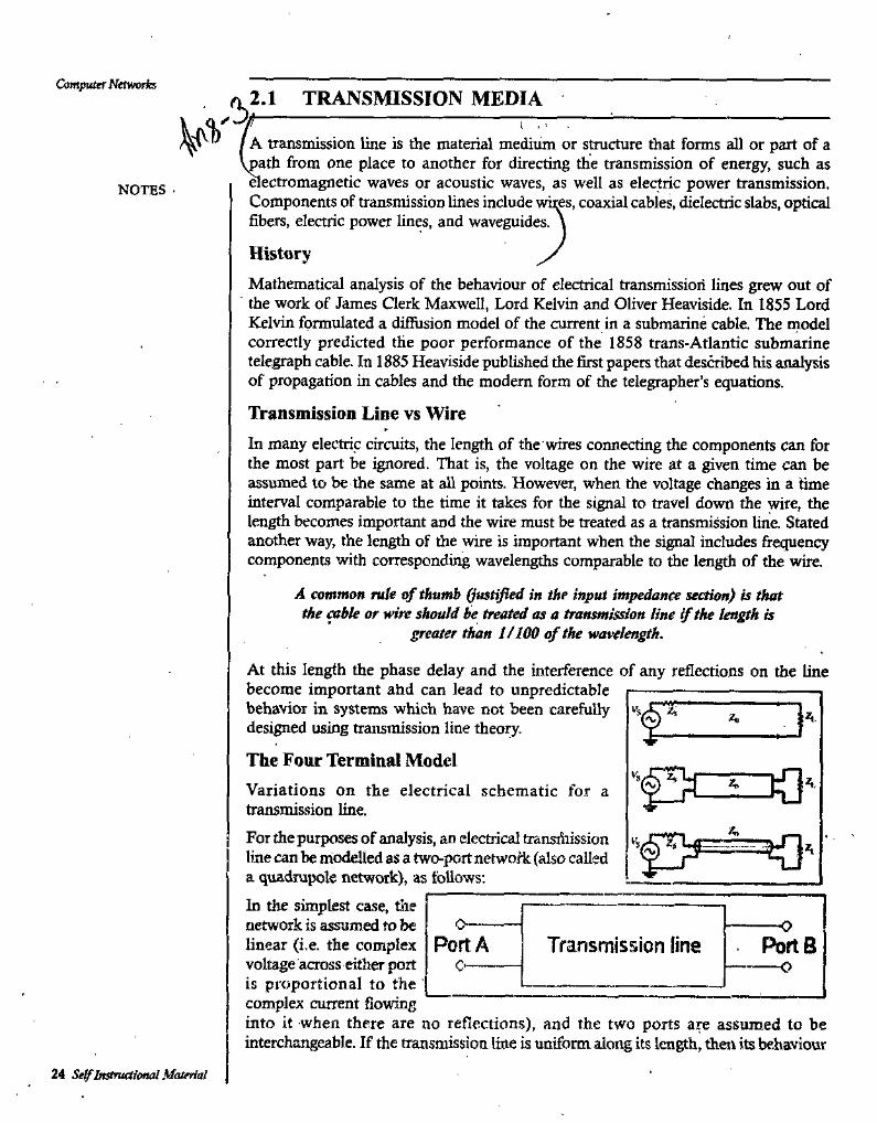
The Four Terminal ModelVariations on the electrical schematic for a transmission line.For the purposes of analysis, an electrical iransiiiission line can be modelled as a two-port network (also called a quadrupole network), as follows:In the simplest case, the network is assumed to be linear (i.e. the complex voltage across eitlier port is proportional to the complex current flowing into it when there are no reflections), and the two ports are assumed to be interchangeable. If the transmission line is uniform along its length, then its behaviour
NOTES .
A.A
A
oPort A Transmission (ine Ports
C' o
24 Se^lnstrutsioftal Material
is largely described by a single parameter called the characteristic impedance, symbol ZO. This is the ratio of the complex voltage of a given wave to the complex current of the same wave at any point on the line. Typical values of ZO are 50 or 75 ohms for a coaxial cable, about 100 ohms for a twisted pair of wires, and about 300 ohms for a common type of untwisted pair used in radio transmission.When sending power dovm a transmission line, it is usually desirable that as much power as possible will be absorbed by the load and as little as possible will be reflected back to the source. This can be ensured by making the source and load impedances equal to ZO, in which case the transmission line is said to be matched.Some of the power that is fed into a transmission line is lost because of its resistance. This effect is called ohmic or resistive loss. At high frequencies, another effect called dielectric loss becomes significant, adding to the losses caused by resistance. Dielectric loss is caused when the insulating material inside the transmission line absorbs energy from the alternating electric field and converts it to heat
The total loss of power in a transmission line is often -specified in decibels per metre, and usually depends on the frequency of the signal.
The Physical Layer
NOTES
The manufacturer often supplies a chart showing the loss in dB/m at a range of frequencies. A loss of 3 dB corresponds approxiihately to a halving of the power.High-fiequency transmission lines can be defined as transmission lines that are designed to carry electromagnetic waves whose wavelengths are shorter than or comparable to the length of the line. Under these conditions, the approximations useful for calculations at lower frequencies are no longer accurate. This often ocafrs with radio, microwave and optical signals, and with the signals found in high-speed digital circuits.
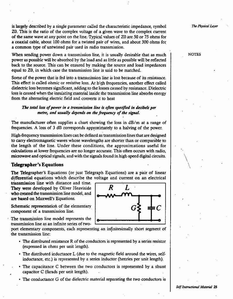
Telegrapher’s EquationsThe Telegrapher’s Equations (or just Telegraph Equations) are a pair of linear differential equations which describe the voltage and current on an electrical transmission line with distance and time.They were developed by Oliver Heaviside who created the transmission line model, and are based on Maxwell’s Equations.Schematic representation of the elementary component of a transmission line.
■ The transmission line model represents the ^ transmission line as an infinite series of two- 1— port elementary components, each representing an in^tesimally short segment of the transmission line:
• The distributed resistance R of the conductors is represented by a series resistor (expressed in ohms per unit length).
• The distributed inductance L (due to the magnetic field around the wires, selfinductance, etc.) is represented by a series inductor (henries per unit length).
• The capacitance C between the two conductors is represented by a shunt capacitor C (farads per unit length).
• The conductance G of the dielectric material separating the two conductors is
\\
R Le
G 4=C
Self Instructional Material 25

Computer Networks represented by a conductance G shunted between the signal wire and the return wire (siemens per unit length).
2.2 TWISTED PAIRNOTES r Cable is the medium through which information usually moves from one network
device to another. There are several types of cable which are commonly used with sXANs. In some cases, a network will utilize only one type of cable, other networks
will use a variety of cable types. The type of cable chosen for a network is related to the network’s topology, protocol, and size. Understanding the characteristics of different types of cable and how they relate to other aspects of a network is necessary for the development of a successful network.The following sections discuss the types of cables used in networks and other related
'topics. "•• Unshielded Twisted Pair (UTP) Cable• Shielded Twisted Pair (STP) Cable• Coaxial Cable• Fiber Optic Cable• Wireless LANs• Cable Installation Guides
Unshielded Twisted Pair (UTP) CableTwisted pair cabling comes in two varieties; shielded and unshielded. Unshielded twisted pair (UTP) is the most popular and is generally the best option for school networks (See fig. 1).
\
V.
Fig.l. Unshielded twisted pairThe quality of UTP may vary from telephone-grade wire to extremely high-speed cable. The cable has four pairs of wires inside the jacket. Each pair is twisted with a different number of twists per inch to help eliminate interference from adjacent pairs and other electrical devices.The tighter the twisting, the higher the supported transmission rate and the greater the cost per foot. The EIA/TIA (Electronic Industry Association/Telecommunication Industry Association) has established standards of UTP and rated five categories of wire.
26 Self Instructional Material
The Physical LayerCategories of Unshielded Twisted Pair
UseType
Voice Only (Telephone Wire)Data to 4 Mbps (LocalTalk)Data to 10 Mbps (Ethernet)Data to 20 Mbps (16 Mbps Token Ring) Data to 100 Nftps (Fast Ethernet)
Category 1 Category 2
Category 3 , Category 4
Category 5
NOTES
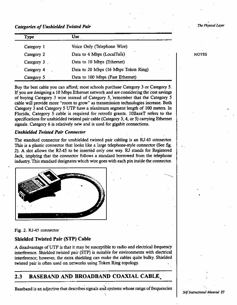
Buy the best cable you can afford; most schools purchase Category 3 or Category 5. If you are designing a 10 Mbps Ethernet network and are considering die cost savings of buying Category 3 wire instead of Category 5, remember that the Category 5 cable will provide more “room to grow” as tr2insmission technologies increase. Both Category 3 and Category 5 UTP have a maximum segment length of 100 meters. In Florida, Category 5 cable is required for retrofit grants. lOBaseT refers to the specifications for unshielded twisted pair cable (Category 3,4, or 5) carrying Ediemet signals. Category 6 is relatively new and is used for gigabit connections.Unshielded Twisted Pair ConnectorThe standard connector for unshielded twisted pair cabling is an RJ-45 connector. This is a plastic connector that looks like a large telephone-style connector (See fig. 2). A slot allows the RJ-45 to be inserted only one way. RJ stands for Registered Jack, implying that the connector follows a standard borrowed from the telephone industry. This standard designates which wire goes with each pin inside the connector.
Fig. 2. RJ-45 connector
Shielded Twisted Pair (STP) CableA disadvantage of UTP is that it may be susceptible to radio and electrical frequency interference. Shielded twisted pair (STP) is suitable for environments with electrical interference; however, the extra shielding can make the cables quite bulky. Shielded twisted pair is often used on networks using Token Ring topology.
2.3 BASEBAND AND BROADBAND COAXIAL CABLE^
Baseband is an adjective that describes signals and systems whose range of frequenciesSelf Instructional Material 27\
Computer NttwoHa is measvffed from 0 to a maximum bandwidth or highest signal frequency; it is sometimes used as a noun for a band of frequencies starting at 0. It can often be considered as synonym to lowpass, and antonym to passband.Various uses
• A baseband bandwidth is equal to a highest frequency of a signal or system, or an upper bound on such frequencies. By contrast, a non-baseband (passband) bandwidth is the difference between a highest frequency and a nonzero lowest frequency.
• A baseband signal or lowpass signal is a signal that can include frequencies that are equal to or very near zero, by comparison with its highest frequency (for .example, a sound waveform can be considered as a baseband signal, whereas a radio signal is not).
• A baseband channel or lowpass channel (or system, or network) is a chaimel (e.g. a telecommunications system) that can transfer frequencies that are equal to or very near zero. Examples are serial cables and local area networks (LANs).
• Baseband modulation, also known as line coding, aims at transferring a digital bit stream over an analog baseband channel, as an alternative to carrier- modulated approaches.
• An equivalent baseband signal or equivalent lowpass signal is - in analog and digital modulation methods with constant carrier frequency (for example ASK, PSK and QAM but not FSK) - a complex valued representation of the modulated physical signal (the so called passband signal or RF signal). The equivalent baseband signal is where I(t) is the inphase signal, Q(t) the quadrature phase signal, and j the imaginary unit. In a digital modulation inethod, the I(t) and Q(t) signals of each modulation symbol are evident from 4e constellation * diagram. The physical passband signal corresponds to where to is the carrier angular frequency in rad/s.
• A signal “at baseband” is usually considered to include frequencies from near 0 Hz up to the highest frequency in the rignal with significant power.
In general, signals can be described as including a whole range of different frequencies added together. In telecommunications in particular, it is often the case that those - parts of the signal which are at low frequencies are ‘copied’ up to higher frequencies for transmission pxirposes, since there are few communications media that will pass low frequencies without distortion. Then, the original, low frequency components, are referred to as the baseband signal. Typically, the new, high-frequency copy is referred to as the ‘RF’ (radio-frequency) signal.The concept of baseband signals is most often applied to real-valued signals, and systems that handle real-value signals. Fourier analysis of such signals includes a negative-frequency band, but the negative-frequency information is just a mirror of the positive-frequency information, not new information.For complex-valued signals, on the other hand, the negative frequencies carry new information. In that case, the full two-sided bandwidth is generally quoted, rather than just the half measm^d from zero; the concept of basebtmd can be applied by treating the real and imaginary parts of the complex-valued signal as two different real signals.
NOTES
28 Self InstruaioriaJ Materid
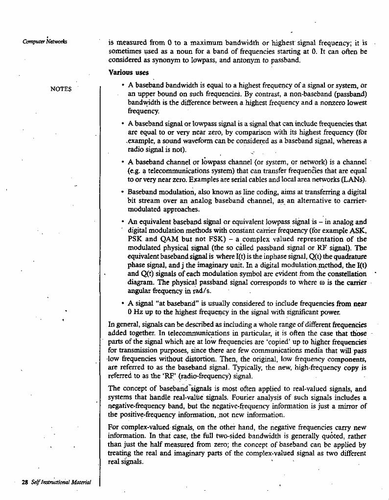
The Physical Layer/ Co^iaal Cable. I Coaxial cabling has a sibgle copper conductor at its center. A plastic layer provides
insulation between the center conductor and a braided metal shield (See fig. 3). The metal shield helps to block any outside interference from fluorescent lights, motors, and other computers.
NOTES
r
Fig. 3. Coaxial cableAlthough coaxial cabling is difficult to install, it is highly resistant to signal interference. In addition, if can support greater cable lengths between network devices than twisted pair cable. The two types of coaxial cabling are thick coaxial and ffiin coaxial.Thin coaxial cable is also referred to as thinnet. 10Base2 refers to file specifications for thin coaxial cable carrying Ethernet signals. The 2 refers to the approximate maximum segment length being 200 meters. In actual fact the maximum segment length is 185 meters. Jhin coaxial cable is popular in school networks, especially linear bus networks.Thick coaxial cable i^so referred to as thicknet. 10Base5 refers to the specifications for thick coaxial cable carrying Ethernet signals. The 5 refers to the maximum segment length being 500 meters. Thick coaxial cable has an extra protective plastic cover that helps keep moisture away fi’om the center conductor. This makes thick coaxial a great choice when running longer lengths in a linear bus network. One disadvantage of thick coaxial is that it does not bend easily and.is difficult to install.Coaxial Cable Connectors .The most common type of connector used with coaxial cables is the Bayone-Neill- Concelman (BNC) connector (See fig. 4). Different types of adapters are available for BNC connectors, including a T-connector, barrel connector, and terminator. Connectors on the cable are the weakest points in any network. To help avoid problems with your network, always use the BNC connectors that crimp, rafiier than screw, onto the cable.
Fig. 4. BNC connector
2.4/ FIBER OPTICS
Fiberoptic cabling consists of a center glass core surrounded by several layers of protective materials (See fig. 5). It transmits light rather than electronic signals eliminating the problem of electrical interference. This makes it ideal for certain environments that contain a large amount of electrical interference. It has also made
Self Instructional Material 29
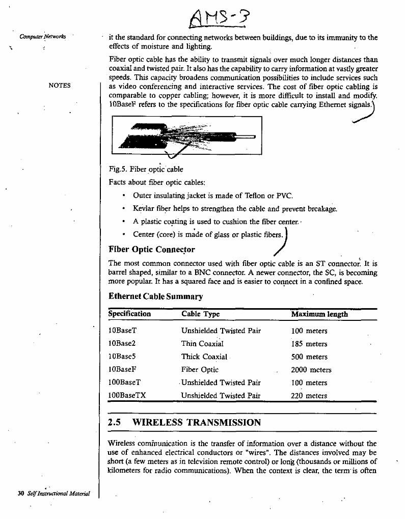
'?Computer Networks • it the standard for connecting networks between buildings, due to its immunity to the
effects of moisture and lighting.Fiber optic cable has the ability to transmit signals over much longer distances than coaxial and twisted pair. It also has the capability to carry information at vastly greater speeds. This capacity broadens communication possibilities to include services such as video conferencing and interactive services. The cost of fiber optic cabling is comparable to copper cabling; however, it is more difficult to install and modify. lOBaseF refers to the specifications for fiber optic cable carrying Ethernet signals.\
NOTES
Fig.5. Fiber optic cable
Facts about fiber optic cables:• Outer insulating jacket is made of Teflon or PVC.• Kevlar fiber helps to strengthen the cable and prevent breakage.• A plastic coating is used to cushion the fiber center. •• Center (core) is made of glass or plastic fibers, j
Fiber Optic Connector /The most common connector used with fiber optic cable is an ST connector. It is barrel shaped, similar to a BNC connector. A newer connector, the SC, is becoming more popular. It has a squared face and is easier to connect in a confined space.
Ethernet Cable Summary
Specification Cable Type Maximum length
lOBaseT Unshielded Twisted Pair 100 meters
185 meters
500 meters
2000 meters
100 meters
220 meters
10Base2 Thin CoaxiallOBaseS Thick Coaxial
Fiber Optic• Unshielded Twisted Pair Unshielded Twisted Pair
lOBaseF100BaseT100BaseTX
2.5 WIRELESS TRANSMISSION
Wireless communication is the transfer of information over a distance without the use of enhanced electrical conductors or "wires". The distances involved may be short (a few meters as in television remote control) or lon'g (thousands or millions of kilometers for radio communications). When the context is clear, the term'is often
30 Self Instructional Material
shortened to "wifeless". Wireless communication is generally considered to be a branch of telecommunications.It encompasses various types of fixed, mobile, and portable two-way radios cellular telephones, personal digital assistants (PDAs), and wireless networking. Other ' examples of wireless technology include GPS units, garage door openers and or garage doors, wireless computer ihice, keyboards and headsets, satellite television and cordless telephones.
Applications of Wireless Technology
Security systemsWireless technology may supplerhent or replace hard wired implementations in security systems for homes or office buildings.Television remote controlModem televisions use wireless (generally infiared) remote control units. Now radio waves are also used.Cellular telephone (phones and modems)Perhaps the best known example of wireless technology is the cellular telephone and . modems. Ibese instruments use radio waves to enable the operator to make phone calls from many locations worldwide. They can. be used anywhere that there is a cellular telephone site to house the equipment that is required to transmit and receive the signal that is used to transfer both voice and data to and from these instruments.m-FiWi-Fi is a wireless local area network that enables portable computing devices to connect easily to the Internet. Standardized as IEEE 802.11 a, b, g, n, Wi-Fi approaches speeds of some types of wired Ethernet. Wi-Fi hot spots have been popular over the past few years. Some businesses charge customers a monthly fee for service,
. while others have begun offering it for free in an effort to inaease the sales of their goods.fhre/ess energy transferWireless energy transfer is a process whereby electrical ener^ is transmitted from a power source to an electrical load that does not' have a built-in power source, without the use of interconnecting wires.Computer Interface DevicesAnswering the call of customers frustrated with cord clutter, many manufactures of computer peripherals turned to wireless technology to satisfy their consumer base. Originally these units used bulky, highly limited transceivers to mediate between a computer and a keyboard and mouse, however more recent generations have used small, high quality devices, some even incorporating Bluetooth. These systems have become so ubiquitous that some users have begun complaining about a lack of wired peripherals. Wireless devices tend to have a slightly slower response time than their wired counterparts, however the gap is deaeasing. Initial concerns about the security of wireless keyboards have also been ad^essed with the maturation of the technology.Many scientists have complained that wireless technology interferes with their
The FkyUeal L-iyer
NOTES
Self Instructional Material 31
Computer Networks experiments, forcing them to use less optimal peripherals because the optimum one is not available in a wired version. This has become especially prevalent among scientists who use trackballs as the number of models in production steadily decreases.
2.6 RADIO TRANSMISSIONNOTES
In telecommunications, transmission is the process of sending, propagating and receiving an analogue or digital information signal over a physical point-to-point or point-to-multipoint transmission medium, either wired, optical fiber or wireless.- Transmission technologies and schemes typically refer to physical layer protocol duties such as modulation, demodulation, line coding, equalization, error control, bit synchronization and multiplexing, but the term may also involve higher-layer protocol duties, for example, digitizing an analog message signal, and source coding (compression).Transmission of a digital message, or of a digitized analog signal, is known as data transmission or digital communication. One transmbsion is the sending of a signal with limited duration, for example a block or packet of data, or a phone call.Radio waves are easy to penerate, can travel long distances, and penetrate buildings easily, so they are widely used for communication, both indoor and outdoors. Radio waves also are omnidirectional, meaning that they travel in all directions from the source, so that the transmitter and receiver do not have to carefully aligned physically.The properties of radio waves are frequency dependent. A low frequencies, radio waves pass through obstacles well, but the power falls off sharply with distance from the source, roughly as l/r*. in air. At high frequencies, radio waves tent to travel in straight lines and bounce off obstacles. They are also absorbed by rain. At all frequencies, radio waves are subject to interference from motors and other electrical equipment.
2.7 MICROWAVE TRANSMISSION
Microwave transmission refers to the technology of transmitting information by the use of the radio waves whose wavelengths are conveniently measured in small numbers of centimeters, by using various electronic technologies. These are called microwaves. This part of the radio spectrum ranges across frequencies of roughly 1.0 gigahertz (GHz) to 30 GHz. Also by using the formula A- = c/f, these correspond to wavelengths from 30 centimeters down to 1.0 cm. [In the above equation, the Greek letter X (lambda ) is tlie wavelength in meters; c is the speed of light in meters per second; .and f is the frequency in hertz (Hz).]In the miaowave frequency band, antennas are usually of convenient sizes and shapes, and also the use of metal waveguides for carrying the radio power works well. Furthermore, with the use of the modern solid-state electronics and traveling wave tube technologies that have been developed since the early 1960s, the electronics used by microwave radio transmission have been readily used by expert electronics engineers.Microwave radio transmission is commonly used by communication systems on the surface of the Earth, in satellite communications, and in deep space radio
32 Se^Instructional Material
communications. Other parts of the microwave radio band are used for radars, radio navigation systems, sensor systems, and radio astronomy.The next higher part of the radio electromagnetic spectrum, where the frequencies are above 30 Gfiz and below. 100 GHz, are called "millimeter waves" because their wavelengths are conveniently measured in millimeters, and their wavelengths range fitjm 10 mm down to 3.0 mm. Radio waves in this band are Usually strongly attenuated by the Earthly.atmosphere and particles contained in it, especially during wet weather. Also, in wide band of frequencies around 60 GHz, the radio waves are strongly attenuated by molecular oxygen in the atmosphere. The electronic technologies needed in the millimeter wave band are also much more difficult to utilize than those of the microwave band.
UsesBackbone or backhaul carriers in cellular networks. Used to link BTS-BSC and BSC- MSC.Communication with satellites
Microwave radio relay links for television and telephone service providersA parabolic antenna for Erdfunkstelle Raisting; the biggest facility for satellite communication in the world, based in Raisting, Bavaria, Germany.Parabolic (microwave) antenna
A parabolic antenna is a high-gain reflector antenna used for radio, television and data communications, and also for radiolocation (radar), on the UHF and SHF parts of the electromagnetic spectrum. The relatively short wavelength of electromagnetic radiation at these frequencies allows reasonably sized reflectors to exhibit the desired highly directional response for both receiving and transmitting.
Microwave linkA microwave link is a communications system that uses a beam of radio waves in the miaowave frequency range to transmit video, audio, or data between two locations, which can be from just a few feet or meters to several miles or kilometers apart. Microwave links are commonly used by television broadcasters to transmit programmes aaoss a country, for instance, or from an outside broadcast back to a studio.Mobile units can be camera mounted, allowing cameras the freedom to move around without trailing cables. These are often seen on the touchlines of sports fields on Steadicam systems.Properties of microwave links
• Involve line of sight (LOS) communication technology• Affected greatly by environmental constraints, including rain fade
. • Have limited penetration capabilities• Sensitive to high pollen count• Signals can be degraded during Solar proton event
The Physical Layer
NOTES
Self Instructional Material 33
Computer Network Uses of microwave links• In communications between satellites and base stations• As backbone carriers for cellular systems
• • In short range indoor communicationsTunable microwave deviceA tunable miaowave device is a device that works at radio frequency range with the dynamic tunable capabilities, especially an electric field. The material systems for such a device usually have multilayer structure. Usually, magnetic or ferroelectric film on ferrite or superconducting film is adopted. The former two are used as the property tunable component to control the working frequency of the whole system. Devices of this type include tunable varators, tunable microwave filters, tunable phase shifters, and tunable resonators. The main application of them is re-configurable microwave networks, for example, reconfigurable wireless communication, wireless network, and reconfigurable phase array antenna.
NOTES
2.8 INFRARED TRANSMISSION
It is widely used for short-range communication. The remote controls used on televisions, VCRs, and stereos all use infrared communication. They are relatively directional, cheap, and easy to build, but have a major drawback; they do not pass through solid objects (try standing between your remote control and your television and see if it still works). In general, as we go from long-wave radio toward visible light, the waves behave more and more like light and less and less like radio.
2.9 LIGHT WAVE TRANSMISSION
Its most common use is to connect the LANs in two buildings via lasers mounted on their rooftops. Coherent optical signaing using lasers is inherently unidirectional, so each building needs its own laser and its own photdetector. This scheme offers very high bandwidth and very low cost. It is also relatively easy to install, and, unlike microwave, does not require an FCC license. A disadvantage is that laser beams cannot penetrate rain or thick fog, but they normally work well on surmy days.
2.10 ISDN SERVICES
Integrated Services Digital Network (ISDN) is a set of communications standards for simultaneous digital transmission of voice, video, data, and other network services over the traditional circuits of the public switched telephone network. It was first defined in 1988 in the CCITT red book.Prior to ISDN, the phone system was viewed as a way to fransport voice, with some special services available for data. The key feature of ISDN is that it integrates speech and data on the same lines, adding features that were not available in the classic telephone system. There are several kinds of access interfaces to ISDN defined as Basic Rate Interface (BRI), Primary Rate Interface (PRI) and Broadband ISDN (B- ISDN).
'34 Self Instrvctionei! Material
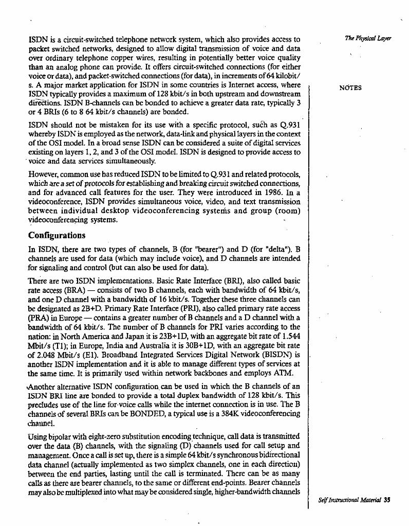
The Physual L<^ISDN is a circuit-switched telephone network system, which also provides access to packet switched networks, designed to allow digital transmission of voice and data over ordinary telephone copper wires, resulting in potentially better voice quality than an analog phone can provide. It offers circuit-switched connections (for either voice or data), and packet-switched connections (for data), in increments of 64 kilobit/ s. A major market application for ISDN in some countries is Internet access, where ISDN typically provides a maximum of 128 kbit/s in both upstream and downstream directions. ISDN B-channels can be bonded to achieve a greater data rate, typically 3 or 4 BRIs (6 to 8 64 kbit/s channels) are bonded.ISDN should not be mistaken for its use with a specific protocol, such as Q.931 whereby ISDN is employed as the network, data-link and physical layers in the context of the OSI model. In a broad sense ISDN can be considered a suite of digital services existing on layers 1,2, and 3 of the OSI model. ISDN is designed to provide access to voice and data services simultaneously.However, common use has reduced ISDN to be limited to Q.931 and related protocols, which are a set of protocols for establishing and breaking drcuit switched connections, and for advanced call features for the user. They were introduced in 1986. In a videoconference, ISDN provides simultaneous voice, video, and text transmission between individual desktop videoconferencing systems and group (room) videoconferencing systems.
ConfigurationsIn ISDN, there are two types of channels, B (for 'Tjearer") and D (for "delta"). B channels are used for data (which may include voice), and D channels are intended for signaling and control (but can also be used for data).There are two ISDN implementations. Basic Rate Interface (BRI), also called basic rate access (BRA) — consists of two B channels, each with bandwidth of 64 kbit/s, and one D channel with a bandwidth of 16 kbit/s. Together these three channels can be designated as 2B+D. Primary Rate Interface (PRI), also called primary rate access (PRA) in Europe — contains a greater number of B channels and a D channel with a bandwidth of M kbit/s. The number of B channels for PRI varies according to the nation: in North America and Japan it is 23B+ ID, with an aggregate bit rate of 1.544 Mbit/s (Tl); in Europe, India and Ausaalia it is 30B+ID, with an aggregate bit rate of 2.048 Mbit/s (El). Broadband Integrated Services Digital Network (BISDN) is another ISDN implementation and it is able to manage different types of services at the same time. It is primarily used within network backbones and employs ATM.•Another alternative ISDN configuration, can be used in which the B channels of an ISDN BRI line are bonded to provide a total duplex bandwidth of 128 kbit/s. This precludes use of the line for voice calls while the internet connection is in use. The B channels of several BRIs can be BONDED, a typical use is a 384K videoconferencing chaimel.Using bipolar with eight-zero substitution encoding technique, call data is transmitted over the data (B) channels, with the signaling (D) channels used for call setup and management. Once a call Is set up, there is a simple 64 kbit/s synchronous bidirectional data channel (actually implemented as two simplex channels, one in each direction) between the end parties, lasting until the call is terminated. There can be as many calls as tliere are l^arer chamiels, to the same or different end-points. Bearer channels may also be multiplexed into what may be considered single, higher-bandwidth chaimels
NdTES
Self Instrjctional Material 35
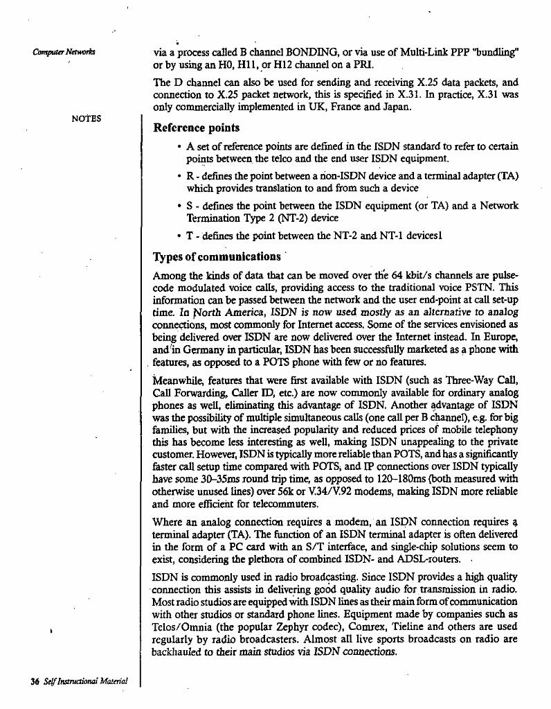
via a process called B channel BONDING, or via use of Multi-Link PPP "bundling" or by using an HO, Hll, or H12 channel on a PRI.The D channel can also be used for sending and receiving X.25 data packets, and connection to X.25 packet network, this is specified in X.31. In practice, X.31 was only commercially implemented in UK, France and Japan.
Reference points• A set of reference points are defined in the ISDN standard to refer to certain
points between the telco and the end user ISDN equipment.• R - defines the point between a non-ISDN device and a terminal adapter (TA)
which provides translation to and fi'om such a device• S - defines the point between the ISDN equipment (or TA) and a Network
Termination T^e 2 (NT-2) device• T - defines the point between the NT-2 and NT-1 devicesl
Types of communicationsAmong the kinds of data that can be moved over the 64 kbit/s channels are pulse- code modulated voice calls, providing access to the traditional voice PSTN. This information can be passed between the network and the user end-point at call set-up time. In f^orth America, ISDN is now used mostly as an alternative to analog connections, most commonly for Internet access. Some of the services envisioned as being delivered over ISDN are now delivered over the Internet instead. In Europe, and^in Germany in particular, ISDN has been successfully marketed as a phone with features, as opposed to a POTS phone with few or no features.Meanwhile, features that were first available with ISDN (such as Three-Way Call, Gall Forwarding, Caller ID, etc.) are now commonly available for ordinary analog phones as well, eliminating this advantage of ISDN. Another advantage of ISDN was the possibility of multiple simultaneous calls (one call per B c^nnel), e.g. for big families, but with the increased popularity and reduced prices of mobile telephony this has become less interesting as well, making ISDN unappealing to the private customer. However, ISDN is typically more reliable than POTS, and has a significantly faster call setup time compared with POTS, and IP connections over ISDN typically have some 30-35ms round trip time, as opposed to 120-180ms (both measured with otherwise unused lines) over 56k or V.34/V.92 modems, making ISDN more reliable and more efficient for telecommuters.Where an analog connection requires a modem, an ISDN connection requires ^ terminal adapter (TA). The function of an ISDN terminal adapter is often delivered in the form of a PC card with an S/T interface, and single-chip solutions seem to exist, considering the plethora of combined ISDN- and ADSL-routers.ISDN is commonly used in radio broadcasting. Since ISDN provides a high quality connection this assists in delivering good quality audio for transmission in radio. Most radio studios are equipped with ISDN lines as their main form of communication with other studios or standmd phone lines. Equipment made by companies such as Telos/Omnia (the popular Zephyr codec), Comrex, Tieline and others are used regularly by radio broadcasters. Almost all live sports broadcasts on radio are backliauled to their main studios via ISDN connections.
Computer Naworh
NOtES
36 Self Instructional Material

The l^ysical Laytr2.11 VIRTUAL CIRCUITS VERSES CIRCUIT SWITCHING
In telecommunications and computer networks, a virtual circuit (VC), synonymous with virtual connection and virtual channel, is a connection oriented communication service that is delivered by means of packet mode communication. After a connection or virtual circuit is established between two nodes or application processes, a bit stream or byte stream may be delivered between the nodes; a virtual circuit protocol allows higher level protocols to avoid dealing with the division of data into segments, packets, or frames.Virtual circuit communication resembles circuit switching, since both are connection orirated, meaning that in both cases data is delivered in correct order, and signalling overhead is required during a connection establishment phase. However, circuit switching provides constant bit rate and latency, while these may vary in a virtual circuit service because of reasons such as:
• varying packet queue lengths in the network nodes,• varying bit rate generated by the application,• varying load from other users sharing the same network resources by means
of statistical multiplexing, etc.Many virtual circuit protocols, but not all, provide reliable communication service, by means of data retransmissions because of error detection and automatic repeat request (AR(2).Examples of protocols that provide virtual circuits
• Transmission Control Protocol (TCP), where a reliable virtual circuit is established on top of the underlying unreliable and connectionless IP protocol. The virtual circuit is identified by the source and destination network socket address pair, i.e. the sender and receiver IP address and port number. Guaranteed QoS is not provided.
• SCTP, where a virtual circuit is established on top of either the IP protocol or the UDP protocol.
Examples of networic layer and datalink layer virtual circuit protocols, where data always is delivered over the same path:
• X.25; where the VC is identified by a virtual channel identifier (VCI). X.25 provides reliable node-to-node communication and guaranteed QoS.
• Frame relay, where the VC is identified by a VCI. Frame relay is unreliable, but may provide guaranteed QoS.
• Asynchronous Transfer Mode (ATM), where the circuit is identified by a virtual path identifiei (\TI) and vutual channel identifier (VCI) pair. ATM is unreliable, but may provide gjiaranteed QoS.
Genera) Packet Radio Service (GPRS)Multiprotocol label switcliing (MPLS), which can be used for IP over virtual circuits. Each circuit is identified by a label. MPLS is unreliable, but provides eight different QoS classes.
NOTES
Se^Instnietioiuil Material $7
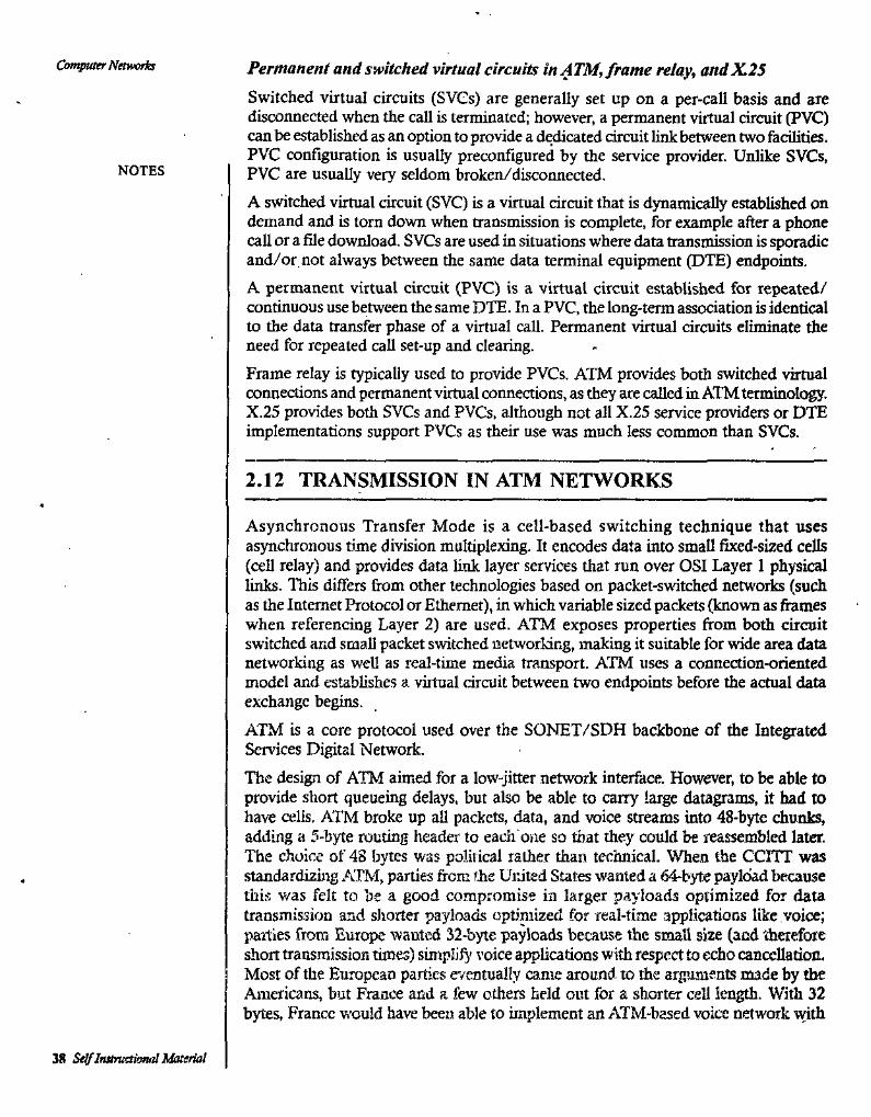
Con^uter Nmvorh Permanent and switched virtual circuits in ATM, frame relay, andX.25Switched virtual circuits (SVCs) are generally set up on a per-call basis and are disconnected when the call is terminated; however, a permanent virtual circuit (PVC) can be established as an option to provide a dedicated circuit link between two facilities. PVC configuration is usually preconfigured by the service provider. Unlike SVCs, PVC are usually very seldom broken/disconneaed.A switched virtual circuit (SVC) is a virtual circuit that is dynamically established on demand and is torn down when transmission is complete, for example after a phone call or a file download. SVCs are used in situations where data transmission is sporadic and/or not always between the same data terminal equipment (DTE) endpoints.A permanent virtual circuit (PVC) is a virtual circuit established for repeated/ continuous use between the same DTE. In a PVC, the long-term association is identical to the data transfer phase of a virtual call. Permanent virtual circuits eliminate the need for repeated call set-up and clearing.Frame relay is typically used to provide PVCs. ATM provides both switched virtual connections and permanent virtual coimections, as they are called in ATM terminolc^. X.25 provides both SVCs and PVCs. although not all X.25 service providers or DTE implementations support PVCs as their use was much less common than SVCs.
NOTES
2.12 TRANSMISSION IN ATM NETWORKS
Asynchronous Transfer Mode is a cell-based switching technique that uses asynchronous time division multiplexing. It encodes data into small fixed-sized cells (cell relay) and provides data link layer services that run over OSI Layer 1 physical links. This differs from other technologies based on packet-suatched networks (such as the Internet Protocol or Ethernet), in which variable sized packets (known as flumes when referencing Layer 2) are used. ATM exposes properties from both circuit switched and small packet switched networking, making it suitable for wide area data networking as weU as real-time media transport. ATM uses a connection-oriented model and establishes a virtual circuit between two endpoints before the actual data exchange begins.ATM is a core protocol used over the SONET/SDH backbone of the Integrated Services Digital Network.The design of ATM aimed for a low-jitter network interface. However, to be able to provide short queueing delays, but also be able to cany large datagrams, it had to have cells. ATM broke up all packets, data, and voice streams into 48-byte chunks, adding a 5-byte routing header' to each one so that they could be reassembled later. The choice of 48 bytes was political rather than technical. When the CCITT was standardizing ATM, parties from the United States wanted a 64-byte payload because this was felt to be a good compromise in larger payloads optimized for data transmission and shorter payloads optiniized for real-time applications like voice; parties from Europe wanted 32-byte payloads because the srtmll size (and therefore short transmission times) simplify voice applications with respect to echo cancellation. Most of the European parties e'/entually came around to the arguments made by tiie Americans, but France and a few others held out for a shorter cell length. With 32 bytes, France would have been able to implement an ATM-based voice network with
38 SelflnstmaiomilMaurial
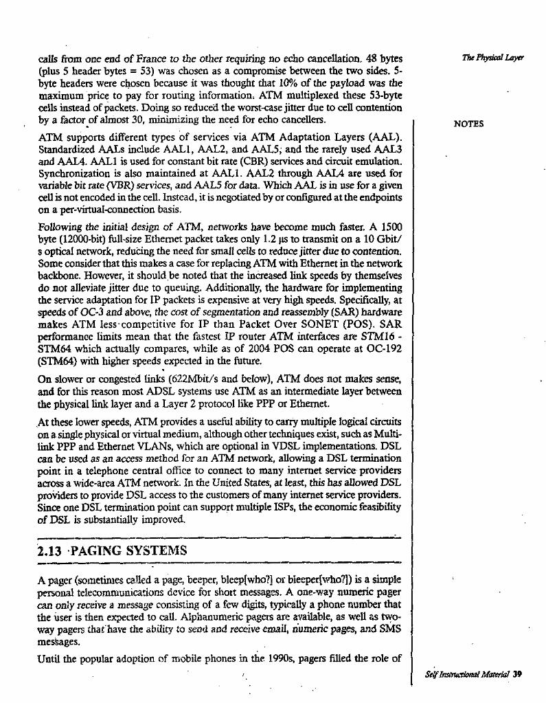
calls ftom one end of France to the other requiring no echo cancellation. 48 bytes (plus 5 header bytes = 53) was chosen as a compromise between the two sides. 5- byte headers were chosen because it was thought that 10% of the payload was the maximum price to pay for routing information^ ATM multiplexed these 53-byte cells instead of packets. Doing so reduced the worst-case jitter due to cell contention by a factor of almost 30, minimizing the need for echo cancellers.ATM supports different types of services via ATM Adaptation Layers (AAL). Standardized AALs include AALl, AAL2, and AAL5; anci the rarely used AAL3 and AAL4. AALl is used for constant bit rate (CBR) services and circuit emulation. Synchronization is also maintained at AALl. AAL2 through AAL4 are used for variable bit rate (VBR) services, and AAL5 for data. Which AAL is in use for a given cell is not encoded in the cell. Instead, it is negotiated by or configured at the endpoints on a per-virtual<onnection basis.Following the initial design of ATM, networks have become much faster. A 1500 byte (12000-bit) full-size Ethernet packet takes only 1.2 gs to transmit on a 10 Gbit/ s optical network, reducing the need for small cells to reduce jitter due to contention. Some consider that this makes a case for replacing ATM with Ethernet in the network backbone. However, it should be noted that the increased link speeds by themselves do not alleviate jitter due to queuing. Additionally, the hardware for implementing the service adaptation for IP packets is expensive at very high speeds. Specifically, at speeds of OC-3 and above, the cost of segmentation and reassembly (SAR) hardware makes ATM less competitive for IP than Packet Over SONET (POS). SAR performance limits mean that the fastest IP router ATM interfeces are STM16 - STM64 which actually compares, while as of 2004 POS can operate at OC-192 (STM64) with h^er speeds expected in the future.On slower or congested links (622Ivfi>it/s and below), ATM does not makes sense, and for this reason most ADSL systems use ATM as an intermediate layer between the physical link layer and a Layer 2 protocol like PPP or Ethernet.At these lower speeds, ATM provides a useful ability to carry multiple logical circuits on a single physical or virtual medium, although other techniques exist, such as Multilink PPP and Ethernet VLANs, whicli are optional in VDSL implementations. DSL can be used as an access method for an ATM network, allowing a DSL termination point in a telephone central office to connea to many internet service providers across a wide-area ATM network. In the United States, at least, tiiis has allowed DSL providers to provide DSL access to the customers of many internet service providers. Since one DSL termination point can support multiple ISPs, the economic feasibfiity of DSL is substantially improved.
The ^^skal Layer
NOTES
2.13 PAGING SYSTEMS
A pager (sometimes called a page, beeper, bleep[who?] or bleepcrjwho?]) is a simple personal telecommunications device for short messages. A one-way numeric pager can only receive a message consisting of a few digits, ^ically a phone number that the user is then expected to call. Alphanumeric pagers are available, as well as two- way pagers that have the ability to send and receive email, numeric pages, and SMS messages.Until the popular adoption of mobile phones in the 1990s, pagers filled the role of
Se^ Instructional Maeriai 39
Qm^naer Networks common personal and mobile communications. Today, pagers mainly support the "critical messaging" markets. They are the ideal solution for very quick, very reliable personal or group messaging.Unlike many other mobile communications networks, they continue to work in times- of emergency or disaster as they do not suffer fiom network overload as has been proven many times. For this reason, they are still very popular with emeigency service personnel, medical personnel, and infonnation technology support staff.Pagers are still in use today in places where mobile phones typically cannot reach users, and also in places where the operation of the radio transmitters contained in mobile phones is problematic or prohibited. One such type of location is a large hospital complex, where cellular coverage is often weak or nonexistent, where radio transmitters are suggested to interfere with sensitive medical equipment and where there is a greater need of assurance for a timely delivery of a message. The U.S. paging industry generated $2.1 billion in revenue in 2008, down from $6.2 billion in 2003.Some common environments in which pagers are still used are:
• Pagers remain in use to notify emergency personnel. For example, they are required to be used by UK lifeboat crew and retained firefi^ters.
• Police, coast, local government emergency co-ordinators and other emergency services also carry pagers as a back-up system in the event of civil emeigendes when mobile transmitters or networks may be unavailable.
• Security services use pagers (including global satellite pagers) as the signal is broadcast nationally (or across a global region in the case of satellite pagers) and there is thus no way of interceptors tracking the location of the pager- holder. Encrypted messages are also used in this scenario.
• Pagers are mostly carried by staff in medical establishments, allowing them to be summoned to emergencies. This is particularly important as one-way pagers do not interfere with medical equipment.
• Some construction and mining staff have to use one-way 'intrinsically safe' pagers as opposed to mobiles, as these do not risk triggering explosions in certain environments.
• Pagers are also widely used m the IT world, especially in cases where on-call technicians cannot rely on more modem cellular telephone systems. A good example would be in a cellular telephone company, where a service interruption in the cellular network would also mean that it would not be possible to notify a technician due to the outage in the network. Therefore, in these companies, engineers are usually equipped with a pager that uses another telco's mobile network to ensure reachability in case of emergency. Pagers are also frequently used by non-teico IT departments.
^ Railway staff (for example those working fca rail companies in the UK) use pagers because of their consistency of .sij^, to supplement mobile usage.
• In certain high-security govermnent and corporate locations, a one-way pager is the only communication device allowed to be brought on-site.
• Deaf people who have no use for mobile voice services sometimes use two- way pagers.
NOTES
40 Self ImivaionaJ Material

• Pagers are widely used by rare bird-chasing "twitchers", paying for rare bird information companies to send tliem messages telling them up^to-the-minute details of the latest rarity sightings across Britain.
• Additionally, some irrigation control systems and traffic signals are now controlled by messages sent via paging networks. Due to energy concerns in the United States and other countries, two way paging networks are being used for power company, meter reading and control.
• Another pager technology in wide use today is the restaurant pager, usually from the beeper category. Mainly used in the hospitality industry, customers are given a theft-protpcted ponable receiver which usually vibrates, flashes or beeps when a table becomes free, or when their meal is ready.
Vu Physical Laytr
NOTES
2.14 CORDLESS TELEPHONES
A cordless telephone or portable telephone is a telephone with a wireless handset that communicates via radio waves with a base station connected to a fixed telephone line, usually within a limited range of its base station (which has the handset cradle). The base station is on the subscriber premises, and attaches to the telephone network the same way a corded telephone does.The base station on subscriber premises is what differentiates a cordless telephone from a mobile telephone. Current cordless telephone standards, such as PHS and DECT, have blurred the once clear-cut line between cordless and mobile telephones by implementing cell handover, various advanced features, such as data-transfer and even, on a limited scale, international roaming. In these models, base stations are maintained by a commercial mobile network operator and users subscribe to the service.Unlike a corded telephone, a cordless telephone needs mains electricity to power the base station. The cordless handset is powered by a rechargeable battery, which is charged when the handset sits in its cradle.
PerformanceManufacturers usually advertise that higher frequency systems improve audio quality and range. Higher frequencies actually have worse propagation in the ideal case, as shown by the basic Friis transmission equation, and path loss tends to increase at higher frequencies as well. More important influences on quality and range are signal strength, antenna quality, the method of modulation used, and interference, wWch varies locally."Plain old telephone service" (POTS) landlines are designed to transfer audio with a quality that is just enough for the parties to understand each other. Typical bandwidth is 3.6 kHz; only a fraction of the frequencies that humans can hetir, but enough to make the voice intelligible. No phone can improve on this quality, as it is a limitation of the phone system itself.
m
Higher-quality phones can transfer this signal to the handset with less interference over a greater range, however. Most cordless telephones, though, no matter what frequency band or transmission method is used, hardly ever exactly match the sound quality of a high-quality wired telephone attached to a good telephone line.
S^Jastruaiond^bterial 41

This constraint is caused by a number of issues, including the following:• Sidetone: hearing one's own voice echoed in the receiver speaker• A noticeable amount of constant background noise (This is not interference
from outside sources, but noi5e within the cordless telephone system.)• Frequency response not being the full frequency response available in a wired
landline telephone• Most manufacturers claim a range of about 30 m (100 ft) for their 2.4 GHz
and 5.8 GHz systems, but inexpensive models often fall short of this claim.However, the higher frequency often brings advantages. The 900 MHz and 2.4 GHz band are increasingly being used for a host of other devices, including baby monitor, microwave oven, Bluetooth, wireless LAN; thus, it is likely that'a cordless phone will suffer interference from signals broadcast by those devices. ItJs also possible for a cordless phone to interfere with the 802.11a wireless standard, as the 802.11a standard can be configured to operate in the 5.8 GHz range. However, this can easily be fixed by configuring the device to work in the 5.180 GHz to 5.320 GHz band. 'The recently allocated 1.9 GHz band is reserved for use by phones that use the DECT standard, which should avoid interference issues that are increasin^y being seen in the unlicensed 900 MHz, 2.4 GHz, and 5.8 GHz bands.Many cordless phones in the early 21st century are distal. Digital technology has helped provide clear soimd and limit eavesdropping. Many cordless phones have one main base station and can add up to 3 or 4 additional bases. This allows for multiple voice paths that allow 3-way conference calls between the bases. This technology also allows multiple handsets to be used at the same time and up to 2 handsets can have an outside conversation.
Computer Noworis
NOTES
2.15 CELLULAR TELEPHONES
Perhaps one of the most well known examples of wireless technology in action is the cellular telephone. These instruments use radio waves to enable the operator to mala phone calls from many locations world-wide. They can be used anywhere that there is a cellular telephone site to house the equipment that is required to transmit and receive the signal that is used to transfer both voice and data to and from these instruments.Wireless is a term used to describe telecommunications in which electromagnetic waves (rather than some form of wire) carry the signal over part or the entire communication path. Common examples of wireless equipment in use today include:
• Cellular phones and pagers; provide connectivity for portable and mobile applications, both personal and business.
• Global Positioning System (GPS); allows drivers of cars and trucks, captains of boats and ships, and pilots of aircraft to ascertain their location anywhere on earth.
• Cordless computer peripherals; the cordless mouse is a common example; keyboards and printers can also be linked to a computer via wireless.
42 Self Itttttvaional Material
The Physical Layer• Cordless telephone sets: these arc limited-range devices, not to be confused with cell phones.'
• Satellite television: allo^vs viewers in almost any location to select from hundreds of chaimels.
Wireless networking is used to meet a variety, of needs. Perhaps the most common use is to connect laptop users who travel from location to location. Another common use is for mobile networks that connect via satellite. A wireless transmission method is a logical choice to network a LAN segment that must frequently change locations.The following situations justify the use of wireless technology:
• To span a distance beyond the capabilities of typical cabling,• To avoid obstacles such as physical structures, EMI, or RFI,• To provide a backup communications link in case of normal network feilure,• To link portable or temporary workstations,• To overcome situations where normal cabling is difficult or financially
impractical, or• To remotely connect mobile users or networks.
>^TES
2.16 COMMUNICATION SATELLITE
A communications satellite (sometimes abbreviated to COMSAT) is an artificial satellite stationed in space for the purpose of telecommunications. Modern communications satellites use a variety of orbits including geostationary orbits, Molniya orbits, other elliptical orbits and low (polar and non-polar) Earth orbits.For fixed (point-to-point) services, communications satellites provide a microwave radio relay technology complementary to that of submarine communication cables. They are also used for mobile applications such as communications to ships, vehicles, planes and hand-held terminals, and for TV and radio broadcasting, for which application of other technologies, such as cable, is impractical or impossible.A Low Earth Orbit (LEO) typically is a circular orbit about 400 kilometres above the earth’s surface and, correspondingly, a period (time to revolve arotmd the earth) of about 90 minutes. Because of their low altitude, these satellites are only visible from within a radius of roughly 1000 kilometres from the sub-satellite point. In addition, satellites in low earth orbit change their position relative to the ground position quiddy. So even for local applications, a large number of satellites are needed if the mission
^requires uninterrupted conneaiviiy.Low earth orbiting satellites are less expensive to launch into orbit than geostationary satpilifps and, due to proximity to the ground, don't require as high signal strength (Recall that signal strength falls off as the square of the distance from the source, so the effect is dramatic). Thus there is a trade off between the number of satellites and their cost. In addition, there are important.differences in the onboard and groimd equipment needed to support the two types of missions.A group of satellites working in concert is known as a satellite constellation. Two such constellations, intended to provide satellite phone services, primarily to remote
Se^ Instructional Material 43
areas, are the Iridiura and Globalstar systems. The Iridium system has 66 satellites. Another LEO satellite constellation known as Teledesic, with hacking ftom Miaosoft entrepreneur Paul Allen, was to have over 840 satellites. This was later scaled back to 288 and ultimately ended up only launching one test satellite.It is also possible to offer discontinuous coverage using a low Earth orbit satellite capable of storing data received while passing over one part of Earth and transmitting it later while passing over another part. This will be &e case with the G\SCADE system of Canada’s CASSIOPE communications satellite. Another system using this store and forward method is Orbcomm.
Applications
Telephony
The first and historically most important application for communication satellites ■ was in intercontinental long distance telephony. The fixed Public Switched Telephone Network relays telephone calls from land line telephones to an earth station, where they are then transmitted to a ^ostationary satellite. The downlink follows an analogous path. Improvements in submarine communications cables, through the use of fiber- optics, caused some decline in the use of satellites for fixed telephony in the late 20th century, but they still serve'remote islands such as Ascension Island, Saint Helena, Diego Garcia, and Easter Island, where no submarine cables are in service.There are also regions of some continents and countries where landline telecommunications are rare to nonexistent, for example large regions of South America, Africa, Canada, China, Russia, and Australia. Satellite communications also provide connection to the edges of Antarctica and Greenland.Satellite phones connect directly to a constellation of either geostationary or low- earth-orbit satellites. Calls are then forwarded to a satellite teleport connected to the Public Switched Telephone Network or to another satellite phone system.
Satellite televisionTelevision became the main market, its demand for simultaneous delivery of relatively few signals of large bandwidth to many receivers being a more precise match for the capabilities of geosynchronous comsats. Two satellite types are used for North American television and radio: Direct Broadcast Satellite (DBS), and Fixed Service Satellite (FSS)The definitions of FSS and DBS satellites outside of North America, especially in Europe, are a bit more ambiguous. Most satellites used for direct-to-home television in Europe have the same high power output as DBS-class satellites in North America, but use the same linear polarization as FSS-class satellites. Examples of these are die Astra, Eutelsat, and Hotbird spacecraft in orbit over the European continent. Because of this, the terms FSS and DBS are more so used throughout the North American continent, and are uncommon in Europe.Fixed Service SatelliteFixed Service Satellites use the C band, and the lower portions of the Ku bands. They are normally used for broadcast feeds to and from television networks and local affiliate stations (such as program feeds for network and syndicated programming, live shots, and backhauls), as well as being used for distance learning by schools and
CompuUr Nttmrks
NOTES
44 Sc^Iharucthnal Material
The Physical Layeruniversities, business television (BTV), Videoconferencing, and general commercial telecommunications. FSS satellites are also used to distribute national cable channels to cable television headends.Free-to-air satellite TV channels are also usually distributed on FSS satellites in the Ku band. The Intelsat Americas 5, Galaxy lOR and AMC 3 satellites over North America provide a quite large amount of FTA channels on their Ku band transponders.The American Dish Network DBS service has also recently utilized FSS technology as well for their programming packages requiring their SuperDish antenna, due to Dish Network needing more capacity to carry local television stations per the FCC's "must-carry" regulations, and for more bandwidth to carry HDTV channels.Direct broadcast satelliteA direct broadcast satellite is a communications satellite that transmits to small DBS satellite dishes (usually 18 to 24 inches or 45 to 60 cm in diameter). Direct broadcast satellites generally operate in the upper portion of the microwave Ku band. DBS technology is used for DTH-oriented (Direct-To-Home) satellite TV services, such as DirecTV and DISH Network in the United States, Bell TV and Shaw Direa in Canada, Freesat in the UK and Sky Digital in the UK, the Republic of Ireland, and New Zealand.Operating at lower frequency and lower power than DBS, FSS satellites require a much larger dish for reception (3 to 8 feet (1 to 2.5m) in diameter for Ku band, and 12 feet (3.6m) or larger for C band). They use linear polarization for each of the transponders' RF input and output (as opposed to circular polarization used by DBS satellites), but this is a minor technical difference that users don't notice.FSS satellite technology was also originally used for DTH satellite TV from the late 1970s to the early 1990s in the United States in the form of TVRO (Television Receive Only) receivers and dishes. It was also used in its Ku band form for the now- defunct Primestar satellite TV service.Satellites for communication have now[when?] been launched that haw transponders in the Ka band, such as DirecTV's SPACEWAY-1 satellite, and Anik F2. NASA as well has launched experimental satellites using the BCa band recently.Mobile satellite technologiesInitially available for broadcast to stationary TV receivers, by 2004 popular mobile direct broadcast applications made their appearance with that arrival of two satellite radio systems in the United States: Sirius and XM Satellite Radio Holdings. Some manufacturers have also introduced special antermas for mobile reception of DBS television.Using GPS technology as a reference, these antennas automatically re-aim to the satellite no matter where or how the vehicle (that the antenna is mounted on) is situated. These mobile satellite antennas are popular with some recreational vehicle ^ owners. Such mobile DBS antennas are also used by JetBlue Airways for DirecTV (supplied by LiveTV, a subsidiary of JetBlue), which passengers can view on-board on LCD screens mounted in the seals.Satellite radioSatellite radio offers audio services in some countries, notably the United States.
NOTES
Self Instructional Material 45
Computer Networks Mobile services allow listeners to roam a continent, listening to the same audio programming anywhere.A satellite radio or subscription radio (SR) is a digital radio signal that is broadcast by a communications satellite, which covers a much wider geographical range than terrestrial radio signals.Satellite radio offers a meaning^ul alternative to ground-based radio services in some countries, notably the United States. Mobile services, such as Sirius, XM, and Worldspace, allow listeners to roam across an entire continent, listening to the same audio programming anywhere they go.Other services, such as Music Choice or Muzak's satellite-delivered content, require a fixed-location receiver and a dish antenna. In all cases, the antenna must have a clear view to the satellites. In areas where tall buildings, bridges, or even parking garages obscure the signal, repeaters can be placed to make the signal available to listeners.Radio services are usually provided by commercial ventures and are subscription- based. The various services are proprietary signals, requiring specialized hardware for decoding and playback. Providers usually car^ a variety of news, weather, sports, and music channels, with the music channels generally being commercial-free.In areas with a relatively high population density, it is easier and less expensive to reach the bulk of the population with terrestrial broadcasts. Thus in the UK and some other countries, the contemporary evolution of radio services is focused on Digital Audio Broadcasting (DAB) services or HD Radio, rather than satellite radio.Amateur radio
Amateur radio operators have access to the OSCAR satellites that have been designed specifically to carry amateur radio traffic. Most such satellites operate as spacebome repeaters, and are generally accessed by amateurs equipped with UHF or VHF radio equipment and highly directional antennas such as Yagis or dish antennas.Due to launch costs, most current amateur satellites arc launched into fairly low Earth orbits, and are designed to deal with only a limited number of brief contacts at any given time. Some satellites also provide data-forwarding services using the AX.25 or similar protocols.Satellite Internet
After the 1990s, satellite communication technology has been used as a means to connect to the Internet via broadband data connections. This can be very useful for users who are located in very remote areas, and cannot access a broadband connection.Military uses
Communications satellites arc used for military communications applications, such as Global Command and Control Systems. Examples of military systems that use communication satellites are the MILSTAR, the DSCS, and the FLTSATCOM of the United States, NATO satellites, United Kingdom satellites, and satellites of the former Soviet Union. Many military satellites operate in the X-band, and some also use UHF radio links, while MILSTAR also utilizes Ka band.
NOTES
46 Self JnSruaional Material
Tht Physical LaytrNavigation
One of the fascinating applications of satellites is GPS (Global Positioning System). Its primary application is navigation. There is a network composed of 24 to 32 satellites in Medium Earth Orbit spaced equally around the world in overlapping pattern for this purpose.
They use low microwave frequencies such as 1.57542Ghz and 1.2276 GHz for transmission. Receivers on the earth pick up transmissions from four satellites simultaneously. The receiver uses the microprocessor to compute and display the exact position, in terms of latitude and longitude.
NOTES
SUMMARY
1. A transmission line is the material medium or structure that forms all or part of a path from one place to another for direaing the transmission of energy, such as electromagnetic
. waves or acoustic waves, as well as electric power transmission.2. In many electric circuits, the length of the wires connecting ihe'components can for the
most part be ignored.3. High-frequency transmission lines can be defined as transmission lines that arc designed to
carry electromagnetic waves whose wavelengths are shorter than or comparable to the length of the line.
4. The Telegrapher’s Equations (or just Telegraph Equations) are a pair of linear differential equations which describe the voltage and current on an electrical transmission line with distance and time.
5. Cable is the medium through which information usually moves from one network device to another.
, 6. The standard connector for unshielded twisted pair cabling is an RJ-45 connector.7. Baseband is an adjective that desaibes signals and systems whose range of frequencies is
measured from 0 to a maximum bandwidth or highest signal frequency; it is sometimes used as a noun for a band of frequencies starting at 0.
8. Coaxial cabling has a single copper conductor at its center. A plastic layer provides insulation between the center conductor and a braided metal shield.
9. Fiberoptic cabling consists of a center glass core surrounded by several layers ofprotective materials. \
10. Wireless communication is the transfer of information over a distance without the use of enhanced electrical conduaors or "wires".
11. Radio waves are easy topencrate, can travel long distances, and penetrate buildings easily, so they are widely used for communication, both indoor and outdoors.
12. Microwave transmission refers to the technology of transmitting information by the use of the radio waves whose wavelengths arc conveniently measured in small numbers of centimeters, by using various electronic technologies.
13. A microwave link is a communications system that uses a beam of radio waves in the microwave frequency range to transmit video, audio, or data between two locations, which can be from just a few feet or meters to several miles or kilometers apart.
14.. The remote controls used on televisions, VCRs, and stereos all use infrared communication.15. Integrated Services Distal Network (ISDN) is a set of communications standards for
simultaneous digital transmission of voice, video, data, and other network services over’ the traditional circuits of the public switched telephone network.
16. In ISDN, there arc two types of channels, B (for "bearer") and D (for "delta"). B channels are used for data (which may include voice), and D channels are intended for signaling and control (but can also be used for data).
S€lfitatr^imi!iiiateriai 47
Computer Network 17. In telecommunications and computer networks, a virtual circuit (VC), synonymous with virtual connection and virtual channel, is a connection oriented communication service that is delivered by means of packet mode communication.
18. Asynchronous Transfer Mode is a cell-based switching technique that uses asynchronous time division multiplexing.
19. Pagers are still in use today in places where mobile phones typically cannot reach users, and also in places where the operation of the radio transmitters contained in mobile phones is problematic or prohibited.
20. A cordless telephone or portable telephone is a telephone with a wireless handset that communicates via radio waves with a base station connected to a fixed telephone line, usually within a limited range of its base station (which has the handret cradle).
21. Perhaps one of the most well known examples of wireless technology in action is the cellular telephone.
22. A communications satellite is an artificial satellite stationed in space for the purpose of telecommunications.
NOTES
SELF ASSESSMENT QUESTIONS
1. Describe Unshielded Twisted Pair.2. What is Unshielded Twisted Pair Connector?3. What is Coaxial Cable?
I
4. Describe Fiber optics;5. What do you understandby Wireless Transmission?6. Describe Radio Transmission.
■ 7. Desaibe Microwave Transmission.8. What do you understand by Inlrared Transmission?9. Describe Light Wave Transmission.
10. What is ISDN?11. What are Virtual Circuits?12. Describe the method of transmission in ATM networks.13. What are paging systems?14. Describe the working of Cordless Telephones.15. What are the features of Communication Satellite?
\
Short Questions with Answers1. What is the transmission line?
Ans. A transmission line is the material medium or structure that forms all or part of a path from one place to another for directing the transmission of energy, such as electromagnetic waves or acoustic waves, as well as electric power transmission. Components of transmission lines include wires, coaxial cables, dielectric slabs, optical fibers, electric power lines, and waveguides. / '
2. What are twisted cables?Ans. Cable is the medium through which information usually moves from one network device
to another. There are several types of cable which are commonly used with LANs. In some cases, a network will utilize only one type of cable, oiher networks will use a variety of cable types. The type of cable chosen for a network is related to the network’s topology, protocol, and size. Understanding the characteristics of different types of cable and how they relate to other aspects of a network is necessary for the development of a successful
• network.3. What is baseband transmission?
Ans. Baseband is an adjective that describes signals and systems whose range of frequencies is48 Self Irtstructioruil Material

measured from 0 to a maximum bandwidth or highest signal frequency; it is sometimes used as a noun for a band of frequencies starting at 0. It can often be considered as synonym to lowpass, and antonym to passband.
4. What are the fibre optic cables?Am. Fiber optic cabling consists of a center glass core surrounded by several layers of protective
materials. It transmits light rather than electronic signals eliminating the problem of electrical interference. This makes it ideal for certain environments that contain a large amount of electrical interference It has also made it the standard for connecting networks between buildings, due to its immunity to the effects of moisture and lighting.
5. What is wifeless transmission?Am. Wireless communication is the transfer of information over a distance without the use of
enhanced electrical conductors or "wires". The distances involved may be short (a few meters as in television remote control) or long (thousands or millions of kilometers for radio communications). When the context is clear, the term is often shortened to "wireless". Wireless communication is generally considered to be abranch of telecommunications.
6. Which are Microwave transmissions?Am. Microwave transmission refers to the technology of transmitting information by the use of
the radio waves whose wavelengths are conveniently measured in small numbers of centimeters, by using various electronic technologies. These are called microwaves. This part of the radio spectrum ranges across frequencies of roughly 1.0 gigahertz (GHz) to 30 GHz. Also by using the formula ? = c/f, these correspond to wavelengths from 30 centimeters down to 1.0 cm. [In the above equation, the Greek letter? (lambda) is the wavelength in meters; c is the speed of light in meters per second; and f is the frequency in hertz (Hz).]
7. What is ISDN?Am. Integrated Services Digital Network (ISDN) is a set of communications standards for
simultaneous digital transmission of voice, video, data, and other network services over the traditional circuits of the public switched telephone network. It was first defined in 1988 in the CCITT red book. Prior to ISDN, the phone system was viewed as a way to transport voice, with some special services available for data. The key feature of ISDN is that it integrates speech and data on the same lines, adding features that were not available in the classic telephone system. There are several kinds of access interfaces to ISDN defined as Basic Rate Interface (BRI), Primary Rate Interface (PRI) and Broadband ISDN (B-ISDN).
8. What is Virtual Circuit?Am. In telecommunications and computer networks, a virtual circuit (VC), synonymous with
virtual connection and virtual channel, is a connection oriented communication service that is delivered by means of packet mode communication. After a connection or virtual circuit is established between two nodes or application processes, a bit stream or byte stream may be delivered between the nodes; a virtual circuit protocol allows higher level protocols to avoid dealing with the division of data into segments, packets, or frames.
9. What is ATM transmission?Am. Asynchronous Transfer Mode is a cell-based switching technique that uses asynchronous
time division multiplexing. It encodes data into small fixed-sized cells (cell relay) and provides data link layer services that run over OSI Layer 1 physical links. This differs from other technologies based on packet-switched networks (such as the Internet Protocol or Ethernet), in which variable sized packets (known as frames when referencing Layer 2) are used. ATM exposes properties from both circuit switched and small packet switched networking, making it suitable for wide area data networking as well as real-time media transport. ATM uses a connection-oriented model and establishes a virtual circuit between two endpoints before the actual data exchange begins.
10. AVhat is a cordless telephone?Am. A cordless telephone or portable telephone is a telephone with a wireless handset that
communicates via radio waves with a base station connected to a fixed telephone line, usually within a limited range of its base station (which has the handset cradle). The base station is on the subscriber premises, and attaches to the telephone network the same way a corded telephone does.
The Physical Layer
NOTES
Se^Instructional Material 49
The base station on subscriber premises is what differentiates a cordless telephone from a mobile telephone. Current cordless telephone standards, such as PHS and DECT, have blurred the once clear-cut line between cordless and mobile telephones by implementing cell handover, various advanced features, such as data-transfer and even, on a limited scale, international roaming. In these models, base stations are maintained by a commercial mobile network operator and users subscribe to the service.
11. What are cellular telephones?Ans. Perhaps one of the most well known examples of wireless technology in action is the
cellular telephone. These instruments use radio waves to enable the operator to make phone calls from many locations world-wide. They can be used anywhere that there is a cellular tdephone site to house the equipment that is required to transmit and receive the signal that is used to transfer both voice and data to and from these instruments.Wireless is a term used to describe telecommunications in which electromagnetic waves (rather than some form of wire) carry the signal over part or the entire comrAunication path.
12. What is a communication satellite?Ans. A communications satellite (sometimes abbreviated to COMSAT) is an artificial satellite
stationed in space for the purpose of telecommunications. Modem communications satellites use a variety of orbits including geostationary orbits, Molniya orbits, other elliptical orbits and low (polar and non-polar) Earth orbits.For fixed (point-to-point) services, communications satellites provide a microwave radio relay technology complementary to that of submarine communication cables. They are also used for mobile applications such as communications to ships, vehicles, planes and hand-held terminals, and for TV and radio broadcasting, for which application of other technologies, such as cable, is impractical or impossible.
Computer Networks
NOTES
\
Fmther Readings1. Elements of Data Communication and Networks: S. A. Amutha Jeevakumari, University
Science Press.2. WideAreaNetworks:NavneetSharma,FirewaIMedia.3. Data Communication System: Monika Khuaran, Firewal Media.4. Computer Network: Bharat Bhushan Agarwal and Sumit Prakash Tayal; University Science
Press.5. Computer Network: Rachna Sharma, University Science Press.6. Computer Network: Sumit Raj Chauhan and Er. Punit Soni, University Science Press.
.SO Self Instructional Material
The Data Link LayerUNIT 3
THE DATA LINK LAYER NOTES
' t ■'STRUCTURE3.1 The Data Link Layer3.2 Framing3.3 Error Control3.4 Flow-Control3.5 Error Detection and Correction Protocols3.6 Simplex Stop and Wait Protocols3.7 One Bit Sliding Window3.8 Using Go-Back n3.9 The Data Link Layer in the Internet '
• Summary• Selft Assessment Questions• Further Readings
Learning ObjectivesAfter going through this unit, students will be able to;
• explain about the Data Link Layer, which is the Layer 2 of the seven-layer OSI model of computer networbng. .
• learn about Framing, which is why we split the bit stream into frames.• know about Error controls which we take to make sure that there is no error
in transmission,• describe about Flow-controls which we take to make sure the data flows
smoothly.• know about the Error detection and correction in the transmission.• explain about the various Protocols which are used,• describe about Simplex Stop, Wait Protocols and One bit sliding w’indow
protocols.• know about Go-Back n, an Automatic Request Protocol.• explain about the Example; The Data Link in the Internet. Self Instructional Material SI
Computer Networks3.1 THE DATA LINK LAYER
vJTie Data Link Layer is Layer 2 of the seven-layer OSI model of computer networking. It corresponds to, or is part of the link layer of the TCP/IP reference model.The Data Link Layer is the protocol layer which transfers data between adjacent network nodes in a wide area network or between nodes on the same local area network segment. The Data Link Layer provides the functional and procedural means to transfer data between network entities and might provide the means to detect and possibly correct errors that may occur in the Physical Layer. Examples of data link protocols are Ethernet for local area networks (multi-node), the Point-to-Point Protocol (PPP), HDLC and ADCCP for point-to-point (dual-node) connections. IThe Data Link Layer is concerned with local delivery of frames between devices on the same LAN. Data Link frames, as these protocol data units are called, do not cross the boundaries of a local network. Inter-network routing and global addressing are higher layer functions, allowing Data Link protocols to focus on local delivery, addressing, and media arbitration. In this way, the Data Link layer is analogous to a neighborhood traffic cop; it endeavors to arbitrate between parties contending for
.^access to a medium.When devices attempt to use a medium simultaneously, frame collisions occur. Data
1 Link protocols specify how devices detea and recover from such collisions, but it '^es not prevent them from happening.Delivery of frames by layer 2 devices is affeaed through the use of unambiguous hardware addresses. A frame’s header contains source and destination addresses that indicate which device originated the frame and which device is expeaed to receive and process it. In contrast to the hierarchical and routable addresses of the rletwork layer, layer 2 addresses are flat, meaning that no part of the address can be used to identify the logical of physical group to which the address belongThe data link thus provides data transfer across the physical link/Tha reliable or unreliable; many data link protocols do not have acknowledgments of successful frame reception and acceptance, and some data link protocols might not even have any form of checksum to check for transmission errors. In those cases, higher-level protocols must provide flow control, error checking, and acknowledgments and retransmission.In some networks, such as IEEE 802 local area networks, the Data Link Layer is described in more detail with Media Access Control (MAC) and Logical Link Control (LLC) sublayers; this means that the IEEE 802.2 LLC protocol can be used with all of the IEEE 802 MAC layers, such as Ethernet, token ring, IEEE 802.11, etc., as well as with some non-802 MAC layers such as FDDI.||other Data Link Layer protocols, such as HDLC, are specified to include both/Sublayers, although some other protocols, such as Cisco HDLC, use HDLC's low-level framing as a MAC layer in combination with a different LLC layer. In the ITU-T G.hn standard, which provides a way to aeate a high-speed (up to 1 Gigabit/s) Local area network using existing home wiring (power lines, phone lines and coaxial cables), the Data Link Layer is divided into three sub-layers (AppUcation Protocol Convergence, Logical Link Control and Medium Access Control).
\ Within the semantics of the OSI network architecture, the Data Link Layer protocols
NOTES
t transfer can be/•
52 Se^Instructional Material

respond to service requests from the Network Layer and they perform their function by issuing service requests to the Physical Layer, j
The Data Link Layer
3.2 FRAMINGNOTES.The usual approach for the data link layer to break the bit stream up into discrete
frames and compute the checksum for each frame. When a frame arrives at the ' destination, the checksum is recomputed. If the newly computed checksum is different from the one contained in the frame, the data link layer knows that an error has occurred and takes steps to deal with it, e.g., discarding Ae bad frame and sending an error report. Breaking the bit stream up into frames is more difficult than it at first appears. One way to achieve this framing is to insertvtime gaps between frames, much like the space between words in ordinary text.However, networks rarely make any guarantees about timing, so it is possible these gaps might be squeezed out, or other gaps might be inserted during transmission. Since it is too ris^ to coimt on timing to mark the start and end of each frame, other methods have been devised.Some of the methods, which are commonly used are:
1. Character count.2. Starting and ending characters, with character stuffing.3. Starting.and ending flags, with bit stuffing.
\4. Physical layer coding violations.
A major disadvantage of using the framing method is that it is closely tied to 8-bit charact^ in general and the ASCII character code in particular. As networks deeloped, the disadvantages of embedding the character code in the framing mechanism became more and more obvious so a new technique had to be developed to allow arbitary sized characters. The new technique allows data frames to contain an arbitary number of bits and allows character codes with an aibitary number of bits per character.The last method of framing is only applicable to networks in which the encoding on the physical medium contains some rdundancy. For example, encode 1 bit of data by using 2 physical bits. Normally, a 1 bit is a high-low pair and 0 bit is a low-high pair. The combination high-high and low-low are not used for data. The scheme means that every data bit has a transition in the middle, making it easy for the receiver to locate the bit boundaries. This use of invahd physical codes is part of the 802 LAN standard.As a final note on framing, many data link protocols use a combination of a characer count with one of the other methods for extra safety. When a frame arrives, the count field is used to locate the end of the frame. Only, if the appropriate swlimirwe is pesent at that position and the checksum is correct, is the frame accqned as valid. Otherwise, the input stream is scanned for the next delimiter.
3.3 ERROR CONTROL
The usual way to ensure reliable delivery of the frames is to provide the sender withSel/InstructionaJ Material 53
Computer Networks some feedback about what is happening at the other end of the line. Typically the protocol calls for the receiver to send back special control frames bearing positive or negative acknowledgements about the incoming frames. If the sender receives a positive acknowledgement about a frame, it knows the frame has arrived safely. On the other hand, a negative acknowledgement means that something has gone wrong, and the frame must be transmitted'again.An additional complication comes from the possibility that hardware troubles may cause a frame to vanish completely, e.g., in a noise burst. In this case, the receiver will not react at all, smee it has no reason to react. It should be clear that a protocol in which the sender transmitted a frame and then waited for an achcknowledgcment, positive or negative, would hand forever if a frame were ever completely lost due to - malfunctioning hardware.This possibility is dealth with by introducing timers into the data link layer. When the sender transmits a frame, it generally also starts a timer. The timer is set to go off after an interval long enough for the frame to reach the destination, to be processed there, and have the acknowledgement propagate back to the sender. Normally, the frame wil be correctly received and,the acknowledgement will get back before the time runs out, in which case it will be canceled.
NOTES
3.4 FLOW-CONTROL
■Take for example, the sender keeps pumping the frames out at a high rate until the receiver is completely swamped. Even if the transmission is error free, at a certain point the receiver will simply not be able to handle the frames as they arrive and will start to lose some. Clearly, somehting has to be done to prevent this situation. The usual solution is to introduce flow control to throttle the sener into sending no faster thun the receivCT can handle the traffic.This throttling generally requires some kind of a feedback mechanism, so the sender can be made aware of whether or not the receiver is able to keep up. Various flow control schemes are known, but most of them use the same basic piinciple. The protocol contains well-defined rules about when a sender may transmit the next frame. These rules often prohibit frames from being sent until the receiver has granted permission, either .implidty or explidty.
3.5 ERROR DETECTION AND CORRECTION
PROTOCOLS
As you know, the telephone system has three parts: the switches, the interoffice . trunks, and the local loops. The first two arc now almost entirely digital in the United States and some other countries. The local loops are still analog twisted copper pairs everywhere and will continue to be so for decades due to the enormous expense of rcpladng them. While errors are rare on the digital part, they arc still conunon on the local loops. , .Furthermore wireless communication is becoming more common, and tlie error rates arc Older of magnitude worse than on the interoffice fiber trunks. As a result of the physical processes that generate them, errors on some media, e.g., radio, tend to
54 SelflramationalMaarial
come in bursts rather than singly. Having tHe errors come in bursts has bothe advantages and isadvantages over isolated single-bit enors. On the advantage side, computer data are always sent in blocks of bits. Suppose that the block size is 1000 bits, and the error rate is 0.001 per bit.If errors were independent, most blcoks would contain an error. If the errors came in bursts of 100 however, only one or two blocks in 100 would be affeaed, on the average. The disadvantage of burst errors is that they are much harder to detect and correct than are isolated errors.
The Data Link Layer
NOTES
3.6 SIMPLEX STOP AND WAIT PROTOCOLS
Now we come to the most unrealistic restriction used in protocol Ijvthe ability of the receiving network layer to process incoming data infinitely fast (or equivalently, the presence in the receiving data link layer of an infinite amount of buffer space in which to store all incoming frames while they arc waiting respective turns). The communication channel is still assumed to be error free however, and the data traffic is still simplex.The main problem we have to deal with here is how to prevent the sender from flooding the receiver with data faster than the latter is able to process it. In essence, if the receiver requires a time x to execute from_j)hysical_layer plus to_networkJaycr, the sender must tmsmit at an average rate less than one fram per time x. Moreover, if we assume that there no automatic buffering and queuing docn within the receiver’s hardware, the sender must never transmit a new frame until the old one has been fetched by from_physicaUayer, lest the new one overwrite the old one.A more general solution to this dilemma is to have the receiver provide feedback to the sender. After having pased a packet up its network layer, the receiver sends a little dummy frame back to the sender which, in effect, gives the sender permission to transmit the next frame. After’having sent a frame, the sender is required by the protocol to bide its time until the little dummy, i.e., acknwlcdgcment, frame aiiiws. Protocols in which the sender sends one frame and then waits for an acknowledgement before proceeding are caled stop-and-wait.
3.7 ONE BIT SLIDING WINDOW
Sliding Window Protocols arc a feature of packet-based data transmission protocols. They are used where reliable in-order delivery of packets is required, such as in the data link layer (OSI model) as well as in TCP (transport layer’ of the OSl model).Conceptually, each po’rtion of the transmission (packets in most data link layers, but bytes in TCP) is assigned a unique consecurive sequence number, and the receiver uses the numbers to place received packets in the correa order, discarding duplicate packets and identifying missing ones. The problem with this is that there is no limit of the size of the sequence numbers that can be required.By placing limits on the number of packets tliat can be transmitted or received at any given time, a sliding window protocol allows an unlimited number of packets to be communicated using fixed-size sequence numbers.
Self Itetructional Materia! 55
Computer Na^rks For the highest possible throughput, it is important that the transmitter is not forced to stop sending by the sliding window protocol earlier than one round-trip delay time(RTT).The limit on the amount of data that it can send before stopping to wait for an acknowledgment should be larger than the bandwidth-delay product of the communications link. If it is not, the protocol will limit the effective bandwidth of the link.
NOTES
ExamplesThe simplest sliding window: Stop-and-waitAlthough commonly distinguished from the sliding-window protocol, the stop-and- wait ARQ protocol is actually the simplest possible implementation of it. The transmit window is I packet, and the receive window is 1 packet. Thus, N=l+1=2 possible sequence numbers (conveniently represented by a single bit) are required.Ambiguity exampleThe transmitter alternately sends packets marked "odd" and "even". The acknowledgments likewise say "odd" and "even". Suppose that the transmitter, having sent an odd packet, did not wait for an odd acknowledgment, and instead immediately sent the following even-packet. It might then receive an acknowledgment saying "expecting an odd packet next". This would leave the transmitter in a quandary: has the receiver received both of the packets, or neither?Go-Back-NGo-Back-N ARQ is the sliding window protocol with wt>l, but a fixed wr=l. The receiver reftises to accept any packet but the next one in sequence. If a packet is lost in transit, following packets are ignored until the missing packet is retransmitted, a minimum loss of one round trip time. For this reason, it is inefficient on links that suffer frequent packet loss.Ambiguity exampleSuppose that we are using a 3-bit sequence number, such as is typical for HDLC. This gives N=2^=8. Since wr= 1, we must limit vrt=7. This is because, after transmitting 7 packets, there are 8 possible results: Anywhere from 0 to 7 packets could have been received successfully. This is 8 possibilities, and the transmitter needs enough information in the acknowledgment to distinguish them all.If the transmitter sent 8 packets without waiting for ackriowledgment, it could find itself in a quandary similar to the stop-and-wait case: does the acknowledgment mean that all 8 packets were received successfully, or none of them?Selective RepeatThe most general case of the sliding window protocol is Selective Repeat ARQ. This requires a much more capable receiver, which can accept packets with sequence numbers higher than the aarent nr and store them until the gap is filled in.The advantage, however, is that it is not necessary to discard following correct data for one round-trip time before the transmitter can be informed that a retransmission is required. This is therefoie preferred for links with low reliability and/or a hi^ bandwidth-delay product.
56 Self InstruOtoml Material
The Data Link LayerThe window size wr need only be larger than the number of consecutive lost packets that can be tolerated. Thus, small values are popular; wr=2 is common.
3.8 USING GO-BACK NNOTESGo-Back-N ARQ is a specific instance of the Automatic Repeat-reQuest (ARQ)
Protocol, in which the sending process continues to send a number of frames specified by a window size even without receiving an ACK packet from the receiver. It is a special case of the general sliding window protocol with the transmit window size of N and receive window size of 1.The receiver process keeps track of the sequence number of the next frame it expects to receive, and sends that number with every ACK it sends. The receiver will ignore any fi-ame that does not have the exact sequence number it expects - whether that firame is a "past" duplicate of a frame it has already ACK'ed or whether that frame is a "ftiture" frame past the last packet it is waiting for.Once the sender has sent all of the frames in its window, it will detect that all of the frames since the first lost frame are outstanding, and will go back to sequence number of the last ACK it received from the receiver process and fill its window starting with that frame and continue the process over again.Go-Back-N ARQ is a more efficient use of a connection than Stop-and-wait ARQ, since unlike waiting for an acknowledgement for each packet, the connection is still being utilized as packets are being sent. In other words, during the time that would otherwis^e be spent waiting, more packets are being sent.However, this method also results in sending frames multiple times - if any fiame was lost or damaged, or the ACK acknowledging them was lost or damaged, then that fiame and all following frames in the window (even if they were received without error) will be re-sent. To avoid this. Selective Repeat ARQ can be used.
3.9 THE DATA LINK LAYER IN THE INTERNET
The Internet consits of individual machines, hosts and routers, and the communication ' infrastructure that connects them. Within a single building, LANs are widely ixsed for interconnection, but most of the wide area infrastructure is built up from point- to-point leased lines.In practice, point-to-point communication is primarily used in two situations. First, thousands of organizations have one or more LANs, each with some number of hosts (or a bridge, which is functionally similar). Often, the routers are interconnected by a backbone LAN.Typically, all connections to the outside would go through one or two routers that have point-to-point leased lines to distant routers. It is these routers and their leased lines that make up the communication subnets on which the Internet is built.The second situation where point-to-point lines play a major role in the Internet is the millions of individuals who have home conneaions to the Internet using modems and dial-up telephone lines. Usually, whatbappens is that the user’s home PC calls up
Internet provider, whichincludes commercial companies like America Online,anSelf Instructional Material 57 .
Computer Naworh CompuServe, and the Microsoft Network, but also many universities and companies that provide home Internet connectivity to their students and employees.
Sometimes the home PC just functions as a character-oriented terminal logged into the Internet service provider’s timesharing system. In this mode, the u^r can type commands and run programs, but the graphical Internet services, such as World Wide Web, are not available This way of working is called having a shell account.NOTES
SUMMARY
1. The Data Link Layer is the protocol layer which transfers data between adjacent network nodes in a wide area network or between nodes on the same local area network segment.
2. Within the semantics of the OSl network architecture, the Data Link Layer protocols respond to service requests from the Network Layer and they perform their function by issuing service requests to the Physical Layer.
3. The usual approach for the data link layer to break the bit stream up into discrete frames and compute the checksum for each frame.
4. The usual way to ensure reliable delivery of the frames is to provide the sender with some feedback about what is happening at the other end of the line.
5. While errors are rare on the digital part, they are still common on the local loops.6. The main problem we have to deal with here is how to prevent the sender from flooding the
receiver with data faster than the latter is able to process it.7. Go-Back-N ARQ is a specific instance of the Automatic Repeat-rcQuest (ARQ) Protocol,
, in which the sending process continues to send a number of frames specified by a windowsize even without receiving an ACK packet from the receiver.
8. The Internet consits of individual machines, hosts and routers, and the communication infrastructure that connects them.
SELF ASSESSMENT QUESTIONS
1. Describe The Data Link Layer.2. What is Framing?3. What is Error control? ■4. Describe Flow control.5. Describe Error detection and correction protocol. . .6. What is Simplex Stop and Wait Protocols?7. Describe One bit sliding window.8. What is Go-Back n?9. Describe Data Link Layer in the Internet.
Short Questions with Answers
1. What is the Data Link Layer?Ans. The Data Link Layer is Layer 2 of the seven-layer OSI model pf computer networking.-
It Corresponds to, or is part of the link layer of the TCP/IP reference model. The Data Link Layer is the protocol layer which transfers data between adjacerit network nodes in a wide area network or between nodes on the same local area network segment.The Data Link Layer provides the functional arid procedural mcaris to transfer data
58 Self Instru^'onal Matenal

between network entities and might provide the means to detect and possibly correct errorsthatmayoccurin the Physical Layer. Examples of data link protocols are Ethernet for local area networks (multi-node), the Point-to-Point Protocol (PPP), HDLC and ADCCP for point-to-point (dual-node) connections.
2. What is framing?Ans. The usual approach for the data link layer to break the bit stream up into discrete frames
and compute the checksum for each frame. When a frame arrives at the destination, the checksum is recomputed. If the newly computed checksum is different from the one contained in the frame, the data link layer knows that an error has occurred and takes steps to deal with it, eg., discarding the bad frame and sending an error report.Breaking the bit stream up into frames is more difficult than it at first appears. One way to achieve this framing is to insert time gaps between frames, much like the space between words in ordinary text.
3. What is Sliding Window Protocol?Ans.' Sliding Window Protocols are a feature of packet-based data transmission protocols. They
are used where reliable in-order delivery of packets is required, such as in the data link layer (OSl model) as well as in TCP (transport layer of the OSl model).Conceptually, each portion of the transmission (pack^ in most data link layers, but bytes in TCP) is assigned a unique consecutive sequence number, and the receiver uses the numbers to place received packets in the correct order, discarding duplicate packets and identifying missing ones. The problem with this is that there is no limit of the size of the sequence numbers that can be required.
4. WhatisGo-Back-N?Ans. Go-Back-N ARQ is a specific instance of the Automatic Repeat-reQuest (ARQ) Protocol,
■ in which the sending process continues to send a number of frames specified by a window size even without receiving an ACK packet from the receiver. It is a special case of the general sliding window protocol with the transmit window size of N and receive window size of 1.The receiver process keeps track of the sequence number of the next frame it expects to receive, and sends that number with every ACK it sends. The receiver will ignore any frame that does not have the exact sequence number it expects - whether that frame is a "past" duplicate ofa frame it has already ACK'ed or whether that frame is a "future" frame past the last packet it is waiting for.
5. What is wireless transmission?Ans. Wireless communication is the transfer of information over a distance without the use of
enhanced electrical conduaors or "wires". The distance involved may be short (a few meters as in television remote control) or long (thousands or millions of kilometers for radiocommunications). When the context is clear, the term is often shortened to "wireless". Wireless communication is generally considered to be a branch of telecommunications.
6. What is the role of Internet in communication?Ans. The Internet cbnsits of individual machines, hosts and routers, and the communication
infrastructure that connects them. Within a single building, LANs are widely used for interronnection, but most of the wide area infrastructure is built up from point-to-point leased lines.In practice, point-to-point communication is primarily used in two situations. First, thousands of organizations have one or more LANs, each with some number of hosts (or a bridge, which is functionally similar). Often, the routers are interconnected by a baeUwne LAN. Typically, all connections to the outside would go through one or two routers that have point-to-point leased lines to distant routers. It is these routers and their leased lines that make up the communication subnets on which the Internet is built.
The Data Link Layer
NOTES
Self JnstTuctional Material 59
Computer Networks Farther Readings I1. Computer Networks: Ajit Kumar Singh, Fiiewal Media.2. TCP / IP and Distributed System: Vivek Archarya, Firewal Media.3. Elements of Data Communication and Networks: S. A. AmuthaJeevakumari, University
Science Press.4. Data Communication System: Monika Khuaran, Firewal Media.5. Computer Network: Rachna Sharma, University Science Press.NOTES
60 Self Instructional Material
I
TheMediwn Access Sub-LayerUNIT 4
NOTESTHE MEDIUM ACCESS
SUB-LAYER
STRUCTURE4.1 The Medium Access'Sub Layer4.2 Framing Static and Dynamic Channel Allocation in LANs and MANs4.3 IEEE standard 802.3 and Ethernet4.4 IEEE standard 802.4 and Token Bus4.5 IEEE 802.4 and token Ring; Bridges4.6 ■ Bridges from 802 x to 802 y4.7 Transparent Bridges4.8 Source Routing Bridges
• Summary• Selft Assessment Questions• Further Readings.
Learning ObjectivesAfter going through this unit, students will be able to:
• understand about the Medium Access Sub Layer used in networking.• know about Framing Static and Dynamic Charmel Allocation in LANs and
MANs.• learn about the various IEEE standard 802.3 and Ethernet.• understand about IEEE standard 802.4 and Token Bus.• know about IEEE 802.4 and token Ring; Bridges.
y
• describe about Bridges from 802 x to 802 y.• understand about the various Transparent Bridges.• know about the Source Routing Bridges.
Selflratruaioml Material 61
Computer Netwoiis4.1 THE MEDIUM ACCESS SUB LAYER
In any broadcast network, the key issue is how to determine who gets to use the chaMel when there is competition for it. To make this point clearer, consider a conference call in which six people, on six different telephones, are all connected together so that each one can hear and talk to all the others. It is very likely that when one of the stops speaking, two or more will start talking at once, leadint to chaos. In a face-to-face meeting, chaos is avoided by external means, for example, at a meeting, people raiseheir hands to request permission to speak. When only a single channel is available, determining who should go next is much harder. The protocols used to determine who goes next on a multiaccesschannel belong to a sublayer of the data link layer called Medium Access Control Sub Layer.
NOTES
4.2 FRAMING STATIC AND DYNAMIC CHANNEL ALLOCATION IN LANS AND MANSt
Let us first formulate the allocation problem of channel allocation. Underlying all the work done in this area are five key assumptions, described below:
1. Station model. The model consists of N independent stations (computers, telephones, personal communications, etc.), each with a program or user that generates frames for transmission. The probality of a frame being generated in an interval of of length At is XAt, where A. is a constant (the arrival-rate of new frames). Once a frame has been generated, the station is blocked anddoes nothing until the frame has been successfully transmitted.•
2. Single Channel Assumption. A single channel is available for all communication. All stations can transmit on it and all can receive from it. As far as the hardware is concerned, all stations are equivalent, although protocol software may assign priorities to them.
3. Collision Assumption. If two frames are trnsmitted simultaneously, they overlap in time and the resulting signal is garbled. This even is called a collsion.All stations can detect collisions. A collided frame must be trnsmitted again later. There are no errors other than those generated by collisions.
4. Continuous Time. Frame transmission can begin at any instant. There is no master clock dividing time into discrete intervals.
5. Slotted Time. Time is divided into discrete intervals (slots). Frame transissions always begin at the start of a slot. A slot may contain 0, 1, or more frames, corresponding to an idel slot, a successful transmission, or a collision, respectively.
6. Carrier Sense. Stations can tell if the channel is in use before trying to use it. If the channel is sensed as busy, no station will attempt to use it until it goes idle.
7. No Carrier Sense. Stations cannot sense the channel before trying to use. ' They just go ahead and transit. Only later can they determine whether or not the transmission was successful.
62 Se^ Instructional Material'
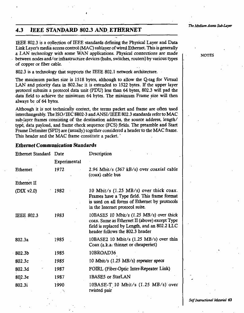
The Medium Access Sub-Layer4.3 IEEE STANDARD 802.3 AND ETHERNET
IEEE 802.3 is a collection of IEEE standards defining the Physical Layer and Data Link Layer's media access control (MAC) sublayer of wired Ethernet. This is generally a LAN technology with some WAN applications. Physical connections are made between nodes and/or infrastructure devices (hubs, switches, routers) by various types of copper or fiber cable.802.3 is a technology that supports the IEEE 802.1 network architecture.The maximum packet-size is 1518 bytes, although to allow the Q-tag for Virtual LAN and priority data in 802.3ac it is extended to 1522 bytes. If the upper layer protocol submits a protocol data unit (PDU) less than 64 bytes, 802.3 t\ill pad the data field to achieve the minimum 64 bytes. The minimum Frame size will then always be of 64 bytes.Al±ough it is not technicaUy correct, the terms packet and frame are often used interchangeably. The ISO/IEC 8802-3 and ANSI/IEEE 802.3 standards refer to MAC sub-layer frames consisting of the destination address, the source address, length/ type, data payload, and frame check sequence (PCS) fields. The preamble and Start Frame Delimiter (SFD) are (usually) together considered a header to the MAC frame. This header and the MAC frame constitute a packet. ‘
Ethernet Communication Standards
Ethernet Standard Date
NOTES
DescriptionExperimental1972 2.94 Mbit/s (367 kB/s) over coaxial cable
(coax) cable busEthernet
Ethernet II (DIX v2.0) 10 Mbit/s (1.25 MB/s) over thick coax.
Frames have a Type field. This frame format is used on all forms of Ethernet by protocols in the Internet protocol suite.10BASE5 10 Mbit/s (1.25 MB/s) over thick coax. Same as Ethernet II (above) except Type field is replaced by Length, and an 802.2 LLC header follows the 802.3 header10BASE2 10 Mbit/s (1.25 MB/s) over thin Coax (a.k.a.- thinnet or cheapernet)10BROAD3610 Mbit/s (1.25 MB/s) repeater specs
FOIRL (Fiber-Optic Inter-Repeater Link) 1BASE5 or StarLANlOBASE-T 10 Mbit/s (1.25 MB/s) over twisted pair
1982
IEEE 802.3 1983
802.3a 1985
1985802.3b802.3c802.3d802.3e802.3i
1985198719871990
\
Self Instructional Material 63
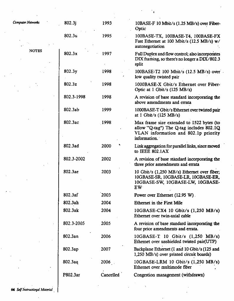
CbmpiOerTVrtMvnb 802.3j 1993 lOBASE-F 10 Mbit/s (1.25 MB/s) over Fiber- Optic100BASE-TX, 100BASE-T4. 100BASE-FX Fast Ethernet at 100 Mbit/s (12.5 MB/s) w/ autonegotiationFull Duplex and flow control; also incoiporates DIX framing, so there’s no longer a DIX/802.3
802.3u 1995
NOTES802.3X 1997
split802.3y 1998 100BASE-T2 100 Mbit/s (12.5 MB/s) over
low quality twisted pairlOOOBASE-X Gbit/s Ethernet over Fiber- Optic at 1 Gbit/s (125 MB/s)A revision of base standard incorporating the above amendments and erratalOOOBASE-T Gbit/s Ethernet over twisted pair at 1 Gbit/s (125 MB/s)Max frame size extended to 1522 bytes (to allow "Q-tag") The Q-tag includes 802. IQ VLAN information and 802. Ip priority information.Link aggregation for parallel links, since moved to IEEE 802.1AXA revision of base standard incorporating flie three prior amendments and errata
802.3Z 1998
802.3-1998 1998
802.3ab 1999
802.3ac 1998
802.3ad 2000
802.3-2002 2002
802.3ae 2003 10 Gbit/s (1,250 MB/s) Ethernet over fiber; lOGBASE-SR, lOGBASE-LR, lOGBASE-ER, IGGBASE-SW, lOGBASE-LW, lOGBASE-EW
802.3af802.3ah802.3ak
2003 Power over Ethernet (12.95 W)Ethernet in the First Mile10GBASE-CX4 10 Gbit/s (1,250 MB/s) Ethernet over twin-axial cableA revision of base standard incorporating the four prior amendments and errata.lOGBASE-T 10 Gbit/s (1,250 MB/s) Ethernet over unshielded twisted pair(UTP)Badcplane Ethernet (1 and 10 Gbit/s (125 and 1,250 MB/s) over printed circuit boards)lOGBASE-LRM 10 Gbit/s (1,250 MB/s) Ethernet over multimode fiberCongestion management (withdrawn)
20042004
802.3-2005 2005
802.3an 2006
802.3ap 2007
802.3aq 2006
P802.3ar Cancelled
64 StlflnstTuaUn^l Material
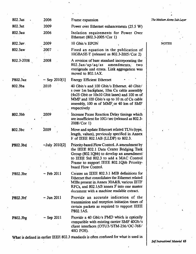
Frame expansionPower over Ethernet enhancements (25.5 W)Isolation requirements for Power Over Ethernet (802.3-2005/Cor 1)10 Gbit/s EPONFixed an equation in the publication of lOGBASE-T (released as 802.3-2005/Cor 2)A revision of base standard incorporating the 802.3an/ap/aq/as amendments, two corrigenda and errata. Link aggregation was moved to 802.lAX.
~ Sep 2010(1] Energy Efficient Ethernet40 Gbit/s and 100 Gbit/s Ethernet. 40 Gbit/ s over Im bac^lane, 10m Cu cable assembly (4x25 Gbit or 10x10 Gbit lanes) and 100 m of MMF and 100 Gbit/s up to 10 m of Cu cable assembly, 100 m of MMF, or 40 km of SMF
. respectivelyIncrease Pause Reaction Delay timings which are insufficient for lOG/sec (released as 802.3- 2008/Cor 1)Move and update Ethernet related TLVs (type, length, values), previously specified in Annex F of IEEE 802.1AB (LLDP) to 802.3.
“July 2010(2] Priority-based Flow Control. A amendment by the IEEE 802.1 Data Center Bridging Task Group (802.1Qbb) to develop an amendment to IEEE Std 802.3 to add a MAC Control Frame to support IEEE 802.1Qbb Priority- based Flow Control.Creates an IEEE 802.3.1 MIB definitions for Ethernet that consolidates the Ethernet related MIBs present in Annex 30A&B, various IETF RFCs, and 802.lAB annex F into one master document with a machine readable extract.Provide an accurate indication of the transmission and reception initiation times of certain packets as required to support IEEE P802.1AS.Provide a 40 Gbit/s PMD which is optically compatible with existing carrier SMF 40Gb/s client interfaces (OTU3/STM-256/OC-768/ 40G POS).
What is defined in earlier IEEE 802.3 standards is often confused for what is used in
802.3as802.3at
2006 The Medium Access Sub-Layer
2009802.3au 2006
802.3av802.3aw
2009 NOTES
2007
802.3-2008 2008
P802.3a2802.3ba 2010
802.3bb 2009
2009802.3bc
P802.3bd ,
“ Feb 2011P802.3be
~ Jun 2011P802.3bf
-Sep 2011P802.3bg
Se^Instructiona! Material 65
practice; most network frames you will find on an Ethernet will be DIX fiames, since the Internet protocol suite will use this format, with the type field set to the corresponding IETF protocol type. IEEE 802.3x-1997 allows the 16-bit field after the MAC addresses to be used as a type field or a length field, so that DIX frames are also valid 802.3 frames in 802.3x-1997 and later versions of the IEEE 802.3 Ethernet standard.
Computer Nawoih
NOTES
4.4 IEEE STANDARD 802.4 AND TOKEN BUS
Token bus is a network implementing the token ring protocol over a "virtual ring" on a coaxial cable. A token is passed around the network nodes and only the node possessing the token may transmit. If a node doesn't have anything to send, the token is passed on to the next node on the virtual ring. Each node must know the address of its neighbour in the ring, so a special protocol is needed to notify the other nodes of connections to, and discoimections from, the ring.Token bus was standardized by IEEE standard 802.4. It is mainly used for industrial applications. Token bus was used by GM (General Motors) for their Manufacturing Automation Protocol (MAP) standardization effort. This is an application of the concepts used in token ring networks. The main difference is that the endpoints of the bus do not meet to form a physical ring. The IEEE 802.4 Working Group is disbanded. In order to guarantee the packet delay and transmission in Token bus protocol, a modified Token bus was proposed in Manufacturing Automation Systems and flexible manufacturing system (FMS).
4.5 IEEE 802.4 AND TOKEN RING; BRIDGES
Ring networks have been around for many yeare and have long been used for both local and wide area networks. Among their many attractive features is the feet that a ring is not really a broadcast .^medium, but a collection of individual point-to-point links that happen to form a circle. Point-to-point links involve a well understood and field-proven technology and can run on twisted pair, coaxial cable, or fibre optics. Ring engineering is also almost entirely digital, whereas 802.3,.for example, has a substantial analog component for collision detection. A ring is also fair and has a known upper bound on channel access. For three reasons, IBM chose the ring as its LAN and IEEE has included the token ring standard as 802.5.In a token ring a special bit pattern, called the token, circulates around the ring whenever all stations are idle. When a station wants to transmit a frame, it is required to seize the token and remove it rfrom the ring before transmitting. This action is done by inverting a sin^e bit in the 3-byte token, which instantly changes it into the first 3 bytes of a normal data frame. Because there is only one token, only station can* tmsmit at a given instant, thus solving the channel access problem the same way the. token bus solves it.'
4.6 BRIDGES FROM 802 X TO 802 Y
You might think that a bridge from one 802 LAN to another one would be completely trival. Such is not the case. Each of the nine combinations of 802.x and 802.y has its
66 Self Instruetional Material
own unique set of problems. However, before dealing with these one at a time, let us look at some general problems common to all the bridges. To start with, each of he LANs uses a different frame format. There is no valid technical reason for this incompatibility. It is just that none of the corporations supporting the three standards (Xerox, GM, and IBM) wanted to change theirs.As a result any copying between different LANs requires reforinatting, which takes CPU time, requires a new checksum calculation, and introduces the possibility of undetected errors due to bad bits in the bridge’s memory. None of this would have been necessary if the three committees has been able to agree on a single format. A second problem is that interconnected LANs do not necessarily run at the same data rate.When forwarding a long run of back-to-back frames from a fast LAN to a slower one, the bridge will not be able to get rid of the frames as fast as they come in. It will have to buffer them, hoping not to run out of memory. The problem also exists from 802.4 to 802.3 at 10 Mbps to some extent because some of 802.3 bandwidth is lost to collisions. It does not really have 10 Mbps, whereas 802.4 really does. Bridges that connect three or more LANs have a similar problem when several LANs are trying to feed the same output LAN at the same time.A third and potentially most serious problem of all, is that, all three 802 LANs have a different maximum frame length. For 802.3 it depends on the parameters of the configuration, but for the standard 10-Mbps system the payload is a maximum of 1500 bytes. For 802.4 it is fixed at 8191 b3ftes. For 802.5 there is not upper limit except that a station may not transmit longer than the token-holding time. With the default value of 10 mses, the maximum frame length is 5000 bytes.From 802.4 to 802.3 two problems exist. First, 802.4 frames carry priority bits that 802.3 framess do not have. As a result, if two 802.4 LANs communicate via an 802.3 LAN, the priority will be lost by the intermediate LAN.
The Medium Access Sub-Layer
NOTES
4.7 TRANSPARENT BRIDGES
Bridging is a forwarding technique used in packet-switched computer networks. Unlike routing, bridging makes no assumptions about where in a network a particular address is located. Instead, it depends on flooding and examination of source addresses in received packet headers to locate unknown devices. Once a device has been located, its location is recorded in a table where the MAC address is stored so as to preclude the need for further broadcasting. The utility of bridging is limited by its dependence on floodmg, and is thus only used in local area networks.Bridging generally refers to Transparent bridging or Learning bridge operation which predominates in Ethernet. Another form of bridging, Source route bridging, was developed for token ring networks.A network bridge connects multiple network segments at the data link layer (Layer 2) of the OSI model. In Etheriiet networks, the term bridge formally means a device that behaves according to the IEEE 802.ID standard. A bridge and switch are very much alike; a switch being a bridge rvith numerous ports. Switch or Layer 2 switch is often used interchangeably with bridge.Bridges are similar to repeaters or network hubs, devices that connect network
Instructicml Material 67

Computer Networks segments at the physical layer; however, with bridging, traffic from one network is managed rather than simply rebroadcast to adjacent network segments. Bridges are more complex than hubs or repeaters. Bridges can analyze incoming data packets to determine if the bridge is able to send the given packet to another segment of the network.
Transparent bridging operationA bridge uses a forwarding database to send frames across network segments. The forwarding database is initially empty and entries in the database are built as the bridge receives frames. If an address entry is not found in the forwarding database, the frame is flooded to all other ports of the bridge, forwarding the frame to all segments except the source address. By means of these broadcast frames, the destination network will respond and forwarding database entry will be created.
* ' I
As an example, consider three hosts. A, B and C and a bridge. The bridge has fliree ports. A is connected to bridge port 1, B is connected bridge port 2, C is connected to bridge port 3. A sends a frame addressed to B to the bridge.'The bridge examines the source address of the frame and creates an address and port number entry for A in its forwarding table. The bridge examines the destination address of the frame and does not find it in its forwarding table so it floods it to all other ports: 2 and 3. Ifre frame is received by hosts B and C. Host C examines the destination address and ignores the fram£. Host B recognizes a destination address match and generates a response to A. On the return path, the bridge adds an address and port number entry for B to its forwarding table. The bridge dready has A's address in its forwarding table so it forwards the response only to port 1. Host C or any other hosts on port 3 are not burdened with the response. Two-way communication is now possible between A and B without any ftirffier flooding.Note that both source and destination addresses are used in this algorithm. Source addresses are recorded in entries in the table, while destination addresses are looked up in the table and matched to the proper segment to send the frame to.The technology was originally developed by the Digital Equipment Corp. in the 1980s.Filtering databaseTo translate between two segments, a bridge reads a frame's destination MAC address and decides to either forward or filter. If the bridge determines that the destination node is on another segment on the network, it forwards it (retransmits) the packet to that segment. If the destination address belongs to the same segment as the source address, the bridge filters (discards) the frame. As nodes transmit data through the bridge, the bridge establishes a filtering database (also known as a forwarding table) of known MAC addresses and their locations on the network. The bridge uses its filtering database to determine whether a packet should be forwarded or filtered.Advantages of network bridges
• Self-configuring• Simple bridges are inexpensive• Isolate collision domain• Reduce the size of collision domain by microsegmentation in non-switched
networks
NOTES
6a Self Instruetioaal Material
• Transparent to protocols above the MAC layer• Allows the introduction of management/peiformance information and access
control• LANs interconnected are separate, and physical constraints such as number
of stations, repeaters and segment length don't apply• Helps minimize bandwidth usage
Disadvantages of network bridges• Does not limit the scope of broadcasts [broadcast domain cannot be controlled]• Does not scale to extremely large networks• Buffering and processing introduces delays• Bridges are more expensive than repeaters or hubs
A complex network topology can pose a problem for transparent bridges. For example, .. multiple paths between transparent bridges and LANs can result in bridge loops. The
spanning tree protocol helps to reduce problems with complex topologies.
The Medium Access Sub-Layer
NOTES
4.8 SOURCE ROUTING BRIDGES
Transparent bridges have the advantages of being easy to install. You just plug them in and walk away. On the other hand, they do not make optimal use of the bandwidi, since they only use a subset of the topology (the spanning tree). The relative importance of these two (and other) factors led to a split within the 802 committees. Tliee ring CSMA/CD and token bus people chose the transparent bridge. The ring people (with encouragement from EBM) preferred a scheme, called source routing, which is ej^lained next.Source route bridging is used on token ring networks, and is standardized in Section 9 of the IEEE 802.2 standard. The operation of the bridge is simpler (spanning tree protocol is not necessary) and much of the bridging functions dre’performed by the end systems, particularly the sources, giving rise .to its name.Source-route transparent bridging, abbreviated SRT bridging, is a hybrid of source routing and transparent bridging, standardized in Section 9 of the IEEE 802.2 standard. It allows source routing and transparent bridging to coexist on the same bridged network by using source routing with hosts that support it and transparent bridging otherwise.A field in the token ring header, the routing information field (RIF), is used to support source-route brid^ng. Upon sending a packet, a host attaches a RIF to the packet indicating the series of bridges and network segments to be used for delivering the packet to its destination. The bridges merely follow the list given in the RIF - if a given bridge Ls next in the list, it forwards the packet, otherwise it ignores it.When a host wishes to send a packet to a destination for the first time, it needs to determine an appropriate RIF. A special type of broadcast packet is used, which instructs the network bridges to append their bridge number and network segment number to each packet as it is forwarded. Loops are avoided by requiring each bridge to ignore packets which already contain its bridge number in the RIF field. At the
Self Instructional Material 69
destinatioD, these broadcast packets are modified to be standard unicast packets and returned to the source along the reverse path listed in the REF. Thus, for each route discovery packet broadcast, the source receives back a set of packets, one for each possible path through the network to the destination. It is then up to the source to choose one of these paths (probably the shortest one) for further communications • with the destination.Two frame types are used in order to find the route to the destination network segment. Single-Route (SR) frames make up most of the network traffic and have set destinations, while All-Route (AR) frames are used to find routes. Bridges send AR frames by broadcasting on all network branches; each step of the followed route is registered by the bridge performing it. Each frame has a maximum hop count, which is determined to be greater than the diameter of the network graph, and is decremented by each bridge, to avoid indefinite looping of AR frames, frames are dropped when this hop count reaches zero. The first AR frame that reaches its destination is considered to have followed the best route, and the route can be used for subsequent SR frames; the other AR frames are discarded.This method of locating a destination network can allow for indirect load balancing among multiple bridges connecting two networks. The more a bridge is loaded, the less likely it is to take part in the route finding process for a new destination as it will be slow to forward packets. A new AR packet will find a different route over a less busy path if one exists. This method is very different from transparent bridge usage, where redundant bridges will be inactivated; however, more overhead is introduced to find routes, and space is wasted to store them in frames. A switch with a faster backplane can be just as good for performance, if not for fault tolerance. They are primarily found in Token Ring networks.
Con^uter Networks
NOTES
SUMMARYThe promcols used Co de^mine who goes next on a multiaccesschannelbeloi^ to a sublayerof the data link layer called Medium Access Control Sub Layer.lEliE 802.3 is a collection of IEEE standards defining the Physical Layer and Data LinkLayei's media access control (MAC) sublayer of wired Ethernet.Token bus is a network implementing the token ring protocol over a "virtual rii^" on a coaxial cable.Each of the nine combinations of 802.x arid 802.y has its own unique set of problems. Bridging is a forwarding technique used in packet-switched computer networks. Unlike routing, bridging makes no assumptions about where in a network a particular address is located .Bridging is a forwarding technique used in packet-switched computer networks. Unlike routing, bridging makes no assumptions about where in a network a particular address is located.Abridge uses a forwarding database to send frames acros.s netv.'ojk ^gments. The forwarding database is inidaily empty and entries in the database are built as the bridge receives frames.Source-route transparent bridging, abbreviated SRT bridging, is a hybrid of source routing and transparent bridging, standardized in Section 9 of the IEEE 802.2 standard.
I.
2.
3.
4.5.
6.
7.
8.
7G Self Instructional Materia!
The Medium Access Sub-LayerSELF ASSESSMENT QUESTIONS1. Describe The Medium Access Sub Layer.2. WhatisFramingStaticandDynamicChallenAUocationiriLANsandMANs?3. Describe IEEE standard 802.3 and Ethernet.4. Describe IEEE standard 802.4 and Token Bus. »5. Describe IEEE standard 802.4 and Token Ring, Bridges.6. What is difference between Bridges 802.x and 802.y?7. What are transparent bridges?8. Describe Source Routing Bridges.
Short Questions with Answers1. What is the framing static arid dynamic channel allocation in LANs andMANs?
Ans. Underlying all the work done in this area are five key assumptions, described below:1. Station model. The model consists of N independent stations (computers,
telephones, personal communications, etc.), each with a program or user that generates frames for transmission. The probality of a frame being generated in aii interval of of length At is XAt, where X is a constant (the arrival rate of new frames). Once a frame has been generated, the station is blocked and does nothing until the frame has been successfully transmitted.
2. Single Channel Assumption. A single channel is available for all communication. All stations can transmit on it and all can receive from it. As far as the hardware is concerned, all stations are equivalent; although protocol software may assign priorities to them.
3. Collision Assumption. If two frames are trnsmitted simultaneously, they overlap in time and the resulting signal is garbled. This even is called a collsion. All stations can detect collisions. A collided frame must be trnsmitted again later. There are no errors other than those generated by collisions.
4. Contumoos Time. Frame transmission can begin at any instant. There is no master clock dividing time into disaete intervals.
5. Slotted Time. Time is divided into disaete intervals (Slots). Frame transissions always begin at the start of a slot. A slot may contain 0, 1, or more frames, corresponding to an idel slot, a successful transmission, or a collision, respectively.
6. Carrier Sense. Stations can tell if the channel is in use before trying to use it. If the channel is sensed as busy, no station will attempt to use it until it goes idle
7. No Carrier Sense. Stations cannot sense the channel before trying to use. They just go ahead and transit. Only later can they determine whether or not the transmission was successful.
2/What is IEEE 802.3 standard?Ans. IEEE 802.3 is a collection of IEEE standards defining the Physical Layer and Data Link
Layer's media access control (MAC) sublayer of wired Ethernet. This is generally a LAN technology with some WAN applications. Physical connections are made between nodes and/or infrastructure devices (hubs, switches, routers) by various types of copper or fiber cable.
3. What is EEE 802.4 standard?Acs. Token bus was standardized by IEEE standard 802.4. It is mainly used for industrial
applications. Token bus was used by GM (General Motors) for their Manufacturing Avitomation Protocol (MAP) standardization effort. This is an application of the concqJts used in token ring networks. The main difference is that the endpoints of the bus do not meet to form a physical ring. The IEEE 802.4 Working Group is disbanded. In order to
NOTES
Self Itatructional Material 71
Computer Networks guarantee the packet delay and transmission in Token bus protocol, a modified Tbken bus was proposed in Manufacturing Automation Systems and flexible manufacturing system (FMS).
4. What is IEEE 802.4 and Token Bridge?Ans. In a token ring a special bit pattern, called the token, circulates around the ring whenever
all stations are idle. When a station wants to transmit a frame, it is required to seize the token and remove it rfrom the ring before transmitting. This action is done by inverting a single bit in the 3-byte token, which instantly changes it into the first 3 bytes of a normal data frame. Because there is only one token, only station can trnsmit at a j^ven instant, thus solving the channel access problem the same way the token bus solves it.
NOTES
Further Readings1. Data and Computer Network Communication: Prof. Shashi Banzai, Firewal Media.2. Networking: Balvir Singh, Firewal Media.3. Wide Area Networks: NavneetSharma, Firewal Me^.4. Computer Network: Bharat Bhushan Agarwal and Sumit Prakash Tayal, University Science
Press.
72 Self Iratmctumal Material
The Network LayerUNIT 5
THE NETWORK LAYER NOTES
STRUCTURE5.1 The Network Layer5.2 Network Layer Design Issues5.3 Shortest Paflt Routing5.4 Flooding5.5 Flow Based Routing5.6 BroadcastRoutii^5.7 Congestion Control and Prevention Policies5.8 InternetWoricing5.9 Connectionless Internet Working
5.10 Tunneling Internet Work Routing5.11 Fragm^tation5.12 Firewalls5.13 IPaddress5.14 Internet Control Protocols
Learning ObjectivesAlter going through this unit, students will be able to:
understand about the Network Layer of the networking.• know about Network Layer Design Issues.• learn the Shortest Path Routing.• describe about the Flooding.• understand about the Flow Based Routine.• know about the Broadcast Routine.• learn about Congestion Control and Prevention Policies.• understand about the Internet Working.• learn about Connectionless Internet Working.• know about Tunneling Internet Work Routing.• understand about Fragmentation, Firewalls, IP address and Internet Control
Protocols.Self Instructional Material 73

Computer Network5.1 THE NETWORK LAYER
The Network layer provides the functional and procedural means of transferring variable length data sequences from a source to a destination via one or more networks while maintaining the quality of service requested by the Transport layer. The Network layer performs network routing functions,- and might also perform fragmentation and reassembly, and report delivery errors. Routers operate at this layer—sending data throughout the extended network and making the Internet possible. This is a logical addressing scheme - values are chosen by the network engineer.Perhaps it’s easier to visualize this layer as managing the sequence of human carriers t^ng a lettA from the sender to the local post office, trucks that carry sacks of mail to other post offices or airports, airplanes that carry airmail between major cities, trucks that distribute mail sacks in a city, and carriers that take a letter to its destinations. Think of fragmentation as splitting a large document into smaller envelopes for shipping, or, in the case of the new.
NOTES
5.2 NETWORK LAYER DESIGN ISSUES
Some of the design issues which need to tackled are:1. Services Provided to the Transport Layer.
»2. Internal Organization of the Network Layer.3. Cbmparision of Virtual Circuit and Ditagram Subnets.
Services Provided to the IVansport Layer
The network layer provides services to the Transport Layer at the network layer/ transport layer internee. This interface is often especially important for another reason; - the boundary of the subnet. The carrier often has control of the protocols and interfaces up to and including the network layer. Its job is to deliver packets given to it by its customers. For this reason, this interface must be especially well defined.The network layer services have been designed with the following goals in mind.
1. The services should be independent of the subnet technology.2. The transport layer should be shielded from the number, type, and topology
of the subnets present.3. The network addresses made available to the transport layer should use a
uniform numbering plan, even across LANs and WANs.. Some people argue that the subnet should provide a (reasonably) reliable, connection- oriented service. They claim 100 years of successful experience with the worldwide telephone system is a good guide. In this view, conections should have the following properties:
1. Before sending data, a network layer process on the sending side must set up a connection to its peer on the receiving side. This connection, which is given a special identifier, is then used until all the data have been sent, at which' time it is explicity released.
74 Seif Instnutiond Material
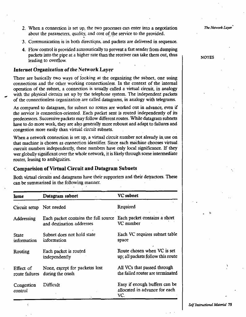
The Network Layer2. When a connection is set up, the two processes can enter into a negotiation about the parameters, quality, and cost of the service to the provided.
3. Communication is in both directions, and packets are delivered in sequence.4. Flow control is provided automatically to prevent a fast sender from dumping
packets into the pipe at a higher rate than the receiver can take them out, thus leading to overflow.
Internet Opganization of the Network LayerThere are basically two ways of looking at the organizing the subnet, one using connections and the other working connectionless. In the context of the internal operation of the subnet, a connection is usually called a virtual circuit, in analogy
^ with the physical circuits set up by the telephone system. The independent packets of the connectionless organization are called datagrams, in analogy with telegrams.As compared to datagram, for subnet no routes are worked out in advance, even if the service is connection-oriented. Each packet sent is routed independently of its predecessors. Successive packets may follow different routes. While datagram subnets have to do more woik, they are also generally more roboust and adapt to failures and congestion more easily than virtual circuit subnets.When a network connection is set up, a virtual circuit number not already in use on that machine is chosen as coimection identifier. Since each machine chooses virtual curcuit numbers independently, these numbers have only local significance. If they wer globally significant over the whole network, it is likely through some intermediate router, leasing to ambiguities.
Comparision of Virtual Circuit and Datagram SubnetsBoth virtual circuits and datagrams have their supporters and their detractors. These can be summarized in the following manner.
NOTES
VC subnetDatagram subnetIssue
RequiredCircuit setup Not needed
Addressing Each packet contains the full source Each packet contains a shortVC numberand destination addresses
Each VC requires subnet table space
Subnet does not hold state information
Stateinformation
Route chosen when VC is set up; all packets follow this route
Each packet is routed independently
Routing
All VCs that passed through the failed router are terminated
Effect of None, esxept for packetss lost route failures during the crash
Easy if enough buffers can be allocated in advance for each
Congestion Difficult control
VC.
Se^Instructional Material 75
Inside the subnet, several trade-off exist between virual circuits and datagrams. One trade-off is between router memory space and bandwidth. Virtual circuits allow pickets to contain cicuit numbers instead of full destination addresses. If the packets tend to
. be fairly short, a full destination address in every packet may represent a significant amout of overhead, and hence wasted bandwidth. The price paid for using virtual circuits internally is the table space viithin the routers. Depending upon the relative cost of communication circuits versus router memory, one or the other may be cheaper.
Computer Naworks
NOTES
5.3 SHORTEST PATH ROUTING
Open Shortest Path First (OSPF) is a dynamic routing protocol for use in Internet Protocol (IP) networks. Specifi^lly, it is a link-state routing protocol and falls into the group of interior gateway protocols, operating within a sin^e autonomous system (AS). It is defined as OSPF Version 2 in RFC 2328 (1998) for IPv4. The updates for IPv6 are specified as OSPF Version 3 in RFC 5340 (2008).OSPF is perhaps the most widely-used interior gateway protocol (IGP) in large enterprise networks; IS-IS, another link-state routing protocol, is more common in large service provider networks. The most widely-used exterior gateway protocol is the Border Gateway Protocol (BGP), the principal routing protocol between autonomous systems oh the Internet.OSPF is an interior gateway protocol that routes Internet Protocol (IP) packets solely within a single routing domain (autonomous system). It gathers link state information fi:om available routers and constructs a topology map of the network. The topology determines the routing table presented to the Internet Layer which makes routing decisions based solely on the destination IP address found in IP datagrams. OSPF was designed to support variable-length subnet masking (VLSM) or Classless Inter- Domain Routing (CIDR) addressing models.OSPF detects changes in the topology, such as link failures, very quickly and converges on a new loop-free routing structure within seconds. It computes the shortest path tree for each route using a method based on Dijkstra's algorithm, a shortest path first algorithm.The link-state information is maintained on each router as a link-state database (LSDB) which is a tree-image of the entire network topology. Identical copies of the LSDB are periodically updated through flooding on all OSPF routers.The OSPF routing policies to construct a route table are governed by link cost factors (external metrics) associated with each routing interface. Cost factors may be the distance of a router (round-trip time), network throughput of a link, or link availability and reliability, expressed as simple unitless numbers, liiis provides a dynamic process of traffic load balancing between routes of equal cost.An OSPF network may be structured, or subdivided, into routing areas to simplify administration and optimize traffic and resource utilization. Areas are identified by 32-bit numbers, expressed either simply in decimal, or often in octet-based dot-decimal notation, familiar from IPv4 address notation.By convention, area 0 (zero) or O.O.O.O represents the core or backbone region of an OSPF network. The identifications of other areas may be chosen at will, often, administrators select the IP address of a main router in an area as the area's
76 Self Instructional Material
identification. Each additional area must have a direct or virtual connection to the backbone OSPF area. Such connections are maintained by an interconnecting router, known as area border router (ABR). An ABR maintains separate link state databases for each area it serves and maintains summarized routes for all areas in the network.OSPF does not use a TCP/IP transport protocol (UDP, TCP), but is encapsulated directly in IP datagrams with protocol number 89. This is in contrast to other routing protocols, such as the Routing Information Protocol (RIP), or the Border Gateway Protocol (BGP). OSPF handles its own error detection and correction functions.OSPF uses multicast addressing for route flooding on a broadcast network link. For non-broadcast networks special provisions for configuration facilitate neighbor discovery. OSPF multicast IP packets never traverse IP routers, they never travel more than one hop. OSPF reserves the multicast addresses 224.0.0.5 for IPv4 or . FF02::5 for IPv6 (all SPF/link state routers, also known as AUSPFRouters) and 224.0.0.6 for IPv4 or FF02::6 for IPv6 (all Designated Routers, AllDRouters), as specified in RFC 2328 and RFC 5340.For routing multicast IP traffic, OSPF supports the Multicast Open Shortest Path First protocol (MOSPF) as defined in RFC 1584. Neither Cisco nor Juniper Networks include MOSPF in their OSPF implementations. PIM (Protocol Independent Multicast) in conjunction with OSPF or other IGPs, (Interior Gateway Protocol), is widely deployed.The OSPF protocol, when running on IPv4, can operate securely between routers, optionally using a variety of authentication methods to allow only trusted routers to participate in routing. OSPFv3, running on IPv6, no longer supports protocol-internal authentication. Instead, it relies on IPv6 protocol security (IPsec).OSPF version 3 introduces modifications to the IPv4 implementation of the protocol. Except for virtual links, all neighbor exchanges use IPv6 link-local addressing exclusively. The IPv6 protocol runs per link, rather than based on the subnet. All IP prefix information has been removed from the link-state advertisements and from the Hello discovery packet making OSPFv3 essentially protocol-independent. Despite the expanded IP addressing to 128-bits in IPv6, area and router identifications are still based on 32-bit values.
The Network Layer
NOTES
5.4 FLOODING
Flooding is a static algorithm in which every incoming packet is sent out on every outgoing line except the one it arrived on; Flooding obviously generates vast numbers of duplicate packets. In faa, an infinite number unless some measures are taken to damp the prrocess. One such measure is to have a hop, counter contained in the header of each packet, which is decremented at each hop, with the packet being discarded when.the counter reaches zero. Ideally, the hop counter should be initialized to the length of the path from source to destination. If Ae sender does not know how long the path is, it can initialize the counter to the worst case, namely, the full diameter of the subnet.An alternative technique for damming the floop is to keep track of which packets have been flooded, to avoid sending them out a second tiem. One way to achieve this goad is to have the source router put a sequence number in each packet it receives
Self InstruOional Material 77
Computer Networks from its hosts. Each router then needs a list per source router telling which sequence numbers originating at that source have already been seen. If an incoming packet is on the list, it is not flooded.To prevent the list from growing without bound, each list should be augmented by a counte, k, meaning all sequence numbers through' k have been seen. When a padcet • comes in, it is easy to check if the packet is a duplicate, if so, it is descarded. Furthermore, the full list below k is not needed, since k effectively summarizes it.
NOTES
5.5 FLOW BASED ROUTING
A static algorithm that uses both topology and load for routing, is called flow-based routing. In some networks, the mean data flow between each pair of nodes is relatively stable and predictable. For example, in a coorporate network for a retail store chain, each store might send orders, sales reports, inventory updates, and other well-defined types of messages to known sites in a predefined pattern, so that the total volume of traffic various little from day to day. Under conditions in which he average traffic from i toj is known.in advance and, to a reasonable approximation, constant in time; it is possible to analyze the flows mathematically to optimize the routing.The basic idea behind the analysis is that for a given line, if the capacity and avarage flow are know, it is possible to compute the mean padcet delay on the line from queueing theory. From the mean delays on all the lines, it is straightforwardto calculate a flow weighted average to get the mean packet delay for the whole subnet. The routing problem then reduces to finding the routing algorithm that produces he minimim avarage delay for the subnet.To use this technique, certain information must be knovm in advance. First the subnet topology must be known. Second, the traffic matrix, Fy, must be given. Third, the line capacity matrix, Cy, specifying the capacity of each line in bps must be available. Finally, a (possibly tentative) routing algorithm must be chosen.
5.6 BROADCAST ROUTING
For some applications, hosts need to send mesages to many or all other hosts. For example, a service distributing wather reports, stock market updates, or live radio programs might work best by broadcasting to all machines and letting those that are interested read the data. Sending a packet to all destinations simultaneously is called Broadcasting; various methods have been proposed for doing it.One broadcasting method that requires no special features from the subnet is for the source to simply send a distinct packet to each destination. Not only is the method wasteful of bandwidth, but it also requires the source to have a complete list of all destinations. In practice this may be the only possibility, but is the least desirable of the methods.Flooding is another obvious choice. Although flooding is ill-suited for ordinary point- to-point communcation, for broadcasting it might rate serious consideration, especially if none of the methods desaibed below are applicable. The problem with flooding as a broadcast technique is the same problem it has as a point-to-point routing algorithm; it generates too many packets and consumes too much bandwith.
78 Self Instruaioml Material
The Network Laytr5.7 CONGESTION CONTROL AND PREVENTION
POLICIES
Congestion control concerns controlling traffic entry into a telecommunications network, so as to avoid congestive collapse by attempting to avoid oversubscription of any of the processing or link capabilities of the intermediate nodes and networks and taking resource reducing steps, such as reducing the rate of sending packets. It should not be confused with flow control, which prevents the sender from overwhelming the receiver.Classification of congestion control algorithms
• There are many ways to classify congestion control algorithms:• By the type and amount of feedback received from the network: Loss; delay;
single-bit or multi-bit explicit signals• By incremental deployability on the current Internet: Only sender needs
modification; sender and receiver need modification; only router needs modification; sender, receiver and routers need modification.
• By the aspect of performance it aims to improve: high bandvridth-delay product networks; lossy links; fairness; advantage to short flows; variable-rate links
• By the fairness criterion it uses: max-min, proportional, "minimum potential delay"
NOTES
5.8 INTERNET WORKING
Up until now, we have implicitly assumed that there is a single homogenous network, with each machine using the same protocol in each layer. Unfortunately, this assumtion is widly optimistic. Many differnt networks exist, including LANs, WANs, and MANs. Numerous protocols are in widespread use in every layer. Now we look at the issues that arise when two or more networks are together to form an internet.First of all, the installed base of different networks is large and growing. Nearly al UNIX shops run TCP/IP. Many largebusinesses still have mainframes running SNA. DEC is still developing DECnet. Personal computer LANs often use Novell, NCP/ IPX or AppleTalk ATM systems are starting to be widespread. Finally, specialized protocols are often used on satellite, cellular, and-infrared networks. This trend will continue for years due to the large number of existing ne^orks and because not all vendors perceive it in their interest for their customers to be able to easily migrate to another vendor’s system.Second, as computers and networks get cheaper, the place where decisions get made moves dovraward. Many companies have a policy to the effect that purchases costing over a million dollars have to be approved by top management, purchases costing
100,000 dollars have to be approved by middle management, but purchasesoverunder 100,000 dollars can be made by department hads without any lugher approval. Thsi can easily lead to the accounting department instaling an Ethernet, the engineering department installing a token bus, and the personnel department installing a tokennng. .
Self Instructional Material 79

Computer Netvnrks Third, different networks, (e.g., ATM and wireless) have radically different technology, so it should not be surprising that as new hardware developments occur, new software will be created to fit eh new hardware. For example, the average home now is like the average office ten years ago; it is full of computers that do not talk to one another. In the future, it may be commonplace for the telephone, the television set, and other applicances all to be networked together, so they can be controlled remotely. This new technology will undoubtedly bring new protocols.
NOTES
5.9 CONNECTIONLESS INTERNET WORKING
In this case, the only, service the network layer offers to the transport layer is the ability to inject daagrams into the subnet and hope for the best. There is no motion of a virtual circuit at all in the network layer, let alone a concatenation of them. This model does not require all packets belonging to one connection to traverse the same sequence of gateways. A routing decision is made separately for each packet, possibly depending on the traffic at the moment the packet is sent. This strategy can use multiple routes and thus achieve a higher bandwidth than the concatenated virtual circuit mode. On the other hand, there is no guarantee that the packets arrive at the destination in order, assuming that they arrive at all.A second and more serious problem, is addressing. Imagine a simple case; a host on the Internet is trying to send an IP packet to a host on an adjoining OSI network. The OSI datagram protocol, CLNP, was based on IP and is close enough to it that a conversion might well work. The trouble is that IP packets all carry the 32-bit Internet address of the destination host in a header field. OSI hosts do not have 32-bit Internet addresses. They use decimal addresses similar to telephone numbers.To make it possible for the multiprotocol router to convert between formats, someone wold have to assign a 32-bit Interest address to each OSI host. Taken to the limit, this approach would mean assigning an Internet address to every mahine in the world that an Internet host might want to talk to. It would also mean assigning an OSI address to every machine in the world that an OSI host might want to talk to. The same problem occurs with every other address space (SNA, AppleTalk, etc.) The problems here are insurmountable. In addition, someone would have to maintain a database mapping everything to everything.
5.10 TUNNELING INTERNET WORK ROUTING
Handling the general case of making two different networks interwork is exceedingly difficult. However, there is a common special case that is manageable. This case is where the source and destination hosts are on the same type of network, but there is a different network in between. As an example, think of an international bank wih a TCP/IP based Ethernet in Paris, a TCP/IP based Ethernet in London, and a PTT WAN in between.The solution to this problem is a technique called tunneling. To send an IP packet to host 2, host 1 constructs the packet containing the IP address of host 2, inserts it not an Ethernet frame addressed to the Paris multiprotocol router, and puts it on the Ethernet. When the multiprotocol router gets the frame, it removes the IP packet, inserts it in the payload field of the WAN network layer packet and addresses the
80 Self IrutTuctional Material

‘Hu Netwoji Layerlatter to the WAN address of the London multiprotocol router. When it gets there, ±e London router reihoves the IP packet and sends it to host 2 inside an Ethernet frame.The WAN can be seen as a big tunnel extending from one multiprotocol router to the other. The IP packet just travesl from one end of the tunnel to the other, snug in its nice box. It does not have to worry about dealing with the WAN at all. Neither do the hosts on either Ethernet. Only the multiprotocol router has to understand IP and WAN packets. In effect, the entire distance from the middle of one rnultiprotocol router to the middle of the other acts like a serial line.
NOTES
5.11 FRAGMENTATION
In computer storage, fragmentation is a phenomenon in which storage space is used inefficiently, reducing storage capacity and in most cases performance. The term is also used to denote the wasted space itself.
I
There are three different but related forms of fragmentation: external fragmentation, internal fragmentation, and data fragmentation. Various storage allocation schemes exhibit one or more of these weaknesses. Fragmentation can be accepted in return for increase in speed or simplicity.
Internal fragmentationInternal fragmentation occurs when storage is allocated without intention to use it. This space is wasted. While this seems foolish, it is often accepted in return for increased efficiency or simplicity. The term ''internal" refers to the fact that the unusable storage is inside the allocated region but is not being used.For example, in many file systems, each file always starts at the beginning of a cluster, because this simplifies organization and makes it easier to grow files. Any space left over between the last byte of the file and the fu st byte of the next cluster is a form of internal fragmentation called file slack or slack space. Slack space is a very important source of evidence in computer forensic investigation. These clips describfe an analogy of a slack space.Similarly, a program which allocates a single byte of data is often allocated many additional bytes for metadata and alignment. This extra space is also internal fragmentation.Another common example: English text is often stored with one character in each 8- bit byte even though in standard ASCII encoding the most significant bit of each byte is always zero. The unused bits are a form of internal fragmentation.Similar problems with leaving reserved resources unused appear in many other areas. For example, IP addresses can only be reserved in blocks of certain sizes, resulting in many IPs that are reserved but not actively used. This is contributing to the IPv4 address shortage.Unlike other types of fragmentation, internal fragmentation is difficult to reclaim; usually the best way to remove it is with a design change. For example, in dynamic memory allocation, memory pools drastically cut internal fragmentation by spreading the space overhead over a larger number of objects.
Self Irutructional Material 81
Computer Networks External fragmentationEjrtemal fragmentation is the phenomenon in which free storage becomes divided into many small pieces over time. It is a weakness of certain storage allocation algorithms, occurring when an application allocates and deallocates ("frees") regions of storage of varying sizes, and the allocation algorithm responds by leaving the allocated and deallocated regions interspersed. The result is that although free storage is available, it is effectively unusable because it is divided into pieces that are too small to satisfy the demands of the application. The term "external" refers to the fact that the unusable storage is outside the allocated regions.For example, in dynamic memory allocation, a block of 1000 bytes might be requested, but the largest contiguous block of free space has only 300 bytes. Even if there are ten blocks of 300 bytes of free space, separated by allocated regions, one still cannot allocate the requested block of 1000 bytes, and the allocation request will fail.External fragmentation also occurs in file systems as many files of different sizes are created, change size, and are deleted. The effect is even worse if a file which is divided into many small pieces is deleted, because this leaves similarly smaU regions of free spaces.'
Data fragmentationData fragmentation occurs when a piece of data in memory is broken up into many pieces that are not close together. It is typically the result of attempting to insert a large object into storage that has already suffered external fragmentation.For example, files in a file system are usually managed in units calledblocks or clusters. When a file system is created, there is free space to store file blocks together contiguously. T^is allows for rapid sequential file reads and writes. However, as files are added, removed, and changed in size, the free space becomes externally fragmented, leaving only small holes in which to place new data. When a new file is written, or when an existing file is extended, the new data blocks are necessarily scattered, slowing access due to seek time and rotational delay of the read/write head, and incurring additional overhead to manage additional locations. This is called file system fragmentation.As another example, if the nodes of a linked list are allocated consecutively in memory, this improves locality of reference and enhances data cache performance during traversal of the list. If the memory pool's free space is fragmented, new nodes will be spread throughout memory, increasing the number of cache misses.Just as compaction can eliminate external fragmentation, data fragmentation can be eliminated by rearranging data storage so that related pieces are close together. For example, the primary job of a defragmentation tool is to rearrange blocks on disk so that the blocks of each file are contiguous. Most defra^enting utilities also attempt to reduce or eliminate free space fragmentation. Some moving garbage collectors will also move related objects close together (this is called compacting) to improve cache performance.
NOTES
5.12 FIREWALLS
A firewall is a part of a computer system or network that is designed to block
82 Se^Instructional Material
unauthorized access while permitting authorized communications. It is a device or set of devices which is configured to permit or deny computer applications based upon a set of rules and other criteria.Firewalls can be implemented in either hardware or software, or a combination of both. Firewalls are frequently used to prevent unauthorized Internet users from accessing private networks connected to the Internet, especially intranets. All messages entering or leaving the intranet pass through the firewall, which examines each message and blocks those that do not meet the specified security criteria.There are several types of firewall techniques:Packet fUter: Packet filtering inspects each packet passing through the network and accepts or rejects it based on user-defined rules. Although difficult to configure, it is fairly effective and mostly transparent to its users. It is susceptible to IP spoofing.Application gateway: Applies security mechanisms to specific applications, such as FTP and Telnet servers. This is very effective, but can impose a performance degradation.Circuit-level gateway: Applies security mechanisms when a TCP or UDP connection is established. Once the connection has been made, packets can flow between the hosts without further checking.Proxy server: Intercepts all messages entering and leaving the network. The proxy server effectively hides the true network addresses.
First generation: packet filtersThe first paper published on fi’^wall technology was in 1988, when engineers from Digital Equipment Corporation (DEC) developed filter systems known as packet filter firewalls. This fairly basic system was the first generation of what became a highly evolved and technical internet security feature. At AT&T Bell Labs, Bill Cheswick and Steve Bellovin were continuing their research in packet filtering and developed a working model for their own company based upon their original first generation architecture.This type of, packet filtering pays no attention to whether a packet is part of an existing stream of traffic (it stores no information on connection "state"). Instead, it filters each packet based only on information contained in the packet itself (most commonly using a combination of the packet's source and destination address, its protocol, and, for TCP and UDP traffic, the port number).TCP and UDP protocols comprise most communication over the Internet, and because TCP and UDP traffic by convention uses well known ports for particular types of traffic, a "stateless" packet filter can distinguish between, and thus control, those types of traffic (such as web browsing, remote printing, email transmission, file transfer), unless the machines on each side of the packet filter are both using the same non-standard ports.Packet filtering firewalls work on the first tliree layers of the OSI reference model, which means all the work is done between the network and physical layers. When a packet originates from the sender and filters through a firewall, the device checks for matches to any of the packet filtering rules that are configured in the firewall and drops or rejects the packet accordingly. W'hen the packet passes through the firewall it filters the packet on a protocol/port number basis (GSS). For example if a rule in
The Network Laytr
NOTES
Setf Instnictioml Material 83
the firewall exists to block telnet access, then the firewall will block the IP protocol for port number 23.
Second generation: application layerThe key benefit of application layer filtering is that it can "understand" certain applications and protocols (such as File Transfer Protocol, DNS, or web browsing), and it can detea if an unwanted protocol is sneaking through on a non-standard port or if a protocol is being abused in any harmful way.An application firewall is much more secure and reliable compared to packa filter firewalls because it works on all seven layers of the OSI reference model, from the application down to the physical Layer. This is similar to a packet filter firewall but here we can also filter information on the basis of content. The best example of an application firewall is ISA (Internet Security and Acceleration) server. An application firewall can filter higher-layer protocols such as FTP, Telnet, DNS, DHCP, HTTP, TCP, UDP and TFTP (GSS). For example, if an organization wants to block 2ill the information related to "foo" then content filtering can be enabled on the firewall to block that particular word. Software-based firewalls are thus much slower than stateful firewalls.
Third generation: "stateful" filtersFrom 1989-1990 three colleagues from AT&T Bell Laboratories, Dave Presetto, Janardan Sharma, arid Kshitij Nigam, developed the third generation of firewalls, calling them circuit level firewalls.Third-generation firewalls, in addition to what first- and second-generation look for, regard placement of each individual packet within the packet series. This technology is generally referred to as a stateful packet inspeaion as it maintains records of all conneaibns passing through the firewall and is able to determine whether a packet is the start of a new connection, a part of an existing conneaion, or is an invalid packa. Though there is still a set of static rules in such a firewall, the state of a connection can itself be one of the criteria which trigger specific rules.This type of firewall can help prevent attacks which exploit existing connections, or certain Denial-of-service attacks.
Networks
NOTES
«TypesThere are several classifications of firewalls depending on whae the communication is taking place, where the communication is intercepted and the state that is being traced.
Network layer and packet filtersNetwork layer firewalls, also called packa filters, operate at a relatively low level of the TCP/IP protocol stack, not allowing packets to pass through the ^wall unless they match the established rule sa. The firewall administrator may define the rules; or default rules may apply. The term "packet filter" originated in the context of BSD operating systems.Network layer firewalls generally fall into two sub-categories, stateful and stateless. Stateful firewalls maintain context about active sessions, and use that "state information" to speed packet processing. Any existing network conneaion can be
H4 §e'f Instructional Material
described by several properties, including source and destination IP address, UDP or TCP ports, and the current stage of the connection’s lifetime (including session initiation, handshaking, data transfer, or completion connection). If a packet does not match an existing connection, it will be evaluated according to the ruleset for new connections. If a packet matches an existing connexion based on comparison with the firewall's state table, it will be allowed to pass without further processing.Stateless firewalls require less memory, and can be faster for simple filters that require less time to filter than to look up a session. They may also be necessary for filtering stateless network protocols that have no concept of a session. However, they cannot make more complex decisions based on what stage communications between hosts have reached.Modem firewalls can filter traffic based on many packet attributes like source IP address, source port, destination IP address or port, destination service like WWW or FTP. They can filter based on protocols, TTL values, netblock of originator, of the source, and many other attributes.Commonly used padcet filters on various versions of Unix are ipf (various), ipfw (FreeBSD/Mac OS X), pf (OpenBSD, and all other BSDs), iptables/ipchains (Linux).
Application-layerAppUcation-layer firewalls work on the application level of the TCP/IP stack (i.e., all browser traffic, or all telnet or ftp traffic), and may intercept all packets traveling to or fiom an application. They block other packets (usually dropping them without acknowledgment to the sender). In principle, application firewalls can prevent all tmwanted outside traffic from reaching protected machines.On inspecting all packets for improper content, firewalls can restrict or prevent outright the spread of networked computer worms and trojans. The additional inspection criteria can add extra latency to the forwarding of packets to their destination.
ProxiesA proxy device (running either on dedicated hardware or as software on a general- purpose machine) may act as a firewall by responding to input packets (connection requests, for example) in the manner of an application, whilst blocking other packets.Proxies make tampering with an internal system from the external network more difficult and misuse of one internal system would not necessarily cause a security breach exploitable from outside the firewall (as long as the application proxy remains intact and properly configured). Conversely, intruders may hijack a publicly-reachable system and use it as a proxy for their own purposes; the proxy then masquerades as that system to other internal machines. While use of internal address spaces enhances security, crackers may still employ methods such as IP spoofing to attempt to pass packets to a target network.
Network address translationFirewalls often have network address translation (NAT) functionality, and the hosts protected behind a firewall commonly have addresses in the "private address range", as defined in RFC 1918. Firewalls often have such functionality to hide the true addicss of protected hosts. Originally, the NAT function was developed to address the limited number of IPv4 routable addresses that could be used or assigned to
The Network Layer
NOTES
S^IiistnutiotUi! Material 8S
Computer Networks companies or individxials as well as reduce both the amount and therefore cost of obtaining enough pubhc addresses for every computer in an organization. Hiding the addresses of protected devices has become an increasingly important defense against network reconnaissance.
NOTES 5.13 IP ADDRESS
An Internet Protocol (IP) address is a numerical label that is assigned to devices participating in a computer network, that t^es the Internet Protocol for communication between its nodes. An IP address serves two principal functions: host or network interface identification and location addressing. Its role has been characterized as follows: "A name indicates what we seek. An address indicates where it is. A route indicates how to get there."The designers of TCP/IP defined an IP address as a 32'bit number and this system, known as Internet Protocol Version 4 or IPv4, is still in use today. However, due to the enormous growth of the Internet and the predicted depletion of available addresses, a new addressing system (IPv6), using 128 bits for the address, was developed in 1995 and standardized by RFC 2460 in 1998. Although IP addresses are stored as binary numbers, they are usually displayed in human-readable notations, such as 208.77.188.166 (for IPv4), and 2001:db8:0:1234;0:567:l:l (for IPv6).The Internet Protocol is used to route data packets between networks; IP addresses specify the locations of the source and destination nodes in the topology of the routing system. For this purpose, some of the bits in an IP address are used to designate a subnetwork. The number of these bits is indicated in CIDR notation, appended to the IP address; e.g., 208.77.188.166/24.As the development of private networks raised the threat of IPv4 address exhaustion, RFC 1918 set aside a group of private address spaces that may be used by anyone on private networks. They are often used with network address translators to connect to the global public Internet.The,Internet Assigned Numbers Authority (lANA), which manages the IP address space allocations globally, cooperates with five Regional Internet Registries (RIRs) to allocate IP address blocks to Local Internet Registries (Internet service providers) and other entities.
Static vs dynamic IP addressesWhen a computer is configured to use the same IP address each time it powers up, this is known as a static IP address. In contrast, in situations when the computer’s IP address is assigned automatically, it is known as a dynamic I? address.
Method of assignmentStatic IP addresses are manually assigned to a computer by an administrator. Tlie exact procedure varies according to platform. This contrasts with dynamic IP addresses, which are assigned either by the computer interface or host sof^re itself, as in Zeroconf. or assigned by a server using Dynamic Host Configuration Protocol (DHCP). Even though IP addresses assigned using DHCP may stay the same for long periods of time, they can generally cliange. In some cases, a network adrainistrator may implement dynamically assigned static IP adc^esses. In this case, a DHCP server
86 Self InstruOUmal Material
The Network Layeris used, but it is specifically configured to always assign the same IP address to a particular computer. This allows static IP addresses to be configured centrally, without having to specifically configure each computer on the network in a manual procedure.In the absence or failure of static or stateful (DHCP) address configurations, an operating system may assign an IP address to a network interface using state-less autoconfiguration methods, such as Zeroconf.
Uses of dynamic addressingDynamic IP addresses are most frequently assigned on LANs and broadband networks by Dynamic Host Configuration Protocol (DHCP) servers. They are used because it avoids the administrative burden of assigning specific static addresses to each device on a network. It also allows many devices to share limited address space on a network if only some of them will be online at a particular time. In most current desktop operating systems, dynamic IP configuration is enabled by default so that a user does not need to manually enter any settings to connect to a network with a DHCP server. DHCP is not the only technology used to assign dynamic IP addresses. Dialup and some broadband networks'use dynamic address features of the Point-to-Point Protocol.
Sticky dynamic IP addressA sticky dynamic IP address or sticky IP is an informal term used by cable and DSL Internet access subscribers to describe a dynamically assigned IP address that does not change often. The addresses are usually assigned with the DHCP protocol. Since the modems are usually powered-on for extended periods of time, the address leases are usually set to long periods and simply renewed upon expiration. If a modem is turned off and powered up again before the next expiration of the address lease, it will most likely receive the same IP address.
Address autoconfigurationRFC 3330 defines an address block, 169.254.0.0/16, for the special use in link-local addressing for IPv4 networks. In IPv6, every interface, whether using static or dynamic address assignments, also receives a local-link address automatically in the fe80::/10 subnet.These addresses are only valid on the link, such as a local network segment or point- to-point connection, that a host is connected to. These addresses are not routable and like private addresses cannot be the source or destination of packets traversing the Internet.
. \When the link-local IPv4 address block was reserved, no standards existed for mechanisms of address autoconfiguration. Filling the void, Microsoft created an implementation that called Automatic Private IP Addressing (APIPA). Due to Microsoft's market power, APIPA lias been deployed on millions of machines and has, thus, become a de facto standard in the industry. Many years later, the IETF defined a formal standard'for this functionality, 3927, entitled Dynamic Configuration of IPv4 Link-Local Addresses.
Uses of static addressingSome infrastructure situations have to use static addressing, such as when finding tlie Domain Name System host tliat will translate domain names to IP addresses. Static addresses are ako convenient, but not absolutely necessary, to locate servers inside
NOTES
Sel/Tnstnictional Material 87
Computer Networks an enterprise. An address obtained from a DNS server comes with a time to live, or caching time, after which it should be looked up to confirm that it has not changed. Even static IP addresses do change as a result of network administration (RFC 2072)
Modifications to IP addressingFirewalls are common on today's Internet. For increased network security, they control access to private networks based on the public IP of the client. Whether using a blacklist or a whitelist, the IP address that is blocked is the perceived public IP address of the client, meaning that if the client is using a proxy server or NAT, blocking one IP address might block many individual people.
IP address translation -Multiple client devices can appear to share IP addresses: either because they are part of a shared hosting web server environment or because an IPv4 network address translator (NAT) or proxy server acts as an intermediary agent on behalf of its aistomers, in which case the real originating IP addresses might be hidden from the server receiving a request. A common practice is to have a NAT hide a large number of IP addresses in a private network. Only the "outside" interface(s) of the NAT need to have Internet-routable addresses.Most commonly, the NAT device maps TCP or UDP port numbers on the outside to individual private addresses on the inside. Just as a telephone number may have site- specific extensions, the port numbers are site-specific extensions to an IP address.In small home networks, NAT functions usually take place in a residential gateway device, typically one marketed as a "router". In this scenario, the computers connected to the router would have 'private' IP addresses and the router would have a 'public' address to communicate with the Internet. This type of router allows several computers to share one public IP address.
NOTES
5.14 INTERNET CONTROL PROTOCOLS
The Internet Control Message Protocol (ICMP) is one of the core protocols of the Internet Protocol Suite. It is chiefly used by the operating systems of networked computers to send error messages—indicating, for instance, that a requested service is not available or that a host or router could not be reached.ICMP relies on IP to perform its tasks, and it is an integral part of IP. It differs in purpose from transport protocols such as TCP and UDP in that it is typically not used to send and receive data between end systems. It is usually not used directly by user network applications, with some notable exceptions being the ping tool and traceroute.ICMP for Internet Prot(x:ol version 4 (IPv4) is also known as ICMPv4. IPv6 has a similar protocol, ICMPv6.
Technical detailsInternet Control Message Protocol is part of the Internet Protocol .Suite as defined in RFC 792. ICMP messages are typically generated in response to errors in IP datagrams (as specified in RFC 1122) or for diagnostic or routing ptirposes.
88 Self Instructional Material
ICMP messages are constructed at tJie IP layer, usually from a normal IP datagram ' that has generated an ICMP response. IP encapsulates the appropriate ICMP message with a new IP header (to get the ICMP message back to the original sending host) and transmits the resultii^ datagram in the usual manner.
For example, every machine (such as an intermediate router) that forwards an IP datagram has to decrement the time to live (TTL) field of the IP header by one; if the TTL reaches 0, an ICMP Time to live exceeded in transit message is sent to the source of the datagram.
Each ICMP message is encapsulated direaly within a single IP datagram, and thus, like UDP, ICMP is unreliable.Although ICMP .messages are contained within standard IP datagrams, ICMP messages are usually processed as a special case, distinguished from normal IP processing, rather than processed as a normal sub-protocol of IP. In many cases, it is necessary to inspect the contents of the ICMP message and deliver the appropriate error message to the application that generated the original IP packet, the one that prompted the sending of the ICMP message.Many commonly-used network utilities are based on ICMP messages. The traceroute command is implemented by transmitting UDP datagrams with specially set IP TTL header fields, and looking for ICMP Time to live exceeded in transit (above) and "Destination unreachable" messages generated in response. The related ping utility is implemented using the ICMP "Echo request" and "Echo reply" messages.
The Netyvork Layer
NOTES
SUMMARY1. The Network layer provides the functional and procedural means of transferring variable
length data sequences from a source to a destination via one or more networks while maintaining the quality of service requested by the Transport layer.
2. The network layer provides services to the Transport Layer at the network layer/transport layer interface.
3. There are basically two ways of looking at the organizing the subnet, one using connections and the other working connectionless.
4. Open Shortest Path First (OSPF) is a dynamic routing protocol for use in Internet Protocol (IP) networks.
5. Flooding is a static algorithm in which every incoming packet is sent out on every outgoing ■ line except the one it arrived on. Flooding obviously generates vast numbers of duplicate packets.
'6. A static algorithm that uses both topology and load for routing, is called flow-based routing. In some networks, the mean data flow between each pair of nodes is relatively stable and prediaable.
7. Sending a packet to all destinations simultaneously is called Broadcasting; various methods have been proposed for doing it.
8. Congestion control concerns controlling traffic entry into a telecommunications network, so as to avoid congestive collapse by attempting to avoid oversubscription of any of the processing or link capabilities of the intermediate nodes and networks and taking resource reducing steps, such as reducing the rate of sending packets.
9. There is no motion of a virtual circuit at all in the network layer, let alone a concatenation of them.
10. The WAN can be seen as a big tunnel extending from one multiprotocol router to the other. The IP packet just travesl from one end of the tunnel to the other, snug in its nice box. It does not have to worry about dealing with the WAN at all.
Self Instructional MeUerial 89
Computer Networks 11. In computer storage, fragmentation is a phenomenon in which storage space is used inefficiently, reducing storage capacity and in most cases performance.
12. External fragmentation is the phenomenon in which ftee storage becomes divided into , many small pieces over time.
13. Data fragmentation occurs when a piece of data in memory is broken up into many pieces that are not dose together. It is typically the result of attempting to insert a large objed into storage that has already suffered external fragmentation.
14. A firewall is a part of a computer system or network that is designed to block unauthorized access while permitting authorized communications. It is a device or set of devices which is configured to permit or deny computer applications based upon a set of rules and other criteria.
15. Network layer firewalls, also called packet filters, operate at a relatively low level of the TCP/IP protocol stack, not allowing packets to pass through the firewall unless they march the established rule set.
16. Application-layer firewalls work on the application level of the TCP/IP stack (i.e., all browser traffic, or all telnet or ftp traffic), and may intercept all packets traveling to or from an application.
17. An Internet Protocol (IP) address is a numerical label that is assigned to devices partidpating in a computer network, that uses the Internet Protocol for communication between its nodes.
18. Dynamic IP addresses are most frequently assigned on LANs and broadband networks by Dynamic Host Configuration Protocol (DHCP) servers.
19. Some infrastructure situations have to use static addressing, such as when findii^ the Domain Name System host that will'translate domain names to IP addresses.
20. The Internet Control Message Protocol (ICMP) is one of the core protocols of the Internet Protocol Suite. It is chiefly used by the operating systems of networked computers to send error messages—indicating, for instance, that a requested service is not available or that a host or router could not be reached.
NOTES
SELF ASSESSMENT QUESTIONS
1. Describe The Network Layer.2. What is the Network Layer Design issue?3. Describe Path Routing.4. Describe Flooding.5. DescribeFlowBasedandBroadcastRouting.6. What do you understand by Congestion Control and Prevention Polides?7. Describe the working of Interent.8. What do you understand by Connectionless Internet Working?9. What is Fragmentation?
10. Describe Firewalls.11. What is IP address? ‘12. Describe the various Internet Control Protocols.
Short Questions with Answers1. What is Network Layer?
Ans. The Network layer provides the funaional and procedural means of transferring variable length data sequences from a source to a destination via one or more networks while maintaining the quality of service requested by the Transport layer. The Network layer performs network routing functions, and might also perform fragmentation and reassembly, and report delivery errors. Routers operate at this layer—sending data throughout the extended network and making the Internet possible. This is a logical addressing scheme - values are chosen by the network engineer.
90 Self Instructional Material
2. What sort of services are provided by the network layer?Ans. The network layer Services have been designed with the following goals in mind.
1. The services should be independent of the subnet technology.2. The transport layer should be shielded from the number, type, and topology of the
subnets present.3. The network addresses made available to the transport layer should use a uniform
numbering plan, even across LANs and WANs.3. WhatisOpenShortesPathFirst?
Ans. Open Shortest Path First (OSPF) is a dynamic routing protocol for use in Internet Protocol (IP) networks. Specifically, it is a link-state routing protocol and falls into the group of interior gateway protocols, operating within a single autonomous system (AS). It is defined as OSPF Version 2 in RFC 2328 (1998) for IPv4. The updates for IPv6 are specified as OSPF Version 3 in RFC 5340 (2008).OSPF is perhaps the most widely-used interior gateway protocol (IGP) in large enterprise networks: IS-IS, another link-state routing protocol, is more common in large service provider networks. The most widely-used exterior gateway protocol is the Border Gateway Protocol (BGP), the principal routing protocol between autonomous systems on the Internet.
4. What is Flooding?Ans. Flooding is a static algorithm in which every incoming packet is sent put on every outgoing
line except the one it arrived on. Flooding obviously generates vast numbers of duplicate packets. In fact, an infinite number unless some measures are taken to damp the prrocess. One such measure is to have a hop, counter contained in the header of each packet, which is decremented at each hop, with the packet being discarded when the counter reaches zero. Ideally, the hop counter should be initialized to the length of the path from source to destination. If the sender does not know how long the path is, it can initialize the counter to the worst case, namely, the full diameter of the subnet.
5. Describe the classification of congestion control algorithms.Ans. Classification of congestion control algorithms
• There are many ways to classify congestion control algorithms:• By the type and amount of feedback received from the network: Loss; delay; single-bit or
multi-bit explicit signals• By incremental deployability on the current Internet: Only sender needs modification;
sender and receiver need modification; only router needs modification; sender, receiver and routers need modification.
• By the aspect of performance it aims to improve: high bandwidth-delay product networks; lossy links; fairness; advantage to short flows; variable-rate links
• By the fairness criterion it uses: max-min, proportional, "minimum potential delay"6. What is fragmentation?
Ans. In computer storage, fragmentation is a phenomenon in which storage space is used inefficiently, reducing storage capacity and in most cases performance. The term is also used to denote the wasted space itself.There are three different but related forms of fiagmentation: external fragmentation, internal fragmentation, and data fragmentation. Various storage allocation schemes exhibit one or more of these weaknesses. Fragmentation can be accepted in return for increase in speed or simplicity.
7. What is Data Fragmentation?Ans. Data fragmentation occurs when a piece of data in memory is broken up into many pieces
that are not close together. It is typically the result of attempting to insert a large object into' storage that has already suffered external fragmentation.
The Network Layer
NOTES
Self Instructional Material 91

8. What is a Firewall?Ans. A firewall is a part of a computer system or network that is designed to block unauthorized
access while permitting authorized communications. It is a device or set of devices which is configured to permit or deny computer applications based upon a set of rules and other criteria.Firewalls can be implemented in either hardware or software, or a combination of both. Firewalls are frequently used to prevent unauthorized Internet users from accessing private • networks connected to the Internet, especially intranets. All messages entering or leaving the intranet pass through the firewall, which examines each message and blocks those that do not meet the specified security criteria.
9. What are Network layer and packet filters?Ans. Network layer firewalls, also called packet filters, operate at a relatively low level of the
TCP/IP protocol stack, not allowing packets to pass through the firewall unless they match the established rule set. The firewall administrator may define the rules; or default rules may apply. The term "packet filter" originated in the context of BSD operating systems.
Computer Networks
NOTES
Further Readings1. Computer Networks: Ajit Kumar Singh, Firewal Media.2. Data and Computer Network Communication: Prof. Shashi Banzai, Firewal Media.3. TCP / IP and Distributed System: Vivek Archarya, Firewal Media.4. Networking: Balvir Singh, Firewal Media.
I .
• 92 Self Instructional Material
The Trm^xjrtation LayerUNIT 6
THE TRANSPORTATIONLAYER
NOTES
STRUCTURE6.1 The Transportation Layer6.2 The Transport Services6.3 Transport Protocols6.4 Addressing6.5 Establishing a Connection6.6 Releasing a Connection6.7 The Internet Transport Protocols6.8 TCP
• Summary• Selft Assessment Questions• Further Readings
Learning ObjectivesAfter going through this unit, students will be able to:
• understand about the Transportation Layer of networking.• explain about the Transport Services it provides.• know about the various Transport Protocols.• understand what is meant by Addressing.• explain about Establishing a Conneaion.• know about Establishing and Releasing a Connection.• explain about the Internet Transport Protocols.• understand about Transmission Control Protocol (TCP).
6.1 THE TRANSPORTATION LAYER
In computer networking, the Transport Layer provides "end-to-end communication services for applications." It is a group of methods and protocols within a layered Self Instructional Material 93 ■
Computer Networks architecture of network components and protocols, providing such services as connection-oriented data stream support, reliability, flow-control, and error<oiTection.Transport layers are contained in both the TCP/IP model (RFC 1122), which is the foundation of the Internet, and the Open Systems Interconnection (OSI) model of general networking.The definitions of the Transport Layer are slightly different in these two models. This article primarily refers to the TCP/IP model, in which TCP is largely for a convenient application programming interface to internet hosts. See also the OSI model definition of the Transport Layer.The most well-known transport protocol is the Transmission Control Protocol (TCP). It lent its name to the title of the entire Internet Protocol Suite. TCP/IP. It is used for connection-oriented transmissions, whereas the connectionlessUser Datagram Protocol (UDP) is used for simpler messaging transmissions. TCP is the more complex protocol, due to its stateflil design incorporating reliable transmission services. Other prominent protocols in this group are the Datagram Congestion Control Protocol (DCCP) and the Stream Control Transmission Protocol (SCTP).The Transport Layer is responsible for delivering data to the appropriate application process on the host computers. This involves statistical multiplexing of data from different application processes, i.e. forming data packets, and adding source and destination port numbers in the header of each Transport Layer data packet.Together with the source and destination IP address, the port numbers constitutes a network socket, i.e. an identification address of the process-to-process communication; In the OSI model, this function is supported by the Session Layer.Some Transport Layer protocols, for example TCP, but not UDP, support virtual circuits, i.e. provide connection oriented communication over an underlying packet oriented datagram network.A bj^te-stream is delivered while hiding the packet mode communication for the application processes. This involves connection establishment, dividing of the data stream into packets called segments, segment numbering and reordering of out-of order data.Finally, some Transport Layer protocols, for example TCP, but not UDP, provide end-to-end reliable communication, i.e. error recovery by means of error detecting code and automatic repeat request (ARQ) protocol. The ARQ protocol also provides flow control, which may be combined wi± congestion avoidance.UDP is a very simple protocol, and does not provide virtual circuits, nor reliable communication, delegating these functions to the application prograni. UDP packets are called datagrams, rather than segments.TCP is used for many protocols, including HTTP web browsing and email transfer. UDP may be used for multicasting and broadcasting, since retransmissions are not possible to a large amount of hosts.UDP typically gives higher throughput and shorter latency, and is therefore often used for real-time multimedia communication where packet loss occasionally can be accepted, for example IP-TV and IP-telephony, and for online computer games.
NOTES
94 Self Instructional Material
In many non-IP-based networks, for example X.25, Frame Relay and ATM, the connection oriented communication is implemented at network layer or data link layer rather than the Transport Layer. In X.25, in telephone network modems and in wireless communication systems, reliable node-to-node communication is implemented at lower protocol layers.The OSI model defines five classes of transport protocols; TPO, providing the least error recovery, to TP4', which is designed for less reliable networks.
The Tmn^foruaion Layer
NOTES
6.2 THE TRANSPORT SERVICES
There is a long list of services that can be optionally provided by the Transport Layer. None of them are compulsory, because not all applications require all available services.Connection-oriented: Interpreting the connection as a data stream can provide many benefits. It is normally easier to deal with than connection-less models, so where the Network layer only provides a connection-less service, often a connection-oriented service is built on top of that in the Transport Layer.Same Order Delivery: The Network layer doesn't generally guarantee that packets of data will arrive in the same order that they were sent, but often this is a desirable feature, so the Transport Layer provides it. The simplest way of doing this is to give each packet a number, and allow the receiver to reorder the packets.Reliability: Packets may be lost in routers, switches, bridges and hosts due to network congestion, when the packet queues are filled and the network nodes have to delete packets. Packets may be lost or corrupted in Ethernet due to interference and noise, since Ethernet does not retransmit corrupted packets. Packets may be delivered in the wrong order by an underlying network. Some Transport Layer protocols, for example TCP, can fix this. By means of an error detection code, for example a checl^m, the transport protocol may check that the data is not corrupted, and verify that by sending an ACK message to the sender. Automatic repeat request schemes may be used to retransmit lost or corrupted data. By introducing segment numbering in ^ Transport Layer packet headers, the packets can be sorted in order. Of course, error free is impossible, but it is possible to substantially reduce the numbers of xmdetected errors.Flow control; The amount of memory on a computer is limited, and without flow control a larger computer might flood a computer with so much information that it
^can't hold it all before dealing with it. Nowadays, this is not a big issue, as memory is cheap while bandwidth is comparatively expensiw, but in earlier times it was more important. Flow control allows the receiver to respond before it is overwhelmed. Sometimes this is already provided by the network, but where it is not, the Transport Layer may add it on.Congestion avoidance: Network congestion occurs when a queue buffer of a network node is full and starts to drop packets. Automatic repeat request may keep tiie network in a congested state. This situation can be avoided by adding congestion avoidance to the flow control, including slow-start. This keeps the bandwidth consumption at a low level in the beginning of the transmission, or after packet retransmission.Byte orientation: Rather than dealing with things on a packet-by-packet basis, the
Se^Instruetioml Material 95
Computer Networks Transport Layer may add the ability to view communication just as a stream of bytes. This is nicer to deal with than random packet sizes, however, it rarely matches the communication model which will normally be a sequence of messages of user defined sizes.Ports-. Ports provide multiplexing. For example, the first line of a postal address is a kind of port, and distinguishes between different occupants of the same house. Computer applications will each listen for information on their own ports, which is why you can use more than one network-based application at the same time. It is part •of the Transport Layer in the TCP/IP model, but of the Session Layer in the OSI model.
NOTES
6.3 TRANSPORT PROTOCOLS
The transport service is implemented by a transport protocol used between the two transport entities. For one thing, in the data link layer, it is not necessary for a router to specify which router it wants to talk to — each outgoing line uniquely specifies a particular router. In the transport layer, explicit addressing of destinations is required.Another major difference between the data link layer and the transport layer is the potential existence of storage capacity in the subnet. When a router sends afiame, it may arrive or to be lost, but it cannot bounce around for a while, go into hiding in a far comer of the world, and then suddenly emerge at an inopprtune moment 30 secs later. If the subnet uses datagrams and adaptive routing sides, there is a nonneglibible probability that a packet may be stored for a number of seconds and then delivered later. The consequences of this ability of the subnet to store packets can sometimes be disastrous and require the use of special protocols.A final difference between the data link and transport layers is one of amount rather than of kind. Buffering and flow control are needed in both layers, but the presence of a large and dynamically varying number of connections in the transport layer may require a different approach than we used in the data link layer.
6.4 ADDRESSING
When an application process wishes to set up a connection to a remote application process, it must specify which one to connea to. The method normally used is to define transport addresses to which processes can listen for connection requests. In the Internet, these end points are (IP address, local port) pairs. In ATM networks, they are AAL-SAPs. A possible connection scenario for a transport connection over a connection-oriented network layer is as follows:
1. A time-of-day server process on host 2 attaches itself to TSAP 122 to wait for incoming call. How. a process attaches itself to a TSAP is outside the networking model and depends entirely on the local operating system. A call such as our LISTEN might be used, for example.
2. An application process on host 1 want to find out the time-of-day, so it issues a CONNECT request specifying TSAP 6 as the source and TSAP 122 as the destination.
3. The transport entity on host 1 selects a nefyvork address on its machine (if it96 Self Instructiona! Material
has more than one) and sets up a network connection between them. {With a connectionless siibent, establishing this network layer connection would not be done.) Using this network connection, host I’s transport entity can talk to the transport entity on host 2.
4. The first thing the transport entity on 1 says to its peer on 2 is: “Good morning, I would like to establish a transport connection between any TSAP 6 and your TSAP 122. What do you say”
5. The transport entity on 2 then asks the time-of-day server at TSAP 122 if it wiling ato accept a new connection. If it agres, the transport connection is established.
The Tmnsponation Layer
NOTES
6.5 ESTABLISHING A CONNECTION
Imagine a subnet that is so congested that acknowledgement hardly ever get back in time, and each packet times out and is retransmitted two or three times. Suppose that the subnet uses datagrams inside, and every packet follows a different route. Some of the packets might get stuck in a traffic jam inside the subnet and take a long time to arrive, that is, they are stored in the subnet and pop out much later. The main problem is the existence of delayed duplicates. It can be attacked in various ways, none of them very satisfactory. One way is to use throwaway transport addresses. In this approach, each time a transport address is needed; a new one is generated. When a connecion is released, the address is discarded.Another possibility is to give each connection a connection identifier (i.e., a sequence number inaemented for each connection established), chosen by the initiating party, and put in each TPDU, including the one requesting the connection. After each connection is released, each transport entity could update a table listing obsolete connections as (peer transport entity, connection identifier) pairs. Whenever a connection reuqest came in, it could be checked against the table, to see if it belonged to a previously released connection. But, it has a flaw: it requires each transport entity to maintain a certain amount of history information indefinitely, If a machine crashes and loses its memory, it will no longer know which connection identifiers have already been used.
6.6 RELEASING A CONNECTION
It is easier than establishing one. Nevertheless, there are more pitfalls than one can expect. There are two styles of terminating a connection; asymmetric release and symmetric lease. Asymmetric relase is the way the telephone system works; when on party hangs up, the connection is broken. Symmetric release treats the connection as two separate unidirectional connections and requires each one to be released separately. Asymmetric relase is abrupt and may result in data loss. After the connection is established, host I sends a TPDU that arrives properly at host 2. Then host 1 sends another TPDU. Unfortunately, host 2 issues a DISCONNECT before
' the second 'FPDU arrives. The result is that the connection is released and data are lost.Clearly, a more sophisticated release protocol is required to avoid data loss. One way is to use symmetric release, in which each direaion is released independently of the
Self Ittstruahnal Material 97
other line. Gere a host can continue to receive data even after it has sent a DISCONNECT TPDU. Symmetric release does the job when each process has a fixed amount of data to send and clearly knows when it has sent it. In other siuations, determining that al the work has been done and the connection should be terminated is not so obvious. One can envision a protocol in which host 1 says; “I am done. Are you don too?” If host 2 responds: “I am done too. Goodbye.” the connection can be safely released. ^
Computer Nttwotks
NOTES
6.7 THE INTERNET TRANSPORT PROTOCOLS
The Internet has two main protocols in the transport layer, a connection-oriented protocol and a connectionless one. In the following section, we would study the most important one, i.e., Transmission Control Protocol (TCP).
6.8 TCP
The Transmission Control Protocol (TCP) is one of the core protocols of the Internet Protocol Suite. TCP is one of the two original components of the suite (the other being Internet Protocol, or IP), so the entire suite is commonly referred to as TCP/IP. Whereas IP handles lower-level transmissions from computer to computer as a message makes its way across the Internet, TCP operates at a higher level, concerned only with the two end systems, for example a Web browser and a Web server. In particular, TCP provides reliable, ordered delivery of a stream of bytes from a program on one computer to another program on another computer. Besides the Web, other common applications of TCP include e-mail and file transfer. Among other management tasks, TCP controls segment size, flow control, and data exchange rate.One interesting aspect of the history of the OSI Reference Model is that the original objective was not to Create a model primarily for educational purposes—even though niany people today think that this was the case. The OSI Reference Model was intended to serve as the foundation for the establishment of a widely-adopted suite of protocols that would be used by international internetworks—basically, what the Internet became. This was called, unsurprisingly, the OSI Protocol Suite.However, things didn't quite work out as planned. The rise in popularity of the Internet and its TCP/IP protocols met the OSI suite head on, and in a nutshell, TCP/IP won. Some of the OSI protocols were implemented, but as a whole, the OSI protocols lost out to TCP/IP when the Internet started to grow.TCP provides a communication service at an intermediate level between an application program and the Internet Protocol (IP), That is, when an application program desires to send a large chunk of data aaoss the Internet using IP, instead of breaking the data into IP-sized pieces and issuing a series of IP requests, the software can issue a single request to TC^ and let TCP handle the IP details.IP works by exchanging pieces of information called packets. A packet is a sequence of bytes and consists of a header followed by a body. The header describes the packet's destination and, optionally, the routers to use for forwarding until it arrives at its final destination.-The body contains the data IP is transmitting.Due to network congestion, traffic load balancing, or other unpredictable networi^
9t Instructional Material
behavior, IP packets can be lost, duplicated, or delivered out of order. TCP detects these problems, requests retransmission of lost packets, rearranges o'ut-of-order packets, and even helps minimize network congestion to reduce the occurrence of the other problems. Once the TCP receiver has finally reassembled a perfect copy of the data originally transmitted, it passes that datagram to the application program. Thus, TCP abstracts the application's communication from the underlying networking details.TCP is used extensively by many of the Internet's most popular applications, including the World Wide Web (WWW), E-mail, File Transfer Protocol, Secure Shell, peer*lo- peer file sharing, and some streaming media applications.TCP is optimized for accurate delivery rather than timely delivery, and therefore, TCP sometimes incurs relatively long delays (in the order of second) while waiting for out-of-order messages or retransmissions of lost messages. It is not particularly suitable for real-time applications such as Voice over IP. For such applications, protocols like the Real-time Transport Protocol (RTP) running over the User Datagram Protocol (UDP) are usually recommended instead.TCP is a reliable stream delivery service that guarantees delivery of a data stream sent from one host to another without duphcation or losing data. Since packet transfer is not reliable, a technique known as positive ficknowledgment with retransmission is used to guarantee reliability of packet transfers. This fundamental technique requires the receiver to respond with an acknowledgment message as it receives the data. The sender keeps a record of each packet it sends, and waits for acknowledgment before sending the next packet. The sender also keeps a timer from when the packet was sent, and retransmits a packet if the timer expires. The timer is needed in case a packet gets lost or corrupted.TCP consists of a set of rules: for the protocol, that are used with the Internet Protocol, and for the IP, to send data "in a form of message units" between computers over the Internet. At the same time that IP takes care of handling the actual delivery of the data, TCP takes care of keeping track of the individual units of data transmission, called segments, that a message is divided into for efficient routing through the network. For example, when an HTML file is sent from a Web server, the TCP software layer of that server divides the sequence of bytes of the file into segments and forwards them individually to the IP sof^are layer (Internet Layer). The Internet Layer encapsulates each TCP segment into an IP packet by adding a header that indudes (among other data) the destination IP address. Even thou^ every packet has the same destination address, they can be routed on different paths through the network. When the client program on the destination computer receives them, the TCP layer (Transport Layer) reassembles the individual segments and ensures they are correctly ordered and error free as it streams them to an application,
Connection establishmentTo establish a coimection, TCP uses a three-way handshake. Before a client attempts to connect with a server, the server must first bind to a port to open it up for comiecfions: this is called-a passive open. Once the passive open is established, a client may initiate an active open. To establish a connection, the three-way (or 3- step) handshake occurs:The active open is performed by the dient sending a SYN to the server. It sets the segment’s sequence number to a random value A.
71u Transportation Layer
NOTES
Self Instruaiona! Material 99
Computer Networks Vln response, the server replies with a SYN-ACK. The acknowledgment number is set to one more than the received sequence number (A + 1), and the sequence number that the server chooses for the packet is another random number, B.Finally, the .client sends an ACK back to the server. The sequence number is set to the received acknowledgement value i.e. A + I. and the acknowledgement number is set to one more than the received sequence number i.e. B + 1.At this point, both the client and server have received an acknowledgment of the conneaion.
Data transferThere are a few key features that set TCP apart from User Datagram Protocol;
• Ordered data transfer - the destination host rearranges according to sequence number
• Retransmission of lost packets - any cumulative stream not acknowledged is retransmitted
• Discarding duplicate packets• Error-free data transfer (The checksum in UDP is optional)
Flow control - limits the rate a sender transfers data to guarantee reliable delivery.- The receiver continually hints the sender on how much data can be received (controlled by the sliding window). When the receiving host's buffer fills, the next acknowledgment contains a 0 in the window size, to stop transfer and allow the data in the buffer to be processed.
Reliable transmissionTCP uses a sequence number to identify each byte of data. The sequence number identifies the order of the bytes sent from each computer so that the data can be reconstructed in order, regardless of any fragmentation, disordering, or packet loss that may occur during transmission. For every payload byte transmitted the sequence number must be incremented. In the first two steps of the 3-way handshake, both computers exchange an initial sequence number (ISN). This number can be arbitrary, and should in fact be unpredictable to defend against TCP Sequence Prediction Attacks.TCP primarily uses a cumulative acknowledgment scheme, where the receiver sends an acknowledgment signifying that the receiver has received all data preceding the acknowledged sequence number. Essentially, the first byte in a segment's data field i^ assigned a sequence number, which is inserted in the sequence number field, and the receiver sends an acknowledgment specifying the sequence number of the'next byte they expect to receive. For example, if computer A sends 4 bytes with a sequence number of 100 (conceptually, the four b>'tes would have a sequence number of 100, 101, 102, & 103 assigned) then the receiver would send back an acknowledgment of 104 since that is the next byte it expects to receive in the next packet.In addition to cumulative acknowledgments, TCP receivers can also send selective acknowledgments to provide further information (see selective acknowledgments).If the sender infers that data has been lost in the network, it retransmits the data.
NOTES
100 Se^InaruOionai Material
The TramportatUm LayerError detectionSequence numbers and acknowledgments cover discarding duplicate packets, retransmission of lost packets, and ordered-data transfer. To assure correctness a checksum field is included (see TCP segment structure for details on checksumming). ’The TCP checksum is a weak check by modem standards. Data Link Layers with high bit error rates may require additional link error correction/detection capabilities. The weak checksum is partially compensated for by the common use of a CRC or better integrity check at layer 2, below both TCP and IP, such as is used in PPP or the Ethernet frame. However, ±is does not mean that the ]6-i)it TCP checksum is redundant: remarkably, introduction of errors in packets between CRC-protected hops is common, but the end-to-end 16-bit TCP checksum catches most of these simple errors. This is the end-to-end principle at work.
Flow controlTCP uses an end-to-end flow control protocol to avoid having the sender send data too fast for the TCP receiver to receive and process it reliably. Having a mechanism for flow control is essential in an environment where machines of <hverse network speeds communicate. For example, if a PC sends data to a hand-held PDA that is slowly processing received data, the PDA must regulate data flow so as not to be overwhelmed.TCP uses a sliding window flow conool protocol. In each TCP segment, the receiver specifies in the receive window field the amount of additional received data (in bytes) that it is willing to buffer for the coimection. The sending host can send only up to that amount of data before it must wait for an acknowledgment and window update from the receiving host.TCP sequence numbers and receive windows behave very much like a clock. The receive window shifts each time the receiver receives and. acknowledges a new segment of data. Once it runs out of sequence numbers, the sequence number loops back to 0.When a receiver advertises a window size of 0, the sender stops sending data and starts the persist timer. The persist timer is used to protect TCP fi-om a deadlock situation that could arise if the window size update fiom the receiver is lost and the sender has no more data to send while the receiver is waiting for the new window size update. When the persist timer expires, the TCP sender sends a small packet so that the receiver sends an acknowledgement with the new window size.If a receiver is processing incoming data in small increments, it may repeatedly advertise a small receive window. This is referred to as the silly window syndrome, since it is inefficient to send only a few bytes of data in a TCP segment, given the relatively large overhead of the TCP header. TCP senders and receivers typically employ flow control logic to specifically avoid repeatedly sending small segments. The sender-side silly window syndrome avoidance logic is referred to as Nagle's algorithm.
Congestion controlThe final main aspect of TCP is congestion control. TCP uses a number of mechanisms to achieve hi^ performance and avoid 'congestion collapse', where
NOTES
St\f instructional Materia! 101
Computer Networks network performance can fall by several ord^s of magnitude. These mprhankTng control the rate of data entering the network, keeping the data flow below a rate that would trigger collapse.Acknowledgments for data sent, or lack of acknowledgments, are used by senders to infer network conditions between the TCP sender and receiver. Coupled with timers, TCP senders and receivers can alter the behavior of the flow of data. This is more generally referred to as congestion control and/or network congestion avoidance.Modem implementations of TCP contain four intertwined algorithms: Slow-start, congestion avoidance, fast retransmit, and fast recovery (RFC 2581).In addition, senders employ a retransmission timeout (RTO) that is based on the estimated round-trip time (or RTT) between the sender and receiver, as well as the variance in this round trip time. The behavior of this timer is specified in RFC 2988. There are subtleties in the estimation of RTT. For example, senders must be careful when calculating RTT samples for retransmitted packets; typically they use Kam's Algorithm or TCP timestamps (see RFC 1323). These individual RTT samples are then averaged over time to create a Smoothed Round Trip Time (SRTT) using Jacobson’s algorithm. This SRTT value is what is finally used as the round-trip time estimate.Enhancing TCP to reliably handle loss, minimize errors, manage congestion and go fast in .very high-speed environments are ongoing areas of research and standards development. As a result, there are a number of TCP congestion avoidance algorithm variations.
Maximum segment size
The Maximum segment size (IvlSS) is the largest amount of data,' specified in bytes, that TCP is willing to send in a single segment. For best performance, the MSS should be set small enough to avoid IP fragmentation, which can lead to excessive retransmissions if there is packet loss. To try to accomplish this, typically the MSS is negotiated using the MSS option when the TCP connection is established, in which case it is determined by the maximum transmission unit (MTU) size of the data link layer of the networks to which the sender and receiver are directly attached. Furthermore, TCP senders can use Path MTU discovery to infer the minimum MTU along the network path betv/een the sender and receiver, and use this to dynamically adjust the MSS to avoid IP ftagraentation within the network.
Selective acknowledgments/
Relying purely on the cumulative acknowledgment scheme employed by the original 'IX2P protocol can lead to inefficiencies when packets are lost. For example, suppose 10,000 bytes are sent in 10 diffeient TCP packets, and the first packet is lost during transmission. In a pure aimulative acknowledgment protocol, Ae receiver caimot say that it received bytes 1,000 to 9,999 successfully, but failed to receive the first packet, containing bytes 0 to 999. Thus the sender may then have to resend all 10,000 bytes.
To solve this problem TCP employs the seleaive acknowledgment (SACK) option, defined in RFC 2018, which allows the receiver to acknowledge discontinuous blocks of packets that were received correctly, in addition to the sequcnc.e number of the last contiguous byte received successively, as in the basic TCP acknowledgment.
NOTES
102 Self In^ruetiom! Material
77ie7hinsp0mi(nfnL<^The acknowledgement can specify a number of SACK blocks, where each SACK block is conveyed by the starting and ending sequence numbers of a contiguous
' range that the receiver correctly received. In the example above, the receiver would send SACK with sequence numbers 1,000 and 9,999. The sender thus retransmits only the first packet, bytes 0 to 999.An extension to the SACK option is the "duplicate-SACK" option, defined in RFC 2883. An out-of-order packet delivery can often falsely indicate the TCP sender of lost packet and, in turn, the TCP sender retransmits the suspected-to-be-lost packet and slow down the data delivery to prevent network congestion. The TCP sender undoes the action of slow-down, that is a recovery of the original pace of data transmission, upon receiving a D-SACK diat indicates the retransmitted packet is duplicate.The SACK option is not mandatory and it is used only if both parties support it. This is negotiated when connection is established. SACK uses the optional part of the TCP header (see TCP segment structure for details). The use of SACK is widespread ' all popular TCP stacks support it. Selective acknowledgment is also used in Stream Control Transmission Protocol (SCTP).
Window scalingFor more efficient use of high bandwidth networks, a larger TCP window size may be used. The TCP window size field controls the flow of data and its value is limited to between 2 and 65,535 bytes.Since the size field caimot be expanded, a scaling factor is used. The TCP window scale option, as defined in RFC 1323, is an option used to increase the maximum wiirdow size from 65,535 bytes to 1 Gigabyte, Scaling up to larger window sizes is a part of what is necessary for TCP Tuning.The window scale option is used only during the TCP 3-way handshake. The window scale value represents the number of bits to left-shift the 16-bit window size field. The window scale value can be set from 0 (no shift) to 14 for each direction independently. Both sides must send the option in their SYN segments to enable window scaling in either direction.Some routers and packet firewalls rewrite the window scaling factor during a transmission. This causes sending and receiving sides to assume different TCP window sizes. The result is non-stable traffic that may be very slow The problem is visible on some sending and receiving sites behind the path of defective routers.
TCP TimestampsICP timestamps, defined in RFC 1323, help TCP compute the round-trip time between the sender and receiver. Timestamp options include a 4-bytc timestamp value, where the sender inserts ils current value of its timestamp clo<±, and a 4-byte echo reply timestamp value, where the receiver generally inserts the most recent timestamp value that it has received. The sender uses the echo reply timestamp in an acknowledgment to compute the total elapsed time since the acknowledged segment was sent.TCP timestamps arc also used to help in the case where TCP sequence numbers encounter their232 bound and "wrap around" the sequence number space. This scheme is known as Protect Against Wrapped Sequence numbers, or PAWS (see RFC 1323
NOTES
Se^ Instructional Mi^riat 103
Coh'.puter Networks for details). Furthermore, the Eifel detection algorithm, defined in RFC 3522, which detects unnecessary loss recovery requires TCP timestamps.
Out of band dataOne is able to interrupt or abort the queued stream instead of waiting for the stream to finish. This is done by specifying the data as urgent. This tells the receiving program to process it immediately, along with the rest of the urgent data. When finished, TCP informs the application and resumes back to the stream queue. An example is when TCP is used for a remote login session, the user can send a keyboard sequence that interrupts or aborts the program at the other end. These signals are most often needed when a program on the remote machine fails to operate correctly. The signals must be sent without waiting for the program to finish its current transfer.TCP OOB data was not designed for the modem Internet. The urgent pointer only alters the processing on the remote host and doesn’t expedite any processing on the network itself. When it gets to the remote host there are two slightly different interpretations of the protocol, which means only single bytes of OOB data are reliable. This is assuming it's reliable at all as it’s one of the least commonly used protocol elements and tends to be poorly implemented.
Forcing data deliveryNormally, TCP waits for the buffer to exceed tlie maximum segment size before sending any data. This creates serious delays when the two sides of the connection are exdianging short messages and need to receive the response before continuing. For example, the login sequence at the beginning of a telnet session begins with the short message "Login", and the session cannot make any progress until these five characters have been transmitted and the response has been received. This process can be seriously delayed by TCP’s normal behavior when the message is provided to TCP in several send calls.However, an application can force delivery of segments to the output stream using a push operation provided by TCP to the application layer. This operation also causes TCP to set the PSH flag or control bit to ensure that data is delivered immediately to the application layer by the receiving transport layer.In the most extreme cases, for example when a user expects each keystroke to be echoed by the receiving application, the push operation can be used each time a keystroke occurs. More generally, application programs use this function to force output to be sent .after writing a character or line of characters. By forcing the data to be sent immediately, delays and wait time are reduced.
Connection terminationThe connection termination phase uses, at most, a four-way handshake, with each side of the connection terminating independently. When an endpoint wishes to stop its half of the connection, it ti ansmits a FIN packet, which the other end ackaowdedges with an ACK. Therefore, a typical tear-down requires a pair of FIN and ACK segments from each TCP endpoint.A connection can be ’’half-open", in v/hich case one side has teimiuated its end, but the othcT has not. The side that lias terminated can no longer send any data into or receive any data from the connection, but the other side can (but generally if it tries,
NOTES
104 Seff'Iratruetional Material

this should result in no acknowledgment and therefore a timeout, or else result in a positive RST, and either way thereby the destruction of the half-open socket).It is also possible to terminate the connection by a 3-way handshake, when host A sends a FIN and host B replies with a FIN & ACK (merely combines 2 steps into one) and host A replies widi an ACK. This is perhaps the most common method.It is possible for both hosts to send FINs simultaneously then both just have to ACK. This could possibly be considered a 2-way handshake since the FIN/ACK sequence is done in parallel for both directions.Some host TCP stacks may implement a "half-duplex" close sequence, as Linux or HP-UX do. If such a host actively closes a connection but still has not read all the incoming data the stack already received from the link, this host sends a RST instead of a FEN (Section 4.2.2.13 in RFC 1122). This allows a TCP application to be sure the remote application has read all the data the former sent—waitii^ the FIN from the remote side, when it actively closes the connection. However, the remote TCP stack cannot distinguish between a Connection Aborting RST and this Data Loss RST. Both cause the remote stack to throw away all the data it received, but that the
• application stiB didn't read.Some application protocols may violate the OSI model layers, using the TCP open/ close handshaking for the application protocol open/close handshaking - these may find the RST problem on active close. As an example;
8 ^ connect(remote);8end(8, data); close(s);
For a usual program flow like above, a TCP/IP stack like that described above does not guarantee that all the data arrives to the other application unless the programmer is sure that the remote side will not send anything.
Denial of serviceBy using a spoofed IP address and repeatedly sending purposely assembled SYN packets, attackers can cause the server to consume large amounts of resources keeping track of the bogus connections. This is known as a SYN flood attack. Proposed solutions to this problem include SYN cookies and Cryptographic puzzles. Soclatress is a similar attack, against which no defense is yet known. An advanced DoS attack involving the exploitation of the TCP Persist Timer was analyzed at Phrack #66.
Connection hijackingAn attacker who is able to eavesdrop a TCP session and redirect packets can hijack a TCP connection. To do so, the attacker learns the sequence number front the ongoing communication and forges a false segment that looks like the next segment in the stream. Such a simple hijack can result in one packet being erroneously accepted at one end. When the receiving host acknowledges the extra segment to the other side of the connection, synchronization is lost. Hijacking might be combined with ARP or routing attacks that allow taking control of the packet flow, so as to get permanent control of the hijacked TCP connection.Impersonating a different IP address was possible prior to RFC 1948, when the initial sequence number was easily guessable. That allowed an attacker to blindly send a
The Tian^Kittation LtQi&
NOTES
I
Self Iratruetioml Material 105
sequence of packets that the receiver would believe to come from a different IP address, without the need to deploy ARP or routing attacks: it is enou^ to ensure that the legitimate host of the impersonated IP address is down, or bring it to that condition using denial of service attacks. This is why the initial sequence number is chosen at random.
/TCP portsTCP uses the notion of port numbers to identify sending and receiving application end-points on a host, or Internet sockets. Each side of a TCP connection has an associated 16-bit unsigned port number (0-65535) reserved by the sending or receiving application. Arriving TCP data packets are identified as belonging to a specific TCP connection by its sockets, that is, the combination of source host adless, source port, destination host address, and destination port. This means that a server computer can provide several clients with several services simultaneously, as long as a dient takes care of initiating any simultaneous connections to one destination port from different source ports.Port numbers are categorized into three basic categories: well-known, registered, and dynamic/private. The well-known ports are assigned by the Internet Assigned Numbers Authority (lANA) and are typically used by system-level or root processes. Well-known applications running as servers and passively listening for connections typically use these ports. Some examples include: FTP (21), SSH (22), TELNET (23), SMTP (25) and HTTP (80). Registered ports are typically used Ijy end user applications as ephemeral source ports when contacting servers, but they can also identify named services that have been registered by a third party. Dynamic/private ports can also be used by end user applications, but are less commonly so. Dynamic/ private ports do not contain any meaning outside of any particular TCP connection.
DevelopmentTCP is a complex protocol. However, while significant enhancements have been made and proposed over the years, its most basic operation has not changed significantly since its first specification RFC 675 in 1974, and the v4 specification RFC 793, published in September 1981. RFC 1122, Host Requirements for Internet Hosts, clarified a number of TCP protocol implementation requirements. RFC 2581, TCP Congestion Control, one of the most important TCP-related RFCs in recenf years, describes updated algorithms that avoid undue congestion. In 2001, RFC 3168 was written to describe explicit congestion notification (ECN), a congestion avoidance signalling mechanism.The original TCP congestion avoidance algorithm was known as "TCP Tahoe", but many alternative algorithms have since been proposed (including TCP Reno, TCP Vegas, FAST TCP, TCP New Reno, and TCP Hybla).TCP Interactive (iTCP) is a research effort into TCP extensions that allows applications to subscribe to TCP events and register handler components that can launch applications for variotis purposes, including application assisted congestion control.Multipath TCP (MPTCP) is a another research effort attempting to utilize multiple path for one TCP connection, thus maximizing resource usage and increasing redundancy.
Computer Networks
NOTES
106 Se^Instruaiotuil Material
The Transportation LayerTCP over wireless networksTCP has been optimized for wired networks. Any packet loss is considered to be the result of congestion and the congestion window size is reduced dramatically as a precaution. However, wireless links are known to experience sporadic and usually temporary losses due to fading, shadowing, hand off, and other radio eflfects, that cannot be considered congestion. After the (erroneous) backoff of the congestion window size, due to wireless packet loss, there can be a congestion avoidance phase ■with a conservative decrease in window size. This causes the radio link to be underutilized. Extensive research has been done on the subject of how to combat tiiese harmful effects. Suggested solutions can be categorized as end-to-end solutions (which require modifications at the dient and/or server), link layer solutions (such as RLP in CDMA2000), or proxy based solutions (which require some changes in the network without modifying end nodes).
Hardware implementationsOne way to overcome the processing power requirements of TCP is to build hardware implementations of it, widely known as TCP Offload Engines (TOE). The main problem of TOEs is that they are hard to integrate into computing systems, requiring extensive changes in the operating system of the computer or device. One company to develop such a device was Alacritech.
DebuggingA packet sniffer, which intercepts TCP traffic on a network link, can be useful in debugging networks, network stacks and applications that use TCP by showing the user what packets are passing through a link. Some networking stacks support the SO_DEBUG socket option, which can be enabled on the socket using setsockopt.
. That option dumps all the packets, TCP states, and events on that socket, which is helpful in debusing. Netstat is another utility that can be used for debugging.
AlternativesFor many applications TCP is not appropriate. One big problem (at least with normal implementations) is that the application cannot get at the packets coming after a lost packet until the retransmitted copy of the lost packet is received. This causes problems for real-time applications such as streaming multimedia (such as Internet radio), realtime multiplayer games and voice over IP (VoIP) where it is sometimes more useful to get most of the data in a timely fashion than it is to get all of the data in order.For both historical and performance reasons, most storage area networks (SANs) prefer to use Fibre Channel protocol (FCP) instead of TCP/IP.Also for embedded systems, network booting and servers that serve simple requests from huge numbers of clients (e.g. DNS servers) the complexity of TCP can be a problem. Finally some tricks such as transmitting data between two hosts that are both behind NAT (usii^ STUN or similar systems) are far simpler without a relatively complex protocol like TCP in the way.Generally where TCP is unsuitable the User Datagram Protocol (UDP) is used. This provides the application multiplexing and checksums that TCP, does, but does not handle building streams or retransmission giving the application developer the ability to code those in a way suitable for the situation and/or to replace them with other methods like forward error correction or interpolation.
NOTES
Seff Ittstmctiotul Material 107
SCTP is another IP protocol that provides reliable stream oriented services not so dissimilar from TCP. It is newer and considerably more complex than TCP, and has not yet seen widespread deployment. However, it is especially designed to be used in situations where reliability and near-real-time considerations are important.Venturi Transport Protocol (VTP) is a patented proprietary protocol that is designed to replace TCP transparently to overcome perceived inefficiencies related to wireless data transport.TCP also has issues in high bandwidth environments. The TCP congestion avoidance algorithm works very well for ad-hoc environments where the data sender is not known in advance, but if the environment is predictable, a timing based protocol such as Asynchronous Transfer Mode (ATM) can avoid TCP's retransmits overhead.Multipurpose Transaction Protocol (MTP/IP) is patented proprietary software that is designed to adaptively achieve high throughput and transaction performance in a wide variety of network conditions, particularly those where TCP is perceived to be inefficient.
Cottier Networks
NOTES
SUMMARY1. In computer networking, the Transport Layer provides "end-to-end osnimunication services
forapplications."2. The transport service is implemented by a transport protocol used between the two transport
entities.3. When an application process wishes to set up a connection to a remote application process,
it must specify which one to cormect to.4. Asymmetric relase is the way the telephone system works: when on party hangs up, the
connectkm is broken. Symmetric rele^ treats ^e connection as two separate unidirectional cormections and requires each one to be released separately.
5. The Transmission Control Protocol (TCP) is one of the core protocols of the Internet Protocol Suite.
6. TCP is used extensively by many of the Internet’s most popular applications, including the World Wide Web (WWW), E-mail, File Transfer Protocol, Secure Shell, peer-to-peer file sharing, and some streaming media applications.
7. TCP uses a sequence number to identify each byte of data.8. The TCP checksum is a weak check by modem standards.9. TCP uses a number of mechanisms to achieve high performance and avoid 'congestion
collapse', where network performance can fall by several orders of magnitude.10. The Maximum segment size (MSS) is the largest amount of data, specified in bytes, that
TCP is willing to send in a single segment.11. The window scale option is used only during the TCP 3-way handshake. The wiiidow scale
value represents the number of bits to left-shift the 16-bit window size field.12. TCP timestamps are also used to help in the case where TCP sequence numbers encounter
their 232 bound and "wrap around" the sequence number space.13. Normally, TCP waits for the buffer to exceed the maximum segment size before sending
any data.14. The connection termination phase uses, at most, a four-way handshake, with each side of
the connection terminating independently.15. TCP has been optimized for wired networks. Any packet loss is considered to be the result
of congestion and the congestion window size is r^uced dramatically as a precaution.
108 Self Instructional Material
The Tmtaponation LayerSELF ASSESSMENT QUESTIONS1. Describe The Transportation Layer. •2. WhatsortofservicesareprovidedbyTTanspprtLayers?3. Describe the various Transport protocols..4. Describe Addressing..5. How would you establish a connection?6. How would you release a connection?7. Describe Uie various Internet Transport Protocols.8. Describe TCP in details.
NOTES
Short Questions with Answers »1. What is Transport Layer?
Ans. In computer networking, the Transport Layer provides "end-toend communication services for applications." It is a group of methods and protocols within a layered architecture of network components and protocols, providing such services as cormection-oriented data stream suppon, reliability, flcjw-control, and enor-correction.
2. What is Flow Control?Ans. The amount of memory on a oomputtr is limited, and without flow control a larger computer
might flood a computer with so much information that it can't hold it all before dealing with it. Nowadays, this is not a big issu^ as memory is cheap while bandwidth is compararively expensive, but in earlier times it was more important. FIcrw control allows the receiver to respond before it is overwhelmed. Sometimes this is already provided by the network, but where it is not, the Tiaitsport Layer may add it on.
3. What are Ports? ,Ans. Ports provide multiplexing. For example, the fust line of a postal address is a kind of port,
and distinguishes between diflerent occupants of the same house. Computer applications will each listen for information on their own ports, which is why you can use more than one network-based application at the same time. It is part of the Transport Layer in the TCP/ IP model, but of the Session Layer in the OSI model.
4. How would you establish a connection?Ans. Imagine a subnet that is so congested that acknowledgement hardly ever get back in time, ' and each packet times out and is retransmitted two or three times. Suppose that the subnet
uses datagrams inside, and every packet follows a different route. Some of the packets might get stuck in a traffic jam insi^ the subnet and take, a long time to arrive, that is, they are stored in the subnet and pop out much later.The main problem is the existence of delayed duplicates. It can be attacked in various ways, none of them very satisfaaory. One way is to use throwaway transport addresses. In this approach, each time a transport address Is needed; a new one is generated. When a connecion is released,.the address is discarded.
5. Dc^heTCP.4.
Ans. The Transmission Control Protocol (TCP) is one of the core protocols of the Internet Protocpl Suite. TCP is one of the two original components of the suite (the other being Internet Protocol, or IP), so the entire suite is commonly referred to as TCP/IP. Whereas IP handles lower-level transmissions from computer to computer as a message makes its way across the Internet, TCP operates at a higher level, concerned only with the two end systems, for example a Wd) browser and a Wd) server in particular, TCP provides reliable, ordered ddiveiy of a stream ofbytes from a program on one computer to another program on another computer. Besides the Web, other common applications of TCP indude e-mail and file transfer. Amcmg other management tasks, TCP controls segment size, flow control,
- and data exchange rate..j
Self InstnutioTuU Mofrrial 109
Computer Networks 6. What is the sequence order of TCP?Ans. TCP uses a sequence number to identify each byte of data. The sequence number identifies
the order of the bytes sent from each computer so that the data can be reconstructed in order, regardless of any fr'agmentation, disordering, or packet loss that may occur during transmission. For every payload byte transmitted the sequence number must be incremented. In the first two steps of the 3-way handshake, both computers exchange an initial sequence number (ISN). This number can be arbitrary, and should in fact be unpredictable to defend against TCP Sequence Prediction Attacks.
7. What is Maximum Segment Size?Ans. The Maximum segment size (MSS) is the largest amount of data, specified in bytes, that
TCP is willing to send in a single segment. For best performance, the MSS should be set small enough to avoid IP fragmentation, which can lead to excessive retransmissions if there is packet loss. To try to accomplish this, typically the MSS is negotiated using the MSS option when the TCP connection is established, in which case it is determined by the maximum transmission unit (MTU) size of the data link layer of the networks Ki which the sender and receiver are directly attached. Furthermore, TCP senders can use Path MTU discovery to infer the minimum MTU along the network path between the sender and receiver, and use this to dynamically adjust the MSS to avoid IP fragmentation within the network.
8. What is a TCP timestapms?Ans. TCP timestamps, defined in RPC 1323, help TCP compute the round-trip time between
the sender and receiver. Timestamp options include a 4-byte timestamp value, wheie the sender inserts its current value of its timestamp clock, and a 4-byte echo reply timestamp value, where the receiver generally inserts the most recent timestamp value that it has received. The sender uses the echo reply timestamp in an acknowledgment to compute the total elapsed time since the acknowledged segment was sent.
9. What do you understand by connection termination?Ans. The connection termination phase uses, at most, a four-way handshake, with each side of
the connection terminating independently. When an endpoint wishes to stop its half of the connection, it transmits a FIN packet, which the other end acknowledges with an ACK. Therefore, a typical tear-down requires a pair of FIN and ACK segments from each TCP endpoint.
10. Describe the various TCP ports.• Ans. TCP uses the notion of port numbers to identify sending and receiving application end
points on a host, or Internet sockets. Each side of a TCP connection has an associated 16- bit unsigned port number (0-65535) reserved by the sending or receiving application. Arriving TCP data packets are identified as belonging to a specific TCP connection by its sockets, that is, the combination of source Jiosi address, source port, destination host address, and destination port. This means that a server computer can provide several clients with several services simultaneously, as long as a client takes care of initiating any simultaneous connections to one destination port from different source ports.
11. What is TCP debugging?Ans. A packet sniffer, which intercepts TCP traffic on a network link, can be useful in debusing
networks, network stacks and applications that use TCP by showing the user what packets are passing through a link. Some networking stacks support the SO_DEBUG sodtet option, which can be enabled on the socket using setsockopt. That option dumps all the packets, TCP states, and events on that socket, which is helpful in debugging. Netstat is another utility that can be used for debugging.
NOTES
Fnither Reading1. Elements of Data Communication and Networks: S. A. Amutha Jeevakumari, University
Science Press.2. Wide Area Networks: Navneet Sharma, Firewal Media.3. Data Communication System: Monika Khuaran, Firewal Media.110 Se^InstruOiotuil Material
The Applieation LayerUNIT 7,
THE APPLICATION
LAYERNOTES
STRUCTURE7.1 The Application Layer 12 Network Security7.3 ElectronicMail7.4 Woridi^ of e-mail
• , Summaiy
• Selfl Assessment Questions• Further Readings
Learning ObjectivesAfter going through this unit, students will be able to:
• understand about the Application Layer of the networking.• know about the Network Security in brief• leant about sending and receiving Electronic Mail.
7.1 THE APPLICATION LAYER
The application layer is the seventh level of the seven-layer OSI model. It inteiftices directly to and performs common application services for the application processes; it also issues requests to the presentation layer. Note carefully that this layer provides services to user-defined application processes, and not to the end user. For example, it defines a file transfer protocol, but the end user must go through an application process to invoke file transfer. The OSI model does not include human inteifades.The common application services sublayer provides functional elements including the Remote Operations Service Element (comparable to Internet Remote Procedure Call), Association Control, and Transaaion Processing (according to the ACID requirements). SelflnstructionalMjteriai 111

CompuierNetyvorks Above the common application service sublayer are functions meaningful to user application programs, such as messaging (X.400), directory (X.500), file transfer (FTAM), virtual terminal (VTAM), and batch job manipulation (JTAM).
7.2 NETWORK SECURITYNOTES
//Computer or network security has been violated when unauthorized access by any I' party occurs. So it becomes your duty as the Network Administrator to work on the V^curity to guard against any such incidence taking place.
Need of Network SecurityComputer security is required because most organizations can be damaged by hostile software or intruders. There may be several forms of damage which are obviously interrelated. Thfese include:
• Damage or destruction of computer systems.• Damage or destruction of internal data.• Loss of sensitive information to hostile parties.• Use of sensitive information to steal items of monitary value.• Use of sensitive information against the organization’s customers which may
result in legal action by customers against the organization and loss of customers.
• Damage to the reputation of an organization.• Monitary damage due to loss of sensitive information, destruction of data,
hostile use of sensitive data, or damage to the organization’s reputation;The methods used to accomplish these unscrupulous objectives are many and varied
, depending on the circumstances. This guide will help adininistratois und^tand some of these methods and explain some countermeasures.
fSecurity Issues
yComputer security can be very complex and may be very cotifusing to many people. If can even be a controversid subject. Network administrators like to believe Aat their network is secure and those who break into networks may like to believe that ftiey can break into any network.There are many fallacies that network administrators may fall victim to. These fallacies may allow administrators to wrongfully believe that Aeir network is more secure
, than it really is. This guide will attempt to clarify many issues related to security by doing the following;
• Help you determine what you are protecting.• Break computer security into categories.• Explain security tentB and methods.• Point out some common fallacies that may allow administrators to be
overconfident, i
112 Self Instructional Material
• Categorize many common attacks against networks and computers.• Explain some attack methods.• Describe tools that can be used to help make a network more secure.
Security Interdependence
There are many different aspects to computer and network security as you will read •'in this book. These different areas of computer security are interdependent on each other in order for a network to be secure. If one or more areas of computer security are ignored, then the entire security integrity of the organization’s network may be compromised. A clear example of this is in the area of computer virus or worm protection.Computer virus ^tection programs can only filter known viruses or worms. There are viruses or worms that are not yet recognized as virus programs immediately after their release.Some of these vulnerabilities are operating system and application program errors. When security patches are created for softvwe, they should be quickly applied. In this way the vulnerability to viruses is minimized but not eliminated. There are other steps which may further reduce this vulnerability, but it can never be completely eliminated.
'Security Limitations and Applications
If you are reading this document and are thinking that you can get all the information required to make your network completely secure, then you are sadly mistaken. In many ways, computer security is almost a statistical game.You can reduce but riot eliminate the chance that you may be penetrated by an intruder or virus. This is mainly for one reason. |This is why even those who consider themself hackers will say that the number one computer security threat is the lack of quality in the applications and operating systems. At this point, I could talk about Ae various corporate entities, that write software and why software lacks the quality that many of us believe that it should possess, but that subject is not only way beyond the scope of this document, but also way beyond the scope of this project.Additionally the users on your network are potentially a greater security risk than any programs. Obviously removing all vulnerabilities is impossible and will not secure' your network against user errors. I have even considered the possibility that an operating system without a network interface can be completely secure, but even this cannot be guaranteed. Unknown viruses or trojan programs can creep in with applications on CDs or floppies. This has been known to happen. Although an attacker may not be able to get data from the system, they can damage or destroy data.
Layered Security .ITte fact that complete security is impossible is the reason security experts recommend “layered scairity”. The idea is to have multiple ways of preventing an intrusion to deaease the chance that intrusions will be successful. For example, you should have virus protection on your client computers. To help layer this security you should also filter viruses at your email server. ^
The implication Layer
NOTES
Self Instructional Material 113
Another good defense layer would also include educating your users about viruses, how they spread, and how to avoid them.iHackers - ’^ere are many documents that attempt to define the term hacker. I believe that the tehn hacker is a connotative term. This means that it is more defined by people’s beliefs rather than by a dictionary. 'NOthers believe that hackers are those thafperfonn unauthorized break-ins to computer systems. The media and many sources have caused many uninformed people to believe that a hacker is a threat to computer and network security while this is not the case. A hacker is no more likely to break the law than anyone else. It would be wise to use the more accurate descriptive term, “intruder” to describe those who intrude into networks or systems without authorization.
'Physical Security^This book will not talk about physical computer security beyond this paragraph.
Your organization should be aware how physically secure every aspect of its network is because if an intruder gets physical access, they can get your data.Be sure that your organization properly secures locations and consider the following:
• Servers - Contain your data and information about how to access that data.• Workstations - May contain some sensitive data and can be used to attack
other computers.• Routers, switches, bridges, hubs and any other network equipment may be
used as an access point to your network.• Network wiring and media and where they pass through may be used to
access your network or place a wireless access point to your network.• External media which may be used between organizational sites or to other
sites the organization does business with.• Locations of staff who may have information that a hostile party can use.• Some employees may take data home or may take laptops home or use laptops ' on the internet firom home then bring them to work. Any information onthese laptops should be considered to be at risk and these laptops should be secure according to proper policy when connected externally on the network (more on this later). \
Some Technical Terms J
This paragaph describes some commonly used computer security terms.• Protocol - Well defined specification allowing computer communication.• Confidentiality - Information is available only to people with rightful access.• Integrity - Information can only be changed by authorized personnel. Integrity
- The receiver of the message should be able to tell that the message was not modified. Requires key exchange.
• Availability • Information is available to only those who need it.
Cotr^uter Networks
NOTES
114 Se^ Itatruetional Material
• Verification - nonrepudiation - There is proof that the sender sent the message.• Authentification • The receiver of the message should be able to be sure of
the origin of the message. Requires a digital signature (One way hash, public key algorithm, and symmetric algorithm) or a public key algorithm.
• Spyware - A computer program whose purpose is to spy on your internet activities usually for marketing purposes and usually done by a shady corporate entity.
• Malware - A computer program with some evil intent. It may on the surface have a good or useful intent, but may be a trojan (with a hidden purpose) which can be used to gain unauthorized access to your computer.
Attackers vs Hackers: attackers from Within and ExternalIn a security context, a Hacker is someone who is mvolved in computer security/ insecurity, specializing in the discovery of exploits in systems (for exploitation or prevention), or in obtaining or preventing unauthorized access to systems through skills, tactics and detailed knowledge. In the most common general form of this usage, “hacker” refers to a black-hat hacker (a malicious or criminal hacker); many who use the term in any other sense insist on using the term cracker to refer to such hackers.The context of computer security hacking forms a subculture which is often referred to as the network hacker subculture or simply the computer underground. According to its adherents, cultural values center around the idea of creative and extraordinary computer usage. Proponents claim to be motivated by artistic and political ends, but are often unconcerned about the use of criminal means to achieve them.Artifacts and CustomsContrary to the academic hacker subculture, networking hackers have no inherently close connection to the academic world. They have a tendency to work anonymously and in private. It is common among them to use aliases for the purpose of concealing identity, rather than revealing their real names.This practice is uncommon within and even frowned upon by the academic hacker subculture. Members of the network hacking scene are often being stereotypically described as crackers by the academic hacker subculture, yet see themselves as hackers and even try to include academic hackers in what they see as one wider hacker culture, a view harshly rejected by the academic hacker subculture itself. Instead of a backer- cracker dichotomy, they give more emphasis to a spectrum of different categories, such as white hat (“ethical hacking”), grey hat, black hat and script kiddie.The network hacking subculture is supported by regular gatherings, so called Hacker cons. 'Ihese have drawn more and more people every year including SummerCon (Summer), DBF CON, HoHoCon (Christmas), PumpCon (Halloween), H.O.P.E. (Hackers on Planet Earth) and HEU (Hacking at the End of the Universe). They have helped ejq>and the definition and solidify the importance of the network hacker subculture. In Germany, members of the subculture are organized mainly around the Chaos Computer Club.The subculture has given birth to what its members consider to be novel forms of art, most notably ascii art, It has also produced its own slang and various forms of unusual alphabet use, for example leetspeak. Both things are usually seen as an especially
77ie Application Layer
NOTES
Self Instructional Material IIS
silly aspect by the academic hacker subculture. In part due to this, the slangs of the two subcultures differ substantially. ' fPolitical attitude usually includes views for freedom of information, freedom of speech, a right for anonymity and most have a strong opposition against copyright. Writing 1 programs and performing other activities to support these views is referred to as hacktivism by the subculture; Some go as far as seeing illegal computer cracking ethically justified for this goal; the most common form is website defacement.The security hackers have also edited some publications, most notably
• “2600: The Hacker Quarterly”
Computer Networks
NOTES
• “Hakin9”• “Binary Revolution Magazine 2006”• “Blacklisted 411”
Academic hackersIn the academic hacker culture, a computer hacker is a person who enjoys designing software and building programs with a sense for aesthetics and playful devemess.According to Eric S. Raymond, the academic hacker subculture developed in the 1960s among hackers working on early minicomputers in academic computer sdence environments. After 1969 it fused with the technical culture of the pioneers of the Internet. One PDP-10 machine at MIT coimeaed to the Internet provided an early hacker meeting point.It was called AI and ran ITS. After 1980 the subculture coalesced with the culture of Unix, and after 1987 with elements of the early microcomputer hobbyists that themselves had connections to radio amateurs in the 1920s. Since the mid-1990s, it has been largely coinddent with what is now called the free software movement and the open source movement.Many programmers have been labeled “great hackers,” but the specifics of who that label applies to is a matter of opinion. Certainly major contributors to computer ^ence such as Hdsger Dijkstra and Donald Knuth, as well as the inventors of popular software such as Linus Torvalds (Linux), and Dennis Ritchie and Ken Thompson (the C programming language) are likely to be induded in any such list.People primarily known for their contributions to the consdousness of the academic hacker culture indude Richard Stallman, the founder of the fiee software movement and the GNU project, president of the Free Software Foundation and author of the famous Emacs text editor as well as the GNU Compiler Collection (GCC), and Eric S. Raymond, one of the foimders of tiie Open Source Initiative and writer of the famous text The Cathedral and the Bazaar and many other essays, maintainer of the Jargon File (which was previously maintained by Guy L. Steele, Jr.).Within the academic backer culture, the term hacker is also used for a programmer who reaches a goal by employing a series of modifications to extend existing code or resources. In this sense, it can have a negative coimotation of using kludges to accomplish programming tasks that are ugly, inelegant, and ineffident.In a very universal sense, a hacker also means someone who makes things work beyond perceived limits in a dever way in general, for example reality hackers.
116 Self Instructional Mtuerial
Hobby HackersThe hobby hacking subculture relates to hobbyist home computing of the late 1970s, beginning with the availability of MITS Altair. An influratial organization was the Homebrew Computer Club.The parts that didn’t fuse with the academic hacker subculture focus mainly on commercial computer and video games, software cracking and exceptional computer programming (demo scene), but also to the modification of computer hardware and ' other electronic devices.Overlaps and differencesThe main basic difference between academic and computer security hackers is their separate historical origin and development. The Jargon File reports that although considerable overlap existed for the early phreaking at the beginning of the 1970s, it quickly started to break when people joined in the activity who did it in a less responsible way.Also, their activities in practice are laigely distina. The former focus on creating new and improving existing infrastructure (especially the software environment they work with), while the latter primarily and strongly emphasize the general act of circumvention of security measures, vwth the effective use of the knowledge (which can be to report and help fixing the security bugs, or exploitation for criminal purpose) being only rather secondary.The most visible difference in these views was in the design of the MIT hackers’ Incompatible Timesharing System, which deliberately didn’t have any security measures. ,
■ ^ It sees secondary circumvention of security mechanisms as legitimate if it is done to get practical barriers out of the way for doing actual work. In special forms, that can even be an expression of playful cleverness. However, the systematic and primary engagement in such activities is not one of the actual interests of the academic hacker subculture and it doesn’t have significance in its actual activities, either.Since the mid-1980s, there are some overlaps in ideas and members with the computer security hacking community. The most prominent case is Robert T. Morris, who was a user of MIT-AI, yet wrote the Morris worm. The Jargon File hence calls him “a true hacker who blundered”.Nevertheless, members of the academic subculture have a tendency to look down and disassociate from these overlaps. They commonly refer disparagingly to people in the computer security subculture as crackers, and refuse to accept any definition of backer that encompasses such activities.The computer security hacking subculture on the other hand trads not to distinguish between the two subcultures a-s harshly, instead acknowledging that they have much in common including many members, political and social goals, and a love of learning about technology. They restrict the use of the term cracker to their categories of script kiddies and black hat hackers instead. There is also overlap into the other direction. Since the mid-1990s, with home computers Chat could run Unix-like operating systems and wiih inexpensive internet home acfcess being available for the first time, many people from outside of the academic world started to take part in the academic hacking subculture.
The Appluation Lc^
NOTES
JT
Self Ittsmiaiom! Maferial 117
Computer Networks All three subcultures have relations to hardware modifications. In the early days of network hacking, phreaks were building blue boxes and various variants. The academic hacker culture has stories about several hardware hacks in its folklore, such as a mysterious ‘magic’ switch attached to a PDP-10 computer in MIT’s AI lab, that, when turned off, crashed the computer.However, all these activities have died out during the 1980s, when the phone network switched to digimlly controlled switchboards, causing network hacking to shift to dialling remote computers with modems, when preassembled inexpensive home computers were available, and when academic institutions started to give individual mass-produced workstation computers to scientists instead of using a central timesharing system. The only kind of widespread hardware modification nowadays is case modding.An encoimter of the academic and the computer security hacker subculture occured at the end of the 1980s, when a group of hackers, sympathizing with the Chaos Computer Club (who disclaimed any knowledge in these activities), broke into computers of American military organizations and academic institutions.They sold data from these machines to the Soviet secret service, one of them in order to fund his drug addiction. The case could be solved when scientists from the environment of the academic hacker subculture found ways to log the attacks and to trace them back.
NOTES
7.3 ELECTRONIC MAIL
Simple Mail Transfer Protocol (SMTP) is an Internet standard for electronic mail (e- mail) transmission aaoss Internet Protocol (IP) networks. SMTP was first defined in RFC 821 (STD 10), and last updated by RFC 5321 (2008), which describes the protocol in widespread use today, also known as extended SMTP (ESMTP).While electronic mail server softwaie uses SMTP to send and receive mail messages, user-level client mail applications typically only use SMTP for sending messages to a mail server for relaying. For receiving messages, client applications usually use either the Post Office Protocol (POP) or the Internet Message Access Protocol (IMAP) to access their mail box accounts on a mail server.SMTP is a relatively simple, text-based protocol, in which one or more recipients of a message are specified (and in most cases verified to exist) along with the message text and pos.sibly other encoded objects. The message is then transferred to a remote server using a series of queries and responses between the client and server. Either an end-user's e-mail client, a.k.a. MUA ^ail User Agent), or a relaying server's MTA (Mail Transit Agents) can act as an SMTP client.An e-mail client knows the outgoing mail SMTP server from its configuration. A relaying server typically determines which SMTP server to connect to by looking up the MX (Mail eXchange) DNS record for eadi redpient's domain name. Conformant MTAs (not all) fall back to a simple.A record in the case of no MX (relaying scr/ers can also be configured to use a smart host). The SMTP client initiates a TCP connection to server’s port 25 (unless overridden by configuration)- It is quite easy to test an SMTP server using the netcat program (see on next page).
118 Self Instructional MateriaJ
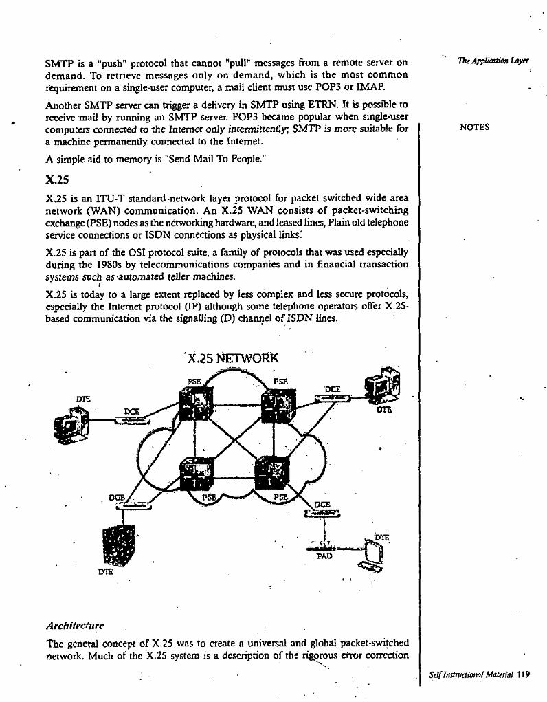
The Ap^ication LayerSMTP is a "push" protocol that cannot "pull" messages from a remote server on demand. To retrieve messages only on demand, which is the most common requirement on a single-user computer, a mail client must use POP3 or IMAP.Another SMTP server can trigger a delivery in SMTP using ETRN. It is possible to receive mail by running an SMTP server. POP3 became popular when single-user computers connected to the Internet only intermittently; SI^TTP is more suitable for a machine permanently connected to the Internet.A simple aid to memory is "Send Mail To People."
NOTES
X.25X.25 is an ITU-T standard network layer protocol for packet switched wide area network (WAN) communication. An X.25 WAN consists of packet-switching exchange (PSE) nodes as the networidng hardware, and leased lines, Plain old telephone service connections or ISDN connections as physical links.'X.25 is part of the OSI protocol suite, a family of protocols that was used especially during the 19S0s by telecommunications companies and in financial transaction systems such as -automated teller machines.
t
X.25 is today to a large extent replaced by less complex and less secure protocols, especially the Internet protocol (IP) although some telephone operators offer X.25- based communication via the signalling (D) channel of ISDN lines.
'X.25 NETWORK
DT&
ArchitectureThe general concept of X.25 was to aeate a universal and global packet-switched network. Much of the X.25 system is a desciiption of the rigprous error correaion
Self InstTvaioml Material 119
Computer Networks needed to achieve this, as well as more efficient sharing of capital-intensive physical resources.The X.25 specification defines only the interface between a subscriber (DTE) and an X.25 network (DCE). X.75, a very similar protocol to X.25, defines the interface between two X.25 networks to allow connections to traverse two or more networks. X.25 does not specify how the network operates internally—many X.25 network implementations used something very similar to X.25 or X.75 internally, but others used quite different protocols internally. The ISO equivalent protocol to X.25, ISO 8208, is the compatible with X.25, but additionally includes provision for two X.25' DTEs to be directly connected to each other with no network in between.The X.25 model was based on the traditional telephony concept of establishing reliable circuits through a shared network, but using software to create "viitual calls" through the network. These calls interconnect ."data terminal equipment" (DTE) providing endpoints to users, which looked like point-to-point connections. Each endpoint can establish many separate virtual calls to different endpoints.For a brief period, the specification also included a connectionless datagram service, but this was dropped in the next revision. The "fast select with restricted response facility" is intermediate between full call establishment and connectionless communicatioru It is widely used in query-response tcansaction applications involving a single request and response limited to 128 bytes of data carried each way. The data is carried in an extended call request packet and the response is carried in an extended field of the call reject packet, with a connection never being fully established.Qosely related to the X.25 protocol are the protocols to connect as5mchronous devices (such as dumb terminals and printers) to an X.25 network; X.3, X.28 and X.29. This functionality was performed using a Packet Assembler/Disassembler or PAD (also known as a Triple-X device, referring to the three protocols used).
' Relation to the OSI Reference ModelAlthough X.25 predates the OSI Reference Model (OSIRM), the physical layer of the model corresponds to the X.25 physical level; the link layer, the X.25 link level; and network layer, the X.25 packet level. The X,25 link-layer, LAPB, provides a reliable data path across a data link (or multiple parallel data links, multilink) which may not be reliable itself. The X.25 packet-layer, provides the virtual call mechanisms, running over X.25 LAPB. As long as the link layer does provide reliable data transmission, the packet-layer will provide error-firee virtual calls, [citation needed] However, the packet-layer also includes mechanisms to maintain virtual calls and to signal data errors in the event that the link-layer does not provide reliable data transmission. All but the earliest versions of X.25 include facilities which provide for OSI network layer Addressing.
User Device Support
X.25 was developed in the era of dumb terminals connecting to host computers, although it also can be used for communications between computers. Instead of dialir^ directly “into” the host computer — which would require the host to have its own pool of modems and phone lines, and require non-local callers to make longdistance calls — the host could have an X.25 connection to a network service provider. Now dumb-terminal users could dial into the network's local “PAD" (Packet
NOTES
//
Self Instruetioml Material
Assembly/Disassembly facility), a gateway device connecting modems and serial lines to the X.25 link as defined by the X.29 and X.3 standards.Having connected to the PAD, the dumb-terminal user tells the PAD which host to coimect to, by giving a phone-number-like address in the X. 121 address format (or by giving a host name, if the service provider allows for names that map to X.121 addresses). The PAD then places an X.25 call to the host, establishing a virtual circuit. Note that X.25 provides for virtual circuits, so appears to be acircuit switched network, even though in fact the data itself is packet switched internally, similar to the way TCP provides virtual circuits even though the underlying data is packet switched. Two X.25 hosts could, of course, call one another directly; no PAD is involved in this case. In theory, it doesn't matter whether the X.25 caller and X.25 destination are both conneaed to the same carrier, but in practice it was not always possible to make calls from one carrier to another.For the purpose of flow-control, a sliding window protocol is used with the default window size of 2. The acknowledgements may have either local or end to end significance. A D bit (Data Delivery bit) in each data packet indicates if the sender requires end to end acknowledgement. When D= 1, it means that the acknowledgement has end to end significance and must take place only after the remote DTE has acknowledged receipt of the data. When D=0, the network is permitted (but not required) to acknowledge before the remote DTE has acknowledged or even received the data. While the PAD function defined by X.28 and X.29 specifically supported asynchronous character terminals, PAD equivalents were developed to support a wide range of proprietary intelligent communications devices, such as those for IBM System Network Architecture (SNA).
The Application Layer
NOTES
7.4 WORKING OF E-MAIL
Since the facility of e-mail provided by Internet, people have more or less stopped using the post. It has been in fact, named as Snail mail, or the mail which moves at the snail speed. Whereas electronic mail is fast and moves over from one computer to another electronically at an amazing speed. Most of the Internet users are very happy with this facility. In fact, you can send not only the text, but pictures and graphics too.Most of the offices are sending their mail through computers. No more fussy papers or carbons. In fact, no need to file them too. All is stored in computers and can be accessed whenever needed. All you need is to open an e-mail account and start mailing your letters even if you do not have a computer. You can send the mail using your account number from any Cyber cafe too.So to work with e-mail you must have an account of your own. For this, as already mentioned, each popular search engine allows you to open an e-mail account. Here, in our case, I am using the account opening process of Hotmail.com.
Opening of e-mail accountThe following are the popular sites which allow you to open an e-mail account:
http://www.mail.yahoo.com
http://www.hotmail.comYahooHotmail
Self Instructional Material 121
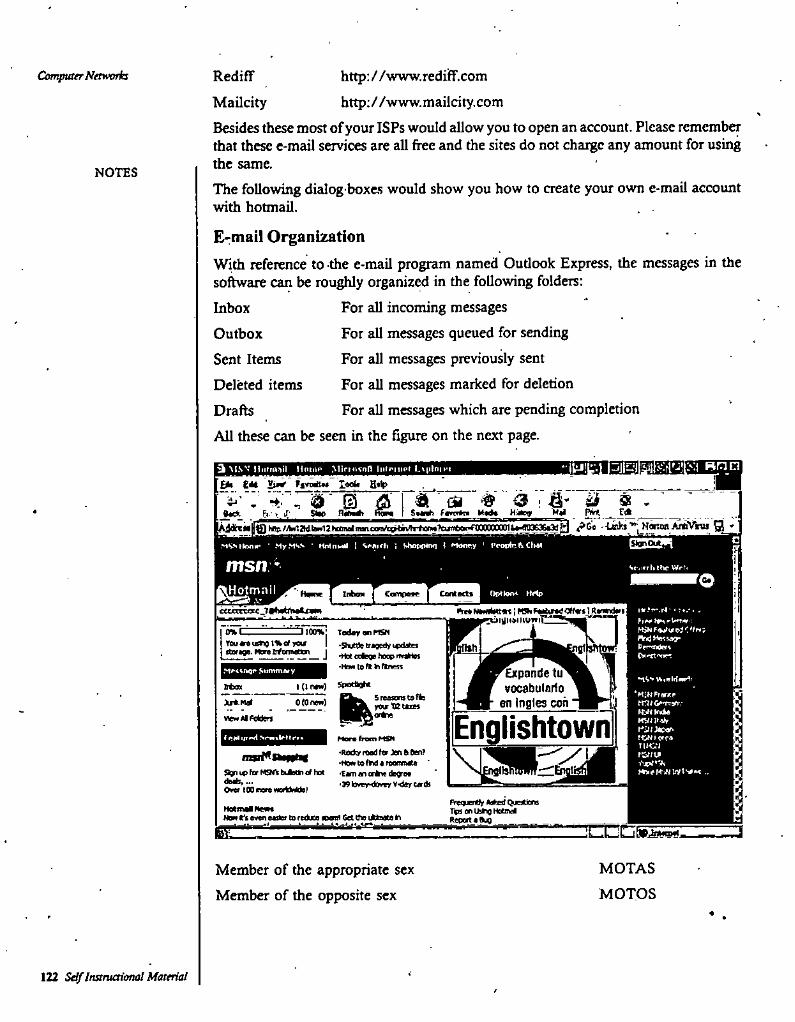
http://www.redifF.comhttp;//www.mailcity.com
Besides these most of your ISPs would allow you to open an account. Please remember that these e-mail services are all free and the sites do not charge any amount for using the same.The following dialog boxes would show you how to create your own e-mail account with hotmaU.
E>niail OrganizationWith reference to the e-mail program named Outlook Express, the messages in the software can be roughly organized in the following folders:
For all incoming messagesFor all messages queued for sendingFor aU messages previously sentFor all messages mariced for deletionFor all messages which are pending completion
Ail these can be seen in the figure on the next page.
Computer Nawoth RediffMailcity
NOTES
InboxOutbox
Sent Items
Deleted items
Drafts
3 M.SV lliitrti^iil HciiiiP MiriiKnf) liiti'iiK-r l.\|ilni>'i
£*• CM ffVDriiw loofa B'lp
. ^ ^ m <3 : ii a < 'SiW HUmOt HoM SMnh fanrtn Xtl fVir(*«* b-- ■ J:
GSEZn 2MS.sflAnir* • MyMVK * MiHomiI | ^ Hooey f-
msn ^ V. ifrUthc
OOl>*lo«» IMp
ctcoCTqt 7»ti»t,fin*i—
E1100%; Tettorw^0%CTBursisTio l%<< yew
•How to ft ^ ftnenSiHonuwy
SpeXfightfttot
ItMitnitMVJIiVr
tWffCs
fW/t!
5re«scnsuffemwXBUm0(0 nn>) %
Englishtownf eel ijr#*<l Hoec froco H9i ■Rsdv read ta Ten 0 Oen> .tren re (M a renmate 'Care an erOie da^aa
torer-dnry vdar cadi
,aari^nowm...
Ow i00ner»WQftMd»f ;FregiienlV Med (^jedeni TbsonudreHatSid BecBreaQia •aWotmaONena
Neai a«ei eadaf to reduce nonl Get tta dttaato bEl ]k
MOTASMember of the appropriate sex
Member of the opposite sex MOTOS
122 Sdf Instruaional Materialf

isLna Tht Ap^iaaion Laytr3 MSN llnltii.iil Moiy INpfnl Fvpiyiliy Mlftaiafl Itilrnii'i I vplojMi
C*> U> Smv ffniMti TmI* Hdp
. -d 3 sSi ' Ga 3Str* %»<ah iMK^ TMtn ««*• >Ma* (M Pwi
> ,i. .Sack
^ ^^GyUtfa •^ NanadAtiliN^ QAjdr««m hnp/^liillkeBwieaMWftewVcgrtMi^
Naw toHotmat?
Hotmail’ NOTESsign Up fori Free l-rwl*cceuM1 (MirSiTil^) <«nd get • FPoetaO^ M7 Pattperf)
msn\ A ps wioot*
#4^ *•*<*•#» yd M* itfstic/.9^4 budd*««» orfr«, «rd ojc^ir dvo**
..«V r^JTi e
Ak'Cddv hevQ • Hotmal accoint?
‘#|NM4inl3^tamoid
fcrgpt tM 9MS9ftCf€i Sigry^Q In?r^Ah- y iV4.i>. '
Sccuiay (^Uons (atiat'f tfCiT):C KiUefiFivrd cofptfa,C, KMp >n ognad n to Mi ard rictfier JCT
PBOoit at«> irton I dip out.
Need nr WaaaBcn en mcmed ml JCT PasQort t Qdi tart.JStRaxxTt
O 2003 Moo<^ CerperflUyii Al rii^ luivuJi TDtMSOFUSE TRUSTfiApprovedPrMcvSMtmwt
Before we start reading and sending the e-mails, we must understand few e-mail terms which are quite useful'in reading and sending messages.Using AbbreviationsAn abbreviation would save both time and space. It is important that the abbreviations used by you are understood equally well by the receiver of your e-Mail. So I give here a list of abbrevations which have by now become the universally accepted abbrevations around the world.
Full Word/Term/Phrase Abbreviation
BTWBy The WayFrequently Asked QuestionsFriend of a friendFor what it is worthFor Your InformationIn My Humble OpinionIn My OpinionIn my opinionIn other wordsIn Regard ToLaterLaughing out loud
FAQFOAFFWTWFYIIMHOIMOIMOlOWIRTLRLOL
Self Instructional Maurial 123
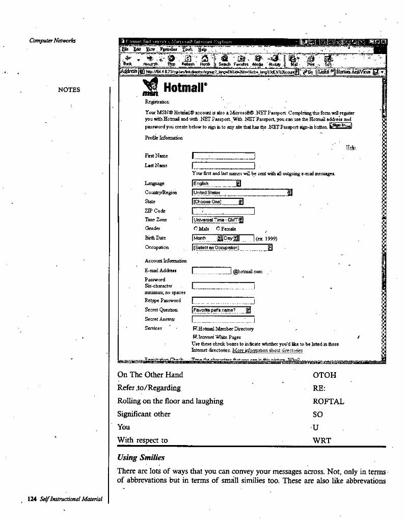
Computer Networks 3 rntllllll .rmil SCI vi'l Miriiisdlt Iiilciricl ISpInici
■-'"nSs* Betoh' Hone ]j Sesch fioidlet tltsftW.
. ( .[|
Hotmail'NOTES mstt.Registration
YourMSNC>Hotmail® account is also a^ficroso&® .HFT Passport Csn^letingtiiis form will register you with Hotmail and witti NET Passport. With NET Passport, you can use the Hotmal address and password you create below to sign in to any site that has the .NET Passport sign-in button.
ProSIe Information
HetoFirst Name
Last Namefour first and last names win be sent wifii all outgoing e-mail messages.
Language Country/Region State ZIP Code Time Zone Gender Birth Date Occupation
11English
MUnited States
81[Choose One]
Universal Time ■ GMT |g} O Male C Female
.. . I(e*. 1999)
znAccount Infoimation
E-mail Address ____ 1 @hotmail.comPassword Six-character minimum; no spaces Retype Password Secret Question Secret Answer Services
.i¥j
J,
%Favorite pet's name? !§
R Hotmail Member Directory R Luemet WUte Pages
Use these check boxes to indicate whether you'd lilce to be listed h these iitemet directories. More infonnation about directories
/y
....i. . - ?V*»Ni4 tisia* mOn The Other HandRefer .to/RegardingRolling on the floor and laughingSignificant otherYouWith respect to
OTOHRE;ROFTALSOUWRT
Using Smilies
There are lots of ways that you can convey your messages across. Not, only in terms of abbrevations but in terms of small similies too. These are also like abbrevations
124 Sey Instructional Material
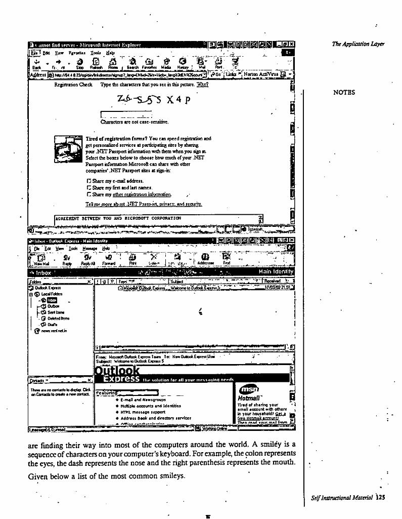
The Application LayerBilKiiails:! Una3 » jiuiot find »pr>ei ■ MifimnH IiiIpiupI ExiiIout
[On g« V,.w FiroiiUi looli Help _
b g j,'£: i ^......... ^A,
IR«|iftr<Boa Checlc Tnie fee daraettn thit you lee n ttii» pieage, T/hv?NOTES
X4 p IIChvscttrt vt net ctse-iensore.
Tired ef ragtotmtion fomt? You cn (peed regimitton end get penoneSzed letyicet it pertidpeting ctei b; tbihsg jreiv ,HET Pisipon infonnition watt tea when you ago n. Select the boxei below to eboo te how taudi ef your .NFT Piftpon nfoRoatioe Micretefi cto (hire with ether eoatpisiet' .NFT Puipott tilei it nst-b:
fj 9iirt my e-mi2 iddrett.C Shm toy fim nd lut nimei.C Sure mv other fewtOMtofi ofonnatiofi. ,■
TeB me more ib.nit .IJET pMtaott. privicv. ind teeuritY.
(
iI1ICUCROrr SETVtCH TOU WS lIlCItOSOrT CORPCtUTICN
• ||5j|‘:ij|iijj:<iiMUX||ij| Biao• OutUiol Ctptext • H«in ItfentitrJi pt ■ £d( Y— ■ 1"* jj* '_2_
■ bO ■; 'B X''] '"^r © ^fl<0» fawnd , Pm J --e-. tfy I, ___ frt______^l.'HlwHJ
' .J
B Main Idontity:' Inbox-!lal.?-iriom**.' I'Scbitct •X
Q~>g<b>Mil}uaad.Ei(»m'-IW»l(xroloOuU3AlintMV'l7! 215l2l^ OiibckEipnn B ^ leulWen
-«!ES]Cuba
Ltd Sen Dm . Q Ddeledllein
^ newt.vptnAn
/
I
a’£itil*J -Fisa: HaotcflOiAokEimnlon Ter N>aOullookEioe»Un>
Sibioct: WeleoiMwOulDefcEiitMiS ___ '________
Outlook ih:
Express TKr ioluUofi for <il1 your m*‘s<«io^nq f»f>r»rtsB^SSSi-Z.Then »enocor(ic*(lodirtw. CM. cn Cemets to enite 4 ran ocrtieL
X,
iJ Hotira/r ITlr«i) of sharing yovr * ) emoil oceount frith othert ^ In yourhovsohoUf Sjtu ^
rfiAfl vmif.mAil frftm
• E'Otoil ofxl ktwtgroups• KuRiole ooeeunu inO Identities• HTMl message supporto Address booir end dreccorr services
AsMemsM » ■ win npTwm
:aty/^(iAoO^' ~rl,woiiDtiil,Tli4^.I
finding their way into most of the computers around the world. A smiley is a sequence of characters on your computer's keyboard. For example, the colon represents the eyes, the dash represents the nose and the right parenthesis represents the mouth.Given below a list of the most common smileys.
are
:
Self InstTuetUmal Material 125
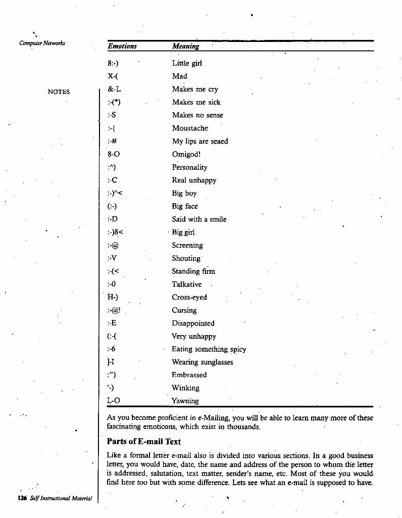
Computer Networks Emotions Meaning
8>) Little girlX-( Mad&-L Makes me cry
Makes me sick
Makes no sense
Moustache
My lips are seaed
Omigod!Personeility
Real unhappy
Big boy
Big faceSaid with a smileBig girlScreeningShoutingStanding fiirnTalkativeCross-eyedCursingDisappointedVery unhappyEating something spicyWearing sunglassesEmbrassedWinkingYawning
NOTES-(*)-S
•{-#
8-0
-C
(:•)-D-)8<
-V
-(<-0
H-)
:-E
(:-(:-6
M
L-0
As you become proficient in e-Mailing, you will be able to learn many more of these fascinating emoticons, which exist in thousands.
Parts of E-mail TextLike a formal letter e-mail also is divided into various sections. In a good business letter, you wotdd have, date, the name and address of the person to whom the letter is addressed, salutation, text matter, sender’s name, etc. Most of these you would find here too but with some difference. Lets see what an e-mail is supposed to have.
126 Self Instructional Material
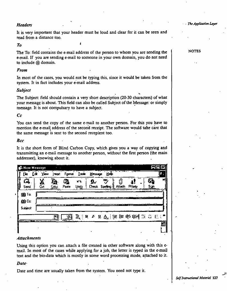
- The Applieation LiyetHeadersIt is very important that your header must be loud and clear for it can be seen and read from a distance too.
♦ToNOTESThe To: field contains the e-mail address of the person to whom you are sending the
e-mail. If you are sending e-mail to someone in your own domain, you do not need to include @ domain.
FromIn most of the cases, you would not be typing this, since it would be taken from the system. It in fact includes your e-mail address.SubjectTTie Subject: field should contain a very short description (20-30 characters) of what your message is about. This field can also be called Subject of the Message: or simply message. It is not compulsary to have a subject.
CcYou can send the copy of the same e-mail to another person. For this you have to mention the e-mail address of the second receipt. The software wotild take care that the same message is sent to the second recepient too.BccIt is the short form of Blind Carbon Copy, which gives you a way of copying and transmitting an e-mail message to another person, without the first person (the main addressee), knowing about it.
New Message m^ Imatt Fgrmat loob Me»age
Undp0/ "S' 1 i3 ♦* .
D)ed( Speing I Attach Pnenty SianSend
gaCc: /
Subject: f
"M I ®- 4; t P- '■ *rL
AttachmentsUsing this option you can attach a file created in other software along with this e- mail. In most of the cases while applying for a job, the letter is typed in the e-mail text and the bio-data which is mostly in some word processing mode, arched to it.
Date-Date and time are usually taken from the system. You need not type it.
Self InstTuetUmal Material 127
Computer Networis Body
The body of an e-mail message is simply the text that you want to .gend to the other person.
Working with Messages 'The first thing that you would do on opening the software would be receive the messages. For this you will have to click on Send/Receive button.You can also set Outlook to automatically check for messages at regular intervals, or you can have Outlook check for message whenever you want.
1. Click the Send/Receive button on the Standard toolbar, as shown below.2. The Intenet connection will be made depending upon the type of connection
you have. Its progress will be shown to you in the dialog box in the lower right comer of the tvindow.
3. When messages arrive. Outlook asks you whether you want to start reading them. Click Yes in the Microsoft Outlook dialog box to starting reading messages, or dick No to read them later.
Reading a MessageOnce the messages have been received in the Inbox, they will be appended to the other ones, i.e., in the last. The last few messages are always new. There are various type of messages which are there in the mailbox.The messages in the Inbox can have the following symbols attached to them.• Unread message• High importance message• Low importance message• Message that has been read• Message with attachment *• Message that has been forwarded• Message that has be,en replied to• Meeting for which response is requested• Follow-up flagAll these have a symbol attached to them..Reading the Message
1. Double-click a message in the Inbox list.
NOTES
. \
OrSelect the message to open and press Ctrl + OOrSelect the message to open and from the File menu, choose Open. Then choose Selected Items from the submenu.
Each message opens in a separate window.128 Self Instructional Materia!
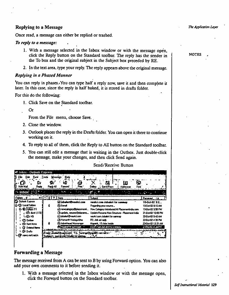
Replying to a MessageOnce read, a message can either be replied or trashed.To reply to a message:
1. With a message selected in the Inbox window or with the message optfn, click the Reply button on the Standard toolbar. The reply has the sender in the To box and the original subject in the Subject box preceded by RE.
2. In the text area, type your reply. The reply appears above the original message. Replying in a Phased MannerVou can reply in phases.* You can type half a reply now, save it and then complete it later. In this case, since the reply is half baked, it is stored in drafts folder.For this do the following:
1. Gick Save on the Standard toolbar.
The Applieotion Layer
NOTES
OrFrom the File menu, choose Save.
2. Close the window.3. Outlook places the reply in the Drafts folder. You can open it there to continue
working on it.4. To reply to all of them, click the Reply to AH bunon on the Standard toolbar.5. You can still edit a message that is waiting in the Outbox. Just double-click
the message, make your changes, and then click Send again.Send/Receive Button
tInbox - Outlook I'.vprpss
k •£}• Edrt Sww .Xuoli M'xlc* U*Ip i i
RwiiAJ Fonwrd RM.' Oabu .J S*ridfi«cv .( Ad^nw Trd /inbox' Z'-i: • • , V' Vj
I Riw^d. ll^ OtlioefcEiemt ^ LecatFdden
U£|M8 r ^ Quito k ^ S«itlteR) t 9 Detodllp*
XII; I e I ? I fot Tsu^BjobtortOnauluicow
tl QSondl£)toic«l«gat;€iplsetmi(i,. HenC<legaylntrediicedAlPlsc«nertrtf»c«nt ISOcitCSiSDPH'Q*«d«!a_t«MiieSvlae«nie- UpdaleRmnaRmSkuchrt-naecmenlInda 21OeMB1Q09PM0 iebtot^ntoA esrn 0 H«nur«i Vedicatto
0 QjafaAhMdWetwnBW
nnduleea Jobalnl lot »i—ajp Reganfcg you lettne..
1U)ct-02 3:2...1SOd-02 aiBAM
(Itwiiui com Jobtol fa Mmay RE: dob (d rao^Maya*. 15 Jeb« Intifc
22Oa4e&40AM 22Oet02d39PM 230ei<CI2 IZn AH
& eom Icr i wMv
f.vwliJlVr't' A."1 .Sim
Forwarding a MessageThe message received from A can be sent to B by using Forward option. You can also add your own comments to it before sending it.
1. V(ith a message selected, in the Inbox window or with the message open, click the Forward button on the Standard toolbar.
SelfInstTuttbmal Material 129
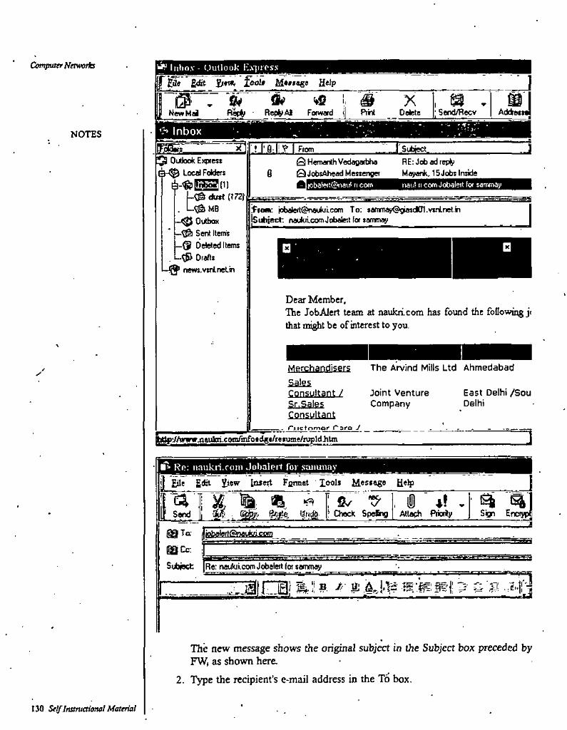
CompuKT Netwolla ^ ln*io,v - Outlook HyprossjTptf £dSt fool* Help
W if ^ i. M XRet»AI Fofwaid t| Prim Oefete
1 0’ : 0 NewHd
fiaI' Send/Recv AddBttt
'h InboxNOTES[^Sh^ “ir .r Subject j? I' fl l! I Ftom
Outlook EKtKe?*Local Folders
A-t&l!n^(n [-^ du»e (172}
. L^mbOuttXK
—^ Sent Items Oeteled Items
, Draftsnews.vsrlneLin
^ Hemanth VedagarUta 0<lobsAhead Messenger
RE: Jobadrep^ Mayank. 15 Jobs Inside6
lobaterttj'oai.i' n com nau! ti com Jobalert for sarrmay
jobaleft^^aukilcorn To: [email protected] {Subject: naukdcomJobalert for samnay
Dear Member,The JobAlert team at naukri.com has found the following j< that might be of interest to you.
The Arvind Mills Ltd AhmedabadMerchar^disers✓SalesConsultant ! East Delhi /Sou
DelhiJoint Venture CompanySr.Sales
Consullaoi- rj.ictomar Taro J
]aufcri.com/infosdas/resuint/tupldhtm
Ro: iiauk.in.r()in Jobalort for saiiunayH Edit 2,iew Insert Fflrmat lools M«s»ag«
"J?* , iS 4? *' ^ ^.. gcjte, ijn# !’_Check Speing | Attach Priority Sign EnctypI[Send \m
2)99 Ta ijkrfaatertg^^^^^
SBgQCc:Subject Re: tsaukrlcom Jobaleft (or sainmay
7i^v' ■:£'•
The new message shows the original subject in the Subject box preceded by FW, as shown here
2. Type the recipient's e-mail address in the To box.
130 Self InstTuetimal Material
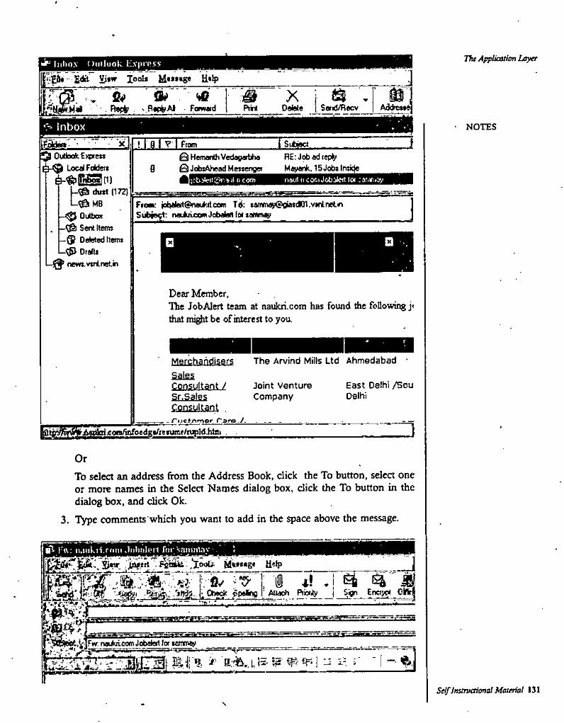
Tfu Appliauim Layerliiltox Onilook L.vpir.'SS
- "Edit W lool* H»ip
X Si J Mm. B«rt? V fl<ptiAi ■ Fowwd A3dre»*^DoMe Sand/RecvPrii
Inbox ■ NOTESi■■ ■■■ 'x I Sublet! I fl I ? I Ftom
Q OUbokEw'ets Local Foidet*
dutt (172) MB
; OutboxSent Items
-9 Deleted Items Drafts
I—news.vsrineLin
0HernanthVeda9art)ha RE: Jobadtepl^S 0J<ibsAhead Messenger Mayank. ISJobsItwde
ti4i.l1 It cor.i Jobjiert lor :3fp>fif3v;cti3l<riit;'it^S'il it com
Fiom: iobalert^neiicilcom To: sammay®giatdK}1.vs(inet.m Subjegt: naululcomJobalart fw samnay
Dear Member,Hie JobAlert team at naukn.com has found die foQowmg j< that mi^t be of interest to you.
The Arvind Mills Ltd Ahmedabad ■Merchaiidisers
SalesConsultant /Sr.SalesConsultant
East Delhi /Sou Delhi
Joint Venture Company
-/■i.ic.tnmor faro./.
]’A*t*^jeon<tofoedg»/refume/njpld.hter
OrTo select an address from the Address Book, click the To button, select one or more names in the Select Names dialog box, click the To button in the dialog box, and click Ok.
3. Type comments'which you want to add in the space above the message.
Frt: ii.jiikii.rriiii JiihiilrMl frii''saitui^y_,|^.srtT.fi^'.,^;ou. M«fs.g< Help
I if .i ^Eno>^ OlftfiAU<sch Priority
»sw. rwArlcom Jobalert lor tcrrvii^
Seif InstTuOional Maierial 131\
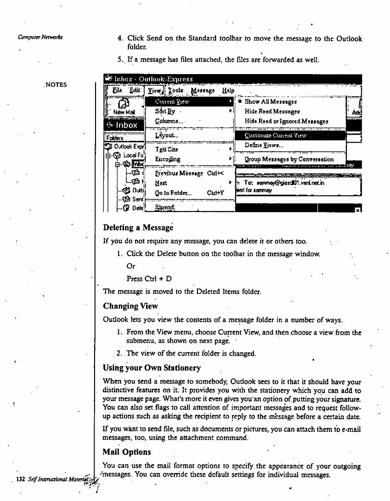
Computer Networks 4. Click Send on the Standard toolbar to move the message to the Outlook folder.
5. . If a message has files attached, the files are forwarded as well.
w? Iiibo.v- OuUoiik-lLi'pi'OSS. NOTES f Die Edit ] l|efl^[jpols . Message de^ 1
• Show AUMetsages Hide Read Messages Hide Read Of Ignored Messages
C'.iiient Views^By •Qohntns...
' NwMai
C-* InboxIc4yout... Customize Cuiienl View .LL^’s'" ]
Define Views...Outkxd^Expt Local Fo^
OultiSent'
1-9 Oe!e|
Tfj±'SizeEncoding
*» ' Qroup Messages by ConversationI
'.leyprevious Message Ctxl-K HartQo to Folder... Ctri+Y
n To: *amma}i09OsdD1.vtrinet.in lieit for temrru^
s
Esjjanj;
Deleting a MessageIf you do not require any message, you can delete it or others too.
1. Click the Delete button on the toolbar in the message window.OrPress Ctrl + D
The message is moved to the Deleted Items folder.
Changing View
Outlook lets you view the contents of a message folder in a number of ways.1. From the View menu, choose Cuircnt View, and then choose a view from the
submenu, as shown on next page.2. The view of the current folder is changed.
Using your Own StationeryWhen you send a message to somebody, Outlook sees to it that it should have your
, distinctive features on it. It provides you with the stationery which you can add to your message page. What's more it even gives you'an option of,putting your signature. You can also set flags to call attention of important messages and to request followup actions such as asking the recipient to reply to the message before a certain dateIf you want to send file, such as documents or pictures, you can attach them to e-mail messages, too, using the attachment command.
Mail OptionsYou can use the mail format options to specify the appearance of your outgoing
''messages. You can override these default settings for individual messages.132 Seif ItatruaUmal Mareriaj^P:'/
The Application LayerSetting Mail Format Options1. From the Tbols menu, choose Options.2. On the Send tab of the Options dialog box, choose a format from the Send in
this Message Format drop-down list.Choose HTML to send the message in the format used for Web pages, which allows text formatting. Most .popular mail programs can display HTML e- mail messages. •Choose Microsoft Outlook Rich Text if you know that your recipient uses Outlook too. This setting allows you to use boldfacing and other formattu^ in the message.
3. Chck Ok when you have finished.
Choosing Default Fonts1. On the Mail Format tab of the Options dialog box, choose the Plain Text or
Microsoft Outlook Rich Text format option.2. Click the Fonts button.
• 3. In the Fonts dialog box, choose the default fonts for messages you type.4. Click Ok to return to the Options dialog box.5. Click Ok when you have finished setting options.6. If you choose HTML or Microsoft Outlook Rich Text as the mail format, a
formatting toolbar appears in a new message window. You can use the buttons on this toolbar to set text formatting for the message text.
7. In the Fonts dialog box, you can indicate when you want your default foots to override stationery fonts.
Starting and Addressing a MessageYou can start a message from any Outlook e-mail folder, address the message to as many recipients as you want, and send copies to anyone who might want to be informed. You can also send a blind copy (hidden fix)m other recipients) to someone.
Starting Message1. In the Inbox or Outlook Today window (or any other e-mail folder), click the
New button on the Standard toolbar.2. If your e-mail editor is not Word, choose whether you want Word to be
defeult editor.3. A message window with the default formal opens.
Typing Addresses '1. In the To box, type a single e-mail address.
NOTES
OrType several addresses, separating them by commas or semicolons.
Self Instructional Maiierial 133
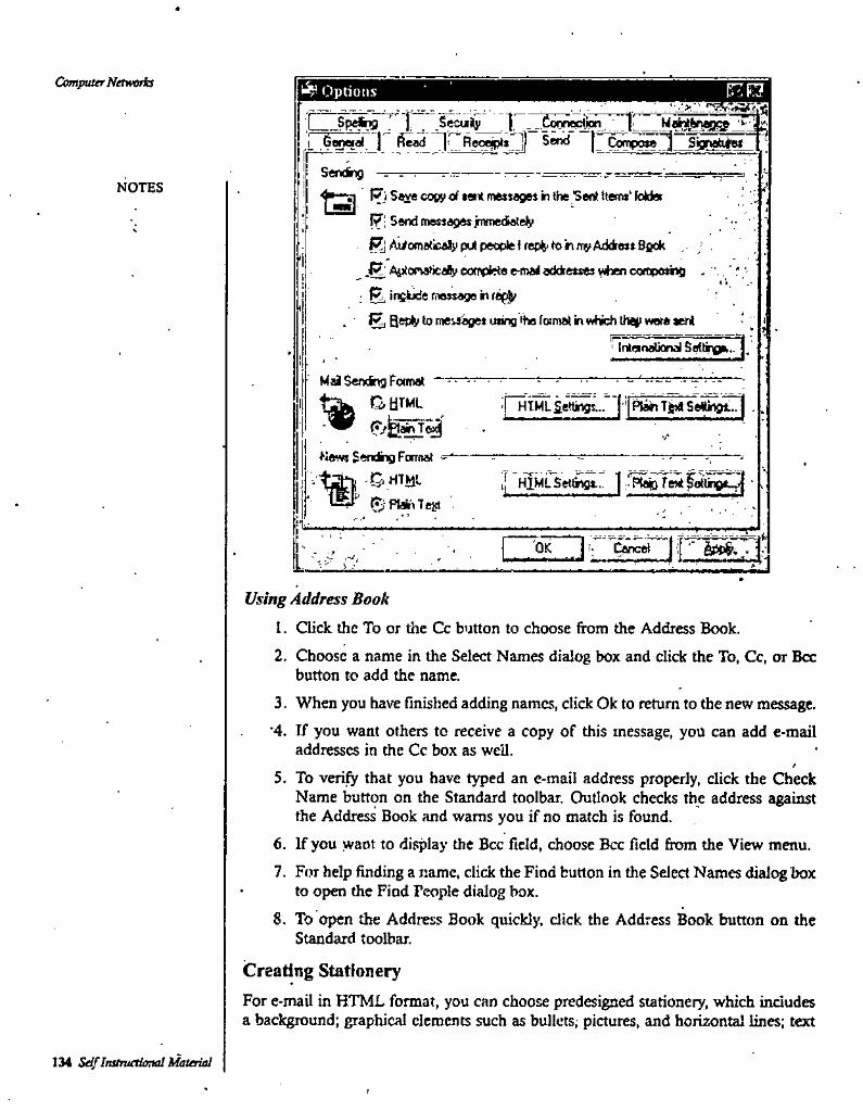
Computer Networh Options
L Sjgrgh^f ^Spefcig ' Seculy | _,Conneic^r"€^^_p fed
Sendlnj - . .------ :------------rr:—
I^iSa^ copy of *«ntmet$age«h the Sent Hems'fdid«I7i Sendcnessegesjnvnediately{^^iomaticdypulpeopleirep^tonrnyAddisssBfiok ;
j^AiJtorkaHcaByeofnpfctee-maioddfetjeswbencoftiposrg .; ^inpl^ message in
H) meisages using the foimal in which they were eeriTntanatiOKdSefti^.. j.
Send
NOTES <*
Mai Serring Foimat “
flews Sending Fornat ^
tSiW e Plainest
pTMlSettisgs... '['|f^~Tjpa'Settytr]V*
I HlMLSeti^gt... :^'Sao TeMfoiUngtw ‘
DCMlIOK }■ Cancei
Using Address Book
1. Click, the To or the Cc button to choose from the Address Book.2. Choose a name in the Select Names dialog box and click the To, Cc, or Bcc
button to add the name.3. When you have finished adding names, click Ok to return to the new message.
•4. If you want others to receive a copy of this message, you can add e-mail addresses in the Cc box as well.
/5. To verify that you have typed an e-mail address properly, click the Check
Name button on the Standard toolbar. Outlook checks the address against the Address Book and warns you if no match is found.
6. If you want to display the Bcc field, choose Bcc field from the View menu.7. For help finding a name, click the Find button in the Select Names dialog box
• to open the Find People dialog box.8. To open the Address Book quickly, dick the Address Book button on the
Standard toolbar.
Creating StationeryFor e-mail in HTML format, you can choose predesigned stationery, which indudes a background; graphical elements such as bullets; pictures, and horizontal lines; text
IM Self InstTvetitmalMaterial
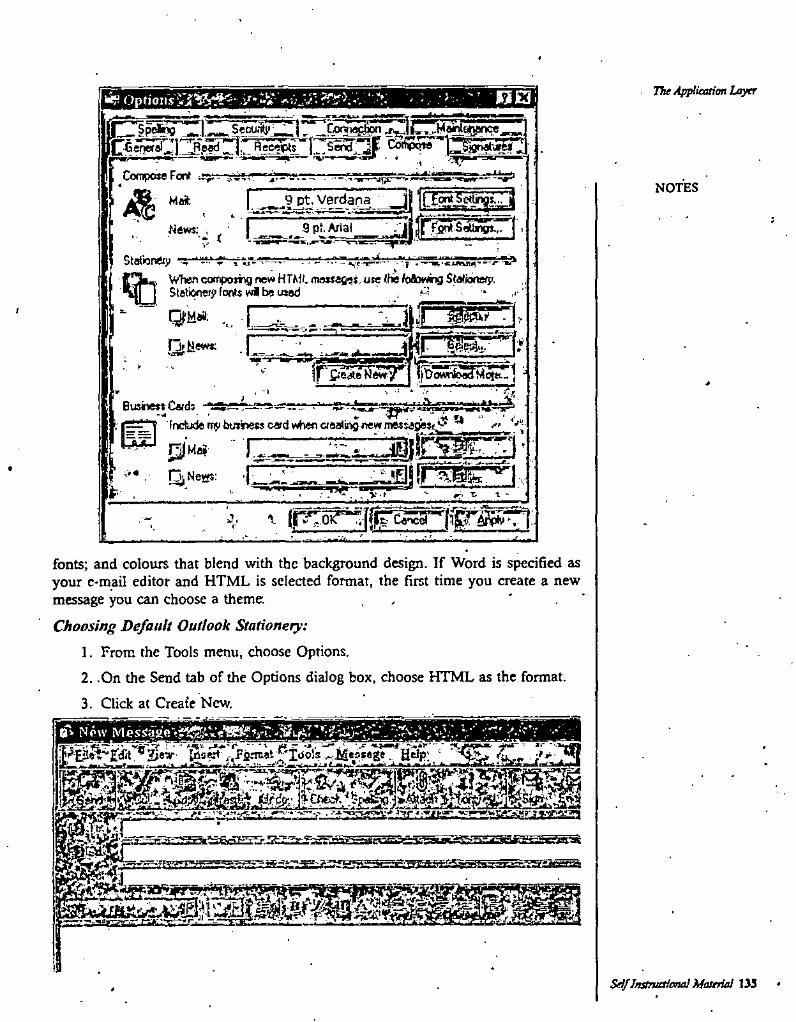
The Application LayerRE3*• r•>•:• ■
CocnposeFont "yg4
1^4.- -«
NOTES>21 ^^9 pt. VerdanaMri:
News:XSWnnery ■^s"*-*' a **
When ccxnposng new HTMi. mnssege^ use (he foAowhg Statnnssp. Ststieriei^ Fonts wi be usedQm ■ [~
-Cr]I
.,. -
rsssjRwH^pSssss:’! ■■V
*V
*, -I
J .V
indude rn^ busbess card when aeatingnew messedest^^ ^ e' ''■'^0'w^' " ’ ’
njNoHS: -^_ IIl_ZEp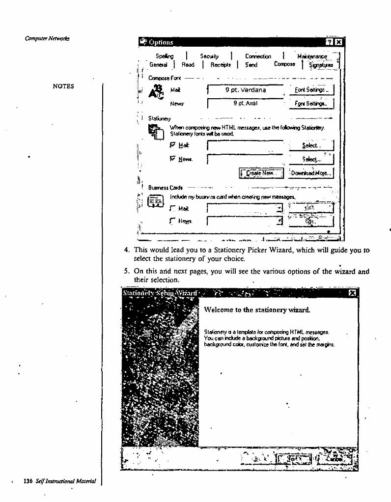
Computer Networks Oprionx 0C3Sec'jii^
GeneiiJ j Read I Receipis I SendSpeling Connection 1 Maei^anw.__ ,
CoW3*e j S’jg^w ’r •I &)inpote Font
NOTES Eont Setting;..IMai’ 9 pt. Verdana4l!
fsf* Seilrge..9dLAjlalNewy
I' 1 StationeijiWhen competing new HTML mesuget. uee the fdowing Slatiorfny. Stationery fonts wi be used.
P Mat ; Sriect. I
Sjeej,.. I
f^i^^e'F?e5rr"’;| lDowrtoadMqe...(
17 tiews.
^ Business Cards
f f■ i.i >.
include my busev'^ card whertoeetingnevi messages. ^ r Mai [
r Hesss, rcc.'t•» . -I
1 ''W9
_ J ini^
4. This would lead you to a Stationery Picker Wizard, which will guide you to selea the stationery of your choice.
5. On this arid next pages, you will see the various options of the wizard and their seleaion.
Welcome to the stationery wizard.
ir-'.-rJStationery is a temptate for compostig HTML messages. Vou can inctude a background pictue and position, background color, cuslomire the font, artd s^ the margins.
V i'-i
.' *? ' .•■■J.
r n T?
136 Self Instnutional Material
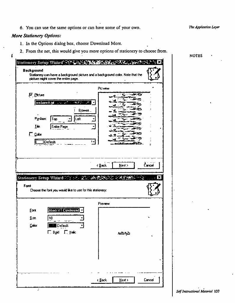
6. You can use the same options or can have some of your own.
More Stationery Options:1. In the Options dialog box, choose Download More.2. From the net, this would give you more options of stationery to choose from.
The Application Layer
I NOTES
BocfcgioundSlationeiy c«n have a background picture and a back^ound color. Note that the pictue night covet the entire page.
PreviewPfctue
airibanrA-grf c
Siowte... -sL*.PirHion; JTo(d~ |Lek
lile: |^nt«P^_^
rCcfa.
3 :A
3
3IC^pefarJt e%sx. •J
<BMk ] ' tlext> j Cancel j
Stnlinnoiy Sohip Wfraid X
0FontChoose the font you would 1^ to use for this stationery;
Preview.
3ISEert .badi K! T- Condensed
\'9 7Z 3&2t-
3£oloi: Default r Bflid r Itafc faibffiz
<fi«k I > I Caned
Self Instructional Material 13?
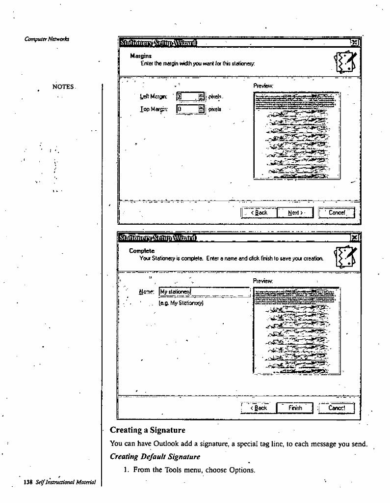
Computer Networks MMaigint
Enta the met^ width you want (ex this stalicmeiy:
Preview;NOTESteft Mcrgn ' ^
Xop Margin: [o pixel*SaTMMCiS'
.■:77j;9-,^>vCJW3S";
?
? ' .i
.J^\ '••
4!JiSs3R•» '
I ^ •
<fiack ] Klexl > | p‘ Cancel.'^'
StatioinFi‘yi.Scttii»lWiMrdl MComplele
Your Slationeiy is complete. Enter a narrre and eSek Tmtsh to save your aeatioa
U
Preview:
ac^: |Myslationei>(
.. le.g. MySlWianay)
gL^Sa?'ga «gi» -SRStSSSSS *
;^rai.^S:5
'_____ t-^r-yi ■■•iM****^
; ''<Ba^ I ~ rnish ’ j ;j ~Cwx1
Creating a SignatureYou can have Outlook add a signature, a special tag line, to each message you send. Creating Default Signature
1. From the Tools menu, choose Options.138 Self Jnstruetional Material
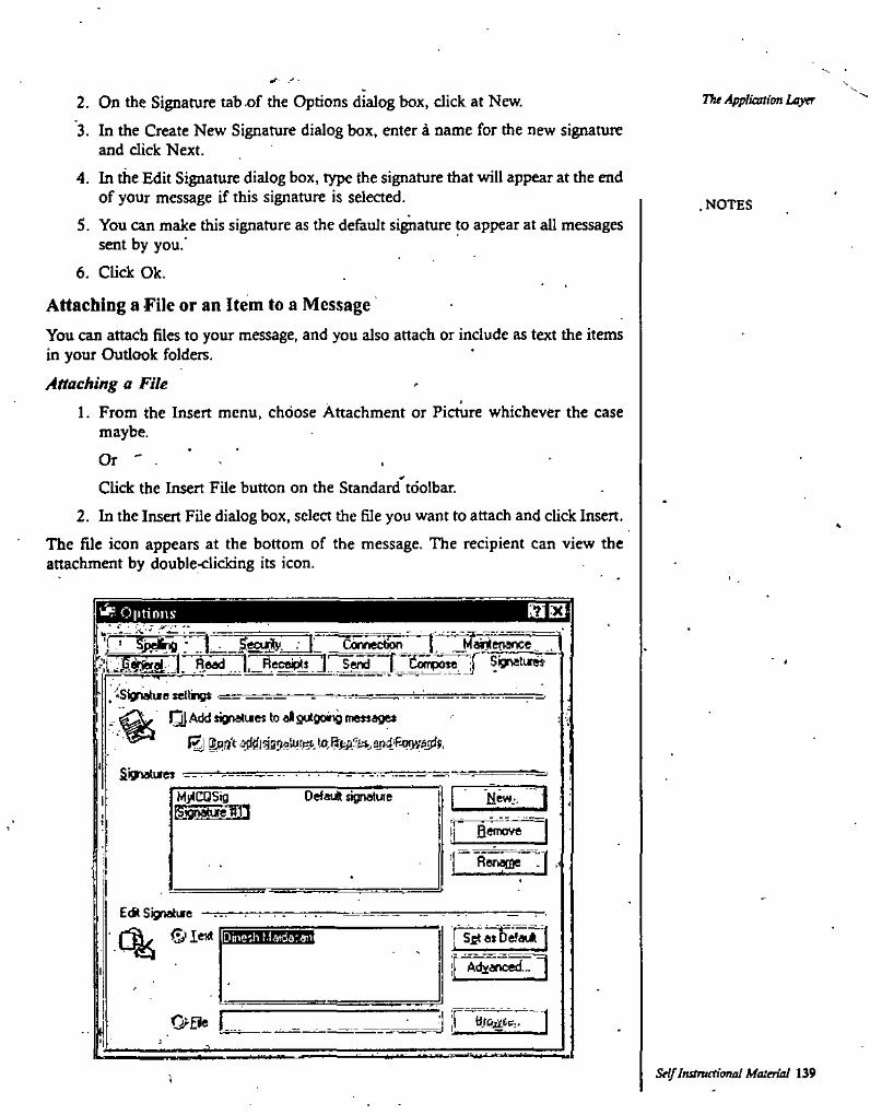
The Apjiiastim Layer2. On the Signature tab of the Options dialog box, click at New.3. In the Create New Signature dialog box, enter a name for the new signature
and dick Next.4. In the Edit Signature dialog box, type the signature that will appear at the end
of your message if this signature is selected.5. You can make this signature as the default signature to appear at all messages
sent by you.’6. CUck Ok.
Attaching a File or an Item to a MessageYou can attach files to your message, and you also attach or include as text the itemsin your Outlook folders.Attaching a File
1. From the Insert menu, choose Attachment or Picture whichever the case maybe.
.NOTES
OrClick the Insert File button on the Standard toolbar.
2. In the Insert File dialog box, select the file you want to attach and click Insert.The file icon appears at the bottom of the message. The recipient can view the attachment by double-clicking its icon.
^ O|itions
. ^peifria I - Seeuily- I Conne^iw '1. iiead gypo”. ir ^gnatiw
n
, -Signatute settrtgsQ|AddsignatuettoalgutCiongrr«»age»
S'sinaturejNw- '' I
» , T . • s -i|
Ronaffie . (
Defauft signatuieMyICQSigBjdriatuw°ig
E<i( Signature —: ©lext fsg default% iDbeih l.iatdatan'
|[ Advanced...
Ofie i
Self InstrueTional Material 139I
CmgmierNetwoHsSUMMARY
1. Computer or network security has been violated when unauthorized access by any party occurs.
2. Network administrators like to believe that their network is secure and those who break into networks may like to believe that they can break into any network.
3. These different areas of computer security are interdependent on each other in order for a network to be secure.
4. The bottom line here is that unless you can remove all the application and operating system problems that allow viruses and intruders to penetrate networks, you can never secure your network.
5. A hacker is no more likely to break the law than anyone else6. Spyware is a computer program whose purpose is to spy on your internet activities usually
for marketing purposes and usually done by a shady corporate entity.'7. Confidentiality is the information available only to people with rightful access.8. Contrary to the academic hacker subculture, networking hackers have no inherently close
connection to the academic world. '9. In die academic had^r culture, a computer hacter is a person who enjoys designing software
and building programs with a sense for aesthetics and playful cleverness.10. Acadeniic hackers usually work openly and use their real name, while computer security
hackers prefer secretive groups and identity-concealing aliases. •11. The early hobbyist hackers buftt their home computers themselves, from construction Idts.12. All Internet Service Provider allow you to open an e-mail account.13. In Oudook Express, Inbox is used for incoming messages..14. Outbox is used for sending messages.15. Sent items stores all messages previously sent.
.16. Deleted items has the messages which are marked for deletion.17. Drafts has all the half completed messages.18. To cut down the time of writing a message, lots of abbrevations are used.19. You can even use Similes in your message.20. Various parts of the e-mail text are: Headers, To, From, Subject, Cc, Bcc, Attachments,
Date and Body.21. Using Send/Receive button on the standard toolbar, you can send and receive mail.22. Various type of messages are: Unread message. High importance message, Low importance
message. Message that has been read. Message with attachment. Message that has been forwarded. Message that has been replied to. Meeting for which response is requested and Follow-up flag.
23. For reading the message you can use Ctrl-t-O.24. You can click the RE button for replying to a message.25. By using FW you can forward a message.26. You can delete a message by Ctrl+D.2 7. You can create your ovm stationery for sending message.28. You can create and put your own signature in messages.29. You can attach a file to your message.30. You can even attach a picture to your message.
NOTES
SELF ASSESSMENT QUESTIONS
1. What is a Network Security?2. What is the need for network security?3. Who are hackers?
140 Se^Instructional Material
'■f
sI
4. What is meant by physical security?5. Who are academic hackers?6. What is the difference between networking hackers and academic hackers?7. What is e-mail?8. How would create your own e-mail account?9. Which are the different folders in Outlook Express? .
10. Which type of messages you have in Outlook Express? •11. Describe the process of replying to a message.12. How would you forward a message?13. Howwouldyoucreateyourownstationery?14. How would you create your own signature? ' '15. Describe the process of attaching a file to your message.16. Define the following terms:
Protocol IntegrityVerification - rionrepudiation Spyware
Short Questions with Answers1. What are the needs for network security?
Am. These include:• Damage or destruction of computer systems.• Damageordestructionofintemaldata.• Loss of sensitive information to hostile parties.• Use of sensitive information to steal items of monitary value.• Use of sensitive information against the organization's customers which may result in leg^
action by customers against the organization and loss of customers.« Damage to Che reputation of an oigariization. -• Monitary damage due to loss of sensitive information, desttuction of data, hostile use of
sensitive data, or damage to the organization’s r^utation.2. Whoisahacker?
Ans. In a security context, a Hacker is someone who is mvolved in computer security/insecurity, specializing in the discovery of exploits in systems (for exploitation or prevention), or in obtaining or preventing unauthorized access to systems through skills, tactics and detailed knowledge.
3. Describe the various components of an e-mail organization.Am. With reference to the e-mail pixjgram named Outlook Expres, the messages in the software
can be roughly organized in the following folders:For all incoming messages For all messages queued for sending For all messages previously sent For all messages marked for deletion
■ For all messages which are pending completion4. Describe the various parts of e-inail message.
Ans. Like a formal letter e-mail also is divided into various sections. In a. good business letter, you would have, date, the name and address of the person to whom the letter is addressed, salutadon, text matter, sender’s name, etc Most of these you would find here too but witl! some difference. Lets see what an e-mail is supposed to have.Headers It is very important that your header must be loud and clear for it can be seen and read iroin a distance too.To The To: field contains the e-mail address of the person to whom you are sending the
The Applieatim Layer
NOTES
r
ConfidentialityAvailabilityAuthentificationMalware
InboxOutbox Sent Items Deleted items Drafts
SeiflesOvahtf^Materhi 141
e-mail. If you are sending e-mail to someone in your own domain, you do not need to include @ domain.From Iri most of the cases, you would hot be typing this, since it would be taken from the system. It in fact includes your e-m_^ address.Subject The Subject: field should conrain a very short description (20-30 characters) of
. what your message is about. This field can also be called Subject of the Message: or simply message.it is not compulsary to have a subject.Cc You can send the copy of the same e-mail to another person. For this you have to mention the e-mail address of the second receipt. The software would take care that the same message is sent to the second recepient too. .‘Bcc It is the short form of Blind Carbon Copy, which gives you a way of copying and transmitting an e-maU message to another person, without the first person (fte main addressee), knowingabout.it.Attachments Using this option you can attach a file created in other sof^are along with this e-mail. In most of the cases while applying for a job, the letter is typed in the e-mail text and the bio-data which is mostly in some word processing mode, attached to it. Date Date and time are usually taken from the system. You need not type it.Body The body of an e-mail message is simply the text that you want to send to the other person.
5. Which flags are associated with an e-mail message?Ans. The messages in the Inbox can have the following symbols attached to them.
• Unread message• High importance message• Low importance message• Message that has been read• Message with attachment• Message that has been forwarded• Message that has been replied to• Meeting for which response is requested• Follow-up flag
6. What is stationery used for in an e-mail message?Ans. When you send a message to somebody, Outlook sees to it that it should have your
distinctive features on it. It provides you with the stationery which you can add to your message page. What's more it even gives .you an option of puttingyaur signature. You can also set flags to callattention of important messages and to request fbllow-up actions such as asking the recipient to reply to the message before a certain date.
Computer Networks
NOTES
Farther Readings1. Computer Networks: Ajit Kumar Singh, Firewal Media.2. Data and Computer NetworjIcCcrmmunication: Prof. Shashi Banzai, Firewal Media.3. TCP / IP-and Distributed Sysliem; Vivek Archarya, Firewal Media.4. Networking: Balvir Singh, Fir^4l(|kledia,/5. Elements of Data Communication'and.NeVo'’^' S- A. Amutha'Jeevakumari, University
Science Press. 11 ^6. Wide Area Networks: Navneet Sharma, Firewal Media.7. Data Communication System: Monika Khuaran, Firewal Media.8. Computer Network: Bharat Bhushan Agarwal and Sumit Prakash Tayal, University Science
Press.
142 Self Instruetionai Material