Aircraft Alerting Systems Criteria Study i - DTIC
289
Report No. FAA-RD.76-222 I 00 Aircraft Alerting Systems Criteria Study i| "• ~Volume I : Collation and Analysis of Aircraft Alerting System Data D6-4499Al gg9r May 1977 FINAL REPORT Document Is available to the U.S. public through the National Technical Information Service, Springfield, Virginia 22161. C-) Prepared for U.S. DEPARTMENT OF TRANSPORTATION FEDERAL AVIATION ADMINISTRATION Systems Research & Development Service SWashington, D.C. 20590 k A. , ....... ............... ..
-
Upload
khangminh22 -
Category
Documents
-
view
1 -
download
0
Transcript of Aircraft Alerting Systems Criteria Study i - DTIC

Report No. FAA-RD.76-222 I
00
Aircraft Alerting Systems Criteria Studyi| "• ~Volume I :
Collation and Analysis of AircraftAlerting System Data
D6-4499Al gg9r
May 1977
FINAL REPORT
Document Is available to the U.S. public throughthe National Technical Information Service,
Springfield, Virginia 22161.
C-) Prepared for
U.S. DEPARTMENT OF TRANSPORTATIONFEDERAL AVIATION ADMINISTRATION
Systems Research & Development ServiceSWashington, D.C. 20590
k A. , ....... ............... ..

I.,
NOTICE
This document is disseminated under the sponsorship ofthe Department of Transportation in the interest ofinformation exchange. The United StateR Governmentassumes no liability for its contents or use thereof.
'1
*port No. 2 Government Accesilon No. 3. Recipient'i Catalog No,
Aicraft Alertinspystems..rita riavSt Ld y Mas7
NoIumne C~ollaflon and '~nalysislof Aircraft "W"Ion Code
Alerting Sysftem!LData
/00 3E etengruber, a. Poucak -r. W.l W it
4 Boeing Commercial Airplane CompanyT1P.O. Box 3707, Seattle, Washington 98124-DT A3k2L3 aW1
12. Slopsormi Aiincy Norres ad Addressvk n
.. *Department of Transportation - Washington, D.C. 20590 L = = ýIP1
6Adbppetnontst oe
Several recent studies, performed to develop optimum alerting methods for new alerts thathad to be retrofitted to existing aircraft, Identified am major alerting system problems theproliferation of alerting systems and the Inconsistent application of alerting concepts in cur-rent commercial transport aircraft. The objective of this study was to address these problemA
* ~areas in the following manner: Nl~ refine and augment the stimuli response data collectedunder the previous studies, M1) provide test plans for additional stimuli response testsrequired to complete the stimuli response data base,13ý provide tabulations of the alertingmethods and alerting requirements used on current commercial transport aircraft, N4 dev-elop a method for prioritizing alerting functions and prioritizing the alerting functionsaccordingly, (5)ipote conflicts between current alerting requirements and the prioritizedlist of alerts, and ()provide recommendations for standardization of alerting functions/methods. The output includes a collation of human factors data pertinent to alerting sys-tems, cursory test plans for obtaining missing human factors data required to completedefinition of and validate the standards recommended for alerting systems, criteria for alertpriority levels, an example tabulation of alerts that might fall within each priority level, andrecommended methods of annunciating the alerts within each priority level.
17 Key. Words J11unestsd by Authari %I 1I1, Distribution statementAlert, Caution/Warning, Warning Systems, Dlocument is available to the U,S. .
* Stimulus Response, Human Factors Alerting public through the National TechnicalSystems, Aircraft, Signal Response, Speech, Informiation Service# Springfield,Visual Alerts, Aural Alerts, Intelligibility, jVirginia 22161.
19. SecurItv Clesaif, lfthi tIm~port) 20. SvcultV Classit, lof this pip) 21 No. of Psps 2 Pie
Unclassified Unclassified j 285 2.P~e
'ii ± ~ '7-)

JoI
4,, *1 0
-E Lla -0I
* c
C 3
ccU
v- y
a2 aE0 EtE
c 4
.2c0 -. cc~~06
aI
Li ~ ~ ~ ~ ~ ~ ~ ~ ~ ~ BS AVILBL COPY~6 ;~L 179 i11lt6 9jL1 ~

FOREWORD
This final technical report covers work performed under the third phase of FAA contract DOT-FA73WA-3233, "Collation and Analysis of Aircraft Alerting Systems Data." The study was ini.tiated to estublish an alerting philosophy for aircraft cockpit alerting systems.
The contract sponsor was FAA Systems Research and Development Service (SRDS) and performedby the Boeing Commercial Airplane Company, Technical guidance for this contract was provided byMr, John Hendrickson, ARD-743, the contract monitor.
Study conduct covered the period January 1976 through November 1976. The performing organi-zation was Systems Technology-Crew Systems, of the Boeing Commercial Airplane Compqny,Seattle, Washington. W. D. Smith was program manager, J. E, Veitentruber was principil Investiga-tot, and 0, P. Boucek was the signal/response analyst.
iUT'
'.i'V
.At
Z1
a.~~~~~ ~~ ~~~ ION I r#a's.~,babx~J.l L

SYNOPSIS
The purpose of this study was to develop preliminary design guidelines and standards for aircraftalerting systems.
The scope of the study encompassed five major tasks. Task I consisted of tabulating current alertingmethods and deciphering factors causing proliferation of the aleits. In Tuk II, criteria for prioritiz-Ing the alerting functions were developed and applied. In Task Il, standards and regulations appli-cable to alerting system standards wert reviewed and compared with the results of Talk II to Identifyconflicts, Tasks IV and V consisted of broadening the Itimull response data base developed in a pre-vious study and defining tests required .to obtain missing data,
Preliminary alerting system design guidelines (standards) were developed from the results of eachtask. The guidelines Included: (1) criteria for four alert priority levels, (2) a tabulation of the alertsthat might fit the criteria for the two highest priority levels, (3) an example tabulation of alertpriorities within each alert category, and (4) recommended methods or annunciating the alerts with-in each priority category, In addition to these guidelines, cursory test plans for obtaining the missinghuman factors data required to complete definition of and validate these guidelines are also provided.
;Lv
.... ..

CONTENTS
'A?
Section Page,
1.0 INTRODUCTION AND SUMMARY ....................................... 11. 1 Introduction ...... ... . . . . . . . . . . .. . . . . . . . . . . 1I1 .2 Summary . ..... .. .4 .. . . . . . .. I
2.0 TECHNICAL REPORT ...................... 72.1 Current Alerting Methods .................................... 7
2.1.1 Baseline Aircraft Configurations .......... ....* ............ * . 7•2.1.2 Alerting Functions ........................................ 10
6 2.1.3 Characteristics of Alerting Signals .................. .......... I I2.2 Alerting Function and System Requirements .......................... 43
2.241 Applicable Standards . . 432.2.2 Survey of Problems with Current Alerting Systems ..... 42.2.3 Correlation Between Checklist and Alerts ............. ...... 452.2.4 Pilot Preferences ........................ .... ... . ... 50
2,3 Alerting Function Categories andPriorities ............................ 532.3,1 Category and Priority Definitions ................... ...... S32.3.2 Application of Category/Priority Rationale ................... 60
2.4 Human Factors Design Guidelines .................................. 602.,4.1 Literature Review and Recommended Guidelines .............. 642.4,2 Requirements for Additional Data ........................ 7S
2.5 Preliminary Recommendations for Standardization of AlertingMethodsand Functions ....................................... . 822.5.1 Recommended Design Guidelines ............................. 832.5.2 Sample Alerting System Concept that Conforms with
Recommended Decign Guidelines ............................. 862.5.3 Conflicts Between Tradition, Requirements and Recommended
D esign Capabilities ........................................ 89
3,0 CO NCLUSIO NS .................................. ................... 91
APPENDIX A Tabulation of Alerting Functions and Implementation Characteristics ...... 93
APPENDIX B Detailed Data Used in Alerting Function and Characteristics Analyses ... , 143
APPENDIX C Cockpit Noise Data ........................................... 149
APPENDIX D Tabulation of Functional Distribution of Alerts on Each BasicType of A ircraft ............................................. 159
APPENDIX E Synopsis of Alerting System Requirements Found in SAE, Military,and RTCA Standards ......................................... 169
APPENDIX F Background Data for Formulation of Alert Prioritizatlon Rationale ...... 189
.... .. a kt f ~ i:''r F .. 'W '¶ ... l4,~-$,' ... t.~'.,hk .......... h~,~aa

CONTENTS (Cont)
Section Pape
APPENDIX G Application of Alert Prioritization Scheme to a 737 Aircraft ............ 213
APPENDIX H Tabulation of Abstracts from Human Factors Papers Relevant toAlerting Systems as a Function of Direct Applicakbllty ................ 229
APPENDIX I Test Plans for Additional Human Factors Tests kequlredto Complete Definition of and Validate RecommendedAlerting System Design Standards ................................ 239
REFERENCE ................................................... 279
BIBLIOG RAPHY ........................................................... 280
Vi
KI
[

FIGURES
Number Page
I Alerting Function Tabulation Example .................................. 122 Number of Visual Alerting Functions on Each Basic Aircraft Type .............. 143 Application of Alerts as a Function of Operadonal Significance
and Aircraft Vintage ................... . .... ........... .. .......... I4 Operational Distribution of Visual Alert Functions .......................... 165 Percentage Distribution of Visual Alert Functions Among
Operational Classifications ............................................. 166 Mechanical Distribution of Alerting Functions ............................ 197 ApplUAtion of Alerting Devices as a Function of Aircraft Vintage ............. 208 Proportion of Alerts that Use Lights .................. ................. 219 Number of Alerts Using Lights on Each Basic Aircraft Type ................... 22
10 Amount of Multifunctioning of Alert Lights ........................ ,.. 22I I ColorDistributionof Lights .......................................... 2412 Color Distribution of Flags ................................... ..... 2513 Color Distribution of Bands ... .... .................. . ............. 2514 Application of Alert Colors as a Function of Aircraft Vintage ............... 2615 Percent of Lights and Flags Associated with Aural Alerts ............ .. ,... 3316 Color Distribution of Visual Alerts that Activate Aurals .................. 3417 Historical Application of Aural Alerts and Identification Lights
Supporting Aural Alerts ................. ....... ........ . ... ....... 3518 Growth History of Subsystem Alerts ........................ . ...... 37
19 Prioritization of Aural Alerts ...... .. .. ...... .. ........ 4120 737 Aural Alert Priority Scheme ................. ......... . ..... .... 4221 Inhibit Philosophies Applied Subsystem Fault Annunciation ............... . 4322 Alert Inhibit Schem e ....................................... . . . .. 52
23 General Type of Logic Required to Prioritize Alerting Functions ............ . 5924 Preferred Placement of Visual Signals ......... .. ....... ........ ...... 6725 Effect of Warning Light Size on Reaction Time ................ .......... 6726 Damage Risk Criteria for Various Exposure Times Up to 8 Hours ............... 6927 Effect of Aural Alerting Signal Source Location ........................... 7028 Alert-Type Effectiveness .................... ......... ......... ........ 7329 Relative Effectiveness of Acceptable Types of Alert Stimuli ................... 7330 Data Collection Priority for Visual Caution and Warning Signals ................ 7831 Data Collection Priority for Nonverbal Auditory Caution
and W arning Signals ............................... . .. . ....... ... . 7932 Data Collection Priority for Verbal Auditory Caution
and W arning Signals .................................................. 8033 Data Collection Priority for Bimodal (Auditory-Visual)
Caution and W arning Signals ........................................... 81C-1 Maximum Cockpit Noise Levels During Various Flight Operations
for 707-320B/C Aircraft .............................................. 150C-2 Maximum Cockpit Noise Levels During Various Flight Operations
Flight Operations for 727-1001200 Aircraft .......................... 151
v'J.£
S.. .. .. .. . .... . .. .. .. ..... ...... . . .. ........ ... . .... ... .. .... . ... . .. .. .. . .. .-... .. ...... 4 • " •' ' - i I -' ' 'i

FIGURES (Cont)
Number Page
C-3 Maximum Cockpit Noise Levels During Various Flight Operationsfor 737-200 Aircraft ........................ ........ 152
C-4 Maximum Cockpit Noise Levels During Various FlightConditions for 747. 100 Aircraft ....................................... 153
C-S Maximum Cockpit Noise Levels During Various Flight Conditionsfor DC-8-63 A ircraft ......... ................................. ... 154
C-6 Estimated Cockpit Noise Levels During Various Flight Conditionsfor DC-9-30 A ircraft ............................ ..................... 1S5
C-7 Cockpit Noise Levels During Various Flight Conditionsfor DC-lO-30 Aircraft ...................................... 156
C-8 Cockpit Noise Levels During Various Flight Operationsfor L- 10 11 A ircraft ............................ ..................... 157
F-I Relationship Between Probability and Severity of Effects .................... 197F-2 Potential Method for Prioritizing Alerting Functions ........................ 198
VILLvUS
.............................................,.

TABLES
Number Page
I Guidelines for Standardization of Alerting Functions and Methods ................ 52 Aircraft Types Used by Airlines ........................................... 83 Aircraft Types Stlected for Data Base ..................................... 104 A lert Type Classifications ............................................... 135 Summary of Currently Used Cockpit Aural Alerts ...................... 286 Aurtl Alert Characteristlcs ............................... . ............. 307 Cockpit Ambient Noise Environment ...................................... 328 Application of Aural Alerts Without Visual Backup Lights ..................... 359 Master Caution and Master Warning Applications ............................. 39
10 Number of Alerts that Also Activate Master Caution and MasterW arning A lerts ....................................................... 40
I I Alerting System Problems and Modifications Reported inIATA Survey of Airlines ............... ...................... 46
12 Correlation Between Number of Alerts and Number of Checklists ................ 4813 Ratio of Alerts to Checklists and Procedures ............................... 4914 Criteria for Categorizing Alerting Functions ........................ 5615 Flight Phases Used in Prioritizing Alerting Functions .......................... 5816 Example Application of Alerting Function Prioritization ....................... 6117 Stimuli Response Sensitivities and Application Guidelines Summary .............. 6518 Typical Stimuli Response Times .......................................... 7219 Areas of Concern of the Literature Search ......... ...................... . 7620 Federal Aviation Regulations Using the Term "Warning" ............. 90B-I Operational Distribution of Visual Alerting Functions ........................ 144B-2 Percentage Distribution of Visual Alerting Functions Among
Operational Classifications ............................ ................ 145B-3 Color Distribution of Warning/Caution/Advisory Alerts ....................... 146B.4 Number of Visual Alerts Which Also Activate an Aural Alert ................... 147D-l Functional Distribution of Warning/Caution/Advisory Alerts
for 707 A ircraft ..................................................... 160D-2 Functional Distribution of Warning/Caution/Advisory Alerts
for 727 A ircraft ..................................................... 16 1D-3 Functional Distribution of Warning/Caution/Advisory Alerts
for 737 Aircraft o W n / .a.to...........is r ...... AI.. .......... ....... 162D-4 Functional Distribution of Warning/Caution/Advisory Alerts
for 747 A ircraft ..................................................... 163D-5 Functional Distribution of Warning/Caution/Advisory Alerts
for D C-8 A ircraft .................................................... 164D-6 Functional Distribution for Warning/Caution/Advisory Alerts
for D C .9 A ircraft ....................................... ............. 165D-7 Functional Distribution of Warning/Caution/Advisory Alerts ;
for D C -IO0 A ircra ft ........... ........................................ 166D-8 Functional Distribution of Warning/Caution/Advisory Alerts
for L-10 11 A ircraft ........................................ ... ....... 167
i L

TABLES (Cont)
Number Page
D-9 Functional Distribution of Waming/Caution/Advisory Alertsfor BAC-I I I A ircraft ................................................. 168
E-1 Alerting System Requirements Found in ARP 450 .......................... 170E-2 Alerting System Requirements Found in ARP 571 ......... ; ................ 176E-3 Alerting System Requirements Found in ARP 1068 ......................... 176JE-4 Alerting System Requirements Found in ARP 1 161 ......................... 177
E-5 Synopsis of Alerting System Requirements Found in RTCADocument No, DO- 161A ........................... ...... .... ..... . 180
E-6 Synopsis of Alerting System Requirements In MIL-STD-411 ................. 182E.7 Synopsis ofAlerting System Requirements in MIL-STD1472 ............... 185E-8 Synopsis of Alerting System Requirements in MIL-C-81774 ................. 187
F-I Criteria for Caution and Warning Categor ies ........................ .... ... 196F.2 Caution and Warning System Concept ...... .. ... ............. . ....... 199
i x
iF

ABBREVIATIONS & SYMBOLS
ACFT AircraftADI Attitude Director IndicatorAG Attention GetterALT AltitudeAMD AmberA/P AutopilotAPU Auxiliary Power UnitATM Air T irbine MotorA/T Auto hrottleASS ALT Assi, ied AttitudeBLK BlackBLU BlueBRT BrightCADC Central Air Data ComputerCAS Collision Avoidance SystemCONT ContinuedCONFIG ConfigurationCSD Constant Speed Drive (Electrical Generator)CWS Control Wheel SteeringdB DecibelsDME Distance Measuring EquipmentEGT Exhaust Gas TemperatureEMER Emergency'ENG EngineEVAC EvacuationFAR Federal Aviation RegulationFE Flight EngineerFL FlashingFLT INST Flight Instrumentft-L Foot LambertsGRD PROX Ground ProximityGRN GreenHORIZ HorizontalHSI Horizontal Situation IndicatorHz HertzIAM Independent Altitude MonitorIATA International Air Transport AssociationIDG Integrated Drive Generator (Electrical)ILS Instrument Landing SystemINS Inertial Navigation SystemLDG LandingLTS LightsMDA Minimum Descent AltitudeORN OrangePRESS PressureQUAN Quantity
,,I

ABBREVIATIONS & SYMBOLS (Cont)
t RA Radio AltitudeRTCA Radio Technical Commission for Aeronautics
t SAE Society of Automotive Engineers, Inc.SAS Stability Augmentation SystemSELCAL Selective'Call System (Company Communication)STAB StabilizerSYST SystemVOR Very High Frequency Omnidirectional Radio RangeWHT WhittYEL Yellow
aII

1.0 INTRODUCTION AND SUMMARY
1.1 INTRODUMTON
This contract is the third of a series of contracts that have evolved from studies of independent alti-tude monitor requirements to this, a study of cockpit alerting system problems, Under the firstcontract, "Development of an Independent Altitude Monitoring (IAM) System Concept," sensorprinciples and control-display-alerting methods for IAM systems were studied, That study indicatedthat additional research was required to assess the effectiveness of various IAM control-display-alerting methods. A second contract was issued to study these alerting problems. A summary of alertphilosophies used in current aircraft and IAM systems, a data base of currently used alerting charc.-teristics including stimulus response characteristics, three recommended IAM alerting methods foreach category of aircraft (light private aircraft, commercial transports, etc.), and guidelines fordeveloping or completing development and implementation of an IAM system were produced. Theproliferation of alerting devices in the cockpit, the inconsistent application of alerting concepts Incurrent commercial transport aircraft, nonadherence to existing alerting system standards becausethey were outdated, and the need for a set of design objectives and design guidelines acceptable toall commercial transport aircraft operatord and manufacturers became evident in this second study.The current contract therefore was issued to study the entire cockpit problem.
The objectives of this study were: (1) refine and augiment the stimuli responsi data collected underthe previous contract, (2) provide test plans for additional stimuli response tests required to comi-plete the stimuli response data bus, (3) provide tabulationb of the alerting methods and alertingrequirements used on current commercial transport aircraft, (4) develop a method for prioritizing"alerting functions and prioritizing the alerting functions accordingly, (5) note conflicts betweencurrent alerting requirements and the prioritized list of alerts, and (6) provide recommendations forstandardization of. alerting functions/methods, The results of this study represent a first cut at designobjectives and design guidelines for alerting systems in new aircraft, Considerable more refinement,testing, and analysis of the hardware/implementation impact of the alerting system concepts thatresulted from this study are required.
1.2 SUMMARY
At the beginning of this study, numerous inconsistencies in the alerting concepts applied to eachtype of aircraft were known to exist (ref. 1). Specific inconsistencies In the aural alerts were knownand similar inconsistencies in the visual alerts were suspected. These suspicions were proven to becorrect. In addition to verifying that these inconsistencies existed and the type of inconsistenciesthat were occurring, the study showed that a proliferation of alerts occurred in the latest generationof aircraft. Analyses of the type of alerts involved In the proliferations revealed the following facts:
0 Each new aircraft has incorporated more alerting functions than previous similar aircraftbecause of:
I. Differences in the operators' alerting system utilization philosophies
2. Differences in the airframers' cockpit design philosophies
3. Additional regulatory requirements

4. Increased size of the later vintage aircraft
S. Use of more •.omplex systems to save weight
a Number of warning-type alerts used in commercial turbojet transport aircraft nearly doubledin the transition from narrow body to wide body aircraft.
0 Number of caution- and advisory.type alerts used in commercial turbojet aircraft has increasedsubstantially with each new aircraft design.
0 A trend exists toward providing the crew with more detailed subsystem information (morelights and bands) so that the pilots can try to resolve malfunctions in flight and record bettermaintenance data.
* Among the narrow body aircraft no significant change in the number of alert lights, aurals,flags or bands occurred, Aircraft size, types of operation, and vintage had little effect on thedelign of the alerting systems in these aircraft.
• Wide body aircraft use substantially more alert lights, flags, and aurals than narrow bodyaircraft,
• A trend exists toward more multifunctioning of the alerting devices.
• The number of warnings increased primarily because of the red flags required to annunciatethe new failure modes of more complex autopilots and avionics on board wide body aircraft.
* Amber and yellow lights are being used more extensively with each new generation of aircraftto annunciate detailed subsystem operations,
* A trend toward annunclating more positive GO and SAFE conditions with green light exists.
* White-lighted pushbuttons are being used more extensively in place of toggle switches in eachnew generation of aircraft.
• Discrete alerts lights are being used to replace traditional color bands.
* No consistent utilization philosophy has been applied to the aural alerts, not even within anyoperator's or airframer's line of aircraft. Somewhat of a standard appears to have been esta-blished for only 5 of the 9 to 17 aural alerts used on each aircraft today,
* The number of aural alerts is increasing,
* Most rapid growth in the number of subsystems alerts has occurred in the electrical and auto-matic flight control systems. Negligible growth has occurred in the air conditioning, altitudealert, APU, communications, emergency equipment, flight Instrument, air data, fuel, andpowerplant systems,
0 Master caution and/or master warning systems are used in all two-man-crew aircraft but in onlyk few throe-man-crew aircraft.
2

* Master warning systems are activated by only a small percentage of the red lights, approximatelyhalf of the red lights in the cockpit. Similarly, master caution systems are activated by onlyabout half of the amber and yellow lights in the cockpit.
* Only a very small percentage of the aural alerts, less than 7%, activate the master warning system,
t Alert prioritization currently is not used on any aircraft except late production models of the737 and a few 727s,
0 Inhibiting of subsystem fault alerts is not used on any aircraft except the D0.10,
* The correlation between the type of alert and type of checklist applied to each situation ispoor.
In addition to these facts, most pilots agreed with the following Issues:
S The number of alerts, especially the number of aural alerts, needs to be reduced.
• Most aural alerts, as currently designed, are too loud,
* Noncritical alerts should be inhibited during high workload periods, such as takeoff and flare/
landing.
* Selected alerts should be prioritized.
• A unique audio, visual, or combination audio-visual method of alerting should be associatedwith each priority to provide an instantaneous assessment of the tituation's-criticality,
0 A definite correlation between the type of alert and the type of checklist or procedure appliedto each situation should be established. (Note: This does not imply that a checklist Is requiredfor each alert,)
'A study of the human factors data relevant to the design of alerting systems was then conducted(ref. 2). The following preliminary guidelines resulted:
0 High-priority alerts should be located no more than 150 from the pilot's normal line of vision.Similarly caution signals should be located no more than 300 from the pilot's line of vision.Normal line of vision is defined as the line between the pilot's eye reference point and the can-ter of the ADI.
* High.priorlty visual alerting devices should be no less than 10 visual angle in size, Secondaryvisual alerts should be no less than 0,50 visual angle in size.
0 High-priority visual signals should have a brightness capability of at least 150 ft-L and be twiceas bright as secondary displays, Secondary visual alerts should have a brightness of at least Isft-L and be at least 10% brighter than lesser priority displays in the same area,
* Automatic brightness adjustment for varying ambient light conditions should be provided.
3
p, M'. ±%....at

0 High.priority (LEVEL 1) visual alerts should flash.
* Each aural alerting. signal should be composed of two or more widely separated frequenciesin the range from 250 to 4000 Hz.
, The maximum Intensity of aural alerts should be 15 dB above threshold noise level or halfway• ibetween the threshold noise level and .110 dB, whichever is less. Threshold equals level at which
50% of the alerts are detected.
6 Automatic intensity adjustment for varying ambient noise conditions should be provided.
CIE. Aural alerts should be presented dichotically to the pilot's dominant ear. If dichotic separationis not posuible, the source of aural alert signals should be located 900 from the primary sourcesof interfering noise or messages,
0 Intermittent sounds should be used for aural alerts.
* Aural alerting messages (voice annunciations) should be preceded by an identifier to which thepilot is more thin normally sensitive.
* Voice warnings should be used only to annunciate highest priority situations.
* Voice warning messages should be constructed of short sentences of polysyllabic words,
0 Pilots should be familiar with all voice warning messages,
0' Use of tactile alerts should be minimized,
SA method of prioritizing the alerting functions was then sought, Criteria defining the priority cate-gories are presented in table 1. These priority categories were applied to the alerting systems datacollected at the beginning of this study, ie., the alerts were categorized as shown in section 2.3,2.During application of these alert priority criteria, It was noted that the LEVEL 3 and LEVEL 4alerts were very sensitive to the peculiar design characteristics of each aircraft, Thus, it was recom-mended that alert priority guidelines be established only for the LEVEL I and possibly someLEVEL 2 alerts, and that the airframe manufacturers and operators define the LEVEL 3 andLEVEL 4 priorities for each type of aircraft,
The results of the alerting systems data analyses, the pilot surveys, the human factors guidelinesstudy, and the alert prioritization study were combined to formulate preliminary recommendationsfor standardization of alerting methods, A synopsis of the proposed guidelines for alerting methodsis presented in table 1. Complete listing of the recommended guidelines Is presented in section 2.5. 1.
4
........................

0 0z0 z z
M f%
S C S-
z 0fS-5
4E 0 r c
.00 c > :~*0 ~ u
Q 4
0 o, Ets'. >
E ~ 3: EI
S .E ~ .2 r.
>a3 050 C
Q 0 I
W -cz
4C4
5 BEST AVAILABLE COPY

The recommended guidelines should be interpreted as (1) preliminary, not final,design guidelines, and (2) design objectives, not minimum performance standards.At this time, the recommended design guidelines are only partially substantiated
/ by quantitative data, Additional testing to derive directly applicable human fac-tors data, additional comparative testing of elements of alerting systems, addi-tional comparative testing of full Plerting system concepts and an analysis of the
/ hardware/implementation impact of these concepts are reiuired to complete and,, validate the proposed design guidelines,
6

2.0 TECHNICAL REPORT
The methods of analysis used in studying this alerting system problem, the data used in and resultingfrom these analyses, and the conclusions derived therefrom are presented In this section. This studywas divided into five tasks:
* Tabulating current alerting methods and requirements
i Establishing alerting function requirements
* Developing a method for categorizing/prioritizing alerting functions
* Developing human factors design guidelines for alerting systems
* Developing recommendutions for standardization of alerting functions and methois
The first task consisted of selecting a baseline aircraft configuration for each basic type of turbo-jet transport used in the U.S,, tabulating the physical characteristics of all alerting functions in theseaircraft, and analyzing the implementation differences between the various types of aircraft, Thesecond task consisted of reviewing applicable standards, accident data, maintenance and operationsrecords concerned with current alerting systems problems, and checklists in an attempt to establishfunctional requirements for alerting systems. The third task consisted of numerous discussions withpilot organizations to obtain a consensus of pilot opinions on how an optimum aircraft warning sys-tem would be designed and then correlating the results of these meetings with the results of therequirements analyses to develop a rationale for categorizing and prioritizing the alerting functions.In the fourth task, a literature search for human factors data applicable to alerting systems was per-formed, a survey of human factors data iequirements was made, and a set of test plans aimed atobtaining the missing data were developed, The requirements, categorization/prioritization rationale,and existing human factosi design guidelines were then combined to devycop recommendations forstandardization of alerting methods, The details of each of these subtasks are presented in the fol-lowing sections,
2.1 CURRENT ALERTING METHODS
A data base consisting of tabulations of the characteristics of the alerting subsystems In each basictype of commercial turbojet transport airplane was established to analyze differences betweenvarious types of aircraft and to correlate pilot comments with specific design features, From theseanalyses, alerting system characteristics that appear to be either good and should be retained, or badand should be avoided were discerned. Descriptions of the data base, analyses, and results of thiseffort follow.
2.1.1 BASELINE AIRCRAFT CONFIGURATIONS
Aircraft types used by each major U.S. and European airline were tabulated as shown in table 2.The quantity of each type of aircraft operated by ,everal of these airlines was also tabulated, Fromthis tabulation, aircraft from several airlines operating a broad raungp of aircraft and a significantnumber of each type of aircraft were selected to use as basulinLi configurations, The airlines and air-craft selected for this purpose are specified in table 3. Airbus (A300) and Concorde data also weresought but were not available in sufficient detail to be usfiul to this study,
.7

Z
w)
UU
0 KI> w
cox m
x _ _
Iz uI 0.
Xq5
Go z I-az
X Xz X <<K 07t) X z
4A ~ ~ P,: p...x g
c,~~ xi go
04~~~~BS AViLBL COPYX4x x x x
8

LUL U.I
<0
XF xe (L U
4w wz
o -zo
- U,W
- 3 'C' x x~ 'C 'C x
0~~ IZ0
u x 'C x 'C
.It~
u x x 0C
Xx x C x _x x X X
'C x ) ' X) 04
.0 r-0
I z
z
<z5 U<
z -U
Wi< u U< 5
< Z ) < 0 - cR U<< L) -< <i. < .UJ(
3: 4r CLz ) D rS z L- ULJ cr 2LU I 1 :3 < <- cý < 0 0
I-~~ - , e J u
BEST AVAILABLE COPY

Tab/e 3 Arcreft Typa Selected for De•v Ba.
Aircraft Baseline Airline(s)
707.720 TWA
727 TWA
737 Western;
747/ TWA
DCll United
DC4 TWA
DC-I0 Wuster
LI.1011 TWA
BAC.1 11 AlleqhonV
Ideally all aircraft used in developing the baseline configuration data would have been from one air-line to eliminate airline-to4airline differences from the data, A mixture of airlines had to be usedbecause no single airline operated all the aircraft covered by the study. Thib mixture of aircraft fromseveral airlines caused small biases in the comparative data that reflect airline differences, not basicaircraft differences, Comparisons of the alerting system features in various aircraft from one airlineshould be valid, but comparisons between aircraft from several airlines must be made with cogni-zance of these differences, In general therefore, comparisons of the aircraft alerting systems datamust be analyzed with caution,
2.1.2 ALERTING FUNCTIONS
Aircraft system malfunctions and operational situations for which alerts are provided vary as a func-tion of the size of the aircraft, type of operations for which the aircraft is used, and cockpit designfeatures specified by the first major customer of each new aircraft type. As an example, a four-engine747 might be expected to have approximately twice as many alerts as a two-engine 737 because bothaircraft were designed during the same time period (1964-1968), However, the 747 has substantiallymore than twice the number of alerts of the 737, The differences are due to the groundrules to whichthe cockpits were designed:
737 Significant automation of systems controls to be compatible with the workload capabili.ties of a two-man crew
747 Maintain similarity with 707 cockpit to allow easy transition of senior 707 crews to the747
10

Because these variations are not predictable, a detailed tabulation of the type of alerts used for eachfunction in these aircraft was constructed,
The alerting function tabulations specify the number and type of alerts used for each function. Asample of this tabulation is provided in figure 1, The complete tabulation is provided in appendix A,
Three new terms requiring definition have entered the discussion now, i.e., alert, alerting fun•t1on,and alerting de~ce , An alr Is the activation of any aural alarm, indicator light, or flag. The term.gI4er includes the situation wheroin a pointer or tape on an analog Indicator displays a parametervalue in the green, yellow, orange, or red band range. AIKUgsf n ctlons are the operatlonal situa-tions or aircraft system conditions annunciated to the crew. More than one alerting function gener.ally exists for each basic alerting situation, The 727, for example, has three alerting functions forengine fire warning, Ari g es are the physical devices used to annunciate alerts. Note that aseparate alerting device is not provided in the cockpit for each alerting function specified in thetabulation, In many cases, a specific alerting device will perform several alerting functions, Anexample of this type of situation is a multicolor light that illuminates green to indicate a system isON and amber to indicate the system is armed or has malfunctioned. Therefore each aircraft typewould in general have fewer physical alerting devices than alerting functions.
2,1.3 CHARACTERISTICS OF ALERTING SIGNALS
No consistent utilization philosophy has been applied to the alerting systems in the types of aircraftcovered by this study, Even within each airframer's product line of aircraft and each operator's air-craft, numerous inconsistencies in the utilization of the alerting systems appear. These differenceswere analyzed by searching the alerting function tabulations for comparable alerting situations andnoting the similarities or differences, The rationale behind obvious differences was then investigated,These observations were combined with analyses of several dissections of the data in the alertingfunction tabulations, In particular the alerting systems data were dissected to analyze the followingcharacteristics of the alerts:
* Operational distribution
9 Mechanical distribution
* Color distribution
* Aural alert applications
* Color of visual alerts associated with aural alerts
* Aircraft systems causing the proliferation of alerts
* Effects of a master caution and master warning subsystems on the overall alerting system design
* Effects of alert prioritization and Inhibits on the overall alerting system design
The results of these analyses were then combined to develop auidellnes for categorizing/prioritizingand designing alerting systems in future aircraft, Each of these analyses Is discussed individually inthe following sections.
11
k . .. ...... ,k

rc
- .0 .0 --
v-4 sa .0
oL - -W.
o - ca -. 0
c- aa
C-4CO.J0
a ID
~~4 I 0 .
C. 10. Wcu C.8 - - .. .
I-. Li~~~ a~ 0.x 0E a '
LL I.
12

2.1.3.1 Operational Distribution of Visual Alerts
Three alert classifications, defined in table 4, were established to allow analysis of differences inthe operational distribution of visual alerts.
The. term "bands" in these definitions includes radial arcs and "tick marks" on round dial and pointerdisplays, and linear bands on horizontal or vertical scale displays.
Some engineers contend that since instruments and advisory/status lights are often functionallyinterchangeable, all informational functions contained within the instruments also should be tabu-lated under the advisory/status alert classification. However, basic instruments do not pollute thevisual environment of the alerting system in the same manner u extraneous lights or flap. Only theparameter limit information (bands) on the instruments was considered to have a significant impacton the visual effectiveness of the alerting system. Thus the basic Informational functions of theinstruments were not included in these analyses.
"Figures 2 and 3 specify the total number of alerting functions on these aircraft and the historicalapplication of these alerts. Figures 4 and 5 specify the number of visual alerting functions on eachbasic type of aircraft that fall within each of these classifications and the ratio of visual alerting func-tions in each classification. These data are also presented in tabular form in appendix B (tables B-iand B-2).
Analyses of these data for alerting system differences as a function design vintage, aircraft size, andtypes of usage were made. The number of engines on these aircraft was used to group the aircraftinto usage categories. Theme usage categories were selected because, in general, two-engine aircraftare uwed o.. short-haul operations, three-engine aircraft are used on medium-range operations, andfour-engine aircraft are used on long-range operations. These categories also conveniently providegroups of aircraft with a similar number of onboard systems,e.g., same number of hydraulic systems,
Figures 2 and 3 illustrate that at least among the two-engine aircraft, the number of visual alertingfunctions increased with each new aircraft type. The question that arises Is whether this increasewas due to an Increase in the number of regulatory requirements or basic philosophical differencesbetween the manufacturer's cockpit designers. A quick survey of the FARs inoicated that a signifl-cant number of new regulations that affected alerting systems evolved between the BAC-I 11 and737 design eras, The DC-9 was designed 2 years after the BAC- 111 and the 737 was designed 4 yearsafter the BAC-I 11; however, not all this increase was due to new regulatory requirements. Thus thegrowth In the number of alerting functions as a function of time among the two-engine aircraft isattributed to both differences in the airframers' cockpit design philosophies and new regulatoryrequirements.
Table 4 Alert Type Clauflcationa
Classification Alert types Included in classiflstion
Warning Red lights, red or orange flap and red bands
Caution Amber or yellow lights, flsp or bands
Advisory/status Green, blue or white lights, flags or bends
13
JWIN I

8DO0"* II
800-
Total number of visual //alerting functions I/:!
400:
aircraft aircraft aircraft
*L.101 I utilizes lighted pushbutton switches with color modes to Indicate switch state In place of toggle switch"s.
Figure 2 Number of V/WOW Alerting Functions on Each Bas/c A/rpeft Type
Among the three-engine aircraft, a similar trend toward Increasing the number of alerting functionswas noted. In general, the 727, DC-1 , and L-l 0l1 have the same number of systems of each type,e.g., all have three main electrical generator systems. However, in a few cases, such as air conditioning,the number of channels was increased from two for the 727 to three for the DC-1 and L-l1 01.Their difference in size (narrow body 727 versus wide body DC-IO0 and L-l 1Oil) may have Influencedthese statistics, The Increased use of late technology and more complex systems may also have attri-buted to the growth In the number of alerting functions. As an example, on McDonnell Douglasaircraft, all narrow body aircraft had a mechanical flap blow-back system; the DC-10, for weight-savings reasons, utilized a more complex but lighter electronic flap blow-back system. Two addi-tional annunciator lights were required with the electronic systeim. Additionally, between the 727and DC-IO/L-l1l1 design eras, a significant number of regulatory requirements were added. The"Interaction between these factors Is not known; the Increase In the number of visual alerting func-tions among three-engine aircraft must be attributed to all these factors.
14
......... ........ ----. .

400 •
0 WARNINGS
It
il pc.,0D 8 72 IIA-11 L .....
L ~ .. .. I 73
less 19.0 1OGS 1970AIRCRAFT VINTAGE,
~1 YEAr OF FIRST FLIGHT
400 CAUTIONS 4 L.101I
S00,.10
727
I 9
les io ..... 190 1,976AIRCR:IAFT VINTAGE,YEAR OF FIRST FLIGHT
400
ADVISORIES7471 747 *L.1011
I200A D •
707 *727 7 7
P0 SA 11
lm INC INSI io7nAIRCRAFT VINTAGE,
YEAR OF FIRST FLIGHT
F.gur. 3 Applicalon of Alert Function of Oporstonl $:inlftcano and Aircraft Vintage
oilI

2-ENGINE 3-ENGINE 4-ENGINEAIRCRAFT AIRCRAFT 400 At RCRAFT
U) U) Z. Co o /. -.... ,.o,0 0 740
I-L-101 I t1
= .. , L . -'Z ZZ
U .2 0I .200 \D C -10 0o cD 200
727 ....... 707Z~Z ~~DC-8
0 *BAC-11 I1 0 t0
z Z C Z c0 0 0
< <( a < <t a < a(
ALERT CLASSIFICATION ALERT CLASSIFICATION ALERT CLASSIFICATION
"*L-101 I utilizes lighted pushbutton switches with color modes to indicate switch stats in pla of tank switches.
Figure 4 Operational Distribution of Visual Alert Functions
2-ENGINE u) 3-ENGINE 4-ENGINEAIRCRAFT Z AIRCRAFT Z AIRCRAFT
o 100 20 2-loo -. "?100
z 7 ZZ) 0o- 80 00 " 0-&- U. U.
z. 4 - z L-1 _. z 7473 6 80 0 707
11/ -Z 727 Z L L DC-8W 20 '-.DC-9 w 20 wU2 0') C.)
BAC-11l c cOR 0 0 OR0
Z Z CC02 Z
0 <
ALERT CLASSIFICATION LkLERT CLASSIFICATION ALERT CLASSIFICATION
L-1 011I utilizes lighted pushbutton switches with color modes to indicate switch state in place of toggle switches.
Figure 5 Percentage Distribution of VisualAlert Functions Among Operational Classifications,
16
BEST AVAILABLE COPY

The 707 and DC-8 were designed with approximately the same number of alerting functions. The747, which was designed 12 years later, emerged with a significant increase in the number of alert-ing functions. In general, the 747 required more channels of each type of system than the 707 orDC4. This was primarily because of its massive size as compared to the 707 or DC-4. McDonnellDouglas claims that a significant portion of the increue in the number of alerting functions on thewide body aircraft is attributable to the application of modern weight-savings technology, Morecomplex but lighter systems were often used to save weight on the wide body aircraft, The widebody aircraft also had to contend with a significant number of now regulatory requirements thatemerged between 1957 and 1969. Therefore, the cause of the increase in the number of alertingfunctions among the four-engine aircraft can he attributed to the size of aircraft, use of more com-plex systems on the wide body aircraft to save weight, and additional regulatory requirements.
In the foregoing discussion it was concluded that the number of alerting functions in the cockpitincreased as a function of time, The question that arises is "what type of alerts were added and howdid the alert distributions change with these additions?" The data presented in figures 4 and 5 fortwo-engine aircraft indicate that the DC-9 and 737 designs incorporated substantially more cautionand advisory alerts than the BAC- 11. All three aircraft rely approximately equally on caution-typealerts as shown by tho percentage distribution curves, However,.the BAC.I I1 alerting system designrelies heavily on warning functions whereas the 737 relies heavily on advisory functions.
Among the three-enline aircraft, a significant growth in the number of dlerting functions from the727 to the DC-10 and L-1 011 is again noted in these data, However, the ratio of warnini-to-cautions- ,to-advisories did not change appreciably,
* Note that many of the advisory functions in the L-1 011 data have no equivalent alerting function inthe 727 or DC.-0 because the L-101 1 cockpit design utilized lighted pushbutton switches with coloror ON/OFF Illumination modes to indicate switch state in place of conventional toggle switches.These lighted puihbutton switches were generally considered to be advisory-type alerting functionswhereas the toggle switches were presumed to have no alerting function, If these functions on theL-1 011 were deleted from the data so as to get more equivalent sets of data, the L-10 11 would haveheavier reliance on warning and caution functions than the 727 or DC-1 0,
The Increase in the number of alerting functions from the 707/DC-8 aircraft to the 747 is alsoevident In the four.engine aircraft data presented in figure 4. The 747 alerting system design incor-porates approximately the same number of warnings, substantially more cautions, and also substan-tilJly more advisories, On a percentage distribution basis, the 747 relies the lent of any four-enginecommercial transport on warning functions, approximately the same as older designs on caution-typealerts and more heavily on advisory-type alerts than older four-engine transports,
From these analyses three significant factors were noted:
E Bach new aircraft has Incorporated more alerting functions than previous similar aircraftbecause of:
(I) Differences In the operators' alerting system utilization philosophies
(2) Differences in the alrframers' cockpit design philosophies
(3) Additional regulatory requirements
17

(4) Increased size of the later vintage aircraft
(5) Use of more complex systems to save weight
* Number of warning-type aletts used in commercial turbojet transport aircraft nearly doubledin the transition from narrow body aircraft to wide body aircraft.
* Number of caution- and advisory-type alerts used in commercial turbojet transport aircrafthgsSihioessd substantially with each'new alrraft design.
2.1.3.2 Mechanical Distribution of Alerts
Trends in the type of mechanical devices used to present the alerts were analyzed by disecting thealerting function information into the following categories:
* Distribution of the alerts between lights, aurals, flags, and bands as a function of type of air-cqft operation (short haul, medium range, long range), aircraft size, and aircraft vintage.
S Amount of multifnctioning of the alert devices,
From these analyses, characteristics of the alerting systems that are considered good and should beretained, or causing problems for the pilots and should be eliminated, were sought,
Figure 6 specifies the number of alerting functions to which each basic type of alerting device hasbeen applied, Filure 7 presents the same data as a function of aircraft vintage, In the analysis ofthese data, it was noted that among two-engine short-haul aircraft, the 737 and DC-9 alerting sys-tems incorporate significantly more lights and bands than the BAC-I 11. However, the applicationof murals and flag is approximately equal in these two-engine aircraft.
The difference in the number of lights incorporated in these cockpits is due primarily to the cock-pit design philosophy applied to these aircraft, The design philosophy on the BAC-l 11 appears tohave been "keep the cockpit very simple-give the pU•,s Just enough information to fly the airplane,don't provide detailed subsystem operation information that the pilots have no control over, anddon't burden them with maintenance information." In contrast to this philosophy, the DC-9 and737 cockpits appear to have been designed to provide the crew with more detailed subsysteminformation (more lights and bands) so that the pilots can try to resolve malfunctions in flight andcan record better maintenance data. Additionally, the DC-9 and 737 had to moot more regulatoryrequirements as noted earlier.
The three-engine aircraft data indicate that discrete lights were used In place of round dial instru-ment alert bands on the L-101 1. rho newer wide body three-engine aircraft also used more flapthan older narrow body aircraft. This is probably due to more complex autopilot and avionicssystems,
The four-engine aircraft data indicate similar trends, The increase in the number of alerting func-tions on the 747 over 707/DC-8 vintage aircraft occurred primarily in the number of lights used toannunciate detailed subsystem information, A slight decrease in the number of colored bands usedto annunciate alerts accompanied this increased dependence on discrete alert lights,
18

amO -•8 O 3-• goo 4 mgt
400- 400 n"
0 %*
' .;; ~The total number of alert l/ights, aurals, flap, and bands may haw changled significantly from one,.•_ :! ~ aircraft to another. However, the proportionate mixture of types of alerting devices did not change: ••:, ~~significantly between aircraft, Figlure 8 illustrates this situation for alert lights,,.i, .
.1.
Sli ~ ~The aircraft vintagle data presented in figure 7 indicate that amongl the narrow body aircraft no i.,;• significant change in the number of alert lights, aurals, flap, or bands occurred. Aircraft size, typesi, i of operation, and vintagle had not effect on the design of alertingl systems during this era. However,•* ~the wide body aircraft utilize substantially More alert lights and flapl than narrow body aircraft.,• The wide body aircraft also rely slightly more on aural alerts than narrow body aircraft. The use of•' : color bands as alert devices increased with the DC-10, decreased sliglhtly with the 747, and
I, I ,
,• decreased significantly with the L-IO 10.1 Thus, in gleneral It can be stated that a trend currently:•• i exists toward incorporatingl more and more alertingl devices bito the cockpit.
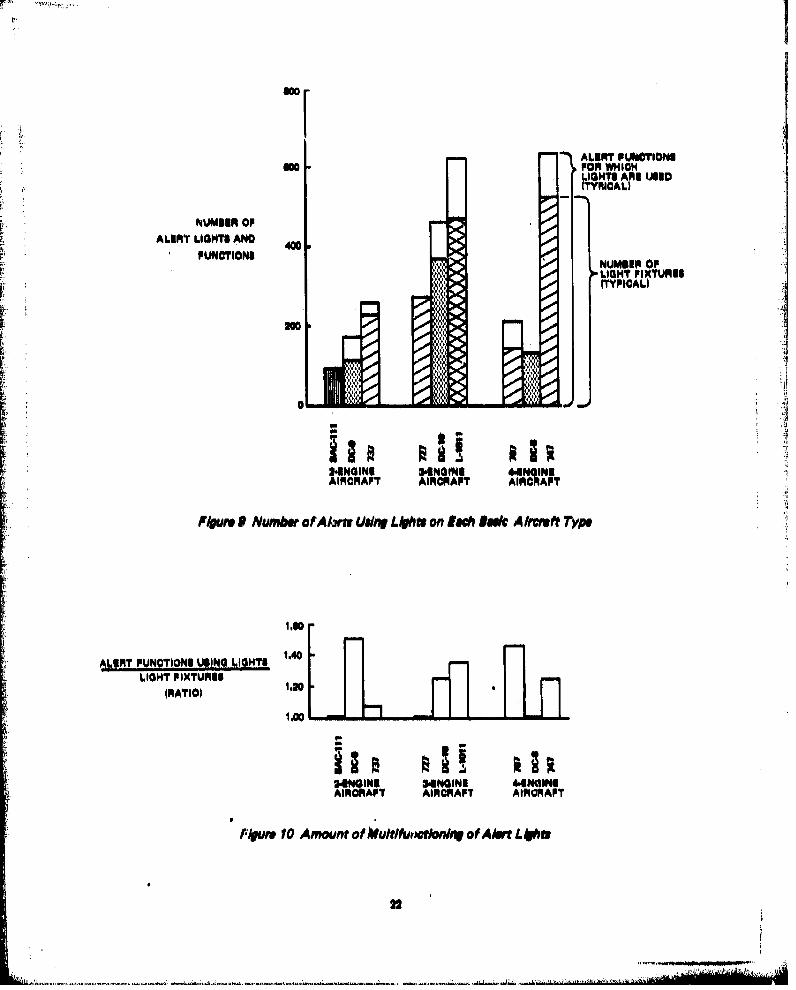
•i. • Figures 9 and 10 illustrate the amount of multifunctioningl of the alert lights on these aircraft.i• Multifunctioningl is defined as any situation in which an alerting device Is used to annunciate more
then one hazardous or abnormal situation, The distinctions between the various situations annun-elated by a device could be made by any obvious mods change, such as a color change, steady ver-
i. ~ sue flashing or Intermittent annunciation, or a change in brightness, The data in these fligures indi. ,
cate that a trend toward more multifunctioning exists. The BAC-I I I and 7/27 did not utilize multi- .functioning whereas the wide body aircraft used considerable multifunctioninol. Increased uusae of •
S~multifu~nction alert lights Is the result of attempts to crowd more and more information into theScockpit*. Available panel space becarme saturated and multifunction devices had to be used to let
e ii

LIGHTS AURALS
140
71 10 WallA1¶
SA%I I
ionIgIo 1970 it"
AIRCRAFT VINTAGE, AIRCRAFT VINTAGEI,YEAR OFPFINT FLIGHT YEAR OF PIANS PLIGHT
FLAWS $AND$
p10 LiARRF100 O4 001
0"
202
70 72 Lfi'Jj711 7. -.

.Aim uettiuton !110t 40 -
lengilne 3.~engls 4,utgnseaircrat aircraft airc'aft
F I~r Prop~rlon of A100 7"hit U LOWh
Bused on the results of these analyses, the alerting system utilization philosophies applied to thewide body aircraft appear to have included the following premises/suppositions:
o The crew should perform more system debug and maintenance functions; to do this, moredetailed systems information needs to be displayed,
* Multlfunction alert devices would not degrado the effectiveness of the alerting systems,
0 Discrete alert lights are more efflctive tho.n analog displays (dial type instruments).
* A slight inorease In the large number of already existing aural alerts would not degrade theeffectiveneu8 of the alerting system.
9 The narrow body aircraft cockpit designs did not saturate the crew, A typical crew can handlesubstantially more complex situations than exists on narrow body aircraft.
The validity of these premises will be discussed in further detail in later sections.
21
Sao~
"ALERT PUliCTIONSam0 FOR WHICH
! .O H T li A f l U D
NUMBINI OPALIRT LIGHTS AND
FUNCTIONSNUMBIR OFLIGHT PIXTUIM-TYPICAL)
ININ
•:2.NGINE 34lN0iffN 4*!INGINII
AIRCRAFT AIRORAPT AIRCRAFT
SP/er 9 Number ofAAlma Vung L6*t on I!0 Role A/trwf Typt
ALERT PUNCTIONI UWING LIGHTS 1.40 iLIGHT PIXTUR18
(RATIO) 1.20
•iNGINE SS4NOINI 44iNGINUAIRORAFT AIRORAFT AIRCRAFT
F/eure 10 Amount of )utlfuiw'tlounf of Alert L6I09
22
• AA
2,1.3.3 Color Distribution of Visual Alerts
Red, fire orange, and dayglow orange colored alerts are generally used to present warnings; amberand yellow colored alerts are used to present caution; and blue, green, or white colored alerts areused to present advisories and status indications, More specifically, blue alerts usually indicate thatsomething is intransit, green alerts usually Indicate that a system is operating satisfactorily and/orhu attained a SAFE/GO status; and white alerts usually indicate a system is ON. The distributionof alerts among these colors was analyzed to determine whether a trend toward presenting any par-ticular type of information exists, To perform these analyses, the alerting functions data was againdissected into the type of aircraft operation, size of aircraft, and vintage of the aircraft,
These data are presented in graphical form in figures 11 through 14 and in tabular form in appendix
B (table P-3).
The data in figure 11 indicate the following signiflcant factors:
* Essentially no difference between aircraft in the application of red lights
* L-1011 and 747 aircraft rely on amber/yellow lights more heavily than other aircraft
B DAC-I 11 utilizes very few blue lights
* 737, 747, and DC-10 aircraft rely more heavily on green annunciators than all other aircraft
* L.-1 011 aircraft use white lights extensively (to replace conventional toggle switch functions)
The data in figure 12 indicate that the wide body aircraft use significantly more red flap thannarrow body aircraft and the 707 uses substantially more white flags than other aircraft, The heavyreliance on red flags in the wide body aircraft is due to incorporation of more complex autopilotand navigation systems, The 707 occasionally used white flags where other aircraft generally usedred or amber lights.
The data on the application of color bands as alerting devices (figure 13) indicate that the DC-10utilizes substantially more amber/yellow bands than other aircraft, the L-10 11 does not utilizegreen bands, and L-10 11 and BAC- 11 aircraft utilize very few bands.
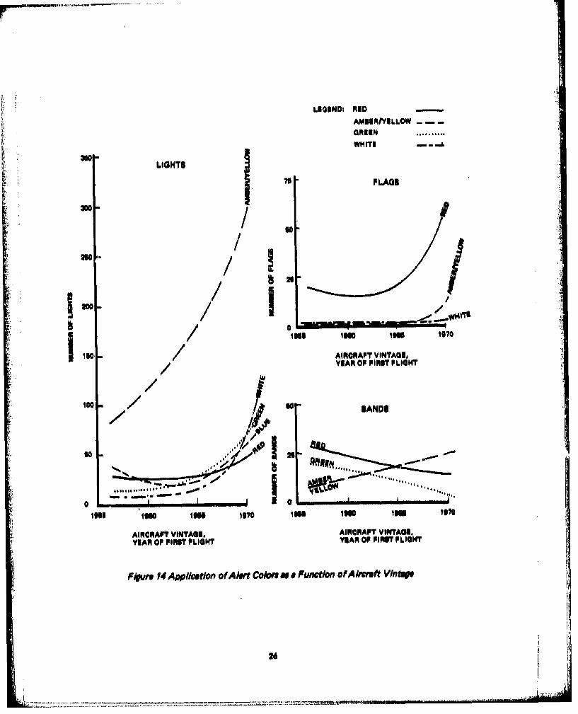
Analyses of the historical application of alert colors (figure 14) revealed significant trends towardmore amber/yellow and white lights, more red flags, and fewer red and green bands. The increase inamber lights is due to requirements for more detailed subsystems information in the cockpit. Morered flags are being incorporated because of more complex autopilot and navigation systems in thenewer aircraft, The traditional red and green bands are being replaced by amber lights.
The following conclusions were derived from these analyses:
* The number of warnings has increased slightly because of red flap that are required to annun-ciate the new failure modes of more complex autopilots and navigation systems
23
!I
_______________ ~-414
- -

* Amber and yellow lights are being used more extensively with each new generation of aircraft
to annunciate detailed subsystem operations
a A trend toward annunciating more SAFE and GO conditions with green lights exists
* White lighted pushbuttons are being used more extensively In place of togle switches in eachnew generation of aircraft.
* Discrete alert lights are being used to replace traditional color band.
400 2.enoln. 400 3.onolne 400- 4.engineairoreft300 aircraft aircraft
300 300 300.
.o itC). MA -
Ij O 20100 : '10
S..... II
Color Color ColorF*gurs I I Color DIstr/but/on of Lights
*24

2..ngine 3$nglne 4-engine70 aircraft 70 aircraft 70 aircraft0 6r0 - 60
1'50 Is so-5Lp J40- 40 L.0140-
30 0 .30
20 -20 20G 707
-10 o4- - 0737 727 747
00=D.9 C0 o~UC.I 0L 0
I I III+Color Color Color
Figure 12 Color OlatrIbut/on of Flogs
60 2,engine 60 3.engine 60 4.engineaircraft eircraft aircraft
30 30 @30-
20 \ 20 727 20 DC.
10- 10•% DC00 DC.10 A741
Color Color Color
Figure 13 Color Distribution of Bands
25
Al2". ~ ~--.-=.-.*---...C
LEND: IO -AND
AMBERIVILLOWSG REEN ..........
WHITI -. A
- LIGHTS
- 1 -FLAGS
ISO /AIRCRAFT VINTAGE,
Ica BANDS
0 --- -0 , ,,-l im I$ ,IW o,, Im lo Isla166 660o jg io us 660 igu 10,
AIRCRAFT VINTAGE, AIRCRAFT VINTAGE,YIAR OP FIRUT PLIGHT YEAR OF FIRST FLIGHT
F/grw 14 Appliostion of A/krt Co/on wa F uncton of A/waft VlntWI
26

2,11.3.4 Aural Alert Applications
Table 5 provides a listing of the various situations for which aural alerts are used. For each situationlisted, the type of aural alert used on each aircraft type is specified. Where It could be determinedthat no aural alert is provided for the situation, "none" is entered; if it could not be determined, thespace is blank.
From this table, it is noted that all aircraft considered in this study use a beol to annunciate anengine fire, However, the characteristics of the bell vary from one aircraft to another. Similar situa-tions exist among all the other aural alerts. Thus, another listing (table 6) that describes the fre.quency, loudness, and continuity characteristics of each specified aural alert Is provided,
The cockpit ambient noise environment in which these aural alerts must function is specified, as apoint of reference, in table 7. The ambient noise levels specified in this table represent the maxi-mum average dotave band value within the specified frequency ranges, These values were taken fromthe cockpit noise curves provided in appendix C.
Examination of these data for (1) consistency of application, (2) factors that may contribute toconfusion in the cockpit and should be avoided in the design of future alerting systems, and (3)aural alerts that have been standardized on and should be retained, revealed the following facts:
* No consistent utilization philosophy has been applied to the aural alerts, not even within anyairframer's or operator's aircraft, 4
* The number of aural alerts is Increasing. Older narrow body aircraft incorporated 9 to 15 auralalerts and newer wide body aircraft have 14 to 17 aural alerts. Human factors data indicatethat pilots can rapidly and accurately interpret only a limited number of discrete aural alertsand that this number decreases as a function of time since recurrent training. The exact num-ber of alerts that the average pilot can effectively recognize is not known. However, the poten-tial for confusion is known to exist currently and should be eliminated.
9 A standard appears to have been established for the following aural alerts:
Alert Situations Type of Aural Alert
Engine fire BellExcessive airspeed ClackerUnsafe landing condition HornUnsafe takeoff condition HornGround proximity Warbler and voice message
or tone and voice message
The specific characteristics of the aural alerts used for each of these situations varies slightlybut the basic function appears to be identical in all cases.
27

L) 0 . z .o o Co o
-~ 0 z
00 0
0 70. 1 E E c c - 4 u C>0 -o S 0 0 0
z 0 'a 1E 1 E z c o *
0 0 u El El E E o. 0
.- .- 0E 0 E ~ 0 0 0>0 u
000
0W - -jc -g E' -
-04 0 0 E0 0ii0 w
4L0 w 4 , ± E 4, 4, 4,m N -r 0 E E ~ ... C C =*u 4 4 C> _2 0 >C0 0 0 4
00 co 0 ):
- -
cc cw E CE c wC 0 0 0 E -o 0- 0 W
0 0 0 a
r CCCDcCu -
JC C E, 0
m Eu C
Cu 0 0 u u2 C0C
4, 0 0' -2
.C :E 0 0 0 , C
Cu 30. 13 0
w CL = = * ~ 4
U ~0 _ o - a -0 0Wto 'a' :
0 0C 03 m ~~C ~1, 0 cc
Z~ 0. > 0l 0 ~4 4 40 0 0 0) 0 0 C _ ~ u
28 AdOO 318VilVAV iS38

(30 *0
- w
F4 ~ 0 CO 0 o00 >z z z z z
0 0 0 0 C C C C
z z z z z z 0
0 0 -0 0 0 0 00a U 0 0 8zI z z X0
-5 0 -
0. cc4 0 -
0 0 0 ý 00z z > z zEz . z 0 o
0 -D, 0. L
'a~~~~ c 0 -0 I 00Co 0 40 z 0 0 .0 0 0 0 Z
t z zz zc
0 0 E 0e I C
z z > z z " ;-
w) r,4, W 4 )
04 0. E 0 E -w- - -.-~o5 Z Z> 0 Z Z -0 0 0 05 4,
Nl 4) < w 4 w
N , 0 0 0 0 0 0 4N > 4 0 0 w
0 3 Ob 0 3 Z Z co
0 0
0 0CC~~ 0. C 0. -- 0
41 c 0 .0 0: c-'
Cx 1 m 2! 0. c; 0 c 0 0 0 w C
C 02 E ' ' 0 0 0 C
_0 EE~ c cm c 0 C>
CL~- 0 C =1 -V 0C 4, ~ > ~ C 0 C0 Cm~c u4a> C C a '
0 ma 0 .- o .0 c4
CL ~ ~ 2 -0 Im c =
0 w ~' w E E m C: C -U) vz (n U) t
29 AdOcO 318V~IlVAV 133g

Table 6 Aural Alert CharecterletlosLOUDNESS, DESCRIPTION
AURAL ALERT FREQUENCY, Hz dB
"HORN A 200 TO 443 90+. 5 continuous ,HORN B 210 TO 280 93+ 5 ContinuousHORN C 635 89 Contnuous-HORN D 02 AND. 057 851 Continuous
ORN I 200 TO 443 . O_ Some as horn A, excepl IntorrutptedHON F 2290 TO 260 93 5 name as horn B, except Interrupted at3 Hz .
HORN G 116 AND 250 ContinuousHORN H6 02 AND 657 Some as horn D, except intirruptedat 1H z ...,.. . . . ,
HOR91 OJn 05 seconds; off 0.8 seconds in vailable.sied groups; 2 seconds between groups
HORN, ,K .8 . On for 0,.5 eon; off for 1 seond
HORN L ,.14 TO 8 Interruoted it 041-:HORN'M _2_ __ _ Interrupted it 0.0 HtH5_RN N 325 AND 390 94 Tow tones alternating it 0,25 HIHORN P ___ _ _ ,_......_ _DhornHORN,,R, 300 B comtihyuou "
HORN 8 300 o0 333.mo period with a 50% duty cycle+TONE A 1000 ContinuousTONE 8 1800 + 300 10 Beeper tons, pulsatl6l at 1. to 5.0 HtTONI C . 00 INCREASING Tons that increses in volume over a
3.seoond periodTONE D 400 INCREASING New system for McDonnell DouglasZON 14rplanes, 1 OplOcalle tion uncertain
ElrONE E 1,4 kf 5r 2,6 K ou-. i" "0A ternetlna tome
TONE F 3 k 77 333.ms period with a 50% duty cycleTONE G 700 TU 1.7 k .0 ulsitn'',ne o-
TONE H 1.0 K Pulsating tons -"C" CHORD A 461 TO 563 67 TO 704 95 ± 5 Intermittent
691 TO 845 ....."C" CHORD ' 512,"640, 768 90 Sound duration 2 secondsBUZZER A 300, 600, AND 900 90_+_ __,
BUZZER B 90 81 2 seoondsWARBLER & 400 TO 900 85 TOBS Three "whoops" per second; followed byVOICE voice saying "pull up." Sorme
of the airplanes Indlcated do not havethis system and some have the warblerwithouttolce
"WAILER A 130 + 20 TO 200 + 30 93 + 3 2 to 4 Hz of variation between longerand higher frsquenoies-minlmumvariation 49 Hz-mod 4.76 Hz
WAILER B 640 ... ....WAILER C 130 TO 200 8eBELL A 600 TO 10,000 93 + 5 Continuous '_ '85'LL B 750 87 ...Continuous; itrikerfrequency, 1,131Hz
similar to telephoneBELL C 640 AND 648 Continuous; two tones alternating,
_........._ striker frequency. 12.5 HzBELL D 600 TO 10,000 95 + 5 Same is bell A, except interrupted !
30

Table 6 Aural Alert Characteristics (Cont)
AURAL ALERT FREQUENCY,Hs LOUDNESS, DESCRIPTIONi: BL,•,t100 'on?"tl ~l-•Iorolvhi~i
CLACKER A 1000 TO 2400 8E Modulated at 5 to 10 HzCLACKER B _ _ _ Repetition frequency, I. Hz
LCKER C 512 Repetition equency, 4.70 Hz, sounds:J nko'uokingof, ehickenCLACKER D TWO TONES. CLICKS L4 TO 90 RepolItion requency, 9 HzCLACKER U 331 87 similar to a squam Wave, modulated
_ _ __-_with ary dnativ clicks at 1,0 Ha
CLACKER F 2500 Be Two bursts In a 20.ms Intervalrepeated it a 140.mi rate
CHIME A 020 - 8 Z Reeitlna. 1.5 seond Wetltion lateCHIMES 7150 SIM'O 4 linen swtrke'gong.llke aound: when
mohW*.io cull 1n*ut 1a. g t 0.851 HitCHIME C 4700 78 Single stroke gongiIIke soundCHIME D 7217 TO 947 9 . "High chime', single stroke gong-IikeCHIME DI 727 TO 047? Ei 5 .. isud:,+
___________sound
CHIME 1 477 TO 497 go ± S "Low chime", single stroke gong.like,,_ __ _ _ sound
CHIME F 727 TO 047 AND 05 ± * High ow chIme combination of ohimes;477 T T497 "_W ,adIre u te dtarateof3+ H2
CHIME 0 95 ±5S "High chime", single stroke gong.likesound '= 'a '"CHIME H , ASN'D 48 go+ I Hllh.iow ch¶,a not re peted
CHME, AD 4818ill'+ am Ies ohime H excoit feot repatCHIME K 588 AND 488 1E Siame is chime H except It does two
Ovlycleand stopsCHIME L 77 T5O 947 AND So_ Same as chime F except It doen two
477 TO.497 a aolU end stopsCHIME M 587 8s lInlla ohime In most conf uratlonsCHIME N 587/487 8a Single hlghilow chimeCHIME P 487 85 Low chime not repeatedCLICK Actual sound of disconnect of the
autopilot laver
31

Table 7 Cockpit Ambient No*g UnvitonmentAMBIENT NOISE LEVEL, W8
AIRCRAFTRAE, o io4o 40-000
F FLI H Hz- P uP__S_
TAK90FF 90 93 79 73707-720 _______ _______ _______
APPROACH 60 6175 72
TAKEOFF BE 79 66 61727 _______ _______ ______
APPROACH8776 6
TAKEOFF Is 84 70 so737
FINAL 8482 78 71APPROACH ___________
TAKEOFF 100 83 77 70
FINALAPPROACH 90 Ill 76 71
TAKEOFF 96 95 79 7300.8 ______ ______ _____ _
FINALAPPROACH 85 81 71 67
TAKEOFF 84 77 as51DCI _ _ _ _ __ _ _ _ _ _ _ _ _ _ _ _
FINALAPPROACH 85 72 69 M8
TAKEOFF 91 01 78 70DC-10 _ _ _ _ _ _ _ _ _ _ _ _ _ _ _ _ _ _ _ _ _ _
FINALAPPROACH 82 75 87 66
TAKEOFF 84 76 75 a8L-1011 -
FINALAPPROACH 84 72 70 8
#VALUES LITEARTH MA!I XIMUM LEVELST6 OCCUR WITHINTHE SPECIFIED FREQUENCY RANGES
32 *
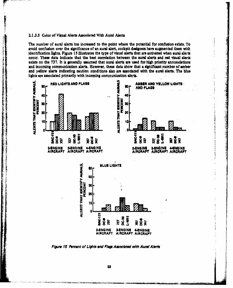
2.1.3.5 Color of Visual Alerts Associated With Aural Alerts
The number of aural alerts has increased to the point where the potential for confusion extists. Toavoid confu•ion over the significance of an aural alert, cockpit designers have augmented them withidentification lights. Figure 15 illustrates the type of visual alerts that are activated when aural alertsoccur, These data indicate that the best correlation between the aural alerts and red visual alertsexists on the 737. It is generally assumed that aural alerts are used for high priority annunciationsand incoming communication alerts, However, these data show that a significant number of amberand yellow alerts indicating caution conditions also are associated with the aural alerts. The bluelights are associated primarily with Incoming communication alerts.
AND LIGHTS AND FLAGS AMENfl AND YELLOW LIGHTSý.10* AND FLAGS -
40 4o0
'10i
2,GININI 31NOINI 4,1NGINE 2,11NGIN . ,IENGINI 4.ENGINEAIRCRAFT AIRCRAPT AIRCRAFT AIRORAPT AIRCRAFI, AIRCRAFT
BIIUR L.IGHT$I:, ,
20
120-10
2.ENGINE 3.ENGINE 4.ENGINEAIRCRAFT AIRCRAFT AIRCRAFT
Figure 15 Percent of Lights and Flop AnociDted with Aurel Alenv
_ -.h ..2W *lht~.~ttIi~h~'tf J.ttl~tlt 'A&mha~l

PT
Figure 16 specifies the color distribution of visual alerts associated with the aural alerts. The heavyreliance of Boeing 707, 727, and 737 aircraft on amber lights that identify aural alerts Is reflectedin these data. These data also indicate that DC-8 and DC- 10 aircraft utilize signiflcantly blue lights 7•than all other aircraft to help identify aural alerts,
The historical correlation between the'growth in aural alerts and the total number of lights and flapto help identify the aurals was analyzed from the data presented in figure 17, These data indicatethat all aircraft, except the BAC-I 11, have multiple lights and flap associated with each aural alert;727, 737, and DC-10 aircraft have sigr P,¢itntly more vistud backup lights for each aural alert thansimilir type aircraft,; the BAC .I 11 rIilie ast of all aircraft on visual backup lights; and the wideaural alerts, All aircraft also were rtd to have several aural alerts that operate without visual
backup alerts as indicated in table A.
2 .e n g ln e 1 0 0- n g n
lo i rcraft aircraft 100 - itera lt
7377- - '-- 727 - 747 - -I0 D s-o -- g 0o OC.10 -.-- =m Do70 -- --
MeI e-es -0 l-e-se7aesas
40 40 ' 40
20 20 \ se. 20
0 0 0
Figure 16 Color Distribution of Visual Alert That Act/vet Aura/l
24

LIIGINDI .L" LIGIA " AURAL ALERTS
40
L L
L21 L 747A727 00
AAA DC4 A
0 A
0 . .........- I , I , ,!~L
less I16 1970'
AIRCRAFT VINTAGI,YEAR OF PIR6T FLIGHT
Figure I Hittorlcal Appl//ca/on of AuralA lerts and Identifiation Light. Supporting Aura/Alelrt
Table& Appl/mt/on of AurI A/Mt. W/thout V/aua/ Bakup Light
Aircraft type Number murals without visual bacup 00lihs
707727737 3747 0DC.3 4
DC-.103L.10114EAC.1 I
35

2.1.3,6 Aircraft Systems Causing Proliferation of Alerts
Tables D-1 through D-9 in appendix D specify the distribution of alerts used by each subsystem oneach basic type of airplane. These data are summarized in figure 18 in a form that Illustrates whichsubsystems are causing increases in the number of alerts. Caution must be used in interpreting thedata curves presented in this figure because (1) not all systems incorporated in the newer model air-craft were Incorporated in the older model aircraft, ea.., autoland systems; (2) the aircraft devel.oped in the mid-1960. were the midsize and smaller narrow body aircraft as opposed to the largernarrow body aircraft that constitute the data points at the start of the curve and the large widebody aircraft that constitute the data points at the end of the curve. Therefore, if all aircraft were
equal, the left end of some curves would be lower than the right end and/or some curves woulddip in the middle, A third factor that Influences thesi data is the trades made between presentingsystems information via alert lights as opposed to dial-type indicators, For example, on most Boeingaircraft, thA air-conditioning and electrical systems require approximately an equal number of func-tions presented to the pilot, Most of these functions could be presented by either lights or dial-typeIndicators, However, the electrical systems have transitioned to lights and the air-conditioning sys-tems have retained dial-type indicators without alert bands as the primary method of presentinginformation. Operating limits am generally downgraded, deemed less critical, if dial-type indicatorsare used, Thus electrical systems would be more likely to show a proliferation of alerts than air-conditioning systems, Cognizance of all these factors and the magnitude of influence of these fac-tore is required when interpreting these data,
Examination of these data reveals that the most rapid growth in the number of subsystem alerts hasoccurred in the following systems:
* Electrical
e Automatic flight control system (AFCS)
Secondary offenders are the following systems:
9 Hydraulics
9 Ice and rain protection
0 Landing gear and brakes
e Navigation
* Pneumatics
Subsystems in which negligible growth in thM number of alerts has occurred are the following:
* Air-conditioning
* Altitude alert
* APU
36

Ila. 100.AN1 OONDI1WNING -~APUAIRCRAFT GENERIAL -APO0ALTIVUOI ALERT OOMMUNICATINE M
50:~~7PA'
AIRCRAPT VINTAGM AIRCRAPT ITG
10 1011ELEC11TRICAL ___PLIGHT CONTtROI.W__
E1MERGENCY EQUIPMEINT nPLIGHT INSTRUMENTATION im
PORN PROTUOTION AND AIRI DATA
1 0
AICRF VITG AICRF VINAG
YNAR OP PIRS? PLIONT YEIAR OP POINT PLIBMT
HYDRAULIC Ogm10, NAVIGATIONR0 N AIN PROTECT Im POWER PANTIC
LANDING GEAR AND URMAKEEI POEMPLANTIC
so 00 %%
a - W- M
ionS lo0 156 1070 ls110IN1070
AIRCRAFT VINTAGE, AIIRORAPT VINTAGEI,YEAR OP PIRIT PLIGHT YEAR OP PIR~I PLIGHT
F/guro 78 Growth History~ of Sub. ysti AMeot
37

* Communications
* Emergency equipment
* Flight Instruments and air data
0 Fuel
0 Powerplant
Inspection of the detailed data in appendix D indicates that most of this growth is occurring amongthe caution and advisory lights,
2.1,3,7 Applications of Master Caution/Muter Warning Systems
Table 9 specifies the aircraft that utilize master caution and mister warning systems, the locationand nunber of lights provided for these functions, and the characteristics of usociated aural alerts,Table 10 specifies the proportions of lights that will actuate either the master caution or the muter /'warning.
Analyses of these data Indicated that master caution and/or master warning systems are used in alltwo.man.crew aircraft but In only a few three-man-crew aircraft. The majority of the three-man-crew aircraft use a central block of lights to annunciate caution and warning situations, The 737,DC.9, and DCl10 aircraft use a combination of the central block of annunciation lights and mastercaution/master warning.
The type of secondary alerts that actuate the master warning alert(s) also varies considerably fromaircraft to aircraft. For example, on the DC10 nearly two-thirds of the rid lights actuate the muterwarning signal whereu on the DC-9 only one-third of the red lights actiyate the muter warning. Noamber, blue, green, white, or clear lights on these aircraft, except the BAC.I 11, activate the muterwarning signal,
Two amber lights on the BAC-i 11 activate the master warning, The rationale behind this discrep-ancy may be that the situation (CSD failure) deserves special attention and, since no master cautionexists in this aircraft, the master warning signal was utilized.
The DC-9 and DC.l 0 alerting systems are designed to augment recognition of the cabin prenuriza.tion aural alert with the master warning. No other aural alerts activate the muter warning systems,No inconsistenciso appeared in the master caution system implementations, The master caution sys-teme In these aircraft activate only when an amber light on the overhead panel or flight engineer'sstation illuminates,
2,1,3,8 Applications of Alert Prioritization and Inhibits
Figures 19 and 20 Indicate respectively (I) the aircraft that have alerting systems with prioritizedaural alerts and (2) the aural alert prioritizatlon scheme incorporated on recent production modelsof the 737, No aircraft except late model 737s and a few 727s have an aural alert prioritization sys-tem. The priority scheme implemented on these 737s allows the aural alerts for FIRE and OVER-
ma

I, U
P¾ Cu I. I L4
K I I 1 2~ i Iii 1111II 1111 ju ''cc

is
SI a €
I-
-l -
*1' 4
S0 S 0
0 C
______________
|ll i , ,
.3 .-

22i
66 Z
-q qtL 0 r Iic 0I
00
-- C

SPEED to occur simultaneously; causes the aural alert for CABIN ALTITUDE and UNSAFETAKEOFF CONFIGURATION tooverride any alert listed below it and the aural alert for UNSAFELANDING GEAR to override any alert listed btlow it, etc.; and causes the aural alert for SELCALto override the aural alert for CREW CALL. The aural alerts for FIRE, OVERSPEED, one itemfrom the middle groups, and one item. froqm the right group can occur simultaneously in thispriority scheme.
In ARINC 577 a priority scheme for all aural alerting functions, currently used and anticipatable inthe near future, was proposed. Three problems are immediately noted with this :scheme: (I) toomany aural alerts are allowed, (2) too many alerting functions have equal priority on the priority 1level, and (3) the significance and urgency of an alert are somewhat alrcraft design dependent andtherefore will vary from aircraft to aircraft, The standard for prioritizing the aural alerts shouldprovide: ;,
* Criteria for detennining whether alert prioritization 4 necessary
* Criteria for determining the priority level of each alert If prioritization is required
e Design guidelines for equipment, that allows aircraft dependent priority assignment of thealerts
1. CABIN ALT AND TAKEOFF CONFIG
2. LANDING GEAR1.SLAfFIRE ANDOVERSPEED 2 CR )
3. (WAI LE R). EWCALL
4. (BUZZER)
BOTH ALERTS PRIORITIZEDCAN OPERATE PRIORITIZED AS NUMBERED AS NUMBEREDSIMULTANEOUSLY (NO. I HAS HIGHEST PRIORITY) (NO. 1 HAS HIGHEST
PRIORITY)
ALL THREE GROUPS CAN BE ACTIVATED SIMULTANEOUSLY
Figure 20 737Aurel Aiert Priority Schmne
42
~ . ~ ... :i..L~..LZ. u.x.L ~ ~ ~ .1 ukLU ~.;2-r.

Alert inhibits also have not been applied extensively. The application of alert, inhibits his been,restricted primarily to enabling and/or 4isabling the aural alerts associated with aircraft co-itfigura,tion management, e.g., flaps extended ahd throttles at idle but no landing gear extended.
Not all alert inhibits are intentional, i.e., some inhibits result because the system with which theyare associated or a sensor that feeds this system has exceeded its region of valid operation. Aniexample of this situation is the ground proximity warning. Above 2500 or 5000 feet radio altitude,depending on type of equipment used, the ground proximity alert is inhibited because th,P radioaltitude signal is not valid,
The PC-10 is the only aircraft that incorporates intentional inhibits of selecte,.l subsystem faultalerts, as described in figure 21, in addition to the traditional configuration-related alert inhibits.The inhibits. o the DC-10 are designed to eliminate potential disturbances to the pilot d,'•ring thecritical segment of the landing maneuver, i.e., below 100 feet,
2,2 ALERTING FUNCTION AND SYSTEM REQUIREMENTS ".,
In section 2.1, the good and bad features of existing alerting systems were discerned, Alerting func-tion and system requiremenLs were implied therefrom, In. this section, a survey of applicable stan-dards, accident data, operations and maintenance data, and pilot opinion data are discussed, An an.l.,ysds of the correlation between the checklists and the alerts applied to each situation is also dis-cussed. Additional alerting system requirements were derived from theae analyses, These require-ments are combined In later sections to derive "preliminary" alerting system implementation con-cepts, "Preliminary" is emphasized because these concepts need further human factors and opera-tional testing to validate their effectiveness,
2.2.1 APPLICABLE STANDARDS
Federal Aviation Regulations pertinent to this study are parts 21, 25, 37, 91, and 121. Commercialaircraft standards applicable to this study are ARINC $77, which was discussed in section 2.1.3,8;SAE documents ARP 450, ARP 571, ARP 1068, and ARP 1161 and RTCA document DO-61A.Pertinent military standards and specifications are MIL-STD-41 1, MIL-STD-1472, and MIL.C-81 774.
AIRPLANE INHIBIT CRITERIA ALERTING FUNCTIONS INHIBITED
. MASTER CAUTION ANDMASTER WARNING LIGHTS
BELOW 100 FT RADIO 0 AMBER AUTOPILOT OUT-OF.DC.10 ALTITUDE WHEN IN DUAL TRIM AND DISCONNECT
LAND MODE LIGHTS* AMBER AUTOTHROTTLE
DISENGAGE LIGHTS
Figure 21 Inhibit Philosophies Applied to Subsystem Fault Annunclations
43- ._________________________________________________i~ r h

Applicable sections of the FARs ara copied verbatim and tabulated in appendix A opposite thealerting functions to which they apply. In cases where the FARs specified a general requirement
f •! applicable to an entire system, the. equirement wu listed at the end of the tabulation for that6y~tem,
, ARP 450 provide. guidelines relative to the design of flight deck visual, audible, and tactile signals;"ARP 571 specifies requirements for visual and aural alerts associated with nay/comm systems, andmethods of annunciating flight director, autopilot, and autothrottle system operating modes; ARP1068 specifies design objectives for all instrumentation and displays on the flight deck; and ARP1161 specifies lighting and color requirekents for each basic type of alert. DO.161A specifies
I .minimum performance standards, including minimum alerting requirements for ground proximitywarning systems, The alerting system requirements/guidelines contained in these standards aresummarized in tables E-l, -2, -3, -4, afid -5 (appendix E), Hardware requirements are not included.
Smost bhsed'the requirement Is copied verbatim; however, in a few cases, these statements areparaphrased to minimize similar Statements,
The mflitarý' standards-and specifications do not provide specific requirements relevant to alertingsystems in ,ommurcial transport category aircraft, Thse requirements are primarily of a generalnature end not directly applicable unless referred to in a PAR or ARP, They do contain substantial
"lis•hman factors data pertinent to the design of alerting systems, The bulk of these data are coveredin the surVey of pertinent human factors data (section 2.4 and ref. 2), The key points in the remain-ing guidelinei provided by these standards aire listed in tables £-6, E-7, and E.8 of appendix E,
2,24 SURV4V OF PROBLEMS WITH CURRENT ALERTING SYSTEMS
The International AirTransport Association (IATA) Technical Committee performed a study of theoperational problerns its membar airlinea had experienced with aircraft warning systems, Theybecame concerned over the number of accidents that have occurred where the aircraft warning sys-tem was a factor or may have contributed significantly to the chain of casual events, and concludedthat an analysis ot these problems was required to protect present fleots and future aircraft fromsimilar accidents, Unfortunately, no systematic effort had been made previously to collect detaileddata regarding operational experiences with the warning systems found in current transport aircraft,As an initial step in this direction, IATA surveyed its member airlines to determine the currentcomplement of cockpit warning systems in transport aircraft, 4nd to identify problems experiencedby airline crews with the functioning Of these systems.
Dr. John Lauber at NASA Ames Research Center was commissioned to perform this survey for"IATA, The survey covered 46 airlines operating the following aircraft:
* DC-3, DC-8, DC-9, and DC-10
_ 707, 727,737, and 747
* L-l88 and L-lOl1
e F-27 and F-28
44
SI- t

* A300B
* BAC- I I and VC-10
* SE 210, C-160P, YS-II A, and HS-748
Included in this fleet were 2614 aircraft,
The survey resulted in identification of 270 operational alerting system problems classified as
F 146 false positive warnings
S. 36 false negative warnings
e 74 system problems
9 9 display problems
False positive warnings are failures of the alerting system to notify the wow that a hazardous orabnormal situation demanding their attention existed, False negative warnings are nuisance alerts,ise,, an alert was given when no hazardous or abnormal situation existed.
The system problems consisted of all cases wherein the operators were forced by regulation toV modify or voluntarily modified the buic alertilng system to avoid spocific operational problems.
The specific alerting system features that constituted each of these statistics were not identified inDr. Lauber's study beyond the level shown in table 11. A more detailed analysis of those data by
i •The Boeing Company was only partially completed during this study.. No specific alarting systemrequirements evolved from the partial analysis, Completion cof the detailed analysis is planned forthe near future.
2.2.3 CORRELATION BETWEEN CHECKLIST AND ALERTS
A cursory review was made of the correlation between the number of alerts in each alerting clausifi-cation (warning, catition, or advisory/status) and the number of checklists or procedures in each ofthe following procedure categories:
* Emergency checklists
* Abnormal .hecklists
to Additional procedures
Aural alerts were not considered in this survey because the alerting classification that each auralalert belongs in is questionable.
i " i

Table 17I Alerting Sys tern Problems and Modifications Reported In 1A TA Survey of Alrlinwi
NUMEER OF NUMBER OFWARN INO SYSTEM CATEGORY OPERATIONAL MODIFICATIONS
_____________________________________ PROBLEMS _______
ENGINE/POWER SYSTEMS:4ENGINE FAILURE WARNING SYSTEM 10 6ELECTRICALESYSTEM WARNINGS 10HYDRAULIC SYSTEM WARNINGS 6 3PNEUMATIC SYSTEM WARNINGS 7 5FUEL SYSTEM WARNINGS 6 3
CABIN EINVIRONMENT SYS1TEMS:AIRCONDITION ING WARNINGS 2 11PRESSURIZATION SYSTEM WARNINGS 2 4CABIN DOOR WARNINGS 27 `12OXYGEN SYSTEM WARNINGS 2 .2
ICE PROTECTION SYSTMS:WINO ANTI./DE.ICE SYSTEM WARNINGS 3 aENGINE ANTIl101 WARNINGS 4 0jPITOT/STATIC HEATING SYSTEM WARNINGS 10 4OTHER WARNINGS 2 3
FIRE DITECTION AND WARNINGS SYSTMS: IENGINE 11IRE1 WARNINGS 34 20AUXILIARY POWER UNIT FIRE WARNINGS55CARGO BAY FIRE WARNINGS IWHEELWILL FIRK WARNINGS00OTHER WARNINGS 4 2
PRIMARY FLIGHT CONTROL SYSTEMS:HORIZ STABILIZER MOVEMENT WAR4NINGS 6 4FLAP AND SLAT SYSTEM WARNINGS S 12SPOILER WARNINGS 4 2AILERON, ELEVATOR. RUDDER SYS WARNINGS 2 2TAKEOFF CONFIGURATION WARNING SYSTEM 14 1LANDING CONFIGURATION WARNING SYSTEM S

Tab/loII Alerting 8S'atm Problems and M~odifications Reported in IA TA Survey of A/rinee (Cont)
NUMBER OP NUMBER OFWARNING SYSTEM CATEGORY OPERATIONAL MODIFICATiONS
___________________________________PROB LEMS
IRAKING SYSTEMS:IRAKE OVERHEAT WARNINGS 5 0ANTISKID-FAILURE WARNINGS 5 2A IVIIIAllTH RUST SYV IM WARN INGS I1 I
PRIMARY PLIGHT PERFORMANCE SYSTEMS:STALL WARNING BYST. M 10QMAMHOVERSPEED WARNING SYSTEM 20
rALTITUDE AND T9RRAIN WARNING SYSTEMS 1 0BAROMETRIC ALTITUDE DEVIATION oRADIO ALTITUDE WARNING 0 1GROUND PROXIMITY WARNING 0 Is
INSTrumENTr FAILURE WARNING SYSTEMS:FLIGHT INSTRUMENT COMPARATOR WARNING,. 9 1FLIGHT' INSTRUMENT FAILURE WARNINGS I 1SNAVIGATION INSTRUMENT FAILURE WARNINGS 3 2ENGINE/POWER11 INSTRUMENT FAILURE 30
AUTOPILOT SYSTEM WARNINGS
The category ADDITIONAL PROCEDURES Includes all procedures listed in the flight operationsmanual that do not warrant at distinct checklist In the pilot's checklist summary booklet but arerequired for the crew to remedy aircraft mialfunctions, Normal checklists, such as engine start,landing, secure, etc., also are not Included In this category because their design Is very dependent on
Ir the nature of each airline's operation,
Table 12 specifies the number of alerts and checklists or procedures that fall Into each of these cute-gories, Table 13 specifies the ratio of alerts to checklists and procedures In each category, No corre-lative pattern between the application of alerts and the usage of checklists was discerned In thesedata, However, the ratio of warning-typo alerts to emergency procedures nearly doubled with theadvent of wide body aircraft, This ratio Jumped from an average of 4.5 for narrow body aircraft toan average of 8.8 for wide body aircraft, The difference apparently developed because of require-ments for additional red lights und flags to annunciate the failure modes of more complex autopilotsystems incorporated In wide body aircraft. No emergency checklist Is usually associated with theseautopilot failure situations.
The correlation between the type of checklist and the type of alert applied to each situation alsowas analyzed. The analysis showed that the majority of the checklists do correlate with tile color ofthe alert light(s) used to annunciate the situation. However', several examples of noncorrelation were
47
INS-
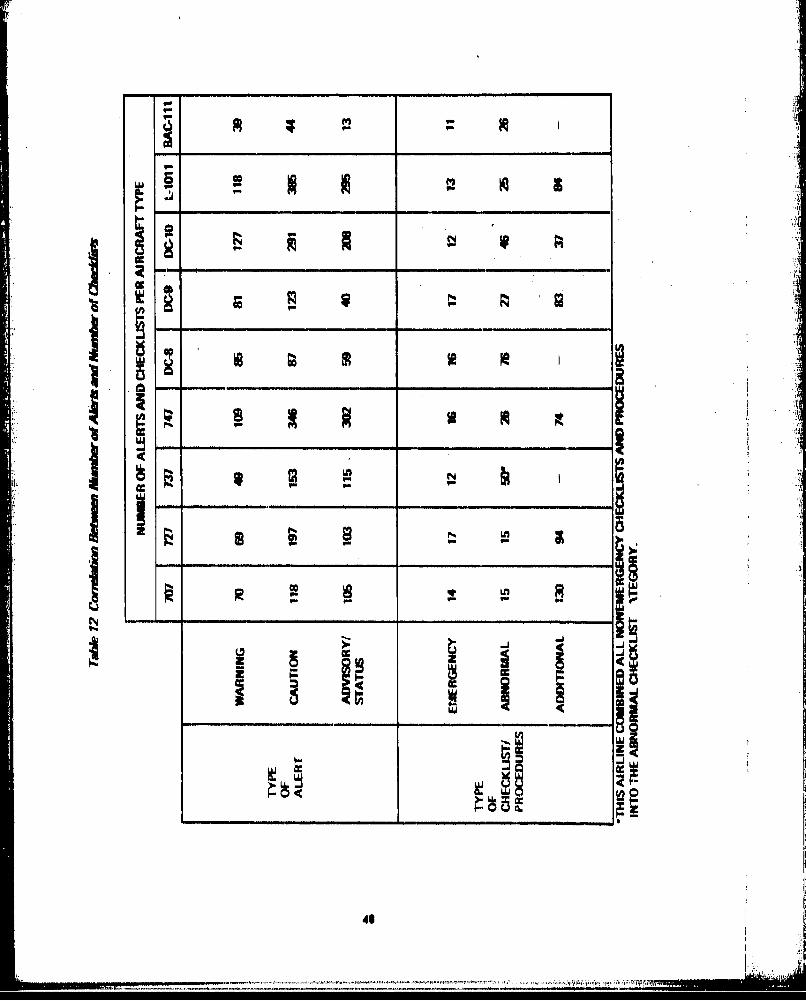
L.
co i in
.Cf
48
------ ----------

t
U, - 4
I
-I
a, in gY,
-U- �
22 in
1: I; ____
a *1I -I
C,,
S _________
p.
II
'9 'II
� h *�*-�>

also found. On the 737, for example, an abnormal checklist is associated with the two blue lightsthat annunciate "generator breaker tripped open." On the BAC-l 11, an abnormal checklist is also-cated with the two red lights that annunciate "fuel boost pump low pressure." A definite correla-tion between the type of alert and the type of checklist or procedure applied to each situationshould be established. If an emergency procedure is required, a warning-type alert should be used toannunciate the situation and if an abnormal procedure is required, a caution-type alert should beused, Advisory and status lights should be used to annunciate situations that do not require crewaction and/or do not have a specific corrective or compensatory procedure associated with them,The reverse of the.e situations also should be applied, e.g., a warning-type alert should not be usedunless an emergency procedure is required. Again, a definite correlation of these functions needs tobe established.
2.2.4 PILOT PREFERENCES
A survey of several pilot organizations resulted in the following consensus relevant to the design ofalertlnq systems:
a Reduce the number of alerts, especially the number of aural alerts,
* Most aural alerts, as currently designed, are too loud,
Noncritical alerts should be inhibited during high workload periods, such as takeoff and flare/
landing.
* Selected alerts should be prioritized,
* Audio-visual characteristics of the alerts should be designed to instantaneously inform the pilotof the criticality of the situation.
* Direct correlation between the type of alerts and the type of checklists should be established,i,e,, warning and emergency, caution and abnormal, etc,
The survey included ALPA representatives and chief technical pilots from most large airlines, pluspilots from the Boeing, McDonnell Douglas, and Lockheed flight test organizations and the Boeingcrew training organization,
The pilots unanimously agree that the current number of aural alerts is excessive and provides thepotential for confusion in the cockpit. Even the most proficient pilots questioned whether they, ina high.stress situation, could rapidly interpret the significance of some of the less frequently heardaural alerts, They indicated that part of the confusion is caused by multifunction applications ofsome of the aural alerts, i.e,, designing the alerting system such that an aural alert has one meaningduring takeoff and another meaning during airborne operations, The number of aural alerts accept-able to moot pilots is four, preferably one. If four aural alerts are used, they must be four familiaralerts.
The intensity of many currently used aural alerts Is too high. Most aural alerts are so loud that nor-mal crew coordination cannot be carried on, Their intensity should be reduced and/or a manualcutoff capability should be provided,
so

Many of the pilots felt that the potential for too many noncritical alerts exists in the critical opera-ting regimes where tihe crew cannot afford to divert their attention from the primary flying tasks.The pilots were particularly concerned about distracting alerts in the following two flight regimes:
* Takeoff (from slightly below V1 through climb to several hundred feet altitude)
* Landing (from 200 feet altitude through braking and thrust reverse)
An inhibit scheme of the type shown in figure 22 was suggested.
Inhibits were also suggested for the following purposes:
* Minimize nuisance alerts by inhibiting appropriate sections of the alerting system in flightphases wherein the alert has no meaning: Override background noise, such as radio chatter, that interferes with aural alerts
Method of prioritizing alerts
The application of Inhibits to suppress nuisance alerts and to prioritize alerts received extensivepilot support. However, the concept of inhibiting radio communications when an aural alert is acti-vated received numerous objections- the pilots were wary of the potential failure mode wherein thealerting system could inhibit their radio communication capability,
The majority of these pilots also felt that alert effectiveness could be improved by selective priori-tization, The alerts should be grouped Into three or four categories wherein each category denotes alevel of criticality. Alerts within each category should also be prioritized. The capability for an alertto transition from one category to another as a function of flilht phase should be incorporated intothe priority system. The priority of the alerts will vary from one aircraft to another. Accordingly,variable prioritization capability must be provided,
These pilots favored piioritization; however, they could not define criteria for when prioritizationwas necessary. In a very simple alerting system, prioritization might not be required- in a complexalerting system, prioritization probably would be beneficial,
A unique audio-visual method of alerting should be associated with each priority category so as to
provide an instantaneous assessment of the situation's criticality. Current alerting systems do notprovide this Information, thereby necessitating somewhat drastic methods of alerting for the higlhestpriority alerts, The need for drastic alerting methods should be eliminated by incorporating thisalerting system characteristic,
The pilots expressed concern over the lack of correlation between the type of Plert and the type ofchecklist applied to each situation. They want emergency checklists to be associated with warning-type alerts, abnormal checklists to be associated with caution-type alerts, and the additional proce-dures specified in the flight operations manual to be associated with the advisory/status alerts,
Other preferences were also expressed by the pilots: however, none as strongly or as uniformly asthese six points,
A 5'

iil
liium .............. -f .....

2.3 ALERTING FUNCTION CATEGORIES AND PRIORITIES
"V The requirements established in previous sorctions were utilized in this portion of the study to (1)define alerting function categories, (2) develop a method for assigning alerting functions to thesecategories, and (3) develop a method for prioritizing the alerting functions within each category,The validity of these definitions and catelory/priority allocation methods was tested by (1)applying them to a 737 and (2) noting conflicts between established standards and the results of theapplication, Each of these tasks is discussed in detail in the following sections.
ki 2.3.1 CATEGORY AND PRIORITY DEFINITIONS
Many cockpit designers and pilots believe that current alerting system problems could be resolved iffirm category definitions and requirements to design to these definitions were established. Attemptsat establishing firm definitions for alerting categories were made long before the current study."Thus, a historical review of recent developments in this subject will be utilized to develop therationale for the category definitions and prioritization methods proposed by this study,
T Two SAE standards-ARP 450 and ARP 1068-established a set of groundrules for mechanizingalerting systems encompassing single-function aural alerts, discrete visual alerts, a master cautionsystem, and a master warning system, No alerting categories or priority schemes were established inthese standards.
During the era in which the aircraft analyzed by this study were designed, these ARP standardsoften were not adhered to because they had not been updated to reflect latest methods of imple-menting cockpits, This lack of operational guidelines resulted in each airframer and each operator
L developing and implementing their own unique alerting system philosophy, Pilot encouragementfinally caused the SAE S-7 Committee to direct their attention to updating these ARP standardsand the FAA to initiate this research program which is aimed at developing a universally agreed toset of desigr objectives/guidelines for alerting systems,
The SAE S-7 committee, "Flight Deck and Handling Qualities Standards for Transport CategoryAircraft," recognized this flaw in their standards and requested Inputs from the airlines and airframemanufacturers. Boeing responded with two proposed sets of alerting system categories plus a list oftypical alerting functions that fall within each category, SAS airlines responded with a dissertationon alerting system implementation requirements, Copies of boff responses are provided inappendix F,
The Boeing response (see section F, I) provided a "first-cut" at categories that were oriented towardimportance of the alert rather than the categories of configuration, flight profile, and systems as hadbeen suggested by earlier studies, Three basic levels of importance (categories) were establishedtherein:
LEVEL I Highest priority alerts requiring immediate crew action, It was recommended that thededicated alerting systems currently used for these functions be retained.
LEVEL 2 Safety of flight items requiring crew action but not immediately, Three sublevels weredefined in this category. LEVEL 2-A consisted primarily of alerts currently annun-ciated by an aural alert; LEVEL 2-B consisted primarily of system malfunctions and
53
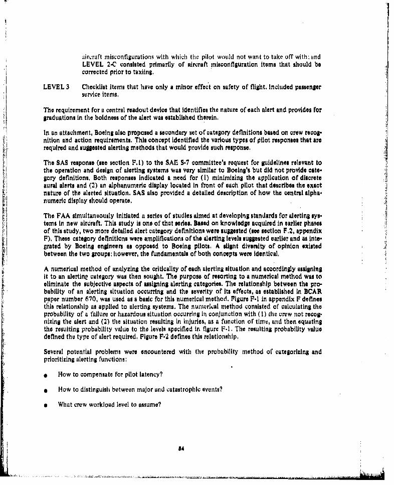
aircraft niisconfigurations with which the pilot would not want to take off with; andLEVEL 2-C consisted primarily of aircraft misconfIguration Items that should becorrected prior to taxiing.
LEVEL 3 Checklist items that have only a minor effect on safety of fight. Included passengerservice Items,
The requirement for a central readout device that identifies the nature of each alert and provides forgraduations in the boldness of the alert was established therein.
In an attachment, Boeing also proposed a secondary set of category definitions based on crew recog-nition and action requirements. This concept Identified the various types of pilot responses that arerequired and sugiested alerting methods that would provide such response.
The SAS response (see section F. I) to the SAE! S-7 committee's request for guidelines relevant tothe operation and design of alerting systems was very similar to Boeing's but did not provide cate- Algory definitions. Both responses Indicated a need for (1) minimizing the application of discreteaural alerts and (2) an alphanumeric display located in front of each pilot that describes the exactnature of the alerted situation. SAS also provided a detailed description of how the central alpha-numeric display should operate.
The FAA simultaneously Initiated a series of studies aimed at developing standards for alerting sys-tems In new alrcraft. This study is one of that series. Based on knowledge acquired in earlier phaensof this study, two more detailed alert category definitions were suggested (see section F.2, appendixF). These category definitions were amplifications of the alerting levels suggested earlier and as Inte-grated by Boeing englneers as opposed to Boeing pilots. A slignt diversity of opinion existedbetween the two groups; however, the fundamentals of both concepts were identical,
A numerical method of analyzing the criticality of each alerting situation and accordingly assigning
it to an alertine category was then sought, The purpose of resorting to a numerical method was toeliminate the subjective aspects of assigning alerting categories. The relationship between the pro-bability of an alerting situation occurring and the severity of its effects, as established In BCAR
paper number 670, was used as a basic for this numerical method. Figure F-I in appendix F definesthis relationship as applied to alerting systems, The numerical method consisted of calculating theprobability of a failure or hazardous situation occurring In conjunction with (I) the crew not recog-nizing the alert and (2) the situation resulting In injuries, as a function of time, and then equatingthe resulting probability value to the levels specifled In figure F-I. The resulting probability valuedefined the type of alert required, Figure F-2 defines this relationship.
Several potential problems were encountered with the probability method of categorizing andprioritizing alerting functions:
* How to compensate for pilot latency?
• How to distinguish between major and catastrophic events?
e What crew workload level to assume?
54

0 What 'time allcwance for corractive crew action" distinguishes a warning from a caution?
9 Should "crew reliability" be utilized to design and certify aircraft systems?
No substmntive answer exists to the first four questions. The answers to thv questions were verydependent on subjective opinions. The last question Is domin'ated' With many legAl implications.Thus, althuugh the probability method of categorizing and priorithilng alerting func~tions is viable,it was abanjdoned.
Nonquantitative methods of prioritization and the. definition of flhner nonnumerical categoriza-tion/prioritization criteria were 4hin resorted to again, Two more sets of category criteria were pro-posed. A 'Boeing engineer proposed the four category definitions defined irn table P-2 (appendix F),The key factor in this proposal w as *the defiiitions of crbw recognition arid. esponse time require-meuts, The. SAE S-1 committee simultaneously dleveloped the alerting systom philosophy,.and4 cate-goi y criteila defined intction F-5. The commentu ot Swissair's" chief echnkial pilot on -the SAVS-57
cmittees alerting system philosophy are also provided. These three cotcep~ts were L tegatd toformulate the category criteria defined'In table 14.
The category criteria provide guidelines for 'cockpit deslgn'trsto roughly prioritize* the Alerting. func-tions. However, they do not Otovide a detalid method for analyzing the :priority of ertch, gleptig.situation as a function- of flight phase and within each category., An air-conditlonlng lystemis failur,.for example, would have higher priority during cruise than during t~krd'f or final approach. Duringfinal approach the crew is almost totall'' okd'upied'M~th' flying thd aircraf t, down the I LS and lutid-
in.Anunciaio'n-of an air-conditioning falitredrg cruis culd result Hi e ''ry ucifralsituation of the remainder of the flight. The crew u.sually Is no't busy durfii. this time period andwould try to remedy the air-conditioning ptoblem promptly.
The mpsO'tof various types of alerts on the creW~s primary tasks durin~g each of the, folkowlng flight os
j, ?reflight * Cruise
* Engine start * Descent
9 Taxi * Approach
0 Takeoff * Landing
9 Climb e Taxi and shutdown
Note that in atpractical situation this nianv flight phases probably would not be used, For thisanalysis, excess detail was felt to be better than lack of detail. Therefore, since thec optimumcombination of flight segments was not known, excessive segmentation was used.
41 I

Table 14 Criteria for Categorizing Alerting Functions
LEVE L CONDITION CRITERIA
I-
1 EMERGENCY EMERGENCY OPERATIONAL OR AIRCRAFT(WARNING) SYSTEMS CONDITIONS WHICH REQUIRE
M A CORRECTIVE OR COMPFNSATORY,CTIN BY THE CREW.
2 ABNORMAL ABNORMAL OPERATIONAL OR AIRCRAFT(CAUTION) SYSTEMS CONDITIONS WHICH REQUIREI CREW A..•fJ.•.'AND REQUIRE
CORRECTIVE OR COMPENSATORY CREWACTION,
3 ADVISORY OPERATIONAL OR AIRCRAFT SYSTEMS CONDI-TIONS WHICH REOUI RE CREW AWAflNIaANDMAY REQUIRE CREW ACTION,
4 INFORMATION OPERATIONAL OR AIRCRAFT SYSTEMS ,CONDITIONS WHICH REQUIRE COCKPITINDICATION BUT NOT NECESSARILY ASPART OF THE INTEGRATED WARNINGSYSTEM.
This analysis showed that a considerable change in the crew's level of concentration on their pri.mary flying tasks occurs midway through each of these flight phases. During takeoff for example,the crew's concentration on the takeoff flying tasks increases as Vi is approached, remains veryhigh through rotation and climb to a safe altitude, and then decreases again. A period of GO/NOGO uncertainty also exists during takeoff roll from approximately 30 knots prior to V1 or VR,Any noncritical alert during this period would disturb the crew and possibly cause the pilot to makean erroneous GO/NO GO decision, Only the most critical situations with which the crew would not
56

want to take off should be annunciated during this period. A similar situation exists in the landingphase wherein the crew should not be dis 'turbed during the last 200 feet of descent, flare, andtouchdown. Distinctions also exist between operations above and below 140PCOIttAd:dotaircraft pressurization requirements.;490fe liued~t
Ground maintenance operations were reviewed and fou'nd to. require rtaily of the tame Alertting:,functions that the flight crews need,' When ttimming an engine, for exa~sple. the nialintnance crewrequires all the engine malf~unctlon and fire protectiont alerts, However, 'the 6riltcality o .f these. func- '
tions may not be as high In maintenance operatiOnis as in flight operations.':
Based on these typei'sof analyses,,the flight phases or flightrphie segmen'ts doefined lIn table~ *'a Wreselected for further prioritizing the alerting functlions. The two problems that.. still; iamwaind weare(1) how to prioritize compound mialfurictions and,.(2) how-to prforlitýeteaetn fntoewtieach catesory..
The compound malfunction situatlion Is very airvr~ft and type of system depen~dent." Th alure,for examnple, of one hydraulic s~'stin 'does'not pose as-oritical a situation ott the.747-Vas opi the 7,37beca'ws the '747 has foiiy paralkA.hydrauliu syst~et~s,'wfiereas %the 737 has only two patallel systems.
is hefalue f wo hydraulic sy~ters or' three. hyvdiaulic systems on the.747 equivalent to thefalluie of a singlo system ov,,the 737? Figure'ý3 ull~srate's the general typeoiflo~gic that had to beavolke, t6 pribritize 'hesq alert~ng sItvtos Teog4thsdarM. was evlopedt primarily'1 for non vioc tywmý. The aeneral application of this loSic to all systemns, however, is not feasible.1ht attsriilts to develop an'd verify nOtiiltizatio'n logic of this type, It was diLtermlned thiat parallel1sets "Oof l6i'were reqquird-o6n6`9et of lq&i for each type of sys~em malfunction anid,.operationalsituation, The development of th .aes. detailed prioritization logic sets required more expertise on thecompound effects. and safety implications of each alerting situation than was available to the groupperforming this, study., Nn~ analysis :6f the effects and safety- Implications of each compound mial-.function wadý required for each biasic type of aircraft in order to ossign relative priorities to thosealerting situations,.
Similar situations arise with regard to compound malfunctions Involving various types of systems,For example, what shbuld thts priority be ot'an alert annunciating a pretarnatic systini failure afterar glr-conoltltottiig system failure has already occurred? Should 'it be the same priority as, or ahigher priunty than, a pneumatic system failure without any previous air-conditioning failures?Another example, how shý.uld the relative priorities of an autopilot channel failure at compared toan electrical generator be established? The electrical generator failure would have broader effects onoperation of other aircraft systemas, Including the autopllot, but the autopilot could have an imme-diate effect on conitrolling the fllghtpath of the aircraft. Which Is more Important?
Somea pilots argue that compound effects should not be considered In prioritlzinp. the alerts, Thepriority assigned to the basic alerting function should be used fur all situations, Irreipective of comn-pound effects, and the sasessment of compound effects should be left up to the pilots. Other pilotswant an elaborate alerting system that makes all the compound effect Judgments for them, Theanalyscs performed In this study indicate that the elaborate versions of the system would;
* Require substantial cornputation capability
a Require software that IN very sensitivo to aircraft configuration modifications and frequentmodifications of this software to keep it current (as with the checklists)
57
4... - .. . . . . . . . . . . . . . . . .,.'...-.N

ccIII Iii ~ L6
18 iiiccIc90 1 6
cr.I
I,6
525

I al
all
1162
IIj 7i 6L>1 fi] ~IiIlei

r,
a Make the logic unique to each aircraft-differences could exist between aircraft of the sametype, even within an airline's fleet
The elaborate version of the system could become an expensive, maintenance item for the airlines,For these reasons, therefore, It is recommended that alert prioritization as a function of compoundeffects be minimized.
The priorAtization of alerts within each category was also studied. An example of such a case isprioritization of the stall warning relative to the ground proximity warning. Both alerts will prob-ably be LEVEL 1 alerts as defined in table 14, If a ground proximity warning occurs and then astall warning occurs while the pilot is pulling up, should the stall warning take precedence, shouldthe ground proximity warning take precedence, or should both be allowed to occur simultane..ously? Ideally, a numerical rating method would be utilized to prioritize these alerting functionswithin each oategory; however, none was conceived, The ranking of these alerts is very subjective;pilot opinion on these rancings currently is diverse, Much of the diversity results from differences in'the designs of the aircraft, However, better agreement exists among the high priority alerting func-tions than on the middle or low priority alerts, Thus it is recommended that priority sequenceguidelines be established only for the LEVEL I and possibly LEVEL 2 alerts, and that the prioriti- ,
zation of LEVEL 3 and LEVEL 4 alerts to be left up to the airframe manufacturers and operators.
2.3,2 APPLICATION OF CATEGORY/PRIORITY RATIONALE
Category criteria for defining alert priorities were specified in table 14, The flight phases and flightphue segments for which alert priorities have to be specified were defined in table 15, Consider&.tion of compound effects was deemed unnecessary. Standardization on alert priorities within thecategories was deemed feasible only within the two highest priority alert categories, The low pri- 00ority alerts are too dependent on aircraft design differences to allow standardization, These alert i Jprioritization philosophies were applied to a 737 to validate the concepts and to identify conflictswith existing standards,
Each alerting function specified in appendix A for the 737 was assigned a priority as a function offlight phase (see appendix G). The alerting functions within LEVELS I and 2 were then prioritizedas shown in table 16, Note that prioritization of the LEVEL 3 and LEVEL 4 alerts was not attemptedbecause these alerts are too aircraft design dependent, Significant differences in the alert prioritieswill exist in these two categories between aircraft models.
2.4 HUMAN FACTORS DESIGN GUIDELINES
In section 2, 1, current alerting methods were reviewed and the good and bad features of each designwere discussed, In section 2.2, existing standards, operational data, and pilot preferences were ana.lyzed to obtain a composite listing of requirements that apply to existing alerting systems and todevelop an alternate set of requirements that should be applied to future alerting systems, In section2.3, alerting function category criteria and a set of alert priorities matching these criteria were estab-lished, The problem that then remained was "what human factors guidelines should be appliedwhen implementing the results of these analyses?" A survey of the human factors data applicable toalerting systems was performed to develop these missing guidelines. The derivation of these guide-lines and the types of data required to complete and validate these guidelineu are discussed in thefollowing sections.
60

Table 76 Example App//cat/on of Alerting Function Prioritize tionALERTLEVEL 1. EMERGENCY (WARNING)
GROUNDORY . GRAN DOWN AND LOCKED BUT LEVIR NOT IN DOWN OITENT
tyMAINTE. 2. UNSAFE TAKEOFF CONPIGUNATION 4. GROUND PROXIMITY WARNINGNANCE 3. STALL WARNING
FLIGHT 1. GEARIDOW.N AND LOCKED NUT LIVIR NOT IN DOWN DETENT
ENGINE 1. OEAR DOWN AND LOCKED EUT LEYM' NOT IN DOWN DETENTSTARTA
Lw
TAXI 1. GEAR DOWN AND LOCKED NUT LEVERNOT INDOWN DETENT
0- INITIAL 1. UNSAFE TAKEOFF CONFIGURATIONISTAKEOFF
ROLL 1. GEAR DOWN AND LOCKED BUT LEVER NOT IN DOWN DETENT
FINALTAKIOPFN- OLL
IIIL 1. STALL WARNING~ CLIME . GROUND PROXIMITY WARNING
I ISOOTO 1. STALL WARNING*14,00W PT
ALTITUDE 2. GROUND PROXIMITY WARNING16
* ASOVE 1. STALL WARNINGASVI
S14,000 3. GROUND PROXIMITY WARNING~ PT 3. PRESSURIZATION FAILURE
APPROACH' 1. STALL WARNING1500200 1. GROUND PROXIMITY WARNING 4. UNSAFE LANDING CONFIGURATION
FT ALT 3. GEAR DOWN AND LOCKED BUT LEVER NOT IN DOWN DETENT
LA1IG 1. STALL WARNING 4. UNSAPE LANDING CONFIGURATION(BELOW 1. GROUND PROXIMITY WARNING S. AUTOPILOT DISCONNECT
ts1 200 FT) 3. GEAR DOWN AND LOCKED BUT LEVER NOT IN DOWN DETENT
2TAX I AND 1. GEAR DOWN AND LOCKED NUT LEVER NOT IN DOWN DETENTSSHUTDOWN
NOTE: ALERTS PRIORITIZED AS NUMBERED. NUMBER I HAS HIGHEST PRIORITY,
61 r

eo
r, ra1011
~ ~~~~~~iiI If s N. 0ý 4NA1 4wN
ISVd H11A40 C i.O~ IN31
I ~ 62

Table I6 Examplh Application of A lrting Function Prioritlvetlon (Cont)
ALERT LEVEL 3 ADVISORIES 4 INFORMATION (NOT PART OFINTEGRATED WARNING SYSTEM)
OROUNDMAINTE-NANCE
PA1-PLIGHT
INGINIITARt
TAXI
INITIAL FUNCTION Oil AIRCRAFT DSI1ON FUNCTION OF AIRCRAFT DESIGNTAKEOFF
ROLL PRIORITIES Tit 1E DITERMINEO PRIORITIES TO 1ie DETERMINEOS Y AIRFRAMA E MANUPACTURIR BY AIRFRAMI MANUFACTUNIRERi-A OPERATOR N OPERATOR
TAKEOFFROLL
INITIALCLIMB
1500TO14,000 FTALTITUDE
ABOVE14,000FT
APPROACH(0500400FT ALT)
LANDING(BELOW200 FT)
TAXIANDSHUTDOWN
63
~ F ,t

2.4.1 LITERATURE REVIEW AND RECOMMENDED GUIDELINES
The lterture review was structured to investipte how pilots respond to alerting signals. Thecurrent variety of signaling devices utilized to transfer information in the cockpit have begun to
saturate the pilot and decreased his efficiency to the point where prioritization of the informationpresented may be necessary, The basis for any prioritization scheme must be the time in which spilot must react to the situation. Signaling devices must be selected to ensure a response time that iscommiiensurate with the priority of the signal and must convey enough information to maximize theprobability of the correct response within a reasonable time. Since current aircraft design practicesfor alerting systems have evolved with some nonoptimum characteristics due to cost, implementa-tion difficulties, or personal blues of various chief pilots and designers, the literature review wasperformed with a ground rule to "ignore current aircraft design practices,"
The literature review was conducted with the following specific objectives:
i Investigate the type of signals that can be used to transfer information in a cockpit
environment.
* Determine the factors that affect the detection of these cignals.* Determine the factors that affect the time from signal detection to a correct action.
* Formulate guidelines for maximizing the effectiveness of signaling systems.
* Evaluate the data with respect to its relevance and applicability and recommend reseerch pro-
grams to augment the existing data and refine the guidelines,
The review was divided into two primary areas of concern:
e Factors that affect detection of signals
* Factors that affect time from detection to correct response
The literature review and guidelines are quite lengthy and will therefore only be presented in a con-densed form in this section; the full text Is contained in reference 2,
2.4,1.1 Factors That Affect Detection of Signals
A summary of the factors that affect visual, auditory, and tactile signals is presented in table 17.These data indicate that the detection of visual signals is affected by the signal location, size, bright.ness, color, and steady state or Intermittent nature,
The location of a visual signal relative to the pilot's centerline of vision has % significant effect onnot only the speed with which a signal Is detected, but also the probability that it will be seen at all.
Evidence Indicates that the likelihood of detecting a small visual signal decreases from 83% for thosealerts located directly in the center of the pilot's visual field to 35% for those diinals located in the300 to 400 deviation zone.
64
-- -... ........ ... . . . . .. . . . . .. .... .. . .-- •--,--:i.• ... ....•.•
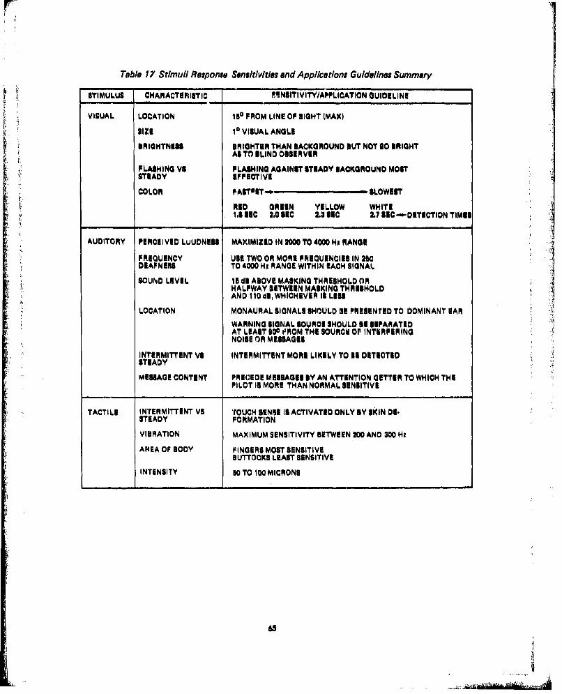
Table 17 StimulI Response Sensitivtites and Applications Guidelines Summary
STIMULUS CHARACTERIISTIC FINSITIVITY/APPLICATION GUIDELINE
VISUAL LOCATION I5 SOPROM LINE OF EIGHT (MAXI
SIZE 16 VISUAL ANGLE
BRIGHTNESS BRIGHTER THAN BACKGROUND BUT NOT SO BRIGHTt AS TO BLIND 0315 RVER
FLASHI NG VS PFLASHING AGAINST STEADY BACKGROUND MOSTSTEADY EFFECTIVE
COLOR OASTPST- SLOWEST
RED GAREEN YELLOW WHITE1.S SEC LO.01S1C 2.3 SIC 2.7 S1C--*.DETICTION TIMES
AUDITORY PERCEIVED LvUDNUSS MAXIMIZED IN 2000 TO 4000 Ha RANGE
FREQUENCY USE TWO OR MORE FREQUENCIES IN 260DEAFNERS TO 4000 Ht RANGE WITHIN EACH SIGNAL
SOUND LEVEL 1S dl ABOVE MASKING THRESHOLD ORHALFWAY BETWEEN MASKING THRESHOLDAND I1 i~d, WHICHEVER IS LESS
LOCATION MONAURAL SIGNALS SHOULD BE PRESENTED TO DOMINANT EAR
WARNING SIGNAL SOURCE SHOULD S1 SEPARATEDAT LEAST 900 ,3ROM THE SOURCE 0OP INTKRPERINGNOISE OR MESSAGES
INTERMITTINT VS INTER4MITTENT MORE LIKELY TO 11 DETECTED
MESSAGE CONTENT PRECEDE MESSAGES BY AN ATTENTION GETTER TO WHICH THEPILOT IS MORE THAN NORMAL SENSITIVE
TACTILE INTERMITTENT VS 'TOUCH SENSE IS ACTIVATED ONLY BY SKIN DE.STEADY FORMATION
VIBRATION MAXIMUM SENSITIVITY BETWEEN 200 AND 300 Hz
AREA OF BODY FINGERS MOST SENSITIVEBUTTOCKS LEAST SENSITIVE
INTENSITY 50 TO 100 MICRONS
63

The military standards and design guides define the pilot's centerline of sight as a vector emanatingfrom the pilot's eye, extending straight forward and angled 100 below horizontal. The commercialairfranme manufacturers have several deti~hitions of the centerline of sight, all of which differ from
the military definition. The most consistently used commercial aircraft definition of centerline ofsight appears to be the lin%; between the pilot's eye reference point and the center of his ADI, Thedefinitions of primary and secondary field of view also vary. The military defines primary field of
view as the region within a 1 SO cone around the centerline of vision and the secondary field of viewas the region between a 150 and a 300 cone around the centerline of vision. Commercial aircraftmanufacturers generally define primary field of view as a binocular-shaped area covering most of thepilot's primary instrument panel (containing ADI, HSI, airspeed, and altitude indicators) and secon-dary field of view as a binocular-shaped area covering most of the pilot's front panel (includingengine instrument and autopilot mode seleot panels). Considerable variations of these definitionswere found in the commercial aircraft industry, The human factors data indicate that most of thesedefinitions are reasonable with respect to location of alerting signals, However, until further testingcan be performed to better define these criteria, the following combination of military and commer-cial criteria for location of visual alerting signals is recommended:
* High priority alerts should be located no more than 150 from the pilot's centerline of vision.
* Caution signals should be located no more than 300 from the pilot's centerline of vision,
To summarize, the higher priority a visual signal is, the closer it should be located to the center ofthe pilot's visual field, An illustration of these guidelines is provided in figure 24.
The size of the visual signal also has a strong effect on its detection time. Figure 25 presents theeffect of increasing the lighted area of a border-lit signal, A moderate improvement in response timeis obtained when the border width was increased from 0,260 visual angle (I square degree of surfacearea) to 0.640 (2,74 square degrees). However, there is essentially no improvement beyond thispoint, Other research efforts have also found this signal size of 10 visual angle produces the quickestresponse times, Therefore it is recommended that: (1) high-priority signals be no less than 10 visualangle in size, and (2) secondary signals be no less than 0.5 visual angle in size,
The higher the priority of a signal, the brighter it should be as long as it is not so bright that itblinds the pilot. High-priority signals should be at least twice as bright as other displays in the samearea.
Even though the criticality of the signal dictates the intensity of any signal, the range of intensitiesis dictated by the detection threshold on one end and the disruption of normal activity on theother. Military standards require rear-lighted signals to have a brightness capability of IS0 ft-L(dimmable) for high-priority signals and a 15 ft-L fdimmable) for secondary signals, These standardsare consistent with research findings, The resulting recommendations were:
a Highect priority signals should be at least twice as bright as secondary displays.
e Lower priority signals should be at least 10% brighter than lesser priority displays in the samevicinity,
* Highest priority signals should have a brightness capbillity of at least 150 ft-L and secondarysignals 15 ft-L,
58

81HONA6I ....
rV 'I0
AREA FOR
SICONDARYSIGNAL3
mFigur 24 Pr.ferred Placement of V/tual Si~gnal
15
S10
MEAN
1 2 2 4
WARNING LIGHT SIZE, DE02 VISUAL AREA
igure 25 Effect of Werning Light Sie on Reaction rime
S67
The detectability of flashing and steady lights is dependent upon whether the other possible distrac-ting signals are flashing or steady, The experimental evidence showed that flashing alert lights aredetected 30% faster than steady alert lights when combined with steady distractors, but 24% dowerthan steady lights when combined with flashing distractors. However, the fastest mean detectiontimes are obtained by flashing alerts with steady distracting signals. Therefore it is recommendedthat high priority alerts should flash and have the capability of making other lights that may beactivated go to a steady state.
The effects of color are small as shown in table 17. In most situations, the 0.9 sec (maximum foundin the data; in most of the data, the difference is closer to 0.1 sea) in detection time between themost efficient and least efficient colors probably has no practical significance. It was, therefore,recommended to continue using the existing ground rules for colors of alerting lights:
0 Red for warning annunciations indicating a hazard that requires immediate action
* Amber for caution annunciations indicating the possible need for future corrective action
* Green for SAFE annunciations
Any other color for lights not described above is acceptable provided the color differs sufflcientlyfrom the colors described above to avoid possible confusion,
The auditory stimuli data indicate that the primary factors affecting detection of such signals are:
* Frequency
* Loudness
* Location
* Intermittency
* Message content
Young humans can detect sounds with frequencies ranging from 20 Hz to about 20,000 Hz, Fre-quency has a strong effect on perceived loudness. Mldfrequency (2000-4000 Hz) sounds tend tosound louder than either high. or low-frequency sounds of the same energy level, Two additionalfrequency-related factors that impact the detection of aural signals are aging which causes a pro.gressive loss of hearing in the higher frequencies, and ear injuries, which occasionally produce unsen.sitivities or denfness to particular frequencies. For these reasons it is recommended that each auralsignal be composed of two or more widely spaced frequencies in the range from 250-4000 Hz.
The guidelines recommended for ,determining the loudness required of aural alerting signals wereexpressed as delta loudness required above the masked threshold created by ambient noise, It isimportant to distinguish between this threshold and ambient noise. "Threshold" Is defined as theloudness level required of an aural alerting signal to assure 50% detection, This factor usually hasa value that is less than the overall ambient noise level, Methods of calculating this threshold valueare presented in reference 2. With cognizance of these factors, the following guidelines for present-ing high priority aural alerting signals werc derived:
68

0 15 dB above threshold
*Halfway. botwoon threshidI and- 110 411
to" However, these guidelines may In sonie oases conflict with the pilot criticism that most aural alertsas currently implemonted ame too !Qou. ,C;are must be taken when applying these guidelines to theactual cockpit environment because It is possible to'introduce sound levels that are intolerable tothe pilot. The range of sigral intensity by necessity must be limited on one end by the auditorythreshold and at the other end by the onset of pain (110 dB). The Intensity/exposure time inter-alt ion, which imposes limits after which there is a high risk of damage for unprotected ears (figure26 must. also be considered, Thos, until data that resolves this conflict are obtained, it Is recoinmme~nded tha't the following' guideline be used:
(THRESHOLD + 15 dBSIGNAL LOUDNESS -OR WIHVRIS LESSt
(THRESHOLD + 1/2 (110dB-TEIRESHOLD)}
140 Body4xposure limit (nonsuditory effects)
130* Pain limit for unproeteetd ears
1120
1110-Exposure limit for aotave bands above 300 H&
90 I kI A I
2.8 5 10 20 30 1 2 5 1 5 3SecndMinutes - .- Hours
Exposure time*Re 0.0002 jAbar
NOTE: PAIN LIMIT FORS UNPROTECTED EIAN$ 1S SHOWN AT 138 db. WHEN EAN PROTECTORSARK USED, SOUND PREMIURE LEVEL IN SOUND FIELD CAN EXC16D THES$ CRITERIANY AMOUNT OF ATTENUATION PROVIDED BY PROTECTORS. lOOP-I XPOSURB LIMITAT 1600s IS POINT AT WHICH POTENTIALLY DANGEROUS NON-AUDITORY EFFECTSOCC' S. THIS LEVEL $HOULD NOT SE OXCZE~DE IN ANY CASE (ELORED 9T Al'155.5).
ftgwv 26 Dwrg ft 011s Criteria for Varaiou Exrpoau, Timem Uip toB 8 ours

The experimental data also indicate that aural signals, which are perceived as coining froni r. differentlocation than the background sounds, are more likely to be detocted than uinials that cannot beseparated in location from background sounds. It was found, as shown in figuit 27. that detect-ability of an aural signal can he improved 40% by going from 00 to 900 directional septietioebetween the sources of background noise and. the aural alerting signals, It was also shown that if,earphones are used, a substantial improvement in detectability can be obtained by presenting allaural alerting signals only tn the pilot's dominant ear, The resulting recommendations from this areaof study were:
VI
* Present aural warning signals dichotically to the pilot's dominant ear. (In dichotic listening thealert ih presented by an earphone to one ear, and interfering noise or mena&s are resti cted tothe other ear.)
* If dichotic separation is not possible, locate the source of aural alerting signals 900 from thesource of interfering noise or messages.
Another factor that must be noted is that the human auditory system rapidly becomes used to ..hearing steady-state signals. Therefore, it is recommended that intermittent sound signals should beutilized for aural alerting.
100
k Detectabilitv,percent 4
I_ I I I I l .
40O - •
20 -•
O0
30 60 g0 120 150 180
Soperation of sources of signal and background noise, de•rms
Figure 27 Effect of Aural Alerting Signal Source Location
70

The detection of a sound signal is often affected by the content of the signal, For example, a per-son's ncme is usually more attention attracting than any other auditory message of the same vol.ume. Experimental data indicate that having a person's name precede an auditory message appearsto have about the same' effect on detection as increasing the loudness of the message by 3 dB. Thus,it Is recommended that aural alerting messages can be preceded by an identifier to which the pilot Ismore than normally sensitivite, e.g,, the pilot's name or aircraft ideptification.
Tactile signals Consiht of such things as vibration, shock, heat, etc. The data indicate that the pri-mary factors affecting. the effectiveness of a tactile type signal are intermittenoy, intensity, and partof body stimulated,
Continuous skin movement is required to stimulate the touch or pressure sense. It has been shownthat this sense is maximally sensitive on the fingers at vibrations in the 200. to 3000-Hz range. Theintensity of these Opgnals has nominally been given the range of 50-microns. This range is directlyrelated tu the area of the body receiving the signal, The sensitivity to touch varies widely from onesection of the body to another; the fingers are the most sensitive and the buttocks the least. There.fore, the amplitude of any tactile signal must be calibrated to produce a sensation on' the body areawhere It is placed,
Other types of tactile stimuli should be used very cautiously. They are either dangerous to use,cause excessive startle or adverse reactions, or otherwise inhibit normal pilot actions, The magnitudeof an electrical shock, for example, is very difficult to control because of Its sensitivity to perspira-tion, Electrical shock also frequently startles the subject to the extent that he is momentarilyincapacitated and then reacts excessively in an inappropriate manner, Other tactile devices such asseatbelt Jerkers or seat Jabbers tend to Inhibit normal pilot movement, These problems are typical ofdifficulties that are encountered with most tactile stimuli.
Environmental factors such as distractors, existing cognitive workload, and vigilance also have asignificant effect on pilot response to a signal. Any kind of distracting stimuli (visual, auditory, ortactile) will have an adverse effect on the detection of alerting signals. In the presence of visual and/or auditory distractors, the effectiveness of types of warning signals from best to poorest are tactile,auditory, and visual, However, tactile distractors have a more disruptive effect than visual or audi-tory distractors on other activities.
Vigilance and cognitive workloads are a function of the rate at which information is presented,There is a limited range of rates at which human beings process Information effectively. When infor-mation is presented at rates slower than the optimum rate. an individual will tend not to monitorthe information sources effectively and will miss a substantial proportion oi' the information beingpresented, Information rates above the optimum range produce cognitive overload, Individualsunder a cognitive overload will miss part of the information being presented and will process otherparts of the information incorrectly. General characteristics such as these were found In the literu-ture. However, consistent quantitative definitions of the minimum information rate necessary tomaintain vigilance and the maximum information rate allowed so as not to cause cognitive overloadwere not found,
A tabulation was made of response times obtained in the experiments covered by the literature andthe conditions under which these times were obtained. This tabulation was used to detect trendsand unique characteristics of combinations of stimuli. These data are presented in table 18, From, an

i• Teblb1t Typicsl Stimuli Rouponw. rime#NATURE OF STIMULI RESPONSE TIME, SEC TEST CONDITIONS
VISUAL I2.12 TRACKING TASK, NO IMPACT ONVISUAL AND BUZZER .4.02 CONCURRENT TRACKING TASKVISUAL AND VOICE 2.40 PERFORMANCE
VISUAL AND BUZZER 4.57 TRACKING "ASKK SEITER TRACKIIG.VISUAL AND VOICE 1.94 WITH.VOICE WARNING
VISUAL AND TONI 9.35VISUAL AND VOICE 7,68
VISUAL AND BUZZER 2,63VISUAL AND VOICE 1.62
VISUAL 123.27 HIGH-SPEED LOW.LEVEL MILITARYvoIce 3.03 FLIGHTTESTS'S
VISUAL 44.05 VISUAL CONSISTED OF ANALOGVVICE 2,53 INSTRUMENTS AND LIGHTS IN
AN P,100 AIRCRAFT
"VISUAL (STEADY) 2.0 HUMAN FACTORS TEST IN A STERILEVISUAL (FLASHING) 1.4 LABORATORY ENVIRONMENT
AUDITORY 2.2 SIMULATION OF A TYPICAL COCKPITVISUAL 2.7 ENVIRONMENT
VOICE 1.94BUZZER 2.57
TONE 9.35 F.1I 1 SIMULATOR; EACH ALERT CON.VOICE 7.89 SISTED OF A MASTER CAUTION
LIGHT, AN ALERT IDENTIFICATIONLIGHT, AND AN AURAL ANNUNCIA-TION OF THE TYPE DESCRIBED TOTHE LEFT
VISUAL 0.494AUDITORY 0.453 NO LOADINGOTACTILE 0.351
VISUAL $LOWESTAUDITORY NO LOADING EXCEPT VISUAL ANDTACTILE FASTEST AUDITORY DISTRACTORS
7i"72i

overview of these data,t It is obvious that tactile signals produce the fastest response in the non--loaded situation and a combination of visual and aural signals produce the fastest response whenused with aitcraft-related tasks. Of the combinat•on visual and aural stimuli, the visual/voice com-binationr appears to be more effective than the visual/tone combination, Voice stimuli consistentlyproduce a faster response than visual stimuli. Based on these data, these types of alerting stimuliand combinations thereof might be ranked as shown in figures 28 and 29.
EFFECTFIVE.. I VVOICI
TONES, SUZZIRS, BELLS, AND CLACKERSLIGHTS AND LEGENDS IANALOG DISPLAYS
VIBRATIONSPRESURE.:SHOCK
INEFFECTIVEFigure 28 Alert. Type Effect/veneas
(BEST)
10 VISUAL AND VOICE
4 VISUAL AND BUZZER OR TONE
VOICE
4 -
2 - VISUAL
0(POOREST)
FIgure 29 Relative Effectiveness of Acceptable Type of Alert Stimull
73
.. ...... .. ......

2.4.1,2 Time From Detection to Response
The foregoing discussion has dealt mainly with the detection of signals. However, if an alerting sig-nal is to be effective, the pilot must both detect the alert and make the appropriate response. There-fore, a warning signal must convey information about the nature of the problem and/or tell thepilot how to respond, There will always be u finite interval of time between the detection of thealert and the completion of the response, The length of this intervRl is primarily dependent onsinal-related factors, environmental factors, and previous experience.
The major signal-related factors that affect the time from detection to response are number of stepsin the data collection and length of the signal.
A pilot cannot make a correct response to an alerting signal until he has deduced the proper res-ponse. If the initial alerting signal contains adequate information, the pilot may initiate action atonce, However, if the initial alert does not give adequate information of the nature of the problem,then the pilot must obtain more information before he can take corrective action, Thus, the extrasteps in the data acquisition will increase the time to the correct response.
Two experiments were reviewed to obtain a quantified estimate of this effect. In both experiments,alert detection and identification times were measured for visual, buzzer, and voice alerts and com-binations thereof. The visual and voice alerts provided enough information so the subjects did nothave to scan the other displays to identify the nature of the alert, i.e,, a single-step process. Thebuzzer alerts required the subject to scan one or more visual displays in order to identify the cases,the voice alerts resulted in the shortest identification times, Another advatage of both systems isthat under high-stress conditions with peak visual load, this type of system permits the pilot toevaluate the criticality of the problem without adding to his visual workload, It was concluded,therefore, that the number uf information-gathering steps required to identify the nature of an alertshould be minimized and that voice warnings should be used wherever possible for high-priorityalerts, Based on these data and other experiments with voice alerting systems, the recommendedpractices for voice alerting systems are:
Reserve voice warnings for highest priority alerting situations.
* Voice alerts, when actuated, should attenuate messages and signals of lower priority,
* Pilots should be familiar with all the messages.
• Messages should be constructed of short sentences of polysyllabic words.
The time from detection to response is also affected by the time required for each step in the datacollection. At each step in the data collection, the observer must detect and locate a signal and thenprocess the information in that signal. The time for each step is dependent upon the followingfactors:
* Time required to process the information in the present step
* Time required to change from one signal source to the next
74

The time to process the information in any one step is dependent upon the amount of informationin that step and the rate at which the information can be assimilated. The rate of data assimilation isdirectly related to the number of absolutely identifiable signals used for data transmission, Theexperimental data indicated that the fastest assimilation rates occur with larger signal vocabulariesthan those currently used for alerts on commercial aircraft, However, this conclusion is valid if, andonly if, the signals are not confusable, The inclusion of confusable signals reduced the informationassimilation rate and led to errors.
The primary factor affecting the time required to change from one signal to the next is search time,i.e., the number of stimuli the subject must reference to obtain the required information and the dataSasimilation characteristics of each stimulus. From the exterimental data, it wes concluded that thelongest time required for shifting from one signal to another occurs when the first signal does notgive the precise location of the second signal, and the second signal is a visual stimulus,
The environment in which pilots must operate may also affect their alert reaction time, No directlyapplicable quantified data were available on this effect. However, the experimental evidence doesindicate that the response to any stimulus is very much dependent upon the number of possibleresponses to that stimulus as well as the number of possible responses to all other stimuli, In general,any environmental factor that increases the demands on the pilot will increase the time signal detec-tion to response,
The performance of airplane pilots Is strongly affected by skills that they have learned previously Inother situations, The effect of a previously learned skill on performance in a new situation is calledtransfer of training. There are two types of transfer of training-positive transfer and negative transfer,Positive transfer is any improvement in performance due to previous experience and usually occurswhen the response to be made in a new situation Is similar to the response made in a previous situa.tion. Negative transfer is any detriment in performance due to previous experience and usuallyoccurs when the response to be made in a new situation Is different than the response that wasmade in a previous situation,
The signal-response relationships are often not the same in different aircraft, This may result In nega-tive transfer of the pilot's experience, A study of the effects of negative transfer on crew perfor-mance was reviewed in order to assess the significance of this factor, It was found that pilots whoare crosstrained to fly several different types of aircraft do make Incorrect responses that can beattributed to this negative transfer effect, To minimize this effect, it was concluded that all alertingsignals, particularly high-priority alerts, should be standardized on all aircraft,
2,4.2 REQUIREMENTS FOR ADDITIONAL DATA
In addition to providing data for the formulation of alerting system design guidelines, another majorobjective of the literature review was to assess the adequacy of the existing data and recommendresearch efforts necessary to complete the data base. Three tasks were undertaken to accomplish thisobjective, First the data were evaluated and categorized Into two groups, those research efforts direc-tly applicable to the design of alerting systemi and those that provided datu which, while not quan-titatively applicable, provided Indications of the direction of the effects. Short abstracts of the datafrom the studies and military standards that fall Into these two cutegories are tabulated in appendixH. The second task was (I ) to delineate those areas where more data are required to provide an ade-quate data base, and (2) to prioritize those needs so that appropriate research objectives and planscould be formulated In the third tusk,
7,

2.4.2.1 Adequacy of Data in Literature
The data evaluation portion of the review asseed each of the areas of concern listed in table 19,Two aspects of the research data for each area were evaluated to determine their usefulness in devel-oping design requirements. Most important was the relevance of the data to the signal detection andresponse process. Many of the studies that were evaluated were not applicable even though theydealt with human sensory mechanisms. The remaining data were then reviewed and classified as tothe applicability of the quantitative results,
Those data that were obtained in an actual or simulated aircraft cockpit using a flight-type task wereconsidered to be directly applicable, In these studies the observer was required to do a primary task(Le, tracking a prescribed course or listening to an air traffic controller) and simultaneously respondcorrectly to any alerting signal. The quantitativc results of this type of study closely resembled whatmay be expected in the "real" flight situation. This class of study included approximately 20% of
Table 19 Areas of Concern of the Literature Search
1. Visual signals
Siae LocationBrightness WorkloadContrast VigilancePotmat Pilot sgeColor Legend characteristic
2. Auditory signals
Frequency Palse signalsIntensity WorkloadAmbient nolse VigilanceDisruptions Ear dominanceNumber of signals
3. Bimodal presentation (auditory-visual)
Interstimulus Interval WorkloadFormat VigilanceIntensity
4. Tactile signals
Detectability FrequencyEffectiveness DisruptivenessNumber of signalsIntensity
76
Ulm -.- 1-- - - -

the cited works (see appendix H). The other 80% of the studies were primarily laboratory studies toobtain basic research data. These studies In general used as their unit of measurement the time ittakes the obse.-ver to react to the signal (reactive time) when that was the only task that he had todo. The quantitative applicobility of these types of data to in-flight alerting situations is suspectbecause of the unrealistic nwture of the data-collection process, What can be said is that the timedata gathered in these studies is the minimum expected response time for a particular sensory chan-nel and that the highest •Vriori alerts should attempt to produce this time as optimum. Even thoughthe actual quantitative tione data from these studies may not be directly relevant to cockpit situa-tius, the information gaWned about the relationship between variables can be used In many cases,
For eamwple, the real effeet of signal location on detection time has not been quantified in the
literatrefor IMt full range of signals. However, there are simple reaction time data that indicate atrend 'ward uleemr reaction as deviation from the line-of-sight Increases. These data may be used asan indiationr, of Ike zslative effect of different locations ifdetection time is a design criteria. Anotherwni possible more im-iortant source of information in these types of data is the number of time. theobserver missed the signal or gave "no response." These data, although still not directly applicable,quantitatively will come closer to "real world" values because they are not time dependent,
These types of evaluations were made for the data collected in each of the areas of concern, Follow-ing this process, it was determined that the amount of directly usable data for all areas of concernwas sufficiently low to warrant augmentation. Since the amount of data needed was large, a methodof prioritization was needed.
2,42.2 Prlorltizatlon of Missing Data
RatinS, ranking, and paired comparison techniques were used to prioritize the data needs, Twoquestionnaires were developed using the matrices illustrated in figures 30 through 33, Each ques-tionnaire was distributed to one of two groups of seven people in the Boeing flight deck designorganization along with the data that had been gathered and abstracted (see appendix H), The firstgroup of seven were told that "each cell in the matrices (excluding the diagonals) represented a com-parison between two variables, I.e., size and location," Their task was to (I) review the data thathad been collected, (2) compare the importance of obtaining more data about each variable, and(3) Indicate the variable for which more data were most needed by putting its number in the cell.This paired comparison technique allowed the comparison of each variable with every other variableand the ranking of the variables according to their importance.
Another objective of the prioritization scheme was to determine how the variables should be com-bined in the testing phase to produce the most effective data, To accomplish this objective, a secondgroup of seven raters was told that "each cell in the matrices represented either a single variable (thediagonals) or a combination of two variables, ILe., size and location." They were to assume for thelatter case that the combinations of the variables was producing an effect on signal detection andthat It was the importance of obtaining additional data on that effect which they were rating, Twovariables were used as the maximum number of combined variables because it was felt that the diffi-culty of rating any more combinations would detract from the usefulness of the findings, The rater'stask was to rate the importance of collecting data for each cell on a four-point scale,
77

r
i ,. . U
" • O -
S, . U * *
i _ , mU . . . mp"
* • * * • U m •U
•' •i o o m , • ,I
" •4 I' ,,j ,, r%
.S .;ci
!! • • m l l • !•75
- I II ,gi4As. •rkoI±mp ,crt •tk•l
-

II-- - - I H I
i U E•I. I I ;- - - - - - - - - - - - - - - -
- - " ' I: :
•g,.
/ -I '4 ••I
ft• ' ,Ii
9. ..

- - --
- aC ~ S E *1
- - o *•I~E ~4•----• ....-r-,.:,•...... ••..... -,-'• -"0....T • - - " ... . .. i

V- - - II- - IH - -- U. :11
SU 0V -I*�� 4� U*
U
� E� *� � -%
a. - - I a
. U. �S / -- I' I
. 0 � � . 0 1.I11141.* / - - - - -- - -
IL.
Ia .1 In '
q s ie p�Ii iii �'
a. -- - - - - - -
61
- - -- '� � k

The results from the two sets of matrices were combined to form the prioritization that can also beseen in figures 30 through 33. The diagonal priorities represent the importance of Individual variablesand the other cell priorities the importance of the two variable interactions. To assess the validity ofthe responses, two variables-visual signal size and aural intensity-were Included even though theywere covered by directly applicable data in the literature review. Both of these variables were lowpriority in the survey,
2.4.2.3 Test Plans for Acquiring Missing Data
The high-priority data requirements established in figures 30 through 33 were evaluated and a set of19 three-page test plans was constructed, The groundrules followed for the first cut at definingrequired test programs were:
0 Use as many of the high-priority data cells as possible,
a The number of variables and levels should be chosen to provide approximately 2 weeks of test-Ing per test plan,
* The test design should be statistically sound,
The resulting test designs are presented in appendix 1, It should be noted that if the time restraints(2 weeks testing per test plan) are relaxed, some of the test plans can be expanded quite easily toinclude a larger number of variables.
These test plans define only the testing necessary to fill the most important gaps in the human fac.tore data required to design Rlerting systems, Elements of alerting systems will be evaluated by thesetests, Then alerting system concepts based on substantiated design data can be developed, Anotherset of tests that provide comparative evaluations of these concepts are then required in order to vali.date the ideas incorporated therein, The exact nature of these comparative tests has not been definedyet,
215 PRELIMINARY RECOMMENDATIONS FOR STANDARDIZATION OF ALERTINGMETHODS AND FUNCTIONS
Current alerting methods and the inconsistencies in the alerting philosophies applied thereto werereviewed In section 2,1, Alerting function and system requirements were established In section 2.2,The rationale, criteria, and method for prioritizing the alerting functions were developed In section2.3. A review of the human factors data applicable to designing alerting systemn was presented insection 24, These four aspects of developing alerting systems were combined to rormnulate Iprm'UI.nary recvmmendatidtio, for standardizing alerting methods and functions, The recomnmendations, asample alerting system concept that conforms with these recommendations, and an analysis of' theconflicts between the proposud prioritized alerting systems, tradition and existing requirements arcepresented In this section,
02
_______-V rItrrm

2.5.1 RECOMMENDED DESIGN GUIDELINES
• The recommendations presented in this section should not be Interpreted as firmdesign guidelines or as minimum performance standards, At this time, these guide- /lines have been only partially substantiated. Significant te.ting Is still required tovalidate these guidelines. ....
\.
The interactions between the data presented in the previous sections were analyzed, agreements,correlation and conflicts were noted, and preliminary design guidelines (not minimum performancestandards) for alerting systems were formulated.
6E The design guidelines were oriented to pr'ovde the following type of alerting system characterts-,tics and cockpit environment:
6 A consistent design philosophy that can be applied to all new aircraft, irrbspective ofmanufacturer.
* Quietj dark cockpit when all systems- are operating normally and when abnormal situationsha've been "cleaned-up" (except automatic flight control mode annunciators).
* Associate a unique audio,' visual, -or combination audio-visual method of alerting with eachalert priority level,
9 Provide alerting system growth capability in a form that doesnot necessitate additional discreteannunciators,. II ,
Accordingly, the following preliminary design- guidelines are recommended.
Prioritization
0 Selected alerts should be categorized as a function of criticality and flight phase, Category cri-teria are presented in table 14. Flight phases that rmight be considered are defined in table 15.
0 Selected alerts within each category should also be priorlized as a function of criticality.
Inhibits
* The number and type of alerts that can be annunciated during critical phases of flight shouldbe restricted.
* Prioritization of the a!erts may be used as a method of inhibiting or at least attenuating non-essential alerts.
NAI.+:J4
A I ":. • r'+ .. :+..: .. ..... .. . . ..... +... .. .. +... .... . .............. "+ + + +'+ ..... ,.,, ",+•",+ """ , ": ::+ i;:++'++:• + + + :++'+ +

Visual Alerts
0 An alphanumeric readout device, located in front of each pilot, should be provided to identifywarning. and caution-type alerts.
0 Discrete alerts-Wherever possible, reduce the number of annunclations in the cockpit.
-Advisory lights should not illuminate unless a discrete crew action, such aspushing a button, is performed (except automatic flight control modeannunciators).
Red alerts-Apply only to situations where immediate action Is required, i.e., only LEVEL Ialerts.
-Use when annunciation by an aural alert plus the alphanumeric readout devices isnot adequate.
Amber/yellow alerts-Apply only to situations that require immediate crew awareness andeventual action, i.e., only to LEVEL 2 alerts.
1J
-Use when annunglation by the common aural alert for all LEVEL 2 itemsand the alphanumeric readout devices is not adequate.
Green alerts-Use to confirm the SAFE OPERATION or GO status of'a system,
-A manual action by the crew, such as pushing a button, should be required toilluminate green lights (except automatic flight mode annunciators).
* Blue alerts-Use to annunciate intransit conditions.
-A manual action by the crew, such as pushing a button, should be required toilluminate blue lights (except automatic flight mode annunciators),
* White alerts-Use for illuminating keyboards and annunciating ON/OFF system modes, i,e,,when used in place of toggle switches.
* Location-LEVEL I alerting devices (warnings) should be located within 150 of the pilot'scenterline of vision (centerline of vision is defined as the line between the pilot's'eye reference point and the center of the ADM).
-LEVEL 2 alerting devices (cautions) should be located within 300 of the pilot'scenterline of vision.
-.Green, blue, and white lights can be located anywhere in the cockpit that is readilyvisible to the crew.
-All alerts presented by discrete lights, flags, or bands should be repeated on thealphanumeric readout device (except automatic flight mode annunciators).
84
~ .3- - -A. .~. A.AL4S..3 .A,:AW,.,, ~At~~S~flW~ £..JlJ L~i~Safn~~.Mt~flZ ...............................................

Size-High priority lights (associated with LEVEL I and 2 alerts) should he no less than 1°visual angle in size.
-Secondary lights (aoclated4with LEVEL 3 and lower priority alerts) should b6 no lessthan 0.50 visual angle in size.
* Brightness-LEV EL' I alerts should have a brightness capability of at least 150 ft-L and should
be at least twice as bright as other displays in the vicinity of the alert.
-LEVEL 3 and lower priority alerts should have a brightness capability of at least15S ft.L and should be it least 10% brigter than''nonalort displays In the vicinity :
of the alert.
-Automatic brightness adjustment for varying ambient light conditions should beprovided.
* Flashing-Use only for highest priority (LEVEL 1) alerts,
Aural Alerts
0 Application-Use discrete aural alerts to annunciate highest priority situations (LEVEL 1 alerts)and to attract attention to LEVEL 2 alerts on the alphanumeric readout device.
,, Maximum number-Less than four familiar alerts (based on pilot opinion).
-If the number of discrete aural and tactile alerts exceeds seven, they should
be supplemented by voice annunciations,
0 Intensity -Should be less than intensity of most currently used aural alerts,
--Maximum intensity of 15 dB above threshold noise level or halfway between thres-hold level and I 10 dB, whichever is less.
-Automatic Intensity adjustment for varying ambient noise conditions should beprovided,
-Aural alerts associated with LEVEL I Items should be noncancellable without cor-rection of the fault or situation.
-A means of reducing the annoyance of continuous aural alerts after Initial recogni-tion is achieved should be provided.
-A means of disabling any nuisance actuation of an aural alert should be provided ina form that does not affect the integrity of the other aural alerts (e.g., one circuitbreaker or guarded/wired shutoff switch for each aural alert).
e. 5

* Sound cia racteristics Each signal should be composed of two or more widely separated fre-quencies in the range from 2504000 Hz.
--Intermittent signals should be used.
0 Voice characteristics-Messages should be preceded by an Identifier to which the pilot is morethan normally sensitive (attention getter).
-Messages should be constructed of short sentences of polysyllabic words,
-Pilots should be familiar with all voice messages.
* Location-Aural alerts should appear to emanate from the vicinity of the alphanumeric readoutdevice,
Tcttile Alerts
* Minimize use of tactile alerts,
Master Warning/Master Caution
0 A master warning signal and a master caution signal should be located in front of each pilot ifthe alphanumeric readout display Is located outside the pilot's primary field of view,
* All L.EVEL I alerts should activate the master warning signal (if utilized),
9 All LEVEL 2 alerts should activate the master caution signal (if utilized),
a No LEVEL 3 or 4 alerts should activate the master warning or master caution signals (ifutilized).
Checklists
0 Type of alert and type of checklist used to rectify an annunciated situation should correlate,
• Emergency procedures should be associated only with LEVEL 1 (warning type) alerts,
• Abnormal procedures should be associated only with LEVEL 2 (caution type) alerts,
NOTE: A checklist Is not necessarily associated with each LEVEL 1 or LEVEL 2 Item, and analert Is not necessarily associated with each checklist,
2.,,2 SAMPLE ALERTING SYSTEM CONCEPT THAT CONFORMS WITH RECOMMENDEDDESIGN GUIDELINES
One of the primary goals of this study is to provide preliminary design guidelines for achieving aquite, dark cockpit when all systems are operating normally and when abnormal situations have been"cleaned-up," With the quiet, dark cockpit concept. all visual and auditory alerting devices except
.6

automatic flight mode annunciators would be OFF unless ( 1) an abnormal situation exists or (2) thecrew desires annunciation of a specific situation. The amount of advisory and status information inthe cockpit would be minimized. The crew would have the capability to enable or disable certainannunciations, primarily status information. Manual action by the crew would be required to Bet amomentary display of certain annunciations, e.g., the annunciation of intransit conditions. Thecrew would then have a "clean" cockpit to work in, would not become Insensitive to commonannunciations, and would recognize and be able to correct abnormal situations more rapidly than Incurrent cockpits.
The recommended preliminary design, guidelines could be applied as follows to fulfill this objective,Discrete aural alerts were recommended for annunciating LEVEL I situations, for attracting atten-tion to the alphanumeric display when LEVEL 2 situations arise, for annunciating assigned altitudedeviations and decision height, and possibly for annunciating incoming communications. Accordingly,a unique discrete aural alert might be required for each of the following situations:
0 Gear down and locked but lever not in down detent
• Unsafe takeoff configuration
* Unsafe landing configuration
* Ground proximity warning 71
* Rapid depressurizatlon
* Autopilot disconnect
* Common attention-gettlng tone for all LEVEL 2 alerts
* SELCAL
* Cabin call
• Data link
* Decision height
* Altitude alert (altitude deviations)
Thus 12 discrete aural alerts would be required; however, another guideline stated that the numberof aural alerts should not exceed 4 (pilot opinion). The number of discrete aurals can be reducedalmost to this number by retaining the traditional horn for all LEVEL i "unsafe configuration"warnings, by Incorporating the alerts for SELCAL, cabin call, and data link into the integrated alert-ing system as LEVEL 2 alerts; and by using a command aural alert for decision height and altitudedeviations, One aural alert could be used for unsafe takeoff configuration, unsafe landing configura-Lion, and gear down and locked but lever not in down detent,
The central alphanumeric readout device could simultaneously denote the exact nature of the con-figuration problem. Similarly, the common tone used for all LEVEL 2 alerts could be used for I
'4

annunciating incoming SELCAL, cabin call, and data link messages, and the alphanumeric readout
device could denote the specific communication channel requiring attention, Decision height couldnot be included as a LEVEL 2 alert because the pilot cannot afford to divert his attention to read-ing the alphanumeric display at the critical time when this is annunciated, Thus decision height andaltitude alert require a separate, distinct aural alert. By implementing the system In this manner, thenumber of aural and tactile alerts would be reduced to six.
The number of potentially ambiguous aural alerts could be even further reduced by using voiceannunciations for all other LEVEL I alert situations listed above. However, the effects of extensiveapplication of voice alert annunciations are not known at this point, Current experience with voicealerting systems has not been satisfactory. The type of systems descrlb,.d above wherein a smallnumber of discrete aurals are used in conjunction with an alphanumeric display is thus recommendedat this time.
In addition to these types of annunciation for the high-priority alerts, a very limited number of green,blue, and white advisory alerts would be utilized, A third switch state might be added to the lightstest switch to handle these alerting functions. The three lights test switch positions would be reas.signed to provide the following functions:
I-
* TEST-All lights ON to test light sources plus test pattern on alphanumeric display to validateoperation of display.
* IMMEDIATE SITUATION-All faults, intransit conditions, etc., would be annunciated as theyoccur, Existing alert situations would also be annunciated. Alerting system operation wouldas In current aircraft.
* CLEAR-This would cancel all currently displayed alerts except warnings and automatic flightmode annunciations and provide a relatively quiet, dark cockpit. No Intransit or SAFE/GOconditions would be automatically annunciated while the system is in this state. Only new cau-tions and warnings would be automatically annunciated. Any new caution annunciation couldbe "cleared" by switching from CLEAR to IMMEDIATE SITUATION and back to CLEAR. Asmall pushbutton might be added to each system's panel, While in this alerting system operatingmode, the crew could get all green, blue. and white light annunciations on that system panelby pushing this button. This would provide the crew with selective alert annunciation capability.
These alerting system implementation ideas are at this point only preliminary sugges-// tions and examples of how the design guidelines could be applied to (1) clean up the
cockpit, (2) provide the crew with the capability to select an alerting system operat- /Y/ ing mode that is similar to current aircraft, and (3) provide the crew with the capa- /
bility to select an alerting system operating mode that results in a relatively quite,dark cockpit when all systems are operating normally and when abnormal situations /
/ have been "cleaned up." These ideas represent only several of many ways in which /San alerting system could be implemented and still conform to the recommended X/ design guidelines. More refinement, testing, and analysis of the hardware/implemen-/ tation impact of these concepts are required to validate them.r
/ /8
"• ,•.[ . ......

2.5,3 CONFLICTS BETWEEN TRADITION, REQUIREMENTS. AND RECOMMENIDED DESIGNGUIDELINES
The preliminary design guidelines recommended in section 2.5,1 conflict with traditional alertingsystem concepts and with the requirements in the following area3:
* Elimination of traditional aurals
* Downgrading of several alerts previously considered high-priority items
0 Terminology used in the FARs
The priority system proposed in table 16 conflicts with tradition by eliminating several traditionalaural alerts. This priority system would eliminate the unique aural alerts associated with fire. exces-sive airspeed, stabilizer in motion, and below glide slope warnings, Many pilots feel that these auralalerts are sacrosanct, However, the analyses showed that the required pilot response to these alertsis not immediate action, Thus, they do not qualify as LEVEL I alerts and do not deserve uniquediscrete aurals,
The proposed priority system also conflicts with tradition by downgrading several alerts previouslyconsidered high-priority alerts from red lights to amber lights or no lights at all aust an alphanumericidentification), in the case of the 737, autopilot disconnect, fire, gear unlocked, and gear not downand locked with thrust lever at idle are examples of traditionally large, red light alerting functionsthat might be downgraded. The amber flight director mode "armed" annunciations are examples ofalerting functions that might be downgraded or modified so as not to imply a "caution" situation,Similarly, other functions might be upgraded, The blue lights used to annunciate APU oil quantitylow and thrust reverser armed are examples of such alerts. In a new aircraft, these alerts might beupgraded to amber lights ond green lights, respectively, so as to make the color of the light reflectthe criticality of the situation,
Federal Aviation Regulations (FARs) use the word "warning" Indiscriminately. Examples of wheresuch usage occurs in the FARs are tabulated in table 20. If the guidelines recommended herein areadopted, the language in these FARs will have to be modified, It is suggested that the type of termi-nology used in other sections of these FARs to indicate a reqwirement for an alert be extended toall FARs and that the term "warning" be deleted. Examples (,i such terminology are the following:
• "Means to indicate"
* "An aural or visual signal"
- "Means must be provided to alert the crew"
99
:iS

Table 20 Federal A viation Regulations Using the Term "Warning"'
25.207(b)
25.729(s)(2), (3) and (4)
25,777(c)25.812(e)(2)
25.841 (bl(8) and (7)
25,869(e)(3)
25.1165 (g)25,1k03(b)(3)
25.1303(c)(1)25,130625.1309(c)25,1353(c)(5)(i1) and (I1l)37.201 (a)(3)91.49
121.289(a) and (b)
121.360(b) and (c)
1.!

3.0 CONCLUSIONS
SThe alerting system implementation guidelines specified herein should be interpreted /as (1)prefimlnarov, not final, design guidelines, and (2) design objectives, not minimum rI
/ performance standards, The recommended design guidelines are only partially sub-stantiated by quantitative data--they represent our best implementation ideas at this
/ time. Additional testing to (1) derive directly applicable human factors data, (2) // quantify the effectiveness of various elements of alerting systems, and (3) quantify /
the effectiveness of various full alerting system concepts plus an analysis of the // hardware/implementation impact of these concepts are required to complete and
validate the proposed design guidelines.
The following conclusions are the results of analyses of current alerting methods and requirements,the development of alert prioritization criteria, and a survey of human factors data pertinent to thedesign of alerting systems.
The aircraft operators and manufacturers apparently feel the pilots need more in-flight malfunctionresolution capability and need to record better maintenance data. Thus each new aircraft has incor-porated more alerting functions specifically due to a trend toward providing the crew with moredetailed subsystem information. The most rapid growth in the number of subsystem alerts hasoccurred in the electrical, navigation, and automatic flight control systems, Negligible growth hasoccurred in the air-conditioning, altitude alert, APU, communications, emergency equipment, flightinstrument, air data, fuel, and powerpiant systems, All other systems have exhibited moderategrowth in the number of alerts. With this proliferation of alerts, the cockpits have become saturatedwith information systems, More multit'unctioning at' the alerts is boing used to get around the lackof panel space problem. The inclusion of these devices is adding to the potential for confusion inthe cockpit.
The number of alerts, especially the number of aural alerts, should be reduced, The potential forconfusion exists with this many alerts. To maximize the effectiveness of the alerts, noncritical alertsshould be inhibited during high workload periods such as takeoff and flare/landing. Prioritization ofthe alerts, so as to identify the most critical problem, should also be considered.
Prioritization of the alerting functions currently must be accomplished via subjective methods,Numerical methods require additional quantitative data about crew reliability and pilot latency, andthe effects of workload on these two factors, or the time history of the aircraft's/system's perfor-mance degradation as related to each alert.
Criteria for four levels of alerting function prioritizution are available. Most organizations workingtoward developing standards for alerting systems basically agree with the four levels of priorityestablished in this study and the criteria defining these levels, Minor grammatical differences remainto be "ironed out,"
91
~4A. k~kM4~ i

Standardization of the alerting function priorities may be possible for alerts within the two highestpriority levels, However, the alerts within tile two lowest priority levels are too dependent on eachaircraft's unique design features to be amenable to priority standardization.
A unique audio, visual, or combination audio-visual method of alerting should be associated witheach priority category to provide an instantaneous assessment of the alerting situation's criticality,Human factors data pertinent to optimizing this audio-visual interface with the pilot are available,However, the data are incomplete and further testing of specific elementa of alerting systems isrequired to fill the major data gaps.
Preliminary design guidelines for standardization of alectlng functions and methods are available,The basic guidelines specified in section 2,531 are recommended, Numerous conflicts exist betweenthese guidelines, traditional alerting system concepts, and existing regulations. Most conflicts withexisting regulations can be resolved with minor modifications of the language used to indicate arequirement for an alert.
k Additional comparative testing of elements or alerting systems and full alerting system conceptsplus analyses of the hardware implementation characteristics of these concepts are required tocomplete and validate the proposed design guidelines.
92
... ..

APPENDIX A
TABULATION OF ALERTING FUNCTIONS AND IMPLEMENTATION CHARACTERISTICS
This appendix provides detailed descriptions of the alerting functions in a typical configuration ofeach basic type of commercial turbojet transport aircraft. To simplify this tabulation, similar type3of indications were consolidated under one title, Examples are: (1) red bands, red limit marks, andpink limit marks were consolidated under the title "red bands" because they have similar operationalimplications- (2) fire orange flap used as warning indications were tabulated as red flas'; and (3)
yellow lights were tabulated as amber lights.The asterisks on tables contained in this section mean "same as,"
93' I

I/
I) II
94 � I a

I- ii i, 1i ii ii i ii iI t
- I-,"- hutu il !i
iIi1111i
--
-,-,i
,
-
I.
I,a i '
u, aI I :
I Il •
I
III,
Si • i i
""
i t
:
9 5

!- -
a
ii ti agt
Em I-'- - - e - -, - -. - - -,
M..,,
Ii I . .]I I2 - - - - -' ~ ~ ~

)�i �IIid
I!II Ija------------ !Iii'ii� III' iii�
r4U1I
a a a I a I a I
*
4 x
II
- - - - - - - p.
a
I ----- - -
- - - -
I II-
p.- - -- - --a -a Ia
a1
N
1 1a
U
_ � � h � Iii- .�. ,, p. �. U - a -
U U N
97 I

i i.ii!i|lIlii~"II ' Itzt
|1 a•J
i 1N
p I
1
I I I

illliai
J1,
h I~ II tI :,
n4 i nl v
Im ± _ _ _ _ _ _ _ _ _ _-uL
a--
~~ I

i'-
-
a-
--
- - -- -
.--
i
Ii
I
•L , I
.|.
- -------------

- - ------ - --
ak A -
d -- -- -- --
I ________
p K
I:
dl - - --- - - --
- - - - -- - - - a -
- -2
- - --- -- - -
aI
IA - - - - - - - - a -
§- - a - - - - -- - -
42 j ii'
�'iIH IHI'- I I I I I I iilli ___________________
------ - -
101
� Af2.l2t2I� �.tI&-2�, �

!iiili~i'iII i+jiiaii
- I Ii1.1!
-- ,..,1~ 1 tii N
-• ---i- - -.--..-...
ii I
-u -i
- --i- - - - - - - -!
N! pj. N-,.. N,... UN4.h
+' " i . .... .. ... . .. . ..• + '• .v_:- .•, • .• •, .; .'+!•: Lr• !Ju • '• i•'-'•• + ''" ''+' • • -: ' • a• •

1 - •mI
U N
* a
I - a a - --. -a
SiII i lj L I " -~ -~1U1 1 I'£ iP aP U-- a a a - - - -- - - -] P d .; , ft.. ,d.
103-
- a a - -- - - - - - - - - - -- "

1' - - ~~ - - - - - -ioi
104
aa a i I I a l a a ,d J• •tI tLL Rl Itttt11111 di
*!

i~i
F4(Id
mI
9a L
*I H ,. ,-.f
T 7T ! I iI ... !,i-, t0
N N •I NN N m I E E E Nitl i i,A . . ~ll i,.,
• ,
,,105
• I ', t,--.: , .i

ru1W1Jf.L~ L L L 1 1 L111111414 o f P N ow 14 14 1
~~ I I U a a J Ji i *~
10

2
ii ______________
N _____
I It =11! ! _________
Uaa a I 1 aI,�a 111111aN N NN��
I - - -- - - - - - - - - - - Iam
______ - - - - - S I
- ---- - -- - I____________ I
------------- - - - - - I_____ I______________ I___________
IIii I
* ill .111 11� F1�I.Fi �I � � Ii "1 I.U 'U I £L�.... ''i" ii �I u II �i _ ________ A
a � a a; a aA
107

'z 't lit
I 1 i
I.i n IiIittti
ii - - Ii! tW -J - - -- -
IMI1 .0 1
S ai . a ma.l
1 1'iliii-. U -. i EI !
-iI.iM! Il l, .; .
1 01
- - U- - - -- -- - - - - a

ii 4
,, a a ,1 5 I -. 1
25 a IJ • . A , U I
Pd h I; ; • •
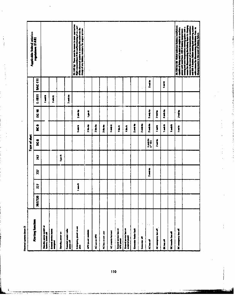
Ii*11 111.11ifliii• .j' !liii
IIIIIi Iu
a 5
2 i 5
" I i 5I I 5I
SIlE_ I
I- -
N1i
II lil _ _I
i~i ' I |! 1III
110 {
L.. .A s . . .1'• ... •gn nl xA g'qza rnfl"

iiIi
I •
a - a 5, I
Sj i !,
ts..miiuj~tI iii! !
I I 1I'•
i ;# iU
S~~~~~~~.. . . . . . . . .. ..... ... .. . -....... .....- :••:";-•• , , , i "l

II
• ii -
4
p,
al
U112
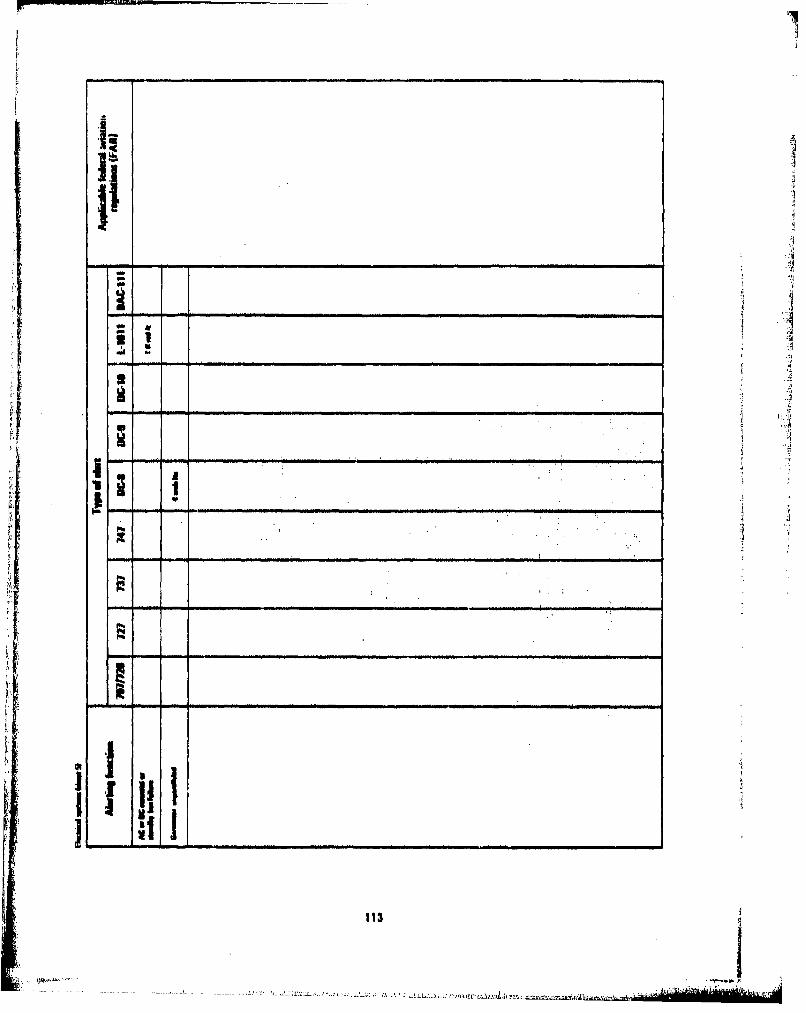
ifi
i i
S
*1 - I -
. iill111
A 113

ii
Iiliti t I| i .. " ,,a
!,,I ! I - __ ___
-id
I I I, ...a I a!
114I

11 1bI
Mai a A*a jifl iiI
a Ill A "
As -a - - - - A- - -
A A
Itil
3. 11 ! a Ili
I ,I
S !! , " ! • "."±± -h A! j, 1~
-,- , ,,, - - i-i---t
I llliil 1
ii; ii ! • U I I
S!1 I , ... I I I++...+
j , a ..

S~io; b i
I I
! I I
I III~l...
i li I' i,',I'i,,- - -pf l -
S~116

j, 11111
t-- - - ~i~li ii1 1
SI ii i . ,
*• I '1t
i~i it .. .
~i iiiiiiiiii!ifiiit I ii ,
i l , , , , II I I i
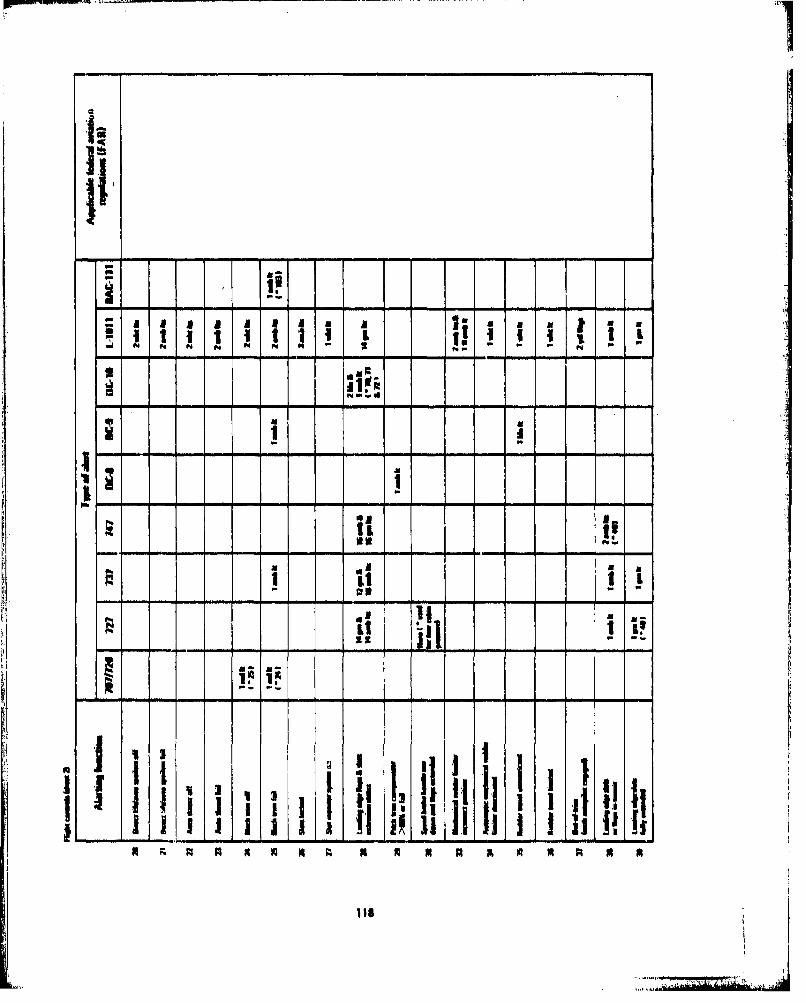
iiII,
: 1 1 , .5,11,13,,,1- li1 Ii I.'-a a
N N N N N I• - -mN N =• l
* -. i
iiiiiil
% 11 a
]III 1fl l I !
I +. II,
.11111111
1 iS

ii,
- a I im ti I-- - - - - -,
Sit!!!!I
•g.•~II ma i III
I
a J l j I I
Ii 1111i
i ililll i

II!II4..
I'm
- - ---- - - - - - - - - -
a UU- *6 U
1 �--Ii
I� � g.M.�a. �' "I N- - I *
a _ � I 1i, U- - -- - - - -- - - - aa - - -
I- -- -- ------- - - a - - --- -
I _ ii-- - -- ------ - - -- - - -
I ii� i � i Ii
a a IA I!
i___ - - a a - - - - - - - - - - a a - -
ii ii liii
�..iu.hm..S...r.MW C - a . - - a a - - a - a - - a
U USUE U III � � N N
lb

I].
nlnn ui •p . n i 1 J
121i
a . .. . I Z
- -,, ,,-u
-* .....,,,I
,• ,•,,, "' -"
SI , [--- ,--.. -.. - - - i - -..
- --- - -- - -- -----1 -1

aa1I ! ItI!
---- - i -i
9 I I Ii,:!:,
II It If
1l *I 1I , l !iiiNi N N .. ..... .. . . . . .
I. , ,,,
"TN NlNd -l--N"j
II l *

- I a >I
= -- c_ O- = = a
=4[ --- - i
-. ! i; a
Si i~0' =Ec = ' • I -= -S-_''- 2
- o , a
I 'f :
- ° a
,I -
BET VALBL-C~
12

a J'4-
- --,
I •
i 0;
I
- -,I I -;,
o --" iI =-
ii____ ____ --___ _________
I o - ' -- I
I I !
Ga -
'U I -EI;R
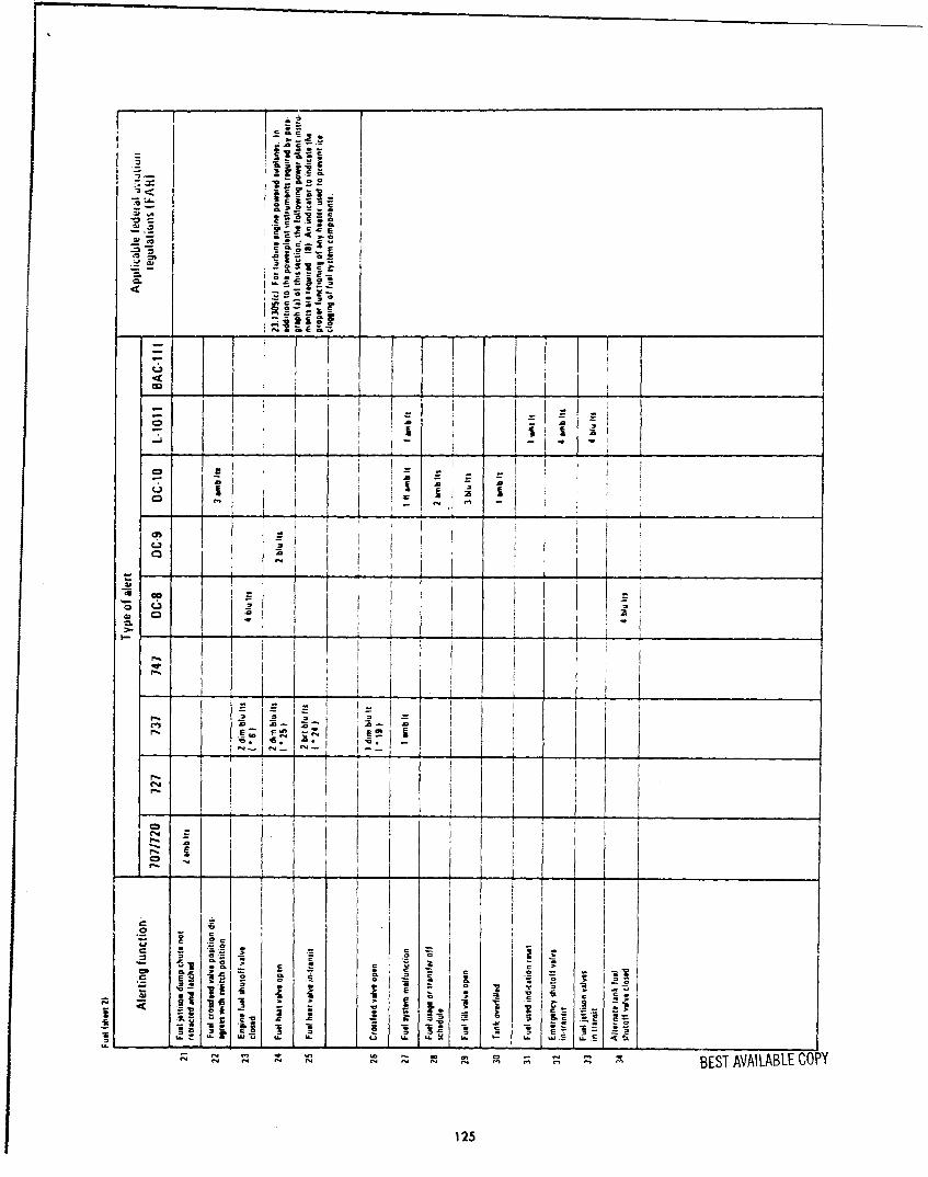
=
I I fsS, I I
" ~~I i r
-• - I iI I -'
- I a
t. go,
co
E t
•, • • m • m •• • •;BEST AVAILABLE COPY
12.5

-I
2? T a a . iI
-- ; t i • -
,- 'I a a , , =
i , iI - c -
a E zt
o at
"--C -• - - -
_- _ . * _ - .• ,• - _ • _
'K. ' iK... . -'&
BEST AVAILABLE COPY
126

0L
,-7
- I,
o I I
I-'I
0 IIII
" " "I..i
- - I~r I I
ga 127 E A I L C
127I BESAVILALE OP

=_
S ES_-,
.0-
.--°-
--
oBE a, -
ALF-COE
S128

c EE
z z
C-, I -
Ii I
- I
BES AVIAL COPYi
I129
0 i --C-i~ , : -r
r i I -i
'tv j --
I. ., - -, " °
BETAVAILABLE COPY
129

I.k
f-I
" " i
Ii
-J
-- I I
9-. i I I I.I I
I Ii
I, "
03

llie
it A
Sab
Cr!4
* 2. 2
- -- I- 11 i ~ Ii- ..,_i-
C - - I I I +
- I i ! -
1 : lW I lj+I i
A IA - i
- ISii I ' xPi ' I -
S' - I
- -.III
- • I- .• .. = -.@
BEST AVAILABLE COPY
131

•. . -- =• • - • ._ .
a a I-' ,- _ o
_ _0 in C - .. ... _ o .~
.- !: -a
-- = tS•j1
C... - *.- C -
, I
I i I
~ I _______ __ _ _ _ _ _ _ _ _ _ _
, 0.-I I
-- - ..,.
BET VALBL CP
132tfl

2E
0. •
- -
- h
-J-
0- Cz
0•
w 0
BES AVALA-E OPI-3

73i.
ZLL
C E
0. * 1.2! • ! I* , ,1.
C-4
Si i ! " g: i j ,
- 1 , , ': i f - '-I i ' : I i
,-, . g:- IC-,, a -a.
____"___ c ' .i i ! "
iI , I I I i
'a ,,I ,
-b t
BEST AVAILABLE COPY
13,4

E' S
SE
. 3 1 e_1 1 E
-- : CC .- : 0 .-m -x
BEST AVIAL ECOPY
3 5__
o=arc.-c- . m •
S!,u o ., - E.•v' ..'a
., • •. 1 ! I I - , ,. ,!0
o II ' , U i
- ;I* I C!
I Ii!i
Ii -
I, ii
- 0 - ISi : i ' I --.. i
4 ! l !I ,
E
"* -. (0
S~-~~I ___ _________
• _ t s - I !t~ iI_ , ,
1 . I I,,
BES AAIABE OP
135 ~ S

- S
- ii
- I -
-- .- __________ ....... =I•
IC , I +
-• -I I
I. i ,
i _ _ __I I _ _ _ _ _ _ _ _ _ _ _ _ _
II iI II- , K• , t ,
SI ! I +,
: I :
I I -, E
i i • I
; ; K: 1< IK S
Si n<n i SiS i i S
BEST AVAILABLE COPY
136

ii ___________
-D 2- = _- _=I T
; o
"I_ _
137 BEST AVAI LAB LE COPY

i*
0=.
o C
"S aom
-ES -VI-ALE-OP
C138

U : - ,+ 2
03-
.:. • +',]:-=i 11 i • ,
91c ý. l ,,"++;;
L r. ,•j e :_ &
f- cc~
- -" + .. I -'-" -- -" S- "
"aI a a .. ""
+',:;,"+-.-,,
E :-a X
< .__-•,~ . a +o;
M 73
, -r, 0S >. C• '
I
C
- - -
*. . 0+ + .:
O .. i a a o •=* -- - *
5 ,
_ _ =+
139.
° . .- -.
- -- - - . .• .! .0"" - - - <
aES aAIABE OP*13a

M ,e. -E ;'c a;
5 -• .•
3s
l,*e . e - c.
E E E
73 7.3
E E
- - . 1 -
I *
C14
BESTLLI AVALALEOP
I .~1 0 .

' '
~LL
S
I M
•- ,
(U
' a I
1 i*~ -
t".LD
10 c
BES1 AVAILABLE COPY
141

0I
ccs
f-a
cmE
I-
BEST AVAILABLE COPY142

APPENDIX B
DETAILED DATA USED IN ALERTING FUNCTION AND CHARACTERISTICS ANALYSES
'.9!
Ii
143
..... ....
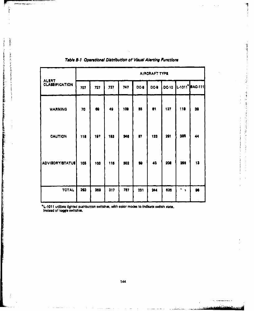
iTabl 8-.1 Operational Diatributlon of VAMe/ Alortdng Fuuntionh
AIRCRAFT TYPE
ALERT -.-CLASIFICATION 707 727 737 747 DC.8 DCI9 DC.10 L.1011 EAC.111
WARNING 70 6G 49 110 85 11 127 111 39
CAUTION 118 107 153 340 87 123 291 30B 44
ADVISORMY/TATUS 105 103 115 202 59 40 206 295 13
TOTAL 293 360 317 757 231 244 626 - 96
*L.1011 utilIzes lighted pushbutton switches, with color modes to Indicate switch state,Instead of toggle switchs..
144

q
S Ni-IU -
dH. N NI
Na?
N N N I1I F,
I- II U N
V I N
b.
j N S N(Wq -- I ji
I I?II I I
145
� � � >.F�.d I a.AIA... �±AaFAS P&�.IAIL&k
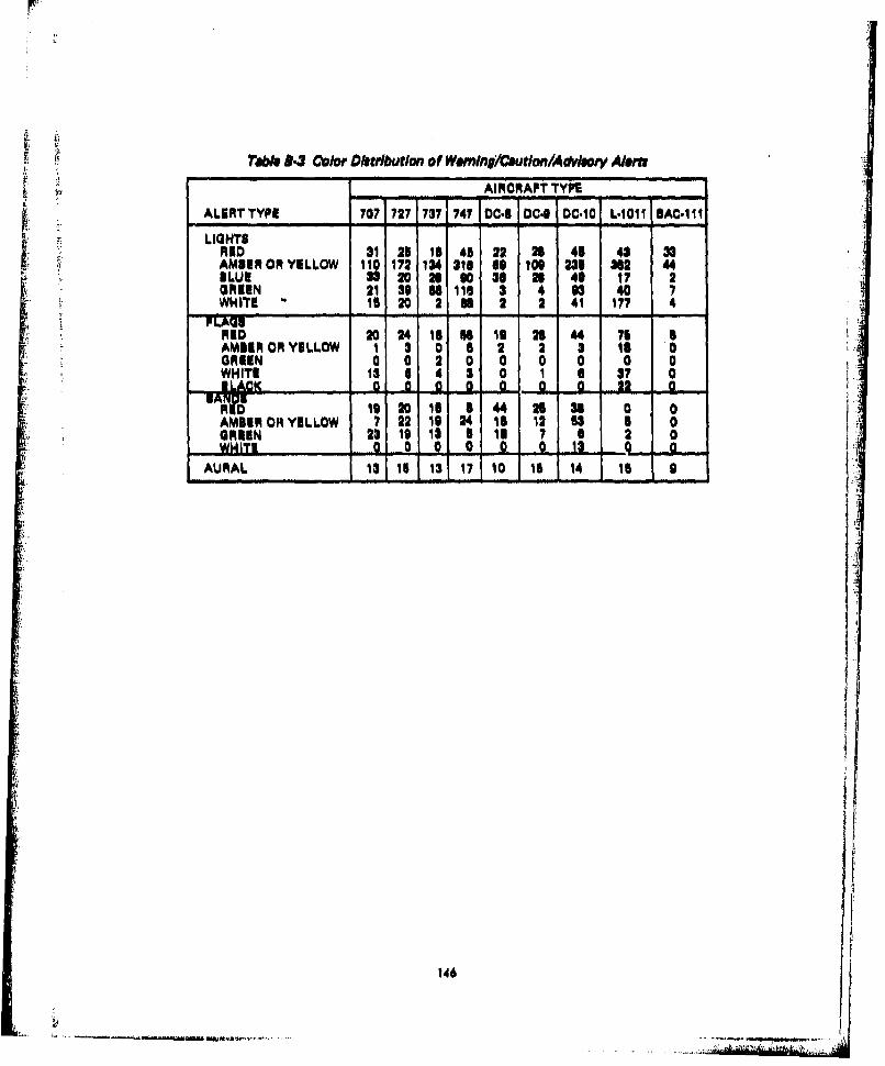
MTeb A.3 Color Dlatriburlan of Wemwn/oufutian/Adylory Alern
A1CRAFT TYPE
ALERT TYPE 707 727 737 747 DC.B OC,9 OC.10 L.1011 BAC.1 1I
LIGHTSRED 31 21 10 45 22 23 41 43 33"AMBER OR YELLOW 110 172 134 311 It 100 231 382 44BLUE 33S 20 28 E0 30 2 40 17 2tGREEN 21 319 1 115 3 4 6 40 7WHITEB 16 20 2 BE 2 2 41 177 4 :
RID 20 24 11 U 10 2 4L4 75AMBEIR OR YELLOW 1 3 0 6 2 23 Is1 0ORKIN a a 2I 0 a 0 0 0 a
WHITE 13 15 4 1 0 1 a 37 0Bl LAC]K a a a a a a, a 322 0
•;AMBER ORYELLOW 7 4"21 24 16 lo 53 5 0O•• RRIN 2319 13 5a 18l 7 e 21 oWT, 0 0 0• 0 a 0 .13AURAL 13it 17 " 10 15 14 15 0
146

�19 0 0
I-______________________
S S 0-I
'Ii _______________________
U p,.
�
S S S
IJI.!
� S I,, S SI I.,, S 04
�
S 04 0
S S .0 0
I-I- S 0
8 Ii 8
I I I- II I!
147

APPENDIX C
COCKPIT NOISE DATA

FREQUENCY, CPS100 1000 100001 1 1 1 3 1 •1 S !
100
-j- ti--- • f---T •---• ,-..- -. - .-.
I'
10. - - --e
U .---- CLIMSCRUISE (0.35 MACH, 20 ,0 WPT)
P-CFINAL APROACH (GEAR DOWN, FLAPS 40)-- 11 LANDING WIT~H THRUST REVERSER OPERATION
F/guiw C.? Maximum Cockpit No/a. Leveli Durlrq Varlaus Flight Opeietona For
" ii70%0/ A Ir-r--
ISO.°
I" "
. - ,,o.1 5.

FREQUENCY, CPS100 100 160
2 2 S 1 2 1
l 2. 22 4. 4.
' O -- , - - • '
70 ------ e' LM -... . -
*1711
I7
FIN"''• ,AL APPROACH I :- -
SILK OCTAVE PASS FANDS, CPS
F/pure C.2 Mai/mum Cockpit No/ge Level, Our/np Var/oua Flight Operation, For727.CRUISE0.M Ai r0rat
181

00 FREflUENCY, CPS 1? a2 5 1 2 U 2 92S 1 is 212 425 m0 1700 3=0 am 150
0
70 ~ ----
so
TAKEOFF THRUST -STATIC.
no , .~ CRUISE (0.78 MACH, 25,000) FT) -A &~ DESCENTCi;----3FINAL APPROACH
LANDINO WITH THRUST REVERSER OPERATION6K
15.3 37s5 75 i15 m 0 no 0 240am 4w0 M0 1320SIL
OCTAVE PASS BANDS, CPS
Figure C-3 Maximum Cockpit Nofte Letvel. During Various Fligh t Operation.For 737-200) A ircraft
152

FREQUENCY, CPS100 2 1000 10,000
26 63 I06 2' 2 425 @s0 I70U 3600 06800 13, 00
too-
so
so- -
70
5- -ED-1 -A--P-OACH-
Ai TOUCHDOWN
-* 13.1 37.5 i6 1S0 200 goo 1200 2400 4000 ciao Ii,200
OI LOCTAVE PASS BANDS, CPS
0
Figure C4 Maximum Cockpit Noise Levela During' Various Piloht Cornditions For74 7. 100 A Ircraft
133

FREQUENCY, CPS
52 1 22 4 SO1 70 0 300 60 10,6000
212 42 O iO 4D 310
soI
I i- TAKEOFF AT SNAKE RELEASE-ALANDOING APPROACH AT 1000 FT
"78.8 37.5 75w 1iir 30 o 20 240 44 00 "0 13,200
OCTAVE PASS BANDS, CPS
NOTE: -NOISE LEVELS MEASURED SEYWElN PILOT AND COPILOT-40 INCHES ABOVE FLOOR
Figurv C-5 Maximum Cockpit No/a. L eil During Various MO/Nu Condition# forDC4-63 A Irmaft
184

1I00 - - - ,-
r~ -
8t
860
u-~ BRAKE,00ILk SEATTAKEQPTHR`UIT ,1
40
75 ISO 3 00 8200200 400 4O .600
OGQCAVý DABS BANbS, AP
Figure C-6 Estimated Cockpit Noise Le've, Dur/np Varloos Fligh~t ConditionsFor DIC.9-30 Aircraft
.155. ...

•..RM
7O0h
560
&m•---A APPROACH, 1600 FT ALTITUDE, 133 KIAS, FINAL APPROACH, 400 FT ALTITUDE, 1.3 V$
A 45 so 1100 351 740 1400 2100 5600g0 1S0 536 710 14 0 2300 5000 11,200
o OCTAVE PASS BANDS, CPS
NOTE: SOUND PRESSURE LEVELS MEASURED 40 INCHES ABOVE FLOORBETWEEN PILOT AND COPILOT
Figure C-7 Cockpit No/ge Lue/ai During Various Flight Conditlons forD0610O-30 Aircraft
I;L . i d I, 156

FREQUENCY, CPS
I 1256 350 500 1000 2000 4000 woo
I , - -u ---- --
70 - .
II -dI i l
jrf
SCONDaTIOaSaTa a5a a
1-.........
45 go IN 55 710 1400 250. 11,200
OCTAVE PASS BANDS, CPS
Figure C-.8 Cockpit Nola. Levels During Various FlIght OpmertiontFor L- 0?11 A ircreft
157
H I I ! minim i I i ,,
if! 0 ... "•'•' "" o, " "" '. "I,,

APPENDIX D
TABULATIONS OF FUNCTIONAL DISTRIBUTION OF ALERTS ON EACH BASICTYPE OF AIRCRAFT
IiI"I.
il'5,
[-r

Table D. I Functional Distribution of WerningiCaution/Advieory Alerts For 707 Almrrft
WARNINGS CAUTIONS ADVISOCAY/STATUSSYSEM - - - -.. ...-...CLAUPIoATIONS RID RID Roo A61911 A01111 AMblRI11 GROIN ILU WHITI ROIIN ORIIN WNITI
LgINl FAGA BAND VILLOW YILLO YVILLOW LIGHT LIGHT LIGHT 1AND FLAG FLAGLIGHT PLAG SAND
AIR CONDITIONING 1 3 2 2
AIRCRAPT GENERAL 1 8
ALTITUDE ALERT YSITIM 1 i ¶ 1 1
APU
APOS 2F 2,,°,- - a ,,-,- - ...... -
COMMUNICATIONA 2 3 I 1 1
ELCTRICAL 2 ¶7 2 2
EMIRGINCY EQUIPM&NT 1 IF 1 3
FIRI PROTECTION 1 6 4 4 4
PLIGHT CONTROLS 2 2 1 2 1 2 2
1* F 7 IN-TRUMI-NTATIONIA.N0 AIR DATA 4 2P 3 11 1 3 1 2
FUEL. 16 16
HYDRAULIC 1 2 2 2 1
ICE AND RAIN PROTECTION 4 4 7
LANDING GEAR AND $RAKI$ 1 3 1 3 4
NAVIGATION 2F+2 18 4 1 ,2F*8
PNEUMATICS 5
POWER PLANT 16 13 4 4 20
WE IGHT AND IA LANCE
NOTE: I )F donOto flwhIn liIht,I Ight of undefined nature not
Included In listing above
140
.... .... ...

Table D.2 Functional Distribution of WarninglCoution/Advisory Alerti For l27Aircraft
1WARNINOI CAUTIONS AOVI$ORYIITATUS
a SYSTEIM , a a a a'SaCLASIFICATIONS REIJ RED RED AMBS11 AE11R/ AMN1RI GROIN ILU9 WHITI GRION 0All" WHII'l
L1IGH FLAG 1AND YELLOW YELLOW YILLOW LIHT LIGHT LIGHT SAND FLAG FLAQLIGHT FLAG BAND
AIR CONOITIONING 1 9 1
AIRCRAPT GENERAL IF 14 1
ALTITUDE ALERT SYSTEM I IF 1 1 1-i-i- - - - - -- - -
APU 1 2 1 1- -- - --a.
APCl 2F 1F+2 4
COMMUNICATIONS 2 3 4 1 9
ILIC¶1IOAL 1 31 3 2PF+
EMERGENCY EQUIPMENT 1 I F 2 3
Is I E PROTECTION 1 2FI8 1 ,
FLI• OHCONT1O4,L 3 27 2 15
PLIGHT INSTRUMENTATION 2AND AIR DATA 5 2F 5 21 1 2 "
PUlL 11 12
HYDRAULIC 2 a 2 1 2
ICE AND MAIN PROTECTION 6 9 2
LANDINQOGEAR AND BRAKIS 1 5 2 6 1 2 1-i- - a - -
NAVIGATION 2 18 3 6
PNEUMATICS 3
POWER PLANT 3 15 11 15 3 15
WEIGHT AND BALANCE
NOTE: I IF denotl Ilnhing lolit.8 flagi of undefined naturn riot
Irncludod in listing above.
161
~ -

Table 0-3 Functlonal Dlatrlbutlon of Warning/Qautlon/AdvisoiV Alert for 737 Alrcraft
WARNINGS CAUTIONS AOV ISORY/EITATUC,
CLASSIFICATION& Rio H Re ID ANIIIIIII Alleall AMSERLCA 0114 O ION LUE 11ITI ORN N RE WIlETILIGHT¶ ?LAO SAN YELLOW YILLO yEO LION?. LIGHT LIGNT SANDl PLIn'1 FLAG
LIGHT PAGn $AND
AIR! CONDITIONING 11 S1 2 3
AIRCR4AFT GINIRAL 14
ALTITUDE ALIEPT SYSTEM 111
APU - - - 1 4 11
APOS 2F 10
COUMMUNICATIONS~ 2 23 1
ELETRCAL104 4
EMERGENCY EOUIPMENT 2 3
PIRE PRO0TECTION 3
PLIGHT CONTROLS 2 2`1 is
PLIGHT INSTRUMENTATION 2 4 2P12 P2AND AIR DATA5 2 4 2F12 22
FUEL 0
HYDRAULIC 1 9 2 1
101EAND RAIN PROTECTION 5 11 0
LANDING GEAM AND ERAKEE 4 2 4 1 3 1
NAVIGATION 12 1
PNEUMATICS
POWER PLANT 1 10 7 10 11
WEIGHT AND SALANCE
NOTE: IIf denotes fiftingfiIg - a - - a a
162
4- - - - - - - - - -- - - - - - - - - - - - - - - - - - - - - - - - - - - - -

v1
Table D4 Function./ Dilstribution of Warning/Caudon/A dvlaory Alerti For 747 Aircraft
WARININGII CAUTION11 AOVIUORY'VISATUS
7LNPCAIN RID AIORD A111111INIIIIIRI A111E11 GREEN ILUE WHITE GREIN CARIN WHIT[
AIR CONDITIONING 1 14 1 a I
AIRCRAPT GENERAL 1 17 3 3
ALTITUDE ALERT SYITIM 1 2 1 1
APU 1 1 2
AMO 1 0+2 2F+20 23
1'COMMUNICATIONS 2 2 7 1 F+2 22
ELCTIALUSa 7 15 17
EMERGENCY ROUIPMENT 1 i 2 3
PLIGHT INTRUMENTATION 22AND AIR DATA 4Fi 12 2
FUEL ig 417 14
HYDRAULIC 20 4 4
ICE AND MAIN PROTECTION 7 20 5 3
LANDING GEAR AND SIIAKES 1 3 4 34 4 8 a 6
NAVIGATION 0 28 14 4
A PNEUMATICS 43 ~ 1
POW Itag PANT 124 20gt 20 a 13 Ilan1
163

Table D-5 Functional Distribution of Warning/Caution/A dvlsorj, Alerts for DC-8 Aircraft
WARNINGS CAUTIONS ADVIISORYJSTATLJS
OLABISIPICATIONS sAI sAI jig A11111111 A1111111 A1111111 R OI I53 LUI WHITE ONIIk05 N WHITEL1GH1 0 LAO SIANG Y111.1,011 VILLD YELL011 LIGHT L IGHT LIGHT SIAND FLAG FLAG
I I LIGHT FLAG SIAND
AIR CONDITIONING 1 4 12 3 2 4
AIRCRAPT GINOEMAL 31 3
ALTITUDE ALERITSYSTEM 112
APO$ 21ICOMMUNICATION$ 2 12
ELECTRICAL 2 13 1- - -
EMS R0INCY EOUIPMANT1
FIREN PROTEOTION 1 4 4 4
P LIGHT CONT14OLS 2 4 2
PLIGHT INSTIIUMENTATION 2 2 S62 2AND AIR DATA2 662 2
FUEL 4 B 8 4
HYDR4AULIC 1 21
ICE AND RAIN PROTECTION B
LANDING GEAR AND SRAKES 1 11 13
* I NAV113ATION - 0 2- - -
PNEUMATICS 12 7 2
POWER PLANT 20 12 12 4 1
WEIGHT AND EALAN4CE I - - - - - -
NOTE: ( IF demotol flashing light.
* Ilghtt of undefined rteturs motIncluded in huitng bo
164

Table D-6 Functional Distribution of Warning/Cautlon/Advisory Alerts For DC.9 Aircraft
WVARNINGS CAUTIONS AOVISORYISTATUS
SYSTEM a-
""A IFIATION8 RI Al111111 AMIIRI AMNIR/ ORKIN IUI ANI1, O RIKN BAIIN WHITi1Y IOH1 AD BANI YILLOW LIGO L LIGHT II AND ?LAO FLAG
LIGHT FLAG SANU
AIR CONDITIONING 1 2 2 3
AIRCRAFT GINIRAL 2 10
ALTITUDE ALIRT IYITIM 1 1 1 1
APU 2 2 2
COMMUNICATIONS 2 2 2-'.. . .. -" "" - - - - -
OLICTRICAL 2 2 13 2 10 1
EMERGENCY EQUIPMENT 1 1 1 1 - -
,PIM PROTECTION 1 3 2 g 2FLIGHT CONTROLS 2 2F,3 6 2
PLIGHT INITRUMINTATION a 2 a 4 1 1 1AND AIR DATA -U - a - a - -2 a -1
PUIL, 2
HYDRAULIC 2 4 2
ICE AND MAIN PROTICTION 10 .
LANDINO GAR AND IRAKII 1 7 2 10 3 2
NAVIOATION 20
PNIUMATICI 1
POWIR PLANT 10 12 6 22
WEIQHT AND BALANCE
NOTI: I IP denotes ftlhimngIlIl.2 ispuofl uctIlflned n tur: notIncliuded In filling Iboy0,
1,.¶65,

Table 0.7 Functional Distribution of Warning/Caution/Advisory Alerts for DC- 10 Aircraft
WARNINGS CAUTION@ ADVIORYISTATUS
CLAIPIPIgATIONNIBROI RIO AMEIRI ANIIM1 AM110 GASIN ILUi WHITl BRIIN WHITl WHITILIGHT FLAG MAND Y oLLOW YILLO VILLO LIGHT. LION? LIGHT SAN FLAG SAND
LIGHT FLAG BAND
AIR CONDITIONING 1 2 2 10 2 2
AIRORAFT GENERAL 3 24 1 2 1
ALTITUDE ALIRTEYI'M 1 - 1F+-
APU 3 3 2 3 2
APWS' 1 UP 40 76 10
COMMUNICATIOWI 2 3 4 9 29
ELICTRICAL 5 4 26 10 4 12 2 3 '
EIMIERNCY-IOUIPMINT I je 1 1 2
P1R1 PROTECTION 1 5 3 18 3
PLIGHTOONTROLI 2 1 I 1 5
PLIGIT INTRLUMENTATION 22AND AIR DATA - - - - - 2 2 - -
FUEL 111+20 3
HYDRAULIC 3 16 9 4
ICE AND RAIN PROTECTION 3 2
LANDING GRAN AND ERAKEE 1 3 2 a 2 3 2
NAVIGATION 4 20 9 2 a
PNEUMATICIS 8 10 3 1 3
POWER PLANT 10 15 23 15 3 5 3
WEIGHT AND SALANC-
NOTE I IF dlanow ftlnhing light.
.;I"

r"le04 Funictlordl Olwtiburloi, oWvnlnp/Cautlbn/Advlory Alert for L- 1011 Aircraft
INWAM4ItOQ6 CAUYIO94I AOVIIGRYIITA7US
1111A?0U I' urn *gg pg AUMK/AUI "B Sali"il 611101 stut WHIIl IN oflu WHISK G111 LAIRI41 FlAB Pilo Ifio V1111,0 Vitt LIGHT t IGNT LIGHT SAID11 F LAO FkAG FLAGS
LIGHT I LAO SIAND
AIR COGSOITIGNIMP 4 P242
AIRCRAFT GGIIMAI,1..2 13
ALITAA LINT~ 1Yv# 2F 2 2 2
APCW 3P 3 22
COMUWA"ATI0#S 4 6 2 1s
OL60?NICAL 1114-5 F *33 3 1
FNPiK K0YTIC0PG 2 4P~ f2 2
PLW4Y.CONTROIA 2 7FP440 2 39PLGH - a - -- - - ----
AND A14IR DATA ??o 4 2 17 21 10 2 2
HYDRAULIC -12S - -
lag ANDRAIN PROTUGION 13 +0* 3 1
LANDING OAll AND ISMAKI7.6 4 P.F08 2 4
NAVIGATION4 2 26 1P+6 12
PNEUMATICIcS51
POM A PLA14T 3F 17 F+21 79
MIGHT 4ANDFBALANICE 3 5 IN076 I IF dnItf l~iahngSiot
167

Table D-9 Functionel Distribution of Warning/Cout/on/Adv/sory Alerts for RAC. 111 Aircraft
WARNiN0S CAUTIONS ADVISORY*ITATUS
IYSTIM ,-CLASSIPICATION'I f AMlCH/ AMLRI AMEIR/ RiltH Ilbi WHiTl GRLON (IRtiN MMirl
LION? P L AII A ELOW YIILLOW V'LLOW LIGHT LIGHT LIGHT RAND PLAO FLAOLIGHT FLAG Ad NW
AIR CON DITIONIN 1 3
AIRCRAFT GNRINAL 2F+5
ALTITUDE ALERT SYSTIM 1
APU (2 LIUH' 8)
APII 1iF (6 FLAS)
CCMMUNICATIONS 1 2
ELECTRICAL 3 3
EMERGENCY IOUIPMINT
PIRE PROTECTION 1 S
FLIGHT CONTROLS 3 9 7 1
FLIGHT INSTRUMENTATIONAND AIR DATA 2 2F 2F --
FUEL 2 2
HYDRAULIC 3 3
ICE AND RAIN PROTECTION U
LANDING GUAM AND SRAKES 1 411
NAVIGATION - -
PNIUMATICS 2
POWIR PLANT 2 6 2F 2
WEIGHT AND BALANCE
NOTE I IF denotes fimthingl ight.
3 lIghts end 12 flop of undefinednature not Included in Noting above,
I
114
I _ __ _ _ _A.'

APPENDIX E
V .SYNOPSIS OF ALERTING SYSTEM REQUIREMENTSFOUND IN .AE, MILITARY, AND RTCA STANDARDS
L
4"
169

"TABLE E-1ALERTING SYSTEM REQUIREMENTS FOUND IN ARP 450
2. FLIGHT DECK SIGNALS
2.1 GENERAL PHILOSOPHY; AIRCRAFT FLIGHT DECK SIGNAL SYSTEMS MA V CONSIST Oa' ONE OR MORE OFTHE SIGNALS HEREIN DEFINED.
INSOFAR AS IS TECHNICALLY FEASIBLE, IT IS DESIRABLE TO PREVENT WARNING OR CAUTION SIG-NALS FROM EXISTING OR OCCURRING WHEN NOT APPLICABLE IN VIEW OF THE BASIC INTENT OR 4SDESIGN AIM OF THE SIGNAL SYSTtM. THIS DESIGN PHILOSOPHY IS DESIRABLF IN ORDER TO PREVENTA BUILD-UP OF FLIGHT CREW TOLERANCE AND DISREGARD FOR THE SIGNAL.
'IF THE PRIME FUNCTION O6t A MASTER VISUAL SIGNAL, OR OF ONE OF THE VISUAL SIGNALS IN ANANNUNCIATOR 'PANEL, IS TO DIRECT ATTENTION TO AN INDICATOR OR CONTROL DEVICE, IT SHALLSUPPLEMENT A SEPARATE VISUAL SIGNAL AT THAT LOCATION. THE INDIVIDUAL VISUAL SIGNALSUSED WITH MASTER WARNING SIGNALS, MASTER CAUTION SIGNALS OR ANNUNCIATOR PANELS, 4SHOULOB# IDENTIFIED WITH TRANSILLUMINATED NOMENCLATURE.
SIGNALS SHOULD BE OF LIMITED INTENSITY SO THAT ATTENTION IS NOT DRAWN MORE TO THE NOISEOR LIGHT THAN IT IS TO THE SITUATION WHICH I9 CAUSING THE SIGNAL. OVERWHELMING SIGNALSSHOULD BE AVOIDED SINCE THEY INTERFERE WITH CREW COORDINATION AND COMMUNICATION ANDMAY ALARM A CREW MEMBER ENOUGH TO REDUCE HIS EFFICIENCY IN AN EMERGENCY SITUATION.
2.1.1 VISUAL SIGNALS: MAY CONSIST OF LIGHTS (WITH OR WITHOUT TRANSILLUMINATED NOMENCLATURE),WARNING FLAGS OR INDICATORS, OR, IN THE CASE OF INSTRUMENT INDICATIONS, IN THE TOTALREMOVAL OF THE PERTINENT INSTRUMENT DISPLAY.
2,1.,,1 MASTER WARNING LIGHT(S): A MASTER WARNING LIGHT IS A LIGHT WHICH IS USED WHERE WARNINGLIGHTS ARE LOCATED OUTSIDE OF THE DIRECT VISION OF EITHER PLOT,
NOTE: A MASTER WARNING LIGHT OR LIGHTS MAY BE REQUIRED BECAUSE OF THE LIMITATIONSOF VISIBILITY OF COLORED LIGHTS AND THE VARIABILITY OF LIGHTING CONDITIONS INTHE FLIGHT DECK,
2.1,1.2 WARNING LIGHTS: LIGHTS PROVIDED TO WARN THE CREWMEMBER. OR THE CREW, o0 A CONDITIONWHICH REQUIRES IMMEDIATE PROTECTIVE OR CORRECTIVE ACTION,
2.1.1,3 MASTER CAUTION LIGHT(S): A MASTER CAUTION LIGHT IS A LIGHT WHICH IS USED WHERE CAUTIONLIGHTS ARE LOCATED OUTSIDE OF THE NORMAL FIELD O VISION OF EITHER PILOT,
2,1,1.4 CAUTION LIGHTS: LIGHTS PROVIDED TO INDICATE MALFUNCTIONS WHICH DO NOT REQUIRE IMME-DIATE ACTION, BUT WHICH MAY HAVE A SUBSEQUENT SIGNIFICANT EFFECT ON THE OPERATION OFTHE AIRCRAFT,
21,1.5 ADVISORY LIGHTS: LIGHTS PROVIDED TO INDICATE SAFE OR NORMAL CONFIGURATION, CONDITIONOF PERFORMANCE, OPERATION OF ESSIENTIAL EQUIPMENT, OR FOR ATTRACTING ATTENTION FORROUTINE PURPOSES,
2,1,1.7 WARNINr FLAGS OR INDICATORS: MEC'IANICALLY OR ELECTRICALLY ACTUATED DISPLAYS USED TOWARN OF AN UNSAFE SETlING OR MALFUNCTION OF INSTRUMENTS OR MECHANICAL DEVICES,
2.1,2 AUDIBLE SIGNALS: IF ONE AUDIBLE SIGNAL IS USED FOR MORE THAN ONE FUNCTION, IT SHALL BEACCOMPANIED BY VISUAL SIGNALS WHICH WILL INDICATE THE MALFUNCTION WHICH IS CAUSING THEAUDIBLE SIGNAL,
2.1.2,1 WARNING BELL; A BELL WHICH OPERATES IN CONJUNCTION WITH A WARNING LIGHT ONLY TO INDI-('ATE THE EXISTENCE Or A FIRE,
2.1.2.2 WARNING HORN: A HORN WiIICII OPERATES TO INDICATE AN UNSAF, CONII{GURATION.
170

TABLE E-1 (CONT)ALERTING SYSTEM REQUIREMENTS FOUND IN ARP 450
I
2,1.2.3 WARNING GONG: A SINGLE BEAT SOUND USED TO WARN OF AN UNSAFE FLIGHT CONDITION OR IINDICATION.
2.1.2.4 WARNING "CRICKET": A DEVICE WHICH GENERATES A CRICKET-LIKE SOUND TO WARN OF SPEUDS INEXCESS OF VMO .MMO.
2,1,2.S CHIMES: USED IN CONJUNCTION WITH COMMUNICATION SYSTEMS OF THE AIRCRAFT. FOR EXAMPLE:CABIN 1O.FLIGHT DECK; SELCAL, ETC,
2.1.2.6 TONE: AN B00oCYCLE THREE.NOTE CORD OF INCREASING AMPLITUDE USED TO INDICATE APPROACH.ING THE DECISION HEIGHT AND CUTTING OFF WHEN REACHING DECISION HEIGHT,
2,1,3,1 STICK41HAKER: A DEVICE WHICH CAUSES THE PILOT'S CONTROL WHEEL TO VIBRATE TO WARN OFAPPROACHING TO, OR OF OPERATION IN, A STALLED CONDITION,
2,1,3.2 FOOT.THUMPER: A DEVICE WHICH VIBRATES THE PILOTS FOOT ON THE DRAKE PEDAL TO INDICATETHE CYCLING OF THE ANTI.SKID SYSTEM, OR TO WARN OF WHEEL SKIDDING'
2,2.1.1 STEADY MASTER WARNING LIGHT: THE STEADY MASTER WARNING LIGHT SHALL BE USED EXCLU.SIVEIY TO WARN OF FIRE AND WILL BE ACCOMPANIED BY THE WARNING BELL,
2.2.1.2 FLASHING MASTER WARNING LIGHT: THE FLASHING MASTER WARNING LIGHT SHALL BE USED TOINDICATE AN UNSAFE CONDITION OTHER THAN FIRE,
212.1.3 LOCATION: THE MASTER WARNING LIGHT, OR LIGHTS, AND THE MASTER CAUTION LIGHT, WILL BELOCATED NEAR THE CENTER LINE OF THE AIRCRAFT NEAR THE TOP OF THE CENTER INSTRUMENTPANEL,
2.2,2.1 WARNING, CAUTION AND ADVISORY LIGHTS: AN INDEPENDENT LIGHT SYSTEM SHALL BE PROVIDEDFOR EACH INDIVIDUAL FUNCTION OR SYSTEM TO BE MONITORED, WHERE A MASTER WARNING LIGHTIS REQUIRED, IT WILL SUPPLEMENT A SPECIFIC STEADY WARNING LIGHT AT THE INDICATOR OR CON-TROL OF THE AREA OR EQUIPMENT AFFECTED,
2,2,2.2 WARNING LIGHTS SHALL BE WITHIN THE CONTROL DEVICE, OR SHALL BE LOCATED IN CLOSE PROX-IMITY TO THE INDICATOR OR CONTROL DEVICE, WHERE ATTENTION TO THE INDICATOR OR CONTROLDEVICE IS THE PRIME FUNCTION OF THE WARNING SIGNAL,
2,2,2.4 THE WARNING LIGHTS FOR THE FOLLOWING SPECIFIC INDICATORS OR CONTROL DEVICES WILL BELOCATED IN THE INDICATOR OR CONTROL DEVICE, OR ON THE CONTROL PANEL IMMEDIATELY ADJA.CENT THERE TO IN SUCH A MANNER AS TO POSITIVELY IDENTIFY THE INDICATOR OR CONTROLREQUIRING ACTION.
A. LANDING GEARB. FIRE CONTROL
2.2.3.3 CAUTION AND ADVISORY LIGHTS SHALL BE LOCATED IN CLOSE PROXIMITY TO THE INDICATOR ORCONTROL DEVICE WHERE ATTENTION TO THE INDICATOR OR CONTROL DEVICE IS THE PRIME FUNC.TION OF THE SIGNAL.
2.2.5 SIGNAL FLAGS-WARNING AND ADVISORY: SIGNAL FLAGS MAY BE USED WHERE SPECIFIC INDICATIONIS ASSOCIATED WITH AN INSTRUMENT OR MECHANICAL DEVICE, WHERE THEY ARE SO USED THE FLAGSIGNAL WILL BE AN INTEGRAL PART OF THE INSTRUMENT OR DEVICE,
2.2.6 AUDIBLE SIGNALS: AUDIBLE SIGNALS ARE REQUIRED FOR ALL FIRE WARNING SYSTEMS AND OTHERCRITICAL SYSTEMS OR DEVICES WHERE VISUAL CHECKS OR WARNING MAY BE INSUFFICIENT TOGUARANTEE SAFETY, THEY MAY ALSO BE USED FOR OTHER FUNCTIONS NOT BEARING ON SAFETYBUT OF SUFFiCIENT IMPORTANCE TO REQUIRE THEIR USE,
171 L

TABLE E-1 (CONT)ALERTING SYSTEM REQUIREMENTS FOUND IN ARP 450
2,2.7 TACTUAL SIGNALS: TACTUAL SIGNALS MAY BE EMPLOYED TO ALERT PILOTS' ATTENTION WHEREVISUAL CHECK OR NORMAL SENSATIONS MAY BE INSUFFICIENT TO GUARANTEE SAFETY' THEY MAYALSO BE USED FOR OTHER FUNCTIONS NOT BEARING ON SAFETY, BUT OF SUFFICIENT IMPORTANCETO REQUIRE THEIR IISE,
2.2,8 VOICE WARNING SYSTEMSi A SYSTEM THAT INDICATES TO THE FLIGHT CREW BY MEANS OF SPOKENWORDS, A SAFETY FLIGHT MALFUNCTION OR ABNORMALITY,
2.2.8.1 WHEN A VOICE WARNING SYSTEM IS USED, IT MAY INCLUDE, BUT NOT BE LIMITED TO, ALL WARNINGSREQUIRING AN AUDIBLE SIGNAL AND SHALL INDICATE THE SPECIFIC ITEM CAUSING THE UNSAFECONDITION,
2.2.8.2 THE WARNING MAY INCLUDE AN APPROPRIATE SIGNAL CORRESPONDING TO THE SPECIFIC ABNOR.MALITY AND SHALL OCCUR ALTERNATELY WITH THE VOICE SIGNAL, J,
2.2.8,3 AN ANNUNCIATOR PANEL SHALL BE INCLUDED IN THE SYSTEM TO INDICATE ABNORMAL CONDITIONSAS LONG AS THEY EXIST, IF A CANCELLABLE AURAL SIGNAL IS EMPLOYED,
2,3.8.4 A SILENCE SWITCH 5HALL BE PROVIDED TO SILENCE THE AURAL SIGNALS ONLY AFTER THEY HAVECOMPLETED ONE CYCLE AND WILL RESET THE SYSTEM. NONCANCELLABLE TAKE-OFF AND LANDINGWARNINGS CANNOT BE SILENCED.
2.2.8.5 THE VOICE WARNING SYSTEM WILL USE SEPARATE COCKPIT SPEAKERS AND THE COCKPIT INTERPHONETO DISSEMINATE INFORMATION, .
2,3,2 COLOR CODE-LIGHTS:
2.3.1 WARNING LIGHTS: WARNING LIGHTS WILL BE COLORED AVIATION RED. THE COLOR IS DEFINED INSPECIFICATION AN.C5642, SECTION D-GENERAL REQUIREMENTS.
2.3 CAUTION LIGHTS: SHALL BE AMBER, AS DEFINED IN AN.C46.2, SECTION D.
213.3 ADVISORY LIGHTS: MAY BE GREEN, BLUE, OR WHITE, AS DEFINED IN AN.C.46.2, SECTION D.
2,3,1 GREEN: USED TO INDICATE A SAFE CONFIGURATION OR CONDITION, WHEN USED IN CONJUNCTIONWITH A WARNING LIGIIT THE GREEN LIGHT WILL INDICATE THAT THE ACTION TAKEN HAS RESULTEDIN COMPLETE SYSTEM OPERATION AND THE RESULTING CONFIGURATION IS SAFE,
2,3.3.2 BLUE: USED TO INDICATE THAT A SYSTEM IS ON AND OPERATING NORMALLY, OR THAT TRANSITORYACTION IS TAKING PLACE (WITH THE EXCEPTION OF THE LANDING GEAR WARNING SYSTEM),
2.4,1.1 MASTER WARNING LIGHTS: THE INTENSITY OF THE MASTER WARNING, MASTER CAUTION ANDWARNING LIGHTS WILL BE 275 MILLILAMBERTS FOR THE BRIGIIT INTENSITY, AND 140 MILLILAMBERTSIF DIMMING IS USED,
2.4.1,4 CAUTION LIGHTS: THE INTENSITY OF CAUTION AND ADVISORY LIGHTS WILL BE 375 MILLILAMBERTSFOR THE BRIGHT INTENSITY AND CAPABLE OF DIMMING TO NOT LESS THAN 25 MILLILAMBERTS. IFCAUTION LIGHTS ARE LOCATED NEAR THE PRINCIPAL FLIGHT INSTRUMENTS THEY SHOULD DIM SOAS NOT TO INTERFERE WITH READING THE INSTRUMENTS DURING NIGHT FLIGHT WITH THE INSTRU.MENT LIGHTS TURNED DOWN,
2.6.1 WARNING LIGHTS: WARNING, CAUTION AND ADVISORY LIGHTS WILL ILLUMINATE WHEN THE CONDI.TION TO BE WARNED REMAINS ILLUMINATED UNTIL ITS CAP IS PUSHED IN, OR UNTIL THE CONDITIONIS CORRECTED, EITHER OF WHICH EXTINGUISHES THE MASTER WARNING AND RESETS IT FOR OTHERPOSSIBLE FAILURES,
2.6.2 WARNING LIGHTS: WARNING CAUTION AND ADVISORY LIGHTS WILL ILLUMINATE WHEN THE CONDI.TION TO be; WARNED OR ADVISED OF OCCURS. THESE LIGHTS WILL REMAIN ON AS LONG AS THE CON-DITION EXISTS OR UNTIL THE SYSTEM IS DEACTIVATED.
172J

TABLE E-l (CONT)ALERTING SYSTEM REQUIREMENTS FOUND IN ARP 450
2.6,3 MASTER CAUTION LIGHT: WILL ILLUMINATE WHEN THE CONDITION TO BE ADVISED OF OCCURS. THEMASTER CAUTION SIGNAL REMAINS ILLUMINATED UNTIL ITS CAP IS PUSHED IN OR UNTIL THE CONDI-TION IS CORRECTED, EITHER OF WHICH EXTINGUISHES THE MASTER CAUTION SIGNAL AND RESETSIT FOR OTHER POSSIBLE ABNORMALITIES,
2.7,1 COLOR CODE: WHERE WARNING FLAGS ARE USED EXTERNALLY OR INDEPENDENTLY FROM INSTRU.MENTATION, THEY SHOULD BE OF A BRIGHT YELLOW WITH BLACK DIAGONALS TO PROVIDE CON-TRAST TO THE SURROUNDING AREA.
WHERE WARNING FLAG INDICATORS ARE USED INTERNALLY IN INSTRUMENTS, THE COLOR SHOULDBE YELLOW, OR FLUORESCENT RED, WITH BLACK WORDING THEREON, IF REQUIRED.
2,,2 WARNING FLAG OR INDICATORS INDEPENDENT FROM INSTRUMENTt FLAGS USED IN CONJUNCTIONWITH MECHANICAL DEVICES INDEPENDENT OF INSTRUMENTATION WILL PROVIDE A CLEAR, UNMIS.TAKABLE WARNING THAT THE CONDITION TO BE WARNED OF HAS OCCURRED,
2.7,3 INSTRUMENT WARNING FLAGS OR INDICATORS: FLAGS USED IN CONJUNCTION WITH INSTRUMENTSWILL PROVIDE A CLEAR, UNMISTAKABLE WARNING THAT THE CONDITION TO BE WARNED OF HASOCCURRED,
23s AUDIBLE SIGNAL-CODE?
2.3,1 BELL: INDICATES "FIRE," FUNCTIONS AUTOMATICALLY AND SIMULTANEOUSLY WITH A FIREWARNING LIGHT,
2.8,32 HORN: INDICATES AN UNSAFE AIRCRAFT CONFIGURATION, 73SPECIFIC APPLICATIONS:
A, LANDING GEAR UNSAFE WITH THROTTLES RETARDED, OR WITH WING FLAPS IN THE
LANDING CONFIGURATION, STEADY SOUND,
I. UNSAFE TAKEOFF CONFIGURATION UPON THROTTLE OPENING INTERMITTENT SOUND,
C. CABIN PRESSURE ABOVE 10,000 FEET INTERMITTENT SOUND.
2,.3 "CRICKET": INDICATES SPEED IN EXCESS OF VMO .MMo,
28,,4 GONG: USED FOR ALTITUDE ALERTING SYSTEM AND SPECIFIC WARNING ASSOCIATED WITH FLIGHTINFORMATION,
2,8.5 CHIME: USED FOR ROUTINE OPERATIONAL INFORMATION.
":.7.6 TONE: AN 800 CYCLE THREE NOTE CORD OF INCREASING AMPLITUDE MADE UP OF THE FOLLOWINGFREQUENCIE-S: 512/640/768 Ht.
2.9 AUDIBLE SIGNAL SOUND LEVEL: THE LEVEL OF SOUND FOR ALL AURAL SIGNALS SHOULD BE THEMINIMUM LEVEL WHICH WILL BE CLEARLY DISTINGUISHABLE ABOVE THE NOISE LEVEL OF THEFLIGHT DECK FOR ALL CONDITIONS OF FLIGHT OPERATIONS OVER THE ENTIRE DESIGN ENVELOPE.
2.10 AUDIBLE SIGNALS TESTING: MEANS SHALL BE PROVIDED IN THE FLIGHT DECK AREA FOR TESTINGAUDIBLE SIGNALS,
2,11 OPERATION OF AUDIBLE SIGNALF: THE AUDIBLE SIGNALS WILL SOUND WHEN THE CONDITION TO BEWARNED OF EXISTS.
2,11.1 BELL:
A. THE WARNING BELL SHALL HAVE A PROVISION FOR CUT-OFF. IF CU1IOFP IS AUTOMATIC,THE BELL WILL RING NOT LESS THAN ONE OR MORE THAN THREE SECONDS.
173
----------------------... .. ..-...........L......... Z.C- ...... .- ' : •I I•I '"

TABLE E-1 (CONT)ALERTING SYSTEM REQUIREMENTS FOUND IN ARP 450
B. THE CUT.OFF WILL NOT AFFECT CONTINUED OPERATION OF THE SIGNAL LIGHT.C, THE CUT-OFF WILL AUTOMATICALLY RESET THE WARNING BELL FOR RECURRING FIRE IN
THE SAME SYSTEM, OR FOR OCCURRENCE OF FIRE IN ANY OTHER SYSTEM, FOR EITHERMANUAL OR AUTOMATIC CUT.OFP.
2.11,2 HORN: THE WARNING HORN SHALL BE PROVIDED WITH A MANUAL CUT-OFF SWITCH, IT SHALL NOT BEPOSSIBLE, HOWEVER, TO SILENCE THE HORN WITH THE CUT.OFF SW'.TCH:
A, DURING TAKEOFF, EXCEPT BY CORRECTING THE UNSAFE rAKEOFF CONDITION.
B. IN FLIGHT WHEN THE WING FLAPS ARE IN THE LANDING CONFIGURATION.
IF THE HORN SOUNDS IN FLIGHT AS A RESULT OF RETARDING THRO7'TLES AND THE HORN IS THENSILENCED WITH THE CUT.OFP SWITCH, THE WARNING SYSTEM SHALL AUTOMATICALLY RESET FOROPERATION UPON ADVANCEMENT OF THROTTLtS,
2,11,3 "CRICKET": WILL BE FULLY AUTOMATIC IN OPERATION WITH NO CUT-OFT: PROVIDED.
2.11,4 GONG: WILL BE FULLY AUTOMATIC IN OPERATION WITH NO CUT-OFF PROVIDED.
2.11,5 CHIME: WILL BE SOUNDED BY AN ACTUATING SWITCH OR BUTTON, AS REQUIRED,
2.12 TACTUAL SIGNALS PERCEPTIBILITY: THE INTENSITY OF TACTICAL SIGNALS SHALL BE SUCH AS TO
ASSURE THEIR PERCEPTIBILITY UNDER ALL CONDITIONS.
2.13 TACTUAL SIGNALS TESTING: MEANS SHALL BE PROVIDED IN THE FLIGHT DECK AREA FOR TESTINGTACTUAL SIGNALS.
2.14 OPERATION OF TACTUAL SIGNALS: THE TACTUAL SIGNALH WILL BE ACTIVATED WHEN THE CONDITIONTO BE WARNED OF EXISTS, OR IMPENDS, AND WILL PERSIST UNTIL THE CONDITION IS CORRECTED,
WHEN THE CONDITION IS CORRECTED THE TACTUAL SIGNAL WILL BE AUTOMATICALLY DEACTIVATEDAND RESET FOR FUTURE RECURRENCE,
174

TABLE E-2ALERTING SYSTEM REQUIREMENTS FOUND IN ARP 571
3.2.2 SELCALi A4 SYSTIM MAY BE INSTALLED FOR PROVIDING VISUAL AND AURAL INDICATION OF A RADIOCALL INIUNDED fOR THAT PARTICULAR AIRCRAFT,
3.2.2.1 VISUAL 411DIOACION SHALL BE PROVIDED FOR .CIH RECEIVER FOR WHICH THE CALLING SYSTEM ISPROVID=, BY: NN ADVISORY LIGHT (OF A COLOR CONFORMING TO ARP 450). EACH LIGHT SHALL BELOCATED AS CLOSE AS PRACTICAL TO THE RESPECTIVE RECEIVER'S FREQUENCY SELECTOR AND/ORVOLUMORCONTROL.
'5,1,1 THE -FLIGH'T DIRECTOR, AUTOPILOT, AND AUTOTHROTTLE SYSTEM MODE ANNUNCIATION DISPLAYSNALLlPROVIDE A VISUAL INDICATION OF THE ARMING AND ENGAGEMENT OF ALL SELECTED MODESiOND, POR SPECIFIED CASES, A VISUAL AND AURAL WARNING OF DISCONNECT CAUSED BY A SYSTEMSAUIU' OR BY PILOT ACTION,
rl.3 THE MODE ANNUNCIATION DISPLAY SHALL BE LOCATED ON EACH PILOT'S FLIGHT INSTRUMENTPANEL WITHIN THE AREA OF THE "BASIC T" LAYOUT, PREFERABLY CENTRALLY ABOVE EACH ATTI."TUDE DIRECTOR INDICATOR (ADI).
5.5 MARKER EQUIPMENT INDICATION: A SET OF MARKER LIGHTS SHALL BE PROVIDED FOR THE CAPTAIN;IT IS CONSIDERED DESIRABLE TO ALSO PROVIDE A SET FOR THE CO-PILOT.
5,.1 THE MARKER -LIGHTS SHALL BE POSITIONED AT THE RIGHT END OF THE TOP ROW OF FLIGHT INSTRU-
MENTS AND SHALL BE FURTHER ARRANGED VERTICALLY AS FOLLOWS! UPPERMOST, WHITE-3000CYCLEi MIDDLE, AMBER-1300 CYCLEi BOTTOM, BLUE-400 CYCLE, THE COLOR OF THE AMBER AND THEBLUE LIGHTS SHALL BE AS DEFINEt) IN AN-C-.6-2, SECTION P.
i.
175
-~ -. ___ _ .-

TABLE E-3ALERTING SYSTEM REQUIREMENTS FOUND IN ARP 1068
5.2 FAILURE WARNINGS: FAILURE WARNINGS FOR THE VARIOUS FUNCTIONS SHALL BE PROVIDED FORTHE PRIMARY FLIGHT PATH CONTROL INSTRUMENT SYSTEMS WHERE OTHER MEANS ARE NOT AVAIL-ABLE FOR THE CREW TO IMMEDIATELY DETERMINE A FAILURE,
5,3,1 INDIVIDUAL FAILURE WARNING SHALL BE PROVIDED FOR EACH INSTRUMENT FUNCTION WHICH ISESSENTIAL FOR .ONTINUATION OF FLIGHT UNDER ANY OPERATION CONDITION.
5,2,2 FAILURE WARNINGS SI'ALL COVER MECHANICAL AND ELECTRICAL MALFUNCTIONS As WELL ASPOWER FAILURES, POWER FAILURE IS CONSIDERED AS ANY TYPE OF POWER DISCREPANCY WHICHWILL RESULT IN A MALFUNCTION OF THE DISPLAY.
5.2,3 PREFERRED METHOD OF FAILURE WARNING IS TO REMOVE THE AFFECTED DISPLAY FROM VIEW OROTHERWISE PREVENT INADVERTENT USE OF THE FAILED DISPLAY,
5,2,4 WHEN A WARNINU FLAG IS USED, IF PRACTICAL, IT SHOULD OBSCURE THE FUNCTION INDICATOR FORWHICH THE WARNING IS PERTINENT,
5,3,1.2 THE AIRSPEED SYSTEMS SHAILL INCORPORATE A WARNING K-EATURE FOR SIGNIFICANT DISCREPANCIES
IN EITHER OF THE SYSTEMS. INCLUDING THE INSTRUMENT READOUT,
5,3,216 THE VSI DISPLAY SHALL PROVIDE WARNING OF SIGNIFICANT DIFFERENCES IN SYSTEMS OUTPUT,
,3,2,11 THE FLIGHT DIRECTOR COMPUTER FAILURE WARNING SHALL RE ACTIVATED BY FAILURE IN THECOMPUTER AND SHALL ALSO INDICATE FAILURES THAT HAVE OCCURRED IN ANY OF THE INPUTS TOTHE COMPUTER THAT ARE BEING MONITORED.
5.3.3.1 A VISUAL ADVISORY SIGNAL SHALL BE PROVIDED TO ALERT THE CREW WHEN THE ASSIGNED ALTI.TUDE IS BEING APrROACHED OR VACATED,
5,3,3,3 THE RADIO ALTIMETERS SHALL INCORPORATE AN AURAL AND VISUAL WARNING OR ALERT SIGNALAT DESIGNATED ALTITUDES ABOVE THE TERRAIN, THIS ALERT SIGNAL SHALL BE SEPARATE AND DIS.TINCT FROM TIl" SIGNAL IN PARAGRAPH S,3,11. SEE ARP 450B FOR DESIGN CRITERIA OF THESE WARN-ING SIGNALS,
.,3•.4 A WARNING SYSTEM SHALL WARN THE PILOT (VISUAL SIGNAL) WHLN A SIGNIFICANT DISCREPANCYEXISTS IN HITIIFR OF THE TWO BAROMETRIC DISPLAYS, THIS ALSO SHALL APPLY TO T1E RADAR ALTI-METER DISPLAYS,
5,3,4,2 A WARNING SHALL BE PROVIDED TO INDICATE SIGNIFICANT DISCREPANCiES IN THE HSI SYSTEMS,5.3.5,2 WARNING, AUDIO AND VISUAL SIGNALS SHALL AUGME'NTTHE DISPLAY IN 5.3,5.1 ABOVE.
5.3.5. IT I5 I•ESIRABLE. THAT A RATIE OG APPROACH TOWARD AN OPERATIONAL SITUATION OR LIMIT ALSOBE DISPLAYED AND WIIIERE NE',CESSARY SUITABLE WARNINGS BE PROVIDED,
176 '" AL

TABLE E-4ALERTING SYSTEM REQUIREMENTS FOUND IN ARP 1161
.52,2,, BLACK BACKGROUNDS:
5,5.2.2,1 NONTRANSILLUMINATED SYSTEMS: THE BRIGHTNESS OF THE BLACK BACKGROUND SHALL HAVE AMAXIMUM VALUE O1, 7%S OF THE BRIGHTNESS OF NEARBY WHITE MARKINGS (WITHIN AN APPROXIMATE0.2S IN. (6.35 MM) RAVIUS), AND WHEREVER PRACTICAL NO LIGHT SHALL BE EMITTED FROM THE BLACKBACKGROUND,
TABLE I DISPLAY COLORS
USE - TYPICAL COl-OR COLOR DESCRIPTION
DISPLAY MARKINGS:
PRIMARY WHITE 37878SECONDARY BLUE 35177EXTRANEOUS BLACK 27038FLAG BLACK 37038
BACKGROUNDS:
DISPLAY BLACK 37038DK. GRAY 36113
FLAG RED DAYGLO FIRE ORANGEYELLOW DAY.OLO SATURN YELLOW
POINTERS, LUBBER LINES A BUGS:
PRIMARY WHITE $7375
SI:CONDA'RY ORANGE DAY.GLO ARC YELLOWRED DAYGOLO FIRE ORANGE
NON.LIT AREAS YELLoW DAY-GLO SATURN YELLOWBLACK 37033
LIMIT MARKS:
WARNING RED DAY.GLO FIRE ORANGECAUTION YE-,LLOW DAY-GI.O SATURN YELLOW
RANGE BANDS:
WHITE 37873YELLOW DAY-GLO SATURN YELLOWGREEN DAY.GLO SIGNAL GREENRED DAY43LO FIRE ORANGE
KNOBS:
HANDLE LT, GRAY 36440SKIRT BLACK 37038MARKINGS WHITE 37875
*I. COLOR NUMBERS NOTED IN THIS TABLE, INCLUDING THEIR FINISH, ARE PER PFED-TD.595
2. ALTHOUGH THE COLORS IDENTIFIED AS DAY.GLO SHALL MATCH IN COLOR THE RESPECTIVE COLORSOF THE DAY.GLO DAYLIGIHT FLUORESCENT PAINTS MADE BY THE DAY-GLO COLOR DIVISION OF
•,, 177

TABLE E-4 (CONT)ALERTING SYSTEM REQUIREMENTS FOUND IN ARP 1161
SWITZER BROS., INC,, CLEVELAND, OHIO, THEY ARE NOT NECESSARILY REQUIRED TO HAVE THEFLUORESCENT CHARACTERISTICS OF THOSE PAINTS,
S. WARNING, CAUTION, AND ADVISORY SYSTEM LIGHTING
REFER TO THE LATEST ISSUE OF SAE ARP 400 FOR RECOMMENDATIONS ON WARNING, CAUTION, ANDADVISORY LIGHTING. AS AN OPTION, SECTIONS 8,1 THROUGH 8.10 CAN BE OMITTED,
8,1 PURPOSE: THE PURPOSE OF THIS SECTION IS TO PRESENT THE LIGHTING REQUIREMENTS FOR WARN.
ING, CAUTION, AND ADVISORY SYSTEMS,
8.2 SCOPE: THIS SECTION SETS FORTH THE LIGHTING REQUIREMENTS FOR WARNING, CAUTION, ANDADVISORY SYSTEMS,
8.3 DEFINITIONS:
8.3,1 MASTER WARNING: A SIGNAL INDICATING A CONDITION REQUIRING IMMEDIATE ACTION, THE SPECI.FIC CONDITION IS SHOWN BY A SEPARATE INDICATION,
8,3,1 INDEPENDENT WARNING: A SIGNAL INDICATING A CONDITION REQUIRING IMMEDIATE ACTION, THESPECIFIC CONDITION IS DEFINED BY THE LOCATION OF THE SIGNAL OR THE LEGEND ASSOCIATEDWITH THE SIGNAL,
8.3,3 MASTER CAUTION: A SIGNAL INDICATING A CONDITION WiHICH MAY REQUIRE ACTION, THE SPECIFICCONDITION IS SHOWN BY A SEPARATE INDICATION.
8,3,4 ADVISORY, SAFE: A SIGNAL INDICATING A SAFE CONDITION.
8,3,5 ADVISORY, STATUS: A SIGNAL INDICATING A STATUS CONDITION ONLY, NOT NECESSARILY A SAFECONDITION,
8,3,6 DEPENDENT WARNING OR CAUTION: A SIGNAL INDICATING THE SPECIFIC CAUSE OF ACTIVATION OFTHE MASTER WARNING OR CAUTION SIGNALS, RESPECTIVELY,
8,4 COLORS:
A, WARNING SIGNALS: AVIATION RED PER MIL,.C-.500.B. CAUTION SIGNALS: AVIATION YELLOW PER MIL.C.25050.C, ADVISORY, SAFE: LIGHT GREEN PER DEVICE SPECIFICATION,D. ADVISORY, STATUS: ANY COLOR INCLUDING WHITE EXCEPT THOSE ABOVE OR COLORS EASILY
CONFUSED WITH THE ABOVE COLORS. A LIGHT (ICE) BLUE IS RECOMMENDED.
5,5 MASTER WARNING INDICATOR AND MASTER CAUTION INDICATOR: THE PURPOSE OF THESE INDICA.TORES IS TO INTRUDE UPON THE ATTENTION OF THE CREW MEMBERS UNDER ALL OPERATING CONDI.TIONS, THUS THE DESIGNER MUST CONSIDER PLACEMENT OF INDICATOR, AMBIENT LIGHTING, SHAD.ING FROM DIRECT SUNLIGHT, SIZE OF LIT AREA, STEADY STATE VERSUS FLASHING AND BRIGHTNESS,MINIMUM BRIGHTNESS SHALL BE ISO FOOTLAMBERTS AT RATED VOLTAGE PROVIDED THE INDICA.TORS CAN BE PLACED OUT OF DIRECT SUNLIGHT, THE INDICATORS SHALL BE DIMMABLE TO 13 FOOT.LAMBERTS, THE BRIGHT-DIM CONTROL SHALL RETURN TO FULL BRIGHT POSITION WHENEVER POWERIS REMOVED FROM THE CONTROL OR THE AMBIENT BRIGHTNESS REACHES A PREDETERMINED LEVEL,THE INDICATORS SHALL BE RESETTABILE SO THAT A SECOND SIGNAL SHALL REACTIVATE THE MAS.TER INDICATOR,
8.6 INDEPENDENT WARNING INDICATOR: IN GENERAL, THE INDEPENDENT WARNING INDICATOR SHALLMEET THE REQUIREMENTS OF 8.5 WITH THE FOLLOWING EXCEPTIONS: THE INDICATOR NEED NOT BLERESETTABLE, EITHER THE. PLACEMENT 01 THE INDICATOR OR AN ASSOCIATED LEGEND SHALLCLEARLY SHOW THE NATURE OF THE WARNING; THE DESIGNER SHALL CONSIDER ADDITIONAL DIM-MING TO 5 ,OOTLAMBBERTS.
178

TABLE E-4 (CONT)ALERTING SYSTEM REQUIREMiENTS FOUND IN ARP 1161
8.7 DEPENDENT WARNING AND CAUTION INDICATORS: THESE INDICATORS SHALL BE ACTIVATED SIMUL.TANEOUSLY WITH THEIR RESPECTIVE MASTER INDICATOR AND SHALL SHOW THE SPECIFIC CAUSE OFTHE MASTER INDICATOR ACTIVATION. IN GENERAL, THEIR BRIGHTNESS SHALL BE 150 FOOTLAMBERTSMINIMUM AT RATED VOLTAGE BUT THE REQUIRED BRIGHTNESS SHALL BE EVALUATED IN TERM OF
t OPERATING CONDITIONS AND LOWER BRIGHITNESS USED WHERE PRACTICABLE, THE INDICATORSSHALL BE DIMMABLE TO 15 FOOTLAMBERTS AND THE DESIGNER SHALL CONSIDER DIMMING TOVALUES APPROXIMATELY TWICE THE NOMINAL VALUES OF THE INTEGRALLY LIGHTED DISPLAYS,
THE BRIGHT.DIM CONTROL SHALL RETURN TO FULL BRIGHT POSITION UNDER THE CONDITIONSDESCRIBED IN 8,5, THE INDICATORS SHALL NOT HE RESETTABLE WHILE THE ACTIVATING CONDITIONEXISTS.
58. STATUS INDICATORSt THE STATUS INDICATORS SHALL HAVE A BRIGHTNESS SUFFICIENT FOR LEGIBI.LITY UNDER ALL CONDITIONS OF PLIGHT OPERATION. THE DESIGNER SHALL CONSIDER LOCATIONAND SHADING FROM SUNLIGHT TO ENHANCE READABILITY AT LOWER BRIGHTNESSES, THE INDICA-TORS SHALL BE DIMMABLE TO VALUES COMPARABLE TO THE INTEGRALLY LIT DISPLAYS OF SECTION 5.
-,9 LEGENDS: IN GENERAL, WHERE INDICATORS HAVE LEGENDS, THE LEGEND SHOULD BEON AN OPAQUE BACKGROUND, CONSIDERATION MAY BE GIVEN TO AN OPAQUE LEGEND ON A TRANS-LUCENT BACKGROUND WHERE ADDITIONAL VISUAL STIMULUS IS CONSIDERED ESSENTIAL. LEGENDSSHOULD BE AS BRIEF AS POSSIBLE AND ONE LINE'PRESENTATIONS ARE PREFERRED, IF ABBREVIA.TIONS ARE USED, THEIR MEANING SHOULD BE CLEAR TO AVOID MISINTERPRETATION,
I,1"
179

TABLE E-5SYNOPSIS OF ALERTING SYSTEM REQUIREMENTS
FOUND IN RTCA DOCUMENT NO. DO-161A
1,6 WARNING AND ALERT INDICATIONS: DISTINCTIVE AURAL AND VISUAL WARNING MUST BE PROVIDEDFOR MODES 1 THROUGH 4, A SEPARATE DISTINCTIVE AURAL ALERT MUST BE PROVIDED FOR MODE S.
I,6,i AURAL WARNING/ALERT: THE AURAL WARNING FOR MODES 1 THROUGH 4 SHALL CONSIST OF THEROUND "WHOOP-WHOOP", FOLLOWED BY EITHER "PULL-UP" OR 'TERRAIN" (OR OTHER ACCEPTABLEANNUNCIATION) REPEATED UNTIL THE HAZARDOUS CONDITION NO LONGER EXISTS, THE WARNINGMAY BE PROVIDED BY THE GPW EQUIPMENT ITSELF OR AN AUXILIARY WARNING UNIT WHICH IS ACTI.VATED BY THE GPW EQUIPMENT,
THE AURAL ALERT FOR MODE S SHALL CONSIST OF THE ANNUNCIATION "GLIDE SLOPE" (OR OTHERACCEPTABLE PHRASE) REPEATED UNTIL THE CONDITION RESPONSIBLE FOR THE ALERT NO LONGEREXISTS OR THE ALERT IS INHIBITED
1.6.2 VISUAL WARNING CHARACTERISTICS (MODES I THROUGH 4): THE VISUAL WARNING PROVIDED FORMODES I THROUGH 4 SHALL BE DISTINCTIVE UNDER ALL NORMAL LIGHTING CONDITIONS AND COM-MENSURATE WITH OTHER COCKPIT WARNINGS.
14,6, EMERGENCY/PLANNED ABNORMAL DEACTIVATION: MEANS.TO DEACTIVATE THE WARNING INDICA-* TIQNS (MODES I THROUGH 4) MAY BE PROVIDED, AND MEANS TO DEACTIVATE THE ALERT INDICA-
TION (MODE 5) MUST BE PROVIDED FOR FLIGHT CREW USE IN PLANNED ABNORMAL OR EMERGENCYCONDITIONS.
21. CHARACTERISTICS OF WARNING INDICATIONS (MODES 1 THROUGH 4)
2,3.1 AURAL WARNING CHARACTERISTICS: THE AURAL WARNING FOR MODES I THROUGH 4 CONSISTS OFTHE SOUND "WHOOP-WHOOP," FOLLOWED BY EITHER "PULL-UP" OR "TERRAIN" (OR OTHER ACCEP-TABLE ANNUNCIATION) REPEATED UNTIL THE HAZARDOUS CONDITION NO LONGER EXISTS, IT iSNOT NECESSARY FOR ANY WARNING CYCLE ("WHOOP.WHOOP" PLUS VOICE ANNUNCIATION) TO BECOMPLETED FOLLOWING THE TERMINATION OF A HAZARDOUS CONDITION. "WHOOP-WHOOP" ISDESCRIBED AS A TONE SWEEP FROM 400 HII 1096 TO 100 Ha + 109 AT A PERIOD OF 0.3 SECONDS +209AND WITH INCREASING AMPLITUDE OF 9 dB •3 dB. THE COMPLETE CYCLE OF TWO TONE SWEEPS PLISVOICE ANNUNCIATION SHOULD TAKE 1.4 SECONDS ta20, WITH THE CYCLE REPEATED IMMEDIATELY,THE GAIN MAY BE AUTOMATICALLY REDUCED AFTER THREE COMPLETE WARNING CYCLES TO ALOWER, BUT DISCERNABLE, LEVEL,
2,3,1,1 SPEAKER OUTPUT LEVEL: THE VOICE WARNING SIGNAL SHALL HAVE AN OUTPUT LEVEL OF AT LEAST2W RMS,
2.,1,2 HEADSET OUTPUT LEVEL: IF PROVIDED, THE HEADSET VOICE WARNING SIGNAL SHALL HAVE AN OUT-PUT LEVEL OF AT LEAST $0 mW,
2,1,2 VISUAL WARNING: THE VISUAL WARNING FOR MODES I THROUGH 4 SHALL DE RED AND INCLUDE, INDISTINCTIVE LETTERS, THE LETTERS GPWS (OR OTHER ACCEPTABLE LEGEND),
2,4 DEACTIVATION CONTROL: THE CONTROL FOR DEACTIVATION OF THE WARNING INDICATIONS UNDERPLANNED ABNORMAL OR EMERGENCY CONDITIONS SHALL BE A CIRCUIT BREAKER, ALTERNATIVELYA SWITCH WHICH IS PROTECTED FROM INADVERTENT CREW OPERATION MAY BE USED. SUCH A SWITCHSHALL PROVIDE OBVIOUS INDICATION IT HAS BEEN OPERATED.
2.6 GLIDE SLOPE DEVIATION ALTERING (MODE S)
2.6,1 ENVELOPE OF CONDITIONS FOR ALERTING: AN ALERT SHALL BE PROVIDED WHEN THE COMBINATIONOF DEVIATION BELOW AN ILS GLIDE SLOPE AND THE HEIGHT ABOVE TERRAIN IS WITHIN THE ENVE-LOPE FOR MODE 5 PRESCRIBED IN APPENDIX A. I
2,6.2 DEACTIVATION: IT SHALL BE POSSIBLE FOR THE FLIGHT CREW TO DEACTIVATE MODE S. THE CON.
TROL PROVIDED FOR THIS PURPOSE SHALL BE SEPARATE FROM ANY CONTROl. PROVIDED TO DEACTI-
SIto

TABLE E-5 (CONT)SYNOPSIS OF ALERTING SYSTEM REQUIREMENTS
FOUND IN RTCA DOCUMENT NO. DO-161A
VATE MODES I THROUGH 4. THE MODE 1 THROUGH 4 DEACTIVATION CONTRIOL, HOWEVER, MAY ALsODEACTIVATE MODE S.
2.6.3 REACTIVATION: IF MODE S IS DEACTIVATED BY THE PILOT, IT SHALL BE AUTOMATICALLY REACTI.VATED FOR THE NEXT APPROACH.
2.6,4 ARMING/DISARMING: MODE S SHALL BE ARMED WHEN THE LANDING GEAR IS SEL.ECTED TO THE LAND-ING POSITION AND DISARMED EITHER WHEN THE FLAPS ARE RETRACTED FROM THE LANDING 005.TION OR THE LANDING GEAR IS SELECTED TO THE NON-LANDING POSITION,
2,6,5 GLIDE SLOPE MODE ALERT: THE GLIDE SLOPE DEVIATION ALERT. SHALL CONSiST OF THE AURALANNUNCIATION "GLIDE SLOPE" (OR OTHER ACCEPTABLE ANNUNCIArTION) REPEATED UNTIL THE CON.DITION RESPONSIELE FOR THE ALERT NO LONGER EXISTS OR THE ALERT IS INHIBITED. AN AURAL,WARNING RELATED TO GPWS MODES I THROUGH 4 SHALL TAKE PRkCEDtNCE OVER THIS ALERT.
THE EQUIPMENT MAY PROVIDE A CONSTANT ALERT REPETITION RATE AND AUDIO OUTPUT LEVEL, ORONE OR BOTH OF THESE QUANTITIES MAY INCREASE AS THE BELOW GLIDE SLOPE DEVIATIONINCREASES AND/OR THE TERRAIN CLEARANCE DECREASES, IN THE FORMER CASE THE ALERT SHALLBE REPEATED AT LEAST ONCE EVERY THREE SECONDS, THE AUDIO OUTPUT POWER LEVELS MAY TAKEON ANY VALUE BETWEEN 0 AND 6dB BELOW THOSE VALUES SPECIFIED FOR THE MODES I THROUGH 4AURAL WARNING IN PARAGRAPHS 2.31,1 AND 2.3.1.2.
IF THE REPETITION RATE/AUDIO OUTPUT LEVEL IS/ARE VARIED WITH TERRAIN CLEA tANCE/OLIDESLOPE DEVIATION, THE ALERT S|IOULD BE REPEATED. ONCE EVERY'SEVEN SECONDS (NOMINAL) AT1000 FEET TERRAIN CLEARANCE AND THE AUDIO LEVELS BE DISCERNABLE 'TO THE PILOt. As THETERRAIN CLEARANCE DECREASES AND/OR THE. GLIDE SLOPE DOVIATION INCREASES. THE ALERTRATE SHOULD INCREASE TO A MAXIMUM OF ONCE EVERY 0.7 SECONDS AND THE AUDIO OUTPUTPOWER LEVELS TO THE MAXIMUM OF THOSE VALUES SPECIFIED FOR THE MODES I THROUGH 4 AURALWARNING IN PARAGRAPHS 2,3.11 AND 2,.31,2.
1 Si

TABLE E-6SYNOPSIS OF ALERTING SYSTEM REQUIREMENTS IN MIL-STD-1472
3.1 LIGHT SIGNALS:
3.1.1 Nt)N-LEGEND TYPE: A NON-LEGEND LIGHT SIGNAL ASSEMBLY IS ONE WHICH HAS NO MARKINGS ON ITSLIGHT TRANSMITTING SURFACE,
3.1,2 LEGEN'4D TYPE: A LEGEND LIGHT SIGNAL ASSEMBLY IS ONE WHICH HAS THE LEGEND ON ITS LIGHTTRANSMITTING SURFACE.
3.1.3 WARNING LIGHT: A WARNING LIGHT IS A SIGNAL ASSEMBLY WHICH INDICATES THE EXISTENCE OF AHAZARDOUS CONDITION REQUIRING IMMEDIATE CORREC rIVE ACTION.
3.1.1.3 MASTER WARNING LIGHT RESET! THE MASTER WARNING LIGHT SHALL HAVE A PUSH.TO-RESET CAPA-BILITY WHICH DEENERGIZES THE MASTER WARNING LIGHTWHILE THE APPLICABLE LEGEND WARNINGLIGHT REMAINS "ON," THE. MASTER WARNING LIGHT AND ANY APPLICABLE WARNING LIGHT(S) SHALLBE ENERGIZEED SIMULTANEOUSLY,
A. THE AIRCRAFT POWER SETTING IS LESS THAN THAT REQUIRED TO MAINTAIN LEVEL FLIGHT INIl|E POWER APPROACH CON"IOUR ATION.
B. TBR FLAPS OR OTHER HIGH-LIFT DEVICES ARE NOT FULLY RETRACTED.,
C. THE WHEELS ARE NOT DOWN AND LOCKED,
3.14 MASTER WARNING LIGHT: A MASTER WARNING LIGHT IS A SIGNAL ASSEMBLY WHICH INDICATES THATAT LEAST ONE OR MQRE WARNING LIGHTS HAVE BEEN ENERGIZED,
3.1.5 CAUTION LIGHT, A CAUTION LIGHT IS A SIGNAL ASSEMALY WHICH INDICATES THE EXISTENCE OF ANIMPENDING DANGEROUS CONDITION REQUIRING ATTrNTION BUT NOT NECESSARILY IMMEDIATEACTION,
3.1,6 MASTER CAUTION LIGHT: A MASTER CAUTION LIGHT IS A SIGNAL ASSEMBLY WHICH INDICATES THATONE OR MORE CAUTION LIGHTS HAVE BEEN ACTUATED,
3,17 ADVISORY LIGHT: AN ADVISORY LIGHT IS A SIGNAL AOSEMBLY TO INDICATE SAFE OR NORMAL CON-FIGURATION, CONDITION OF PERFORMANCE, OPRAtIpN OF ESSENTIAL EQUIPMENT, OR TO A'rTRACTATTENTION AND IMPART INFORMATION FOR ROUTINE ACTION PURPOSES,
3.2 AUDITORY WARNING SIGNALS: AUDITORY WARNING SIGNALS ARE AUDIBLE SIGNALS INDICATING THEEXISTENCE OF A HAZARDOUS CONDITION(S) REQUIRING IMMEDIATE CORRECTIVE ACTION,
3.1.1 WARNING LIGHTS: LEGEND WARNING LIGHTS SHALL BE USED IN ALL AIRCREW STATIONS, A MASTERWARNING LIGHT, WHEN REQUIRED, SHALL BE ENERGIZED SIMULTANEOUSLY WITH ANY APPLICABLEWARNING LIGHT,
5,1,1.1 COLOR: THE rULOR OF THE WARNING LIGHTS SHALL BE AVIATION RED.
5,1,2 CAUTION LIGHTS; LEGEND TYPE MASTER CAUTION AND LEGEND TYPE CAUTION LIGHTS SHALL BEUSED IN ALL AIRCREW STATIONS, THE MASTER CAIITION LIGHT AND ANY APPLICABLE LFGEND CAU.TION LIGHT SHALL BE ENERGIZED SIMULTANEOUSLY.
5,1,2,1 COLOR: THE COLOR OF THE CAUTION LIGHTS SHALL BE AVIATION YELLOW,
5.1.2,6 MASTER CAUTION LIGHT RESET: THE MASTER CAUTION LIGHT SHALL HAVE A PUSH-TO.RESFT CAPA.BILITY WHICH DEENERGIZES THE MASTER CAUTION LIGHT WHILE THE APPLICABLE LEGEND CAUTIONLIGHT REMAINS "ON,"
5,1,3 ADVISORY LIGHTS: EVERY ATTEMPT SHOULD BE MADE TO MINIMIZE THE USE O. ADVISORY LIGHTS INTHE COCKPIT AREA, PRIMARILY TO AVOID UNNE('ESSARY DISTRACTION OIF THiE. PILOTS AND TO MINI.
182
... ... ... .. La i

+., ,. .........
TABLE E-6 (CONT)SYNOPSIS OF ALERTING SYSTEM REQUIREMENTS IN MIL-STD,41 I
MIZE TIIOSF FACTORS WHICH DITI:RIORATE NIGHT VISION CAPABILITY OIF THL CREW. THEY SHALLNOT BE USED WHERE OTHER METHODS, SUCH AS SWITCH LABELING, MECHANICAL VISUAL SIGNALS,ETC., MAY BE EMPLOYED. ADVISORY LIGHTS MAY BE EITHER OF THE LEGEND OR NON-LEGEND TYPE,IN THE EVENT THAT A LEGEND LIGHT IS NOT EMPLOYED, A READILY IDENTIFIABLE LABEL SHALL BEPROVIDED ADJACENT TO THE LIGHT, PREFERABLY ABOVE,
5,1,3.1 COLOR: THE COLOR OF ADVISORY LIGHTS IN THE FLIGHT COMPARTMENT SHALL BE AVIATION GREEN,GREEN, BLUE, OR WHITE COLORS MAY BE USED IN OTHER CREW STATIONS.
5.2,1 MASTER WARNING SIGNALS: A NON-VERBAL AUDIO MASTER WARNING SIGNAL SHALL PRODUCE ANOUTPUT WITH THE FOLLOWING FREQUENCY AND INTERRUPTION RATES:
A. FUNDAMENTAL AUDIO OUTPUT FREQUENCY SHALL SWEEP PROM 700 Hz TO 1,700 Hi IN 0,85SECOND.
B. INTERRUPTION INTERVAL 0.12 SECOND,
C. THE CYCLE' SHALL BE REPEATED UNTIL THE Sk.NAL GENERATOR IS DEENERGIZED.
5,2.3 WHEELS-UP.SIGNAL: WHEN A NON-VERBAL AUDIO WHEELS-UP SIGNAL IS USED, IT SHALL HAVE THEFOLLOWING TONE:
FREQUENCY 250 t50 Hi, FUNDAMENTAL TONE INTERRUPTED AT 5.0 *1,0 HiWITH A 0 *10 PERCENT ON-OFF CYCLE,
5.2.4 AUDIO ANGLE OF ATTACK/AIRSPEED/STALL WARNING SIGNAL: WHEN A NON.VERBAL AUDIO SIGNALIS USED FOR PRESENTING ANGLE OF ATTACK/AIRSPEED/STALL WARNING INFORMATION, REFER.ENCED TO A SELECTED ANGLE OF ATTACK/AIRSPEED/STALL SPEED, IT SHALL BE AS NOTED IN TABLEIV. THE DISCRETE POSITION AT WHICH THE CHOPPED SIGNAL COMMENCES ON EITHER SIDE OF THE"CORRECT" SIGNAL WILL BE READILY ADJUSTABLE,
5,2,5 VERBAL AUDITORY WARNING SIGNALS: VERBAL WARNING SIGNALS SHALL BE AUDIBLE SIGNALS INVERBAL FORM INDICATING THE EXISTENCE OF A HAZARDOUS OR IMMINENT CATASTROPHIC CONDI.TION REQUIRING IMMEDIATE ACTION AND SHALL ONLY BE USED TO COMPLEMENT RED WARNING OROTHER CRITICAL VISUAL SIGNALS, THE VERBAL WARNING SIGNALS SHALL BE PRESENTED AT LEVELSWHICH WILL INSURE OPERATOR RECEPTION UNDER NOISE CONDITIONS IN THE SPECIFIC AIRCRAFT,THERE SHALL BE PROVISION FOR OVERRIDING AND RESETTING THE SIGNALS. THE SIGNAL, WHENACTIVATED, SHALL ALWAYS START AT THE BEGINNING OF THE MESSAGE AND SHALL CONTINUE TO"BE PRESENTED UNTIL EITHER:
A, THE CAUSATIVE CONDITION IS CORRECTED,
B. A WARNING OF HIGHER PRIORITY IS PRESENTED,
C, THE SIGNAL IS SILENCED BY MANUAL ACTUATION 01: THE OVERRIDE SWITCH,
THE STRUCTURE FOR VERBAL WARNINGS SHALL BE:
A. GENERAL HEADING-I.E., THE SYSTEM OR SERVICE INVOLVED
B, SPECIFIC SUBSYSTEM OR LOCATION
C. NATURE OF EMERGENCY
183
.........................................................r~/*

TABLE E-6 (CONT)SYNOPSIS OF ALTERING SYSTEM REQUIREMENTS IN MIL-STD-41
'TABLE IVAUDIO ANGLE OF ATTACK/AIRSPEED/STALL
WARNING SIGNAL
ANGLE OFATTACK AIRSPEED TONE SIGNAL
LOW FAST 1,600 TONE INTERRUPTED AT A RATE OF I TO 10 HI,THERATE INCREASING LINEARLY WITH DECREASINU ANULEOF ATTACK/INCREASING AIRSPEED,
SAFE LOW SAFE FAST 900 Hz STEADY TONE, PLUS 1,600 Ha TONE INTERRUPTEDAT A RATE Or ZERO TO I Hz. THE RATE INCREASINGLINEARLY WITH DECREASING ANGLE OF ATTACK/INCREASING AIRSPEED,
CORRECT CORRECT 900 Hz STEADY TONE,
SAFE HIGH SAFE LOW 900 Hz STEADY TONE. PLUS 400 Ht TONE INTERRUPTEDAT A RATE OF ZERO TO I Hz, THE RATE INCREASINGLINEARLY WITH INCREASING ANGLE Or ATTACK/ :
DECREASING AIRSPEED.
HIGH SLOW 400 Hz TONE INTERRUPTED AT A RATE OF 1 Hz TO 10 Hz,THE RATE INCREASING LINEARLY WITH INCREASINGANGLE OF ATTACK/DECREASING AIRSPEED (STALLS.... WARNING)., . ...
5,4,1,2 WARNING LIGHTS: WARNING LIGHTS SHALL BE INSTALLED WITHIN THE PILOT'S 30.DEGREE CONE OFVISION, WHEN SPACE IS LIMITED OR THE REQUIRED NUMBER OF WARNING LIGHTS IS EXCESSIVE,WARNING LIGHTS MAY BE GROUPED OUTSIDE OF THE PILOT'S 30DEGREE CONE OF VISION. IN THESECASES, A MASTER WARNING LIGHT SHALL BE INSTALLED IN THE PILOT'S 30IDEGREE CONE OF VISION,AND IN ADDITION, A MASTER AUDITORY WARNING SIGNAL MAY BE USED.
5.4,1,3,2 SIDE.BY-SIDE PILOT COCKPITS: CAUTION LIGHTS SHALL BE GROUPED AT THE LOWER PORTION OF THECENTER INSTRUMENT PANEL BELOW THE INSTRUMENTS OR ON THE CENTER PEDESTAL IMMEDIATELYAFT OF THE POWER QUADRANT. THF LIGHTS SHALL BE VISIBLE TO BOTH PILOTS.
S.4,4.5 SIDE.BY-SIDE PILOT COCKPITS: A MASTER CUATION LIGHT SHALL BE INSTALLED ON THE UPPER POR.TION OF THIE INSTRUMENT PANEL WITHIN BOTH PILOTS' 30-DEGREE CONE OF VISION. IF THE ABOVECRITERIA CANNOT BE MET WITH ONE LIGHT ASSEMBLY, THEN TWO MASTER CAUTION LIGHTS SHALL11E INSTALLED.
3,4.4,4.2 ADVISORY LIGHTS: ADVISORY LIGHTS SHALL BE GROUPED CATEGORICALLY OR FUNCTIONALLYWHERE PRACTICAL, OR ASSOCIATED WITH A SPECIFIC UNIT OR COMPONENT, AND SHALL BE SOLOCATED THAT THEY CAN BiE OBSERVED FROM THE OPERATOR'S NORMAL POSITION, EXCEPT WHERESPECIFICALLY AUTHORIZED, ADVISORY LIGHTS SHALL NOT BE LOCATED ON THE MAIN INSTRUMENTPANEL OR SUBPANEL IN THE COCKPIT.
184

TABLE E-7SYNOPSIS OF ALERTING SYSTEM REQUIREMENTS IN MIL-STD-1472
5.2.2.1.1 USE: TRANSILLUMINATED INDICATORS SHOULD BE USED TO DISPLAY QUALITATIVE INFORMATION TOTHE OPERATOR (PRIMARILY, INFORMATION THAT REQUIRES EITHER AN IMMEDIATE REACTION ONTHE PART OF THE OPERATOR, OR THAT HIS ATTENTION BE CALLED TO AN IMPORTANT SYSTEMSTATUS). SUCH INDICATORS MAY ALSO BE USED OCCASSIONALLY FOR MAINTENANCE AND ADJUST-MENT FUNCTIONS.
3,2.2.1,5 GROUPING: MASTER CAUTION, MASTER WARNING, MASTER ADVISORY AND SUMMATION LIGHTS USEDTO INDICATE THE CONDITION OF AN ENTIRE SUBSYSTEM SHALL BE SET APART FROM THE LIGHTSWHICH SHOW THE STATUS OF THE SUBSYSTEM COMPONENTS, EXCEPT AS REQUIRED UNDER PARA-GRAPH 5.2,2.1.8.
5,2,2.1,6 LOCATION: WHEN A TRANSILLUMINATED INDICATOR IS ASSOCIATED WITH A CONTROL, THE INDI-CATOR LIGHT SHALL BE SO LOCATED AS TO BE IMMEDIATELY AND UNAMBIGUOUSLY ASSOCIATEDWITH THE CONTROL AND VISIBLE TO THE OPERATOR DURING CONTROL OPERATION.
3,2,2,1,7 LOCATION, CRITICAL FUNCTIONS: FOR CRITICAL FUNCTIONS, INDICATORS SHALL BE LOCATED WITHIN1S° OF THE OPERATOR'S NORMAL LINE OF SIGHT (SEE FIGURE 2), WARNING LIGHTS SHALL BE ANINTEGRAL PART OF, OR LOCATED ADJACENT TO, THE LEVER, SWITCH, OR OTHER CONTROL DEVICE BYWHICH THE OPERATOR IS TO TAKE ACTION,
5.2,2.1.18 COLOR CODING: WITH THE EXCEPTION OF AIRCREW STATION SIGNALS WHICH SHALL CONFORM TOMIL-STD411, AND TRA!NING EQUIPMENT WHICH SHALL CONFORM TO MIL-T-23991, TRANSILLUMINATEDLIGHT EMITTING DIODE (LED) AND INCANDESCENT DISPLAYS SHALL CONFORM TO THE FOLLOWINGCOLOR CODING SCHEME, IN ACCORDANCE WITH TYPE I-AVIATION COLORS OF MIL-C.2500,
A. RED SHALL BE USED TO ALERT AN OPERATOR THAT THE SYSTEM OR ANY PORTION OF THE SYS-TEM IS INOPERATIVE, OR THAT A SUCCESSFUL MISSION IS NOT POSSIBLE UNTIL APPROPRIATECORRECTIVE OR OVERRIDE ACTION IS TAKEN, EXAMPLES OF INDICATORS WHICH SHOULD BECODED RED ARE THOSE WHICH DISPLAY SUCH INFORMATION AS "NO.GO", "ERROR", "FAILURE","MALFUNCTION", ETC.
B. FLASHING RED SHALL BE USED ONLY TO DENOTE EMERGENCY CONDITIONS WHICH REQUIRE
OPERATOR ACTION TO BE TAKEN WITHOUT UNDUE DELAY, TO AVERT IMPENDING PERSONNELINJURY, EQUIPMENT DAMAGE, OR BOTH,
C. YELLOW SHALL BE USED TO ADVISE AN OPERATOR THAT A CONDITION EXISTS WHICH IS MAR.GINAL. YELLOW SHALL ALSO BE USED TO ALERT THE OPERATOR TO SITUATIONS WHERE CAU-TION, RECHECK, OR UNEXPECTED DELAY IS NECESSARY,
D. GREEN SHALL BE USED TO INDICATE THAT THE MONITORED EQUIPMENT IS IN TOLERANCE OR ACONDITION IS SATISFACTORY AND THAT IT IS ALL RIGHT TO PROCEED (E.G,, "GO-AHEAD", "IN-TOLERANCE", "READY", "FUNCTION ACTIVATED," "POWER ON", ETC,),
E, WHITE SHALL BE USED TO INDICATE SYSTEM CONDITIONS THAT DO NOT HAVE "RIGHT" OR"WRONG" IMPLICATIONS, SUCH AS ALTERNATIVE FUNCTIONS (EG., MISSILE NO. 1 SELECTED FORLAUNCH, ETC,) OR TRANSITORY CONDITIONS (E.G,, ACTION OR TEST IN PROGRESS, FUNCTIONAVAILABLE), PROVIDED SUCH INDICATION DOES NOT IMPLY SUCCESS OR FAILURE OFOPERATIONS,
F, BLUE MAY BE USED FOR AN ADVISORY LIGHT, BUT PREFERENTIAL USE OF BLUE SHOULD BEAVOIDED,
5.2.2.1,19 FLASHING LIGHTS: THE USE OF FLASHING LIGHTS SHALL BE MINIMIZED. FLASHING LIGHTS MAY BEUSED ONLY WHEN IT IS NECESSARY TO CALL THE OPERATOR'S ATTENTION TO SOME CONDITIONREQUIRING ACTION, THE FLASH RATE SHALL BE WITHIN 3 TO S FLASHES PER SECOND WITH APPROXI-MATELY EQUAL AMOUNTS OF ON AND OFF TIME. THE INDICATOR SHALL BE SO DESIGNED THAT, IF ITIS ENERGIZED AND THE FLASHER DEVICE FAILS, TH4E LIGHT WILL ILLUMINATE AND BURN STEADILY(SEE 5.3.2,4).

TABLE E-7 (CONT)SYNOPSIS OF ALERTING SYSTEM REQUIREMENTS IN MIL-STD-1472
5.2,6.5 FLAGS:
5.2.6,5.1 APPLICATION: FLAGS SHOULD BE USED TO DISPLAY QUALITATIVE, NON-EMERGENCY CONDITIONS.
5,2,6.,5 MALFUNCTION INDICATION: WHEN FLAGS ARE USED TO INDICATE THE MALFUNCTION OF A VISUALDISPLAY, THE MALFUNCTION POSITION OF THE FLAG SHALL AT LEAST PARTIALLY OBSCURE TIHEOPERATOR'S VIEW OF THE MALFUNCTIONING DISPLAY AND SHALL BE READILY APPARENT 1TO THEOPERATOR UNDER ALL EXPECTED LEVELS OF ILLUMINATION.
5,2,6.5,6 TEST PROVISION: A CONVENIENT MEANS SHALL BE PROVIDED FOR TESTI?1.3 THE OPERATIONI OFFLAGS,
5.3,4.3.6 PROHIBITED TYPES OF SIGNALS; THE FOLLOWING TYPES OF SIGNALS SHALL, NOT BE USED AS WARN-ING DEVICES WHERE POSSIBLE CONFUSION MIGHT EXIST BECAUSE OF THE OPERATIONALENVIRONMENT:
A, MODULATED OR INTERRUPTED TONES THAT RESEMBLE NAVIGATION SIGNALS OR CODED RADIOTRANSMISSIONS,
B, STEADY SIGNALS THAT RESEMBLE HISSES, STATIC, OR SPORADIC RADIO SIGNALS,
C, TRAINS OF IMPULSES THAT RESEMBLE ELECTRICAL INTERFERENCE WHETHER REGULARLY ORIRREGULARLY SPACED IN TIME,
D. SIMPLE WARBLES WHICH MAY BE CONFUSED WITH THE TYPE MADE BY TWO CARRIERS WHEN ONEIS BEING SHIFTED IN FREQUENCY (BEAT.FREQUENCY'OSCILLATOR EFFECT).
E, SCRAMBLED SPEECH EFFECTS THAT MAY BE CONFUSED WITH CROSS MODULATION SIGNALSFROM ADJACENT CHANNELS,
F. SIGNALS THAT RESEMBLE RANDOM NOISE, PERIODIC PULSES, STEADY OR FREQUENCY MODU-LATED SIMPLE TONES, OR ANY OTHER SIGNALS GENERATED BY STANDARD COUNTERMEASUREDEVICES (E.G,o "BAGPIPES"),
G. SIGNALS SIMILAR TO RANDOM NOISE GENERATED BY AIR CONDITIONING OR ANY OTHEREQUIPMENT.
H. SIGNALS THAT RESEMBLE SOUNDS LIKELY TO OCCUR ACCIDENTLY UNDER OPERATIONAL
CONDITIONS,
43,5 VERBAL WARNING SIGNALS:
5,3,5.1 NATURE OF SIGNALS: VERBAL WARNING SIGNALS SHALL CONSIST OF:
A. AN INITIAL ALERTING SIGNAL, (NONSPEECH) TO ATTRACT ATTENTION AND TO DESIGNATE THEGENERAL PROBLEM,
B, A BRIEF STANDARDIZED SPEECH SIGNAL (VERBAL MESSAGE) WHICH IDENTIFIES THE SPECIFICCONDITION AND SUGGESTS APPROPRIATE ACTION,
5,3.5,6,1 CRITICAL WARNING SIGNALS: CRITICAL WARNING SIGNALS SHALL BE REPEATED WITH NOT MORETHAN A 3-SECOND PAUSE BETWEEN MUSSAGES UNTIL THE CONDITION IS CORRECTED ON OVERRIDDENBY THE CREW,
S,3,6,2 AUTOMATIC RESET: WHETHER AUDIO WARNING SIGNALS ARE DESIGNED TO BE TERMINATED AUTO.MATICALLY, BY MANUAL CONTROL, OR BOTH, AN AUTOMATIC RESET FUNCTION SHALL BE PROVIDED.THE AUTOMATIC RESET FUNCTION SHALL BE CONTROLLED BY THE SENSING MIWCHANISM WHICHSHALL RECYCLE, THE SIGNAL SYSTEM TO A SPICIIIFED CONDITION AS A FUNCTION OF TIME OR THESTATE OF TIll SICNALING SYSTEM,
186
L
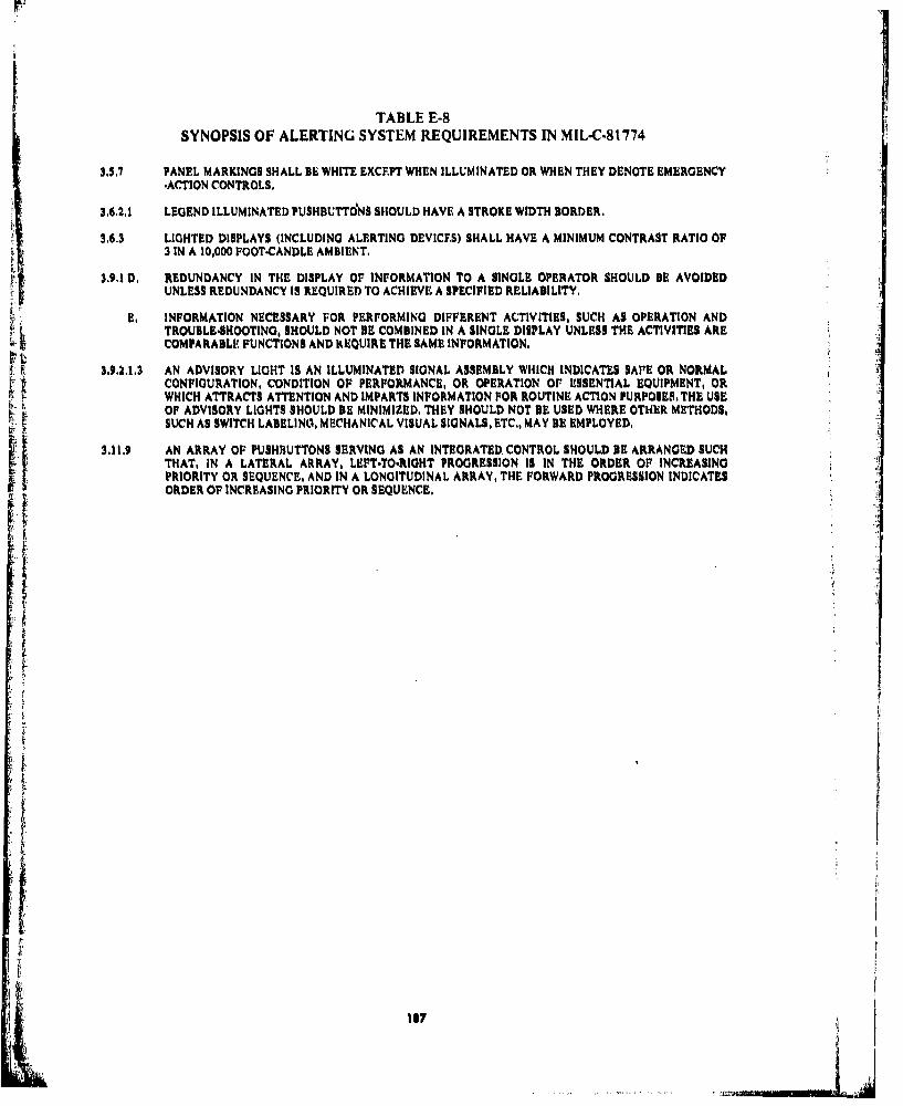
TABLE E-8SYNOPSIS OF ALERTING SYSTEM REQUIREMENTS IN MIL-C.81774
3.S,7 PANEL MARKINGS SHALL BE WHITE EXCEPT WHEN ILLUMINATED OR WHEN THEY DENOTE EMERGENCY-ACTION CONTROLS,
3.6.2,1 LEGEND ILLUMINATED PUSHBU'rTdNs SHOULD HAVE A STROKE WIDTH BORDER,
3.6,3 LIGHTED DISPLAYS (INCLUDING ALERTING DEVICES) SHALL HAVE A MINIMUM CONTRAST RATIO OF3 IN A 10,000 FOOT.CANDLE AMBIENT,
3.9.1 D. REDUNDANCY IN THE DISPLAY OF INFORMATION TO A SINGLE OPERATOR SHOULD BE AVOIDEDUNLESS REDUNDANCY IS REQUIRED TO ACHIEVE A SPECIFIED RELIABILITY,
E. INFORMATION NECESSARY FOR PERFORMING DIFFERENT ACTIVITIES, SUCH AS OPERATION ANDTROUBLE.SHOOTING, SHOULD NOT BE COMBINED IN A SINGLE DISPLAY UNLESS THE ACTIVITIES ARECOMPARABLE FUNCTIONS AND kEQUIRE THE SAME INFORMATION.
S.9.,.1,3 AN ADVISORY LIGHT IS AN ILLUMINATED SIGNAL ASSEMBLY WHICH INDICATES SAVE OR NORMALCONFIGURATION, CONDITION OF PERFORMANCE, OR OPERATION Or ESSENTIAL EQUIPMENT, ORWHICH ATTRACTS ATTENTION AND IMPARTS INFORMATION FOR ROUTINE ACTION PURPOSES, THE USEOF ADVISORY LIGHTS SHOULD BE MINIMIZED, THEY SHOULD NOT BE USED WHERE OTHER METHODS,SUCH AS SWITCH LABELINO, MECHANICAL VISUAL SIGNALS, ETC,. MAY BE EMPLOYED,
3,11,9 AN ARRAY OF PUSHBUTTONS SERVING AS AN INTEGRATED CONTROL SHOULD BE ARRANGED SUCHTHAT, IN A LATERAL ARRAY, LEFTTO.RIGHT PROGRESSION IS IN THE ORDER OF INCREASINGPRIORITY OR SEQUENCE, AND IN A LONGITUDINAL ARRAY, THE FORWARD PROGRESSION INDICATESORDER OF INCREASING PRIORITY OR SEQUENCE.
ili

APPENDIX F
BACKGROUND DATA FOR FORMULATION OF ALERT PRIORITIZATION RATIONALE
F.0 INTRODUCTION
This appendix presents a historical series of working papers and dissertations used to develop theproposed method of prioritizing alerting functions. The papers are presented in chronologicalsequencu. Each major section in this appendix denotes a historical break point in the commercialaviation industry's development of alerting system standards.
-..
13
-i . -

F.1 PAPERS FROM THE 49TH MEETING OF THE SAE S-7 COMM ITTEE, APRIL 1976
Page I
49TH MEETING OF SAE S-7 COMMITTEEAPRIL 1976
STANDARDS AND CRITERIA FOR DESIGN OFAN INTEGRATED WARNING SYSTEM
The lists of warnings that are presented here are oriented more to importance of the wamrin ratherthan being broken into the categories of configuration, flight profile, and systems as had beensuggested. The reason for this was that It seemed that a system or installation designed to accomplish .1
our objectives would at least address the Level I and part of Level II, as appropriate, depending oncost and complexity. Level III type of items are lower priority and would reduce the checklist signi-ficantly but quite likely would be of higher cost and complexity,
In considering an operational installation, one concept might be to use a multiline readout (seeFigure 1) with the computer logic as noted under the visual and audio alert columns. By tying theaudio alert to takeoff thrust application, or to being airborne, or to descent to a height near theground most or the nuisance audio alerts can be eliminated. This would mean that the system wouldbe in the "ground mode" or "before takeoff mode" all the time when on the ground - the readoutwould show items not set for takeoff but the audio would be silent until the throttles are advanced,Similarly, in flight below 2500' the "landing mode" would be energized and the readout wouldshow items not in proper configurution for landing but no audio would sound until descent through1000' had occurred with the aircraft still not in configuration. This type of logic must be thoroughlythought out and evaluated so please, let us have your ideas! I
If there were more than five or six discrepancies, the remaining ones would appear on the readoutdevice or devices as soon as the previous discrepancies were cleared, Also, there would have to be aprovision to cancel the audio in the event of an engine shutdown or loss of a particular system andfor other reasons, It may not be desirable to cancel the visual; let it serve as a reminder. Possibly wemight need more than five or six lines for discrepancies after we look at all possibilities, The readoutdevice would provide the crew a self-check or confidence check during the pre-start and pre-takeoffphase since its monitoring of the various items would be apparent to the crew.
Level I items would remain as currently implemented, iLe,, specially dedicated systems, Level ii Aconsists mostly of the present-day warnings that excite an audio signal, An integrated warning systemwould offer the most benefit by including the items in this group, Items in Level 11 B and II C arehighly desirable but the associated costs would require individual consideration for each item,
AIRCRAFT OPERATIONS AND SYSTEMS MONITOR
It Is recommended that an integrated monltpr and warning system be implemented wherein a visualalert or annunciation provision and a single audio alert signal be employed to bring to the flightcrew's attention any faults or aWiplanc configuration incompatibilities. The aircraft monitor andwarning system should not In any way create confusion on the part of the flight crew, should alertthem to a fault or discrepancy in a timely fashlon and should result in reduced crew workload,
*190.11

Page 2
The aircraft faults and discrepancies can be broken into three levels of Importance or urgency:
Tactile Visual AudioLevel I (Immediate Action) Alert AeM Alert
1. Engine Fire None Cont. Cont,2. Stall or Sudden Loss of Lift Cent, None Cont,-Airborne3. Inadvertent Ground Proximity None Cont. Voice/Cont.
Level il (Flight Safety-Action Required) Visual AudioA,) Alert Alert
t. Cabin Altitude-Too HI (rate & height) Cont. Cont,2. Spoilers-Extended On Flaps Ext, T$&1000' RA.3. T.E & LE. Flhtps-lmprop. Set On Ground Tt&lO00' RA.4, Airspeed-VMO, MMO Exceedance Cont, Cont,5, Altitude Diversion-(Flitht Profile) 200' After Cptr, 300' Aft. Cptr,6. Landing Gear-UP Landing Flaps 1000' RA.7. Stabllizer-Improp, Set On Ground TB8. Other A/C Conflg-Unsafe LdgFlaps&/orOn Grnd, To& 1000' R.A.9. Flap Placard-Exceeded Cont. Cont,
10. Landing Gear Placard-Exceeded Cont. Cont,11, Engine Thrust Setting-Over Limits Cont. Cont.12, Wheel Well Fire Cont. Cont,13, APU Fire Cont. Cont.14. Radio Altimeter Cont, Cont,
Level ]i Visual AudioB,) Alert Alert (ptI l)
I, Hydraulic Press, & Quant-Low Cont. Cont, After Tg2. Engine Oil Press, & Quant-Low Cont, Cont, After TS3. Essential Elect, Pwr-Fall Cant, Cant, After TS
*4, Auto.Pilot & Autothrottle-Disconnect "Cont, *Cent,5. instr, Comparator Sys-Alert Cont. Cont.6. Gyro & Compass Flags-Visible Cont, Cont.7, Cabin & Exterior Doors-Not Closed Cont. Cont, After TS8. Pitot Heat-Off Cont. Cont. After Tg9, Window Heat-Off Cont. Cont. After TS
10, Anti-Skid-Off Con . Cont. After T&11, Engine Fuel Switch-Off Cont. Cont, After TS12, CADC-Falled Cont, Cont.13, Niiv System-Failed Cent, Cant.
Level II Visual Audio
&d) AIMI. Emergency Flop Switch-Not Oft' On Ground None2. Rudder & Spoiler Switch-Not On On Ground None3. INS-Not Nay On Ground None
191

Page 3
4. Yaw Damper-Not On On Ground None5, Rudder & Aileron Trim-Not Zero On Ground None6. Battery-Not On On Ground None7, Compass Cont-Not Mag Cont, None8. instr, Transfer Switch-Not Norm On Ground None
Level Ill (All other items that have less effect on basic safety of flight, i.e., additional checklistitems)
Visual Audio
I. Emerg. Exit Lights-Not Armed Cont. None2. Pneumatic Brake Press-Below 1200 psi Cont. None3. Static Source-Not Norm Cont. None4. Start Levers-Not as Req'd Cont, None5. Gear Pins-Not Pulled Cont. None6. Air Cond-Not as Req'd Cont., None7. Galley Power-Not as Req'd Cont, None8. Beacon-Not On Cont. None9. Parking Brakes-Not as Req'd Cant, None
10, Eng. Fuel Heat-Not Off Cont. None11, No Smoking & Seat Belts-Not as Req'd. Cont. None12, Anti-ice, Engine-Not Off Cant, None13, Smoke Detector System-Not On Cont. None14. Ground Start Switches-Not Off Cont. None15, Elect, System-Not Norm (No Lights) Cont, None
*11 B.)4. Two pushes on Disconnect button cancels warningSTg a Application of T.O. Thrust on Ground
*1000' R.A. - 1000 Ft, Radio Altitude on ApproachCont. = Continuous MonitorA/B • Airborne
pLAPS
STAB,
HYD PR1I0@.
OIL p161106 AUDIO CANCIL
DOOM
PITOT typIaICRT dI0Iay
Figure . Sample Readout During Engine Start
192
.,'..4

PP
hu lw cac r 4
* S@0
m -, •.- -
z
6wJ li jIMI
Igo 'MIIw no Il W
K.10 cc- ~
RE II
U'.-,= !
!U mu III II
"6 601 7•1t r. ge-e9 c0t
w>
2- 2
II I I I I - I
f9 c I -i -
...- UK K"19
, 193
ii,

29DEC75"GI/00-P-AV/Born/bli
VIEWPOINTS ON DESIGN OF WARNING/CAUTION SYSTEMS
GENERAL
In today's aircraft aural and visual warnings/cautions have proli-ferated to an extent that makes it difficult for the pilot to distin-guish between them. It is, therefore, desirable to centralize thewarnings and more carefully scrutinize the need for individualwarnings and, where needed, make them more explicit.
In order to minimize nuisance warn'ng, the warning systems shouldbe provided with logic that inhibits the warning in case of a techni-cal failure in the system or the stage of flight is such that a warningis irrelevant or distracting, for example a fire warning at lift-off orat low altitude during an approach.
2. AURAL WARNINGS
Warnings that require immediate recognition and action. shall beaural, each using a specific sound supplemented by a viiiagl displayand preferably also by voice.
If the number of aural warngs,mincluding tactile warnings, exceeds7 they must be supplemented by voice.
Other warnings and cautions should be announced by a commonsound supplemented by voice and/or a visual display.
Aural warnings shall be loud enough to be heard under all flightconditions but low enough not to interfere with cockpit com-munication.
3. VISUAL WARNINGS
Warnings and cautions should be presented on an alphmaumericdisplay in front of each pilot,
The display should be capable of 'isplaying at least 3 warningssimultaneously.
The light intensity of the alphanumeric display should be manuallyadjustable with automatic compensation for changes in cockpitlight level.
Individual lights should be connected to a central dimming circuit.
194

2.
Failures in redundant systems should not be announced as warningsor cautions when no pilot action is required, Such tailures shouldbe shown on a system status display.
Whenever possible, controls that must be actuated in case of awarning should be illuminated or indicated by some other means.
It should be possible to clear the display by a push-button, but thewarning should be stored in a memory as long as it persists and beredisplayed in case of a new warning.
It should be possible to recall warnings from the memory with arecall button. A test button for confidence check should beprovided.
Since it is doubtful that all individual warning and caution lightscan be eliminated the remaining ones should have dual light bulbsseparated by a light barrier and it peripherally located they shouldbe flashing.
Instrument failure warninp should be designed in such a way thatthe affected display is removed or, if this Is not possible, obscuredby a warning flag. Even if the display Is removed a warning flasshall be displayed.
4. SHORT TERM ACTION ITEMS
I. Make up a proposal for a centralized visual/aural integratedwarning system.
2. Enumerate warnings and cautions that need to be fed to theCentral Warning system.
3. Define inhibit logics that are necessary to milimize nuisancewarnings,
5. STUDY ITEMS
Simulator studies should be made to determine if there is anybenefit to be gained from the following refinements.
1. Display of the checklist valid, for the warning condition, on amalfunction display.
2. Automatic execution of this checklist after pilot's Initiation.
3. Schematic display of failed system with indication of failedand usable portion of system.
195

F.2 CRITERIA FOR ALERTING FUNCTION CATEGORIES DEVELOPED BY THE BOEINGCOMPANY EARLY IN THIS STUDY
aIs
'II I''il l ,,
I~ :iiiti ... . ... I.. ..
l iii''~ *1l Sl !h:| iI
I i. t; 111111 Ii *I i!
196

F.3 APPLICATION OF PROBABILITY AND SEVERITY OF EFFECTS CRITERIA
DEVELOPED IN BCAR PAPER NO. 670 TO ALERTING SYSTEMS
t J
S197
I III
t , i i

•'..
{, .!° ~m.m..... ILI
cc- -l,
g c
w ÷
+
"j x
.- -. i

FA4 ALTERNATE SET OF ALERTING FUNCTION CATEGORY CRITERIA DEVELOPED ATTHE BOEING COMPANY
Table F.2 Caution and Warning System Concept
AIRPLANE CATE- CREW RECOGNITION/ EXAMPLES OF
CONDITION CRITERIA GORY RESPONSE TIME OR EVENTS
MINIMUM CREW S STALL WARNINTRINSICALLY REACTION TIMEGROUND PROXHAZARDOUS WITHOUT HESITATION
OR LOS OF TIME. 0 EMER CABIN ALT"IMMEDIATE" ATE/LEVEL
"" EXCEED %MOIMMoEXTRINSICALLY DEFERRED POSITIVE 0 ENGINE IIREHAZARDOUS. THOSE 2 (PREDETERMINEDWHICH IN THEMSELVES COURSE OF ACTION) 0 ENGINE OIL
ARE NOT HAZARDOUS pRE8S./C#TY LOWBUT ARE KNOWN THROUGH DEERDCNIIAL PSEI!TNOEXPERIENCE TO BE DEFERRED CONDITIONAL •PROSE HA IOECONDITIONALLY (COURSE OF ACTION S WINDOW HEAT FAILCOHAZARDOUS, 3 CONTINGENT UPON 0 HYD PRI$SS/OTYH DOTHER CONDITIONS) S GEN DI1CONNECT
0 A/T DISC
* FLIGHT RECORDERHAZARDOUS UNDER NO ACTION REQUIRED INOPCONDITIONS. SUPER- 4 AT NO TIME 0 SELCAI.NUMERARY BY NATURE.
I I 1 STEW CALL
*DEVELOPED BY J. OHLSON, THE BOEING COMPANY, 1976
[I

F,5 PAPERS FROM THE 50TH MEETING OF THE SAE S-7 COMMITTEE, SEPTEMBER 1976
WORKING PAPERAN INTEGRATED AIRCRAFT WARNING SYSTEM
FORSAE COMMITTEE 8.7
THE DELIVERY SYSTEM AND ITS PHILOSOPHY
A. As a first step toward evolving a delivery system, it was necessary to enumerate the faultsof present systems,
1. Present warning systems have "grown like Topsy" with more added, it seems, eachtime there is an accident, The result has been a proliferation of discretn aural warningsto the extent that there can be confusion as to the meaning of a specific aural warning,The crew must first determine which of several potential problems is triggering theaural warning being heard before taking action,
2. The level of urgency in terms of flight conditions Is not presently annunciated, Thecrew must evaluate this level to determine the requirements for immediacy of actionand division of attention between the problem and conduct of the flight.
3, Too many warninp occur during normal operational conditions. Any warning that isheard repeatedly when no action is really required will be psychologically "blockedout", including any recollection of inhibiting the warning, Even if the warning "getsthrough", the crew must still determine if it is a real or a nuisance warning beforetaking action, There are several reasons for the occurrence of warnings in normalconditions:
a. Faulty design logicb. Poorly considered regulatory requirementsQ. Lack of reliability resulting In nuisance wurings
4. Noise levels of existing audio warnings may be so high and so annoying as to degradethe human response capability, This is often due to a regulatory requirement for aminimum decibel limit to "get attention", which, in turn, is related to several of theproblems listed above. As a spinoff of this specific problem, an inhibit capability isoften required to removw the raucous audio before intelligent action canl be taken,
B. In seeking solutions to existing faults in warning systenm philosolphy, tle working groupwas able to construct it model o' a desirable system.
, To replace tw nmulti adde ort aural warnings, a single unique tone should be utilizedL'for all problemns requiring aural Lilert. This tone should he complemented by a visul1idisplay, and oral annunchition, declaring tile nlature and locaItlon of tihe iprobhlem!..
20I0

2, The level of urgency should be annunciated by repeating the tone one, two or threetimes, or by otherwise modifying the tone while retaining its unique nature. Urgencylevel should also be annunciated by color coding of the message on the visual display.
3, Design logic, very high reliability, and regulatory changes must be created to eliminatethe problem of unnecessary and nuisance warnings,
4, The tone, being unique and meaningful can be soft and non-irritating, It is believedthat its very uniquesness and dedication will allow it to "cut through" ambient noisebecause crews will be attuned to its sound, much as the sound of an engine room tele-graph will raise a ship captain from the deepest sleep, Having heard one tone the crewwill be immediately attentive to see if a second will occur and, that happening, will bedoubly attentive for a third, We do not wish to see a button required to inhibit thetone and voice warning, Since they are compelling enough to get attention andspecific enough to spell out the problem, they should be non-repetitive, Any require-ments for recall can be provided for by the visual display,
5. Several cases came up where our design philosophy was at odds with present regula-tion, In order to achieve the optimum logic, the group elected to proceed as thoughthere were no regulatory constraints, This may soon have to be resolved,
6. It was argued that some may wish to retain existing discrete audio warnings on thegrounds that they have withstood the test of time, (The fire bell Is an example.)Though wishing to discourage such a prospect, we decided to Include an option fora limited number of discrete aural warnings with the admonition that these shouldbe kept to a minimum and used only for the highest urgency level.
II LEVELS OF URGENCY (See Table One)
A, After lengthy discussion it was concluded that four, rather than three levels of urgencywould be needed, This concept made it difficult to accommodate the levels with thedesired tone repetitions of one, two and three times. An acceptable solution was reachedby creating a fourth level, zero, to be the lowest level of urgency, Thus, level zero wouldhave no awial tone, no visual display and no voice annunciation, Warning would be pro-vided by lights much as they exist today.
1. Level Ill would be described as emergency, urgent or serious, Action requiredwould be imme'diate, Warning would be provided by three aural tones, a visual dis-play and voice annunciation of the problem,
2. Level 11 would be described as caution or abnormaaL Action required would beprompt, Warning would be provided by two aural tones and a visual display, withvoice annunciation recommended,
3. Level I would be describod as irregular, Action would be required but may be defer-red. Warning would be provided by one aural tone and a visual display, with voiceannunciation optional,
201U&-.| A
.... ... .---- --- -

4, Level Zero would be described as advisory. Later action may or may not berequired. Warning would be provided by visual means, such as a light or flag,
B. The various warnings are categorized by urgency level In tables two through five, Somepoints of discussion follow:
I, Decision height, selcal, and cabin call alerts present a special problem. By naturethey are of the lowest priority level, but placing these in level Zero would deprivethem of aural alerting. If they are placed in level I, then the aural tone would beapplied, but we would be violating our philosophy of having no warnings for normalconditions, To create a discrete aural sound for these conditions Is one solution, butwould add an extra audio, This needs further discussion.
2. The ground proximity/high sink warning has been Included in the three higher levelsto account for different flight conditions. This was not unanimous and the logic forthis problem needs further exploration.
3. We have assigned low urgency level (level 1) to a CADC failure, although such a fail.ure ha far reaching significance. The rationale for this is that several other failurewarnings would be displayed simultaneously in case of a CADC failure, Some of
these, such as autopilot disconnect, have a higher urgency level,
4, The warnings for landing gear door open and gear not properly stowed we assignedto level Zero, so that lights presently used would be applicable to these problems,
5. On the engine over limit warning for'level 11, we believe the annunciation should besimply "engine number 2 over limit", The crew then could refer to their engineInstruments to determine which parameter Is over limit.
6, On the instrument comparator warning for level I, we believe we should have thesoft aural tone and the visual display would annunciate the parameter that Is out oforder, such as compass, altitude Indicator, etc,
III INHIBIT AND OTHER LOGIC
A. In some cases we were able to apply logic to the conditions, In many other cases, the con-siderations were so complex that time did not permit our completing this task, Where weassigned logic it appears in the tables under "remarks", Much work remains to be done Inthis area.
B. One theory that was agreed to is thitt, during critical flight phases, such as takeoff andlanding, selective Inhibits should be applied as the aircraft approaches the most criticalpoint until at that point perhaps no warning would be given. Then the Inhibits may beselectively removed as the aircraft progresses toward a less critical condition so that allwarnings would be active at some later point.
IV PRIORITIES
Time permitted assigning priorities only to level l1e, (Illustrated by A, B, and C on tabletwo.) A great deal of work remains to be done on this task,
S"" .. . . . . . .. . .. . . .. . . . .. . . . . . ... . ,20 2

V OTHER UNRESOLVED ISSUES
A. Consideration must be given to the effects of radio altimeter failure, both on dispatch andwarning capability, Much logic will probably be based on radio altitude.
B. Autopilot malfunctions and their kiffects need further expansion.
C, There Is a need to find the optimarm aural tone for crew alert. Tape samples should beconstructed.
D. Some philosophy must be added on dimming, cancellation and recall of the visual display.(Sture Bostrom has done some work on this,)
E. The precise means of color.coding the visual display must be developed,
F. This working paper must be hardened and worked into format of ARP 1068.
------ .- . . . . .. . ... . . . .

TABLE ONE
General System Concepts
I. Aural attention getter-prefer unique tone for all problems--should define level of urgency by 2 or 3 repetitions or by slightly modifying tone-should not be annoyingly loud-should not require silencing (NON repetitive)
2. Discrete sounds may be used on a selective basis-should be limited in number-suggest for most urgent level only
3. Checklist Requirements not incorporated (?)
4, Should have priority system which includes phise of flight
S. The visual display should employ color-coding to Indicate the urgency level of the warningbeing annunciation,
S6, Consideration should be given to inhibiting certain warnings during critical phases of flight,such as takeoff, low approach, etc.
7. In some cases the priority system should inhibit secondary mode warnings,
Levels of Urgency
III Emergency Immediate Action RequiredUrgentSerious(I) Aural AG* (2) Visual (3) Voice Annunciation Recommended
II Caution Prompt Action RequiredAbnormal(I) Aural AG (2) Visual (3) Voice Annunciation Optional
I Irregular Action Required(1) Aural AG (2) Visual
0 Advisory May Require Action Later(I) Visual AG#
*Very limited number of discrete aural warnings is optional#such as light or flagAG = attention getter
204
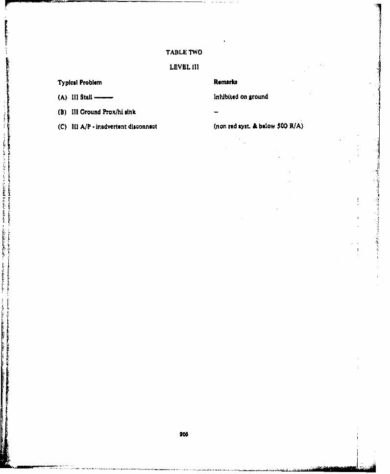
TABLE TWO
LEVEL III
Typical Problem Remark,
(A) III Stall - Inhibited on around
(D) III Ground Prox/hi sink
(C) III A/P - inadvertent disconnect (non red iyut. & below 500 RIA)
Tr
"½i
205,
.i

TABLE THREE
LEVEL 11
Typical Problem Remarks
Engine fire Phase of flight
Engine Failure (catastrophic) Phase of flight
Degraded takeoff performance Possible future
Overrotation (rate or angle) Takeoff
Excessive wind shear Possible future below 1000' RA,TO or APP
High Cabin alt, 10,000 ft.
A/P. Inadvertent disconnect Non-redundant syst, above 500' RA
A/T. Inadvertent disconnect
Takeoff Warning (spoiler., hi lift dev,, brakes stab.) Early speed warning (60 KOS)
Ground prox/high sink Logic to be determined
Dev. from Ass, Alt. Mmo, Vmo, Tmo Regulatory considerations
Cargo compt, only where cockpit action isFire/smoke possible
A.PU, fireGalley fire/smoke only where cockpit action isWheel well fire possible
Engine over limit Appropriate parameters for eng.first limit
Hydraulic press,/quant, single syst. remaining
FIt inst, power failure Where manual switching req,
Goar unsafe for landing Logic to be determined.
296

TABLE FOUR[
LEVEL I
Excessive rate of change of cabin press.
Instrument warning
Prognosis of wind shear potential
Lavatory fire/smoke
Hydraulic press./quan, Multiple systems remaining
Engine oil press,/quan.
Flight inst. power failure where syst. restoration is automatic
Inst. comparator alert
CADC failure
Inadvertent stabilizer in motion
Ground prox./hIgh sink
207
.i

TABLE FIVE
LEVEL 0
A/P in reversion (i.e., Turb Mode, etc.)
Navigation system fail (recommend to sys. designers that if a ,guidance input has failed that theappropriate command bar, etc., be removed from view ARP 1068)
Antiskid off/fail (if this item were on Level I could eliminate from the approach checklist)
Radio altimeter failure
Gyro or compass flag visible
Exterior doors not closed
Yaw damper fail
Instrument transfer switch not normal
Landing gear door open
Gear not properly stowed
Autopilot stabilizer out of trim
208
1~J

Capt. B. Schmitt September 15th, 1976
WORKING PAPER
AN INTEGRATED AIRCRAFT WARNING SYSTEM
SAE - COMMITTEE S-7
Comments on the above Working Paper
THE DELIVERY SYSTEM AND ITS PHILOSOPHY
A.
Item 2: 1 am of the opinion that using the MASTER WARNING/MASTER CAUTION sys-tam, as installed in most of the present day airraft, the level of urgency is annun-ciated - maybe not optimal but at least usable. As a consequence, two differentkind of checklists exist, namely the EMERGENCY CHECKLIST and the MAL-FUNCTION OR ABNORMAL CHECLIST,
Item 3: 1 fully agree; too high a noise level can even lead to a wrong decision,
B.
Item 1/2: 1 fully support the statement that too many aural warnings are used today,
Instead of repeating the tone once, twice or three times, I suggest that we look intothe aural warning as used on the French Caravelle, e.g,, I could think of using onetone for Level II, but a GING/GONG type tone for Level III, etc. I am pretty surethat this would be more suggestive than always repeating the same tone,
Item 3-5: No comment.
Item 6: During evaluation of the present warnings it also occurred to me that a discreteaudio warning is in certain cases a must, e6g.,
"* DH aural warning"* SELCAL* CABIN to COCKPIT, etc.
Since these tones are routinely heard, the meaning is well understood.
209

IILEVELS OF URGENCY
A.
Item 1.4: 1 generally agree, but I suggest that the present philosophy of having a lot of recallor memory items should be reviewed. The only memory item we have retained atSWISSAIR is the EMERGENCY DESCENT. All other items may only be performedusing the EMERGENCY Checklist except for the 2-man cockpit. Only this puaran-tees that the right action is performed in the correct sequence,
It may be worthwhile to convince the FAA to review their philosophy.
B.
Item 1: Based on my experience, I think that it will be very difficult to delete the auralwarning for DH, especially with regard to CAT If/CAT III A operation, where theDH is a very important element for decision making. AlsoSelcal as well as theCabin to Cockpit call . even r outine - calls for a discrete aural signal unless somebodyhas a really good solution.
Item 2: GPWS. If a warning occurs, this at leart calls for investigation, Therebre,"it mightInot be necessary to put Jolgic in, in order to identify phase of flight. Of course this
•!• can differ from corn,,my to company and may~also',depend on 'whether the warning
"TERRAIN" or tho order "PULL-UIP" has been selected,
Item 3: No' mments.Iterd 4: Agreed, !
Item S. The present osed "over-limit" light in the respective engine instrument has been
proved to be a good idea. So I think it could be deleted from the warning system,
Item 6: Needs further discussion,
III INHIBIT AND OTHER LOGIC
A. + B. Agree,
IV PRIORITIES
See comments on Tables,
V OTHER UNRESOLVED ISSUES
A. Agreed; fortunately the newest brand of radio altimeters has a very high reliabilityi and/or MTBF.
B. - E. Agree.
210
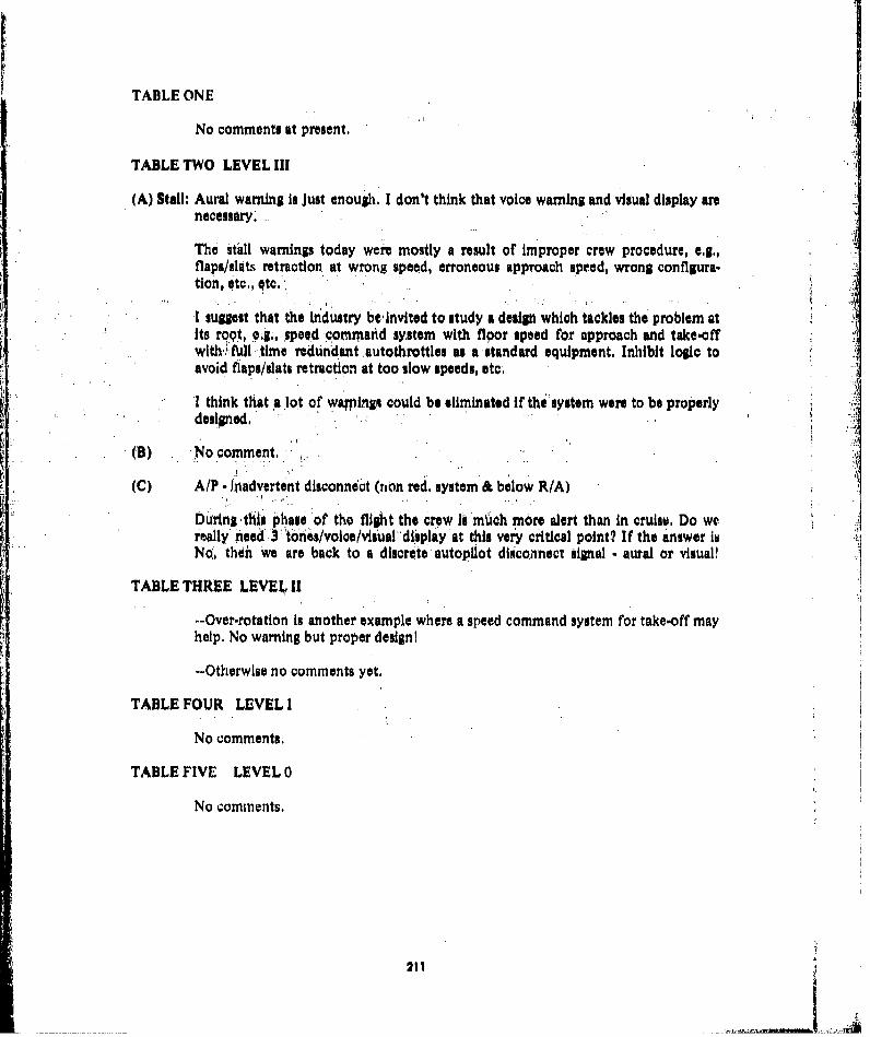
TABLE ONE
No comments at present,
TABLE TWO LEVEL III
(A) Stall: Aural warning is Just enough, I don't think that voice warning and visual display arenecessary.
The stall warnings today were mostly a result of improper crew procedure, e.g.,flaps/slats retraction at wrong speed, erroneous approach speed, wrong configura-tion, etc., etc.
I suggest that the Industry be,invited to study a design which tackles the problem atits roq9t, eg., speed conrafid system with floor speed for approach and take.offwlthý.ý full time redundant .autothrottles as a*standard equipment, Inhibit logic toavoid flaps/slats retrtction at too slow speeds, etc,
I think tfiat a lot of warnings could be eliminated if the' system were to be properly
designed.
(B) No comment, . -..
(C) A/P - Inadvertent disconnect (rinn red, system & below R/A)
During this phase of the flight the crew Is ml~ch more alert than in cruise, Do wereally' need 3'tones/voice/visual display at this very critical point? If the answer isNo, theh we are back to a discrete autopiiot din€onnect signal - aural or visuall
TABLE THREE LEVEL II
-Over-rotation is another example where a speed command system for take-off mayhelp. No warning but proper design I
-Otherwise no comments yet.
TABLE FOUR LEVEL I
No comments.
TABLE FIVE LEVEL 0
No comments.
211
- ---------

APPENDIX G
i! APPLICATION OF ALERT PRIORITIZATIONil • CliME TO A 737 AIRCRAPT
• i'iilThis appendix provides a tabulation of the priority levels that each alerting function on a 737 air-'• •"craft might be udssned by the proposed prloritliation criteria, The alert levels specified for each•]r•. •flight .phuse correlate with the categories defined in table 14, A dash in these columns indicates that
•.• •:the alert is (1) not required in that flight phase or (2) should be inhibited 111 that flight phue.
,: A

'. i i i I I I I I I I
M MN Pd m N it t
cw 1 m Mei
H 66 j N N ~N 9
iii I i• g
214

Im m
IN fl m fm mW
4Nm N m m m MM 1*
m -
Nm
mI mNg6
3lii I6

SI" " I I' I I I 't I I ,I
ILI,
i!lie
SI I I I I I I I I I V ,
I I, ... ........ I
i I I i i I I
I•i I I I I I *I I I I I
216 0 0
IN I NIN IN IN IN IN .S. ... ......... i l. ,Ii '•
(h. f If j ~
• ! 216

• " I I I I II
.Oil
S............
I I
o I~ 217
I I Ioft

-rM P . N 0 Pm 44 l
-- I I I I• iinIU~g'~.4N V t' N V I
q ML
1')1 1 N .4 V
qm M fl N V N F
5 I I I I I i
I m I
Iii. .....

em N N N r q
N N N N r m m m
4IIi N N N fn14 144
cc N -~ I 0
N N 9 P f " P
N N N N ~~2 9 ' i M P 9

I; • I I I 1W e- I I
t i 4 t P 1 P
V N
I I. I J 7 I I 11 i ii . I I I . . .. .I - -,6I I I Im I I I I . I
I p t W W ft P1 P
V V i9l9...... . ... ..... I , gq
I II II III I- Ij I I I I Iq. N1 l N N
jira i i I i •u. ii • , ii .I! !
220
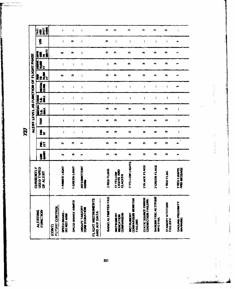
M M e m
A, I , N , I m fn f M m
I I II I I I M I
N m (6 m m
-. -
i~m 111,I I II , ... , I ,hi. I ,, It • ' I
I22'

I m m
__ •I I i I i, I i
~Ii I i ii
g i.llil ii i II
iiimJ ii i
LLC
U.LA i Ic 6
222
. . . A " - - .0 : ;o '0I ý

Vq4 s N 4 q q mq Eq m
Eq vq N N V q ~ q E
m7 sq s N V sq Eq mqEq
I m Or m m m
cc w w I I w
IIEq -. J s N 4 q E q E
LU B
z .9
223
&=1mgI

m m-______
qt mt
I I
SM fI qq t I I q $
ii 9 9 ', 99 i
II
cc! i i t .!..,..,
Si~i d'IIII l"
224

(Yn m N N~ MaN
44 I
fn q I I N
Em M N r4 fm N I N
U . ~ ~~~~ -_ __ _ _4_ __ _ __ _ _ __ _ _ __ _ _ __ _ _
I I I ICC_ _ _ _ _ _ _ _ _ _ _
I ~~ ~ i if I N
('1 I N I N I
~~i~iiP1 d 25

~!II I Pd 4 Md fd~illIPd PN - n in I 1" . P.in
w
1
Pi• II":. .. ' P ... -- .............
V _ _ _ I_ .... ..... to
NI mn M m I m I P I i n
I° I I. W' ii I !ii
IIII6I
-ill
226

N .. . . N 1 .
Vf. q 4 N
. . ..... .. N. N... ... . .. .....
I I, I. I ,Il ln I
- ti ]I -I I i I
I I .• N. . N... N N , , , , ,
"•:i ), .. .. . • ... ....i
i- -
S~INIII I I il'iiimIII II lIn t iulI 1.1lI I I•
i• 927

APPENDIX 'H
TAPULATION OF ABSTRACTS FROM HUMAN FACTORS PAP'ERS RELEVANTTO ALERTINGJ SYSTEMS AS A FUNCTION OF DIRECT APPUCADILITY
229
L A I

E% .00U v5
10 _c-..
""0 E s 2 -. E
.0 0 .~
C3
o
,c
ccs
c E
0i -*cc
01 Ccc
cc~
'ar
C ~ vs
- 230
AY*44 Cop

<
-T- C3
V - C
! -
=7 r; )
00
231 BES AVIALECP

G7a
Z- e
G7
"0
---
Z EE
Ic ms
,=..,=3 f -5 E , ,C3 • _
= .- CC, "-= CL M= -
-a- r
<-_aa
BEST AVAILABLE COPY232

.Ca C 1,0.0C .0 a. aoo
�---a C'a-a� .� a
.00 - .0a (0
C C0 �
A � - aam -. a
.4 �
a -5 00 �
01 0'" aoo � 0 a.C .� �0
- 00 a0
-� a'C - 00
-. 4C�*�C C� 00- �a.C -- --
.0 - a.oC a- �...0Cu -- ".0
C - 4.o _ - un.a.; �� a.
-0 --CC..,-- *�0 - -t� � - 0
Cu a.�E a: � a.4J.0 oaa a _
� a� 4,0c
3C�. 00 a-
-- a �o -- a.4 ,
0 "a -0a
0.C �fl no,, tOO C..S
('-±0.0 -'
* S S S 0
a. a.
* (0 oa-o 'a - -
0t � ,JC.. � -'0 4V__ - - a. -a.�O) ____
0 a a� � a
a -c - OCa. C -- C.o C�.0 �- - .0
C, - - a� �.0 �.0 -
amC
0.010 Os... C . - - .,�,, SC a-- 'a- .- �-0 - a
.0 04.0.0 � az - aC �a '4� - _ - - -�
.�00 ... CC� .0.0� 0� a.. a- �
CU Cc-.. 0 0CC 0.
CU !�-� �E0
�!-�CC.0
0C a. �
aC�C" C�
'40-C 0 C' a
-� 0=�CoC '-ca -- 000"', a0 .0
a�"� � �C 4., � a-Cu � tOo-c �C�0�a. 0C
.0 Ca' C'C.- �C, � CC
4 '
- - "C 4CC'. a"�%� �
Cu �C('4'C �
aaa� os.- � E- �C- � 1C� .0 00
.0 �- " 00a.-- aa o�±�-�S' E�-a a.000 �= 00
.0aC C.. .. 0C 4-, <0_____ �22'� _ _CCC "0 -- " � �aa� Z-
- - a 0 -0 -,00 -CC4 �., -�CC 4. CC - (C =
(0- a.- a.- .-CC
a.0.0 - .0
0 -CCC a
F" -:- L � _____
Cu � v..' �
0.0 !a C - 0
�:C !�!�i II; .0
- 0,, CC>-EC �C a0
T��-o� � -o ECO" o-ca � 0� .0
C .04-- "0t.�" C-Ca - ... � C � a.
aaEC4' �0. -
2C0 - E�" 5� . 00. oO -
� CC0
a a. -
.4(0 .C� O'a - 4'(J�J� .0CC toOto �' a,
aC4 CCC 0CC "C' 404 -
0
- C
OJ -��C �..
0 -�E
233

Or' r, a
f 7n
- o
-i 0- -, - 0~7-
- ~ ~ ý Ea,
o~ Ea a,
23 BES AVILBL COP

Ii
* -S
atC -S01 -� -0I *-,-- -S --
c - -c- ot -c
'0 --
a 0*0Cto �� -3 a
to- 4, .0 -� 4,
4-� -
6* 6 6 * S
0- Ot tfl'O- 0
- I.- -
01
'a - a0) 4- a 0 �CC o-'
-� 00�4.34,
- 0 j 0 4,
toO� 0*-� .�04,
8)- - - S. a�-flfl �.0 0-� - -,
4,�..* -. C.-., C,
to-. -, 4,0a. 4,�'- -a; -fi - -
000,
- -� r, ac C-cEL __
0 0S� 4.
- Va,0 >fl-
cc 0 ra -�C 'a-
to 4, 0* 00 cc 44000
00- ,,c
.� ,01
to S. C�-8t 4,04'0
- -fl 4,-c� - -
V -- -t
4,00-' - �a � aa�C
to ao.�o � 4-0-S a
o cc., � 4, 4,0 4, S.c �s.o ,C0,
4, 4 -
4-fl - *0.C4,4,0. - o� ;�
4, � 4, �a � Ca C0
�
0 Cso, - 00 .�- - E
-" -. 0 01 C 1.1 .r, o .0 - C -01 -S�4� ,� 4,.n '"' a,.. - Cl 00a. - 001
- - I a- C 014,
to I.,
<14 a 4, 0a a 'C
0 0
BEST AVAILABLE COPY235

CL)
cn ccn ~ 0 ~ 0
3,s'
C C)
too
(Uz
E C, c c
-e 00 7T0.
L )
123BEST AVU30 OP

F ~~~~ . -m
Mc
wp
c"_____
K-;BES AVIALECP
I 237

APPENDIX I
TEST PLANS FOR ADDITIONAL HUMAN FACTORS TESTS REQUIREDTO COMPLETE DEFINITION OF AND VALI)ATE RECOMMENDED
ALERTING SYSTEM DESIGN STANDARDS
4
239
,., -J .

TITLE: CAUTION AND WARNING SYSTEMS DATA BASE AUGMENTATION -VISUAL SYSTEMS
VARIABLES: SIGNAL BRIGHTNESS x SIGNAL STYLE x PILOT WORKLOAD x AMBIENT. LIGHT LEVEL
PROBLEM: The effectiveness of any visual caution and/or warning system is dependent on thedetection and correct interpretation of the signals by the user, Information is
! •required on the effect of certain variables on detection performance and design.], constraints produced by these variables.
:" • TEST OBJECTIVES:
I Augment the existing data base of information on caution and warning signal detection.
1I Provide definitive data on the effect of slgnj brightness, signal style, pilot workload andt.inbient light intensity oh the detection of Ni ual caution and witrning signals,
Ill.. betetmin,. tlhe impact of these findings on system design and standardization.
OUTPUT/PRODUCT:
Comparati:. pilot porformance data on visual caution and warning signals which differ as a function'of style ind008ri1ainoss, Interactions of different signah'with the surroundingl light and the amount
.of pilot workload. Recommendations on signal requirements and design specifications.
'DATA MEASU!REMENTS:
The measurelnents will describe the time it takes a pilot to detect a signal, tile time to respond tothe signal, the accuracy of both detection and response, and a subjective evaluation of the aestheticvalue of each of the signals.
TEST APPROACH:
This effort will develop empirical Rtatistical data describing caution and warning signal detectionperformance in a cockpit environment. The measurements will be taken in a simulated aircraftcockpit using two different styles (positive & negative) and four different brightness levels for thesignal (0,15 to 150 ft-L), The cockpit environment will also be changed with respect to the ambientlightingS (0 to 7000 At L).
To simulate the circumstdnce surrounding the pilot in an actual aircraft environment, the pilots willbe assigned flight related tasks (i.e., IFR flight) to accomplish. The workload Imposed by., these tukswill have three levels (high, medium, low), and the appearance of the caution and/or warning signalswill occur simultaneously with the flight tasks.
The data from thla study will be used to make recommendations on the selection of style andbrightness for caution and warning signal lights to be used under different lighting and workloadconditions.
240

EXPIRIMENTAL 018ION----
SIGNAL STYLI POSITIVE'
SIGNALSR IGHTNEUS,
Igo
WORKLOAD mED9U~mAMSVLGTN
2. aswaW~m 7& 140ONN A CIiIACY
4, AUWhUTIC VALUE
S~KITOWING ANALYMI l
WI I K I 5lx 11K 4
241

TITLE, CAUTION AND WARNING SYSTEMS DATA BASA AUGMENTATION -VISUAL SYSTEMS
VARIABLES-. SIGNAL BRIGHTNESS x 9[GNAL LOCATION x FLASH RATE xc PILOTý4 I JWORIKLtOAD
P.dDL .M Tho effletivaneuss of. any visual caution, and/or warning system. is dependent on theiitcto nd .correct, lnterpretttion "of tesignals by the user. Information is
.'0 1.q"o thO ef06ct -of cdftah: variables on doteto performaince and design
Sproduoed by thea, variables.
1.Aughiept the exi~sting. data bRis-of information on caution and warning si~iat detection.
11 I Prwvide, deftinitve data on the effect of signal brightness, signal location, signofashfisand',lplot workload, or the detection of visuai caution and warning siflasalse
U!Determino the Impa#;ot the.. findings on system design and standardization.
OUTPUT/P4~~C:
Comparative pilot performance data on caution and warning signals which differ as a fu~nction ofbhiis~location and flash. r~te, Interactions of different signals with the amount of pilot work-
Joad,'1.Akom~ehdatlotis 6AW~ tnl requirements and design specifications.
bATA.lNEASUftEMENTS.
The mesasurements will describe the tim~e it talkes a pilot to detect a signal, the time to respond tothe signal, the accuracy of both~ detection and response and a subjective evaluation of the aestheticvalue ot, the signal,
TEST APPROACH:
This effort, will develop empirical statistical data describing caution and warning signal detectionperformance In an actual cockpit environment, The nreaourements will be taken In a simulated air-craft cockpit using either steady cot-flashini signals of three different brightness levels (1.5 to 1.50ft-L) at three locations (0"), 150, and 4510 horizontal displacement from the pilot's centerline ofvision). In an attempt to simulate the circurnstanccis surrounding the pilot in an aircraft environ-inent, this pilots will be asisigned flight related tasks (i.e., IFR flitght) to accomplish. The workloadimyosed by these tasks will have three levels (high, mnedium, and low), The appearance of the cau-tion and/or warnIn3 signals and the flight tasks will occur simultanitouuly.
The data from this study will be uised to make recommendations on the selection of location,brightn~ess and flash rate for caution and warning signal lights to bc used under dIffeitnt workloadconditions.
242
2K~ .- .-.-.- ~-~-.~- -.- ______1101_

EXPPRRIMUNTAL 0h0M
'IS
lUSTFASING AAYI
243

/
TITLE: CAUTION AND WARNING SYSTEMS DATA BASE AUGMENTATION -VISUAL SYSTEMS /
VARIABLES: SIGNAL BRIGHTNESS x SIGNAL LOCATION x NUMBER OF DISTRACTINGSIGNALS x AMBIENT LIGHT LEVEL
PROBLEM: The effectiveness of any visual caution and/or warning system is dependent on the /detection and correct interpretation of the signals by the user, Information I'required on the effect of certain variables on detection performance and desiconstraints produced by these variables.
TEST OBJECTIVES:
I Augment the existing data bast of information on caution and warning signal det ection.
II Provide definitive data on the effect of signal brightness, signal location, numbr of die.tracting signals and the brightness of the ambient light on the detection of visuAl caution
lj and warning signals, /
III ;Determine the 'impact of these flndinp on system design and standardization.
OUTPUT/PRODUT:, "S~/
Comparative pilot performance data on caution and warning signals which differ as foction of loca.* tion and brightness, Interactions of different signals with distracting signals and the brightness ofthe ambient light. Recommendations on signal requirements and design speciflcations," / •/DATA MEASUREMENTS:
Iahe measurements will describe the time it takes a pilot to detect a signal, the time to respond to
the signal, the accuracy of both detection and response, and a subjective evaluation of the aestheticvalue of each of the signals,
TEST APPROACH:
This effort will develop empirical statistical data describing caution and warning signal detectionperformatioe in an actual cockpit environment, The measurements will be taken in a simulated air-craft cockpit using signals of two different brlghtnesses (15 and IS0 ft-L) at three different loca.tions (0Q, 150, and 450 horizontal displacement from the pilot's centerUne of vision). Distributionwill be created by using three different numbers of similar lights (0, 10, 20 lights differing only Incolor and format) placed In a circular area around the signal with a diameter of 300 visual angle.During the test the cockpit will be changed with respect to the ambient lighting (approximately 0to 7000 ft-L), In an attempt to simulate the circumstances surrounding the pilot In an aircraftenvironment, the pilot will be assigned a flight related task (i.e., IFR flight) of medium workload toaccomplish simultaneously with detecting signals.
The data from this study will be used to make recommendations on the selection of location andbrightness for coution and/or warning signals to be used under different levels of ambient lightingand distracting conditions.
244_ _ ,,,.1<l.

EKPMNIW'TAL, 513GM -
sPIONTNIEPT.L i
LQOCATION 13
Ito
30
CMIDULETUSTING W ANALYSIS .
_____ IIol

TITLE: CAUTION AND WARNING SYSTEMS DATA BASE AUGMENTATION -VISUAL SYSTEMS
VARIABLES: FALSE SIGNALS x FREQUENCY OF OCCURRENCE x NUMBER OF DIS-TRACTING SIGNALS x WORKLOAD
PROBLEM: The effectiveness of any visual caution and/or warning system is dependent on thedetection and correct interpretation of the signals by the user. Information isrequired on the effect of certain variables on detection performance and designconstraints produced by these variables.
TEST OBJECTIVES:
I Augment the existing data base of Information on caution and warning signal detection.
II Provide definitive data on the effect of false signals, frequency of occurrence pilot work-load and the number of distracting signals on the detection of visual caution and warningsignals,
III Determine the impact of these findings on system design and standardization,
OUTPUT/PRODUCT:
Comparative pilot performance data on caution and warning signals when the surrounding environ.ment Is changing as a function of false signals and the number of distracting signals, Interactions ofthe environment with the amount of pilot workload and the frequency of signal occurrence,Recommendations of hignel requirements and design specifications,
DATA MEASUREMENTS:
The measurements will describe the time It takes a pilot to detect a signal, the time to respond tothe signal and the accuracy of the detection and response.
TEST APPROACH:
This effort will develop empirical statistical data describing caution and warning signal detectionperformance in an actual cockpit environment, The measurements will be taken In a simulated air.craft cockpit using a signal of moderate intensity (50 ft-L). This signal will Indicate a valid warningeither 100, 80, or 60 percent of the time and will be activated at either 1, 2 or 5 minute (030 sec)intervals, Distraction will be created by using 3 different numbers (0, 10 and 20) of similar (dif.fering only in color and format) lights placed In a circular area around the signal with a diameter of300 visual angle. To simulate the circumstances surrounding the pilot in an aircraft environment thepilots will be assigned flight related tasks (i.e., IFR flight) to accomplish, The workload imposed bythese tasks will have 3 levels (high, medium and low). The appearance of the caution and warningsignals and the flight tasks will occur simultaneously,
The data from this study will provide guidelines for controlling the environment Into which a cau-tion and warning signal light Is placed and an assessment of the effect of uncertainty and workloadon these situations,
246

EXPERIMENTAL DESIGN
22
TIME BETWEEN SIGNAL OCCURRENCEIS, MIN
t0
HIGH
WORLOA PERCEINT CORRICT• SIIGNAL ,W~ftKLOW
SCHEDULNTESTING ANALYSIT
WINK 1 WIK 2 WEEKS WEEK4 WEEK 5
'I
71
247
S... ................ ';LP ... ..A..;- . .2 I'' ....- ~..... ................. AAN, ... ..... .A+'+I S• Nk+'fl-,.reNI*mIk-tk NI,+#0I I I I+ i +

TITLE: CAUTION AND WARNING SYSTEMS DATA BASE AUGMENTATION -AUDITORY NON-VERBAL SYSTEMS
VARIABLES: NUMBER OF DIFFERENT SIGNALS x FREQUENCY OF OCCURRENCE xWORKLOAD
PROBLEM: The effectiveness of any auditory caution and/or warning system is dependent onthe detection and correct interpretation of the signals by the user, Information isrequired on the effect of certain variables on detection performance and designconstraints produced by these variables.
TEST OBJECTIVES:
I Augment the existing data base of information on caution and warning signal detection,
1I Provide definitive data on the effect of the number of different signals, frequency ofoccurrence, and pilot workload on the detection of auditory non-verbal caution andwarning signals,
III Determine the impact of the findings on system design and standardization.
OUTPUT/PRODUCT:
Comparative pilot performance data on caution and warning signals which differ as a function ofnumber and frequency. Interaction of different signals with the cmount of pilot workload. Recoe-mendations on signal requirements and design specifications, 4
DATA MEASUREMENTS:
The measurements will describe the time it takes a pilot to detect a signal, the time to respond tothe signal and accuracy of the detection and response.
TEST APPROACH:
This effort will develop empirical statistical data describing caution and warning signal detectionperformance In an actual cockpit environment, The measurements will be taken in a simulated air-craft cockpit using a 747 aural warning box to provide discrete caution and warning signals. Thepilots will learn to perform specific responses to a number of soun'ds (either 5, 10 or IS') and will bepresented each sound immediately after training for a baseline meuure and then again at 24 hoursand at 72 hours, To simulate the circumstances surrounding the pilot in an aircraft environment thepiloti will be assigned flight related tasks (i e., IFR flight with ATC) to accomplish. The workloadimposed by these tasks will have three levels (high, medium, and low). The caution and warningsignals will be presented simultaneously with the flight tasks.
The data from this study will be used to make recommendations on the number of non-verbal audi-tory caution and warning signals that should be expected to be correctly identified under differentworkload conditions,
24S
"- -

IXPIRIMINTAL 0tlllN
'is
it 14S 'I!
WORKLOAD MEDIUM 24 TIM# UNTILPASUONTATION, HP
L 0
TKrr'NG y ANALYSIS
"oiEK 7 W%"oK1 WINK 3 %1K i 7
249
t _ _ _,

TITLE: CAUTION AND WARNING SYSTEMS DATA BASE AUGMENTATION -AUDITORY NON-VERBAL SYSTEMS
VARIABLES: INTENSITY x SIGNAL TO NOISE RATIO x TYPE OF BACKGROUND NOISE xWORKLOAD
PROBLEM: The effectiveness of any auditory caution and/or warning system Is dependent onthe detection and correct Interpretation of the signals by the user, Information isrequired on the effect of certain varliblos on detection performance and designconstraints produced by these variables.
TEST OBJECTIVES:
I Augment the existing data base o.f Info'mation on caution and warning signal detection.
II Provide definitive data on the effect of signal intensity, signal to n9ise ratio, pilot work-.load and type of background noise on the detection of auditory caution and warningsignals,
OUTPUT/PRODUCT:
Comparative pilot performance data on caution and warning signals which differ as a function ofintensity and signal to noise ratio,. Interactions of different signals with type of backgtound noiseand the amount of pilot workload. Recommendations on signal requirements and designspecifications,
DATA MEASUREMENTS:
The measurements wili describe the time It takes a pilot to detect a signal, the time to respond tothe signal and the a-,curacy of the detection and response.
TEST APPROACH:
This effort will develop empirical statistical data describing caution and warning signal detectionperformance In an actual cockpit environment. The measurements will be taken in a simulated air-craft cockpit using a 747 aural warning box to provide discrete warning signals, Using one standardwarning signal two different signal intensities (80 dB and 110 dB) will be tested at three differentsignal to noise intensity levels (-S, 0, and 10 dB). The cockpit environment will also be changed withrespect to the type of background noise (aircraft noise, aircraft noise and speech), In an attempt tosimulate the circumstances surrounding the pilot in an aircraft environment the pilots will beassigned flight related tasks (i.e., IFR flight) to accomplish, The workload Imposed by these taskswill have three levels (high, medium, and low) and the signals will be presented simultaneouslywith the flight tasks,
The data from this study will be used to make recommendations on the intensity and signal tonoise ratio for non-verbal auditory caution and warning signals which are to be used with differenttypes of background noise and under different workload conditions.
250
.. _ ...._. _..__._

EXPIRIMENTAL 0111814
SIGNAL INTENSITY. dl
~110
10
WORKLAD LOTYPO OF BACKGROU94D
SCEDLE TOTING ANALYSIS
W11K I WINK 2 WlEK3 WONK4
251

TITLE: CAUTION AND WARNING SYSTEMS DATA BASE AUGMENTATION -AUDITORY NON-VERBAL SYSTEMS
VARIABLES: FALSE SIGNALS x FREQUENCY OF OCCURRENCE x LOCATION xWORKLOAD
PROBLEM: The effectiveness of any auditory caution and/or warning system is dependent onthe detection and correct Interpretation of the signals by the user. Information isrequired on the effect of certain variables on detection performance and designconstraints produced by these variables.
TEST OBJECTIVES:
I Augment the existing data bue of Information on caution and warning signal detection.
II Provide definite data on the effect of signal location, false signals, pilot workload and .
frequency of signal occurrence on the detection of auditory caution and warning signals.
III Determine the impact of these findings on system design and standardization.
OUTPUT/PRODUCT:
Comparative pilot performance data on the location of the sound In an auditory non-verbal cautionand warning system when the surrounding environment Is changing as a function of the number offalse signals, the frequency of signal occurrence and the amount of workload Imposed on the pilot,Recommendations on signal requirements and design specification,
DATA MEASUREMENTS:
The measurements will describe the time it takes a pilot to detect the signal, the time to respond tothe signal and the accuracy of the detection and response.
TEST APPROACH:
This effort will develop empirical statistical data describing caution and warning signal detection inan aircraft environment, The measurements will be taken in a simulated aircraft cockpit using a 747aural warning box ro provide discrete caution and warning signals. A standard aural warning signalwill be presented at three different locations (left, right and behind) and at 1, 2 or 5 minute (43 sac)intervals, This signal will signify a valid warning either 100, 80 or 60 percent of the time. To simu-late the circumstances surrounding the pilot in an aircraft environment the pilot will be assignedflight related tasks (i.e., IFR flight with ATC) to accomplish, The workload imposed by these taskswill have three levels (high, medium and low). The signal will be presented simultaneously with theflight task,
The data from the study will be used to make recommendations on the environment in which dis-crete aural warnings can be used,
2532

EXPERIMEUNTAL DEhbGN
TIMI BETWEEN SIGNAL OCCU~RRNCCS, MII'
'I I
MORCNTI CORVIT SIONAL
WORKLOAD LW41,o
raTING ANALYMI
waEK I W IE I WREK 2 WEEK 4ý WENIK
253

TITLE: CAUTION AND WARNING SYSTEMS DATA BASE AUGMENTATION -AUDITORY NON-VERBAL SYSTEMS
VARIABLES: LOCATION x FALSE SIGNALS x TYPES OF BACKGROUND NOISE xNUMBER OF DIFFERENT SIGNALS
PROBLEM: The effectiveness of any auditory caution and/or warning system Is dopendent onthe detection and correct interpretation of the signals by the user, Information isrequired on the effect of certain variables on detection perform;,nce and designconstraints produced by these variables,
~TESt' O=ECTIVES'.T AugmentIthe existing data base of information on caution 'nd warning signit.l detection,
II Provide definitive data on the effect of signal location, false signals, types of backgroundnoise and number of different signals on the detection of auditory and warning signals.
III Determine the impact of these findings on system design and standardization,
OUTPUT/PRODUCT: A"
Comparative pilot performance data on the location of sound in a auditory non-verbid. oaution Fknd "-warning system when the surrounding environment is changing as i fundtionl of 1he,.type ot back. .ground noise, the number of different signals and the number of false signals. Recommendtions Onsignal requirements and design specifications,
DATA MEASUREMENTS: ,
The measurements will describe the time it takes a pilot to detect the signal, the time to respond tothe signal and the accuracy of the detection and response
TEST APPROACH:
This effort will develop empirical statistical data describing caution and warning signal detection inan actual cockpit environment. The measurements will be taken in a simulated aircraft cockpit usinga 747 aural warning box to provide the caution and warning signals The pilots will learn to performspecific responses to a number of discrete warning signals (either 5, 10 or 15) "he aural warning sig-nals will be presented in two locations (left, and behind) and will be a valid warning either 100, 80or 60 percent of the time. The background noise will either be aircraft noise or aircraft noise com.bined with speech, To simulate the circumstances surrounding the pilot. in an aircraft environmentthe pilot will be assigned a flight related task (i e., IFR flight) of medium workload to.accomplishsimultaneously with detecting the signals,
The data from this study will be. used to make recommendations on the environment in which dis-crete aural warnings can be used.
254

11MIN
LOALIOILI
LLEF
FVAAID
SIHIDUlE R
?ISTINO ANALYSIS
1 WIEK 2 WESK 3I
255a"c

TITLE: CAUTION AND WARNING SYSTEMS DATA BASE AUGMENTATION -AUDITORY VERBAL SYSTEMS
VARIABLES: SIGNAL INTENSITY, SIGNAL CONTENT, TYPES OF BACKGROUND NOISE
PROBLEM: The effectiveness of any verbal caution and/or warning system Is dependent on thedetection and correct interpretation of the signals by the user, 'Information iirequired on the effect of certain variables on detection performance and designconstraints produced by these variables.
TEST OBJECTIVES:
"I Augment the existing data base of information on caution and waring signal detectiot,.
II Provide definite Aa on the effect of signal content, signal intensity, and types of back.gpound noise mn the detection of verbal caution and warning signals.
III Determine the impact of these findings on system design and standardization.
OUTPUT/PRODUCT:
Comparative pilot performance data on caution and warning signals which differ as a function ofcontent and intensity; ,nd the interactions of different signals with the types of background noise.
* l.Recommendations on signal requirements and design specifications.
IF ' DATA MEASUREMENTS:
The measurements will describe the time it takes a pilot to detect the signal, the time to respond tothe signal, the accuracy of the detection and response and a subjective evaluation of the aesthetic ivalue of the signals,
TEST APPROACH:This effort will develop empirical statistical data describing verbal caution and warning signal detec.tion and interpretation in a cockpit environment, The measurements will be taken in a simulatedaircraft cockpit using a series of messages which will have been previously developed and classifiedas to their intelligibility, Mossages of a medium Intellgibility will be presented at different Intensi-
ties (80 and 105 dB) with the signal to noise ratio being held constant at 15 dB. The messaps willbe of three types, (1) one or two keywords with short presentation time, (2) the same messages pre.ceded by an alerting signal, and (J)' sentences with longer presentation time. The background sourdwill be either aircraft noise or aircraft rfoise combined with speech (ATC or weather). To simulatethe circumstances surrounding the pilot in an actual aircraft environment the pilot will be assigned aflight related task (i.e., IFR flight) of medium workload to accomplish simultaneously with de'ec-ting and interpreting'the warning signal.
The data from this study will be used to make recommendations on the intensity and content ofverbal warnings which are to be used with different types of background sounds.
256
• .• ..................... . ... .... ........ 44.P7 •'• ,-.r-_______________ - - . ,a.7'7. I

EPfIMMENTAL, DO~WN"
NOIS
JrSPU..
Ty-re 0.0
~WORVj ALERT
INTE' IlTY tell ..8.O TN
~ I .*4,WARININON PIN COLL
SCHEDULETESTINOA ANALYSIS -
la T WREK 2 WIR~
257

I / ,..ý .
TITLE: CAUTION AND WARNING SYSTEMS DATA BASE AUGMENTATION -
AUDITORY VERBAL SYSTEMS
VARIABLES: SIGNAL INTENSITY x SIGNAL CONTENT x PILOT WORKL AD
PROBLEM: The effectiveness of any verbal caution and/or warning system a dependent on thedetection and correct interpretation of the signals by the air. Information isrequired on the effect of certain variables on detection pe manes and designconstraints produced by these variables.
TEST OBJECTIVES:
I Augment the existing data base of information on caution and arnbag signal detection.
11 Provide definite data on the effect of signal intensity, signal c ntent, and pilot workloadon the detection of verbal caution and warning signals.
III Determine the impact of these findings on system design and tandardization.
OUTPUT/PPRODUCT:
Comparative pilot performance data on caution and warnin8 signal which differ as a function ofintensity and content. Interactions of different signals with the am unt of pilot workload. Recom-inendations on signal requirements and design specifications,
DATA MEASUREMENTS:
The measurements will describe the tiMe it takes a pilot to dete t the signal, the time to respond tothe signal, the accuracy of the detection and response, and a s bjective evaluation of the aestheticvalue of the signals,
TEST APPROACH:
This effort will develop empirical statistical data describing rbal caution anad warning signal detec-tion and interpretation In a cockpit environment. The me urements will be taken in a simulatedaircraft Qockpit usinig'a series of messages which will have een previously developed and classifiedas to their intelligibility, Messages of a medium intelligibil level will be presented at either 80 or105 dB intensity with a constant signal to noise ratio of 15 B.
These messages will be of three types: (1) one or two key words with a short presentation time; (2)the same messages preceded by an alerting signal; and (3) sentences with the same key words anda longer presentation time. In an attempt to simulate the circumstances surrounding the pilot in anactual aircraft environment, the pilots will be assigned flight related tasks (i.e., IFR flight) to accom-plish simultaneously with detecting and interpreting the warinig signals. These tasks will imposethree levels of workload, (high, medium and low) on the pilotA.
The data from this study will be used to make recommendations on the intensity and content ofverbal warnings which are to be used under different workload conditions.
238

EXPIRIMENTAL ONSION
INlUNSIlY, dl
TNSTING ANAL Y819
WBNK I WINK 2 WEEK1S M WIEK4
25,

TITLE: CAUTION AND WARNING SYSTEMS DATA BASE AUGMENTATION -AUDITORY VERBAL SYSTEMS
VARIABLES: SIGNAL INTENSITY x VOICE TYPE x MESSAGE INTELLIGIBILITY
PROBLEM: The effectiveness of any auditory caution and/or warning system is dependent onthe detection and correct interpretation of the signals by the user. Information isrequired on the effect of certain variables on detection performance and designconstraints produced by these variables.
TEST OBJECTIVES:-
I Augment the existing data base of information on caution and warning detection.
11 Provide definitive data on the effect of signal intensity, message intelligibility and voice [type on the detection of verbal caution and warning signals.
II Determine the impact of these flndinp on system design and standardization,
OUTPUT/PRODUCT:
Comparative pilot performance data on caution and warning signals which differ as a function ofintensity, intelligibility and voice type, Recommendations on signal requirements and designspeciftcations,
DATA MEASUREMENTS:
The measurements will describe the time it takes a pilot to detect the signal, the time to respond tothe signal, the accuracy of the detection and response, and a subjective evaluation of the aestheticvalue of the signals.
TEST APPROACH:
This effort will develop empirical statistical data describing verbal caution and warning signal detec-tion and interpretation In a cockpit environment. The measurements will be taken in a simulatedaircraft cockpit using a series of messages which will have been previously developed and classifiedas to their intelligibility. Messages of three Intelligibility levels (high, medium and low) will bepresented at two different intensities (80 and 105 dB) with a constant signal to noise ratio of 15dB, Each message will be recorded three times, once using a male voice, once using a female voice,and once using a computer generated voice, To simulate the circumstances surrounding the pilot inan actual aircraft environment, the pilot will be assigned a flight related task (i.e., IFR flight) ofmedium workload to perform simultaneously with deterting and interpreting the warning signals,
The data from the study will be used to make recommendations on the intensity, intelligbility andvoice type of verbal warnings which are to be used in an aircraft cockpit.
" V

EXPERIMENTAL DESIGN
106
IIS
SIHFDULA
WEEK ING ANALYSISWEEK4
4INK IN
261

TITLE: CAUTION AND WARNING SYSTEMS DATA BASE AUGMENTATION -AUDITORY VERBAL SYSTEMS
VARIABLES: SIGNAL TO NOISE RATIO x TYPES OF BACKGROUND NOISE x TYPE OFVOICE
PROBLEM: The effectiveness of any verbal caution and/or warning system is dependent on thedetection and correct interpretation of the signals by the user. Information isrequired on the effect of certain variables on detection performance and designconstraints produced by these variables,
TEST OBJECTIVES:
I Augment the existing data base of information on caution and warning signal detection.
II Provide definitive data on the effect of voice type, signal to noise ratio, types of back-pround noise on the detection of verbal caution and warning signals,
III Determine the impact of these flndinp on system design and standardization,
OUTPUT/PRODUCT:
Comparative pilot performance data on caution and warning signals which differ as a function ofvoice type and the interactions of different signals with the signal to noise ratio and types of back.ground noise. Recommendations on signal requirements and design specifications,
DATA MEASUREMENTS:
The measurements will describe the time it takes a pilot to detect the signal, the time to respond tothe signal, thc accuracy of the detection and response, and a subjective evaluation of the aestheticvalue of the signal.
TEST APPROACH:
This effort will develop empirical statistical data describing verbal caution and warning signal detec.tion and interpretation in a cockpit environment. The measurements will be taken in a simulatedaircraft cockpit using a series of messages which will have been previously developed and cl9ssifiedas to their intelligibility. Messages of a medium intelligibility will be presented at an intensity of 80dB and the signal to noise ratio will be varied in three levels, (-3, 0 and 10 dB). Each message will berecorded three times, once using a male voice, once a female voice, and once a computer generatedvoice, The background sound will either be aircraft noise or a combination of aircraft noise andspeech (ATC or weather), In an attempt to simulate the circumstances surrounding the pilot in anactual aircraft environment, the pilot will be assigned a flight related task (i.e., IFR flight) ofmedium workload to accomplish simultaneously with detecting and interpreting the warning signal,
The data from this study will be used to make recommendations on the type of voice presentationin a verbal warning system to be used under conditions of different signal to noise ratios and dif-fercnt types of background sound,
262

EXPERIMINTAL DESIGN
NOISE+
- SPEECHBACKGROUND
- SOUND
~ j NOISE
VOIE0 SIGNAL.TO*NOISE
PIMALI
SCHEDULE
WEK TESTING WEK2WS3ANALYSIS EK
263
~... .7 1 ... ...~ .-

TITLE: CAUTION AND WARNING SYSTEMS DATA BASE AUGMENTATION -AUDITORY VERBAL SYSTEMS
VARIABLES: MESSAGE CONTENT x MESSAGE INTELLIGIBILITY x FAMILIARITYWITH MESSAGE
PROBLEM: The effectiveness of any auditory caution and/or warning system Is dependent onthe setection and correct Interpretation of the signals by the user. Information isrequired on the effect of certain variables on detection performance and designconstraints produced by these variables,
TEST OBJECTIVES:
I Augment the existing data baus of information on caution and warning signals detection,
II Provide definitive data on the effect of message content, message Intelligibility, and thepilot's familiarity with the messages on the detection of verbal caution and warningsignals.
III Determine the Impact of these flndingp on system design and standardization,
OUTPUT/PRODUCT:
Comparative piloL performance data on caution and warning signals which differ as a function ofcontent and intelligibility and the interactions of different signals with the pilot's familiarity withthe mesages, Recommendations on signal requirements and design specifications.
DATA MEASUREMENT:
The measurements will describe the time it takes a pilot to detect the signal, the time to rempond tothe signal %nd the accuracy of the detection and response,
TEST APPROACH:
This effort will develop empirical statistical data describing verbal caution and warning signal detec-tion and Interpretation in a cockpit environment, The measurements will be taken In a simulatedaircraft cockpit using a series of verbal messages which will have been previously developed andclassified as to their intelligibility. Messages of three intelligibility levels (high, medium and low) willbe presented at an intensity of 80 dB and a signal to noise ratio of 15 dB, These messages will be oftwo types: (1) one or two key words with a short presentation time; and (2) sentences with thesame key words and a longer presentation time, Half of the pilots will review the messages beforetesting to familiarize themselves with the warnings. The other half will not be introduced to themessages until testing. To simulate the circumstances surrounding the pilot in an actual aircraftenvironment, the pilot will be assigned a flight related task (i.e., IFR flight) of medium workload toperform simultaneously with detecting and interpreting the warning signals,
The data from this study will be used to make recommendations on the content and intelligibilityof verbal warnings which are to be used In an aircraft cockpit.
264

EXPERIMENTAL DESIGN
FAMILIARITY
WORDý MEDIUM
CONTENT SENTENCE HIGH I
INTELLIGIBILITY
iLI
SCHEDULETESTING ANALYSIS
WEEKI 11 119 2 T7 1K 3 WEEK4
265
-~. .., .. .. .1 . . .. *dL .-. .---

TITLE:' CAUTION AND WARNING SYSTEMS DATA BASE AUGMENTATION -AUDITORY VERBAL SYSTEMS
VARIABLES: SIGNAL CONTENT x SIGNAL INTENSITY x SIGNAL TO NOISE RATIO xI• NUMBER OF FALSE SIGNALS
PROBLEMW The effectiveness of any verbal caution and/or warning system is dependent on the,;oetection and correct interpretation of the signals by the user. Information isrequired on the effect of certain variables on detection performance and designconstraints produced by these variable#.
TEST OBJECTIVES:
I Augment the existing data base of information on caution and warning signal detection.
II Provide definitive data on the effect of signal content, signal to noise ratio, and the num-bar of false signals on the detection of verbal caution and warning signals,
fII Determine the Impact of these findings on systen' design and standardization,
OUTPUT/PRODUCT:;i
Comparative pilot performance data on caution and waming signals which differ as a function of
content and signal to nolie ratio, Interactions of different signals with the number of false signals,Recommendations on signal requirements and design specifications,
DATAMFASUREMENTS:
The measurements will describe the time it takes a pilot to detect the signal, the time to respond tothe signal and the accuracy of the detection and response,
TEST APPROACH:
This effort will develop empirical statistical data describing verbal caution and warning signal detec-tion and interpretation in a cockpit environment. The measurements will be taken in a simulatedaircraft cockpit using a series of messages which will have been previously devefloped and classifiedas to their intelligibility. Messages of a moderate intelligibility level will be presented at an intensityot either 80 or 105 dB with a signal to noise ratio of -3, 0, or 10 dB. The messages will be of twotypes: (1) one or two key wordr with a short presentation time; and (2) sentences with the samekey words and a longer presentation time. The signals that occur will be valid signals either 100, 80or 60 percent of the time. To simulate the circumstance, surrounding the pilot in an actual aircraftenvironment, the pilot will be assigned a flight related task (.o., IFR flight) of medium workload toperform simultaneously with detecting and interpreting the warning signals.
The data from thli study will be used to make recommendations on the message content and signalto noise ratio for verbal caution and warning messages to he used wher4 there is a possibility of falsesignals.
266
S•:" •'• •"•' '•••:•"•"•••'• • II ] "Z".1L

EkPEAIMENTAL DESIGN
INTENSITY, dB
CONENTEC
PERCENT CORRECT WRSIGNALS 6
SCHEDULE ETNGANALYSIS -
WEIK WEEK2 WEK) 3dIK
261

TITLE: CAUTION AND WARNING SYSTEMS DATA BASE AUGMENTATION -AUDITORY VERBAL SYSTEMS
VARIABLES: INTELLIGIBILITY OF MESSAGE x TYPES OF BACKGROULTD NOISE xFAMILIARITY WITH MESSAGES
PPROBLEM: The effectiveness of any verbal caution and/or wariing systerri is dependent on thedetection -nd correct Interpretation of the Rignlals by the user, Information is'required on the effect of certain variables on detection ýperformance and designconstraints produced by these variables,
TEST OBJECTIVES:
I Augment the existing data base of Information on caution and warningsignal detection.
II Provide definitive data on the effect of signal intelligibility, type of background noise andthe pilot's familiarity with the messages on the detection of verbal caution and warningsignals.
III Determine the impact of these findings on system design and standardization,
OUTPUT/PRODUCT.-
Comparative pilot performance data on caution and warning signals Which differ as a function ofintelligibility. Interactions of different signals with the type of background noise and familiaritywith the messages. Recommendations on.signal requirements and design specifications.'
DATA MEASUREMENTS:
The measurements will describe the time it takes a pilot to detect the signal, the time to respond tothe signal and the accuracy of the detection and response.
TEST APPROACH:
This effort will develop empirical statistical data describing verbal caution and warning signal detec-tion and interpretation in a cockpit environment. The measurements will be taken in a simulatedaircraft cockpit using a series of messages which will have been previously developed and classifiedas to their intelllgibility. Messages of three intelligibility levels (high, medium andllow) will be pre-sented at an 80 dB intensity and a signal to noise ratio of 15 dB. The background sound will eitherbe aircraft noise or a combination of aircraft noise and speech (ATC or weather). Half of the pilotswill review the warning messages before they begin the test, thus familiarizing themselves with thecontent. The other half will not be introduced to the messages until their test. In an attempt tosimulate the circumstances surrounding the pilot in an actual aircraft environment, the pilot will beassigned a flight related task (i.e., IFR flight) of medium workload to perform simultaneously withdetecting and interpreting the warning signal.
The data from this study will be used to make recommendations on the content and intelligibilityneeded for messages to be given with different types of background noise.
268I1

*1111UMIENTAL DUIBON.
NLO
PAMILIA~iIfL T
BACKGROULID*NOIS111 SPINCH
SCIDULKTESTING v ANALYMS S
WE~iWINK2 3EK WERK4
209

TITLE: CAUTION AND WARNING SYSTEMS DATA BASE AUGMENTATION -
BIMODAL SYSTEMS
VARIABLES: MOD~AL PRIORITY x SIGNAL LOCATION x flIPFEREýItIAL INTENSITY
I ~PROBLEM: .1he effectivpness ýof any bimodul caution and/or~warnins systlim is doopendent oniN 'the detection and oorrect interpretition ofithe sigaI by t e r. !n~fo4nation is
required on the Oftect of certain variables "oh: detection, peiff~tance and design'constraints produced by these variables
TEST OBJECTIVES:
-1ý \Auginet thivexisting data nobsef infornieflon on cautionai a~n inldtcin
it Provide definiti ve data'6 orihi effect of signal locatiioh6 differential intensity and. .whichsignal- comes-first on the detectibri of visual arid auditory' caution and ýwpning slgn'alili
11..DatermniIe the impipct of these fi1ndings on system design and standardltation,
0' UTPUT/ RODVCT': I
i-Co~rparati ve pilot''orforrnifice data on bimodal~oaution and warning signals which differ a a ftinc-ýtidn of tho- riodal prlority and differential signal Intvnsity', Inteupalons of 4$fforent qip#.ls with thelocatioh of the signals. Recomhmendatlofis.onsiignal rdquirrnients arid design pspeiflqations.
DATA.MEAOPUREE.NTS:
The measuremeonts will describe- the tiane it takes a pilot to detect the slmnsl. the time to respond tothe signal, the, accuracy of the detection and response and a subjective evaluation of the aestheticvalue of the signal.
TEST APPROACH:
This e iffort will develop empirical %tatistical data describing bimodal caution and warning signaldetection and Interpretation In a cockpit environment. The measurements will be taken in a simu-lated aircraft cockpit using both visual and auditory warnings. The spatial location of the two sig-nals will be varied so that either the two signals come from the same location or from differentlocations. The intensities of the two signals will vary such that both signals will be presented at amoderate intensity or either the visual or auditory signal will be at a high Intensity and the other ata low Intensity. Finally, the order in which the signals will be presented will differ with visual beingfirst half of the time arid auditory first the other hplf, To simulate the circumstances surroundingthe pilot In an actual aircraft environment, the pilot will be assigned a flight related task (i.e., IFRflight) of moderate workload to perform simultaneously with detecting and Interpreting thewarning signals..
The data from this study will be used to make recommendations on modal priority, signal locationand Intensity for bimodal systems to be used in the cockpit.
270

EXPERIMENTAL DESIGN
r PRIMARY SIGNAL VSA
SAME
LOCATION
MODALITORTYj
DPENTALUNTNITOY VISUAL
IIGSCEUE TESTING ANALYSIS
WEEKI 1 WEEK 2 WEEKS 1 WEC
VIEW WREK

TITLE: CAUTION AND WARNING SYSTEMS DATA BASE AUGMENTATION -BIMODAL SYSTEMS
VARIABLES: SIGNAL LOCATION x FALSE SIGNALS x WORKLOAD x PILOT AGE
PROBLEM: The effectiveness of any bimodal caution and/or warning system is dependent onthe detection and correct Interpretation of the signals by the user. Information isrequired on the effect of certain variables on detection performance and designconstraints produced by these variables.
TEST OBJECTIVES:
I Augment the existing data base of information on caution and warning signal detection.
II Provide definitive dAta on the effect of signal location, false signals, pilot workload andpilot age Intensity on the detection of visual and auditory caution and warning signals,
III Determine the impact of these findings on system design and standardization,
OUTPUT/PRODUCT:
Comparative pilot performance data on caution and warning signals which differ as a function oflocation and number of false signals, Interactions of different signals with the pilot age and theamount of pilot workloads, Recomniendations on signal requirements and design specifications.
DATA MEASUREMENTS:
The measurements will describe the time it takes a pilot to detect the signal, the time to respond tothe signal, and the accuracy of the detection and response,
TEST APPROACH:
This effort will develop empirical statistical data describing bimodal caution and warning signaldetection and interpretation in u cockpit environment, The measurements will be taken in a simu-lated aircraft cockpit using both visual and auditory warnings, The spatial location of the two sig-nals will be varied so that they either come from the same place or from at least 900 apart, Theauditory signal will always be presented first and be the alerting signal to the primary visual signal.The visual signal will be a valid warning 100, 80 and 60 percent of the time, Pilots will be classifiedas to their age (over 40 and under 40). To simulate the circumstances surrounding the pilot in anactual aircraft environment, the pilot will be assigned flight related tasks (i.e., IFR flight) to per-form simultaneously with detecting and interpreting the warning signal, These tasks will be one ofthree workload levels (high, medium or low).
The data from this study will be used to make recommendations on signal location for bimodal sys-terms to be used under different workload conditions by pilots in different age groups.
F 272

EXPERIMENTAL DESIGN p4
HIGH
MEDIUM
LOW
SIGNAL VALIDITY, 30PERCENT
WEEKIU~ TESTING WEK I WESANALYSIS
Wit -- __IIN__W EK3_19

TITLE: CAUTION AND WARNING SYSTEMS DATA BASE AUGMENTATION -BIMODAL SYSTEMS
VARIABLES: MODAL PRIORITY x INTERSTIMULUS INTERVAL x SIGNAL DURATION xPILOT WORKLOAL
PROBLEM: The effectiveness of any bimodal caution and/or warning system is dependent onthe detection and correct interpretation of the signals by the user. Information isrequired on the effect of certain variables on detection performance and designconstraints produced by these variables.
TEST OBJECTIVES:
I Augment the existing data base of information on caution and warning signal detection.
II Provide definitive data on the effect of the interval between the two signals, which signalcomes first, the duration of the signals, and the pilot workload on the detection of visualand auditory caution and warning signals.
III Determine the impact of these findings on system design and standardization.
OUTPUT/PRODUCT:
Comparative pilot performance data on bimodal caution and warning signals which differ as a func-tion of the stimulus duration, the modal priority and interstimulus interval. Interactions of differentsignals with the amount of pilot workload, Recommendations on signal requirements and designspecifications,
DATA MEASUREMENTS:
The measurements will describe the time it takes a pilot to detect the signal, the time to respond tothe signal, the accuracy of the detection and response and a subjective evaluation of the aestheticvalue of tho signal.
TEST APPROACH:
The effort will develop empirical statistical data describing bimodal caution and warning signaldetection and interpretation in a cockpit environment, The measurements will be taken in a simu-lated aircraft cockpit using both visual and auditory warnings. The visual warnings will be lightedsignals of moderate brightness presented in the pilot's natural line of vision while the auditory sig-nal will be of moderate pitch and intensity with a signal to noise ratio of 15 dB. The order in whichthe signals will be presented will be varied, visual first and auditory second or vice versa with threeintervals between the signals (0, 0.1 and I see). For half of the pilots, the visual signal will be theprimary warning and the auditory signal will be an alert. This relationship will be reversed for the
* second half of the pilots. Each signal will be present for one of three durations (0.4 and 4 sec orconstantly), To simulate the circumstances surrounding the pilot in an actual aircraft environment,the pilot will be assigned flight related tasks (i.e., IFR flight) to accomplish simultaneously withdetecting and interpreting the warning signals. These tasks will Impose one of two workload levels(high and low) on the pilots.
274
r * ic

EXPERIMINTALI-1.SG*
I.
VISUAL 4CONTINUOUS
,4
AUDITORY CONTINUOUSE
MODAL PRIORITY
INTERSTIMULUS AUDITORYINTERVAL, SIEC
SCHEDULETESTING 'V ANALYSIS
WINKI Wlll2 WURK 3 WhK4 WEEKi
275

The data from this study will be used to make recommendations on modal priority, interstimulusInterval and signal duration for bimodal caution and warning signals to be used under differentworkload conditions,
TITLE: CAUTION AND WARNING SYSTEMS'DATA BASE AUGMENTATION -
BIMODAL SYSTEMS
VARIABLES: SIGNAL CONTENT x PILOT WORKLOAD
PROBLEM: The effectiveness of any bimodal caution and/or warning system is dependent onthe detection and correct interpretation of the signals by the user. Information isrequired on the effect of certain variables on detection performance and designconstraints produced by these variables.
TEST OBJECTIVES:
I Augment the existing data base of information on caution and warning signal detection.
II Provide definitive data on the effect of signal content and pilot workload on the detec-tion of visual and auditory caution and warning signals.
III Determine the impact of these flndinp on system design and standardization,
OUTPUT/PRODUCT:
Comparative pilot performance data on caution and warning signals which differ as a function ofcontent; and the interactions of different signals with the amount of pilot workload, Recommends-tions on signal requirements and design specifications,
DATA MEASUREMENTS:
The measurements will describe the time it takes a pilot to detect the signal, the time to respond tothe signal, the accuracy of the detection and response and a subjective evaluation of the aestheticvalue of the signal.
TEST APPROACH:
This effort will develop empirical statistical data describing bimodal caution and warning signaldetection and interpretation in a cockpit environment, The meuurements will be taken in a simu-lated aircraft cockpit using both visual and auditory warnings, The warnings will have three typesof content- (1) visual signal tones; (2) auditory non-verbal signal with visual signal; and (3) auditoryverbal signal (sentence) with a visual signal, In order to direct the pilot to the correct annunciatorpanel for response two types of cueing will be tested, (1) a legend cue on the visual signal and (2)an alphanumeric readout panel, To simulate the circumstances surrounding the pilot in an actualaircraft environment, the pilot will be assigned flight related tasks (i.e., IFR flight) to performsimultaneously with detecting and interpreting the warning signals. These tasks will impose one oftwo workload levels (high or low) on the pilot,
The data from this study will be used to make recommendations on the signal content for bimodalsystems to be used under different workload conditions,
276
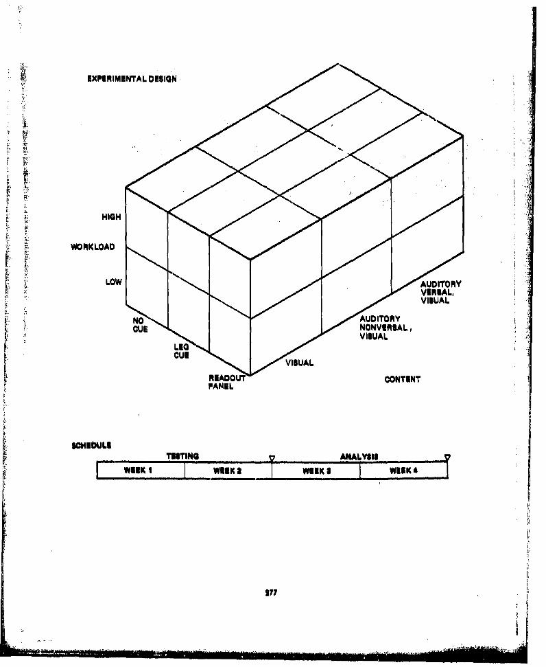
EXPERIMENTAL DESIGN
HIGH
WORKLOAD
LOW ADTRVEIL
VISUALL
REAOU N ONTENTAL
SON~bLEO
TESTING WEK2ANALYSIS
177

REFERENCES
1I Smith, Wayne D. et al., Independent Altitude Monitor Alert Melhods and Modes Study, FAAReport FAA-RD.75-86, July 1975,
2. Boucek, George P., Veitengruber, James E,, and Smith, Wayne D,, Aircraft Alerting SystemsCriteria Study, Volume II: Human Factors Guidelines for Aircraft Alerting Systems, FAAReport FAA-RD-76.222, May 1977.
3. Federal Aviation Regulations, Part 21, Certification Procedures for Products and Pfrts, Depart-ment of Transportation, FAA, May 1974.
4, Federal Aviation Regulations, Part 25, Airworthiness Standards: Transport Category Airplanes,Department of Transportation, FAA, June 1974,
5. Federal Aviation Regulations, Part 37, Technical Standard Order Authorizations, Departmentof Transportation, FAA, May 1974.
6. Federal Aviation Regulations, Part 91, General Operating and Flight Rules, Department ofTransportation, FAA, March 1974,
7, Federal Aviation Regulations, Part 121, Certification and Operations: Domestic, Flag, andSupplemental Air Carriers and Commercial Operators of Large Aircraft, Department of Trans-
, portation, FAA, April 1974.
"8. ARINC Characteristic 577, Audible Warning System, Aeronautical Radio Inc,, July 1, 1970.
k • 9, ARP 450, Flight Deck Visual, Audible and Tactile Signals, Society of Automotive Engineers,Inc., December 31, 197 1,
10, ARP 571, Instrument and Cockpit Control Arrangement for Electronic Navigation andCommunication Aids, Society of Automotive Engineers, Inc,, May 25, 1973,
11, ARP 1068, Flight Deck Instrumentation and Display Design O,•iectives, Society of Autormo-tive Engineers, Inc., March 15, 1971.
12. ARP 1161, Crew Station Lighting-Commercial Aircraft, Society of Automotive Engineers,
Inc., May 1972,
13, MIL.STD-41 1, Aircrew Station Signals, Department of Defense, August 30, 1974.
14, MIL-STD-1472, Human Engineering Design Criteria for Military Systems, Equipment andFacilities, Department of Defense, December 31, 1974.
15, MIL.C-81774, Control Panel, Aircraft, General Requirements for, Department of Defense,March 23, 1973.
16. Anderson, Coe M., Accident Summaries, Reference Document for Paper: Civil Aircraft Acci-dent Anaiysis in the United States, "The Jet Age," NTSB Bureau of Aviation Safety,May 1976,
279

BIBLIOGRAPHY
Aircraft Warning Systems, IATA letter to all member airlines, Letter No, 4007-F, April 24, 1975.Airline Warning Systems Operational Data Received in Response to IATA Letter 4007-F, Dr. JohnLauber, NASA Ames Research Center, Moffett Field, California, June 1976.
Boeing 747 Operations Manual; Document D6-30151-284B, February 1974. S
Boeing 707 Operations Manual; Document D6-3071-95C, June 1974.
Boeing 737 Maintenance Manual, Aural Warning and Call Devices-Description and Operation,Boeing Commercial Airplane Co,, Report D6-20056, November 15, 1968.
Boeing 737 Operations Manual; Document D6-27370-229, July 1974,
Boeing 737 Operations Manual, Volume 1, Reference and Procedures, Western Airlines International,January 21, 1976.
Boeing 737 Operations Manual, Volume I1, System Description, Western Airlines International,
January 21, 1976.
Boeing 727 Operations Manual; Document D6.3727-357, February 1974.
Box, Aural Warning Devices, 747, Boeing Commercial Airplane Co,, Report 60B40029, Revision L,October 1975,
DC.8 Warning Systems Description, McDonnel Douglas Corp,, 1976.
DC-10 Flight Crew Operating Manual, Reference and Performance, Western Airlines International,November 1, 1975.
DC-10 Flight Crew Operating Manual, Systems Descriptions, Western Airlines International, October,1975.
Description and Failure Analysis of the 737-130 Aural Warning Box, Boeing Commercial AirplaneCo., Report D6-20056, June 1967,
Design Guide Warning, Caution, and Advisory Signals and Warning and Caution Systems (Draft),Boeing Document L)6-6000-1530.
Detail Specification for American Airlines Model 727-223, Boeing Document D6-5467-2, July 1974,
Eastern Airlines L- 101 I Flight Manual, Section 19- Autopilot, December 31, 197-1,
P Hodgson. D,, Preliminary Studies of Auditory Flight Control Displays, Boeing Document D6-57104,k iunie 1966,
250

Howitt, J. S., Flight Deck WorkloLAd Stuidies in Civil Transport Aircraft in Measurement of AircrcwPerf'orniincv: 'hile Flight Deck Workload and Its Relation to Pilot Performance, AGARD ConferenceProceedings, 56, North Atlantic Treaty Organization, Advisory Group for Aerospace Research andDevelopment, 1969.
L-I01 I TriStar, TWA Flight Station Configuration and Panel Arrangements, Lockheed-CaliforniaCo., Report LR 23549.3, December 10, 1973.
Lauber, Dr. John, Results of IATA Study--Collation of Airlines Alerting Systems Operational Data,NASA Ames Research Center, Moffett Field, California, June 1976.
Lens, Pushbutton, Illuminated (L 10 11), Lockheed-California Co,, Drawing No. 741173, May 1975.
MARK 13 RNAV Annunciator, Warnings and Discretes, Boeing Commercial Airplane Co,, ReportB-41-10-5-229, December 18, 1975,
Master Warning System, Lockheed Document LR-25914, November 1973.
Northwest Airlines DC-10 Flight Operations Manual, August 12, 1975,
Nose Cargo Door Latch-Lock Indication System (747), Boeing Commercial Airplane Co, letterto Japan Air Lines, Letter No, M-7101-50SE, November 7, 1974.
Operational and Technical Guidelines on Failure Warning and Functional Test, ARINC Report No,415-2 and ATA Report No, 1 12-2, January 10, 1968.
Osgood, Alan G,, Psychological Stimulus Response Study for Independent Altitude Monitoring(IAM) Alert Methods and Modes, Boeing Commercial Airplane Co., Report D6-42532, July 1975,
Panel Drawings for PSA L-10 11 Aircraft, Lockheed--California Co., June 1, 1974,
Panel Drawings for United Airlines DC-8 Aircraft, United Airlines, August 1970,
Parks, D. L., Hayashi, M. M,, and Fries, J. R., Development of an Independent Altitude MonitorConcept, FAA Report FAA-RD-73-168, September 1973.
Standardization or Alarms, subject of letter to Airworthiness Review Conference, December 4,1974, from Richard Bartell, President, Air Taxi and Commercial Pilots' Association, November 1974,
Thorburn, D. E., Voice Warning Systems: A Cockpit Improvement That Should Not Be Overlooked,AMRL-70-138, Aerospace Medical Research Laboratory, Aerospace Medical Division, Air Force Sys-tents Command, Wright-Patterson Air Force Baue, Ohio, 1971.
Transport Category Airplanes -Proposed Pitot Heat Warning Indicators, Aerospuce lndustriv3 Asso.ciation of America letter to FAA, July 27, 1976.
Trans World Airlines Boeing 707 Flight Handbook, January 30, 1076.
Trans World Airlines Boeing 727 Flight Handbook, January 30, 1976.
2S1

Trans World Airlines Boeing 747 Flight Handbook. January 30, 1976,
Trans World Airlines Douglas DC-9 Flight Handbook, January 30, 1976.
Trans World Airlines Lockheed L- I 1 Flight Handbook, January 30, 1976,
Van Leer, J., Golanter, E. H., and Klein, S. J., Factors Relevent to the Development of AircraftWarning and Caution Signal Systems, Aerospace Medicine, 31, p. 31-39, 1960.
Western Airlines 737 Abnormal and Emergency Checklist, October 1975. 4Western Airlines B-737 Checklist, November 1974.
Western Airlines DC- 10 Abnormal and Emergency Checklist, December 1975.
Western Airlines DC-b0 Checklist, November 1975.
World Commercial Aircraft Inventory, McDonnell Douglas Corp., June 30, 1975.
YC-14 Cockpit Warning System, The Boeing Company, Report 953-EL-154, March 1975.
$
®R
28