
AIRCRAFT RECOVERY MANUAL - Index of
292
The content of this document is the property of Airbus Industrie. It is supplied in confidence and commercial security on its contents must be maintained. It must not be used for any purpose other than that for which it is supplied, nor may information contained in it be disclosed to unauthorized persons. It must not be reproduced in whole or in part without permission in writing from the owners of the copyright. Requests for reproduction of any data in this document and the media authorized for it must be addressed to Airbus Industrie. © Airbus Industrie 1990. All rights reserved. Airbus Industrie Customer Services Directorate Technical Data And Documentation 31707 Blagnac Cedex FRANCE Reference : F. ARM Issue : Mar 98
-
Upload
khangminh22 -
Category
Documents
-
view
0 -
download
0
Transcript of AIRCRAFT RECOVERY MANUAL - Index of

The content of this document is the property of Airbus Industrie. It issupplied in confidence and commercial security on its contents must bemaintained.It must not be used for any purpose other than that for which it is supplied,nor may information contained in it be disclosed to unauthorized persons.It must not be reproduced in whole or in part without permission inwriting from the owners of the copyright. Requests for reproduction ofany data in this document and the media authorized for it must beaddressed to Airbus Industrie.
© Airbus Industrie 1990. All rights reserved.
Airbus IndustrieCustomer Services DirectorateTechnical Data And Documentation
31707 Blagnac CedexFRANCE
Reference : F. ARM Issue : Mar 98
Page 1 of 1MAR 30/98
REVISION TRANSMITTAL SHEET
TO : ALL HOLDERS OF A340 AIRCRAFT RECOVERY MANUAL
The revision, dated MAR 30/98 is attached and covers all the Aircraft RecoveryManual data identified in the Highlights.
FILING INSTRUCTIONS
NOTE : Before introducing this revision make certain that previous revisions areincorporated.
– affected pages are listed on the ″List of Effective Pages″ anddesignated as follows :
R = revised (to be replaced)D = deleted (to be removed)N = new (to be introduced)
– make certain that the content of the manual is in compliance withthe List of Effective Pages.
– file the Revision Transmittal Sheet separately.
– remove and destroy the pages which are affected by thisrevision.
REASON FOR ISSUE
The attached Highlights detail the reasons for issue.
Printed in France
AIRCRAFT RECOVERY MANUAL
R

HIGHLIGHTSPage 1 of 1MAR 30/98
HIGHLIGHTS
REV. 06 – MAR 30/98
Description of change :
1-10 Page 1 – Updated MZFW definition in page : ″BASIC DEFINITIONS″1-50 Page 2 – Updated page : ″Ground clearances – Model 300
(254 Tonnes)″1-50 Page 2A – Updated page : ″Ground clearances – Model 200
(254 Tonnes)″1-50 Page 2B – New page : ″Ground clearances – Model 300 (271 Tonnes)″1-50 Page 2C – New : ″Ground clearances – Model 200 (271 Tonnes)″1-60 Page 6 – Updated page : ″Ground Service Connections – Oil System –
Model 300″1-60 Page 6A – Updated page : ″Ground Service Connections – Oil System –
Model 200″1-70 Pages 3 – Updated page : ″LOWER DECK COMPARTMENTS″2-34 Pages 1 to 26 – Updated chapter : ″DEFUELING″2-34 Page 27 – New page in chapter : ″DEFUELING″3-27 Page 3 – Updated table in page : ″Landing Gear and Jacking Point
Location – Model 300″3-27 Page 3A – Updated table in page : ″Landing Gear and Jacking Point
Location – Model 200″3-27 Page 4A – Updated table in page : ″Jacking Design – Model 200″3-28 Page 1 – Updated page : ″Auxiliary Jacking Points″4-10 Page 1 – Updated page : ″Moving Damaged Aircraft on Its Landing
Gear″4-10 Pages 2 – Updated page : ″Landing Gear Footprint″4-21 Pages 1 and 2 – Updated page : ″TOWING″4-21 Page 4 – Updated page : ″Limit Towing Angles″5-20 Page 2 – Updated page in chapter : ″Tethering″
Printed in France
AIRCRAFT RECOVERY MANUAL

L.E.PPage 1
MAR 30/98
LIST OF EFFECTIVE PAGES
CHAPTER/SECTION
C PAGES DATE
List of R 1 MAR 30/98Effective R 2 MAR 30/98Pages
R 3 MAR 30/98R 4 MAR 30/98
Record of R 1 MAR 30/98Revisions
Table of R 1 MAR 30/98Contents 2 JAN 01/96
Alphabetical 1 JAN 30/93Index
1-00 1 JAN 30/93
1-10 R 1 MAR 30/981-10 2 JAN 01/96
1-10 3 JUL 01/941-10 4 OCT 30/93
1-10 3A JUL 01/941-10 4A OCT 30/93
1-20 1 JUL 01/951-20 2 JUL 01/95
1-20 3 JUL 01/951-20 4 JUL 01/95
1-20 3A JUL 01/951-20 4A JUL 01/95
1-30 1 SEP 30/921-30 2 JUL 01/94
1-40 1 SEP 30/921-40 2 JUL 01/95
1-40 3 JUL 01/951-40 4 JUL 01/95
1-40 5 JUL 01/951-40 6 JUL 01/95
1-40 7 JUL 01/951-40 8 JUL 01/95
1-50 1 SEP 30/921-50 R 2 MAR 30/98
1-50 1 SEP 30/921-50 R 2A MAR 30/98
1-50 N 2B MAR 30/981-50 N 2C MAR 30/98
1-50 3 SEP 30/921-50 4 JUL 01/95
1-60 1 SEP 30/921-60 2 OCT 30/93
CHAPTER/SECTION
C PAGES DATE
1-60 3 OCT 30/931-60 4 OCT 30/93
1-60 3 OCT 30/931-60 4A OCT 30/93
1-60 5 OCT 30/931-60 R 6 MAR 30/98
1-60 5A OCT 30/931-60 R 6A MAR 30/98
1-60 7 OCT 30/931-60 8 OCT 30/93
1-60 9 OCT 30/931-60 10 OCT 30/93
1-60 11 OCT 30/931-60 12 OCT 30/93
1-60 11A OCT 30/931-60 12A OCT 30/93
1-60 13 OCT 30/931-60 14 OCT 30/93
1-60 13A OCT 30/931-60 14A OCT 30/92
1-60 15 JUL 01/941-60 16 OCT 30/93
1-60 15A JUL 01/941-60 16 OCT 30/93
1-70 1 SEP 30/921-70 2 SEP 30/92
1-70 R 3 MAR 30/981-70 4 OCT 30/93
1-70 5 JUL 01/941-70 6 OCT 30/93
2-05 1 OV 30/922-05 2 OV 30/92
2-10 1 SEP 30/922-10 2 SEP 30/92
2-10 3 SEP 30/92
2-20 1 SEP 30/922-20 2 SEP 30/92
2-30 1 JAN 30/932-30 2 JUL 30/93
2-31 1 JUL 30/932-31 2 JUL 30/93
2-31 1 JUL 30/932-31 2A JUL 30/93
Printed in France
AIRCRAFT RECOVERY MANUAL

L.E.PPage 2
MAR 30/98
LIST OF EFFECTIVE PAGES
CHAPTER/SECTION
C PAGES DATE
2-31 3 JAN 30/932-31 4 JUL 30/93
2-31 3 JAN 30/932-31 4A JUL 30/93
2-31 5 JUL 30/932-31 6 JUL 30/93
2-31 5A JUL 30/932-31 6A JUL 30/93
2-31 7 JUL 30/932-31 8 JUL 30/93
2-31 7A JUL 30/932-31 8A JUL 30/93
2-31 9 OCT 30/932-31 10 JUL 30/93
2-31 9A JUL 30/932-31 10A JUL 30/93
2-31 11 JUL 30/932-31 12 JUL 30/93
2-31 11A JUL 30/932-31 12A JUL 30/93
2-31 13 JUL 30/932-31 14 JUL 30/93
2-31 13A JUL 30/932-31 14A JUL 30/93
2-31 15 JUL 30/932-31 16 JUL 30/93
2-31 15A JUL 30/932-31 16A JUL 30/93
2-31 17 JUL 30/932-31 18 JUL 30/93
2-31 17A JUL 30/932-31 18A JUL 30/93
2-31 19 JUL 30/932-31 20 JUL 30/93
2-31 19A JUL 30/932-31 20A JUL 30/93
2-31 21 JUL 30/932-31 22 JUL 30/93
2-31 21A JUL 30/932-31 22 JUL 30/93
2-31 23 JUL 30/932-31 24 JUL 30/93
2-31 23 JUL 30/932-31 24A JUL 30/93
CHAPTER/SECTION
C PAGES DATE
2-31 25 JUL 30/932-31 26 JUL 30/93
2-31 25A JUL 30/932-31 26 JUL 30/93
2-31 27 JAN 01/962-31 28 JUL 30/93
2-31 27A JAN 01/962-31 28A JUL 30/93
2-31 29 JUL 30/932-31 30 JAN 01/96
2-31 31 JUL 30/932-31 32 JUL 30/93
2-33 1 JAN 01/962-33 2 JAN 01/96
2-33 3 JAN 01/962-33 4 JAN 01/96
2-33 5 JAN 01/962-33 6 JUL 01/95
2-33 7 JUL 01/952-33 8 JAN 01/96
2-33 9 JAN 01/962-33 10 JUL 01/95
2-33 11 JAN 01/962-33 12 JAN 01/96
2-33 13 JUL 01/952-33 14 JAN 01/96
2-33 15 JAN 01/962-33 16 JUL 01/95
2-33 17 JAN 01/962-33 18 JAN 01/96
2-33 19 JAN 01/962-33 20 JAN 01/96
2-33 21 JAN 01/962-33 22 JUL 01/95
2-33 23 JAN 01/962-33 24 JAN 01/96
2-33 25 JUL 01/952-33 26 JAN 01/96
2-33 27 JAN 01/962-33 28 JAN 01/96
2-33 29 JAN 01/962-33 30 JAN 01/96
2-33 31 JUL 01/952-33 32 JUL 01/95
Printed in France
AIRCRAFT RECOVERY MANUAL

L.E.PPage 3
MAR 30/98
LIST OF EFFECTIVE PAGES
CHAPTER/SECTION
C PAGES DATE
2-34 R 1 MAR 30/982-34 R 2 MAR 30/98
2-34 R 3 MAR 30/982-34 R 4 MAR 30/98
2-34 R 5 MAR 30/982-34 R 6 MAR 30/98
2-34 R 7 MAR 30/982-34 R 8 MAR 30/98
2-34 R 9 MAR 30/982-34 R 10 MAR 30/98
2-34 R 11 MAR 30/982-34 R 12 MAR 30/98
2-34 R 13 MAR 30/982-34 R 14 MAR 30/98
2-34 R 15 MAR 30/982-34 R 16 MAR 30/98
2-34 R 17 MAR 30/982-34 R 18 MAR 30/98
2-34 R 19 MAR 30/982-24 R 20 MAR 30/98
2-24 R 21 MAR 30/982-34R 22 MAR 30/98
2-34 R 23 MAR 30/982-34 R 24 MAR 30/98
2-34 R 25 MAR 30/982-34 R 26 MAR 30/982-34 N 27 MAR 30/98
2-40 1 JAN 30/932-40 2 JAN 30/93
2-40 3 JAN 30/932-40 4 JAN 30/93
3-10 1 JUL 30/933-10 2 JUL 30/93
3-10 3 JUL 30/933-10 4 JUL 30/93
3-10 3A JUL 30/933-10 4 JUL 30/93
3-10 5 JAN 01/963-10 6 JAN 01/96
3-10 5A JAN 01/963-10 6 JAN 01/96
3-10 7 JAN 01/963-10 8 JAN 01/96
3-20 1 JUL 30/933-20 2 JUL 01/95
CHAPTERSECTION
C PAGES DATE
3-21 1 JUL 30/933-21 2 JUL 30/93
3-21 3 JUL 30/933-21 4 JUL 01/95
3-21 3A JUL 30/933-21 4A JUL 01/95
3-21 5 JUL 30/933-21 6 JAN 01/96
3-21 7 JUL 30/933-21 8 JUL 30/93
3-22 1 JUL 30/933-22 2 JUL 30/93
3-22 1 JUL 30/933-22 2A JUL 30/93
3-23 1 JUL 30/933-23 2 JUL 30/93
3-23 1 JUL 30/933-23 2A JUL 30/93
3-24 1 JUL 30/933-24 2 JUL 30/93
3-24 1 JUL 30/933-24 2A JUL 30/93
3-25 1 JUL 30/933-25 2 JUL 30/93
3-25 1 JUL 30/933-25 2A JUL 30/93
3-26 1 JUL 30/933-26 2 JUL 30/93
3-26 3 JUL 30/933-26 4 JUL 01/95
3-27 1 JUL 30/933-27 2 JUL 01/94
3-27 R 3 MAR 30/983-27 4 JUL 01/95
3-27 R 3A MAR 30/983-27 R 4A MAR 30/98
3-27 5 JUL 01/943-27 6 JUL 01/94
3-27 5 JUL 01/943-27 6A JUL 01/94
3-28 R 1 MAR 30/983-28 2 JUL 01/95
3-28 3 JUL 01/953-28 4 JUL 01/95
Printed in France
AIRCRAFT RECOVERY MANUAL

L.E.PPage 4
MAR 30/98
LIST OF EFFECTIVE PAGES
CHAPTER/SECTION
C PAGES DATE
4-10 R 1 MAR 30/984-10 R 2 MAR 30/98
4-10 1A JAN 01/964-10 2 JAN 30/93
4-10 1B JAN 01/964-10 2 JAN 30/93
4-10 3 JAN 30/934-10 4 JUL 01/95
4-10 5 JAN 01/964-10 6 JAN 01/96
4-10 7 JAN 01/964-10 8 JUL 30/93
4-10 9 JAN 30/934-10 10 JAN 30/93
4-10 11 JAN 30/934-10 12 JAN 30/93
4-10 13 JAN 30/93
4-21 R 1 MAR 30/984-21 R 2 MAR 30/98
4-21 3 OCT 30/934-21 R 4 MAR 30/98
4-21 5 SEP 30/924-21 6 SEP 30/92
4-22 1 JAN 01/964-22 2 JAN 01/96
4-22 3 JAN 01/964-22 4 JAN 01/96
4-22 5 JAN 01/964-22 6 JAN 01/96
4-22 7 JAN 01/964-22 8 JAN 01/96
4-30 1 JUL 30/934-30 2 JUL 30/93
5-10 1 OCT 30/93
5-20 1 JAN 01/965-20 R 2 MAR 30/98
CHAPTERSECTION
C PAGES DATE
Printed in France
AIRCRAFT RECOVERY MANUAL

RECORD OF REVISIONSPage 1
MAR 30/98
RECORD OF REVISIONS
REVISIONINSERTED
DATE SIGNATURE
PRELIMINARY (ISSUE 1) SEP 30/92
PRELIMINARY (ISSUE 2) JAN 30/93
ISSUE JUL 30/93
REVISION N°. 1 OCT 30/93
REVISION N°. 2 JUL 01/94
REVISION N°. 3 FEB 01/95
REVISION N°. 4 JUL 01/95
REVISION N°. 5 JAN 01/96
REVISION N°. 6 MAR 30/98
Printed in France
AIRCRAFT RECOVERY MANUAL
R

CONTENTSPage 1
MAR 30/98
TABLE OF CONTENTS
SUBJECT CH/SE PAGE
ALPHABETICAL INDEX 1
INTRODUCTION 1-00 1General Aircraft Characteristics 1-10 1 to 6Fuselage Frame Stations 1-20 1 to 6Wing Rib Stations 1-30 1 to 2Door Clearances 1-40 1 to 8Ground Clearances 1-50 1 to 6Ground Service Connections and Locations 1-60 1 to 26Cargo Load Arrangements 1-70 1 to 6
SURVEY AND PREPARATION 2-00Quick Reference Guideline for A/C Recovery 2-05 1 to 2Damage and Terrain 2-10 1 to 3Damage Control and Safety 2-20 1 to 2Weight and H-Arm Management 2-30 1Empty Weight Revision and H-Arm 2-30 2Location ComputationEffect of the Nose Gear, Flap and Slat positionon the Aircraft CG
2-31 1
Weight and Aircraft CG Variations due to anyFluids aboard other than Fuel
2-31 2
Weight and Aircraft CG Variations due to Cargoaboard
2-31 3 to 12
Net Recoverable Weight (NRW) and H-Arm Location 2-31 13Component Removal – CG Shifts 2-31 14Mass, H-Arm and Moment Concerning VariousComponents of Engines
2-31 15 to 32
Weight and Aircraft CG Variations due to any Fuelaboard
2-33 1 to 32
Defueling 2-34 1 to 27Removal of Payload 2-40 1 to 4
STABILIZE AIRCRAFT 3-00Tethering 3-10 1 to 8Lifting Damaged Aircraft 3-20 1 to 2Nose Gear Retracted, Collapsed or Lost 3-21 1 to 8Main Gears Retracted, Collapsed or Lost 3-22 1 to 2AOne Main Gear Retracted, Collapsed or Lost 3-23 1 to 2ANose Gear and either Left or Right Hand MainGear Retracted, Collapsed or Lost
3-24 1 to 2A
All Gears Retracted, Collapsed or Lost 3-25 1 to 2Lifting Using Inflatable Bags 3-26 1 to 4Lifting with Hydraulic Jacks 3-27 1 to 6AAuxiliary Jacking Points 3-28 1 to 4
Printed in France
AIRCRAFT RECOVERY MANUAL
R

CONTENTSPage 2
JAN 01/96
SUBJECT CH/SE PAGE
MOVING AIRCRAFT 4-00Moving Damaged Aircraft 4-10 1 to 13Towing 4-21 1 to 6Taxiing and Towing of Aircraft with Deflated Tires 4-22 1 to 8Returning Undamaged Aircraft to Runway 4-30 1 to 2
TOOLING AND EQUIPMENT 5-00General Recovery Equipment 5-10 1Equipment Peculiar to the Aircraft 5-20 1Specialized Recovery Equipment 5-20 2
PREVIOUS AIRCRAFT RECOVERY EXPERIENCE 6-00
Printed in France
AIRCRAFT RECOVERY MANUAL
R
R

ALPHABETICAL INDEXPage 1
JAN 30/93
ALPHABETICAL INDEX
SUBJECT CH/SE
Aircraft on its Landing Gear 4-10Aircraft with Landing Gear Collapsed 4-11All Gears Retracted, Collapsed or Lost 3-25Auxiliary Jacking Points 3-28Cargo Load Arrangements 1-70Component Removal - CG Shifts 2-31Damage and Terrain 2-10Damage Control and Safety 2-20Defueling 2-34Door Clearances 1-40Effect of the Nose Gear, Flap andSlat position on the Aircraft CG
2-31
Empty Weight Revision and H-Arm Location Computation 2-30Equipment Peculiar to the Aircraft 5-20Escape Slide Removal 2-35Fuselage Frame Stations 1-20General Aircraft Characteristics 1-10General Recovery Equipment 5-10Ground Clearances 1-50Ground Service Connections and Locations 1-60Lifting Damaged Aircraft 3-20Lifting Using Inflatable Bags 3-26Lifting with Hydraulic Jacks 3-27Main Gears Retracted, Collapsed or Lost 3-22Mass, H-Arm and Moment Concerning 2-31Various Components of EnginesMoving Damaged Aircraft 4-10Net Recoverable Weight (NRW) and H-Arm Location 2-31Nose Gear Retracted, Collapsed or Lost 3-21Nose Gear and either LH or RH Hand Main Gear 3-24Retracted, Collapsed or LostOne Main Gear Retracted, Collapsed or Lost 3-23Quick Reference Guideline for A/C Recovery 2-05Removal of Payload 2-40Returning Undamaged Aircraft to Runway 4-30Specialized Recovery equipment 5-20Tethering 3-10Towing 4-21Towing an Aircraft with Tires Deflated 4-22Weight and H-Arm Management 2-30Weight and Aircraft CG Variations due to any Fuel aboard 2-33Weight and Aircraft CG Variations due to any 2-31Fluids aboard other than FuelWeight and Aircraft CG Variations due to Cargo aboard 2-31Wing Rib Stations 1-30
Printed in France
AIRCRAFT RECOVERY MANUAL
1-00Page 1
JAN 30/93
INTRODUCTION
1. Purpose of Manual
The AIRCRAFT RECOVERY MANUAL is intended to provide Airlines and AirportAuthorities with optimum planning, preparation and accomplishment data forthe lifting and moving of a disabled aircraft which may be obstructingairport traffic.
2. Scope of Manual
The Manual contains general information covering the different aircraftmodels. Of course, it will not be easy in every instance to locate all therequisite data in the Manual within a very short time ; it is hence advisiblefor Airport Authorities and Airlines to use this Manual to jointly draw upone or more schemes based on their specific requirements, equipment availableas well as on recommendations contained in publications, such as the U.S.Federal Aviation Agency circular AC 150/5200-13 of August 27, 1970, entitled″Removal of Disabled Aircraft″, and the specification written by the ″ATAAircraft Recovery Subcommittee″. Endeavours are made for the information inthis Manual to comply with that in the Aircraft Technical Specifications ;however, in case of conflict, the Aircraft Technical Specification shallprevail.
Printed in France
AIRCRAFT RECOVERY MANUAL
1-10Page 1
MAR 30/98
GENERAL AIRPLANE CHARACTERISTICS
BASIC DEFINITIONS
The weight terms used throughout this manual are given below together with theirrespective definitions.
MAXIMUM RAMP WEIGHT
Maximum weight authorized for ground maneuver by the applicable governmentregulations, including taxi and run-up fuel.
MAXIMUM LANDING WEIGHT (MLW)
The maximum landing weight shall be the maximum weight at which the aircraftmeets the appropriate landing certification requirements.
MAXIMUM TAKEOFF WEIGHT (MTOW)
The maximum takeoff weight shall be the maximum permissible weight of theaircraft when the brakes are released for takeoff, or at the start of thetakeoff roll.
OPERATING WEIGHT EMPTY (OWE)
The operational weight empty shall be the manufacturer's weight empty plus theoperator's items weight. The operator's items weight shall be the flight andcabin crew and their baggage, unusable fuel, oil for engines, APU, IDG,emergency equipment, toilet, chemicals and fluids, galley structure, cateringequipment, seats, documents, pallets and baggage containers, emergency equipment(as detailed in the WBM).
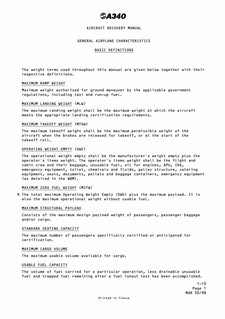
MAXIMUM ZERO FUEL WEIGHT (MZFW)
The total maximum Operating Weight Empty (OWE) plus the maximum payload. It isalso the maximum operational weight without usable fuel.
MAXIMUM STRUCTURAL PAYLOAD
Consists of the maximum design payload weight of passengers, passenger baggageand/or cargo.
STANDARD SEATING CAPACITY
The maximum number of passengers specifically certified or anticipated forcertification.
MAXIMUM CARGO VOLUME
The maximum usable volume available for cargo.
USABLE FUEL CAPACITY
The volume of fuel carried for a particular operation, less drainable unusablefuel and trapped fuel remaining after a fuel runout test has been accomplished.
Printed in France
AIRCRAFT RECOVERY MANUAL
R

1-10
Page2
JUL01/96
GENERAL AIRPLANE CHARACTERISTICS DATA
WEIGHTS USABLE FUEL CAPACITY
WEIGHTVARIANTS
MAXRAMPWEIGHT
MAXTAKEOFFWEIGHT
MAXLANDINGWEIGHT
MAXZERO FUELWEIGHT
OPERATINGWEIGHTEMPTY
MAXSTRUCTURALPAYLOAD
EnginesCFM56 – US Pounds at
15.6°C (60°F)Kilograms at15.6°C (60°F)
Designation lb kg lb kg lb kg lb kg lb kg lb kg GALLONS LITERS JP1-JETA1D=0.790
JP4D=0.775
JP1-JETA1D=0.790
JP4D=0.775
A340/300
Basic WV OOO 560850 254400 558866 253500 410056 186000 383598 174000 289276 131215 112346 50960 5C2/5C3/5C4 36883.8 139605 243141 238524 110288 108194
WV 002 575180 260900 573196 260000 414464 188000 392418 178000 289486 131310 112346 50960 5C2/5C3/5C4 36883.8 139605 243141 238524 110288 108194
High GrossWV 020 599431 271900 597446 271000 418874 190000 392418 178000 298331 135322 112436 50960 5C4 39286 148700 258981 254062 117473 115242
A340/200
Basic WV OOO 560850 254400 558866 253500 399032 181000 372577 169000 280187 127092 92234 41837 5C2/5C3/5C4 36883.8 139605 243141 238524 110288 108194
WV 002 575180 260900 573196 260000 399032 181000 372577 169000 280396 127187 92234 41837 5C2/5C3/5C4 36883.8 139605 243141 238524 110288 108194
VOLUME
STDSEATINGCAPACITY
PAX
TotalFUSELAGEVOLUME
PassengerCABINVOLUME
COCKPIT
VOLUME
AVIONICSCOMPARTMENT
VOLUME
MAXCARGOVOLUME
ft3 m3 ft3 m3 ft3 m3 ft3 m3 ft3 m3
A340/300 37292 1056 13773 390 424 12 1540 43.6 5392 152.6 335
A340/200 33549 950 12819 363 424 12 1540 43.6 4456 126.1 303
PrintedinFrance
AIRCRAFTRECOVERYMANUAL

1-10Page 3
JUL 01/94
Airplane DimensionsModel 300
Printed in France
AIRCRAFT RECOVERY MANUAL

1-10Page 3A
JUL 01/94
Airplane DimensionsModel 200
Printed in France
AIRCRAFT RECOVERY MANUAL

1-10Page 4
OCT 30/93
Airplane DimensionsModel 300
Printed in France
AIRCRAFT RECOVERY MANUAL

1-10Page 4A
OCT 30/93
Airplane DimensionsModel 200
Printed in France
AIRCRAFT RECOVERY MANUAL

1-20Page 1
JUL 01/95
FUSELAGE FRAMES/STATIONS
"This section gives the fuselage frame stations measured along X datum 6382 mmfrom the nose.
The stations (STA) are given in millimeters without conversion.
Fuselage frame stations are shown on pages 2, 3, 4 for Model 300 and pages 2,3A, 4A for Model 200.
Printed in France
AIRCRAFT RECOVERY MANUAL
R
RR

1-20Page 2
JUL 01/95
Fuselage Frames/StationsNose Section (FR 1 to FR 38)
Printed in France
AIRCRAFT RECOVERY MANUAL

1-20Page 3
JUL 01/95
Fuselage Frames/StationsForward Section (FR 37.1 to FR 58)
MODEL 300
Printed in France
AIRCRAFT RECOVERY MANUAL

1-20Page 3A
JUL 01/95
Fuselage Frames/StationsForward Section (FR 38 to FR 58)
MODEL 200
Printed in France
AIRCRAFT RECOVERY MANUAL

1-20Page 4
JUL 01/95
Fuselage Frames/StationsForward Section (FR 58 to FR 106A)
MODEL 300
Printed in France
AIRCRAFT RECOVERY MANUAL

1-20Page 4A
JUL 01/95
Fuselage Frames/StationsForward Section (FR 58 to FR 106.A)
MODEL 200
Printed in France
AIRCRAFT RECOVERY MANUAL

1-30Page 1
SEP 30/92
WING RIB STATIONS
Wing rib stations are shown on page 2.
NOTE : All dimensions of stations in this section are in millimeters.
Printed in France
AIRCRAFT RECOVERY MANUAL

1-30Page 2
JUL 01/94
Wing Ribs/Stations
Printed in France
AIRCRAFT RECOVERY MANUAL

1-40Page 1
SEP 30/92
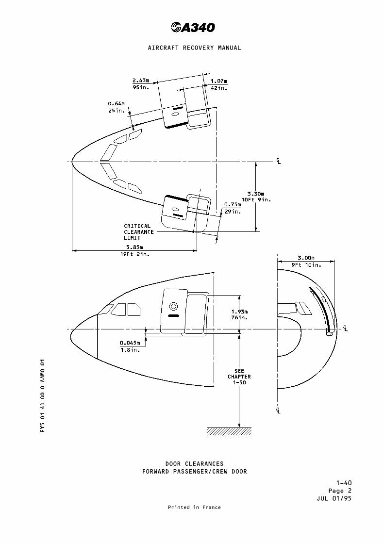
DOOR CLEARANCES
Location, shape and dimensions of passenger/crew and cargo compartment doors andof emergency exits are shown on pages 2 thru 8.
Ground clearances of door sills are shown in Section 1-50.
Printed in France
AIRCRAFT RECOVERY MANUAL
1-40Page 2
JUL 01/95
DOOR CLEARANCESFORWARD PASSENGER/CREW DOOR
Printed in France
AIRCRAFT RECOVERY MANUAL

1-40Page 3
JUL 01/95
DOOR CLEARANCESMID PASSENGER/CREW DOOR
Printed in France
AIRCRAFT RECOVERY MANUAL

1-40Page 4
JUL 01/95
DOOR CLEARANCESEMERGENCY EXIT
Printed in France
AIRCRAFT RECOVERY MANUAL

1-40Page 5
JUL 01/95
DOOR CLEARANCESAFT PASSENGER/CREW DOOR
Printed in France
AIRCRAFT RECOVERY MANUAL

1-40Page 6
JUL 01/95
DOOR CLEARANCESFORWARD CARGO COMPARTMENT DOOR
Printed in France
AIRCRAFT RECOVERY MANUAL

1-40Page 7
JUL 01/95
DOOR CLEARANCESAFT CARGO COMPARTMENT DOOR
Printed in France
AIRCRAFT RECOVERY MANUAL

1-40Page 8
JUL 01/95
DOOR CLEARANCESBULK CARGO COMPARTMENT DOOR
Printed in France
AIRCRAFT RECOVERY MANUAL

1-50Page 1
SEP 30/92
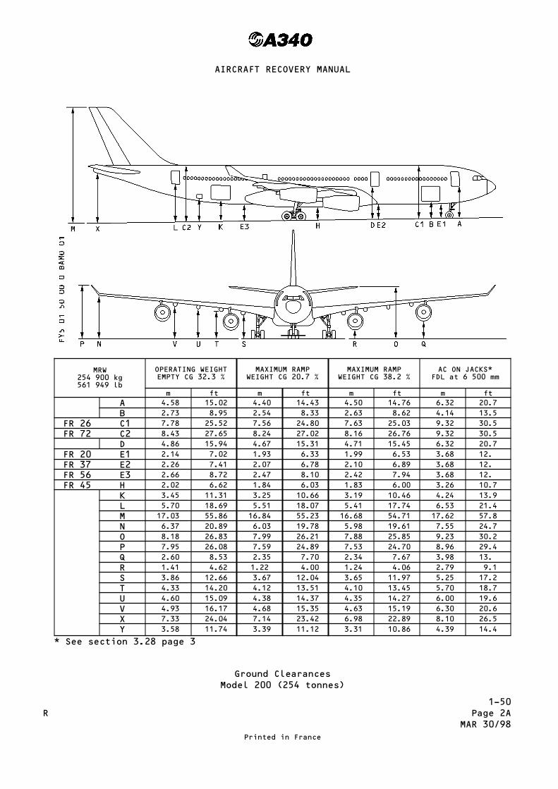
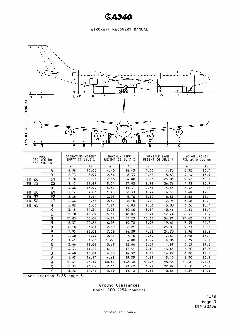
GROUND CLEARANCES
The heights of the doors, fuselage, wing tip, stabilizer, nacelle and mainlanding gear door above the ground are given on pages 2 to 3.Dimensions in the tables are approximate and will vary with tire type andconditions.
Printed in France
AIRCRAFT RECOVERY MANUAL

1-50Page 2
MAR 30/98
MRW254 900 kg561 949 lb
OPERATING WEIGHTEMPTY CG 31.9 %
MAXIMUM RAMPWEIGHT CG 20.7 %
MAXIMUM RAMPWEIGHT CG 38.2 %
AC ON JACKS*FDL at 6 500 mm
m ft m ft m ft m ftA 4.59 15.05 4.41 14.59 4.52 14.8 6.32 20.7
B 2.73 8.95 2.54 8.33 2.58 8.62 4.14 13.5
FR 26 C1 7.76 25.45 7.58 24.86 7.60 25.09 9.32 30.5
FR 72 C2 8.42 27.62 8.25 27.06 8.20 26.73 9.32 30.5
D 4.84 15.87 4.65 15.25 4.67 15.41 6.32 20.7
FR 20 E1 2.13 6.98 1.94 6.36 1.96 6.59 3.68 12.
FR 37 E2 2.27 7.44 2.09 6.85 2.10 6.95 3.68 12.
FR 56 E3 2.37 7.77 2.49 8.17 2.46 7.97 3.68 12.
FR 45 H 2.02 6.62 1.84 6.03 1.83 6.00 3.26 10.7
K 3.44 11.28 3.26 10.69 3.23 10.49 4.24 13.9
L 5.70 18.69 5.52 18.10 5.47 17.74 6.53 21.4
M 16.99 55.72 16.82 55.17 16.73 54.61 17.62 57.8
N 6.35 20.83 6.01 19.71 5.98 19.55 7.55 24.7
O 8.14 26.70 7.96 26.11 7.88 25.58 9.23 30.2
P 7.91 25.94 7.57 24.83 7.53 24.60 8.96 29.4
Q 2.59 8.49 2.35 7.71 2.34 7.67 3.98 13.
R 1.42 4.65 1.23 4.03 1.24 4.10 2.79 9.1
S 3.85 12.63 3.67 12.04 3.65 11.94 5.25 17.2
T 4.31 14.14 4.12 13.51 4.10 13.45 5.70 18.7
U 4.59 15.05 4.38 14.37 4.36 14.23 6.00 19.6
V 4.90 16.07 4.66 15.28 4.64 15.15 6.30 20.6
X 7.30 23.94 7.12 23.35 7.05 22.83 8.10 26.5
Y 3.58 11.74 3.39 11.12 3.35 10.86 4.39 14.4
* See section 3.28 page 3
Ground ClearancesModel 300 (254 tonnes)
Printed in France
AIRCRAFT RECOVERY MANUAL
R
1-50Page 2A
MAR 30/98
MRW254 900 kg561 949 lb
OPERATING WEIGHTEMPTY CG 32.3 %
MAXIMUM RAMPWEIGHT CG 20.7 %
MAXIMUM RAMPWEIGHT CG 38.2 %
AC ON JACKS*FDL at 6 500 mm
m ft m ft m ft m ftA 4.58 15.02 4.40 14.43 4.50 14.76 6.32 20.7
B 2.73 8.95 2.54 8.33 2.63 8.62 4.14 13.5
FR 26 C1 7.78 25.52 7.56 24.80 7.63 25.03 9.32 30.5
FR 72 C2 8.43 27.65 8.24 27.02 8.16 26.76 9.32 30.5
D 4.86 15.94 4.67 15.31 4.71 15.45 6.32 20.7
FR 20 E1 2.14 7.02 1.93 6.33 1.99 6.53 3.68 12.
FR 37 E2 2.26 7.41 2.07 6.78 2.10 6.89 3.68 12.
FR 56 E3 2.66 8.72 2.47 8.10 2.42 7.94 3.68 12.
FR 45 H 2.02 6.62 1.84 6.03 1.83 6.00 3.26 10.7
K 3.45 11.31 3.25 10.66 3.19 10.46 4.24 13.9
L 5.70 18.69 5.51 18.07 5.41 17.74 6.53 21.4
M 17.03 55.86 16.84 55.23 16.68 54.71 17.62 57.8
N 6.37 20.89 6.03 19.78 5.98 19.61 7.55 24.7
O 8.18 26.83 7.99 26.21 7.88 25.85 9.23 30.2
P 7.95 26.08 7.59 24.89 7.53 24.70 8.96 29.4
Q 2.60 8.53 2.35 7.70 2.34 7.67 3.98 13.
R 1.41 4.62 1.22 4.00 1.24 4.06 2.79 9.1
S 3.86 12.66 3.67 12.04 3.65 11.97 5.25 17.2
T 4.33 14.20 4.12 13.51 4.10 13.45 5.70 18.7
U 4.60 15.09 4.38 14.37 4.35 14.27 6.00 19.6
V 4.93 16.17 4.68 15.35 4.63 15.19 6.30 20.6
X 7.33 24.04 7.14 23.42 6.98 22.89 8.10 26.5
Y 3.58 11.74 3.39 11.12 3.31 10.86 4.39 14.4
* See section 3.28 page 3
Ground ClearancesModel 200 (254 tonnes)
Printed in France
AIRCRAFT RECOVERY MANUAL
R

1-50Page 2B
MAR 30/98
MRW271 900 kg599 431 lb
OPERATING WEIGHTEMPTY CG 29.2 %
MAXIMUM RAMPWEIGHT CG 21.5 %
MAXIMUM RAMPWEIGHT CG 37.6 %
AC ON JACKS*FDL at 6 500 mm
m ft m ft m ft m ftA 4.65 15.25 4.45 14.59 4.60 15.09 6.32 20.7
B 2.78 9.12 2.58 8.46 2.71 8.88 4.14 13.5
FR 26 C1 7.74 25.4 7.54 24.73 7.66 25.12 9.32 30.5
FR 72 C2 8.87 29.09 8.30 27.23 8.18 26.83 9.32 30.5
D 6.32 20.7
FR 20 E1 2.04 6.7 1.84 6.03 1.98 6.49 3.68 12.
FR 37 E2 2.26 7.41 2.06 6.75 2.13 6.98 3.68 12.
FR 56 E3 2.63 8.62 2.45 8.03 2.39 7.83 3.68 12.
FR 45 H 2.01 6.59 1.82 5.97 1.83 6.00 3.26 10.7
K 3.45 11.31 3.27 10.73 3.18 10.43 4.24 13.9
L 5.66 18.56 5.49 18.01 5.36 17.58 6.53 21.4
M 17.04 55.89 16.88 55.36 16.67 54.68 17.62 57.8
N 6.33 20.76 6.00 19.6 5.94 19.48 7.55 24.7
O 8.19 26.86 8.04 26.37 7.83 25.68 9.23 30.2
P 7.89 25.88 7.55 24.76 7.48 24.54 8.96 29.4
Q 2.60 8.53 2.35 7.70 2.35 7.70 3.98 13.
R 1.44 4.72 1.25 4.10 1.28 4.20 2.79 9.1
S 3.85 12.63 3.66 12.01 3.64 11.94 5.25 17.2
T 4.30 14.10 4.12 13.51 4.10 13.45 5.70 18.7
U 4.55 14.92 4.37 14.33 4.33 14.20 6.00 19.6
V 4.83 15.84 4.66 15.28 4.61 15.12 6.30 20.6
X 7.34 24.07 7.19 23.58 6.98 22.89 8.10 26.5
Y 3.60 11.80 3.43 11.25 3.32 10.89 4.39 14.4
Z 5.44 17.84 5.23 17.15 5.41 17.74
* See section 3.28 page 3Ground Clearances
Model 300 (271 tonnes)
Printed in France
AIRCRAFT RECOVERY MANUAL
N

1-50Page 2C
MAR 30/98
MRW271 900 kg599 431 lb
OPERATING WEIGHTEMPTY CG 32.3 %
MAXIMUM RAMPWEIGHT CG 23.6 %
MAXIMUM RAMPWEIGHT CG 37.0 %
AC ON JACKS*FDL at 6 500 mm
m ft m ft m ft m ftA 4.66 15.28 4.44 14.56 4.56 14.95 6.32 20.7
B 2.79 9.15 2.58 8.46 2.68 8.79 4.14 13.5
FR 26 C1 7.76 25.45 7.54 24.73 7.64 25.06 9.32 30.5
FR 72 C2 8.46 27.75 8.29 27.19 8.19 26.86 9.32 30.5
D 6.32 20.7
FR 20 E1 2.05 6.72 1.83 6.00 1.95 6.40 3.68 12.
FR 37 E2 2.28 7.48 2.08 6.82 2.13 6.98 3.68 12.
FR 56 E3 2.65 8.69 2.46 8.06 2.41 7.90 3.68 12.
FR 45 H 2.05 6.72 1.86 6.10 1.85 6.07 3.26 10.7
K 3.44 11.28 3.41 11.18 3.18 10.43 4.24 13.9
L 5.66 18.56 5.49 18.01 5.38 17.64 6.53 21.4
M 17.06 55.95 16.90 55.43 16.72 54.85 17.62 57.8
N 6.35 20.83 6.01 19.71 5.96 19.55 7.55 24.7
O 8.21 26.93 8.05 26.41 7.88 25.84 9.23 30.2
P 7.92 25.98 7.57 24.83 7.50 24.60 8.96 29.4
Q 2.60 8.53 2.34 7.67 2.34 7.67 3.98 13.
R 1.43 4.69 1.22 4.00 1.26 4.13 2.79 9.1
S 3.85 12.63 3.66 12.01 3.64 11.94 5.25 17.2
T 4.31 14.14 4.11 13.48 4.10 13.45 5.70 18.7
U 4.56 14.95 4.37 14.33 4.34 14.23 6.00 19.6
V 4.85 15.90 4.66 15.28 4.62 15.15 6.30 20.6
X 7.36 24.14 7.20 23.61 7.02 23.02 8.10 26.5
Y 3.59 11.77 3.41 11.18 3.33 10.92 4.39 14.4
Z 5.44 17.84 5.21 17.09 5.36 17.58
* See section 3.28 page 3
Ground ClearancesModel 200 (271 tonnes)
Printed in France
AIRCRAFT RECOVERY MANUAL
N
1-50Page 3
SEP 30/96
MRW254 400 kg560 850 lb
OPERATING WEIGHTEMPTY CG 32.3 %
MAXIMUM RAMPWEIGHT CG 20.7 %
MAXIMUM RAMPWEIGHT CG 38.2 %
AC ON JACKS*FDL at 6 500 mm
m ft m ft m ft m ftA 4.58 15.02 4.40 14.43 4.50 14.76 6.32 20.7
B 2.73 8.95 2.54 8.33 2.63 8.62 4.14 13.5
FR 26 C1 7.78 25.52 7.56 24.80 7.63 25.03 9.32 30.5
FR 72 C2 8.43 27.65 8.24 27.02 8.16 26.76 9.32 30.5
D 4.86 15.94 4.67 15.31 4.71 15.45 6.32 20.7
FR 20 E1 2.14 7.02 1.93 6.33 1.99 6.53 3.68 12.
FR 37 E2 2.26 7.41 2.07 6.78 2.10 6.89 3.68 12.
FR 56 E3 2.66 8.72 2.47 8.10 2.42 7.94 3.68 12.
FR 45 H 2.02 6.62 1.84 6.03 1.83 6.00 3.26 10.7
K 3.45 11.31 3.25 10.66 3.19 10.46 4.24 13.9
L 5.70 18.69 5.51 18.07 5.41 17.74 6.53 21.4
M 17.03 55.86 16.84 55.23 16.68 54.71 17.62 57.8
N 6.37 20.89 6.03 19.78 5.98 19.61 7.55 24.7
O 8.18 26.83 7.99 26.21 7.88 25.85 9.23 30.2
P 7.95 26.08 7.59 24.89 7.53 24.70 8.96 29.4
Q 2.60 8.53 2.35 7.70 2.34 7.67 3.98 13.
R 1.41 4.62 1.22 4.00 1.24 4.06 2.79 9.1
S 3.86 12.66 3.67 12.04 3.65 11.97 5.25 17.2
T 4.33 14.20 4.12 13.51 4.10 13.45 5.70 18.7
U 4.60 15.09 4.38 14.37 4.35 14.27 6.00 19.6
V 4.93 16.17 4.68 15.35 4.63 15.19 6.30 20.6
W 60.41 198.14 60.47 198.38 60.47 198.38 60.30 197.8
X 7.33 24.04 7.14 23.42 6.98 22.89 8.10 26.5
Y 3.58 11.74 3.39 11.12 3.31 10.86 4.39 14.4
* See section 3.28 page 3
Ground ClearancesModel 200 (254 tonnes)
Printed in France
AIRCRAFT RECOVERY MANUAL

1-50Page 4
SEP 30/96
MRW275 900 kg608 249 lb
OPERATING WEIGHTEMPTY CG 29.2 %
MAXIMUM RAMPWEIGHT CG 21.5 %
MAXIMUM RAMPWEIGHT CG 37.6 %
AC ON JACKS*FDL at 6 500 mm
m ft m ft m ft m ftA 4.65 15.25 4.45 14.59 4.60 15.09 6.32 20.7
B 2.78 9.12 2.58 8.46 2.71 8.88 4.14 13.5
FR 26 C1 7.74 25.4 7.54 24.73 7.66 25.12 9.32 30.5
FR 72 C2 8.87 29.09 8.30 27.23 8.18 26.83 9.32 30.5
D 6.32 20.7
FR 20 E1 2.04 6.7 1.84 6.03 1.98 6.49 3.68 12.
FR 37 E2 2.26 7.41 2.06 6.75 2.13 6.98 3.68 12.
FR 56 E3 2.63 8.62 2.45 8.03 2.39 7.83 3.68 12.
FR 45 H 2.01 6.59 1.82 5.97 1.83 6.00 3.26 10.7
K 3.45 11.31 3.27 10.73 3.18 10.43 4.24 13.9
L 5.66 18.56 5.49 18.01 5.36 17.58 6.53 21.4
M 17.04 55.89 16.88 55.36 16.67 54.68 17.62 57.8
N 6.33 20.76 6.00 19.6 5.94 19.48 7.55 24.7
O 8.19 26.86 8.04 26.37 7.83 25.68 9.23 30.2
P 7.89 25.88 7.55 24.76 7.48 24.54 8.96 29.4
Q 2.60 8.53 2.35 7.70 2.35 7.70 3.98 13.
R 1.44 4.72 1.25 4.10 1.28 4.20 2.79 9.1
S 3.85 12.63 3.66 12.01 3.64 11.94 5.25 17.2
T 4.30 14.10 4.12 13.51 4.10 13.45 5.70 18.7
U 4.55 14.92 4.37 14.33 4.33 14.20 6.00 19.6
V 4.83 15.84 4.66 15.28 4.61 15.12 6.30 20.6
X 7.34 24.07 7.19 23.58 6.98 22.89 8.10 26.5
Y 3.60 11.80 3.43 11.25 3.32 10.89 4.39 14.4
Z 5.44 17.84 5.23 17.15 5.41 17.74
* See section 3.28 page 3Ground Clearances
Model 300 (271 tonnes)
Printed in France
AIRCRAFT RECOVERY MANUAL

1-50Page 5
SEP 30/96
MRW275 900 kg608 249 lb
OPERATING WEIGHTEMPTY CG 32.3 %
MAXIMUM RAMPWEIGHT CG 23.6 %
MAXIMUM RAMPWEIGHT CG 37.0 %
AC ON JACKS*FDL at 6 500 mm
m ft m ft m ft m ftA 4.66 15.28 4.44 14.56 4.56 14.95 6.32 20.7
B 2.79 9.15 2.58 8.46 2.68 8.79 4.14 13.5
FR 26 C1 7.76 25.45 7.54 24.73 7.64 25.06 9.32 30.5
FR 72 C2 8.46 27.75 8.29 27.19 8.19 26.86 9.32 30.5
D 6.32 20.7
FR 20 E1 2.05 6.72 1.83 6.00 1.95 6.40 3.68 12.
FR 37 E2 2.28 7.48 2.08 6.82 2.13 6.98 3.68 12.
FR 56 E3 2.65 8.69 2.46 8.06 2.41 7.90 3.68 12.
FR 45 H 2.05 6.72 1.86 6.10 1.85 6.07 3.26 10.7
K 3.44 11.28 3.41 11.18 3.18 10.43 4.24 13.9
L 5.66 18.56 5.49 18.01 5.38 17.64 6.53 21.4
M 17.06 55.95 16.90 55.43 16.72 54.85 17.62 57.8
N 6.35 20.83 6.01 19.71 5.96 19.55 7.55 24.7
O 8.21 26.93 8.05 26.41 7.88 25.84 9.23 30.2
P 7.92 25.98 7.57 24.83 7.50 24.60 8.96 29.4
Q 2.60 8.53 2.34 7.67 2.34 7.67 3.98 13.
R 1.43 4.69 1.22 4.00 1.26 4.13 2.79 9.1
S 3.85 12.63 3.66 12.01 3.64 11.94 5.25 17.2
T 4.31 14.14 4.11 13.48 4.10 13.45 5.70 18.7
U 4.56 14.95 4.37 14.33 4.34 14.23 6.00 19.6
V 4.85 15.90 4.66 15.28 4.62 15.15 6.30 20.6
X 7.36 24.14 7.20 23.61 7.02 23.02 8.10 26.5
Y 3.59 11.77 3.41 11.18 3.33 10.92 4.39 14.4
Z 5.44 17.84 5.21 17.09 5.36 17.58
* See section 3.28 page 3
Ground ClearancesModel 200 (271 tonnes)
Printed in France
AIRCRAFT RECOVERY MANUAL

1-50Page 6
SEP 30/96
Main Landing Gear
Printed in France
AIRCRAFT RECOVERY MANUAL
1-50Page 7
SEP 30/96
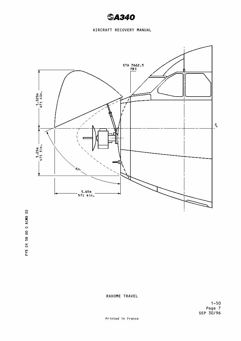
RADOME TRAVEL
Printed in France
AIRCRAFT RECOVERY MANUAL

1-50Page 8
SEP 30/96
This Page Left Blank Intentionally
Printed in France
AIRCRAFT RECOVERY MANUAL
1-60Page 1
SEP 30/92
GROUND SERVICE CONNECTIONS
AND LOCATIONS
The ground service connections and locations are specified on pages 1 thru 12A.
Printed in France
AIRCRAFT RECOVERY MANUAL

1-60Page 2
OCT 30/93
1 – OXYGEN SYSTEM
2 – EXTERNAL POWER (ELECTRICAL)
3 – POTABLE WATER DRAIN
4 – LOW PRESSURE PRE-CONDITIONING
5 – HIGH PRESSURE AIR PRE-CONDITIONING AND ENGINE STARTING
6 – IDG OIL FILLING
7 – ENGINE OIL FILLING
8 – PRESSURE REFUEL
9 – OVERWING REFUEL
10 – HYDRAULIC GROUND POWER SUPPLY (YELLOW)
11 – HYD RESERVOIR FILLING AND GROUND POWER SUPPLY (GREEN)
12 – HYD RESERVOIR AIR PRESSURIZATION & GROUND POWER SUPPLY (BLUE)
13 – NITROGEN CHARGING FOR HYDRAULIC ACCUMULATORS
14 – REFUEL/DEFUEL PANEL
15 – POTABLE WATER FILLING
16 – TOILET SERVICING
17 – APU OIL FILLING
GROUND SERVICE CONNECTIONSSYMBOLS USED ON GROUND
SERVICE CONNECTIONS DIAGRAMS
Printed in France
AIRCRAFT RECOVERY MANUAL
R
R
R
R

1-60Page 3
OCT 30/93
GROUND SERVICE CONNECTIONSGROUND SERVICE CONNECTIONS LAYOUT
Printed in France
AIRCRAFT RECOVERY MANUAL
1-60Page 4
OCT 30/93
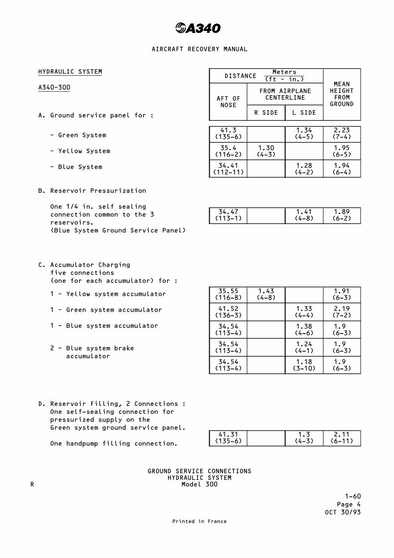
HYDRAULIC SYSTEM
A340–300
A. Ground service panel for :
– Green System
– Yellow System
– Blue System
B. Reservoir Pressurization
One 1/4 in. self sealingconnection common to the 3reservoirs.(Blue System Ground Service Panel)
C. Accumulator Chargingfive connections(one for each accumulator) for :
1 – Yellow system accumulator
1 – Green system accumulator
1 – Blue system accumulator
2 – Blue system brakeaccumulator
D. Reservoir Filling, 2 Connections :One self-sealing connection forpressurized supply on theGreen system ground service panel.
One handpump filling connection.
DISTANCEMeters
(ft – in.)MEANHEIGHTFROMGROUND
AFT OFNOSE
FROM AIRPLANECENTERLINE
R SIDE L SIDE
41.3(135-6)
1.34(4-5)
2.23(7-4)
35.4(116-2)
1.30(4-3)
1.95(6-5)
34.41(112-11)
1.28(4-2)
1.94(6-4)
34.47(113-1)
1.41(4-8)
1.89(6-2)
35.55(116-8)
1.43(4-8)
1.91(6-3)
41.52(136-3)
1.33(4-4)
2.19(7-2)
34.54(113-4)
1.38(4-6)
1.9(6-3)
34.54(113-4)
1.24(4-1)
1.9(6-3)
34.54(113-4)
1.18(3-10)
1.9(6-3)
41.31(135-6)
1.3(4-3)
2.11(6-11)
GROUND SERVICE CONNECTIONSHYDRAULIC SYSTEM
Model 300
Printed in France
AIRCRAFT RECOVERY MANUAL
R

1–60Page 4A
OCT 30/93
HYDRAULIC SYSTEM
A340–200
A. Ground service panel for :
– Green System
– Yellow System
– Blue System
B. Reservoir Pressurization
One 1/4 in. self sealingconnection common to the 3reservoirs.(Blue System Ground Service Panel)
C. Accumulator Chargingfive connections(one for each accumulator) for :
1 – Yellow system accumulator
1 – Green system accumulator
1 – Blue system accumulator
2 – Blue system brakeaccumulator
D. Reservoir Filling, 2 Connections :One self-sealing connection forpressurized supply on theGreen system ground service panel.
One handpump filling connection.
DISTANCEMeters
(ft – in.)MEANHEIGHTFROMGROUND
AFT OFNOSE
FROM AIRPLANECENTERLINE
R SIDE L SIDE
39.17(128-5)
1.34(4-5)
2.23(7-4)
33.27(128-1)
1.30(4-3)
1.95(6-5)
32.28(105-10)
1.28(4-2)
1.94(6-4)
32.34(106- )
1.41(4-8)
1.89(6-2)
33.42(109-7)
1.43(4-8)
1.91(6-3)
39.39(129-2)
1.33(4-4)
2.19(7-2)
32.41(106-3)
1.38(4-6)
1.9(6-3)
32.41(106-3)
1.24(4-1)
1.9(6-3)
32.41(106-3)
1.18(3-10)
1.9(6-3)
39.18(128-6)
1.3(4-3)
2.11(6-11)
GROUND SERVICE CONNECTIONSHYDRAULIC SYSTEM
Model 200
Printed in France
AIRCRAFT RECOVERY MANUAL

1-60Page 5
OCT 30/93
A340-300DISTANCE
Meters(ft – in.)
MEANHEIGHTFROMGROUND
AFT OFNOSE
FROM AIRPLANECENTERLINE
R SIDE L SIDE
E. Reservoir DrainOne 3/8 in. self-sealing connectionon reservoir for :
– Yellow system
– Green system
– Blue system
29.03( 95.24)
2.12(6.95) – 2.40
( 7.87)
33.17(108.82) – 0.70
(2.29)3.80
(12.46)
29.03( 95.24) – 2.12
(6.95)2.40
( 7.87)
F. Ground test
Three 1 in. self-sealing connectionsand three 1-1/2 in.self-sealing connections (one pairper system)
– Green system ground service panel
– Yellow system ground service panel
– Blue system ground service panel
34.92(114.56) – 1.35
(4.42)2.2
( 7.21)
29.03( 95.24)
1.30( 4.26) – 2.0
( 6.56)
28.03( 91.96) – 1.28
(4.19)2.0
( 6.56)
GROUND SERVICE CONNECTIONSHYDRAULIC SYSTEM
Model 300
Printed in France
AIRCRAFT RECOVERY MANUAL
R
R

1–60Page 5A
OCT 30/93
A340-200DISTANCE
Meters(ft – in.)
MEANHEIGHTFROMGROUND
AFT OFNOSE
FROM AIRPLANECENTERLINE
R SIDE L SIDE
E. Reservoir DrainOne 3/8 in. self-sealing connectionon reservoir for :
– Yellow system
– Green system
– Blue system
26.90( 88-2)
2.12(6.95) – 2.40
( 7.87)
31.04(101-9) – 0.70
(2.29)3.80
(12.46)
26.90( 88-2) – 2.12
(6.95)2.40
( 7.87)
F. Ground test
Three 1 in. self-sealing connectionsand three 1-1/2 in.self-sealing connections (one pairper system)
– Green system ground service panel
– Yellow system ground service panel
– Blue system ground service panel
32.79(107-6) – 1.35
(4.42)2.2
( 7.21)
26.90( 88-2)
1.30( 4.26) – 2.0
( 6.56)
25.90( 84-11) – 1.28
(4.19)2.0
( 6.56)
GROUND SERVICE CONNECTIONSHYDRAULIC SYSTEM
Model 200
Printed in France
AIRCRAFT RECOVERY MANUAL

1-60Page 6
MAR 30/98
OIL SYSTEM
A340-300
A. ENGINE OIL REPLENISHMENT
– One gravity filling cap andone pressure filling connectionper engine
ENGINE OIL GRAVITYFILLING CAP
→
ENGINE OIL PRESSUREFILLING PORT
→
DISTANCEMeters
(Ft − in.)MEANHEIGHTFROMGROUND
AFT OFNOSE
FROM AIRPLANECENTERLINE
LH Side RH Side
Engine 1-431.035 m
(101 ft 8 in)Engine 2-324.460 m
( 80 ft 2 in)
Engine 120.560 m
(67 ft 4 in)Engine 210.330 m
(33 ft 9 in)
Engine 38.410 m
(27 ft 6 in)Engine 418.640 m
(61 ft 1 in)
Engine 1-43.470 m
(11 ft 3 in)Engine 2-32.200 m
( 7 ft 2 in)
Engine 1-430.900 m
(101 ft 3 in)Engine 2-324.325 m
( 79 ft 8 in)
Engine 120.640 m
(67 ft 7 in)Engine 210.410 m
(34 ft 1 in)
Engine 38.320 m
(27 ft 3 in)Engine 418.560 m
(60 ft 9 in)
Engine 1-43.470 m
(11 ft 3 in)Engine 2-32.200 m
( 7 ft 2 in)
Max delivery pressure required : 25 psi (1.7 bar)Max delivery flow required : 66 US GAL/hour (250 liters/hour)
Tank capacity :
– Full level → 20.7 QTS (19.6 liters)– Minimum Usable → 9.7 QTS ( 9.2 liters)
B. IDG OIL REPLENISHMENT
– One pressure filling connectionper engine
IDG OIL PRESSUREFILLING PORT
→
Engine 1-430.120 m
(98 ft 8 in)Engine 2-323.545 m
(77 ft 2 in)
Engine 119.400 m
(63 ft 6 in)Engine 29.170 m(30 ft)
Engine 39.570 m
(31 ft 3 in)Engine 419.800 m
(64 ft 9 in)
Engine 1-42.550 m
(8 ft 3 in)Engine 2-31.350 m
( 4 ft 4 in)
Max delivery pressure required : 40 Psi (2.75 bar)Max OIL capacity of IDG : 1.1 US GAL (4.1 liters)
GROUND SERVICE CONNECTIONSOIL SYSTEM – CFM56-5C2 ENGINE
Model 300
Printed in France
AIRCRAFT RECOVERY MANUAL
R

1-60Page 6A
MAR 30/98
OIL SYSTEM
A340-200
A. ENGINE OIL REPLENISHMENT
– One gravity filling cap andone pressure filling connectionper engine
ENGINE OIL GRAVITYFILLING CAP
→
ENGINE OIL PRESSUREFILLING PORT
→
DISTANCEMeters
(Ft − in.)MEANHEIGHTFROMGROUND
AFT OFNOSE
FROM AIRPLANECENTERLINE
LH Side RH Side
Engine 1-428.905 m
(94 ft 9 in)Engine 2-322.330 m
(73 ft 3 in)
Engine 120.560 m
(67 ft 4 in)Engine 210.330 m
(33 ft 9 in)
Engine 38.410 m
(27 ft 6 in)Engine 418.640 m
(61 ft 1 in)
Engine 1-43.470 m
(11 ft 3 in)Engine 2-32.200 m
( 7 ft 2 in)
Engine 1-428.770 m
(94 ft 4 in)Engine 2-322.195 m
(72 ft 9 in)
Engine 120.640 m
(67 ft 7 in)Engine 210.410 m
(34 ft 1 in)
Engine 38.320 m
(27 ft 3 in)Engine 418.560 m
(60 ft 9 in)
Engine 1-43.470 m
(11 ft 3 in)Engine 2-32.200 m
( 7 ft 2 in)
Max delivery pressure required : 25 psi (1.7 bar)Max delivery flow required : 66 US GAL/hour (250 liters/hour)
Tank capacity :
– Full level → 20.7 QTS (19.6 liters)– Minimum Usable → 9.7 QTS ( 9.2 liters)
B. IDG OIL REPLENISHMENT
– One pressure filling connectionper engine
IDG OIL PRESSUREFILLING PORT
→
Engine 1-427.99 m
(91 ft 9 in)Engine 2-321.415 m
(70 ft 2 in)
Engine 119.400 m
(63 ft 6 in)Engine 29.170 m(30 ft)
Engine 39.570 m
(31 ft 3 in)Engine 419.800 m
(64 ft 9 in)
Engine 1-42.550 m
(8 ft 3 in)Engine 2-31.350 m
( 4 ft 4 in)
Max delivery pressure required : 40 Psi (2.75 bar)Max OIL capacity of IDG : 1.1 US GAL (4.1 liters)
GROUND SERVICE CONNECTIONSOIL SYSTEM – CFM56-5C2 ENGINE
Model 200
Printed in France
AIRCRAFT RECOVERY MANUAL
R

1-60Page 7
OCT 30/93
Ground Service ConnectionsEngine Oil TankCFM56-5-C2 Engine
Printed in France
AIRCRAFT RECOVERY MANUAL

1-60Page 7A
SEP 30/92
FUEL SYSTEM
A340-200
Four Standard 2.5 in.connections – ISO R45 SPEC.Two service connections(gravity refuel)
DISTANCEMeters
(ft – in.)MEANHEIGHTFROMGROUND
AFT OFNOSE
FROM AIRPLANECENTERLINE
R SIDE L SIDE
27.80(91-2)
12.6(41-4)
12.6(41-4)
5.00(16-5)
31.2(102-4)
17.2(56-5)
17.2(56-5)
5.80(19-0)
Flow Rate :1250 l/min (275 Imp. gal/min) (331 U.S. gal/min) per connectionMaximum Pressure :– 50 psig (3.45 bars)
GROUND SERVICE CONNECTIONSFUEL SYSTEM
(MODEL 340-200)
Printed in France
AIRCRAFT RECOVERY MANUAL

1–60Page 8
OCT 30/93
Ground Service ConnectionsIDG
CFM56-5C2 Engine
Printed in France
AIRCRAFT RECOVERY MANUAL

1-60Page 9
OCT 30/93
ELECTRICAL SYSTEM
Two standard 6 pin connectorsISO R 461 specification
DISTANCEMeters
(ft – in.) MEANHEIGHTFROMGROUND
AFT OFNOSE
AIRPLANECENTERLINE
7.01(22-12)
1.98(6-6)
Supply :115/200 Volt, 3-Phase, 400 HzPower required : 2 – (90 KVA)
GROUND SERVICE CONNECTIONSELECTRICAL SYSTEM
Printed in France
AIRCRAFT RECOVERY MANUAL

1-60Page 9A
SEP 30/92
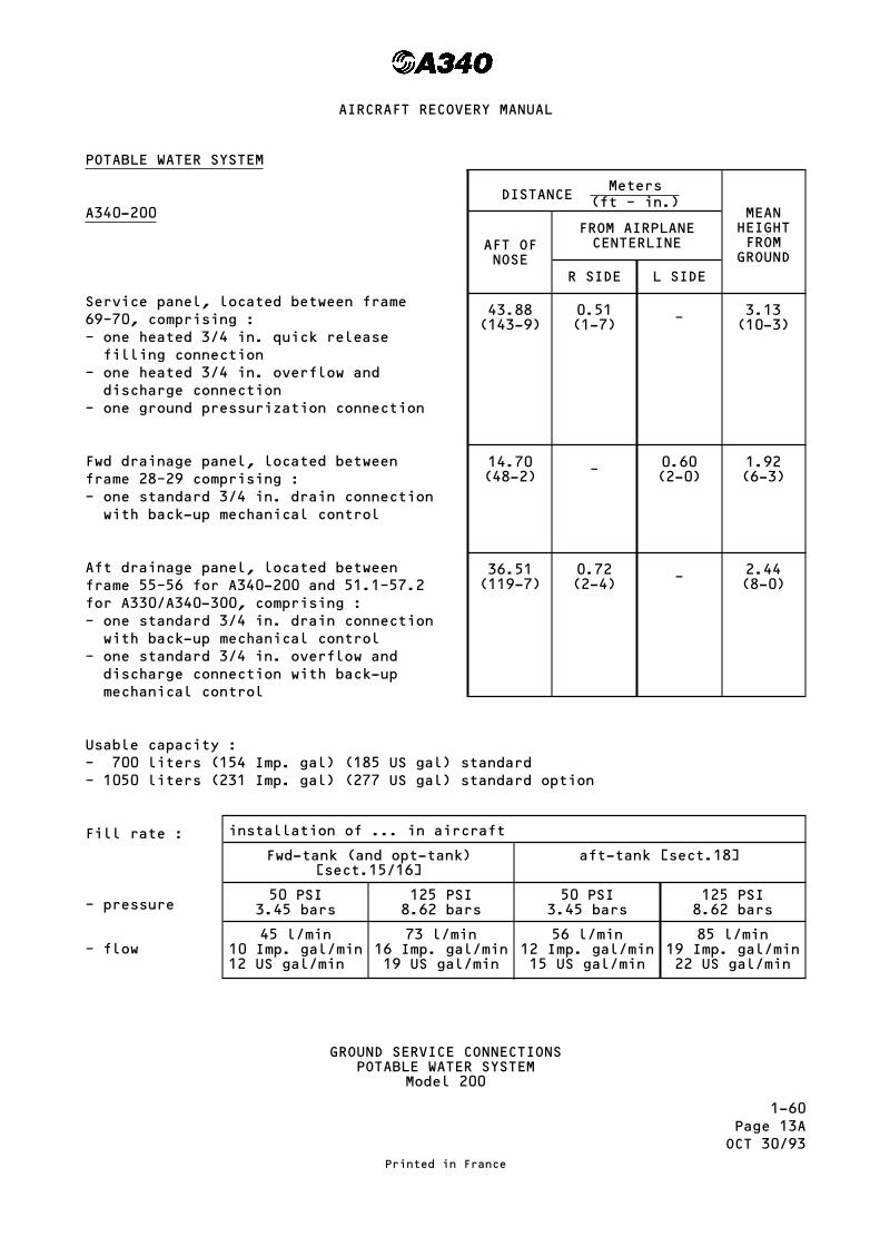
POTABLE WATER SYSTEM
A340-200
Service panel, located between frame69–70, comprising :– one heated 3/4 in. quick releasefilling connection
– one heated 3/4 in. overflow anddischarge connection
– one ground pressurization connection
Fwd drainage panel, located betweenframe 28–29 comprising :– one standard 3/4 in. drain connectionwith back-up mechanical control
Aft drainage panel, located betweenframe 55–56 for A340-200 and 51.1–57.2for A330/A340-300, comprising :– one standard 3/4 in. drain connectionwith back-up mechanical control
– one standard 3/4 in. overflow anddischarge connection with back-upmechanical control
Usable capacity :– 700 liters (154 Imp. gal) (185 US gal) standard– 1050 liters (231 Imp. gal) (277 US gal) standard option
Fill rate :
– pressure
– flow
DISTANCEMeters
(ft – in.)MEANHEIGHTFROMGROUND
AFT OFNOSE
FROM AIRPLANECENTERLINE
R SIDE L SIDE
43.88(143-9)
0.51(1-7) – 3.13
(10-3)
14.70(48-2) – 0.60
(2-0)1.92(6-3)
36.51(119-7)
0.72(2-4) – 2.44
(8-0)
installation of ... in aircraft
Fwd-tank (and opt-tank)[sect.15/16]
aft-tank [sect.18]
50 PSI3.45 bars
125 PSI8.62 bars
50 PSI3.45 bars
125 PSI8.62 bars
45 l/min10 Imp. gal/min12 US gal/min
73 l/min16 Imp. gal/min19 US gal/min
56 l/min12 Imp. gal/min15 US gal/min
85 l/min19 Imp. gal/min22 US gal/min
GROUND SERVICE CONNECTIONSPOTABLE WATER SYSTEM
Printed in France
AIRCRAFT RECOVERY MANUAL

1–60Page 10
OCT 30/93
OXYGEN SYSTEM
0 – BASIC
1 – OPTION
2 – OPTION
NOTE : INTERNAL CHARGING CONNECTIONPROVIDED
DISTANCEMeters
(ft – in.)MEANHEIGHTFROMGROUND
AFT OFNOSE
FROM AIRPLANECENTERLINE
R SIDE L SIDE
OPTION 1 2.5(8-2)
0.53(1-8) – 3.2
(10-6)
OPTION 2 2.5(8-2)
0.68(2-2) – 3.2
(10-6)
Zero, one or two service connection (external charging in the avionicscompartment) MS22066 Std
GROUND SERVICE CONNECTIONSOXYGEN SYSTEM
Printed in France
AIRCRAFT RECOVERY MANUAL

1-60Page 10ASEP 30/92
Ground Service ConnectionsEngine Oil TankCFM56-5-C2 Engine
Printed in France
AIRCRAFT RECOVERY MANUAL

1-60Page 10BSEP 30/92
Ground Service Connections – IDGCFM56-5-C2 Engine
Printed in France
AIRCRAFT RECOVERY MANUAL
1-60Page 11
OCT 30/93
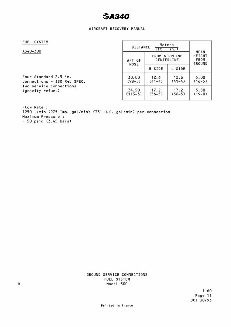
FUEL SYSTEM
A340-300
Four Standard 2.5 in.connections – ISO R45 SPEC.Two service connections(gravity refuel)
DISTANCEMeters
(ft – in.)MEANHEIGHTFROMGROUND
AFT OFNOSE
FROM AIRPLANECENTERLINE
R SIDE L SIDE
30.00(98-5)
12.6(41-4)
12.6(41-4)
5.00(16-5)
34.50(113-3)
17.2(56-5)
17.2(56-5)
5.80(19-0)
Flow Rate :1250 l/min (275 Imp. gal/min) (331 U.S. gal/min) per connectionMaximum Pressure :– 50 psig (3.45 bars)
GROUND SERVICE CONNECTIONSFUEL SYSTEMModel 300
Printed in France
AIRCRAFT RECOVERY MANUAL
R

1-60Page 11AOCT 30/93
FUEL SYSTEM
A340-200
Four Standard 2.5 in.connections – ISO R45 SPEC.Two service connections(gravity refuel)
DISTANCEMeters
(ft – in.)MEANHEIGHTFROMGROUND
AFT OFNOSE
FROM AIRPLANECENTERLINE
R SIDE L SIDE
27.80(91-2)
12.6(41-4)
12.6(41-4)
5.00(16-5)
31.2(102-4)
17.2(56-5)
17.2(56-5)
5.80(19-0)
Flow Rate :1250 l/min (275 Imp. gal/min) (331 U.S. gal/min) per connectionMaximum Pressure :– 50 psig (3.45 bars)
GROUND SERVICE CONNECTIONSFUEL SYSTEMModel 200
Printed in France
AIRCRAFT RECOVERY MANUAL
R

1–60Page 12
OCT 30/93
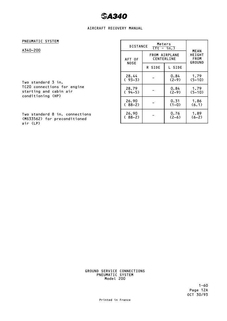
PNEUMATIC SYSTEM
A340-300
Two standard 3 in.TC20 connections for enginestarting and cabin airconditioning (HP)
Two standard 8 in. connections(MS33562) for preconditionedair (LP)
DISTANCEMeters
(ft – in.)MEANHEIGHTFROMGROUND
AFT OFNOSE
FROM AIRPLANECENTERLINE
R SIDE L SIDE
30.57(100-4) – 0.84
(2-9)1.79(5-10)
30.92(101-5) – 0.84
(2-9)1.79(5-10)
29.03(95-3) – 0.31
(1-0)1.86(6.1)
29.03(95-3) – 0.76
(2-6)1.89(6-2)
GROUND SERVICE CONNECTIONSPNEUMATIC SYSTEM
Model 300
Printed in France
AIRCRAFT RECOVERY MANUAL
1–60Page 12AOCT 30/93
PNEUMATIC SYSTEM
A340-200
Two standard 3 in.TC20 connections for enginestarting and cabin airconditioning (HP)
Two standard 8 in. connections(MS33562) for preconditionedair (LP)
DISTANCEMeters
(ft – in.)MEANHEIGHTFROMGROUND
AFT OFNOSE
FROM AIRPLANECENTERLINE
R SIDE L SIDE
28.44( 93-3) – 0.84
(2-9)1.79(5-10)
28.79( 94-5) – 0.84
(2-9)1.79(5-10)
26.90( 88-2) – 0.31
(1-0)1.86(6.1)
26.90( 88-2) – 0.76
(2-6)1.89(6-2)
GROUND SERVICE CONNECTIONSPNEUMATIC SYSTEM
Model 200
Printed in France
AIRCRAFT RECOVERY MANUAL

1-60Page 13
OCT 30/93
POTABLE WATER SYSTEM
A340-300
Service panel, located between frame69–70, comprising :– one heated 3/4 in. quick releasefilling connection
– one heated 3/4 in. overflow anddischarge connection
– one ground pressurization connection
Fwd drainage panel, located betweenframe 28–29 comprising :– one standard 3/4 in. drain connectionwith back-up mechanical control
Aft drainage panel, located betweenframe 55–56 for A340-200 and 51.1–57.2for A330/A340-300, comprising :– one standard 3/4 in. drain connectionwith back-up mechanical control
– one standard 3/4 in. overflow anddischarge connection with back-upmechanical control
Usable capacity :– 700 liters (154 Imp. gal) (185 US gal) standard– 1050 liters (231 Imp. gal) (277 US gal) standard option
Fill rate :
– pressure
– flow
DISTANCEMeters
(ft – in.)MEANHEIGHTFROMGROUND
AFT OFNOSE
FROM AIRPLANECENTERLINE
R SIDE L SIDE
48.15(157-9)
0.51(1-7) – 3.15
(10-3)
14.70(48-2) – 0.60
(2-0)1.90(6-2)
40.18(131-7)
0.72(2-4) – 2.46
(8-1)
installation of ... in aircraft
Fwd-tank (and opt-tank)[sect.15/16]
aft-tank [sect.18]
50 PSI3.45 bars
125 PSI8.62 bars
50 PSI3.45 bars
125 PSI8.62 bars
45 l/min10 Imp. gal/min12 US gal/min
73 l/min16 Imp. gal/min19 US gal/min
56 l/min12 Imp. gal/min15 US gal/min
85 l/min19 Imp. gal/min22 US gal/min
GROUND SERVICE CONNECTIONSPOTABLE WATER SYSTEM
Model 300
Printed in France
AIRCRAFT RECOVERY MANUAL
1-60Page 13AOCT 30/93
POTABLE WATER SYSTEM
A340-200
Service panel, located between frame69–70, comprising :– one heated 3/4 in. quick releasefilling connection
– one heated 3/4 in. overflow anddischarge connection
– one ground pressurization connection
Fwd drainage panel, located betweenframe 28–29 comprising :– one standard 3/4 in. drain connectionwith back-up mechanical control
Aft drainage panel, located betweenframe 55–56 for A340-200 and 51.1–57.2for A330/A340-300, comprising :– one standard 3/4 in. drain connectionwith back-up mechanical control
– one standard 3/4 in. overflow anddischarge connection with back-upmechanical control
Usable capacity :– 700 liters (154 Imp. gal) (185 US gal) standard– 1050 liters (231 Imp. gal) (277 US gal) standard option
Fill rate :
– pressure
– flow
DISTANCEMeters
(ft – in.)MEANHEIGHTFROMGROUND
AFT OFNOSE
FROM AIRPLANECENTERLINE
R SIDE L SIDE
43.88(143-9)
0.51(1-7) – 3.13
(10-3)
14.70(48-2) – 0.60
(2-0)1.92(6-3)
36.51(119-7)
0.72(2-4) – 2.44
(8-0)
installation of ... in aircraft
Fwd-tank (and opt-tank)[sect.15/16]
aft-tank [sect.18]
50 PSI3.45 bars
125 PSI8.62 bars
50 PSI3.45 bars
125 PSI8.62 bars
45 l/min10 Imp. gal/min12 US gal/min
73 l/min16 Imp. gal/min19 US gal/min
56 l/min12 Imp. gal/min15 US gal/min
85 l/min19 Imp. gal/min22 US gal/min
GROUND SERVICE CONNECTIONSPOTABLE WATER SYSTEM
Model 200
Printed in France
AIRCRAFT RECOVERY MANUAL

1-60Page 14
OCT 30/93
This Page Left Blank Intentionally
Printed in France
AIRCRAFT RECOVERY MANUAL

1-60Page 14AOCT 30/92
This Page Left Blank Intentionally
Printed in France
AIRCRAFT RECOVERY MANUAL
1-60Page 15
JUL 01/94
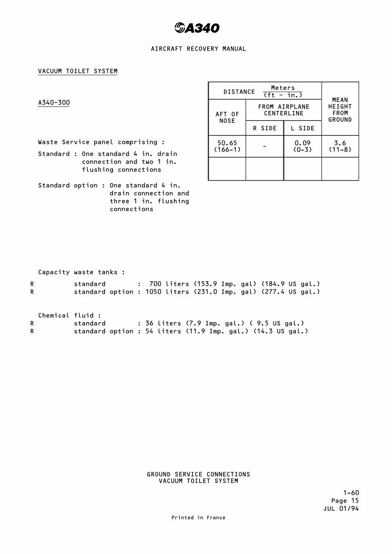
VACUUM TOILET SYSTEM
A340–300
Waste Service panel comprising :
Standard : One standard 4 in. drainconnection and two 1 in.flushing connections
Standard option : One standard 4 in.drain connection andthree 1 in. flushingconnections
Capacity waste tanks :
standard : 700 liters (153.9 Imp. gal) (184.9 US gal.)standard option : 1050 liters (231.0 Imp. gal) (277.4 US gal.)
Chemical fluid :standard : 36 liters (7.9 Imp. gal.) ( 9.5 US gal.)standard option : 54 liters (11.9 Imp. gal.) (14.3 US gal.)
DISTANCEMeters
(ft – in.)MEANHEIGHTFROMGROUND
AFT OFNOSE
FROM AIRPLANECENTERLINE
R SIDE L SIDE
50.65(166-1) – 0.09
(0-3)3.6
(11-8)
GROUND SERVICE CONNECTIONSVACUUM TOILET SYSTEM
Printed in France
AIRCRAFT RECOVERY MANUAL
RR
RR

1-60Page 15AJUL 01/94
VACUUM TOILET SYSTEM
A340–200
Waste Service panel comprising :
Standard : One standard 4 in. drainconnection and two 1 in.flushing connections
Standard option : One standard 4 in.drain connection andthree 1 in. flushingconnections
Capacity waste tanks :
standard : 700 liters (153.9 Imp. gal) (184.9 US gal.)standard option : 1050 liters (231.0 Imp. gal) (277.4 US gal.)
Chemical fluid :standard : 36 liters (7.9 Imp. gal.) ( 9.5 US gal.)standard option : 54 liters (11.9 Imp. gal.) (14.3 US gal.)
DISTANCEMeters
(ft – in.)MEANHEIGHTFROMGROUND
AFT OFNOSE
FROM AIRPLANECENTERLINE
R SIDE L SIDE
46.39(152-1) – 0.09
(0-4)3.6
(11-8)
GROUND SERVICE CONNECTIONSVACUUM TOILET SYSTEM
Printed in France
AIRCRAFT RECOVERY MANUAL
RR
RR

1–60Page 16
OCT 30/93
AIRCRAFT GROUNDING LOCATION
The aircraft must be grounded in these conditions– when it is Refueled/Defueled– maintenance– bad weather conditions.
NOTE : In all other conditions, the electrostatic discharge through the tyre issufficient.
The Main Landing Gear and the Nose Landing Gear grouding Studs (1) take aclip-on connector, such as Appleton TGR (2).
– connect ground end of static electric ground connection to approved connectionon ramp or in hangar.
Printed in France
AIRCRAFT RECOVERY MANUAL

1-70Page 1
SEP 30/92
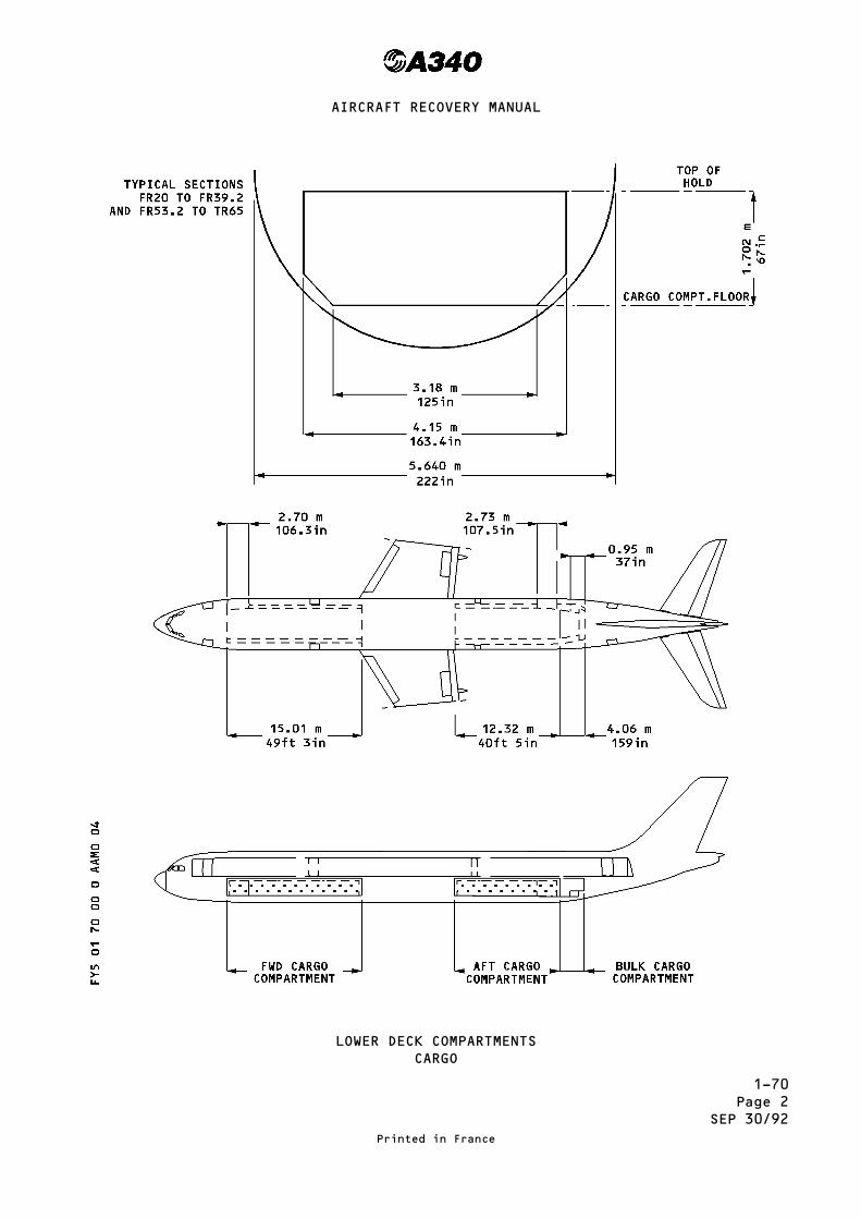
CARGO COMPARTMENTS
LOADING AND UNLOADING
1. General
Cargo and baggage may be containerized or palletized or loaded in bulk. Itis loaded in three underfloor compartments (forward cargo compartment, aftcargo compartment and bulk cargo compartment).
2. Forward Cargo Compartment
A. Capacity
The FWD compartment can be loaded with different types of containers :
– half size containers, full size containers, pallets (see example ofcombinations page 4)
B. Access Door (Ref. Section 1-40, page 5)
3. Aft Cargo Compartment
A. Capacity
The aft compartment can be loaded with different types of containers :
half size containers, full size containers, pallets (see example ofcombinations page 4)
B. Access Door (Ref. Section 1-40, page 6)
4. Bulk Cargo Compartment
A. Capacity
The volume of the bulk cargo compartment is 11.3 m3 (400 cu.ft). Thecompartment extends from FR 67 to FR 69. It can accommodate up to3 468 kg (7 645 lb) of baggage or freight (based on an average density of11 lb/Ft3 (176 kg/m3)
B. Access Door (Ref. Section 1-40, page 7)
Printed in France
AIRCRAFT RECOVERY MANUAL
1-70Page 2
SEP 30/92
LOWER DECK COMPARTMENTSCARGO
Printed in France
AIRCRAFT RECOVERY MANUAL

1-70Page 2A
SEP 30/92
Cargo Compartment Palletized volume Containerized volume
–200 –300 –200 –300
Forward
Door size (h × w)
2025 cu.ft.
(57.34 cu.m)
2430 cu.ft.
(68.8 cu.m)
2184 cu.ft.
(61.8 cu.m)
2808 cu.ft.
(79.5 cu.m)
66.89 in × 106.34 in
(1.699 m × 2.701 m)
based on 96 in × 125 in
pallets loaded to height
of 64 in (1.625 m)
based on LD3
(IATA E NAS 3610-2K2C)
container volume
Aft
Door size (h × w)
1620 cu.ft.
(45.87 cu.m)
1620 cu.ft.
(45.87 cu.m)
1872 cu.ft.
(53 cu.m)
2184 cu.ft.
(61.8 cu.m)
66.61 in × 107.68 in
(1.692 m × 2.735 m) based on 96 in × 125 in
pallets loaded to height
of 64 in (1.625 m)
based on LD3
(IATA E NAS 3610-2K2C)
container volume
Bulk
Door size (h × w)
37.3 in × 37.3 in
(0.95 m × 0.95 m)
Approximate usable volume
400 cu.ft. = 11.3 cu.m
LOWER DECK COMPARTMENTSCARGO HOLD VOLUME
Printed in France
AIRCRAFT RECOVERY MANUAL
1-70Page 3
MAR 30/98
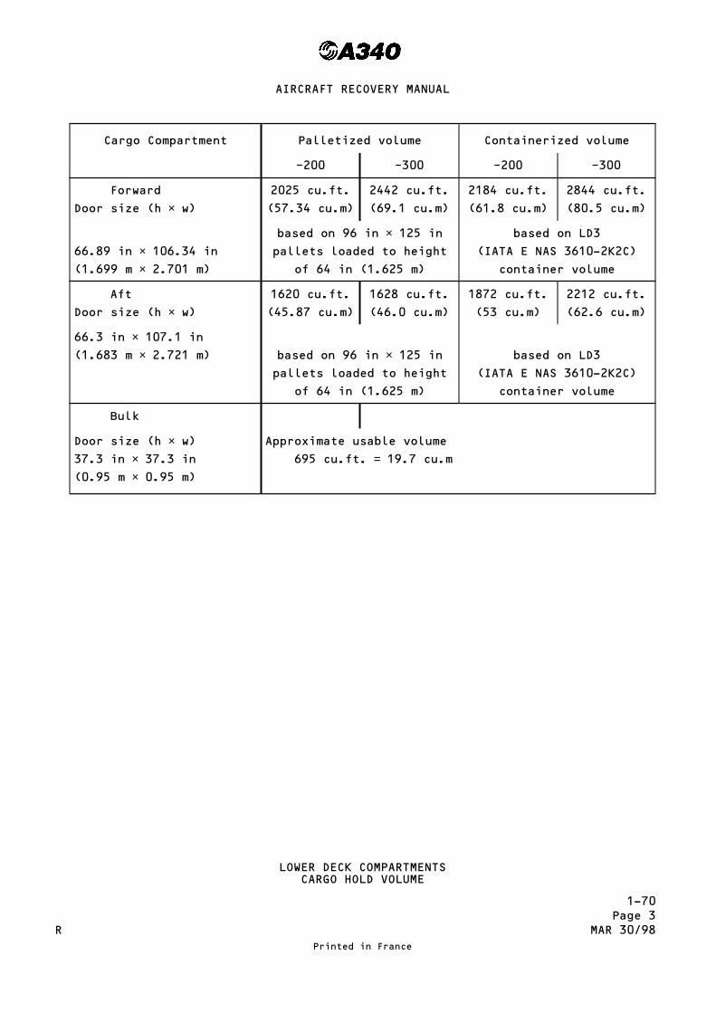
Cargo Compartment Palletized volume Containerized volume
–200 –300 –200 –300
Forward
Door size (h × w)
2025 cu.ft.
(57.34 cu.m)
2442 cu.ft.
(69.1 cu.m)
2184 cu.ft.
(61.8 cu.m)
2844 cu.ft.
(80.5 cu.m)
66.89 in × 106.34 in
(1.699 m × 2.701 m)
based on 96 in × 125 in
pallets loaded to height
of 64 in (1.625 m)
based on LD3
(IATA E NAS 3610-2K2C)
container volume
Aft
Door size (h × w)
1620 cu.ft.
(45.87 cu.m)
1628 cu.ft.
(46.0 cu.m)
1872 cu.ft.
(53 cu.m)
2212 cu.ft.
(62.6 cu.m)
66.3 in × 107.1 in
(1.683 m × 2.721 m) based on 96 in × 125 in
pallets loaded to height
of 64 in (1.625 m)
based on LD3
(IATA E NAS 3610-2K2C)
container volume
Bulk
Door size (h × w)
37.3 in × 37.3 in
(0.95 m × 0.95 m)
Approximate usable volume
695 cu.ft. = 19.7 cu.m
LOWER DECK COMPARTMENTSCARGO HOLD VOLUME
Printed in France
AIRCRAFT RECOVERY MANUAL
R

1-70Page 4
OCT 30/93
Cargo flexibility – Loading combinations
Typical Loading combinations – standard aircraftA340–200 A340–300
FWD AFT FWD AFT
– Half-size containers NAS 3610-2K2C as per IATAcontour E or 60.4 in. × 61.5 in. pallets NAS3610-2K3P limited to max gross weight 3 500 lb(1 587 kg) each
14 12 18 14
– Half-size containers NAS 3610-2K2C as per IATAcontour C limited to max gross weight 3 500 lb(1 587 kg) each
7 6 9 7
– Full-size containers NAS 3610-2L2C as per IATAcontour F or 60.4 in. × 61.5 in. pallets NAS3610-2L3P, 2L4P limited to max gross weight 7 000 lb(3 174 kg) each
7 6 9 7
– 96 in. × 125 in. pallets NAS 3610-2M1P, 2P, 3Plimited to max gross weight 10 200 lb (4 626 kg)each (with potential for extension to 11 250 lb(5 103 kg)
5 4 6 4
Plus-Half-size containers NAS 3610-2K2C as per IATAcontour E or N limited to max gross weight3 500 lb (1 587 kg) each
– – – 2
– Or 60.4 in. × 61.5 in. pallets NAS 3610-2K3Plimited to max gross weight 3 500 lb (1 587 kg)each
– – – 2
– Or 60.4 in. × 125 in. pallets NAS 3610-2L3P,2L4P limited to max gross weight 7 000 lb(3 174 kg) each
– – – 1
– Or Full-size containers NAS 3610-2L2C as perIATA contour P limited to max gross weight7 000 lb (3 174 kg) each
– – – 1
LOWER DECK COMPARTMENTSLOADING COMBINATIONS
Printed in France
AIRCRAFT RECOVERY MANUAL

1-70Page 5
JUL 01/94
CONTAINERS
Half size container (60.4 x 61.5 in) IATA CONTOUR E, G, C, H
Full size container (60.4 / 88.0 / 96.0 x 125 in) IATA CONTOUR F
PALLETS
Different Types of Containers and Pallets
Printed in France
AIRCRAFT RECOVERY MANUAL

1-70Page 6
OCT 30/93
This Page Left Blank Intentionally
Printed in France
AIRCRAFT RECOVERY MANUAL

2-05Page 1
NOV 30/92
QUICK REFERENCE GUIDELINE FOR A/C RECOVERY
1. OBTAIN INITIAL INFORMATION ABOUT INCIDENT.
2. ESTABLISH COMMUNICATION WITH LOCAL AIRLINE/AGENT/OWN REPRESENTATIVE.
3. DISPATCH DESIGNATED PERSON FROM RECOVER TEAM TO MAKE A DETAILED SURVEY ONSITE.
4. PREPARATION AND SELECTION OF PERSONNEL/EQUIPMENT/MANUALS.
5. CHECK AVAILABILITY FOR IATP-KITS AND ORDER IF REQUIRED.
ON THE SITE
1. ESTABLISH NECESSARY CONTACT WITH LOCAL SECURITY/FIRE FIGHTING BRIGADE TOSECURE THE SITE, AND PROVIDE AREA MAP.
2. FORMULATE DETAILED A/C RECOVERY PLAN.
3. OBTAIN NECESSARY CLEARANCE FROM LOCAL AUTHORITIES TO PROCEED WITH RECOVERYOPERATION.
4. A) ESTABLISH COMMUNICATION TO/FROM AND ON SITE.
B) ESTABLISH TRANSPORTATION TO/FROM SITE.
C) ESTABLISH ACCOMODATION AND FACILITIES AS NECESSARY ON SITE.
5. CONTACT LOCAL AIRLINES, AIRPORT AUTHORITIES AND LOCAL SUPPLIERS FORASSISTANCE.
A) HEAVY MACHINERY/CRANES, ETC.
B) ACCESS ROADS – BUILDING MATERIALS.
C) TIMBER/GRAVEL/SAND/STEEL PLATES, ETC.
D) LIGHTING EQUIPMENT.
Printed in France
AIRCRAFT RECOVERY MANUAL

2-05Page 2
NOV 30/92
6. MAKE ACCESS TO BAGGAGE/CARGO FOR REMOVAL.
A) CHECK MANIFESTS FOR RESTRICTED ARTICLES.
B) REMOVE REF. RESP. REC. MANUAL.
7. WEIGHT AND BALANCE CALCULATION.
8. CAUTION : CHECK THAT RECOVERY PLAN DETAILED IN ITEM 2IS STILL VALID AND ALL SAFETY PRECAUTIONS ARE TAKEN.
9. REMOVAL OF MAJOR COMPONENTS AS NECESSARY.
A) TO LIGHTEN A/C.
B) DUE TO WIND FORCES.
C) DUE AUTHORITY REQUEST (VERT. FIN).
10. MAKE PREPARATION FOR :
A) TETHERING
B) LIFTING REF. RESP. REC. MANUAL
C) MOVING
11. PREPARE FOR HANGARING AND PARKING.
Printed in France
AIRCRAFT RECOVERY MANUAL

2-10Page 1
SEP 30/92
DAMAGE AND TERRAIN
1. The exact condition of a damaged aircraft must be ascertained in order toprepare for its recovery and make arrangements for its repair at the earliestopportunity.
WARNING : PRIOR TO STARTING RECOVERY PROPER, DISCONNECT AND REMOVE ALLAIRCRAFT BATTERIES ; IF REMOVAL IS NOT POSSIBLE, DISCONNECT ANDINSULATE THE BATTERY GROUND TO AVOID ACCIDENTS WHICH MAY ARISEBECAUSE OF SHORT CIRCUITS.
2. After the obvious damage has been observed, the structural condition of theaircraft should be determined and an attempt made to visualize how the impactmight have been transmitted to other members. To this effect, throughly checkthe external structure to the aircraft, panel by panel ; joggles, bulges inthe skin or at structural joints are indications of structure internaldamage ; rivets, bolts or other fasteners that are torn off or damaged arealso signs of damage and justify an internal inspection of the zonesconcerned.
3. If the accident has been caused by any malfunction of the landing gear, it isoften possible to tow the aircraft after it has been lifted. It should bedetermined whether the structure is capable of supporting the weight of theaircraft lowered on to the gear. Several cases may occur :
A. The gears were up locked when the aircraft landed ; the aircraft rests onthe engines and on the aft fuselage. It is very probable the gears may beextended and downlocked, after the aircraft has been jacked, and used fornormal towing.
B. When landing, the aircraft touched the runway violently or got bogged. Thegears or the gear struts have been damaged ; in certain cases, it will bepossible to strengthen the damaged parts temporarily by means of braces inorder to downlock the gear for towing.
C. If the gears have collapsed after touchdown because of a malfunction ofthe landing gear locking, it is possible, if the condition of the aircraftso allows, to strengthen the damaged parts, temporarily, as describedabove.
Printed in France
AIRCRAFT RECOVERY MANUAL

2-10Page 2
SEP 30/92
4. The violence of the shock, the position of the damaged aircraft and theconditions of the terrain on which it landed, are major factors to beconsidered in determining the method of recovery.The other factors are :
A. Immediate availability of lifting equipment
B. Urgency of removal
C. The necessity of reducing the weight of the aircraft to ensure a safelifting operation.
Printed in France
AIRCRAFT RECOVERY MANUAL

2-10Page 3
SEP 30/92
Load Bearing Capabilities of Terrain
Printed in France
AIRCRAFT RECOVERY MANUAL

2-20Page 1
SEP 30/92
DAMAGE CONTROL AND SAFETY
1. General
All necessary precautions must be taken when carrying out recovery operationson crashed aircraft to avoid injury to personnel or damage to equipment.
WARNING : IT IS STRICTLY FORBIDDEN TO SMOKE OR EXPOSE NAKED LIGHTS.
2. Batteries
WARNING : PRIOR TO STARTING RECOVERY PROPER, DISCONNECT AND REMOVE ALLAIRCRAFT BATTERIES ; IF REMOVAL IS NOT POSSIBLE, DISCONNECT ANDINSULATE THE BATTERY GROUND TO AVOID ACCIDENTS WHICH MAY ARISEBECAUSE OF SHORT CIRCUITS.
3. Oxygen
WARNING : A WARNING NOTICE SHALL BE INSTALLED IN THE WORK AREA. PERSONNELSHALL CLEAN TOOLS AND ENSURE THAT THEIR HANDS ARE CLEAN TO AVOIDCONTAMINATION.STRICTLY PROHIBIT ANY ELECTRICAL POWER SUPPLY ON THE AIRCRAFT.PROHIBIT ANY OPERATION ON THE AIRCRAFT.USE ONLY TOOLS AND EQUIPMENT SPECIFICALLY ALLOCATED FOR HANDLINGOXYGEN.GROUND THE AIRCRAFT ELECTROSTATICALLY AND EFFECT A GROUNDCONNECTION BETWEEN THE EQUIPMENT AND THE AIRCRAFT.PERSONNEL IN CHARGE OF CARRYING OUT THE ACTIONS BELOW MUST BE AWAREOF THE RISKS INVOLED IN HANDLING OXYGEN WHICH ENHANCES COMBUSTIONIN THE PRESENCE OF FUEL, AND BECOMES EXPLOSIVE IN THE PRESENCE OFHYDROCARBONS (FUELS, LUBRICANTS).
4. Fuel Tank Defueling
WARNING : BEFORE PROCEEDING WITH MAINTENANCE WORK ON OR NEAR MECHNICAL FLIGHTCONTROLS OR PRIMARY FLIGHT CONTROL SURFACES, LANDING GEARS,ASSOCIATED DOORS OR ANY MOVING COMPONENT, MAKE CERTAIN THAT GROUNDSAFETIES AND/OR WARNING NOTICES ARE IN CORRECT POSITION TO PREVENTINADVERTENT OPERATION OF CONTROLS.BEFORE POWER IS SUPPLIED TO THE AIRCRAFT MAKE CERTAIN THATELECTRICAL CIRCUITS UPON WHICH WORK IS IN PROGRESS ARE ISOLATED.BEFORE PRESSURIZING FUEL SYSTEMS, MAKE CERTAIN THAT FUEL SYSTEMUNDER MAINTENANCE HAS BEEN ISOLATED.CHECK THAT THE LANDING GEAR GROUND SAFETIES INCLUDING WHEEL CHOCKSARE IN POSITION.
Printed in France
AIRCRAFT RECOVERY MANUAL

2-20Page 2
SEP 30/92
BEFORE UNDERTAKING MAINTENANCE OPERATIONS ON THE FUEL SYSTEM, MAKECERTAIN THAT FIRE FIGHTING EQUIPMENT IS READILY AVAILABLE AND INPROXIMITY TO THE WORK AREA.BEFORE CONNECTING THE TANKER'S REFUELING HOSE TO THE AIRCRAFT, MAKECERTAIN THAT BOTH THE TANKER AND THE AIRCRAFT ARE CORRECTLYCONNECTED TO AN APPROVED GROUND AND THAT ELECTRICAL BONDING BETWEENTHE AIRCRAFT AND THE TANKER IS EFFECTED.
5. External Power
WARNING : BEFORE POWER IS SUPPLIED TO THE AIRCRAFT, MAKE CERTAIN THATELECTRICAL CIRCUITS UPON WHICH WORK IS IN PROGRESS ARE ISOLATED.
WARNING : IT IS FORBIDDEN TO DISCONNECT THE GROUND POWER UNIT CONNECTOR WHENTHE CIRCUIT IS ENERGIZED AS THIS COULD CAUSE ARCING WHICH WOULD BEDANGEROUS FOR PERSONNEL, OR DAMAGE TO EQUIPMENT. CUT OFF THEELECTRICAL SUPPLY BEFORE DISCONNECTING THE GROUND POWER UNITCONNECTOR.
WARNING : WITH ELECTRICAL NETWORK ENERGIZED AND NLG SHOCK ABSORBER EXTENDEDTHE BLUE HYD. SYS. ELECTRIC PUMP WILL AUTOMATICALLY RUN.OPEN, SAFETY AND TAG C/B 2701 GJ AND 2702 GJ TO ISOLATE THE PUMP.
6. Towing
WARNING : BEFORE POSITIONING THE LOCKING DEVICES, MAKE CERTAIN THAT THELANDING GEAR IS DOWNLOCKED.
CAUTION : THE LANDING GEAR BRACE STRUT LOCKING DEVICES MUST ALWAYS BE FITTEDWHEN THE AIRCRAFT IS ON THE GROUND OR BEING TOWED.USE ONLY TOWING EQUIPMENT DESIGNED OR APPROVED BY THE AIRCRAFTMANUFACTURER.
Printed in France
AIRCRAFT RECOVERY MANUAL
2-30Page 1
JAN 30/93
WEIGHT AND H-ARM MANUAL
1. General
An accurate knowledge of the weight and horizontal arm from station 0 (zero)(H-arm) location of a damaged aircraft is essential to determine the requiredcapacity of lifting and transportation facilities. In practically all cases,it is advisable to reduce the weight of the aircraft as much as possible byremoving fuel and water, cargo and in certain cases some major aircraftcomponents : engines, flight surfaces etc...
2. Lifting weight of the Aircraft
A. Definition
The aircraft lifting weight (REW = Recoverable Empty Weight) is theaircraft empty weight (MEW = Manufacturer's Empty Weight) plus the weightof various items of operational equipment that are an integral part of theaircraft.
The Manufacturer's Empty Weight is the dry weight (without fuel)guaranteed by the manufacturer. The H-arm is given with the aircraftconsidered in gears extended, flaps and slats retracted configuration.
B. Determination of the Lifting Weight
Obtain from the Weight and Balance Manual (WBM) the MEW of the consideredaircraft.
Obtain from this WBM supplement the weight of particular items ofequipment.
The sum of these different weights is the REW (Recoverable Empty Weight).
Printed in France
AIRCRAFT RECOVERY MANUAL
2-30Page 2
JUL 30/93
EMPTY WEIGHT REVISION AND H-ARM LOCATION COMPUTATION
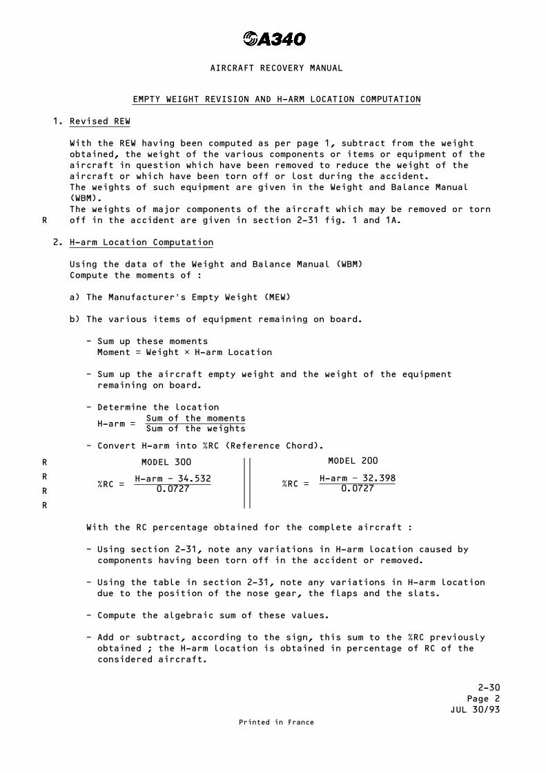
1. Revised REW
With the REW having been computed as per page 1, subtract from the weightobtained, the weight of the various components or items or equipment of theaircraft in question which have been removed to reduce the weight of theaircraft or which have been torn off or lost during the accident.The weights of such equipment are given in the Weight and Balance Manual(WBM).The weights of major components of the aircraft which may be removed or tornoff in the accident are given in section 2-31 fig. 1 and 1A.
2. H-arm Location Computation
Using the data of the Weight and Balance Manual (WBM)Compute the moments of :
a) The Manufacturer's Empty Weight (MEW)
b) The various items of equipment remaining on board.
– Sum up these momentsMoment = Weight × H-arm Location
– Sum up the aircraft empty weight and the weight of the equipmentremaining on board.
– Determine the location
H-arm = Sum of the momentsSum of the weights
– Convert H-arm into %RC (Reference Chord).
MODEL 300
%RC = H-arm − 34.5320.0727
MODEL 200
%RC = H-arm − 32.3980.0727
With the RC percentage obtained for the complete aircraft :
– Using section 2-31, note any variations in H-arm location caused bycomponents having been torn off in the accident or removed.
– Using the table in section 2-31, note any variations in H-arm locationdue to the position of the nose gear, the flaps and the slats.
– Compute the algebraic sum of these values.
– Add or subtract, according to the sign, this sum to the %RC previouslyobtained ; the H-arm location is obtained in percentage of RC of theconsidered aircraft.
Printed in France
AIRCRAFT RECOVERY MANUAL
R
R
R
R
R

2-31Page 1
JUL 30/93
EFFECTS OF MOVING COMPONENTS ON THE AIRCRAFT CG
Balance effects caused by operation of slats, flaps, thrust reversers andlanding gears are given below.
A. Slats and flaps extension
COCKPIT INDICATION (°) MOMENTS
SLATSINBOARD/OUTBOARD
FLAPS SLATS FLAPS TOTAL
Kgm FtLb Kgm FtLb Kgm FtLb
17.7/20 0 − 638 − 4615 0 0 − 638 − 4615
17.7/20 17 − 638 − 4615 + 1015 + 7341 + 377 + 2727
19.6/23 22 − 719 − 5201 + 1087 + 7862 + 368 + 2662
19.6/23 26 − 719 − 5201 + 1142 + 8260 + 423 + 3060
19.6/23 32 − 719 − 5201 + 1195 + 8643 + 476 + 3443
B. Thrust reverser extension
Thrust reverser = Negligeable
C. Landing gear retraction
MOMENTS
NLG MLG CLG
Kgm FtLb Kgm FtLb Kgm FtLb
− 974 − 7045 − 3372 − 24390 − 1224 − 8853
Printed in France
AIRCRAFT RECOVERY MANUAL
2-31Page 2
JUL 30/93
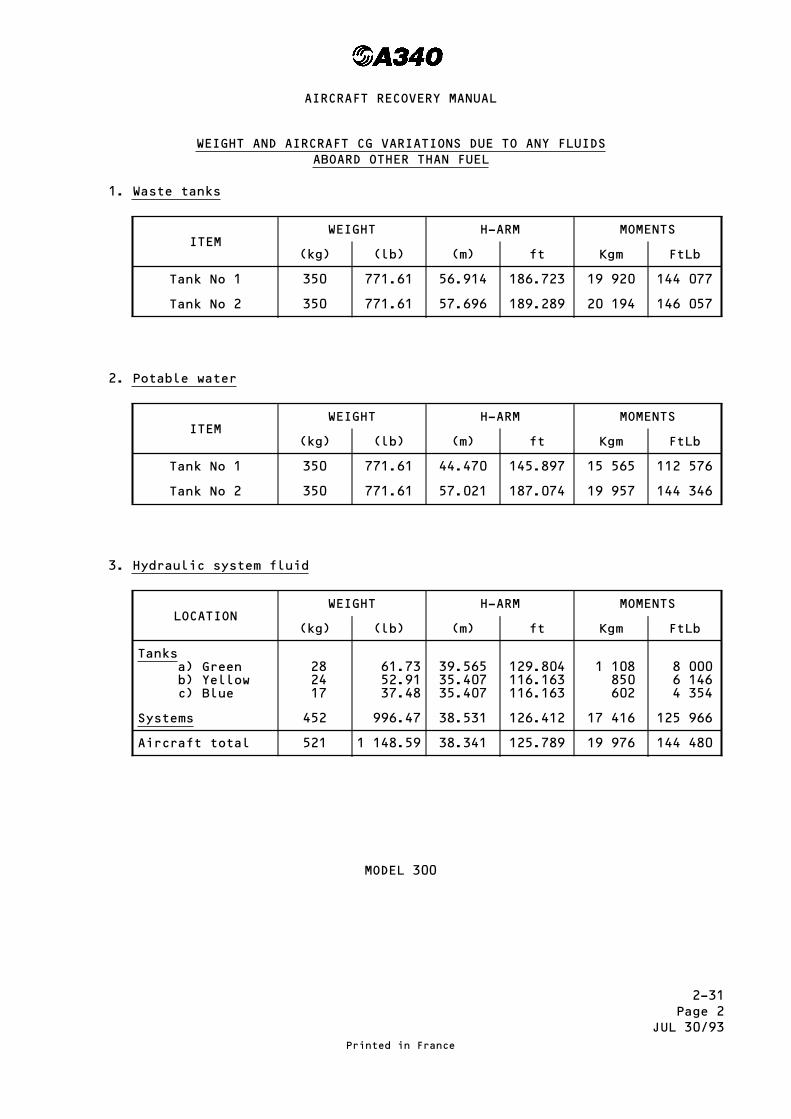
WEIGHT AND AIRCRAFT CG VARIATIONS DUE TO ANY FLUIDSABOARD OTHER THAN FUEL
1. Waste tanks
ITEMWEIGHT H-ARM MOMENTS
(kg) (lb) (m) ft Kgm FtLb
Tank No 1 350 771.61 56.914 186.723 19 920 144 077
Tank No 2 350 771.61 57.696 189.289 20 194 146 057
2. Potable water
ITEMWEIGHT H-ARM MOMENTS
(kg) (lb) (m) ft Kgm FtLb
Tank No 1 350 771.61 44.470 145.897 15 565 112 576
Tank No 2 350 771.61 57.021 187.074 19 957 144 346
3. Hydraulic system fluid
LOCATIONWEIGHT H-ARM MOMENTS
(kg) (lb) (m) ft Kgm FtLb
Tanksa) Greenb) Yellowc) Blue
282417
61.7352.9137.48
39.56535.40735.407
129.804116.163116.163
1 108850602
8 0006 1464 354
Systems 452 996.47 38.531 126.412 17 416 125 966
Aircraft total 521 1 148.59 38.341 125.789 19 976 144 480
MODEL 300
Printed in France
AIRCRAFT RECOVERY MANUAL

2-31Page 2A
JUL 30/93
WEIGHT AND AIRCRAFT CG VARIATIONS DUE TO ANY FLUIDSABOARD OTHER THAN FUEL
1. Waste tanks
ITEMWEIGHT H-ARM MOMENTS
(kg) (lb) (m) ft Kgm FtLb
Tank No 1 350 771.61 52.647 172.724 18 426 133 276
Tank No 2 350 771.61 53.429 175.289 18 700 135 255
2. Potable water
ITEMWEIGHT H-ARM MOMENTS
(kg) (lb) (m) ft Kgm FtLb
Tank No 1 350 771.61 40.227 131.976 14 079 101 834
Tank No 2 350 771.61 52.754 173.075 18 464 133 546
3. Hydraulic system fluid
LOCATIONWEIGHT H-ARM MOMENTS
(kg) (lb) (m) ft Kgm FtLb
Tanksa) Greenb) Yellowc) Blue
282417
61.7352.9137.48
37.43133.27333.273
122.803109.162109.162
1 048799799
7 5815 7764 091
Systems 449 989.86 36.289 119.056 16 294 117 849
Aircraft total 518 1 141.98 36.112 118.476 18 706 135 297
MODEL 200
Printed in France
AIRCRAFT RECOVERY MANUAL

2-31Page 3
JAN 30/93
WEIGHT AND AIRCRAFT CG VARIATIONS DUE TO CARGO ABOARD
1. Establish the mass of the containers or pallets remaining in each cargocompartment.
2. In order to determine the effect of this cargo on the aircraft CG locationproceed as mentioned in section 2-33, pages 1 to 3 (read ″cargo″ instead of″fuel″ in the corresponding applicable text and formula).
Using the following tables the masses of each container or pallet arespecified in increments of 250 kg (551 lb) or 500 kg (1 102 lb) for easyinterpolation. The values in column ″H-ARM″ represent the distance of the CGof each container or pallet to the point about which the resulting "MOMENTS"are being taken.
Adjusting the masses of the cargo load can reduce the lifting load by theCARGO MOMENTS listed in the following tables :
Printed in France
AIRCRAFT RECOVERY MANUAL

2-31Page 4
JUL 30/93
CARGO MOMENTS
1. FWD Cargo CompartmentA. Half Size Containers (NAS 3610.2K1C, 2K2C) 60.4 × 61.5 in MAX IATA
contour E, G.
CONTAINERPOSITION
MASSKg
H-ARMm
MOMENTKgm
MASSLb
H-ARMFt
MOMENTFt. Lb
11 R+L
1 5871 2501 000750500250
15.43215.43215.43215.43215.43215.432
24 49119 29015 43211 5747 7163 858
3 5002 7562 2051 6531 102551
50.62950.62950.62950.62950.62950.629
177 201139 534111 63783 69055 79327 897
---------------------------------------------- ----------------------------------
12 R+L
1 5871 2501 000750500250
17.21817.21817.21817.21817.21817.218
27 32521 52217 21812 9138 6094 304
3 5002 7562 2051 6531 102551
56.48956.48956.48956.48956.48956.489
197 711155 684124 55893 37662 25131 125
---------------------------------------------- ----------------------------------
13 R+L
1 5871 2501 000750500250
18.80118.80118.80118.80118.80118.801
29 83723 50118 80114 1019 4004 700
3 5002 7562 2051 6531 102551
61.68261.68261.68261.68261.68261.682
215 887169 996136 009101 96067 97433 987
---------------------------------------------- ----------------------------------
21 R+L
1 5871 2501 000750500250
20.56320.56320.56320.56320.56320.563
32 63325 70420 56315 42210 2815 141
3 5002 7562 2051 6531 102551
67.46367.46367.46367.46367.46367.463
236 120185 928148 756111 51674 34437 172
---------------------------------------------- ----------------------------------
22 R+L
1 5871 2501 000750500250
22.14622.14622.14622.14622.14622.146
35 14627 68222 14616 60911 0735 536
3 5002 7562 2051 6531 102551
72.65772.65772.65772.65772.65772.657
254 300200 242160 209120 10280 06840 034
---------------------------------------------- ----------------------------------
23 R+L
1 5871 2501 000750500250
23.72823.72823.72823.72823.72823.728
37 65629 66023 72817 79611 8645 932
3 5002 7562 2051 6531 102551
77.84777.84777.84777.84777.84777.847
272 464214 546171 653128 68185 78742 894
---------------------------------------------- ----------------------------------
24 R+L
1 5871 2501 000750500250
25.49125.49125.49125.49125.49125.491
40 45431 86425 49119 11812 7456 373
3 5002 7562 2051 6531 102551
83.63183.63183.63183.63183.63183.631
292 708230 487184 406138 24292 16146 081
---------------------------------------------- ----------------------------------
25 R+L
1 5871 2501 000750500250
27.07327.07327.07327.07327.07327.073
42 96533 84127 07320 30513 5366 768
3 5002 7562 2051 6531 102551
88.82188.82188.82188.82188.82188.821
310 873244 791195 850146 82197 88148 940
---------------------------------------------- ----------------------------------
26 R+L
1 5871 2501 000750500250
28.65528.65528.65528.65528.65528.655
45 47535 81928 65521 49114 3277 164
3 5002 7562 2051 6531 102551
94.01194.01194.01194.01194.01194.011
329 038259 094207 294155 400103 60051 800
MODEL 300
Printed in France
AIRCRAFT RECOVERY MANUAL

2-31Page 4A
JUL 30/93
CARGO MOMENTS
1. FWD Cargo Compartment
A. Half Size Containers (NAS 3610.2K1C, 2K2C) 60.4 × 61.5 in MAX IATAcontour E, G.
CONTAINERPOSITION
MASSKg
H-ARMm
MOMENTKgm
MASSLb
H-ARMFt
MOMENTFt. Lb
11 R+L
1 5871 2501 000750500250
15.43215.43215.43215.43215.43215.432
24 49119 29015 43211 5747 7163 858
3 5002 7562 2051 6531 102551
50.62950.62950.62950.62950.62950.629
177 201139 534111 63783 69055 79327 897
---------------------------------------------- ----------------------------------
12 R+L
1 5871 2501 000750500250
17.21817.21817.21817.21817.21817.218
27 32521 52217 21812 9138 6094 304
3 5002 7562 2051 6531 102551
56.48956.48956.48956.48956.48956.489
197 711155 684124 55893 37662 25131 125
---------------------------------------------- ----------------------------------
13 R+L
1 5871 2501 000750500250
18.80118.80118.80118.80118.80118.801
29 83723 50118 80114 1019 4004 700
3 5002 7562 2051 6531 102551
61.68261.68261.68261.68261.68261.682
215 887169 996136 009101 96067 97433 987
---------------------------------------------- ----------------------------------
21 R+L
1 5871 2501 000750500250
20.56320.56320.56320.56320.56320.563
32 63325 70420 56315 42210 2815 141
3 5002 7562 2051 6531 102551
67.46367.46367.46367.46367.46367.463
236 120185 928148 756111 51674 34437 172
---------------------------------------------- ----------------------------------
22 R+L
1 5871 2501 000750500250
22.14622.14622.14622.14622.14622.146
35 14627 68222 14616 60911 0735 536
3 5002 7562 2051 6531 102551
72.65772.65772.65772.65772.65772.657
254 300200 242160 209120 10280 06840 034
---------------------------------------------- ----------------------------------
23 R+L
1 5871 2501 000750500250
23.72823.72823.72823.72823.72823.728
37 65629 66023 72817 79611 8645 932
3 5002 7562 2051 6531 102551
77.84777.84777.84777.84777.84777.847
272 464214 546171 653128 68185 78742 894
---------------------------------------------- ----------------------------------
24 R+L
1 5871 2501 000750500250
26.19226.19226.19226.19226.19226.192
41 56732 74026 19219 64413 0966 548
3 5002 7562 2051 6531 102551
85.93185.93185.93185.93185.93185.931
300 758236 826189 478142 04494 69647 348
MODEL 200
Printed in France
AIRCRAFT RECOVERY MANUAL

2-31Page 5
JUL 30/93
CARGO MOMENTS
B. Half Size Containers (NAS 3610.2K1C, 2K2C) 60.4 × 61.5 in MAX IATAcontour C, H.
CONTAINERPOSITION
MASSKg
H-ARMm
MOMENTKgm
MASSLb
H-ARMFt
MOMENTFt. Lb
11R or L
1 5871 2501 000750500250
15.43215.43215.43215.43215.43215.432
24 49119 29015 43211 5747 7163 858
3 5002 7562 2051 6531 102551
50.62950.62950.62950.62950.62950.629
177 201139 534111 63783 69055 79327 897
---------------------------------------------- ----------------------------------
12R or L
1 5871 2501 000750500250
17.21817.21817.21817.21817.21817.218
27 32521 52217 21812 9138 6094 304
3 5002 7562 2051 6531 102551
56.48956.48956.48956.48956.48956.489
197 711155 684124 55893 37662 25131 125
---------------------------------------------- ----------------------------------
13R or L
1 5871 2501 000750500250
18.80118.80118.80118.80118.80118.801
29 83723 50118 80114 1019 4004 700
3 5002 7562 2051 6531 102551
61.68261.68261.68261.68261.68261.682
215 887169 996136 009101 96067 97433 987
---------------------------------------------- ----------------------------------
21R or L
1 5871 2501 000750500250
20.56320.56320.56320.56320.56320.563
32 63325 70420 56315 42210 2815 141
3 5002 7562 2051 6531 102551
67.46367.46367.46367.46367.46367.463
236 120185 928148 756111 51674 34437 172
---------------------------------------------- ----------------------------------
22R or L
1 5871 2501 000750500250
22.14622.14622.14622.14622.14622.146
35 14627 68222 14616 60911 0735 536
3 5002 7562 2051 6531 102551
72.65772.65772.65772.65772.65772.657
254 300200 242160 209120 10280 06840 034
---------------------------------------------- ----------------------------------
23R or L
1 5871 2501 000750500250
23.72823.72823.72823.72823.72823.728
37 65629 66023 72817 79611 8645 932
3 5002 7562 2051 6531 102551
77.84777.84777.84777.84777.84777.847
272 464214 546171 653128 68185 78742 894
---------------------------------------------- ----------------------------------
24R or L
1 5871 2501 000750500250
25.49125.49125.49125.49125.49125.491
40 45431 86425 49119 11812 7456 373
3 5002 7562 2051 6531 102551
83.63183.63183.63183.63183.63183.631
292 708230 487184 406138 24292 16146 081
---------------------------------------------- ----------------------------------
25R or L
1 5871 2501 000750500250
27.07327.07327.07327.07327.07327.073
42 96533 84127 07320 30513 5366 768
3 5002 7562 2051 6531 102551
88.82188.82188.82188.82188.82188.821
310 873244 791195 850146 82197 88148 940
---------------------------------------------- ----------------------------------
26R or L
1 5871 2501 000750500250
28.65528.65528.65528.65528.65528.655
45 47535 81928 65521 49114 3277 164
3 5002 7562 2051 6531 102551
94.01194.01194.01194.01194.01194.011
329 038259 094207 294155 400103 60051 800
MODEL 300
Printed in France
AIRCRAFT RECOVERY MANUAL

2-31Page 5A
JUL 30/93
CARGO MOMENTS
B. Half Size Containers (NAS 3610.2K1C, 2K2C) 60.4 × 61.5 in MAX IATAcontour C, H.
CONTAINERPOSITION
MASSKg
H-ARMm
MOMENTKgm
MASSlb
H-ARMFt
MOMENTFt. Lb
11R or L
1 5871 2501 000750500250
15.43215.43215.43215.43215.43215.432
24 49119 29015 43211 5747 7163 858
3 5002 7562 2051 6531 102551
50.62950.62950.62950.62950.62950.629
177 201139 534111 63783 69055 79327 897
---------------------------------------------- ----------------------------------
12R or L
1 5871 2501 000750500250
17.21817.21817.21817.21817.21817.218
27 32521 52217 21812 9138 6094 304
3 5002 7562 2051 6531 102551
56.48956.48956.48956.48956.48956.489
197 711155 684124 55893 37662 25131 125
---------------------------------------------- ----------------------------------
13R or L
1 5871 2501 000750500250
18.80118.80118.80118.80118.80118.801
29 83723 50118 80114 1019 4004 700
3 5002 7562 2051 6531 102551
61.68261.68261.68261.68261.68261.682
215 887169 996136 009101 96067 97433 987
---------------------------------------------- ----------------------------------
21R or L
1 5871 2501 000750500250
20.56320.56320.56320.56320.56320.563
32 63325 70420 56315 42210 2815 141
3 5002 7562 2051 6531 102551
67.46367.46367.46367.46367.46367.463
236 120185 928148 756111 51674 34437 172
---------------------------------------------- ----------------------------------
22R or L
1 5871 2501 000750500250
22.14622.14622.14622.14622.14622.146
35 14627 68222 14616 60911 0735 536
3 5002 7562 2051 6531 102551
72.65772.65772.65772.65772.65772.657
254 300200 242160 209120 10280 06840 034
---------------------------------------------- ----------------------------------
23R or L
1 5871 2501 000750500250
23.72823.72823.72823.72823.72823.728
37 65629 66023 72817 79611 8645 932
3 5002 7562 2051 6531 102551
77.84777.84777.84777.84777.84777.847
272 464214 546171 653128 68185 78742 894
---------------------------------------------- ----------------------------------
24R or L
1 5871 2501 000750500250
26.19226.19226.19226.19226.19226.192
41 56732 74026 19219 64413 0966 548
3 5002 7562 2051 6531 102551
85.93185.93185.93185.93185.93185.931
300 758236 826189 478142 04494 69647 348
MODEL 200
Printed in France
AIRCRAFT RECOVERY MANUAL

2-31Page 6
JUL 30/93
CARGO MOMENTS
C. Full Size Containers (NAS 3610-2L1C, 2L2C) 60.4 × 125 in MAX IATA contour F.
CONTAINERPOSITION
MASSKg
H-ARMm
MOMENTKgm
MASSLb
H-ARMFt
MOMENTFt. Lb
11
3 1742 5002 0001 5001 000500
15.43215.43215.43215.43215.43215.432
48 98138 58030 86423 14815 4327 716
7 0005 5114 4093 3072 2051 102
50.62950.62950.62950.62950.62950.629
354 403279 016223 223167 430111 63755 793
---------------------------------------------- ----------------------------------
12
3 1742 5002 0001 5001 000500
17.21817.21817.21817.21817.21817.218
54 65043 04534 43625 82717 2188 609
7 0005 5114 4093 3072 2051 102
56.48956.48956.48956.48956.48956.489
395 423311 311249 060186 809124 55862 251
---------------------------------------------- ----------------------------------
13
3 1742 5002 0001 5001 000500
18.80118.80118.80118.80118.80118.801
59 67447 00237 60228 20118 8019 400
7 0005 5114 4093 3072 2051 102
61.68261.68261.68261.68261.68261.682
431 774339 929271 956203 982136 00967 974
---------------------------------------------- ----------------------------------
21
3 1742 5002 0001 5001 000500
20.56320.56320.56320.56320.56320.563
65 26751 40741 12630 84420 56310 281
7 0005 5114 4093 3072 2051 102
67.46367.46367.46367.46367.46367.463
472 241371 789297 444223 100148 75674 344
---------------------------------------------- ----------------------------------
22
3 1742 5002 0001 5001 000500
22.14622.14622.14622.14622.14622.146
70 29155 36544 29233 21922 14611 073
7 0005 5114 4093 3072 2051 102
72.65772.65772.65772.65772.65772.657
508 599400 489320 345240 277160 20980 068
---------------------------------------------- ----------------------------------
23
3 1742 5002 0001 5001 000500
23.72823.72823.72823.72823.72823.728
75 31359 32047 45635 59223 72811 864
7 0005 5114 4093 3072 2051 102
77.84777.84777.84777.84777.84777.847
544 929429 015343 227257 440171 65385 787
---------------------------------------------- ----------------------------------
24
3 1742 5002 0001 5001 000500
25.49125.49125.49125.49125.49125.491
80 90863 72750 98238 23625 49112 745
7 0005 5114 4093 3072 2051 102
83.63183.63183.63183.63183.63183.631
585 417460 890368 729276 568184 40692 161
---------------------------------------------- ----------------------------------
25
3 1742 5002 0001 5001 000500
27.07327.07327.07327.07327.07327.073
85 93067 68254 14640 60927 07313 536
7 0005 5114 4093 3072 2051 102
88.82188.82188.82188.82188.82188.821
621 747489 493391 612293 731195 85097 881
---------------------------------------------- ----------------------------------
26
3 1742 5002 0001 5001 000500
28.65528.65528.65528.65528.65528.655
90 95171 63757 31042 98228 65514 327
7 0005 5114 4093 3072 2051 102
94.01194.01194.01194.01194.01194.011
658 077518 095414 494310 894207 294103 600
MODEL 300
Printed in France
AIRCRAFT RECOVERY MANUAL

2-31Page 6A
JUL 30/93
CARGO MOMENTS
C. Full Size Containers (NAS 3610-2L1C, 2L2C) 60.4 × 125 in MAX IATA contour F.
CONTAINERPOSITION
MASSKg
H-ARMm
MOMENTKgm
MASSLb
H-ARMFt
MOMENTFt. Lb
11
3 1742 5002 0001 5001 000500
15.43215.43215.43215.43215.43215.432
48 98138 58030 86423 14815 4327 716
7 0005 5114 4093 3072 2051 102
50.62950.62950.62950.62950.62950.629
354 403279 016223 223167 430111 63755 793
---------------------------------------------- ----------------------------------
12
3 1742 5002 0001 5001 000500
17.21817.21817.21817.21817.21817.218
54 65043 04534 43625 82717 2188 609
7 0005 5114 4093 3072 2051 102
56.48956.48956.48956.48956.48956.489
395 423311 311249 060186 809124 55862 251
---------------------------------------------- ----------------------------------
13
3 1742 5002 0001 5001 000500
18.80118.80118.80118.80118.80118.801
59 67447 00237 60228 20118 8019 400
7 0005 5114 4093 3072 2051 102
61.68261.68261.68261.68261.68261.682
431 774339 929271 956203 982136 00967 974
---------------------------------------------- ----------------------------------
21
3 1742 5002 0001 5001 000500
20.56320.56320.56320.56320.56320.563
65 26751 40741 12630 84420 56310 281
7 0005 5114 4093 3072 2051 102
67.46367.46367.46367.46367.46367.463
472 241371 789297 444223 100148 75674 344
---------------------------------------------- ----------------------------------
22
3 1742 5002 0001 5001 000500
22.14622.14622.14622.14622.14622.146
70 29155 36544 29233 21922 14611 073
7 0005 5114 4093 3072 2051 102
72.65772.65772.65772.65772.65772.657
508 599400 489320 345240 277160 20980 068
---------------------------------------------- ----------------------------------
23
3 1742 5002 0001 5001 000500
23.72823.72823.72823.72823.72823.728
75 31359 32047 45635 59223 72811 864
7 0005 5114 4093 3072 2051 102
77.84777.84777.84777.84777.84777.847
544 929429 015343 227257 440171 65385 787
---------------------------------------------- ----------------------------------
24
3 1742 5002 0001 5001 000500
26.19226.19226.19226.19226.19226.192
83 13365 48052 38439 28826 19213 096
7 0005 5114 4093 3072 2051 102
85.93185.93185.93185.93185.93185.931
601 517473 566378 870284 174189 47894 696
MODEL 200
Printed in France
AIRCRAFT RECOVERY MANUAL

2-31Page 7
JUL 30/93
CARGO MOMENTS
D. Full Size Containers (NAS 3610-2A2C, 2A6C) 88 × 125 in MAX IATAcontour F.
CONTAINERPOSITION
MASSKg
H-ARMm
MOMENTKgm
MASSLb
H-ARMFt
MOMENTFt. Lb
11P
4 6264 0003 5003 0002 5002 0001 5001 000500
15.78315.78315.78315.78315.78315.78315.78315.78315.783
73 01263 13255 24047 34939 45731 56623 67415 7837 891
10 2008 8187 7166 6145 5114 4093 3072 2051 102
51.78151.78151.78151.78151.78151.78151.78151.78151.781
528 166456 605399 542342 480285 365228 302171 240114 17757 063
---------------------------------------------- ----------------------------------
12P
4 6264 0003 5003 0002 5002 0001 5001 000500
18.45018.45018.45018.45018.45018.45018.45018.45018.450
85 35073 80064 57555 35046 12536 90027 67518 4509 225
10 2008 8187 7166 6145 5114 4093 3072 2051 102
60.53160.53160.53160.53160.53160.53160.53160.53160.531
617 416533 762467 057400 352333 586266 881200 176133 47166 705
---------------------------------------------- ----------------------------------
21P
4 6264 0003 5003 0002 5002 0001 5001 000500
20.91420.91420.91420.91420.91420.91420.91420.91420.914
96 74883 65673 19962 74252 28541 82831 37120 91410 457
10 2008 8187 7166 6145 5114 4093 3072 2051 102
68.61568.61568.61568.61568.61568.61568.61568.61568.615
699 873605 047529 433453 820378 137302 523226 910151 29675 614
---------------------------------------------- ----------------------------------
22P
4 6264 0003 5003 0002 5002 0001 5001 000500
23.37723.37723.37723.37723.37723.37723.37723.37723.377
108 14293 50881 81970 13158 44246 75435 06523 37711 688
10 2008 8187 7166 6145 5114 4093 3072 2051 102
76.69576.69576.69576.69576.69576.69576.69576.69576.695
782 289676 296591 779507 261422 666338 148253 630169 11284 518
---------------------------------------------- ----------------------------------
23P
4 6264 0003 5003 0002 5002 0001 5001 000500
25.84125.84125.84125.84125.84125.84125.84125.84125.841
119 540103 36490 44377 52364 60251 68238 76125 84112 920
10 2008 8187 7166 6145 5114 4093 3072 2051 102
84.77984.77984.77984.77984.77984.77984.77984.77984.779
864 746747 581654 155560 728467 217373 791280 364186 93893 426
---------------------------------------------- ----------------------------------
24P
4 6264 0003 5003 0002 5002 0001 5001 000500
28.30528.30528.30528.30528.30528.30528.30528.30528.305
130 939113 22099 06784 91570 76256 61042 45728 30514 152
10 2008 8187 7166 6145 5114 4093 3072 2051 102
92.86392.86392.86392.86392.86392.86392.86392.86392.863
947 203818 866716 531614 196511 768409 433307 098204 763102 335
MODEL 300
Printed in France
AIRCRAFT RECOVERY MANUAL

2-31Page 7A
JUL 30/93
CARGO MOMENTS
D. Full Size Containers (NAS 3610-2A2C, 2A6C) 88 × 125 in MAX IATAcontour F.
CONTAINERPOSITION
MASSKg
H-ARMm
MOMENTKgm
MASSLb
H-ARMFt
MOMENTFt. Lb
11P
4 6264 0003 5003 0002 5002 0001 5001 000500
15.78315.78315.78315.78315.78315.78315.78315.78315.783
73 01263 13255 24047 34939 45731 56623 67415 7837 891
10 2008 8187 7166 6145 5114 4093 3072 2051 102
51.78151.78151.78151.78151.78151.78151.78151.78151.781
528 166456 605399 542342 480285 365228 302171 240114 17757 063
---------------------------------------------- ----------------------------------
12P
4 6264 0003 5003 0002 5002 0001 5001 000500
18.45018.45018.45018.45018.45018.45018.45018.45018.450
85 35073 80064 57555 35046 12536 90027 67518 4509 225
10 2008 8187 7166 6145 5114 4093 3072 2051 102
60.53160.53160.53160.53160.53160.53160.53160.53160.531
617 416533 762467 057400 352333 586266 881200 176133 47166 705
---------------------------------------------- ----------------------------------
21P
4 6264 0003 5003 0002 5002 0001 5001 000500
20.91420.91420.91420.91420.91420.91420.91420.91420.914
96 74883 65673 19962 74252 28541 82831 37120 91410 457
10 2008 8187 7166 6145 5114 4093 3072 2051 102
68.61568.61568.61568.61568.61568.61568.61568.61568.615
699 873605 047529 433453 820378 137302 523226 910151 29675 614
---------------------------------------------- ----------------------------------
22P
4 6264 0003 5003 0002 5002 0001 5001 000500
23.37723.37723.37723.37723.37723.37723.37723.37723.377
108 14293 50881 81970 13158 44246 75435 06523 37711 688
10 2008 8187 7166 6145 5114 4093 3072 2051 102
76.69576.69576.69576.69576.69576.69576.69576.69576.695
782 289676 296591 779507 261422 666338 148253 630169 11284 518
---------------------------------------------- ----------------------------------
23P
4 6264 0003 5003 0002 5002 0001 5001 000500
25.84125.84125.84125.84125.84125.84125.84125.84125.841
119 540103 36490 44377 52364 60251 68238 76125 84112 920
10 2008 8187 7166 6145 5114 4093 3072 2051 102
84.77984.77984.77984.77984.77984.77984.77984.77984.779
864 746747 581654 155560 728467 217373 791280 364186 93893 426
MODEL 200
Printed in France
AIRCRAFT RECOVERY MANUAL

2-31Page 8
JUL 30/93
CARGO MOMENTS
E. Full Size Containers (NAS 3610-2M1C, 2M3C) 96 × 125 in MAX IATA contour F
CONTAINERPOSITION
MASSKg
H-ARMm
MOMENTKgm
MASSLb
H-ARMFt
MOMENTFt. Lb
11P
5 1034 5004 0003 5003 0002 5002 0001 5001 000500
15.88515.88515.88515.88515.88515.88515.88515.88515.88515.885
81 06171 48263 54055 59747 65539 71231 77023 82715 8857 942
11 2509 9208 8187 7166 6145 5114 4093 3072 2051 102
52.11552.11552.11552.11552.11552.11552.11552.11552.11552.115
586 294516 981459 550402 119344 689287 206229 775172 344114 91457 431
------------------------------------------------- ------------------------------------
12P
5 1034 5004 0003 5003 0002 5002 0001 5001 000500
18.34818.34818.34818.34818.34818.34818.34818.34818.34818.348
93 63082 56673 39264 21855 04445 87036 69627 52218 3489 174
11 2509 9208 8187 7166 6145 5114 4093 3072 2051 102
60.19660.19660.19660.19660.19660.19660.19660.19660.19660.196
677 205597 144530 808464 472398 136331 740265 404199 068132 73266 336
------------------------------------------------- ------------------------------------
21P
5 1034 5004 0003 5003 0002 5002 0001 5001 000500
20.81220.81220.81220.81220.81220.81220.81220.81220.81220.812
106 20493 65483 24872 84262 43652 03041 62431 21820 81210 406
11 2509 9208 8187 7166 6145 5114 4093 3072 2051 102
68.28068.28068.28068.28068.28068.28068.28068.28068.28068.280
768 150677 338602 093526 848451 604376 291301 046225 802150 55775 245
------------------------------------------------- ------------------------------------
22P
5 1034 5004 0003 5003 0002 5002 0001 5001 000500
23.27623.27623.27623.27623.27623.27623.27623.27623.27623.276
118 777104 74293 10481 46669 82858 19046 55234 91423 27611 638
11 2509 9208 8187 7166 6145 5114 4093 3072 2051 102
76.36376.36376.36376.36376.36376.36376.36376.36376.36376.363
859 084757 521673 369589 217505 065420 836336 684252 532168 38084 152
------------------------------------------------- ------------------------------------
23P
5 1034 5004 0003 5003 0002 5002 0001 5001 000500
25.74025.74025.74025.74025.74025.74025.74025.74025.74025.740
131 351115 830102 96090 09077 22064 35051 48038 61025 74012 870
11 2509 9208 8187 7166 6145 5114 4093 3072 2051 102
84.44884.44884.44884.44884.44884.44884.44884.44884.44884.448
950 040837 724744 662651 601558 539465 393372 331279 269186 20893 062
------------------------------------------------- ------------------------------------
24P
5 1034 5004 0003 5003 0002 5002 0001 5001 000500
28.20328.20328.20328.20328.20328.20328.20328.20328.20328.203
143 920126 913112 81298 71084 60970 50756 40642 30428 20314 101
11 2509 9208 8187 7166 6145 5114 4093 3072 2051 102
92.52892.52892.52892.52892.52892.52892.52892.52892.52892.528
1 040 940917 878815 912713 946611 980509 922407 956305 990204 024101 966
MODEL 300
Printed in France
AIRCRAFT RECOVERY MANUAL

2-31Page 8A
JUL 30/93
CARGO MOMENTS
E. Full Size Containers (NAS 3610-2M1C, 2M3C) 96 × 125 in MAX IATA contour F.
CONTAINERPOSITION
MASSKg
H-ARMm
MOMENTKgm
MASSLb
H-ARMFt
MOMENTFt. Lb
11P
5 1034 5004 0003 5003 0002 5002 0001 5001 000500
15.88515.88515.88515.88515.88515.88515.88515.88515.88515.885
81 06171 48263 54055 59747 65539 71231 77023 82715 8857 942
11 2509 9208 8187 7166 6145 5114 4093 3072 2051 102
52.11552.11552.11552.11552.11552.11552.11552.11552.11552.115
586 294516 981459 550402 119344 689287 206229 775172 344114 91457 431
---------------------------------------------- ----------------------------------
12P
5 1034 5004 0003 5003 0002 5002 0001 5001 000500
18.34818.34818.34818.34818.34818.34818.34818.34818.34818.348
93 63082 56673 39264 21855 04445 87036 69627 52218 3489 174
11 2509 9208 8187 7166 6145 5114 4093 3072 2051 102
60.19660.19660.19660.19660.19660.19660.19660.19660.19660.196
677 205597 144530 808464 472398 136331 740265 404199 068132 73266 336
---------------------------------------------- ----------------------------------
21P
5 1034 5004 0003 5003 0002 5002 0001 5001 000500
20.81220.81220.81220.81220.81220.81220.81220.81220.81220.812
106 20493 65483 24872 84262 43652 03041 62431 21820 81210 406
11 2509 9208 8187 7166 6145 5114 4093 3072 2051 102
68.28068.28068.28068.28068.28068.28068.28068.28068.28068.280
768 150677 338602 093526 848451 604376 291301 046225 802150 55775 245
---------------------------------------------- ----------------------------------
22P
5 1034 5004 0003 5003 0002 5002 0001 5001 000500
23.27623.27623.27623.27623.27623.27623.27623.27623.27623.276
118 777104 74293 10481 46669 82858 19046 55234 91423 27611 638
11 2509 9208 8187 7166 6145 5114 4093 3072 2051 102
76.36376.36376.36376.36376.36376.36376.36376.36376.36376.363
859 084757 521673 369589 217505 065420 836336 684252 532168 38084 152
---------------------------------------------- ----------------------------------
23P
5 1034 5004 0003 5003 0002 5002 0001 5001 000500
25.74025.74025.74025.74025.74025.74025.74025.74025.74025.740
131 351115 830102 96090 09077 22064 35051 48038 61025 74012 870
11 2509 9208 8187 7166 6145 5114 4093 3072 2051 102
84.44884.44884.44884.44884.44884.44884.44884.44884.44884.448
950 040837 724744 662651 601558 539465 393372 331279 269186 20893 062
MODEL 200
Printed in France
AIRCRAFT RECOVERY MANUAL

2-31Page 9
OCT 30/93
CARGO MOMENTS
F. Half Size Pallets (NAS 3610-2K3P) 60.4 × 61.5 in
PALLETPOSITION
MASSKg
H-ARMm
MOMENTKgm
MASSLb
H-ARMFt
MOMENTFt. Lb
11 R + L
1 5871 2501 000750500250
15.43215.43215.43215.43215.43215.432
24 49119 29015 43211 5747 7163 858
3 5002 7562 2051 6531 102551
50.62950.62950.62950.62950.62950.629
177 201139 534111 63783 69055 79327 897
---------------------------------------------- ----------------------------------
12 R + L
1 5871 2501 000750500250
17.21817.21817.21817.21817.21817.218
27 32521 52217 21812 9138 6094 304
3 5002 7562 2051 6531 102551
56.48956.48956.48956.48956.48956.489
197 711155 684124 55893 37662 25131 125
---------------------------------------------- ----------------------------------
13 R + L
1 5871 2501 000750500250
18.80118.80118.80118.80118.80118.801
29 83723 50118 80114 1019 4004 700
3 5002 7562 2051 6531 102551
61.68261.68261.68261.68261.68261.682
215 887169 996136 009101 96067 97433 987
---------------------------------------------- ----------------------------------
21 R + L
1 5871 2501 000750500250
20.56320.56320.56320.56320.56320.563
32 63325 70420 56315 42210 2825 141
3 5002 7562 2051 6531 102551
67.46367.46367.46367.46367.46367.463
236 120185 928148 756111 51674 34437 172
---------------------------------------------- ----------------------------------
22 R + L
1 5871 2501 000750500250
22.14622.14622.14622.14622.14622.146
35 14627 68222 14616 60911 0735 536
3 5002 7562 2051 6531 102551
72.65772.65772.65772.65772.65772.657
254 300200 242160 209120 10280 06840 034
---------------------------------------------- ----------------------------------
23 R + L
1 5871 2501 000750500250
23.72823.72823.72823.72823.72823.728
37 65629 66023 72817 79611 8645 932
3 5002 7562 2051 6531 102551
77.84777.84777.84777.84777.84777.847
272 464214 546171 653128 68185 78742 894
---------------------------------------------- ----------------------------------
24 R + L
1 5871 2501 000750500250
25.49125.49125.49125.49125.49125.491
40 45431 86425 49119 11812 7456 373
3 5002 7562 2051 6531 102551
83.63183.63183.63183.63183.63183.631
292 708230 487184 406138 24292 16146 081
---------------------------------------------- ----------------------------------
25 R + L
1 5871 2501 000750500250
27.07327.07327.07327.07327.07327.073
42 96533 84127 07320 30513 5366 768
3 5002 7562 2051 6531 102551
88.82188.82188.82188.82188.82188.821
310 873244 791195 850146 82197 88148 940
---------------------------------------------- ----------------------------------
26 R + L
1 5871 2501 000750500250
28.65528.65528.65528.65528.65528.655
45 47535 81928 65521 49114 3277 164
3 5002 7562 2051 6531 102551
94.01194.01194.01194.01194.01194.011
329 038259 094207 294155 400103 60051 800
MODEL 300
Printed in France
AIRCRAFT RECOVERY MANUAL
RRRRRR

2-31Page 9A
JUL 30/93
CARGO MOMENTS
F. Half Size Pallets (NAS 3610-2K3P) 60.4 × 61.5 in
PALLETPOSITION
MASSKg
H-ARMm
MOMENTKgm
MASSLb
H-ARMFt
MOMENTFt. Lb
11 R + L
1 5871 2501 000750500250
15.43215.43215.43215.43215.43215.432
24 49119 29015 43211 5747 7163 858
3 5002 7562 2051 6531 102551
50.62950.62950.62950.62950.62950.629
177 201139 534111 63783 69055 79327 897
---------------------------------------------- ----------------------------------
12 R + L
1 5871 2501 000750500250
17.21817.21817.21817.21817.21817.218
27 32521 52217 21812 9138 6094 304
3 5002 7562 2051 6531 102551
56.48956.48956.48956.48956.48956.489
197 711155 684124 55893 37662 25131 125
---------------------------------------------- ----------------------------------
13 R + L
1 5871 2501 000750500250
18.80118.80118.80118.80118.80118.801
29 83723 50118 80114 1019 4004 700
3 5002 7562 2051 6531 102551
61.68261.68261.68261.68261.68261.682
215 887169 996136 009101 96067 97433 987
---------------------------------------------- ----------------------------------
21 R + L
1 5871 2501 000750500250
20.56320.56320.56320.56320.56320.563
32 63325 70420 56315 42210 2815 141
3 5002 7562 2051 6531 102551
67.46367.46367.46367.46367.46367.463
236 120185 928148 756111 51674 34437 172
---------------------------------------------- ----------------------------------
22 R + L
1 5871 2501 000750500250
22.14622.14622.14622.14622.14622.146
35 14627 68222 14616 60911 0735 536
3 5002 7562 2051 6531 102551
72.65772.65772.65772.65772.65772.657
254 300200 242160 209120 10280 06840 034
---------------------------------------------- ----------------------------------
23 R + L
1 5871 2501 000750500250
23.72823.72823.72823.72823.72823.728
37 65629 66023 72817 79611 8645 932
3 5002 7562 2051 6531 102551
77.84777.84777.84777.84777.84777.847
272 464214 546171 653128 68185 78742 894
---------------------------------------------- ----------------------------------
24 R + L
1 5871 2501 000750500250
26.19226.19226.19226.19226.19226.192
41 56732 74026 19219 64413 0966 548
3 5002 7562 2051 6531 102551
85.93185.93185.93185.93185.93185.931
300 758236 826189 478142 04494 69647 348
MODEL 200
Printed in France
AIRCRAFT RECOVERY MANUAL

2-31Page 10
JUL 30/93
CARGO MOMENTS
G. Full Size Pallets (NAS 3610-2L3, 2L4P) 60.4 × 125 in
PALLETPOSITION
MASSKg
H-ARMm
MOMENTKgm
MASSLb
H-ARMFt
MOMENTFt. Lb
11
3 1742 5002 0001 5001 000500
15.43215.43215.43215.43215.43215.432
49 98238 58030 86423 14815 4327 716
7 0005 5114 4093 3072 2051 102
50.62950.62950.62950.62950.62950.629
354 403279 016223 223167 430111 63655 793
---------------------------------------------- ----------------------------------
12
3 1742 5002 0001 5001 000500
17.21817.21817.21817.21817.21817.218
54 65048 04534 43625 82717 2188 609
7 0005 5114 4093 3072 2051 102
56.48956.48956.48956.48956.48956.489
395 423311 311249 060186 809124 55862 251
---------------------------------------------- ----------------------------------
13
3 1742 5002 0001 5001 000500
18.80118.80118.80118.80118.80118.801
59 67447 00237 60228 20118 8019 400
7 0005 5114 4093 3072 2051 102
61.68261.68261.68261.68261.68261.682
431 774339 929271 956203 982136 00967 974
---------------------------------------------- ----------------------------------
21
3 1742 5002 0001 5001 000500
20.56320.56320.56320.56320.56320.563
65 26751 40741 12630 84420 56310 281
7 0005 5114 4093 3072 2051 102
67.46367.46367.46367.46367.46367.463
472 241371 789297 444223 100148 75674 344
---------------------------------------------- ----------------------------------
22
3 1742 5002 0001 5001 000500
22.14622.14622.14622.14622.14622.146
70 29155 36544 29233 21922 14611 073
7 0005 5114 4093 3072 2051 102
72.65772.65772.65772.65772.65772.657
508 599400 413320 345240 277160 20980 068
---------------------------------------------- ----------------------------------
23
3 1742 5002 0001 5001 000500
23.72823.72823.72823.72823.72823.728
75 31359 32047 45635 59223 72811 824
7 0005 5114 4093 3072 2051 102
77.84777.84777.84777.84777.84777.847
544 929429 015343 227257 440171 65385 787
---------------------------------------------- ----------------------------------
24
3 1742 5002 0001 5001 000500
25.49125.49125.49125.49125.49125.491
80 90863 72750 98238 23625 49112 745
7 0005 5114 4093 3072 2051 102
83.63183.63183.63183.63183.63183.631
585 417460 890368 729276 568184 40692 161
---------------------------------------------- ----------------------------------
25
3 1742 5002 0001 5001 000500
27.07327.07327.07327.07327.07327.073
85 93067 68254 14640 60927 07313 536
7 0005 5114 4093 3072 2051 102
88.82188.82188.82188.82188.82188.821
621 747489 493390 730293 731195 85097 881
---------------------------------------------- ----------------------------------
26
3 1742 5002 0001 5001 000500
28.65528.65528.65528.65528.65528.655
90 95171 63757 31042 98228 65514 327
7 0005 5114 4093 3072 2051 102
94.01194.01194.01194.01194.01194.011
658 077518 095414 494310 894207 294103 600
MODEL 300
Printed in France
AIRCRAFT RECOVERY MANUAL
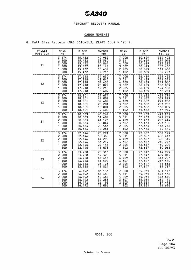
2-31Page 10AJUL 30/93
CARGO MOMENTS
G. Full Size Pallets (NAS 3610-2L3, 2L4P) 60.4 × 125 in
PALLETPOSITION
MASSKg
H-ARMm
MOMENTKgm
MASSLb
H-ARMFt
MOMENTFt. Lb
11
3 1742 5002 0001 5001 000500
15.43215.43215.43215.43215.43215.432
49 98238 58030 86423 14815 4327 716
7 0005 5114 4093 3072 2051 102
50.62950.62950.62950.62950.62950.629
354 403279 016223 223167 430111 63655 793
---------------------------------------------- ----------------------------------
12
3 1742 5002 0001 5001 000500
17.21817.21817.21817.21817.21817.218
54 65048 04534 43625 82717 2188 609
7 0005 5114 4093 3072 2051 102
56.48956.48956.48956.48956.48956.489
395 423311 311249 060186 809124 55862 251
---------------------------------------------- ----------------------------------
13
3 1742 5002 0001 5001 000500
18.80118.80118.80118.80118.80118.801
59 67447 00237 60228 20118 8019 400
7 0005 5114 4093 3072 2051 102
61.68261.68261.68261.68261.68261.682
431 774339 929271 956203 982136 00967 974
---------------------------------------------- ----------------------------------
21
3 1742 5002 0001 5001 000500
20.56320.56320.56320.56320.56320.563
65 26751 40741 12630 84420 56310 281
7 0005 5114 4093 3072 2051 102
67.46367.46367.46367.46367.46367.463
472 241371 789297 444223 100148 75674 344
---------------------------------------------- ----------------------------------
22
3 1742 5002 0001 5001 000500
22.14622.14622.14622.14622.14622.146
70 29155 36544 29233 21922 14611 073
7 0005 5114 4093 3072 2051 102
72.65772.65772.65772.65772.65772.657
508 599400 413320 345240 277160 20980 068
---------------------------------------------- ----------------------------------
23
3 1742 5002 0001 5001 000500
23.72823.72823.72823.72823.72823.728
75 31359 32047 45635 59223 72811 824
7 0005 5114 4093 3072 2051 102
77.84777.84777.84777.84777.84777.847
544 929429 015343 227257 440171 65385 787
---------------------------------------------- ----------------------------------
24
3 1742 5002 0001 5001 000500
26.19226.19226.19226.19226.19226.192
83 13365 48052 38439 28826 19213 096
7 0005 5114 4093 3072 2051 102
85.93185.93185.93185.93185.93185.931
601 517473 566378 870284 174189 47894 696
MODEL 200
Printed in France
AIRCRAFT RECOVERY MANUAL

2-31Page 11
JUL 30/93
CARGO MOMENTS
H. Full Size Pallets (NAS 3610-2A1, 2A2, 2A3, 2A4, 2A6P) 88 × 125 in
PALLETPOSITION
MASSKg
H-ARMm
MOMENTKgm
MASSLb
H-ARMFt
MOMENTFt. Lb
11P
4 6264 0003 5003 0002 5002 0001 5001 000500
15.78315.78315.78315.78315.78315.78315.78315.78315.783
73 01263 13255 24047 34939 45731 56623 67415 7837 891
10 2008 8187 7166 6145 5114 4093 3072 2051 102
51.78051.78051.78051.78051.78051.78051.78051.78051.780
528 156456 596399 534342 473285 360228 298171 236114 17557 062
---------------------------------------------- ----------------------------------
12P
4 6264 0003 5003 0002 5002 0001 5001 000500
18.45018.45018.45018.45018.45018.45018.45018.45018.450
85 35073 88064 57555 35046 12536 90027 67518 4509 225
10 2008 8187 7166 6145 5114 4093 3072 2051 102
60.53060.53060.53060.53060.53060.53060.53060.53060.530
617 406533 754467 049400 345333 581266 877200 173133 46966 704
---------------------------------------------- ----------------------------------
21P
4 6264 0003 5003 0002 5002 0001 5001 000500
20.91420.91420.91420.91420.91420.91420.91420.91420.914
96 74883 65673 19962 74252 28541 82831 37120 91410 457
10 2008 8187 7166 6145 5114 4093 3072 2051 102
68.61468.61468.61468.61468.61468.61468.61468.61468.614
699 863605 038529 426453 813378 132302 519226 906151 29475 613
---------------------------------------------- ----------------------------------
22P
4 6264 0003 5003 0002 5002 0001 5001 000500
23.37723.37723.37723.37723.37723.37723.37723.37723.377
108 14293 50881 81970 13158 44246 75435 06523 37711 688
10 2008 8187 7166 6145 5114 4093 3072 2051 102
76.69576.69576.69576.69576.69576.69576.69576.69576.695
782 289676 297591 779507 261422 666338 148253 630169 11284 518
---------------------------------------------- ----------------------------------
23P
4 6264 0003 5003 0002 5002 0001 5001 000500
25.84125.84125.84125.84125.84125.84125.84125.84125.841
119 540103 36490 44377 52364 60251 68238 76125 84112 920
10 2008 8187 7166 6145 5114 4093 3072 2051 102
84.77984.77984.77984.77984.77984.77984.77984.77984.779
864 746747 581654 155560 728467 217373 791280 364186 93893 426
---------------------------------------------- ----------------------------------
24P
4 6264 0003 5003 0002 5002 0001 5001 000500
28.30528.30528.30528.30528.30528.30528.30528.30528.305
130 939113 22099 06784 91570 76256 61042 45728 30514 152
10 2008 8187 7166 6145 5114 4093 3072 2051 102
92.86392.86392.86392.86392.86392.86392.86392.86392.863
947 203818 866716 531614 196511 768409 433307 098204 763102 335
MODEL 300
Printed in France
AIRCRAFT RECOVERY MANUAL

2-31Page 11AJUL 30/93
CARGO MOMENTS
H. Full Size Pallets (NAS 3610-2A1, 2A2, 2A3, 2A4, 2A6P) 88 × 125 in
PALLETPOSITION
MASSKg
H-ARMm
MOMENTKgm
MASSLb
H-ARMFt
MOMENTFt. Lb
11P
4 6264 0003 5003 0002 5002 0001 5001 000500
15.78315.78315.78315.78315.78315.78315.78315.78315.783
73 01263 13255 24047 34939 45731 56623 67415 7837 891
10 2008 8187 7166 6145 5114 4093 3072 2051 102
51.78051.78051.78051.78051.78051.78051.78051.78051.780
528 156456 596399 534342 473285 360228 298171 236114 17557 062
---------------------------------------------- ----------------------------------
12P
4 6264 0003 5003 0002 5002 0001 5001 000500
18.45018.45018.45018.45018.45018.45018.45018.45018.450
85 35073 88064 57555 35046 12536 90027 67518 4509 225
10 2008 8187 7166 6145 5114 4093 3072 2051 102
60.53060.53060.53060.53060.53060.53060.53060.53060.530
617 406533 754467 049400 345333 581266 877200 173133 46966 704
---------------------------------------------- ----------------------------------
21P
4 6264 0003 5003 0002 5002 0001 5001 000500
20.91420.91420.91420.91420.91420.91420.91420.91420.914
96 74883 65673 19962 74252 28541 82831 37120 91410 457
10 2008 8187 7166 6145 5114 4093 3072 2051 102
68.61468.61468.61468.61468.61468.61468.61468.61468.614
699 863605 038529 426453 813378 132302 519226 906151 29475 613
---------------------------------------------- ----------------------------------
22P
4 6264 0003 5003 0002 5002 0001 5001 000500
23.37723.37723.37723.37723.37723.37723.37723.37723.377
108 14293 50881 81970 13158 44246 75435 06523 37711 688
10 2008 8187 7166 6145 5114 4093 3072 2051 102
76.69576.69576.69576.69576.69576.69576.69576.69576.695
782 289676 297591 779507 261422 666338 148253 630169 11284 518
---------------------------------------------- ----------------------------------
23P
4 6264 0003 5003 0002 5002 0001 5001 000500
25.84125.84125.84125.84125.84125.84125.84125.84125.841
119 540103 36490 44377 52364 60251 68238 76125 84112 920
10 2008 8187 7166 6145 5114 4093 3072 2051 102
84.77984.77984.77984.77984.77984.77984.77984.77984.779
864 746747 581654 155560 728467 217373 791280 364186 93893 426
MODEL 200
Printed in France
AIRCRAFT RECOVERY MANUAL
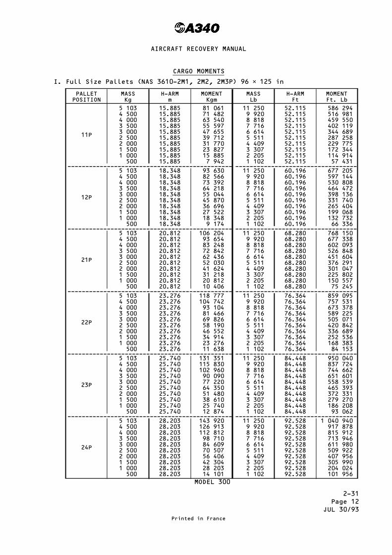
2-31Page 12
JUL 30/93
CARGO MOMENTS
I. Full Size Pallets (NAS 3610-2M1, 2M2, 2M3P) 96 × 125 in
PALLETPOSITION
MASSKg
H-ARMm
MOMENTKgm
MASSLb
H-ARMFt
MOMENTFt. Lb
11P
5 1034 5004 0003 5003 0002 5002 0001 5001 000500
15.88515.88515.88515.88515.88515.88515.88515.88515.88515.885
81 06171 48263 54055 59747 65539 71231 77023 82715 8857 942
11 2509 9208 8187 7166 6145 5114 4093 3072 2051 102
52.11552.11552.11552.11552.11552.11552.11552.11552.11552.115
586 294516 981459 550402 119344 689287 258229 775172 344114 91457 431
---------------------------------------------- ----------------------------------
12P
5 1034 5004 0003 5003 0002 5002 0001 5001 000500
18.34818.34818.34818.34818.34818.34818.34818.34818.34818.348
93 63082 56673 39264 21855 04445 87036 69627 52218 3489 174
11 2509 9208 8187 7166 6145 5114 4093 3072 2051 102
60.19660.19660.19660.19660.19660.19660.19660.19660.19660.196
677 205597 144530 808464 472398 136331 740265 404199 068132 73266 336
---------------------------------------------- ----------------------------------
21P
5 1034 5004 0003 5003 0002 5002 0001 5001 000500
20.81220.81220.81220.81220.81220.81220.81220.81220.81220.812
106 20493 65483 24872 84262 43652 03041 62431 21820 81210 406
11 2509 9208 8187 7166 6145 5114 4093 3072 2051 102
68.28068.28068.28068.28068.28068.28068.28068.28068.28068.280
768 150677 338602 093526 848451 604376 291301 047225 802150 55775 245
---------------------------------------------- ----------------------------------
22P
5 1034 5004 0003 5003 0002 5002 0001 5001 000500
23.27623.27623.27623.27623.27623.27623.27623.27623.27623.276
118 777104 74293 10481 46669 82658 19046 55234 91423 27611 638
11 2509 9208 8187 7166 6145 5114 4093 3072 2051 102
76.36476.36476.36476.36476.36476.36476.36476.36476.36476.364
859 095757 531673 378589 225505 071420 842336 689252 536168 38384 153
---------------------------------------------- ----------------------------------
23P
5 1034 5004 0003 5003 0002 5002 0001 5001 000500
25.74025.74025.74025.74025.74025.74025.74025.74025.74025.740
131 351115 830102 96090 09077 22064 35051 48038 61025 74012 874
11 2509 9208 8187 7166 6145 5114 4093 3072 2051 102
84.44884.44884.44884.44884.44884.44884.44884.44884.44884.448
950 040837 724744 662651 601558 539465 393372 331279 270186 20893 062
---------------------------------------------- ----------------------------------
24P
5 1034 5004 0003 5003 0002 5002 0001 5001 000500
28.20328.20328.20328.20328.20328.20328.20328.20328.20328.203
143 920126 913112 81298 71084 60970 50756 40642 30428 20314 101
11 2509 9208 8187 7166 6145 5114 4093 3072 2051 102
92.52892.52892.52892.52892.52892.52892.52892.52892.52892.528
1 040 940917 878815 912713 946611 980509 922407 956305 990204 024101 956
MODEL 300
Printed in France
AIRCRAFT RECOVERY MANUAL

2-31Page 12AJUL 30/93
CARGO MOMENTS
I. Full Size Pallets (NAS 3610-2M1, 2M2, 2M3P) 96 × 125 in
PALLETPOSITION
MASSKg
H-ARMm
MOMENTKgm
MASSLb
H-ARMFt
MOMENTFt. Lb
11P
5 1034 5004 0003 5003 0002 5002 0001 5001 000500
15.88515.88515.88515.88515.88515.88515.88515.88515.88515.885
81 06171 48263 54055 59747 65539 71231 77023 82715 8857 942
11 2509 9208 8187 7166 6145 5114 4093 3072 2051 102
52.11552.11552.11552.11552.11552.11552.11552.11552.11552.115
586 294516 981459 550402 119344 689287 258229 775172 344114 91457 431
---------------------------------------------- ----------------------------------
12P
5 1034 5004 0003 5003 0002 5002 0001 5001 000500
18.34818.34818.34818.34818.34818.34818.34818.34818.34818.348
93 63082 56673 39264 21855 04445 87036 69627 52218 3489 174
11 2509 9208 8187 7166 6145 5114 4093 3072 2051 102
60.19660.19660.19660.19660.19660.19660.19660.19660.19660.196
677 205597 144530 808464 472398 136331 740265 404199 068132 73266 336
---------------------------------------------- ----------------------------------
21P
5 1034 5004 0003 5003 0002 5002 0001 5001 000500
20.81220.81220.81220.81220.81220.81220.81220.81220.81220.812
106 20493 65483 24872 84262 43652 03041 62431 21820 81210 406
11 2509 9208 8187 7166 6145 5114 4093 3072 2051 102
68.28068.28068.28068.28068.28068.28068.28068.28068.28068.280
768 150677 338602 093526 848451 604376 291301 047225 802150 55775 245
---------------------------------------------- ----------------------------------
22P
5 1034 5004 0003 5003 0002 5002 0001 5001 000500
23.27623.27623.27623.27623.27623.27623.27623.27623.27623.276
118 777104 74293 10481 46669 82658 19046 55234 91423 27611 638
11 2509 9208 8187 7166 6145 5114 4093 3072 2051 102
76.36476.36476.36476.36476.36476.36476.36476.36476.36476.364
859 095757 531673 378589 225505 071420 842336 689252 536168 38384 153
---------------------------------------------- ----------------------------------
23P
5 1034 5004 0003 5003 0002 5002 0001 5001 000500
25.74025.74025.74025.74025.74025.74025.74025.74025.74025.740
131 351115 830102 96090 09077 22064 35051 48038 61025 74012 874
11 2509 9208 8187 7166 6145 5114 4093 3072 2051 102
84.44884.44884.44884.44884.44884.44884.44884.44884.44884.448
950 040837 724744 662651 601558 539465 393372 331279 270186 20893 062
MODEL 200
Printed in France
AIRCRAFT RECOVERY MANUAL

2-31Page 13
JUL 30/93
CARGO MOMENTS
2. AFT Cargo Compartment
A. Half Size Containers (NAS 3610-2K1C, 2K2C) 60.4 × 61.5 in MAX IATAContour E.G.
CONTAINERPOSITION
MASSKg
H-ARMm
MOMENTKgm
MASSLb
H-ARMFt
MOMENTFt. Lb
31 R + L
1 5871 2501 000750500250
40.88940.88940.88940.88940.88940.889
64 89151 11140 88930 66720 44410 222
3 5002 7562 2051 6531 102551
134.149134.149134.149134.149134.149134.149
469 521369 715295 799221 748147 83273 916
---------------------------------------------- ----------------------------------
32 R + L
1 5871 2501 000750500250
43.35243.35243.35243.35243.35243.352
68 80054 19043 35232 51421 67610 838
3 5002 7562 2051 6531 102551
142.229142.229142.229142.229142.229142.229
497 801391 983313 615235 105156 73678 368
---------------------------------------------- ----------------------------------
33 R + L
1 5871 2501 000750500250
44.93544.93544.93544.93544.93544.935
71 31256 16944 93533 70122 46711 234
3 5002 7562 2051 6531 102551
147.423147.423147.423147.423147.423147.423
515 980406 298325 068243 690162 46081 230
---------------------------------------------- ----------------------------------
34 R + L
1 5871 2501 000750500250
46.51746.51746.51746.51746.51746.517
73 82258 14646 51734 88823 25811 629
3 5002 7562 2051 6531 102551
152.613152.613152.613152.613152.613152.613
534 145420 601336 512252 269168 18084 090
---------------------------------------------- ----------------------------------
41 R + L
1 5871 2501 000750500250
48.07748.07748.07748.07748.07748.077
76 29860 09648 07736 05825 00012 019
3 5002 7562 2051 6531 102551
157.731157.731157.731157.731157.731157.731
552 058434 707347 797260 729178 82086 910
---------------------------------------------- ----------------------------------
42 R + L
1 5871 2501 000750500250
49.65949.65949.65949.65949.65949.659
78 80962 07449 65937 24424 82912 415
3 5002 7562 2051 6531 102551
162.921162.921162.921162.921162.921162.921
570 223449 010359 241269 308179 53989 769
---------------------------------------------- ----------------------------------
43 R + L
1 5871 2501 000750500250
51.24151.24151.24151.24151.24151.241
81 31964 05151 24138 43125 62012 810
3 5002 7562 2051 6531 102551
168.111168.111168.111168.111168.111168.111
588 388463 314370 685277 887185 25892 629
MODEL 300
Printed in France
AIRCRAFT RECOVERY MANUAL
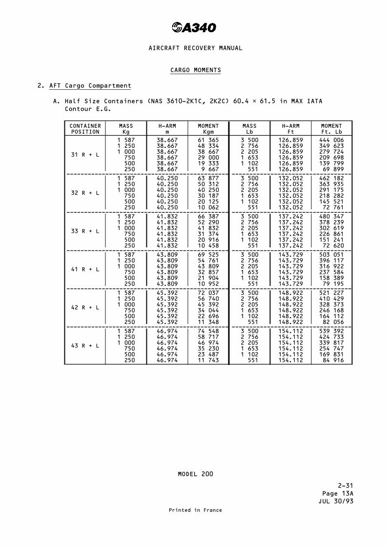
2-31Page 13AJUL 30/93
CARGO MOMENTS
2. AFT Cargo Compartment
A. Half Size Containers (NAS 3610-2K1C, 2K2C) 60.4 × 61.5 in MAX IATAContour E.G.
CONTAINERPOSITION
MASSKg
H-ARMm
MOMENTKgm
MASSLb
H-ARMFt
MOMENTFt. Lb
31 R + L
1 5871 2501 000750500250
38.66738.66738.66738.66738.66738.667
61 36548 33438 66729 00019 3339 667
3 5002 7562 2051 6531 102551
126.859126.859126.859126.859126.859126.859
444 006349 623279 724209 698139 79969 899
---------------------------------------------- ----------------------------------
32 R + L
1 5871 2501 000750500250
40.25040.25040.25040.25040.25040.250
63 87750 31240 25030 18720 12510 062
3 5002 7562 2051 6531 102551
132.052132.052132.052132.052132.052132.052
462 182363 935291 175218 282145 52172 761
---------------------------------------------- ----------------------------------
33 R + L
1 5871 2501 000750500250
41.83241.83241.83241.83241.83241.832
66 38752 29041 83231 37420 91610 458
3 5002 7562 2051 6531 102551
137.242137.242137.242137.242137.242137.242
480 347378 239302 619226 861151 24172 620
---------------------------------------------- ----------------------------------
41 R + L
1 5871 2501 000750500250
43.80943.80943.80943.80943.80943.809
69 52554 76143 80932 85721 90410 952
3 5002 7562 2051 6531 102551
143.729143.729143.729143.729143.729143.729
503 051396 117316 922237 584158 38979 195
---------------------------------------------- ----------------------------------
42 R + L
1 5871 2501 000750500250
45.39245.39245.39245.39245.39245.392
72 03756 74045 39234 04422 69611 348
3 5002 7562 2051 6531 102551
148.922148.922148.922148.922148.922148.922
521 227410 429328 373246 168164 11282 056
---------------------------------------------- ----------------------------------
43 R + L
1 5871 2501 000750500250
46.97446.97446.97446.97446.97446.974
74 54858 71746 97435 23023 48711 743
3 5002 7562 2051 6531 102551
154.112154.112154.112154.112154.112154.112
539 392424 733339 817254 747169 83184 916
MODEL 200
Printed in France
AIRCRAFT RECOVERY MANUAL

2-31Page 14
JUL 30/93
CARGO MOMENTS
B. Half Size Containers (NAS 3610-2K1C, 2K2C) 60.4 × 61.5 in MAX IATAContour C.H.
CONTAINERPOSITION
MASSKg
H-ARMm
MOMENTKgm
MASSLb
H-ARMFt
MOMENTFt. Lb
31R or L
1 5871 2501 000750500250
40.88940.88940.88940.88940.88940.889
64 89151 11140 88930 66720 44410 222
3 5002 7562 2051 6531 102551
134.149134.149134.149134.149134.149134.149
469 521369 715295 799221 748147 83273 916
---------------------------------------------- ----------------------------------
32R or L
1 5871 2501 000750500250
43.35243.35243.35243.35243.35243.352
68 80054 19043 35232 51421 67610 838
3 5002 7562 2051 6531 102551
142.229142.229142.229142.229142.229142.229
497 801391 983313 615235 105156 73678 368
---------------------------------------------- ----------------------------------
33R or L
1 5871 2501 000750500250
44.93544.93544.93544.93544.93544.935
71 31256 16944 93533 70122 46711 234
3 5002 7562 2051 6531 102551
147.423147.423147.423147.423147.423147.423
515 980406 298325 068243 690162 46081 230
---------------------------------------------- ----------------------------------
34R or L
1 5871 2501 000750500250
46.51746.51746.51746.51746.51746.517
73 82258 14646 51734 88823 25811 629
3 5002 7562 2051 6531 102551
152.613152.613152.613152.613152.613152.613
534 145420 601336 512252 269168 18084 090
---------------------------------------------- ----------------------------------
41R or L
1 5871 2501 000750500250
48.07748.07748.07748.07748.07748.077
76 29860 09648 07736 05825 00012 019
3 5002 7562 2051 6531 102551
157.731157.731157.731157.731157.731157.731
552 058434 707347 797260 729178 82086 910
---------------------------------------------- ----------------------------------
42R or L
1 5871 2501 000750500250
49.65949.65949.65949.65949.65949.659
78 80962 07449 65937 24424 82912 415
3 5002 7562 2051 6531 102551
162.921162.921162.921162.921162.921162.921
570 223449 010359 241269 308179 53989 769
---------------------------------------------- ----------------------------------
43R or L
1 5871 2501 000750500250
51.24151.24151.24151.24151.24151.241
81 31964 05151 24138 43125 62012 810
3 5002 7562 2051 6531 102551
168.111168.111168.111168.111168.111168.111
588 388463 314370 685277 887185 25892 629
MODEL 300
Printed in France
AIRCRAFT RECOVERY MANUAL

2-31Page 14AJUL 30/93
CARGO MOMENTS
B. Half Size Containers (NAS 3610-2K1C, 2K2C) 60.4 × 61.5 in MAX IATAContour C.H.
CONTAINERPOSITION
MASSKg
H-ARMm
MOMENTKgm
MASSLb
H-ARMFt
MOMENTFt. Lb
31R or L
1 5871 2501 000750500250
38.66738.66738.66738.66738.66738.667
61 36548 33438 66729 00019 3339 667
3 5002 7562 2051 6531 102551
162.859162.859162.859162.859162.859162.859
444 006349 623279 724209 698139 79969 899
---------------------------------------------- ----------------------------------
32R or L
1 5871 2501 000750500250
40.25040.25040.25040.25040.25040.250
63 87750 31240 25030 18720 12510 062
3 5002 7562 2051 6531 102551
132.052132.052132.052132.052132.052132.052
462 182363 935291 175218 282145 52172 761
---------------------------------------------- ----------------------------------
33R or L
1 5871 2501 000750500250
41.83241.83241.83241.83241.83241.832
66 38752 29041 83231 37420 91610 458
3 5002 7562 2051 6531 102551
137.242137.242137.242137.242137.242137.242
480 347378 239302 619226 861151 24172 620
---------------------------------------------- ----------------------------------
41R or L
1 5871 2501 000750500250
43.80943.80943.80943.80943.80943.809
69 52554 76143 80932 85721 90410 952
3 5002 7562 2051 6531 102551
143.729143.729143.729143.729143.729143.729
503 051396 117316 922237 584158 38979 195
---------------------------------------------- ----------------------------------
42R or L
1 5871 2501 000750500250
45.39245.39245.39245.39245.39245.392
72 03756 74045 39234 04422 69611 348
3 5002 7562 2051 6531 102551
148.922148.922148.922148.922148.922148.922
521 227410 429328 373246 168164 11282 056
---------------------------------------------- ----------------------------------
43R or L
1 5871 2501 000750500250
46.97446.97446.97446.97446.97446.974
74 54858 71746 97435 23023 48711 743
3 5002 7562 2051 6531 102551
154.112154.112154.112154.112154.112154.112
539 392424 733339 817254 747169 83184 916
MODEL 200
Printed in France
AIRCRAFT RECOVERY MANUAL
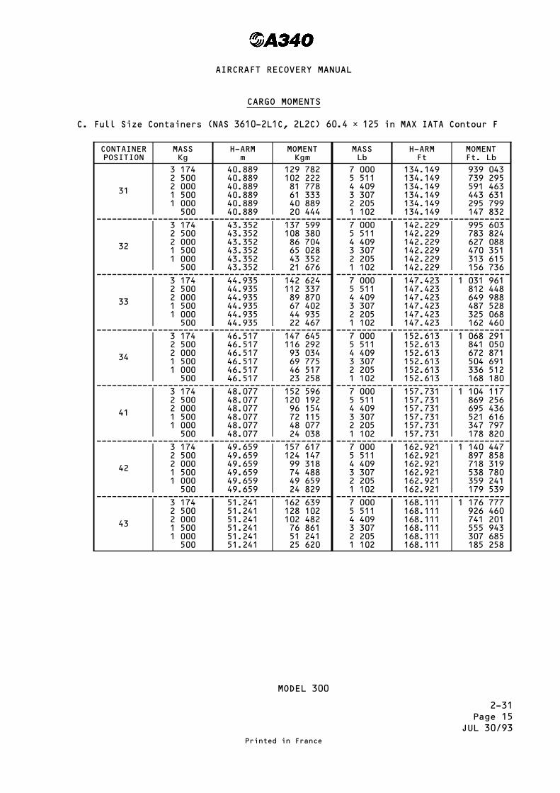
2-31Page 15
JUL 30/93
CARGO MOMENTS
C. Full Size Containers (NAS 3610-2L1C, 2L2C) 60.4 × 125 in MAX IATA Contour F
CONTAINERPOSITION
MASSKg
H-ARMm
MOMENTKgm
MASSLb
H-ARMFt
MOMENTFt. Lb
31
3 1742 5002 0001 5001 000500
40.88940.88940.88940.88940.88940.889
129 782102 22281 77861 33340 88920 444
7 0005 5114 4093 3072 2051 102
134.149134.149134.149134.149134.149134.149
939 043739 295591 463443 631295 799147 832
---------------------------------------------- ----------------------------------
32
3 1742 5002 0001 5001 000500
43.35243.35243.35243.35243.35243.352
137 599108 38086 70465 02843 35221 676
7 0005 5114 4093 3072 2051 102
142.229142.229142.229142.229142.229142.229
995 603783 824627 088470 351313 615156 736
---------------------------------------------- ----------------------------------
33
3 1742 5002 0001 5001 000500
44.93544.93544.93544.93544.93544.935
142 624112 33789 87067 40244 93522 467
7 0005 5114 4093 3072 2051 102
147.423147.423147.423147.423147.423147.423
1 031 961812 448649 988487 528325 068162 460
---------------------------------------------- ----------------------------------
34
3 1742 5002 0001 5001 000500
46.51746.51746.51746.51746.51746.517
147 645116 29293 03469 77546 51723 258
7 0005 5114 4093 3072 2051 102
152.613152.613152.613152.613152.613152.613
1 068 291841 050672 871504 691336 512168 180
---------------------------------------------- ----------------------------------
41
3 1742 5002 0001 5001 000500
48.07748.07748.07748.07748.07748.077
152 596120 19296 15472 11548 07724 038
7 0005 5114 4093 3072 2051 102
157.731157.731157.731157.731157.731157.731
1 104 117869 256695 436521 616347 797178 820
---------------------------------------------- ----------------------------------
42
3 1742 5002 0001 5001 000500
49.65949.65949.65949.65949.65949.659
157 617124 14799 31874 48849 65924 829
7 0005 5114 4093 3072 2051 102
162.921162.921162.921162.921162.921162.921
1 140 447897 858718 319538 780359 241179 539
---------------------------------------------- ----------------------------------
43
3 1742 5002 0001 5001 000500
51.24151.24151.24151.24151.24151.241
162 639128 102102 48276 86151 24125 620
7 0005 5114 4093 3072 2051 102
168.111168.111168.111168.111168.111168.111
1 176 777926 460741 201555 943307 685185 258
MODEL 300
Printed in France
AIRCRAFT RECOVERY MANUAL

2-31Page 15AJUL 30/93
CARGO MOMENTS
C. Full Size Containers (NAS 3610-2L1C, 2L2C) 60.4 × 125 in MAX IATA Contour F
CONTAINERPOSITION
MASSKg
H-ARMm
MOMENTKgm
MASSLb
H-ARMFt
MOMENTFt. Lb
31
3 1742 5002 0001 5001 000500
38.66738.66738.66738.66738.66738.667
122 72996 66777 33458 00038 66719 333
7 0005 5114 4093 3072 2051 102
126.859126.859126.859126.859126.859126.859
888 013699 120559 321419 523279 724139 799
---------------------------------------------- ----------------------------------
32
3 1742 5002 0001 5001 000500
40.25040.25040.25040.25040.25040.250
127 753100 62580 50060 37540 25020 125
7 0005 5114 4093 3072 2051 102
132.052132.052132.052132.052132.052132.052
924 364727 739582 217436 696291 175145 521
---------------------------------------------- ----------------------------------
33
3 1742 5002 0001 5001 000500
41.83241.83241.83241.83241.83241.832
132 775104 58083 66462 74841 83220 916
7 0005 5114 4093 3072 2051 102
137.242137.242137.242137.242137.242137.242
960 694756 341605 100453 859302 618151 241
---------------------------------------------- ----------------------------------
41
3 1742 5002 0001 5001 000500
43.80943.80943.80943.80943.80943.809
139 050109 52287 61865 71343 80921 904
7 0005 5114 4093 3072 2051 102
143.729143.729143.729143.729143.729143.729
1 006 103792 091633 701475 312316 922158 389
---------------------------------------------- ----------------------------------
42
3 1742 5002 0001 5001 000500
45.39245.39245.39245.39245.39245.392
144 074113 48090 78468 08845 39222 696
7 0005 5114 4093 3072 2051 102
148.922148.922148.922148.922148.922148.922
1 042 454820 709656 597492 485328 373164 112
---------------------------------------------- ----------------------------------
43
3 1742 5002 0001 5001 000500
46.97446.97446.97446.97446.97446.974
149 095117 43593 94870 46146 97423 487
7 0005 5114 4093 3072 2051 102
154.122154.122154.122154.122154.122154.122
1 078 854849 366679 524509 681339 839169 842
MODEL 200
Printed in France
AIRCRAFT RECOVERY MANUAL

2-31Page 16
JUL 30/93
CARGO MOMENTS
D. Full Size Containers (NAS 3610-2A2C, 2A6C) 88 × 125 in MAX IATA contour F.
CONTAINERPOSITION
MASSKg
H-ARMm
MOMENTKgm
MASSLb
H-ARMFt
MOMENTFt. Lb
31P
4 6264 0003 5003 0002 5002 0001 5001 000500
41.23941.23941.23941.23941.23941.23941.23941.23941.239
190 772164 956144 336123 717103 09782 47861 85841 23920 619
10 2008 8187 7166 6145 5114 4093 3072 2051 102
135.297135.297135.297135.297135.297135.297135.297135.297135.297
1 380 0291 193 0491 043 952894 854745 622596 524447 427298 330149 097
---------------------------------------------- ----------------------------------
32P
4 6264 0003 5003 0002 5002 0001 5001 000500
43.70343.70343.70343.70343.70343.70343.70343.70343.703
202 170174 812152 960131 109109 25787 40665 55443 70321 851
10 2008 8187 7166 6145 5114 4093 3072 2051 102
143.380143.380143.380143.380143.380143.380143.380143.380143.380
1 462 2761 264 3251 106 320948 315790 167632 162474 158316 153158 005
---------------------------------------------- ----------------------------------
33P
4 6264 0003 5003 0002 5002 0001 5001 000500
46.16746.16746.16746.16746.16746.16746.16746.16746.167
213 569184 668161 584138 501115 41792 33469 25046 16723 083
10 2008 8187 7166 6145 5114 4093 3072 2051 102
151.465151.465151.465151.465151.465151.465151.465151.465151.465
1 544 9431 335 6181 168 7041 001 790834 724667 809500 895333 980166 914
---------------------------------------------- ----------------------------------
41P
4 6264 0003 5003 0002 5002 0001 5001 000500
48.42748.42748.42748.42748.42748.42748.42748.42748.427
224 023193 708169 494145 281121 06796 85472 64048 42724 213
10 2008 8187 7166 6145 5114 4093 3072 2051 102
158.879158.879158.879158.879158.879158.879158.879158.879158.879
1 620 5661 400 9951 225 9101 050 826875 582700 498525 413350 328175 085
---------------------------------------------- ----------------------------------
42P
4 6264 0003 5003 0002 5002 0001 5001 000500
50.68850.68850.68850.68850.68850.68850.68850.68850.688
234 483202 752177 408152 064126 720101 37676 03250 68825 344
10 2008 8187 7166 6145 5114 4093 3072 2051 102
166.297166.297166.297166.297166.297166.297166.297166.297166.297
1 696 2291 466 4071 283 1481 099 888916 463733 203549 944366 685183 259
MODEL 300
Printed in France
AIRCRAFT RECOVERY MANUAL

2-31Page 16AJUL 30/93
CARGO MOMENTS
D. Full Size Containers (NAS 3610-2A2C, 2A6C) 88 × 125 in MAX IATA contour F.
CONTAINERPOSITION
MASSKg
H-ARMm
MOMENTKgm
MASSLb
H-ARMFt
MOMENTFt. Lb
31P
4 6264 0003 5003 0002 5002 0001 5001 000500
39.01839.01839.01839.01839.01839.01839.01839.01839.018
180 497156 072136 563117 05497 54578 03658 52739 01819 509
10 2008 8187 7166 6145 5114 4093 3072 2051 102
128.010128.010128.010128.010128.010128.010128.010128.010128.010
1 305 7021 128 792987 725846 658705 463564 396423 329282 262141 067
---------------------------------------------- ----------------------------------
32P
4 6264 0003 5003 0002 5002 0001 5001 000500
41.48141.48141.48141.48141.48141.48141.48141.48141.481
191 891165 924145 183124 443103 70282 96262 22141 48120 740
10 2008 8187 7166 6145 5114 4093 3072 2051 102
136.091136.091136.091136.091136.091136.091136.091136.091136.091
1 388 1281 200 0501 050 078900 106749 997600 025450 053300 081149 972
---------------------------------------------- ----------------------------------
41P
4 6264 0003 5003 0002 5002 0001 5001 000500
44.16044.16044.16044.16044.16044.16044.16044.16044.160
204 284176 640154 560132 480110 40088 32066 24044 16022 080
10 2008 8187 7166 6145 5114 4093 3072 2051 102
144.880144.880144.880144.880144.880144.880144.880144.880144.880
1 477 7761 277 5521 117 894958 236798 434638 776479 118319 460159 658
---------------------------------------------- ----------------------------------
42P
4 6264 0003 5003 0002 5002 0001 5001 000500
46.42046.42046.42046.42046.42046.42046.42046.42046.420
214 739185 680162 470139 260116 05092 84069 63046 42023 210
10 2008 8187 7166 6145 5114 4093 3072 2051 102
152.295152.295152.295152.295152.295152.295152.295152.295152.295
1 553 4091 342 9371 175 1081 007 279839 298671 469503 640335 810167 829
MODEL 200
Printed in France
AIRCRAFT RECOVERY MANUAL

2-31Page 17
JUL 30/93
CARGO MOMENTS
E. Full Size Containers (NAS 3610-2M1C, 2M3C) 96 × 125 in MAX IATA Contour F
CONTAINERPOSITION
MASSKg
H-ARMm
MOMENTKgm
MASSLb
H-ARMFt
MOMENTFt. Lb
31P
5 1034 5004 0003 5003 0002 5002 0001 5001 000500
41.34141.34141.34141.34141.34141.34141.34141.34141.34141.341
210 963186 034165 364144 693124 023103 35282 68262 01141 34120 670
11 2509 9208 8187 7166 6145 5114 4093 3072 2051 102
135.632135.632135.632135.632135.632135.632135.632135.632135.632135.632
1 525 8601 345 4691 196 0031 046 537897 070747 468598 001448 535299 069149 466
---------------------------------------------- ----------------------------------
32P
5 1034 5004 0003 5003 0002 5002 0001 5001 000500
43.80543.80543.80543.80543.80543.80543.80543.80543.80543.805
223 537197 122175 220153 317131 415109 51287 61065 70743 80521 902
11 2509 9208 8187 7166 6145 5114 4093 3072 2051 102
143.715143.715143.715143.715143.715143.715143.715143.715143.715143.715
1 616 7941 425 6531 267 2791 108 905950 531792 013633 639475 265316 892158 374
---------------------------------------------- ----------------------------------
41P
5 1034 5004 0003 5003 0002 5002 0001 5001 000500
48.32648.32648.32648.32648.32648.32648.32648.32648.32648.326
246 608217 467193 304169 141144 978120 81596 65272 48948 32624 163
11 2509 9208 8187 7166 6145 5114 4093 3072 2051 102
158.548158.548158.548158.548158.548158.548158.548158.548158.548158.548
1 783 6651 572 7961 398 0761 223 3561 048 636873 758699 038524 318349 598174 720
---------------------------------------------- ----------------------------------
42P
5 1034 5004 0003 5003 0002 5002 0001 5001 000500
50.78950.78950.78950.78950.78950.78950.78950.78950.78950.789
259 176228 550203 156177 761152 367126 972101 57876 18350 78925 394
11 2509 9208 8187 7166 6145 5114 4093 3072 2051 102
166.629166.629166.629166.629166.629166.629166.629166.629166.629166.629
1 874 5761 652 9601 469 3351 285 7091 102 084918 292734 667551 042367 417183 625
MODEL 300
Printed in France
AIRCRAFT RECOVERY MANUAL

2-31Page 17AJUL 30/93
CARGO MOMENTS
E. Full Size Containers (NAS 3610-2M1C, 2M3C) 96 × 125 in MAX IATA Contour F
CONTAINERPOSITION
MASSKg
H-ARMm
MOMENTKgm
MASSLb
H-ARMFt
MOMENTFt. Lb
31P
5 1034 5004 0003 5003 0002 5002 0001 5001 000500
39.11939.11939.11939.11939.11939.11939.11939.11939.11939.119
199 624176 035156 476136 916117 35797 79778 23858 67839 11919 559
11 2509 9208 8187 7166 6145 5114 4093 3072 2051 102
128.342128.342128.342128.342128.342128.342128.342128.342128.342128.342
1 443 8371 273 1531 131 720990 287848 854707 293565 860424 427282 994141 433
---------------------------------------------- ----------------------------------
32P
5 1034 5004 0003 5003 0002 5002 0001 5001 000500
41.58341.58341.58341.58341.58341.58341.58341.58341.58341.583
212 198187 123166 332145 540124 749103 95783 16662 37441 58320 791
11 2509 9208 8187 7166 6145 5114 4093 3072 2051 102
136.425136.425136.425136.425136.425136.425136.425136.425136.425136.425
1 534 7811 353 3361 202 9961 052 655902 315751 838601 498451 157300 817150 340
---------------------------------------------- ----------------------------------
41P
5 1034 5004 0003 5003 0002 5002 0001 5001 000500
44.05844.05844.05844.05844.05844.05844.05844.05844.05844.058
224 828198 261176 232154 203132 174110 14588 11666 08744 05822 029
11 2509 9208 8187 7166 6145 5114 4093 3072 2051 102
144.546144.546144.546144.546144.546144.546144.546144.546144.546144.546
1 626 1421 433 8961 274 6071 115 317956 027796 593637 303478 014318 724159 290
---------------------------------------------- ----------------------------------
42P
5 1034 5004 0003 5003 0002 5002 0001 5001 000500
46.52246.52246.52246.52246.52246.52246.52246.52246.52246.522
237 402209 349186 088162 827139 566116 30593 04469 78346 52223 261
11 2509 9208 8187 7166 6145 5114 4093 3072 2051 102
152.629152.629152.629152.629152.629152.629152.629152.629152.629152.629
1 717 0761 514 0801 345 8831 177 6851 009 488841 138672 941504 744336 547168 197
MODEL 200
Printed in France
AIRCRAFT RECOVERY MANUAL

2-31Page 18
JUL 30/93
CARGO MOMENTS
F. Half Size Pallets (NAS 3610-2K3P) 60.4 × 61.5 in
PALLETPOSITION
MASSKg
H-ARMm
MOMENTKgm
MASSLb
H-ARMFt
MOMENTFt. Lb
31 R + L
1 5871 2501 000750500250
40.88940.88940.88940.88940.88940.889
64 89151 11140 88930 66720 44410 222
3 5002 7562 2051 6531 102551
134.149134.149134.149134.149134.149134.149
469 521369 715295 799221 748147 83273 916
---------------------------------------------- ----------------------------------
32 R + L
1 5871 2501 000750500250
43.35243.35243.35243.35243.35243.352
68 80054 19043 35232 51421 67610 838
3 5002 7562 2051 6531 102551
142.229142.229142.229142.229142.229142.229
497 801391 983313 615235 105156 73678 368
---------------------------------------------- ----------------------------------
33 R + L
1 5871 2501 000750500250
44.93544.93544.93544.93544.93544.935
71 31256 16944 93533 70122 46711 234
3 5002 7562 2051 6531 102551
147.423147.423147.423147.423147.423147.423
515 980406 298325 068243 690162 46081 230
---------------------------------------------- ----------------------------------
34 R + L
1 5871 2501 000750500250
46.51746.51746.51746.51746.51746.517
73 82258 14646 51734 51723 25811 629
3 5002 7562 2051 6531 102551
152.613152.613152.613152.613152.613152.613
534 145420 601336 512252 269168 18084 090
---------------------------------------------- ----------------------------------
41 R + L
1 5871 2501 000750500250
48.07748.07748.07748.07748.07748.077
76 29860 09648 07736 05825 00012 019
3 5002 7562 2051 6531 102551
157.731157.731157.731157.731157.731157.731
552 058434 707347 797260 729178 82086 910
---------------------------------------------- ----------------------------------
42 R + L
1 5871 2501 000750500250
49.65949.65949.65949.65949.65949.659
78 80962 07449 65937 24424 82912 415
3 5002 7562 2051 6531 102551
162.921162.921162.921162.921162.921162.921
570 223449 010359 241269 308179 53989 769
---------------------------------------------- ----------------------------------
43 R + L
1 5871 2501 000750500250
51.24151.24151.24151.24151.24151.241
81 31964 05151 24138 43125 62012 810
3 5002 7562 2051 6531 102551
168.111168.111168.111168.111168.111168.111
588 388463 314370 685277 887185 25892 629
MODEL 300
Printed in France
AIRCRAFT RECOVERY MANUAL

2-31Page 18AJUL 30/93
CARGO MOMENTS
F. Half Size Pallets (NAS 3610-2K3P) 60.4 × 61.5 in
PALLETPOSITION
MASSKg
H-ARMm
MOMENTKgm
MASSLb
H-ARMFt
MOMENTFt. Lb
31 R + L
1 5871 2501 000750500250
38.66738.66738.66738.66738.66738.667
61 36548 33438 66729 00019 3339 667
3 5002 7562 2051 6531 102551
162.859162.859162.859162.859162.859162.859
444 006349 623279 724209 698139 79969 899
---------------------------------------------- ----------------------------------
32 R + L
1 5871 2501 000750500250
40.25040.25040.25040.25040.25040.250
63 87750 31240 25030 18720 12510 062
3 5002 7562 2051 6531 102551
132.052132.052132.052132.052132.052132.052
462 182363 935291 175218 282145 52172 761
---------------------------------------------- ----------------------------------
33 R + L
1 5871 2501 000750500250
41.83241.83241.83241.83241.83241.832
66 38752 29041 83231 37420 91610 458
3 5002 7562 2051 6531 102551
137.242137.242137.242137.242137.242137.242
480 347378 239302 619226 861151 24172 620
---------------------------------------------- ----------------------------------
41 R + L
1 5871 2501 000750500250
43.80943.80943.80943.80943.80943.809
69 52554 76143 80932 85721 90410 952
3 5002 7562 2051 6531 102551
143.729143.729143.729143.729143.729143.729
503 051396 117316 922237 584158 38979 195
---------------------------------------------- ----------------------------------
42 R + L
1 5871 2501 000750500250
45.39245.39245.39245.39245.39245.392
72 03756 74045 39234 04422 69611 348
3 5002 7562 2051 6531 102551
148.922148.922148.922148.922148.922148.922
521 227410 429328 373246 168164 11282 056
---------------------------------------------- ----------------------------------
43 R + L
1 5871 2501 000750500250
46.97446.97446.97446.97446.97446.974
74 54858 71746 97435 23023 48711 743
3 5002 7562 2051 6531 102551
154.112154.112154.112154.112154.112154.112
539 392424 733339 817254 747169 83184 916
MODEL 200
Printed in France
AIRCRAFT RECOVERY MANUAL

2-31Page 19
JUL 30/93
CARGO MOMENTS
G. Full Size Pallets (NAS 3610-2L3, 2L4P) 60.4 × 125 in
PALLETPOSITION
MASSKg
H-ARMm
MOMENTKgm
MASSLb
H-ARMFt
MOMENTFt. Lb
31
3 1742 5002 0001 5001 000500
40.88940.88940.88940.88940.88940.889
129 782102 22281 77861 33340 88920 444
7 0005 5114 4093 3072 2051 102
134.149134.149134.149134.149134.149134.149
939 043739 295591 463443 631295 799147 832
---------------------------------------------- ----------------------------------
32
3 1742 5002 0001 5001 000500
43.35243.35243.35243.35243.35243.352
137 599108 38086 70465 02843 35221 676
7 0005 5114 4093 3072 2051 102
142.229142.229142.229142.229142.229142.229
995 603783 824627 088470 351313 615156 736
---------------------------------------------- ----------------------------------
33
3 1742 5002 0001 5001 000500
44.93544.93544.93544.93544.93544.935
142 624112 33789 87067 40244 93522 467
7 0005 5114 4093 3072 2051 102
147.423147.423147.423147.423147.423147.423
1 031 961812 448649 988487 528325 068162 460
---------------------------------------------- ----------------------------------
34
3 1742 5002 0001 5001 000500
46.51746.51746.51746.51746.51746.517
147 645116 29293 03469 77546 51723 258
7 0005 5114 4093 3072 2051 102
152.613152.613152.613152.613152.613152.613
1 068 291841 050672 871504 691336 512168 180
---------------------------------------------- ----------------------------------
41
3 1742 5002 0001 5001 000500
48.07748.07748.07748.07748.07748.077
152 596120 19296 15472 11548 07724 038
7 0005 5114 4093 3072 2051 102
157.731157.731157.731157.731157.731157.731
1 104 117869 256695 436521 616347 797178 820
---------------------------------------------- ----------------------------------
42
3 1742 5002 0001 5001 000500
49.65949.65949.65949.65949.65949.659
157 617124 14799 31874 48849 65924 829
7 0005 5114 4093 3072 2051 102
162.921162.921162.921162.921162.921162.921
1 140 447897 858718 319538 780359 241179 539
---------------------------------------------- ----------------------------------
43
3 1742 5002 0001 5001 000500
51.24151.24151.24151.24151.24151.241
162 639128 102102 48276 86151 24125 620
7 0005 5114 4093 3072 2051 102
168.111168.111168.111168.111168.111168.111
1 176 777926 460741 201555 943307 685185 258
MODEL 300
Printed in France
AIRCRAFT RECOVERY MANUAL
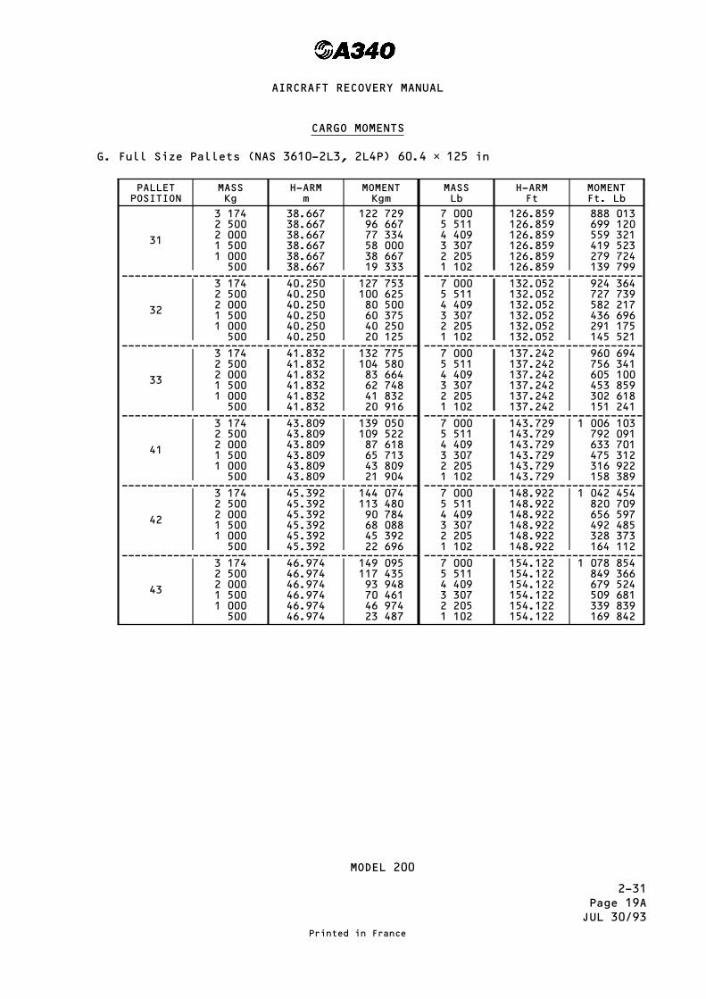
2-31Page 19AJUL 30/93
CARGO MOMENTS
G. Full Size Pallets (NAS 3610-2L3, 2L4P) 60.4 × 125 in
PALLETPOSITION
MASSKg
H-ARMm
MOMENTKgm
MASSLb
H-ARMFt
MOMENTFt. Lb
31
3 1742 5002 0001 5001 000500
38.66738.66738.66738.66738.66738.667
122 72996 66777 33458 00038 66719 333
7 0005 5114 4093 3072 2051 102
126.859126.859126.859126.859126.859126.859
888 013699 120559 321419 523279 724139 799
---------------------------------------------- ----------------------------------
32
3 1742 5002 0001 5001 000500
40.25040.25040.25040.25040.25040.250
127 753100 62580 50060 37540 25020 125
7 0005 5114 4093 3072 2051 102
132.052132.052132.052132.052132.052132.052
924 364727 739582 217436 696291 175145 521
---------------------------------------------- ----------------------------------
33
3 1742 5002 0001 5001 000500
41.83241.83241.83241.83241.83241.832
132 775104 58083 66462 74841 83220 916
7 0005 5114 4093 3072 2051 102
137.242137.242137.242137.242137.242137.242
960 694756 341605 100453 859302 618151 241
---------------------------------------------- ----------------------------------
41
3 1742 5002 0001 5001 000500
43.80943.80943.80943.80943.80943.809
139 050109 52287 61865 71343 80921 904
7 0005 5114 4093 3072 2051 102
143.729143.729143.729143.729143.729143.729
1 006 103792 091633 701475 312316 922158 389
---------------------------------------------- ----------------------------------
42
3 1742 5002 0001 5001 000500
45.39245.39245.39245.39245.39245.392
144 074113 48090 78468 08845 39222 696
7 0005 5114 4093 3072 2051 102
148.922148.922148.922148.922148.922148.922
1 042 454820 709656 597492 485328 373164 112
---------------------------------------------- ----------------------------------
43
3 1742 5002 0001 5001 000500
46.97446.97446.97446.97446.97446.974
149 095117 43593 94870 46146 97423 487
7 0005 5114 4093 3072 2051 102
154.122154.122154.122154.122154.122154.122
1 078 854849 366679 524509 681339 839169 842
MODEL 200
Printed in France
AIRCRAFT RECOVERY MANUAL
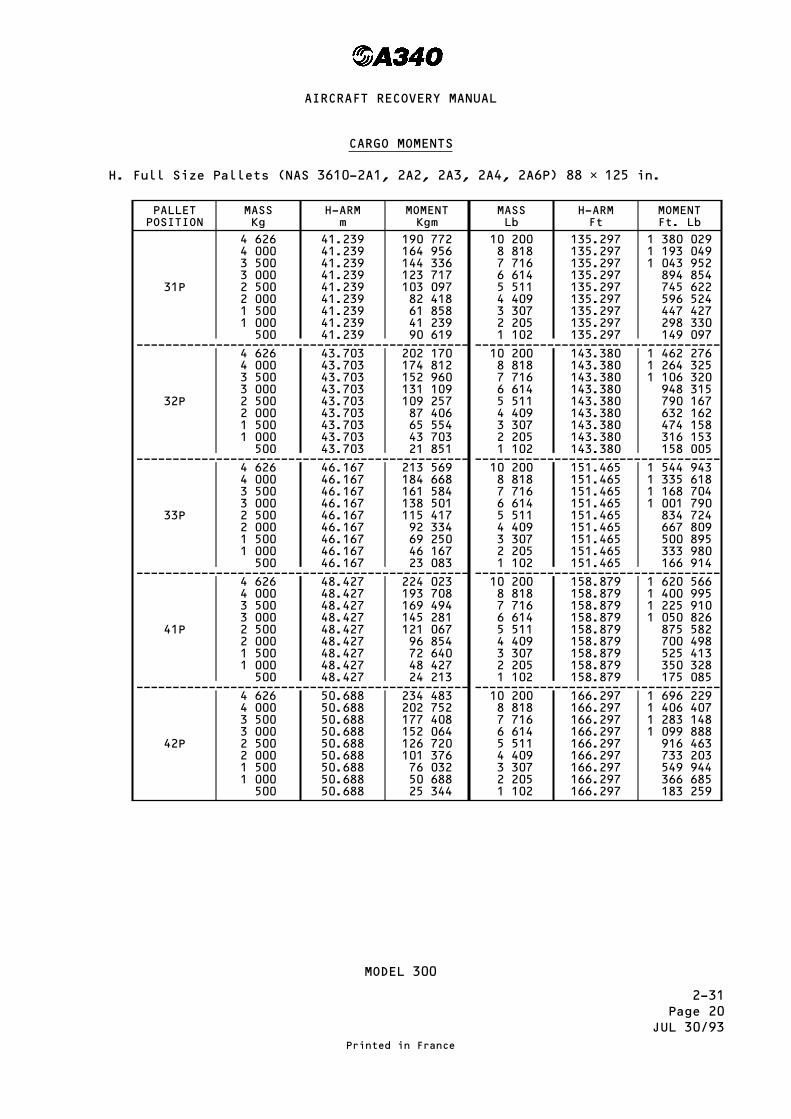
2-31Page 20
JUL 30/93
CARGO MOMENTS
H. Full Size Pallets (NAS 3610-2A1, 2A2, 2A3, 2A4, 2A6P) 88 × 125 in.
PALLETPOSITION
MASSKg
H-ARMm
MOMENTKgm
MASSLb
H-ARMFt
MOMENTFt. Lb
31P
4 6264 0003 5003 0002 5002 0001 5001 000500
41.23941.23941.23941.23941.23941.23941.23941.23941.239
190 772164 956144 336123 717103 09782 41861 85841 23990 619
10 2008 8187 7166 6145 5114 4093 3072 2051 102
135.297135.297135.297135.297135.297135.297135.297135.297135.297
1 380 0291 193 0491 043 952894 854745 622596 524447 427298 330149 097
---------------------------------------------- ----------------------------------
32P
4 6264 0003 5003 0002 5002 0001 5001 000500
43.70343.70343.70343.70343.70343.70343.70343.70343.703
202 170174 812152 960131 109109 25787 40665 55443 70321 851
10 2008 8187 7166 6145 5114 4093 3072 2051 102
143.380143.380143.380143.380143.380143.380143.380143.380143.380
1 462 2761 264 3251 106 320948 315790 167632 162474 158316 153158 005
---------------------------------------------- ----------------------------------
33P
4 6264 0003 5003 0002 5002 0001 5001 000500
46.16746.16746.16746.16746.16746.16746.16746.16746.167
213 569184 668161 584138 501115 41792 33469 25046 16723 083
10 2008 8187 7166 6145 5114 4093 3072 2051 102
151.465151.465151.465151.465151.465151.465151.465151.465151.465
1 544 9431 335 6181 168 7041 001 790834 724667 809500 895333 980166 914
---------------------------------------------- ----------------------------------
41P
4 6264 0003 5003 0002 5002 0001 5001 000500
48.42748.42748.42748.42748.42748.42748.42748.42748.427
224 023193 708169 494145 281121 06796 85472 64048 42724 213
10 2008 8187 7166 6145 5114 4093 3072 2051 102
158.879158.879158.879158.879158.879158.879158.879158.879158.879
1 620 5661 400 9951 225 9101 050 826875 582700 498525 413350 328175 085
---------------------------------------------- ----------------------------------
42P
4 6264 0003 5003 0002 5002 0001 5001 000500
50.68850.68850.68850.68850.68850.68850.68850.68850.688
234 483202 752177 408152 064126 720101 37676 03250 68825 344
10 2008 8187 7166 6145 5114 4093 3072 2051 102
166.297166.297166.297166.297166.297166.297166.297166.297166.297
1 696 2291 406 4071 283 1481 099 888916 463733 203549 944366 685183 259
MODEL 300
Printed in France
AIRCRAFT RECOVERY MANUAL

2-31Page 20AJUL 30/93
CARGO MOMENTS
H. Full Size Pallets (NAS 3610-2A1, 2A2, 2A3, 2A4, 2A6P) 88 × 125 in.
PALLETPOSITION
MASSKg
H-ARMm
MOMENTKgm
MASSLb
H-ARMFt
MOMENTFt. Lb
31P
4 6264 0003 5003 0002 5002 0001 5001 000500
39.01839.01839.01839.01839.01839.01839.01839.01839.018
180 497156 072136 563117 05497 54578 03658 52739 01819 509
10 2008 8187 7166 6145 5114 4093 3072 2051 102
128.010128.010128.010128.010128.010128.010128.010128.010128.010
1 305 7021 128 792987 725846 658705 463564 396423 329282 262141 067
---------------------------------------------- ----------------------------------
32P
4 6264 0003 5003 0002 5002 0001 5001 000500
41.48141.48141.48141.48141.48141.48141.48141.48141.481
191 891165 924145 183124 443103 70282 96262 22141 48120 740
10 2008 8187 7166 6145 5114 4093 3072 2051 102
136.091136.091136.091136.091136.091136.091136.091136.091136.091
1 388 1281 200 0501 050 078900 106749 997600 025450 053300 081149 972
---------------------------------------------- ----------------------------------
41P
4 6264 0003 5003 0002 5002 0001 5001 000500
44.16044.16044.16044.16044.16044.16044.16044.16044.160
202 284176 640154 560132 480110 40088 32066 24044 16022 080
10 2008 8187 7166 6145 5114 4093 3072 2051 102
144.880144.880144.880144.880144.880144.880144.880144.880144.880
1 477 7761 277 5521 117 894958 236798 434638 776479 118319 460159 658
---------------------------------------------- ----------------------------------
42P
4 6264 0003 5003 0002 5002 0001 5001 000500
46.42046.42046.42046.42046.42046.42046.42046.42046.420
214 739185 680162 470139 260116 05092 84069 63046 42023 210
10 2008 8187 7166 6145 5114 4093 3072 2051 102
152.295152.295152.295152.295152.295152.295152.295152.295152.295
1 553 4091 342 9371 175 1081 007 279839 298671 469503 640335 810167 829
MODEL 200
Printed in France
AIRCRAFT RECOVERY MANUAL

2-31Page 21
JUL 30/93
CARGO MOMENTS
I. Full Size Pallets (NAS 3610-2M1, 2M2, 2M3P) 96 × 125 in
PALLETPOSITION
MASSKg
H-ARMm
MOMENTKgm
MASSLb
H-ARMFt
MOMENTFt. Lb
31P
5 1034 5004 0003 5003 0002 5002 0001 5001 000500
41.34141.34141.34141.34141.34141.34141.34141.34141.34141.341
210 963186 034165 364144 693124 023103 35282 68262 01141 34120 670
11 2509 9208 8187 7166 6145 5114 4093 3072 2051 102
135.632135.632135.632135.632135.632135.632135.632135.632135.632135.632
1 525 8601 345 4691 196 0031 046 537897 070747 468598 001448 535299 069149 466
---------------------------------------------- ----------------------------------
32P
5 1034 5004 0003 5003 0002 5002 0001 5001 000500
43.80543.80543.80543.80543.80543.80543.80543.80543.80543.805
223 537197 122175 220153 317131 415109 51287 61065 70743 80521 902
11 2509 9208 8187 7166 6145 5114 4093 3072 2051 102
143.715143.715143.715143.715143.715143.715143.715143.715143.715143.715
1 616 7941 425 6531 267 2791 108 905950 531792 013633 639475 265316 892158 374
---------------------------------------------- ----------------------------------
41P
5 1034 5004 0003 5003 0002 5002 0001 5001 000500
48.32648.32648.32648.32648.32648.32648.32648.32648.32648.326
246 608217 467193 304169 141144 978120 81596 65272 48948 32624 163
11 2509 9208 8187 7166 6145 5114 4093 3072 2051 102
158.548158.548158.548158.548158.548158.548158.548158.548158.548158.548
1 783 6651 572 7961 398 0761 223 3561 048 636873 758699 038524 318349 598174 720
---------------------------------------------- ----------------------------------
42P
5 1034 5004 0003 5003 0002 5002 0001 5001 000500
50.78950.78950.78950.78950.78950.78950.78950.78950.78950.789
259 176228 550203 156177 761152 367126 972101 57876 18350 78925 394
11 2509 9208 8187 7166 6145 5114 4093 3072 2051 102
166.629166.629166.629166.629166.629166.629166.629166.629166.629166.629
1 874 5761 652 9601 469 3351 285 7091 102 084918 292734 667551 042367 417183 625
MODEL 300
Printed in France
AIRCRAFT RECOVERY MANUAL

2-31Page 21AJUL 30/93
CARGO MOMENTS
I. Full Size Pallets (NAS 3610-2M1, 2M2, 2M3P) 96 × 125 in
PALLETPOSITION
MASSKg
H-ARMm
MOMENTKgm
MASSLb
H-ARMFt
MOMENTFt. Lb
31P
5 1034 5004 0003 5003 0002 5002 0001 5001 000500
39.11939.11939.11939.11939.11939.11939.11939.11939.11939.119
199 624176 035156 476136 916117 35797 79778 23858 67839 11919 559
11 2509 9208 8187 7166 6145 5114 4093 3072 2051 102
128.342128.342128.342128.342128.342128.342128.342128.342128.342128.342
1 443 8371 273 1531 131 720990 287848 854707 293565 860424 427282 994141 433
---------------------------------------------- ----------------------------------
32P
5 1034 5004 0003 5003 0002 5002 0001 5001 000500
41.58341.58341.58341.58341.58341.58341.58341.58341.58341.583
212 198187 123166 332145 540124 749103 95783 16662 37441 58320 791
11 2509 9208 8187 7166 6145 5114 4093 3072 2051 102
136.425136.425136.425136.425136.425136.425136.425136.425136.425136.425
1 534 7811 353 3361 202 9961 052 655902 315751 838601 498451 157300 817150 340
---------------------------------------------- ----------------------------------
41P
5 1034 5004 0003 5003 0002 5002 0001 5001 000500
44.05844.05844.05844.05844.05844.05844.05844.05844.05844.058
224 828198 261176 232154 204132 174110 14588 11666 08744 05822 029
11 2509 9208 8187 7166 6145 5114 4093 3072 2051 102
144.546144.546144.546144.546144.546144.546144.546144.546144.546144.546
1 626 1421 433 8961 274 6071 115 317956 027796 593637 303478 014318 724159 290
---------------------------------------------- ----------------------------------
42P
5 1034 5004 0003 5003 0002 5002 0001 5001 000500
46.52246.52246.52246.52246.52246.52246.52246.52246.52246.522
237 402209 349186 088162 827139 566116 30593 04469 78346 52223 261
11 2509 9208 8187 7166 6145 5114 4093 3072 2051 102
152.629152.629152.629152.629152.629152.629152.629152.629152.629152.629
1 717 0761 514 0801 345 8831 176 6851 009 488841 138672 941504 744336 547168 197
MODEL 200
Printed in France
AIRCRAFT RECOVERY MANUAL

2-31Page 22
JUL 30/93
3. BULK CARGO COMPARTMENT
MODEL 300
LOADPOSITION
MASSkg
H-ARMm
MOMENTKgm
MASSLb
H-ARMFt
MOMENTFt.Lb
51 329 52.755 17 356 726 173.078 125 655
52 1 387 53.195 73 781 3 058 174.522 533 688
53 1 752 55.330 96 938 3 861 181.526 700 872
TOTAL 3 468 54.335 188 434 7 645 178.262 1 362 813
MODEL 200
LOADPOSITION
MASSkg
H-ARMm
MOMENTKgm
MASSLb
H-ARMFt
MOMENTFt.Lb
51 329 48.487 15 952 726 159.076 115 489
52 1 387 49.017 67 987 3 058 160.815 491 772
53 1 752 51.062 89 461 3 861 167.524 646 810
TOTAL 3 468 50.067 173 632 7 645 164.260 1 255 768
Printed in France
AIRCRAFT RECOVERY MANUAL

2-31Page 23
JUL 30/93
NET RECOVERABLE WEIGHT (NRW) AND H-ARM LOCATION
1. Net Recoverable Weight (NRW)
The NRW is the weight obtained in section 2-30 (revised REW) plus :– the weight of the different fluids remaining aboard (sections 2-31 and2-33).
– the weight of the cargo which may still be on the aircraft, (section 2-31).
2. H-arm Location
– Determine the location
H-arm =Sum of the momentsSum of the weights
– Convert H-arm into %RC (Reference Chord).
MODEL 300 MODEL 200
%RC =H-arm – 34.532
0.0727 %RC =H-arm – 32.398
0.0727
Printed in France
AIRCRAFT RECOVERY MANUAL

2-31Page 24
JUL 30/93
ITEM COMPONENT WEIGHT H-ARM MOMENTSKg Lb m Ft Kgm Ft.lb
1 NOSE LANDING GEAR(complete)
749 1 651 12.957 42.51 9 705 70 184
2 MAIN LANDING GEAR(1 Side Complete)
3 888 8 571 38.217 125.38 148 588 1 074 632
3 CENTER LINE LANDING GEAR 844 1 861 39.334 129.05 33 198 240 1624 RUDDER 183 404 66.897 219.47 12 242 88 6665 ELEVATOR (1 Side) 270 595 67.482 221.39 18 220 131 7276 INNER ENGINE (1 Side) 2 633 5 805 31.214 102.40 82 186 594 4327 OUTER ENGINE (1 Side) 2 633 5 805 37.786 123.96 99 491 719 5888 SLAT 1 (1 Side) 163 360 31.547 103.49 5 142 37 2569 SLAT 2 (1 Side) 73 160 34.771 114.07 2 538 18 25110 SLAT 3 (1 Side) 62 137 36.783 120.67 2 281 16 53211 SLAT 4 (1 Side) 57 126 38.705 126.98 2 206 15 99912 SLAT 5 (1 Side) 52 114 40.948 134.34 2 129 15 31513 SLAT 6 (1 Side) 45 99 43.078 141.33 1 938 13 99214 SLAT 7 (1 Side) 38 83 44.558 146.18 1 693 12 13315 INNER FLAP (1 Side) 262 579 39.149 128.44 10 257 74 36716 OUTER FLAP (1 Side) 383 843 41.521 136.22 15 903 114 83317 INNER AILERON (1 Side) 92 203 44.136 144.80 4 060 29 39418 OUTER AILERON (1 Side) 78 172 45.871 150.49 3 578 25 884
Component Removal (Figure 1)MODEL 300
Printed in France
AIRCRAFT RECOVERY MANUAL

2-31Page 24AJUL 30/93
ITEM COMPONENT WEIGHT H-ARM MOMENTSKg Lb m Ft Kgm Ft.lb
1 NOSE LANDING GEAR(complete)
749 1 651 12.957 42.51 9 705 70 184
2 MAIN LANDING GEAR(1 Side Complete)
3 903 8 605 36.082 118.38 140 828 1 018 660
3 CENTER LINE LANDING GEAR 844 1 861 37.200 122.05 31 397 227 1354 RUDDER 183 404 62.630 205.48 11 461 83 0145 ELEVATOR (1 Side) 270 595 63.215 207.40 17 068 123 4036 INNER ENGINE (1 Side) 2 633 5 805 29.080 95.41 76 568 553 8557 OUTER ENGINE (1 Side) 2 633 5 805 35.652 116.97 93 872 679 0118 SLAT 1 (1 Side) 163 360 29.413 96.50 4 794 34 7409 SLAT 2 (1 Side) 73 160 32.637 107.08 2 382 17 13310 SLAT 3 (1 Side) 62 137 34.649 113.68 2 148 15 57411 SLAT 4 (1 Side) 57 126 36.571 119.98 2 085 15 11712 SLAT 5 (1 Side) 52 114 38.814 127.34 2 018 14 51713 SLAT 6 (1 Side) 45 99 40.944 134.33 1 842 13 29914 SLAT 7 (1 Side) 38 83 42.424 139.18 1 612 11 55215 INNER FLAP (1 Side) 262 579 37.015 121.44 9 698 70 31416 OUTER FLAP (1 Side) 383 843 39.387 129.22 15 085 108 93217 INNER AILERON (1 Side) 92 203 42.002 137.80 3 864 27 97318 OUTER AILERON (1 Side) 78 172 43.737 143.50 3 411 24 682
Component Removal (Figure 1)MODEL 200
Printed in France
AIRCRAFT RECOVERY MANUAL

2-31Page 25
JUL 30/93
ITEM COMPONENTWEIGHT H-ARM MOMENTS
Kg Lb m Ft Kgm Ft.lb19 SPOILER 1 (1 Side) 25 55 38.346 125.80 959 6 91920 SPOILER 2 (1 Side) 23 51 38.879 127.55 894 6 50521 SPOILER 3 (1 Side) 26 56 39.666 130.13 1 031 7 28722 SPOILER 4 (1 Side) 26 56 40.476 132.79 1 052 7 43623 SPOILER 5 (1 Side) 26 56 41.316 135.55 1 074 7 59124 SPOILER 6 (1 Side) 23 50 42.326 138.86 973 6 94325 WING TIP 61 134 47.390 155.47 2 891 20 83326 APU 250 551 67.028 219.90 16 757 121 16527 Horizontal Tail 1 337 2 948 65.335 214.35 87 353 631 90428 Vertical Tail 519 1 145 64.010 210 33 221 240 45029 INNER Pylon 883 1 947 33.318 109.30 29 420 212 80730 OUTER Pylon 912 2 011 39.747 130.40 36 249 262 234
Component Removal (Figure 1A)MODEL 300
Printed in France
AIRCRAFT RECOVERY MANUAL

2-31Page 25AJUL 30/93
ITEM COMPONENTWEIGHT H-ARM MOMENTS
Kg Lb m Ft Kgm Ft.lb19 SPOILER 1 (1 Side) 25 55 36.212 118.80 905 6 53420 SPOILER 2 (1 Side) 23 51 36.745 120.56 845 6 14921 SPOILER 3 (1 Side) 26 56 37.532 123.13 976 6 89522 SPOILER 4 (1 Side) 26 56 38.342 125.80 997 7 04523 SPOILER 5 (1 Side) 26 56 39.182 128.55 1 019 7 19924 SPOILER 6 (1 Side) 23 50 40.192 131.86 924 6 59325 WING TIP 61 134 45.256 148.48 2 761 19 89626 APU 250 551 62.755 205.89 15 689 113 44527 Horizontal Tail 1 337 2 948 61.068 200.35 81 648 590 63228 Vertical Tail 519 1 145 59.743 196.00 31 007 224 42029 INNER Pylon 883 1 947 31.184 102.31 27 535 199 19830 OUTER Pylon 912 2 011 37.613 123.40 34 303 248 157
Component Removal (Figure 1A)MODEL 200
Printed in France
AIRCRAFT RECOVERY MANUAL
2-31Page 26
JUL 30/93
REMOVAL OF POWER PLANT
1. General
When a power plant is damaged or removed it is necessary to calculate thechange in CG location for airplane recovery.
The loss of one or more airplane power plant (engine nacelle) will cause alateral shift in the airplane center of gravity (CG) (along the wing meanaerodynamic chord) as well as aft (along the fuselage longitudinalcenterline).Removal of the symmetrical power plants may be necessary to facilitatelifting the airplane. Such removal will cause the CG to return to itsoriginal lateral position (as with all power plants installed) but will causeit to move further aft. If the airplane can be supported and towed on itslanding gear, removal of the symmetrical power plants may not be necessary.
To aid in the computation of the airplane CG shift due to loss of one or morepower plants, the weights and CG locations of the complete power plant and ofits major components are given in Tables :
(Pages 28 and 30) – CFM56-5C2 engine
The CG locations are given by Nacelle Stationline, Nacelle Waterline, andNacelle Buttline as shown in Figure :
Fig. 2 – CFM56-5C2 engine
The power plant (nacelle) CG locations must be converted to the airplanestation system of space coordinates before they can be used to compute theshift of airplane CG.
The new CG location could make it necessary to use different hoisting,jacking, and shoring procedures to recover the airplane.
Printed in France
AIRCRAFT RECOVERY MANUAL
RR
R
R
R
R
R
RR
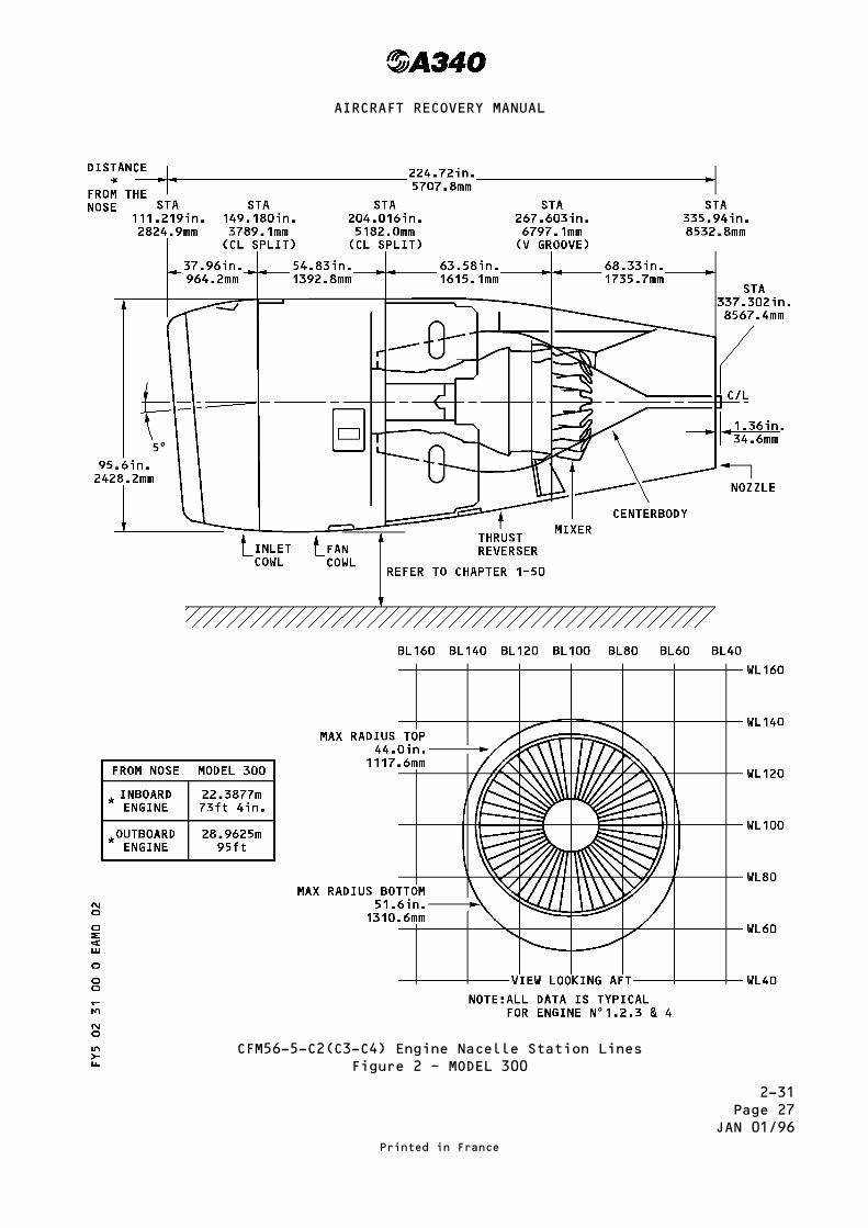
2-31Page 27
JAN 01/96
CFM56-5-C2(C3-C4) Engine Nacelle Station LinesFigure 2 – MODEL 300
Printed in France
AIRCRAFT RECOVERY MANUAL

2-31Page 27AJAN 01/96
CFM56-5-C2(C3-C4) Engine Nacelle Station LinesFigure 2 – MODEL 200
Printed in France
AIRCRAFT RECOVERY MANUAL

2-31Page 28
JUL 30/93
OUTER POWER PLANT
COMPOMENTWEIGHT H-ARM MOMENTS
(kg) (lb) (m) ft Kgm ft.lbINLET COWL 143 315 35.801 117.46 5 119 37 000FAN COWL 75 165 36.980 119.68 2 773 19 747THRUST REVERSER 438 966 38.483 126.25 16 856 121 957PRIMARY NOZZLE 113 247 40.159 131.75 4 538 32 542CENTERBODY 95 209 40.176 131.81 3 817 27 548PYLON 912 2 011 39.747 130.40 36 249 262 234ENGINE 2 633 5 805 37.786 123.96 99 490 719 588
INNER POWER PLANT
COMPOMENTWEIGHT H-ARM MOMENTS
(kg) (lb) (m) ft Kgm ft.lbINLET COWL 143 315 29.229 95.90 4 180 30 208FAN COWL 75 165 30.408 99.76 2 281 16 460THRUST REVERSER 438 966 31.911 104.69 13 977 101 130PRIMARY NOZZLE 113 247 33.587 110.19 3 795 27 217CENTERBODY 95 209 33.604 110.25 3 192 23 042PYLON 883 1 947 33.318 109.30 29 420 212 807ENGINE 2 633 5 805 31.214 102.40 82 186 594 432
Mass, H-ARM, and Moment ConcerningVarious Components of Engines
CFM56-5-C2MODEL - 300
Printed in France
AIRCRAFT RECOVERY MANUAL
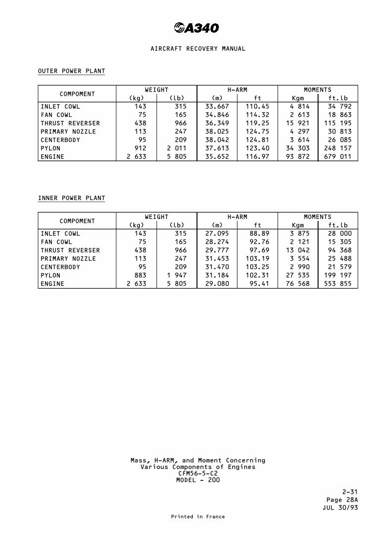
2-31Page 28AJUL 30/93
OUTER POWER PLANT
COMPOMENTWEIGHT H-ARM MOMENTS
(kg) (lb) (m) ft Kgm ft.lbINLET COWL 143 315 33.667 110.45 4 814 34 792FAN COWL 75 165 34.846 114.32 2 613 18 863THRUST REVERSER 438 966 36.349 119.25 15 921 115 195PRIMARY NOZZLE 113 247 38.025 124.75 4 297 30 813CENTERBODY 95 209 38.042 124.81 3 614 26 085PYLON 912 2 011 37.613 123.40 34 303 248 157ENGINE 2 633 5 805 35.652 116.97 93 872 679 011
INNER POWER PLANT
COMPOMENTWEIGHT H-ARM MOMENTS
(kg) (lb) (m) ft Kgm ft.lbINLET COWL 143 315 27.095 88.89 3 875 28 000FAN COWL 75 165 28.274 92.76 2 121 15 305THRUST REVERSER 438 966 29.777 97.69 13 042 94 368PRIMARY NOZZLE 113 247 31.453 103.19 3 554 25 488CENTERBODY 95 209 31.470 103.25 2 990 21 579PYLON 883 1 947 31.184 102.31 27 535 199 197ENGINE 2 633 5 805 29.080 95.41 76 568 553 855
Mass, H-ARM, and Moment ConcerningVarious Components of Engines
CFM56-5-C2MODEL - 200
Printed in France
AIRCRAFT RECOVERY MANUAL

2-31Page 29
JUL 30/93
A. Analysis of Airplane CG Change Because of Power PlantRemoval or Damage
A. Look at the damage to each power plant to see what items are not there.
B. See Tables 1 (page 30) for the weights of the removed or lost componentand their CG locations in the nacelle. Convert nacelle component CGlocations to airplane station locations and calculate the arm for eachitem from airplane CG.
C. Calculate the lateral and longitudinal change in the airplane CG becauseof a removed power plant or components. See paragraph 3.
D. Put together the CG change because of damaged or removed power plantswith the CG change because of damaged or removed aircraft components andcalculate the total airplane CG change.
E. Decide if it is necessary to remove the remaining power plants so theresulting CG change will make airplane recovery easier.
WARNING : DEATH OR SERIOUS INJURY MAY RESULT IF THE AIRPLANE FALLS ON RECOVERYPERSONNEL. VERIFY THAT ALL PERSONNEL ARE AWAY FROM AIRPLANE WHEN POWERPLANT IS REMOVED. REMOVAL OF POWER PLANT WEIGHT FROM WING MAY CAUSEAIRPLANE TO CHANGE POSITION BECAUSE OF CHANGE OF AIRPLANE CENTER OFGRAVITY.
CAUTION : VERIFY THAT THE DENISTY OF THE GROUND IS ABLE TO HOLD THE WEIGHT OFREMOVED ENGINE AND SUPPORT EQUIPMENT.
F. If it is necessary to remove one or more power plant, see removalinstructions in the Airbus Industrie A340 Aircraft Maintenance Manual.
Printed in France
AIRCRAFT RECOVERY MANUAL
2-31Page 30
JAN 01/96
This Page Left Blank Intentionally
Printed in France
AIRCRAFT RECOVERY MANUAL
RR

2-31Page 31
JUL 30/93
3. Calculation of Center of Gravity (CG) Location with one or more Power PlantRemoved
Use the weight and CG data from Table (Page 24 and 25) to calculate theairplane CG changes because of power plant or component removal. The CGlocations are given by Nacelle Stationline, Waterline, and Buttline. SeeFigure 2.
The power plant CG locations must be converted from the nacelle locations toairplane station locations before they can be used to calculate the change inairplane CG.
The change in CG location is calculated as follows :
1. The equation for the new location of the airplane CG is :
Airplane moment minus power plant momentAirplane weight minus power plant weight = airplane CG
2. The equation for percent of CG change of the airplane is :
Change in CGPower Plant Arm × 100 = percent of CG change
Airplane and power plant weight and arm values have been assigned as followsfor use in the examples. The true values may be different.
Recoverable Empty Weight (REW) = 340,000 lbAircraft arm from CG (AA) = 0Power Plant Weight (PPW) = 10,500 lbPower Plant Arm (PPA) laterally from CG = 25 ftPower Plant Arm forward of CG = 20 ft
Calculation Example A :
Calculate the lateral change in CG because of removal of one power plant :
(REW × AA) – (PPW × PPA)REW – PPW = CG change in feet
340,000 × 0 − 10,500 × 25340,000 − 10,500 = 0 − 262,500
329,500 = − 0.796
In this example the calculation shows that when one power plant is removed,the CG of this airplane moves laterally 0.796 feet from its initial CGlocation toward the remaining power plants.
Printed in France
AIRCRAFT RECOVERY MANUAL
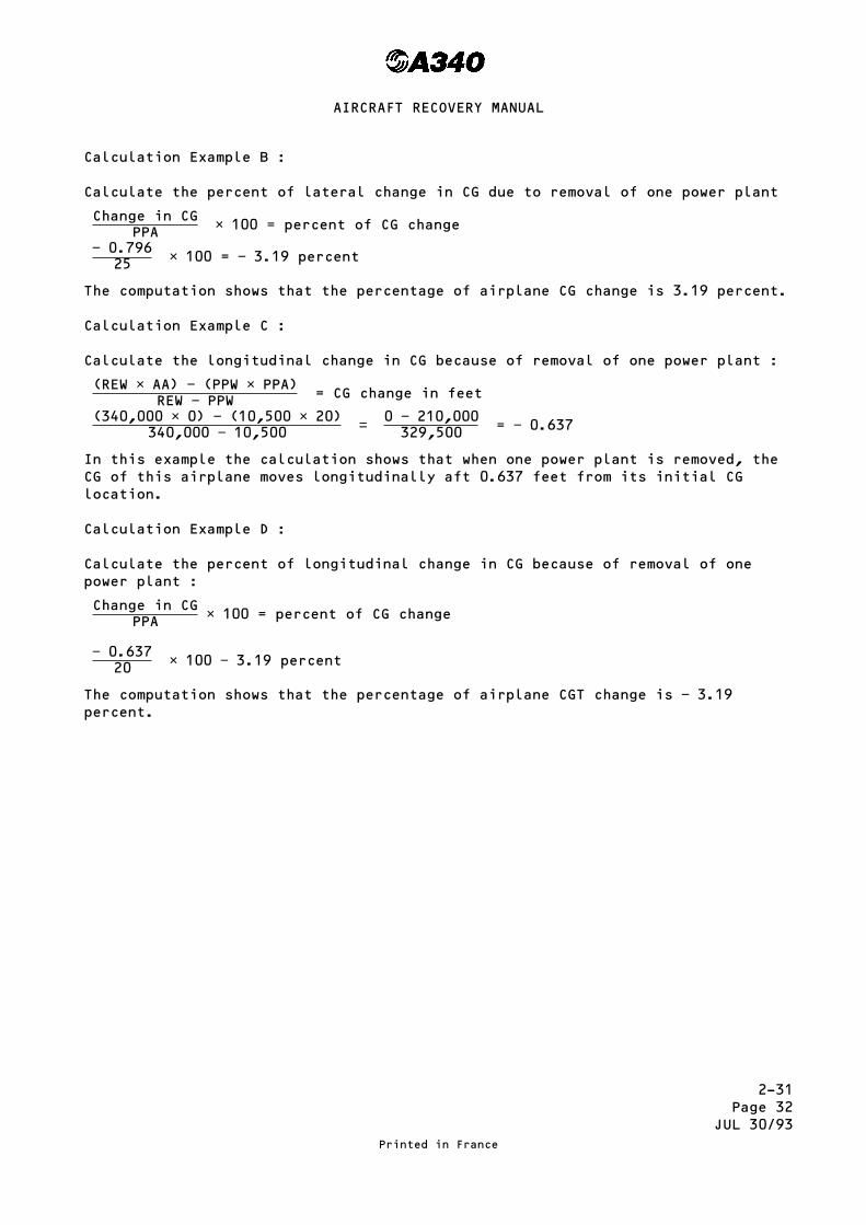
2-31Page 32
JUL 30/93
Calculation Example B :
Calculate the percent of lateral change in CG due to removal of one power plant
Change in CGPPA × 100 = percent of CG change
− 0.79625 × 100 = − 3.19 percent
The computation shows that the percentage of airplane CG change is 3.19 percent.
Calculation Example C :
Calculate the longitudinal change in CG because of removal of one power plant :
(REW × AA) − (PPW × PPA)REW − PPW = CG change in feet
(340,000 × 0) − (10,500 × 20)340,000 − 10,500 = 0 − 210,000
329,500 = − 0.637
In this example the calculation shows that when one power plant is removed, theCG of this airplane moves longitudinally aft 0.637 feet from its initial CGlocation.
Calculation Example D :
Calculate the percent of longitudinal change in CG because of removal of onepower plant :
Change in CGPPA × 100 = percent of CG change
− 0.63720 × 100 − 3.19 percent
The computation shows that the percentage of airplane CGT change is − 3.19percent.
Printed in France
AIRCRAFT RECOVERY MANUAL

2-33Page 1
JAN 01/96
WEIGHT AND CG CHANGES DUE TO THE FUEL IN THE AIRCRAFT FUEL TANKS
1. General
This topic on fuel weights and CG changes deals with the A340 aircraft models :– 200, 300– 300 at 271 tonnes Maximum Take-Off Weight (MTOW)– 200 and 300 at 260 tonnes MTOW.
The trim-tank pump fitted in the Trimmable Horizontal Stabilizer is anoptional modification to all models.
The model 300 at 271 tonne MTOW has an Additional Center Tank (ACT) fitted asan optional modification.
All mass and moment data for fuel in the ACT is shown on page 29.
The weight and CG position of the aircraft will change due to fuel quantitiesin each tank.
To find the changes in weight and CG position, calculate :– the H-arm dimension along the longitudinal plane from nose to tail– the Y-arm dimension along the lateral plane from wing tip to wing tip.
The H-arm is a dimension from the CG of an item/component to the horizontalarm reference datum plane.
The Y-arm is a dimension from the CG of an item/component to the lateral armreference datum plane.
2. H-arm Calculations (Ref. Fig.1)
To calculate the H-arm, establish the following :– the aircraft weight empty (Ref. 1-10 page 2)– the aircraft H-arm at 25% Reference Chord (RC). This is the H-arm designref.
– the total fuel moment– the total fuel weight.
To calculate the total weight and moment of the fuel in the tanks :– find the remaining fuel quantities in each tank– use the mass and moment data on pages 9 thru 29.
Use this information in Equation 1 to determine the effect of the fuel onthe H-arm.
Equation 1 :
H-arm from position X0 =
(Aircraft Wt Empty x Aircraft H-arm) + Total Fuel MomentAircraft Wt Empty + Total Fuel Wt
After Equation 1 is complete, calculate the change in the percentageReference Chord in Equations 2 or 3.
Printed in France
AIRCRAFT RECOVERY MANUAL
R
RRR
RR
R
R
R
R
RR
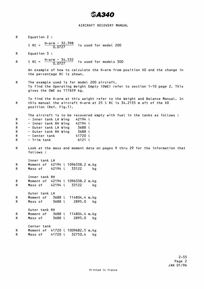
2-33Page 2
JAN 01/96
Equation 2 :
% RC =H-arm – 32.398
0.0727 is used for model 200
Equation 3 :
% RC =H-arm – 34.532
0.0727 is used for models 300
An example of how to calculate the H-arm from position X0 and the change inthe percentage RC is shown.
The example used is for model 200 aircraft.To find the Operating Weight Empty (OWE) refer to section 1-10 page 2. Thisgives the OWE as 117659 kg.
To find the H-arm at this weight refer to the Weight and Balance Manual. Inthis manual the aircraft H-arm at 25 % RC is 34.2155 m aft of the X0position (Ref. Fig.1).
The aircraft is to be recovered empty with fuel in the tanks as follows :– Inner tank LH Wing 42194 l– Inner tank RH Wing 42194 l– Outer tank LH Wing 3688 l– Outer tank RH Wing 3688 l– Center tank 41720 l– Trim tank 6121 l
Look at the mass and moment data on pages 9 thru 29 for the information thatfollows :
Inner tank LHMoment of 42194 l 1096338.2 m.kgMass of 42194 l 33122 kg
Inner tank RHMoment of 42194 l 1096338.2 m.kgMass of 42194 l 33122 kg
Outer tank LHMoment of 3688 l 114804.4 m.kgMass of 3688 l 2895.0 kg
Outer tank RHMoment of 3688 l 114804.4 m.kgMass of 3688 l 2895.0 kg
Center tankMoment of 41720 l 1009682.5 m.kgMass of 41720 l 32750.4 kg
Printed in France
AIRCRAFT RECOVERY MANUAL
R
R
R
R
R
RRRRRR
R
RR
RR
RR
RR
RR

2-33Page 3
JAN 01/96
Trim tankMoment of 6121 l 292719.69 m.kgMass of 6121 l 4805.3 kg
Total Fuel Moment = 3724687.4 m.kgTotal Fuel Mass = 109589.0 kg
Now enter the Total Fuel Moment and Total Fuel Mass into equation 1.
H-arm from position X0 =(117659 × 34.2155) + 3724687.4
117659 + 109589
H-arm = 34.10 m
Enter this H-arm in equation 2 and calculate the % RC :
% RC =34.10 − 32.398
0.0727
% RC = 23.48%
3. Y-Arm Calculations
When the aircraft is in level flight the Y-arm dimension is usually loadedequally about the centerline. That is, the Y-arm dimension about the RH wingis equal to the Y-arm dimension about the LH wing.
In this configuration all the moments and loads are equal about thecenterline.
To calculate the Y-arm for an aircraft on a recovery, establish thefollowing :– the aircraft weight empty– the dimension from the aircraft centerline to the MLGs– the dimension from the aircraft centerline to the jacking point– the total fuel weight– the total fuel moment.
To find the total fuel weight and moment of the fuel in the tanks :– find the remaining fuel quantities in each tank– use the mass and moment data on pages 9 thru 29.
The example shows how to calculate :– the Y-arm moment with an allowance– the total fuel mass and moments– the lifting load, for an aircraft on a recovery with a MLG failure.
If the aircraft, has a LH MLG failure, it will rest on the LH inboard enginewith the fuselage horizontal. The aircraft will be recovered from thisposition.
The loads acting on the aircraft with a LH MLG failure are shown in Fig.2.
Printed in France
AIRCRAFT RECOVERY MANUAL
RR
RR
R
R
R
R
R
R
RR
RR
R
R
R
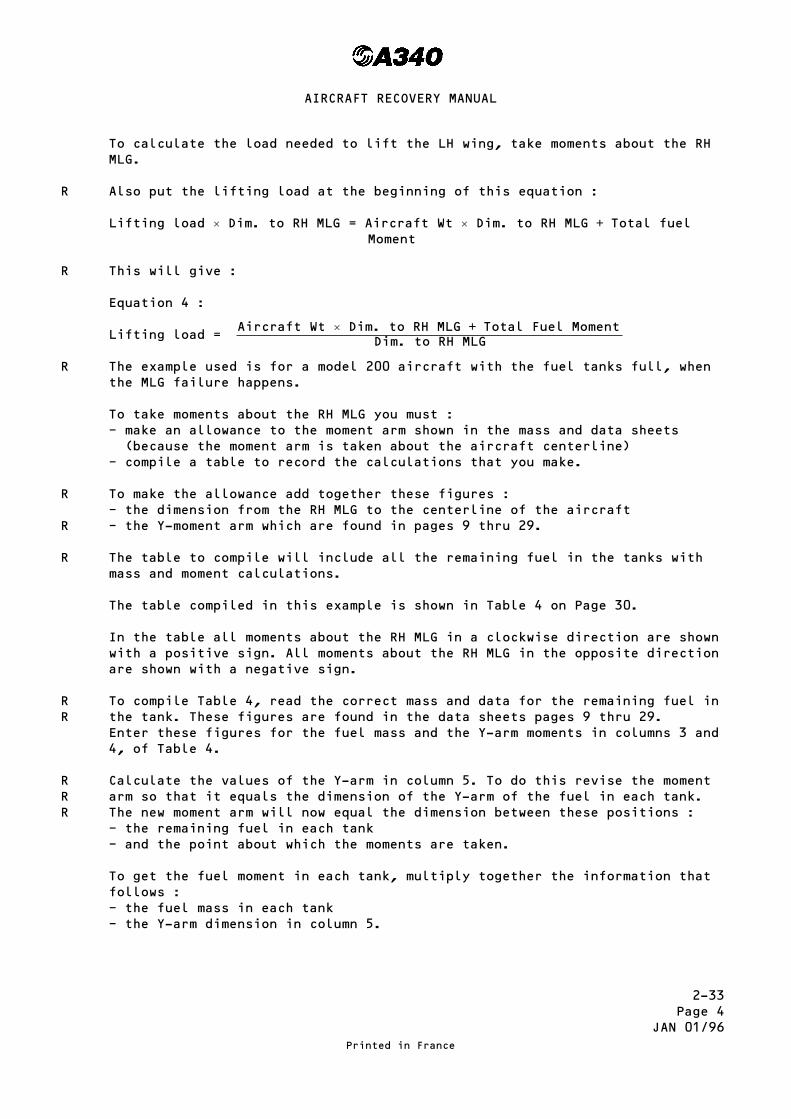
2-33Page 4
JAN 01/96
To calculate the load needed to lift the LH wing, take moments about the RHMLG.
Also put the lifting load at the beginning of this equation :
Lifting load × Dim. to RH MLG = Aircraft Wt × Dim. to RH MLG + Total fuelMoment
This will give :
Equation 4 :
Lifting load =Aircraft Wt × Dim. to RH MLG + Total Fuel Moment
Dim. to RH MLG
The example used is for a model 200 aircraft with the fuel tanks full, whenthe MLG failure happens.
To take moments about the RH MLG you must :– make an allowance to the moment arm shown in the mass and data sheets(because the moment arm is taken about the aircraft centerline)
– compile a table to record the calculations that you make.
To make the allowance add together these figures :– the dimension from the RH MLG to the centerline of the aircraft– the Y-moment arm which are found in pages 9 thru 29.
The table to compile will include all the remaining fuel in the tanks withmass and moment calculations.
The table compiled in this example is shown in Table 4 on Page 30.
In the table all moments about the RH MLG in a clockwise direction are shownwith a positive sign. All moments about the RH MLG in the opposite directionare shown with a negative sign.
To compile Table 4, read the correct mass and data for the remaining fuel inthe tank. These figures are found in the data sheets pages 9 thru 29.Enter these figures for the fuel mass and the Y-arm moments in columns 3 and4, of Table 4.
Calculate the values of the Y-arm in column 5. To do this revise the momentarm so that it equals the dimension of the Y-arm of the fuel in each tank.The new moment arm will now equal the dimension between these positions :– the remaining fuel in each tank– and the point about which the moments are taken.
To get the fuel moment in each tank, multiply together the information thatfollows :– the fuel mass in each tank– the Y-arm dimension in column 5.
Printed in France
AIRCRAFT RECOVERY MANUAL
R
R
R
R
R
R
RR
RRR
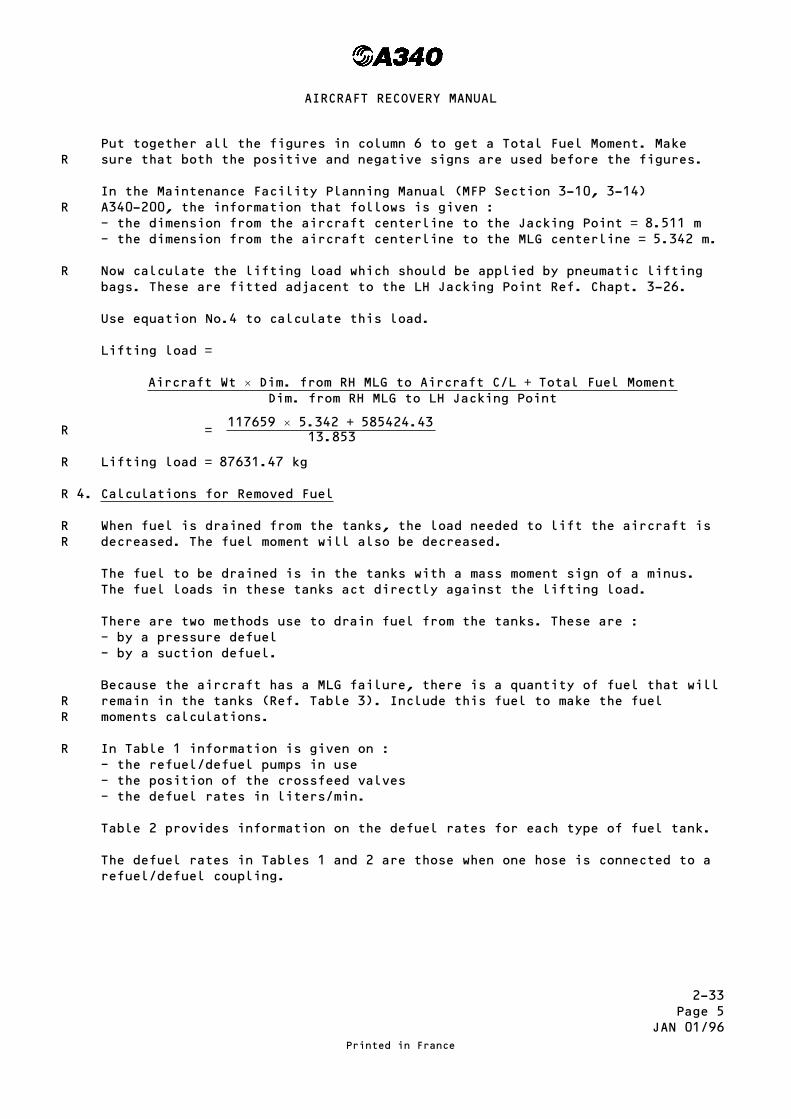
2-33Page 5
JAN 01/96
Put together all the figures in column 6 to get a Total Fuel Moment. Makesure that both the positive and negative signs are used before the figures.
In the Maintenance Facility Planning Manual (MFP Section 3-10, 3-14)A340-200, the information that follows is given :– the dimension from the aircraft centerline to the Jacking Point = 8.511 m– the dimension from the aircraft centerline to the MLG centerline = 5.342 m.
Now calculate the lifting load which should be applied by pneumatic liftingbags. These are fitted adjacent to the LH Jacking Point Ref. Chapt. 3-26.
Use equation No.4 to calculate this load.
Lifting load =
Aircraft Wt × Dim. from RH MLG to Aircraft C/L + Total Fuel MomentDim. from RH MLG to LH Jacking Point
= 117659 × 5.342 + 585424.4313.853
Lifting load = 87631.47 kg
4. Calculations for Removed Fuel
When fuel is drained from the tanks, the load needed to lift the aircraft isdecreased. The fuel moment will also be decreased.
The fuel to be drained is in the tanks with a mass moment sign of a minus.The fuel loads in these tanks act directly against the lifting load.
There are two methods use to drain fuel from the tanks. These are :– by a pressure defuel– by a suction defuel.
Because the aircraft has a MLG failure, there is a quantity of fuel that willremain in the tanks (Ref. Table 3). Include this fuel to make the fuelmoments calculations.
In Table 1 information is given on :– the refuel/defuel pumps in use– the position of the crossfeed valves– the defuel rates in liters/min.
Table 2 provides information on the defuel rates for each type of fuel tank.
The defuel rates in Tables 1 and 2 are those when one hose is connected to arefuel/defuel coupling.
Printed in France
AIRCRAFT RECOVERY MANUAL
R
R
R
R
R
R
RR
RR
R

2-33Page 6
JUL 01/95
PUMP(S) CROSSFEED VALVES DEFUEL RATESl/min
2 CENTER TK. CLOSED 351.2
1 CENTER TK. CLOSED 215.6
MAIN 1 AND 2 CROSSFEEDS 1 AND 2 OPEN 366.8
MAIN 2 AND 3 CROSSFEEDS 2 AND 3 OPEN 365.6
MAIN 1, 2, 3 AND 4 CROSSFEEDS 1, 2, 3, AND 4 OPEN 406.8
6 PUMPS(MAIN 1, 2, 3 AND 4+ 2 CENTER TK)
CROSSFEEDS 1, 2, 3 AND 4 OPEN 462
Pressure Defuel InformationTable 1
The suction defuel uses the pumps of the fuel tanker to give the necessarynegative pressure of 0.76 bar (11 psi).
The defuel rates, in Table 2 are those, when :– a negative pressure of 0.76 bar (11 psi) is applied at the refuel/defuelcoupling
– the fuel flows through one defuel hose– the appropriate tank refuel/defuel valve is open.
FUEL TANK DEFUEL RATEl/min
INNER 288.0
OUTER 89.0
CENTER 281.0
TRIM (No trim pump fitted) 72.0
TRIM (Trim pump fitted) 125.0
ACT 130.0
Suction Defuel InformationTable 2
After a Pressure Defuel or a Suction Defuel there will still be a quantity offuel remaining in the tanks.
The quantity of this remaining fuel is given in Table 3. It gives differentpositions of the aircraft attitudes.
Printed in France
AIRCRAFT RECOVERY MANUAL
R
R
R
RR
RR

2-33Page 7
JUL 01/95
The fuel quantities in the table are calculated when :– the fuel pumps are available and not damaged– the fuel tank drains have also been used to drain the fuel.
Fuel tank abbreviations for Table 3 are as follows :
CC – Collector Cells (Total, i.e. 4)LF – Left Forward InnerLA – Left Aft InnerRF – Right Forward InnerRA – Right Aft InnerCTR – Centre TankTRM – Trim TankRO – Right Outer TankLO – Left Outer Tank.ACT – Additional Center Tank
AIRCRAFTCONFIGURATION CC LF LA RF RA CTR TRM RO LO ACT TOTAL
QTY
1. NLG COLLAPSE 24 64 79 64 79 775 70 42 42 9 1 248
2. 1 RH or LH MLGCOLLAPSE
24 23 83 25 108 25 450 2238 1 4 2 981
3. 1 NLG and 1 RH orLH MLG COLLAPSE
24 52 72 51 72 63 15 78 17 1 445
4. ALL MLGsCOLLAPSE
24 18 86 18 86 37 45 2 2 97 415
5. ALL GEARSCOLLAPSE
24 24 86 24 86 61 25 6 6 0 342
6. OVERBALANCEDTAIL ON GROUND
24 17 264 17 264 327 276 821 821 395 3 226
7. NORMAL ATTITUDE 24 28 76 28 76 39 9 7 7 4 298
All quantities are in liters
The Remaining Fuel Quantities that you Cannot DrainTable 3
Now calculate the decreased Total Fuel Moment to find the decreased lifting loadneeded to lift the aircraft.
The table compiled in this example is shown in Table 5.
To calculate the decreased Total Fuel Moment (Ref. Table 5), use Equation 4again.
Lifting Load =117659 x 5.342 + (-21673.7)
13.853
= 46,936.27 kg
Printed in France
AIRCRAFT RECOVERY MANUAL
R
R
R
R
R
R
R
R
R
RR
R
R
R
R

2-33Page 8
JAN 01/96
The lifting load needed, is therefore decreased if all the fuel in the LHwing and fuselage is drained.
The decreased lifting load will be :
87,631.47 − 46,936.272 = 40695.2 kg
That is a decrease of 46.43% in the lifting load required to lift theaircraft with the fuel removed.
Printed in France
AIRCRAFT RECOVERY MANUAL
RR
R
R

2-33Page 9
JAN 01/96
5. FUEL DATA FOR INNER TANK, LEFT OR RIGHT HAND WING (Model 200)
A. H-ARM
Fuel specific gravity 0.785
CAPACITY MASS H-ARM MOMENT MASS H-ARM MOMENT
(l) (kg) (m) (m.kg) (lb) (ft) (ft.lbx103)
400 314 31.735 9964.79 692.244 104.116 72.074800 628 31.684 19897.56 1384.488 103.949 143.921200 942 31.609 29775.68 2076.733 103.703 215.361600 1256 31.576 39659.46 2768.977 103.594 286.852000 1570 31.564 49555.48 3461.222 103.555 358.432400 1884 31.560 59459.04 4153.466 103.542 430.062800 2198 31.561 69371.08 4845.711 103.543 501.743200 2512 31.562 79283.74 5537.955 103.548 573.443600 2826 31.567 89208.34 6230.199 103.565 645.234000 3140 31.572 99136.08 6922.444 103.581 717.034400 3454 31.575 109060.05 7614.688 103.591 788.814800 3768 31.582 119000.98 8306.933 103.614 860.715200 4082 31.588 128942.22 8999.177 103.634 932.625600 4396 31.593 138882.83 9691.421 103.650 1004.526000 4710 31.599 148831.29 10383.666 103.67 1076.476400 5024 31.607 158793.57 11075.91 103.696 1148.536800 5338 31.614 168755.53 11768.155 103.719 1220.587200 5652 31.620 178716.24 12460.399 103.739 1292.637600 5966 31.627 188686.68 13152.644 103.762 1364.748000 6280 31.636 198674.08 13844.888 103.791 1436.978400 6594 31.644 208660.54 14537.132 103.818 1509.228800 6908 31.651 218645.11 15229.377 103.841 1581.439200 7222 31.657 228626.85 15921.621 103.860 1653.629600 7536 31.666 238634.98 16613.866 103.890 1726.0110000 7850 31.674 248640.90 17306.110 103.916 1798.3810400 8164 31.682 258651.85 17998.354 103.942 1870.7810800 8478 31.689 268659.34 18690.599 103.965 1943.1711200 8792 31.696 278671.23 19382.843 103.988 2015.5811600 9106 31.705 288705.73 20075.088 104.018 2088.1712000 9420 31.713 298736.46 20767.33 104.04 2160.6312400 9734 31.720 308762.48 21459.58 104.07 2233.3012800 10048 31.728 318802.94 22151.82 104.09 2305.7813200 10362 31.734 328827.71 22844.06 104.11 2378.2313600 10676 31.742 338877.59 23536.31 104.14 2451.0714000 10990 31.750 348932.5 24228.55 104.16 2523.6414400 11304 31.758 358992.43 24920.80 104.19 2596.5014800 11618 31.765 369045.77 25613.04 104.21 2669.1315200 11932 31.772 379103.5 26305.29 104.24 2742.0615600 12246 31.778 389153.39 26997.53 104.25 2814.4916000 12560 31.786 399232.16 27689.78 104.28 2887.4916400 12874 31.794 409315.96 28382.02 104.31 2960.52
Printed in France
AIRCRAFT RECOVERY MANUAL
R
R
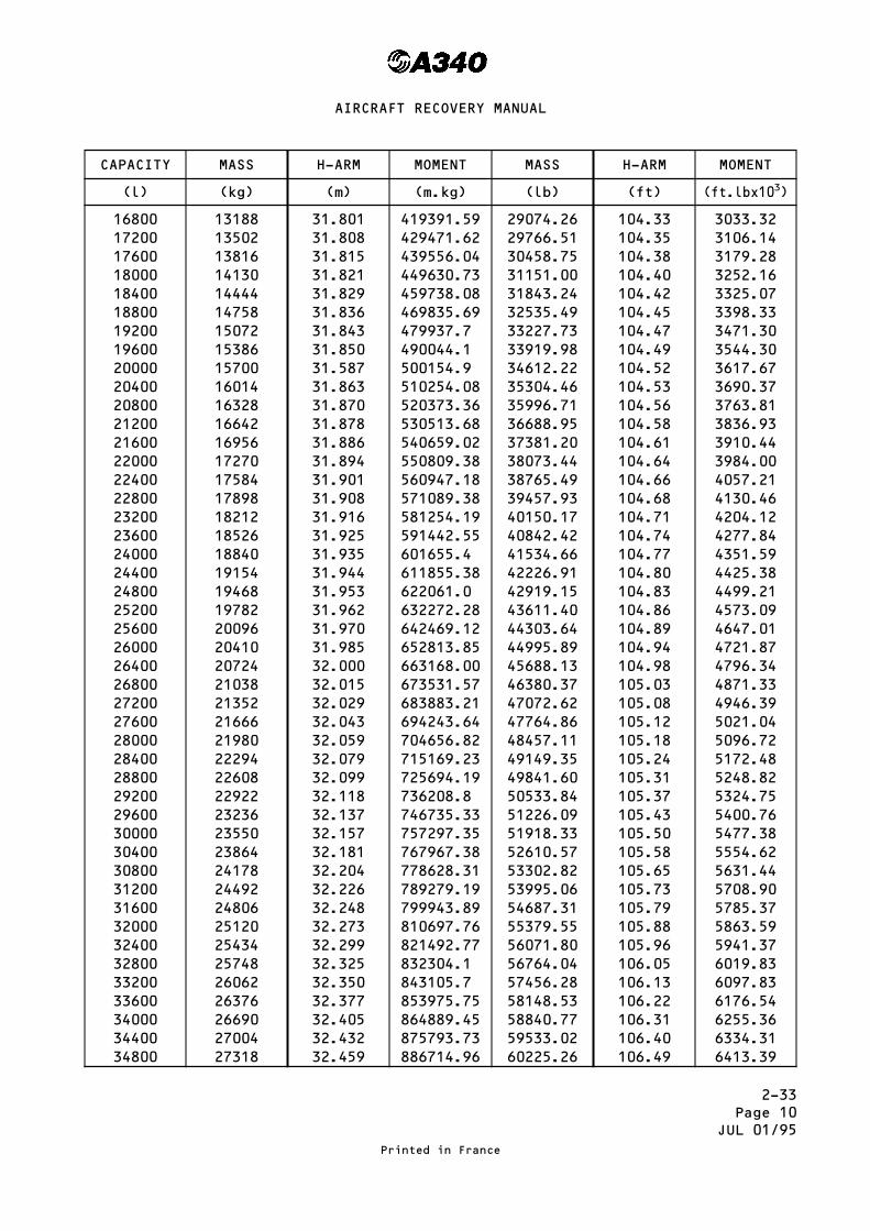
2-33Page 10
JUL 01/95
CAPACITY MASS H-ARM MOMENT MASS H-ARM MOMENT
(l) (kg) (m) (m.kg) (lb) (ft) (ft.lbx103)
16800 13188 31.801 419391.59 29074.26 104.33 3033.3217200 13502 31.808 429471.62 29766.51 104.35 3106.1417600 13816 31.815 439556.04 30458.75 104.38 3179.2818000 14130 31.821 449630.73 31151.00 104.40 3252.1618400 14444 31.829 459738.08 31843.24 104.42 3325.0718800 14758 31.836 469835.69 32535.49 104.45 3398.3319200 15072 31.843 479937.7 33227.73 104.47 3471.3019600 15386 31.850 490044.1 33919.98 104.49 3544.3020000 15700 31.587 500154.9 34612.22 104.52 3617.6720400 16014 31.863 510254.08 35304.46 104.53 3690.3720800 16328 31.870 520373.36 35996.71 104.56 3763.8121200 16642 31.878 530513.68 36688.95 104.58 3836.9321600 16956 31.886 540659.02 37381.20 104.61 3910.4422000 17270 31.894 550809.38 38073.44 104.64 3984.0022400 17584 31.901 560947.18 38765.49 104.66 4057.2122800 17898 31.908 571089.38 39457.93 104.68 4130.4623200 18212 31.916 581254.19 40150.17 104.71 4204.1223600 18526 31.925 591442.55 40842.42 104.74 4277.8424000 18840 31.935 601655.4 41534.66 104.77 4351.5924400 19154 31.944 611855.38 42226.91 104.80 4425.3824800 19468 31.953 622061.0 42919.15 104.83 4499.2125200 19782 31.962 632272.28 43611.40 104.86 4573.0925600 20096 31.970 642469.12 44303.64 104.89 4647.0126000 20410 31.985 652813.85 44995.89 104.94 4721.8726400 20724 32.000 663168.00 45688.13 104.98 4796.3426800 21038 32.015 673531.57 46380.37 105.03 4871.3327200 21352 32.029 683883.21 47072.62 105.08 4946.3927600 21666 32.043 694243.64 47764.86 105.12 5021.0428000 21980 32.059 704656.82 48457.11 105.18 5096.7228400 22294 32.079 715169.23 49149.35 105.24 5172.4828800 22608 32.099 725694.19 49841.60 105.31 5248.8229200 22922 32.118 736208.8 50533.84 105.37 5324.7529600 23236 32.137 746735.33 51226.09 105.43 5400.7630000 23550 32.157 757297.35 51918.33 105.50 5477.3830400 23864 32.181 767967.38 52610.57 105.58 5554.6230800 24178 32.204 778628.31 53302.82 105.65 5631.4431200 24492 32.226 789279.19 53995.06 105.73 5708.9031600 24806 32.248 799943.89 54687.31 105.79 5785.3732000 25120 32.273 810697.76 55379.55 105.88 5863.5932400 25434 32.299 821492.77 56071.80 105.96 5941.3732800 25748 32.325 832304.1 56764.04 106.05 6019.8333200 26062 32.350 843105.7 57456.28 106.13 6097.8333600 26376 32.377 853975.75 58148.53 106.22 6176.5434000 26690 32.405 864889.45 58840.77 106.31 6255.3634400 27004 32.432 875793.73 59533.02 106.40 6334.3134800 27318 32.459 886714.96 60225.26 106.49 6413.39
Printed in France
AIRCRAFT RECOVERY MANUAL

2-33Page 11
JAN 01/96
CAPACITY MASS H-ARM MOMENT MASS H-ARM MOMENT
(l) (kg) (m) (m.kg) (lb) (ft) (ft.lbx103)
35200 27632 32.489 897736.05 60917.50 106.59 6493.1935600 27946 32.519 908775.97 61609.75 106.69 6573.1436000 28260 32.549 919834.74 62301.99 106.79 6653.2336400 28574 32.579 930912.35 62994.24 106.88 6732.8236800 28888 32.611 942066.57 63686.48 106.99 6813.8537200 29202 32.643 953240.89 64378.73 107.09 6894.3237600 29516 32.674 964405.78 65070.97 107.19 6974.9638000 29830 32.709 975709.47 65763.22 107.31 7057.0538400 30144 32.743 987004.99 66455.46 107.42 7138.6438800 30458 32.776 998291.41 67147.71 107.53 7220.3939200 30772 32.813 1009721.60 67839.95 107.65 7302.9739600 31086 32.848 1021112.90 68532.19 107.77 7385.7140000 31400 32.887 1032651.80 69224.44 107.89 7468.6240400 31714 32.925 1044183.50 69916.68 108.02 7552.4040800 32028 32.933 1054778.10 70608.93 108.04 7628.5941200 32342 33.001 1067318.30 71301.17 108.27 7719.7841600 32656 33.401 1078986.90 71993.42 108.40 7804.0841904 32895 33.071 1087870.50 72520.30 108.50 7868.4542000 32970 33.081 1090680.60 72685.66 108.53 7888.5742194 33122 33.100 1096338.20 73020.76 108.59 7929.32
Printed in France
AIRCRAFT RECOVERY MANUAL
RR
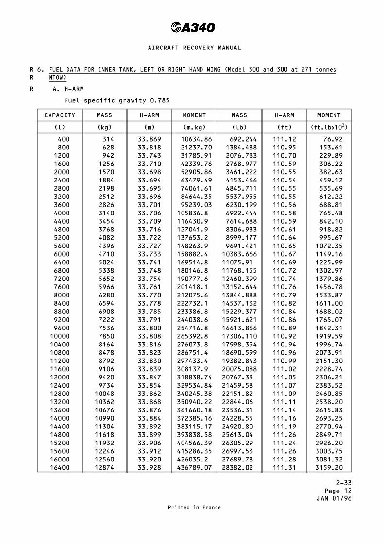
2-33Page 12
JAN 01/96
6. FUEL DATA FOR INNER TANK, LEFT OR RIGHT HAND WING (Model 300 and 300 at 271 tonnesMTOW)
A. H-ARM
Fuel specific gravity 0.785
CAPACITY MASS H-ARM MOMENT MASS H-ARM MOMENT
(l) (kg) (m) (m.kg) (lb) (ft) (ft.lbx103)
400 314 33.869 10634.86 692.244 111.12 76.92800 628 33.818 21237.70 1384.488 110.95 153.611200 942 33.743 31785.91 2076.733 110.70 229.891600 1256 33.710 42339.76 2768.977 110.59 306.222000 1570 33.698 52905.86 3461.222 110.55 382.632400 1884 33.694 63479.49 4153.466 110.54 459.122800 2198 33.695 74061.61 4845.711 110.55 535.693200 2512 33.696 84644.35 5537.955 110.55 612.223600 2826 33.701 95239.03 6230.199 110.56 688.814000 3140 33.706 105836.8 6922.444 110.58 765.484400 3454 33.709 116430.9 7614.688 110.59 842.104800 3768 33.716 127041.9 8306.933 110.61 918.825200 4082 33.722 137653.2 8999.177 110.64 995.675600 4396 33.727 148263.9 9691.421 110.65 1072.356000 4710 33.733 158882.4 10383.666 110.67 1149.166400 5024 33.741 169514.8 11075.91 110.69 1225.996800 5338 33.748 180146.8 11768.155 110.72 1302.977200 5652 33.754 190777.6 12460.399 110.74 1379.867600 5966 33.761 201418.1 13152.644 110.76 1456.788000 6280 33.770 212075.6 13844.888 110.79 1533.878400 6594 33.778 222732.1 14537.132 110.82 1611.008800 6908 33.785 233386.8 15229.377 110.84 1688.029200 7222 33.791 244038.6 15921.621 110.86 1765.079600 7536 33.800 254716.8 16613.866 110.89 1842.3110000 7850 33.808 265392.8 17306.110 110.92 1919.5910400 8164 33.816 276073.8 17998.354 110.94 1996.7410800 8478 33.823 286751.4 18690.599 110.96 2073.9111200 8792 33.830 297433.4 19382.843 110.99 2151.3011600 9106 33.839 308137.9 20075.088 111.02 2228.7412000 9420 33.847 318838.74 20767.33 111.05 2306.2112400 9734 33.854 329534.84 21459.58 111.07 2383.5212800 10048 33.862 340245.38 22151.82 111.09 2460.8513200 10362 33.868 350940.22 22844.06 111.11 2538.2013600 10676 33.876 361660.18 23536.31 111.14 2615.8314000 10990 33.884 372385.16 24228.55 111.16 2693.2514400 11304 33.892 383115.17 24920.80 111.19 2770.9414800 11618 33.899 393838.58 25613.04 111.26 2849.7115200 11932 33.906 404566.39 26305.29 111.24 2926.2015600 12246 33.912 415286.35 26997.53 111.26 3003.7516000 12560 33.920 426035.2 27689.78 111.28 3081.3216400 12874 33.928 436789.07 28382.02 111.31 3159.20
Printed in France
AIRCRAFT RECOVERY MANUAL
RR
R

2-33Page 13
JUL 01/95
CAPACITY MASS H-ARM MOMENT MASS H-ARM MOMENT
(l) (kg) (m) (m.kg) (lb) (ft) (ft.lbx103)
16800 13188 33.935 447534.78 29074.26 111.33 3236.8417200 13502 33.942 458284.88 29766.51 111.36 3314.8017600 13816 33.949 469039.38 30458.75 111.38 3392.4918000 14130 33.955 479784.15 31151.00 111.40 3470.2218400 14444 33.963 490561.57 31843.24 111.43 3548.2918800 14758 33.970 501329.26 32535.49 114.45 3626.0819200 15072 33.977 512101.34 33227.73 111.47 3703.8919600 15386 33.984 522877.84 33919.98 111.49 3781.7420000 15700 33.991 533658.7 34612.22 111.52 3859.9520400 16014 33.997 544427.96 35304.46 111.54 3937.8620800 16328 34.004 555217.31 35996.71 111.56 4015.7021200 16642 34.012 566027.7 36688.95 111.59 4094.1221600 16956 34.020 576843.12 37381.20 111.61 4172.1622000 17270 34.028 587663.56 38073.44 111.64 4250.5222400 17584 34.035 598471.44 38765.69 111.66 4328.5822800 17898 34.042 609283.72 39457.93 111.68 4406.6623200 18212 34.050 620118.6 40150.17 111.71 4485.1723600 18526 34.059 630977.03 40842.42 111.74 4563.7324000 18840 34.069 624825.46 41534.66 111.77 4642.3324400 19154 34.078 652730.01 42226.91 111.80 4720.9724800 19468 34.087 663430.5 42919.15 111.83 4799.6525200 19782 34.096 674487.07 43611.40 111.86 4878.3725600 20096 34.104 685353.98 44303.64 111.89 4957.1326000 20410 34.119 696368.79 44995.89 111.94 5036.8426400 20724 34.134 707393.02 45688.13 111.99 5116.6126800 21038 34.149 718426.66 46380.37 112.04 5196.4627200 21352 34.163 729448.38 47072.62 112.08 5275.9027600 21666 34.177 740478.88 47764.86 112.13 5355.8828000 21980 34.193 751562.14 48457.11 112.18 5435.9228400 22294 34.213 762744.62 49149.35 115.25 5517.0128800 22608 34.233 773939.66 49841.60 112.31 5597.7129200 22922 34.252 785124.34 50533.84 112.37 5678.4929600 23236 34.271 796320.96 51226.09 112.44 5759.8630000 23550 34.291 807553.05 51918.33 112.50 5840.8130400 23864 34.315 818893.16 52610.57 112.58 5922.9030800 24178 34.338 830224.16 53302.82 112.66 6005.0131200 24492 34.360 841545.12 53995.06 112.73 6086.8631600 24806 34.382 852879.89 54687.31 112.80 6168.7332000 25120 34.407 864303.84 55379.55 112.88 6251.2432400 25434 34.433 875768.92 56071.80 112.97 6334.4332800 25748 34.459 887250.33 56764.04 113.05 6417.1733200 26062 34.484 898722.01 57456.28 113.14 6500.6033600 26376 34.511 910262.14 58148.53 113.22 6583.5834000 26690 34.539 921845.91 58840.77 113.32 6667.8434400 27004 34.566 933420.26 59533.02 113.40 6751.0434800 27318 34.593 945011.57 60225.26 113.49 6834.96
Printed in France
AIRCRAFT RECOVERY MANUAL
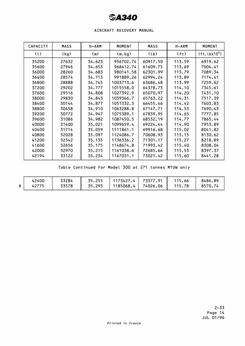
2-33Page 14
JUL 01/96
CAPACITY MASS H-ARM MOMENT MASS H-ARM MOMENT
(l) (kg) (m) (m.kg) (lb) (ft) (ft.lbx103)
35200 27632 34.623 956702.74 60917.50 113.59 6919.6235600 27946 34.653 968412.74 61609.75 113.69 7004.4136000 28260 34.683 980141.58 62301.99 113.79 7089.3436400 28574 34.713 991889.26 62994.24 113.89 7174.4136800 28888 34.745 1003713.6 63686.48 113.99 7259.6237200 29202 34.777 1015558.0 64378.73 114.10 7345.6137600 29516 34.808 1027392.9 65070.97 114.20 7431.1038000 29830 34.843 1039366.7 65763.22 114.31 7517.3938400 30144 34.877 1051332.3 66455.46 114.42 7603.8338800 30458 34.910 1063288.8 67147.71 114.53 7690.4339200 30772 34.947 1075389.1 67839.95 114.65 7777.8539600 31086 34.982 1087450.5 68532.19 114.77 7865.4440000 31400 35.021 1099659.4 69224.44 114.90 7953.8940400 31714 35.059 1111861.1 69916.68 115.02 8041.8240800 32028 35.097 1124086.7 70608.93 115.15 8130.6241200 32342 35.135 1136336.2 71301.17 115.27 8218.8941600 32656 35.175 1148674.8 71993.42 115.40 8308.0442000 32970 35.215 1161038.6 72685.66 115.53 8397.3742194 33122 35.234 1167031.1 73021.42 115.60 8441.28
Table Continued For Model 300 at 271 tonnes MTOW only
42400 33284 35.255 1173427.4 73377.91 115.66 8486.8942775 33578 35.293 1185068.4 74026.06 115.78 8570.74
Printed in France
AIRCRAFT RECOVERY MANUAL
R

2-33Page 15
JAN 01/96
7. FUEL DATA FOR INNER TANK, LEFT OR RIGHT HAND WING (Models 200, 300 and 300 at271 tonnes MTOW)
A. Y-ARM
Fuel specific gravity 0.785
CAPACITY MASS Y-ARM MOMENT MASS Y-ARM MOMENT
(l) (kg) (m) (m.kg) (lb) (ft) (ft.lbx103)
400 314 3.140 985.90 692.244 10.30 7.13800 628 3.195 2006.46 1384.488 10.48 14.511200 942 3.254 3065.27 2076.733 10.66 22.141600 1256 3.305 4151.08 2768.977 10.84 30.162000 1570 3.357 5270.49 3461.222 11.01 34.652400 1884 3.405 6415.02 4153.466 11.17 46.392800 2198 3.454 7591.89 4845.711 11.33 54.903200 2512 3.493 8774.41 5537.955 11.46 63.463600 2826 3.541 10006.86 6230.199 11.62 72.394000 3140 3.582 11247.48 6922.444 11.75 81.344400 3454 3.617 12493.12 7614.688 11.87 90.384800 3768 3.660 13790.88 8306.933 12.01 99.175200 4082 3.697 15091.15 8999.177 12.13 109.165600 4396 3.730 16397.08 9691.421 12.24 118.626000 4710 3.764 17728.44 10383.666 12.35 128.246400 5024 3.800 19091.12 11075.91 12.46 138.016800 5338 3.832 20455.21 11768.155 12.57 147.937200 5652 3.861 21822.37 12460.399 12.67 157.877600 5966 3.892 23219.67 13152.644 12.77 167.968000 6280 3.924 24642.72 13844.888 12.87 178.188400 6594 3.954 26072.68 14537.132 12.97 188.558800 6908 3.982 27507.66 15229.377 13.06 198.899200 7222 4.007 28938.55 15921.621 13.15 209.379600 7536 4.038 30430.37 16613.866 13.25 220.1310000 7850 4.066 31918.10 17306.110 13.34 230.8610400 8164 4.093 33415.25 17998.354 13.43 241.7210800 8478 4.117 34903.93 18690.599 13.51 252.5111200 8792 4.141 36407.67 19382.843 13.59 263.4111600 9106 4.169 37962.91 20075.088 13.68 274.6312000 9420 4.196 39526.32 20767.33 13.77 285.9712400 9734 4.220 41077.48 21459.58 13.85 297.2112800 10048 4.244 42643.71 22151.82 13.92 308.3513200 10362 4.266 44204.29 22844.06 14.00 319.8213600 10676 4.291 45810.72 23536.31 14.08 331.3914000 10990 4.317 47443.83 24228.55 14.16 343.0814400 11304 4.342 49081.97 24920.80 14.25 355.1214800 11618 4.365 50712.57 25613.04 14.32 366.7815200 11932 4.388 52357.62 26305.29 14.40 378.8015600 12246 4.409 53992.61 26997.53 14.46 390.3816000 12560 4.435 55703.60 27689.78 14.55 402.8916400 12874 4.461 57430.91 28382.02 14.64 415.51
Printed in France
AIRCRAFT RECOVERY MANUAL
RR
R
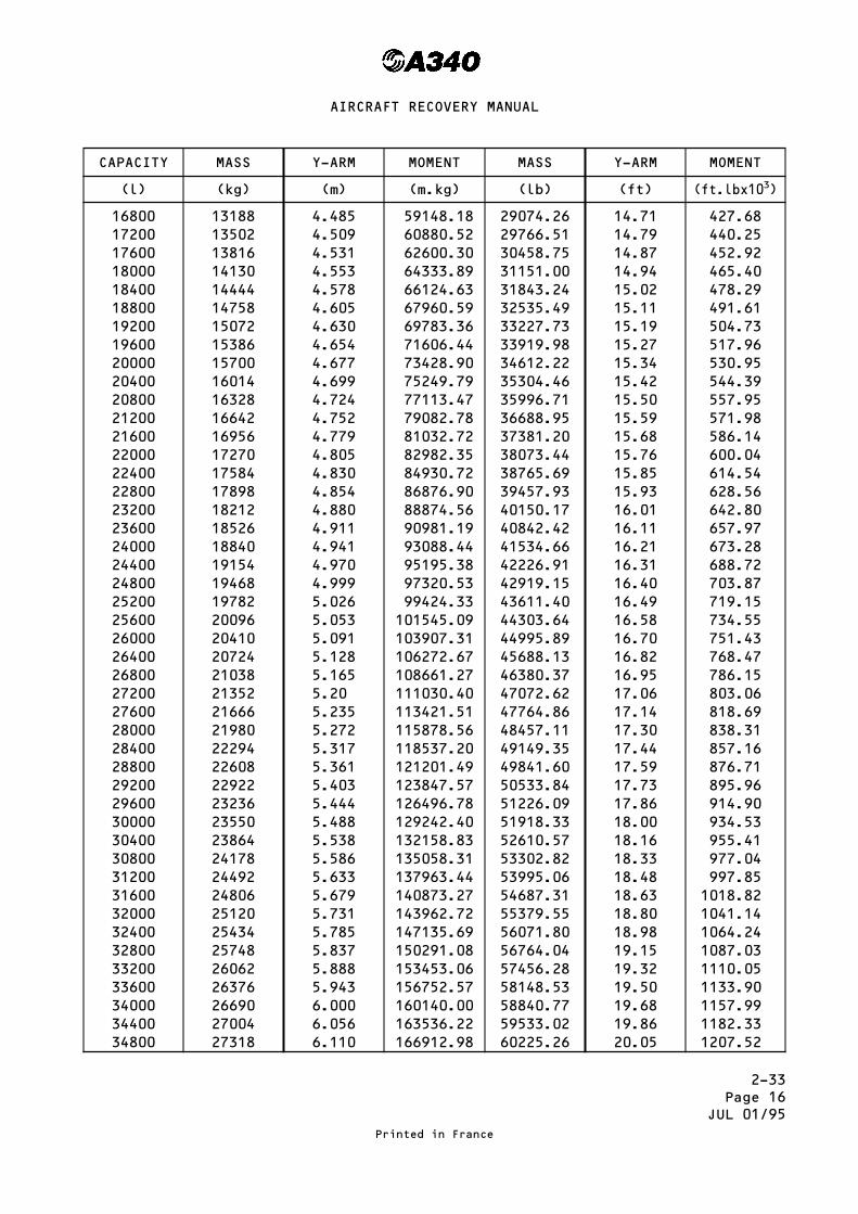
2-33Page 16
JUL 01/95
CAPACITY MASS Y-ARM MOMENT MASS Y-ARM MOMENT
(l) (kg) (m) (m.kg) (lb) (ft) (ft.lbx103)
16800 13188 4.485 59148.18 29074.26 14.71 427.6817200 13502 4.509 60880.52 29766.51 14.79 440.2517600 13816 4.531 62600.30 30458.75 14.87 452.9218000 14130 4.553 64333.89 31151.00 14.94 465.4018400 14444 4.578 66124.63 31843.24 15.02 478.2918800 14758 4.605 67960.59 32535.49 15.11 491.6119200 15072 4.630 69783.36 33227.73 15.19 504.7319600 15386 4.654 71606.44 33919.98 15.27 517.9620000 15700 4.677 73428.90 34612.22 15.34 530.9520400 16014 4.699 75249.79 35304.46 15.42 544.3920800 16328 4.724 77113.47 35996.71 15.50 557.9521200 16642 4.752 79082.78 36688.95 15.59 571.9821600 16956 4.779 81032.72 37381.20 15.68 586.1422000 17270 4.805 82982.35 38073.44 15.76 600.0422400 17584 4.830 84930.72 38765.69 15.85 614.5422800 17898 4.854 86876.90 39457.93 15.93 628.5623200 18212 4.880 88874.56 40150.17 16.01 642.8023600 18526 4.911 90981.19 40842.42 16.11 657.9724000 18840 4.941 93088.44 41534.66 16.21 673.2824400 19154 4.970 95195.38 42226.91 16.31 688.7224800 19468 4.999 97320.53 42919.15 16.40 703.8725200 19782 5.026 99424.33 43611.40 16.49 719.1525600 20096 5.053 101545.09 44303.64 16.58 734.5526000 20410 5.091 103907.31 44995.89 16.70 751.4326400 20724 5.128 106272.67 45688.13 16.82 768.4726800 21038 5.165 108661.27 46380.37 16.95 786.1527200 21352 5.20 111030.40 47072.62 17.06 803.0627600 21666 5.235 113421.51 47764.86 17.14 818.6928000 21980 5.272 115878.56 48457.11 17.30 838.3128400 22294 5.317 118537.20 49149.35 17.44 857.1628800 22608 5.361 121201.49 49841.60 17.59 876.7129200 22922 5.403 123847.57 50533.84 17.73 895.9629600 23236 5.444 126496.78 51226.09 17.86 914.9030000 23550 5.488 129242.40 51918.33 18.00 934.5330400 23864 5.538 132158.83 52610.57 18.16 955.4130800 24178 5.586 135058.31 53302.82 18.33 977.0431200 24492 5.633 137963.44 53995.06 18.48 997.8531600 24806 5.679 140873.27 54687.31 18.63 1018.8232000 25120 5.731 143962.72 55379.55 18.80 1041.1432400 25434 5.785 147135.69 56071.80 18.98 1064.2432800 25748 5.837 150291.08 56764.04 19.15 1087.0333200 26062 5.888 153453.06 57456.28 19.32 1110.0533600 26376 5.943 156752.57 58148.53 19.50 1133.9034000 26690 6.000 160140.00 58840.77 19.68 1157.9934400 27004 6.056 163536.22 59533.02 19.86 1182.3334800 27318 6.110 166912.98 60225.26 20.05 1207.52
Printed in France
AIRCRAFT RECOVERY MANUAL

2-33Page 17
JUL 01/96
CAPACITY MASS Y-ARM MOMENT MASS H-ARM MOMENT
(l) (kg) (m) (m.kg) (lb) (ft) (ft.lbx103)
35200 27632 6.170 170489.44 60917.50 20.25 1233.5835600 27946 6.230 174103.58 61609.75 20.44 1259.3036000 28260 6.289 177727.14 62301.99 20.63 1285.2936400 28574 6.349 181416.33 62994.24 20.83 1312.1736800 28888 6.413 185258.74 63686.48 21.04 1339.9637200 29202 6.476 189112.15 64378.73 21.25 1368.0537600 29516 6.537 192946.09 65070.97 21.45 1395.7738000 29830 6.605 197027.15 65763.22 21.67 1425.0938400 30144 6.672 201120.77 66455.46 21.89 1454.7138800 30458 6.737 205195.55 67147.71 22.10 1483.9639200 30772 6.808 209495.78 67839.95 22.34 1515.5439600 31086 6.878 213809.51 68532.19 22.57 1546.7740000 31400 6.949 218198.60 69224.44 22.80 1578.3240400 31714 7.019 222600.57 69916.68 23.03 1610.1840800 32028 7.093 227174.60 70608.93 23.27 1643.0741200 32342 7.168 231827.46 71301.17 23.52 1677.0041600 32656 7.246 236625.38 71993.42 23.77 1711.2842000 32970 7.324 241472.28 72685.66 24.03 1746.6442194 33122 7.365 243945.67 73021.40 24.16 1764.42
Table Continued for Model 300 at 271 tonnes MTOW only
42400 33284 7.402 246368.17 73377.91 24.28 1781.6242775 33578 7.475 250995.55 74026.06 24.52 1815.36
Printed in France
AIRCRAFT RECOVERY MANUAL
R

2-33Page 18
JAN 01/96
8. FUEL DATA FOR OUTER TANK, LEFT OR RIGHT HAND WING (Model 200)
A. H-ARM
Fuel specific gravity 0.785
CAPACITY MASS H-ARM MOMENT MASS H-ARM MOMENT
(l) (kg) (m) (m.kg) (lb) (ft) (ft.lbx103)
200 157 38.446 6036.02 346.122 126.134 43.66400 314 38.554 12105.96 692.244 126.488 87.56600 471 38.616 18188.14 1038.367 126.691 131.55800 628 38.670 24284.76 1384.488 126.869 175.651000 785 38.715 30391.28 1730.611 127.016 219.821200 942 38.765 36516.63 2076.733 127.180 264.121400 1099 38.802 42643.40 2422.855 127.301 308.431600 1256 38.866 48815.70 2768.977 127.512 335.081800 1413 38.916 54988.31 3115.100 127.676 397.722000 1570 38.986 61208.02 3461.222 127.905 442.712200 1727 39.046 67432.44 3807.344 128.102 487.732400 1884 39.122 73705.85 4153.466 128.351 533.102600 2041 39.195 79997.00 4499.589 128.591 578.612800 2198 39.272 86319.86 4845.711 128.844 624.343000 2355 39.355 92681.03 5191.833 129.116 670.353200 2512 39.438 99068.26 5537.955 129.388 716.543400 2669 39.523 105486.90 5884.077 129.667 762.973600 2826 39.615 111952.00 6230.199 129.969 809.733688 2895 39.655 114804.40 6382.317 130.100 830.34
Printed in France
AIRCRAFT RECOVERY MANUAL
R
R
R

2-33Page 19
JUL 01/96
9. FUEL DATA FOR OUTER TANK, LEFT OR RIGHT HAND WING (Model 300 and 300 at271 tonnes MTOW)
H. ARM
Fuel specific gravity 0.785
CAPACITY MASS H-ARM MOMENT MASS H-ARM MOMENT
(l) (kg) (m) (m.kg) (lb) (ft) (ft.lbx103)
200 157 40.580 6371.06 346.122 133.13 46.08400 314 40.688 12766.03 692.244 133.49 92.41600 471 40.750 19193.25 1038.367 133.69 138.82800 628 40.804 25624.91 1384.488 133.87 185.341000 785 40.849 32066.47 1730.611 134.02 231.941200 942 40.899 38526.86 2076.733 134.18 278.661400 1099 40.936 44988.66 2422.855 134.30 325.391600 1256 41.000 51496.00 2768.977 134.51 372.461800 1413 41.050 58003.65 3115.100 134.68 419.542000 1570 41.120 64558.40 3461.222 134.91 466.952200 1727 41.180 71117.86 3807.344 135.10 514.372400 1884 41.256 77726.30 4153.466 135.35 562.172600 2041 41.329 84352.49 4499.589 135.59 610.102800 2198 41.406 91010.39 4845.711 135.84 658.243000 2355 41.489 97706.60 5191.833 136.12 706.713200 2512 41.571 104426.35 5537.955 136.39 755.323400 2669 41.657 111182.53 5884.077 136.67 804.103600 2826 41.749 117982.67 6230.199 136.97 853.353688 2895 41.789 120979.16 6382.317 137.10 875.02
Tank Capacity for Model 300 at 271 tonnes MTOW only
3650 2865 41.773 119679.65 6316.18 137.04 865.57
Printed in France
AIRCRAFT RECOVERY MANUAL
R
R

2-33Page 20
JUL 01/96
10. FUEL DATA FOR OUTER TANK, LEFT OR RIGHT HAND WING (Models 200, 300 and 300at 271 tonnes MTOW)
Y. ARM.
Fuel specific gravity 0.785
CAPACITY MASS Y-ARM MOMENT MASS Y-ARM MOMENT
(l) (kg) (m) (m.kg) (lb) (ft) (ft.lbx103)
200 157 18.020 2829.14 346.122 59.12 20.46400 314 18.144 5697.22 692.244 59.53 41.21600 471 18.229 8585.86 1038.367 59.81 62.10800 628 18.313 1150.56 1384.488 60.08 83.181000 785 18.390 14436.15 1730.611 60.33 104.411200 942 18.480 17408.16 2076.733 60.63 125.911400 1099 18.547 20383.15 2422.855 60.85 147.431600 1256 18.669 23448.26 2768.977 61.25 169.601800 1413 18.767 26517.78 3115.100 61.57 191.802000 1570 18.898 29669.86 3461.222 62.00 214.602200 1727 19.014 32837.18 3807.344 62.38 237.502400 1884 19.158 36093.67 4153.466 62.85 261.052600 2041 19.295 39381.10 4499.589 63.30 284.822800 2198 19.439 42726.92 4845.711 63.77 309.013000 2355 19.592 46139.16 5191.833 64.28 333.733200 2512 19.745 49599.44 5537.955 64.78 358.753400 2669 19.902 53118.44 5884.077 65.29 384.203600 2826 20.069 56714.99 6230.199 65.84 410.203688 2895 20.142 58312.70 6382.317 66.08 421.76
Tank Capacity for Model 300 at 271 tonnes MTOW only
3650 2865 20.111 57618.02 6316.18 65.98 416.74
Printed in France
AIRCRAFT RECOVERY MANUAL
R
R
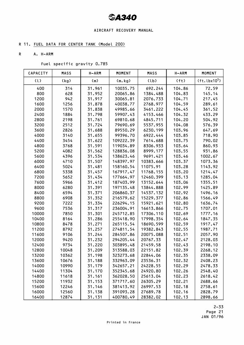
2-33Page 21
JAN 01/96
11. FUEL DATA FOR CENTER TANK (Model 200)
A. H-ARM
Fuel specific gravity 0.785
CAPACITY MASS H-ARM MOMENT MASS H-ARM MOMENT
(l) (kg) (m) (m.kg) (lb) (ft) (ft.lbx103)
400 314 31.961 10035.75 692.244 104.86 72.59800 628 31.952 20065.86 1384.488 104.83 145.141200 942 31.917 30065.81 2076.733 104.71 217.451600 1256 31.878 40038.77 2768.977 104.59 289.612000 1570 31.838 49985.66 3461.222 104.45 361.522400 1884 31.798 59907.43 4153.466 104.32 433.292800 2198 31.761 69810.68 4845.711 104.20 504.923200 2512 31.724 79690.69 5537.955 104.08 576.393600 2826 31.688 89550.29 6230.199 103.96 647.694000 3140 31.655 99396.70 6922.444 103.85 718.904400 3454 31.622 109222.39 7614.688 103.75 790.024800 3768 31.591 119034.89 8306.933 103.64 860.935200 4082 31.562 128836.08 8999.177 103.55 931.865600 4396 31.534 138623.46 9691.421 103.46 1002.676000 4710 31.507 148397.97 10383.666 103.37 1073.366400 5024 31.481 158160.54 11075.91 103.28 1143.926800 5338 31.457 167917.47 11768.155 103.20 1214.477200 5652 31.434 177664.97 12460.399 103.13 1285.047600 5966 31.412 187403.99 13152.644 103.06 1355.518000 6280 31.391 197135.48 13844.888 102.99 1425.898400 6594 31.371 206860.37 14537.132 102.92 1496.168800 6908 31.352 216579.62 15229.377 102.86 1566.499200 7222 31.334 226294.15 15921.621 102.80 1636.749600 7536 31.317 236004.91 16613.866 102.75 1707.0110000 7850 31.301 245712.85 17306.110 102.69 1777.1610400 8164 31.286 255418.90 17998.354 102.64 1847.3510800 8478 31.271 265115.54 18690.599 102.59 1917.4711200 8792 31.257 274811.54 19382.843 102.55 1987.7111600 9106 31.244 284507.86 20075.088 102.51 2057.9012000 9420 31.232 294205.44 20767.33 102.47 2128.0312400 9734 31.220 303895.48 21459.58 102.43 2198.1012800 10048 31.209 313588.03 22151.82 102.39 2268.1213200 10362 31.198 323273.68 22844.06 102.35 2338.0913600 10676 31.188 332963.09 23536.31 102.32 2408.2314000 10990 31.179 342657.21 24228.55 102.29 2478.3314400 11304 31.170 352345.68 24920.80 102.26 2548.4014800 11618 31.161 362028.50 25613.04 102.23 2618.4215200 11932 31.153 371717.60 26305.29 102.21 2688.6615600 12246 31.146 381413.92 26997.53 102.18 2758.6116000 12560 31.138 391093.28 27689.78 102.16 2828.7916400 12874 31.131 400780.49 28382.02 102.13 2898.66
Printed in France
AIRCRAFT RECOVERY MANUAL
R
R

2-33Page 22
JUL 01/95
CAPACITY MASS H-ARM MOMENT MASS H-ARM MOMENT
(l) (kg) (m) (m.kg) (lb) (ft) (ft.lbx103)
16800 13188 31.125 410476.50 29074.26 102.11 2968.7717200 13502 31.119 420168.74 29766.51 102.10 3039.1617600 13816 31.113 429857.21 30458.75 102.08 3109.2318000 14130 31.108 439556.04 31151.00 102.06 3179.2718400 14444 31.102 449237.29 31843.24 102.04 3249.2818800 14758 31.098 458944.28 32535.49 102.03 3319.6019200 15072 31.093 468633.70 33227.73 102.01 3389.5619600 15386 31.089 478335.35 33919.98 102.00 3459.8420000 15700 31.084 488018.80 34612.22 101.98 3529.7520400 16014 31.080 497715.12 35304.46 101.97 3599.9920800 16328 31.077 507425.26 35996.71 101.96 3670.2221200 16642 31.073 517116.87 36688.95 101.94 3740.0121600 16956 31.070 526822.92 37381.20 101.93 3810.2722000 17270 31.067 536527.09 38073.44 101.92 3880.4422400 17584 31.064 546229.38 38765.69 101.91 3950.6122800 17898 31.061 555929.78 39457.93 101.90 4020.7623200 18212 31.058 565628.30 40150.17 101.89 4090.9023600 18526 31.056 575343.46 40842.42 101.88 4161.0324000 18840 31.053 569512.02 41534.66 101.87 4231.1424400 19154 31.051 594750.85 42226.91 101.87 4301.6624800 19468 31.049 604461.93 42919.15 101.86 4371.7425200 19782 31.046 614151.97 43611.40 101.85 4441.8225600 20096 31.044 623860.22 44303.64 101.85 4512.3326000 20410 31.042 633567.22 44995.89 101.84 4582.3826400 20724 31.040 643272.96 45688.13 101.83 4652.4226800 21038 31.038 652977.44 46380.37 101.83 4722.9127200 21352 31.036 662680.67 47072.62 101.82 4792.9327600 21666 31.034 672382.64 47764.86 101.82 4863.4228000 21980 31.033 682105.34 48457.11 101.81 4933.4228400 22294 31.031 691805.11 49149.35 101.81 5003.9028800 22608 31.029 701503.63 49841.60 101.80 5073.8829200 22922 31.027 711200.89 50533.84 101.80 5144.3429600 23236 31.025 720896.90 51226.09 101.78 5213.8030000 23550 31.023 730591.65 51918.33 101.78 5284.2530400 23864 31.021 740285.14 52610.57 101.77 5354.1830800 24178 31.018 749953.20 53302.82 101.76 5424.1031200 24492 31.016 759643.87 53995.06 101.76 5494.5431600 24806 31.013 769308.48 54687.31 101.75 5564.4332000 25120 31.011 778996.32 55379.55 101.74 5634.3132400 25434 31.008 788657.47 56071.80 101.73 5704.1832800 25748 31.005 798316.74 56764.04 101.72 5774.0433200 26062 31.002 807974.12 57456.28 101.71 5843.8833600 26376 30.998 817603.25 58148.53 101.69 5913.1234000 26690 30.944 825895.36 58840.77 101.52 5973.5234400 27004 30.990 836853.96 59533.02 101.67 6052.7234800 27318 30.986 846475.55 60225.26 101.66 6122.50
Printed in France
AIRCRAFT RECOVERY MANUAL

2-33Page 23
JAN 01/96
CAPACITY MASS H-ARM MOMENT MASS H-ARM MOMENT
(l) (kg) (m) (m.kg) (lb) (ft) (ft.lbx103)
35200 27632 30.981 856066.99 60917.50 101.64 6191.6535600 27946 30.976 865655.30 61609.75 101.63 6261.4036000 28260 30.971 875240.46 62301.99 101.61 6330.5136400 28574 30.965 884793.91 62994.24 101.59 6399.5836800 28888 30.959 894343.59 63686.48 101.57 6468.6337200 29202 30.952 903860.30 64378.73 101.55 6537.6637600 29516 30.945 913372.62 65070.97 101.52 6606.0038000 29830 30.937 922850.71 65763.22 101.50 6674.9738400 30144 30.928 932293.63 66455.46 101.47 6743.2438800 30458 30.919 941730.90 67147.71 101.44 6811.4639200 30772 30.909 951131.75 67839.95 101.41 6879.6539600 31086 30.899 960526.31 68532.19 101.37 6947.1140000 31400 30.877 969537.80 69224.44 101.30 7012.4440400 31714 30.875 979169.75 69916.68 101.29 7081.8640800 32028 30.862 988448.14 70608.93 101.25 7149.1541200 32342 30.848 997686.02 71301.17 101.21 7216.3941600 32656 30.834 1006915.10 71993.42 101.16 7282.8541720 32750 30.830 1009682.50 72201.09 101.14 7302.42
Printed in France
AIRCRAFT RECOVERY MANUAL
RR

2-33Page 24
JAN 01/96
12. FUEL DATA FOR CENTER TANK (Model 300 and 300 at 271 tonnes MTOW)
A. H-ARM
Fuel specific gravity 0.785
CAPACITY MASS H-ARM MOMENT MASS H-ARM MOMENT
(l) (kg) (m) (m.kg) (lb) (ft) (ft.lbx103)
400 314 34.095 10705.83 692.244 111.86 77.43800 628 34.086 21406.01 1384.488 111.83 153.831200 942 34.051 32076.04 2076.733 111.71 231.991600 1256 34.012 42719.07 2768.977 111.59 308.992000 1570 33.972 53336.04 3461.222 111.45 385.752400 1884 33.933 63929.77 4153.466 111.33 462.402800 2198 33.895 74501.21 4845.711 111.20 538.843200 2512 33.858 85051.30 5537.955 111.08 615.163600 2826 33.822 95580.97 6230.199 110.96 691.304000 3140 33.789 106097.46 6922.444 110.85 767.354400 3454 33.756 116593.22 7614.688 110.75 843.334800 3768 33.725 127075.80 8306.933 110.64 919.085200 4082 33.696 137547.07 8999.177 110.55 994.865600 4396 33.668 148004.53 9691.421 110.46 1070.516000 4710 33.641 158449.11 10383.666 110.37 1146.056400 5024 33.615 168881.76 11075.91 110.28 1221.456800 5338 33.591 179308.76 11768.155 110.21 1296.977200 5652 33.568 189726.34 12460.399 110.13 1372.267600 5966 33.546 200135.44 13152.644 110.06 1447.588000 6280 33.525 210537.00 13844.888 109.99 1522.808400 6594 33.505 220931.97 14537.132 109.92 1597.928800 6908 33.486 231321.29 15229.377 109.86 1673.109200 7222 33.468 241705.90 15921.621 109.80 1748.199600 7536 33.451 252086.74 16613.866 109.75 1823.3710000 7850 33.435 262464.75 17306.110 109.69 1898.3110400 8164 33.420 272840.88 17998.354 109.64 1973.3410800 8478 33.405 283207.59 18690.599 109.60 2048.4911200 8792 33.391 293573.67 19382.843 109.55 2123.3911600 9106 33.378 303940.07 20075.088 109.51 2198.4212000 9420 33.366 314307.72 20767.33 109.47 2273.4012400 9734 33.354 324667.84 21459.58 109.42 2348.1112800 10048 33.343 335030.46 22151.82 109.39 2423.1913200 10362 33.332 345386.18 22844.06 109.35 2497.9913600 10676 33.322 355745.67 23536.31 109.32 2572.9914000 10990 33.313 366109.87 24228.55 109.29 2647.9414400 11304 33.304 376468.42 24920.80 109.26 2722.8514800 11618 33.295 386821.31 25613.04 109.23 2797.7115200 11932 33.287 397180.48 26305.29 109.21 2872.8015600 12246 33.280 407546.88 26997.53 109.19 2947.8616000 12560 33.272 417896.32 27689.78 109.16 3022.6216400 12874 33.265 428253.61 28382.02 109.14 3097.61
Printed in France
AIRCRAFT RECOVERY MANUAL
R
R

2-33Page 25
JUL 01/95
CAPACITY MASS H-ARM MOMENT MASS H-ARM MOMENT
(l) (kg) (m) (m.kg) (lb) (ft) (ft.lbx103)
16800 13188 33.259 438619.69 29074.26 109.17 3174.0417200 13502 33.253 448982.01 29766.51 109.10 3247.5317600 13816 33.247 459340.55 30458.75 109.15 3324.5718000 14130 33.242 469709.46 31151.00 109.06 3397.3318400 14444 33.236 480060.78 31843.24 109.04 3472.1818800 14758 33.232 490437.86 32535.49 109.03 3547.3419200 15072 33.227 500797.34 33227.73 109.01 3622.1519600 15386 33.223 511169.08 33919.98 109.00 3697.2820000 15700 33.218 521522.60 34612.22 108.98 3772.0420400 16014 33.214 531889.00 35304.46 108.97 3847.1320800 16328 33.211 542269.21 35996.71 108.96 3922.2021200 16642 33.207 552630.89 36688.95 108.95 3997.2621600 16956 33.204 563007.02 37381.20 108.94 4072.3122000 17270 33.201 573381.27 38073.44 108.93 4147.3422400 17584 33.198 583753.63 38765.69 108.92 4222.3622800 17898 33.195 594124.11 39457.93 108.91 4297.3623200 18212 33.192 604492.70 40150.17 108.90 4372.3523600 18526 33.190 614877.94 40842.42 108.89 4447.3324000 18840 33.187 625243.08 41534.66 108.88 4522.3024400 19154 33.185 635625.49 42226.91 108.87 4597.2424800 19468 33.183 646006.64 42919.15 108.86 4672.1825200 19782 33.180 656366.76 43611.40 108.85 4747.1025600 20096 33.178 666745.09 44303.64 108.85 4822.4526000 20410 33.176 677122.16 44995.89 108.84 4897.3526400 20724 33.174 687497.98 45688.13 108.83 4972.2426800 21038 33.172 697872.54 46380.37 108.83 5047.5827200 21352 33.170 708245.84 47072.62 108.82 5122.4427600 21666 33.168 718617.89 47764.86 108.82 5197.7828000 21980 33.167 729010.66 48457.11 108.81 5272.6228400 22294 33.165 739380.51 49149.35 108.81 5347.9428800 22608 33.163 749749.10 49841.60 108.80 5422.7729200 22922 33.161 760116.44 50533.84 108.79 5497.5729600 23236 33.159 770482.52 51226.09 108.79 5572.8930000 23550 33.157 780847.35 51918.33 108.78 5647.6730400 23864 33.155 791210.92 52610.57 108.77 5722.4530800 24178 33.152 801549.06 53302.82 108.76 5797.2131200 24492 33.150 811909.80 53995.06 108.76 5872.5031600 24806 33.147 822244.48 54687.31 108.75 5947.2532000 25120 33.145 832602.40 55379.55 108.74 6021.9732400 25434 33.142 842933.63 56071.80 108.73 6096.6932800 25748 33.139 853262.97 56764.04 108.72 6171.3933200 26062 33.136 863590.43 57456.28 108.71 6246.0733600 26376 33.132 873889.63 58148.53 108.70 6320.7534000 26690 33.128 884186.32 58840.77 108.68 6394.8134400 27004 33.124 894480.50 59533.02 108.67 6469.4534800 27318 33.120 904772.16 60225.26 108.66 6544.08
Printed in France
AIRCRAFT RECOVERY MANUAL

2-33Page 26
JUL 01/96
CAPACITY MASS H-ARM MOMENT MASS H-ARM MOMENT
(l) (kg) (m) (m.kg) (lb) (ft) (ft.lbx103)
35200 27632 33.115 915033.68 60917.50 108.64 6618.0835600 27946 33.110 925292.06 61609.75 108.63 6692.6736000 28260 33.105 935547.30 62301.99 108.61 6766.6236400 28574 33.099 945770.83 62994.24 108.59 6840.5436800 28888 33.093 955990.58 63686.48 108.57 6914.4437200 29202 33.086 966177.37 64378.73 108.55 6988.3137600 29516 33.079 976359.76 65070.97 108.53 7062.1538000 29830 33.071 986507.93 65763.22 108.50 7135.3138400 30144 33.062 996620.93 66455.46 108.47 7208.4238800 30458 33.053 1006728.90 67147.71 108.44 7281.1539200 30772 33.043 1016799.20 67839.95 108.41 7354.5339600 31086 33.033 1026863.80 68532.19 108.37 7426.8340000 31400 33.021 1036859.40 69224.44 108.33 7499.0840400 31714 33.009 1046847.40 69916.68 108.30 7571.9840800 32028 32.996 1056795.90 70608.93 108.25 7643.4241200 32342 32.982 1066703.80 71301.17 108.21 7715.5041600 32656 32.968 1076603.00 71993.42 108.16 7786.8141720 32750 32.964 1079571.00 72201.09 108.15 7808.42
Table Continued for Model 300 at 271 tonnes MTOW only
42000 32970 32.954 1086493.4 72685.66 108.12 7858.77
42420 33300 32.938 1096835.4 73413.18 108.06 7933.00
Printed in France
AIRCRAFT RECOVERY MANUAL
R

2-33Page 27
JAN 01/96
13. FUEL DATA FOR TRIM TANK (Model 200)
A. H-ARM
Fuel specific gravity 0.785
CAPACITY MASS H-ARM MOMENT MASS H-ARM MOMENT
(l) (kg) (m) (m.kg) (lb) (ft) (ft.lbx103)
200 157 59.877 9400.69 346.122 196.44 67.99400 314 59.855 18794.47 692.244 196.37 135.94600 471 59.855 28205.84 1038.367 196.47 204.01800 628 59.918 37628.50 1384.488 196.58 272.161000 785 59.948 47059.18 1730.611 196.68 340.381200 942 59.973 56494.57 2076.733 196.76 408.621400 1099 59.994 65933.41 2422.855 196.83 476.891600 1256 60.013 75376.33 2768.977 196.89 545.181800 1413 60.030 84822.39 3115.100 196.95 613.522000 1570 60.046 94272.22 3461.222 197.00 681.862200 1727 60.063 103728.80 3807.344 197.05 750.242400 1884 60.081 113192.60 4153.466 197.11 818.692600 2041 60.101 122666.14 4499.589 197.18 887.232800 2198 60.124 132152.55 4845.711 197.25 955.823000 2355 60.149 141650.90 5191.833 197.34 1024.563200 2512 60.177 151164.62 5537.955 197.43 1093.363400 2669 60.209 160697.82 5884.077 197.53 1162.283600 2826 60.244 170249.54 6230.199 197.65 1231.403800 2983 60.282 179821.21 6582.936 197.77 1301.914000 3140 60.323 189414.22 6922.444 197.91 1370.024200 3297 60.368 199033.30 7268.566 198.06 1439.614400 3454 60.415 208673.41 7614.688 198.21 1509.314600 3611 60.465 218339.12 7960.810 198.37 1579.194800 3768 60.517 228028.06 8306.933 198.54 1649.265000 3925 60.572 237745.10 8653.055 198.72 1719.545200 4082 60.626 247475.33 8999.177 198.90 1789.945400 4239 60.689 257260.67 9345.299 199.11 1860.745600 4396 60.750 267057.00 9691.422 199.31 1931.605800 4553 60.814 276886.14 10037.544 199.52 2002.696000 4710 60.880 286744.80 10383.666 199.74 2074.036121 4805 60.920 292719.69 10593.070 199.86 2117.20
Printed in France
AIRCRAFT RECOVERY MANUAL
R
R
R
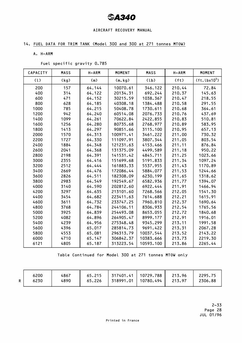
2-33Page 28
JUL 01/96
14. FUEL DATA FOR TRIM TANK (Model 300 and 300 at 271 tonnes MTOW)
A. H-ARM
Fuel specific gravity 0.785
CAPACITY MASS H-ARM MOMENT MASS H-ARM MOMENT
(l) (kg) (m) (m.kg) (lb) (ft) (ft.lbx103)
200 157 64.144 10070.61 346.122 210.44 72.84400 314 64.122 20134.31 692.244 210.37 145.63600 471 64.152 30215.59 1038.367 210.47 218.55800 628 64.185 40308.18 1384.488 210.58 291.551000 785 64.215 50408.78 1730.611 210.68 364.611200 942 64.240 60514.08 2076.733 210.76 437.691400 1099 64.261 70622.84 2422.855 210.83 510.811600 1256 64.280 80735.68 2768.977 210.89 583.951800 1413 64.297 90851.66 3115.100 210.95 657.132000 1570 64.313 100971.41 3461.222 211.00 730.322200 1727 64.330 111097.91 3807.344 211.05 803.542400 1884 64.348 121231.63 4153.466 211.11 876.842600 2041 64.368 131375.09 4499.589 211.18 950.222800 2198 64.391 141531.42 4845.711 211.25 1023.663000 2355 64.416 151699.68 5191.833 211.34 1097.243200 2512 64.444 161883.33 5537.955 211.43 1170.893400 2669 64.476 172086.44 5884.077 211.53 1244.663600 2826 64.511 182308.09 6230.199 211.65 1318.623800 2983 64.549 192549.67 6582.936 211.77 1394.074000 3140 64.590 202812.60 6922.444 211.91 1466.944200 3297 64.635 213101.60 7268.566 212.05 1541.304400 3454 64.682 223411.63 7614.688 212.21 1615.914600 3611 64.732 233747.25 7960.810 212.37 1690.644800 3768 64.784 244106.11 8306.933 212.54 1765.565000 3925 64.839 254493.08 8653.055 212.72 1840.685200 4082 64.896 264905.47 8999.177 212.91 1916.015400 4239 64.956 275348.48 9345.299 213.11 1991.585600 4396 65.017 285814.73 9691.422 213.31 2067.285800 4553 65.081 296313.79 10037.544 213.52 2143.226000 4710 65.147 306842.37 10383.666 213.73 2219.306121 4805 65.187 313223.54 10593.100 213.86 2265.44
Table Continued for Model 300 at 271 tonnes MTOW only
6200 4867 65.215 317401.41 10729.788 213.96 2295.756230 4890 65.226 318991.01 10780.494 213.97 2306.88
Printed in France
AIRCRAFT RECOVERY MANUAL
R

2-33Page 29
JAN 01/96
15. FUEL DATA FOR ADDITIONAL CENTER TANK (Model 300 at 271 tonnes MTOW)
A. H-ARM
Fuel specific gravity 0.78
CAPACITY MASS H-ARM MOMENT MASS H-ARM MOMENT
(l) (kg) (m) (m.kg) (lb) (ft) (ft.lbx103)
200 157 43.340 6804.38 346.122 142.189 49.21400 314 43.340 13608.76 692.244 142.189 98.43600 471 43.340 20413.14 1038.367 142.189 147.64800 628 43.340 27217.52 1384.489 142.189 196.921000 785 43.340 34021.90 1730.611 142.189 246.071200 942 43.340 40826.28 2076.733 142.189 295.291400 1099 43.340 47630.66 2422.855 142.189 344.501600 1256 43.340 54435.04 2768.978 142.189 393.721800 1413 43.340 61239.42 3115.100 142.189 442.932000 1570 43.340 68043.80 3461.222 142.189 492.152200 1727 43.340 74848.18 3807.344 142.189 541.362400 1884 43.340 81652.56 4153.466 142.189 590.582600 2041 43.340 88456.94 4499.589 142.189 639.792800 2198 43.340 95261.32 4845.711 142.189 689.013000 2355 43.340 102065.70 5191.833 142.189 738.223200 2512 43.340 108870.08 5537.955 142.189 787.443400 2669 43.340 115674.46 5884.077 142.189 836.653600 2826 43.340 122478.84 6230.200 142.189 885.873800 2983 43.340 129283.22 6576.322 142.189 935.084000 3140 43.340 136087.60 6922.444 142.189 984.304200 3297 43.340 142891.98 7268.566 142.189 1033.514400 3454 43.340 149696.36 7614.688 142.189 1082.734600 3611 43.340 156500.74 7960.810 142.189 1131.944800 3768 43.340 163305.12 8306.933 142.189 1181.155000 3925 43.340 170109.50 8653.055 142.189 1230.375200 4082 43.340 176913.88 8999.177 142.189 1279.585400 4239 43.340 183718.26 9345.299 142.189 1328.805600 4396 43.340 190522.64 9691.422 142.189 1378.015800 4553 43.340 197327.02 10037.544 142.189 1427.236000 4710 43.340 204131.40 10383.666 142.189 1476.446200 4867 43.340 210935.78 10729.788 142.189 1525.666400 5024 43.340 217740.16 11075.910 142.189 1574.876600 5181 43.340 224544.54 11422.033 142.189 1624.096800 5338 43.340 231348.92 11768.155 142.189 1673.307000 5495 43.340 238153.30 12114.277 142.189 1722.527200 5652 43.340 244957.68 12460.399 142.189 1771.737248 5690 43.340 246604.60 12544.200 142.190 1783.66
Printed in France
AIRCRAFT RECOVERY MANUAL
R
R

2-33Page 30
JAN 01/96
16. FUEL MOMENTS
COLUMN1 2 3 4 5 6
CELL No. CAPACITY MASS(From table)
Y-ARM ABOUTAIRCRAFTCENTERLINE(From table)
Y-ARM ABOUTRH MAINGEAR
MOMENT ABOUTRH MAINGEAR
Litres kg m m m.kg
1 42194 33122 7.365 12.707 420881.252 42194 33122 7.365 – 2.023 – 67005.8061A 3688 2895 20.142 25.484 73776.02A 3688 2895 20.142 – 14.800 – 42846.0
Center 41720 33750 0.0 5.342 174950.5Trim 6121 4805 0.0 5.342 25668.31
TOTAL FUEL MOMENT ABOUT RH MLG = 585424.43 m.kg
Fuel Moment Table with Fuel Remaining in the tanks
Table 4
COLUMN1 2 3 4 5 6
CELL No. CAPACITY MASS(From table)
Y-ARM ABOUTAIRCRAFTCENTERLINE(From table)
Y-ARM ABOUTRH MAINGEAR
MOMENT ABOUTRH MAINGEAR
Litres kg m m m.kg
1 118 92.6 31.020 36.362 3367.12 145 113.8 31.110 – 25.768 – 2932.41A 1 0.785 38.450 43.792 34.42A 2238 1756.8 19.079 – 13.737 – 24133.2
Center 25 19.6 0.0 5.342 104.7Trim 450 353.3 0.0 5.342 1885.7
TOTAL FUEL MOMENT ABOUT RH MLG = – 21673.7 m.kg
Fuel Moment Table with Fuel that you Cannot Drain with the L/H MLG Collapsed
Table 5
Printed in France
AIRCRAFT RECOVERY MANUAL
R
RRRRRRR
R
R

2-33Page 31
JUL 01/95
Aircraft Reference Axis (A340-200)Figure 1
Printed in France
AIRCRAFT RECOVERY MANUAL

2-33Page 32
JUL 01/95
Type and Position of Loads Acting on AircraftFigure 2
Printed in France
AIRCRAFT RECOVERY MANUAL

2-34Page 1
MAR 30/98
DEFUELING
1. General
This topic deals with defueling on all models of the A340 aircraft. It dealswith models that have optional ACTs fitted and those that have no optionalACTs fitted.
It is not possible to estimate the position or the condition of a damagedaircraft. Specific operations to defuel the aircraft before recovery, can notbe given. In some conditions it will be necessary to use procedures adaptedfrom the Aircraft Maintenance Manual (AMM).
One or two Additional Center Tank (ACTs) can be fitted as an optionalmodification.
These ACTs are fitted in the fwd part of the lower deck, aft cargocompartment.
2. Precautions
Before you start to defuel the aircraft you must make sure that :
– the safety zone (Ref. Fig. 1) is marked, to prevent the entry of personnelnot required for the defuel operation
– all equipment and material not required for the defuel procedure is movedout of the safety zone
– the safety and fire fighting equipment is in position together with thepersonnel approved to operate it
– the fuel tankers are in the correct position (Ref. Fig. 1).– the escape lanes for the fuel tankers are clear– the fuel tankers have sufficient capacity for the fuel quantity to bedefuelled
– the aircraft is grounded correctly– all fuel tankers are connected to an approved ground connection– the ground cable from the tankers are connected to the main landing gearground connection
– you use only the electrical equipment necessary for the defuel procedure.– you do not operate the aircraft main engines or the APU during the defuelprocedure
– the electrical equipment you use will not cause a spark– caps are installed on all damaged fuel pipes– damaged electrical wiring and fuel pumps are isolated– you use only fuel pumps that are serviceable– do not do a defuel procedure in bad weather conditions, lightning isdangerous
– do not operate radio or radar equipment during the defuel operation– immediately flush away with water, or remove, fuel spillage.
Printed in France
AIRCRAFT RECOVERY MANUAL
RR
RR
R
RR
R
R
RR
R
RRRR

2-34Page 2
MAR 30/98
Safety Area and Fueling ZoneFigure 1
Printed in France
AIRCRAFT RECOVERY MANUAL
R

2-34Page 3
MAR 30/98
3. Preparation (Ref. Figs. 2, 3 and 4).
A. Put access platforms in position, below the access panels 522HB and 622HB.
B. Open the access panels 522HB and 622HB.
C. Remove the defuel coupling caps from the refuel/defuel couplings.
D. Make sure that the coupling(s) of the fuel supply hose(s) are clean.
E. Connect the fuel supply hose(s) to the aircraft defuel couplings.
E. Open the access panel 198DB.
CAUTION : THE GROUND POWER UNIT (GPU) MUST NOT BE CONNECTED TO THE AIRCRAFTIF THE DEFUEL IS TO BE DONE WITH NO ELECTRICAL POWER TO THEAIRCRAFT.
CAUTION : THE AIRCRAFT ELECTRICAL SYSTEM MUST NOT BE ENERGIZED, IF THE DEFUELIS TO BE DONE WITH NO ELECTRICAL POWER TO THE AIRCRAFT.
G. If necessary, and if it is safe to do so, put the GPU in position as farfrom the aircraft as possible. The GPU required must have 3-phases, with115 volts at 400 Hz and supply 20KVA.
H. If necessary, and if it is safe to do so, connect the GPU to the aircraftand energize the aircraft electrical system.
I. If necessary, start the Electronic Instrument System (EIS) and theElectronic Centralized Aircraft Monitoring (ECAM).
4. Defuel (Ref. Figs. 2, 3, 4 and 6)
You can defuel all or part of the fuel from the aircraft. There are two waysto defuel the aircraft. These are :– with a pressure defuel (the aircraft fuel pumps supply the fuel pressurefor the defuel system).
– with a suction defuel (the external defuel source supplies the suction todefuel the aircraft).
Printed in France
AIRCRAFT RECOVERY MANUAL
R
R
R
R
R

2-34Page 4
MAR 30/98
Refuel/Defuel CouplingFigure 2
Printed in France
AIRCRAFT RECOVERY MANUAL
R

2-34Page 5
MAR 30/98
Refuel/Defuel Control - Panel 990 VU– Models with no ACTsFigure 3 (Sheet 1 of 2)
Printed in France
AIRCRAFT RECOVERY MANUAL
R

2-34Page 6
MAR 30/98
Refuel/Defuel Control Panel 990 VU- Model with ACT OptionFigure 3 (Sheet 2 of 2)
Printed in France
AIRCRAFT RECOVERY MANUAL
R

2-34Page 7
MAR 30/98
Overwing Refuel CapFigure 4
Printed in France
AIRCRAFT RECOVERY MANUAL
R

2-34Page 8
MAR 30/98
Cockpit Fuel Indication - Model with no ACTsFigure 5 (Sheeet 1 of 2)
Printed in France
AIRCRAFT RECOVERY MANUAL
R

2-34Page 9
MAR 30/98
Cockpit Fuel Indication - Model with ACT OptionFigure 5 (Sheet 2 of 2)
Printed in France
AIRCRAFT RECOVERY MANUAL
R

2-34Page 10
MAR 30/98
Cockpit Fuel Control - Model with no ACTFigure 6 (Sheet 1 of 2)
Printed in France
AIRCRAFT RECOVERY MANUAL
R

2-34Page 11
MAR 30/98
Cockpit Fuel Control - Model with two ACTs OptionFigure 6 (Sheet 2 of 2)
Printed in France
AIRCRAFT RECOVERY MANUAL
R

2-34Page 12
MAR 30/98
Refuel/Defuel Component Location- Model with no ACTs
Figure 7 (Sheet 1 of 4)
Printed in France
AIRCRAFT RECOVERY MANUAL
R

2-34Page 13
MAR 30/98
Refuel/Defuel Component Location- Model with ACT OptionFigure 7 (Sheet 2 of 4)
Printed in France
AIRCRAFT RECOVERY MANUAL
R

2-34Page 14
MAR 30/98
Refuel/Defuel Component Location- Model with two ACTs Option
Figure 7 (Sheet 3 of 4)
Printed in France
AIRCRAFT RECOVERY MANUAL
R

2-34Page 15
MAR 30/98
Refuel/Defuel Component Location - All modelsFigure 7 (Sheet 4 of 4)
Printed in France
AIRCRAFT RECOVERY MANUAL
R

2-34Page 16
MAR 30/98
In the leading edge of both LH and RH wings there is a refuel/defuel coupling.These are the interfaces between the refuel/defuel system and the externalsource. Each refuel/defuel coupling can have two refuel/defuel hoses connectedto it. The aircraft can then be defuelled through one or more of therefuel/defuel adaptors.
CAUTION : IF ONLY ONE REFUEL/DEFUEL COUPLING IS USED IT MUST BE THE ONEIDENTIFIED - USE THIS ADAPTOR TO DEFUEL.
The pressure or suction defuel can be done in these electrical conditions :– an electrical GPU connected to the aircraft electrical system– the aircraft batteries or the APU connected to the electrical system– no electrical power available. The fuel valves are operated manually aftertheir electrical actuators have been removed. The fuel pumps are thenelectrically powered with an independent supply.
You cannot start the pressure defuel until all the tank inlet valves are closed.
CAUTION : THE CENTER AND THE INNER TANK HIGH LEVEL PROTECTION DOES NOT FUNCTIONDURING A DEFUEL. YOU MUST USE THE MANUAL MAGNETIC INDICATORS (MMIs) TOMONITOR THE FUEL LEVELS.
There is no high level protection of the inner tanks when you pressure defuelthe aircraft. It is only possible to pressure defuel the center and inner tanks.
To defuel the outer tank, the trim tank and the ACTS, if fitted, the fuel mustfirst be transferred to the center or inner tanks.
These are four procedures you can use to remove fuel from the aircraft.These are :– a pressure defuel with electrical power– a suction defuel with electrical power– a pressure defuel without electrical power– a suction defuel without electrical power.
A. Pressure Defuel Procedure with electrical power
NOTE : The pressure defuel is controlled from the cockpit overhead panel245VU. (Ref. Fig. 5). You can defuel the ACTs and the trim tank at thesame time as you defuel the center tank.
(1) In the Cockpit
(a) Push in the FUEL pushbutton switch (P/BSW) and make sure that theECAM System Display Unit shows the FUEL page.
(b) Read and make a record of the fuel quantities.
Printed in France
AIRCRAFT RECOVERY MANUAL
R
RRRRR
RR
R
RRR
R
RRRRRR
R
R

2-34Page 17
MAR 30/98
(2) On the refuel/defuel control panel 990VU :
(a) Make sure that the REFUEL/DEFUEL VALVES switches (49QU, 5QU1, 5QU2,6QU1, 6QU2, 7QU and 8QU) are in the NORM (guarded) position
(b) Put the MODE SELECT switch (3QU) to the DEFUEL position.
(c) Lift the guard and set the TRANS VALVE switch (11QU) to OPEN.
(3) To defuel the center tank until empty :
(a) Push in the L and R CTR TANK P/BSWs (3QL1 and 3QL2).Make sure that :– the OFF lights go off– the FUEL page shows the L and R CTR TANK fuel-pump symbols arein-line (pumps in operation).
CAUTION : DO NOT LET THE FUEL PUMPS OPERATE FOR MORE THAN 15 MINUTES WITHTHE FAULT LIGHT ON. THIS PREVENTS DAMAGE TO THE FUEL PUMPS.
(b) Operate the L and R CTR TANK pumps until a pump FAULT light comes on.
(c) Release out the related CTR TANK P/BSW. Make sure that :– the OFF light comes on– the FAULT light goes off– the FUEL page shows the related CTR TANK fuel-pump symbol iscrossline (pump not in operation).
(d) Do step A. (3) (c) for the other pump.
(4) To defuel the trim tank and the trim pipe until empty :
CAUTION : MAKE SURE THAT THERE IS SUFFICIENT SPACE IN THE CENTER TANK FORTHE FUEL FROM THE TRIM TANK. IF NECESSARY, DEFUEL THE CENTERTANK TO MAKE SPACE.
(a) Push in the T TANK FWD P/BSW (21QL) and put the T TANK AUTO Switch(13QN) to the OPEN position. Make sure that :1 The FWD light comes on.2 The FUEL page shows :– the trim-tank isolation valve symbol is in-line (valve open)– the forward-transfer triangular symbol is in view (fuel transferis in operation)
Printed in France
AIRCRAFT RECOVERY MANUAL
R
R
R
R
RRR
2-34Page 18
MAR 30/98
(b) Monitor the fuel contents, and make sure that the trim-tank fuelcontents figure decreases.
CAUTION : IF THE TRIM TRANSFER PUMP IS FITTED AND YOU USE IT TODEFUEL, DO NOT LET THE FUEL PUMP OPERATE FOR MORE THAN 15MINUTES WITH THE FAULT LIGHT ON. THIS PREVENTS DAMAGE TOTHE FUEL PUMP.
(c) Continue the defuel until the trim-tank fuel quantity indication iszero and the center-tank fuel quantity indication is stable.
(d) Release out the T TANK FWD P/BSW and put the T TANK AUTO switch tothe AUTO position. Make sure that :1 The FWD light goes off.2 The FUEL page shows :– the trim-tank isolation valve symbol is crossline (valve closed)– the forward transfer triangular symbol is not in view (fueltransfer not in operation).
(5) To defuel the ACT 1 or ACT 2, if fitted :
(a) If necessary, set the ACT switch to the applicable ACT position.
(b) Push in the ACT FWD P/BSW (37QU). Make sure that :1 The FWD light comes on.The FUEL page shows :– the ACT inlet valve symbol is in line (valve open)– the ACT forward-transfer triangular symbol is in view (fueltransfer from ACT is in operation).
(c) Monitor the fuel contents and make sure that the ACT fuel contentsfigure decreases.
(d) Continue to defuel until the ACT fuel quantity is zero.
CAUTION : DO NOT LET THE FUEL PUMPS OPERATE FOR MORE THAN 15 MINUTES WITHTHE FAULT LIGHT ON. THIS PREVENTS DAMAGE TO THE FUEL PUMPS.
(e) Release out the ACT FWD P/BSW. Make sure that :1 The FWD light goes off.2 The FUEL page shows– the ACT inlet valve symbol is crossline (valve closed)– the ACT forward transfer, triangular symbol is not in view (fueltransfer from ACT not in operation).
(f) If necessary, repeat the operation for the other ACT.
Printed in France
AIRCRAFT RECOVERY MANUAL
R
R

2-34Page 19
MAR 30/98
(6) To defuel the wing tanks until empty :
(a) Push in the 1, 2, 3 and 4 X FEED P/BSWs. Make sure that :– the ON and OPEN lights come on– the FUEL page shows the 1, 2, 3 and 4 crossfeed-valve symbols arein-line (valves open).
(b) Push in the L TANK (1 and 2) and R TANK (3 AND 4) P/BSWs to start thepumps. Make sure that :– the OFF lights go off– the FUEL page shows the related fuel-pump symbols are inline (pumpsin operation).
CAUTION : DO NOT LET THE FUEL PUMPS OPERATE FOR MORE THAN 15 MINUTES WITHTHE FAULT LIGHT ON. THIS PREVENTS DAMAGE TO THE FUEL PUMPS.
(c) Operate the pumps.
(d) When a TANK-pump FAULT-light comes on, release out the related TANKP/BSW. Make sure that :– the related FAULT light goes off– the related TANK P/BSW OFF light comes on– the FUEL page shows the related fuel-pump symbols are crossline(pumps not in operation).
(e) Do operation (d) for each pump.
B. Suction Defuel Procedure with electrical power
CAUTION : IF ONLY ONE REFUEL/DEFUEL CONNECTOR IS USED. YOU MUST USE EITHERTHE INBOARD COUPLING ON THE LEFT HAND WING OR THE OUTBOARD COUPLINGON THE RIGHT HAND WING.
NOTE : A suction defuel is controlled from the refuel/defuel control panel990VU.
(1) To defuel the wing tanks, the trim tank and the center tank and the ACTsif fitted, until empty :
(a) Put the REFUEL/DEFUEL VALVE switches (49QU1, 49QU2, 5QU1, 5QU2, 6QU1,6QU2, 7QU and 8QU) to the OPEN position.
(b) Put the MODE SELECT switch (3QU) to the DEFUEL position.
(c) Start the tanker(s) suction motor(s).
(d) Set the applicable REFUEL/DEFUEL VALVE switches to SHUT when eachfuel tank becomes empty.
Printed in France
AIRCRAFT RECOVERY MANUAL
R

2-34Page 20
MAR 30/98
External ElectricalWiring Harness
Figure 8
Printed in France
AIRCRAFT RECOVERY MANUAL
R

2-34Page 21
MAR 30/98
(2) To stop the Suction Defuel
(a) At the fuel tanker(s), stop the suction motor(s).
(b) Put the MODE SELECT switch to the OFF position.
(c) Put the REFUEL/DEFUEL VALVE switch(es) to the SHUT position.
C. Pressure Defuel Procedure with no electrical power available(Ref. Figs. 6 and 7).
When there is no electrical power available :– all the fuel quantity instruments are unserviceable– all the defuel related valves, must be operated manually– the MMIs can be used to give an indication of the aircraft fuel contents– a GPU must not be connected to the aircraft– the aircraft electrical system must not be energized– the fuel pumps are isolated from the aircraft electrical system– an External Wiring Harness (EWH) and control box is used to operate theserviceable aircraft fuel pumps.
NOTE : There are no MMIs in the trim tank or the ACTs.
WARNING : THE AIRCRAFT ELECTRICAL SYSTEM MUST BE SWITCHED OFF AND ISOLATED.
CAUTION : YOU MUST KEEP THE BALANCE OF THE AIRCRAFT CORRECT WHEN YOU DEFUELIT. YOU MUST DEFUEL THE TRIM TANK BEFORE YOU DEFUEL THE WING TANKS.YOU MUST DEFUEL THE WING TANKS EQUALLY.
(1) Open the main landing gear and the centerline gear doors.
(2) Write down the positions of the valves, so that you can return them totheir original positions after the defuel.
(3) Remove the electrical actuators from the valves.
(4) Set these valves to CLOSED :– fuel inlet, trim-tank (5705QA)– fuel inlet, center-tank (5501QA)– fuel inlet, left and right inner-tank (5603QA1 and 5603QA2)– fuel inlet, left and right outer-tank (5500QA1 and 5500QA2)– auxiliary fwd fuel transfer (5703QA)– APU fuel isolation, center section (5204AQ)– fuel trim pipe isolation, center section (5701QA)– aft fuel transfer left and right (5700QA1 and 5700QA2)
Printed in France
AIRCRAFT RECOVERY MANUAL
R
R

2-34Page 22
MAR 30/98
(5) If necessary set these valves to OPEN :– fuel crossfeed 1,2,3 and 4 (5306QA1, 5306QA2, 5306QA3 and 5306QA4).
NOTE : The fuel crossfeed valves will allow you to defuel the completeaircraft from one wing.
(6) Disconnect the electrical connectors from the left and right transferpumps (5600QA1 and 5600QA2) in the center tank.
(7) Connect the EWH to the left and right transfer pumps (5600QA1 and5600QA2).
(8) On the control box of the EWH, set the pump switches to ON.
(9) Push open and hold in, the refuel/defuel isolation valves (502QU1 and502QU2).
NOTE : The refuel/defuel isolation valves must be held in while thedefuel is in progress.
(10) Monitor the pumped fuel on the fuel tanker(s) gages and the aircraftfuel contents with the MMIs.
(11) To defuel the trim-tank :
NOTE : On the model with no ACTs the fuel contents in the center tankmust be 27000 litres or less before you defuel the trim tank.
NOTE : On the model fitted with ATCs, the fuel in the center tank must be23000 liters or less before you defuel the trim tank.
(a) On the control box of the EWH, set the pump switches to OFF.
(b) Open the trim tank isolation valve (5702QA).
(c) Open the auxiliary fwd fuel transfer valve (5703QA).
(d) Monitor the fuel quantity of the center tank.
(e) When the center tank fuel quantity indication is stable, close theauxiliary fwd fuel transfer valve (5703QA).
(f) Close the trim tank isolation valve (5702QA).
Printed in France
AIRCRAFT RECOVERY MANUAL
R
RR
R
R

2-34Page 23
MAR 30/98
(g) To continue the defuel :– on the control box of the EWH, set the pump switches to ON.
NOTE : There are no MMIs in the trim tank. To monitor the fuel in thetrim tank you must record the fuel quantity that is receivedin the center tank.
(12) To defuel the ACTs, if fitted :
NOTE : The fuel contents in the center tank must be 23000 liters or lessbefore you defuel the ACTs.
(a) Open the ACT transfer valve (5801QA).
(b) Open the ACT inlet valves (5805QA1 and 5805QA2).
(c) Monitor the fuel quantity of the ACTs.
(d) When the ACT fuel quantity indication is stable, close both the ACTtransfer valve and the ACT inlet valves.
(13) To defuel the outer tanks :
CAUTION : YOU MUST KEEP THE BALANCE OF THE AIRCRAFT CORRECT WHEN YOUDEFUEL IT. YOU MUST DEFUEL THE TRIM TANK BEFORE YOU DEFUEL THEWING TANKS. YOU MUST DEFUEL THE WING TANKS EQUALLY.
(a) On the control box of the EWH, set the pump switches to OFF.
(b) Open the intertank transfer valves (601QL1 and 601QL2).
CAUTION : DO NOT LET THE FUEL PUMPS OPERATE FOR MORE THAN 15 MINUTES WITHNO FUEL IN THE TANKS. THIS PREVENTS DAMAGE TO THE FUEL PUMPS.
(c) To continue the defuel :– on the control box of the EWH, set the pump switches to ON.
(14) When the defuel is complete :
(a) Release the refuel/defuel isolation valves (502QU1 and 502QU2).
(b) Set all the fuel valves to their correct recorded position.
(c) Install the electrical actuators on these valves.
Printed in France
AIRCRAFT RECOVERY MANUAL
RRR
R
R

2-34Page 24
MAR 30/98
Drain Valve LocationFigure 9
Printed in France
AIRCRAFT RECOVERY MANUAL
R

2-34Page 25
MAR 30/98
(d) Remove the EWH from the left and right hand transfer pumps.
(e) Reconnect the electrical connectors to the left and right handtransfer pumps.
(f) Close the main landing gear and centerline gear doors.
D. Suction Defuel Procedure with no electrical power available.
When there is no electrical power available :– all the fuel quantity instruments are unserviceable– all the defuel related valves must be operated manually– the MMIs can be used to give an indication of the fuel contents– a GPU must not be connected to the aircraft– the aircraft electrical system must not be energized.
NOTE : There are no MMIs in the trim tank or in the ACTs.
WARNING : THE AIRCRAFT ELECTRICAL SYSTEM MUST BE SWITCHED OFF AND ISOLATED.
CAUTION : YOU MUST KEEP THE BALANCE OF THE AIRCRAFT CORRECT WHEN YOU DEFUELIT. YOU MUST DEFUEL THE TRIM-TANK BEFORE YOU DEFUEL THE WING-TANKS.YOU MUST DEFUEL THE WING-TANKS EQUALLY.
(1) Open the main landing gear and the centerline gear doors.
(2) Write down the positions of the valves, so that you can return them totheir correct positions after the defuel.
(3) Remove the electrical actuators from these valves :– fuel inlet, trim-tank (5705QA)– fuel inlet, center-tank (5501QA)– fuel inlet, left and right inner-tank (5603QA1 and 5603QA2)– fuel inlet, left and right outer-tank (5500QA1 and 5500QA2)– fuel trim-pipe isolation center-section (5701QA)– auxiliary-fwd fuel transfer (5703QA)– fuel trim-tank isolation (5702QA)– APU fuel isolation center-section (5204QA).– fuel inlet ACT (5805QA1)– fuel inlet ACT (5805QA2)– fuel, ACT refuel isolation (5517QA).
(4) Set these valves to open (Refer to Step (3)).
(5) Start the fuel tankers suction pumps, to supply the required negativepressure of 0.76 bar (11 psi).
Printed in France
AIRCRAFT RECOVERY MANUAL
R
R

2-34Page 26
MAR 30/98
(6) Push open and hold in the refuel/defuel isolation valves (502QU1 and502QU2).
NOTE : The refuel/defuel isolation valves must be held in while thedefuel is in progress.
(7) Use the MMIs to monitor the aircraft fuel contents, or the fueltanker(s) gages, to monitor the quantity of fuel removed.
(8) Set the applicable tank inlet valves to closed, when each tank becomesempty.
NOTE : This suction defuel procedure will leave 2400 kg (approximately)of fuel in the fuel collector cells in each wing. If it isnecessary to remove this fuel you must open :– the crossfeed valves (5306QA1, 5306QA2, 5306QA3 and 5306QA4)– the fuel transfer valves (601QL1 and 601QL2).
(9) When the defuel is complete :
(a) Stop the fuel tanker(s) suction motor(s).
(b) Release, the refuel/defuel isolation valves (502QU1 and 502QU2).
(c) Set the applicable valves to their correct position.
(d) Install the electrical actuators on the applicable valves.
(e) Close the main landing gear and centerline gear doors.
5. Procedure to Drain the Remaining Fuel (Ref. Fig. 8)
A. Make sure that the fuel tank to be drained has been defuelled to itsunusable fuel level.
B. If necessary, put an access platform below the applicable water drainvalve.
C. Put a container (capacity 200 l 53 US gal) below the applicable waterdrain valve.
D. Install the drain tool in the bottom of the water drain valve.
E. Put the end of the hose into the container.
WARNING : DO NOT GET AIRCRAFT FUEL :– IN YOUR MOUTH– IN YOUR EYES– ON YOUR SKIN FOR A LONG TIME.AIRCRAFT FUEL IS POISONOUS.
Printed in France
AIRCRAFT RECOVERY MANUAL
RRRRR

2-34Page 27
MAR 30/98
F. Operate the drain tool to OPEN the drain valve.
G. Continuously monitor the fuel flow into the container. Make sure there issufficient space in the container for all the drained fuel.
H. When the fuel flow stops, operate the drain tool to close the drain valve.
J. Remove the drain tool from the water drain valve.
K. Discard the drained fuel, (you must refer to your local regulations).
6. Close-up
A. If necessary, stop the EIS and the ECAM.
B. If necessary, de-energize the aircraft electrical system and disconnectthe GPU from the aircraft.
C. If necessary, remove the GPU from its position near the aircraft.
D. Close the access panel 198DB.
E. Disconnect the hose(s) from the aircraft refuel/defuel coupling(s).
F. Install the refuel/defuel coupling caps.
G. Close the access panels 522HB and 622HB.
H. Remove the access platforms from their position below the access panels.
J. Disconnect the ground cables from the tanker(s) and from the aircraft.
K. Move the fuel tanker(s) away from the safety zone.
L. Remove all the ground support equipment, the maintenance equipment, thestandard and special tool(s) and all other items.
Printed in France
AIRCRAFT RECOVERY MANUAL

2-40Page 1
JAN 30/93
REMOVAL OF PAYLOAD
01. General
Removal of the payload is necessary to reduce aircraft weight for recovery.In passenger aircraft, the removal of baggage/cargo containers, cargopallets and bulk cargo must be considered. It is assumed, for the purposesof this publication, that the total payload is to be removed. This sectionincludes removal of containers/pallets and other Unit Load Devices (ULD)from the aircraft.
If the aircraft has come to rest on an unpaved or soft surface, access tothe aircraft with normal loaders, transporters and other vehicles with smallwheels and low ground clearances may be a major difficulty. In thisparticular case, Pierced Steel Plank (PSP) type surfaces may be anadvantage.
With the aircraft in a nose-down attitude, the AFT cargo compartment doormay be higher than the type of loader available can reach. For access inthis instance, fork-lift type vehicles may be of use.
If the aircraft attitude is such that the cargo compartment doors are lowerthan normal container and pallet transporter vehicles may be close enough tothe desired height to permit direct unloading. Alternatively, standardcontainer or pallet conveyor equipment may be used.
Removal of containers and/or pallets from the aircraft will in most caseshave to be done manually, due to lack of electrical power supply for thecargo loading system. Upward or downward movement of the aircraft about thelongitudinal or lateral axes, or a combination of both, may be expectedduring unloading, dependent on the at-rest attitude of the aircraft and onthe location of a specific container or pallet in the cargo compartment.
A block and tackle or other tensioning equipment may be used to pullcontainers upwards or to restrain them when being lowered. If a rope isused, it can be looped around the container and the opposite end anchoredaround the side guide tie-down attachment. Pallets may also be removed bythis method, provided that they can withstand the strain of a rope loop. Ifnot, it is advisable to unload the pallet piece by piece. If there is aconsiderable height difference between the door threshold and the loadingequipment, restraint from inside and a pulling force from outside may benecessary. Pulling may be achieved by means of a block and tackle anchoredto the loading vehicle, a tractor with a rope of suitable strength or bymeans of a vehicle equipped with a winch. It is possible that damage tocontainers may result when using this method.
Bulk cargo may be removed from any of the cargo compartments by any of themethods previously mentioned or by manhandling, if the weight of these itemspermits. For aircraft which have ″load thru capability″, large items of bulkcargo which have been loaded thru the AFT cargo compartment into the Bulkcargo compartment must be unloaded the same way. The divider net must firstbe released and any latches lowered which are in the way of cargo.
Printed in France
AIRCRAFT RECOVERY MANUAL
2-40Page 2
JAN 30/93
2. FWD, AFT and Bulk Cargo Compartment Doors – Operating Instructions
A. General
The following instructions detail various methods of gaining access tothe FWD, AFT and Bulk cargo compartments. For this purpose it must beassumed that electrical and hydraulic power is not available and that thedoors cannot be opened in the normal way. If access can be gained to theright-hand side of the belly fairing, it may be possible to open the FWDand AFT cargo compartment doors using the hand pump.
B. Open the FWD and AFT cargo compartment door using the hand pump (Ref. AMMTASK 52-30-00-010-802).
C. Open the FWD or AFT cargo compartment door when the hydraulic system isdefective (Ref. AMM TASK 52-30-00-010-804).
D. Open the Bulk cargo compartment door (Ref. AMM TASK 52-30-00-010-803).
3. Manual Unloading of the FWD and AFT Cargo Compartment (Fig. 1 and 2)
A. The following instructions refer to the unlatching and positioning ofcontainers and pallets prior to their removal from the cargocompartments. No attempt is made to provide firm rules for removalprocedures, as these will largely depend on the attitude of the aircraftat rest. However, the notes contained in Paragraph 1. General, should beof assistance in determining the method to be employed.
WARNING : CONTAINERS AND PALLETS MUST BE RESTRAINED BEFORE RELEASINGLATCHES IF CARGO COMPARTMENT FLOOR IS NOT LEVEL. SEE 1.GENERAL.
Refer to the Cargo Loading Manual (CLS) for the method of raising andlowering the latches used in the cargo loading system.
Floor plans with procedures detailing the unloading steps for the ULD areprovided in Fig. 1 and 2.
Printed in France
AIRCRAFT RECOVERY MANUAL

2-40Page 3
JAN 30/93
Manual Unloading – FWD Cargo CompartmentFigure 1
MODEL 200 & 300
Printed in France
AIRCRAFT RECOVERY MANUAL

2-40Page 4
JAN 30/93
Manual Unloading – Aft Cargo CompartmentFigure 2
MODEL 200 & 300
Printed in France
AIRCRAFT RECOVERY MANUAL

3-10Page 1
JUL 30/93
TETHERING
1. General
A. During lifting operations of a damaged aircraft, in which cranes, jacks,and/or inflatable bags are used, the aircraft should be tethered toprevent horizontal shifting due to lifting side forces, (weight of theaircraft, wing forces, etc...). Tethers can be attached to fabric slingspassed around the fuselage or the engine pylons or to different fittiangssuch as pylon hoist fittings, fuselage fittings and vertical stabilizefittings.
B. To ensure satisfactory horizontal stability, aircraft tethering cablesshould be secured to heavy vehicles or to deadmen fixed firmly in theground ; the tethers should lead at various angles to the fuselage centerline so that aircraft shifting in any direction is prevented. Figure 1shows a typical installation which might be used.
C. A tensioning device should be provided for each tethering line so that asteady but no excessive tethering action is maintained throughout thelifting operation.
D. The number of tethers will vary with the type of recovery operation andaccording to wind strength and direction. Figure 2 shows approximately theforces exerted on the aircraft according to their magnitude and direction.
2. Tethering
A. Using straps and/or cablesIf tethering fittings are not availablem or if it is impossible to installthem, the aircraft can be tethered with straps or cables passed around theengine pylons and the fuselage main frames on which the slings secured tothe ground will be fitted. In this case, it is necessary to protect thefuselage with pylwood sheets covered with thick padding at places wherecables or straps are in contact with the fuselage. The fuselage framescapable of bearing these loads are frames 17, 36, 59 and 76.
Printed in France
AIRCRAFT RECOVERY MANUAL

3-10Page 2
JUL 30/93
B. By means of tethering fittings (For P/N Ref. See chapter 5.20 § 3)
Figure 3 shows positions on the airplane at which fittings can beinstalled.On the fuselage, fitting attachment points are blanked off by screws whichmust be removed.
WARNING THE SAME FITTING MUST NOT BE USED TO TETHER AND LIFT THE AIRPLANEAT THE SAME TIUME ; THE STRESSES IMPOSED ON THE STRUCTURE WOULD BETOO SEVERE.
Printed in France
AIRCRAFT RECOVERY MANUAL

3-10Page 3
JUL 30/93
Example of TetheringFigure 1
Printed in France
AIRCRAFT RECOVERY MANUAL

3-10Page 3A
JUL 30/93
Example of TetheringFigure 1A
Printed in France
AIRCRAFT RECOVERY MANUAL
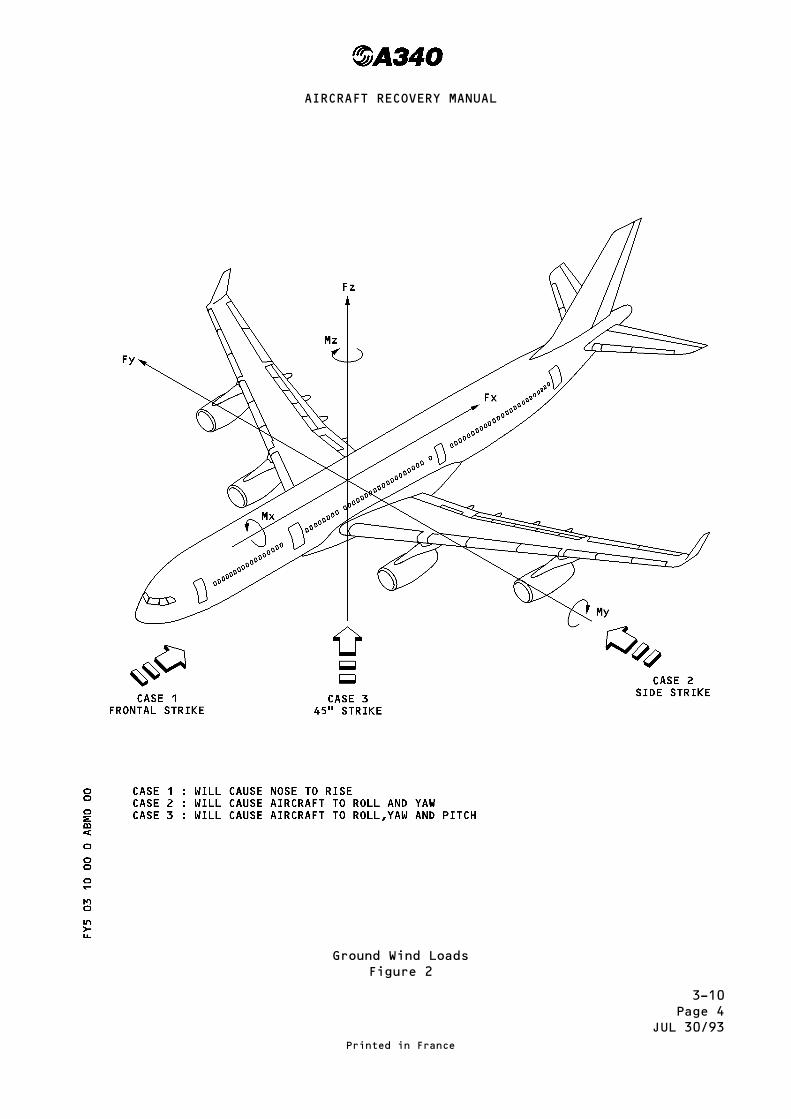
3-10Page 4
JUL 30/93
Ground Wind LoadsFigure 2
Printed in France
AIRCRAFT RECOVERY MANUAL

3-10Page 5
JAN 01/96
Location of Tethering Fittings (Model 300)Figure 3
Printed in France
AIRCRAFT RECOVERY MANUAL

3-10Page 5A
JAN 01/96
Location of Tethering Fittings (Model 200)Figure 3A
Printed in France
AIRCRAFT RECOVERY MANUAL

3-10Page 6
JAN 01/96
Tethering Fittings at FR36Figure 4
Printed in France
AIRCRAFT RECOVERY MANUAL

3-10Page 7
JAN 01/96
Tethering Fittings at FR59-FR76Figure 5
Printed in France
AIRCRAFT RECOVERY MANUAL

3-10Page 8
JAN 01/96
This Page Left Blank Intentionally
Printed in France
AIRCRAFT RECOVERY MANUAL

3-20Page 1
JUL 30/93
LIFTING DAMAGED AIRCRAFT
This section describes the ways and means to lift the aircraft by means ofeither inflatable bags (3-26) or hydraulic jacks (3-27) or by using theauxiliary jacking points (3-28) in the various configuration listed below :
– Nose gear retracted, collapsed or lost (3-21)
– Main gear retracted, collapsed or lost (3-22)*
– One main gear retracted, collapsed or lost (3-23)*
– Nose gear and either left or right hand main gear retracted, collapsed or lost(3-24)*
– All gears retracted, collapsed or lost (3-25)*
* Note : in these cases the center line gear will be collapsed.
Printed in France
AIRCRAFT RECOVERY MANUAL

3-20Page 2
JUL 01/95
This Page Left Blank Intentionally
Printed in France
AIRCRAFT RECOVERY MANUAL

3-21Page 1
JUL 30/93
NOSE GEAR RETRACTED, COLLAPSED OR LOST
01. General
In all probability, the aircraft will be resting on the main gears, theengine nacelles, and on the nose gear door area at the lower forward part ofthe fuselage, the front jack pad being probably damaged (ref. Figure 1). Themost obvious lifting methods consist in :– Lifting the aircraft at FR17 with a strap, a cross bar and crane,– Lifting the aircraft at FR17 by means of 2 special fittings either withjacks, or with a crane, a cross bar and 2 slings,
– Lifting the aircraft with inflatable bags placed under the fuselage.– Any combination of the above 3 methods.
The choice of the lifting method depends on the weight and the aircraftH-arm as computed in section 2 and the lifting means available.
It is obviously advisable to locate the H-arm as far back as possible in theaircraft, but without tilting the aircraft on to the aft fuselage. Thetables included in this section give the reactions and lifting limitationsversus aircraft CG and weight. If the reaction is above the limitation, theaircraft H-arm location can be moved by :– Reducing the weight of the aircraft by removing removable equipment.
WARNING : IN NO CIRCUMSTANCES MUST THE AIRCRAFT H-ARM LOCATION BE FURTHERBACK THAN TBD.
02. Lifting
A. Using a strap aft of FR17, a cross bar and a crane.
Figure 2 gives the reactions at FR17 according to the weight, theaircraft H-arm location and the lifting limitation by one strap.Figure 3 gives the minimum dimensions of the strap and the approximateheight to which the aircraft must be lifted. The strap must obligatorilybe positioned immediately aft of FR17.
B. By means of two special fittings installed at FR17
Figure 4 shows a drawing of the fittings
(1) Using hydraulic jacks
Figure 5 gives ground clearances of the fitting jack pads, aircrafton the ground and aircraft lifted.
Figure 2 gives the reactions at FR17 according to the weight andaircraft H-arm and the lifting limitation by 2 jacks.It is advisable to use jacks provided with a loadmeter.
Printed in France
AIRCRAFT RECOVERY MANUAL
3-21Page 2
JUL 30/93
NOTE : When the lifting is achieved by jacks, the variation of thehorizontal projection of the distance between the restingpoints of the aircraft on the ground is 0.1 m (0.33 ft)maximum ; if special articulated jacks are not available, itis advisable to carry out the lifting operation in incrementsby blocking and moving the jacks.
(2) Using two slings, a cross bar and a crane
Figure 6 gives the measurements of the cross bar, the slings and theheight from the ground of the Reference Fuselage Datum (RFD) of theaircraft when lifted.
Figure 2 gives the reaction at FR17 according to the weight andaircraft H-arm and the limitation of lifting with two slings.
It is advisable to use slings provided with a loadmeter.
C. Using inflatable bags
Using of inflatable bags is covered in section 3-26. As the zones whichrest on the bags will be practically touching the ground, it will benecessary to pre-lift using one of the methods mentioned above, in orderto be able to slide the bags under the fuselage ; however, if consistencyof the ground so allows, a trench may be dug out under the aircraft.
Printed in France
AIRCRAFT RECOVERY MANUAL

3-21Page 3
JUL 30/93
MODEL 300Nose Gear Collapsed
Figure 1
Printed in France
AIRCRAFT RECOVERY MANUAL

3-21Page 3A
JUL 30/93
MODEL 200Nose Gear Collapsed
Figure 1
Printed in France
AIRCRAFT RECOVERY MANUAL

3-21Page 4
JUL 01/95
MODEL 300Reactions at FR 17
Figure 2
Printed in France
AIRCRAFT RECOVERY MANUAL

3-21Page 4A
JUL 01/95
MODEL 200Reactions at FR 17
Figure 2
Printed in France
AIRCRAFT RECOVERY MANUAL
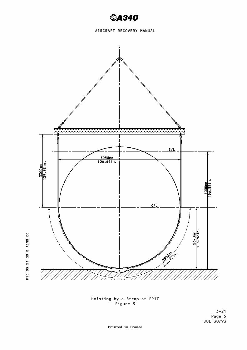
3-21Page 5
JUL 30/93
Hoisting by a Strap at FR17Figure 3
Printed in France
AIRCRAFT RECOVERY MANUAL

3-21Page 6
JAN 01/96
Fittings at FR17Fig. 4
Printed in France
AIRCRAFT RECOVERY MANUAL

3-21Page 7
JUL30/93
JackPadsatFR17Figure5
PrintedinFrance
AIRCRAFTRECOVERYMANUAL

3-21Page 8
JUL30/93
Hoistingby2SlingsatFR17Figure6
PrintedinFrance
AIRCRAFTRECOVERYMANUAL
3-22Page 1
JUL 30/93
MAIN GEARS RETRACTED, COLLAPSED OR LOST
01. General
The aircraft rests on the internal engine nacelles and the aft fuselage(Fig. 1).The most obvious methods of lifting the aircraft consist in :– Using hydraulic jacks,– Using inflatable bags.
Whatever the method used, a jack will be placed at the front jack pad ; thenose gear is not necessarily in contact with the ground as its positiondepends on the damage to the engine nacelles.
02. Lifting
A. Using hydraulic jacks
Section 3-27 covers lifting with hydraulic jacks and gives theinformation required for their utilisation ; it also gives thepermissible loads and the location of the jacking points.The height of the wing jack pads from the ground when the aircraft is onthe ground can vary from :1.6 m (5.2 ft) to 2.6 m (8.5 ft) Model 2001.7 m (5.6 ft) to 2.7 m (8.8 ft) Model 300
this height depends on the degree of damage to the internal enginenacelles.
The height of the wing jack pads when the aircraft is lifted is about5.8 m (19.0 ft).
B. Using inflatable bags
Section 3-26 covers utilisation of inflatable bags and gives thenecessary instructions for use.For aircraft lifting, it is preferable to place 2 bags on each side ofthe aircraft between the fuselage and the engine pylon taking care not toplace bags under the jack pads.
Printed in France
AIRCRAFT RECOVERY MANUAL

3-22Page 2
JUL 30/93
MODEL 300Main Gears Retracted, Collapsed or Lost
Figure 1
Printed in France
AIRCRAFT RECOVERY MANUAL

3-22Page 2A
JUL 30/93
MODEL 200Main Gears Retracted, Collapsed or Lost
Figure 1
Printed in France
AIRCRAFT RECOVERY MANUAL

3-23Page 1
JUL 30/93
ONE MAIN GEAR RETRACTED, COLLAPSED OR LOST
01. General
In all probability, the aircraft will be resting on the nose gear, on one ofthe main gears and the engine nacelles of the damaged side (Fig. 1). Theaircraft may be in an unstable condition, depending on aircraft H-armlocation, with a risk of tilting backwards on to the aft fuselage. The firststep is therefore to place inflatable bags under the aft fuselage (Ref.section 3-26).These bags must be deflated as the down wing is raised, to avoid excessivestress on the aircraft skin.Lifting methods consist in :
– using hydraulic jacks under the lifting points.– using inflatable bags.
02. Lifting
A. Using hydraulic jacks
Section 3-27 covers lifting with hydraulic jacks and gives theinformation required for this process. A jack will be placed under thedamaged wing jack pad. The height of the jack pad from the ground, whenthe aircraft is on the ground, is about :3.0 m ( 9.8 ft) Model 200,3.1 m (10.1 ft) Model 300
this height depends on the degree of damage to the engine nacelles. Theheight of the wing jack pad when the aircraft is lifted is about 5.8 m(19.0 ft) to allow extension of the gear, if this is possible. Themaximum load a wing jack pad can bear is 73 700 daN. It is advisable toplace jacks under the two remaining jack pads.
B. Using inflatable bags
Section 3-26 covers utilisation of inflatable bags and gives thenecessary instructions for use. Two bags should be placed between thefuselage and the internal engine pylon ; two more should be placedbetween the internal engine pylon and the external engine pylon.
Printed in France
AIRCRAFT RECOVERY MANUAL

3-23Page 2
JUL 30/93
MODEL 300One Main Gear Retracted
Figure 1
Printed in France
AIRCRAFT RECOVERY MANUAL

3-23Page 2A
JUL 30/93
MODEL 200One Main Gear Retracted
Figure 1
Printed in France
AIRCRAFT RECOVERY MANUAL

3-24Page 1
JUL 30/93
NOSE GEAR AND EITHER LEFT OR RIGHT HANDMAIN GEAR RETRACTED, COLLAPSED OR LOST
01. General
The aircraft rests on the front lower part of the fuselage on the nose geardoors, on the internal engine nacelle on the damaged gear side, and on theopposite main gear (Fig. 1) ; the forward jack pad is probably damaged.
02. Lifting
For reason of structural resistance, the lifting operation must be done intwo stages :
1°) Lift the aircraft under the wing of the damaged side, following theprocedure described in section 3-23.
The height of the wing jack pad from the ground when the aircraft is onthe ground, is about : 3.7 m (12.1 ft) Model 300
3.8 m (12.4 ft) Model 200
2°) Lift the aircraft by the forward fuselage, following the proceduredescribed in section 3-21.
Note : By using this method, further damage to the aircraft will be avoided,and less personnel will be required for the lifting operation than ifthe aircraft was lifted under the wing and forward fuselagesimultaneously.
Printed in France
AIRCRAFT RECOVERY MANUAL

3-24Page 2
JUL 30/93
MODEL 300Nose Gear and Either Left or Right Hand
Main Gear RetractedFigure 1
Printed in France
AIRCRAFT RECOVERY MANUAL

3-24Page 2A
JUL 30/93
MODEL 200Nose Gear and Either Left or Right Hand
Main Gear RetractedFigure 1
Printed in France
AIRCRAFT RECOVERY MANUAL

3-25Page 1
JUL 30/93
ALL GEARS RETRACTED, COLLAPSED OR LOST
01. General
The aircraft rests on the internal engine nacelles and on the aft lower partof the fuselage (ref. Figure 1).The most obvious lifting methods consist in :
– Using hydraulic jacks– Using inflatable bags.
02. Lifting
A. Using hydraulic jacks
Section 3-27 covers lifting with hydraulic jacks and gives theinformation required for their utilisation ; it also gives thepermissible loads and the position of the jacking points. It is advisableto use jacks provided with loadmeters.
The height of the wing jack pads from the ground when the aircraft is onthe ground is about 2.6 m (8.5 ft), the height of the forward jack padfrom the ground is about : 2.53 m (8.2 ft) Model 200 and 300.
These dimensions are given only as an indication since they depend on thedegree of damage to the engine nacelles.
The height of the jack pads when the aircraft is lifted, is about 4.37 m(14.3 ft) for the forward jack pad and 5.8 m (19 ft) for the wing jackpads ; these heights allow the gears to be extended if this is possible.
B. Using inflatable bags
Section 3-26 covers utilisation of the inflatable bags and gives thenecessary instructions for use.
– Place 2 bags under the forward fuselage aft of FR26– Place two bags on each side of the aircraft, under the wings, betweenthe fuselage and the internal engine pylon.Depending on the weight of the aircraft, one or two more bags can beplaced under each wing between internal engine pylon and externalengine pylon ; in no circumstances must the bags be placed under thejack pads, as this would prevent positioning of the jacks.
Printed in France
AIRCRAFT RECOVERY MANUAL

3-25Page 2
JUL 30/93
MODEL 300All Gears Retracted
Figure 1
Printed in France
AIRCRAFT RECOVERY MANUAL

3-25Page 2A
JUL 30/93
MODEL 200All Gears Retracted
Figure 1
Printed in France
AIRCRAFT RECOVERY MANUAL

3-26Page 1
JUL 30/93
LIFTING USING INFLATABLE BAGS
01. General
Lifting a damaged aircraft with inflatable bags is subject to a certainnumber of specifications which must be scrupulously observed ; thesespecifications are given in the "Specifications For Use" delivered by thevendors with the equipment.
02. Use of Inflatable Bags
Figure 1 shows those undersurfaces of the aircraft capable of withstandingon bagloads ; with bags inflated between 3.5 and 7 psi.Figure 2 shows the positions at which bags may be placed (for example).All bags are capable of lifting : See Page 3.As this means of lifting is not stable, avoid covering the jack pads underthe wing in order to allow positioning of hydraulic jacks at the earliestopportunity.
Printed in France
AIRCRAFT RECOVERY MANUAL
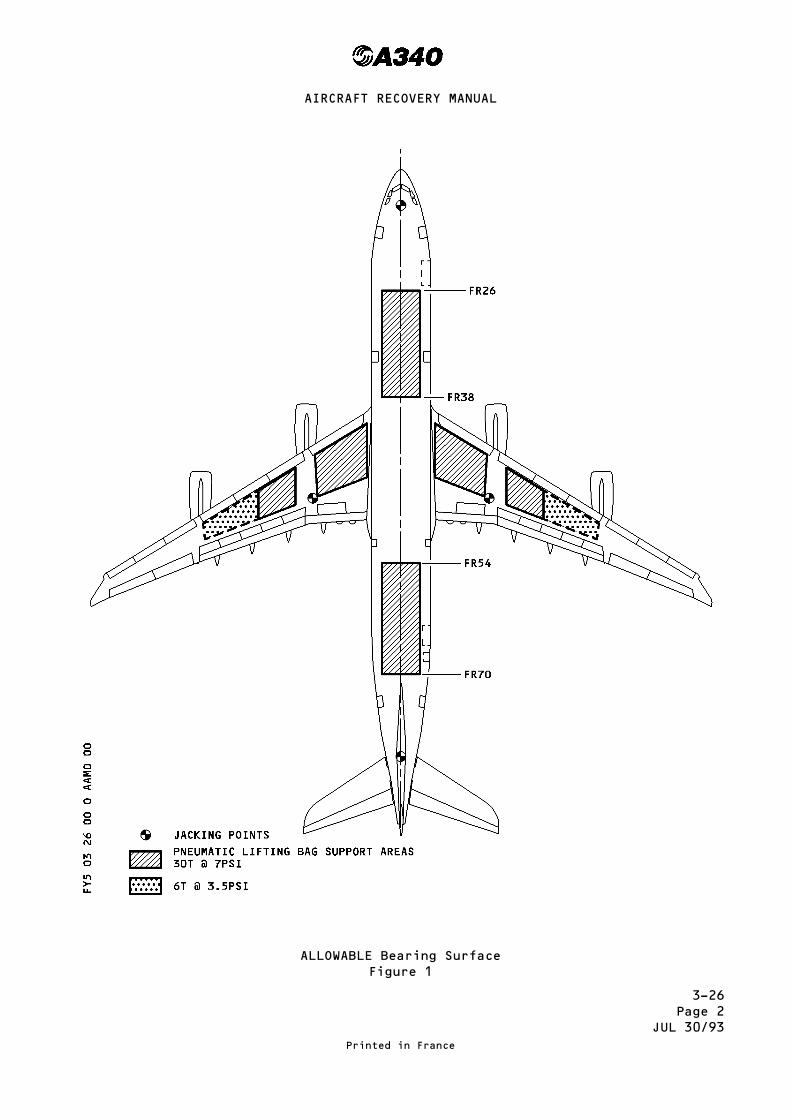
3-26Page 2
JUL 30/93
ALLOWABLE Bearing SurfaceFigure 1
Printed in France
AIRCRAFT RECOVERY MANUAL

3-26Page 3
JUL 30/93
Example Of Location For Inflatable BagsFigure 2
Printed in France
AIRCRAFT RECOVERY MANUAL

3-26Page 4
JUL 01/95
This Page Left Blank Intentionally
Printed in France
AIRCRAFT RECOVERY MANUAL
3-27Page 1
JUL 30/93
LIFTING WITH HYDRAULIC JACKS
01. General
Positioning of the jacks under the aircraft jack pads, shown in page 2, isdefinitely the safest procedure for lifting a damaged aircraft. However somegeneral rules are to be observed.
The ground must be suitably prepared in order to provide a firm base for thejacks.
When the aircraft is not level with the ground, the jack head moves throughan arc during lifting and generates side forces on the ball pads which couldcause accidents. In such cases, it is advisable to lift in increments,shoring the aircraft and repositioning the jacks each time. However jacksnow exist with rams articulated on the base thus removing the risk ofaccidents.
02. Lifting by Means of Jacks
– The dimensions of the jacks pads are shown on page 4.– The aircraft height when it is on jacks are shown on page 5.
Printed in France
AIRCRAFT RECOVERY MANUAL

3-27Page 2
JUL 01/94
This Page Left Blank Intentionally
Printed in France
AIRCRAFT RECOVERY MANUAL

3-27Page 3
MAR 30/98
Landing Gear and Jacking Point LocationMODEL 300
Printed in France
AIRCRAFT RECOVERY MANUAL
R
R
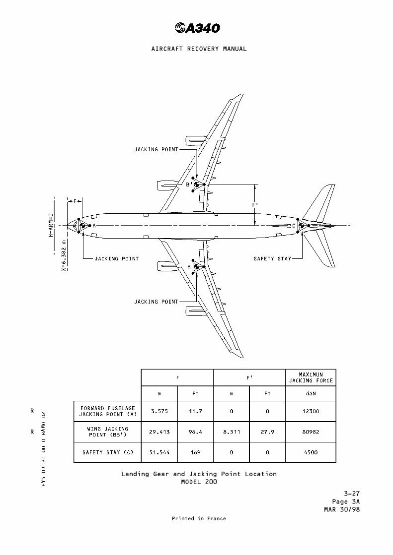
3-27Page 3A
MAR 30/98
Landing Gear and Jacking Point LocationMODEL 200
Printed in France
AIRCRAFT RECOVERY MANUAL
R
R

3-27Page 4
JUL 01/95
Jacking DesignMODEL 300
Printed in France
AIRCRAFT RECOVERY MANUAL

3-27Page 4A
MAR 30/98
Jacking DesignMODEL 200
Printed in France
AIRCRAFT RECOVERY MANUAL
R
R

3-27Page 5
JUL 01/94
Forward Jacking Point A, Underwing Jacking Point BSafety Stay Point C
Printed in France
AIRCRAFT RECOVERY MANUAL

3-27Page 6
JUL 01/94
Load at the Aircraft Jacking PointsMODEL - 300
Printed in France
AIRCRAFT RECOVERY MANUAL
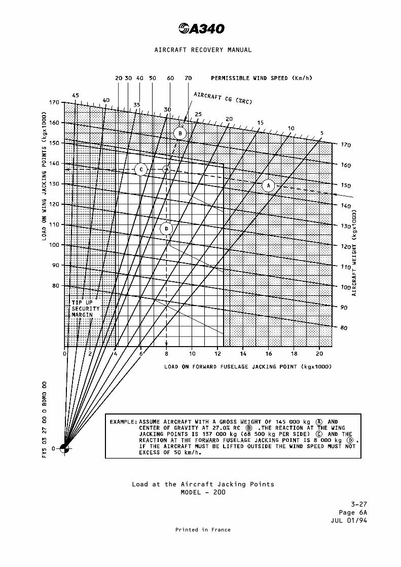
3-27Page 6A
JUL 01/94
Load at the Aircraft Jacking PointsMODEL - 200
Printed in France
AIRCRAFT RECOVERY MANUAL
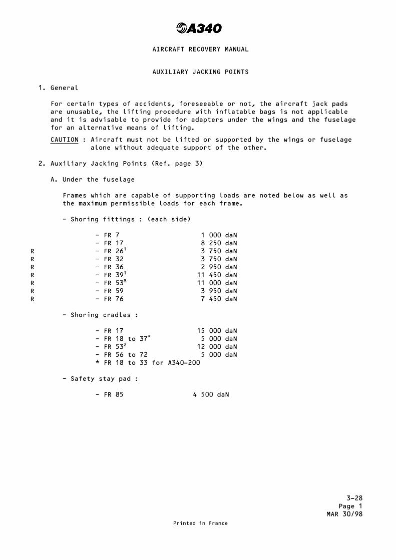
3-28Page 1
MAR 30/98
AUXILIARY JACKING POINTS
1. General
For certain types of accidents, foreseeable or not, the aircraft jack padsare unusable, the lifting procedure with inflatable bags is not applicableand it is advisable to provide for adapters under the wings and the fuselagefor an alternative means of lifting.
CAUTION : Aircraft must not be lifted or supported by the wings or fuselagealone without adequate support of the other.
2. Auxiliary Jacking Points (Ref. page 3)
A. Under the fuselage
Frames which are capable of supporting loads are noted below as well asthe maximum permissible loads for each frame.
– Shoring fittings : (each side)
– FR 7 1 000 daN– FR 17 8 250 daN– FR 261 3 750 daN– FR 32 3 750 daN– FR 36 2 950 daN– FR 391 11 450 daN– FR 538 11 000 daN– FR 59 3 950 daN– FR 76 7 450 daN
– Shoring cradles :
– FR 17 15 000 daN– FR 18 to 37* 5 000 daN– FR 532 12 000 daN– FR 56 to 72 5 000 daN* FR 18 to 33 for A340-200
– Safety stay pad :
– FR 85 4 500 daN
Printed in France
AIRCRAFT RECOVERY MANUAL
RRRRRRR

3-28Page 2
JUL 01/95
B. Under the Wings
Shoring cradles positioned under the wings can be used in the operationto recover a damaged aircraft.
Typical recovery action may require the aircraft to be supported whilst areplacement/retracted/collapsed landing gear is made functional.Functional landing gear is necessary in the recovery, to permit theaircraft to be moved the accident area.
The shoring cradles, each with two adjustable pads, 152.4 mm (6.0 in)square, may be positioned at locations under each wing. These locationsare detailed in Table 1 and shown on page 3.
The adjustable pads are faced with thin rubber and contact the wingprofile at the datum intersections of the ribs and the front and rearspars (F/S and R/S).
Table 1 shows the maximum load limit allowed at each jack pad when thewings are supported by the cradles. These load limits apply to all A340aircraft and variants.
It is important that the loads at each rib position are not exceeded ordamage to the aircraft may occur.
RIBPOSITION SPAR
MAXIMUM ALLOWABLE LOADdaN Lbf
6 F/S 7651 172006 R/S 7651 1720015 F/S 4782 1075015 R/S 4782 1075022 F/S 5600 1259022 R/S 5600 1259027 F/S 4650 1045427 R/S 4650 1045431 F/S 3899 876531 R/S 3899 8765
Table 1 – Maximum Allowable Load at each Jack Pad
Printed in France
AIRCRAFT RECOVERY MANUAL
R
RR
RRRR
RRR
RRR
RRR
RR

3-28Page 3
JUL 01/95
Location of auxiliary Jacking Points
Printed in France
AIRCRAFT RECOVERY MANUAL

3-28Page 4
JUL 01/95
This Page Left Blank Intentionally
Printed in France
AIRCRAFT RECOVERY MANUAL

4-10Page 1
MAR 30/98
MOVING DAMAGED AIRCRAFT ONITS LANDING GEAR
1. General
Before the aircraft is raised at the three main jacking points, the weight ofthe aircraft must be reduced. The maximum jacking weight is 152000 kg(335 099 lb).After the aircraft has been lifted, it is possible to extend and lock themain and nose landing gears down. The aircraft can then be towed to therepair area.The center line gear is not extended by the free-fall system.WARNING : BEFORE YOU EXTEND THE LANDING GEAR(S) MAKE SURE THAT :
– ALL PERSONS ARE IN A SAFE POSITION– THE AIRCRAFT IS SUPPORTED AND MOORED CORRECTLY– ALL EQUIPMENT IS REMOVED FROM THE AREA WHERE THE LANDING GEAR(S)WILL EXTEND (REF. FIG.1).
2. Manual Extension of the Landing Gears
CAUTION : DEFLATION AND COMPRESSION OF A MLG OLEO STRUT WHILST THE GEAR ISPARTLY OR WHOLLY RETRACTED WILL RESULT IN THE BLOCKAGE OF GEAREXTENSION BY THE GEAR SHORTENING MECHANISM.
A. Remove all damaged gear-doors. If the doors are badly damaged, you canbreak them to remove them.
B. Only the nose and main landing gears can be extended by the free fallsystem. The system is operated electrically by switches on panel 312VU inthe cockpit (Ref. Fig. 2). The switches must only be used if it is safe toenergise the aircraft electrical network.
If it is not safe to energise the electrical network, the landing gears canbe extended :– by the connection of an external power supply through control unit, PartN°. 98F32001001000, to each of the electrical actuators 5GF, 6GF and 7GF(Ref. Fig. 3)
– manually, by removal of the applicable electrical actuators 5GF, 6GF and7GF, and the use of a ratchet and splined drive, Part N°. 98F32104022000(Ref. Fig. 3)
The main landing gears lock down by their own weight and the springs on thelock links.Install the Landing Gear Ground locking pins when the Landing Gears areextended.Visually inspect all the Landing Gears and their attachments for damage andcorrect attachment before the aircraft is moved.For the graphs that show the loads at the wing main jacking points and theforward fuselage jacking points, refer to figures 4 and 5.The loads detailed on the graphs apply to the following A340 models :– 300 and 200– 300 at 271.9 tonne, Maximum Ramp Weight (MRW)– 300 at 260.9 tonne (MRW)– 200 at 260.9 tonne (MRW).
3. Moving the AircraftRefer to chapter 4-21 for the procedures on Towing, before you move theaircraft on its landing gear.
Printed in France
AIRCRAFT RECOVERY MANUAL
R

4-10Page 1A
JAN 01/96
The loads detailed on the graphs apply to the following A340 models :
– 300 and 200– 300 at 271.9 tonne, Maximum Ramp Weight (MRW)– 300 at 260.9 tonne (MRW)– 200 at 260.9 tonne (MRW).
3. Moving the Aircraft
Refer to chapter 4-21 for the procedures on Towing, before you move theaircraft on its landing gear.
Printed in France
AIRCRAFT RECOVERY MANUAL
R
R

4-10Page 1B
JAN 01/96
This Page Left Blank Intentionally
Printed in France
AIRCRAFT RECOVERY MANUAL

4-10Page 2
MAR 30/98
Landing Gear FootprintFigure 1
Printed in France
AIRCRAFT RECOVERY MANUAL
R

4-10Page 3
JAN 30/93
Free-Fall Selector SwitchesFigure 2
Printed in France
AIRCRAFT RECOVERY MANUAL

4-10Page 4
JUL 01/95
Free-Fall ActuatorsFigure 3
Printed in France
AIRCRAFT RECOVERY MANUAL

4-10Page 5
JAN 01/96
Wing Jacking Point Loads
Figure 4
Printed in France
AIRCRAFT RECOVERY MANUAL
RRRRRRRRRRRRRRRRRRRRRRRRRRRR
RRR
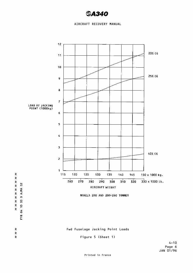
4-10Page 6
JAN 01/96
Fwd Fuselage Jacking Point Loads
Figure 5 (Sheet 1)
Printed in France
AIRCRAFT RECOVERY MANUAL
RRRRRRRRRR
RRR

4-10Page 7
JAN 01/96
Fwd Fuselage Jacking Point Loads
Figure 5 (Sheet 2)
Printed in France
AIRCRAFT RECOVERY MANUAL
RRRRRRRRRR
RRR

4-10Page 8
JUL 30/93
NLG Jacking Point LoadsModel 300
Figure 5 (Sheet 2)
Printed in France
AIRCRAFT RECOVERY MANUAL

4-10Page 9
JAN 30/93
Nose Landing Gear Jacking Point HeightsFigure 2
Printed in France
AIRCRAFT RECOVERY MANUAL

4-10Page 10
JAN 30/93
Main Gear Jacking Point HeightsFigure 1 (Sheet 1)
Printed in France
AIRCRAFT RECOVERY MANUAL

4-10Page 11
JAN 30/93
Main Gear Jacking Point HeightsFigure 1 (Sheet 2)
Printed in France
AIRCRAFT RECOVERY MANUAL

4-10Page 12
JAN 30/93
Main Gear Jacking Point HeightsFigure 1 (Sheet 3)
Printed in France
AIRCRAFT RECOVERY MANUAL

4-10Page 13
JAN 30/93
Center Line Gear Jacking Point HeightsFigure 2
Printed in France
AIRCRAFT RECOVERY MANUAL

4-21Page 1
MAR 30/98
TOWING
1 – General
The A340 is designed with means for conventional tractor towing.
It is possible to tow or push the aircraft, at maximum ramp weight withengines at zero or up to idle thrust, using a tow bar attached to the nosegear leg. The two bar fitting is installed at the front of the leg.
The main gears have attachments points for towing and debogging. Theseattachment points are be able to be used to restrain the aircraft when theengines are running at up to maximum thrust.
2 – Approximate Towing Loads
Aircraft towing forces cannot be accurately calculated.
They can only be established through experience or testing.
For the A340 as for most aircraft, the following maximum values have beenset :
– Breakaway on dry level concrete : 6 % x MTW
– To maintain rolling on level surface : 3 % x MTW
– Breakaway on slope : 6 % x MTW
+ 1 % x MTW per
1 % slope
– To maintain rolling on slope : 3 % x MTW
+ 1 % x MTW per
1 % slope
Note :
– In all above formula, MTW = Maximum Taxi Weight.
– When the aircraft is pushed rearward with the engines idling, the enginethrust resistance must be added to the above formulae values.
Moreover, the following coefficients of friction between the tow tractor tiresand the ground have been adopted :
– Dry concrete or asphalt : 0.80
– Wet asphalt : 0.75
– Wet concrete : 0.57
– Hard snow : 0.20
– Ice : 0.05
Printed in France
AIRCRAFT RECOVERY MANUAL
R

4-21Page 2
MAR 30/98
3 – Limit Loads and Angles
The limit towing loads and angles are shown in page 4.
Whatever the towing arrangement used, the steering angle allowed on each sideof the aircraft centerline is 83° only when the nose wheel steeringdesactivation electrical-box towing lever in towing position and locked witha special pin.
The steering angle is limited to 40° during rearward pushing with the enginesat idle to avoid the possibility of NLG tire slippage.
4 – Towing by Main Gears (Ref. page 5)
Forward or rearward towing by the main landing gears uses two fork-shapedfittings and a cable. The two fittings, which are specific tools, areattached to lug provided at each end of the gear.The two fitting/cable set is provided with a safety shear pin calibrated to61 900 daN (139 151 lbf).
5 – Landing Gear Downlock Ground Safety Pins
If required the landing gear may be mechanically locked in the ″down″position during towing by inserting a ground safety pin in the nose geartelescopic drag strut (Ref. page 6) and a ground safety sleeve around the MLGLock Link actuator ram.
NOTE : If gear braces are damaged they may be replaced with steel juryrigging to permit towing to the maintenance area.
6 – Nose Gear Tow Bar
Towing by Nose Gear FWD Fitting (Ref. page 3)
A conventional type tow bar designed in accordance WITH SAE ARP 915 isrequired, and should be equipped with a damping system to protect the nosegear against jerks and with towing shear pins :
– (calibrated to 28 620 daN) (64 337 lbf) for gear protection againstexessive loads
– (calibrated to 3130 m.daN) (23 100 lbf.ft) for gear protection againstexcessive torque.
The towing head is designed according to SAE AS 1614 cat I.
Printed in France
AIRCRAFT RECOVERY MANUAL
R

4–21Page 3
OCT 30/93
Nose Gear TowingFittings
Printed in France
AIRCRAFT RECOVERY MANUAL

4–21Page 4
MAR 30/98
Limit Towing angles
Printed in France
AIRCRAFT RECOVERY MANUAL
R
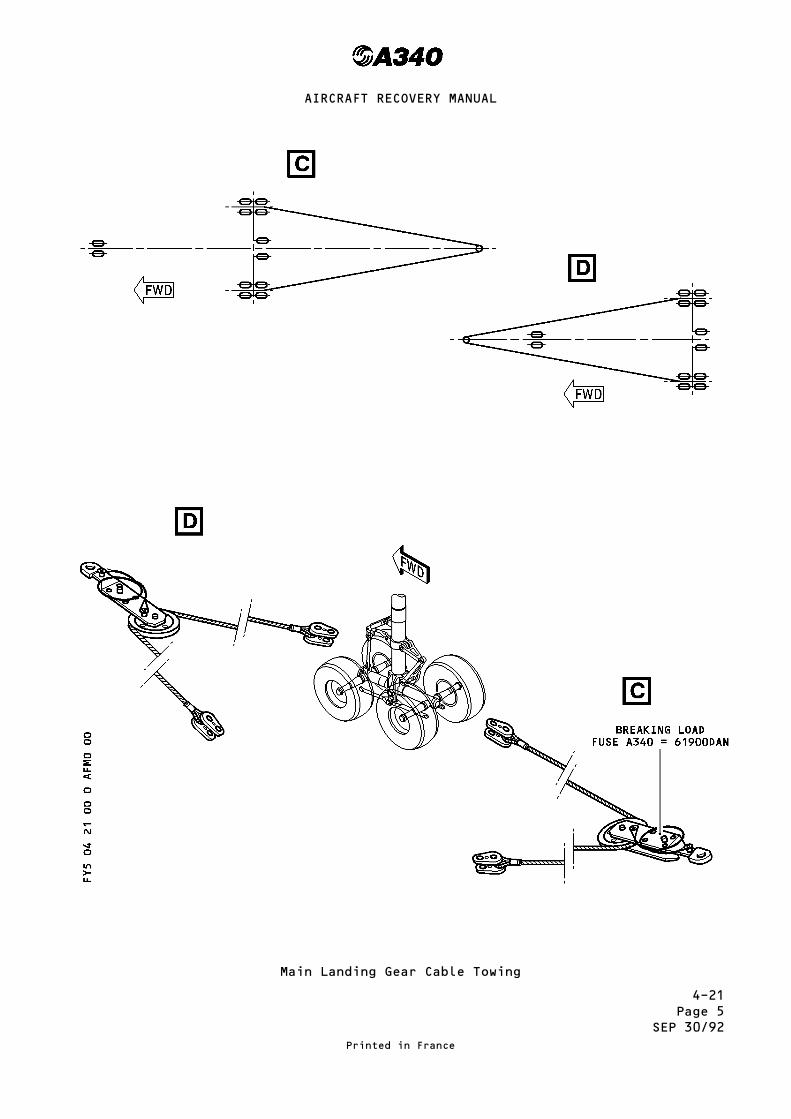
4–21Page 5
SEP 30/92
Main Landing Gear Cable Towing
Printed in France
AIRCRAFT RECOVERY MANUAL
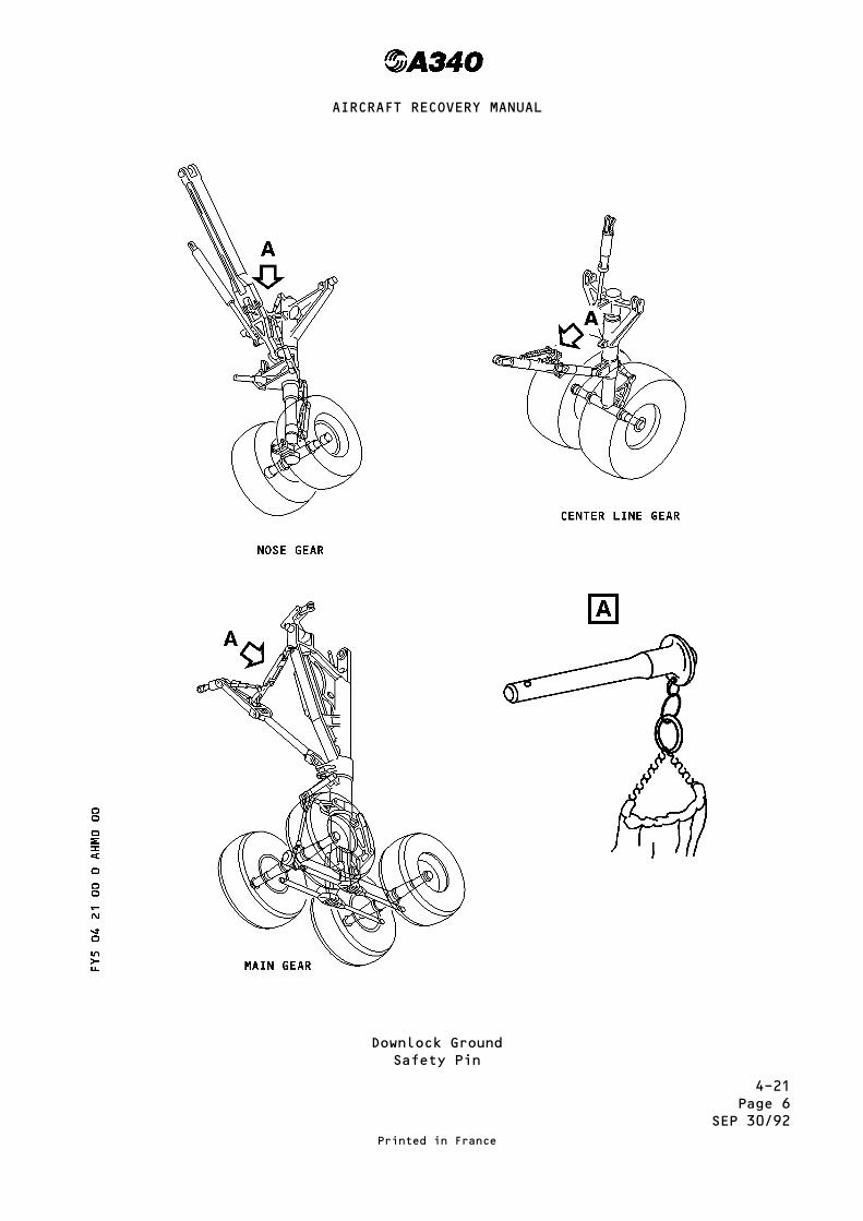
4–21Page 6
SEP 30/92
Downlock GroundSafety Pin
Printed in France
AIRCRAFT RECOVERY MANUAL

4-22Page 1
JAN 01/96
TAXIING AND TOWING OF AIRCRAFT WITH DEFLATED TIRES
1. General
Deflated tires on an aircraft will limit the possible movement that can bemade on the ground.
Deflated tires can be on one or more of the Landing Gears. They limit themovement of the aircraft in the ways that follow :– they limit the aircraft from being moved at taxiing speed on certain nose-wheel steering angles
– they limit the aircraft from being towed at the maximum towing angles
Two methods can be used to move an aircraft these are :– with its own power (taxiing)– with a tow (towing)
2. Taxiing Using Engine Power
Figure 1 to 4 detail aircraft variants with three different Landing Gearconfigurations with deflated tires.The figures show the Landing Gear configurations as follows :– Figure 1, for models 200 and 300– Figure 2, for model 300 at 271.9 tonne Maximum Ramp Weight (MRW)– Figure 3, for model 300 at 260.9 tonne (MRW)– Figure 4, for model 200 at 260.9 tonne (MRW).
The three Landing Gear configurations are identified by the Curves A, B and C.The figures also show the maximum nose-wheel steering angle at differentaircraft speeds.
A. Refer to Curve A, if any one tire is deflated on one or more LandingGears.
The permitted maximum is four deflated tires for each aircraft, this is amaximum of one for each Landing Gear.
For figure 1, the maximum steering angle permitted on Curve A is 65 deg.
For figures 2, 3 and 4, the maximum steering angle permitted on Curve A is60 deg.
With more than four deflated tires on an aircraft refer to another curve.
B. Refer to Curve B if you have one deflated tire on each axle of one or bothMain Landing Gears together with :– one Nose Gear deflated tire– and one Center Line Gear deflated tire.
The permitted maximum is six deflated tires for each aircraft but theremust not be more than one deflated tire on any axle.
Printed in France
AIRCRAFT RECOVERY MANUAL
RR
RR
R
R
RRRRRRR
RRR
R
R
R
RR
RRR
R
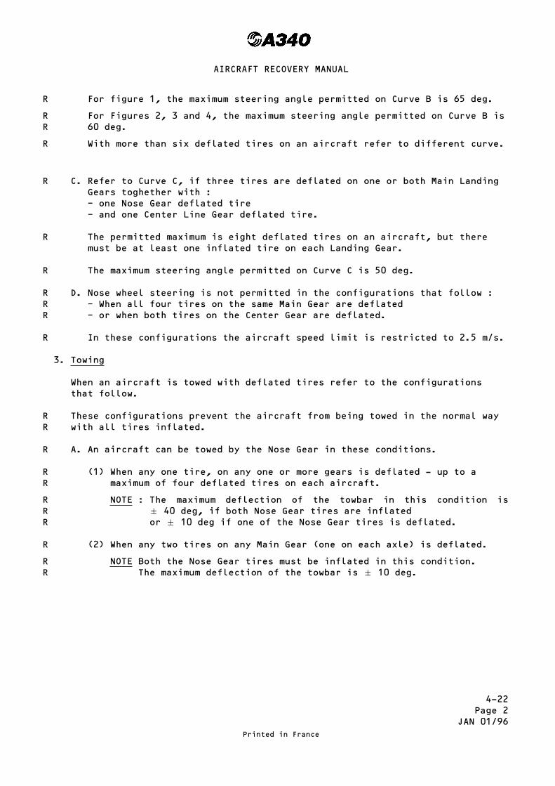
4-22Page 2
JAN 01/96
For figure 1, the maximum steering angle permitted on Curve B is 65 deg.
For Figures 2, 3 and 4, the maximum steering angle permitted on Curve B is60 deg.
With more than six deflated tires on an aircraft refer to different curve.
C. Refer to Curve C, if three tires are deflated on one or both Main LandingGears toghether with :– one Nose Gear deflated tire– and one Center Line Gear deflated tire.
The permitted maximum is eight deflated tires on an aircraft, but theremust be at least one inflated tire on each Landing Gear.
The maximum steering angle permitted on Curve C is 50 deg.
D. Nose wheel steering is not permitted in the configurations that follow :– When all four tires on the same Main Gear are deflated– or when both tires on the Center Gear are deflated.
In these configurations the aircraft speed limit is restricted to 2.5 m/s.
3. Towing
When an aircraft is towed with deflated tires refer to the configurationsthat follow.
These configurations prevent the aircraft from being towed in the normal waywith all tires inflated.
A. An aircraft can be towed by the Nose Gear in these conditions.
(1) When any one tire, on any one or more gears is deflated - up to amaximum of four deflated tires on each aircraft.
NOTE : The maximum deflection of the towbar in this condition isq 40 deg, if both Nose Gear tires are inflatedor q 10 deg if one of the Nose Gear tires is deflated.
(2) When any two tires on any Main Gear (one on each axle) is deflated.
NOTE Both the Nose Gear tires must be inflated in this condition.The maximum deflection of the towbar is q 10 deg.
Printed in France
AIRCRAFT RECOVERY MANUAL
R
RR
R
R
R
R
RRR
R
RR
R
RR
RRR
R
RR

4-22Page 3
JAN 01/96
B. An aircraft must be towed by the Main Gear in these conditions.
(1) When two tires on the same axle or three tires on the same Main Gearare deflated.
NOTE : The aircraft can be steered by normal steering control orsteered by the Nose Gear using the toward. Maximum Nose Gearsteering angle is q 50 deg.
(2) When all four tires on the same Main Gear or both tires on theCenterline Gear are deflated.
NOTE : In this condition both Nose Gear tires must be inflated.No deflection of the tow bar is allowed and the speed must belimited to 1.3 m/s.
Printed in France
AIRCRAFT RECOVERY MANUAL
R
R
RRR
RR
RRR
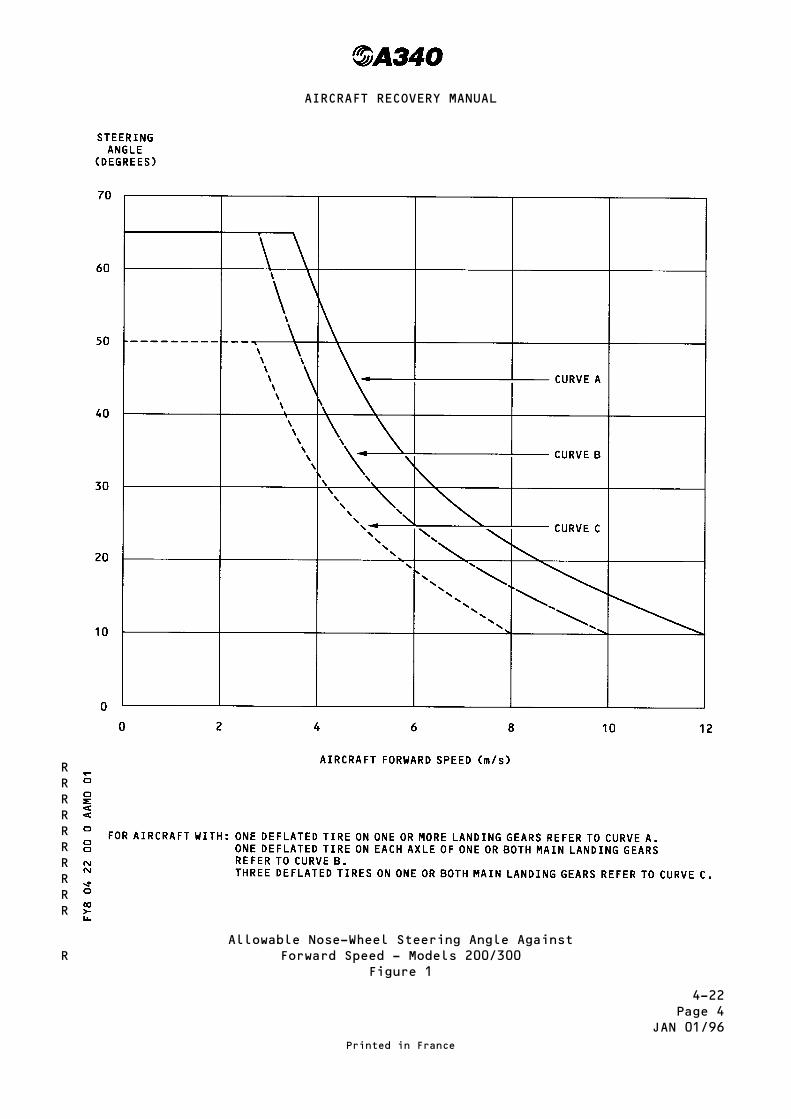
4-22Page 4
JAN 01/96
Allowable Nose-Wheel Steering Angle AgainstForward Speed - Models 200/300
Figure 1
Printed in France
AIRCRAFT RECOVERY MANUAL
RRRRRRRRRR
R

4-22Page 5
JAN 01/96
Allowable Nose-Wheel Steering Angle Against Forward Speed- Model 300 at 271.9 tonne (MRW)
Figure 2
Printed in France
AIRCRAFT RECOVERY MANUAL

4-22Page 6
JAN 01/96
Allowable Nose-Wheel Steering Angle AgainstForward Speed - Models 300 at 260.9 tonne (MRW)
Figure 3
Printed in France
AIRCRAFT RECOVERY MANUAL

4-22Page 7
JAN 01/96
Allowable Nose-Wheel Steering Angle AgainstForward Speed - Models 200 at 260.9 tonne (MRW)
Figure 4
Printed in France
AIRCRAFT RECOVERY MANUAL

4-22Page 8
JAN 01/96
This Page Left Blank Intentionally
Printed in France
AIRCRAFT RECOVERY MANUAL

4-30Page 1
JUL 30/93
RETURNING UNDAMAGED AIRCRAFT TO RUNWAY
1. General
A. When, as a result of various circumstances, an aircraft has left therunway, it may be partially or completely bogged. Probably there will beno damage to the aircraft but other than normal towing is necessary toturn the aircraft to the runway.
B. If only the main gear of one side is off the runway all fuel should beremoved or transferred from wing with bogged gear to opposite wing tank.Refer to Aircraft Maintenance Manual for applicable fuel transferprocedures.
C. Aircraft weight should be reduced as near as possible to the emptyequipped weight except for fuel in the case mentioned above.
D. In practically all cases, the runway or a major taxiway will be blockednecessitating rapid clearance in order that the airport may resumeoperations. Valuable time will be saved by planning the job to completionbefore starting the operation.
2. Job Planning
Job planning to completion should include the weight to be removed, conditionof terrain, direction aircraft is to be towed, equipment available to installan emergency runway, tractors, hoists and towing vehicles available.
A. Determine whether it is necessary to lift the aircraft to strengthen theground under the wheels, and start digging to prepare ramps gentlyinclined up to the ground level.
B. If the accident has been caused by malfunction of the brakes or of thenose gear steering, take the necessary steps to free seized brakes orlocked steering.
C. Ensure that available vehicles are capable of towing the aircraft on theramps.
D. Prepare the ground in the direction chosen for towing. Fill the holes withcrushed rock or gravel. If the equipment necessary for an emergency runwayis not available, a track is to be constructed with timbers covered withsteel plates or plywood sheets.
Printed in France
AIRCRAFT RECOVERY MANUAL

4-30Page 2
JUL 30/93
E. Make sure that the method used is adapted to the nature of the terrain.
F Ensure that a sufficient quantity of material is available to constructfoundations for ramps.
3. Return of Aircraft to Runway
Note : If the wheels have bogged down only to a depth of less than center ofaxle and if they do not sink any further, it will not be necessary tolift the airplane to strengthen the ground under the landing gear.
A. Starting from the gear, construct gently inclined ramps in the directionchosen for towing ; these ramps should extend approximately one meter oneach side of the landing gear.The depth an length of these ramps depend on the depth that gear is boggeddown.
Note : On extremely soft ground the channel will require additionalexcavation and filling with resistant material (crushed rock orgravel) to provide sufficient bearing strength.
B. Lay heavy timbers or railroad crossties crosswise in each channel. Covertimbers or crossties with thick plywood sheets, steel sheets at least 6 mmthick or 20 mm thick light alloy sheets.
Note : To have a firm channel bottom, two layers of plywood will beplaced, one accross the ramp, the other one lengthwise ; ifplywood isused in this manner, joints must be straggered to avoidsteps under load.
Station towing and winching vehicles on a concrete surface.
Tow airplane form main gear. See chapter 4-21 for towing procedures.
Printed in France
AIRCRAFT RECOVERY MANUAL

5-10Page 1
OCT 30/93
GENERAL RECOVERY EQUIPMENT
1. Jacks.
2. Work lights, floodlights.
3. Engine Removal Equipment (tools, slings, shipping trailers etc).
4. On-site communication equipment.
5. Ballast bags.
6. Sheets of plywood, steel plate, planking, etc...
7. Cribbing timber (railroad ties) to make platform for bags.
8. Bulldozers, forklift, cranes, winching vehicles, bucket loader forexcavating (as required).
9. Aircraft towing tractor.
10. Cables, pulley blocks, ladder.
11. Miscellaneous tools : shovels, picks, crowbars, sledge hammers, hoes,chainsaws, hammers and nails, handsaw, small hydraulic jacks, shackles,etc ...
12. Miscellaneous materials : Crushed rock, steel beams, padding to protectaircraft.
13. Mobile shelter-trailer; etc ...
14. Copperloy coated steel grounding rod with cable and clips.
Printed in France
AIRCRAFT RECOVERY MANUAL

5-20Page 1
JAN 01/96
EQUIPMENT PECULIAR TO THE AIRCRAFT
1. Towing
Bar-steering nose wheel P/N 98F 09101003 000
Cable-Towing, main landing gear P/N 98F 09101002 000
2. Lifting and Shoring
– Jacks
Front Jack – Point A TR 470000 P/N 98F 07101000 000
Main Jack LH – Point B1 TR 090000 P/N 98F 07101001 000
Main Jack RH – Point B2 TR 090000 P/N 98F 07101001 000
Safety (FR85) – Point C TR 120000 P/N 98F 07101002 000
Fitting - FR7 LH P/N 98F 07203000 100
Fitting - FR7 RH P/N 98F 07203000 101
Fitting - FR17 LH P/N 98A 07003903 100
Fitting - FR17 RH P/N 98A 07003903 101
A/C Lifting Assy FR17 comprising : P/N 98A 07003900 000
- Sling assy P/N 98A 07003900 001
- Hoisting beam P/N 98A 07003900 002
- Upper slings P/N 98A 07003900 003
- Sling fitted with ring P/N 98A 07003900 004
Fitting - FR26-1, 32, 36 LH P/N 98F 07203000 102
Fitting - FR26-1, 32, 36 RH P/N 98F 07203000 103
Fitting - FR39-1 LH P/N 98F 07203000 104
Fitting - FR39-1 RH P/N 98F 07203000 105
Fitting - FR53-8 LH P/N 98F 07203000 108
Fitting - FR53-8 RH P/N 98F 07203000 109
Fitting - FR59 LH P/N 98F 07203000 110
Fitting - FR59 RH P/N 98F 07203000 111
Fitting - FR76 LH P/N 98F 07203000 112
Fitting - FR76 RH P/N 98F 07203000 113
Printed in France
AIRCRAFT RECOVERY MANUAL
R
R

5-20Page 2
MAR 30/98
Shoring Cradles - Damaged Aircraft Repair
Shall be placed under each wing and fuselage as necessary :
– Under FuselageFR : 11, 17, 26 to 58, 532, 72 and 80.
– Under WingRIBS 6, 12, 22 and 31
3. Lifting Using Inflatable Bags
– 30000 kg (66138 lb) and 6000 kg (13228 lb) high stability inflatable bagswith related hoses, valves and protectives pads.
– A Compressor delivering oil-free air at 3,5 and 7 PSI.
4. Tethering
Tethering fitting at Frame 17 LH P/N 98A 07003903 100
Tethering fitting at Frame 17 RH P/N 98A 07003903 101
Tethering fitting at Frame 36 LH P/N 98F 07203000 102
Tethering fitting at Frame 36 RH P/N 98F 07203000 103
Tethering fitting at Frame 59 LH P/N 98F 07203000 110
Tethering fitting at Frame 59 RH P/N 98F 07203000 111
Tethering fitting at Frame 76 LH P/N 98F 07203000 112
Tethering fitting at Frame 76 RH P/N 98F 07203000 113
5. Landing Gear, Manual Extension
Control Unit, free-fall P/N 98F 32001001 000
Splined Drive, free-fall P/N 98F 32104022 000
Shoring Assy, Under Fuselage P/N 98F 07203001
Printed in France
AIRCRAFT RECOVERY MANUAL
R
R