
AIRCRAFT ACCIDENT REPORT AND EXECUTIVE SUMMARY
46
CA 12-12a 23 FEBRUARY 2006 Page 1 of 46 Section/division Accident & Incident Investigation Form Number: CA 12-12a AIRCRAFT ACCIDENT REPORT AND EXECUTIVE SUMMARY Reference: CA18/2/3/8010 Aircraft Registration ZS-RRB Date of Accident 3 September 2005 Time of Accident 0935Z Type of Aircraft Agusta Westland 109-K2 Type of Operation Commercial Pilot-in-command Licence Type Commercial Age 34 Licence Valid Yes Pilot-in-command Flying Experience Total Flying Hours 2 640.0 Hours on Type 320.0 Last point of departure National Port Authority helipad, Richards Bay Next point of intended landing National Port Authority helipad, Richards Bay Location of the accident site with reference to easily defined geographical points (GPS readings if possible) Crashed into the sea, Richards Bay Harbour (GPS position: South 28° 48.751’ East 032° 06.012’) Meteorological Information Surface wind; 030°/12 to 24 knots; Temperature; 27.5°C, Visibility; +10 km Number of people on board 2 + 1 No. of people injured 1 + 1 No. of people killed 1 Synopsis The Agusta helicopter with registration number ZS-RRB, serial number 10035, was withdrawn from service and subjected to a 4,800-hour maintenance inspection in Pretoria. After the inspection and two test flights, the helicopter flew from Pretoria to Richards Bay, a total of 5 hours since the inspection, and commenced with marine pilot services for the National Ports Authority in Richards Bay. On Saturday, 3 September 2005 at 0930Z, the helicopter pilot and the hoist operator were tasked to pick up a marine pilot from a Greek-registered cargo ship, the Alpha Afovos, which was exiting the harbour of Richards Bay. The cargo ship had a designated helicopter landing area on the deck and the ship’s fire and rescue team was positioned, awaiting the landing of the helicopter. After a two-way radio conversation between the helicopter pilot and the marine pilot, the helicopter approached the cargo ship from the stern on the right-hand side and formatted parallel with the cargo ship at a height of approximately 7 to 8 metres above the port bridge wing area, from where the marine pilot was hoisted. While the marine pilot was still hanging from the hoist, the helicopter started to roll uncontrollably to the right, impacted with the Inmarsat B antenna and the main mast of the cargo ship and crashed into the sea on the starboard side of the ship. Both the helicopter pilot and the marine pilot were rescued and taken to hospital with serious injuries. The hoist operator was fatally injured. Nobody on board the cargo ship was injured. Probable Cause The helicopter, in strong cross-wind conditions, probably ran out of lateral left control input when the additional mass of the marine pilot was lifted by the hoist. It then rolled over to the right, collided with the cargo ship, crashed into the sea and sunk. IARC Date Release Date
-
Upload
khangminh22 -
Category
Documents
-
view
0 -
download
0
Transcript of AIRCRAFT ACCIDENT REPORT AND EXECUTIVE SUMMARY

CA 12-12a 23 FEBRUARY 2006 Page 1 of 46
Section/division Accident & Incident Investigation Form Number: CA 12-12a
AIRCRAFT ACCIDENT REPORT AND EXECUTIVE SUMMARY
Reference: CA18/2/3/8010
Aircraft Registration ZS-RRB Date of Accident 3 September 2005 Time of Accident 0935Z
Type of Aircraft Agusta Westland 109-K2 Type of Operation Commercial
Pilot-in-command Licence Type Commercial Age 34 Licence Valid Yes
Pilot-in-command Flying Experience Total Flying Hours 2 640.0 Hours on Type 320.0
Last point of departure National Port Authority helipad, Richards Bay
Next point of intended landing National Port Authority helipad, Richards Bay
Location of the accident site with reference to easily defined geographical points (GPS readings if possible)
Crashed into the sea, Richards Bay Harbour (GPS position: South 28° 48.751’ East 032° 06.012’)
Meteorological Information Surface wind; 030°/12 to 24 knots; Temperature; 27.5°C, Visibility; +10 km
Number of people on board 2 + 1 No. of people injured 1 + 1 No. of people killed 1
Synopsis
The Agusta helicopter with registration number ZS-RRB, serial number 10035, was withdrawn from service and subjected to a 4,800-hour maintenance inspection in Pretoria. After the inspection and two test flights, the helicopter flew from Pretoria to Richards Bay, a total of 5 hours since the inspection, and commenced with marine pilot services for the National Ports Authority in Richards Bay.
On Saturday, 3 September 2005 at 0930Z, the helicopter pilot and the hoist operator were tasked to pick up a marine pilot from a Greek-registered cargo ship, the Alpha Afovos, which was exiting the harbour of Richards Bay. The cargo ship had a designated helicopter landing area on the deck and the ship’s fire and rescue team was positioned, awaiting the landing of the helicopter. After a two-way radio conversation between the helicopter pilot and the marine pilot, the helicopter approached the cargo ship from the stern on the right-hand side and formatted parallel with the cargo ship at a height of approximately 7 to 8 metres above the port bridge wing area, from where the marine pilot was hoisted. While the marine pilot was still hanging from the hoist, the helicopter started to roll uncontrollably to the right, impacted with the Inmarsat B antenna and the main mast of the cargo ship and crashed into the sea on the starboard side of the ship. Both the helicopter pilot and the marine pilot were rescued and taken to hospital with serious injuries. The hoist operator was fatally injured. Nobody on board the cargo ship was injured.
Probable Cause
The helicopter, in strong cross-wind conditions, probably ran out of lateral left control input when the additional mass of the marine pilot was lifted by the hoist. It then rolled over to the right, collided with the cargo ship, crashed into the sea and sunk.
IARC Date Release Date

CA 12-12a 23 FEBRUARY 2006 Page 2 of 46
Section/division Accident & Incident Investigation Form Number: CA 12-12a
AIRCRAFT ACCIDENT REPORT
Name of Owner : Viamax Fleet Management (Pty) Ltd
Name of Operator : Acher Aviation (Pty) Ltd
Manufacturer : Agusta Westland Company
Model : Agusta 109-K2
Nationality : South African
Registration Marks : ZS-RRB
Place : Richards Bay Harbour (In the sea)
Date : 3 September 2005
Time : 0935Z
All times given in this report are Co-ordinated Universal Time (UTC) and will be denoted by (Z). South
African Standard Time is UTC plus 2 hours.
Purpose of the Investigation:
In terms of Regulation 12.03.1 of the Civil Aviation Regulations (1997) this report was compiled in the
interest of the promotion of aviation safety and the reduction of the risk of aviation accidents or incidents and
not to establish legal liability.
Disclaimer:
This report is produce without prejudice to the rights of the CAA, which are reserved.
1. FACTUAL INFORMATION 1.1 History of Flight:
1.1.1 The National Ports Authority (NPA) of South Africa utilised an Agusta 109-K2
helicopter, based in Richards Bay, for the transportation and transferring of
marine pilots within the harbour. Marine pilots would either be transferred from
shore to a cargo ship waiting to enter the harbour, picked up from a cargo ship
leaving the harbour or for inter-cargo-ship transfers. This operation requires a 24-
hour service and the helicopter crews therefore worked in shifts. The Agusta 109-
K2 is a twin-engine turbine helicopter with a single rotor. It was approved to

CA 12-12a 23 FEBRUARY 2006 Page 3 of 46
operate in VFR or IFR non-icing conditions.
1.1.2 The helicopter with registration ZS-RRB, serial number 10035, was released to
service on 2 September 2005 by an approved Agusta Aircraft Maintenance
Organisation (AMO) in Pretoria after completion of a 4800-hour maintenance
inspection. The helicopter was subjected to two test flights by an appropriately
rated test pilot and flew from Pretoria to Richards Bay on the afternoon of 2
September 2005. According to the aircraft’s flight folio, the helicopter had flown a
total of 5 hours since the inspection.
1.1.3 In Richards Bay harbour at approximately 0930Z, the helicopter got airborne for a
routine flight, which required a marine pilot to be off-loaded from the cargo ship
which was sailing out of the harbour channel towards the open sea. The cargo
ship was the Alpha Afovos, a Greek-registered cargo ship with a gross weight of
39 941 tons. It was 224.9 m long and 32.26 m wide with seven (7) cargo carrying
compartments, each compartment being covered with a hatch cover. Hatch
number four was demarcated as a helicopter landing area. The helicopter was
tasked to land on this hatch in order to pick up the marine pilot. Instead, the
helicopter hoisted the marine pilot from the wing of the right bridge and never
landed or attempted to land on the demarcated area on the deck.
1.1.4 This arrangement had been made after a discussion between the marine pilot and
the helicopter pilot via two-way radio. According to the pilot, he and the hoist
operator were both comfortable with this arrangement as it was not out of the
norm to perform bridge wing hoist operations. On many other cargo ships, marine
pilots are hoisted from the bridges.
1.1.5 During the hoisting operation, the helicopter pilot flew parallel to the cargo ship
and noticed that approximately 2 to 3 seconds after taking the weight of the
marine pilot, the helicopter started a slow, uncontrolled right roll. He realized that
the helicopter was not responding to his cyclic control inputs and noticed a full
deflection to the left in order to counter the right roll. The hoist operator warned
the helicopter pilot several times not to move to the right, but the helicopter was
not responding to any control inputs.
1.1.6 The helicopter continued to roll right and first impacted with the Inmarsat B antenna
(dome shaped) of the cargo ship and the main rotor blades of the helicopter struck

CA 12-12a 23 FEBRUARY 2006 Page 4 of 46
the main mast of the cargo ship. At this stage the marine pilot was hanging below
the helicopter and both crashed into the sea on the right-hand side of the cargo
ship in a nose-down attitude.
1.1.7 The rescue crew from the cargo ship immediately threw several life rings into the
water and the Master of the cargo ship informed the Port Control that the
helicopter had crashed into the sea at the South Breakwater area.
1.1.8 Two persons in a kayak close by, saw the accident and assisted the helicopter
pilot and marine pilot by keeping them afloat until a ski boat with professional
divers on board, arrived on the scene. Both the helicopter pilot and marine pilot
were seriously injured, and taken to a local private hospital.
1.1.9 The marine pilot was admitted to the intensive care unit (ICU) of the hospital
where he was sedated for most of the time and remained in ICU for nearly two
weeks. He had sustained several injuries, which included severe and multiple
fractures to his ribs, broken collarbones, as well as head, shoulder and internal
injuries, including punctured lungs. His recollection of the accident was very hazy.
1.1.10 The helicopter pilot sustained a serious back injury and was hospitalised for 12
days.
1.1.11 The hoist operator was fatally injured in the accident. Police divers recovered his
body the following morning from the wreckage at a depth of approximately 22
metres.
1.1.12 The accident occurred during daylight conditions at a geographical position
determined as South 28° 48.751’ East 032° 06.012’.
1.2 Injuries to Persons:
Injuries Pilot Crew Pass. Other
Fatal - 1 - -
Serious 1 - 1 -
Minor - - - -
None - - - -

CA 12-12a 23 FEBRUARY 2006 Page 5 of 46
1.2.1 Both the helicopter pilot and the marine pilot survived the accident, but sustained
serious injuries. Both were subjected to surgery, and hospitalised for several weeks.
1.2.2 The hoist operator’s body was recovered from the wreckage the following morning
by Police divers. He was wearing floatation equipment which was not inflated and
found still secured by his safety harness in the aft cabin area of the helicopter.
1.3 Damage to Aircraft:
1.3.1 The helicopter was extensively damaged and found at the bottom of the sea.
A view of the wreckage being lifted out of the sea by a crane.
1.4 Other Damage:
1.4.1 The cargo ship suffered some structural damage caused by several main rotor
blade strikes to the structure. The Inmarsat B antenna was destroyed in the
process.

CA 12-12a 23 FEBRUARY 2006 Page 6 of 46
The Inmarsat antenna visible on the left and the main mast impact markings visible on the right of the picture.
1.5 Personnel Information:
1.5.1 Pilot-in-command:
Nationality South African Gender Male Age 34
Licence Number *************** Licence Type Commercial
Licence valid Yes Type Endorsed Yes
Ratings Instructor Rating Grade 2, Instrument Rating (H), Under
sling/winch Rating
Medical Expiry Date 31 January 2006
Restrictions None
Previous Accident
Pilot was flying a sea rescue helicopter (Bell 206B, ZS-
HEK, 29 December 2000) during the Trans-Agulhas yacht
race when he experienced a loss of tail rotor effect (LTE)
while flying over the sea. The helicopter crashed into the
sea near Reebok in the Western Cape. All the occupants
on board the helicopter survived the accident. The
helicopter was later recovered from the sea.
The pilot had flown several helicopter types prior to his conversion onto the Agusta
109 series helicopter. According to available records, the pilot had completed his
conversion onto the Agusta 109-K2 on 5 February 2004. During his conversion
training he flew a total of 3 hours and 30 minutes of dual instruction with an
instructor. The required documentation was submitted to the SACAA on 25
February 2004 for endorsement of the Agusta 109 type helicopter onto his licence.

CA 12-12a 23 FEBRUARY 2006 Page 7 of 46
He was regarded by his colleagues as a very good pilot and had conducted over a
thousand hoist operations.
Flying Experience:
Total Hours 2 640.0
Total Past 90 Days 50.0
Total on Type Past 90 Days 50.0
Total on Type 320.0
Breakdown of Flying Experience:
Total Flying Hours Aeroplane 970.0
Total Flying Hours Helicopter 1 670.0
Total Hours 2 640.0
1.5.2 Hoist operator:
The hoist operator was employed by the operator. His designation was: “Hoist
Operator daylight operations only, engineer under training”. He had received his
initial aviation training in the South African Air Force (SAAF) where he qualified as a
maintenance engineer in January 2001. In November 2003 he qualified as a flight
engineer. He resigned from the SAAF and joined the helicopter operator in
December 2004. He was signed out as a hoist operator on 24 February 2005 for
daylight service(s) only. He was in the process of obtaining his civilian Aircraft
Maintenance Engineer (AME) qualification by attending the required training
courses during designated periods, as stipulated in his employment contract.
1.6 Aircraft Information:
The Agusta 109-K2 is a twin-engine helicopter. It is equipped with two Turbomeca
Arriel 1K1 turbo-shaft engines. The helicopter has eight seats and was certified
under FAR 27 with the exemption of paragraph 27.1(a) for a maximum gross weight
increase to 2 850 kg (6283 lb). The helicopter was approved for land operation
under day and night VFR and IFR, non-icing conditions. No aerobatic manoeuvres
were permitted.

CA 12-12a 23 FEBRUARY 2006 Page 8 of 46
A photo of the helicopter that was taken some time prior to the accident.
The helicopter was equipped with the ‘High Altitude Configuration” P/N 109-0822-36
kit, which provides an improvement in yaw controllability in hovering and it was
especially designed for rescue operations at high altitudes with an external hoist.
The configuration consists of a horizontally mounted tail boom strake on the left
side, and a reduced vertical fin surface with a new trailing edge.
Also included was a “Tail Rotor Configuration” P/N 109-08220-42 to extend the tail
rotor pitch angle setting to 23°.
1.6.1 Airframe:
Type Agusta 109-K2
Serial Number 10035
Manufacturer Agusta Westland Company
Year of Manufacture 1998

CA 12-12a 23 FEBRUARY 2006 Page 9 of 46
Total Airframe Hours (At time of Accident) 4 801.1
Last Inspection (Hours & Date) 4 796.1 2 September 2005
Hours since Last Inspection 5.0
C of A (Issue Date) 9 December 1998
C of A (Currency Fee, Expiry date) 8 December 2005
C of R (Issue Date) (Present owner) 18 December 2001
Operating Categories Standard
AD’s and SB’s status Complied with
Type acceptance in RSA Yes
1.6.2 Engine No. 1:
Type Turbomeca Arriel 1K1
Serial Number 16077
Hours since New 4 321.6
Hours since Overhaul Modular engine
1.6.3 Engine No. 2:
Type Turbomeca Arriel 1K1
Serial Number 16079
Hours since New 5 811.6
Hours since Overhaul Modular engine
1.6.4 Mass and Balance:
According to the helicopter’s Airframe Logbook the Mass and Balance was last
determined on 20 November 2003. The aircraft data used in the Mass and Balance
calculation below was obtained from the mass sheet. The investigation calculated
the mass of the helicopter and the centre of gravity (CG) as shown in Table 1.
CA 12-12a 23 FEBRUARY 2006 Page 10 of 46
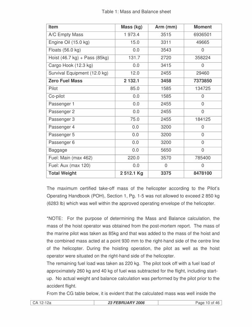
Table 1: Mass and Balance sheet
Item Mass (kg) Arm (mm) Moment
A/C Empty Mass 1 973.4 3515 6936501
Engine Oil (15.0 kg) 15.0 3311 49665
Floats (56.0 kg) 0.0 3543 0
Hoist (46.7 kg) + Pass (85kg) 131.7 2720 358224
Cargo Hook (12.3 kg) 0.0 3415 0
Survival Equipment (12.0 kg) 12.0 2455 29460
Zero Fuel Mass 2 132.1 3458 7373850
Pilot 85.0 1585 134725
Co-pilot 0.0 1585 0
Passenger 1 0.0 2455 0
Passenger 2 0.0 2455 0
Passenger 3 75.0 2455 184125
Passenger 4 0.0 3200 0
Passenger 5 0.0 3200 0
Passenger 6 0.0 3200 0
Baggage 0.0 5650 0
Fuel: Main (max 462) 220.0 3570 785400
Fuel: Aux (max 120) 0.0 0 0
Total Weight 2 512.1 Kg 3375 8478100
The maximum certified take-off mass of the helicopter according to the Pilot’s
Operating Handbook (POH), Section 1, Pg. 1-5 was not allowed to exceed 2 850 kg
(6283 lb) which was well within the approved operating envelope of the helicopter.
*NOTE: For the purpose of determining the Mass and Balance calculation, the
mass of the hoist operator was obtained from the post-mortem report. The mass of
the marine pilot was taken as 85kg and that was added to the mass of the hoist and
the combined mass acted at a point 930 mm to the right-hand side of the centre line
of the helicopter. During the hoisting operation, the pilot as well as the hoist
operator were situated on the right-hand side of the helicopter.
The remaining fuel load was taken as 220 kg. The pilot took off with a fuel load of
approximately 260 kg and 40 kg of fuel was subtracted for the flight, including start-
up. No actual weight and balance calculation was performed by the pilot prior to the
accident flight.
From the CG table below, it is evident that the calculated mass was well inside the

CA 12-12a 23 FEBRUARY 2006 Page 11 of 46
longitudinal envelope and well within limits, with the lateral table being on the edge
of the allowable limit for non-hoisting operations.

CA 12-12a 23 FEBRUARY 2006 Page 12 of 46
Below is a copy of the POH page, which allows the lateral Centre of Gravity (CG) to
be increased into the shaded area when hoisting operations are being conducted.
It should be noted that the longitudinal CG limits do not change when operating in
the external hoist configuration. See figure 1-3 (on page 17) for Lateral CG limits.
The POH continues on the subject of External Hoisting by stipulating in the pre-flight
checks the requirement that the hoist operation should be verified. Refer below.
CAUTION
“Avoid, whenever possible, operating the hoist with crosswind or rear wind.
.
NOTE:
Lift hoist load slightly above contact surface, by application of collective pitch, to
obtain a feeling of the controls.
Lateral CG position as calculated

CA 12-12a 23 FEBRUARY 2006 Page 13 of 46
EMERGENCY AND MALFUNCTION PROCEDURES
The external hoist installation is provided with an electrical cable cut system
operated by the pilot. If an emergency condition should require the release of
cargo, lift the guard to break the safety wire and operate CABLE CUT switch to
shear the hoist cable. If the electrically operated cable cut system fails to operate,
cut the cable with the manual cable cutter accessible to the operator. Cut the cable
as close to the hoist as possible.”
1.7 Meteorological Information:
1.7.1 An official weather report was obtained from the SA Weather Services following this
accident.
(i) Weather conditions at the time of the accident:
A cold front south-west of the country with a high-pressure system east of
the country, causing an offshore flow in the Richards Bay area.
(ii) Satellite Imagery:
The satellite imagery showed fine weather in the Richards Bay area with no
clouds.
(iii) Weather conditions in the vicinity of the accident:
No official observation was available at the time and place of the accident.
However, the satellite image shows fine weather in the area. The most likely
weather conditions at the place and time of the accident were:
Temperature - 27.5°C
Dew point - 19.0°C
Wind direction - 030°
Wind speed - 12 knots
Cloud - Nil
1.7.2 The reported wind at the time of the accident according to the Master of the Alpha
Afovos was 5 to 6 on the Beaufort scale, which was between 19 to 24 knots from
the north-east.
1.7.3 The weather conditions at the time of the accident were well within the operating
limitations of the helicopter and the pilot. According to the helicopter pilot, at no
stage during the operation was the prevailing cross-wind a concern, as he was able

CA 12-12a 23 FEBRUARY 2006 Page 14 of 46
to maintain a steady hover up until the right roll commenced.
1.8 Aids to Navigation:
1.8.1 The helicopter was certified for Instrument Flight Rule conditions and was properly
equipped.
1.9 Communications:
1.9.1 The helicopter was equipped with a dual VHF radio as well as an FM Tactical
Communication radio.
1.9.2 A recording of communication between the cargo ship, the marine pilot and Port
Control was obtained from Port Control. During one of these recordings, the
discussion of the marine pilot with the helicopter pilot regarding the position for the
pick-up was clear but the response from the helicopter pilot was, however, not
audible.
The following is a transcript of the communication by the marine pilot with the
helicopter at 0934Z:
From marine pilot to helicopter pilot:
John, good afternoon, you know you can land on No. 4 hatch, over. It is marked
‘Winch Only’ but it is a landing area, by the way take me off anywhere you like
from the bridge wing.
Unreadable communication from helicopter pilot.
Yes, are you talking about the bridge wing?
Unreadable communication from helicopter pilot.
South side?
Unreadable communication from helicopter pilot.
Port (unreadable word) I am on standby now.
1.9.3 Extract from the Operations Manual, Annexure H, SOP – Marine Pilot Services:
“Appendix K: Communications with Port Control and Shipping

CA 12-12a 23 FEBRUARY 2006 Page 15 of 46
The standard working channel for the helicopter is Channel 14 for Richards Bay and
Channel 13 for Durban. This channel is used for communications with both Port
Control and the ship. Port Control is required to monitor this channel for the
duration of the flight. This is important because of the possibility of the helicopter
ditching.
Appendix T: Communication with cargo ships
Various responsibilities that cannot be delegated are associated with ship service
operations in general. This is especially true in the case of cargo ships transporting
hazardous cargoes.
Communication between the helicopter and the cargo ship master or designate is a
prerequisite.
Language limitations do sometimes require sound professional judgement from the
helicopter crew in their efforts to provide the service.
Port Control/Signals are to establish contact with cargo ships, advise of the
helicopter service and deal with the bulk of the information required in terms of the
international guide to ship service operations by helicopter.
The helicopter should, however, still communicate directly with the cargo ship with
the following brief requirements:
• Establish contact with the cargo ship
• Establish the position of authority of the respondent
• Advise of the helicopter ETA overhead
• Establish if there is a designated landing/hoisting area
• Request permission to land pilot/provide service.
It is recommended that communication be established with the cargo ship at least
30 minutes prior to service. This allows the cargo ship masters to organize and
mobilize their fire crews if they feel that this is necessary.
It is the responsibility of the duty helicopter commander to ensure that he has all the
information required to conduct a safe service. This most importantly includes the
cargo ship master’s authority. Authority given to the marine pilot on board the

CA 12-12a 23 FEBRUARY 2006 Page 16 of 46
helicopter is sufficient; provided that the helicopter commander confirms that he has
heard the authority and any limitations associated with this authority.”
1.10 Aerodrome Information:
1.10.1 Not applicable.
1.11 Flight Recorders:
1.11.1 The helicopter was not fitted with a Cockpit Voice Recorder (CVR) or a Flight Data
Recorder (FDR) and neither was it required by regulation to be fitted to this type of
helicopter.
1.12 Wreckage and Impact Information:
1.12.1 The right rear section of the fuselage of the helicopter from behind the main landing
gear impacted with the Inmarsat B satellite communications antenna of the cargo
ship. The main rotor blade contacted with the main mast five to seven metres above
the antenna and impacted with various objects on the cargo ship before the
helicopter ditched on the starboard side of the cargo ship. The helicopter yawed
towards the right through 40° to 90° from the initial blade contact to water impact.
Illustration of accident position relative to the harbour channel.
Position of the accident
Prevailing wind at the time of the accident.

CA 12-12a 23 FEBRUARY 2006 Page 17 of 46
1.12.2 The right side of the helicopter suffered substantial impact damage consistent with
the damage to the cargo ship, residual paint marks and helicopter blade debris
found on the cargo ship. The helicopter was predominantly intact except for the tail
cone, including the tail rotor gearbox and blades. Impact marks on the right-hand
vertical tail fin suggest that impact with the cargo ship had caused the separation of
these components. Further blade rotational impact marks on the left stabiliser
confirmed that the tail rotor was turning at the time of impact.
1.12.3 Water impact indentation on the nose section of the helicopter suggests that it
impacted with the water in a nose-down attitude. Consistent with this, was the cabin
roof bowing upwards due to the weight of the main gearbox, main rotor head and
the nose cone.
1.12.4 The rescue hoist had separated from the attachment points at some stage during
the accident and was found on top of the helicopter when recovered. This was due
to impact with the cargo ship or severely distorted main rotor blade impact. Two
point six five metres of the cable was still unreeled. The hoist cable and hook
mechanism was found undamaged.
1.12.5 The top left side of the helicopter above the co-pilot’s seat was separated from the
wreckage due to main rotor blade impact.
1.12.6 Various other impact marks on the helicopter were found, consistent with impact
with the cargo ship and the distorted main rotor blades.
1.12.7 The cockpit of the helicopter was damaged at the rear bottom of the cabin area and
on top of the cabin just in front of the door posts between the cabin and the cockpit.
This damage could, however, also have occurred during the recovery, towing and
lifting of the wreckage out of the water by crane.
1.12.8 No underwater photos were taken while the helicopter was submerged prior to
recovery, due to the poor visibility under the water.
1.13 Medical and Pathological Information:
1.13.1 The hoist operator was fatally injured. He was located in the rear cabin and found
secured to the helicopter structure by means of an extended safety harness.

CA 12-12a 23 FEBRUARY 2006 Page 18 of 46
According to the post-mortem report the deceased did not drown, but was killed due
to multiple blunt force injuries involving the head, the chest and lungs and the
abdominal organs. There was no evidence to indicate that water was inhaled into
the lungs. The injuries indicated a high level of impact forces due to the break-up of
the helicopter or as a result of impact with the water.
A specimen of blood of the deceased was made available to the Forensic
Chemistry Laboratory of the Department of Health in Pretoria and the following
results were obtained:
(i) The concentration of alcohol in the blood was 0.00 grams per 100 millilitres.
(ii) The sample contained 2.5% sodium fluoride, which was sufficient to prevent
the formation of alcohol therein.
(iii) The carbon monoxide saturation of the haemoglobin was less than 5%.
1.14 Fire:
1.14.1 There was no evidence of a pre- or post-accident impact fire.
1.15 Survival Aspects:
1.15.1 Helicopter Pilot:
The helicopter pilot was secured by the helicopter-installed four-point safety
harness, and survived the accident but sustained serious injuries. After impact with
the water, the helicopter started to sink and he followed the HUET (Helicopter-
Under-Water-Escape-Training) procedure and exited the helicopter through the
pilot’s door and reached the surface. The pilot was wearing floatation equipment
which was found inflated. He remained in hospital for a period of 12 days due to a
fractured vertebra (L5) in his lower back.
1.15.2 Marine Pilot:
The marine pilot sustained serious injuries. He was also wearing emergency
floatation equipment which was fully inflated around his waist instead of around his
neck. He was taken to the same hospital as the helicopter pilot and was admitted to
the Intensive Care Unit for 27 days. He sustained severe injuries, including severe

CA 12-12a 23 FEBRUARY 2006 Page 19 of 46
and multiple fractures to his ribs, broken collar bones, injuries to his head and
shoulder and internal injuries, which included punctured lungs. During most of this
period he was heavily sedated.
1.15.3 Hoist Operator:
The hoist operator was seated in the rear cabin area behind the helicopter pilot on
the right-hand side aft-facing seat. He was wearing emergency floatation
equipment which was found to be not inflated. He was attached to the helicopter by
means of a “monkey chain” which was attached to the roof structure of the
helicopter. The quick release mechanism of the “monkey chain” was unsuitable for
the application as the quick release was located behind his back and required effort
to release in case of an emergency. Police divers recovered the hoist operator’s
body from the wreckage still secured to the “monkey chain”.
1.15.4 Helicopter Floatation Gear:
The helicopter was not equipped with floatation gear. After impact, the helicopter
wreckage sank within minutes to the bottom of the sea. According to the helicopter
operator, the floatation gear was unserviceable at the time of the accident and was
in the process of reparation.
Part 127 of the Operations Manual of the Operator, stipulates the following in Part
2, page 202:
“Over Water Flights;
(a) The operator ensures that, in the case of flight over water –
(iii) The helicopter is equipped for flights over water in terms of the CARs.
The requirements in terms of the Civil Aviation Regulations of 1997;
Part 91.04.27 No owner or operator of –
(c) a helicopter, shall operate over water beyond authoritative distance from
land, other than only for take-off and initial climb, or final approach and
landing, unless –
(ii) such helicopter is equipped with –
(bb) floatation equipment to ensure a safe ditching: Provided that in

CA 12-12a 23 FEBRUARY 2006 Page 20 of 46
the case of aerial spraying operations over water, the owner or
operator may apply to the Commissioner for an exemption in
terms of Part 11.”
1.15.5 Emergency Locator Transmitter (ELT)
The helicopter was equipped with a Kannad 406 MHz ELT with serial number
26115680005. The purpose of the unit is to broadcast a distress signal during
activation (during the accident impact sequence) in order to locate the wreckage as
quickly as possible, and to save human lives.
The ELT on this helicopter was located within the tail boom, as called for in Service
Bulletin BT109K-41. The unit, however, was unable to survive the impact forces
and was found to have burst open, as can be seen in the photo below. The
activation selection button on the unit was also found to be in the off position, which
rendered the unit of no value.
A view of the ELT as it was found after recovery of the wreckage.
1.16 Tests and Research:
1.16.1 Servo Actuators:
The three main servo actuators, as well as the tail rotor servo actuator, were
removed from the wreckage and forwarded to Agusta in Italy for further
investigation by the vendor Microtecnica. The following conclusions were made:

CA 12-12a 23 FEBRUARY 2006 Page 21 of 46
“All the servo actuators were subjected to functional tests. The results were in
line with the manufacturer’s requirements, except for minor deviations, which
could not effect the normal operation of the items. Some of these deviations
derived from the impact while others were function deviations. In most cases
typical wear signs due to normal operation were visible. Some minor
deformations, mainly on rods, were observed and were easily related to the
impact damage. In some cases corrosion was observed at the input areas of
the spools of the servo valves. In one case, corrosion was quite extended and
probably existent before the accident”.
The final assumption is that there was no evidence of malfunctioning prior to the
accident.
The full investigation/technical report of the servo actuators can be found attached
to this report as Annexure “B”.
1.16.2 Engine Investigation:
Both engines were subjected to pre-removal inspections by a Turbomeca’s engine
accident investigator before removal from the wreckage. Both engines were
subjected to a teardown inspection at the facilities of Turbomeca, under the
auspices of the investigator-in-charge.
The engines were both found to be in a serviceable condition and were producing
sufficient power at the time of the accident.
The non-rotation of the gas generator, the free turbine and gearbox assemblies
were due to corrosion progression as a result of engine water submersion. The full
investigation/technical report can be found in Annexure “C”.
1.16.3 Metallurgical Examination Report:
A number of fractured metal components were removed for metallurgical
examination in order to determine the possible failure modes. The tail rotor gearbox
and tail rotor blades were never recovered from the sea. The following components
were subjected for examination:
(i) Mixing Unit
(ii) Fractured main rotor blade horn
(iii) Main rotor gearbox supports

CA 12-12a 23 FEBRUARY 2006 Page 22 of 46
(iv) Flight control rods
(v) Main rotor pitch change link
(vi) Main drive shaft couplings
(vii) Tail rotor drive shaft coupling
(viii) Tail rotor gearbox attachment.
Conclusion:
All the components examined were found to have failed under the influence of
overload stresses, either brittle failure caused by impact, or ductile failure caused by
conditions associated with overload. No evidence of any pre-existing defects was
observed. The available evidence therefore suggests that failure of all the
components examined was caused by the accident.
NOTE:
Two of the components examined were components/structures related to the tail
rotor. The tail rotor assembly was never recovered from the sea and therefore no
physical evidence was available. It was therefore important to establish if the tail
rotor assembly contributed or may have caused the accident. The recollection of
the pilot and eyewitnesses did not indicate that it could have been a failure/event
related to the tail rotor. The pilot did not mention any sudden loss of tail rotor
control authority problems or any sudden yaw associated with a tail rotor failure. In
order to eliminate any condition related to the tail rotor, available evidence had to be
examined with the conclusion that the failure modes observed were caused by the
accident itself.
The full report on the examination of the components listed above can be found
attached to this report under reference Annexure “D”.
1.17 Organisational and Management Information:
1.17.1 The helicopter operator was the holder of a valid Class II and a Class III Air Service
Licence, which was issued on 21 April 2004 by the Air Service Licensing Council in
terms of the Air Services Licensing Act of 1990 (Act No. 115 of 1990). According to
the certificate they were authorized to provide type G3, G11 and G15 air services,
by making use of category H1 and H2 type aircraft.
1.17.2 The helicopter operator was in possession of a valid Air Operating Certificate (AOC)

CA 12-12a 23 FEBRUARY 2006 Page 23 of 46
issued by the SACAA. The helicopter ZS-RRB was duly authorised to operate
under the AOC.
1.17.3 The Aircraft Maintenance Organisation (AMO) which had carried out the 4800-hour
maintenance inspection on the helicopter was in possession of a valid AMO
Approval. It should be noted that another team of maintenance personnel from a
different AMO had assisted the maintenance personnel of AMO.
1.17.4 The day-to-day maintenance of the helicopter and the rectification of defects were
the responsibility of AMO No. 852.
1.18 Additional Information:
1.18.1 Inspection on board the cargo ship Alpha Afovos.
After the accident, the cargo ship was allowed to leave port and was requested by
Port Control to anchor in the open sea, clear of the harbour channel. Another
helicopter from the same operator was dispatched from Durban and landed at the
NPA helicopter base in Richards Bay. Four occupants were uplifted; a ship surveyor
from the South African Maritime Safety Authority (SAMSA), the harbour captain and
two senior members of the helicopter operator. The helicopter landed on the cargo
ship to interview the Master of the cargo ship and the Chief Officer. During the
subsequent inspection of the ship, several photos were taken on board, which were
made available to the investigating team:
A view of the deck of the Alpha Afovos, indicating the helicopter area on deck.
Demarcated area on deck, hatch cover No. 4

CA 12-12a 23 FEBRUARY 2006 Page 24 of 46
A view of a helicopter that landed on the hatch cover of another similar type of cargo ship.
The investigating team did not get the opportunity to inspect the cargo ship and had
to rely on the evidence that was made available. An attempt was made to inspect
the cargo ship once it had docked in Brindisi, Italy, but the cargo ship owners
refused to give them permission.
1.18.2 External Hoist:
The external hoist enables cargo and emergency rescue operations in areas where
a landing cannot be accomplished. It consists of an electric hoist motor and winch
assembly, mounting frame, and electronic control system that allow the pilot or the
crew member to operate the hoist from the right-hand side of the helicopter and was
installed on the right-hand side of the helicopter 904 mm from the centre-line of the
helicopter.
The hoist unit contains 75 useable metres (245 feet) of hoist cable. Cargo hoisting
and lowering can be controlled by the hoist operator through the remote control
thumbwheel providing variable cable speeds, or by the pilot through the hoist
control switch on the collective stick at a fixed cable speed.
Hoist operation was permitted with the helicopter in stationary hover only.
During this specific hoisting operation, the helicopter was not in stationary hover but
at an airspeed of at least 6 knots, which was the speed of the ship.
Aircraft horizontal translation with external hoisted load outside the aircraft cabin is
approved in any azimuth direction, limited to 20 knots relative airspeed up to 9 000
ft density altitude, provided that the following installations are installed:

CA 12-12a 23 FEBRUARY 2006 Page 25 of 46
P/N 109-0822-36 “High altitude configuration”
P/N 109-0822-42 “Tail rotor configuration”
or
P/N 109-0822-36 “High altitude configuration”
P/N 109-0881-01 “Tail modification”
P/N 109-0822-42 “Tail rotor configuration.”
The hoist unit was equipped with a squab mechanism that could be utilized by the
pilot to jettison the load and the cable in the case of an emergency, which would
usually be done in collaboration with the hoist operator.
However, the crew was not allowed to jettison a hoist cable during ‘live cargo’
operation at any time, as it would be against company policy and procedures. This
was found to be in conflict with the SACAA approved Operations Manual of the
Operator Part 127, Annexure H, Appendix S, Paragraph 3.2.
View of rescue hoist lying on top of the roof structure of the helicopter as recovered.
Rescue hoist
CA 12-12a 23 FEBRUARY 2006 Page 26 of 46
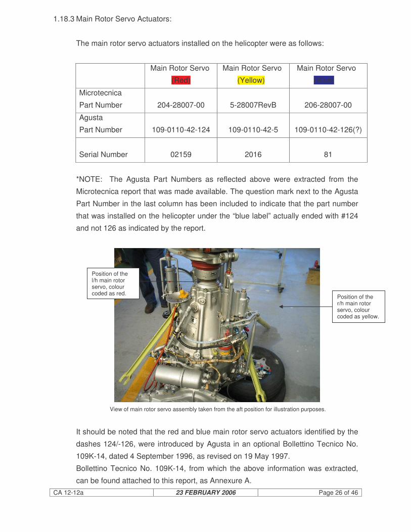
1.18.3 Main Rotor Servo Actuators:
The main rotor servo actuators installed on the helicopter were as follows:
Main Rotor Servo
(Red)
Main Rotor Servo
(Yellow)
Main Rotor Servo
(Blue)
Microtecnica
Part Number
204-28007-00
5-28007RevB
206-28007-00
Agusta
Part Number
109-0110-42-124
109-0110-42-5
109-0110-42-126(?)
Serial Number
02159
2016
81
*NOTE: The Agusta Part Numbers as reflected above were extracted from the
Microtecnica report that was made available. The question mark next to the Agusta
Part Number in the last column has been included to indicate that the part number
that was installed on the helicopter under the “blue label” actually ended with #124
and not 126 as indicated by the report.
View of main rotor servo assembly taken from the aft position for illustration purposes.
It should be noted that the red and blue main rotor servo actuators identified by the
dashes 124/-126, were introduced by Agusta in an optional Bollettino Tecnico No.
109K-14, dated 4 September 1996, as revised on 19 May 1997.
Bollettino Tecnico No. 109K-14, from which the above information was extracted,
can be found attached to this report, as Annexure A.
Position of the r/h main rotor servo, colour coded as yellow.
Position of the l/h main rotor servo, colour coded as red.

CA 12-12a 23 FEBRUARY 2006 Page 27 of 46
The main rotor servo actuators were removed from the wreckage and forwarded to
the manufacturer Microtecnica for examination.
The Microtecnica Investigation/Technical Report TR-A109-205 pertaining to the
servo actuators was made available, with the following conclusion; “The final
assumption is that for all the items there was no evidence of any malfunctioning
prior to the accident”. (Reference: Paragraph 1.16.1 of this report, as well as
Annexure B).
1.18.4 Flight Controls:
After the recovery of the wreckage from the water and the subsequent post-crash
inspection of the continuity of the flight controls, it was noted that a substantial
number of control rods had failed during the impact. Most of these control rods
were located on the transmission platform (forward roof structure) of the helicopter
where it met up with the mixing unit and from there to different attachments on the
main rotor head. The fact that the rescue hoist came to rest on the roof structure
was probably due to a totally aerodynamically unstable main rotor blade, or portion
of it that flexed down and impacted with the hoist motor, smashing its housing and
dislodging it completely in the direction of blade rotation onto the top of the
transmission platform. This resulted in the failure of nearly all the control rods on the
transmission platform. It was not possible to check the rigging and status of the
flight controls due to the destruction of the wreckage. All flight control rods were
accounted for and several were subjected to metallurgical examination in order to
determine the failure mode, which was found to be consistent with overload
conditions.

CA 12-12a 23 FEBRUARY 2006 Page 28 of 46
Basic layout of the cyclic and collective pitch controls.
The tail rotor controls were also inspected and displayed continuity up to the station
where the tail rotor assembly had separated from the tail boom. All four main rotor
pitch change linkages were accounted for, and were found to be wire-locked as
required.
1.18.5 Hydraulic System:
An inspection of the hydraulic system was undertaken. Due to the submersion in
the sea, all evidence associated with a possible leak in the system was destroyed.
All system-associated components were accounted for, apart from accident
damage. According to the pilot, he had not experienced a hydraulic system failure
nor any warning light associated with such a failure.
1.18.6 Tail Rotor Failure:
The tail rotor assembly separated from the wreckage during the impact, most
probably during the events that followed the main rotor blade strike on the
superstructure of the cargo ship. According to the pilot, he had full tail rotor authority
while he was established in hover flight awaiting the pick-up of the marine pilot.
Main servo actuators
Mixing unit
Collective pitch levers
Cyclic controls

CA 12-12a 23 FEBRUARY 2006 Page 29 of 46
The initial roll of the helicopter to the right was not accompanied by any yaw but by
a roll. The tail rotor associated linkages were subjected to metallurgical examination
in order to determine the failure mode. All failures that were examined were
consistent with overload failure mode.
1.18.7 Cyclic Control Stick Position:
The cyclic stick can be attached to the cyclic control stub to provide slightly different
cyclic positions in the neutral position. The cyclic stick position was found to allow
full control movement.
1.18.8 Post Maintenance Adjustments:
After the 1 200 hour maintenance inspection, no defects or any rectifications were
recorded in any helicopter Flight Folio and logbooks. It came to the attention of the
investigating team that during the night shift, some minor adjustments were made to
the pitch change links of the main rotor system. According to the pilot who flew the
helicopter at the time of the accident, no defects were reported during the two flights
prior to the accident. The pitch change links were inspected and apart from having
sustained accident-related damage, all four were found to be wire-locked as
required.
1.18.9 Dynamic Roll-Over:
The possibility of a dynamic roll-over of the helicopter was investigated.
• No evidence could be found that the hoist cable got hooked or entangled during
any phase of the hoisting operation. According to the helicopter pilot they were
positioned approximately 7 to 8 metres above the bridge wing for the hoist pick-
up. On recovery of the wreckage it was noted that 2.65 metres of the hoist
cable was still extended, which indicated that the hoist was functional and the
marine pilot had been in the process of being hoisted.
• There was no visible damage to the hoist cable or the hook mechanism that
could have been associated with a hook-up or entanglement on the bridge wing.
• At no stage during the operation did the hoist operator indicate verbally to the
helicopter pilot that the hoist cable was hooked up or entangled.

CA 12-12a 23 FEBRUARY 2006 Page 30 of 46
• Any hoist loading will introduce a lateral right roll-over of the helicopter due to
the offset installation of the hoist.
• A left cross-wind component acting on a hovering helicopter would introduce a
roll-over which would have to be counteracted by a left cyclic control stick input
in order to maintain a steady hover. This means that the stronger the cross-
wind, the more cyclic control input would be required to maintain a steady hover
over a fixed point.
• Forward speed of the helicopter would aggravate the roll-over tendency of the
helicopter, due to the increased pitch angle requirement of the retreating rotor
blade.
• The hoist load is acting on a point forward of the longitudinal centre of gravity of
the helicopter. Any hoist load would tend to lower the nose of the helicopter
which through gyroscopic precession would act through 90 ° in the direction of
rotation of the rotor. This means that the moment when the hoist takes load, a
further tendency towards a right roll would be introduced with regard to the
helicopter.
1.18.10 Cargo Ship Inspection Durban Harbour:
A while after the marine pilot’s discharge from hospital, he accompanied the
investigation team to a similar cargo ship, the MSC Selin, which was harboured at
Durban. Although the cargo ship was different in design, the bridge wing layout
was very similar to the Alpha Afovos. He pointed out where he was standing on the
bridge wing at the time when hoisting commenced and identified the possible
hazards associated with such an operation.
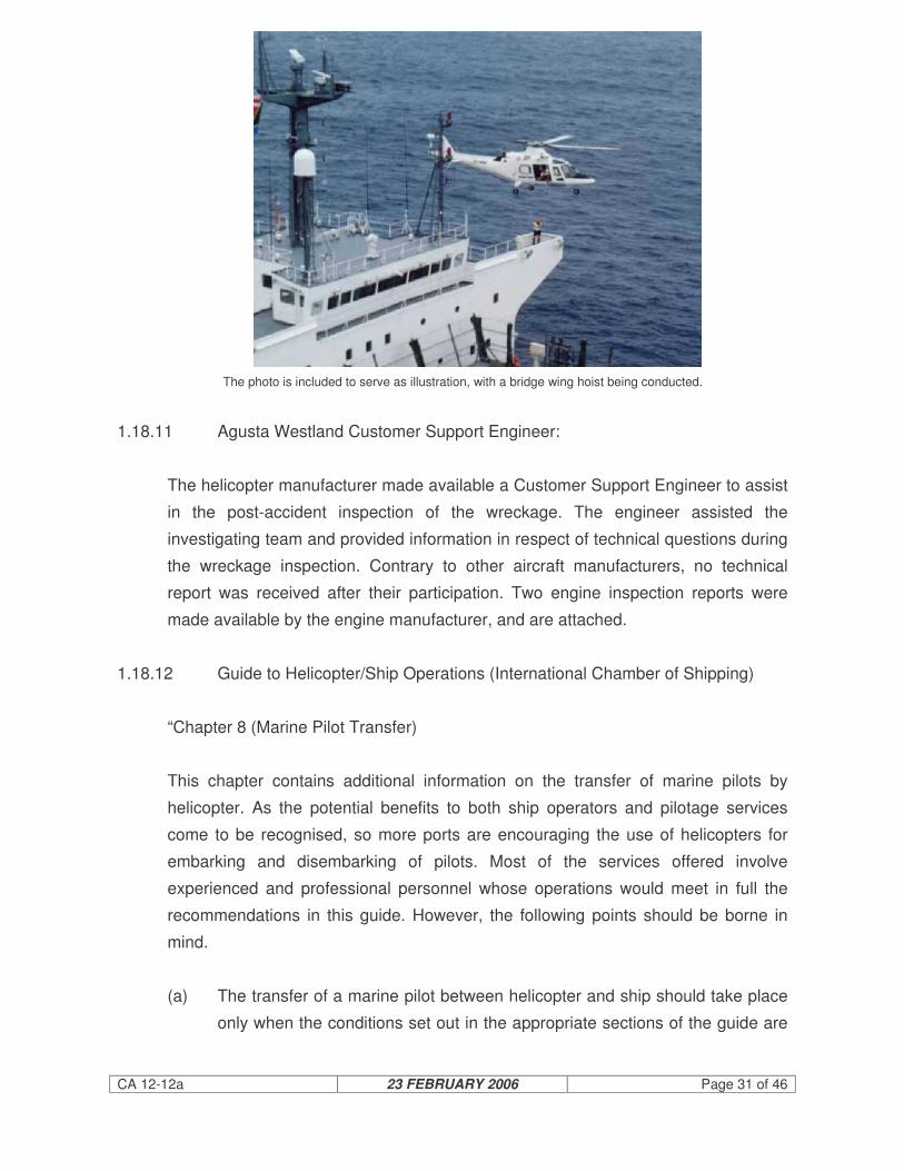
CA 12-12a 23 FEBRUARY 2006 Page 31 of 46
The photo is included to serve as illustration, with a bridge wing hoist being conducted.
1.18.11 Agusta Westland Customer Support Engineer:
The helicopter manufacturer made available a Customer Support Engineer to assist
in the post-accident inspection of the wreckage. The engineer assisted the
investigating team and provided information in respect of technical questions during
the wreckage inspection. Contrary to other aircraft manufacturers, no technical
report was received after their participation. Two engine inspection reports were
made available by the engine manufacturer, and are attached.
1.18.12 Guide to Helicopter/Ship Operations (International Chamber of Shipping)
“Chapter 8 (Marine Pilot Transfer)
This chapter contains additional information on the transfer of marine pilots by
helicopter. As the potential benefits to both ship operators and pilotage services
come to be recognised, so more ports are encouraging the use of helicopters for
embarking and disembarking of pilots. Most of the services offered involve
experienced and professional personnel whose operations would meet in full the
recommendations in this guide. However, the following points should be borne in
mind.
(a) The transfer of a marine pilot between helicopter and ship should take place
only when the conditions set out in the appropriate sections of the guide are

CA 12-12a 23 FEBRUARY 2006 Page 32 of 46
met and the ship operator and master are satisfied that the transfer can be
conducted safely.
(b) The transfer of marine pilots by helicopter is now a routine operation and
familiarity must not be allowed to compromise safety standards for the
helicopter, the pilot, the ship or its personnel.
(c) The helicopter operator must confirm that he carries sufficient third party
insurance to cover all his possible liabilities in helicopter/ship pilot transfer.
(d) In order to agree on a safe and effective rendezvous, it is important that
sufficient advance notice of the intended helicopter/ship pilot transfer is given
to all parties concerned.
(e) Adherence to the recommended procedures for continuous communication,
regarding the rendezvous and for ship identification, is essential for
helicopter/ship operations: it must be remembered that a helicopter may
have to service a number of widely separated cargo ships in the course of a
single flight.
(f) Although ultimate responsibility for the safety of the ship and its navigation in
pilotage waters rest with the Master, the marine pilot has a direct interest in
the choice of time and place for his transfer to the ship. He should be party to
the agreement reached between the Master and the helicopter operator and
pilot before the transfer operation commences. There may be special
circumstances affecting the suitability of time or location of a proposed
rendezvous on which the marine pilot may be able to advise. Sufficient prior
notice will allow necessary arrangements to be agreed upon (see Chapter 5).
(g) Marine pilots should be required to do an approved course involving training
in helicopter flight procedures, embarkation and disembarkation (including
winching) and safety and emergency drills before undertaking helicopter
transfers (see Section 6.6). The operational and organisational procedures
and arrangements regarding safety as set out in Chapter 6 must be fully
understood.
(h) When embarking or disembarking either by winch or from the landing area,
the marine pilot should wear protective clothing similar to that recommended
for the deck party (see Section 6.4.1), and while in flight a life jacket, and if

CA 12-12a 23 FEBRUARY 2006 Page 33 of 46
necessary a survival suit (see Section 6.6.1(e) and (f). On long flights in
certain aircraft, the noise level may temporarily impair hearing and in such
circumstances marine pilots should wear suitable ear protection.
(i) A member of the deck party should be detailed to assist and guide the
marine pilot between the landing area and the bridge.
(j) Operations involving helicopter touch-down on ships equipped with
helicopter landing areas marked as in Section 4.2 are preferred by helicopter
operators for marine pilot transfers.
The advantages of helicopter transfers of marine pilots can only be fully realised
when the service is reliable and capable of being maintained with almost all ships
under all but the most adverse weather conditions. While commercial pressure to
see helicopter/pilot services operating universally will be a consideration in the
provision of helicopter landing areas on new ships of most types, the critical
examination of space on board existing ships for safety of landing or for facilities for
helicopter winching operations should be undertaken in the light of industry
guidance”.
1.18.13 Helicopter Balance (Centre of Gravity):
Reference: Principles of Helicopter Flight, W.J. Wagtendonk, Pg. 251, 252, 253.
“Even though the weight of a helicopter may fall within the prescribed limits, if the
distribution of this weight is not correct the helicopter’s centre of gravity (CG) may
be outside authorized limits, in which case the aircraft’s balance is unsatisfactory
and the aircraft is unsafe for flight.
The CG of a body can simply be defined as the point through which weight acts. It
is the point of balance of the aircraft. If a helicopter is placed on a fulcrum (support)
in such a way that the aircraft’s CG is exactly above the fulcrum, the aircraft tips
neither forward or back, left or right. Similarly, when the main rotor is suspending
the aircraft in the calm hover, the helicopter hangs level beneath the rotor, provided
the rotor mast and the CG position are in line vertically.
As pilot(s), crew, payload and fuel are either added to or subtracted from the
aircraft, the point of balance (CG) moves and the helicopter no longer hangs
horizontally beneath the rotor. Instead it hangs nose up or nose down, depending

CA 12-12a 23 FEBRUARY 2006 Page 34 of 46
on the weight distribution. This pitching movement causes the disc to be displaced
and the aircraft moves forward, back or to one side. To compensate for a re-
positioned CG, cyclic inputs are required. An aft CG needs forward cyclic, while a
forward CG needs aft cyclic, the amounts depending on the CG distance from
datum.
The same principles also apply to lateral CG positions in that CG movement either
to the left or right requires lateral compensating cyclic inputs. This factor is worthy
of note particularly for aircraft equipped with hoist operations where lateral CG
positions become very important and because of that, maximum permissible hoist
loads are invariably stipulated in the aircraft’s Flight Manual.
There comes a CG position where no more cyclic input is available and the
helicopter becomes uncontrollable. To avoid this situation, the manufacturer of the
aircraft predetermines the allowable amount of CG movement that can be safely
accepted. This information is published in the aircraft’s Flight Manual in terms of
distance from the datum line, fore and aft, and left and right CG limits.
Some helicopters have the longitudinal datum coincidental with the rotor mast, in
which case the CG limits are expressed in units of distance forward or aft of datum.
Since this arrangement involves positive and negative turning moments and since it
is easy to make mistakes adding these different values, few helicopters use this
arrangement. A more common datum is one located at the front of the skids, in
which case the CG limits are expressed in units of distance aft of datum only.
Some helicopters have datum located three feet or more in front of the skids. This
arrangement makes all moments positive because all weights acting aft of the
datum produce a clockwise turning moment (which is positive).
Lateral datum is usually the butt line running through the CG of the aircraft from the
nose to the tail. To calculate lateral CG position, it is impossible to avoid positive
and negative moments because various weight items are on either side of the butt
line.
Excessive Lateral CG
Limits for lateral CG are often quite small and, especially in the case of light
helicopters, great care must be exercised to remain within lateral limits. Depending
on fuel tank location, the pilot may have to occupy a seat on the opposite side when

CA 12-12a 23 FEBRUARY 2006 Page 35 of 46
flying solo to ensure that lateral limits are not exceeded. (The pilot’s operating
handbook for the specific helicopter model being flown should always be obeyed.)
The consequences of excessive lateral CG are similar to those for longitudinal CG.
The longitudinal and lateral CG positions are both important for the safe operation
of a helicopter. Thorough calculations must be made prior to flight to ensure that
limits are not exceeded”.
1.18.14 The quick release mechanism on the specific harness was located behind the
hoist operator’s back. It furthermore necessitates that both levers be depressed
simultaneously (as can be seen in the photo below); once that was achieved it still
needed to be unhooked from the harness that was secured around the person’s
waist before the person could be detached from the airframe.
Safety harness: quick release mechanism that was worn by the hoist operator.
The body harness (waist harness) buckle was of the insertion type and also
requires time and effort before it can be released.
The airframe attachment was again located behind the hoist operator’s back. The
release of this mechanism requires it to be unsecured before the latch mechanism
can be depressed and the harness can be unhooked from its latch.
It is therefore recommended that the operator (and all other helicopter operators
making use of the extended safety harness) comply to the same standard by
making use of an approved safety harness that is equipped with a quick release
mechanism that is safe and easily accessible and in the case of an emergency can
be released without undue effort. The USCG (U.S. Coast Guard) would be a good

CA 12-12a 23 FEBRUARY 2006 Page 36 of 46
benchmark to work from in this regard.
1.19 Useful or Effective Investigation Techniques:
1.19.1 None.
2. ANALYSIS
2.1 No member of the investigating team had the opportunity to inspect the cargo ship.
The investigating team had to depend on information made available by the Master
of the cargo ship, the First Officer, the shipping agent, a SAMSA official and two
senior members of the helicopter operator. Although alternative attempts were
made to inspect the cargo ship, the owners refused the SACAA’s investigating team
permission to board the cargo ship once it had left South African waters.
2.2 The helicopter crew was well qualified to perform the task. Conducting a bridge
wing hoist was considered to be a standard operation for the operator and the crew.
Both crew members were well rested and both were wearing life jackets.
2.3 Since reporting for duty, the crew had conducted a few flights prior to the accident.
The marine pilot had had two land-on, drop-off and pick-ups. The only difference
was that this was the first hoisting operation since this helicopter had returned to
service the previous day. After the recovery of the wreckage, only 2.65 m of cable
was still unreeled. This indicated that the hoist was in the process of reeling the
marine pilot upwards.
2.4 The hoist jettison mechanism was not armed due to the fact that company policy did
not allow live cargo to be jettisoned, irrespective of what situation or emergency
might be encountered. This decision meant that the helicopter operator was
indirectly willing to sacrifice an entire helicopter, the lives of the crew members and
potential damage to third parties and property. All rescue hoists are designed and
equipped with a jettison mechanism for emergency purposes and could have saved
a life in this case.
2.5 The helicopter pilot’s communication was not audible on the recording, but it would
appear that the final decision for the pick-up from the bridge was made by the

CA 12-12a 23 FEBRUARY 2006 Page 37 of 46
helicopter pilot. This arrangement was in contradiction with the arrangements made
by the Master of the cargo ship, who had his fire and rescue team in position on the
deck, awaiting the arrival of the helicopter to land on the deck. 2.5 The weather conditions were reported to be fine; the wind was from the north north-
east at between 19 and 24 knots. This would have constituted a cross-wind
component of between 19 and 24 knots on the cargo ship and since the helicopter
was flying parallel to the cargo ship, this cross-wind component was also applicable
to the helicopter. In order for the pilot to compensate for this cross-wind condition,
the cyclic control input would have had to be utilised.
2.6 The helicopter was fitted with a ‘High Altitude Configuration Kit’, which improves the
yaw controllability in the hover and especially during rescue hoist operations at high
altitude. The helicopter pilot did not indicate that he had any problem in maintaining
directional control in the yaw plane prior to the pick-up.
2.7 Why did the helicopter start to roll to the right as the marine pilot was lifted?
The following factors were considered:
(i) The lateral CG limit was exceeded, thereby exceeding the left cyclic input
available. The pilot attempted to counteract the right roll movement by
applying left cyclic input to such an extent that he had the cyclic control stick
all the way deflected against his inner left leg. The lateral CG was calculated
to be on the edge of the allowable CG limit for normal flight operations. The
POH, however, allowed for an amended CG envelope, which was applicable
for hoisting operations only. Utilizing the amended graph, the calculated
lateral CG limit was found to be within the approved shaded area for a
hoisting operation into wind.
(ii) The weight of the helicopter changed when the marine pilot was picked up
on the hoist. The post-accident weight and balance calculation indicated that
the helicopter was well within its maximum gross weight limitation as
stipulated in the POH.
(iii) The prevailing cross-wind measured at the time was ± 24 knots from the left-
hand side. This already imposed a lateral force on the helicopter from the
left, which required some control input to maintain a steady hover over the
moving ship. The reason why the pilot did not turn the helicopter into wind

CA 12-12a 23 FEBRUARY 2006 Page 38 of 46
could be attributed to the obstructions on the bridge and the danger of the tail
rotor operating even closer to the ship. The POH does indicate to the user
that during hoisting operations cross-wind operations should be avoided.
(iv) The hoisting technique that was used by the operator differs from the
procedure recommended in the POH. The POH procedure recommends that
the helicopter pilot lift the weight from the deck. “Lift hoist load slightly above
contact surface, by application of the collective pitch, to obtain a feeling of
the controls”.
(v) The pilot might have aggravated the situation by applying collective pitch
(increased power demand), but at that moment it might have been the most
logical action to take in order to prevent any form of main rotor blade or
fuselage contact with the cargo ship.
(vi) The pilot stated that he had not experienced any right roll control tendency
prior to commencing the hoist pick-up. The right roll only manifested itself
when the marine pilot was lifted with the hoist. This was confirmed by the
chief officer of the cargo ship, who was standing on the deck at hatch
number 4 looking at the helicopter from the front. “It would appear that the
marine pilot was too heavy for the helicopter”.
(vii) The possibility that the hoist cable or the marine pilot was hooked up or
entangled during the hoist lift can be ruled out.
3. CONCLUSION 3.1 Findings
3.1.1 Helicopter Pilot:
(i) The pilot was the holder of a valid commercial pilot’s licence and had the
helicopter type endorsed in his logbook.

CA 12-12a 23 FEBRUARY 2006 Page 39 of 46
(ii) The pilot was in possession of a valid aviation medical certificate that had
been issued by an approved SACAA medical examiner.
(iii) The pilot was well rested prior to commencing his duties on the morning of 3
September 2005.
(iv) The pilot was current on the HUET (helicopter under water escape training)
procedures.
(v) Although the pilot was properly restrained to his seat at the time of the
accident via his four-point aircraft equipped safety harness, he sustained
serious injuries.
(vi) The pilot was wearing a May-West (life jacket) during the flight.
(vii) The pilot had not conducted a weight and balance calculation for the flight in
question.
3.1.2 Helicopter:
(i) The helicopter was subjected to a 1 200-hour maintenance inspection during
the period 22 July 2005 to 2 September 2005 and had returned to service the
day prior to the accident.
(ii) After the inspection of the helicopter, two acceptance test flights were
performed on 2 September 2005, whereafter it was released to service and
flown from Pretoria to Richards Bay.
(iii) On arrival at Richards Bay, the aircraft was returned to service and five
subsequent flights were conducted before the accident flight, with no serious
defects being reported.
(iv) The ELT unit that was installed on the helicopter was not able to sustain the
impact forces associated with the accident.
(v) The helicopter was not equipped with floatation gear.
(vi) Aircraft examinations revealed that one of the main rotor servo actuators,
part number (P/N); 109-0110-42-5 was not of the same compliance status as

CA 12-12a 23 FEBRUARY 2006 Page 40 of 46
the other two actuators P/Ns 109-0110-42-124/-126.
(vii) Agusta Bollettino Tecnico No. 109K-14 Rev A, compliance instructions note
states the following; “the servo actuators P/Ns 109-0110-42-124/-125/-126
are not mixable with the servo actuators P/N 109-0110-42-4/-5/-6 or 114/-
115/-116”.
(viii) The discrepancy regarding the servo actuators was never noticed by the
maintenance personnel.
(ix) No evidence of any pre-impact engine failures or mechanical malfunctions
was found.
(x) All indications were that the tail rotor assembly failed due to impact with the
structure of the cargo ship.
(xi) The helicopter’s weight and balance as well as the centre of gravity (both
longitudinal and lateral) were found to be within the approved POH
limitations as amended for hoisting operations.
(xii) The un-commanded right roll commenced when the helicopter took the
weight of the marine pilot.
3.1.3 Hoist Operator:
(i) The hoist operator was wearing a May-West (life jacket) during the flight. He
was not wearing a helmet.
(ii) He was secured in the aft cabin area by means of an extended safety
harness (monkey chain) and was not secured in a seat.
(iii) The extended safety harness was found to be ineffective due to the release
mechanism situated behind the hoist operator’s back.
(iv) The hoist operator was familiar with his task.
(v) Available records indicate that the hoist operator had not received any
HUET procedure training.

CA 12-12a 23 FEBRUARY 2006 Page 41 of 46
(vi) There was no evidence that physiological factors or incapacitation had
affected the performance of the hoist operator.
3.1.4 Marine Pilot:
(i) The marine pilot was wearing a life jacket at the time of the accident.
(ii) He was still in the process of being hoisted at the time of the accident.
(iii) He was carrying a ‘shoulder’ bag which was never recovered.
(iv) The marine pilot was well familiar with helicopter hoisting operations.
(v) The marine pilot had completed two ‘land-on’ tasks earlier in the shift without
incident.
(vi) The decision to conduct the hoist pick-up from the bridge wing was a
collaborated decision between the marine pilot and the helicopter pilot.
(vii) He was familiar with, and current on the HUET procedure.
(viii) The marine pilot was seriously injured in the accident.
3.1.5 Cargo ship (Alpha Afovos)
(i) The cargo ship sustained some impact damage, mostly from the main rotor
blade impact.
(ii) After the accident the cargo ship was requested by Port Control to go on
anchor in the open, where it was inspected by a SAMSA official and was
declared seaworthy to continue the journey.
(iii) The cargo ship was never inspected by a SACAA investigator. All evidence
used to compile this report was obtained from external sources.
(iv) The cargo ship had a demarcated helicopter landing area on hatch cover No.
4, which was duly marked.
(v) The fire and rescue crew of the ship was positioned on deck in close vicinity

CA 12-12a 23 FEBRUARY 2006 Page 42 of 46
to hatch No. 4, awaiting the arrival and landing of the helicopter to uplift the
marine pilot.
(vi) The Master of the cargo ship instructed the marine pilot to make use of the
demarcated helicopter landing area on hatch No. 4.
(vii) The Master of the cargo ship never communicated with the helicopter pilot at
any stage during the operation.
(viii) There was no crew on standby to assist the marine pilot on the bridge wing.
3.1.6 Helicopter Operator:
(i) Failure by the Operator not to allow ‘live cargo’ being jettisoned or cut away
during hoisting operations, jeopardized the entire hoisting operation. This is
regarded as a significant operational shortcoming.
(ii) The helicopter service sometimes allowed several pick-ups and drop-offs
during one mission, which rendered it impossible for flying crew to perform a
detailed mass calculation for each and every task. Therefore most of the
centre of gravity calculations involving marine pilot operations were of a
generic nature.
3.1.7 Weather Conditions:
(i) The wind at the time was directly from the left-hand side at ± 24 knots cross-
wind to the cargo ship and the helicopter.
3.2 Probable Cause/s:
The helicopter was operated with an already marginal lateral centre of gravity
position and contrary to the manufacturer’s warning, they carried out a hoisting
operation in strong cross-wind conditions.
The combined effect of the cross-wind and forward speed of the helicopter flying
parallel to the cargo ship probably aggravated the roll-over effect of the
helicopter.
CA 12-12a 23 FEBRUARY 2006 Page 43 of 46
The helicopter probably ran out of lateral left input control when the additional
mass was lifted by the hoist, rolled over to the right, collided with the cargo ship,
crashed into the sea and sunk.
3.2 Contributory Factor/s:
The helicopter pilot deviated from the instruction to land the helicopter on the cargo
ship and instead carried out the hoisting operation when uplifting the marine pilot
from the cargo ship. This decision was made by the marine pilot and the helicopter
pilot.
4. SAFETY RECOMMENDATIONS
4.1 The extended safety harness (monkey chain) of the hoist operator was considered
to be an unsuitable/unsafe harness for helicopter operations.
4.2 It is recommended that an MOU (Memorandum of Understanding) be drafted and
implemented between the SACAA and SAMSA to ensure that a recurrence of this
accident is avoided in the future.
The MOU should clearly stipulate the work ethic and requirements to be met by the
two Authorities.
In this case the Alpha Afovos was released to sail by a SAMSA official without
consultation with a SACAA investigator at any time prior to making the decision.
The fact that no member of the SACAA investigating team had the opportunity to
inspect the cargo ship in person should be regarded as a significant shortcoming to
this investigation.
4.3 The post-mortem report of the hoist operator, which indicates that he suffered a
serious head injury during the impact sequence; and several other fatal aircraft
accidents that have occurred during the past few years, indicate that a substantial
number of fatalities could have been prevented if the pilot/s or crew-member/s had
worn helmets at the time of such accident/s. In many cases the person/s had died
as the result of an isolated head injury sustained during the impact sequence.

CA 12-12a 23 FEBRUARY 2006 Page 44 of 46
It is recommended that all flying crew be encouraged to fly with helmets at all times
in the interests of aviation safety and the redemption of human lives.
4.4 The aircraft Flight Folio in use by the helicopter Operator was found not to comply
with Part 91.03.5, Document SA-CATS-OPS 91. The design/layout of the Flight
Folio (called Captain’s Log) by the Operator was of such a nature that it was
designed to cater more for the type of operation (marine pilot service/s) and
therefore it was lacking maintenance-related information and any outstanding
deferred defects.
It is recommended that the “Flight Folio” that was in use by the Operator be brought
in line with the requirements as stipulated in Part 91.03.5 of the Civil Aviation
Regulations of 1997 and Document SA-CATS-OPS 91 listed below.
The main reason for the recommendation is the lack of defect and maintenance-
related entries, and the action/s that followed to rectify such defects/maintenance, if
any.
Flight Folio requirements as stated in Document SA-CATS-OPS 91:
“Part 91.03.5 Flight Folio (Information to be contained in a flight folio)
(1) An owner or operator must retain the following information for each flight in
the form of a flight folio:
(a) Aircraft registration;
(b) date;
(c) name(s) of flight crew member(s);
(d) Duty assignment of flight crew member(s);
(e) Place of departure;
(f) Place of arrival;
(g) Time of departure (off-block time);
(h) Time of arrival (on-block time);
(i) Hours of flight;
(j) Nature of flight;
(k) Incidents, observations (if any);
(l) Signature of pilot-in-command;
(m) The current maintenance statement giving the aeroplane maintenance

CA 12-12a 23 FEBRUARY 2006 Page 45 of 46
status of what maintenance, scheduled or out of phase, is next due;
(n) All outstanding deferred defects which affect the operation of the
aeroplane;
(o) Fuel used; and
(p) Fuel uplift.
(2) The owner or operator need not keep a flight folio or parts thereof, if the
relevant information is available in other documentation.
(3) The owner or operator must ensure that all entries are made concurrently
and that they are permanent in nature.”
4.5 It is recommended that Helicopter Underwater Escape Training (HUET) as well as
refresher training be made compulsory to all helicopter off-shore operational crew
members.
4.6 It is recommended that the SACAA conduct a study into the international best
practice for hoist operations with regard to cable jettison procedures involving an in-
flight emergency.
5. APPENDICES
5.1 Annexure A (Agusta Bollettino Tecnico No. 109K-14 Rev A)
5.2 Annexure B (Microtechnica, Servo Actuators test report)
5.3 Annexure C (Turbomeca Engine teardown inspection report)
5.4 Annexure D (Facet Consulting Metallurgical report)
5.5 Annexure E (Agusta Helicopters, Technical Note N. PBE/A109/03/2005)
5.6 Annexure F (Operations Manual, page 68)
5.7 Annexure G (Statement from Master and Chief Officer of the Alpha Afovos).
Report reviewed and amended by Office of the EM:AIID
12 Aug 2009.

CA 12-12a 23 FEBRUARY 2006 Page 46 of 46
-END-