AIRCRAFT ACCIDENT REPORT - Aviation Safety Network >
210
Published by Accident Investigation Bureau, of Nigeria v AIRCRAFT ACCIDENT REPORT DANA/2012/06/03/F Accident Investigation Bureau Report on the Accident to DANA AIRLINES NIGERIA LIMITED Boeing MD-83 aircraft with registration 5N-RAM which occurred at Iju-Ishaga Area of Lagos State, Nigeria On 3rd June 2012
-
Upload
khangminh22 -
Category
Documents
-
view
0 -
download
0
Transcript of AIRCRAFT ACCIDENT REPORT - Aviation Safety Network >
Published by Accident Investigation Bureau, of Nigeria
v
AIRCRAFT ACCIDENT
REPORT DANA/2012/06/03/F
Accident Investigation Bureau
Report on the Accident to DANA AIRLINES NIGERIA LIMITED
Boeing MD-83 aircraft with registration 5N-RAM which occurred at Iju-Ishaga Area of Lagos State,
Nigeria On 3rd June 2012
Aircraft Accident Report
DANA/2012/06/03/F 5N-RAM
ii
This Report is produced by the Accident Investigation Bureau (AIB), Murtala
Muhammed International Airport, Ikeja, Lagos.
The Report is based upon the investigation carried out by Accident Investigation
Bureau, in accordance with Annex 13 to the Convention on International Civil
Aviation, Nigerian Civil Aviation Act 2006, and Civil Aviation (Investigation of Air
Accidents and Incidents) Regulations.
It is not the purpose of aircraft accident/serious incident investigations to
apportion blame or liability.
Readers are advised that Accident Investigation Bureau investigates for the sole
purpose of enhancing aviation safety. Consequently, Accident Investigation Bureau
reports are confined to matters of safety significance and should not be used for
any other purpose.
As the Bureau believes that safety information is of great value if it is passed on
for the use of others, readers are encouraged to copy or reprint for further
distribution, acknowledging Accident Investigation Bureau, Nigeria as the source.
Recommendations in this report are addressed to the regulatory Authorities of the
state (NCAA). It is for this authority to ensure enforcement.
© Copyright: Accident Investigation Bureau, Nigeria
Printed in Nigeria for the Accident Investigation Bureau (AIB)

Aircraft Accident Report
DANA/2012/06/03/F 5N-RAM
iii
TABLE OF CONTENTS
GLOSSARY OF ABBREVIATIONS USED IN THIS REPORT .......................... viii LIST OF FIGURES...........................................................................................xi SYNOPSIS ...................................................................................................... 1 1.0 FACTUAL INFORMATION ...................................................................... 4
1.1 History of the Flight .......................................................................... 4
1.2 Injuries to Persons ............................................................................ 7
1.3 Damage to Aircraft ............................................................................ 7
1.4 Other Damage .................................................................................. 9
1.5 Personnel Information ..................................................................... 10
1.5.1 Captain ..................................................................... 10
1.5.2 First Officer ................................................................ 14
1.6 Aircraft Information ......................................................................... 15
1.6.1 Engine Description…………………………………………………….19
1.6.2 Left Engine (No.1)-Serial Number-(SN)-718142 ............ 21
1.6.3 Right Engine (No.2)-Serial Number-728113……………. .... 28
1.6.4 Engines Audio Spectrum Analysis ................................. 33
1.6.5 Auxiliary Power Unit (APU) .......................................... 33
1.6.6 Battery Power ............................................................. 33
1.6.7 Fuel System - Airframe ................................................ 34
1.6.8 The Engine Fuel System .............................................. 35
1.6.9 F.S.C. Engine No.1 Teardown Report ........................... 37

Aircraft Accident Report
DANA/2012/06/03/F 5N-RAM
iv
1.6.9.1 F.S.C. Engine No.2 Teardown Report………………………….38
1.6.10 Hydraulics .................................................................. 39
1.7 Meteorological Information .............................................................. 40
1.8 Aids to Navigation ........................................................................... 41
1.9 Communications ............................................................................. 42
1.10 Aerodrome Information ................................................................... 42
1.11 Flight Recorders .............................................................................. 42
1.12 Wreckage and Impact Information ................................................... 44
1.13 Medical and Pathological Information ............................................... 47
1.14 Fire ................................................................................................ 48
1.15 Survival Aspects .............................................................................. 48
1.16 Test and Research .......................................................................... 49
1.16.1 Fuel Test .................................................................... 49
1.16.2 Simulator Programme Conducted at PAIFA ................... 50
1.16.3 Fuel Nozzle Test……………………………………………………….55
1.16.4 Metallurgical Test of Fuel Manifold Component ............. 55
1.17 Organization and Management Information ...................................... 55
1.17.1 Description of Organizational Structure ......................... 55
1.17.1.1 Chief Pilot ................................................................... 57
1.17.1.2 Recruitment of Foreign pilots ....................................... 59
1.17.2 NCAA ......................................................................... 59
1.17.3 NAMA. ........................................................................ 60
Aircraft Accident Report
DANA/2012/06/03/F 5N-RAM
v
1.17.4 Millenium Engine Associates Inc ................................... 61
1.17.5 Pratt and Whitney ....................................................... 61
1.18 Additional Information ..................................................................... 62
1.18.1 Dana Airlines Internal Investigation (5N-RAM) ........................ 62
1.18.2 Related Incident-MD-83-(5N-SAI) .......................................... 65
1.18.3 Regulatory Information ......................................................... 68
1.18.4 Witness Account by Ground Personnel (Abuja)……………………. 68
1.18.4.1 Other Witness Accounts……………………………………………….....69
1.19 Useful or Effective Investigation Techniques ..................................... 69
2.0 ANALYSIS…………………………………………………………….…………….70
2.1 The Conduct of Flight ...................................................................... 70
2.2 Dana Airlines Policy/Procedures ....................................................... 74
2.2.1 Captain Recruitment/Training Records ..................................... 76 2.3 Simulator Programme Conducted at PAIFA ......................................... 78
2.4 Similarities in Engines Inspection Reports of the Accident Aircraft 5N-RAM
and Air Return Aircraft 5N-SAI ........................................................ 78
2.4.1 Fuel System Components (Engine No. 1) ................................ 81
2.4.2 Fuel System Components (Engine No.2) ................................. 82
2.4.3 Fuel Nozzle ............................................................................ 82
2.4.4 Engine Audio Spectrum Analysis .............................................. 83
2.4.5 Auxiliary Power Unit (APU) ...................................................... 83
2.4.6 Battery Power ........................................................................ 83

Aircraft Accident Report
DANA/2012/06/03/F 5N-RAM
vi
2.4.7 Hydraulics .............................................................................. 84
2.4.8 Engines…………………………………………………………………………….. . 84
2.4.9 Suction Feed Capability………………………………………………………. . 85
2.5 The Dana Airlines Air Return (Related Incident) ................................ 85
2.6 Metallurgical Test of Fuel Manifold Component………………………………. 87
2.7 Witnesses………………………………………………………………………………….. 89
2.8 NCAA ................................................................................... ………..89
2.9 NAMA ............................................................................................ 90
3.0 CONCLUSIONS ................................................................................... 92
3.1 Findings. ........................................................................................ 92
3.2 Probable Causal Factors ................................................................. 94
4.0 SAFETY RECOMMENDATIONS……………………………..………………....95
Interim Safety Recommendations .............................................................. 95
Responses to Interim Safety Recommendations .......................................... 99
SAFETY ACTIONS TAKEN ................................................................................ 99
Engineering Authorization-Dana Air ............................................................ 99
APPENDICES:
A. Engine Exam and Disassembly Field Notes……………………….. 100
B. Extract from Dana Airlines Operations Manual Part A (Captain’s
Authority) ……………….…………………………………………………… 154
C. Extract from Dana Airlines Operations Document (Quick

Aircraft Accident Report
DANA/2012/06/03/F 5N-RAM
vii
Reference Checklist) (QRC)…………………………..……………….. 158
D. NCAA Audit on Dana ……………………………………………………… 166
E. Final Report on Forensic Investigation of bodies………………… 167
F. Preliminary Inspection Report…………………………………………. 174
G. Engineering Authorization ………………………………………………. 186
H. NAMA ATC OPS Manager Report……………………………………… 191
I. Metallurgical Test of the Fuel Manifold Component Report….. 193

Aircraft Accident Report
DANA/2012/06/03/F 5N-RAM
viii
GLOSSARY OF ABBREVIATIONS USED IN THIS REPORT
ABV Abuja
AFM Aircraft Flight Manual
AGL Above ground level
AIB Accident Investigation Bureau
ATB Air Turn Back
ATC Air Traffic Controller
ATPL Air Transport Pilot Licence
C of A Certificate of Airworthiness
CB Circuit Breaker
CRM Crew Resource Management
CSD Constant Speed Drive
CVR Cockpit Voice Recorder
DME Distance Measuring Equipment
DNA Deoxyribonucleic Acid
ERAMI Waypoint
ESN Engine Serial Number
FAA Federal Aviation Administration
FAAN Federal Airport Authority of Nigeria
FDR Flight Data Recorder
FEGV Fan Exit Guide Vane
FH Flight Hour
Aircraft Accident Report
DANA/2012/06/03/F 5N-RAM
ix
FO First Officer
FRSC Federal Road Safety Corps
FSC Fuel System Components
GSM Global System for Mobile
IFR Instrument Flight Rules
IFSD In Flight Shut Down
IGVs Inlet Guide Vanes
ILS Instrument landing System
LDP Landing Decision Point
LOS Lagos
MEL Minimum Equipment List
MRO Maintenance Repair Overhaul
NAMA Nigeria Airspace Management Agency
NCAA Nigerian Civil Aviation Authority
NEMA National Emergency Management Agency
NDB Non Directional Beacon
NTSB National Transportation Safety Board
OCC Operations Control Centre
PAIFA PANAM Aviation International Flight Academy
PHCN Power Holdings Company of Nigeria
PF Pilot Flying
PIC Pilot in Command

Aircraft Accident Report
DANA/2012/06/03/F 5N-RAM
x
PM Pilot Monitoring
QNH Airfield Pressure corrected for sea level
QRC Quick Reference Checklist
QRH Quick Reference handbook
RT Radio Telephony
SB Service Bulletin
SMS Safety Management System
SOP Standard Operating Procedure
TSN/CSN Time Since New/Cycles Since New
TSO/CSO Time Since Overhaul/Cycles Since Overhaul
UER Unscheduled Engine Removal
VHF Very High Frequency
VMC Visual Meteorological Condition
VOR Very High Omini-directional Range
VSI Vertical Speed Indicator
WX Weather
Aircraft Accident Report
DANA/2012/06/03/F 5N-RAM
xi
LIST OF FIGURES
Figure 1: Tail Plane of the aircraft at the crash site ..................................................... 7
Figure 2: Left Hand Engines and what was left of printing press at the crash site.......... 8
Figure 3: The tail plane being removed from the crash site .......................................... 8
Figure 4: The 2-storey building the aircraft crashed into .............................................. 9
Figure 5: The damaged 2-storey building ................................................................. 10
Figure 6: The stamped but unsigned Licence of the Captain ...................................... 12
Figure 7: Aircraft before the accident ....................................................................... 16
Figure 8: Section Identification ................................................................................ 20
Figure 9: Engine Bearing and Internal Diagram ......................................................... 21
Figure 10: Top View of the No. 1 Engine s/n 718142 ................................................. 22
Figure 11: Damaged to the Front and Rear Fan Cases ............................................... 23
Figure 12: No. 1 Roller Bearing Intact and Covered in Rust........................................ 24
Figure 13: Inlet Case with Fractured and Damaged Inlet Guide Vanes ........................ 24
Figure 14: Exhaust Case, Inner Duct, Cone and Mixer Damage at the 6:00 o’clock
Position .................................................................................................. 26
Figure 15: US department of transport major repair and alteration certificate s/n
718142 .................................................................................................. 27
Figure 16: Right-Hand Side Of The No. 2 Engine s/n 728113 ..................................... 29
Figure 17: Right-Hand Side Of No. 2 Engine With Flange Locations ............................ 29
Figure 18: Engine Inlet ............................................................................................ 30
Figure 19: Forward Fan Case Thermal and Impact Damage ....................................... 31
Figure 20: US department of transport major repair and alteration certificate s/n
728113 .................................................................................................. 32
Figure 21: Fuel System Schematic -- Airframe ........................................................... 35
Figure 22: Fuel System Schematic – Engine .............................................................. 36
Figure 23: Right-Hand Fuel Manifold with Fractured Feeder Tube .............................. 38
Figure 24: Pinched Transfer Tube ............................................................................ 38
Figure 25: Fractured Feeder Line ............................................................................. 38

Aircraft Accident Report
DANA/2012/06/03/F 5N-RAM
xii
Figure 26: Satellite Imagery Report of Lagos on the day of the Accident .................... 41
Figure 27: Picture of the severely burnt Flight Recorders ........................................... 44
Figure 28: Pictorial Representation of Crash Site ....................................................... 45
Figure 29: The Crash Site Wreckage Distribution ....................................................... 46
Figure 30: The two Engines lying side by side in the wreckage at the crash site .......... 47
Figure 31: FAA Major Repair and Alteration Certificate .............................................. 67
Figure 32: Section Identification ............................................................................ 104
Figure 33: Engine Bearing and Internal Diagram ..................................................... 105
Figure 34: Engine Flange Designations ................................................................... 107

Aircraft Accident Report
DANA/2012/06/03/F 5N-RAM
1
Aircraft Accident Report No: DANA/2012/06/03/F Registered Owner and Operator: Dana Airlines (Nig.) Ltd.
Manufacturer: Boeing Company, USA Model: MD-83 Nationality: Nigerian Registration: 5N-RAM Place of Accident: Iju-Ishaga Area Of
Lagos State Date And Time: 3rd June 2012 at about
1545:00hrs. All times in this report are local times (equivalent to UTC+1) unless otherwise
stated Location: N 06o 40.310’ E 003o 18.837'
Elevation 177ft
SYNOPSIS:
Accident Investigation Bureau (AIB) was notified by the Federal Airport Authority of
Nigeria (FAAN) Fire Service section at about 1605:00hrs on 3rd June 2012, of an
accident involving a Dana Airlines Boeing MD-83 aircraft with registration 5N-RAM at
Iju-Ishaga area of Lagos.
Air Safety Investigators were dispatched to the scene of the accident and investigation
commenced immediately. All appropriate stakeholders were notified accordingly.
In accordance with International Civil Aviation Organization (ICAO) Annex 13, the
National Transportation Safety Board (NTSB) of the United States of America (USA),

Aircraft Accident Report
DANA/2012/06/03/F 5N-RAM
2
representing the State of Design and Manufacture of the aircraft, appointed an
Accredited Representative along with a team of experts from Federal Aviation
Administration (FAA), the Boeing Company and Pratt & Whitney USA.
The operator co-operated with the investigation and provided assistance as required.
The Nigerian Civil Aviation Authority (NCAA) was kept informed of developments.
On 3rd June 2012 at about 1545:00hrs, 5N-RAM, a Boeing MD-83, a domestic
scheduled commercial flight, operated by Dana Airlines Nigeria Limited as flight 0992
(DANACO 0992), crashed into a densely populated area. Engine number 1 lost power
seventeen minutes into the flight with a further loss of power on number 2 engine on
final approach to runway 18R at Murtala Muhammed Airport, Lagos, Nigeria. Visual
Meteorological Conditions (VMC) prevailed at the time and the airplane was on an
Instrument Flight Rules (IFR). All 153 persons onboard the airplane, including six crew
were fatally injured. There were also six confirmed ground fatalities. The airplane was
destroyed. There was post impact fire. The flight originated from Abuja (ABV) and the
destination was Lagos (LOS).
AIB published a preliminary report on 5th September, 2012 and four interim statements
have been published.
Four Interim Safety Recommendations were made and have been implemented by the
Operator and the Regulatory Authority.
The investigation identified the following:
Probable Causal Factors: 1. Engine number 1 lost power seventeen minutes into the flight, and
thereafter on final approach, Engine number 2 lost power and failed to
respond to throttle movement on demand for increased power to sustain the
aircraft in its flight configuration.

Aircraft Accident Report
DANA/2012/06/03/F 5N-RAM
3
2. The inappropriate omission of the use of the Checklist, and the crew’s
inability to appreciate the severity of the power-related problem, and their
subsequent failure to land at the nearest suitable airfield.
3. Lack of situation awareness, inappropriate decision making, and poor
airmanship.
Eight Safety Recommendations were made.
Aircraft Accident Report
DANA/2012/06/03/F 5N-RAM
4
1.0 FACTUAL INFORMATION
1.1 History of the Flight
On 3rd June, 2012 at about 1545:00hrs, 5N-RAM, a Boeing MD-83, a domestic
scheduled commercial flight, operated by Dana Airlines (Nig.) Limited as flight 0992
(DANACO 0992), crashed into a densely populated area of Iju-Ishaga, a suburb of
Lagos, following engine number 1 loss of power seventeen minutes into the flight and
engine number 2 loss of power while on final approach to Murtala Muhammed Airport
Lagos, Nigeria. Visual Meteorological Conditions prevailed at the time and the airplane
was on an instrument flight plan. All 153 persons onboard the airplane, including the six
crew were fatally injured. There were also six confirmed ground fatalities. The airplane
was destroyed. There was post impact fire. The flight originated at Abuja (ABV) and the
destination was Lagos (LOS).
The airplane was on the fourth flight segment of the day, consisting of two round-trips
between Lagos and Abuja. The accident occurred during the return leg of the second
trip. DANACO 0992 was on final approach to runway 18R at LOS when the crew
declared a Mayday call “Dual Engine Failure – negative response from the throttles.”
According to records, the flight arrived ABV as Dana Air flight 0993 at about 1350:00hrs
and routine turn-around activities were carried out.
DANACO 0992 initiated engine start up at 1436:00hrs. Abuja Control Tower cleared the
aircraft to taxi to the holding point of runway 04. En-route ATC clearance was passed
on to DANACO 0992 on approaching holding point of runway 04. According to the ATC
ground recorder transcript, the aircraft was cleared to line-up on runway 04 and wait,
but the crew requested for some time before lining-up.

Aircraft Accident Report
DANA/2012/06/03/F 5N-RAM
5
DANACO 0992 was airborne at 1458:00hrs after reporting a fuel endurance of 3 hours
30 minutes. The aircraft made contact with Lagos Area Control Centre at 1518:00hrs
and reported 1545:00hrs as the estimated time of arrival at LOS at cruising altitude of
26,000 ft.
The Cockpit Voice Recorder (CVR) retained about 30 minutes 53 seconds of the flight
and started recording at 1513:44hrs by which time the Captain and First Officer (F/O)
were in a discussion of a non-normal condition regarding the correlation between the
engine throttle setting and an engine power indication. However, they did not voice
concerns then that the condition would affect the continuation of the flight. The flight
crew continued to monitor the condition and became increasingly concerned as the
flight transitioned through the initial descent from cruise altitude at 1522:00hrs and the
subsequent approach phase.
DANACO 0992 reported passing 18,100ft and 7,700ft, at 1530:00hrs and 1540:00hrs
respectively. After receiving radar vectors in heading and altitude from the Controller,
the aircraft was issued the final heading to intercept the final approach course for
runway 18R.
According to CVR transcript, at 1527:30hrs the F/O advised the Captain to use runway
18R for landing and the request was made at 1531:49hrs and subsequently approved
by the Radar Controller. The crew accordingly changed the decision height to
correspond with runway 18R. At 1531:12hrs, the crew confirmed that there was no
throttle response on the left engine and subsequently the Captain took over control as
Pilot Flying (PF) at 1531:27hrs. The flight was however continued towards Lagos with
no declaration of any distress message. With the confirmation of throttle response on
the right engine, the engine anti-ice, ignition and bleed-air were all switched off. At
1532:05hrs, the crew observed the loss of thrust in No.1 Engine of the aircraft.

Aircraft Accident Report
DANA/2012/06/03/F 5N-RAM
6
During the period between 1537:00hrs and 1541:00hrs, the flight crew engaged in pre-
landing tasks including deployment of the slats, and extension of the flaps and landing
gears. At 1541:46hrs the First Officer inquired, "both engines coming up?" and the
Captain replied “negative” at 1541:48hrs. The flight crew subsequently discussed and
agreed to declare an emergency. At 1542:10hrs, DANACO 0992 radioed an emergency
distress call indicating "dual engine failure . . . negative response from throttle."
At 1542:35hrs, the flight crew lowered the flaps further and continued with the
approach and discussed landing alternatively on runway 18L. At 1542:45hrs, the
Captain reported the runway in sight and instructed the F/O to retract the flaps and
four seconds later to retract the landing gears.
At 1543:27hrs, the Captain informed the F/O, "we just lost everything, we lost an
engine. I lost both engines". During the next 25 seconds until the end of the CVR
recording, the flight crew attempted to recover engine power without reference to any
Checklist.
The airplane crashed into a densely populated residential area about 5.8 miles north of
LOS. The airplane wreckage was approximately on the extended centreline of runway
18R, with the main wreckage concentrated at N 06o 40.310’ E 003o 18.837' coordinates,
with elevation of 177ft.
During the impact sequence, the airplane struck an uncompleted building, two trees
and three other buildings. The wreckage was confined in a small area, with the
separated tail section and engines located at the beginning of the debris trail.
The airplane was mostly consumed by post crash fire. The tail section, both engines
and portions of both wings representing only about 15% of the airplane, were
recovered from the accident site for further examination.
Aircraft Accident Report
DANA/2012/06/03/F 5N-RAM
7
1.2 Injuries to Persons
Injuries Crew Passengers Others
Fatal 6 147 6
Serious 0 0 0
Minor/None 0 0
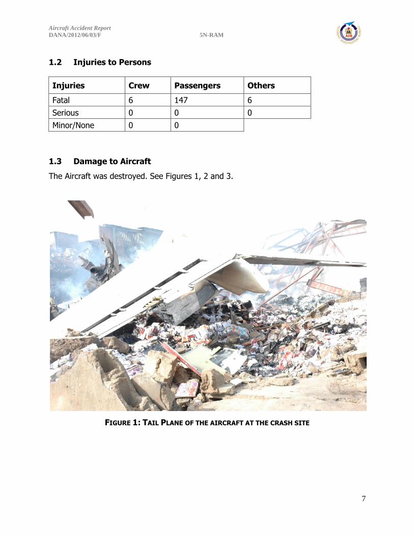
1.3 Damage to Aircraft
The Aircraft was destroyed. See Figures 1, 2 and 3.
FIGURE 1: TAIL PLANE OF THE AIRCRAFT AT THE CRASH SITE

Aircraft Accident Report
DANA/2012/06/03/F 5N-RAM
8
FIGURE 2: LEFT HAND ENGINES AND WHAT WAS LEFT OF PRINTING PRESS AT THE CRASH SITE
FIGURE 3: THE TAIL PLANE BEING REMOVED FROM THE CRASH SITE

Aircraft Accident Report
DANA/2012/06/03/F 5N-RAM
9
1.4 Other Damage
A storey building, one 2-storey building, Power Holding Company of Nigeria (PHCN)
electric poles/cables and a warehouse/printing press were completely burnt and
destroyed. See Figures 4 and 5.
FIGURE 4: THE 2-STOREY BUILDING THE AIRCRAFT CRASHED INTO

Aircraft Accident Report
DANA/2012/06/03/F 5N-RAM
10
FIGURE 5: THE DAMAGED 2-STOREY BUILDING
1.5 Personnel Information
1.5.1 Captain
Nationality: American
Age: 55 years
Gender: Male
License No: ATPL 3138436
Aircraft rating: A320, DC-9, FK28, SF340
Instrument Rating Currency: Valid till 7th February, 2013
Medical: Valid till 1st October, 2012

Aircraft Accident Report
DANA/2012/06/03/F 5N-RAM
11
Total flying Experience: 18116:06 hrs
On type: 7,466:06 hrs
Last 90 days: 116:06 hrs
Last 28 days: 78:49 hrs
Last 24 hrs: N/A
However, DC-9 and MD-83 are considered common type ratings.

Aircraft Accident Report
DANA/2012/06/03/F 5N-RAM
12
FIGURE 6: THE STAMPED BUT UNSIGNED LICENCE OF THE CAPTAIN

Aircraft Accident Report
DANA/2012/06/03/F 5N-RAM
13
The captain was employed on 14th March, 2012. He began flying line training
operations under the supervision of a training captain on 26th April, 2012 after
completing ground school and simulator training.
The background checks were said to have been done with nothing found to disqualify
the pilot.
The pilot was suspended in 2009 by the United States Federal Aviation Administration
(FAA) for some misdemeanours related to a heavy landing and fixing of panels that
were neither entered in the aircraft logbook nor reported.
The revalidated licence issued to him by NCAA was stamped but not signed by any
NCAA official. See Figure 6 above.
Most of the recommendation letters submitted by the captain were also not signed. The
line trainings that preceded the captain’s checkout had a lot of adverse remarks made
by the training captain. They are as follows:
1. "Callout and operating procedures needs to improve, Abuja Company
Procedures to be adhered to, PM RT procedures and callout"
26th April, 2012.
2. "Expanded checklist and cockpit flow time management" “RT
procedures and reporting needs to be standardized to ICAO format"
27th April, 2012.
3. "Standardized Operating procedures, RT to be standardized ICAO
positioning" " SOP RT procedures" "SOP positioning" "SOP Positioning
reporting" 28th April, 2012.

Aircraft Accident Report
DANA/2012/06/03/F 5N-RAM
14
4. "SOP Airport departures ABV to be adhered to" “RT Procedure Positioning
reporting" "SOP" "SOP RT Reporting to be improved, Standard call out" “RT
Procedures & Positioning needs to [be] improved" 29th April, 2012.
5. "RT procedures to be improved" 30th April, 2012.
6. “PM LOC approach Runway 18L" "Released for final line check. 01st May, 2012"
7. "GOOD AIRMANSHIP WAS SHOWN ON THESE 2 SECTORS PLEASE OBSERVE
TRANSITION ALTITUDES/ LEVELS ARE DIFFERENTLY AS THE USA, MONITOR ATC
TRANSMISSIONS CONSTANTLY AS ATC ACCENT IS ALSO DIFFERENT HERE IN
NIGERIA". 01st May, 2012
He started flying as checked out captain on 2nd May, 2012 and had accrued over 120
hours of flight time before the accident.
There was no documented evidence that the crew performed the mandatory CRM
training.
1.5.2 First Officer
Nationality: Indian
Age: 34 years
Gender: Male
Licence No: CPL 5999
Aircraft Rating: DC-9
Instrument Rating Currency: Valid till 04th March, 2013

Aircraft Accident Report
DANA/2012/06/03/F 5N-RAM
15
Proficiency Check: Valid till 04th September, 2012
Medical: Valid till 05th September, 2012
Total flying Experience: 1,143:40 hrs
On type: 808:32 hrs
Last 90 days: 154:21 hrs
Last 28 days: 42:43 hrs
Last 24 hrs: 03:23 hrs
However, DC-9 and MD-83 are considered common type ratings. He was previously
employed at Dana Air as the Director of Cabin Service before he was hired as a pilot in
January 2011.
1.6 Aircraft Information:
Aircraft Type: MD-83
Year of Manufacture: 1990
Serial Number: 53019
Registration: 5N-RAM
Total Airframe time: 60850:47hrs
Certificate of Airworthiness: Issued 16th September, 2011
Category: Transport (Passenger)
Certificate of Registration: Issued 3rd February, 2009
Operator: Dana Airlines Ltd

Aircraft Accident Report
DANA/2012/06/03/F 5N-RAM
16
Engine Type: JT8D-217C
Manufacturer: Pratt & Whitney
Engine No 1:
Total Time since new: 54318:29hrs
Cycles: 30928
Serial No: P718142
Engine No 2:
Total Time since new: 26021:46hrs
Cycles: 12461
Serial No: P728113D
FIGURE 7: THE AIRCRAFT BEFORE THE ACCIDENT
Aircraft Accident Report
DANA/2012/06/03/F 5N-RAM
17
A review of the aircraft technical logs did not reveal any anomaly that would have had
serious effect on the airworthiness of the aircraft. The airplane had last undergone
maintenance on 1st June 2012, and after a return to service flight on 2nd June 2012, it
operated four revenue flights (two round trips between LOS and ABV) and another four
flights on 3rd June 2012.
Fuelling records indicated that the aircraft uplifted 8000lbs of fuel before departure
from ABV. The flight crew reported to ATC that they had a total of 26,000lbs of fuel.
Preliminary analysis of fuel samples from the refuelling truck and the supply tank at
ABV were negative for contamination.
Detailed engines examination was carried out in the USA. History, operational and
performance information of the accident aircraft engines were looked into.
The two engines were found at the crash site on both sides of the burnt-out fuselage
with the left engine facing the opposite direction. Physical inspection carried out
showed that there was little or no damage to the engine fan blade which was consistent
with low thrust engine. This also corroborated the fact that the engines were not fully
powered.
Check A-03 was carried out on 31st May, 2012. The Left Aileron Bus Cable was replaced
and adjusted with duplicate inspection carried out on 1st June, 2012. Work was carried
out on the APU Fuel Shut-Off Valve Electrical Plug on 2nd June, 2012. The aircraft was
serviceable and airworthy at the time of the accident.
Dana Airlines MD-83 5N-RAM A-03 check accomplished on 01/06/2012 included the
following:
A-03 check consists of a 1A plus 4A-1 plus 450 FH items.
Aircraft Accident Report
DANA/2012/06/03/F 5N-RAM
18
No. 35 OAMP 71-2401 General visual inspection – CSD 1 charge and scavenge
filter differential pressure indicators Interval 1A WC TC-801A-010.
No. 36 OAMP 72-2401 General visual inspection – CSD 2 charge and scavenge
filter differential pressure indicators Interval 1A WC TC-801A-010.
No. 47 OAMP 71-7901 Restoration – clean or replace No. 1 engine oil pressure
filter and check for contamination Interval 1A WC TC-801A-020 TC-801A-021.
No. 48 OAMP 72-7901 Restoration – clean or replace No. 2 engine oil pressure
filter and check for contamination Interval 1A WC TC-801A-020 TC-801A-021.
No. 49 OAMP 71-7203 Detailed inspection – visible parts of No. 1 engine
compressor fan blades Interval 1A WC TC-801A-022.
No. 50 OAMP 72-7203 Detailed inspection – visible parts of No. 2 engine
compressor fan blades Interval 1A WC TC-801A-022.
No. 68 OAMP 71-0501 Zonal inspection – No. 1 engine (demountable power
plant) Interval 1A WC TC-801A-508.
No. 69 OAMP 72-0501 Zonal inspection – No. 2 engine (demountable power
plant) Interval 1A WC TC-801A-508.
No. 70 OAMP 77-0501 Zonal inspection – No. 1 engine upper and lower nacelle
doors Interval 1A WC TC-801A-508.
No. 71 OAMP 78-0501 Zonal inspection – No. 2 engine upper and lower nacelle
doors Interval 1A WC TC-801A-508.
No. 72 OAMP 70-0501 Zonal inspection – External surfaces of power plants, cowl
doors, inlet areas, and nose cowls from ground level Interval 1A WC TC-801A-
509.
No. 73 OAMP 80-501 Zonal inspection – External surfaces of the pylons from
ground level Interval 1A Work card TC-801A-509.
The engines were overhauled at Millenium Engine Associates Inc. in Miami Florida.
Manufacturer’s Service Bulletin (SB) 6452 on the JT8D engines with a Category 6
compliance was issued in October 2003.

Aircraft Accident Report
DANA/2012/06/03/F 5N-RAM
19
The type of fuel used was JET-A1.
1.6.1 Engine Description
The JT8D-217C series engine is an axial-flow front turbofan engine having a fourteen
stage split compressor, a nine can (can-annular) combustion chamber, and a split four
stage reaction impulse turbine. The engine has six general sections, the air inlet
section, the compressor section, the combustion section, the turbine and exhaust
section, the accessory drives, and the fan discharge section (FIGURE 8) and seven main
shaft bearings shown in FIGURE 9 (listed in Appendix A TABLE 1). The engine is
equipped with a full length annular fan discharge duct. The low pressure system is
made up of the front compressor rotor and the stages 2, 3, and 4 turbine rotors and is
mechanically independent of the high pressure system which consists of the rear
compressor rotor and the stage 1 turbine rotor (FIGURE 9).

Aircraft Accident Report
DANA/2012/06/03/F 5N-RAM
20
FIGURE 8: SECTION IDENTIFICATION

Aircraft Accident Report
DANA/2012/06/03/F 5N-RAM
21
FIGURE 9: ENGINE BEARING AND INTERNAL DIAGRAM
The engine is mounted from two points. The front mount is located at the fan discharge
intermediate case. The engine rear mount is located at the turbine exhaust section
outer duct. According to the FAA Type Certificate Data Sheet E9NE, Revision 12, dated
December 13, 2010, the sea level static thrust takeoff rating of the JT8D-217C engine is
20,850 pounds and the sea level static thrust maximum continuous rating is 18,000
pounds, both are flat rated to 77°F (25°C).
1.6.2 LEFT ENGINE (NO. 1) – SERIAL NUMBER (SN) 718142
The engine was un-crated and placed on pallets for examination and disassembly
(FIGURE 10). The inlet case, and the front and rear fan cases were attached as a unit,
but were no longer attached to the rest of the engine. This unit was clocked
approximately 120° clockwise direction relative to the core of the engine. The fan and

Aircraft Accident Report
DANA/2012/06/03/F 5N-RAM
22
exhaust ducting was missing from the “D”-flange (aft flange of the rear fan case) aft
except for a section of the front compressor fan duct that was still attached to the D-
flange and ranged from 9 to 13-inches axially and approximately 100° circumferentially.
FIGURE 10: TOP VIEW OF THE NO. 1 ENGINE S/N 718142
The inlet case, and the rear fan case were intact but the front fan case was missing
material from the 5:00 to 10:00 o’clock position. The part of the front fan case that
remained exhibited signs of thermal distress and melted material. The inlet case and
the front fan case did not exhibit any significant distortion; however, the rear fan case
exhibited inward distortion/deformation at the 7:30 o’clock position and also at the
11:00 o’clock position with part of the “D”-flange (approximately 5 bolt holes in length)
missing. The “C”-flange (front flange of the rear fan case) was fractured at
approximately the 11:00 o’clock position, which was in-line axially with the rear fan
case stiffening rib and “D”-flange fractures. All the flange fractures were deformed in
the aft direction (FIGURE 11).
Aircraft Accident Report
DANA/2012/06/03/F 5N-RAM
23
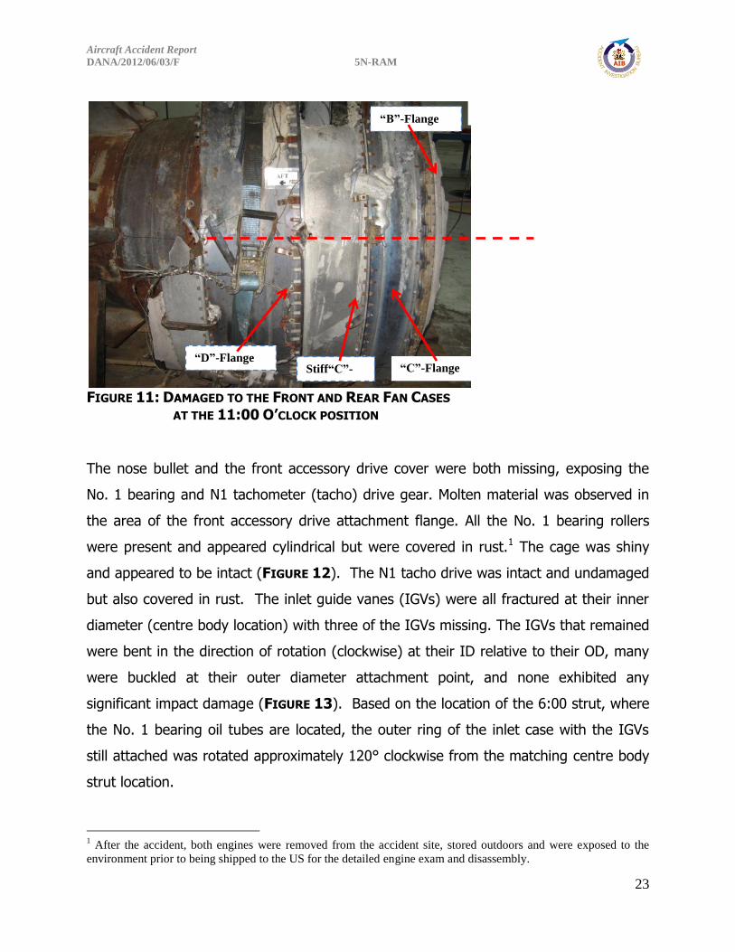
FIGURE 11: DAMAGED TO THE FRONT AND REAR FAN CASES
AT THE 11:00 O’CLOCK POSITION
The nose bullet and the front accessory drive cover were both missing, exposing the
No. 1 bearing and N1 tachometer (tacho) drive gear. Molten material was observed in
the area of the front accessory drive attachment flange. All the No. 1 bearing rollers
were present and appeared cylindrical but were covered in rust.1 The cage was shiny
and appeared to be intact (FIGURE 12). The N1 tacho drive was intact and undamaged
but also covered in rust. The inlet guide vanes (IGVs) were all fractured at their inner
diameter (centre body location) with three of the IGVs missing. The IGVs that remained
were bent in the direction of rotation (clockwise) at their ID relative to their OD, many
were buckled at their outer diameter attachment point, and none exhibited any
significant impact damage (FIGURE 13). Based on the location of the 6:00 strut, where
the No. 1 bearing oil tubes are located, the outer ring of the inlet case with the IGVs
still attached was rotated approximately 120° clockwise from the matching centre body
strut location.
1 After the accident, both engines were removed from the accident site, stored outdoors and were exposed to the
environment prior to being shipped to the US for the detailed engine exam and disassembly.
“B”-Flange
“C”-Flange Stiff“C”-
Flange
ening Rib
“D”-Flange
“A”-Flange

Aircraft Accident Report
DANA/2012/06/03/F 5N-RAM
24
Blades
FIGURE 12: NO. 1 ROLLER BEARING INTACT AND COVERED IN RUST
FIGURE 13: INLET CASE WITH FRACTURED AND DAMAGED INLET GUIDE VANES
Inlet Guide
Vanes
No. 1 Bearing Rollers

Aircraft Accident Report
DANA/2012/06/03/F 5N-RAM
25
All the fan blades were present and secured in the fan hub. Numerous blades exhibited
small leading edge nicks, tears, and dents with some exhibiting leading edge round
bottom impact marks with material transfer. The material deformation associated with
this damage was in the direction of rotation and/or aft. A single fan blade was fractured
at the leading edge corner tip. Three randomly blade tips were curled/bent in the
direction opposite rotation and five random blades (of which two were adjacent to each
other) were bent in the direction of rotation. One fan blade exhibited appreciable
forward blade tip corner bending while a different blade exhibited appreciable aft
bending. Four adjacent blades exhibited blade spanwise buckling. Several sets of blades
exhibited mid-span shroud shingling.
Seven of the tangential fan exhaust duct strut rods that connect the turbine exhaust
case to the exhaust duct were still secured to the turbine exhaust case at their inner
ends. Five were fractured at their inner end (turbine exhaust case mount rail location),
two were almost entirely intact (one at the 2:00 o’clock and one at the 10:00 o’clock
position) and fractured at their outer end; the eighth rod was missing. The exhaust
mixer remained attached to the turbine exhaust case. At the 6:00 o’clock position,
exhaust mixer was deformed inwards with longitudinal/axial scrape marks. The majority
of the remainder of the mixer was pushed/buckled inwards and forward. iThe turbine
exhaust inner duct and tail cone were still attached to the turbine exhaust case centre
body (No. 6 bearing housing). The turbine exhaust duct was dented and cracked at the
6:00 o’clock position, in-line with inward deformation of the tail cone. The deformed
area of the tail cone also exhibited axial scrape marks (FIGURE 14). No other significant
damage was noted on the exhaust duct or tail cone.

Aircraft Accident Report
DANA/2012/06/03/F 5N-RAM
26
FIGURE 14: EXHAUST CASE, INNER DUCT, CONE AND MIXER DAMAGE AT THE 6:00 O’CLOCK
POSITION

Aircraft Accident Report
DANA/2012/06/03/F 5N-RAM
27
FIGURE 15: US DEPARTMENT OF TRANSPORT MAJOR REPAIR AND ALTERATION CERTIFICATE
S/N 718142
No. 1 Engine was overhauled at Millenium Engine Associates Inc. (MRO), Miami, Florida,
U.S.A on the 3rd August, 2011. See Figure 15 above. Records available to AIB showed
that Service Bulletin 6452 was not accomplished on this engine during all the shop
visits. The maintenance repair organization (MRO) is approved by both NCAA and FAA.
The history of shop visits of engine serial number (ESN) 718142 as shown below;

Aircraft Accident Report
DANA/2012/06/03/F 5N-RAM
28
Engine Type: - JT8D-217C ESN: - 718142 POSITION #1
* Engine Shop Visit done at ST Aerospace Engine dated 28 October2000.
* Engine Shop Visit done at Pacific GAS Turbine dated 1 November 2002.
* Engine Shop Visit done at Dallas Aviation Field Service dated 1 June 2004.
* Engine Shop Visit done at Pacific GAS Turbine dated 24 August 2004.
* Engine Shop Visit done at Pacific GAS Turbine dated 3 February 2005
* Engine Shop Visit done at Pacific GAS Turbine dated 30 August 2007.
* Engine Shop Visit done at IBERIAI Maintenance dated 19 April 2010.
* Engine Shop Visit done at Millenium Engine Associates, Inc. dated 3 August, 2011.
1.6.3 Right Engine (No. 2) – SN728113
The engine was un-crated and placed on pallets for examination and disassembly
(FIGURE 16). The engine was intact from the nose bullet aft to the exhaust tail cone
with all major modules in place. Engine cases appeared round and did not exhibit signs
of structural deformation or case breach. Fan and exhaust ducting was missing from the
“E”-flange (aft flange of the fan exit guide vane (FEGV) Outer Case) aft to the “F”-
flange (forward flange intermediate case outer diameter ring) and from the “G”-flange
(aft flange of the intermediate case outer diameter ring) to the “K”-flange (forward
flange of the turbine case outer diameter ring). Some wiring, and pneumatic and oil
system plumbing along with crash debris were removed to facilitate teardown (FIGURE
17).

Aircraft Accident Report
DANA/2012/06/03/F 5N-RAM
29
FIGURE 16: RIGHT-HAND SIDE OF THE NO. 2 ENGINE S/N 728113
FIGURE 17: RIGHT-HAND SIDE OF NO. 2 ENGINE WITH FLANGE LOCATIONS
G E F
K
Aircraft Accident Report
DANA/2012/06/03/F 5N-RAM
30
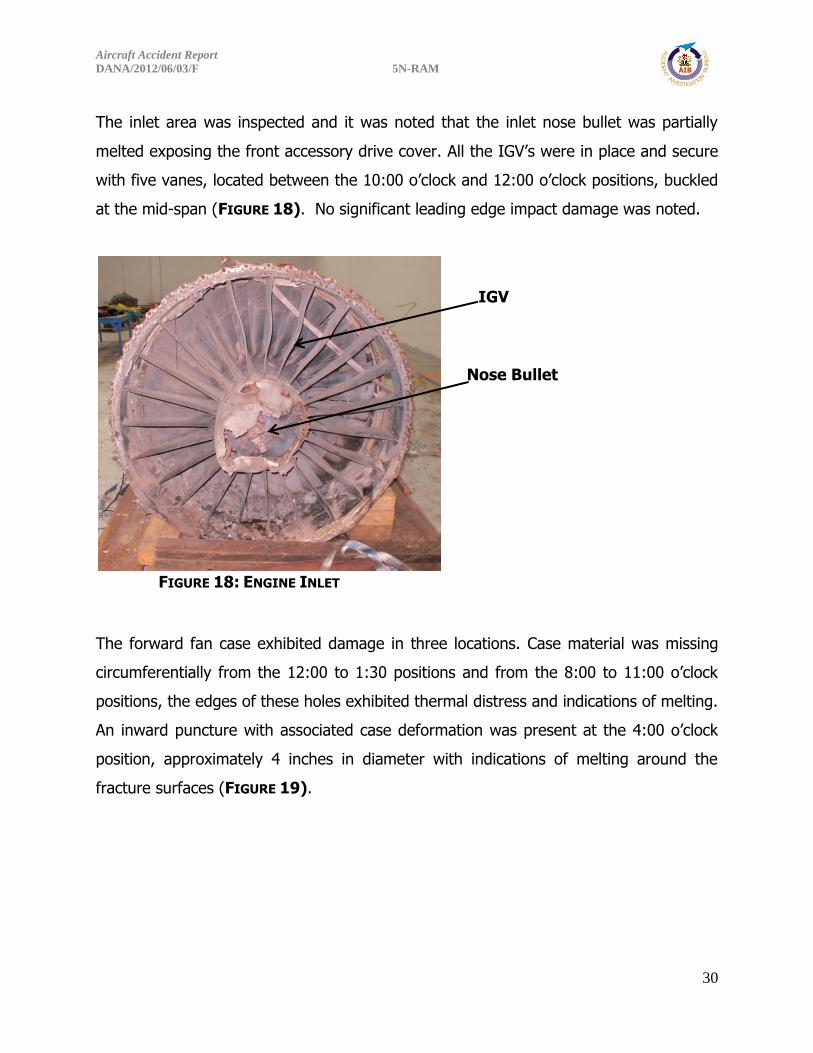
The inlet area was inspected and it was noted that the inlet nose bullet was partially
melted exposing the front accessory drive cover. All the IGV’s were in place and secure
with five vanes, located between the 10:00 o’clock and 12:00 o’clock positions, buckled
at the mid-span (FIGURE 18). No significant leading edge impact damage was noted.
FIGURE 18: ENGINE INLET
The forward fan case exhibited damage in three locations. Case material was missing
circumferentially from the 12:00 to 1:30 positions and from the 8:00 to 11:00 o’clock
positions, the edges of these holes exhibited thermal distress and indications of melting.
An inward puncture with associated case deformation was present at the 4:00 o’clock
position, approximately 4 inches in diameter with indications of melting around the
fracture surfaces (FIGURE 19).
Nose Bullet
IGV Buckling

Aircraft Accident Report
DANA/2012/06/03/F 5N-RAM
31
FIGURE 19: FORWARD FAN CASE THERMAL AND IMPACT DAMAGE
The exhaust mixer lobes exhibited crushing damage both radially inward and forward
from the 6:00 to 9:00 o’clock positions. The tail cone and inner exhaust duct were both
present and undamaged (FIGURE 14). There was no distress noted in the exhaust duct
mount rails.
Aircraft Accident Report
DANA/2012/06/03/F 5N-RAM
32
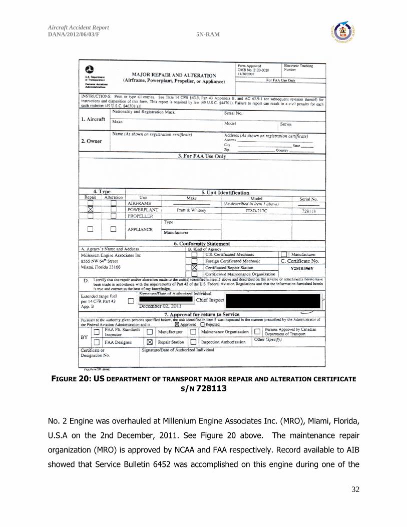
FIGURE 20: US DEPARTMENT OF TRANSPORT MAJOR REPAIR AND ALTERATION CERTIFICATE
S/N 728113
No. 2 Engine was overhauled at Millenium Engine Associates Inc. (MRO), Miami, Florida,
U.S.A on the 2nd December, 2011. See Figure 20 above. The maintenance repair
organization (MRO) is approved by NCAA and FAA respectively. Record available to AIB
showed that Service Bulletin 6452 was accomplished on this engine during one of the

Aircraft Accident Report
DANA/2012/06/03/F 5N-RAM
33
shop visits in Volvo Aero Engine Maintenance facility on 27th September, 2005. The
history of shop visits of engine serial number: ESN. 728113 as shown below;
Engine Type: - JT8D-217C
ESN: - 728113 POSITION #2
* Engine Shop Visit done at Pratt & Whitney dated 21 November 2001.
* Engine Shop Visit done at Volvo Aero dated 27 September 2005.
* Engine Shop Visit done at IAI Bedek Aviation Group dated 2 February 2009.
* Engine Shop Visit done at Millenium Engine Associates, Inc. dated 2 December 2011.
1.6.4 Engines Audio Spectrum Analysis
The audio spectrum analysis was performed and nothing conclusive was determined.
The test was carried out by Pratt and Whitney, and observed by Boeing, FAA and NTSB
as requested by AIB.
1.6.5 Auxiliary Power Unit (APU)
The auxiliary power unit (APU) supplies pneumatic and electrical power for ground
starting of main engines, fuselage air-conditioning, and ground operation of the aircraft
electrical system in the absence of ground power or an operating engine. The APU can
also be operated in flight to provide an alternate source of electric power. The APU was
sent to the USA for analysis.
1.6.6 Battery Power
Two 14-Volt Batteries are installed in the Electrical/Electronic (E/E) compartment. They
are connected in series to provide 28 Volts DC to the Starter Control Relay of the APU
and through an 80-ampere Circuit Breaker (CB) directly to the Battery Direct Bus.

Aircraft Accident Report
DANA/2012/06/03/F 5N-RAM
34
1.6.7 Fuel System - Airframe
The fuel on the MD-83 aircraft is stored in three integral tanks; left main, centre and
right main. Additional fuel is stored in fuselage tanks to be transferred to the centre
wing tank when space is available. A series of flapper valves incorporated into two flow
baffles near the inboard end of each main tank, creates a reservoir. The reservoir
provides a head of fuel around the tank pumps during all normal manoeuvres and
aircraft attitude changes. Engine fuel supply from the tanks to the engines is
accomplished by tank boost pumps through lines direct to the engines. The right and
left main tank-to-engine fuel feed lines are interconnected by a cross feed line and a
cross feed valve.
The fuel feed system consists of six fuel boost pumps (two single pumps for each main
tank and two series-mounted pumps for the centre tank), necessary check valves, a
cross feed valve, two engine fuel fire shutoff valves, and an APU fuel fire shutoff valve.
Fuel is supplied to the engine and the APU through shrouded lines. The shroud system
has a drain valve located on the lower right side of the fuselage aft of the wheel well. A
start pump is also installed in the right main tank to provide starting fuel pressure to
engines and/or APU when AC power is not available.
The fuel vent system permits equalization of pressure differential in the tanks, created
during refuelling/defueling or manoeuvring of the aircraft. The system is designed to
prevent siphoning or spilling of fuel during normal flight or ground manoeuvres.
Fuel Suction Feed capability
The MD-80 engines suction feed certification capability was demonstrated in accordance
with FAR 25.1351(d) Amdt. 25-41 “Operation without normal electrical power. It must
be shown by analysis, tests, or both, that the airplane can be operated safely in VFR
conditions, for a period of not less than five minutes, with the normal electric power
(electric power sources excluding the battery) inoperative, with critical type fuel (from
Aircraft Accident Report
DANA/2012/06/03/F 5N-RAM
35
the standpoint of flameout and restart capability), and with the airplane initially at the
maximum certified altitude.”
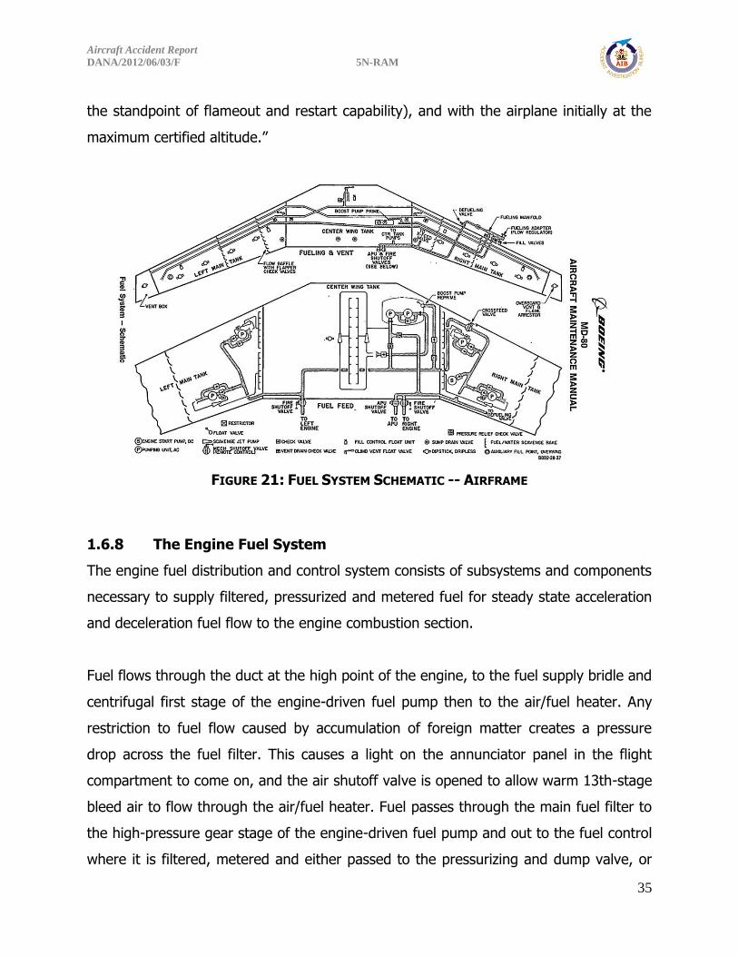
FIGURE 21: FUEL SYSTEM SCHEMATIC -- AIRFRAME
1.6.8 The Engine Fuel System
The engine fuel distribution and control system consists of subsystems and components
necessary to supply filtered, pressurized and metered fuel for steady state acceleration
and deceleration fuel flow to the engine combustion section.
Fuel flows through the duct at the high point of the engine, to the fuel supply bridle and
centrifugal first stage of the engine-driven fuel pump then to the air/fuel heater. Any
restriction to fuel flow caused by accumulation of foreign matter creates a pressure
drop across the fuel filter. This causes a light on the annunciator panel in the flight
compartment to come on, and the air shutoff valve is opened to allow warm 13th-stage
bleed air to flow through the air/fuel heater. Fuel passes through the main fuel filter to
the high-pressure gear stage of the engine-driven fuel pump and out to the fuel control
where it is filtered, metered and either passed to the pressurizing and dump valve, or

Aircraft Accident Report
DANA/2012/06/03/F 5N-RAM
36
bypassed back to the inlet of the fuel pump high-pressure gear stage. Before entering
the main fuel filter, a portion of the fuel is diverted to provide the motive fluid stream
for the eductor. Fuel discharging from the eductor nozzle evacuates the eductor
chamber by entraining vapour molecules, compressing and mixing them in a constant-
area mixing section, and then forcing the mixture into the inlet of the fuel pump
centrifugal first stage. Fuel leaving the fuel control passes through the fuel flow meter
and fuel/oil cooler to the pressurizing and dump valve. Upon leaving the pressurizing
and dump valve, the fuel flow is divided and passes into primary and secondary
manifolds. Fuel enters the dual inlet manifolds where it is distributed through the nine
individual fuel nozzles into the combustion chambers.
FIGURE 22: FUEL SYSTEM SCHEMATIC – ENGINE

Aircraft Accident Report
DANA/2012/06/03/F 5N-RAM
37
1.6.9 Fuel System Components (F.S.C.) (Engine No. 1. ESN: 718142)
Teardown Report
The only parts of the fuel system that were available for examination were the fuel
nozzles, and left- and right-hand primary and secondary fuel manifolds, which are
located on the diffuser case. For this engine, the fuel nozzle documentation was
covered in the combustion module section. There was no residual fuel remaining in the
fuel system. Both fuel manifolds were removed from the engine for evaluation.
The fuel-feeder lines that attach to the No. 5 fitting were both (primary and secondary)
fractured flush with the No. 5 fitting and a piece of the fuel-feeder tubes remained
within the No. 5 fittings in both manifolds (FIGURE 23). These fractured fuel-feeder
tubes both exhibited shear lips. The left-hand manifold exhibited the following damage
and observations:
1) heavily sooted at fuel nozzle fitting Nos. 8, 9 and 1,
2) the primary fuel transfer tube was pinched almost closed at the No. 8 fuel
nozzle fitting (FIGURE 24), and
3) the primary fuel transfer tube diameter was reduced at the No. 7 fuel nozzle
fitting. The fuel-feeder lines that attach to the No. 6 fitting were both
fractured at the No. 6 fitting with an appreciable piece of the secondary
feeder tube was still attached and twisted/crimped (FIGURE 25).
Aircraft Accident Report
DANA/2012/06/03/F 5N-RAM
38
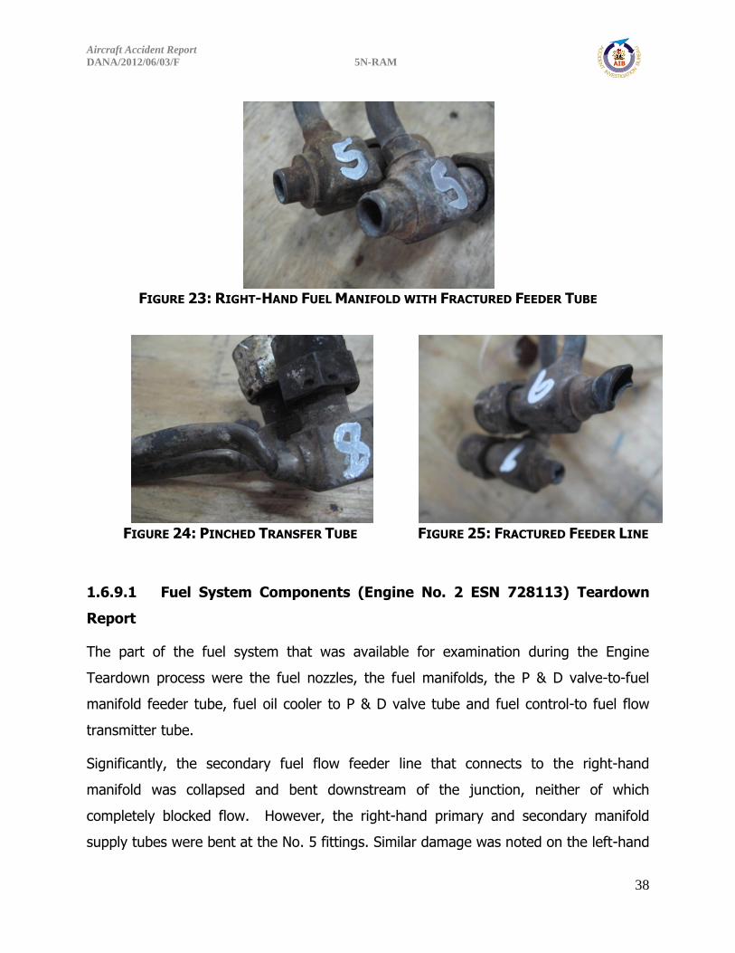
FIGURE 23: RIGHT-HAND FUEL MANIFOLD WITH FRACTURED FEEDER TUBE
FIGURE 24: PINCHED TRANSFER TUBE
FIGURE 25: FRACTURED FEEDER LINE
1.6.9.1 Fuel System Components (Engine No. 2 ESN 728113) Teardown
Report
The part of the fuel system that was available for examination during the Engine
Teardown process were the fuel nozzles, the fuel manifolds, the P & D valve-to-fuel
manifold feeder tube, fuel oil cooler to P & D valve tube and fuel control-to fuel flow
transmitter tube.
Significantly, the secondary fuel flow feeder line that connects to the right-hand
manifold was collapsed and bent downstream of the junction, neither of which
completely blocked flow. However, the right-hand primary and secondary manifold
supply tubes were bent at the No. 5 fittings. Similar damage was noted on the left-hand

Aircraft Accident Report
DANA/2012/06/03/F 5N-RAM
39
primary and secondary manifold supply tube at the No. 6 fittings. Again, neither of
these bends completely obstructed flow. Furthermore, the left hand primary manifold
had a circumferential crack just outboard of the fan duct pass through.
Detailed engine examination was carried out in the USA. History, operational and
performance information of the accident aircraft engines were looked into. See
Appendix A for details of teardown investigation.
The engine teardown was performed at Global Engine Maintenance facility (formerly
Millenium Engine Associates) in the USA. The organization is also responsible for
securing and ensuring that all the parts examined are returned to the engine owners
with the permission of the investigating body. However, certain components such as
the right fuel manifold were not available for subsequent examination.
1.6.10 Hydraulics
Main hydraulic power is provided by two, separate, closed-circuit hydraulic systems
identified as the left and right systems. One engine-driven hydraulic pump on each
engine, supplies power to the corresponding system. The hydraulic systems are filled
with a fire-resistant hydraulic fluid and are normally pressurized by the engine-driven
pumps to approximately 3000psi. Hydraulic power is required for the operation of the
elevator boost, rudder, flaps, slats, flight spoilers, ground spoilers, ventral stairway,
engine thrust reversers, landing gears, brakes and nose wheel steering systems. Each
main hydraulic system is provided with similar components and the necessary controls
and indicators for system operations. Up till the time of the crash, hydraulic related
systems were all operative, e.g. the landing gears were extended and retracted before
the crash.

Aircraft Accident Report
DANA/2012/06/03/F 5N-RAM
40
1.7 Meteorological Information
The Weather Forecast for MMIA issued by MET Office at MMIA Ikeja at 030955Z
0312/0418 19007K 9999
SCT 013 TEMPO 0312/0318 TS
BKN 013 FEW 020 CB PROB 30
0317/0317 5000- TSRA BKN009
FEW019 CB BECMG
0320/0322 19004KT FEW 009
TEMPO 0405/0407 VRB 02KT
5000 BR FEW 008
Actual Weather LOS
Time: 1400 UTC
Wind: 200/06 kts
Visibility: 10 Km
Weather: Nil
Cloud: SCT 1400
Temperature/Dew: 31/230C
Tempo Information: NOSIG
QNH: 1013 hPa
Time: 1500 UTC
Wind: 190/07 kts
Visibility: 10 km
Weather: Nil
Cloud: SCT 420m
Temp.: 30°C/23°C
QNH: 1013 hPa

Aircraft Accident Report
DANA/2012/06/03/F 5N-RAM
41
The weather was available to the Crew. The light condition available to the Crew was
daylight at the time of the accident. The Satellite Imagery Report in Figure 26 below
shows that Lagos was clear of any bad weather.
FIGURE 26: SATELLITE IMAGERY REPORT OF LAGOS ON THE DAY OF THE ACCIDENT
1.8 Aids to Navigation
The Navigation aids available at the time of the accident were ILS and VOR/DME on
both runways 18L and 18R. Their effectiveness on the day of the accident were as
follows:
“LAG” VOR/DME: Serviceable
ILS/DME: Serviceable
Lagos DNMM
Aircraft Accident Report
DANA/2012/06/03/F 5N-RAM
42
1.9 Communications
There was good communication between the aircraft and the Radar Control as evident
from the Cockpit Voice Recorder (CVR) and the Control Tower tape/transcript.
Communication was Strength Five. The status of the equipment on the day of the
accident was as follows:
Lagos Radar VHF 124.7 Control: Serviceable
Lagos Control Tower VHF 118.1: Serviceable
1.10 Aerodrome Information
Lagos was the intended landing airfield before the crash. The aerodrome has two
parallel runways 18L/36R and 18R/36L serving both the International and the Local
airport with standard equipment. ATC, weather and the Fire services are readily
available to the airport users.
The airport elevation is 135ft and runway length of 18L/36R is 9,006ft (2745m) while
18R/36L is 12,795ft (3,900m).
There are other suitable airports for landing between Abuja and Lagos, notably Ilorin
Airport which was officially filed as the alternate. Akure and Ibadan Airports were within
the reach of the crew in an emergency.
1.11 Flight Recorders
The Flight Recorders were located around the rear cargo hold. They were severely
burnt and found around where the burnt-out cargo compartment was located. See
Figure 27 (on page 44).
The Flight Data Recorder was recovered, washed/cleaned in fresh water and placed in
the custody of AIB before being sent to National Transportation Safety Board (NTSB)
for data download and analysis.

Aircraft Accident Report
DANA/2012/06/03/F 5N-RAM
43
The two flight recorders, the Cockpit Voice Recorder (CVR) and the Flight Data
Recorder (FDR) were analysed at the facilities of the (NTSB), Washington, D.C., USA.
The solid-state based memory in the CVR was in good condition and retained 30
minutes 53 seconds of audio information. The digital tape-based memory in the FDR
succumbed to the post-crash fire and melted, consequently no data could be recovered
from it.
In accordance with regulatory requirement, the aircraft was equipped with flight
recorders as follows:
Flight Data Recorder
Part Number: 980-4100-FWUS
S/N: 1340
Manufacturer: Fairchild
Cockpit Voice Recorder
The aircraft was installed with a solid state cockpit voice recorder (CVR);
Part Number: 2100-1010-00
S/N: 292937
Manufacturer: L3/Fairchild
The unit records 30 minutes of digital cockpit audio in a four-channel format; one for
each flight crew audio panel, one channel for the cockpit area microphone (CAM) and
one channel for the interphone, public address or additional crew member. The CVR
suffered severe heat and fire damage but the memory modules were extracted from
the crash survivable memory unit for repair and evaluation. The ribbon cable was
replaced and the memory was downloaded normally.
The transcript began as the aircraft was in cruise heading toward Lagos. The CVR
captured events from cruise, descent and accident sequence over a duration of 30
minutes and 53 seconds.

Aircraft Accident Report
DANA/2012/06/03/F 5N-RAM
44
FIGURE 27: PICTURE OF THE SEVERELY BURNT FLIGHT RECORDERS
1.12 Wreckage and Impact Information
The airplane crashed in a built-up area of Iju-Ishaga, a densely populated area in Lagos
State. The wreckage was confined to a small area around the crash site, with the tail
section and engines located at the beginning of the debris trail. The airplane was mostly
consumed by post-crash fire. The tail section, both engines and portions of both wings,
representing only about 15% of the airplane were recovered from the accident site
while the rest of the aircraft was destroyed by the impact forces and fire outbreak.
The airplane crashed in a residential area about 5.8 miles north of LOS. The airplane
wreckage was on approximately the extended centreline of runway 18R, with the main
wreckage concentrated at N 06o 40.310’ E 003o 18.837' coordinates, with Elevation of
177ft. See Figure 28 below.
During the impact sequence, the airplane struck an uncompleted building, two trees
and three other buildings. The wreckage was confined in a small area, with the
separated tail section and engines located at the beginning of the debris trail. See
Figures 28 and 29 on the following page.
Aircraft Accident Report
DANA/2012/06/03/F 5N-RAM
45
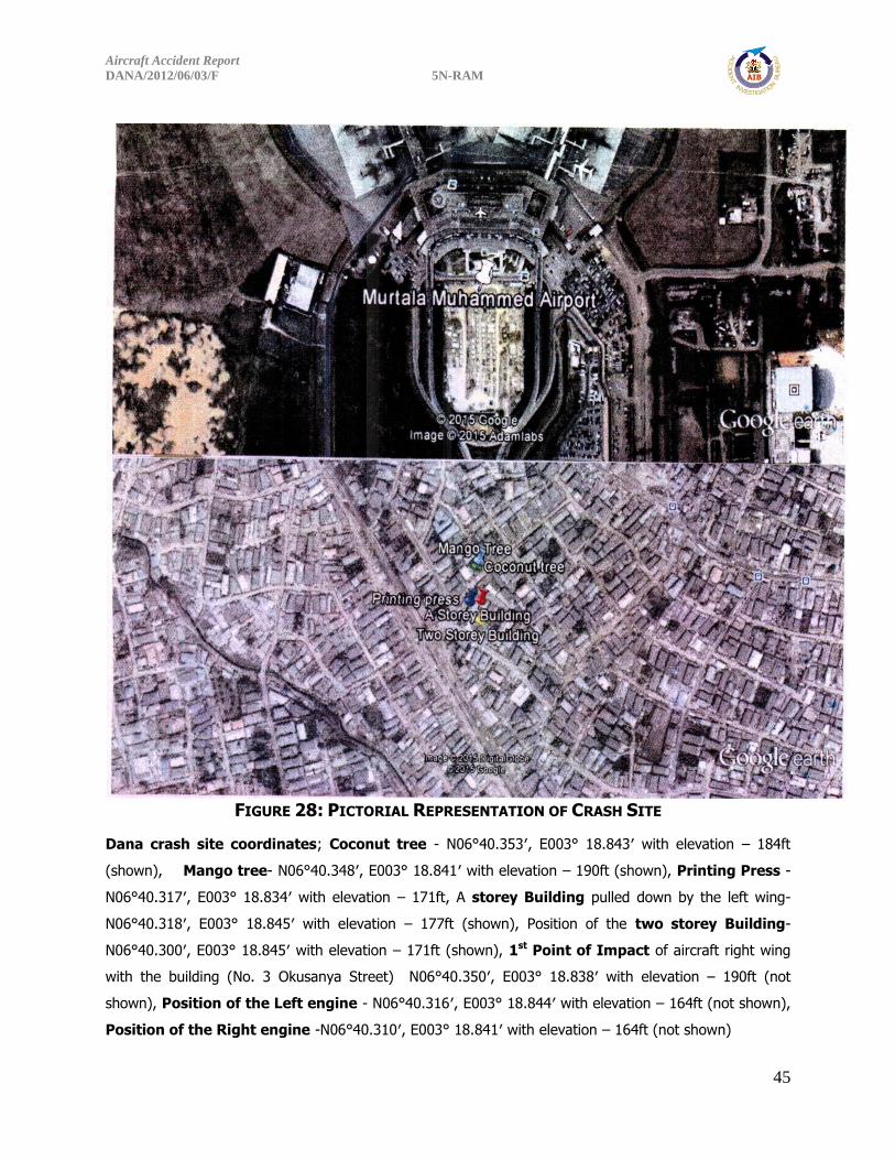
FIGURE 28: PICTORIAL REPRESENTATION OF CRASH SITE
Dana crash site coordinates; Coconut tree - N06°40.353′, E003° 18.843′ with elevation – 184ft
(shown), Mango tree- N06°40.348′, E003° 18.841′ with elevation – 190ft (shown), Printing Press -
N06°40.317′, E003° 18.834′ with elevation – 171ft, A storey Building pulled down by the left wing-
N06°40.318′, E003° 18.845′ with elevation – 177ft (shown), Position of the two storey Building-
N06°40.300′, E003° 18.845′ with elevation – 171ft (shown), 1st Point of Impact of aircraft right wing
with the building (No. 3 Okusanya Street) N06°40.350′, E003° 18.838′ with elevation – 190ft (not
shown), Position of the Left engine - N06°40.316′, E003° 18.844′ with elevation – 164ft (not shown),
Position of the Right engine -N06°40.310′, E003° 18.841′ with elevation – 164ft (not shown)

Aircraft Accident Report
DANA/2012/06/03/F 5N-RAM
46
FIGURE 29: THE CRASH SITE WRECKAGE DISTRIBUTION
RIGHT
ENG. LEFT
ENG.
TAIL
SECTION
MAIN AIRCRAFT
FUSELAGE
UNDERCARRAGE
LEFT WING RIGHT
WING

Aircraft Accident Report
DANA/2012/06/03/F 5N-RAM
47
FIGURE 30: THE TWO ENGINES LYING SIDE BY SIDE IN THE WRECKAGE AT THE CRASH SITE
1.13 Medical and Pathological Information The Lagos State University Teaching Hospital (LASUTH) carried out autopsy to identify
the cause of death, identification of recognizable bodies and DNA test was carried out
to identify unrecognizable bodies. Some of the most difficult cases were sent overseas
for proper analysis and identification. The cockpit area was completely burnt and
destroyed; this made it impossible to identify the crew.
However, one hundred and forty-eight (148) bodies were identified positively through
DNA. There were at least three (3) suspected victims among the 148 bodies positively
identified and three (3) unidentified bodies out of one hundred and fifty-two (152)

Aircraft Accident Report
DANA/2012/06/03/F 5N-RAM
48
bodies recovered from the crash site. There were fifteen (15) nationals representing
nine (9) countries on board the ill-fated aircraft. See Appendix E (on page 167) for the
detailed pathological report.
1.14 Fire
There was outbreak of fire which consumed about 85% of the aircraft. However, there
was no evidence of in-flight fire before the crash. The evidence available showed that
the aircraft departed Abuja with about twenty-six thousand pounds of fuel (26,000lbs)
and the expected burn-off to Lagos was 8,000lbs. This meant that the airplane crashed
with about 18,000lbs of fuel on-board. One of the buildings the airplane crashed into
was a printing press with a huge amount of paper and other printing materials which
enhanced the fire. The Fire Services that were at the crash site came with water and
foam chemical extinguishers. The crash was into a built-up area which made
accessibility to the crash site almost impossible for the fire services to move their
equipment to fight the fire. It was a massive fire which consumed the entire length of
the airplane fuselage. It took the combined effort of all the fire services which include
Federal, State, and Airport fire services to put out the huge fire. The crash site was
smouldering for over four days while body recovery and evidence gathering were in
progress.
1.15 Survival Aspects
The nature of the crash greatly reduced the chances of survival due to massive post-
crash fire. There was no liveable volume within the forward section of the aircraft. The
ground impact, with over eighteen thousand pounds (18,000lbs) of fuel onboard the
aircraft, and a printing press with a warehouse of printed books and paper materials
turned the whole area into a huge fire ball.

Aircraft Accident Report
DANA/2012/06/03/F 5N-RAM
49
The pathology report showed that some passengers died of smoke inhalation, that is, of
carbon monoxide poisoning. “This suggests that the victims were alive for some time in
the fire that probably followed the crash, that is, they did not die immediately after the
impact.” Though the response of the search and rescue team was prompt, the
operation of the fire services was hampered by inaccessibility to the crash site as a
result of a bad road network. The massive crowd at the scene did not help the
situation; crowd control became a big problem to the fire services and the National
Emergency Management Agency (NEMA).
The recovery of bodies was intermittently delayed due to the crowd interrupting the
recovery process by the massive looting that took place while the recovery was going
on. The bodies of some passengers were however found in the 2-storey building into
which the aircraft crashed. The cockpit area was completely destroyed, with the
pathologist unable to identify any of the flight crew, either physically or by DNA testing,
as a result of the impact and massive fire.
1.16 Test and Research
1.16.1 Fuel Test
Test was performed on the fuel truck, fuel bay and other aircraft belonging to Dana
Airlines. See below the fuel test analysis report.
Fuel Test Analysis:
“Please note both samples provided do not show similar consistency as observed from
test results carried out, implying that they are not of the same refinery batch source.
Analysis - Sample brought by client and labelled MRS ABUJA has a low
microseparometer rating of 57pS/m which is below the required specification of 70
pS/m for samples with SDA. (Microseparometer rating is a water separation index that
rates the ability of a fuel to release entrained or emulsified water when passed through
a fibreglass filter coalescer.) - Sample brought by client and Labelled BOWSER (MRS

Aircraft Accident Report
DANA/2012/06/03/F 5N-RAM
50
RF2213) Truck gave a positive indication of presence of reactive Sulphur compounds,
and further qualitative testing gave results of Mercaptans Sulphur of 0.0047% mass
which exceeds the specification limit of 0.003% mass (Mercaptans Sulphur are free
radicals present in fuel having an unpleasant odour, and attack certain elastomer
materials found in fuel systems.).”
1.16.2 Simulator Programme Conducted at the PANAM Aviation
Academy (PAIFA) Florida, USA (Ref, MD- 83 Air Accident
Investigation)
Simulator Flight Test was carried out in Miami Florida USA. Details are shown below:
The simulator was prepared with a take-off weight of 138,000 lbs, fuel of 26,400 lbs
and the airport assumed scenario of Abuja with temperature of 310C, QNH 1013 hPa
and wind calm, landing weight of 130,000lbs. The first engine start-up was with all
booster pumps ON and the engine parameters were as follows:
Engines were shut down and the second engine start-up was with all Booster pumps
OFF and relevant parameters were as follows:
Left Engine Right Engine EPR 1.03 1.03 Oil Pressure 44 44 N1 27 27 N2 55 55 EGT 433 432 Hyd. Pressure 2600 2900 psi Oil Temp. 79 82
Fuel Temp. 32 31
Left Engine Right Engine EPR 1.03 1.03 Oil Pressure 44 44 N1 27 27 N2 55 55 EGT 433 432 Hyd. Pressure 2600 2900 psi Oil Temp. 79 82
Fuel Temp. 32 31
Aircraft Accident Report
DANA/2012/06/03/F 5N-RAM
51
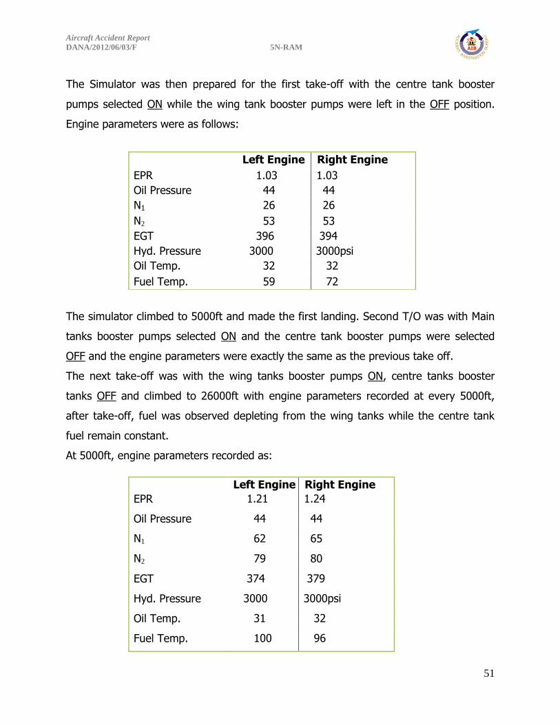
The Simulator was then prepared for the first take-off with the centre tank booster
pumps selected ON while the wing tank booster pumps were left in the OFF position.
Engine parameters were as follows:
The simulator climbed to 5000ft and made the first landing. Second T/O was with Main
tanks booster pumps selected ON and the centre tank booster pumps were selected
OFF and the engine parameters were exactly the same as the previous take off.
The next take-off was with the wing tanks booster pumps ON, centre tanks booster
tanks OFF and climbed to 26000ft with engine parameters recorded at every 5000ft,
after take-off, fuel was observed depleting from the wing tanks while the centre tank
fuel remain constant.
At 5000ft, engine parameters recorded as:
Left Engine Right Engine
EPR 1.03 1.03
Oil Pressure 44 44
N1 26 26
N2 53 53
EGT 396 394
Hyd. Pressure 3000 3000psi
Oil Temp. 32 32
Fuel Temp. 59 72
Left Engine Right Engine
EPR 1.21 1.24
Oil Pressure 44 44
N1 62 65
N2 79 80
EGT 374 379
Hyd. Pressure 3000 3000psi
Oil Temp. 31 32
Fuel Temp. 100 96
Aircraft Accident Report
DANA/2012/06/03/F 5N-RAM
52
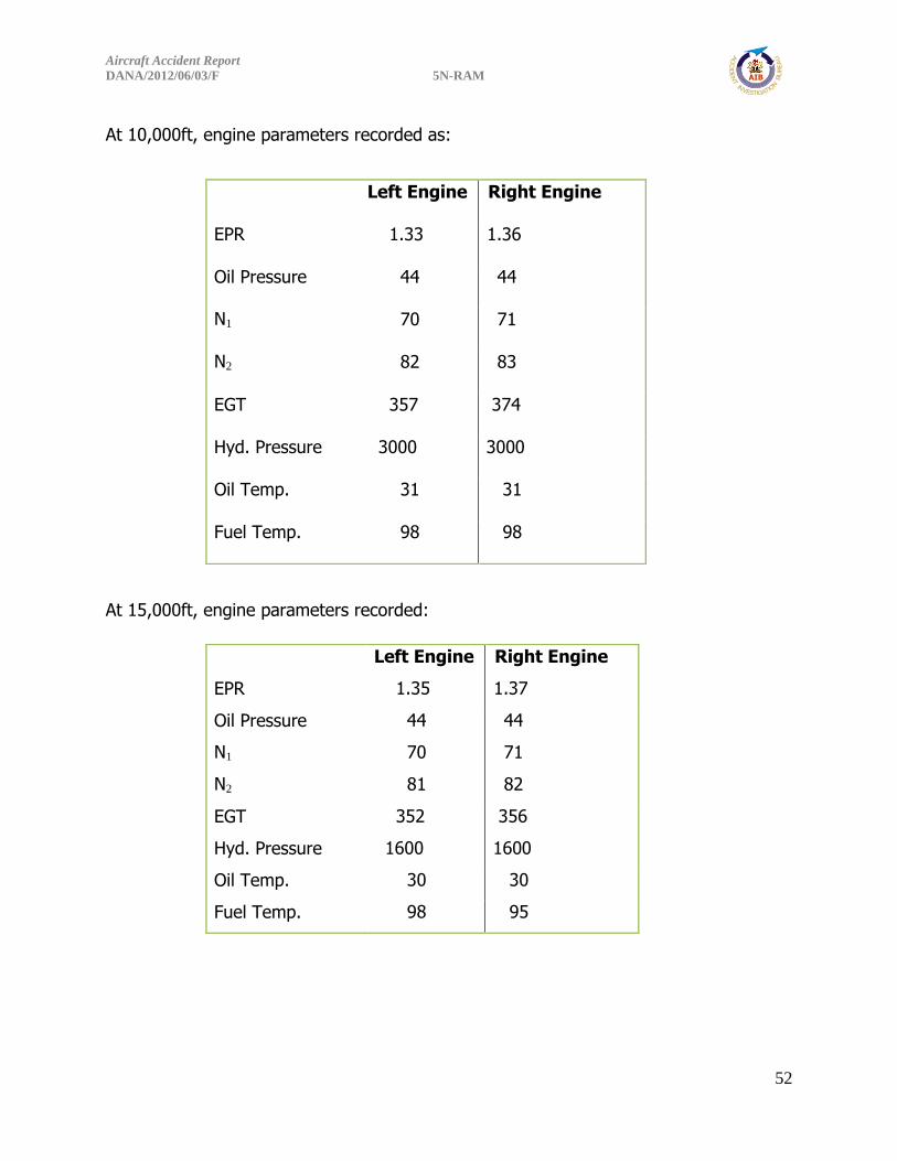
At 10,000ft, engine parameters recorded as:
At 15,000ft, engine parameters recorded:
Left Engine Right Engine
EPR 1.33 1.36
Oil Pressure 44 44
N1 70 71
N2 82 83
EGT 357 374
Hyd. Pressure 3000 3000
Oil Temp. 31 31
Fuel Temp. 98 98
Left Engine Right Engine
EPR 1.35 1.37
Oil Pressure 44 44
N1 70 71
N2 81 82
EGT 352 356
Hyd. Pressure 1600 1600
Oil Temp. 30 30
Fuel Temp. 98 95
Aircraft Accident Report
DANA/2012/06/03/F 5N-RAM
53
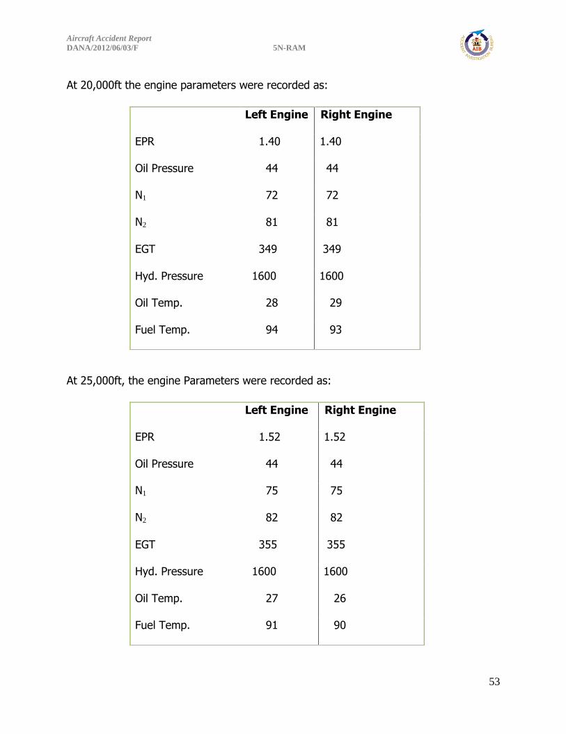
At 20,000ft the engine parameters were recorded as: At 25,000ft, the engine Parameters were recorded as:
Left Engine Right Engine
EPR 1.40 1.40
Oil Pressure 44 44
N1 72 72
N2 81 81
EGT 349 349
Hyd. Pressure 1600 1600
Oil Temp. 28 29
Fuel Temp. 94 93
Left Engine Right Engine
EPR 1.52 1.52
Oil Pressure 44 44
N1 75 75
N2 82 82
EGT 355 355
Hyd. Pressure 1600 1600
Oil Temp. 27 26
Fuel Temp. 91 90

Aircraft Accident Report
DANA/2012/06/03/F 5N-RAM
54
At 26,000ft, all the six booster pumps were selected OFF and some manoeuvres like
steep turns, rapid descent and slow flights were performed. The speed was increased to
290kts, then reduced to 250kts and further down to 210kts. The engine driven pumps
were observed to have sustained the engines with NO engine parameter fluctuations.
Descent commenced to 5000ft, aircraft configured for landing but with only 28° of flap
and at 15 miles to touch ground, both engines were shut down and the final approach
commenced. The simulator touch down at the middle of the runway and over ran the
runway. Second attempt was with flaps 15° and the result was the same as flap 28°.
Simulator was repositioned for final approach with gear down and flaps 15° but this
time at 2200ft, then engine shut down but it was not possible to make the field. It
crashed before the threshold of the runway.
Another normal take-off was carried out and climbed to 15000ft. Fuel
restriction/contamination was simulated by shutting down the left engine to correspond
to engine rollback, the right engine parameters were observed to be normal. The
simulator was configured for landing with 28° flaps, both the hydraulic pressure and the
electrical power were normal and sustained. The simulator was descended to 2,200ft
followed by flaps selected up, gears selected up and the systems operation and
responses remain normal as the MD-83 control surfaces are cable powered.
Thereafter, the right engine was shut down, the flaps were selected up and the landing
gear also selected up but on landing it was discovered that the right landing gear was
not fully retracted before touch down but the flaps were fully up. Electrical operations
were from the hot battery bus (Battery Switch On).
Aircraft Accident Report
DANA/2012/06/03/F 5N-RAM
55
1.16.3 Fuel Nozzle Test
The fuel nozzles from both engines were quarantined for further evaluation and testing.
Work scope, testing facility, and test dates were determined and the test was carried
out in the USA.
1.16.4 Metallurgical Test of Fuel Manifold Component
Fuel manifold segment test from #1 Engine was performed at the NTSB laboratory in
the USA. The fuel manifold from Engine #2 was not provided by the operator who had
custody of the accident engines.
The Fuel Manifold segment from Engine #1 of a Pratt & Whitney JT8D-217C revealed
during examination using stereo microscope, that the fractures were consistent with
overstress separations and bending load. See Appendix I for the full report.
1.17 Organizational and Management Information
Dana Airlines Nigeria Limited was incorporated as a private limited liability company in
Nigeria, a member of Dana Group of companies.
Dana Airlines Nigeria Limited is an Air Operator Certificate (AOC) holder with
operational base in Murtala Muhammed Airport (MMA 2), Ikeja where it maintains
operational and line maintenance support facilities. The Airline operates both scheduled
and non-scheduled domestic passenger services within Nigeria.
1.17.1 Description of Organizational Structure Dana Airlines Nigeria Limited has in place a functioning management system headed by
a senior corporate official who is the Accountable Manager and has the overall
accountability including the authority and control of the resources necessary to finance,
implement and enforce policies and procedures within the operations.
a. The Company Board of Directors appoints the Dana Airline Limited Management.

Aircraft Accident Report
DANA/2012/06/03/F 5N-RAM
56
b. The Accountable Manager of Dana Airlines sees to the day to day running of the
airline. He has under him a Management Team who performs assigned functions to
help achieve the company corporate goals.
c. The Director of Flight Operations reporting to the Accountable Manager has the
responsibility of running the Flight Operations Department in line with the applicable
requirements of the Nig. CARs.
d. The Head of Maintenance & Engineering reporting to the Accountable Manager has
the responsibility of running the Maintenance and Engineering Department in line with
the applicable requirements of the Nig. CARs.
e. The Head of Quality reporting to the Accountable Manager monitors compliance with
the approved procedures to ensure compliance with the applicable Nig. CARs
requirements.
f. The Head of Safety, reporting to the Accountable Manager monitors the
implementation of the airline safety management programme.
g. The Chief Security Officer reporting to the Accountable Manager ensures the safe
and efficient operation of the security apparatus of the airlines within limits set by
professional and mandatory criteria.

Aircraft Accident Report
DANA/2012/06/03/F 5N-RAM
57
The General Company Organogram is as shown below:
1.17.1.1 Chief Pilot Reports to : The Director of Flight Operations Direct Subordinates : The Fleet Captains
The Chief Pilot is responsible for all crew irrespective of fleet and shall be an active line
pilot (commander) rated on one or more aircraft type. The Chief Pilot is responsible to
BOARD OF DIRECTORS
MANAGING DIRECTOR / CEO
HEAD OF SAFETY HEAD OF QUALITY
CHIEF SECURITY OFFICER
HEAD OF MAINTENANCE &
ENGINEERING
DIRECTOR OF FLIGHT
OPERATIONS
HEAD OF BUSINESS HEAD OF ACCOUNT/FINANCE
HEAD OF I.T HEAD OF ADMIN / H.R

Aircraft Accident Report
DANA/2012/06/03/F 5N-RAM
58
the Director of Flight Operations for the safe and efficient operation of Dana Air Fleet of
aircraft and the management of its flight crew training resources.
Responsibilities
The Chief Pilot is responsible for:
a) Effective man management, discipline, development and motivation of flight deck
crew to ensure performance to the highest standards of flight safety and passenger
care;
b) Advising on flight training matters, recommending courses of training to maintain
and improve standards as appropriate.
c) Recommending pilot training appointments, and ensuring training captains operate to
a high standard and a full awareness of their responsibilities to both the airline and the
regulatory authority;
d) Advising on the selection and recruitment of new entrant pilots
e) Advising on flight technical matters, ensuring Company procedures and techniques
are consistent with the aircraft manufacturer's requirements, and the relevant technical
and airworthiness authorities.
f) Maintenance of all records of aircrew licences and medicals.
g) Maintaining all records, of aircrew conversion training and periodic training and
testing.
h) Random check of Voyage Reports complete flight documentation.
i) Operation of the pilot leave policy and approval of leave; Flying company routes on a
regular basis, keeping the Director of Flight Operations informed of any potential.
With reference to Dana Airline approved Ops Manual Part A, the authority of the
Captain, responsibilities of the co-pilot, the use of the Quick Reference Checklist used to
stabilize emergency conditions are clearly stated, situation awareness and clear decision
making capability were emphasized and can be seen in Appendices ‘B’ and ‘C’. There
was no record of mandatory company procedure indoctrination in accordance with Nig.
CARs 8.10.1.9a.

Aircraft Accident Report
DANA/2012/06/03/F 5N-RAM
59
1.17.1.2 Recruitment of Foreign Pilots
Reference to the approved Ops Manual, Part A, Section 6, Dana Airlines outlined some
qualifications and requirements for the recruitment of foreign pilots which included:
Oral interview of shortlisted candidates following the advertisement on-line, and there
after other information on technical competencies and skills; aviation experience;
credentials and licences; interpersonal skills; medical fitness; security background check
and English language fluency, and any other information if so required upon successful
implication of the above, the foreign crew license will be revalidated by NCAA in order
to fly Nigeria Registered aircraft, general written test, appraisal check flight for 2hrs in
the simulator, ground school at PAIFA, Miami in Florida short and long course.
The investigation revealed that the Quality Department of Dana Airlines Nigeria Limited
was not involved in the recruitment process and screening of the flight crew as stated
in the company’s Operations Manual.
1.17.2 Nigerian Civil Aviation Authority (NCAA)
The NCAA is charged with regulation of airlines, Personnel, Equipment, and
Organizations etc., in Nigeria. Below are some pertinent regulations to this investigation
which the airline needed to comply with as an AOC holder.
Validation and Conversion of Foreign Licences, Ratings, Authorisation and Certificates
Nig. CARs. 2.2.4.1 General Requirements for Validation
1) A person who holds a current and valid pilot licence issued by another
Contracting State in accordance with ICAO Annex 1, may apply for a validation of
such licence for use on aircraft registered in Nigeria.
2) The applicant for the validation certificate shall present to the Authority the
foreign licence and evidence of the experience required by presenting the record
(e.g. logbook).

Aircraft Accident Report
DANA/2012/06/03/F 5N-RAM
60
5) The Authority will verify the authenticity of the licence, ratings authorizations and
the medical certificate with the state of licence issue prior to issuing the
validation.
Checklist Compliance
Nig. CARs. 8.5.1.9 The PIC shall ensure that the flight crew follows the approved
checklist procedures when operating the aircraft.
Diversion Decision – Engine Inoperative
Nig. CARs. 8.8.1.10 (a) Except as provided in paragraph (b), the PIC shall land the
aircraft at the nearest suitable aerodrome at which a safe landing can be made
whenever an engine of the aircraft fails or is shut down to prevent possible damage.
Initial Aircraft Flight Training
Nig. CARs. 8.10.1.15 (a) No person may serve nor may any AOC holder use a person
as a flight crewmember unless he or she has completed the initial flight training
approved by the Authority for aircraft type.
(b) Initial flight training shall focus on the manoeuvring and safe operation of the
aircraft in accordance with AOC holders normal, abnormal and emergency procedures.
(c) An AOC holder may have separate initial flight training curricula, which recognise
the experience.
1.17.3 Nigerian Airspace Management Agency (NAMA)
NAMA is charged among other functions with the responsibility of providing Air
Navigation Services to airspace users in Nigeria. However, NCAA has oversight functions
over NAMA. Air traffic services which include Air Traffic Control (ATC), Area Control,
Radar etc., are under its administration. Air Traffic Controllers are charged with helping
pilots at any time especially during emergency.
The airspace manager submitted a report on Dana Air Flight 0992. See Appendix H.

Aircraft Accident Report
DANA/2012/06/03/F 5N-RAM
61
1.17.4 Millenium Engine Associates Incorporated
Millenium Engine Associates Incorporated is a Maintenance Repair Overhaul (MRO)
facility approved by the United States Department of Transportation, and the Federal
Aviation Administration, to perform major repairs and alterations on aircraft airframe,
powerplant, propeller and appliance.
The MRO is equally approved by Nigerian Civil Aviation Authority (NCAA) to perform
repairs and overhaul of engines and components on Nigerian registered aircraft.
Millenium Engine Associates Incorporated overhauled the two engines on the crashed
aircraft. No. 1 Engine on 5N-RAM was overhauled on the 3rd of August 2011, while No.
2 Engine had its shop visit on 2nd of December 2011 at the Millenium facility.
Millenium Engine Associates Incorporated has since changed its name to Global Engine
Maintenance, LLC with the same FAA Certificate No. Y2MR496Y. Under the new name,
it overhauled the No.1 Engine ESN 725851 on a similar aircraft with registration 5N-SAI
operated by Dana Airlines Nigeria Limited on 11th of April 2013, which had an air return
on 6th October 2013, for engine failing to respond to throttle movement.
The engine teardown was performed at Global Engine Maintenance facility (formerly
Millenium Engine Associates) in the USA. The organization is also responsible for
securing and ensuring that all the parts examined are returned to the engine owners
with the permission of the investigating body. However, certain components such as
the right fuel manifold were not available for subsequent examination.
1.17.5 Pratt and Whitney
This is a United Technologies Company. Pratt and Whitney is an approved primary
manufacturing organization, manufacturer of the JT8D-217C and JT8D-219 engine
series installed on 5N-RAM amongst other axial-flow turbofan engines.

Aircraft Accident Report
DANA/2012/06/03/F 5N-RAM
62
Turbojet Engine Service Bulletin No JT8D 6452
Pratt and Whitney was fully aware of the problem of reported secondary fuel manifold
assembly fractures, causing fuel leaks which resulted to unscheduled engine removals,
in-flight shutdowns and air returns including engine-contained fire in 2001.
The manufacturer issued a Service Bulletin JT8D 6452, in October 2003, providing
secondary fuel manifold assemblies fabricated with new tube material, which have a
significantly greater fatigue life than the old tube material at 0.080 inch (2,032mm)
displacement.
The improved fatigue life of the new material will result in manifold configurations that
are more durable, reducing the occurrence of fractures.
Following several instances of reported secondary fuel manifold assembly fractures due
to thermal stresses, causing 94 UERs, 1 IFSD, 2 ATBs, and 1 contained fire, Pratt and
Whitney issued an SB with compliance code ‘6’.
1.18 Additional Information
1.18.1 Dana Airlines Nigeria Limited Internal Investigation on 5N-RAM
Dana Airlines Nigeria Limited carried out an internal investigation on the accident
aircraft 5N-RAM.
Below is an extract from the report:
Flight Operations: Record Check (6/6/2012)
In this department, we began by interviewing the Chief Pilot to intimate us with the
hiring process followed by the department in the recruitment of flight staff. The
following were enumerated in order:
1. Advertisement on-line through the following agencies:
Climb –to-350 located in the US
PARC Aviation located in the UK
2 . Oral interview of short listed candidates

Aircraft Accident Report
DANA/2012/06/03/F 5N-RAM
63
3. General written test
4. Appraisal checks flight for 2 hours in the Simulator.
5. Background check is carried out on successful candidates.
By calling on previous employers
By checking on people who know the candidates.
6. Ground school at PAIFA, Miami Florida: Candidates are grouped under two categories
thus:
Candidates who are current and qualified are taken through SHORT course of 4
days duration.
Candidates who are not current but qualified are taken through a LONG course
of 7 days duration.
SHORT COURSE comprises: (System, CRM, RVSM, and Hazmat)
3 training sessions of 4 hours each and 4th session of proficiency check in the
simulator.
LONG COURSE comprises:
6 training sessions on system knowledge of 4 hours each and a 7th session of
proficiency check in the simulator.
7. Company Indoctrination
8. Medical Check
9. Air law for those who pass their medicals.
10. Validation by the NCAA.
11. Line Training of up to 25 hours flying.
12. Release to Line Operation.
Observation
1. Record of due diligence performed on accident Captain in respect of Falcon
Airlines where he acquired flying hours as PIC, was not sighted in his file. Note
that he flew the MD 80 for Falcon Airlines.

Aircraft Accident Report
DANA/2012/06/03/F 5N-RAM
64
2. Record of security background check carried out was not sighted.
3. Recommended letters from persons attesting for the suitability of the candidate
were not signed.
4. The following remarks were noted during accident Captain check-out Flight (Line
Training)
(a) On 26/04/12:”Call-out & Operating procedures needs to improve.’’
(b) On 26/04/12:”Company procedures to be adhered to.”
(c) On 27/04/12:”Procedures & position reporting needs to be standardized to
ICAO format.’’
(d) On 28/04/12:”Standard Operating procedures to be standardized to ICAO
position”.
(e) ON 29/04/12:”RT Reporting to be improved”.
(f) On 29/04/12:”RT Procedures & positioning reporting needs to improve.’’
(g) On 30/04/12:”RT procedures to be improved”.
5. There was no record showing any improvement before accident captain took
command.
6. We tried to do a due diligence on accident Captain, as part of this investigation by
contacting Spirit Airlines, where he flew 6500hrs on the MD83 as PIC. We were
informed that they were already working with the NTSB and that we could contact the
NTSB for any information we may need on accident Captain.
7. There are no records of Ground school attendance in Miami.
8. There are no records of Indoctrination courses conducted for Pilots.
9. Departure and arrival call-out to OCC, which is a standard procedure, was not
complied with by all the pilots. Accident Captain, the PIC of the ill-fated Flt 0992 did
not call Abuja or Lagos OCC throughout the flight.

Aircraft Accident Report
DANA/2012/06/03/F 5N-RAM
65
RECOMMENDATION
It is observed that Quality Department of Dana Airlines is not involved at any stage in
the recruitment process of flight crew. The Quality department should be involved at
the screening phase of the recruitment exercise.
1.18.2 Related Incident – MD-83, 5N-SAI (Air return due to No.1 Engine
Power Loss and Not Responding to throttle movement) ESN P725851D
On 6th October 2013, 5N-SAI MD-83 belonging to Dana Airlines Nigeria Limited,
operating flight 0348 Port Harcourt to Lagos, suffered loss of power on No.1 Engine
during climb out at 14,000ft. The Engine failed to respond to throttle movement and
remained at idle power 1.03 EPR. The Captain noticed a dip of the left wing, loss of
thrust, and auto throttle disconnected.
The crew noticed slow acceleration of the No. 1 Engine in the previous flight legs. The
Captain asked the ground Engineer to ride with him in the cockpit to monitor the
subject Engine. During acceleration check at the threshold, the crew observed that left
engine took thirty seconds (30 sec) to accelerate from idle rpm to 58-60% N2 instead
of 6 seconds as recommended by the M.M. (from ground Idle to 1.4 EPR).
The table below shows the parameters on both engines up to the moment thrust was
lost on the left engine, as recorded by the Engineer riding in the cockpit.
IDLE
LH Engine RH Engine
N1 28% 28%
EGT 420oC 440oC
N2 54% 50%
FF 1000pph 1000pph
EPR 1.03 1.03
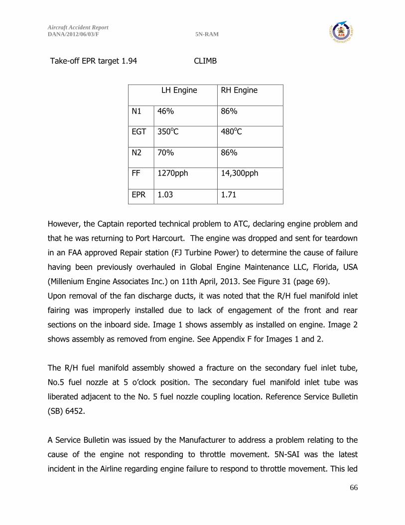
Aircraft Accident Report
DANA/2012/06/03/F 5N-RAM
66
Take-off EPR target 1.94 CLIMB
LH Engine RH Engine
N1 46% 86%
EGT 350oC 480oC
N2 70% 86%
FF 1270pph 14,300pph
EPR 1.03 1.71
However, the Captain reported technical problem to ATC, declaring engine problem and
that he was returning to Port Harcourt. The engine was dropped and sent for teardown
in an FAA approved Repair station (FJ Turbine Power) to determine the cause of failure
having been previously overhauled in Global Engine Maintenance LLC, Florida, USA
(Millenium Engine Associates Inc.) on 11th April, 2013. See Figure 31 (page 69).
Upon removal of the fan discharge ducts, it was noted that the R/H fuel manifold inlet
fairing was improperly installed due to lack of engagement of the front and rear
sections on the inboard side. Image 1 shows assembly as installed on engine. Image 2
shows assembly as removed from engine. See Appendix F for Images 1 and 2.
The R/H fuel manifold assembly showed a fracture on the secondary fuel inlet tube,
No.5 fuel nozzle at 5 o’clock position. The secondary fuel manifold inlet tube was
liberated adjacent to the No. 5 fuel nozzle coupling location. Reference Service Bulletin
(SB) 6452.
A Service Bulletin was issued by the Manufacturer to address a problem relating to the
cause of the engine not responding to throttle movement. 5N-SAI was the latest
incident in the Airline regarding engine failure to respond to throttle movement. This led

Aircraft Accident Report
DANA/2012/06/03/F 5N-RAM
67
to the discovery of two fuel manifolds enclosing primary and secondary fuel supply lines
in the fan air discharge section located approximately 5 o’clock position, which were
found not to have conformed to standard configuration, resulting in the secondary
supply line being severed. See Appendix F.
FIGURE 31: FAA MAJOR REPAIR AND ALTERATION CERTIFICATE

Aircraft Accident Report
DANA/2012/06/03/F 5N-RAM
68
1.18.3 Regulatory Information
The Nigerian Civil Aviation Authority (NCAA) carried out an audit of Dana Airlines
Nigeria Limited between the 9th and 12th December 2013. There were open findings
that needed to be addressed by the Operator.
However, on the 18th December 2013, NCAA directed that all the Engines that had
been previously overhauled by Millenium MRO should be sent to NCAA approved engine
shop(s) for overhaul before they could be allowed to be re-installed on any Dana
Airlines aircraft that may be allowed to commence operations. See Appendix D
Investigation revealed that NCAA documents for the background checks and MROs
monitoring are not adequately structured to reveal anomalies.
1.18.4 Witness Account by Ground Personnel (Abuja)
On arrival of the aircraft in Abuja, the ground staff asserted that the Captain ordered
that the rear passenger exit door should not be opened nor used for passenger
disembarkation/embarkation.
Routine turnaround activities were performed, which includes the transit flight
preparations and refuelling of the aircraft in which 8000lbs of fuel was uplifted in
addition to what was left in the main tanks and thus summed up the total fuel on board
at departure as 26000lbs.
At two separate times, the Station Manager and the Duty Ramp Officer requested
permission from the Captain to board the passengers. This was refused first by the
Captain and secondly by the First Officer as both stated that they were having a
meeting with all the crewmembers.
The Engineer that rode on the flight from Lagos on relief duty disembarked in Abuja to
take over from the ground Engineer in Abuja, who later died in the ill-fated crash.
All these were confirmed by Dana Airline personnel in Abuja.

Aircraft Accident Report
DANA/2012/06/03/F 5N-RAM
69
1.18.4.1 Other Witness Accounts
Other witness’s accounts were recorded, mostly from former pilots of the airline. They
gave their various perceptions/opinions about Dana Airlines Nigeria Limited
maintenance culture and other safety related issues e.g. the habit of not entering
defects in the technical log book. Most of them left the airline either sacked or
frustrated out of the company and are being owed various amounts of money.
1.19 Useful or Effective investigation Techniques
Nil.
Aircraft Accident Report
DANA/2012/06/03/F 5N-RAM
70
2.0 ANALYSIS
2.1 The Conduct of Flight
On 3rd June 2012, Dana Airlines Nigeria Limited operated a Boeing MD-83 aircraft
registered 5N-RAM as DANACO 0993 from Lagos to Abuja on an instrument flight rule
(IFR). The flight was uneventful and was about one hour late as it arrived Abuja at
about 1450:00hrs. According to Dana Airlines Nigeria Limited ground Engineer in Abuja,
the Captain after parking, ordered that the rear passenger exit door should not be used
for passenger disembarkation/embarkation. The reasons for this instruction were not
known. Routine turnaround activities were performed which included the transit flight
preparations and refuelling of the aircraft in which 8000lbs of fuel was uplifted that
summed up the total fuel on board at departure as 26000lbs. The Lagos inbound flight
was called DANACO 0992. At two separate times, the Station Manager and the Duty
Ramp Officer requested permission from the Captain to board the passengers. This was
refused first by the Captain and secondly by the First Officer as both stated that they
were having a meeting with the crewmembers. Details of this meeting were not known
to anyone. These were all confirmed by Dana Airlines Nigeria Limited ground personnel
in Abuja.
Finally, the passengers boarded and the crew requested for engine start up and FL330
(thirty three thousand feet) to Lagos from the Control Tower. Engine start up clearance
was approved, temperature of 23oC, QNH 1013 and to squawk 0412. Subsequently the
aircraft was cleared to taxi to the holding point of runway 04. En-route clearance on
airway UH340 was passed to DANACO 0992 to climb to FL180 (eighteen thousand feet)
initially and to request level change en-route. On approaching holding point of runway
04, DANACO 0992 was cleared to line up on runway 04 and wait but DANACO 0992
requested for some time before lining-up, according to the ATC ground recorder
transcript.
The aircraft was airborne Abuja for Lagos at 1458:00hrs. After airborne, DANACO 0992
contacted Kano Control Centre for traffic information and was further cleared to FL260

Aircraft Accident Report
DANA/2012/06/03/F 5N-RAM
71
(Twenty six thousand feet). Thereafter, DANACO 0992 was cleared to continue with
Kano Centre by Abuja ATC.
According to the CVR, as early as 17 minutes into the flight, the crew started discussing
an unspecified problem with particular reference to the ‘left’ which AIB believed was a
reference to the left engine. This coincided with the time the CVR 30-minutes limit
started recording and at 1515:56hrs the Captain stated that “we just want to get #
home” which AIB believed was the aircraft.
During further discussions, the First Officer asked if he can call in the Engineer who was
repositioning to Lagos to help analyse the problem but the Captain refused. The
Captain concluded, “well I don’t need him here cause we can figure it out, he’s not
going to be able to help us”. During the period that the flight crew were discussing and
trying to manage the situation they were facing, the Captain also asked the First Officer
if any Engineer had tampered with the panel by the rear exit door on ground Abuja and
finally concluded that “this is the guy that had an issue with us. uh he’s pissed off at
us”; according to the CVR transcript. The flight however continued towards Lagos as
the crew continuously discussed the problem with vague references to EPR and non-
response from the throttle inputs, with the left engine operating at idle power or
inoperative. The crew decided that they should start a gradual descent and accordingly
established contact with Lagos ATC, passed the estimates of ERAMI at 1530:00hrs and
LAG at 1543:00hrs which was followed with a request for descent clearance.
Meanwhile, from the CVR transcript, there was no evidence that the crew did call for
the non-normal/emergency checklist in an attempt to ascertain the sudden and
unexplained non-response of the left engine to throttle movement.
During the initial descent, the Captain wanted the F/O who was then the Pilot Flying
(PF) to increase the rate of descent but the F/O stated that he would prefer a gradual
descent in order to have enough height over Lagos. Lagos ATC had cleared DANACO
0992 to descend initially to FL160 (Sixteen thousand feet) and to expect radar vectors
for an ILS approach for runway 18L and further approved high speed approach. The

Aircraft Accident Report
DANA/2012/06/03/F 5N-RAM
72
flight crew accordingly maintained a continuous monitoring watch of the situation. At
1527:30hrs the F/O advised the Captain to use runway 18R for landing and the request
was made at 1531:49hrs and subsequently approved by the Radar Controller. The crew
accordingly changed the decision height to correspond with runway 18R.
Earlier at 1531:12hrs, the crew confirmed that there was no throttle response on the
left engine and subsequently the Captain took over control as PF at 1531:27hrs. Then
flight was however continued towards Lagos with no declaration of any distress
message. With the confirmation of throttle response on the right engine, the engine
anti-ice, ignition and bleed-air were all switched off. At 1534:33hrs the Captain
confirmed that “okay this one is good for us so far”.
At 1535:19hrs, the Captain instructed the F/O to call ‘it’ then since they were probably
not going anywhere and concluded that “we’re gonna be investigated by the NCAA”.
The flight crew became increasingly concerned as the flight transitioned into the
approach phase during which time the crew received series of heading and altitude
radar vectors from the Radar Controller. At the same time, the crew also carried out
some of the pre-landing tasks that included the extension of slats at 1537:07hrs and
the speed-brakes were deployed at 1537:10hrs. The First Officer indicated that they
were slightly high and the Captain replied that he was correcting and then requested
for flaps eleven. At 1537:53hrs the Captain further requested for flaps one-five (flaps
fifteen). And subsequently the problem became compounded as thrust was required to
continue the final approach. Meanwhile, there was no evidence from the CVR transcript,
that an engine-out descent profile was followed and flown towards Lagos.
At 1538:35hrs, both crew indicated that they were 21 miles on the localizer. At
1538:54hrs, there was EGPWS automated voice warning of “landing gear” which the
Captain responded to at 1539:10hrs by requesting for the landing gear to be selected
down. At 1539:56hrs, Lagos Radar Controller requested DANACO 0992 to verify passing
seven thousand seven hundred feet which was confirmed by the First Officer. At
Aircraft Accident Report
DANA/2012/06/03/F 5N-RAM
73
1540:42hrs, he confirmed to the Captain that they were five thousand, fifteen miles,
which the Captain acknowledged with an increase in the rate of descent.
According to the CVR transcript at 1541:46hrs the First Officer inquired if “both engines
come up” and the Captain replied “negative” at 1541:48hrs. The two engines finally did
not respond to throttle inputs as both engines failed to produce the commanded thrust.
From evidence available, there was never any call for the checklist both normal and
non-normal/emergency throughout the entire flight and the use of the Quick Reference
Hand Book (QRH) was never detected.
At 1541:56hrs, the F/O asked the Captain if he can declare an emergency and they
subsequently discussed and agreed to declare an emergency. At 1542:10hrs, DANACO
0992 radioed an Emergency Distress Call stating “Dual Engine Failure, negative
response from throttles”. The Radar Controller then requested DANACO 0992 to “say
again the last transmission” and the crew repeated the Distress message before the
Radar Controller directed DANACO 0992 to contact the Control Tower on 118.1 MHz for
landing instructions. DANACO 0992 was however unable to contact the Tower before
the crash.
According to the CVR transcript, they tried to change frequency to 118.1 MHz which
was indicated by a sound similar to radio frequency knob spinning at 1542:25hrs but
were unable to select the Tower frequency. At 1542:35hrs the Captain requested for
flaps twenty eight which the First Officer selected. This was after the crew had declared
an Emergency of dual engine failure. At 1542:50hrs the First Officer informed the
Purser through the intercom to prepare for landing and that, as of then the situation
appeared under control.
At 1543:30hrs there was an automated voice of “altitude” followed by the Captain’s
indication of sighting the runway at 1543:45hrs. He then instructed the First Officer to
select the flaps up at 1543:49hrs followed by another instruction to select the landing
gears up at 1543:50hrs. At this point, the Captain stated that he would not want to stall
the aircraft. The Captain then concluded that “we just lost everything, we lost an

Aircraft Accident Report
DANA/2012/06/03/F 5N-RAM
74
engine, I lost both engines”. And during the next twenty five seconds, the Captain
requested for everything that could help recover thrust including “relight”, “ignition
override” “just anything” to be given to him. During the later stages of the approach,
there were numerous sounds similar to stabilizer trim in motion as the Captain tried to
keep the aircraft flying to avoid impacting obstacles but to no avail. From 1543:32hrs
the automated voice of “altitude” continued sounding until the end of recording.
Indeed, the Captain expressed concern that he would not want to stall the aircraft, as
the aircraft had no power. The last event captured on the CVR was “too low gear” at
1544:29hrs.
The aircraft crashed into a densely populated residential area about 5.8 miles north of
Lagos airport at 1544:33hrs in daylight and in Visual Meteorological Conditions,
reference point N06o 40.318, E003o 18.845, elevation of 177ft. The aircraft wreckage
was on approximately the extended centre line of runway 18R.
The aircraft was largely consumed by impacts and post crash fire with the tail section,
the two burnt engines and portions of both wings representing only about 15% of the
airplane which was recovered from the crash-site for further examination. The flight
recorders were recovered with signs of extreme exposure to fire, which made the FDR
unreadable due to the damage caused by the fire. However, the CVR was downloaded
successfully.
2.2 Dana Airlines Policy/Procedures
Dana Airlines has an NCAA approved Operations Manual to guide their operations and
enhance safety. However, a good policy and procedure is one thing, understanding the
need for adherence to these policies and procedures is another. As evident in the CVR
transcript, the crew did not follow the dictates of the Operations Manual as approved by
NCAA. Checklists were not used. Occasionally, the call out for completion of checklist
was made without checklist being read.
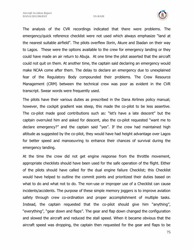
Aircraft Accident Report
DANA/2012/06/03/F 5N-RAM
75
The analysis of the CVR recordings indicated that there were problems. The
emergency/quick reference checklist were not used which always emphasize “land at
the nearest suitable airfield”. The pilots overflew Ilorin, Akure and Ibadan on their way
to Lagos. These were the options available to the crew for emergency landing or they
could have made an air return to Abuja. At one time the pilot asserted that the aircraft
could not quit on them. At another time, the captain said declaring an emergency would
make NCAA come after them. The delay to declare an emergency due to unexplained
fear of the Regulatory Body compounded their problems. The Crew Resource
Management (CRM) between the technical crew was poor as evident in the CVR
transcript. Swear words were frequently used.
The pilots have their various duties as prescribed in the Dana Airlines policy manual;
however, the cockpit gradient was steep, this made the co-pilot to be less assertive.
The co-pilot made good contributions such as: “let’s have a late descent” but the
captain overruled him and asked for descent, also the co-pilot requested “want me to
declare emergency?” and the captain said “yes”. If the crew had maintained high
altitude as suggested by the co-pilot, they would have had height advantage over Lagos
for better speed and manoeuvring to enhance their chances of survival during the
emergency landing.
At the time the crew did not get engine response from the throttle movement,
appropriate checklists should have been used for the safe operation of the flight. Either
of the pilots should have called for the dual engine failure Checklist; this Checklist
would have helped to outline the commit points and prioritized their duties based on
what to do and what not to do. The non-use or improper use of a Checklist can cause
incidents/accidents. The purpose of these simple memory joggers is to improve aviation
safety through crew co-ordination and proper accomplishment of multiple tasks.
Instead, the captain requested that the co-pilot should give him “anything”,
“everything”, “gear down and flaps”. The gear and flap down changed the configuration
and slowed the aircraft and reduced the stall speed. When it became obvious that the
aircraft speed was dropping, the captain then requested for the gear and flaps to be

Aircraft Accident Report
DANA/2012/06/03/F 5N-RAM
76
retracted, this increased the stall speed. The captain was heard saying “I don’t want to
stall, I don’t want to stall”. At a time the pilots were not sure which runway was nearer.
The aircraft crashed into a built-up area in Lagos.
Inappropriate decision making was observed as deviation from regulatory and company
procedures in considering diversion option to the officially filed alternate airport which
was Ilorin. The crew also exhibited a lack of situation awareness which compounded
their problem.
2.2.1 Captain Recruitment/Training Records
AIB carried out a comprehensive overview of the Captain’s recruitment and training
records both in the simulator and the flight line training, and the following findings were
observed.
Before arrival of the captain in Nigeria, he was sent to Miami, Florida in USA for Ground
School Programme and Simulator Recurrency. On arrival in Nigeria, he took the Air Law
Examination and the medical test. Records of the above requirements were sighted by
AIB and found satisfactory. The ground school training in PAIFA (Miami, Florida) and
the simulator training at the centre were sighted and found to be acceptable.
The line training record of twenty-five hours (25hrs) was sighted by AIB, which was
conducted within five days, from 26th April - 30th April 2012. There were adverse
comments from the training captain which requested for a constant improvement in his
flight line performance. However, there was no evidence that any corrections were
made before the Captain was recommended for a final route check. On completion of
the line training, he performed the recommended check for the final route check the
following day which also contained some adverse comments that called for more
improvement and with no other better grading or improvement. He was recommended
for the final route check which was performed the same day and he was subsequently
released on line as Pilot in Command (PIC).

Aircraft Accident Report
DANA/2012/06/03/F 5N-RAM
77
Fourth observation was that there was no record showing any improvement in his
performance before the final route check. The revalidated licence issued by NCAA to the
Captain was stamped with NCAA official licencing stamp but not signed by any NCAA
official. During the investigation, this was pointed out to NCAA but no satisfactory
explanation was provided for this omission.
Furthermore, there was no documented evidence to confirm that the Captain performed
the mandatory requirements before the recruitment which are general written test,
selection interview, background check, appraisal check for 2hrs in the simulator and a
record of company indoctrination which was not sighted. This was not in compliance
with Nig CARs 8.10.1.9(a).
The above recruitment procedures and training record of the captain indicate that he
was hurriedly hired. The performance assessment by all the training captains (on the
accident captain) had always called for improvement which bordered on: inadequate
cockpit discipline, non-standard ICAO phraseology and inadequate radio
communications technique. Others included non-adherence to company/ICAO
procedures, limited crew experience and inadequate line training on MD-83 aircraft
type. The training was hurriedly performed.
In the course of this investigation, AIB discovered some deviations in the organizational
policies in hiring and training of flight crew. Proper and adequate background checks
needed to be carried out in the employment of foreign airline captains. Such checks
needed to include review of cases of revocation, withdrawal and suspension of licences
by Regulatory bodies, current and historical employment records, as there were no
records of the mandatory company Procedures Indoctrination in compliance with Nig.
CARs 8.10.1.9a.

Aircraft Accident Report
DANA/2012/06/03/F 5N-RAM
78
2.3 Simulator Programme conducted at PAIFA
The simulator programme conducted at PAIFA in Florida, USA assumed the entire
scenario relative to that of Dana Airlines MD-83 aircraft that crashed near Lagos airport,
which assumed a take-off weight of 138,000lbs, fuel of 26,000lbs onboard and a
landing weight of 130,000lbs. The simulated weather at Abuja was – wind calm,
temperature 310C and QNH 1013 hPa, while the Lagos weather was as passed to the
crew according to CVR transcript.
After all the above stated manoeuvres were carried out, it became evident that if the
crew had taken appropriate decisions and demonstrated adequate performance under
the prevailing conditions, the accident could have been prevented, or at the worst, the
number of casualties involved would have been minimized.
It was demonstrated in the Simulator that all the scenarios executed were within the
limits of the aircraft performance and safe operations. However, the aggravating factors
were lack of situation awareness, inappropriate decision making, and poor airmanship.
2.4 Similarities in Engine Inspection Reports of the Accident Aircraft 5N-
RAM and the Air Return Aircraft 5N-SAI
5N-RAM No.1 Engine ESN 718142 (Fuel System Component Damage)
Slight diameter reduction near nozzle No. 2 fittings.
Fuel feeder lines attaching No.5 fittings were both (primary and secondary)
fractured flush, exhibiting shear lips.
The left hand manifold exhibited the following damage and observations:
Primary fuel transfer tube was pinched almost closed at the No. 8 fuel nozzle
fitting and reduced diameter at fuel nozzle No.7 fittings.
Engine was not responsive to throttle movement.
The fuel-feeder lines attached to the No. 6 fittings were both fractured at the
No.6 fitting while the secondary feeder tube was attached and twisted/crimped.
These are shown in Photos 21, 22, and 23 in Appendix A.

Aircraft Accident Report
DANA/2012/06/03/F 5N-RAM
79
Engine was not in compliance with SB 6452 and was overhauled on 3rd August, 2011 at
Millenium facility in Miami, USA.
5N-RAM No. 2 Engine ESN 728113 (Fuel System Component Damage):
Secondary fuel feeder line to right hand manifold collapsed and bent.
Right hand primary and secondary manifold supply tubes were bent at the No.5
fittings.
Similar damage occurred on left hand primary and secondary manifold supply
tube at the No. 6 fittings.
The left hand primary manifold had a circumferential crack outboard of the fan
bypass duct.
Engine not responsive to throttle movement.
Engine was in compliance with SB 6452 which was accomplished during one of
the shop visits to Volvo Aero Engine Maintenance facility in Sweden on 27th
September, 2005.
Overhauled on 2nd December, 2011 in Millennium Engine Associates Inc.
5N-SAI No.1 Engine ESN P725851D (Fuel System Component Damage):
Right hand fuel manifold inlet fairing improperly installed.
Right hand fuel manifold assembly fractured at the secondary fuel inlet tube,
No.5 fuel nozzle at 5 O’clock position.
Secondary fuel manifold inlet tube, liberated adjacent to the No. 5 fuel nozzle
coupling location.
Fuel leak from lower fan discharge duct.
Engine not responsive to throttle movement.
Engine was not in compliance with SB 6452.
Overhauled in April 11, 2013 in Global Engine Maintenance facility (formerly,
Millenium Engine Associates).
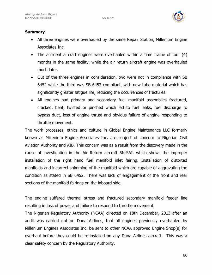
Aircraft Accident Report
DANA/2012/06/03/F 5N-RAM
80
Summary
All three engines were overhauled by the same Repair Station, Millenium Engine
Associates Inc.
The accident aircraft engines were overhauled within a time frame of four (4)
months in the same facility, while the air return aircraft engine was overhauled
much later.
Out of the three engines in consideration, two were not in compliance with SB
6452 while the third was SB 6452-compliant, with new tube material which has
significantly greater fatigue life, reducing the occurrences of fractures.
All engines had primary and secondary fuel manifold assemblies fractured,
cracked, bent, twisted or pinched which led to fuel leaks, fuel discharge to
bypass duct, loss of engine thrust and obvious failure of engine responding to
throttle movement.
The work processes, ethics and culture in Global Engine Maintenance LLC formerly
known as Millenium Engine Associates Inc. are subject of concern to Nigerian Civil
Aviation Authority and AIB. This concern was as a result from the discovery made in the
cause of investigation in the Air Return aircraft 5N-SAI, which shows the improper
installation of the right hand fuel manifold inlet fairing. Installation of distorted
manifolds and incorrect shimming of the manifold which are capable of aggravating the
condition as stated in SB 6452. There was lack of engagement of the front and rear
sections of the manifold fairings on the inboard side.
The engine suffered thermal stress and fractured secondary manifold feeder line
resulting in loss of power and failure to respond to throttle movement.
The Nigerian Regulatory Authority (NCAA) directed on 18th December, 2013 after an
audit was carried out on Dana Airlines, that all engines previously overhauled by
Millenium Engines Associates Inc. be sent to other NCAA approved Engine Shop(s) for
overhaul before they could be re-installed on any Dana Airlines aircraft. This was a
clear safety concern by the Regulatory Authority.

Aircraft Accident Report
DANA/2012/06/03/F 5N-RAM
81
Consequently, the loss of thrust and no response to throttle movement were common
to failure sequence in all three engines with catastrophic result in 5N-RAM.
2.4.1 Fuel System Components (Engine No. 1)
The major components of the fuel system comprise: the main fuel pump, fuel heater,
fuel control unit, fuel flow transmitter, fuel-oil cooler, pressurizing and dump valve, and
the nine fuel nozzles, in addition to the fuel lines that connect these components. The
parts of the fuel system that were available for examination were the fuel nozzles and
left and right primary and secondary fuel manifolds which are located on the diffuser
case. For this engine, the fuel nozzle documentation was covered in the combustion
module section. There was no residual fuel remaining in the fuel system.
Both fuel manifolds were removed from the engine for evaluation. The right-hand
manifold encompasses fuel nozzle positions Nos. 2 to 5 (the fuel supply to these
manifolds is introduced through fittings on the back side of the nozzle No. 5 fittings)
while the left-hand manifold encompasses fuel nozzle positions Nos. 6 to 9 and No. 1
(the fuel supply to these manifolds is introduced through fittings on the back side of the
nozzle No. 6 fittings). The fuel right-hand manifold was intact and the fuel transfer
tubes between the nozzle fittings were undamaged except for some slight diameter
reduction/crushing in the primary manifold near the nozzle No. 2 fitting. The fuel-
feeder lines that attach to the No. 5 fitting (primary and secondary) were both fractured
flush with the No. 5 fitting and a piece of the fuel-feeder tubes remained within the No.
5 fittings in both manifolds (see FIGURE 23). These fractured fuel-feeder tubes both
exhibited shear lips. The left-hand manifold exhibited the following damage and
observations:
1) heavily sooted at fuel nozzle fitting Nos. 8, 9 and 1,
2) the primary fuel transfer tube was pinched almost closed at the No. 8 fuel nozzle
fitting (see FIGURE 24), and
3) the primary fuel transfer tube diameter was reduced at the No. 7 fuel nozzle fitting.

Aircraft Accident Report
DANA/2012/06/03/F 5N-RAM
82
The fuel-feeder lines that attach to the No. 6 fitting were both fractured at the No. 6
fitting with an appreciable piece of the secondary feeder tube still attached and
twisted/crimped (see FIGURE 25).
Looking at Figures 23, 24 and 25, it is very clear that the tubes were either broken or
bent, which will cause loss or restriction of fuel flow and will further translate into
failure of the engines to respond to throttles movement.
2.4.2 Fuel System Components (Engine No. 2)
The secondary fuel flow feeder line that connects to the right hand manifold collapsed
and bent downstream of the junction, neither of which completely blocked the fuel flow.
The P & D valve B-nut end and fitting on the secondary line were not present.
The right-hand primary and secondary manifold supply tubes were bent at the No. 5
fittings. Similar damage was noted on the left-hand primary and secondary manifold
supply tubes at the No. 6 fittings. Neither of these bends completely obstructed the fuel
flow. The left hand primary manifold also had a circumferential crack just outboard of
the fan duct pass through. Visual examination did not identify any blockages looking
into the open ends of the tubes.
Both engines’ fuel system components exhibited the same types of damage which was
consistent with others that suffered lack of response to the throttles.
2.4.3 Fuel Nozzle
The fuel nozzles from both engines were quarantined for further evaluation and testing.
Work scope, testing facility, and test dates were determined. However, test was carried
out in the USA but the fuel nozzle testing did not explain why both engines would not
respond to throttle movement. The fuel nozzles did not flow to the values set forth in
the as-serviceable test, they flow to values lower than specified. But due to debris and
environmental conditions (namely rust), this was somewhat expected.

Aircraft Accident Report
DANA/2012/06/03/F 5N-RAM
83
2.4.4 Engine Audio Spectrum Analysis
The audio spectrum analysis carried out by the engine manufacturer (Pratt and
Whitney) and NTSB as requested by AIB was inconclusive. No definitive outcome was
established. According to the CVR transcript, at 1432:05hrs, it was evident that the
problem started with the left hand engine of 5N-RAM, but no engine flameout was
established.
2.4.5 Auxiliary Power Unit (APU)
The APU provides auxiliary power to the airplane. It is the same type as in an engine-
driven generator. The APU generator is driven by a constant speed gas turbine engine
installed in the aft accessory compartment of the airplane.
It supplies electrical power to the dead buses if the engine driven generators fail
during flight.
It also supplies AC load buses when airplane is on the ground and external
power is not available.
On selection, it could also provide bleed air for engine start-up and air
conditioning.
Through the use of control switches and relays, the auxiliary power can be supplied to
all AC load buses at the same time or only to the LEFT or RIGHT AC buses, or GROUND
service AC bus, provided the bus selected is not receiving power from an engine driven
generator.
There was no evidence that the APU was on, however, on-site inspection of the unit
and the CVR readout confirmed this assertion.
2.4.6 Battery Power
Two 14-Volt Batteries are installed in the Electrical/Electronic (E/E) compartments. They
are connected in series to provide 28 Volt to the STARTER CONTROL RELAY of the APU
and through an 80-ampere Circuit Breaker (CB) directly to the BATTERY DIRECT BUS.

Aircraft Accident Report
DANA/2012/06/03/F 5N-RAM
84
The Battery Direct Bus CB, located on the E/E compartment’, can be manually
reset from the flight compartment.
Battery power is utilized to start the APU or for Refuelling operations when no
other electrical power source is available.
Also with a Proper air supply connected to the engine starter, the Battery can
supply the necessary electrical power for starting an engine.
If AC power is not available during flight, the Batteries are capable of supplying
DC power to operate the Single-Phase Inverter and to the most important DC
operated equipment, e.g. GPWS.
There was no evidence of emergency power supply usage from the battery and the
inverter throughout the critical phase of the flight. It is evident that the engine-driven
generators were supplying their respective buses.
2.4.7 Hydraulics
Up till the time of the accident there was no reported loss in any hydraulic systems.
Though there was loss in engine power, there was no evidence of engine flameout
since the crew were able to select flaps, lower and retract the landing gears as evident
on the CVR transcript.
2.4.8 Engines
The engines teardown were successfully carried out without any core engine anomalies
detected apart from the fuel manifold issues that would have made the aircraft
mechanically unsafe. However, the observed damage to the engines was consistent
with low-to no rotation speed at impact but no indications of core engine hardware pre-
impact malfunction was revealed at the engines teardown.

Aircraft Accident Report
DANA/2012/06/03/F 5N-RAM
85
2.4.9 Suction Feed Capability
The aircraft engines were certificated to be able to provide the engines with fuel under
normal power-out situation as long as the battery switch is on. Test was performed to
reach this conclusion. The certification dates are: Model DC-9 Series 10, 28 February,
1966 while the DC-9 Super 80 was 19 December, 1980.
The MD-80 certification test was conducted at 37,000 ft, maximum cruise thrust and at
maximum continuous thrust at 0.72 and 0.77 Mach. Flight with 30 degree bank turns
and manoeuvring were accomplished to the left and right. The engines operated
satisfactorily for over 5 minutes as required by the test. No engine instability was noted.
The Aircraft Flight Manual (AFM) shows no restrictions for suction feed. Every MD-80
delivered was tested for suction feed capability on each engine during climb prior to
delivery.
The engines were thus certified by the manufacturers with the above capabilities to
enhance safety in an emergency situation.
2.5 The Dana Airlines Air Return (Related Incident)
On the other aircraft 5N-SAI that made an air return on 6th October, 2013, the shop
and teardown investigation showed the same characteristics as the engines on DANACO
0992 which had a fatal crash in Lagos.
In the course of the internal investigation carried out by the airline, the captain of the
air return asserted emphatically that there were other aircraft in the Operator’s fleet
that exhibited slow acceleration as in 5N-SAI.
NCAA Audit of Dana Airlines of between 9th and 12th December, 2013 highlighted the
need for Dana to propose corrective action on the directive that all the previously
overhauled engines by Millennium MRO should be re-certified by an NCAA approved
engine shop(s) before re-installation on Dana aircraft.

Aircraft Accident Report
DANA/2012/06/03/F 5N-RAM
86
The summary of the two problems is that they are common occurrences on the JT8D-
217C and 219 engines as acknowledged by Pratt & Whitney. As a result, the
manufacturer in October, 2003 issued a Service Bulletin (SB) 6452 on the JT8D engines.
Reason:
1. Problem: There have been several instances reported of secondary fuel manifold
assembly fractures, causing fuel leaks, which resulted in 94 Unscheduled Engine
Removals (UERs), one In-flight Shut Down (IFSD) and two Air Turn Backs
(ATBs). There was also one contained fire in 2001 and the extent of the damage
was confined to a dark streak of coked fuel on the Combustion Chamber Outer
Case (CCOC), and fan duct damage.
2. Cause: Thermal expansion results in high stresses on the tubes, which do not
have adequate fatigue life for those stresses. Also, installation of distorted
manifolds and incorrect shimming of the manifold during installation can
aggravate the condition.
3. Solution: Provide new secondary fuel manifold assemblies, incorporating tubes
fabricated from new material which has a fatigue life that is approximately 2
times greater than the current tube material to improve the durability of the
manifold assemblies.
Description:
Replace or modify the left and right secondary fuel manifold assemblies.
The incident which led to the issuing of Engineering Authorization No. MD83-EA-73-001
dated 28/01/2013 is one in so many incidents that brought to the fore, failure of engine
to respond to throttle movement. The following were the reasons and shop findings:
Reasons:
Following a recent incident involving an air return for an engine failing to respond to
throttle movement, the engine was subsequently removed for shop investigation after
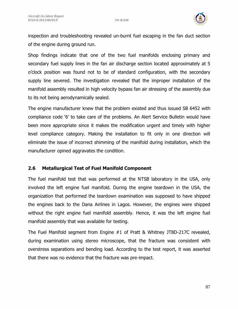
Aircraft Accident Report
DANA/2012/06/03/F 5N-RAM
87
inspection and troubleshooting revealed un-burnt fuel escaping in the fan duct section
of the engine during ground run.
Shop findings indicate that one of the two fuel manifolds enclosing primary and
secondary fuel supply lines in the fan air discharge section located approximately at 5
o’clock position was found not to be of standard configuration, with the secondary
supply line severed. The investigation revealed that the improper installation of the
manifold assembly resulted in high velocity bypass fan air stressing of the assembly due
to its not being aerodynamically sealed.
The engine manufacturer knew that the problem existed and thus issued SB 6452 with
compliance code ‘6’ to take care of the problems. An Alert Service Bulletin would have
been more appropriate since it makes the modification urgent and timely with higher
level compliance category. Making the installation to fit only in one direction will
eliminate the issue of incorrect shimming of the manifold during installation, which the
manufacturer opined aggravates the condition.
2.6 Metallurgical Test of Fuel Manifold Component
The fuel manifold test that was performed at the NTSB laboratory in the USA, only
involved the left engine fuel manifold. During the engine teardown in the USA, the
organization that performed the teardown examination was supposed to have shipped
the engines back to the Dana Airlines in Lagos. However, the engines were shipped
without the right engine fuel manifold assembly. Hence, it was the left engine fuel
manifold assembly that was available for testing.
The Fuel Manifold segment from Engine #1 of Pratt & Whitney JT8D-217C revealed,
during examination using stereo microscope, that the fracture was consistent with
overstress separations and bending load. According to the test report, it was asserted
that there was no evidence that the fracture was pre-impact.

Aircraft Accident Report
DANA/2012/06/03/F 5N-RAM
88
However, on the air return aircraft, the fracture was at the same position; “the right
hand fuel manifold assembly showed a fracture on the secondary fuel inlet tube, #5
fuel nozzle at 5 o’clock position. The secondary fuel manifold inlet tube was liberated
adjacent to the #5 fuel nozzle coupling location”. See Images 3 & 4 of Appendix F.
Referencing SB 6452, this condition can be caused by Thermal expansion resulting in
high stresses. Additionally as discovered, installation of distorted manifolds and
incorrect shimming of the manifold can aggravate this condition. This was the case with
air return aircraft where there was no accident or impact.
In the crashed aircraft 5N-RAM, AIB was unable to confirm leaks/restrictions or
inadequate fuel supply to both engines, owing to crushed and fractured primary and
secondary fuel feed lines of the fuel manifold assemblies, due to the absence of any
recorded data or physical incontrovertible evidences, even though it was considered a
factor in the subject Engine of the air return aircraft (5N-SAI).
This brings to focus the work process, ethics, skills and reliability of the Maintenance
Repair and Overhaul (MRO) organization that overhauled the three engines in question,
which were installed in both the crashed and air return aircraft. All displayed similar
failure characteristics. The fundamental solution to the problem of fractures lies with
installation and correct shimming of the fuel manifold assemblies during engines
overhaul process. The SB 6452 compliance provides secondary fuel manifolds
assemblies fabricated with tube material which have significantly greater fatigue life,
but must be complemented with proper installation of the fairings.
A fool proof installation procedure is being recommended as part of manufacturer’s
redesign to prevent incorrect installation by operator.
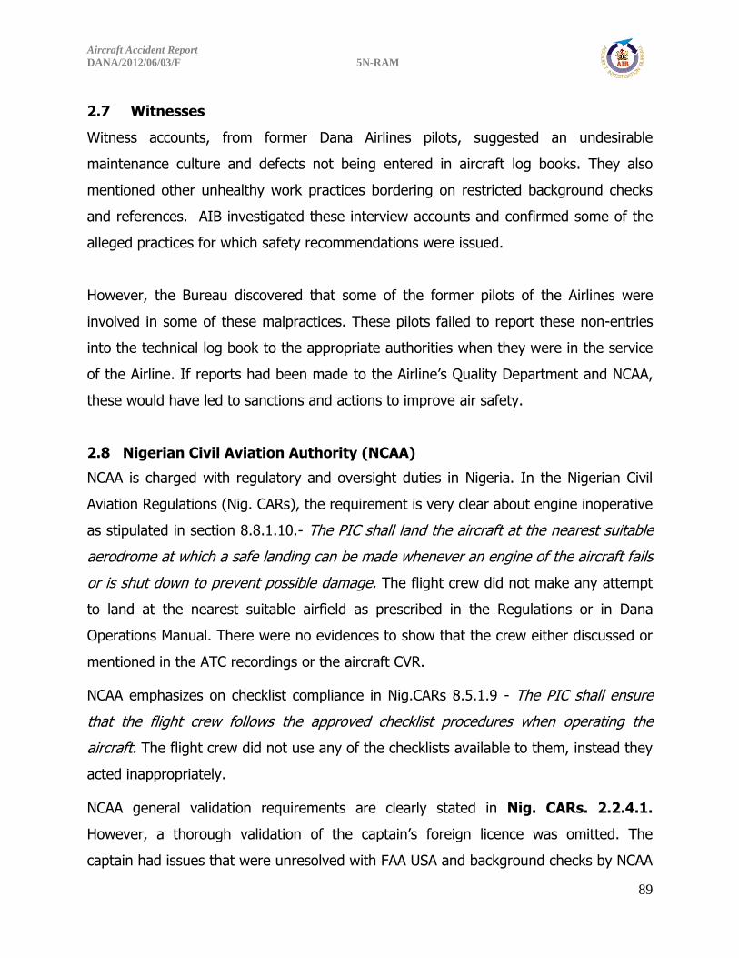
Aircraft Accident Report
DANA/2012/06/03/F 5N-RAM
89
2.7 Witnesses
Witness accounts, from former Dana Airlines pilots, suggested an undesirable
maintenance culture and defects not being entered in aircraft log books. They also
mentioned other unhealthy work practices bordering on restricted background checks
and references. AIB investigated these interview accounts and confirmed some of the
alleged practices for which safety recommendations were issued.
However, the Bureau discovered that some of the former pilots of the Airlines were
involved in some of these malpractices. These pilots failed to report these non-entries
into the technical log book to the appropriate authorities when they were in the service
of the Airline. If reports had been made to the Airline’s Quality Department and NCAA,
these would have led to sanctions and actions to improve air safety.
2.8 Nigerian Civil Aviation Authority (NCAA)
NCAA is charged with regulatory and oversight duties in Nigeria. In the Nigerian Civil
Aviation Regulations (Nig. CARs), the requirement is very clear about engine inoperative
as stipulated in section 8.8.1.10.- The PIC shall land the aircraft at the nearest suitable
aerodrome at which a safe landing can be made whenever an engine of the aircraft fails
or is shut down to prevent possible damage. The flight crew did not make any attempt
to land at the nearest suitable airfield as prescribed in the Regulations or in Dana
Operations Manual. There were no evidences to show that the crew either discussed or
mentioned in the ATC recordings or the aircraft CVR.
NCAA emphasizes on checklist compliance in Nig.CARs 8.5.1.9 - The PIC shall ensure
that the flight crew follows the approved checklist procedures when operating the
aircraft. The flight crew did not use any of the checklists available to them, instead they
acted inappropriately.
NCAA general validation requirements are clearly stated in Nig. CARs. 2.2.4.1.
However, a thorough validation of the captain’s foreign licence was omitted. The
captain had issues that were unresolved with FAA USA and background checks by NCAA

Aircraft Accident Report
DANA/2012/06/03/F 5N-RAM
90
were found to be inadequate. The validated licence was stamped but not signed by the
authority. The authority should have looked more on the type of training given and the
training required. The validation was done without compliance with the Nig. CARs,
which stated that before validation is issued, the authenticity of the foreign licence
would have been confirmed. The confirmation had not been concluded when the
captain started flying for Dana Airlines. The Regulations state: The Authority will verify
the authenticity of the licence, ratings, authorizations and the medical certificate with
the state of licence issue prior to issuing the validation.
AIB investigation of the accident revealed that the Regulatory Authority’s
Questionnaires Form could be designed to adequately collect background information
from flight crew seeking validation of foreign licences. It should oblige applicants to
declare personal confidential and historical career information under oath/declaration in
compliance with the requirement in Nig.CARs. There is need to maintain contact and
exchange of confidential information among applicable Regulatory Authorities.
The Bureau further observed that NCAA needed to intensify its oversight functions on
all overseas Maintenance Repairs and Overhaul (MROs) by monitoring their track
records, work processes, and overall reputations prior to and during approval renewals
and reviews of their authorizations.
2.9 Nigerian Airspace Management Agency (NAMA)
NAMA is in charge of the administration of Nigeria airspace. Air Traffic Controllers are
charged with the responsibility of providing assistance to pilots at any time especially in
emergency situations. The Airspace Manager at the Lagos airport in his report
confirmed that everything about the flight went well until 1542:10hrs when the crew
declared emergency. The crew delayed the declaration of Emergency. Declaring an
Emergency generates maximum assistance from Air Traffic Controllers worldwide, but
delay in declaring an Emergency may create confusion or narrow the pilots, options to
manage the situation.

Aircraft Accident Report
DANA/2012/06/03/F 5N-RAM
91
Extract from the CVR transcript of the Emergency declaration:
14:42:01
RDO-2 Lagos Tower Danaco zero niner niner two.
14:42:05
RAD Danaco zero niner niner two this is Lagos uh Radar. Go
14:42:10
RDO-2 mayday mayday mayday Danaco zero niner niner two, five November
romeo alpha mike, dual engine failure.
14:42:16
RAD Danaco zero niner niner two how do you read?
14:42:18
RDO-2 I read you five by five, dual engine failure, negative response from
throttle, requesting direct approach. Danaco zero niner niner two.
14:42:27
RAD position is one zero miles to touchdown one eight right, contact tower
now one one eight one.
14:42:32
RDO-2 one one eight one good day.
The Radar was the last contact the aircraft made before the fatal crash. The Radar
Control should have stayed with the aircraft rather than transferring it to Lagos Tower.
The assertion of “how do you read?” by the Radar Control wasn’t necessary at this point
in time. Dual engine failure is a serious emergency that should be treated with the
highest level of professionalism and urgency. Radar vector would have been ideal and
most appropriate at this time.
Aircraft Accident Report
DANA/2012/06/03/F 5N-RAM
92
3.0 CONCLUSIONS
3.1 Findings
1. The flight crew were certified to fly the aircraft.
2. The two pilots were foreigners.
3. The Captain was new in the company having been employed on the 14th
March, 2012 and was checked out as a line Captain on 1st May, 2012.
4. The Captain had previous regulatory issues with the U.S.A Federal Aviation
Administration (FAA) which led to his suspension at that time.
5. All the reference letters presented by the Captain to Dana Airlines were
neither signed nor authenticated.
6. The background check on the Captain was inadequate.
7. The line training given to the Captain was hurriedly carried out.
8. There was no evidence that the deficiencies observed by the checkout
Captain were addressed before the accident Captain was released for line
operation.
9. The Co-pilot’s first experience on a commercial jet airplane was with Dana
Airlines.
10. The aircraft was airworthy at the time of departure.
11. The aircraft came out from a check and was released to service on 1st June,
2012.
12. All deferred defects were cleared during the last check.
13. The left aileron bus cable was replaced on 1st June, 2012.
14. A test flight was carried out on 2nd June, 2012 after the replacement of left
aileron bus cable.
15. 5N-RAM Engine No.1 was not compliant with SB 6452 while Engine No. 2 was
in compliance with the SB.
16. Both 5N-RAM Engines were overhauled in Millenium Engine Associates Inc.
within a time frame of four (4) months.

Aircraft Accident Report
DANA/2012/06/03/F 5N-RAM
93
17. The aircraft departed Abuja with three hours and thirty minutes fuel
endurance.
18. The Engine number 1 lost power seventeen minutes into the flight.
19. There was no evidence that both normal and emergency Checklist were used
throughout the duration of the flight before the crash.
20. The aircraft did not make any contact with the Control Tower before the
crash.
21. The aircraft crashed five miles on the extended centreline of runway 18R.
22. The aircraft crashed into a residential area.
23. The aircraft first point of impact was an uncompleted building followed by a
Mango tree, a Coconut tree, and finally three other buildings.
24. There was fire outbreak.
25. All 147 passengers and six crew were fatally injured.
26. There were other fatalities on ground.
27. The aircraft wreckage was concentrated in a small area.
28. The huge crowd of people at the crash site slowed down rescue efforts and
investigation.
29. The Fire Service ran out of water and it was very difficult to replenish supply
because of the crowd and poor road network.
30. Flight recorders (black boxes) were recovered but were badly burnt.
31. NCAA revalidation procedures were not followed before the captain’s licence
was issued.
32. The validated licence issued by NCAA to the captain was stamped but not
signed.
33. There was a related incident involving 5N-SAI, an aircraft in Dana Airlines’
fleet that led to an air return on 6th October, 2013 for which the Airline
issued an Engineering Authorization No. MD83-EA-73-001.
34. Millenium Engine Associates Inc. (MRO) has changed its name to Global
Engine Maintenance LLC with the same FAA certificate number Y2MR496Y.
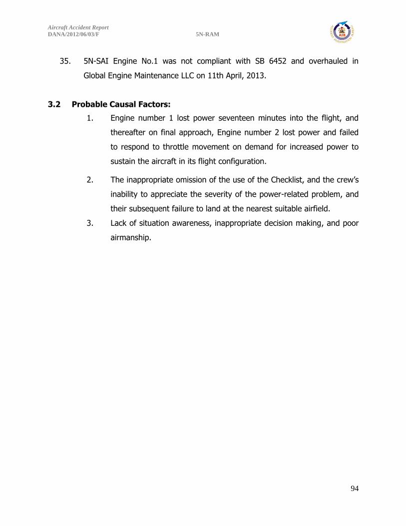
Aircraft Accident Report
DANA/2012/06/03/F 5N-RAM
94
35. 5N-SAI Engine No.1 was not compliant with SB 6452 and overhauled in
Global Engine Maintenance LLC on 11th April, 2013.
3.2 Probable Causal Factors:
1. Engine number 1 lost power seventeen minutes into the flight, and
thereafter on final approach, Engine number 2 lost power and failed
to respond to throttle movement on demand for increased power to
sustain the aircraft in its flight configuration.
2. The inappropriate omission of the use of the Checklist, and the crew’s
inability to appreciate the severity of the power-related problem, and
their subsequent failure to land at the nearest suitable airfield.
3. Lack of situation awareness, inappropriate decision making, and poor
airmanship.

Aircraft Accident Report
DANA/2012/06/03/F 5N-RAM
95
4.0 SAFETY RECOMMENDATIONS
Safety Recommendations previously made in the Preliminary Report published on 5th
September 2012.
Interim Safety Recommendations
1. AIB investigation so far, discovered that Dana Airlines aircraft operate in areas
where fungal growth can be encountered, or where there is the possibility of
temperature in the fuel tanks frequently rising to 25°C in tropical conditions,
microbiological growths have been known to develop when the spores of the
fungus are in contact with water in fuel at temperatures such as those reached
when the aircraft or storage tanks are exposed to the sun for long periods in a
tropical environment.
The dangers that exist in microbiological contamination of fuel tanks include fuel
tank corrosion, erratic fuel content indication, obstruction of fuel filters and fuel
pipes within the tanks.
4.1 Safety Recommendation 2013 – 001
Dana Airlines should ensure that prior to resumption of flights, visual fuel tanks
inspection for evidence of fungal growth or contamination followed by biocide
treatment be carried out in all operating MD-83 aircraft. The fungicide additives
used in the fuel must be approved by aircraft and engine manufacturers. The
frequency of treatment and the dilutions prescribed by the aircraft and engine
manufacturers must be adhered to. The aircraft maintenance schedule or
programme should be amended to include the exercise in accordance with the
aircraft and engine manufacturers’ requirement.

Aircraft Accident Report
DANA/2012/06/03/F 5N-RAM
96
2. According to evidence available to the Bureau, Dana Airlines was practicing a
peculiar fuel management system in the flight operation of the MD83-217C
aircraft. It was discovered that the centre fuel tank remained completely
depleted in most flights arriving at destinations, while wing tanks remained full
and unused. The Bureau has reviewed this operational change with the operator.
4.2 Safety Recommendation 2013 – 002
Dana Airlines should ensure that for all its flight operations with MD-83, a
minimum of 2000lbs of fuel must be maintained in the centre fuel tank of the
aircraft on landing at any destination, while AIB investigation goes on.
3. Accident Investigation Bureau has discovered inadequacy in the background
checks of newly employed foreign flight crew members and safety critical staff.
There is also need to help newly employed foreign captains to be conversant
with Airline’s routes and Nigerian Airspace to ensure confidence and safety in
operation.
4.3 Safety Recommendation 2013 – 003
Dana Airlines should ensure;
(a) Adequate background check is conducted in the employment of foreign
airline captains and safety critical employees. Such checks should include review
of cases of revocation, withdrawal and suspension of licences by regulatory
bodies in the applicant’s current or historical employment records where
applicable.
(b) Any newly employed foreign captain must fly with a competent senior first
officer who is familiar with Nigerian Airspace and routes for at least the first 100
flight hours, to enable the new captain be conversant with the operations of the
airlines within Nigerian Airspace.

Aircraft Accident Report
DANA/2012/06/03/F 5N-RAM
97
4. The on-going investigation by AIB revealed that the Regulatory Authority’s
questionnaire/form designed to collect background information from foreign
flight crew seeking validation of the foreign licences, is not adequate. It does
not oblige the applicant to declare personal confidential and historical career
information under oath/declaration.
4.4 Safety Recommendation 2013 – 004
NCAA should;
(a) As an essential aspect of its oversight function review
CPL/ATPL/issue/renewal/validation forms to include background check with
the view to discover cases of revocation, withdrawal or suspension of flight
crew licences issued to applicants by any other regulatory authority.
(b) Validation of foreign licences should be effected when all confidential
details have been received from previous employers and appropriate
regulatory authority including satisfactory aero-medical reports and a return
of due diligence form/document carried out by the airline.
(c) Appropriate declaration should be included in the questionnaire/form to
oblige applicants to declare all relevant information as requested.
Safety Recommendations made in this Report:
4.5 Safety Recommendation 2015 – 001
FAA should ensure that Pratt & Whitney considers the following:
a) Revise Service Bulletin JT8D 6452 making it mandatory within a given
time-frame, thereby upgrading the Compliance Category.
b) Re-design the installation and shimming procedures of the manifold assembly
to remain foolproof to prevent incorrect installations.

Aircraft Accident Report
DANA/2012/06/03/F 5N-RAM
98
4.6 Safety Recommendation 2015 – 002
Dana Airlines should ensure the following:
a) Any remarks or deviations from Company Standard Procedures noted by the
Training Captain on the Trainee during Line Training must be addressed
before final checkout as a Line Captain.
b) All training procedures must be in compliance with approved Company
Operations Manual, SOPs and Nig. CARs.
4.7 Safety Recommendation 2015 – 003
NCAA should consider the following:
a) Monitoring closely the work processes, ethics and conducts of foreign
Maintenance Repair and Overhaul (MROs) facilities approved to overhaul
and repair Nigerian registered aircraft, airframes, powerplants, propellers or
appliances.
b) Oversight Functions on MROs should include but not limited to review of
track records, reputation, and audit reports by appropriate national
regulatory authority before approval or renewal of NCAA authorization.
c) NCAA should ensure that for any checkout of a new line captain, a type-rated
NCAA Inspector must be involved as an observer.
4.8 Safety Recommendation 2015 – 004
NAMA Quality Assurance Management (QAM) should ensure that all Air Traffic
Controllers strictly adhere to the ethics of their profession, which is, providing
assistance to flight crewmembers in emergency/critical situations.

Aircraft Accident Report
DANA/2012/06/03/F 5N-RAM
99
RESPONSES TO INTERIM SAFETY RECOMMENDATIONS
Dana Airlines accepted interim safety recommendations 2013-001, 2013-002, and 2013-
003.
“Various safety recommendations under reference i.e. 2013-001, 2013-002, 2013-003
and 2013-004, have been duly incorporated into the SOPs of relevant departments of
Dana Airlines Ltd. These safety recommendations have since become operationally
implemented.”
NCAA response on AIB Interim Safety Recommendation 2013-004
NCAA accepts recommendation 2013-004.
“In response to the AIB Interim Safety Recommendations Reference Safety Rec. 2013-
004, it is important to note that this is a welcome development.
This already is a part of the Processes and Procedures for Issue/Renewal/Validations of
CPL/ATPL licence by the Authority. All these recommendations are already practiced by
the Authority.”
SAFETY ACTIONS TAKEN
Engineering Authorization – Dana Airlines Nigeria Limited
As part of Dana Airlines Safety Action, an Engineering Authorization Ref:
MD-83 – EA – 73 – 001 was issued mandating the implementation of inspection of the
left hand and right hand fuel manifold assemblies on all currently installed JT8D – 200
series engines in the Airlines’ MD-83 aircraft. This is to verify the integrity and correct
installation of the fuel manifold assembly using a flexible or rigid Borescope probe. The
procedures and the pictorial guidance, as well as certification for release to service of
the aircraft are clearly stated in Appendix G.

Aircraft Accident Report
DANA/2012/06/03/F 5N-RAM
100
APPENDICES
Appendix A
ENGINE EXAM AND DISASSEMBLY FIELD NOTES OCTOBER 12, 2012 A. ACCIDENT
Location: Lagos, Nigeria
Date: Jun 3, 2012
Time: 15:45 local
Aircraft: Boeing MD-83, registration number 5N-RAM, Dana Air Flight 0992
B. POWERPLANTS GROUP National Transportation Safety Board: Jean-Pierre Scarfo, Powerplant Lead Engineer
Washington D.C. Robert Hunsberger, Powerplant Engineer Washington D.C.
Pratt & Whitney: Douglas Zabawa, Accident and Incident Investigator East Hartford, Connecticut
Boeing: Jim Talay, Flight Safety Investigator Long Beach, California John Gross, Powerplant Engineer Long Beach, California
Federal Aviation Administration: Eric West, Air Safety Investigator Washington, D.C
Nigerian Accident Investigation Bureau: Clement Onyeyiri, Air Safety Investigator Nigeria

Aircraft Accident Report
DANA/2012/06/03/F 5N-RAM
101
C. Summary
On June 3, 2012, at about 1545 local time, Dana Airlines flight 0992, a Boeing
MD-83 airplane, registered in Nigeria as 5N-RAM, crashed into a residential area of
Lagos, Nigeria after a loss of power in both engines. The airplane was equipped with
two Pratt & Whitney (P&W) JT8D-217C turbofan engines. The pilots radioed to Lagos
Radar, “Mayday, Mayday, Mayday, Danaco zero niner niner two, five november romeo
alpha mike, dual engine failure.” The pilots subsequently reported that they had
“negative throttle response.” The airplane crashed into a woodworking shop, a paper
printing shop, and two apartment buildings. The airplane was destroyed by impact
forces and fire. The 2 pilots, 4 flight attendants, and 147 passengers on board the
airplane as well as an unknown number of people on the ground were killed. The
airplane was operating as a regularly scheduled domestic flight from Abuja, Nigeria to
Lagos.
A Powerplant group comprised of members from the Nigeria Accident
Investigation Bureau, the National Transportation Safety Board, Federal Aviation
Administration, P&W, and Boeing convened at the Millennium Engine Associates engine
facility in Miami, Florida to disassemble and exam both engines involved in the Dana
Airlines accident. The group commenced work on October 8, 2012 and completed the
engine disassembly and examination on October 12, 2012.
Examination and disassembly of the No. 1 engine did not identify any mechanical
condition which would have prevented normal operation of the engine at the time of
impact. There were no signs of case ruptures, uncontainments, in-flight fire, internal
hardware failures, core foreign object ingestion, or main bearing compartment fires.
Continuity of the low pressure and high pressure rotor systems was confirmed and all
the main shaft bearings were in good condition, intact, shiny, and oil wetted. None of
the engine cases were crushed inwards or ovalized to produce clashing damage
between the static and rotating components to provide indications of relative rotation.
There were no indications that the engine fan or core was turning at a high rotational
speed at the time of impact. However, fan blade foreign object damage (leading edge

Aircraft Accident Report
DANA/2012/06/03/F 5N-RAM
102
nicks, tears, some round bottom dents) and sporadic fan blade bending in the direction
opposite rotation and in the direction of rotation was consistent with the fan rotating at
low-to-no appreciable speed. Rub noted on the No. 3 bearing housing aft cover, high
pressure compressor (HPC) stage 7 disk forward aft face, forward ends of the HPC tie-
rods, and the high pressure turbine (HPT) blade tip shrouds and blade outer air seal
was consistent with core turning most likely at a low rotation speed at the time of
impact. The lack of fuel system components still attached to the engine prevented any
detailed examination and overall assessment of the condition of the fuel system pre-
and post-impact. However, examination of the combustor and the fuel nozzles did not
reveal thermal distress and the fuel nozzles tips did not appear blocked. Using shop air,
a flow test of the fuel manifolds showed them to flow freely; however, a flow test of the
nozzles was not performed.
Examination and disassembly of the No. 2 engine did not identify any mechanical
condition which would have prevented normal operation of the engine at the time of
impact. There were no signs of case ruptures, uncontainments, in-flight fire, internal
hardware failures, core foreign object ingestion, or main bearing compartment fires.
Continuity of the low pressure and high pressure rotor systems was confirmed and all
the main shaft bearings were in good condition, intact, shiny, and oil wetted. None of
the engine cases were crushed inwards or ovalized to produce clashing damage
between the static and rotating components to provide indications of relative rotation.
There were no indications that the engine fan or core was turning at a high rotational
speed at the time of impact. However, static fan blade impact marks in the fan blade
rub strip panels were consistent with the fan rotating at low-to-no appreciable speed.
Rub noted on the HPT blade tip shrouds and blade outer air seal was consistent with
core turning most likely at a low rotation speed at the time of impact. The lack of fuel
system components still attached to the engine prevented any detailed examination and
overall assessment of the condition of the fuel system pre- and post-impact. However,
examination of the combustor and the fuel nozzles did not reveal thermal distress and
the fuel nozzles tips did not appear blocked. Using shop air, a flow test of the available

Aircraft Accident Report
DANA/2012/06/03/F 5N-RAM
103
fuel system plumbing showed them to flow freely but some restriction was noted when
the fuel nozzles were flowed.
The fuel nozzles from both engines were quarantined for further evaluation and testing.
Work scope, testing facility, and test dates are to be determined.
D. DETAILS OF THE INVESTIGATION 1.0 ENGINE DESCRIPTION
The JT8D-217C series engine is an axial-flow front turbofan engine having a
fourteen stage split compressor, a nine can (can-annular) combustion chamber, and a
split four stage reaction impulse turbine. The engine has six general sections, the air
inlet section, the compressor section, the combustion section, the turbine and exhaust
section, the accessory drives, and the fan discharge section (FIGURE 1) and seven main
shaft bearings listed in TABLE 1 and shown in FIGURE 2. The engine is equipped with a
full length annular fan discharge duct. The low pressure system is made up of the front
compressor rotor and the stages 2, 3, and 4 turbine rotors and is mechanically
independent of the high pressure system which consists of the rear compressor rotor
and the stage 1 turbine rotor (FIGURE 2).
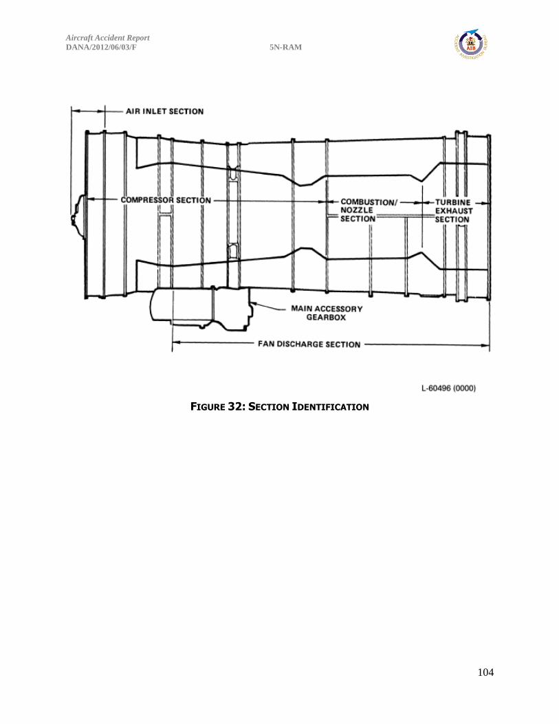
Aircraft Accident Report
DANA/2012/06/03/F 5N-RAM
104
FIGURE 32: SECTION IDENTIFICATION

Aircraft Accident Report
DANA/2012/06/03/F 5N-RAM
105
FIGURE 33: ENGINE BEARING AND INTERNAL DIAGRAM
The engine is mounted from two points. The front mount is located at the fan
discharge intermediate case. The engine rear mount is located at the turbine exhaust
section outer duct. According to the FAA Type Certificate Data Sheet E9NE, Revision
12, dated December 13, 2010, the sea level static thrust takeoff rating of the JT8B-
217C engine is 20,850 pounds and the sea level static thrust maximum continuous
rating is 18,000 pounds, both are flat rated to 77°F (25°C)2
FIGURE 3 provides the identification of the engine flanges. They are designated
by letter. Interruptions in the lettering sequence may result when development
changes have removed or added flanges.
2 Flat-rated to a specific temperature indicates that the engine will be capable of attaining the rated thrust level up to
the specified inlet temperature.
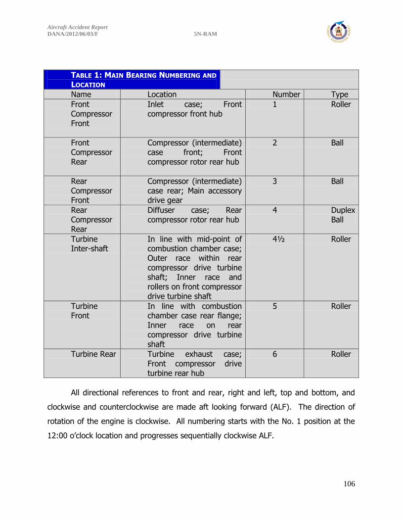
Aircraft Accident Report
DANA/2012/06/03/F 5N-RAM
106
TABLE 1: MAIN BEARING NUMBERING AND
LOCATION
Name Location Number Type
Front Compressor Front
Inlet case; Front compressor front hub
1 Roller
Front Compressor Rear
Compressor (intermediate) case front; Front compressor rotor rear hub
2 Ball
Rear Compressor Front
Compressor (intermediate) case rear; Main accessory drive gear
3 Ball
Rear Compressor Rear
Diffuser case; Rear compressor rotor rear hub
4 Duplex Ball
Turbine Inter-shaft
In line with mid-point of combustion chamber case; Outer race within rear compressor drive turbine shaft; Inner race and rollers on front compressor drive turbine shaft
4½ Roller
Turbine Front
In line with combustion chamber case rear flange; Inner race on rear compressor drive turbine shaft
5 Roller
Turbine Rear Turbine exhaust case; Front compressor drive turbine rear hub
6 Roller
All directional references to front and rear, right and left, top and bottom, and
clockwise and counterclockwise are made aft looking forward (ALF). The direction of
rotation of the engine is clockwise. All numbering starts with the No. 1 position at the
12:00 o’clock location and progresses sequentially clockwise ALF.

Aircraft Accident Report
DANA/2012/06/03/F 5N-RAM
107
FIGURE 34: ENGINE FLANGE DESIGNATIONS

Aircraft Accident Report
DANA/2012/06/03/F 5N-RAM
108
2.0 Left Engine (No. 1) – Serial Number (SN) 718142
2.1 AS-RECEIVED
The engine was un-crated and placed on pallets for examination and
disassembly (PHOTO 1). The inlet case, and the front and rear fan cases were attached
as a unit, but were no longer attached to the rest of the engine. This unit was clocked
approximately 120° clockwise direction relative to the core of the engine. The fan and
exhaust ducting was missing from the “D”-flange (aft flange of the rear fan case) aft
except for a section of the front compressor fan duct that was still attached to the D-
flange and ranged from 9 to 13-inches axially and approximately 100° circumferentially.
PHOTO 1: TOP VIEW OF THE NO. 1 ENGINE SN 718142
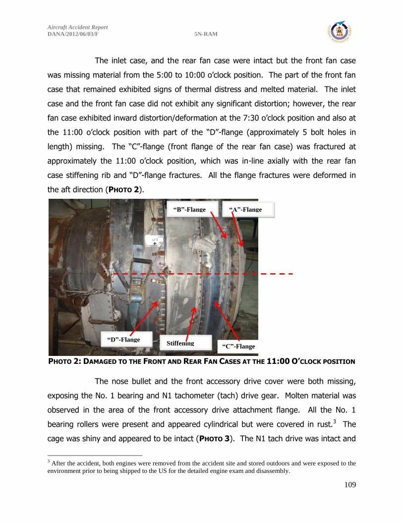
Aircraft Accident Report
DANA/2012/06/03/F 5N-RAM
109
The inlet case, and the rear fan case were intact but the front fan case
was missing material from the 5:00 to 10:00 o’clock position. The part of the front fan
case that remained exhibited signs of thermal distress and melted material. The inlet
case and the front fan case did not exhibit any significant distortion; however, the rear
fan case exhibited inward distortion/deformation at the 7:30 o’clock position and also at
the 11:00 o’clock position with part of the “D”-flange (approximately 5 bolt holes in
length) missing. The “C”-flange (front flange of the rear fan case) was fractured at
approximately the 11:00 o’clock position, which was in-line axially with the rear fan
case stiffening rib and “D”-flange fractures. All the flange fractures were deformed in
the aft direction (PHOTO 2).
PHOTO 2: DAMAGED TO THE FRONT AND REAR FAN CASES AT THE 11:00 O’CLOCK POSITION
The nose bullet and the front accessory drive cover were both missing,
exposing the No. 1 bearing and N1 tachometer (tach) drive gear. Molten material was
observed in the area of the front accessory drive attachment flange. All the No. 1
bearing rollers were present and appeared cylindrical but were covered in rust.3 The
cage was shiny and appeared to be intact (PHOTO 3). The N1 tach drive was intact and
3 After the accident, both engines were removed from the accident site and stored outdoors and were exposed to the
environment prior to being shipped to the US for the detailed engine exam and disassembly.
“D”-Flange “C”-Flange
Stiffening
Rib
“A”-Flange “B”-Flange

Aircraft Accident Report
DANA/2012/06/03/F 5N-RAM
110
undamaged but also covered in rust. The inlet guide vanes (IGVs) were all fractured at
their inner diameter (center body location) with three of the IGVs missing. The IGVs
that remained were bent in the direction of rotation (clockwise) at their ID relative to
their OD, many were buckled at their outer diameter attachment point, and none
exhibited any significant impact damage (PHOTO 4). Based on the location of the 6:00
strut, where the No. 1 bearing oil tubes are located, the outer ring of the inlet case with
the IGVs still attached was rotated approximately 120° clockwise from the matching
center body strut location.
PHOTO 3: NO. 1 ROLLER BEARING INTACT AND COVERED IN RUST
No. 1 Bearing Rollers

Aircraft Accident Report
DANA/2012/06/03/F 5N-RAM
111
PHOTO 4: INLET CASE WITH FRACTURED AND DAMAGED INLET GUIDE VANES
All the fan blades were present and secured in the fan hub. Numerous
blades exhibited small leading edge nicks, tears, and dents with some exhibiting leading
edge round bottom impact marks with material transfer. The material deformation
associated with this damage was in the direction of rotation and/or aft. A single fan
blade was fractured at the leading edge corner tip. Three randomly blade tips were
curled/bent in the direction opposite rotation and five random blades (2 were adjacent
to each other) were bent in the direction of rotation. One fan blade exhibited
appreciable forward blade tip corner bending while a different blade exhibited
appreciable aft bending. Four adjacent blades exhibited blade spanwise buckling.
Several sets of blades exhibited mid-span shroud shingling.
Inlet Guide
Vanes
Fan Blades
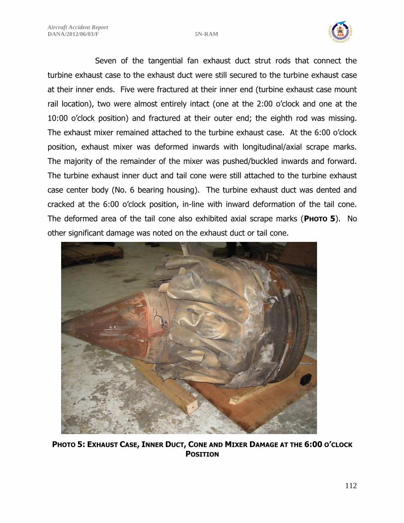
Aircraft Accident Report
DANA/2012/06/03/F 5N-RAM
112
Seven of the tangential fan exhaust duct strut rods that connect the
turbine exhaust case to the exhaust duct were still secured to the turbine exhaust case
at their inner ends. Five were fractured at their inner end (turbine exhaust case mount
rail location), two were almost entirely intact (one at the 2:00 o’clock and one at the
10:00 o’clock position) and fractured at their outer end; the eighth rod was missing.
The exhaust mixer remained attached to the turbine exhaust case. At the 6:00 o’clock
position, exhaust mixer was deformed inwards with longitudinal/axial scrape marks.
The majority of the remainder of the mixer was pushed/buckled inwards and forward.
The turbine exhaust inner duct and tail cone were still attached to the turbine exhaust
case center body (No. 6 bearing housing). The turbine exhaust duct was dented and
cracked at the 6:00 o’clock position, in-line with inward deformation of the tail cone.
The deformed area of the tail cone also exhibited axial scrape marks (PHOTO 5). No
other significant damage was noted on the exhaust duct or tail cone.
PHOTO 5: EXHAUST CASE, INNER DUCT, CONE AND MIXER DAMAGE AT THE 6:00 O’CLOCK
POSITION

Aircraft Accident Report
DANA/2012/06/03/F 5N-RAM
113
2.2 DISASSEMBLY
2.2.1 Front Compressor Module
The inlet case, and the front and rear fan cases were cut at approximately the 5:00 and
12:00 o’clock positions to facilitate removal from the fan module (front compressor
module). The right-hand section (12:00 to 5:00 o’clock) had no fan rub strip material
present and all the exit guide vanes were missing. The left-hand side (5:00 to 12:00
o’clock) had 7 ½ fan rub strip panels present – from approximately the 2 to 5 o’clock
position. No circumferential rubbing or gouging was observed; however, a couple of
panels located at approximately the 3 o’clock position exhibited what appeared to be
longitudinal static marks at angles and spacing not consistent (tighter) with typical fan
blade static marks. These panels also exhibited more physical and thermal distress
than the other panels still present. The acoustic liners located forward and aft of the
fan blade running position exhibited slicing and gouging marks more consistent with
typical fan blade static marks. The impact marks in the forward acoustic liner were
approximately 5-inches forward of the normal fan blade running position and the impact
marks in the aft acoustic liner were approximately 7-inches aft the fan blade normal
running position. Ten exit guide vanes, around the 2:00 to 3:00 o’clock position,
remained attached to the outer ring and all the vanes were bent over in the direction of
rotation (clockwise) at their ID relative to their OD (PHOTO 6).

Aircraft Accident Report
DANA/2012/06/03/F 5N-RAM
114
PHOTO 6: FAN CASE DAMAGE
The front compressor rotor and stator assembly consists of a seven-stage front
compressor rotor and the stator, stages through stage six, for documentation purposes
(PHOTO 7). The numbering of the front compressor stages is 1 through 6, with a 1.5
stage following the stage 1 so that the total of the stages is seven. For documentation
purposes the No. 2 bearing will be included in this section. The front compressor was
removed from the core of the engine and was not disassembled further. The fan
blades were documented in the “As-Received” section and will not be described here.
The front outer compressor cases stages 1 through 3 were melted from approximately
the 3:00 to 10:00 o’clock position exposing the following rotor stages: stages 1.5 and 2
approximately 75% visible and stages 3 and 4 approximately 50% visible. Stage 6 was
fully visible from the aft side of the module. The general condition of all the visible
front compressor rotors blades were that they were all present, full length and straight,
secured to their respective disks/hub, and exhibited no noteworthy airfoil or tip
Rub
Strip
Static
Marks
Exit
Guide
Vane
Acoustic
Liner Static
Marks
Rub Strip
Panels

Aircraft Accident Report
DANA/2012/06/03/F 5N-RAM
115
damage. The melted front outer compressor cases stages 1 through 3 also exposed the
stators as follows: 1) stage 1, vanes missing from the 3:00 to 10:00 o’clock position, 2)
stage 1.5, vanes missing from the 3:00 to 9:00 o’clock position, 3) stage 2, vanes
missing from the 4:00 to 8:00 o’clock position and 4) stage 3, vanes missing from 5:00
to 7:00 o’clock position. In each of these stages, the vanes that remained exhibited
thermal distress and melting. In stage 4, vanes were visible from approximately the
4:00 to 7:00 o’clock position looking through the stage 4 blades and in stage 5 all the
vanes were visible looking through the stage 6 rotor blades. In general, the stage 4
and 5 vanes were present, in good condition and did not exhibit airfoil damage. The
stage 4 and 5 outer shroud rings were intact and did not exhibit thermal distress.

Aircraft Accident Report
DANA/2012/06/03/F 5N-RAM
116
PHOTO 7: FRONT COMPRESSOR ROTOR AND STATOR BLADE, VANE, AND OUTER CASE
DAMAGE
The No. 2 bearing spun freely and smoothly when turned by hand.
The rolling elements were all intact, in place, round, and secured in their cage.
2.2.2 Rear Compressor Module
The rear compressor group (High Pressure Compressor - HPC)
consists of seven rotor stages, with a stage of stator vanes following every rotor stage.
The rotor stages are numbered 7 through 13 from front to rear. The last rotor stage,
stage 13, is followed by the compressor exit stator, which is part of the diffuser case
group. For documentation purposes the No. 3 bearing is covered in this section.
1B 1.5B 2B 4B 3B
1V 1.5V 2V 3V
6B

Aircraft Accident Report
DANA/2012/06/03/F 5N-RAM
117
The HPC was removed from the core to facilitate examination. All the stator cases were
intact and exhibited no punctures; however, the stage 8 stator outer shroud exhibited
circumferential cracking approximately 2-inches in length at the location of two of the
positioning lugs. The stage 7 blades were all present, full length, and exhibited no
leading edge damage or tip rub. The stage 7 disk exhibited two distinctive intermittent
superficial circumferential scoring marks (PHOTO 8). The SN on the HPC stage 7 disk
was BENCAS6409 and it match what was recorded in the maintenance records. The
forward ends of the HPC tie-rods exhibited light contact rub. Looking through the stage
7 blades, the stage 7 vanes were visible; all were intact and exhibited no leading edge
impact damage. The stage 13 blades were all present, full length, and exhibited no
trailing edge damage or tip rub (PHOTO 9). Looking through the stage 13 blades, the
stage 12 vanes were visible; all were intact and exhibited no trailing edge impact
damage.
PHOTO 8: HPC STAGE 7 DISK RUB
Rub
Rub
Rub

Aircraft Accident Report
DANA/2012/06/03/F 5N-RAM
118
PHOTO 9: HPC STAGE 13 BLADE - UNDAMAGED
The No. 3 bearing spun freely and smoothly when turned by hand. The oil from the
No. 2/3 compartment was dark in color but did not exhibit an acrid odor. The No. 3
bearing housing aft cover exhibited light 360° circumferential scoring with the heaviest
located between the 3:00 and 6:00 o’clock positions. In this area, the washers
underneath the aft cover attachment bolts at 3 locations were also rubbed (PHOTO 10).
Reviewing the engine cross-section, the washer and aft housing cover rub was in-line
with the forward end of the HPC tie-rods.
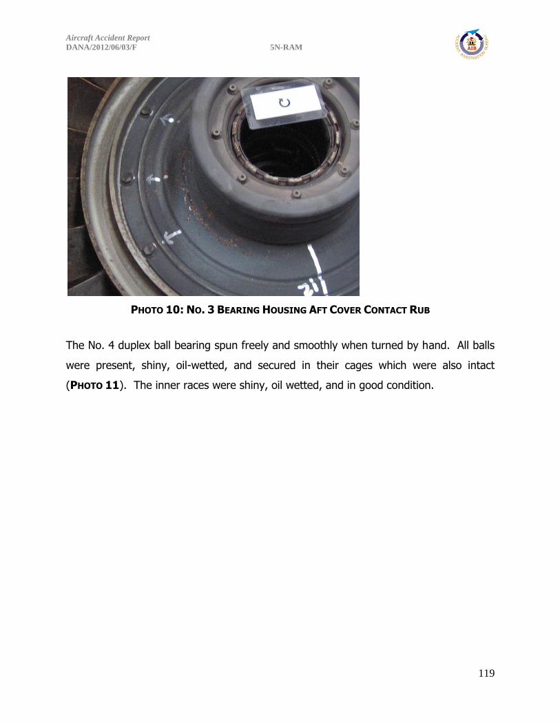
Aircraft Accident Report
DANA/2012/06/03/F 5N-RAM
119
PHOTO 10: NO. 3 BEARING HOUSING AFT COVER CONTACT RUB
The No. 4 duplex ball bearing spun freely and smoothly when turned by hand. All balls
were present, shiny, oil-wetted, and secured in their cages which were also intact
(PHOTO 11). The inner races were shiny, oil wetted, and in good condition.
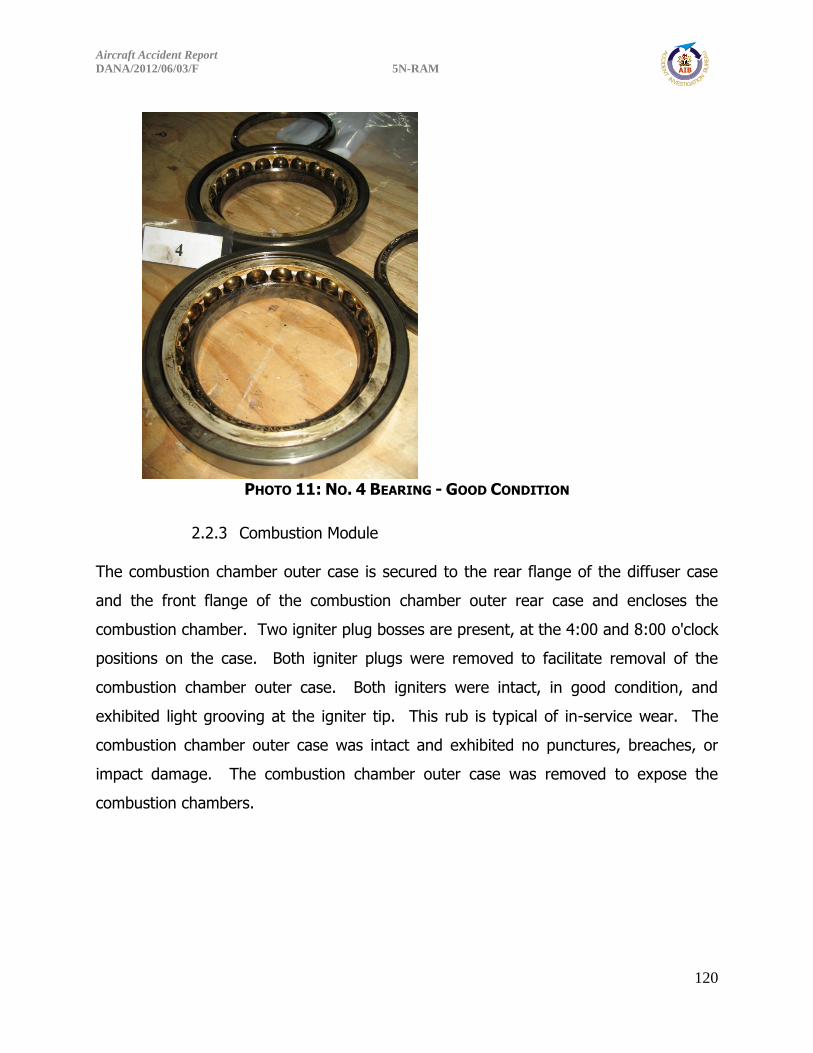
Aircraft Accident Report
DANA/2012/06/03/F 5N-RAM
120
PHOTO 11: NO. 4 BEARING - GOOD CONDITION
2.2.3 Combustion Module
The combustion chamber outer case is secured to the rear flange of the diffuser case
and the front flange of the combustion chamber outer rear case and encloses the
combustion chamber. Two igniter plug bosses are present, at the 4:00 and 8:00 o'clock
positions on the case. Both igniter plugs were removed to facilitate removal of the
combustion chamber outer case. Both igniters were intact, in good condition, and
exhibited light grooving at the igniter tip. This rub is typical of in-service wear. The
combustion chamber outer case was intact and exhibited no punctures, breaches, or
impact damage. The combustion chamber outer case was removed to expose the
combustion chambers.
Aircraft Accident Report
DANA/2012/06/03/F 5N-RAM
121
Nine one piece combustion chambers (or burner cans) are located between the
combustion chamber outer cases and the combustion chamber inner case in a can-
annular arrangement. All nine combustion chambers were present, secure, intact, and
exhibited no thermal distress (burn-through or erosion), cracking in the louvers or
dilution holes, burn-through, or impact damage (PHOTO 12). All nine combustion
chambers were secured at the front by positioning pins that were intact and safety
wired. The aft ends of the combustion chambers were secured into the front of the
combustion chamber rear support assembly. All the interconnecting cross-over tubes
were present, secured, and lockwired. The combustion chambers were removed to
expose the interior of the chambers and the fuel nozzles. All nine combustion
chambers exhibited a similar condition: 1) no thermal distress (burn-through or
erosion), 2) no localized sooting, or evidence of nozzle streaking in the ID of the
chambers, 3) some minor flaking/chipping of the thermal barrier coating on the ID of
the chambers, 4) no significant contact wear on the pin support, fuel nozzle port, cross-
over tubes, or rear skirt, and 5) no significant cracking of the dilution holes or louvers.
Some of the combustion chambers exhibited a white fibrous growth on the ID of the
chambers. Tactilely the growth lacked structure and felt soft. All the combustion
chamber support pins were intact and no appreciable wear was noted. The combustion
chamber rear support assembly was in good condition and no wear or thermal distress
was noted on the combustion chamber supports.

Aircraft Accident Report
DANA/2012/06/03/F 5N-RAM
122
PHOTO 12: COMBUSTION CHAMBERS STILL INSTALLED IN THE ENGINE - NO VISIBLE
THERMAL DISTRESS
The combustion chamber inner case is secured to the diffuser case
inner rear flange and to the outer flange of the No. 5 bearing housing. It forms the
inner wall of the combustion chamber and serves to position the No. 5 bearing through
the bearing housing. The combustion chamber inner case was intact and exhibited no
punctures, breaches, or impact damage.
Combustion
Chamber
Pins
Combustion
Chamber
Rear
Support
Cross-Over
Tubes
Igniter Port
Combustion
Chambers

Aircraft Accident Report
DANA/2012/06/03/F 5N-RAM
123
All the fuel nozzles were intact and secure in the diffuser case (PHOTO 13). No wear or
thermal distress was noted on any of the fuel nozzle shields and all the air flow holes
were unobstructed. None of the nozzle tips appeared blocked but varied in appearance
- some were clean, some exhibited rust, while others were black in appearance. In
general all the fuel nozzles were coated in a light brown residue that was easily
removed by hand. Removal of the fuel nozzles from the diffuser case revealed that
most of the nozzles exhibited rust on the swirler vanes and that some of the nozzles
exhibited rust and or debris in the fuel passages (primary and secondary); however, no
significant blockage was observed.
PHOTO 13: FUEL NOZZLES INSTALLED AND SECURE IN THE DIFFUSER CASE
Rusted
Nozzle Tip
Clean Nozzle
Tip
Aircraft Accident Report
DANA/2012/06/03/F 5N-RAM
124
2.2.4 High Pressure Turbine Module
The high pressure turbine module is comprised of a single rotor, supported by the No. 5
bearing, and a rear compressor drive turbine shaft bolted to the disk, and for
documentation purposes, a single stage of nozzle vanes located ahead of the rotor.
The vanes are attached to the combustion chamber rear support assembly. The serial
number HPT disk was BKLBCL7170 and that matched with what was recorded in
maintenance records for the HPT installed in the No. 1 engine. The HPT shaft serial
number was BKLBDA5672 it also matched the maintenance records.
The HPT case exhibited an inward impact mark and associated case puncture at the
4:00 to 4:30 o’clock location (PHOTO 14). All the HPT stage 1 vanes were present,
intact, and secure. No signs of thermal distress, no leading edge erosion, and no
trailing edge cracks were observed. The thermal barrier coating on the nozzles was in
good condition. All the HPT stage 1 blades were present, full length, and no signs of
thermal distress were observed. The tip shrouds exhibited a light 360° circumferential
rub (PHOTO 15). The HPT outer air seal ring exhibited a 360° circumferential rub of the
honeycomb that was dull and matted consistent with normal engine break-in, as well as
a fresh shiny thin light 360° circumferential rub consistent with a more recent contact.
The shiny rub was more distinctive around the bottom of the engine. On the aft side of
the HPT disk, a light 360° circumferential rub was noted on the stage 1 vane inner
rotating air seal land. The HPT shaft did not exhibit any circumferential contact rub.

Aircraft Accident Report
DANA/2012/06/03/F 5N-RAM
125
PHOTO 14: PUNCTURED HPT CASE
PHOTO 15: HPT BLADE TIP RUB
All the No. 5 bearing rollers were present, shiny, oil wetted, and secured in their cage
which was also intact. The No. 5 bearing spun freely and smoothly when turned by
hand. The No. 5 bearing inner race was shinny and in good condition (PHOTO 16). The
oil from the No. 5 bearing compartment was dark brown in color with no acrid smell.
Coke build-up was noted on the ID of the No. 5 bearing compartment on the top half.
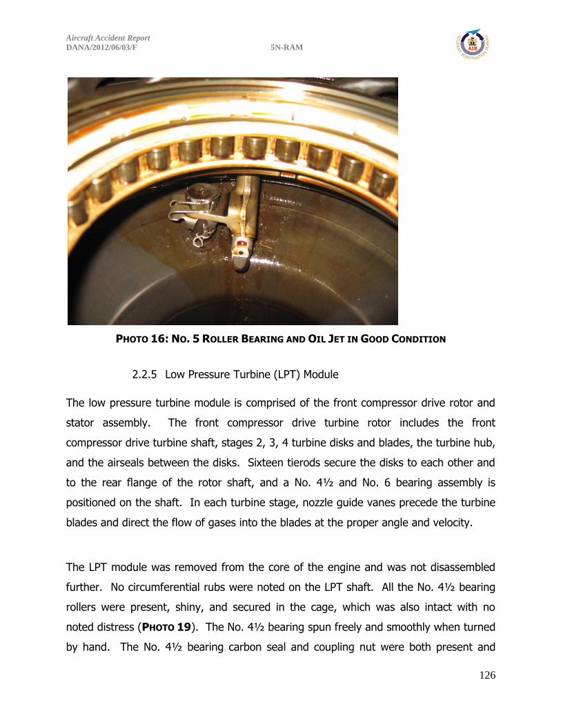
Aircraft Accident Report
DANA/2012/06/03/F 5N-RAM
126
PHOTO 16: NO. 5 ROLLER BEARING AND OIL JET IN GOOD CONDITION
2.2.5 Low Pressure Turbine (LPT) Module
The low pressure turbine module is comprised of the front compressor drive rotor and
stator assembly. The front compressor drive turbine rotor includes the front
compressor drive turbine shaft, stages 2, 3, 4 turbine disks and blades, the turbine hub,
and the airseals between the disks. Sixteen tierods secure the disks to each other and
to the rear flange of the rotor shaft, and a No. 4½ and No. 6 bearing assembly is
positioned on the shaft. In each turbine stage, nozzle guide vanes precede the turbine
blades and direct the flow of gases into the blades at the proper angle and velocity.
The LPT module was removed from the core of the engine and was not disassembled
further. No circumferential rubs were noted on the LPT shaft. All the No. 4½ bearing
rollers were present, shiny, and secured in the cage, which was also intact with no
noted distress (PHOTO 19). The No. 4½ bearing spun freely and smoothly when turned
by hand. The No. 4½ bearing carbon seal and coupling nut were both present and

Aircraft Accident Report
DANA/2012/06/03/F 5N-RAM
127
intact. The LPT stage 2 vanes were all present, in good condition, and no leading edge
damage was noted (PHOTO 17). Looking through the LPT stage 2 vanes, the stage 2
turbine blades were visible. All the stage 2 turbine blades were present and appeared
undamaged and straight. The LPT stage 4 blades were all present, straight, in good
condition, and no trailing edge damage was noted (PHOTO 18). No visible wear or
trenching of the honeycomb was noted on the LPT stage 4 outer air seal ring. Looking
through the LPT stage 4 blades, the stage 4 vanes were visible. All the stage 4 turbine
vanes were present and appeared undamaged. There were no indications of rub on the
LPT stage 4 blade outer air seal. All the No. 6 bearing rollers were present, shiny, and
secured in their cage which was also intact. The No. 6 bearing spun freely and
smoothly when turned by hand (PHOTO 19). The No. 6 bearing carbon seal was
present and intact. All the LPT disk tie-rods were present, and the tie-rods were
secure.
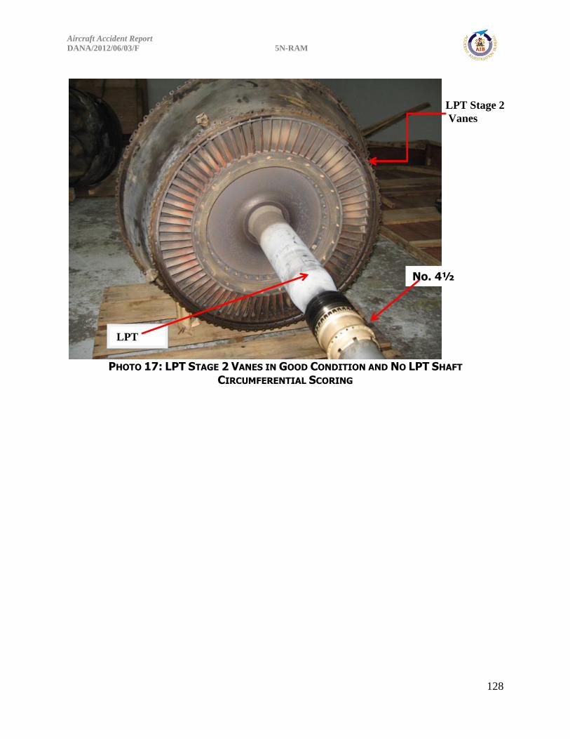
Aircraft Accident Report
DANA/2012/06/03/F 5N-RAM
128
PHOTO 17: LPT STAGE 2 VANES IN GOOD CONDITION AND NO LPT SHAFT
CIRCUMFERENTIAL SCORING
LPT Stage 2
Vanes
No. 4½
Bearing
LPT
Shaft
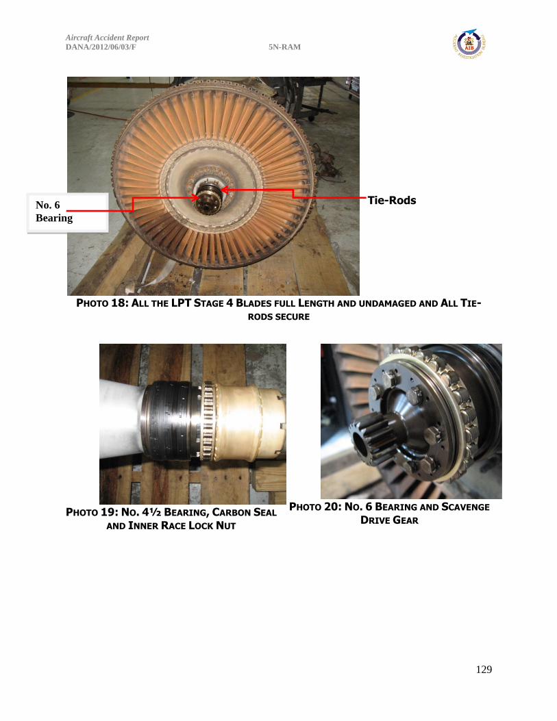
Aircraft Accident Report
DANA/2012/06/03/F 5N-RAM
129
PHOTO 18: ALL THE LPT STAGE 4 BLADES FULL LENGTH AND UNDAMAGED AND ALL TIE-
RODS SECURE
PHOTO 19: NO. 4½ BEARING, CARBON SEAL
AND INNER RACE LOCK NUT
PHOTO 20: NO. 6 BEARING AND SCAVENGE
DRIVE GEAR
Tie-Rods No. 6
Bearing

Aircraft Accident Report
DANA/2012/06/03/F 5N-RAM
130
2.2.6 Turbine Exhaust Case Module
The turbine exhaust case is bolted to the rear flange of the turbine rear case. The
exhaust case is inner diameter was nearly cylindrical and serves to straighten the
turbine exhaust gases. Eight integral exhaust struts in the gas-path shield the No. 6
bearing support strut rods which support the No. 6 bearing housing. The turbine
exhaust case was removed from the rest of the engine. No punctures, exit holes, or
tears were noted. All eight exhaust struts were intact and no buckling or leading edge
damage was observed. The center body (No. 6 bearing housing) was undamaged, and
oil wetted – the oil was dark brown in color with no acrid smell, the No. 6 bearing inner
race was shinny and in good condition, and the scavenge pump gear turned freely by
hand.
2.2.7 Fuel System Components
The major components of the fuel system are comprised of: the main fuel pump, fuel
heater, fuel control unit, fuel flow transmitter, fuel-oil cooler, pressurizing and dump
valve, and the nine fuel nozzles, in addition to the fuel lines that connect these
components. The only parts of the fuel system that were available for examination
were the fuel nozzles, and left- and right-hand primary and secondary fuel manifolds,
which are located on the diffuser case. For this engine, the fuel nozzle documentation
was covered in the combustion module section. There was no residual fuel remaining in
the fuel system.
Both fuel manifolds were removed from the engine for evaluation. The right-hand
manifold encompasses fuel nozzle positions Nos. 2 to 5 (the fuel supply to these
manifolds is introduced through fittings on the back side of the nozzle No. 5 fittings)
while the left-hand manifold encompasses fuel nozzle positions Nos. 6 to 9 and No. 1
(the fuel supply to these manifolds is introduced through fittings on the back side of the
nozzle No. 6 fittings). The fuel right-hand manifold was intact and the fuel transfer
tubes between the nozzle fittings were undamaged except for some slight diameter

Aircraft Accident Report
DANA/2012/06/03/F 5N-RAM
131
reduction/crushing in the primary manifold near the nozzle No. 2 fitting. The fuel-
feeder lines that attach to the No. 5 fitting were both (primary and secondary) fractured
flush with the No. 5 fitting and a piece of the fuel-feeder tubes remained within the No.
5 fittings in both manifolds (PHOTO 21). These fractured fuel-feeder tubes both
exhibited shear lips. The left-hand manifold exhibited the following damage and
observations: 1) heavily sooted at fuel nozzle fitting Nos. 8, 9 and 1, 2) the primary
fuel transfer tube was pinched almost closed at the No. 8 fuel nozzle fitting (PHOTO
22), and 3) the primary fuel transfer tube diameter was reduced at the No. 7 fuel
nozzle fitting,. The fuel-feeder lines that attach to the No. 6 fitting were both fractured
at the No. 6 fitting with an appreciable piece of the secondary feeder tube was still
attached and twisted/crimped (PHOTO 23).
PHOTO 21: RIGHT-HAND FUEL MANIFOLD WITH FRACTURED FEEDER TUBE

Aircraft Accident Report
DANA/2012/06/03/F 5N-RAM
132
PHOTO 22: PINCHED TRANSFER TUBE
PHOTO 23: FRACTURED FEEDER LINE
A flow test of the fuel manifolds were conducted using shop air at approximately
130psi. On the left-hand manifold, shop air was introduced into the primary No. 1 fuel
nozzle fitting and a steady stream of air was felt at all the fuel nozzles positions with
the No. 7 and 8 positions flowed at a noticeably reduced rate. The same flow test was
conducted on the right-hand secondary, and both the primary and secondary on the
left-hand manifold (air introduced at the No. 2 fitting) and all flowed steadily. No
significant debris came out during the flow test but some residual water did flow out.
3.0 RIGHT ENGINE (NO. 2) – SN 728113
3.1 AS-RECEIVED
The engine was uncrated and placed on pallets for examination and disassembly
(PHOTO 24). The engine was intact from the nose bullet aft to the exhaust tail cone
with all major modules in place. Engine cases appeared round and did not exhibit signs
of structural deformation or case breach. Fan and exhaust ducting was missing from the
“E”-flange (aft flange of the fan exit guide vane (FEGV) Outer Case) aft to the “F”-
flange (forward flange intermediate case outer diameter ring) and from the “G”-flange
(aft flange of the intermediate case outer diameter ring) to the “K”-flange (forward
flange of the turbine case outer diameter ring). Some wiring, and pneumatic and oil

Aircraft Accident Report
DANA/2012/06/03/F 5N-RAM
133
system plumbing along with crash debris were removed to facilitate teardown (PHOTO
25).
PHOTO 24: RIGHT-HAND SIDE OF THE NO. 2 ENGINE SN 728113
PHOTO 25: RIGHT-HAND SIDE OF NO. 2 ENGINE WITH FLANGE LOCATIONS
E F
G K

Aircraft Accident Report
DANA/2012/06/03/F 5N-RAM
134
The inlet area was inspected and it was noted that the inlet nose bullet was partially
melted exposing the front accessory drive cover. All the IGV’s were in place and secure
with five vanes, located between the 10:00 o’clock and 12:00 o’clock positions, buckled
at the mid-span (PHOTO 26). No significant leading edge impact damage was noted.
PHOTO 26: ENGINE INLET
The forward fan case exhibited damage in three locations. Case material was missing
circumferentially from the 12:00 to 1:30 positions and from the 8:00 to 11:00 o’clock
positions, the edges of these holes exhibited thermal distress and indications of melting.
An inward puncture with associated case deformation was present at the 4:00 o’clock
position, approximately 4 inches in diameter with indications of melting around the
fracture surfaces (PHOTO 27).
Nose Bullet
IGV Buckling
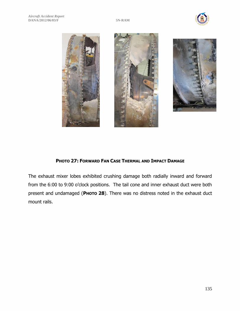
Aircraft Accident Report
DANA/2012/06/03/F 5N-RAM
135
PHOTO 27: FORWARD FAN CASE THERMAL AND IMPACT DAMAGE
The exhaust mixer lobes exhibited crushing damage both radially inward and forward
from the 6:00 to 9:00 o’clock positions. The tail cone and inner exhaust duct were both
present and undamaged (PHOTO 28). There was no distress noted in the exhaust duct
mount rails.

Aircraft Accident Report
DANA/2012/06/03/F 5N-RAM
136
PHOTO 28: EXHAUST CASE AND MIXER
3.2 DISASSEMBLY
3.2.1 Front Compressor Module and Intermediate Case Module
The front accessory drive cover was removed exposing the No. 1 bearing. All rollers
were present, intact, shiny, and oil wetted. No damage was noted on the bearing cage
or races (PHOTO 29). The front compressor was removed from the core of the engine
and not disassembled further. Except for the stator 1 case and shroud, the low
pressure compressor cases and shrouds were round without indication of deformation
or breach. A uniform coating of light gray ash was found throughout of the observable
gaspath hardware in the LPC. The ash coated easily brushed or blown off (PHOTO 30).
Impact Crushing

Aircraft Accident Report
DANA/2012/06/03/F 5N-RAM
137
PHOTO 29: NO. 1 BEARING
PHOTO 30: LPC STAGE 6 BLADES WITH ASH COATING
The aft fan case was removed from the LPC. Two sets of static witness marks were
present on the abradable panels between the 4:30 and 6:00 position. The distance
between the individual marks in a given set were measured and were consistent with
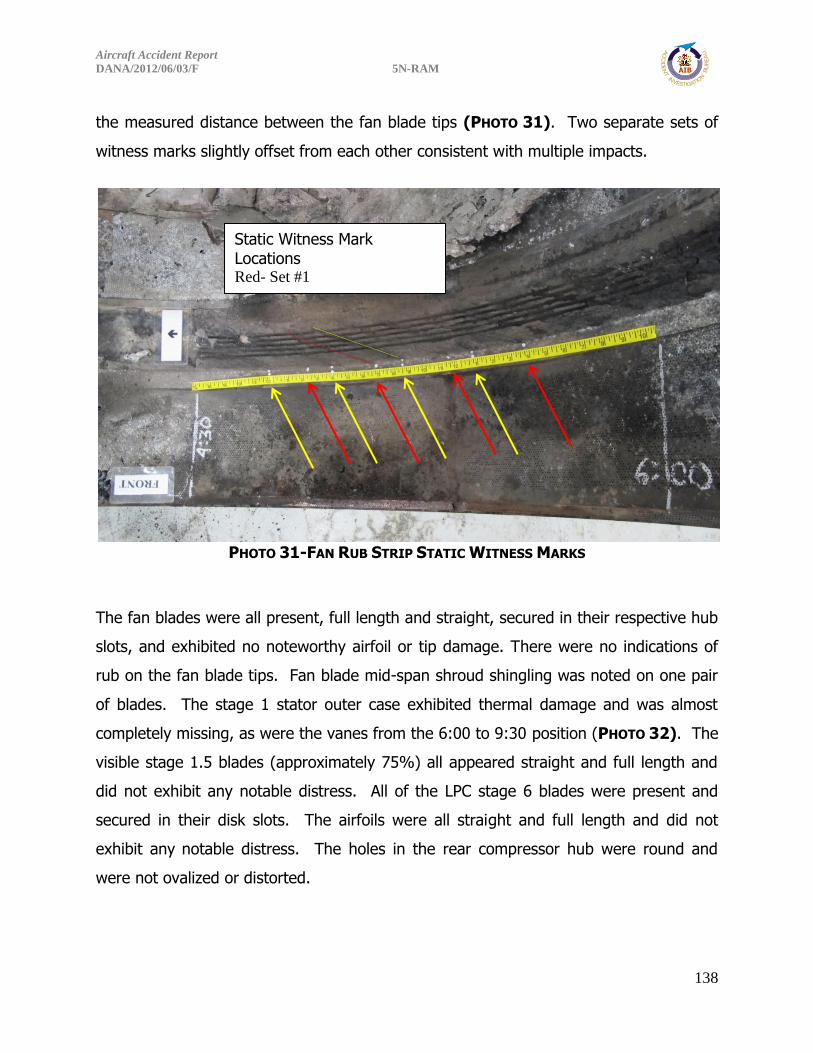
Aircraft Accident Report
DANA/2012/06/03/F 5N-RAM
138
the measured distance between the fan blade tips (PHOTO 31). Two separate sets of
witness marks slightly offset from each other consistent with multiple impacts.
PHOTO 31-FAN RUB STRIP STATIC WITNESS MARKS
The fan blades were all present, full length and straight, secured in their respective hub
slots, and exhibited no noteworthy airfoil or tip damage. There were no indications of
rub on the fan blade tips. Fan blade mid-span shroud shingling was noted on one pair
of blades. The stage 1 stator outer case exhibited thermal damage and was almost
completely missing, as were the vanes from the 6:00 to 9:30 position (PHOTO 32). The
visible stage 1.5 blades (approximately 75%) all appeared straight and full length and
did not exhibit any notable distress. All of the LPC stage 6 blades were present and
secured in their disk slots. The airfoils were all straight and full length and did not
exhibit any notable distress. The holes in the rear compressor hub were round and
were not ovalized or distorted.
Static Witness Mark Locations Red- Set #1
Yellow- Set #2

Aircraft Accident Report
DANA/2012/06/03/F 5N-RAM
139
PHOTO 32-LPC STAGE 1 STATOR CASE MELTED AND MISSING VANES
The No. 2 bearing spun freely and smoothly when turned by hand. The rolling
elements were all intact, in place, round, and secured in their cage. The No. 2 bearing
carbon seal was in good condition with minimal damage.
The intermediate case was documented after removal from the engine. The case was
intact. The core vanes were in place and intact with no noted distress and exhibited a
light coating of gray ash. The outer struts were intact with no noted distress. The lower
forward mount lug was fractured at its base and bent forward. The upper forward
mount lug was bent forward. The upper and lower aft lugs did not exhibit any notable
distress. A sheared mount bolt was present in the upper aft lug.
3.2.2 Rear Compressor Module
The HPC was removed from the core to facilitate examination and was not further
disassembled (PHOTO 33). All the stator cases were round, intact, and exhibited no
punctures. The outside of the module had a black oily residue that could be removed
with medium finger pressure. The stage 7 blades were all present, full length, and
exhibited no leading edge damage or tip rub. The stage 7 blade shroud did not exhibit
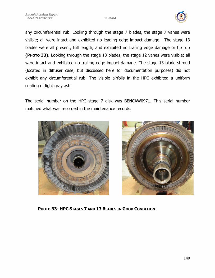
Aircraft Accident Report
DANA/2012/06/03/F 5N-RAM
140
any circumferential rub. Looking through the stage 7 blades, the stage 7 vanes were
visible; all were intact and exhibited no leading edge impact damage. The stage 13
blades were all present, full length, and exhibited no trailing edge damage or tip rub
(PHOTO 33). Looking through the stage 13 blades, the stage 12 vanes were visible; all
were intact and exhibited no trailing edge impact damage. The stage 13 blade shroud
(located in diffuser case, but discussed here for documentation purposes) did not
exhibit any circumferential rub. The visible airfoils in the HPC exhibited a uniform
coating of light gray ash.
The serial number on the HPC stage 7 disk was BENCAW0971. This serial number
matched what was recorded in the maintenance records.
PHOTO 33- HPC STAGES 7 AND 13 BLADES IN GOOD CONDITION

Aircraft Accident Report
DANA/2012/06/03/F 5N-RAM
141
The No. 3 bearing spun freely and smoothly when turned by hand. The oil from the
No. 2/3 compartment was dark in color but did not exhibit an acrid odor. The tower
shaft bevel gear within the compartment spun freely when turned by hand.
The No. 4 duplex ball bearing spun freely and smoothly when turned by hand. All balls
were present, shiny, oil-wetted, and secured in their cages which were also intact
(PHOTO 11). The inner races were shiny, oil wetted, and in good condition.
PHOTO 34: NO. 4 BEARING - GOOD CONDITION
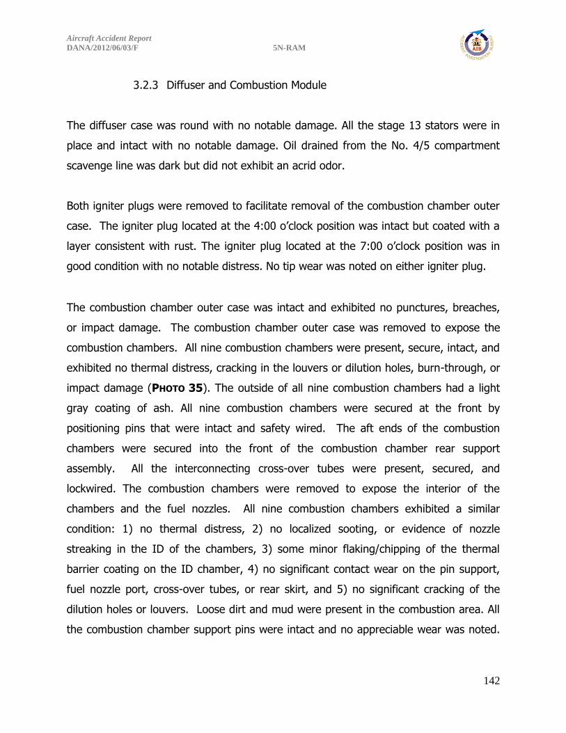
Aircraft Accident Report
DANA/2012/06/03/F 5N-RAM
142
3.2.3 Diffuser and Combustion Module
The diffuser case was round with no notable damage. All the stage 13 stators were in
place and intact with no notable damage. Oil drained from the No. 4/5 compartment
scavenge line was dark but did not exhibit an acrid odor.
Both igniter plugs were removed to facilitate removal of the combustion chamber outer
case. The igniter plug located at the 4:00 o’clock position was intact but coated with a
layer consistent with rust. The igniter plug located at the 7:00 o’clock position was in
good condition with no notable distress. No tip wear was noted on either igniter plug.
The combustion chamber outer case was intact and exhibited no punctures, breaches,
or impact damage. The combustion chamber outer case was removed to expose the
combustion chambers. All nine combustion chambers were present, secure, intact, and
exhibited no thermal distress, cracking in the louvers or dilution holes, burn-through, or
impact damage (PHOTO 35). The outside of all nine combustion chambers had a light
gray coating of ash. All nine combustion chambers were secured at the front by
positioning pins that were intact and safety wired. The aft ends of the combustion
chambers were secured into the front of the combustion chamber rear support
assembly. All the interconnecting cross-over tubes were present, secured, and
lockwired. The combustion chambers were removed to expose the interior of the
chambers and the fuel nozzles. All nine combustion chambers exhibited a similar
condition: 1) no thermal distress, 2) no localized sooting, or evidence of nozzle
streaking in the ID of the chambers, 3) some minor flaking/chipping of the thermal
barrier coating on the ID chamber, 4) no significant contact wear on the pin support,
fuel nozzle port, cross-over tubes, or rear skirt, and 5) no significant cracking of the
dilution holes or louvers. Loose dirt and mud were present in the combustion area. All
the combustion chamber support pins were intact and no appreciable wear was noted.

Aircraft Accident Report
DANA/2012/06/03/F 5N-RAM
143
The combustion chamber rear support assembly was in good condition and no wear or
thermal distress was noted on the combustion chamber supports.
PHOTO 35- COMBUSTION CHAMBER INSTALLED IN THE ENGINE- NO VISIBLE THERMAL
DISTRESS
All the fuel nozzles were intact and secure in the diffuser case with no notable distress
(see section 3.2.7 for details) (PHOTO 36).

Aircraft Accident Report
DANA/2012/06/03/F 5N-RAM
144
PHOTO 36: FUEL NOZZLES INSTALLED AND SECURE IN THE DIFFUSER CASE
The combustion chamber inner case was intact and exhibited no punctures, breaches,
or impact damage.
3.2.4 High Pressure Turbine Module
All HPT stage 1 vanes were present, intact, and secure. No signs of thermal distress,
no leading edge erosion, and no trailing edge cracks were observed. The thermal
barrier coating on the nozzles was in good condition. All the HPT stage 1 blades were
present, full length, and no signs of thermal distress were observed (PHOTO 37). The
OD surface of the tip shrouds exhibited a light, shiny 360° circumferential rub on the
cooling air channel and the forward seal land (PHOTO 38). The HPT outer air seal ring
exhibited a light shiny 360° circumferential rub of the honeycomb, as well as an
approximately 4 inch rub through the honeycomb that was dark and oxidized
suggesting a pre-existing rub. HPT shaft serial number, BKLBBW1127 was recorded
from the outer diameter of the HPT flange and it did not match maintenance records. A
serial number could not be located on the HPT disk. HPT airfoils exhibited a coating of
light gray ash. The HPT shaft was intact and did not exhibit any rubs or circumferential
scoring.

Aircraft Accident Report
DANA/2012/06/03/F 5N-RAM
145
PHOTO 37- HPT STAGE 1 DISK
PHOTO 38-HPT STAGE 1 BLADE TIP RUB

Aircraft Accident Report
DANA/2012/06/03/F 5N-RAM
146
All the No. 5 bearing rollers were present, shiny, oil wetted, and secured in their cage
which was also intact. The No. 5 bearing spun freely and smoothly when turned by
hand. The No. 5 bearing inner race was shiny and in good condition (PHOTO 39). The
oil from the No. 5 bearing compartment was dark brown in color but did not have an
acrid odor.
PHOTO 39-NO.5 ROLLER BEARING- GOOD CONDITION
3.2.5 LPT Module
The LPT module was removed from the core of the engine and was not disassembled
further. No circumferential rubs were noted on the LPT shaft. All the No. 4½ bearing
rollers were present and secured in their cage, which was also intact with no noted
distress (PHOTO 40). The No. 4½ bearing spun freely and smoothly when turned by
hand. The No. 4½ bearing carbon seal and inner race coupling nut were both present
and intact. Soot was noted on the forward part of the LPT shaft as well as on the No.
4½ bearing inner race lock nut. The LPT stage 2 vanes were all present, in good
condition, and no leading edge damage was noted (PHOTO 41). The stage 2 vanes
outer air sealing ring spacer was fractured at the 9:00 o’clock position and part of the

Aircraft Accident Report
DANA/2012/06/03/F 5N-RAM
147
ring was deformed inward, into the gas path. The deformed end exhibited contact
wear and the fracture surface was oxidized consistent with a pre-existing fracture. The
bent material was in a position that would not interfere with normal engine operation
(PHOTO 42).
Looking through the LPT stage 2 vanes, the stage 2 turbine blades were visible. All the
stage 2 turbine blades were present and appeared undamaged and straight. The stage
2 blade and vane airfoils visible exhibited a coating of light gray ash. The LPT stage 4
blades were all present, straight, in good condition, and no trailing edge damage was
noted (PHOTO 43). There were no indications of rub on the stage 4 blade tip shroud or
outer air seal to the extent that could be observed in the assembled condition. Melted
aluminium had pooled and subsequently solidified around the stage 4 turbine blades at
the 6 o’clock position. Looking through the LPT stage 4 blades, the stage 4 vanes were
visible. All the stage 4 turbine vanes were present and appeared undamaged. All the
No. 6 bearing rollers were present, shiny, and secured in their cage which was also
intact. The No. 6 bearing spun freely and smoothly when turned by hand. The No. 6
bearing carbon seal was present and intact. All the LPT disk tie-rods were present, and
the tie-rods were secure.
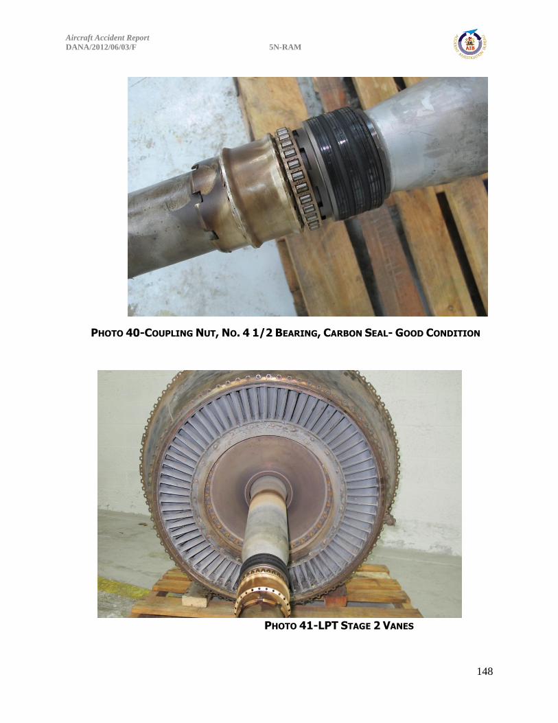
Aircraft Accident Report
DANA/2012/06/03/F 5N-RAM
148
PHOTO 40-COUPLING NUT, NO. 4 1/2 BEARING, CARBON SEAL- GOOD CONDITION
PHOTO 41-LPT STAGE 2 VANES
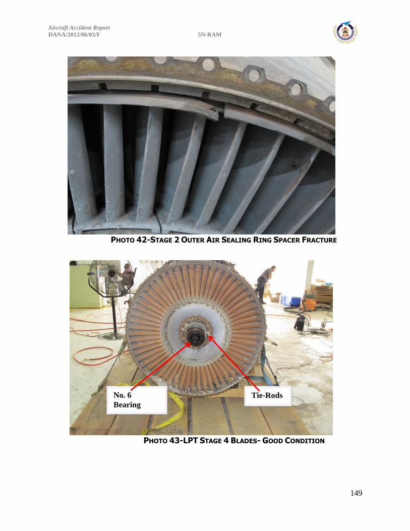
Aircraft Accident Report
DANA/2012/06/03/F 5N-RAM
149
PHOTO 42-STAGE 2 OUTER AIR SEALING RING SPACER FRACTURE
PHOTO 43-LPT STAGE 4 BLADES- GOOD CONDITION
No. 6
Bearing
Tie-Rods
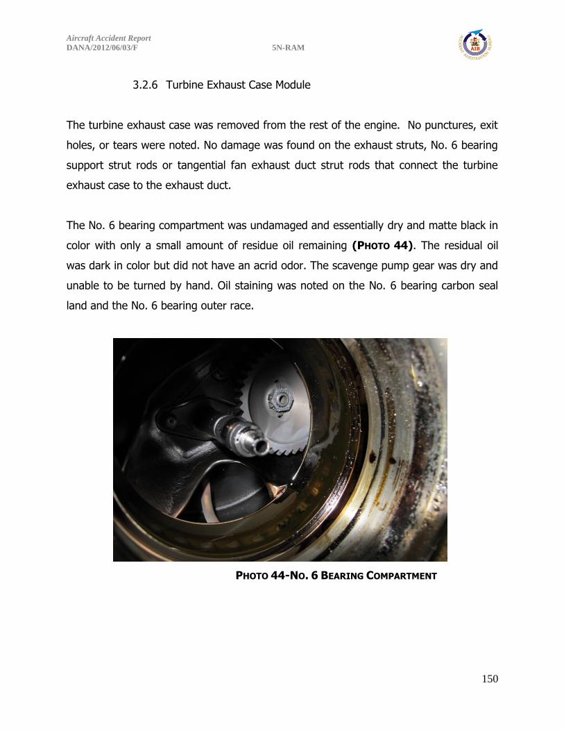
Aircraft Accident Report
DANA/2012/06/03/F 5N-RAM
150
3.2.6 Turbine Exhaust Case Module
The turbine exhaust case was removed from the rest of the engine. No punctures, exit
holes, or tears were noted. No damage was found on the exhaust struts, No. 6 bearing
support strut rods or tangential fan exhaust duct strut rods that connect the turbine
exhaust case to the exhaust duct.
The No. 6 bearing compartment was undamaged and essentially dry and matte black in
color with only a small amount of residue oil remaining (PHOTO 44). The residual oil
was dark in color but did not have an acrid odor. The scavenge pump gear was dry and
unable to be turned by hand. Oil staining was noted on the No. 6 bearing carbon seal
land and the No. 6 bearing outer race.
PHOTO 44-NO. 6 BEARING COMPARTMENT

Aircraft Accident Report
DANA/2012/06/03/F 5N-RAM
151
3.2.7 Fuel System Components
The parts of the fuel system that were available for examination were: the fuel nozzles,
the fuel manifolds, the P&D valve-to-fuel manifold feeder tubes, fuel oil cooler-to-P&D
valve tube, and fuel control-to-fuel flow transmitter tube. There was no residual fuel
remaining in the fuel system.
A series of flow tests were conducted to check for fuel nozzle, fuel manifold and fuel
feeder tube blockages using shop air at approximately 130psi. The fuel system was left
intact “as received”. For the first test shop air was introduced into the P&D valve-to-
fuel manifold primary and secondary lines and relative air flow from the fuel nozzles
was recorded. Air was introduced first into the left-hand primary line, and air flow was
felt flowing from the Nos. 7 and 8 nozzles, low flow was felt from the Nos. 6 and 9
nozzles and no flow was detected from the No. 1 nozzle. Air was then introduced into
the left-hand secondary line and there was no air flow through the Nos. 1, 6, 7, 8 or 9
nozzles. Next air was introduced into the right-hand primary line and there was air flow
felt from the Nos. 3 and 4 nozzles, low air flow felt through the No. 2 nozzle and no
flow through the No. 5 nozzle. Finally, air was introduced into the right hand-hand
secondary line and no flow was detected from the Nos. 2, 3, 4 or 5 nozzles.
After removal of the P&D valve-to-fuel manifold feeder tubes, air was blown directly
into the fuel manifolds. The results of this series of tests were the same as the testing
described above.
All the fuel manifolds were then removed from the engine, and a final flow test was
conducted on the fuel manifolds and the P&D valve-to-feeder line tubes. Air flowed
freely through all the lines.

Aircraft Accident Report
DANA/2012/06/03/F 5N-RAM
152
The fuel control unit-to-fuel flow transmitter line was flattened and bent over a majority
of its length but was not collapsed to the point of complete blockage. No line breaches
were noted. A piece of melted fuel control housing flange was still attached to the fuel
control unit end of the line. No obstructions were observed during a visual inspection
into both ends of the tube.
The fuel oil cooler-to- P&D valve line had two dents, one at the oil cooler attachment
end and the other at approximately the mid-span. The line was not collapsed, no
breaches were present, and no obstructions were observed during a visual inspection
into both ends.
The primary fuel flow feeder line that connects the P&D valve to the fuel flow manifolds
had multiple dents downstream of the junctions between the left and right manifolds.
The P&D valve end B-nut and fitting were still present. No obstructions were observed
during a visual inspection into both ends. The secondary fuel flow feeder line that
connects to the right hand manifold was collapsed and bent downstream of the
junction, neither of which completely blocked flow. The P&D valve end B-nut and fitting
on the secondary line were not present.
The right-hand primary and secondary manifold supply tubes were bent at the No. 5
fittings. Similar damage was noted on the left-hand primary and secondary manifold
supply tube at the No. 6 fittings. Neither of these bends completely obstructed flow.
The left hand primary manifold also had a circumferential crack just outboard of the fan
duct pass through. Visual examination did not identify any blockages looking into the
open ends of the tubes.
Fuel nozzles were intact with varying amounts of discoloration. The appearance of the
nozzle tips also varied, some were clean, others exhibited a dark colored material that
was quickly dislodged when shop air was blown through the nozzles. Several fuel

Aircraft Accident Report
DANA/2012/06/03/F 5N-RAM
153
nozzles exhibited a soft black residue in the primary and secondary fuel inlet ports that
crumbled to the touch.
PHOTO 45-FUEL SYSTEM TUBING
4.0 CONTINUING WORK
The fuel nozzles from the both engines have been quarantined for further
evaluation and testing. Work scope, testing facility, and test dates are to be
determined.
Fuel Control-to-Fuel Flow Transmitter Tube
Fuel Oil Cooler-to-P&D Valve Tube
P&D Valve-to-Fuel Manifold Feeder Tubes
Secondary
Primary
Feeds Right Manifold
Feeds the Left Manifold
Left Manifold
Right Manifold
Fuel Nozzle

Aircraft Accident Report
DANA/2012/06/03/F 5N-RAM
154
Appendix B
Extract from Dana Airlines Operations Manual Part A (Captain’s Authority)1.17.1.3
The authority of a Dana Air Captain comes from two sources, namely Nigerian Law, and
his status within Dana Air. Nigerian Law requires that every person in an aircraft must
obey the lawful commands of an aircraft Captain for the purpose of securing the safety
of the aircraft and all persons and property on board. The Captain also has legal
authority to maintain good order and discipline in the aircraft.
Dana Air Management has a statutory responsibility for the safe operation of the airline
which is delegated to the Managing Director who, in turn, entrusts it to Departmental
Heads within their particular area of activity. The Captain is thus empowered through
the Flight Operations Department to exercise authority and is accountable for his
actions in so doing.
The Captain's authority and responsibility in respect of safety is the same within Dana
Air as under Nigeria Law. Additionally, he is responsible to Flight Operations
Department managers for compliance with instructions and regulations relating to his
duties.
When exercising his command, the Captain is responsible for ensuring that the licences
of each flight crew member have been issued or rendered valid by the State of Registry,
contain the proper ratings, and that all the flight crew members have maintained
recency of experience. The Captain is also responsible for ensuring that. personnel
subordinate to him perform the duties assigned to them by Dana Air in accordance with
the standards and procedure established by Dana Air. No flight crew member shall
perform duties during a critical phase of flight except those required for the safe
operation of the aircraft. The Captain shall not permit a flight crew member to engage
in any activity during a critical phase of flight which could distract or interfere with the
performance of their assigned duties.
Aircraft Accident Report
DANA/2012/06/03/F 5N-RAM
155
Aircrew Fitness for duty
a. The Captain shall be responsible for ensuring that a flight is not commenced if any
flight crewmember is incapacitated from performing duties by any cause such as injury,
sickness, fatigue, the effects of alcohol or drugs or continued beyond the nearest
suitable aerodrome if a flight crewmember's capacity to perform functions is
significantly reduced by impairment of faculties from causes such as fatigue, sickness
or lack of oxygen.
b, The Captain is to prohibit a flight crew from flying or continuing beyond the nearest
suitable aerodrome if found to be unfit for duty. In determining fitness for duty, the
following factors shall be considered:
i. alcohol and psychoactive substance use;
ii. pregnancy;
iii. illness or use of medication(s);
iv. blood donations;
v. surgery;
vi. deep diving;
vii. fatigue.
Co-pilot Responsibilities
The Co-pilot's responsibilities include continuous monitoring of the Captain, the
instrument panel, reading the checklist and being mindful of the two ‘Call Rule’,
communications, advising the Captain as at when required, etc.
The Co-pilot's responsibilities include ensuring the following:
Pre-flight:
He is fully aware of the flight-planned route, contents of briefing sheets, and the
forecast meteorological conditions and runway states at the destination and alternate
aerodromes. By delegation of the commander, the co-pilot will usually:

Aircraft Accident Report
DANA/2012/06/03/F 5N-RAM
156
- calculate the take-off data and the operational flight plan and file the corresponding
ATS flight plan (whenever those tasks have been delegated to others, he shall
cross-check these documents before handing them over to the commander for
signature),
- check that the prescribed manuals, maps, charts, documents and forms are on
board and cover the aircraft's intended operation until return to a home base,
- check the radio and navigation equipment for proper functioning,
- ascertain that fuel on board and fuel assumed for take-off data calculation are
identical, and equal to or higher than the minimum fuel specified by the Operational
Flight Plan (OFP),
- at Stations without qualified personnel, check use of the correct fuel type, and
supervise the fuelling of the aircraft, and ensure proper distribution of fuel.
In Flight:
Notwithstanding the overriding authority of the commander, it is of the
utmost importance that the co-pilot draw the attention of the commander to
facts, circumstances or unfavourable variables which may impair the safety
of the flight and which may not yet have been noticed by the commander.
Such facts and circumstances may be:
exceedance of limitations, abnormal indication, changes in meteorological conditions
enroute or at alternates/destination, ambiguous ATS clearances, deficiencies in
navigation or the aeroplane's handling, abnormal response of the aeroplane to controls
input, etc. Specifically, the co-pilot:
Aircraft Accident Report
DANA/2012/06/03/F 5N-RAM
157
Situational Awareness & Decision Making
Monitors developments (fuel, weather, ATC, etc.)
Anticipates required actions
Asks the right questions
Tests assumptions, confirms understanding
Monitors workload distribution and fellow crew members
Reports fatigue, stress and overload in self and others
Decision Making
Fly the aircraft
Obtain all pertinent information
All crew members state recommendations
Better idea suggested? Abandon yours
Clearly state plan or intentions
Establish “Bottom Linea”
Resolve conflicts and doubts quickly

Aircraft Accident Report
DANA/2012/06/03/F 5N-RAM
158
Appendix C
Extract from Dana Airlines Operations Quick Reference Checklist (QRC) 1.17.1.5
The Quick Reference Checklist is used to stabilize emergency conditions that are
considered time-critical. This card provides step-by-step guidance assuring timely and
accurate execution of the emergency action steps. After all QRC checklist items are
accomplished, the last line on the QRC checklist concludes with "Checklist Completed",
or transitions you to the QRH by means of a gray Reference Bar. The PM reads the
Reference Bar. After transitioning from the QRC to the QRH, continue the QRH from the
gray Reference Bar marked "Continue from QRC". It is not necessary to repeat the
steps already performed in the QRC. There were no records that checklist, Normal,
Non-normal and Emergency were used at anytime throughout the duration of the flight.
Quick Reference Handbook (QRH)
All Emergency and Abnormal Checklists are in the form of aself-contained QRH. All
checklist items, notes and amplification are contained within the applicable QRH
checklist.
The QRH is divided into the following:
Emergency Checklist Section
Abnormal Checklist Section
Reference Cards Section
CB List
Alphabetical Index
Annunciator Lights Reference Page

Aircraft Accident Report
DANA/2012/06/03/F 5N-RAM
159
There are three ways to locate a QRH procedure:
1) The Emergency checklists are listed and grouped by the red tab numbers (E#) on
the front cover. An Abnormal checklist is located by system title on any of the
numbered tab dividers (1 thru 12). Abnormal tab provides a "Table of Content" for
each system.
2) Additionally, an index section provides an alphabetized list of all QRH checklist.
Emergency Checklist are balded in the index.
3) An Annunciator Light Reference Page locator is found on the back cover of the
QRH.
RECALL Action items
RECALL BOXED action are performed without reference to the checklist to ensure the
safety of the aircraft and/or personnel.
These steps are methodically accomplished by or at the command of the Pilot Flying
(PF). After the the RECALL actions are accomplished, the PF calls for the appropriate
QRC checklist. The monitoring (PM) reads aloud, in sequence, each checklist item,
including the response. Recall items are rechecked by the PM to ensure the challenge
action (i.e., switch position, instrument configuration, etc) has been accomplished.
NUMBERED Action Steps
NUMBERED action steps are accomplished by reference to the checklist (read and do).
The PM reads aloud both challenges and response from the QRC/QRH. The PF should
accomplish those items affection aircraft controls, such as disconnecting the autopilot
and auto-throttles. Items such as moving a Throttle to idle, moving a Fuel Lever to OFF,

Aircraft Accident Report
DANA/2012/06/03/F 5N-RAM
160
or pulling an Engine Fire Handle are accomplished by the PM. The items accomplished
by the PM are performed in a deliberate and unhurried manner.
EMERGENCY AND ABNORMAL PROCEDURES
Flight crews shall properly manage non-normal situations through the use of
prioritization, task sharing, division of PM/PF duties and crew coordination. During the
execution of abnormal/non-normal and emergency procedures, across check and verbal
confirmation by the two flight crew members (dual response) must be ensured before
the actuation of any critical aircraft system controls, as defined by the OEM, The critical
aircraft system controls include:
a) Engine thrust levers;
b) Fuel master or control switches;
c) Engine fire handles or switches;
d) Engine fire extinguisher switches;
e) IDG/CSD disconnect switch.
ENGINE FAILURE DURING FLIGHT
Only in exceptional circumstances should the Captain of a twin-engined aircraft not land
at the nearest suitable airfield following the loss of engine in flight. A Captain electing
not to land at the nearest aerodrome, is to state the reasons for his decision on the
Flight Crew Voyage Report and the Air Safety Report.
Aircraft Accident Report
DANA/2012/06/03/F 5N-RAM
161
QUALIFICATION REQUIREMENTS:
DESCRIPTION OF LICENCE, QUALIFICATION /COMPETENCY, TRAINING AND
CHECKING.
Dana Air shall not allow any person to act as a pilot flight crewmember of its aircraft
unless a valid licence or validation certificate is held showing compliance with the
specifications of Nig. CARs Part 2 and appropriate to the duties to be performed by that
person.
a) No person, shall be employed as a flight crew member unless prior to being
employed, such a person is screened for the purpose of reviewing and/or
assessing:
i) technical competencies and skills;
ii) aviation experience;
iii) credentials and licenses;
iv) interpersonal skills;
v) medical fitness;
vi) security background;
vii) English language fluency as all flight crew members are required to
use the English language for communication on the flight deck
during line operations, between the flight crew training and
evaluation activities.

Aircraft Accident Report
DANA/2012/06/03/F 5N-RAM
162
CAUTION: EGT or N1 response to throttle movement may indicate LOSS OF ALL GENERATORS(TAB E6, Pg. E6.3) 3. CABIN ATL CONTROL...........................MANUAL/FULL FWD 4. OXYGEN MASKS.............................................AS REQUIRED 5. EMERGENCY POWER.............................................CHECKED *Pull the BAD DIRECT BUS FEED C/B RESET (CENTER PEDESTAL)if required. CONTINUE FROM QRC CAUTION: Immediately select a landing site. 6. AIRSPEED...................................MINIMUM MANEUVERING *Windmill start may NOT be successful below 180KIAS or above FL 240 7. THROTTLES...................................................................IDLE 8. ENGINE ANTI-ICE SWITCHES..........................................ON 9. BATT SWITCH CHECK.......................................................ON 10. DC START PUMP SWITCH.................................................ON *Optimum attitude for scavenging fuel is 00 pitch and 1.5" right wing up. 11. L & R ENG GEN SWITCHES ..............................................OFF 12. L & R ENG HYD PUMP SWITCHES....................................OFF 13. FUEL CONTROL LEVERS....................................................ON 14. MAIN & CENTER TANK BOOST PUMPS.......................ALL ON 15. FUEL X-FEED LEVER.........................................................OFF OR 16. APU MASTER SWITCH.................................................START 17. APU L & R BUS SWITCHES(ONE AT A TIME).....................ON 18. EMER LTS SWITCH.............................................................ON 19. L & R ENG HYD PUMP SWITCHES .....................................ON *Use alternate landing gear handle if APU not available. 20. CABIN ALT CONTROL WHEEL.................................. FULL AFT
1. EMERGENCY POWER..................................................ON
2. IGNITION..............................................................OVRD
NO RESTART ONE OR BOTH RESTART
JUST PRIOR TO LANDING

Aircraft Accident Report
DANA/2012/06/03/F 5N-RAM
163
21. FLAPS................................ . .............................AS REQUIRED 22. PA ANNOUNCEMENT..............................................COMPLETE "BRACE - BRACE" *CHECKLIST COMPLETE* 16. ELECRTICAL SYSTEM.........................................AS REQUIRED 17. CABIN ALT CONTROL LEVER...........................................AUTO 18. DC START PUMP SWITCH..................................................OFF 19. L & R ENG HYD PUMP SWITCHES......................AS REQUIRED 20. ENGINE ANTI-ICE SWITCHES............................AS REQUIRED 21. ENG IGN SWITCH...............................................AS REQUIRED 22. COMPLETE THE ENGINE IN FLIGHT SHUTDOWN PROCEDURE (TAB E5, Pg. E5.3) 23. LAND AT THE NEAREST SUITABLE AIRPORT. *DUEL ENGINE FAILURE CHECKLIST COMPLETE* CHECKLISTS ACCOMPLISHMENT
The NORMAL checklist is used as a verification to ensure that certain critical or essential
steps of the preceding procedure have been accomplished. The expanded checklists of
this section serve the dual purpose of defining the procedure to be accomplished for
each phase of flight and providing expanded notes appropriate to checklist
accomplishment.
The procedure defined for each phase of flight will be accomplished by recall (flow)
prior to the reading of the applicable checklist. In all cases the checklist will be read
AT 500 FEET AGL:
ONE OR BOTH RESTART
IF ONLY ONE ENGINE RELIGHTS:

Aircraft Accident Report
DANA/2012/06/03/F 5N-RAM
164
from the printed checklist card. At no time is the use of a checklist from memory
acceptable.
The Pre-flight check list is to be completed by the operating crew on their first Sector.
Only the *items on the Pre-flight checklist need to be completed on subsequent
(transit) sectors.
If the flight deck is left unsupervised (all pilots away from the flight deck) prior to the
BEFOFE START checklist, all previously accomplished checklists must be re-
accomplished in their entirety. If a non-crewmember is present on the flight deck during
the absence of one or more crew members, the non-crew member must be supervised
by a remaining crew member or any previously accomplished checklist must be re-
accomplished.
The Captain will call for all checklists during ground operations. The Pilot Flying will call
for all checklists in flight.
Normally a flow will be accomplished before the checklist is read. The point at which
the associated flow may be initiated is defined in the preamble of each checklist.
However, no flight control will be moved or positioned until called for.
Each item will be challenged out loud by the designed crew member unless otherwise
noted. The responding crew member will visually confirm that the challenged action has
been properly accomplished and will respond appropriately to the challenge, confirming
the action or describing the configuration. Items which have an associated numerical
value or switch position (i.e. reference speeds, altimeter settings, etc.), will have the
value or switch position stated as described in the expanded section. Any item listing an
“AS REQUIRED” response will be responded to by the actual configuration or condition
as described in the expanded section
Aircraft Accident Report
DANA/2012/06/03/F 5N-RAM
165
If a checklist item is not installed in a particular aircraft, the crew member will
nevertheless challenge the item and the response will be “NOT INSTALLED”. Any
action, which has not been performed or completed when challenged, must be
completed before the next challenge is read. If performance of the challenged action
cannot be completed immediately, the crew member responding will reply “STANDBY”
or other suitable response to indicate that further reading of the checklist will be
suspended until the item can be accomplished.
Checklist Completion
An unwritten last step of any checklist for the pilot accomplishing the checklist to call
the checklist complete. Calling the checklist is complete is a last safeguard that
everything is in order. When a checklist is complete, the announcement of “(title)
CHECKLIST COMPLETE” mentally closes the loop on the process that began when
the checklist was called for. This also mentally opens the door for the next activity.

Aircraft Accident Report
DANA/2012/06/03/F 5N-RAM
166
Appendix D
Aircraft Accident Report
DANA/2012/06/03/F 5N-RAM
167
Appendix E
Final Report on the Forensic Investigation of Bodies Recovered from the
Dana Air Crash (Flight 0992. 5N-RAM)
The bodies of the victims of the air crash started arriving at TOS Funerals late on
Sunday June 3, 2012 and this continued till Tuesday, June 5, 2012. A so-called
identification took place at the crash site and subsequently at TOS Funerals, which
unfortunately created problems later. The latter was aggravated by the fact that most
of the items allegedly retrieved from or around the bodies never accompanied same to
the autopsy room. Ideally, the forensic pathology team should be part of the recovery
team and certain processing should start from the scene barring the Nigerian factor of
miscreants and thieves invading a crash site.
The Chief Medical Examiner instructed (through TOS Funerals) that the bodies be
tagged DANA/1/12…….up to DANA/152/12. The body parts/fragments were tagged
DANA/BP/1/12…….up to DANA/BP/16/12. In addition there were 7 human bone
fragments tagged DANA/HT/1……..up to DANA/HT/7. These identification numbers
were retained throughout the entire procedure and were subsequently used to
determine the identity of the victims following correlations with supposedly closely-
linked family members.
The post-mortem investigations of the mass disaster victims of the DANA AIR crash
took place within the Department of Pathology and Forensic Medicine of the Lagos
State University Teaching Hospital. The forensic pathology investigating team
comprised five units working simultaneously, apart from the radiology and odontology
(dental) teams. In addition, a DNA Collection Centre was set up within the department,
for the sole purpose of victim identification. To hasten the whole investigation, forensic
pathologists were invited from the University of Abuja, Obafemi Awolowo University at
Ife, and the University of Ibadan. The forensic pathology teams were headed by Prof.
J.O. Obafunwa (who was also coordinating the operational activities), Prof. V.P.N.

Aircraft Accident Report
DANA/2012/06/03/F 5N-RAM
168
Mordi, Prof. W. Odesanmi, Prof. E.J.C. Nwana and Dr. U. Eze; there were two other
consultant pathologists, namely, Dr. F. Faduyile and Dr. S. Soyemi. The team of
consultants was supported by five Senior Resident doctors (Drs. Lawal, Sanni, Oyewole,
Okeke and Williams) and, three Junior Residents (Drs. Emiogun, Kila and Osuolale).
The radiology team led by Prof. Awosika commenced the investigation process by
taking full skeletal (including dental) X-rays of the bodies of the victims, highlighting
any pattern of bone fractures/injuries, apart from the identification of any peculiar
features geared towards identification. The latter includes bone moldings, prostheses,
implants and dental patterns among others.
The forensic pathology teams then received the bodies and took detailed photographs
of the bodies with video recordings in some of the bodies. Each victim was
accompanied by documentation sheets and charts which were contained in water-proof
transparent jackets. The teams described the clothing, jewelleries, scars, and recorded
other external features that could assist with subsequent identification. The team
thereafter performed detailed forensic dissections on all the bodies, charted and
documented the pattern of skeletal and soft tissue injuries, and took toxicological
samples. The latter comprised specimens from the vitreous humour (eye fluid), blood
and urine. In the absence of blood, samples of bone marrow were taken in cases where
this was readily available. Routine histological (tissue samples) for further evaluation
under the microscope were also taken. The team then took DNA samples from bones
(ribs or long bones), muscle and pulled hair, depending on the state of the body.
Finally, the Pathologists made conclusions as to the cause of death, based on gross
morphological findings.
The bodies were passed on to the odontology team comprising Dr. Bode Ogunbanjo
and Dr. Biyi Ogunbanjo, who did the dental charting following prior exposure of the
maxilla and mandible by the pathology teams. The dental charts were used as

Aircraft Accident Report
DANA/2012/06/03/F 5N-RAM
169
additional identification tools by comparing the findings with the victims’ ante mortem
dental records where available.
Following the entire autopsy procedures the bodies were returned to TOS Funerals
where they were cleaned, embalmed and refrigerated in preparation for subsequent
release.
The collection of DNA reference samples was anchored by Miss Avril, a forensic science
graduate and National Youth Service Corp Member attached to the department. She
was assisted by the Graduate students in the Forensic Science programme run by the
department. Two relations of each suspected victim were invited to provide DNA
samples; primary emphases were laid on the parents, siblings and offspring, in that
decreasing order of preference. The provision of reference samples was done using
buccal (mouth) smears after taking necessary standard precautions. These included
taking of individual pictures of the sample donors, an exercise handled by the Public
Relations Unit of LASUTH. Explanations were provided to the donors about the process
of sample collection and informed signed consents were obtained before proceeding
with the collection of the samples.
In conducting this investigation, the teams started with the supposedly better preserved
bodies which were 49 in number; this was completed on Wednesday 6th June 2012.
The remaining charred and largely partial bodies (which form the vast majority) were
processed thereafter and the post-mortem procedures were completed on Thursday
14th June 2012. In all a total of 152 complete/partial bodies were examined with two
bags of 16 body parts and 7 bone remains. A total of 323 buccal smears were collected
from family members as reference DNA samples.
A debriefing meeting took place on Friday 15th June 2012 where the five pathology
teams met and discussed the entire operations. The meeting touched on such issues as

Aircraft Accident Report
DANA/2012/06/03/F 5N-RAM
170
the ideal way for investigating fatalities resulting from mass disasters. This included the
setting up of a standing committee, regular rehearsals, body recovery at scenes, roles
of the Chief Coroner and Chief Medical Examiner, storage, processing of bodies,
identification procedures, determination of the cause of death, and the release of the
bodies. The session also discussed various handicaps including problems with storage,
transportation and radiological examinations. However, the procedure so far was
generally considered a success and surely future investigations (God forbid) would be
much better handled.
The pathology team collated various photographs and images taken at autopsy
including those of radiology and dental examination. All these were burnt on individual
CDs for each victim.
The Histology samples collected during the post-mortem examination were grossed,
processed and microscopically examined by the Pathology teams.
The DNA samples were sent in six installments to Orchid-Cellmark in the United
Kingdom; the last batch was on 10/12/12. The samples include those from the victims
and reference samples from the 323 family members; 154 families providing two
reference samples each, 5 families provided only one, another provided four reference
samples while one provided 5 reference samples. One family also submitted a personal
item (tooth brush) of the victim for DNA extraction.
The toxicology samples (where available) were sent to the Forensic Toxicology
Laboratory of St. Louis Chief Medical Examiner’s Office in Missouri, USA. The reports
(84) of the toxicology analyses have been received and analysed. Some of the samples
were insufficient for analysis. Thirty four were positive for alcohol but most were
essentially due to post-mortem endogenous production. One victim had apparently used
marijuana sometime before boarding the plane. Though there were 9 results indicating
Aircraft Accident Report
DANA/2012/06/03/F 5N-RAM
171
the presence of carbon monoxide poisoning (smoke inhalation), the post-mortem
examination indicated that 27 victims had died of suspected carbon monoxide
poisoning. This suggests that the victims were alive for some time in the fire that
probably followed the crash, that is, they did not die immediately after the impact.
In all, the Pathology teams discovered ‘152’ partial to complete bodies with over two-
thirds being moderately to severely charred, as well as, body parts and bone fragments.
Out of the ‘152’ bodies, four bags were shown by DNA analysis as actually representing
two bodies only; in other words only 150 bodies (complete/partial) had been
recovered. Of a total of 150 recovered bodies, 147 (98.0%) of them were positively
identified through the DNA analysis in combination with other ancillary investigations
like the dental imaging. Another victim was identified from a combination of the
recovered bone fragments. On the whole, 148 victims of the DANA Air Crash were
positively identified. The list is herewith attached as Appendix 2.
The list of identified victims was conspicuously pasted for family members to see;
phone calls were made to notify some of them. The bodies have since been released
and Death Certificates issued to the next-of-kin. All these were done based on
guidelines agreed with the Coroner and the Lagos State Ministry of Justice.
There are three (3) ‘bodies’ that remain unidentified. Orchid-Cellmark have done
exhaustive and repeated tests with, cross-referencing and came to the conclusion that
there are no further matches with the submitted reference DNA samples.
Going through the Manifest provided by DANA Air (Appendix 3), 153 people were on
board the flight (including the Pilot, Co-Pilot, 4 other Crew members and one Flight
Engineer). Of these, only 144 victims were identified from the Manifest; this represents
94% of those supposedly on board the plane and who used their real names. This
Aircraft Accident Report
DANA/2012/06/03/F 5N-RAM
172
means that 9 individuals on the Manifest cannot be accounted for. The explanations for
these include the following:
1. Absence of such individuals aboard the plane;
2. Individuals other than those who bought the tickets might have boarded the
plane using an adopted name;
3. The victim might have been completely incinerated;
It is noteworthy that both the Pilot and Co-Pilot could not be identified among the
bodies, body parts and bone fragments that were recovered. Orchid-Cellmark was very
emphatic on this, following repeated tests and cross-referencing. It is noteworthy that
the 4 flight attendants and, a flight engineer who was apparently just travelling on the
plane were among those identified.
Another observation in the manifest is the fact that names were often spelt incorrectly
and perhaps incompletely.
There were at least three (3) suspected ground victims among the 148 bodies
identified.
At the moment there are three (3) unidentified bodies, labeled as:
1. DANA/29/12
2. DANA/66/12 and
3. DANA121/12.
The last two are charred while the first is fairly complete with better preservation.
From all available records, there were 15 foreign nationals representing 9 countries,
aboard the ill-fated flight. These include the under listed:

Aircraft Accident Report
DANA/2012/06/03/F 5N-RAM
173
1. Canadian 1
2. Chinese 4
3. Indians 2 (One, the Co-Pilot, was not identified)
4. Indonesian 1
5. Lebanese 1
6. German 1
7. French 1
8. American 3 (One, the Pilot, was not identified)
9. Beninois 1.
Prof. John O. Obafunwa
Chief Medical Examiner
Aircraft Accident Report
DANA/2012/06/03/F 5N-RAM
174
Appendix F

Aircraft Accident Report
DANA/2012/06/03/F 5N-RAM
175

Aircraft Accident Report
DANA/2012/06/03/F 5N-RAM
176

Aircraft Accident Report
DANA/2012/06/03/F 5N-RAM
177
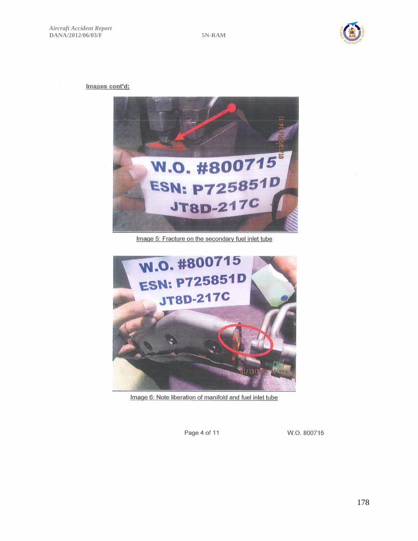
Aircraft Accident Report
DANA/2012/06/03/F 5N-RAM
178

Aircraft Accident Report
DANA/2012/06/03/F 5N-RAM
179

Aircraft Accident Report
DANA/2012/06/03/F 5N-RAM
180

Aircraft Accident Report
DANA/2012/06/03/F 5N-RAM
181
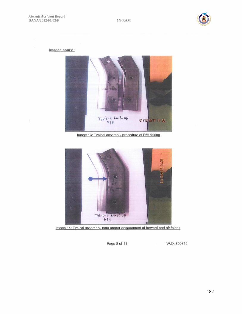
Aircraft Accident Report
DANA/2012/06/03/F 5N-RAM
182
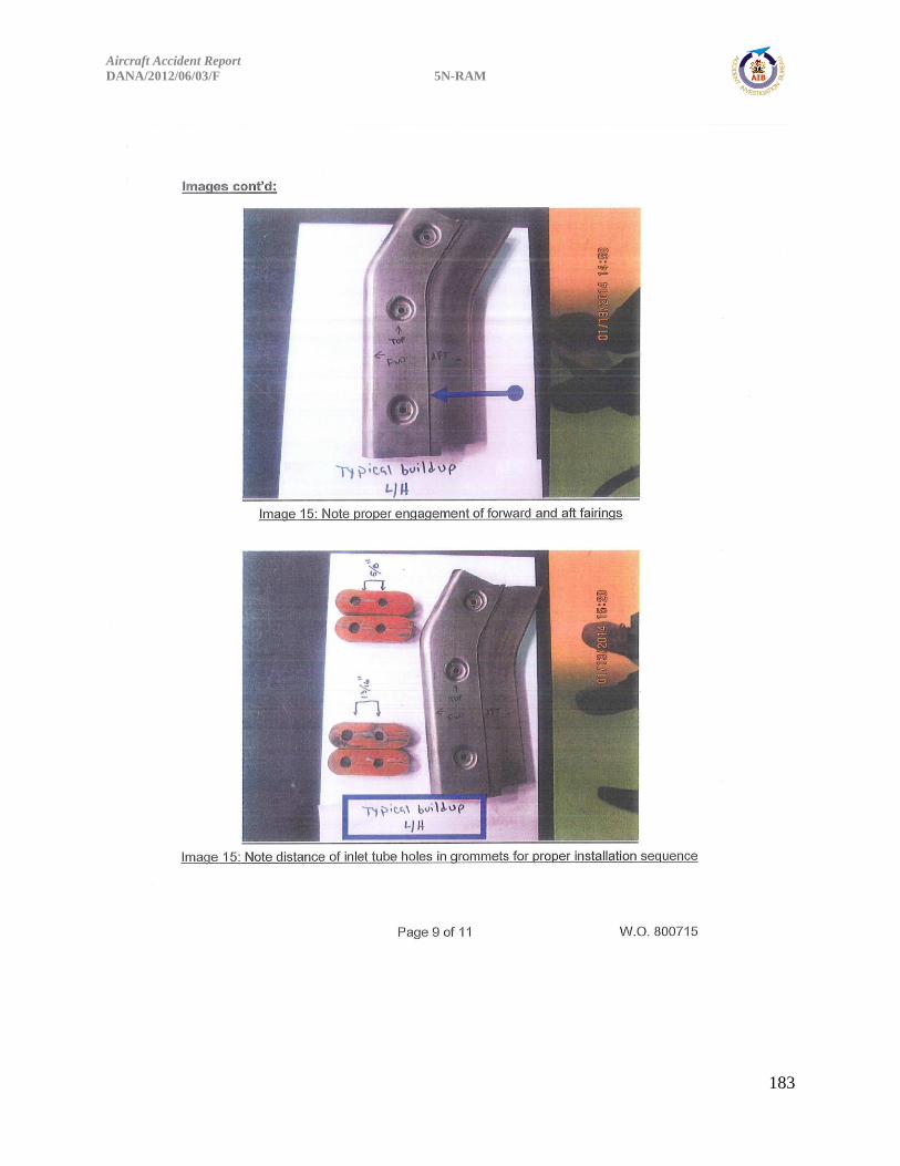
Aircraft Accident Report
DANA/2012/06/03/F 5N-RAM
183
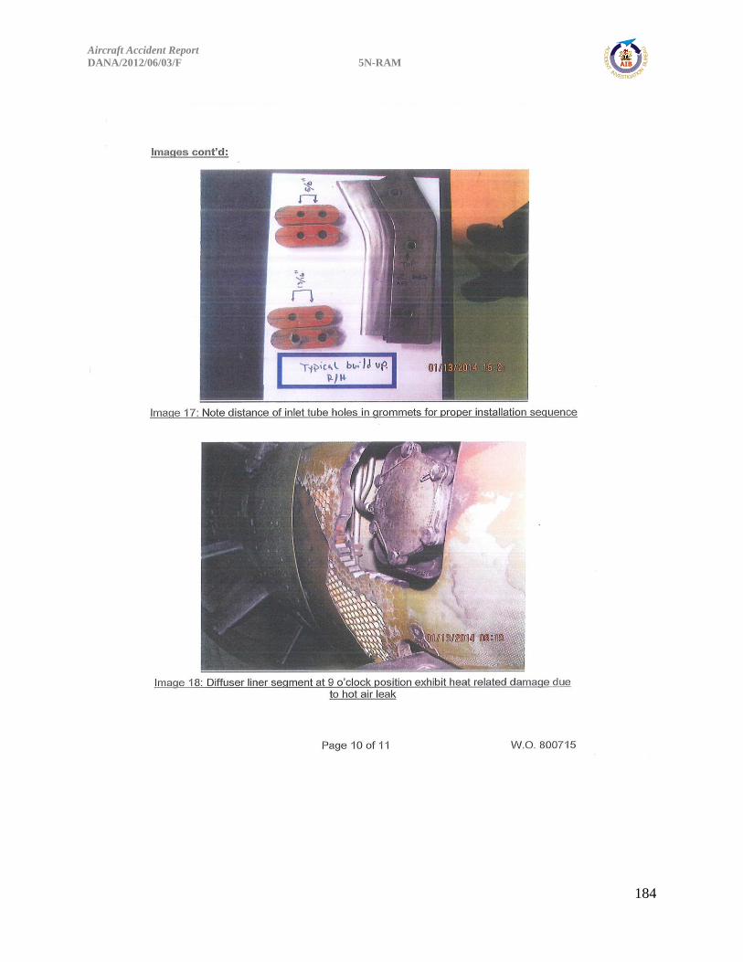
Aircraft Accident Report
DANA/2012/06/03/F 5N-RAM
184

Aircraft Accident Report
DANA/2012/06/03/F 5N-RAM
185
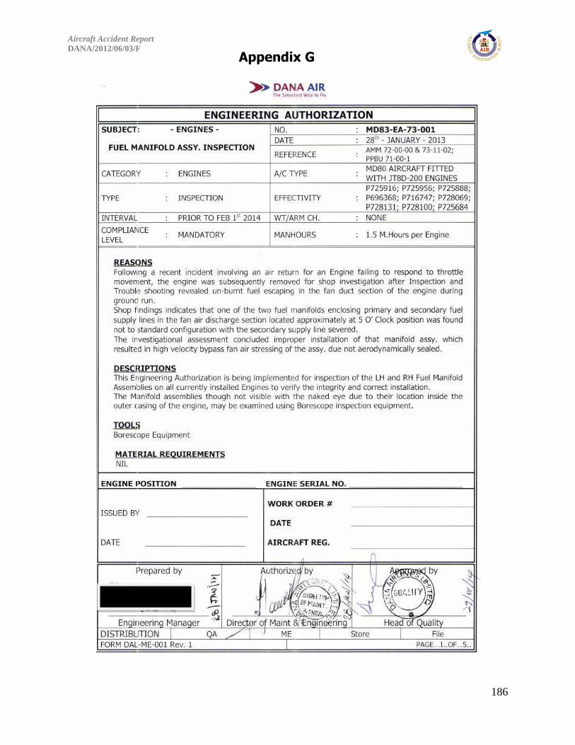
Aircraft Accident Report
DANA/2012/06/03/F 5N-RAM
186
Appendix G

Aircraft Accident Report
DANA/2012/06/03/F 5N-RAM
187

Aircraft Accident Report
DANA/2012/06/03/F 5N-RAM
188

Aircraft Accident Report
DANA/2012/06/03/F 5N-RAM
189

Aircraft Accident Report
DANA/2012/06/03/F 5N-RAM
190
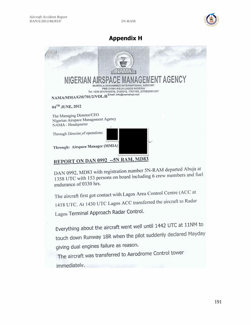
Aircraft Accident Report
DANA/2012/06/03/F 5N-RAM
191
Appendix H

Aircraft Accident Report
DANA/2012/06/03/F 5N-RAM
192

Aircraft Accident Report
DANA/2012/06/03/F 5N-RAM
193
Appendix I
Metallurgical Test of the Fuel Manifold Component Report

Aircraft Accident Report
DANA/2012/06/03/F 5N-RAM
194
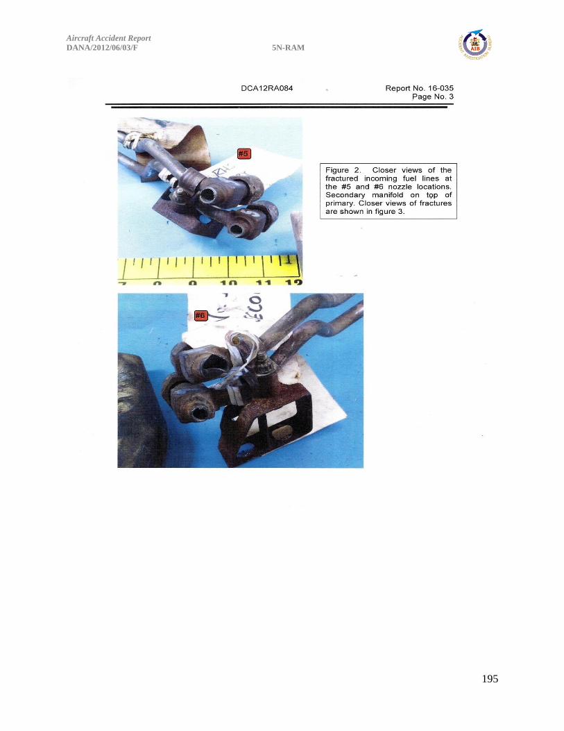
Aircraft Accident Report
DANA/2012/06/03/F 5N-RAM
195
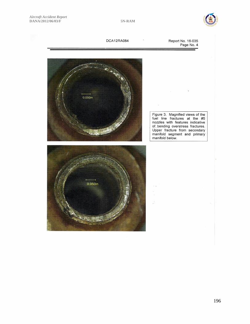
Aircraft Accident Report
DANA/2012/06/03/F 5N-RAM
196
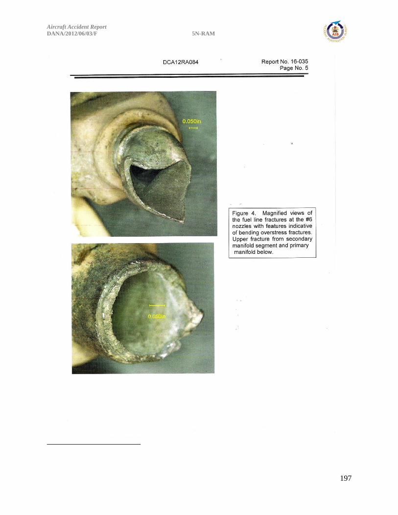
Aircraft Accident Report
DANA/2012/06/03/F 5N-RAM
197

Aircraft Accident Report
DANA/2012/06/03/F 5N-RAM
198
i END NOTE
Numbering philosophy used in the body of this Report is simple and
sequential and in no way contradicts the references in the Tear Down
Report (Engine Exam and Disassembly Field Notes) as contained in
Appendix B.