
airClient™TOTAL 241 sB3415-01 & sB3415-02
43
Copyright © smartBridges Pte Ltd. All Rights Reserved. u n w i r i n g o u r w o r l d TM airClient™ TOTAL 241 sB3415-01 & sB3415-02 User Guide Version 1.0
-
Upload
khangminh22 -
Category
Documents
-
view
0 -
download
0
Transcript of airClient™TOTAL 241 sB3415-01 & sB3415-02

Copyright © smartBridges Pte Ltd. All Rights Reserved.
u n w i r i n g o u r w o r l d T M
airClient™ TOTAL 241 sB3415-01 & sB3415-02
User Guide
Version 1.0
Page 2 of 43
i n t e l l i g e n t w i r e l e s s p l a t f o r m
airClient™ TOTAL 3415 User Guide
TABLE OF CONTENTS
ABOUT THIS DOCUMENT ..........................................................................................................3 Overview of User Guide......................................................................................................3 Related Publications...........................................................................................................3 Technical Support Center ..................................................................................................4
1. INTRODUCTION...................................................................................................................5 1.1. SYSTEM REQUIREMENTS.................................................................................................5 1.2. CHECKLISTS ...................................................................................................................6
2. AIRCLIENT TOTAL CONFIGURATION.............................................................................10 2.1. ADMINISTRATOR LOGIN .................................................................................................10 2.2. WEB GUI ADMINISTRATOR USER NAME AND PASSWORD CHANGE..................................13 2.3. USING THE CONFIGURATION PAGES ..............................................................................14 2.4. DEVICE MODE CONFIGURATION.....................................................................................17 2.5. CHANGING FROM NAT TO ROUTER MODE......................................................................18 2.6. CHANGING FROM ROUTER TO NAT MODE......................................................................18 2.7. AIRCLIENT TOTAL ROUTER AND NAT CONFIGURATION .................................................20
2.7.1. LAN Settings ......................................................................................................20 2.7.2. WLAN Settings ..................................................................................................21 2.7.3. DHCP Configurations........................................................................................24 2.7.4. IP/Port Forwarding ............................................................................................26 2.7.5. Routing Table ....................................................................................................27
2.8. SECURITY .....................................................................................................................29 2.8.1. Open System / Shared Key...............................................................................29 2.8.2. WPA-PSK ...........................................................................................................31
3. WIRELESS SETTINGS AND BANDWIDTH CONTROLLER ............................................32 3.1. WIRELESS SETTINGS.....................................................................................................32 3.2. BANDWIDTH CONTROL ..................................................................................................33
4. TRAFFIC STATISTICS.......................................................................................................34
5. TOOLS................................................................................................................................35 5.1. SYSTEM CONFIGURATION..............................................................................................35 5.2. SNTP SETTING.............................................................................................................36 5.3. SITE SURVEY ................................................................................................................37 5.4. SYSTEM ADMIN .............................................................................................................38 5.5. SNMP CONFIGURATION ................................................................................................38 5.6. BACKUP/RESTORE SETTINGS ........................................................................................39 5.7. FIRMWARE UPGRADE ....................................................................................................39 5.8. REBOOT .......................................................................................................................41
APPENDIX A – SOME USEFUL TERMS AND DEFINITIONS..................................................42

Page 3 of 43
i n t e l l i g e n t w i r e l e s s p l a t f o r m
airClient™ TOTAL 3415 User Guide
About This Document This user guide is for the networking professional who installs, configures and manages the smartBridges’ airClient™ TOTAL unit [model number: sB3415]. It provides detailed information on using the web-based configuration Graphics User Interface (GUI) to configure the airClient TOTAL sB3415 unit. This manual will help you gain a better understanding of how the various components of the sB3415 work. To configure smartBridges’ products, you need to have fundamental understanding of the concepts and technology of Local Area Networks (LAN) and wireless networking. The system installer will require expertise in the following areas:
• Outdoor radio equipment installation • Network configuration • Use of web browser for system configuration, monitoring and fault finding
In this chapter, you will find an overview of the user guide, and where to obtain additional information regarding installation and set-up.
Overview of User Guide This user guide provides all necessary information needed to set up, configure and deploy the airClient TOTAL sB3415 unit. The first chapter gives information on the configuration features and the system requirements. The second chapter provides detailed information on deploying the airClient TOTAL 241 in Router or NAT modes, and modifying the various configuration settings. The process of configuring the radio performance parameters and Bandwidth Controller is similar for the two modes and is shown in chapter 3. Chapter 4 shows how to display the wireless traffic statistics. The site survey tool is explained in Chapter 5, together with information about the system configuration tools, backup/restore features and firmware upgrade steps. The abbreviations and acronyms used in this user guide are explained in the Appendix.
Related Publications In addition to this user guide, the following related publications provide complete information on the TOTAL series (airHaul™, airPoint™ and airClient™) of radio units:
• Quick Install Guide (QIG) • Release Notes • Technical Specification
All the information can also be found on our website at http://www.smartbridges.com/.

Page 4 of 43
i n t e l l i g e n t w i r e l e s s p l a t f o r m
airClient™ TOTAL 3415 User Guide
Technical Support Center Comprehensive technical support by dedicated smartBridges engineers is available to all customers through the smartBridges support center website. The website provides updated tools and documents to help troubleshoot and resolve technical issues related to smartBridges products and technologies. To access the technical support resources, please visit the support center website at http://www.smartbridges.com/support/ For additional services and free downloads, you would need to register on the smartBridges support center website.

Page 5 of 43
i n t e l l i g e n t w i r e l e s s p l a t f o r m
airClient™ TOTAL 3415 User Guide
1. Introduction This user guide provides information on how to set up and deploy the airClient TOTAL 241 [sB3415] unit. A web-based management tool is provided to assist the user to configure the airClient TOTAL unit for different purposes. The airClient TOTAL web-based management tool provides the user with the following features:
1. System configuration 2. Device operational mode configuration 3. Ethernet and wireless IP configurations 4. Radio parameter configuration 5. Bandwidth management 6. Traffic Statistics 7. Site Survey 8. Saving/Restoring good configuration settings 9. Restore to Default settings 10. Firmware Upgrade
1.1. System Requirements The following are the minimum system requirements for the airClient TOTAL web-based configuration management tool:
1. Operating System: Windows 98/2000/XP/NT or Linux 2. Connection to the Internet for downloading the latest firmware and Sun JRE
3. Web browser: either Internet Explorer 5.0 and higher, Netscape 7.2 and higher, Mozilla 1.7 and
higher or Mozilla Firefox 0.8 and higher

Page 6 of 43
i n t e l l i g e n t w i r e l e s s p l a t f o r m
airClient™ TOTAL 3415 User Guide
1.2. Checklists Deployment time, link uptime and support time can be improved by adopting proper site survey analysis, link planning, pre-installation tests, and web-GUI familiarization. The following pre-installation and post-installation checklist attempts to give the installer the basic understanding on the points to consider for a wireless deployment.
Pre-Installation Checklist for airClient TOTAL
Organization Name/Site Name
Address
City
State
Zip Code
Telephone Number
Site Survey and Link Planning No Parameters Units Site A Site B 1 Regulatory Standard to be followed FCC/ETSI 2 Frequency Band sB3415: 2.4GHz only
3 Maximum Output Power as per the
Regulatory Authority (EIRP) 100mW/1W/4W
4 Latitude Deg Min Sec 5 Longitude Deg Min Sec 6 UPS Installed Yes/No 7 UPS specification if any KVA 8 Line Voltage 90V-264V AC,50-60 Hz
9 Near Line of Site between sites Yes/No
10 Height of tower Feet/Meters 11 Required Throughput Mbps 12 Distance between sites Miles/km 13 Antenna Type Internal/External
14 Antenna Manufacturer smartBridges/Other
15 Gain of antenna dBi
16 Antenna Polarization Horizontal/Vertical
Horizontal - deg
17 Beam width of antenna
Vertical – deg

Page 7 of 43
i n t e l l i g e n t w i r e l e s s p l a t f o r m
airClient™ TOTAL 3415 User Guide
No Parameters Units Site A Site B 18 Length of external cable connecting Radio
and antenna Feet/meters
19 Fade Margin taken into account for link
budgeting Ideally between 15 to 20 dB
20 Model of smartBridges airClient TOTAL equipment selected for a link. Please refer to note below for selecting the right equipment
sB3415
21 Grounding- Earth to Neutral Voltage Ideally less than 2 Volts
22 Length of the Ethernet cable required for
powering the unit Feet/meters
23 Choose the best channel which can be
used with the help of the Site Survey Tool and scanning tools like Netstumbler
Specify channel number
Pre Installation Lab Testing of Equipment No Parameters Units Site A Site B 1 Network diagram along with IP address of
all the interfaces for link to be set up in place
Yes/No
2 Availability of Quick Installation Guide Yes/No 3 Availability of User Guide and CD Yes/No 4 Ensure that all items listed in the "Package
Contents" of Quick Installation Guide are included in the shipment
Yes/No
5 Availability of Installation Kit Yes/No 6 Radio MAC address of Access Point MAC ID no. 7 Configured for pre-installation testing Yes/No 8 Ping response ms 9 Ping Success Rate Percentage % 10 Throughput test (Upload/Download) Varies depending on the
Bandwidth Control, signal strength, link quality and distance
Note: Throughput for sB3415 Series sB3415-01: As much as 512 kbps data throughput with a range of up to 4 miles (6 km) sB3415-02: As much as 1 Mbps data throughput with a range of up to 4 miles (6 km) Signature of Engineer:
Name: Email: Date:

Page 8 of 43
i n t e l l i g e n t w i r e l e s s p l a t f o r m
airClient™ TOTAL 3415 User Guide
Post-Installation Checklist for airClient TOTAL
Organization Name/Site Name
Address
City
State
Zip Code
Telephone Number
General Configuration Information No Parameters Units Site A Site B 1 Radio operation mode
Router/NAT
2 SSID of a Radio
Up to 32 characters
3 IP address of Ethernet Port
32-bit numeric address
4 IP address of Wireless Port
32-bit numeric address
5 RSSI
dBm (At present, ‘Level’ in the current firmware version)
6 Channel selected for link
7 Radio TX Output Power
0 to +18 dBm
8 Model of smartBridges airClient TOTAL equipment selected for a link.
sB3415
9 Antenna Type Internal/External
10 Antenna Manufacturer smartBridges/Name of other manufacturer
11 Antenna Polarization Horizontal/Vertical
Horizontal – deg
12 Beam width of antenna
Vertical – deg
13 Antenna Gain
dBi

Page 9 of 43
i n t e l l i g e n t w i r e l e s s p l a t f o r m
airClient™ TOTAL 3415 User Guide
Checklist No Parameters Units Site A Site B 1 Check the crimping of the Ethernet cable
at both the ends
Yes/No
2 Check the proper grounding of the antenna and equipment
Yes/No
3 Ensure that there are no extreme bends or kinks in the cable
Yes/No
4 Ensure Ethernet cable is not running near a sharp edge
Yes/No
5 Ensure antenna is aligned to get the best RSSI and link quality
Yes/No
6 Ping response
ms
7 Ping success rate
Percentage
8 Throughput test (Upload/Download)
Mbps
9 Link stability based on observation for 1 hour
Yes/No
10 Shielded RJ-45 cable to be used from POE to the unit
Yes/No
Signature of Engineer:
Name:
Email:
Installation Date:
Commissioned Date: For the latest information on smartBridges products, please visit our website at: http://www.smartbridges.com/

Page 10 of 43
i n t e l l i g e n t w i r e l e s s p l a t f o r m
airClient™ TOTAL 3415 User Guide
2. airClient TOTAL Configuration The airClient TOTAL can work in either Router or NAT mode. The procedures for configuring the various parameters in each mode are outlined in this chapter. Some of the details on the technical terms, acronyms and abbreviations used can be found in Appendix A.
2.1. Administrator Login The airClient TOTAL unit comes with a pre-configured default Ethernet (wired-side) IP address: 192.168.0.225 and subnet mask: 255.255.255.0. This default device IP address should be used when accessing the device configuration management interface for the first time using a web-browser. The PC must be on the same subnet as the airClient TOTAL unit. Follow the steps below to login as an Administrator to the web-based configuration management interface:
1. Connect the airClient TOTAL using the Power over Ethernet (PoE) to a PC or network via the
ETH (Ethernet) port. (Please refer to the Quick Install Guide for more information on connections).
2. Open a web browser on the PC, type the default device IP address, (http://192.168.0.225) in the
web browser address field, and press the Enter key.
3. A user login box as shown below (Fig 2-1) will appear. Enter the User name and Password. The default user name is administrator and the password is smartBridges (case sensitive).
Figure 2-1 Administrator Login
4. Click on the Login button. The airClient TOTAL Summary Information page (Fig 2-2) will
appear.

Page 11 of 43
i n t e l l i g e n t w i r e l e s s p l a t f o r m
airClient™ TOTAL 3415 User Guide
Figure 2-2 airClient TOTAL Summary Information Page

Page 12 of 43
i n t e l l i g e n t w i r e l e s s p l a t f o r m
airClient™ TOTAL 3415 User Guide
The descriptions of the fields in the Summary Information page is provided in the table (Table 2-1) below:
Table 2-1 Description of the field items in the ‘Summary Information’ page
Field Items on Summary Info page Descriptions
LAN IP Mode Set to Static IP by default
System Name This is the user defined name of the unit
IP Address Ethernet (wired) IP Address. LAN Settings
Subnet Mask Ethernet (wired) IP subnet Mask
WLAN Type Static IP or Dynamic IP
IP Address Wireless IP address
Network mask Wireless IP Mask
Gateway Address Wireless IP Gateway
DNS Server Primary DNS Server
WLAN Settings
Secondary DNS Secondary DNS Server
SSID Displays the SSID currently set for the device. This is the public name of the wireless link
Channel Displays the channel at which the Client is associated
Association Status Displays Associated or Not Associated status
Wireless Mode Wireless operating mode (802.11b / 802.11g)
Security Mode Displays if security is Enabled or Disabled
Authentication Open System / Shared Key / WPA-PSK
Data Rate (Mbps) This indicates the rate at which the radio has been asked to operate by the user.
Transmit Power This is used to set the output power of the radio.
Preamble The radio preamble is a section of data at the head of a packet. The preamble contains information that the radio needs when sending and receiving packets
Wireless Settings
Slot Time This can be set to Long Short time or Short time DHCP Server Settings
DHCP Server Displays if DHCP Server is Enabled or Disabled
Address Pool Allows the Address Pool to be System defined or User defined
Start Address The Starting address of the DHCP Client IP Address pool
End Address The Ending address of the DHCP Client IP Address pool
Lease Time The maximum time of the DHCP Leases. The maximum allowable limit is 2880 minutes.
NAT Virtual Server Displays the no. of entries in the IP/Port Forwarding Table
Routing Setting
Static Routing Displays the no. of static routes in the Static Routing Table

Page 13 of 43
i n t e l l i g e n t w i r e l e s s p l a t f o r m
airClient™ TOTAL 3415 User Guide
2.2. Web GUI Administrator User Name and Password Change The default administrator user name for the airClient TOTAL 3415 is administrator and administrator password is smartBridges (please note that this is case sensitive). Follow the steps below to change the administrator user name and password:
1. From the top navigation menu bar, click on Tools | System Admin. A System Administration
interface will appear as shown below. 2. Enter the user name you wish in the User Name field.
3. Enter the new password in Password and Verify Password fields. Click on the Save button to
save the settings.
4. From the top navigation menu bar, click on Tools | Reboot . This is to reboot the unit for the new user name and password to take effect.
Figure 2-3 Administrator User Name and Password Change
Page 14 of 43
i n t e l l i g e n t w i r e l e s s p l a t f o r m
airClient™ TOTAL 3415 User Guide
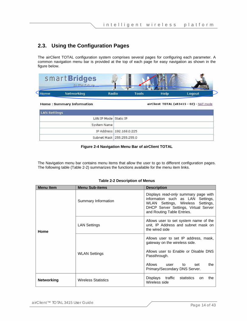
2.3. Using the Configuration Pages The airClient TOTAL configuration system comprises several pages for configuring each parameter. A common navigation menu bar is provided at the top of each page for easy navigation as shown in the figure below.
Figure 2-4 Navigation Menu Bar of airClient TOTAL
The Navigation menu bar contains menu items that allow the user to go to different configuration pages. The following table (Table 2-2) summarizes the functions available for the menu item links.
Table 2-2 Description of Menus
Menu Item Menu Sub-items Description Summary Information
Displays read-only summary page with information such as LAN Settings, WLAN Settings, Wireless Settings, DHCP Server Settings, Virtual Server and Routing Table Entries.
LAN Settings Allows user to set system name of the unit, IP Address and subnet mask on the wired side Home
WLAN Settings
Allows user to set IP address, mask, gateway on the wireless side. Allows user to Enable or Disable DNS Passthrough. Allows user to set the Primary/Secondary DNS Server.
Networking
Wireless Statistics
Displays traffic statistics on the Wireless side

Page 15 of 43
i n t e l l i g e n t w i r e l e s s p l a t f o r m
airClient™ TOTAL 3415 User Guide
Menu Item Menu Sub-items Description Association Status
Shows the status of the association and the MAC of the AP associated with
DHCP
Allows user to Enable or Disable DHCP Server
DHCP List
Displays the DHCP List; if DHCP Server is Enabled
IP/Port Forwarding
Allows user to add entries to map Local Area Network IP Address (or port) behind the NAT to a global port accessible through the wireless interface. User will be able to use this option only when the unit is configured in the NAT mode.
Routing Table
Allows the user to view, add and delete or update static routes. Allows the user to Enable or Disable RIP running on the device. RIPv2 is run by default on the device.
Bandwidth Control Allows bandwidth management of the wireless link
Wireless Settings
Allows the user to select internal or external antenna, configure distance, select data rate, set transmit power, Preamble and Slot time
Radio
Security
Security: Allows user to set the security mode for the device. User can choose Open System, Shared, or WPA-PSK. Open System / Shared Key: • Allows
Allow user to turn on encryption using WEP at 64 or 128 bits and choose between Open Systems and Shared Key.
• WPA-PSK:
This mode allows user to use WPA pre-shared key and cipher as TKIP or AES for client authentication.
Note: By default, the Security mode is Disabled.
Tools System Configuration
Allows user to switch the operation mode between Router or NAT mode. Allows user to set the SSID, Enable or Disable SSID Suppressed.

Page 16 of 43
i n t e l l i g e n t w i r e l e s s p l a t f o r m
airClient™ TOTAL 3415 User Guide
Menu Item Menu Sub-items Description
Channel: This is not selectable by the user in the current Router or NAT configuration mode. Wireless Mode: Allows the user to select between 802.11b or 802.11g wireless standards.
SNTP Setting Allows user to set the Network Time Server and the Time Zone.
Site Survey Shows all the standards based wireless devices operating in the area.
System Admin
Allows user to change the Administrator user name and/or password.
System Log
Allows user to display the system log locally or remotely. Currently, this device will only log in case of any problems with the unit.
SNMP Configuration This allows the user to Enable/Disable SNMP.
Backup/Restore Settings
Allows user to save or restore good settings, backup the configuration file and upload it later, do a Factory Reset on the unit.
Reboot
Allows user to reboot the unit. Note: All changes made to the unit will take effect only after a Reboot is done.
Technical Support Information on Technical Support
User Guide – Online Link to online user guide
Product Registration and Feedback
Allows user to register product and provide feedback or suggestions.
Check for Updates
Checks smartBridges website for any software updates.
Help
About airClient TOTAL
General system description, software version information and warranty information.
Logout Logout Allows user to logout from the airClient TOTAL device.

Page 17 of 43
i n t e l l i g e n t w i r e l e s s p l a t f o r m
airClient™ TOTAL 3415 User Guide
2.4. Device Mode Configuration The device operational mode is displayed at the top right hand corner of each page. The device mode configuration allows the user to configure the airClient TOTAL to a NAT (Network Address Translation) mode or Router mode. These modes are explained below. NAT: This is the default operating mode. This mode allows you to use one segment of private IP
addresses for mulitple hosts to access the external network using a single wireless IP address. This translation helps in protecting the access of internal hosts from external network.
Router: This mode allows you to configure different segment of IP address in Ethernet and Wireless interface. A standard routing functionality is available in this mode.
Figure 2-5 airClient TOTAL Device Mode Configuration

Page 18 of 43
i n t e l l i g e n t w i r e l e s s p l a t f o r m
airClient™ TOTAL 3415 User Guide
2.5. Changing from NAT to Router Mode The default configuration of the airClient TOTAL is in the NAT mode. Follow the steps below to change the airClient TOTAL from the default NAT mode to Router mode:
1. From the navigation menu bar, click on Tools | System Configuration. The Operation Mode
screen will appear as shown below. 2. Choose Non-WDS Client with Router in the Operation Mode screen.
3. Click on Save and click on Tools | Reboot to reboot the unit. The settings will be applied after
the Reboot. 4. The IP Address, IP Mask and Gateway for LAN Settings and WLAN Settings remain the same
in the Router mode as it was in the NAT mode.
Figure 2-6 Changing NAT Mode to Router Mode
2.6. Changing from Router to NAT Mode Follow the steps below to change the airClient TOTAL from Router Mode to NAT Mode:
1 From the navigation menu bar, click on Tools | System Configuration. The Operation Mode
screen will appear as shown below. 2 Choose Non-WDS Client with NAT in the Operation Mode screen. 3 Click on Save and click on Tools | Reboot to reboot the unit. The settings will be applied after
the Reboot.

Page 19 of 43
i n t e l l i g e n t w i r e l e s s p l a t f o r m
airClient™ TOTAL 3415 User Guide
4 The IP Address, IP Mask and Gateway for Ethernet Configuration and Wireless Configuration remains the same in the NAT mode as it was in the Router mode.
Figure 2-7 Changing Router Mode to NAT Mode

Page 20 of 43
i n t e l l i g e n t w i r e l e s s p l a t f o r m
airClient™ TOTAL 3415 User Guide
2.7. airClient TOTAL Router and NAT Configuration This section covers the procedures for configuring various parameters in the Router and NAT modes.
2.7.1. LAN Settings The LAN and the WLAN settings are maintained in two different subnets. Follow the steps below to re-configure the airClient TOTAL Router/NAT Ethernet parameters:
1. From the navigation menu bar, click on Home | LAN Settings to change Ethernet/wired side
parameters. The LAN Settings screen will appear as shown below.
2. Enter the System Name of the unit, if required.
3. Enter the IP address and Subnet mask to set the LAN IP address and subnet mask.
4. Click on Save and click on Tools | Reboot to reboot the unit. The settings will be applied after the Reboot.
Figure 2-8 airClient TOTAL Router/NAT LAN Settings

Page 21 of 43
i n t e l l i g e n t w i r e l e s s p l a t f o r m
airClient™ TOTAL 3415 User Guide
2.7.2. WLAN Settings The wireless parameters need to be configured to allow the airClient TOTAL unit to associate with an airPoint™ Nexus device or any other third party wireless access point. Follow the steps below to configure the airClient TOTAL Router/NAT Mode Wireless IP Settings parameters:
1. From the navigation menu bar, click on the Home | WLAN Settings to set the wireless
parameters for the unit. The WLAN Settings screen will be displayed as shown below. 2. Select the Dynamic checkbox if the IP address can be obtained automatically from the wireless
link; else select the Static checkbox to manually configure the wireless IP/mask.
3. For Static Connection Type, enter the wireless IP Address, IP Mask, Gateway IP address for the airClient TOTAL unit.
4. To enable DNS Passthrough, check the DNS Passthrough checkbox.
5. Set the Primary/Secondary DNS Server, as required.
6. Click on Save and click on Tools | Reboot to reboot the unit. The settings will be applied after
the Reboot.
Figure 2-9 airClient TOTAL Router/NAT WLAN Settings
For the airClient TOTAL device to associate with an access point, the user also needs to configure the access point’s SSID, security (if used), and select External/Internal antenna options.

Page 22 of 43
i n t e l l i g e n t w i r e l e s s p l a t f o r m
airClient™ TOTAL 3415 User Guide
Follow the steps below to configure the airClient TOTAL Router/NAT Mode wireless association parameters:
1. From the navigation menu bar, click on Tools | System Configuration to set the SSID and
wireless mode (802.11 b/g). The Operation mode screen will be displayed as shown in Fig 2-10.
2. Set the SSID, and the wireless mode to either 802.11 b/g.
3. Click on Save to save the settings.
4. From the navigation menu bar, click on Radio | Wireless Settings to set the wireless parameters for link association. The Wireless Settings screen will be displayed as shown in Fig 2-11.
5. For the Antenna Selection, choose either Internal or External antenna, as per the requirement.
6. Configure the Distance parameter.
7. Select the Data rate from the drop down menu. By default, the data rate is set to Best.
8. Select the Transmit power of the radio from the drop down menu.
9. Select the Preamble to be Long or Short. By default the preamble is set to Long.
10. Click on Save and click on Tools | Reboot to reboot the unit. The unit will attempt to associate
after the Reboot.
Note: The Association Status field in the Wireless Settings of the Summary Information page will
show the status as Associated if the unit has associated successfully, as shown in Fig 2-12a below. Under Networking | Association Status, the status will also show the Access Point that the client is associated with, as shown in Fig 2-12b below.
Figure 2-10 airClient TOTAL Router Wireless Operating Mode

Page 23 of 43
i n t e l l i g e n t w i r e l e s s p l a t f o r m
airClient™ TOTAL 3415 User Guide
Figure 2-11 airClient TOTAL Router Wireless Settings
Figure 2-12a airClient TOTAL Summary Information page
Figure 2-12b airClient TOTAL Router/NAT Wireless Association Status

Page 24 of 43
i n t e l l i g e n t w i r e l e s s p l a t f o r m
airClient™ TOTAL 3415 User Guide
2.7.3. DHCP Configurations The airClient TOTAL unit can be used as a DHCP server. DHCP (Dynamic Host Configuration Protocol) allows a host to be automatically assigned a new IP address out of a pool of preconfigured IP addresses for the network. Follow the steps below to configure the airClient TOTAL unit as a DHCP server:
1. From the Navigation menu bar, click on Networking | DHCP to access the DHCP configuration
page. The DHCP server screen will be displayed as shown below. 2. Click on Enable DHCP Server to start the DHCP server configuration, and click on Save to
enable the IP Address Pool buttons.
3. Select System Define if you wish the system to assign the IP addresses.
4. Select User Define if you wish to assign the IP address from the IP Address Pool.
5. If setting is User Define, enter the Start IP address and an End IP Address for the IP pool range that can be assigned to a DHCP client. Note that the Start and End IP address have to be in the same network segment as of the Ethernet IP address segment.
6. In case you require to reserve certain IP addresses for known devices, enter the corresponding
MAC and IP address in the DHCP server reserved entries table .
7. Enter the lease time in minutes. The maximum lease time that is allowed is 2880 minutes.
8. Click on Save and click on Tools | Reboot to reboot the unit. The settings will be applied after the Reboot.
9. The revised DHCP settings will show up in the Summary Information page of the unit.

Page 25 of 43
i n t e l l i g e n t w i r e l e s s p l a t f o r m
airClient™ TOTAL 3415 User Guide
Figure 2-13 DHCP Server Configurations
Follow the steps below to disable the airClient TOTAL Router/NAT DHCP server:
1. From the Navigation menu bar, click on Networking | DHCP Server to access the DHCP
configuration page. 2. Uncheck the Enable DHCP Server button to disable the DHCP server configuration.
3. Click on Save and click on Tools | Reboot to reboot the unit. The settings will be applied after
the Reboot.

Page 26 of 43
i n t e l l i g e n t w i r e l e s s p l a t f o r m
airClient™ TOTAL 3415 User Guide
2.7.4. IP/Port Forwarding IP/Port forwarding (also referred to as Virtual Server in this document) allows the user to define the port mapping between the local area network and the public network. This feature is only available when the device is configured in the NAT mode. Follow the steps below to map a local port to the global port (accessible through the wireless interface):
1. Click on Networking | IP/Port Forwarding from the menu bar to access the IP Port Forwarding
page. 2. Depending on the application, select the protocol as TCP/UDP.
3. Enter the Local IP Address and the Local Port and the corresponding Global port that can be
used to access this Local IP/port through the wireless interface.
4. Activate/Deactivate the entry.
5. Click Add to add the entry into the IP Port Forwarding Table. This will result in an entry into the table as shown below.
6. Click on Save and click on Tools | Reboot to reboot the unit. The settings will be applied after
the Reboot.
7. Upon the reboot, the total no. of entries in this table will show up in Summary Information page as shown in Fig 2-15
Figure 2-14 airClient TOTAL IP/Port Forwarding Table

Page 27 of 43
i n t e l l i g e n t w i r e l e s s p l a t f o r m
airClient™ TOTAL 3415 User Guide
Figure 2-15 IP/Port Forwarding Table Entries on Summary Page
Follow the steps below to edit or delete a port forwarding entry in the airClient TOTAL operating in NAT Mode.
1. Click on Networking | IP/Port Forwarding from the menu bar to access the Port Forwarding
Table page. 2. In case you want to edit an existing entry, click on the Edit corresponding to the row. The entries
will show up in the fields. Edit the entries and click the Update button to update the table.
3. In case you want to delete an existing entry from the Port Forwarding table, select the mapping you wish to delete, and click Delete.
4. Click on Save and click on Tools | Reboot to reboot the unit for the changes to be effective.
2.7.5. Routing Table The airClient TOTAL Router web-interface has the provision to add, delete or view static routes. To view the routing table page, click on Networking | Routing Table from the menu bar. To enable dynamic routing, select Support RIP v2 on the Routing Table page. Dynamic Routing is enabled by default. Adding and deleting static routes is allowed in the Router Mode of the airClient TOTAL. Follow the steps below to add a static route entry in the airClient TOTAL operating in the Router Mode.
1. Click on Networking | Routing Table from the menu bar to access the routing table page. 2. Enter the Destination IP, IP Mask, Gateway for the new route. Select Add to add a new route as
shown in Fig 2-16.
3. Select the status to activate or deactivate the static route. 4. Click on Save and click on Tools | Reboot to reboot the unit. The new routes will be activated or
deactivated after the Reboot.
5. Upon the reboot, the total number of entries in this Routing Table will show up in Summary Information page as shown in Fig 2-17 below.

Page 28 of 43
i n t e l l i g e n t w i r e l e s s p l a t f o r m
airClient™ TOTAL 3415 User Guide
Figure 2-16 Adding Static Route
Figure 2-17 Static Route Entries on Summary Page
Follow the steps below to edit or delete a static route entry in the airClient TOTAL operating in the Router Mode.
1. Click on Networking | Routing Table from the menu bar to access the view routing table page. 2. From the Routing table on this page, select the route you wish to delete, and click Delete, as
shown in Fig 2-18.
3. In case you want to edit the existing entry, click on the Edit corresponding to the row. The entries will show up in the fields. Edit the entries and click the Update button to update the table.
4. Click on Save and click on Tools | Reboot to reboot the unit for the changes to be effective.

Page 29 of 43
i n t e l l i g e n t w i r e l e s s p l a t f o r m
airClient™ TOTAL 3415 User Guide
Figure 2-18 Deleting the Static Route
2.8. Security This section allows you to configure wireless encryption to prevent unauthorized parties from accessing the network. The security options on the airClient TOTAL are as follows: 1. Open System 2. Shared Key 3. WPA –PSK Note: By default, security is Disabled.
2.8.1. Open System / Shared Key
Open System/Shared Key authentication is used for security between the airClient TOTAL and the airPoint Nexus (or any other access point). To enable, disable or change security settings, the user needs to access the security setting page on the web interface. The following table describes the information for the security settings for the Open System or Shared Key authentication. Follow the steps below to configure the Data Encryption parameters:
1. Click on Radio | Security from the main menu, and a screen as shown in Fig 2-19 will be
displayed. 2. Choose the Authentication Type as Open System or Shared Key in the drop down menu.
3. Choose the Key Entry Method as HEX or ASCII. Key should be HEX when trying to
associate with the airPoint Nexus Access Point.

Page 30 of 43
i n t e l l i g e n t w i r e l e s s p l a t f o r m
airClient™ TOTAL 3415 User Guide
4. Choose the Key length (64 bits or 128 bits) from the drop down list. For HEX entry method, Key length is 10 characters for 64 bits, and 26 characters for 128 bits.
5. Enter the WEP key in the Key Table entries.
6. Select the Key ID of the index of the key to be used to associate.
7. Click Save to save the settings.
8. Select Tools | Reboot to reboot the unit. The settings will be effective after the reboot
Figure 2-19 airClient TOTAL Security - Open System/Shared Key Configuration
Table 2-4 Security Settings for Open System/Shared Key
Page Items Descriptions
Authentication Type
Choose between open system and shared key authentication modes Open System: Open System is null authentication. With WEP enabled and valid WEP key on both ends, it provides data encryption. Shared Key: Strict authentication for both authentication and data encryption. Clients must provide valid WEP key to associate
Key Entry Method Choose HEX if the key entered is the Hexadecimal format, choose ASCII if the key entered is in ASCII format.
Key ID
Select one of the key indexes from the 1 to 4.
Key The value of the encryption key
Page 31 of 43
i n t e l l i g e n t w i r e l e s s p l a t f o r m
airClient™ TOTAL 3415 User Guide
Page Items Descriptions
Key Length
Choose encryption key size between 64bits and 128bits 64 bits: User has to input 10 HEX digits. 128 bits: User has to input 26 HEX digits.
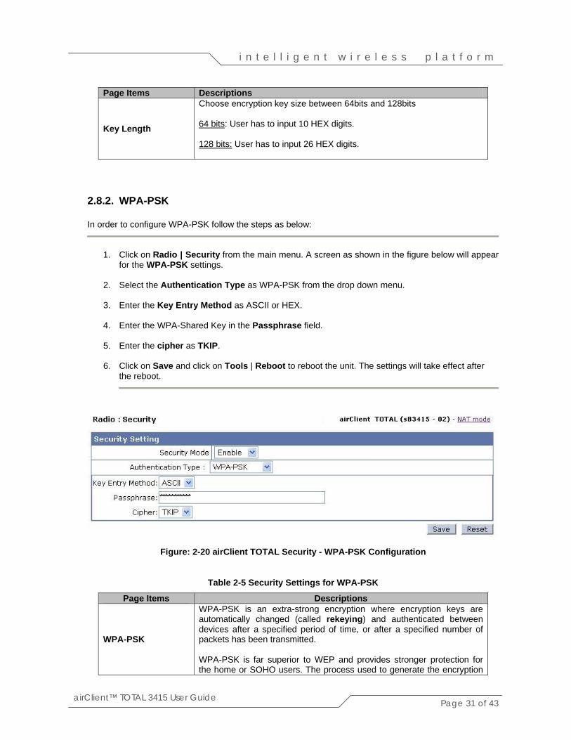
2.8.2. WPA-PSK In order to configure WPA-PSK follow the steps as below:
1. Click on Radio | Security from the main menu. A screen as shown in the figure below will appear
for the WPA-PSK settings. 2. Select the Authentication Type as WPA-PSK from the drop down menu.
3. Enter the Key Entry Method as ASCII or HEX. 4. Enter the WPA-Shared Key in the Passphrase field.
5. Enter the cipher as TKIP. 6. Click on Save and click on Tools | Reboot to reboot the unit. The settings will take effect after
the reboot.
Figure: 2-20 airClient TOTAL Security - WPA-PSK Configuration
Table 2-5 Security Settings for WPA-PSK
Page Items Descriptions
WPA-PSK
WPA-PSK is an extra-strong encryption where encryption keys are automatically changed (called rekeying) and authenticated between devices after a specified period of time, or after a specified number of packets has been transmitted. WPA-PSK is far superior to WEP and provides stronger protection for the home or SOHO users. The process used to generate the encryption

Page 32 of 43
i n t e l l i g e n t w i r e l e s s p l a t f o r m
airClient™ TOTAL 3415 User Guide
Page Items Descriptions key is very rigorous and the re-keying (or key changing) is done very quickly. This stops even the most determined hacker from gathering enough data to break the encryption.
Key Entry Method Key entry method can be HEX or ASCII. To associate with the airPoint Nexus device, this value should be set to ASCII.
Passphrase This key is used by the client to become authenticated with the airPoint Nexus or any third party WPA capable device.
Cipher This can be set to TKIP
3. Wireless Settings and Bandwidth Controller
3.1. Wireless Settings The Wireless Settings can be accessed from the Radio | Wireless Settings in the navigation menu bar.
Figure 3-1 airClient TOTAL Wireless Settings
The following table summarizes the information for the wireless settings.
Table 2-3 Wireless Settings
Page Items Descriptions Antenna Selection
This sets the Antenna to Internal or External.
Distance
The range of the link which corresponds to ACK window size

Page 33 of 43
i n t e l l i g e n t w i r e l e s s p l a t f o r m
airClient™ TOTAL 3415 User Guide
Page Items Descriptions
Data Rate This rate at which the operator wants radio to operate. By default, this rate is set to Best.
Transmit Power
This is used to set the output power of the radio. The valid radio power range is from 0 to 18 dBm.
Preamble
The radio preamble is a section of data at the head of a packet that contains information the airClient device needs when sending and receiving packets By default this value is set to Long.
Slot Time This can be set to Long Short Time or Short Slot time.
Protection Mode Select None, Always or Auto
Protection Type Select CTS only or RTS-CTS
RTS/CTS Threshold
Default value is 2346 bytes. The range of value is from 256 to 2346 bytes
3.2. Bandwidth Control Using the Bandwidth Controller, the user can limit the wireless link bandwidth speed. The maximum allowable bandwidth is up to 512Kbps in sB3415-01 and 1Mbps in 3415-02. This is subject to the available upstream bandwidth, signal level and distance. Follow the steps below to change the bandwidth parameters:
1. From the navigation menu bar, click on Networking | Bandwidth Control. 2. Click on the Bandwidth Control button to enable the bandwidth controlling feature.
3. Enter the desired value in kbps. The maximum bandwidth allowable is 1024 kbps.
4. Click on Save and click on Tools | Reboot to reboot the unit. The settings will take effect after
the Reboot.

Page 34 of 43
i n t e l l i g e n t w i r e l e s s p l a t f o r m
airClient™ TOTAL 3415 User Guide
Figure 3-2 airClient TOTAL Bandwidth Control
4. Traffic Statistics Wireless Statistics can be displayed by clicking on Networking | Wireless Statistics from the navigation menu. The following figure shows the statistics page.
Figure 4-1 airClient TOTAL Wireless Statistics

Page 35 of 43
i n t e l l i g e n t w i r e l e s s p l a t f o r m
airClient™ TOTAL 3415 User Guide
The following table summarizes the information for the wireless traffic settings.
Table 4-1 Wireless Traffic Statistics
Wireless Traffic Statistics
Total Bytes Receive Total no. of bytes received on the wireless interface. Total Bytes Transmit Total no. of bytes transmitted on the wireless interface. Broadcast Packets Receive Total no. of broadcast packets received. Broadcast Packets Transmit Total no. of broadcast packets transmitted. Multicast Packets Receive Total no. of multicast packets received. Multicast Packets Transmit Total no. of multicast packets transmitted.
Unicast Packets Receive Total no. of unicast packets received from a specific destination.
Unicast Packets Transmit Total no. of unicast packets transmitted to a specific destination.
Up Time Displays the time since the last reboot of the device.
5. Tools In this section, you will find relevant information for changing the operating mode of the device, saving the configuration, restoring to factory defaults and upgrading the firmware.
5.1. System Configuration The System Configuration page allows the user to change the operating mode of the unit. Click on Tools | System Configuration from the navigation menu bar, to access the System Configuration page. The following figure displays the System Configuration page.
Figure 5-1 airClient TOTAL System Configuration

Page 36 of 43
i n t e l l i g e n t w i r e l e s s p l a t f o r m
airClient™ TOTAL 3415 User Guide
The following table summarizes the information for the System Configuration page.
Table 5-1 System Configuration Page Items
5.2. SNTP Setting The device time comes from the network time information source. The device needs access to a network timer (NTP time server) source. The NTP time server IP can be configured as follows:
1. From the navigation menu bar, click on Tools | SNTP Setting to configure the NTP Server. A
page as shown below will appear. 2. Enter a valid SNTP server IP address and select the Time Zone. The default NTP server is
128.250.36.2 and the default Time Zone is Singapore.
3. Click on the Save button to configure the NTP. Click on Tools | Reboot to reboot the unit let the settings take effect.
4. After the reboot, the network time will appear on the browser, if the NTP server is contactable.
Figure 5.2 airClient TOTAL SNTP Time Settings
Page Item Descriptions.
Operation Mode Displays the operating mode of the unit. This could be Non-WDS Client with Router or Non-WDS Client with NAT.
SSID The network name for the wireless network. SSID Suppressed Shows if the SSID Suppressed is Enable or Disabled
Channel This is not selectable in the current Router/NAT device configuration. The client will follow the channel of the AP to be associated with.
Wireless Mode This is the radio operating mode of the client. This can be set to the wireless 802.11b or 802.11g.
802.11g Only If this option is selected, the wireless client will only operate in the 802.11g standards.

Page 37 of 43
i n t e l l i g e n t w i r e l e s s p l a t f o r m
airClient™ TOTAL 3415 User Guide
5.3. Site Survey From the navigation menu bar, click on Tools | Site Survey to access the Site Survey page. A screen, similar to the one below, would show all the standards-based wireless devices operating in the area.
Figure 5-3 airClient TOTAL Site Survey
Note: The Signal Strength (RSSI) is measured in Level, ranging from 1 to 100. The minimum
recommened RSSI level is 20. Better the RSSI level is better in performance and stablity. The following table summarizes the information for the Site Survey items.
Table 5-2 Site Survey Page Items
Page Item Descriptions. ESSID The network name for the wireless network. BSSID The MAC address of the device Wireless Mode Displays the radio operating mode of the device. Channel Displays the channel at which the device is operating. RSSI Displays the signal strength of the corresponding device. Security Displays the security mode that the device is currently operating in.
Network Mode Displays the current wireless mode of the device. This could be Infrastructure or Ad-Hoc

Page 38 of 43
i n t e l l i g e n t w i r e l e s s p l a t f o r m
airClient™ TOTAL 3415 User Guide
5.4. System Admin This menu option allows the user to change the User Name and/or password to access the unit. Refer to chapter 2.2 to change the user name and/or administrator password. The default user name is administrator and the default password is smartBridges (case sensitive).
5.5. SNMP Configuration The user can enable or disable the SNMP configuration using this tool. Follow the steps below to change the SNMP settings:
1. Click on Tools | SNMP Configuration to access the SNMP Configuration page.
2. Enable or Disable SNMP by using the checkbox. 3. The Read Community String is set to smartBridges.
4. Set the System Contact/Location on the page, if required.
5. Click on the Save button, and click on Tools | Reboot for the changes to take effect.
Figure 5-4 airClient TOTAL SNMP Configuration

Page 39 of 43
i n t e l l i g e n t w i r e l e s s p l a t f o r m
airClient™ TOTAL 3415 User Guide
5.6. Backup/Restore Settings The Backup/Restore page backs up good configuration settings of the system. This can be used to restore the unit in case of any undesired circumstances. Follow the steps below to change the Backup/Restore settings:
1. From the navigation menu bar, click on Tools | Backup/Restore to save or restore the settings
on the unit. A page will appear as shown below. 2. Click on the Save button to save the current good settings of the system.
3. In the event the unit needs to be restored, select the Restore & Reboot button to recover the
settings of unit that was saved earlier. This action will also reboot the system for the new settings to take effect.
4. The user can also save the current settings of the system to the PC through the Ethernet
interface. Click on Here to save the options to a PC.
5. The saved file can be used to restore the system at a later time. (Note: The system will currently only allow a file with the name apcfg to be uploaded).
6. By clicking the FactoryReset & Reboot button, the unit will reset and go back to the factory
defaults.
Figure 5-5 airClient TOTAL Backup/Restore Settings
5.7. Firmware Upgrade The latest firmware for airClient TOTAL is available for download from the smartBridges support website at http://www.smartbridges.com/support/aCT241.asp.

Page 40 of 43
i n t e l l i g e n t w i r e l e s s p l a t f o r m
airClient™ TOTAL 3415 User Guide
The airClient TOTAL unit firmware can be upgraded from the web management interface. Follow the steps below to upgrade the airClient TOTAL firmware:
1. Download the latest (or a particular release version) of the airClient TOTAL firmware from the
web URL - http://www.smartbridges.com/support/aCT241.asp for sB3415.
1. Unzip the archive file to get a file with the name apimg1. This is the file expected by the unit for the firmware upgrade.
2. Login to the device web interface. Click on Tools | Firmware Upgrade from the drop down
menu. The Firmware Upgrade page will be displayed as shown below. 3. Use the Browse button to select the location of the firmware file apimg1 unzipped in step 2.
4. Click on the Upload button to upload the firmware. Wait for around 60 seconds to allow the new
firmware to be uploaded to the unit.
5. When the firmware file transfer is completed successfully, a Post Completed. Upload Succeeded message will be displayed on the web-page.
6. Reboot the unit by clicking Tools | Reboot for the new firmware to take effect.
Note: During the upgrade period (about 1 minute), the airClient TOTAL unit MUST NOT be reset
or power cycled. Improper actions can damage the unit.
Figure 5-6 airClient TOTAL Firmware Upgrade page

Page 41 of 43
i n t e l l i g e n t w i r e l e s s p l a t f o r m
airClient™ TOTAL 3415 User Guide
5.8. Reboot The device would need to be rebooted in case any changes are to be made to the system, or a new firmware is downloaded. Click on Tools | Reboot to reboot the unit. A figure showing the countdown to 0 will appear as shown below during the Reboot process.
Figure 5-8 airClient TOTAL Reboot page
Note: The reboot may take around 30 seconds to complete Once the reboot is complete, click Here on the following screen to bring up the Administrator Login screen.
Figure 5-9 airClient TOTAL Reboot page 2
This concludes the user guide. For the latest updates, tools and documents to help troubleshoot the sB3415, visit the support section of the smartBridges website at http://www.smartbridges.com/support/.

Page 42 of 43
i n t e l l i g e n t w i r e l e s s p l a t f o r m
airClient™ TOTAL 3415 User Guide
Appendix A – Some useful terms and definitions
Acronyms and Abbreviations MAC Media Access Control RSSI Receive Signal Sensitivity Indication SSID Service Set Identifier DHCP Dynamic Host Configuration Protocol ACL Access Control List SNMP Simple Network Management Protocol SNTP Simple Network Time Protocol STP Spanning Tree Protocol TCP Transmission Control Protocol IP Internet Protocol
SSID Each ESS has a Service Set Identifier (SSID) used to identify the Radio that belongs to the ESS. Radios can be configured with the SSID of the ESS to which they should associate. By default, radios broadcast their SSID to advertise their presence. WEP According to the IEEE 802.11 standard, Wired Equivalent Privacy (WEP) is intended to provide “confidentiality that is subjectively equivalent to the confidentiality of a wired local area network medium and that does not employ cryptographic techniques to enhance privacy.” WEP relies on a secret key that is shared between a mobile station and an access point. WEP uses the RC4 stream cipher invented by RSA Data Security. RC4 is a symmetric stream cipher that uses the same variable length key for encryption and decryption. With WEP enabled, the sender encrypts the data frame payload and replaces the original payload with the encrypted payload. The sender then forwards the encrypted frame to its destination. The encrypted data frames are sent with the MAC header WEP bit set. Thus, the receiver knows to use the shared WEP key to decrypt the payload and recover the original frame. The new frame, with an unencrypted payload can then be passed to an upper layer protocol. WEP keys can be either statically configured or dynamically generated. In either case, WEP has been found to be easily broken. WPA Wi-Fi Protected Access (WPA) is a replacement security standard for WEP. It is a subset of the IEEE 802.11i standard being developed. WPA makes use of TKIP to deliver security superior to WEP. 802.1X access control is still employed. The Authentication Server provides the material for creating the keys. COFDM COFDM involves modulating the data onto a large number of carriers using the OFDM technique. The Key features which makes it work, in a manner is so well suited to terrestrial channels, includes:
• Orthogonality (the “O” of COFDM); • The addition of Guard interval; • The use of error coding (the “C” of COFDM), interleaving and channel-state information
COFDM is resistant to multipath effects because it uses multiple carriers to transmit the same signal.

Page 43 of 43
i n t e l l i g e n t w i r e l e s s p l a t f o r m
airClient™ TOTAL 3415 User Guide
RIP The most popular of the TCP/IP interior routing protocols is the Routing Information Protocol (RIP). RIP is used to dynamically exchange routing information. RIP routers broadcast their routing tables every 30 seconds by default. Other RIP equipments will listen for these RIP broadcasts and update their own route tables. DHCP DHCP stands for ‘Dynamic Host Configuration Protocol’ and is a means for networked computers to get their TCP/IP networking settings from a central server. Importantly, DHCP assigns IP addresses and other TCP/IP configuration parameters automatically. SNMP Short for Simple Network Management Protocol, a set of protocols for managing complex networks. The first versions of SNMP were developed in the early 80s. SNMP works by sending messages, called protocol data units (PDUs), to different parts of a network. SNMP-compliant devices, called agents, store data about themselves in Management Information Bases (MIB) and return this data to the SNMP requesters. SYSLOG In order to track information on events, device jobs, and packets flows, most security devices out put these events using the syslog information model.


![100040.ppt [\254\333\256e\274\322\246\241]](https://static.fdokumen.com/doc/165x107/633baafca215b3a22b0d61d3/100040ppt-254333256e274322246241.jpg)