Oscilloscope Dual Trace/Channel 241-541 - Amazon AWS
28
Instruction Manual Oscilloscope Dual Trace/Channel 241-541
-
Upload
khangminh22 -
Category
Documents
-
view
3 -
download
0
Transcript of Oscilloscope Dual Trace/Channel 241-541 - Amazon AWS
Instruction Manual
Oscilloscope Dual Trace/Channel
241-541

Catalogue1. Brief Introduction2. Technical Specifications3. Matters needing paying attention to3.1 Opening3.2 Voltage & Power Checking3.3 Environment3.4 Installation & Operation3.5 Fluorescent Coating for CRT3.6 Max. Voltage on Input Terminal
4. Operation Methods4.1 Description on Front Panel4.2 Description on Rear Panel4.3 Basic operation & Single-channel Operation4.4 Dual-channel Operation4.5 Plus-minus Operation4.6 Selection of Trigger Source4.7 Sweep-speed controlling4.8 Sweep Magnification4.9 X-Y Operation4.10 Probe Calibration4.11 Component Test ( only for specifically model)
5. Measurement5.1 Checking & Adjusting before measuring5.2 Amplitude Measuring5.3 Time Measuring5.4 TV Signal Measuring
6. Maintenance6.1 Fuse Replacement6.2 Cleaning6.3 Standard layout
1. Brief IntroductionCharacterized in beautiful appearance, reasonable internal structure, advancedfunctions and lower price, the serial dual-trace oscilloscope has been widely used in thefields of teaching, enterprises, scientific research and medical treatments. The mainfunctions and characteristics are listed as following:l The vertical frequency response is up to 20MHz / 30MHz and the maximum sensitivity
would be up to 1mV/DIV.l The sensitivity would be 20V/DIV with the broad voltage input range.l The vertical operating modes would be CH1, CH2, ALT, CHOP, CH1+CH2, CH1-CH2.l There are three trigger sources for selection: INT, EXT, Power (ALT function for INT
trigger mode).l The triggering and sweeping modes are: NORM, AUTO (TV-H) , TV-V & Level Lock.l The lowest sweep time would be 0.5s/DIV, the fastest would be 0.2 us/DIV. The
sweep speed can be up to 20ns/DIV by ×10 magnification.l The sweep can be adjusted with hold-off time and it can synchronize the periodic
and complex waveforms.l It has the function of X-Y display and the highest sensitivity would be 1mV/DIV.l The auto level-locking function can display waveforms stably without adjusting the
level potential.l The light emitting diode (LED) would be lighted on when the stable waveforms are
displayed.l The auto-focusing function can display waveforms clearly when the CRT lightness
is changed.l It has the function for components test (only for specifically model).l It has DDS function signal output (only for specifically model).
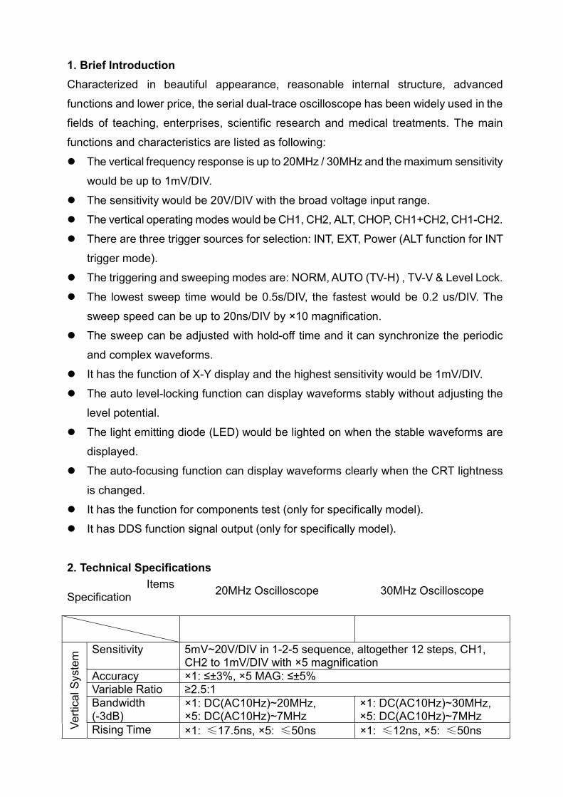
2. Technical SpecificationsItems
Specification 20MHz Oscilloscope 30MHz Oscilloscope
Verti
cal S
yste
m Sensitivity 5mV~20V/DIV in 1-2-5 sequence, altogether 12 steps, CH1,CH2 to 1mV/DIV with ×5 magnification
Accuracy ×1: ≤±3%, ×5 MAG: ≤±5%Variable Ratio ≥2.5:1Bandwidth(-3dB)
×1: DC(AC10Hz)~20MHz,×5: DC(AC10Hz)~7MHz
×1: DC(AC10Hz)~30MHz,×5: DC(AC10Hz)~7MHz
Rising Time ×1: ≤17.5ns, ×5: ≤50ns ×1: ≤12ns, ×5: ≤50ns

InputImpedance
1MΩ±5% // 25pF±5pF
DC Balance 5mV~20V/DIV: ±0.5DIVLinearity The amplitude change would be within±0.1V when the waveform
moves vertically in the middle of the division.
Vertical Mode CH1, CH2, ALT, CHOP, ADD (CH1+CH2, CH1-CH2)Input Coupling AC, GND, DCMax. Input 400V with the frequency ≤1kHzVoltage Max. effective readout would be 160Vp-p (56Vrms sine wave)
when the probe is set as 1:1.Max. effective readout would be 400Vp-p (140Vrms sine wave)when the probe is set as 10:1.
CH2 INV BAL ≤1DIV
Trig
ger
Trigger Sources INT, EXT, LINE INT Trigger CH1, CH2, VERT.SourceTrigger Modes NORM, AUTO (TV-H), TV-V, LEVEL LOCKCoupling AC: 5Hz to the whole frequency rangePolarity +/-Sensitivity INT: 5Hz~10MHz≤1DIV; INT: 5Hz~10MHz≤1DIV;
10MHz~20MHz≤1.5DIV; TV: 10MHz~30MHz≤2DIV; TV:≤2DIV ≤2DIVEXT: 5Hz~10MHz≤200mVpp; EXT:10MHz~20MHz≤300mVpp; TV: 5Hz~10MHz≤200mVpp;≤500mVpp 10MHz~30MHz≤400mVpp;
TV: ≤500mVppInputimpedance withEXT triggersignalsMax InputVoltage
1MΩ±5%//25pF±5pF
400V(DC+ACpeak) AC frequency:≤1kHz
Sweep time 0.5s~0.2us/DIV, in 1-2-5 sequence, altogether 20 stepsAccuracy ×1: ≤±3%; ×10MAG: ≤±5%(20ns~50ns :±10%)
Variable Ratio ≥2.5:1Linearity ×1: 5%; ×10MAG: 10%(20ns~50ns :15%)
Movement by <2DIV in CRT center×10 MAG
ItemsSpecification 20MHz Oscilloscope 30MHz Oscilloscope
X-Y
Mod
e
Sensitivity Same the vertical systemFrequency Bandwidth DC: 0~500kHz; AC: 10Hz~500kHz(-3dB)XY Phase Difference ≤3°(DC~50kHz)
Cal
ibra
ting
Sign
al
Waveform Square wave
Frequency Approx. 1kHz
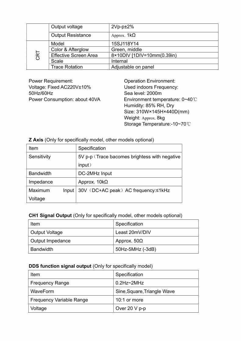
Output voltage 2Vp-p±2%
Output Resistance Approx. 1kΩC
RT
Model 15SJ118Y14Color & Afterglow Green, middleEffective Screen Area 8×10DIV [1DIV=10mm(0.39in)Scale InternalTrace Rotation Adjustable on panel
Power Requirement: Operation Environment:Voltage: Fixed AC220V±10% Used indoors Frequency:50Hz/60Hz Sea level: 2000mPower Consumption: about 40VA Environment temperature: 0~40
Humidity: 85% RH, DrySize: 310W×145H×440D(mm)Weight: Approx. 8kgStorage Temperature:-10~70
Z Axis (Only for specifically model, other models optional)
Item Specification
Sensitivity 5V p-p(Trace bacomes brightess with negativeinput)
Bandwidth DC-2MHz Input
Impedance Approx. 10kΩ
Maximum Input 30V(DC+AC peak)AC frequency:≤1kHzVoltage
CH1 Signal Output (Only for specifically model, other models optional)
Item Specification
Output Voltage Least 20mV/DIV
Output Impedance Approx. 50Ω
Bandwidth 50Hz-5MHz (-3dB)
DDS function signal output (Only for specifically model)
Item Specification
Frequency Range 0.2Hz~2MHz
WaveForm Sine,Square,Triangle Wave
Frequency Variable Range 10:1 or more
Voltage Over 20 V p-p
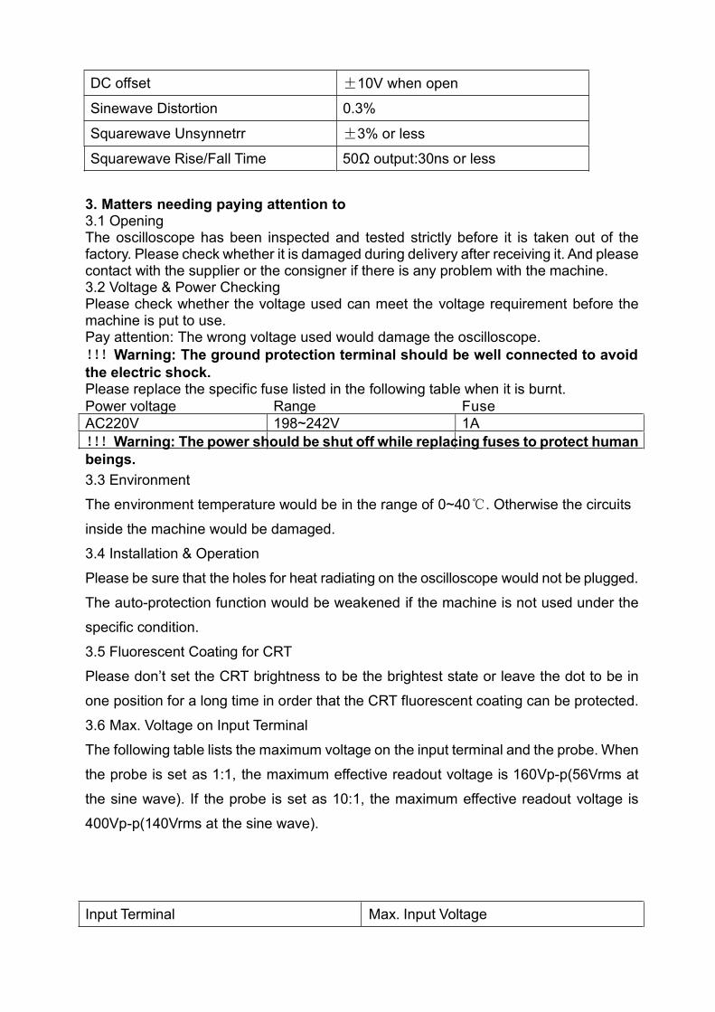
DC offset ±10V when open
Sinewave Distortion 0.3%
Squarewave Unsynnetrr ±3% or less
Squarewave Rise/Fall Time 50Ω output:30ns or less
3. Matters needing paying attention to3.1 OpeningThe oscilloscope has been inspected and tested strictly before it is taken out of thefactory. Please check whether it is damaged during delivery after receiving it. And pleasecontact with the supplier or the consigner if there is any problem with the machine.3.2 Voltage & Power CheckingPlease check whether the voltage used can meet the voltage requirement before themachine is put to use.Pay attention: The wrong voltage used would damage the oscilloscope.!!!Warning: The ground protection terminal should be well connected to avoidthe electric shock.Please replace the specific fuse listed in the following table when it is burnt.Power voltage Range FuseAC220V 198~242V 1A!!!Warning: The power should be shut off while replacing fuses to protect humanbeings.3.3 EnvironmentThe environment temperature would be in the range of 0~40. Otherwise the circuitsinside the machine would be damaged.3.4 Installation & OperationPlease be sure that the holes for heat radiating on the oscilloscope would not be plugged.The auto-protection function would be weakened if the machine is not used under thespecific condition.3.5 Fluorescent Coating for CRTPlease don’t set the CRT brightness to be the brightest state or leave the dot to be inone position for a long time in order that the CRT fluorescent coating can be protected.3.6 Max. Voltage on Input TerminalThe following table lists the maximum voltage on the input terminal and the probe. Whenthe probe is set as 1:1, the maximum effective readout voltage is 160Vp-p(56Vrms atthe sine wave). If the probe is set as 10:1, the maximum effective readout voltage is400Vp-p(140Vrms at the sine wave).
Input Terminal Max. Input Voltage
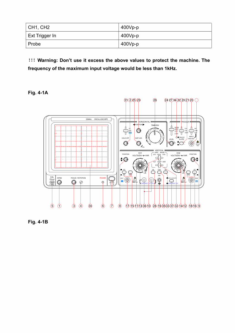
CH1, CH2 400Vp-p
Ext Trigger In 400Vp-p
Probe 400Vp-p
!!!Warning: Don’t use it excess the above values to protect the machine. Thefrequency of the maximum input voltage would be less than 1kHz.
Fig. 4-1A29
400VpKMAX.
VOLTS/DIV
SWP.VAR.
POSITION
.2
CAL2Vp-p
1 KHz
5 1
INTEN
90
0%
10
100
20MHz OSCILLOSCOPE
POWER
3 4
ROTATIONFOCUS
30 6
5
CH1
7 8
1 0
17 15 11
GND
X
DC
AC
CAT.Ⅱ
1MΩ//25pF
POSITION
HOLD OFF
V
.5
2
1
X YX10X1
.
.
.
31 2 25
37
COMPONENT TEST
OSCILLOSCOPE
VOLTS/DIV
LEVEL
X5X55
2813 36 10
COMPONENT TEST INPUT
2010CAL
19 35 33
INV
CH2
ALT
VERTICALVERT MODE
CH1 DUAL
TIME/DIV
20
mV
VARCH1
.150
10
20
CAL
.5.2
5 0.1
s
HORIZONTAL
510
ms2
1 .5
5μs
ADD
CH2
CHOP
.2.5
21
V
50.2 .1
2010
5 5
GND
1832 14 12
2010
400VpKMAX.
CAT.Ⅱ
1MΩ//25pF
CAL
16 9
CH2
Y
AC
DC
1MΩ//25pF
TRIGGER
TRIG'DSLOPE
.1
CH2
.2.5
2
1mV
VAR
50
10
20
+_
TV-V.LOCK
(TV-H)
.NORM
.AUTO
.VERT
.CH1
.CH2
.
CAT.Ⅱ
MAX.400Vpk
POSITION
INPUT
.LINE
.INT
.EXT
26 24 27 34 22 23 21 20
Fig. 4-1B
01
FOCUS ROTATION POWER
20MHz OSCILLOSCOPE
100
1 0
0%
90
INTEN
1 KHz
CAL2Vp-p
VARCH2
VOLTS/DIV
CAL
FUNCGENERATOR
X10UNCAL
DC-OFFSET
GENERATOROUTPUT
50Ω
MIN-
RANGE
AMPLITUDE FREQUENCY
X10 MAG
HORIZONTAL
SOURCEMODE
SWP.VAR.POSITION
X Y
1M 100K 10K 1K 100 10 1
ADD
CH2
DC
1MΩ//25pF400VpKMAX.
CAT.ⅡCH1
X
INV
.1
VOLTS/DIVCH1
1V
5
2
.5.2
AC
POSITION
CHOPALT
DUALVERT MODE
CH1
VERTICAL
CH2X5
VAR
50
20
10mV
5
DC
400VpKMAX.
1MΩ//25pF
CAT.ⅡY
CH2
5
2
5
10
20
50
1
.5.2 .1
X5
POSITION
AC
s
.2
25μ
.5
20
1
10
50.2 .11
TIME/DIV.5
CAL
5
502010
.2.1
s
ms2
.5
TRIGGER
CH2
.CH1
.VERT
SLOPETRIG'D
..
.NORM
.AUTO
.LOCK
LEVEL
_+
.
.INT
.LINEEXT
10 20CAL
mVV
2010CAL
GND GND
(TV-H)
TV-V
NORMAL
DC
+MAX
55
5 1 3 4 30 6 7 8 17 15 11 13 10 28 19 35 33 32 14 12 18 16 9
24 27 34 22 23 212529 4 4 45 42 46 48 47 43 49 50 51
Fig. 4-2A
TO AVOID ELECTRIC SHOCK,PROTECTIVE GROUNDINGCONDUCTOR IN THE POWER CORD MUST BE CONNECTED TOGROUND.THIS INSTRUMENT CONTAINS NO OPERATOR SERVICEABLEPARTS.SERVICE BY QUALIFIED PERSONS ONLY. DISCONNECTINPUT POWER BEFORE REPLACING FUSE.FOR CONTINUED FIRE PROTECTION,USE MANUAL SPECIFIEDTYPE/RATING FUSE ONLY.
WARNING
4039
Z-AXIS INPUT
CAT Ⅱ 30Vpk MAX
SIGNAL OUTPUT
FUSE
99-121V
198-242V
RANGE(50/60Hz)
2A125V
1A250V
SERIAL NO.
110V
LINE VOLTAGESELECTION
220V
AC
ENSURE THE POWER ISREMOVE FROM THE INSTRUMENTBEFORE REPLACING THE FUSE
38
Fig. 4-2B
38
ENSURE THE POWER ISREMOVE FROM THE INSTRUMENTBEFORE REPLACING THE FUSE
AC
220V
LINE VOLTAGESELECTION
110V
SERIAL NO.
1A250V
2A125V
RANGE(50/60Hz)
198-242V
99-121V
FUSE
39 40
WARNINGTO AVOID ELECTRIC SHOCK,PROTECTIVE GROUNDINGCONDUCTOR IN THE POWER CORD MUST BE CONNECTED TOGROUND.THIS INSTRUMENT CONTAINS NO OPERATOR SERVICEABLEPARTS.SERVICE BY QUALIFIED PERSONS ONLY. DISCONNECTINPUT POWER BEFORE REPLACING FUSE.FOR CONTINUED FIRE PROTECTION,USE MANUAL SPECIFIEDTYPE/RATING FUSE ONLY.
Z-AXIS INPUT
CAT Ⅱ 30Vpk MAX
CH1 OUTPUT
TRIG IN1MΩ//25pF
CAT.Ⅱ
MAX.400Vpk
41
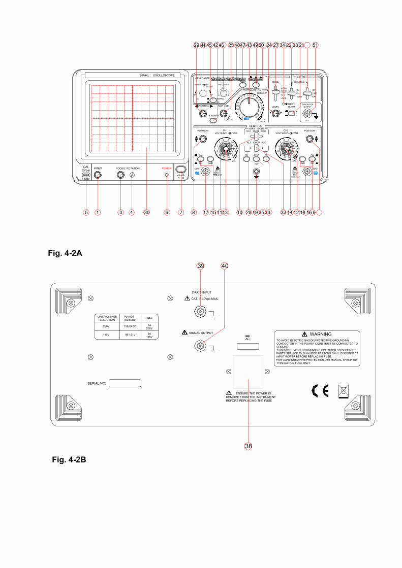
4. Operation Methods4.1 Description on Front Panel (Refer to Fig. 4-1A or Fig. 4-1B)CRT:7 —Power: Main power switch. The LED 6 would be lighted When it is on.1 —Intensity: Adjust the intensity of the trace or the dot.3 —Focus: Adjust the clearness of the trace or the dot.4 —Trace Rotation: The half-fixed potentiometer is used to adjust the horizontal tradeto be parallel with the scale.30 – Color Filter: Make the display effect be more comfortable.
Vertical Axis:17 —CH1 (X) Input: Channel 1 input terminal, which is used as X axis input in X-Ymode.18 —CH2 (Y) Input: Channel 2 input terminal, which is used as Y axis input in X-Ymode.28 33 -- ×5 MAG for CH1 & CH2: Used to adjust the vertical sensitivity to be 1mV/DIV.15 16 —AC-GND-DC: Select the input mode for the input signals of the vertical axis.
AC: AC couplingGND: The input of the vertical magnifier is grounded and the input is cut off.DC: DC coupling11 12 —Vertical Attenuator: Adjust the vertical deflection sensitivity from 5mV to20V/DIV in 12 steps.13 14 – Vertical Variable: The variable ratio would be no less than 2.5:1. Thesensitivity calibration would the label value in the calibrated position.8 9 Vertical Position: Adjust the vertical position of the trace on the screen.10 —Vertical Mode: Select the operating modes for CH1 & CH2 magnifiers.CH1 or CH2: Channel 1 or 2 displayed separately.Dual: Two channels are displayed at the same time.32 —Dual-trace Display:ADD: Press to display the algebraic sum of the two channels CH1+CH2 in the dual-tracedisplay mode. Press CH2 INV 35 , the display would be the algebraic differenceCH1-CH2.ALT: Press the display the traces alternatively of CH1 and CH2 in the dual-tracedisplay mode (usually for the quick-speed sweep).CHOP: Press to display the traces on CH1 & CH2 in Chop mode.35—CH2 INV: The signal in CH2 would be inversed. Press the key to make the signalsfrom CH2 and the inner trigger signals of CH2 be inversed at the same time.
Trigger:20—EXT trigger input: For the external trigger signals. The trigger source selectorshould be set to be EXT when it functions. (Only for specifically model)21—Trigger Source Selection:INT: Select the signals from CH1 or CH2 as the trigger source.LINE: Select AC power as the trigger signal.EXT: The external signals on 20 is selected as the trigger signal.22—INT Trigger source selection:VERT: When the vertical mode selector 10 is set to be DUAL and the trigger sourceselector 21 is set to be INT, press VERT to select CH1 & CH2 alternatively as the internaltrigger signal source.CH1: Select Channel 1 as the internal trigger signal source.CH2: Select Channel 2 as the internal trigger signal source.23—Polarity: Select the polarity of the trigger signals. “+” means the rising-edge triggerand “-” means the trailing-edge trigger.
24—Trigger Level: Display a synchronized stable waveform and set the starting pointfor the waveform. Rotate clockwise to increase the level and rotate counterclockwise todecrease the level.27—Trigger mode: Select the trigger mode.AUTO (TV-H): The sweep mode is the AUTO mode when there is no trigger signalinput.Used to observe the TV-H signals. (It can only be synchronized when the synchronizedsignal is of negative pulse. )NORM: The trace wouldn’t be displayed when there is no trigger signal.TV-V: Used to observe the TV-V signals.(It can only be synchronized when the synchronized signal is of negative pulse. )LOCK: The trigger lock is locked in a fixed level. It is not necessary to adjust the levelto get the synchronized signal when the sweep speed or the signal amplitude ischanged. 34 —Trigger Indicator: The LED would be lighted in the trigger sweep.
Time base:26—Horizontal Sweep Speed Switch: The sweep speed would be divided into 20 stepsfrom 0.2us/DIV to 0.5s/DIV. (Only for specifically model)43—Horizontal Sweep Speed Switch. (Only for specifically model)The sweep speed would be divided into 20 steps from 0.2us/DIV to 0.5s/DIV.X-Y: X-Y mode.25—Horizontal Variable: Adjust the horizontal sweep time to calibrate it to be the sameshown by TIME/DIV on the panel. The TIME/DIV can be adjusted continuously and wouldbe in calibrated position when it is rotated to the end clockwise. The whole time delaycan be up to 2.5 times or more.2 —HOLD OFF:Change the sweep off time, synchronize multicycle waves. (Only forspecifically model)29-- Horizontal Position: Adjust the horizontal position of the traces on the screen.31—Sweep Mode: Select the sweep mode. (Only for specifically model)×1: The sweep is not magnified.×10: The sweep is 10 times magnified.X-Y: The key 26 doesn’t function when in X-Y mode.42—Sweep Mode: Select the sweep mode. (Only for specifically model)×1: The sweep is not magnified.×10: The sweep is 10 times magnified.
DDS function:44 --Voltage and DC offset regulation button45 --DC offset:when open DC regulation46 --Adjust the frequency knob47 --Stall frequency adjustment button48 --The frequency of stalls instructions49 --Waveform select button50 --Waveform selection of indicators51 --Signal output
Other keys:5 – CAL: Supply a square wave signal with the amplitude 2Vp-p and the frequency1kHz to calibrate the compensate capacity of the 10:1 probe and detect the deflectionfactors of the horizontal and vertical systems of the oscilloscope.19—GND: The ground terminal for the oscilloscope.36—Input Hole for Component testing( only for specifically model).37—Oscilloscope/Component test: Press it to test components. (only for specificallymodel).
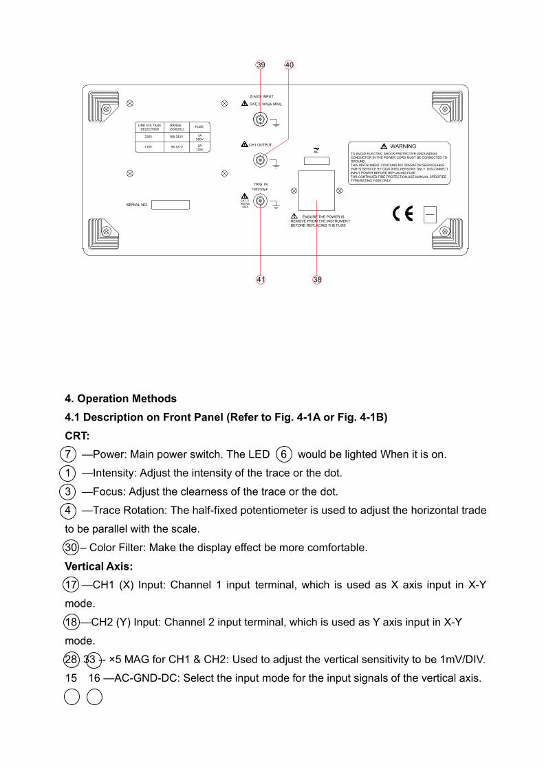
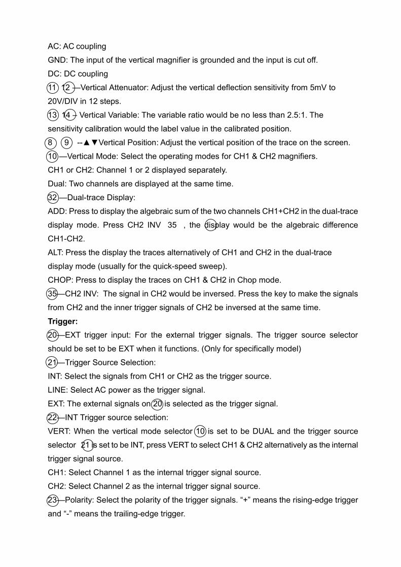
4.2 Description on Rear Panel (Refer to Fig. 4-2A or Fig. 4-2B)38—Power plug & Fuse: 220V voltage plug.
39—Z-Axis Input: Input terminal for external intensity modulation signal.(option)40—Signal Output: CH1 signal output terminal,Used to measure frequency.(option)41—EXT trigger input: For the external trigger signals. The trigger source selectorshould be set to be EXT when it functions. (Only for specifically model)
4.3 Basic operation & Single-channel OperationCheck whether the voltage connected meets the requirements of the machine andset the following keys listed in the table below:
Function No. Setting
POWER 7 OFF INTEN
1 MIDDLE
FOCUS 3 MIDDLE
VERT MODE 10 CH1 DUAL-
TRACE DISPLAY 32 ALT
CH2 INV 35 Release
VERT POSITION 8,9 MIDDLE
VOLTS/DIV 11,12 50mV/DIV
VAR 13,14 CAL
AC-GND-DC 15,16 GND
TRIGGER SOURCE 21 INT
SLOPE 23 +
INT TRIGGIER 22 CH1SELECTOR
TRIGGER MODE 27 AUTO
TIME/DIV 26 0.5ms/DIV
SWP.VAR 25 CAL HOR.
POSITION 29 MIDDLE
SWEEP MODE 31 ×1
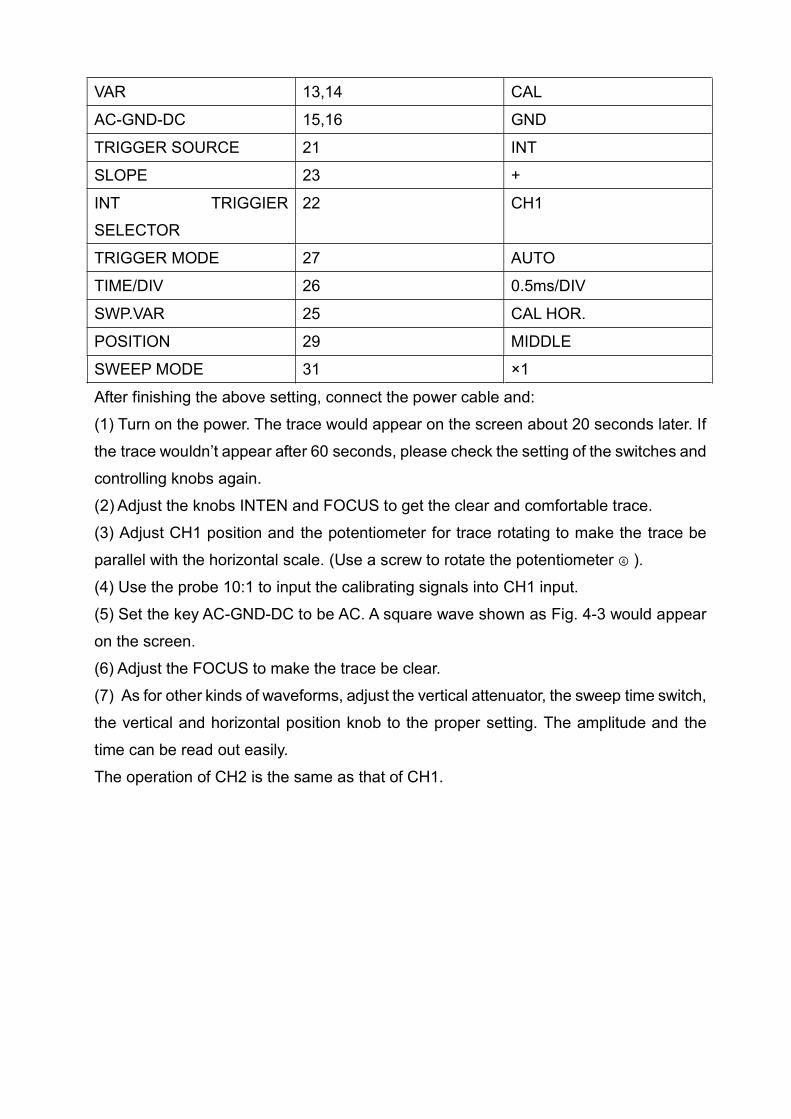
After finishing the above setting, connect the power cable and:(1) Turn on the power. The trace would appear on the screen about 20 seconds later. Ifthe trace wouldn’t appear after 60 seconds, please check the setting of the switches andcontrolling knobs again.(2) Adjust the knobs INTEN and FOCUS to get the clear and comfortable trace.(3) Adjust CH1 position and the potentiometer for trace rotating to make the trace beparallel with the horizontal scale. (Use a screw to rotate the potentiometer ④ ).(4) Use the probe 10:1 to input the calibrating signals into CH1 input.(5) Set the key AC-GND-DC to be AC. A square wave shown as Fig. 4-3 would appearon the screen.(6) Adjust the FOCUS to make the trace be clear.(7) As for other kinds of waveforms, adjust the vertical attenuator, the sweep time switch,the vertical and horizontal position knob to the proper setting. The amplitude and thetime can be read out easily.The operation of CH2 is the same as that of CH1.
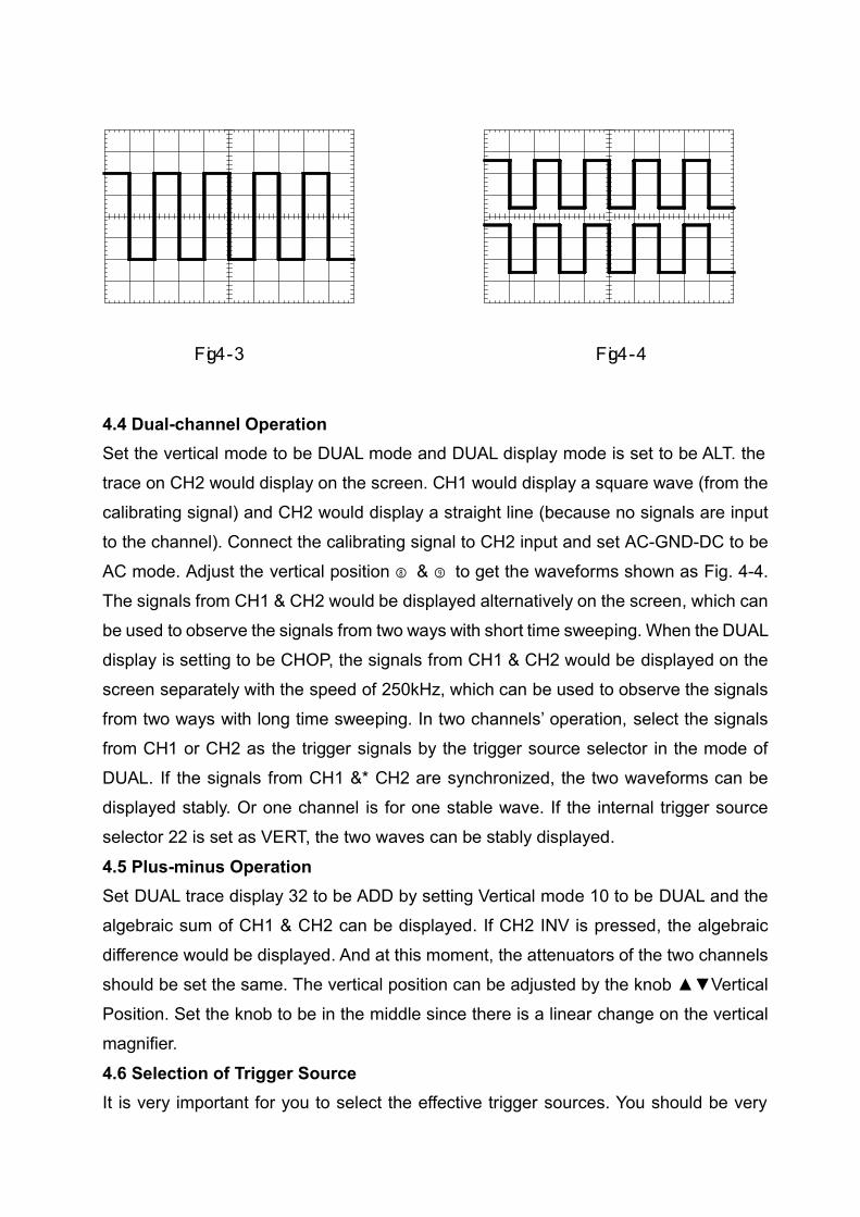
Fig.4-3 Fig.4-4
4.4 Dual-channel OperationSet the vertical mode to be DUAL mode and DUAL display mode is set to be ALT. thetrace on CH2 would display on the screen. CH1 would display a square wave (from thecalibrating signal) and CH2 would display a straight line (because no signals are inputto the channel). Connect the calibrating signal to CH2 input and set AC-GND-DC to beAC mode. Adjust the vertical position ⑧ & ⑨ to get the waveforms shown as Fig. 4-4.The signals from CH1 & CH2 would be displayed alternatively on the screen, which canbe used to observe the signals from two ways with short time sweeping. When the DUALdisplay is setting to be CHOP, the signals from CH1 & CH2 would be displayed on thescreen separately with the speed of 250kHz, which can be used to observe the signalsfrom two ways with long time sweeping. In two channels’ operation, select the signalsfrom CH1 or CH2 as the trigger signals by the trigger source selector in the mode ofDUAL. If the signals from CH1 &* CH2 are synchronized, the two waveforms can bedisplayed stably. Or one channel is for one stable wave. If the internal trigger sourceselector 22 is set as VERT, the two waves can be stably displayed.
4.5 Plus-minus OperationSet DUAL trace display 32 to be ADD by setting Vertical mode 10 to be DUAL and thealgebraic sum of CH1 & CH2 can be displayed. If CH2 INV is pressed, the algebraicdifference would be displayed. And at this moment, the attenuators of the two channelsshould be set the same. The vertical position can be adjusted by the knob VerticalPosition. Set the knob to be in the middle since there is a linear change on the verticalmagnifier.
4.6 Selection of Trigger SourceIt is very important for you to select the effective trigger sources. You should be very
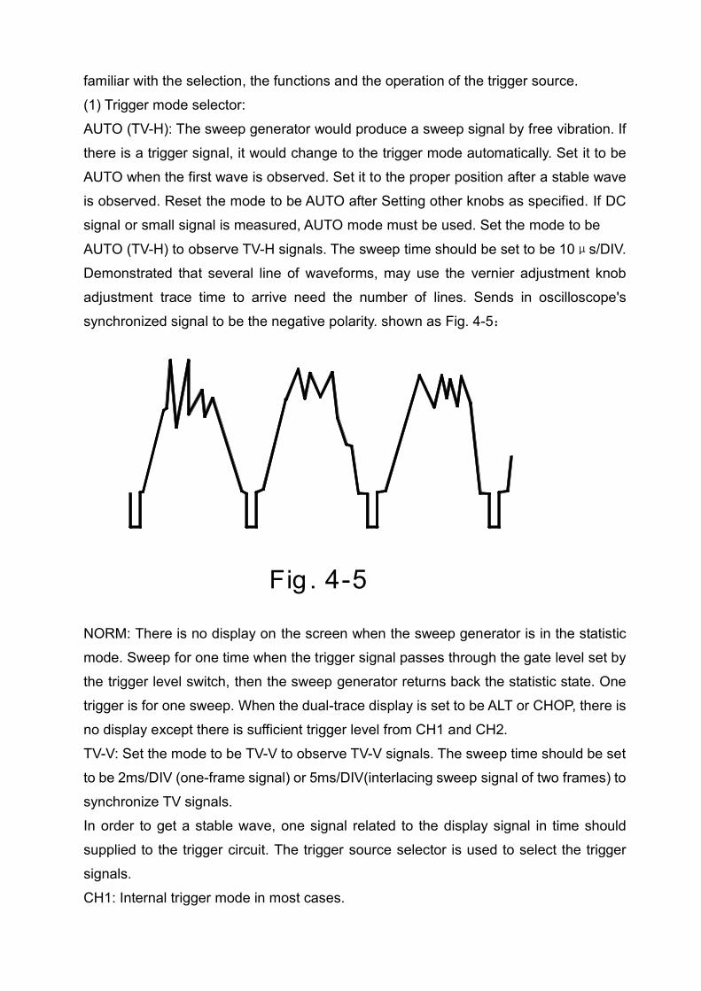
familiar with the selection, the functions and the operation of the trigger source.(1) Trigger mode selector:AUTO (TV-H): The sweep generator would produce a sweep signal by free vibration. Ifthere is a trigger signal, it would change to the trigger mode automatically. Set it to beAUTO when the first wave is observed. Set it to the proper position after a stable waveis observed. Reset the mode to be AUTO after Setting other knobs as specified. If DCsignal or small signal is measured, AUTO mode must be used. Set the mode to be
AUTO (TV-H) to observe TV-H signals. The sweep time should be set to be 10μs/DIV.Demonstrated that several line of waveforms, may use the vernier adjustment knobadjustment trace time to arrive need the number of lines. Sends in oscilloscope'ssynchronized signal to be the negative polarity. shown as Fig. 4-5:
Fig . 4-5
NORM: There is no display on the screen when the sweep generator is in the statisticmode. Sweep for one time when the trigger signal passes through the gate level set bythe trigger level switch, then the sweep generator returns back the statistic state. Onetrigger is for one sweep. When the dual-trace display is set to be ALT or CHOP, there isno display except there is sufficient trigger level from CH1 and CH2.TV-V: Set the mode to be TV-V to observe TV-V signals. The sweep time should be setto be 2ms/DIV (one-frame signal) or 5ms/DIV(interlacing sweep signal of two frames) tosynchronize TV signals.In order to get a stable wave, one signal related to the display signal in time shouldsupplied to the trigger circuit. The trigger source selector is used to select the triggersignals.CH1: Internal trigger mode in most cases.
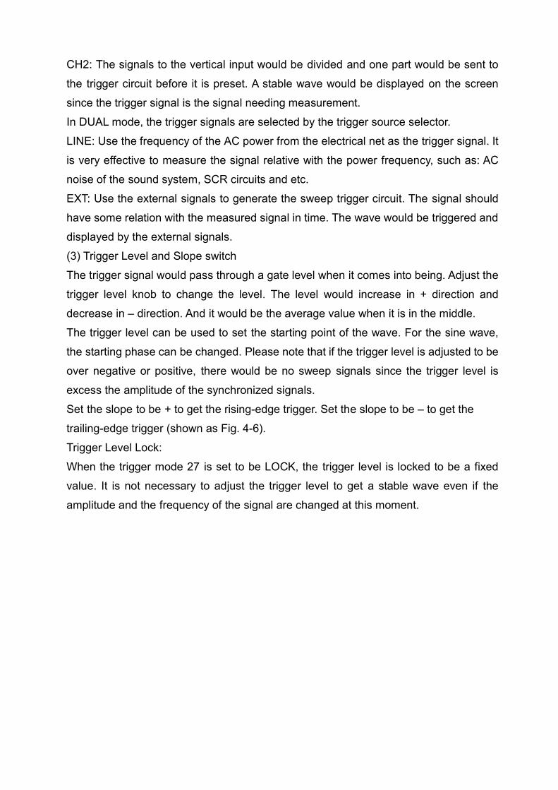
CH2: The signals to the vertical input would be divided and one part would be sent tothe trigger circuit before it is preset. A stable wave would be displayed on the screensince the trigger signal is the signal needing measurement.In DUAL mode, the trigger signals are selected by the trigger source selector.LINE: Use the frequency of the AC power from the electrical net as the trigger signal. Itis very effective to measure the signal relative with the power frequency, such as: ACnoise of the sound system, SCR circuits and etc.EXT: Use the external signals to generate the sweep trigger circuit. The signal shouldhave some relation with the measured signal in time. The wave would be triggered anddisplayed by the external signals.(3) Trigger Level and Slope switchThe trigger signal would pass through a gate level when it comes into being. Adjust thetrigger level knob to change the level. The level would increase in + direction anddecrease in – direction. And it would be the average value when it is in the middle.The trigger level can be used to set the starting point of the wave. For the sine wave,the starting phase can be changed. Please note that if the trigger level is adjusted to beover negative or positive, there would be no sweep signals since the trigger level isexcess the amplitude of the synchronized signals.Set the slope to be + to get the rising-edge trigger. Set the slope to be – to get thetrailing-edge trigger (shown as Fig. 4-6).Trigger Level Lock:When the trigger mode 27 is set to be LOCK, the trigger level is locked to be a fixedvalue. It is not necessary to adjust the trigger level to get a stable wave even if theamplitude and the frequency of the signal are changed at this moment.
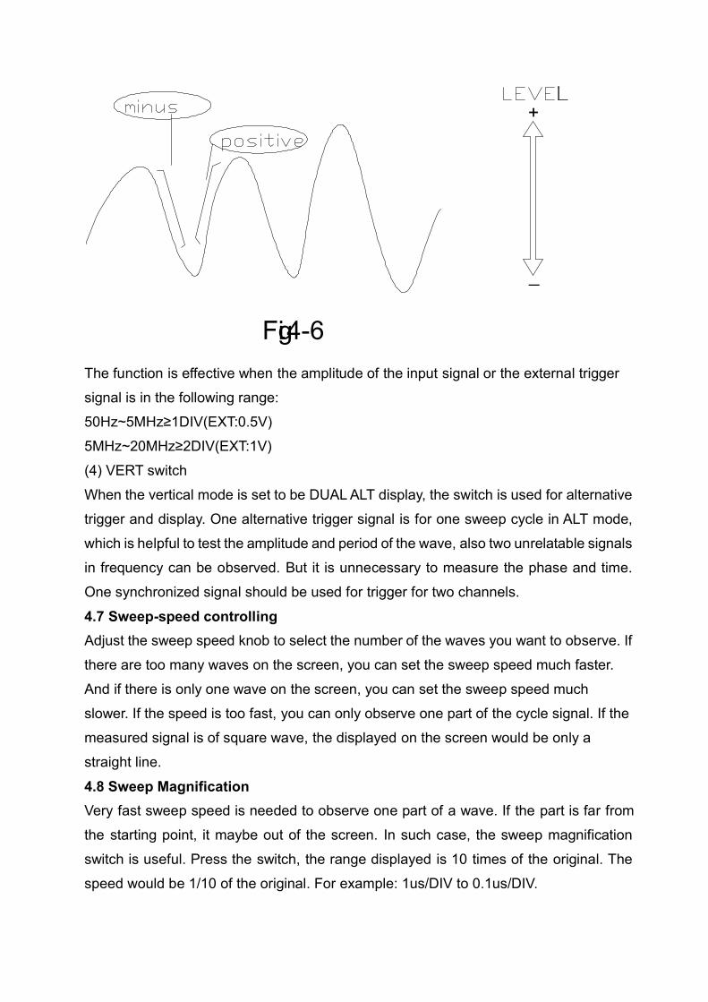
Fig.4-6
_
+
The function is effective when the amplitude of the input signal or the external triggersignal is in the following range:50Hz~5MHz≥1DIV(EXT:0.5V)5MHz~20MHz≥2DIV(EXT:1V)(4) VERT switchWhen the vertical mode is set to be DUAL ALT display, the switch is used for alternativetrigger and display. One alternative trigger signal is for one sweep cycle in ALT mode,which is helpful to test the amplitude and period of the wave, also two unrelatable signalsin frequency can be observed. But it is unnecessary to measure the phase and time.One synchronized signal should be used for trigger for two channels.
4.7 Sweep-speed controllingAdjust the sweep speed knob to select the number of the waves you want to observe. Ifthere are too many waves on the screen, you can set the sweep speed much faster.And if there is only one wave on the screen, you can set the sweep speed muchslower. If the speed is too fast, you can only observe one part of the cycle signal. If themeasured signal is of square wave, the displayed on the screen would be only astraight line.
4.8 Sweep MagnificationVery fast sweep speed is needed to observe one part of a wave. If the part is far fromthe starting point, it maybe out of the screen. In such case, the sweep magnificationswitch is useful. Press the switch, the range displayed is 10 times of the original. Thespeed would be 1/10 of the original. For example: 1us/DIV to 0.1us/DIV.
× 10 MAG
Fig.4-7
Adjusts position knob to be possible
to observe the entire region the profile
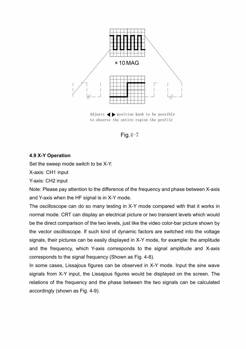
4.9 X-Y OperationSet the sweep mode switch to be X-Y.X-axis: CH1 inputY-axis: CH2 inputNote: Please pay attention to the difference of the frequency and phase between X-axisand Y-axis when the HF signal is in X-Y mode.The oscilloscope can do so many testing in X-Y mode compared with that it works innormal mode. CRT can display an electrical picture or two transient levels which wouldbe the direct comparison of the two levels, just like the video color-bar picture shown bythe vector oscilloscope. If such kind of dynamic factors are switched into the voltagesignals, their pictures can be easily displayed in X-Y mode, for example: the amplitudeand the frequency, which Y-axis corresponds to the signal amplitude and X-axiscorresponds to the signal frequency (Shown as Fig. 4-8).In some cases, Lissajous figures can be observed in X-Y mode. Input the sine wavesignals from X-Y input, the Lissajous figures would be displayed on the screen. Therelations of the frequency and the phase between the two signals can be calculatedaccordingly (shown as Fig. 4-9).
X Axis
(CH1)
Y Axis
(CH2)
Fig.4-8 Fig.4-9
Display Wave
1:1 2:1 3:1 3:2
Phase Difference
0
45
90
f(y):f(x)
4.10 Probe CalibrationThe oscilloscope probe can be used for a very wide frequency range mentioned above,but the phase should be compensated. The distorted wave would lead to the errormeasurement. So, the probe should be calibrated before measurement(the method isreferred to Paragraph 1.2 of Chapter 5) .
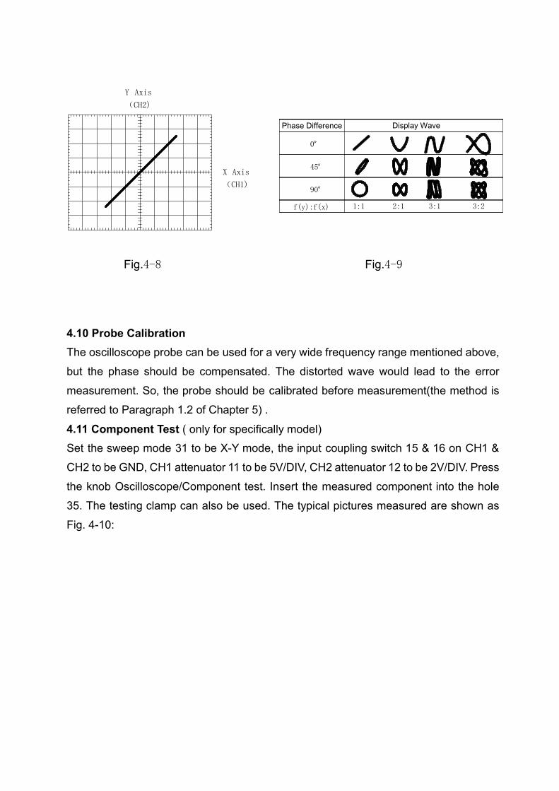
4.11 Component Test ( only for specifically model)Set the sweep mode 31 to be X-Y mode, the input coupling switch 15 & 16 on CH1 &CH2 to be GND, CH1 attenuator 11 to be 5V/DIV, CH2 attenuator 12 to be 2V/DIV. Pressthe knob Oscilloscope/Component test. Insert the measured component into the hole35. The testing clamp can also be used. The typical pictures measured are shown asFig. 4-10:
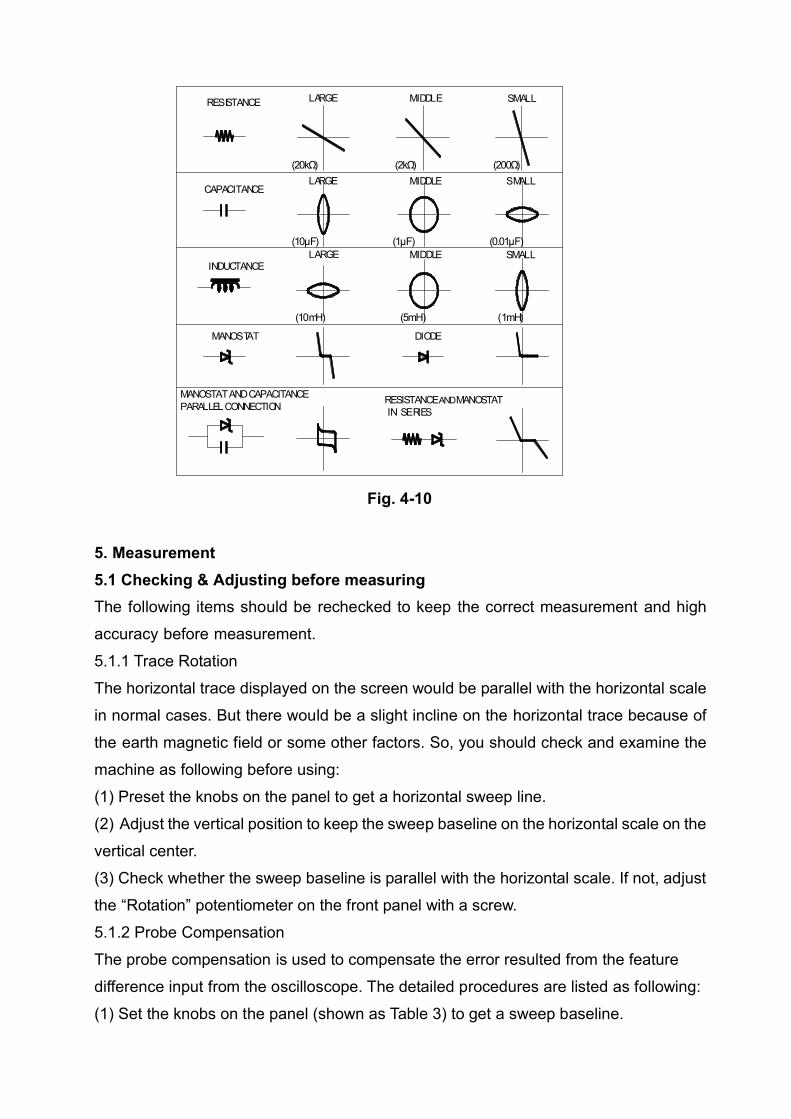
RESISTANCEAND MANOSTATIN SERIES
MANOSTAT AND CAPACITANCEPARALLEL CONNECTION
DIODEMANOSTAT
INDUCTANCE
CAPACITANCE
SMALLMIDDLERESISTANCE
LARGE MIDDLE SMALL
LARGE MIDDLE SMALL
LARGE
(20kΩ) (2kΩ) (200Ω)
(10μF) (1μF) (0.01μF)
(10mH) (5mH) (1mH)
Fig. 4-10
5. Measurement5.1 Checking & Adjusting before measuringThe following items should be rechecked to keep the correct measurement and highaccuracy before measurement.5.1.1 Trace RotationThe horizontal trace displayed on the screen would be parallel with the horizontal scalein normal cases. But there would be a slight incline on the horizontal trace because ofthe earth magnetic field or some other factors. So, you should check and examine themachine as following before using:(1) Preset the knobs on the panel to get a horizontal sweep line.(2) Adjust the vertical position to keep the sweep baseline on the horizontal scale on thevertical center.(3) Check whether the sweep baseline is parallel with the horizontal scale. If not, adjustthe “Rotation” potentiometer on the front panel with a screw.5.1.2 Probe CompensationThe probe compensation is used to compensate the error resulted from the featuredifference input from the oscilloscope. The detailed procedures are listed as following:(1) Set the knobs on the panel (shown as Table 3) to get a sweep baseline.
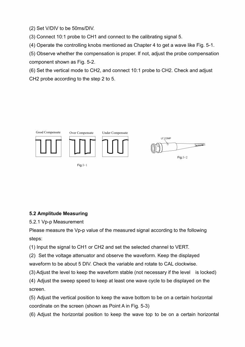
(2) Set V/DIV to be 50ms/DIV.(3) Connect 10:1 probe to CH1 and connect to the calibrating signal 5.(4) Operate the controlling knobs mentioned as Chapter 4 to get a wave like Fig. 5-1.(5) Observe whether the compensation is proper. If not, adjust the probe compensationcomponent shown as Fig. 5-2.(6) Set the vertical mode to CH2, and connect 10:1 probe to CH2. Check and adjustCH2 probe according to the step 2 to 5.
Under CompensateGood Compensate
Fig.5-1
Fig.5-2
LF COMP
Over Compensate
5.2 Amplitude Measuring5.2.1 Vp-p MeasurementPlease measure the Vp-p value of the measured signal according to the followingsteps:(1) Input the signal to CH1 or CH2 and set the selected channel to VERT.(2) Set the voltage attenuator and observe the waveform. Keep the displayedwaveform to be about 5 DIV. Check the variable and rotate to CAL clockwise.(3) Adjust the level to keep the waveform stable (not necessary if the level is locked)(4) Adjust the sweep speed to keep at least one wave cycle to be displayed on thescreen.(5) Adjust the vertical position to keep the wave bottom to be on a certain horizontalcoordinate on the screen (shown as Point A in Fig. 5-3)(6) Adjust the horizontal position to keep the wave top to be on a certain horizontal
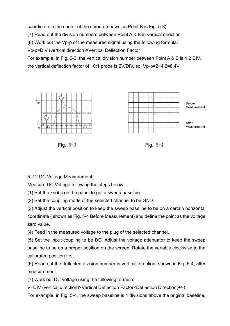
coordinate in the center of the screen (shown as Point B in Fig. 5-3)(7) Read out the division numbers between Point A & B in vertical direction.(8) Work out the Vp-p of the measured signal using the following formula:Vp-p=DIV (vertical direction)×Vertical Deflection FactorFor example: in Fig. 5-3, the vertical division number between Point A & B is 4.2 DIV,the vertical deflection factor of 10:1 probe is 2V/DIV, so, Vp-p=2×4.2=8.4V
Fig. 5-4
BeforeMeasurement
Fig. 5-3
AfterMeasurement
5.2.2 DC Voltage MeasurementMeasure DC Voltage following the steps below:(1) Set the knobs on the panel to get a sweep baseline.(2) Set the coupling mode of the selected channel to be GND.(3) Adjust the vertical position to keep the sweep baseline to be on a certain horizontalcoordinate ( shown as Fig. 5-4 Before Measurement) and define the point as the voltagezero value.(4) Feed in the measured voltage to the plug of the selected channel.(5) Set the input coupling to be DC. Adjust the voltage attenuator to keep the sweepbaseline to be on a proper position on the screen. Rotate the variable clockwise to thecalibrated position first.(6) Read out the deflected division number in vertical direction, shown in Fig. 5-4, aftermeasurement.(7) Work out DC voltage using the following formula:V=DIV (vertical direction)×Vertical Deflection Factor×Deflection Direction(+/-)For example, in Fig. 5-4, the sweep baseline is 4 divisions above the original baseline,
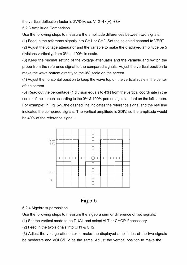
the vertical deflection factor is 2V/DIV, so: V=2×4×(+)=+8V5.2.3 Amplitude ComparisonUse the following steps to measure the amplitude differences between two signals:(1) Feed in the reference signals into CH1 or CH2. Set the selected channel to VERT.(2) Adjust the voltage attenuator and the variable to make the displayed amplitude be 5divisions vertically, from 0% to 100% in scale.(3) Keep the original setting of the voltage attenuator and the variable and switch theprobe from the reference signal to the compared signals. Adjust the vertical position tomake the wave bottom directly to the 0% scale on the screen.(4) Adjust the horizontal position to keep the wave top on the vertical scale in the centerof the screen.(5) Read out the percentage (1 division equals to 4%) from the vertical coordinate in thecenter of the screen according to the 0% & 100% percentage standard on the left screen.For example: In Fig. 5-5, the dashed line indicates the reference signal and the real lineindicates the compared signals. The vertical amplitude is 2DIV, so the amplitude wouldbe 40% of the reference signal.
Fig.5-55.2.4 Algebra superpositionUse the following steps to measure the algebra sum or difference of two signals:(1) Set the vertical mode to be DUAL and select ALT or CHOP if necessary.(2) Feed in the two signals into CH1 & CH2.(3) Adjust the voltage attenuator to make the displayed amplitudes of the two signalsbe moderate and VOLS/DIV be the same. Adjust the vertical position to make the

waves of the two signals be in the center of the screen.(4) Set DUAL to be ADD to get the algebra sum displayed. If you want to observe thealgebra difference, please press in the knob CH2 INV. Fig. 5-6 shows the algebra sumand difference of two signals.
(Y2 -)(Y2 +)
Fig.5-6
5.3 Time Measuring5.3.1 Measurement of Time IntervalsThe time intervals can be measured as following steps:(1) Feed in the signal to CH1 or CH2 and set the selected channel to be VERT.(2) Adjust the level to keep the wave to be displayed stably (It is unnecessary to adjustthe level if it is locked).(3) Rotate the variable clockwise to the calibrated position. Adjust the sweep speedswitch to display one to two signal cycles on the screen.(4) Adjust the vertical and horizontal positions to make the two points on the wavemeasured be on the horizontal scale in the center of the screen.(5) Measure the horizontal scale between the two points and work out the time intervalusing the following formula:Time interval (T)=[Horizontal distance between two points (DIV)×Sweep time factor(Time/DIV)]/Horizontal Magnification RateFor example: In Fig. 5-7, the horizontal distance between A and B is 8DIV, the sweeptime factor is 2us/DIV, the horizontal magnification rate is ×1, so: Time Interval =(2us/DIV×8DIV)/1=16us.

Fig.5-75.3.2 Measurement of Cycle and FrequencyIn Fig. 5-7, the measured time interval is the cycle of the signal T, the frequency wouldbe 1/T. For example: T=16us,then the frequency would be : f=1/T-1/16×10-6=62.5kHz5.3.3 Measurement of Rising Time and Trailing TimeThe measuring method of the rising time and trailing time is just the same as that of thetime interval, only except the measurement is done to one part of the signal amplitude:from 10% to 90%. The steps are listed as following:(1) Set the vertical mode to be CH1 or CH2. Feed in the signals to the selected channel.(2) Adjust the voltage attenuator and the variable to keep the signal vertical amplitudeto be displayed for 5 divisions.(3) Adjust the vertical position to make the top and the bottom of the signal be locatedon the scale of 0% and 100% separately.(4) Adjust the sweep speed switch to make the rising edge or the trailing edge bedisplayed on the screen.(5) Adjust the horizontal position to make the 10% of the rising edge be located on acertain vertical scale.(6) Measure the horizontal distance between two points from 10% to 90%. If the risingor trailing edge is too fast, the horizontal magnification ×10 can be used to magnify thewave to be 10 times in horizontal direction.(7) Use the following formula to work out the rising or trailing time of the wave:Rising (trailing) time=[Horizontal distance (DIV)×Sweep Time Factor (Time/Div)]/Horizontal Magnification RateFor example: In Fig. 5-8, the distance from 10% to 90% of the rising edge of the wave
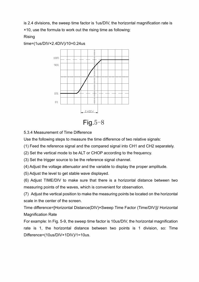
is 2.4 divisions, the sweep time factor is 1us/DIV, the horizontal magnification rate is×10, use the formula to work out the rising time as following:Risingtime=(1us/DIV×2.4DIV)/10=0.24us
Fig.5-85.3.4 Measurement of Time DifferenceUse the following steps to measure the time difference of two relative signals:(1) Feed the reference signal and the compared signal into CH1 and CH2 separately.(2) Set the vertical mode to be ALT or CHOP according to the frequency.(3) Set the trigger source to be the reference signal channel.(4) Adjust the voltage attenuator and the variable to display the proper amplitude.(5) Adjust the level to get stable wave displayed.(6) Adjust TIME/DIV to make sure that there is a horizontal distance between twomeasuring points of the waves, which is convenient for observation.(7) Adjust the vertical position to make the measuring points be located on the horizontalscale in the center of the screen.Time difference=[Horizontal Distance(DIV)×Sweep Time Factor (Time/DIV)]/ HorizontalMagnification RateFor example: In Fig. 5-9, the sweep time factor is 10us/DIV, the horizontal magnificationrate is 1, the horizontal distance between two points is 1 division, so: TimeDifference=(10us/DIV×1DIV)/1=10us.
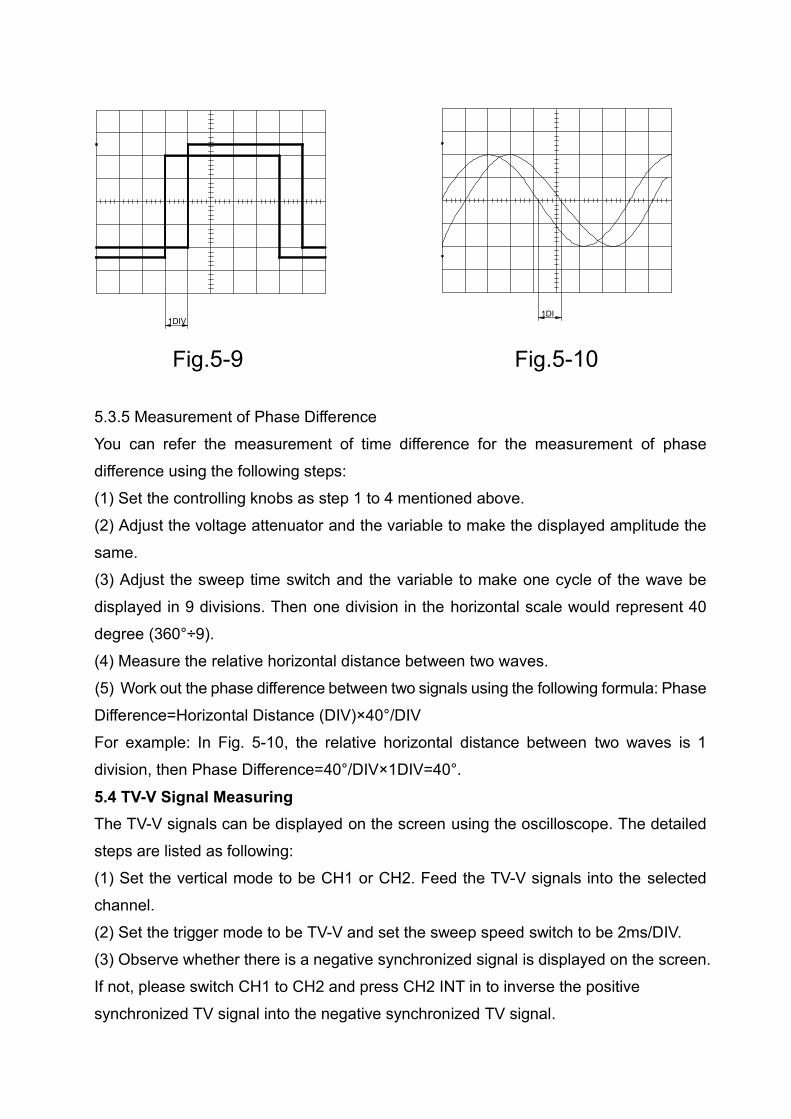
Fig.5-10
1DI1DIV
Fig.5-9
5.3.5 Measurement of Phase DifferenceYou can refer the measurement of time difference for the measurement of phasedifference using the following steps:(1) Set the controlling knobs as step 1 to 4 mentioned above.(2) Adjust the voltage attenuator and the variable to make the displayed amplitude thesame.(3) Adjust the sweep time switch and the variable to make one cycle of the wave bedisplayed in 9 divisions. Then one division in the horizontal scale would represent 40degree (360°÷9).(4) Measure the relative horizontal distance between two waves.(5) Work out the phase difference between two signals using the following formula: PhaseDifference=Horizontal Distance (DIV)×40°/DIVFor example: In Fig. 5-10, the relative horizontal distance between two waves is 1division, then Phase Difference=40°/DIV×1DIV=40°.
5.4 TV-V Signal MeasuringThe TV-V signals can be displayed on the screen using the oscilloscope. The detailedsteps are listed as following:(1) Set the vertical mode to be CH1 or CH2. Feed the TV-V signals into the selectedchannel.(2) Set the trigger mode to be TV-V and set the sweep speed switch to be 2ms/DIV.(3) Observe whether there is a negative synchronized signal is displayed on the screen.If not, please switch CH1 to CH2 and press CH2 INT in to inverse the positivesynchronized TV signal into the negative synchronized TV signal.

(4) Adjust the voltage attenuator and the variable to display proper amplitude.(5) Horizontal magnification ×10 can be used if necessary.
6. Maintenance!!!Warning: Only qualified professional can do the maintenance.6.1 Fuse ReplacementThe power indicator would be off and the oscilloscope wouldn’t function if the fuse isbroken. Usually the fuse would not be open-circuited except there is anything wrong withthe circuit. Please check the circuit which would lead to the broken fuse. Replace thebroken fuse with the specific one.
!!!Warning: Only the fuse with 250V and corresponding current can be used.Shut off the oscilloscope from the electric net.6.2 CleaningPlease use soft cloth with neutral detergent and water to clean the oscilloscope. Don’tspray the detergent directly to the surface of the machine so that the water can beprevented entering inside the machine.Don’t use the detergent which contents chemical matters like gasoline, benzene,toluene(-uol), xylene, acetone and etc.Don’t use the matters like abrasive to clean the machine.
6.3 Standard layout1. Operation manual 1 copy2. Power cable 1 pc3. Probe 2 pcs4. Test clamp 1 pcs (only for specifically model)
Edu-LabUnit 1, Karoo Close
Bexwell Business ParkBexwell, Norfolk
PE38 9GA 01366 385777 | [email protected]


![100019.ppt [\254\333\256e\274\322\246\241]](https://static.fdokumen.com/doc/165x107/631ce499b8a98572c10d1be1/100019ppt-254333256e274322246241.jpg)


![HKIFM CPD MVAC.ppt [\254\333\256e\274\322\246\241]](https://static.fdokumen.com/doc/165x107/63175591c72bc2f2dd056c30/hkifm-cpd-mvacppt-254333256e274322246241.jpg)