AGENDA BPV III Special Committee on Interpretations ...
126
AGENDA BPV III Special Committee on Interpretations Session February 12, 2014 tel 1.212.591.8500 fax 1.212.591.8501 www.asme.org Two Park Avenue New York, NY 10016-5990 U.S.A. Tracking PTM Subject Page 12-1021 Deubler, Pete ASME BPVC Section III, Division 1, Appendix I, Fig. I-9.1 Status: Mr. Deubler is asked to report. 5 12-1042 Yan, Jinquan ASME BPVC Section III, Division 1, NF 3322.8(c)(4)(a) Status: Mr. Masterson is asked to follow up with Chris Sanna and work with John Minichiello to collaborate with the CIWG to gain further clarification. 8 12-1919 Hunter, Steve ASME BPVC Section III, Division 1, NB-2223.3 **Associated with III-1-86-07** Oct 2013: It has been advised that the inquirer will withdraw this request for interpretation pending the withdrawal of III-1-86-07. The request for withdrawal was added to the BPV III Standards Committee agenda. Based on discussion at the BPV III Standards Committee meeting this item will be sent to BPV III SG on MF&E for consideration at their upcoming meeting. 11 12-1972 Hunter, Steve ASME Section III Div.1, 2011 Addenda and earlier Editions/Addenda, NB, NC, ND, NE, NF, NG-5521(a)(4) *INTENT* - Linked to 12-454 Status: This item has been approved via ballot 13-2714, this item will proceed to BNCS procedural review. 13 13-799 Hunter, Steve ASME BPVC Section III NB-6114.2, Edition 1998, Addenda 2000 and NCA-8322 Edition 2010, Addenda 2011 Status: This item was sent for BPV III ballot 13-2714. As a result it received 23 Page 1 of 126
-
Upload
khangminh22 -
Category
Documents
-
view
1 -
download
0
Transcript of AGENDA BPV III Special Committee on Interpretations ...

AGENDA BPV III Special Committee on Interpretations Session
February 12, 2014
t e l 1 . 212 .591 .8500 f ax 1 .21 2 .591 .850 1 w w w . a s me . o r g
Two Park Avenue New York, NY 10016-5990 U.S.A.
Tracking PTM Subject Page
12-1021 Deubler, Pete ASME BPVC Section III, Division 1, Appendix I, Fig. I-9.1 Status: Mr. Deubler is asked to report.
5
12-1042 Yan, Jinquan
ASME BPVC Section III, Division 1, NF 3322.8(c)(4)(a) Status: Mr. Masterson is asked to follow up with Chris Sanna and work with John Minichiello to collaborate with the CIWG to gain further clarification.
8
12-1919 Hunter, Steve
ASME BPVC Section III, Division 1, NB-2223.3 **Associated with III-1-86-07** Oct 2013: It has been advised that the inquirer will withdraw this request for interpretation pending the withdrawal of III-1-86-07. The request for withdrawal was added to the BPV III Standards Committee agenda. Based on discussion at the BPV III Standards Committee meeting this item will be sent to BPV III SG on MF&E for consideration at their upcoming meeting.
11
12-1972 Hunter, Steve
ASME Section III Div.1, 2011 Addenda and earlier Editions/Addenda, NB, NC, ND, NE, NF, NG-5521(a)(4) *INTENT* - Linked to 12-454 Status: This item has been approved via ballot 13-2714, this item will proceed to BNCS procedural review.
13
13-799 Hunter, Steve
ASME BPVC Section III NB-6114.2, Edition 1998, Addenda 2000 and NCA-8322 Edition 2010, Addenda 2011 Status: This item was sent for BPV III ballot 13-2714. As a result it received
23
Page 1 of 126

AGENDA – BPV III Special Interpretations Session February 12, 2014
III-1-10-20 (Record 10-
856) Hunter, Steve
Section III Division 1, NA/NCA 1971 Edition to 2007 Edition, through 2009 Addenda February 2013: At the February 2013 meeting this item was brought forward for withdrawal. Mr. Jessee is asked to follow up with Mr. Ed Renaud. October 2013: This item is on hold pending on the development of a code case. Record 13-1490 for the mechanical plugging code case was BNCS approved via ballot 13-2240. Status:
28
13-969 Plante, Lisa
ASME BPVC Section III, Division 1, NCA-3620(q) Design Certification vs. Data Report Responsibilities Oct 13: This item is on hold pending development of the intent portion of the interpretation. Status:
29
13-1401 Hunter, Steve
ASME BPVC Section III, Division 1, NB-4000 (1998 Edition through 2000 Addenda) Oct 13: This item is on hold. It was determined that this item is consulting and a reply is being drafted by Messrs. Hill and Minichiello. Status:
31
13-1819 Hunter, Steve
ASME BPVC Section III, Division 1, NB-2000, NB-4000 and NCA 3800 Status: This item is on hold. It was determined that this item could be construed as consulting and alternate wording has been requested from the inquirer.
33
13-1820 Plante, Lisa
ASME BPVC Section III, Division 1, NCA-9200 Definition of Fabrication. *INTENT* Status: This item is currently out for BNCS procedural review ballot 13-2860RC1.
38
13-1822 Vock, Preston
ASME BPVC Section Ill, NB-2121 (b), NB-3591.1, and Data Sheet Form NV-1 (1998 Edition through the 2013 Edition) Status:
46
Page 2 of 126

AGENDA – BPV III Special Interpretations Session February 12, 2014
13-2155 Plante, Lisa ASME BPVC, Section III, Paragraph NCA-3855.5 Status:
46
14-22 Plante, Lisa
ASME BPVC, Section III, Paragraph NCA-9200, Definition of “Appurtenance” Status:
49
14-33 Plante, Lisa
ASME BPVC, Section III, Paragraph NCA-4134.17 and Appendix XXIII Status:
52
14-37 Hunter, Steve
(Strunk, James)
ASME BPVC, Section III, Paragraph NB, NC, ND, NE, NF, NG, WB, and WC-2582 *INTENT* Status:
57
14-131 Hunter, Steve ASME BPVC, Section III, Paragraph NB-2541 (1971 Edition) Status:
68
14-155 Hunter, Steve
ASME BPVC, Section III, NB-2551, Examination Requirement of Tubular Products and Fittings Status:
71
14-169 Plante, Lisa ASME BPVC, Section III, NCA-3820 Status:
77
14-176 Snow, Spencer
ASME BPVC, Section III, NB-3222.4, NB-3232.3, Appendix II-1500 (2007 Edition through 2008 Addenda) Status:
81
14-182 Hunter, Steve ASME BPVC, Section III, NF-4622.7 Status:
89
14-190 Snow, Spencer ASME BPVC, Section III, NB-3227.4 Status:
94
14-244 Plante, Lisa
and Ball, Joseph
ASME BPVC, Section III, NCA-1130(a), NCA-2124, NCA-3252 (a), NB-7000 Status:
100
Page 3 of 126

AGENDA – BPV III Special Interpretations Session February 12, 2014
14-262 Plante, Lisa
ASME BPVC, Section III, NCA-3855.5(a)(1) Utilization of Unqualified Source Material. Status:
114
III-1-10-71 (Record 11-
1844)
Hunter, Steve And
Yee, Stan
Withdrawal of Interpretation III-1-10-71 Status: It was noted that III-1-10-71 and 12-920 are in conflict. SG-MF&E would like to withdraw published interpretation III-1-10-71. Mr. Stan Yee is asked to report.
119
Page 4 of 126
C&S Connect
UPDATE: C&S Connect is now supported on the Internet Explorer 10, Chrome, Friefox, and Safari web browsers.
* Required field
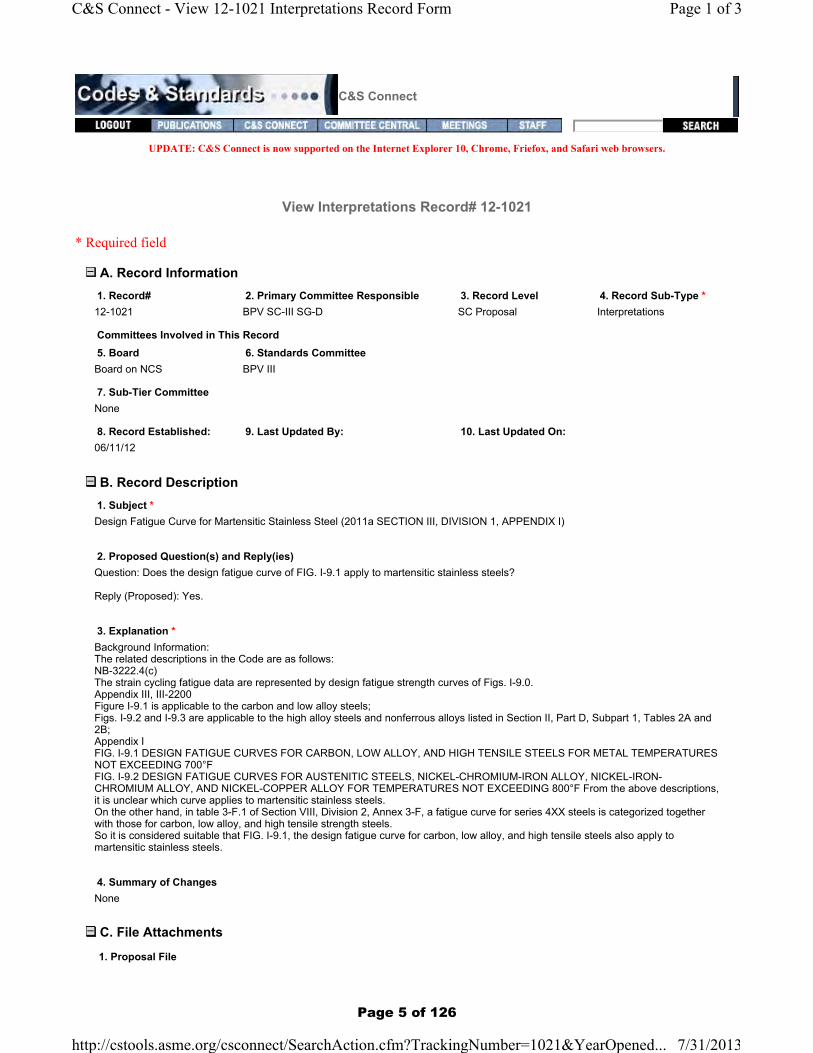
View Interpretations Record# 12-1021
A. Record Information
B. Record Description
C. File Attachments
1. Record# 2. Primary Committee Responsible 3. Record Level 4. Record Sub-Type *12-1021 BPV SC-III SG-D SC Proposal Interpretations
Committees Involved in This Record5. Board 6. Standards CommitteeBoard on NCS BPV III
7. Sub-Tier CommitteeNone
8. Record Established: 9. Last Updated By: 10. Last Updated On:06/11/12
1. Subject *Design Fatigue Curve for Martensitic Stainless Steel (2011a SECTION III, DIVISION 1, APPENDIX I)
2. Proposed Question(s) and Reply(ies) Question: Does the design fatigue curve of FIG. I-9.1 apply to martensitic stainless steels?
Reply (Proposed): Yes.
3. Explanation *Background Information:The related descriptions in the Code are as follows:NB-3222.4(c)The strain cycling fatigue data are represented by design fatigue strength curves of Figs. I-9.0.Appendix III, III-2200Figure I-9.1 is applicable to the carbon and low alloy steels;Figs. I-9.2 and I-9.3 are applicable to the high alloy steels and nonferrous alloys listed in Section II, Part D, Subpart 1, Tables 2A and 2B;Appendix IFIG. I-9.1 DESIGN FATIGUE CURVES FOR CARBON, LOW ALLOY, AND HIGH TENSILE STEELS FOR METAL TEMPERATURES NOT EXCEEDING 700°FFIG. I-9.2 DESIGN FATIGUE CURVES FOR AUSTENITIC STEELS, NICKEL-CHROMIUM-IRON ALLOY, NICKEL-IRON-CHROMIUM ALLOY, AND NICKEL-COPPER ALLOY FOR TEMPERATURES NOT EXCEEDING 800°F From the above descriptions, it is unclear which curve applies to martensitic stainless steels.On the other hand, in table 3-F.1 of Section VIII, Division 2, Annex 3-F, a fatigue curve for series 4XX steels is categorized together with those for carbon, low alloy, and high tensile strength steels.So it is considered suitable that FIG. I-9.1, the design fatigue curve for carbon, low alloy, and high tensile steels also apply to martensitic stainless steels.
4. Summary of ChangesNone
1. Proposal File
Page 1 of 3C&S Connect - View 12-1021 Interpretations Record Form
7/31/2013http://cstools.asme.org/csconnect/SearchAction.cfm?TrackingNumber=1021&YearOpened...
Page 5 of 126

1
Allyson B. Byk
From: [email protected]: Saturday, June 02, 2012 1:36 AMTo: Steven J. RossiSubject: Inquiry for Code Interpretation
Attn : Secretary of ASME Boiler and Pressure Vessel Committee I'm sending this e‐mail for Code Interpretation. The following is the inquiry. Your reply would be helpful for us. Sincerely, ‐‐‐‐‐‐‐‐‐‐‐‐‐‐‐‐‐‐‐‐‐‐‐‐‐‐‐‐‐‐‐‐‐‐‐‐‐‐‐‐‐‐‐‐‐‐‐‐‐‐‐‐‐‐‐‐‐‐‐‐‐‐‐‐‐‐‐‐‐‐‐‐‐‐‐‐‐‐‐‐‐‐‐‐‐‐‐ Purpose: Code Interpretation Subject: Design Fatigue Curve for Martensitic Stainless Steel (2011a SECTION III, DIVISION 1, APPENDIX I) Question: Does the design fatigue curve of FIG. I‐9.1 apply to martensitic stainless steels? Reply (Proposed): Yes. Background Information: The related descriptions in the Code are as follows: NB‐3222.4(c) The strain cycling fatigue data are represented by design fatigue strength curves of Figs. I‐9.0. Appendix III, III‐2200 Figure I‐9.1 is applicable to the carbon and low alloy steels; Figs. I‐9.2 and I‐9.3 are applicable to the high alloy steels and nonferrous alloys listed in Section II, Part D, Subpart 1, Tables 2A and 2B; Appendix I FIG. I‐9.1 DESIGN FATIGUE CURVES FOR CARBON, LOW ALLOY, AND HIGH TENSILE STEELS FOR METAL TEMPERATURES NOT EXCEEDING 700°F FIG. I‐9.2 DESIGN FATIGUE CURVES FOR AUSTENITIC STEELS, NICKEL‐CHROMIUM‐IRON ALLOY, NICKEL‐IRON‐CHROMIUM ALLOY, AND NICKEL‐COPPER ALLOY FOR TEMPERATURES NOT EXCEEDING 800°F From the above descriptions, it is unclear which curve applies to martensitic stainless steels. On the other hand, in table 3‐F.1 of Section VIII, Division 2, Annex 3‐F, a fatigue curve for series 4XX steels is categorized together with those for carbon, low alloy, and high tensile strength steels. So it is considered suitable that FIG. I‐9.1, the design fatigue curve for carbon, low alloy, and high tensile steels also apply to martensitic stainless steels. ‐‐‐‐‐‐‐‐‐‐‐‐‐‐‐‐‐‐‐‐‐‐‐‐‐‐‐‐‐‐‐‐‐‐‐‐‐‐‐‐‐‐‐‐‐‐‐‐‐‐‐‐‐‐‐‐‐‐‐‐‐‐‐‐‐‐‐‐‐‐‐‐‐‐‐‐‐‐‐‐‐‐‐‐‐‐‐
Page 6 of 126
byka
Text Box
12-1021

2
******************************************* Kosei Umemori First Design Section Nuclear Equipment Design Department Hitachi‐GE Nuclear Energy, Ltd. Hitachi Works 2‐2, Omika‐cho, 5‐chome, Hitachi‐shi, Ibaraki‐ken, 319‐1221, Japan Tel : +81‐294‐55‐5154 Fax : +81‐294‐55‐9915 E‐mail : [email protected] *******************************************
Page 7 of 126
byka
Text Box
12-1021
C&S Connect
UPDATE: C&S Connect is now supported on the Internet Explorer 10, Chrome, Friefox, and Safari web browsers.
* Required field
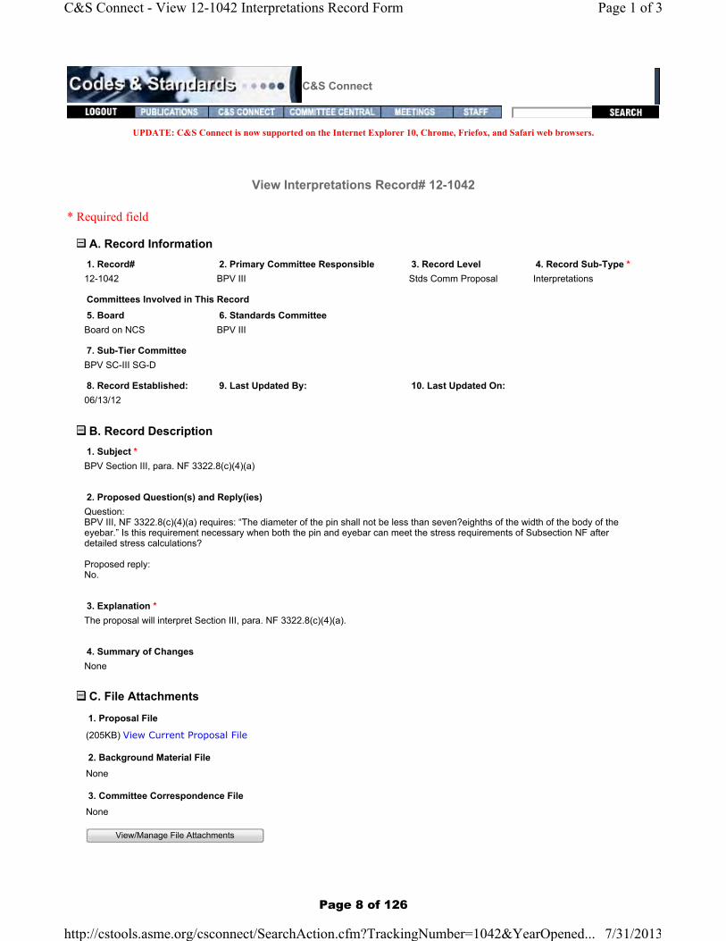
View Interpretations Record# 12-1042
A. Record Information
B. Record Description
C. File Attachments
1. Record# 2. Primary Committee Responsible 3. Record Level 4. Record Sub-Type *12-1042 BPV III Stds Comm Proposal Interpretations
Committees Involved in This Record5. Board 6. Standards CommitteeBoard on NCS BPV III
7. Sub-Tier CommitteeBPV SC-III SG-D
8. Record Established: 9. Last Updated By: 10. Last Updated On:06/13/12
1. Subject *BPV Section III, para. NF 3322.8(c)(4)(a)
2. Proposed Question(s) and Reply(ies) Question:BPV III, NF 3322.8(c)(4)(a) requires: “The diameter of the pin shall not be less than seven?eighths of the width of the body of the eyebar.” Is this requirement necessary when both the pin and eyebar can meet the stress requirements of Subsection NF after detailed stress calculations?
Proposed reply:No.
3. Explanation *The proposal will interpret Section III, para. NF 3322.8(c)(4)(a).
4. Summary of ChangesNone
1. Proposal File
(205KB) View Current Proposal File
2. Background Material FileNone
3. Committee Correspondence FileNone
View/Manage File Attachments
Page 1 of 3C&S Connect - View 12-1042 Interpretations Record Form
7/31/2013http://cstools.asme.org/csconnect/SearchAction.cfm?TrackingNumber=1042&YearOpened...
Page 8 of 126

Subject: BPV Section III, para. NF 3322.8(c)(4)(a) Background (sketch):
Question: BPV III, NF 3322.8(c)(4)(a) requires: “The diameter of the pin shall not be less than seven‐eighths of the width of the body of the eyebar.” Is this requirement necessary when both the pin and eyebar can meet the stress requirements of Subsection NF after detailed stress calculations? Proposed reply: No.
Page 9 of 126
byka
Text Box
12-1042
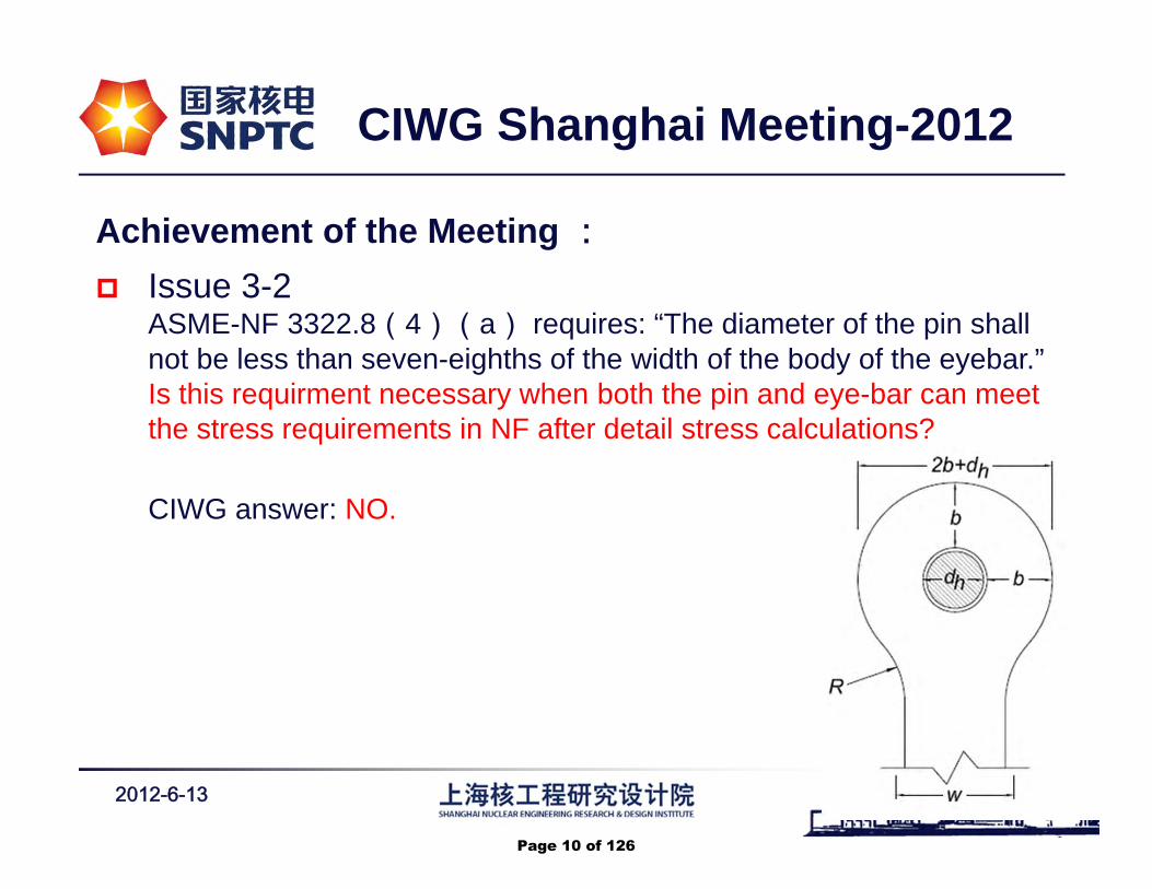
Achievement of the Meeting : Issue 3-2
ASME-NF 3322.8(4)(a) requires: “The diameter of the pin shall not be less than seven-eighths of the width of the body of the eyebar.” Is this requirment necessary when both the pin and eye-bar can meet the stress requirements in NF after detail stress calculations?
CIWG answer: NO.
2012-6-13 -14-
CIWG Shanghai Meeting-2012
Page 10 of 126
byka
Text Box
12-1042

C&S Connect
UPDATE: C&S Connect is now supported on the Internet Explorer 10, Chrome, Friefox, and Safari web browsers.
* Required field
View Interpretations Record# 12-1919
A. Record Information
B. Record Description
C. File Attachments
1. Record# 2. Primary Committee Responsible 3. Record Level 4. Record Sub-Type *12-1919 BPV SC-III MF&E SG SC Proposal Interpretations
Committees Involved in This Record5. Board 6. Standards CommitteeBoard on NCS BPV III
7. Sub-Tier CommitteeNone
8. Record Established: 9. Last Updated By: 10. Last Updated On:10/30/12 BykA 06/03/13
1. Subject *BPVC Section III, Division 1, NB-2223.3
2. Proposed Question(s) and Reply(ies) Question: Does preparing a separate forging in accordance with NB-2223 .3 for parts cettified to ASME Section III Class I override SA508 Paragraph 6.1.6.3 Method 3 in Section II as stated in NB.2122 for the 1986 Edition and subsequent years?
Proposed Reply: Yes.
3. Explanation *This proposal will interpret BPVC Section III, Division 1, NB-2223.3.
Background: Interpretation lll-1-86-07 was issued in 1985 to respond to a specific situation for material supplied to the 1983 Edition with Summer 1985 Addenda Code Year. This interpretation overrides NB.2122 which states that the requirements in this Article (NB-2000) apply in lieu of the material requirements when in conflict. We are trying to determine iflnterpretation III-1-86-07 became permanent for all Code years going forward since there was no change to subsequent Code wording and no Code Case was issued.
4. Summary of ChangesNone
1. Proposal File
(25KB) View Current Proposal File - Revised request - 4/29/13
2. Background Material File
(25KB) View Current Background Material File - Revised request - 4/29/13
3. Committee Correspondence FileNone
Page 1 of 3C&S Connect - View 12-1919 Interpretations Record Form
7/31/2013http://cstools.asme.org/csconnect/SearchAction.cfm?TrackingNumber=1919&YearOpened...
Page 11 of 126

Page 12 of 126
byka
Text Box
12-1919
C&S Connect
UPDATE: C&S Connect is now supported on the Internet Explorer 10, Chrome, Firefox, and Safari web browsers.
View Interpretations Record# 12-1972
* Required field
A. Record Information 1. Record# 2. Primary Committee Responsible 3. Record Level 4. Record Sub-Type *12-1972 BPV SC-III MF&E SG Stds Comm Approved Intent Interpretation
Committees Involved in This Record
5. Board 6. Standards Committee
Boards IncludedBoard on NCS
BPV III
7. Sub-Tier Committee None
8. Record Established: 9. Last Updated By: 10. Last Updated On: 11. Date of Issuance:11/05/2012 HunterS 10/25/2013
B. Record Description 1.Subject *
Standard Designation * Edition/Addenda *
Paragraph/Fig./Table No. *
Subject Description *ASME Section III, Winter 1975 Addenda through 2013 Edition, NB, NC, ND, NE, NF, NG-5521(a)(4), CC-5120, WB-5500, and WC-5500
2. Proposed Question(s) and Reply(ies) *Is it the intent of paragraphs NB, NC, ND, NE, NF, NG-5521(a)(4), CC-5120, WB-5500, and WC-5500 to require all NDE personnel performing any Code required Nondestructive Examinations (NDE) regardless of the NDE method to be visually examined for near visual acuity using Jaeger Number 1 letters in lieu of the Jaeger Number 2 letters required by SNT-TC-1A paragraph 8.2(1)?Proposed Reply: YES.
3. Explanation *This proposal will interpret ASME Section III, Winter 1975 Addenda through 2013 Edition, NB, NC, ND, NE, NF, NG-5521(a)(4), CC-5120, WB-5500, and WC-5500.
Record 12-454 (the Code change) has Board Approval and the primary action of this Record is the Interpretation.
See Background information included for further information.
C. File Attachments
1. Background File
(379KB) View Background File - Background
2. Proposal File
Page 1 of 6C&S Connect - View 12-1972 Interpretations Record Form
2/4/2014http://cstools.asme.org/csconnect/SearchAction.cfm?TrackingNumber=1972&YearOp...
Page 13 of 126

Page 14 of 126
shunter
Text Box
12-1972 Page 1 of 9
shunter
Text Box
shunter
Text Box
shunter
Text Box
shunter
Text Box
shunter
Callout
For NDE personnel performing any NDE in accordance with this Subsection, the Near Vision Acuity requirements specified in paragraph 8.2.1 of SNT-TC-1A shall apply except Jaeger Number 1 letters shall be used in lieu of the Jaeger Number 2 letters.

Page 15 of 126
shunter
Text Box
FOR REFERENCE ONLY
shunter
Text Box
12-1972 Page 2 of 9

Page 16 of 126
shunter
Text Box
shunter
Text Box
shunter
Text Box
shunter
Text Box
shunter
Callout
For NDE personnel performing any NDE in accordance with this Subsection, the Near Vision Acuity requirements specified in paragraph 8.2.1 of SNT-TC-1A shall apply except Jaeger Number 1 letters shall be used in lieu of the Jaeger Number 2 letters.
shunter
Text Box
12-1972 Page 3 of 9

Page 17 of 126
shunter
Text Box
shunter
Text Box
shunter
Text Box
shunter
Text Box
shunter
Callout
For NDE personnel performing any NDE in accordance with this Subsection, the Near Vision Acuity requirements specified in paragraph 8.2.1 of SNT-TC-1A shall apply except Jaeger Number 1 letters shall be used in lieu of the Jaeger Number 2 letters.
shunter
Text Box
12-1972 Page 4 of 9
Page 18 of 126
shunter
Text Box
12-1972 Page 5 of 9
shunter
Text Box
FOR REFERENCE ONLY

Page 19 of 126
shunter
Text Box
shunter
Text Box
shunter
Text Box
shunter
Text Box
shunter
Callout
For NDE personnel performing any NDE in accordance with this Subsection, the Near Vision Acuity requirements specified in paragraph 8.2.1 of SNT-TC-1A shall apply except Jaeger Number 1 letters shall be used in lieu of the Jaeger Number 2 letters.
shunter
Text Box
12-1972 Page 6 of 9

Page 20 of 126
shunter
Text Box
shunter
Text Box
shunter
Text Box
shunter
Text Box
shunter
Callout
For NDE personnel performing any NDE in accordance with this Subsection, the Near Vision Acuity requirements specified in paragraph 8.2.1 of SNT-TC-1A shall apply except Jaeger Number 1 letters shall be used in lieu of the Jaeger Number 2 letters.
shunter
Text Box
12-1972 Page 7 of 9

Page 21 of 126
shunter
Text Box
12-1972 Page 8 of 9
shunter
Text Box
FOR REFERENCE ONLY

Page 22 of 126
shunter
Text Box
shunter
Text Box
shunter
Text Box
shunter
Text Box
shunter
Callout
For NDE personnel performing any NDE in accordance with this Subsection, the Near Vision Acuity requirements specified in paragraph 8.2.1 of SNT-TC-1A shall apply except Jaeger Number 1 letters shall be used in lieu of the Jaeger Number 2 letters.
shunter
Text Box
12-1972 Page 9 of 9

C&S Connect
UPDATE: C&S Connect is now supported on the Internet Explorer 10, Chrome, Firefox, and Safari web browsers.
* Required field
View Interpretations Record# 13-799
A. Record Information
B. Record Description
C. File Attachments
1. Record# 2. Primary Committee Responsible 3. Record Level 4. Record Sub-Type *13-799 BPV SC-III MF&E SG SC Proposal Interpretations
Committees Involved in This Record5. Board 6. Standards CommitteeBoard on NCS BPV III
7. Sub-Tier CommitteeBPV SC-III MF&E SG
8. Record Established: 9. Last Updated By: 10. Last Updated On:04/29/13 BykA 10/21/13
1. Subject *ASME BPVC Seciton III NB-6114.2, Edition 1998, Addenda 2000 and NCA-8322 Edition 2010, Addenda 2011
2. Proposed Question(s) and Reply(ies) Question:Is it the intent for ASME Section III, Division 1, NB-6114.2(d) and NCA-8322(b) to allow a pump component N- Certificate Holder to perform the stamping of a pump with the Certification Mark and Designator under the following circumstances?(a) The pump component N-Certificate Holder fabricates and performs a pressure test of his subassembly at his location.(b) The pump component N-Certificate Holder ships the subassembly to his subcontracted N-type Certificate Holder who fabricates and pressure tests the casing. The N-type Certificate Holder shop assembles the pump by mechanical means, and marks the casing with the Certification Mark and NPT designator.(c) As allowed by NCA-8322 (b), the pump component N-Certificate Holder stamps the pump at the location of the subcontractor.
Proposed Reply:Yes, provided all the requirements of NB-6114.2 (d) are followed.
3. Explanation *This propsoal will interpret NB-6114.2, Edition 1998, Addenda 2000 and NCA-8322 Edition 2010, Addenda 2011
4. Summary of ChangesNone
1. Proposal File
(142KB) View Current Proposal File
2. Background Material File
(142KB) View Current Background Material File
3. Committee Correspondence File
Page 1 of 3C&S Connect - View 13-799 Interpretations Record Form
10/22/2013http://cstools.asme.org/csconnect/SearchAction.cfm?TrackingNumber=799&YearOpened...
Page 23 of 126

Record 13‐799 dated 9/10/2013 rev 0 Page 1 of 4 Inquiry 2013 Code Edition
Question:
Is it the intent for ASME Section III, Division 1, NB-6114.2(d) and NCA-8322(b) to allow a pump component N- Certificate Holder to perform the stamping of a pump with the Certification Mark and Designator under the following circumstances?
(a) The pump component N‐Certificate Holder fabricates and performs a
pressure test of his subassembly at his location.
(b) The pump component N‐Certificate Holder ships the subassembly to his
subcontracted N‐type Certificate Holder who fabricates and pressure
tests the casing. The N‐type Certificate Holder shop assembles the
pump by mechanical means, and marks the casing with the Certification
Mark and NPT designator.
(c) As allowed by NCA‐8322 (b), the pump component N‐Certificate Holder
stamps the pump at the location of the subcontractor.
Reply:
Yes, provided all the requirements of NB‐6114.2 (d) are followed.
Page 24 of 126

Record 13‐799 dated 9/10/2013 rev 0 Page 2 of 4 Inquiry 2013 Code Edition
Associated Proposed Code Revision – Delete the Strikethrough and insert the text box information. NCA-8322 Application of the Certification Mark With N Designator at Field Sites or Other Locations The N Certificate Holder may apply the Certification Mark with N Designator to the component in the field , without having the N Certificate of Authorization extended to a field site or other location, under the following provisions: (a) where the N Certificate Holder elects to substitute the system pressure test [NB/NC/ND‐6221(a)] for the component pressure test, the test is conducted under the responsibility of an N or NA Certificate of Authorization issued for that field site and is witnessed and accepted by the N Certificate Holder responsible for the component, or (b) where the N Certificate Holder elects to subcontract the performance of the component pressure test, the N Certificate Holder shall be responsible for supervising, witnessing, and accepting the pressure test and assuring that the test is controlled in accordance with the suppliers’ approved program, or (c) where the N Certificate Holder elects to perform the component pressure test at a field site or other location, the pressure test shall be controlled in accordance with the N Certificate Holder’s Quality Assurance Program. The completed shop fabrication portion of the Data Report Form, together with the Inspector’s own inspections of the component, shall be authority for that field Inspector to witness the test and authorize stamping of the completed component.
INSERT: where the N Certificate Holder elects to subcontract the performance of the component and appurtenance pressure test in accordance with NB-6114.2(d), the component and appurtenance N-Certificate Holder shall be responsible for the completed component and appurtenance as described in his Quality Assurance Program,
Insert:
or other location
Page 25 of 126

Record 13‐799 dated 9/10/2013 rev 0 Page 3 of 4 Inquiry 2013 Code Edition
FOR REFERENCE ONLY NOT PART OF THE ACTION
NB-6114.2 Component and Appurtenance Pressure Test. (a) Components and appurtenances shall be pressure tested prior to installation in a system, except as permitted in (b) below. (b) The system pressure test may be substituted for a component or appurtenance pressure test, provided: (1) the component can be repaired by welding in accordance with the rules of NB-4130 and NB-4450, if required, as a result of the system pressure test; (2) the component repair weld can be postweld heat treated in accordance with NB-4620, if required, and nondestructively examined in accordance with the rules of NB-4130 and NB-4450, as applicable; (3) the component is resubjected to the required system pressure test following the completion of repair and examination if the repair is required to be radiographed by NB-4453.4. (c) Valves require pressure testing prior to installation in a system in accordance with NB-3500. (d) Items which, when assembled, form a completed pump or valve may be tested in the form of subassemblies, provided: (1) the test pressure is in accordance with the requirements of NB-6221; (2) the pressure test is performed in a manner which, in the subassembly under test, will simulate the loadings present when the completed pump or valve is assembled and pressurized; (3) the component Certificate Holder approves any pressure test of component subassemblies; (4) the component Certificate Holder specifies the pressure test requirements and test pressure to be used; (5) each subassembly pressure test is performed by a Certificate Holder and is performed in the presence of the Authorized Inspector; (6) each subassembly pressure tested by other than the component Certificate Holder is stamped with the Certification Mark with NPT Designator, except as provided in NCA‑8330. The test pressure shall be identified on the Partial Data Report Form. (7) each subassembly pressure tested by other than the component Certificate Holder is listed on the Code Data Report Form; (8) the pressure tested subassemblies of pumps or valves are subsequently assembled by mechanical methods only; (9) welds examined during the subassembly pressure test need not be reexamined during the system pressure test.
Page 26 of 126
Record 13‐799 dated 9/10/2013 rev 0 Page 4 of 4 Inquiry 2013 Code Edition
FOR REFERENCE ONLY NOT PART OF THE ACTION
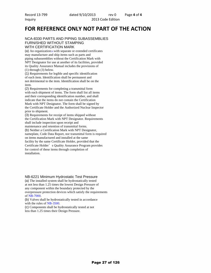
NCA-8330 PARTS AND PIPING SUBASSEMBLIES FURNISHED WITHOUT STAMPING WITH CERTIFICATION MARK (a) An organization16 with separate or extended certificates may manufacture and ship items such as parts and piping subassemblies without the Certification Mark with NPT Designator for use at another of its facilities, provided its Quality Assurance Manual includes the provisions of (1) through (3) below. (1) Requirements for legible and specific identification of each item. Identification shall be permanent and not detrimental to the item. Identification shall be on the item. (2) Requirements for completing a transmittal form with each shipment of items. The form shall list all items and their corresponding identification number, and shall indicate that the items do not contain the Certification Mark with NPT Designator. The form shall be signed by the Certificate Holder and the Authorized Nuclear Inspector prior to shipment. (3) Requirements for receipt of items shipped without the Certification Mark with NPT Designator. Requirements shall include inspection upon receipt and maintenance and retention of transmittal forms. (b) Neither a Certification Mark with NPT Designator, nameplate, Code Data Report, nor transmittal form is required on items manufactured and installed at the same facility by the same Certificate Holder, provided that the Certificate Holder’s Quality Assurance Program provides for control of these items through completion of installation.
NB-6221 Minimum Hydrostatic Test Pressure (a) The installed system shall be hydrostatically tested at not less than 1.25 times the lowest Design Pressure of any component within the boundary protected by the overpressure protection devices which satisfy the requirements of NB-7000. (b) Valves shall be hydrostatically tested in accordance with the rules of NB-3500. (c) Components shall be hydrostatically tested at not less than 1.25 times their Design Pressure.
Page 27 of 126

Page 28 of 126
byka
Rectangle

C&S Connect
UPDATE: C&S Connect is now supported on the Internet Explorer 10, Chrome, Firefox, and Safari web browsers.
* Required field
View Component Record# 13-969
A. Record Information
B. Record Description
C. File Attachments
1. Record# 2. Primary Committee Responsible 3. Record Level 4. Record Sub-Type *13-969 BPV SC-III WG-DR SC Proposal Intent Interp & Prop Rev
Committees Involved in This Record5. Board 6. Standards CommitteeBoard on NCS BPV III
7. Sub-Tier CommitteeBPV SC-III SGGR
8. Record Established: 9. Last Updated By: 10. Last Updated On:05/24/13
1. Subject *NCA-3620(q) Design Certification vs. Data Report Responsibilities
2. Proposal TBD
3. Explanation *Interpretation request 13-864Question 1: addressed at 5/13 Code Week, Miami{May an N Certificate Holder assume design responsibility for an appurtenance in accordance with NCA-3530?}
Question 2: addressed at 5/13 Code Week, Miami{In accordance with NCA-3530 may an N Certificate Holder provide the Design Report for an appurtenance required by NCA-3620(q)?
Question 3: Whe the N certificate Holder subcontracts fabrication to an NPT Certificate Holder and provides the Desigtn Report for an appurtenance required by NCA-3620(q), does completion of information on the N-2 for "Certification of Deisgn" mean that th eNPT Certificate Holder assumes design responsibility?Proposed Reply: No
Question 4: If the answer to question 2 is yes, may the NPT Certificate Holder record on the N-2 Data Report "Design Certification" that the n Certificate Holder assumes responsibiloiity for the appurtenance Data Report required by NCA-3620(q)?Proposed Reply: Yes
Question 5: If the answer to question 4 is No, is the N-Certificate Holder required to complete an additional N-2 Data Report for "Certification of Design"?Proposed Reply: Yes
4. Summary of ChangesNone
1. Proposal File
Page 1 of 3C&S Connect - View 13-969 Component Record Form
10/22/2013http://cstools.asme.org/csconnect/SearchAction.cfm?TrackingNumber=969&YearOpened...
Page 29 of 126

D. Project Administrative Manager
E. Record Creator
F. Project Technical Manager
G. Sub-Tier Committee Level
H. Additional Committee information
None
2. Background Material FileNone
3. Committee Correspondence FileNone
View/Manage File Attachments
1. Staff ContactAllyson [email protected](212)591-8539
2. Staff NotesNone
Jay [email protected](724)275-5235
1. Project Manager *Plante, [email protected](603)433-1064
2. Project Manager NotesNone
1. Original Inquirer Contact InformationJames G. OylerASME QA Program ManagerWestinghouse Electric CompanyNuclear Power Plants1000W
2. Project Team Name 3. Project Team MembersNone Lisa Plante - PM / Chair
Jim OylerGene ImbroMike SullivanSteve BellMrett McGlure
4. Subcommittee Item HistoryThis was originally addressed in record 13-864 at the 5/13 Code Week in Miami. Questions 1 and 2 were answered. SGGR felt that questions 3, 4 and 5 were intent interpretations and assigned the above project team to address these questions.
1. Codes Affected by Proposed Revision 2. Related Committee RecordsBPVC-III-NCA 13-864 BPV III Stds Comm Approved
Page 2 of 3C&S Connect - View 13-969 Component Record Form
10/22/2013http://cstools.asme.org/csconnect/SearchAction.cfm?TrackingNumber=969&YearOpened...
Page 30 of 126

C&S Connect
UPDATE: C&S Connect is now supported on the Internet Explorer 10, Chrome, Firefox, and Safari web browsers.
* Required field
View Interpretations Record# 13-1401
A. Record Information
B. Record Description
C. File Attachments
D. Project Administrative Manager
1. Record# 2. Primary Committee Responsible 3. Record Level 4. Record Sub-Type *13-1401 BPV III Stds Comm Proposal Interpretations
Committees Involved in This Record5. Board 6. Standards CommitteeBoard on NCS BPV III
7. Sub-Tier CommitteeBPV SC-III MF&E SG
8. Record Established: 9. Last Updated By: 10. Last Updated On:08/12/13
1. Subject *BPV Section III, Subsection NB-4000 (1998 Edition through 2000 Addenda)
2. Proposed Question(s) and Reply(ies) We have a steam generator upper shell, which is right below the elliptical head, that is out-of-round after final heat treatment. The shell is just a cylinder and is made of lower alloy steel - SA508Gr3Cl.2 (smiliar to the pressure vessel material). The nominal ID of the shell is around 120" with a thickness of about 6" (before final machining). The current shape is sort of "elliptical" with deviation as much as -1.3" in some angular locations and +0.5" in other locations. The manufacturer intends to force it round at room temperature and stress relieve afterwards. Does the Section III Subsection NB allow the manufacturer to force the cylinder shell round?
3. Explanation *The proposal will interpret BPV Section III, Subsection NB-4000 (1998 Edition through 2000 Addenda)
4. Summary of ChangesNone
1. Proposal File
(19KB) View Current Proposal File
2. Background Material File
(19KB) View Current Background Material File
3. Committee Correspondence FileNone
View/Manage File Attachments
Page 1 of 3C&S Connect - View 13-1401 Interpretations Record Form
10/22/2013http://cstools.asme.org/csconnect/SearchAction.cfm?TrackingNumber=1401&YearOpene...
Page 31 of 126

Technical Inquiry to the ASME Boiler and Pressure Vessel Committee
1. Purpose (Check one of the following) � Revision of present Code rules � New or additional Code rules � Code Case √ Code Interpretation
2. Proposed Revisions or Additions / Inquiry and Reply
Inquiry:
Does the ASME B&PV Code Section III subsection NB allow the manufacturer to force the
cylinder shell round? and this will do at what conditions ?
3. Statement of Need
This inquiry is to clarify ASME B&PV Code Section III subsection NB 1998 Edition through 2000
Addenda.
4. Background We have an AP1000 steam generator upper shell, which is right below the elliptical head, is out of round after final heat treatment. The shell is just a cylinder and is made of lower alloy steel - SA508Gr3Cl.2 (smiliar to the pressure vessel material). The nominal ID of the shell is around 120" with a thickness of about 6" (before final machining). The current shape is sort of "elliptical" with deviation as much as -1.3" in some angular locations and +0.5" in other locations. The manufacturer intends to force it round at room temperature and stress relieve afterwards
Is it allowable? Is there a code case? or previous experience?
5. Inquirer Information
Name Shaoxuan Lin E-mail [email protected]
Organization Shanghai Nuclear Engineering Research and Design Institute
Address No.29 Hongcao Road, Shanghai 200233, China
Telephone No. +86 21 61861004 Fax No. +86 21 61861000
Page 32 of 126
BykA
Text Box
13-1401

C&S Connect
UPDATE: C&S Connect is now supported on the Internet Explorer 10, Chrome, Firefox, and Safari web browsers.
* Required field
View Interpretations Record# 13-1819
A. Record Information
B. Record Description
C. File Attachments
1. Record# 2. Primary Committee Responsible 3. Record Level 4. Record Sub-Type *13-1819 BPV III Stds Comm Proposal Interpretations
Committees Involved in This Record5. Board 6. Standards CommitteeBoard on NCS BPV III
7. Sub-Tier CommitteeBPV SC-III SGGRBPV SC-III MF&E SG
8. Record Established: 9. Last Updated By: 10. Last Updated On:10/21/13
1. Subject *ASME BPVC Section III, Division 1, NCA-3800, NB-2000 and NB-4000
2. Proposed Question(s) and Reply(ies) Question: N and NPT Certificate Holder has performed Ultrasonic Test By NB-2550 for the Tube from Round bar after deep hole was machined during manufacturing. The Data Report will be issued for equipment to certify that the fabrication complies with the requirements of NB-2000 and NB-4000. In this case, shall Certificate Holder issue the CMTR by NB-4121.1 with test result by NB-2550 before issue the Data Report?
Proposed Reply: No.
3. Explanation *According to "NB-2121.1 Certification of Treatments, Tests, and Examinations." prescribes that if the Certificate Holder performs tests required by other Articles of NB-4000, Certificate Holder shall certify that this requirement has been fulfilled by NCA-3862. NCA-3862 has described for Certification of material by means of issue the CMTR.
N and NPT Certificate Holder has purchased Round bar from Material Organization to manufacture equipment by NB-4000 and it was deep hole machined to make Tube. IN this case, the Certificate Holder performed Ultrasonic Test by NB-2550 for the Tube. The Certificate Holder will issue the Data Report for Equipment to certify that the fabrication complies with the requirements of NB-2000 and NB-4000.
4. Summary of ChangesNone
1. Proposal FileNone
2. Background Material FileNone
Page 1 of 3C&S Connect - View 13-1819 Interpretations Record Form
10/22/2013http://cstools.asme.org/csconnect/SearchAction.cfm?TrackingNumber=1819&YearOpene...
Page 33 of 126

D. Project Administrative Manager
E. Record Creator
F. Project Technical Manager
G. Sub-Tier Committee Level
H. Additional Committee information
I. Additional Standards Committee information
3. Committee Correspondence FileNone
View/Manage File Attachments
1. Staff ContactAllyson [email protected](212)591-8539
2. Staff NotesNone
Allyson [email protected](212)591-8539
1. Project Manager *Hunter, [email protected](434)832-2799
2. Project Manager NotesNone
1. Original Inquirer Contact InformationJong-In KimDoosan555 Guigok-Dong, Changwon, Gyeongsangnam-Do 641-792, Korea(Tel.+82-55-278-574
2. Project Team Name 3. Project Team MembersNone None
4. Subcommittee Item HistoryNone
1. Codes Affected by Proposed Revision 2. Related Committee RecordsBPVC-III-NCA Interp
3. Proposal Keywords4. Secondary Committee[s] w/Related Actions
Pending Committees Committees Responded
5. Type (Nuclear Only)None
6.Text of Subordinate Group Negatives 7.Subordinate Group Action Date01/01/00
Page 2 of 3C&S Connect - View 13-1819 Interpretations Record Form
10/22/2013http://cstools.asme.org/csconnect/SearchAction.cfm?TrackingNumber=1819&YearOpene...
Page 34 of 126

J. Editor Input
K. Latest Ballot
L. Ballot History
M. ANSI Level
N. Publications Level
None
Minimum Site Requirements: IE 6.0+ • Firefox 2.0+ • Chrome 4.0+
Copyright © 1996-2013 ASME. All Rights Reserved. Terms of Use | Privacy Statement
Page 3 of 3C&S Connect - View 13-1819 Interpretations Record Form
10/22/2013http://cstools.asme.org/csconnect/SearchAction.cfm?TrackingNumber=1819&YearOpene...
Page 35 of 126

Page 36 of 126
BykA
Text Box
13-1819

Page 37 of 126
BykA
Text Box
13-1819

C&S Connect
UPDATE: C&S Connect is now supported on the Internet Explorer 10, Chrome, Firefox, and Safari web browsers.
View Component Record# 13-1820
* Required field
A. Record Information 1. Record# 2. Primary Committee Responsible 3. Record Level 4. Record Sub-Type *13-1820 BPV SC-III SGGR Out for Board Ballot Intent Interp & Prop Rev
Committees Involved in This Record
5. Board 6. Standards Committee
Boards IncludedBoard on NCS
BPV III
7. Sub-Tier Committee None
8. Record Established: 9. Last Updated By: 10. Last Updated On: 10/21/2013 BykA 01/06/2014
B. Record Description 1. Subject *ASME BPVC Section III, Division1, NCA-9200 and NCA-1282
2. Proposal Question: Is it the intent of ASME Section III, NCA-1282 to prohibit an NS Certificate Holder from attaching supports to building structure during fabrication at the location authorized by their Certificate?
Answer: No.
3. Explanation *Background: Maximum usage of shop facilities and the completion of many activities in parallel while minimizing field work is a major part of the strategy for our projects at Vogtle in Waynesboro, GA and V. C. Summer near Jenkinsville, SC. As a result, we contracted with an NS Certificate Holder for most of the piping and component supports. The NS Certificate Holder has completed the “manufacturing” of an NF Component Support (pump stand). The support consists of three large columns connected to baseplates by welding. The NF boundary is at the column to baseplate weld with the baseplate being designated as building structure as required by NF-1132(d). The NF weld to the baseplate was performed by the NS Certificate Holder. During review of the work, a question was raised regarding whether this weld could be performed by the NS Certificate Holder. Note that Article NF-4000 states the following:NF-4111 Fabrication and InstallationSupports shall be fabricated and installed in accordance with the requirements of this Article and shall be manufactured from material which meets the requirements of NF-2000.NF-4121 Means of CertificationThe NS Certificate Holder for a support shall certify Code compliance by the furnishing of an NS-1 Certificate of Conformance (NCA-3687) for welded supports or a Certificate of Compliance (NCA-3689) for nonwelded supports.The scope of all of the issued NS-1 Certificates is only for fabrication. Here is the definition of fabrication:fabrication: those actions required to manufacture components, parts, and appurtenances. These actions may include forming, machining, assembling, welding, brazing, heat treating, examination, testing, inspection, and certification. Fabrication does not include design.Note that this definition for fabrication addresses only actions required to manufacture “components, parts and appurtenances.” Thus, it is not clear how the definition of fabrication applies to component supports. Next, we investigated the definition of the NS Certificate Holder:NS Certificate Holder: the organization holding a valid NS Certificate of Authorization issued by the Society that constructs, including
Page 1 of 5C&S Connect - View 13-1820 Component Record Form
2/10/2014http://cstools.asme.org/csconnect/SearchAction.cfm?TrackingNumber=1820&YearO...
Page 38 of 126

construction by welding of all classes of supports, and all classes of standard supports. The NS Certificate Holder is not required to apply a Certification Mark.This definition indicates that the NS Certificate Holder “constructs” supports. The definition of “construction” is as follows:construction (as used in Division 1): an all-inclusive term comprising materials, design, fabrication, examination, testing, inspection, and certification required in the manufacture and installation of an item.This definition includes activities required “in the manufacture and installation of an item.” The question which follows is related to the scope of the NS Certificate. We believe that it is appropriate for the NS Certificate Holder to make connections to building structure when such work is requested as part of the fabrication. Since this inquiry is related to intent, a proposed Code change is also included.
4. Summary of Changes Revised text and definitions to clarify responsibilities of NA and NS Certificate Holders with regard to the attachment of supports to building structure
C. File Attachments
1. Proposal File
(22KB) View Current Proposal File - Editorially Revised 1/6/14
2. Background Material File
(23KB) View Current Background Material File
3. Committee Correspondence File None
View/Manage File Attachments
D. Project Administrative Manager1. Staff Contact Allyson [email protected](212)591-8539
2. Staff Notes None
E. Record Creator Allyson [email protected](212)591-8539
F. Project Technical Manager 1. Project Manager *Bell, [email protected](706)437-2260
2. Project Manager Notes None
G. Sub-Tier Committee Level 1. Original Inquirer Contact Information Steven R. Bell, P.E.ASME Control Center SupervisorField EngineeringPowerNuclearTel: 706-43
Page 2 of 5C&S Connect - View 13-1820 Component Record Form
2/10/2014http://cstools.asme.org/csconnect/SearchAction.cfm?TrackingNumber=1820&YearO...
Page 39 of 126

2. Project Team Name 3. Project Team Members None None
4. Subcommittee Item History None
H. Additional Committee information 1. Codes Affected by Proposed Revision 2. Related Committee Records 3287 None
3. Proposal Keywords None
4. Secondary Committee[s] w/Related Actions
Pending Committees Committees RespondedNone None
5. Type (Nuclear Only) None
6.Text of Subordinate Group Negatives 7.Subordinate Group Action Date 01/01/2000
I. Additional Standards Committee information 1. Standards Committee Description 1 2. Standards Committee Action 1 3. Committee Action Date 1 None None None
4. Standards Committee Description 2 5. Standards Committee Action 2 6. Committee Action Date 2 None None None
7. Addenda/Edition Year None
J. Editor Input 1. Editor Acceptance of Proposed Revision Attachment N/A
2. Editorial Review(Activated only if ItemLevel = Board Approved)Has not yet been reviewed by the editor for publication
3. Editor Notes
Editor's Fields Last Updated By:
K. Latest Ballot
Ballot#: 13-2860RC1Ballot Level: Board Procedural Final Record Status: Pending Date Opened: 01/23/14 Date Closed: Description:Recirculation of Board Procedural Ballot 13-2860 for record 13-1820
Voting Results:
Comments & Negatives Posted for Ballot#: 13-2860RC1
Page 3 of 5C&S Connect - View 13-1820 Component Record Form
2/10/2014http://cstools.asme.org/csconnect/SearchAction.cfm?TrackingNumber=1820&YearO...
Page 40 of 126

SchaafF (Objection) Date Posted: 02/05/14After a discussion with Mr. Swayne on this item, I agree with his objection. Proper procedures are not being followed. An "intent Inquiry" is used to clarify Code words and a Code revision is included. In this case there already is a inquiry and appears to conflict with the new inquiry. If the subject action proceeds there will be two conflicting Inquiries and Code revision. Section III needs to discuss this action and develop a proper course of action. The proposed Code action could be submitted to revise NCA-1282 which would avoid the conflicting inquiries.
Response:
BellS: 02/06/14Frank - Thank you for your comment. I assume you are referring to previous Interpretation III-1-86-26 which indicates that connection of supports to building structure is not considered a Code activity. This previous interpretation is consistent with the fact that the definition of installation does not address connection of supports to building structure, but inconsistent with NCA-1282 which describes connection of supports to building structure as installation. Second, the current definition of NS Certificate Holder indicates that he "constructs" supports. "Construction" is an all inclusive term comprising materials, design, fabrication, examination, testing, inspection, and certification required in the manufacture and installation of an item. Thus, it seems to me, as a Code user that some combination of ambiguity, conflict or incorrect wording exists within the current Code regarding whether the NS Certificate Holder is permitted to weld supports to building structure, since he is defined as one who constructs and since installation does not refer to attachment of supports to building structure. This interpretation seeks to clarify those requirements within the guidance of CSP-33 which requires intent interpretations to be accompanied by Code changes. At this point, either solution (installation of supports is not a Code activity or this proposed interpretation) would resolve my current problem. From our work so far, it is evident that there is a vast array of opinions on this topic. I would support a more comprehensive review, but I do not believe this action violates the procedural requirements.
L. Ballot History 1. Board Ballot History
Ballot#: 13-2860RC1 Please click on the Ballot# button to view comments / negatives for this ballot.Ballot Level: Board Procedural Final Record Status: Pending Date Opened: 01/23/14 Date Closed: Description:Recirculation of Board Procedural Ballot 13-2860 for record 13-1820
Ballot#: 13-2860 Please click on the Ballot# button to view comments / negatives for this ballot.Ballot Level: Board Procedural Final Record Status: Standards Committee Recirculation Required Date Opened: 12/11/13 Date Closed: 01/06/14 Record Status Date: 01/06/2014Description:BPV Section III Standards Actions approved since the October 2013 BPV III Standards Committee Meeting.
Voting Results:For records 12-887, 13-1032 and 13-1417: 19 No Objection, and 10 votes not returned.For record 13-1820: 2 Objections, 16 No Objection, and 11 votes not returned.
As a result, 12-887 and 13-1417 are approved for publication. 13-1032 is approved for publication pending the response to the comment received. 13-1820 will be sent back to BPV III for recirculation of the editorial changes resulting from comments on this ballot.
2. Standards Committee Ballot History
Ballot#: 13-2526RC2 Please click on the Ballot# button to view comments / negatives for this ballot.Ballot Level: Standards Committee Final Record Status: Approved Date Opened: 01/06/14 Date Closed: 01/23/14 Record Status Date: 01/23/2014Description:
Page 4 of 5C&S Connect - View 13-1820 Component Record Form
2/10/2014http://cstools.asme.org/csconnect/SearchAction.cfm?TrackingNumber=1820&YearO...
Page 41 of 126

Record Number 13‐1820
Updated 01/06/14
Inquiry to ASME Section III
[NOTE – During the procedural review of this record (Ballot 13‐2860), several editorial
comments were suggested. These have been incorporated for a recirculation ballot. ]
Question: Is it the intent of NCA‐1282 to prohibit an NS Certificate Holder from attaching
supports to building structure during fabrication at the location authorized by its Certificate?
Answer: No.
Code Changes to accompany this answer (deletions noted as double strikethrough, additions
[shaded bold with brackets])
NCA-1282 Support Installation
Installation of supports consists of those activities required to attach supports to the building structure and join parts and materials by welding or mechanical means [by the NA Certificate Holder at the location authorized by its Certificate. Attachment of supports to building structure may also be performed during support fabrication by the NS Certificate Holder at the location authorized by its Certificate.] The requirements pertaining to installation governing materials, fabrication, examination, inspection, stamping, and reporting shall be in accordance with the rules applicable to the classification and type of support involved.
NCA-9200
fabrication: those actions required to manufacture components, parts, [supports] and appurtenances. These actions may include forming, machining, assembling, welding, brazing, heat treating, examination, testing, inspection, and certification. Fabrication does not include design.
NS Certificate Holder: the organization holding a valid NS Certificate of Authorization [(issued by the Society with or without design)] issued by the Society that [fabricates] constructs, including construction by welding of all classes of supports, and all classes of standard supports. The NS Certificate Holder is not required to apply a Certification Mark.
Page 42 of 126
C&S Connect
UPDATE: C&S Connect is now supported on the Internet Explorer 10, Chrome, Firefox, and Safari web browsers.
* Required field
View Interpretations Record# 13-1822
A. Record Information
B. Record Description
1. Record# 2. Primary Committee Responsible 3. Record Level 4. Record Sub-Type *13-1822 BPV SC-III Valves WG SC Proposal Interpretations
Committees Involved in This Record5. Board 6. Standards CommitteeBoard on NCS C&S Connect Membership PT
7. Sub-Tier CommitteeBPV SC-III MF&E SG
8. Record Established: 9. Last Updated By: 10. Last Updated On:10/21/13
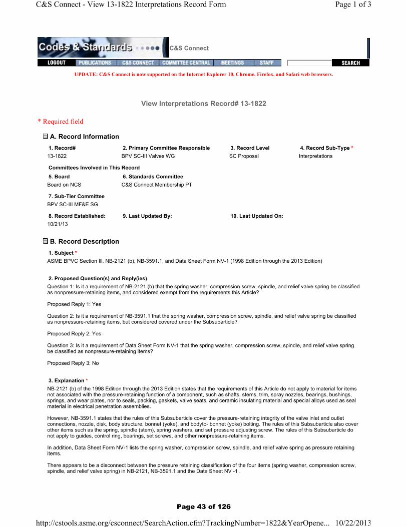
1. Subject *ASME BPVC Section Ill, NB-2121 (b), NB-3591.1, and Data Sheet Form NV-1 (1998 Edition through the 2013 Edition)
2. Proposed Question(s) and Reply(ies) Question 1: Is it a requirement of NB-2121 (b) that the spring washer, compression screw, spindle, and relief valve spring be classified as nonpressure-retaining items, and considered exempt from the requirements this Article?
Proposed Reply 1: Yes
Question 2: Is it a requirement of NB-3591.1 that the spring washer, compression screw, spindle, and relief valve spring be classified as nonpressure-retaining items, but considered covered under the Subsubarticle?
Proposed Reply 2: Yes
Question 3: Is it a requirement of Data Sheet Form NV-1 that the spring washer, compression screw, spindle, and relief valve spring be classified as nonpressure-retaining items?
Proposed Reply 3: No
3. Explanation *NB-2121 (b) of the 1998 Edition through the 2013 Edition states that the requirements of this Article do not apply to material for items not associated with the pressure-retaining function of a component, such as shafts, stems, trim, spray nozzles, bearings, bushings, springs, and wear plates, nor to seals, packing, gaskets, valve seats, and ceramic insulating material and special alloys used as seal material in electrical penetration assemblies.
However, NB-3591.1 states that the rules of this Subsubarticle cover the pressure-retaining integrity of the valve inlet and outlet connections, nozzle, disk, body structure, bonnet (yoke), and bodyto- bonnet (yoke) bolting. The rules of this Subsubarticle also cover other items such as the spring, spindle (stem), spring washers, and set pressure adjusting screw. The rules of this Subsubarticle do not apply to guides, control ring, bearings, set screws, and other nonpressure-retaining items.
In addition, Data Sheet Form NV-1 lists the spring washer, compression screw, spindle, and relief valve spring as pressure retaining items.
There appears to be a disconnect between the pressure retaining classification of the four items (spring washer, compression screw, spindle, and relief valve spring) in NB-2121, NB-3591.1 and the Data Sheet NV -1 .
Page 1 of 3C&S Connect - View 13-1822 Interpretations Record Form
10/22/2013http://cstools.asme.org/csconnect/SearchAction.cfm?TrackingNumber=1822&YearOpene...
Page 43 of 126

Page 44 of 126
BykA
Text Box
13-1822

Page 45 of 126
BykA
Text Box
13-1822

C&S Connect
UPDATE: C&S Connect is now supported on the Internet Explorer 10, Chrome, Firefox, and Safari web browsers.
View Interpretations Record# 13-2155
* Required field
A. Record Information 1. Record# 2. Primary Committee Responsible 3. Record Level 4. Record Sub-Type *13-2155 BPV SC-III SGGR SC Proposal Interpretations
Committees Involved in This Record
5. Board 6. Standards Committee
Boards IncludedBoard on NCS
BPV III
7. Sub-Tier Committee None
8. Record Established: 9. Last Updated By: 10. Last Updated On: 11. Date of Issuance:11/26/2013
B. Record Description 1.Subject *
Standard Designation * Edition/Addenda *
Paragraph/Fig./Table No. *
Subject Description *American Society of Mechanical Engineers (ASME) Boiler and Pressure Vessel Code, Section III Paragraph NCA-3855.5
2. Proposed Question(s) and Reply(ies) *Where Certificates of Compliance [NCA-3862.1(g)] are acceptable,1) Is the traceability required between chemical analysis results[NCA-3855.5 (2)] of each piece with the eachpiece material?Where Certificates of Compliance [NCA-3862.1(g)] are not acceptable,2) Is the traceability required between chemical analysis results[NCA-3855.5 (2)] of each piece with the eachpiece material?3) If all other tests is performed and each piece is cut and machined, is the traceability required between allother test results[NCA-3855.5 (3)] of each piece with each piece material?4) If the process affecting to mechanical properties such as forging and heat treatment is performed, is thetraceability required for each piece on the process?5) and after the process, are all other tests [NCA-3855.5 (3)] performed for each piece?6) and is the traceability required between all other test results[NCA-3855.5 (3)] of each piece with eachpiece material?
Proposed response:1) No2) No, 3) Yes, 4) No, 5) No, 6) No
3. Explanation *NCA-3855.5 gives requirements for Utilization of Unqualified Source Material.(2) The Material Organization performs or subcontracts a product analysis to verify the chemicalcomposition of each piece of unqualified source material.
Page 1 of 4C&S Connect - View 13-2155 Interpretations Record Form
2/4/2014http://cstools.asme.org/csconnect/SearchAction.cfm?TrackingNumber=2155&YearOp...
Page 46 of 126

(3) The Material Organization performs or subcontracts all other requirements of the material specificationon each piece of unqualified source material. Where Certificates of Compliance [NCA-3862.1(g)] areacceptable, testing of each piece is not required. Alternatively, the Material Organization may perform orsubcontract all other requirements of the material specification on each heat and lot of unqualified sourcematerial provided
C. File Attachments
1. Background File
(83KB) View Background File
2. Proposal File
(83KB) View Current Proposal File
3. Committee Correspondence File None
4. Signed Issuance Letter None
View/Manage File Attachments
D. Project Administrative Manager1. Staff Contact Allyson [email protected](212)591-8539
2. Staff Notes None
E. Record Creator Allyson [email protected](212)591-8539
F. Project Technical Manager 1. Project Manager *Plante, [email protected](603)433-1064
2. Project Manager Notes None
G. Inquirer Information 1. First Name 2. Last NameNone None
3. Company/Organization 4. Address 1None None
5. Address 2 6. Address 3None None
7. Country 8. State/Province/Region/CountyNone None
9. Town/City 10. Zip/Postal CodeNone None
Page 2 of 4C&S Connect - View 13-2155 Interpretations Record Form
2/4/2014http://cstools.asme.org/csconnect/SearchAction.cfm?TrackingNumber=2155&YearOp...
Page 47 of 126
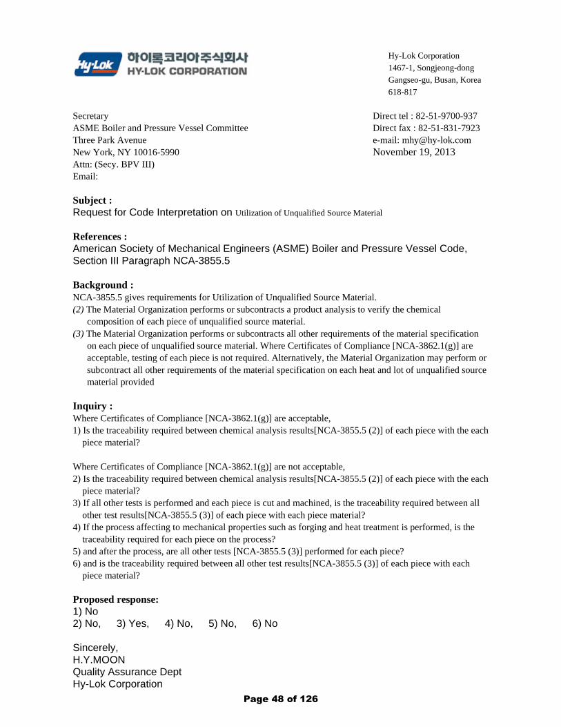
Hy-Lok Corporation
1467-1, Songjeong-dong
Gangseo-gu, Busan, Korea
618-817
Secretary ASME Boiler and Pressure Vessel Committee Three Park Avenue New York, NY 10016-5990 Attn: (Secy. BPV III) Email:
Direct tel : 82-51-9700-937 Direct fax : 82-51-831-7923 e-mail: [email protected] November 19, 2013
Subject : Request for Code Interpretation on Utilization of Unqualified Source Material
References : American Society of Mechanical Engineers (ASME) Boiler and Pressure Vessel Code, Section III Paragraph NCA-3855.5 Background : NCA-3855.5 gives requirements for Utilization of Unqualified Source Material. (2) The Material Organization performs or subcontracts a product analysis to verify the chemical
composition of each piece of unqualified source material. (3) The Material Organization performs or subcontracts all other requirements of the material specification
on each piece of unqualified source material. Where Certificates of Compliance [NCA-3862.1(g)] are acceptable, testing of each piece is not required. Alternatively, the Material Organization may perform or subcontract all other requirements of the material specification on each heat and lot of unqualified source material provided
Inquiry : Where Certificates of Compliance [NCA-3862.1(g)] are acceptable, 1) Is the traceability required between chemical analysis results[NCA-3855.5 (2)] of each piece with the each
piece material? Where Certificates of Compliance [NCA-3862.1(g)] are not acceptable, 2) Is the traceability required between chemical analysis results[NCA-3855.5 (2)] of each piece with the each
piece material? 3) If all other tests is performed and each piece is cut and machined, is the traceability required between all
other test results[NCA-3855.5 (3)] of each piece with each piece material? 4) If the process affecting to mechanical properties such as forging and heat treatment is performed, is the
traceability required for each piece on the process? 5) and after the process, are all other tests [NCA-3855.5 (3)] performed for each piece? 6) and is the traceability required between all other test results[NCA-3855.5 (3)] of each piece with each
piece material? Proposed response: 1) No 2) No, 3) Yes, 4) No, 5) No, 6) No Sincerely, H.Y.MOON Quality Assurance Dept Hy-Lok Corporation
Page 48 of 126
BykA
Text Box
13-2155

C&S Connect
UPDATE: C&S Connect is now supported on the Internet Explorer 10, Chrome, Firefox, and Safari web browsers.
View Interpretations Record# 14-22
* Required field
A. Record Information 1. Record# 2. Primary Committee Responsible 3. Record Level 4. Record Sub-Type *14-22 BPV III Stds Comm Proposal Interpretations
Committees Involved in This Record
5. Board 6. Standards Committee
Boards IncludedBoard on NCS
BPV III
7. Sub-Tier Committee BPV SC-III SGGR
8. Record Established: 9. Last Updated By: 10. Last Updated On: 11. Date of Issuance:01/07/2014 BykA 01/07/2014
B. Record Description 1.Subject *
Standard Designation * Edition/Addenda * Paragraph/Fig./Table No. *BPV Section III NCA 2013 NCA-9200
Subject Description *Definition of "Appurtenance"
2. Proposed Question(s) and Reply(ies) *Question: In the definition of "appurtenance," does "it" refer to the item or the component?
Proposed Reply: "It" refers to the component.
3. Explanation *To clarify the definition of appurtenance.
C. File Attachments
1. Background File
(229KB) View Background File
2. Proposal File None
3. Committee Correspondence File None
4. Signed Issuance Letter
Page 1 of 3C&S Connect - View 14-22 Interpretations Record Form
2/4/2014http://cstools.asme.org/csconnect/SearchAction.cfm?TrackingNumber=22&YearOpene...
Page 49 of 126

None
View/Manage File Attachments
D. Project Administrative Manager1. Staff Contact Allyson [email protected](212)591-8539
2. Staff Notes None
E. Record Creator
F. Project Technical Manager 1. Project Manager *Plante, [email protected](603)433-1064
2. Project Manager Notes None
G. Inquirer Information 1. First Name 2. Last NameJarno Makkonen
3. Company/Organization 4. Address 1Sulzer Pumps 2800 NW Front Ave
5. Address 2 6. Address 3None None
7. Country 8. State/Province/Region/CountyUnited States Oregon
9. Town/City 10. Zip/Postal CodePortland 97210
Inquirer Contact Information
11. Phone 12. Fax503-226-5542 None
14. Background Info:In NCA-9200,
15. Original Inquiry(ies):Question: Does
16. Proposed Reply(ies):Proposed answer:
H. Additional Committee information
Page 2 of 3C&S Connect - View 14-22 Interpretations Record Form
2/4/2014http://cstools.asme.org/csconnect/SearchAction.cfm?TrackingNumber=22&YearOpene...
Page 50 of 126

Secretary ASME Boiler and Pressure Vessel Committee Three Park Avenue New York, NY 10016-5990
Reference
SULZER Sulzer Pumps Sulzer Pumps (US) Inc. 2800 NW Front Ave. Portland, OR, USA Phone + 1 (503) 226-5542 Fax + 1 (503) 226·5283 www.sulzerpumps.com
Department Quality Assurance
E-mail direct [email protected]
Date 11/14/13
Request for Interpretation Ref: ASME Section Ill, NCA-9200, "Appurtenance", 2013 Edition
To Whom it may concern,
Background: In NCA-9200, "Appurtenance" is defined as:
Inquiry:
appurtenance: an item intended to be attached to a completed and stamped component that has work performed on it requiring verification by an Inspector.
Q. Does "it" reference the item or the component?
Proposed answer: "It" refers to the component.
Yours sincerely
-Jarno Makkonen Quality Manager
Page 51 of 126
BykA
Text Box
14-22

C&S Connect
UPDATE: C&S Connect is now supported on the Internet Explorer 10, Chrome, Firefox, and Safari web browsers.
View Interpretations Record# 14-33
* Required field
A. Record Information 1. Record# 2. Primary Committee Responsible 3. Record Level 4. Record Sub-Type *14-33 BPV SC-III SGGR Stds Comm Proposal Interpretations
Committees Involved in This Record
5. Board 6. Standards Committee
Boards IncludedBoard on NCS
BPV III
7. Sub-Tier Committee None
8. Record Established: 9. Last Updated By: 10. Last Updated On: 11. Date of Issuance:01/08/2014 BykA 02/04/2014
B. Record Description 1.Subject *
Standard Designation * Edition/Addenda * Paragraph/Fig./Table No. *BPV Section III NCA 2013 NCA-4134.17-1 and Appendix XXIII-1210
Subject Description *Quality Records and Document Retention
2. Proposed Question(s) and Reply(ies) *Question 1:Are records of qualifications of Registered Professional Engineers Non-permanent Records?
Question 2:Is the Certificate Holder's mandatory retention period of the records of qualification of Registered Professional Engineers 10 years after the last document that was certified by the Engineer?
Question 3:For Division 1 work, in XX II 1-1210, does responsible organization mean the Certificate Holder who is applying the ASME Certification Mark with Designator to the component even if the design had been subcontracted to another organization?
Question 4:Does it really make any sense to allow the PE to retain the quality record of their qualification?
3. Explanation *Answer 1: Yes.Answer 2: Yes.Answer 3: Yes.Answer 4: No.
C. File Attachments
Page 1 of 4C&S Connect - View 14-33 Interpretations Record Form
2/4/2014http://cstools.asme.org/csconnect/SearchAction.cfm?TrackingNumber=33&YearOpene...
Page 52 of 126

1. Background File
(86KB) View Background File
2. Proposal File None
3. Committee Correspondence File None
4. Signed Issuance Letter None
View/Manage File Attachments
D. Project Administrative Manager1. Staff Contact Allyson [email protected](212)591-8539
2. Staff Notes None
E. Record Creator
F. Project Technical Manager 1. Project Manager *Plante, [email protected](603)433-1064
2. Project Manager Notes None
G. Inquirer Information 1. First Name 2. Last NameJarno Makkonen
3. Company/Organization 4. Address 1Sulzer Pumps 2800 NW Front Ave
5. Address 2 6. Address 3None None
7. Country 8. State/Province/Region/CountyUnited States Oregon
9. Town/City 10. Zip/Postal CodePortland 97210
Inquirer Contact Information
11. Phone 12. FaxNone None
14. Background Info:Record retention is defined in tables NCA-4134. 17-1 for Lifetime Records and NCA-4134.17 -2 for Non-Permanent Records. With regards to the Qualifications for Registered Professional Engineers
Page 2 of 4C&S Connect - View 14-33 Interpretations Record Form
2/4/2014http://cstools.asme.org/csconnect/SearchAction.cfm?TrackingNumber=33&YearOpene...
Page 53 of 126

for Certifying Design Specifications, Design Reports, Load Capacity Data Sheets, Construction Specifications, Design Drawings, Fabrication Specification, and Overpressure Protection Report,Mandatory Appendix XXIII-121 0 states
15. Original Inquiry(ies):Question 1:Are records of qualifications of Registered Professional Engineers Non-permanent Records?
Question 2:Is the Certificate Holder's mandatory retention period of the records of qualification of Registered Professional Engineers 10 years after the last document that was certified by the Engineer?
Question 3:For Division 1 work, in XX II 1-1210, does responsible organization mean the Certificate Holder who is applying the ASME Certification Mark with Designator to the component even if the design had been subcontracted to another organization?
Question 4:Does it really make any sense to allow the PE to retain the quality record of their qualification?
16. Proposed Reply(ies):Answer 1: Yes.Answer 2: Yes.Answer 3: Yes.Answer 4: No.
H. Additional Committee information 1. Codes Affected by Proposed Revision 2. Related Committee Records BPVC-III-NCA Interp None
3. Proposal Keywords None
4. Secondary Committee[s] w/Related Actions
Pending Committees Committees RespondedNone None
5. Type (Nuclear Only) None
6. Committee Notes None
7. Text of Committee Objections (if made at a meeting) 8. Committee Approval Date None None
I. Editor Input 1. Editor Acceptance of Proposed Revision Attachment N/A
2. Editorial Review(Activated only if ItemLevel = Board Approved)Has not yet been reviewed by the editor for publication
3. Editor Notes
Editor's Fields Last Updated By:
J. Latest Ballot None
Page 3 of 4C&S Connect - View 14-33 Interpretations Record Form
2/4/2014http://cstools.asme.org/csconnect/SearchAction.cfm?TrackingNumber=33&YearOpene...
Page 54 of 126

Page 55 of 126
BykA
Text Box
14-33

Page 56 of 126

C&S Connect
UPDATE: C&S Connect is now supported on the Internet Explorer 10, Chrome, Firefox, and Safari web browsers.
View Interpretations Record# 14-37
* Required field
A. Record Information 1. Record# 2. Primary Committee Responsible 3. Record Level 4. Record Sub-Type *14-37 BPV SC-III MF&E SG Stds Comm Proposal Intent Interpretation
Committees Involved in This Record
5. Board 6. Standards Committee
Boards IncludedNone
BPV III
7. Sub-Tier Committee None
8. Record Established: 9. Last Updated By: 10. Last Updated On: 11. Date of Issuance:01/08/2014 StrunkJ 01/08/2014
B. Record Description 1.Subject *
Standard Designation * Edition/Addenda * Paragraph/Fig./Table No. *
BPV Section III NB 2013 NB, NC, ND, NE, NF, NG, WB, and WC-2582
Subject Description *NB, NC, ND, NE, NF, NG, WB, and WC-2582 Visual Examination
2. Proposed Question(s) and Reply(ies) *Question: Is it the intent that the visual examination in NB, NC, ND, NE, NF, NG, WB, and WC-2582 be performed by nondestructive examination personnel qualified in accordance with the requirements of NB, NC, ND, NE, NF, NG, WB, and WC-5520?
Proposed Reply: No.
3. Explanation *The use of the word "examination" in NB, NC, ND, NE, NF, NG, WB, and WC-2582 Visual Examination, it is being interpreted that the bolt inspecion is to be performed by nondestructive examination personnel qualified in accordance with the requirements of NB, NC, ND, NE, NF, NG, WB, and WC-5520. The concensus of the SC III, SG MFE, is that this inspection may be performed by inspection / operation personnel who are NOT qualified in accordance with the requirements of NB, NC, ND, NE, NF, NG, WB, and WC-5520.
C. File Attachments
1. Background File
(91KB) View Background File
2. Proposal File
Page 1 of 4C&S Connect - View 14-37 Interpretations Record Form
2/4/2014http://cstools.asme.org/csconnect/SearchAction.cfm?TrackingNumber=37&YearOpene...
Page 57 of 126

(82KB) View Current Proposal File - Current Record proposal uploaded 1-8-14.
3. Committee Correspondence File None
4. Signed Issuance Letter None
View/Manage File Attachments
D. Project Administrative Manager1. Staff Contact Allyson [email protected](212)591-8539
2. Staff Notes None
E. Record Creator
F. Project Technical Manager 1. Project Manager *Strunk, [email protected](412)295-8224
2. Project Manager Notes Current Proposal uploaded on 1-8-14 - Proposal now contains the Record No. 14-37.
G. Inquirer Information 1. First Name 2. Last NameJames Strunk
3. Company/Organization 4. Address 1TARSCO Inc. 9 Greenview Dr.
5. Address 2 6. Address 3None None
7. Country 8. State/Province/Region/CountyUnited States Pennsylvania
9. Town/City 10. Zip/Postal CodeMcKees Rocks 15136
Inquirer Contact Information
11. Phone 12. FaxNone None
14. Background Info:None
15. Original Inquiry(ies):Question: Is it the intent that the visual examination in NB, NC, ND, NE, NF, NG, WB, and WC-2582 be performed by nondestructive examination personnel qualified in accordance with the requirements of NB, NC, ND, NE, NF, NG, WB, and WC-5520?
Page 2 of 4C&S Connect - View 14-37 Interpretations Record Form
2/4/2014http://cstools.asme.org/csconnect/SearchAction.cfm?TrackingNumber=37&YearOpene...
Page 58 of 126

16. Proposed Reply(ies):Proposed Reply: No
H. Additional Committee information 1. Codes Affected by Proposed Revision 2. Related Committee Records None None
3. Proposal Keywords Examination - NDEMaterials
4. Secondary Committee[s] w/Related Actions
Pending Committees Committees RespondedNone None
5. Type (Nuclear Only) None
6. Committee Notes None
7. Text of Committee Objections (if made at a meeting) 8. Committee Approval Date None 01/01/1900
I. Editor Input 1. Editor Acceptance of Proposed Revision Attachment N/A
2. Editorial Review(Activated only if ItemLevel = Board Approved)Has not yet been reviewed by the editor for publication
3. Editor Notes
Editor's Fields Last Updated By:
J. Latest Ballot None
K. Ballot History 1. Board Ballot History None
2. Standards Committee Ballot History None
3. SC Ballot History None
4. Interpretation Ballot History None
L. ANSI Level No ANSI information is available at this time
M. Publications Level No Publications Level Information is available at this time.
Page 3 of 4C&S Connect - View 14-37 Interpretations Record Form
2/4/2014http://cstools.asme.org/csconnect/SearchAction.cfm?TrackingNumber=37&YearOpene...
Page 59 of 126

Intent Interpretation - NB, NC, ND, NE, NF, NG, WB, and WC-2582 Visual Examination
Question: Is it the intent that the visual examination in NB, NC, ND, NE, NF, NG, WB, and WC-2582 be performed by nondestructive examination personnel qualified in accordance with the requirements of NB, NC, ND, NE, NF, NG, WB, and WC-5520?
Proposed Reply: NO
PARALLEL CODE REVISION
NB-2580 EXAMINATION AND VISUAL INSPECTION OF BOLTS, STUDS, AND NUTS NB-2581 Required Inspection and Examination All bolting material shall be visually examined inspected in accordance with NB-2582. Nominal sizes greater than 1 in. (25 mm) shall be examined by either the magnetic particle or the liquid penetrant method. In addition, nominal sizes greater than 2 in. (50 mm) but not over 4 in. (100 mm) shall be examined by the ultrasonic method in accordance with NB-2585 and nominal sizes greater than 4 in. (100 mm) shall be examined by the ultrasonic method in accordance with both NB-2585 and NB-2586. NB-2582 Visual Examination Inspection The areas final surfaces of threads, shanks, and heads of final machined parts shall be visually examined inspected for workmanship, finish and appearance. Harmful discontinuities such as laps, seams, or cracks that would be detrimental to the intended service are unacceptable. NB-2582.1 Inspections Visual inspection activities that are performed solely to verify compliance with requirements of NB-2580, may be performed by the persons who perform or supervise the work. These visual inspections are not required to be performed by personnel and procedures qualified to NB-5500 and NB-5100, respectively, unless so specified.
Delete - Strikethroughs and
Insert - Underlines
Page 60 of 126

NC-2580 EXAMINATION VISUAL INSPECTION OF BOLTS, STUDS, AND NUTS NC-2581 Requirements All bolting material shall be visually examined inspected in accordance with NC-2582. NC-2582 Visual Examination Inspection Visual examination shall be applied to the areas of threads, shanks, and heads of final machined parts. Harmful discontinuities such as laps, seams, or cracks that would be detrimental to the intended service are unacceptable.
The final surfaces of threads, shanks, and heads shall be visually inspected for workmanship, finish and appearance . Harmful discontinuities such as laps, seams, or cracks that would be detrimental to the intended service are unacceptable. NC-2582.1 Inspections Visual inspection activities that are performed solely to verify compliance with requirements of NC-2580, may be performed by the persons who perform or supervise the work. These visual inspections are not required to be performed by personnel and procedures qualified to NC-5500 and NC-5100, respectively, unless so specified.
Page 61 of 126

ND-2580 EXAMINATION VISUAL INSPECTION OF BOLTS, STUDS, AND NUTS ND-2581 Requirements All bolting materials shall be visually examined inspected in accordance with ND-2582. ND-2582 Visual Examination Inspection Visual examination shall be applied to the areas of threads, shanks, and heads of final machined parts. Harmful discontinuities such as laps, seams, or cracks that would be detrimental to the intended service are unacceptable.
The final surfaces of threads, shanks, and heads shall be visually inspected for workmanship, finish and appearance . Harmful discontinuities such as laps, seams, or cracks that would be detrimental to the intended service are unacceptable. ND-2582.1 Inspections Visual inspection activities that are performed solely to verify compliance with requirements of ND-2580, may be performed by the persons who perform or supervise the work. These visual inspections are not required to be performed by personnel and procedures qualified to ND-5500 and ND-5100, respectively, unless so specified.
Page 62 of 126

NE-2580 EXAMINATION VISUAL INSPECTION OF BOLTS, STUDS, AND NUTS NE-2581 Requirements All bolting material shall be visually examined inspected in accordance with NE-2582. NE-2582 Visual Examination Inspection Visual examination shall be applied to the areas of threads, shanks, and heads of final machined parts. Harmful discontinuities such as laps, seams, or cracks that would be detrimental to the intended service are unacceptable.
The final surfaces of threads, shanks, and heads shall be visually inspected for workmanship, finish and appearance . Harmful discontinuities such as laps, seams, or cracks that would be detrimental to the intended service are unacceptable. NE-2582.1 Inspections Visual inspection activities that are performed solely to verify compliance with requirements of NE-2580, may be performed by the persons who perform or supervise the work. These visual inspections are not required to be performed by personnel and procedures qualified to NE-5500 and NE-5100, respectively, unless so specified.
Page 63 of 126

NF-2580 EXAMINATION AND VISUAL INSPECTION OF BOLTING MATERIAL AND RODS8 NF-2581 Required Inspection and Examinations NF-2581.1 Class 1 Supports. All bolting material and rods shall be visually examined inspected in accordance with NF-2582. Nominal sizes greater than 2 in. (50 mm) shall be examined by either the magnetic particle or liquid penetrant method (NF-2583). In addition, nominal sizes greater than 4 in. (100 mm) shall be ultrasonically examined in accordance with NF-2584. NF-2581.2 Class 2, 3, and MC Supports. Bolts, studs, and nuts shall be examined inspected in accordance with the requirements of the material specification and NF-2582. NF-2582 Visual Examination Inspection The areas of threads, shanks, and heads of final machined parts shall be visually examined. Harmful discontinuities such as laps, seams, or cracks that would be detrimental to the intended service are unacceptable.
The final surfaces of threads, shanks, and heads shall be visually inspected for workmanship, finish and appearance . Harmful discontinuities such as laps, seams, or cracks that would be detrimental to the intended service are unacceptable. NF-2582.1 Inspections Visual inspection activities that are performed solely to verify compliance with requirements of NF-2580, may be performed by the persons who perform or supervise the work. These visual inspections are not required to be performed by personnel and procedures qualified to NF-5500 and NF-5100, respectively, unless so specified.
Page 64 of 126

NG-2580 EXAMINATION AND VISUAL INSPECTION OF THREADED STRUCTURAL FASTENERS NG-2581 Required Inspections and Examinations Threaded structural fasteners shall be visually examined inspected in accordance with NG-2582. Externally threaded structural fasteners 3/8 in. (10 mm) and greater and nuts greater than 1 in. (25 mm) shall be examined by either the magnetic particle or liquid penetrant method. In addition, nominal sizes greater than 1/2 in. (13 mm) but not over 4 in. (100 mm) shall be examined by ultrasonic methods in accordance with NG-2584, and nominal sizes greater than 4 in. (100 mm) shall be examined by ultrasonic methods in accordance with both NG-2584 and NG-2585. NG-2582 Visual Examination Inspection Externally threaded structural fasteners less than 3/8 in. (10 mm) and nuts 1 in. (25 mm) and smaller shall be visually examined in the areas of threads, shanks, and heads of final machined parts prior to plating or other surface protection type treatments. Harmful discontinuities such as laps, seams, or cracks that would be detrimental to the intended service are unacceptable.
The final surfaces of threads, shanks, and heads of externally threaded structural fasteners less than 3/8 in. (10 mm) and nuts 1 in. (25 mm) and smaller shall be visually inspected for workmanship, finish and appearance . Harmful discontinuities such as laps, seams, or cracks that would be detrimental to the intended service are unacceptable. NG-2582.1 Inspections Visual inspection activities that are performed solely to verify compliance with requirements of NG-2580, may be performed by the persons who perform or supervise the work. These visual inspections are not required to be performed by personnel and procedures qualified to NG-5500 and NG-5100, respectively, unless so specified.
Page 65 of 126

WB-2580 EXAMINATION AND VISUAL INSPECTION OF BOLTS, STUDS, AND NUTS WB-2581 Required Examination and Inspection All bolting material shall be visually examined inspected in accordance with WB-2582. Nominal sizes greater than 1 in. (25 mm) shall be examined by either the magnetic particle or the liquid penetrant method. In addition, nominal sizes greater than 2 in. (50 mm) but not over 4 in. (100 mm) shall be examined by the ultrasonic method in accordance with WB-2585 and nominal sizes greater than 4 in. (100 mm) shall be examined by the ultrasonic method in accordance with both WB-2585 and WB-2586. WB-2582 Visual Examination Inspection The areas of threads, shanks, and heads of final machined parts shall be visually examined. The requirements of WB-5520 do not apply to personnel performing this examination. Harmful discontinuities such as laps, seams, or cracks that would be detrimental to the intended service are unacceptable.
The final surfaces of threads, shanks, and heads shall be visually inspected for workmanship, finish and appearance . Harmful discontinuities such as laps, seams, or cracks that would be detrimental to the intended service are unacceptable. WB-2582.1 Inspections Visual inspection activities that are performed solely to verify compliance with requirements of WB-2580, may be performed by the persons who perform or supervise the work. These visual inspections are not required to be performed by personnel and procedures qualified to WB-5500 and WB-5100, respectively, unless so specified.
Page 66 of 126

WC-2580 EXAMINATION VISUAL INSPECTION OF BOLTS, STUDS, AND NUTS WC-2581 Requirements All bolting material shall be visually examined inspected in accordance with WC-2582. WC-2582 Visual Examination Inspection Visual examination shall be applied to the areas of threads, shanks, and heads of final machined parts. Harmful discontinuities such as laps, seams, or cracks that would be detrimental to the intended service are unacceptable.
The final surfaces of threads, shanks, and heads shall be visually inspected for workmanship, finish and appearance . Harmful discontinuities such as laps, seams, or cracks that would be detrimental to the intended service are unacceptable. WC-2582.1 Inspections Visual inspection activities that are performed solely to verify compliance with requirements of WC-2580, may be performed by the persons who perform or supervise the work. These visual inspections are not required to be performed by personnel and procedures qualified to WC-5500 and WC-5100, respectively, unless so specified.
Page 67 of 126

C&S Connect
UPDATE: C&S Connect is now supported on the Internet Explorer 10, Chrome, Firefox, and Safari web browsers.
View Interpretations Record# 14-131
* Required field
A. Record Information 1. Record# 2. Primary Committee Responsible 3. Record Level 4. Record Sub-Type *14-131 BPV SC-III MF&E SG Stds Comm Proposal Interpretations
Committees Involved in This Record
5. Board 6. Standards Committee
Boards IncludedBoard on NCS
BPV III
7. Sub-Tier Committee None
8. Record Established: 9. Last Updated By: 10. Last Updated On: 11. Date of Issuance:01/21/2014 BykA 02/07/2014
B. Record Description 1.Subject *
Standard Designation * Edition/Addenda * Paragraph/Fig./Table No. *BPV Section III NB 1971 NB-2541
Subject Description *Request for clarification of when radiographic examination is required
2. Proposed Question(s) and Reply(ies) *Original Question: Is radiographic examination required when angle beam ultrasonic techniques will not yield meaningful results due to geometric configuration?
Proposed response: No, when angle beam methods are deemed impractical due to geometric configuration, straight beam ultrasonic examination will fulfill the requirement of NB-2541.
3. Explanation *A solid, 6" diameter forging is to be machined hollow with a 1" diameter bore, per interpretation III-1-78-219, " Machined hollow forgings are not excluded from the term "other hollow forgings" and are required to be examined by the angle beam technique." As the forging will be machined hollow, per NB-2542.1(b), the forging shall be subjected to ultrasonic examination by straight and angle beam methods.
The forging is subjected to 100% examination by straight beam methods and yields meaningful results.
However, the OD to ID ratio exceeds the limitations established by Section II part SA-388 and due to geometric configuration, angle beam methods will not produce meaningful results.
This results in a forging which has been subjected to 100% straight beam examination, yielding meaningful results, and an attempted angle beam examination which did not yield meaningful results.
We believe that per Section III NB-2542.1-b and Section II Part B SA-388, the straight beam examination results fulfill the ultrasonic examination requirement.
The Authorized Inspector believes that after subjecting a forging to 100% straight beam examination, if angle beam examination does
Page 1 of 4C&S Connect - View 14-131 Interpretations Record Form
2/10/2014http://cstools.asme.org/csconnect/SearchAction.cfm?TrackingNumber=131&YearOp...
Page 68 of 126

not yield meaningful results that the forging must then be subjected to radiographic examination.
C. File Attachments
1. Background File None
2. Proposal File None
3. Committee Correspondence File None
4. Signed Issuance Letter None
View/Manage File Attachments
D. Project Administrative Manager1. Staff Contact Allyson [email protected](212)591-8539
2. Staff Notes None
E. Record Creator
F. Project Technical Manager 1. Project Manager *Hunter, [email protected](434)832-2799
2. Project Manager Notes None
G. Inquirer Information 1. First Name 2. Last NameKurt Wivagg
3. Company/Organization 4. Address 1Pentair Flow Control 55 Cabot Boulevard
5. Address 2 6. Address 3None None
7. Country 8. State/Province/Region/CountyUnited States Massachusetts
9. Town/City 10. Zip/Postal CodeMansfield 02048
Inquirer Contact Information
11. Phone 12. FaxNone None
13. Email
Page 2 of 4C&S Connect - View 14-131 Interpretations Record Form
2/10/2014http://cstools.asme.org/csconnect/SearchAction.cfm?TrackingNumber=131&YearOp...
Page 69 of 126

14. Background Info:After subjecting the forging to 100% straight beam examination, the Authorized Inspector believes radiographic examination is required when angle beam techniques will not yield meaningful results.
15. Original Inquiry(ies):Is radiographic examination required when angle beam ultrasonic techniques will not yield meaningful results due to geometric configuration?
16. Proposed Reply(ies):No, when angle beam methods are deemed impractical due to geometric configuration, straight beam ultrasonic examination will fulfill the requirement of NB-2541.
As stated by NB-2542.1-b and Section II Part B SA-388, angle beam examination is not required when geometric configruations make this technique impractical.
H. Additional Committee information 1. Codes Affected by Proposed Revision 2. Related Committee Records BPVC-III-NCA Interp None
3. Proposal Keywords None
4. Secondary Committee[s] w/Related Actions
Pending Committees Committees RespondedNone None
5. Type (Nuclear Only) None
6. Committee Notes None
7. Text of Committee Objections (if made at a meeting) 8. Committee Approval Date None None
I. Editor Input 1. Editor Acceptance of Proposed Revision Attachment N/A
2. Editorial Review(Activated only if ItemLevel = Board Approved)Has not yet been reviewed by the editor for publication
3. Editor Notes
Editor's Fields Last Updated By:
J. Latest Ballot None
K. Ballot History 1. Board Ballot History None
2. Standards Committee Ballot History None
Page 3 of 4C&S Connect - View 14-131 Interpretations Record Form
2/10/2014http://cstools.asme.org/csconnect/SearchAction.cfm?TrackingNumber=131&YearOp...
Page 70 of 126

C&S Connect
UPDATE: C&S Connect is now supported on the Internet Explorer 10, Chrome, Firefox, and Safari web browsers.
View Interpretations Record# 14-155
* Required field
A. Record Information 1. Record# 2. Primary Committee Responsible 3. Record Level 4. Record Sub-Type *14-155 BPV SC-III MF&E SG Stds Comm Proposal Interpretations
Committees Involved in This Record
5. Board 6. Standards Committee
Boards IncludedBoard on NCS
BPV III
7. Sub-Tier Committee None
8. Record Established: 9. Last Updated By: 10. Last Updated On: 11. Date of Issuance:01/23/2014 BykA 01/27/2014
B. Record Description 1.Subject *
Standard Designation * Edition/Addenda * Paragraph/Fig./Table No. *BPV Section III NB 2000 Addenda NB-2551
Subject Description *Examination Requirement of Tubular Products and Fittings
2. Proposed Question(s) and Reply(ies) *Question: Does the requirement NB-2551 (b) be applied to the instrument nozzle when the inside of nozzle has no flow of pressurized water?
Proposed Reply: Yes.
3. Explanation *See background file for explanation.
C. File Attachments
1. Background File
(592KB) View Background File
2. Proposal File None
3. Committee Correspondence File None
4. Signed Issuance Letter
Page 1 of 4C&S Connect - View 14-155 Interpretations Record Form
2/4/2014http://cstools.asme.org/csconnect/SearchAction.cfm?TrackingNumber=155&YearOpe...
Page 71 of 126

None
View/Manage File Attachments
D. Project Administrative Manager1. Staff Contact Allyson [email protected](212)591-8539
2. Staff Notes None
E. Record Creator
F. Project Technical Manager 1. Project Manager *Byk, [email protected](212)591-8539
2. Project Manager Notes None
G. Inquirer Information 1. First Name 2. Last NameOak-sug Kim
3. Company/Organization 4. Address 1DOOSAN 555 Guigok-Dong
5. Address 2 6. Address 3Changwon, Gyeongsangnam-Do None
7. Country 8. State/Province/Region/CountyRepublic of Korea None
9. Town/City 10. Zip/Postal CodeChangwon, Gyeongsangnam-Do 641-792
Inquirer Contact Information
11. Phone 12. FaxNone None
14. Background Info:NB-2551(b) Wrought seamless and welded without filler metal fittings (including pipe flanges and fittings machined from forgings and bars) shall be examined in accordance with the material specification, and in addition by the magnetic particle method in accordance with NB-2555, or the liquid penetrant method in accordance with NB-2556 on all externalsurfaces and all accessible internal surfaces (exclud ing bolt holes and threads). Additionally, for fittings over 6 in. (152 mm) nominal size, the entire volume shall be examined by the ultrasonic method, if feasible, in accordance with NB-2552, or the radiographic method in accordance with NB-2553. Alternatively, the plate shall be examined by the ultrasonic method in accordance with NB-2530 prior to forming and theweld shall be examined by the radiographic method in accordance with NB-2553. Radiographic examination of welds, including repair welds, shall be performed after final rolling and forming, and may be performed prior to any required postweld heat treatment.
(c) Tubular products used for vessel nozzles shall be examined over the entire volume of material by either the ultrasonic method in two opposite circumferential directions in accordance with NB-2552(b) or the radiographic method in accordance with NB-2553,and shall be examined on all external and all accessible internal surfaces by either the magnetic particle method in accordance with
Page 2 of 4C&S Connect - View 14-155 Interpretations Record Form
2/4/2014http://cstools.asme.org/csconnect/SearchAction.cfm?TrackingNumber=155&YearOpe...
Page 72 of 126

NB-2555 or the liquid penetrant method in accordance with NB-2556.
An instrument nozzle for temperature measuring is machined from forging bar material as shown on Fig-1, so some examinations are required according to NB-2541(d) and NB- 2551 .The nozzle for temperature measuring is assembled with Reactor Coolant System main pipe by partial penetration weld, but the nozzle inside has no flow of pressurized water since a thermowell is installed in the instrument nozzle as shown on Fig-2. So, this product does not perform a nozzle's inherent function which is
15. Original Inquiry(ies):Question: Does the requirement NB-2551 (b) be applied to the instrument nozzle when the inside of nozzle has no flow of pressurized water?
16. Proposed Reply(ies):Proposed Reply: Yes
H. Additional Committee information 1. Codes Affected by Proposed Revision 2. Related Committee Records None None
3. Proposal Keywords None
4. Secondary Committee[s] w/Related Actions
Pending Committees Committees RespondedNone None
5. Type (Nuclear Only) None
6. Committee Notes None
7. Text of Committee Objections (if made at a meeting) 8. Committee Approval Date None 01/01/1900
I. Editor Input 1. Editor Acceptance of Proposed Revision Attachment N/A
2. Editorial Review(Activated only if ItemLevel = Board Approved)Has not yet been reviewed by the editor for publication
3. Editor Notes
Editor's Fields Last Updated By:
J. Latest Ballot None
K. Ballot History 1. Board Ballot History None
2. Standards Committee Ballot History None
3. SC Ballot History
Page 3 of 4C&S Connect - View 14-155 Interpretations Record Form
2/4/2014http://cstools.asme.org/csconnect/SearchAction.cfm?TrackingNumber=155&YearOpe...
Page 73 of 126

(Tel : 82-55-278-5725)
ASME Section Ill Secretary ASME Boiler and Pressure Vessel Committee Three Park Avenue New York, NY 10016-5990 Email : [email protected]
2014- 01-09 15:41 /~ Xf ~ )ACPJH ~I!I ACP~~ lll§ /oksuk.k im/~ ~~
Doosan Heavy Industries & Construction
T r
Ref: OS ASME 1401 - -January 9, 2014 Page 1 of 3
Subject Request for Code Interpretation Regarding Examination Requirement of Tubular Products and Fittings
Reference: (1) ASME Boiler and Pressure Vessel Code, Section Ill, Division 1, NB-2551 ,
2000 Addenda
Dear Ms. Byk,
Following is a request for interpretation of ASME Code NB-2551 regarding the examination requirement of instrument nozzle.
Purpose: Code Interpretation
Background
NB-2551 (b) Wrought seamless and welded without filler metal fittings (including pipe flanges and fittings machined from forgings and bars) shall be examined in accordance with the material specification, and in addition by the magnetic particle method in accordance with NB-2555, or the liquid penetrant method in accordance with NB-2556 on all external surfaces and all accessible internal surfaces (exclud ing bolt holes and threads). Additionally, for fittings over 6 in. (152 mm) nominal size, the entire volume shall be examined by the ultrasonic method, if feasible , in accordance with NB-2552, or the radiographic method in accordance with NB-2553. Alternatively, the plate shall be examined by the ultrasonic method in accordance with NB-2530 prior to forming and the weld shall be examined by the radiographic method in accordance with NB-2553. Radiographic examination of welds, including repair welds, shall be performed after final rolling and forming, and may be performed prior to any required postweld heat treatment.
(c) Tubular products used for vessel nozzles shall be examined over the entire volume of material by either the ultrasonic method in two opposite ci rcumferential directions in accordance with NB-2552(b) or the radiographic method in accordance with NB-2553, and shall be examined on all external and all accessible internal surfaces by either the magnetic particle method in accordance with NB-2555 or the liquid penetrant method in accordance with NB-2556.
Copyright by DOOSAN Heavy Industries and Construction. Co .. Ltd. 9-~3i$gj All Ri ghts Reserved.
Page 74 of 126
BykA
Text Box
14-155

(Tel : 82-55-278-5725)
ASME Section Ill Secretary ASME Boiler and Pressure Vessel Committee Three Park Avenue New York, NY 10016-5990 Email : [email protected]
2014-01-09 15 : 41 /~Ai ill)RCPJH iii~ RCP$111:111§/oksuk.kim/~ !;Ill:
Doosan Heavy Industries & Construction
T F
Ref : OS ASME 1401 - -January 9, 2014 Page 2 of 3
An instrument nozzle for temperature measuring is machined from forging bar material as shown on Fig-1, so some examinations are required according to NB-2541(d) and NB-2551 .
The nozzle for temperature measuring is assembled with Reactor Coolant System main pipe by partial penetration weld, but the nozzle inside has no flow of pressurized water since a thermowell is installed in the instrument nozzle as shown on Fig-2. So, this product does not perform a nozzle's inherent function which is providing a flow path. Therefore, this product is not a nozzle functionally.
r---- t- -- ., I I
I ! , I
I
STEP - 1 ---~-- -
FOF\G' \C ~ -,?
I
i ----;n-----, • I I 1
II ! i ~
I:! I . ,.d I l I ' i I: I i ! II: .
1 I j
IiI
1
1
l! IiI I! I IiI I i: : i i
STEP - 2
<Fig.1 Fabrication Sequence>
Copyright by DOOSAN Heavy Industries and Construction. Co .. Ltd. fP.t.!-3~gj All Rights Reserved.
Page 75 of 126
BykA
Text Box
14-155

2014-01-09 15:41 / S All:!l)RCPJMII/!!j RCP$1"1 llf§/oksuk.kim/~ ~~
Doosan Heavy Industries & Construction
T
(Tel : 82-55-278-5725)
ASME Section Ill Secretary ASME Boiler and Pressure Vessel Committee Three Park Avenue New York, NY 10016-5990 Email : [email protected]
' ' \
~._:.: F pc ' ~II
. Iii~ ) : ~ ilif1~-'
!8 \ ~~ '-"'"" '"''"''"' .,.,
<Fig.2 Installation of Instrument Nozzle>
Inquiry
Ref: DS ASME 1401 - -January 9, 2014 Page 3 of 3
Does the requirement NB-2551 (b) be applied to the instrument nozzle when the inside of nozzle has no flow of pressurized water?
Proposed Reply: Yes
Sincerely yours,
Oak-sug Kim, Staff R&PD Consultant RCP R&D Team DOOSAN
Copyright by DOOSAN Heavy Industries and Construction. Co .. Ltd. ~t_~-~;ggj All Rights Reserved.
Page 76 of 126
BykA
Text Box
14-155
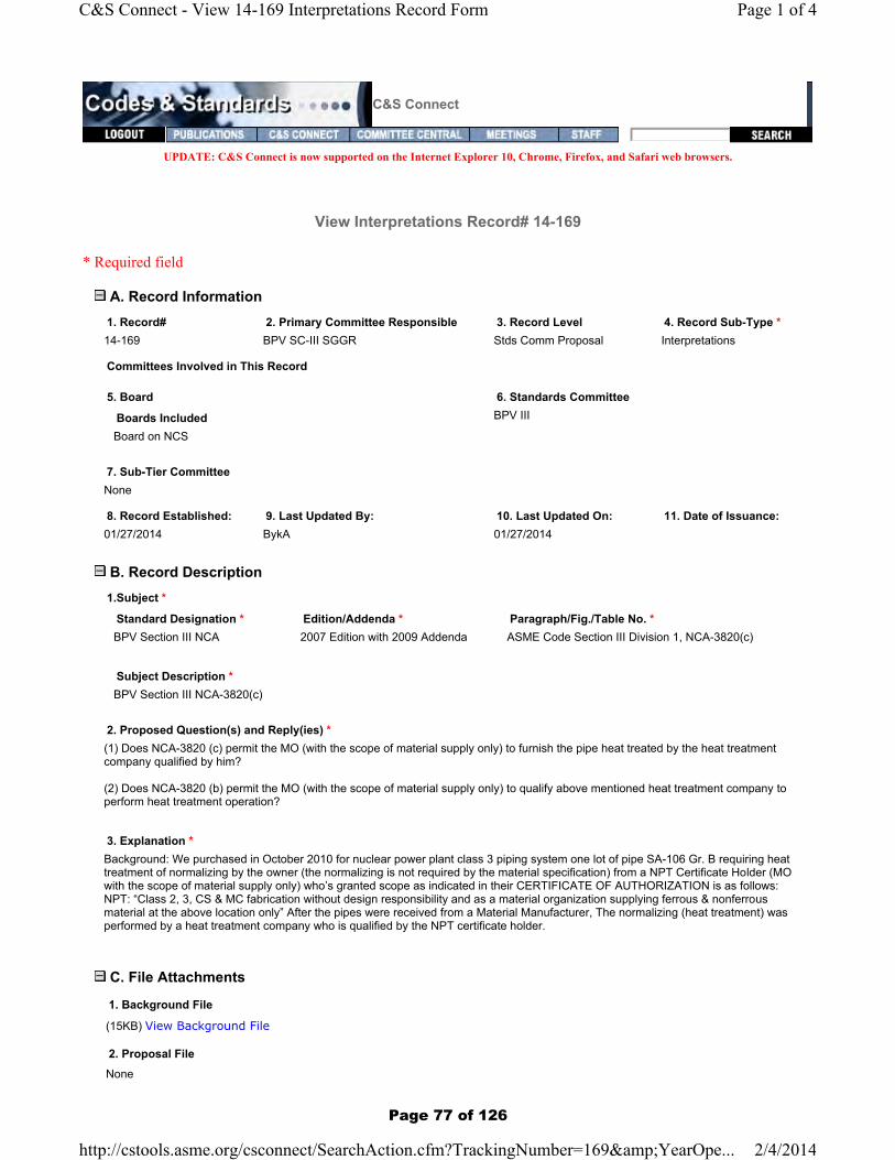
C&S Connect
UPDATE: C&S Connect is now supported on the Internet Explorer 10, Chrome, Firefox, and Safari web browsers.
View Interpretations Record# 14-169
* Required field
A. Record Information 1. Record# 2. Primary Committee Responsible 3. Record Level 4. Record Sub-Type *14-169 BPV SC-III SGGR Stds Comm Proposal Interpretations
Committees Involved in This Record
5. Board 6. Standards Committee
Boards IncludedBoard on NCS
BPV III
7. Sub-Tier Committee None
8. Record Established: 9. Last Updated By: 10. Last Updated On: 11. Date of Issuance:01/27/2014 BykA 01/27/2014
B. Record Description 1.Subject *
Standard Designation * Edition/Addenda * Paragraph/Fig./Table No. *BPV Section III NCA 2007 Edition with 2009 Addenda ASME Code Section III Division 1, NCA-3820(c)
Subject Description *BPV Section III NCA-3820(c)
2. Proposed Question(s) and Reply(ies) *(1) Does NCA-3820 (c) permit the MO (with the scope of material supply only) to furnish the pipe heat treated by the heat treatment company qualified by him?
(2) Does NCA-3820 (b) permit the MO (with the scope of material supply only) to qualify above mentioned heat treatment company to perform heat treatment operation?
3. Explanation *Background: We purchased in October 2010 for nuclear power plant class 3 piping system one lot of pipe SA-106 Gr. B requiring heat treatment of normalizing by the owner (the normalizing is not required by the material specification) from a NPT Certificate Holder (MO with the scope of material supply only) who’s granted scope as indicated in their CERTIFICATE OF AUTHORIZATION is as follows: NPT: “Class 2, 3, CS & MC fabrication without design responsibility and as a material organization supplying ferrous & nonferrous material at the above location only” After the pipes were received from a Material Manufacturer, The normalizing (heat treatment) was performed by a heat treatment company who is qualified by the NPT certificate holder.
C. File Attachments
1. Background File
(15KB) View Background File
2. Proposal File None
Page 1 of 4C&S Connect - View 14-169 Interpretations Record Form
2/4/2014http://cstools.asme.org/csconnect/SearchAction.cfm?TrackingNumber=169&YearOpe...
Page 77 of 126

3. Committee Correspondence File None
4. Signed Issuance Letter None
View/Manage File Attachments
D. Project Administrative Manager1. Staff Contact Allyson [email protected](212)591-8539
2. Staff Notes None
E. Record Creator
F. Project Technical Manager 1. Project Manager *Plante, [email protected](603)433-1064
2. Project Manager Notes None
G. Inquirer Information 1. First Name 2. Last NameWan-Lung Liang
3. Company/Organization 4. Address 1CTCI Corporation 13 FI, 89, Sec. 6, Zhongshan North Road
5. Address 2 6. Address 3None None
7. Country 8. State/Province/Region/CountyTaiwan None
9. Town/City 10. Zip/Postal CodeTaipei 1115 None
Inquirer Contact Information
11. Phone 12. FaxNone None
14. Background Info:Background: We purchased in October 2010 for nuclear power plant class 3 piping system one lot of pipe SA-106 Gr. B requiring heat treatment of normalizing by the owner (the normalizing is not required by the material specification) from a NPT Certificate Holder (MO with the scope of material supply only) who’s granted scope as indicated in their CERTIFICATE OF AUTHORIZATION is as follows:NPT: “Class 2, 3, CS & MC fabrication without design responsibility and as a material organization supplying ferrous & nonferrous material at the above location only”
After the pipes were received from a Material Manufacturer, The normalizing (heat treatment) was performed by a heat treatment
Page 2 of 4C&S Connect - View 14-169 Interpretations Record Form
2/4/2014http://cstools.asme.org/csconnect/SearchAction.cfm?TrackingNumber=169&YearOpe...
Page 78 of 126

company who is qualified by the NPT certificate holder.
15. Original Inquiry(ies):(1) Does NCA-3820 (c) permit the MO (with the scope of material supply only) to furnish the pipe heat treated by the heat treatment company qualified by him?(2) Does NCA-3820 (b) permit the MO (with the scope of material supply only) to qualify above mentioned heat treatment company to perform heat treatment operation?
16. Proposed Reply(ies):None
H. Additional Committee information 1. Codes Affected by Proposed Revision 2. Related Committee Records None None
3. Proposal Keywords None
4. Secondary Committee[s] w/Related Actions
Pending Committees Committees RespondedNone None
5. Type (Nuclear Only) None
6. Committee Notes None
7. Text of Committee Objections (if made at a meeting) 8. Committee Approval Date None 01/01/1900
I. Editor Input 1. Editor Acceptance of Proposed Revision Attachment N/A
2. Editorial Review(Activated only if ItemLevel = Board Approved)Has not yet been reviewed by the editor for publication
3. Editor Notes
Editor's Fields Last Updated By:
J. Latest Ballot None
K. Ballot History 1. Board Ballot History None
2. Standards Committee Ballot History None
3. SC Ballot History None
4. Interpretation Ballot History None
Page 3 of 4C&S Connect - View 14-169 Interpretations Record Form
2/4/2014http://cstools.asme.org/csconnect/SearchAction.cfm?TrackingNumber=169&YearOpe...
Page 79 of 126

15 January 2014 To: Boiler and Pressure Vessel Standards Committees Two Park Avenue New York, NY 10016‐5990
Attn: Secretary
Submitted via email: [email protected]
Technical Inquiry:
(a) Purpose:
Code Interpretation
(b) Background:
We purchased in October 2010 for nuclear power plant class 3 piping system one lot of pipe SA‐
106 Gr. B requiring heat treatment of normalizing by the owner (the normalizing is not required
by the material specification) from a NPT Certificate Holder (MO with the scope of material supply
only) who’s granted scope as indicated in their CERTIFICATE OF AUTHORIZATION is as follows:
NPT: “Class 2, 3, CS & MC fabrication without design responsibility and as a material organization
supplying ferrous & nonferrous material at the above location only”
After the pipes were received from a Material Manufacturer, The normalizing (heat treatment)
was performed by a heat treatment company who is qualified by the NPT certificate holder.
(c) Inquiry:
Code reference: ASME Code Section III Division 1 2007 Ed. 2009 Addenda
(1) Does NCA‐3820 (c) permit the MO (with the scope of material supply only) to furnish the pipe
heat treated by the heat treatment company qualified by him?
(2) Does NCA‐3820 (b) permit the MO (with the scope of material supply only) to qualify above
mentioned heat treatment company to perform heat treatment operation?
(d) Proposed response:
Yes or No with brief provisions if needed
Submitted by:
Mr. Wan‐Lung Liang
QA/QC Manager
Quality Management Department
CTCI Corporation
13 FI, 89, Sec. 6, Zhongshan North Road, Taipei 1115, Taiwan, R.O.C.
Tel: (886) 2‐2833‐9999
Site address: No. 62, Yen‐Hai Street, Kung‐Liao District, New Taipei City
Tel: (886) 2‐2490‐3219 Ext.: 209
Email: [email protected]
Page 80 of 126
BykA
Text Box
14-169

C&S Connect
UPDATE: C&S Connect is now supported on the Internet Explorer 10, Chrome, Firefox, and Safari web browsers.
View Interpretations Record# 14-176
* Required field
A. Record Information 1. Record# 2. Primary Committee Responsible 3. Record Level 4. Record Sub-Type *14-176 BPV SC-III Des Mthd WG Stds Comm Proposal Interpretations
Committees Involved in This Record
5. Board 6. Standards Committee
Boards IncludedBoard on NCS
BPV III
7. Sub-Tier Committee None
8. Record Established: 9. Last Updated By: 10. Last Updated On: 11. Date of Issuance:01/28/2014 BykA 02/04/2014
B. Record Description 1.Subject *
Standard Designation * Edition/Addenda * Paragraph/Fig./Table No. *BPV Section III NB 2007 Edition through 2008 Addenda NB-3222.4, NB-3232.3, Appendix II-1500
Subject Description *Application of Cyclic Tests to Bolts
2. Proposed Question(s) and Reply(ies) *Inquiry 1: Is ASME Code Sec III Appendix II-1500 applicable for fatigue analysis of bolts as an alternative for NB-3232.3?
Inquiry 2: (in case of the response to the above inquiry 1 is “yes”)Is the fatigue strength reduction factor less than 4.0 applicable if it is obtained by cyclic test in accordance with ASME Code Sec III Appendix II-1500?
Inquiry 3: (in case of the response to the above inquiry 1 is “yes”)Is a scale down model with tolerance acceptable for cyclic test in accordance with ASME Code Sec III Appendix II-1520?
3. Explanation *Proposed Response (1): Yes.Proposed Response (2): Yes.Proposed Response (3): Yes.
C. File Attachments
1. Background File
(32KB) View Background File
2. Proposal File None
Page 1 of 4C&S Connect - View 14-176 Interpretations Record Form
2/4/2014http://cstools.asme.org/csconnect/SearchAction.cfm?TrackingNumber=176&YearOpe...
Page 81 of 126

3. Committee Correspondence File None
4. Signed Issuance Letter None
View/Manage File Attachments
D. Project Administrative Manager1. Staff Contact Allyson [email protected](212)591-8539
2. Staff Notes None
E. Record Creator
F. Project Technical Manager 1. Project Manager *Snow, [email protected](208)526-8510
2. Project Manager Notes None
G. Inquirer Information 1. First Name 2. Last NameAkio Yamamoto
3. Company/Organization 4. Address 1Mitsubishi Heavy Industries, Ltd. 1-1, WADASAKI-CHO 1-CHOME
5. Address 2 6. Address 3HYOGO-KU None
7. Country 8. State/Province/Region/CountyJapan None
9. Town/City 10. Zip/Postal CodeKobe None
Inquirer Contact Information
11. Phone 12. FaxNone None
14. Background Info:Background:- In NB-3222.4 Analysis for Cyclic Operation which is applied to other than bolts, it is described that fatigue test shall be made in accordance with Appendix II-1500. The fatigue test in accordance with Appendix II-1500 is accepted.- On the other hand in NB-3232.3 (b) Fatigue Analysis of Bolts which is applied to High Strength Alloy Steel Bolting such as Reactor Vessel Stud Bolts, it is described that the design fatigue curve of Fig. I-9.4 provided may be used and it is not described about the application of a fatigue test in accordance with Appendix II-1500.- On the other hand in NB-3232.3 (b) Fatigue Analysis of Bolts which is applied to High Strength Alloy Steel Bolting such as Reactor Vessel Stud Bolts, it is described that the design fatigue curve of Fig. I-9.4 provided may be used and it is not described about the application of a fatigue test in accordance with Appendix II-1500.
Page 2 of 4C&S Connect - View 14-176 Interpretations Record Form
2/4/2014http://cstools.asme.org/csconnect/SearchAction.cfm?TrackingNumber=176&YearOpe...
Page 82 of 126

- Therefore we also would like to clarify whether or not a scale down model with tolerance is acceptable to satisfy “Geometrical similarity”.
15. Original Inquiry(ies):Inquiry 1: Is ASME Code Sec III Appendix II-1500 applicable for fatigue analysis of bolts as an alternative for NB-3232.3?
Inquiry 2: (in case of the response to the above inquiry 1 is “yes”)Is the fatigue strength reduction factor less than 4.0 applicable if it is obtained by cyclic test in accordance with ASME Code Sec III Appendix II-1500?
Inquiry 3: (in case of the response to the above inquiry 1 is “yes”)Is a scale down model with tolerance acceptable for cyclic test in accordance with ASME Code Sec III Appendix II-1520?
16. Proposed Reply(ies):Proposed Response (1): Yes.Proposed Response (2): Yes.Proposed Response (3): Yes.
H. Additional Committee information 1. Codes Affected by Proposed Revision 2. Related Committee Records BPVC-III-NCA Interp None
3. Proposal Keywords None
4. Secondary Committee[s] w/Related Actions
Pending Committees Committees RespondedNone None
5. Type (Nuclear Only) None
6. Committee Notes None
7. Text of Committee Objections (if made at a meeting) 8. Committee Approval Date None None
I. Editor Input 1. Editor Acceptance of Proposed Revision Attachment N/A
2. Editorial Review(Activated only if ItemLevel = Board Approved)Has not yet been reviewed by the editor for publication
3. Editor Notes
Editor's Fields Last Updated By:
J. Latest Ballot None
K. Ballot History 1. Board Ballot History None
2. Standards Committee Ballot History None
Page 3 of 4C&S Connect - View 14-176 Interpretations Record Form
2/4/2014http://cstools.asme.org/csconnect/SearchAction.cfm?TrackingNumber=176&YearOpe...
Page 83 of 126

CABIE ADDRtSSIOOCK KOBE
IIITSUBTSHI HEAYY IIIDUSTRIES, LTD.Nucleal Energy Systems Divlslon, Energy & Environment
I -I, WADASAKI.CHO I-CHOTIAE, HYOGO.KU
1of 5
URL
htlp://www.mhi.co jplcompoKOEE,JAPAN nylorgonizolion/kobew/index
Letter No.: KBS-20140039
Date: January"l7, 2014
ASME Section lll SecretaryASME Boiler and Pressure Vessel CommitteeThree Park AvenueNew York, NY 1001-5990
Purpose:ASMESectionlll,2OOTEditionthrough2OOSAddenda'Appendixll'Articlell-1500, cYcLlc TESTS
Dear Secretary,
Thefo||owingisinquiriestoconfirmapp|icabi|ityofASMECodeSec.|||Appendixl|.1500toboltsandacceptabi|ityofASMECodeSec.|||Appendixl|-1520usingsca|edownmodel.
Your prompt responses of these matters are greatly appreciated'
Page 84 of 126
BykA
Text Box
14-176

0tl]||ITSUBISHI HEAVY IIIDUSTRIES, LTD.
Nuclear Energy Systems Division, Energy & Envitonment
2ot5
CABLT ADDRESSi
DOCK KOBEI -I, WADASAKI-CHO I -CHOME. HYOGO-KU
KOBE,JA?AN
URL
hllp://www.mhi.co jplcomPonylorgonizolion/kobew/index.hlmr
Background:- ln NB-3222.4 Analysis for cyclic operation which is applied to other than bolts, it is
described that fatigue test shall be made in accordance with Appendix ll-1500. The
fatigue test in accordance with ll-1500 is
application of a test in accordance with il-1500
NB-3220 STRESS LIMITS FOR OTHER THANBOLTS
N8-3222.4 Analysis for Cyclic Operstion(a) Suitability for Cyclic Condition. The suitability ofa component for specified service loadings involving-cyclic
applicarion ofloais and thermal conditions shall be determined
bv the methods described herein. except lhat the
tuitubitity ofhigtt ttrength bolts shall be derermined by
the methods ofNB-3232.3(b) and the possibility of themal
stress ratch€t shall be investigated in accordance with
NB-3222.5. If the specified Service Loadings of the component
meet all ofthe conditions of(d) below. no analysis
for cvclic service is required, and it may be assumed that
the limits on peak stresi intensities as governed by fatigue
have been saiisfied by compliance with the applicable
requirements for material, design, fabrication, examination'
uril"sting of tftit subsection if the Service Loadings do
ioimeet a-tt ttre conaitions of(d) below, a fatieue analvsis
shall be nrade in accordan
.ontheotherhandinNB-3232.3(b)FatigueAna|ysisofBo|tswhichisapp|iedtoHighStrengthA||oyStee|Bo|tingsuchaSReactorVesse|StudBo|ts,itisdescribedthatthedesignfatiguecurveofFig.l-g.4providedmaybeusedanditiSnotdescribedaboutthe
NB.323O STRESS LIMTTS FOR BOLTS
NB-J2J2.3 Frtigue Analysis of Bolts
O) nign Snenst-h,atloy Steel Boltins High strenglh
utiov ireet Uoti ana suds may be evaluated for cyclic
service by the methods ofNB-3222 4(e) usins the desien
fatieue curve ofFiq. l-9 4 plovjdedt ^,- .-,, ,-.G) Fatigue Strength Reduction laclot (N6-Jz t J I I t'
Unless it c- b. sho*n b) analysis or tests that a lo$er
uuir. i, uoptoptiu,". the fatigue strength reduction factor
irr.a in tit. fuiig* "valuation
ofthreaded membets shall
noiGr"rt trt-i.o nowever, when applying the rulesof
NB-3232.3(b) for high strength alloy steel bolts' thc !oluc
used shall not be lcss than 'l'()'
Page 85 of 126
BykA
Text Box
14-176

3of5
IITTSUBISHI HEAYY ITIDI'STRIES, LTD.Nuclear Energy Systems Division, Enelgy & Envilonment
c^8,'E^DDREss: l-l.wADAsAKr-cHo.h?1i"" HYoGo'Ku |yi;gm*rug;;m..html
- NB-3232.3 (c) specifies that the fatigue strength reduction factor shall not be less than
4.0. The fatigue strength reduction factor less than 4.0 may, however, be obtained if
Appendix ll-1500 is applied.
- Therefore we would like to clarify that ASME Code sec lll Appendix ll-1500 is applicable
to bolts.
.|nadditionifAppendix||-l5ooisapp|icab|etobo|ts'.Geometrica|Simi|arity'describedin
Appendix||-1520isnotab|etobemaintainedduetothe|imitationoftestequipment'sloading caPability
rT.I52O REQUIREMENTS FOR CYCLICTESTING OF COMPONENTSThe reouirem€nts of(a) through (g) b€low shall be met'
(o) The test component or ponion being tested shall be
constructed of material having the same composition and
subiected to mechanical working and hear treating so as
io produce mectrattical prop€rties equivalent to those of,h" ru,"riut in the prototype component' Ccomeuical
simitarin must be maintainetl. at least in those ponions whose
"Uifitv to t itfttu"a .yclic loading is being investigated'.
-J iit tttote "Oj"".niateas
which affect the stresses in the
portion under test.
- Therefore we also would like to clarify whether or not a scale down model with tolerance
is acceptable to satisfy 'Geometrical similarity''
Page 86 of 126
BykA
Text Box
14-176

4of5
IITTSUBISHT HEAVY T]IDUSTR|ES. LTD.Nuclear Enelgy Systems Division, Energy & Environment
ff5.1%??"', r-r, wADASAKT-cHo,h?1i"" HYoGo-Ku $i;grul;:lrug;;m'hlml
lnquiry 1:
ls ASME Code Sec lll Appendix ll-1500 applicable for fatigue analysis of bolts as an
alternative for N8-3232.3?
Proposed ResPonse:
Yes.
lnquiry 2: (in case of the response to the above inquiry 1 is 'yes")
ls the fatigue strength reduction factor less than 4.0 applicable if it is obtained by cyclic test
in accordance with ASME Code Sec lll Appendix ll-1500?
Proposed ResPonse:
Yes.
Inquiry 3: (in case of the response to the above inquiry 1 is 'yes')
|sasca|edownmode|withto|eranceacceptab|eforcyc|ictestinaccordancewithASMECode Sec lll APPendix ll-1520?
Proposed ResPonse:
Yes.
Page 87 of 126
BykA
Text Box
14-176

(^f4
ITIITSUBISHT HEAYY IXDUSTRIES, LTD.Nuclear Energy Systems Division, Energy & Environment
TL'.f31"', r-r,wADAsAKr-cHo,l;ili"" HYoGo-Ku $i*xxemg;;m.hlml
I thank you in advance for considering the above inquiry. I and/or my colleague will be in
attendance the next ASME meetings in San Diego, and will plan to attend the Section lll
inquiry session and the other related meetings to help explain the specifics of the above
inquire and to assist with editorial revisions should the need arise. Please let me know
which meetings I should attend.
Akio Yamamoto,
Acting Section Manager
Component Designing Section
Nuclear Plant Component Designing Department
Nuclear Energy Systems Division, Energy & Environment
Mitsubishi Heavy Industries, Ltd.
e-mail: [email protected]
Best regards,
Page 88 of 126
BykA
Text Box
14-176

C&S Connect
UPDATE: C&S Connect is now supported on the Internet Explorer 10, Chrome, Firefox, and Safari web browsers.
View Interpretations Record# 14-182
* Required field
A. Record Information 1. Record# 2. Primary Committee Responsible 3. Record Level 4. Record Sub-Type *14-182 BPV SC-III MF&E SG SC Proposal Interpretations
Committees Involved in This Record
5. Board 6. Standards Committee
Boards IncludedBoard on NCS
BPV III
7. Sub-Tier Committee None
8. Record Established: 9. Last Updated By: 10. Last Updated On: 11. Date of Issuance:01/29/2014 BykA 02/04/2014
B. Record Description 1.Subject *
Standard Designation * Edition/Addenda * Paragraph/Fig./Table No. *BPV Section III NF 2013 NB/NC/ND/NE/NF-4622.7(b)-1
Subject Description *Post Weld Heat Treatment, NB/NC/ND/NE/NF-4622.7(b)-1
2. Proposed Question(s) and Reply(ies) *Inquiry 1 : Is the case, mentioned in the background (P-Number 1, full penetration weld in material over 1.5 in. and nominal thickness 3/4 in. or less), not to be exempted to PWHT in accordance with Table NF-4622.7(b)-1 contrary to Table NB/NC/ND/NE-4622.7(b)-1?
Proposed Reply 1 : Yes
Inquiry 2 : If the proposed reply 1 is yes, is it required for Table NF-4622.7(b)-1 to be revised to make the case, mentioned in the background, be interpreted in the same manner as Table NB/NC/ND/NE-4622.7(b)-1?
Proposed Reply 2 : Yes
3. Explanation *See background document.
C. File Attachments
1. Background File File not found
Page 1 of 4C&S Connect - View 14-182 Interpretations Record Form
2/4/2014http://cstools.asme.org/csconnect/SearchAction.cfm?TrackingNumber=182&YearOpe...
Page 89 of 126

2. Proposal File None
3. Committee Correspondence File None
4. Signed Issuance Letter None
View/Manage File Attachments
D. Project Administrative Manager1. Staff Contact Allyson [email protected](212)591-8539
2. Staff Notes None
E. Record Creator
F. Project Technical Manager 1. Project Manager *Hunter, [email protected](434)832-2799
2. Project Manager Notes None
G. Inquirer Information 1. First Name 2. Last NameIl-Kwun Nam
3. Company/Organization 4. Address 1KEPCO E&C 257, Yonggudaero
5. Address 2 6. Address 3Giheung-gu, Yongin-si None
7. Country 8. State/Province/Region/CountyRepublic of Korea None
9. Town/City 10. Zip/Postal CodeKyeonggi-do 446-713
Inquirer Contact Information
11. Phone 12. Fax82-31-289-4825 82-31-289-4109
14. Background Info:Background: In accordance with NF-4622.7, postweld heat treatment (PWHT) is not required for welds exempted in Table NF-4622.7(b)-1. In the case of P-Number 1, full penetration weld, as shown in figure below, in material over 1.5 in. and nominal thicknes
15. Original Inquiry(ies):
Page 2 of 4C&S Connect - View 14-182 Interpretations Record Form
2/4/2014http://cstools.asme.org/csconnect/SearchAction.cfm?TrackingNumber=182&YearOpe...
Page 90 of 126

Inquiry 1 : Is the case, mentioned in the background (P-Number 1, full penetration weld in material over 1.5 in. and nominal thickness 3/4 in. or less), not to be exempted to PWHT in accordance with Table NF-4622.7(b)-1 contrary to Table NB/NC/ND/NE-4622
16. Proposed Reply(ies):Proposed Reply 1 : Yes Proposed Reply 2 : Yes
H. Additional Committee information 1. Codes Affected by Proposed Revision 2. Related Committee Records BPVC-III-NCA Interp None
3. Proposal Keywords None
4. Secondary Committee[s] w/Related Actions
Pending Committees Committees RespondedNone None
5. Type (Nuclear Only) None
6. Committee Notes None
7. Text of Committee Objections (if made at a meeting) 8. Committee Approval Date None 01/01/1900
I. Editor Input 1. Editor Acceptance of Proposed Revision Attachment N/A
2. Editorial Review(Activated only if ItemLevel = Board Approved)Has not yet been reviewed by the editor for publication
3. Editor Notes
Editor's Fields Last Updated By:
J. Latest Ballot None
K. Ballot History 1. Board Ballot History None
2. Standards Committee Ballot History None
3. SC Ballot History None
4. Interpretation Ballot History None
L. ANSI Level No ANSI information is available at this time
M. Publications Level
Page 3 of 4C&S Connect - View 14-182 Interpretations Record Form
2/4/2014http://cstools.asme.org/csconnect/SearchAction.cfm?TrackingNumber=182&YearOpe...
Page 91 of 126

257, Yonggudaero , Giheung-gu, Yongin-s i , Kyeonggi -do , South Korea , 446-713
Tel.82-31-289-4825, Fax.82-31-289-4109, E-Mail: [email protected]
Secretary (BPV III) ASME Boiler and Pressure Vessel Committee Three Park Avenue New York, NY 10016-5990 U.S.A Attn: Allyson Byk Email: [email protected]
Jan. 23 , 2014
Subject : Request for Code Interpretation on Exemptions to Mandatory PWHT in Table NF-4622.7(b)-1
References: ASME Boiler and Pressure Vessel Code, Section III, Table NB/NC/ND/NE/NF-4622.7(b)-1 Background: In accordance with NF-4622.7, postweld heat treatment (PWHT) is not required for welds exempted in Table NF-4622.7(b)-1. In the case of P-Number 1, full penetration weld, as shown in figure below, in material over 1.5 in. and nominal thickness 3/4 in. or less, PWHT does not seem to be exempted based on Table NF-4622.7(b)-1. But for the same case, Table NB/NC/ND-4622.7(b)-1 allows exemption to PWHT because “All welds in material over 1.5 in.” is written under heading “Type of Weld” for P-No.1 different from “Fillet, partial penetration, and repair welds in material over 1.5 in.” described under the same heading in Table NF-4622.7(b)-1. In accordance with Figure NF-1132-1(i), it is stated that weld between anchor and sleeve is NF or MC, as applicable. Contrary to NF Code, however, when the same case is applied to MC, PWHT can be exempted based on Table NE-4622.7(b)-1. It is strange for the same case to be interpreted differently between NF and NE Codes.
Page 92 of 126
BykA
Text Box
14-182

Inquiry 1 : Is the case, mentioned in the background (P-Number 1, full penetration weld in material over 1.5 in. and nominal thickness 3/4 in. or less), not to be exempted to PWHT in accordance with Table NF-4622.7(b)-1 contrary to Table NB/NC/ND/NE-4622.7(b)-1? Proposed Reply 1 : Yes Inquiry 2 : If the proposed reply 1 is yes, is it required for Table NF-4622.7(b)-1 to be revised to make the case, mentioned in the background, be interpreted in the same manner as Table NB/NC/ND/NE-4622.7(b)-1? Proposed Reply 2 : Yes Sincerely, Il-Kwun Nam KEPCO E&C Plant Design Department (E-mail: [email protected])
Page 93 of 126
BykA
Text Box
14-182

C&S Connect
UPDATE: C&S Connect is now supported on the Internet Explorer 10, Chrome, Firefox, and Safari web browsers.
View Interpretations Record# 14-190
* Required field
A. Record Information 1. Record# 2. Primary Committee Responsible 3. Record Level 4. Record Sub-Type *14-190 BPV III Stds Comm Proposal Interpretations
Committees Involved in This Record
5. Board 6. Standards Committee
Boards IncludedNone
None
7. Sub-Tier Committee None
8. Record Established: 9. Last Updated By: 10. Last Updated On: 11. Date of Issuance:01/28/2014 BykA 02/04/2014
B. Record Description 1.Subject *
Standard Designation * Edition/Addenda * Paragraph/Fig./Table No. *BPV Section III NB 2013 NB-3227.4
Subject Description *Applicable Condition of Triaxial Stresses Stipulated in NB-32274
2. Proposed Question(s) and Reply(ies) *Inquiry #1: Is it the intent of NB-3227.4 that the requirement of triaxial stresses is applied to the Design Condition, Service Level A to C and Test Condition?
Inquiry #2: Is it the intent of NB-3227.4 that the primary principal stresses include general primary membrane stress. local primary membrane stress, and primary bending stress?
Proposed Reply (1): YesProposed Reply (2): Yes
3. Explanation *See background file.
C. File Attachments
1. Background File
(550KB) View Background File
2. Proposal File None
Page 1 of 4C&S Connect - View 14-190 Interpretations Record Form
2/4/2014http://cstools.asme.org/csconnect/SearchAction.cfm?TrackingNumber=190&YearOpe...
Page 94 of 126

3. Committee Correspondence File None
4. Signed Issuance Letter None
View/Manage File Attachments
D. Project Administrative Manager1. Staff Contact Allyson [email protected](212)591-8539
2. Staff Notes None
E. Record Creator
F. Project Technical Manager 1. Project Manager *Snow, [email protected](208)526-8510
2. Project Manager Notes None
G. Inquirer Information 1. First Name 2. Last NameOak-sug Kim
3. Company/Organization 4. Address 1Doosan Heavy Industries and Construction Co., Ltd. 555 Guigok-Dong, Changwon
5. Address 2 6. Address 3None None
7. Country 8. State/Province/Region/CountyRepublic of Korea None
9. Town/City 10. Zip/Postal CodeGyeongsangnam-Do 641-792
Inquirer Contact Information
11. Phone 12. FaxNone None
14. Background Info:Background 1: Subsubarticle NB-3220 stipulates stress limits for other than bolts including Design Condition, Service Levels A to D, and Test Condition. Some paragraphs in the subsubarticle definitely describes the application of special stress limits such as Design Condition (NB-3221 ), Service Level A to C Conditions (NB-3222, NB-3223, NB-3224) but the paragraph for Test Condition (NB-3226) does not specify the application of special stress limits (NB-3227). Additionally, subparagraph of NB-3227.4 is exceptional only for Service Level D. Considering the structure of code requirements above, the application of subparagraph of NB-3227.4 is ambiguous for test condition.
Background 2: Subparagraph NB-3227.4 describes that the algebraic sum of the three primary principal stresses (0 1 + 02 + 03) shall not exceed four times the tabulated value of Sm except for Service Level D. The primary stress may include general primary
Page 2 of 4C&S Connect - View 14-190 Interpretations Record Form
2/4/2014http://cstools.asme.org/csconnect/SearchAction.cfm?TrackingNumber=190&YearOpe...
Page 95 of 126

membrane stress, local primary membrane stress, and primary bending stress.
15. Original Inquiry(ies):Inquiry #1: Is it the intent of NB-3227.4 that the requirement of triaxial stresses is applied to the Design Condition, Service Level A to C and Test Condition?
Inquiry #2: Is it the intent of NB-3227.4 that the primary principal stresses include general primary membrane stress. local primary membrane stress, and primary bending stress?
16. Proposed Reply(ies):Proposed Reply (1): YesProposed Reply (2): Yes
H. Additional Committee information 1. Codes Affected by Proposed Revision 2. Related Committee Records BPVC-III-NCA Interp None
3. Proposal Keywords None
4. Secondary Committee[s] w/Related Actions
Pending Committees Committees RespondedNone None
5. Type (Nuclear Only) None
6. Committee Notes None
7. Text of Committee Objections (if made at a meeting) 8. Committee Approval Date None 01/01/1900
I. Editor Input 1. Editor Acceptance of Proposed Revision Attachment N/A
2. Editorial Review(Activated only if ItemLevel = Board Approved)Has not yet been reviewed by the editor for publication
3. Editor Notes
Editor's Fields Last Updated By:
J. Latest Ballot None
K. Ballot History 1. Board Ballot History None
2. Standards Committee Ballot History None
3. SC Ballot History None
Page 3 of 4C&S Connect - View 14-190 Interpretations Record Form
2/4/2014http://cstools.asme.org/csconnect/SearchAction.cfm?TrackingNumber=190&YearOpe...
Page 96 of 126
4. Interpretation Ballot History None
L. ANSI Level No ANSI information is available at this time
M. Publications Level No Publications Level Information is available at this time.
Minimum Site Requirements: IE 6.0+ • Firefox 2.0+ • Chrome 4.0+
Copyright © 1996-2013 ASME. All Rights Reserved. Terms of Use | Privacy Statement
Page 4 of 4C&S Connect - View 14-190 Interpretations Record Form
2/4/2014http://cstools.asme.org/csconnect/SearchAction.cfm?TrackingNumber=190&YearOpe...
Page 97 of 126

Page 98 of 126
BykA
Text Box
14-190

Page 99 of 126
BykA
Text Box
14-190

C&S Connect
UPDATE: C&S Connect is now supported on the Internet Explorer 10, Chrome, Firefox, and Safari web browsers.
View Interpretations Record# 14-244
* Required field
A. Record Information 1. Record# 2. Primary Committee Responsible 3. Record Level 4. Record Sub-Type *14-244 BPV SC-III SGGR Stds Comm Proposal Interpretations
Committees Involved in This Record
5. Board 6. Standards Committee
Boards IncludedBoard on NCS
BPV III
7. Sub-Tier Committee BPV SC-III PR SG
8. Record Established: 9. Last Updated By: 10. Last Updated On: 11. Date of Issuance:02/04/2014 BykA 02/04/2014
B. Record Description 1.Subject *
Standard Designation * Edition/Addenda * Paragraph/Fig./Table No. *BPV Section III NCA 2013 NCA-1130(a), NCA-2142, NCA-3252(a)
Subject Description *Load Combinations
2. Proposed Question(s) and Reply(ies) *Inquiry No: 1Does Paragraph NCA-2142 of Section III, Division 1 identify the actual loadings and combination of loadings to be considered in the Design Specification?
Reply No: 1No.
Inquiry No: 2Paragraphs NCA-2142 of Section III provides service limits for consideration in the construction of a component. Is the owner responsible for identifying how these service limits will be applied to the loadings and combination of loadings?
Reply No: 2Yes.
Inquiry No: 3Does Section III, paragraph NCA-3252 (a), require loads not identified in the Design Specification be considered in the design and construction of a component?
Reply No: 3No.Inquiry No: 4As a code for new construction (paragraph NCA-1130 (a)), does Section III require consideration of loads that occur subsequent to the construction of the component that were not identified in the Design Specification?
Page 1 of 5C&S Connect - View 14-244 Interpretations Record Form
2/4/2014http://cstools.asme.org/csconnect/SearchAction.cfm?TrackingNumber=244&YearOpe...
Page 100 of 126

Reply No: 4No.?Inquiry No: 5Does paragraph NB-7732 require that each pressure relief valve installed in the system to provide overpressure protection, be individually tested to demonstrate its relieving capacity?
Reply No: 5No.
Inquiry No: 6Does paragraph NB-7311 (a), require the installation geometry be replicated in the capacity certification tests?
Reply No: 6No.
Inquiry No: 7Does paragraph NB-7732 require the valve to be tested for capacity to the actual valve to be used?
Reply No: 7No.
Inquiry No: 8Does NB-7220 require the loads identified in the Design Specification that result in overpressure, be addressed in the Overpressure Protection Report?
Reply No: 8Yes
Inquiry No: 9Does paragraph NB-7321 allow unexpected system excess pressure transientsexceed Level C limits?
Reply No: 9No.?Inquiry No: 10Does paragraph NB-7731.3 require the capacity certification test be done at the maximum "Unexpected system excess pressure transient"?
Reply No: 10No.
Inquiry No: 11When a design without pressure relief devices does not exceed the Service Limits specified in the Design Specification, does sub-sub-article NB-7120 (c) and paragraph NB-7321 require the unexpected system excess pressure transients be limited, such that the calculated stress intensity and other design limitations for Service Limit C specified in NB-3000 are not exceeded for each of the components in the protected system?
Reply No: 11Yes
3. Explanation *BackgroundRecently, statements have been made that it is Section III of the ASME Boiler and Pressure Vessel Code that identifies the loads and combination of loads to be considered in the design of components. These statements are associated with the determination of the overpressure protection requirements for components and especially those requirements related to the determination of the certification of the relieving capacity of the pressure relieving devices. The following inquiries are intended to provide clarification for some of these requirements.
C. File Attachments
1. Background File File not found
2. Proposal File None
3. Committee Correspondence File None
Page 2 of 5C&S Connect - View 14-244 Interpretations Record Form
2/4/2014http://cstools.asme.org/csconnect/SearchAction.cfm?TrackingNumber=244&YearOpe...
Page 101 of 126

CODE INTERPRETATION
Background
Recently, statements have been made that it is Section III of the ASME Boiler and Pressure Vessel Code that identifies the loads and combination of loads to be considered in the design of components. These statements are associated with the determination of the overpressure protection requirements for components and especially those requirements related to the determination of the certification of the relieving capacity of the pressure relieving devices. The following inquiries are intended to provide clarification for some of these requirements.
Inquiry No: 1 Does Paragraph NCA-2142 of Section III, Division 1 identify the actual loadings and combination of loadings to be considered in the Design Specification?
Reply No: 1 No.
Inquiry No: 2 Paragraphs NCA-2142 of Section III provides service limits for consideration in the construction of a component. Is the owner responsible for identifying how these service limits will be applied to the loadings and combination of loadings?
Reply No: 2 Yes.
Inquiry No: 3 Does Section III, paragraph NCA-3252 (a), require loads not identified in the Design Specification be considered in the design and construction of a component?
Reply No: 3 No.
Page 102 of 126
BykA
Text Box
Questions 1-4 have been assigned to SGGR Questions 5-11 have been assigned to WG on Pressure Relief
BykA
Text Box
14-244

Inquiry No: 4 As a code for new construction (paragraph NCA-1130 (a)), does Section III require consideration of loads that occur subsequent to the construction of the component that were not identified in the Design Specification?
Reply No: 4 No.
Inquiry No: 5 Does paragraph NB-7732 require that each pressure relief valve installed in the system to provide overpressure protection, be individually tested to demonstrate its relieving capacity?
Reply No: 5 No.
Inquiry No: 6 Does paragraph NB-7311 (a), require the installation geometry be replicated in the capacity certification tests?
Reply No: 6 No.
Inquiry No: 7 Does paragraph NB-7732 require the valve to be tested for capacity to the actual valve to be used?
Reply No: 7 No.
Inquiry No: 8 Does NB-7220 require the loads identified in the Design Specification that result in overpressure, be addressed in the Overpressure Protection Report?
Reply No: 8 Yes
Inquiry No: 9 Does paragraph NB-7321 allow unexpected system excess pressure transients exceed Level C limits?
Reply No: 9 No.
Page 103 of 126
BykA
Text Box
14-244

Inquiry No: 10 Does paragraph NB-7731.3 require the capacity certification test be done at the maximum "Unexpected system excess pressure transient"?
Reply No: 10 No.
Inquiry No: 11 When a design without pressure relief devices does not exceed the Service Limits specified in the Design Specification, does sub-sub-article NB-7120 (c) and paragraph NB-7321 require the unexpected system excess pressure transients be limited, such that the calculated stress intensity and other design limitations for Service Limit C specified in NB-3000 are not exceeded for each of the components in the protected system?
Reply No: 11 Yes
Page 104 of 126
BykA
Text Box
14-244

2013 SECTION III, DIVISIONS 1 AND 2 - NCA
ARTICLE NCA-1000 SCOPE OF SECTION III
NCA-1100 GENERAL
NCA-1110 SCOPE' 2
The rules of this Section constitute requirements for the design, construction, stamping, and overpressure protec-tion of items used in nuclear power plants and other nu-clear facilities. This Section consists of the following three divisions:
(a) Division 1. Metallic vessels, heat exchangers, storage tanks, piping systems, pumps, valves, core support struc-tures, supports, and similar items.
(b) Division 2. Concrete containment vessels. (c) Division 3. Metallic containment systems for storage
or transportation of spent nuclear fuel and high level radioactive materials and waste.
The General Requirements of Subsection NCA apply to Division 1 and Division 2 only General Requirements for Division 3 are only in Subsection WA
Section XI contains rules for inservice inspections of items used in nuclear power plants.
NCA-1120 DEFINITIONS
Definitions of key terms used in Subsection NCA are in-cluded in NCA 9000
NCA-1130 LIMITS OF THESE RULES
(a) The rules of this Section provide requirements for new construction and include consideration of mechanical and thermal stresses due to cyclic operation. They do not cover deterioration that may occur in service as a result of environmental effects such as radiation, corrosion, ero-sion, or instability of the materia1.3 These effects shall be taken into account with a view to realizing the design or the specified life of the components and supports. The changes in properties of materials subjected to neutron ra-diation can be checked periodically by means of material surveillance programs. These rules provide requirements for new construction of concrete containments. They are applicable only to those components that are designed to provide a pressure retaining or containing barrier. They are not applicable to other concrete structures in the plant, as for example to concrete shield and support struc-tures, except as they directly affect the components.
(b) The rules are not intended to be applicable to valve operators, controllers, position indicators, pump impel-lers, pump drivers, or other accessories and devices,
unless they are pressure retaining parts or act as core sup-port structures or supports. If such items are in a support load path, the provisions of NF-1100 apply.
(c) The rules of this Section do not apply to instruments, or permanently sealed fluid filled tubing systems furn-ished with instruments, but do apply to instrument, con-trol, and sampling piping when specified in Design Specifications.
(d) Auxiliary systems for concrete containments that are required to assure functional adequacy of the vessels in accordance with the requirements of the Design Speci-fication, including but not limited to concrete cooling sys-tems, thermal insulation, corrosion protection, leakage monitors, and strain monitoring systems, must be deli-neated fully by appropriate performance, reliability, and test requirements. These rules are not intended to other-wise be applicable to auxiliary systems.
NCA-1140 USE OF CODE EDITIONS, ADDENDA, AND CASES
(a) See (1) and (2) below: (1) Under the rules of this Section, the Owner or his
designee shall establish the Code Edition and Addenda to be included in the Design Specifications. All items of a nuclear power plant may be constructed to a single Code Edition and Addenda, or each item may be constructed to individually specified Code Editions and Addenda.
(2) In no case shall the Code Edition and Addenda dates established in the Design Specifications be earlier than:
(-a) 3 years prior to the date that the nuclear power plant construction permit application is docketed
(-b) the latest edition and addenda endorsed by the regulatory authority having jurisdiction at the plant site at the time the construction permit application is docketed or
(-c) the edition and addenda endorsed for a design certified or licensed by the regulatory authority
(b) Except as permitted in (e) below for materials, Code Editions and Addenda later than those established by (a) above, including any referenced Code Edition and Adden-da, may be used by mutual consent of the Owner or his de-signee and Certificate Holder. For Division 2 design and construction, the consent of the Designer shall also be ob-tained. Specific provisions within an Edition or Addenda later than those established in the Design Specifications may be used, provided that all related requirements are met.
(13)
1
Page 105 of 126
BykA
Text Box
14-244

2013 SECTION III, DIVISIONS 1 AND 2 - NCA
(e) Those items designated as parts (Division 1) or ap-purtenances (Division 1) when used in a Division 2 com-ponent, if stamped as parts (Division 1), may be used without further stamping under Division 2 requirements, provided
(1) the Designer identifies the parts to be stamped under Division 1 requirements in the Construction Specification
(2) the Designer separately establishes that the use of such parts satisfies the requirements of the Design Sped-fication, the Construction Specifications, and the Design Drawings
NCA-2135 Code Cases for Division 2 Parts
Parts specified to meet the requirements of Division 1 for material, design, fabrication, and examination may be stamped CC in accordance with Division 2 when used in a Division 2 component (CC 1000) For these parts, Divi-sion 1 Code Cases that are applicable for material, design, fabrication, and examination may be used for Division 2 construction in accordance with NCA-1140.
DESIGN BASIS
Consideration of Plant and System Operating and Test Conditions5
(a) Components and supports of a nuclear power sys-tem (NCA-1110) may be subjected to plant and system op-erating and test conditions that are required to be considered in the design and overpressure protection of the components and the design of supports in order to sa-tisfy applicable systems safety criteria The significance of plant and system operating and test conditions upon de-sign may vary from item to item within a system for a spe-cific operating or test condition experienced by the plant or system. The temperatures, pressures, and mechanical loads to which components and supports are subjected in consequence of plant or system operating and test con-ditions are referred to in this Section as component or sup-port Design, Service, or Test Loadings.
(b) The definition of plant and system operating and test conditions, and the determination of their significance to the design and operability of components and supports of a nuclear power system, are beyond the scope of this Section. Appropriate guidance for the selection of plant or system operating and test conditions, that may be de-termined to be of significance in the selection of compo-nent or support Design, Service, or Test Loadings, the combinations thereof, and the corresponding acceptable Limits, may be derived from systems safety criteria docu-ments for specific types of nuclear power systems and may be found in the requirements of regulatory and enfor-cement authorities having jurisdiction at the site.
NCA-2142 Establishment of Design, Service, and Test Loadings and Limits
In the Design Specification, the Owner or his designee shall identify the loadings and combinations of loadings and establish the appropriate Design, Service, and Test Limits for each component or support.
(a) Loadings. The Design, Service, and Test Loadings shall be identified considering all plant or system operat-ing and test conditions anticipated or postulated to occur during the intended service life of the component or sup-port Service Loadings are not required to be identified for Class 2 and 3 components, Class 2 and 3 component sup-ports, and Class MC supports, when the Design Pressure and Design Mechanical Loads result in stresses of greater magnitude, relative to the allowable stress or stress inten-sity at the Design Temperature, than would the Service Loadings relative to the allowables for the appropriate Service Level. When this is not the case, and for piping and its supports, Service Loadings shall be identified in the Design Specification. For the Class MC containment vessel, loadings associated with the containment function shall be identified as Design Loadings, except as provided in NE-3000.
(b) Limits. The selection of Design, Service, and Test Limits for each item shall be established in accordance with NCA-2142.4. The rules of this Section do not assure operability of components in which mechanical motion is required. The selection of limits for Design, Service, or Test Loadings to assure operability is beyond the scope of this Section. However, the rules of this Section do re-quire operability of pressure relief valves. When assur-ance of operability is required, it is the responsibility of the Owner to define the appropriate limiting parameters by referring to documents that specify the requirements for operability. Such parameters are outside the scope of this Section [NCA-1130, NCA-2160, and NCA-5210(b)].
NCA-2142.1 Design Loadings. Design Loadings for components and supports shall be in accordance with (a), (b), and (c) below and the additional requirements of the applicable Subsections of this Section.
(a) Design Pressure. The specified internal and external Design Pressure shall not be less than the maximum differ-ence in pressure between the inside and outside of the item, or between any two chambers of a combination unit that exists under the most severe loadings for which the Level A Service Limits are applicable The Design Pressure shall include allowances for pressure surges, control sys-tem error, and system configuration effects such as static pressure heads.
(b) Design Temperature. The specified Design Tempera-ture shall not be less than the expected maximum mean metal temperature through the thickness of the part con-sidered for which Level A Service Limits are specified. Where a component is heated by trace heating, such as in-duction coils, jacketing, or by internal heat generation, the effect of such heat input shall be considered in
NCA-2140
NCA-2141
6
Page 106 of 126
BykA
Text Box
14-244
2013 SECTION III, DIVISIONS 1 AND 2 - NCA
establishing the Design Temperature. The Design Tem-perature shall consider control system error and system configuration effects.
(c) Design Mechanical Loads. The specified Design Me-chanical Loads shall be selected so that when combined with the effects of Design Pressure, they produce the high-est primary stresses of any coincident combination of loadings for which Level A Service Limits are designated in the Design Specification.
NCA-2142.2 Service Loadings When the Design Spe-cification or applicable Subsection of this Section requires computations to demonstrate compliance with specified Service Limits the Design Specification shall provide infor-mation from which Service Loadings can be identified (pressure, temperature, mechanical loads cycles, or tran-sients). The Design Specification shall designate the appro-priate Service Limit (NCA-2142.4) to be associated with each Service Loading or combination of Loadings.
NCA-2142.3 Test Loadings. (a) Test Loadings include pressure tests required by
this Section. (b) Loads due to other types of tests as may be required
by the Owner shall be included in the Design Specification.
NCA-2142.4 Design, Service, and Test Limits. (a) Design Limits. The limits for Design Loadings shall
meet the requirements of the appropriate Subsection of this Section.
(b) Service Limits. The Design Specification may desig-nate Service Limits as defined in (1) through (4) below.
(1) Level A Service Limits. Level A Service Limits are those sets of limits that must be satisfied for all Level A Service Loadings identified in the Design Specifications to which the component or support may be subjected in the performance of its specified service function.
(2) Level B Service Limits. Level B Service Limits are those sets of limits that must be satisfied for all Level B Service Loadings identified in the Design Specifications for which these Service Limits are designated. The compo-nent or support must withstand these loadings without damage requiring repair.
(3) Level C Service Limits. Level C Service Limits are those sets of limits that must be satisfied for all Level C Service Loadings identified in the Design Specifications for which these Service Limits are designated. These sets of limits permit large deformations in areas of structural discontinuity that may necessitate the removal of the com-ponent or support from service for inspection or repair of damage to the component or support Therefore, the selec-tion of this limit shall be reviewed by the Owner for com-patibility with established system safety criteria (NCA-2141).
(4) Level D Service Limits. Level D Service Limits are those sets of limits that must be satisfied for all Level D Service Loadings identified in the Design Specifications for which these Service Limits are designated. These sets of limits permit gross general deformations with some consequent loss of dimensional stability and damage re-quiring repair, that may require removal of the component or support from service. Therefore, the selection of this limit shall be reviewed by the Owner for compatibility with established system safety criteria (NCA-2141).
(c) Alternative Service Limits. Components or supports may be alternatively designed using more restrictive Ser-vice Limits than specified in the Design Specification. For example, Level B Service Limits may be used where Level C Service Limits have been specified.
(d) Test Limits (1) The limits for Test Loadings shall meet the re-
quirernents of the appropriate Subsection of this Section. (2) The selection of Limits for other tests defined by
the Owner [NCA-2142.3(b)] shall be included in the De-sign Specification.
NCA-2143 Acceptance Criteria
(a) Components and supports shall comply with the de-sign rules established for Design, Service, and Test Load-ings in the appropriate Subsections.
(b) It is the responsibility of the Owner to define accep-tance criteria for the Service Level Loading for which ac-ceptance criteria are not contained in this Section.
(c) Design documentation shall be completed in accor-dance with the requirements of the Subsection applicable to the component or support.
NCA-2144 Concrete Containments
Concrete containments, in addition to satisfying the structure design allowables (CC 3400) shall be evaluated for load categories in CC-3200.
NCA-2160 SPECIAL REQUIREMENTS APPLIED TO CODE CLASSES
Contractual arrangements between the Owner and Cer-tificate Holder that specify requirements in addition to or more restrictive than those specified by the rules of this Section for the applicable class of an item may be applied, provided such requirements do not negate any rules of this Section. Such special contractual requirements are be-yond the scope of this Section and shall not apply as con-ditional requirements for Code construction of items.
7
Page 107 of 126
BykA
Text Box
14-244

2013 SECTION III, DIVISIONS 1 AND 2 - NCA
piles require an allowable bearing pressure or allowable load per caisson or pile to be determined by the Owner and furnished to the Designer.
NCA-3250 PROVISION OF DESIGN SPECIFICATIONS
NCA-3251 Provision and Correlation
It is the responsibility of the Owner to provide, or cause to be provided, Design Specifications for components, sup-ports, and appurtenances. The Owner, either directly or through his designee, shall be responsible for the proper correlation of all Design Specifications. Separate Design Specifications are not required for parts, piping subassem-blies, appurtenances, or supports when they are included in the Design Specification for a component (NCA-1210). However, the applicable data from the component Design Specification (Division 1) or the Construction Specification and Design Drawings (Division 2) shall be provided in suf-ficient documented detail to form the basis for fabrication in accordance with this Section.
NCA-3252 Contents of Design Specifications8
(a) The Design Specifications shall contain sufficient de-tail to provide a complete basis for Division 1 construction or Division 2 design in accordance with this Section. Such requirements shall not result in construction that fails to conform with the rules of this Section. All Design Specifica-tions shall include (1) through (8) below
(1) the functions and boundaries of the items covered (NCA-3254)
(2) the design requirements [NCA-2110(a) and NCA-2110(b) and NCA-2140] including all required over-pressure protection requirements [NCA-3220(m)]
(3) the environmental conditions, 9 including radiation
(4) the Code classification of the items covered (NCA-2000)
(5) material requirements including impact test requirements
(6) additional fracture mechanics data for base metal, weld metal, and heat affected zone required to use Figure G-2210-1 in accordance with G-2110(b), when the meth-ods of Appendix G are used to provide protection against nonductile fracture for materials that have specified mini-mum yield strengths at room temperature greater than 50.0 ksi (345 MPa) but not exceeding 90.0 ksi (620 MPa); where these materials of higher yield strengths are to be used in conditions where radiation may affect the material properties, the effect of radiation on the K1 curve shall be determined for the material prior to its use in construction
(7) when operability of a component is a require-ment, the Design Specification shall make reference to other appropriate documents that specify the operating requirements
(8) the effective Code Edition, Addenda, and Code Cases to be used for construction
(b) A Design Specification shall be provided for each concrete containment serving in a single power generating unit or for multiple concrete containments at the same site. In addition to the requirements of (a) above, the De-sign Specifications for Division 2 items shall also include (1) through (7) below
(1) design life (2) corrosion effects (3) structural acceptance testing requirements
(CC-6000) (4) shielding requirements (5) construction surveillance required by the
Designer (6) foundation type and allowable loading, if applic-
able (NCA-3240)
(7) loads from internal structures (NCA-2132) (c) The Design Specification shall identify those compo-
nents and/or parts that require a preservice examination and shall include the following:
(1) examination (-a) Edition and Addenda of Section XI to be used (-b) category and method, and (-c) qualifications of personnel, procedures, and
equipment (2) welds
(-a) surface conditioning requirements, and (-b) identification/marking system to be used
NCA-3253 Classification of Components, Parts, and Appurtenances
The Owner, either directly or through his designee, shall establish the Code classification of the items that comprise the nuclear power plant.
NCA-3254 Boundaries of Jurisdiction
In order to define the boundaries of components with respect to adjacent components, intervening elements, and other structures, the Design Specifications shall include
(a) the locations of each such boundary (b) the forces, moments, strains, or displacements that
are imposed at each such boundary (c) the structural characteristics of the attached compo-
nents or structures, whether or not they are within this Section's jurisdiction when such components or structures provide constraints to the movement of components or appurtenances
(d) when the foundation support is constructed as an in-tegral part of the concrete containment, it shall be in-cluded within this Section's Division 2 jurisdiction to the extent required by NCA-2132
NCA-3254.1 Definition of Division 1 Boundaries. (a) The boundaries for Class 1 components are given in
NB-1130.
11
Page 108 of 126
BykA
Text Box
14-244
2013 SECTION III, DIVISION 1 - NB
ARTICLE NB-7000 OVERPRESSURE PROTECTION
NB-7100 GENERAL REQUIREMENTS
NB-7110 SCOPE
(a) A system36 shall be protected from the conse-quences arising from the application of conditions of pres-sure and coincident temperature that would cause either the Design Pressure or the Service Limits specified in the Design Specification to be exceeded.
(b) Pressure relief devices 37 are 'required when the op-erating conditions considered in the Overpressure Protec-tion Report would cause the Service Limits specified in the Design Specification to be exceeded.
(c) Protection of the system from the effects of pressure increases of extremely short duration, such as water ham-mer resulting from the rapid closing of a valve, is beyond the scope of this Article. These effects shall be included in the Design Specification.
(d) Rules covering the design of reactor shutdown sys-tems and their application as an integrated part of system overpressure protection are beyond the scope of this Arti-cle. Appropriate guidance is found in engineering stan-dards and in requirements of the regulatory and enforcement authorities having jurisdiction at the nuclear power plant site.
NB-7111 Definitions
(a) Overpressure is that pressure which exceeds the De-sign Pressure and is caused by increases in system fluid pressure resulting from thermal imbalances, excess pump flow, and other similar phenomena capable of causing a system pressure increase of a sufficient duration to be compatible with the dynamic response characteristics of the pressure relief devices listed in this Article.
(b) The basic definitions of pressure relief devices as specified in this Article are given in ASME PTC 25-2001, Pressure Relief Devices.
(c) Primary pressure is the pressure of the fluid at the in-let of the pressure relief device.
(d) Secondary pressure is that value of pressure existing in the passage between the actual discharge area and the outlet for which the discharge system of the pressure re-lief devices shall be designed.
NB-7120 INTEGRATED OVERPRESSURE PROTECTION
Overpressure protection of the components shall be provided by any of the following as an integrated over-pressure protection:
(a) the use of pressure relief devices and associated pressure sensing elements;
(b) the use of the reactor shutdown system; (c) a design without pressure relief devices that does
not exceed the Service Limits specified in the Design Spe-cifications [NB-7110(b)].
NB-7130 VERIFICATION OF THE OPERATION OF RECLOSING PRESSURE RELIEF DEVICES
NB-7131 Construction
(a) Reclosing pressure relief devices shall be con-structed so that potential impairment of the overpressure protection function from service exposure to fluids can be determined by test or examination.
(b) Means shall be provided for remote monitoring of valve position (fully open and fully closed). These means may be incorporated in the valve design or its system in-stallation.
(c) Reclosing pressure relief devices and their asso-ciated pressure sensing elements shall be so constructed that their correct operation can be demonstrated under service conditions, ce or test cond as may be required by regula- tory or enforcement authorities having jurisdiction at the nuclear power plant site.
NB-7140 INSTALLATION
NB-7141 Pressure Relief Devices
(a) Pressure relief devices shall be as close as practic-able to the major source of overpressure anticipated to arise within the system under the conditions summarized in the Overpressure Protection Report (NB-7200).
(b) The connection between a system and its pressure relief device shall have a minimum inside diameter equal to or greater than the nominal inside diameter of the pres-sure relief device inlet. The opening in the connection shall be designed to provide direct and unobstructed flow be-tween the system and the pressure relief device.
(c) The connection between a system and its safety valve shall be not longer than the face-to-face dimension of the corresponding tee fitting of the same dimension and pressure rating listed in ASME B16.5, ASME B16.9,
Page 109 of 126
BykA
Text Box
14-244

NB-7178 Nonreclosing Devices
Rupture disk devices46 may be used on air or gas ser-vice in accordance with NB-7600.
2013 SECTION III, DIVISION 1 - NB
NB-7174 Pilot Operated Pressure Relief Valves"
Pilot operated pressure relief valves, meeting the re-quirements of NB-7520, may be used for:
(a) steam service; (b) air and gas service; (c) liquid service.
NB-7175 Power Actuated Pressure Relief Valves45
Power actuated pressure relief valves, meeting the re-quirements of NB-7530, may be used for:
(a) steam service; (b) air and gas service; (c) liquid service.
NB-7176 Safety Valves With Auxiliary Actuating Devices
Safety valves with auxiliary actuating devices, meeting the requirements of NB-7540, may be used for steam ser-vice.
NB-7177 Pilot Operated Pressure Relief Valves Wth Auxiliary Actuating Devices
Pilot operated pressure relief valves with auxiliary ac-tuating devices, meeting the requirements of NB-7540, may be used for:
(a) steam service; (b) air and gas service; (c) liquid service.
NB-7200 OVERPRESSURE PROTECTION REPORT
NB-7210 RESPONSIBILITY FOR REPORT
The provisions intended to meet the requirements of this Article shall be the subject of an Overpressure Protec-tion Report prepared by the Owner or his designee.
NB-7220 CONTENT OF REPORT
The Overpressure Protection Report shall define the protected systems and the integrated overpressure pro-tection provided. As a minimum, the Report shall include the following:
(a) identification of specific ASME Section III, Article NB-7000, Edition and Addenda and applicable Code Cases used in the design of the overpressure protection system;
(b) drawings showing arrangement of protected sys-tems, including the pressure relief devices;
(c) the range of operating conditions, including the ef-fect of discharge piping back pressure;
(d) an analysis of the conditions that give rise to the maximum pressure relieving requirements, except when the basis for establishing relieving capacity is the loss of the heat sink of the protected system when the thermal output of the reactor is at its rated power;
(e) the relief capacity required to prevent a pressure rise in any component from exceeding the limitations of NB-7300;
(f) the operating controls or safety controls of the pro-tected system upon which the anticipated required relief capacity and the maximum pressure and temperature are predicted;
(g) the redundancy and independence of the pressure relief devices and their associated pressure sensors and controls employed to preclude a loss of overpressure pro-tection in the event of a failure of any pressure relief de-vice, sensing elements, associated controls, or external power sources;
(Ii) the extent that an individual component can be iso-lated from the overall system overpressure protection and the analysis of the conditions under which additional indi-vidual overpressure protection is necessary;
(i) the design secondary pressure, including a justifica-tion of the value identified in the Design Specification for pressure relief devices;
09 the analysis of pressure transient conditions, includ-ing those associated with the response time of pressure relief valves, taking into account the effect of liquid and two-phase flow;
(k) consideration of set pressure and blovvdown limita-tions, taking into account opening pressure tolerances and overpressure of the pressure relief device;
(I) consideration of burst pressure tolerance and manu-facturing design range of the rupture disk device;
(m) verification that pressure relief devices are not re-quired, if applicable. Verification shall include reference to each component's Design Report and applicable re-quirements in NB-3000 that demonstrate that the calcu-lated stress intensity levels do not exceed the Service Limits specified in the component Design Specification for all system service loadings; and
(n) the purge time of the inlet water loop seal, if the pressure relief valve is installed on a loop seal, since the full opening of the valve may not occur until the loop seal is purged of water.
NB-7230 CERTIFICATION OF REPORT
The Report, after it has been reconciled with the re-quirements of this Article, shall be certified by one or more Registered Professional Engineers competent in the ap-plicable field of design and qualified in accordance with the requirements of Appendix XXIII of Section III Appen-dices.
191
Page 110 of 126
BykA
Text Box
14-244
2013 SECTION III, DIVISION 1 - NB
NB-7732.2 Demonstration of Function.
(a) The function of three valves of the design to be cer-tified shall be demonstrated by test. The three valves se-lected shall envelop the largest and smallest combination of inlet size and orifice size of the specific de-sign. Such tests may be performed in conjunction with the capacity certification tests outlined above or as separate tests using production valves.
(b) These tests shall be conducted at a place meeting the requirements of NB-7739 to demonstrate to the satisfac-tion of a representative from an ASME designated organi-zation that the valves will meet the operating requirements specified in NB-7500 and achieve full lift un-der the conditions established in (c).
(c) The NV Certificate Holder shall specify the range of pressures, temperatures, and other fluid conditions for which the valves are to be tested. The range shall be suffi-cient to cover all expected operating fluid conditions. Ad-ditionally, tests shall include the range of inlet pressure losses and discharge back pressure conditions for which the valves are expected to be used.
(d) The NV Certificate Holder shall document in the re-marks section on the Data Report Form NV-1 that the re-quirements of this subparagraph have been met.
NB-7734.1 Number of Valves to Be Tested. For each design, at least three valves for each of three different sizes shall be submitted for test. Each valve of a given size shall be set at a different pressure.
NB-7734.2 Establishment of Coefficient of Dis- (1.3) charge.
(a) Tests shall be made on each pressure relief valve to determine its lift, opening, blowdown pressures, and capa-city in terms of the fluid used in the test. A coefficient of discharge Kr) shall be established for each test run as fol-lows:
Actual Flow = Coefficient of Discharge Theoretical Flow
where Actual Flow is determined quantitatively by test, and Theoretical Flow is calculated by the following equa-tion:
For test with dry saturated steam:
(U.S. Customary Units)
WT = 51.5AP
(SI Units)
NB-7733 Slope Method
(a) For pressure relief valves of a specific design, four valves of each combination inlet size and orifice size shall be tested. These four valves shall be set at pressures that will cover the appropriate range of pressures for which the valves are to be used or within the range of the author-ized test facility.
(b) The instantaneous slope of each test point shall be calculated and averaged, where slope is defined as the measured capacity divided by the absolute inlet pressure. If any of the experimentally determined slopes fall outside of a range of ±5% of the average slope, the unacceptable valves shall be replaced by two valves of the same size and set pressure. Following a test of these valves, a new average slope shall be determined, excluding the replaced valve test results. If any individual slope is now outside of the ±5% range, then the tests shall be considered unsatis-factory and shall be cause for the ASME designated orga-nization to refuse certification of the particular valve design. The certified capacity shall be 90% of the average slope multiplied by the flow rating pressure, psia.
(c) In addition, demonstration of function tests shall be conducted as prescribed in NB-7732.2.
NB-7734 Coefficient of Discharge Method
A coefficient K may be established for a specific pres-sure relief valve design according to the procedure given in the following subparagraphs.
Pressures over 1,500 psig (10 MPa gage) and up to 3,200 psig (22.1 MPa gage) the value of Wr, calculated by the above equation, shall be corrected by being multi-plied by the following factor (which shall only be used if it is 1.0 or greater):
(U.S. Customary Units)
(0.1906P — 1,000) (0.2292P - 1,061)
(SI Units)
(27.6P — 1000) (33.2P — 1 061)
For test with air:
(U.S. Customary Units)
199
Page 111 of 126
BykA
Text Box
14-244

2013 SECTION III, DIVISION 1 - NB
NB-7240 REVIEW OF REPORT AFTER INSTALLATION
(a) Any modification of the installation from that used for the preparation of the Overpressure Protection Report shall be reconciled with the Overpressure Protection Re-port.
(13) Modifications shall be documented in an addendum to the Overpressure Protection Report. The addendum shall contain a copy of the as-built drawing and shall in-clude either:
(1) a statement that the as-built system meets the re-quirements of the Overpressure Protection Report; or
(2) a revision to the Overpressure Protection Report to make it agree with the as-built system; or
(3) a description of the changes made to the as-built system to make it comply with the Overpressure Protec-tion Report.
(c) The addendum shall be certified by one or more Re-gistered Professional Engineers competent in the applic-able field of design and qualified in accordance with the requirements of Appendix XXIII of Section III Appendices.
NB-7250 FILING OF REPORT
A copy of the Overpressure Protection Report shall be filed at the nuclear power plant site prior to the Inspector signing the Owner's Data Report. The report shall be made available to the Authorized Inspector and regulatory and enforcement authorities having jurisdiction at the nuclear plant site.
NB-7300 RELIEVING CAPACITY
NB-7310 EXPECTED SYSTEM PRESSURE TRANSIENT CONDITIONS47
NB-7311 Relieving Capacity of Pressure Relief Devices
(a) The total relieving capacity of the pressure relief de-vices (certified in accordance with NB-7700 intended for overpressure protection within the scope of this Subsec-tion and credited in conformance with NB-7500 or NB-7600) shall take into account any losses due to flow through piping and other components.
(b) The total relieving capacity shall be sufficient to pre-vent a rise in pressure of more than 10% above the Design Pressure of any component within the pressure-retaining boundary of the protected system under any expected sys-tem pressure transient conditions as summarized in the Overpressure Protection Report (NB-7200).
NB-7312 Relieving Capacity of Pressure Relief Devices Used With Pressure-Reducing Devices
When using pressure-reducing devices, the combined relieving capacity of the pressure relief devices shall be sufficient to meet the requirements of NB-7311, when:
(a) pressure-reducing devices and their bypass valves are fully open; and
(b) all discharge paths are blocked on the low pressure side of the pressure-reducing device.
NB-7313 Required Number and Capacity of Pressure Relief Devices
The required relieving capacity for overpressure pro-tection of a system shall be provided by the use of at least two pressure relief devices. In each such group of pressure relief devices when more than one device is used, no de-vice shall have a capacity less than 50% of the device with the largest capacity.
NB-7314 Required Number and Capacity of Pressure Relief Devices for Isolatable Components
The required relieving capacity of an isolatable compo-nent shall be provided by at least one pressure relief de-vice meeting the requirements of NB-7500 or NB-7600. Alternatively, pressure relief devices are not required if the design of the component, when isolated, is in compli-ance with NB-7120(c).
NB-7320 UNEXPECTED SYSTEM EXCESS PRESSURE TRANSIENT CONDITIONS48
NB-7321 Relieving Capacity of Pressure Relief Devices
(a) The total relieving capacity of the pressure relief de-vices (certified in accordance with NB-7700 intended for overpressure protection within the scope of this Subsec-tion and credited in conformance with NB-7500 or NB-7600) shall take into account any losses due to flow through piping and other components.
(b) The total relieving capacity shall be sufficient to lim-it the maximum system pressure such that the require-ments of (c) are satisfied for each of the components of the system for which overpressure protection is provided, under each of the unexpected system excess pressure transient conditions specified in the Overpressure Protec-tion Report.
(c) The system overpressure established for setting the required total relieving capacity of (b) shall be such that the calculated stress intensity and other design limitations for Service Limit C specified in NB-3000 are not exceeded for each of the components in the protected system.
192
Page 112 of 126
BykA
Text Box
14-244
2013 SECTION III, DIVISION 1 - NB
(d) the opening provided through the rupture disk de-vice after burst is sufficient for the pressure relief valve to flow at its certified capacity.
NB-7700 CERTIFICATION NB-7710 RESPONSIBILITY FOR CERTIFICATION
OF PRESSURE RELIEF VALVES
The Certificate Holder shall be responsible for having the relieving capacity of its valves certified as prescribed in this Subarticle.
NB-7720 RESPONSIBILITY FOR CERTIFICATION OF,NONRECLOSING PRESSURE RELIEF DEVICES
The rupture disk Manufacturer shall certify the stamped burst pressure of the disk.
NB-7730 CAPACITY CERTIFICATION PRESSURE RELIEF VALVES — COMPRESSIBLE FLUIDS
NB-7731 General Requirements NB-7731.1 Capacity Certification. (a) Capacity certification procedures shall be as re-
quired in NB-7732 through NB-7737.
(b) For steam at pressures over 1,500 psig (10.4 MPa) and up to 3,200 psig (2.21 MPa), the value of K used to de-termine the certified relieving capacity shall be multiplied by:
Customary Units)
(0.1906P — 1, 000) 40.2292P — 1,061)
(SI Units)
where
(27.6P — 1 000)! (33.2P — 1 061
P = set pressure, psig
This correction is also applicable to the certified reliev-ing capacity as determined by the curve method. This cor-rection shall only be used if it is 1.0 or greater.
NB-7731.2 Test Media. (a) Capacity certification tests of pressure relief valves
for steam service shall be conducted with dry saturated steam. For test purposes, the limits of 98% minimum qual-ity and 20°F (10°C) maximum superheat shall apply. Capa-city shall be corrected to the dry saturated condition from within these limits
(b) Capacity certification tests for pressure relief valves for air and gas service shall be conducted with air, gas, or dry saturated steam.
(c) Demonstration of function tests shall be performed using the same fluid media to which the pressure relief valve is expected to be exposed in service.
NB-7731.3 Test Pressure. (a) Capacity certification tests of pressure relief valves
(except safety relief valves) for steam service shall be con-ducted at a pressure which does not exceed the set pres-sure by more than 3% or 2 psi (15 kPa), whichever is greater, except as permitted in (b).
(b) Capacity certification tests of safety relief valves (NB-7513) for steam service shall be conducted at a pres-sure which does not exceed the set pressure by more than 10% or 3 psi (20 kPa), whichever is greater.
(c) Capacity certification tests of pressure relief valves for air or gas shall be conducted at a pressure which does not exceed the set pressure by more than 10% or 3 psi (20 kPa), whichever is greater.
NB-7731.4 Blowdown. Valves having an adjustable blowdown construction shall be adjusted prior to capacity certification testing so that the blowdown does not exceed 5% of the set pressure.
NB-773L5 Drawings. Prior to capacity certification and demonstration of function tests, the Certificate Holder shall submit drawings showing the valve construction to the Authorized Observer. The Authorized Observer shall submit the drawings and all test results to the ASME desig-nated organization for review and acceptance.
NB-773L6 Design Changes. When changes are made in the design of a pressure relief valve which affect the flow path, lift, or performance characteristics, new tests shall be performed in accordance with this Subarticle.
NB-7732 Flow Model Test Method NB-7732.1 Flow Capacity. When test facility limita-
tions make it impossible to perform tests of the full-scale pressure relief valves, flow models of three different sizes may be utilized as a basis for capacity certification. Such flow models shall be sized consistent with the capabilities of the accepted test laboratory where the tests will be con-ducted and shall accurately model those features which af-fect flow capacity, such as orifice size, valve lift, and internal flow configuration. The test models need not be functional pressure relief valves, provided that other tests are conducted to demonstrate proper function of the valve design as prescribed in NB-7732.2. The relieving capacity of valve designs certified by the use of flow models shall be established by the coefficient of discharge method simi-lar to that outlined in NB-7734.1 and NB-7734.2. The cer-tified relieving capacity of all sizes and pressures of a given design for which the value of K has been established, based on flow model tests in accordance with the method of NB-7734, shall not exceed the value calculated by the appropriate equation in NB-7734.2 multiplied by the coef-ficient K.
198
Page 113 of 126
BykA
Text Box
14-244

C&S Connect
UPDATE: C&S Connect is now supported on the Internet Explorer 10, Chrome, Firefox, and Safari web browsers.
View Interpretations Record# 14-262
* Required field
A. Record Information 1. Record# 2. Primary Committee Responsible 3. Record Level 4. Record Sub-Type *14-262 BPV SC-III SGGR Stds Comm Proposal Interpretations
Committees Involved in This Record
5. Board 6. Standards Committee
Boards IncludedBoard on NCS
BPV III
7. Sub-Tier Committee None
8. Record Established: 9. Last Updated By: 10. Last Updated On: 11. Date of Issuance:02/06/2014 BykA 02/06/2014
B. Record Description 1.Subject *
Standard Designation * Edition/Addenda * Paragraph/Fig./Table No. *BPV Section III NCA 2013 NCA-3855.5(a)(1)
Subject Description *NCA-3855.5(a)(1) Utilization of Unqualified Source Material.
2. Proposed Question(s) and Reply(ies) *Question 1: Is it permissible to accept a letter stating no welding was performed from the originating mill in meeting the requirements of NCA 3855.5?
Reply 1: Yes
Question 2: Does the letter stating no welding was performed need to identify the address and/or the location of the originating mill?
Reply 2 : No
3. Explanation *Tioga is requesting interpretation. The requirement in question is described in ASME 2013 Section III, Divisions 1 NCA-3855.5(a)(1). The requirement states that the Material Organization may accept certification of the material specification that must be performed during the melting, heat analysis, and heat treatment of the material, and may use or furnish unqualified source material, provided the requirements of (1) through (5) are met. Requirement (1) states that no welding with filler metal has been performed on the unqualified source material. The organization that establishes the material form and issues the source material test report shall not perform any welding with filler metal and shall confirm that no welding will filler metal has been performed.
C. File Attachments
1. Background File
(936KB) View Background File
Page 1 of 4C&S Connect - View 14-262 Interpretations Record Form
2/10/2014http://cstools.asme.org/csconnect/SearchAction.cfm?TrackingNumber=262&YearOp...
Page 114 of 126

2. Proposal File
(223KB) View Current Proposal File - Updated Request 2/6/14
3. Committee Correspondence File None
4. Signed Issuance Letter None
View/Manage File Attachments
D. Project Administrative Manager1. Staff Contact Allyson [email protected](212)591-8539
2. Staff Notes None
E. Record Creator
F. Project Technical Manager 1. Project Manager *Plante, [email protected](603)433-1064
2. Project Manager Notes None
G. Inquirer Information 1. First Name 2. Last NameSamuel Mummert
3. Company/Organization 4. Address 1Tioga Pipe Supply 100 Mort Drive
5. Address 2 6. Address 3Forks Distribution Center None
7. Country 8. State/Province/Region/CountyUnited States Pennsylvania
9. Town/City 10. Zip/Postal CodeEaston 18040
Inquirer Contact Information
11. Phone 12. FaxNone None
14. Background Info:During an ASME Survey/Audit conducted by Michael Sullivan on November 13, 2013 at the above mentioned address, Reference a) was issued to Tioga Pipe Supply. As part of the corrective action, Tioga is submitting a request for interpretation. The requirement in question isdescribed in ASME 2013 Section III, Divisions 1 and 2 -NCA-3855.5(a)(1). The requirement states that the Material Organization may accept certification of the material specification that must be performed during the melting, heat analysis, and heat treatment of the
Page 2 of 4C&S Connect - View 14-262 Interpretations Record Form
2/10/2014http://cstools.asme.org/csconnect/SearchAction.cfm?TrackingNumber=262&YearOp...
Page 115 of 126
material, and mayuse or furnish unqualified source material, provided the requirements of (1) through ( 5) are met. Requirement ( 1) states that no welding with filler metal has been performed on the unqualified source material. The organization that establishes the material form and issues the sourcematerial test report shall not perform any welding with filler metal and shall confirm that no welding will filler metal has been performed.
15. Original Inquiry(ies):Is a generic letter issued to the purchaser on the organization that establishes the material form company's letter head, stating
16. Proposed Reply(ies):None
H. Additional Committee information 1. Codes Affected by Proposed Revision 2. Related Committee Records BPVC-III-NCA Interp None
3. Proposal Keywords Materials
4. Secondary Committee[s] w/Related Actions
Pending Committees Committees RespondedNone None
5. Type (Nuclear Only) None
6. Committee Notes None
7. Text of Committee Objections (if made at a meeting) 8. Committee Approval Date None 01/01/1900
I. Editor Input 1. Editor Acceptance of Proposed Revision Attachment N/A
2. Editorial Review(Activated only if ItemLevel = Board Approved)Has not yet been reviewed by the editor for publication
3. Editor Notes
Editor's Fields Last Updated By:
J. Latest Ballot None
K. Ballot History 1. Board Ballot History None
2. Standards Committee Ballot History None
3. SC Ballot History None
4. Interpretation Ballot History
Page 3 of 4C&S Connect - View 14-262 Interpretations Record Form
2/10/2014http://cstools.asme.org/csconnect/SearchAction.cfm?TrackingNumber=262&YearOp...
Page 116 of 126

100 Mort Drive
Forks Distribution Center
Easton, PA 18040
February 6th, 2014
Re: Request for Interpretation
Tioga is requesting interpretation. The requirement in question is described in ASME 2013
Section III, Divisions 1 NCA-3855.5(a)(1). The requirement states that the Material
Organization may accept certification of the material specification that must be performed
during the melting, heat analysis, and heat treatment of the material, and may use or
furnish unqualified source material, provided the requirements of (1) through (5) are met.
Requirement (1) states that no welding with filler metal has been performed on the
unqualified source material. The organization that establishes the material form and issues
the source material test report shall not perform any welding with filler metal and shall
confirm that no welding will filler metal has been performed.
Our request is to seek answers to the below questions:
Question 1
Is it permissible to accept a letter stating no welding was performed from the originating
mill in meeting the requirements of NCA 3855.5?
Reply: Yes
Question 2
Does the letter stating no welding was performed need to identify the address and/or the
location of the originating mill?
Reply: No
Page 117 of 126
BykA
Text Box
14-262

Please advise Tioga as to the response to the above questions. Thank you for your support.
Sincerely,
Sam Mummert
Quality Assurance Manager
Tioga Pipe
Page 118 of 126
BykA
Text Box
14-262

Page 119 of 126

September 21, 2012 Secretary ASME Boiler and Pressure Vessel Committee New York, NY 10016-5990 Purpose: Section III Code Interpretation Subject: Postweld Heat Treat Exemptions Table NX-4622.7(b)-1. Background Information: For ASME Section III, all the circumferential butt welds and socket welds in a piping system made with Cr-Mo (P4 or P5A) material meet the exemption requirements of Table NB-4622.7(b)-1 and would be considered exempt from required postweld heat treatment (PWHT). A integrally reinforced branch connection fitting is now required to be added by welding into the piping system that was previously exempt from PWHT. Does the weld for the integrally reinforced branch connection fitting meet the intent of the exemption requirements of Table NB-4622.7(b)-1 and is exempt from PWHT? (a)Inquiry: Is it the intent that the words in Table NX-4622.7(b)-1 “circumferential butt welds in pipe and tubes” include branch connection welds? Proposed Reply: Yes Attached are Tables NB-4622.7(b)-1, NC-4622.7(b)-1, ND-4622.7(b)-1 that are marked up with the proposed code changes for materials P4 and P5A,P5B and P5C. The proposed changes would then be consistent with the Tables currently in NF and NG. Sincerely, Stan Yee Welding Engineer Bechtel Construction Operations Incorporated Phone: 415-768-4353 E-mail: [email protected]
Page 120 of 126

P-No. (Section IX, QW·420
1,3
1 Gr, 1 or Gr. 2
3 except Gr, 3
Vessels
ASME 2011a SECTION III, DIVISION 1 - NB
TabLe NB-4622.7(b)-1 Exemptions to Mandatory PWHT
Circumferential butt and socket welds connecting pipe and tubes to nozzles
where the materials being joined
are l '1z in, (38 mm) and less
Fillet welds
114 (32) and less
Over 1 '/, to 1 '!z (32 to 38)
:'14 (19) or less Over :'!., 1 19 to 38
:'14 (19) or less
Full and partial penetration welds, provided % (16) or less
the welding procedure qualification is
Other All welds where the materials being joined components are 1 'iz in, (38 mm) and less
All welds in material over l' in,
For repair without required PWIIT,
see NB·4622,9,
Cladding or repair of cladding [Note (4)]
with A-No, 8 or F·No, 43 filler metal on
base material of: 1 'l2 ill, (38 mm) or less over 1 'l2 in, to 3 in, (38 mm to 75 mm)
over 3 in, (75 mm)
All welds, except repair welds in vessels,
provided welding procedure qualification
is made using equal or greater thickness
base material than the production weld
[Note (3)]
Attachment welds joining
nonpressure-retaining material to
pressure-retaining material
4 (19) or less
% (16) or less
'iz (13) or less
Max. Reported
0.30 or less
0.30 or less
Over 0.30
0.25 or less
0.30 or less 0.30 or less
Over 0.30
0.30 0.30
0.30
0,25 or less
(),25 or less
0,25 or less
Min. Preheat
200 (95)
200 95
200 9S
200 (95)
200 (95)
200 95
200 (95)
350 (175)
100 (38)
200 (95) [Note (5)]
250 (120) [Note (6)
200 (95)
200 (95)
ZOO 95)
Page 121 of 126
smyee
Line
smyee
Text Box
All
smyee
Line
smyee
Line
smyee
Line
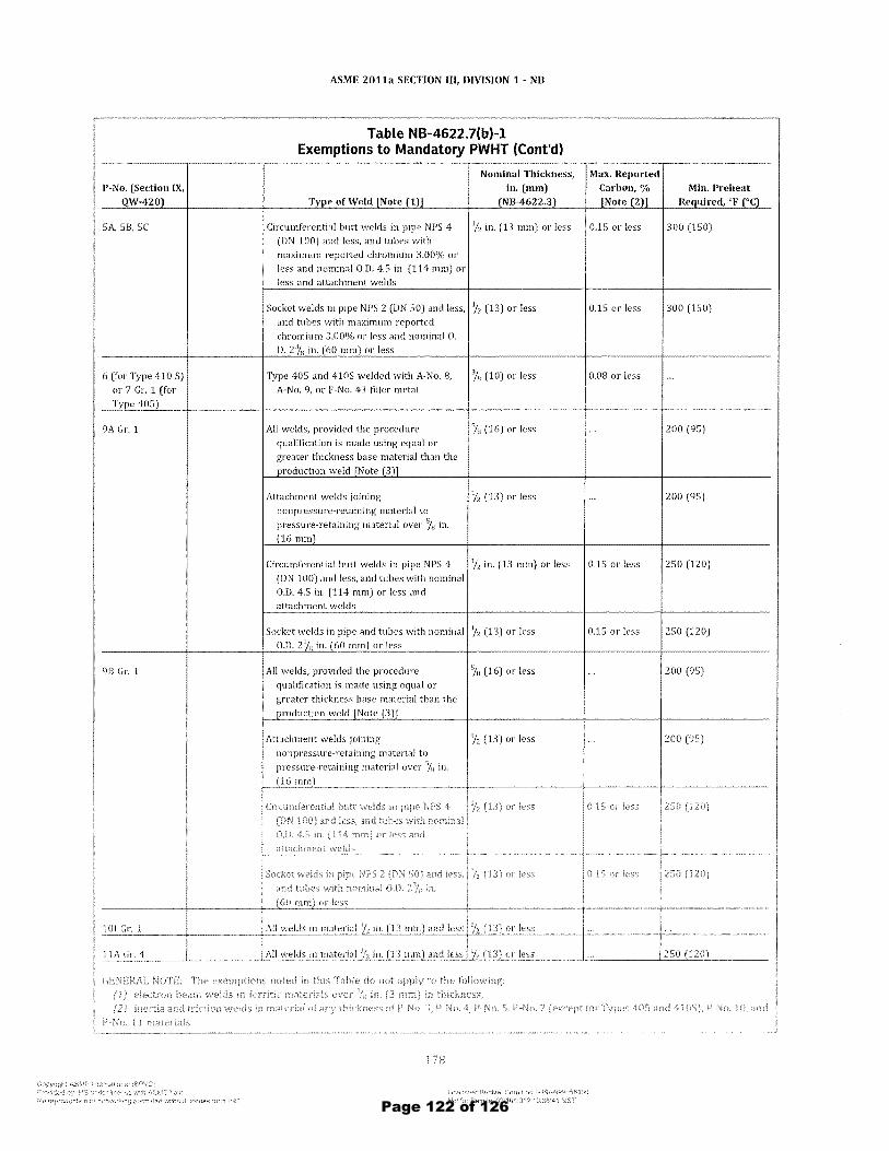
P-No. (Section IX, QW-420
SA,SB.SC
6 (for Type 410 S)
or 7 G1'. 1 (for Ty e 405)
9A G1'. 1
9B Gr. 1
ASME 2011a SECTION III, DIVISION 1 - NB
Table NB-4622.7(b)-1 Exemptions to Mandatory PWHT (Cont'd)
Nominal Thickness, Max. Reported
Circumferential butt welds in pipe NPS 4 (ON 100) and less. and tubes with maximum reported chromium 3.00% or less and nominal 0.0. 45 in. (114 mm) or less and attacbment welds
in. (mm) (NB-4622.3
liz in. (13 mm) or less
Socket welds in pipe NPS 2 (ON 50) and less. liz (13) or less
and tubes with maximum reported chromium 3.0()'% or less and nominal O.
O. in. (60 mm) or less
Type 405 and 410S welded with A-No.8. A-No.9. or F-No. 43 filler metal
All welds, proVided the procedure qualification is made using equal or greater thickness base material than the
Attachment welds joining nonpressure-retainjng material to
pressure-retaining material over ~!H in. (16 mm)
Circumferential butt welds in pipe N PS 4 (ON 100) and less, and tubes with nominal 0.0. 45 in. (114 mm) or less and attachment welds
% (10) or less
% (16) or less
'h (13) or less
liz in. (13 mm) or less
Socket welds in pipe and tubes with nominal % (13) or less 0.0. in. (60 mm) or less
All welds, provided the procedure
qualification is made using equal or
% (16) or less
liz (l3) or less
O.LS or less
0.15 or less
0.08 or less
0.15 or less
0.15 or less
Min. Preheat 0c)
300 (150)
300 (150)
200 (9S)
200 (95)
250 (120)
250 (120)
200 (95)
200 (95)
Page 122 of 126
smyee
Line
smyee
Line
smyee
Line
smyee
Line
smyee
Line
smyee
Text Box
All

ASME ZOl1a SECTION III, DIVISION 1 - NC
Table NC-4622.7(b)-1 Exemptions to Mandatory PWHT
P-No. (Section IX, QW- Nominal Thickness, in. Max. Reported Carhon, Min. Preheat 420) Type of Weld (Note (I)] (mm) (NC-4622.3) % [Note {2l] Required, of (0C)
1 All welds, where the materials heing joined 1 llt (321 and less 0.30 and less are 1'h in. (38 mm) and less Over 1 '/. to 11/z (32 to 38J 0.30 and less 200 (95)
% (19) or less Over 0.30
Over "/4 to 1'h (19 to 38) Over 0.30 200 (95)
All welds in material over 1 liz in. (38 mm) "/4 (19) or less ... 200 (95)
1 Gr. 1 or Gr. 2 Cladding or repair of cladding [Note (3J] with 0.30 100 (38) A-No.8 or F-No. 43 filler metal in base
material of: 111z in. (38 mm) or less
Over 1 '12 in. to 3 in. (38 mm to 75 mm) ... 0.30 200 (95) [Note (4)]
Over 3 in. (75 nun) ... 0.30 250 (120) [Note
(5)1
3 For vessel repair without required PW!lT, ... ... 350 (l7S) see NC-4622.9
3 except Gr. 3 All welds, except repair welds in vessels, 'i,. (16) or less 0.25 or less 200 (95) provided weld procednre qualification is made using equal or greater thickness base material than production weld [Note (6)]
Attachment welds joining nonpressure- liz (13) or less 0.25 or less 200 (95) retaining material to pressure retaining
material
Circumferential butt welds in pipe and tubes liz (13) or less 0.25 or less 200 (95)
Socket welds in pipe NPS 2 (DN 50J and less, liz (13) or less 0.25 or less 200 (95) and tubes with nominal O.D. in. (60 mm)
or less
4 Circumferential butt welds in pipe NPS 4 liz (13) or less (l.lS or less 250 (120) (DN 100) and less, and tubes with nominal O.D. 4.5 in. (114 mmJ or less and attachment welds
Socket welds in pipe NPS 2 (DN 50J and less, '12 (13) or less 0.15 or less 250 (120)
and tubes with nominal O.D. 2% in. (60 mmJ or less
SA, 5B, and 5C Circumferential butt welds in pipe NPS 4 '12 (13J or less (US or less 300 (150) (DN 100) and less, and tubes with maximum reported chromium 3.00'Vt, or less and
nominal O.D. 4.5 in. (114 mm) or less and attachment welds
Socket welds in pipe NPS 2 (DN 50) and less. liz (13) or less 0.15 or less 300 (150) and tubes with maximum reported chromium 3.00 l% or less nominalO.
I D. 23;" in. (60 mm) or less
() ,A·No.
I (for Type 4(5) 9, (;l' F·No 43 nile,. metal
Page 123 of 126
smyee
Line
smyee
Line
smyee
Line
smyee
Line
smyee
Line
smyee
Line
smyee
Line
smyee
Line
smyee
Line
smyee
Text Box
All
smyee
Text Box
All

ASME 2011a SECTION III, DIVISION 1 - ND
Table ND-4622.7(b)-1 Exemptions to Mandatory PWHT
Max. Reported Min. Preheat
P-No. (Sect. IX, Carbon, % Req'd., of QW-420) Type of Weld [Note (1)] Nominal Thickness (ND-4622.3) [Note (2)] f°c)
1 All welds, where the materials heing joined 11/. in. (32 mOl) and less 0.30 and less ...
are 1112 in. (38 mm) and less Over 11/4 in. (32 mm) to 1112 in. [38 mm} 0.30 and less 200 (95)
:~} in. (19 mm) or less Over 0.30
3, in. (19 mm) to 1112 in. (38 mm) Over 0.30 200 (95)
All welds in material over l'jz in. (38 mm) '1. in. (19 mm) or less ... 200 (95)
1 Gr. 1 or Gr. 2 Cladding or repair of cladding [Note (3)J with A- ... 0.30 100 (38) No.8 or F-No. 43 filler metal in base material
of: 1 'iz in. (38 mm) or less
Over 1 Yz in. (38 mm) to 3 in. (75 mm) ... 0.30 200 (95) [Note (4)]
Over 3 in. (75 mm) ... 0.30 250 (120)
[Note (5)J
13 For vessel repair without required PWHT, see NC- ... 350 (175) 4622.9
13 Except Gr. 3 All welds, except repair welds in vessels, provided % in. (16 mm) or less 0.25 or less 200 (95) weld procedure qualification is made using equal or greater thickness base material than production weld [Note (6)1
Attachment welds joining nonpressure-retaining 'Iz in. (13 mm) or less 0.25 or less 200 (9S) material to pressure retaining material
Circumferential butt welds in pipe and tubes Yz in. (13 mm) or less 0.25 or less 200 (95)
14 Circumferential butt welds or socket welds in pipe 'iz in. (13 mm) or less 0.15 or less 250 (120) NPS 4 (DN 100) and less, and tubes with nominal O.D. 4.5 in. (114 mm) or less and attachment welds
ISA, 58, 5C Circumferential butt welds or socket welds in pipe liz in. (13 mm) or less 0.15 or less 300 (lS0) NPS 4 (DN 100) and less, and tubes with maximum, reported chromium 3.00% or less and nominal O.D. 4.5 in. (114 mm) or less and attachment welds
16 (for type 41(5) Type 405 and 41()S welded with A-No.8, A-No.9, % in. (10 mm) or less 0.08 or less or 7 Gr. 1 (for or F-No. 43 filler metal type 405)
19A Gr. 1 All welds, provided the procedure qualification is %in. (16 Il1m) or less 200 (95) made using equal or greater thickness base material than the production weld [Note (6)]
Attachment welds joining "1" coou> c-, ""'U"';; in. (1 mm) 200 (95J I
over cig in (16 mm) I 'u"'''' ",""
I,
attachment weldt
I') I (.
'IUdEHLd"'"
material than the productwn weld [Note (6)] I I
Attachment welds joining nonpressure-retaining '/2 in. (13 mm] or 200 (95) material to pressure retaining material over 5/n in. (16 mm)
!
Page 124 of 126
smyee
Line
smyee
Line
smyee
Text Box
All
smyee
Text Box
All

P~Number
(Sect. IX, QW420l
3 except Gr.3
4
SA, 58, SC
6 (for Type 410S) or
7 Gr. 1 (for Type 405)
9A Gr. 1
98 Gr. 1
2011a SECTION III, DIVISION 1 - NF
TABLE NF-4622.7(bJ-I EXEMPTIONS TO MANDATORY PWHT
Type of Weld [Note (1)]
All welds where the materials being joined are in. (38 mm) and less
Fillet, partial penetration, and repair welds in material over in. (38 mm)
All welds
All welds in pipes NPS 4 CDN 100) or less or tubes with nominal O. D. 4.5 in. Cl14 mm) or less and attachment welds
All welds in pipes or tubes with maximum specified chromium 3.00% or less, NPS 4 CDN 100) or less pipe, and nominal O.D. 4.5 in. (114 mm) or less tubes
Type 405 and 410S welded with A~No. 8, A-No.9, or F~No. 43 filler metal
All welds, provided the procedure qualifica~ tion is made using equal or greater thickness base material than the production weld [Note (3)]
Attachment welds joining nonpressure~ retaining material to pressure~retaining material over % in. (16 mm)
All welds in pipes N PS 4 CDN 100) or less or tubes with nominal O.D. 4.5 in. (114 mm) and less
All welds, provided the procedure qualifica~
Nominal Thickness (NF-4b22.3)
1 \14 in. (32 mm) and less Over 1 y. in. (32 mm) to in.
(38 mm) ~ in. (19 mm) or less Over 14 in. 09 mm) to in.
(38 mm)
3;" in. Cl9 mm) or less
%, in. (13 mm) or less
12 in. Cl3 mm) or less
%, in. (13 mm) or less
in. ClO mm) or less
% in. (16 mm) or less
12 in. (13 mm) or less
\I, in. (13 mm) or less
% in. (16 mm) or less
Max. Reported
Carbon, % [Note (2)]
0.30 or less 0.30 or less
Over 0.30 Over 0.30
0.25 or less
0.15 or less
0.15 or less
0.08 or less
0.15 or less
M in. Preheat Req'd, of (OC)
200 (95)
200 (95)
200 (95)
200 (95)
250 Cl20)
300 (1S0)
200 (9S)
200 (9S)
2S0 (120)
200 (9S)
For Information Only
Page 125 of 126

P-No. (Sect. IX, QW-420)
1
1 Gr. 1 or Gr. 2
3 except Gr. 3 = 4
SA, 58, SC
7
9A Gr, 1
98 Gr. 1
tOJ Ilr 1
J 11\ GL 4
ASME 2011a SECTION III, DIVISION 1 - NG
Table NG-4622.7(b)-1 Exemptions to Mandatory PWHT
Type of Weld [Note (1)] Nominal Thickness (NG-4622.3)
All welds where the materials being joined 1'/4 in. (32 mm) or less are 1'12 in, (38 rnrn) and less Over 1 Y4 in. (32 rnm) to 1'1z in. (38 rnm)
y, in. (19 mm) or less
Over 3/4 in. (19 mm) to 1 Y2 in. (38 mm)
All welds in material over 1'12 in. (38 mm) % in. (19 rnm) or less
Cladding or repair of cladding [Note (3)] with ...
A-No.8 or r-No. 43 filler metal in base material of: 1 Y2 in. (38 mm) or less
Over 1'1z in, (38 mm) to 3 in. (75 mm)
Over 3 in, (75 mm)
:;;il welds 112 in, (13 mm) or less
All welds in pipes NPS 4 (DN 100) and less or '1z in. (13 mm) or less tubes with nominal O.D. 4.5 in, (114 mm) or less
All welds in pipes or tubes witb maximum '12 in, (13 mm) or less speCified cbromium 3,00%, or less, NPS 4 (DN 100) or less pipe, and nominal O.D. 4.5 in, (114 mm) or less tubes
Type 405 and 4105 welded with A-No, 8, A- 3/" in. (10 mm) or less No.9, or F·No. 43 filler metal
All welds provided the procedure % in, (16 mm) or less qualification is made using equal or greater
thickness base material than the production weld
Attachment welds joining non pressure Y2 in. (13 mm) or less retaining material to pressure·retaining
material over % in. (16 mm)
Circumferential butt welds or socket welds in '12 in. (13 nun) or less pipe NPS 4 (DN 100) or less and tubes with nominal O.D, 4.5 in. (114 mm) or less and attachment welds
All welds provided the procedure % in. (16 mm) or less qualification is made using equal or greater
thickness base matel'ial than the production weld
Attachment welds Joining l1onpressure- 1', in" (13 nun) or
JE ""u; ",' "', materia! over 7" in, 116 mm)
Ail welds in material '/; ill, (13 111m) 1md lesr '/; ill, [13 lllmJ or !es';
Ali wolds ill matenal ,;, 1l1. (I it (lim) and less ';2 m. (Ll lllmJ ot less
Max. Reported
Carbon, % [Note (2)]
0.30 or less 0.30 or less Over 0.30
...
... 0.30
0.30
0.30
0.25 or less
0.15 or less
0.15 or less
0,08 or less
, ..
0.15 or less
. '"
(1) Where the thickness of material identified in the Type of Weld column, it is the thickness of the hase
joint. Carbon level of the pressure·retaining materials being joined.
Min. Preheat Req'd., OF ("C)
... 200 (95) ... 200 (95)
200 (95)
100 (38)
1200 (95) [Note (4)]
250 (120) [Note (5)]
200 (95)
250 (120)
300 (150)
...
200 (95)
200 (95)
250 (120)
200 (95)
200 (95)
I 2S\J (120)
at the welded
Maximum process heat input 150,000 l/in. (150 000 )/25 mm). The maximum resulting hardness of the heat affected zone in
shall
For Information Only
Page 126 of 126