CITY OF SAN MARINO DESIGN REVIEW COMMITTEE AGENDA ...
391
CITY OF SAN MARINO DESIGN REVIEW COMMITTEE AGENDA WEDNESDAY, DECEMBER 4, 2019 7:00 P.M. CITY HALL COUNCIL CHAMBERS 2200 HUNTINGTON DRIVE, SAN MARINO, CA The City of San Marino appreciates your attendance. Citizens’ interest provides the Design Review Committee with valuable information regarding issues of the community. Regular Meetings are held on the 1 st and 3rd Wednesday of every month. In compliance with the Americans with Disabilities Act, any person with a disability who requires a modification or accommodation in order to participate in a meeting should contact the City Clerk’s Office at (626) 300-0705 at least 48 hours prior to the meeting. CALL TO ORDER PLEDGE OF ALLEGIANCE ROLL CALL: Chair Kevin Cheng, Vice-Chair Joyce Gatsoulis Batnij, Committee Member Howard Brody, Committee Member Christa Lakon, Committee Member Peter Wong, and Alternate Committee Member Rick Chou POSTING OF AGENDA The agenda is posted 72 hours prior to each meeting at the following locations: City Hall, 2200 Huntington Drive, the Crowell Public Library, 1890 Huntington Drive and the Recreation Department, 1560 Pasqualito Drive. The agenda is also posted on the City’s Website: http://www.cityofsanmarino.org PUBLIC COMMENTS Section 54954.3 of the Brown Act provides an opportunity for members of the public to address the Design Review Committee on any item of interest to the public, before or during the Design Review Committee’s consideration of the item, that is within the subject matter jurisdiction of the Design Review Committee. Kevin Cheng, Chair Joyce Gatsoulis-Batnij, Vice-Chair Howard Brody Christa Lakon Peter Wong Rick Chou, Alternate www.cityofsanmarino.org (626) 300-0711 Phone (626) 300-0716 Fax City Hall Council Chamber 2200 Huntington Drive San Marino, CA 91108
-
Upload
khangminh22 -
Category
Documents
-
view
2 -
download
0
Transcript of CITY OF SAN MARINO DESIGN REVIEW COMMITTEE AGENDA ...
CITY OF SAN MARINO
DESIGN REVIEW COMMITTEE AGENDA
WEDNESDAY, DECEMBER 4, 2019
7:00 P.M. CITY HALL
COUNCIL CHAMBERS 2200 HUNTINGTON DRIVE, SAN MARINO, CA
The City of San Marino appreciates your attendance. Citizens’ interest provides the Design Review Committee with valuable information regarding issues of the community. Regular Meetings are held on the 1st and 3rd Wednesday of every month. In compliance with the Americans with Disabilities Act, any person with a disability who requires a modification or accommodation in order to participate in a meeting should contact the City Clerk’s Office at (626) 300-0705 at least 48 hours prior to the meeting. CALL TO ORDER PLEDGE OF ALLEGIANCE ROLL CALL: Chair Kevin Cheng, Vice-Chair Joyce Gatsoulis Batnij, Committee Member Howard
Brody, Committee Member Christa Lakon, Committee Member Peter Wong, and Alternate Committee Member Rick Chou
POSTING OF AGENDA The agenda is posted 72 hours prior to each meeting at the following locations: City Hall, 2200 Huntington Drive, the Crowell Public Library, 1890 Huntington Drive and the Recreation Department, 1560 Pasqualito Drive. The agenda is also posted on the City’s Website: http://www.cityofsanmarino.org PUBLIC COMMENTS Section 54954.3 of the Brown Act provides an opportunity for members of the public to address the Design Review Committee on any item of interest to the public, before or during the Design Review Committee’s consideration of the item, that is within the subject matter jurisdiction of the Design Review Committee.
Kevin Cheng, Chair Joyce Gatsoulis-Batnij, Vice-Chair Howard Brody Christa Lakon Peter Wong Rick Chou, Alternate
www.cityofsanmarino.org (626) 300-0711 Phone (626) 300-0716 Fax City Hall Council Chamber 2200 Huntington Drive San Marino, CA 91108
DESIGN REVIEW COMMITTEE AGENDA – DECEMBER 4, 2019 PAGE 2 OF 3
PUBLIC HEARINGS
1. DESIGN REVIEW CASE NO. DRC19-69
2520 RIDGEWAY RD., (TSE) This item was continued from the November 6, 2019 meeting. The applicant proposes to install a roofing material not found on the City’s Pre-Approved Roofing Material List. (Required Action Date: 12-6-19)
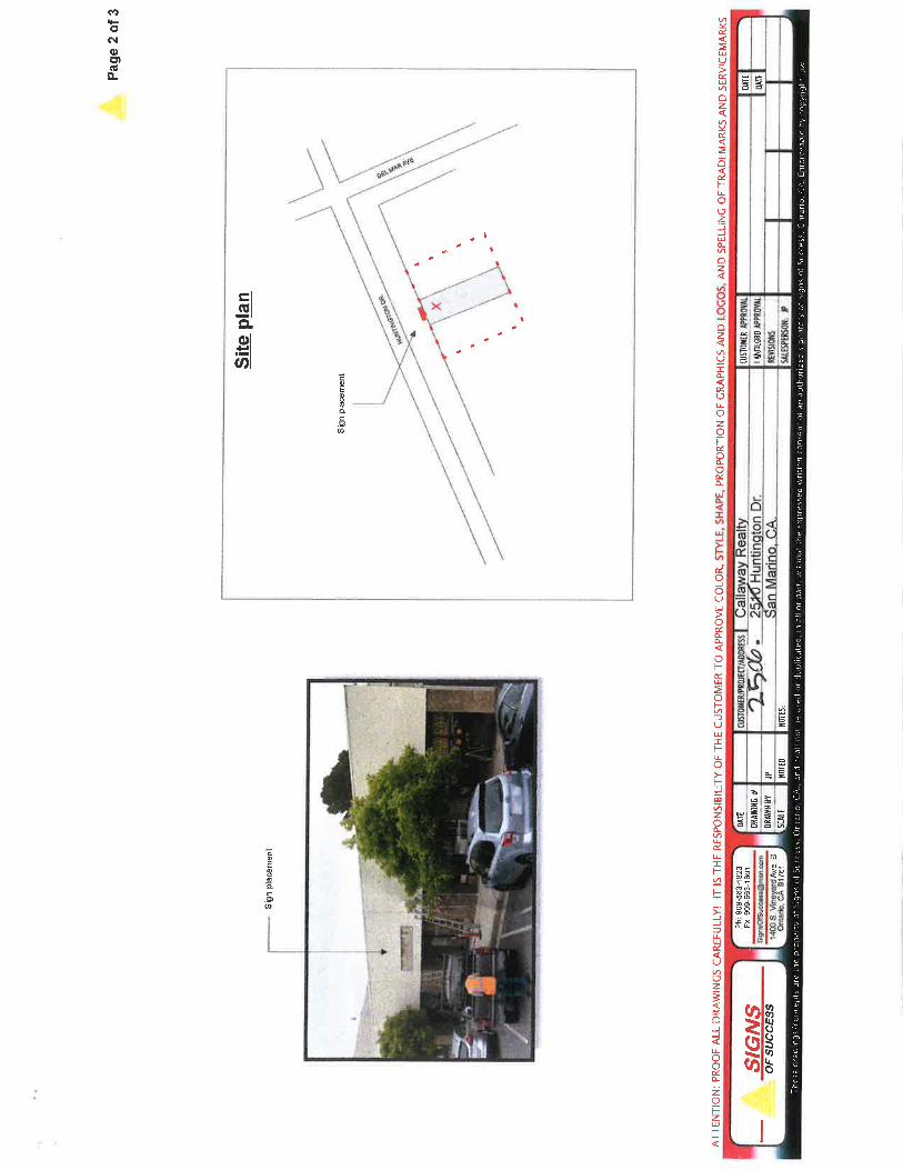
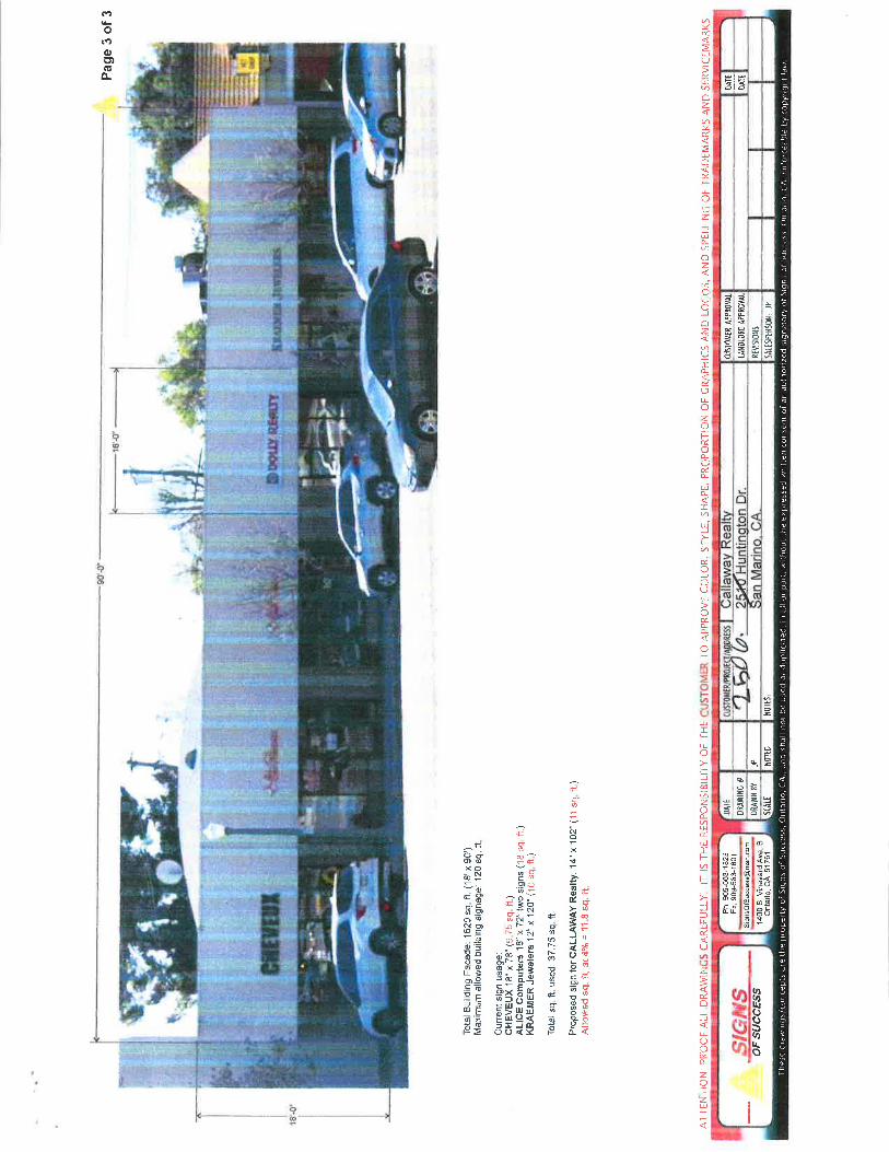
2. DESIGN REVIEW CASE NO. DRC19-67 2506 HUNTINGTON DR., (DATWYLER/SIGNS OF SUCCESS) This item was continued from the November 6, 2019 meeting. The applicant proposes to install a commercial wall sign. (Required Action Date: 12-6-19)
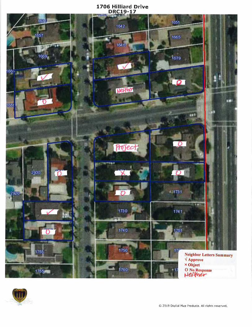
3. DESIGN REVIEW CASE NO. DRC19-17 1706 HILLIARD DR., (KY/LIN) This item was continued from the October 2, 2019 and November 6, 2019 meetings. The applicant proposes to construct a single-story addition and exterior modifications, and to install roofing materials that is not on the City’s Pre-Approved Material and Color List. (Required Action Date: 11-9-19)
4. DESIGN REVIEW CASE NOS. DRC19-80 and DRC19-81
3325 MONTEREY RD., (DIG DESIGN) The applicant proposes to construct a first and second story addition and exterior modifications to an existing two-story residence, and a new detached three-car garage. (Required Action Date: 12-29-19)
5. DESIGN REVIEW CASE NO. DRC19-59 2105 SHERWOOD RD., (LIU) The applicant proposes to construct a street-facing side yard fence and pedestrian gate. (Required Action Date: 1-17-20)
6. DESIGN REVIEW CASE NO. DRC19-61 1380 BELHAVEN RD., (LAW/LOUIE) The applicant proposes to construct a single-story addition project. (Required Action Date: 1-17-20)
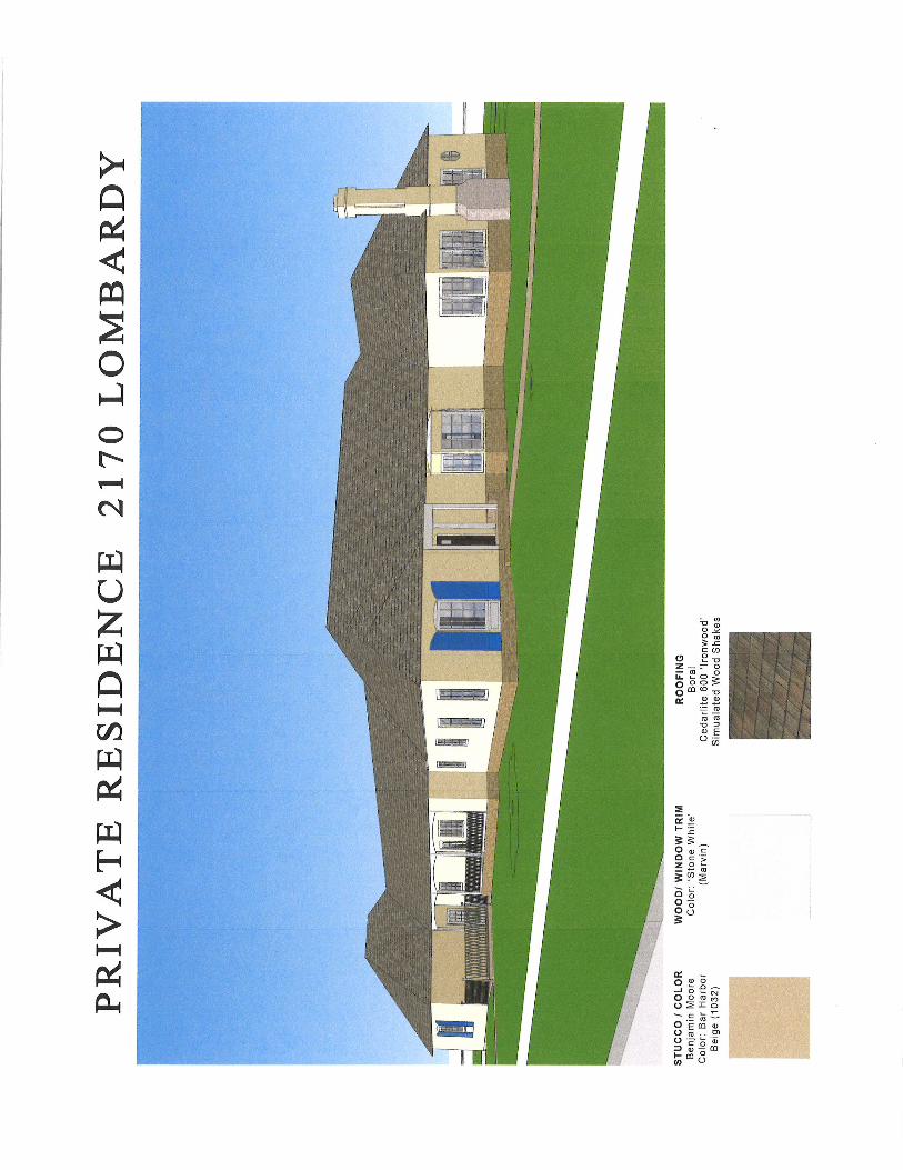
7. DESIGN REVIEW CASE NO. DRC19-56 2170 LOMBARDY RD., (WANG/JAMES V. COANE) The applicant proposes to construct a single-story addition project. (Required Action Date: 1-17-20)
OTHER MATTERS
OPEN FORUM This is an opportunity for future applicants to informally present preliminary design concepts for feedback from members of the DRC. Comments received are based on members not having visited the site and neighborhood.
DESIGN REVIEW COMMITTEE AGENDA – DECEMBER 4, 2019 PAGE 3 OF 3
Therefore, positive comments should not be perceived as preliminary approval of a project but rather as a tool in facilitating a project through the Design Review process. No more than two DRC members may participate in Open Forum discussions. Applications that have been heard by the DRC may not be discussed during Open Forum. PUBLIC WRITINGS DISTRIBUTED All public writings distributed by the City of San Marino to at least a majority of the Design Review Committee regarding any item on this agenda will be made available at the Public Counter at City Hall located at 2200 Huntington Drive, San Marino, California. ADJOURNMENT The San Marino Design Review Committee will adjourn to the next regular meeting to be held on Wednesday, January 15, 2020 at 7:00 p.m. in the City Hall Council Chamber, 2200 Huntington Drive, San Marino, California. APPEALS
There is a fifteen day appeal period for all applications. All appeals should be filed with the Planning and Building Department. Please contact the Planning and Building Department for further information.
PROJECT DESCRIPTION
The applicant proposes to install a roofing material not found on the City’s Pre-Approved Roof
Materials Colors and Application List.
The project was continued from the November 6, 2019 meeting.
REQUESTS The applicant has submitted a written request to continue this matter to the January 15, 2020 meeting. The applicant has also provided a written waiver of the Permit Streamlining Act, which allows the action date for this item to be extended an additional 90 days. RECOMMENDATION Staff recommends a continuance of Design Review No. DRC19-69 to the January 15, 2020 meeting.
Attachment: Written request to continue the project
TO: Chair Cheng and Members of the Design Review Committee
FROM: Eva Choi, Associate Planner
DATE: December 4, 2019
SUBJECT: DESIGN REVIEW CASE NO. DRC19-69 2520 RIDGEWAY RD., (TSE)
Kevin Cheng, Chair Joyce Gatsoulis Batnij, Vice-Chair
Howard Brody Christa Lakon Peter Wong
Rick Chou, Alternate

PROJECT DESCRIPTION
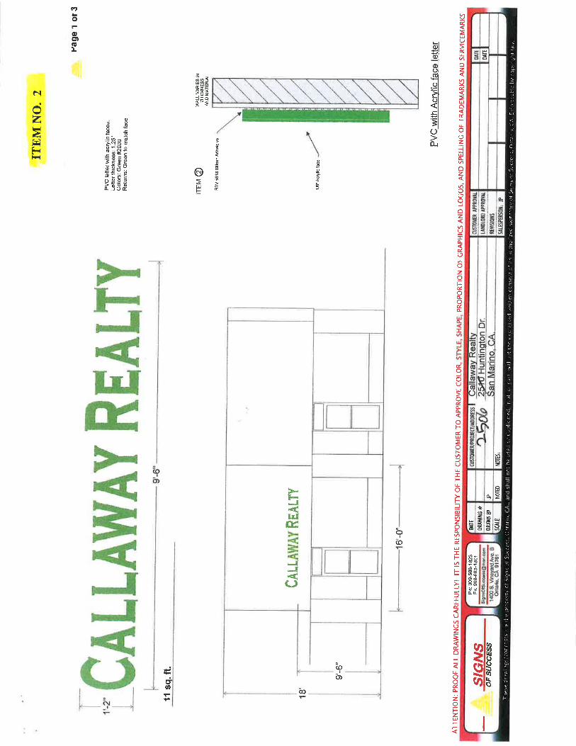
The applicant proposed to install a non-illuminated wall sign for a new business known as Callaway Realty. Pursuant to Subsection 23.15.03(G), all new commercial signage which changes the size, style, color, and/or materials are subject to review and approval by the Design Review Committee. ENVIRONMENTAL DETERMINATION The project is Categorically Exempt from the California Environmental Quality Act pursuant to CEQA Guidelines Section 15301, Classs 1(g) – Installation of signs are ministerial and therefore exempt from CEQA. PROJECT HISTORY December 4, 2019 – First hearing before the DRC December 6, 2019 – Required action date BACKGROUND At the November 6th meeting, staff informed the Committee that the application and hearing notice contains the wrong project address. The Committee continued the project to the December 4th meeting allowing staff to provide new hearing notice with the correct address.
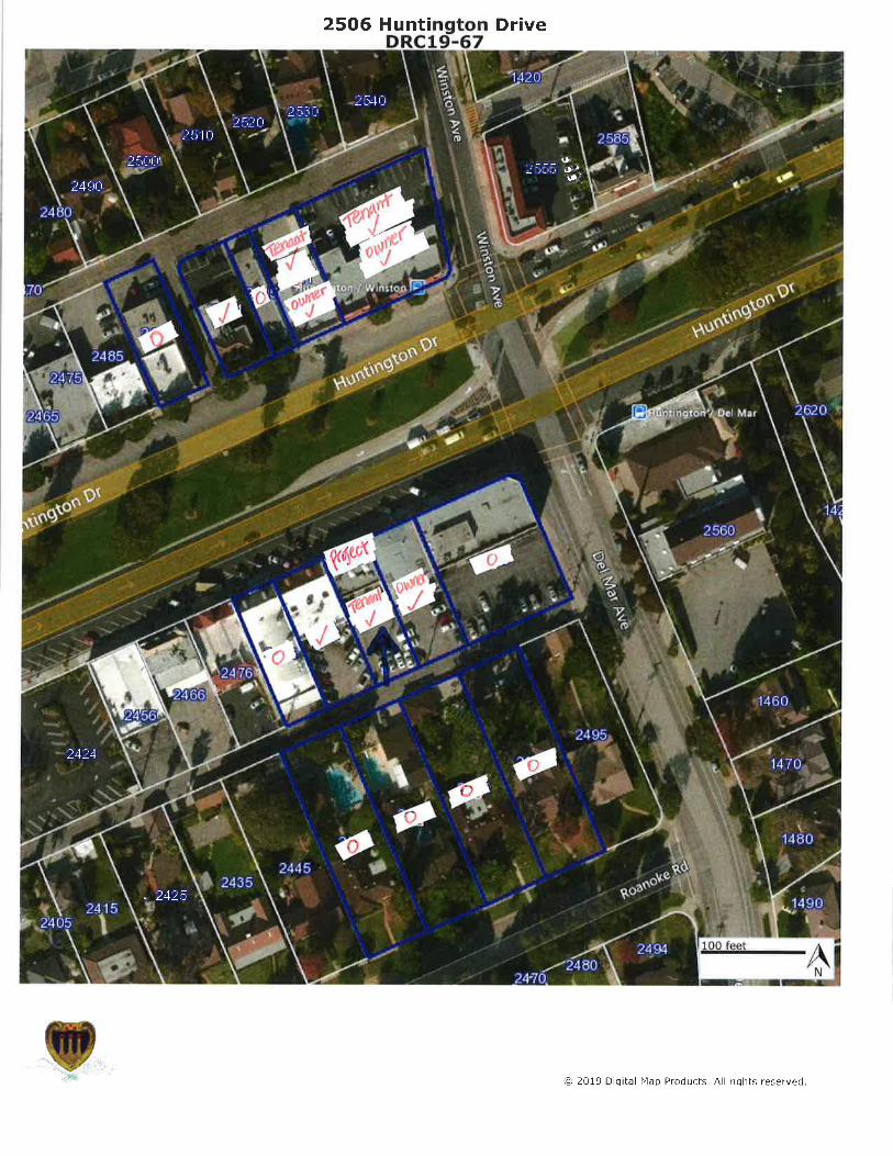
NEIGHBOR APPROVAL/OBJECTION LETTERS
Approve – 8
Object – 0
No response – 11
TO: Chair Cheng and Members of the Design Review Committee
FROM: Eva Choi, Associate Planner
DATE: December 4, 2019
SUBJECT: DESIGN REVIEW CASE NO. DRC19-67 2506 HUNTINGTON DR., (DATWYLER/SIGNS OF SUCCESS)
Kevin Cheng, Chair Joyce Gatsoulis Batnij, Vice-Chair
Howard Brody Christa Lakon Peter Wong
Rick Chou, Alternate
2
DESIGN REVIEW FINDINGS
Section 23.15.08 of the San Marino City Code states that the DRC shall approve the application if it finds all of the following to be true:
1. That the proposed structure is compatible with the neighborhood.
Staff can make this finding: ☐YES ☐NO ☒NOT APPLICABLE Comment: The addition of a new wall sign will not alter the structure and its compatibility with the neighborhood.
2. That the proposed structure is designed and will be developed in a manner which balances the reasonable expectation of privacy of persons residing on contiguous properties with the reasonable expectations of the applicants to develop their property within the restrictions of this Code.
Staff can make this finding: ☐YES ☐NO ☒NOT APPLICABLE
3. In the case of a building addition, the proposal is compatible with the existing building which includes the rooflines.
Staff can make this finding: ☐YES ☐ NO ☒NOT APPLICABLE
4. That the colors and materials are consistent and match the existing building or structure.
Staff can make this finding: ☒YES ☐NO ☐ NOT APPLICABLE Comments: The non-illuminated wall sign provides font size and style that are similar to adjacent signs. The sign location and overall size are consistent with adjacent signs. The proposed polyvinyl chloride (PVC) material with an acrylic face is a common material for commercial signage due to its durability and is an appropriate choice given the south facing wall with no overhang from the building. Staff finds the proposed sign compatible with adjacent signages and design elements on the commercial structure. In reviewing the compatibility of the proposed signage, Subsection 23.12.01(D)(6) states, The dimensions, design, colors, text, lettering and construction materials of all signs must be of a nature or quality so as to ensure compatibility with the architecture of the building on or near which the signs are to be located and with the architecture and aesthetics of the adjacent area.
PROJECT DESCRIPTION
The applicant proposes to construct a single-story addition and exterior modifications to an existing single-story residence, and provide roofing material and color not found on the City’s Pre-Approved Materials Colors and Application List. TREE PRESERVATION The applicant proposes to remove two trees adjacent to the existing structure. Staff recommends that the City Arborist determines whether these trees can be removed, and any replacement trees be provided through the Tree Removal Permit process prior to submitting the project for structural plan check. ENVIRONMENTAL DETERMINATION The project is Categorically Exempt from the California Environmental Quality Act pursuant to CEQA Guidelines Section 15301(e)(1) – Existing Facilities. PROJECT HISTORY October 2, 2019 – First hearing before the DRC November 6, 2019 – Second hearing before the DRC December 4, 2019 – Third hearing before the DRC February 7, 2020 – Required action date BACKGROUND At the October 2nd hearing, the Committee continued the project citing concerns with the proposed skylight locations, front door treatments, exterior lighting feature and whether the new roofing material will seamlessly match with the existing material.
TO: Chair Cheng and Members of the Design Review Committee
FROM: Eva Choi, Associate Planner
DATE: December 4, 2019
SUBJECT: DESIGN REVIEW CASE NO. DRC19-17 1706 HILLIARD DR., (KY/LIN)
Kevin Cheng, Chair Joyce Gatsoulis Batnij, Vice-Chair
Howard Brody Christa Lakon Peter Wong
Rick Chou, Alternate
2
At the November 6th meeting, the Committee granted a request by the project designer to continue the project to the December 4th meeting as he was compiling information on the proposed roofing material and needed additional time to submit the revised plans. The project design also agreed to waive the Permit Streamlining Act pertaining to the project processing time.
NEIGHBOR APPROVAL/OBJECTION LETTERS
(as of 10/2/19 meeting)
Approve – 3
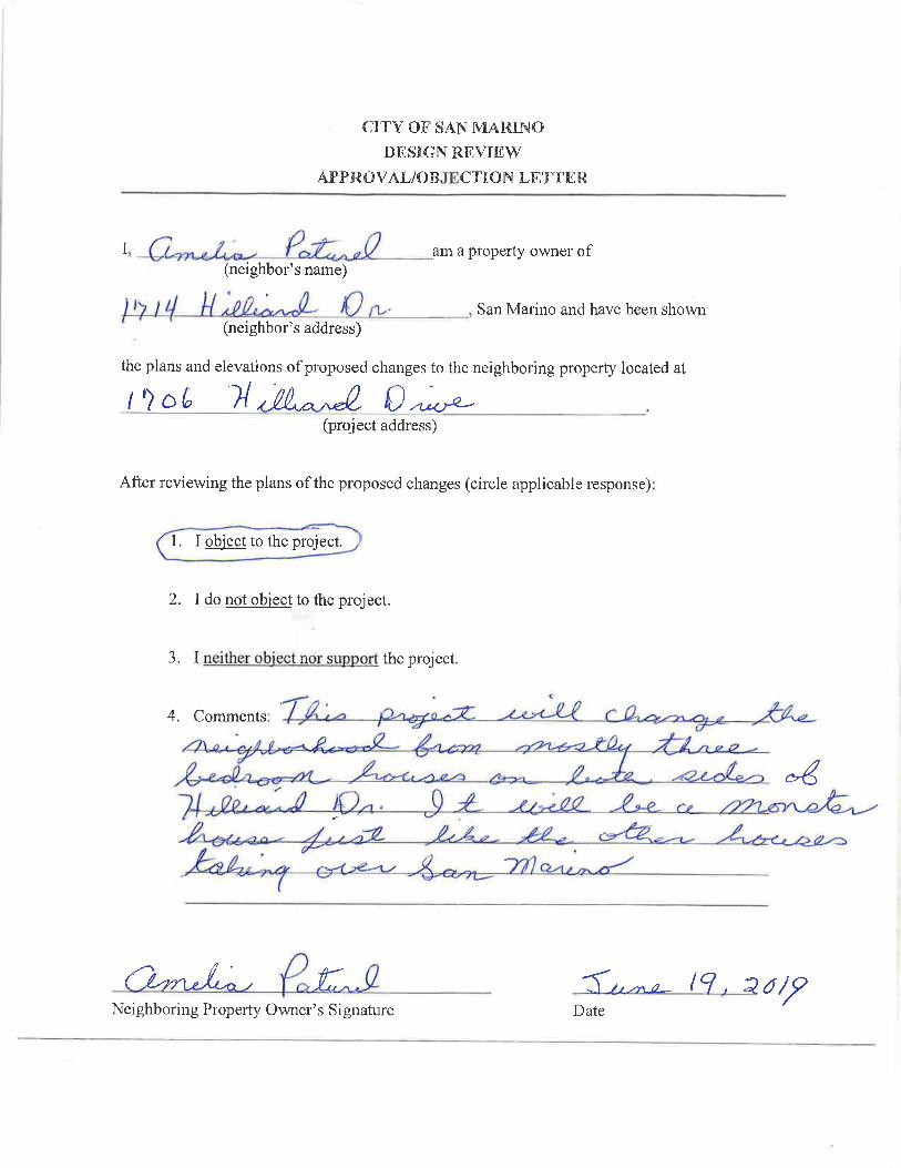
Object – 1 (letter attached)
Neither - 1
No response – 7
DESIGN REVIEW FINDINGS
Section 23.15.08 of the San Marino City Code states that the DRC shall approve the application if it finds all of the following to be true:
1. That the proposed structure is compatible with the neighborhood.
Staff can make this finding: ☒ YES ☐NO ☐ NOT APPLICABLE Comments: The legal neighborhood predominantly consists of modest single-story structures. The proposed addition would be in keeping with the massing and exterior treatments of the existing residence, therefore also maintaining its compatibility with the legal neighborhood.
2. That the proposed structure is designed and will be developed in a manner which balances the reasonable expectation of privacy of persons residing on contiguous properties with the reasonable expectations of the applicants to develop their property within the restrictions of this Code.
Staff can make this finding: ☒YES ☐NO ☐ NOT APPLICABLE Comments: The single-story addition in the rear of the structure provided ample setbacks and would not provide any direct sightlines into the north and south neighbors’ homes. Thus, the project would not impact any reasonable expectation of privacy.
3. In the case of a building addition, the proposal is compatible with the existing
building which includes the rooflines.
Staff can make this finding: ☒ YES ☐ NO ☐NOT APPLICABLE Comments: Staff finds that the proposed addition is generally integrated with the existing structure. Although the roof pitch over the family room addition is different from the
3
rest of the structure, staff finds this element acceptable given that it renders the addition invisible from public’s view.
4. That the colors and materials are consistent and match the existing building
or structure.
Staff can make this finding: ☒YES ☐ NO ☐ NOT APPLICABLE Comments: The proposed earth tone color palette is consistent for the style of the structure and similar to homes in the immediate area. The proposed skylights are located away from street view which helps to preserve the appearance of the structure. The proposed exterior lighting fixture’s style has an industrial appearance, staff recommends a downcast fixture that is also Dark Sky friendly. The applicant is requesting to use a roofing product that is not on the City’s Pre-Approved Roof Materials Colors and Application list (City’s list). The proposed product is a simulated slate, manufactured by DaVinci. While the DRC and Planning Commission approved to add the DaVinci simulated slate material on the City’s list, it was only for the Multi-Width slate product. In this case, the applicant found that the single-width product would provide the least visual differences between the existing roofing material which is no longer available, and the proposed single-width simulated slate in the Brownstone color. The project designer provided a list of locations where the single width product in various colors, including the proposed Brownstone color, is installed. To further ensure a cohesive roof appearance, staff recommends removing some of the existing roof material from the east/rear portion of the structure and re-install them over the new entry porch, and only use the new DaVinci single width material for the rear portion of the structure.
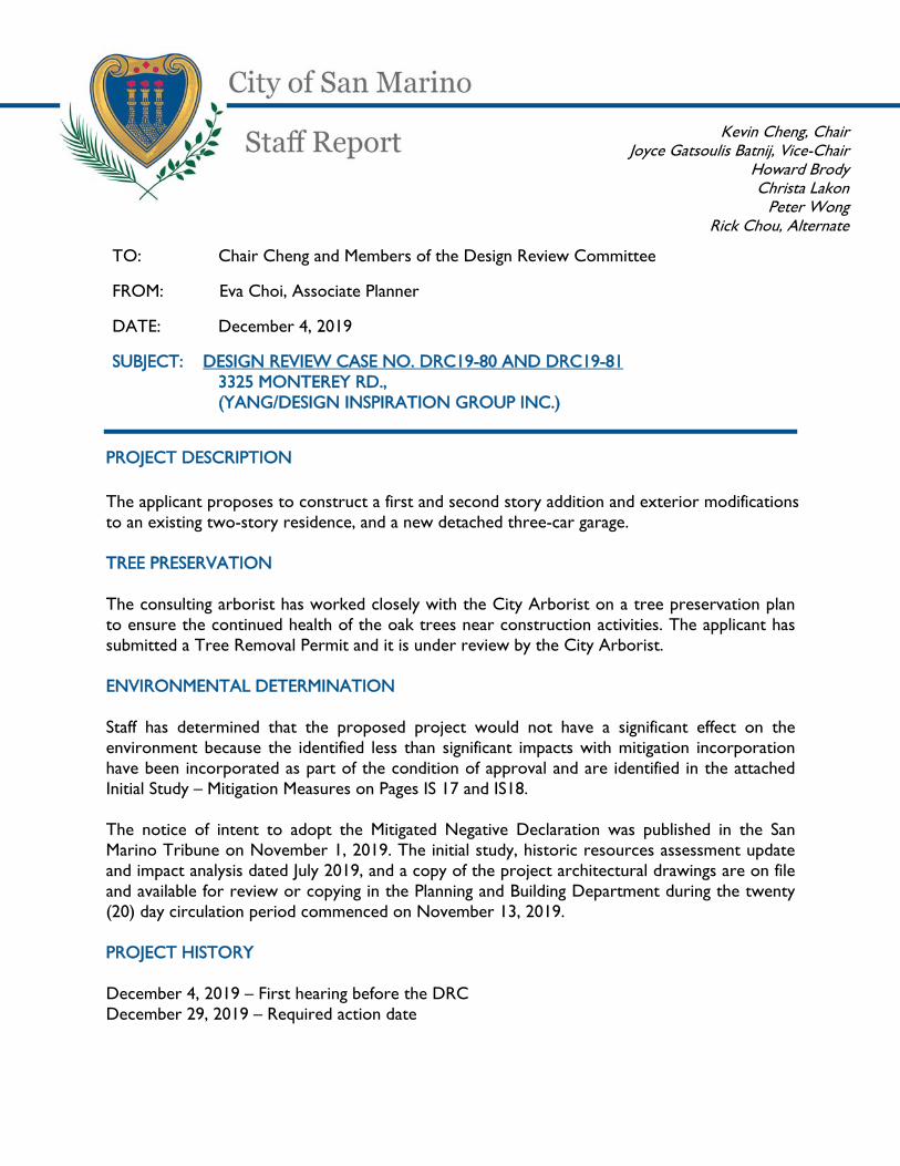
PROJECT DESCRIPTION The applicant proposes to construct a first and second story addition and exterior modifications to an existing two-story residence, and a new detached three-car garage. TREE PRESERVATION The consulting arborist has worked closely with the City Arborist on a tree preservation plan to ensure the continued health of the oak trees near construction activities. The applicant has submitted a Tree Removal Permit and it is under review by the City Arborist. ENVIRONMENTAL DETERMINATION Staff has determined that the proposed project would not have a significant effect on the environment because the identified less than significant impacts with mitigation incorporation have been incorporated as part of the condition of approval and are identified in the attached Initial Study – Mitigation Measures on Pages IS 17 and IS18. The notice of intent to adopt the Mitigated Negative Declaration was published in the San Marino Tribune on November 1, 2019. The initial study, historic resources assessment update and impact analysis dated July 2019, and a copy of the project architectural drawings are on file and available for review or copying in the Planning and Building Department during the twenty (20) day circulation period commenced on November 13, 2019. PROJECT HISTORY December 4, 2019 – First hearing before the DRC December 29, 2019 – Required action date
TO: Chair Cheng and Members of the Design Review Committee
FROM: Eva Choi, Associate Planner
DATE: December 4, 2019
SUBJECT: DESIGN REVIEW CASE NO. DRC19-80 AND DRC19-81 3325 MONTEREY RD.,
(YANG/DESIGN INSPIRATION GROUP INC.)
Kevin Cheng, Chair Joyce Gatsoulis Batnij, Vice-Chair
Howard Brody Christa Lakon
Peter Wong Rick Chou, Alternate
2
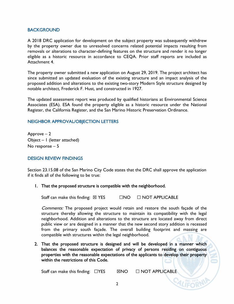
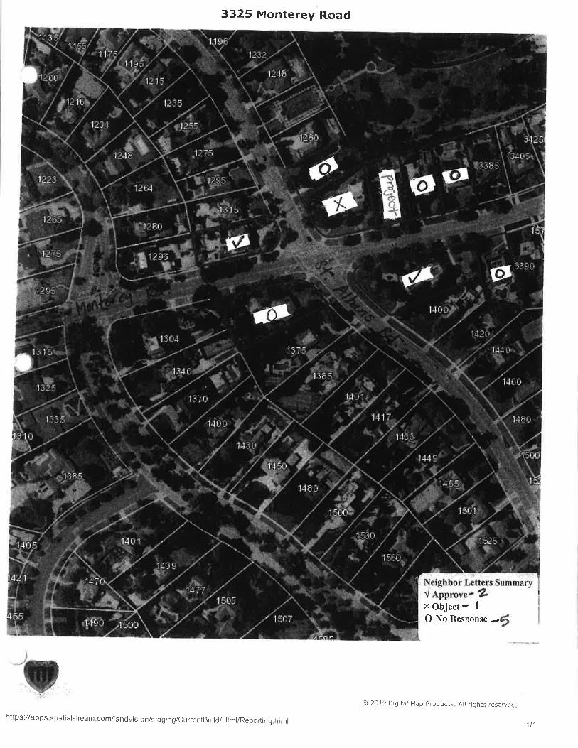
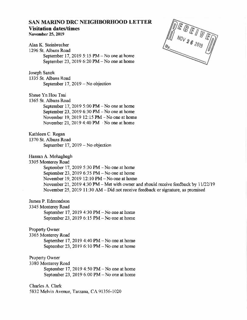
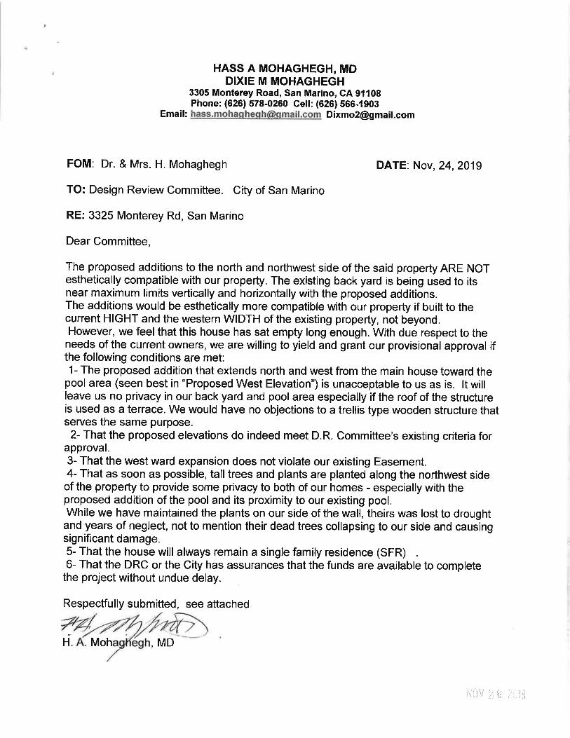
BACKGROUND A 2018 DRC application for development on the subject property was subsequently withdrew by the property owner due to unresolved concerns related potential impacts resulting from removals or alterations to character-defining features on the structure and render it no longer eligible as a historic resource in accordance to CEQA. Prior staff reports are included as Attachment 4. The property owner submitted a new application on August 29, 2019. The project architect has since submitted an updated evaluation of the existing structure and an impact analysis of the proposed addition and alterations to the existing two-story Modern Style structure designed by notable architect, Frederick F. Hust, and constructed in 1927. The updated assessment report was produced by qualified historians at Environmental Science Associates (ESA). ESA found the property eligible as a historic resource under the National Register, the California Register, and the San Marino Historic Preservation Ordinance. NEIGHBOR APPROVAL/OBJECTION LETTERS Approve – 2 Object – 1 (letter attached) No response – 5 DESIGN REVIEW FINDINGS Section 23.15.08 of the San Marino City Code states that the DRC shall approve the application if it finds all of the following to be true:
1. That the proposed structure is compatible with the neighborhood. Staff can make this finding: ☒ YES ☐NO ☐ NOT APPLICABLE Comments: The proposed project would retain and restore the south façade of the structure thereby allowing the structure to maintain its compatibility with the legal neighborhood. Addition and alterations to the structure are located away from direct public view or are designed in a manner that the new second story addition is recessed from the primary south façade. The overall building footprint and massing are compatible with structures within the legal neighborhood.
2. That the proposed structure is designed and will be developed in a manner which balances the reasonable expectation of privacy of persons residing on contiguous properties with the reasonable expectations of the applicants to develop their property within the restrictions of this Code. Staff can make this finding: ☐YES ☒NO ☐ NOT APPLICABLE

3
Comments: The design program provides two balconies on the second floor. The new balcony accessed from the Den would not cause privacy concerns due to its 42 feet setback from the property line and adjacent to an overgrown oak tree canopy. Staff found the rear-facing balcony in the new master bedroom may have a direct view into the west neighbor’s property since there is no structure or element that exist to disrupt the direct view of someone standing on the balcony. Staff recommends removal of the master bedroom balcony.
3. In the case of a building addition, the proposal is compatible with the existing building
which includes the rooflines. Staff can make this finding: ☒ YES ☐ NO ☐NOT APPLICABLE Comments: The proposed project has been evaluated against the Secretary of the Interior’s Standards for the Treatment of Historic Properties and was found to comply with the ten guidelines (pages 56 – 59 of the Historic Resources Assessment Update report). Although the property has not been formally designated as a historic resource or historic landmark by local ordinance, adhering to the ten guidelines to preserve the character-defining features and replace in-kind of these features if necessary aligns with recommendations found in the City’s Residential Design Guidelines. The project proposed to rehabilitate special tile work at various locations throughout the structure and property (driveway gate).
4. That the colors and materials are consistent and match the existing building or
structure. Staff can make this finding: ☒YES ☐ NO ☐ NOT APPLICABLE Comments: In accordance with the Secretary of the Interior’s Standards, the new addition provides materials that are different from the original construction. Window material will be aluminum clad wood, manufactured by Sierra Pacific, exterior finish provides horizontal wood cladding that is consistent with prior addition done in 1928, and in place of decorative railing, contemporary balconies with glass material are proposed.
ATTACHMENTS:
1. DRC Map and Visitation Log 2. Objection letter from Dr. Mohaghegh at 3305 Monterey Rd. 3. Notice of intent to adopt the Mitigated Negative Declaration 4. Initial Study 5. Proposed Conditions of Approval 6. Prior DRC Reports for the 2018 application 7. Historic Resources Assessment Update and Impact Analysis dated July 2019
1
PUBLIC NOTICE
NOTICE OF INTENT TO ADOPT A MITIGATED NEGATIVE DECLARATION AND NOTICE OF PUBLIC HEARING
The City of San Marino hereby gives notice that pursuant to the authority and criteria contained in the California Environmental Quality Act of 1970, as amended (“CEQA”), the State CEQA Guidelines and the CEQA Guidelines of the City of San Marino, the Planning and Building Department, has analyzed a request regarding the following item and has recommended that the Design Review Committee adopt a MITIGATED NEGATIVE DECLARATION:
1. DESIGN REVIEW CASE NOS. DRC19-80 AND DRC19-81
3325 MONTEREY ROAD, (YANG/DIG GROUP, INC.) The applicant requests to construct a one and two-story addition and remodel, implement exterior modifications to the existing two-story residence, and construct a new detached three-car garage. The project involves demolition of a detached carport and accessory structure. The project requires two design review actions pursuant to City Code Sections 23.15.03(A) and 23.15.03(C).
After reviewing the initial study for this project, the Planning and Building Department has determined that this project will not have a significant effect on the environment with the mitigated measures. Accordingly, a MITIGATED NEGATIVE DECLARATION has been prepared and recommended to the Design Review Committee for adoption. A public hearing will be held by the Design Review Committee to consider the adoption of this proposed MITIGATED NEGATIVE DECLARATION and the DESIGN REVIEW application on December 4, 2019 at 7:00 P.M., or as soon as it may be heard thereafter, at San Marino City Hall, in the Council Chamber. The City Hall is located at 2200 Huntington Drive, San Marino, California. Public comments will be received by the City during the twenty (20) day period commencing on November 13, 2019 and continuing through December 4, 2019. Comments can be presented in writing at any time during the period to Mr. Cervantes in the City of San Marino Planning and Building Department at the address set forth below. A copy of all relevant and referenced materials, including the project specifications, Initial Study, and the proposed MITIGATED NEGATIVE DECLARATION, is on file and available for review or copying in the offices of the City of San Marino, Planning and Building Department. The address for the City Planning and Building Department is 2200 Huntington Drive, San Marino, California. By: Aldo Cervantes Planning and Building Director
City of San Marino
1
INITIAL STUDY AND PROPOSED MITIGATED NEGATIVE DECLARATION
FOR 3325 MONTEREY ROAD, SAN MARINO
The City of San Marino has analyzed and completed an initial study for the following project:
DESIGN REVIEW CASE NOS. DRC19-80 AND DRC19-81 3325 MONTEREY ROAD, (YANG/DIG GROUP, INC.)
The applicant requests to construct a one and two-story addition and remodel, implement exterior
modifications to the existing two-story residence, and construct a new detached three-car garage. The project
involves demolition of a detached carport and accessory structure. The project requires two design review
actions pursuant to City Code Sections 23.15.03(A) and 23.15.03(C).
Based on the attached initial study, the City has determined that the proposed project COULD have a
significant effect on the environment, however there will not be a significant effect in this case with the
implementation of the mitigated measures described in the attached Mitigation Monitoring Program.
The notice of intent to adopt the mitigated negative declaration was published in the San Marino Tribune
on November 1, 2019.
Environmental Checklist Form November 2019
City of San Marino
2
ENVIRONMENTAL CHECKLIST FORM
1. Project Title Design Review Nos. DRC19-80 and DRC19-81
2. Lead agency name and address: City of San Marino, Planning and Building Department
2200 Huntington Drive, 1st Floor
San Marino, CA 91108
3. Contact person and phone number: Eva Choi, Associate Planner
(626) 300-0713
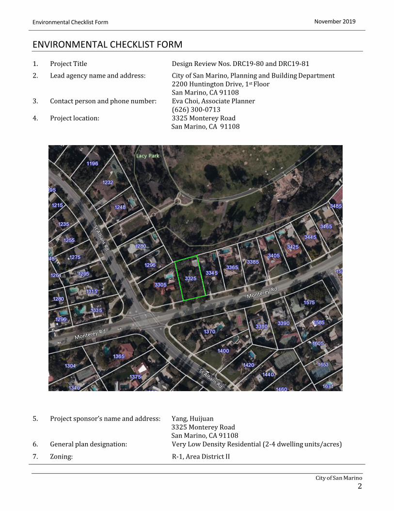
4. Project location: 3325 Monterey Road
San Marino, CA 91108
5. Project sponsor’s name and address: Yang, Huijuan
3325 Monterey Road
San Marino, CA 91108
6. General plan designation: Very Low Density Residential (2-4 dwelling units/acres)
7. Zoning: R-1, Area District II
November 2019 Environmental Checklist Form
3
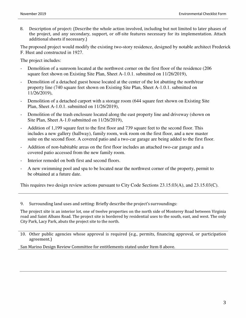
8. Description of project: (Describe the whole action involved, including but not limited to later phases of
the project, and any secondary, support, or off-site features necessary for its implementation. Attach
additional sheets if necessary.)
The proposed project would modify the existing two-story residence, designed by notable architect Frederick
F. Hust and constructed in 1927.
The project includes:
- Demolition of a sunroom located at the northwest corner on the first floor of the residence (206
square feet shown on Existing Site Plan, Sheet A-1.0.1. submitted on 11/26/2019),
- Demolition of a detached guest house located at the center of the lot abutting the north/rear
property line (740 square feet shown on Existing Site Plan, Sheet A-1.0.1. submitted on
11/26/2019),
- Demolition of a detached carport with a storage room (644 square feet shown on Existing Site
Plan, Sheet A-1.0.1. submitted on 11/26/2019),
- Demolition of the trash enclosure located along the east property line and driveway (shown on
Site Plan, Sheet A-1.0 submitted on 11/26/2019),
- Addition of 1,199 square feet to the first floor and 739 square feet to the second floor. This
includes a new gallery (hallway), family room, wok room on the first floor, and a new master
suite on the second floor. A covered patio and a two-car garage are being added to the first floor.
- Addition of non-habitable areas on the first floor includes an attached two-car garage and a
covered patio accessed from the new family room.
- Interior remodel on both first and second floors.
- A new swimming pool and spa to be located near the northwest corner of the property, permit to
be obtained at a future date.
This requires two design review actions pursuant to City Code Sections 23.15.03(A), and 23.15.03(C).
9. Surrounding land uses and setting: Briefly describe the project’s surroundings:
The project site is an interior lot, one of twelve properties on the north side of Monterey Road between Virginia
road and Saint Albans Road. The project site is bordered by residential uses to the south, east, and west. The only
City Park, Lacy Park, abuts the project site to the north.
10. Other public agencies whose approval is required (e.g., permits, financing approval, or participation
agreement.)
San Marino Design Review Committee for entitlements stated under Item 8 above.
Environmental Checklist Form November 2019
IS-4
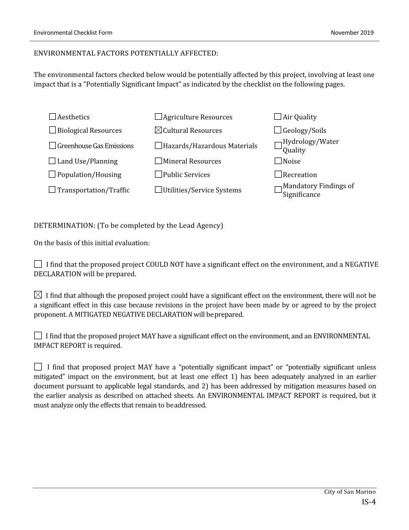
ENVIRONMENTAL FACTORS POTENTIALLY AFFECTED:
The environmental factors checked below would be potentially affected by this project, involving at least one
impact that is a “Potentially Significant Impact” as indicated by the checklist on the following pages.
Aesthetics
Biological Resources
Greenhouse Gas Emissions
Land Use/Planning
Population/Housing
Transportation/Traffic
Agriculture Resources
Cultural Resources
Hazards/Hazardous Materials
Mineral Resources
Public Services
Utilities/Service Systems
Air Quality
Geology/Soils
Hydrology/Water
Quality
Noise
Recreation
Mandatory Findings of
Significance
DETERMINATION: (To be completed by the Lead Agency)
On the basis of this initial evaluation:
I find that the proposed project COULD NOT have a significant effect on the environment, and a NEGATIVE
DECLARATION will be prepared.
I find that although the proposed project could have a significant effect on the environment, there will not be
a significant effect in this case because revisions in the project have been made by or agreed to by the project
proponent. A MITIGATED NEGATIVE DECLARATION will be prepared.
I find that the proposed project MAY have a significant effect on the environment, and an ENVIRONMENTAL
IMPACT REPORT is required.
I find that proposed project MAY have a “potentially significant impact” or “potentially significant unless
mitigated” impact on the environment, but at least one effect 1) has been adequately analyzed in an earlier
document pursuant to applicable legal standards, and 2) has been addressed by mitigation measures based on
the earlier analysis as described on attached sheets. An ENVIRONMENTAL IMPACT REPORT is required, but it
must analyze only the effects that remain to be addressed.
City of San Marino
November 2019 Environmental Checklist Form
IS-5
I find that although the proposed project could have a significant effect on the environment, because all
potentially significant effects (a) have been analyzed adequately in an earlier EIR or NEGATIVE DECLARATION
pursuant to applicable standards, and (b) have been avoided or mitigated pursuant to that earlier EIR or
NEGATIVE DECLARATION, including revisions or mitigation measures that are imposed upon the proposed
project, nothing further is required.
November 8, 2019
Signature Date
Eva Choi, Associate Planner City of San Marino
Printed Name For
Environmental Checklist Form November 2019
IS-6
EVALUATION OF ENVIRONMENTAL IMPACTS:
1) A brief explanation is required for all answers except “No Impact” answers that are adequately supported by
the information sources a lead agency cites in the parentheses following each question. A “No Impact” answer
is adequately supported if the referenced information sources show that the impact simply does not apply to
projects like the one involved (e.g., the project falls outside a fault rupture zone). A “No Impact” answer
should be explained where it is based on project-specific factors as well as general standards (e.g., the project
will not expose sensitive receptors to pollutants, based on a project-specific screening analysis).
2) All answers must take account of the whole action involved, including off-site as well as on-site, cumulative as
well as project-level, indirect as well as direct, and construction as well as operational impacts.
3) Once the lead agency has determined that a particular physical impact may occur, then the checklist answers
must indicate whether the impact is potentially significant, less than significant with mitigation, or less than
significant. “Potentially Significant Impact” is appropriate if there is substantial evidence that an effect may be
significant. If there are one or more “Potentially Significant Impact” entries when the determination is made,
an EIR is required.
4) “Negative Declaration: Less Than Significant With Mitigation Incorporated” applies where the incorporation
of mitigation measures has reduced an effect from “Potentially Significant Impact” to a “Less Than Significant
Impact.” The lead agency must describe the mitigation measures, and briefly explain how they reduce the
effect to a less than significant level (mitigation measures from Section XVII, “Earlier Analyses,” may be cross-
referenced).
5) Earlier analyses may be used where, pursuant to the tiering, program EIR, or other CEQA process, an effect
has been adequately analyzed in an earlier EIR or negative declaration. Section 15063(c)(3)(D). In this case,
a brief discussion should identify the following:
a) Earlier Analysis Used. Identify and state where they are available for review.
b) Impacts Adequately Addressed. Identify which effects from the above checklist were within the scope of
and adequately analyzed in an earlier document pursuant to applicable legal standards, and state
whether such effects were addressed by mitigation measures based on the earlier analysis.
c) Mitigation Measures. For effects that are “Less than Significant with Mitigation Measures Incorporated,”
describe the mitigation measures which were incorporated or refined from the earlier document and
the extent to which they address site-specific conditions for the project.
6) Lead agencies are encouraged to incorporate into the checklist references to information sources for
potential impacts (e.g., general plans, zoning ordinances). Reference to a previously prepared or outside
document should, where appropriate, include a reference to the page or pages where the statement is
substantiated.
City of San Marino
November 2019 Environmental Checklist Form
IS-7
7) Supporting Information Sources: A source list should be attached, and other sources used or individuals
contacted should be cited in the discussion.
8) This is only a suggested form, and lead agencies are free to use different formats; however, lead agencies
should normally address the questions from this checklist that are relevant to a project’s environmental
effects in whatever format is selected.
9) The explanation of each issue identify:
a) the significance criteria or threshold, if any, used to evaluate each question; and
b) the mitigation measure identified, if any, to reduce the impact to less than significance.
Environmental Checklist Form November 2019
IS-8
Issues: Potentially
Significant
Less Than
Significant
With
Mitigation
Less Than
Significant No
Impact Incorporation Impact Impact
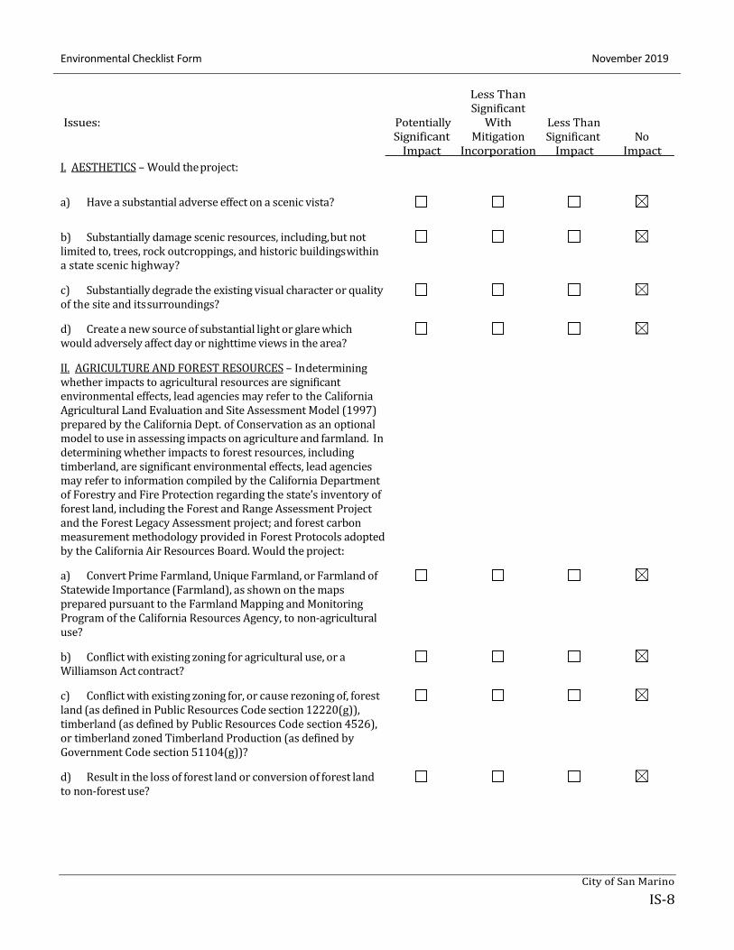
I. AESTHETICS – Would the project:
a) Have a substantial adverse effect on a scenic vista?
b) Substantially damage scenic resources, including, but not limited to, trees, rock outcroppings, and historic buildings within
a state scenic highway?
c) Substantially degrade the existing visual character or quality of the site and its surroundings?
d) Create a new source of substantial light or glare which would adversely affect day or nighttime views in the area?
II. AGRICULTURE AND FOREST RESOURCES – In determining
whether impacts to agricultural resources are significant
environmental effects, lead agencies may refer to the California
Agricultural Land Evaluation and Site Assessment Model (1997)
prepared by the California Dept. of Conservation as an optional
model to use in assessing impacts on agriculture and farmland. In
determining whether impacts to forest resources, including
timberland, are significant environmental effects, lead agencies
may refer to information compiled by the California Department
of Forestry and Fire Protection regarding the state’s inventory of
forest land, including the Forest and Range Assessment Project
and the Forest Legacy Assessment project; and forest carbon
measurement methodology provided in Forest Protocols adopted
by the California Air Resources Board. Would the project:
a) Convert Prime Farmland, Unique Farmland, or Farmland of Statewide Importance (Farmland), as shown on the maps
prepared pursuant to the Farmland Mapping and Monitoring
Program of the California Resources Agency, to non-agricultural
use?
b) Conflict with existing zoning for agricultural use, or a Williamson Act contract?
c) Conflict with existing zoning for, or cause rezoning of, forest land (as defined in Public Resources Code section 12220(g)),
timberland (as defined by Public Resources Code section 4526),
or timberland zoned Timberland Production (as defined by
Government Code section 51104(g))?
d) Result in the loss of forest land or conversion of forest land to non-forest use?
City of San Marino
November 2019 Environmental Checklist Form
IS-9
Issues: Potentially
Significant
Less Than
Significant
With
Mitigation
Less Than
Significant No
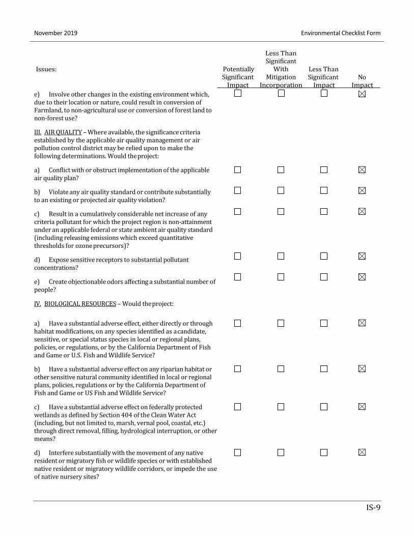
e) Involve other changes in the existing environment which,
due to their location or nature, could result in conversion of
Farmland, to non-agricultural use or conversion of forest land to
non-forest use?
III. AIR QUALITY – Where available, the significance criteria
established by the applicable air quality management or air
pollution control district may be relied upon to make the
following determinations. Would the project:
a) Conflict with or obstruct implementation of the applicable
air quality plan?
b) Violate any air quality standard or contribute substantially
to an existing or projected air quality violation?
c) Result in a cumulatively considerable net increase of any
criteria pollutant for which the project region is non-attainment
under an applicable federal or state ambient air quality standard
(including releasing emissions which exceed quantitative
thresholds for ozone precursors)?
d) Expose sensitive receptors to substantial pollutant
concentrations?
e) Create objectionable odors affecting a substantial number of
people?
IV. BIOLOGICAL RESOURCES – Would the project:
Impact Incorporation Impact Impact
a) Have a substantial adverse effect, either directly or through habitat modifications, on any species identified as a candidate,
sensitive, or special status species in local or regional plans,
policies, or regulations, or by the California Department of Fish
and Game or U.S. Fish and Wildlife Service?
b) Have a substantial adverse effect on any riparian habitat or
other sensitive natural community identified in local or regional
plans, policies, regulations or by the California Department of
Fish and Game or US Fish and Wildlife Service?
c) Have a substantial adverse effect on federally protected wetlands as defined by Section 404 of the Clean Water Act
(including, but not limited to, marsh, vernal pool, coastal, etc.)
through direct removal, filling, hydrological interruption, or other
means?
d) Interfere substantially with the movement of any native resident or migratory fish or wildlife species or with established
native resident or migratory wildlife corridors, or impede the use
of native nursery sites?
Environmental Checklist Form November 2019
IS-10
Issues: Potentially
Significant
Less Than
Significant
With
Mitigation
Less Than
Significant No
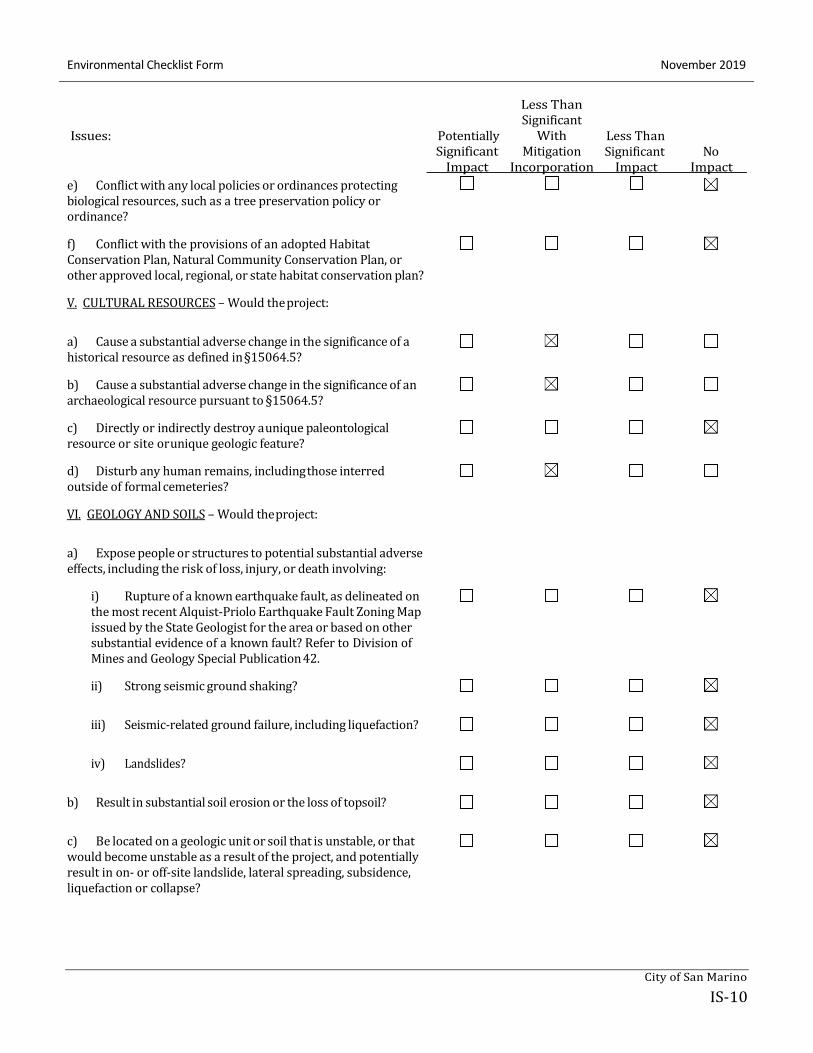
e) Conflict with any local policies or ordinances protecting
biological resources, such as a tree preservation policy or
ordinance?
f) Conflict with the provisions of an adopted Habitat
Conservation Plan, Natural Community Conservation Plan, or
other approved local, regional, or state habitat conservation plan?
V. CULTURAL RESOURCES – Would the project:
Impact Incorporation Impact Impact
a) Cause a substantial adverse change in the significance of a historical resource as defined in §15064.5?
b) Cause a substantial adverse change in the significance of an
archaeological resource pursuant to §15064.5?
c) Directly or indirectly destroy a unique paleontological resource or site or unique geologic feature?
d) Disturb any human remains, including those interred outside of formal cemeteries?
VI. GEOLOGY AND SOILS – Would the project:
a) Expose people or structures to potential substantial adverse
effects, including the risk of loss, injury, or death involving:
i) Rupture of a known earthquake fault, as delineated on the most recent Alquist-Priolo Earthquake Fault Zoning Map
issued by the State Geologist for the area or based on other
substantial evidence of a known fault? Refer to Division of
Mines and Geology Special Publication 42.
ii) Strong seismic ground shaking?
iii) Seismic-related ground failure, including liquefaction?
iv) Landslides?
b) Result in substantial soil erosion or the loss of topsoil?
c) Be located on a geologic unit or soil that is unstable, or that would become unstable as a result of the project, and potentially
result in on- or off-site landslide, lateral spreading, subsidence,
liquefaction or collapse?
City of San Marino
November 2019 Environmental Checklist Form
IS-11
Issues: Potentially
Significant
Less Than
Significant
With
Mitigation
Less Than
Significant No
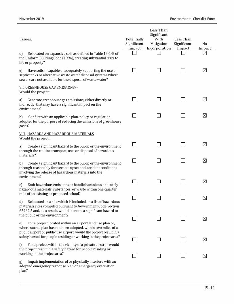
d) Be located on expansive soil, as defined in Table 18-1-B of
the Uniform Building Code (1994), creating substantial risks to
life or property?
e) Have soils incapable of adequately supporting the use of
septic tanks or alternative waste water disposal systems where
sewers are not available for the disposal of waste water?
VII. GREENHOUSE GAS EMISSIONS --
Would the project:
a) Generate greenhouse gas emissions, either directly or
indirectly, that may have a significant impact on the
environment?
b) Conflict with an applicable plan, policy or regulation
adopted for the purpose of reducing the emissions of greenhouse
gases?
VIII. HAZARDS AND HAZARDOUS MATERIALS –
Would the project:
a) Create a significant hazard to the public or the environment
through the routine transport, use, or disposal of hazardous
materials?
b) Create a significant hazard to the public or the environment
through reasonably foreseeable upset and accident conditions
involving the release of hazardous materials into the
environment?
c) Emit hazardous emissions or handle hazardous or acutely
hazardous materials, substances, or waste within one-quarter
mile of an existing or proposed school?
d) Be located on a site which is included on a list of hazardous
materials sites compiled pursuant to Government Code Section
65962.5 and, as a result, would it create a significant hazard to
the public or the environment?
e) For a project located within an airport land use plan or,
where such a plan has not been adopted, within two miles of a
public airport or public use airport, would the project result in a
safety hazard for people residing or working in the project area?
f) For a project within the vicinity of a private airstrip, would
the project result in a safety hazard for people residing or
working in the project area?
g) Impair implementation of or physically interfere with an
adopted emergency response plan or emergency evacuation
plan?
Impact Incorporation Impact Impact
Environmental Checklist Form November 2019
IS-12
Issues: Potentially
Significant
Less Than
Significant
With
Mitigation
Less Than
Significant No
h) Expose people or structures to a significant risk of loss,
injury or death involving wildland fires, including where
wildlands are adjacent to urbanized areas or where residences
are intermixed with wildlands?
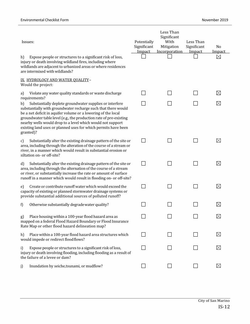
IX. HYDROLOGY AND WATER QUALITY –
Would the project:
a) Violate any water quality standards or waste discharge
requirements?
b) Substantially deplete groundwater supplies or interfere
substantially with groundwater recharge such that there would
be a net deficit in aquifer volume or a lowering of the local
groundwater table level (e.g., the production rate of pre-existing
nearby wells would drop to a level which would not support
existing land uses or planned uses for which permits have been
granted)?
Impact Incorporation Impact Impact
c) Substantially alter the existing drainage pattern of the site or area, including through the alteration of the course of a stream or
river, in a manner which would result in substantial erosion or
siltation on- or off-site?
d) Substantially alter the existing drainage pattern of the site or area, including through the alternation of the course of a stream
or river, or substantially increase the rate or amount of surface
runoff in a manner which would result in flooding on- or off-site?
e) Create or contribute runoff water which would exceed the capacity of existing or planned stormwater drainage systems or
provide substantial additional sources of polluted runoff?
f) Otherwise substantially degrade water quality?
g) Place housing within a 100-year flood hazard area as mapped on a federal Flood Hazard Boundary or Flood Insurance
Rate Map or other flood hazard delineation map?
h) Place within a 100-year flood hazard area structures which would impede or redirect flood flows?
i) Expose people or structures to a significant risk of loss, injury or death involving flooding, including flooding as a result of
the failure of a levee or dam?
j) Inundation by seiche, tsunami, or mudflow?
City of San Marino
November 2019 Environmental Checklist Form
IS-13
X
Issues: Potentially
Significant
Less Than
Significant
With
Mitigation
Less Than
Significant No
Impact Incorporation Impact Impact
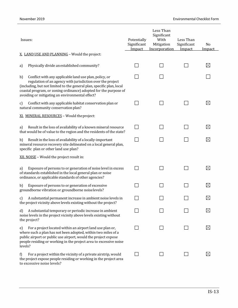
X. LAND USE AND PLANNING – Would the project:
a) Physically divide an established community?
b) Conflict with any applicable land use plan, policy, or
regulation of an agency with jurisdiction over the project
(including, but not limited to the general plan, specific plan, local
coastal program, or zoning ordinance) adopted for the purpose of
avoiding or mitigating an environmental effect?
c) Conflict with any applicable habitat conservation plan or natural community conservation plan?
XI. MINERAL RESOURCES – Would the project:
a) Result in the loss of availability of a known mineral resource
that would be of value to the region and the residents of the state?
b) Result in the loss of availability of a locally-important mineral resource recovery site delineated on a local general plan,
specific plan or other land use plan?
XII. NOISE – Would the project result in:
a) Exposure of persons to or generation of noise level in excess of standards established in the local general plan or noise
ordinance, or applicable standards of other agencies?
b) Exposure of persons to or generation of excessive groundborne vibration or groundborne noise levels?
c) A substantial permanent increase in ambient noise levels in the project vicinity above levels existing without the project?
d) A substantial temporary or periodic increase in ambient noise levels in the project vicinity above levels existing without
the project?
e) For a project located within an airport land use plan or, where such a plan has not been adopted, within two miles of a
public airport or public use airport, would the project expose
people residing or working in the project area to excessive noise
levels?
f) For a project within the vicinity of a private airstrip, would the project expose people residing or working in the project area
to excessive noise levels?
Environmental Checklist Form November 2019
IS-14
Issues: Potentially
Significant
Less Than
Significant
With
Mitigation
Less Than
Significant No
Impact Incorporation Impact Impact
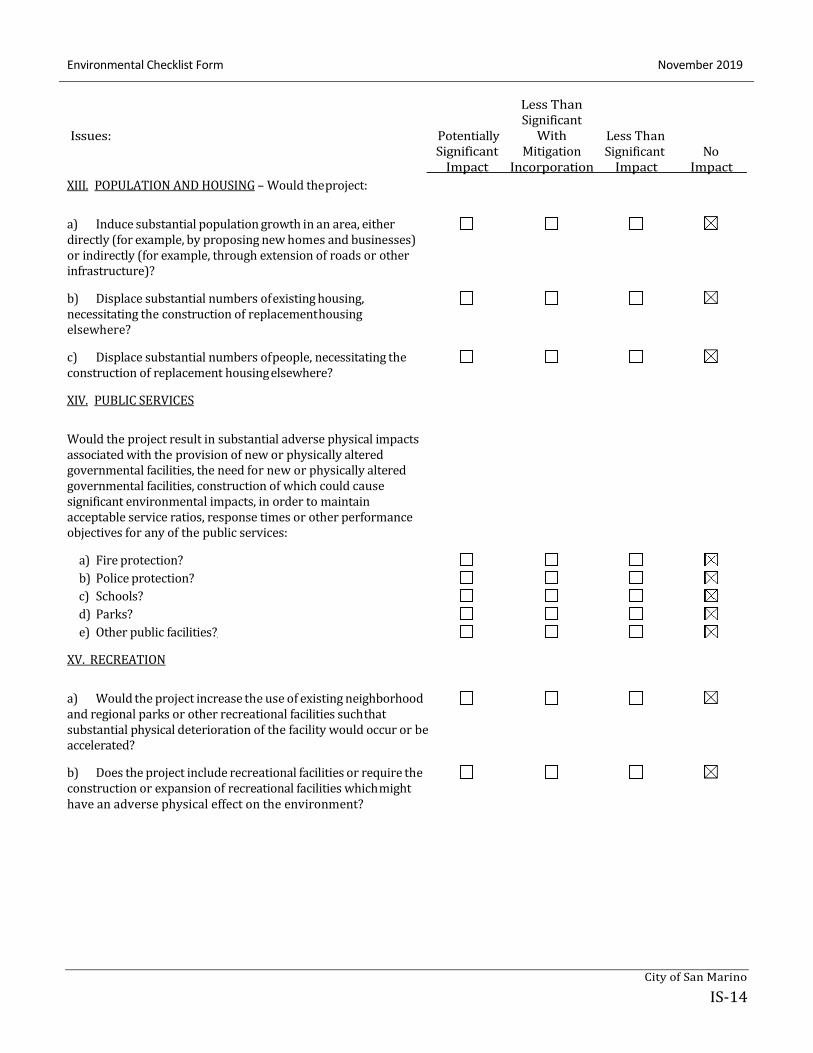
XIII. POPULATION AND HOUSING – Would the project:
a) Induce substantial population growth in an area, either directly (for example, by proposing new homes and businesses)
or indirectly (for example, through extension of roads or other
infrastructure)?
b) Displace substantial numbers of existing housing,
necessitating the construction of replacement housing
elsewhere?
c) Displace substantial numbers of people, necessitating the construction of replacement housing elsewhere?
XIV. PUBLIC SERVICES
Would the project result in substantial adverse physical impacts
associated with the provision of new or physically altered
governmental facilities, the need for new or physically altered
governmental facilities, construction of which could cause
significant environmental impacts, in order to maintain
acceptable service ratios, response times or other performance
objectives for any of the public services:
a) Fire protection?
b) Police protection?
c) Schools?
d) Parks?
e) Other public facilities?
XV. RECREATION
a) Would the project increase the use of existing neighborhood and regional parks or other recreational facilities such that
substantial physical deterioration of the facility would occur or be
accelerated?
b) Does the project include recreational facilities or require the construction or expansion of recreational facilities which might
have an adverse physical effect on the environment?
City of San Marino
November 2019 Environmental Checklist Form
IS-15
Issues: Potentially
Significant
Less Than
Significant
With
Mitigation
Less Than
Significant No
Impact Incorporation Impact Impact
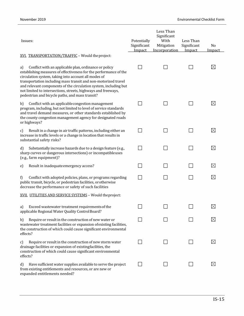
XVI. TRANSPORTATION/TRAFFIC – Would the project:
a) Conflict with an applicable plan, ordinance or policy
establishing measures of effectiveness for the performance of the
circulation system, taking into account all modes of
transportation including mass transit and non-motorized travel
and relevant components of the circulation system, including but
not limited to intersections, streets, highways and freeways,
pedestrian and bicycle paths, and mass transit?
b) Conflict with an applicable congestion management program, including, but not limited to level of service standards
and travel demand measures, or other standards established by
the county congestion management agency for designated roads
or highways?
c) Result in a change in air traffic patterns, including either an increase in traffic levels or a change in location that results in
substantial safety risks?
d) Substantially increase hazards due to a design feature (e.g., sharp curves or dangerous intersections) or incompatible uses
(e.g., farm equipment)?
e) Result in inadequate emergency access?
f) Conflict with adopted policies, plans, or programs regarding public transit, bicycle, or pedestrian facilities, or otherwise
decrease the performance or safety of such facilities
XVII. UTILITIES AND SERVICE SYSTEMS – Would the project:
a) Exceed wastewater treatment requirements of the applicable Regional Water Quality Control Board?
b) Require or result in the construction of new water or wastewater treatment facilities or expansion of existing facilities,
the construction of which could cause significant environmental
effects?
c) Require or result in the construction of new storm water drainage facilities or expansion of existing facilities, the
construction of which could cause significant environmental
effects?
d) Have sufficient water supplies available to serve the project
from existing entitlements and resources, or are new or
expanded entitlements needed?
Environmental Checklist Form November 2019
IS-16
Issues: Potentially
Significant
Less Than
Significant
With
Mitigation
Less Than
Significant No
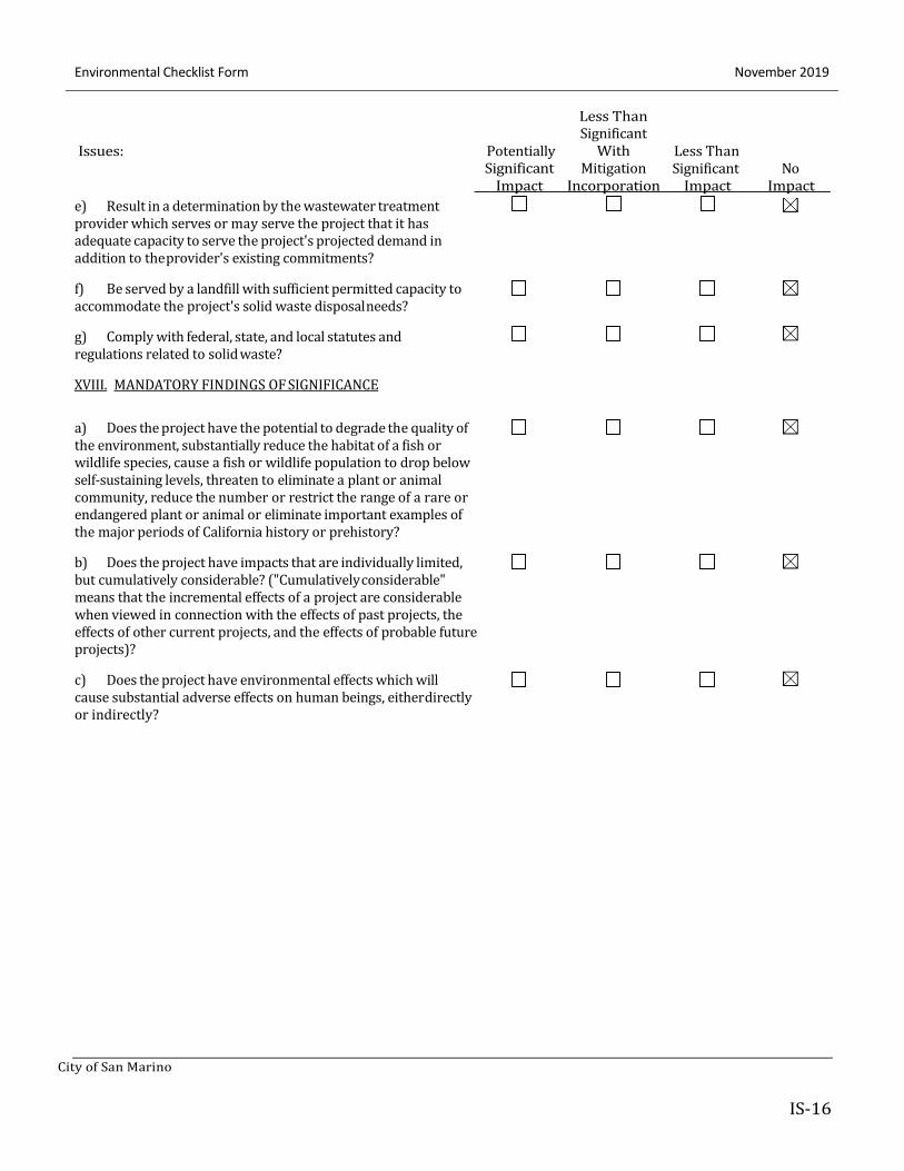
e) Result in a determination by the wastewater treatment
provider which serves or may serve the project that it has
adequate capacity to serve the project's projected demand in
addition to the provider's existing commitments?
f) Be served by a landfill with sufficient permitted capacity to
accommodate the project's solid waste disposal needs?
g) Comply with federal, state, and local statutes and
regulations related to solid waste?
XVIII. MANDATORY FINDINGS OF SIGNIFICANCE
Impact Incorporation Impact Impact
a) Does the project have the potential to degrade the quality of the environment, substantially reduce the habitat of a fish or
wildlife species, cause a fish or wildlife population to drop below
self-sustaining levels, threaten to eliminate a plant or animal
community, reduce the number or restrict the range of a rare or
endangered plant or animal or eliminate important examples of
the major periods of California history or prehistory?
b) Does the project have impacts that are individually limited, but cumulatively considerable? ("Cumulatively considerable"
means that the incremental effects of a project are considerable
when viewed in connection with the effects of past projects, the
effects of other current projects, and the effects of probable future
projects)?
c) Does the project have environmental effects which will cause substantial adverse effects on human beings, either directly
or indirectly?
City of San Marino
November 2019 Environmental Checklist Form
IS-17
Mitigation Measure
Mitigation
Monitoring
Timing
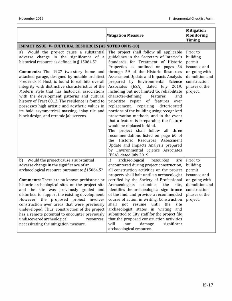
IMPACT ISSUE: V- CULTURAL RESOURCES (AS NOTED ON IS-10)
a) Would the project cause a substantial
adverse change in the significance of a
historical resource as defined in § 15064.5?
Comments: The 1927 two-story home and
attached garage, designed by notable architect
Frederick F. Hust, is found to exhibits overall
integrity with distinctive characteristics of the
Modern style that has historical associations
with the development patterns and cultural
history of Tract 6012. The residence is found to
possesses high artistic and aesthetic values in
its bold asymmetrical massing, inlay tile and
block design, and ceramic Jali screens.
The project shall follow all applicable
guidelines in the Secretary of Interior’s
Standards for Treatment of Historic
Properties as outlined on pages 56
through 59 of the Historic Resources
Assessment Update and Impacts Analysis
prepared by Environmental Science
Associates (ESA), dated July 2019,
including but not limited to, rehabilitate
character-defining features and
prioritize repair of features over
replacement, repairing deteriorated
portions of the building using recognized
preservation methods, and in the event
that a feature is irreparable, the feature
would be replaced in-kind.
The project shall follow all three
recommendations listed on page 60 of
the Historic Resources Assessment
Update and Impacts Analysis prepared
by Environmental Science Associates
(ESA), dated July 2019.
Prior to
building
permit
issuance and
on-going with
demolition and
construction
phases of the
project.
b) Would the project cause a substantial
adverse change in the significance of an
archaeological resource pursuant to §15064.5?
Comments: There are no known prehistoric or
historic archeological sites on the project site
and the site was previously graded and
disturbed to support the existing development.
However, the proposed project involves
construction over areas that were previously
undeveloped. Thus, construction of the project
has a remote potential to encounter previously
undiscovered archeological resources,
necessitating the mitigation measure.
If archaeological resources are
encountered during project construction,
all construction activities on the project
property shall halt until an archaeologist
certified by the Society of Professional
Archaeologists examines the site,
identifies the archaeological significance
of the find, and provide a recommended
course of action in writing. Construction
shall not resume until the site
archaeologist states in writing and
submitted to City staff for the project file
that the proposed construction activities
will not damage significant
archaeological resource.
Prior to
building
permit
issuance and
on-going with
demolition and
construction
phases of the
project.
November 2019 Environmental Checklist Form
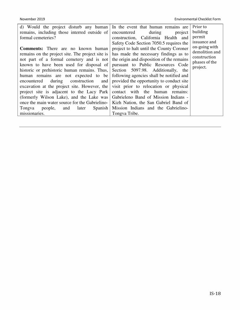
IS-18
d) Would the project disturb any human
remains, including those interred outside of
formal cemeteries?
Comments: There are no known human
remains on the project site. The project site is
not part of a formal cemetery and is not
known to have been used for disposal of
historic or prehistoric human remains. Thus,
human remains are not expected to be
encountered during construction and
excavation at the project site. However, the
project site is adjacent to the Lacy Park
(formerly Wilson Lake), and the Lake was
once the main water source for the Gabrielino-
Tongva people, and later Spanish
missionaries.
In the event that human remains are
encountered during project
construction, California Health and
Safety Code Section 7050.5 requires the
project to halt until the County Coroner
has made the necessary findings as to
the origin and disposition of the remains
pursuant to Public Resources Code
Section 5097.98. Additionally, the
following agencies shall be notified and
provided the opportunity to conduct site
visit prior to relocation or physical
contact with the human remains:
Gabrieleno Band of Mission Indians -
Kizh Nation, the San Gabriel Band of
Mission Indians and the Gabrielino-
Tongva Tribe.
Prior to
building
permit
issuance and
on-going with
demolition and
construction
phases of the
project.
3325 Monterey Road
City of San Marino
B-1
ATTACHMENT B - EXPLANATION OF CHECKLIST DETERMINATION
I. AESTHETICS
Would the project:
a) Have a substantial adverse effect on a scenic vista?
No Impact. The proposed project will not have a substantial adverse effect on a scenic vista. The project
consists of a one and two-story addition to an existing two-story residence, removal of two detached
accessory structures (carport and guest house) and construction of a detached three-car garage. The project
will also be reviewed by the Design Review Committee to ensure compatibility with the surrounding
neighborhood.
b) Substantially damage scenic resources, including, but not limited to, trees, rock
outcroppings, and historic buildings within a state scenic highway?
No Impact. There are no state scenic highways within the city. Therefore, the project would not
substantially damage a scenic resource along a state scenic highway.
c) Substantially degrade the existing visual character or quality of the site and its
surroundings?
No Impact. There will be no degrading of the existing visual character. The project provides rehabilitation
and replacement of in-kind architectural features found on the existing residence and hardscape
improvement compatible with the style of the residence. The project will also be reviewed by the Design
Review Committee to ensure compatibility with the site and surrounding neighborhood.
d) Create a new source of substantial light or glare which would adversely affect day
or nighttime views in the area?
No Impact. The lighting associated with the project consists of light fixtures on the building that are typical
of other single-family homes in the area and that are required by building codes. There is no type of lighting
proposed that would create a substantial source of light or glare.
II. AGRICULTURE AND FOREST RESOURCES
In determining whether impacts to agricultural resources are significant environmental effects, lead agencies
may refer to the California Agricultural Land Evaluation and Site Assessment Model (1997) prepared by the
California Dept. of Conservation as an optional model to use in assessing impacts on agriculture and farmland.
In determining whether impacts to forest resources, including timberland, are significant environmental effects,
lead agencies may refer to information compiled by the California Department of Forestry and Fire Protection
regarding the state’s inventory of forest land, including the Forest and Range Assessment Project and the Forest
Attachment B - Explanation Of Checklist Determination December 2019
B-2
Legacy Assessment project; and forest carbon measurement methodology provided in Forest Protocols adopted
by the California Air Resources Board. Would the project:
a) Convert Prime Farmland, Unique Farmland, or Farmland of Statewide Importance
(Farmland), as shown on the maps prepared pursuant to the Farmland Mapping and
Monitoring Program of the California Resources Agency, to non-agricultural use?
No Impact. The Project site has been developed with institutional uses since 1919 and is located within an
urban area. Although there is a history of agricultural use within the San Marino city boundary, including
citrus and avocado groves going back to the early 1900s, the Project site does not include farmland and has
not been mapped as Prime Farmland, Unique Farmland, or Farmland of Statewide Importance pursuant to
the Farmland Mapping and Monitoring Program of the California Resources Agency.
b) Conflict with existing zoning for agricultural use, or a Williamson Act contract?
No Impact. There are no agricultural lands on the site or designated in the City of San Marino General Plan.
Furthermore, no lands within the Project site are under a Williamson Act contract. Therefore, no impacts
associated with a conflict with agricultural zoning or Williamson Act contracts would occur.
c) Conflict with existing zoning for, or cause rezoning of, forest land (as defined in
Public Resources Code section 12220(g)), timberland (as defined by Public Resources
Code section 4526), or timberland zoned Timberland Production (as defined by
Government Code section 51104(g))?
No Impact. The City of San Marino has no designated forest land or timberland. Because the Project site is
not designated as timberland or forest land, it would not cause any changes with respect to this issue.
Therefore, no impact would occur.
d) Result in the loss of forest land or conversion of forest land to non-forest use?
No Impact. As described in Response II.c, no impact would occur on forest land.
e) Involve other changes in the existing environment which, due to their location or
nature, could result in conversion of Farmland, to non-agricultural use or conversion of
forest land to non-forest use?
No Impact. As previously described, no farmland or forest land is located on the Project site. Therefore, no
impact on farmland or forest land would occur.
December 2019 Attachment B - Explanation Of Checklist Determination
City of San Marino
B-3
III. AIR QUALITY
Where available, the significance criteria established by the applicable air quality management or air pollution
control district may be relied upon to make the following determinations. Would the project:
a) Conflict with or obstruct implementation of the applicable air quality plan?
No Impact. The project will not conflict with the applicable air quality plan. The project proposes to
construct an addition to an existing residential structure which remain within the allowable residential
density in accordance with the City’s General Plan.
b) Violate any air quality standard or contribute substantially to an existing or
projected air quality violation?
No Impact. The scale and use of the proposed project would not have the potential to violate air quality
standards or contribute substantially to an existing or projected air quality violation.
c) Result in a cumulatively considerable net increase of any criteria pollutant for
which the project region is non-attainment under an applicable federal or state ambient
air quality standard (including releasing emissions which exceed quantitative thresholds
for ozone precursors)?
No Impact. The expansion of an existing residential structure that will remain as a single-family residence
would not result in a considerable net increase of pollutants.
d) Expose sensitive receptors to substantial pollutant concentrations?
No Impact. Sensitive receptors in the area include the surrounding single-family homes. The proposed
project consists of the expansion of a single-family home, the use of which would not generate pollutants.
Construction of this scale would not generate substantial pollutant concentrations.
e) Create objectionable odors affecting a substantial number of people?
No Impact. The finished project would not create objectionable odors that would affect a substantial
number of peoples. There is the potential for the construction to temporarily generate odors that would be
detectible only in the immediate area. However, these odors would be typical for construction activities and
are subject to San Marino Municipal Code Section 10.03.03 related to smoke, duct, and fumes.
Attachment B - Explanation Of Checklist Determination December 2019
B-4
IV. BIOLOGICAL RESOURCES
Would the project:
a) Have a substantial adverse effect, either directly or through habitat
modifications, on any species identified as a candidate, sensitive, or special status
species in local or regional plans, policies, or regulations, or by the California
Department of Fish and Game or U.S. Fish and Wildlife Service?
No Impact. The project would not have an adverse impact on wildlife or their habitats. The proposed
building expansion will be constructed in an urbanized area. Therefore, there will be no potential damage to
a sensitive species or its habitat.
b) Have a substantial adverse effect on any riparian habitat or other sensitive
natural community identified in local or regional plans, policies, regulations or by the
California Department of Fish and Game or US Fish and Wildlife Service?
No Impact. No impact. The City has no riparian habitats.
c) Have a substantial adverse effect on federally protected wetlands as defined by
Section 404 of the Clean Water Act (including, but not limited to, marsh, vernal pool,
coastal, etc.) through direct removal, filling, hydrological interruption, or other means?
No Impact. No impact. There are no federally protected wetlands in the City.
d) Interfere substantially with the movement of any native resident or migratory fish
or wildlife species or with established native resident or migratory wildlife corridors, or
impede the use of native nursery sites?
No impact. The project proposes to expand an existing single-family structure with minor expansion on the
overall building footprint. There are no established native wildlife corridors that would be impacted by the
project.
e) Conflict with any local policies or ordinances protecting biological resources, such
as a tree preservation policy or ordinance?
No Impact. The project would not conflict with any local policies protecting biological resources.
Furthermore, the Project subject to the City’s Tree Preservation Ordinance.
December 2019 Attachment B - Explanation Of Checklist Determination
City of San Marino
B-5
f) Conflict with the provisions of an adopted Habitat Conservation Plan, Natural
Community Conservation Plan, or other approved local, regional, or state habitat
conservation plan?
No Impact. The project will not impact any conservation plan because no such resources exist in the City.
V. CULTURAL RESOURCES
Would the project:
a) Cause a substantial adverse change in the significance of a historical resource as
defined in §15064.5?
Less than significant with mitigation. The Project site has been determined eligible for listing on the
National Register of Historic Places, the California Register of Historical Resources, and as a local landmark.
The two-story residence and attached garage, designed by notable architect Frederick F. Hust, construct in
1927 is found to exhibits overall integrity with distinctive characteristics of the Modern style that has
historical associations with the development patterns and cultural history of Tract 6012. The residence is
found to possesses high artistic and aesthetic values in its bold asymmetrical massing, inlay tile and block
design, and ceramic Jali screens.
The proposed project includes mitigation measures than would reduce the impact on the historic resources to
less than significance. The mitigation measures are listed on IS 17 and IS 18.
b) Cause a substantial adverse change in the significance of an archaeological
resource pursuant to §15064.5?
Less than significant with mitigation. No part of the City is known to have prehistoric or historic
archeological resources. Although the project site was previously graded and disturbed to support the
existing residence. The proposed expansion involves construction over areas that were previously
undeveloped. Thus, construction of the project has a remote potential to encounter previously undiscovered
archeological resources, necessitating the mitigation measure listed on IS 17 and IS18.
c) Directly or indirectly destroy a unique paleontological resource or site or unique
geologic feature?
No Impact. No part of the City is known to have paleontological resources or unique geologic features.
Attachment B - Explanation Of Checklist Determination December 2019
B-6
d) Disturb any human remains, including those interred outside of formal
cemeteries?
Less than significant with mitigation. No part of the City is known to have human remains outside of formal
cemeteries. The project site is not part of a formal cemetery and is not known to have been used for
disposal of historic or prehistoric human remains. Thus, human remains are not expected to be
encountered during construction and excavation at the project site. However, the project site is adjacent to
the Lacy Park (formerly Wilson Lake), and the Lake was once the main water source for the Gabrielino-
Tongva people, and later Spanish missionaries.
In accordance with applicable state law, in the unlikely event that human remains are encountered during
project construction, California Health and Safety Code Section 7050.5 requires the project to halt until
the County Coroner has made the necessary findings as to the origin and disposition of the remains
pursuant to Public Resources Code Section 5097.98. Additionally, the following agencies shall be notified
and provided the opportunity to conduct site visit prior to relocation or physical contact with the human
remains: Gabrieleno Band of Mission Indians - Kizh Nation, the San Gabriel Band of Mission Indians and
the Gabrielino- Tongva Tribe.
VI. GEOLOGY AND SOILS
Would the project:
a) Expose people or structures to potential substantial adverse effects, including the
risk of loss, injury, or death involving:
i) Rupture of a known earthquake fault, as delineated on the most recent Alquist-Priolo Earthquake
Fault Zoning Map issued by the State Geologist for the area or based on other substantial evidence
of a known fault? Refer to Division of Mines and Geology Special Publication 42.
No Impact. The project site is not located in an Alquist-Priolo Earthquake Fault zone and therefore, would
not expose people or structures to potential substantial adverse effects from seismic ground shaking.
ii) Strong seismic ground shaking?
No Impact. The project will adhere to all current seismic safety requirements and therefore, would not
expose people or structures to potential substantial adverse effects from seismic ground shaking.
iii) Seismic-related ground failure, including liquefaction?
No Impact. According to the California Geological Survey the site is not located within an area identified as
having a potential for liquefaction. In addition, as indicated on the City of San Marino General Plan Hazards
Map, the Project site is not within a designated Liquefaction Zone.
December 2019 Attachment B - Explanation Of Checklist Determination
City of San Marino
B-7
iv) Landslides?
No Impact. The topography of the Project site is either relatively level or gently sloping.
b) Result in substantial soil erosion or the loss of topsoil?
No Impact. The project will follow all City requirements related to the prevention of soil erosion, therefore,
substantial soil erosion would not occur.
c) Be located on a geologic unit or soil that is unstable, or that would become
unstable as a result of the project, and potentially result in on- or off-site landslide,
lateral spreading, subsidence, liquefaction or collapse?
No Impact. The project will be construction in a developed area and will have minor expansion from the
existing building footprint. It will not cause soil to become unstable.
d) Be located on expansive soil, as defined in Table 18-1-B of the Uniform Building
Code (1994), creating substantial risks to life or property?
No Impact. The Project site do not consist of expansive clay soils.
e) Have soils incapable of adequately supporting the use of septic tanks or
alternative waste water disposal systems where sewers are not available for the
disposal of waste water?
No Impact. The project will be served by existing sewer infrastructure.
VII. GREENHOUSE GAS EMISSIONS --
Would the project:
a) Generate greenhouse gas emissions, either directly or indirectly, that may have a
significant impact on the environment?
No Impact. The expansion of a single-family residence would not generate greenhouse gases that would
have a significant impact on the environment.
b) Conflict with an applicable plan, policy or regulation adopted for the purpose of
reducing the emissions of greenhouse gases?
No Impact. The project would comply with any applicable regulations relating to reducing greenhouse gas
emissions.
Attachment B - Explanation Of Checklist Determination December 2019
B-8
VIII. HAZARDS AND HAZARDOUS MATERIALS –
Would the project:
a) Create a significant hazard to the public or the environment through the routine
transport, use, or disposal of hazardous materials?
No Impact. The hazardous materials that would be associated with the project include common household
products, such as cleaning agents, pesticides or paints. Use of these items would be subject to all applicable
regulations. These items would not create a significant hazard to the public or environment.
b) Create a significant hazard to the public or the environment through reasonably
foreseeable upset and accident conditions involving the release of hazardous materials
into the environment?
No Impact. The hazardous materials that would be associated with the project include common household
products, such as cleaning agents, pesticides or paints. Use of these items would be subject to all applicable
regulations. These items would not create a significant hazard to the public or environment.
c) Emit hazardous emissions or handle hazardous or acutely hazardous materials,
substances, or waste within one-quarter mile of an existing or proposed school?
No Impact. The hazardous materials that would be associated with the project include common household
products, such as cleaning agents, pesticides or paints. Use of these items would be subject to all applicable
regulations. These items would not create a significant hazard to the public or environment. There are no
schools within one-quarter mile of the project site.
d) Be located on a site which is included on a list of hazardous materials sites
compiled pursuant to Government Code Section 65962.5 and, as a result, would it
create a significant hazard to the public or the environment?
No Impact. Staff has reviewed the hazardous sites listed under Government Code Section 65962.5 and has
found that none exist in the City of San Marino.
e) For a project located within an airport land use plan or, where such a plan has not
been adopted, within two miles of a public airport or public use airport, would the
project result in a safety hazard for people residing or working in the project area?
No Impact. No part of the City is located within an airport land use plan.
December 2019 Attachment B - Explanation Of Checklist Determination
City of San Marino
B-9
f) For a project within the vicinity of a private airstrip, would the project result in a
safety hazard for people residing or working in the project area?
No Impact. No part of the City is located near a private airstrip.
g) Impair implementation of or physically interfere with an adopted emergency
response plan or emergency evacuation plan?
No Impact. No street closures or main access points would be impacted as a result of the project. The
project will not interfere with an emergency evacuation plan.
h) Expose people or structures to a significant risk of loss, injury or death involving
wildland fires, including where wildlands are adjacent to urbanized areas or where
residences are intermixed with wildlands?
No Impact. There are no wildland areas in the City.
IX. HYDROLOGY AND WATER QUALITY –
Would the project:
a) Violate any water quality standards or waste discharge requirements?
No Impact. The project would comply with all applicable water quality standards and waste discharge
requirements.
b) Substantially deplete groundwater supplies or interfere substantially with
groundwater recharge such that there would be a net deficit in aquifer volume or a
lowering of the local groundwater table level (e.g., the production rate of pre-existing
nearby wells would drop to a level which would not support existing land uses or
planned uses for which permits have been granted)?
No Impact. The project would not interfere with ground water supplies and site landscaping would be in
compliance with applicable codes which encourage groundwater retention.
c) Substantially alter the existing drainage pattern of the site or area, including
through the alteration of the course of a stream or river, in a manner which would
result in substantial erosion or siltation on- or off-site?
No Impact. The project would not substantially alter the existing drainage pattern.
Attachment B - Explanation Of Checklist Determination December 2019
B-10
d) Substantially alter the existing drainage pattern of the site or area, including
through the alternation of the course of a stream or river, or substantially increase the
rate or amount of surface runoff in a manner which would result in flooding on- or off-
site?
No Impact. The project would not substantially alter the existing drainage pattern.
e) Create or contribute runoff water which would exceed the capacity of existing or
planned stormwater drainage systems or provide substantial additional sources of
polluted runoff?
No Impact. The project would not create a substantial amount of runoff water.
f) Otherwise substantially degrade water quality?
No Impact. The project would comply with all water quality regulations and would not substantially
degrade water quality.
g) Place housing within a 100-year flood hazard area as mapped on a federal Flood
Hazard Boundary or Flood Insurance Rate Map or other flood hazard delineation map?
No Impact. No part of the City is within a 100-year flood hazard.
h) Place within a 100-year flood hazard area structures which would impede or
redirect flood flows?
No Impact. No part of the City is within a 100-year flood hazard.
i) Expose people or structures to a significant risk of loss, injury or death involving
flooding, including flooding as a result of the failure of a levee or dam?
No Impact. The project will not result in people being exposed to risks associated with flooding.
j) Inundation by seiche, tsunami, or mudflow?
No Impact. The Project site is located approximately 22 miles northeast of the Pacific Ocean and does not lie
in close proximity to an enclosed body of water. Therefore, the potential for exposure of people to a seiche
or tsunami would be low. As the Project site and surrounding area are relatively flat, the potential for
mudflows to occur on site is also low. As such, no impacts associated with the inundation of seiche, tsunami,
or mudflows would occur.
December 2019 Attachment B - Explanation Of Checklist Determination
City of San Marino
B-11
X. LAND USE AND PLANNING
Would the project:
a) Physically divide an established community?
No Impact. The project site will remain as a single-family residence with minor expansion to the existing
building footprint in compliance with applicable development standards such as building height, setbacks,
lot coverage, and impervious surface ratio. The project would not have the potential to physically divide an
existing community.
b) Conflict with any applicable land use plan, policy, or regulation of an agency with
jurisdiction over the project (including, but not limited to the general plan, specific plan,
local coastal program, or zoning ordinance) adopted for the purpose of avoiding or
mitigating an environmental effect?
No Impact. No impact. The project would not conflict with any established plan, policy or regulation that is
adopted for the purpose of mitigating an environmental effect.
c) Conflict with any applicable habitat conservation plan or natural community
conservation plan?
No Impact. There is no applicable conservation plan in the City.
XI. MINERAL RESOURCES
Would the project:
a) Result in the loss of availability of a known mineral resource that would be of
value to the region and the residents of the state?
No Impact. The Project site is located within an urbanized area and has been previously disturbed due to
the development of the existing buildings and landscaping. No mineral resources are known to exist within
the City of San Marino. Therefore, Project implementation would not result in the loss of availability of a
known mineral resource, and no impact would occur.
b) Result in the loss of availability of a locally-important mineral resource recovery
site delineated on a local general plan, specific plan or other land use plan?
No Impact. There is no mineral resource recovery site in the City.
Attachment B - Explanation Of Checklist Determination December 2019
B-12
XII. NOISE
Would the project result in:
a) Exposure of persons to or generation of noise level in excess of standards
established in the local general plan or noise ordinance, or applicable standards of
other agencies?
No Impact. The project may result in temporary construction noise; however, the project would be required
to be within the City Code regulations (Chapter 14, Article 4) regarding construction hours and allowable
noise levels.
b) Exposure of persons to or generation of excessive groundborne vibration or
groundborne noise levels?
No Impact. The expansion and associated construction activities for a two-story single-family residential
structure on an existing building site would not generate excessive groundborne vibration or noise levels.
c) A substantial permanent increase in ambient noise levels in the project vicinity
above levels existing without the project?
No Impact. Although there may be a temporary increase in construction related noise, the proposed
expansion will render the same single-family residential use on the project site. It would not result in a
permanent increase in ambient noise levels.
d) A substantial temporary or periodic increase in ambient noise levels in the project
vicinity above levels existing without the project?
No Impact. The project may result in temporary construction noise; however, the project would be required
to be within the City Code regulations (Chapter 14, Article 4) regarding construction hours and allowable
noise levels
e) For a project located within an airport land use plan or, where such a plan has not
been adopted, within two miles of a public airport or public use airport, would the
project expose people residing or working in the project area to excessive noise levels?
No Impact. No part of the City is located within an airport land use plan.
f) For a project within the vicinity of a private airstrip, would the project expose
people residing or working in the project area to excessive noise levels?
No Impact. No part of the City is located near a private airstrip.
December 2019 Attachment B - Explanation Of Checklist Determination
City of San Marino
B-13
XIII. POPULATION AND HOUSING
Would the project:
a) Induce substantial population growth in an area, either directly (for example, by
proposing new homes and businesses) or indirectly (for example, through extension of
roads or other infrastructure)?
No Impact. The project would not induce substantial population growth as it will only expand an existing
residential structure intended for one family.
b) Displace substantial numbers of existing housing, necessitating the construction
of replacement housing elsewhere?
No Impact. The project will demolish a detached guest house that has historically been use as an accessory
living area in addition to the main residential structure on site. The removal of this structure would not
displace existing housing units that trigger the need to provide replacement housing elsewhere within the
City.
c) Displace substantial numbers of people, necessitating the construction of
replacement housing elsewhere?
No Impact. The project would not displace any people. The property has been unoccupied for the past five
years.
XIV. PUBLIC SERVICES
Would the project result in substantial adverse physical impacts associated with the provision of new or
physically altered governmental facilities, the need for new or physically altered governmental facilities,
construction of which could cause significant environmental impacts, in order to maintain acceptable service
ratios, response times or other performance objectives for any of the public services:
a) Fire protection?
No Impact. The project will expand an existing single-family structure. The need for public services would
not increase and the expansion will comply with all current fire protection requirements.
b) Police protection?
No Impact. The project will remain as a single-family structure. The need for public services would not
increase.
Attachment B - Explanation Of Checklist Determination December 2019
B-14
c) Schools?
No Impact. The project will remain as a single-family structure. The need for public services would not
increase and the potential increase in school enrollment would be within the threshold of a single-family use.
d) Other Public Facilities?
No Impact. The project will remain as a single-family structure. The need for public services would not
increase.
XV. RECREATION
a) Would the project increase the use of existing neighborhood and regional parks
or other recreational facilities such that substantial physical deterioration of the facility
would occur or be accelerated?
No Impact. The project will remain as a single-family structure. The project does not have the potential to
result in a substantial population increase or generate substantial increased use of public facilities.
b) Does the project include recreational facilities or require the construction or
expansion of recreational facilities which might have an adverse physical effect on the
environment?
No Impact. The project does not include recreational facilities nor require the construction or expansion of
such facilities.
XVI. TRANSPORTATION/TRAFFIC
Would the project:
a) Conflict with an applicable plan, ordinance or policy establishing measures of
effectiveness for the performance of the circulation system, taking into account all
modes of transportation including mass transit and non-motorized travel and relevant
components of the circulation system, including but not limited to intersections, streets,
highways and freeways, pedestrian and bicycle paths, and mass transit?
No Impact. The project would not burden the circulation system to the extent of exceeding its capacity.
There are no other applicable congestion management programs.
b) Conflict with an applicable congestion management program, including, but not
limited to level of service standards and travel demand measures, or other standards
December 2019 Attachment B - Explanation Of Checklist Determination
City of San Marino
B-15
established by the county congestion management agency for designated roads or
highways?
No Impact. There are no applicable regulations regarding vehicle caps for a single-family use.
c) Result in a change in air traffic patterns, including either an increase in traffic
levels or a change in location that results in substantial safety risks?
No Impact. There would be no impact on air traffic patterns.
d) Substantially increase hazards due to a design feature (e.g., sharp curves or
dangerous intersections) or incompatible uses (e.g., farm equipment)?
No Impact. The project would not result in a change to any existing traffic features or patterns. No physical
alterations to public streets are proposed.
e) Result in inadequate emergency access?
No Impact. The project would not affect emergency access. No physical alterations to public streets are
proposed.
f) Conflict with adopted policies, plans, or programs regarding public transit,
bicycle, or pedestrian facilities, or otherwise decrease the performance or safety of such
facilities?
No Impact The project would have no conflict with alternative transportation policies.
XVII. UTILITIES AND SERVICE SYSTEMS
Would the project:
a) Exceed wastewater treatment requirements of the applicable Regional Water
Quality Control Board?
No Impact. The project renders a larger structure with one additional bedroom than the existing structure
and as such, has the potential to create additional wastewater. However, the increase would be minimal, and
the existing sewer and wastewater system would be more than adequate.
Attachment B - Explanation Of Checklist Determination December 2019
B-16
b) Require or result in the construction of new water or wastewater treatment
facilities or expansion of existing facilities, the construction of which could cause
significant environmental effects?
No Impact. The minimal increase in water usage/wastewater production that may occur because of the
project would not result in the need to construction a new water or wastewater treatment facility.
c) Require or result in the construction of new storm water drainage facilities or
expansion of existing facilities, the construction of which could cause significant
environmental effects?
No Impact. The use of the project site as well as the amount of pervious and impervious area would be
similar to existing conditions, resulting in similar storm water drainage conditions. Construction of a new
facility would not be necessary.
d) Have sufficient water supplies available to serve the project from existing
entitlements and resources, or are new or expanded entitlements needed?
No Impact. The project site will remain as a single-family use. The expansion project would implement
required water conservation measures and there would be sufficient water supply to accommodate this use.
e) Result in a determination by the wastewater treatment provider which serves or
may serve the project that it has adequate capacity to serve the project's projected
demand in addition to the provider's existing commitments?
No Impact. The project site will remain as a single-family use. The wastewater provider has adequate
capacity to accommodate the proposed expansion to the single-family residential unit.
f) Be served by a landfill with sufficient permitted capacity to accommodate the
project's solid waste disposal needs?
No Impact. There is sufficient landfill capacity for the proposed expansion to the single-family use.
g) Comply with federal, state, and local statutes and regulations related to solid
waste?
No Impact. The project would comply with all solid waste regulations.
December 2019 Attachment B - Explanation Of Checklist Determination
City of San Marino
B-17
XVIII. MANDATORY FINDINGS OF SIGNIFICANCE
a) Does the project have the potential to degrade the quality of the environment,
substantially reduce the habitat of a fish or wildlife species, cause a fish or wildlife
population to drop below self-sustaining levels, threaten to eliminate a plant or animal
community, reduce the number or restrict the range of a rare or endangered plant or
animal or eliminate important examples of the major periods of California history or
prehistory?
No Impact. The project would not have the potential to degrade the quality of the environment or
negatively impact fish or wildlife as it consists of expansion to an existing residential structure and
construction of a new detached garage.
As indicated under Section V – Cultural Resources, the Project site has been determined eligible for listing on
the National Register of Historic Places, the California Register of Historical Resources, and as a local
landmark. Therefore, the project includes mitigation measures than would reduce the impact on the historic
resources to less than significance. The mitigation measures are listed on IS 17 and IS 18.
b) Does the project have impacts that are individually limited, but cumulatively
considerable? ("Cumulatively considerable" means that the incremental effects of a
project are considerable when viewed in connection with the effects of past projects,
the effects of other current projects, and the effects of probable future projects)?
No Impact. The project plans show a swimming pool and spa located in the rear yard to be implemented at
a future date. Even when viewed together, the proposed expansion project plus the recreation amenities will
not result in a significant impact, primarily because they will not increase density on the property
Temporary increases in construction noise may occur but would be mitigated by City noise ordinances and
construction hours.
c) Does the project have environmental effects which will cause substantial adverse
effects on human beings, either directly or indirectly?
No Impact. The project would not cause substantial adverse impacts on human beings. It consists of
expansion to an existing residential structure and construction of a detached garage.
1
PLANNING AND BUILDING DEPARTMENT
STANDARD CONDITIONS
PROJECT NO: Design Review Nos. DRC19-80 and DRC19-81
SUBJECT: First and Second Story Addition and Exterior Modifications, and Construction of a detached 3-car garage.
APPLICANT: Yang/Design Inspiration Group Inc.
LOCATION: 3325 Monterey Road
ALL OF THE FOLLOWING CONDITIONS APPLY TO YOUR PROJECT.
APPLICANT SHALL CONTACT THE PLANNING DEPARTMENT, (626) 300-0710, FOR COMPLIANCE WITH THE FOLLOWING CONDITIONS:
A. General Requirements Completion Date
1. The applicant shall defend, indemnify, protect and hold harmless city, its elected and appointed council members, boards, commissions, officers, officials, agents, consultants, employees, and volunteers from and against any and all claims, actions, or proceeding against the city and its elected and appointed council members, boards, commissions, officers, officials, agents, consultants, employees and volunteers to attack, set aside, void or annul, an approval of the city, Design Review Committee, Planning Commission or City Council concerning this permit and the project. Such indemnification shall include damages, judgments, settlements, penalties, fines, defensive costs or expenses, including, but not limited to, interest, attorneys’ fees and expert witness fees, or liability of any kind related to or arising from such claim, action, or proceeding. The city shall promptly notify the applicant of any claim, action, or proceeding. Nothing contained herein shall prohibit city from participating in a defense of any claim, action or proceeding. The city shall have the option of coordinating the defense, including, but not limited to, choosing counsel for the defense at applicant’s expense.
___/___/___
2. Copies of the signed Design Review Committee Approval Letter, Standard Conditions, and all environmental mitigations shall be included on the plans (full size). The sheet(s) are for information only to all parties involved in the construction/grading activities and are not required to be wet sealed/stamped by a licensed Engineer/Architect.
___/___/___
B. Time Limits
1. Any approval shall expire if Building Permits are not issued or approved use has not commenced within 1 year from the date of approval or a time extension has been granted.
___/___/___
Project Nos. DRC19-80, DRC19-80
2
C. Site Development
1. Prior to submitting the project for structural plan check, the applicant shall submit proof of a qualified preservation professional who is responsible for the Preservation Treatment Plan and Construction Monitoring of the project as stated in the adopted Negative Mitigated Declaration.
2. Prior to obtaining Building Permits, the applicant shall submit an estimated construction schedule to Planning staff.
3. Prior to obtaining Building Permits, the applicant shall document the existing conditions at the subject property in a HABS Level III report. Said report shall include a sketch plan, exterior and interior views, and an architectural data form. The report shall be archivally produced and deposited in a publically accessible local library or museum archive.
4. The site shall be developed and maintained in accordance with the approved plans which include site plans, architectural elevations, exterior materials and colors, landscaping, and grading on file in the Planning and Building Department, the conditions contained herein, and the Zoning Code regulations.
___/___/___ ___/___/___ ___/___/___ ___/___/___
5. Prior to any use of the project site being commenced thereon, all Conditions of Approval shall be completed to the satisfaction of the Planning and Building Director.
___/___/___
6. Occupancy of the structure shall not commence until such time as all California Building Code and Fire Marshal regulations have been complied with. Prior to commencement of occupancy, plans shall be submitted to the San Marino Fire Department and the Building Department to show compliance. The structure shall be inspected for compliance and final acceptance granted prior to start of occupancy.
7. The master bedroom balcony shall be eliminated from the project.
___/___/___ ___/___/___

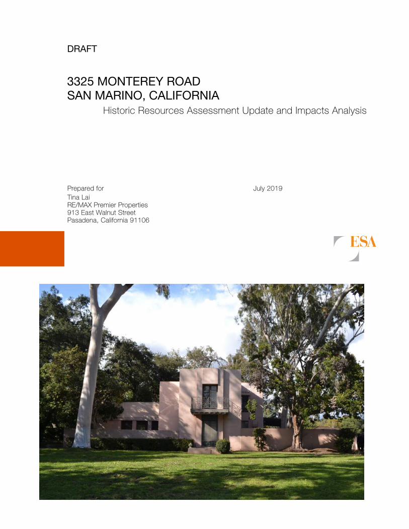
DRAFT
3325 MONTEREY ROAD SAN MARINO, CALIFORNIA
Historic Resources Assessment Update and Impacts Analysis
Prepared for July 2019 Tina Lai RE/MAX Premier Properties 913 East Walnut Street Pasadena, California 91106

DRAFT
3325 MONTEREY ROAD SAN MARINO, CALIFORNIA
Historic Resources Assessment Update and Impacts Analysis
Prepared for July 2019 Tina Lai RE/MAX Premier Properties 913 East Walnut Street Pasadena, California 91106
626 Wilshire Boulevard Suite 1100 Los Angeles, CA 90017 213.599.4300 esassoc.com
Bend
Camarillo
Delray Beach
Destin
Irvine
Los Angeles
Oakland
Orlando
Pasadena
Petaluma
Portland
Sacramento
San Diego
San Francisco
Santa Monica
Sarasota
Seattle
Tampa

OUR COMMITMENT TO SUSTAINABILITY | ESA helps a variety of public and private sector clients plan and prepare for climate change and emerging regulations that limit GHG emissions. ESA is a registered assessor with the California Climate Action Registry, a Climate Leader, and founding reporter for the Climate Registry. ESA is also a corporate member of the U.S. Green Building Council and the Business Council on Climate Change (BC3). Internally, ESA has adopted a Sustainability Vision and Policy Statement and a plan to reduce waste and energy within our operations. This document was produced using recycled paper.
3325 Monterey Road i ESA / D180090.00 Historic Resource Assessment Update and Impacts Analysis July 2019
TABLE OF CONTENTS Historic Resource Assessment Update and Impacts Analysis
Page
Introduction ........................................................................................................................... 1 Executive Summary ....................................................................................................... 1 Project Location ............................................................................................................. 2 Research and Field Methodology .................................................................................. 3
Regulatory Framework ......................................................................................................... 6 Federal Eligibility Criteria and Integrity Aspects ............................................................. 6
National Register of Historic Places ...................................................................... 6 State Register and Eligibility Criteria .............................................................................. 8
California Register of Historical Resources .......................................................... 8 California Historical Resources Status Codes .................................................... 10
Local Historic Preservation Ordinance and Eligibility Criteria ....................................... 11 City of San Marino Current Code ........................................................................ 11
Environmental Setting ........................................................................................................ 13 Historic Context ............................................................................................................ 13
City of San Marino (1900-1960) .......................................................................... 14 Modern Style (1920-1940) .................................................................................. 22 Construction and Occupancy History of 3325 Monterey Road ........................... 24
Evaluation ............................................................................................................................ 35 Historical resources identified ...................................................................................... 35
Previous Evaluations of the Subject Property ..................................................... 35 Evaluation of Potential Historical Resources within the Subject Property .................... 35
Architectural Description ..................................................................................... 35 National Register, California Register, City of San Marino ................................. 46 Integrity Analysis ................................................................................................. 49
Conclusion ................................................................................................................... 50
CEQA Analysis .................................................................................................................... 51 CEQA Guidelines ................................................................................................ 51
Project Description ....................................................................................................... 52 Analysis of Project Impacts .......................................................................................... 55
Direct Impacts ..................................................................................................... 55 Indirect Impacts .................................................................................................. 56
Secretary of the Interior’s Standards Reviews ............................................................. 56 Conclusion ................................................................................................................... 60
Bibliography ........................................................................................................................ 62
Table of Contents
Page
3325 Monterey Road ii ESA / D180090.01 Historic Resource Assessment Update and Impacts Analysis July 2019
Appendices
A. Professional Qualifications B. Tract Map C. Sanborn Maps D. Building Permits E. Assessor Records F. Historic Photographs G. Character-Defining Features Matrix H. DPR Forms I. Proposed Project Plans J. NPS Preservation Briefs
Figures
Figure 1 Regional and Subject Property Vicinity Map ......................................................... 4 Figure 2 Aerial Photograph of Subject Property and Vicinity .............................................. 5 Figure 3 Pacific Electric Railway map, 1910, with location of San Marino indicated
by red arrow ........................................................................................................ 16 Figure 4 Pacific Electric freight train on Huntington Drive, San Marino, 1951 ................... 17 Figure 5 Arroyo Seco Parkway, probably post-World War II period .................................. 17 Figure 6 Pacific Electric Railway lines begin removed, c.1950s ....................................... 18 Figure 7 Excerpt of Tract No. 6012 Map, subdivided in 1923, depicting area
surrounding subject property (outlined in red) .................................................... 19 Figure 8 Lacy Park, circa 1930 ......................................................................................... 20 Figure 9 Excerpt of Sanborn Map, volume 7, sheet 717, 718, 719, depicting
single-family residential nature of area surrounding subject property (outlined in red) in 1950 ...................................................................................... 21
Figure 10 Excerpt of Aerial Photograph, depicting single-family residential nature of area surrounding subject property (outlined in red) in 1964 ................................ 22
Figure 11 The Taggart House by Lloyd Wright ................................................................... 23 Figure 12 The Derby House by Lloyd Wright, 1926 ............................................................ 24 Figure 13 Design of Hust building on Rio Grande Road, Los Angeles ............................... 29 Figure 14 View of Hust building on Rio Grande Road. Additions to the sides and
alterations to the fenestration are visible ............................................................ 30 Figure 15 Gate to the Salt Lake City Cemetery .................................................................. 30 Figure 16 Design of the Henry Carr Memorial Gate ............................................................ 31 Figure 17 Note the gate existing today ............................................................................... 31 Figure 18 William F. Tempel House, 1910 .......................................................................... 33 Figure 19 Aerial view of subject property (outlined in yellow), oriented north ..................... 35 Figure 20 View of the south (front) garden ......................................................................... 36 Figure 21 Primary (south) elevation, view north. ................................................................. 37 Figure 22 Decorative iron work and dentals on second story porch and grillwork on
first story window of primary (south) façade. ...................................................... 37 Figure 23 East massing on primary (south) elevation, view north. ...................................... 38 Figure 24 Detail of the east elevation and main entrance ................................................... 39 Figure 25 East elevation ..................................................................................................... 39 Figure 26 East elevation of attached garage ...................................................................... 40 Figure 27 View of the west elevation from southeast .......................................................... 40 Figure 28 Porte-cochère located near the center of the north wing, view north .................. 41 Figure 29 West façade of living room ................................................................................. 42
Table of Contents
Page
1221 North Detroit Street iii ESA PCR Historic Resource Assessment and Impacts Analysis July 2019
Figure 30 East elevation ..................................................................................................... 42 Figure 31 East elevation of attached garage ...................................................................... 43 Figure 32 North (rear) elevation of subject property ........................................................... 44 Figure 33 South (primary) elevation of the guesthouse ...................................................... 44 Figure 34 Carport ................................................................................................................ 45 Figure 35 Proposed Project south elevation ....................................................................... 53 Figure 36 Proposed Project north elevation ........................................................................ 54 Figure 37 Proposed Project isometric with green and blue colors indicating original
fabric, and grey indicating new construction ....................................................... 54
List of Tables
Table 1 3325 Monterey Road San Marino Department of Building and Safety Building Permits .................................................................................................. 26
Table 2 Occupancy History for 3325 Monterey Road ...................................................... 32

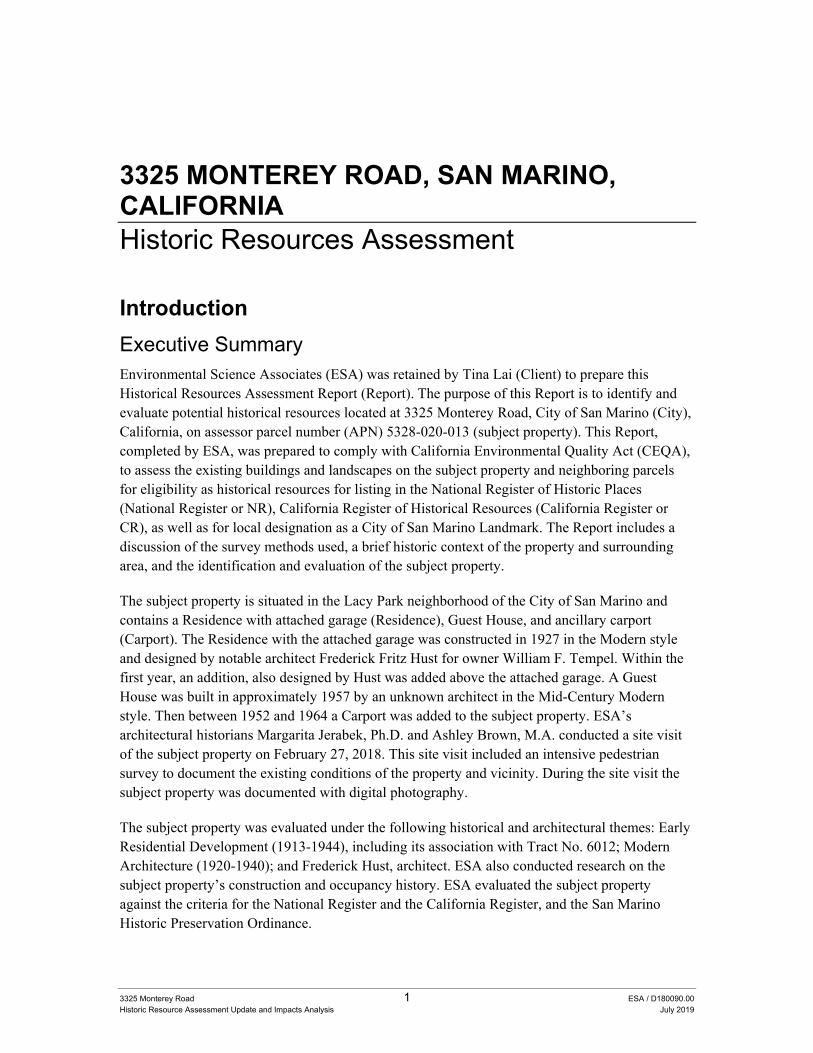
3325 Monterey Road 1 ESA / D180090.00 Historic Resource Assessment Update and Impacts Analysis July 2019
3325 MONTEREY ROAD, SAN MARINO, CALIFORNIA Historic Resources Assessment
Introduction
Executive Summary Environmental Science Associates (ESA) was retained by Tina Lai (Client) to prepare this Historical Resources Assessment Report (Report). The purpose of this Report is to identify and evaluate potential historical resources located at 3325 Monterey Road, City of San Marino (City), California, on assessor parcel number (APN) 5328-020-013 (subject property). This Report, completed by ESA, was prepared to comply with California Environmental Quality Act (CEQA), to assess the existing buildings and landscapes on the subject property and neighboring parcels for eligibility as historical resources for listing in the National Register of Historic Places (National Register or NR), California Register of Historical Resources (California Register or CR), as well as for local designation as a City of San Marino Landmark. The Report includes a discussion of the survey methods used, a brief historic context of the property and surrounding area, and the identification and evaluation of the subject property.
The subject property is situated in the Lacy Park neighborhood of the City of San Marino and contains a Residence with attached garage (Residence), Guest House, and ancillary carport (Carport). The Residence with the attached garage was constructed in 1927 in the Modern style and designed by notable architect Frederick Fritz Hust for owner William F. Tempel. Within the first year, an addition, also designed by Hust was added above the attached garage. A Guest House was built in approximately 1957 by an unknown architect in the Mid-Century Modern style. Then between 1952 and 1964 a Carport was added to the subject property. ESA’s architectural historians Margarita Jerabek, Ph.D. and Ashley Brown, M.A. conducted a site visit of the subject property on February 27, 2018. This site visit included an intensive pedestrian survey to document the existing conditions of the property and vicinity. During the site visit the subject property was documented with digital photography.
The subject property was evaluated under the following historical and architectural themes: Early Residential Development (1913-1944), including its association with Tract No. 6012; Modern Architecture (1920-1940); and Frederick Hust, architect. ESA also conducted research on the subject property’s construction and occupancy history. ESA evaluated the subject property against the criteria for the National Register and the California Register, and the San Marino Historic Preservation Ordinance.
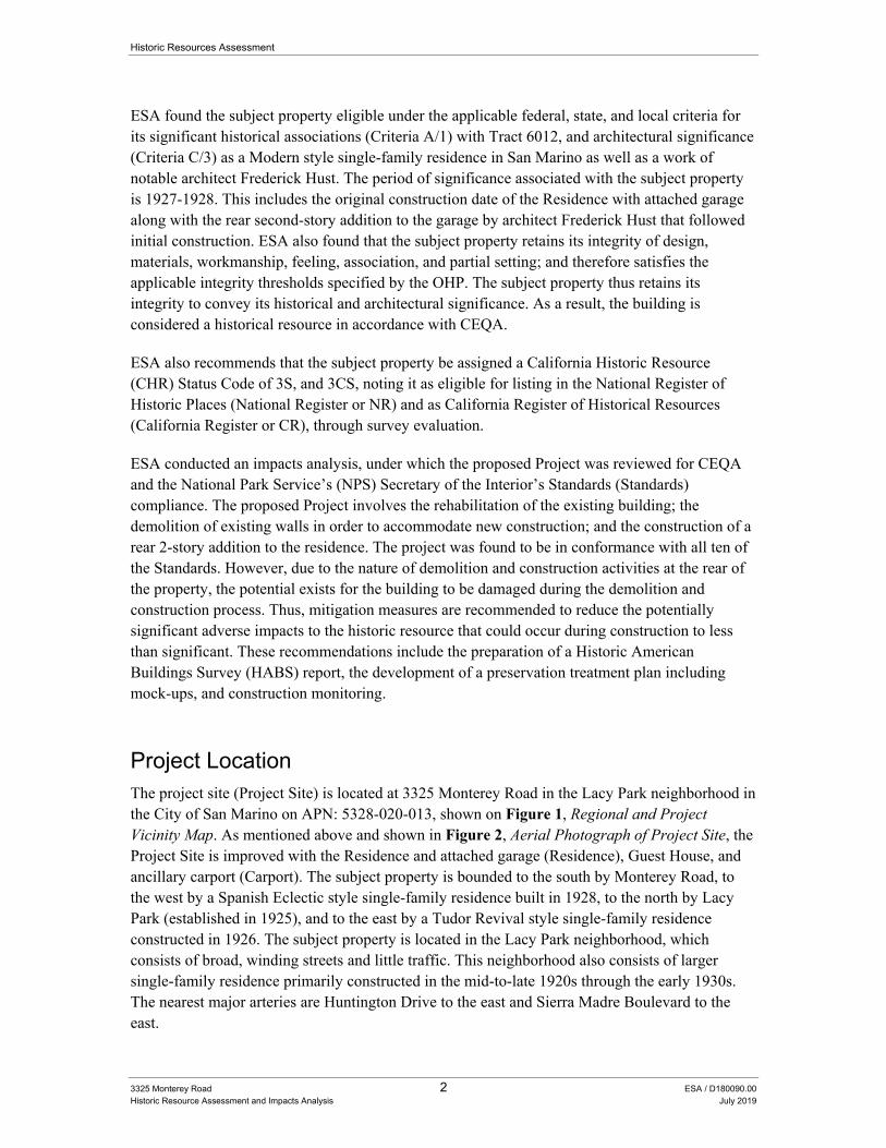
Historic Resources Assessment
3325 Monterey Road 2 ESA / D180090.00 Historic Resource Assessment and Impacts Analysis July 2019
ESA found the subject property eligible under the applicable federal, state, and local criteria for its significant historical associations (Criteria A/1) with Tract 6012, and architectural significance (Criteria C/3) as a Modern style single-family residence in San Marino as well as a work of notable architect Frederick Hust. The period of significance associated with the subject property is 1927-1928. This includes the original construction date of the Residence with attached garage along with the rear second-story addition to the garage by architect Frederick Hust that followed initial construction. ESA also found that the subject property retains its integrity of design, materials, workmanship, feeling, association, and partial setting; and therefore satisfies the applicable integrity thresholds specified by the OHP. The subject property thus retains its integrity to convey its historical and architectural significance. As a result, the building is considered a historical resource in accordance with CEQA.
ESA also recommends that the subject property be assigned a California Historic Resource (CHR) Status Code of 3S, and 3CS, noting it as eligible for listing in the National Register of Historic Places (National Register or NR) and as California Register of Historical Resources (California Register or CR), through survey evaluation.
ESA conducted an impacts analysis, under which the proposed Project was reviewed for CEQA and the National Park Service’s (NPS) Secretary of the Interior’s Standards (Standards) compliance. The proposed Project involves the rehabilitation of the existing building; the demolition of existing walls in order to accommodate new construction; and the construction of a rear 2-story addition to the residence. The project was found to be in conformance with all ten of the Standards. However, due to the nature of demolition and construction activities at the rear of the property, the potential exists for the building to be damaged during the demolition and construction process. Thus, mitigation measures are recommended to reduce the potentially significant adverse impacts to the historic resource that could occur during construction to less than significant. These recommendations include the preparation of a Historic American Buildings Survey (HABS) report, the development of a preservation treatment plan including mock-ups, and construction monitoring.
Project Location The project site (Project Site) is located at 3325 Monterey Road in the Lacy Park neighborhood in the City of San Marino on APN: 5328-020-013, shown on Figure 1, Regional and Project Vicinity Map. As mentioned above and shown in Figure 2, Aerial Photograph of Project Site, the Project Site is improved with the Residence and attached garage (Residence), Guest House, and ancillary carport (Carport). The subject property is bounded to the south by Monterey Road, to the west by a Spanish Eclectic style single-family residence built in 1928, to the north by Lacy Park (established in 1925), and to the east by a Tudor Revival style single-family residence constructed in 1926. The subject property is located in the Lacy Park neighborhood, which consists of broad, winding streets and little traffic. This neighborhood also consists of larger single-family residence primarily constructed in the mid-to-late 1920s through the early 1930s. The nearest major arteries are Huntington Drive to the east and Sierra Madre Boulevard to the east.
Historic Resources Assessment
3325 Monterey Road 3 ESA / D180090.00 Historic Resource Assessment Update and Impacts Analysis July 2019
Research and Field Methodology This Report was prepared by ESA’s architectural historians, including Margarita Jerabek, Ph.D., Director of Historical Resources; Ashley Brown, M.A., Senior Architectural Historian; Max Loder, M.A., Associate Architectural Historian; and Hanna Winzenried, M.S.C., Associate Architectural Historian, all of whom meet and exceed the Secretary of the Interior’s Professional Qualification Standards in history and architectural history. The CEQA Analysis portion of the Report, including the Analysis of Project Impacts Plan Review and the Secretary of the Interior’s Standards Conformance Review, were prepared by the ESA staff that follow: Alison Garcia-Kellar, M.A., Senior Architectural Historian; and Gabrielle Harlan, Ph.D., Senior Architectural Historian. Professional qualifications are provided in Appendix A.
The historical resources evaluation involved a review of the National Register and its annual updates, the California Register, the Statewide Historical Resources Inventory (HRI) database maintained by the State Office of Historic Preservation (OHP), the California Historical Resources Information System (CHRIS), and the City of San Marino’s inventory of historic properties to identify any previously recorded properties within or near the subject property. An intensive pedestrian survey was also undertaken to document the existing conditions of the property and vicinity. In addition, the following tasks were performed for the study:
Conducted field inspections of the subject property and utilized the survey methodology of the State OHP.
Photographed the subject property and associated landscape features, and examined other properties in the vicinity that exhibited potential architectural and/or historical associations.
Conducted site-specific research on the property utilizing building permits, Sanborn Fire Insurance Maps (Sanborn Maps), City directories, historical photographs, California Index, Avery Index, Online Archive of California, Huntington Library, Calisphere, University of Southern California (USC) Digital Collections, historical Los Angeles Times, and other published sources.
Conducted research at the City’s Building and Safety and Community Development departments as well as the Los Angeles County Office of the Assessor (Assessor).
Reviewed and analyzed ordinances, statutes, regulations, bulletins, and technical materials relating to federal, state, and local historic preservation, designation assessment processes, and related programs.
Evaluated potential historical resources based upon criteria used by the National Register, California Register, and City of San Marino Cultural Heritage Preservation Ordinance.
A character-defining features analysis was conducted by ESA and provided to the architects to inform design development. Concept plans for the proposed Project were provided to ESA for review, and ESA reviewed the plans and provided input for conformance with the Secretary of the Interior’s Standards for Rehabilitation.
Once the concept plans were completed, ESA conducted a plan review for compliance with the California Environmental Quality Act §15064.5, for conformance with the Standards and the San Marino Cultural Heritage Preservation Ordinance.
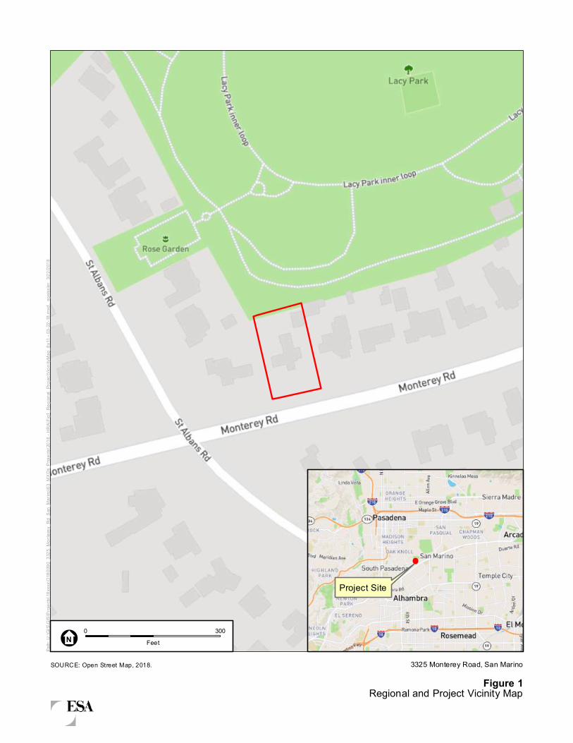
Path:
U:\G
IS\G
IS\P
rojec
ts\18
xxxx
\D18
0090
_332
5_Mo
nterey
_Rd_
San_
Marin
o\03_
MXDs
_Proj
ects\
2018
- HR
A\Fig
1_Re
giona
l_Pro
jectVi
cinity
Map_
8x11
- 03
-22-18
.mxd
, sge
issler
3/22
/2018
SOURCE: Open Street Map, 2018.
0 300Feet
Figure 13325 Monterey Road, San Marino
Regional and Project Vicinity Map
N
Project Site
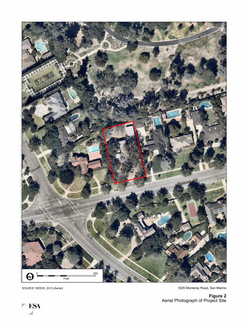
Path:
U:\G
IS\GI
S\Proj
ects\
18xx
xx\D
1800
90_3
325_
Monte
rey_R
d_Sa
n_Ma
rino\0
3_MX
Ds_P
rojec
ts\20
18 - H
RA\Fi
g2_A
erial
Photo
graph
of Pr
oject
Site_
8x11
- 03-2
2-18.m
xd, s
geiss
ler 3
/22/20
18
SOURCE: MODIS, 2013 (Aerial).
0 200Feet
Figure 23325 Monterey Road, San Marino
Aerial Photograph of Project Site
N
Historic Resources Assessment
3325 Monterey Road 6 ESA / D180090.00 Historic Resource Assessment and Impacts Analysis July 2019
Regulatory Framework
Historical resources fall within the jurisdiction of the federal, state, and local designation programs. Federal laws provide the framework for the identification, and in certain instances, protection of historical resources. Additionally, state and local jurisdictions play active roles in the identification, documentation, and protection of such resources within their communities. The National Historic Preservation Act (NHPA) of 1966, as amended and the California Public Resources Code (PRC), Section 5024.1, are the primary federal and state laws and regulations governing the evaluation and significance of historical resources of national, state, regional, and local importance. Descriptions of these relevant laws and regulations are presented below.
Federal Eligibility Criteria and Integrity Aspects National Register of Historic Places
The National Register was established by the NHPA as “an authoritative guide to be used by federal, state, and local governments, private groups and citizens to identify the Nation’s cultural resources and to indicate what properties should be considered for protection from destruction or impairment.”1 The National Register recognizes properties that are significant at the national, state, and/or local levels.
To be eligible for listing in the National Register, a resource must be significant in American history, architecture, archaeology, engineering, or culture. Four criteria for evaluation have been established to determine the significance of a resource:
A. Associated with events that have made a significant contribution to the broad patterns of our history;
B. Associated with the lives of persons significant in our past;
C. Embodies the distinctive characteristics of a type, period, or method of construction or that represent the work of a master, or that possess high artistic values, or that represent a significant and distinguishable entity whose components may lack individual distinction;
D. Yields, or may be likely to yield, information important in prehistory or history.2
Districts, sites, buildings, structures, and objects that are 50 years in age must meet one or more of the above criteria and retain integrity (that is, convey their significance) to be eligible for listing.
Under the National Register, a property can be significant not only for the way it was originally constructed, but also for the way it was adapted at a later period, or for the way it illustrates changing tastes, attitudes, and uses over a period of time.3
1 36 CFR Section 60.2. 2 “Guidelines for Completing National Register Forms,” in National Register Bulletin 16, U.S. Department of
Interior, National Park Service, 1977, Revised 1997. This bulletin contains technical information on comprehensive planning, survey of cultural resources and registration in the NRHP.
3 National Register Bulletin 15, p. 19.
Historic Resources Assessment
3325 Monterey Road 7 ESA / D180090.00 Historic Resource Assessment Update and Impacts Analysis July 2019
Within the concept of integrity, the National Register recognizes seven aspects or qualities that, in various combinations, define integrity: Location, Design, Setting, Materials, Workmanship, Feeling, and Association:
Location is the place where the historic property was constructed or the place where the historic event occurred. The relationship between the property and its location is often important to understanding why the property was created or why something happened. The actual location of a historic property, complemented by its setting, is particularly important in recapturing the sense of historic events and persons. Except in rare cases, the relationship between a property and its historic associations is destroyed if the property is moved.
Design is the combination of elements that create the form, plan, space, structure, and style of a property. It results from conscious decisions made during the original conception and planning of a property (or its significant alteration) and applies to activities as diverse as community planning, engineering, architecture, and landscape architecture. Design includes such elements as organization of space, proportion, scale, technology, ornamentation, and materials. A property’s design reflects historic functions and technologies as well as aesthetics. It includes such considerations as the structural system; massing; arrangement of spaces; pattern of fenestration; textures and colors of surface materials; type, amount and style of ornamental detailing; and arrangement and type of plantings in a designed landscape.
Setting is the physical environment of a historic property. Whereas location refers to the specific place where a property was built or an event occurred, setting refers to the character of the place in which the property played its historic role. It involves how, not just where, the property is situated and its relationship to surrounding features and open space.
Workmanship is the physical evidence of the crafts of a particular culture or people during any given period in history or prehistory. It is the evidence of artisans’ labor and skill in constructing or altering a building, structure, object, or site. Workmanship can apply to the property as a whole or to its individual components.
Materials are the physical elements that were combined or deposited during a particular period of time and in a particular pattern or configuration to form a historic property.
The choice and combination of materials reveal the preferences of those who created the property and indicate the availability of particular types of materials and technologies. A property must retain key exterior materials dating from the period of its historic significance.
Feeling is a property’s expression of the aesthetic or historic sense of a particular period of time. It results from the presence of physical features that, taken together, convey the property’s historic character.
Historic Resources Assessment
3325 Monterey Road 8 ESA / D180090.00 Historic Resource Assessment and Impacts Analysis July 2019
Association is the direct link between an important historic event or person and a historic property. A property retains association if it is the place where the event or activity occurred and is sufficiently intact to convey that relationship to an observer.4
To retain historic integrity, a property will always possess most of the aspects and depending upon its significance, retention of specific aspects of integrity may be paramount for a property to convey its significance.5 Determining which of these aspects are most important to a particular property requires knowing why, where and when a property is significant.6 For properties that are considered significant under National Register Criteria A and B, National Register Bulletin 15: How to Apply the National Register Criteria for Evaluation (National Register Bulletin 15) explains, “a property that is significant for its historic association is eligible if it retains the essential physical features that made up its character or appearance during the period of its association with the important event, historical pattern, or person(s).”7 In assessing the integrity of properties that are considered significant under National Register Criterion C, National Register Bulletin 15 states, “a property important for illustrating a particular architectural style or construction technique must retain most of the physical features that constitute that style or technique.”8
State Register and Eligibility Criteria California Register of Historical Resources
The OHP, as an office of the California Department of Parks and Recreation (DPR), implements the policies of the NHPA on a statewide level.
The OHP also carries out the duties as set forth in the PRC and maintains the HRI and the California Register. The State Historic Preservation Officer (SHPO) is an appointed official who implements historic preservation programs within the state’s jurisdictions.
Also implemented at the state level, CEQA requires projects to identify any substantial adverse impacts which may affect the significance of identified historical resources.
4 National Register Bulletin 15: How to Apply the National Register Criteria for Evaluation, 44-45,
http://www.nps.gov/nr/publications/bulletins/pdfs/nrb15.pdf, accessed July 7, 2013. 5 The National Register defines a property as an “area of land containing a single historic resource or a group of
resources, and constituting a single entry in the National Register of Historic Places.” A “Historic Property” is defined as “any prehistoric or historic district, site, building, structure, or object at the time it attained historic significance.” Glossary of National Register Terms, http://www.nps.gov/nr/publications/bulletins/nrb16a/nrb16a_appendix_IV.htm, accessed June 1, 2013.
6 National Register Bulletin 15, 44. 7 “A property retains association if it is the place where the event or activity occurred and is sufficiently intact to
convey that relationship to an observer. Like feeling, association requires the presence of physical features that convey a property’s historic character. Because feeling and association depend on individual perceptions, their retention alone is never sufficient to support eligibility of a property for the National Register.” Ibid, p. 46.
8 “A property that has lost some historic materials or details can be eligible if it retains the majority of the features that illustrate its style in terms of the massing, spatial relationships, proportion, pattern of windows and doors, texture of materials, and ornamentation. The property is not eligible, however, if it retains some basic features conveying massing but has lost the majority of the features that once characterized its style.” Ibid.
Historic Resources Assessment
3325 Monterey Road 9 ESA / D180090.00 Historic Resource Assessment Update and Impacts Analysis July 2019
The California Register was created by Assembly Bill 2881 which was signed into law on September 27, 1992. The California Register is “an authoritative listing and guide to be used by state and local agencies, private groups, and citizens in identifying the existing historical resources of the state and to indicate which resources deserve to be protected, to the extent prudent and feasible, from substantial adverse change.”9 The criteria for eligibility for the California Register are based upon National Register criteria.10
The California Register consists of resources that are listed automatically and those that must be nominated through an application and public hearing process. The California Register automatically includes the following:
California properties listed on the National Register and those formally Determined Eligible for the National Register; 11
California Registered Historical Landmarks from No. 770 onward;
Those California Points of Historical Interest (PHI) that have been evaluated by the OHP and have been recommended to the State Historical Commission for inclusion on the California Register.12
Other resources which may be nominated to the California Register include:
Individual historical resources;
Historical resources contributing to historic districts;
Historical resources identified as significant in historical resources surveys with significance ratings of Category 1 through 5;
Historical resources designated or listed as local landmarks, or designated under any local ordinance, such as an HPOZ.13
To be eligible for the California Register, a historical resource must be significant at the local, state, or national level, under one or more of the following four criteria:
1. Is associated with events that have made a significant contribution to the broad patterns of California's history and cultural heritage;
2. Is associated with the lives of persons important in our past;
3. Embodies the distinctive characteristics of a type, period, region, or method of construction, or represents the work of an important creative individual, or possesses high artistic values; or
4. Has yielded, or may be likely to yield, information important in prehistory or history.
Additionally, a historical resource eligible for listing in the California Register must meet one or more of the criteria of significance described above and retain enough of its historic character or
9 PRC Section 5024.1(a). 10 PRC Section 5024.1(b). 11 PRC Section 5024.1(d). 12 Ibid. 13 PRC Section 5024.1(e)
Historic Resources Assessment
3325 Monterey Road 10 ESA / D180090.00 Historic Resource Assessment and Impacts Analysis July 2019
appearance to be recognizable as a historical resource and to convey the reasons for its significance. Historical resources that have been rehabilitated or restored may be evaluated for listing. Integrity is evaluated with regard to the retention of seven aspects of integrity similar to the National Register (location, design, setting, materials, workmanship, feeling, and association). Also like the National Register, it must also be judged with reference to the particular criteria under which a resource is proposed for eligibility. Alterations over time to a resource or historic changes in its use may themselves have historical, cultural, or architectural significance. It is possible that historical resources may not retain sufficient integrity to meet the criteria for listing in the National Register, but they may still be eligible for listing in the California Register. A resource that has lost its historic character or appearance may still have sufficient integrity for the California Register if it maintains the potential to yield significant scientific or historical information or specific data.14
California Historical Resources Status Codes
The California State OHP developed National Register Status Codes in 1975 as a standardized system for classifying historical resources in the state’s Historic Resources Inventory. In 2003 these codes were revised to reflect the application of California Register and local criteria and the name was changed to California Historical Resource (CHR) Status Codes. CHR Status codes consist of three digits and are assigned to properties or historic districts through a survey process and as a result of varying regulatory processes. The first digit ranges from 1-7. Code categories 1-5 reflect properties determined eligible for designation according to the criteria established for the National Register, California Register and local government criteria for significance. Code categories 6-7 generally identify properties that do not meet established criteria for significance, have not been evaluated, or need to be reevaluated. The code categories are as follows:
1. Properties listed in the National Register or the California Register;
2. Properties determined eligible for listing in the National Register or the California Register;
3. Appears eligible for National Register or the California Register through survey evaluation;
4. Appears eligible for the National Register or the California Register through other evaluation;
5. Properties recognized as historically significant by local government;
6. Not eligible for listing or designation as specified; and
7. Not evaluated for the National Register or California Register or needs re-evaluation.
The second digit of the CHR Status Code is a letter code indicating whether the resource is separately eligible (S), eligible as part of a district (D), or both (B). The third digit is a number that is used to further specify significance and refine the relationship of the property to the National Register and/or California Register. Under this evaluation system, categories 1 through 4 pertain to various levels of National Register and California Register eligibility. Locally eligible resources are given a rating code level 5. Properties found ineligible for listing in the National Register, California Register, or for designation under a local ordinance are given an evaluation
14 Codified in California Code of Regulations, Title 14, Chapter 11.5, Section 4852(c) which can be accessed on the
internet at http://ohp.parks.ca.gov
Historic Resources Assessment
3325 Monterey Road 11 ESA / D180090.00 Historic Resource Assessment Update and Impacts Analysis July 2019
Status Code of 6. Properties given an evaluation Status Code of 6Z are “found ineligible for the National Register, California Register, or Local designation through survey evaluation.”15
Local Historic Preservation Ordinance and Eligibility Criteria City of San Marino Current Code
The San Marino Historic Preservation Ordinance No. O-18-1366 (23.18.010-23.18.220) establishes criteria for designating local historic landmarks.16 This Code was adopted on April 11, 2018. A cultural resource may be recommended for designation as a landmark if it manifests one of the criteria described in a section below entitled “Designation Criteria for Historic Landmarks.” The San Marino Historic Preservation Ordinance is not reproduced in its entirety here; Section 23.18.020, which provides some basic definitions of the terms used here, is not included in the interest of brevity:
23.18.010 Purpose
The purpose of the Historic Preservation Ordinance is to promote the public health, safety, and general welfare by providing for the identification, designation, protection, enhancement, and ongoing use of historical resources that represent the City's cultural, architectural, social, economic, and political heritage. It is the intent and purpose of the San Marino City Council in passing this article to:
A. Preserve, maintain, and safeguard the City's heritage and character for the enjoyment of present and future generations, by providing for the protection and thoughtful management of historic resources as defined in this article; B. Foster awareness, recognition, and stewardship of the City's historic resources; C. Encourage public knowledge and appreciation of the City's heritage, and foster civic and neighborhood pride and sense of identity through the recognition of historic resources; D. Encourage the maintenance and preservation of cultural landscapes that contribute to the historic character of our neighborhoods and built environment; E. Recognize the City's historic resources as economic assets; F. Stabilize and improve property values within the City, and increase the economic and financial benefits to the City and its inhabitants through the
15 Ibid. 16 San Marino, California: Historic Preservation Ordinance, Ordinance No. O-18-1336, 23.18.010-23.18.220, adopted
on April 11, 2018.
Historic Resources Assessment
3325 Monterey Road 12 ESA / D180090.00 Historic Resource Assessment and Impacts Analysis July 2019
preservation, rehabilitation, and ongoing use of historic resources;
G. Integrate the conservation of historic resources into the public and private development process; H. Implement the General Plan by protecting the historical and culturally significant resources that contribute to community identity and a sense of history; I. Facilitate the City's compliance with the National Historic Preservation Act (NHPA) and California Environmental Quality Act (CEQA) and their provisions for cultural and historical resources; J. Preserve diverse and significant architectural styles and property types reflecting the City's history and encourage complementary new construction and design, to maintain the City's historic scale and character; and K. Adopt and encourage the use of historic preservation incentives, both regulatory and economic, that promote the retention, rehabilitation, and protection of historic resources.
23.18.020 Designation of Historic Landmarks
A. Automatic Designation. Any property within the City that is listed in the National Register of Historic Places or the California Register of Historic Places is automatically designated as a historic landmark for purposes of this article. B. Prior Designations. Any historic landmark previously designated as such by the City on or before the effective date of this article shall continue to be a historic landmark as previously designated for purposes of this article and shall be subject to all provisions herein. C. New Designations. The Council may designate any structure, property, or properties as a historic landmark or historic resource subject to criteria in this section. D. Amendment or Rescission. The Council may amend or rescind the designation of any historic landmark, for the purposes of this article, subject to the same procedures required for their designation, including without limitation, hearing and recommendation of the Director.
1. Criteria for Amendment. Once a historic landmark has been designated, the designation shall not be amended unless the City Council determines the findings required under Section 23.18.030 can still be made. 2. Criteria for Rescission. Once a historic landmark has been designated, the designation shall not be rescinded unless the City Council finds that: (I) the evidence supporting the designation was erroneous; or (2) the findings required under Section 23.18.030 can no longer be made.

Historic Resources Assessment
3325 Monterey Road 13 ESA / D180090.00 Historic Resource Assessment Update and Impacts Analysis July 2019
23.18.030 Criteria for Amendment Once a historic landmark has been designated, the designation shall not be amended unless the City Council determines the findings required under Section 23.18.030 can still be made. Criteria for Rescission. Once a historic landmark has been designated, the designation shall not be rescinded unless the City Council finds that: (I) the evidence supporting the designation was erroneous; or (2) the findings required under Section 23.18.030 can no longer be made. 23.18.04 Designation Criteria for Historic Landmarks
A. The Council may designate a historic resource a historic landmark if it meets the requirements of both subsections B and C of this section. B. Historic landmarks must meet at least one of the following criteria:
1. It is or was once associated or identified with important events or broad patterns of development that have made a significant contribution to the cultural, architectural, historical, and political heritage of the City, region, state, or nation; or 2. It is or was associated with an important person or persons who made a significant contribution to the history, development, or culture of the City, region, State, or Nation; or 3. It embodies the distinctive characteristics of a style, type, period, or method of construction; exemplifies the work of a well-recognized architect or builder, or possesses high artistic or aesthetic values; or it represents one of the last, best remaining examples of an architectural type or style in a neighborhood or the City that was once common but is now increasingly rare.
C. Historic landmarks must retain integrity from their period of significance with respect to its location, design, setting, materials, workmanship, feeling, association, or any combination of these factors. A proposed landmark need not retain all such original aspects, but must retain sufficient integrity to convey its historic, cultural, or architectural significance. Neither the deferred maintenance of a proposed landmark nor its dilapidated condition shall, on its own, be equated with a loss of integrity. Integrity shall be judged with reference to the particular characteristics that support the property's eligibility (Ord. 0-18-1336, 4-11-2018).17
Environmental Setting
Historic Context The historic context developed below presents the background necessary to evaluate the historical and architectural significance of the subject property, including the history of its construction and alterations, as well as the surrounding neighborhood’s development. ESA evaluated the subject property under the following historical and architectural themes: Early Residential Development (1913-1944), including Tract No. 6012, Modern Architecture (1920-1940), and Frederick Hust, architect. Also presented below is the construction and occupancy history of 3325 Monterey 17 San Marino Municipal Code, Chapter XXIII, Article 18, Historic Preservation
(https://www.sterlingcodifiers.com/codebook/index.php?book_id=825, accessed June 2018).
Historic Resources Assessment
3325 Monterey Road 14 ESA / D180090.00 Historic Resource Assessment and Impacts Analysis July 2019
Road. The preliminary period of significance associated with the subject property is 1927-1928. This includes the original construction date of the Residence with attached garage as well as the rear second-story addition by Frederick Hust.
City of San Marino (1900-1960)
To a considerable degree, San Marino owes its presence to agricultural cultivation, especially the citrus industry. Together with neighboring foothill communities, San Marino occupies a portion of the so-called “citrus belt,” a climatic sub-region reaching from the San Gabriel Valley to San Bernardino. A direct outgrowth of the completion of the transcontinental railroad, which greatly increased marketing opportunities for the fruit, the citrus industry flourished in southern California from 1880 to roughly 1940 and was one of San Marino’s earliest industries. An infrastructure that included growers’ exchanges and associations developed rapidly. Local citrus production peaked around 1891, when San Marino and Pasadena out-produced neighboring cities, and remained an integral part of the local economy until the early twentieth century, when urbanization overtook agricultural production. 18
Early agricultural estate owners in San Marino included Benjamin Davis Wilson, George S. Patton, Sr., and James De Barth Shorb. Wilson, who served as Mayor of Los Angeles and State Senator for two terms, owned the Lake Vineyard Ranch (formerly Rancho Huerta de Cuati, a Mexican land grant) on present-day Euston Road. Wilson’s daughter, Maria, married Shorb and received a portion her father’s estate as a wedding gift; she went on to rename it “San Marino.” In 1903, the Shorb ranch was purchased by Henry E. Huntington and presently comprises The Huntington.19
To protect their estates and avoid annexation by Los Angeles, local land owners pulled together and the City of San Marino was incorporated in 1913.20 Patton, who married Ruth, Wilson’s daughter from a second marriage, served as the first mayor. The newly incorporated City of San Marino included land from the three neighboring ranchos owned by Huntington, Wilson, and Patton, as well as other subdivided and smaller ranchos owned by Stoneman, White, and Rose.21 In 1917, the first school was opened in the City, located on the corner of Monterey Road and Oak Knoll (originally called Calle de Lopez), approximately a half-mile east of the subject property.22
The Pacific Electric railway system, established by Henry Huntington in 1901, encouraged the development of San Marino as a largely single-family residential community, as it afforded citizens convenient access to jobs throughout the Los Angeles area. The map below (Figure 3) shows the geographic scope of the lines in 1910. Prior to World War II, the Sierra Madre Line to San Marino transported approximately 300,000 passengers annually. By 1944, that number had
18 Architectural/Historical Development of the City of Pasadena: Historic Context/Property Type Report, prepared by
Pamela O’Connor and Urban Conservation Section, Planning Division, City of Pasadena, January 13, 1993. 19 San Marino Historical Society, “History: San Marino,” accessed March 9, 2016,
http://sanmarinohistoricalsociety.org/history.html 20 Sam Watters, Houses of Los Angeles: 1885-1919, p. 27. 21 “San Marino History,” City of San Marino, accessed June 21, 2011, http://www.cityofsanmarino.org/about.htm. 22 City of San Marino. “General Plan,” San Marino, CA, 2003.
Historic Resources Assessment
3325 Monterey Road 15 ESA / D180090.00 Historic Resource Assessment Update and Impacts Analysis July 2019
climbed to 625,000.23 In addition to commuters, the electric railway transported freight (Figure 4) and brought tourists to the area.
The rise of automobile culture in Southern California, which led to increased suburbanization in the region, further contributed to the growth of San Marino. This was especially the case during the postwar period when commuters began to rely more and more on automobiles and buses. Road and highway construction took off, with the first segment of the Arroyo Seco Parkway completed in 1939, and continued into the postwar period (Figure 5). The Arroyo Seco Parkway, the first freeway in the American West, connected Pasadena with Los Angeles. By the early 1960s, the electric railway system had been discontinued altogether, with landscaped medians replacing the rail lines on major thoroughfares in San Marino, such as Huntington Drive and Sierra Madre Boulevard (Figure 6).24
The rapid growth of the 1930s and 1940s began to slow in the 1950s. In the 1950s, San Marino had lost most of its rural character and approached its built-out capacity.25 This is illustrated by United States Federal Census data for San Marino between 1930 and 1960: 1930 (3,730 residents), 1940 (8,175 residents), 1950 (11,230 residents), and 1960 (13,658 residents).
23 City of San Marino, General Plan, 2003, p. I-3-4. 24 Ibid. 25 Ibid.
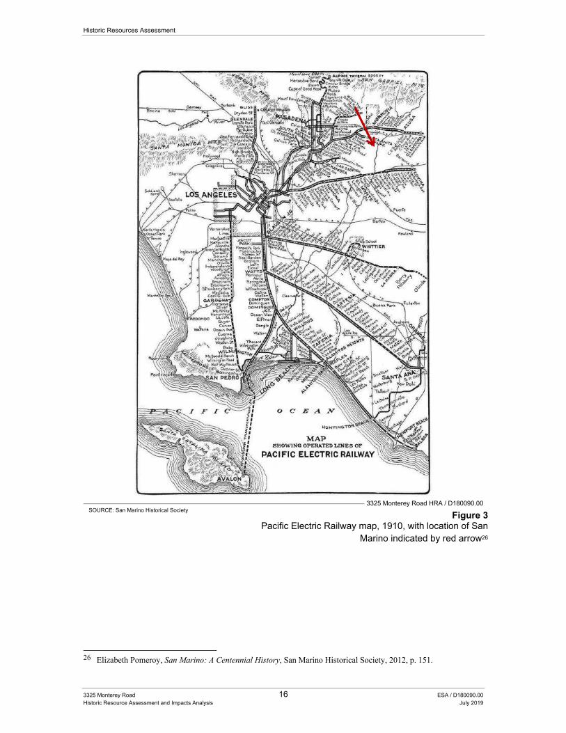
Historic Resources Assessment
3325 Monterey Road 16 ESA / D180090.00 Historic Resource Assessment and Impacts Analysis July 2019
3325 Monterey Road HRA / D180090.00
SOURCE: San Marino Historical Society Figure 3
Pacific Electric Railway map, 1910, with location of San Marino indicated by red arrow26
26 Elizabeth Pomeroy, San Marino: A Centennial History, San Marino Historical Society, 2012, p. 151.
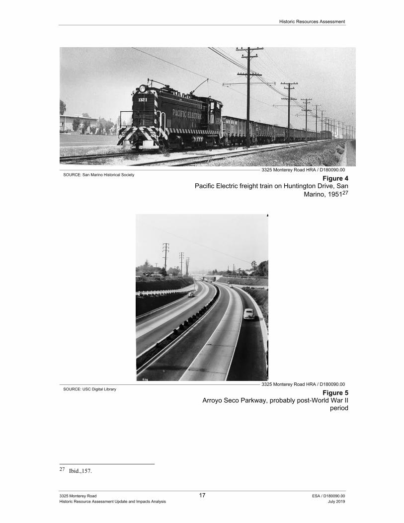
Historic Resources Assessment
3325 Monterey Road 17 ESA / D180090.00 Historic Resource Assessment Update and Impacts Analysis July 2019
3325 Monterey Road HRA / D180090.00
SOURCE: San Marino Historical Society Figure 4
Pacific Electric freight train on Huntington Drive, San Marino, 195127
3325 Monterey Road HRA / D180090.00
SOURCE: USC Digital Library Figure 5
Arroyo Seco Parkway, probably post-World War II period
27 Ibid.,157.
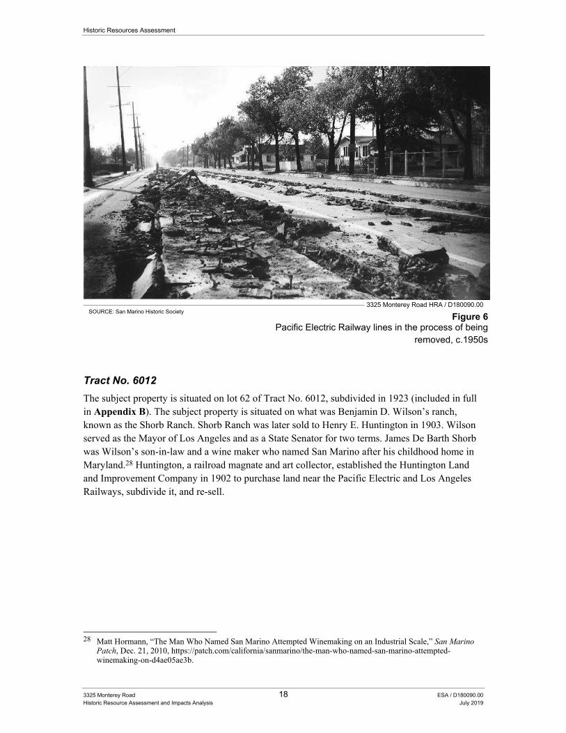
Historic Resources Assessment
3325 Monterey Road 18 ESA / D180090.00 Historic Resource Assessment and Impacts Analysis July 2019
3325 Monterey Road HRA / D180090.00
SOURCE: San Marino Historic Society Figure 6
Pacific Electric Railway lines in the process of being removed, c.1950s
Tract No. 6012
The subject property is situated on lot 62 of Tract No. 6012, subdivided in 1923 (included in full in Appendix B). The subject property is situated on what was Benjamin D. Wilson’s ranch, known as the Shorb Ranch. Shorb Ranch was later sold to Henry E. Huntington in 1903. Wilson served as the Mayor of Los Angeles and as a State Senator for two terms. James De Barth Shorb was Wilson’s son-in-law and a wine maker who named San Marino after his childhood home in Maryland.28 Huntington, a railroad magnate and art collector, established the Huntington Land and Improvement Company in 1902 to purchase land near the Pacific Electric and Los Angeles Railways, subdivide it, and re-sell.
28 Matt Hormann, “The Man Who Named San Marino Attempted Winemaking on an Industrial Scale,” San Marino
Patch, Dec. 21, 2010, https://patch.com/california/sanmarino/the-man-who-named-san-marino-attempted-winemaking-on-d4ae05ae3b.
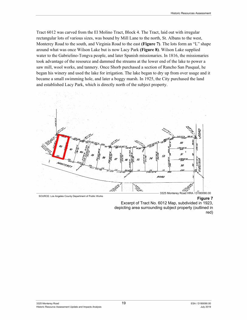
Historic Resources Assessment
3325 Monterey Road 19 ESA / D180090.00 Historic Resource Assessment Update and Impacts Analysis July 2019
Tract 6012 was carved from the El Molino Tract, Block 4. The Tract, laid out with irregular rectangular lots of various sizes, was bound by Mill Lane to the north, St. Albans to the west, Monterey Road to the south, and Virginia Road to the east (Figure 7). The lots form an “L” shape around what was once Wilson Lake but is now Lacy Park (Figure 8). Wilson Lake supplied water to the Gabrielino-Tongva people, and later Spanish missionaries. In 1816, the missionaries took advantage of the resource and dammed the streams at the lower end of the lake to power a saw mill, wool works, and tannery. Once Shorb purchased a section of Rancho San Pasqual, he began his winery and used the lake for irrigation. The lake began to dry up from over usage and it became a small swimming hole, and later a boggy marsh. In 1925, the City purchased the land and established Lacy Park, which is directly north of the subject property.
3325 Monterey Road HRA / D180090.00 SOURCE: Los Angeles County Department of Public Works
Figure 7 Excerpt of Tract No. 6012 Map, subdivided in 1923,
depicting area surrounding subject property (outlined in red)
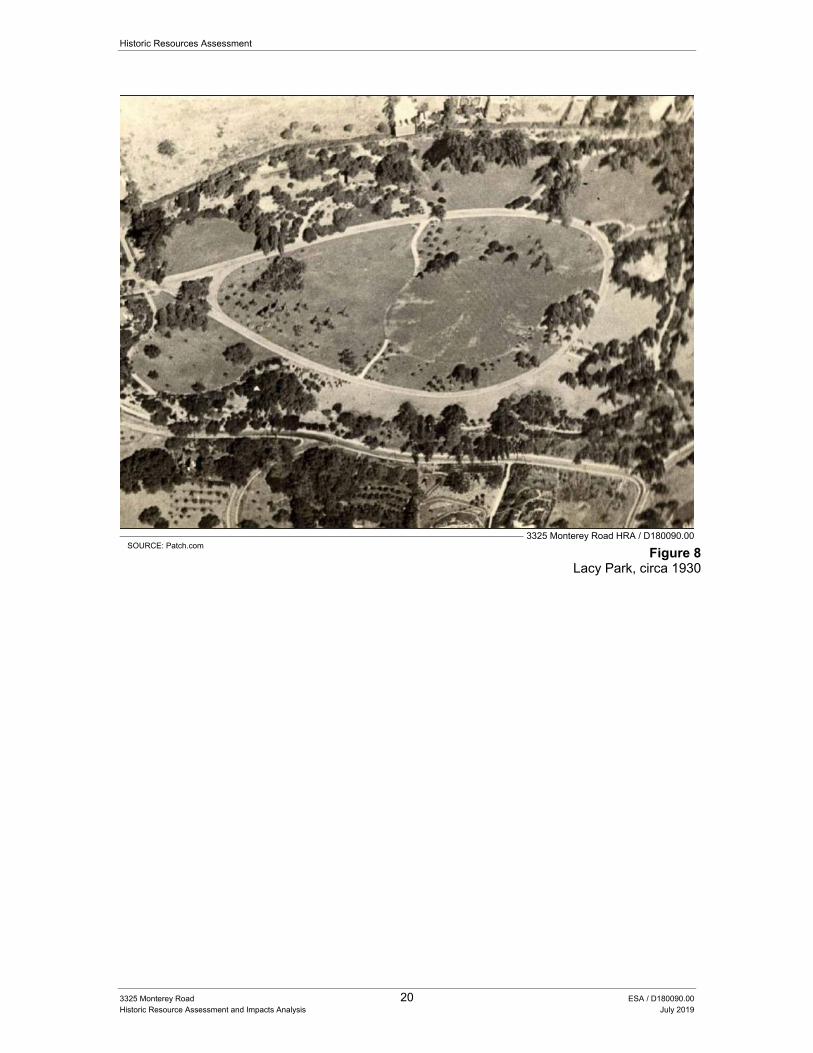
Historic Resources Assessment
3325 Monterey Road 20 ESA / D180090.00 Historic Resource Assessment and Impacts Analysis July 2019
3325 Monterey Road HRA / D180090.00
SOURCE: Patch.com Figure 8
Lacy Park, circa 1930
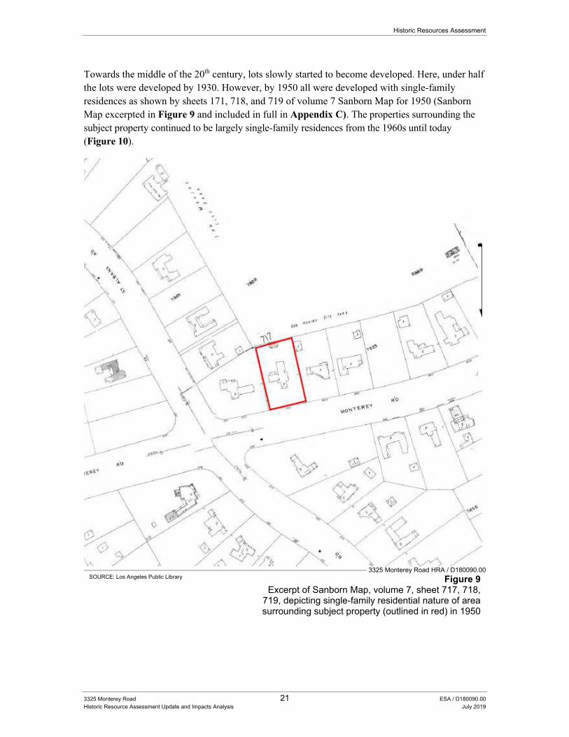
Historic Resources Assessment
3325 Monterey Road 21 ESA / D180090.00 Historic Resource Assessment Update and Impacts Analysis July 2019
Towards the middle of the 20th century, lots slowly started to become developed. Here, under half the lots were developed by 1930. However, by 1950 all were developed with single-family residences as shown by sheets 171, 718, and 719 of volume 7 Sanborn Map for 1950 (Sanborn Map excerpted in Figure 9 and included in full in Appendix C). The properties surrounding the subject property continued to be largely single-family residences from the 1960s until today (Figure 10).
3325 Monterey Road HRA / D180090.00 SOURCE: Los Angeles Public Library Figure 9
Excerpt of Sanborn Map, volume 7, sheet 717, 718, 719, depicting single-family residential nature of area surrounding subject property (outlined in red) in 1950
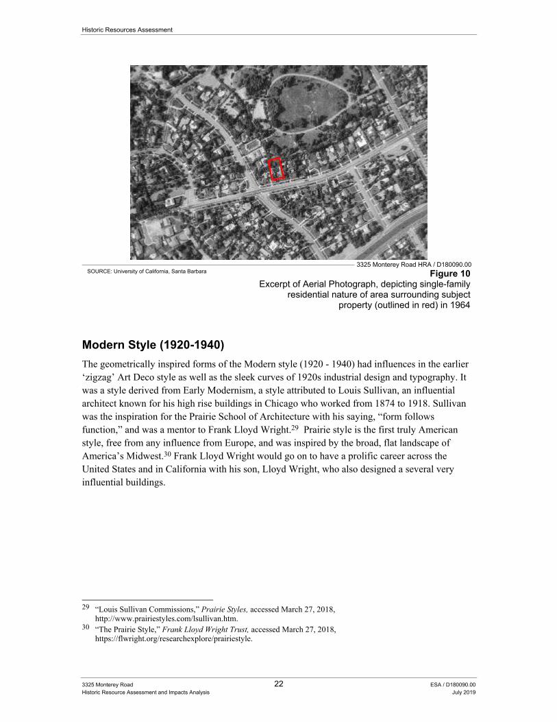
Historic Resources Assessment
3325 Monterey Road 22 ESA / D180090.00 Historic Resource Assessment and Impacts Analysis July 2019
3325 Monterey Road HRA / D180090.00
SOURCE: University of California, Santa Barbara Figure 10 Excerpt of Aerial Photograph, depicting single-family
residential nature of area surrounding subject property (outlined in red) in 1964
Modern Style (1920-1940)
The geometrically inspired forms of the Modern style (1920 - 1940) had influences in the earlier ‘zigzag’ Art Deco style as well as the sleek curves of 1920s industrial design and typography. It was a style derived from Early Modernism, a style attributed to Louis Sullivan, an influential architect known for his high rise buildings in Chicago who worked from 1874 to 1918. Sullivan was the inspiration for the Prairie School of Architecture with his saying, “form follows function,” and was a mentor to Frank Lloyd Wright.29 Prairie style is the first truly American style, free from any influence from Europe, and was inspired by the broad, flat landscape of America’s Midwest.30 Frank Lloyd Wright would go on to have a prolific career across the United States and in California with his son, Lloyd Wright, who also designed a several very influential buildings.
29 “Louis Sullivan Commissions,” Prairie Styles, accessed March 27, 2018,
http://www.prairiestyles.com/lsullivan.htm. 30 “The Prairie Style,” Frank Lloyd Wright Trust, accessed March 27, 2018,
https://flwright.org/researchexplore/prairiestyle.
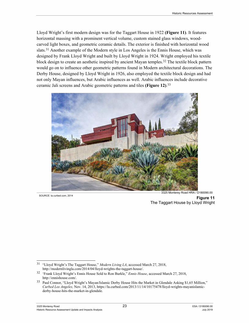
Historic Resources Assessment
3325 Monterey Road 23 ESA / D180090.00 Historic Resource Assessment Update and Impacts Analysis July 2019
Lloyd Wright’s first modern design was for the Taggart House in 1922 (Figure 11). It features horizontal massing with a prominent vertical volume, custom stained glass windows, wood-carved light boxes, and geometric ceramic details. The exterior is finished with horizontal wood slats.31 Another example of the Modern style in Los Angeles is the Ennis House, which was designed by Frank Lloyd Wright and built by Lloyd Wright in 1924. Wright employed his textile block design to create an aesthetic inspired by ancient Mayan temples.32 The textile block pattern would go on to influence other geometric patterns found in Modern architectural decorations. The Derby House, designed by Lloyd Wright in 1926, also employed the textile block design and had not only Mayan influences, but Arabic influences as well. Arabic influences include decorative ceramic Jali screens and Arabic geometric patterns and tiles (Figure 12).33
3325 Monterey Road HRA / D180090.00
SOURCE: la.curbed.com, 2014 Figure 11
The Taggart House by Lloyd Wright
31 “Lloyd Wright’s The Taggart House,” Modern Living LA, accessed March 27, 2018,
http://modernlivingla.com/2014/04/lloyd-wrights-the-taggart-house/. 32 ‘Frank Lloyd Wright’s Ennis House Sold to Ron Burkle,” Ennis House, accessed March 27, 2018,
http://ennishouse.com/. 33 Paul Connor, “Lloyd Wright’s Mayan/Islamic Derby House Hits the Market in Glendale Asking $1,65 Million,”
Curbed Los Angeles, Nov. 14, 2013, https://la.curbed.com/2013/11/14/10175478/lloyd-wrights-mayanislamic-derby-house-hits-the-market-in-glendale.
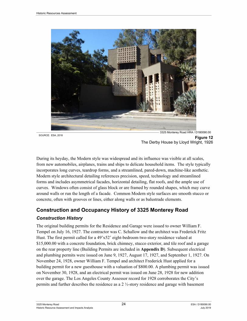
Historic Resources Assessment
3325 Monterey Road 24 ESA / D180090.00 Historic Resource Assessment and Impacts Analysis July 2019
3325 Monterey Road HRA / D180090.00 SOURCE: ESA, 2018
Figure 12 The Derby House by Lloyd Wright, 1926
During its heyday, the Modern style was widespread and its influence was visible at all scales, from new automobiles, airplanes, trains and ships to delicate household items. The style typically incorporates long curves, teardrop forms, and a streamlined, pared-down, machine-like aesthetic. Modern style architectural detailing references precision, speed, technology and streamlined forms and includes asymmetrical facades, horizontal detailing, flat roofs, and the ample use of curves. Windows often consist of glass block or are framed by rounded shapes, which may curve around walls or run the length of a facade. Common Modern style surfaces are smooth stucco or concrete, often with grooves or lines, either along walls or as balustrade elements.
Construction and Occupancy History of 3325 Monterey Road
Construction History
The original building permits for the Residence and Garage were issued to owner William F. Tempel on July 16, 1927. The contractor was C. Schallow and the architect was Frederick Fritz Hust. The first permit called for a 49’x52’ eight-bedroom two-story residence valued at $15,000.00 with a concrete foundation, brick chimney, stucco exterior, and tile roof and a garage on the rear property line (Building Permits are included in Appendix D). Subsequent electrical and plumbing permits were issued on June 9, 1927, August 17, 1927, and September 1, 1927. On November 24, 1928, owner William F. Tempel and architect Frederick Hust applied for a building permit for a new guesthouse with a valuation of $800.00. A plumbing permit was issued on November 30, 1928, and an electrical permit was issued on June 28, 1928 for new addition over the garage. The Los Angeles County Assessor record for 1928 corroborates the City’s permits and further describes the residence as a 2 ½-story residence and garage with basement
Historic Resources Assessment
3325 Monterey Road 25 ESA / D180090.00 Historic Resource Assessment Update and Impacts Analysis July 2019
built in 1927. It documents that it has a stucco exterior, flat composition roof, fireplace, gas heating, electrical lighting, seventeen plumbing fixtures, a bathroom with tile floor, and plaster finish with plain woodwork. In 1928, the Assessor Record also documented the second story addition over the attached garage. Assessor records are provided in Appendix E. In 1929, the subject property was photographed by Harold A. Parker. These photos showed the elaborate landscape and original character of the house including the decorative blocks above the balcony, ceramic Jali screen, elaborate landscaping with pond/fountain at the front elevation and fountain and decorative patio at the rear. These photographs are included in Appendix F.34
There are many subsequent building permits issued since the construction of the residence. Rea L. Eaton got a permit for a reroof on February 28, 1944 and August 17, 1946. Eaton was also issued a permit on February 16, 1955 for the remodel of kitchen. Eaton got two electrical permits, one on February 17, 1955 for a new range, dish washer, oven, and disposal and one on April 4, 1957 for an underground conduit from the main house to the guest house. Although it remains unclear, this permit may indicate that that the guest house was constructed in 1957. Eaton was issued a permit on an unknown date for insulation to be applied over entire ceiling area of the house. The permit does not specify if the insulation was for the main residence or the guest house.
The last owner to receive building permits is Jack D. Whitehead. He was issued a reroof permit on November 14, 1963. He didn’t get another permit until December 1, 1981 for a 306 square-foot addition to the existing guest house for $13,158. He received subsequent permits for the addition including an electrical permit, a plumbing permit, and a mechanical permit all on December 31, 1981. He was issued two more plumbing permits on August 27, 2002 and on July 31, 2008.
On February 15, 2013, the Whitehead Family Trust applied for a Residential Compliance Certificate. However, Amanda Merlo of the City of San Marino Planning Department informed the applicants that the Planning Department could not prepare a Certificate of Compliance because there was construction on site not consistent with city building permit files. Specifically, the garage had been converted to a storage area and carport without building permits, and it was not in compliance with applicable codes. An enclosed garage must be maintained at all times according to the city code. Marino said that the attached garage must be restored to its original condition in order to receive a City Residential Compliance Certificate. Also, an original screened porch (rear porch, however never screened) may have been converted to livable area without proper permits and the City required this space to be legalized to receive the City Residential Compliance Certificate.
The final permit was issued on February 24, 2015 to Jack D. Whitehouse for a kitchen remodel, and a water heater, water closet, and vent change out. There was to be no change in the floor plan or exterior. This history is summarized below in Table 1.
34 Harold A. Parker Studio Collection of Negatives, The Huntington Library, San Marino, California.
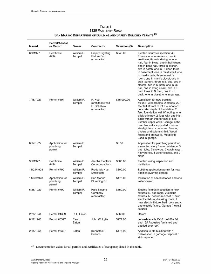
Historic Resources Assessment
3325 Monterey Road 26 ESA / D180090.00 Historic Resource Assessment and Impacts Analysis July 2019
TABLE 1 3325 MONTEREY ROAD
SAN MARINO DEPARTMENT OF BUILDING AND SAFETY BUILDING PERMITS35
Issued Permit/Assessor Record Owner Contractor Valuation ($) Description
6/9/1927 Certificate #494
William F. Tempel
Empire Lighting Fixture Co. (contractor)
$340.00 Electric fixtures inspection: 48 fixtures: one in entrance, one in vestibule, three in dining, one in hall, four in living, one in hall closet, one in pass hall, three in kitchen, two in porch, one in R. door, three in basement, one in maid’s hall, one in maid’s bath, three in maid’s room, one in maid’s closet, one in stair laundry, three in S. bed, two in closets, two in S. bath, one in up hall, one in living closet, two in E. bed, three in N. bed, one in up deck, one in closet, one in garage.
7/16/1927 Permit #494 William F. Tempel
F. Hust (architect) Fred C. Schallow (contractor)
$15,000.00 Application for new building: 49’x52’, 3 bedrooms, 2 stories, 22 feet tall at front of lot. Foundation: concrete, depth of foundation, 2 feet, foundation wall 8” footing, one brick chimney, 2 flues with one inlet each with an interior size of 8x8. Lumber upper walls. Garage in the rear. No walls supported n iron or steel girders or columns. Beams, girders and columns 4x6. Wood floors and stairways. Metal lath used in garage.
8/17/1927 Application for plumbing permit
William F. Tempel
$6.50 Application for plumbing permit for a new two story frame residence. 3 bath tubs, 2 showers, 2 wash trays, 4 lavatories, 4 water closets, and 2 sinks
9/1/1927 Certificate #494
William F. Tempel
Jacobs Electrics Co. (contractor)
$685.00 Electric wiring inspection and instillation
11/24/1928 Permit #790 William F. Tempel
Frederick Hust (Architect)
$800.00 Building application permit for new addition over the garage
11/30/1928 Application for plumbing permit
William F. Tempel
San Marino Plumbing Co.
$175.00 Instillation of one lavatories and one water closet
6/28/1929 Permit #790 William F. Tempel
Hale Electric Company (contractor)
$150.00 Electric fixtures inspection: 5 new fixtures: N. bed room, 2 electric fixtures, N. bedroom closet: 1 new electric fixture, dressing room, 1 new electric fixture, bed room entry, one electric fixture, Garage (new) 2 fixtures
2/28/1944 Permit #4369 R. L. Eaton $86.00 Reroof
8/17/1946 Permit #5327 Rea L. Eaton
John W. Lytle $277.00 Johns-Manville C-10 roof-30# felt and 15# Asbestos furnished and applied over roof.
2/15/1955 Permit #5327 Eaton Kenneth E Schoch
$175.99 Addition to old building with 1 dishwasher, 1 garbage disposal, 1 sink replaced
35 Documentation exists for all permits and certificates of occupancy listed in this table.
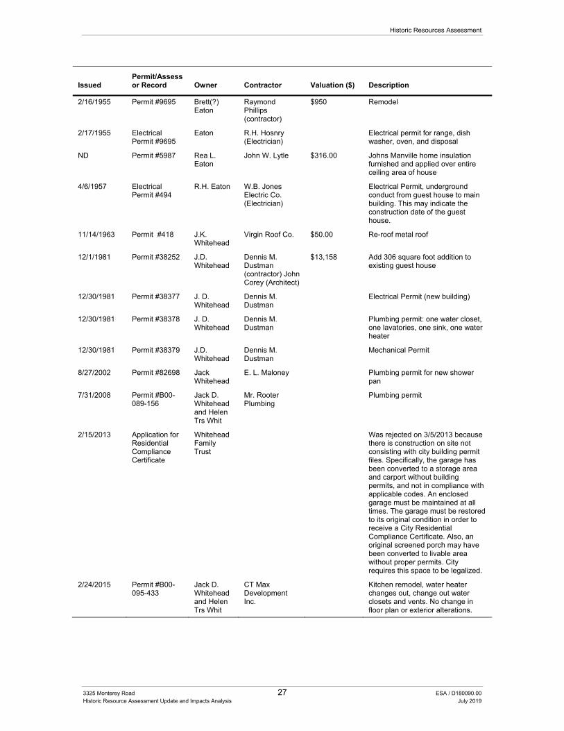
Historic Resources Assessment
3325 Monterey Road 27 ESA / D180090.00 Historic Resource Assessment Update and Impacts Analysis July 2019
Issued Permit/Assessor Record Owner Contractor Valuation ($) Description
2/16/1955 Permit #9695 Brett(?) Eaton
Raymond Phillips (contractor)
$950 Remodel
2/17/1955 Electrical Permit #9695
Eaton R.H. Hosnry (Electrician)
Electrical permit for range, dish washer, oven, and disposal
ND Permit #5987 Rea L. Eaton
John W. Lytle $316.00 Johns Manville home insulation furnished and applied over entire ceiling area of house
4/6/1957 Electrical Permit #494
R.H. Eaton W.B. Jones Electric Co. (Electrician)
Electrical Permit, underground conduct from guest house to main building. This may indicate the construction date of the guest house.
11/14/1963 Permit #418 J.K. Whitehead
Virgin Roof Co. $50.00 Re-roof metal roof
12/1/1981 Permit #38252 J.D. Whitehead
Dennis M. Dustman (contractor) John Corey (Architect)
$13,158 Add 306 square foot addition to existing guest house
12/30/1981 Permit #38377 J. D. Whitehead
Dennis M. Dustman
Electrical Permit (new building)
12/30/1981 Permit #38378 J. D. Whitehead
Dennis M. Dustman
Plumbing permit: one water closet, one lavatories, one sink, one water heater
12/30/1981 Permit #38379 J.D. Whitehead
Dennis M. Dustman
Mechanical Permit
8/27/2002 Permit #82698 Jack Whitehead
E. L. Maloney Plumbing permit for new shower pan
7/31/2008 Permit #B00-089-156
Jack D. Whitehead and Helen Trs Whit
Mr. Rooter Plumbing
Plumbing permit
2/15/2013 Application for Residential Compliance Certificate
Whitehead Family Trust
Was rejected on 3/5/2013 because there is construction on site not consisting with city building permit files. Specifically, the garage has been converted to a storage area and carport without building permits, and not in compliance with applicable codes. An enclosed garage must be maintained at all times. The garage must be restored to its original condition in order to receive a City Residential Compliance Certificate. Also, an original screened porch may have been converted to livable area without proper permits. City requires this space to be legalized.
2/24/2015 Permit #B00-095-433
Jack D. Whitehead and Helen Trs Whit
CT Max Development Inc.
Kitchen remodel, water heater changes out, change out water closets and vents. No change in floor plan or exterior alterations.
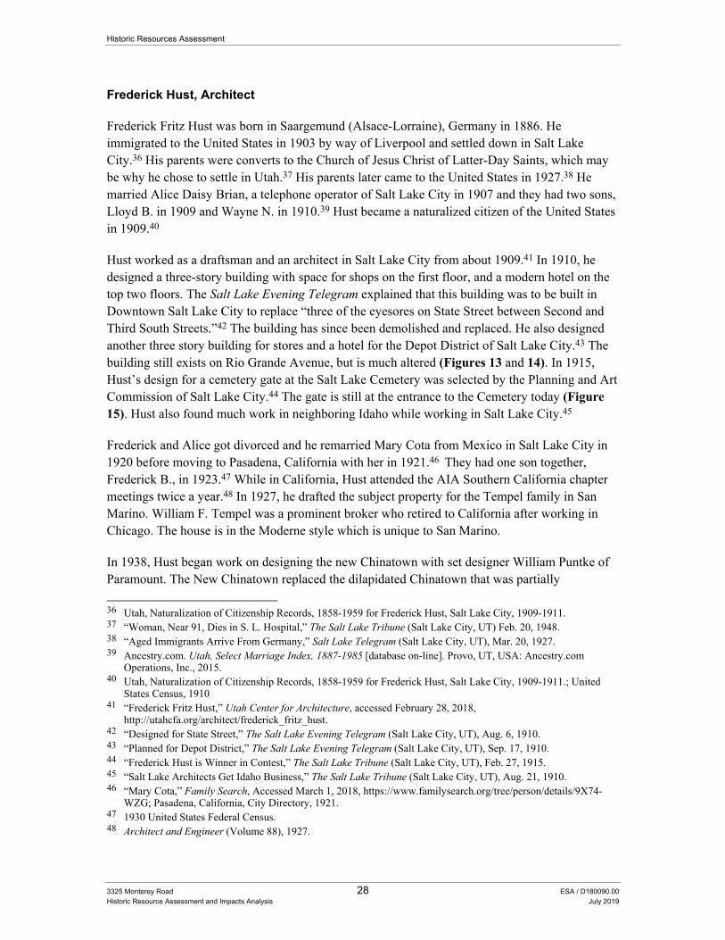
Historic Resources Assessment
3325 Monterey Road 28 ESA / D180090.00 Historic Resource Assessment and Impacts Analysis July 2019
Frederick Hust, Architect
Frederick Fritz Hust was born in Saargemund (Alsace-Lorraine), Germany in 1886. He immigrated to the United States in 1903 by way of Liverpool and settled down in Salt Lake City.36 His parents were converts to the Church of Jesus Christ of Latter-Day Saints, which may be why he chose to settle in Utah.37 His parents later came to the United States in 1927.38 He married Alice Daisy Brian, a telephone operator of Salt Lake City in 1907 and they had two sons, Lloyd B. in 1909 and Wayne N. in 1910.39 Hust became a naturalized citizen of the United States in 1909.40
Hust worked as a draftsman and an architect in Salt Lake City from about 1909.41 In 1910, he designed a three-story building with space for shops on the first floor, and a modern hotel on the top two floors. The Salt Lake Evening Telegram explained that this building was to be built in Downtown Salt Lake City to replace “three of the eyesores on State Street between Second and Third South Streets.”42 The building has since been demolished and replaced. He also designed another three story building for stores and a hotel for the Depot District of Salt Lake City.43 The building still exists on Rio Grande Avenue, but is much altered (Figures 13 and 14). In 1915, Hust’s design for a cemetery gate at the Salt Lake Cemetery was selected by the Planning and Art Commission of Salt Lake City.44 The gate is still at the entrance to the Cemetery today (Figure 15). Hust also found much work in neighboring Idaho while working in Salt Lake City.45
Frederick and Alice got divorced and he remarried Mary Cota from Mexico in Salt Lake City in 1920 before moving to Pasadena, California with her in 1921.46 They had one son together, Frederick B., in 1923.47 While in California, Hust attended the AIA Southern California chapter meetings twice a year.48 In 1927, he drafted the subject property for the Tempel family in San Marino. William F. Tempel was a prominent broker who retired to California after working in Chicago. The house is in the Moderne style which is unique to San Marino.
In 1938, Hust began work on designing the new Chinatown with set designer William Puntke of Paramount. The New Chinatown replaced the dilapidated Chinatown that was partially
36 Utah, Naturalization of Citizenship Records, 1858-1959 for Frederick Hust, Salt Lake City, 1909-1911. 37 “Woman, Near 91, Dies in S. L. Hospital,” The Salt Lake Tribune (Salt Lake City, UT) Feb. 20, 1948. 38 “Aged Immigrants Arrive From Germany,” Salt Lake Telegram (Salt Lake City, UT), Mar. 20, 1927. 39 Ancestry.com. Utah, Select Marriage Index, 1887-1985 [database on-line]. Provo, UT, USA: Ancestry.com
Operations, Inc., 2015. 40 Utah, Naturalization of Citizenship Records, 1858-1959 for Frederick Hust, Salt Lake City, 1909-1911.; United
States Census, 1910 41 “Frederick Fritz Hust,” Utah Center for Architecture, accessed February 28, 2018,
http://utahcfa.org/architect/frederick_fritz_hust. 42 “Designed for State Street,” The Salt Lake Evening Telegram (Salt Lake City, UT), Aug. 6, 1910. 43 “Planned for Depot District,” The Salt Lake Evening Telegram (Salt Lake City, UT), Sep. 17, 1910. 44 “Frederick Hust is Winner in Contest,” The Salt Lake Tribune (Salt Lake City, UT), Feb. 27, 1915. 45 “Salt Lake Architects Get Idaho Business,” The Salt Lake Tribune (Salt Lake City, UT), Aug. 21, 1910. 46 “Mary Cota,” Family Search, Accessed March 1, 2018, https://www.familysearch.org/tree/person/details/9X74-
WZG; Pasadena, California, City Directory, 1921. 47 1930 United States Federal Census. 48 Architect and Engineer (Volume 88), 1927.
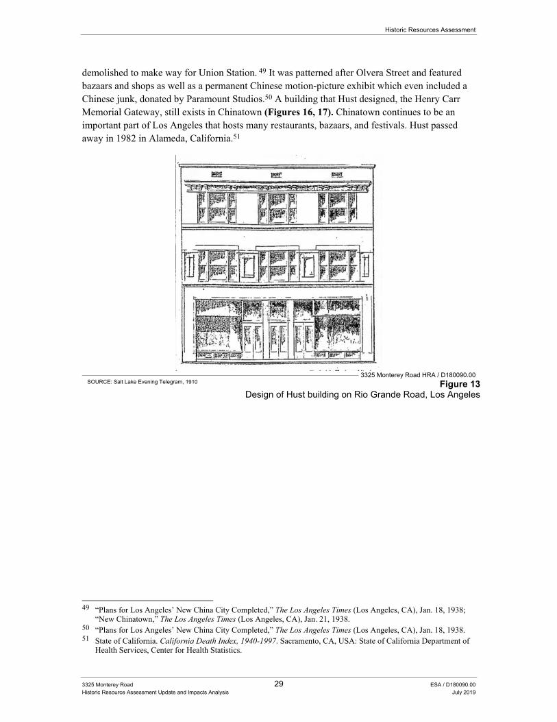
Historic Resources Assessment
3325 Monterey Road 29 ESA / D180090.00 Historic Resource Assessment Update and Impacts Analysis July 2019
demolished to make way for Union Station. 49 It was patterned after Olvera Street and featured bazaars and shops as well as a permanent Chinese motion-picture exhibit which even included a Chinese junk, donated by Paramount Studios.50 A building that Hust designed, the Henry Carr Memorial Gateway, still exists in Chinatown (Figures 16, 17). Chinatown continues to be an important part of Los Angeles that hosts many restaurants, bazaars, and festivals. Hust passed away in 1982 in Alameda, California.51
3325 Monterey Road HRA / D180090.00 SOURCE: Salt Lake Evening Telegram, 1910 Figure 13
Design of Hust building on Rio Grande Road, Los Angeles
49 “Plans for Los Angeles’ New China City Completed,” The Los Angeles Times (Los Angeles, CA), Jan. 18, 1938;
“New Chinatown,” The Los Angeles Times (Los Angeles, CA), Jan. 21, 1938. 50 “Plans for Los Angeles’ New China City Completed,” The Los Angeles Times (Los Angeles, CA), Jan. 18, 1938. 51 State of California. California Death Index, 1940-1997. Sacramento, CA, USA: State of California Department of
Health Services, Center for Health Statistics.
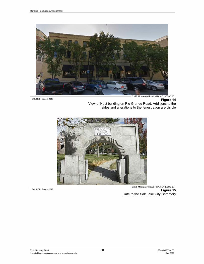
Historic Resources Assessment
3325 Monterey Road 30 ESA / D180090.00 Historic Resource Assessment and Impacts Analysis July 2019
3325 Monterey Road HRA / D180090.00 SOURCE: Google 2019 Figure 14
View of Hust building on Rio Grande Road. Additions to the sides and alterations to the fenestration are visible
3325 Monterey Road HRA / D180090.00 SOURCE: Google 2018 Figure 15
Gate to the Salt Lake City Cemetery
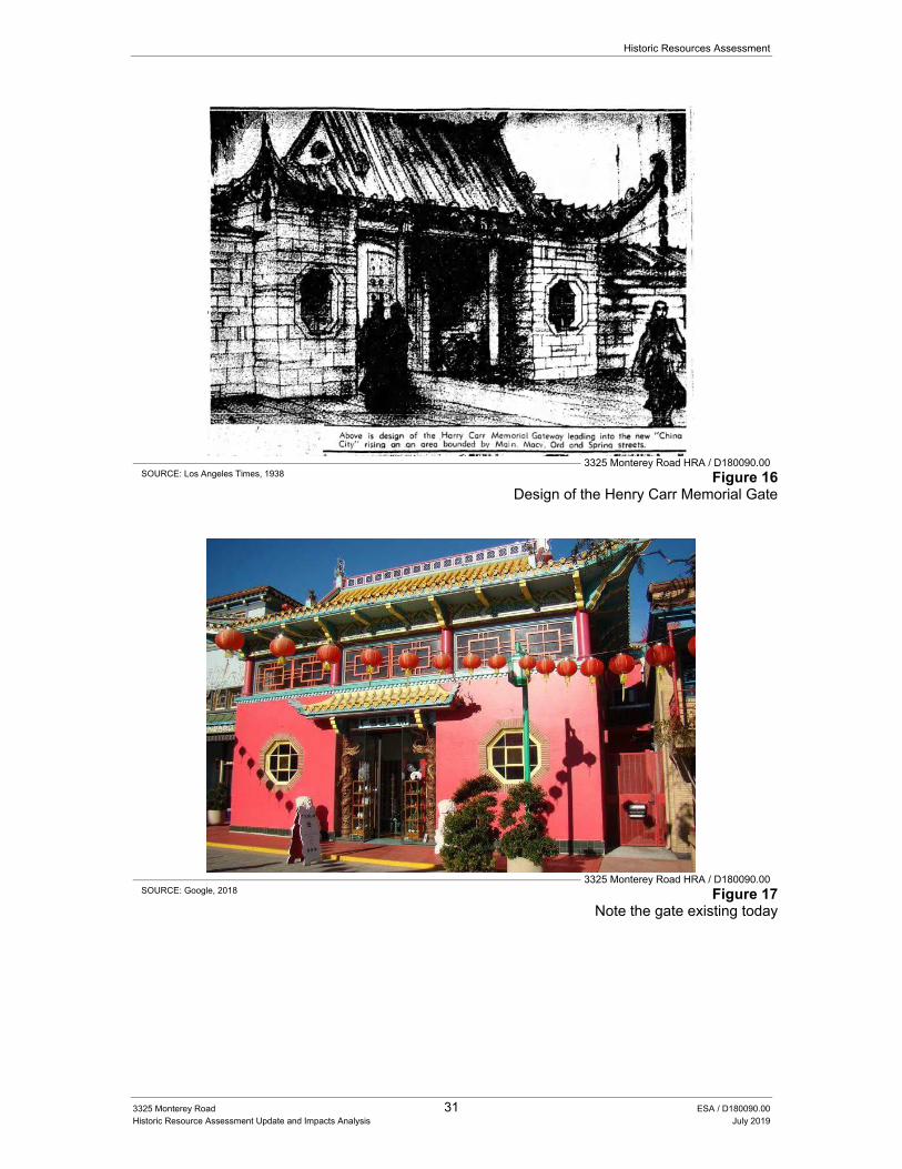
Historic Resources Assessment
3325 Monterey Road 31 ESA / D180090.00 Historic Resource Assessment Update and Impacts Analysis July 2019
3325 Monterey Road HRA / D180090.00 SOURCE: Los Angeles Times, 1938 Figure 16
Design of the Henry Carr Memorial Gate
3325 Monterey Road HRA / D180090.00 SOURCE: Google, 2018 Figure 17
Note the gate existing today
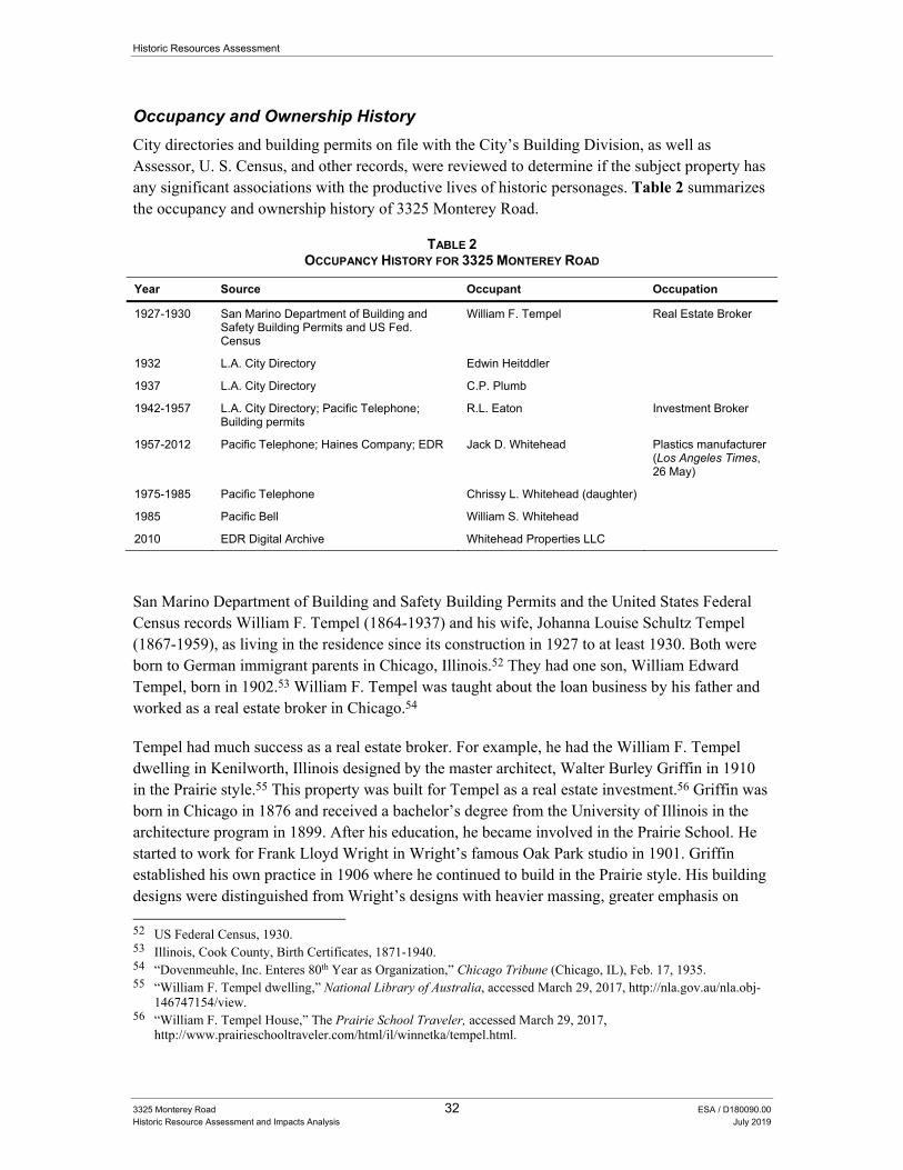
Historic Resources Assessment
3325 Monterey Road 32 ESA / D180090.00 Historic Resource Assessment and Impacts Analysis July 2019
Occupancy and Ownership History
City directories and building permits on file with the City’s Building Division, as well as Assessor, U. S. Census, and other records, were reviewed to determine if the subject property has any significant associations with the productive lives of historic personages. Table 2 summarizes the occupancy and ownership history of 3325 Monterey Road.
TABLE 2 OCCUPANCY HISTORY FOR 3325 MONTEREY ROAD
Year Source Occupant Occupation
1927-1930 San Marino Department of Building and Safety Building Permits and US Fed. Census
William F. Tempel Real Estate Broker
1932 L.A. City Directory Edwin Heitddler
1937 L.A. City Directory C.P. Plumb
1942-1957 L.A. City Directory; Pacific Telephone; Building permits
R.L. Eaton Investment Broker
1957-2012 Pacific Telephone; Haines Company; EDR Jack D. Whitehead Plastics manufacturer (Los Angeles Times, 26 May)
1975-1985 Pacific Telephone Chrissy L. Whitehead (daughter)
1985 Pacific Bell William S. Whitehead
2010 EDR Digital Archive Whitehead Properties LLC
San Marino Department of Building and Safety Building Permits and the United States Federal Census records William F. Tempel (1864-1937) and his wife, Johanna Louise Schultz Tempel (1867-1959), as living in the residence since its construction in 1927 to at least 1930. Both were born to German immigrant parents in Chicago, Illinois.52 They had one son, William Edward Tempel, born in 1902.53 William F. Tempel was taught about the loan business by his father and worked as a real estate broker in Chicago.54
Tempel had much success as a real estate broker. For example, he had the William F. Tempel dwelling in Kenilworth, Illinois designed by the master architect, Walter Burley Griffin in 1910 in the Prairie style.55 This property was built for Tempel as a real estate investment.56 Griffin was born in Chicago in 1876 and received a bachelor’s degree from the University of Illinois in the architecture program in 1899. After his education, he became involved in the Prairie School. He started to work for Frank Lloyd Wright in Wright’s famous Oak Park studio in 1901. Griffin established his own practice in 1906 where he continued to build in the Prairie style. His building designs were distinguished from Wright’s designs with heavier massing, greater emphasis on 52 US Federal Census, 1930. 53 Illinois, Cook County, Birth Certificates, 1871-1940. 54 “Dovenmeuhle, Inc. Enteres 80th Year as Organization,” Chicago Tribune (Chicago, IL), Feb. 17, 1935. 55 “William F. Tempel dwelling,” National Library of Australia, accessed March 29, 2017, http://nla.gov.au/nla.obj-
146747154/view. 56 “William F. Tempel House,” The Prairie School Traveler, accessed March 29, 2017,
http://www.prairieschooltraveler.com/html/il/winnetka/tempel.html.
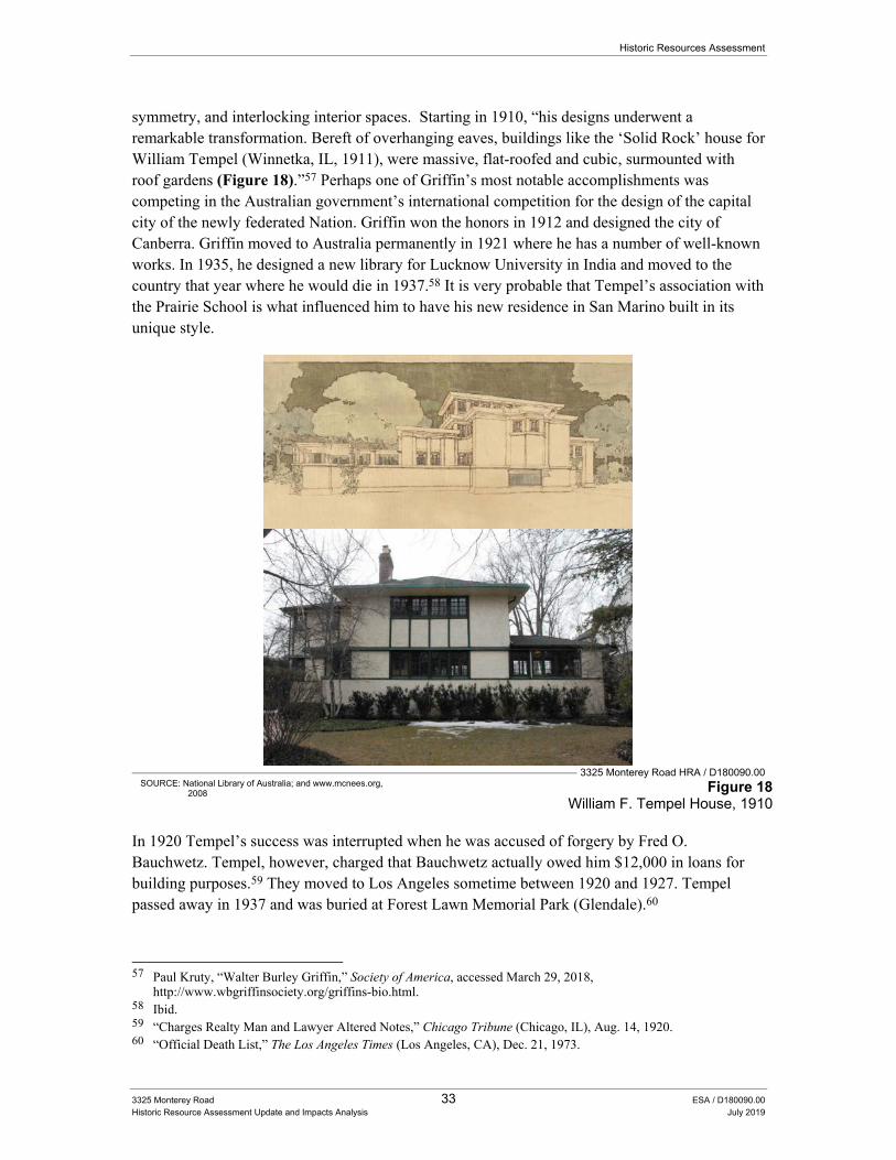
Historic Resources Assessment
3325 Monterey Road 33 ESA / D180090.00 Historic Resource Assessment Update and Impacts Analysis July 2019
symmetry, and interlocking interior spaces. Starting in 1910, “his designs underwent a remarkable transformation. Bereft of overhanging eaves, buildings like the ‘Solid Rock’ house for William Tempel (Winnetka, IL, 1911), were massive, flat-roofed and cubic, surmounted with roof gardens (Figure 18).”57 Perhaps one of Griffin’s most notable accomplishments was competing in the Australian government’s international competition for the design of the capital city of the newly federated Nation. Griffin won the honors in 1912 and designed the city of Canberra. Griffin moved to Australia permanently in 1921 where he has a number of well-known works. In 1935, he designed a new library for Lucknow University in India and moved to the country that year where he would die in 1937.58 It is very probable that Tempel’s association with the Prairie School is what influenced him to have his new residence in San Marino built in its unique style.
3325 Monterey Road HRA / D180090.00
SOURCE: National Library of Australia; and www.mcnees.org, 2008 Figure 18
William F. Tempel House, 1910
In 1920 Tempel’s success was interrupted when he was accused of forgery by Fred O. Bauchwetz. Tempel, however, charged that Bauchwetz actually owed him $12,000 in loans for building purposes.59 They moved to Los Angeles sometime between 1920 and 1927. Tempel passed away in 1937 and was buried at Forest Lawn Memorial Park (Glendale).60
57 Paul Kruty, “Walter Burley Griffin,” Society of America, accessed March 29, 2018,
http://www.wbgriffinsociety.org/griffins-bio.html. 58 Ibid. 59 “Charges Realty Man and Lawyer Altered Notes,” Chicago Tribune (Chicago, IL), Aug. 14, 1920. 60 “Official Death List,” The Los Angeles Times (Los Angeles, CA), Dec. 21, 1973.
Historic Resources Assessment
3325 Monterey Road 34 ESA / D180090.00 Historic Resource Assessment and Impacts Analysis July 2019
The City directory records Edwin Heitddler living at the subject property in 1932 and C. P. Plumb in 1937. No additional information was found about either of those people. The next person listed in the City Directory is Rae L. Eaton who lived with his wife, Carol H., his son Ben H., and his daughters Mary C. and Nancy J. Rea L. Eaton was born in Eaton, Colorado, in 1896 and was a member of the prominent pioneer family that helped build that community. He moved to San Marino in his early thirties and joined the brokerage business, opening the first brokerage office in San Marino.61 Eaton worked for Davies & Co. which was transferred to Hogle & Co. in 1942 in their San Marino Office.62 Later, Eaton managed Dean Wittier & Co.’s San Marino office and became partner in February of 1954.63 He also had interests in the Oil Shale development in Western Colorado.64 Eaton was an avid golfer and placed second place at the weekly Choose-up tournament at O’Donnel Golfing Club in 1961.65 Eaton was also active in politics, donating $150 to Senator Richard Nixon’s fund in 1952.66 Eaton and his wife hosted two weddings at the residence, the wedding of their nephew, Rex Carr Eaton Jr. in 1950, and the wedding of their Daughter Nancy in 1953.67 Eaton passed away on November 12, 1970.
The City directories record Jack D. Whitehead residing at the property since 1957 until his death in 2012. He was born in 1922 in Kansas and moved to California with his family when he was five years old. He studied engineering and architecture at UCLA and worked for Bertea Engineering, the architectural firm Bennet & Bennet, John Case Engineering and the American Olympic Committee. Upon marrying Helen Louise Williams in 1951 and moving to San Marino in 1954, he left architecture and joined the plastics industry where he had much success buying and selling companies. They had three children together, Chrissy, Robert, and Bill.68 Whitehead was very active in the community. He served as Vice President over the Burbank Chamber of Commerce in 1960.69 He was on the board for the Boys Club of Pasadena, to which he donated a small railroad and train in 1960. It had originally been used by his children at home.70 He also served on the Rose Bowl Committee for many years including 1964 and 1977.71 Helen passed away in 1994 and he passed away on April 9, 2012 leaving the house in the care of the Whitehead Family Trust. 72
61 “Obituaries: Eaton, Rea L.,” The Los Angeles Times (Los Angeles, CA), Nov. 13, 1970. 62 “Hogle Takes Over Davies & Co. Here,” The Los Angeles Times (Los Angeles, CA), Sep. 27, 1942. 63 “New Partners for Dean Witter,” The Los Angeles Times (Los Angeles, CA), Feb. 2, 1954. 64 “Obituaries: Eaton, Rea L.,” The Los Angeles Times. 65 “Team Winners in Choose-Up,” The Desert Sun (Palm Springs, CA), Dec. 20, 1961. 66 “Contributors to Nixon Fund,” The San Bernardino County Sun (San Bernardino, CA), Sep. 21, 1952. 67 “Ensign Eaton Claims Bride in San Marino,” The Los Angeles Times (Los Angeles, CA), Oct. 2, 1950; “Many
Parties Fete Betrothed Couple,” The Los Angeles Times (Los Angeles, CA), Jul. 12, 1953. 68 “Jack Whitehead,” Obituaries, The Los Angeles Times (Los Angeles, CA), Apr. 29, 2012. 69 “Ecclestone Will Take Over Burbank C of C,” The Los Angeles Times (Los Angeles, CA), Jan. 10, 1960. 70 “Pasadena Boys’ Club Given Small Railroad,” The Los Angeles Times (Los Angeles, CA), May 26, 1960. 71 “Assignments Set for Rose Bowl Committee of 325,” Pasadena Independent (Pasadena, CA), Oct. 22, 1964; “Carl
Wopschall to Head 1977 Rose Fest,” Arcadia Tribune (Arcadia, CA), Feb. 19, 1976. 72 “Jack Whitehead,” The Los Angeles Times.
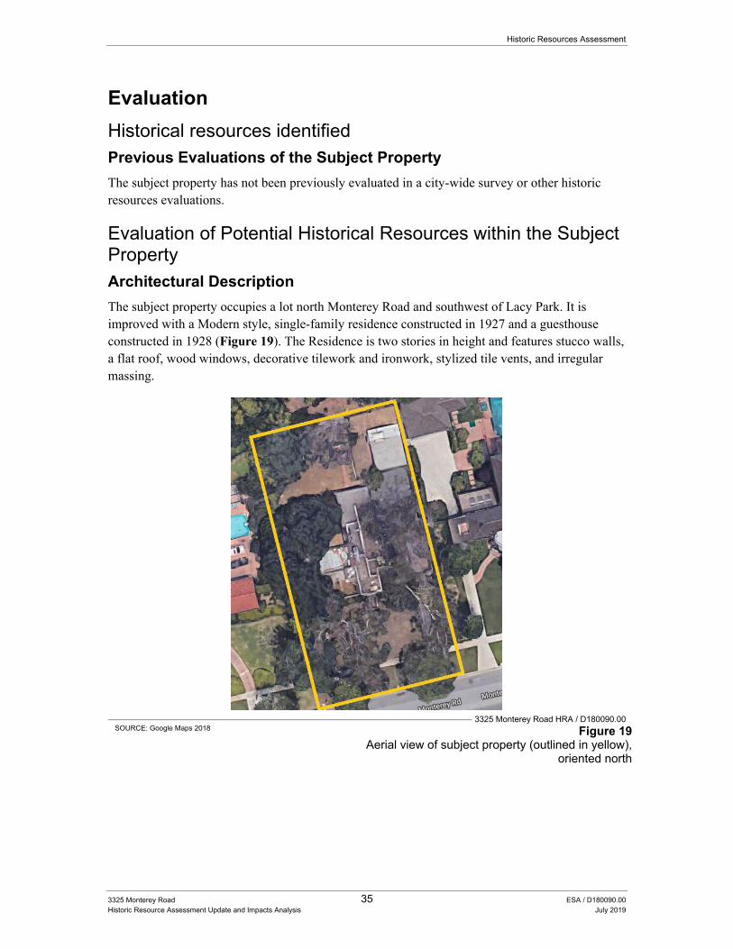
Historic Resources Assessment
3325 Monterey Road 35 ESA / D180090.00 Historic Resource Assessment Update and Impacts Analysis July 2019
Evaluation
Historical resources identified Previous Evaluations of the Subject Property
The subject property has not been previously evaluated in a city-wide survey or other historic resources evaluations.
Evaluation of Potential Historical Resources within the Subject Property Architectural Description
The subject property occupies a lot north Monterey Road and southwest of Lacy Park. It is improved with a Modern style, single-family residence constructed in 1927 and a guesthouse constructed in 1928 (Figure 19). The Residence is two stories in height and features stucco walls, a flat roof, wood windows, decorative tilework and ironwork, stylized tile vents, and irregular massing.
3325 Monterey Road HRA / D180090.00
SOURCE: Google Maps 2018 Figure 19 Aerial view of subject property (outlined in yellow),
oriented north
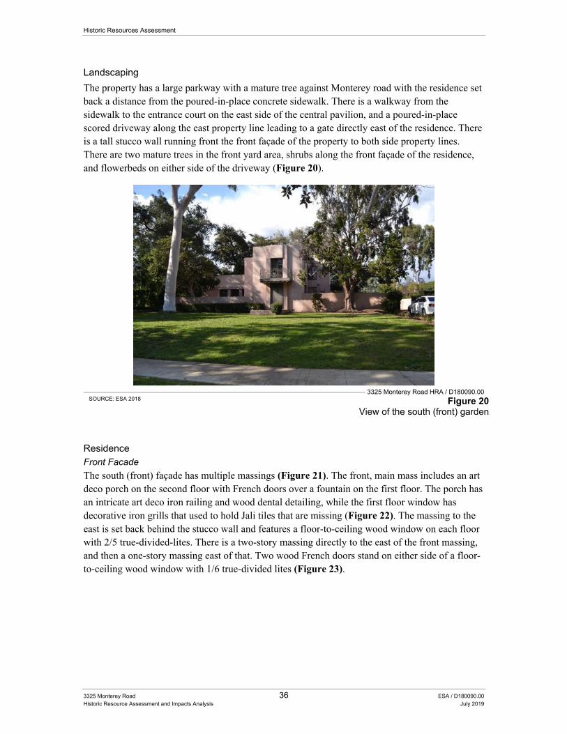
Historic Resources Assessment
3325 Monterey Road 36 ESA / D180090.00 Historic Resource Assessment and Impacts Analysis July 2019
Landscaping
The property has a large parkway with a mature tree against Monterey road with the residence set back a distance from the poured-in-place concrete sidewalk. There is a walkway from the sidewalk to the entrance court on the east side of the central pavilion, and a poured-in-place scored driveway along the east property line leading to a gate directly east of the residence. There is a tall stucco wall running front the front façade of the property to both side property lines. There are two mature trees in the front yard area, shrubs along the front façade of the residence, and flowerbeds on either side of the driveway (Figure 20).
3325 Monterey Road HRA / D180090.00
SOURCE: ESA 2018 Figure 20 View of the south (front) garden
Residence Front Facade
The south (front) façade has multiple massings (Figure 21). The front, main mass includes an art deco porch on the second floor with French doors over a fountain on the first floor. The porch has an intricate art deco iron railing and wood dental detailing, while the first floor window has decorative iron grills that used to hold Jali tiles that are missing (Figure 22). The massing to the east is set back behind the stucco wall and features a floor-to-ceiling wood window on each floor with 2/5 true-divided-lites. There is a two-story massing directly to the east of the front massing, and then a one-story massing east of that. Two wood French doors stand on either side of a floor-to-ceiling wood window with 1/6 true-divided lites (Figure 23).
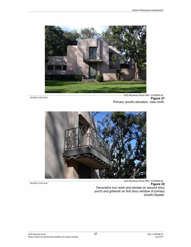
Historic Resources Assessment
3325 Monterey Road 37 ESA / D180090.00 Historic Resource Assessment Update and Impacts Analysis July 2019
3325 Monterey Road HRA / D180090.00
SOURCE: ESA 2018 Figure 21 Primary (south) elevation, view north.
3325 Monterey Road HRA / D180090.00
SOURCE: ESA 2018 Figure 22 Decorative iron work and dentals on second story
porch and grillwork on first story window of primary (south) façade.
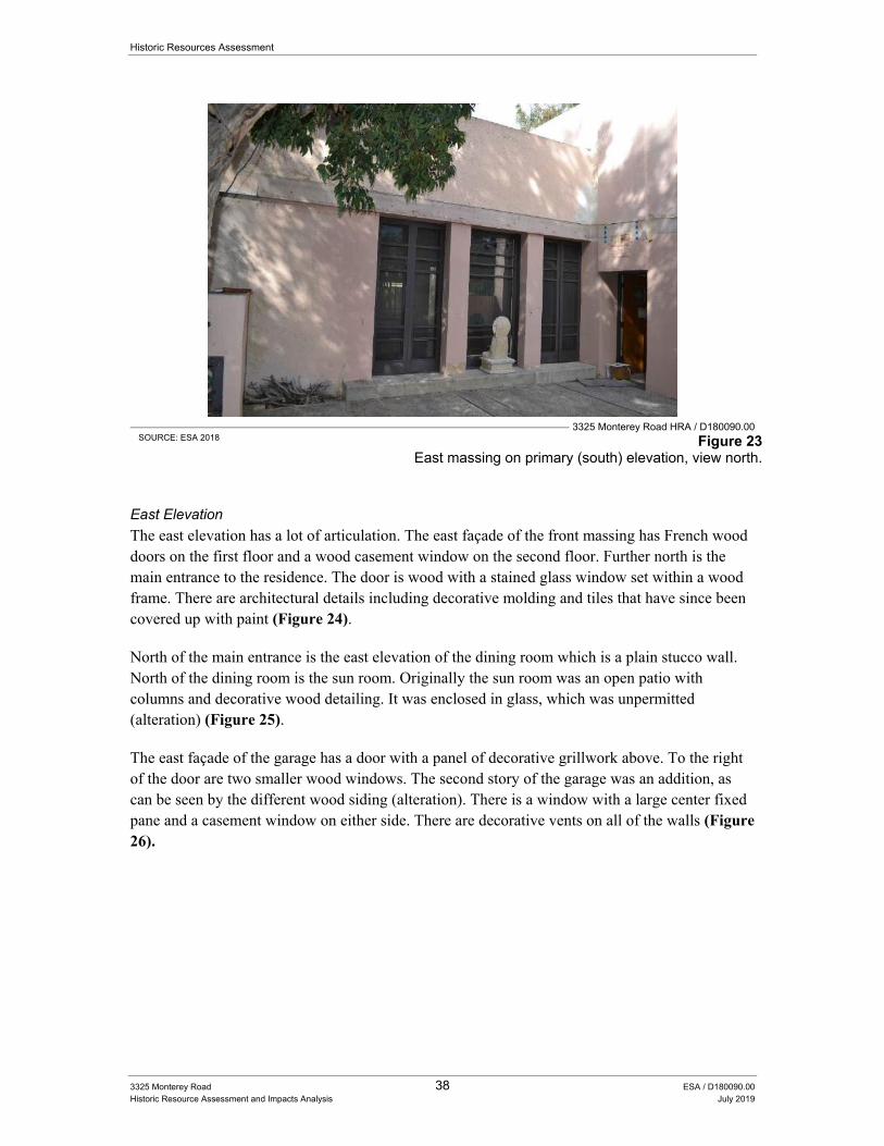
Historic Resources Assessment
3325 Monterey Road 38 ESA / D180090.00 Historic Resource Assessment and Impacts Analysis July 2019
3325 Monterey Road HRA / D180090.00
SOURCE: ESA 2018 Figure 23 East massing on primary (south) elevation, view north.
East Elevation
The east elevation has a lot of articulation. The east façade of the front massing has French wood doors on the first floor and a wood casement window on the second floor. Further north is the main entrance to the residence. The door is wood with a stained glass window set within a wood frame. There are architectural details including decorative molding and tiles that have since been covered up with paint (Figure 24).
North of the main entrance is the east elevation of the dining room which is a plain stucco wall. North of the dining room is the sun room. Originally the sun room was an open patio with columns and decorative wood detailing. It was enclosed in glass, which was unpermitted (alteration) (Figure 25).
The east façade of the garage has a door with a panel of decorative grillwork above. To the right of the door are two smaller wood windows. The second story of the garage was an addition, as can be seen by the different wood siding (alteration). There is a window with a large center fixed pane and a casement window on either side. There are decorative vents on all of the walls (Figure 26).
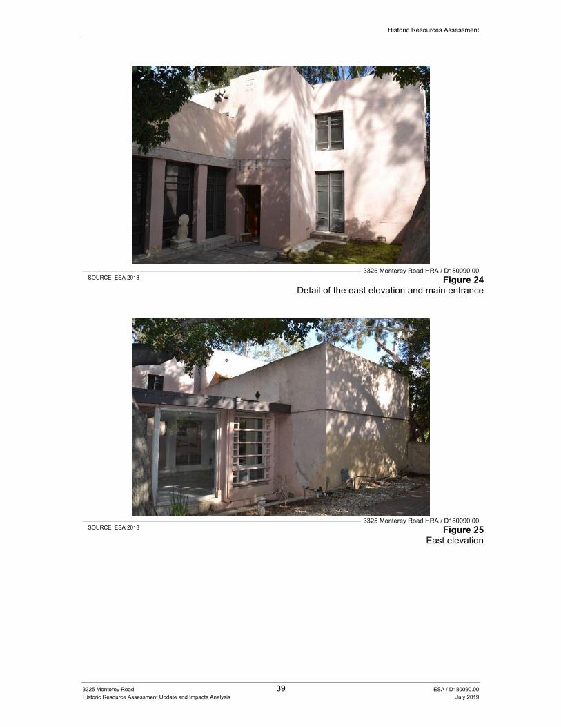
Historic Resources Assessment
3325 Monterey Road 39 ESA / D180090.00 Historic Resource Assessment Update and Impacts Analysis July 2019
3325 Monterey Road HRA / D180090.00
SOURCE: ESA 2018 Figure 24 Detail of the east elevation and main entrance
3325 Monterey Road HRA / D180090.00
SOURCE: ESA 2018 Figure 25 East elevation
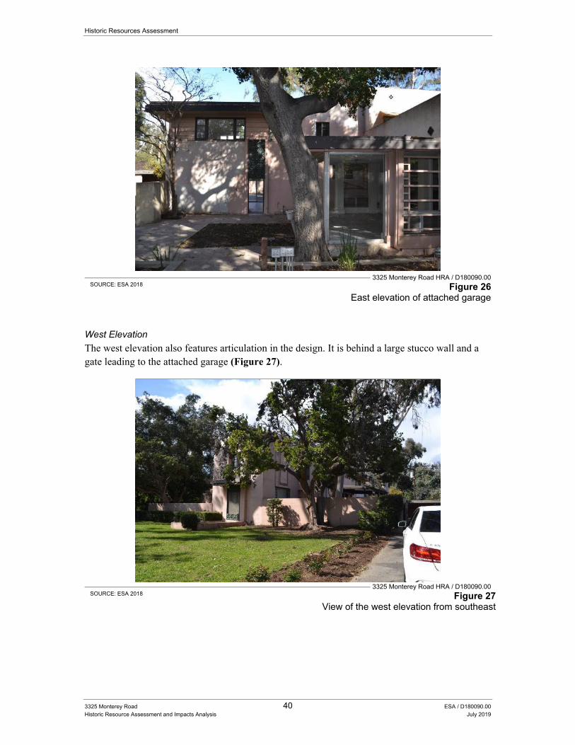
Historic Resources Assessment
3325 Monterey Road 40 ESA / D180090.00 Historic Resource Assessment and Impacts Analysis July 2019
3325 Monterey Road HRA / D180090.00
SOURCE: ESA 2018 Figure 26 East elevation of attached garage
West Elevation
The west elevation also features articulation in the design. It is behind a large stucco wall and a gate leading to the attached garage (Figure 27).
3325 Monterey Road HRA / D180090.00
SOURCE: ESA 2018 Figure 27 View of the west elevation from southeast
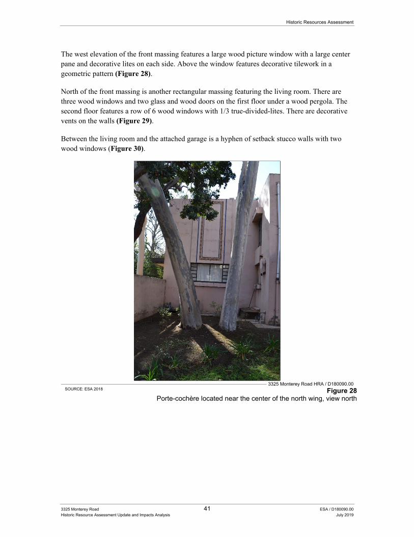
Historic Resources Assessment
3325 Monterey Road 41 ESA / D180090.00 Historic Resource Assessment Update and Impacts Analysis July 2019
The west elevation of the front massing features a large wood picture window with a large center pane and decorative lites on each side. Above the window features decorative tilework in a geometric pattern (Figure 28).
North of the front massing is another rectangular massing featuring the living room. There are three wood windows and two glass and wood doors on the first floor under a wood pergola. The second floor features a row of 6 wood windows with 1/3 true-divided-lites. There are decorative vents on the walls (Figure 29).
Between the living room and the attached garage is a hyphen of setback stucco walls with two wood windows (Figure 30).
3325 Monterey Road HRA / D180090.00
SOURCE: ESA 2018 Figure 28 Porte-cochère located near the center of the north wing, view north
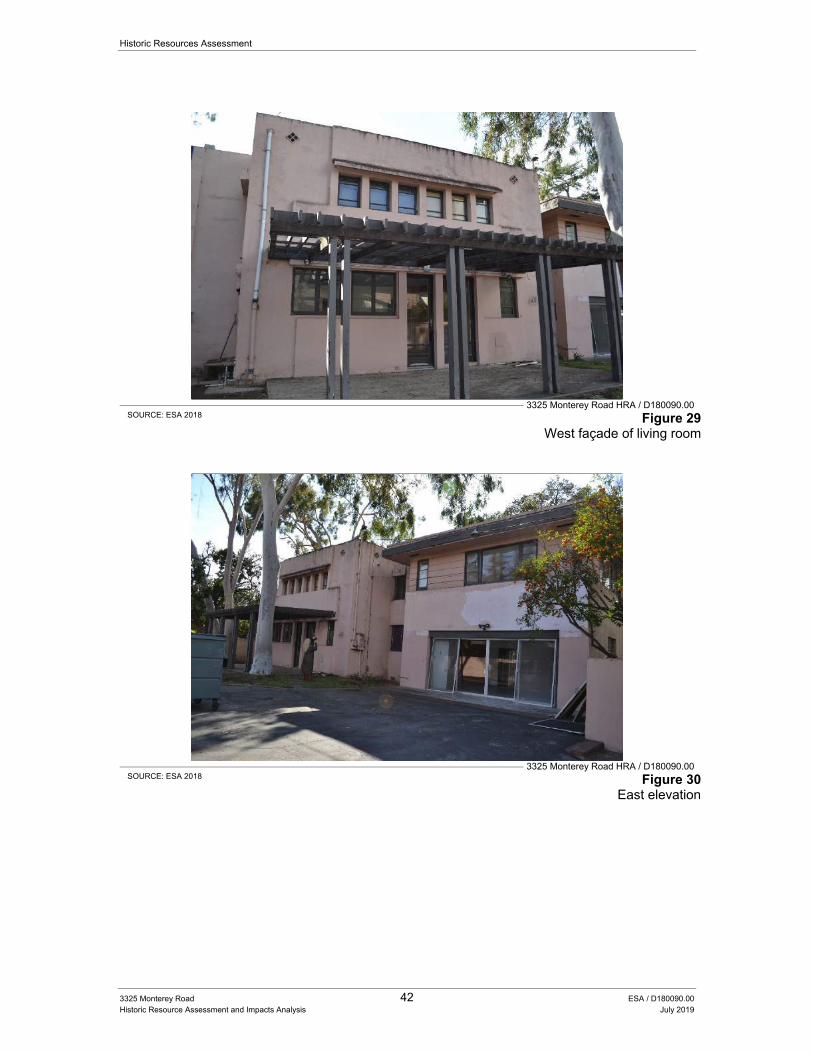
Historic Resources Assessment
3325 Monterey Road 42 ESA / D180090.00 Historic Resource Assessment and Impacts Analysis July 2019
3325 Monterey Road HRA / D180090.00 SOURCE: ESA 2018 Figure 29
West façade of living room
3325 Monterey Road HRA / D180090.00 SOURCE: ESA 2018 Figure 30
East elevation
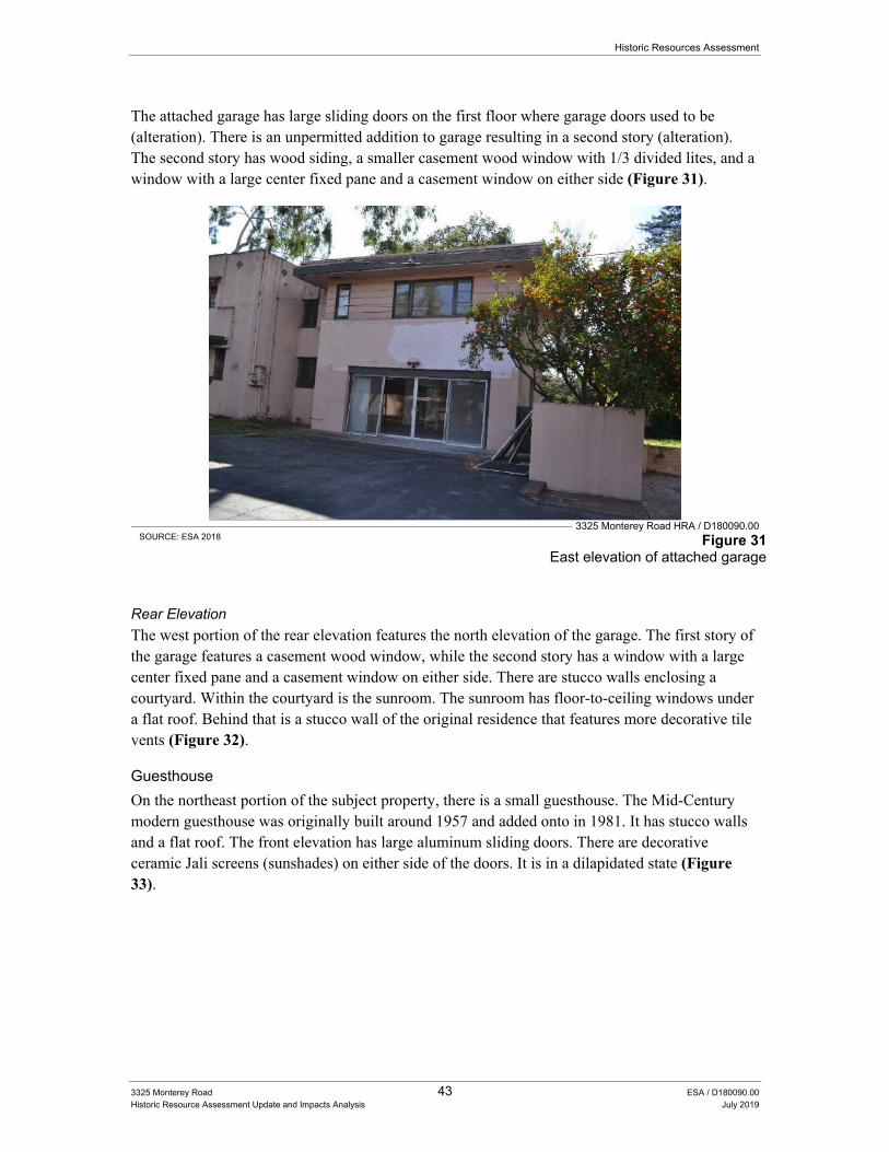
Historic Resources Assessment
3325 Monterey Road 43 ESA / D180090.00 Historic Resource Assessment Update and Impacts Analysis July 2019
The attached garage has large sliding doors on the first floor where garage doors used to be (alteration). There is an unpermitted addition to garage resulting in a second story (alteration). The second story has wood siding, a smaller casement wood window with 1/3 divided lites, and a window with a large center fixed pane and a casement window on either side (Figure 31).
3325 Monterey Road HRA / D180090.00 SOURCE: ESA 2018 Figure 31
East elevation of attached garage
Rear Elevation
The west portion of the rear elevation features the north elevation of the garage. The first story of the garage features a casement wood window, while the second story has a window with a large center fixed pane and a casement window on either side. There are stucco walls enclosing a courtyard. Within the courtyard is the sunroom. The sunroom has floor-to-ceiling windows under a flat roof. Behind that is a stucco wall of the original residence that features more decorative tile vents (Figure 32).
Guesthouse
On the northeast portion of the subject property, there is a small guesthouse. The Mid-Century modern guesthouse was originally built around 1957 and added onto in 1981. It has stucco walls and a flat roof. The front elevation has large aluminum sliding doors. There are decorative ceramic Jali screens (sunshades) on either side of the doors. It is in a dilapidated state (Figure 33).
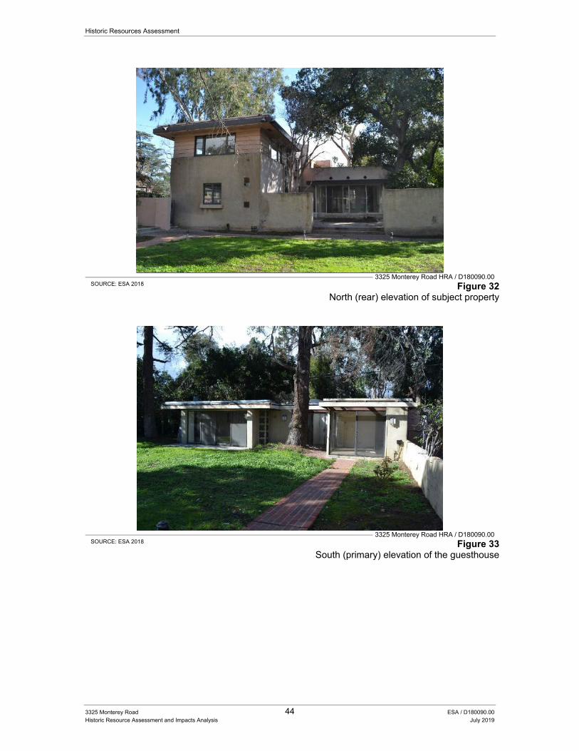
Historic Resources Assessment
3325 Monterey Road 44 ESA / D180090.00 Historic Resource Assessment and Impacts Analysis July 2019
3325 Monterey Road HRA / D180090.00 SOURCE: ESA 2018 Figure 32
North (rear) elevation of subject property
3325 Monterey Road HRA / D180090.00 SOURCE: ESA 2018 Figure 33
South (primary) elevation of the guesthouse
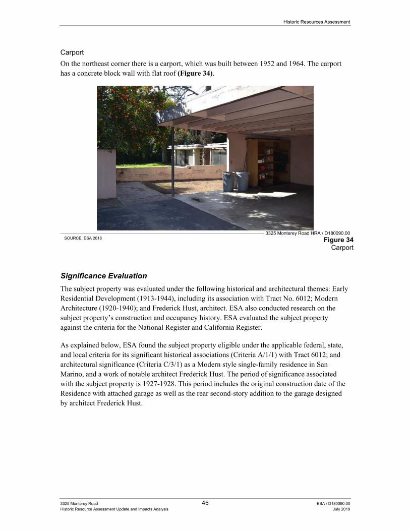
Historic Resources Assessment
3325 Monterey Road 45 ESA / D180090.00 Historic Resource Assessment Update and Impacts Analysis July 2019
Carport
On the northeast corner there is a carport, which was built between 1952 and 1964. The carport has a concrete block wall with flat roof (Figure 34).
3325 Monterey Road HRA / D180090.00 SOURCE: ESA 2018 Figure 34
Carport
Significance Evaluation
The subject property was evaluated under the following historical and architectural themes: Early Residential Development (1913-1944), including its association with Tract No. 6012; Modern Architecture (1920-1940); and Frederick Hust, architect. ESA also conducted research on the subject property’s construction and occupancy history. ESA evaluated the subject property against the criteria for the National Register and California Register.
As explained below, ESA found the subject property eligible under the applicable federal, state, and local criteria for its significant historical associations (Criteria A/1/1) with Tract 6012; and architectural significance (Criteria C/3/1) as a Modern style single-family residence in San Marino, and a work of notable architect Frederick Hust. The period of significance associated with the subject property is 1927-1928. This period includes the original construction date of the Residence with attached garage as well as the rear second-story addition to the garage designed by architect Frederick Hust.
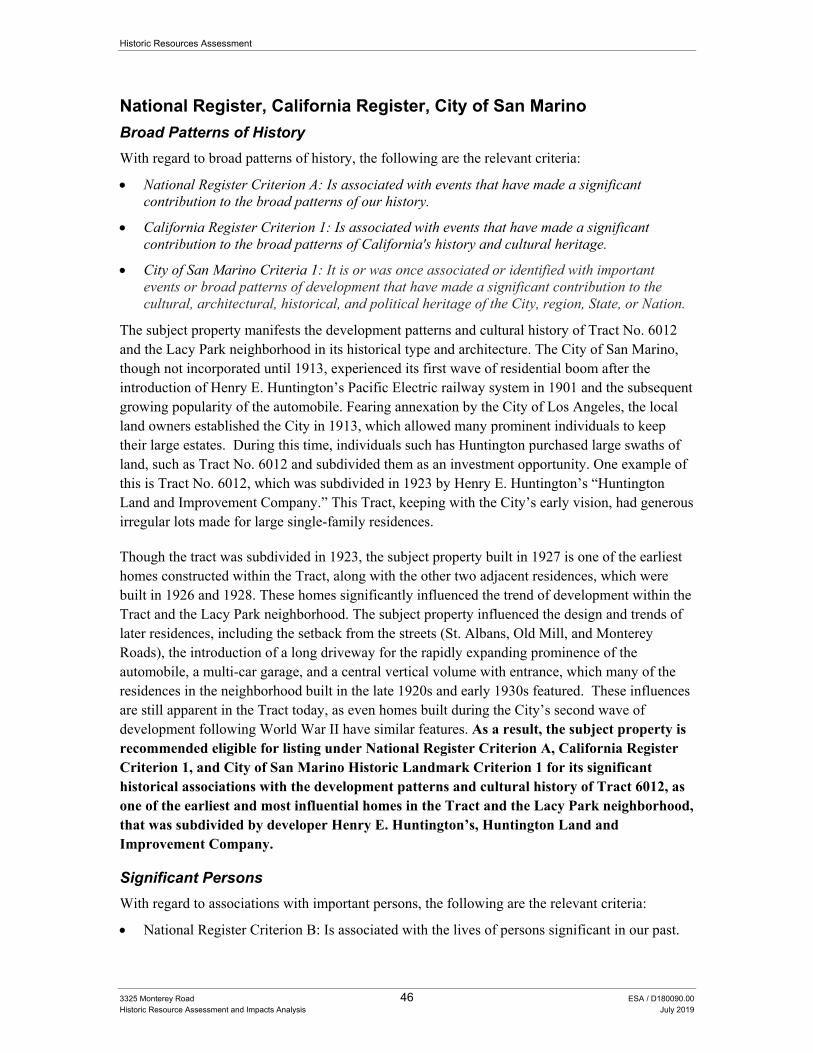
Historic Resources Assessment
3325 Monterey Road 46 ESA / D180090.00 Historic Resource Assessment and Impacts Analysis July 2019
National Register, California Register, City of San Marino
Broad Patterns of History
With regard to broad patterns of history, the following are the relevant criteria:
National Register Criterion A: Is associated with events that have made a significant contribution to the broad patterns of our history.
California Register Criterion 1: Is associated with events that have made a significant contribution to the broad patterns of California's history and cultural heritage.
City of San Marino Criteria 1: It is or was once associated or identified with important events or broad patterns of development that have made a significant contribution to the cultural, architectural, historical, and political heritage of the City, region, State, or Nation.
The subject property manifests the development patterns and cultural history of Tract No. 6012 and the Lacy Park neighborhood in its historical type and architecture. The City of San Marino, though not incorporated until 1913, experienced its first wave of residential boom after the introduction of Henry E. Huntington’s Pacific Electric railway system in 1901 and the subsequent growing popularity of the automobile. Fearing annexation by the City of Los Angeles, the local land owners established the City in 1913, which allowed many prominent individuals to keep their large estates. During this time, individuals such has Huntington purchased large swaths of land, such as Tract No. 6012 and subdivided them as an investment opportunity. One example of this is Tract No. 6012, which was subdivided in 1923 by Henry E. Huntington’s “Huntington Land and Improvement Company.” This Tract, keeping with the City’s early vision, had generous irregular lots made for large single-family residences.
Though the tract was subdivided in 1923, the subject property built in 1927 is one of the earliest homes constructed within the Tract, along with the other two adjacent residences, which were built in 1926 and 1928. These homes significantly influenced the trend of development within the Tract and the Lacy Park neighborhood. The subject property influenced the design and trends of later residences, including the setback from the streets (St. Albans, Old Mill, and Monterey Roads), the introduction of a long driveway for the rapidly expanding prominence of the automobile, a multi-car garage, and a central vertical volume with entrance, which many of the residences in the neighborhood built in the late 1920s and early 1930s featured. These influences are still apparent in the Tract today, as even homes built during the City’s second wave of development following World War II have similar features. As a result, the subject property is recommended eligible for listing under National Register Criterion A, California Register Criterion 1, and City of San Marino Historic Landmark Criterion 1 for its significant historical associations with the development patterns and cultural history of Tract 6012, as one of the earliest and most influential homes in the Tract and the Lacy Park neighborhood, that was subdivided by developer Henry E. Huntington’s, Huntington Land and Improvement Company.
Significant Persons
With regard to associations with important persons, the following are the relevant criteria:
National Register Criterion B: Is associated with the lives of persons significant in our past.

Historic Resources Assessment
3325 Monterey Road 47 ESA / D180090.00 Historic Resource Assessment Update and Impacts Analysis July 2019
California Register Criterion 2: Is associated with the lives of persons important in our past.
City of San Marino Criteria 2: It is or was associated with an important person or persons who made a significant contribution to the history, development, or culture of the City, region, State, or Nation.
The known occupants and their confirmed dates of occupation include William F. Tempel (1927-1930); Edwin Heitddler (1932); C.P. Plumb (1937); R.L. Eaton (1942-1957); Jack D. Whitehead (1957-2012); Chrissy L. Whitehead (1975-1985); and William S. Whitehead (1985). The original owner William F. Tempel was a successful real estate broker in Chicago and appears to have commissioned the house for his retirement, which was a common practice during this era in the City and larger region. Tempel though successful, gained his notoriety in Chicago and the town of Winnetka, Illinois which he helped develop as a real estate broker, and not San Marino where he retired. Therefore, the town of Winnetka and his residence there are more befitting for his historical associations.
The next person who lived at the subject property was Rea L. Eaton. Eaton was a member of the prominent pioneer family who founded Eaton, Colorado. Eaton lived at the subject property for approximately fifteen years. Although prominent in Colorado, Eaton was a typical businessperson working and living in San Marino. He does not appear to have had a significant contribution to city, state, or national history.
The last person to live at the subject property was Jack D. Whitehead with his family. Whitehead, the longest resident of the subject property lived there from 1957, until his death in 2012. Whitehead with his wife Helen had three children Chrissy, Robert and Bill. Jack was an active member in the City and region. He served as Vice President over the Burbank Chamber of Commerce, a board member for the Boys Club of Pasadena, and served on the Rose Bowl Committee. Though Jack was an active member of the community he did not significantly contribute to the City’s history.
As such, there does not appear to be sufficient evidence to suggest that any of the individuals who resided at the subject property were significant in national or state history for the purposes of this Report. Therefore, the subject property is recommended ineligible for listing under National Register Criterion B, California Register Criterion 2, and City of San Marino Historic Landmark Criterion 2.
Architecture
With regard to architecture, design, or construction, the following are the relevant criteria:
National Register Criterion C: Embodies the distinctive characteristics of a type, period, or method of construction or that represent the work of a master, or that possess high artistic values, or that represent a significant and distinguishable entity whose components may lack individual distinction.
California Register Criterion 3: Embodies the distinctive characteristics of a type, period, region, or method of construction, or represents the work of an important creative individual, or possesses high artistic values.
Historic Resources Assessment
3325 Monterey Road 48 ESA / D180090.00 Historic Resource Assessment and Impacts Analysis July 2019
City of San Marino Criteria 3: It embodies the distinctive characteristics of a style, type, period, or method of construction; exemplifies the work of a well-recognized architect or builder, or possesses high artistic or aesthetic values; or it represents one of the last, best remaining examples of an architectural type or style in a neighborhood or the City that was once common but is now increasingly rare.
The subject property is an early example of a Modern style single-family residence within the City of San Marino. At its time of construction, it was a unique sight in San Marino, and even caught the eye of photographer Harold Parker, who documented the subject property in 1929. The subject property was designed by notable modernist architect Fred Hust, who designed several distinguished works in Salt Lake City before moving to Los Angeles. Hust later went on to contribute to the design of the New Chinatown with Paramount set designer William Puntke.
The original owner William Tempel, a native Chicagoan, was familiar with the emerging Modern style and the Prairie School in the Midwest made famous by Frank Lloyd Wright and his mentee Walter Burley Griffin (master architect). As a well-off professional, Tempel commissioned Griffin to design a residence as an investment property in Winnetake, a small town outside of Chicago. Once he was ready to retire, Tempel then commissioned the subject property by Frederick Hust to be designed in the Modern style, a bold statement at the time. Most likely influenced by the work Frank Lloyd Wright and his son Lloyd Wright were doing in Los Angeles, Hust developed a design that would incorporate the character-defining features of the Modern style and the experimental elements of Mayan and Asian influences. The subject property is a unique and rare example of the Modern style as exemplified by its clean lines, bold asymmetrical massing, large central volume, its inlay tile and block design, and the integration of the ceramic Jali screens for use as sunshades and light shades at the front entrance.
The subject property embodies the distinctive characteristics of an early Modern style single-family residence within San Marino and the greater Los Angeles region. It also represents the work of notable architect Frederik Hust, an important creative individual whose refined aesthetic as can be seen in the subject property and the Henry Carr Memorial Gate in Los Angeles. It embodies distinctive characteristics with its decorative tile and block design and incorporation of the Jali screens around the property. Therefore, the subject property is recommended eligible for listing under National Register Criterion C, California Register Criterion 3, and City of San Marino Historic Landmark Criterion 3 because it embodies the distinctive characteristics of early Modern architecture and exemplifies the work of notable architect Frederick Hust, and possesses high artistic and aesthetic values in its bold asymmetrical massing, inlay tile and block design, and ceramic Jali screens.
Data
National Register Criterion D. It yields, or may be likely to yield, information important in prehistory or history.
California Register Criterion 4. Has yielded, or may be likely to yield, information important in prehistory or history.
While most often applied to archaeological districts and sites, Criterion D/4 can also apply to buildings, structures, and objects that contain important information. In order for these types of
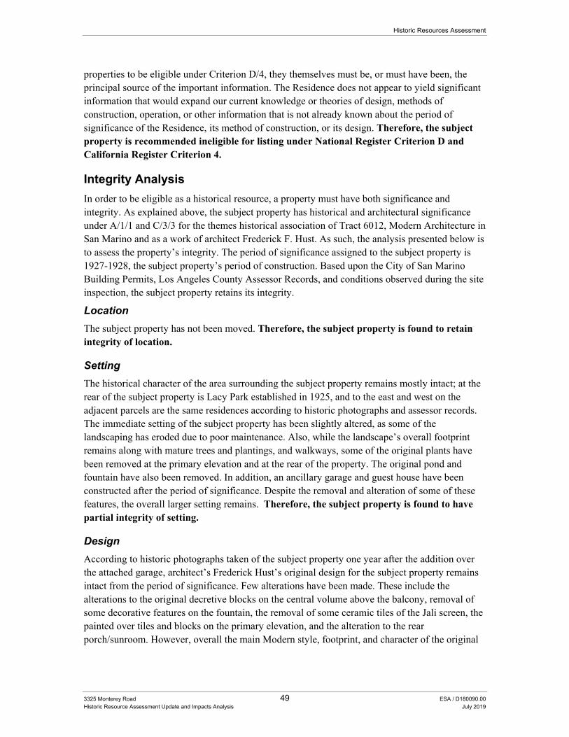
Historic Resources Assessment
3325 Monterey Road 49 ESA / D180090.00 Historic Resource Assessment Update and Impacts Analysis July 2019
properties to be eligible under Criterion D/4, they themselves must be, or must have been, the principal source of the important information. The Residence does not appear to yield significant information that would expand our current knowledge or theories of design, methods of construction, operation, or other information that is not already known about the period of significance of the Residence, its method of construction, or its design. Therefore, the subject property is recommended ineligible for listing under National Register Criterion D and California Register Criterion 4.
Integrity Analysis
In order to be eligible as a historical resource, a property must have both significance and integrity. As explained above, the subject property has historical and architectural significance under A/1/1 and C/3/3 for the themes historical association of Tract 6012, Modern Architecture in San Marino and as a work of architect Frederick F. Hust. As such, the analysis presented below is to assess the property’s integrity. The period of significance assigned to the subject property is 1927-1928, the subject property’s period of construction. Based upon the City of San Marino Building Permits, Los Angeles County Assessor Records, and conditions observed during the site inspection, the subject property retains its integrity.
Location
The subject property has not been moved. Therefore, the subject property is found to retain integrity of location.
Setting
The historical character of the area surrounding the subject property remains mostly intact; at the rear of the subject property is Lacy Park established in 1925, and to the east and west on the adjacent parcels are the same residences according to historic photographs and assessor records. The immediate setting of the subject property has been slightly altered, as some of the landscaping has eroded due to poor maintenance. Also, while the landscape’s overall footprint remains along with mature trees and plantings, and walkways, some of the original plants have been removed at the primary elevation and at the rear of the property. The original pond and fountain have also been removed. In addition, an ancillary garage and guest house have been constructed after the period of significance. Despite the removal and alteration of some of these features, the overall larger setting remains. Therefore, the subject property is found to have partial integrity of setting.
Design
According to historic photographs taken of the subject property one year after the addition over the attached garage, architect’s Frederick Hust’s original design for the subject property remains intact from the period of significance. Few alterations have been made. These include the alterations to the original decretive blocks on the central volume above the balcony, removal of some decorative features on the fountain, the removal of some ceramic tiles of the Jali screen, the painted over tiles and blocks on the primary elevation, and the alteration to the rear porch/sunroom. However, overall the main Modern style, footprint, and character of the original
Historic Resources Assessment
3325 Monterey Road 50 ESA / D180090.00 Historic Resource Assessment and Impacts Analysis July 2019
design remain. None of the minor alterations since its period of significance detract from the original design. Therefore, the subject property is found to retain integrity of design.
Materials
The subject property’s original materials, including its original stucco cladding, fenestration (windows and doors), ornamentation tile, decorative block, ceramic Jali screens, block wall privacy wall, and glass windows remain. Therefore, the subject property is found to retain integrity of materials.
Workmanship
The subject property exhibits minor alterations as mentioned above, however it retains a majority of its original materials, along with the evidence of their workmanship. Therefore, the subject property is found to retain integrity of workmanship.
Feeling
Despite having undergone minor alterations, as explained above, the subject property continues to convey the feeling of a Modern style single-family residence constructed during the mid-to late 1920s. Therefore, the subject property is found to retain integrity of feeling.
Association
The subject property retains sufficient integrity to convey its historical associations. Therefore, the subject property is found to retain integrity of association.
Summary
As discussed above, the subject property retains integrity of design, materials, workmanship, feeling, association, and partial setting. Therefore, the subject property satisfies the applicable integrity thresholds specified by the City of San Marino’s Historic Preservation Ordinance. The subject property thus retains its integrity to convey its historical and architectural significance. As a result, the building is considered a historical resource in accordance with CEQA.
Conclusion The subject property was evaluated under the following historical and architectural themes: Early Residential Development (1913-1944), including its association with Tract No. 6012, Modern Architecture (1920-1940), and Frederick Hust, architect. ESA also conducted research on the subject property’s construction and occupancy history. ESA evaluated the subject property against the criteria for the National Register and the California Register.
ESA found the subject property eligible under the applicable federal and state criteria for its significant historical associations (Criteria A/1/1) with Tract 6012, and architectural significance (Criteria C/3/3) as a Modern style single-family residence in San Marino, and a work of notable architect Frederick Hust. The period of significance associated with the subject property is 1927-1928. This period includes the original construction date of the Residence with attached garage as well as the rear second-story addition to the garage by architect Frederick Hust. ESA also found that the subject property retains its integrity of design, materials, workmanship, feeling,
Historic Resources Assessment
3325 Monterey Road 51 ESA / D180090.00 Historic Resource Assessment Update and Impacts Analysis July 2019
association, and partial setting. Therefore, the subject property satisfies the applicable integrity thresholds specified by the City of San Marino’s Historic Preservation Ordinance. The subject property thus retains its integrity to convey its historical and architectural significance. As a result, the building is considered a historical resource in accordance with CEQA. A Character-Defining Features Matrix identified and prioritizes the historic features extant at the building and is located in Appendix G.
ESA also recommends that the subject property be assigned a California Historic Resource (CHR) Status Code of 3S; and 3CS, noting it as eligible for listing in the National Register of Historic Places (National Register or NR), the California Register of Historical Resources (California Register or CR), and as a City of San Marino historic landmark through survey evaluation.
CEQA Analysis
The thresholds for determining the significance of environmental effects on historical resources identified below are derived from the CEQA Guidelines as defined in §15064.5. Pursuant to this guidance, a project that would physically detract, either directly or indirectly, from the integrity and significance of the historical resource such that its eligibility for listing in the National Register of Historic Places (“National Register”), California Register or as a San Marino historic landmark would no longer be maintained, is considered a project that would result in a significant impact on the historical resource. Adverse impacts, that may or may not rise to a level of significance, result when one or more of the following occurs to a historical resource: demolition, relocation, conversion, rehabilitation, or alteration, or new construction on the site or in the vicinity.73
CEQA Guidelines
According to the State CEQA Guidelines, Section 15064.5(b) a project involves a “substantial adverse change” in the significance of the resource when one or more of the following occurs:
Substantial adverse change in the significance of an historical resource means physical demolition, destruction, relocation, or alteration of the resource or its immediate surroundings such that the significance of an historical resource would be materially impaired.
The significance of a historical resource is materially impaired when a project:
A. Demolishes or materially alters in an adverse manner those physical characteristics of an historical resource that convey its historical significance and that justify its inclusion in, or eligibility for inclusion in, the California Register of Historical Resources; or
B. Demolishes or materially alters in an adverse manner those physical characteristics that account for its inclusion in a local register of historical resources pursuant to Section 5020.1(k) of the PRC or its identification in a historical resources survey meeting the requirements of Section 5024.1(g) of the PRC, unless the public agency reviewing the
73 L.A. CEQA Thresholds Guide, Section D.3. Historical Resources, City of Los Angeles, 2006, p. D.3-1
(http://environmentla.org/programs/Thresholds/D‐Cultural%20Resources.pdf, accessed 6/04/2013)
Historic Resources Assessment
3325 Monterey Road 52 ESA / D180090.00 Historic Resource Assessment and Impacts Analysis July 2019
effects of the project establishes by a preponderance of evidence that the resource is not historically or culturally significant; or
C. Demolishes or materially alters in an adverse manner those physical characteristics of a historical resource that convey its historical significance and that justify its eligibility for inclusion in the California Register of Historical Resources as determined by a lead agency for purposes of CEQA.
Under CEQA, a proposed development must be evaluated to determine how it may impact the potential eligibility of a structure(s) or a site for designation as a historic resource. The Standards were developed as a means to evaluate and approve work for federal grants for historic buildings and then for the federal rehabilitation tax credit (see 36 Code of Federal Regulations (“CFR”) Section 67.7). Therefore, the Standards are used for regulatory approvals for designated resources but not for resource evaluations.74 Similarly, CEQA recognizes the value of the Standards by using them to demonstrate that a project may be approved without an EIR. In effect, CEQA has a “safe harbor” by providing either a categorical exemption or a negative declaration for a project which meets the Standards (see State CEQA Guidelines Section 15331 and 15064.5(b)(3)). Therefore, what follows in the next several sections are a project description as well as a plan review that includes an impacts analysis under CEQA and an evaluation of conformance with the Standards.
Project Description The proposed Project will include the addition of 1,938 square feet of livable area to the residence that will be designed to be compatible with the existing historic structure, and it will be comprised primarily of stucco and wood siding (Figures 35, 36, and 37). With this addition, the total proposed livable area will be 5,284 square feet. Drawings for the proposed Project, dated June 20, 2019 and included in Appendix I, were created by Design Inspiration Group Inc., and they include the proposed scope of work as follows:
1. Remodel exterior and interior, and construct 2-story addition in rear of existing house
2. Construct new attached two-car garage and detached three-car garage
3. Build new patio
4. Demolish existing sun room, guest house, car port, and portions of east and west elevations
5. Construct new pool and spa, under separate permit
At the ground floor, work will include an expansion of the kitchen/dining room area to the east of the subject building, as well as the addition of a terrace to the east, and a fireplace addition to the living room at the west. The new work will include the demolition of the rear (north) courtyard
74 Century Plaza Hotel EIR, Appendix IV.D-3, Historic Thresholds Letter, from Michael J. Logrande, Director of
Planning and Ken Bernstein, Manager, Office of Historic Resources, City of Los Angeles, to Bruce Lackow, President, Matrix Environmental, Los Angeles, California, December 15, 2010.
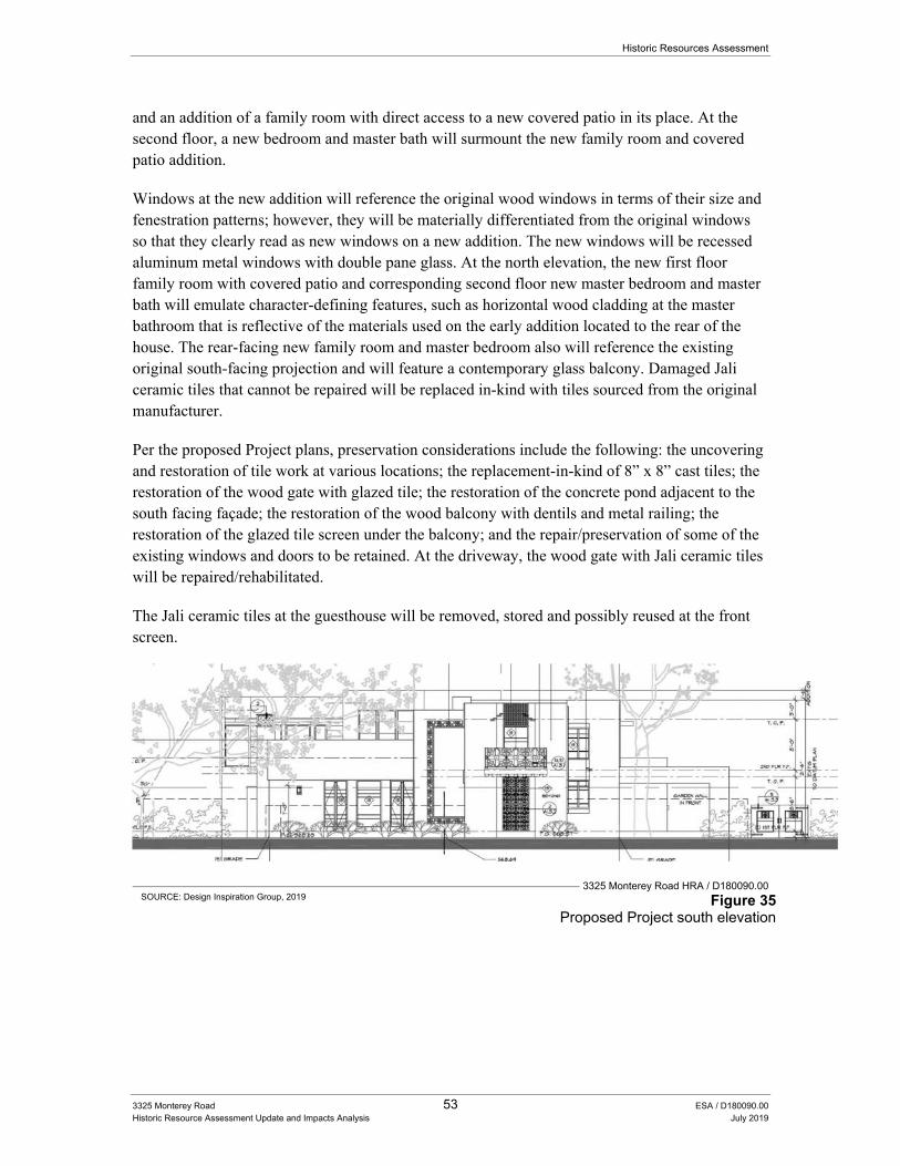
Historic Resources Assessment
3325 Monterey Road 53 ESA / D180090.00 Historic Resource Assessment Update and Impacts Analysis July 2019
and an addition of a family room with direct access to a new covered patio in its place. At the second floor, a new bedroom and master bath will surmount the new family room and covered patio addition.
Windows at the new addition will reference the original wood windows in terms of their size and fenestration patterns; however, they will be materially differentiated from the original windows so that they clearly read as new windows on a new addition. The new windows will be recessed aluminum metal windows with double pane glass. At the north elevation, the new first floor family room with covered patio and corresponding second floor new master bedroom and master bath will emulate character-defining features, such as horizontal wood cladding at the master bathroom that is reflective of the materials used on the early addition located to the rear of the house. The rear-facing new family room and master bedroom also will reference the existing original south-facing projection and will feature a contemporary glass balcony. Damaged Jali ceramic tiles that cannot be repaired will be replaced in-kind with tiles sourced from the original manufacturer.
Per the proposed Project plans, preservation considerations include the following: the uncovering and restoration of tile work at various locations; the replacement-in-kind of 8” x 8” cast tiles; the restoration of the wood gate with glazed tile; the restoration of the concrete pond adjacent to the south facing façade; the restoration of the wood balcony with dentils and metal railing; the restoration of the glazed tile screen under the balcony; and the repair/preservation of some of the existing windows and doors to be retained. At the driveway, the wood gate with Jali ceramic tiles will be repaired/rehabilitated.
The Jali ceramic tiles at the guesthouse will be removed, stored and possibly reused at the front screen.
3325 Monterey Road HRA / D180090.00 SOURCE: Design Inspiration Group, 2019 Figure 35
Proposed Project south elevation
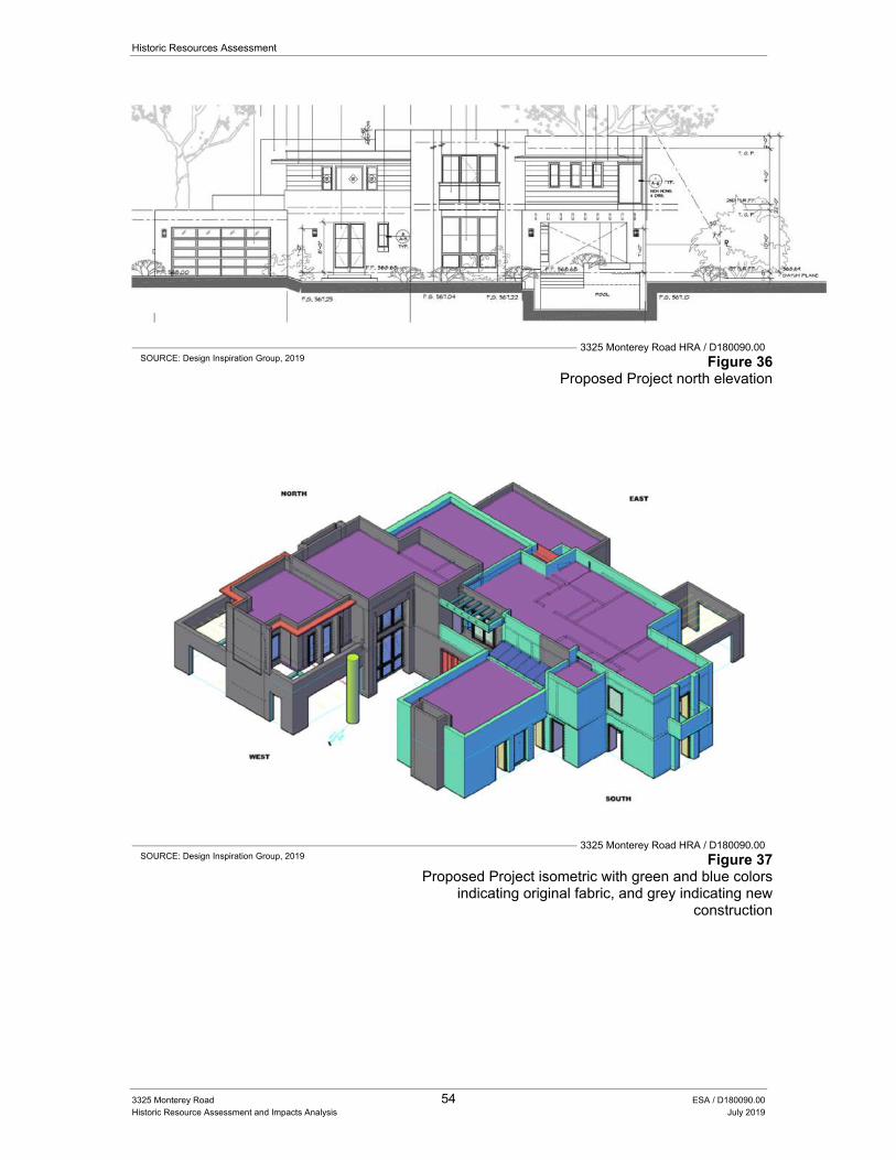
Historic Resources Assessment
3325 Monterey Road 54 ESA / D180090.00 Historic Resource Assessment and Impacts Analysis July 2019
3325 Monterey Road HRA / D180090.00 SOURCE: Design Inspiration Group, 2019 Figure 36
Proposed Project north elevation
3325 Monterey Road HRA / D180090.00 SOURCE: Design Inspiration Group, 2019 Figure 37
Proposed Project isometric with green and blue colors indicating original fabric, and grey indicating new
construction
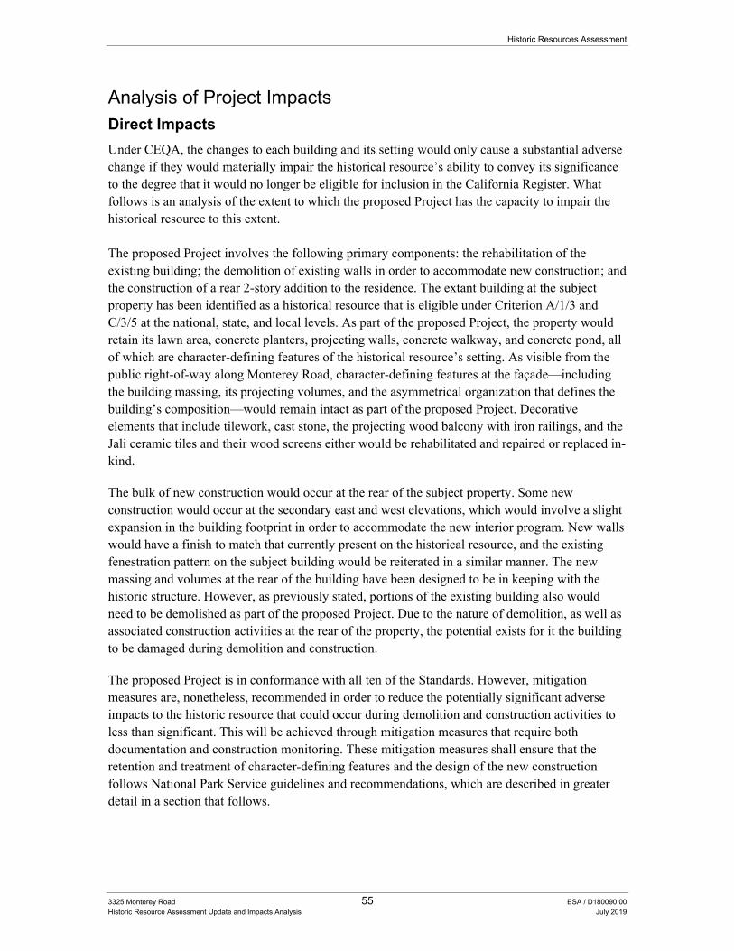
Historic Resources Assessment
3325 Monterey Road 55 ESA / D180090.00 Historic Resource Assessment Update and Impacts Analysis July 2019
Analysis of Project Impacts Direct Impacts
Under CEQA, the changes to each building and its setting would only cause a substantial adverse change if they would materially impair the historical resource’s ability to convey its significance to the degree that it would no longer be eligible for inclusion in the California Register. What follows is an analysis of the extent to which the proposed Project has the capacity to impair the historical resource to this extent. The proposed Project involves the following primary components: the rehabilitation of the existing building; the demolition of existing walls in order to accommodate new construction; and the construction of a rear 2-story addition to the residence. The extant building at the subject property has been identified as a historical resource that is eligible under Criterion A/1/3 and C/3/5 at the national, state, and local levels. As part of the proposed Project, the property would retain its lawn area, concrete planters, projecting walls, concrete walkway, and concrete pond, all of which are character-defining features of the historical resource’s setting. As visible from the public right-of-way along Monterey Road, character-defining features at the façade—including the building massing, its projecting volumes, and the asymmetrical organization that defines the building’s composition—would remain intact as part of the proposed Project. Decorative elements that include tilework, cast stone, the projecting wood balcony with iron railings, and the Jali ceramic tiles and their wood screens either would be rehabilitated and repaired or replaced in-kind.
The bulk of new construction would occur at the rear of the subject property. Some new construction would occur at the secondary east and west elevations, which would involve a slight expansion in the building footprint in order to accommodate the new interior program. New walls would have a finish to match that currently present on the historical resource, and the existing fenestration pattern on the subject building would be reiterated in a similar manner. The new massing and volumes at the rear of the building have been designed to be in keeping with the historic structure. However, as previously stated, portions of the existing building also would need to be demolished as part of the proposed Project. Due to the nature of demolition, as well as associated construction activities at the rear of the property, the potential exists for it the building to be damaged during demolition and construction.
The proposed Project is in conformance with all ten of the Standards. However, mitigation measures are, nonetheless, recommended in order to reduce the potentially significant adverse impacts to the historic resource that could occur during demolition and construction activities to less than significant. This will be achieved through mitigation measures that require both documentation and construction monitoring. These mitigation measures shall ensure that the retention and treatment of character-defining features and the design of the new construction follows National Park Service guidelines and recommendations, which are described in greater detail in a section that follows.
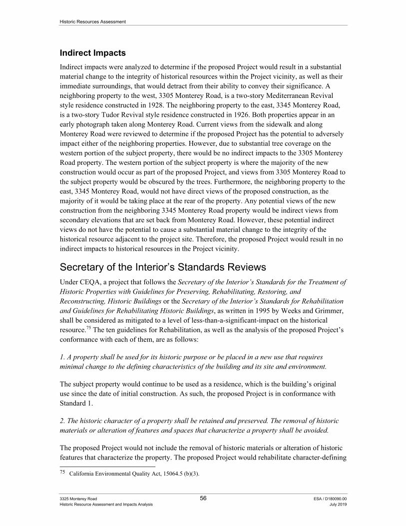
Historic Resources Assessment
3325 Monterey Road 56 ESA / D180090.00 Historic Resource Assessment and Impacts Analysis July 2019
Indirect Impacts
Indirect impacts were analyzed to determine if the proposed Project would result in a substantial material change to the integrity of historical resources within the Project vicinity, as well as their immediate surroundings, that would detract from their ability to convey their significance. A neighboring property to the west, 3305 Monterey Road, is a two-story Mediterranean Revival style residence constructed in 1928. The neighboring property to the east, 3345 Monterey Road, is a two-story Tudor Revival style residence constructed in 1926. Both properties appear in an early photograph taken along Monterey Road. Current views from the sidewalk and along Monterey Road were reviewed to determine if the proposed Project has the potential to adversely impact either of the neighboring properties. However, due to substantial tree coverage on the western portion of the subject property, there would be no indirect impacts to the 3305 Monterey Road property. The western portion of the subject property is where the majority of the new construction would occur as part of the proposed Project, and views from 3305 Monterey Road to the subject property would be obscured by the trees. Furthermore, the neighboring property to the east, 3345 Monterey Road, would not have direct views of the proposed construction, as the majority of it would be taking place at the rear of the property. Any potential views of the new construction from the neighboring 3345 Monterey Road property would be indirect views from secondary elevations that are set back from Monterey Road. However, these potential indirect views do not have the potential to cause a substantial material change to the integrity of the historical resource adjacent to the project site. Therefore, the proposed Project would result in no indirect impacts to historical resources in the Project vicinity.
Secretary of the Interior’s Standards Reviews Under CEQA, a project that follows the Secretary of the Interior’s Standards for the Treatment of Historic Properties with Guidelines for Preserving, Rehabilitating, Restoring, and Reconstructing, Historic Buildings or the Secretary of the Interior’s Standards for Rehabilitation and Guidelines for Rehabilitating Historic Buildings, as written in 1995 by Weeks and Grimmer, shall be considered as mitigated to a level of less-than-a-significant-impact on the historical resource.75 The ten guidelines for Rehabilitation, as well as the analysis of the proposed Project’s conformance with each of them, are as follows:
1. A property shall be used for its historic purpose or be placed in a new use that requires minimal change to the defining characteristics of the building and its site and environment.
The subject property would continue to be used as a residence, which is the building’s original use since the date of initial construction. As such, the proposed Project is in conformance with Standard 1.
2. The historic character of a property shall be retained and preserved. The removal of historic materials or alteration of features and spaces that characterize a property shall be avoided.
The proposed Project would not include the removal of historic materials or alteration of historic features that characterize the property. The proposed Project would rehabilitate character-defining 75 California Environmental Quality Act, 15064.5 (b)(3).
Historic Resources Assessment
3325 Monterey Road 57 ESA / D180090.00 Historic Resource Assessment Update and Impacts Analysis July 2019
features and prioritize repair of features over replacement. If it were necessary to replace a feature due to damage that was irreparable, the feature would be replaced in-kind. The building’s primary facade would remain intact and in its original configuration. The secondary elevations on the east and west of the building would be extended in order to accommodate a new program to the building’s interior. The exterior finish and windows at these locations would be compatible with the existing historic material. As such, the proposed Project is in conformance with Standard 2.
3. Each property shall be recognized as a physical record of its time, place, and use. Changes that create a false sense of historical development, such as adding conjectural features or architectural elements from other buildings, shall not be undertaken.
The proposed Project would include new construction at the subject property in addition to rehabilitation work. Original features including the ceramic Jali tiles and wood screens, the wood balcony and metal handrails, and decorative tilework and cast stone tiles would be preserved and rehabilitated in-place, or removed, rehabilitated and replaced back in their original locations. There will be some replication on the new addition to the building of the original decorative tilework and cast stone, which somewhat detracts from the building’s ability to convey itself as a physical record of its time. However, this decorative tilework and cast stone does not represent a conjectural feature or an architectural feature taken from another building. Moreover, the area in which this replication of original materials on the new addition will occur is located to the rear of the building, away from the public right of way. Therefore, the historical appearance of the building will be maintained with respect to the most important vantage point—the street from which the primary façade may be viewed by the public. Finally, contemporary metal windows and a glass balcony at the proposed addition will allow the building’s new elements to read as a physical record of their time—the present—while the appearance of the historic building is preserved as a physical record of its time, place, and use. As such, the proposed Project is in conformance with Standard 3.
4. Most properties change over time; those changes that have acquired historic significance in their own right shall be retained and preserved.
The guest house addition to the property, which was constructed around 1957, represents the only significant change to the subject property that potentially could have acquired historic significance over time. However, this Historic Resource Assessment for the subject property did not find that the guest house possessed any historic significance, either as a contributor to the main property or as an individual resource. As part of the proposed Project, the guest house is proposed for demolition. However, since the guest house has not acquired historic significance, it is not necessary to retain it in order to conform with Standard 4. Therefore, the proposed Project is in conformance with Standard 4.
5. Distinctive features, finishes, and construction techniques or examples of craftsmanship that characterize a property shall be preserved.
The majority of the distinctive features, finishes, and construction techniques that characterize the subject property would be preserved as part of the proposed Project. One secondary character-defining-feature—the secondary north elevation’s courtyard—would be removed as part of the
Historic Resources Assessment
3325 Monterey Road 58 ESA / D180090.00 Historic Resource Assessment and Impacts Analysis July 2019
proposed Project; however, this modification is occurring to the rear of the property, which is not visible from the public right-of-way. The property’s primary character-defining-features—which include its overall massing, asymmetrical configuration, wood balcony with iron railings, ceramic Jali tiles with wood screens, decorative tilework and cast tiles, concrete pond, and other landscape features—would be preserved as part of the proposed Project. Therefore, despite the removal of the rear courtyard, the majority of the primary character-defining features would be retained and preserved. As such, the proposed Project is substantially in conformance with Standard 5.
6. Deteriorated historic features shall be repaired rather than replaced. Where the severity of deterioration requires replacement of a distinctive feature, the new feature shall match the old in design, color, texture, and other visual qualities and, where possible, materials. Replacement of missing features shall be substantiated by documentary, physical, or pictorial evidence.
Historic features including the Jali ceramic tiles and their wood screens, wood balcony and iron railing, various tiles and cast stone tiles are planned to be rehabilitated, and restored/repaired, where possible, as part of the proposed Project. In instances where an historic feature is too deteriorated to repair, it would be replaced in-kind. The Project applicant would substantiate the replacement of missing features with documentary or physical evidence in order to ensure compliance with this Standard. As such, the proposed Project is in conformance with Standard 6.
7. Chemical or physical treatments, such as sandblasting, that cause damage to historic materials shall not be used. The surface cleaning of structures, if appropriate, shall be undertaken using the gentlest means possible.
No chemical or physical treatments, such as sandblasting, that cause damage to historic materials shall be used as part of the proposed Project. Moreover, the proposed Project would follow the NPS Preservation Briefs that are applicable to it and that are provided in Appendix J. This would ensure that the gentlest means possible are utilized for surface cleaning during building rehabilitation. Finally, the construction monitoring that is recommended as a mitigation measure for the proposed Project would provide a means to observe that the appropriate protocols were being followed during construction. Therefore, the proposed Project is in conformance with Standard 7.
8. Significant archeological resources affected by a project shall be protected and preserved. If such resources must be disturbed, mitigation measures shall be undertaken.
No archeological resources are believed to be in the area of the proposed Project. However, if archeological resources are discovered during the construction work, the appropriate measures to protect and preserve them would be undertaken. The construction monitoring that is recommended as a mitigation measure for the proposed Project would provide a means to observe that the appropriate protocols for protecting and preserving any archeological discoveries were being followed during construction. As such, the Project is in conformance with Standard 8.
9. New additions, exterior alterations, or related new construction shall not destroy historic materials that characterize the property. The new work shall be differentiated from the old and
Historic Resources Assessment
3325 Monterey Road 59 ESA / D180090.00 Historic Resource Assessment Update and Impacts Analysis July 2019
shall be compatible with the massing, size, scale, and architectural features to protect the historic integrity of the property and its environment.
The primary character-defining features that are important for conveying the significance of the property are located in on the front façade and on the front portion of the residence and associated landscape, and all of these features are being retained and preserved. The new construction would occur at the rear of the subject property, including a two-story addition. The design for the new addition is compatible with the historic residence and would retain and preserve historic materials that characterize the property. The related new construction strongly references the existing structure with its rectangular volume projections, mirroring of siding materials, and tilework found at original locations on the building. The additions are toward the rear of the building and are set back from Monterey Road and would not be visible or only partially visible, and therefore the historic residence would remain visually prominent from the public-right of way. Due to the fact that the new two-story addition will be significantly set back from the public right of way, it will only be partially visible at that distance. An existing tree will be retained at the courtyard on the site and the branches of its canopy will further obscure the new addition from view. The new metal windows proposed for the additions are compatible in proportion, design and pattern with the original wood fenestration pattern, but are subtly differentiated from the historic windows. To the rear of the property, the stucco and horizontal wood portions of the original siding materials are being replicated on the rear-facing new addition. The new siding materials will be similar but differentiated from the original siding materials and will be associated with the other components of the new construction to achieve further differentiation, including a contemporary pool and patio area and a glass and metal balcony. These new elements will by distinctly discernable from the historical resource, and compatible in scale, massing, design and materials, and would not destroy historic materials that characterize the property. As such, the Project is in conformance with Standard 9.
10. New additions and adjacent or related new construction shall be undertaken in such a manner that if removed in the future, the essential form and integrity of the historic property and its environment would be unimpaired.
The primary character-defining features that are important for conveying the significance of the property are located in on the front façade and on the front portion of the residence and associated landscape, and all of these features are being retained and preserved. The new construction would occur at the rear of the subject property, including a two-story addition. Other proposed modifications to the existing structure include additions to enlarge the footprint of the building at the east and west elevations that are needed for its continued residential use, and which are compatible with the materiality, massing, and scale of the existing historic resource. The proposed Project would maintain historic integrity of the property because its character-defining features would be retained and preserved. If the new construction would be removed in the future, the character-defining features of the resource that are being preserved under the project would still remain and the essential form and integrity of the historic property would be unimpaired. If the additions were removed in the future, their removal would not impair or destroy the essential form and integrity of the historic property. As such, the Project is in conformance with Standard 10.

Historic Resources Assessment
3325 Monterey Road 60 ESA / D180090.00 Historic Resource Assessment and Impacts Analysis July 2019
Conclusion and Recommendations The proposed Project would retain and rehabilitate the existing building and construct new additions at the rear that would alter and enlarge the footprint, massing and landscape of the existing residence at the rear of the residence in areas not visible or only partially visible from the public right of way. The Project will retain and preserve the primary character-defining features that are visible from the public right-of-way. Furthermore, deteriorated or lost features would be repaired or replaced in-kind, thus enhancing the property’s historic appearance and improving the integrity of these features. Review of the proposed Project, summarized above, found that the Project conforms with the Standards 1, 2, 3, 4, 5, 6, 7, 8, 9, and 10, and therefore is considered to have no adverse impact to historical resources and would be fully mitigated pursuant to CEQA. However, construction activities and unforeseen circumstances that may arise during construction have the potential to damage character-defining features of the subject property and would require construction monitoring by a qualified preservation consultant to ensure the project would be completed in conformance with the Standards. In order to minimize these potential construction impacts to the historic resource, the following Mitigation Measures are recommended to reduce adverse impacts to less than significant:
Historic American Buildings Survey (HABS) Level III Report Prior to any construction, it is recommended that the existing conditions at the subject property at 3325 Monterey Road be recorded in a HABS Level III report which would serve as a base line reference for the proposed Project and any other future work that may be undertaken at this location. The HABS Level III report would include a sketch plan, exterior and interior views, and an architectural data form. The report should be archivally produced and deposited in a publically accessible library or museum archive.
Preservation Treatmen Plan The project applicant shall create a detailed historic preservation treatment plan and prepare scaled mock-ups for character-defining architectural features and tilework that are to be rehabilitated and/or replaced in-kind. These mockups will include pertinent colors, finishes, and features, representative of the work to be performed. Mock ups will be reviewed by the qualified architectural historian or historic preservation professional selected by the project applicant. Prior to any construction work, the 90% construction documents shall be updated with specifications for treatment and reviewed for conformance with the Standards by a historic preservation professional meeting the Secretary of the Interior’s Professional Qualifications Standards with demonstrated experience conducting Standards conformance reviews.
Construction Monitoring The retained architectural historian shall conduct construction monitoring at key points—including during both demolition and construction—to ensure that damage to any historic fabric that is to be retained is avoided or minimized. A qualified architectural historian or historic preservation professional who satisfies the Secretary of the Interior’s Professional Qualification Standards for Architectural History, pursuant to 36 CFR 61, shall conduct the monitoring and provide preservation treatment consultation to address any unanticipated issues that may arise and to ensure that the
Historic Resources Assessment
3325 Monterey Road 61 ESA / D180090.00 Historic Resource Assessment Update and Impacts Analysis July 2019
Project meets the Standards. The construction monitoring process would be documented in daily logs and a substantial completion monitoring report letter. The construction monitoring site visits shall be fully recorded in photographs and written manuscript notes which would be documented in a memorandum. At the completion of construction, a final completion letter report shall be prepared and placed in the property file at the Planning Division.
As discussed above, the Project conforms with Standards 1, 2, 3, 4, 5, 6, 7, 8, 9, and 10. The proposed Project would retain and restore the character-defining features of the residence and the new addition at the rear is compatible with the massing, form, materiality, and overall style of the existing building. Therefore, pursuant to CEQA, the Project would have a less than significant impact on historical resources because the Project has been designed in conformance with the Standards and the eligibility of the subject property as a historical resource would be retained upon Project completion.
Historic Resources Assessment
3325 Monterey Road 62 ESA / D180090.00 Historic Resource Assessment and Impacts Analysis July 2019
Bibliography “819 N Sweetzer Ave,” San Marino Historic Preservation, http://www.wehopreservation.org/
portfolio_page/819-n-sweetzer-ave/
“1000 Larrabee Street.” San Marino Historic Preservation.
http://www.wehopreservation.org/portfolio_page/1000-larrabee-street/
“Aged Immigrants Arrive from Germany,” Salt Lake Telegram (Salt Lake City, UT), Mar. 20, 1927.
Ancestry.com. U.S. Census, California Voter Registration, California Death Index, City Directory, and Street Address Directory records.
Ancestry.com. Utah, Select Marriage Index, 1887-1985 [database on-line]. Provo, UT, USA: Ancestry.com Operations, Inc., 2015.
Architect and Engineer (Volume 88), 1927.
Architectural/Historical Development of the City of Pasadena: Historic Context/Property Type Report, prepared by Pamela O’Connor and Urban Conservation Section, Planning Division, City of Pasadena, January 13, 1993.
Architectural Resources Group. Multi-Family Survey Report. November 2008.
“Assignments Set for Rose Bowl Committee of 325.” Pasadena Independent (Pasadena, CA), Oct. 22, 1964.
California Code of Regulations, California Register of Historical Resources (Title 14, Chapter11.5), Section 4852(c).
“Carl Wopschall to Head 1977 Rose Fest.” Arcadia Tribune (Arcadia, CA). Feb. 19, 1976.
“Charges Realty Man and Lawyer Altered Notes.” Chicago Tribune (Chicago, IL). Aug. 14, 1920.
City of San Marino. “General Plan.” San Marino, CA. 2003.
City of San Marino, “An Ordinance of the City of San Marino Regarding Historic Preservation and Design Review and Amending the San Marino City Regarding the Same.” February 28, 2018.
City of San Marino R2, R3, R4 Multi-Family Survey Report. November 2008. http://www.wehopreservation.org/wp-content/uploads/2016/03/2008_Survey_Full_Document.pdf
Code of Federal Regulations (CFR), 36 § 60.2.
Codified in California Code of Regulations, Title 14, Chapter 11.5, Section 4852©. http://ohp.parks.ca.gov
Historic Resources Assessment
3325 Monterey Road 63 ESA / D180090.00 Historic Resource Assessment Update and Impacts Analysis July 2019
Connor, Paul. “Lloyd Wright’s Mayan/Islamic Derby House Hits the Market in Glendale Asking $1,65 Million.” Curbed Los Angeles. Nov. 14, 2013. https://la.curbed.com/2013/11/14/10175478/lloyd-wrights-mayanislamic-derby-house-hits-the-market-in-glendale.
“Contributors to Nixon Fund.” The San Bernardino County Sun (San Bernardino, CA). Sep. 21, 1952.
“Designed for State Street.” The Salt Lake Evening Telegram (Salt Lake City, UT). Aug. 6, 1910.
“Dovenmeuhle, Inc. Enteres 80th Year as Organization.” Chicago Tribune (Chicago, IL). Feb. 17, 1935.
“Ensign Eaton Claims Bride in San Marino.” The Los Angeles Times (Los Angeles, CA). Oct. 2, 1950.
“Ecclestone Will Take Over Burbank C of C.” The Los Angeles Times (Los Angeles, CA). Jan. 10, 1960.
‘Frank Lloyd Wright’s Ennis House Sold to Ron Burkle.” Ennis House. Accessed March 27, 2018. http://ennishouse.com/.
“Frederick Fritz Hust,” Utah Center for Architecture. Accessed February 28, 2018. http://utahcfa.org/architect/frederick_fritz_hust.
“Frederick Hust is Winner in Contest.” The Salt Lake Tribune (Salt Lake City, UT). Feb. 27, 1915.
Glossary of National Register Terms. http://www.nps.gov/nr/publications/bulletins/nrb16a/nrb16a_appendix_IV.htm. Accessed June 1, 2013.
“Guidelines for Completing National Register Forms.” in National Register Bulletin 16, U.S. Department of Interior, National Park Service, 1977, Revised 1997.
Griffin, Walter Burley and Griffin, Marion Mahony. William F. Tempel dwelling, Kenilworth, Illinois, 1910: 1910. Web. 29 March 2018 <http://nla.gov.au/nla.obj-146747154>
Harold A. Parker Studio Collection of Negatives. The Huntington Library, San Marino, California.
Harrison, Paul. “Hollywood.” The Post-Register (Idaho Falls). April 16, 1936.
“Hogle Takes Over Davies & Co. Here.” The Los Angeles Times (Los Angeles, CA). Sep. 27, 1942.
Hormann, Matt. “The Man Who Named San Marino Attempted Winemaking on an Industrial Scale.” San Marino Patch. Dec. 21, 2010. https://patch.com/california/sanmarino/the-man-who-named-san-marino-attempted-winemaking-on-d4ae05ae3b.
Illinois, Cook County, Birth Certificates, 1871-1940.
“Jack Whitehead.” Obituaries. The Los Angeles Times (Los Angeles, CA). Apr. 29, 2012.
Historic Resources Assessment
3325 Monterey Road 64 ESA / D180090.00 Historic Resource Assessment and Impacts Analysis July 2019
“Johnny Marvin, Biography.” IMDB.com. Accessed October 11, 2017.
Kruty, Paul. “Walter Burley Griffin.” Society of America, Accessed March 29, 2018. http://www.wbgriffinsociety.org/griffins-bio.html.
“Lloyd Wright’s The Taggart House.” Modern Living LA. Accessed March 27, 2018. http://modernlivingla.com/2014/04/lloyd‐wrights‐the‐taggart‐house/.
“Louis Sullivan Commissions.” Prairie Styles. Accessed March 27, 2018. http://www.prairiestyles.com/lsullivan.htm.
“Many Parties Fete Betrothed Couple.” The Los Angeles Times (Los Angeles, CA). Jul. 12, 1953.
“Mary Cota,” Family Search. Accessed March 1, 2018. https://www.familysearch.org/tree/person/details/9X74-WZG; Pasadena, California, City Directory, 1921.
McAlester, Virginia Savage. A Field Guide to American Houses. New York: Alfred A. Knopf, 2013.
McWilliams, Carey. Southern California: An Island on the Land. Layton, Utah: Gibbs Smith, 1973.
National Park Service. National Register Bulletin 15: How to Apply the National Register Criteria for Evaluation. Washington DC: U.S. Dept. of the Interior, National Park Service, Interagency Resources Division, 1990, rev. 1991.
National Park Service. National Register Bulletin 16: Guidelines for Completing National Register Forms. Washington, D.C.: U.S. Dept. of the Interior, National Park Service, 1997.
National Register Bulletin 15: How to Apply the National Register Criteria for Evaluation. http://www.nps.gov/nr/publications/bulletins/pdfs/nrb15.pdf. Accessed July 7, 2013.
“New Chinatown.” The Los Angeles Times (Los Angeles, CA). Jan. 21, 1938.
“New Partners for Dean Witter.” The Los Angeles Times (Los Angeles, CA). Feb. 2, 1954.
“Obituaries: Eaton, Rea L.” The Los Angeles Times (Los Angeles, CA). Nov. 13, 1970.
Office of Historic Preservation. Instructions for Recording Historical Resources. March 1995.
Office of State Historic Preservation. California Historic Resources Inventory, Survey Workbook (excerpts). Sacramento, CA: State of California, 1986.
“Official Death List.” The Los Angeles Times (Los Angeles, CA). Dec. 21, 1973.
Ord. 03-663 § 4 (part), 2003: Ord. 02-643 § 48, 2003: Ord. 01-594 § 2 (Exh. A), 2001
“Pasadena Boys’ Club Given Small Railroad.” The Los Angeles Times (Los Angeles, CA). May 26, 1960.
“Planned for Depot District.” The Salt Lake Evening Telegram (Salt Lake City, UT). Sep. 17, 1910.
Historic Resources Assessment
3325 Monterey Road 65 ESA / D180090.00 Historic Resource Assessment Update and Impacts Analysis July 2019
“Plans for Los Angeles’ New China City Completed.” The Los Angeles Times (Los Angeles, CA). Jan. 18, 1938.
Pomeroy, Elizabeth. San Marino: A Centennial History. San Marino Historical Society, 2012.
PRC Section 5024.1
“Salt Lake Architects Get Idaho Business.” The Salt Lake Tribune (Salt Lake City, UT). Aug. 21, 1910.
Sanborn Map and Publishing Company, Insurance Maps of Los Angeles County, 1910.
San Marino, California: Historic Preservation Ordinance, Ordinance No. O-18-1336 (23.18.010-23.18.220), adopted on April 11, 2018.
San Marino Historical Society. “History: San Marino.” Accessed March 9, 2016. http://sanmarinohistoricalsociety.org/history.html.
“San Marino History.” City of San Marino. Accessed June 21, 2011, http://www.cityofsanmarino.org/about.htm.
State of California. California Death Index, 1940-1997. Sacramento, CA, USA: State of California Department of Health Services, Center for Health Statistics.
“Team Winners in Choose-Up.” The Desert Sun (Palm Springs, CA). Dec. 20, 1961.
“The Prairie Style.” Frank Lloyd Wright Trust. Accessed March 27, 2018. https://flwright.org/researchexplore/prairiestyle.
United States Census, 1910
United States Census, 1930
Utah, Naturalization of Citizenship Records, 1858-1959 for Frederick Hust, Salt Lake City, 1909-1911.
Vulcan, Robert. “A Community Evolves: History of San Marino.” San Marino Incorporation Committee. 1984.
Watters, Sam. Houses of Los Angeles: 1885-1919. p. 27.
“William F. Tempel dwelling.” National Library of Australia. Accessed March 29, 2017 http://nla.gov.au/nla.obj-146747154/view.
“William F. Tempel House.” The Prairie School Traveler. Accessed March 29, 2017. http://www.prairieschooltraveler.com/html/il/winnetka/tempel.html.
Woman, Near 91, Dies in S. L. Hospital.” The Salt Lake Tribune (Salt Lake City, UT). Feb. 20, 1948.

Appendix A Professional Qualifications


Margarita Jerabek, PhD Historic Resources Director
Margarita Jerabek has 30 years of professional practice in the United States with an extensive background in historic preservation, architectural history, art history and decorative arts, and historical archaeology. She specializes in Visual Art and Culture, 19th‐20th Century American Architecture, Modern and Contemporary Architecture, Architectural Theory and Criticism, Urbanism, and Cultural Landscape, and is a regional expert on Southern California architecture. Her qualifications and experience meet and exceed the Secretary of the Interior’s Professional Qualification Standards in History, Archaeology, and Architectural History. Margarita has managed and conducted a wide range of technical studies in support of environmental compliance projects, developed preservation and conservation plans, and implemented preservation treatment projects for public and private clients in California and throughout the United States.
Relevant Experience Margarita has prepared a broad range of environmental documentation and conducted preservation projects throughout the Los Angeles metropolitan area and Southern California. She provides expert assistance to public agencies and private clients in environmental review, from due diligence through planning/design review and permitting and when necessary, implements mitigation and preservation treatment measures on behalf of her clients. As primary investigator and author of hundreds of technical reports, plan review documents, preservation and conservation plans, HABS/HAER/HALS reports, construction monitoring reports, salvage reports and relocation plans, she is a highly experienced practitioner and expert in addressing historical resources issues while supporting and balancing project goals.
She is an expert in the evaluation, management and treatment of historic properties for compliance with Sections 106 and 110 of the NHPA, NEPA, Section 4(f) of the Department of Transportation Act, CEQA, and local ordinances and planning requirements. Margarita regularly performs assessments to ensure conformance with the Secretary of the Interior’s Standards for the Treatment of Historic Properties, and assists clients with adaptive reuse/rehabilitation projects by providing preservation design and treatment consultation, agency coordination, legally defensible documentation, construction monitoring and conservation treatment.
Margarita is a regional expert on Southern California architecture. She has prepared a broad range of environmental documentation and conducted preservation projects throughout the Los Angeles metropolitan area as well as in Ventura, Orange, Riverside, San Bernardino and San Diego counties. Beyond her technical skill, she is a highly experienced project manager with broad national experience throughout the United States. She currently manages ESA’s on‐call historic preservation services with the City of Santa Monica, and Los Angeles Unified School District.
EDUCATION
Ph.D., Art History, University of California, Los Angeles
M.A., Architectural History, School of Architecture, University of Virginia
Certificate of Historic Preservation, School of Architecture, University of Virginia
B.A., Art History, Oberlin College
30 YEARS EXPERIENCE
AWARDS
2014 Preservation Award, The Dunbar Hotel, L.A. Conservancy
2014 Westside Prize, The Dunbar Hotel, Westside Urban Forum
2014Design Award: Tongva Park & Ken Genser Square, Westside Urban Forum
Preservation Design Awards, RMS Queen Mary Conservation Plan 2012; and Restoration and Exhibit Design for Home Savings, Montebello,2016, California Preservation Foundation
PROFESSIONAL AFFILIATIONS
California Preservation Foundation
Santa Monica Conservancy
Society of Architectural Historians, Life Member
American Institute of Architects (AIA), National Allied Member
Gabrielle Harlan, Ph.D.
Architectural Historian
Relevant Experience
M
Alison Garcia Kellar Architectural Historian
Alison is an architectural historian with 7 years of professional and academic experience with a background in historic preservation, design, and museum collections. Her work with historic resources and cultural heritage in California has included managing and authoring historic resource assessments, National Register Nominations, historic structure reports, feasibility studies, tax credit applications, and extensive archival research and resource documentation. In her previous work, Alison managed the historic resources studio of a preservation architecture firm in San Francisco where she collaborated with architects to identify preservation-related issues and constraints, craft rehabilitation recommendations, and design sensitive mitigation solutions for new development within historic buildings and districts with the goal of minimizing adverse effects on historic resources. Alison uses her understanding of preservation design and historic interiors to inform impacts analyses of proposed development and recommendations for adaptive reuse. She exceeds the Secretary of the Interior’s Qualification Standards for Architectural History.
Relevant Experience Wilshire Historic District Update, Los Angeles, CA. Architectural Historian, Project Manager, ongoing. Alison is coordinating efforts to update a historic district survey. As several contributing structures in the Mediterranean Revival and Spanish Revival multi- and single-family district have recently been demolished or heavily altered, the City has requested a current analysis of the remaining district in order to determine its continued eligibility.
Historic Resource Evaluation for Golden Gate Village, Marin City, CA. Architectural Historian. The highly-intact Golden Gate Village low-income housing complex was constructed in 1958 to house many of the former Marinship workers and their families. Designed by prominent mid-century designers including Aaron G. Green, John Carl Warnecke, and Lawrence Halprin, the property serves as an example of a well-designed housing complex, significant as a product of post-war urban development and for its prominent mid-century designers. Alison performed the site visit and conducted research through local and private archival repositories, plan analysis, and interviews, producing the report narrative and historic evaluation for the property. Today, the property is listed on the National Register of Historic Places.
Historic Structure Report for McDonnell Hall, Our Lady of Guadalupe Chapel, San Jose, CA. Architectural Historian. Constructed as a parish church in 1914, the building moved to its current location in 1953. Here, the building served as a newly formed Catholic Mission, the Center of Our Lady of Guadalupe. The property is associated with civil rights activist and labor rights leader Cesar Chavez, and the mid-20th century Mexican American civil rights movement. Alison
EDUCATION
MS, Historic Preservation, University of Pennsylvania
BA, Design, University of California at Davis
7 YEARS EXPERIENCE
PROFESSIONAL AFFILIATIONS California Preservation Foundation Member Society of Architectural Historians Member National Trust for Historic Preservation Member AWARDS Albert Binder Travel Fellowship, 2012 and 2013 PennDesign Departmental Grant, 2011-2013
Alison Garcia Kellar, M.S. Page 2
assisted with the research, production, and design recommendations, including bringing the building back to its appearance during its period of significance, which required a meticulous analysis of the building’s historic integrity. The property today is listed as a National Historic Landmark.
Historic Preservation Consulting for the Palo Alto History Museum, Palo Alto, CA. Architectural Historian. The Spanish Revival style Roth Building was the original location of the Palo Alto Medical Foundation. The former medical building is undergoing a conversion into a local history museum with gallery space, interpretive areas, and archival and study rooms. Alison assisted with secondary research efforts of both the medical foundation and the building, upon modifications to the museum’s scope of work. She conducted a Part 2 Federal historic rehabilitation tax credit application review which included recommendation to best comply with the Secretary of the Interior’s Standards for Historic Preservation.
915 Laurel Avenue, San Mateo, CA. Architectural Historian. Alison conducted a Historic Resource Assessment of a one-story Spanish Revival home, and later performed a Secretary of the Interior’s Standards review of proposed modifications to add more square footage to the historic home. Guided the property owner to refine their concept while working closely with San Mateo Panning to come to an agreeable solution for the historic property to maintain its aesthetic within the neighborhood, while achieving more space.
Delta Feasibility Study for three historic resources, Walnut Grove, CA. Architectural Historian, Project Manager. Three heritage buildings were identified for feasibility studies, including the adaptive reuse of a church for artist live/work and performance/gallery space; the adaptive reuse of a school into a community center; and the construction of a park to commemorate Asian American Heritage. Work included a market demand analysis, conceptual plan, cost estimate, and potential partnerships and funding. Serving as the project manager and primary author, Alison coordinated site visits and served as the day-to-day contact for the sub consultant team. She undertook extensive primary source research, she assisted with the creation of rehabilitation recommendations.
Historic Resource Evaluation and Preservation Consulting for the Half Moon Bay Barn and Jail Museum, Half Moon Bay, CA. Architectural Historian. The City of Half Moon Bay was working with a local historical society to implement a history museum at the site of its early 20th century jail and adjacent barn. Alison conducted an in-depth historic resource assessment then reviewed proposed plans for buildings and site modifications to accommodate gallery space, offices, and archival storage. Coordinating with project architects, she assisted with the creation of recommendations for project compliance with the Secretary of the Interior’s Standards for Rehabilitation.
630 Purissima Street, Half Moon Bay, CA. Architectural Historian, Project Manager. Alison conducted a Historic Resource Assessment and an analysis of proposed modifications to an early 20th century Craftsman-style home. Working closely with the City of Half Moon Bay, she provided the building owner with design recommendations and guidance compliant with the Secretary of the Interior’s Standards for Rehabilitation.

Hanna Winzenried
Architectural Historian
Relevant Experience

Hanna Winzenried Page 2
Previous Work Experience
Publications and Presentations

Appendix B Tract Map (Tract 6012)

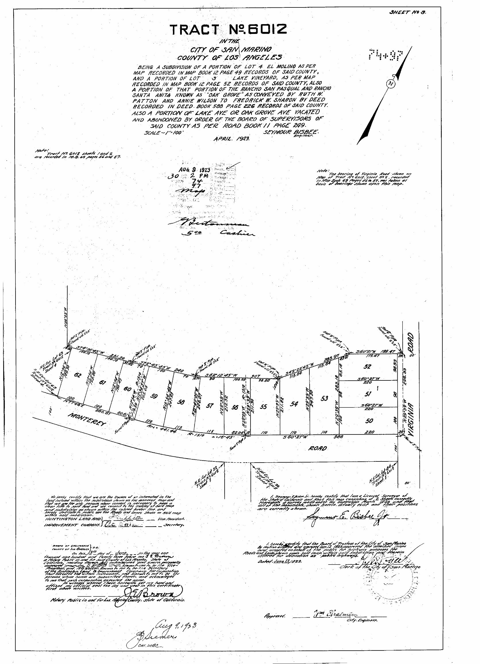
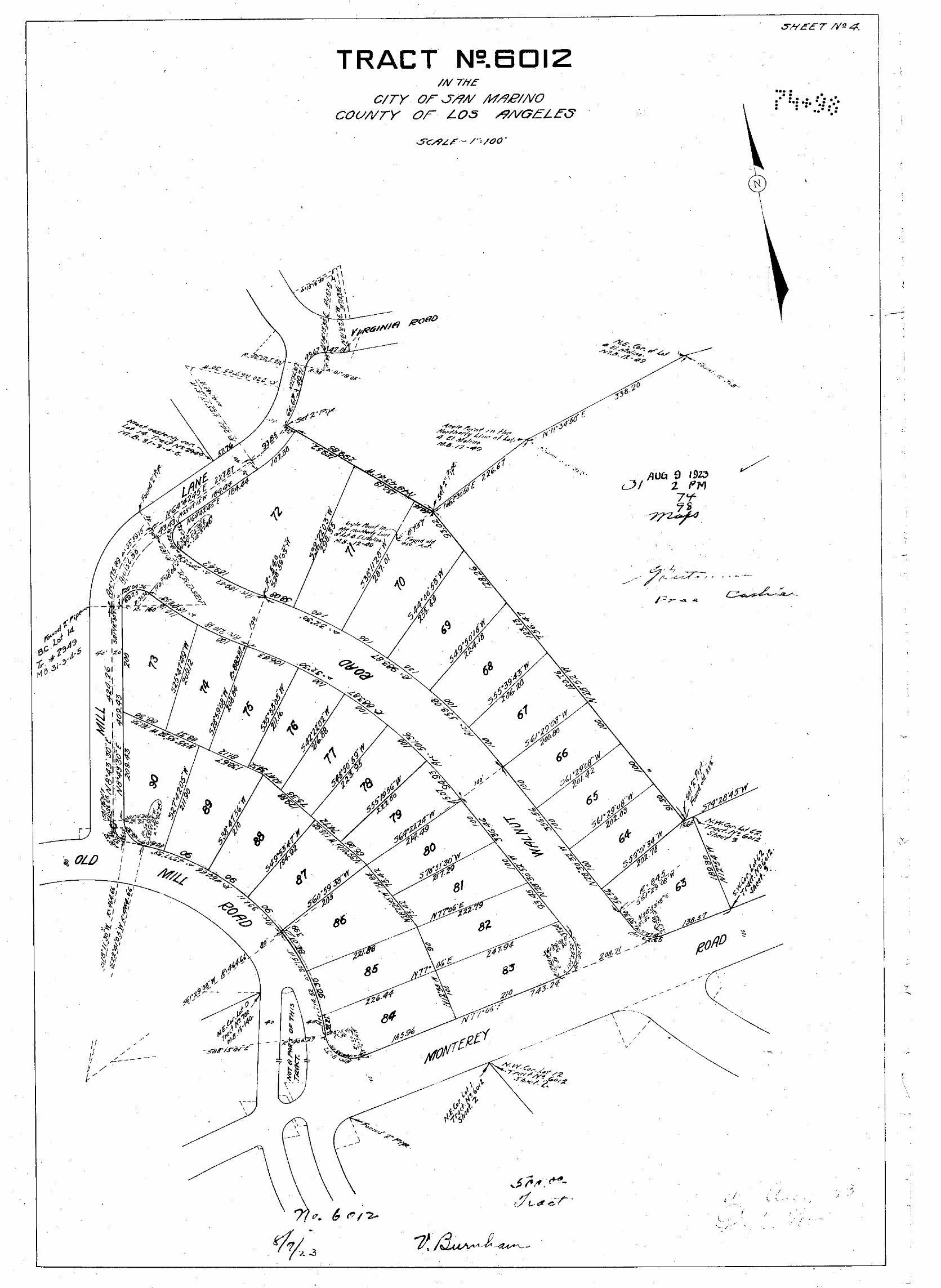

Appendix C Sanborn Maps

Certified Sanborn® Map Report
Inquiry Number:
6 Armstrong Road, 4th floor Shelton, CT 06484Toll Free: 800.352.0050 www.edrnet.com
3325 MONTEREY RD
3325 MONTEREY RD
SAN MARINO, CA 91108
February 26, 2018
5199926.3
Certified Sanborn® Map Report
Certified Sanborn Results:
Disclaimer - Copyright and Trademark Notice
EDR and its logos (including Sanborn and Sanborn Map) are trademarks of Environmental Data Resources, Inc. or its affiliates. All other trademarks used herein are the property of their respective owners.
page-
The Sanborn Library includes more than 1.2 millionfire insurance maps from Sanborn, Bromley, Perris &Browne, Hopkins, Barlow and others which trackhistorical property usage in approximately 12,000American cities and towns. Collections searched:
Library of Congress
University Publications of America
EDR Private Collection
The Sanborn Library LLC Since 1866™
Limited Permission To Make Copies
Sanborn® Library search results
Contact:EDR Inquiry #
Site Name: Client Name:
Certification #
PO #
Project
1961
1950
1930
02/26/18
3325 MONTEREY RD
3325 MONTEREY RD ESA
626 Wilshire Blvd
SAN MARINO, CA 91108
5199926.3
Los Angeles, CA 90017
Max Loder
The Sanborn Library has been searched by EDR and maps covering the target property location as provided by ESA were identified for the
years listed below. The Sanborn Library is the largest, most complete collection of fire insurance maps. The collection includes maps from
Sanborn, Bromley, Perris & Browne, Hopkins, Barlow, and others. Only Environmental Data Resources Inc. (EDR) is authorized to grant
rights for commercial reproduction of maps by the Sanborn Library LLC, the copyright holder for the collection. Results can be
authenticated by visiting www.edrnet.com/sanborn.
The Sanborn Library is continually enhanced with newly identified map archives. This report accesses all maps in the collection as of the
day this report was generated.
75E4-45A1-929E
D180090.00
Maps Provided:
3325 Monterey Road HRA
Certification #: 75E4-45A1-929E
ESA (the client) is permitted to make up to FIVE photocopies of this Sanborn Map transmittal and each fire insurance map accompanying this report solely for the
limited use of its customer. No one other than the client is authorized to make copies. Upon request made directly to an EDR Account Executive, the client may be
permitted to make a limited number of additional photocopies. This permission is conditioned upon compliance by the client, its customer and their agents with EDR's
copyright policy; a copy of which is available upon request.
This Report contains certain information obtained from a variety of public and other sources reasonably available to Environmental Data Resources, Inc. It cannot
be concluded from this Report that coverage information for the target and surrounding properties does not exist from other sources. NO WARRANTY
EXPRESSED OR IMPLIED, IS MADE WHATSOEVER IN CONNECTION WITH THIS REPORT. ENVIRONMENTAL DATA RESOURCES, INC. SPECIFICALLY
DISCLAIMS THE MAKING OF ANY SUCH WARRANTIES, INCLUDING WITHOUT LIMITATION, MERCHANTABILITY OR FITNESS FOR A PARTICULAR USE
OR PURPOSE. ALL RISK IS ASSUMED BY THE USER. IN NO EVENT SHALL ENVIRONMENTAL DATA RESOURCES, INC. BE LIABLE TO ANYONE,
WHETHER ARISING OUT OF ERRORS OR OMISSIONS, NEGLIGENCE, ACCIDENT OR ANY OTHER CAUSE, FOR ANY LOSS OF DAMAGE, INCLUDING,
WITHOUT LIMITATION, SPECIAL, INCIDENTAL, CONSEQUENTIAL, OR EXEMPLARY DAMAGES. ANY LIABILITY ON THE PART OF ENVIRONMENTAL
DATA RESOURCES, INC. IS STRICTLY LIMITED TO A REFUND OF THE AMOUNT PAID FOR THIS REPORT. Purchaser accepts this Report "AS IS". Any
analyses, estimates, ratings, environmental risk levels or risk codes provided in this Report are provided for illustrative purposes only, and are not intended to
provide, nor should they be interpreted as providing any facts regarding, or prediction or forecast of, any environmental risk for any property. Only a Phase I
Environmental Site Assessment performed by an environmental professional can provide information regarding the environmental risk for any property.
Additionally, the information provided in this Report is not to be construed as legal advice.
Copyright 2018 by Environmental Data Resources, Inc. All rights reserved. Reproduction in any media or format, in whole or in part, of any report or map of
Environmental Data Resources, Inc., or its affiliates, is prohibited without prior written permission.
5199926 3 2
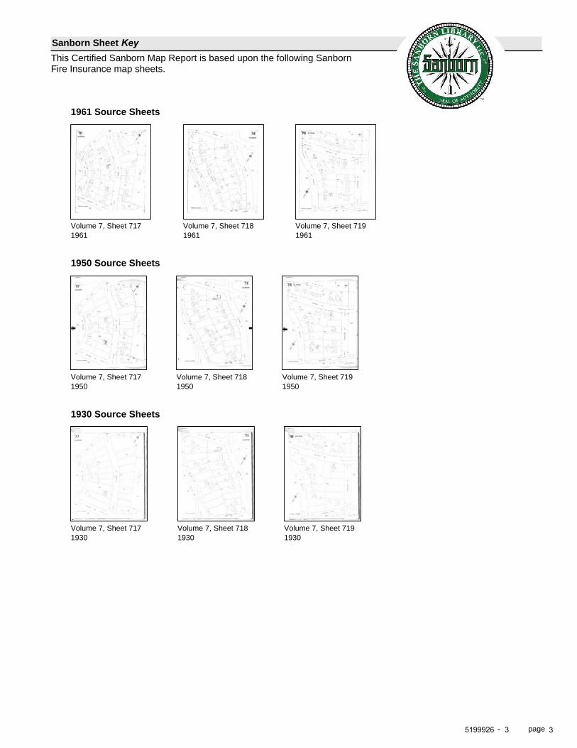
page-
Sanborn Sheet KeyThis Certified Sanborn Map Report is based upon the following SanbornFire Insurance map sheets.
1961 Source Sheets
1961Volume 7, Sheet 717
1961Volume 7, Sheet 718
1961Volume 7, Sheet 719
1950 Source Sheets
1950Volume 7, Sheet 717
1950Volume 7, Sheet 718
1950Volume 7, Sheet 719
1930 Source Sheets
1930Volume 7, Sheet 717
1930Volume 7, Sheet 718
1930Volume 7, Sheet 719
5199926 3 3

This Certified Sanborn Map combines the following sheets.Outlined areas indicate map sheets within the collection. 0 Feet 150 300 600
- page
Certified Sanborn® Map
75E
4-45
A1-
929E
75E4-45A1-929E
1961
1961
Order Date: 02/26/2018
Certification #
Site Name:
Address:
3325 MONTEREY RD
3325 MONTEREY RD
City, ST, ZIP: SAN MARINO, CA 91108
EDR Inquiry: 5199926.3
Client: ESA
Copyright
Volume 7, Sheet 719Volume 7, Sheet 718Volume 7, Sheet 717
5199926 3 4

This Certified Sanborn Map combines the following sheets.Outlined areas indicate map sheets within the collection. 0 Feet 150 300 600
- page
Certified Sanborn® Map
75E
4-45
A1-
929E
75E4-45A1-929E
1950
1950
Order Date: 02/26/2018
Certification #
Site Name:
Address:
3325 MONTEREY RD
3325 MONTEREY RD
City, ST, ZIP: SAN MARINO, CA 91108
EDR Inquiry: 5199926.3
Client: ESA
Copyright
Volume 7, Sheet 719Volume 7, Sheet 718Volume 7, Sheet 717
5199926 3 5
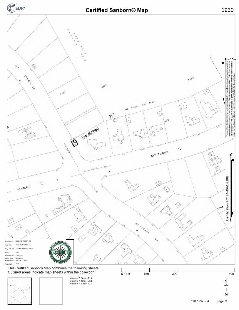
This Certified Sanborn Map combines the following sheets.Outlined areas indicate map sheets within the collection. 0 Feet 150 300 600
- page
Certified Sanborn® Map
75E
4-45
A1-
929E
75E4-45A1-929E
1930
1930
Order Date: 02/26/2018
Certification #
Site Name:
Address:
3325 MONTEREY RD
3325 MONTEREY RD
City, ST, ZIP: SAN MARINO, CA 91108
EDR Inquiry: 5199926.3
Client: ESA
Copyright
Volume 7, Sheet 719Volume 7, Sheet 718Volume 7, Sheet 717
5199926 3 6
Appendix D Building Permits

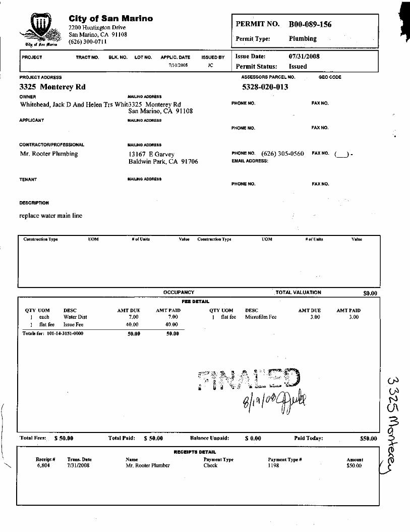
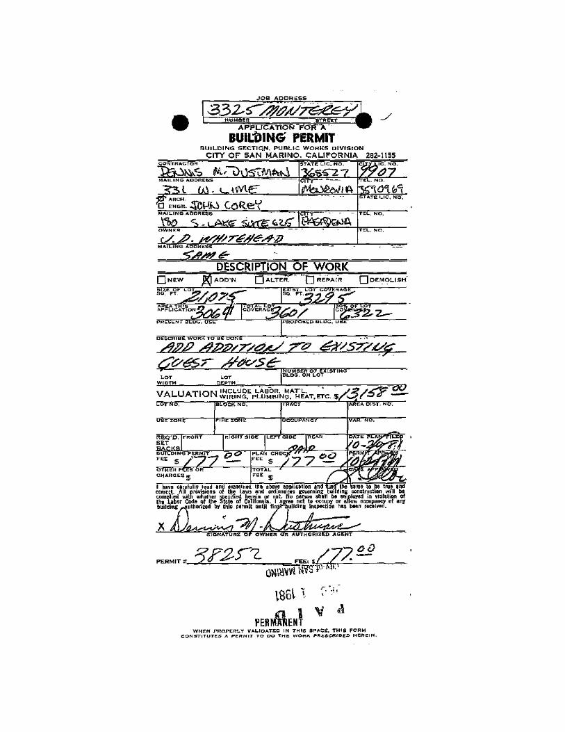
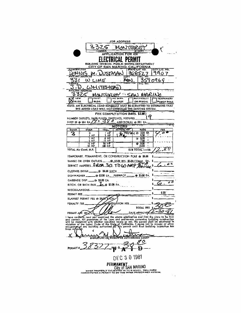
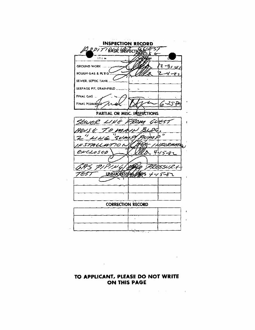
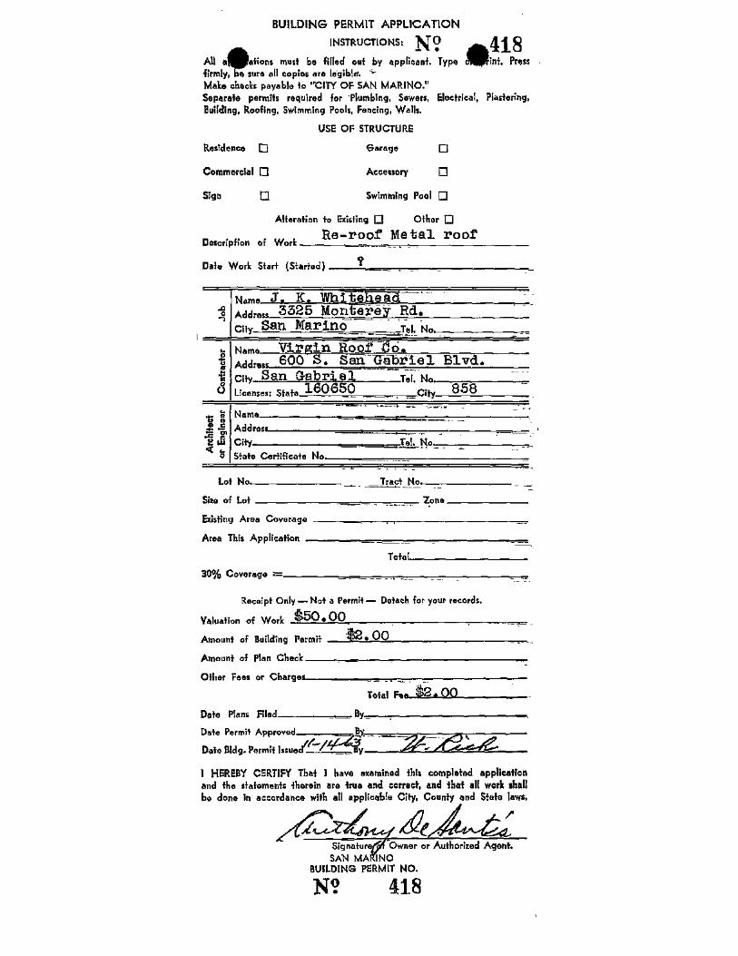
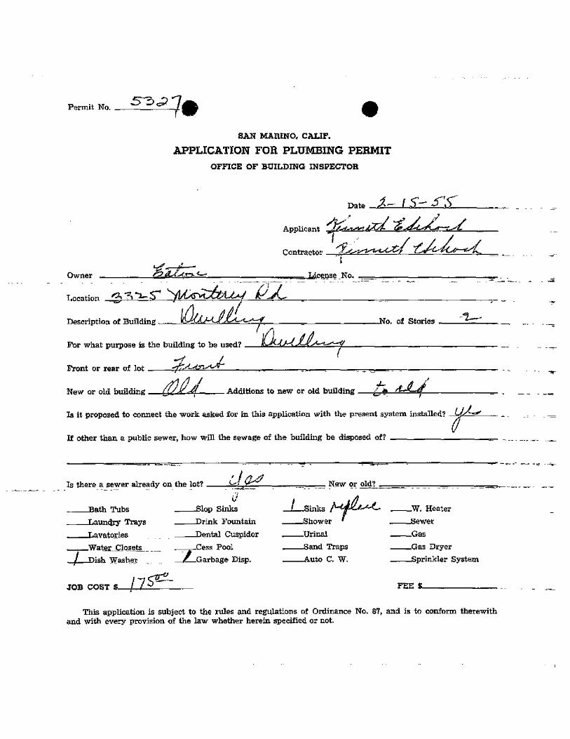
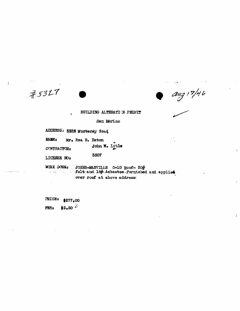
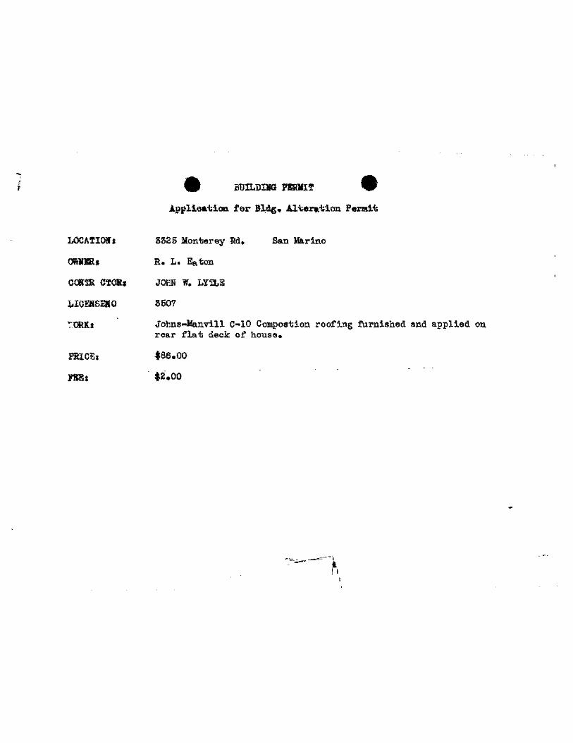
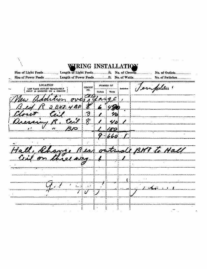
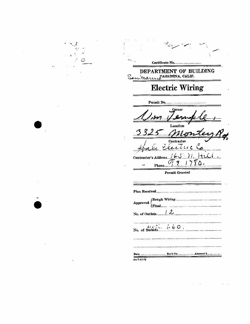
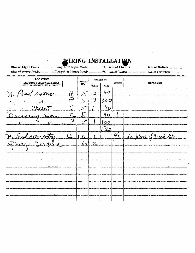
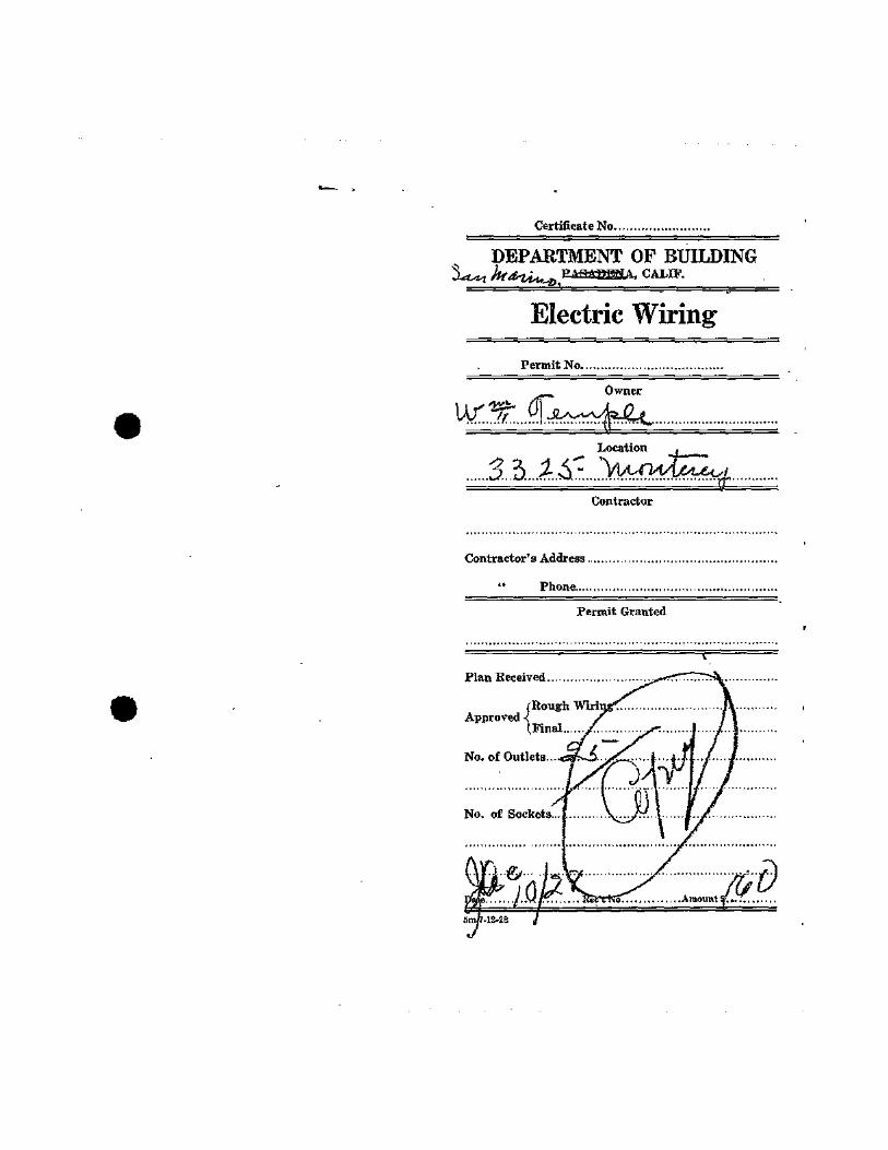
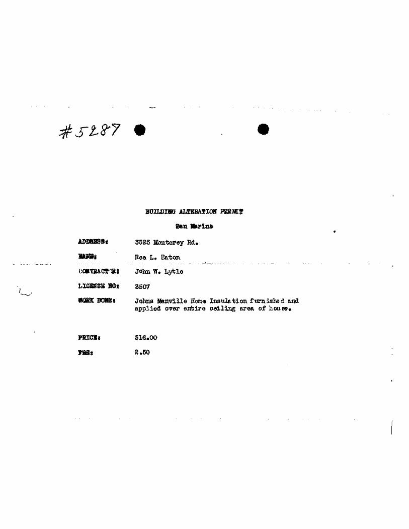
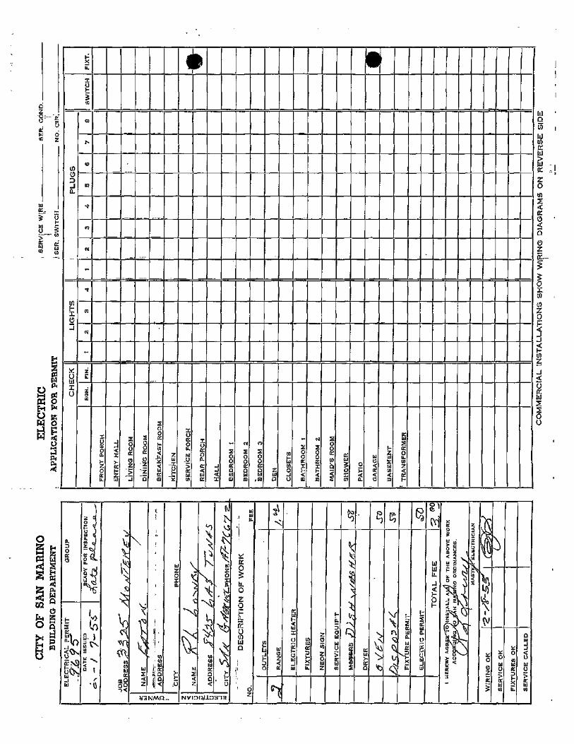
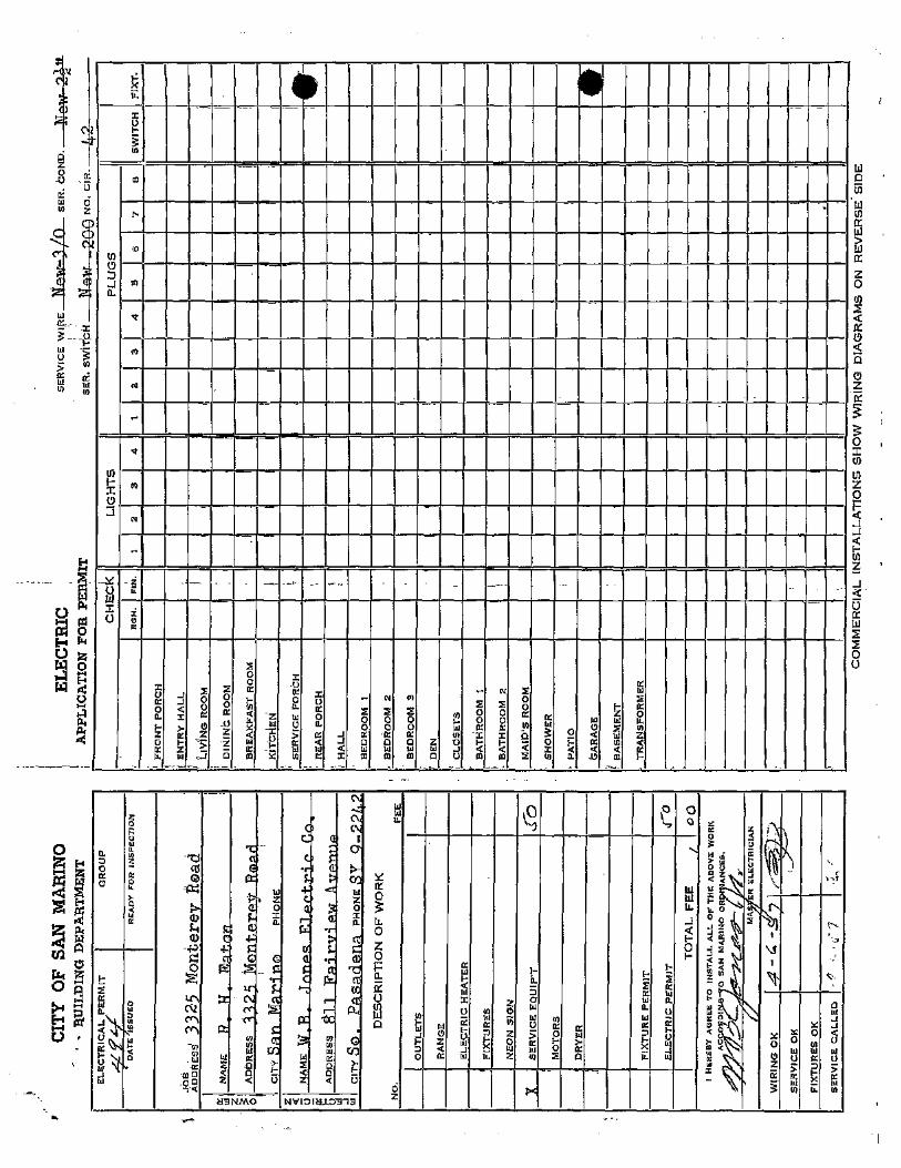
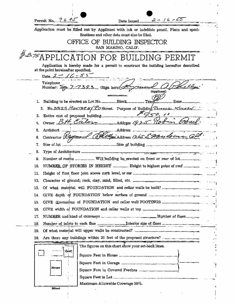
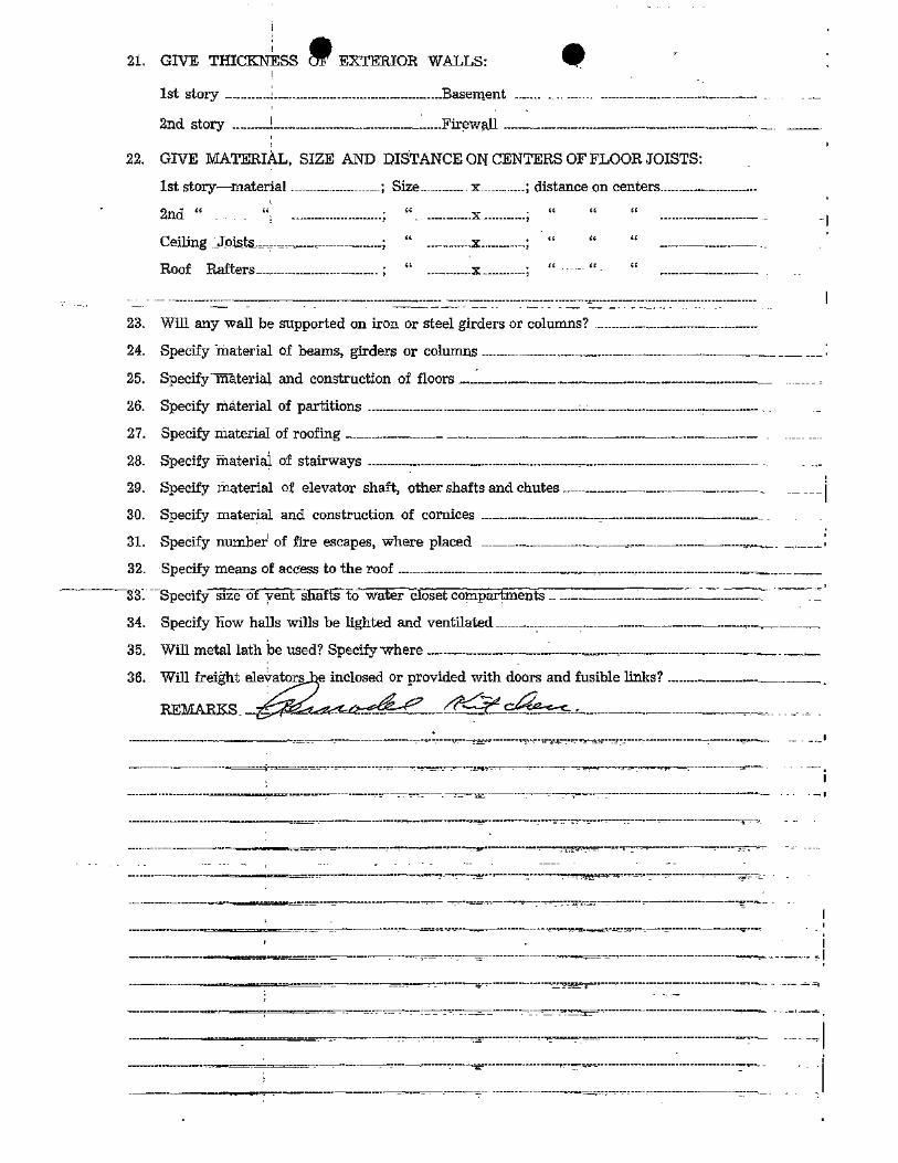
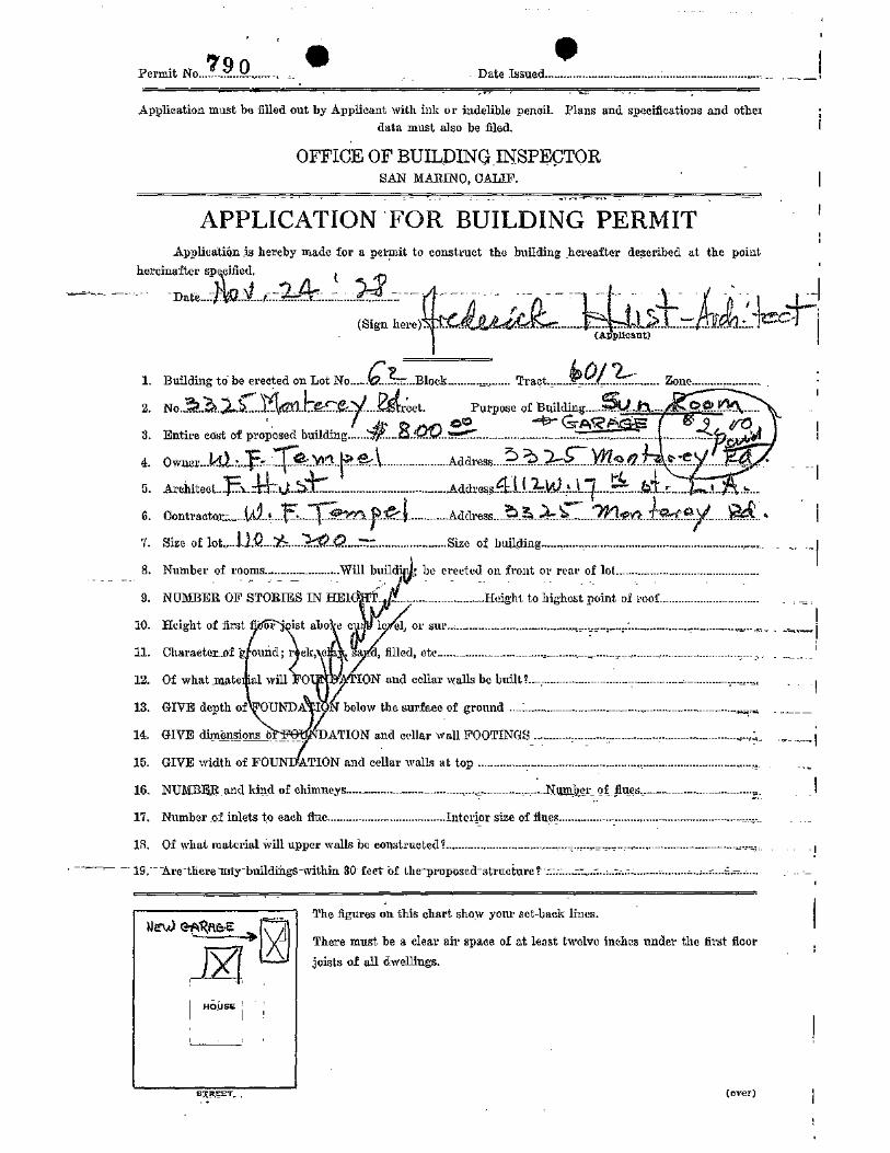
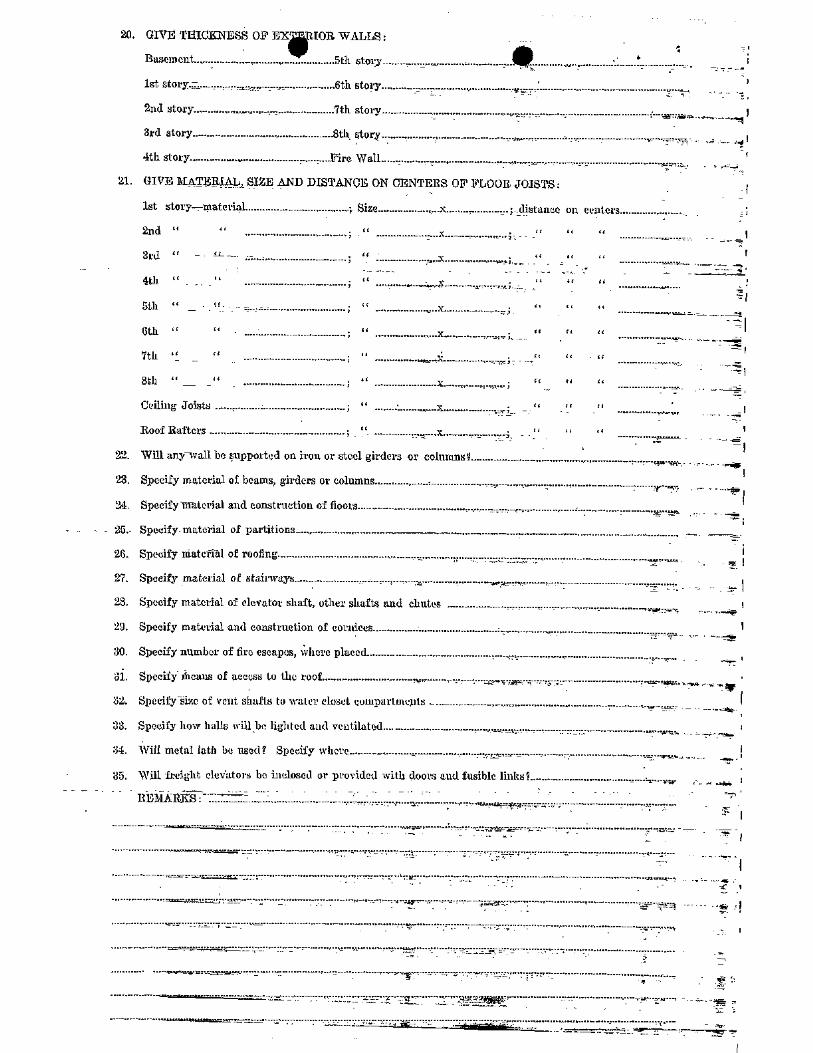
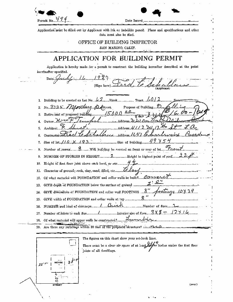
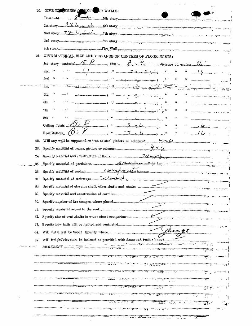
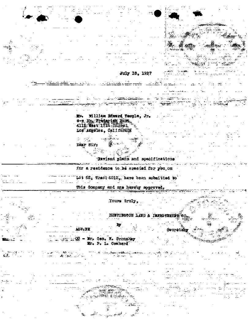
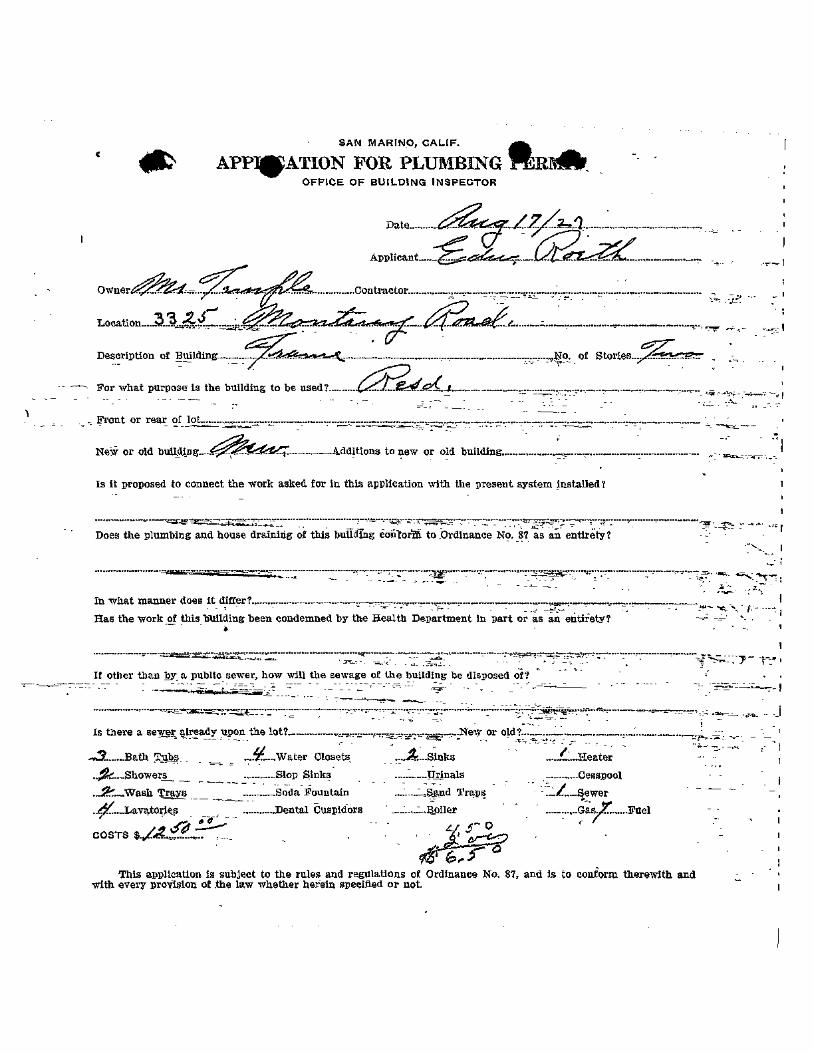
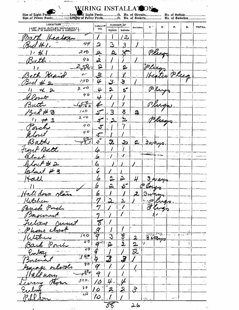
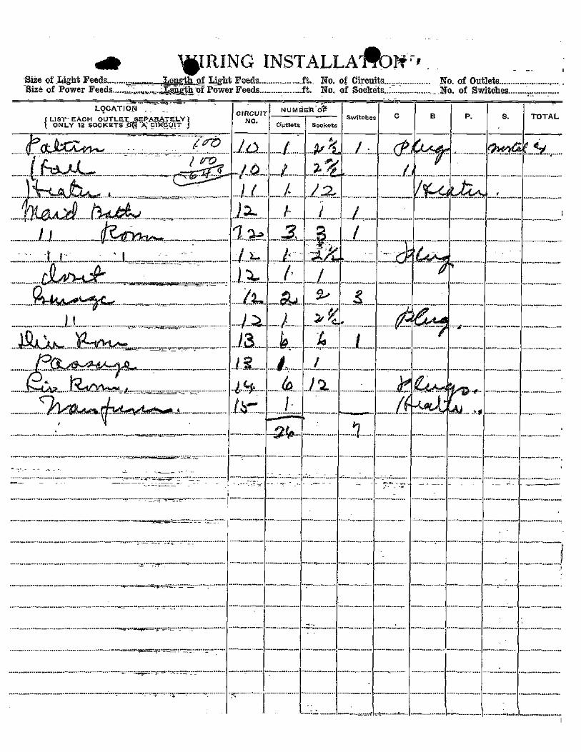
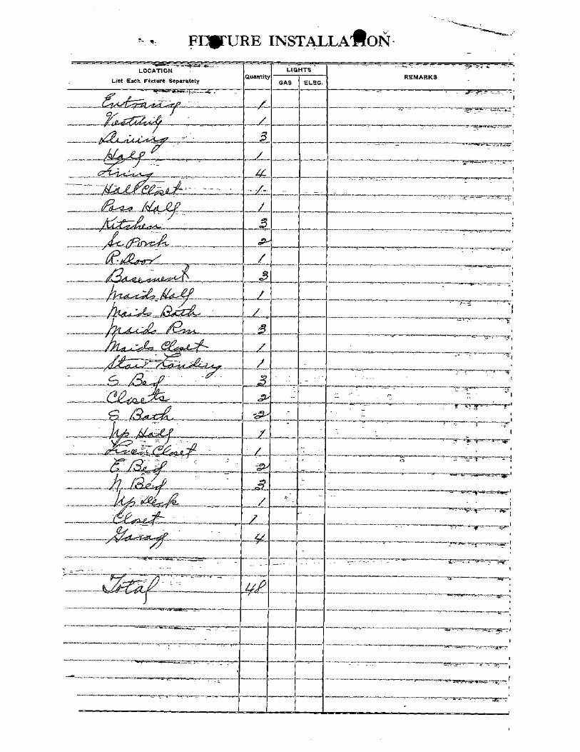

Appendix E Assessor Records

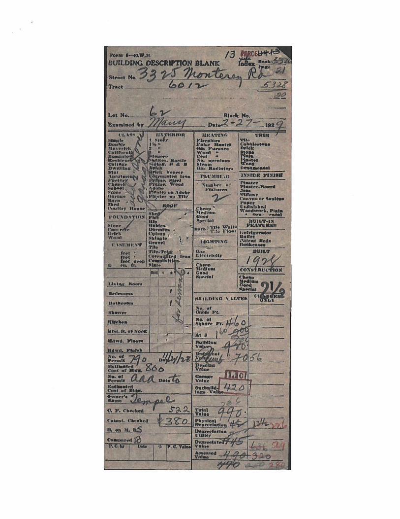
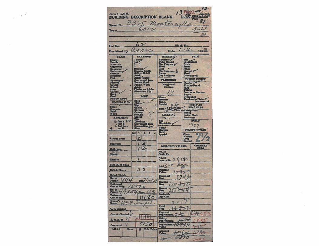
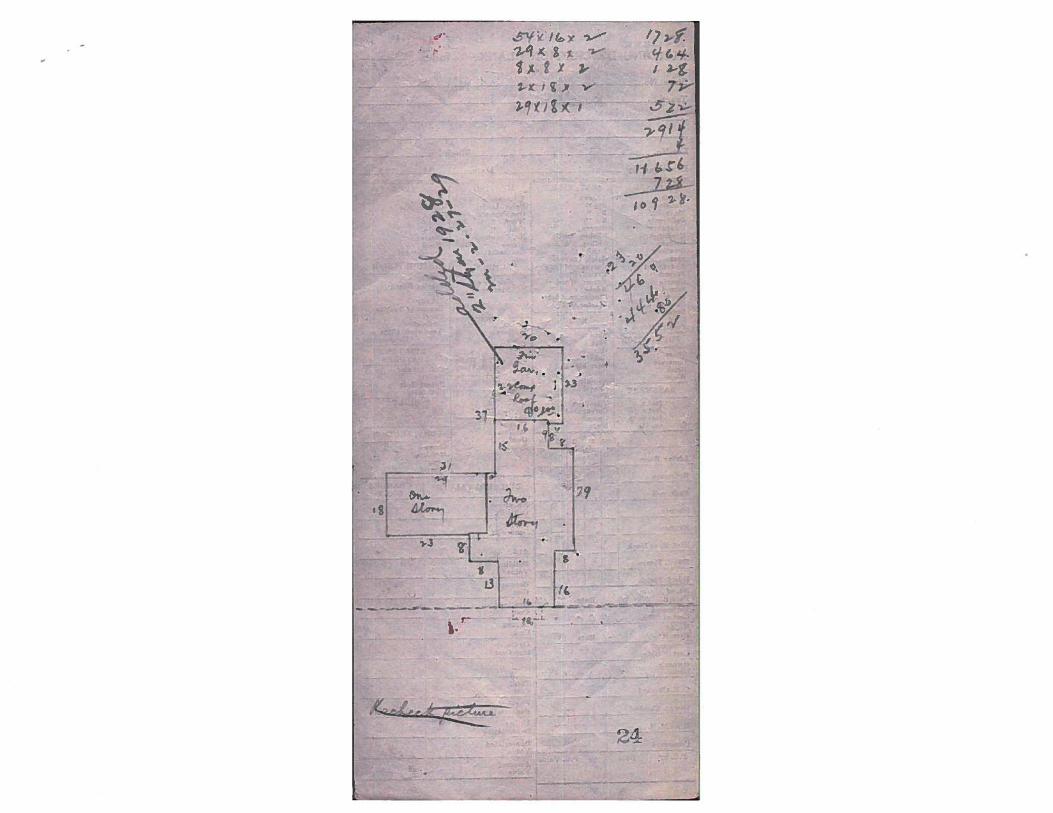
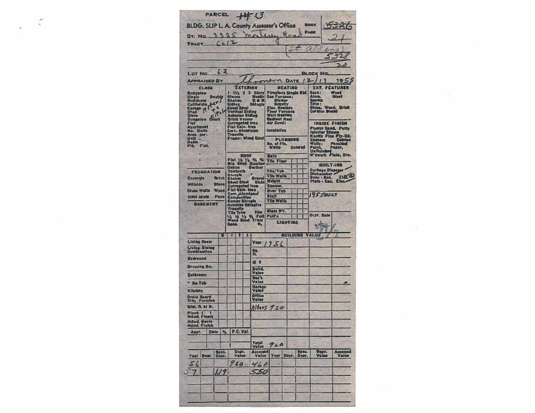
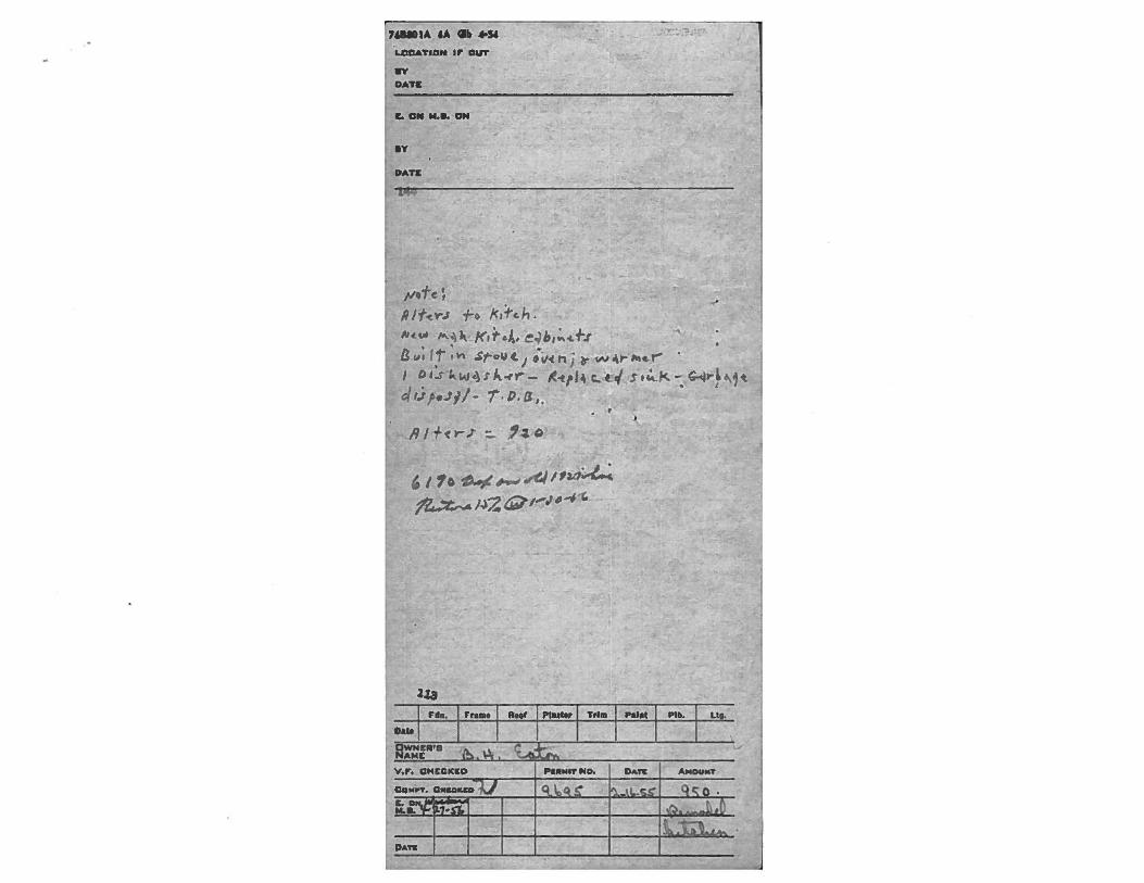
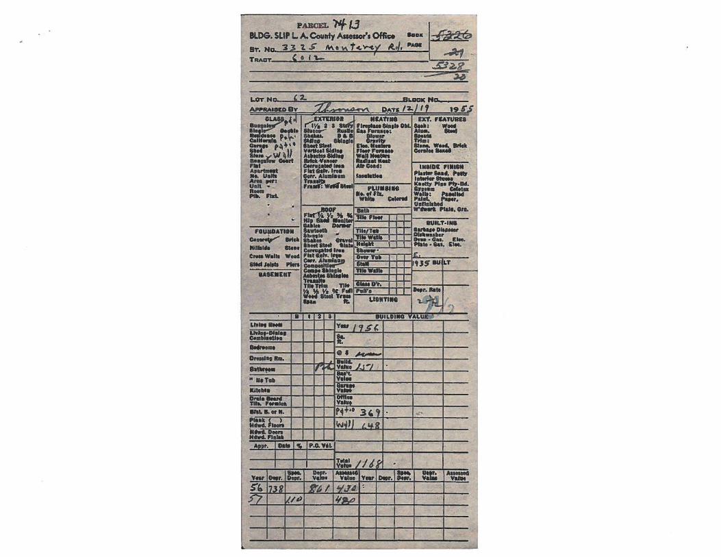
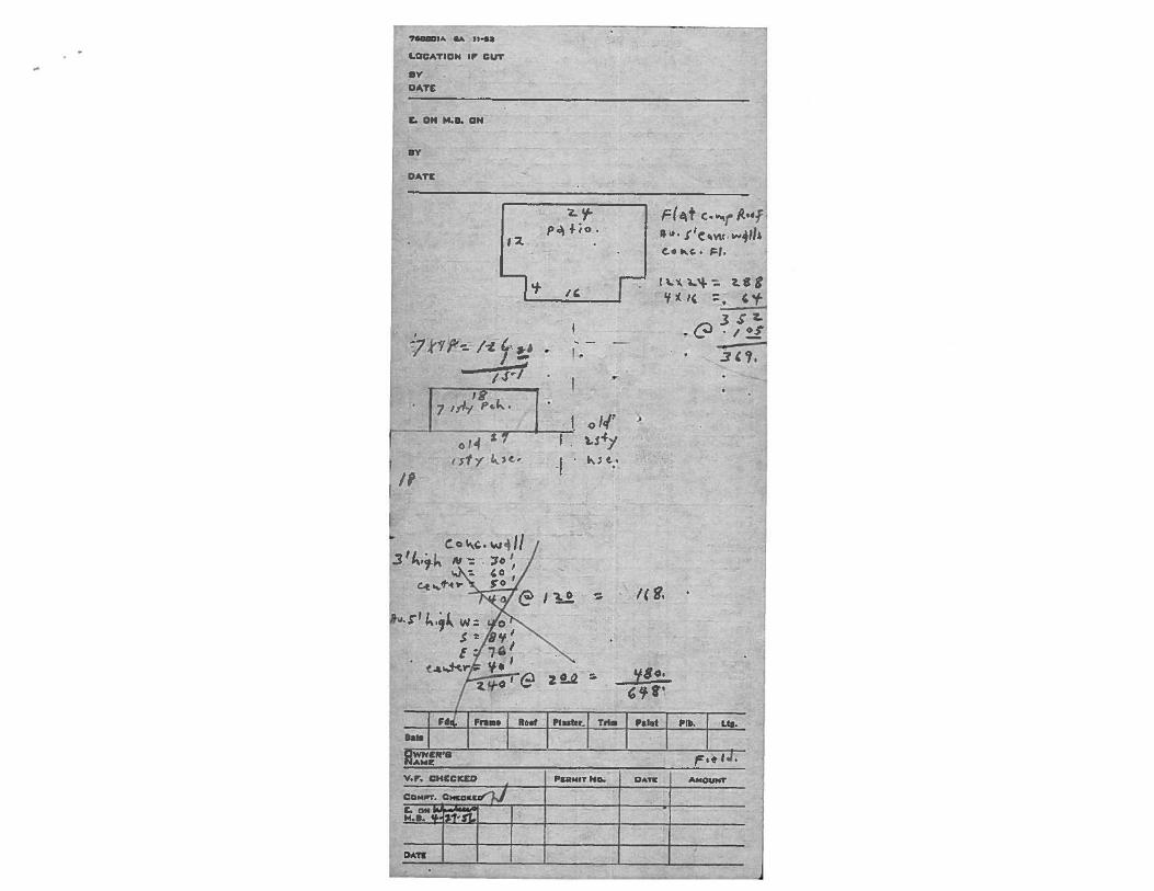
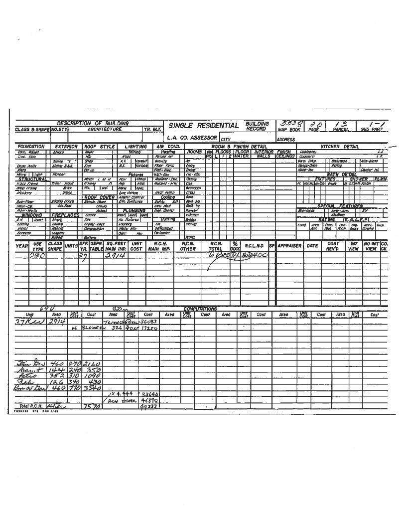
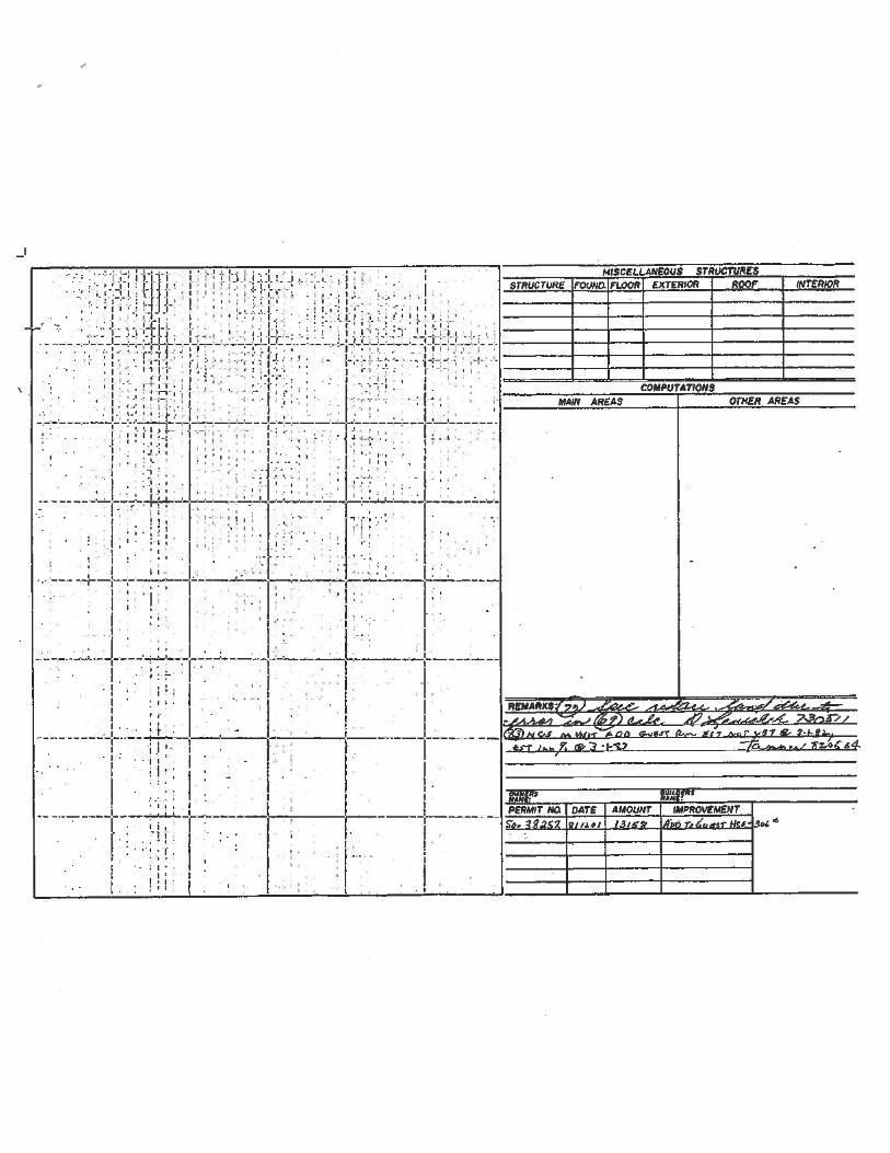
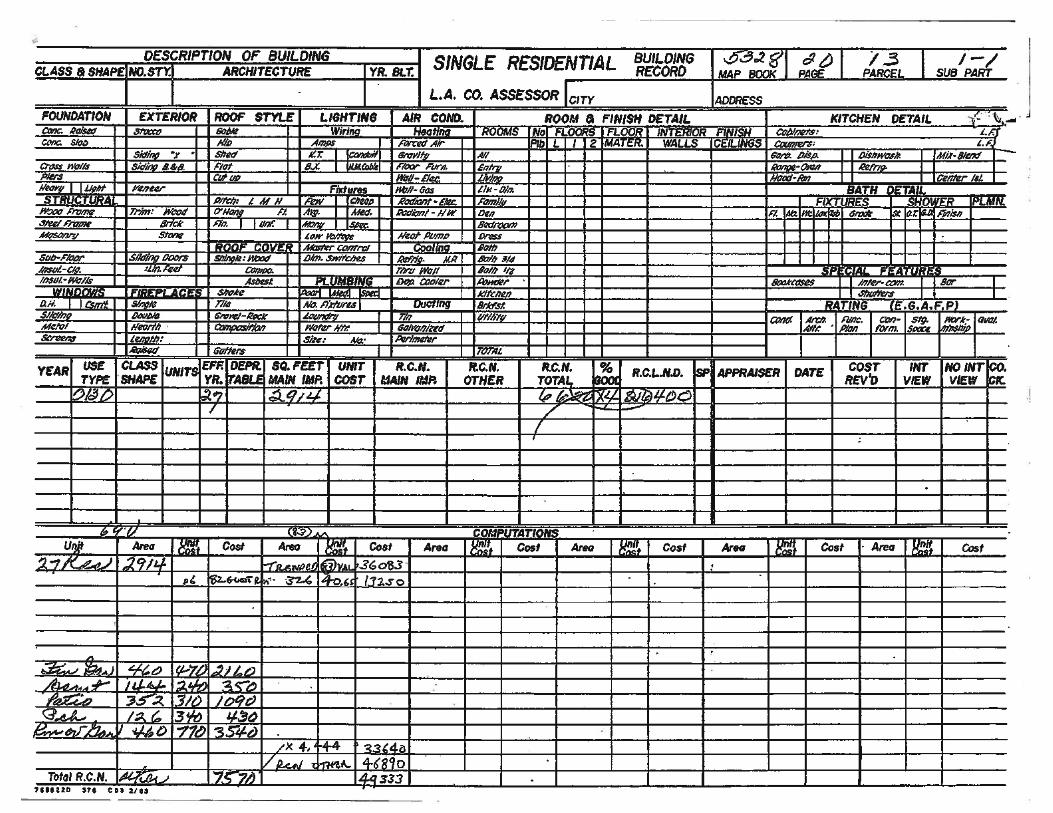
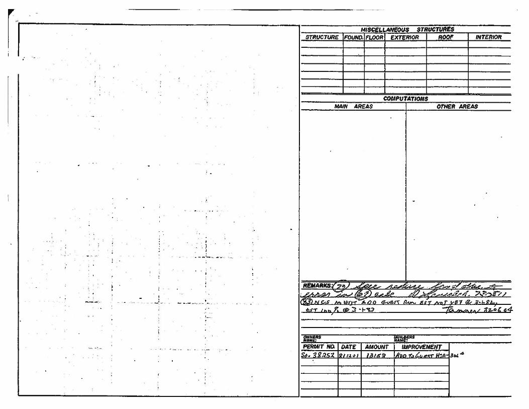

Appendix F Historic Photographs

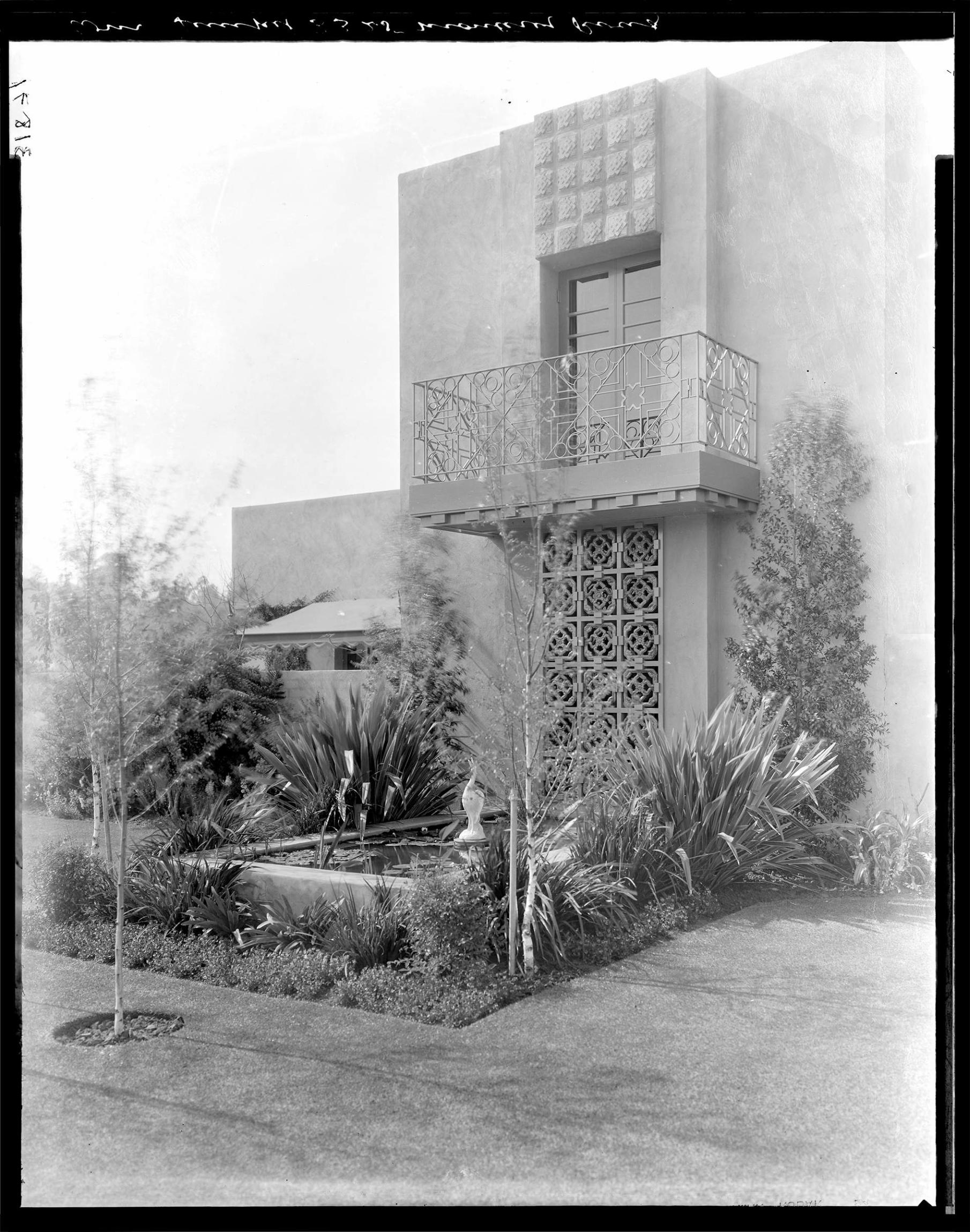
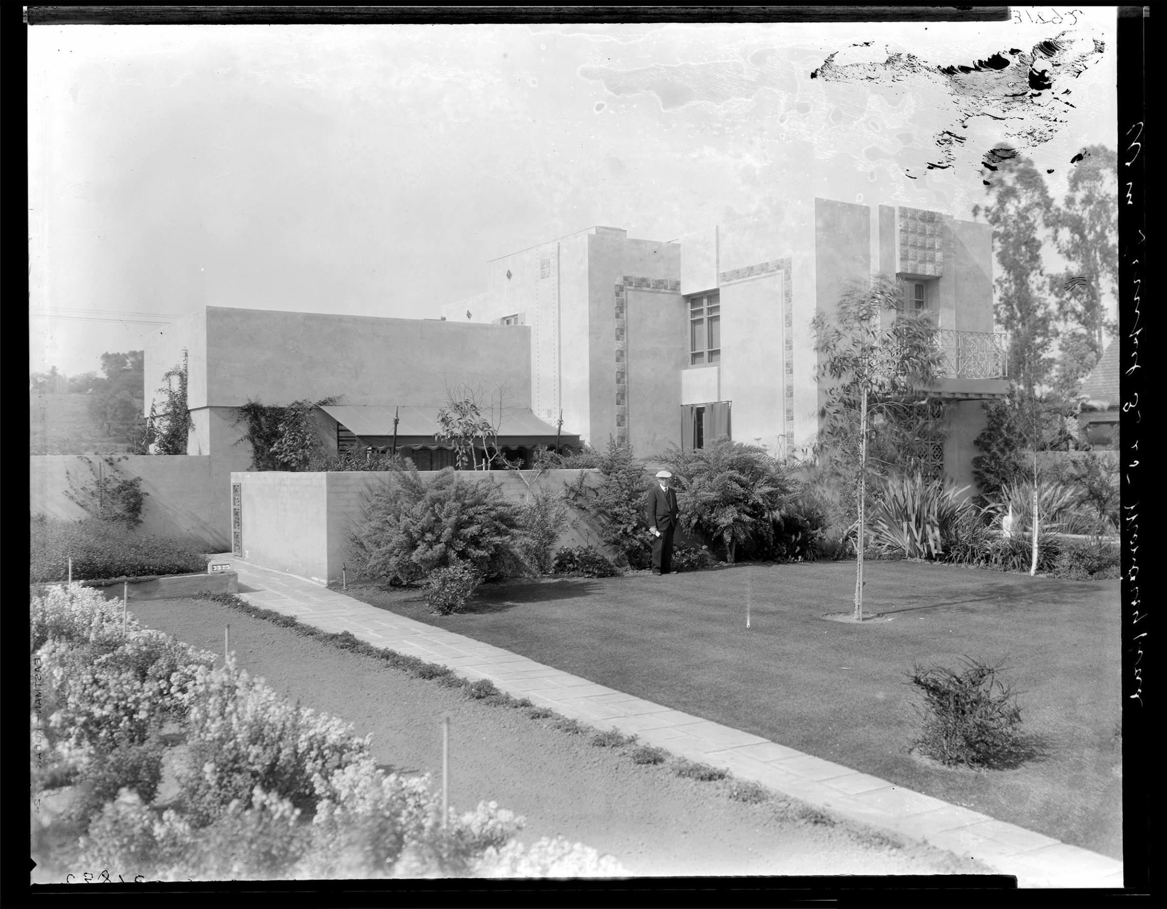
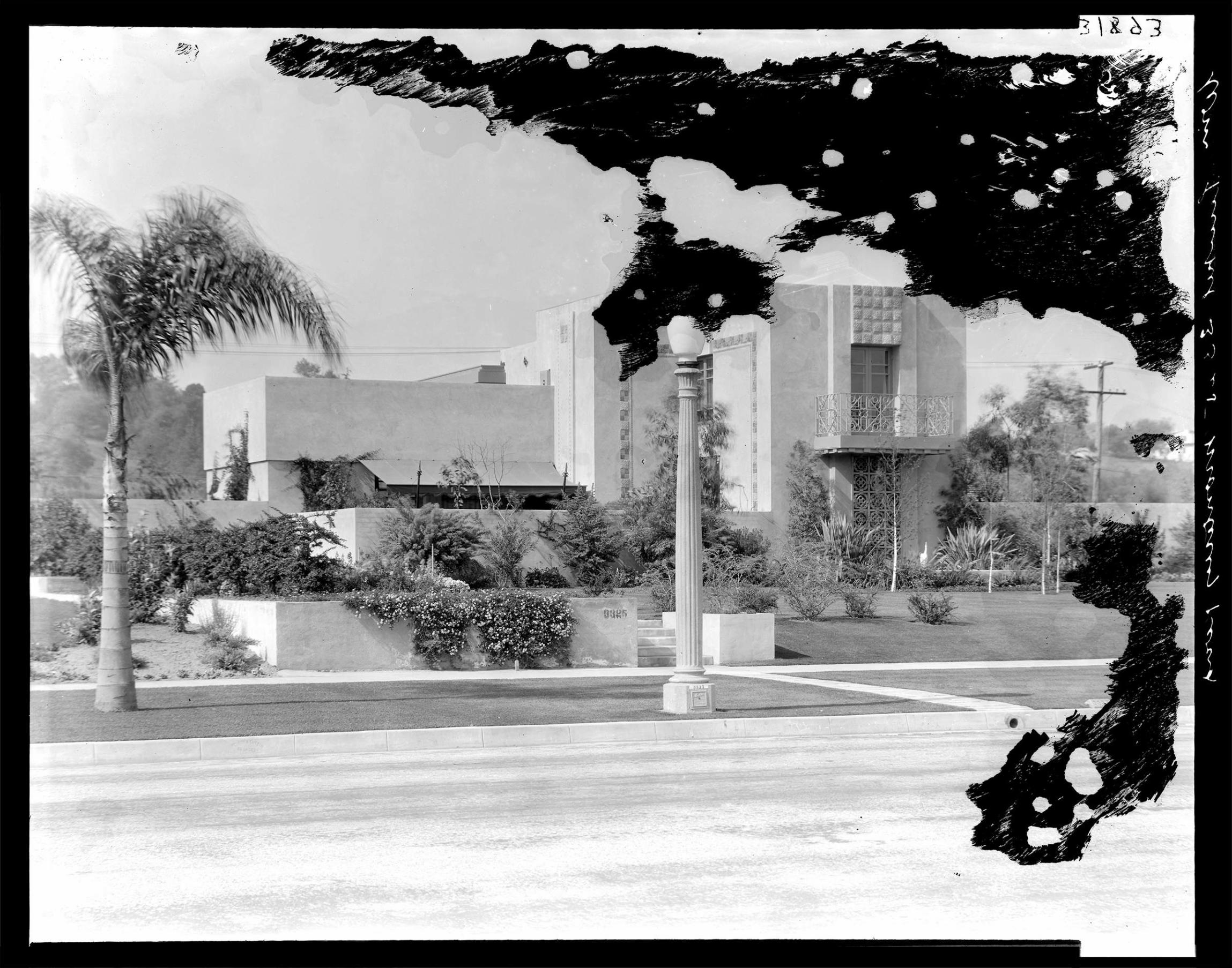
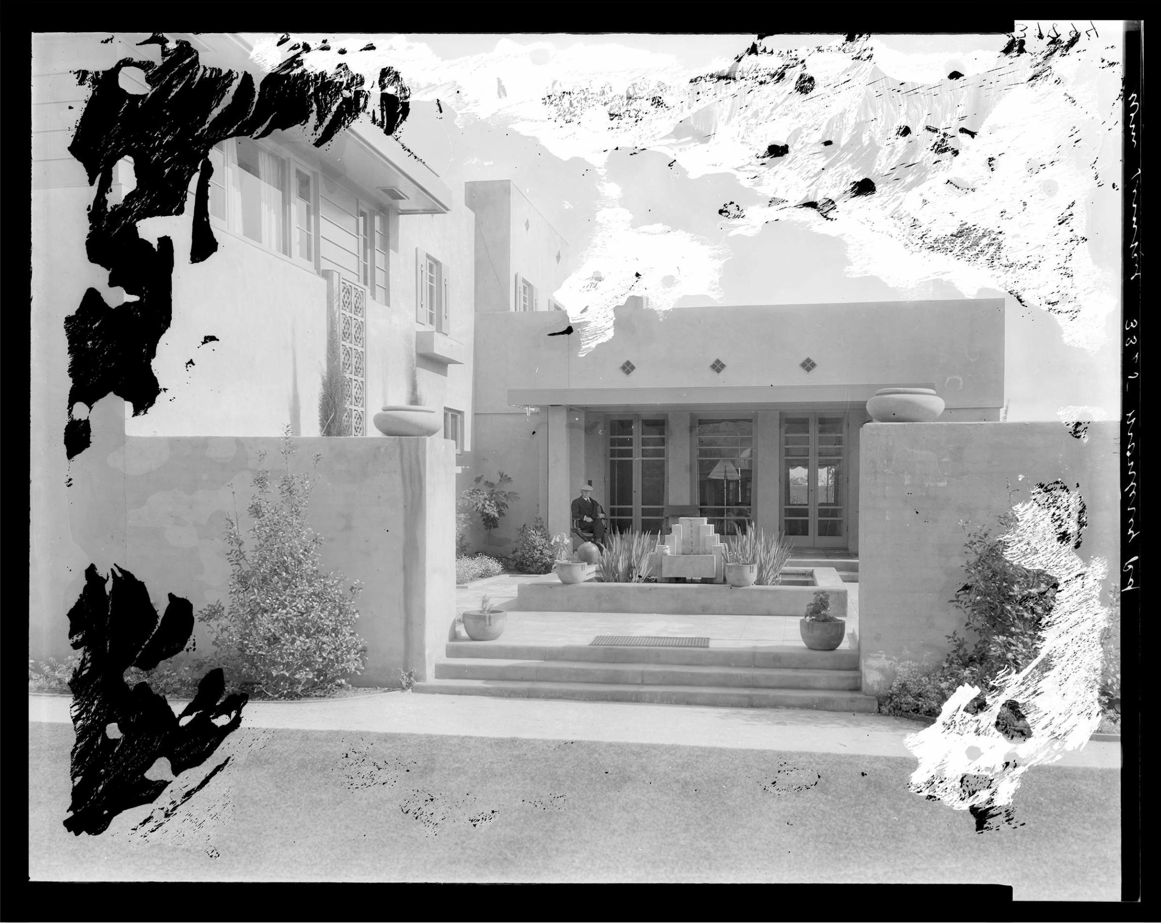
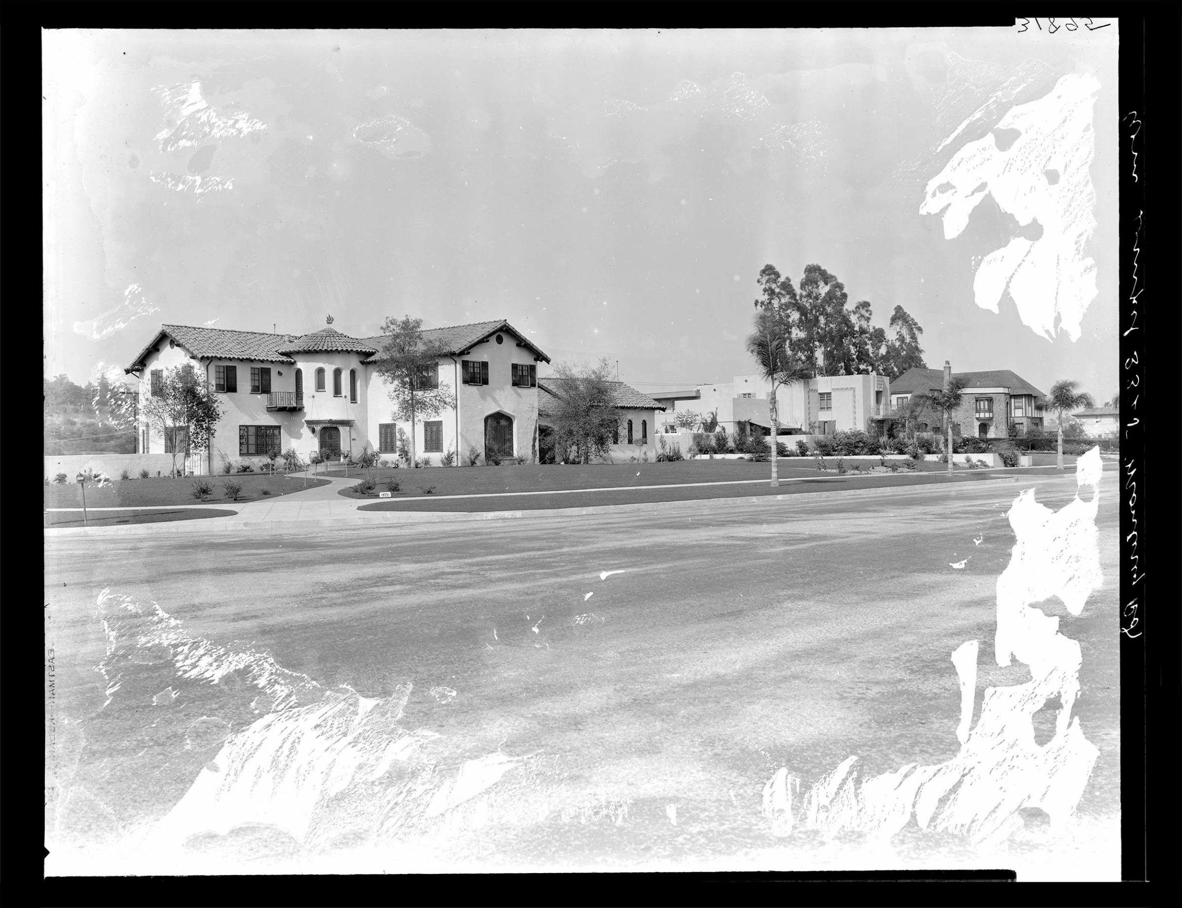

Appendix G Character-Defining Features Matrix

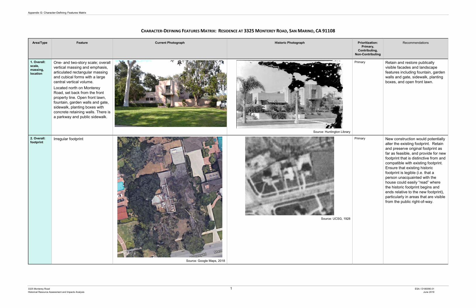
Appendix G: Character-Defining Features Matrix
3325 Monterey Road 1 ESA / D180090.01 Historical Resource Assessment and Impacts Analysis June 2019
CHARACTER-DEFINING FEATURES MATRIX: RESIDENCE AT 3325 MONTEREY ROAD, SAN MARINO, CA 91108
Area/Type Feature Current Photograph Historic Photograph Prioritization: Primary,
Contributing, Non-Contributing
Recommendations
1. Overall: scale, massing, location
One- and two-story scale; overall vertical massing and emphasis, articulated rectangular massing and cubical forms with a large central vertical volume. Located north on Monterey Road, set back from the front property line. Open front lawn, fountain, garden walls and gate, sidewalk, planting boxes with concrete retaining walls. There is a parkway and public sidewalk.
Source: Huntington Library
Primary Retain and restore publically visible facades and landscape features including fountain, garden walls and gate, sidewalk, planting boxes, and open front lawn.
2. Overall: footprint
Irregular footprint
Source: Google Maps, 2018
Source: UCSG, 1928
Primary New construction would potentially alter the existing footprint. Retain and preserve original footprint as far as feasible, and provide for new footprint that is distinctive from and compatible with existing footprint. Ensure that existing historic footprint is legible (i.e. that a person unacquainted with the house could easily “read” where the historic footprint begins and ends relative to the new footprint), particularly in areas that are visible from the public right-of-way.
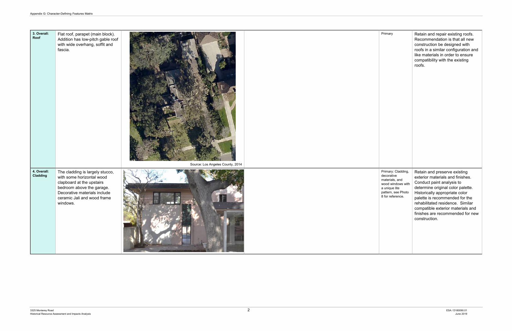
Appendix G: Character-Defining Features Matrix
3325 Monterey Road 2 ESA / D180090.01 Historical Resource Assessment and Impacts Analysis June 2019
3. Overall: Roof
Flat roof, parapet (main block). Addition has low-pitch gable roof with wide overhang, soffit and fascia.
Source: Los Angeles County, 2014
Primary
Retain and repair existing roofs. Recommendation is that all new construction be designed with roofs in a similar configuration and like materials in order to ensure compatibility with the existing roofs.
4. Overall: Cladding
The cladding is largely stucco, with some horizontal wood clapboard at the upstairs bedroom above the garage. Decorative materials include ceramic Jali and wood frame windows.
Primary: Cladding, decorative materials, and wood windows with a unique lite pattern, see Photo 8 for reference.
Retain and preserve existing exterior materials and finishes. Conduct paint analysis to determine original color palette. Historically appropriate color palette is recommended for the rehabilitated residence. Similar compatible exterior materials and finishes are recommended for new construction.
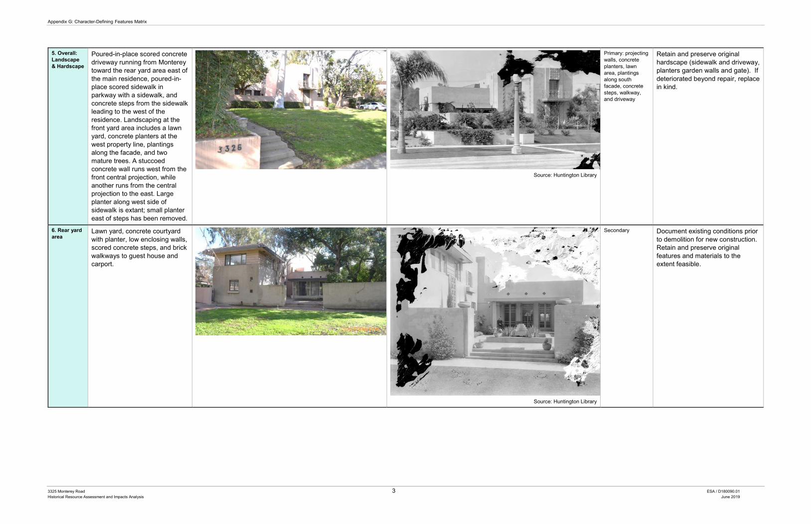
Appendix G: Character-Defining Features Matrix
3325 Monterey Road 3 ESA / D180090.01 Historical Resource Assessment and Impacts Analysis June 2019
5. Overall: Landscape & Hardscape
Poured-in-place scored concrete driveway running from Monterey toward the rear yard area east of the main residence, poured-in-place scored sidewalk in parkway with a sidewalk, and concrete steps from the sidewalk leading to the west of the residence. Landscaping at the front yard area includes a lawn yard, concrete planters at the west property line, plantings along the facade, and two mature trees. A stuccoed concrete wall runs west from the front central projection, while another runs from the central projection to the east. Large planter along west side of sidewalk is extant; small planter east of steps has been removed.
Source: Huntington Library
Primary: projecting walls, concrete planters, lawn area, plantings along south facade, concrete steps, walkway, and driveway
Retain and preserve original hardscape (sidewalk and driveway, planters garden walls and gate). If deteriorated beyond repair, replace in kind.
6. Rear yard area
Lawn yard, concrete courtyard with planter, low enclosing walls, scored concrete steps, and brick walkways to guest house and carport.
Source: Huntington Library
Secondary Document existing conditions prior to demolition for new construction. Retain and preserve original features and materials to the extent feasible.
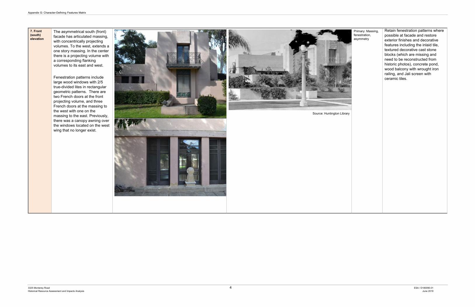
Appendix G: Character-Defining Features Matrix
3325 Monterey Road 4 ESA / D180090.01 Historical Resource Assessment and Impacts Analysis June 2019
7. Front (south) elevation
The asymmetrical south (front) facade has articulated massing, with concentrically projecting volumes. To the west, extends a one story massing. In the center there is a projecting volume with a corresponding flanking volumes to its east and west. Fenestration patterns include large wood windows with 2/5 true-divided lites in rectangular geometric patterns. There are two French doors at the front projecting volume, and three French doors at the massing to the west with one on the massing to the east. Previously, there was a canopy awning over the windows located on the west wing that no longer exist.
Source: Huntington Library
Primary: Massing, fenestration, asymmetry
Retain fenestration patterns where possible at facade and restore exterior finishes and decorative features including the inlaid tile, textured decorative cast stone blocks (which are missing and need to be reconstructed from historic photos), concrete pond, wood balcony with wrought iron railing, and Jali screen with ceramic tiles.
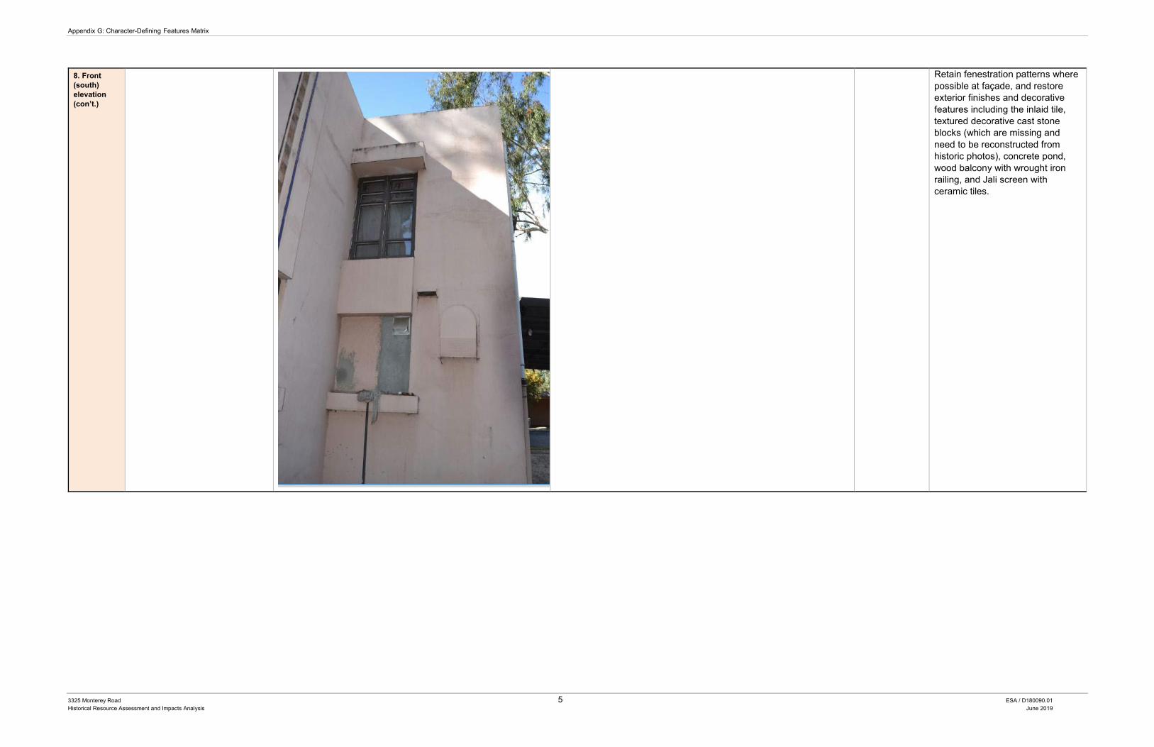
Appendix G: Character-Defining Features Matrix
3325 Monterey Road 5 ESA / D180090.01 Historical Resource Assessment and Impacts Analysis June 2019
8. Front (south) elevation (con’t.)
Retain fenestration patterns where possible at façade, and restore exterior finishes and decorative features including the inlaid tile, textured decorative cast stone blocks (which are missing and need to be reconstructed from historic photos), concrete pond, wood balcony with wrought iron railing, and Jali screen with ceramic tiles.
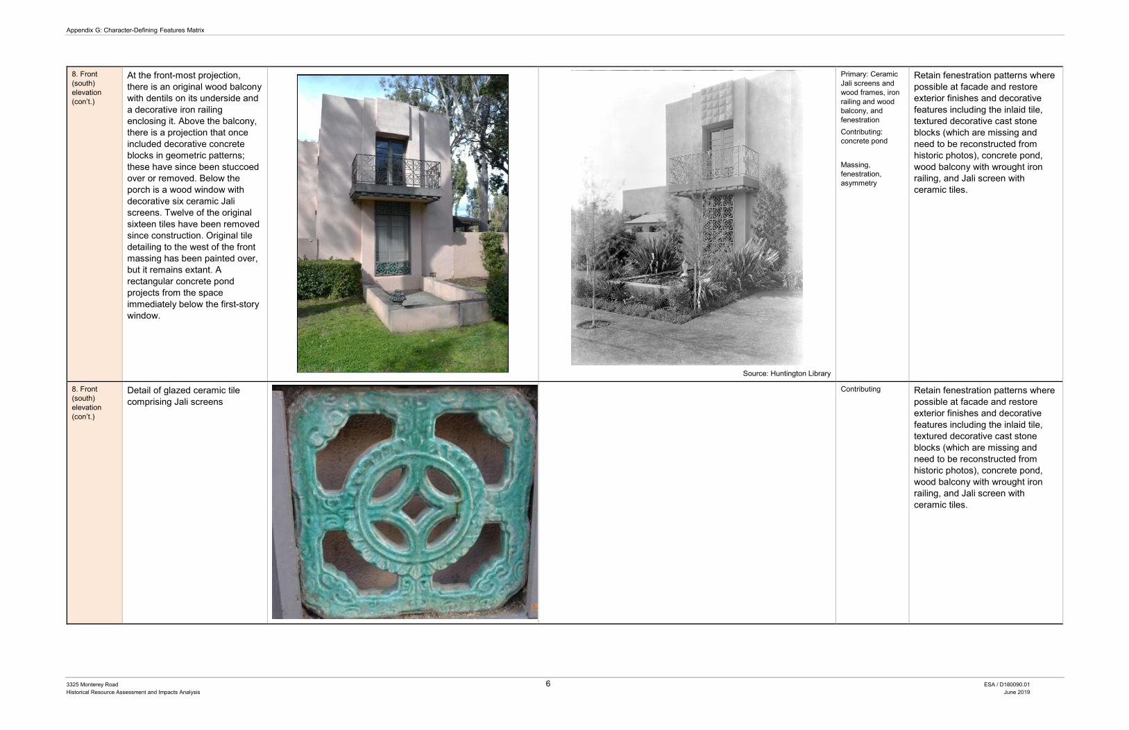
Appendix G: Character-Defining Features Matrix
3325 Monterey Road 6 ESA / D180090.01 Historical Resource Assessment and Impacts Analysis June 2019
8. Front (south) elevation (con’t.)
At the front-most projection, there is an original wood balcony with dentils on its underside and a decorative iron railing enclosing it. Above the balcony, there is a projection that once included decorative concrete blocks in geometric patterns; these have since been stuccoed over or removed. Below the porch is a wood window with decorative six ceramic Jali screens. Twelve of the original sixteen tiles have been removed since construction. Original tile detailing to the west of the front massing has been painted over, but it remains extant. A rectangular concrete pond projects from the space immediately below the first-story window.
Source: Huntington Library
Primary: Ceramic Jali screens and wood frames, iron railing and wood balcony, and fenestration Contributing: concrete pond Massing, fenestration, asymmetry
Retain fenestration patterns where possible at facade and restore exterior finishes and decorative features including the inlaid tile, textured decorative cast stone blocks (which are missing and need to be reconstructed from historic photos), concrete pond, wood balcony with wrought iron railing, and Jali screen with ceramic tiles.
8. Front (south) elevation (con’t.)
Detail of glazed ceramic tile comprising Jali screens
Contributing Retain fenestration patterns where possible at facade and restore exterior finishes and decorative features including the inlaid tile, textured decorative cast stone blocks (which are missing and need to be reconstructed from historic photos), concrete pond, wood balcony with wrought iron railing, and Jali screen with ceramic tiles.
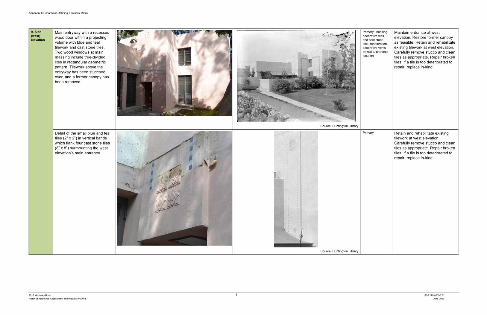
Appendix G: Character-Defining Features Matrix
3325 Monterey Road 7 ESA / D180090.01 Historical Resource Assessment and Impacts Analysis June 2019
9. Side (west) elevation
Main entryway with a recessed wood door within a projecting volume with blue and teal tilework and cast stone tiles. Two wood windows at main massing include true-divided lites in rectangular geometric pattern. Tilework above the entryway has been stuccoed over, and a former canopy has been removed.
Source: Huntington Library
Primary: Massing, decorative tiles and cast stone tiles, fenestration, decorative vents on walls, entrance location
Maintain entrance at west elevation. Restore former canopy as feasible. Retain and rehabilitate existing tilework at west elevation. Carefully remove stucco and clean tiles as appropriate. Repair broken tiles; if a tile is too deteriorated to repair, replace in-kind.
Detail of the small blue and teal tiles (2” x 2”) in vertical bands which flank four cast stone tiles (8” x 8”) surmounting the west elevation’s main entrance
Source: Huntington Library
Primary Retain and rehabilitate existing tilework at west elevation. Carefully remove stucco and clean tiles as appropriate. Repair broken tiles; if a tile is too deteriorated to repair, replace in-kind.
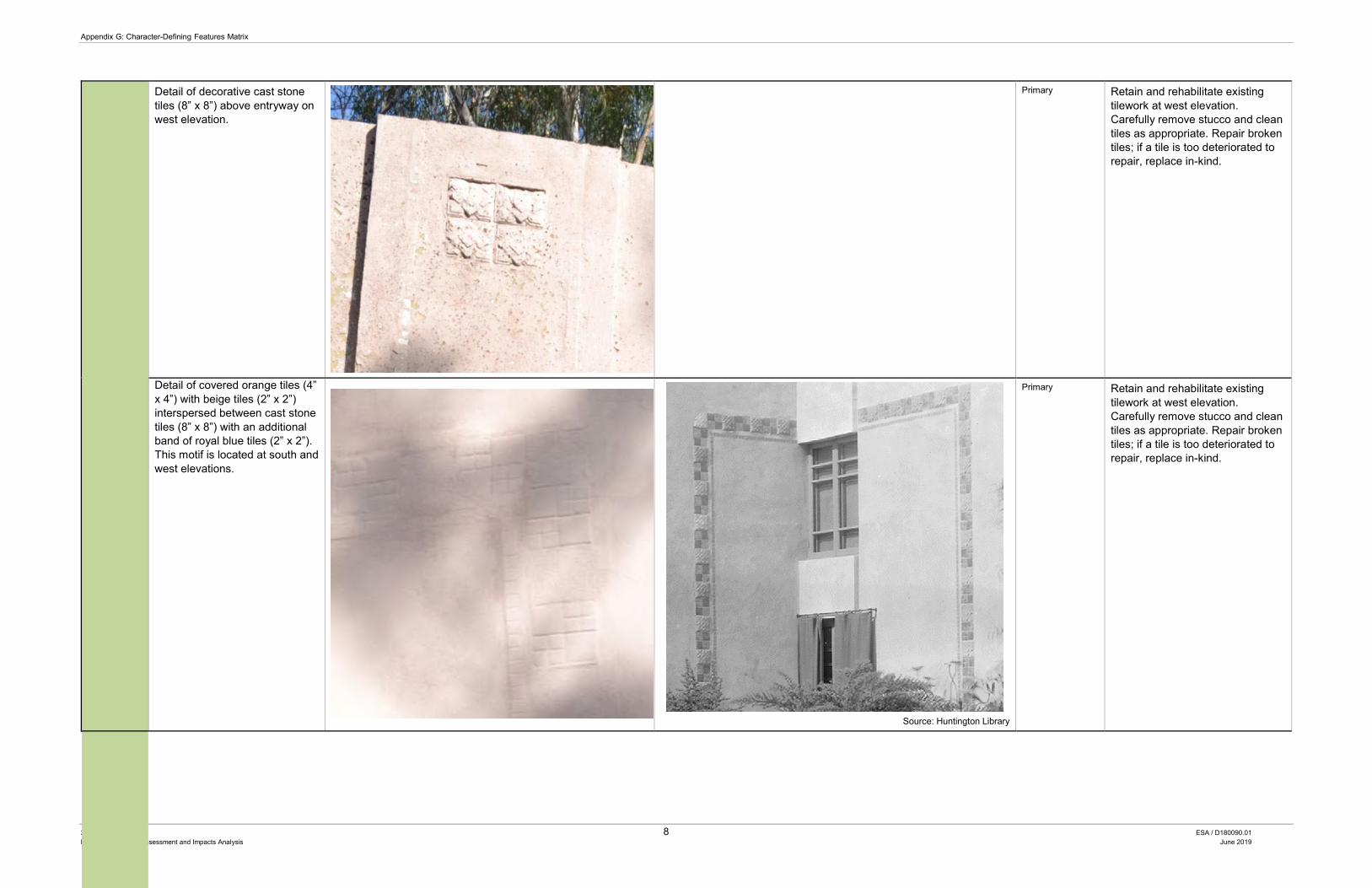
Appendix G: Character-Defining Features Matrix
3325 Monterey Road 8 ESA / D180090.01 Historical Resource Assessment and Impacts Analysis June 2019
Detail of decorative cast stone tiles (8” x 8”) above entryway on west elevation.
Primary Retain and rehabilitate existing tilework at west elevation. Carefully remove stucco and clean tiles as appropriate. Repair broken tiles; if a tile is too deteriorated to repair, replace in-kind.
Detail of covered orange tiles (4” x 4”) with beige tiles (2” x 2”) interspersed between cast stone tiles (8” x 8”) with an additional band of royal blue tiles (2” x 2”). This motif is located at south and west elevations.
Source: Huntington Library
Primary Retain and rehabilitate existing tilework at west elevation. Carefully remove stucco and clean tiles as appropriate. Repair broken tiles; if a tile is too deteriorated to repair, replace in-kind.
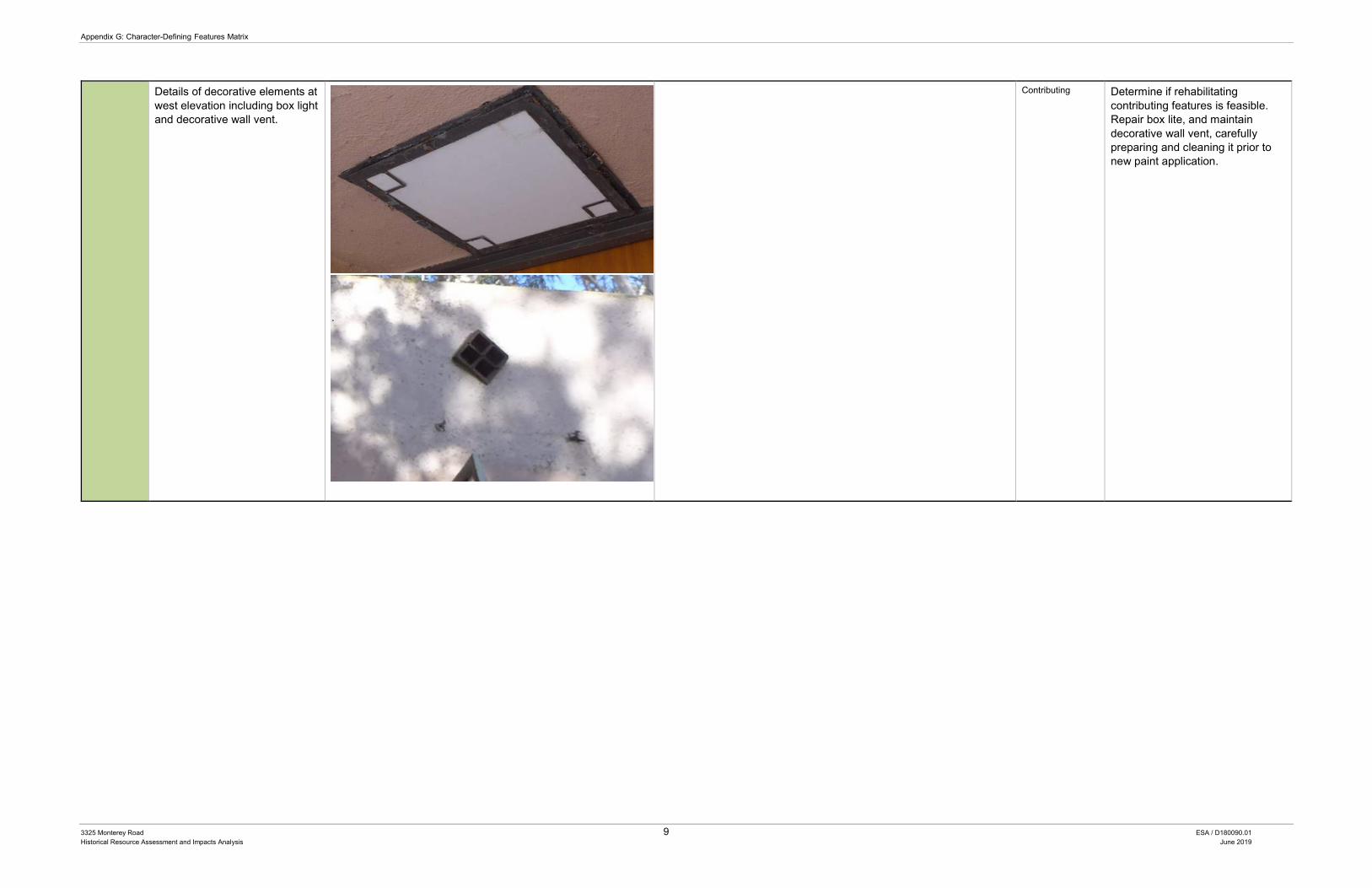
Appendix G: Character-Defining Features Matrix
3325 Monterey Road 9 ESA / D180090.01 Historical Resource Assessment and Impacts Analysis June 2019
Details of decorative elements at west elevation including box light and decorative wall vent.
Contributing Determine if rehabilitating contributing features is feasible. Repair box lite, and maintain decorative wall vent, carefully preparing and cleaning it prior to new paint application.
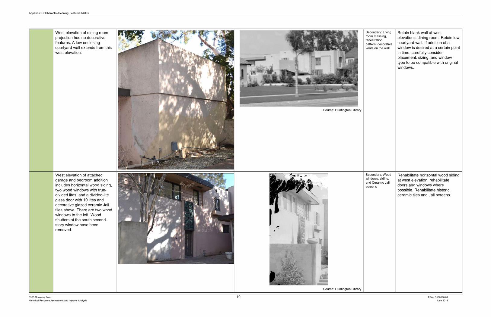
Appendix G: Character-Defining Features Matrix
3325 Monterey Road 10 ESA / D180090.01 Historical Resource Assessment and Impacts Analysis June 2019
West elevation of dining room projection has no decorative features. A low enclosing courtyard wall extends from this west elevation.
Source: Huntington Library
Secondary: Living room massing, fenestration pattern, decorative vents on the wall
Retain blank wall at west elevation’s dining room. Retain low courtyard wall. If addition of a window is desired at a certain point in time, carefully consider placement, sizing, and window type to be compatible with original windows.
West elevation of attached garage and bedroom addition includes horizontal wood siding, two wood windows with true-divided lites, and a divided-lite glass door with 10 lites and decorative glazed ceramic Jali tiles above. There are two wood windows to the left. Wood shutters at the south second-story window have been removed.
Source: Huntington Library
Secondary: Wood windows, siding, and Ceramic Jali screens
Rehabilitate horizontal wood siding at west elevation, rehabilitate doors and windows where possible. Rehabilitate historic ceramic tiles and Jali screens.
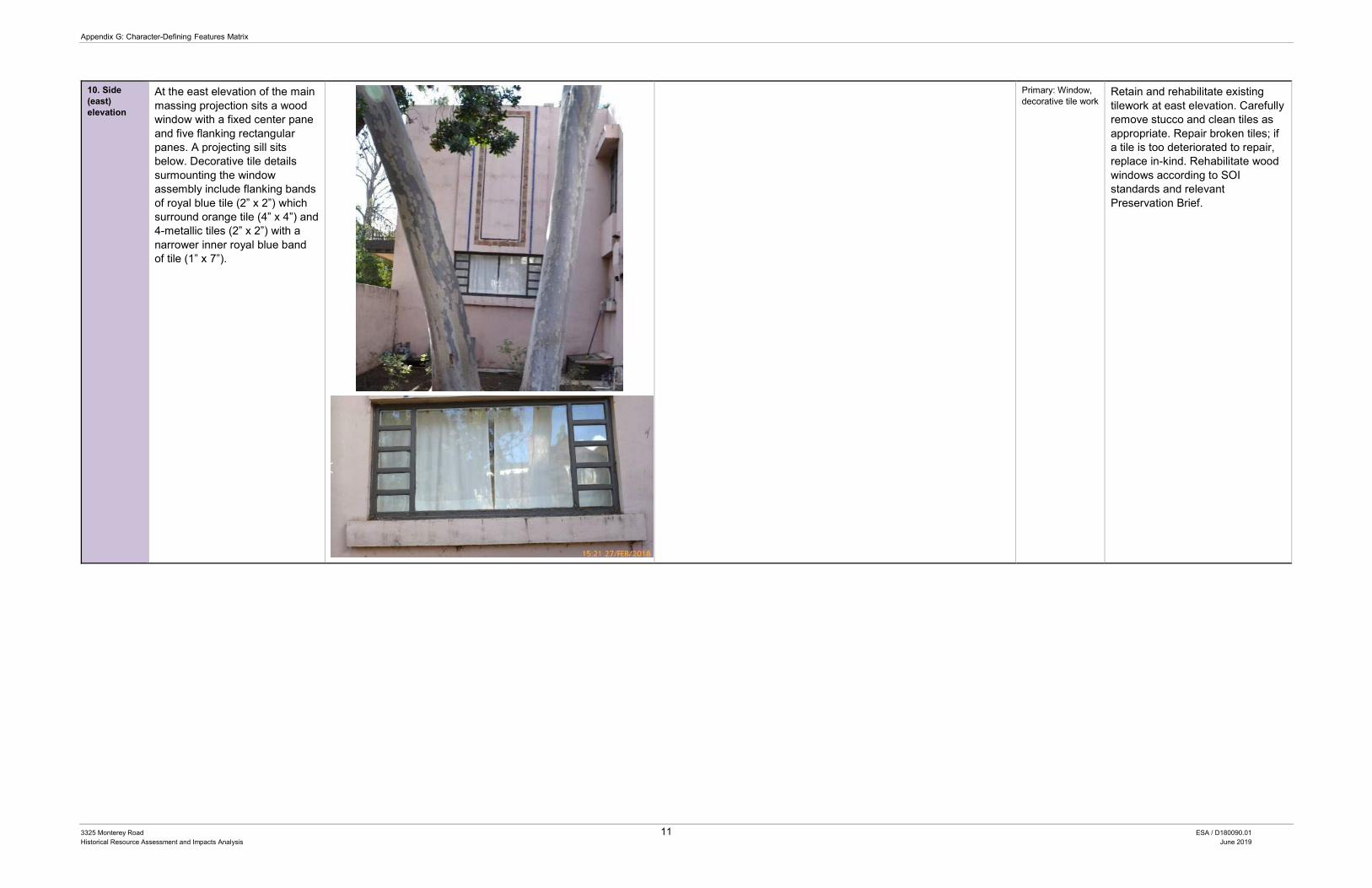
Appendix G: Character-Defining Features Matrix
3325 Monterey Road 11 ESA / D180090.01 Historical Resource Assessment and Impacts Analysis June 2019
10. Side (east) elevation
At the east elevation of the main massing projection sits a wood window with a fixed center pane and five flanking rectangular panes. A projecting sill sits below. Decorative tile details surmounting the window assembly include flanking bands of royal blue tile (2” x 2”) which surround orange tile (4” x 4”) and 4-metallic tiles (2” x 2”) with a narrower inner royal blue band of tile (1” x 7”).
Primary: Window, decorative tile work
Retain and rehabilitate existing tilework at east elevation. Carefully remove stucco and clean tiles as appropriate. Repair broken tiles; if a tile is too deteriorated to repair, replace in-kind. Rehabilitate wood windows according to SOI standards and relevant Preservation Brief.
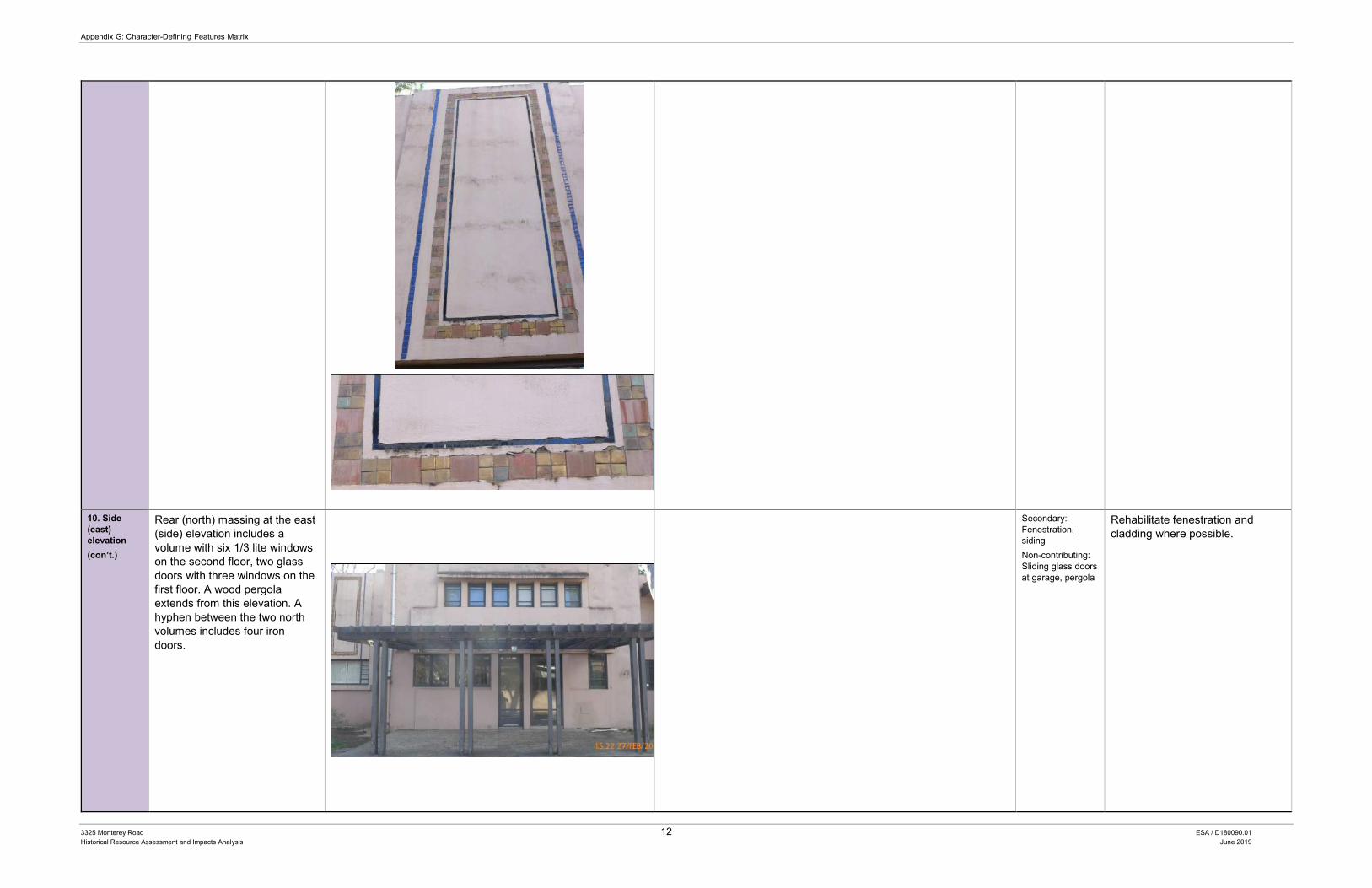
Appendix G: Character-Defining Features Matrix
3325 Monterey Road 12 ESA / D180090.01 Historical Resource Assessment and Impacts Analysis June 2019
10. Side (east) elevation (con’t.)
Rear (north) massing at the east (side) elevation includes a volume with six 1/3 lite windows on the second floor, two glass doors with three windows on the first floor. A wood pergola extends from this elevation. A hyphen between the two north volumes includes four iron doors.
Secondary: Fenestration, siding Non-contributing: Sliding glass doors at garage, pergola
Rehabilitate fenestration and cladding where possible.

Appendix G: Character-Defining Features Matrix
3325 Monterey Road 13 ESA / D180090.01 Historical Resource Assessment and Impacts Analysis June 2019
The attached garage has wood-clapboard at the second story bedroom addition. The first story has glass sliding doors and the second story has two wood windows.
11. North (rear) elevation
The north elevation of the attached garage with a surmounting bedroom has two wood windows with true-divided lites at the ground floor, sided in stucco. The second floor includes a central window with five flanking lites. The second floor includes wood clapboard siding. The rear elevation of the dining room was once a patio with decorative iron doors and a pergola. This area is now enclosed with glass doors and windows. However, some details such as the original iron doors and wood decorative details are still intact
Source: Huntington Library
Secondary: original fenestration, decorative wall vents, wood detailing at patio
Maintain stucco and wood clapboard siding where possible. Rehabilitate wood overhangs, remaining doors and windows, ceramic tiles, and Jali screens.
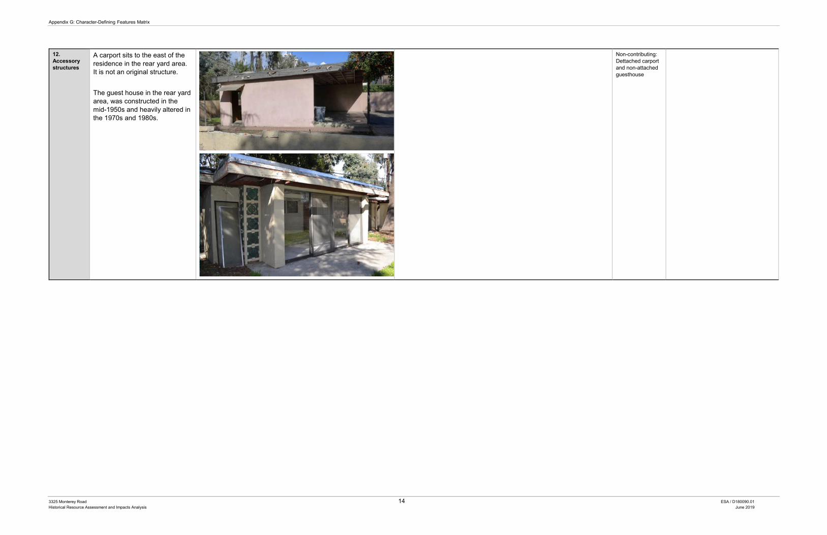
Appendix G: Character-Defining Features Matrix
3325 Monterey Road 14 ESA / D180090.01 Historical Resource Assessment and Impacts Analysis June 2019
12. Accessory structures
A carport sits to the east of the residence in the rear yard area. It is not an original structure. The guest house in the rear yard area, was constructed in the mid-1950s and heavily altered in the 1970s and 1980s.
Non-contributing: Dettached carport and non-attached guesthouse
Appendix H DPR Forms

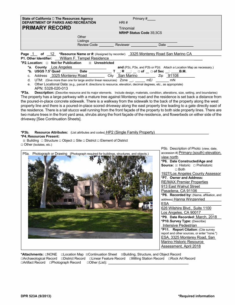
DPR 523A (9/2013) *Required information
Page 1 of 12 *Resource Name or #: (Assigned by recorder) 3325 Monterey Road San Marino CA P1. Other Identifier: William F. Tempel Residence ____ *P2. Location: ☐ Not for Publication ☒ Unrestricted *a. County Los Angeles and (P2c, P2e, and P2b or P2d. Attach a Location Map as necessary.) *b. USGS 7.5' Quad Date T ; R ; ☐ of ☐ of Sec ; B.M.
c. Address 3325 Monterey Road City San Marino Zip 91108 d. UTM: (Give more than one for large and/or linear resources) Zone , mE/ mN
e. Other Locational Data: (e.g., parcel #, directions to resource, elevation, decimal degrees, etc., as appropriate) APN: 5328-020-013 *P3a. Description: (Describe resource and its major elements. Include design, materials, condition, alterations, size, setting, and boundaries) The property has a large parkway with a mature tree against Monterey road and the residence is set back a distance from the poured-in-place concrete sidewalk. There is a walkway from the sidewalk to the back of the property along the west property line and there is a poured-in-place scored driveway along the east property line leading to a gate directly east of the residence. There is a tall stucco wall running from the front façade of the property to both side property lines. There are two mature trees in the front yard area, shrubs along the front façade of the residence, and flowerbeds on either side of the driveway [See Continuation Sheets]. *P3b. Resource Attributes: (List attributes and codes) HP2 (Single Family Property) *P4. Resources Present: ☒ Building ☐ Structure ☐ Object ☐ Site ☐ District ☐ Element of District ☐ Other (Isolates, etc.)
P5b. Description of Photo: (view, date, accession #) Primary (south) elevation, view north *P6. Date Constructed/Age and Source: ☒ Historic ☐ Prehistoric ☐ Both 1927/Los Angeles County Assessor *P7. Owner and Address: RE/MAX Premier Properties 913 East Walnut Street Pasadena, CA 91106 *P8. Recorded by: (Name, affiliation, and address) Hanna Winzenried ESA 626 Wilshire Blvd., Suite 1100 Los Angeles, CA 90017 *P9. Date Recorded: March, 2018 *P10. Survey Type: (Describe) Intensive Pedestrian *P11. Report Citation: (Cite survey report and other sources, or enter "none.") ESA, 3325 Monterey Road, San Marino Historic Resource Assessment, April 2018
*Attachments: ☐NONE ☐Location Map ☒Continuation Sheet ☒Building, Structure, and Object Record ☐Archaeological Record ☐District Record ☐Linear Feature Record ☐Milling Station Record ☐Rock Art Record ☐Artifact Record ☐Photograph Record ☐Other (List):
State of California The Resources Agency Primary # DEPARTMENT OF PARKS AND RECREATION HRI # PRIMARY RECORD Trinomial NRHP Status Code 3S;3CS Other Listings Review Code Reviewer Date
P5a. Photograph or Drawing (Photograph required for buildings, structures, and objects.)
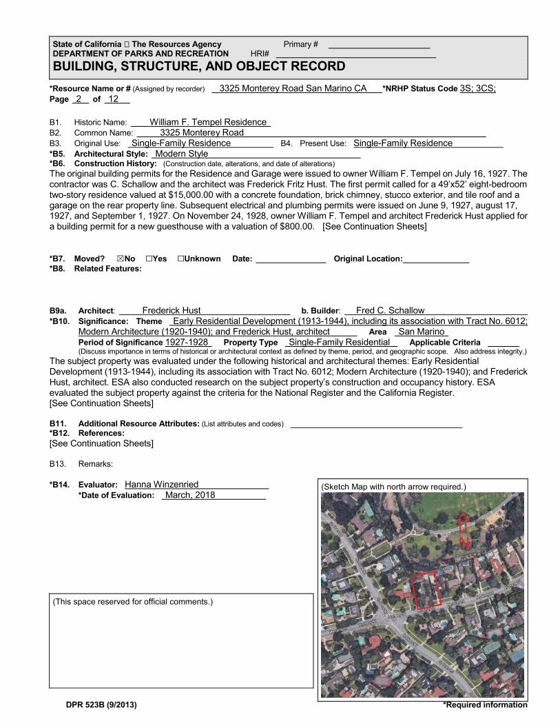
DPR 523B (9/2013) *Required information
*Resource Name or # (Assigned by recorder) 3325 Monterey Road San Marino CA *NRHP Status Code 3S; 3CS; Page 2 of 12 B1. Historic Name: William F. Tempel Residence B2. Common Name: 3325 Monterey Road B3. Original Use: Single-Family Residence B4. Present Use: Single-Family Residence *B5. Architectural Style: Modern Style *B6. Construction History: (Construction date, alterations, and date of alterations) The original building permits for the Residence and Garage were issued to owner William F. Tempel on July 16, 1927. The contractor was C. Schallow and the architect was Frederick Fritz Hust. The first permit called for a 49’x52’ eight-bedroom two-story residence valued at $15,000.00 with a concrete foundation, brick chimney, stucco exterior, and tile roof and a garage on the rear property line. Subsequent electrical and plumbing permits were issued on June 9, 1927, august 17, 1927, and September 1, 1927. On November 24, 1928, owner William F. Tempel and architect Frederick Hust applied for a building permit for a new guesthouse with a valuation of $800.00. [See Continuation Sheets] *B7. Moved? ☒No ☐Yes ☐Unknown Date: Original Location: *B8. Related Features: B9a. Architect: Frederick Hust b. Builder: Fred C. Schallow *B10. Significance: Theme Early Residential Development (1913-1944), including its association with Tract No. 6012;
Modern Architecture (1920-1940); and Frederick Hust, architect Area San Marino Period of Significance 1927-1928 Property Type Single-Family Residential Applicable Criteria
(Discuss importance in terms of historical or architectural context as defined by theme, period, and geographic scope. Also address integrity.) The subject property was evaluated under the following historical and architectural themes: Early Residential Development (1913-1944), including its association with Tract No. 6012; Modern Architecture (1920-1940); and Frederick Hust, architect. ESA also conducted research on the subject property’s construction and occupancy history. ESA evaluated the subject property against the criteria for the National Register and the California Register. [See Continuation Sheets] B11. Additional Resource Attributes: (List attributes and codes) *B12. References: [See Continuation Sheets] B13. Remarks: *B14. Evaluator: Hanna Winzenried
*Date of Evaluation: March, 2018
State of California The Resources Agency Primary # DEPARTMENT OF PARKS AND RECREATION HRI# BUILDING, STRUCTURE, AND OBJECT RECORD
(Sketch Map with north arrow required.)
(This space reserved for official comments.)
DPR 523L (Rev. 1/1995)(Word 9/2013)
*P3a. Description (continued): Residence
The subject property occupies a lot north Monterey Road and southwest of Lacy Park. It is improved with a modern style, single-family residence constructed in 1927 and a guesthouse constructed in 1928. The Residence two stories in height and features stucco walls, a flat roof, wood windows, decorative tilework, decorative ironwork, decorative tile vents, and irregular massing.
The south (front) façade has multiple masses. The front, main mass includes an art deco porch on the second floor with a large window over a fountain on the first floor. The porch has intricate art deco iron railing and wood dental detailing, and the first floor window has decorative iron grills. The massing to the east is set back behind the stucco wall and features a floor-to-ceiling wood window on each floor with 2/5 true-divided-lites. There is a two-story massing directly to the east of the front massing, and then a one story massing east of that. There are two wood French doors on either side of a floor-to-ceiling wood window with 1/6 true-divided lites.
The east elevation has a lot of articulation. The east façade of the front massing has French wood doors on the first floor and a wood casement window on the second floor. Further north is the main entrance to the residence. The door is wood with a stained glass window set within a wood frame. There are architectural details including decorative molding and decorative tiles that have since been covered up with paint. North of the main entrance is the east façade of the dining room which is a plain stucco wall. North of the dining room is the sun room. Originally the sun room was an existing patio with columns and decorative wood detailing. It was enclosed in glass, which was unpermitted. The east façade of the garage has a door with a panel of decorative grillwork above. To the right of the door are two smaller wood windows. The second story of the garage was an addition, as seen by the different wood siding (alteration). There is a window with a large center fixed pane with a casement window on either side. There are decorative vents on all of the walls.
The west elevation also features articulation in the design. It is behind a large stucco wall and a gate leading to the attached garage. The west elevation of the front massing features a large wood picture window with a large center pane and decorative lites on each side. Above the window features decorative tilework in a geometric pattern. North of the front massing is another rectangular massing featuring the living room. There are three wood windows and two glass and wood doors on the first floor under a wood pergola. The second floor features a row of 6 wood windows with 1/3 true-divided-lites. There are decorative vents on the walls. Between the living room and the attached garage is a hyphen of setback stucco walls with two wood windows. The attached garage has large sliding doors on the first floor where garage doors used to be (alteration). There is an unpermitted addition to garage resulting in a second story (alteration). The second story has wood siding, a smaller casement wood
State of California Natural Resources Agency Primary# DEPARTMENT OF PARKS AND RECREATION HRI # Trinomial CONTINUATION SHEET Property Name: William F. Tempel Residence/ 3325 Monterey Road San Marino Page 3 of 12
DPR 523L (Rev. 1/1995)(Word 9/2013)
window with 1/3 divided lites, and a window with a large center fixed pane with a casement window on either side.
The west portion of the rear elevation features the north elevation of the garage. The first story of the garage features a casement wood window and the second story has a window with a large center fixed pane with a casement window on either side. There are stucco walls enclosing a courtyard. Within the courtyard is the sunroom. The sunroom has floor-to-ceiling windows under a flat roof. Behind that is a stucco wall of the original residence that features more decorative tile vents.
Landscaping
The property has a large parkway with a mature tree against Monterey road and the residence is set back a distance from the poured-in-place concrete sidewalk. There is a walkway from the sidewalk to the back of the property along the west property line and there is a poured-in-place scored driveway along the east property line leading to a gate directly east of the residence. There is a tall stucco wall running front the front façade of the property to both side property lines. There are two mature trees in the front yard area, shrubs along the front façade of the residence, and flowerbeds on either side of the driveway
Guesthouse
On the northeast portion of the subject property, there is a small guesthouse. The Mid-Century modern guesthouse was originally built in the 1950s and added onto in 1981. It has stucco walls and a flat roof. The front elevation has large aluminum sliding doors. There are decorative ceramic Jali screens (sunshades) on either side of the doors. It is in a dilapidated state.
Carport
On the northeast corner there is a carport, which was built between 1952 and 1964. The carport has a concrete block wall with flat roof.
*B6. Construction History (continued):
The original building permits for the Residence and Garage were issued to owner William F. Tempel on July 16, 1927. The contractor was C. Schallow and the architect was Frederick Fritz Hust. The first permit called for a 49’x52’ eight-bedroom two-story residence valued at $15,000.00 with a concrete foundation, brick chimney, stucco exterior, and tile roof and a garage on the rear property line. Subsequent electrical and plumbing permits were issued on June 9, 1927, august 17, 1927, and September 1, 1927. On November 24, 1928, owner William F. Tempel and architect Frederick Hust applied for a building permit for a new guesthouse with a valuation of $800.00. A plumbing permit was issued on November 30, 1928, and an electrical permit issued June 28, 1928 for the new guesthouse. The Los Angeles County Assessor record for 1928 corroborates the City’s permits and further describes the residence as a 2 ½-story residence and garage with basement built in 1927. It documents that it has a stucco exterior, flat composition roof, fireplace, gas heating, electrical lighting, seventeen plumbing fixtures, a bathroom with tile floor, and plaster finish with plain woodwork. In 1928, the Assessor Record
DPR 523L (Rev. 1/1995)(Word 9/2013)
also documented the second story addition over the attached garage. In 1929, the subject property was photographed by Harold A. Parker. These photo showed the elaborate landscape and original character of the house including the decorative blocks above the balcony, ceramic Jali screen, elaborate landscaping with pond/fountain at the front elevation and fountain and decorative patio at the rear.
There are many subsequent building permits issued since the construction of the residence. Rea L. Eaton got a permit for a reroof on February 28, 1944 and August 17, 1946. Eaton was also issued a permit on February 16, 1955 for the remodel of kitchen. Eaton got two electrical permits, one on February 17, 1955 for a new range, dish washer, oven, and disposal and one on April 4, 1957 for an underground conduct from the main house to the guest house. This permit may indicate that that the guest house was constructed in 1957. Eaton was issued a permit on an unknown date for insulation to be applied over entire ceiling area of the house. The permit does not specify if the insulation was for the main residence or the guest house.
The last owner to receive building permits is Jack D. Whitehead. He was issued a reroof permit on November 14, 1963. He didn’t get another permit until December 1, 1981 for a 306 square-foot addition to the existing guest house for $13,158. He received subsequent permits for the addition including and electrical permit, a plumbing permit, and a mechanical permit all on December 31, 1981. He was issued two more plumbing permits on August 27, 2002 and on July 31, 2008.
On February 15, 2013, the Whitehead Family Trust applied for a Residential Compliance Certificate. However, Amanda Merlo of the City of San Marino Planning Department informed the applicants that the Planning Department cannot prepare a Certificate of Compliance because there was construction on site not consisting with city building permit files. Specifically, the garage had been converted to a storage area and carport without building permits, and was not in compliance with applicable codes. An enclosed garage must be maintained at all times according to the city code. Marino said that the attached garage must be restored to its original condition in order to receive a City Residential Compliance Certificate. Also, an original screened porch (rear porch, however never screened) may have been converted to livable area without proper permits and the City required this space to be legalized to receive the City Residential Compliance Certificate.
The final permit was issued on February 24, 2015 to Jack D. Whitehouse for a kitchen remodel, and a water heater, water closet, and vent change out. There was to be no change in the floor plan or exterior.
*B10. Significance (continued):
National Register and California Register
a. Broad Patterns of History
DPR 523L (Rev. 1/1995)(Word 9/2013)
With regard to broad patterns of history, the following are the relevant criteria:
• National Register Criterion A: Is associated with events that have made a significant contribution to the broad patterns of our history.
• California Register Criterion 1: Is associated with events that have made a significant contribution to the broad patterns of California's history and cultural heritage.
The subject property manifests the development patterns and cultural history of Tract No. 6012 and the Lacy Park neighborhood in its historical type and architecture. The City of San Marino, though not incorporated until 1913, experienced its first wave of residential boom after the introduction of Henry E. Huntington’s Pacific Electric railway system in 1901 and the subsequent growing popularity of the automobile. Fearing annexation by the City of Los Angeles, the local land owners established the City in 1913, which allowed many prominent individuals to keep their large estates. During this time, individuals such has Huntington purchased large swaths of land, such as Tract No. 6012 and subdivided them as an investment opportunity. One example of this is Tract No. 6012, which was subdivided in 1923 by Henry E. Huntington’s “Huntington Land and Improvement Company.” This Tract, keeping with the City’s early vision, had generous irregular lots made for large single-family residences.
Though the tract was subdivided in 1923, the subject property built in 1927 is one of the earliest homes constructed within the Tract, along with the other two adjacent residences, which were built in 1926 and 1928. These homes significantly influenced the trend of development within the Tract and the Lacy Park neighborhood. The subject property influenced the design and trends of later residences, including the setback from the streets (St. Albans, Old Mill, and Monterey Roads), the introduction of a long driveway for the rapidly expanding prominence of the automobile, a multi-car garage, and a central vertical volume with entrance, which many of the residences in the neighborhood built in the late 1920s and early 1930s featured. These influences are still apparent in the Tract today, as even homes built during the City’s second wave of development following World War II have similar features. As a result, the subject property is recommended eligible for listing under National Register Criterion A and California Register Criterion 1 for its significant historical associations with Tract 6012.
Significant Persons With regard to associations with important persons, the following are the relevant criteria:
• National Register Criterion B: Is associated with the lives of persons significant in our past.
• California Register Criterion 2: Is associated with the lives of persons important in our past.
The known occupants and their confirmed dates of occupation include William F. Tempel (1927-1930); Edwin Heitddler (1932); C.P. Plumb (1937); R.L. Eaton (1942-1957); Jack D. Whitehead (1957-2012); Chrissy L. Whitehead (1975-1985); and William S. Whitehead (1985). The original owner William F. Tempel was a successful real estate broker in Chicago and appears to have commissioned the house for his retirement, which was a common practice during this era in the City and larger region. Tempel though successful, gained his notoriety in Chicago and the town of Winnetka, Illinois which he helped develop as a real estate broker, and not San Marino where he retired. Therefore, the town of Winnetka and his residence there are more befitting for his historical associations.
The next person who lived at the subject property was Rea L. Eaton. Eaton was a member of the prominent pioneer family who founded Eaton, Colorado. Eaton lived at the subject property for
DPR 523L (Rev. 1/1995)(Word 9/2013)
approximately fifteen years. Although prominent in Colorado, Eaton was a typical businessperson working and living in San Marino. He does not appear to have had a significant contribution to city, state, or national history.
The last person to live at the subject property was Jack D. Whitehead with his family. Whitehead, the longest resident of the subject property lived there from 1957, until his death in 2012. Whitehead with his wife Helen had three children Chrissy, Robert and Bill. Jack was an active member in the City and region. He served as Vice President over the Burbank Chamber of Commerce, a board member for the Boys Club of Pasadena, and served on the Rose Bowl Committee. Though Jack was an active member of the community he did not significantly contribute to the City’s history.
As such, there does not appear to be sufficient evidence to suggest that any of the individuals who resided at the subject property were significant in national or state history for the purposes of this Report. Therefore, the subject property is recommended ineligible for listing under National Register Criterion B orCalifornia Register Criterion 2
Architecture With regard to architecture, design, or construction, the following are the relevant criteria:
• National Register Criterion C: Embodies the distinctive characteristics of a type, period, or method of construction or that represent the work of a master, or that possess high artistic values, or that represent a significant and distinguishable entity whose components may lack individual distinction.
• California Register Criterion 3: Embodies the distinctive characteristics of a type, period, region, or method of construction, or represents the work of an important creative individual, or possesses high artistic values.
The subject property is an early example of a Modern style single-family residence within the City of San Marino. At its time of construction, it was a unique sight in San Marino, and even caught the eye of photographer Harold Parker, who documented the subject property in 1929. The subject property was designed by notable modernist architect Fred Hust, who designed several distinguished works in Salt Lake City before moving to Los Angeles. Hust later went on to contribute to the design of the New Chinatown with Paramount set designer William Puntke.
The original owner William Tempel, a native Chicagoan, was familiar with the emerging Modern style and the Prairie School in the Midwest made famous by Frank Lloyd Wright and his mentee Walter Burley Griffin (master architect). As a well-off professional, Tempel commissioned Griffin to design a residence as an investment property in Winnetake, a small town outside of Chicago. Once he was ready to retire, Tempel then commissioned the subject property by Frederick Hust to be designed in the Modern style, a bold statement at the time. Most likely influenced by the work Frank Lloyd Wright and his son Lloyd Wright were doing in Los Angeles, Hust developed a design that would incorporate the character-defining features of the Modern style and the experimental elements of Mayan and Asian influences. The subject property is a unique and rare example of the Modern style. It exemplifies the style with its clean lines, bold asymmetrical massing, large central volume, its inlay tile and block design, the integration of the ceramic Jali screens for use as sunshades and light shades at the front entrance.
The subject property embodies the distinctive characteristics of an early Modern style single-family residence within San Marino and the greater Los Angeles region. It also represents the work of notable

DPR 523L (Rev. 1/1995)(Word 9/2013)
architect Frederik Hust, an important creative individual who refined his aesthetic as can be seen between the subject property and Henry Carr Memorial Gate in Los Angeles. It embodies distinctive characteristics with its decorative tile and block design and incorporation of the Jali screens around the property. Therefore, the subject property is recommended eligible for listing under National Register Criterion C and California Register Criterion 3.
Data • National Register Criterion D. It yields, or may be likely to yield, information important in prehistory
or history.
• California Register Criterion 4. Has yielded, or may be likely to yield, information important in prehistory or history.
While most often applied to archaeological districts and sites, Criterion D/4 can also apply to buildings, structures, and objects that contain important information. In order for these types of properties to be eligible under Criterion D/4, they themselves must be, or must have been, the principal source of the important information. The Residence does not appear to yield significant information that would expand our current knowledge or theories of design, methods of construction, operation, or other information that is not already known about the period of significance of the Residence, its method of construction, or its design. Therefore, the subject property is recommended ineligible for listing under National Register Criterion D and California Register Criterion 4.
*B12. References (continued):
“819 N Sweetzer Ave,” San Marino Historic Preservation, http://www.wehopreservation.org/portfolio_page/819-n-sweetzer-ave/
“1000 Larrabee Street.” San Marino Historic Preservation. http://www.wehopreservation.org/portfolio_page/1000-larrabee-street/
“Aged Immigrants Arrive from Germany,” Salt Lake Telegram (Salt Lake City, UT), Mar. 20, 1927.
Ancestry.com. U.S. Census, California Voter Registration, California Death Index, City Directory, and Street Address Directory records.
Ancestry.com. Utah, Select Marriage Index, 1887-1985 [database on-line]. Provo, UT, USA: Ancestry.com Operations, Inc., 2015.
Architect and Engineer (Volume 88), 1927.
Architectural/Historical Development of the City of Pasadena: Historic Context/Property Type Report, prepared by Pamela O’Connor and Urban Conservation Section, Planning Division, City of Pasadena, January 13, 1993.
Architectural Resources Group. Multi-Family Survey Report. November 2008.
DPR 523L (Rev. 1/1995)(Word 9/2013)
“Assignments Set for Rose Bowl Committee of 325.” Pasadena Independent (Pasadena, CA), Oct. 22, 1964.
California Code of Regulations, California Register of Historical Resources (Title 14, Chapter11.5), Section 4852(c).
“Carl Wopschall to Head 1977 Rose Fest.” Arcadia Tribune (Arcadia, CA). Feb. 19, 1976.
“Charges Realty Man and Lawyer Altered Notes.” Chicago Tribune (Chicago, IL). Aug. 14, 1920.
City of San Marino. “General Plan.” San Marino, CA. 2003.
City of San Marino R2, R3, R4 Multi-Family Survey Report. November 2008. http://www.wehopreservation.org/wp-
content/uploads/2016/03/2008_Survey_Full_Document.pdf. Code of Federal Regulations (CFR), 36 § 60.2.
Codified in California Code of Regulations, Title 14, Chapter 11.5, Section 4852©. http://ohp.parks.ca.gov Connor, Paul. “Lloyd Wright’s Mayan/Islamic Derby House Hits the Market in Glendale Asking $1,65
Million.” Curbed Los Angeles. Nov. 14, 2013. https://la.curbed.com/2013/11/14/10175478/lloyd-wrights-mayanislamic-derby-house-hits-the-market-in-glendale.
“Contributors to Nixon Fund.” The San Bernardino County Sun (San Bernardino, CA). Sep. 21, 1952.
“Designed for State Street.” The Salt Lake Evening Telegram (Salt Lake City, UT). Aug. 6, 1910.
“Dovenmeuhle, Inc. Enteres 80th Year as Organization.” Chicago Tribune (Chicago, IL). Feb. 17, 1935.
“Ensign Eaton Claims Bride in San Marino.” The Los Angeles Times (Los Angeles, CA). Oct. 2, 1950.
“Ecclestone Will Take Over Burbank C of C.” The Los Angeles Times (Los Angeles, CA). Jan. 10, 1960.
‘Frank Lloyd Wright’s Ennis House Sold to Ron Burkle.” Ennis House. Accessed March 27, 2018. http://ennishouse.com/.
“Frederick Fritz Hust,” Utah Center for Architecture. Accessed February 28, 2018. http://utahcfa.org/architect/frederick_fritz_hust.
“Frederick Hust is Winner in Contest.” The Salt Lake Tribune (Salt Lake City, UT). Feb. 27, 1915.
Glossary of National Register Terms. http://www.nps.gov/nr/publications/bulletins/nrb16a/nrb16a_appendix_IV.htm. Accessed June
1, 2013.
DPR 523L (Rev. 1/1995)(Word 9/2013)
“Guidelines for Completing National Register Forms.” in National Register Bulletin 16, U.S. Department
of Interior, National Park Service, 1977, Revised 1997.
Griffin, Walter Burley and Griffin, Marion Mahony. William F. Tempel dwelling, Kenilworth, Illinois, 1910: 1910. Web. 29 March 2018 <http://nla.gov.au/nla.obj-146747154>
Harold A. Parker Studio Collection of Negatives. The Huntington Library, San Marino, California.
Harrison, Paul. “Hollywood.” The Post-Register (Idaho Falls). April 16, 1936.
“Hogle Takes Over Davies & Co. Here.” The Los Angeles Times (Los Angeles, CA). Sep. 27, 1942.
Hormann, Matt. “The Man Who Named San Marino Attempted Winemaking on an Industrial Scale.” San Marino Patch. Dec. 21, 2010. https://patch.com/california/sanmarino/the-man-who-named-san-marino-attempted-winemaking-on-d4ae05ae3b.
Illinois, Cook County, Birth Certificates, 1871-1940.
“Jack Whitehead.” Obituaries. The Los Angeles Times (Los Angeles, CA). Apr. 29, 2012.
“Johnny Marvin, Biography.” IMDB.com. Accessed October 11, 2017.
Kruty, Paul. “Walter Burley Griffin.” Society of America, Accessed March 29, 2018. http://www.wbgriffinsociety.org/griffins-bio.html.
“Lloyd Wright’s The Taggart House.” Modern Living LA. Accessed March 27, 2018. http://modernlivingla.com/2014/04/lloyd-wrights-the-taggart-house/.
“Louis Sullivan Commissions.” Prairie Styles. Accessed March 27, 2018. http://www.prairiestyles.com/lsullivan.htm.
“Many Parties Fete Betrothed Couple.” The Los Angeles Times (Los Angeles, CA). Jul. 12, 1953.
“Mary Cota,” Family Search. Accessed March 1, 2018. https://www.familysearch.org/tree/person/details/9X74-WZG; Pasadena, California, City Directory, 1921.
McAlester, Virginia Savage. A Field Guide to American Houses. New York: Alfred A. Knopf, 2013.
McWilliams, Carey. Southern California: An Island on the Land. Layton, Utah: Gibbs Smith, 1973.
National Park Service. National Register Bulletin 15: How to Apply the National Register Criteria for Evaluation. Washington DC: U.S. Dept. of the Interior, National Park Service, Interagency Resources Division, 1990, rev. 1991.
National Park Service. National Register Bulletin 16: Guidelines for Completing National Register Forms. Washington, D.C.: U.S. Dept. of the Interior, National Park Service, 1997.
DPR 523L (Rev. 1/1995)(Word 9/2013)
National Register Bulletin 15: How to Apply the National Register Criteria for Evaluation. http://www.nps.gov/nr/publications/bulletins/pdfs/nrb15.pdf. Accessed July 7, 2013. “New Chinatown.” The Los Angeles Times (Los Angeles, CA). Jan. 21, 1938.
“New Partners for Dean Witter.” The Los Angeles Times (Los Angeles, CA). Feb. 2, 1954.
“Obituaries: Eaton, Rea L.” The Los Angeles Times (Los Angeles, CA). Nov. 13, 1970.
Office of Historic Preservation. Instructions for Recording Historical Resources. March 1995.
Office of State Historic Preservation. California Historic Resources Inventory, Survey Workbook
(excerpts). Sacramento, CA: State of California, 1986.
“Official Death List.” The Los Angeles Times (Los Angeles, CA). Dec. 21, 1973.
Ord. 03-663 § 4 (part), 2003: Ord. 02-643 § 48, 2003: Ord. 01-594 § 2 (Exh. A), 2001
“Pasadena Boys’ Club Given Small Railroad.” The Los Angeles Times (Los Angeles, CA). May 26, 1960.
“Planned for Depot District.” The Salt Lake Evening Telegram (Salt Lake City, UT). Sep. 17, 1910.
“Plans for Los Angeles’ New China City Completed.” The Los Angeles Times (Los Angeles, CA). Jan. 18, 1938.
Pomeroy, Elizabeth. San Marino: A Centennial History. San Marino Historical Society, 2012.
PRC Section 5024.1
“Salt Lake Architects Get Idaho Business.” The Salt Lake Tribune (Salt Lake City, UT). Aug. 21, 1910.
Sanborn Map and Publishing Company, Insurance Maps of Los Angeles County, 1910.
San Marino, California: City Code, Designation of Historical Landmarks, Section 02.12.01-02.12.02, Ordinance No. 951, adopted March 8, 1989.
San Marino Historical Society. “History: San Marino.” Accessed March 9, 2016. http://sanmarinohistoricalsociety.org/history.html.
“San Marino History.” City of San Marino. Accessed June 21, 2011, http://www.cityofsanmarino.org/about.htm.
State of California. California Death Index, 1940-1997. Sacramento, CA, USA: State of California Department of Health Services, Center for Health Statistics.
“Team Winners in Choose-Up.” The Desert Sun (Palm Springs, CA). Dec. 20, 1961.
DPR 523L (Rev. 1/1995)(Word 9/2013)
“The Prairie Style.” Frank Lloyd Wright Trust. Accessed March 27, 2018. https://flwright.org/researchexplore/prairiestyle.
United States Census, 1910
United States Census, 1930
Utah, Naturalization of Citizenship Records, 1858-1959 for Frederick Hust, Salt Lake City, 1909-1911.
Vulcan, Robert. “A Community Evolves: History of San Marino.” San Marino Incorporation Committee. 1984.
Watters, Sam. Houses of Los Angeles: 1885-1919. p. 27.
“William F. Tempel dwelling.” National Library of Australia. Accessed March 29, 2017 http://nla.gov.au/nla.obj-146747154/view.
“William F. Tempel House.” The Prairie School Traveler. Accessed March 29, 2017. http://www.prairieschooltraveler.com/html/il/winnetka/tempel.html.
Woman, Near 91, Dies in S. L. Hospital.” The Salt Lake Tribuine (Salt Lake City, UT). Feb. 20, 1948.

Appendix I Proposed Project

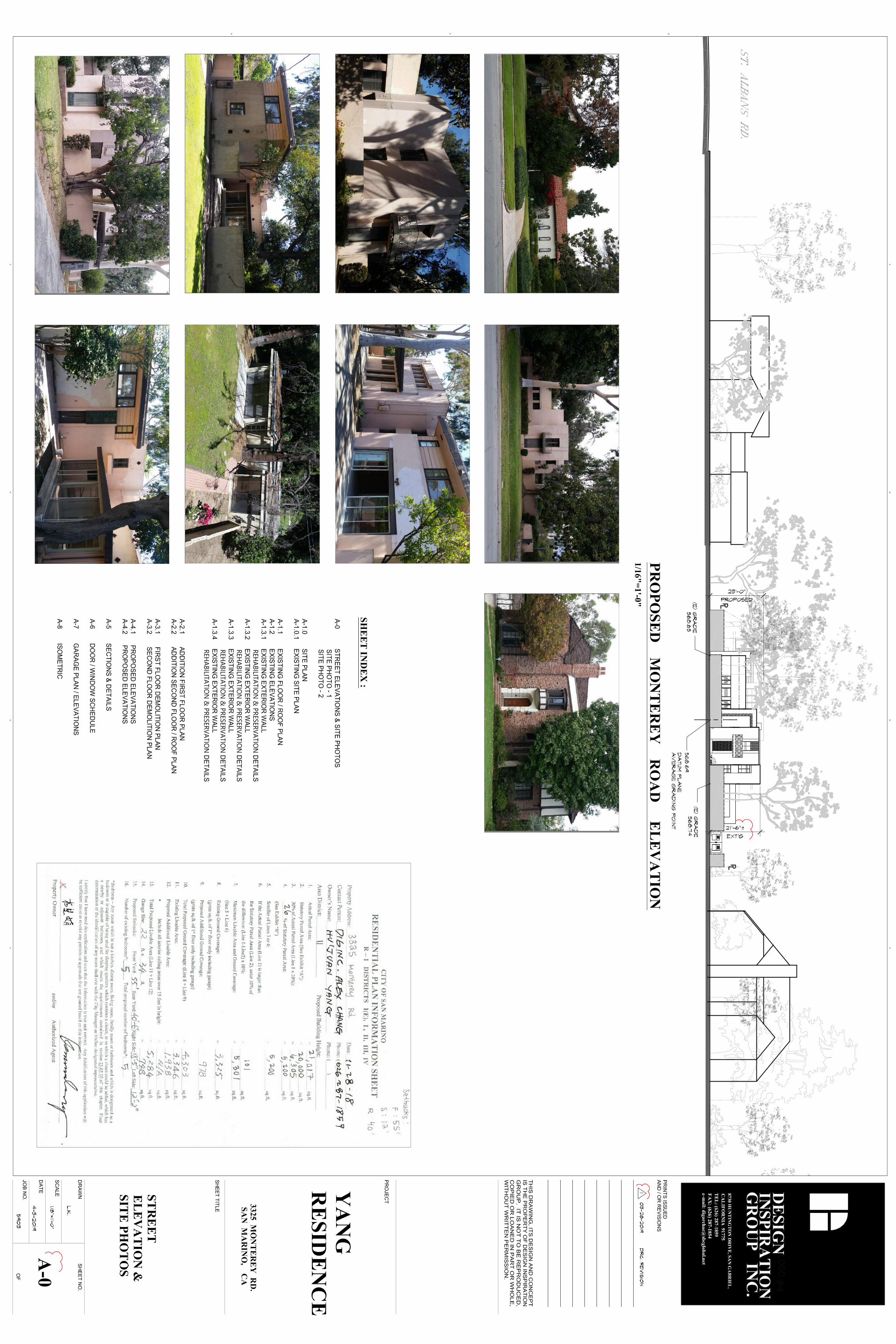
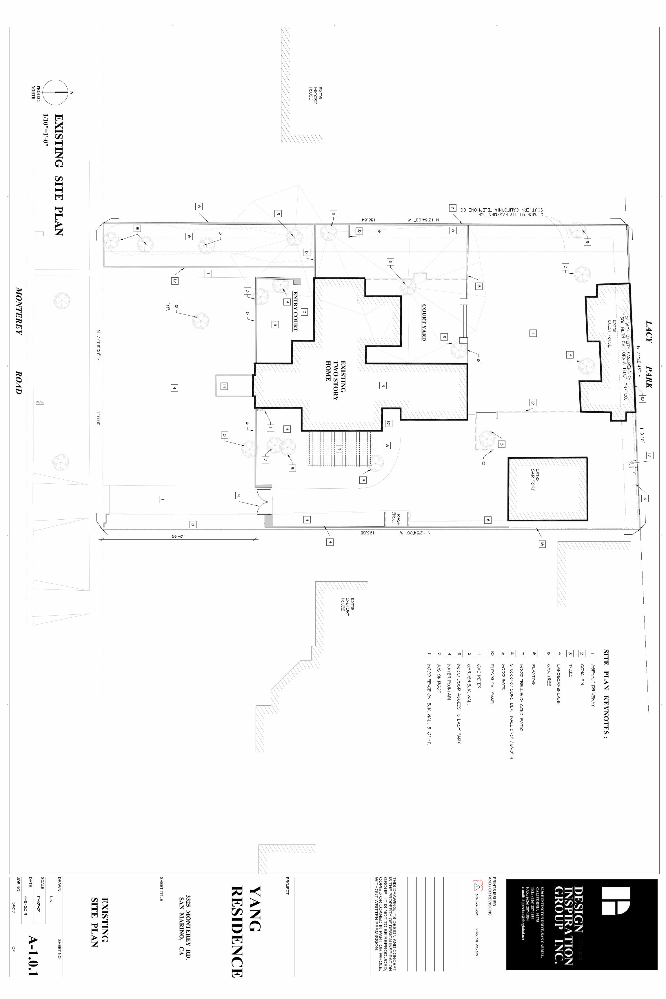
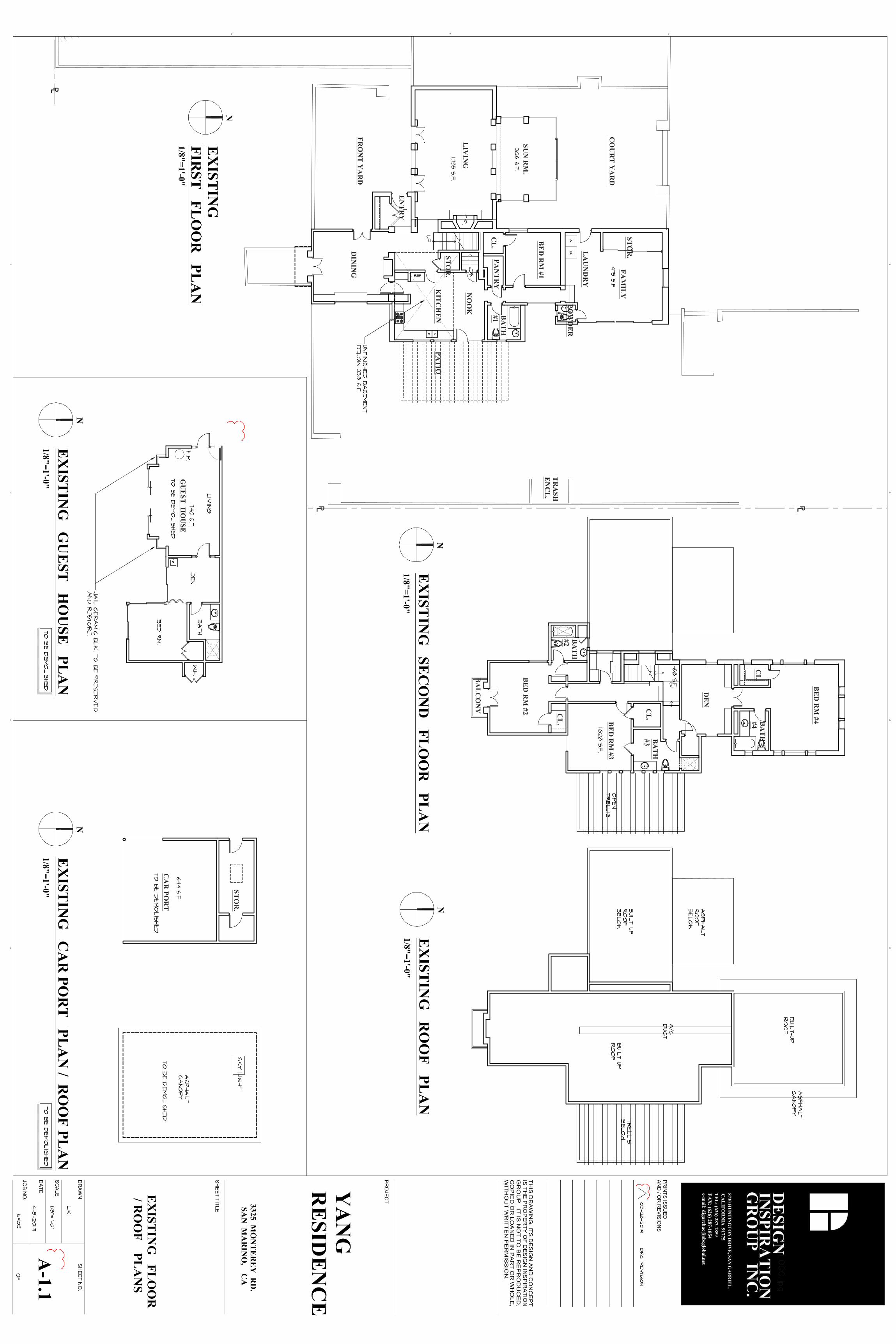
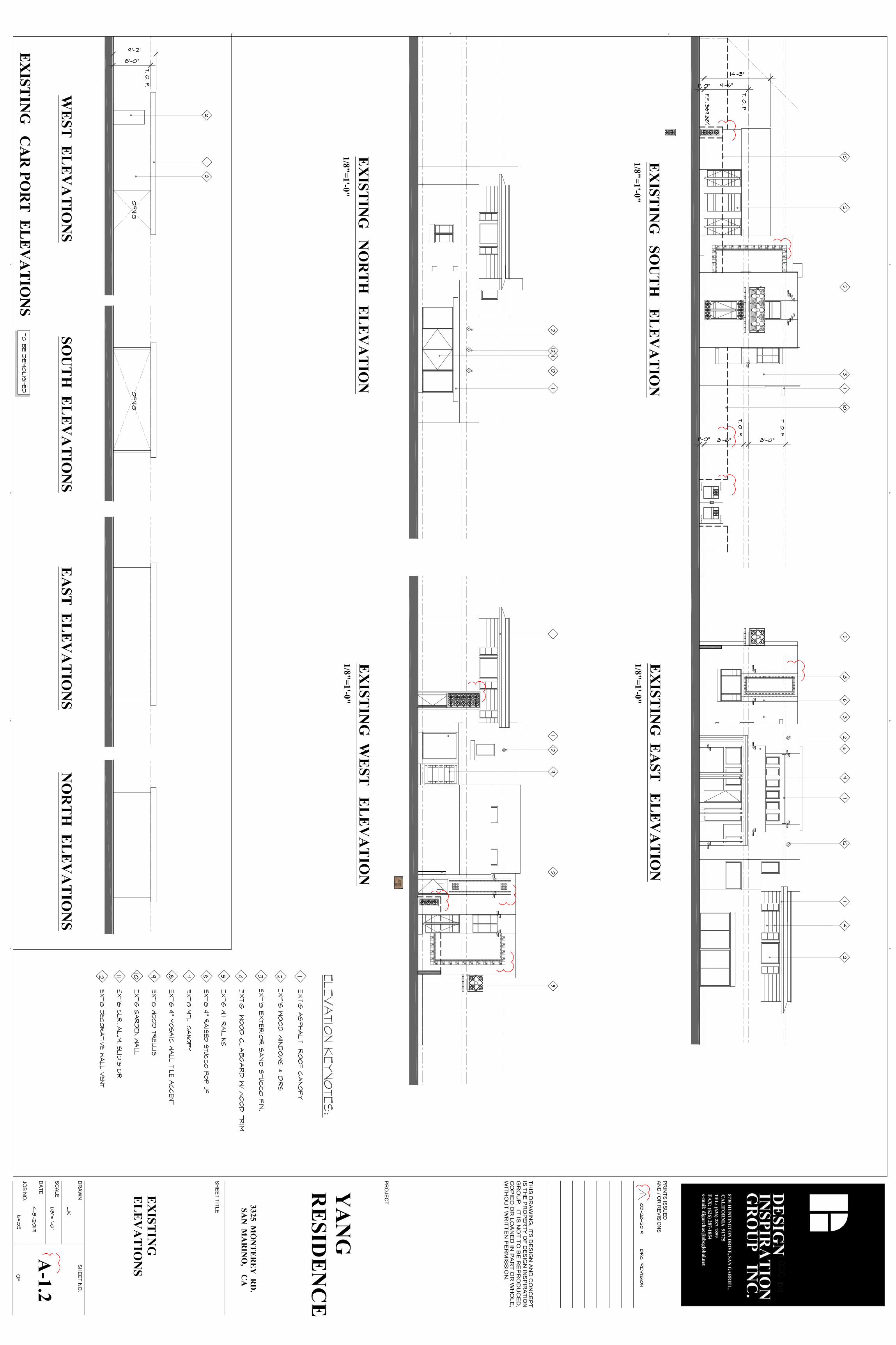
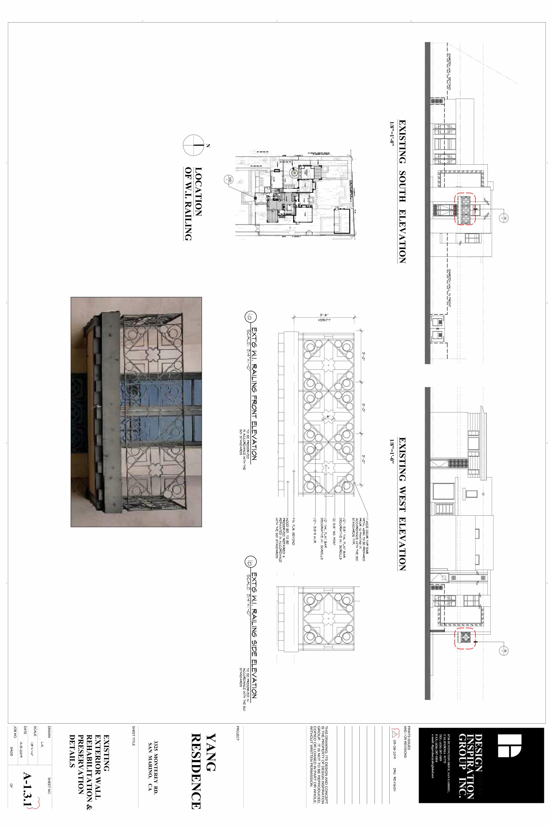
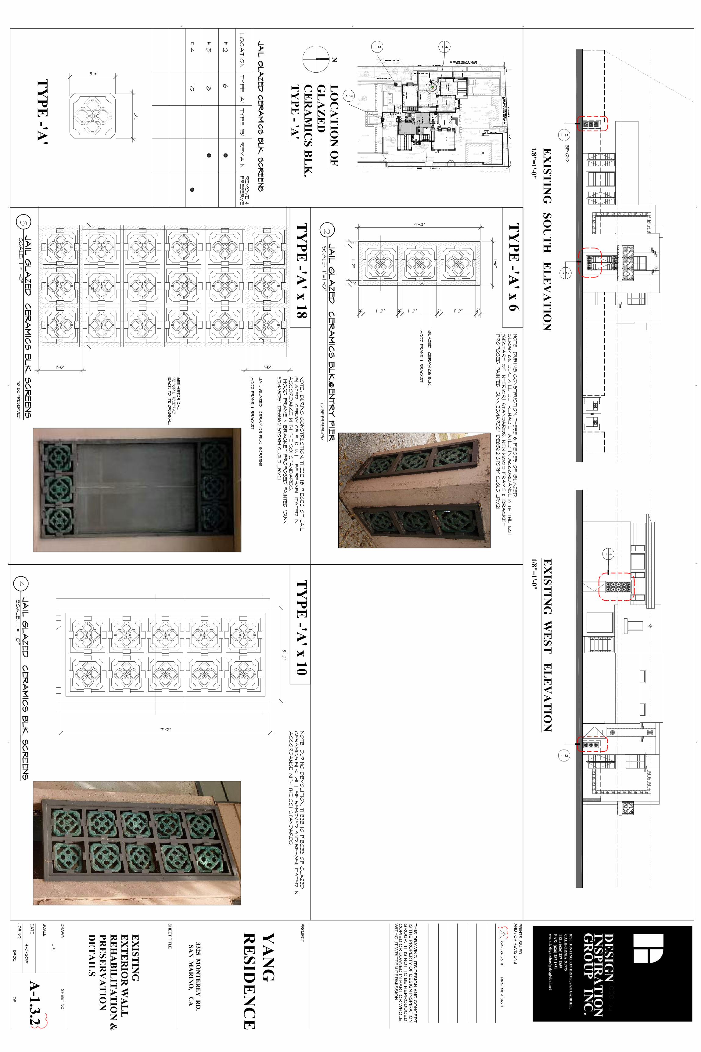
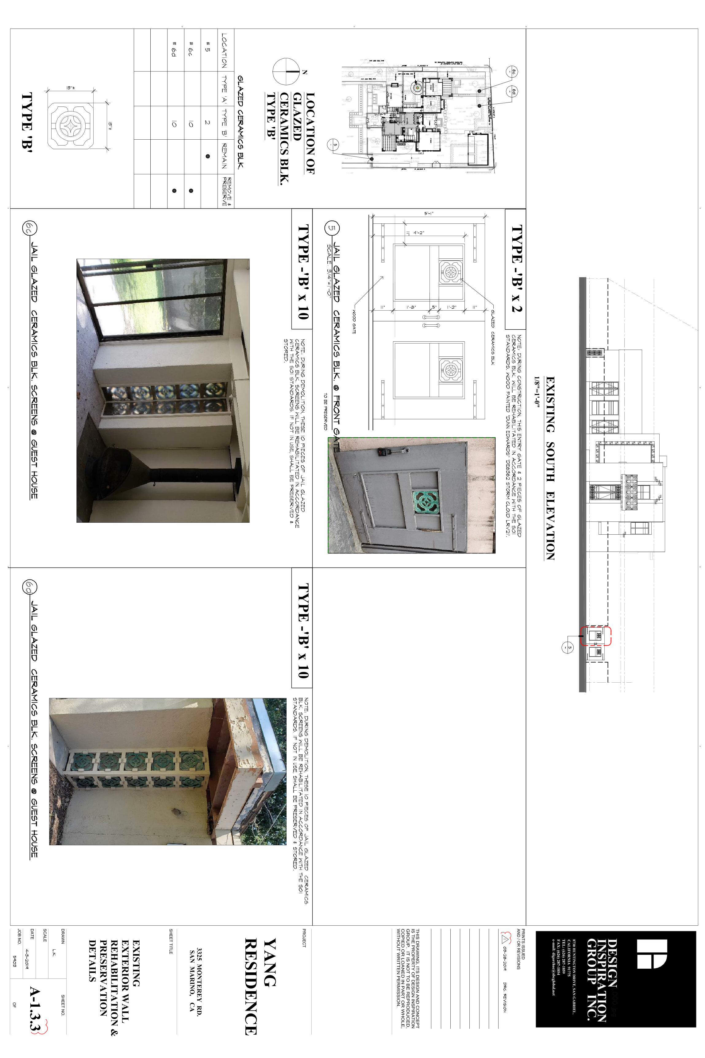
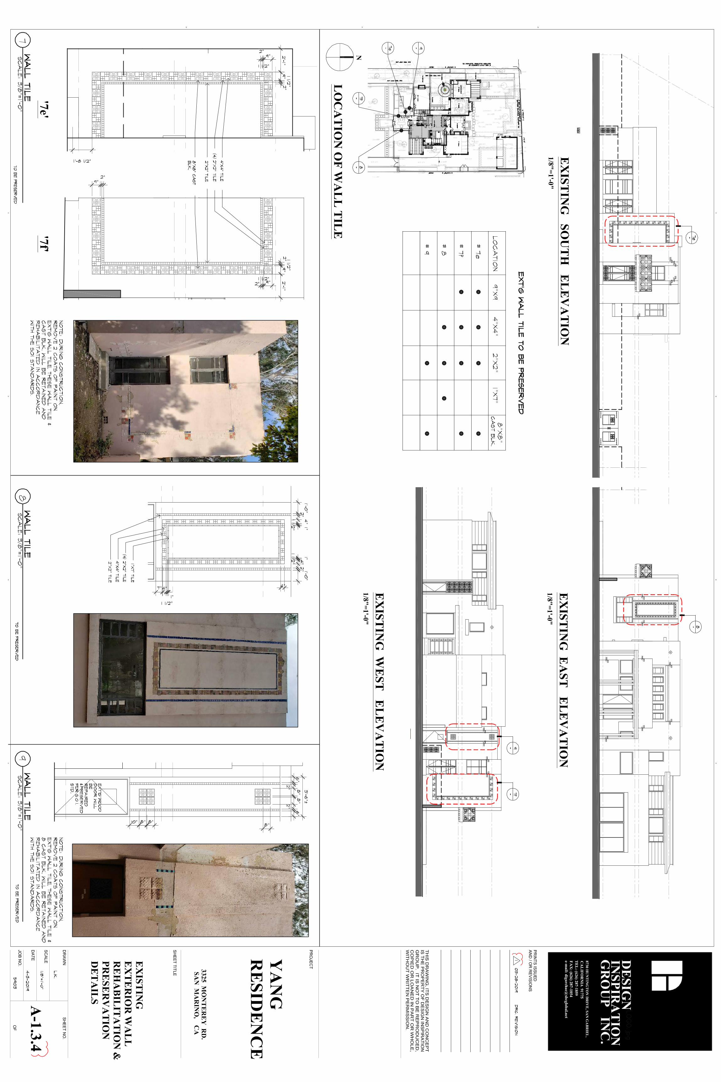
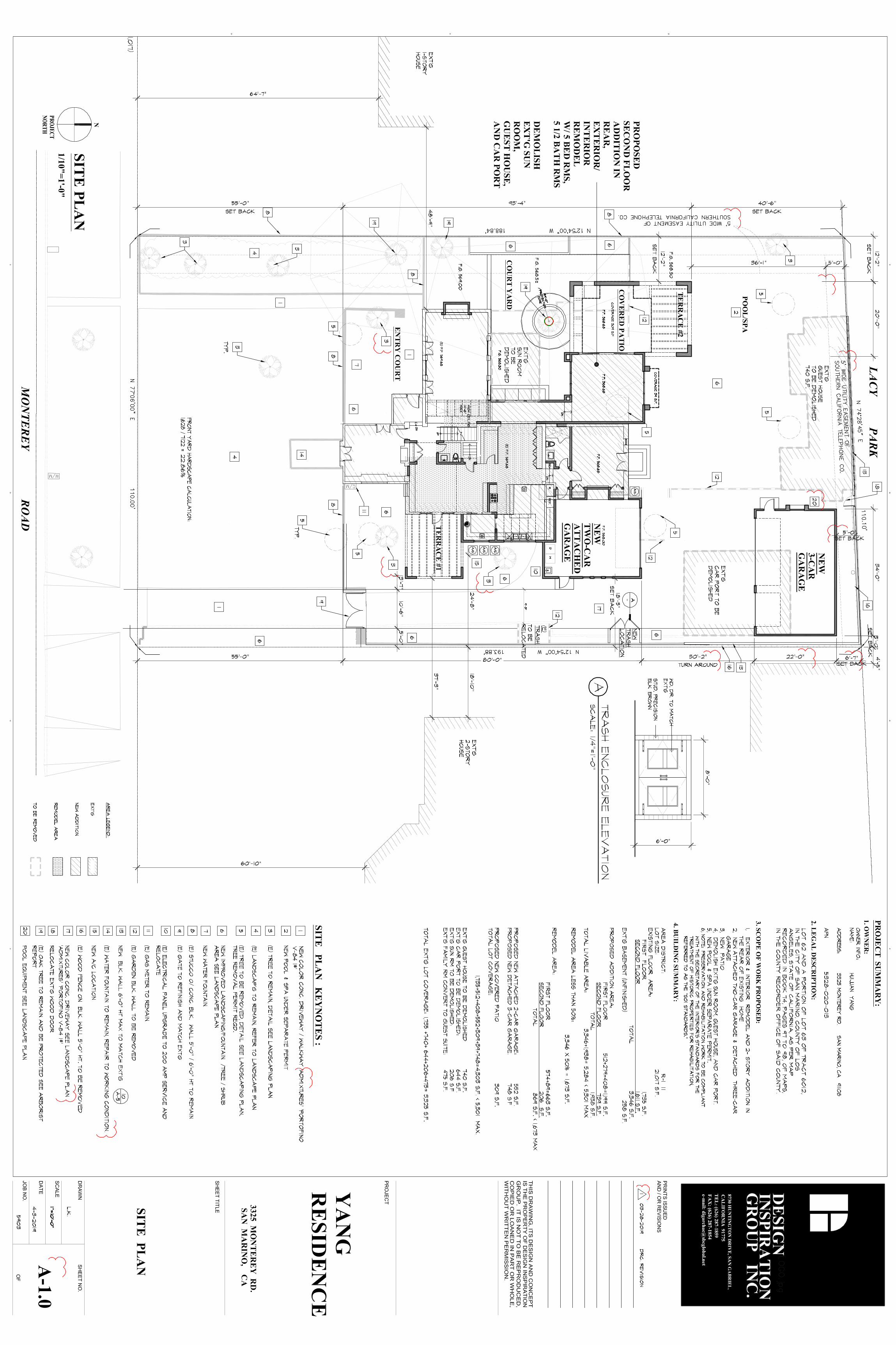
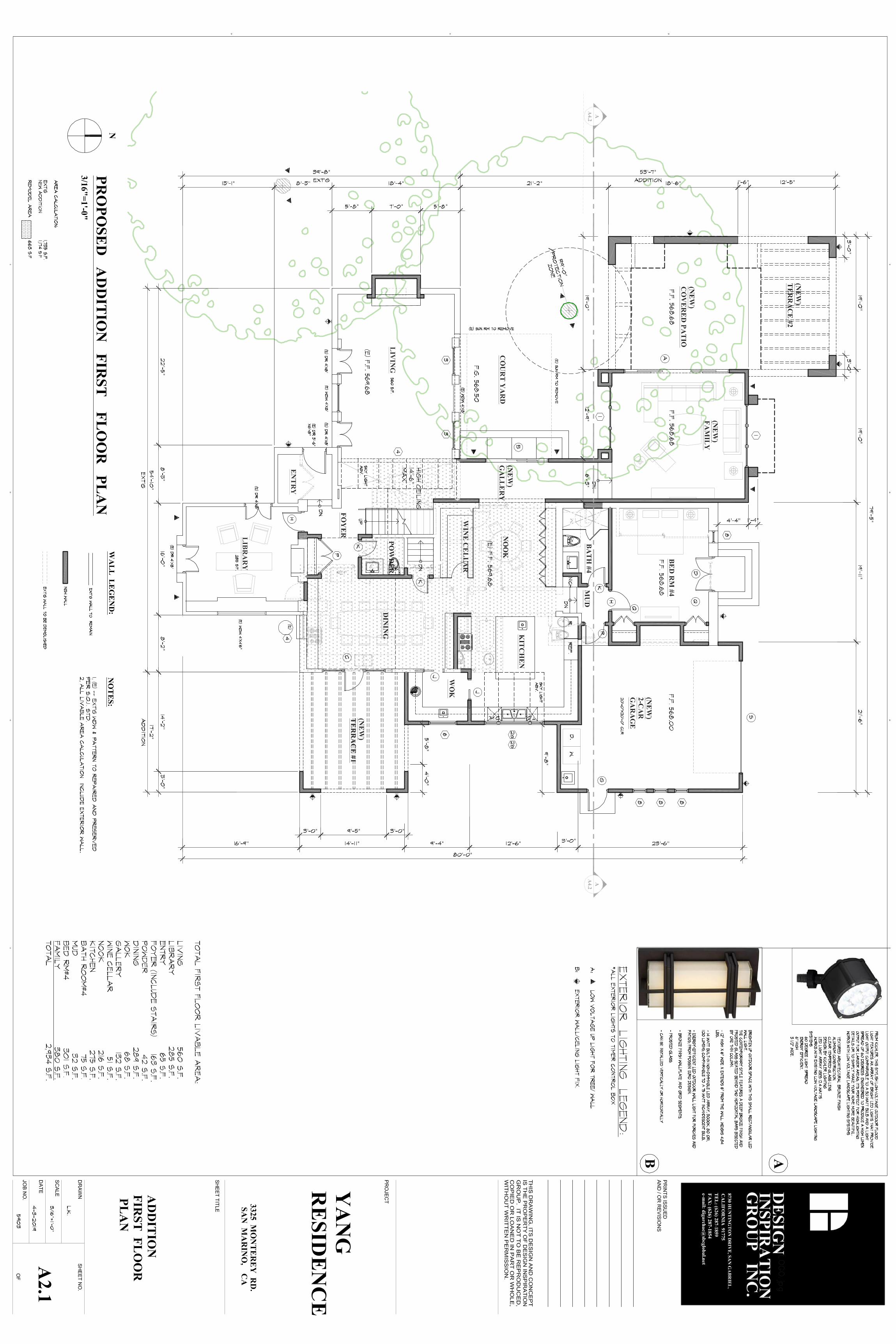
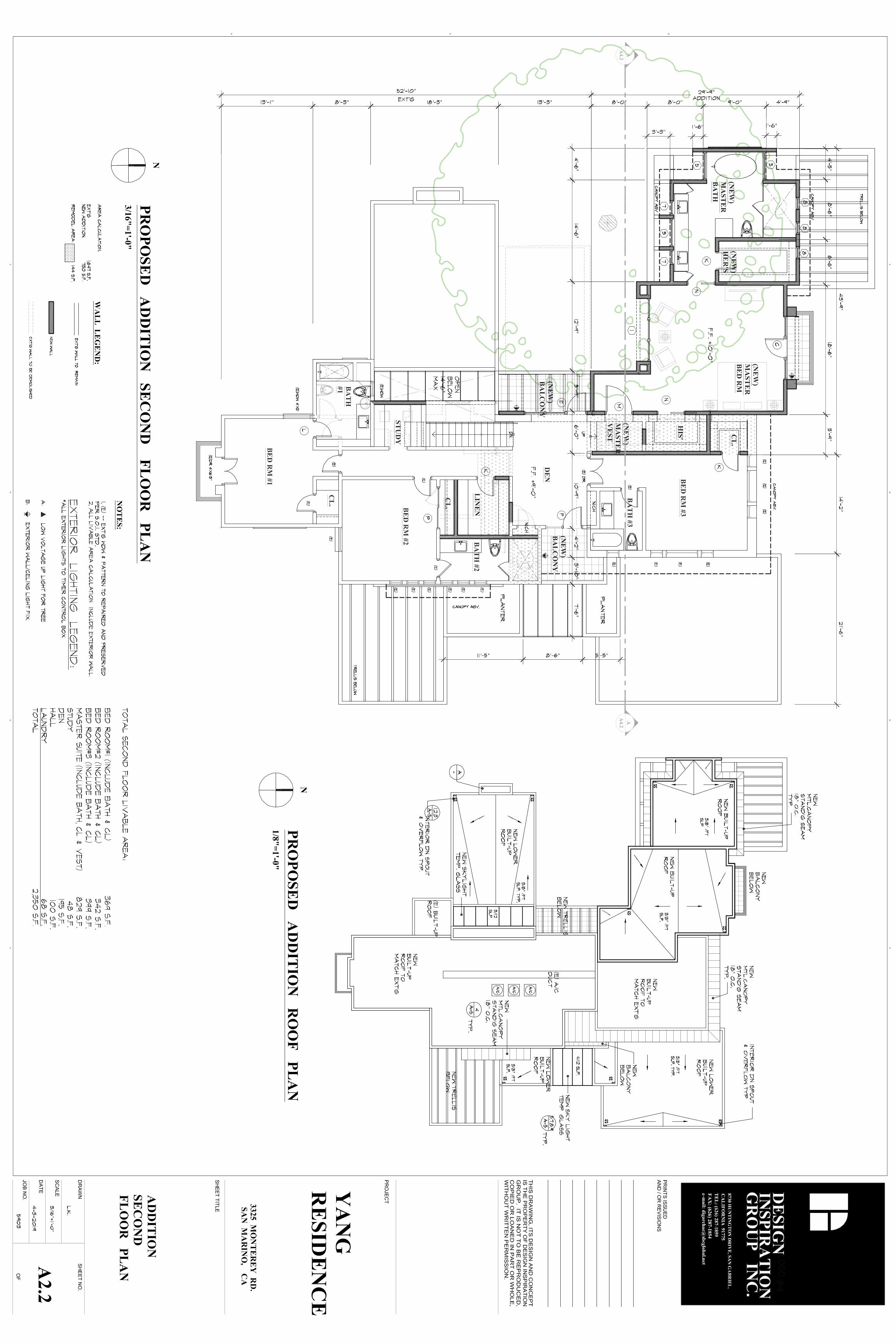
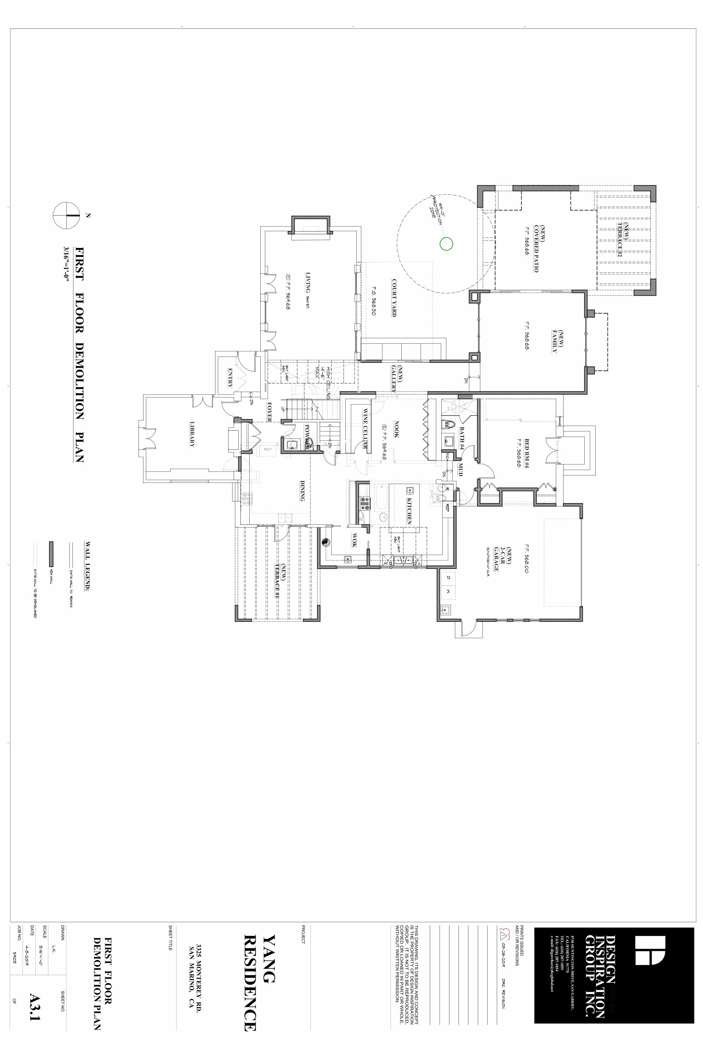
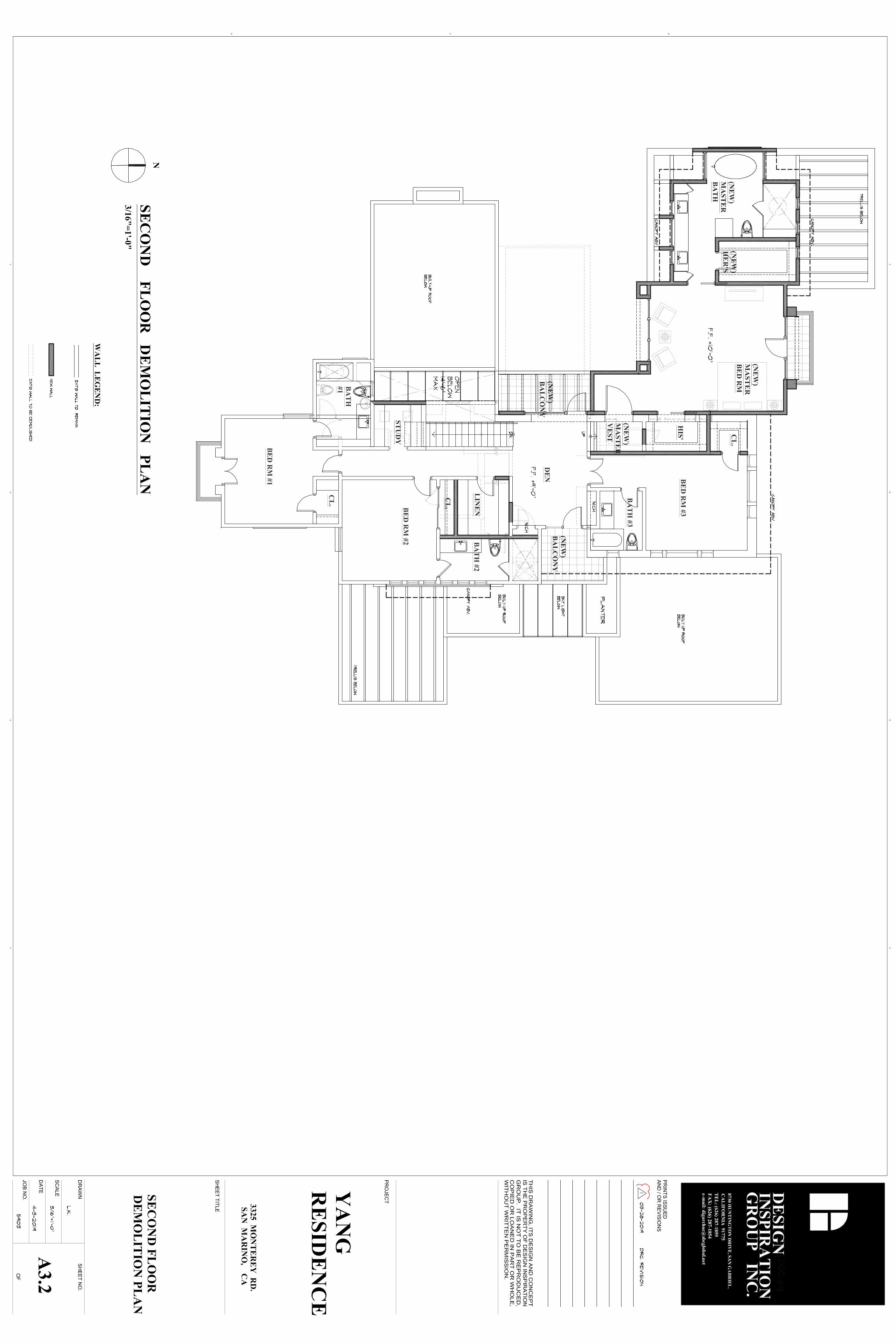
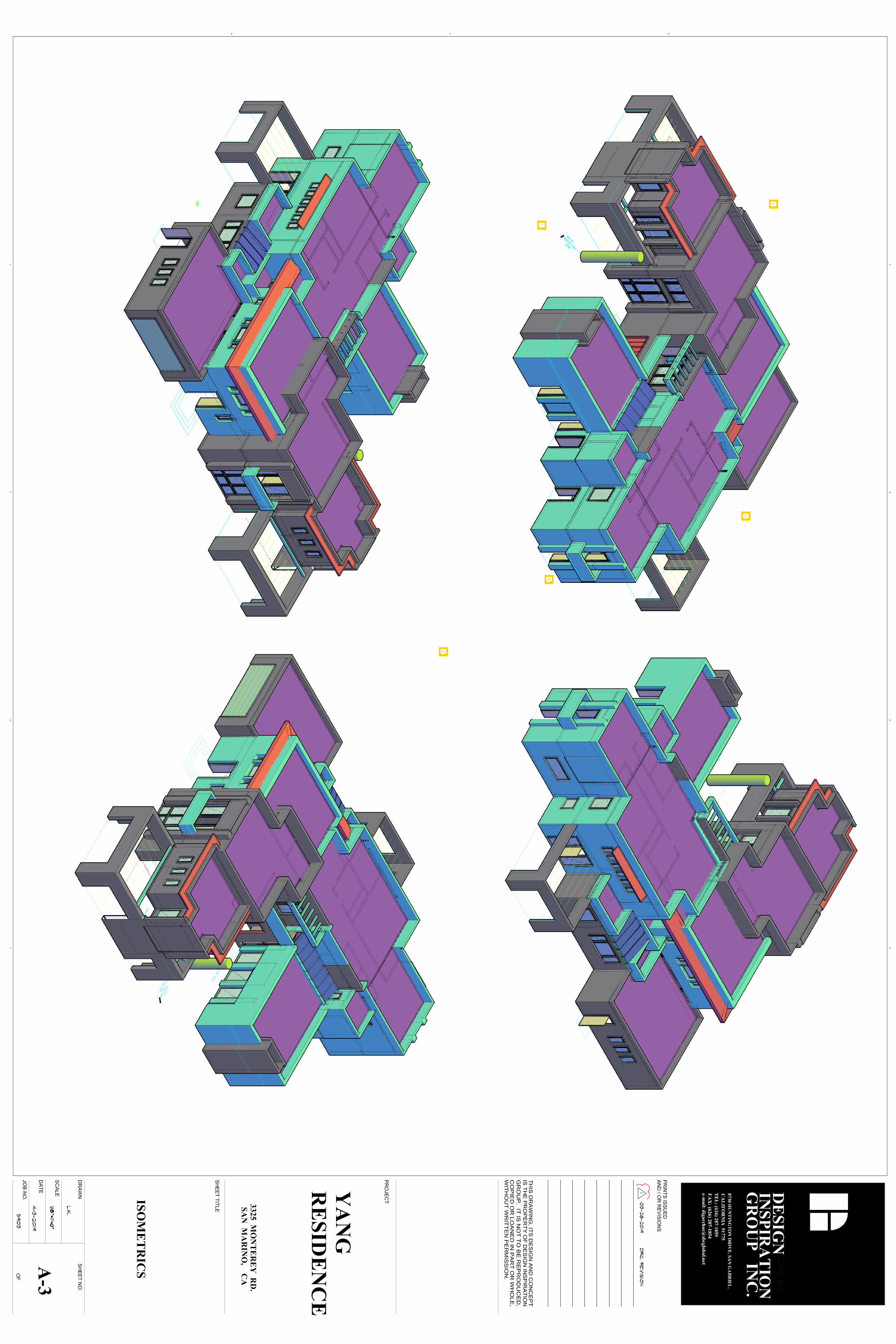
agarcia
Sticky Note
South
agarcia
Sticky Note
North
agarcia
Sticky Note
East
agarcia
Sticky Note
West
agarcia
Sticky Note
Adding cardinal directions to each of these isometrics will be helpful to better understand the proposed modifications to the existing building. Please include a colored key for reference.
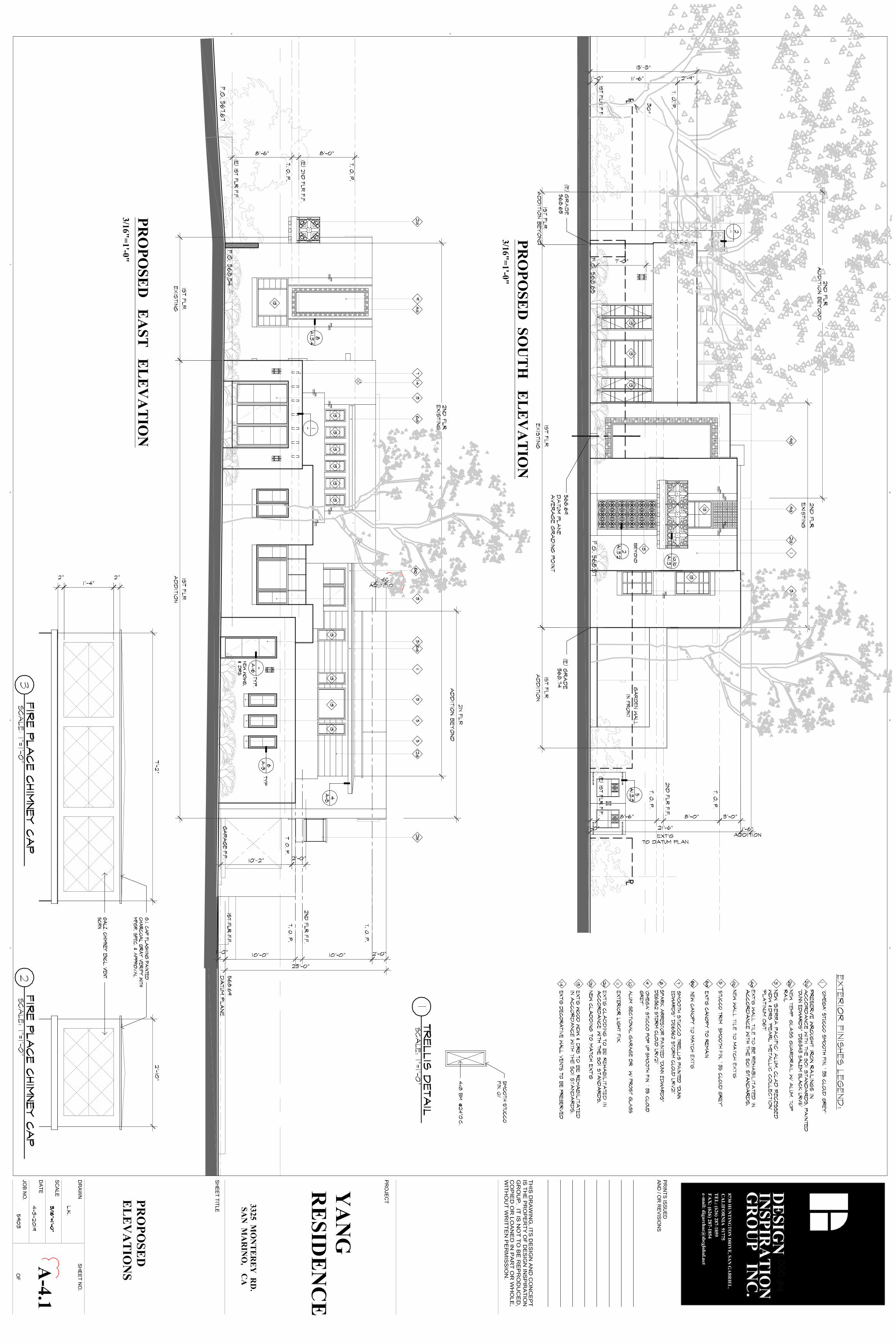
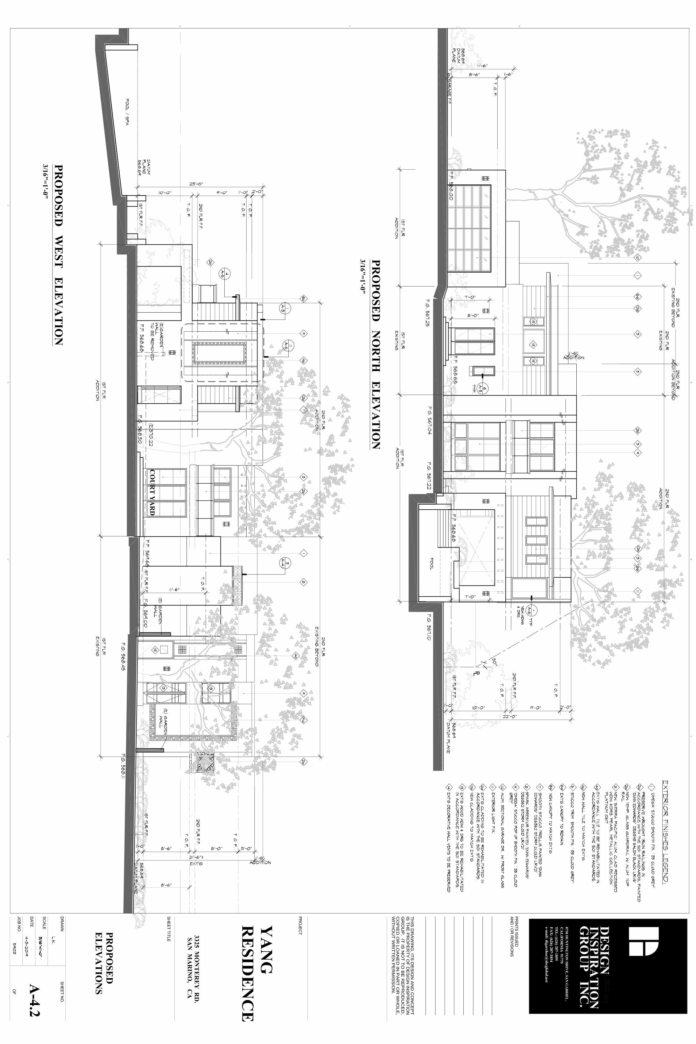
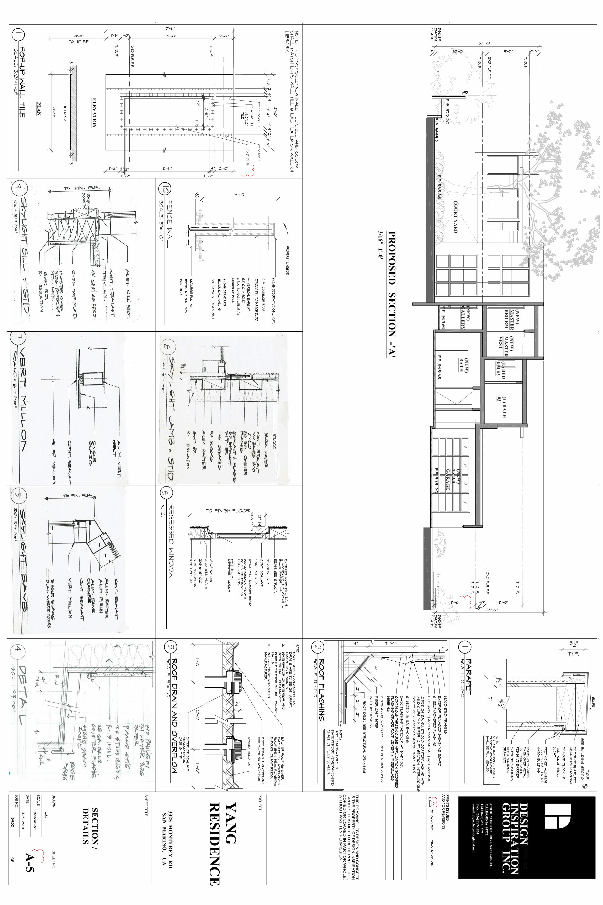
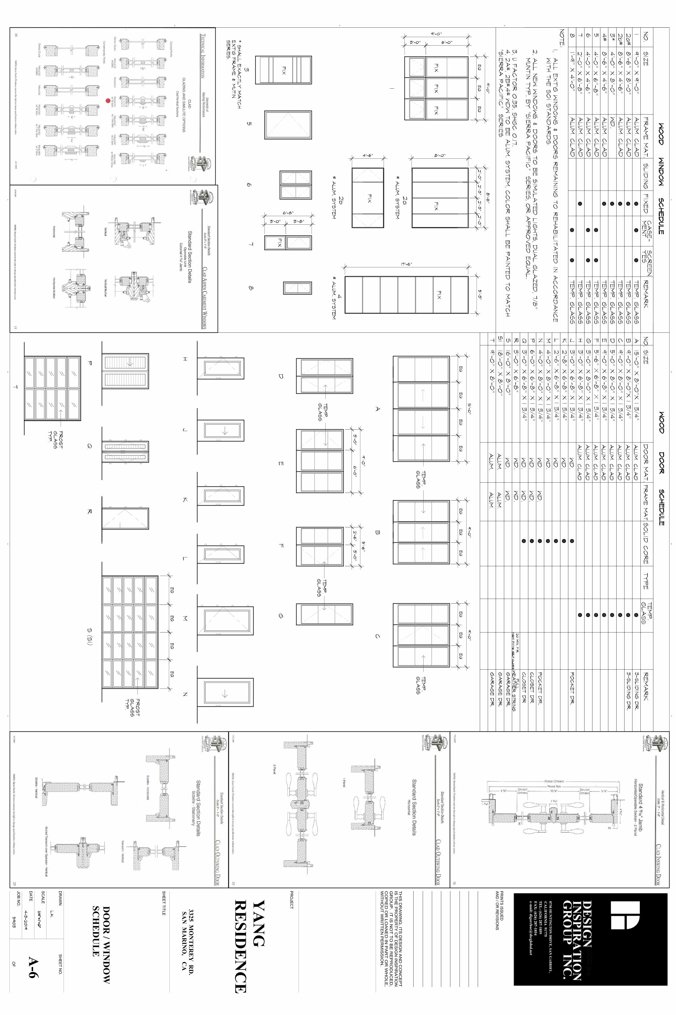
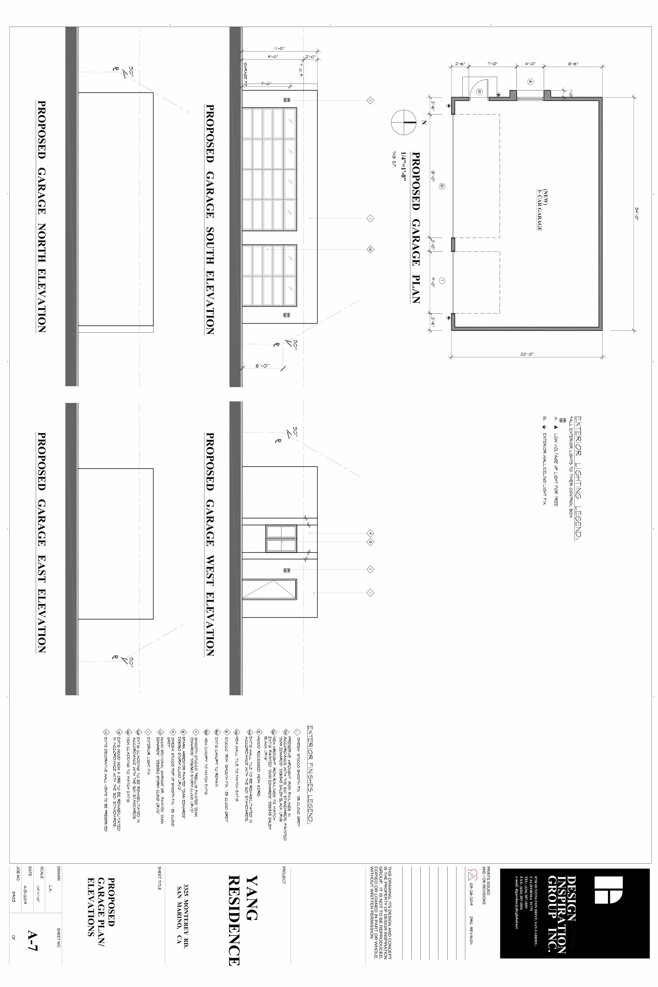
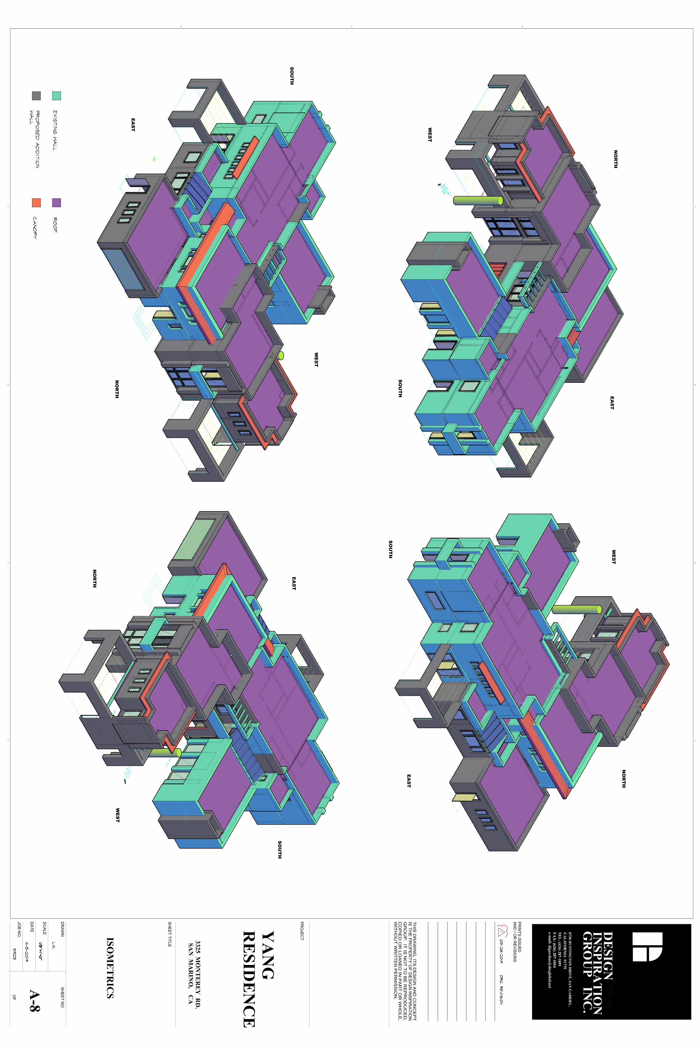
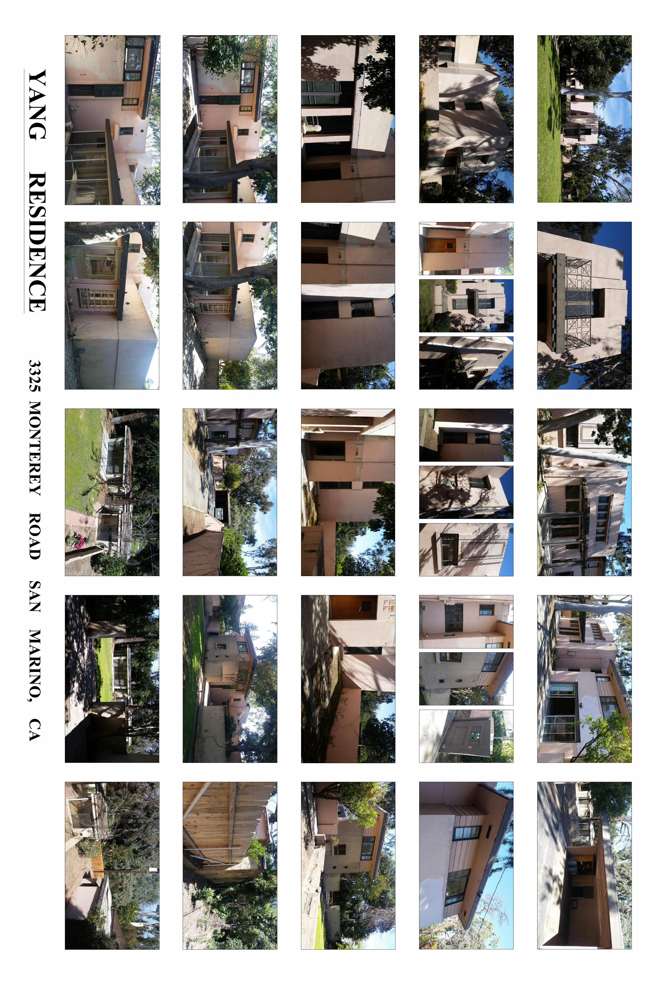


Appendix J NPS Preservation Briefs
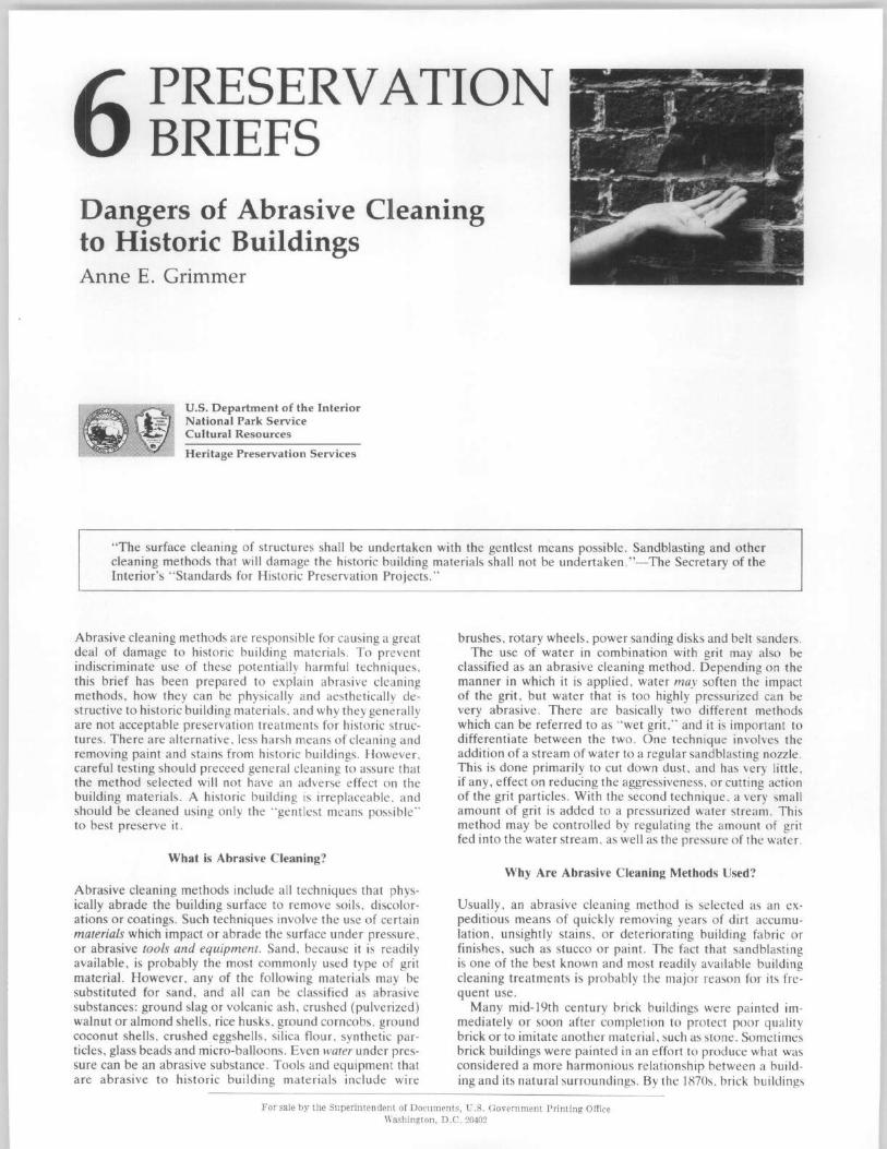
6 PRESERV ATION BRIEFS
Dangers of Abrasive Cleaning to Historic Buildings Anne E. Grimmer
U.S. Department of the Interior National Park Service Cultural Resources
Heritage Preservation Services
" The surface cleaning of structures shall be unde rtaken with the gentlest means possible . Sandblasting and other cleaning methods that will damage the historic building materials shall not be undertaken ."-The Secretary of the Interior's "Standards for Historic Preservation Projects ."
Abrasive cleaning methods are responsible for ca using a great deal of damage to historic building material s. To prevent indiscriminate use of these potentially harmful techniques. this brief has been prepared to explain abrasive cleaning methods, how they can be physically and aesthetically destructive to historic building materials , and why they generally are not acceptable preservation treatments for historic st ructures. There are alternative, less harsh means of cleaning and removing paint and stains from historic buildings. However . careful testing should preceed general cleaning to assure that the method selected will not have an adverse effect on th e building materials. A historic building is irreplaceable. and should be cleaned using only the "gen tlest means possible" to best preserve it.
What is Abrasive Cleaning?
Abrasive cleaning methods include all techniques that physically abrade the building surface to remove soils, discolorations or coatings . Such techniques involve the use of certain materials which impact or abrade the surface under pressure , or abrasive tools and equipment. Sand, because it is readily available, is probably the most commonly used type of grit material. However , any of the following materials may be substituted for sand, and all can be classified as abrasive substances: ground slag or volcanic ash, crushed (pulverized) walnut or almond shells. rice husks , gwund corncobs, ground coconut shells, crushed eggshells, silica flour , synthetic particles, glass beads and micro-balloons. Even water under pressure can be an abrasive substance. Tools and equipment that are abrasive to historic building materials include wire
brushes , rotary wheels, power sanding disks and belt sanders. The use of water in combination with grit may also be
classified as an abrasive cleaning method. Depending on the manner in which it is applied, water may soften the impact of the grit, but water that is too highly pressurized can be very abrasive . There are basically two different methods which can be referred to as " wet grit," and it is importa nt to differentiate between the two. One technique involves the addition of a stream of water to a regular sandb lasting nozzle. This is done primarily to cut down dust. and has very little, if any , effect on reducing the aggressiveness, or cutting action of the grit particles. With the second technique, a very small amount of grit is added to a pressurized water stream. This method may be controlled by regulating the amount of grit fed into the water stream, as well as the pressure of the water.
Why Are Abrasive Cleaning Methods Used?
Usually, an abrasive cleaning method is selected as an expeditious means of quickly removing years of dirt accumulation, unsightly stains, or deteriorating building fabric or finishes , such as stucco or paint. The fact that sandblasting is one of the best known and most readily available building cleaning treatments is probably the major reason for its frequent use .
Many mid-19th century brick buildings were painted immediately or soon after completion to protect poor quality brick or to imitate another material. such as stone. Sometimes brick buildings were painted in an effort to produce what was considered a more harmonious relationship between a building and its natural surroundings. By the 1870s , brick buildings
For sale by the Superintendent of Documents, U.S. Government Printing Office Washington, D.C. 20402
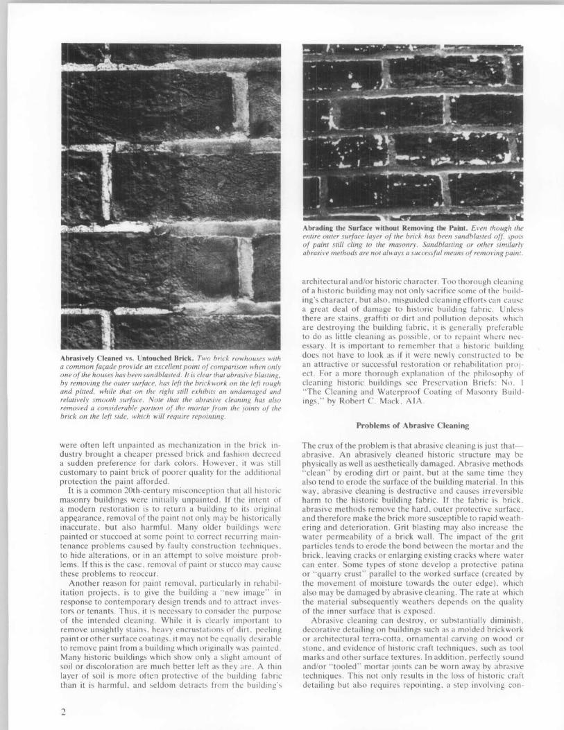
Abrasively Cleaned vs. Untouched Brick. Two brick rowhouses with a common far;ade provide an excellent point of comparison when only one of the houses has been sandblasted. It is clear that abrasive blasting. by removing the outer surface. has left the brickwork on the left rough and pitted. while that on the right still exhibits an undamaged and relatively smooth surface. Note that the abrasive cleaning has also removed a considerable portion of the mortar from the joints of the brick on the left side. which will require repointing.
were often left unpainted as mechanization in the brick industry brought a cheaper pressed brick and fashion decreed a sudden preference for dark colors. However . it was still customary to paint brick of poorer quality for the additional protection the paint afforded.
It is a common 20th-century misconception that a ll historic masonry buildings were initially unpainted. If the intent of a modern restoration is to return a building to its original appearance. removal of the paint not only may be historically inaccurate, but also harmful. Many older buildings were painted or stuccoed at some point to correct recurring maintenance problems caused by faulty construction techniques. to hide alterations, or in an attempt to solve moisture problems. If this is the case. removal of paint or stucco may cause these problems to reoccur.
Another reason for paint removal. particularly in rehabilitation projects . is to give the building a " new image" in response to contemporary design trends and to attract investors or tenants. Thus. it is necessary to consider the purpose of the intended cleaning. While it is clearly important to remove unsightly stains. heavy encrustations of dirt. peeling paint or other surface coatings. it may not be equally desirable to remove paint from a building which originally was painted. Many historic buildings which show only a slight amount of soil or discoloration are much better left as they are. A thin layer of soil is more often protective of the building fabric than it is harmful. and seldom detracts from the building's
2
Abrading the Surface without Removing the Paint. Even though the entire outer surface layer of the brick has been sandblasted off. spots of paint still cling to the masonry. Sandblasting or other similarly abrasive methods are not always a successful means of removing paint.
architectural and/or historic character. Too thorough cleaning of a historic building may not only sacrifice some of the building's character, but also. misguided cleaning efforts can cause a great deal of damage to historic building fabric. Unless there are stains, graffiti or dirt and pollution deposits which are destroying the building fabric. it is generally preferable to do as little cleaning as possible. or to repaint where necessary. It is important to remember that a historic building does not have to look as if it were newly constructed to be an attractive or successful restoration or rehabilitation project. For a more thorough explanation of the philosophy of cleaning historic buildings see Preservation Briefs: No. I "The Cleaning and Waterproof Coating of Masonry Buildings," by Robert C. Mack . AlA.
Problems of Abrasive Cleaning
The crux of the problem is that abrasive cleaning is just thatabrasive. An abrasively cleaned historic structure may be physically as well as aesthetically damaged. Abrasive methods "clean" by eroding dirt or paint, but at the same time they also tend to erode the surface of the building material. In this way, abrasive cleaning is destructive and causes irreversible harm to the historic building fabric. If the fabric is brick, abrasive methods remove the hard, outer protective surface, and therefore make the brick more susceptible to rapid weathering and deterioration . Grit blasting may also increase the water permeability of a brick wall. The impact of the grit particles tends to erode the bond beiween the mortar and the brick, leaving cracks or enlarging existing cracks where water can enter. Some types of stone develop a protective patina or " quarry crust" parallel to the worked surface (created by the movement of moisture towards the outer edge). which also may be damaged by abrasive cleaning. The rate at which the material subsequently weathers depends on the quality of the inner surface that is exposed.
Abrasive cleaning can destroy . or substantially diminish. decorative detailing on buildings such as a molded brickwork or architectural terra-cotta. ornamental carving on wood or stone. and evidence of historic craft techniques . such as tool marks and other surface textures. In addition. perfectly sound and/or "tooled" mortar joints can be worn away by abrasive techniques . This not only results in the loss of historic craft detailing but also requires repointing. a step involving con-
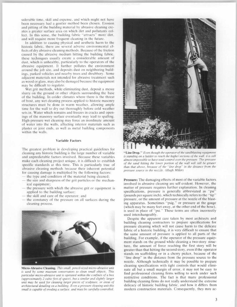
slderable time, skill and expense, and which might not have been necessary had a gentler method been chosen. Erosion and pitting of the building material by abrasive cleaning creates a greater surface area on which dirt and pollutants collect. In this sense, the building fabric "attracts" more dirt, and will require more frequent cleaning in the future.
In addition to causing physical and aesthetic harm to the historic fabric, there are several adverse environmental effects of dry abrasive cleaning methods. Because of the friction caused by the abrasive medium hitting the building fabric, these techniques usually create a considerable amount of dust, which is unhealthy, particularly to the operators of the abrasive equipment. It further pollutes the environment around the job site, and deposits dust on neighboring buildings, parked vehicles and nearby trees and shrubbery. Some adjacent materials not intended for abrasive treatment such as wood or glass, may also be damaged because the equipment may be difficult to regulate.
Wet grit methods, while eliminating dust, deposit a messy slurry on the ground or other objects surrounding the base of the building. In colder climates where there is the threat of frost , any wet cleaning process applied to historic masonry structures must be done in warm weather, allowing ample time for the wall to dry out thoroughly before cold weather sets in. Water which remains and freezes in cracks and openings of the masonry surface eventually may lead to spalling. High-pressure wet cleaning may force an inordinate amount of water into the walls, affecting interior materials such as plaster or joist ends, as well as metal building components within the walls.
Variable Factors
The greatest problem in developing practical guidelines for cleaning any historic building is the large number of variable and unpredictable factors involved. Because these variables make each cleaning project unique, it is difficult to establish specific standards at this time. This is particularly true of abrasive cleaning methods because their inherent potential for causing damage is multiplied by the following factors : - the type and condition of the material being cleaned; - the size and sharpness of the grit particles or the mechan-
ical equipment; - the pressure with which the abrasive grit or equipment is
applied to the building surface; - the skill and care of the operator; and - the constancy of the pressure on all surfaces during the
cleaning process.
Micro-Abrasive Cleaning. This small. pencil-sized micro-abrasive unit is used by some museum conservators to clean small objects. This particular micro-abrasive unit is operated within the confines of a box (approximately 2 cubic feet of space) . but a similar and slightly larger unit may be used for cleaning larger pieces of sculpture. or areas of architectural detailing on a building. Even a pressure cleaning unit this small is capable of eroding a surface. and must be carefully controlled.
"Line Drop." Even though the operator afthe sandblasting equipment is standing on a ladder to reach the higher sections of the wall. it is still almost impossible to have total control over the pressure. The pressure of the sand hitting the lower portion of the wall will still be greater than that above. because of the "line drop" in the distance from the pressure source to the nozzle. (Hugh Miller)
Pressure: The damaging effects of most of the variable factors involved in abrasive cleaning are self evident. However, the matter of pressure requires further explanation. In cleaning specifications, pressure is generally abbreviated as " psi" (pounds per square inch), which technically refers to the "tip" pressure, or the amount of pressure at the nozzle of the blasting apparatus. Sometimes "psig," or pressure at the gauge (which may be many feet away, at the other end of the hose), is used in place of "psi." These terms are often incorrectly used interchangeably.
Despite the apparent care taken by most architects and building cleaning contractors to prepare specifications for pressure cleaning which will not cause harm to the delicate fabric of a historic building, it is very difficult to ensure that the same amount of pressure is applied to all parts of the building. For example, if the operator of the pressure equipment stands on the ground while cleaning a two-story structure, the amount of force reaching the first story will be greater than that hitting the second story, even if the operator stands on scaffolding or in a cherry picker, because of the "line drop" in the distance from the pressure source to the nozzle. Although technically it may be possible to prepare cleaning specifications with tight controls that would eliminate all but a small margin of error, it may not be easy to find professional cleaning firms willing to work under such restrictive conditions. The fact is that many professional building cleaning firms do not really understand the extreme delicacy of historic building fabric, and how it differs from modern construction materials. Consequently, they mily ac-
3
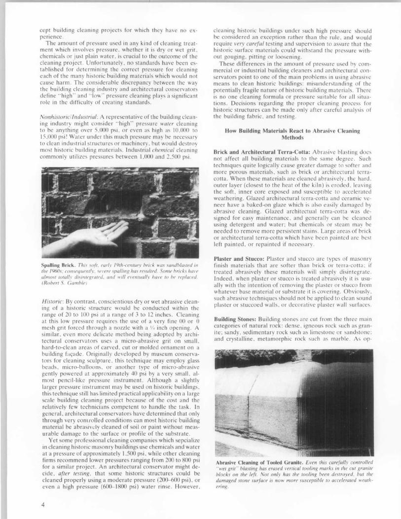
cept building cleaning projects for which they have no experience.
The amount of pressure used in any kind of cleaning treatment which involves pressure, whether it is dry or wet grit, chemicals or just plain water, is crucial to the outcome of the cleaning project. Unfortunately, no standards have been established for determining the correct pressure for cleaning each of the many historic building materials which would not cause harm. The considerable discrepancy between the way the building cleaning industry and architectural conservators define " high" and "low" pressure cleaning plays a significant role in the difficulty of creating standards.
Nonhistoricllndustria/: A representative of the building cleaning industry might consider " high" pressure water cleaning to he anything over 5,000 psi, or even as high as 10,000 to 15 ,000 psi' Water under this much pressure may be necessary to clean industrial structures or machinery, but would destroy most historic building materials. Industrial chemical cleaning commonly utilizes pressures between I ,000 and 2,500 psi.
Spalling Brick, This soft. earlv 19th-cell/llry hrick was sandblasted ill the 1960s; consequentlv. ~el'ere spallillg has resulted. Some hricks hal'l' almo.1'I towlly disintegrated. and will el'enll/allv hUl'e to he replaced. (Rohert S. Gamhle)
Historic: By contrast. conscientious dry or wet abrasive cleaning of a historic structure wo uld be conducted within the range of 20 to 100 psi at a range of 3 to 12 inches. Cleaning al this low pressure requires the use of a very fine 00 or 0 mesh grit forced through a nozzle with a Y4 inch opening. A similar. even more delicate method being adopted by architectural conservators uses a micro-abrasive grit on small, hard-to-clean areas of carved, cut or molded ornament on a building fac;ade. Originally developed by museum conservators for cleaning sculpture, this technique may employ glass beads, micro-balloons , or another type of micro-abrasive gently powered at approximately 40 psi by a very small, almost pencil-like pressure instrument. Although a slightly larger pressure instrument may be used on historic buildings, this technique still has limited practical applicability on a large scale building cleaning project because of the cost and the relatively few technicians competent to handle the task. In general. architectural conservators have determined that only through very com rolled conditions can most historic building material be abrasivl:ly cleaned of soil or paint without measurable damage to the surface or profile of the substrate.
Yet some professional cleaning companies which sepcialize in cleaning historic masonry buildings use chemicals and water at a pressure of approximately 1,500 psi, while other cleaning firms recommend lower pressures ranging from 200 to 800 psi for a similar project. An architectural conservator might decide, after testing. that some historic structures could be cleaned properly using a moderate pressure (200-600 psi), or even a high pressure (600-1800 psi) water rinse . However,
4
cleaning historic buildings under such high pressure should be considered an exception rather than the rule, and would require very careful testing and supervision to assure that the historic surface materials could withstand the pressure without gouging, pitting or loosening.
These differences in the amount of pressure used by commercial or industrial building cleaners and architectural conservators point to one of the main problems in using abrasive means to clean historic buildings: misunderstanding of the potentially fragile nature of historic building materials . There is no one cleaning formula or pressure suitable for all situations . Decisions regarding the proper cleaning process for historic structures can be made only after careful analysis of the building fabric, and testing.
How Building Materials React to Abrasive Cleaning Methods
Brick and Architectural Terra-Cotta: Abrasive blasting does not affect all building materials to the same degrec. Such techniques quite logically cause greater damage to softer and more porous materials, such as brick or architectural terracotta. When these materials are cleaned abrasively, the hard , outer layer (closest to the heat of the kiln) is eroded, leaving the soft. inner core exposed and susceptible to accelerated weathering. Glazed architectural terra-cotta and ceramic veneer have a baked-on glaze which is also easily damaged by abrasive cleaning. Glazed architectual terra-cotta was designed for easy maintenance, and generally can be cleaned using detergent and water ; but chemicals or steam may be needed to remove more persistent stains. Large areas of brick or architectural terra-cotta which have been painted are best left painted. or repainted if necessary .
Plaster and Stucco: Plaster and stucco are types of masonry finish materials that are softer than brick or terra-cotta: if treated abrasively these materials will simply disintegrate. Indeed. when plaster or stucco is treated abrasively it is usually with the intention of removing the plaster or stucco from whatever base material or substrate it is covering. Obviously. such abrasive techniques should not be applied to clean sound plaster or stuccoed walls, or decorative plaster wall surfaces.
Building Stones: Building stones are cut from the three main categories of natural rock: dense, igneous rock such as granite; sandy. sedimentary rock such as limestone or sandstone: and crystalline, metamorphic rock such as marble. As op-
Abrasive Cleaning of Tooled Granite, Even this carefully colllrolled "wet grit" blasting has erased verticallOoling marks in the CIII granite blocks on the left. Not only has the lOoling been destroyed, bill the damaged stone surface is now more susceptible 10 accelerated weathering.
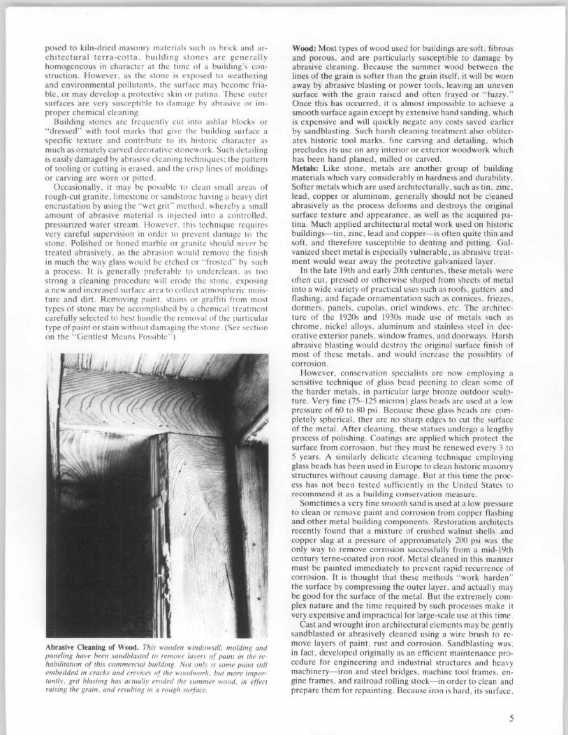
posed to kiln-dried masonry materials such as brick and architectural terra-cotta , building stones are generally homogeneous in character at the time of a bui lding's construction . However , as the stone is exposed to weatheri ng and environmental pollutants , the surface may become friable, or may develop a protective skin or patina. These outer surfaces are very susceptible to damage by abrasive or improper chemical cleaning.
Building stones are frequently cut into ashlar blocks or "dressed" with tool marks that give the building surface a specific texture and contribute to its historic character as much as ornately carved decorative stonework. Such detailing is easi ly damaged by abrasive cleaning techniques: the pattern of tooling o r cutting is erased, and the crisp lines of moldings or carving are worn or pitted .
Occasionally, it may be possible to clean small areas of rough-cut granite , limestone or sandstone having a heavy dirt encrustation by using the " wet grit" method . whereby a small amount of abrasive material is injected into a controlled. pressurized water stream. However, this techn ique requires very ca reful supervision in order to prevent damage to the stone. Po li shed or honed marble or granite shou ld never be treated abrasively, as the abrasion would remove the fin ish in much the way glass would be etched or "frosted" by such a process. It is genera ll y preferable to underclean . as too strong a cleaning procedure will erode the stone, exposing a new and increased surface area to collect atmospheric moisture and dirt. Removing paint, stains or graffiti from most types of stone may be accomplished by a chemical treatment carefully selected to best handle the removal of the particular type of paint or stain without damaging the stone. (See section on the "Gentl est Means Possible")
Abrasive Cleaning of Wood. This wooden windowsill. molding and paneling have been sandblasted to remove layers oj paint in the rehabilitation oj this commercial building. Not only is some paint still embedded in cracks and crevices oj the woodwork. but more importantly. grit blasting has actually eroded the summer wood. in eJJect raising the grain. and resulting in a rough surJace.
Wood: Most types of wood used for buildings are soft. fibrous and porous, and are particularly susceptible to damage by abrasive cleaning. Because the summer wood between the lines of the grain is softer than the grain itself, it will be worn away by abrasive blasting or power tools, leaving an uneven surface with the grain raised and often frayed or "fuzzy," Once this has occurred, it is almost impossible to achieve a smooth surface again except by extensive hand sanding , which is expensive and will quickly negate any costs saved earlier by sandblasting. Such harsh cleaning treatment also obliterates historic tool marks , fine carving and detailing, which precludes its use on any interior or exterior woodwork which has been hand planed , milled or carved. Metals: Like stone, metals are another group of building materials which vary considerably in hardness and durability. Softer metals which are used architecturally. such as tin, zinc , lead , copper or aluminum, generally should not be cleaned abrasively as the process deforms and destroys the original surface texture and appearance, as well as the acquired patina . Much applied architectural metal work used on historic buildings-tin , zinc , lead and copper-is often quite thin and soft, and therefore susceptible to denting and pitting. Galvanized sheet metal is especially vulnerable, as abrasive treatment would wear away the protective galvanized layer.
In the late 19th and early 20th centuries , these metals were often cut, pressed or otherwise shaped from sheets of metal into a wide variety of practica l uses such as roofs, gutters and flashing , and fac;ade ornamentation such as cornices. friezes . dormers, panels , cupolas . oriel windows. etc. The architecture of the 1920s and 1930s made use of metals such as chrome, nickel alloys, aluminum and stainless steel in decorative exterior panels , window frames. and doorways. Harsh abrasive blasting would destroy the original surface finish of most of these metals , and would increase the possiblity of corrosion.
However , conservation specialists are now employing a sensitive technique of glass bead peening to clean some of the harder metals, in particular large bronze outdoor sculpture . Very fine (75-125 micron) glass beads are used at a low pressure of 60 to 80 psi. Because these glass beads are completely spherical, ther are no sharp edges to cut the surface of the metal. After cleaning, these statues undergo a lengthy process of polishing. Coatings are applied which protect the surface from corrosion. but they must be renewed every 3 to 5 years. A similarly delicate cleaning technique employing glass beads has been used in Europe to clean historic masonry structures without causing damage. But at this time the process has not been tested sufficiently in the United States to recommend it as a building conservation measure.
Sometimes a very fine smooth sand is used at a low pressure to clean or remove paint and corrosion from copper flashing and other metal building components. Restoration architects recently found that a mixture of crushed walnut shells and copper slag at a pressure of approximately 200 psi was the only way to remove corrosion successfully from a mid-19th century terne-coated iron roof. Metal cleaned in this manner must be painted immediately to prevent rapid recurrence of corrosion. It is thought that these methods "work harden " the surface by compressing the outer layer. and actually may be good for the surface of the metal. But the extremely complex nature and the time required by such processes make it very expensive and impractical for large-scale use at this time.
Cast and wrought iron architectural elements may be gently sandblasted or abrasively cleaned using a wire brush to remove layers of paint, rust and corrosion. Sandblasting was. in fact , developed originally as an efficient maintenance procedure for engineering and industrial structures and heavy machinery-iron and steel bridges, machine tool frames . engine frames, and railroad rolling stock-in order to clean and prepare them for repainting . Because iron is hard , its surface.
5
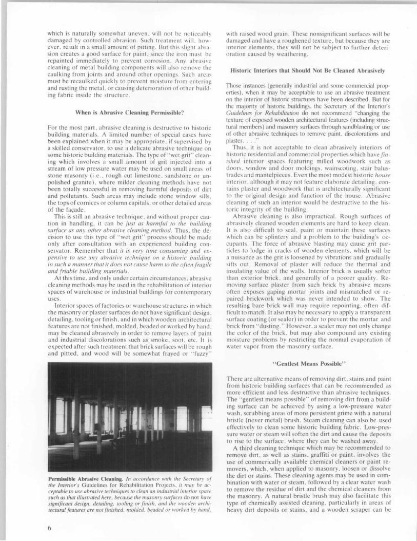
which is naturally somewhat uneven, will not be noticeably damaged by controlled abrasion. Such treatment will. how'ever, re~ult in a small amount of pitting. But this slight abrasion creates a good surface for paint, since the iron must bc repainted immediately to prevent corrosion. Any abrasive cleaning of metal building components will also remove the caulking from joints and around other openings. Such areas must be recaulked quickly to prevent moisture from entering and rusting the metal, or causing deterioration of other building fabric inside the structure.
When is Abrasive Cleaning Permissible?
For the most part, abrasive cleaning is destructive to historic building materials. A limited number of special cases have been explained when it may be appropriate, if supervised by a skilled conservator, to use a delicate abrasive technique on some historic building materials. The type of "wet grit" cleaning which involves a small amount of grit injected into a stream of low pressure water may be used on small areas of stone masonry (i.e., rough cut limestone, sandstone or unpolished granite), where milder cleaning methods have not been totally successful in removing harmful deposits of dirt and pollutants. Such areas may include stone window sills, the wps of cornices or column capitals, or other detailed areas of the fa<;ade.
This is still an abrasive technique, and without proper caution in handling, it can be jus I as harmful 10 Ihe building surface as any olher abrasive cleaning method. Thus, the decision to use this type of "wet grit" process should be made only after consultation with an experienced building conservator. Remember that il is very lime consuming and expensive to use any abrasive technique on a historic building in such a manner that it does not cause harm to the often fragile and friable building materials.
At this time , and only under certain circumstances, abrasive cleaning methods may be used in the rehabilitation of interior spaces of warehouse or industrial buildings for contemporary uses.
Interior spaces of factories or warehouse structures in which the masonry or plaster surfaces do not have significant design, detailing, tooling or finish, and in which wooden architectural features are not finished, molded, beaded or worked by hand, may be cleaned abrasively in order to remove layers of paint and industrial discolorations such as smoke, soot, etc. It is expected after such treatment that brick surfaces will be rough and pitted, and wood will be somewhat frayed or "fuzzy"
Permissible Abrasive Cleaning, In accordance with the Secretary of the Interior's Guidelines for Rehabilitation Projects, it may be acceptable to use abrasive techniques to clean an industrial interior space such as that il/ustraled here, because the masonry surfaces do not have significant design, detailing, tooling or finish, and the wooden architectural features are not finished, molded, beaded or worked by hand.
6
with raised wood grain. These nonsignificant surfaces will be damaged and have a roughened texture, but because they are interior elements, they will not be subject to further deterioration caused by weathering.
Historic Interiors that Should Not Be Cleaned Abrasively
Those instances (generally industrial and some commercial properties), when it may be acceptable to use an abrasive treatment on the interior of historic structures have been described. But for the majority of historic buildings, the Secretary of the Interior's Guidelines for Rehabilitation do not recommend "changing the texture of exposed wooden architectural features (induding structural members) and masonry surfaces through sandblasting or use of other abrasive techniques to remove paint, discolorations and plaster. ... "
Thus, it is not acceptable to clean abrasively interiors of historic residential and commercial properties which have finished interior spaces featuring milled woodwork such as doors, window and door moldings, wainscoting, stair balustrades and mantelpieces. Even the most modest historic house interior, although it may not feature elaborate detailing, contains plaster and woodwork that is architecturally significant to the original design and function of the house. Abrasive cleaning of such an interior would be destructive to the historic integrity of the building.
Abrasive cleaning is also impractical. Rough surfaces of abrasively cleaned wooden elements are hard to keep clean. It is also difficult to seaL paint or maintain these surfaces which can be splintery and a problem to the building's occupants. The force of abrasive blasting may cause grit particles to lodge in cracks of wooden elements, which will be a nuisance as the grit is loosened by vibrations and gradually sifts out. Removal of plaster will reduce the thermal and insulating value of the walls. Interior brick is usually softer than exterior brick, and generally of a poorer quality. Removing surface plaster from such brick by abrasive means often exposes gaping mortar joints and mismatched or repaired brickwork which was never intended to show . The resulting bare brick wall may require repointing, often difficult to match. It also may be necessary to apply a transparent surface coating (or sealer) in order to prevent the mortar and brick from "dusting." However, a sealer may not only change the color of the brick, but may also compound any existing moisture problems by restricting the normal evaporation of water vapor from the masonry surface.
"Gentlest Means Possible"
There are alternative means of removing dirt, stains and paint from historic building surfaces that can be recommended as more efficient and less destructive than abrasive techniques. The "gentlest means possible" of removing dirt from a building surface can be achieved by using a low-pressure water wash, scrubbing areas of more persistent grime with a natural bristle (never metal) brush. Steam cleaning can also be used effectively to clean some historic building fabric. Low-pressure water or steam will soften the dirt and cause the deposits to rise to the su rface , where they can be washed away.
A third cleaning technique which may be recommended to remove dirt, as well as stains, graffiti or paint, involves the use of commerically avai lable chemical cleaners or paint removers, which, when applied to masonry, loosen or dissolve the dirt or stains. These cleaning agents may be used in combination with water or steam, followed by a clear water wash to remove the residue of dirt and the chemical cleaners from the masonry. A natural bristle brush may also facilitate this type of chemically assisted cleaning, particularly in areas of heavy dirt deposits or stains, and a wooden scraper can be
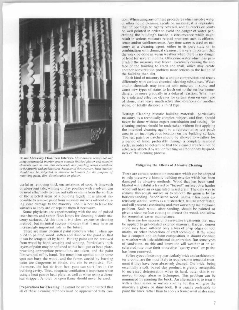
Do not Abrasively Clean these Interiors. Most historic residential and some commercial interior spaces contain finished plaster and wooden elements such as this stair balustrade and paneling which cOlltribwe to the historic and architectural character of the structure. Such interiors should not be subjected to abrasive techniques for the purpose of removing paint, dirt, discoloration or plaster.
useful in removing thick encrustations of soot. A limewash or absorbent talc, whiting or clay poultice with a solvent can be used effectively to draw out salts or stai ns from the surface of the selected areas of a building fa<;ade. It is almost impossible to remove paint from masonry surfaces without causing some damage to the masonry, and it is best to leave the surfaces as they are or repaint them if necessary.
Some physicists are experimenting with the use of pulsed laser beams and xenon flash lamps for cleaning historic masonry surfaces. At this time it is a slow, expensive cleaning method, but its initial success indicates that it may have an increasingly important role in the future.
There are many chemical paint removers which. when applied to painted wood, soften and dissolve the paint so that it can be scraped off by hand . Peeling paint can be removed from wood by hand scraping and sandin g. Particularly thick layers of paint may be softened with a heat gun or heat plate. providing appropriate precautions are taken. and the paint film scraped off by hand . Too much heat applied to the same spot can burn the wood, and the fumes caused by burning paint are dangerous to inhale, and can be explosive. Furthermore. the hot air from heat guns can start fires in the building cavity. Thus. adequate venti lat ion is important when using a heat gun or heat plate. as well as when using a chemical stripper. A torch or open flame should never be used .
Preparations for Cleaning: It cannot be overemph asized that all of these cleaning methods must be approached with cau-
tion . When using any of these procedures which involve water or other liquid cleaning agents on masonry , it is imperative that all openings be tightly covered. and all cracks or joints be well pointed in order to avoid the danger of water penetrating the building's facade, a circumstance which might result in serious moisture related problems such as efflorescence and/or subflorescence. Any time water is used on masonry as a cleaning agent, either in its pure state or in combination with chemical cleaners. it is very important that the work be done in warm weather when there is no danger of frost for several months . Otherwise water which has penetrated the masonry may freeze, eventually causing the surface of the building to crack and spall, which may create another conservation problem more serious to the health of the building than dirt.
Each kind of masonry has a unique composition and reacts differently with various chemical cleaning substances. Water and/or chemicals may interact with minerals in stone and cause new types of stains to leach out to the surface immediately, or more gradually in a delayed reaction. What may be a safe and effective cleaner for certain stain on one type of stone, may leave unattractive discolorations on another stone, or totally dissolve a third type.
Testing: Cleaning historic building materials. particularly masonry , is a technically complex subject. and thus. should never be done without expert consultation and testing. No cleaning project should be undertaken without first applying the intended cleaning agent to a representative test patch area in an inconspicuous location on the building surface. The test patch or patches should be allowed to weather for a period of time , preferably through a complete seasonal cycle, in order to determine that the cleaned area will not be adversely affected by wet or freezing weather or any by-products of the cleaning process.
Mitigating the Effects of Abrasive Cleaning
There are certain restoration measures which can be adopted to help preserve a historic building exterior which has been damaged by abrasive methods. Wood that has been sandblasted will exhibit a frayed or " fuzzed" surface, or a harder wood will have an exaggerated raised grain. The only way to remove this rough surface or to smooth the grain is by laborious sanding. Sandblasted wood, unless it has been extensively sanded, serves as a dustcatcher , will weather faster , and will present a continuing and ever worsening maintenance problem. Such wood, after sanding. should be painted or given a clear surface coating to protect the wood , and allow for somewhat easier maintenance.
There are few successful preservative treatments that may be applied to grit-blasted exterior masonry . Harder , denser stone may have suffered only a loss of crisp edges or tool marks, or other indications of craft technique. If the stone has a compact and uniform composition, it should continue to weather with little additional deterioration. But some types of sandstone, marble and limestone will weather at an accelerated rate once their protective "quarry crust" or patina has been removed.
Softer types of masonry , particularly brick and architectural terra-cotta, are the most likely to require some remedial treatment if they have been abrasively cleaned . Old brick. being essentially a soft, baked clay product. is greatly susceptible to Increased deterioration when its hard . outer skin is removed through abrasive techniques. This problem can be minimized by painting the brick. An alternative is to treat it with a clear sealer or surface coating but this will give the masonry a glossy or shiny look. It is usuafly preferable to paint the brick rather than to apply a transparent sealer since
7
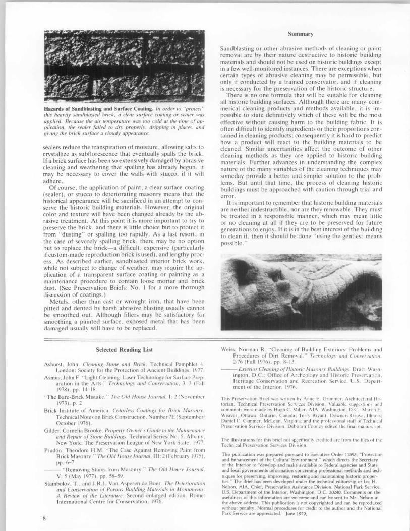
Hazards of Sandblasting and Surface Coating. In order to "protect" this heavily sandblasted brick, a clear surface coating or sealer was applied. Because the air temperature was too cold at the time of ap· plication, the sealer failed to dry properly, dripping in places. and giving the brick surface a cloudy appearance.
sealers reduce the transpiration of moisture, allowing salts to crystallize as subflorescence that eventually spalls the brick. If a brick surface has been so extensively damaged by abrasive cleaning and weathering that spalling has already begun. it may be necessary to cover the walls with stucco. if it will adhere.
Of course. the application of paint. a clear surface coating (sealer). or stucco to deteriorating masonry means that the historical appearance will be sacrificed in an attempt to conserve the historic building materials. However, the original color and texture will have been changed already by the abrasive treatment . At this point it is more important to try to preserve the brick. and there is little choice but to protect it from "dusting" or spalling too rapidly. As a last resort. in the case of severely spalling brick. there may be no option but to replace the brick-a difficult. expensive (particularly if custom-made reproduction brick is used) , and lengthy process. As described earlier. sandblasted interior brick work. while not subject to change of weather. may require the application of a transparent surface coating or painting as a maintenance procedure to contain loose mortar and brick dust. (See Preservation Briefs: No. 1 for a more thorough discussion of coatings.)
Metals, other than cast or wrought iron, that have been pitted and dented by harsh abrasive blasting usually cannot be smoothed out. Although fillers may be satisfactory for smoothing a painted surface, exposed metal that has been damaged usually will have to be replaced .
Selected Reading List
Ashurst. John. Cleaning Stone and Brick . Technical Pamphlet 4. London: Society for the Protection of Ancient Buildings. IY77.
Asmus. John F. "Light Cleaning: Laser Technology for Surface Preparation in the Arts." Technology and Conservation. 3: 3 (Fall 1978). pp. 14-18.
"The Bare-Brick Mistake. " The Old House Journal. I: 2 (November 1973). p. 2
Brick Institute of America. Colorless Coatings for Brick Masonrl'. Technical Notes on Brick Construction. Number 7E (September/ October 1976) .
Gilder. Cornelia Brooke . Property OWller's Guide to the Maintenance and Repair of Stone Buildings. Technical Series/ Nn. 5. Albany. New York: The Preservation League of New York State. 1977.
Prudon . Theodore H.M . "The Case Against Removing Paint from Brick Masonry ." The Old HouseJournal. III : 2 (February 1975). pp . fr-7
--- "Removing Stains from Masonry. " The Old House Journal. V: 5 (May 1977). pp. 58-59.
Stambolov . T.. and J.R.J. Van Asperen de Boer. The Deterioration and Conservation of Porous Building Materials in Monumellts: A Review of the Literature. Second enlarged edition. Rome: International Centre for Conservation. 1976.
8
Summary
Sandblasting or other abrasive methods of cleaning or paint removal are by their nature destructive to historic building materials and should not be used on historic buildings except in a few well-monitored instances. There are exceptions when certain types of abrasive cleaning may be permissible. but only if conducted by a trained conservator, and if cleaning is necessary for the preservation of the historic structure.
There is no one formula that will be suitable for cleaning a ll historic building surfaces. Although there are many commerical cleaning products and methods available. it is impossible to state definitively which of these will be the most effective without causing harm to the building fabric . It is often difficult to identify ingredients or their proportions contained in cleaning products; consequently it is hard to predict how a product will react to the building materials to be cleaned. Similar uncertanities affect the outcome of other cleaning methods as they are applied to historic building materials. Further advances in understanding the complex nature of the many variables of the cleaning techniques may someday provide a better and simpler solution to the problems. But until that time. the process of cleaning historic buildings must be approached with caution through trial and error.
It is important to remember that historic building materials are neither indestructible. nor are they renewable. They must be treated in a responsible manner . which may mean little or no cleaning at all if they are to be preserved for future generations to enjoy. If it is in the best interest of the building to clean it , then it should be done "using the gentlest means possible."
Weiss. Norman R. "Cleani ng of Building Exteriors: Problems anu Procedures of Dirt Removal." Technolo?.\' and COllSen'atioll. 2176 (Fall 1976). pp. 8- 13.
--- Exterior Cleaning of Historic Masollr.\' Buildings. Draft. Washington. D.C.: Office of Archeology and Historic Preservation. Heritage Conservation and Recreation Service. U.S. Depart· ment of the Interior. 1976.
Th is Preservation Brief was writlen hy Anne E. Grimmer. Architectura l Hi,· torian. Technical Preservation Services Division. Valuahle suggestions and comments were made hy Hugh C. Miller. AlA. Washington. D.C.: Marlin E. Weaver. Otlawa. Ontario. Canada: Terry Bryant. Downers Grove. IIlinoi" Daniel C. Cammer. McLean. Virginia: and the professional staff of Technical Preservation Services Division. Dehorah Cooney edited the final manuscript.
The illustrations for this brief not sRf'cifically credited are from the fi les of the Technical Preservation Services Division.
This publication was prepared pursuant to Executive Order 11593. "Protection and Enhancement of the Cultural Environment." which directs the Secretary of the Interior to "develop and make available to Federal agencies and State and local governments information concerning professional methods and techniques for preserving, improving, restoring and maintaining historic properties." The Brief has been developed under the technical editorship of Lee H. Nelson, AlA, Chief, Preservation Assistance Division, National Park Service, U.S. Department of the Interior, Washington, D.C. 20240. Comments on the usefulness of this information are welcome and can be sent to Mr . Nelson at the above address. This publication is not copyrighted and can be reproduced without penalty. Normal procedures for credit to the author and the National Park Service are appreciated. June 1979.
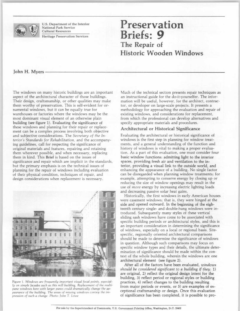
U.S. Department of the Interior National Park Service Cultural Resources
Heritage Preservation Services
Preservation Briefs: 9 The Repair of Historic Wooden Windows
JohnH. ~yers------------------------------------------------------------------
The windows on many historic buildings are an important aspect of the architectural character of those buildings. Their design, craftsmanship, or other qualities may make them worthy of preservation . This is self-evident for ornamental windows, but it can be equally true for warehouses or factories where the windows may be the most dominant visual element of an otherwise plain building (see figure 1). Evaluating the significance of these windows and planning for their repair or replacement can be a complex process involving both objective and subjective considerations . The Secretary of the Interior's Standards for Rehabilitation, and the accompanying guidelines, call for respecting the significance of original materials and features , repairing and retaining them wherever possible, and when necessary, replacing them in kind. This Brief is based on the issues of significance and repair which are implicit in the standards, but the primary emphasis is on the technical issues of planning for the repair of windows including evaluation of their physical condition, techniques of repair, and design considerations when replacement is necessary.
Figure 1. Windows are frequently important visual focal points, especiallyon simple facades such as this mill building. Replacement of the multipane windows here with larger panes could dramatically change the appearance of the building. The areas of missing windows convey the impression of such a change. Photo: John T. Lowe
Much of the technical section presents repair techniques as an instructional guide for the do-it-yourselfer. The information will be useful, however, for the architect, contractor, or developer on large-scale projects. It presents a methodology for approaching the evaluation and repair of existing windows, and considerations for replacement, from which the professional can develop alternatives and specify appropriate materials and procedures.
Architectural or Historical Significance Evaluating the architectural or historical significance of windows is the first step in planning for window treatments, and a general understanding of the function and history of windows is vital to making a proper evaluation. As a part of this evaluation, one must consider four basic window functions: admitting light to the interior spaces, providing fresh air and ventilation to the interior, providing a visual link to the outside world, and enhancing the appearance of a building . No single factor can be disregarded when planning window treatments; for example, attempting to conserve energy by closing up or reducing the size of window openings may result in the use of more energy by increasing electric lighting loads and decreasing passive solar heat gains.
Historically, the first windows in early American houses were casement windows; that is, they were hinged at the side and opened outward. In the beginning of the eighteenth century single- and double-hung windows were introduced. Subsequently many styles of these vertical sliding sash windows have come to be associated with specific building periods or architectural styles, and this is an important consideration in determining the significance of windows, especially on a local or regional basis. Sitespecific, regionally oriented architectural comparisons should be made to determine the significance of windows in question. Although such comparisons may focus on specific window types and their details, the ultimate determination of significance should be made within the context of the whole building, wherein the windows are one architectural element (see figure 2).
After all of the factors have been evaluated, windows should be considered significant to a building if they; 1) are original, 2) reflect the original design intent for the building, 3) reflect period or regional styles or building practices, 4) reflect changes to the building resulting from major periods or events, or 5) are examples of exceptional craftsmanship or design. Once this evaluation of significance has been completed, it is possible to pro-
For sale by the Superintendent 01 Documents, U.S. Government Printing Office, Washington, D.C. 20402
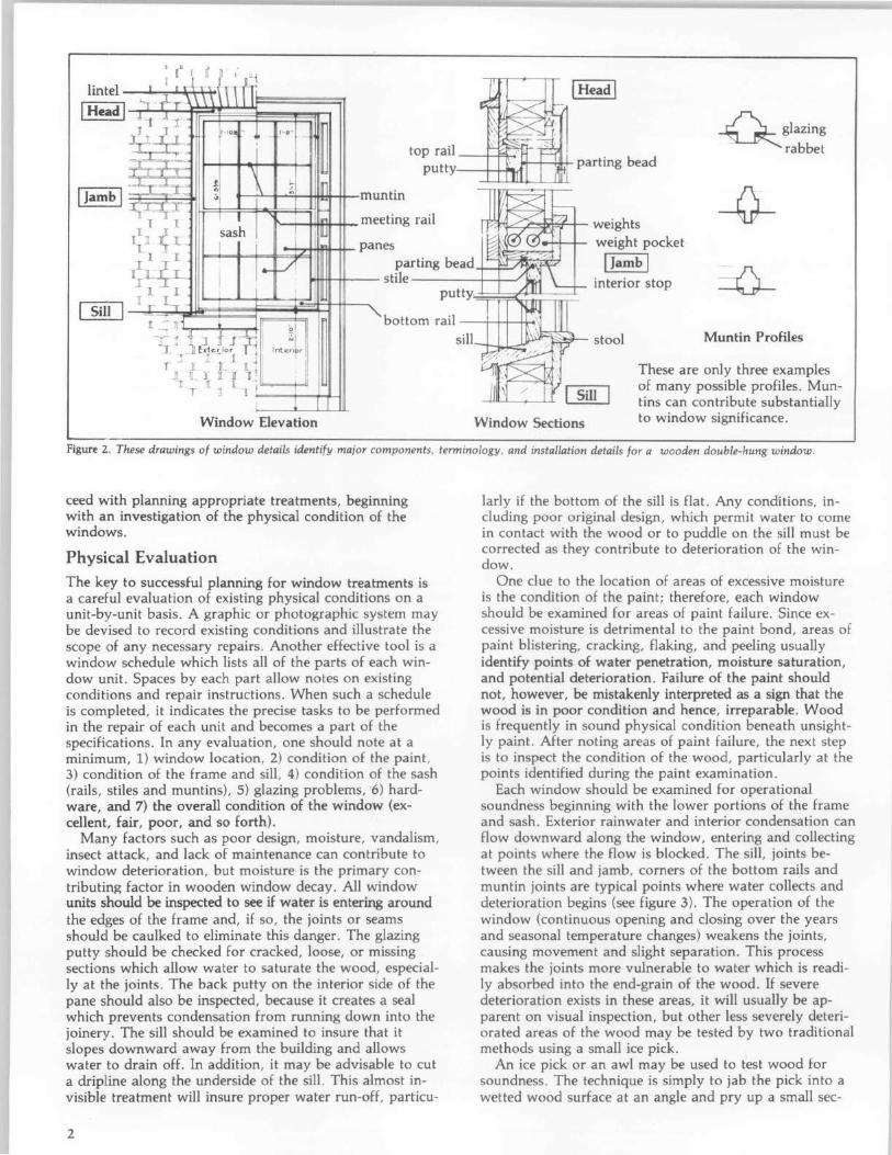
lintel
I Head I
, u a I' n" , I I ' i
'-ll .j-r \ \ \ \ I \ II -J!1. JI r
_J! J I - IOJ . _ r-e " -- . ~ J~, - ~
:::C~-=' top rail --4-f:'1_
putty 1oI-+--:~ parting bead
-QglaZing
rabbet
~ ! ~ Ir ~ .,
':'1 ., mu
rT:'~(Jr l[ - ][ : I me 1 11 1. ~ sash ! It ltl JJ[ JL- I i i pa nes
ntin
eting rail ~~~~+- weights weight pocket
I III I ~ V ][
[ LLJL parting bead I Jamb I
r --::J[ I stile --__ -+--+-J interior stop 1 .1 I I
][ ~ I. - . ,~,; , Pl
~ putty'.;- ~;;:::;<~~~
T bottom rail---+++--+H
.:; :; 1 Ji t .t~J..~ ~[ J' H1~~;orl rj Inten r I -r J~ 1. 11 ~ 1
J[ lL.l II 1 I
l!l[J I I'
Window Elevation
sill--l-.l...l--_ \C_--;:~"------- stool
Window Sections
Muntin Profiles
These are only three examples of many possible profiles. Muntins can contribute substantially to window significance.
Figure 2. These drawings of window details identify major components, terminology, and installation details for a wooden double-hung window.
ceed with planning appropriate treatments, beginning with an investigation of the physical condition of the windows.
Physical Evaluation
The key to successful planning for window treatments is a careful evaluation of existing physical conditions on a unit-by-unit basis. A graphic or photographic system may be devised to record existing conditions and illustrate the scope of any necessary repairs. Another effective tool is a window schedule which lists all of the parts of each window unit. Spaces by each part allow notes on existing conditions and repair instructions. When such a schedule is completed, it indicates the precise tasks to be performed in the repair of each unit and becomes a part of the specifications. In any evaluation, one should note at a minimum, 1) window location, 2) condition of the paint, 3) condition of the frame and sill, 4) condition of the sash (rails, stiles and muntins), 5) glazing problems, 6) hardware, and 7) the overall condition of the window (excellent, fair, poor, and so forth).
Many factors such as poor design, moisture, vandalism, insect attack, and lack of maintenance can contribute to window deterioration, but moisture is the primary contributing factor in wooden window decay. All window units should be inspected to see if water is entering around the edges of the frame and, if so, the joints or seams should be caulked to eliminate this danger. The glazing putty should be checked for cracked, loose, or missing sections which allow water to saturate the wood, especially at the joints. The back putty on the interior side of the pane should also be inspected, because it creates a seal which prevents condensation from running down into the joinery. The sill should be examined to insure that it slopes downward away from the building and Cl-llows water to drain off. In addition, it may be advisable to cut a dripline along the underside of the sill. This almost invisible treatment will insure proper water run-off, particu-
2
larly if the bottom of the sill is flat. Any conditions, including poor original design, which permit water to come in contact with the wood or to puddle on the sill must be corrected as they contribute to deterioration of the window.
One clue to the location of areas of excessive moisture is the condition of the paint; therefore, each window should be examined for areas of paint failure. Since excessive moisture is detrimental to the paint bond, areas of paint blistering, cracking, flaking, and peeling usually identify points of water penetration, moisture saturation, and potential deterioration. Failure of the paint should not, however, be mistakenly interpreted as a sign that the wood is in poor condition and hence, irreparable. Wood is frequently in sound physical condition beneath unsightly paint. After noting areas of paint failure, the next step is to inspect the condition of the wood, particularly at the points identified during the paint examination.
Each window should be examined for operational soundness beginning with the lower portions of the frame and sash. Exterior rainwater and interior condensation can flow downward along the window, entering and collecting at points where the flow is blocked. The sill, joints between the sill and jamb, corners of the bottom rails and muntin joints are typical points where water collects and deterioration begins (see figure 3). The operation of the window (continuous opening and closing over the years and seasonal temperature changes) weakens the joints, causing movement and slight separation. This process makes the joints more vulnerable to water which is readily absorbed into the end-grain of the wood. If severe deterioration exists in these areas, it will usually be apparent on visual inspection, but other less severely deteriorated areas of the wood may be tested by two traditional methods using a small ice pick.
An ice pick or an awl may be used to test wood for soundness. The technique is simply to jab the pick into a wetted wood surface at an angle and pry up a small sec-
Figure 3. Deterioration of poorly maintained windows usually begins on horizontal surfaces and at joints where water can collect and saturate the wood. The problem areas are clearly indicated by paint failure due to moisture. Photo: Baird M. Smith, AlA
tion of the wood. Sound wood will separate in long fibrous splinters, but decayed wood will lift up in short irregular pieces due to the breakdown of fiber strength.
Another method of testing for soundness consists of pushing a sharp object into the wood, perpendicular to the surface. If deterioration has begun from the hidden side of a member and the core is badly decayed, the visible surface may appear to be sound wood. Pressure on the probe can force it through an apparently sound skin to penetrate deeply into decayed wood. This technique is especially useful for checking sills where visual access to the underside is restricted.
Following the inspection and analysis of the results, the scope of the necessary repairs will be evident and a plan for the rehabilitation can be formulated. Generally the actions necessary to return a window to "like new" condition will fall into three broad categories: 1) routine maintenance procedures, 2) structural stabilization, and 3) parts replacement. These categories will be discussed in the following sections and will be referred to respectively as Repair Class I, Repair Class II, and Repair Class III. Each successive repair class represents an increasing level of difficulty, expense, and work time. Note that most of the points mentioned in Repair Class I are routine maintenance items and should be provided in a regular maintenance program for any building. The neglect of these routine items can contribute to many common window problems.
Before undertaking any of the repairs mentioned in the following sections all sources of moisture penetration should be identified and eliminated, and all existing decay fungi destroyed in order to arrest the deterioration process. Many commercially available fungicides and wood preservatives are toxic, so it is extremely important to follow the manufacturer's recommendations for application, and store all chemical materials away from children and animals. After fungicidal and preservative treatment the windows may be stabilized, retained, and restored with every expectation for a long service life.
Repair Class I: Routine Maintenance
Repairs to wooden windows are usually labor intensive and relatively uncomplicated. On small scale projects this
allows the do-it-yourselfer to save money by repairing all or part of the windows. On larger projects it presents the opportunity for time and money which might otherwise be spent on the removal and replacement of existing windows, to be spent on repairs, subsequently saving all or part of the material cost of new window units. Regardless of the actual costs, or who performs the work, the evaluation process described earlier will provide the knowledge from which to specify an appropriate work program, establish the work element priorities, and identify the level of skill needed by the labor force.
The routine maintenance required to upgrade a window to "like new" condition normally includes the following steps: 1) some degree of interior and exterior paint removal, 2) removal and repair of sash (inCluding reglazing where necessary) , 3) repairs to the frame, 4) weatherstripping and reinstallation of the sash, and 5) repainting. These operations are illustrated for a typical double-hung wooden window (see figures 4a-f) , but they may be adapted to other window types and styles as applicable.
Historic windows have usually acquired many layers of paint over time. Removal of excess layers or peeling and flaking paint will facilitate operation of the window and restore the clarity of the original detailing. Some degree of paint removal is also necessary as a first step in the proper surface preparation for subsequent refinishing (if paint color analysis is desired, it should be conducted prior to the onset of the paint removal). There are several safe and effective techniques for removing paint from wood, depending on the amount of paint to be removed . Several techniques such as scraping, chemical stripping, and the use of a hot air gun are discussed in "Preservation Briefs: 10 Paint Removal from Historic Woodwork" (see Additional Reading section at end) .
Paint removal should begin on the interior frames , being careful to remove the paint from the interior stop and the parting bead, particularly along the seam where these stops meet the jamb. This can be accomplished by running a utility knife along the length of the seam, breaking the paint bond. It will then be much easier to remove the stop, the parting bead and the sash. The interior stop may be initially loosened from the sash side to avoid visible scarring of the wood and then gradually pried loose using a pair of putty knives, working up and down the stop in small increments (see figure 4b) . With the stop removed, the lower or interior sash may be withdrawn . The sash cords should be detached from the sides of the sash and their ends may be pinned with a nail or tied in a knot to prevent them from falling into the weight pocket.
Removal of the upper sash on double-hung units is similar but the parting bead which holds it in place is set into a groove in the center of the stile and is thinner and more delicate than the interior stop. After removing any paint along the seam, the parting bead should be carefully pried out and worked free in the same manner as the interior stop. The upper sash can be removed in the same manner as the lower one and both sash taken to a convenient work area (in order to remove the sash the interior stop and parting bead need only be removed from one side of the window). Window openings can be covered with polyethylene sheets or plywood sheathing while the sash are out for repair.
The sash can be stripped of paint using appropriate techniques, but if any heat treatment is used (see figure 4c), the glass should be removed or protected from the sudden temperature change which can cause breakage . An
3

Figure 4a. The following series of photographs of the repair of a historic double-hung window use a unit which is structurally sound but has many layers of paint, some cracked and missing putty, slight separation at the joints, broken sash cords, and one cracked pane. Photo: John H. Myers
Figure 4d. Reglazing or replacement of the putty requires that the existing putty be removed manually, the glazing points be extracted, the glass removed, and the back putty scraped out. To reglaze, a bed of putty is laid around the perimeter of the rabbet, the pane is pressed into place, glazing points are inserted to hold the pane (shown), and a final seal of putty is beveled around the edge of the glass. Photo: John H. Myers
4
Figure 4b. After removing paint from the seam between the interior stop and the jamb, the stop can be pried out and gradually worked loose using a pair of putty knives as shown. To avoid visible scarring of the wood, the sash can be raised and the stop pried loose initially from the outer side. Photo: John H. Myers
Figure 4e. A common repair is the replacement of broken sash cords with new cords (shown) or with chains. The weight pocket is often accessible through a removable plate in the jamb, or by removing the interior trim. Photo: John H. Myers
Figure 4c. Sash can be removed and repaired in a convenient work area. Paint is being removed from this sash with a hot air gun while an asbestos sheet protects the glass from sudden temperature change. Photo: John H. Myers
( ( 1 Figure 4£. Following the relatively simple repairs, the window is weathertight, like new in appearance, and serviceable for many years to come. Both the historic material and the detailing and craftsmanship of this original window have been preserved. Photo: John H. Myers
overlay of aluminum foil on gypsum board or asbestos can protect the glass from such rapid temperature change. It is important to protect the glass because it may be historic and often adds character to the window. Deteriorated putty should be removed manually, taking care not to damage the wood along the rabbet . If the glass is to be removed, the glazing points which hold the glass in place can be extracted and the panes numbered and removed for cleaning and reuse in the same openings. With the glass panes out, the remaining putty can be removed and the sash can be sanded, patched, and primed with a preservative primer. Hardened putty in the rabbets may be softened by heating with a soldering iron at the point of removal. Putty remaining on the glass may be softened by soaking the panes in linseed oil, and then removed with less risk of breaking the glass. Before reinstalling the glass, a bead of glazing compound or linseed oil putty should be laid around the rabbet to cushion and seal the glass. Glazing compound should only be used on wood which has been brushed with linseed oil and primed with an oil based primer or paint. The pane is then pressed into place and the glazing points are pushed into the wood around the perimeter of the pane (see figure 4d) . The final glazing compound or putty is applied and beveled to complete the seal. The sash can be refinished as desired on the inside and painted on the outside as soon as a "skin" has formed on the putty, usually in 2 or 3 days. Exterior paint should cover the beveled glazing compound or putty and lap over onto the glass slightly to complete a weathertight seal. After the proper curing times have elapsed for paint and putty, the sash will be ready for reinstallation.
While the sash are out of the frame, the condition of the wood in the jamb and sill can be evaluated. Repair and refinishing of the frame may proceed concurrently with repairs to the sash, taking advantage of the curing times for the paints and putty used on the sash. One of the most common work items is the replacement of the sash cords with new rope cords or with chains (see figure 4e). The weight pocket is frequently accessible through a door on the face of the frame near the sill , but if no door exists, the trim on the interior face may be removed for access . Sash weights may be increased for easier window operation by elderly or handicapped persons . Additional repairs to the frame and sash may include consolidation or replacement of deteriorated wood. Techniques for these repairs are discussed in the following sections.
The operations just discussed summarize the efforts necessary to restore a window with minor deterioration to "like new" condition (see figure 4f) . The techniques can be applied by an unskilled person with minimal training and experience. To demonstrate the practicality of this approach, and photograph it, a Technical Preservation Services staff member repaired a wooden double-hung, two over two window which had been in service over ninety years. The wood was structurally sound but the window had one broken pane, many layers of paint , broken sash cords and inadequate, worn-out weatherstripping. The staff member found that the frame could be stripped of paint and the sash removed quite easily . Paint , putty and glass removal required about one hour for each sash, and the reglazing of both sash was accomplished in about one hour. Weatherstripping of the sash and frame , replacement of the sash cords and reinstallation of the sash, parting bead, and stop required an hour and a half. These times refer only to individual operations; the entire proc-
ess took several days due to the drying and curing times for putty, primer, and paint, however, work on other window units could have been in progress during these lag times.
Repair Class II: Stabilization The preceding description of a window repair job focused on a unit which was operationally sound. Many windows will show some additional degree of physical deterioration, especially in the vulnerable areas mentioned earlier, but even badly damaged windows can be repaired using simple processes. Partially decayed wood can be waterproofed, patched, built-up, or consolidated and then painted to achieve a sound condition, good appearance, and greatly extended life. Three techniques for repairing partially decayed or weathered wood are discussed in this section, and all three can be accomplished using products available at most hardware stores.
One established technique for repairing wood which is split, checked or shows signs of rot, is to: 1) dry the wood, 2) treat decayed areas with a fungicide, 3) waterproof with two or three applications of boiled linseed oil (applications every 24 hours), 4) fill cracks and holes with putty, and 5) after a "skin" forms on the putty, paint the surface. Care should be taken with the use of fungicide which is toxic. Follow the manufacturers' directions and use only on areas which will be painted. When using any technique of building up or patching a flat surface, the finished surface should be sloped slightly to carry water away from the window and not allow it to puddle. Caulking of the joints between the sill and the jamb will help reduce further water penetration.
When sills or other members exhibit surface weathering they may also be built-up using wood putties or homemade mixtures such as sawdust and resorcinol glue, or whiting and varnish. These mixtures can be built up in successive layers, then sanded, primed, and painted. The same caution about proper slope for flat surfaces applies to this technique.
Wood may also be strengthened and stabilized by consolidation, using semi-rigid epoxies which saturate the porous decayed wood and then harden. The surface of the consolidated wood can then be filled with a semi-rigid epoxy patching compound, sanded and painted (see figure 5). Epoxy patching compounds can be used to build up
Figure 5. This illustrates a two-part epoxy patching compound used to fill the surface of a weathered sill and rebuild the missing edge. When the epoxy cures, it can be sanded smooth and painted to achieve a durable and waterproof repair. Photo: John H. Myers
5
missing sections or decayed ends of members. Profiles can be duplicated using hand molds, which are created by pressing a ball of patching compound over a sound section of the profile which has been rubbed with butcher's wax. This can be a very efficient technique where there are many typical repairs to be done. Technical Preservation Services has published Epoxies for Wood Repairs in Historic Buildings (see Additional Reading section at end), which discusses the theory and techniques of epoxy repairs. The process has been widely used and proven in marine applications; and proprietary products are available at hardware and marine supply stores. Although epoxy materials may be comparatively expensive, they hold the promise of being among the most durable and long lasting materials available for wood repair.
Any of the three techniques discussed can stabilize and restore the appearance of the window unit. There are times, however, when the degree of deterioration is so advanced that stabilization is impractical, and the only way to retain some of the original fabric is to replace damaged parts.
Repair Class III: Splices and Parts Replacement When parts of the frame or sash are so badly deteriorated that they cannot be stabilized there are methods which permit the retention of some of the existing or original fabric. These methods involve replacing the deteriorated parts with new matching pieces, or splicing new wood into existing members. The techniques require more skill and are more expensive than any of the previously discussed alternatives. It is necessary to remove the sash and / or the affected parts of the frame and have a carpenter or woodworking mill reproduce the damaged or missing parts. Most millwork firms can duplicate parts, such as muntins, bottom rails, or sills , which can then be incorporated into the existing window, but it may be necessary to shop around because there are several factors controlling the practicality of this approach. Some woodworking mills do not like to repair old sash because nails or other foreign objects in the sash can damage expensive knives (which cost far more than their profits on small repair jobs); others do not have cutting knives to duplicate muntin profiles. Some firms prefer to concentrate on larger jobs with more profit potential, and some may not have a craftsman who can duplicate the parts. A little searching should locate a firm which will do the job, and at a reasonable price. If such a firm does not exist locally, there are firms which undertake this kind of repair and ship nationwide. It is possible, however, for the advanced do-it-yourselfer or craftsman with a table saw to duplicate moulding profiles using techniques discussed by Gordie Whittington in "Simplified Methods for Reproducing Wood Mouldings," Bulletin of the Association for Preservation Technology, Vol. III, No . 4, 1971, or illustrated more recently in The Old House, Time-Life Books, Alexandria, Virginia, 1979.
The repairs discussed in this section involve window frames which may be in very deteriorated condition, possibly requiring removal; therefore, caution is in order. The actual construction of wooden window frames and sash is not complicated. Pegged mortise and tenon units can be disassembled easily, if the units are out of the building. The installation or connection of some frames to the surrounding structure, especially masonry walls, can complicate the work immeasurably, and may even require
6
dismantling of the wall. It may be useful , therefore, to take the following approach to frame repair: 1) conduct regular maintenance of sound frames to achieve the longest life possible, 2) make necessary repairs in place wherever possible, using stabilization and splicing techniques, and 3) if removal is necessary, thoroughly investigate the structural detailing and seek appropriate professional consultation.
Another alternative may be considered if parts replacement is required, and that is sash replacement. If extensive replacement of parts is necessary and the job becomes prohibitively expensive it may be more practical to purchase new sash which can be installed into the existing frames . Such sash are available as exact custom reproductions, reasonable facsimiles (custom windows with similar profiles), and contemporary wooden sash which are similar in appearance . There are companies which still manufacture high quality wooden sash which would duplicate most historic sash. A few calls to local build-ing suppliers may provide a source of appropriate replacement sash, but if not, check with local historical associations, the state historic preservation office, or preservation related magazines and supply catalogs for information.
If a rehabilitation project has a large number of windows such as a commercial building or an industrial complex, there may be less of a problem arriving at a solution . Once the evaluation of the windows is completed and the scope of the work is known, there may be a potential economy of scale. Woodworking mills may be interested in the work from a large project; new sash in volume may be considerably less expensive per unit ; crews can be assembled and trained on site to perform all of the window repairs; and a few extensive repairs can be absorbed (without undue burden) into the total budget for a large number of sound windows. While it may be expensive for the average historic home owner to pay seventy dollars or more for a mill to grind a custom knife to duplicate four or five bad muntins, that cost becomes negligible on large commercial projects which may have several hundred windows.
Most windows should not require the extensive repairs discussed in this section . The ones which do are usually in buildings which have been abandoned for long periods or have totally lacked maintenance for years. It is necessary to thoroughly investigate the alternatives for windows which do require extensive repairs to arrive at a solution which retains historic significance and is also economically feasible . Even for projects requiring repairs identified in this section, if the percentage of parts replacement per window is low, or the number of windows requiring repair is small, repair can still be a cost effective solution.
Weatherization A window which is repaired should be made as energy efficient as possible by the use of appropriate weatherstripping to reduce air infiltration. A wide variety of products are available to assist in this task . Felt may be fastened to the top, bottom, and meeting rails, but may have the disadvantage of absorbing and holding moisture, particularly at the bottom rail. Rolled vinyl strips may also be tacked into place in appropriate locations to reduce infiltration. Metal strips or new plastic spring strips may be used on the rails and, if space permits, in
the channels between the sash and jamb. Weatherstripping is a historic treatment, but old weatherstripping (felt) is not likely to perform very satisfactorily. Appropriate contemporary weatherstripping should be considered an integral part of the repair process for windows. The use of sash locks installed on the meeting rail will insure that the sash are kept tightly closed so that the weatherstripping will function more effectively to reduce infiltration. Although such locks will not always be historically accurate, they will usually be viewed as an acceptable contemporary modification in the interest of improved thermal performance.
Many styles of storm windows are available to improve the thermal performance of existing windows. The use of exterior storm windows should be investigated whenever feasible because they are thermally efficient, cost-effective, reversible, and allow the retention of original windows (see "Preservation Briefs: 3") . Storm window frames may be made of wood, aluminum, vinyl, or plastic; however, the use of unfinished aluminum storms should be avoided. The visual impact of storms may be minimized by selecting colors which match existing trim color. Arched top storms are available for windows with special shapes. Although interior storm windows appear to offer an attractive option for achieving double glazing with minimal visual impact, the potential for damaging condensation problems must be addressed. Moisture which becomes trapped between the layers of glazing can condense on the colder, outer prime window, potentially leading to deterioration. The correct approach to using interior storms is to create a seal on the interior storm while allowing some ventilation around the prime window. In actual practice, the creation of such a durable, airtight seal is difficult.
Window Replacement Although the retention of original or existing windows is always desirable and this Brief is intended to encourage that goal, there is a point when the condition of a window may clearly indicate replacement. The decision process for selecting replacement windows should not begin with a survey of contemporary window products which are available as replacements, but should begin with a look at the windows which are being replaced. Attempt to understand the contribution of the window(s) to the appearance of the facade including: 1) the pattern of the openings and their size; 2) proportions of the frame and sash; 3) configuration of window panes; 4) muntin profiles; 5) type of wood; 6) paint color; 7) characteristics of the glass; and 8) associated details such as arched tops, hoods, or other decorative elements. Develop an understanding of how the window reflects the period, style, or regional characteristics of the building, or represents technological development.
Armed with an awareness of the significance of the existing window, begin to search for a replacement which retains as much of the character of the historic window as possible. There are many sources of suitable new windows. Continue looking until an acceptable replacement can be found. Check building supply firms, local woodworking mills, carpenters, preservation oriented magazines, or catalogs or sUl'pliers of old building materials, for product information. Local historical associations and state historic preservation offices may be good sources of
information on products which have been used successfully in preservation projects.
Consider energy efficiency as one of the factors for replacements, but do not let it dominate the issue. Energy conservation is no excuse for the wholesale destruction of historic windows which can be made thermally efficient by historically and aesthetically acceptable means. In fact , a historic wooden window with a high quality storm window added should thermally outperform a new doubleglazed metal window which does not have thermal breaks (insulation between the inner and outer frames intended to break the path of heat flow) . This occurs because the wood has far better insulating value than the metal, and in addition many historic windows have high ratios of wood to glass, thus reducing the area of highest heat transfer. One measure of heat transfer is the U-value, the number of Btu's per hour transferred through a square foot of material. When comparing thermal performance, the lower the U-value the better the performance. According to ASHRAf 1977 Fundamentals, the U-values for single glazed wooden windows range from 0.88 to 0.99. The addition of a storm window should reduce these figures to a range of 0.44 to 0.49. A non-thermal break, double-glazed metal window has a U-value of about 0.6.
Conclusion Technical Preservation Services recommends the retention and repair of original windows whenever possible. We believe that the repair and weatherization of existing wooden windows is more practical than most people realize, and that many windows are unfortunately replaced because of a lack of awareness of techniques for evaluation, repair, and weatherization. Wooden windows which are repaired and properly maintained will have greatly extended service lives while contributing to the historic character of the building. Thus, an important element of a building's significance will have been preserved for the future.
Additional Reading ASHRAE Handbook-1977 Fundamentals. New York: American Society
of Heating, Refrigerating and Air-conditioning Engineers, 1978 (chapter 26).
Ferro, Maximillian. Preservation: Present Pathway to Fall River's Future. Fall River, Massachusetts: City of Fall River, 1979 (chapter 7).
"Fixing Double-Hung Windows." Old House Journal (no. 12, 1979): 135.
Look, David W. "Preservation Briefs: 10 Paint Removal from Historic Woodwork." Washington, DC: Technical Preservation Services, U.S. Department of the Interior, forthcoming.
Morrison, Hugh. Early American Architecture. New York: Oxford University Press, 1952.
Phillips, Morgan, and Selwyn, Judith, Epoxies for Wood Repairs in Historic Buildings. Washington, DC: Technical Preservation Services, U.S. Department of the Interior (Government Printing Office, Stock No. 024-016-00095-1), 1978.
Rehab Right. Oakland, California: City of Oakland Planning Department, 1978 (pp. 78-83).
"Sealing Leaky Windows." Old House Journal (no. 1, 1973): 5.
Smith, Baird M, "Preservation Briefs: 3 Conserving Energy in Historic Buildings," Washington, DC: Technical Preservation Services, U.S. Department of the Interior, 1978.
1981
7
PRESERVATION BRIEFS
New Exterior Additions to Historic Buildings: Preservation Concerns
Anne E. Grimmer and Kay D. Weeks
National Park Service U.S. Department of the Interior
Technical Preservation Services
A new exterior addition to a historic building should be considered in a rehabilitation project only after determining that requirements for the new or adaptive use cannot be successfully met by altering nonsignificant interior spaces. If the new use cannot be accommodated in this way, then an exterior addition may be an acceptable alternative. Rehabilitation as a treatment "is defined as the act or process of making possible a compatible use for a property through repair, alterations, and additions while preserving those portions or features which convey its historical, cultural, or architectural values."
The topic of new additions, including rooftop additions, to historic buildings comes up frequently, especially as it
relates to rehabilitation projects. It is often discussed and it is the subject of concern, consternation, considerable disagreement and confusion. Can, in certain instances, a historic building be enlarged for a new use without destroying its historic character? And, just what is significant about each particular historic building that should be preserved? Finally, what kind of new construction is appropriate to the historic building?
The vast amount of literature on the subject of additions to historic buildings reflects widespread interest as well as divergence of opinion. New additions have been discussed by historians within a social and political framework; by architects and architectural historians in terms of construction technology and style; and
by urban planners as successful or unsuccessful contextual design. However, within the historic preservation and rehabilitation programs of the National Park Service, the focus on new additions is to ensure that they preserve the character of historic buildings.
Most historic districts or neighborhoods are listed in the National Register of Historic Places for their significance within a particular time frame. This period of significance of historic districts as well
Figure 1. The addition to the right with its connecting hyphen is compatible with the Collegiate Gothic-style library. The addition is set back from the front of the library and uses the same materials and a simplified design that references, but does not copy, the historic building. Photo: David Wakely Photography.
as individually-listed properties may sometimes lead to a misunderstanding that inclusion in the National Register may prohibit any physical change outside of a certain historical period - particularly in the form of exterior additions. National Register listing does not mean that a building or district is frozen in time and that no change can be made without compromising the historical significance. It does mean, however, that a new addition to a historic building should preserve its historic character.
1
2
Figure 2. The new section on the right is appropriately scaled and reflects the design of the historic Art Deco-style hotel. The apparent separation created by the recessed connector also enables the addition to be viewed as an individual building.
Guidance on New Additions
To meet Standard 1 of the Secretary of the Interior's Standards for Rehabilitation, which states that "a property shall be used for its historic purpose or be placed in a new use that requires minimal change to the defining characteristics of the building and its site and environment," it must be determined whether a historic building can accommodate a new addition. Before expanding the building's footprint, consideration should first be given to incorporating changes-such as code upgrades or spatial needs for a new use-within secondary areas of the historic building. However, this is not always possible and, after such an evaluation, the conclusion may be that an addition is required, particularly if it is needed to avoid modifications to character-defining interior spaces. An addition should be designed to be compatible with the historic character of the building and, thus, meet the Standards for Rehabilitation. Standards 9 and 10 apply specifically to new additions:
(9) "New additions, exterior alterations, or related new construction shall not destroy historic materials that characterize the property. The new work shall be differentiated from the old and shall be compatible with the massing, size, scale, and architectural features to protect the historic integrity of the property and its environment."
(10) "New additions and adjacent or related new construction shall be undertaken in such a manner that if removed in the future, the essential form and integrity of the historic property and its environment would be unimpaired."
The subject of new additions is important because a new addition to a historic building has the potential to change its historic character as well as to damage and destroy significant historic materials and features. A new addition also has the potential to confuse the public and to make it difficult or impossible to differentiate the old from the new or to recognize what part of the historic building is genuinely historic.
The intent of this Preservation Brief is to provide guidance to owners, architects and developers on how to design a compatible new addition, including a rooftop addition, to a historic building. A new addition to a historic building should preserve the building's historic character. To accomplish this and meet the Secretary of the Interior's Standards for Rehabilitation, a new addition should:
• Preserve significant historic materials, features and form;
• Be compatible; and
• Be differentiated from the historic building.
Every historic building is different and each rehabilitation project is unique. Therefore, the guidance offered here is not specific, but general, so that it can be applied to a wide variety of building types and situations. To assist in interpreting this guidance, illustrations of a variety of new additions are provided. Good examples, as well as some that do not meet the Standards, are included to further help explain and clarify what is a compatible new addition that preserves the character of the historic building.
Figure 3. The red and buff-colored parking addition with a rooftop playground is compatible with the early-20th century school as well as with the neighborhood in which it also serves as infill in the urban setting.
Preserve Significant Historic Materials, Features and Form
Attaching a new exterior addition usually involves some degree of material loss to an external wall of a historic building, but it should be minimized. Damaging or destroying significant materials and craftsmanship should be avoided, as much as possible.
Generally speaking, preservation of historic buildings inherently implies minimal change to primary or "public" elevations and, of course, interior features as well. Exterior features that distinguish one historic building or a row of buildings and which can be seen from a public right of way, such as a street or sidewalk, are most likely to be the most significant. These can include many different elements, such as: window patterns, window hoods or shutters; porticoes, entrances and doorways; roof shapes, cornices and decorative moldings; or commercial storefronts with their special detailing, signs and glazing patterns. Beyond a single building, entire blocks of urban or residential structures are often closely related architecturally by their materials, detailing, form and alignment. Because significant materials and features should be preserved, not damaged or hidden, the first place to consider placing a new addition is in a location where the least amount of historic material and character-defining features will be lost. In most cases, this will be on a secondary side or rear elevation.
One way to reduce overall material loss when constructing a new addition is simply to keep the addition smaller
Figure 4. This glass and brick structure is a harmonious addition set back and connected to the rear of the Colonial Revival-style brick house. Cunningham/Quill Architects. Photos: © Maxwell MacKenzie.
in proportion to the size of the historic building. Limiting the size and number of openings between old and new by utilizing existing doors or enlarging windows also helps to minimize loss. An often successful way to accomplish this is to link the addition to the historic building by means of a hyphen or connector. A connector provides a physical link while visually separating the old and new, and the connecting passageway penetrates and removes only a small portion of the historic wall. A new addition that will abut the historic building along an entire elevation or wrap around a side and rear elevation, will likely integrate the historic and the new interiors, and thus result in a high degree of loss of form and exterior walls, as well as significant alteration of interior spaces and features, and will not meet the Standards.
Compatible but Differentiated Design
In accordance with the Standards, a new addition must preserve the building's historic character and, in order to do that, it must be differentiated, but compatible, with the historic building. A new addition must retain the essential form and integrity of the historic property. Keeping the addition smaller, limiting the removal of historic materials by linking the addition with a hyphen, and locating the new addition at the rear or on an inconspicuous side elevation of a historic building are techniques discussed previously that can help to accomplish this.
Rather than differentiating between old and new, it might seem more in keeping with the historic character
3
4
simply to repeat the historic form, material, features and detailing in a new addition. However, when the new work is highly replicative and indistinguishable from the old in appearance, it may no longer be possible to identify the "real" historic building. Conversely, the treatment of the addition should not be so different that it becomes the primary focus. The difference may be subtle, but it must be clear. A new addition to a historic building should protect those visual qualities that make the building eligible for listing in the National Register of Historic Places.
The National Park Service policy concerning new additions to historic buildings, which was adopted in 1967, is not unique. It is an outgrowth and continuation of a general philosophical approach to change first expressed by John Ruskin in England in the 1850s, formalized by William Morris in the founding of the Society for the Protection of Ancient Buildings in 1877, expanded by the Society in 1924 and, finally, reiterated in the 1964 Venice Charter-a document that continues to be followed by the national committees of the International Council on Monuments and Sites (lCOMOS). The 1967 Administrative Policies for Historical Areas of the National Park System direct that " .. . a modern addition should be readily distinguishable from the older work; however, the new work should be harmonious with the old in scale, proportion, materials, and color. Such additions should be as inconspicuous as
Figure 5. This addition (a) is constructed of matching brick and attached by a recessed connector (b) to the 1914 apartment building (c) . The design is compatible and the addition is smaller and subordinate to the historic building (d) .
possible from the public view." As a logical evolution from these Policies specifically for National Park Service-owned historic structures, the 1977 Secretary of the Interior's Standards for Rehabilitation, which may be applied to all historic buildings listed in, or eligible for listing in the National Register, also state that "the new work shall be differentiated from the old and shall be compatible with the massing, size, scale, and architectural features to protect the historic integrity of the property and its environment."
Preserve Historic Character
The goal, of course, is a new addition that preserves the building's historic character. The historic character of each building may be different, but the methodology of establishing it remains the same. Knowing the uses and functions a building has served over time will assist in making what is essentially a physical evaluation. But, while written and pictorial documentation can provide a framework for establishing the building's history, to a large extent the historic character is embodied in the physical aspects of the historic building itselfshape, materials, features, craftsmanship, window arrangements, colors, setting and interiors. Thus, it is important to identify the historic character before making decisions about the extent-or limitations-of change that can be made.
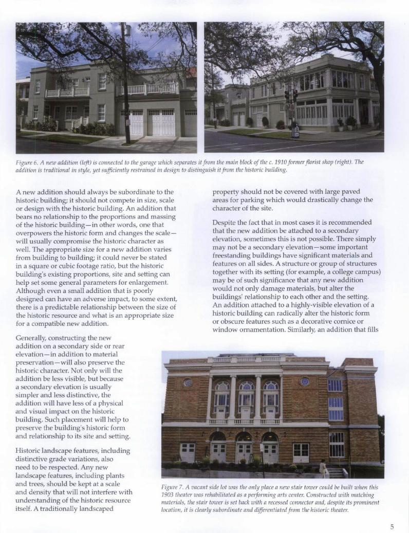
Figure 6. A new addition (left) is connected to the garage which separates it from the main block of the c. 1910 former florist shop (right). The addition is traditional in style, yet sufficiently restrained in design to distinguish it from the historic building.
A new addition should always be subordinate to the historic building; it should not compete in size, scale or design with the historic building. An addition that bears no relationship to the proportions and massing of the historic building-in other words, one that overpowers the historic form and changes the scalewill usually compromise the historic character as well. The appropriate size for a new addition varies from building to building; it could never be stated in a square or cubic footage ratio, but the historic building's existing proportions, site and setting can help set some general parameters for enlargement. Although even a small addition that is poorly designed can have an adverse impact, to some extent, there is a predictable relationship between the size of the historic resource and what is an appropriate size for a compatible new addition.
Generally, constructing the new addition on a secondary side or rear elevation-in addition to material preservation-will also preserve the historic character. Not only will the addition be less visible, but because a secondary elevation is usually simpler and less distinctive, the addition will have less of a physical and visual impact on the historic building. Such placement will help to preserve the building's historic form and relationship to its site and setting.
Historic landscape features, including distinctive grade variations, also
property should not be covered with large paved areas for parking which would drastically change the character of the site.
Despite the fact that in most cases it is recommended that the new addition be attached to a secondary elevation, sometimes this is not possible. There simply may not be a secondary elevation-some important freestanding buildings have significant materials and features on all sides. A structure or group of structures together with its setting (for example, a college campus) may be of such significance that any new addition would not only damage materials, but alter the buildings' relationship to each other and the setting. An addition attached to a highly-visible elevation of a historic building can radically alter the historic form or obscure features such as a decorative cornice or window ornamentation. Similarly, an addition that fills
need to be respected. Any new landscape features, including plants and trees, should be kept at a scale and density that will not interfere with understanding of the historic resource itself. A traditionally landscaped
Figure 7. A vacant side lot was the only place a new stair tower could be built when this 1903 theater was rehabilitated as a performing arts center. Constructed with matching materials, the stair tower is set back with a recessed connector and, despite its prominent location, it is clearly subordinate and differentiated from the historic theater.
5
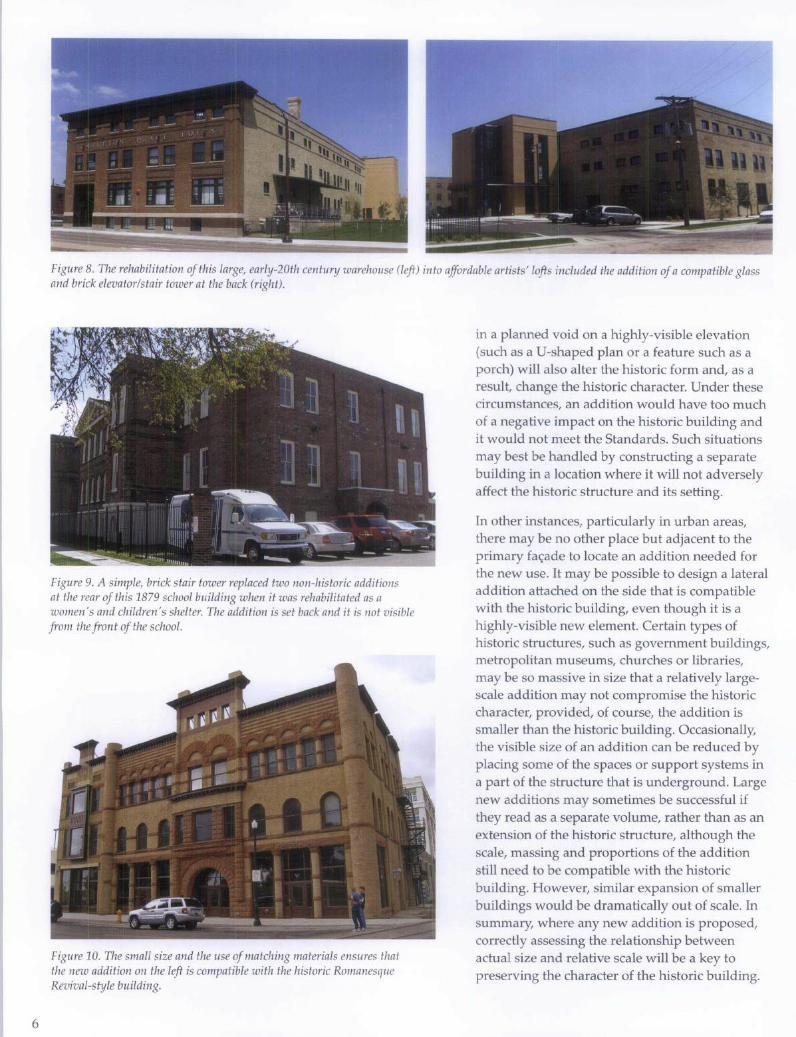
6
Figure 8. The rehabilitation of this large, early-20th century warehouse (left) into affordable artists' lofts included the addition of a compatible glass and brick elevator/stair tower at the back (right).
Figure 9. A simple, brick stair tower replaced two non-historic additions at the rear of this 1879 school building when it was rehabilitated as a women's and children's shelter. The addition is set back and it is not visibLe from the front of the school.
Figure 10. The small size and the use of matching materials ensures that the new addition on the left is compatible with the historic Romanesque Revival-style building.
in a planned void on a highly-visible elevation (such as a U-shaped plan or a feature such as a porch) will also alter the historic form and, as a result, change the historic character. Under these circumstances, an addition would have too much of a negative impact on the historic building and it would not meet the Standards. Such situations may best be handled by constructing a separate building in a location where it will not adversely affect the historic structure and its setting.
In other instances, particularly in urban areas, there may be no other place but adjacent to the primary fa<;:ade to locate an addition needed for the new use. It may be possible to design a lateral addition attached on the side that is compatible with the historic building, even though it is a highly-visible new element. Certain types of historic structures, such as government buildings, metropolitan museums, churches or libraries, may be so massive in size that a relatively largescale addition may not compromise the historic character, provided, of course, the addition is smaller than the historic building. Occasionally, the visible size of an addition can be reduced by placing some of the spaces or support systems in a part of the structure that is underground. Large new additions may sometimes be successful if they read as a separate volume, rather than as an extension of the historic structure, although the scale, massing and proportions of the addition still need to be compatible with the historic building. However, similar expansion of smaller buildings would be dramatically out of scale. In summary, where any new addition is proposed, correctly assessing the relationship between actual size and relative scale will be a key to preserving the character of the historic building.
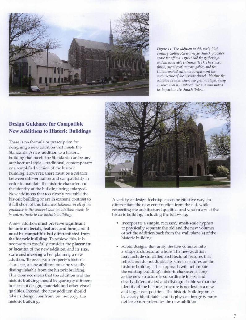
Design Guidance for Compatible New Additions to Historic Buildings
There is no formula or prescription for designing a new addition that meets the Standards. A new addition to a historic building that meets the Standards can be any architectural style-traditional, contemporary or a simplified version of the historic building. However, there must be a balance between differentiation and compatibility in order to maintain the historic character and the identity of the building being enlarged. New additions that too closely resemble the historic building or are in extreme contrast to it fall short of this balance. Inherent in all of the guidance is the concept that an addition needs to be subordinate to the historic building.
A new addition must preserve significant historic materials, features and form, and it must be compatible but differentiated from the historic building. To achieve this, it is necessary to carefully consider the placement or location of the new addition, and its size, scale and massing when planning a new addition. To preserve a property's historic character, a new addition must be visually distinguishable from the historic building. This does not mean that the addition and the historic building should be glaringly different in terms of design, materials and other visual qualities. Instead, the new addition should take its design cues from, but not copy, the historic building.
Figure 11. The addition to this early-20th century Gothic Revival-style church provides space for offices, a great hall for gatherings and an accessible entrance (left). The stucco finish, metal roof, narrow gables and the Gothic-arched entrance complement the architecture of the historic church. Placing the addition in back where the ground slopes away ensures that it is subordinate and minimizes its impact on the church (below).
A variety of design techniques can be effective ways to differentiate the new construction from the old, while respecting the architectural qualities and vocabulary of the historic building, including the following:
• Incorporate a simple, recessed, small-scale hyphen to physically separate the old and the new volumes or set the addition back from the wall plane(s) of the historic building.
• Avoid designs that unify the two volumes into a single architectural whole. The new addition may include simplified architectural features that reflect, but do not duplicate, similar features on the historic building. This approach will not impair the existing building'S historic character as long as the new structure is subordinate in size and clearly differentiated and distinguishable so that the identity of the historic structure is not lost in a new and larger composition. The historic building must be clearly identifiable and its physical integrity must not be compromised by the new addition.
7
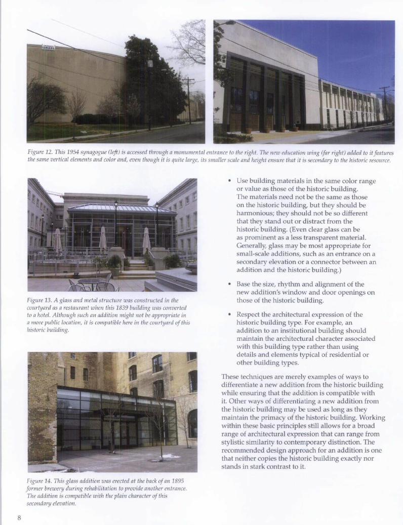
8
Figure 12. This 1954 synagogue (left) is accessed through a monumental entrance to the right. The new education wing (far right) added to it features the same vertical elements and color and, even though it is quite large, its smaller scale and height ensure that it is secondary to the historic resource.
Figure 13. A glass and metal structure was constructed in the courtyard as a restaurant when this 1839 building was converted to a hotel. Although such an addition might not be appropriate in a more public location, it is compatible here in the courtyard of this historic building.
Figure 14. This glass addition was erected at the back of an 1895 former brewery during rehabilitation to provide another entrance. The addition is compatible with the plain character of this secondary elevation.
• Use building materials in the same color range or value as those of the historic building. The materials need not be the same as those on the historic building, but they should be harmonious; they should not be so different that they stand out or distract from the historic building. (Even clear glass can be as prominent as a less transparent material. Generally, glass may be most appropriate for small-scale additions, such as an entrance on a secondary elevation or a connector between an addition and the historic building.)
• Base the size, rhythm and alignment of the new addition's window and door openings on those of the historic building.
• Respect the architectural expression of the historic building type. For example, an addition to an institutional building should maintain the architectural character associated with this building type rather than using details and elements typical of residential or other building types.
These techniques are merely examples of ways to differentiate a new addition from the historic building while ensuring that the addition is compatible with it. Other ways of differentiating a new addition from the historic building may be used as long as they maintain the primacy of the historic building. Working within these basic principles still allows for a broad range of architectural expression that can range from stylistic similarity to contemporary distinction. The recommended design approach for an addition is one that neither copies the historic building exactly nor stands in stark contrast to it.
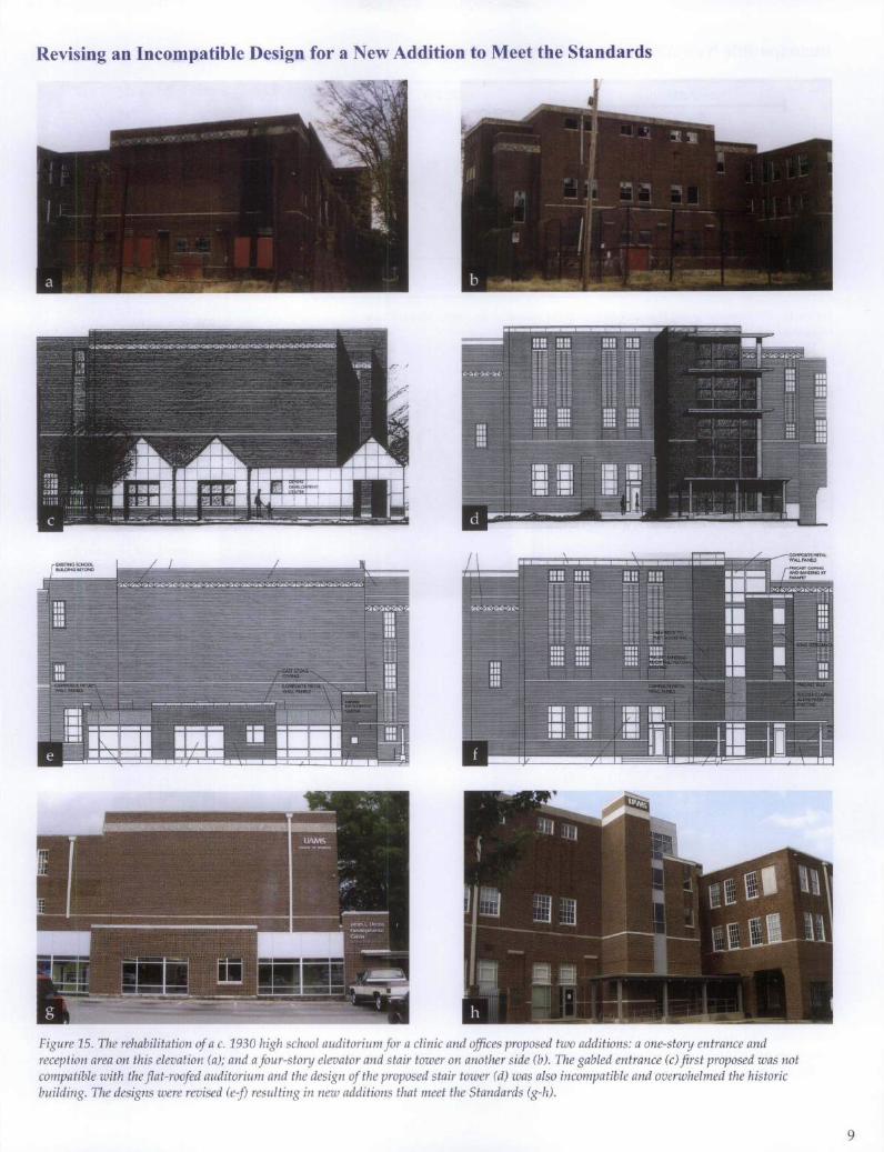
Revising an Incompatible Design for aNew Addition to Meet the Standards
Figure 15. The rehabilitation of a c. 1930 high school auditorium for a clinic and offices proposed two additions: a one-story entrance and reception area on this elevation (a); and a four-story elevator and stair tower on another side (b). The gabled entrance (c) first proposed was not compatible with the flat-roofed auditorium and the design of the proposed stair tower (d) was also incompatible and overwhelmed the historic building. The designs were revised (e-fJ resulting in new additions that meet the Standards (g-h).
9
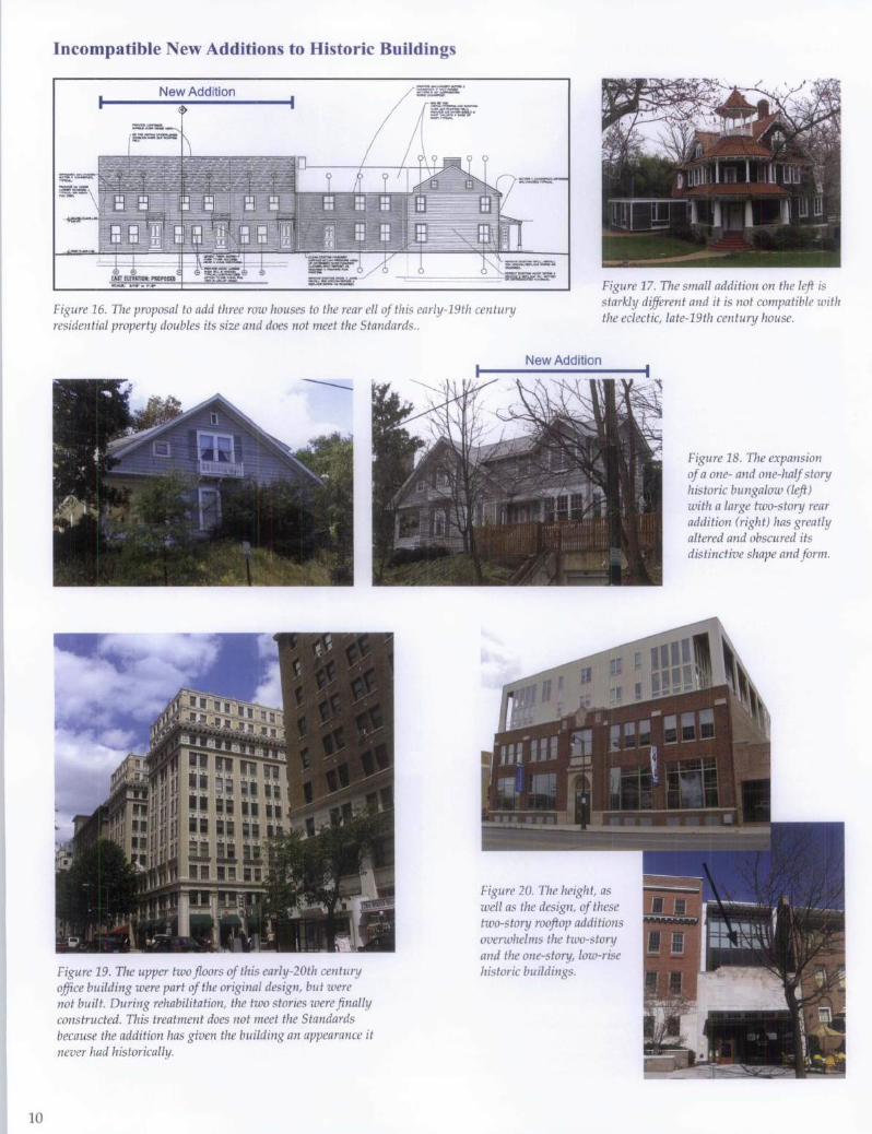
10
Incompatible New Additions to Historic Buildings
New Addition
Figure 16. The proposal to add three row houses to the rear ell of this early-19th century residential property doubles its size and does not meet the Standards ..
Figure 17. The small addition on the left is starkly different and it is not compatible with the eclectic, late-19th century house.
----
Figure 19. The upper two floors of this early-20th century office building were part of the original design, but were not built. During rehabilitation, the two stories were finally constructed. This treatment does not meet the Standards because the addition has given the building an appearance it never had historically.
New Addition
Figure 20. The height, as well as the design, of these two-story rooftop additions overwhelms the two-story and the one-story, low-rise historic buildings.
Figure 18. The expansion of a one- and one-half story historic bungalow (left) with a large two-story rear addition (right) has greatly altered and obscured its distinctive shape and form.
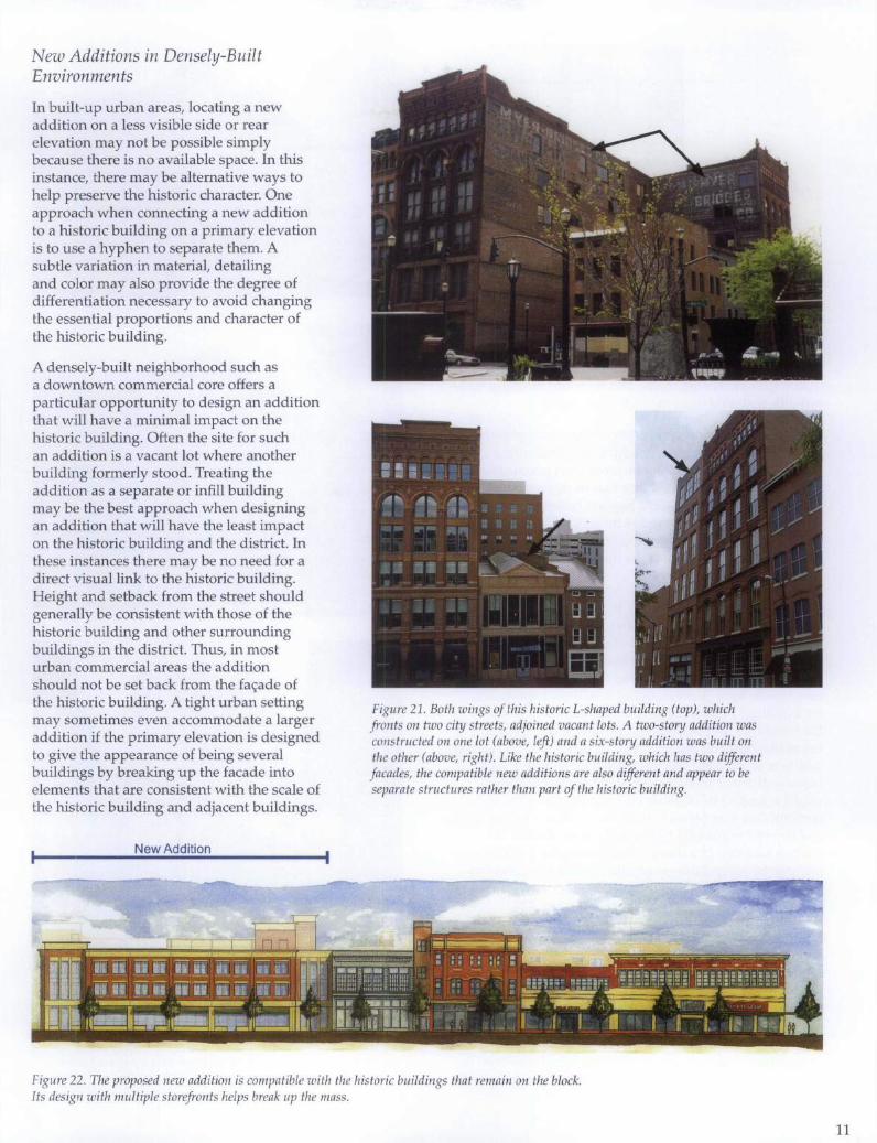
New Additions in Densely-Built Environments
In built-up urban areas, locating a new addition on a less visible side or rear elevation may not be possible simply because there is no available space. In this instance, there may be alternative ways to help preserve the historic character. One approach when connecting a new addition to a historic building on a primary elevation is to use a hyphen to separate them. A subtle variation in material, detailing and color may also provide the degree of differentiation necessary to avoid changing the essential proportions and character of the historic building.
A densely-built neighborhood such as a downtown commercial core offers a particular opportunity to design an addition that will have a minimal impact on the historic building. Often the site for such an addition is a vacant lot where another building formerly stood. Treating the addition as a separate or infill building may be the best approach when designing an addition that will have the least impact on the historic building and the district. In these instances there may be no need for a direct visual link to the historic building. Height and setback from the street should generally be consistent with those of the historic building and other surrounding buildings in the district. Thus, in most urban commercial areas the addition should not be set back from the fa<;:ade of the historic building. A tight urban setting may sometimes even accommodate a larger addition if the primary elevation is designed to give the appearance of being several buildings by breaking up the facade into elements that are consistent with the scale of the historic building and adjacent buildings.
New Addition
Figure 21. Both wings of this historic L-shaped building (top), which fronts on two city streets, adjoined vacant lots. A two-story addition was constructed on one lot (above, left) and a six-story addition was built on the other (above, right). Like the historic building, which has two different facades, the compatible new additions are also different and appear to be separate structures rather than part of the historic building.
Figure 22. The proposed new addition is compatible with the historic buildings that remain on the block. Its design with multiple storefronts helps break up the mass.
11
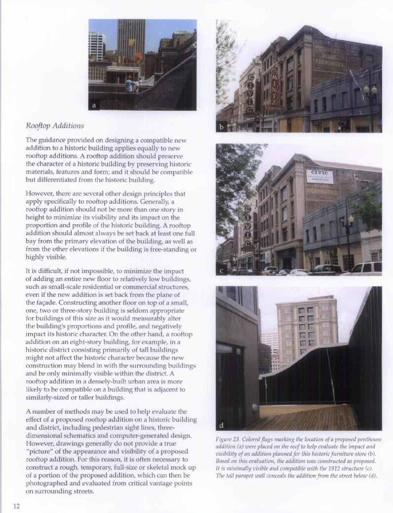
12
Rooftop Additions
The guidance provided on designing a compatible new addition to a historic building applies equally to new rooftop additions. A rooftop addition should preserve the character of a historic building by preserving historic materials, features and form; and it should be compatible but differentiated from the historic building.
However, there are several other design principles that apply specifically to rooftop additions. Generally, a rooftop addition should not be more than one story in height to minimize its visibility and its impact on the proportion and profile of the historic building. A rooftop addition should almost always be set back at least one full bay from the primary elevation of the building, as well as from the other elevations if the building is free-standing or highly visible.
It is difficult, if not impossible, to minimize the impact of adding an entire new floor to relatively low buildings, such as small-scale residential or commercial structures, even if the new addition is set back from the plane of the fac;ade. Constructing another floor on top of a small, one, two or three-story building is seldom appropriate for buildings of this size as it would measurably alter the building's proportions and profile, and negatively impact its historic character. On the other hand, a rooftop addition on an eight-story building, for example, in a historic district consisting primarily of tall buildings might not affect the historic character because the new construction may blend in with the surrounding buildings and be only minimally visible within the district. A rooftop addition in a densely-built urban area is more likely to be compatible on a building that is adjacent to similarly-sized or taller buildings.
A number of methods may be used to help evaluate the effect of a proposed rooftop addition on a historic building and district, including pedestrian sight lines, threedimensional schematics and computer-generated design. However, drawings generally do not provide a true "picture" of the appearance and visibility of a proposed rooftop addition. For this reason, it is often necessary to construct a rough, temporary, full-size or skeletal mock up of a portion of the proposed addition, which can then be photographed and evaluated from critical vantage points on surrounding streets.
Figure 23. Colored flags marking the location of a proposed penthouse addition (a) were placed on the roof to help evaluate the impact and visibility of an addition planned for this historic furniture store (b) . Based on this evaluation, the addition was constructed as proposed. It is minimally visible and compatible with the 1912 structure (c). The tall parapet wall conceals the addition from the street below (d) .
Figure 24. How to Evaluate a Proposed Rooftop Addition. A sight-line study (above) only factors in views from directly across the street, which can be very restrictive and does not illustrate the full effect of an addition from other public rights of way. A mock up (above, right) or a mock up enhanced by a computer-generated rendering (below, right) is essential to evaluate the impact of a proposed rooftop addition on the historic building.
Figure 25. It was possible to add a compatible, three-story, penthouse addition to the roof of this five-story, historic bank building because the addition is set far back, it is surrounded by taller buildings and a deep parapet conceals almost all of the addition from be/ow.
Figure 26. A rooftop addition would have negatively impacted the character of the primary facade (right) of this mid-19th century, four-story structure and the low-rise historic district. However, a third floor was successfully added on the two-story rear portion (be/ow) of the same building with little impact to the building or the district because it blends in with the height of the adjacent building.
13
14
Figure 27. Although the new brick stair/elevator tower (left) is not visible from the front (right), it is on a prominent side elevation of this 1890 stone bank. The compatible addition is set back and does not compete with the historic building. Photos: Chadd Gossmann, Aurora Photography, LLC.
Designing a New Exterior Addition to a Historic Building
This guidance should be applied to help in designing a compatible new addition that that will meet the Secretary of the Interior's Standards for Rehabilitation:
• A new addition should be simple and unobtrusive in design, and should be distinguished from the historic building-a recessed connector can help to differentiate the new from the old.
• A new addition should not be highly visible from the public right of way; a rear or other secondary elevation is usually the best location for a new addition.
• The construction materials and the color of the new addition should be harmonious with the historic building materials.
• The new addition should be smaller than the historic building-it should be subordinate in both size and design to the historic building.
The same guidance should be applied when designing a compatible rooftop addition, plus the following:
• A rooftop addition is generally not appropriate for a one, two or three-story building-and often is not appropriate for taller buildings.
• A rooftop addition should be minimally visible.
• Generally, a rooftop addition must be set back at least one full bay from the primary elevation of the building, as well as from the other elevations if the building is freestanding or highly visible.
• Generally, a rooftop addition should not be more than one story in height.
• Generally, a rooftop addition is more likely to be compatible on a building that is adjacent to similarly-sized or taller buildings.
Figure 28. A small addition (left) was constructed when this 1880s train station was converted for office use. The paired doors with transoms and arched windows on the compatible addition reflect, but do not replicate, the historic building (right).
Summary
Figure 29. This simple glass and brick entrance (left) added to a secondary elevation of a 1920s school building (right) is compatible with the original structure.
Because a new exterior addition to a historic building can damage or destroy significant materials and can change the building's character, an addition should be considered only after it has been determined that the new use cannot be met by altering non-significant, or secondary, interior spaces. If the new use cannot be met in this way, then an attached addition may be an acceptable alternative if carefully planned and designed. A new addition to a historic building should be constructed in a manner that preserves significant materials, features and form, and preserves the building's historic character. Finally, an addition should be differentiated from the historic building so that the new work is compatible with - and does not detract from - the historic building, and cannot itself be confused as historic.
Additional Reading
Byard, Paul Spencer. The Architecture of New Additions: Design and ReguLation. New York, NY: W.W. Norton & Company, 1998.
Day, Steven, AlA. "Modernism Meets History: New Additions to Historic Structures." Preservation Seattle [Historic Seattle's online monthly preservation magazine.] May 2003. www.historicseattle.orglpreservationseattle/publicpolicy/ defaultmay2.htm.
Incentives! A Guide to the Federal Historic Preservation Tax Incentives Program for Income-Producing Properties. "Avoiding Incompatible Treatments: New Additions & Rooftop Additions." Technical Preservation Services Branch, National Park Service. Online at www.nps.gov/history/hps/tps/.
Interpreting the Standards Bulletins (ITS). Technical Preservation Services Branch, National Park Service. Online at www.nps.gov/history/hps/tps/.
New Additions to Historic Buildings. Technical Preservation Services Branch, National Park Service. Online at www.nps. gov /history/hps/tps/.
O'Connell, Kim A. "Making Connections." Traditional Building. March/April 2004. (Vol. 17, No.2), pp. 12-15.
The Secretary of the Interior's Standards for Rehabilitation and Guidelines for Rehabilitating Historic Buildings. Washington, D.C.: U.S. Department of the Interior, National Park Service, Preservation Assistance Division, rev. 1990.
The Secretary of the Interior's Standards for Rehabilitation & Illustrated Guidelines for Rehabilitating Historic Buildings. (Authors: W. Brown Morton, III, Gary L. Hume, Kay D. Weeks, and H. Ward Jandl. Project Directors: Anne E. Grimmer and Kay D. Weeks.) Washington, D.C.: U.S. Department of
the Interior, National Park Service, Preservation Assistance Division, 1992. Online at www.nps.gov/history/hps/tps/.
Semes, Steven W. "Differentiated and Compatible: The Secretary's Standards revisited." Traditional Building. February 2009. (Vol. 22, No.1), pp. 20-23.
Semes, Steven W. The Future of the Past: A Conservation Ethic for Architecture, Urbanism, and Historic Preservation. (In association with The Institute of Classical Architecture and Classical America.) New York, NY: W.w. Norton & Company, 2009.
Figure 30. The small addition on the right of this late-19th century commercial structure is clearly secondary and compatible in size, materials and design with the historic building.
15
16
Acknowledgements
Figure 31. An elevator/stair tower was added at the back of this Richardsonian Romanesque-style theater when it was rehabilitated. Rough-cut stone and simple cut-out openings ensure that the addition is compatible and subordinate to the historic building. Photo: Chuck Liddy, AlA.
Anne E. Grimmer, Senior Architectural Historian, Technical Preservation Services Branch, National Park Service, revised Preservation Brief 14, written by Kay D. Weeks and first published in 1986. The revised Brief features all new illustrations and contains expanded and updated design guidance on the subject of new additions that has been developed by the Technical Preservation Services Branch since the original publication of the Brief. Several individuals generously contributed their time and expertise to review the revision of this Preservation Brief including: Sharon C. Park, FAIA, Chief, Architectural History and Historic Preservation, Smithsonian Institution; Elizabeth Tune and Karen Brandt, Department of Historic Resources, Commonwealth of Virginia; and Phillip Wisley and David Ferro, Division of Historical Resources, Florida Department of State. The Technical Preservation Services professional staff, in particular Michael J. Auer, Jo Ellen Hensley, Gary Sachau and Rebecca Shiffer, also provided important guidance in the development of this publication. All illustrations are from National Park Service files unless otherwise credited. Front cover image: Detail of new addition shown in Figure 4. Photo: © Maxwell MacKenzie.
This publication has been prepared pursuant to the National Historic Preservation Act of 1966, as amended, which directs the Secretary of the Interior to develop and make available information concerning historic properties. The Technical Preservation Services Branch, National Park Service, prepares standards, guidelines and other educational materials on responsible historic preservation treatments for a broad public audience. Additional information about the programs of Technical Preservation Services is available on the website at www.nps.govlhistorylhps/tps. Comments about this publication should be addressed to: Charles E. Fisher, Technical Preservation Publications Program Manager, Technical Preservation Services-2255, National Park Service, 1849 C Street, NW, Washington, DC 20240. This publication is not copyrighted and can be reproduced without penalty. Normal procedures for credit to the author and the National Park Service are appreciated.
ISBN: 978-0-16-085869-7 U.S. Government Printing Office Stock Number: 024-005-01280-0 August 2010
15 PRESERVATION BRIEFS
Preservation of Historic Concrete Paul Gaudette and Deborah Slaton
National Park Service U.S. Department of the Interior
Introduction to Historic Concrete
Concrete is an extraordinarily versatile building material used for utilitarian, ornamental, and monumental structures since ancient times. Composed of a mixture of sand, gravel, crushed stone, or other coarse material, bound together with lime or cement, concrete undergoes a chemical reaction and hardens when water is added. Inserting reinforcement adds tensile strength to structural concrete elements. The use of reinforcement contributes significantly to the range and size of building and structure types that can be constructed with concrete.
While early twentieth century proponents of modern concrete often considered it to be permanent, it is, like all materials, subject to deterioration. This Brief provides an overview of the history of concrete and its popularization in the United States, surveys the principal causes and modes of concrete deterioration, and outlines approaches to repair and protection that are appropriate to historic concrete. In the context of this Brief, historic concrete is considered to be concrete used in construction of structures of historical, architectural, or engineering interest, whether those structures are old or relatively new.
Brief History of Use and Manufacture
The ancient Romans found that a mixture of lime putty and pozzolana, a fine volcanic ash, would harden under water. The resulting hydraulic cement became a major feature of Roman building practice, and was used in many buildings and engineering projects such as bridges and aqueducts. Concrete technology was kept alive during the Middle Ages in Spain and Africa. The Spanish introduced a form of concrete to the New World in the first decades of the sixteenth century, referred to as "tapia" or "tabby." This material, a mixture of lime, sand, and shell or stone aggregate
mixed with water, was placed between wooden forms, tamped, and allowed to dry in successive layers. Tabby was later used by the English settlers in the coastal southeastern United States.
The early history of concrete was fragmented, with developments in materials and construction techniques occurring on different continents and in various countries. In the United States, concrete was slow in achieving widespread acceptance in building construction and did not begin to gain popularity until the late nineteenth century. It was more readily accepted for use in transportation and infrastructure systems.
The Erie Canal in New York is an example of the early use of concrete in transportation in the United States. The natural hydraulic cement used in the canal construction was processed from a deposit of limestone found in 1818 near Chittenango, southeast of Syracuse. The use of concrete in residential construction was
Figure 1. The Sebastopol House in Seguin, Texas, is an 1856 Greek Revival-style house constructed of lime concrete. Lime concrete or "limecrete" was a popular construction material, as it could be made inexpensively from local materials. By 1900, the town had approximately ninety limecrete structures, twenty of which remain. Photo: Texas Parks and Wildlife Department.
1
2
Figure 2. Chatterton House was the home of the post trader at Fort Fred Steel in Wyoming, one of several forts established in the 1860s to protect the Union Pacific Railroad. The walls of the post trader's house were built using stone aggregate and lime, without cement. The use of this material presents special preservation challenges.
publicized in the second edition of Orson S. Fowler's A Home for All (1853) which described the advantages of "gravel wall" construction to a wide audience. The town of Seguin, Texas, thirty-five miles east of San Antonio, already had a number of concrete buildings by the 1850s and came to be called "The Mother of Concrete Cities," with approximately ninety concrete buildings made from local "lime water" and gravel (Fig. 1).
Impressed by the economic advantages of poured gravel wall or "lime-grout" construction, the Quartermaster General's Office of the War Department embarked on a campaign to improve the quality of building for frontier military posts. As a result, lime-grout structures were constructed at several western posts soon after the Civil War, including Fort Fred Steele and Fort Laramie, both in Wyoming (Fig. 2). By the 1880s, sufficient experience had been gained with unreinforced concrete to permit construction of much larger buildings. A notable example from this period is the Ponce de Leon Hotel in St. Augustine, Florida.
Figure 3. The Lincoln Highway Association promoted construction of a high quality continuous hard surface roadway across the country. The Boys Scouts of America installed concrete road markers along the Lincoln Highway in 1928.
Extensive construction in concrete also occurred through the system of coastal fortifications commissioned by the federal government in the 1890s for the Atlantic, Pacific, and Gulf coasts. Unlike most concrete construction to that time, the special requirements of coastal fortifications called for concrete walls as much as 20 feet thick, often at sites that were difficult to access. Major structures in the coastal defenses of the 1890s were built of mass concrete with no internal reinforcing, a practice that was replaced by the use of reinforcing bars in fortifications constructed after about 1905.
The use of reinforced concrete in the United States dates from 1860, when S.T. Fowler obtained a patent for a reinforced concrete wall. In the early 1870s, William E. Ward built his own house in Port Chester, New York, using concrete reinforced with iron rods for all structural elements. Despite these developments, such construction remained a novelty until after 1880, when innovations introduced by Ernest L. Ransome made the use of reinforced concrete more practicable. Ransome made many contributions to the development of concrete construction technology, including the use of twisted reinforcing bars to improve bond between the concrete and the steel, which he patented in 1884. Two years later, Ransome introduced the rotary kiln to United States cement production. The new kiln had greater capacity and burned more thoroughly and uniformly, allowing development of a less expensive, more uniform, and more reliable manufactured cement. Improvements in concrete production initiated by Ransom led to a much greater acceptance of concrete after 1900.
The Lincoln Highway Association, incorporated in 1913, promoted the use of concrete in construction of a coast-to-coast roadway system. The goal of the Lincoln Highway Association and highway advocate Henry B. Joy was to educate the country in the need for good roads made of concrete, with an improved Lincoln
Figure 4. The highly ornamental concrete panels on the exterior facade of the Baha'i House of Worship in Wilmette, Illinois, illustrate the work of fabricator John J. Earley, known as "the man who made concrete beautiful. "
Figure 5. Following World War II, architects and engineers took advantage of improvements in concrete production, quality control, and advances in precast concrete to design structures such as the Police Headquarters building in Philadelphia, Pennsylvania, constructed in 1961. Photo: Courtesy of the Philadelphia Police Department.
Highway as an example. Concrete "seedling miles" were constructed in remote areas to emphasize the superiority of concrete over unimproved dirt. The Association believed that as people learned about concrete, they would press the government to construct good roads throughout their states. Americans' enthusiasm for good roads led to the involvement of the federal government in road-building and the creation of numbered U.S. routes in the 1920s (Fig. 3).
During the early twentieth century, Ernest Ransome in Beverly, Massachusetts, Albert Kahn in Detroit, and Richard E. Schmidt in Chicago, promoted concrete for use in "Factory Style" utilitarian buildings with an exposed concrete frame infilled with expanses of glass. Thomas Edison's cast-in-place reinforced concrete homes in Union Township, New Jersey (1908), proclaimed a similarly functional emphasis in residential construction. From the 1920s onward, concrete began to be used with spectacular design results: examples include John J. Earley's Meridian Hill Park in Washington, D.C.; Louis Bourgeois' exuberant, graceful Baha'i Temple in Wilmette, Illinois (1920-1953), for which Earley fabricated the concrete (Fig. 4); and Frank Lloyd Wright's Fallingwater near Bear Run, Pennsylvania (1934). Continuing improvements in quality control and development of innovative fabrication processes, such as the Shockbeton method for precast concrete, provided increasing opportunities for architects and engineers. Wright's Guggenheim Museum in New York City (1959); Geddes Brecher Qualls & Cunningham'S Police Headquarters building in Philadelphia, Pennsylvania (1961); and Eero Saarinen's soaring terminal building at Dulles International Airport outside Washington, D.C., and the TWA terminal at Kennedy Airport in New York (1962), exemplify the masterful use of concrete achieved in the modern era (Fig. 5).
Figure 6. The Bailey Magnet School in Jackson, Mississippi, was designed as the Jackson Junior High School by the firm of N. W. Overstreet & Town in 1936. The streamlined building exemplifies the applicability of concrete to creating a modern architectural aesthetic. Photo: Bill Burris, Burris/Wagnon Architects, P.A.
Figure 7. Detailed bas reliefs as well as sculptures, such as this lion at the Bailey Magnet School, could be used as ornamentation on concrete buildings. Sculptural concrete elements were typically cast in molds.
Throughout the twentieth century, a wide range of architectural and engineering structures were built using concrete as a practical and cost-effective choice-and concrete also became valued for its aesthetic qualities. Cast in place and precast concrete were readily adapted to the Streamlined Moderne style, as exemplified by the Bailey Magnet School in Jackson, Mississippi, designed as the Jackson Junior High School by N.W. Overstreet & Town in 1936 (Figs. 6 and 7). The school is one of many concrete buildings designed and constructed under the auspices of the Public Works Administration. Recreational structures and landscape features also utilized the structural range and unique character of exposed concrete to advantage, as seen in Chicago'S Lincoln Park Chess Pavilion, designed by Morris Webster in 1956 (Fig. 8), and the Ira C. Keller Fountain in Portland Oregon, designed by Lawrence Halprin in 1969 (Fig. 9). Concrete was also popular for building interiors, with ornamental features and exposed structural elements recognized as part of the design aesthetic (See Figs. 10 and 11 in sidebar).
3

4
Historic Interiors
The expanded use of concrete provided new opportunities to create dramatic spaces and ornate architectural detail on the interiors of buildings, at a significant cost savings over traditional construction practices. The architectural design of the Berkeley City Club in Berkeley, California, expressed Moorish and Gothic elements in concrete on the interior of the building (Fig. 10). Used as a woman's social club, the building was designed by noted California architect Julia Morgan and constructed in 1929. The vaulted ceilings, columns, and ornamental capitals of the lobby and the ornamental arches and beamed ceiling of the "plunge" are all constructed of concrete.
Figure 10. The Berkeley City Club has significant interior spaces alld features of concrete construction, including the lobby and pool. Photos: Una Gilmartin (left) and Brian Kehoe (right), Wiss, Janney, Elstner Associates, Illc.
The historic character of a building's interior can also be conveyed in a more utilitarian manner in terms of concrete features and finishes (Fig. 11). The exposed concrete structure-columns, capitals, and drop panels- is an integral part of the character of this old commercial building in Minneapolis. In concrete warehouse and factory buildings of the early twentieth century, exposed concrete columns and formboard finish concrete slab ceilings are common features as seen in this warehouse, now converted for use as a parking garage and shops.
Figure 11. Whether in a circa 1925 office (left) or in a parking garage and retail facility (right), exposed concrete structures help characterize these building interiors. Photo: Minnesota Historical Society (left).
Concrete Characteristics
Concrete is composed of fine (sand) and coarse (crushed stone or gravel) aggregates and paste made of portland cement and water. The predominant material in terms of bulk is the aggregate. Portland cement is the binder most commonly used in modern concrete. It is commercially manufactured by blending limestone or chalk with clays that contain alumina, silica, lime, iron oxide and magnesia, and heating the compounds together to high temperatures. The hydration process that occurs between the portland cement and water results in formation of an alkali paste that surrounds and binds the aggregate together as a solid mass.
The quality of the concrete is dependent on the ratio of water to the binder; binder content; sound, durable, and well-graded aggregates; compaction during placement; and proper curing. The amount of water used in the mix affects the concrete permeability and strength. The use of excess water beyond that required in the hydration process results in more permeable concrete, which is more susceptible to weathering and deterioration. Admixtures are commonly added to concrete to adjust concrete properties such as setting or hardening time, requirements for water, workability, and other characteristics. For example, the advent of air entraining agents in the 1930s provided enhanced durability for concrete.
During the twentieth century, there was a steady rise in the strength of ordinary concrete as chemical processes became better understood and quality control measures improved. In addition, the need to protect embedded reinforcement against corrosion was acknowledged. Requirements for concrete cover over reinforcing steel, increased cement content, decreased water-cement ratio, and air entrainment all contributed to greater concrete strength and improved durability.
Mechanisms and Modes of Deterioration
Causes of Deterioration
Concrete deterioration occurs primarily because of corrosion of the embedded steel, degradation of the concrete itself, use of improper techniques or materials in construction, or structural problems. The causes of concrete deterioration must be understood in order to select an appropriate repair and protection system.
While reinforcing steel has played a pivotal role in expanding the applications of concrete in twentieth century architecture, corrosion of this steel has also caused deterioration in many historic structures. Reinforcing steel embedded in the concrete is normally surrounded by a passivating oxide layer that, when present, protects the steel from corrosion and aids in bonding the steel and concrete. When the concrete's normal alkaline environment (above a pH of 10) is compromised and the steel is exposed to water, water vapor, or high relative humidity, corrosion of the
Lack of proper maintenance of building elements such as roofs and drainage systems can contribute to water-related deterioration of the adjacent concrete, particularly when concrete is saturated with water and then exposed to freezing temperatures. As water
within the concrete freezes, it expands and exerts forces on the adjacent concrete. Repeated freezing and thawing can result in the concrete cracking and delaminating. Such damage appears as surface degradation, including severe scaling and micro-cracking that extends into the concrete. The condition is most often observed near
steel reinforcing takes place. A reduction in alkalinity results from carbonation, a process that occurs when the carbon dioxide in the atmosphere reacts with calcium hydroxide and moisture in the concrete. Carbonation starts at the concrete's exposed surface but may extend to the reinforcing steel over time. When carbonation reaches
Figure 8. The Chess Pavilion in Chicago'S Lincoln Park was designed by architect Morris Webster and constructed in 1956. The pavilion is a distinctive landscape feature, with its reinforced concrete cantilevered slab that provides cover for chess players.
the surface of the concrete but can also eventually occur deep within the concrete. This type of deterioration is usually most severe at joints, architectural details, and other areas with more surface exposure to weather. In the second half of the twentieth century, concrete has utilized entrained air (the incorporation of microscopic air bubbles) to provide enhanced protection against damage due to cyclic freezing of saturated concrete.
the metal reinforcement, the concrete no longer protects the steel from corrosion.
Corrosion of embedded reinforcing steel may be initiated and accelerated if calcium chloride was added to the concrete as a set accelerator during original construction to promote more rapid curing. It may also take place if the concrete is later exposed to deicing salts, as may occur during the winter in northern climates. Seawater or other marine environments can
Figure 9. The Ira C. Keller Fountain in Portland, Oregon, was designed by Lawrence Halprin and constructed in 1969. The fountain is constructed primarily of concrete pillars with formboard textures and surrounding elements, patterned with geometric lines, which facilitate the path
The use of certain aggregates can also result in deterioration of the concrete. Alkaliaggregate reactions-in some cases alkali-silica reaction (ASR)-occur when alkalis normally present in cement react with certain aggregates, leading to the development of an expansive crystalline gel. When this gel is exposed to moisture, it expands and causes of water. Photo: Anita Washko, Wiss, Janney, Elstner
Associates, Inc. cracking of the aggregate and concrete matrix. Deleterious also provide large amounts
of chloride, either from inadequately washed original aggregate or from exposure of the concrete to seawater.
Corrosion-related damage to reinforced concrete is the result of rust, a product of the corrosion process of steel, which expands and thus requires more space in the concrete than the steel did at the time of installation. This change in volume of the steel results in expansive forces, which cause cracking and spalling of the adjacent concrete (Fig. 12). Other signs of corrosion of embedded steel include delamination of the concrete (planar separations parallel to the surface) and rust staining (often a precursor to spalling) on the concrete near the steel.
aggregates are typically found only in certain areas of the country and can be detected through analysis by an experienced petrographer. Low-alkali cements as well as fly ash are used today in new construction to prevent such reactions where this problem may occur.
Problems Specifically Encountered with Historic Concrete
Materials and workmanship used in the construction of historic concrete structures, particularly those built before the First World War, sometimes present potential sources of problems. For example, where the aggregate consisted of cinder from burned coal or crushed brick,
5
6
Figure 12. The concrete lighthouse at the Kilauea Point Light Station, Kilauea, Kauai, Hawaii, was constructed circa 1913. The concrete, which was a good quality, high strength mix for its day, is in good condition after almost one hundred years in service. Deterioration in the form of spalling related to corrosion of embedded reinforcing steel has occurred primarily in areas of higher ornamentation such as projecting bands and brackets (see close-up photo).
the concrete tends to be weak and porous because these aggregates absorb water. Some of these aggregates can be extremely susceptible to deterioration when exposed to moisture and cyclic freezing and thawing. Concrete was sometimes compromised by inclusion of seawater or beach sand that was not thoroughly washed with fresh water, a condition more common with coastal fortifications built prior to 1900. The sodium chloride present in seawater and beach sand accelerates the rate of corrosion of the reinforced concrete.
Another problem encountered with historic concrete is related to poor consolidation of the
concrete during its placement in forms, or in molds in the case of precasting. This problem is especially prevalent in highly ornamental units. Early twentieth century concrete was often tamped or rodded into place, similar to techniques used in forming cast stone. Poorly consolidated concrete often contains voids (lfbugholes" or "honeycombs"), which can reduce the protective concrete cover over the embedded reinforcing bars, entrap water, and, if sufficiently large and strategically numerous, reduce localized concrete strength. Vibration technology has improved over time and flowability agents are also used today to address this problem.
A common type of deterioration observed in concrete is the effect of weathering from exposure to wind, rain, snow, and salt water or spray. Weathering appears as erosion of the cement paste, a condition more prevalent in northern regions where precipitation can be highly acidic. This results in the exposure of the aggregate particles on the exposed concrete surface. Variations may occur in the aggregate exposure due to differential erosion or dissolution of exposed cement paste. Erosion can also be caused by the mechanical action of water channeled over concrete, such as by the lack of drip grooves in belt courses and sills, and by inadequate drainage. In addition, high-pressure water when used for cleaning can also erode the concrete surface.
In concrete structures built prior to the First World War, concrete was often placed into forms in relatively short vertical lifts due to limitations in lifting and pouring techniques available at the time. Joints between different concrete placements (often termed cold joints or lift lines) may sometimes be considered an important part of the character of a concrete element (Fig. 13). However, wide joints may permit water to infiltrate the concrete, resulting in more rapid paste erosion or freeze-thaw deterioration of adjacent concrete in cold climates.
In the early twentieth century, concrete was sometimes placed in several layers parallel to the exterior surface. A base concrete was first created with form work and then a more cement rich mortar layer was applied to the exposed vertical face of the
Figure 13. Fort Casey on Admiralty Head, Fort Casey, Washington, was constructed in 1898. The lift lines from placement of concrete are clearly visible on the exterior walls and characterize the finished appearance.
base concrete. The higher cement content in the facing concrete provided a more water-resistant outer layer and finished surface. The application of a cement-rich top layer, referred to in some early concrete publications as "waterproofing," was also used on top surfaces of concrete walls, or as the top layer in sidewalks. With this type of concrete construction, deterioration can occur over time as a result of debonding between layers, and can proceed very rapidly once the protective cement-rich layer begins to break down.
It is common for historic concrete to have a highly variable appearance, including color and finish texture. Different levels of aggregate exposure due to paste erosion are often found in exposed aggregate concrete. This variability in the appearance of historic concrete increases the level of difficulty in assessing and repairing weathered concrete.
Signs of Distress and Deterioration
Characteristic signs of failure in concrete include cracking, spalling, staining, and deflection. Cracking occurs in most concrete but will vary in depth, width, direction, pattern, and location, and can be either active or dormant (inactive). Active cracks can widen, deepen, or migrate through the concrete, while dormant cracks remain relatively unchanged in size. Some dormant cracks, such as those caused by early age shrinkage of the concrete during curing, are not a structural concern but when left unrepaired, can provide convenient channels for moisture penetration and subsequent damage. Random surface cracks, also called map cracks due to their resemblance to lines on a map, are usually related to early-age shrinkage but may also indicate other types of deterioration such as alkali-silica reaction.
Structural cracks can be caused by temporary or continued overloads, uneven foundation settling, seismic forces, or original design inadequacies. Structural cracks are active if excessive loads are applied to a structure, if the overload is continuing, or if settlement is ongoing. These cracks are dormant if the temporary overloads have been removed or if differential settlement has stabilized. Thermally-induced cracks result from stresses produced by the expansion and contraction of the concrete during temperature changes. These cracks frequently occur at the ends or re-entrant corners of older concrete structures that were built without expansion joints to relieve such stress.
Spalling (the loss of surface material) is often associated with freezing and thawing as well as cracking and delamination of the concrete cover over embedded reinforcing steel. Spalling occurs when reinforcing bars corrode and the corrosion by-products expand, creating high stresses on the adjacent concrete, which cracks and is displaced. Spalling can also occur when water absorbed by the concrete freezes and thaws (Fig. 14). In addition, surface spalling or scaling may result from the improper finishing, forming, or other surface
Figures 14. Layers of architectural concrete that have debonded (spaUed) from the surface were removed from a historic water tank during the investigation performed to assess existing conditions. Photos: Anita Washko, Wiss, Janney, Elstner Associates, Inc.
phenomena when water-rich cement paste (laitance) rises to the surface. The resulting weak material is vulnerable to spalling of thin layers, or scaling. In some cases, spalling of the concrete can diminish the loadcarrying capacity of the structure.
Deflection is the bending or sagging of structural beams, joists, or slabs, and can be an indication of deficiencies in the strength and structural soundness of concrete. This condition can be produced by overloading, corrosion of embedded reinforcing, or inadequate design or construction, such as use of low-strength concrete or undersized reinforcing bars.
Staining of the concrete surface can be related to soiling from atmospheric pollutants or other contaminants, dirt accumulation, and the presence of organic growth. However, stains can also indicate more serious underlying problems, such as corrosion of embedded reinforcing steel, improper previous surface treatments, alkali-aggregate reaction, or efflorescence, the deposition of soluble salts on the surface of the concrete as a result of water migration (Fig. 15).
7
8
Planning for Concrete Preservation
The significance of a historic concrete building or structure-including whether it is important for its architectural or engineering design, for its materials and construction techniques, or both-guides decision making about repair and, if needed, replacement methods. Determining the causes of deterioration is also central to the development of a conservation and repair plan. With historic concrete buildings, one of the more difficult challenges is allowing for sufficient time during the planning phase to analyze the concrete, develop mixes, and provide time for adequate aging of mock-ups for matching to the original concrete.
An understanding of the original construction techniques (cement characteristics, mix design, original intent of assembly, type of placement, precast versus cast in place, etc.) and previous repair work performed on the concrete is important in determining causes of existing deterioration and the susceptibility of the structure to potential other types of deterioration. For example, concrete placed in short lifts (individual concrete placements) or constructed in precast segments will have numerous joints that can provide entry points for water infiltration. Inappropriate prior repairs, such as installation of patches using an incompatible material, can affect the future performance of the concrete. Such prior repairs may require corrective work.
As with other preservation projects, three primary approaches are usually considered for historic concrete structures: maintenance, repair, or replacement. Maintenance and repair best achieve the preservation goal of minimal intervention and the greatest retention of existing historic fabric. However, where elements of the building are severely deteriorated or where inherent problems with the material lead to ongoing failures, replacement may be necessary.
During planning, information is gathered through research, visual survey, inspection openings, and laboratory studies. The material should then be reviewed by professionals experienced in concrete deterioration to help evaluate the nature and causes of the concrete problems, to assess both the short-term and long-term effects of the deterioration, and to formulate proper repair approaches.
Condition Assessment
A condition assessment of a concrete building or structure should begin with a review of all available documents related to original construction and prior repairs. While plans and specifications for older concrete buildings are not always available, they can be an invaluable resource and every attempt should be made to find them. They may provide information on the composition of the concrete mix or on the type and location of reinforcing bars. If available, documents related to past repairs should also be reviewed to
Figure 15. Evidence of moisture movement through concrete is apparent in the form of mineral deposits on the concrete surface. Cyclic freezing and thawing of entrapped moisture, and corrosion of embedded reinforcement, have also contributed to deterioration of the concrete column on this fence at Crocker Field in Fitchburg, Massachusetts, designed by the Olmsted Brothers.
understand how the repairs were made and to help evaluate their anticipated performance and service life. Archival photographs can also provide a valuable source of information about original construction.
A visual condition survey will help identify and evaluate the extent, types, and patterns of distress and deterioration. The American Concrete Institute offers several useful guides on how to perform a visual condition survey of concrete. Generally, the condition assessment begins with an overall visual survey, followed by a close-up investigation of representative areas to obtain more detailed information about modes of deterioration.
A number of nondestructive testing methods can be used in the field to evaluate concealed conditions. Basic techniques include sounding with a hand-held hammer (or for horizontal surfaces, a chain) to help identify areas of delamination. More sophisticated techniques include impact-echo testing (Fig. 16), ground penetrating radar, pulse velocity, and other methods that characterize concrete thickness and locate voids or delaminations. Magnetic detection instruments are used to locate embedded reinforcing steel and can be calibrated to identify the size and depth of reinforcement. Corrosion measurements can be taken using copper-copper sulfate half-cell tests or linear polarization techniques to determine the probability or rate of active corrosion of the reinforcing steel.
To further evaluate the condition of the concrete, samples may be removed for laboratory study to determine material components and composition, and causes of deterioration. Samples need to be representative of existing conditions but should be taken from unobtrusive locations. Laboratory studies of the concrete may include petrographic evaluation following ASTM C856, Practice for Petrographic Examination of Hardened Concrete. Petrographic examination, consisting of microscopical studies performed by a geologist specializing in the evaluation of construction materials, is performed to determine air content, watercement ratio, cement content, and general aggregate characteristics. Laboratory studies can also include
chemical analyses to determine chloride content, sulfate content, and alkali levels of the concrete; identification of deleterious aggregates; and determination of depth of carbonation. Compressive strength studies can be conducted to evaluate the strength of the existing concrete and provide information for repair work. The laboratory studies provide a general identification of the original concrete's components and aggregates, and evidence of damage due to various mechanisms including cyclic freezing and thawing, alkali-aggregate reactivity, or sulfate attack. Information gathered through laboratory studies can also be used to help develop a mix design for the repair concrete.
Cleaning
As with other historic structures, concrete structures are cleaned for several reasons: to improve the appearance of the concrete, as a cyclical maintenance measure, or in preparation for repairs. Consideration should first be given to whether the historic concrete structure needs to be cleaned at all. If cleaning is required, then the gentlest system that will be effective should be selected.
Three primary methods are used for cleaning concrete: water methods, abrasive surface treatments, and chemical surface treatments. Low-pressure water (less than 200 psi) or steam cleaning can effectively remove surface soiling from sound concrete; however, care is required on fragile or deteriorated surfaces. In addition, water and steam methods are typically not effective in removing staining or severe soiling. Power washing with high-pressure water is sometimes used to clean or remove coatings from sound, high-strength concrete, but high-pressure water washing is generally damaging to and not appropriate for concrete on historic structures.
When used with proper controls and at very low pressures (typically 35 to 75 psi), microabrasive
Figure 16. Impact echo testing is performed on a concrete structural slab to help determine depth of deterioration. In this method, a short pulse of energy is introduced into the structure and a transducer mounted on the impacted surface of the structure receives the reflected input waves or echoes. These waves are analyzed to help identify flaws and deterioration within the concrete.
surface treatments using very fine particulates, such as dolomitic limestone powder, can sometimes clean effectively. However, micro abrasive cleaning may alter the texture and surface reflectivity of concrete. Some concrete can be damaged even by fine particulates applied at very low pressures.
Chemical surface treatments can clean effectively but may also alter the appearance of the concrete by bleaching the concrete, removing the paste, etching the aggregate, or otherwise altering the surface. Detergent cleaners or mild, diluted acid cleaners may be appropriate for removal of staining or severe soiling. Cleaning products that contain strong acids such as hydrochloric (muriatic) or hydrofluoric acid, which will damage concrete and are harmful to persons, animals, site features, and the environment, should not be used.
For any cleaning process, trial samples should be performed prior to full-scale implementation. The intent of the cleaning program should not be to return the structure to a like new appearance. Concrete can age gracefully, and as long as soiling is not severe or deleterious, many structures can still be appreciated without extensive cleaning.
Methods of Maintenance and Repair
The maintenance of historic concrete often is thought of in terms of appropriate cleaning to remove unattractive dirt or soiling materials. However, the implementation of an overall maintenance plan for a historic structure is the most effective way to help protect historic concrete. For examples, the lack of maintenance to roofs and drainage systems can promote water related damage to adjacent concrete features. The repeated use of deicing salts in winter climates can pit the surface of old concrete and also may promote decay in embedded steel reinforcements. Inadequate protection of concrete walls adjacent to driveways and parking areas can result in the need for repair work later on.
The maintenance of historic concrete involves the regular inspection of concrete to establish baseline conditions and identify needed repairs. Inspection tasks involve monitoring protection systems, including sealant joints, expansion joints, and protective coatings; reviewing existing conditions for development of distress such as cracking and delaminations; documenting conditions observed; and developing and implementing a cyclical repair program.
Sealants are an important part of maintenance of historic concrete structures. Elastomeric sealants, which have replaced traditional oil-resin based caulks for many applications, are used to seal cracks and joints to keep out moisture and reduce air infiltration. Sealants are commonly used at windows and door perimeters, at interfaces between concrete and other materials, and at attachments to or through walls or roofs, such as with lamps, signs, or exterior plumbing fixtures.
9
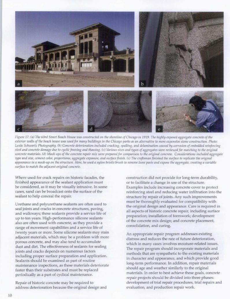
10
Figure 17. (a) The 63rd Street Beach House was constructed on the shoreline of Chicago in 1919. The highly exposed aggregate concrete of the exterior walls of the beach house was used for many buildings in the Chicago parks as an alternative to more expensive stone construction. Photo: Leslie Schwartz Photography. (b) Concrete deterioration included cracking, spalling, and delamination caused by corrosion of embedded reinforcing steel and concrete damage due to cyclic freezing and thawing. (c) Various sizes and types of aggregates were reviewed for matching to the original concrete materials. (d) Mock-ups of the concrete repair mix were prepared for comparison to the original concrete. Considerations included aggregate type and size, cement color, proportions, aggregate exposure, and surface finish. (e) The craftsman finished the surface to replicate the original appearance in a mock-up on the structure. Here, he used a nylon bristle brush to remove loose paste and expose the aggregate, creating a variable surface to match the adjacent original concrete.
Where used for crack repairs on historic facades, the finished appearance of the sealant application must be considered, as it may be visually intrusive. In some cases, sand can be broadcast onto the surface of the sealant to help conceal the repair.
Urethane and polyurethane sealants are often used to seal joints and cracks in concrete structures, paving, and walkways; these sealants provide a service life of up to ten years. High-performance silicone sealants also are often used with concrete, as they provide a range of movement capabilities and a service life of twenty years or more. Some silicone sealants may stain adjacent materials, which may be a problem with more porous concrete, and may also tend to accumulate dust and dirt. The effectiveness of sealants for sealing joints and cracks depends on numerous factors including proper surface preparation and application. Sealants should be examined as part of routine maintenance inspections, as these materials deteriorate faster than their substrates and must be replaced periodically as a part of cyclical maintenance.
Repair of historic concrete may be required to address deterioration because the original design and
construction did not provide for long-term durability, or to facilitate a change in use of the structure. Examples include increasing concrete cover to protect reinforcing steel and reducing water infiltration into the structure by repair of joints. Any such improvements must be thoroughly evaluated for compatibility with the original design and appearance. Care is required in all aspects of historic concrete repair, including surface preparation; installation of form work; development of the concrete mix design; and concrete placement, consolidation, and curing.
An appropriate repair program addresses existing distress and reduces the rate of future deterioration, which in many cases involves moisture-related issues. The repair program should incorporate materials and methods that are sympathetic to the existing materials in character and appearance, and which provide good long-term performance. In addition, repair materials should age and weather similarly to the original materials. In order to best achieve these goals, concrete repair projects should be divided into three phases: development of trial repair procedures, trial repairs and evaluation, and production repair work.

For any concrete repair project, the process of investigation, laboratory analysis, trial samples, mock-ups, and full-scale repairs allows ongoing refinement of the repair work as well as implementation of quality-control measures. The trial repair process provides an opportunity for the owner, architect, engineer, and contractor to evaluate the concrete mix design and the installation and finishing techniques for the repairs from both technical and aesthetic standpoints. The final repair materials and procedures should match the original concrete in appearance while meeting the established criteria for durability. Information gathered through trial repairs and mock-ups is invaluable in refining the construction documents prior to the start of the overall repair project (Fig. 17).
Surface Preparation
In undertaking surface preparation for historic concrete repair, care must be taken to limit removal of existing material while still providing an appropriate substrate for repairs. This is particularly important where ornamentation and fine details are involved. Preparation for localized repairs usually begins with removal of the loose concrete to determine the general extent of the repair, followed by saw-cutting the perimeter of the repair area. The repair area should extend beyond the area of concrete deterioration to a sufficient extent to provide a sound substrate. When repairing concrete with an exposed aggregate or other special surface texture, a sawcut edge may be too visually evident. To hide the repair edge, techniques such as lightly hand-chipping the edge of the patch may be used to conceal the joint between the original concrete and the new repair material. The depth to which the concrete needs to be removed may be difficult to determine without invasive probing in the repair area. Removal of concrete should typically extend beyond the level of the reinforcing steel, if present, so that the patch encapsulates the reinforcing steel, which provides mechanical attachment for the repair.
If the concrete was originally of lower strength and quality, the assessment of present soundness is more difficult. Deteriorated and unsound concrete is typically removed using pneumatic chipping hammers. Removal of concrete in historic structures is better controlled by using smaller chipping hammers or hand tools. The area of the concrete to be repaired and the exposed reinforcing steel are then cleaned, usually by careful sandblast and air blast procedures applied only within the repair area. Adjacent original concrete surfaces should be protected during this work. In some cases, project constraints such as dust control may limit the ability to thoroughly clean the concrete and steel. For example, it may be necessary to use needle scaling (a small pneumatic impact device) and wire brushing instead of sandblasting.
Supplemental steel may be needed when existing reinforcing steel is severely deteriorated, or if reinforcing steel is not present in repair areas. Exposed existing reinforcing and other embedded steel elements can be cleaned, primed, and painted with a corrosion-inhibiting coating. The patching material should be reinforced
and mechanically attached to the existing concrete. Reinforcement materials used in repairs most often include mild steel, epoxy-coated steel, or stainless steel, depending on existing conditions.
Formwork and Molds
Special formwork is needed to recreate ornamental concrete features - which may be complex, in high relief, or architecturally detailed-and to provide special surface finishes such as wood form board textures. Construction of the formwork itself requires particular skill and craftsmanship. Reusable forms can be used for concrete ornamentation that is repeated across a building facade, or precast concrete elements may be used to replace missing or unrepairable architectural features. Formwork for ornamental concrete is often created using a four-step process: a casting of the original concrete is taken; a plaster replica of the unit is prepared; a mold or form is made from the plaster replica; and a new concrete unit is cast. Custom formwork and molds are often the work of specialty companies, such as precasters and cast stone fabricators.
The process of forming architectural features or special surface textures is particularly challenging if early age stripping (removal of formwork early in the concrete curing process) is needed to perform surface treatment on the concrete. Timing for formwork removal is related to strength gain, which in turn is partly dependent on temperature and weather conditions. Early age removal of formwork in highly detailed concrete can lead to damage of the new concrete that has not yet gained sufficient strength through curing.
Selection of Repair Materials and Mix Design
Selection and design of proper repair materials is a critical component of the repair project. This process requires evaluation of the performance, characteristics, and limitations of the repair materials, and may involve laboratory testing of proposed materials and trial repairs. The materials should be selected to address the specific type of repair required and to be compatible with special characteristics of the original concrete. Some modern repair materials are designed to have a high compressive strength and to be impermeable. Even though inherently durable, these newer materials may not be appropriate for use in repairing a low strength historic concrete.
The concrete's durability, or resistance to deterioration, and the materials and methods selected for repair depend on its composition, design, and quality of workmanship. In most cases, a mix design for durable replacement concrete should use materials similar to those of the original concrete mix. Prepackaged materials are often not appropriate for repair of historic concrete. The concrete patching material can be air entrained or polymer-modified if subject to exterior exposure, and should incorporate an appropriate selection of aggregate and cement type, and proper water content and water
11
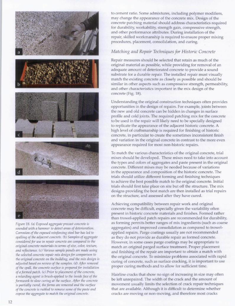
12
• • I '{\ I ., • • , -II t, . \ ',~,' j , ~ ;.\ '\ -.:
\: .... ·~·~I"I · I "'".",'. , .. " . ..r.,,. ,T, . " I.... • •. ~ •. .. ~ • -: • \ I·, ... ~ t' I'!, ' ;. ' "w --. I '.' . I, .',: "i '" 1 ~ ) .'
'. j I I - • , , I b .•
Figure 18. (a) Exposed aggregate precast concrete is sounded with a hammer to detect areas of deterioration. Corrosion of the exposed reinforcing steel bar has led to spalling of the adjacent concrete. (b) Samples of aggregate considered for use in repair concrete are compared to the original concrete materials in terms of size, color, texture, and reflectance. (c) Various sample panels are made using the selected concrete repair mix design for comparison to the original concrete on the building, and the mix design is adjusted based on review of the samples. (d) After removal of the spall, the concrete surface is prepared for installation of a formed patch. (e) Prior to placement of the concrete, a retarding agent is brush-applied to the inside face of the formwork to slow curing at the surface. After the concrete is partially cured, the forms are removed and the surface of the concrete is rubbed to remove some of the paste and expose the aggregate to match the original concrete.
to cement ratio. Some admixtures, including polymer modifiers, may change the appearance of the concrete mix. Design of the concrete patching material should address characteristics required for durability, workability, strength gain, compressive strength, and other performance attributes. During installation of the repair, skilled workmanship is required to ensure proper mixing procedures, placement, consolidation, and curing.
Matching and Repair Techniques for Historic Concrete
Repair measures should be selected that retain as much of the original material as possible, while providing for removal of an adequate amount of deteriorated concrete to provide a sound substrate for a durable repair. The installed repair must visually match the existing concrete as closely as possible and should be similar in other aspects such as compressive strength, permeability, and other characteristics important in the mix design of the concrete (Fig. 18).
Understanding the original construction techniques often provides opportunities in the design of repairs. For example, joints between the new and old concrete can be hidden in changes in surface profile and cold joints. The required patching mix for the concrete to be used in the repair will likely need to be specially designed to replicate the appearance of the adjacent historic concrete. A high level of craftsmanship is required for finishing of historic concrete, in particular to create the sometimes inconsistent finish and variation in the original concrete in contrast to the more even appearance required for most non-historic repairs.
To match the various characteristics of the original concrete, trial mixes should be developed. These mixes need to take into account the types and colors of aggregates and paste present in the original concrete. Different mixes may be needed because of variations in the appearance and composition of the historic concrete. The trials should utilize different forming and finishing techniques to achieve the best possible match to the original concrete. Initial trials should first take place on site but off the structure. The mix designs providing the best match are then installed as trial repairs on the structure, and assessed after they have cured.
Achieving compatibility between repair work and original concrete may be difficult, especially given the variability often present in historic concrete materials and finishes. Formed rather than trowel-applied patch repairs are recommended for durability, as forming permits better ranges of mix ingredients (such as coarse aggregates) and improved consolidation as compared to trowelapplied repairs. Parge coatings usually are not recommended as they do not provide as durable repair as formed concrete. However, in some cases parge coatings may be appropriate to match an original parged surface treatment Proper placement and finishing of the repair are important to obtain a match with the original concrete. To minimize problems associated with rapid curing of concrete, such as surface cracking, it is important to use proper curing methods and to allow for sufficient time.
Hairline cracks that show no sign of increasing in size may often be left unrepaired. The width of the crack and the amount of movement usually limits the selection of crack repair techniques that are available. Although it is difficult to determine whether cracks are moving or non-moving, and therefore most cracks
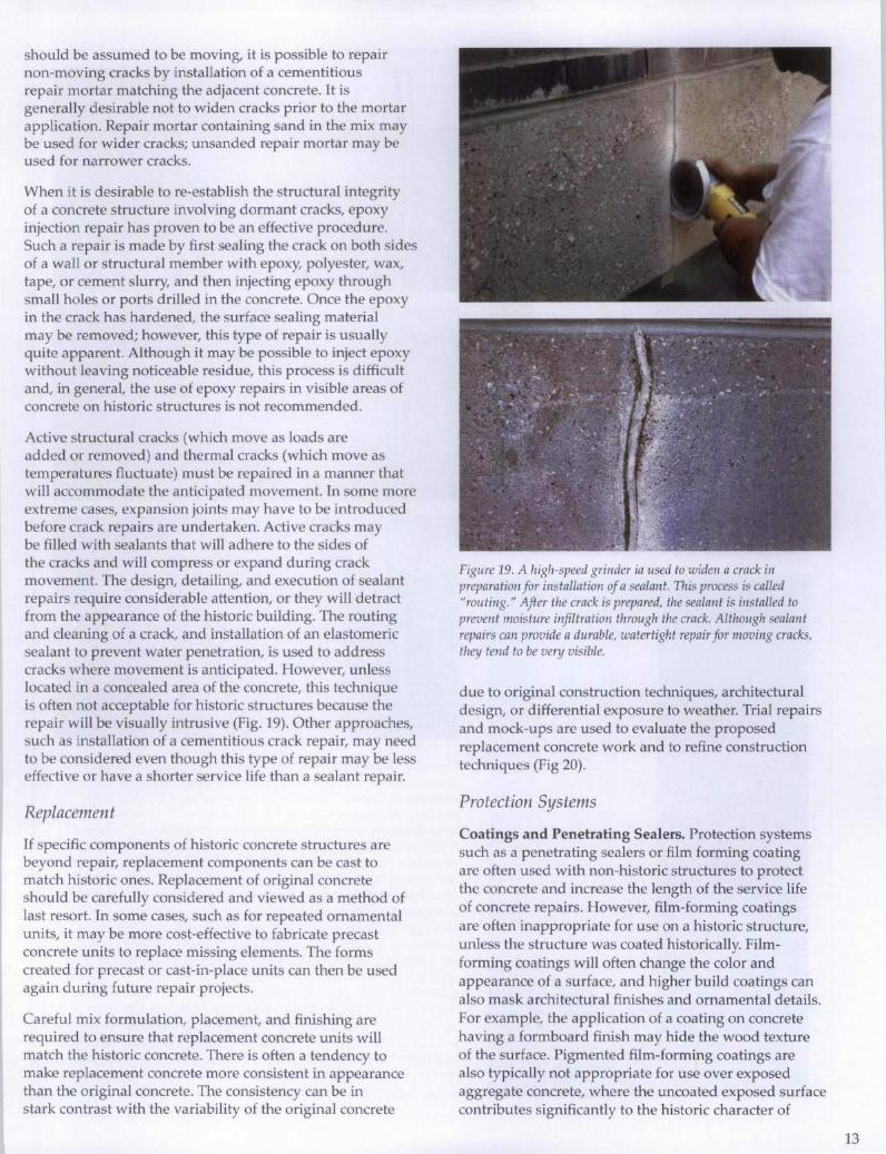
should be assumed to be moving, it is possible to repair non-moving cracks by installation of a cementitious repair mortar matching the adjacent concrete. It is generally desirable not to widen cracks prior to the mortar application. Repair mortar containing sand in the mix may be used for wider cracks; unsanded repair mortar may be used for narrower cracks.
When it is desirable to re-establish the structural integrity of a concrete structure involving dormant cracks, epoxy injection repair has proven to be an effective procedure. Such a repair is made by first sealing the crack on both sides of a wall or structural member with epoxy, polyester, wax, tape, or cement slurry, and then injecting epoxy through small holes or ports drilled in the concrete. Once the epoxy in the crack has hardened, the surface sealing material may be removed; however, this type of repair is usually quite apparent. Although it may be possible to inject epoxy without leaving noticeable residue, this process is difficult and, in general, the use of epoxy repairs in visible areas of concrete on historic structures is not recommended.
Active structural cracks (which move as loads are added or removed) and thermal cracks (which move as temperatures fluctuate) must be repaired in a manner that will accommodate the anticipated movement. In some more extreme cases, expansion joints may have to be introduced before crack repairs are undertaken. Active cracks may be filled with sealants that will adhere to the sides of the cracks and will compress or expand during crack movement. The design, detailing, and execution of sealant repairs require considerable attention, or they will detract from the appearance of the historic building. The routing and cleaning of a crack, and installation of an elastomeric sealant to prevent water penetration, is used to address cracks where movement is anticipated. However, unless located in a concealed area of the concrete, this technique is often not acceptable for historic structures because the repair will be visually intrusive (Fig. 19). Other approaches, such as installation of a cementitious crack repair, may need to be considered even though this type of repair may be less effective or have a shorter service life than a sealant repair.
Replacement
If specific components of historic concrete structures are beyond repair, replacement components can be cast to match historic ones. Replacement of original concrete should be carefully considered and viewed as a method of last resort. In some cases, such as for repeated ornamental units, it may be more cost-effective to fabricate precast concrete units to replace missing elements. The forms created for precast or cast-in-place units can then be used again during future repair projects.
Careful mix formulation, placement, and finishing are required to ensure that replacement concrete units will match the historic concrete. There is often a tendency to make replacement concrete more consistent in appearance than the original concrete. The consistency can be in stark contrast with the variability of the original concrete
Figure 19. A high-speed grinder ia used to widen a crack in preparation for installation of a sealant. This process is called "routing. " After the crack is prepared, the sealant is installed to prevent moisture infiltration through the crack. Although sealant repairs can provide a durable, watertight repair for moving cracks, they tend to be very visible.
due to original construction techniques, architectural design, or differential exposure to weather. Trial repairs and mock-ups are used to evaluate the proposed replacement concrete work and to refine construction techniques (Fig 20).
Protection Systems
Coatings and Penetrating Sealers. Protection systems such as a penetrating sealers or film forming coating are often used with non-historic structures to protect the concrete and increase the length of the service life of concrete repairs. However, film-forming coatings are often inappropriate for use on a historic structure, unless the structure was coated historically. Filmforming coatings will often change the color and appearance of a surface, and higher build coatings can also mask architectural finishes and ornamental details. For example, the application of a coating on concrete having a formboard finish may hide the wood texture of the surface. Pigmented film-forming coatings are also typically not appropriate for use over exposed aggregate concrete, where the uncoated exposed surface contributes significantly to the historic character of
13
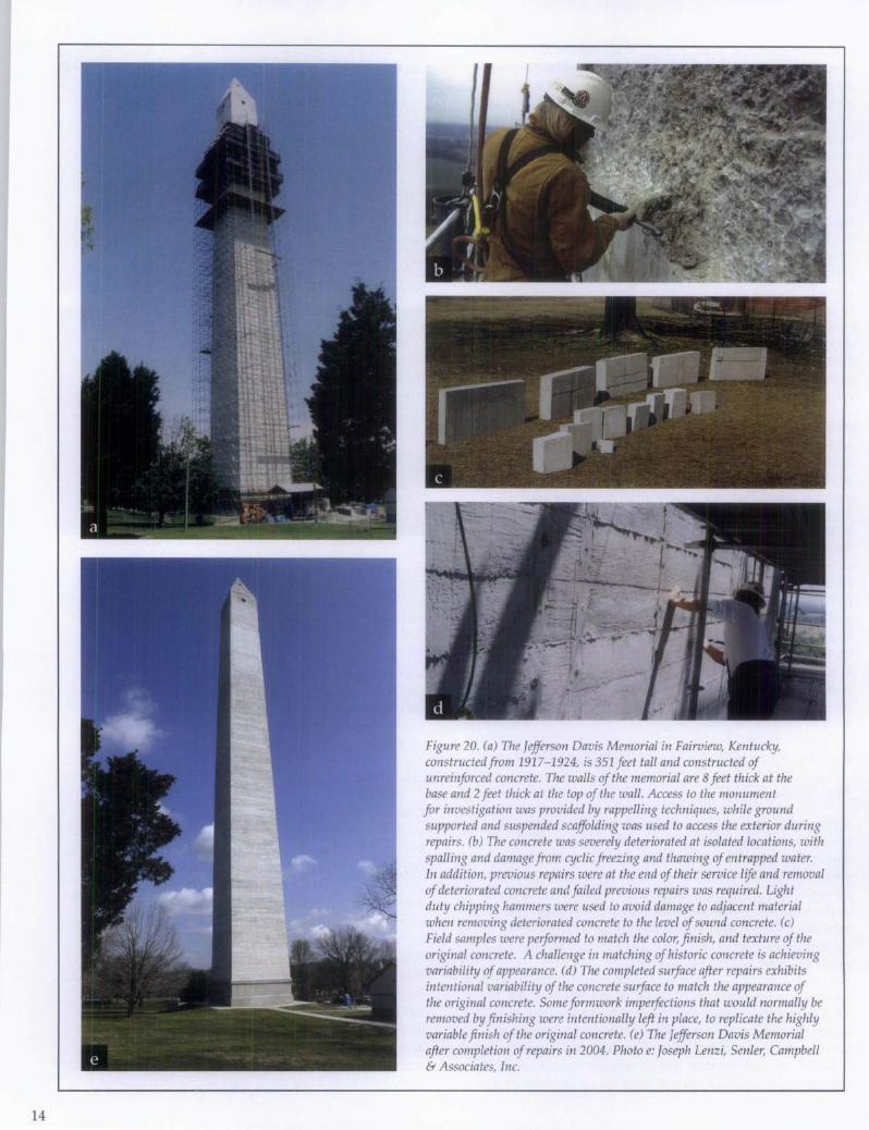
14
Figure 20. (a) The Jefferson Davis Memorial in Fairview, Kentucky, constructed from 1917-1924, is 351 feet tall and constructed of unreinforced concrete. The walls of the memorial are 8 feet thick at the base and 2 feet thick at the top of the wall. Access to the monument for investigation was provided by rappelling techniques, while ground supported and suspended scaffolding was used to access the exterior during repairs. (b) The concrete was severely deteriorated at isolated locations, with spalling and damage from cyclic freezing and thawing of entrapped water. In addition, previous repairs were at the end of their service life and removal of deteriorated concrete and failed previous repairs was required. Light duty chipping hammers were used to avoid damage to adjacent material when removing deteriorated concrete to the level of sound concrete. (c) Field samples were performed to match the color, finish, and texture of the original concrete. A challenge in matching of historic concrete is achieving variability of appearance. (d) The completed surface after repairs exhibits intentional variability of the concrete surface to match the appearance of the original concrete. Some formwork imperfections that would normally be removed by finishing were intentionally left in place, to replicate the highly variable finish of the original concrete. (e) The Jefferson Davis Memorial after completion of repairs in 2004. Photo e: Joseph Lenzi, Senler, Campbell & Associates, Inc.
concrete. In cases where the color of a substrate needs to be changed, such as to modify the appearance of existing repairs, an alternative to pigmented film-forming coatings is the use of pigmented stains.
Many proprietary clear, penetrating sealers are currently available to protect concrete substrates. These products render fine cracks and pores within the concrete hydrophobic; however, they do not bridge or fill cracks. Clear sealers may change the appearance of the concrete in that treated areas become more visible after rain in contrast to the more absorptive areas of original concrete. Once applied, penetrating sealers cannot be effectively removed and are therefore considered irreversible. They should not be used on historic concrete without thorough prior consideration. However, clear penetrating sealers provide an important means of protection for historic concrete that is not of good quality and can help to avoid more extensive future repairs or replacement. Thus they are sometimes appropriate for use on historic concrete. Once applied, these sealers will require periodic re-application.
Waterproofing membranes are systems used to protect concrete surfaces such as roofs, terraces, plazas, or balconies, as well as surfaces below grade. Systems range from coal tar pitch membranes used on older buildings, to asphalt or urethane-based systems. On historic buildings, membrane systems are typically used only on surfaces that were originally protected by a similar system and surfaces that are not visible from grade. Waterproofing membranes may be covered by roofing, paving, or other architectural finishes .
Laboratory and field testing is recommended prior to application of a protection system or treatment on any concrete structure; testing is even more critical for historic structures because many such treatments are not reversible. As with other repairs, trial samples are important to evaluate the effectiveness of the treatment and to determine whether it will harm the concrete or affect its appearance.
Cathodic Protection. Corrosion is an electrochemical process in which electrons flow between cathodic (positively charged) and anodic (negatively charged) areas on a metal surface; corrosion occurs at the anodes. Cathodic protection is a technique used to control the corrosion of metal by making the whole metal surface the cathode of an electrochemical cell. This technique is used to protect metal structures from corrosion and is also sometimes used to protect steel reinforcement embedded in concrete. For reiniorced concrete, cathodic protection is typically accomplished by connecting an auxiliary anode to the reiniorcing so that the entire reiniorcing bar becomes a cathode. In sacrificial anode (passive) systems, current flows naturally by galvanic action between the less noble anode (such as zinc) and the cathode. In impressed-current (active) systems, current is impressed between an inert anode (such as titanium) and the cathode. Cathodic protection is intended to reduce the rate of corrosion of embedded steel in concrete, which in turn reduces overall deterioration. Protecting embedded steel from corrosion helps to prevent concrete cracking and spalling.
Impressed-current cathodic protection is the most effective means of mitigating steel corrosion and has been used in practical structural applications since the 1970s. However, impressed-current cathodic protection systems are typically the most costly to install and require substantial ongoing monitoring, adjustment, and maintenance to ensure a proper voltage output (protection current) over time. Sacrificial anode cathodic protection dates back to the 1800s, when the hulls of ships were protected using this technology. Today many industries utilize the concept of sacrificial anode cathodic protection for the protection of steel exposed to corrosive environments. It is less costly than an impressed-current system, but is somewhat less effective and requires reapplication of the anode when it becomes depleted.
Re-alkalization. Another technique currently available to protect concrete is realkalization, which is a process to restore the alkalinity of carbonated concrete. The treatment involves soaking the concrete with an alkaline solution, in some cases forcing it into the concrete to the level of the reiniorcing steel by passage of direct current. These actions increase the alkalinity of the concrete around the reiniorcement, thus restoring the protective alkaline environment for the reiniorcement. Like impressed-current cathodic protection methods, it is costly. Other corrosion methods are also available but have a somewhat shorter history of use.
Careful evaluation of existing conditions, the causes and nature of distress, and environmental factors is essential before a protection method is selected and implemented. Not every protection system will be effective on each structure. In addition, the level of intrusion caused by the protection system must be carefully evaluated before it is used on a historic concrete structure.
Summary
In the United States, concrete has been a popular construction material since the late nineteenth century and recently has gained greater recognition as a historic material. Preservation of historic concrete requires a thorough understanding of the causes and types of deterioration, as well as of repair and replacement materials and methods. It is important that adequate time is allotted during the planning phase of a project to provide for trial repairs and mock-ups in order to evaluate the effectiveness and aesthetics of the repairs. Careful design is essential and, as with other preservation efforts, the skill of those performing the work is critical to the success of the repairs. The successful repair of many historic concrete structures in recent years demonstrates that the techniques and materials now available can extend the life of such structures and help ensure their preservation.
15
16
Selected Reading
American Concrete Institute. Guide for Making a Condition Survey of Concrete in Service. ACI Committee 201, ACI 201.1R-92.
American Concrete Institute. Guide to Evaluation of Concrete Structures before Rehabilitation. ACI Committee 364, ACI 364.1R-07.
American Concrete Institute. Concrete Repair Guide. ACI Committee 546, ACI 546R-04.
American Concrete Institute. Guide for Evaluation of Existing Concrete Buildings. ACI Committee 437, ACI 437R-03.
Childe, H.L. Manufacture and Uses of Concrete Products and Cast Stone. London: Concrete Publications Limited, 1930.
Collins, Peter. Concrete: The Vision of a New Architecture. New York, New York: Faber and Faber, 1959.
Cowden, Adrienne B., compo Historic Concrete: An Annotated Bibliography. Washington, D.C: National Park Service, 1993.
Komandant, August E. Contemporary Concrete Structures. New York, New York: McGraw Hill, 1972.
Erlemann, Gustav G. "Steel Reinforcing Bar Specification in Old Structures." Concrete International, April 1999, 49-50.
Federal Highway Administration. Guide to Nondestructive Testing of Concrete. FHWA Publication Number FHWA-SA-97-105.
Gaudette, Paul E. "Special Considerations in Repair of Historic Concrete." Concrete Repair Bulletin, January/February 2000,12-13.
Jester, Thomas C, ed. Twentieth CentunJ Building Materials. New York, New York: McGraw-Hill, 1995.
Johnson, Arne P., and Seung Kyoung Lee. "Protection Methods for Historic Concrete at Soldier Field." Preserve and Play: Preserving Historic Recreation and Entertainment Sites. Washington, D.C: Historic Preservation Education Foundation, National Council for Preservation Education, and National Park Service, 2006.
Macdonald, Susan, ed. Concrete: Building Pathology. Osney Mead, Oxford, u.K.: Blackwell Science, 2003.
McGovern, Martin S. "A Clear View of Sealers." Concrete Construction, January 2000, 53-58.
Morton, W. Brown III, Gary L. Hume, Kay D. Weeks, H. Ward Jandl, and Anne E. Grimmer. The Secretary of the Interior's Standards for Rehabilitation & Illustrated Guidelines for Rehabilitating Historic Buildings. Washington, D.C: National Park Service, 1983, reprinted 1997.
"Repairing Cracks." Concrete Repair Digest, August/September 1992, 160-164. Condensed from ACI document 224.1R-93.
Slaton, Deborah. "Cleaning Historic Concrete." Concrete Repair Bulletin, January/February 2000,14-15.
Acknowledgements
Paul Gaudette is an engineer with Wiss, Janney, Elstner Associates, Inc., in Chicago, Illinois. Deborah Slaton is an architectural conservator with Wiss, Janney, Elstner Associates, Inc., in Northbrook, Illinois. All photographs by Paul Gaudette unless otherwise stated. Front cover image: Kyle Normandin, Wiss, Janney, Elstner Associates, Inc.
The authors wish to thank William Bing Coney; author of the first edition of this preservation brief, who served as a peer reviewer for the current edition. In addition, the authors gratefully acknowledge the assistance of the following individuals as peer reviewers of this brief: Arne Johnson and Una Gilmartin, Wiss, Janney, Elstner Associates, Inc.; Robert Joyce, Quality Restorations, Inc.; Susan Macdonald, New South Wales Heritage Office; Miles T. Murray; Restruction Corporation; and Jack Pyburn, OJP/Architect, Inc. Anne E. Grimmer, Chad Randl, and former staff Sharon C Park, FAIA, of the Technical Preservation Services, National Park Service, offered valuable comments during development of the brief. Charles E. Fisher of the National Park Service was the technical editor for this publication project.
This publication has been prepared pursuant to the National Historic Preservation Act of 1966, as amended, which directs the Secretary of the Interior to develop and make available information concerning historic properties. Comments about this publication should be addressed to: Charles E. Fisher, Technical Preservation Publications Program Manager, Technical Preservation Services-2255, National Park Service, 1849 C Street, NW, Washington, DC 20240. This publication is not copyrighted and can be reproduced without penalty. Normal procedures for credit to the authors and the National Park Service should be provided. The photographs used in this publication may not be used to illustrate other publications without permission of the owners. For more information about the programs of the National Park Service's Technical Preservation Services see our website at http://www.nps.govlhistorylhps/tps.htm
ISBN: 978-0-16-078946-5 U.S. Government Printing Office Stock Number: 024-005-01253-2 2007
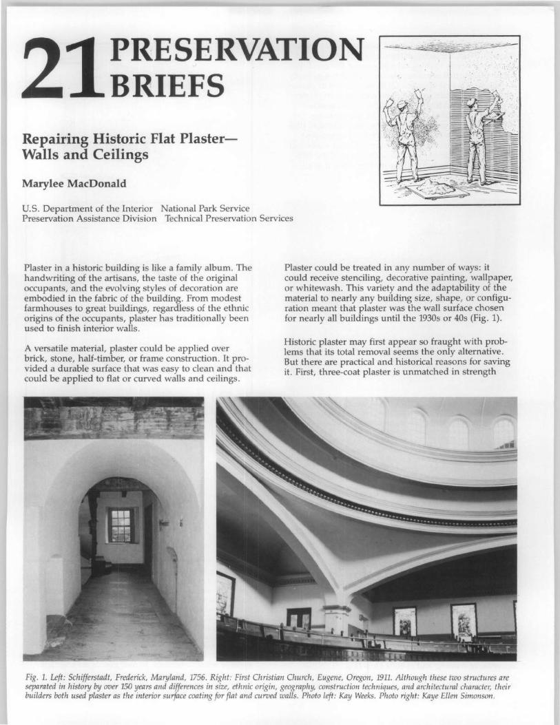
.~~.~-~~~~ PRESERVATION BRIEFS
I . . " .
Repairing Historic Flat PlasterWalls and Ceilings
Marylee MacDonald
'" ..
u.s. Department of the Interior National Park Service Preservation Assistance Division Technical Preservation Services
Plaster in a historic building is like a family album. The handwriting of the artisans, the taste of the original occupants, and the evolving styles of decoration are embodied in the fabric of the building. From modest farmhouses to great buildings, regardless of the ethnic origins of the occupants, plaster has traditionally been used to finish interior walls.
A versatile material, plaster could be applied over brick, stone, half-timber, or frame construction. It provided a durable surface that was easy to clean and that could be applied to flat or curved walls and ceilings.
Plaster could be treated in any number of ways: it could receive stenciling, decorative painting, wallpaper, or whitewash. This variety and the adaptability of the material to nearly any building size, shape, or configuration meant that plaster was the wall surface chosen for nearly all buildings until the 1930s or 40s (Fig. 1).
Historic plaster may first appear so fraught with problems that its total removal seems the only alternative. But there are practical and historical reasons for saving it. First, three-coat plaster is unmatched in strength
Fig. 1. Left: Schifferstadt, Frederick, Maryland, 1756. Right: First Christian Church, Eugene, Oregon, 1911. Although these two structures are separated in history /Jy over 150 years and differences in size, ethnic origin, geography, construction techniques, and architectural character, their builders both used plaster as the interior surface coating for flat and curved walls. Photo left: Kay Weeks. Photo right: Kaye Ellen Simonson.
.,',
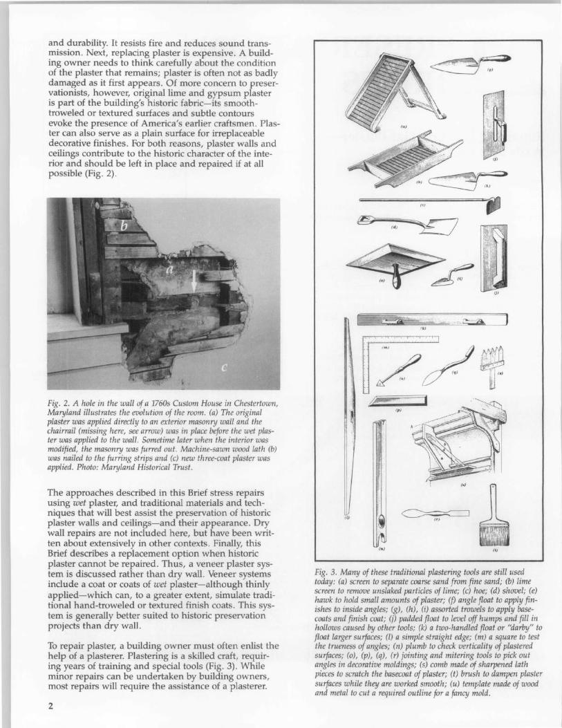
and durability. It resists fire and reduces sound transmission. Next, replacing plaster is expensive. A building owner needs to think carefully about the condition of the plaster that remains; plaster is often not as badly damaged as it first appears. Of more concern to preservationists, however, original lime and gypsum plaster is part of the building's historic fabric-its smoothtroweled or textured surfaces and subtle contours evoke the presence of America's earlier craftsmen. Plaster can also serve as a plain surface for irreplaceable decorative finishes. For both reasons, plaster walls and ceilings contribute to the historic character of the interior and should be left in place and repaired if at all possible (Fig. 2).
Fig. 2. A hole in the wall of a 1760s Custom House in Chestertown, Maryland illustrates the evolution of the room. (a) The original plaster was applied directly to an exterior masonry wall and the chairrail (missing here, see arrow) was in place before the wet pIaster was applied to the wall. Sometime later when the interior was modified, the masonry was furred out. Machine-sawn wood lath (b) was nailed to the furring strips and (c) new three-coat plaster was applied. Photo: Maryland Historical Trust.
The approaches described in this Brief stress repairs using wet plaster, and traditional materials and techniques that will best assist the preservation of historic plaster walls and ceilings-and their appearance. Dry wall repairs are not included here, but have been written about extensively in other contexts. Finally, this Brief describes a replacement option when historic plaster cannot be repaired. Thus, a veneer plaster system is discussed rather than dry wall. Veneer systems include a coat or coats of wet plaster-although thinly applied-which can, to a greater extent, simulate traditional hand-troweled or textured finish coats. This system is generally better suited to historic preservation projects than dry wall.
To repair plaster, a building owner must often enlist the help of a plasterer. Plastering is a skilled craft, requiring years of training and special tools (Fig. 3). While minor repairs can be undertaken by building owners, most repairs will require the assistance of a plasterer.
2
ell
~ 10' ~
Id, YJ
'"' / ~ ~) f')
Ip )
It,
Fig. 3. Many of these traditional plastering tools are still used today: (a) screen to separate coarse sand from fine sand; (b) lime screen to remove unslaked particles of lime; (c) hoe; (d) shovel; (e) hawk to hold small amounts of plaster; (f) angle float to apply finishes to inside angles; (g), (h), (i) assorted trowels to apply basecoats and finish coat; (j) padded float to level off humps and fill in hollows caused by other tools; (k) a two-handled float or "darby" to float larger surfaces; (I) a simple straight edge; (m) a square to test the trueness of angles; (n) plumb to check verticality of plastered surfaces; (0), (p), (q), (r) jointing and mitering tools to pick out angles in decorative moldings; (s) comb made of sharpened lath pieces to scratch the basecoat of plaster; (t) brush to dampen plaster surfaces while they are worked smooth; (u) template made of wood and metal to cut a required outline for a fancy mold.
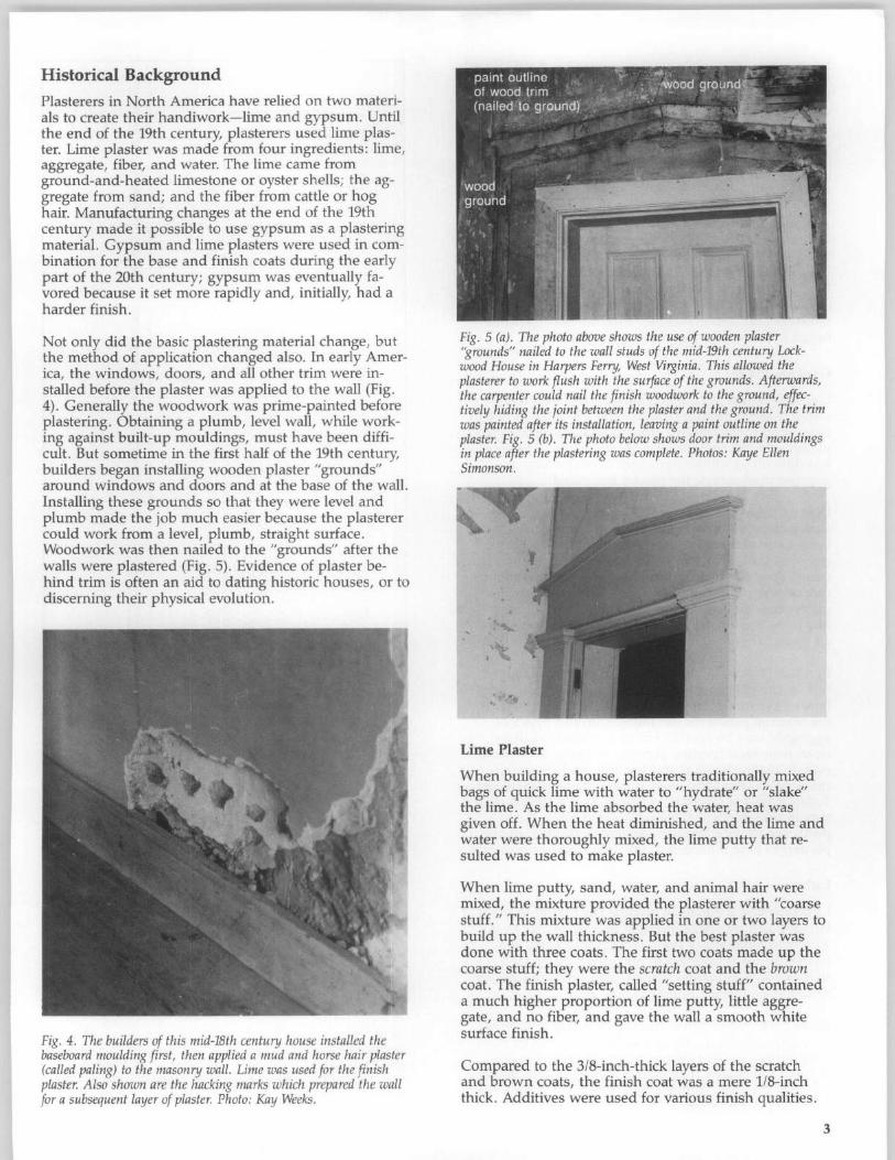
Historical Background Plasterers in North America have relied on two materials to create their handiwork-lime and gypsum. Until the end of the 19th century, plasterers used lime plaster. Lime plaster was made from four ingredients: lime, aggregate, fiber, and water. The lime came from ground-and-heated limestone or oyster shells; the aggregate from sand; and the fiber from cattle or hog hair. Manufacturing changes at the end of the 19th century made it possible to use gypsum as a plastering material. Gypsum and lime plasters were used in combination for the base and finish coats during the early part of the 20th century; gypsum was eventually favored because it set more rapidly and, initially, had a harder finish.
Not only did the basic plastering material change, but the method of application changed also. In early America, the windows, doors, and all other trim were installed before the plaster was applied to the wall (Fig. 4). Generally the woodwork was prime-painted before plastering. Obtaining a plumb, level wall, while working against built-up mouldings, must have been difficult. But sometime in the first half of the 19th century, builders began installing wooden plaster "grounds" around windows and doors and at the base of the wall. Installing these grounds so that they were level and plumb made the job much easier because the plasterer could work from a level, plumb, straight surface. Woodwork was then nailed to the "grounds" after the walls were plastered (Fig. 5). Evidence of plaster behind trim is often an aid to dating historic houses, or to discerning their physical evolution.
Fig. 4. The builders of this mid-18th century house installed the baseboard moulding first, then applied a mud and horse hair plaster (called paling) to the masonry wall . Lime was used for the finish plaster. Also shown are the hacking marks which prepared the wall for a subsequent layer of plaster. Photo: Kay Weeks.
Fig. 5 (a). The photo above shows the use of wooden plaster "grounds" nailed to the wall studs of the mid-19th century Lockwood House in Harpers Ferry, West Virginia. This allowed the plasterer to work flush with the surface of the grounds. Afterwards, the carpenter could nail the finish woodwork to the ground, effectively hiding the joint between the plaster and the ground. The trim was painted after its installation, leaving a paint outline on the plaster. Fig. 5 (b). The photo below shows door trim and mouldings in place after the plastering was complete. Photos: Kaye Ellen Simonson.
Lime Plaster
When building a house, plasterers traditionally mixed bags of quick lime with water to "hydrate" or "slake" the lime. As the lime absorbed the water, heat was given off. When the heat diminished, and the lime and water were thoroughly mixed, the lime putty that resulted was used to make plaster.
When lime putty, sand, water, and animal hair were mixed, the mixture provided the plasterer with "coarse stuff." This mixture was applied in one or two layers to build up the wall thickness. But the best plaster was done with three coats. The first two coats made up the coarse stuff; they were the scratch coat and the brown coat. The finish plaster, called "setting stuff" contained a much higher proportion of lime putty, little aggregate, and no fiber, and gave the wall a smooth white surface finish.
Compared to the 3/8-inch-thick layers of the scratch and brown coats, the finish coat was a mere 1/8-inch thick. Additives were used for various finish qualities.
3
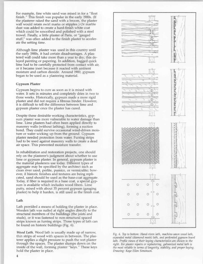
For example, fine white sand was mixed in for a "float finish." This finish was popular in the early 1900s. (If the plasterer raked the sand with a broom, the plaster wall would retain swirl marks or stipples .) Or marble dust was added to create a hard-finish white coat which could be smoothed and polished with a steel trowel. Finally, a little plaster of Paris, or "gauged stuf£;' was often added to the finish plaster to accelerate the setting time.
Although lime plaster was used in this country until the early 1900s, it had certain disadvantages. A plastered wall could take more than a year to dry; this delayed painting or papering. In addition, bagged quick lime had to be carefully protected from contact with air, or it became inert because it reacted with ambient moisture and carbon dioxide . Around 1900, gypsum began to be used as a plastering material.
Gypsum Plaster
Gypsum begins to cure as soon as it is mixed with water. It sets in minutes and completely dries in two to three weeks . Historically, gypsum made a more rigid plaster and did not require a fibrous binder. However, it is difficult to tell the difference between lime and gypsum plaster once the plaster has cured.
Despite these desirable working characteristics, gypsum plaster was more vulnerable to water damage than lime. Lime plasters had often been applied directly to masonry walls (without lathing), forming a suction bond. They could survive occasional wind-driven moisture or water wicking up from the ground. Gypsum plaster needed protection from water. Furring strips had to be used against masonry walls to create a dead air space. This prevented moisture transfer.
In rehabilitation and restoration projects, one should rely on the plasterer's judgment about whether to use lime or gypsum plaster. In general, gypsum plaster is the material plasterers use today. Different types of aggregate may be specified by the architect such as clean river sand, perlite, pumice, or vermiculite; however, if historic finishes and textures are being replicated, sand should be used as the base-coat aggregate . Today, if fiber is required in a base coat, a special gypsum is available which includes wood fibers. Lime putty, mixed with about 35 percent gypsum (gauging plaster) to help it harden, is still used as the finish coat.
Lath
Lath provi8.ed a means of holding the plaster in place . Wooden lath was nailed at right angles directly to the structural members of the buildings (the joists and studs), or it was fastened to non-structural spaced strips known as furring strips . Three types of lath can be found on historic buildings (Fig. 6).
Wood Lath. Wood lath is usually made up of narrow, thin strips of wood with spaces in between. The plasterer applies a slight pressure to push the wet plaster through the spaces . The plaster slumps down on the inside of the wall, forming plaster "keys ." These keys hold the plaster in place .
4
~ ~ ~
~ ~ ~ ~ ~~ ~ ~~~ ~ ~ - ~~ ~~ ~~
~ E ~ • ~ ~
o o
o o
o o
o o
Ji~il
)1~~ I I ~'
~T' !/ I
f<' ~~ ~ ~
~
~ ~ ;
~ ~ ~ pf,: ~ '1/1 "-4,J..:.
o 0
o 0
o 0
o 0
o 0 o 0
o 0
/ ( \ \ \
Fig. 6. Top to bottom: Hand-riven lath, machine-sawn wood lath, expanded metal (diamond mesh) lath, and perforated gypsum board lath. Profile views of their keying characteristics are shown to the right. For plaster repairs or replastering, galvanized metal lath is the most reliable in terms of longevity, stability, and proper keying. Drawing: Kaye Ellen Simonson.
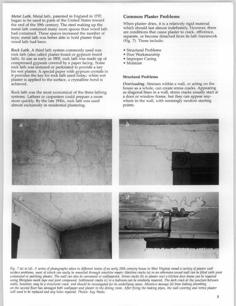
Metal Lath. Metal lath, patented in England in 1797, began to be used in parts of the United States toward the end of the 19th century. The steel making up the metal lath contained many more spaces than wood lath had contained. These spaces increased the number of keys; metal lath was better able to hold plaster than wood lath had been.
Rock Lath. A third lath system commonly used was rock lath (also called plaster board or gypsum-board lath). In use as early as 1900, rock lath was made up of compressed gypsum covered by a paper facing. Some rock lath was textured or perforated to provide a key for wet plaster. A special paper with gypsum crystals in it provides the key for rock lath used today; when wet plaster is applied to the surface, a crystalline bond is achieved.
Rock lath was the most economical of the three lathing systems. Lathers or carpenters could prepare a room more quickly. By the late 1930s, rock lath was used almost exclusively in residential plastering.
Common Plaster Problems
When plaster dries, it is a rehl.tively rigid material which should last almost indefinitely. However, there are conditions that cause plaster to crack, effloresce, separate, or become detached from its lath framework (Fig. 7). These include:
• Structural Problems • Poor Workmanship • Improper Curing • Moisture
Structural Problems
Overloading. Stresses within a wall, or acting on the house as a whole, can create stress cracks. Appearing as diagonal lines in a wall, stress cracks usually start at a door or window frame, but they can appear anywhere in the wall, with seemingly random starting points.
'\
Fig. 7 (a) to (d). A series of photographs taken in different rooms of an early 20th century house in West Virginia reveal a variety of plaster wall surface problems, most of which can easily be remedied through sensitive repair: Hairline cracks (a) in an otherwise sound wall can be filled with joint compound or patching plaster. The wall can also be canvassed or wallpapered. Stress cracks (b) in plaster over a kitchen door frame can be repaired using fiberglass mesh tape and joint compound. Settlement cracks (c) in a bedroom can be similarly repaired. The dark crack at the ;uncture between walls, however, may be a structural crack and should be investigated for its underlyinR cause. Moisture damaRe (d) from leakinR plumbin!{ on the second floor has damaged both wallpaper and plaster in the dining room. After fixing the leaking pipes, the wall covering and rotted plaster will need to be replaced and any holes repaired. Photos: Kay Weeks.
5
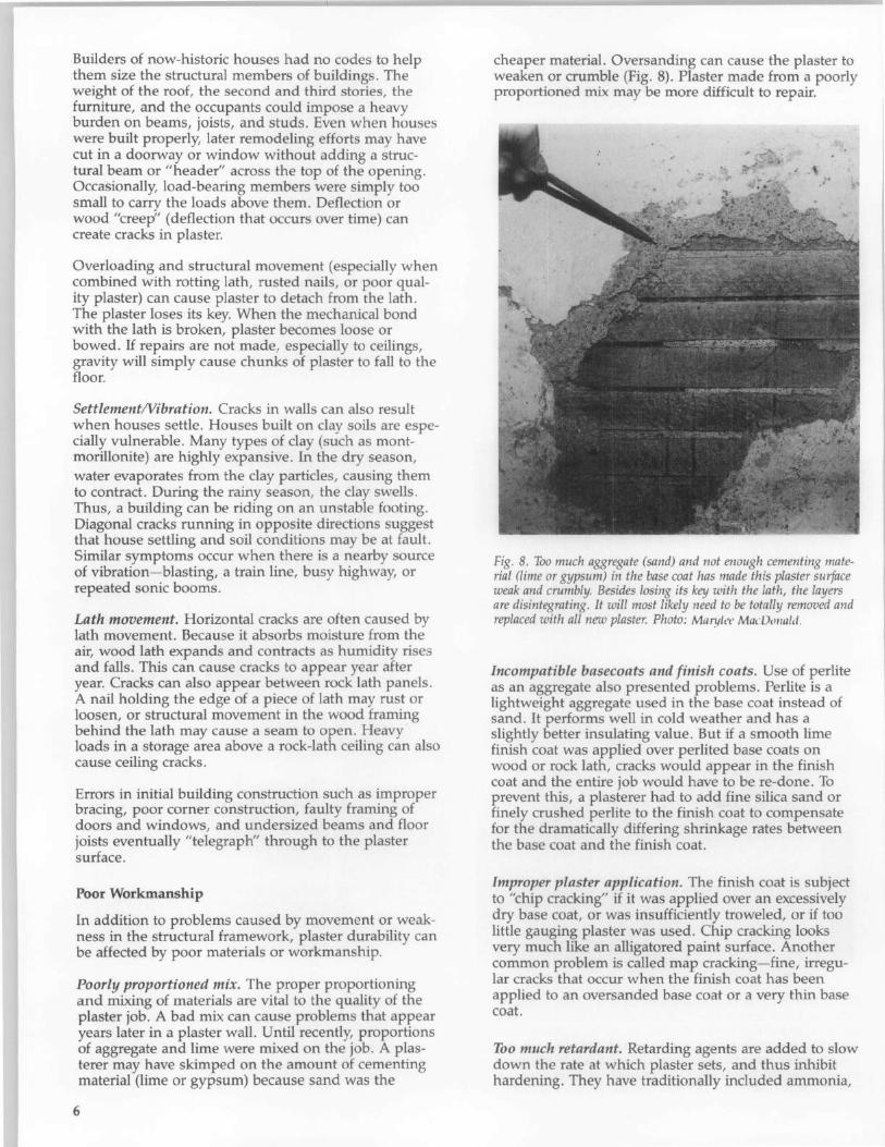
Builders of now-historic houses had no codes to help them size the structural members of buildings. The weight of the roof, the second and third stories, the furniture, and the occupants could impose a heavy burden on beams, joists, and studs. Even when houses were built properly, later remodeling efforts may have cut in a doorway or window without adding a structural beam or "header" across the top of the opening. Occasionally, load-bearing members were simply too small to carry the loads above them. Deflection or wood "creep" (deflection that occurs over time) can create cracks in plaster.
Overloading and structural movement (especially when combined with rotting lath, rusted nails, or poor quality plaster) can cause plaster to detach from the lath. The plaster loses its key. When the mechanical bond with the lath is broken, plaster becomes loose or bowed. If repairs are not made, especially to ceilings, gravity will simply cause chunks of plaster to fall to the floor.
SettlementNibration. Cracks in walls can also result when houses settle. Houses built on clay soils are especially vulnerable. Many types of clay (such as montmorillonite) are highly expansive. In the dry season, water evaporates from the clay particles, causing them to contract. During the rainy season, the clay swells. Thus, a building can be riding on an unstable footing. Diagonal cracks running in opposite directions suggest that house settling and soil conditions may be at fault. Similar symptoms occur when there is a nearby source of vibration-blasting, a train line, busy highway, or repeated sonic booms.
Lath movement. Horizontal cracks are often caused by lath movement. Because it absorbs moisture from the air, wood lath expands and contracts as humidity rises and falls. This can cause cracks to appear year after year. Cracks can also appear between rock lath panels. A nail holding the edge of a piece of lath may rust or loosen, or structural movement in the wood framing behind the lath may cause a seam to open. Heavy loads in a storage area above a rock-lath ceiling can also cause ceiling cracks.
Errors in initial building construction such as improper bracing, poor corner construction, faulty framing of doors and windows, and undersized beams and floor joists eventually "telegraph" through to the plaster surface.
Poor Workmanship
In addition to problems caused by movement or weakness in the structural framework, plaster durability can be affected by poor materials or workmanship.
Poorly proportioned mix. The proper proportioning and mixing of materials are vital to the quality of the plaster job. A bad mix can cause problems that appear years later in a plaster wall. Until recently, proportions of aggregate and lime were mixed on the job. A plasterer may have skimped on the amount of cementing material (lime or gypsum) because sand was the
6
cheaper material. Oversanding can cause the plaster to weaken or crumble (Fig. 8). Plaster made from a poorly proportioned mix may be more difficult to repair.
Fig. 8. Too much aggregate (sand) and not enough cementing material (lime or gypsum) in the base coat has made this plaster surface weak and crumbly. Besides losing its key with the lath, the layers are disintegrating. It will most likely need to be totally removed and replaced with all new plaster. Photo: M"rylt't' MllcOo/wld .
Incompatible basecoats and finish coats. Use of perlite as an aggregate also presented problems. Perlite is a lightweight aggregate used in the base coat instead of sand. It performs well in cold weather and has a slightly better insulating value. But if a smooth lime finish coat was applied over perlited base coats on wood or rock lath, cracks would appear in the finish coat and the entire job would have to be re-done. To prevent this, a plasterer had to add fine silica sand or finely crushed perlite to the finish coat to compensate for the dramatically differing shrinkage rates between the base coat and the finish coat.
Improper plaster application. The finish coat is subject to "chip cracking" if it was applied over an excessively dry base coat, or was insufficiently troweled, or if too little gauging plaster was used. Chip cracking looks very much like an alligatored paint surface. Another common problem is called map cracking-fine, irregular cracks that occur when the finish coat has been applied to an oversanded base coat or a very thin base coat.
Too much retardant. Retarding agents are added to slow down the rate at which plaster sets, and thus inhibit hardening. They have traditionally included ammonia,
glue, gelatin, starch, molasses, or vegetable oil. If the plasterer has used too much retardant, however, a gypsum plaster will not set within a normal 20 to 30 minute time period. As a result, the surface becomes soft and powdery.
Inadequate plaster thickness. Plaster is applied in three coats over wood lath and metal lath-the scratch, brown, and finish coats. In three-coat work, the scratch coat and brown coat were sometimes applied on successive days to make up the required wall thickness. Using rock lath allowed the plasterer to apply one base coat and the finish coat-a ~wo-coat job.
If a plasterer skimped on materials, the wall may not have sufficient plaster thickness to withstand the normal stresses withb a building. The minimum total thickness for plaster on gypsum board (rock lath) is 1/2 inch. On metal lath the minimum thickness is 5/8 inch; and for wood lath it is about 3/4 to 7/8 inch. This minimum plaster thickness may affect the thickness of trim projecting from the wall's plane .
Improper Curing
Proper temperature and air circulation during curing are key factors in a durable plaster job. The ideal temperature for plaster to cure is between 55-70 degrees Fahrenheit. However, historic houses were sometimes plastered before window sashes were put in. There was no way to control temperature and humidity.
Dryouts, freezing, and sweat~outs. When temperatures were too hot, the plaster would return to its original condition before it was mixed with water, that is, calcined gypsum. A plasterer would have to spray the wall with alum water to re-set the plaster. If freezing occurred before the plaster had set, the job would simply have to be re-done. If the windows were shut so that air could not circulate, the plaster was subject to sweat-out or rot. Since there is no cure for rotted plaster, the affected area had to be removed and replastered.
Moisture
Plaster applied to a masonry wall is vulnerable to water damage if the wall is constantly wet. When salts from the masonry substrate come in contact with water, they migrate to the surface of the plaster, appearing as dry bubbles or efflorescence. The source of the moisture must be eliminated before replastering the damaged area.
Sources of Water Damage. Moisture problems occur for several reasons . Interior plumbing leaks in older houses are common. Roofs may leak, causing ceiling damage. Gutters and downspouts may also leak, pouring rain water next to the building foundation . In brick buildings, dampness at the foundation level can wick up into the above-grade walls. Another common source of moisture is splash-back. When there is a paved area next to a masonry building, rainwater splashing up from the paving can dampen masonry walls . In both cases water travels through the masonry and damages interior plaster. Coatings applied to the
interior are not effective over the long run. The moisture problem must be stopped on the outside of the wall .
Repairing Historic Plaster
Many of the problems described above may not be easy to remedy. If major structural problems are found to be the source of the plaster problem, the structural problem should be corrected. Some repairs can be made by removing only small sections of plaster to gain access . Minor structural problems that will not endanger the building can generally be ignored. Cosmetic damages from minor building movement, holes, or bowed areas can be repaired without the need for wholesale demolition. However, it may be necessary to remove deteriorated plaster caused by rising damp in order for masonry walls to dry out. Repairs made to a wet base will fail again.
Canvassing Uneven Wall Surfaces
Uneven wall surfaces, caused by previous patching or by partial wallpaper removal, are common in old houses. As long as the plaster is generally sound, cosmetically unattractive plaster walls can be "wallpapered" with strips of a canvas or fabric-like material. Historically, canvassing covered imperfections in the plaster and provided a stable base for decorative painting or wallpaper.
Filling Cracks
Hairline cracks in wall and ceiling plaster are not a serious cause for concern as long as the underlying plaster is in good condition. They may be filled easily with a patching material (see Patching Materials, page 13). For cracks that re-open with seasonal humidity change, a slightly different method is used. First the crack is widened slightly with a sharp, pointed tool such as a crack widener or a triangular can opener. Then the crack is filled . For more persistent cracks, it may be necessary to bridge the crack with tape . In this instance, a fiberglass mesh tape is pressed into the patching material. After the first application of a quicksetting joint compound dries, a second coat is used to cover the tape, feathering it at the edges. A third coat is applied to even out the surface, followed by light sanding. The area is cleaned off with a damp sponge, then dried to remove any leftover plaster residue or dust:
When cracks are larger and due to structural movement, repairs need to be made to the structural system
. before repairing the plaster. Then, the plaster on each side of the crack should be removed to a width of about 6 inches down to the lath. The debris is cleaned out, and metal lath applied to the cleared area, leaving the existing wood lath in place. The metal lath usually prevents further cracking. The crack is patched with an appropriate plaster in three layers (i.e., basecoats and finish coat) . If a crack seems to be expanding, a structural engineer should be consulted.
7
Replacing Delaminated Areas of the Finish Coat
Sometimes the finish coat of plaster comes loose from the base coat (Fig. 9). In making this type of repair, the plasterer paints a liquid plaster-bonding agent onto the areas of base-coat plaster that will be replastered with a new lime finish coat. A homeowner wishing to repair small areas of delaminated finish coat can use the methods described in Patching Materials.
Fig. 9. The smooth-troweled lime finish coat has delaminated from the brown coat underneath . This is another repair that can be undertaken without further loss of the historic plaster. Photo: Marylee MacDonald.
I
Patching Holes in Walls
For small holes (less than 4 inches in diameter) that involve loss of the brown and finish coats, the repair is made in two applications. First, a layer of basecoat plaster is troweled in place and scraped back below the level of the existing plaster. When the base coat has set but not dried, more plaster is applied to create a smooth, level surface. One-coat patching is not generally recommended by plasterers because it tends to produce concave surfaces that show up when the work is painted. Of course, if the lath only had one coat of plaster originally, then a one-coat patch is appropriate (Fig. 10).
For larger holes where all three coats of plaster are damaged or missing down to the wood lath, plasterers generally proceed along these lines. First, all the old plaster is cleaned out and any loose lath is re-nailed. Next, a water mist is sprayed on the old lath to keep it from twisting when the new, wet plaster is applied, or better still, a bonding agent is used. To provide more reliable keying and to strengthen the patch, expanded metal lath (diamond mesh) should be attached to the wood lath with tie wires or nailed over the wood lath with lath nails (Fig. 11). The plaster is then applied in three layers over the metal lath, lapping each new layer of plaster over the old plaster so that old and new are evenly joined. This stepping is recommended to produce a strong, invisible patch (Fig. 12). Also, if a patch is made in a plaster wall that is slightly wavy, the contour of the patch should be made to conform to the irregularities of the existing work. A flat patch will stand out from the rest of the wall .
';
Fig. 10 (a) and (b). In this New Hampshire residence dating from the 1790s, the original plaster was a single coat of lime, sand, and horsehair applied over split lath. A one-coat repair, in this case, is appropriate. To the left: a fiat sheet of galvanized expanded metal lath is placed over the patch area and an outline marked with a large soft lumber crayon. The metal lath is then cut to fit the hole and nailed to the lath . To the right: the edges of the original plaster and wood lath beneath have been thoroughly soaked with water. A steel trowel is used to apply the plaster in large, rough strokes. Finally, it will be scraped and smoothed off. Because only one coat of plaster is used, without a finish coat, a clean butt-joint is made with the original plaster. Photos: John Leeke.
8
Fig. 11. Repairs are being made to the historic plaster in an early 20th century residence in Tennessee. A fairly sizeable hole in threecoat plaster extends to the wood lath. Expanded metal lath has been cut to fit the hole, then attached to the wood lath with a tie-wire. Two ready-mix gypsum base coats are in the process of being applied. After they set, the finish coat will be smooth-troweled gauged lime to match the existing wall. Photo: Walter Jowers.
The patch is stepped so that each new coat of plaster laps over the others
2 x 4 studs
I
Fig. 12. This explains how a hole in historic plaster is repaired over the existing wood lath. First, metal lath ;s secured over the wood lath with a tie wire, then the new plaster is applied in three layers, "stepped" so that each new coat overlaps the old plaster to create a good adhesive bond. Drawing: Kaye Ellen Simonson.
Patching Holes in Ceilings
Hairline cracks and holes may be unsightly, but when portions of the ceiling come loose, a more serious problem exists (Fig. 13). The keys holding the plaster to the ceiling have probably broken. First, the plaster around the loose plaster should be examined. Keys may have deteriorated because of a localized moisture problem, poor quality plaster, or structural overloading; yet, the surrounding system may be intact. If the areas surrounding the loose area are in reasonably good condition, the loose plaster can be reattached to the lath using flat-head wood screws and plaster washers (Fig. 14). To patch a hole in the ceiling plaster, metal lath is fastened over the wood lath; then the hole is filled with successive layers of plaster, as described above.
Fig. 13. This beaded ceiling in one of the bedrooms of the 1847 Lockwood House, Harpers Ferry, West Virginia, is missing portions of plaster due to broken keys. This is attributable, in part, to deterioration of the wood lath. Photo: Kaye Ellen Simonson.
,... _ ~ ~J
-~ .
• • Fig. 14. In a late 18th century house in Massachusetts, fiat-head wood screws and plaster washers were used to reattach loose ceiling plaster to the wood lath . After the crack is covered with fiberglass mesh tape, both the taped crack and the plaster washers will be skim-coated with a patching material. Photo: John Obed Curtis.
9
Establishing New Plaster Keys
If the back of the ceiling lath is accessible (usually from the attic or after removing floor boards), small areas of bowed-out plaster can be pushed back against the lath. A padded piece of plywood and braces are used to secure the loose plaster. After dampening the old lath and coating the damaged area with a bonding agent, a fairly liquid plaster mix (with a glue size retardant added) is applied to the backs of the lath, and worked into the voids between the faces of the lath and the back of the plaster. While this first layer is still damp, plaster-soaked strips of jute scrim are laid across the backs of the lath and pressed firmly into the first layer as reinforcement. The original lath must be secure, otherwise the weight of the patching plaster may loosen it.
Loose, damaged plaster can also be re-keyed when the goal is to conserve decorative surfaces or wallpaper. Large areas of ceilings and walls can be saved. This method requires the assistance of a skilled conservator-it is not a repair technique used by most plasterers. The conservator injects an acrylic adhesive mixture through holes drilled in the face of the plaster (or through the lath from behind, when accessible). The loose plaster is held firm with plywood bracing until the adhesive bonding mixture sets. When complete, gaps between the plaster and lath are filled, and the loose plaster is secure (Fig. 15).
Fig. 15. When ceiling repairs are made with wet plaster or with an injected adhesive mixture, the old loose plaster must be supported with a plywood brace until re-keying is complete. Photo: John Leeke.
10
Replastering Over the Old Ceiling
If a historic ceiling is too cracked to patch or is sagging (but not damaged from moisture), plasterers routinely keep the old ceiling and simply relath and rep laster over it. This repair technique can be used if lowering the ceiling slightly does not affect other ornamental features. The existing ceiling is covered with lx3-inch wood furring strips, one to each joist, and fastened completely through the old lath and plaster using a screw gun. Expanded metal lath or gypsum board lath is nailed over the furring strips. Finally, two or three coats are applied according to traditional methods. Replastering over the old ceiling saves time, creates much less dust than demolition, and gives added fire protection.
When Damaged Plaster Cannot be Repaired-Replacement Options
Partial or complete removal may be necessary if plaster is badly damaged, particularly if the damage was caused by long-term moisture problems. Workers undertaking demolition should wear OSHA-approved masks because the plaster dust that flies into the air may contain decades of coal soot. Lead, from leadbased paint, is another danger. Long-sleeved clothing and head-and-eye protection should be worn. Asbestos, used in the mid-twentieth century as an insulating and fireproofing additive, may also be present and OSHA-recommended precautions should be taken. If plaster in adjacent rooms is still in good condition, walls should not be pounded-a small trowel or pry bar is worked behind the plaster carefully in order to pry loose pieces off the wall.
When the damaged plaster has been removed, the owner must decide whether to replaster over the existing lath or use a different system. This decision should be based in part on the thickness of the original plaster and the condition of the original lath. Economy and time are also valid considerations. It is important to ensure that the wood trim around the windows and doors will have the same "reveal" as before. (The "reveal" is the projection of the wood trim from the surface of the plastered wall). A lath and plaster system that will give this required depth should be selected.
Replastering-Alternative Lath Systems for New Plaster
Replastering old wood lath. When plasterers work with old lath, each lath strip is re-nailed and the chunks of old plaster are cleaned out. Because the old lath is dry, it must be thoroughly soaked before applying the base coats of plaster, or it will warp and buckle; furthermore, because the water is drawn out, the plaster will fail to set properly. As noted earlier, if new metal lath is installed over old wood lath as the base for new plaster,
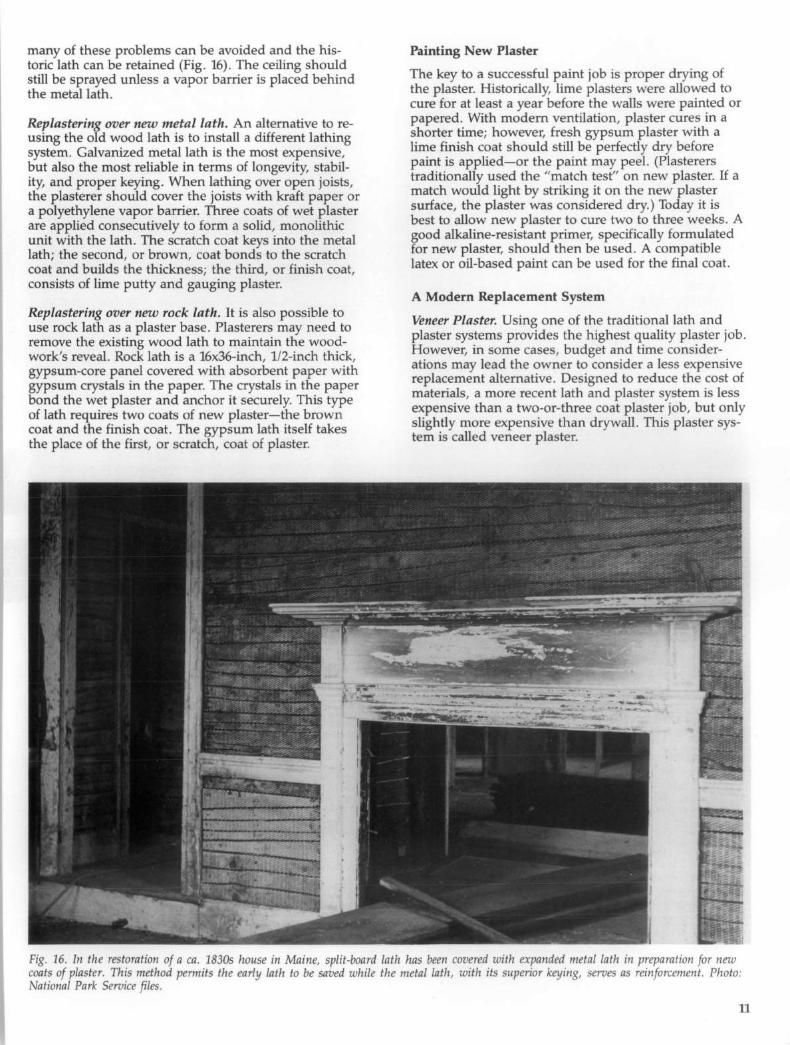
many of these problems can be avoided and the histo!ic lath can be retained (Fig. 16). The ceiling should still be sprayed unless a vapor barrier is placed behind the metal lath.
Replastering over new metal lath. An alternative to reusing the old w.ood lath is to i~stall a different lathing system. Galvamzed metal lath IS the most expensive, ~)Ut also the most reliable in terms of longevity, stabilIty, and proper keying. When lathing over open joists, the plasterer should cover the joists with kraft paper or a polyet~ylene vapo~ barrier. Three coats of wet plaster are apphed consecutively to form a solid monolithic unit with the lath. The scratch coat keys into the metal lath; the second, or brown, coat bonds to the scratch coat ~nd bu~ds the thickness; the third, or finish coat, consIsts of hme putty and gauging plaster.
Replastering over new rock lath. It is also possible to use rock lath ~s ~ plaster base. Plasterers may need to remove the eXIstmg wood lath to maintain the woodwork's reveal . Rock lath is a 16x36-inch, 1/2-inch thick, gypsum-core pa~el covered with absorbent paper with gypsum crystals m the paper. The crystals in the paper bond the wet plaster and anchor it securely. This type of lath requires two coats of new plaster-the brown coat and the finish coat. The gypsum lath itself takes the place of the first, or scratch, coat of plaster.
Painting New Plaster
The key to a successful paint job is proper drying of the plaster. Historically, lime plasters were allowed to cure for at l~ast a year before the walls were painted or papered .. WIth modern ventilation, plaster cures in a s.hort~r ~Ime; however, fresh gypsum plaster with a h~e f~Ish c<;>at should still be perfectly dry before pamt IS apphed-or the paint may peel. (Plasterers traditionally used the "match test" on new plaster. If a match would light by striking it on the new plaster surface, the plaster was considered dry.) Today it is best to allow new plaster to cure two to three weeks. A good alkaline-resistant primer, specifically formulated for new plaster, should then be used . A compatible latex or oil-based paint can be used for the final coat.
A Modern Replacement System
Veneer Plaster. Using one of the traditional lath and plaster sys~ems provides the highest quality plaster job. H?wever, m some cases, budget and time considerations may lead the owner to consider a less expensive replacement alternative. Designed to reduce the cost of materi~s, a more recent lath and plaster system is less e~pensive than a tw~-or-three coat plaster job, but only shghtly more expensIve than drywall. This plaster system is called veneer plaster.
Fig . 16. In the rest?ration of a ca. 1830s house in Maine, split-board lath has been covered with expanded metal lath in re aration for new cNoatt~ oflPplastkerS' Th~s mfi~lthod permits the early lath to be saved while the metal lath, with its superior keying serves as !i/fiorcement Photo'
a IOna ar ervlce es. ,. .
11
T.he system uses gypsum-core panels that are the same SIZe as drywall (4x8 feet), and specially made for veneer plaster. They can be installed over furring channels to masonry walls or over old wood lath walls and ceilings . Known most commonly as "blueboard;' the p~nels are covered with a special paper compatible WIth veneer plaster. Joints between the 4-foot wide ~heets are taped with fiberglass mesh, which is bedded m th~ veneer plaster. After the tape is bedded, a thin, 1/16-mch coat of high-strength veneer plaster is applied to the entire wall surface. A second veneer layer can be used as th~ "finish" coat, or the veneer plaster can be covered WIth a gauged lime finish-co at-the same coat that covers ordinary plaster (Fig. 17).
Fig. 1Z This contemporary plasterer is mixing a lime finish coat in mu~h the same way as America's earlier artisans. The ring consists of .lzme p~tty; the white powder inside is gauging plaster. After the mIxture IS blended, a steel trowel will be used to apply it. It should be noted that a traditional lime finish coat can be applied over a veneer plaster base coat to approximate the look of historic plaster walls and ceilings. Photo: Marylee MacDonald.
Although extremely thin, a two-coat veneer plaster system has a 1,500 psi rating and is thus able to withstand. struct~ral J?ovements in a building or surface abraslO.n .. WIth eIther a veneer finish or a gauged limeputty fImsh coat, the room will be ready for painting almost immediately. When complete, the troweled or textured wall surface looks more like traditional plaster than drywall.
The t~in prof~e of the veneer system has an added be~e~It, espeCIally: for owners of uninsulated masonry buildmgs. Insulation can be installed between the pieces of furring channel used to attach blue board to masonry walls. This can be done without having to furr out the window and door jambs. The insulation plus the veneer system will result in the same thickn~ss as the original plaster. Occupants in the rooms will be more comfortable because they will not be losing heat to cold wall surfaces.
Summary
The National Park Service recommends retaining historic p~?ster. ~,at all poss.ibl~. Plaster is a significant part o~ the ~abnc of the b~ildmg. Much of the building's hIStOry IS d~cumented m the layers of paint and paper f?und ~o~enng old plaster. For buildings with decorative pamtm~, conservation of historic flat plaster is even more Important. Consultation with the National Park Service, with State Historic Preservation Officers local preservation organizations, historic preservation' consultants, or with the Association for Preservation Technology is recommended. Where plaster cannot be rep~ed ?r co~ser:'ed using one of the approaches outhned m thIS Bnef, documentation of the layers of wallpaper and paint should be undertaken before removing the historic plaster. This information may be needed to complete a restoration plan.
12
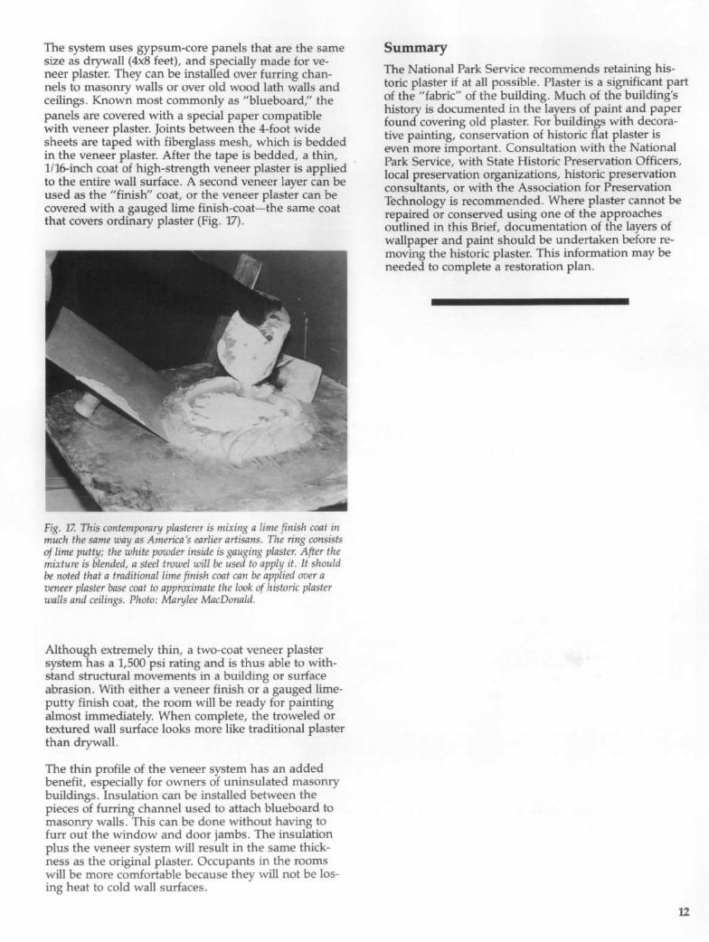
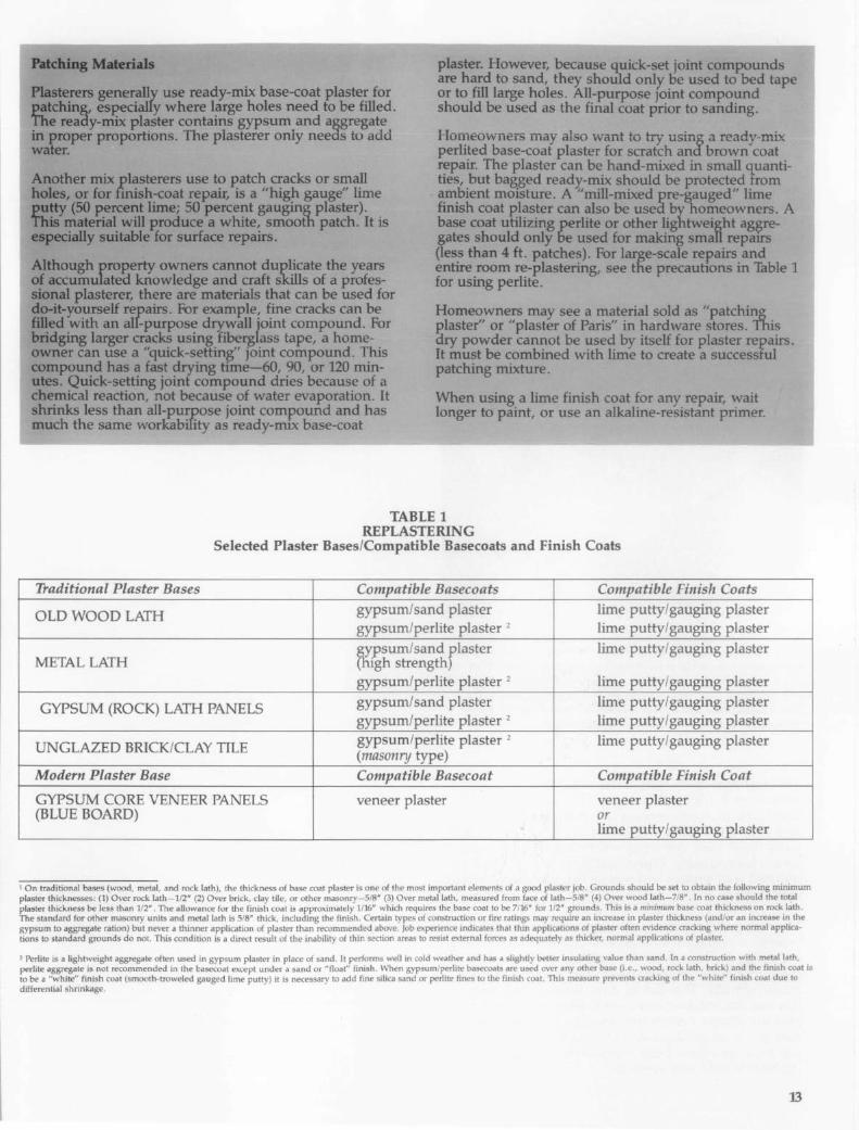
ftl&il1IIIII ....... PSllteu!1s =~ use ready-mix base-coat plaster for ~ . y where large holes need to be filled. 'n1e reaay-mix plaSter contains gypsum and aggregate =per proportions. The plasterer only needs to-add
~0th4!!r mix plasterers use to patch cracks or small for finish-coat repair, is a "high gauge" lime peJrterlltWlJlei 50 pen:ent gauging plaster).
,~=;-:: will a white, sJIiOOth patch. It is t suitable surface repairs.
AJthough property owners cannot duplicate the years aI accumulateQ knowledge and craft sldlls of a pfofesaiDnal plasterer, there are materials that can be used for
-yourself repairs. For example, fine cracks can be with an arr-p~se drf.!vaIl joint compound. For ~ larger crilckS using fi~ass tape, a homeawner can use a "quick-~" Joint compound. This can~und has a fast ~ time-60, 90, or 120 minutes. Quick-setting joint compound dries because of a chemical reaction, not because of water evap()ration. It shrinks less than all-purpose joint com~und and has much the same worICabillty as ready-mIX base-coat
plaster. However, because quick-set joint comROunds are hard to sand, they shoUld only be used to bed tape or to fill large holes. A1l-p~se Joint compound should be used as the fuial coat prior to sanding.
Homeowners may also want to try using a ready-mix perlited base-coat plaster for scratch and brown coat repair. The plaster can be hand-mixed in small quantities, but ba~ed ready-mix should be protected from ambient moisture. A "mill-mixed pre-gauged" lime finish coat plaster can also be used by nomeowners. A base coat utilizing perlite or other lightweistht aggregates should only De used for makiIig small repatrs (less than 4 ft. patches). For large-scare repairs and entire room re-plastering, see tile precautions in Table 1 for using perlite.
Homeowners may see a material sold as "patching plaster" or "plaster of Paris" in hardware stores. This ~ powder cannot be used by itself for plaster repairs. It must be combined with lime to create a successful patching mixture.
When using a lime finish coat for any repair, wait longer to paint, or use an alkaline-resistant primer.
TABLE 1 REPLASTERING
Selected Plaster Bases/Compatible Basecoats and Finish Coats
Traditional Plaster Bases Compatible Basecoats Compatible Finish Coats
OLD WOOD LATH gypsum/sand plaster lime putty/gauging plaster gypsum/perlite plaster 2 lime putty/gauging plaster
METAL LATH ~rsum/sand flaster hIgh strength
lime putty/gauging plaster
gypsum/perlite plaster 2 lime putty/gauging plaster
GYPSUM (ROCK) LATH PANELS gypsum/sand plaster lime putty/gauging plaster gypsum/perlite plaster 2 lime putty/gauging plaster
UNG LAZED BRICK/CLAY TILE gypsum/perlite plaster 2 lime putty/gauging plaster (masonry type)
Modern Plaster Base Compatible Basecoat Compatible Finish Coat
GYPSUM CORE VENEER PANELS veneer plaster veneer plaster (BLUE BOARD) or
lime putty/gauging plaster
I On traditional bases (wood, metal, and rock lath), the thickness of base coat plaster is one of the most important elements of a good plaster job~ Grounds should be set t~ obtain the following minimum plaster thicknesses: (1) Over rock lath-1 /2" (2) Over brick, clay tile, or other masonry-SIS" (3) Over metal lath, measured from face of lat~-S/S (4) Over wood lath-7/S . In no case should the t~talh
laster thickness be less than 1/2". The allowance for the finish coat is approximately 1116" which requires the base coat to be 7/16" for 1/2 ~roun~s. ThlS ~ a trll1l1mum.base coat thlcknes~ on rOCk, at . h,e standard for other masonry units and metal lath is 5/8" thick, including the finish. Certain types of construction or fire ratings may req.urre an mcrease m pla~ter thlcknes~ (and/or an mcrease ~ the
psum to aggregate ration) but never a thinner application of plaster than recommended above. Job experience indicates that thin applicahons ~f plaster often evl?en.ce cracking where normal apphca~~ns to standard grounds do not. This condition is a direct result of the inability of thin section areas to resist external forces as adequately as thicker, normal applicahons of plaster.
2 Perlite is a lightweight aggregate often used in gypsum plaster in place of sand . It performs well in cold weather and has a slightly better insulating value. than sand . In a constr~ction with m~t~ lath, . rlite aggregate is not recom.mended in the basecoat except under a sand or "float" finish . ~hen gypsum/ p:rlit~ basecoats ~.~ used over .any other base (I.e. , w~, rock lat~,' br~c~J ~n~ the ftmsh coat IS
rae be a "white" finish coat (smooth-troweled gauged lime putty) it is necessary to add fine silica sand or perlIte flOes to the finish coat. This measure prevents cracking of the white finish coat due to differential shrinkage.
13
Plaster Terms
Scratch coat. The first base coat put on wood or metal lath. The wet plaster is "scratched" with a scarifier or comb t? provide a rough surface so the next layer of base coat will stick to it.
Brown coat. The brown coat is the second application of wet, base-coat plaster with wood lath or metal systems. With gypsum board lath (rock lath, plasterboard), it is the only base coat needed.
Finish coat. Pure lime, mixed with about 35 percent gauging plaster to help it harden, is used for the very thin surface finish of the plaster wall. Fine sand can be added for a sanded finish coat.
Casing Bead. Early casing bead was made of wood. In the 19th century, metal casing beads were sometimes used around fireplace projections, and door and window openings. Like a wood ground, they indicate the proper thickness for the plaster.
Corner Bead. Wire mesh with a rigid metal spline used on outside comers. Installing the comer bead plumb is important.
Cornerite. Wire mesh used on inside comers of adjoining walls and ceilings. It keeps com ers from cracking.
Ground. Plasterers use metal or wood strips around the edges of doors and windows and at the bottom of walls. These grounds help keep the plaster the same thickness and provide a stopping edge for the plaster. Early plaster work, however, did not use grounds. On early buildings, the woodwork was installed and primed before plastering began. Some time in the early 19th century, a transition occurred, and plasterers applied their wall finish before woodwork was installed.
Gypsum. Once mined from large gypsum quarries near Paris (thus the name plaster of Paris), gypsum in its natural form is calcium sulfate. When calcined (or heated), one-and-a-half water molecules are driven off, leaving a hemi-hydrate of calcium sulfate. When mixed with water, it becomes calcium sulfate again. While gypsum was used in base-coat plaster from the 1890s on, it has always been used in finish coat and decorative plaster. For finish coats, gauging plaster was added to lime putty; it causes the lime to harden. Gypsum is also the ingredient in moulding plaster, a finer plaster used to create decorative mouldings in ornamental plasterwork.
Lime. Found in limestone formations or shell mounds, naturally occurring lime is calcium carbonate. When heated, it becomes calcium oxide. After water has been added, it becomes calcium hydroxide. This calcium hydroxide reacts with carbon dioxide in the air to recreate the original calcium carbonate.
Screed. Screeds are strips of plaster run vertically or hOrizontally on walls or ceilings . They are used to plumb and straighten uneven walls and level ceilings. Metal screeds are used to separate different types of plaster finishes or to separate lime and cement plasters.
Reading List
Ashurst, John and Ashurst, Nicola. Practical Building Conservation, English Heritage Technical Handbook, Volume 3. Mortars, Plasters and Renders. New York: Halsted Press, 1988.
Gypsum Construction Handbook. Chicago: United States Gypsum Company, 1986.
Hodgson, Frederick Thomas. Plaster and Plastering: Mortars and Cements, How to Make and How to Use. New York : The Industrial Publication Company, 1901.
Jowers, Walter. "Plaster Patching, Part II." Restoration Primer. New England Builder, November, 1987, pp. 41-43.
Leeke, John. "Problems with Plaster, Part One. " Landmarks Observer, Vol. 12. March/April, 1985., pp. 10, 14. Also "Problems with Plaster, Part Two." Vol. 12., May/June, 1985, p. 12.
_____ . "Saving Irreplaceable Plaster." Old House Journal. Vol. XV, No.6, November/December, 1987, pp. 51- 55.
McKee, Harley J., FAIA. Introduction to Early American Masonry-Stone, Brick, Mortar, and Plaster. New York: National Trust for Historic Preservation and Columbia University, 1973.
Phillips, Morgan . "Adhesives for the Reattachment of Loose Plaster;' A.P. T. Bulletin, Vol. XII, No.2, 1980, pp. 37-63.
Poore, Patricia . "The Basics of Plaster Repair." Old House Journal, Vol. 16, No. 2, March/April, 1988, pp. 29-35 .
Shivers, Natalie. Walls and Molding: How to Care for Old and Historic Wood and Plaster. Washington, D.C.: National Trust for Historic Preservation, 1989.
Stagg, W. D. and B. Pegg. Plastering: A Craftsman's Encyclopedia. Woodstock, New York: Beekman Publishers, 1976.
Van den Branden, F. and Thomas L. Hartsell. Plastering Skills. Homewood, Illinois : American Technical Publishers, Inc., 1984.
Weaver, Martin. "Nuts and Bolts: Properly Plastered." Canadian Heritage. Aug./Sept., 1981, pp. 34-36. Also "Nuts and Bolts: Fixing Plaster." Oct., 1981, pp. 33-35.
Acknow ledgements
Preservation Brief 21 was based on an article in Old House Restoration on repairing historic plaster published by the University of Illinois at UrbanaChampaign, 1984. Kay D. Weeks, Preservation Assistance Division, Te~hnical Preservation Services Branch, expanded the article and made substantial contributions to its development as a Brief. Special thanks go to the technical experts in the field who reviewed and comment upon the draft ma.nu~~ript : Andrew Ladygo (Society for the Preservation of New England AntiqUIties), David Flaharty, Gilbert Wolf (National Plastering Industries), Michael Kempster, and Walter Jowers. Insightful comments were offered by the Technical Preservation Services Branch which is directed by H . Ward Jand!. Finally, staff member Karen Kummer, Small Homes Council-Building Research Council, University of Illinois, provided invaluable production assistance.
The publicalion has been prepared pursuant to the National Historic Preservation Act of 1966, as amended. Preservation Briefs 2J was droeloped under the technirnl editorship of Lee H. Nelson, FAIA , Chief, Preservation Assistance Division, National Park Sennet, Department of the Interior, P.D. Box 37127, Washingtoll, D.C. 20013-7127. Comments on the usefulness of this illfonllation are welcomed and may be sent to Mr. Nelson at the above address . This publication is not copyrighted and can be reproduced without penalty. Nonnal procedures for credit to the author and the National Park Service are appreciated. October, 1989
For sale by the U.S. Government Printing Office Superintendent of DocumenIB, Mail Stop: SSOP, Washington, DC 20402-9828
14
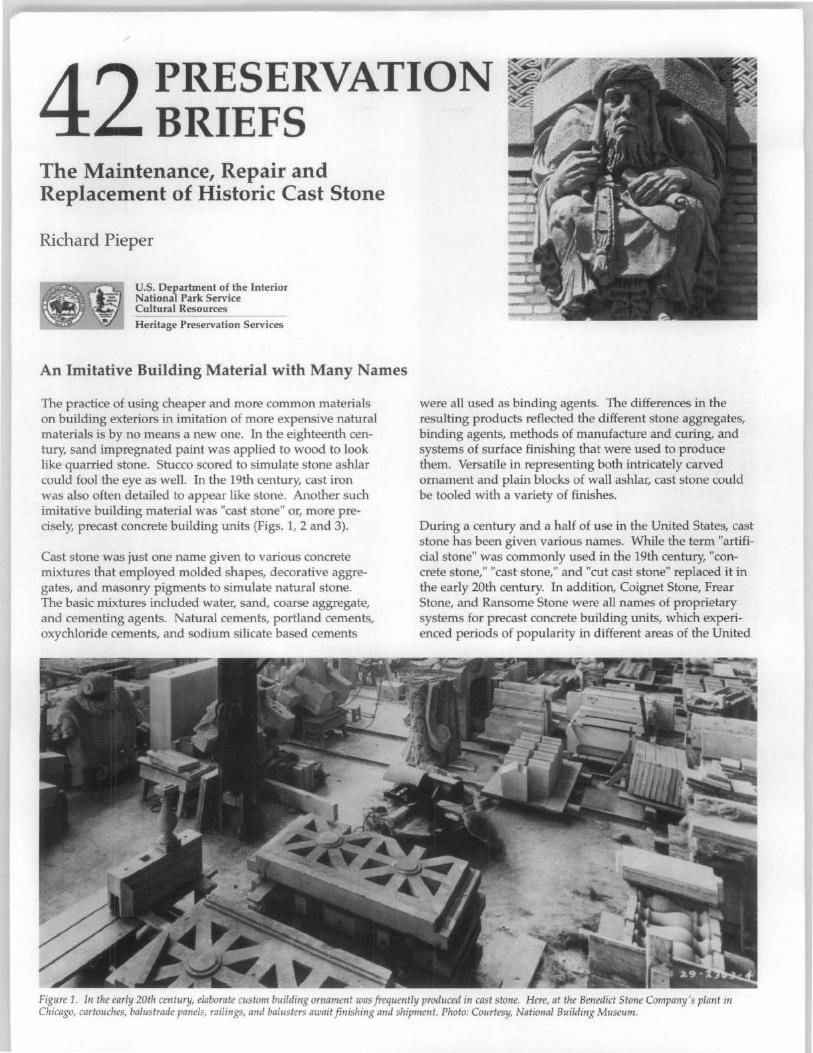
/
42 PRESERVATION BRIEFS
The Maintenance, Repair and Replacement of Historic Cast Stone
Richard Pieper
U.S. Department of the Interior National Park Service Cultural Resources
Heritage Preservation Services
An Imitative Building Material with Many Names
The practice of using cheaper and more common materials on building exteriors in imitation of more expensive natural materials is by no means a new one. In the eighteenth century, sand impregnated paint was applied to wood to look like quarried stone. Stucco scored to simulate stone ashlar could fool the eye as well. In the 19th century, cast iron was also often detailed to appear like stone. Another such imitative building material was "cast stone" or, more precisely, precast concrete building units (Figs. 1,2 and 3).
Cast stone was just one name given to various concrete mixtures that employed molded shapes, decorative aggregates, and masonry pigments to simulate natural stone. The basic mixtures included water, sand, coarse aggregate, and cementing agents. Natural cements, portland cements, oxychloride cements, and sodium silicate based cements
were all used as binding agents. The differences in the resulting products reflected the different stone aggregates, binding agents, methods of manufacture and curing, and systems of surface finishing that were used to produce them. Versatile in representing both intricately carved ornament and plain blocks of wall ashlar, cast stone could be tooled with a variety of finishes.
During a century and a half of use in the United States, cast stone has been given various names. While the term "artificial stone" was commonly used in the 19th century, "concrete stone," "cast stone," and "cut cast stone" replaced it in the early 20th century. In addition, Coignet Stone, Frear Stone, and Ransome Stone were all names of proprietary systems for precast concrete building units, which experienced periods of popularity in different areas of the United
Figure 1. In the early 20th century, elaborate custom building ornament was frequently produced in cast stone. Here, at the Benedict Stone Company's plant in Chicago, cartouches, balustrade pane/s, railings, and balusters await finishing and shipment. Photo: Courtesy, National Building Museum.
Figure 2. The prominent Delaware and Hudson Building in Albany, New York (1916) made extensive use of cast stone as trim combined with a random ashlar facing of natural granite. The elaborate gothic trim was produced by the Onondaga Litholite Company of Syracuse, New York.
States in the 19th century. These systems may be contrasted with "Artistic Concrete," decorative molded concrete construction, both precast and cast-in-place, which made little effort to simulate natural stone (Fig. 4).
Having gained popularity in the United States in the 1860s, cast stone had become widely accepted as an economical substitute for natural stone by the early decades of the 20th century. Now, it is considered an important historic material in its own right with unique deterioration problems that require traditional, as well as innovative solutions. This Preservation Brief discusses in detail the maintenance and repair of historic cast stone--precast concrete building units that simulate natural stone. It also covers the conditions that warrant replacement of historic cast stone with appropriate contemporary concrete products and provides guidance on their replication. Many of the issues and techniques discussed here are relevant to the repair and replacement of other precast concrete products, as well.
2
Figure 3. Sculptural ornament was frequently produced in cast stone. Repetitive detail, such as these banding course panels on the Level Club in New York City (1926), were produced much more economically than they could be in natural stone.
-. f /~\. ~,., -,' ... l',._-'\.
Figure 4. As shown in this Sears, Roebuck and Co. concrete machinery catalog, artistic concrete used standard concrete mixes to produce precast and cast-in-place concrete in molded forms, but made little effort to simulate naturalstone.
History of Use and Manufacture
Early Patented Systems
While some use of cast stone may be dated to the Middle Ages, more recent efforts to replicate stone with cementitious materials began in England and France at the end of the 18th century. Coade Stone, one of the best known of the early English manufactures, was used for architectural ornament and trim, and saw limited use for interior decoration in the United States as early as 1800. Significant advances in the artificial stone industry in the United States were tied to the production of natural cement or hydraulic lime, which began about 1820.
A large number of patented American, English, and French systems were marketed immediately after the Civil War. One of the earliest American patents for cast stone was awarded to George A. Frear of Chicago in 1868. Frear Stone was a mixture of natural cement and sand, to which a solution of shellac was added to provide initial curing strength. Frear's system was widely licensed around the
country, and the resultant variation in materials and manufacturing methods apparently resulted in some significant failures.
Another product which utilized natural cement as its cementing agent was Beton Coignet (literally, "Coignet concrete," also known as "Coignet Stone"). Francois Coignet was a pioneer of concrete construction in France. He received United States patents in 1869 and 1870 for his system of precast concrete construction, which consisted of portland cement, hydraulic lime, and sand. In the United States the formula was modified to a mix of sand with Rosendale Cement ( a high quality natural cement manufactured in Rosendale, Ulster County, New York). In 1870 Coignet's U.S. patent rights were sold to an American, John C. Goodrich, Jr., who formed the New York and Long Island Coignet Stone Company. This company fabricated
the cast stone for one of the earliest extant cast stone structures in the United States, the Cleft Ridge Span in Prospect Park, Brooklyn, New York (Fig. 5).
Some proprietary systems substituted other cements for the portland cement or hydraulic lime. The British patent process of Frederick Ransome utilized a mixture of sand and sodium silicate, combined with calcium chloride, to form blocks of calcium silicate. The sodium chloride by-product was intended to be removed with water washes during the curing process. The Sorel cement process, developed in 1853 and later applied to the manufacture of grindstones, tiles, and cast stone for buildings, combined zinc oxide with zinc chloride, or magnesium oxide and magnesium chloride, to form a hydrated oxychloride cement mixture that bound together sand or crushed stone. The Union Stone Company in Boston manufactured cast stone using the Sorel process. Ultimately, however, alternate cementing systems were abandoned in favor of portland cement, which proved to be more dependable and less expensive.
Figure 5. Constructed in 1868 of Beton Coignet, the Cleft Ridge Span in New York City 's Prospect Park is one of the earliest extant cast stone structures in the United States.
Late 19th and 20th Century Development
The use of cast stone grew rapidly with the extraordinary development of the portland cement and concrete industries at the end of the 19th century. In the early decades of the 20th century, cast stone became widely accepted as an economical substitute for natural stone. It was sometimes used as the only exterior facing material for a building, but was more often used as trim on a rock-faced natural stone or brick wall (Fig. 6). In most early 20th century installations, cast stone was used for exterior window and door surrounds or lintels, copings, parapets and balustrades, banding courses, cornices and friezes, and sculptural ornament. On occasion, decorative interiors were also finished with cast stone, although elaborate interior cornices and ornaments were more frequently fabricated of plaster.
3
Manufacture
Manufacturers of cast stone used graded mixes of crushed marble, limestone, granite, and smelting slag to produce a variety of stone effects. A light cement matrix with an aggregate of crushed marble could replicate limestone, while a mix of marble and small amounts of smelting slag would give the effect of white granite (Fig. 7). Some manufacturers added masonry pigments and varied colors on the faces of the stone to give a somewhat stylized effect of variegated sandstone. Each manufacturer prepared a variety of stock mixes as well. Not surprisingly, aggregates varied in different localities. In New York State, for example, crushed Gouverneur and Tuckahoe marbles were popular facing aggregates; in other areas, crushed feldspar or granite and even silica sand were commonly used.
The two basic cast stone production systems were "dry tamp" and "wet cast." The dry tamp process employed a stiff, low-slump concrete mix that was pressed and compacted into the molds. The decorative aggregate mix was frequently distributed only on the exterior facing of the cast units (typically 3/4" to tW' thick), while the cores of the units were common concrete. Because of the stiff mix, dry tamp units required a relatively short period of time in the molds, which could then be used several times a day. After removal from the molds, the dry tamp units were often cured in steam rooms to assure proper hydration of the cement. The wet cast process, on the other hand, used a much more plastic concrete mix that could be poured and vibrated into the molds. This system used significantly more water in the mix, assuring proper hydration of the cement mix without elaborate curing, but requiring that the units be left in the molds for at least a day. Because of this method of fabrication, wet cast products necessarily distributed their decorative aggregate mix through the entire unit, rather than simply an outer facing.
Concrete was cast in molds of wood, plaster, sand and, early in the 20th century, even hide glue or gelatin, depending upon the production method, the intricacy of the piece to be cast, and the number of units to be manufactured. Metal molds were sometimes used for stock ornamental items, less frequently for custom architectural work. When the units
4
Figure 6. Cast stone was commonly used fo r molded trim in conjunction with brick or natural stone. This brick building in Rochester, New York, uses cast stone for the entry surround, and natural stone for unornamented window sills, thresholds, and water table units.
Figure 7. A combination of crushed white marble and black smelting slag was frequently used to give the appearance of a "white granite". The hammered finish on this early twentieth century cast stone would have been produced with a pneumatic chisel.
were adequately hard, finish surfaces were worked to expose the decorative stone aggregate. When removed from the mold, wet cast units exhibit a surface film of cement paste, which must be removed to expose the aggregate. Partially cured units could be sprayed with water, rubbed with natural bristle brushes, etched with acid, or sandblasted to remove the cement layer. The surface of dry tamp products required less finishing.
High quality cast stone was frequently "cut" or tooled with pneumatic chisels and hammers similar to those used to cut natural stone (Fig. 9). In some cases, rows of small masonry blades were used to create shallow parallel grooves similar to lineal chisel marks. The results were often strikingly similar in appearance to natural stone. Machine and hand tooling was expensive, however, and simple molded cut cast stone was sometimes only slightly less costly than similar work in limestone. Significant savings could be achieved over the cost of natural stone when repetitive units of ornate carved trim were required.
Finally, cast stone is sometimes used today to replace natural stone when the original historic stone is no longer available, or the greater strength of reinforced concrete is desired. Reinforced cast stone columns, for instance, are frequently used to replace natural stone columns in seismic retrofits of historic structures. Fine-grained stones, such as sandstones, may be very successfully replicated with cast stone. Coarse-grained granites and marbles with pronounced patterns or banding are, for obvious reasons, not so successfully matched with cast stone. The replacement of natural stone with cast stone requires careful attention to selection of fine aggregates and the pigmentation of the cementing matrix (Fig. 8). Coarse aggregate, which is generally used in cast stone to control shrinkage and assure adequate compressive strength, can present an aesthetic problem if it is visible at the surface of cast stone elements which simulate sandstone. Careful control of aggregate sizes in the mix formulation can reduce this problem.
Figure 8. For this column, the appearance of a "pink granite" was simulated by using a pinkish matrix with white and black aggregate. Erosion of a tinted matrix results in a significant lightening of the cast stone surface.
Mechanisms and Modes of Deterioration
The best historic cast stone can rival natural stone in longevity. Many quality cast stone installations from the first decades of the twentieth century are still in excellent condition, and require little repair. Like any other building material, however, cast stone is subject to deterioration, which may occur in several ways:
• Separation of the facing and core layers
• Deterioration of the aggregate
• Deterioration or erosion of the cementing matrix
• Deterioration of the iron or steel reinforcement
• Deterioration of cramps and anchors used in its installation
Separation of the Facing and Core Layers
Separation of the facing and core layers of dry tamp units is not uncommon, and often reflects fabrication defects such as poor compaction, lengthy fabrication time, or improper curing. Where separation of facing and core layers is suspected, cast stone units may be "sounded" to establish the extent of delamination.
5
Fi$ure 10. Scaling of cast stone units signals problems with the cementing mIx and method of manufacture. Serious deterioration of cast stone, such as this, warrants replacement.
Deterioration of the Aggregate
Cast stone failure caused by deterioration of the aggregate is uncommon. Granites, marbles, and silica sand are generally durable, although limestone and marble aggregate are subject to the same dissolution problems that affect quarried units of these stones. In rare instances, a reaction between the alkalis in the cement matrix and the stone aggregate may also cause deterioration.
Figure 11. Erosion of the cementing matrix on the surface of cast stone is common in areas exposed to water runoff, such as window sills and copings. If no other deterioration is present, this condition does not warrant repair or replacement, but should be considered normal weathering. The unweathered surface at the left of this photograph shows the appearance of the original hammer-dressed finish. At right, the matrix has eroded, and the aggregate is much more prominent than on the unweathered surface.
6
Deterioration or Erosion of the Cementing Matrix
While it is relatively uncommon in twentieth century cast stone, serious deterioration of the cementing matrix can cause extensive damage to cast stone units (Fig. 10). A properly prepared cementing mix will be durable in most exterior applications, and any flaking of exterior surfaces signals problems in the cementing mix and in the method of manufacture. The use of poor quality or improperly stored cement, impure water, or set accelerators can cause cement problems to occur years after a structure is completed. Improper mixing and compaction can also result in a porous concrete that is susceptible to frost damage and scaling. Severe cement matrix problems may be impossible to repair properly and often necessitate replacement of the deteriorating cast stone units.
More common and less serious than flaking or scaling caused by deterioration of the cementing matrix is the erosion of the matrix surface (Fig. 11). This usually occurs on surfaces of projecting features exposed to water runoff, such as sills, water tables, and window hoods. In these areas, the matrix may erode, leaving small grains of aggregate projecting from the surface. The resultant rough surface is not at all the intended original appearance. In some historic cast stone installations, the thin layer of cement and fine sand at the surface of the cast stone units was not originally tooled from the molded surface, but was finished with patterns of masonry pigments in a stylized imitation of highly figured sandstones or limestones (Fig. 12). Erosion of the pigmented surface layer on this type of cast stone results in an even more dramatic change in appearance.
Figure 12. Elaborate pigmentation of the cementing matrix sometimes gave a rather stylized or unnatural appearance to the finished cast stone (left). Texts state that effects like this were sometimes produced by drawing strings dipped in masonry pigments across the surface of the uncured units. Cast stone, such as this, has its coloration only at the outer surface of the stone, and was not intended to be brushed or tooled to expose the aggregate. Erosion of the cementing matrix of this type of cast stone, as seen on the base of the wall (right), will result in a significant alteration of appearance.
Deterioration of the Iron or Steel Reinforcement
During their original manufacture, unusually long and thin cast stone units, such as window sills or balustrade railings, and units requiring structural capacity, such as lintels, were generally reinforced with mild steel reinforcing bars. Large pieces sometimes had cable loops or hooks cast into them to facilitate handling and attachment. On occasion, this reinforcement and wire may be too close (less than 2") to the surface of the piece and rusting will cause spalling of the surface (Fig. 13). This frequently happens to sills, copings, and water tables where repeated heavy wetting leads to loss of alkalinity in the concrete, allowing the reinforcement to rust. If damage from the deteriorating reinforcement is extensive, as for instance, the splitting of a baluster from the rusting of a central reinforcing rod, the cast stone unit may require replacement.
Deterioration of Cramps and Anchors
Even when reinforcement has not been added to individual cast stone units, mild steel cramps may have been used to anchor a cast stone veneer to backup masonry. Where spalls have occurred primarily at the tops of ashlar or frieze units, this is generally the cause.
Maintenance of Cast Stone Installations
Cleaning
Cast stone installations with marble or limestone aggregates may sometimes be cleaned with the same alkaline pre-wash/ acid afterwash chemical cleaning systems used to clean limestone and other calcareous natural stones. If no marble or limestone aggregates are present, acidic cleaners, such as those used for natural granites and sandstones, may be used. In either case, dark particulate staining in protected areas may be persistent, however, and require experimentation with other cleaning methods. Some micro-abrasive cleaning techniques used under very controlled circumstances by skilled cleaning personnel can be appropriate for removing tenacious soiling. Ordinary sand blasting or wet grit blasting can seriously damage the surface of the cast stone and should not be used (Fig. 14).
Figure 13. Rusting of reinforcement near the surface of the stone may result in spalling. Sections of reinforcement, such as this, may be cut out and the spall repaired with a matching composite mortar.
7
Figure 14. Sandblasting and wet grit blasting can seriously erode the surface and should not be used to clean cast stone surfaces.
Repointing
Early cast stone installations may have been constructed with natural cement mortars, but in late 19th century and 20th century installations, cast stone units were generally bedded and pointed with mortars composed of portland cement, lime, and sand. When rep ointing or replacement of the historic mortar is required, a Type N mortar (about one part cement, and one part lime to six parts of sand) is generally appropriate. When rep ointing any historic masonry, it is important to match both the character and color of the sand and color of the cement matrix in the historic mortar. Cement matrix color can often be adjusted by using combinations of white, "light," and gray portland cement in the mortar.
Joints in historic cast stone installations can be quite thin and the dense mortar thus difficult to remove. Unnecessary repointing can cause significant damage to
8
historic cast stone. Cracked and open joints will most often be found on exposed features, such as balustrades and copings, and, of course, require rep ointing. When a hard and tenacious mortar was used in the original installation or a later repointing, the removal of the mortar can easily chip the edges of the cast stone units.
While the careless use of "grinders" to remove mortar has damaged countless historic masonry buildings, a skilled mason may sometimes use a hand held grinder fitted with a thin diamond blade to score the center of a joint, and then remove the rest of the mortar with a hand chisel. If this method is not done carefully, however, wandering of the blade can widen or alter joints and cause significant damage to the cast stone. Care must be taken to prevent damage from over cutting of vertical joints by stopping blades well short of adjacent units. The use of small pneumatic chisels, such as those used to tool stone, can also work well for mortar removal, but even this method can cause chipping to the edges of cast stone units if it is not done carefully.
Methods of Repair
Much historic cast stone is unnecessarily replaced when it could easily be repaired in situ, or left untreated. This is especially true of areas that exhibit isolated spalls from rusting reinforcement bars or anchorage, or installations where erosion of the matrix has left a rough surface of exposed aggregate.
The weathering of cast stone, while different from that of natural stone, produces a patina of age and does not warrant large-scale replacement, unless severe cement matrix problems or rusting reinforcement bars have caused extensive scaling or spalling. Severe rusting of reinforcement bars on small decorative features, such as balusters, may signal carbonation (loss of alkalinity) of the matrix. Where carbonation of the matrix has occurred, untreated reinforcement will continue to rust. Replacement may be an acceptable approach for exposed and severely deteriorated features, such as hand railings, roof balustrades, or wall copings, where disassembly is unlikely to damage adjacent construction. Conversely, small areas of damage should generally be repaired with mortar "composites", or left alone.
Re-securing Separated Surface Facing
Where the decorative facing of dry tamped cast stone has separated from core layers, injected grouts may be used to re-secure the facing. Re-attachment of a separated facing layer may be time consuming, and should be undertaken by a conservator, rather than a mason (Fig. 15). This technique may be the best, most economical, approach for repair of figurative sculpture or unique elements that are not repeated elsewhere on a building. Theoretically, cementitious grouts are most appropriate for re-attaching separated facings, but hairline fissures may require the use of resin adhesives. Low-viscosity epoxies have been used
for this purpose, and may be applied through small injection ports. Cracks that would allow the adhesive to leak must be repaired prior to injection, of course. Holes made for adhesive injection will require patching after re-attachment is complete.
Repairing Spalls from Rusting Reinforcement Bars and Mechanical Damage
Drilled holes, mechanically damaged comers, and occasional spalls from rusting reinforcement bars and anchorage are repairable conditions that do not warrant the replacement of cast stone. Small "composite " repairs to damaged masonry units can be made with mortar formulated to visually match the original material, and may be successfully undertaken by a competent and sensitive mason. If deterioration appears widespread, however, or if large surface areas are spalling or cracking and replacement appears necessary, the owner may wish to consult a preservation architect or consultant to determine the cause of deterioration and to specify necessary repairs or replacement, as appropriate.
The methods of composite repair used for stone masonry are also generally applicable for the repair of historic cast stone. For repairs to damaged cast stone to be successful, however, both the cement matrix color and the aggregate size and coloration must match that of the historic unit. Crushed stone and slag (such as "Black Beauty" abrasive grit), which are similar to many common traditional aggre-
gates, are widely available, although some additional crushing and / or sieving may be necessary to obtain aggregate of an appropriate size. Remember that half or more of a weathered surface is exposed aggregate, so careful aggregate selection and size grading is extremely important for patching. Even differences in aggregate angularity (rounded pebbles vs. crushed stone) will be noticeable in the final repair. If more than one aggregate was used in the cast stone, the ratio of the selected aggregates in the mix is, of course, equally important. Variation in coloring of the cement matrix may be achieved through the use of either white, "light, " or gray portland cement. If additional tinting is required, only inorganic alkali-resistant masonry pigments should be used. Because most historic cast stone was manufactured primarily from portland cement and aggregate (with a less than 15% lime / cement ratio), it is not necessary to add large amounts of hydrated lime to cast stone composite repair mixtures. Small amounts of lime may be added for plasticity of the working mix.
To repair a spall caused by deterioration of a ferrous reinforcement bar or anchorage, it is necessary to remove all cracked concrete adjacent to the spall; grind and brush the reinforcement to remove all rust and scale; and paint the metal with a rust-inhibiting primer prior to applying the cast stone composite. If the reinforcement bar is much too close to the surface of the stone, it may be advisable to cut out the deteriorating section of reinforcement after consultation with a structural engineer. If deteriorating cramps are removed, it may be necessary to install new stainless steel anchorage.
Figure 15. A delaminated layer of ornamental cast stone on the Orpheum Theater, San Francisco, California (1925), was successfully re-attached using qJoxy. The multiple delivenj ports for the qJ0XY are removed after treatment and the holes patched. Photo: David P Wessel/.
9
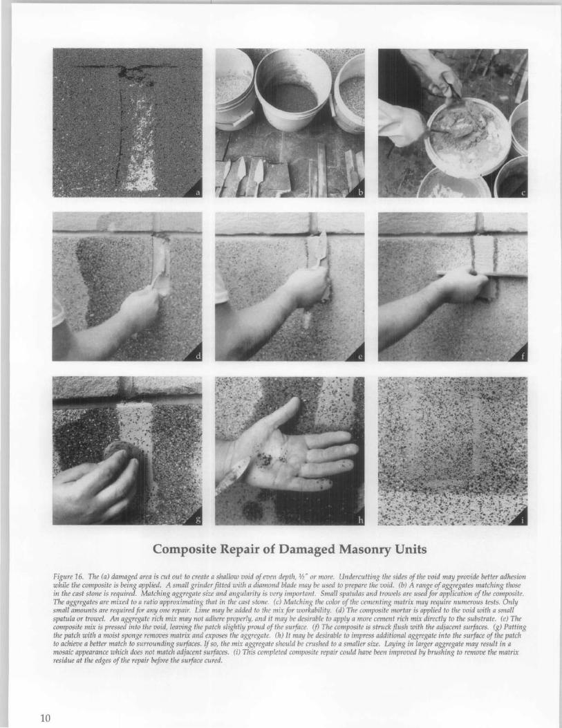
10
Composite Repair of Damaged Masonry Units
Figure 16. The (a) damaged area is cut out to create a shallow void of even depth, 1h" or more. Undercutting the sides of the void may provide better adhesion while the composite is being applied. A small grinder fitted with a diamond blade may be used to prepare the void. (b) A range of aggregates matching those in the cast stone is required. Matching aggregate size and angularity is very important. Small spatulas and trowels are used for application of the composite. The aggregates are mixed to a ratio approximating that in the cast stone. (c) Matching the color of the cementing matrix may require numerous tests. Only small amounts are required for anyone repair. Lime may be added to the mix for workability. (d) The composite mortar is applied to the void with a small spatula or trowel. An aggregate rich mix may not adhere properly, and it may be desirable to apply a more cement rich mix directly to the substrate. (e) The composite mix is pressed into the void, leaving the patch slightly proud of the surface. if) The composite is struck flush with the adjacent surfaces. (g) Patting the patch with a moist sponge removes matrix and exposes the aggregate. (h) It may be desirable to impress additional aggregate into the surface of the patch to achieve a better match to surrounding surfaces. If so, the mix aggregate should be crushed to a smaller size. Laying in larger aggregate may result in a mosaic appearance which does not match adjacent surfaces. (i) This completed composite repair could have been improved by brushing to remove the matrix residue at the edges of the repair before the surface cured.
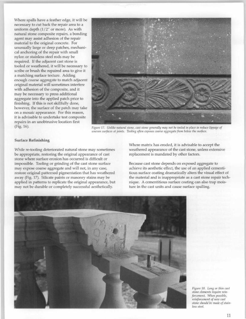
Where spalls have a feather edge, it will be necessary to cut back the repair area to a uniform depth (1/2" or more). As with natural stone composite repairs, a bonding agent may assist adhesion of the repair material to the original concrete. For unusually large or deep patches, mechanical anchoring of the repair with small nylon or stainless steel rods may be required. If the adjacent cast stone is tooled or weathered, it will be necessary to scribe or brush the repaired area to give it a matching surface texture. Adding enough coarse aggregate to match adjacent original material will sometimes interfere with adhesion of the composite, and it may be necessary to press additional aggregate into the applied patch prior to finishing. If this is not skillfully done, however, the surface of the patch may take on a mosaic appearance. For this reason, it is advisable to undertake test composite repairs in an unobtrusive location first (Fig. 16). Figure 17. Unlike natural stone, cast stone generally may not be tooled in place to reduce lippage of
uneven surfaces at joints. Tooling often exposes coarse aggregate from below the surface.
Surface Refinishing
While re-tooling deteriorated natural stone may sometimes be appropriate, restoring the original appearance of cast stone where surface erosion has occurred is difficult or impossible. Tooling or grinding of the cast stone surface may expose coarse aggregate and will not, in any case, restore original patterned pigmentation that has weathered away (Fig. 17). Silicate paints or masonry stains may be applied in patterns to replicate the original appearance, but may not be durable or completely successful aesthetically.
Where matrix has eroded, it is advisable to accept the weathered appearance of the cast stone, unless extensive replacement is mandated by other factors.
Because cast stone depends on exposed aggregate to achieve its aesthetic effect, the use of an applied cementitious surface coating dramatically alters the visual effect of the material and is inappropriate as a cast stone repair technique. A cementitious surface coating can also trap moisture in the cast units and cause surface spalling.
Figure 18. Long or thin cast stone elements require reinforcement. When possible, reinforcement of new cast stone should be made of stainless steel.
11

Figure 19. Molds for the replication of cast stone may be made on site using rubber materials and reinforcement. The molded profile of this window pediment will be used to run a plaster mockup, from which a production mold will be made. Photo: Michael Devonshire.
Replacement of Historic Cast Stone Installations
Individual cast stone units, which are subject to repeated wetting (such as copings, railings and balusters) and exhibit severe failure due to spalling or reinforcement deterioration, may require replacement with new cast stone (Fig. 18). Fortunately, a number of companies custom manufacture precast concrete units and can replicate deteriorated units in existing buildings (Fig. 19). The variables involved in manufacture are considerable, and it is wise to use a firm with experience in ornamental and custom work rather than a precast concrete firm which manufactures stock structural items, concrete pipe, or the like. Several trade organizations, including the Cast Stone Institute, the National Precast Concrete Association, and the Architectural Precast Association, have developed recommendations and / or guide specifications for the manufacture of cast stone and precast concrete. These specifications set standards for characteristics such as compressive strength and water absorptivity, and discuss additives such as air entraining agents and water reducing agents, which influence the longevity of new cast stone. Trade references and guide specifications should be consulted before contracting for replacement of historic cast stone.
Fabrication Defects in New Cast Stone
While the cement matrix coloration and aggregate considerations previously described require the most careful attention, project staff should also look for defects which are common to cast stone fabrication:
Air bubbles. Small pits on the surface of the stone may form if the unit is not given adequate vibration to release trapped air during pouring. Bubbles can also be a problem
12
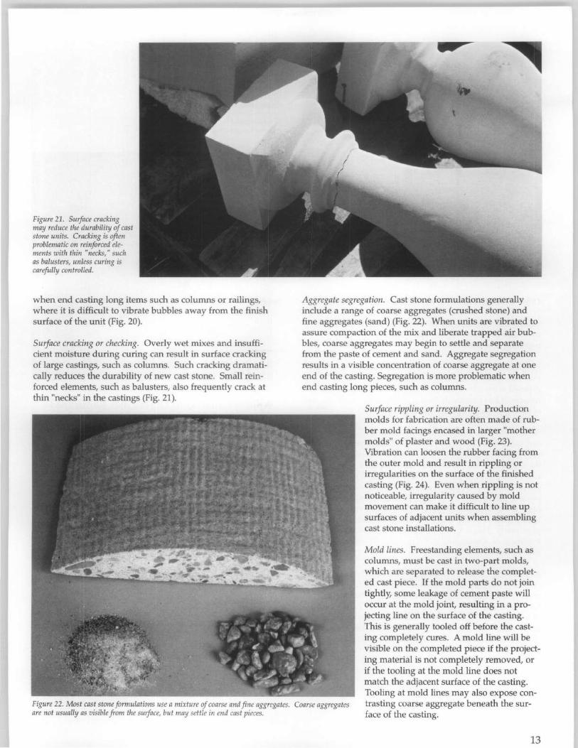
Figure 21. Surface cracking may reduce the durability of cast stone units. Cracking is often problematic on reinforced elements with thin "necks," such as balusters, unless curing is carefully controlled.
when end casting long items such as columns or railings, where it is difficult to vibrate bubbles away from the finish surface of the unit (Fig. 20).
Surface cracking or checking. Overly wet mixes and insufficient moisture during curing can result in surface cracking of large castings, such as columns. Such cracking dramatically reduces the durability of new cast stone. Small reinforced elements, such as balusters, also frequently crack at thin "necks" in the castings (Fig. 21).
Aggregate segregation. Cast stone formulations generally include a range of coarse aggregates (crushed stone) and fine aggregates (sand) (Fig. 22). When units are vibrated to assure compaction of the mix and liberate trapped air bubbles, coarse aggregates may begin to settle and separate from the paste of cement and sand. Aggregate segregation results in a visible concentration of coarse aggregate at one end of the casting. Segregation is more problematic when end casting long pieces, such as columns.
Surface rippling or irregularity. Production molds for fabrication are often made of rubber mold facings encased in larger "mother molds" of plaster and wood (Fig. 23). Vibration can loosen the rubber facing from the outer mold and result in rippling or irregularities on the surface of the finished casting (Fig. 24). Even when rippling is not noticeable, irregularity caused by mold movement can make it difficult to line up surfaces of adjacent units when assembling cast stone installations.
Figure 22. Most cast stone formulations use a mixture of coarse and fine aggregates. Coarse aggregates are not usually as visible from the surface, but may settle in end cast pieces.
Mold lines. Freestanding elements, such as columns, must be cast in two-part molds, which are separated to release the completed cast piece. If the mold parts do not join tightly, some leakage of cement paste will occur at the mold joint, resulting in a projecting line on the surface of the casting. This is generally tooled off before the casting completely cures. A mold line will be visible on the completed piece if the projecting material is not completely removed, or if the tooling at the mold line does not match the adjacent surface of the casting. Tooling at mold lines may also expose contrasting coarse aggregate beneath the surface of the casting.
13
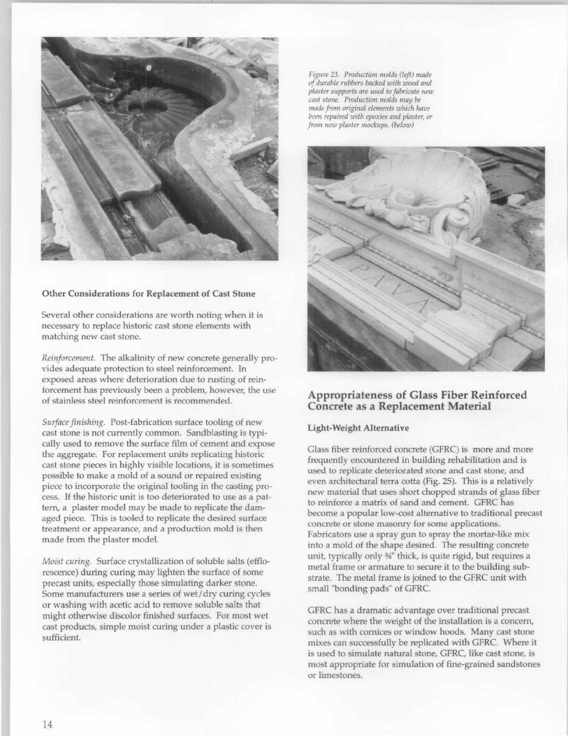
Other Considerations for Replacement of Cast Stone
Several other considerations are worth noting when it is necessary to replace historic cast stone elements with matching new cast stone.
R~inforcement. The alkalinity of new concrete generally provIdes adequate protection to steel reinforcement. In exposed areas where deterioration due to rusting of reinforcement has previously been a problem, however, the use of stainless steel reinforcement is recommended.
Surface finishing. Post-fabrication surface tooling of new cast stone is not currently common. Sandblasting is typically used to remove the surface film of cement and expose the aggregate. For replacement units replicating historic cast stone pieces in highly visible locations, it is sometimes P?ssible .to make a mold of a sound or repaired existing pIece to mcorporate the original tooling in the casting process. If the historic unit is too deteriorated to use as a pattern, a plaster model may be made to replicate the damaged piece. This is tooled to replicate the desired surface treatment or appearance, and a production mold is then made from the plaster model.
Moist curing. Surface crystallization of soluble salts (efflorescence) during curing may lighten the surface of some precast units, especially those simulating darker stone. Some manufacturers use a series of wetl dry curing cycles or washing with acetic acid to remove soluble salts that might otherwise discolor finished surfaces. For most wet cast products, simple moist curing under a plastic cover is sufficient.
14
Figure 23. Production molds (left) made of durable rubbers backed with wood and plaster supports are used to fabricate new cast stone. Production molds may be made from original elements which have been repaired with epoxies and plaster, or from new plaster mockups. (below)
Appropriateness of Glass Fiber Reinforced Concrete as a Replacement Material
Light-Weight Alternative
Glass fiber reinforced concrete (GFRC) is more and more frequently encountered in building rehabilitation and is used to replicate deteriorated stone and cast stone, and even architectural terra cotta (Fig. 25). This is a relatively new material that uses short chopped strands of glass fiber to reinforce a matrix of sand and cement. GFRC has become a popular low-cost alternative to traditional precast concrete or stone masonry for some applications. Fabricators use a spray gun to spray the mortar-like mix into a mold of the shape desired. The resulting concrete unit, typically only 3,4" thick, is quite rigid, but requires a metal frame or armature to secure it to the building substrate. The metal frame is joined to the GFRC unit with small "bonding pads" of GFRC.
GFRC has a dramatic advantage over traditional precast concrete where the weight of the installation is a concern, such as with cornices or window hoods. Many cast stone mixes can successfully be replicated with GFRC. Where it is used to simulate natural stone, GFRC, like cast stone, is most appropriate for simulation of fine-grained sandstones or limestones.
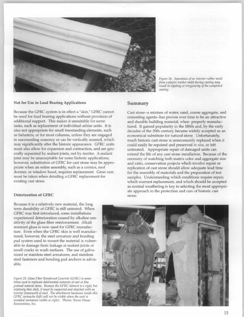
Not for Use in Load Bearing Applications
Because the GFRC system is in effect a "skin," GFRC cannot be used for load bearing applications without provision of additional support. This makes it unsuitable for some tasks, such as replacement of individual ashlar units. It is also not appropriate for small freestanding elements, such as balusters, or for most columns, unless they are engaged to surrounding masonry or can be vertically seamed, which may significantly alter the historic appearance. GFRC units must also allow for expansion and contraction, and are generally separated by sealant joints, not by mortar. A sealant joint may be unacceptable for some historic applications; however, substitution of GFRC for cast stone may be appropriate when an entire assembly, such as a cornice, roof dormer, or window hood, requires replacement. Great care must be taken when detailing a GFRC replacement for existing cast stone.
Deterioration of GFRC
Because it is a relatively new material, the long term durability of GFRC is still untested. When GFRC was first introduced, some installations experienced deterioration caused by alkaline sensitivity of the glass fiber reinforcement. Alkali resistant glass is now used for GFRC manufacture. Even when the GFRC skin is well manufactured, however, the steel armature and bonding pad system used to mount the material is vulnerable to damage from leakage at sealant joints or small cracks in wash surfaces. The use of galvanized or stainless steel armatures, and stainless steel fasteners and bonding pad anchors is advisable.
Figure 25. Glass Fiber Reinforced Concrete (GFRC) is sometimes used to replicate deteriorated elements of cast or fine grained natural stone. Because the GFRC element is a rigid, but relatively thin shell, it must be supported and attached with an interior framework of steel. The attachment hardware inside this GFRC cartouche (left) will not be visible when the unit is installed (armature visible at right). Photos: Towne House Restorations, Inc.
Summary
Figure 24. Separation of an interior rubber mold from a plaster mother mold during casting may result in rippling or irregularity of the completed casting.
Cast stone--a mixture of water, sand, coarse aggregate, and cementing agents--has proven over time to be an attractive and durable building material, when properly manufactured. It gained popularity in the 1860s and, by the early decades of the 20th century, became widely accepted as an economical substitute for natural stone. Unfortunately, much historic cast stone is unnecessarily replaced when it could easily be repaired and preserved in situ, or left untreated. Appropriate repair of damaged units can extend the life of any cast stone installation. Because of the necessity of matching both matrix color and aggregate size and ratio, conservation projects which involve repair or replication of cast stone should allow adequate lead time for the assembly of materials and the preparation of test samples. Understanding which conditions require repair, which warrant replacement, and which should be accepted as normal weathering is key to selecting the most appropriate approach to the protection and care of historic cast stone.
15
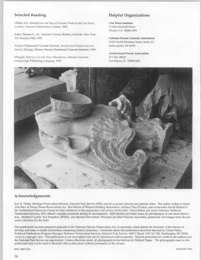
Selected Reading
Childe, H.L. Manufacture and Uses of Concrete Products and Cast Stone, London: Concrete Publications Limited, 1930.
Jester, Thomas c., ed., Twentieth Century Building Materials, New York, NY: McGraw-Hill, 1995.
Precast/Prestressed Concrete Institute, Architectural Precast Concrete, 2nd ed., Chicago, Illinois: Precast/Prestressed Concrete Institute, 1989.
Whipple, Harvey, Concrete Stone Manufacture, Detroit: ConcreteCement Age Publishing Company, 1918.
Acknowledgements
Helpful Organizations
Cast Stone Institute 10 West Kimball Street Winder, GA 30680-2535
National Precast Concrete Association 10333 North Meridian Street, Suite 272 Indianapolis, IN 46290
Architectural Precast Association P.O. Box 08669 Fort Myers, FL 33908-0669
Kay D. Weeks, Heritage Preservation Services, National Park Service (NPS), served as project director and general editor. The author wishes to thank Alan Barr of Towne House Restorations, Inc., Ron Moore of Western Building Restoration, architect Theo Prudon, and conservator David Wessell of the Architectural Resources Group for their assistance in the preparation and review of this brief. Chuck Fisher and Anne Grimmer, Technical Preservation Services, NPS, offered valuable comments during its development. MJM Studios provided access for photography of cast stone fabrication. Michael F. Lynch, Vice President, SPNEA, and Michael Devonshire, Principal, Jan Hird Pokorny Associates, generously lent images from the personal collections for the Brief.
This publication has been prepared pursuant to the National Historic Preservation Act, as amended, which directs the Secretary of the Interior to develop and make available information concerning historic properties. Comments about this publication should be directed to: Chuck Fisher, Technical Publications Program Manager, Technical Preservation Services, National Park Service, 1849 C Street, NW, NC-200, Washington, DC 20240. <www2.cr.nps.gov /tps> This publication is not copyrighted and can be reproduced without penalty. Normal procedures for credit to the authors and the National Park Service are appreciated. Unless otherwise noted, all photographs in the brief are by Richard Pieper. The photographs used in this publication may not be used to illustrate other publications without permission of the owners.
ISSN: 0885-7016 September 2001
16
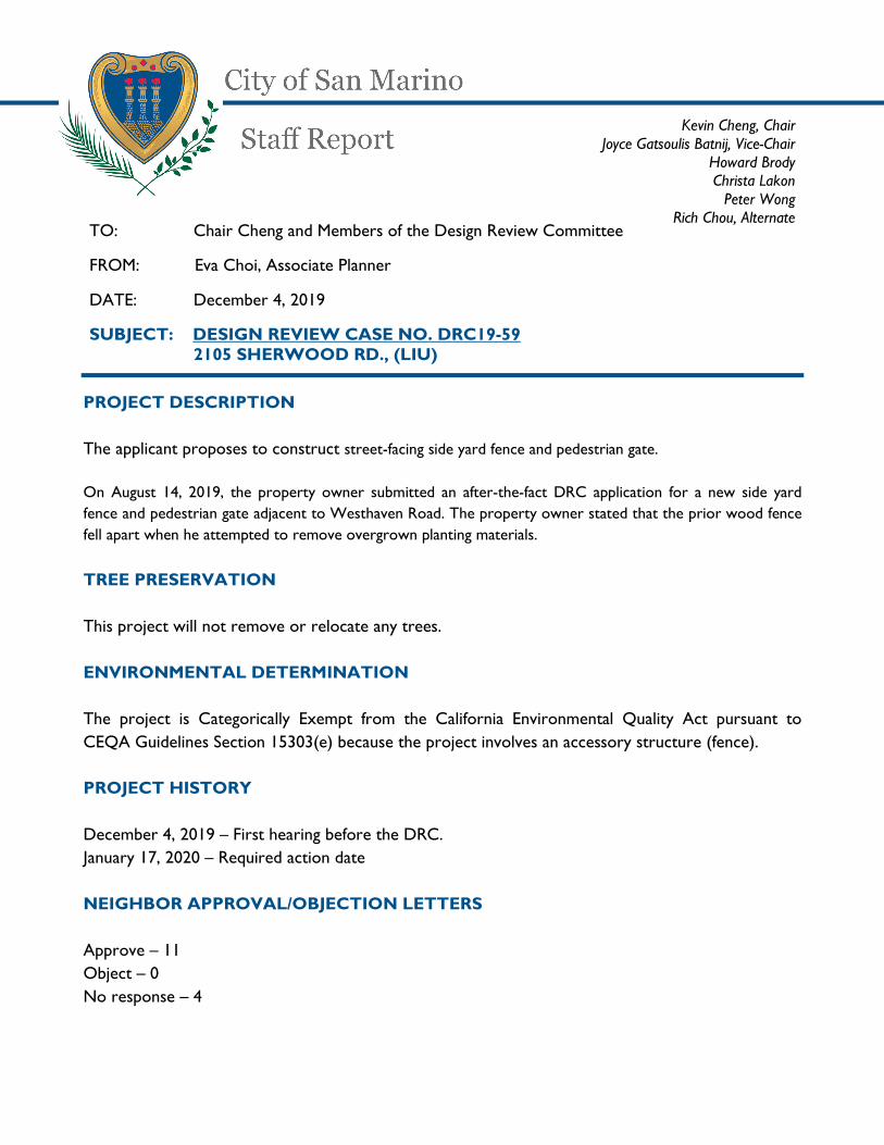
PROJECT DESCRIPTION
The applicant proposes to construct street-facing side yard fence and pedestrian gate.
On August 14, 2019, the property owner submitted an after-the-fact DRC application for a new side yard
fence and pedestrian gate adjacent to Westhaven Road. The property owner stated that the prior wood fence
fell apart when he attempted to remove overgrown planting materials.
TREE PRESERVATION
This project will not remove or relocate any trees.
ENVIRONMENTAL DETERMINATION
The project is Categorically Exempt from the California Environmental Quality Act pursuant to
CEQA Guidelines Section 15303(e) because the project involves an accessory structure (fence).
PROJECT HISTORY
December 4, 2019 – First hearing before the DRC.
January 17, 2020 – Required action date
NEIGHBOR APPROVAL/OBJECTION LETTERS
Approve – 11
Object – 0
No response – 4
TO: Chair Cheng and Members of the Design Review Committee
FROM: Eva Choi, Associate Planner
DATE: December 4, 2019
SUBJECT: DESIGN REVIEW CASE NO. DRC19-59 2105 SHERWOOD RD., (LIU)
Kevin Cheng, Chair Joyce Gatsoulis Batnij, Vice-Chair
Howard Brody Christa Lakon Peter Wong
Rich Chou, Alternate
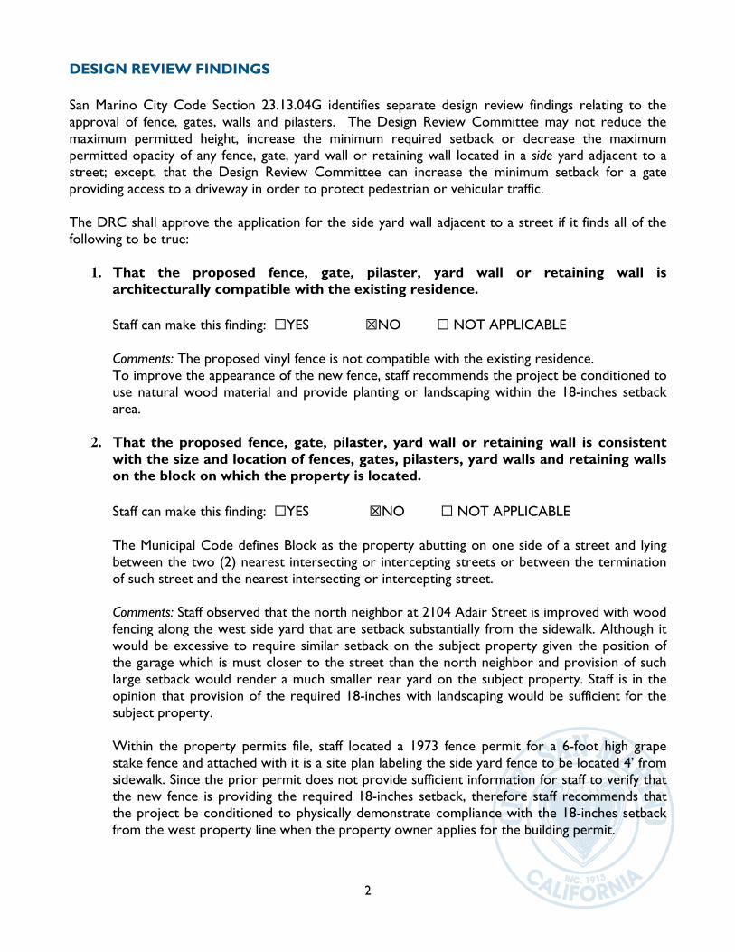
2
DESIGN REVIEW FINDINGS
San Marino City Code Section 23.13.04G identifies separate design review findings relating to the approval of fence, gates, walls and pilasters. The Design Review Committee may not reduce the maximum permitted height, increase the minimum required setback or decrease the maximum permitted opacity of any fence, gate, yard wall or retaining wall located in a side yard adjacent to a street; except, that the Design Review Committee can increase the minimum setback for a gate providing access to a driveway in order to protect pedestrian or vehicular traffic. The DRC shall approve the application for the side yard wall adjacent to a street if it finds all of the following to be true:
1. That the proposed fence, gate, pilaster, yard wall or retaining wall is architecturally compatible with the existing residence.
Staff can make this finding: ☐YES ☒NO ☐ NOT APPLICABLE Comments: The proposed vinyl fence is not compatible with the existing residence. To improve the appearance of the new fence, staff recommends the project be conditioned to use natural wood material and provide planting or landscaping within the 18-inches setback area.
2. That the proposed fence, gate, pilaster, yard wall or retaining wall is consistent
with the size and location of fences, gates, pilasters, yard walls and retaining walls on the block on which the property is located.
Staff can make this finding: ☐YES ☒NO ☐ NOT APPLICABLE The Municipal Code defines Block as the property abutting on one side of a street and lying between the two (2) nearest intersecting or intercepting streets or between the termination of such street and the nearest intersecting or intercepting street.
Comments: Staff observed that the north neighbor at 2104 Adair Street is improved with wood fencing along the west side yard that are setback substantially from the sidewalk. Although it would be excessive to require similar setback on the subject property given the position of the garage which is must closer to the street than the north neighbor and provision of such large setback would render a much smaller rear yard on the subject property. Staff is in the opinion that provision of the required 18-inches with landscaping would be sufficient for the subject property. Within the property permits file, staff located a 1973 fence permit for a 6-foot high grape stake fence and attached with it is a site plan labeling the side yard fence to be located 4’ from sidewalk. Since the prior permit does not provide sufficient information for staff to verify that the new fence is providing the required 18-inches setback, therefore staff recommends that the project be conditioned to physically demonstrate compliance with the 18-inches setback from the west property line when the property owner applies for the building permit.
3
3. That the proposed fence, gate, pilaster, yard wall or retaining wall preserves site lines and is otherwise located in a manner not to create a hazard to pedestrian or vehicular traffic.
Staff can make this finding: ☒YES ☐NO ☐ NOT APPLICABLE
Comments: The location and height of the proposed fence will not create hazardous conditions
to drivers and pedestrians provided that planting material are maintained in such manner as
not to create a hedge condition that impairs visual clearance for pedestrians to see a moving
vehicle exiting the driveway.
ATTACHMENTS: 1. DRC Map 2. Application review letters to the property owner 3. Submitted site plan, dated 10/17/2019 4. Fence permit from 1973 with site plan showing a 4-foot setback from sidewalk
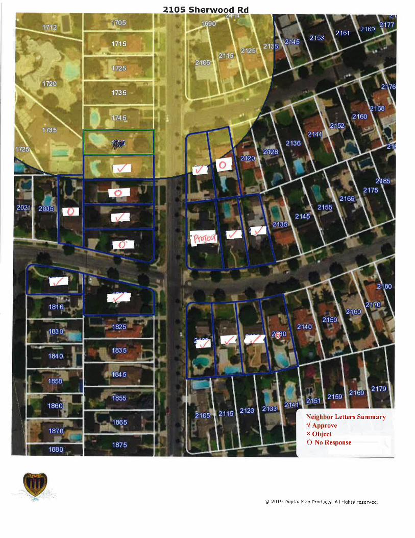
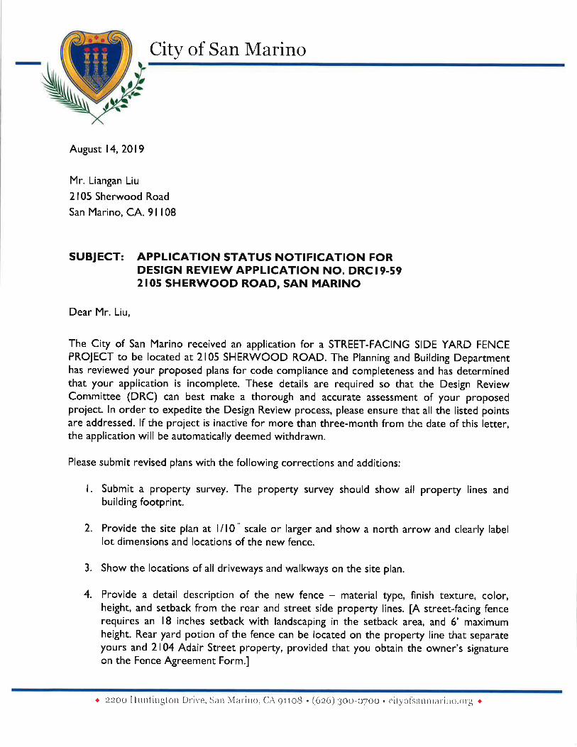
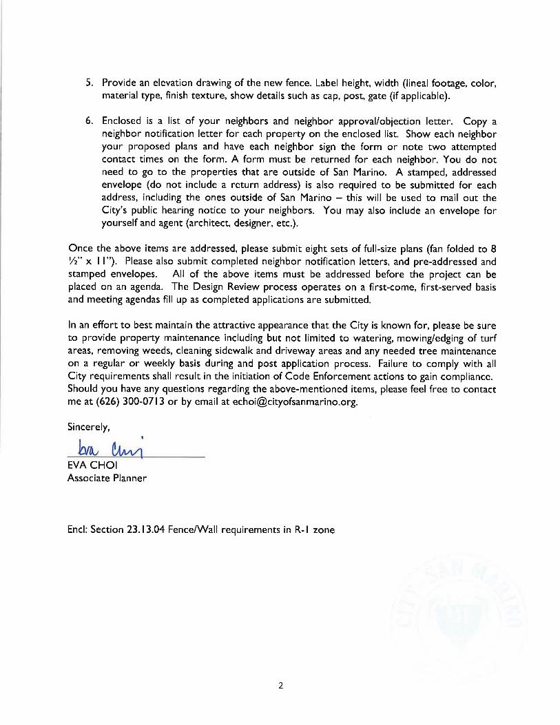
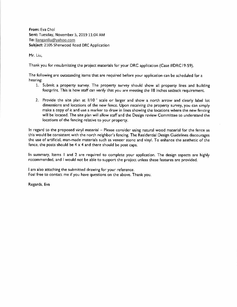
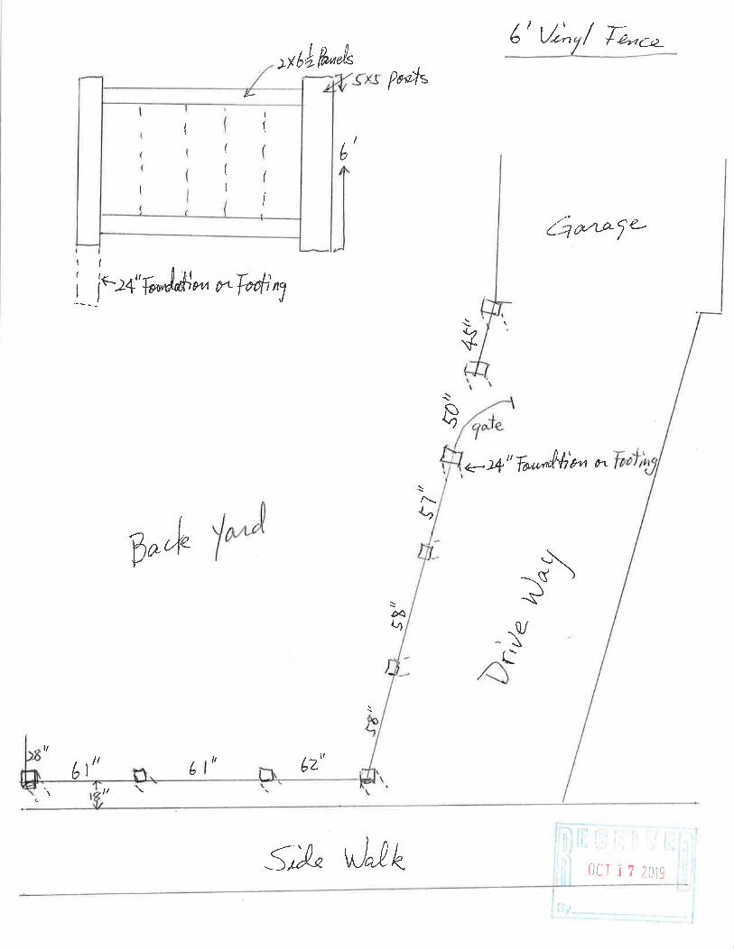
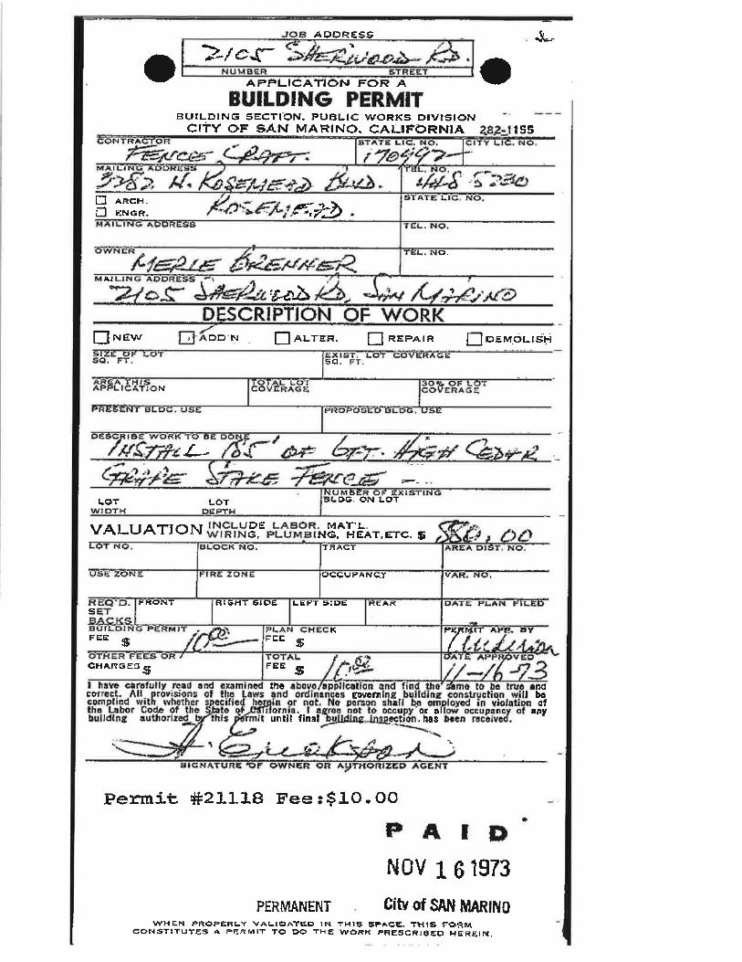
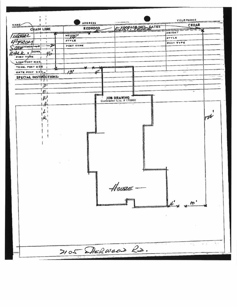
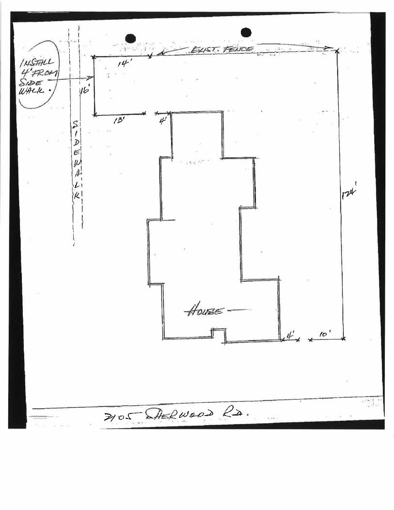
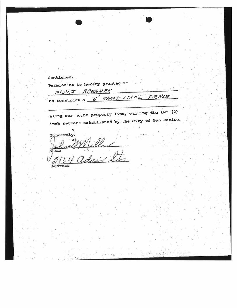
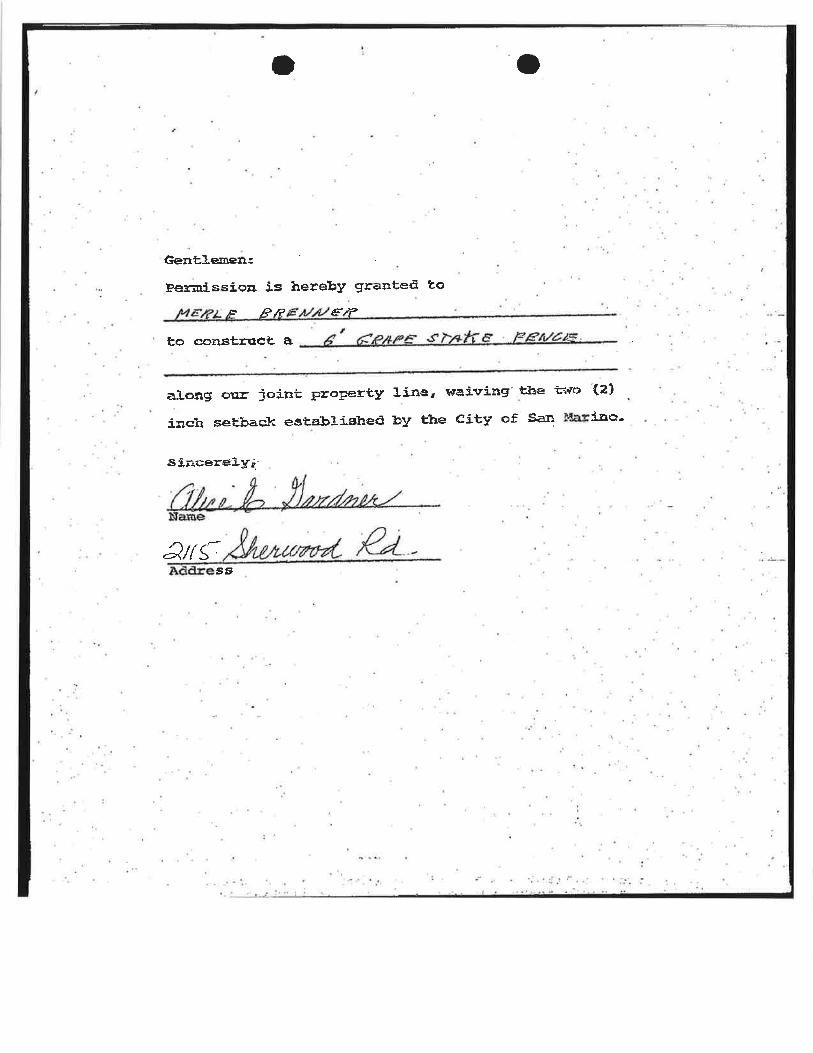
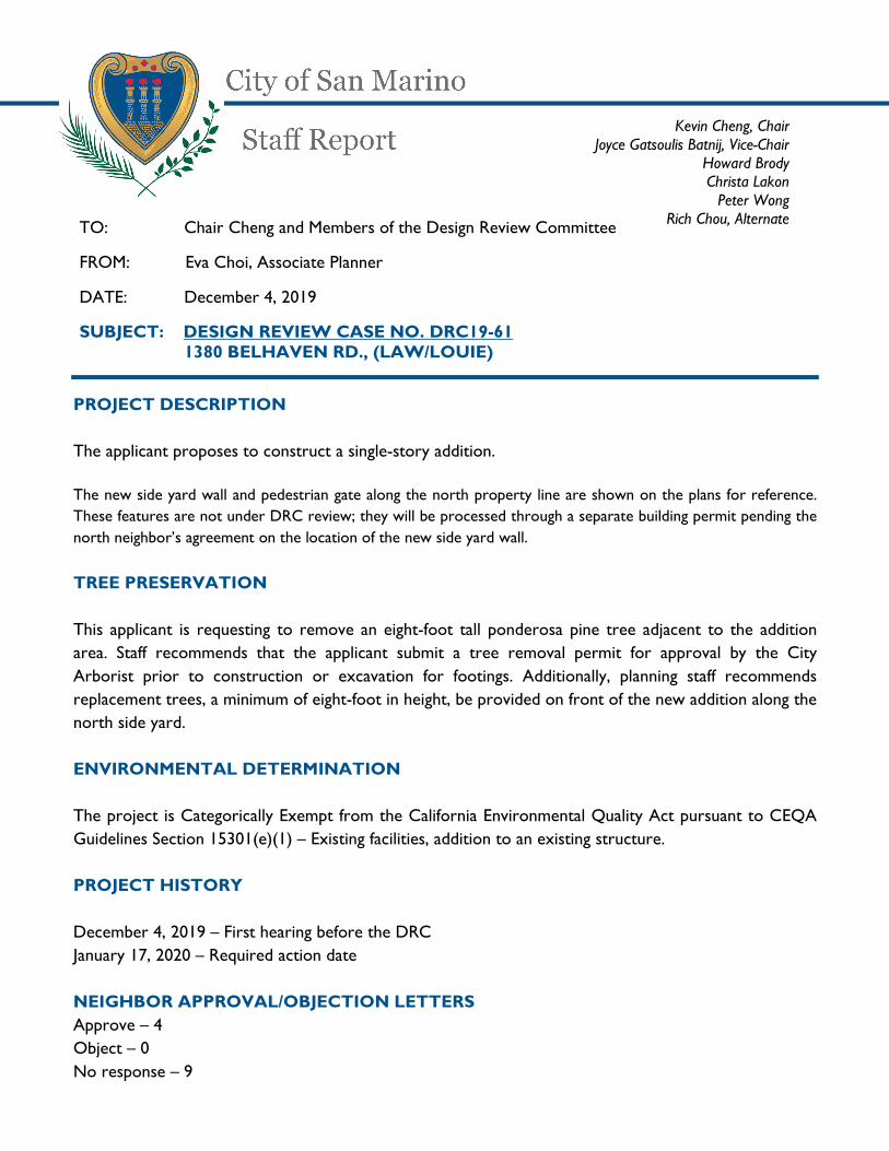
PROJECT DESCRIPTION
The applicant proposes to construct a single-story addition.
The new side yard wall and pedestrian gate along the north property line are shown on the plans for reference.
These features are not under DRC review; they will be processed through a separate building permit pending the
north neighbor’s agreement on the location of the new side yard wall.
TREE PRESERVATION
This applicant is requesting to remove an eight-foot tall ponderosa pine tree adjacent to the addition
area. Staff recommends that the applicant submit a tree removal permit for approval by the City
Arborist prior to construction or excavation for footings. Additionally, planning staff recommends
replacement trees, a minimum of eight-foot in height, be provided on front of the new addition along the
north side yard.
ENVIRONMENTAL DETERMINATION
The project is Categorically Exempt from the California Environmental Quality Act pursuant to CEQA
Guidelines Section 15301(e)(1) – Existing facilities, addition to an existing structure.
PROJECT HISTORY
December 4, 2019 – First hearing before the DRC
January 17, 2020 – Required action date
NEIGHBOR APPROVAL/OBJECTION LETTERS
Approve – 4
Object – 0
No response – 9
TO: Chair Cheng and Members of the Design Review Committee
FROM: Eva Choi, Associate Planner
DATE: December 4, 2019
SUBJECT: DESIGN REVIEW CASE NO. DRC19-61 1380 BELHAVEN RD., (LAW/LOUIE)
Kevin Cheng, Chair Joyce Gatsoulis Batnij, Vice-Chair
Howard Brody Christa Lakon Peter Wong
Rich Chou, Alternate

2
DESIGN REVIEW FINDINGS
Section 23.15.08 of the San Marino City Code states that the DRC shall approve the application if it finds all of the following to be true:
1. That the proposed structure is compatible with the neighborhood.
Staff can make this finding: ☒ YES ☐NO ☐ NOT APPLICABLE Comments: The legal neighborhood predominantly consists of single-story structures. The proposed addition minimally alters the appearance of the structure from street view and the addition is in keeping with the scale and building footprint found in the neighborhood. The addition extends into the north side yard and similar condition is found within the legal neighborhood (at 1360 and 1365 Belhaven Road) where the side projection is recessed from the front façade.
2. That the proposed structure is designed and will be developed in a manner which balances the reasonable expectation of privacy of persons residing on contiguous properties with the reasonable expectations of the applicants to develop their property within the restrictions of this Code.
Staff can make this finding: ☐YES ☒NO ☐ NOT APPLICABLE Comments: The addition along the north side yard generally aligns with the north neighbor’s garage structure. There is a new window in bedroom #1, 3’ wide by 4’-6” high, that provides a view into the north neighbor’s backyard, staff recommends using frosted glass for both windows in Bedroom #1 to mitigate potential privacy impacts on the north neighbor.
3. In the case of a building addition, the proposal is compatible with the existing
building which includes the rooflines.
Staff can make this finding: ☒ YES ☐ NO ☐NOT APPLICABLE Comments: The addition provides consistent roof form and slope. With the recommended changes to the windows and sidelites on the east elevation, staff would able to make this finding.
4. That the colors and materials are consistent and match the existing building or
structure.
Staff can make this finding: ☐YES ☒NO ☐ NOT APPLICABLE Comments: The project provides consistent exterior colors and materials as those existing on the structure. However, staff noted on the east elevation that two triangular shaped windows above the patio doors are not consistent with the architectural style of the structure, and the sidelites adjacent to the patio doors are out of balance for such a small area. Staff recommends removal of the windows and sidelites to provide a better balance for the east elevation. The proposed Sierra Pacific aluminum-clad wood windows are on the City’s pre-approved list and the project will provide consistent window treatments including the recessed surround and window sill.
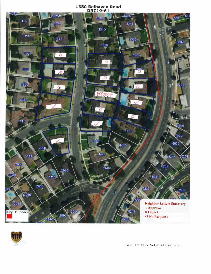
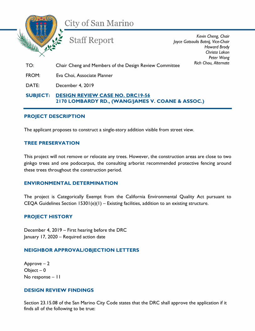
PROJECT DESCRIPTION
The applicant proposes to construct a single-story addition visible from street view.
TREE PRESERVATION
This project will not remove or relocate any trees. However, the construction areas are close to two
ginkgo trees and one podocarpus, the consulting arborist recommended protective fencing around
these trees throughout the construction period.
ENVIRONMENTAL DETERMINATION
The project is Categorically Exempt from the California Environmental Quality Act pursuant to
CEQA Guidelines Section 15301(e)(1) – Existing facilities, addition to an existing structure.
PROJECT HISTORY
December 4, 2019 – First hearing before the DRC
January 17, 2020 – Required action date
NEIGHBOR APPROVAL/OBJECTION LETTERS
Approve – 2
Object – 0
No response – 11
DESIGN REVIEW FINDINGS
Section 23.15.08 of the San Marino City Code states that the DRC shall approve the application if it finds all of the following to be true:
TO: Chair Cheng and Members of the Design Review Committee
FROM: Eva Choi, Associate Planner
DATE: December 4, 2019
SUBJECT: DESIGN REVIEW CASE NO. DRC19-56 2170 LOMBARDY RD., (WANG/JAMES V. COANE & ASSOC.)
Kevin Cheng, Chair Joyce Gatsoulis Batnij, Vice-Chair
Howard Brody Christa Lakon Peter Wong
Rich Chou, Alternate
2
1. That the proposed structure is compatible with the neighborhood.
Staff can make this finding: ☒ YES ☐NO ☐ NOT APPLICABLE Comments: The addition, in three different areas on the existing single-story structure, maintains the structure’s current massing and scale, therefore remain compatible with the legal neighborhood.
2. That the proposed structure is designed and will be developed in a manner which balances the reasonable expectation of privacy of persons residing on contiguous properties with the reasonable expectations of the applicants to develop their property within the restrictions of this Code.
Staff can make this finding: ☒YES ☐NO ☐ NOT APPLICABLE Comments: The proposed addition along the street-facing, east side of the structure would not generate privacy concerns. The addition along the west side of the structure will introduce new two pairs of double hung windows, however the structure is sufficiently setback (at 20 feet from the property line) that it would not provide a direct sightline to the west neighbor’s structure.
3. In the case of a building addition, the proposal is compatible with the existing
building which includes the rooflines.
Staff can make this finding: ☐YES ☒ NO ☐NOT APPLICABLE Comments: The proposed addition would be in keeping with the architectural style of the existing residence. The addition would provide matching rooflines, roof pitch, and overall design elements. The addition along the east side appears seamless from the street view as it is integrated with the existing covered porch feature. The new interior program provides a “Back Kitchen” that is adjacent to the new guest suite (living room, bedroom and bathroom), staff finds this particular layout would potentially lead to the creation of an unpermitted dwelling unit within the single-family structure. Staff recommends the removal of the dish washer, refrigerator, and the room should be labeled as “Wok Kitchen” to eliminate future confusion that the kitchen is intended for a back unit.
4. That the colors and materials are consistent and match the existing building or
structure.
Staff can make this finding: ☒YES ☐ NO ☐ NOT APPLICABLE Comments: Exterior materials and finishes are proposed to match those found on the existing structure. The proposed Marvin aluminum-clad wood windows are on the City’s pre-approved list and the Stone White color is a compatible to the existing window color.