AFT-800 series Electrolytes/TCO2 analyzer User Manual
95
AFT-800 series Electrolytes/TCO2 analyzer User Manual MEIZHOU CORNLEY© HI-TECH CO. ,LTD. A/0
-
Upload
khangminh22 -
Category
Documents
-
view
3 -
download
0
Transcript of AFT-800 series Electrolytes/TCO2 analyzer User Manual

AFT-800 series
Electrolytes/TCO2 analyzer
User Manual
MEIZHOU CORNLEY© HI-TECH CO. ,LTD.
A/0

Meizhou Cornley Hi-Tech Co.,Ltd Oxford Medico Europe Limited
Nanshan Industrial Estate,Baigong 514765,Meixian, Guangdong P.R.China
6-9 Trinity Street, Dublin 2, D02 EY47 lreland.

Preface Meizhou Cornley Hi-Tech Co., Ltd. is an enterprise specialized in R&D, manufacture, marketing and service for
clinical IVD instrument and life science instrument. The AFT-800D electrolyte analyzer is designed for accurate and
rapid tests on ion concentration of Li+, K+, Na+, Cl -, Ca2+ (the standard calcium ion modified pH value), pH value
and total carbon dioxide content in serum samples. It uses ion selective electrode technique (ISE) and the pressure
sensor to realize every test. Controlled by a microprocessor and equipped with the hierarchical menu software
structure, the analyzer is simple and more convenient for users to operate.
The Electrolyte analyzers of Meizhou Cornley Hi-Tech Co., Ltd. inherit all advantages of similar domestic and
foreign products and improve in the structure, circuit, software and operating system with colorful touch screen.
They are essential assistance for every laboratory as they are able to be a real sense from three to six parameters
with high performance.
The operation of every analyzer can be done in a simple hierarchical menu. The specification of the content is
about the detailed installation and operation of electrolyte analyzer.
AFT-800D electrolyte analyzer combines the advantages of our original analyze to test lithium, sodium,
potassium chlorine, calcium concentration, pH value in one sample with the direct test on total carbon dioxide to
improve the efficiency.
At the same time, users can choose an optional automatic sampler according to the actual needs. Automatic
sampling can improve the speed of analysis while the manual sampling is still available.
In addition, please install the electrodes of AFT-800D in order: Li+, K+, Na+, Ca2+, Cl-, pH, Ref according to this
manual. If you have any questions, please contact our customer service department.
Meizhou Cornley Hi-Tech Co., Ltd. adopted independent packs of calibration solutions. The user can handle
waste more conveniently. The analyzer increases data storage function for 10000 sample test record, 100 quality
control records every QC level. Through three levels quality control test and input target value, the analyzer can be
automatically calculate the slope and the deviation as well as the use of median verification slope and mean
deviation.
The aim of Meizhou Cornley Hi-Tech Co., Ltd.is to provide more advanced and better medical devices for the
user.

Notice:
Without the written consent of the Meizhou Cornley Hi-Tech Co., Ltd., any individual or organization shall not
reproduce, modify or translate this manual.
Meizhou Cornley Hi-Tech Co., Ltd. reserves to change, modify, update or delete any part of this manual without
prior notice.
Cornley has the final right to interpret this manual.
Meizhou Cornley Hi-Tech Co., Ltd.

Contents CHAPTER 1 ABSTRACT .......................................................................................................... 1
1.1 APPLICABLE RANGE --------------------------------------------------------------------------------------------- 1
1.2 MODELS --------------------------------------------------------------------------------------------------------- 1
1.3 FEATURES-------------------------------------------------------------------------------------------------------- 1
1.4 STRUCTURE ----------------------------------------------------------------------------------------------------- 2
1.4.1 Appearance ............................................................................................................................... 2
1.4.2 Sensor System ........................................................................................................................... 4
1.4.3 Barcode Scanner ...................................................................................................................... 5
1.4.4 Reagents .................................................................................................................................... 5
1.5 WORKING ENVIRONMENT ----------------------------------------------------------------------------------- 6
CHAPTER 2 OPERATION CAUTIONS ................................................................................... 7
2.1 PRECAUTIONS ------------------------------------------------------------------------------------------------- 7
2.2 LABELS -------------------------------------------------------------------------------------------------------- 8
2.3 SAMPLE COLLECTION AND STORAGE ----------------------------------------------------------------------- 11
2.4 FACTORS THAT MAY AFFECT THE ELECTRODE --------------------------------------------------------------- 12
2.4.1 Ionized calcium(iCa2+)and total calcium(tCa2+) ................................................................ 12
2.4.2 Some factors that may affect the electrode ..................................................................... 14
CHAPTER 3 WORKING PRINCIPLE ....................................................................................... 16
3.1 FLOW PATH---------------------------------------------------------------------------------------------------- 16
3.2 MEASURING PRINCIPLE --------------------------------------------------------------------------------------- 16
3.2.1 Reference Electrode ............................................................................................................... 17
3.2.2 pH Electrode ............................................................................................................................ 17
3.2.3 ISE .............................................................................................................................................. 18
CHAPTER 4 TECHNICAL FEATURE ........................................................................................ 19
4.1PARAMETER ---------------------------------------------------------------------------------------------------- 19
4.1.1 Measured Parameter ............................................................................................................ 19
4.1.2 Calculated Parameter............................................................................................................ 19
4.1.3 The normal ISE concentration range of Serum ................................................................ 19
4.1.4 Testing range ........................................................................................................................... 20
4.1.5 Electrode Parameters ............................................................................................................ 20
4.2 SAMPLE TYPE -------------------------------------------------------------------------------------------------- 20
4.3 TEST SPEED --------------------------------------------------------------------------------------------------- 20
4.4 MINIMUM SAMPLE VOLUME --------------------------------------------------------------------------------- 20
4.5 OUTPUT ------------------------------------------------------------------------------------------------------- 20
4.6 DIMENSION AND WEIGHT ------------------------------------------------------------------------------------ 21
4.7 FUSE ----------------------------------------------------------------------------------------------------------- 21
4.8 MEMORY ------------------------------------------------------------------------------------------------------ 21

4.9 DISPLAY ------------------------------------------------------------------------------------------------------- 21
4.10 COMMUNICATION AGREEMENT --------------------------------------------------------------------------- 21
4.11 PRINTER ----------------------------------------------------------------------------------------------------- 21
CHAPTER 5 INSTALLATION .................................................................................................. 22
5.1 UNPACKING --------------------------------------------------------------------------------------------------- 22
5.2 INSTALLATION OF ACCESSORIES ------------------------------------------------------------------------------ 23
5.3 INSTALLATION OF ELECTRODES ------------------------------------------------------------------------------- 23
5.4 INSTALLATION OF PUMP TUBE --------------------------------------------------------------------------------- 27
5.5 INSTALLATION OF PRINTING PAPER ---------------------------------------------------------------------------- 27
5.6 INSTALLATION OF REAGENTS --------------------------------------------------------------------------------- 28
5.6.1 Installation of calibration solution...................................................................................... 28
5.6.2 Installation of TCO2 Reaction Solution ............................................................................... 29
5.7 INSTALLATION OF AUTOSAMPLER ---------------------------------------------------------------------------- 29
CHAPTER 6 MAIN MENU ................................................................................................. 32
6.1 POWER ON---------------------------------------------------------------------------------------------------- 32
6.2 SELF TEST ----------------------------------------------------------------------------------------------------- 32
6.3 MAIN MENU ------------------------------------------------------------------------------------------------- 32
6.4 TEST MENU --------------------------------------------------------------------------------------------------- 33
6.4.1 Place the Probe Cleanser at 25 cup .................................................................................... 33
6.4.2 Serum test ................................................................................................................................ 33
6.4.3 Emergency test ....................................................................................................................... 34
6.5 QC ------------------------------------------------------------------------------------------------------------ 34
6.6.1 QC Plot ...................................................................................................................................... 34
6.6.2 QC Test ...................................................................................................................................... 36
6.6 MAINTENANCE MENU ----------------------------------------------------------------------------------------37
6.6.1 ISE Deproteinization .............................................................................................................. 37
6.6.2 Flush .......................................................................................................................................... 38
6.6.3 Deep cleaning ......................................................................................................................... 38
6.6.3 ISE Cleaning ............................................................................................................................. 38
6.6.5 Na&pH conditioning .............................................................................................................. 38
6.6.6 Serum soak .............................................................................................................................. 39
6.6.7 One_ Key_Maintenance ........................................................................................................ 39
6.6.8 TCO2 Deproteinization .......................................................................................................... 40
6.6.9 All Cleaning .............................................................................................................................. 40
6.7 SYSTEM SETUP ------------------------------------------------------------------------------------------------ 40
6.7.1 Reference Range Configuration .......................................................................................... 41
6.7.2 Printer Setup ........................................................................................................................... 41
6.7.3 Unit Configuration ................................................................................................................. 41
6.7.4 Screen Configuration ............................................................................................................. 42

6.7.5 Testing Parameter .................................................................................................................. 42
6.7.6 Maintenance Setup ............................................................................................................... 42
6.7.7 Date&Time Configuration .................................................................................................... 43
6.7.8 QC Control Configuration ..................................................................................................... 43
6.7.9 Correlation Coefficient Configuration ................................................................................ 44
6.7.10 Calibration Intervals Configuration .................................................................................. 44
6.7.11 Sampling Mode .................................................................................................................... 45
6.7.12 Sample Volume Configuration .......................................................................................... 45
6.7.13 Resistance Setup .................................................................................................................. 45
6.7.14 Data Transfer Mode ............................................................................................................ 45
6.7.15 Operation Mode ................................................................................................................... 46
6.7.16 Other ...................................................................................................................................... 46
6.8 DATA MANAGER ---------------------------------------------------------------------------------------------- 46
6.8.1 Test Result .................................................................................................................................47
6.8.2 ISE Calibration Results............................................................................................................47
6.8.3 TCO2 Calibration Results ....................................................................................................... 48
6.8.4 Test Results Transmission ..................................................................................................... 48
6.9 SERVICE ------------------------------------------------------------------------------------------------------- 48
6.9.1 ShutDown ................................................................................................................................ 48
6.9.2 Version...................................................................................................................................... 49
6.9.3 Help ........................................................................................................................................... 49
6.9.4 Tools .......................................................................................................................................... 49
6.9.5 Self Test .................................................................................................................................... 49
6.9.6 Sample Needle Adjust ........................................................................................................... 50
6.9.7 Sample Tray Adjust ................................................................................................................ 50
6.9.8 Multiplexer Check .................................................................................................................. 50
6.9.9 Cal Pack Used .......................................................................................................................... 51
6.9.10 TCO2 Clog Check ................................................................................................................... 51
6.10 CONSUMABLES MANAGEMENT ---------------------------------------------------------------------------- 51
CHAPTER 7 CALIBRATION ................................................................................................... 53
7.1 GENERAL INFORMATION -------------------------------------------------------------------------------------- 53
7.2 ONE POINT CALIBRATION ------------------------------------------------------------------------------------- 53
7.3 TWO POINT CALIBRATION------------------------------------------------------------------------------------- 54
7.4 LI_K VALUE ADJUSTMENT------------------------------------------------------------------------------------ 55
7.5 TCO2 CALIBRATION ------------------------------------------------------------------------------------------- 55
7.6 ISE+TCO2 CALIBRATION ------------------------------------------------------------------------------------- 56
7.7 CALIBRATION INTERVALS ------------------------------------------------------------------------------------- 56
7.8 CALIBRATION RESULTS ---------------------------------------------------------------------------------------- 56
CHAPTER 8 PATIENT SAMPLE ANALYSIS .............................................................................. 58

8.1 SAMPLE COLLECTION ----------------------------------------------------------------------------------------- 58
8.2 STEPS OF SAMPLE ANALYSIS --------------------------------------------------------------------------------- 58
8.3 TEST RESULT -------------------------------------------------------------------------------------------------- 59
CHAPTER 9 TROUBLE SHOOTING .........................................................................................60
9.1 NORMAL TROUBLES AND SOLUTIONS ----------------------------------------------------------------------- 60
9.2 ELECTRODE --------------------------------------------------------------------------------------------------- 60
9.2.1 Drifting ..................................................................................................................................... 60
9.2.2 Unstable ................................................................................................................................... 60
9.2.3 Slow reaction and low slope ................................................................................................ 61
9.3 A SIMPLE METHOD TO CHECK RESPONDENT CIRCUIT CHANNEL OF EACH ELECTRODE ---------------------- 61
9.4 ONLY ONE UNSTABLE ELECTRODE ---------------------------------------------------------------------------- 61
9.5 TWO OR MORE UNSTABLE ELECTRODES --------------------------------------------------------------------- 61
9.6 LONGER BALANCE TIME ON LI+、K+、CL
-、CA2+
ELECTRODES ----------------------------------------- 61
9.7 LONGER BALANCE TIME ON NA+、PH ---------------------------------------------------------------------- 61
9.8 PROBLEMS ON FLOW PATH -----------------------------------------------------------------------------------62
9.9 SLOPE OUT OF RANGE -----------------------------------------------------------------------------------------62
9.10 PROBLEMS ON REPEATABILITY-------------------------------------------------------------------------------62
9.11 PROBLEMS ON ACCURACY-----------------------------------------------------------------------------------62
9.12 PROBLEMS ON QC -------------------------------------------------------------------------------------------62
9.13 PROBLEMS ON FUSE ---------------------------------------------------------------------------------------- 63
9.14 NO FLUSH OR FLOW SLOWLY ------------------------------------------------------------------------------- 63
9.15 NO CAL A OR CAL B ---------------------------------------------------------------------------------------- 63
9.16 NO SAMPLE WHEN SAMPLING------------------------------------------------------------------------------ 63
9.17 PROBLEMS ON PUMP TUBES ------------------------------------------------------------------------------- 64
9.18 LOOSE CONNECTOR ----------------------------------------------------------------------------------------- 64
CHAPTER 10 MAINTENANCE .............................................................................................. 65
10.1 DAILY MAINTENANCE --------------------------------------------------------------------------------------- 65
10.2 WEEKLY MAINTENANCE ------------------------------------------------------------------------------------ 65
10.3 MONTHLY MAINTENANCE ---------------------------------------------------------------------------------- 66
10.4 YEARLY MAINTENANCE ------------------------------------------------------------------------------------- 66
10.5 AS NECESSARY ---------------------------------------------------------------------------------------------- 66
10.6 SHELF LIFE --------------------------------------------------------------------------------------------------- 66
10.7 TRANSPORTATION AND STORAGE----------------------------------------------------------------------------67
APPENDIX A SYMOBOLS .................................................................................................. 68
APPENDIX B BARCODE SCANNER INITIALIZATION ............................................................70

Page 1
Chapter 1 Abstract This chapter introduces the scope of application, model characteristics and the
composition of the structure about AFT-800D series electrolyte analyzer,
1.1 Applicable Range
1.1.1 This manual applies to AFT-800D series electrolyte analyzer (hereinafter referred to as
the analyzer).
1.1.2 This analyzer for the medical tests on contents of K+, Na+, Cl-, Ca2+, Li+, pH, TCO2 in
serum samples.
1.1.3 This analyzer should be operated by trained technicians, nurses, doctors in the laboratory,
bedside monitoring or designated guardian.
1.2 Models
Depending on different configuration, the analyzer has many types. This manual is composed
according to the most completed configuration model (AFT-800D). The manual also applies to
other models listed below. The differences between different models are:
1) The operation menu and display, such as the menu of calibration, testing and setup to
display only some certain parameters.
2) The calculated parameters are different.
Model Parameters Note AFT-800A K+, Na+, Cl-, TCO2
AFT-800D series have the same appearance butdifferent parameters.
AFT-800B K+, Na+, Cl-, Ca2+, pH, TCO2 AFT-800D K+, Na+, Cl-, Ca2+, Li+, pH, TCO2 AFT-800E K+, Na+, Cl-
AFT-800F K+, Na+, Cl-, Li+ AFT-800G K+, Na+, Cl-, Ca2+, pH AFT-800H K+, Na+, Cl-, Ca2+, Li+, pH
1.3 Features
※ Support color TFT touch screen, and brightness adjustable.
※ Optional auto sampler
※ Support original blood sample tube
※ Built-in thermal printer, serial port
※ Reagent and waste in one pack

Page 2
※ Storage and search function on quality control, calibration and test results (store 10000 test
results, 100 quality control results per level, 31 days quality control graph and 7 days calibration
records)
※ Clot alarm and bubble alarm function, automatic and manual clot-removal function
※ Support LIS, HL7
※ Automatic and manual calibration, cleaning, quality control and self check functions
※ Printing on sample analysis report and sample analysis chart
※ Printing on test report
※ Barcode scanning function to support consumables scan
※ Automatically identify the expiry date of consumables
※ Online software upgrade
※ Reagent consumption calculation function
※ To review and print test result according to the sample number or test time
※ Support print of calibration and quality control data
※ Support export of test data
※ Support multitasking operating and sample edition on patient information
※ Automatic cleaning for sampling needle
※ Support online graphic guide and online assistance
1.4 Structure
The system includes main analyzer (Display, measuring chamber, peristaltic pump,
multiplexer, flow path, printer), autosampler, barcode scanner and reagent pack.
1.4.1 Appearance
Front

Page 3
Part Function
Display Interface between operator and analyzer
Measuring chamber The place to do test
Peristaltic Pump Sample aspiration and waste drain
Calibration solution The place for both reagent and waste
Manual sampling Aspiration of samples and reagents
Autosampler For automatic sampling
multiplexer Control the flow of liquid
TCO2 reaction cell The place for sample and reaction solution to generate total dissolved CO2
Printer Print out test results and messages
Back
Part Function
Barcode scanner interface Connect analyzer and barcode scanner
Nameplate Describe the basic information and configuration of the analyzer
Barcode scanner Slot for scanner, read barcode of consumable RS232 interface(communication) Data transmission Autosampler interface Connect analyzer and autosampler

Page 4
Side
Part Function
Power inlet
For the analyzer to boot into standby mode
Note: when the analyzer is connected with an external power supply, analyzer is in standby mode. If the analyzer is not connected with any external power supply, the analyzer is in shutdown mode.
Power switch Turn on or off the power
Autosampler(Optional)
1.4.2 Sensor System This sensor system of this analyzer integrates modern technique of microelectrode. It can be
used for the measurements of
Li electrode(Li+)
K electrode (K+)
Na electrode (Na+)
Ca electrode (Ca2+)
Cl electrode (Cl-)

Page 5
pH electrode (pH)
Reference electrode(Ref)
1.4.3 Barcode Scanner
The barcode systems of reagent pack, electrode and other consumables contain necessary
information such as lot number and the validity period. The scanner is for barcode
scanning to control the use of consumables.
To scan the data of reagents(type, lot number, validity period)
To scan the data of electrodes(type, lot number, validity period)
To scan the data of pump tubes(type, lot number, validity period)
To scan the data of sampling probe interfaces(type, lot number, validity period)
Instruction
Light Source 620 nm visible red light diode Reading Mode CCD
Symbologies Code128, EAN-13, EAN-8, Code 39, UPC-A, UPC-E, Codabar, Interleaved 2 of 5, ISBN, Code 93, UCC/EAN-128, GS1 Databar, etc.
Resolution ≥4 mil Scanning speed 300 scans per second Interface RS232 Dimension Length * width * height: 156mm×95mm×71mm Weight 105g Working temperature 0℃-50℃ Storage temperature -40℃-60℃ Humidity Relative humidity 0-95% (no condensation)
1.4.4 Reagents
Calibration of the analyzer system is performed by the solution in the reagent pack. There
is standard solution with accurate concentration in the pack. It is placed in the vacuum
packaging. At the same time, waste will be collected in the bag automatically after calibration
Page 6
and test. As standard calibration solution and waste are sealed in the pack, it can effectively
avoid the pollution of the environment.
The standard calibration solutions are used to calibrate Li+, K+, Na+, Ca2+, Cl- electrodes.
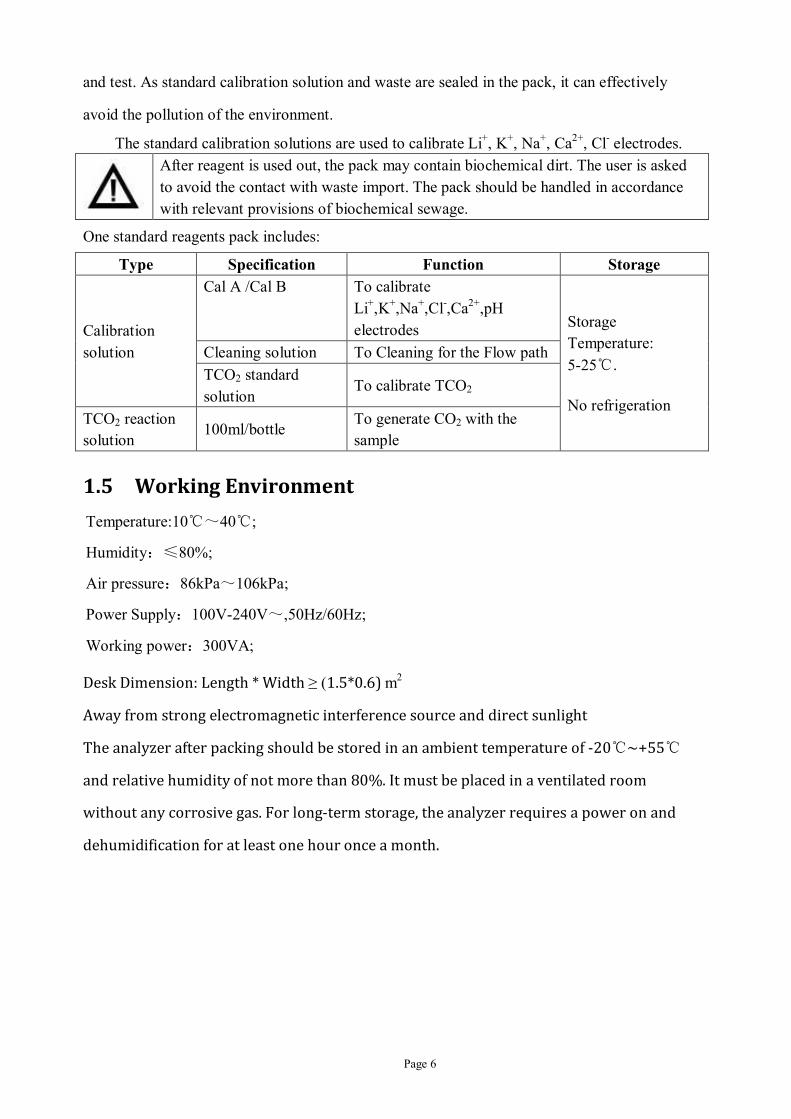
One standard reagents pack includes:
Type Specification Function Storage
Calibration solution
Cal A /Cal B To calibrate Li+,K+,Na+,Cl-,Ca2+,pH electrodes Storage
Temperature: 5-25℃.
No refrigeration
Cleaning solution To Cleaning for the Flow path TCO2 standard solution
To calibrate TCO2
TCO2 reaction solution
100ml/bottle To generate CO2 with the sample
1.5 Working Environment
Temperature:10℃~40℃;
Humidity:≤80%;
Air pressure:86kPa~106kPa;
Power Supply:100V-240V~,50Hz/60Hz;
Working power:300VA;
Desk Dimension: Length * Width ≥ (1.5*0.6) m2
Away from strong electromagnetic interference source and direct sunlight
The analyzer after packing should be stored in an ambient temperature of -20℃~+55℃
and relative humidity of not more than 80%. It must be placed in a ventilated room
without any corrosive gas. For long-term storage, the analyzer requires a power on and
dehumidification for at least one hour once a month.
After reagent is used out, the pack may contain biochemical dirt. The user is asked to avoid the contact with waste import. The pack should be handled in accordance with relevant provisions of biochemical sewage.

Page 7
Chapter 2 Operation Cautions
2.1 Precautions
● No reagent of flame photometer or biochemistry analyzer can be used on this analyzer as
such reagent may damage ion selective electrodes.
● Only the original reagent of Cornley can be used.
● Only the trained professional can operate the analyzer.
● Never use mildew or precipitated sample. Such sample should be abandoned immediately
as it will affect the test result negatively.
● Never open the cover of measuring chamber when doing a test.
● Please protect the unique serial number on every electrode. There will be no after-sales
guarantee for any electrode without such serial number.
● Please perform routine maintenance for the analyzer according to this manual.
● The analyzer needs stable voltage and good grounding.
● The serum must be separated well. The sample should be tested within 1 hour after
collection. The TCO2 reaction cell for the sample must be cleaned by distilled water and dried.
● The adjustment on "slope" and "deviation" parameter must be done very carefully. Only
the extremely fresh serum can be used for those adjustments. Please do not adjust the slope or
deviation frequently. Generally, a micro adjustment will be OK enough.
● Please remain the analyzer power-on to guarantee the normal working of electrodes and
test accuracy.
● Please avoid direct sunlight or other strong light on multiplexer
● Pressure sensor is a maintenance-free component. The replacement of this sensor can only
be done by a professional appointed by Cornley(applicable for the models with TCO2
parameter)。
● If the power of the analyzer is off for more than 24 hours, the left calibrator in the Flow
path may be crystallized. This will ruin the future two-point calibrations on the analyzer.
● The protection of the analyzer may be damaged if the analyzer is not operated according to
this manual.
● The handling of waste has to be done according to local standard and the guidance from
the local distributor.

Page 8
● This analyzer is a precision instrument. After transportation, it needs to run at least 48
hours to return reliable.
● If the analyzer has any damage as the user does not supply stable power according to this
manual, Cornley will not be responsible for the loss.
2.2 Labels
For safe and effective operation of the analyzer, this manual lists several warning information. This part is very important. Please read carefully before the operation.
Symbol Definition
Biological contamination
To remind the user to abide by the instructions. Otherwise there will be the risk of biological contamination.
Alert
To remind the user to use of equipment safely and effectively.
Caution
To illustrate the procedure of important information or other information which need to remind to the users.
All risk warnings of this manual are listed as follows:
Sampling
Biological contamination: The collecting samples must follow the basic rules of prevention as all blood samples are potentially infectious. In order to reduce the possible risk, the collector must master the correct treatment of blood collection to wear gloves and take the necessary protective measures.
Environment Pollution
Biological contamination: Please always remember environment protection when you handle biological waste or its container.
Reagents
Biological contamination: The will be waste after the usage of every reagent pack. Please never touch the waste interface. Handle the splashed liquid with flush solution carefully. For the used packs of calibration solutions, please handle them according to local laws about biological waste.
Analyzer
Biological contamination: Please switch off the analyzer and disconnect the power supply when cleaning the analyzer. Gloves are also advised for this cleaning.

Page 9
Alert: Never clean the sample probe with wet cloth or anything similar.
Restrictions in operation
Alert: Before being applied to clinical diagnosis, all test results of the analyzer need to be checked by the doctor according to the clinical status of the patient.
Storage
Alert: All reagents have to be removed before shut-down of the analyzer.
Alert: For long term storage of the analyzer, the power supply must be shut down. Necessary shut-down procedures have to be followed also.
Maintenance
Alert: Please observe the sample status in the measuring chamber to guarantee the integrity of the sample.
Alert: Please perform de-protein and conditioning for the electrodes regularly.
Pump Tube
Alert: Please install the tube correctly on the pump wheel to guarantee the normal rolling of the wheel.
QC
Alert: Never use any QC with Fluorine carbon compounds
Troubleshooting
Biological contamination: When flushing any part of this analyzer, please be careful for the liquid outlet from the Flow path.
Alert: Before being applied to clinical diagnosis, all test results of the analyzer need to be checked by the doctor according to the clinical status of the patient.
Caution: In order to guarantee a good EMC, please use protected cable at communication port.
Caution: please contact the local distributor whenever necessary.
Safety In order to use this analyzer safely, please read the content below carefully. There will be danger for the analyzer or the operator if the operation does not apply such safety instructions.
Alert: If the user does not follow this manual, the safety protection system of this analyzer may fail.

Page 10
Electric shock prevention\ To prevent electric shock, please notice that:
Alert: Never open the back board of the analyzer when the power is on. Never put any reagent or sample on the analyzer. If any reagent or sample is splashed into the analyzer, please shut down the power immediately and contact the local distributor or Cornley for professional advice.
Moving Parts To prevent the injury by the moving part of the analyzer, please notice that:
Alert: Please do not touch or put your hand inside the range of moving part when the analyzer is working.
Laser Radioactivity To prevent the injury by Laser light source of the barcode scanner, please notice that:
Alert: Please do not look at the laser light source directly. It is harmful for the eyes.
Blood Pollution To prevent the blood pollution for the operator, please notice that:
Alert: Please never touch blood sample, interface of reagent pack, QC, calibrator and reaction solution. Please do wear gloves and necessary uniform to prevent possible pollution. Spectacles are also required if necessary. If any sample is splashed on the skin, please handle with care and consult a doctor.
Chemical Danger To prevent chemical danger, please notice that:
Alert: Some reagents and chemical flush solution are harmful for skin. If any of such liquid is splashed into eyes by accident, please wash with plenty of clean waters immediately and see a doctor without delay.
Waste To prevent waste pollution, please notice that:
Biological risk: some contents of QC, calibrator, flush and waste are dangerous. Please handle them according to relevant local laws. Please do wear gloves and necessary uniform to when handling waste. Spectacles are also required if necessary.
Used analyzer To handle used analyzer safely.
Alert: some materias of the used analyzer may cause pollution. Please handle them according to relevant local laws about waste products.

Page 11
2.3 Sample collection and storage
2.3.1 Blood samples must be sent to the laboratory immediately after collection, especially
when the environment temperature is over 22℃.
2.3.2 The tubes for blood samples must be sealed and placed vertically with mouth upwards.
This is to reduce the coagulation completely by possible vibrations and to prevent contamination,
evaporation and splashing, etc.
2.3.3 Blood samples can be collected according to the conventional method. The collected
blood samples shall be handled gently to prevent hemolysis by possible vibrations.
2.3.4 The collected blood samples should be processed as early as possible. Generally, the
isolation of serum from the samples must be done within two hours since collection.
2.3.5 The delivery of collected blood samples must be done with great cautious. The
professional requests on packaging, temperature sample and processing methods must be strictly
followed to ensure the stability of components. Sample tubes must be sealed and placed upward
vertical during transportation.
2.3.6 The collected samples must be fully agglutinated. The samples with anticoagulant can be
centrifuged immediately after collection. The samples with coagulant must be centrifuged
within 5~15 minutes after collection. The samples with anticoagulant cannot be centrifuged if
for tests on Lithium, Zinc and Protoporphyrin.
2.3.7 Blood samples before centrifugation should be agglutinated naturally. Please never use
stick or anything similar to separate blood clots. For normal room temperature (22~25℃), the
samples can be completely agglutinated after 30~60 minutes of collection. Frozen blood
samples will be agglutinated slowly. They may need some coagulants to accelerate agglutination
(gently reverse and mix 5~10 times to ensure the functions of coagulants).
2.3.8 It is better to complete sample centrifugation in one time. If a second centrifugation is
needed, it should be done in a very short time after the previous one. But the samples with
separated substances cannot be centrifuged again.
2.3.9 The storage of serum in 22~25℃cannot be over 8 hours.
2.3.10 If the centrifugation cannot be completed within 8 hours after collection, the serum
should be kept in the environment of 2℃~8℃.
2.3.11 If centrifugation cannot be completed within 48 hours after collection, or the serum
samples should be stored for 48 hours, the samples should be stored in -20℃.

Page 12
2.3.12 For anticoagulants, the ones with heparin lithium shall not be applied when the tests
include parameters about lithium. By the same means, the anticoagulants with heparin sodium
shall not be applied when the tests include parameters about sodium. Otherwise the results of
relevant parameters will be abnormal.
2.3.13 The serum samples cannot be frozen and thawed repeatedly. They can only be frozen and
thawed once. Such samples cannot be stored in frost free refrigerator as this kind of refrigerator
will bring frequent temperature changes on the samples.
2.3.14 Serum samples shall be stored in sealed tubes.
2.3.15 All calibration solutions for the instrument should be stored in 5℃~25℃ and clean
environment. Direct sunlight and long-term open in the air must be avoided.
2.3.16 The increase in salicylate and its derivatives and bromide content in the sample increases
the chlorine reading, which may be the contamination of the sample with perchlorate,
thiocyanate, iodide or nitrate.
2.4 Factors that may affect the electrode
2.4.1 Ionized calcium(iCa2+)and total calcium(tCa2+)
Between 40-50% of the calcium in plasma is protein-bound, and 5-10% is in the form of
complexes with organic acids and phosphates. The remainder (40-50%) is ionized. Ionized
calcium is a physiologically active form of calcium, many important physiological processes
such as the formation and absorption of bones, nerve conduction, muscle contraction, serum
coagulation and many enzyme activity and so on with the activity of Ca2+. As the iCa2+ reflected
more patient's clinical symptoms and calcium metabolism than tCa2+, so the determination of
serum iCa2+ has more clinical significance than tCa2+. Determination of tCa2+ usually by EDTA
solution, colorimetric or atomic absorption spectroscopy.
In a certain range (pH 7.0 ~ 8.0), iCa2+ and pH changes were negatively correlated. When
Serum pH increased (every 0.1 pH units), ionized calcium concentration decreased of about
4-5%. By detecting the pH of the serum sample, the actual ionized calcium value, actually, the
standard ionized calcium value ( pH = 7.40, the normalized calcium value; nCa2+), and tCa2+ ≈
2×nCa2+ (Here, tCa2+ is a derived value, can’t use for clinical diagnosis, for reference only),
when the serum pH> 8.0, the nCa2+ results may high, while measuring iCa2+<0.85mmol/L or
iCa2+>1.5 mmol/L, the tCa2+ cannot be used as a reference and is recommended to be measured

Page 13
in other ways.
As time goes by, carbon dioxide escape from serum, pH rose high, and the iCa2+ is lower,
this will affect the test results. So the serum should be measured as soon as possible, not more
than an hour as to avoid the pH effects.
Note: Different batches of serum quality control, their pH values are different, so tCa2+
cannot be calculated by iCa2+.
Factors influencing iCa2+ determination:
① Sampling: fasting, no tourniquet. (Diet, intravenous congestion, upright, etc. can make
iCa2+ increased);
② Time: the sample should be measured as soon as possible after sampling, it is best not
to more than 1 hours;
③ Anticoagulant: do not use EDTA, citrate, oxalate as anticoagulant, heparin
concentration should not be too high (10IU/mL or so).
Hypercalcemia: hyperthyroidism, malignant tumors, poliomyelitis, vitamin D intoxication
and so on.
Hypocalcemia: kidney disease, vitamin D deficiency, intestinal malabsorption,
hypoparathyroidism and so on.
The results of serum samples:
Hypoparathyroidism: tCa2+ ↓ ↓, nCa2+ ↓ ↓
Hyperparathyroidism: tCa2+ ↑, nCa2+ ↑ ↑
Vitamin deficiency: tCa2+ ↓, nCa2+ ↓
Vitamin D intoxication: tCa2+ ↑, nCa2+ ↑
Chronic nephritis: tCa2+ ↓ ↓, nCa2+ ↓ ↓
Malignant neoplasms: tCa2+ ↓ ↓, nCa2+ ↑↑
Hypoproteinemia: tCa2+ ↓, nCa2+ normal, hyperproteinemia: tCa2+ ↑, nCa2+ normal
Atherosclerosis: tCa2+ ↑, nCa2+ ↓
Pregnant women: tCa2+ ↓, nCa2+ ↓
In addition:
Surgical patients, organ transplant patients need to enter a large number of citrate
anticoagulated whole serum tCa2+ normal, iCa2+ ↓.

Page 14
Pediatric rickets patients TCa2+ normal, iCa2+ ↓.
People under the age of 45, iCa2+ basic normal, and later with the age of growth and
gradually reduced. Patients with acute pancreatitis TCa2+ change is not obvious, iCa2+ ↓ ↓, and is
proportional to the severity of the disease.
The results of blood samples:
Acute respiratory acidosis: TCa2+ and Alb normal, pH ↓, iCa2+ ↑, nCa2+ normal.
Acute respiratory alkalosis: TCa2+ and Alb normal, pH ↑, iCa22+ ↓, nCa2+ normal,, pCO2 ↓.
Acute metabolic acidosis: TCa2+↓, pH ↓, iCa2+ normal, nCa2+↓.
2.4.2 Some factors that may affect the electrode
Analyte Interferent Effect On Analyte Result
K+
A hemolysis occurred in the sample Increase (↑) Heparin potassium anticoagulant Increase (↑) Contamination in container Increase (↑) Procaine Decrease(↓) Ammonium carbonate Increase (↑) Nystatin Increase (↑) Amphotericin Increase (↑) Lidocaine Decrease(↓) Perchlorate Decrease(↓) Benzalkonium chloride Increase (↑) Thiopental sodium Decrease(↓)
Na+
Heparin sodium anticoagulant Increase (↑) Contamination in container Increase (↑) Bromide Increase (↑) Ammonium carbonate Increase (↑) Benzalkonium chloride Increase (↑) Thiopental sodium Increase (↑)
Cl-
Contamination in container Increase (↑) Bromide Decrease(↓) Nitrates Increase (↑) Salicylate Increase (↑) Ammonium carbonate Decrease(↓) Iodide Increase (↑) Thiocyanate Increase (↑) Perchlorate Increase (↑) Citrate Decrease(↓) Acetylcysteine Decrease(↓)

Page 15
iCa2+
Contamination in container Increase (↑) Procaine Decrease(↓) Bromide Increase (↑) Salicylate Decrease(↓) Ammonium carbonate Decrease(↓) Nystatin Decrease(↓) Amphotericin Decrease(↓) Lidocaine Decrease(↓) Thiocyanate Decrease(↓) Perchlorate Decrease(↓) Benzalkonium chloride Increase (↑) Thiopental sodium Decrease(↓) Acetylcysteine Decrease(↓) Acetaminophen Decrease(↓) Magnesium Increase (↑) Lactate Decrease(↓)
Li+ Heparin lithiumanticoagulant Increase (↑) Contamination in container Increase (↑)
pH Thiopental sodium Decrease(↓) Halothane Decrease(↓)

Page 16
Chapter 3 Working Principle
3.1 Flow Path
1) After a sample is sucked into the Measuring Chamber, there are Li+, K+, Na+, Ca2+, pH, Cl-,
Ref inside for seven electrodes. (each type electrode vary) in response to samples of the Li+, K+,
Na+, Ca2+, pH, Cl-, Ref. These signals will display the testing results after amplification analog
to digital conversion and after being sent to the microcontroller for statistics and calculation.
The printer will print the results accordingly.
2) After a sample and reaction solution are sucked into TCO2 reaction cell, the HCO3- ion and
the reaction solution are in the full reaction after mixing to generate CO2. The pressure inside
the TCO2 reaction cell changes accordingly and will attract the pressure sensor. These signals
will display the testing results after amplification analog to digital conversion and after being
sent to the microcontroller for statistics and calculation. The printer will print the results
accordingly.
3.2 Measuring Principle

Page 17
3.2.1 Reference Electrode [Introduction]
The reference electrode is made up of a small silver bar (coated with AgCl) dipped in KCl
saturated solution and along with a cellulose diffusion membrane.
[Principle]
In the solution of Cl- ion solubility unchanged, the reference electrode to maintain a constant
potential. In the process of measurement, the sample and KCl solutions have diffusion potentials
as the diffusion rate of each ion are different. The potential is sent to the measuring device so
that the potential and REF electrodes can be compared. The potential of reference electrode
potential will change with the extension of time. But the change in the relative measurement
error will not bring significant.
3.2.2 pH Electrode [Introduction]
The pH electrode adopts ion selection technique (ISE). It constitutes an electrochemical cell
with external reference electrode. It consists of Ag/AgCl core soaking in a buffer with constant
H+ concentration and a H+ sensitive membrane.
[Principle]
pH electrode measures the concentration of hydrogen ions in the sample according to the
changes of voltage on the sensitive membrane. H+ ion sensitive membrane will separates buffer
solution and sample. When the sample contacts the sensitive membrane of pH electrode contact,
half-cell potential is generated due to H+ ion exchange. The potential is sent to the measuring
device and compared with the potential of reference electrode. The potentials of the two
electrodes reflect the H+ ion concentration in the sample solution and pH value of the sample is
calculated.
The voltage of a reference electrode is always constant.
The relationship between voltage and pH at a special temperature can be calculated by the
Nernst formula.
[Nernst Formula]
pH: H2O ⇋ H+ + OH- , at 25℃, the ion product constant Kw = 10-14,define +HpH=-lg[a ]。
Nernst Formula
0RTE=E 2.303 lgZF
Ha
E = Measured voltage (mV)

Page 18
E0 = Standard voltage (mV) R = Gas Constant (8.314 J mol-1 K-1) T = Temperature Z = The ion charge F = Faraday constant (96458 C mol-1); a = Ion activity Therefore, at 37℃(310K), ⊿E=-61.5⊿pH(mV),a voltage of 61.5 mV is developed
for every pH unit difference.
3.2.3 ISE [Introduction]
The analyzer includes ion selective electrodes to measure Li+, Na+, K+, Ca2+ and Cl- ion
concentration in human blood. Each ion selective electrode has the external electrode as
reference. Li+, Na+, K+ and Ca2+ electrodes have solid sensitive membranes of ion selective. The
Cl- electrode contains electrolyte materials and is covered with an ion selective membrane.
[Principle]
The ion sensitive membrane has high selectivity through capacity. Proportional relations are
applicable between the concentration of ionic signal and the of the electrode output of sample.
This conforms to the Nernst formula.
[Nernst Formula]
The sensitive membrane potential in the electrolyte electrode in the differential can be
calculated as
0 ionelog [a ] RTE EZF
E=Measured voltage (mV) E0= Standard voltage (mV) R= Gas Constant (8.314 J mol-1 K-1) T=Temperature Z=The ion charge F= Faraday constant (96458 C mol-1); a =Ion activity

Page 19
Chapter 4 Technical Feature This chapter presents major features and parameters of AFT-800D series analyzers.
4.1 Parameter
4.1.1 Measured Parameter
Parameter Description Li+ Lithium K+ Potassium Na+ Sodium Ca2+ Calcium Cl- Chloride pH Hydrogen
TCO2 Total carbon dioxide
4.1.2 Calculated Parameter
Parameter Description AG Anion Gap
Ca2+(7.4) Ca2+ corrected TCa2+ Total Ca2+
4.1.3 The normal ISE concentration range of Serum
Parameter Unit Range
K+ mmol/L mEq/L
(3.50~5.50)mmol/L (3.50~5.50)mEq/L
Na+ mmol/L mEq/L
(135.00~145.00)mmol/L (135.00~145.00) mEq/L
Cl- mmol/L mEq/L
(96.00~106.00) mmol/L (96.00~106.00) mEq/L
iCa2+ mmol/L mg/dL
Adult:(1.10~1.35)mmol/L (4.40~5.40)mg/dL
nCa2+ mmol/L mg/dL
Adult:(1.10~1.35)mmol/L (4.40~5.40)mg/dL
TCa2+ mmol/L mg/dL
Adult:(2.20~2.70)mmol/L (8.80~10.80)mg/dL
Infant:(2.25~2.67)mmol/L (4.40~5.40)mg/dL
Li+ mmol/L mEq/L
(0.00~0.30) mmol/L (0.00~0.30) mEq/L
pH 7.35 ~ 7.45

Page 20
TCO2 mmol/L mEq/L
(20.00~29.00)mmol/L (20.00~29.00) mEq/L
AG mmol/L mEq/L
(8.00~16.00) mmol/L (8.00~16.00) mEq/L
4.1.4 Testing range
Parameter Testing Range K+ (0.5~15.0)mmol/L Na+ (20.0~200.0)mmol/L Cl- (20.0~200.0)mmol/L Li+ (0~3.0)mmol/L Ca2+ (0.1~5.0)mmol/L pH 6.0~9.0 TCO2 (6.0~50.0)mmol/L
4.1.5 Electrode Parameters
Electrode Normal Range Limit for New Refilling Solutions
Slope Range
Li+ 50 mV~140 mV < 50mV or >140mV +5.0mV~+9.0mV
K+ 45mV~140mV <45mV or >140mV +12.0mV~+21.0mV
Na+ 45mV~120mV <45mV or >120mV -4.2mV~-7.3mV
Ca2+ 35mV~100mV <35mV or >100mV +6.6mV~+10.5mV
Cl- 50mV~120mV <50mV or >120mV +5.4 mV~+10.8mV
pH 70mV~170mV <70mV or >170mV +16.0mV~+28.0mV
4.2 Sample type
Serum samples from human blood
4.3 Test Speed
40 samples per hour
4.4 Minimum sample volume
80μL
4.5 Output
Liquid crystal display, built-in thermal printer and RS232 output

Page 21
4.6 Dimension and weight
Main Unit (Length×width×height):344mm×283mm×455mm
Autosampler (Length×width×height):335mm×192mm×372mm
Net weight of main unit:13kg
Net weight of autosampler: 4.8kg
4.7 Fuse
2×F3.15AL250V。
4.8 Memory
RAM of 8Kb, flash of 116Kb。
4.9 Display
Resolution 800×480; touch screen of 7 inch
4.10 Communication Agreement
HL7 and Own-Protocol
4.11 Printer
Automatic thermal printer
Paper width:30 mm(W) × 57 mm(D);
Speed:15mm/s;
Resolution:240×128 Pixels

Page 22
Chapter 5 Installation
5.1 Unpacking
Steps of unpacking:
1. To check whether the outside carton is intact or not.
2. To check the quantity and quality of all items according to the packing list. Please contact the
local distributor if anything is absent or broken.
3. Carefully take out the analyzer. Place it on a dry platform. Let the panel be close to the power
socket.
4. Check the outside power part :
1) Switch the multimeter to AC 750V position.
2) Connect the power as the picture:
3) Insert the red pen (positive pole) of multimeter into the live wire on the other end and insert
the black pen (negative pole) into the hole neutral wire. It is normal if the multimeter shows the
voltage between the neutral wire and live wire is 220V (or 110V, depends on electric supply).
4) Insert the red pen (positive pole) of multimeter into the ground wire inlet while keep the
black pen(negative pole) unchanged. It is normal if the multimeter shows the voltage between
the ground wire and the neutral wire is 1V.

Page 23
5) Then insert the red pen into the live wire inlet while insert the black pen into ground wire
hole. It is normal if the multimeter shows voltage between the grounding wire and the live wire
is 220V (or 110V, depends on electric supply).
The analyzer shall be installed by the professional engineer of the distributor. The distributor can send some engineers to Cornley for necessary training before installation.
5.2 Installation of Accessories
1. Installation of electrodes
Please refer to 5.3
2. Installation of pump tubes
Please refer to 5.4
3. Installation of printing paper
Please refer to 5.5
4. Installation of reagent
Please refer to 5.6
5. Installation of auto-sampler
Please refer to 5.7
7. Please put the scanner beside the analyzer as a stand-by
7. Switch on:
1) Switch off the power and battery first
2) To connect one end of the power cord to the back of the analyzer while plug the other end
into the power supply inlet.
3) Switch on the power and battery to start the analyzer. There must be an adjustment on touch
screen for the first usage. The analyzer will start a self test after such adjustment (please refer to
6.2 for the details about self test).
The analyzer must use three core power cord. The power grounding must be correct. Incorrect grounding may result in electric shock or analyzer damage. Please confirm the power supply inlet is qualified enough for the analyzer.
The fuse must be installed to the analyzer before power-on.
Please remain power-off for the analyzer before the connection of power cord.
5.3 Installation of electrodes
According to different functions, the electrodes can be grouped as below:

Page 24
ISE electrodes: K+/Na+/Cl-/Ca2+/pH. Refillable.The K+, Cl-, Ca2+ electrodes need to refilling
solution before installation. When solution less height than 1/2, user need to dry the electrode
and refill .The refilling solution has to be replaced for every 3 months.
Reference electrode: Fixed type with internal solution.
The steps to add refilling solution to ISE electrodes: 1) Open the contact terminal of Li+, K+, Na+, Ca2+, pH, Cl- electrode (taking Na+ electrode as
the example in the pictures):
2) Empty the internal electrode solution.
Step1 Step 2
3) Cut the bottle of refilling solution with a scissors. Use a syringe to aspirate the liquid.
4) Use the syringe to inject refilling solution into the electrode (The needle of the syringe can
never touch the bottom of the electrode. Otherwise the membrane may be broken)
Step 3 Step 4
5) To dry the rest refilling solution on the terminal of electrode by tissue paper.
6) The electrode terminal must be properly tightened. Then seize the electrode to upright
position. Please click the bottom of electrode several times with a finger to remove bubbles at
the bottom of the inner cavity of the electrode.
7) To dry the rest refilling solution on the electrode by tissue paper again.

Page 25
Step 5 Step 7
The steps to add refilling solution to Ref electrode:
a) Spin out the cap and terminal of Ref electrode
b) Open the small bottle of refilling solution for Ref electrode. Use a sucker or a syringe
to aspirate the liquid.
c) After the smaller inner cavity of the Ref electrode is filled with refilling solution to the
inner cavity mouth, please tighten the electrode terminal of this side first. Then added
some more refilling solution to 4/5 of the inner cavity of the bigger side and tighten
the electrode terminal of this side.
d) Seize the electrode to upright position. Please click the bottom of electrode several
times with a finger to remove bubbles at the bottom of the inner cavity of the
electrode.
e) The refilling solution for Ref electrode is an oversaturated solution. There will be
white crystal inside the inner cavity of the electrode during the usage. The refilling
solution may volatilize after long time usage. So please add refilling solution for Ref
electrode one time. (When replace refilling solutions for ISE electrodes, the original
liquid inside the electrodes must be empty first. However, it is OK to add refilling
solution for Ref electrode directly no matter the electrode is empty or not. Please
notice that the refilling solutions for ISE electrodes and Ref electrodes are different.
Please only add correct refilling solution to the correct electrode(s).)
8) After inject enough refilling solution into the electrodes, please install them into the
measuring chamber according to the order (from left to right) of Li+, K+, Na+, Ca2+,
Cl-, pH and Ref.
Installation steps:

Page 26
1. Open the front cover of the analyzer and the cover of measuring chamber.
2. For the first usage of all electrodes, or the refilling solution in one electrode is less than
half of its inner cavity, new refilling solution must be injected into the electrode(s).
3. Before installation, please use a clean paper towel to clean the measuring chamber and
the electrode terminal.
4. Pull the spanner to right
5. Check whether the O-rings on the both sides of each electrode are normal or not. Use a
tissue paper to clean the channel of each electrode.
6. Place the electrode head tightly against spring. Then press to inner side and trim all
electrodes from left to right according to the correct order.
7. Install the Ref electrode at last.
8. Level all electrodes again when all of them are installed into the right places.
9. Release the hand slowly so that the spanner can press all electrodes tightly.
10. Check whether all electrodes are leveled or not at last.
11. Close the cover of the measuring chamber.
Electrodes shall maintain a channel end to end to form of a Flow path (no dislocation)
After installation, please check whether there is any bubble at the bottom of every electrode. If yes, please tap the bottom of the electrode several times to remove the bubble.
Correct position of each electrode is shown in the picture below.

Page 27
The replacement of the electrode is similar to the installation. The parameter of each electrode is in 4.1.5 section.
5.4 Installation of pump tube
The steps of pump tube installation are as below.
1. Please wrap the pump tube to the peristaltic pump. (To avoid failure due to long-term
taut, the tube must be removed from the peristaltic pump during transportation).
2. Rotate the wheel of peristaltic pump to card the tube into the pump wheel slowly. When
the whole tube is carded into the wheel, card the other end into peristaltic pump.
3. Rotate the pump wheel anticlockwise first and clockwise later until the tube is rotated
just in the middle of the wheel.
4. Check whether the ends of the pump tube are in the correct position or not.
5. Insert the Tygon tube into the joint pipe of pump tube for at least 5 mm.
Please remain power-off during the installation of pump tubes.
5.5 Installation of printing paper
The steps to install printing paper are as below. 1. Push the open key on the printer and open the cover of the printer.
2. Load a new roll of paper inside the compartment. Please notice that thermal surface of the
paper must be upward (use a hard objects scratches both sides of the paper. The side with black
scratch is thermal surface).
Step 1 Step 2
3. Drag the paper out for about 3 cm.

Page 28
4. Steady the paper and close the printer cover.
5. Tear off the redundant paper
Never pull the paper from inside. It may damage the gear of the printer.
5.6 Installation of Reagents
5.6.1 Installation of calibration solution
Generally, please always remain power-on for the analyzer. If the analyzer is power off for more than 24 hours, there may be crystal in Flow path.
The barcode for each calibration solution cannot be used again after a successful installation.
The steps to install/replace calibration solution:
1. Open the front cover of the analyzer, release the reagent connector, and take out the previous
pack. (Ignore this when install the first pack of calibration solution)
2. Hold a new pack at hand. Tap the “consumable” on the main menu to enter the sub-menu of
consumable management. Use the scanner to scan the bar code on the pack.
3. Remove the sticker “please remove before usage” on the new pack and expose the exhaust
holes of the pack. Remove the plastic cover over the pack connector.
4. Connect the pack connector with the reagent connector of the analyzer.
5. Place the plastic cover of the new pack over the pack connector of the old pack to seal the
waste inside the old pack.

Page 29
Do wear gloves when replacing the packs. Put the old pack in upright position and cover its connector with the plastic
cover once it is taken out. Please destroy the old packs according to relevant local laws.
5.6.2 Installation of TCO2 Reaction Solution Place the bottle of TCO2 reaction solution at the front groove of the analyzer. Get through the
tubes then.
5.7 Installation of autosampler
1. Connect tube 1 with the upper interface of the sample probe of the autosampler, connect the
tube 2 with the lower interface of the manual sample probe. Please ensure the joint length of
each point is ≥5mm as the picture below

Page 30
2. Lift up the autosampler and hook on the the analyzer.
3. Connect two sockets of auto sampling on the analyzer and the autosampler with the data
cable.
Never connect these two sockets when the analyzer is power on.
4. Lift the autosampler by the handle. Set the positioning hole right on the positioning pin at the
bottom. Then flat the handle as the picture below.

Page 31
5. Match the gap on the cover of autosampler to the gap of the autosampler. Place the cover
over the sampler and confirm it is fixed.
Autosampler is only for the automatic models. The sampler disc can only be taken out when the handle is totally upright. Never remove the cover of autosampler during testing. Otherwise the test will
be halted automatically. The test will only be continued when the cover is correctly placed again.

Page 32
Chapter 6 Main Menu
6.1 Power on
This analyzer uses colorful touch screen. After install the analyzer, connect the power
and power on, the interface will show the logo, and two seconds it will show self test menu.
6.2 Self Test
The self test of the analyzer includes the checks on sampling module, motor module,
sensor module and liquid level detection module.
Flush and calibration solution is aspirated and emptied to set up liquid and air reference
with the cooperation of pumps and multiplexer. After any step of this self test, the analyzer
will show the test result, pass or fail.
After a successful self test, the analyzer will into the calibration process automatically.
6.3 Main Menu
When the analyzer completes the self test and calibration, it will enter the main menu,
Menu bar: display the consumables status (CAL pack, pump tube and electrodes) and
troubleshooting tips.
Center section: display Test, QC, Calibration, and other menu, etc.

Page 33
Status bar: display system time, status message and maintenance tips.
6.4 Test Menu
6.4.1 Place the Probe Cleanser at 25 cup 1) The Probe Cleanser applies to the J25 type autosampler tray of electrolyte analyzer, which is
used to clean the probe of autosampler, and eliminate blockage in the probe.
2) Take out the Probe Cleanser, carefully open cap and put the Probe Cleanser at 25 cup.
Change another Probe Cleanser in 3 days.
6.4.2 Serum test 1) Tap the “Test” button of the main menu. The analyzer will enter the test menu as the picture
below, select the testing parameter. Tap the “Cup choice” to select the desired cup number and
place the sample in the correct position.
2) Tap “Sample ID” to input the ID of the sample.
3) Place the sample into the right position and tap “Start” button directly. The sample will be
aspirated into the measuring chamber. Then the color of each cup means: White indicates that
there is no sample; Pink indicates that the sample is testing now; Blue indicates that the sample
is not tested yet; Grey indicates that the sample has been tested.
After the test, the result will be printed automatically. Also, you can check the results by
tapping the sample number.
Page 34
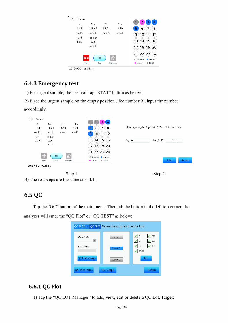
6.4.3 Emergency test
1) For urgent sample, the user can tap “STAT” button as below:
2) Place the urgent sample on the empty position (like number 9), input the number
accordingly.
Step 1 Step 2
3) The rest steps are the same as 6.4.1.
6.5 QC
Tap the “QC” button of the main menu. Then tab the button in the left top corner, the
analyzer will enter the “QC Plot” or “QC TEST” as below:
6.6.1 QC Plot
1) Tap the “QC LOT Manager” to add, view, edit or delete a QC Lot, Target:

Page 35
3) Select the desired QC LOT, then place QC solutions on the right position,”Level 1”
correspond with (# 25 QC1), “Level 2” correspond with (# 24 QC2), “Level 3”
correspond with (# 23 QC3).
4) Then tap “Test” button to test the QC solutions.
5) Tap the “QC Plot Datas”, the user can view, delete and transfer the results to LIS.
6) Tap the “QC Graph” to view Levey–Jennings graph:

Page 36
6.6.2 QC Test
1) Select the desired QC LOT and test number for each level, then place QC solutions on the
right position,”Level 1” correspond with (# 25 QC1), “Level 2” correspond with (# 24 QC2),
“Level 3” correspond with (# 23 QC3).
2) Then select “Level 1”, “Level 2”, “Level 3” or “All Level”,press “Test” button to test the
QC solutions.
3) Tap “QC Datas” button then select the date to view the test results:
4) Tap “Statistics” button to calculate each level’s CV.
5) Tap “Calculation” button (pass word: 88), the user can get “Correlation Coefficient” of each
parameter, please check “6.7.9 Correlation Coefficient Configuration” for detail:

Page 37
6.6 Maintenance Menu
To obtain high reproducibility of measure results and high stability of sensors, it is
essential to maintenance the unit regularly. Tap the “Maintenance” button of the main
menu to enter the submenu of maintenance.
6.6.1 ISE Deproteinization
Use this procedure to clean the sample path with deproteinization solution once 10 days
or every 100 samples. Deproteinization removes protein buildup from the sample path.
Wait 10 minutes for the ISE Deproteinization cycle to finish.
Caution: The deproteinization solution is for single use.

Page 38
6.6.2 Flush
Tap the “Flush” button, the flow path will be flushed automatically.
6.6.3 Deep cleaning Tap the “Deep cleaning” button, the analyzer will show as follows. Wait 10 minutes for the
deep cleaning cycle to finish.
6.6.3 ISE Cleaning Tap the button “ISE Cleaning”, the analyzer will aspirate cleaning solution automatically. Wait
5 minutes for the ISE Cleaning cycle to finish.
6.6.5 Na&pH conditioning
“Na&pH conditioning” works for Na and pH, place the Conditioning solution in #22

Page 39
cup. Wait 5 minutes for the Na&pH conditioning cycle to finish.
Caution: The Na&pH conditioning is for single use.
6.6.6 Serum soak
Tap the “Serum soak” button, prompt will instruct the user to place Serum in #21 cup.
Wait 10 minutes for the Serum soak cycle to finish.
6.6.7 One_ Key_Maintenance
Tap the “One_Key_Mainteinance” button, the analyzer will perform “All Cleaning”,
“ISE Deproteinization”, “Na&pH Conditioning”(if triggered) , “Serum soak”. Wait 45
minutes for the One_Key_Maintenance cycle to finish.

Page 40
6.6.8 TCO2 Deproteinization After long-term use, protein buildup in the reaction cup.Please remove protein regularly. Wait 5
minutes for the TCO2 Deproteinization cycle to finish.
6.6.9 All Cleaning Tap the “All Cleaning” button, the analyzer will perform “ISE Cleaning”,”TCO2 Cleaning”
and flow path cleaning. Wait 20 minutes for the All Cleaning cycle to finish.
6.7 System Setup
Return to the main menu, tap “System Setup” button to enter the submenu of system
configuration.
The analyzer has 16 parameters for the user to meet various demands of clinical diagnostics.
Page 41
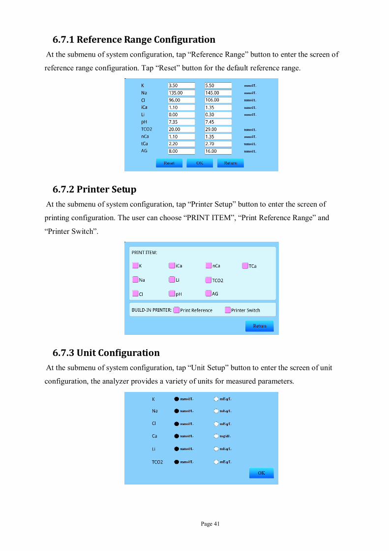
6.7.1 Reference Range Configuration At the submenu of system configuration, tap “Reference Range” button to enter the screen of
reference range configuration. Tap “Reset” button for the default reference range.
6.7.2 Printer Setup At the submenu of system configuration, tap “Printer Setup” button to enter the screen of
printing configuration. The user can choose “PRINT ITEM”, “Print Reference Range” and
“Printer Switch”.
6.7.3 Unit Configuration At the submenu of system configuration, tap “Unit Setup” button to enter the screen of unit
configuration, the analyzer provides a variety of units for measured parameters.

Page 42
6.7.4 Screen Configuration At the submenu of system configuration, tap “Screen” button to enter the screen of Screen
configuration. “LCD Brightness” can be adjusted by user.
6.7.5 Testing Parameter
At the submenu of system configuration, tap “test parameter” button to enter the screen
of test parameter configuration. The user can select measured parameters.
6.7.6 Maintenance Setup At the submenu of systematic configuration, tap “Maintenance Setup” to adjust the days or
sample tested counts.
Page 43
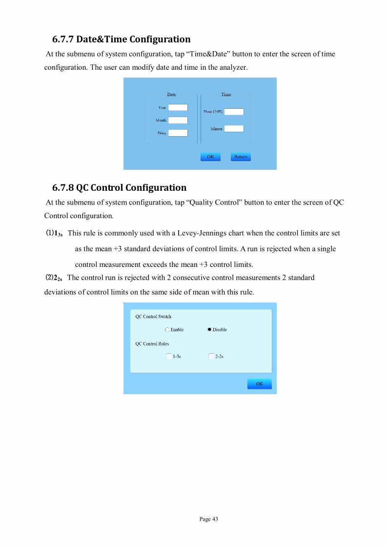
6.7.7 Date&Time Configuration At the submenu of system configuration, tap “Time&Date” button to enter the screen of time
configuration. The user can modify date and time in the analyzer.
6.7.8 QC Control Configuration At the submenu of system configuration, tap “Quality Control” button to enter the screen of QC
Control configuration.
⑴13s This rule is commonly used with a Levey-Jennings chart when the control limits are set
as the mean +3 standard deviations of control limits. A run is rejected when a single
control measurement exceeds the mean +3 control limits.
⑵22s The control run is rejected with 2 consecutive control measurements 2 standard
deviations of control limits on the same side of mean with this rule.

Page 44
6.7.9 Correlation Coefficient Configuration At the submenu of system configuration, tap “Correlation Coefficient” button to enter the
screen of Correlation Coefficient configuration (password: 88). This setup screen allows the user
to mathematically adjust the analytical results of the analyzer based on results from a reference
analyzer or reference material. The correlation coefficients can be specified for slope and
intercept for each measured parameter. The correlation coefficients of K+, Na+, Cl-, Ca2+, Li+,
pH and TCO2can be calculated automatically. Please refer to chapter 7 for details. Tap “Reset
Slop” button for the default correlation coefficients of K+, Na+, Cl-, Ca2+, Li+, pH and TCO2.
Tap “Reset K-value” button for the default K-value.
6.7.10 Calibration Intervals Configuration At the submenu of system configuration, tap “Calibration Intervals” button (password: 88) to
enter the screen of Calibration Intervals configuration. The user can select frequency of
one-point calibration. The system default interval for one-point calibration is 240 minutes, while
two-point calibration interval is fixed four hours. The user can define system standby time,
during the time there only liquid movement. The system default interval for Li-K value is 7 days,
please refer to chapter 7 for details.

Page 45
6.7.11 Sampling Mode At the submenu of systematic configuration, tap “Sampling Mode” to select “Auto” or
“Manual” mode.
6.7.12 Sample Volume Configuration At the submenu of system configuration, tap “Sample Volume” button to enter the screen of
sample volume configuration. The user can select the volume of sample aspirated, which is
increases from 1 to 5.
6.7.13 Resistance Setup For customer service staff.
6.7.14 Data Transfer Mode At the submenu of system configuration, tap “Data Transfer Mode” button to select the “HL7
Mode” or “Self Mode”:
HL7 Mode: Tranfer the data to LIS (Laboratory Information System).
Self Mode: Tranfer the data to the Data management software developed by Cornley.

Page 46
6.7.15 Operation Mode At the submenu of systematic configuration, tap “Operation Mode” to select “Economization”
or “Standard” mode:
In “Standard mode”, during the sample test, the analyzer will aspirate Cal A to start a
background 1-Point calibration for a more accurate test result than “Economization Mode”. But
it will consume more Cal A and take about 12 seconds more than “Economization Mode”.
6.7.16 Other At the submenu of systematic configuration, tap “Other” to select “Bubble”, “TCO2 Pathway”,
“Clog”, “TCO2 Res”.
6.8 Data Manager
Tap “Data Manager” button of the main menu to enter data management section.
Page 47
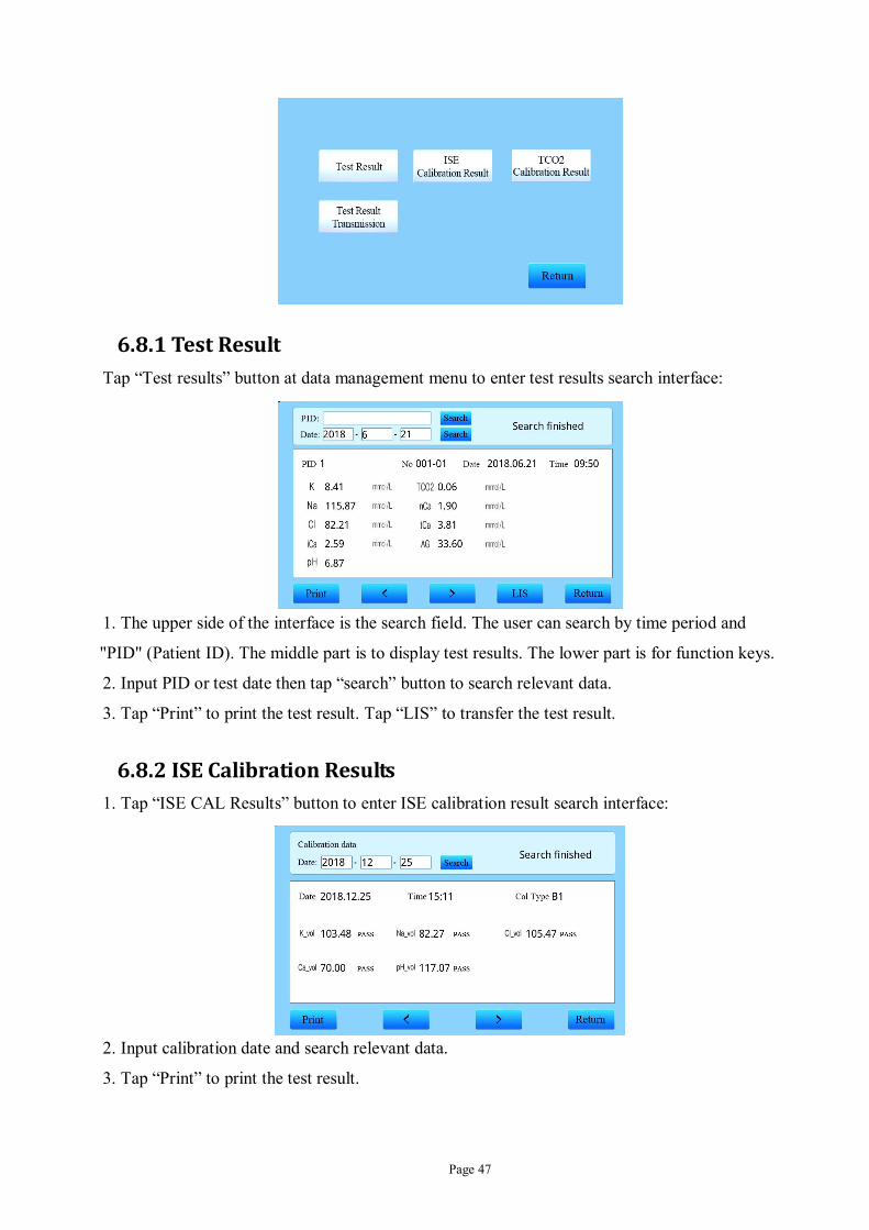
6.8.1 Test Result Tap “Test results” button at data management menu to enter test results search interface:
1. The upper side of the interface is the search field. The user can search by time period and
"PID" (Patient ID). The middle part is to display test results. The lower part is for function keys.
2. Input PID or test date then tap “search” button to search relevant data.
3. Tap “Print” to print the test result. Tap “LIS” to transfer the test result.
6.8.2 ISE Calibration Results 1. Tap “ISE CAL Results” button to enter ISE calibration result search interface:
2. Input calibration date and search relevant data.
3. Tap “Print” to print the test result.

Page 48
6.8.3 TCO2 Calibration Results Similar to ISE CAL Results, which is used for checking calibration results of TCO2.
6.8.4 Test Results Transmission Tap “Test Results Transmission” button to transfer the data of the selected date.
6.9 Service
Return to the main menu, tap “Service” button to enter the submenu of Servers:
6.9.1 ShutDown
Tap “ShutDown” button to shutdown the system:
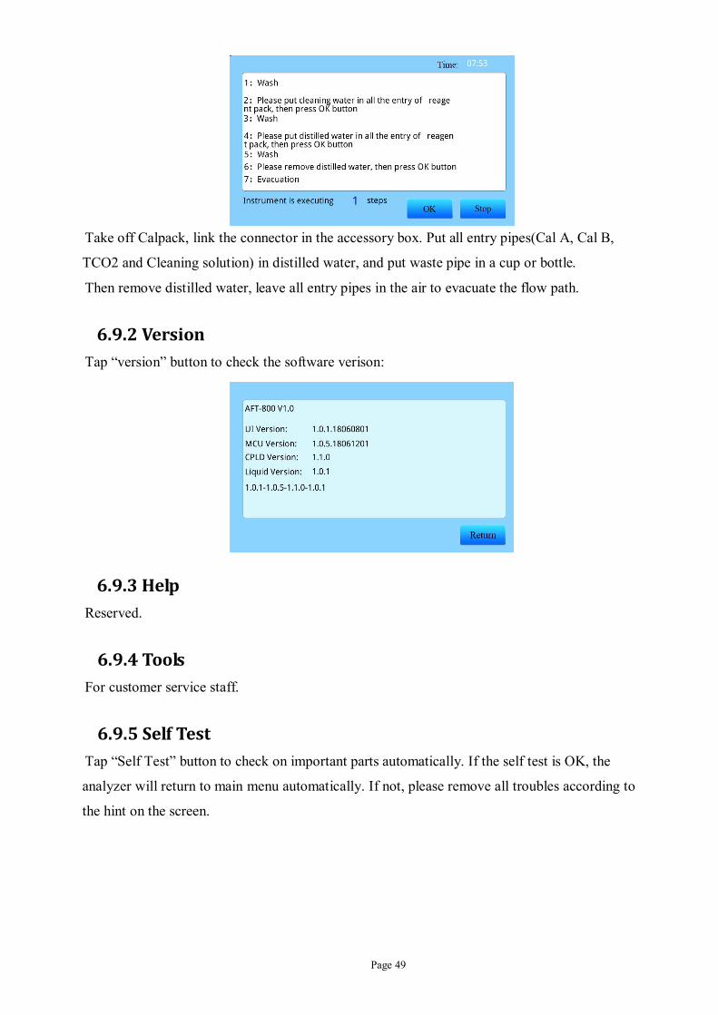
Page 49
Take off Calpack, link the connector in the accessory box. Put all entry pipes(Cal A, Cal B,
TCO2 and Cleaning solution) in distilled water, and put waste pipe in a cup or bottle.
Then remove distilled water, leave all entry pipes in the air to evacuate the flow path.
6.9.2 Version Tap “version” button to check the software verison:
6.9.3 Help Reserved.
6.9.4 Tools For customer service staff.
6.9.5 Self Test Tap “Self Test” button to check on important parts automatically. If the self test is OK, the
analyzer will return to main menu automatically. If not, please remove all troubles according to
the hint on the screen.

Page 50
6.9.6 Sample Needle Adjust Tap “Sample Needle Adjust” button to adjust the probe if its position is shifted. Press “Sample
Frame Transposition” button and then press “Left” or “Right” button to make the probe align the
center of its dock.
6.9.7 Sample Tray Adjust Tap “Sample Tray Adjust” button to adjust the sample tray if its position is shifted. First Cup 25
is adjusted, press “Right” or “Left” button to make the probe to align the center of Cup 25 .Then
adjust position Cup 1. Press OK to save.
6.9.8 Multiplexer Check Tap “Multiplexer Check” button to check whether the multiplexer can aspirate Cal A, Cal B,
TCO2 Cal and Cleaning solution.

Page 51
6.9.9 Cal Pack Used Tap “Cal Pack Used” button to check out remaining of cal pack.
6.9.10 TCO2 Clog Check Tap “TCO2 Clog Check” button to check out whether the gas flow path is clogged or not.
6.10 Consumables Management
1. Tap “Consumables Management” at the main menu, and scan the barcode on the
consumables, tap “List” button to check state of current consumables:

Page 52
3. Tap “Manually Barcode” button to input the barcode if there is problem with the barcode
scanner.

Page 53
Chapter 7 Calibration
7.1 General information
Calibration defines both points of Cal A and Cal B. When calibration is passed, the
concentration in an unknown sample can be calculated from the two points via Nernst equation.
The voltage (mV) difference between Cal B and Cal A should fall within the requirement to
ensure linearity range of electrodes.
The response relationship between voltage and ion concentration is shown as below
Generally, if the slope of measured parameters by an electrode (or sensitivity) and drift rate
(output electrode signal of the parameter) is known, the unknown value can be calculated by
measuring the electrode. Electrode calibration is a process to obtain slope and drift rate from the
output signal of the electrode associated with liquid concentration. Two-point calibration
solution is used by this analyzer to achieve this goal.
7.2 One point calibration
One point calibration can associate mV values with ion concentration of Cal A. It defines the
first point of two point calibration. It is also used to check the status of electrodes after two point
calibrations is passed.
The step of one point calibration is as follow:
1. Tap “1 Point Calibration” button at the submenu of calibration.

Page 54
2. The analyzer will aspirate calibrator automatically.
3. The calibration result will be printed after one pint calibration is done.
4. The analyzer will aspirate flush solution automatically to flush the Flow path.
5. When the flush is done, system will return to the main menu automatically or wait for the
further command from the operator
There are four possibilities for one point calibration
Pass The system will display the corresponding concentration of Cal A and return to the main menu.
Unstable Unstable mV value. The system will also alarm voltage value is unstable
Drift When two mV values are beyond a certain range, the system will alarm the electrode drift. The abnormal electrode channel will be displayed at the bottom of the screen.
OR: mV out of range
If the electrode mV value exceeds the set range, the system will prompt the mV is out of range. Please refer to the following instructions for the range of each electrode.
Notice:
“Cal A”:”A1” here means the first one point calibration
“02:01”: Calibration time
“Voltage”: Potential (mV) of the electrode
“Value” : The concentration of ion, unit mmol/L。
“Status”: Status of calibration, show “PASS” when the calibration passes or “FAIL” when the
calibration fails.
7.3 Two point calibration
Two point calibration is necessary before testing or QC on Li+, K+ ,Na+ , Ca2+,pH ,Cl- ,Two
point calibration includes calibration A and B.
1. Tap “two point calibration” button at the submenu of calibration;
2. The analyzer will do Cal A (the same as one point calibration);
3. When the Cal A passes, the analyzer will do Cal B automatically;
4. The analyzer will aspirate Cal B to perform the calibration;

Page 55
5. The calibration result will be printed after two pint calibration is done;
6. The analyzer will aspirate flush solution automatically to flush the flow path;
7. When the flush is done, system will return to the main menu automatically or wait for the
further command from the operator.
There are five possibilities for two point calibration:
Pass The system will display the corresponding concentration of Cal A /B and return to the main menu. The system is ready for test
Unstable Unstable mv value. The system will also alarm voltage value is unstable
Drift When two mV values are beyond a certain range, the system will alarm the electrode drift. The abnormal electrode channel will be displayed at the bottom of the screen.
OR: mV out of range
If the electrode mV value exceeds the set range, the system will prompt the mV is out of range. Please refer to the following instructions for the range of each electrode.
Slope Abnomal Difference on MV between Cal B and Cal A is called slope. If the difference exceeds the prescribed range, it is called the slope abnormal. Please refer to the following instructions.
7.4 Li_K Value Adjustment
This menu is applicable to perform Lithium calibration only.
1. Perform ISE Two point calibration. Continue to next step if it is passed with one trial only.
2. Enter “Main Menu→QC Test”, test QC level1/level2/level3. If Na is in the range, then
continue to next step. If Na is out of range, then perform Na correlation as section 6.7.9 and
6.6.2.
3. 4. Feed selective coefficient calibrator (for Li+) to the #25 cup, enter Calibration and select
Li_K test.
5. After 3 times of repeated K test, the result of K is automatically printed out and update the
Li_K in “Correlation Coefficient” menu.
Li is affected by the status of Na electrode. Make sure Na is stable and in the range when Li has problem.
K test must be done after maintenance of Li and Na electrode.
7.5 TCO2 Calibration
1. Tap “TCO2 Calibration” button to enter TCO2 calibration menu
2. The analyzer will aspirate TCO2 standard solution to the reaction cup to perform the
calibration on TCO2
3. Once TCO2 calibration passes, the result will be displayed and printed automatically
4. The analyzer will aspirate flush solution automatically to flush the flow path.

Page 56
5. When the flush is done, system will return to the previous menu automatically.
7.6 ISE+TCO2 Calibration
ISE + TCO 2 Calibation will be two point calibration on ISE and TCO2 calibration. The analyzer
must perform ISE + TCO 2 calibration before test or QC.
1. Tap “ISE+TCO2 Calibration” button to enter ISE+TCO2 calibration menu;
2. The analyzer will perform two pint calibration on ISE as 7.3 section;
3. When two point calibration passes, the analyzer will perform TCO2 calibration;
4. The analyzer will aspirate flush solution automatically to flush the flow path;
7.7 Calibration Intervals
This analyzer supports automatic calibration function, which is to keep and monitor electrode
condition. The steps to set calibration interval is as follow, tap “System Setup” button at main
menu:
Tap “Calibration Intervals” button:
3. The system default interval for one-point calibration is 240 minutes, while two-point
calibration interval is fixed four hours.
4. Tap “OK” button to save
7.8 Calibration Results

Page 57
1. Tap “ISE CAL Results” or “TCO2 CAL Results” button at “Data Management” menu to
enter calibration result search interface:
2. Input calibration time and search relevant data.
3. Tap “more” button to check more calibration data or to print these calibration results.
Calibration type Description A1,2, or 3 The first, second or third attempt on Cal A B1,2, or 3 The first, second or third attempt on Cal B

Page 58
Chapter 8 Patient Sample Analysis The sample analysis of this analyzer only needs three steps. The following describes only the
analysis on sample but does not involve any sample type. The sample analyses on different
types are nearly the same except for some minor differences.
8.1 Sample collection
1. Please refer to the blood collection standard procedures and Label the sample.
2. Let blood stand for 20-30 minutes to allow clot formation.
3. Centrifuge the tube for 10-15 minutes. Serum may be analyzed immediately, stored at
22-25℃ up to 8 hours. Please refer to chapter 2.3.
8.2 Steps of Sample Analysis
1) Tap the “Test” button of the main menu. The analyzer will enter the test menu as the picture
below, select the testing parameter. Tap the “Cup choice” to select the desired cup number and
place the sample in the correct position.
2) Tap “Sample ID” to input the ID of the sample.
3) Place the sample into the right position and tap “Start” button directly. The sample will be
aspirated into the measuring chamber. Then the color of each cup means: White indicates that
there is no sample; Pink indicates that the sample is testing now; Blue indicates that the sample
is not tested yet; Grey indicates that the sample has been tested.

Page 59
After the test, the result will be printed automatically. Also, you can check the results by
tapping the sample number.
8.3 Test Result
Tap “Test Result” button at data management menu to enter test results search interface:
1. The upper side of the interface is the search field. The user can search by time period and
"Sample ID" (Patient ID). The middle part is to display test results. The lower part is for
function keys.
2. Input sample ID or test date then tap “search” button to search relevant data.
3. Tap “more” button to check more details like basic information, test results, A5 test report,
analysis report, edit, etc.

Page 60
Chapter 9 Trouble Shooting This section covers the trouble shooting procedures of the instrument. The instrument can
perform self test when power up. It will detect most of the problem except electrodes.
9.1 Normal Troubles and Solutions
The instrument is not the control material factory production of corrected in the measured sample of some projects may be biased, need to readjust the project machine, belonging to the matrix effect is a normal phenomenon.
to ensure the measurement results are accurate, the user shall regularly conduct quality control measure, usually once a day, in addition to the use of the company's quality control liquid and a variety of quality control serum, the standard of quality control liquid cannot use similar instrument equipped with measurement, because of some additives other standard solution which may cause unnecessary damage of electrode.
As Li+ electrode test is modified by the Na+, when the Na+ electrode is abnormal, of the test results Li+ electrodes is not reliable.
9.2 Electrode
The electrode may have some faults during testing on samples, especially complex samples. It will affect the measurement accuracy or even can not be measured at all. Please make correct judgment according to the fault phenomena, troubleshooting in time, make the instrument to maintain normal operation when there is electrode failure.
9.2.1 Drifting Activation time is not enough Increased activation time
Electrode has the slight leakage To replace the new electrode
Concentration change on Refilling
solutions
Replace the refilling solution and enhance
the seal
Reference electrode core coating goes
off Replace the reference electrode core
9.2.2 Unstable 1) Electrode loose contact Wipe each contact with alcohol
2) Unstable power supply Install a regulator

Page 61
9.2.3 Slow reaction and low slope 1) Electrode pollution Perform de-protein, conditioning to clean the electrode
2) Sensitive membrane damaged Replace a new electrode
9.3 A simple method to check respondent circuit channel of
each electrode
9.3.1 To change the position of the normal electrode (such as Cl-) and unstable (mV variably)
electrode (such as K+) between each other. Do a calibration and observe the display screen.
9.3.2 K display (the actual measured Cl-):
If the mV value stability indicating K+ circuit is no problem, there may be a problem with K+
electrode.
If the mV value is not stable description of K+ circuit problem, there can be no problem with K+
electrode.
9.4 Only one unstable electrode
Solution:
A. to do de-protein (K+, Cl-, Ca2+ electrode) or conditioning (Na+, pH electrode)
B. to exchange the position of two electrodes, refer to the "common fault handling"
If the problem can not be settled, please contact customer service department of Cornley for
guidance and assistance
9.5 Two or more unstable electrodes
The solution:
A. De-protein or conditioning;
B. Replace new calibration standard solution;
C. Check reference electrode: whether there is leakage, bubble, not clean, silver bar peeling
coating, or no liquid;
D. Check the external power supply: whether the grounding or the regulator is installed well.
9.6 Longer balance time on Li+、K+、Cl-、Ca2+ electrodes
Possible contamination, do de-protein immediately.
9.7 Longer balance time on Na+、pH
Possible contamination, do conditioning immediately.

Page 62
9.8 Problems on Flow Path
There are two liquid-sensors in the measuring chamber. The front is used to check air bubble,
while the back is used to check if the sample is arrived. If there is no sampl, both the
liquid-sensor is 1.7±0.2V; When the sample arrived, both the liquid-sensor is below 1.0V.
9.9 Slope out of range
Metamorphic standard solution, showed turbid, precipitation, to replace the new standard
solution; electrode contamination must be to de-protein or conditioning.
9.10 Problems on Repeatability
Electrode: eliminate the bubble in the bubble near the sensing membrane electrode.
The sample mixed with bubble: find out reason, be removed.
Reason: the test samples prepared with the new quality control samples or fresh serum.
9.11 Problems on Accuracy
Interference of other substances in the sample: pay attention to sampling method.
Standard concentration change: to replace a new calibration standard solution.
Protein, lipid, deviation and flame photometer, may this deviation will be corrected according to
ion electrode method for quasi.
Correct parameter adjustment.
9.12 Problems on QC
The analyzer is designed for fast and accurate measurement of human blood. Advanced
technology that has good accuracy and repeatability in the linear range is quite wide.

Page 63
To ensure that your analysis report has indisputable accuracy, you should regularly carry out
quality control measure, usually once a day, in addition to the use of the company's quality
control liquor, quality control and reagent please don't measure other types of analyzer are used,
because the control material and reagent in the face of some additives may cause damage to the
electrode.
9.13 Problems on Fuse
Confirm the fuse has burned out, need to perform following replacement:
Turn off the power switch, unplug the power plug;
A convex mark in the power supply socket analyzer on the cover using a screwdriver, lever out
the fuse socket outward force;
Remove the fuse burned out;
Install new fuse.
9.14 No flush or flow slowly
The flush solution is out: to replace a new reagent pack.
Electrode dislocation or not installed by pressing wrench compression, so that measuring the
pipeline does not seal: this can be seen when cleaning with a cleaning liquid overflow on the
electrode surface. Need to be installed and tightened electrode.
Cleaning pump weak or damaged: replace the pump.
Cleaning pipeline damaged or blocked: piecewise check syringe, replace the defective pipeline.
Cleaning the pump does not turn: required by the electrical technicians to inspect the relevant
circuit.
9.15 No Cal A or Cal B
Error message "No Cal A" (or "No Cal B"), and returns to sleep.
Electrode dislocation or not installed by pressing wrench compression, so that measuring
pipeline is not sealed: re electrode installed correctly and fasteners.
A suction pump is weak or damaged: replace the pump.
The suction pipeline damaged or blocked: piecewise check syringe, replace the defective
pipeline.
9.16 No sample when sampling
Have a careful check according to the instruction. If the problem can not be settled, please
contact Cornley for further guidance.

Page 64
9.17 Problems on Pump Tubes
In case of any of the following circumstances, it means the pump tube shall be replaced
Over the shelf life
Pipe sticking together.
Pump tube aging.
Pipe rupture.
9.18 Loose Connector
The power supply interface loosening: analyzer cannot test.
Reagent: interface loosening caused interface showed no reagent.
As for the above problem needs to check whether the interface loosening, if yes, then connect
the interfaces well.

Page 65
Chapter 10 Maintenance This section includes the recommended maintenance procedures for the instrument. The
frequency of preventive maintenance operations is based on average workload of 20 to 30
samples per day with a normal instrument use. Facilities with heavier workloads should
schedule maintenance operations more frequently.
Wear disposable gloves to avoid contact with potentially infectious materials while maintaining
the instrument.
10.1 Daily maintenance
The maintenance operations described here are recommended to be performed everyday just
before or after routine measurements.
1. Clean the probe and sample tray
2. Clean surface of the instrument.
3. Do TCO2+ 2 PT calibration first to check the instrument first. After calibration is passed, test
a sample to check.
4. Near day off, do deproteinization or cleaning to maintain electrodes and reaction cell if
necessary.
10.2 Weekly maintenance
The maintenance operations described here are recommended to be performed every week at
the end of the routine measurements.
1. Sterilize exterior and interior surface and aspiration probe tie-in
2. Take out reference electrode and shake it for serial time to avoid crystal formation.
3. Cleaning the flow path to prevent blockage.
4. Check the multiplexer if there is any leakage.
5. Check TCO2, Cal A if it is not enough.
6. Test middle level QC, adjust slope and intercept accordingly.
7. Perform deproteinization and cleaning to maintain electrode and reaction cell.
8. Clean flow path with syringe. Hard pushing can break the membrane. Careful cautions
should be taken when sterilizing probe to avoid injury and potential infections.

Page 66
10.3 Monthly maintenance
1. Check the solution level of K+, Na+, Cl- electrodes. Replace the refill solution of K+, Na+, Cl-
electrodes if it is less than 2/3.
For K+, Na+, Cl-, Ca2+ and pH electrodes, empty the remaining refill solution before filling
new.
2. Correct coefficient factors (slope and intercept) with high/middle/low level QC.
3. Take out the reference electrode, remove crystal if there is too much. Refill if the solution is
not enough.
4. Clean the entire flow path to avoid blockage
10.4 Yearly Maintenance
To do a completed inspection for the instrument every year.
10.5 As necessary
1. Never switch off the analyzer
2. Never mix old and new reagents together
3. Serum must be centrifuged within one hour after the collection of blood sample
4. Do not change the slope or interception frequently. Minor changes are OK for routine
checks.
5. No direct strong light on multiplexer.
6. The instrument may be abnormal if the operation or maintenance is not done strictly
according to this manual.
7. Only the trained engineer can do maintenance and fix for the instrument. All spare parts
for such maintenance and fix must be original from Cornley.
8. If the analyzer must be stopped with any reason, the flow path must be washed and
emptied. The calibration standard solutions must be handled according to guidance of 6.9.1.
9. To prevent the clot in flow path, please 1) The liquid level of the serum in the tube must be
over 10mm; 2) Please separate the protein fibers from the serum samples.
10.6 Shelf life
Storage shelf life:three years

Page 67
Designed usage shelf life:five years
10.7 Transportation and storage
This analyzer allows the use of common traffic tools. But need to prevent the severe impact,
vibration, and rain splash during transportation process. Transportation requirements must be
included in the contract. Analyzer packaging should be stored indoors with ambient temperature
-20℃~+55℃, relative humidity of not more than 80%, non corrosive gas with good ventilation.
For the long-term storages, the analyzer is required to be power-on once a month and
dehumidification at the same time.

Page 68
Appendix A Symobols
IVD product
CE mark
Biological contamination risk
Alert
Notice
This way up
Please consult the manual
Serial number of the analyzer
Electronics waste
Possible injury for hand
Warning of high temperature
Risk of electric shock
Laser
EC representative

Page 69
Manufacture date
Manufacturer
Keep away from rain
Keep away from sunlight
Only three layers at the most
Fragile
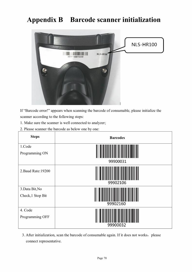
Page 70
Appendix B Barcode scanner initialization
If “Barcode error!” appears when scanning the barcode of consumable, please initialize the scanner according to the following steps: 1. Make sure the scanner is well connected to analyzer; 2. Please scanner the barcode as below one by one:
Steps Barcodes
1.Code
Programming ON
2.Baud Rate:19200
3.Data Bit,No
Check,1 Stop Bit
4. Code
Programming OFF
3. After initialization, scan the barcode of consumable again. If it does not works,please connect representative.

Tec hnical Document Auto s ampler
CORNLEY
Product name Auto sampler
Manufacture Meizhou Cornley Hi-Tech Co., Ltd Nanshan Estate Baigong, Meizhou,
Guangdong, 514765, China
Country of origin China
Product Description The Auto sampler is a compact, easy-to-use option for users who value letting their instrument to get on with the analyses. It makes the perfect walk-away system for laboratories with high workload. Just pre-load up to 25 samples and let the Auto sampler do the work. It tilts and reads its barcode. Note that emergency samples can easily be analyzed in the middle of an automated run.
Model configuration
Figure 1 – Auto sampler
Instructions for use Use in accordance with manufacturer’s instructions for use in AFT-800 User´s Manual
Storage +5 to +35 ºC
Packaging and Weight 347mm x 277mm x 451mm (L x W x H); 6.5 kg,
MEIZHOU CORNLEY® HI-TECH CO,.LTD Nanshan Estate Baigong, Meizhou, Guangdong, 514765, China (+86-753) 2878808/(+86-753) 2878811 wwww.cornley.com


Instructions for Installation of electrodes CORNLEY
According to different functions, the electrodes can be grouped as below:
ISE electrodes: K+/Na+/Cl-/Ca2+/pH. Refillable.The K+, Cl-, Ca2+ electrodes need to refilling
solution before installation. When solution less height than 1/2, user need to dry the electrode
and refill .The refilling solution has to be replaced for every 3 months.
Reference electrode: Fixed type with internal solution.
The steps to add refilling solution to ISE electrodes:
1) Open the contact terminal of Li+, K+, Na+, Ca2+, pH, Cl- electrode (taking Na+ electrode as
the example in the pictures):
2) Empty the internal electrode solution.
Step1 Step 2 3) Cut the bottle of refilling solution with a scissors. Use a syringe to aspirate the liquid.
4) Use the syringe to inject refilling solution into the electrode (The needle of the syringe can
never touch the bottom of the electrode. Otherwise the membrane may be broken)
Step 3 Step 4 5) To dry the rest refilling solution on the terminal of electrode by tissue paper.
6) The electrode terminal must be properly tightened. Then seize the electrode to upright
position. Please click the bottom of electrode several times with a finger to remove bubbles at
the bottom of the inner cavity of the electrode.
7) To dry the rest refilling solution on the electrode by tissue paper again.

Step 5 Step 7
The steps to add refilling solution to Ref electrode:
a) Spin out the cap and terminal of Ref electrode
b) Open the small bottle of refilling solution for Ref electrode. Use a sucker or a syringe
to aspirate the liquid.
c) After the smaller inner cavity of the Ref electrode is filled with refilling solution to the
inner cavity mouth, please tighten the electrode terminal of this side first. Then added
some more refilling solution to 4/5 of the inner cavity of the bigger side and tighten the
electrode terminal of this side.
d) Seize the electrode to upright position. Please click the bottom of electrode several
times with a finger to remove bubbles at the bottom of the inner cavity of the
electrode.
e) The refilling solution for Ref electrode is an oversaturated solution. There will be
white crystal inside the inner cavity of the electrode during the usage. The refilling
solution may volatilize after long time usage. So please add refilling solution for Ref
electrode one time. (When replace refilling solutions for ISE electrodes, the original
liquid inside the electrodes must be empty first. However, it is OK to add refilling
solution for Ref electrode directly no matter the electrode is empty or not. Please
notice that the refilling solutions for ISE electrodes and Ref electrodes are different.
Please only add correct refilling solution to the correct electrode(s).)
8) After inject enough refilling solution into the electrodes, please install them into the
measuring chamber according to the order (from left to right) of Li+, K+, Na+, Ca2+,
Cl-, pH and Ref.
Installation steps:

1. Open the front cover of the analyzer and the cover of measuring chamber.
2. For the first usage of all electrodes, or the refilling solution in one electrode is less than
half of its inner cavity, new refilling solution must be injected into the electrode(s).
3. Before installation, please use a clean paper towel to clean the measuring chamber and
the electrode terminal.
4. Pull the spanner to right
5. Check whether the O-rings on the both sides of each electrode are normal or not. Use a
tissue paper to clean the channel of each electrode.
6. Place the electrode head tightly against spring. Then press to inner side and trim all
electrodes from left to right according to the correct order.
7. Install the Ref electrode at last.
8. Level all electrodes again when all of them are installed into the right places.
9. Release the hand slowly so that the spanner can press all electrodes tightly.
10. Check whether all electrodes are leveled or not at last.
11. Close the cover of the measuring chamber.
Electrodes shall maintain a channel end to end to form of a Flow path (no dislocation)
After installation, please check whether there is any bubble at the bottom of every electrode. If yes, please tap the bottom of the electrode several times to remove the bubble.
Correct position of each electrode is shown in the picture below.