
SIGNAL ANALYZER - Rohde & Schwarz
859
1119.5063.12-02- 1 1/00 Test and Measurement Division Operating Manual SIGNAL ANALYZER FSIQ3 1119.5005.13 FSIQ7 1119.5005.17 FSIQ26 1119.6001.27 FSIQ40 1119.6001.40 Printed in the Federal Republic of Germany
-
Upload
khangminh22 -
Category
Documents
-
view
2 -
download
0
Transcript of SIGNAL ANALYZER - Rohde & Schwarz

1119.5063.12-02- 1 1/00
Test and MeasurementDivision
Operating Manual
SIGNAL ANALYZER
FSIQ31119.5005.13
FSIQ71119.5005.17
FSIQ261119.6001.27
FSIQ401119.6001.40
Printed in the FederalRepublic of Germany


FSIQ Tabbed Divider Overview
1119.5065.12 RE E-2
Tabbed Divider Overview
Contents
Data Sheet
Safety InstructionsCertificate of QualityEU Certificate of ConformityList of R&S Representatives
Manuals for Signal Analyzer FSIQ
Tabbed Divider
1 Chapter 1: Putting into Operation
2 Chapter 2: Getting Started
3 Chapter 3: Operation
4 Chapter 4: Functional Description
5 Chapter 5: Remote Control – Basics
6 Chapter 6: Remote Control – Commands
7 Chapter 7: Remote Control – Program Examples
8 Chapter 8: Maintenance and Hardware Interfaces
9 Chapter 9: Error Messages
10 Index

1171.0000.42-02.00 Sheet 1
Before putting the product into operation for the first time, make sure to read the following
S a f e t y I n s t r u c t i o n s
Rohde & Schwarz makes every effort to keep the safety standard of its products up to date and to offer its customers the highest possible degree of safety. Our products and the auxiliary equipment required for them are designed and tested in accordance with the relevant safety standards. Compliance with these standards is continuously monitored by our quality assurance system. This product has been designed and tested in accordance with the EC Certificate of Conformity and has left the manufacturers plant in a condition fully complying with safety standards. To maintain this condition and to ensure safe operation, observe all instructions and warnings provided in this manual. If you have any questions regarding these safety instructions, Rohde & Schwarz will be happy to answer them.
Furthermore, it is your responsibility to use the product in an appropriate manner. This product is designed for use solely in industrial and laboratory environments or in the field and must not be used in any way that may cause personal injury or property damage. You are responsible if the product is used for an intention other than its designated purpose or in disregard of the manufacturer's instructions. The manufacturer shall assume no responsibility for such use of the product.
The product is used for its designated purpose if it is used in accordance with its operating manual and within its performance limits (see data sheet, documentation, the following safety instructions). Using the products requires technical skills and knowledge of English. It is therefore essential that the products be used exclusively by skilled and specialized staff or thoroughly trained personnel with the required skills. If personal safety gear is required for using Rohde & Schwarz products, this will be indicated at the appropriate place in the product documentation.
Symbols and safety labels
Observe operating instructions
Weight indication for units >18 kg
Danger of electric shock
Warning! Hot surface
PE terminal Ground Ground terminal
Attention! Electrostatic sensitive devices
Supply voltage ON/OFF
Standby indication
Direct current (DC)
Alternating current (AC)
Direct/alternating current (DC/AC)
Device fully protected by double/reinforced insulation

Safety Instructions
1171.0000.42-02.00 Sheet 2
Observing the safety instructions will help prevent personal injury or damage of any kind caused by dangerous situations. Therefore, carefully read through and adhere to the following safety instructions before putting the product into operation. It is also absolutely essential to observe the additional safety instructions on personal safety that appear in other parts of the documentation. In these safety instructions, the word "product" refers to all merchandise sold and distributed by Rohde & Schwarz, including instruments, systems and all accessories.
Tags and their meaning DANGER This tag indicates a safety hazard with a high potential of risk for the
user that can result in death or serious injuries. WARNING This tag indicates a safety hazard with a medium potential of risk for the
user that can result in death or serious injuries. CAUTION This tag indicates a safety hazard with a low potential of risk for the user
that can result in slight or minor injuries. ATTENTION This tag indicates the possibility of incorrect use that can cause damage
to the product. NOTE This tag indicates a situation where the user should pay special attention
to operating the product but which does not lead to damage. These tags are in accordance with the standard definition for civil applications in the European Economic Area. Definitions that deviate from the standard definition may also exist. It is therefore essential to make sure that the tags described here are always used only in connection with the associated documentation and the associated product. The use of tags in connection with unassociated products or unassociated documentation can result in misinterpretations and thus contribute to personal injury or material damage.
Basic safety instructions 1. The product may be operated only under
the operating conditions and in the positions specified by the manufacturer. Its ventilation must not be obstructed during operation. Unless otherwise specified, the following requirements apply to Rohde & Schwarz products: prescribed operating position is always with the housing floor facing down, IP protection 2X, pollution severity 2, overvoltage category 2, use only in enclosed spaces, max. operation altitude max. 2000 m. Unless specified otherwise in the data sheet, a tolerance of ±10% shall apply to the nominal voltage and of ±5% to the nominal frequency.
2. Applicable local or national safety regulations and rules for the prevention of accidents must be observed in all work performed. The product may be opened only by authorized, specially trained personnel. Prior to performing any work on the product or opening the product, the
product must be disconnected from the supply network. Any adjustments, replacements of parts, maintenance or repair must be carried out only by technical personnel authorized by Rohde & Schwarz. Only original parts may be used for replacing parts relevant to safety (e.g. power switches, power transformers, fuses). A safety test must always be performed after parts relevant to safety have been replaced (visual inspection, PE conductor test, insulation resistance measurement, leakage current measurement, functional test).
3. As with all industrially manufactured goods, the use of substances that induce an allergic reaction (allergens, e.g. nickel) such as aluminum cannot be generally excluded. If you develop an allergic reaction (such as a skin rash, frequent sneezing, red eyes or respiratory difficulties), consult a physician immediately to determine the cause.
Safety Instructions
1171.0000.42-02.00 Sheet 3
4. If products/components are mechanically and/or thermically processed in a manner that goes beyond their intended use, hazardous substances (heavy-metal dust such as lead, beryllium, nickel) may be released. For this reason, the product may only be disassembled, e.g. for disposal purposes, by specially trained personnel. Improper disassembly may be hazardous to your health. National waste disposal regulations must be observed.
5. If handling the product yields hazardous substances or fuels that must be disposed of in a special way, e.g. coolants or engine oils that must be replenished regularly, the safety instructions of the manufacturer of the hazardous substances or fuels and the applicable regional waste disposal regulations must be observed. Also observe the relevant safety instructions in the product documentation.
6. Depending on the function, certain products such as RF radio equipment can produce an elevated level of electromagnetic radiation. Considering that unborn life requires increased protection, pregnant women should be protected by appropriate measures. Persons with pacemakers may also be endangered by electromagnetic radiation. The employer is required to assess workplaces where there is a special risk of exposure to radiation and, if necessary, take measures to avert the danger.
7. Operating the products requires special training and intense concentration. Make certain that persons who use the products are physically, mentally and emotionally fit enough to handle operating the products; otherwise injuries or material damage may occur. It is the responsibility of the employer to select suitable personnel for operating the products.
8. Prior to switching on the product, it must be ensured that the nominal voltage setting on the product matches the nominal voltage of the AC supply network. If a different voltage is to be set, the power fuse of the product may have to be changed accordingly.
9. In the case of products of safety class I with movable power cord and connector, operation is permitted only on sockets with earthing contact and protective earth connection.
10. Intentionally breaking the protective earth connection either in the feed line or in the product itself is not permitted. Doing so can result in the danger of an electric shock from the product. If extension cords or connector strips are implemented, they must be checked on a regular basis to ensure that they are safe to use.
11. If the product has no power switch for disconnection from the AC supply, the plug of the connecting cable is regarded as the disconnecting device. In such cases, it must be ensured that the power plug is easily reachable and accessible at all times (length of connecting cable approx. 2 m). Functional or electronic switches are not suitable for providing disconnection from the AC supply. If products without power switches are integrated in racks or systems, a disconnecting device must be provided at the system level.
12. Never use the product if the power cable is damaged. By taking appropriate safety measures and carefully laying the power cable, ensure that the cable cannot be damaged and that no one can be hurt by e.g. tripping over the cable or suffering an electric shock.
13. The product may be operated only from TN/TT supply networks fused with max. 16 A.
14. Do not insert the plug into sockets that are dusty or dirty. Insert the plug firmly and all the way into the socket. Otherwise this can result in sparks, fire and/or injuries.
15. Do not overload any sockets, extension cords or connector strips; doing so can cause fire or electric shocks.
16. For measurements in circuits with voltages Vrms > 30 V, suitable measures (e.g. appropriate measuring equipment, fusing, current limiting, electrical separation, insulation) should be taken to avoid any hazards.
17. Ensure that the connections with information technology equipment comply with IEC 950/EN 60950.
18. Never remove the cover or part of the housing while you are operating the product. This will expose circuits and components and can lead to injuries, fire or damage to the product.

Safety Instructions
1171.0000.42-02.00 Sheet 4
19. If a product is to be permanently installed, the connection between the PE terminal on site and the product's PE conductor must be made first before any other connection is made. The product may be installed and connected only by a skilled electrician.
20. For permanently installed equipment without built-in fuses, circuit breakers or similar protective devices, the supply circuit must be fused in such a way that suitable protection is provided for users and products.
21. Do not insert any objects into the openings in the housing that are not designed for this purpose. Never pour any liquids onto or into the housing. This can cause short circuits inside the product and/or electric shocks, fire or injuries.
22. Use suitable overvoltage protection to ensure that no overvoltage (such as that caused by a thunderstorm) can reach the product. Otherwise the operating personnel will be endangered by electric shocks.
23. Rohde & Schwarz products are not protected against penetration of water, unless otherwise specified (see also safety instruction 1.). If this is not taken into account, there exists the danger of electric shock or damage to the product, which can also lead to personal injury.
24. Never use the product under conditions in which condensation has formed or can form in or on the product, e.g. if the product was moved from a cold to a warm environment.
25. Do not close any slots or openings on the product, since they are necessary for ventilation and prevent the product from overheating. Do not place the product on soft surfaces such as sofas or rugs or inside a closed housing, unless this is well ventilated.
26. Do not place the product on heat-generating devices such as radiators or fan heaters. The temperature of the environment must not exceed the maximum temperature specified in the data sheet.
27. Batteries and storage batteries must not be exposed to high temperatures or fire. Keep batteries and storage batteries away from children. If batteries or storage batteries are improperly replaced, this can cause an explosion (warning: lithium cells). Replace the battery or storage battery only with the
matching Rohde & Schwarz type (see spare parts list). Batteries and storage batteries are hazardous waste. Dispose of them only in specially marked containers. Observe local regulations regarding waste disposal. Do not short-circuit batteries or storage batteries.
28. Please be aware that in the event of a fire, toxic substances (gases, liquids etc.) that may be hazardous to your health may escape from the product.
29. Please be aware of the weight of the product. Be careful when moving it; otherwise you may injure your back or other parts of your body.
30. Do not place the product on surfaces, vehicles, cabinets or tables that for reasons of weight or stability are unsuitable for this purpose. Always follow the manufacturer's installation instructions when installing the product and fastening it to objects or structures (e.g. walls and shelves).
31. Handles on the products are designed exclusively for personnel to hold or carry the product. It is therefore not permissible to use handles for fastening the product to or on means of transport such as cranes, fork lifts, wagons, etc. The user is responsible for securely fastening the products to or on the means of transport and for observing the safety regulations of the manufacturer of the means of transport. Noncompliance can result in personal injury or material damage.
32. If you use the product in a vehicle, it is the sole responsibility of the driver to drive the vehicle safely. Adequately secure the product in the vehicle to prevent injuries or other damage in the event of an accident. Never use the product in a moving vehicle if doing so could distract the driver of the vehicle. The driver is always responsible for the safety of the vehicle; the manufacturer assumes no responsibility for accidents or collisions.
33. If a laser product (e.g. a CD/DVD drive) is integrated in a Rohde & Schwarz product, do not use any other settings or functions than those described in the documentation. Otherwise this may be hazardous to your health, since the laser beam can cause irreversible damage to your eyes. Never try to take such products apart, and never look into the laser beam.

1171.0000.42-02.00 página 1
Por favor lea imprescindiblemente antes de la primera puesta en funcionamiento las siguientes informaciones de seguridad
Informaciones de seguridad
Es el principio de Rohde & Schwarz de tener a sus productos siempre al día con los estandards de seguridad y de ofrecer a sus clientes el máximo grado de seguridad. Nuestros productos y todos los equipos adicionales son siempre fabricados y examinados según las normas de seguridad vigentes. Nuestra sección de gestión de la seguridad de calidad controla constantemente que sean cumplidas estas normas. Este producto ha sido fabricado y examinado según el comprobante de conformidad adjunto según las normas de la CE y ha salido de nuestra planta en estado impecable según los estandards técnicos de seguridad. Para poder preservar este estado y garantizar un funcionamiento libre de peligros, deberá el usuario atenerse a todas las informaciones, informaciones de seguridad y notas de alerta. Rohde&Schwarz está siempre a su disposición en caso de que tengan preguntas referentes a estas informaciones de seguridad.
Además queda en la responsabilidad del usuario utilizar el producto en la forma debida. Este producto solamente fue elaborado para ser utilizado en la indústria y el laboratorio o para fines de campo y de ninguna manera deberá ser utilizado de modo que alguna persona/cosa pueda ser dañada. El uso del producto fuera de sus fines definidos o despreciando las informaciones de seguridad del fabricante queda en la responsabilidad del usuario. El fabricante no se hace en ninguna forma responsable de consecuencias a causa del maluso del producto.
Se parte del uso correcto del producto para los fines definidos si el producto es utilizado dentro de las instrucciones del correspondiente manual del uso y dentro del margen de rendimiento definido (ver hoja de datos, documentación, informaciones de seguridad que siguen). El uso de los productos hace necesarios conocimientos profundos y el conocimiento del idioma inglés. Por eso se deberá tener en cuenta de exclusivamente autorizar para el uso de los productos a personas péritas o debidamente minuciosamente instruidas con los conocimientos citados. Si fuera necesaria indumentaria de seguridad para el uso de productos de R&S, encontrará la información debida en la documentación del producto en el capítulo correspondiente.
Símbolos y definiciones de seguridad
Ver manual de instrucciones del uso
Informaciones para maquinaria con uns peso de > 18kg
Peligro de golpe de corriente
¡Advertencia! Superficie caliente
Conexión a conductor protector
Conexión a tierra
Conexión a masa conductora
¡Cuidado! Elementos de construción con peligro de carga electroestática
potencia EN MARCHA/PARADA
Indicación Stand-by
Corriente continua DC
Corriente alterna AC
Corriente continua/alterna DC/AC
El aparato está protegido en su totalidad por un aislamiento de doble refuerzo

Informaciones de seguridad
1171.0000.42-02.00 página 2
Tener en cuenta las informaciones de seguridad sirve para tratar de evitar daños y peligros de toda clase. Es necesario de que se lean las siguientes informaciones de seguridad concienzudamente y se tengan en cuenta debidamente antes de la puesta en funcionamiento del producto. También deberán ser tenidas en cuenta las informaciones para la protección de personas que encontrarán en otro capítulo de esta documentación y que también son obligatorias de seguir. En las informaciones de seguridad actuales hemos juntado todos los objetos vendidos por Rohde&Schwarz bajo la denominación de producto, entre ellos también aparatos, instalaciones así como toda clase de accesorios.
Palabras de señal y su significado PELIGRO Indica un punto de peligro con gran potencial de riesgo para el
ususario.Punto de peligro que puede llevar hasta la muerte o graves heridas.
ADVERTENCIA Indica un punto de peligro con un protencial de riesgo mediano para el usuario. Punto de peligro que puede llevar hasta la muerte o graves heridas .
ATENCIÓN Indica un punto de peligro con un protencial de riesgo pequeño para el usuario. Punto de peligro que puede llevar hasta heridas leves o pequeñas
CUIDADO Indica la posibilidad de utilizar mal el producto y a consecuencia dañarlo.
INFORMACIÓN Indica una situación en la que deberían seguirse las instrucciones en el uso del producto, pero que no consecuentemente deben de llevar a un daño del mismo.
Las palabras de señal corresponden a la definición habitual para aplicaciones civiles en el ámbito de la comunidad económica europea. Pueden existir definiciones diferentes a esta definición. Por eso se debera tener en cuenta que las palabras de señal aquí descritas sean utilizadas siempre solamente en combinación con la correspondiente documentación y solamente en combinación con el producto correspondiente. La utilización de las palabras de señal en combinación con productos o documentaciones que no les correspondan puede llevar a malinterpretaciones y tener por consecuencia daños en personas u objetos.
Informaciones de seguridad elementales 1. El producto solamente debe ser utilizado
según lo indicado por el fabricante referente a la situación y posición de funcionamiento sin que se obstruya la ventilación. Si no se convino de otra manera, es para los productos R&S válido lo que sigue: como posición de funcionamiento se define principialmente la posición con el suelo de la caja para abajo , modo de protección IP 2X, grado de suciedad 2, categoría de sobrecarga eléctrica 2, utilizar solamente en estancias interiores, utilización hasta 2000 m sobre el nivel del mar. A menos que se especifique otra cosa en la hoja de datos, se aplicará una tolerancia de ±10% sobre el voltaje nominal y de ±5% sobre la frecuencia nominal.
2. En todos los trabajos deberán ser tenidas en cuenta las normas locales de seguridad de trabajo y de prevención de accidentes. El producto solamente debe de ser abierto por personal périto autorizado. Antes de efectuar trabajos en el producto o abrirlo deberá este ser desconectado de la corriente. El ajuste, el cambio de partes, la manutención y la reparación deberán ser solamente efectuadas por electricistas autorizados por R&S. Si se reponen partes con importancia para los aspectos de seguridad (por ejemplo el enchufe, los transformadores o los fusibles), solamente podrán ser sustituidos por partes originales. Despues de cada recambio de partes elementales para la seguridad deberá ser efectuado un control de

Informaciones de seguridad
1171.0000.42-02.00 página 3
seguridad (control a primera vista, control de conductor protector, medición de resistencia de aislamiento, medición de medición de la corriente conductora, control de funcionamiento).
3. Como en todo producto de fabricación industrial no puede ser excluido en general de que se produzcan al usarlo elementos que puedan generar alergias, los llamados elementos alergénicos (por ejemplo el níquel). Si se producieran en el trato con productos R&S reacciones alérgicas, como por ejemplo urticaria, estornudos frecuentes, irritación de la conjuntiva o dificultades al respirar, se deberá consultar inmediatamente a un médico para averigurar los motivos de estas reacciones.
4. Si productos / elementos de construcción son tratados fuera del funcionamiento definido de forma mecánica o térmica, pueden generarse elementos peligrosos (polvos de sustancia de metales pesados como por ejemplo plomo, berilio, níquel). La partición elemental del producto, como por ejemplo sucede en el tratamiento de materias residuales, debe de ser efectuada solamente por personal especializado para estos tratamientos. La partición elemental efectuada inadecuadamente puede generar daños para la salud. Se deben tener en cuenta las directivas nacionales referentes al tratamiento de materias residuales.
5. En el caso de que se produjeran agentes de peligro o combustibles en la aplicación del producto que debieran de ser transferidos a un tratamiento de materias residuales, como por ejemplo agentes refrigerantes que deben ser repuestos en periodos definidos, o aceites para motores, deberan ser tenidas en cuenta las prescripciones de seguridad del fabricante de estos agentes de peligro o combustibles y las regulaciones regionales para el tratamiento de materias residuales. Cuiden también de tener en cuenta en caso dado las prescripciones de seguridad especiales en la descripción del producto.
6. Ciertos productos, como por ejemplo las instalaciones de radiación HF, pueden a causa de su función natural, emitir una radiación electromagnética aumentada. En vista a la protección de la vida en desarrollo deberían ser protegidas personas embarazadas debidamente. También las personas con un bypass pueden correr
peligro a causa de la radiación electromagnética. El empresario está comprometido a valorar y señalar areas de trabajo en las que se corra un riesgo de exposición a radiaciones aumentadas de riesgo aumentado para evitar riesgos.
7. La utilización de los productos requiere instrucciones especiales y una alta concentración en el manejo. Debe de ponerse por seguro de que las personas que manejen los productos estén a la altura de los requerimientos necesarios referente a sus aptitudes físicas, psíquicas y emocionales, ya que de otra manera no se pueden excluir lesiones o daños de objetos. El empresario lleva la responsabilidad de seleccionar el personal usuario apto para el manejo de los productos.
8. Antes de la puesta en marcha del producto se deberá tener por seguro de que la tensión preseleccionada en el producto equivalga a la del la red de distribución. Si es necesario cambiar la preselección de la tensión también se deberán en caso dabo cambiar los fusibles correspondientes del prodcuto.
9. Productos de la clase de seguridad I con alimentación móvil y enchufe individual de producto solamente deberán ser conectados para el funcionamiento a tomas de corriente de contacto de seguridad y con conductor protector conectado.
10. Queda prohibida toda clase de interrupción intencionada del conductor protector, tanto en la toma de corriente como en el mismo producto ya que puede tener como consecuencia el peligro de golpe de corriente por el producto. Si se utilizaran cables o enchufes de extensión se deberá poner al seguro, que es controlado su estado técnico de seguridad.
11. Si el producto no está equipado con un interruptor para desconectarlo de la red, se deberá considerar el enchufe del cable de distribución como interruptor. En estos casos deberá asegurar de que el enchufe sea de fácil acceso y nabejo (medida del cable de distribución aproximadamente 2 m). Los interruptores de función o electrónicos no son aptos para el corte de la red eléctrica. Si los productos sin interruptor están integrados en construciones o instalaciones, se deberá instalar el interruptor al nivel de la instalación.

Informaciones de seguridad
1171.0000.42-02.00 página 4
12. No utilice nunca el producto si está dañado el cable eléctrico. Asegure a través de las medidas de protección y de instalación adecuadas de que el cable de eléctrico no pueda ser dañado o de que nadie pueda ser dañado por él, por ejemplo al tropezar o por un golpe de corriente.
13. Solamente está permitido el funcionamiento en redes de distribución TN/TT aseguradas con fusibles de como máximo 16 A.
14. Nunca conecte el enchufe en tomas de corriente sucias o llenas de polvo. Introduzca el enchufe por completo y fuertemente en la toma de corriente. Si no tiene en consideración estas indicaciones se arriesga a que se originen chispas, fuego y/o heridas.
15. No sobrecargue las tomas de corriente, los cables de extensión o los enchufes de extensión ya que esto pudiera causar fuego o golpes de corriente.
16. En las mediciones en circuitos de corriente con una tensión de entrada de Ueff > 30 V se deberá tomar las precauciones debidas para impedir cualquier peligro (por ejemplo medios de medición adecuados, seguros, limitación de tensión, corte protector, aislamiento etc.).
17. En caso de conexión con aparatos de la técnica informática se deberá tener en cuenta que estos cumplan los requisitos de la EC950/EN60950.
18. Nunca abra la tapa o parte de ella si el producto está en funcionamiento. Esto pone a descubierto los cables y componentes eléctricos y puede causar heridas, fuego o daños en el producto.
19. Si un producto es instalado fijamente en un lugar, se deberá primero conectar el conductor protector fijo con el conductor protector del aparato antes de hacer cualquier otra conexión. La instalación y la conexión deberán ser efecutadas por un electricista especializado.
20. En caso de que los productos que son instalados fijamente en un lugar sean sin protector implementado, autointerruptor o similares objetos de protección, deberá la toma de corriente estar protegida de manera que los productos o los usuarios estén suficientemente protegidos.
21. Por favor, no introduzca ningún objeto que no esté destinado a ello en los orificios de la caja del aparato. No vierta nunca ninguna clase de líquidos sobre o en la caja. Esto puede producir corto circuitos en el producto y/o puede causar golpes de corriente, fuego o heridas.
22. Asegúrese con la protección adecuada de que no pueda originarse en el producto una sobrecarga por ejemplo a causa de una tormenta. Si no se verá el personal que lo utilice expuesto al peligro de un golpe de corriente.
23. Los productos R&S no están protegidos contra el agua si no es que exista otra indicación, ver también punto 1. Si no se tiene en cuenta esto se arriesga el peligro de golpe de corriente o de daños en el producto lo cual también puede llevar al peligro de personas.
24. No utilice el producto bajo condiciones en las que pueda producirse y se hayan producido líquidos de condensación en o dentro del producto como por ejemplo cuando se desplaza el producto de un lugar frío a un lugar caliente.
25. Por favor no cierre ninguna ranura u orificio del producto, ya que estas son necesarias para la ventilación e impiden que el producto se caliente demasiado. No pongan el producto encima de materiales blandos como por ejemplo sofás o alfombras o dentro de una caja cerrada, si esta no está suficientemente ventilada.
26. No ponga el producto sobre aparatos que produzcan calor, como por ejemplo radiadores o calentadores. La temperatura ambiental no debe superar la temperatura máxima especificada en la hoja de datos.

Informaciones de seguridad
1171.0000.42-02.00 página 5
27. Baterías y acumuladores no deben de ser expuestos a temperaturas altas o al fuego. Guardar baterías y acumuladores fuera del alcance de los niños. Si las baterías o los acumuladores no son cambiados con la debida atención existirá peligro de explosión (atención celulas de Litio). Cambiar las baterías o los acumuladores solamente por los del tipo R&S correspondiente (ver lista de piezas de recambio). Baterías y acumuladores son deshechos problemáticos. Por favor tirenlos en los recipientes especiales para este fín. Por favor tengan en cuenta las prescripciones nacionales de cada país referente al tratamiento de deshechos. Nunca sometan las baterías o acumuladores a un corto circuito.
28. Tengan en consideración de que en caso de un incendio pueden escaparse gases tóxicos del producto, que pueden causar daños a la salud.
29. Por favor tengan en cuenta que en caso de un incendio pueden desprenderse del producto agentes venenosos (gases, líquidos etc.) que pueden generar daños a la salud.
30. No sitúe el producto encima de superficies, vehículos, estantes o mesas, que por sus características de peso o de estabilidad no sean aptas para él. Siga siempre las instrucciones de instalación del fabricante cuando instale y asegure el producto en objetos o estructuras (por ejemplo paredes y estantes).
31. Las asas instaladas en los productos sirven solamente de ayuda para el manejo que solamente está previsto para personas. Por eso no está permitido utilizar las asas para la sujecion en o sobre medios de transporte como por ejemplo grúas, carretillas elevadoras de horquilla, carros etc. El usuario es responsable de que los productos sean sujetados de forma segura a los medios de transporte y de que las prescripciones de seguridad del fabricante de los medios de transporte sean tenidas en cuenta. En caso de que no se tengan en cuenta pueden causarse daños en personas y objetos.
32. Si llega a utilizar el producto dentro de un vehículo, queda en la responsabilidad absoluta del conductor que conducir el vehículo de manera segura. Asegure el producto dentro del vehículo debidamente para evitar en caso de un accidente las lesiones u otra clase de daños. No utilice nunca el producto dentro de un vehículo en movimiento si esto pudiera distraer al conductor. Siempre queda en la responsabilidad absoluta del conductor la seguridad del vehículo y el fabricante no asumirá ninguna clase de responsabilidad por accidentes o colisiones.
33. Dado el caso de que esté integrado un producto de laser en un producto R&S (por ejemplo CD/DVD-ROM) no utilice otras instalaciones o funciones que las descritas en la documentación. De otra manera pondrá en peligro su salud, ya que el rayo laser puede dañar irreversiblemente sus ojos. Nunca trate de descomponer estos productos. Nunca mire dentro del rayo laser.

DIN EN ISO 9001 : 2000DIN EN 9100 : 2003DIN EN ISO 14001 : 1996
DQS REG. NO 001954 QM/ST UM
Certified Quality System
Sehr geehrter Kunde,Sie haben sich für den Kauf eines Rohde & Schwarz-Produktes entschie-den. Hiermit erhalten Sie ein nach modernsten Fertigungsmethoden hergestelltes Produkt. Es wurde nach den Regeln unseres Management-systems entwickelt, gefertigt und geprüft. Das Rohde & Schwarz Management-system ist zertifiziert nach:
DIN EN ISO 9001:2000DIN EN 9100:2003DIN EN ISO 14001:1996
Dear Customer,you have decided to buy a Rohde & Schwarz product. You are thus as-sured of receiving a product that is manufactured using the most modern methods available. This product was developed, manufactured and tested in compliance with our quality manage-ment system standards. The Rohde & Schwarz quality manage-ment system is certified according to:
DIN EN ISO 9001:2000DIN EN 9100:2003DIN EN ISO 14001:1996
Cher Client,vous avez choisi d‘acheter un produit Rohde & Schwarz. Vous disposez donc d‘un produit fabriqué d‘après les méthodes les plus avancées. Le développement, la fabrication et les tests respectent nos normes de ges-tion qualité. Le système de gestion qualité de Rohde & Schwarz a été homologué conformément aux normes:
DIN EN ISO 9001:2000DIN EN 9100:2003DIN EN ISO 14001:1996
QUALITÄTSZERTIFIKAT CERTIFICATE OF QUALITY CERTIFICAT DE QUALITÉ


1119.5005.13 CE E-1
EC Certificate of Conformity
Certificate No.: 98091
This is to certify that:
Equipment type Stock No. Designation
FSIQ3 1119.5005.03/.13 Signal AnalyzerFSIQ7 1119.5005.07/.17FSIQ26 1119.6001.26/.27FSIQ40 1119.6001.40
FSE-B13 1119.6499.02 Option: 1 dB Input AttenuatorFSIQB70 1119.6747.02 Option: DSP and IQ Memory Extension
complies with the provisions of the Directive of the Council of the European Union on theapproximation of the laws of the Member States
- relating to electrical equipment for use within defined voltage limits(73/23/EEC revised by 93/68/EEC)
- relating to electromagnetic compatibility(89/336/EEC revised by 91/263/EEC, 92/31/EEC, 93/68/EEC)
Conformity is proven by compliance with the following standards:
EN61010-1 : 1993 + A2 : 1995EN50081-1 : 1992EN50082-2 : 1995
Affixing the EC conformity mark as from 1998
ROHDE & SCHWARZ GmbH & Co. KGMühldorfstr. 15, D-81671 München
Munich, 2000-02-11 Central Quality Management FS-QZ / Becker


1007.8684.14-04.00
Customer Support
Technical support – where and when you need it For quick, expert help with any Rohde & Schwarz equipment, contact one of our Customer Support Centers. A team of highly qualified engineers provides telephone support and will work with you to find a solution to your query on any aspect of the operation, programming or applications of Rohde & Schwarz equipment.
Up-to-date information and upgrades To keep your Rohde & Schwarz equipment always up-to-date, please subscribe to our electronic newsletter at http://www.rohde-schwarz.com/www/response.nsf/newsletterpreselectionor request the desired information and upgrades via email from your Customer Support Center (addresses see below).
Feedback We want to know if we are meeting your support needs. If you have any comments please email us and let us know [email protected].
USA & Canada Monday to Friday (except US public holidays) 8:00 AM – 8:00 PM Eastern Standard Time (EST)
Tel. from USA 888-test-rsa (888-837-8772) (opt 2) From outside USA +1 410 910 7800 (opt 2) Fax +1 410 910 7801
E-mail [email protected]
East Asia Monday to Friday (except Singaporean public holidays) 8:30 AM – 6:00 PM Singapore Time (SGT)
Tel. +65 6 513 0488 Fax +65 6 846 1090
E-mail [email protected]
Rest of the World Monday to Friday (except German public holidays) 08:00 – 17:00 Central European Time (CET)
Tel. from Europe +49 (0) 180 512 42 42 From outside Europe +49 89 4129 13776 Fax +49 (0) 89 41 29 637 78
E-mail [email protected]

Adressen/Addresses
FIRMENSITZ/HEADQUARTERS (Tel) Phone(Fax) Fax
Rohde & Schwarz GmbH & Co. KG Mühldorfstraße 15 · D-81671 MünchenPostfach 80 14 69 · D-81614 München
(Tel) +49 (89) 41 29-0(Fax) +49 89 4129-121 [email protected]
WERKE/PLANTS
Rohde & Schwarz Messgerätebau GmbHRiedbachstraße 58 · D-87700 MemmingenPostfach 1652 · D-87686 Memmingen
(Tel) +49 (8331) 108-0(Fax) +49 (8331) 108-11 24
Rohde & Schwarz GmbH & Co. KGWerk TeisnachKaikenrieder Straße 27 · D-94244 TeisnachPostfach 1149 · D-94240 Teisnach
(Tel) +49 (9923) 857-0(Fax) +49 (9923) 857-11 74
Rohde & Schwarz GmbH & Co. KG Dienstleistungszentrum KölnGraf-Zeppelin-Straße 18 · D-51147 KölnPostfach 98 02 60 · D-51130 Köln
(Tel) +49 (2203) 49-0(Fax) +49 (2203) 49 51-229
[email protected]·service.rsdc@rohde-
schwarz.com
TOCHTERUNTERNEHMEN/SUBSIDIARIES
Rohde & Schwarz Vertriebs-GmbHMühldorfstraße 15 · D-81671 MünchenPostfach 80 14 69 · D-81614 München
(Tel) +49 (89) 41 29-137 74(Fax) +49 (89) 41 29-137 77
Rohde & Schwarz International GmbHMühldorfstraße 15 · D-81671 MünchenPostfach 80 14 60 · D-81614 München
(Tel) +49 (89) 41 29-129 84(Fax) +49 (89) 41 29-120 50
Rohde & Schwarz Engineering and Sales GmbHMühldorfstraße 15 · D-81671 MünchenPostfach 80 14 29 · D-81614 München
(Tel) +49 (89) 41 29-137 11(Fax) +49 (89) 41 29-137 23
R&S BICK Mobilfunk GmbHFritz-Hahne-Str. 7 · D-31848 Bad MünderPostfach 2062 · D-31844 Bad Münder
(Tel) +49 (5042) 998-0(Fax) +49 (5042) 998-105
Rohde & Schwarz FTK GmbHWendenschlossstraße 168, Haus 28D-12557 Berlin
(Tel) +49 (30) 658 91-122(Fax) +49 (30) 655 50-221
Rohde & Schwarz SIT GmbHAgastraße 3D-12489 Berlin
(Tel) +49 (30) 658 84-0(Fax) +49 (30) 658 84-183
R&S Systems GmbHGraf-Zeppelin-Straße 18 D-51147 KölnPostfach 98 02 60 D-51130 Köln
(Tel) +49 (2203) 49-5 23 25(Fax) +49 (2203) 49-5 23 36
ADRESSEN WELTWEIT/ADDRESSES WORLDWIDE
Rohde & Schwarz Bureau d'Alger5B Place de Laperrine16035 Hydra-Alger
(Tel) +213 (21) 48 20 18(Fax) +213 (21) 69 46 08
Algeria
siehe / see MexicoAntilles (Neth.)
Precision Electronica S.R.L.Av. Pde Julio A. Roca 710 - 6° Piso1067 Buenos Aires
(Tel) +541 (14) 331 10 67(Fax) +541 (14) 334 51 11
Argentina
Rohde & Schwarz (Australia) Pty. Ltd.Sales SupportUnit 62-8 South StreetRydalmere, N.S.W. 2116
(Tel) +61 (2) 88 45 41 00(Fax) +61 (2) 96 38 39 88
Australia
Rohde & Schwarz-Österreich Ges.m.b.H.Am Europlatz 3Gebäude B1120 Wien
(Tel) +43 (1) 602 61 41-0(Fax) +43 (1) 602 61 41-14
Austria
Rohde & Schwarz AzerbaijanLiaison Office BakuISR Plaza, 5th floor340 Nizami Str.370000 Baku
(Tel) +994 (12) 93 31 38(Fax) +994 (12) 93 03 14
Azerbaijan
BIL Consortium Ltd.Corporate OfficeHouse-33, Road-4, Block-FBanani, Dhaka-1213
(Tel) +880 (2) 881 06 53(Fax) +880 (2) 882 82 91
Bangladesh
siehe / see MexicoBarbados
siehe/see UkraineBelarus
Rohde & Schwarz Belgium N.V.Excelsiorlaan 31 Bus 11930 Zaventem
(Tel) +32 (2) 721 50 02(Fax) +32 (2) 725 09 36
Belgium
siehe / see MexicoBelize
siehe/see MexicoBermuda
siehe/see SloveniaBosnia-Herzegovina
Rohde & Schwarz Do Brasil Ltda.Av. Alfredo Egidio de Souza Aranha n° 177, 1° andar - Santo Amaro04726-170 Sao Paulo - SP
(Tel) +55 (11) 56 44 86 11(general)·+55 (11) 56 44 86 25 (sales)
(Fax) +55 (11) 56 44 86 [email protected]
schwarz.com
Brazil
George Keen Lee Equipment Pte Ltd.#11-01 BP Tower396 Alexandra RoadSingapore 119954
(Tel) +656 276 06 26(Fax) +656 276 06 29
Brunei
Rohde & SchwarzRepresentation Office Bulgaria39, Fridtjof Nansen Blvd.1000 Sofia
(Tel) +359 (2) 96 343 34(Fax) +359 (2) 963 21 97
Bulgaria
Rohde & Schwarz Canada Inc.555 March Rd.Kanata, Ontario K2K 2M5
(Tel) +1 (613) 592 80 00(Fax) +1 (613) 592 80 09
Canada
Dymeq Ltda.Av. Larrain 6666Santiago
(Tel) +56 (2) 339 20 00(Fax) +56 (2) 339 20 10
Chile
Rohde & Schwarz China Ltd.Representative Office Beijing6F, Parkview Center2 Jiangtai RoadChao Yang DistrictBeijing 100016
(Tel) +86 (10) 64 31 28 28(Fax) +86 (10) 64 37 98 [email protected]
schwarz.com
China
Rohde & Schwarz China Ltd.Representative Office ShanghaiRoom 807-809, Central Plaza227 Huangpi North RoadShanghai 200003
(Tel) +86 (21) 63 75 00 18(Fax) +86 (21) 63 75 91 70
Rohde & Schwarz China Ltd.Representative Office GuangzhouRoom 2903, Metro Plaza183 Tian He North RoadGuangzhou 510075
(Tel) +86 (20) 87 55 47 58(Fax) +86 (20) 87 55 47 59
siehe/see AustriaAlbania

Adressen/Addresses
Rohde & Schwarz China Ltd.Representative Office ChengduUnit G, 28/F, First City Plaza308 Shuncheng AvenueChengdu 610017
(Tel) +86 (28) 86 52 76 06(Fax) +86 (28) 86 52 76 [email protected]
schwarz.com
China
Rohde & Schwarz China Ltd.Representative Office XianRoom 603, Jin Xin InternationalNo. 99 Heping RoadXian 710001
(Tel) +86 (29) 87 41 53 77(Fax) +86 (29) 87 20 65 00
Rohde & Schwarz China Ltd.Representative Office ShenzhenRoom 1901, Central Business BuildingNo. 88 Fuhua YiluFutian DistrictShenzhen 518026
(Tel) +86 (755) 82 03 11 98(Fax) +86 (755) 82 03 30 70
siehe / see MexicoCosta Rica
siehe/see SloveniaCroatia
siehe / see MexicoCuba
Hinis Telecast Ltd.Agiou Thoma 18KitiLarnaca 7550
(Tel) +357 (24) 42 51 78(Fax) +357 (24) 42 46 21
Cyprus
Rohde & Schwarz Praha, s.r.o.Hadovka Office ParkEvropská 2590/33c16000 Praha 6
(Tel) +420 (2) 24 31 12 32(Fax) +420 (2) 24 31 70 43
Czech Republic
Rohde & Schwarz Danmark A/SEjby Industrivej 402600 Glostrup
(Tel) +45 (43) 43 66 99(Fax) +45 (43) 43 77 44
Denmark
U.A.S. Universal Advanced Systems 31 Manshiet El-Bakry StreetHeliopolis11341 Cairo
(Tel) +20 (2) 455 67 44(Fax) +20 (2) 256 17 40
Egypt
siehe/see MexicoEl Salvador
Rohde & Schwarz Danmark A/SEstonian Branch OfficeNarva mnt. 1310151 Tallinn
(Tel) +372 (6) 14 31 23(Fax) +372 (6) 14 31 21
Estonia
Rohde & Schwarz Finland OyTaivaltie 501610 Vantaa
(Tel) +358 (207) 60 04 00(Fax) +358 (207) 60 04 17
Finland
Rohde & Schwarz FranceImmeuble "Le Newton"9-11, rue Jeanne Braconnier92366 Meudon La Forêt Cédex
(Tel) +33 (0) 141 36 10 00(Fax) +33 (0) 141 36 11 11
France
Niederlassung/Subsidiary Rennes37 Rue du BignonBâtiment A35510 Cesson Sévigné
(Tel) +33 (2) 99 51 97 00(Fax) +33 (2) 99 51 98 77
Zweigniederlassungen der Rohde & Schwarz Vertriebs-GmbH/Branch offices of Rohde & Schwarz Vertriebs-GmbH
Germany
Zweigniederlassung Nord, Geschäftsstelle BerlinErnst-Reuter-Platz 10 · D-10587 BerlinPostfach 100620 · D-10566 Berlin
(Tel) +49 (30) 34 79 48-0(Fax) +49 (30) 34 79 48 48
Zweigniederlassung Büro BonnJosef-Wirmer-Straße 1-3 · D-53123 BonnPostfach 140264 · D-53057 Bonn
(Tel) +49 (228) 918 90-0(Fax) +49 (228) 25 50 87
Germany
Zweigniederlassung Nord, Geschäftsstelle HamburgVierenkamp 6 D-22423 Hamburg
(Tel) +49 (40) 38 61 83 - 00(Fax) +49 (40) 38 61 83 - 20
Zweigniederlassung Mitte, Geschäftsstelle KölnNiederkasseler Straße 33 · D-51147 KölnPostfach 900 149 · D-51111 Köln
(Tel) +49 (2203) 807-0(Fax) +49 (2203) 807-650
Zweigniederlassung Süd, Geschäftsstelle MünchenMühldorfstraße 15 · D-81671 MünchenPostfach 80 14 69 · D-81614 München
(Tel) +49 (89) 41 86 95-0(Fax) +49 (89) 40 47 64
Zweigniederlassung Süd, Geschäftsstelle NürnbergDonaustraße 36D-90451 Nürnberg
(Tel) +49 (911) 642 03-0(Fax) +49 (911) 642 03-33
Zweigniederlassung Mitte, Geschäftsstelle Neu-IsenburgSiemensstraße 20 D-63263 Neu-IsenburgPostfach 16 51 D-63236 Neu-Isenburg
(Tel) +49 (6102) 20 07-0(Fax) +49 (6102) 20 07 12
Kop Engineering Ltd.P.O. Box 110123rd Floor Akai House, OsuAccra North
(Tel) +233 (21) 77 89 13(Fax) +233 (21) 701 06 20
Ghana
Mercury S.A.6, Loukianou Str.10675 Athens
(Tel) +302 (10) 722 92 13(Fax) +302 (10) 721 51 98
Greece
siehe/see Mexico Guatemala
siehe / see MexicoGuiana
siehe / see MexicoHaiti
siehe/see Mexico Honduras
Electronic Scientific Engineering9/F North Somerset HouseTaikoo Place979 King's Road, Quarry BayHong Kong
(Tel) +852 (25) 07 03 33(Fax) +852 (25) 07 09 25
Hong Kong
Rohde & Schwarz Budapesti IrodaVáci út 1691138 Budapest
(Tel) +36 (1) 412 44 60(Fax) +36 (1) 412 44 61
Hungary
siehe/see DenmarkIceland
Rohde & Schwarz India Pvt. Ltd.244, Okhla Industrial EstatePhase - IIINew Delhi 110 020
(Tel) +91 (11) 26 32 63 81(Fax) +91 (11) 26 32 63 73
India
Rohde & Schwarz India Pvt. Ltd.Bangalore OfficeNo. 24, Service Road, Domlur2nd Stage ExtensionBangalore - 560 071
(Tel) +91 (80) 535 23 62(Fax) +91 (80) 535 03 61
Rohde & Schwarz India Pvt. Ltd.Hyderabad Office302 & 303, Millennium Centre6-3-1099/1100, SomajigudaHyderabad - 500 016
(Tel) +91 (40) 23 32 24 16(Fax) +91 (40) 23 32 27 32
Adressen/Addresses
Rohde & Schwarz India Pvt. Ltd.Mumbai OfficeB-603, Remi Bizcourt, Shah IndustrialEstate, Off Veera Desai RoadAndheri WestMumbai - 400 058
(Tel) +91 (22) 26 30 18 10(Fax) +91 (22) 26 73 20 81
India
PT Rohde & Schwarz IndonesiaGraha Paramita 5th FloorJln. Denpasar Raya Blok D-2Jakarta 12940
(Tel) +62 (21) 252 36 08(Fax) +62 (21) 252 36 07
[email protected]·[email protected]
schwarz.com
Indonesia
Rohde & Schwarz IranLiaison Office TehranGroundfloor No. 1, 14th StreetKhaled Eslamboli (Vozara) Ave.15117 Tehran
(Tel) +98 (21) 872 42 96(Fax) +98 (21) 871 90 12
Iran
siehe/see United KingdomIreland
Eastronics Ltd.Measurement Products11 Rozanis St.P.O.Box 39300Tel Aviv 61392
(Tel) +972 (3) 645 87 77(Fax) +972 (3) 645 86 [email protected]
Israel
J.M. Moss (Engineering) Ltd.Communications Products9 Oded StreetP.O.Box 96752109 Ramat Gan
(Tel) +972 (3) 631 20 57(Fax) +972 (3) 631 40 58
Rohde & Schwarz Italia S.p.a.Centro Direzionale LombardoVia Roma 10820060 Cassina de Pecchi (MI)
(Tel) +39 (02) 95 70 41(Fax) +39 (02) 95 30 27 72
Italy
Rohde & Schwarz Italia S.p.a.Via Tiburtina 118200156 Roma
(Tel) +39 (06) 41 59 81(Fax) +39 (06) 41 59 82 70
siehe / see MexicoJamaica
Rohde & Schwarz Japan K.K. Tokyo Office711 Bldg., Room 501 (5th floor)7-11-18 Nishi-ShinjukuShinjuku-kuTokyo 160-00023
(Tel) +81 (3) 59 25 12 88(Fax) +81 (3) 59 25 12 90
Japan
Rohde & Schwarz Japan K.K. Shin-Yokohama OfficeKM Daiichi Bldg., 8F2-13-13 Kouhoku-ku Yokohama-shiKanagawa 222-0033
(Tel) +81 (4) 54 77 35 70
Rohde & Schwarz Japan K.K. Osaka OfficeTEK Dai 2 Bldg., 8F1-13-20 Esaka-shiSuita-shiOsaka-fu 564-0063
(Tel) +81 (6) 63 10 96 51
Jordan Crown Engineering & Trading Co.Jabal Amman, Second CircleYoussef Ezzideen StreetP.O.Box 830414Amman, 11183
(Tel) +962 (6) 462 17 29(Fax) +962 (6) 465 96 72
Jordan
Rohde & Schwarz KazakhstanRepresentative Office AlmatyPl. Respubliki 15480013 Almaty
(Tel) +7 (32) 72 67 23 54(Fax) +7 (32) 72 67 23 46
Kazakhstan
Excel Enterprises LtdDunga RoadP.O.Box 42 788Nairobi
(Tel) +254 (2) 55 80 88(Fax) +254 (2) 54 46 79
Kenya
Rohde & Schwarz Korea Ltd.83-29 Nonhyun-Dong, Kangnam-Ku Seoul 135-010
(Tel) +82 (2) 34 85 19 00(Fax) +82 (2) 547 43 00
[email protected]·[email protected]
schwarz.com
Korea
Group Five Trading & Contracting Co.Mezzanine FloorAl-Bana TowersAhmad Al Jaber StreetSharq
(Tel) +965 (244) 91 72/73/74(Fax) +965 (244) 95 28
Kuwait
Rohde & Schwarz Danmark A/SLatvian Branch OfficeMerkela iela 21-3011050 Riga
(Tel) +371 (7) 50 23 55(Fax) +371 (7) 50 23 60
Latvia
Rohde & SchwarzLiaison Office RiyadhP.O.Box 361Riyadh 11411
(Tel) +966 (1) 465 64 28 Ext. 303(Fax) +966 (1) 465 64 28 Ext. 229
Lebanon
NetcomP.O.Box 55199Op. Ex-Presidential PalaceHorch TabetBeirut
(Tel) +961 (1) 48 69 99(Fax) +961 (1) 49 05 11
siehe/see SwitzerlandLiechtenstein
Rohde & Schwarz Danmark A/SLithuanian Branch OfficeLukiskiu 5-2282600 Vilnius
(Tel) +370 (5) 239 50 10(Fax) +370 (5) 239 50 11
Lithuania
siehe/see BelgiumLuxembourg
NETRASarski odred 71000 Skopje
(Tel) +389 (2) 329 82 30(Fax) +389 (2) 317 74 88
Macedonia
Rohde & Schwarz Malaysia Sdn BhdSuite 10.04, Level 10, Wisma E&CNo. 2 Lorong Dungun KiriDamansara Heights50490 Kuala-Lumpur
(Tel) +60 (3) 20 94 00 33(Fax) +60 (3) 20 94 24 33
Malaysia
Tektraco International Technology Ltd.121, B'Kara RoadSan Gwann SGN 08
(Tel) +356 (21) 37 43 00 or 37 80 88(Fax) +356 (21) 37 66 67
Malta
Rohde & Schwarz de MexicoS. de R.L. de C.V.German Centre Oficina 4-2-2Av. Santa Fé 170Col. Lomas de Santa Fé01210 Mexico D.F.
(Tel) +52 (55) 85 03 99 13(Fax) +52 (55) 85 03 99 [email protected]
schwarz.com
Mexico
siehe/see AustriaMoldava
ICTC Pvt. Ltd.Hattisar, Post Box No. 660Kathmandu
(Tel) +977 (1) 443 48 95(Fax) +977 (1) 443 49 37
Nepal

Adressen/Addresses
Rohde & Schwarz Nederland B.V.Perkinsbaan 13439 ND Nieuwegein
(Tel) +31 (30) 600 17 00(Fax) +31 (30) 600 17 99
Netherlands
Nichecom1 Lincoln Ave.Tawa, Wellington
(Tel) +64 (4) 232 32 33(Fax) +64 (4) 232 32 30
New Zealand
siehe/see MexicoNicaragua
Ferrostaal AbujaPlot 3323, Barada CloseP.O.Box 8513, WuseOff Amazon StreetMaitama, Abuja
(Tel) +234 (9) 413 52 51(Fax) +234 (9) 413 52 50
Nigeria
Rohde & Schwarz Norge ASEnebakkveien 302 B1188 Oslo
(Tel) +47 (23) 38 66 00(Fax) +47 (23) 38 66 01
Norway
Mustafa Sultan Science & Industry Co.LLC.Test & Measurement ProductsWay No. 3503Building No. 241Postal Code 112Al Khuwair, Muscat
(Tel) +968 63 60 00(Fax) +968 60 70 66
Oman
Siemens Pakistan23, West Jinnah AvenueIslamabad
(Tel) +92 (51) 227 22 00(Fax) +92 (51) 227 54 98
Pakistan
siehe/see Mexico Panama
siehe/see AustraliaPapua New Guinea
siehe/see ArgentinaParaguay
Rohde & Schwarz (Philippines) Inc.Unit 2301, PBCom Tower6795, Ayala Ave. cor. Herrera St.Makati City
(Tel) +63 (2) 753 14 44(Fax) +63 (2) 753 14 56
Philippines
Rohde & Schwarz SP.z o.o.Przedstawicielstwo w Polsceul. Stawki 2, Pietro 2800-193 Warszawa
(Tel) +48 (22) 860 64 94(Fax) +48 (22) 860 64 99
Poland
Rohde & Schwarz Portugal, Lda.Alameda Antonio Sergio 7-R/C - Sala A2795-023 Linda-a-Velha
(Tel) +351 (21) 415 57 00(Fax) +351 (21) 415 57 10
Portugal
siehe/see MexicoRepublic Dominican
Rohde & SchwarzRepresentation Office Bucharest89 Eroii Sanitari Bldv., sector 5050472 Bucuresti
(Tel) +40 (21) 411 20 13(Fax) +40 (21) 410 68 46
Romania
Rohde & Schwarz International GmbH119180, Yakimanskaya nab., 2Moscow
(Tel) +7 (095) 745 88 50 to 53(Fax) +7 (095) 745 88 54
Russian Federation
Rohde & Schwarz International GmbH - Liaison Office Riyadhc/o Haji Abdullah Alireza Co. Ltd.P.O.Box 361Riyadh 11411
(Tel) +966 (1) 293 2035(Fax) +966 (1) 466 1657
Saudi Arabia
GentecHaji Abdullah Alireza & Co. Ltd.P.O.Box 43054Riyadh
(Tel) +966 (1) 293 20 35(Fax) +966 (1) 466 16 57
Saudi Arabia
Rohde & SchwarzRepresentative Office BelgradeTose Jovanovica 711030 Beograd
(Tel) +381 (11) 305 50 25(Fax) +381 (11) 305 50 24
Serbia-Montenegro
Rohde & Schwarz Regional Headquarters Singapore Pte. Ltd.1 Kaki Bukit View#05-01/02 TechviewSingapore 415 941
(Tel) +65 68 46 18 72(Fax) +65 68 46 12 52
Singapore
Rohde & Schwarz Systems & Communications Asia Pte LtdService1 Kaki Bukit View#04-01/07 TechviewSingapore 415 941
(Tel) +65 68 46 37 10(Fax) +65 68 46 00 29
Specialne systemy a software, a.s.Svrcia ul. 3841 04 Bratislava 4
(Tel) +421 (2) 65 42 24 88(Fax) +421 (2) 65 42 07 68
Slovak Republic
Rohde & Schwarz Representative Office LjubljanaTbilisijska 891000 Ljubljana
(Tel) +386 (1) 423 46 51(Fax) +386 (1) 423 46 11
Slovenia
Protea Data Systems (Pty.) Ltd.Communications and Measurement DivisionPrivate Bag X19Bramley 2018
(Tel) +27 (11) 719 57 00(Fax) +27 (11) 786 58 91
South Africa
Protea Data Systems (Pty.) Ltd.Cape Town BranchUnit G9, Centurion Business ParkBosmandam RoadMilnertonCape Town, 7441
(Tel) +27 (21) 555 36 32(Fax) +27 (21) 555 42 67
Rohde & Schwarz Espana S.A.Salcedo, 1128034 Madrid
(Tel) +34 (91) 334 10 70(Fax) +34 (91) 729 05 06
Spain
Rohde & Schwarz Espana S.A.Av. Princep d'Astúries, 6608012 Barcelona
(Tel) +34 (93) 415 15 68(Fax) +34 (93) 237 49 95
Dynatel Communications (PTE) Ltd.451/A Kandy RoadKelaniya
(Tel) +94 (112) 90 80 01(Fax) +94 (112) 91 04 69 69
Sri Lanka
SolarMan Co. Ltd.P.O.Box 11 545North of Fraouq Cementry 6/7/9 Bldg. 16Karthoum
(Tel) +249 (183) 47 31 08(Fax) +249 (183) 47 31 38
Sudan
Rohde & Schwarz Sverige ABFlygfältsgatan 15128 30 Skarpnäck
(Tel) +46 (8) 605 19 00(Fax) +46 (8) 605 19 80
Sweden
Roschi Rohde & Schwarz AGMühlestr. 73063 Ittigen
(Tel) +41 (31) 922 15 22(Fax) +41 (31) 921 81 01
Switzerland
Electro Scientific OfficeBaghdad StreetDawara Clinical Lab. BldgP.O.Box 8162Damascus
(Tel) +963 (11) 231 59 74(Fax) +963 (11) 231 88 [email protected]
Syria
Adressen/Addresses
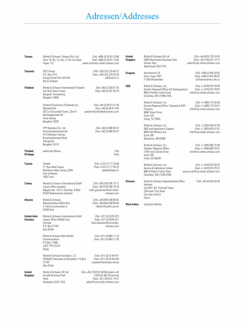
Rohde & Schwarz Taiwan (Pvt.) Ltd.Floor 14, No. 13, Sec. 2, Pei-Tou RoadTaipei 112
(Tel) +886 (2) 28 93 10 88(Fax) +886 (2) 28 91 72 60
Taiwan
SSTL GroupP.O. Box 7512Dunga Street Plot 343/345Dar Es Salaam
(Tel) +255 (22) 276 00 37(Fax) +255 (22) 276 02 93
Tanzania
Rohde & Schwarz International Thailand2nd floor Gems TowerBangrak, SuriyawongBangkok 10600
(Tel) +66 (2) 200 07 29(Fax) +66 (2) 267 00 79
Thailand
Schmidt Electronics (Thailand) Ltd.Messtechnik202 Le Concorede Tower, 23rd Fl.Ratchadaphisek Rd.Huay kwangBangkok 10320
(Tel) +66 (2) 69 41 47 05(Fax) +66 (2) 69 41 476
TPP Operation Co. Ltd.Kommunikationstechnik41/5 Mooban TarineeBoromrajchonnee RoadTalingchanBangkok 10170
(Tel) +66 (2) 880 93 47(Fax) +66 (2) 880 93 47
siehe/see Mexico (Tel)(Fax)
Trinidad &Tobago
Teletek71, Rue Alain SavaryResidence Alain Savary (C64)Cité el Khadra1003 Tunis
(Tel) +216 (71) 77 33 88(Fax) +216 (71) 77 05 53
Tunisia
Rohde & Schwarz International GmbHLiaison Office IstanbulBagdat Cad. 191/3, Arda Apt. B-Blok81030 Selamicesme-Istanbul
(Tel) +90 (216) 385 19 17(Fax) +90 (216) 385 19 18
Turkey
Rohde & SchwarzRepresentative Office Kiev4, Patris Loumoumba ul.01042 Kiev
(Tel) +38 (044) 268 60 55(Fax) +38 (044) 268 83 64
Ukraine
Rohde & Schwarz International GmbH Liaison Office Middle EastVertriebP.O. Box 31156Abu Dhabi
(Tel) +971 (2) 6335 670(Fax) +971 (2) 6335 671
Dario [email protected]
United Arab Emirates
Rohde & Schwarz Bick Mobile CommunicationP.O.Box 17466JAFZ, PPU ZG-07Dubai
(Tel) +971 (4) 883 71 35(Fax) +971 (4) 883 71 36
Rohde & Schwarz Emirates L.L.C.ESNAAD Premisses at Mussafah, P.O.Box 31156Abu Dhabi
(Tel) +971 (2) 55 49 411(Fax) +971 (2) 55 49 433
Rohde & Schwarz UK Ltd.Ancells Business ParkFleetHampshire GU51 2UZ
(Tel) +44 (1252) 81 88 88 (sales)·+44(1252) 81 88 18 (service)
(Fax) +44 (1252) 81 14 [email protected]
United Kingdom
Rohde & Schwarz UK Ltd.3000 Manchester Business ParkAviator WayManchester M22 5TG
(Tel) +44 (870) 735 16 42(Fax) +44 (1252) 81 14 77
United Kingdom
Aeromarine S.A.Cerro Largo 149711200 Montevideo
(Tel) +598 (2) 400 39 62(Fax) +598 (2) 401 85 [email protected]
Uruguay
Rohde & Schwarz, Inc.Eastern Regional Office (US Headquarters)8661A Robert Fulton DriveColumbia, MD 21046-2265
(Tel) +1 (410) 910 78 00(Fax) +1 (410) 910 78 01
USA
Rohde & Schwarz, Inc.Central Regional Office / Systems & EMI Products8080 Tristar DriveSuite 120Irving, TX 75063
(Tel) +1 (469) 713 53 00(Fax) +1 (469) 713 53 01
Rohde & Schwarz, Inc.R&D and Application Support8905 SW Nimbus AveSuite 240Beaverton, OR 97008
(Tel) +1 (503) 403 47 00(Fax) +1 (503) 403 47 01
Rohde & Schwarz, Inc. Western Regional Office7700 Irvine Center DriveSuite 100Irvine, CA 92618
(Tel) +1 (949) 885 70 00(Fax) +1 (949) 885 70 01
Rohde & Schwarz, Inc.Service & Calibration Center8661A Robert Fulton DriveColumbia, MD 21046-2265
(Tel) +1 (410) 910 50 02(Fax) +1 (410) 910 79 31
Rohde & Schwarz Representative Office VietnamUnit 807, 8/F, Schmidt Tower239 Xuan Thuy RoadCau Giay DistrictHanoi
(Tel) +84 (4) 834 20 46Vietnam
siehe/see MexicoWest Indies

FSIQ Manuals
1119.5063.12 0.1 E-1
Contents of Manuals for Signal Analyzer FSIQ
Operating Manual FSIQThe operating manual describes the foll,owing models and options:• FSIQ3 20 Hz to 3,5 GHz• FSIQ7 20 Hz to 7 GHz• FSIQ3 20 Hz to 26,5 GHz• FSIQ40 20 Hz to 40 GHz
• Option FSE-B8/9/10/11 Tracking Generator• Option FSE-B13 1-dB Attenuator• Option FSE-B15 Ethernet Adapter• Option FSE-B17 Second IEC/IEEE Bus Interface• Option FSIQ-B70 DSP and IQ Memory Extension
Option FSE-B21, External Mixer Output, is described in a separate manual.
The present operating manual contains comprehensive information about the technical data of theinstrument, the setup and putting into operation of the instrument, the operating concept and controlsas well as the operation of the FSIQ via the menus and via remote control. Typical measurementtasks for the FSIQ are explained using the functions offered by the menus and a selection of pro-gram examples.
In addition the operating manual gives information about maintenance of the instrument and abouterror detection listing the error messages which may be output by the instrument. It is subdivided in-tothe data sheet plus 9 chapters:
The data sheet informs about guaranteed specifications and characteristics of the instrument.
Chapter 1 describes the control elements and connectors on the front and rear panel as wellas all procedures required for putting the FSIQ into operation and integration intoa test system.
Chapter 2 gives an introduction to typical measurement tasks of the FSIQ which are ex-plained step by step.
Chapter 3 describes the operating principles, the structure of the graphical interface and of-fers a menu overview.
Chapter 4 forms a reference for manual control of the FSIQ and contains a detailed de-scription of all instrument functions and their application.
Chapter 5 describes the basics for programming the FSIQ, command processing and thestatus reporting system.
Chapter 6 lists all the remote-control commands defined for the instrument. At the end of thechapter a alphabetical list of commands and a table of softkeys with commandassignment is given.
Chapter 7 contains program examples for a number of typical applications of the FSIQ.
Chapter 8 describes preventive maintenance and the characteristics of the instrument’s in-terfaces.
Chapter 8 gives a list of error messages that the FSIQ may generate.
Chapter 9 contains a list of error messages.
Chapter 10 contains an index for the operating manual.

Manuals FSIQ
1119.5063.12 0.2 E-1
Service Manual - Instrument
The service manual - instrument informs on how to check compliance with rated specifications (per-formance test) and on the self tests.
Service Manual
The service manual is not delivered with the instrument but may be obtained from your R&S servicedepartment using the order number 1065.6016.24.
The service manualinforms on instrument function, repair, troubleshooting and fault elimination. Itcontains all information required for the maintenance of FSIQ by exchanging modules.It contains in-formation about the individual modules of FSIQ. This comprises the test and adjustment of the mod-ules, fault detection within the modules and the interface description.
FSIQ Contents - Preparing for Operation
1119.5063.12 I-1.1 E-1
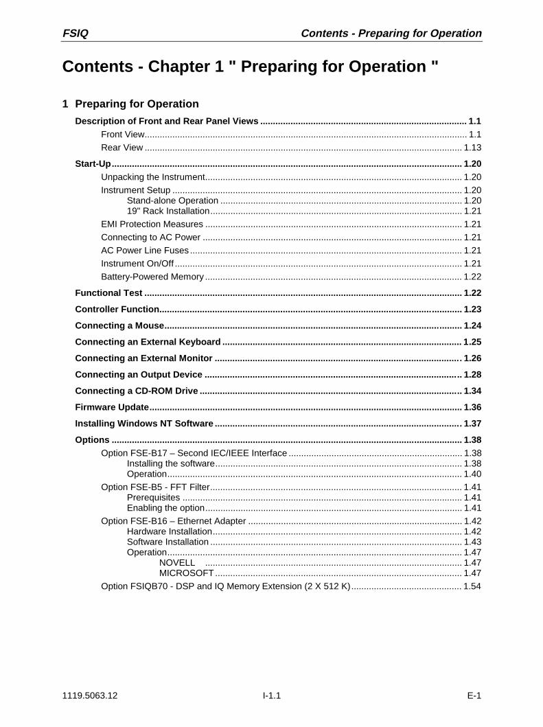
Contents - Chapter 1 " Preparing for Operation "
1 Preparing for Operation
Description of Front and Rear Panel Views .................................................................................. 1.1Front View................................................................................................................................ 1.1
Rear View .............................................................................................................................. 1.13
Start-Up........................................................................................................................................... 1.20Unpacking the Instrument...................................................................................................... 1.20
Instrument Setup ................................................................................................................... 1.20Stand-alone Operation ................................................................................................ 1.2019" Rack Installation.................................................................................................... 1.21
EMI Protection Measures ...................................................................................................... 1.21
Connecting to AC Power ....................................................................................................... 1.21
AC Power Line Fuses ............................................................................................................ 1.21
Instrument On/Off .................................................................................................................. 1.21
Battery-Powered Memory ...................................................................................................... 1.22
Functional Test .............................................................................................................................. 1.22
Controller Function........................................................................................................................ 1.23
Connecting a Mouse...................................................................................................................... 1.24
Connecting an External Keyboard ............................................................................................... 1.25
Connecting an External Monitor .................................................................................................. 1.26
Connecting an Output Device ...................................................................................................... 1.28
Connecting a CD-ROM Drive ........................................................................................................ 1.34
Firmware Update............................................................................................................................ 1.36
Installing Windows NT Software .................................................................................................. 1.37
Options ........................................................................................................................................... 1.38Option FSE-B17 – Second IEC/IEEE Interface ..................................................................... 1.38
Installing the software.................................................................................................. 1.38Operation..................................................................................................................... 1.40
Option FSE-B5 - FFT Filter.................................................................................................... 1.41Prerequisites ............................................................................................................... 1.41Enabling the option...................................................................................................... 1.41
Option FSE-B16 – Ethernet Adapter ..................................................................................... 1.42Hardware Installation................................................................................................... 1.42Software Installation .................................................................................................... 1.43Operation..................................................................................................................... 1.47
NOVELL ...................................................................................................... 1.47MICROSOFT.................................................................................................. 1.47
Option FSIQB70 - DSP and IQ Memory Extension (2 X 512 K)............................................ 1.54

Contents - Preparing for Operation FSIQ
1119.5063.12 I-1.2 E-1

FSIQ Front View
1119.5063.12 1.1 E-12
1 Preparing for Operation
Chapter 1 describes the controls and connectors of the Spectrum Analyzer FSIQ by means of the frontand rear view. Then follows all the information that is necessary to put the instrument into operation andconnect it to the AC supply and to external devices.
A more detailed description of the hardware connectors and interfaces can be found in chapter 8.Chapter 2 provides an introduction into the operation of the FSIQ by means of typical examples ofconfiguration and measurement; for the description of the concept for manual operation and anoverview of menus refer to chapter 3.
For a systematic explanation of all menus, functions and parameters and background information referto the reference part in chapter 4.
For remote control of the FSIQ refer to the general description of the SCPI commands, the instrumentmodel, the status reporting system, and command description in chapter 5 and 6.
Description of Front and Rear Panel Views
Front View
1
Display Screen see Chap. 3 and 4
2
Softkeys see Chap. 3 and 4
3 USER
USER Generate macros see Chap. 4
4 MARKER
MARKER
NORMAL SEARCH
DELTA MKR
Select and set marker
NORMAL Select and set the marker
SEARCH Set and start the peak/min search
DELTA Select and set the delta markers
MKR ⇒ Set the active marker
see Chap. 4
5 FREQUENCY
FREQUENCY
CENTER SPAN
START STOP
Define frequency axis in the active window
CENTER Set center frequency.
SPAN Set sweep width
START Set start frequency
STOP Set stop frequency
see Chap. 4

Front View FSIQ
1119.5063.12 1.2 E-12
012
3
45
6
78
9
.-
CL
RB
AC
K
GH
z
MH
z
kHz
Hz
EXP
-dB
m V s
dB
mm
Vm
s dB µV µs
dB.. nV ns
AF
OU
TPU
TP
RO
BE
PO
WE
RP
RO
BE
/ C
OD
E30
dB
m+
DC
0V
MA
X
MA
DE
IN
GE
RM
AN
Y
US
ER
HO
LDS
TEP
50
W
SYST
EM
CONF
IGUR
ATIO
N
PRES
ET
CA
L
DIS
PLA
YIN
FO
MO
DE
SE
TUP
SE
TTIN
G
ST
AR
T
HARD
COPY
STAT
US
SR
Q
RE
MO
TE
LOC
AL
FRE
QU
ENC
YLE
VEL
DA
TA E
NTR
Y
CEN
TER
SP
AN
STA
RT
STO
PR
AN
GE
MA
RK
ER
LIN
ES
NO
RM
AL
SEA
RCH
D L
INE
S
DE
LTA
LIM
ITS
MK
R
TRA
CE
SWEE
PD
ATA
VA
RIA
TIO
NTR
IGG
ER
SW
EE
P
12
34
RBW
VBW
SWT
MEN
U
ME
MO
RY
CO
NFI
G
SAVE
REC
ALL
INPU
TC
OU
PLIN
G
GE
N O
UTP
UT
50
W
RF
INP
UT
1
MA
X
RE
F
SIG
NA
L A
NA
LYZE
R
20
Hz
. . .3
.5 G
Hz
F
SIQ
1119
.500
5
13
..
12
45
67
89
10 11 12
1314
1517
1618
1920
2122
2324
262728
3
25
Fig. 1-1 Front View

FSIQ Front View
1119.5063.12 1.3 E-12
6 LINES
LINES
D LINES
LIMITS
Setup evaluation lines and tolerance limits
D LINES Setup evaluation lines (display lines)
LIMITS Definition and recall of tolerance limits
see Chap. 4
7 LEVEL
LEVEL
RANGE
REF
Define reference levels and display range in theactive measurement window.
REF Set reference level (= max. displaylevel)
RANGE Set range
see Chap. 4
8 DATA ENTRY
0
1 2 3
4 5 6
7 8 9
. -
CLR BACK
GHz
MHz
kHz
Hz
EXP
-dBmVs
dBmmVms
dBµVµs
dB..nVns
DATA ENTRY Keypad for data input
0...9 input numbers
. input decimal point
– change sign
CLR – close input field (for uncompleted oralready closed inputs, the originalentry is kept)
– erase the current entry in input field(beginning of an input)
– close message window (status, errorand warning messages)
BACK erase last character input
GHz The units keys close the data-dBm V s input and define the multipli-cation
factor for each basic unit.MHz dBm For dimension-less ormV ms alphanumeric inputs, the units keys
have weight 1.kHz dB They behave, in this case, likeµV µs the ENTER key.
Hz dBnV ns
EXP Append an exponent
see Chap. 3

Front View FSIQ
1119.5063.12 1.4 E-12
012
3
45
6
78
9
.-
CL
RB
AC
K
GH
z
MH
z
kHz
Hz
EXP
-dB
m V s
dB
mm
Vm
s dB µV µs
dB.. nV ns
AF
OU
TPU
TP
RO
BE
PO
WE
RP
RO
BE
/ C
OD
E30
dB
m+
DC
0V
MA
X
MA
DE
IN
GE
RM
AN
Y
US
ER
HO
LDS
TEP
50
W
SYST
EM
CONF
IGUR
ATIO
N
PRES
ET
CA
L
DIS
PLA
YIN
FO
MO
DE
SE
TUP
SE
TTIN
G
ST
AR
T
HARD
COPY
STAT
US
SR
Q
RE
MO
TE
LOC
AL
FRE
QU
ENC
YLE
VEL
DA
TA E
NTR
Y
CEN
TER
SP
AN
STA
RT
STO
PR
AN
GE
MA
RK
ER
LIN
ES
NO
RM
AL
SEA
RCH
D L
INE
S
DE
LTA
LIM
ITS
MK
R
TRA
CE
SWEE
PD
ATA
VA
RIA
TIO
NTR
IGG
ER
SW
EE
P
12
34
RBW
VBW
SWT
MEN
U
ME
MO
RY
CO
NFI
G
SAVE
REC
ALL
INPU
TC
OU
PLIN
G
GE
N O
UTP
UT
50
W
RF
INP
UT
1
MA
X
RE
F
SIG
NA
L A
NA
LYZE
R
20
Hz
. . .3
.5 G
Hz
F
SIQ
1119
.500
5
13
..
12
45
67
89
10 11 12
1314
1517
1618
1920
2122
2324
262728
3
25
Fig. 1-1 Front View

FSIQ Front View
1119.5063.12 1.5 E-12
9
3 1/2" diskette drive; 1.44 MByte
10 DATA VARIATION
HOLD STEP
DATA VARIATION Key group for entering data and for cursormovement
HOLD Disable control elements / overallcontrol. The LED indicates the holdcondition.
STEP Set step size for cursor keys and roll-key.
Cursor keys – Move the cursor within the inputfields and tables.
– Vary the input value.– Define the direction of movement for
the roll-key.
Roll-key – Vary input values.– Move markers and limits.– Select letters in the help line editor.– Move cursor in the tables
see Chap. 3
11 MEMORY
MEMORY
CONFIG
SAVE
RECALL
Memory media and file management
SAVE Save instrument data
RECALL Recall instrument data
CONFIG Configuration of memory media and data
see Chap. 4
12 INPUT
INPUT Set impedance and attenuation at the RF input. see Chap. 4
13 RF INPUT 1
30 dBm+ DC 0VMAX
MADE IN GERMANY
50 W
RF INPUT 1
MAX
RF-Input 1Caution:The maximum DC voltage is 0 V, themaximum power is 1 W (= 30 dBm at ≥10 dB attenuation)

Front View FSIQ
1119.5063.12 1.6 E-12
012
3
45
6
78
9
.-
CL
RB
AC
K
GH
z
MH
z
kHz
Hz
EXP
-dB
m V s
dB
mm
Vm
s dB µV µs
dB.. nV ns
AF
OU
TPU
TP
RO
BE
PO
WE
RP
RO
BE
/ C
OD
E30
dB
m+
DC
0V
MA
X
MA
DE
IN
GE
RM
AN
Y
US
ER
HO
LDS
TEP
50
W
SYST
EM
CONF
IGUR
ATIO
N
PRES
ET
CA
L
DIS
PLA
YIN
FO
MO
DE
SE
TUP
SE
TTIN
G
ST
AR
T
HARD
COPY
STAT
US
SR
Q
RE
MO
TE
LOC
AL
FRE
QU
ENC
YLE
VEL
DA
TA E
NTR
Y
CEN
TER
SP
AN
STA
RT
STO
PR
AN
GE
MA
RK
ER
LIN
ES
NO
RM
AL
SEA
RCH
D L
INE
S
DE
LTA
LIM
ITS
MK
R
TRA
CE
SWEE
PD
ATA
VA
RIA
TIO
NTR
IGG
ER
SW
EE
P
12
34
RBW
VBW
SWT
MEN
U
ME
MO
RY
CO
NFI
G
SAVE
REC
ALL
INPU
TC
OU
PLIN
G
GE
N O
UTP
UT
50
W
RF
INP
UT
1
MA
X
RE
F
SIG
NA
L A
NA
LYZE
R
20
Hz
. . .3
.5 G
Hz
F
SIQ
1119
.500
5
13
..
12
45
67
89
10 11 12
1314
1517
1618
1920
2122
2324
262728
3
25
Fig. 1-1 Front View

FSIQ Front View
1119.5063.12 1.7 E-12
14 PROBE/CODE
PROBE / CODE Power supply and coded socket for R&Saccessories.(12-pin Tuchel)
15 SWEEP
SWEEPTRIGGER
SWEEP
RBW
VBW
SWT
COUPLING
Input sweep parameters
TRIGGER Set trigger source. The LED illuminates onvalid trigger.
SWEEP Define the sweep mode parameters.
COUPLING Set coupled parameters. ResolutionBandWidth (RBW), Video BandWidth(VBW) and SWeep Time (SWT).The LEDs light indicating coupledparameters which are manually cancelled.
see Chap. 4
16 GEN OUTPUT 50W
GEN OUTPUT 50W Generator oputput; N-connector
17 MENU
MENU Menu-change keys
Call main menu
Change to left menu
Change to right menu
see Chap. 3
18 TRACE
TRACE
1 2
3 4
Select and activate measurement traces (Trace 1...4).
The LEDs indicate traces turned on.
see Chap. 4

Front View FSIQ
1119.5063.12 1.8 E-12
012
3
45
6
78
9
.-
CL
RB
AC
K
GH
z
MH
z
kHz
Hz
EXP
-dB
m V s
dB
mm
Vm
s dB µV µs
dB.. nV ns
AF
OU
TPU
TP
RO
BE
PO
WE
RP
RO
BE
/ C
OD
E30
dB
m+
DC
0V
MA
X
MA
DE
IN
GE
RM
AN
Y
US
ER
HO
LDS
TEP
50
W
SYST
EM
CONF
IGUR
ATIO
N
PRES
ET
CA
L
DIS
PLA
YIN
FO
MO
DE
SE
TUP
SE
TTIN
G
ST
AR
T
HARD
COPY
STAT
US
SR
Q
RE
MO
TE
LOC
AL
FRE
QU
ENC
YLE
VEL
DA
TA E
NTR
Y
CEN
TER
SP
AN
STA
RT
STO
PR
AN
GE
MA
RK
ER
LIN
ES
NO
RM
AL
SEA
RCH
D L
INE
S
DE
LTA
LIM
ITS
MK
R
TRA
CE
SWEE
PD
ATA
VA
RIA
TIO
NTR
IGG
ER
SW
EE
P
12
34
RBW
VBW
SWT
MEN
U
ME
MO
RY
CO
NFI
G
SAVE
REC
ALL
INPU
TC
OU
PLIN
G
GE
N O
UTP
UT
50
W
RF
INP
UT
1
MA
X
RE
F
SIG
NA
L A
NA
LYZE
R
20
Hz
. . .3
.5 G
Hz
F
SIQ
1119
.500
5
13
..
12
45
67
89
10 11 12
1314
1517
1618
1920
2122
2324
262728
3
25
Fig. 1-1 Front View

FSIQ Front View
1119.5063.12 1.9 E-12
19 PROBE POWER
PROBE POWER Power supply connector (+15V / - 12.6V) formeasurement accessories (probes)
see Chap. 8
20
Reserved for options
21
Reserved for options
22 AF OUTPUT
AF OUTPUT AF output connector (head phones) (miniaturephone jack)
see Chap. 8
23
Internal loudspeaker
The loudspeaker is disabled when the phone jackis inserted in the AF output.
see Chap. 8
24
ON/STANDBY-switch
Caution:In standby mode, the AC linevoltage is still present within theinstrument.
see Chap. 1

Front View FSIQ
1119.5063.12 1.10 E-12
012
3
45
6
78
9
.-
CL
RB
AC
K
GH
z
MH
z
kHz
Hz
EXP
-dB
m V s
dB
mm
Vm
s dB µV µs
dB.. nV ns
AF
OU
TPU
TP
RO
BE
PO
WE
RP
RO
BE
/ C
OD
E30
dB
m+
DC
0V
MA
X
MA
DE
IN
GE
RM
AN
Y
US
ER
HO
LDS
TEP
50
W
SYST
EM
CONF
IGUR
ATIO
N
PRES
ET
CA
L
DIS
PLA
YIN
FO
MO
DE
SE
TUP
SE
TTIN
G
ST
AR
T
HARD
COPY
STAT
US
SR
Q
RE
MO
TE
LOC
AL
FRE
QU
ENC
YLE
VEL
DA
TA E
NTR
Y
CEN
TER
SP
AN
STA
RT
STO
PR
AN
GE
MA
RK
ER
LIN
ES
NO
RM
AL
SEA
RCH
D L
INE
S
DE
LTA
LIM
ITS
MK
R
TRA
CE
SWEE
PD
ATA
VA
RIA
TIO
NTR
IGG
ER
SW
EE
P
12
34
RBW
VBW
SWT
MEN
U
ME
MO
RY
CO
NFI
G
SAVE
REC
ALL
INPU
TC
OU
PLIN
G
GE
N O
UTP
UT
50
W
RF
INP
UT
1
MA
X
RE
F
SIG
NA
L A
NA
LYZE
R
20
Hz
. . .3
.5 G
Hz
F
SIQ
1119
.500
5
13
..
12
45
67
89
10 11 12
1314
1517
1618
1920
2122
2324
262728
3
25
Fig. 1-1 Front View

FSIQ Front View
1119.5063.12 1.11 E-12
25 STATUS
STATUSSRQ
REMOTE
LOCAL
Indicators for remote control and switch for manualcontrol.
LOCAL Switch from remote to manual control.
The LED SRQ indicates that a servicerequest from the instrument is active on theIEC Bus.The LED REMOTE indicates that theinstrument is under remote control.
see Chap. 4andChap. 5
26 HARDCOPY
SETTING
START
HARDCOPY Printer control
START Start a print job with the setup defined inthe SETTING menu.
SETTING Configure the diagram, parameter list andmeasurement protocol outputs on thevarious output media.
see Chap. 4
27 CONFIGURATION
CONFIGURATION
MODE
SETUP
Select operational modes and define default settings
MODE Select mode
SETUP Define configurationss
see Chap. 1andChap. 4
28 SYSTEM
SYSTEM
PRESET CAL
DISPLAY INFO
General instrument default settings
PRESET Recall instrument default settings
DISPLAY Configure the display screen format
CAL Calibrate the analyzer
INFO – Information concerning instrument stateand measurement parameters
– Call help functions
see Chap. 4

Rear View FSIQ
1119.5063.12 1.12 E-12
CO
M1
CO
M2
AN
AL
YZ
ER
MO
NIT
OR
US
ER
PO
RT
MO
US
E
EX
T R
EF
IN/O
UT
NO
ICE
S
OU
RC
ES
WE
EP
21.4
MH
zO
UT
2930
3135
36
3738
3940
4142
4346
4748
4449
LO
GV
IDE
O O
UT K
EY
BO
AR
D
EX
T T
RIG
GA
TE
CC
VS
/FB
AS
OU
T
IEC
62
5S
CP
I
32
50ETH
ER
NE
T
51P
C M
ON
ITO
R
TG
INI/A
M/A
LC
TG
Q F
M
IEC
625
SC
PI
IEC
FO
R C
OM
PU
TE
RF
UN
CT
ION
LP
T
3433
45
Fig. 1-2 Rear View

FSIQ Rear View
1119.5063.12 1.13 E-12
Rear View
29
Power switch
Fuse holder
AC power connector
see Chap. 1
30
Power supply fans
31 EXT TRIG/GATE
IN/OUTEXT TRIG
GATEInput connector for an external trigger or an externalgate signal
see Chap. 2andChap. 8
32 CCVS/FBAS OUT
IN/OUTCCVS/FBAS
OUTConnector for external CCVS/FBAS monitor see Chap. 8
33 TG IN I/AM/ALC
I
IN/OUTTG IN
I/AM/ALCSignal input connector for external modulation ofTracking Generator (options FSE-B9 and FSE-B11)
see Chap. 8
34 TG IN Q/FM
I
IN/OUTTG INQ/FM
Signal input connector for external modulation ofTracking Generator (options FSE-B9 and FSE-B11)
see Chap. 8

Rear View FSIQ
1119.5063.12 1.14 E-12
CO
M1
CO
M2
AN
AL
YZ
ER
MO
NIT
OR
US
ER
PO
RT
MO
US
E
EX
T R
EF
IN/O
UT
NO
ICE
S
OU
RC
ES
WE
EP
21.4
MH
zO
UT
2930
3135
36
3738
3940
4142
4346
4748
4449
LO
GV
IDE
O O
UT K
EY
BO
AR
D
EX
T T
RIG
GA
TE
CC
VS
/FB
AS
OU
T
IEC
62
5S
CP
I
32
50ETH
ER
NE
T
51P
C M
ON
ITO
R
TG
INI/A
M/A
LC
TG
Q F
M
IEC
625
SC
PI
IEC
FO
R C
OM
PU
TE
RF
UN
CT
ION
LP
T
3433
45
Fig. 1-2 Rear View

FSIQ Rear View
1119.5063.12 1.15 E-12
35 21.4 MHZ OUT
I
IN/OUT21.4 MHz
OUTOutput connector for 21.4 MHz IF see Chap. 8
36 LOG VIDEO OUT
IN/OUTLOG
VIDEO OUTOutput connector for a switchable noise source see Chap. 8
37 KEYBOARD
KEYBOARD Connector for an external keyboard(5-pin DIN socket)
see Chap. 1andChap. 8
38 SWEEP
IN/OUTSWEEP
Output connector
During a sweep, a sawtooth voltage is output which isproportional to frequency.
see Chap. 8
39 <SCPI> IEC625
IEC 625 SCPI IEC Bus-connector see Chap. 8
40 NOISE SOURCE
IN/OUT
NOICE SOURCE
Output connector for a switchable noise source see Chap. 8
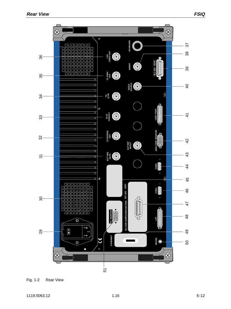
Rear View FSIQ
1119.5063.12 1.16 E-12
CO
M1
CO
M2
AN
AL
YZ
ER
MO
NIT
OR
US
ER
PO
RT
MO
US
E
EX
T R
EF
IN/O
UT
NO
ICE
S
OU
RC
ES
WE
EP
21.4
MH
zO
UT
2930
3135
36
3738
3940
4142
4346
4748
4449
LO
GV
IDE
O O
UT K
EY
BO
AR
D
EX
T T
RIG
GA
TE
CC
VS
/FB
AS
OU
T
IEC
62
5S
CP
I
32
50ETH
ER
NE
T
51P
C M
ON
ITO
R
TG
INI/A
M/A
LC
TG
Q F
M
IEC
625
SC
PI
IEC
FO
R C
OM
PU
TE
RF
UN
CT
ION
LP
T
3433
45
Fig. 1-2 Rear View

FSIQ Rear View
1119.5063.12 1.17 E-12
41 USER
USER PORT User interface connector with configurable inputs andoutputs (USER-PORT A and USER-PORT B)
see Chap. 8
42 ANALYZER MONITOR
ANALYZER MONITOR Connector for an external VGA monitorsee Chap. 8
43 EXT REF IN/OUT
EXT REFIN/OUTIN/OUT
Input for external reference frequency (1 MHz to 16MHz), can be switched to output 10 MHz.
see Chap. 4andChap. 8
44 COM2
COM2 Connector for serial interface 2(9-pin socket; COM2)
see Chap. 1andChap. 8
45
Inputs / Outputs for options(cover plates for digital interface expansion)
46 COM1
COM1 Connector for serial interface 1(9-pin socket; COM1)
see Chap. 1andChap. 8

Rear View FSIQ
1119.5063.12 1.18 E-12
CO
M1
CO
M2
AN
AL
YZ
ER
MO
NIT
OR
US
ER
PO
RT
MO
US
E
EX
T R
EF
IN/O
UT
NO
ICE
S
OU
RC
ES
WE
EP
21.4
MH
zO
UT
2930
3135
36
3738
3940
4142
4346
4748
4449
LO
GV
IDE
O O
UT K
EY
BO
AR
D
EX
T T
RIG
GA
TE
CC
VS
/FB
AS
OU
T
IEC
62
5S
CP
I
32
50ETH
ER
NE
T
51P
C M
ON
ITO
R
TG
INI/A
M/A
LC
TG
Q F
M
IEC
625
SC
PI
IEC
FO
R C
OM
PU
TE
RF
UN
CT
ION
LP
T
3433
45
Fig. 1-2 Rear View

FSIQ Rear View
1119.5063.12 1.19 E-12
47 IEC FOR COMPUTER FUNCTION <SCPI> IEC625
IEC 625 SCPIIEC FOR COMPUTERFUNCTION IEC Bus-connector for computer function(option FSE-B16)
see Chap. 1andChap. 8
48 LPT
LPT Parallel interface connector(printer connector, Centronics compatible)
see Chap. 1andChap. 8
49 ETHERNET
Connector for ethernet (option FSE-B16)
50 MOUSE
MOUSE Connector for PS/2-Mouse see Chap. 1andChap. 8
51 PC MONITOR
PC MONITORConnector for an external PC-Monitor
see Chap. 1andChap. 8

Start-Up FSIQ
1119.5063.12 1.20 E-12
Start-Up
Important Note:Before turning the instrument on, it must be observed that the following conditionsare fulfilled:
• instrument covers are in place and all fasteners are tightened,
• fan openings are free from obstructions,
• signal levels at the input connectors are all within specified maximums,
• signal outputs are correctly connected.and not overloaded.
Non-observance may cause damage to the instrument .
Unpacking the Instrument
After the instrument has been removed from its packaging, insure that all deliverable items are presentas follows:
• signal analyzer FSIQ
• AC power cable
• keyboard and mouse
• Windows NT operating manual
• this operating manual
Now check the instrument for visible mechanical damage. If damage is present, promptly inform thedelivery firm that delivered the instrument. In case damage is found, retain the carton and the packingmaterials.
Instrument Setup
Stand-alone Operation
The instrument is designed for use under general laboratory conditions. The ambient conditions requiredat the operational site are as follows:
Wrist strap with cord
Building ground
Floor mat
Ground connectionof operational site
Heel strap
• The ambient temperature must be in the rangerecommended in the data sheet.
• All fan openings must be unobstructed and the air flow atthe rear panel and at the side-panel perforations must notbe obstructed. The distance to the wall should be at least10 cm.
• The mounting surface should be flat.
• To avoid damage of electronic components of the DUTand the instrument, the operational site must be protectedagainst electrostatic discharge.
For applications in the laboratory or on a work bench, it is recommended that the support feet on thebottom of the instrument be extended. For the LCD display, this provides the optimum viewing anglewhich typically ranges from perpendicular to the display front to approximately 30° below.

FSIQ Start-Up
1119.5063.12 1.21 E-12
19" Rack Installation
Important Note:For rack installation, insure that the air flow at the side-panelperforations and the air exhaust at the rear panel are not obstructed.
The instrument may be mounted in a 19" rack by using the rack adapter kit ZZA-95 (order number:396.4911.00). The installation instructions are included in the adapter kit.
EMI Protection Measures
In order to prevent electromagnetic interference (EMI), the instrument may be operated only when allcovers are correctly in place. Only adequately shielded signal and control cables may be used (seerecommended accessories).
Connecting to AC Power
The FSIQ is equipped with an AC voltage selection feature and will automatically set itself according tothe applied AC voltage (range: 90 to 132 VAC and 180 to 265 VAC, 47 to 440 Hz). The AC powerconnector is located on the rear panel (see below).
À Connect the instrument to the AC power source using the AC power cable delivered with theinstrument.
AC Power Line Fuses
The FSIQ is protected by two fuses as specified on the power supply name-plate. The fuses are locatedin a removable fuse holder which is located between the AC power switch and the AC power connector(see below).
Instrument On/Off
AC power switch on the rear panel
I 0
ON
OF
F
Ac power switch
Fuse holder
AC power connector
Power On/Off
À Depress the AC Power Switch to the desired positionON/OFF.
After turn-on (position ON), the instrument is in the readystate (STANDBY) or in operation dependent upon theposition of the ON/STANDBY switch located on theinstrument front panel (see below).
Note: The AC power switch may remain ON continuously.Switching to OFF is only required when the instrumentmust be completely removed from the AC power source.
Switching to OFF (position OFF) removes all instrumentcircuitry from the AC power source.
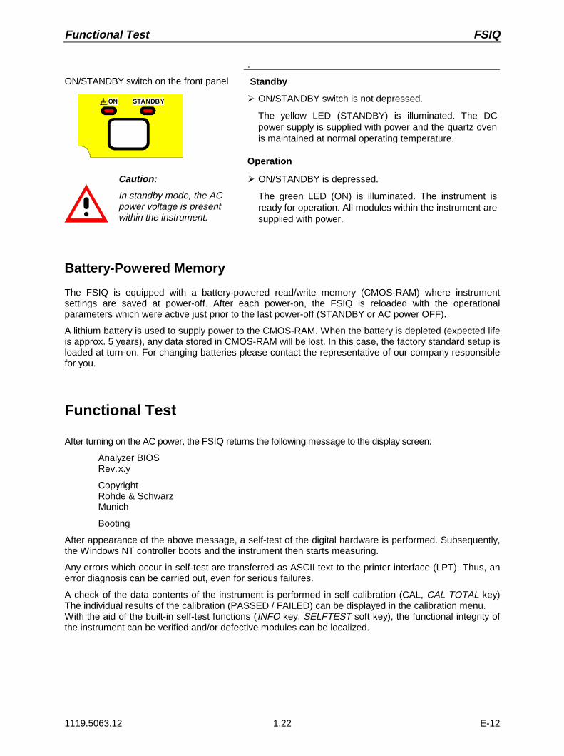
Functional Test FSIQ
1119.5063.12 1.22 E-12
ON/STANDBY switch on the front panel
ON STANDBY
.
Standby
À ON/STANDBY switch is not depressed.
The yellow LED (STANDBY) is illuminated. The DCpower supply is supplied with power and the quartz ovenis maintained at normal operating temperature.
Operation
Caution:
In standby mode, the ACpower voltage is presentwithin the instrument.
À ON/STANDBY is depressed.
The green LED (ON) is illuminated. The instrument isready for operation. All modules within the instrument aresupplied with power.
Battery-Powered Memory
The FSIQ is equipped with a battery-powered read/write memory (CMOS-RAM) where instrumentsettings are saved at power-off. After each power-on, the FSIQ is reloaded with the operationalparameters which were active just prior to the last power-off (STANDBY or AC power OFF).
A lithium battery is used to supply power to the CMOS-RAM. When the battery is depleted (expected lifeis approx. 5 years), any data stored in CMOS-RAM will be lost. In this case, the factory standard setup isloaded at turn-on. For changing batteries please contact the representative of our company responsiblefor you.
Functional Test
After turning on the AC power, the FSIQ returns the following message to the display screen:
Analyzer BIOSRev.x.y
CopyrightRohde & SchwarzMunich
Booting
After appearance of the above message, a self-test of the digital hardware is performed. Subsequently,the Windows NT controller boots and the instrument then starts measuring.
Any errors which occur in self-test are transferred as ASCII text to the printer interface (LPT). Thus, anerror diagnosis can be carried out, even for serious failures.
A check of the data contents of the instrument is performed in self calibration (CAL, CAL TOTAL key)The individual results of the calibration (PASSED / FAILED) can be displayed in the calibration menu.With the aid of the built-in self-test functions (INFO key, SELFTEST soft key), the functional integrity ofthe instrument can be verified and/or defective modules can be localized.

FSIQ Controller Function
1119.5063.12 1.23 E-12
Controller Function
Caution:The drivers used in the integrated controller function are adapted to the measuringinstrument. Only the settings described below should be resorted to. The existing driversoftware should be modified only with the update software released byRohde&Schwarz.
The instrument possesses an integrated Windows-NT controller. The user can switch between themeasurement screen and the controller screen. When an external monitor is connected, themeasurement function and the controller function can be displayed simultaneously (see section"Connecting an External Monitor"). The controller function is automatically booted on instrument power-up.Windows NT operation is described in the supplied manual or in the online help of Windows NT.
Login
Windows NT requires a login window in which the user is asked to identify himself by entering his nameand password. An autologin comes as standard in the instrument, ie the login is performed automaticallyin the background. The user name used for this is "instrument" and the password is also "instrument" (insmall letters).
To login under another name, call up the logout window in the task bar with START - SHUT DOWN.Mark the item "Close all programs and log on as a different user?" in the window and click YES whileholding the SHIFT key down until the login window is displayed to enter the user identification. Thepassword should be entered in the correct syntax including low-case and upper-case characters.
Administrator identification
Some of the installations (eg CD-ROM drive) described below are possible only under the administratorlogin. This is indicated in the relevant window.The administrator is an identification prescribed by Windows NT which in particular allows systemsettings which are disabled for the standard user.
The password for the administrator is 894129 for the instrument.
After an installation under the administrator identification, the "Service Pack X" of Windows NT is to bere-installed, see section "Installation of Windows NT Software".On the power-up following an installation under the administrator identification, the NT login window isdisplayed (no autologin). The user name "Administrator" is indicated in the window. This entry is to bereplaced by "instrument" and then "instrument" as password entered. An autologin is then possible.
Changeover between measurement screen and controller screen
To call up the controller screen use key combination <ALT><SYSREQ> (US keyboard).To return to the measurement screen, activate the window "R&S Analyzer Interface" on the controller.
Logout
The instrument can be switched off (standby mode). Logging out of Windows NT is not necessary.

Connecting a Mouse FSIQ
1119.5063.12 1.24 E-12
Connecting a Mouse
Caution:The mouse may only be connected when the instrument is switched off(STANDBY). Otherwise, correct operation of the mouse and instrument cannot beguaranteed.
The instrument has the facility to simplify operation by connecting a mouse to the rear-panel PS/2-mouse connector (MOUSE) for .
MOUSE
During measurement operation, soft keys, tables and data input fields may also be controlled via themouse. For computer function, the mouse has the usual functions.
The control functions for the mouse during measurement operation are described in Chapter 3 in thesection "Mouse Control of Further Display Elements". This section contains a list in which the screendisplay elements for mouse control of the corresponding soft keys and push buttons of the instrumentare described. Chapter 8 contains the interface description.
After connection the mouse is automatically recognized. Special settings such as mouse cursor speedetc., can be performed in the Windows NT menu START - SETTINGS - CONTROL PANEL - MOUSE.

FSIQ Connecting an External Keyboard
1119.5063.12 1.25 E-12
Connecting an External Keyboard
Caution:The keyboard may only be connected when the instrument is switched off(STANDBY). Otherwise, correct operation of the keyboard cannot be guaranteed.
The instrument is fitted with a rear-panel 5-contact DIN connector (KEYBOARD) for the connection ofan external PC keyboard.
KEYBOARD x
During measurement operations, the keyboard simplifies the input of commentary text, filenames, etc.For computer function, the keyboard has the usual functions.
Chapter 3, in section "External Keyboard Control", contains a list which describes the assignment of theinstrument front-panel key functions to the key codes of the external keyboard as well as special keycombinations used for quick operations. Chapter 8 contains the interface description.
After connection the keyboard is automatically recognized. The default setting is for the US keyboard.Special settings such as repetitional rate etc. can be performed in Windows NT menu START -SETTINGS - CONTROL PANEL - KEYBOARD.

Connecting an External Monitor FSIQ
1119.5063.12 1.26 E-12
Connecting an External Monitor
Caution:The monitor may only be connected when the instrument is switched off (STANDBY).Otherwise, the monitor may be damaged.
Do not modify the screen driver (display type) since this would disturb instrumentoperation.
Notes: - When connecting the monitor to the PC MONITOR connector, the display of controllerfunction can be adapted to the external screen (eg higher resolution) in the NT menuSTART-SETTING - CONTROL PANEL - DISPLAY PROPERTIES.
- CHIPS (setting = both) should not be modified since otherwise switching between theexternal monitor and the instrument screen is not possible.
The instrument is fitted with a rear-panel connector PC MONITOR or ANALYZER MONITOR for theconnection of an external monitor.
PC MONITOR
ANALYZER MONITOR
With an external monitor it is possible to have an enlarged display of the measurement screen(ANALYZER MONITOR connector) or of the controller screen (PC MONITOR connector). Themeasuring instrument and the Windows NT controller can be operated in parallel. The mouse and thekeyboard are allocated to only one mode.
Display of the measurement screen - Connection to ANALYZER MONITOR connector
ConnectionAfter connecting the external monitor the measurement screen is displayed on both the external monitorand the instrument. Further settings are not necessary.
OperationThe instrument is operated as usual via its softkeys, the mouse and keyboard, etc..
Toggle between measurement screen and controller screenKey combination <ALT><SYSREQ> is used to call up the controller. After call up, the mouse andkeyboard are allocated to the controller function.By activating the window "R&S Analyzer Interface" the user returns to the measurement screen and themouse and keyboard are allocated to this screen.
Display of the controller screen - Connection to PC MONITOR connector
ConnectionAfter connecting the monitor external monitor operation should be selected.
Setting is performed in the SETUP-GENERAL SETUP menu (key group: CONFIGURATION, see inChapter 4, the section "Presettings and Interface Configuration"):

FSIQ Connecting an External Monitor
1119.5063.12 1.27 E-12
CONFIGURATION
MODE
SETUP
EXTERNALREFERENCE
GENERAL SETUP
Call SETUP-GENERAL SETUP menu
À Press the SETUP key in the CONFIGURATIONfield.
The SETUP menu is opened.
À Press the GENERAL SETUP softkey.
The GENERAL SETUP submenu is opened and thecurrent settings of the instrument parameters aredisplayed on the screen in the form of tables.
MONITORCONNECTED
Selecting the external monitor mode
À Press the MONITOR CONNECTED softkey.
The softkey is in color to indicate that the externalmonitor mode is activated. The external monitordisplays the controller screen.
Operation
The controller function is operated as usual with the mouse and keyboard. The measuring instrument(displayed on the instrument screen) can be operated with both the softkeys and keys of the instrument.
Toggle between screens
By activating (clicking) the window "R&S Analyzer Interface" at the controller the mouse and keyboardare allocated to the measurement screen. The mouse and keyboard are allocated to the controller whenthe window is deactivated.

Connecting an Output Device FSIQ
1119.5063.12 1.28 E-12
Connecting an Output Device
Caution:The output device may be connected only when the instrument is switched off(STANDBY)
Notes: - The installation of some printer drivers is possible only under the administrator identification(see section "Controller Function").
- After the installation, the "Service Pack X" of Windows NT is to be re-installed, see "NewInstallation of Windows NT Software".
- To ensure that the instrument performs an autologin, the user identification is to be reset to"instrument" after the next power-up, see section "Controller Function".
The instrument provides an option for connecting up to three different output devices to allow printing ahard copy of the display screen.The interfaces can also be used for printing in the controller mode. The output formats "WMF"(Windows Metafile) and "Clipboard" are preset. A large number of output devices can be connectedunder Windows NT after installing suitable printer drivers.The output devices supported by the instrument can be found in the selection box DEVICE/LANGUAGEin the HARDCOPY –SETTINGS DEVICE1/2 menu (see in Chapter 4, the section "Documentation ofMeasurement Results"). To print out via the COM interface, the latter must be assigned the controllerfunction in the SETUP - GENERAL SETUP menu (owner = OS)..Chapter 8 contains the interface description of the connectors.
The interface connectors are located on the rear panel:
LPT COM1 COM2
After connection of the output device to the appropriate interface connector, the configuration of theinterface as well as the output device must be entered and the output device must be assigned to theinterface.
1. Configuration of the interface
LPT1 Interface LPT1 cannot be configured.
Note: An external CM-ROM drive can be connected to this interface. If thisinterface is allocated, one of the serial interfaces can be used for theprintout.
COM1/COM2 The configuration of serial interfaces COM1 and COM2 can be performed in theWindows NT menu START - SETTINGS - CONTROL PANEL - PORTS. Theparameters COM PORTS BAUDRATE, BITS, PARITY, STOPBITS, HW/SW-HANDSHAKE determine the transmission parameters of the interface They mustagree with the specifications of the output device (see the operating manual for theoutput device).
2. Selection and installation of the printer driver
The selection and installation of the printer driver, the assignment to the interface and the setting ofmost of the printer-specific parameters (eg paper size) is performed under Windows NT in theSTART - SETTINGS - PRINTER menu.

FSIQ Connecting an Output Device
1119.5063.12 1.29 E-12
3. Configuration of the connected output device
The configuration of the connected output device and the assignment to the interface takes place inthe HARDCOPY DEVICE–SETTINGS DEVICE1/2 menu (key group: HARDCOPY, see in Chapter 4,the section "Selection and Configuration of the Output Device "). The configuration of up to twooutput devices (DEVICE1 and DEVICE2) may be entered, of which, at least one must be activatedfor printing.• The parameter DEVICE/LANGUAGE determines which output device is to be used.
• The parameter PRINT TO FILE determines if the output is in the form of a file.
• The parameter ORIENTATION sets the page format to horizontal or vertical (portrait).
Selecting the type of printer automatically sets the parameters PRINT TO FILE and ORIENTATIONto values which correspond to a standard mode with this output device. Other printer-dependentparameters such as FORMFEED, PAPERFEED etc., can be modified under Windows NT in theprinter properties window (START/SETTINGS/PRINTER/SETTINGS/....).
Table 1-1 shows the standard factory settings for the two output devices.
The factory settings of DEVICE 1 correspond to output format "WMF" (Windows Metafile), printing isperformed in a file. WMF is a common format which is used for the import of hardcopies (egmeasurement windows) to other Windows applications that support this format (eg WinWord).
The factory setting of DEVICE 2 is "Clipboard". In this setting the printout is copied to the WindowsNT clipboard. Most of Windows applications support the clipboard. The clipboard content can bedirectly inserted in a document via EDIT - PASTE.
Table 1-1 Factory settings for DEVICE 1 and DEVICE 2 in the HARDCOPY-DEVICE SETTINGS menu.
Parameter Parameter Name DEVICE 1 Settings DEVICE 2 Settings
Output Device DEVICE/LANGUAGE WINDOWS METAFILE CLIPBOARD
Output PRINT TO FILE YES ---
Paper Format ORIENTATION --- ---
In the following example, a HP DeskJet 660C printer is connected to interface LPT1 and configured asDEVICE2 of the instrument to output hardcopies of the measurement screen.
Switch off device.
Connect printer to interface LPT1.
Switch on device.

Connecting an Output Device FSIQ
1119.5063.12 1.30 E-12
Select printer driver under Windows NT
À Press key combination <ALT> <SYSREQ>
The Windows NT screen is displayed.
À In the Start menu press first "Setting" andthen "Printers".
The printer window is opened.
À Double-click symbol "Add Printer".
The "Add Printer Wizard" window isopened. This window leads through thefollowing printer driver installation.
À Click first "My computer" and then "Next".
The available ports are displayed.
À Select LPT1 port.
The selection is marked by a tick.
À Click "Next".
The available printer drivers are displayed.The left-hand selection table indicates themanufacturers and the right-hand one theavailable printer drivers.

FSIQ Connecting an Output Device
1119.5063.12 1.31 E-12
À Mark "HP" in selection table"Manufacturers" and "HP DeskJet 660C"in selection table "Printers".
Note: If the desired type of output deviceis not shown in this list, it meansthat it is not supported byWindows NT.
À Click "Next".
The entry field for the printer name isdisplayed.
À The printer name can be modified in theentry field "Printer name" (max. 60characters).
If one or more printers are alreadyinstalled, a query is displayed in thiswindow to ask if the printer last installed asdefault printer should be selected for theWindows NT applications (Do you wantyour Windows-based programs to use thisprinter as default printer?) "No" is preset.
À Click "Next".
A query is displayed for providing theprinter in the network. This query isirrelevant when installing a local printer.The answer "Not shared" is preset.
À Click "Next".
The window for starting a test page isdisplayed. The test page is for checking ifthe installation was successful.

Connecting an Output Device FSIQ
1119.5063.12 1.32 E-12
À Switch on printer.
À Click Yes (recommended)".
À Click "Finish".
A test page is printed out if the installationwas successful.If the test page is not printed out or notcompletely, the Windows NT online helpoffers troubleshooting instructions underthe entry "Printer Trouble Shooting".
Note: If after clicking "Finish" the user is asked tospecify the path for the printer driver, thisprinter installation should be performed underthe administrator identification (see section"Controller Function".
The instrument has to be configured with thisprinter for the printout of the measurementscreen.
Configuring HP DeskJet 660C.
À Click button "R&S Analyzer Interface".
The measurement screen is displayed.
START
HARDCOPYDEVICE
HARDCOPY
TRC COLORAUTO INC
COLORON OFF
SETTING
À Press the SETTINGS key in theHARDCOPY field.
The SETTING menu is opened.
HARDCOPYDEVICE À Press the HARDCOPY DEVICE softkey.
The HARDCOPY DEVICE submenu isopened and the current settings of the twopossible output devices are displayed onthe screen in the form of tables.
SETTINGSDEVICE2
HARDCOPY DEVICE SETTINGS
Device1 WINDOWS METAFILE
Print to File YES
Orientation ---
Device2 CLIPBOARD
Print to File ---
Orientation ---
À Press SETTING DEVICE2.
Line DEVICE2 is marked with theselection bar.

FSIQ Connecting an Output Device
1119.5063.12 1.33 E-12
sV
-dBm
DATA ENTRY
GHz
HARDCOPY DEVICE SETTINGS
Device1 WINDOWS METAFILE
Print to File YES
Orientation ---
Device2 CLIPBOARD
Print to File ---
Orientation ---
DEVICE
CLIPBOARD
WINDOWS METAFILE
ENHANCED METAFILE
BITMAP FILE
HP DeskJet 660C
À Press one of the unit keys.
The selection box DEVICE is displayed onthe screen. The current selection ismarked by a tick and highlighted by theselection bar.
DATA VARIATION À Press cursor key Æ until the entry HPDeskJet 600C is highlighted by theselection bar.
sV
-dBm
DATA ENTRY
GHz
HARDCOPY DEVICE SETTINGS
Device1 WINDOWS METAFILE
Print to File YES
Orientation ---
Device2 HP Deskjet 660C
Print to File NO
Orientation PORTRAIT
À Press one of the unit keys.
The selection box DEVICE is closed andHP DeskJet 660C is entered in lineDEVICE2.
Note:Selecting the type of printer automaticallysets the parameters PRINT TO FILE andORIENTATION to values which correspondto a standard mode with this output device.Other printer-dependent parameters such asPAPERSIZE, can be modified underWindows NT in the printer properties window(START/SETTINGS/PRINTER/SETTINGS)..
ENABLEDEV1 DEV2
Switch on printer.
À Press ENABLE softkey until DEV2 ismarked on the second softkey line.
Printing can then be started with theSTART key in the HARDCOPY menu.
MENU Return to main menu
À Press the menu key several times.
Note: After the installation, the "ServicePack X" of Windows NT is to be re-installed, see "New Installation ofWindows NT Software".

Connecting a CD ROM Drive FSIQ
1119.5063.12 1.34 E-12
Connecting a CD-ROM Drive
Caution:The CD-ROM may only be connected when the instrument is switched off (STANDBY).If this is not observed correct operation of the CD-ROM and the instrument cannot beguaranteed.
Notes: - The installation of a CD-ROM is possible only under the administrator identification (seesection "Controller Function").
- After the installation, the "Service Pack X" of Windows NT is to be re-installed, see "NewInstallation of Windows NT Software".
- To ensure that the instrument performs an autologin, the user identification is to be reset to"instrument" after the next power-up, see section "Controller Function",
The instrument is fitted with a rear-panel interface LPT1 for the connection of a CD-ROM drive.
LPT
The following CD-ROM drives are supported:
− MICROSOLUTIONS BACKPACK External CD-ROM.− FREECOM IQ DRIVE− ADAPTEC Parallel SCSI Adapter + SCSI CD-ROM
After connection, the CD-ROM drive is to be installed under Windows NT.
Switch off device.
Connect CD-ROM drive to interface LPT1 of theinstrument and to AC power source.
Switch on device.
Administrator identification
À Press key combination <ALT> <SYSREQ>
The Windows NT screen is displayed.
À Call the logout window with "Shut Down" inthe "Start" menu.

FSIQ Connecting a CD ROM Drive
1119.5063.12 1.35 E-12
À Mark entry "Shut down and log on as adifferent user".
À Press Shift key and click button "Yes" at thesame time.
The login window is displayed.
À Enter "administrator" under "name" and"894129" under "password", confirm entrywith "OK".
Select driver under Windows NT
À In the Start menu press first "Setting" andthen "Control Panel".
The system control window is opened.
À Double-click symbol "SCSI Adapters".
The "SCSI Adapters" window is opened.
À Click "Driver" index card and then button"Add".
The list of installed drivers is displayed.
À Click "Have Disk".
This window leads through the followinginstallation.
Note: After the installation, the "Service PackX" of Windows NT is to be re-installed,see "New Installation of Windows NTSoftware".

Windows NT Software FSIQ
1119.5063.12 1.36 E-12
Firmware Update
The installation of a new firmware version can be performed using the built-in diskette drive and doesnot require opening the spectrum analyzer. The firmware update kit contains several diskettes.The installation program is called up in the CONFIGURATION - SETUP menu.
Insert diskette 1 into the drive.
CONFIGURATION
MODE
SETUP
Call SETUP-GENERAL SETUP menu
À Press the SETUP key in the CONFIGURATIONfield.
The SETUP menu is opened.
MENU À Change to the right-hand menu using the menu key.
FIRMWAREUPDATE
À Press the FIRMWARE UPDATE softkey.
The submenu is opened.
UPDATE À Press the UPDATE softkey.
The installation program starts and leads the userthrough the remaining steps of the update.
The installation can be cancelled.
RESTOREÀ Press the RESTORE softkey.
The previous firmware version is restored.

FSIQ Firmware Update
1119.5063.12 1.37 E-12
Installing Windows NT Software
The driver software and the system settings of Windows NT are exactly adapted to the measurementfunctions of the instrument. Correct operation of the instrument can therefore be guaranteed only if thesoftware and hardware used is released or offered by Rohde & Schwarz.The use of other software or hardware may cause malfunctioning or failures in the functions of theinstrument.A current list of released software can be obtained from your nearest Rohde&Schwarz agency (see listof addresses).
After each software installation requiring the administrator identification, it is necessary to re-install the"Service Pack X" of Windows NT (also with administrator identification; see section "ControllerFunction"):
Re-installing Service Pack X
À In the Start menu press first "Setting" and then"Run".
The entry window is opened.
À Enter "C:\SPX\I386\UPDATE" into the commandline and start installation with "OK".
The following window leads through the installation.

Options FSIQ
1119.5063.12 1.38 E-12
Options
Notes: - Option FSE-B13, 1 dB Attenuator, is described in Chapter 4, Section "Level Display/RFInput"
- Options FSE-B8 to B12, Tracking Generator, are described in Chapter 4, Section "TrackingGenerator"
Option FSE-B17 – Second IEC/IEEE Interface
Notes: - The installation of option FSE-B17 is possible only under the administrator identification(see section "Controller Function").
- After the installation, the "Service Pack X" of Windows NT is to be re-installed, see "NewInstallation of Windows NT Software".
- To ensure that the instrument performs an autologin, the user identification is to be reset to"instrument" after the next power-up, see section "Controller Function".
Besides the instrument external devices can also be controlled via the IEC/IEEE bus using the optional2nd bus interface FSE-B17 and the computer function for instrument. The interface software permitsIEC/IEEE-bus commands to be included in user programs. The installation instructions are enclosedwith the option.
Installing the software
The operating software is already installed and need not be loaded from the driver diskettes which serveas backup diskettes.
The driver must be loaded on the start-up of Windows NT. To do this, enter the type of board, configurethe board and enter the parameters for the connected equipment. If the option is factory fitted, all thishas been done in the factory.
The following parameters may not be changed after selection on configuration of the board:
Board Type ...................AT-GPIB/TNTBase I/O Address .............02C0hInterrupt Level ..............3DMA Channel ..................5Enable Auto Serial Polling ...No
For further parameters, refer to manual for the board.
Selecting the board type
À Click "Start" in the task bar.
À Click consecutively "Settings", "ControlPanel" and "GPIB" in this sequence.
The "GPIB Configuration" menu forselecting the board type and configuringthe board is opened.
À Click button "Board Type".
The "Board Type" menu for selecting theboard type is opened.
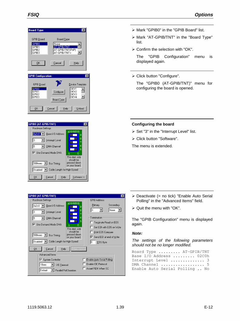
FSIQ Options
1119.5063.12 1.39 E-12
À Mark "GPIB0" in the "GPIB Board" list.
À Mark "AT-GPIB/TNT" in the "Board Type"list.
À Confirm the selection with "OK".
The "GPIB Configuration" menu isdisplayed again.
À Click button "Configure".
The "GPIB0 (AT-GPIB/TNT)" menu forconfiguring the board is opened.
Configuring the board
À Set "3" in the "Interrupt Level" list.
À Click button "Software".
The menu is extended.
À Deactivate (= no tick) "Enable Auto SerialPolling" in the "Advanced Items" field.
À Quit the menu with "OK".
The "GPIB Configuration" menu is displayedagain.
Note:
The settings of the following parametersshould not be no longer modified.
Board Type ......... AT-GPIB/TNTBase I/O Address ......... 02C0hInterrupt Level .............. 3DMA Channel .................. 5Enable Auto Serial Polling .. No

Options FSIQ
1119.5063.12 1.40 E-12
Setting the parameters for the connectedequipment
À Mark the instrument in the "DeviceTemplate" list and confirm selection with"OK".
The "DEV.. Settings" menu is opened.
À Perform the settings for the selected unitin the "DEV.. Settings" menu.
The logic name for the instrument is presetwith DEV1 and address 20. See boardmanual for further units.
Note: When assigning logic names toconnected equipment note thatthese names do not correspond tothe directory names under DOS.
À Terminate setting with "OK".
The query asking if the GPIB softwareshould be re-started is displayed.
À Select "No".
À Re-start controller with Start-Restart in thetask bar.
After the controller has been re-started,the settings for the GPIB interface areeffective.
Note: After the installation, the "ServicePack X" of Windows NT is to be re-installed, see "New Installation ofWindows NT Software".
Use of DOS Programs
When using DOS programs, driver GPIB-NT.COM should be loaded. For this to take place, the linedevice=C:\PROGRA~1\NATION~1\GPIB\NI488\DosWin16\Gpib-nt.com has to be activated inthe file C:\WINNT\SYSTEM32\CONFIG.NT. If the option is factory fitted, this line will have beenentered in the factory.
Operation
The second IEC/IEEE-bus interface corresponds physically to that of the instrument (see Chapter 8).If the instrument is to be controlled via the IEC/IEEE bus, a bus cable must be plugged to both busconnectors. The interface can be driven under DOS/WINDOWS3.1/95/NT by R&S software (FS-K3,Order No. 1057.3028.02, etc.) or by user-written software. The handling of IEC/IEEE-bus commands inuser programs is described in the manual for the card.
The files are in directory C:\Program Files\National Instrument\GPIB\NI488.

FSIQ Options
1119.5063.12 1.41 E-12
Option FSE-B5 - FFT Filter
Option FFT Filter FSE-B5 is a firmware option. It has to be enabled by a keyword.
Prerequisites
1. KeywordsThe keyword is printed on a label which is part of the equipment supplied and has to be stuck to therear of FSIQ.
2. HardwareThe modification state of module DIGITAL IF has to be either MODIF INDEX > 5 orMODIF INDEX = 5 and HW CODE ≥ 6. The modification state can be checked in the module listINSTALLED COMPONENTS in menu INFO HARDWARE+OPTIONS.
3. FirmwareThe modification state of the firmware has to ≥ 1.62. The modification state can be checked in tableFIRMWARE VERSION in menu INFO FIRMWARE VERSIONS.
Enabling the option
SETUP
MODE
CONFIGURATIONÀ Call up menu SETUP by pressing the SETUP key.
OPTIONSÀ Call up submenu OPTIONS by pressing the OPTIONS softkey.
Table FIRMWARE OPTIONS is displayed, listing the installedoptions.
ENABLE NEWOPTION À Activate the entry field by pressing the ENABLE NEW OPTION
soft key.
1
.
.
.
MHzdBmmVms
DATA ENTRY À Enter the 10-digit keyword via the numeric keypad and terminatethe entry by pressing one of the unit keys.
Now option FFT filter is listed in table FIRMWARE OPTIONS.
Note: Message ’option key invalid’ indicates an invalid entry.

Options FSIQ
1119.5063.12 1.42 E-12
Option FSE-B16 – Ethernet Adapter
With the option Ethernet Adapter FSE-B16, the device can be connected to an Ethernet-LAN (local areanetwork). It is possible to transmit data via the network and to use the network printer. The adapteroperates with a 10 MHz Ethernet in line with standards IEEE 802.3 10Base2 (Thin Ethernet,CheaperNet, BNC-Net) (B16 model 03) or 10Base5 (Thick Ethernet) (B16 model 02).
Hardware Installation
Caution:Prior to installation contact the network administrator, especially in case of complexLAN installations since mistakes in cabling might have influence the whole network.
If the adapter is installed at the factory, it is preconfigured. In case of retrofitting, refer to the installationinstructions. The hardware settings must not be modified since the functions of the device couldotherwise be impaired.
The following parameters are factory-set:I/O Addr. 300, IRQ 5, MEM D0000
The connection with the network depends on the connectors used in the network.
BNC (Thin Ethernet, CheaperNet; FSE-B16 Var. 03)
Connection The device is looped into the LAN segment via rear-panel 2 BNCconnectors.If a cable is not connected to one of the BNC connectors, this BNCconnector has to be terminated with 50 Ohm. BNC T connectorsmust not be used.
Network trafficNote that the network traffic is disturbed if a segment is interrupted.
Requirements Thin Ethernet segment requirements have to be complied with:- maximum segment length of 185 m- minimum distance between the connectors of 0.5 m- maximum of 30 connectors per segment.
If components that comply with enhanced requirements areexclusively used (Ethernet Adapter FSE-B16 complies with theenhanced requirements):- maximum length of segment of 300 m- maximum number of connectors of 100
With repeaters used:- maximum total length of the network of 900 m containing a- maximum of 3 segments- maximum of two repeaters between two connectors

FSIQ Options
1119.5063.12 1.43 E-12
AUI (Thick Ethernet; FSE B16 Var. 02)
Connection The device is connected to the LAN segment using a transceivercable (DB-15 AUI connector, not part of the equipment supplied)which is connected to the rear panel and to the transceiver.
Network traffic The connection does not conflict with the network traffic. The devicecan also be disconnected from the network without any problemsbut make sure that data are not being transmitted.
Requirements The Thick Ethernet segment requirements have to be taken intoaccount.- The maximum segment length should be 500 m and the- distance between the connectors should at least be 2.5 m.- A maximum of 100 connectors may be used in a segment.
With repeaters used,- the total length of the network must not be more than 2500 m containing- a maximum of 3 segments.- There should be no more than two repeaters between two connectors.
If other network components are used, these conditions may vary.
RJ45 (UTP, 10BaseT, Western Connector)
Connection The device is connected to the LAN segment using a RJ45 cable(not part of the equipment supplied) which is connected to the rearpanel and to the network hub of the LAN segment.
Network traffic This connection does not conflict with the network traffic. Thedevice can also be disconnected from the network without anyproblems but make sure that data are not being transmitted.
Requirements Since RJ45 is not a bus but a star topology no special requirementshave to be taken into account for the connection.The LAN requirements should be considered in the installation.
Software Installation
Data transmission within the network is by means of data blocks, the so-called packets. Besides userdata other information, the so-called protocol data (transmitter, receiver, type of data, order) aretransmitted. The drivers corresponding to the protocol have to be installed to process protocolinformation. A network operating system is required for network services (data transmission, directoryservices, printing in the network) and thus has to be installed.
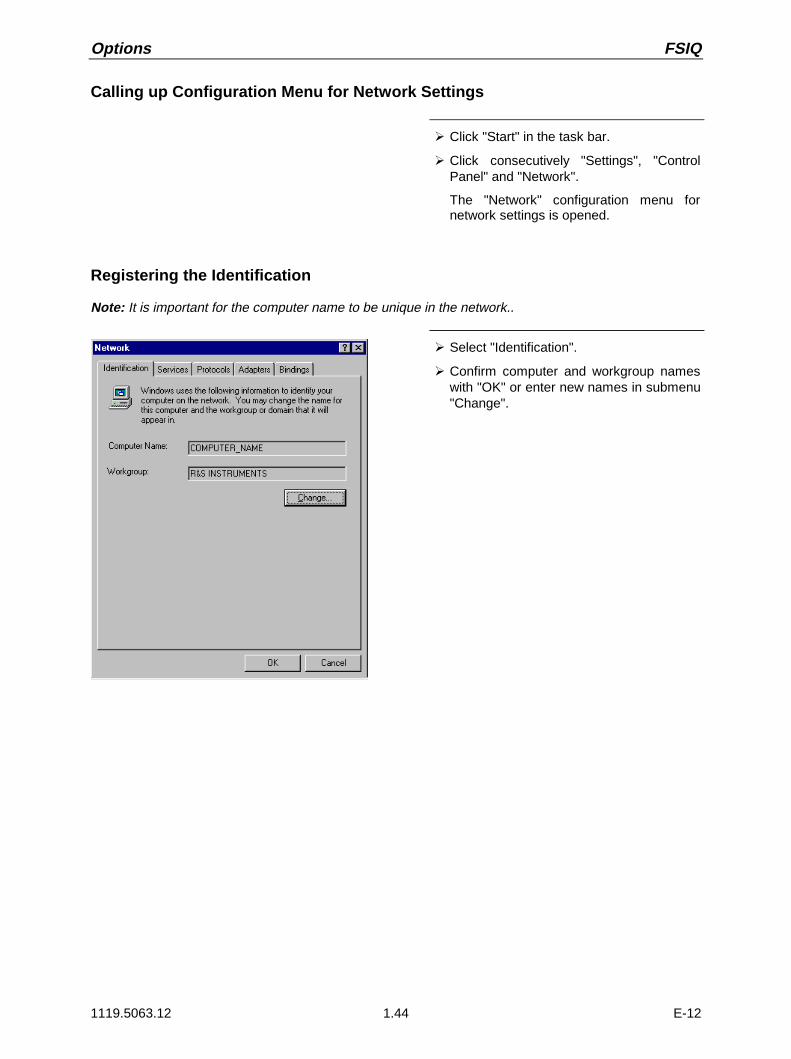
Options FSIQ
1119.5063.12 1.44 E-12
Calling up Configuration Menu for Network Settings
À Click "Start" in the task bar.
À Click consecutively "Settings", "ControlPanel" and "Network".
The "Network" configuration menu fornetwork settings is opened.
Registering the Identification
Note: It is important for the computer name to be unique in the network..
À Select "Identification".
À Confirm computer and workgroup nameswith "OK" or enter new names in submenu"Change".

FSIQ Options
1119.5063.12 1.45 E-12
Installation and Configuration of the Driver for the Network Adapter
À Select "Adapter".
À Click "Add" and mark network driver "SMC8416 EtherEZ" and select with "OK".
The query "Files.." is displayed.
À Answer it by clicking "Continue".
The "SMCEthernet Card Setup" window isdisplayed.
À Close the window with "OK".
Some files are copied and the networkadapter is displayed under "NetworkAdapters".The entry "MS Loopback Adapter" refersto a driver which ensures instrumentcontrol and should not be modified.
Note: The network adapter settings mustnot be modified since this may causeproblems to the instrument.
Installation of Network Protocols
Note: The network administrator knows which protocols are to be used..
À Select "Protocol".
À Click "Add", mark the desired protocol andselect with "OK".
This operation has to be performedseveral times when several protocols areselected.
À Execute the installation by clicking"Continue".
Note: If a protocol requires further settings,they can be performed with "Proper-ties" after marking the correspondingentry. If further settings are notpossible, this field is gray.

Options FSIQ
1119.5063.12 1.46 E-12
Installation of Network Services
To utilize the resources of the network it is necessary to install the corresponding services.
Note: The network administrator knows which services are to be used.
À Select "Services".
À Click "Add", mark the desired service andselect with "OK".
This operation has to be performedseveral times when several services areselected.Some services are pre-installed and canbe cleared with "Remove" if they are notneeded.
À Execute the installation by clicking"Continue".
Note: If a service requires further settings,they can be performed with"Properties" after marking the corres-ponding entry. If further settings arenot possible, this field is gray.
Terminating the Installation
À Quit the "Network" configuration menu fornetwork settings with "OK".
The settings are checked and processed.Missing information is queried.
À Answer the query "You must shutdown..."with "Yes".
The settings are valid after computer re-start.
Note: After the installation, the "ServicePack X" of Windows NT is to be re-installed, see "New Installation ofWindows NT Software".

FSIQ Options
1119.5063.12 1.47 E-12
Examples of Configurations
Network Protocols Services Notes
NOVELL Netware NWLink IPX/SPXCompatibleTransport
Client Service forNetWare
The "Frame Type" used under "Protocols -Properties" should be set.
IP networks(FTP, TELNET, WWW,GOPHER, etc.)
TCP/IP Protocol Simple TCP/IPServices
An "IP Address" unambiguous in the networkshould be set under "Protocols - Properties".
MICROSOFT network NetBEUI ProtocolorTCP/IP Protocol
WorkstationServer
A name unambiguous in the network should beregistered under "Identification - ComputerName".
Operation
After installing the network operating system it is possible to transfer data between the device and othercomputers and to use printers in the network. A precondition for network operation is the authorization touse network resources. Resources may be access to the file directories of other computers or the use ofa central printer. The network or server administrator will grant the authorizations. The network name ofthe resource and the corresponding authorization are required. Passwords protect the resourcesagainst improper use. A user name is normally assigned to every authorized user. The user also has apassword. Resources may then be assigned to the user. The type of access, i.e. whether data are onlyread or also written as well as a shared access to data has to be defined. Other types are possibledepending on the network operating system.
NOVELL
Operating system NETWARE from NOVELL is as server-supported system. Data transfer between theindividual workstations is not possible. Data transfer is between workstation computers and a centralcomputer, the server. This server provides storage capacity and the connection to the network printers.Like under DOS, the data on a server are organized in directories and are offered to the workstation asvirtual drives. A virtual drive on a workstation is like a hard disk and data can be processed accordingly.This is called drive mapping. Also network printers can be addressed as normal printers.Network operating system NOVELL is available in two forms: NETWARE 3 and NETWARE 4 NDS. Inthe previous version NETWARE 3, each server manages its own resources itself and is independent. Auser has to be managed separately on each server. For NOVELL 4 NDS, all resources are managed inthe NDS (NOVELL DIRECTORY SERVICE). The user only has to log in once and gains access to theresources released for him. The individual resources and the user are managed as objects in ahierarchical tree (NDS TREE). The position of the object in the tree is called CONTEXT for NETWAREand must be known in order to access the resources.
MICROSOFT
For MICROSOFT, data can be transferred between workstations (peer-to-peer) but also betweenworkstations and servers. The servers can provide access to individual files as well as the connection tonetwork printers. Like under DOS, the data on a server are organized in directories and are offered tothe workstation as virtual drives. A virtual drive on a workstation is like a hard disk and data can beprocessed accordingly. This is called drive mapping. Also network printers can be addressed as normalprinters. A connection to DOS, WINDOWS FOR WORKGROUPS, WINDOWS95, WINDOWS NT ispossible.

Options FSIQ
1119.5063.12 1.48 E-12
Installing a user
After the network software has been installed, the instrument logs with an error message during the nextstart-up since there is no user "Instrument" (= user identification for NT autologin) in the network. It istherefore necessary to install a user which should be the same for Windows NT and for the network.The network administrator is responsible for the installation of new users in the network.
Note: The installation of new users is possible only under the administrator identification (seesection "Controller Function").
À Click "Start" in the task bar.
À Click consecutively "Programs""Administrative Tools (Common)" and"User Manager" .
The "User Manager" menu is opened.
À Click "User" and select "New User".
The menu "New User" for entering userdata is opened.
À Fill in the lines "Username", "Password"and "Confirm Password" and confirmthe entry with OK.
The user data should correspond to thenetwork settings.

FSIQ Options
1119.5063.12 1.49 E-12
Only NOVELL network:Configure NOVELL Client À Click "Start" in the task bar.
À Click consecutively "Settings","Control Panel", "CSNW".
NOVELL 3.x
À Click "Preferred Server".
À Under "Select Preferred Server"select the NOVELL server for whichthe user has been installed.
NOVELL 4.x
À Click "Default Tree and Context" .
À Enter the NDS Tree under "Tree" and,under "Context", the hierarchical pathfor which the user has been installed.
Note: These specifications can beobtained from the networkadministrator.
Login in the Network
Network login is automatically performed with the operating system login. A prerequisite is that the username and the password are the same under Windows NT and in the network.
Use of Network Drives
À Click "Start" in the task bar.
À Click consecutively "Programs" and"Windows NT Explorer".
À Click "Network" line in the "AllDirectories" list.
A list of available network drives isdisplayed.
À Click "Tools" and "Map Network Drive".
In the list "Shared Directories:" thenetwork paths available in the networkare displayed.
À Mark the desired network path.

Options FSIQ
1119.5063.12 1.50 E-12
À Select the drive under "Drive:"
À Activate "Reconnect at Logon:" if thelink is to be automatically established ateach unit start.
À Connect the network path to theselected drive with "OK".
The user name and the password arequeried. The drive is then displayed inthe "All Directories" list of Explorer.
Note: Only drives for which anauthorization is available maybe connected.
Disconnect link:
À Click "Tools" and "Disconnect NetworkDrive" in Explorer.
À Select under "Drive:" the drive whoseconnection is to be removed.
À Disconnect link with "OK". The queryshould be answered with "Yes".
Printing on a Network Printer
Select printer driver under Windows NT
À Press key combination <ALT> <SYSREQ>
The Windows NT screen is displayed.
À In the Start menu press first "Setting" andthen "Printers".
The printer window is opened.
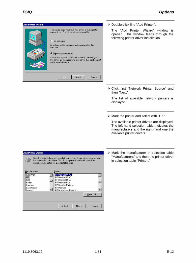
FSIQ Options
1119.5063.12 1.51 E-12
À Double-click line "Add Printer".
The "Add Printer Wizard" window isopened. This window leads through thefollowing printer driver installation.
À Click first "Network Printer Source" andthen "Next".
The list of available network printers isdisplayed.
À Mark the printer and select with "OK".
The available printer drivers are displayed.The left-hand selection table indicates themanufacturers and the right-hand one theavailable printer drivers.
À Mark the manufacturer in selection table"Manufacturers" and then the printer driverin selection table "Printers".

Options FSIQ
1119.5063.12 1.52 E-12
À Click "Next".
The window for starting a test page isdisplayed. The test print is for checking ifthe installation was successful.
À Switch on printer.
À Click Yes (recommended)".
À Click "Finish".
A test page is printed out if the installationwas successful.If the test page is not printed out or notcompletely, the Windows NT online helpoffers troubleshooting instructions underthe entry "Printer Trouble Shooting".
The instrument has to be configured withthis printer for the printout of themeasurement screen. This configuration isdescribed in this chapter in the section"Connecting an Output Device".
Server Function
With the server function data can be provided on the instrument for use in other computers. This ispossible only in the MICROSOFT network. The server function is released after network installation asstandard. If this is not required, it should be deactivated, see "Installation of Network Services".
The availability of instrument data in the network is controlled by releases. The release is a property ofa file or of a directory. To grant a release, the object is to be marked in "Windows NT Explorer" andpressed by the right-hand mouse key. The release is performed under Properties -> Sharing byselecting "Shared As". Other computers can then access these objects with the names allocated under"Share Name". The online help gives further information on the network operation.
TCP/IP
The TCP/IP protocol allows files to be transmitted between different computer systems. A programrunning on both computers is required to control the data transfer. The same operating or file systemneed not be used by the two partners. A file transfer is possible between DOS/WINDOWS and UNIX,for example. One partner has to be configured as host the other as client or vice versa. The systemperforming several processes at the same time (UNIX) will normally be the host. The usual file transferprogram used for TCP/IP is FTP (File Transfer Protocol). An FTP host is installed as standard on mostof the UNIX systems.
After installing the TCP/IP services, a terminal link can be established with "Start" - "Programs" -"Accessories" - "Telnet" or a data transmission with FTP using "Start" - "Run" "ftp" - "OK". Thus, allcontroller systems can be accessed which support these universal protocols (UNIX, VMS, ...).
Further information is given in the NT online help which can be called up with "Help".

FSIQ Options
1119.5063.12 1.53 E-12
FTPFor a complete description of the functions and commands see the FTP documentation.
Establishing a connection À Click "Start" and then "Run" in the task bar.
The program is started with the DOS commandFTP
The following command sets up the connection:OPEN <xx.xx.xx.xx>
xx.xx.xx.xx = IP address, e.g. 89.0.0.13
File transmission To transmit a file to the target system, the following command isused:
PUT <file name>
file name = name of file e.g. DATA.TXT.
To call a file from the target system, the following command isused:
GET<file name>
file name = name of file e.g. SETTING.DAT.
TYPE B
allows the transmission of files in the BINARY format, noconversion is performed.
TYPE A
allows the transmission of files in the ASCII format. Thus, controlcharacters are converted so that the text files can be read on thetarget system, too.
Examples:PUT C:\AUTOEXEC.BAT
sends the AUTOEXEC.BAT file to the target system.LCD DATA
changes to subdirectory DATA in the computer function.CD SETTING
changes to the subdirectory SETTING on the target system.
Changing directories The commandLCD <path>
changes the directory as the corresponding DOS command.
LDIR
lists the directory.
These commands refer to the computer function of theinstrument. If the ’L’ preceding the commands is omitted, theyapply to the target system.

Options FSIQ
1119.5063.12 1.54 E-12
Option FSIQB70 - DSP and IQ Memory Extension (2 X 512 K)
FSIQB70 is a hardware option. FSIQ has to be equipped with this option to enable the installation offuture firmware options such as option FSIQK71, Code Domain Power Measurement for IS95.
Moreover, option FSIQB70 is the prerequisite for a R&S demo software used for the CDP measurementon W-CDMA signals (NTT DoCoMo and 3GPP downlink).
Apart from this, FSIQB70 has no effect on the operation of the unit.

FSIQ Contents - Getting Started
1119.5063.12 I-2.1 E-1
Contents - Chapter 2 "Getting Started"
2 Getting Started
Level and Frequency Measurements............................................................................................. 2.1Measurement Task.................................................................................................................. 2.2
Important Spectrum Analyzer Functions ................................................................................. 2.2
Sweep, Level and Frequency Measurements – Example 1 .................................................. 2.2
Sweep, Level and Frequency Measurements – Example 2 .................................................. 2.7
Level Measurement Accuracy ................................................................................................. 2.9
Measurement of Harmonic Separation ........................................................................................ 2.10Measurement Task................................................................................................................ 2.10
Important Spectrum Analyzer Functions ............................................................................... 2.11
Measurement Procedure - Harmonic Separation – Example 1........................................... 2.12
Measurement Procedure - Harmonic Separation – Example 2........................................... 2.16
Measurement Procedure - Harmonic Separation – Example 3........................................... 2.20
Measurement of Intermodulation Distortions............................................................................. 2.24Measuring Task ..................................................................................................................... 2.24
Important Spectrum-Analyzer Functions ............................................................................... 2.25
Measurement......................................................................................................................... 2.26
Time-domain Measurements with Pulsed Signals ..................................................................... 2.31Measuring Task ..................................................................................................................... 2.31
Important Spectrum Analyzer Functions ............................................................................... 2.31
Measurement......................................................................................................................... 2.32

Contents - Getting Started FSIQ
1119.5063.12 I-2.2 E-1

FSIQ Level and Frequency Measurements
1119.5063.12 2.1 E-10
2 Getting Started
Chapter 2 presents basic measurements performed by a signal analyzer to provide fast and easyaccess to the operation of the instrument.
Before starting any measurement with the FSIQ, please note the instructions given in chapter 1 forputting the instrument into operation. In chapters 3 you will find detailed information on customizing theinstrument and the display.
For a systematic explanation of all menus, functions and parameters and background information referto the reference part in chapter 4.
In the following description, each step is explained in detail using the FSIQ so that the instrument can beimmediately used without the need for learning all of the available functions. The describedmeasurement applications are:
• Measurement of the level and frequency of a sine wave signal.
• Measurement of harmonics.
• Measurement of third order intermodulation and determination of the intercept point.
• Zero span measurement of a pulsed signal.
All of the following examples assume the standard settings for the analyzer. These are set with thePRESET key in the SYSTEM key field. The most important standard settings are shown in Table 2-1. Acomplete listing of standard settings can be found in chapter 4.
Table 2-1 Important PRESET settings
Parameter Parameter name Setting
FSIQ3 FSIQ7 FSIQ26 FSIQ40
Mode Mode Analyzer Analyzer Analyzer Analyzer
Center frequency Center Frequency 1.75 GHz 3.5 GHz 13.25 GHz 20 GHz
Active Freq. Meas. Range Span 3.5 GHz 7 GHz 26.5 GHz 40 GHz
Reference Level Ref Level – 20 dBm – 20 dBm – 20 dBm – 20 dBm
RF Attenuation RF ATT 10 dB 10 dB 10 dB 10 dB
Level Display Range Level Range 100 dB 100 dB 100 dB 100 dB
Resolution Bandwidth Res Bw 3 MHz 3 MHz 3 MHz 3 MHz
Video Bandwidth Video Bw 3 MHz 3 MHz 3 MHz 3 MHz
Sweep Time Sweep Time 5 ms 5 ms 150 ms 225 ms
Trigger Trigger free run free run free run free run
Level and Frequency Measurements
Measurement Task
The determination of the level and frequency of a signal is one of the most frequently encounteredmeasurement tasks typically performed by a spectrum analyzer. Usually, for the measurement of anunknown signal, the PRESET settings are initially selected. If levels above +30 dBm are expected orpossible, then a power attenuator must be inserted ahead of the analyzer input. Without attenuation,these signal levels might damage or destroy the input attenuator or the input mixer.

Level and Frequency Measurements FSIQ
1119.5063.12 2.2 E-10
Important Spectrum Analyzer Functions
Important parameters for level and frequency measurements are the settings for the CENTERFREQUENCY, the selection of the active measurement frequency range (SPAN) and the MARKERfunctions.
Sweep, Level and Frequency Measurements – Example 1
In this example, a signal with a frequency of 200 MHz and a level of -10 dBm are applied to the RFINPUT of the analyzer. The selection of the center frequency and the active frequency range takes placemanually.The necessary setup functions are performed almost without exception by the fixed-function keys. Themenus which appear with a key can, for the most part, be ignored. In this manner, fast, key-orientedoperation is possible.
The following setup steps are performed:1. Reset the instrument.2. Apply the test signal.3. Set the center frequency to 200 MHz.4. Reduce the active measurement frequency range (SPAN) to 1 MHz.5. Measure the level and frequency using the marker.6. Optimize the measurement dynamic range and reduce the level measurement error.7. Measure the frequency with the internal frequency counter
SYSTEM
PRESET
1. Reset the instrument.
À Press the PRESET key.
2. Connect the test signal to the RF INPUT locatedon the instrument front panel.
CENTER FREQUENCY
CENTER
FREQUENCY
1.75 GHz
3. Set the center frequency to 200 MHz.
À Press the CENTER key in the FREQUENCY keyfield.
The input field for center frequency appears on thedisplay screen.
DATA ENTRY
2
0
CENTER FREQUENCY dBm
0
200 MHz MHzms
mV
À Enter 200 via the numeric keypad and terminatewith the MHz key.

FSIQ Level and Frequency Measurements
1119.5063.12 2.3 E-10
SPAN
FREQUENCY
SPAN
SPAN
400 MHz
4. Reduce the measurement frequency range(SPAN) to 1 MHz.
À Press the SPAN key in the FREQUENCY key field.
DATA ENTRY
1
dBm MHz
ms
mV SPAN
FREQUENCY SPAN
MHz1
À Enter 1 via the numeric keypad and terminate withthe MHz key.
Note: In conjunction with the change in measure-ment frequency range (SPAN), the resolutionbandwidth (RES BW), video bandwidth(VIDEO BW) and sweep time (SWEEP TIME)are set to new values since they are definedas coupled functions in the standard PRESETsettings.
MARKER
NORMAL MARKER
200.00000000 MHz-10.5 dBm
[T1]1
5. Measure level and frequency using the markerand read the resulting values on the displayscreen.
À Press the NORMAL key in the MARKER key field.
The marker jumps to the largest signal peak shownon the display screen.
Note: When the marker is switched on for thefirst time, it automatically performs thePEAK SEARCH function as demonstratedin this example.If a marker was already active, theSEARCH key in the MARKER key fieldmust be pressed in order to set thecurrently active marker to the displayedsignal maximum.
The level and frequency measured by the markercan be read in the marker field at the upper edge ofthe display screen. (see Fig. 2-1).
DATA VARIATION À Using the roll-key, the marker can be moved alongthe measured curve.
The corresponding level and frequency valuesappear in the marker field.

Level and Frequency Measurements FSIQ
1119.5063.12 2.4 E-10
Fig. 2-1 shows the measured curve on the display screen over a 1 MHz range as well as the markerlevel and frequency values.
Markerfield
|USER
Ref Lvl-20 dBm
RBW 20 kHzVBW 20 kHzSWT 7.5 ms
Marker 1[T1]-10.8 dBm200.0052 MHz
Span 1 MHz100 kHz/
1
Center 200 MHz
RF ATT 10 dB
Unit dBmMARKERNORMAL
MARKER 2
MARKER 3
SIGNALCOUNT
MARKERDEMOD
MARKER 1
SIGNAL ID
MARKER 4
ALL MARKER OFF
MARKER INFO
MARKERZOOM
-20
-40
-60
-80
-100
-120
-30
-50
-70
-90
-110
Fig. 2-1 200-MHz signal. The measured values are displayed in the marker field.
At low signal-to-noise ratios, the level measurement accuracy can be improved by an optimum selectionof the FSIQ parameters. The accuracy of the frequency display can also be enhanced by applying theinternal frequency counter.
MKR
USERMARKER
MKR->CENTER
MKR->REF LEVEL
PEAK
MARKER ->
6. Optimize the dynamic range and reduce thelevel measurement error.
À Press the MKR→ key in the MARKER key field.
The MARKER-MKR→ menu is opened.
REF LEVELMKR
À Press MKR → REF LEVEL softkey.
The reference level (REF LEVEL) is reduced to thesignal level.

FSIQ Level and Frequency Measurements
1119.5063.12 2.5 E-10
MARKER
NORMAL
ON
USER
NORMAL
MARKER1
MARKER2
MARKER3
MARKER
N
SIGNALCOUNT
MARKER4
7: Determine the exact frequency with the internalfrequency counter.
Note: The frequency counter measures the frequencyof the marked signal with the selected counterresolution and at the accuracy of the internalfrequency reference. A frequency measurementmade using the marker is, however, limited bythe number of horizontal display points and theapplicable resolution bandwidth.
À Press the NORMAL key in the MARKER key field.
The MARKER NORMAL menu is opened.
COUNTSIGNAL
À Press the SIGNAL COUNT softkey.
The internal frequency counter is now active andmeasures the signal frequency with the PRESET re-solution. The resolution is to be increased to10 Hz.
MENU
N
N
COUNTERRESOL
À Press the menu change key .
The supplementary menu is opened.
COUNTERRESOL
N
10 kHz
100 Hz
USER
COUNTERRESOLUTION
1 kHz
10 Hz
À Press the COUNTER RESOL softkey.
The COUNTER RESOLUTION sub-menu isopened.
10 HzMARKER 1 [T1 CNT]
-10.5 dBm200.00001 MHz
À Press the 10 Hz softkey.
The desired frequency resolution (10 Hz) is nowselected.
In the marker field, the item [CNT] indicates that thecounter is active (see Fig. 2-2).

Level and Frequency Measurements FSIQ
1119.5063.12 2.6 E-10
USER
COUNTERRESOLUTION
10 kHz
SIGNAL ID
1 kHz
100 Hz
10 Hz
1 Hz
0.1 Hz
Ref Lvl-20 dBm
RBW 20 kHzVBW 20 kHzSWT 7.5 ms
Marker 1[T1 CNT]-10.8 dBm200.00513 MHz
Span 1 MHz100 kHz/
1
Center 200 MHz
RF ATT 10 dB
Unit dBm
-20
-40
-60
-80
-100
-120
-30
-50
-70
-90
-110
Fig. 2-2 Frequency measurement using the internal frequency counter.
Sweep, Level and Frequency Measurements – Example 2
The zoom function (MARKER ZOOM) operates much faster than the manual input of center frequencyand measurement frequency range, and permits the measurement frequency range displayed on thescreen to be as narrow as desired.
As in Example 1, a signal with a frequency of 200 MHz and a level of -10 dBm is applied to the analyzerRF INPUT.
The following setup steps are performed:
1. Reset the instrument.
2. Apply the signal.
3. Zoom in on the signal.
4. Measure the level and frequency with the marker.
5. Optimize the dynamic range and reduce the level measurement error.
6. Measure the frequency with the internal frequency counter.
Steps 1 to 2 and 4 to 6 correspond to steps 1 to 2 and 5 to 7, respectively, of Example 1. Step 3replaces the manual input of center frequency and measurement frequency range. (steps 3 and 4).

FSIQ Level and Frequency Measurements
1119.5063.12 2.7 E-10
See steps 1 and 2 of example 1
1. Reset the instrument to standard settings.
2. Connect the test signal to the analyzer RFINPUT.
MARKER
NORMAL
3. Zoom in on the signal.
À Press the NORMAL key in the MARKER key field .
The marker moves to the largest signal displayed onthe screen. In this example, it is the signal at 200MHz. (PEAK SEARCH function, see step 5 inExample 1).
MARKERZOOM
MARKER ZOOM
3.5 GHz
À Press the MARKER ZOOM softkey.
The input field for the measurement frequencyrange appears on the display screen.
DATA ENTRY
1
dBm MHz
ms
mV MARKER ZOOM
1 MHz
À Enter 1 via the numeric keypad and terminate withthe MHz key.
After entry of the measurement frequency range,the marked signal is counted and then used as thenew center frequency. At the same time, theentered measurement frequency range is set.
Note: In conjunction with the active measurementfrequency range (SPAN) change, theresolution bandwidth (RES BW), videobandwidth (VIDEO BW) and sweep time(SWEEP TIME) are also set to new valuessince they are defined as coupled functionsin the standard PRESET settings.
See steps 5 to 7 of example 1:
4. Read the values for level and frequency asmeasured by the marker.
5. Optimize the dynamic range and reduce thelevel measurement error.
6. Determine the frequency with the internalfrequency counter.
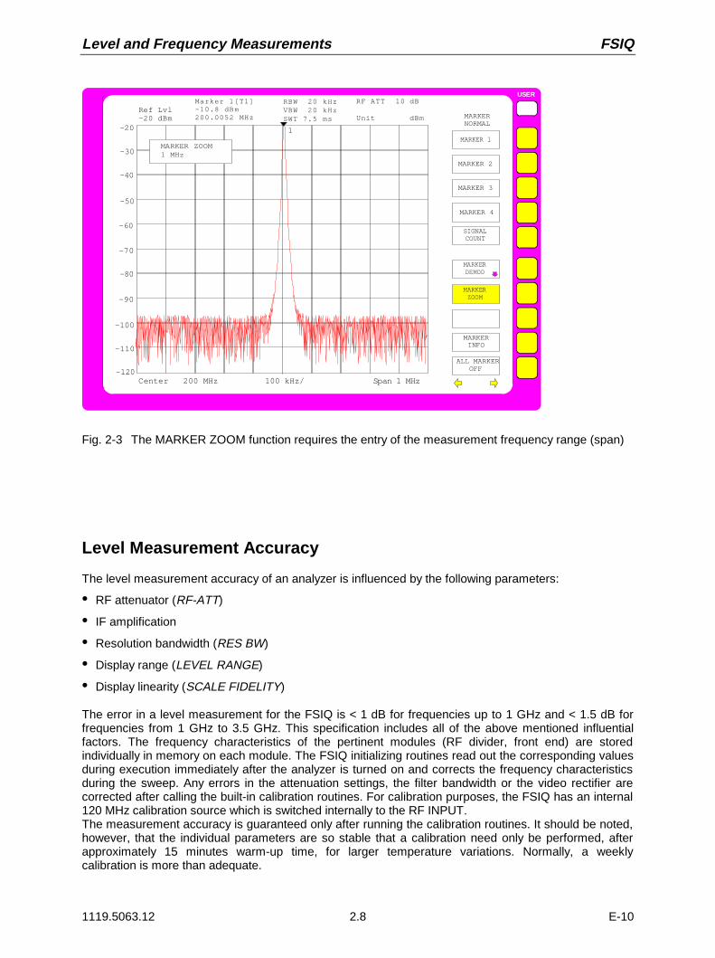
Level and Frequency Measurements FSIQ
1119.5063.12 2.8 E-10
USER
MARKERNORMAL
MARKER 2
MARKER 3
SIGNALCOUNT
MARKERDEMOD
MARKER 1
SIGNAL ID
MARKER 4
ALL MARKER OFF
MARKER INFO
MARKERZOOM
Ref Lvl-20 dBm
RBW 20 kHzVBW 20 kHzSWT 7.5 ms
Marker 1[T1]-10.8 dBm200.0052 MHz
Span 1 MHz100 kHz/
1
Center 200 MHz
RF ATT 10 dB
Unit dBm
-20
-40
-60
-80
-100
-120
-30
-50
-70
-90
-110
MARKER ZOOM1 MHz
Fig. 2-3 The MARKER ZOOM function requires the entry of the measurement frequency range (span)
Level Measurement Accuracy
The level measurement accuracy of an analyzer is influenced by the following parameters:
• RF attenuator (RF-ATT)
• IF amplification
• Resolution bandwidth (RES BW)
• Display range (LEVEL RANGE)
• Display linearity (SCALE FIDELITY)
The error in a level measurement for the FSIQ is < 1 dB for frequencies up to 1 GHz and < 1.5 dB forfrequencies from 1 GHz to 3.5 GHz. This specification includes all of the above mentioned influentialfactors. The frequency characteristics of the pertinent modules (RF divider, front end) are storedindividually in memory on each module. The FSIQ initializing routines read out the corresponding valuesduring execution immediately after the analyzer is turned on and corrects the frequency characteristicsduring the sweep. Any errors in the attenuation settings, the filter bandwidth or the video rectifier arecorrected after calling the built-in calibration routines. For calibration purposes, the FSIQ has an internal120 MHz calibration source which is switched internally to the RF INPUT.The measurement accuracy is guaranteed only after running the calibration routines. It should be noted,however, that the individual parameters are so stable that a calibration need only be performed, afterapproximately 15 minutes warm-up time, for larger temperature variations. Normally, a weeklycalibration is more than adequate.

FSIQ Measurement of Harmonic Separation
1119.5063.12 2.9 E-10
Measurement of Harmonic Separation
Measurement Task
The measurement of signal harmonics is a frequently occurring task which can be optimally performedby a spectrum analyzer. In general, all signals will contain harmonics to some degree. Harmonics areespecially critical in high-power transmitters, e.g., in radio transmitters, where a significant radiatedharmonic component may interfere with the reception of other radio services. Generally, non-lineardevice characteristics create harmonics which are often selectively reduced through the use of low-passfilters. Since the spectrum analyzer also has non-linear characteristics, e.g., at the first mixer, it isnecessary to exercise caution during a measurement to insure that the spurious harmonics generatedby the analyzer do not influence the measurement results. If necessary, the fundamental frequencymust be selectively attenuated with respect to the harmonics by insertion of an appropriate high-passfilter.
For harmonic-content measurements, the achievable measurement dynamic range is dependent uponthe k2 intercept of the spectrum analyzer. The k2 intercept point is defined as the fictitious first-mixerinput level where the levels of the first harmonic and of the fundamental frequency are equal. In practice,this level cannot be applied to the mixer since, to do so, would cause its destruction. However, using thek2 intercept point concept, the achievable measurement dynamic range for the harmonics of a UnitUnder Test (UUT) can be calculated with relative simplicity.
As can be seen in Fig.2-4, the harmonic level is reduced by 20 dB when the level at the fundamentalfrequency is reduced by 10 dB.
Fig.2-4 Theoretical display curve of fundamental and first harmonic with a k2 intercept of 50 dBm.
0
10
20
30
40
50
-10
-20
-30
-40
-50
-60
-70
-80
-90
-100
-30 -20 -10 0 10 20 30 40 50
DisplayLevel[dBm]
RF Level[dBm]
k2 Intercept[dBm]
Funda-mental First
Harmonic
-110
-120
-130
1
1
1
2

Measurement of Harmonic Separation FSIQ
1119.5063.12 2.10 E-10
From the linear equations and the given intercept point, the following formula can be derived for theachievable harmonic separation ak2 in dB:
a IP Pk e2 2= − ’ (1) ak2 = harmonic separation
Pe = mixer level/dBm
IP2 = k2 intercept point
The formula for the internally produced level P1 at the first harmonic in dBm is:
P P IPe1 2 2= • − (2)
The lower harmonic measurement limit is dictated by the noise figure of the spectrum analyzer. Throughadequate averaging with the video filter, the UUT harmonic level which is to be measured should be atleast 4 dB over the noise figure so that the measurement error caused by the input noise is less than 1dB.
From the above, the following rules for the measurement of large harmonic separations can be derived:
• Select an IF bandwidth as narrow as possible in order to reduce the noise figure.
• Select the RF attenuation as high as required so that the necessary harmonic separation can still bemeasured.
Note: The mixer amplitude is the applied RF level reduced by the selected RF attenuation. The lowdistortion (LOW DISTORTION function) mode of the analyzer automatically sets the optimumRF attenuation for the best harmonic separation.
The maximum harmonic separation is achieved when the harmonics level is equal to the inherent noiselevel of the receiver. The corresponding level at the mixer according to (2) is:
[ ]P dBmP dBm IP
enoise= +/ 2
2
For a 30 Hz resolution bandwidth, (noise level < -140 dB, IP2 = 50 dBm), this level is -45 dBm.Therefore, according to (1) , the maximum measurable harmonic separation is 95 dB less 4 dBminimum signal-to-noise ratio.
Important Spectrum Analyzer Functions
In addition to frequency and level settings, the harmonic separation measurement requires, above all,the delta markers. Also, the MRK→ CF STEP SIZE function (marker frequency = center frequency step-width) is used in order to quickly measure the individual harmonics with the cursor keys.
There are several methods to measure harmonic content:
ì The measurement of fundamental and harmonic signals in one measurement frequency range.
ì The individual measurement of the harmonic separation in a narrow measurement frequency range.This method is preferred when high harmonic separation is to be measured (requires large dynamicrange and, thus, narrow resolution bandwidth) or the frequency of the fundamental is very high, i.e., avery wide measurement frequency range is necessary.
ì The measurement of fundamental and harmonics in two independent windows on the display screen(SPLIT SCREEN mode).
Example 1 describes the measurement of fundamental and harmonics in one measurement frequency range.
Example 2 describes the measurement of harmonic separation in separate measurement frequency ranges.
Example 3 shows the measurement of fundamental and harmonics in two independent windows on thedisplay screen.

FSIQ Measurement of Harmonic Separation
1119.5063.12 2.11 E-10
Measurement Procedure - Harmonic Separation – Example 1
The analyzer 10 MHz reference signal is used at the input signal. The connector EXT REF IN/OUT onthe rear panel is connected to the analyzer front-panel RF INPUT. Since the output level is 7 dBm, thereference level must be set to 10 dBm.
The following setup steps are performed:
1. Reset the instrument.
2. Set the reference level to 10 dBm.
3. Connect the rear-panel 10 MHz reference signal to the analyzer input RF INPUT.
4. Set the start frequency to 5 MHz.
5. Set the stop frequency to 55 MHz.
6. Smooth the displayed noise with the video bandwidth.
7. Measure the fundamental signal with the marker.
8. Measure the harmonic separation with the delta marker.
9. Measure the separation of remaining harmonics.
SYSTEM
PRESET
1. Reset the analyzer.
À Press the PRESET key.
LEVEL
REF
REFERENCE LEVEL-20 dBm
2. Set the reference level to 10 dBm.
À Press REF key in the LEVEL key field.
The entry field for the reference level appears on thedisplay screen.
DATA ENTRY
1
0
10 dBm
REFERENCE LEVEL dBm MHz
ms
mV
À Enter 10 via the numeric keypad and terminate withthe dBm key.
3. Connect the 10 MHz-reference signal (outputEXT REF IN/OUT) to the analyzer RF INPUT.

Measurement of Harmonic Separation FSIQ
1119.5063.12 2.12 E-10
FREQUENCY
START
START FREQUENCY0 Hz
4. Set the start frequency to 5 MHz
À Press the START key in the FREQUENCY key field.
The entry window for the start frequency appears onthe display screen.
DATA ENTRY
5
5 MHz
START FREQUENCY dBm MHz
ms
mV
À Enter 5 via the numeric keypad and terminate withthe MHz key.
FREQUENCY
STOP
STOP FREQUENCY3.5 GHz
5. Set the stop frequency to 55 MHz
À Press the STOP key in the FREQUENCY key field.
The entry window for the stop frequency appears onthe display screen.
DATA ENTRY
5
55 MHz
5
STOP FREQUENCY dBm MHz
ms
mV
À Enter 55 via the numeric keypad and terminate withthe MHz key.
SWEEP
COUPLING
VIDEO BWMANUAL
COUPLINGRATIO
COUPLINGDEFAULT
VIDEO BWAUTO
6. Smooth the displayed noise with the videobandwidth
À Press the COUPLING key in the SWEEP key field.
The SWEEP-COUPLING menu is opened.
The video bandwidth can now be eitherautomatically coupled to the resolution bandwidth ormanually entered.

FSIQ Measurement of Harmonic Separation
1119.5063.12 2.13 E-10
USER
COUPLINGRATIO
RBW / VBWSINE [1]
COUPLINGRATIO
RBW / VBWPULSE [.1]
RBW / VBWNOISE [10]
either:
Automatic coupling of the video bandwidth to themeasurement frequency range
À Press the COUPLING RATIO softkey.
The sub-menu for setting the automatic coupling ofbandwidths to the measurement frequency range isopened.
RBW / VBWNOISE[10]
À Press the RBW / VBW NOISE softkey [10].
The video bandwidth is set to a factor of 10 lessthan the resolution bandwidth. This smoothes thedisplayed noise.
MENU À Press the menu change key .
The COUPLING RATIO submenu is closed.
VIDEO BWMANUAL
VIDEO BANDWIDTH
3 MHz
or:
Manual input of the video bandwidth
À Press the VIDEO BW MANUAL softkey.
The entry field for the video bandwidth appears onthe display screen.
VIDEO BANDWIDTH
DATA ENTRY
1
0
10 kHzµsµVdB
kHz
À Enter 10 via the numeric keypad and terminate withthe kHz key.
The analyzer displays the fundamental as well asthe first to third harmonics (see Fig.2-5).
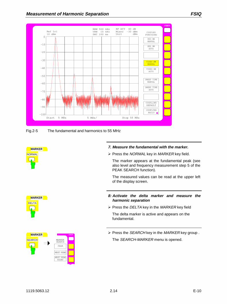
Measurement of Harmonic Separation FSIQ
1119.5063.12 2.14 E-10
USER
Ref Lvl10 dBm
RBW 500 kHzVBW 10 kHzSWT 100 ms
Stop 55 MHz
0
-20
-40
-60
-80
-1005 MHz/
-10
-30
-50
-70
-90
Start 5 MHz
RF ATT 40 dBMixer -30 dBmUnit dBm
COUPLEDFUNCTIONS
RES BWMANUAL
COUPLINGRATIO
RES BWAUTO
VIDEO BWMANUAL
VIDEO BWAUTO
SWEEP TIMEMANUAL
SWEEP TIMEAUTO
COUPLINGDEFAULT
Fig.2-5 The fundamental and harmonics to 55 MHz
MARKER
NORMAL
7. Measure the fundamental with the marker.
À Press the NORMAL key in MARKER key field.
The marker appears at the fundamental peak (seealso level and frequency measurement step 5 of thePEAK SEARCH function).
The measured values can be read at the upper leftof the display screen.
MARKER
DELTA
8: Activate the delta marker and measure theharmonic separation
À Press the DELTA key in the MARKER key field
The delta marker is active and appears on thefundamental.
MARKER
SEARCH
ON
USER
SEARCH
PEAK
NEXT PEAK
NEXT PEAKRIGHT
MARKER
À Press the SEARCH key in the MARKER key group .
The SEARCH-MARKER menu is opened.

FSIQ Measurement of Harmonic Separation
1119.5063.12 2.15 E-10
NEXT PEAKRIGHT
À Press the NEXT PEAK RIGHT softkey.
The delta marker jumps to the first harmonic andmeasures the difference between the harmonic andthe fundamental. The measured values can be readat the upper left of the display screen. In thisexample, the harmonic separation is approx. 40 dB(see Fig.2-6).
NEXT PEAKRIGHT
9. Measure the separation of additional harmonics
À Press the NEXT PEAK RIGHT softkey.
The delta marker jumps to the next highestharmonic. The measured value can be read asbefore.
USER
Ref Lvl10 dBm
RBW 500 kHzVBW 10 kHzSWT 100 ms
Delta [T1]-44.8 dB10.0000 MHz
Stop 55 MHz
0
-20
-40
-60
-80
-1005 MHz/
-10
-30
-50
-70
-90
1
Start 5 MHz
RF ATT 40 dBMixer -30 dBmUnit dBm
1
MARKERNORMAL
MARKER 2
MARKER 3
SIGNALCOUNT
MARKERDEMOD
MARKER 1
SIGNAL ID
MARKER 4
ALL MARKER OFF
MARKER INFO
MARKERZOOM
Fig.2-6 First harmonic separation: approx. 40 dB referred to the fundamental

Measurement of Harmonic Separation FSIQ
1119.5063.12 2.16 E-10
Measurement Procedure - Harmonic Separation – Example 2
In example 2, the fundamental frequency of the test signal and the separation of the individualharmonics are measured. The reference to the fundamental is established with the REFERENCEFIXED marker, and the movement from harmonic to harmonic is performed with the MKR→ CF STEPSIZE and step keys. This method is recommended when the highest dynamic range is to be achieved.
The following measurement steps are carried out:
1. Reset the instrument.
2. Set the reference level to 10 dBm.
3. Connect the rear-panel 10 MHz reference signal (connector EXT REF IN/OUT) to the analyzerinput RF INPUT.
4. Set the start frequency to 5 MHz.
5. Set the stop frequency to 55 MHz.
6. Smooth the displayed noise with the video bandwidth.
7. Measure the fundamental signal with the marker.
8. Reduce the measurement frequency range (ZOOM function):
9. Set the frequency step size to the fundamental frequency.
10. Save the reference value (REFERENCE FIXED)
11. Measure the separation to the first harmonic.
12. Measure the separations to the remaining harmonics.
Set the analyzer according to Example 1 up to andincluding "Measure the fundamental with themarker" (steps 1 to 7).
MARKER
NORMAL
ALL MARKERSOFF
MARKERINFO
MARKERZOOM
8. Reduce the measurement frequency range.
À Press the NORMAL key in the MARKER key field .
The MARKER-NORMAL menu is opened.
MARKERZOOM
SPAN
MARKER ZOOM
3.5 GHz
À Press the MARKER ZOOM softkey.
The entry field for the measurement frequencyrange appears on the display screen.

FSIQ Measurement of Harmonic Separation
1119.5063.12 2.17 E-10
DATA ENTRY
µ sµV
dBm
1
0
0
SPAN
MARKER ZOOM
100 kHzkHz
ÀEnter 100 via the numeric keypad and terminate withthe kHz key.
MKR
USERMARKER
PEAK
MKR->CENTER
MKR->REF LEVEL
MARKER->
9. Set the frequency step size to the fundamentalfrequency
À Press the MKR → key in the MARKER key field
The MARKER-MKR → menu is opened.
PEAKÀ Press the PEAK softkey.
The marker appears at peak of the fundamentalsignal.
MKR CFSTEPSIZE
.
À Press the MKR → CF STEP SIZE softkey.
The step size used when setting the centerfrequency with the cursor keys is set equal to themarker frequency.
MARKER
DELTA
ALL DELTAOFF
DELTA MRKABS REL
REFERENCEFIXED
10. Fix reference value
À Press the DELTA key in the MARKER key field.
The DELTA-MARKER menu is opened.
REFERENCEFIXED
À Press the REFERENCE FIXED softkey.
The position of the marker is now a curve-independent reference for the delta measurement,even when the actual reference point is not visibleon the display screen.

Measurement of Harmonic Separation FSIQ
1119.5063.12 2.18 E-10
USER
Ref Lvl 10 dBm
RBW 2 kHzVBW 2 kHzSWT 100 ms
DELTA1 [T1 FXD]-80.8 dB48.0 kHz
Span 100 kHz
10.0
-10
-30
-50
-70
-9010 kHz/
0
-20
-40
-60
-80
1
Center 10.000002 MHz
RF ATT 40 dBMixer -30 dBmUnit dBm
FXD
FXD
DELTAMARKER
DELTA 2
DELTA 3
PHASENOISE
DELTA 1
REFERENCE FIXED
DELTA 4
ALL DELTA OFF
REFERENCE POINT
DELTA MKRABS REL
Fig. 2-7 Fundamental with REFERENCE FIXED marker
FREQUENCY
CENTER SPAN
CENTER FREQUENCY
10 MHz
11. Measure the harmonic
À Press the CENTER key in the FREQUENCY keyfield.
The entry field for the center frequency appears onthe display screen.
DATA VARIATION
SPAN
CENTER FREQUENCY
20 MHz
À Press the cursor key in the DATA VARIATIONkey field.
The center frequency is increased by one step(= fundamental frequency).
MARKER
SEARCH
ON
USER
SEARCH
PEAK
NEXT PEAK
NEXT PEAKRIGHT
MARKER
À Press the SEARCH key in the MARKER key field.
The SEARCH-MARKER menu is opened.

FSIQ Measurement of Harmonic Separation
1119.5063.12 2.19 E-10
PEAKÀ Press the PEAK softkey.
The delta marker appears at the first harmonic andmeasures the separation from harmonic tofundamental. The measured value is displayed inthe marker field at the upper left of the displayscreen (see Fig. 2-8).
12. Measure the separation of additionalharmonics
À Repeat all of step 11.
The center frequency is once again increased by thefrequency of the fundamental. The delta markerthus appears at the next harmonic.
Fig. 2-8 Measurement of the first harmonic
Note: The spurious harmonics generated internal to the analyzer can be easily recognised by switchingin additional RF attenuation. When an additional 10 dB attenuation is inserted, the displayed levelof harmonics generated by the analyzer will be reduced by 10 dB, however, harmonics from theUUT will remain unchanged. This assumes that the receiver noise is substantially below thedisplayed level.
USER
Ref Lvl 10 dBm
RBW 2 kHzVBW 2 kHzSWT 100 ms
DELTA1 [T1 FXD]-42.3 dB10.001 MHz
Span 100 kHz
10.0
-10
-30
-50
-70
-9010 kHz/
0
-20
-40
-60
-80
1
Center 20.002118 MHz
RF ATT 40 dBMixer -30 dBmUnit dBm
MARKERSEARCH
NEXT PEAK
NEXT PEAKRIGHT
NEXT PEAKLEFT
SEARCH LIMON OFF
SELECTMARKER
PEAK
ACTIVEMKR DELTA

Measurement of Harmonic Separation FSIQ
1119.5063.12 2.20 E-10
Measurement Procedure - Harmonic Separation – Example 3
The measurement of fundamental and harmonics can also be performed in two independent windowson the display screen (SPLIT-SCREEN mode). This mode permits the simultaneous presentation of thefundamental and harmonics with higher resolution and dynamic range.
The following measurement steps are carried out:
1. Reset the instrument.
2. Set the reference level to 10 dBm.
3. Connect the rear-panel 10 MHz reference signal (connector EXT REF IN/OUT) to the analyzerinput RF INPUT.
4. Set the start frequency to 5 MHz.
5. Set the stop frequency to 55 MHz.
6. Smooth the displayed noise with the video bandwidth.
7. Measure the fundamental signal with the marker.
8. Reduce the measurement frequency range (ZOOM function):
9. Set the frequency step size to the fundamental frequency.
10. Set the display to two measurement windows.
11. Uncouple the window settings.
12. Measure the harmonic separation.
Set the analyzer according to Example 2 up to andincluding " Set the frequency step size to thefundamental frequency" (steps 1 to 9).
DISPLAY
SYSTEM USER
DISPLAY
FULLSCREEN
SPLITSCREEN
10. Set the display to two uncoupledmeasurement windows.
À Press the DISPLAY key in the SYSTEM key field.
The SYSTEM DISPLAY menu is opened.
SPLITSCREEN
À Press the SPLIT SCREEN softkey.
Two windows are displayed simultaneously on thedisplay screen (see Fig.2-9). The upper measure-ment window is called Screen A and the lower iscalled Screen B. At the initial turn-on, bothmeasurement windows are coupled, i.e., changes insettings such as frequency or levels take place inboth windows.

FSIQ Measurement of Harmonic Separation
1119.5063.12 2.21 E-10
SCREENCOUPLING
SCREENUNCOUPLED
11. Uncouple the window settings
À Press the SCREEN COUPLING softkey.
The SCREEN COUPLING sub-menu is opened.
SCREENUNCOUPLED À Press the SCREEN UNCOUPLED softkey .
The settings for each measurement window cannow be selected independently. The entry isassigned to either ACTIVE SCREEN A or ACTIVESCREEN B as selected by the softkey in the mainmenu window.
USER
Ref Lvl 10 dBm
RBW 1 kHzVBW 1 kHzSWT 100 ms
MKR1 [T1]+9.8 dBm10.010000 MHz
Span 100 kHz
10.0
-10
-30
-50
-70
-90
10 kHz/
-0
-20
-40
-60
-80
Center 10.000002 MHz
RF ATT 40 dBMixer -30 dBmUnit dBm
SCREENCOUPLING
MODECOUPLED
SCREENS UNCOUPLED
Ref Lvl 10 dBm
RBW 1 kHzVBW 1 kHzSWT 100 ms
RF ATT 40 dBMixer -30 dBmUnit dBm
Span 100 kHz10 kHz/ Center 10.000002 MHz
10.0
-10
-30
-50
-70
-90
-0
-20
-40
-60
-80
1
MKR1 [T2]+9.8 dBm10.010000 MHz
B
A
HORIZONTAL SCALING
VERTICAL SCALING
1
COUPLINGCONTROL
Fig.2-9 SPLIT-SCREEN Mode
MENU
ACTIVESCREEN A
ACTIVESCREEN B
12. Measure the harmonic in the lowermeasurement window SCREEN B.
À Press the menu change key .
The main menu is opened.

Measurement of Harmonic Separation FSIQ
1119.5063.12 2.22 E-10
ACTIVESCREEN B À Press the ACTIVE SCREEN B softkey.
The following entries are now valid for the lowerwindow which is used to measure the harmonicseparation.
FREQUENCY
CENTER SPAN
CENTER FREQUENCY
10 MHz
À Press the CENTER key in the FREQUENCY keyfield.
The entry field for the center frequency appears onthe display screen.
DATA VARIATION
SPAN
CENTER FREQUENCY
20 MHz
À Press the cursor key in the DATA VARIATIONkey field.
The center frequency is increased by one step.(= fundamental frequency).
MARKER
SEARCH
ON
USER
SEARCH
PEAK
NEXT PEAK
NEXT PEAKRIGHT
MARKER
À Press the SEARCH key in the MARKER key field.
The SEARCH-MARKER menu is opened.
PEAKÀ Press the PEAK softkey.
A marker appears at the first harmonic and meas-ures the level of the harmonic. The measured valueis displayed in the marker field at the upper left ofthe second measurement window (see Fig.2-10).

FSIQ Measurement of Harmonic Separation
1119.5063.12 2.23 E-10
USER
Ref Lvl 10 dBm
RBW 1 kHzVBW 1 kHzSWT 100 ms
MKR1 [T1]+9.8 dBm10.010000 MHz
Span 100 kHz
10.0
-10
-30
-50
-70
-90
10 kHz/
-0
-20
-40
-60
-80
Center 20.000004 MHz
RF ATT 40 dBMixer -30 dBmUnit dBm
Ref Lvl 10 dBm
RBW 1 kHzVBW 1 kHzSWT 100 ms
RF ATT 40 dBMixer -30 dBmUnit dBm
Span 100 kHz10 kHz/ Center 10.000002 MHz
10.0
-10
-30
-50
-70
-90
-0
-20
-40
-60
-80
1
DELTA [T2]-36.8 dBm10.000010 MHz
A
B
1
MARKERSEARCH
NEXT PEAK
NEXT PEAKRIGHT
NEXT PEAKLEFT
SEARCH LIMON OFF
SELECTMARKER
PEAK
ACTIVEMKR DELTA
Fig.2-10 Alternate representation of fundamental and first harmonic

Intermodulation Distortions FSIQ
1119.5063.12 2.24 E-10
Measurement of Intermodulation Distortions
Measuring Task
If several signals are applied to a transmission quadripole with a non-linear characteristic,intermodulation products occur at its output due to addition and subtraction of the signals. The non-linear characteristic causes harmonics of the information signals to occur, which are mixed up at thecharacteristic. The low-order mixture products are particularly significant since they have the highestlevels and are close to the information signals. The third-order intermodulation product causes the mostsignificant distortions. In case of two-tone modulation it is the mixture product of the first informationsignal and the first harmonic of the second information signal.The frequencies of the spurious signals occur with an offset of the information signals above and belowthe information signals. Fig. 2-11 shows the intermodulation products PS1 and PS2, which are obtainedfrom the two information signals PN1 and PN2.
fN1
fN2
fS2
fS1
f∆ f∆f∆
ad3
PN1
PN2
PS1 PS2
Frequency
Level
Fig. 2-11 Intermodulation products PS1 and PS2
The intermodulation product at fS2 is obtained by mixture of the first harmonic of the information signalPN2 with the signal PN1, the intermodulation product at fS1 by mixture of the first harmonic of theinformation signal PN1 with the signal PN2 .
fs1 = 2 x fn1 - fn2 (1)
fs2 = 2 x fn2 - fn1 (2)
The level of the spurious products depends on the level of the information signals. If both informationsignals are increased by 1 dB, the level of the spurious responses increases by 3 dB. I.e., the offset ad3of the spurious responses decreases by 2 dB. This is illustrated by Fig.2-12.

FSIQ Intermodulation Distortions
1119.5063.12 2.25 E-10
Outputlevel
Intercept point
IntermodulationproductInformation
signal
Input level
Compression
11 1
3
Fig.2-12 Dependance of the spurious product level from the level of the information signals
The information signals at the output of a four-terminal network increase as the input level increases aslong as the input level is in the linear range. If the level changes by 1 dB at the input, it also changes by1 dB at the output. At a specified input level the quadripole compresses and the output level does notincrease any more. The third-order intermodulation products increase three times as fast as theinformation signals. The intercept point is the fictitious level where both lines intersect. It cannot bemeasured directly since the wanted level is limited by the maximum output power of the quadripole.It can however be calculated from the known gradients of the lines and the measured intermodulationoffset aD3 with a given level using the following formula:
IPa
PDN3
23= + (3)
If, e.g., the intermodulation offset is 60 dB and the input level PN is -20 dBm, the third-order intercept IP3is calculated as follows:
IP dBm dBm3602
20 10= + − =( ) . (4)
Important Spectrum-Analyzer Functions
Correct setting of the RF attenuation is particularly important for intermodulation measurements. In theFSIQ, the attenuation can be set automatically according to the reference level. There are threecoupling methods:
– RF ATTEN AUTO
– ATTEN AUTO LOW DIST
– ATTEN AUTO LOW NOISE
The coupling mode ATTEN AUTO LOW DIST is recommended to be used for measurement ofintermodulation distortions since the intrinsic spurious products are minimized.

Intermodulation Distortions FSIQ
1119.5063.12 2.26 E-10
Measurement
In the following, measurement of the third-order intercept of an amplifier is described, by way ofexample.
Two signal generators with the frequencies f1 and f2 supply signals to the amplifier via a power divider.The output of the device under test is connected to the RF input of the FSIQ. The level of the two signalgenerators is the same and is selected such that the DUT is not overloaded.
f1 = 99.5 MHz
f2 = 100.5 MHz
Level at amplifier input = -20 dBm with f1 and f21
Test setup:
AnalyzerPower-splitter
DUT
f1
f2 10-dBamplifier
The following measurement steps are carried out:
1. Reset the FSIQ.
2. Set the center frequency to 100 MHz.
3. Set the frequency-display range to 5 MHz (SPAN function).
4. Set the reference level to -10 dBm.
5. Set the resolution bandwidth to 10 kHz.
6. Set the RF attenuation for low-distortion mode.
7. Measure the intercept point using the markers.
8. Calculate IP3 from the measured offset and the signal level according to (4)

FSIQ Intermodulation Distortions
1119.5063.12 2.27 E-10
Cf. measurement example Level and FrequencyMeasurements (steps 1 to 3)
1. Reset the instrument.
2. Set the center frequency to 100 MHz.
3. Set the frequency-display range to 5 MHz.
LEVEL
REF
REFERENCE LEVEL-20 dBm
4. Set the reference level to -10 dBm
À Press the REF key in the LEVEL key field.
The entry window for the reference level isdisplayed.
DATA ENTRY
1
0
dBmmVms
-10 dBm
REFERENCE LEVEL
-
MHz
À Enter -10 via the numeric keypad in the entry fieldand terminate the entry by pressing the dBm key.
SWEEP
COUPLING
US ER
COUPLEDFUNCTIONS
RES BWMANUAL
RES BWAUTO
5. Set the resolution bandwidth to 10 kHz
À Press the COUPLING key in the SWEEP key field.
The SWEEP-COUPLING menu is opened.
RES BWMANUAL
RESOLUTION BANDWIDTH
3 MHz
À Press the RES BW MANUAL softkey.
The entry field for the resolution bandwidth isdisplayed.

Intermodulation Distortions FSIQ
1119.5063.12 2.28 E-10
DATA ENTRY
1
0
RESOLUTION BANDWIDTH dBµVµs
10 kHz kHz
À Enter 10 in the entry field via the numeric keypadand terminate the entry by pressing the kHz key.
USER
INPUT
RF ATTENMANUAL
ATTEN AUTONORMAL
ATTEN AUTOLOW NOISE
INPUT
ATTEN AUTOLOW DIST
6. Set low-distortion mode
À Press the INPUT key
The INPUT menu is opened.
ATTEN AUTOLOW DIST
either
À Press the ATTEN AUTO LOW DIST softkey.
The low-distortion mode is selected. Thus, thecombination of input attenuation and IF gain isselected such that the internal intermodulationproducts are the smallest possible and theintermodulation-free range is as large as possible.
The FSIQ shows the measuring diagram in Fig.2-13
RF ATTENMANUAL
10 dB
INPUT ATTENUATIONor
À Press the RF ATTEN MANUAL softkey.
The entry window for the RF attenuation isdisplayed.
DATA VARIATION À Vary the RF attenuation using the roll-key.
If the amplitude of the IM products doesn’t change,the existing setting is sufficient(see Fig.2-13)
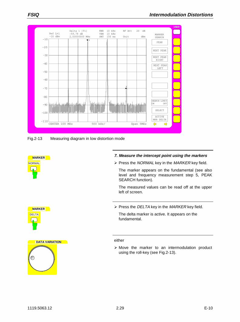
FSIQ Intermodulation Distortions
1119.5063.12 2.29 E-10
USER
-10
-40
-60
-80
-100
-20
-30
-50
-70
-90
CENTER 100 MHz 500 kHz/ Span 5MHz
MARKERSEARCH
PEAK
S D
NEXT PEAK
NEXT PEAKRIGHT
NEXT PEAKLEFT
SELECT
ACTIVEMKR DELTA
Ref Lvl-10 dBm
Delta 1 [T1] RWB 10 kHz RF Att 20 dB-59.78 dB VBW 10 kHz2.00000000 MHz SWT 150 ms Unit dBm
-110
1
1
SEARCH LIMITON OFF
Fig.2-13 Measuring diagram in low distortion mode
MARKER
NORMAL
7. Measure the intercept point using the markers
À Press the NORMAL key in the MARKER key field.
The marker appears on the fundamental (see alsolevel and frequency measurement step 5, PEAKSEARCH function).
The measured values can be read off at the upperleft of screen.
MARKER
DELTA
À Press the DELTA key in the MARKER key field.
The delta marker is active. It appears on thefundamental.
DATA VARIATION either
À Move the marker to an intermodulation productusing the roll-key (see Fig.2-13).

Intermodulation Distortions FSIQ
1119.5063.12 2.30 E-10
MARKER
SEARCH
ON
USER
SEARCH
PEAK
NEXT PEAK
NEXT PEAKRIGHT
MARKER
or
À Press the SEARCH key of the MARKER keys.
The SEARCH-MARKER menu is opened.
NEXT PEAKÀ Press the NEXT PEAK RIGHT softkey until the delta
marker appears on one of the IM products (seeFig.2-13).
8. Calculate IP3 from the measured offset and thesignal level according to (4)
In the example, an intermodulation ratio of approx.60 dB at a level of -10 dBm was measured. IP3 isthus:
IP3 = 60 dB/2 + (-10dBm) = 20 dBm

FSIQ Time-domain Measurements with Pulsed Signals
1119.5063.12 2.31 E-10
Time-domain Measurements with Pulsed Signals
Measuring Task
A lot of systems which handle pulsed signals do not only require measurement of the pulse width andthe pulse repetition rate which can be derived from the spectrum but also assess the rise and fall timeas well as the power ramping during the pulse. In particular, modern digital mobile radio systems which,like GSM e.g., employ the TDMA method, require the power to be measured versus time over a widedynamic range.
Time-domain measurements are performed using the spectrum analyzer with ZERO SPAN selected.The analyzer operates as fix-tuned receiver on the set center frequency such that the signal powerversus time is displayed.
Important Spectrum Analyzer Functions
Trigger functions such as video trigger and sweep settings such as blanking of the measured value(GAP SWEEP) are of particular importance for time-domain measurements. The pretrigger function ofthe GAP SWEEP just enables measurement of rise times since it allows for representation ofmeasurements prior to the trigger point. The GAP function, which enables cutout of a part of the pulseallows for simultanous representation of both edges of a pulse signal on the screen at high timeresolution. During the GAP time, the sweep and thus data acquisition at the time marked by the "GAP"line is interrupted and thus the pulse is not completely displayed (the part which is not important for thismeasurement is blanked) (see Fig. 2-14).
trigger
time
time gap
time
(not displayed)displayed displayed
pre-trigger trigger to gap
time
Fig. 2-14 Parameters of Gap Sweep
Note: If the pretrigger time and the trg-to-gap time is 0 s, the gap time function has the same effect asa delayed trigger.

Timedomain Measurements with Pulsed Signals FSIQ
1119.5063.12 2.32 E-10
Measurement
This example shows the measurement of the rise and fall times as well as the power ramping during thepulse.
The signal generator SME with built-in pulse modulation source SME-B4 is used as signal source. Asignal generator providing for pulse modulation in conjunction with an external pulse generator may beused, instead.Settings on the signal generator:
Frequency 900 MHzLevel –5 dBmModulation PulsePulse width ca. 600 µsPulse frequency ca. 500 Hz
The following measuring steps are made:
1. Reset the instrument.The video bandwidth is thus set to 3 MHz.
2. Set the center frequency to 900 MHz.
3. Set the frequency display range to zero span.
4. Set the reference level to 0 dBm.
5. Set the resolution bandwidth to 2 MHz.
6. Set the sweep time to 1 ms.
7. Connect the RF output of the SME to the RF input of the FSIQ.
8. Set the video trigger.
9. Set the sweep time to 100 µs.
10. Set the trigger points.
11. Activate the gap sweep.
comp. measuring example - level and frequencymeasurement (steps 1 to 3)
1. Set the instrument to the default state. I.e., thevideo bandwidth is set to 3 MHz.
2. Set the center frequency to 900 MHz.
3. Set the frequency-display range to zero span.
Note: With first calling of the zero span followingpreset, a resolution bandwidth of 1 MHz isautomatically set. Apart from that, switching onthe zero span always causes that resolutionbandwidth to be set that was last set in zerospan.

FSIQ Time-domain Measurements with Pulsed Signals
1119.5063.12 2.33 E-10
LEVEL
REF
REFERENCE LEVEL-20 dBm
4. Set the reference level to 0 dBm.
À Press the REF key in the LEVEL key field.
The entry field for the reference level appears on thedisplay screen.
DATA ENTRY
dBmmVms
0
REFERENCE LEVEL
0 dBmMHz
À Enter 0 in the entry field via the numeric keypad andterminate the entry by pressing the MHz/ms key.
SWEEP
COUPLING
SWEEP TIMEAUTO
COUPLEDFUNCTION
USER
RES BWAUTO
RES BWMANUAL
SWEEP TIMEMANUAL
5. Set the resolution bandwidth to 2 MHz
À Press the COUPLING key in the SWEEP key field.
The SWEEP-COUPLING menu is opened.
RES BWMANUAL
RESOLUTION BANDWIDTH
1 MHz
À Press the RES BW MANUAL soft key.
The entry field for the resolution bandwidth appearson the display screen.
DATA ENTRY
2
RESOLUTION BANDWIDTH
2 MHz
dBmmVms
MHz
À Enter 2 via the numeric key pad and terminate theentry by pressing the MHz key.
SWEEP TIMEMANUAL
SWEEP TIME
5 ms
6. Set the sweep time to 1 ms
À Press the SWEEP TIME MANUAL softkey.
The entry field for the sweep time is opened.

Timedomain Measurements with Pulsed Signals FSIQ
1119.5063.12 2.34 E-10
DATA ENTRY
1
SWEEP TIME
1 ms
dBmmVms
MHz
À Enter 1 in the entry field via the numeric keypad andterminate the entry by pressing the MHz key.
7. Connect the RF output of the SME to the RFinput of the FSIQ.
SWEEP
TRIGGER
ON
USER
FREE RUN
VIDEO
LINE
TRIGGER
8. Initiate triggering by means of the displayvoltage (video trigger)
À Press the TRIGGER key in the SWEEP key field
The TRIGGER menu is opened.
VIDEOÀ Press the VIDEO softkey.
A dashed horizontal line is displayed which marksthe trigger level.
DATA VARIATION À Set the trigger level using the roll key such that atriggered display is obtained.(see Fig. 2-15)
SWEEP TIMEMANUAL
SWEEP TIME
5 ms
9. Set the sweep time to 100 µs
À Press the SWEEP TIME MANUAL softkey.
The window for entering the sweep time is opened.
DATA ENTRY
1
SWEEP TIME
100 µs
0
0
dBµVµs
kHz
À Enter 100 via the numeric keypad and terminate theentry by pressing the kHz/µs key.

FSIQ Time-domain Measurements with Pulsed Signals
1119.5063.12 2.35 E-10
USER
0
-40
-60
-80
-100
-10
-30
-50
-70
-90
START 0 s 100 µs/ Stop 1 ms
TRIGGER
FREE RUN
SIGNAL ID
VIDEO
LINE
EXTERN
TRIGGERDELAY
SLOPEPOS NEG
Ref Lvl0 dBm
RWB 1 MHz RF Att 10 dB VBW 1 MHz Mixer -20 dBm SWT 1 ms Unit dBm
RF POWER
-20
Fig. 2-15 Representation of pulse sequence with video trigger
SWEEP
SWEEP
GAP SWEEPSETTINGS
GAP SWEEPON OFF
SWEEPCOUNT
10. Set the trigger points.
À Press the SWEEP key in the SWEEP keyfield.
The SWEEP menu is opened.
USER
GAP SWEEPSETTINGS
TRIGGERLEVEL
GAP SWEEPSETTINGS
PRETRIGGER
TRG TO GAPTIME
GAPLENGTH
À Press the GAP SWEEP SETTINGS softkey.
The GAP SWEEP SETTINGS submenu for settingthe trigger points is opened.
PRETRIGGER
GAP PRETRIGGER
0 msÀ Press the PRE TRIGGER softkey.
The entry field for the pretrigger is opened.

Timedomain Measurements with Pulsed Signals FSIQ
1119.5063.12 2.36 E-10
DATA ENTRY
1
GAP PRETRIGGER
10 µs
0
dBµVµs
kHz
À Enter 10 via the numeric keypad in the entry fieldand terminate the entry by pressing the kHz/µs key.
TRG TO GAPTIME
TRG TO GAP
0 ms
À Press the TRG TO GAP softkey.
The entry field for the trigger-to-gap-time is opened.
DATA ENTRY
4
TRG TO GAP
40 µs
0
dBµVµs
kHz
À Enter 40 via the numeric keypad in the entry fieldand terminate the entry by pressing the kHz/µs key.
GAPLENGTH
GAP LENGTH
0 ms
À Press the GAP LENGTH softkey.
The entry field for the length of the time gap isopened.
DATA ENTRY
5
GAP LENGTH
540 µs
4
0
dBµVµs
kHz
À Enter 540 in the entry field via the numeric keypadand terminate the entry by pressing the kHz/µs key.

FSIQ Time-domain Measurements with Pulsed Signals
1119.5063.12 2.37 E-10
MENU
GAP SWEEPSETTINGS
GAP SWEEPON OFF
11. Activate the measurement with mask-out ofmeasured value
À Press the menu change key.
The right supplementary menu is opened.
GAP SWEEPON OFF À Press the GAP SWEEP ON/OFF key.
The measurement with blanking of measured valueis activated. The measurement results are shown inFig. 2-16
USER
0
-40
-60
-80
-100
-10
-30
-50
-70
-90
0 s 10 µs/ 50 µs 590 µs 10 µs 640 µs
SWEEP
CONTINOUSSWEEP
SINGLESWEEP
SWEEP TIMEAUTO
SWEEPCOUNT
GAP SWEEPSETTINGS
SGL SWEEPDISP OFF
Ref Lvl0 dBm
RWB 1 MHz RF Att 10 dB VBW 1 MHz Mixer -20 dBm SWT 100 µs Unit dBm
GAP SWEEPON OFF
-20
EXT GATEON OFF
EXT GATESETTINGS
SWEEP TIMEMANUAL
Fig. 2-16 Measured-value blanking for simultaneous display of rising and falling edge of a pulsesignal. The position of the gap is indicated by the thick vertical line. The gap time isindicated via the double label 50 µs and 590 µs in the time axis.


FSIQ Contents - Manual Operation
1119.5063.12 I-3.1 E-1
Contents - Chapter 3 "Manual Operation"
3 Manual Operation
The Screen........................................................................................................................................ 3.2Diagram Area .......................................................................................................................... 3.3
Full Screen............................................................................................................................... 3.9
Split Screen ............................................................................................................................. 3.9
Softkey Area .......................................................................................................................... 3.10
Changing the Menu ............................................................................................................... 3.11
Setting the Parameters.................................................................................................................. 3.13Data Entry.............................................................................................................................. 3.13
Numeric Keypad on the Front Panel ........................................................................... 3.13Roll-key and Cursor Keys............................................................................................ 3.14
Entry Windows....................................................................................................................... 3.15Setting Up the Entry Window ...................................................................................... 3.15Editing of Numeric Parameters ................................................................................... 3.16Editing of Alphanumeric Parameters........................................................................... 3.17Help Line Editor ........................................................................................................... 3.17
Table Entry ............................................................................................................................ 3.18Shifting Mode............................................................................................................... 3.18Editing Mode................................................................................................................ 3.19
Disabling the Control Elements - HOLD Key .............................................................................. 3.20
Setting the Stepsize - STEP Key................................................................................................... 3.21
Mouse and External Keyboard Control ....................................................................................... 3.22External Keyboard Control..................................................................................................... 3.22
Data Entry Windows with Mouse Control .............................................................................. 3.23
Mouse Control of Further Display Elements.......................................................................... 3.24
Menu Overview .............................................................................................................................. 3.25System Key Group................................................................................................................. 3.25
Configuration Key Group ....................................................................................................... 3.27
Hardcopy Key Group ............................................................................................................. 3.33
Frequency Key Group............................................................................................................ 3.34
Level Key Group, Input Key.................................................................................................. 3.36
Marker Key Group ................................................................................................................. 3.38
Lines Key Group .................................................................................................................... 3.42
Trace Key Group ................................................................................................................... 3.43
Sweep Key Group.................................................................................................................. 3.44
Memory Key Group................................................................................................................ 3.47
User Key Group ..................................................................................................................... 3.49

Contents - Manual Operation FSIQ
1119.5063.12 I-3.2 E-1

FSIQ Manual Operation
1119.5063.12 3.1 E-12
3 Manual Operation
Chapter 3 provides an overview of the operating concept and the basic steps of manual operation of theFSIQ. This includes a description of the screen, of the control of menus and of the setting ofparameters. An overview of the menus will be listed at the end of this chapter.
The functions of the menus are described in dtail in Chapter 4. Chapter 2 contains a short introductionon step-by-step simple measurements. The remote control of the instrument is described in Chapters 5,6 and 7
The operation of the signal analyzer is menu-controlled via keys and softkeys. The setting of theinstrument and test parameters in the menus is made either directly via softkeys or by entry of values inentry fields and by selection in tables. The operating mode and the screen mode is selected via thesoftkeys.If required, data entry windows and tables are superimposed on the screen.
After switching on the instrument a message about the BIOS version installed is displayed for a fewseconds (e.g. "Analyzer BIOS Rev. 1.2").
The results of the self test is displayed next.
MAINPROCESSORSELFTEST STARTING ...TESTING CMOS ...DMA CHANNEL ...INTERRUPTS ...NMI ...BASE MEMORY ...EXTENDED MEMORY ...HD CAPACITY ...INIT FLOPPY DRIVE ...INIT HD ...
SELFTEST DONE,SYSTEM IS BOOTING ...
Subsequently, the Windows NT controller boots and the instrument then starts measuring. The type ofmeasurement which was activated prior to last switch-off is performed, as long as no other instrumentconfiguration was selected via AUTO RECALL in the MEMORY RECALL menu. While themeasurement is being performed other menus and measuring modes can be entered simultaneously.The measurement results and the settings of the parameters are displayed on the screen.

Screen FSIQ
1119.5063.12 3.2 E-12
The Screen
The screen informs continuously on the results and parameters of the selected measuring functions. Itshows the assignment of the softkeys and menus, which are required for setting the measuringparameters. The display of test results, the softkey labeling and the type of menu depend on theselected measuring function.
The screen is subdivided into two areas:
USER
Diagram area Softkey area
A
Marker 1 [T1 CNT] -36.42 dBm 100.002 MHz
Ref Lvl-20 dBm
RBW 1 MHzVBW 1 MHzSWT 5 ms
RF Att 20 dBMixer -40 dBmUnit dBm
D1
D2
F1 F2
-20
-30
-40
-50
-60
-70
-80
-90
-100
-110
Center 100.0 MHz Span 50.0 MHz
DELTAMARKER
DELTA 1
DELTA 2
DELTA 3
DELTA 4
NOISEPHASE
REFERENCEPOINT
FIXED
ALL DELTAOFF
DELTA MKRABS REL
SAMPLESNOISE MEAS
REFERENCE
5 MHz/
-120
Fig. 3-1 Subdivision of screen
Diagram area This area contains the measuring diagrams and other measured-valueinformation as well as the parameters and status information which areimportant for analysis of the results.In addition, message fields, entry windows and tables may be shown in thisarea.
Softkey area This area contains the instrument functions which can be selected via thesoftkeys. The softkey area is not superimposed by other graphics.

FSIQ Screen
1119.5063.12 3.3 E-12
Diagram Area
ER
Entry window
Message field
Table
Level scalelabelling
Frequency scale or time scalelabelling
Hardware settingsStatus
0
Instrument settings(enhancementlabels)
0
UNCAL OVLD
LVLFRQ
1-R2-R3-R4-RGATTRG
75ΩMAC
*A
R
S
-10.0
-20.0
-30.0
-40.0
-60.0
-50.0
-70.0
-80.0
-90.0
-100.0
Reference-/max level
Marker /deltamarker
Span 50.0 MHzCenter 100.0 MHz
Grid
Logo
MOUSE
InterfaceOwner
PS/2Instrument
WARNING
Hardcopy not completed.Stop printer?
YES NO
START FREQUENCY
1.000000 MHz
Marker 1 [T1 CNT] -36.42 dBm 100.002 MHz
Ref Lvl-20 dBm
RBW 1 MHzVBW 1 MHzSWT 5 ms
RF Att 20 dBMixer -40 dBmUnit dBm
Fig. 3-2 Subdivision of the FSIQ screen in analyzer mode (without measuring diagram)
D2
F1 F2
L1 L3L2
Marker
Deltamarker
Trace
Display lines(level lines)
2
3
D1
Display line(frequency line)
Display line(frequency line)
Limit lines
Fig. 3-3 Measuring diagram

Screen FSIQ
1119.5063.12 3.4 E-12
The following graphic elements are displayed in the diagram area:
Status information Hint at irregularity (e.g. UNCAL)
In addition the status display displays MAX / REF LVL, if the maximumlevel and the reference level have different values .
UNCAL "UNCAL" is indicated under the following circumstances:• no valid calibration data (Status CALIBRATION FAILED in
table CAL RESULTS), may occur after a cold startfollowing a firmware update⇒ Total calibration
• correction data are switched off (menu CAL, CAL CORROFF).⇒ switch on CAL CORR ON or PRESET
• Sweep time too short for current instrument settings(span, resolution bandwidth, video band width).⇒ increase sweep time
• resolution bandwidth too small for set symbol rate (VectorAnaylsis: digital demodulation) .⇒ increase resolution bandwidth
OVLD „Overload“ is indicated when the input mixer is overloaded⇒ Increase input attenuation
IFOVLD „IF Overload“ is indicated when overload occurs after theinput mixer.⇒ Increase reference level
DIFOVL „Digital IF Overload“ is indicated when the digital resolutionfilter is overloaded.⇒ Increase reference level
ExtRef „External Reference“ is indicated when the instrument is setto REFERENCE EXT (menu SETUP), but the referencesignal is missing at the rear panel connector.⇒ Ceck input signal of external reference
LO unl „LO unlock“ is indicated when the 1st LO is unlocked(moduleerror).
LO Lvl „LO Level“ is indicated when the output level of the 1st LO istoo small (module error).
LO LvD „LO Level Digital IF“ is indicated when the output level of theoscillator of module Digital IF is too small (module error).
OCXO „OCXO cold“ is indicated when the crystal oscillator has notyet reached ist operating temperature. This indicationvanishes after a few minutes after switch on.
UNLD 'Underload' is indicated when the analyzer is not in itsoptimal dynamic range. In this case the measuring accuracyis not optimal. This indication is only output in vectoranalyzer operating mode.⇒ Decrease reference level

FSIQ Screen
1119.5063.12 3.5 E-12
Marker/Deltamarker This label displays the position of the last selected marker ordeltamarker in the x and y-directions and the marker/deltamarker index.As additional information, 2 fields in square brackets are provided whichcontain the curve which the marker is assigned to and the activemeasuring function of the marker indicated. The measuring function ofthe markers in the second field is indicated by the followingabbreviations:
CNT frequency counter active
TRK signal track active
NOI noise measurement active
The marker text has the same color as the trace which the marker isassigned to. If, for example, the active marker is assigned to trace 1,and trace 1 is yellow, the marker text will be yellow, too.
Hardware settings
Analyzer modeRBW
VBW
SWT
RF Att
Mixer
Unit
Tracking generator mode
TG Lvl
Indication of the set resolution bandwidth.
Indication of the set video bandwidth.
Indication of the set sweep time.
Indication of the set RF attenuation.
Indication of the user set level at the input mixer (only when level differsfrom standard settings) ( = level of the reference level REF LVL).
Indication of the level unit of the measuring results and the associatedsetting and test parameters in full length. This label is particularlyimportant for selection of units with more than 4 digits, since they canonly be indicated as dB* in the other labels (except for marker).
Only available with one of the options FSE-B8/9/10/11
Indication of the set output level of the tracking generator
Vector Analyzer mode
CF
SR
Demod
Standard
Indication of the set center frequency
Indication of the symbol rate
Indication of the switched on demodulator.
Indication of the set standard (e.g. GSM)
Grid X-axis: frequency or time,Y-axis: level

Screen FSIQ
1119.5063.12 3.6 E-12
Instrument settings(Enhancement Labels)
Indication of user instrument settings which influence the measuringresult and which are not immediately obvious when viewing themeasured values.
* The current instrument setting does not correspond to the one whichapplied when one of the displayed curves had been stored. Thisoccurs under the following circumstances:
• The instrument setting is modified while a sweep is being performed.
• The instrument setting is modified in SINGLE SWEEP modesubsequent to the end of the sweep and no new sweep is started.
• The instrument setting is modified after setting the trace to VIEW.
The display is retained until the cause is eliminated by the user. I.e.,either a new sweep is started (SINGLE SWEEP mode), or the trace ofinterest is switched to BLANK (all cases).
A Identification for screen A. Screen A is activated for the entry of testparameters.
B Identification for screen B. Screen B is activated for the entry of testparameters.
C
D
If, in the Vector Analyzer mode, the inphase and quadrature signal isdisplayed in the measurement window A, the window is subdivided intotwo diagrams. The upper diagram is marked with an A and the bottomone with C.
If, in the Vector Analyzer mode, the inphase and quadrature signal isdisplayed in the measurement window B, the window is subdivided intotwo diagrams. The upper diagram is marked with an B and the bottomone with D.
LN The automatic setting of the input attenuation is set to ATTEN LOWNOISE .
LD The automatic setting of the input attenuation is set to ATTEN LOWDISTORTION.
NOR Normalization is activated; high accuracy (only with one of the options FSE-B8/9/10/11).
APP Normalization is activated; medium accuracy (only with one of the optionsFSE-B8/9/10/11).
TDF A antenna correction factor (TRANSDUCER FACTOR) is switched on.
TDS A set of antenna correction factors (TRANSDUCER SETS) is switchedon.
LVL A level offset ≠ 0 dB has been set. A level offset of the installed trackinggenerator (option) leads to the same display.
FRQ A frequency offset ≠ 0 Hz has been set.
SGL The sweep is set to SINGLE SWEEP.

FSIQ Screen
1119.5063.12 3.7 E-12
1-<n> Subtraction Trace 1 - Trace <n> active (<n>: numeric value) orsubtraction Trace 1 - Reference Line active (<n>: R)
2-<n> Subtraction Trace 2 - Trace <n> active (<n>: numeric value) orsubtraction Trace 1 - Reference Line active (<n>: R)
3-<n> Subtraction Trace 3 - Trace <n> active (<n>: numeric value) orsubtraction Trace 1 - Reference Line active (<n>: R)
4-<n> Subtraction Trace 4 - Trace <n> active (<n>: numeric value) orsubtraction Trace 1 - Reference Line active (<n>: R)
<n>AP For trace <n> (n = 1 to 4) the detector is set to AUTOPEAK.
<n>MA For trace <n> (n = 1 to 4) the detector is set to MAX PEAK.
<n>MI For trace <n> (n = 1 to 4) the detector is set to MIN PEAK.
<n>SA For trace <n> (n = 1 to 4) the detector is set to SAMPLE.
<n>AV For trace <n> (n = 1 to 4) the detector is set to AVERAGE.
<n>RM For trace <n> (n = 1 to 4) the detector is set to RMS.
GAT The frequency sweep is controlled via the EXT TRIG/GATE input ofthe instrument.
TRG The instrument is not triggered in FREE RUN mode.
EXT The unit is configured for operation with external reference
75 Ω The input impedance of the unit is set to 75 Ω.
MAC Macro recording active.
PRN A printer output is active. PRN overwrites the enhancement labelMAC.
<n>VIEW Trace <n> (n = 1 to 4) is set to VIEW
<n>AVG
MIX
SID
AID
Trace <n> (n = 1 to 4) is set AVERAGE
The external mixer output is switched on (option FSE-B21).
External mixer output: SIGNAL ID is switched on (option FSE-B21).
External mixer output: AUTO ID is switched on (option FSE-B21).
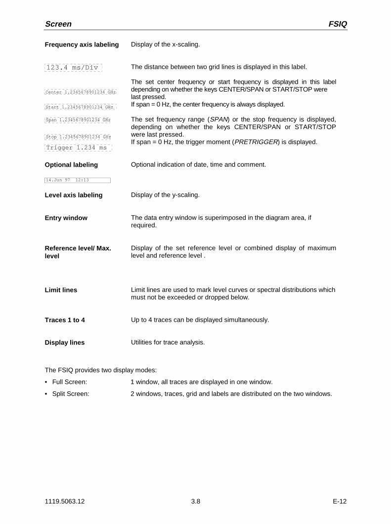
Screen FSIQ
1119.5063.12 3.8 E-12
Frequency axis labeling
123.4 ms/Div
Center 1.2345678901234 GHz
Start 1.2345678901234 GHz
Display of the x-scaling.
The distance between two grid lines is displayed in this label.
The set center frequency or start frequency is displayed in this labeldepending on whether the keys CENTER/SPAN or START/STOP werelast pressed.If span = 0 Hz, the center frequency is always displayed.
Span 1.2345678901234 GHz
Stop 1.2345678901234 GHz
Trigger 1.234 ms
The set frequency range (SPAN) or the stop frequency is displayed,depending on whether the keys CENTER/SPAN or START/STOPwere last pressed.If span = 0 Hz, the trigger moment (PRETRIGGER) is displayed.
Optional labeling
14.Jun 97 12:13
Optional indication of date, time and comment.
Level axis labeling Display of the y-scaling.
Entry window The data entry window is superimposed in the diagram area, ifrequired.
Reference level/ Max.level
Display of the set reference level or combined display of maximumlevel and reference level .
Limit lines Limit lines are used to mark level curves or spectral distributions whichmust not be exceeded or dropped below.
Traces 1 to 4 Up to 4 traces can be displayed simultaneously.
Display lines Utilities for trace analysis.
The FSIQ provides two display modes:
• Full Screen: 1 window, all traces are displayed in one window.
• Split Screen: 2 windows, traces, grid and labels are distributed on the two windows.

FSIQ Screen
1119.5063.12 3.9 E-12
Full Screen
In the full-screen mode, the settings and measurements are performed in the active visible window. Allindications on the screen refer to this window. The designation (SCREEN A or SCREEN B) is insertedas enhancement label A or B on the right diagram margin.Switching between the windows is by means of DISPLAY key. The current measurement is terminatedwhen its window is blanked out.Switching from split-screen to full-screen mode is performed in menu SYSTEM DISPLAY.
Split Screen
In Split Screen mode, the screen is divided into two halves.
USER
SOFTKEY 1
SOFTKEY 2
SOFTKEY 3
SOFTKEY 4
SOFTKEY 5
SOFTKEY 6
SOFTKEY 7
SOFTKEY 8
SOFTKEY 9
SOFTKEY 10
A
Center 100.0 MHz 5 MHz/ Span 50.0 MHz
Center 100.0 MHz 5 MHz/ Span 50.0 MHz
Marker 1 [T1 CNT] -36.42 dBm 100.002 MHz
Ref Lvl-20 dBm
RBW 1 MHzVBW 1 MHzSWT 5 ms
RF Att 20 dBMixer -40 dBmUnit dBm
Marker 1 [T1 CNT] -36.42 dBm 100.002 MHz
Ref Lvl-20 dBm
RBW 1 MHzVBW 1 MHzSWT 5 ms
RF Att 20 dBMixer -40 dBmUnit dBm
-20.0
-40.0
-60.0
-80.0
-100.0
-120.0
-20.0
-40.0
-60.0
-80.0
-100.0
-120.0
Fig. 3-4 Subdivision of the screen in Split Screen mode
The upper half is assigned Screen A, the lower one Screen B. The settings for measurement can beselected independently for both screens. E.g., a spectrum may be displayed in Screen A and a timeamplitude in the time range is displayed in Screen B. The window for entry of the measuring parametersor the marker operation is selected using the DISPLAY key.The indications which are valid only for one window appear in the margin of the associated diagram.Indications which are valid for the two windows are displayed between the diagrams.The assignment of traces to the windows is fixed and cannot be modified.
Table 3-1 Assignment of traces to windows with split screen in the signal or vector analyzer mode
Trace 1: upper (screen A) Trace 3: upper (screen A)
Trace 2: lower (screen B) Trace 4: lower (screen B)
The two windows can be subdivided into two measurement diagrams. This applies to separate displayof measurement values, eg to the display of the inphase and quadrature signal in vector analysis.Screen A is divided into diagrams A and C, screen B is divided in diagrams B and D.
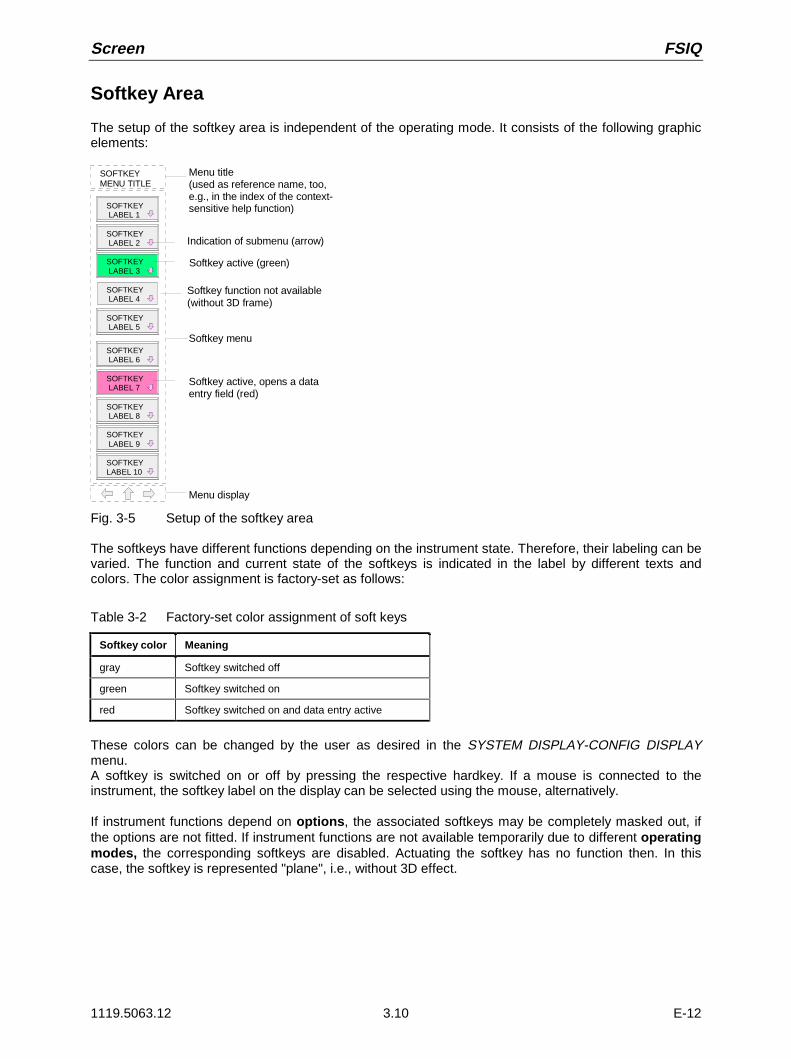
Screen FSIQ
1119.5063.12 3.10 E-12
Softkey Area
The setup of the softkey area is independent of the operating mode. It consists of the following graphicelements:
SOFTKEYMENU TITLE
SOFTKEY LABEL 1
Menu title(used as reference name, too,e.g., in the index of the context-sensitive help function)
Softkey menu
Menu display
SOFTKEY LABEL 2
SOFTKEY LABEL 3
SOFTKEY LABEL 4
SOFTKEY LABEL 5
SOFTKEY LABEL 6
SOFTKEY LABEL 7
SOFTKEY LABEL 8
SOFTKEY LABEL 9
SOFTKEY LABEL 10
Softkey function not available(without 3D frame)
Indication of submenu (arrow)
Softkey active (green)
Softkey active, opens a dataentry field (red)
Fig. 3-5 Setup of the softkey area
The softkeys have different functions depending on the instrument state. Therefore, their labeling can bevaried. The function and current state of the softkeys is indicated in the label by different texts andcolors. The color assignment is factory-set as follows:
Table 3-2 Factory-set color assignment of soft keys
Softkey color Meaning
gray Softkey switched off
green Softkey switched on
red Softkey switched on and data entry active
These colors can be changed by the user as desired in the SYSTEM DISPLAY-CONFIG DISPLAYmenu.A softkey is switched on or off by pressing the respective hardkey. If a mouse is connected to theinstrument, the softkey label on the display can be selected using the mouse, alternatively.
If instrument functions depend on options, the associated softkeys may be completely masked out, ifthe options are not fitted. If instrument functions are not available temporarily due to different operatingmodes, the corresponding softkeys are disabled. Actuating the softkey has no function then. In thiscase, the softkey is represented "plane", i.e., without 3D effect.

FSIQ Screen
1119.5063.12 3.11 E-12
Changing the Menu
With manual control, the FSIQ can be operated via the front-panel keys, the external keyboard or with amouse.
Operation is menu-controlled. Various softkey menus are displayed depending on the instrumentstatus. The individual menus constitute the so-called menu tree. The top menu (the root of the menutree) is always called by means of a keystroke. The individual softkeys are then used to branch intofurther menus (submenus).
Root menu
Submenu
SCREEN
USER
Supplementarymenus
Fig. 3-6 Theory of menu selection
Each softkey menu consists of max. 30 softkeys, 10 softkeys being arranged in a main menu, 10 in aleft-hand supplementary menu and 10 in a right-hand supplementary menu. In contrast to empty mainmenus, empty supplementary menus are not displayed. Arrows at the lower edge of the softkey areaindicate whether a supplementary menu exists or not.

Screen FSIQ
1119.5063.12 3.12 E-12
Main menuLeft-hand supplementary menu
Softkey21
Softkey22
Softkey23
Softkey24
Softkey25
Softkey26
Softkey27
Softkey28
Softkey29
Softkey30
Softkey1
Softkey2
Softkey3
Softkey4
Softkey5
Softkey6
Softkey7
Softkey8
Softkey9
Softkey10
Softkey11
Softkey12
Softkey13
Softkey14
Softkey15
Softkey16
Softkey17
Softkey18
Softkey19
Softkey20
Right-hand supplementary menu
Fig. 3-7 Switching between main menu and supplementary menu
The menu arrows help to orient inside the menu tree.
Examples: This menu has a right-hand and a lefthand supplementary menu. It is theroot menu since there is no ⇑ arrow.
Only a right-hand supplementary menu or the upper menu can be accessedfrom this menu.
M E N U The MENU keys allow for selecting the main menu and the supplementarymenus. If a mouse is connected to the instrument, the menu arrows can beselected to enter the respective menus. The MENU keys have the followingfunctions:
When this key is pressed, the FSIQ enters the left-hand supplementarymenu.
This key is pressed to call the upper menu which is located in the next higherhierarchical level in the menu tree. Several menus provide for automaticchange, i.e., return to the next higher menu is caused automatically afterpressing a softkey.
The right-hand supplementary menu is selected by pressing this key.A supplementary menu cannot be selected from another supplementarymenu but only via the main menu.
SOFTKEY The labelling of all softkeys which call a submenu includes an arrow.Selection of a submenu is always effected via a softkey.
The softkeys are masked out in remote mode and during macro processing.

FSIQ Setting the Parameters
1119.5063.12 3.13 E-12
Setting the Parameters
Data Entry
Instrument parameters can be entered in an entry window or in a table via the numeric keypad on thefront panel (DATA ENTRY), an external keyboard and the roll-key.The numeric keypad DATA ENTRY is provided for entry of numeric parameters (e.g., the startfrequency). The roll-key is used for fast incrementing or decrementing of numeric parameters with adefined step size.
It is advisable to use the external keyboard for definition of alphanumeric parameters (e.g., file names)since the front panel does not allow for entry of letters.
Numeric Keypad on the Front Panel
The keys are assigned the following functions:
D AT A E N T R Y
0 9... Number keys
-
D AT A E N T R Y
Changes the sign of the mantissa or exponent of a numeric parameter. A"-" is inserted at the cursor position in case of an alphanumeric parameter.
D AT A E N T R Y
. Inserts a decimal point "." at the cursor position in the numeric string.
-dBmVs
GHz
MHz
kHz
Hz
dBmmVms
dBµVµs
dB..nVns
D AT A E N T R Y
Provide the numeric value entered with the selected unit and terminate theentry.
The unit keys are all assigned the value "1" if quantities are indicatedwithout dimensions in order to prevent faulty operations The unit keys thusadopt the function of an ENTER key. The same applies for analphanumeric entry field.
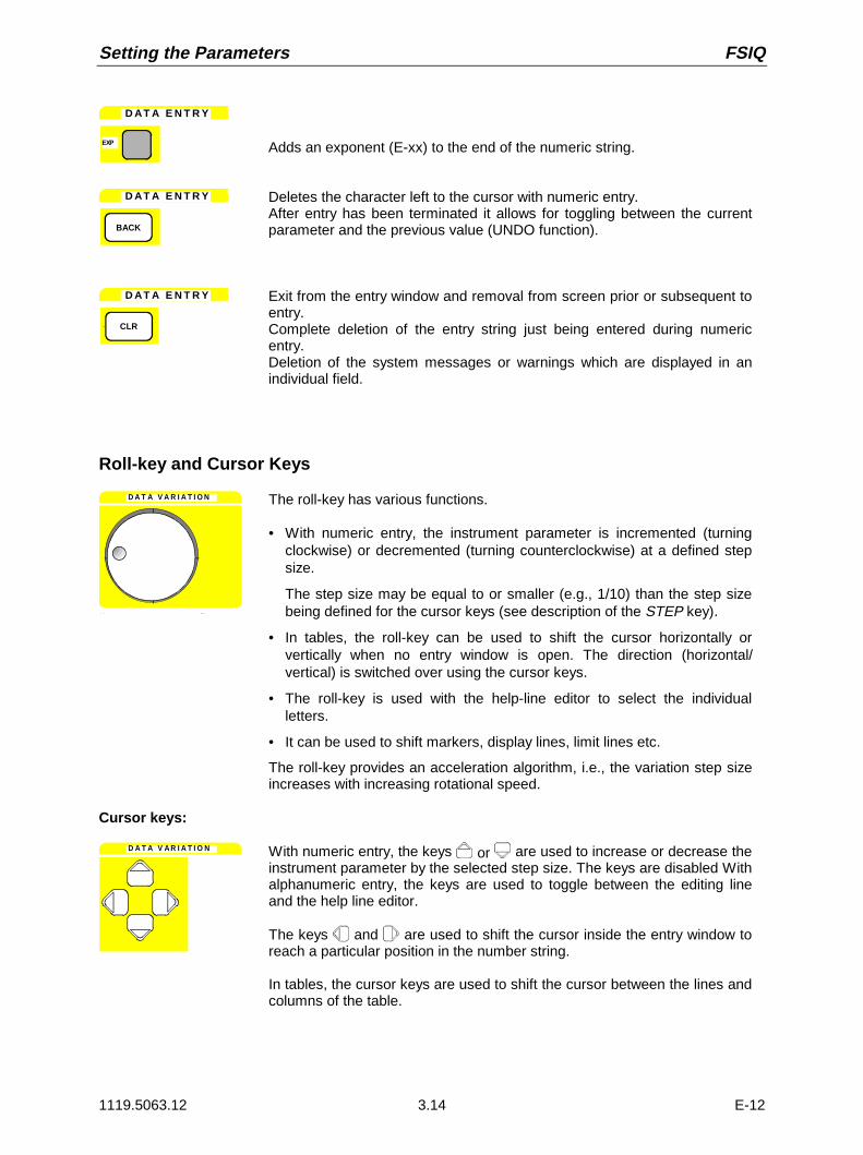
Setting the Parameters FSIQ
1119.5063.12 3.14 E-12
D AT A E N T R Y
EXP Adds an exponent (E-xx) to the end of the numeric string.
D AT A E N T R Y
BACK
Deletes the character left to the cursor with numeric entry.After entry has been terminated it allows for toggling between the currentparameter and the previous value (UNDO function).
D AT A E N T R Y
CLR
Exit from the entry window and removal from screen prior or subsequent toentry.Complete deletion of the entry string just being entered during numericentry.Deletion of the system messages or warnings which are displayed in anindividual field.
Roll-key and Cursor Keys
D A T A V A R I A T I O N The roll-key has various functions.
• With numeric entry, the instrument parameter is incremented (turningclockwise) or decremented (turning counterclockwise) at a defined stepsize.
The step size may be equal to or smaller (e.g., 1/10) than the step sizebeing defined for the cursor keys (see description of the STEP key).
• In tables, the roll-key can be used to shift the cursor horizontally orvertically when no entry window is open. The direction (horizontal/vertical) is switched over using the cursor keys.
• The roll-key is used with the help-line editor to select the individualletters.
• It can be used to shift markers, display lines, limit lines etc.
The roll-key provides an acceleration algorithm, i.e., the variation step sizeincreases with increasing rotational speed.
Cursor keys:
D A T A V A R I A T I O N With numeric entry, the keys or are used to increase or decrease theinstrument parameter by the selected step size. The keys are disabled Withalphanumeric entry, the keys are used to toggle between the editing lineand the help line editor.
The keys and are used to shift the cursor inside the entry window toreach a particular position in the number string.
In tables, the cursor keys are used to shift the cursor between the lines andcolumns of the table.

FSIQ Setting the Parameters
1119.5063.12 3.15 E-12
Entry Windows
Setting Up the Entry Window
The instrument parameters are not entered at the location where the parameter is displayed but in anindividual entry window.
The entry window is called by a softkey or a hardkey and is used for definition of numeric oralphanumeric instrument parameters (START FREQUENCY by way of example):
START FREQUENCY
10.2457535 GHZ
START FREQUENCY OUT OF RANGE
Headline with parameter designation
Editing line withparameter value and unit
Status and error messages
Fig. 3-8 Setup of an entry window
Subsequent to calling the entry window the current parameter value including the unit is displayed in theediting line. Status and error messges which refer to the current entry are displayed in the third and(optionally) fourth line.
The entry window is displayed in the left upper edge of the active measuring window with the defaultsetting. When a mouse is connected to the instrument, open entry windows can be shifted to anyposition on the screen provided that they do not cover the softkey line. The new position is valid untilmeasuring window is selected. The data entry window is represented transparent or non-transparent, asrequired.
Alphanumeric parameters are displayed as a simple character string in the editing line. Numericparameters which consist of mantissa, exponent and unit are set up as follows:
-123.456789 E-12 MHz
Mantissa Exponent
SpaceSign
Unit
Fig. 3-9 Setup of numeric parameters
Mantissa: The first character is the sign of the mantissa, the positive sign is not displayed. Theactual numeric value follows. The number of digits depends on the instrumentparameter. The cursor may be shifted to the first digit of the mantissa at maximum,however, it may not precede the sign. The decimal point can be set as required.
Exponent: The exponent is separated from mantissa by a space character. The sign field of theexponent follows the "E", the positive sign "+" being not displayed similar to therepresentation of the mantissa. The cursor skips the "E" and the sign field. Twocharacters are fixed for the exponent value.
Unit: The unit (not represented in editing mode) is separated from the exponent by a spacecharacter.
The number of digits which can be entered for each instrument parameter is limited by the width of theinput field only, but not by the amount which is physically enabled. (Example: Levels should be indicatedwith two decimals. The user may, however, enter as many decimals as desired - the entered value isrounded accordingly).

Setting the Parameters FSIQ
1119.5063.12 3.16 E-12
There are two types of entry windows:
START FREQUENCY
10.2457535 GHZ
START FREQUENCY OUT OF RANGE
The editing line of the entry window for numericparameters allows for display of up to 24characters. Horizontal scrolling is not possible inthe editing line.
HARDCOPY TITLE
BANDPASS-FILTER TEST 23AThe editing line of the entry window foralphanumeric parameters allows for display of upto 60 characters (cf. display section). Maximum256 characters may be entered. Horizontalscrolling is possible.
Editing of Numeric Parameters
Calling the entry window:
• Subsequent to calling the entry window, the current value of the numeric parameter including the unitis displayed in inverted color. The cursor is not displayed in this state. The transparent data entrywindow has no background color.
• The entry window is closed upon pressing the key CLR.
Editing mode:
• Pressing a number, sign or decimal point key causes the value and unit to be deleted. The new valueis output left-justified. The individual characters are entered in insert mode. If the maximum amount ofcharacters for the mantissa or the exponent has been entered, no further entry is possible (nohorizontal scrolling). If characters are positioned to the right of the cursor, they are shifted right whenreaching the maximum length and get lost.
• Pressing the keys DATA VARIATION or causes normal representation of the current value.The unit is no longer displayed and the cursor precedes the first digit of the mantissa ( ) or followsthe last digit entered ( ). The DATA VARIATION keys and change the numeric value of thecursor.
• Pressing the DATA VARIATION keys or or the roll-key causes the original parameter value tobe restored and modified according to the defined step size for this parameter.
• The data management of the instrument stores the previous value of a parameter in addition to thecurrent value. The BACK key allows for toggling between these two values.
Termination and abortion of entry:
• The editing mode is terminated by pressing a unit key. The validity of the new parameter value ischecked and accepted for the instrument setting. If an error occurs, a corresponding error message isdisplayed in the status line of the editing field, e.g., "Out of range", "Value adjusted", etc.
• Editing of a parameter can be aborted by pressing the key CLR. The original parameter is thendisplayed again. The entry window is closed by pressing the CLR key again.
• Pressing a key or softkey subsequent to starting the entry causes the entry to be aborted and theentry window to be closed. If the same softkey which has opened the entry window is activated duringentry, the original value is restored and displayed.
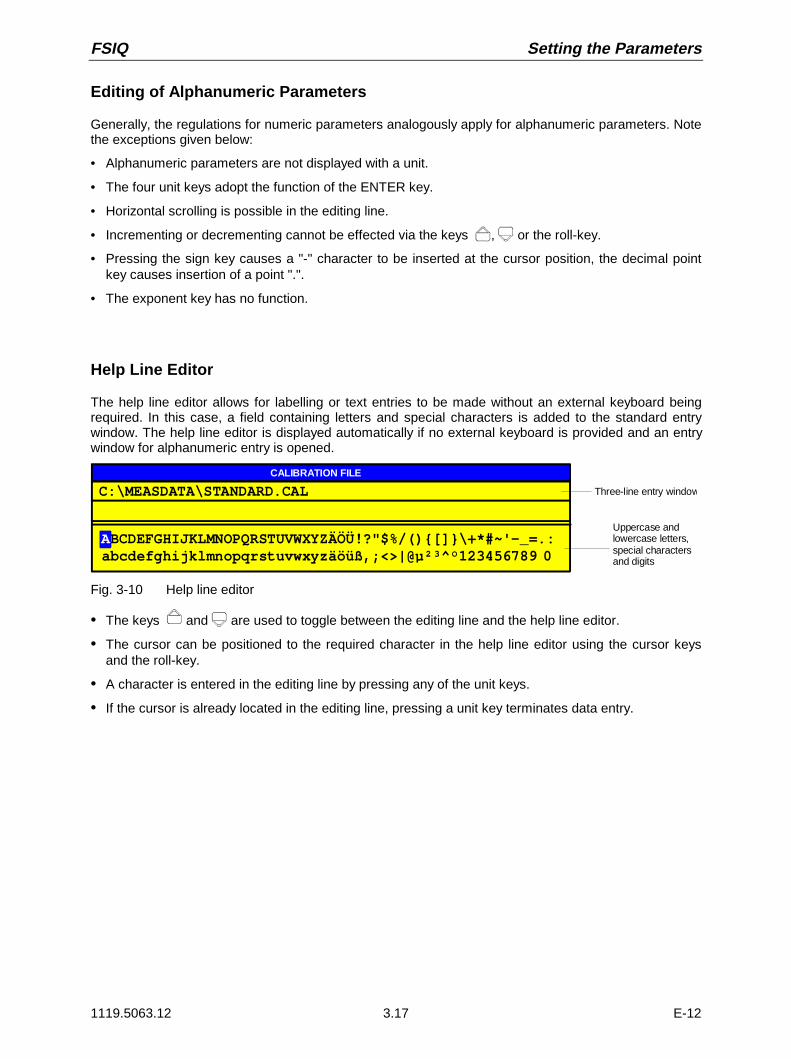
FSIQ Setting the Parameters
1119.5063.12 3.17 E-12
Editing of Alphanumeric Parameters
Generally, the regulations for numeric parameters analogously apply for alphanumeric parameters. Notethe exceptions given below:
• Alphanumeric parameters are not displayed with a unit.
• The four unit keys adopt the function of the ENTER key.
• Horizontal scrolling is possible in the editing line.
• Incrementing or decrementing cannot be effected via the keys , or the roll-key.
• Pressing the sign key causes a "-" character to be inserted at the cursor position, the decimal pointkey causes insertion of a point ".".
• The exponent key has no function.
Help Line Editor
The help line editor allows for labelling or text entries to be made without an external keyboard beingrequired. In this case, a field containing letters and special characters is added to the standard entrywindow. The help line editor is displayed automatically if no external keyboard is provided and an entrywindow for alphanumeric entry is opened.
BCDEFGHIJKLMNOPQRSTUVWXYZÄÖÜ!?"$%/()[]\+*#~'-_=.:abcdefghijklmnopqrstuvwxyzäöüß,;<>|@µ²³^°123456789 0A
CALIBRATION FILE
C:\MEASDATA\STANDARD.CAL Three-line entry window
Uppercase andlowercase letters,special characters and digits
Fig. 3-10 Help line editor
• The keys and are used to toggle between the editing line and the help line editor.
• The cursor can be positioned to the required character in the help line editor using the cursor keysand the roll-key.
• A character is entered in the editing line by pressing any of the unit keys.
• If the cursor is already located in the editing line, pressing a unit key terminates data entry.

Setting the Parameters FSIQ
1119.5063.12 3.18 E-12
Table Entry
The FSIQ uses numerous tables for indication and configuration of instrument parameters. The tablesdiffer very much in the number of lines, columns and inscriptions and have a different functionality.
Tables are represented in a non-transparent form. The size is predefined and cannot be modified. If amouse is connected, the tables may be shifted on the display without covering the softkeys. Tables canbe superimposed by entry windows or suchlike.
Tables are mostly coupled to a softkey menu which provides further functions for editing table entries,e.g., deletion of tables, copying lines or columns, marking of table elements, restoring of default statesetc. Another kind of tables is exclusively used for indication of instrument parameters and cannot beedited.
The definition of individual tables and the operation of particular editing functions can be looked up in thereference section with the description of the corresponding softkey menu.
The basic concept of operation is, however, the same for all tables. A differentiation is made betweenshifting mode and editing mode.
Shifting Mode
This mode is active subsequent to opening a table. The cursor is shifted between the table elements bymeans of the cursor keys. The table element which is below the cursor is represented in inverted color.
AntennaAnt_Cab2Ant_Pre
Probeset
dBµV/mdBµV/mdBµV/mdBµV/mdBµA
Name Unit
TRANSDUCER SET
Ant_Cab1
Cursor
Fig. 3-11 Shifting mode
FSIQ Setting the Parameters
1119.5063.12 3.19 E-12
Editing Mode
A table element which is marked by a cursor can be editied as follows:
• by pressing one of the unit keys on the front panel or the ENTER key on the external keyboard.
• by a double-click of the mouse on the table element. If the clicked element is not yet marked by thecursor, the letter is positioned on the element, additionally.
• For numeric or alphanumeric instrument parameters, the editing operation may be started by entry ofany number or letter on the front panel or on the external keyboard.
The data entry window, the selection list or the toggle editor are provided for this purpose.
After the editing operation has been terminated, the table enters the shifting mode again. The cursor ispositioned automatically on the next table element.
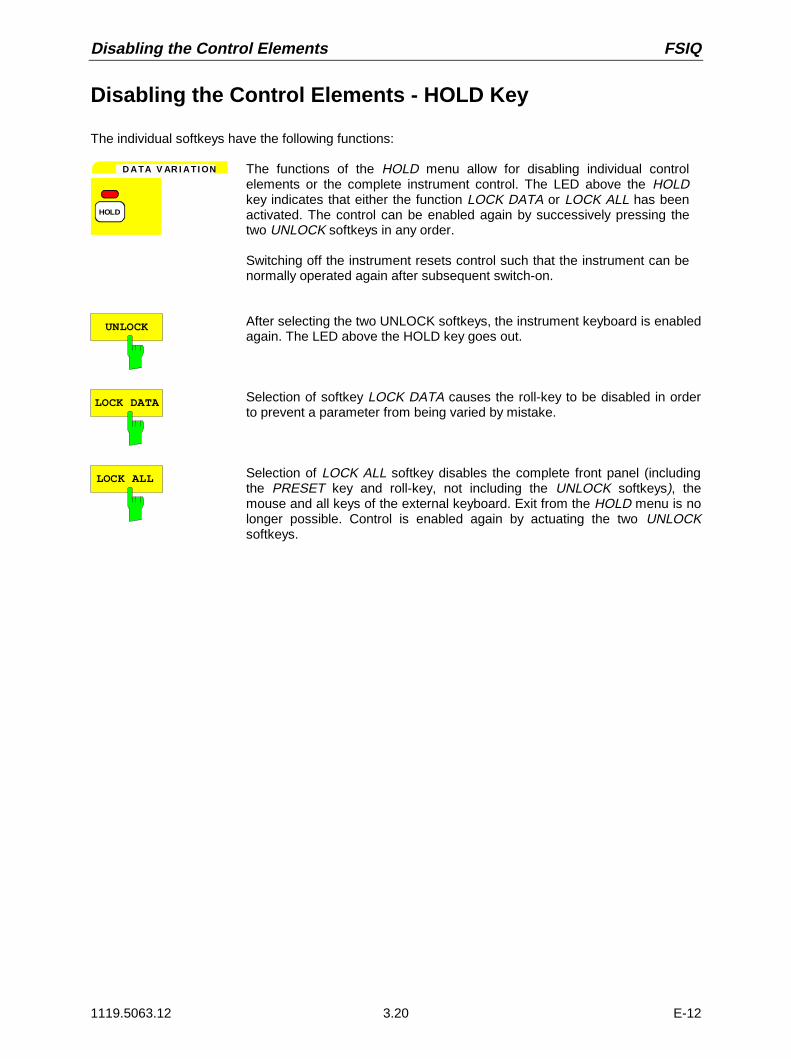
Disabling the Control Elements FSIQ
1119.5063.12 3.20 E-12
Disabling the Control Elements - HOLD Key
The individual softkeys have the following functions:
D A TA V AR I AT I ON
HOLD
The functions of the HOLD menu allow for disabling individual controlelements or the complete instrument control. The LED above the HOLDkey indicates that either the function LOCK DATA or LOCK ALL has beenactivated. The control can be enabled again by successively pressing thetwo UNLOCK softkeys in any order.
Switching off the instrument resets control such that the instrument can benormally operated again after subsequent switch-on.
UNLOCK After selecting the two UNLOCK softkeys, the instrument keyboard is enabledagain. The LED above the HOLD key goes out.
LOCK DATA Selection of softkey LOCK DATA causes the roll-key to be disabled in orderto prevent a parameter from being varied by mistake.
LOCK ALL Selection of LOCK ALL softkey disables the complete front panel (includingthe PRESET key and roll-key, not including the UNLOCK softkeys), themouse and all keys of the external keyboard. Exit from the HOLD menu is nolonger possible. Control is enabled again by actuating the two UNLOCKsoftkeys.
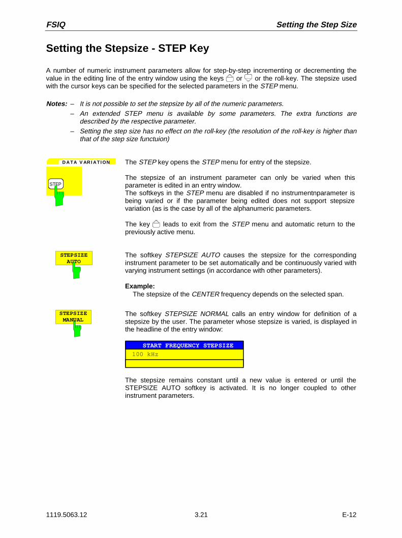
FSIQ Setting the Step Size
1119.5063.12 3.21 E-12
Setting the Stepsize - STEP Key
A number of numeric instrument parameters allow for step-by-step incrementing or decrementing thevalue in the editing line of the entry window using the keys or or the roll-key. The stepsize usedwith the cursor keys can be specified for the selected parameters in the STEP menu.
Notes: – It is not possible to set the stepsize by all of the numeric parameters.– An extended STEP menu is available by some parameters. The extra functions are
described by the respective parameter.– Setting the step size has no effect on the roll-key (the resolution of the roll-key is higher than
that of the step size functuion)
D A TA V AR I AT I ON
STEP
The STEP key opens the STEP menu for entry of the stepsize.
The stepsize of an instrument parameter can only be varied when thisparameter is edited in an entry window.The softkeys in the STEP menu are disabled if no instrumentnparameter isbeing varied or if the parameter being edited does not support stepsizevariation (as is the case by all of the alphanumeric parameters.
The key leads to exit from the STEP menu and automatic return to thepreviously active menu.
STEPSIZE AUTO
The softkey STEPSIZE AUTO causes the stepsize for the correspondinginstrument parameter to be set automatically and be continuously varied withvarying instrument settings (in accordance with other parameters).
Example:The stepsize of the CENTER frequency depends on the selected span.
STEPSIZE MANUAL
The softkey STEPSIZE NORMAL calls an entry window for definition of astepsize by the user. The parameter whose stepsize is varied, is displayed inthe headline of the entry window:
START FREQUENCY STEPSIZE
100 kHz
The stepsize remains constant until a new value is entered or until theSTEPSIZE AUTO softkey is activated. It is no longer coupled to otherinstrument parameters.

Mouse and External Keyboard Control FSIQ
1119.5063.12 3.22 E-12
Mouse and External Keyboard Control
External Keyboard Control
The connection of an external keyboard provides additional characters for the entry (letters and specialcharacters). It is permitted to use both, front panel keys and the external keyboard, for control. Thenumber, cursor and sign keys have the same effect as the corresponding front panel keys. A few keysof the external keyboard provide an extended functionality with entries or tables which is described in thefollowing table. The table shows the external keyboard key combinations through which the functions ofthe front panel keys can be emulated.
Note: The key combination <ALT> <SYSREQ> switches between the instrument display screenand the controller display screen
Table 3-3 Front Panel Keyboard Emulation
FSIQ front panel keys Key assignmentsfor the externalkeyboard
Soft keys: SK1SK2SK3SK4SK5SK6SK7SK8SK9SK10
F1F2F3F4F5F6F7F8F9F10
Menu select: Menu leftMenu rightMenu up
CTRL ←CTRL →CTRL ↑
Cursor control: Cursor leftCursor rightCursor upCursor down
←→↑↓
Roll-key: Turn leftTurn right
SHIFT ↑SHIFT ↓
Numeric keys: 0 to 9 0 to 9
Units keys: GHz...MHz...kHz...Hz...
ALT-GALT-MALT-K<ENTER>
Edit keys: ClearBackspace
<ESC>BACK
Misc. data entry keys:Exponent "Exp"Sign "+/-"Decimal point"."
ALT-E-.
Hold key: Hold SHIFT-F1
User menu: User SHIFT-F2
System keys: PresetCalDisplayInfo
SHIFT-F4ALT-F12ALT-F10SHIFT-F5
Configuration key group: Mode Setup
ALT-F2SHIFT-F8
FSIQ front panel keys Key assignmentsfor the externalkeyboard
Hardcopy key group: StartSettings
SHIFT-F6SHIFT-F9
Status key group : Local SHIFT-F3
Frequency key group: StartStopCenterCenterSpan
CTRL-F7CTRL-F8CTRL-F9CTRL-F10
Level key group: RefRangeInputCal
CTRL-F11CTRL-F12ALT-F11ALT-F12
Marker key group : NormalSearchDelta→ Mkr
CTRL-F1CTRL-F2CTRL-F3CTRL-F4
Lines key group : DisplayLimit
CTRL-F5CTRL-F6
Traces key group : 1234
ALT-1ALT-2ALT-3ALT-4
Sweep key group : ------Coupl.SweepTrigger
ALT-F3ALT-F4ALT-F5ALT-F6ALT-F7ALT-F8
Memory key group: SaveRecallConfig
SHIFT-F10SHIFT-F11SHIFT-F12
Data entry key group : Step SHIFT-F7
Letters and special characters A to Z (ext.)a to z (ext.)Specialcharacters (ext.)
Edit key Delete
Cursor control HomeEndPage upPage down

FSIQ Mouse and External Keyboard Control
1119.5063.12 3.23 E-12
Data Entry Windows with Mouse Control
With a mouse being connected, additional functions are provided in the entry windows. Therefore,buttons are displayed in the entry window.
Essentially, the definitions which have been made for all types of entry window also apply for mousecontrol. However, note the following deviations:
• The so-called close-button is displayed on the left margin of the headline. Selecting this button via themouse aborts the entry and closes the entry window. This corresponds to the function of the CLR keywith manual control.
• In the numeric entry window, two buttons ( ) are displayed on the left margin of the editing line.Simply clicking the buttons causes the parameter in the editing line to be incremented ordecremented (similar to the keys / or the roll-key with manual control).
• The cursor can be positioned in the entry line by clicking a character using the mouse.
• A character in the letter window of the help line editor can be selected by a single click. A double clickcopies the character from the letter window into the editing line.
• Open entry windows can be shifted across the complete screen using the mouse; they must not,however, be superimposed on the softkey line. Shifting is performed by clicking the headline andpushing the mouse while he mouse-key is being pressed.
Example: Numeric entry window with mouse control
START FREQUENCY
10.2457535 GHZ
START FREQUENCY OUT OF RANGE
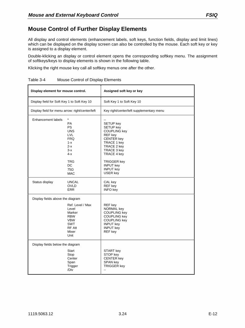
Mouse and External Keyboard Control FSIQ
1119.5063.12 3.24 E-12
Mouse Control of Further Display Elements
All display and control elements (enhancement labels, soft keys, function fields, display and limit lines)which can be displayed on the display screen can also be controlled by the mouse. Each soft key or keyis assigned to a display element.
Double-klicking an display or control element opens the corresponding softkey menu. The assignmentof softkeys/keys to display elements is shown in the following table.
Klicking the right mouse key call all softkey menus one after the other.
Table 3-4 Mouse Control of Display Elements
Display element for mouse control. Assigned soft key or key
Display field for Soft Key 1 to Soft Key 10 Soft Key 1 to Soft Key 10
Display field for menu arrow: right/center/left Key right/center/left supplementary menu
Enhancement labels *PAPSUNSLVLFRQ1-x2-x3-x4-x
TRGDC75ΩMAC
--SETUP keySETUP keyCOUPLING keyREF keyCENTER keyTRACE 1 keyTRACE 2 keyTRACE 3 keyTRACE 4 key
TRIGGER keyINPUT keyINPUT keyUSER key
Status display UNCALOVLDERR
CAL keyREF keyINFO key
Display fields above the diagram
Ref. Level / MaxLevelMarkerRBWVBWSWTRF AttMixerUnit
REF keyNORMAL keyCOUPLING keyCOUPLING keyCOUPLING keyINPUT keyINPUT keyREF key
Display fields below the diagram
StartStopCenterSpanTrigger/Div
START keySTOP keyCENTER keySPAN keyTRIGGER key--

FSIQ Menu Overview
1119.5063.12 3.25 E-12
Menu Overview
System Key Group
SCREENCOUPLING
DISPLAY INFO
PRESET CAL
SYSTEM DISPLAY
SPLIT SCREEN
FULLSCREEN
CONFIGDISPLAY
ACTIVESCREEN A
ACTIVESCREEN B
SCREENCOUPLING
SCREENSUNCOUPLED
HORIZONTALSCALING
VERTICALSCALING
CONFIGDISPLAY
TINT
SATURATION
DEFAULTCOLORS
SELECTOBJECT
BRIGHTNESS
LOGOON OFF
FREQUENCYON OFF
DATAENTRYFIELD
ACTIVESCREEN C
ACTIVESCREEN D
MODECOUPLED
COUPLINGCONTROL
PREDEFINEDCOLORS
DISPLAYCOMMENT
TIMEON OFF
CONFIGDISPLAY
DATAENTRYY
DATAENTRYX
DEFAULTPOSITION
DATAENTRYFIELD
DATAENTRYOPAQUE
SCR SAVERON OFF
SCR SAVER TIME

Menu Overview FSIQ
1119.5063.12 3.26 E-12
PRESET CAL
SYSTEM
DISPLAY INFO
CALIBRATE CALRESULTS
CALIBRATE
CAL TOTAL
CALRES BW
CAL SHORT
CAL LOG
CAL I/Q
CAL CORR ON OFF
PAGE UP
PAGE DOWN
CALI/Q
CALLO SUPP
PRESELPEAK
FSIQ26and FSIQ40
SELFTEST
PRESET CAL
SYSTEM
DISPLAY INFO
INFO
FIRMWAREVERSIONS
HARDWARE+OPTIONS
SYSTEMMESSAGES
SELFTEST
EXECUTETESTS
SYSTEM MESSAGES
CLEARMESSAGE
CLEAR ALLMESSAGES
UPDATEMESSAGES
OPTIONS
STATISTIC STATISTIC
ATTENSWITCHES
.
.
.

FSIQ Menu Overview
1119.5063.12 3.27 E-12
Configuration Key Group
MODE
ANALYZER
VECTORANALYZER
CONFIGURATION
MODE
SETUP
CT2
DEMOD
MEASRESULT
DIGITALSTANDARDS
DIGITALSTANDARDS
GSM
NADCFWD CH
PHS
PDC DOWN
TETRA
CDPD
DECT
W-CDMA4.096 FWD
DIGITALSTANDARDS
TRIGGER
ERMES
MODACOM
FLEX16_2
FLEX32_2
FLEX32_4
FLEX64_4
TFTS
PDC UP
DIGITALSTANDARDS
IS95-CDMA FWD CH
TRACKINGGENERATOR
see Section "SWEEP Key Group"
APCO25C4FM
APCO25CQPSK
NADCREV CH
PWT
DIGITAL
DEMODULATION
BPSKQPSKDQPSKΠ/4DQPSK0QPSK8PSKD8PSK3Π/8-8PSKMSKDMSK2FSK4FSK16QAM
RANGE
IFBANDWIDTH
DEMODANALOG
MODULATIONPARAMETER
SWEEPTIME
DIGITALDEMOD
DEMODBANDWIDTH
see below
VECTOR ANALYZERDIGITAL DEMOD
IS95-CDMA REV CH
EDGE
Option TrackingGenerator; see below
Option FSE-K10;see manual of option
GSM MSANALYZER
GSM BTSANALYZER
W-CDMA4.096 REV
W-CDMA3GPP FWD
W-CDMA3GPP REV
CDMA 2000SR3/DS FWD
Option FSE-K10;see manual of option
see below
see below
see Section "SWEEP Key Group"
see Section "LEVEL Key Group"

Menu Overview FSIQ
1119.5063.12 3.28 E-12
MODE
ANALYZER
VECTORANALYZER
CONFIGURATION
MODE
SETUP
VECTORANALYZER
DIGITALDEMOD
SYMBOLRATE
MEASFILTER
MODULATIONPARAMETER
ALPHA/BT
NORMALIZEON OFF
MODULATIONPARAMETER
MEASRESULT
DIGITALSTANDARDS
REFERENCEFILTER
FSK REFDEVIATION
POINTS/SY MBOL
16 8 4 2 1
FRAME LENGTH
MEMOR Y SIZE
PHASE WRAP OFF
16384 POINTS 8192 POINTS 4096 POINTS 2048 POINTS 1024 POINTS
800 SYMBOLS
700 SYMBOLS
600 SYMBOLS
500 SYMBOLS
400 SYMBOLS
300 SYMBOLS
200 SYMBOLS
100 SYMBOLS
MAGNITUDE
PHASE
FREQUENCY
REAL/IMAGPART
EYE DIAG[I]
EYE DIAG[Q]
EYE DIAGTRELLIS
POLAR [IQ]VECTOR
POLAR [IQ]CONSTELL
EYELENGTH
MAGNITUDE
PHASE
FREQUENCY
SYMBOLDISPLAY
POLAR [IQ]CONSTELL
POLAR [IQ]VECTOR
SYMBOLDISPLAY
MEASSIGNAL
MEASSIGNAL
ERRORSIGNAL
REAL/IMAGPART
ERROR VECTMAGNITUDE
TRIGGER
REF FILTER
Raised CosRoot raised cosGaussian
apco25fmedge_mesedge_refbess1_22bess1_25bess2_44IS95_fmIS95_frIS95_rmIS95_rr
1600 SYMBOLS
1500 SYMBOLS
1400 SYMBOLS
1300 SYMBOLS
1200 SYMBOLS
1100 SYMBOLS
1000 SYMBOLS
900 SYMBOLS
RESULTLENGTH
MEASSIGNAL
REFERENCESIGNAL
FRAMELENGTH
ERRORSIGNAL
POINTS PERSYMBOL
MEMORY SIZE
MEASRESULT
MAGNITUDECAP BUFFER
SYMB TABLE/ ERRORS
TRACKINGGENERATOR
SIDE BAND INV
MEAS FILTER
RANGE
IFBANDWIDTH
ANALOGDEMOD
VECTOR ANALYZERDIGITAL DEMOD
see above
MAGNITUDE
FREQUENCY
EYE DIAG[FREQ]
MAGNITUDE
FREQUENCY
SYMBOLDISPLAY
MEASSIGNAL
ERRORSIGNAL
EYELENGTH
Modulation FSK
GSM MSANALYZER
GSM BTSANALYZER
Modulation Not FSK
NoneRaised CosRoot raised cosGaussian
apco25fmedge_mesedge_refbess1_22bess1_25bess2_44IS95_fmIS95_frIS95_rmIS95_rr
Option TrackingGenerator;see below
Option FSE-K10;see manual of option
NORM
ON
see above
Option FSE-K10;see manual of option

FSIQ Menu Overview
1119.5063.12 3.29 E-12
SINAD 1kHzON OFF
SUMMARYSETTINGS
INDICATION
ABS REL
SET REFERENCE
MEAS->REF
SWEEP COUNT
AVERAGE/ HOLD ON
REL UNIT dB %
MODE
ANALYZER
RECEIVER
VECTORANALYZER
AF DEMOD
VECTORANALYZER
ANALOGDEMOD
DIGITALDEMOD
MEASRESULT
DIGITALSTANDARDS
AF FILTER
TRIGGER
DEMODSETTINGS
HIGH PASSAF FILTER
SQUELCHON OFF
RANGE
AM/FM DEEMPH
DEEMPHASISON OFF
MEAS RESULT
FM S IGNAL
PM S IGNAL
VOLUME
AM/FM DEEMPHASIS
50 us
DEMOD BANDWIDTH
IF BANDWIDTH
75 us
750 us
REAL TIMEON OFF
AF COUPL’GAC DC
SQUELCH LEVEL
MODULATION SUMMARY
AM S IGNAL
HIGH PASS
NONE30 Hz300 Hz
LOW PASSAF FILTER
WEIGHTINGAF FILTER
AF FILTERLOW PASS
NONE3 kHz15 kHz
NONECCITTC-Message
AF FILTERWEIGHTING
PRE DISPLON SUMM ARY
SETT INGS
NON INV
O
SIDE BAND
SUMMARYMEAS TIME
SENSITIV AF OUTPUT
SWEEP TIME
MODULATIONPARAMETER
CONFIGURATION
MODE
SETUP
VECTOR ANALYZERANALOG DEMOD / REAL TIME ON
OptionTracking Generator;see below
Option FSE-K10;see manual of option
TRACKINGGENERATOR
GSM MSANALYZER
GSM BTSANALYZER
OFF
Option FSE-K11;see manual of option

Menu Overview FSIQ
1119.5063.12 3.30 E-12
SUMMARYSETTINGS
INDICATIONABS REL
SET REFERENCE
MEAS->REF
SWEEP COUNT
AVERAGE/ HOLD ON
REL UNIT% dB
MODE
ANALYZER
VECTORANALYZER
VECTORANALYZER
ANALOGDEMOD
DIGITALDEMOD
MEASRESULT
DIGITALSTANDARDS
TRIGGER
DEMODSETTINGS
SQUELCHON OFF
RANGE
MEAS RESULT
FM S IGNAL
PM S IGNAL
DEMOD BANDWIDTH
IF BANDWIDTH
REAL TIMEON OFF
AF COUPL’GAC DC
SQUELCH LEVEL
MODULATION SUMMARY
AM S IGNAL
LOW PASSAF FILTER
AF FILTERLOW PASS
NONE 5% [DEMOD BW]10% [DEMOD BW]20% [DEMOD BW]
SUMM ARYSETT INGS
SIDE BANDNORM INV
SUMMARYMEAS TIME
SWEEP TIME
MODULATIONPARAMETER
CONFIGURATION
MODE
SETUP
VECTOR ANALYZERANALOG DEMOD / REAL TIME OFF
OptionTracking Generator;see below
Option FSE-K10;see manual of option
TRACKINGGENERATOR
GSM MSANALYZER
GSM BTSANALYZER
Option FSE-K11;see manual of option

FSIQ Menu Overview
1119.5063.12 3.31 E-12
MODE
ANALYZER
VECTORANALYZER
CONFIGURATION
MODE
SETUP
TRACKINGGENERATOR
TRACKING GENERATOR
GSM MSANALYZER
GSM BTSANALYZER
OptionTracking Generator
Option FSE-K10;see manual of option
Option FSE-K11;see manual of option
see above
TRACKINGGENERATOR
SOURCEON OFF
SOURCEPOWER
POWEROFFSET
SOURCECAL
FREQUENCYOFFSET
MODULATION
SOURCECAL
CALTRANS
CAL REFLSHORT
CAL REFLOPEN
REF VALUEPOSITION
REF VALUE
NORMALIZE
RECALL
MODULATION
EXT AM
EXT FM
EXT ALC
EXT I/Q

Menu Overview FSIQ
1119.5063.12 3.32 E-12
CONFIGURATION
MODE
SETUP
SETUP
REFERENCEEXT INT
PREAMPON OFF
PRESELECTON OFF GPIB
ADDRESS
GENERALSETUP
TIME
DATE
MONITORCONNECTED
USER PORT A
USER PORT B
SERVICE
EXT REFFREQUENCY
GENERALSETUP
TRANSDUCER
KEY CLICKON OFF
OPTIONS
TRANSDUCER
EDIT TRD FACTOR
EDIT TRDSET
TRANSDUCERFACTOR
TRANSDUCERSET
PAGE UP
PAGE DOWN
DELETEFACTOR/SET
NEWFACTOR/SET
EDIT TRD FACTORTRD FACTOR
NAME
TRD FACTORUNIT
TRD FACTORVALUES
DELETE LINE
INSERT LINE
DRAW TRDFACTOR
SAVE TRD FACTOR
EDITTRANSD SET
TRANSD SETRANGES
INSERT LINE
TRANSD SET NAME
TRANSD SET UNIT
DELETE LINE
DRAWTRD SET
SAVE TRD SET
PAGE UP
PAGE DOWN
OPTIONS
ENABLE NEWOPTION
.
.
.
REFERENCEADJUST
REFERENCE
.
.
.
REFERENCEPROG
SERVICE
INPUTRF
INPUTCAL
ENTERPASSWORD
SERVICEFUNCTION
NOISESOURCE
REFERENCEADJUST
.
.
.
FIRMWAREUPDATE
UPDATE
RESTORE
COMPORT2
COMPORT1
MODE FSEON OFF

FSIQ Menu Overview
1119.5063.12 3.33 E-12
Hardcopy Key Group
HARDCOPY
SETTINGS
START
COPY TRACE
SELECTQUADRANT
HARDCOPY DEVICE
TRC COLORAUTO INC
ENTERTEXT
HARDCOPYSETTINGS
COPYSCREEN
SELECTQUADRANT
FULLPAGE
ENTERTEXT
COMMENTSCREEN A
COMMENTSCREEN B
TITLE
SETTINGSDEVICE 1
SETTINGSDEVICE 2
ENABLEDEV1 DEV2
HARDCOPY DEVICE
UPPERLEFT
UPPERRIGHT
LOWERLEFT
LOWERRIGHT
COPY TABLE
HARDCOPY
SETTINGS
START
without softkey menu
COLORON OFF
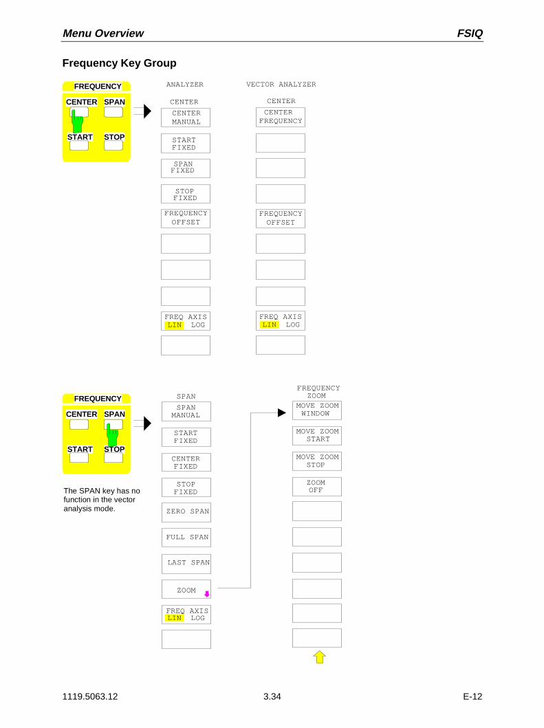
Menu Overview FSIQ
1119.5063.12 3.34 E-12
Frequency Key Group
CENTER SPAN
START STOP
FREQUENCY
FIXED
CENTERMANUAL
STARTFIXED
SPAN
CENTER
STOPFIXED
CENTER SPAN
START STOP
FREQUENCYFREQUENCY
MOVE ZOOMWINDOW
ZOOM
MOVE ZOOM
MOVE ZOOMSTOP
START
ZOOMOFF
SPAN
SPANMANUAL
STARTFIXED
CENTERFIXED
FIXEDSTOP
ZERO SPAN
FULL SPAN
LAST SPAN
ZOOM
FREQ AXIS
FREQUENCYOFFSET
MIXERINTERNAL
MIXEREXTERNAL
LIN LOG
The SPAN key has nofunction in the vectoranalysis mode.
LIN LOGFREQ AXIS
CENTERFREQUENCY
CENTER
FREQUENCYOFFSET
MIXERINTERNAL
MIXEREXTERNAL
LIN LOGFREQ AXIS
ANALYZER VECTOR ANALYZER

FSIQ Menu Overview
1119.5063.12 3.35 E-12
CENTER SPAN
START STOP
FREQUENCY
CENTERFIXED
START FREQ
STOP FREQ
STOPMANUALCENTER SPAN
START STOP
FREQUENCY
SPANFIXED
STOPFIXED
STARTMANUAL
SPANFIXED
CENTERFIXED
STARTFIXED
FREQ AXISLIN LOG
FREQ AXISLIN LOG
The START key has nofunction in vector analysismode.
The STOP key has nofunction in vector analysismode.

Menu Overview FSIQ
1119.5063.12 3.36 E-12
Level Key Group, Input Key
dBm
dBµV
dB µA
VOLT
AMP ERE
WATT
PR OBE CODEON OFF
MAX LEVELAUTO
MAX LEVELMANUAL
d B* / MH
dBmV
dBp W
REF LEVEL
REF LEVEL
GRIDABS REL
REF LEVEL A UTO
UNIT
REF LEVELOFFSET
RF AT TEN MANU AL
MIXERLEVEL
ATTEN AUTONORMAL
ATTEN AUTOLOW NOISE
ATTEN A UTOLOW DI ST
VECTOR ANALYZER
RANGE
REF
LEVELANALYZER
REF LEVEL REF LEVEL
REF LEVEL
RF ATTENMANUAL
ATTEN AUTONORMAL
ATTEN AUTOLOW NOISE
ATTEN AUTOLOW DIST
MIXERLEVEL
UNIT
ATTEN STEP1dB 10dB
Option FSE-B13,1 dB Attenuator
REF LEVEL OFFSET
ATTEN STEP1dB 10dB
Option FSE-B13,1 dB Attenuator

FSIQ Menu Overview
1119.5063.12 3.37 E-12
LOG 100 dB
LOG 50 dB
LOG 20 dB
LOG 10 dB
LEVEL RANGE
LOG MANUAL
LOG 120 dB
INPUT
ATTEN AUTOLOW NOISE
ATTEN AUTOLOW DIST
MIXER LEVEL
RF INPUT50 OHM
RF INPUT75 OHM/RAZ
RF INPUT75 OHM/RAM
ATTEN AUTONORMAL
INPUTSELECT
INPUTSELECT
LEVEL
REF
RANGE
LINEAR/dB
LINEAR/%
GRIDABS REL
REF VALUEY AXIS
REF VALUEX AXIS
REF VALUEPOSITION
LEVEL RANGE
Y PER DIV
UNIT
Y UNITLOG[dB]
Y UNITLINEAR
X UNITTIME
X UNITSYMBOL
Y UNIT dBm
Y UNIT VOLT
Y UNIT WATT
Y UNIT RAD
SCALE
SCALEUNIT
Y UNIT DEG
ANALYZER VECTOR ANALYZER
INPUT
RF ATTENMANUAL
SENSITIVAF OUTPUT
VOLUMEANALOG DEMOD,REAL TIME ON
ATTEN STEP1dB 10dB
Option FSE-B13,1 dB Attenuator
DIGITAL DEMOD
ANALOG DEMOD,REAL TIME ON

Menu Overview FSIQ
1119.5063.12 3.38 E-12
Marker Key Group
MARKERNORMAL
MARKER 2
MARKER 3
SIGNALCOUNT
NOISE
SIGNALTRACK
MARKERNORMAL
MARKERDEMOD
MARKER 1
MARKER 4
ALL MARKER OFF
COUNTER RESOL
MARKER INFO
MARKER ZOOM
COUNTERRESOLUTION
100 Hz
1 Hz
0.1 Hz
10 kHz
10 Hz
1 kHz
OCCUPIEDPWR BANDW
MARKERNORMAL
POLAR MKRR/I MA/PH
COUPLEDMARKER
POLAR MKRDEG RAD
MARKERNORMAL
MARKER 2
MARKER 1
ALL MARKER OFF
MARKER INFO
ANALYZER VECTOR ANALYZER
AM
FM
MKR DEMODSTOP TIME
VOLUMEPOWER MEASSETTINGPOWER MEAS
SETTING
MARKER
SEARCHNORMAL
DELTA MKRMKR DEMODON OFF
MARKERDEMOD
CHANNEL POWER
CP / ACPABS REL
SET CPREFERENCE
C / N
C / No
ADJACENTCHAN POWER
ADJUST CPSETTINGS
SET NO. OFADJ CHAN’S
CH FILTER ON OFF
CHANNELBANDWIDTH
CHANNELSPACING
ACPSTANDARD
EDIT ACP LIMITS
LIMITCHECK
% POWERBANDWIDTH
DIGITALDEMOD
DIGITALDEMOD

FSIQ Menu Overview
1119.5063.12 3.39 E-12
DELTA 2
DELTA 3
PHASENOISE
DELTA 1
REFERENCE FIXED
DELTA 4
ALL DELTA OFF
REFERENCE POINT
DELTA MKRABS REL
REFERENCE POINT
REF POINT LEVEL
REF POINTLVL OFFSET
REF POINTFREQUENCY
REF POINTTIME
MARKER
NORMAL SEARCH
DELTA MKR
DELTAMARKER
DELTA 2
DELTA 1
ALL DELTA OFF
DELTA MKRABS REL
DELTAMARKER
ANALYZER VECTOR ANALYZER

Menu Overview FSIQ
1119.5063.12 3.40 E-12
MARKER
NORMAL SEARCH
DELTA MKR
MARKERSEARCH
N DB DOWN
SHAPE FACT 60 /6 DB
MARKERSEARCH
NEXT PEAK
NEXT PEAKRIGHT
NEXT PEAKLEFT
MIN
NEXT MIN
NEXT MIN RIGHT
SEARCH LIM ON OFF
ALL MARKERTO MIN
MARKERSEARCH
SELECTMARKER
SELECTMARKER
SHAPE FACT 60 /3 DB
SELECTMARKER
ACTIVEMKR DELTA
NEXT MIN LEFT
PEAK
ACTIVEMKR DELTA
ACTIVEMKR DELTA
PEAKEXCURSION
SUM MKRON OFF
SUMMARYMARKER
SUMMARYMARKER
SWEEPCOUNT
RMS
MEAN
ALL SUMMKR OFF
PEAK HOLDON OFF
AVERAGEON OFF
MARKERSEARCH
MIN
MAX |PEAK|
SELECTMARKER
AUTO PEAK ON OFF
PEAK
ACTIVEMKR DELTA
SUM MKR ON OFF
SUMMARYMARKER
SUMMARYMARKER
SWEEPCOUNT
RMS
MEAN
ALL SUMMKR OFF
PEAK HOLDON OFF
AVERAGEON OFF
SEARCH LIM ON OFF
MAX |PEAK|
+ PEAK
- PEAK
± PEAK/2
EXCLUDE LOON OFF
VECTOR ANALYZERANALYZER

FSIQ Menu Overview
1119.5063.12 3.41 E-12
CENTER
PEAK
REF LEVEL
ACTIVEMKR DELTA
MARKER
MKR
MKR
TRACEMKR
START
MKR
AUTOSCALE
MKR->CFSTEPSIZE
STOPMKR
SELECTMARKER
ANALYZER
MARKER
NORMAL SEARCH
MKRDELTA
PEAK
ACTIVEMKR DELTA
MARKER
TRACEMKR
SELECTMARKER
VECTOR ANALYZER

Menu Overview FSIQ
1119.5063.12 3.42 E-12
Lines Key Group
LINESDISPLAYLINES
DISPLAY LINE 2
DISPLAY LINE 1
DISPLAY LINE 2
DISPLAY LINE 1
or
TIMELINE 1
TIMELINE 2
REFERENCELINE
THRESHOLDLINE
THRESHOLDLINE
REFERENCELINE
SHOWLINE INFO
SHOWLINE INFO
DISPLAY LINE 2
DISPLAY LINE 1
TIME/SYMBLINE 1
TIME/SYMBLINE 2
REFERENCELINE
THRESHOLDLINE
D LINES
SHOWLINE INFO
SPAN = 0 SPAN = 0
DISPLAYLINES
ANALYZER VECTOR ANALYZER
FREQUENCYLINE 1
FREQUENCYLINE 2
LIMITS
D LINES
BASELINECLIPPING
BASELINECLIPPING
LIMIT LINES
PAGE UP
PAGE DOWN
NEW LIMIT LINE
EDITLIMIT LINE NAME
VALUES
DELETE VALUE
INSERTVALUE
EDIT
ACCEPTPOSITION
TABLE GRAPH
PAGE UP
PAGE DOWN
SAVELIMIT LINE
SHIFT XLIMIT LINE
EDIT LIMITLINE
NEW LIMITLINE
DELETELIMIT LINE
SELECTLIMIT LINE
COPYLIMIT LINE
X OFFSET
Y OFFSET
SHIFT YLIMIT LINE
LINES
D LINES
LIMITS

FSIQ Menu Overview
1119.5063.12 3.43 E-12
Trace Key Group
CLEAR/ WRITE
MAX HOLD
MIN HOLD
AVERAGETRACEMATH
VIEW
BLANK
TRACE 1
DETECTOR
SWEEPCOUNT
TRACE 1
COPY..
ANALOG TRON OFF
TRACE MATHOFF
T1-T2+REF -> T1
T1-REF ->T1
TRACE MATH
T1-T3+REF -> T1
T1-T4+REF -> T1
ADJUST TO TRACE
AUTOSELECT
DETECTORSAMPLE
TRACE 1 DETECTOR
DETECTORAUTOPEAK
DETECTORMIN PEAK
DETECTORMAX PEAK
1 2
3 4
CLEAR/ WRITE
MAX HOLD
AVERAGE
VIEW
BLANK
TRACE 1
SWEEPCOUNT
CONTINOUSWRITE
MIN HOLD
VECTOR ANALYZER DIGITAL MOD
ANALYZER
TRACE
DETECTORRMS
ASCIIEXPORT
ASCIICONFIG
HOLD CONTON OFF EDIT PATH
HEADERON OFF
ASCII CONFIG
DECIM SEP . ,
NEWAPPEND
DETECTORAVERAGE

Menu Overview FSIQ
1119.5063.12 3.44 E-12
Sweep Key Group
FREE RUN
VECTOR ANALYZER ANALOG DEMOD
TRIGGER
FREE RUN
VIDEO
EXTERN
SLOPE
TRIGGEROFFSET
FIND BURSTON OFF
FIND SYNC
SYNCOFFSET
SYNCPATTERN
SELECTPATTERN
NEW SYNCPATTERN
EDIT SYNCPATTERN
DELETEPATTERN
PAGE UP
PAGE DOWN
SYNCPATTERN
EDIT SYNCPATTERN
SAVEPATTERN
NAME
COMMENT
TRIGGER
FREE RUN
VIDEO
EXTERN
SLOPEPOS NEG
TRIGGERDELAY
LINE
VECTOR ANALYZER DIGITAL DEMOD
ANALYZER
SWEEP
TRIGGER
RBW
V B W
SW T
SWEEP
COUPLING RF POWER
VALUE
TRIGGER
VIDEO
EXTERN
TRIGGEROFFSET
SLOPE
AFSIGNAL
MEAS ONLYIF SYNC’D
POS NEG
POS NEG
ON OFF
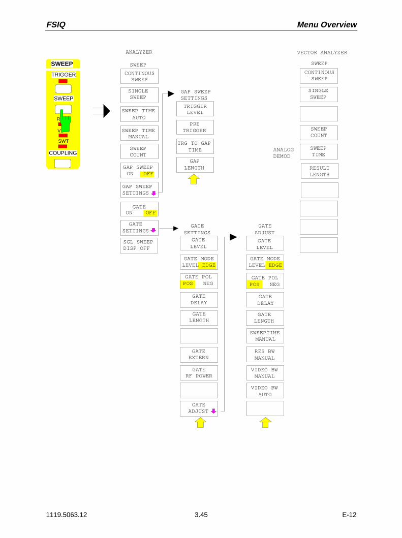
FSIQ Menu Overview
1119.5063.12 3.45 E-12
GATELEVEL
GATE MODELEVEL EDGE
GATEDELAY
GATE POLPOS NEG
GATESETTINGS
SWEEP
CONTINOUSSWEEP
SGL SWEEPDISP OFF
SWEEP TIMEMANUAL
GATESETTINGS
GATEON OFF
GAP SWEEPSETTINGS
GAP SWEEPON OFF
SWEEPCOUNT
SINGLESWEEP
GATELENGTH
TRIGGER LEVEL
PRETRIGGER
GAPLENGTH
TRG TO GAPTIME
GAP SWEEP SETTINGS
SWEEP TIMEAUTO
SWEEP
RESULTLENGTH
SINGLESWEEP
GATEADJUST
GATELEVEL
GATE MODELEVEL EDGE
GATEDELAY
GATE POLPOS NEG
GATELENGTH
GATEADJUST
SWEEPTIMEMANUAL
RES BWMANUAL
VIDEO BWMANUAL
VIDEO BWAUTO
ANALYZER VECTOR ANALYZER
SWEEPCOUNT
SWEEP
TRIGGER
V
SWT
SWEEP
COUPLING
CONTINOUSSWEEP
GATEEXTERN
GATERF POWER
SWEEPTIME
ANALOGDEMOD
R
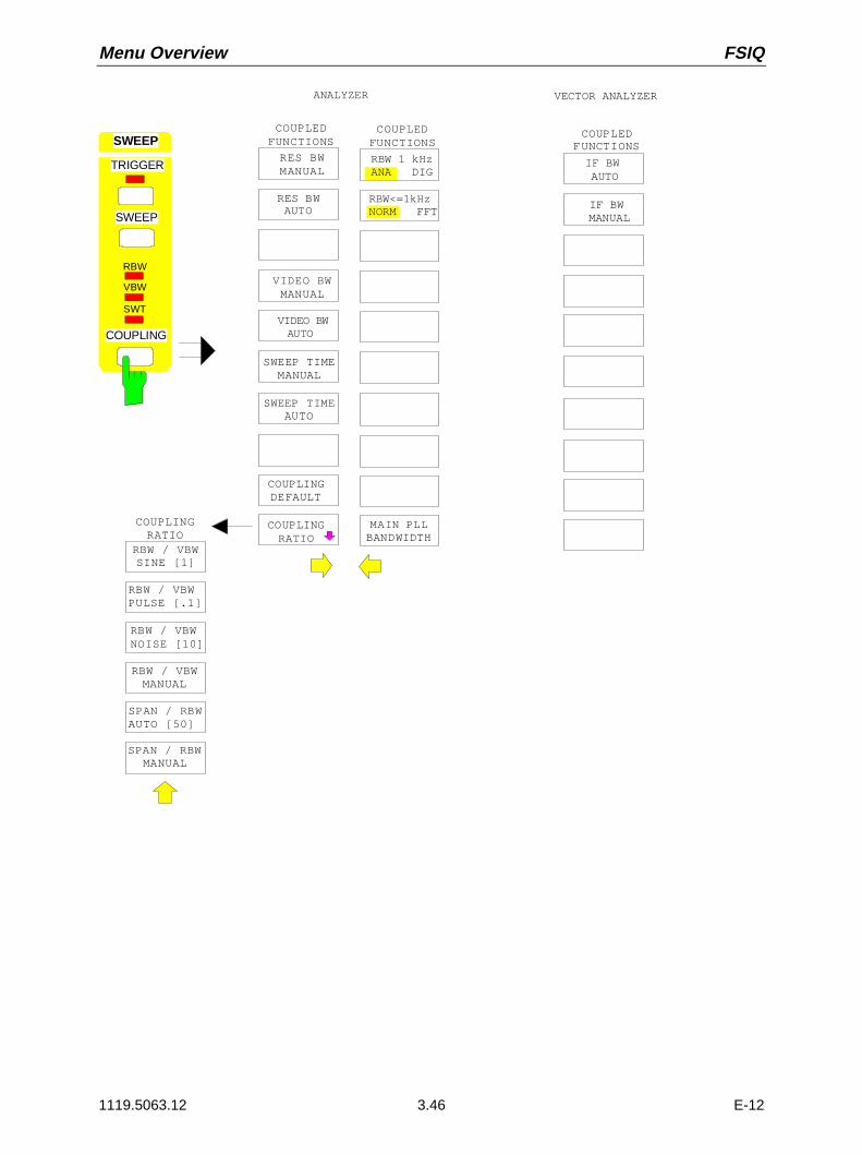
Menu Overview FSIQ
1119.5063.12 3.46 E-12
COUPLEDFUNCTIONS
RES BWAUTO
RES BW MANUAL
VIDEO BWAUTO
VIDEO BW MANUAL
SWEEP TIMEAUTO
SWEEP TIMEMANUAL
COUPLINGRATIO
RBW / VBWPULSE [.1]
RBW / VBWSINE [1]
RBW / VBWNOISE [10]
SPAN / RBWAUTO [50]
RBW / VBWMANUAL
COUPLINGRATIO
SPAN / RBWMANUAL
COUPLINGDEFAULT
SWEEP
MAIN PLLBANDWIDTH
COUPLEDFUNCTIONS
COUPLEDFUNCTIONS
ANALYZER VECTOR ANALYZER
IF BWAUTO
IF BWMANUAL
TRIGGER
SWEEP
RBW
VBW
COUPLING
SWT
RBW 1 kHzANA DIG
RBW<=1kHzNORM FFT

FSIQ Menu Overview
1119.5063.12 3.47 E-12
Memory Key Group
PAGE DOWN
MEMORYSAVE
PAGE UP
SEL ITEMS TO SAVE
DATA SETLIST
EDITPATH
DATA SETCLEAR
DATA SETCLEAR ALL
EDITNAME
EDITCOMMENT
ENABLEALL ITEMS
DISABLEALL ITEMS
SEL ITEMSTO SAVE
DEFAULTCONFIG
SELECTITEMS
MEMORY
RECALL
SAVE
CONFIG

Menu Overview FSIQ
1119.5063.12 3.48 E-12
MEMORY
RECALL
SAVE
CONFIG
PAGE DOWN
MEMORYRECALL
PAGE UP
SEL ITEMS TO RECALL
DATA SETLIST
EDITPATH
DATA SETCLEAR
DATA SETCLEAR ALL
EDITNAME
AUTORECALL
ENABLEALL ITEMS
DISABLEALL ITEMS
SEL ITEMSTO RECALL
DEFAULTCONFIG
SELECTITEMS
EDITPATH
COPY
PAGE DOWN
MEMORYCONFIG
DELETE
RENAME
SORT MODE
MAKEDIRECTORY
FORMATDISK
PAGE UP
PAGE DOWN
PAGE UP
MEMORYCONFIGMEMORY
RECALL
SAVE
CONFIG

FSIQ Menu Overview
1119.5063.12 3.49 E-12
User Key Group
USER
(MACRO 1)
(MACRO 2)
(MACRO 3)
(MACRO 4)
(MACRO 5)
(MACRO 6)
(MACRO 7)
DEFINEMACRO
USER
DEFINEMACRO
SELECTMACRO
RECORDON OFF
DEFINEPAUSE
DELETEMACRO
MACROTITLE


FSIQ Contents - "Instrument Functions"
1119.5063.12 I-4.1 E-1
Contents - Chapter 4 "Instrument Functions"
4 Instrument Functions
General Configuration – SYSTEM and CONFIGURATION Key Groups...................................... 4.2FSIQ Initial Configuration – PRESET Key ............................................................................... 4.2
Display Configuration – DISPLAY Key .................................................................................... 4.3Display Screen Mode Selection..................................................................................... 4.4Measurement Window Coupling ................................................................................... 4.5Display Screen Configuration ........................................................................................ 4.6
FSIQ Calibration – CAL Key .................................................................................................... 4.9Calibration Function Calls............................................................................................ 4.10Calibration Results ...................................................................................................... 4.12
Instrument Status and Measurement Parameters – INFO Key............................................. 4.13Firmware Versions ...................................................................................................... 4.13Hardware Configuration and Options .......................................................................... 4.14Self Test ...................................................................................................................... 4.15System Messages ....................................................................................................... 4.16Statistics Function for Input Attenuator Switching ....................................................... 4.17
Mode Selection – MODE Key ................................................................................................ 4.18
Preliminary Setup and Interface Configuration – SETUP Key............................................... 4.20Using Transducers ...................................................................................................... 4.20
Activating Transducer Factors and Transducer Sets ..................................... 4.21New Entry and Editing of Transducer Factors................................................ 4.23New Entry and Editing of Transducer Sets..................................................... 4.27
Enabling Firmware Options ......................................................................................... 4.31External Reference Oscillator...................................................................................... 4.31Service Functions........................................................................................................ 4.32Programming the Interface Configuration and Time ................................................... 4.34
IEC Bus Address Selection ............................................................................ 4.34User Port Configuration .................................................................................. 4.35Serial Interface Configuration ......................................................................... 4.36Setting Date and Time.................................................................................... 4.38Connecting the External Monitor .................................................................... 4.39Switching the Beeper ON/OFF ....................................................................... 4.39
Firmware Update......................................................................................................... 4.40Compatibility to FSE Instrument Family ...................................................................... 4.40
Status Display-Remote/Manual Control – STATUS Key Group ................................................ 4.41
Measurement Documentation – HARDCOPY Key Group.............................................................. 4.42Printing Data – START Key ................................................................................................... 4.42
Printing Configuration – SETTINGS Key............................................................................... 4.44Selection of Displayed Elements and Colour Settings ................................................ 4.45Selection of Hardcopy Format..................................................................................... 4.46Entry of Comment Text ............................................................................................... 4.47Selection and Configuration of the Output Device ...................................................... 4.48
Saving and Recalling Data Sets – MEMORY Key Group............................................................ 4.50Configuration of Memory – CONFIG Key ............................................................................. 4.52
Saving Data Sets – SAVE Key ............................................................................................. 4.54Selecting the Data Set for Storage.............................................................................. 4.55Selecting the Data subset for Storage......................................................................... 4.57
Recalling of Data Sets – RECALL Key................................................................................. 4.58Selecting the Data Set for Recalling............................................................................ 4.59
Building a Data Set ......................................................................................... 4.61

Contents - "Instrument Functions" FSIQ
1119.5063.12 I-4.2 E-1
Macros – USER Key....................................................................................................................... 4.62Fundamentals........................................................................................................................ 4.62
Starting Macros...................................................................................................................... 4.63
Defining Macros..................................................................................................................... 4.64
Analyzer Mode.................................................................................................................. .............. 4.66Frequency and Span Selection – FREQUENCY Key Group................................................. 4.67
Start Frequency – START Key.................................................................................... 4.67Stop Frequency – STOP Key ...................................................................................... 4.69Center Frequency – CENTER Key.............................................................................. 4.70Center Frequency Step Size ....................................................................................... 4.72Frequency Span – SPAN Key ..................................................................................... 4.74Display Zoom............................................................................................................... 4.76
Level Display and RF Input Configuration – LEVEL Key Group............................................ 4.77Reference Level – REF key ........................................................................................ 4.77Display Units................................................................................................................ 4.79Level Range – RANGE Key ........................................................................................ 4.82RF Input Configuration – INPUT Key .......................................................................... 4.83Option 1 dB Attenuator - FSE-B13 .............................................................................. 4.86
Marker Functions – MARKER Key Group ............................................................................. 4.88Main Markers– NORMAL Key ..................................................................................... 4.88
LF Demodulation ............................................................................................ 4.92Frequency Measurement................................................................................ 4.94Noise Power Density Measurement ............................................................... 4.95Channel Power Measurements ...................................................................... 4.96Marker Step Size .......................................................................................... 4.109
Delta Markers – DELTA Key ..................................................................................... 4.110Phase Noise Measurement .......................................................................... 4.113Delta-Marker Step Size - STEP Key............................................................. 4.114
Search Functions – SEARCH Key ............................................................................ 4.115Summary Marker .......................................................................................... 4.120
Instrument Parameter Changes via Markers – MKR Ð Key .................................... 4.123
Setup of Display and Limit Lines – LINES Key Field ........................................................... 4.125Display Lines – D LINES Key .................................................................................... 4.125Limit Lines – LIMITS Key .......................................................................................... 4.129
Limit Line Selection ...................................................................................... 4.130Entry and Editing of Limit Lines .................................................................... 4.133
Trace Selection and Setup –TRACE Key Group................................................................. 4.138Measurement Function Selection - TRACE 1 to 4 key.............................................. 4.138Detector Selection ..................................................................................................... 4.143Quasi Analog Display ................................................................................................ 4.146Mathematical Functions for Traces ........................................................................... 4.147Trace Export.............................................................................................................. 4.148
Sweep Control – SWEEP Key Group .................................................................................. 4.152Coupled Settings – COUPLING Key ......................................................................... 4.152
Setting and Coupling the Coupling Resolution, Video Bandwidth and SweepTime............................................................................................ 4.153
Sweep Coupling Ratio .................................................................................. 4.158Sweep Trigger – TRIGGER Key ............................................................................... 4.160Sweep Setup – SWEEP Key..................................................................................... 4.162
Gated Sweep................................................................................................ 4.164Sweep Blanking – Gap Sweep ..................................................................... 4.170

FSIQ Contents - "Instrument Functions"
1119.5063.12 I-4.3 E-1
Vector Analyzer Mode ................................................................................................................. 4.174Selecting the Operating Mode ............................................................................................. 4.175
Analog Demodulation Methods............................................................................................ 4.177Selecting the Modulation Parameters ....................................................................... 4.181Selecting the Audio Signal......................................................................................... 4.186Triggering with Analog Demodulation - Softkey TRIGGER or Hardkey TRIGGER... 4.194Setting the Display Range and the Scaling - Softkey RANGE or Hardkey RANGE.. 4.196Sweep Menu with Analog Demodulation - Softkey SWEEP TIME or Hardkey SWEEP4.199
Digital Demodulation Methods............................................................................................. 4.202Diagram for signal processing................................................................................... 4.202Symbol Mapping........................................................................................................ 4.203
Phase Shift Keying (PSK)............................................................................. 4.203Differential PSK ............................................................................................ 4.205Frequency Shift Keying (FSK) ...................................................................... 4.206Minimum Shift Keying (MSK), CDPD ........................................................... 4.207Quadrature Amplitude Modulation (QAM) .................................................... 4.207
Selecting the Digital Demodulators ........................................................................... 4.208Standard Settings...................................................................................................... 4.209Selecting Modulation Parameters for Digital Demodulation ...................................... 4.211Selecting Measurement Results for Digital Demodulation ........................................ 4.216
Magnitude of Capture Buffer ........................................................................ 4.216Measurement of Reference Signal............................................................... 4.217Measurement of Modulation Errors .............................................................. 4.224Symbol Table and Table of Modulation Errors ............................................. 4.227
Selecting Memory Size, Demodulation Length and Display Range .......................... 4.231
Frequency Settings- FREQUENCY Key Group.................................................................. 4.234Setting the Frequency - CENTER Key ...................................................................... 4.234Setting the Frequency Span - START, STOP, and SPAN Key ................................. 4.234
Setting the Level Display and Configuring the RF Input ...................................................... 4.235Setting the Reference Level ...................................................................................... 4.235Setting the Display Range and Scaling - RANGE Key .............................................. 4.237Configuration of RF Input in Vector Signal Analysis.................................................. 4.240
MARKER Key Group ........................................................................................................... 4.241Main Marker - NORMAL Key..................................................................................... 4.241Delta Marker - DELTA Key........................................................................................ 4.244Search Functions (Marker Search menu) - SEARCH Key........................................ 4.245
The Summary Marker................................................................................... 4.247Varying Instrument Settings by means of Markers - MKRÐKey .............................. 4.250
Setup of Display and Limit Lines – LINES Key Field ........................................................... 4.251Display Lines – D LINES Key .................................................................................... 4.251Limit Lines – LIMITS Key .......................................................................................... 4.253
Limit Line Selection ...................................................................................... 4.254Entry and Editing of Limit Lines .................................................................... 4.257
Selection and Setting of Traces - TRACE Key Group ......................................................... 4.261
SWEEP Key Group.............................................................................................................. 4.264Setting the Analog Bandwidth - COUPLING Key ...................................................... 4.264Sweep Setup - SWEEP Key...................................................................................... 4.265Triggering Data Storage - TRIGGER Key ................................................................. 4.266

Contents - "Instrument Functions" FSIQ
1119.5063.12 I-4.4 E-1
Tracking Generator Option ......................................................................................................... 4.277Tracking Generator Settings................................................................................................ 4.278
Transmission Measurement ................................................................................................ 4.279Calibration of Transmission Measurement................................................................ 4.279Normalization............................................................................................................. 4.281
Reflection Measurement...................................................................................................... 4.285Calibration of Reflection Measurement ..................................................................... 4.285
Functioning of Calibration .................................................................................................... 4.286
Frequency-Converting Measurements ................................................................................ 4.287
External Modulation of Tracking Generator......................................................................... 4.288

FSIQ Instrument Functions
1119.5063.12 4.1 E-13
4 Instrument Functions
All functions of the spectrum analyzer are explained in detail in this chapter.
The instrument functions for general settings, printout and data management are described at thebeginning of this chapter – key groups SYSTEM, CONFIGURATION, HARDCOPY, MEMORY and theUSER key.
The sequence of the following key groups depends on their appearance on the front panel: key groupsFREQUENCY, LEVEL, MARKER, LINES, TRACE, SWEEP and the INPUT key.
All options that provide an additional operating mode and are not supplied with a separate manual aredescribed at the end of the chapter.
The different softkeys of a menu are described from top to bottom and from the left to the right sidemenu. The submenus are marked by an indentation or displayed in a separate section. The whole path(key - softkey - ...) is indicated in the line above the menu display.
An overview of the menus is given in chapter 3 which also contains the description of the operatingconcept.
For fast lookup a list of softkeys with the associated IEC/IEEE-bus commands is given at the end ofChapter 6.
An index at the end of the handbook serves as further help for the user.
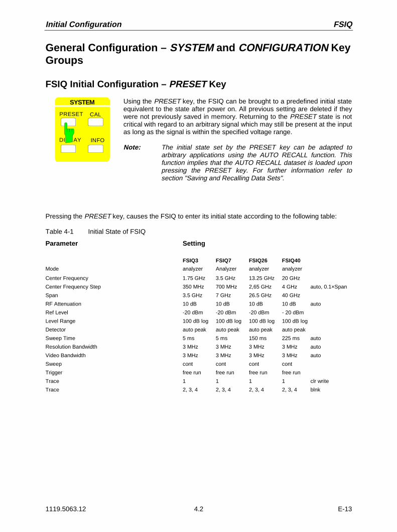
Initial Configuration FSIQ
1119.5063.12 4.2 E-13
General Configuration – SYSTEM and CONFIGURATION KeyGroups
FSIQ Initial Configuration – PRESET Key
PRESET CAL
SYSTEM
DI AY INFO
Using the PRESET key, the FSIQ can be brought to a predefined initial stateequivalent to the state after power on. All previous setting are deleted if theywere not previously saved in memory. Returning to the PRESET state is notcritical with regard to an arbitrary signal which may still be present at the inputas long as the signal is within the specified voltage range.
Note: The initial state set by the PRESET key can be adapted toarbitrary applications using the AUTO RECALL function. Thisfunction implies that the AUTO RECALL dataset is loaded uponpressing the PRESET key. For further information refer tosection "Saving and Recalling Data Sets".
Pressing the PRESET key, causes the FSIQ to enter its initial state according to the following table:
Table 4-1 Initial State of FSIQ
Parameter Setting
FSIQ3 FSIQ7 FSIQ26 FSIQ40
Mode analyzer Analyzer analyzer analyzer
Center Frequency 1.75 GHz 3.5 GHz 13.25 GHz 20 GHz
Center Frequency Step 350 MHz 700 MHz 2,65 GHz 4 GHz auto, 0.1×Span
Span 3.5 GHz 7 GHz 26.5 GHz 40 GHz
RF Attenuation 10 dB 10 dB 10 dB 10 dB auto
Ref Level -20 dBm -20 dBm -20 dBm - 20 dBm
Level Range 100 dB log 100 dB log 100 dB log 100 dB log
Detector auto peak auto peak auto peak auto peak
Sweep Time 5 ms 5 ms 150 ms 225 ms auto
Resolution Bandwidth 3 MHz 3 MHz 3 MHz 3 MHz auto
Video Bandwidth 3 MHz 3 MHz 3 MHz 3 MHz auto
Sweep cont cont cont cont
Trigger free run free run free run free run
Trace 1 1 1 1 clr write
Trace 2, 3, 4 2, 3, 4 2, 3, 4 2, 3, 4 blnk

FSIQ Display Configuration
1119.5063.12 4.3 E-13
Display Configuration – DISPLAY Key
The display of the measurement results on the FSIQ display screen takes place in either one or twomeasurement windows. In some cases, the two windows can be subdivided into two diagrams each, e.g. for the representation of the inphase and quadrature signal in the vector analyzer mode.
If only one window is used, this window fills the complete display screen. Two measurement windowsare always placed over each other. The axes labelling and measurement settings are definedindependently in each measurement window.
When two measurement windows are used, the settings can be chosen to be either coupled or fullyindependent from each other. The measurement procedure is always sequential.
New instrument settings can only be entered in the active measurement window. This window is markedon the upper right corner of the grid. Coupled settings are changed simultaneously in both windows atthe time of entry.
The entry of the measurement parameters for each of the two windows can be either independent fromone another using numerical inputs, or by graphical definition of the span through the use of level andfrequency lines. The former case, e.g., may be used for harmonic or frequency convertermeasurements, and the latter case, for a zoom display of a frequency or level segment.
USER
Ref Lvl 10 dBm
RBW 1 kHzVBW 1 kHzSWT 100 ms
MKR1 [T1]+9.8 dBm10.010000 MHz
Span 100 kHz
10.0
-10
-30
-50
-70
-90
10 kHz/
-0
-20
-40
-60
-80
Center 20.000004 MHz
RF ATT 40 dBMixer -30 dBmUnit dBm
Ref Lvl 10 dBm
RBW 1 kHzVBW 1 kHzSWT 100 ms
RF ATT 40 dBMixer -30 dBmUnit dBm
Span 100 kHz10 kHz/ Center 10.000002 MHz
10.0
-10
-30
-50
-70
-90
-0
-20
-40
-60
-80
1
DELTA [T2]-36.8 dBm10.000010 MHz
A
B
1
MARKERSEARCH
NEXT PEAK
NEXT PEAKRIGHT
NEXT PEAKLEFT
SEARCH LIMON OFF
SELECT
PEAK
ACTIVEMKR DELTA
Fig. 4-1 Split screen mode, screens uncoupled

Display Configuration FSIQ
1119.5063.12 4.4 E-13
SYSTEM DISPLAY menu:
DISPLAY
SPLIT SCREEN
FULLSCREEN
CONFIGDISPLAY
SCREENCOUPLING
ACTIVESCREEN A
ACTIVESCREEN B
DISPLAY INFO
PRESET CAL
SYSTEM
ACTIVESCREEN C
ACTIVESCREEN D
The DISPLAY key calls a menu which is used to configurethe display screen and to select the active measurementwindow in SPLIT-SCREEN mode.
Display Screen Mode Selection
SYSTEM DISPLAY menu:
FULLSCREEN
The FULL SCREEN softkey configures the display screen to onemeasurement window. This is the default setting of the FSIQ.
In this mode, the ACTIVE SCREEN A / ACTIVE SCREEN B and SCREENCOUPLING softkeys are not used.
SPLITSCREEN
The SPLIT SCREEN softkey sets the display screen to show twomeasurement windows. The upper window is called SCREEN A, the lower iscalled SCREEN B.
ACTIVESCREEN A
.
.
.
If SPLIT SCREEN display is activated, the ACTIVE SCREEN A and ACTIVESCREEN B softkeys are used to activate either window A or window B.
The entry of new settings is only possible for the active window.
When switching back to FULL SCREEN mode, the active measurementwindow is displayed.
If, in addition, the two windows are both subdivided into two diagrams, theACTIVE SCREEN A/B softkeys activate the upper diagram, ACTIVESCREEN C/D the lower diagram in each window.

FSIQ Display Configuration
1119.5063.12 4.5 E-13
Measurement Window Coupling
For the most part, the settings for the two windows can be either independently performed or coupled toone another. In many cases, when changes are made in one window (e.g., the reference level) it isdesirable to also make the corresponding changes in the second window. The measurement windowparameters which are to be coupled may be selected in the SCREEN COUPLING menu.
SYSTEM DISPLAY-SCREEN COUPLING submenu:
SCREENCOUPLING
SCREENCOUPLING
SCREENSUNCOUPLED
HORIZONTALSCALING
VERTICALSCALING
MODECOUPLED
COUPLINGCONTROL
...
The SCREEN COUPLING softkey calls a sub-menu inwhich the coupling between the two measurementwindows SCREEN A and SCREEN B can be defined. Thiscoupling is only effective when both windows aredisplayed (SPLIT SCREEN).
In the default setting, all of the items which are selectableare also coupled.
MODECOUPLED
The MODE COUPLED softkey switches the coupling of the operating mode(Analyzer, Vector Analyzer) on/off.
HORIZONTALSCALING
The HORIZONTAL SCALING softkey switches the coupled scaling of thehorizontal axes on and off. In the frequency domain, the center frequency andthe frequency span are identical. In the time domain, the sweep time for bothwindows is the same.
VERTICALSCALING
The VERTICAL SCALING softkey switches the coupled scaling of the verticalaxes on and off. For a level measurement, this means that the reference leveland the vertical resolution (LEVEL RANGE) are set to the same values inboth windows.
COUPLINGCONTROL
The COUPLING CONTROL softkey switches the coupling of the trigger andgate parameters and of SWEEP COUNT and SWEEP SINGLE/CONTINOUS on/off.
SCREENSUNCOUPLED
The SCREENS UNCOUPLED softkey switches all of the possible couplingsbetween the measurement windows to off.

Display Configuration FSIQ
1119.5063.12 4.6 E-13
Display Screen Configuration
SYSTEM DISPLAY-CONFIG DISPLAY submenu:
DATAENTRY FIELD
FREQUENCYON OFF
CONFIGDISPLAY
CONFIGDISPLAY
TINT
SATURATION
DEFAULTCOLORS
SELECTOBJECT
BRIGHTNESS
LOGOON OFF
PREDEFINEDCOLORS
TIMEON OFF
CONFIGDISPLAY
DISPLAYCOMMENT
SCR SAVERON OFF
SCR SAVERTIME
The CONFIG DISPLAY softkey calls asubmenu and its supplementary menu, inwhich the selection of color and brightnessfor the individual elements on the displayscreen takes place. The actual selection ofthe elements takes place in thecorresponding menu table.
The color assignment of the softkeys iscoupled with the color assignment of otherdisplay elements.
Changing for example the color ofSOFTKEY STATE OFF causes the color ofthe table background to be changed at thesame time. The same applies to SOFTKEYSTATE DATA ENTRY and display lines, andto SOFTKEY STATE ON and enhancementlabels.
In the supplementary menu, date, time anda diagram label can be displayed on thescreen.
SELECTOBJECT
The SELECT OBJECT softkey activates the SELECT DISPLAY OBJECTtable, with which a graphics element can be selected. After selection, thebrightness, tint and saturation of the selected element can be changed usingthe softkeys of the same name. The color changes can be seen immediatelyon the display screen.
SELECT DISPLAY OBJECT
TRACE 1
TRACE 3TRACE 4MARKERGRIDSOFTKEY STATE ONSOFTKEY STATE DATA ENTRYSOFTKEY STATE OFFSOFTKEY SHADETEXTTITLEBACKGROUND
TRACE 2
BRIGHTNESS The BRIGHTNESS softkey activates the entry of the brightness of the colorfor the selected element. The range of input values is 0 to 100%.
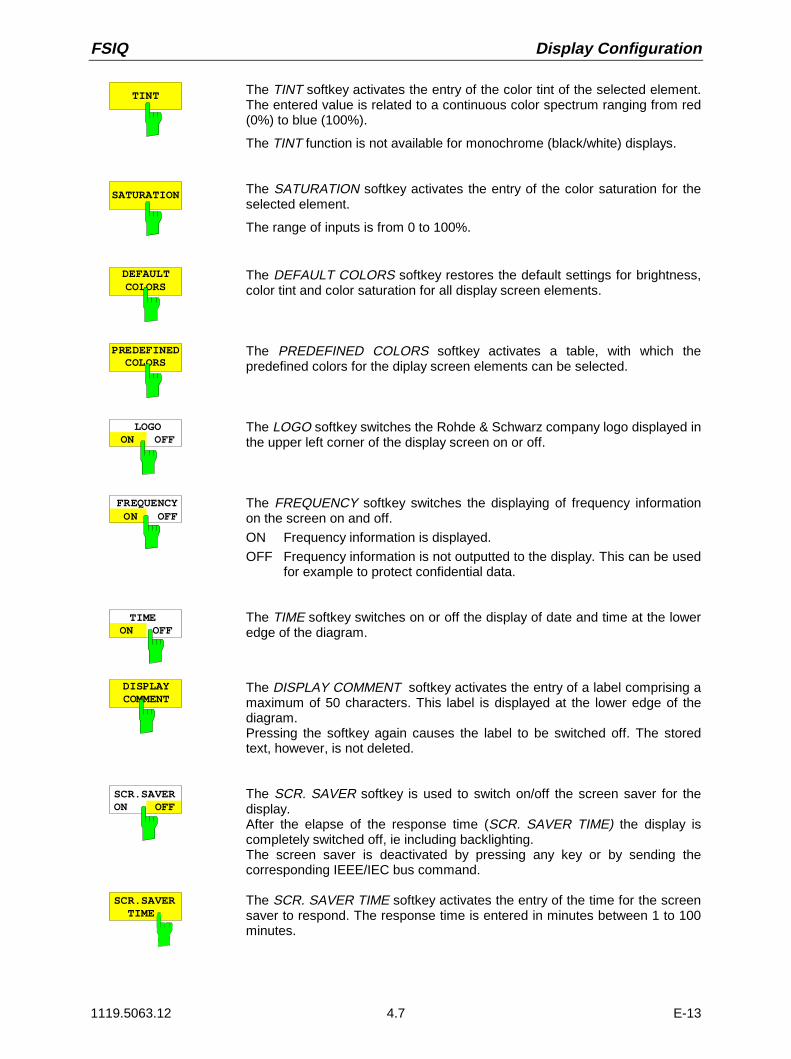
FSIQ Display Configuration
1119.5063.12 4.7 E-13
TINT The TINT softkey activates the entry of the color tint of the selected element.The entered value is related to a continuous color spectrum ranging from red(0%) to blue (100%).
The TINT function is not available for monochrome (black/white) displays.
SATURATION The SATURATION softkey activates the entry of the color saturation for theselected element.
The range of inputs is from 0 to 100%.
DEFAULTCOLORS
The DEFAULT COLORS softkey restores the default settings for brightness,color tint and color saturation for all display screen elements.
PREDEFINEDCOLORS
The PREDEFINED COLORS softkey activates a table, with which thepredefined colors for the diplay screen elements can be selected.
LOGOON OFF
The LOGO softkey switches the Rohde & Schwarz company logo displayed inthe upper left corner of the display screen on or off.
FREQUENCY ON OFF
The FREQUENCY softkey switches the displaying of frequency informationon the screen on and off.
ON Frequency information is displayed.
OFF Frequency information is not outputted to the display. This can be usedfor example to protect confidential data.
TIME ON OFF
The TIME softkey switches on or off the display of date and time at the loweredge of the diagram.
DISPLAYCOMMENT
The DISPLAY COMMENT softkey activates the entry of a label comprising amaximum of 50 characters. This label is displayed at the lower edge of thediagram.Pressing the softkey again causes the label to be switched off. The storedtext, however, is not deleted.
SCR.SAVERON OFF
The SCR. SAVER softkey is used to switch on/off the screen saver for thedisplay.After the elapse of the response time (SCR. SAVER TIME) the display iscompletely switched off, ie including backlighting.The screen saver is deactivated by pressing any key or by sending thecorresponding IEEE/IEC bus command.
SCR.SAVER TIME
The SCR. SAVER TIME softkey activates the entry of the time for the screensaver to respond. The response time is entered in minutes between 1 to 100minutes.
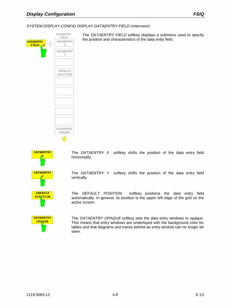
Display Configuration FSIQ
1119.5063.12 4.8 E-13
SYSTEM DISPLAY-CONFIG DISPLAY DATAENTRY FIELD Untermenü:
DATAENTRYOPAQUE
DATAENTRYFIELD
DATAENTRYFIELD
DATAENTRYX
DATAENTRYY
DEFAULTPOSITION
The DATAENTRY FIELD softkey displays a submenu used to specifythe position and characteristics of the data entry field.
DATAENTRYX
The DATAENTRY X softkey shifts the position of the data entry fieldhorizontally.
DATAENTRYY
The DATAENTRY Y softkey shifts the position of the data entry fieldvertically.
DEFAULTPOSITION
The DEFAULT POSITION softkey positions the data entry fieldautomatically. In general, its position is the upper left edge of the grid on theactive screen.
DATAENTRYOPAQUE
The DATAENTRY OPAQUE softkey sets the data entry windows to opaque.This means that entry windows are underlayed with the background color fortables and that diagrams and traces behind an entry window can no longer beseen.

FSIQ Calibration
1119.5063.12 4.9 E-13
FSIQ Calibration – CAL Key
The FSIQ maintains its high measurement accuracy through the application of numerous self-calibrationtechniques. The CAL hard key provides a series of calibration functions which allow not only thecalibration of the complete instrument, but also calibration functions which are specifically applicable tothe measurement requirements of relevant instrument sections.
The measurement settings of the FSIQ are saved and, after calibration, completely restored. Thecalibration data valid before calibration are saved and, in case of a calibration abort, restored.
A window shows the progress of the calibration while it is running. ABORT can be used to abort thecalibration at any time.
SYSTEM MESSAGE
Cal BW and CentFreq of 5MHz filt
ABORT
SYSTEM CAL menu:
CALIBRATECAL
RESULTS
CALIBRATE
CAL TOTAL
CALRES BW
CAL SHORT
CAL LOG
CALLO SUPP
CAL CORR ON OFF
PAGE UP
PAGE DOWN
PRESET CAL
SYSTEM
DISPLAY I O
PRESEL PEAK
CAL I/Q
The CAL key displays a menu withthe available calibration functions.
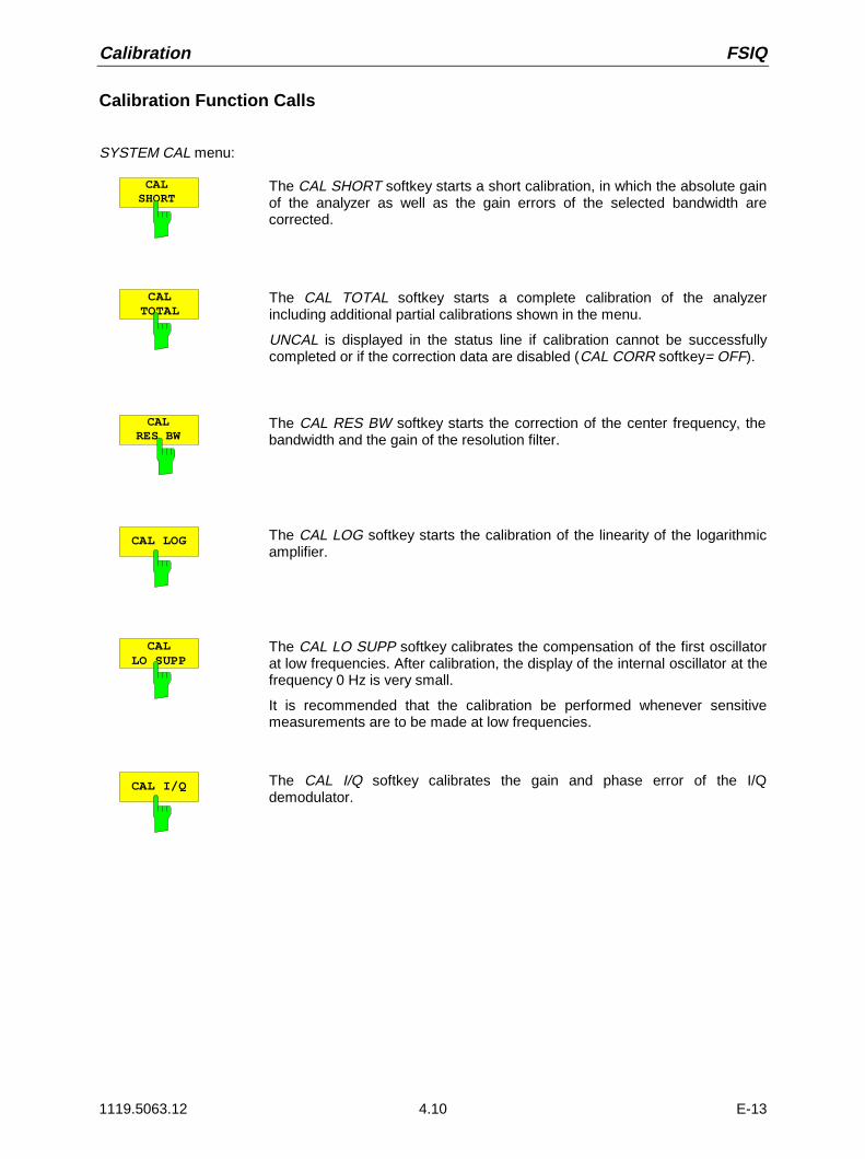
Calibration FSIQ
1119.5063.12 4.10 E-13
Calibration Function Calls
SYSTEM CAL menu:
CALSHORT
The CAL SHORT softkey starts a short calibration, in which the absolute gainof the analyzer as well as the gain errors of the selected bandwidth arecorrected.
CALTOTAL
The CAL TOTAL softkey starts a complete calibration of the analyzerincluding additional partial calibrations shown in the menu.
UNCAL is displayed in the status line if calibration cannot be successfullycompleted or if the correction data are disabled (CAL CORR softkey= OFF).
CALRES BW
The CAL RES BW softkey starts the correction of the center frequency, thebandwidth and the gain of the resolution filter.
CAL LOG The CAL LOG softkey starts the calibration of the linearity of the logarithmicamplifier.
CALLO SUPP
The CAL LO SUPP softkey calibrates the compensation of the first oscillatorat low frequencies. After calibration, the display of the internal oscillator at thefrequency 0 Hz is very small.
It is recommended that the calibration be performed whenever sensitivemeasurements are to be made at low frequencies.
CAL I/Q The CAL I/Q softkey calibrates the gain and phase error of the I/Qdemodulator.
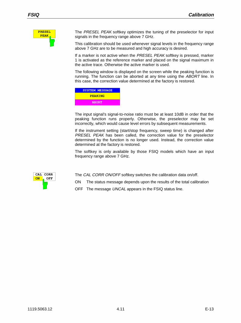
FSIQ Calibration
1119.5063.12 4.11 E-13
PRESELPEAK
The PRESEL PEAK softkey optimizes the tuning of the preselector for inputsignals in the frequency range above 7 GHz.
This calibration should be used whenever signal levels in the frequency rangeabove 7 GHz are to be measured and high accuracy is desired.
If a marker is not active when the PRESEL PEAK softkey is pressed, marker1 is activated as the reference marker and placed on the signal maximum inthe active trace. Otherwise the active marker is used.
The following window is displayed on the screen while the peaking function isrunning. The function can be aborted at any time using the ABORT line. Inthis case, the correction value determined at the factory is restored.
ABORT
SYSTEM MESSAGE
PEAKING
The input signal’s signal-to-noise ratio must be at least 10dB in order that thepeaking function runs properly. Otherwise, the preselector may be setincorrectly, which would cause level errors by subsequent measurements.
If the instrument setting (start/stop frequency, sweep time) is changed afterPRESEL PEAK has been called, the correction value for the preselectordetermined by the function is no longer used. Instead, the correction valuedetermined at the factory is restored.
The softkey is only available by those FSIQ models which have an inputfrequency range above 7 GHz.
CAL CORRON OFF
The CAL CORR ON/OFF softkey switches the calibration data on/off.
ON The status message depends upon the results of the total calibration
OFF The message UNCAL appears in the FSIQ status line.

Calibration FSIQ
1119.5063.12 4.12 E-13
Calibration Results
SYSTEM CAL menu:
CALRESULTS
The CAL RESULTS softkey in the right-hand supplementary menu calls theCALIBRATION RESULTS table, which shows the correction data foundduring calibration.
The CALIBRATION RESULTS table contains the following information:
page 1:• date and time of the last total calibration• overall results of the total calibration• list of the calibration procedures according to function/module, including
the correction values, the measured results and the individualresults for each of the calibration procedures
The results for the individual calibration procedures are categorised anddisplayed as follows:
PASSED calibration successful without restrictions
CHECK deviations larger than expected, however, corrections couldbe performed
FAILED deviations too large, no corrections were possible
ABORTED calibration aborted
CALIBRATION RESULTS
CALIBRATION: PASSEDLast cal total: 05.Jun 1997 16:24:54
Calibration of IF Filters PASSEDIF GAIN Adjust PASSEDBandwidth:Filter Cal Val [Hz] DAC Val State 1kHz 2.806e+01 1679 PASSED 2kHz 1.603e+01 2887 PASSED 3kHz -6.012e+00 3238 PASSED 5kHz -1.002e+01 3514 PASSED 10kHz 1.804e+02 3703 PASSED 20kHz 3.607e+02 3801 PASSED 30kHz 8.417e+02 3831 PASSED 50kHz 1.403e+03 3743 PASSED100kHz 1.804e+03 3698 PASSED200kHz 3.607e+03 3606 PASSED300kHz 8.417e+03 3516 PASSED500kHz 1.403e+04 3329 PASSED 1MHz 2.806e+04 2881 PASSED
PAGE UP
PAGE DOWN
The PAGE UP and PAGE DOWN softkeys can be used to page through thetable of calibration results.

FSIQ Instrument Status and Measurement Parameters
1119.5063.12 4.13 E-13
Instrument Status and Measurement Parameters – INFO Key
SYSTEM INFO menu:
PRESET CAL
SYSTEM
INFODISPLAY
HELP
INFO
INSTRUMENTSETTINGS
FIRMWAREVERSIONS
HARDWARE+OPTIONS
SELFTEST
SYSTEMMESSAGES
OPTIONS
STATISTIC
The INFO key is used to request general informationconcerning the instrument. These include:
• firmware version• installed hardware and hardware options• modification level of the individual modules• self-test results with the option of calling self-test
functions• list of generated system messages• installed firmware and hardware options.• Statistical evaluations
Firmware Versions
SYSTEM INFO menu:
FIRMWAREVERSION
The FIRMWARE VERSIONS softkey opens two tables, which provide thefollowing informations:
• Table MODEL displays the exact instrument model.
MODEL
FSIQ 26
• In the FIRMWARE VERSION table, the version of each softwarecomponent installed in the instrument is listed. The versions ofprogrammable logic devices are also included if the firmware version ofthe device can be determined.
FIRMWARE VERSION
BIOS 1.2ANALYZER 1.80SERIAL NUMBER 101379/005

Instrument Status and Measurement Parameters FSIQ
1119.5063.12 4.14 E-13
Hardware Configuration and Options
SYSTEM INFO menu:
HARDWARE+OPTION
The HARDWARE+OPTIONS softkey opens two tables in which the modules(INSTALLED COMPONENTS) installed in the instrument are listed.
• Table MODEL lists the instrument name and model:
MODEL
FSIQ 26
• Table INSTALLED COMPONENTS consists of four columns:
COMPONENT name of module
MODEL INDEX model number of the module
MODIF INDEX main modification index of the module
HW CODE secondary modification index of the module
These lists contain only the modules which are actually present in theinstrument, i.e., the modules which were identified by the modulerecognition software.
Main Processor 4 n/a 0Graphic Board 4 n/a 0I/O Board 4 n/a 0FRAC SYN 4 0 4RF Module 4 0 42nd IF Converter 3 2 2LOPhase 3 4 17Detector 4 0 2 IF Filter 3 2 3Digital IF 2 0 2I/Q Demod (B7) 2 3 2
MODEL INDEXCOMPONENT MODIF INDEX HW CODE
INSTALLED COMPONENTS
OPTIONS The OPTIONS softkey opens two tables listing the options installed. Thestandard FSIQ is equipped with options FSE-B4, FSE-B5 and FSE-B7
TYPE
B5
FIRMWARE OPTIONS
DESIGNATION
FFT
CODE
1938496289
Note: New firmware options can be enabled in the SETUP menu.
HARDWARE OPTIONS
DESIGNATION
Low Phase Noise & OCXO
CODE
B4

FSIQ Instrument Status and Measurement Parameters
1119.5063.12 4.15 E-13
Self Test
SYSTEM INFO-SELFTEST submenu:
SELFTEST
SELFTESTEXECUTETESTS
.
.
.
The SELFTEST softkey opens a submenu with which the self testcan be started.
The instrument has extensive self test functions whichcomprehensively test instrument functionality. In case of a fault,the instrument can locate a defective module on its own. The selftest sequence is described in more detail in the service manualinstrument (supplied with the FSIQ).
EXECUTETESTS
The EXECUTE TESTS softkey starts the test of the complete instrument.During the self test a window is displayed:
SELFTEST
ABORT
in progress
The functions are tested in the following order:
1. Modules main CPU, digital motherboard, graphics and the interfaces
2. Reference frequency conditioning, the synthesizer modules and all LOsignals
3. All RF, IF and signal-weighting modules
If no failure occurs during the execution of the self test, the following messageis displayed when the complete self test is finished:
SELFTEST
OK
successfully completed
If a failure occurs during the execution of the self test, the self test isimmediately aborted and a message indicating the defective module and thedefective function is displayed:
SELFTEST FAILED
ABORT
IF Filter Stepgain
Further testing should be performed by an R&S service department.

Instrument Status and Measurement Parameters FSIQ
1119.5063.12 4.16 E-13
System Messages
The SYSTEM MESSAGES softkey opens a submenu including a table in which the generated systemmessages are displayed. The most recent messages are at the top of the list.The following information is presented:NO Device specific three digit error code (shown as XXX in the figure)
MESSAGE Brief description of the reason for the message
DATE/TIME Date and time of occurrence of the message
The messages that have occurred since the last call to the SYSTEM MESSAGES menu are marked byan asterix "*".
SYSTEM INFO-SYSTEM MESSAGES submenu:
SYSTEMMESSAGES
USER
S Y S T E M M E S S A G E S
SYSTEMMESSAGES
NO MESSAGE DATE/TIME
CLEARMESSAGE
CLEAR ALLMESSAGES
UPDATEMESSAGES
* CH1 LO unl: frac syn synth. 17.Oct.99; 12:05:33102
CLEARMESSAGE
The CLEAR MESSAGE softkey deletes the message just selected.All subsequent messages are shifted automatically one line upwards so thatno empty lines exist. When the last message has been deleted, the selectionbar also disappears.
CLEAR ALLMESSAGES
The CLEAR ALL MESSAGES softkey deletes all messages.
UPDATE MESSAGES
The UPDATE MESSAGES softkey causes all newly arrived messages to beentered at the top of the table.At this time, all messages previously indicated as "new" are displayed as "old"messages

FSIQ Instrument Status and Measurement Parameters
1119.5063.12 4.17 E-13
Statistics Function for Input Attenuator Switching
SYSTEM INFO menu:
STATISTIC
STATISTICS ATTSWITCHES
The STATISTICS softkey calls a submenu for indication ofdevice statistics.
ATTENSWITCHES
The ATT SWITCHES softkey displays various tables listing the mechanicalswitches and attenuators fitted in the instrument, plus the number ofswitching operations for the respective switch or attenuator.
INPUT ATTENUATOR
Date 5 Aug 1999Calibration Input 610 dB 12120 dB 21730 dB 137

Mode Selection FSIQ
1119.5063.12 4.18 E-13
Mode Selection – MODE Key
The FSIQ can be operated in one of several modes, each of which is different with respect tofunctionality and control. The differences in control, however, consist not only in the enabling/disabling ofadditional softkeys within existing softkey menus, but rather in the fact that existing menus arecompletely replaced by new menus and menu trees which are tailored to the functional requirements. Inthe simultaneous application of two measurement diagrams, two modes may also simultaneouslyenabled. Each mode can be assigned to a measurement window.
CONFIGURATION MODE menu
CONFIGURATION
MODE
SE P
ANALYZER
VECTORANALYZER
MODE
TRACKINGGENERATOR
The MODE key opens the menu for selectionof the mode.
Herein, the modes can be selected accordingto the available FSIQ options.
• Analyzer
• Tracking Generator and
• Vector Signal Analysis
ANALYZER The ANALYZER softkey selects the ANALYZER mode.
This mode is the default setting of the FSIQ.
The functions provided correspond to those of a conventional spectrumanalyzer. The analyzer measures the frequency spectrum of the test signalover the selected frequency range with the selected resolution and sweeptime, or, for a fixed frequency, displays the waveform of the video signal.
TRACKINGGENERATOR
The TRACKING GENERATOR softkey selects the operating mode ScalarNetwork Analysis.The softkey is only available if FSIQ is equipped with one of the followingoptions: FSE-B8/B9/B10 and B11. For a detailed description of operation seeSection ’Option Tracking Generator’.

FSIQ Mode Selection
1119.5063.12 4.19 E-13
VECTORANALYZER
Softkey VECTOR ANALYZER selects the vector analysis mode.
In the vector analyzer mode the FSIQ is automatically set to a fixedfrequency (center frequency) since vector analysis can only be carried out onone frequency.The IF signal is digitized by the selected resolution bandwidth after filteringand mixed into the baseband by a digital mixer. Further processing is viadigital signal processors which display the time characteristic of the amplitudeor phase. As an option, the baseband can also be demodulated and thedemodulated signal can be displayed. Principally any type of modulation(digital and analog) can be processed.
The functions of the analyzer mode are supplemented by the vector analysisfunctions which are described in detail in Section ’Vector Analyzer Mode’.

Configuration/Setup FSIQ
1119.5063.12 4.20 E-13
Preliminary Setup and Interface Configuration – SETUP Key
CONFIGURATION SETUP menu:
SETUP
MODE
CONFIGURATION
SERVICE
SETUP
GENERALSETUP
EXT REFFREQUENCY
REFERENCEINT EXT
TRANSDUCER
OPTIONS
SETUPFIRMWAREUPDATE
FSE MODEON OFF
The SETUP key opens the menu forconfiguration of the FSIQ.
The TRANSDUCER softkey opens asubmenu to consider the characteristics oftransducers in the test result.
The OPTIONS softkey allows the enabling offirmware options (Application FirmwareModules).
The REFERENCE INT/EXT and EXTERNALREF FREQUENCY softkey determine thereference to be used.
The SERVICE softkey provides special setupfunctions which, although not necessary innormal use, are useful in instrument service.
The GENERAL SETUP softkey opens asubmenu for all the general settings such asdate and time as well as the configuration ofthe device interfaces.
The FIRMWARE UPDATE softkey opens asubmenu for the installation of a firmewareupdate.
The FSE MODE softkey determines whetherthe FSIQ is FSE-compatible after preset.
Using Transducers
A transducer is often connected ahead of FSIQ both during the measurement of useful signals and EMIand converts the useful or interference variable such as field strength, current or RFI voltage into avoltage across 50 Ohm. Transducers with a frequency-independent transducer factor can be coded in10-dB steps together with the unit at connector PROBE CODE. They are supplied at the same time bythis connector. Transducers such as antennas, probes or current probes mostly have a frequency-dependent transducer factor which can be stored in FSIQ and automatically has the correct unit duringlevel measurement.
If a transducer is switched on it is considered as part of the unit during the measurement, ie themeasured values are displayed in the correct unit and magnitude. When working with two measurementwindows, the transducer is always assigned to two windows.
FSIQ distinguishes between transducer factor and transducer set. A transducer factor takes thefrequency response of a single transfer element, eg an antenna into consideration. A transducer set cansummarize different transducer factors in several subranges (several transducer factors at the sametime), eg an antenna, a cable and a diplexer.
A transducer factor consists of max. 50 reference values defined with frequency, transducer factor andthe unit. For the measurement between frequency values linear or logarithmic interpolation of thetransducer factor can be chosen.

FSIQ Configuration/Setup
1119.5063.12 4.21 E-13
Several factors can be compiled in a transducer set provided that all factors have the same unit or unit"dB". The frequency range covered by a set can be subdivided into max. 10 subranges (each with up to4 transducer factors) which follow each other without a gap, ie the stop frequency of a subrange is thestart frequency of the next subrange.
The transducer factors used in a subrange have to fully cover the subrange.
The definition of a transducer set is recommended if different transducers are used in the frequencyrange to be measured or if a cable attenuation or an amplifier has to be taken into consideration.
If a transducer set is defined during a frequency sweep, the latter can be stopped at the interfacebetween two transducer ranges and the user is asked to exchange the transducer.The following message informs the user that the limit has been reached:
TDS Range # reached, CONTINUE / BREAK
He can continue the sweep by confirming the message (CONTINUE) or he can switch off the transducer(BREAK).
With the automatic switchover of the transducer used, the frequency sweep is not interrupted.
Note: Transducers cannot be used in vector analyzer mode.
Activating Transducer Factors and Transducer Sets
The TRANSDUCER softkey opens a submenu in which already defined transducer factors or sets canbe activated or deactivated, new transducer factors or sets can be generated or existing transducerfactors or sets can be edited. Tables with the defined transducer factors and sets are displayed. Thetable (factor or set) in which a transducer is active is set.
By switching on the transducers all the level settings and outputs are automatically made in the unit ofthe transducer. A change of the unit in menu LEVEL REF is no longer possible as FSIQ together withthe transducer used is regarded as a measuring instrument. Only if the transducer has the unit dB, canthe original unit at FSIQ be maintained and changed.
Note: If one of the units dBµV, dBµV/m, dBµA, or dBµA/m is selected, the LEVEL REF key (seeUNIT-submenu) can be used to switch to the corresponding units referred to the bandwidth,i.e. dBµV/MHz, dBµV/mMHz, dBµA/MHz, dBµA/mMH.
If a transducer factor is active, TDF is displayed in the column of the enhancement labels and TDS if thetransducer set is active.After switching off all the transducers, FSIQ continues to use the unit which was selected before atransducer was switched on.
In the analyzer mode, an active transducer for a sweep is uniquely calculated for each point displayedafter its setting and added to the result of the level measurement during the sweep. If the sweep rangeis changed, the correction values are recalculated. If several measured values are combined, only asingle value is taken into consideration.
If an active transducer factor/set is not defined over the whole sweep or scan range during themeasurement, the missing values are replaced by zero.

Configuration/Setup FSIQ
1119.5063.12 4.22 E-13
CONFIGURATION SETUP Menu
USER
TRANSDUCER
EDIT TRD FACTOR
EDITTRD SET
TRANSDUCERFACTOR
TRANSDUCERSET
PAGE UP
PAGE DOWN
Name Unit
TRANSDUCER SETTRANSDUCER FACTOR
DELETEFACTOR/SET
Name Unit
Cable_1
ACTIVE TRANSDUCER FACTOR
TRANSDUCER
Freq range: 0 Hz to: 2.000 GHz
Name: Cable_1Unit: dB
Comment: Cable length 1.50 m, No.112234
Press ENTER to (de)activate
Antenna1Probe_AProbe_BProbe_CMy_Probe
Cable_2Preamp_
AntennaAnt_Cab2Ant_PreAnt_Cab1Probeset_
dBµV/mdBµV/mdBµV/mdBµV/mdBµA
dBµV/mdBµAdBµAdBµAdBµVdBdBdB
NEWFACTOR/SET
The upper table ACTIVE TRANSDUCER FACTOR / SET indicates the active transducer factor or theset with the associated name, frequency range and unit. If no factor or set is active, none is displayed inthe table. Additional information can be entered in a comment line. If a transducer factor is active, theselected interpolation is displayed in addition, if a set is active, the break setting is displayed.
The left table TRANSDUCER FACTOR comprises all the defined factors with name and unit. If thenumber of defined transducer factors exceeds the number of possible lines in the table, the table will bescrolled.
The right table TRANSDUCER SET comprises all the defined transducer sets with the correspondinginformation.
Only one set or transducer can be activated. An already active transducer factor or set is switched offautomatically if another one is switched on. An activated transducer factor or set is marked with a checksign.
TRANSDUCERFACTOR
The TRANSDUCER FACTOR softkey sets the selection bar to the position ofthe active transducer factor.If no transducer factor is switched on, the bar is positioned to the first line ofthe table.
TRANSDUCERSET
The TRANSDUCER SET softkey sets the selection bar to the position of theactive transducer set.If no transducer set is switched on, the bar is set to the first line of the table.
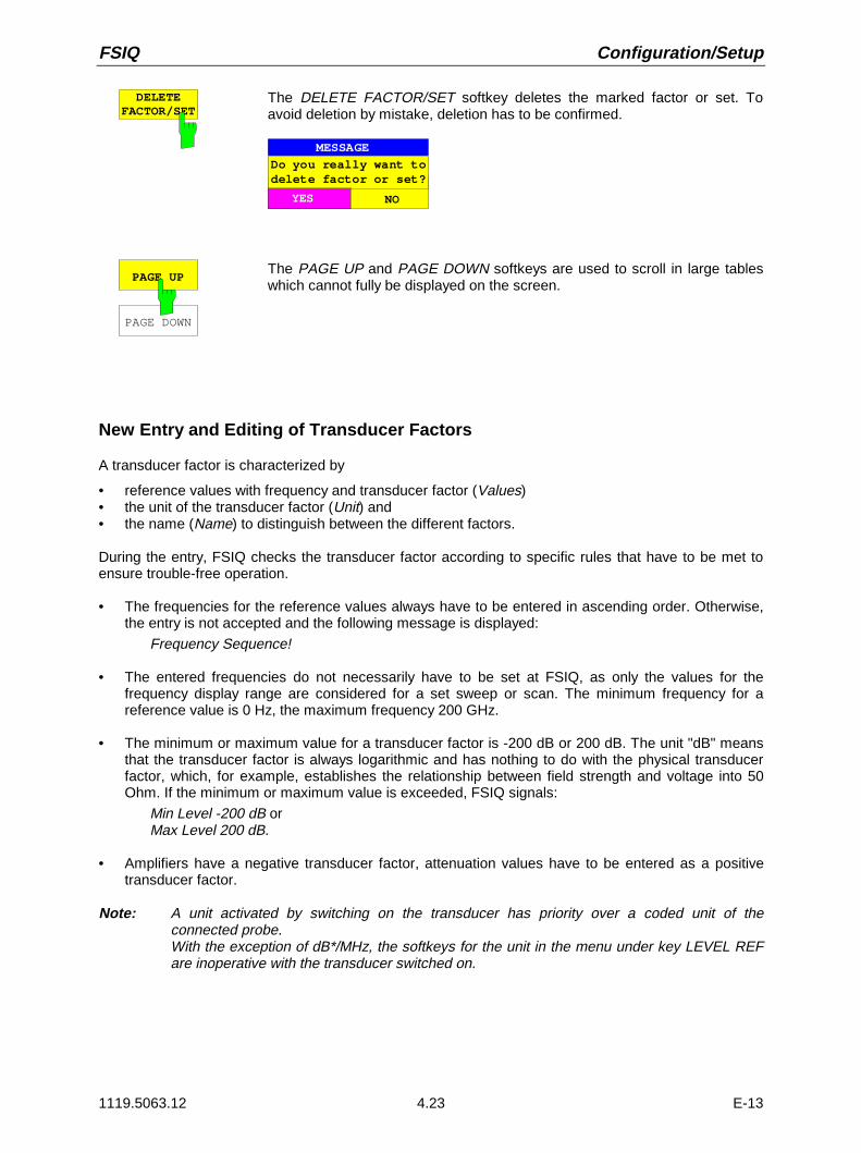
FSIQ Configuration/Setup
1119.5063.12 4.23 E-13
DELETEFACTOR/SET
The DELETE FACTOR/SET softkey deletes the marked factor or set. Toavoid deletion by mistake, deletion has to be confirmed.
YES NO
MESSAGE
Do you really want todelete factor or set?
PAGE UP
PAGE DOWN
The PAGE UP and PAGE DOWN softkeys are used to scroll in large tableswhich cannot fully be displayed on the screen.
New Entry and Editing of Transducer Factors
A transducer factor is characterized by
• reference values with frequency and transducer factor (Values)• the unit of the transducer factor (Unit) and• the name (Name) to distinguish between the different factors.
During the entry, FSIQ checks the transducer factor according to specific rules that have to be met toensure trouble-free operation.
• The frequencies for the reference values always have to be entered in ascending order. Otherwise,the entry is not accepted and the following message is displayed:
Frequency Sequence!
• The entered frequencies do not necessarily have to be set at FSIQ, as only the values for thefrequency display range are considered for a set sweep or scan. The minimum frequency for areference value is 0 Hz, the maximum frequency 200 GHz.
• The minimum or maximum value for a transducer factor is -200 dB or 200 dB. The unit "dB" meansthat the transducer factor is always logarithmic and has nothing to do with the physical transducerfactor, which, for example, establishes the relationship between field strength and voltage into 50Ohm. If the minimum or maximum value is exceeded, FSIQ signals:
Min Level -200 dB orMax Level 200 dB.
• Amplifiers have a negative transducer factor, attenuation values have to be entered as a positivetransducer factor.
Note: A unit activated by switching on the transducer has priority over a coded unit of theconnected probe.With the exception of dB*/MHz, the softkeys for the unit in the menu under key LEVEL REFare inoperative with the transducer switched on.

Configuration/Setup FSIQ
1119.5063.12 4.24 E-13
EDIT TRDFACTOR
NEW TRDFACTOR/SET
The EDIT TRD FACTOR and NEW FACT/SET softkeysboth open the submenu for editing and entering newtransducer factors. A precondition for the NEWFACTOR/SET softkey is that the selection bar is locatedin the table when the table TRANSDUCER FACTOR iscalled up.
USER
TRD FACTORNAME
TRD FACTORUNIT
TRD FACTORVALUES
DRAW TRDFACTOR
Name: Antenna1Unit: dBuV/mInterpolation: LINComment: Ant1 and cable 1
EDIT TRANSDUCER FACTOR
2425
NO.
484950
FREQUENCY FREQUENCYTDF/dB..
20.0000 MHz25.0000 MHz30.0000 MHz40.0000 MHz50.0000 MHz60.0000 MHz70.0000 MHz80.0000 MHz
25.523.820.519.820.019.519.118.2
TDF/dB..
SAVE TRD FACTOR
INSERTLINE
DELETELINE
EDIT TRDFACTOR
The table with the data of the marked factor (the EDIT TRD FACTOR softkey) or an empty table isdisplayed in which the following entries are preset (the NEW FACTOR/SET softkey):Unit: dBInterpolation: LIN for linear frequency scaling
LOG for logarithmic frequency scaling
The characteristics of the factor can be entered in the header field of the table, the frequency and thetransducer factor in the columns of the table.
Name Entry of the name
Unit Selection of unit
Interpolation Selection of interpolation
Comment Entry of a comment
FREQUENCY Entry of the frequency of the reference points
TDF/dB Entry of the transducer factor.
An overwritten transducer factor remains stored in the background as long as the edited factor is storedwith the SAVE TRD FACTOR softkey or until the table is closed. A factor overwritten by mistake can berestored by leaving the entry.

FSIQ Configuration/Setup
1119.5063.12 4.25 E-13
TRD FACTORNAME
The TRD FACTOR NAME softkey activates the entry of the transducer factorcharacteristics in the header field of the table.
Name - Entry of name
A maximum of 8 characters is permissible for the name. The characters haveto comply with the convention of DOS file names. The unit automaticallystores all transducer factors with the extension .TDS.
If an existing name is changed, the factor stored under the previous name isretained and will not be overwritten automatically with the new name. Theprevious factor can be deleted at a later time, using DELETE FACTOR/SET.Thus, factors can be copied.
TRD FACTORUNIT
Unit - Selection of unit
The unit of the transducer factor is selected from a selection box activated bythe TRD FACTOR UNIT softkey.
FACTOR UNIT
dBdBmdBµVdBµV/mdBµAdBµA/mdBpWdBpT
The default setting is dB.
Interpolation - Selection of interpolation
Linear or logarithmic interpolation can be carried out between the frequencyreference points of the table. Selection is via the ENTER key which is toggledbetween LIN and LOG (toggle function).
The following diagrams indicate the effect of the interpolation on thecalculated characteristic:
Fig. 4-2 inear frequency axis and linear interpolation

Configuration/Setup FSIQ
1119.5063.12 4.26 E-13
Fig. 4-3 Logarithmic frequency axis and logarithmic interpolation
Fig. 4-4 Logarithmic frequency axis and linear interpolation
Comment - Entry of a comment
The comment can be freely selected. It can have a maximum number of 50characters.
TRD FACTORVALUES
The TRD FACTOR VALUES softkey activates the entry for the referencevalues of the transducer factor.
The selection bar marks the first reference value. The desired referencevalues have to be entered in ascending frequency sequence.After entering the frequency the selection bar automatically jumps to thecorresponding level value.
After entering the first reference value the table can be edited. The twoINSERT LINE and DELETE LINE softkeys are displayed. Individual valuesare changed at a later time by marking the field and by entering the newvalue.
DELETELINE
INSERTLINE
The INSERT LINE softkey inserts a free line above the marked referencevalue. When entering a new reference value into this line watch out for theascending frequency sequence.
The DELETE LINE softkey deletes the marked reference value (the wholeline). The following reference values move up.
SAVE TRDFACTOR
The SAVE TRD FACTOR softkey saves the changed table in a file on theinternal hard disk.
If a transducer factor with the same name already exists, a correspondingquery is performed beforehand.
If the factor to be newly saved is currently switched on, the new values willimmediately be valid. If a transducer set is switched on comprising the factor,the values will only be used when the set is switched on next time.

FSIQ Configuration/Setup
1119.5063.12 4.27 E-13
New Entry and Editing of Transducer Sets
A transducer set is characterized by:− maximum 10 ranges (Ranges) in which different transducer factors can be active− the combination of several transducer factors per range (Factor)− a transducer-set name (Name)
EDITTRD SET
NEW TRDFACTOR/SET
The EDIT TRD SET and NEW FACTOR/SET softkeysboth open the submenu for editing and entering newtransducer factors. A precondition for the NEWFACTOR/SET softkey is that the selection bar is locatedin the table TRANSDUCER SET.
USER
EDITTRANSD SET
TRANSD SETRANGES
INSERT LINE
TRANSD SET NAME
TRANSD SET UNIT
TRANSDUCER SET RANGES
Start Stop
Comment: Ant. 1 and cable 1
EDIT TRANSDUCER SET
Unit: dBµV/mBreak: ON
20.00000 MHz 80.00000 MHz80.00000 MHz 400.00000 MHz400.0000 MHz 1.00000 GHz
Selfac
DELETE LINE
Name: Ant_Cab1
DRAWTRD SET
SAVE TRD SET
PAGE UP
PAGE DOWN
The table with the data of the marked set (the EDIT TRD SET softkey) or an empty table in which thefollowing entries are preset (the NEW FACTOR/SET softkey) is displayed:Unit: dBBreak: NO
The characteristics of the set can be entered in the header field of the table, the subranges in thecolumns of the set.Name Entry of the nameUnit Selection of unitBreak Activating the query when changing the subrangeComment Entry of a commentStart Entry of the start frequency of the subrangeStop Entry of the stop frequency of the subrangeSel Fac Selection of the transducer factors for the subrange
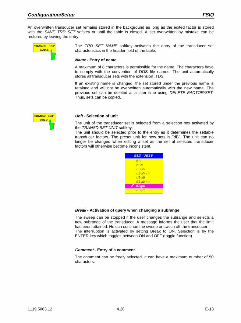
Configuration/Setup FSIQ
1119.5063.12 4.28 E-13
An overwritten transducer set remains stored in the background as long as the edited factor is storedwith the SAVE TRD SET softkey or until the table is closed. A set overwritten by mistake can berestored by leaving the entry.
TRANSD SETNAME
The TRD SET NAME softkey activates the entry of the transducer setcharacteristics in the header field of the table.
Name - Entry of name
A maximum of 8 characters is permissible for the name. The characters haveto comply with the convention of DOS file names. The unit automaticallystores all transducer sets with the extension .TDS.
If an existing name is changed, the set stored under the previous name isretained and will not be overwritten automatically with the new name. Theprevious set can be deleted at a later time using DELETE FACTOR/SET.Thus, sets can be copied.
TRANSD SETUNIT
Unit - Selection of unit
The unit of the transducer set is selected from a selection box activated bythe TRANSD SET UNIT softkey.The unit should be selected prior to the entry as it determines the settabletransducer factors. The preset unit for new sets is "dB". The unit can nolonger be changed when editing a set as the set of selected transducerfactors will otherwise become inconsistent.
SET UNIT
dBdBmdBµVdBµV/mdBµAdBµA/mdBpWdBpT
Break - Activation of query when changing a subrange
The sweep can be stopped if the user changes the subrange and selects anew subrange of the transducer. A message informs the user that the limithas been attained. He can continue the sweep or switch off the transducer.The interruption is activated by setting Break to ON. Selection is by theENTER key which toggles between ON and OFF (toggle function).
Comment - Entry of a comment
The comment can be freely selected. It can have a maximum number of 50characters.

FSIQ Configuration/Setup
1119.5063.12 4.29 E-13
TRANSD SETRANGES
Softkey TRANSD SET RANGES activates the entry of subranges and theassociated transducer factors. The selection bar marks the frequency valueslast active.
Start - Entry of start frequency of subrangeStop - Entry of stop frequency of subrange
The individual subranges have to be linked without a gap. That is why thestart frequency is already defined from the second subrange (= stopfrequency of previous range).
After entering the first frequency value the table can be edited. The twoINSERT LINE and DELETE LINE softkeys are displayed. Some values arechanged at a later time by marking the field and by entering the new value. Itshould be noted that both the stop frequency of a particular subrange and thestart frequency of the subsequent subrange are changed to the same extent.
Sel fac- Selection of factors for the subrange
A check sign in column Sel Fac (select factor) indicates whether one orseveral transducer factors were selected for the subrange.
The permissible transducer factors for the marked subrange can be selectedin a selection box. Only factors matching with the unit of the set and fullycovering the selected subrange are permissible.After each change of range limits, FSIQ thus checks the factor list and, ifrequired, rebuilds it.After reducing the start frequency or increasing the stop frequency of a rangeit may happen that the factors defined for this range no longer fully cover therange. These factors are deleted for this range when the transducer factortable is opened next time.
A maximum of 4 transducer factors can be switched on at the same time ineach subrange. If none of them is switched on, 0 dB is assumed as a factorfor the whole subrange.
Antenna1Probe_AProbe_B
Cable_2
dBµV/mdBµV/mdBµV/m
dBdB
Name Unit
SELECT TRANSDUCER FACTOR
Cable_1
Probe_C
Preamp
dBµV/mMy_Probe dB
dB
Press ENTER to (de)select

Configuration/Setup FSIQ
1119.5063.12 4.30 E-13
INSERT LINE
DELETE LINE
The INSERT LINE softkey inserts a free line above the marked subrange.
The DELETE LINE softkey deletes the marked subrange (whole line). Thefollowing subranges move up.
In both cases FSIQ checks that the ranges follow each other without a gap.
SAVE TRDSET
The SAVE TRD SET softkey saves the changed table in a file on the internalhard disk. If a transducer name with the same name already exists, acorresponding query is performed beforehand:
YES NO
MESSAGE
File exists! Do you want to overwrite?
After pressing ENTER, the data set is overwritten on the hard disk.If the saved set is switched on, the new values will be used immediately.
PAGE UP
PAGE UP
The PAGE UP and PAGE DOWN softkeys set the table to the next orprevious page.
The softkeys are locked during selection of factors in the right table.

FSIQ Configuration/Setup
1119.5063.12 4.31 E-13
Enabling Firmware Options
CONFIGURATION SETUP menu:
OPTIONS The OPTIONS softkey opens a submenu for entering keywords for newfirmware options (Application Firmware Modules). Options which are alreadyavailable are indicated in a table that is opened when the menu is called.
ENABLE NEWOPTION
The ENABLE OPTION softkey activates the entry of akeyword for a firmware option.
One or several keywords may be specified in the entryfield. When a valid keyword is entered, the messageOPTION KEY OK appears in the info line and the optionis written into the FIRMWARE OPTIONS table.
The FIRMWARE OPTIONS table can also be displayedusing the FIRMWARE OPTIONS softkey in the INFOmenu.
If a keyword is invalid the message OPTION KEYINVALID is displayed in the info line.
External Reference Oscillator
In general, the FSIQ can generate all internal oscillators from either the internal or an external referenceoscillator. A 10 MHz quartz-controlled oscillator is used as the internal reference. A reference oscillatoroutput is also available at the rear panel via the EXT REF IN/OUT connector.This output can be used, e.g., to synchronize other instruments to the FSIQ. This connector can also beconverted to an input connector for application of an external frequency standard. The FSIQ requiresthat the frequency of the external standard be entered so that the internal oscillators can besynchronized to it.
CONFIGURATION SETUP Menu:
REFERENCEINT EXT
The REFERENCE INT EXT softkey switches between the internal andexternal references.
EXT REFFREQUENCY
The EXT REF FREQUENCY softkey activates the entry of the frequency ofthe external source.Range of input values is 1 MHz to 16 MHz in 1 MHz steps.
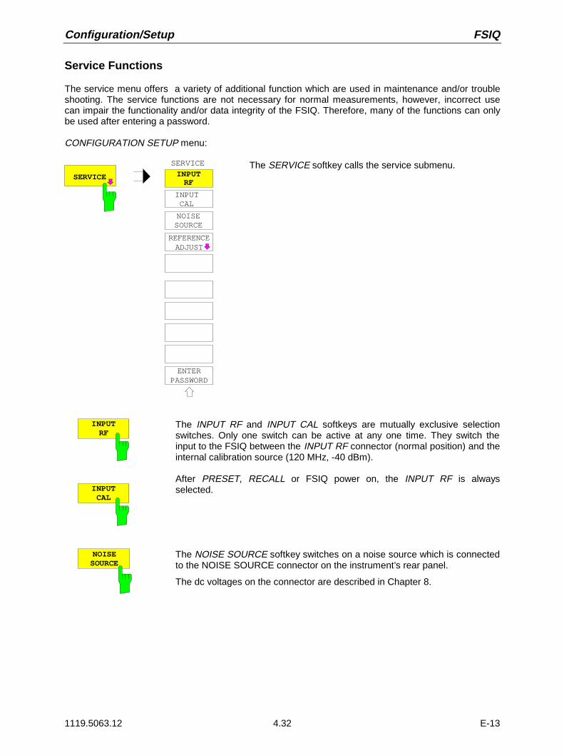
Configuration/Setup FSIQ
1119.5063.12 4.32 E-13
Service Functions
The service menu offers a variety of additional function which are used in maintenance and/or troubleshooting. The service functions are not necessary for normal measurements, however, incorrect usecan impair the functionality and/or data integrity of the FSIQ. Therefore, many of the functions can onlybe used after entering a password.
CONFIGURATION SETUP menu:
SERVICE
INPUTRF
SERVICE
INPUTCAL
ENTERPASSWORD
NOISESOURCE
REFERENCEADJUST
The SERVICE softkey calls the service submenu.
INPUTRF
INPUTCAL
The INPUT RF and INPUT CAL softkeys are mutually exclusive selectionswitches. Only one switch can be active at any one time. They switch theinput to the FSIQ between the INPUT RF connector (normal position) and theinternal calibration source (120 MHz, -40 dBm).
After PRESET, RECALL or FSIQ power on, the INPUT RF is alwaysselected.
NOISESOURCE
The NOISE SOURCE softkey switches on a noise source which is connectedto the NOISE SOURCE connector on the instrument’s rear panel.
The dc voltages on the connector are described in Chapter 8.

FSIQ Configuration/Setup
1119.5063.12 4.33 E-13
CONFIGURATION SETUP SERVICE menu:
REFERENCEADJUST
REFERENCEADJUST REFERENCE
REFERENCEPROG
The REFERENCE ADJUST softkey opens a submenu used toadjust the frequency precision of the reference oscillator.The value should be modified only after the frequencyprecision was checked and found to be erroneous (settingrange 0 to 4095).
For more information about how to perform the adjustment ofthe frequency precision refer to service manual instrument(delivered with the FSIQ).The modified reference value is preserved when the menu isclosed.
The current adjustment value can be permanently stored in anEEPROM in the instrument.
Caution: As the specifications of the whole instrumentdepend directly on the setting of the referenceoscillator (frequency precision), storing incorrectadjustment values should be avoided.
Note: If no adjustment value has been stored(REFERENCE PROG softkey) before the analyzeris switched off and on again, the factory-set valueof the reference frequency or the value that hasbeen programmed last will be used.
REFERENCE The REFERENCE softkey adjusts thefrequency precision of the referenceoscillator.
REFERENCEPROG
The REFERENCE PROG softkeystores the current adjustment value inan EEPROM in the instrument.
ENTERPASSWORD
The ENTER PASSWORD softkey allows the entry of a password.
The FSIQ contains a variety of service functions which, if incorrectly used,can impair the functionality of the analyzer. These functions are normally notaccessible and are only usable after the entry of a password (ENTERPASSWORD).

Configuration/Setup FSIQ
1119.5063.12 4.34 E-13
Programming the Interface Configuration and Time
The GENERAL SETUP softkey branches to a sub-menu in which the basic setup of general instrumentparameters may be performed. The current settings are displayed in tabular form on the display screenwhere they may then be edited.
CONFIGURATION SETUP menu:
US E R
GPIBADDRESS
GENERALSETUP
TIME
DATE
MONITORCONNECTED
USER PORT A
USER PORT B
GPIB ADRESS
19
PORT A PORT B
DirectionValue
Input10101010
Output00010001
USER PORTS
TIME AND DATE
TimeDate
21:5901 Oct 1994
GENERALSETUP
KEY CLICKON OFF
COM 1
COM 2
BaudBitsParityStopbitsHW-HandshakeSW-HandshakeOwner
CO M PORTS
COM 1
8None1NoneXON/XOFFInstrument
COM 2
12008None1NoneNoneInstrument
9600
IEC Bus Address Selection
CONFIGURATION SETUP-GENERAL SETUP submenu:
GPIBADDRESS
The GPIB ADDRESS softkey activates the entry of the IEC Bus address.
Permitted addresses are 0 through 31. The default setting is address 20.

FSIQ Configuration/Setup
1119.5063.12 4.35 E-13
User Port Configuration
The instrument provides two parallel interfaces, each of which is 8 bits wide. Over these ports, arbitrarybit patterns can be output or input. The interfaces are designated USER PORT A and USER PORT B.
CONFIGURATION SETUP-GENERAL SETUP submenu:
USERPORT A
The USER PORT A and USER PORT B softkeys activate the columns PORTA and PORT B, respectively, in the USERPORTS table for entry of theparameters for both of the parallel interfaces in the instrument. Because thetwo interfaces are configured in the same manner, how to configure aninterface is described in the following using USER PORT A.
The following parameters need to be configured in the table:
Direction Direction of data transmission
Value Indication/entry of current value
USERPORTS
PORT A PORT B
OUTPUT
10101010
INPUTDirectionValue
Direction – Direction of data transmissionThe DIRECTION parameter determines in which direction the interfacetransmits data.
INPUT read operation
OUTPUT write operation
DIRECTION
INPUTOUTPUT
Value – Indication/Entry of current valueThe VALUE parameter shows the current value of the data at the port fordata input as well as for data output. The displayed data is in binary formatwith the least significant bit (LSB) on the right.
If the port is configured as an OUTPUT then, the displayed value can beedited. Data entry must also be in binary format (i.e., only the digits 0 and 1are accepted).
VALUE
00010001

Configuration/Setup FSIQ
1119.5063.12 4.36 E-13
Serial Interface Configuration
CONFIGURATION SETUP-GENERAL SETUP submenu:
COMPORT 1
COMPORT 2
The COM PORT 1 and COM PORT 2 softkeys activate the columns COM1and COM2, respectively, for entry of the serial interface parameters Since thetwo interfaces are configured in the same manner, how to configure aninterface is described in the following using COM PORT 1.
The following parameters need to be configured in the table:
Baud rate data transmission rate
Bits number of data bits
Parity bit parity check
Stop bits number of stop bits
HW-Handshake hardware handshake protocol
SW-Handshake software handshake protocol
Owner assignment to the measuring instrument or computer
BaudBitsParityStopbitsHW-HandshakeSW-HandshakeOwner
COM PORTS
COM 1
8None1NoneXON/XOFFInstrument
COM 2
12008None1NoneNoneInstrument
9600
Note: A serial interface (COM1 or COM2) cannot be used for anotherpurpose if a mouse is connected to it.
Baud – Data transmission rateAllowed are the indicated values between 110 and 19200 baud. The defaultsetting is 9600 baud.
BAUD RATE
19200960048001200600300110
Bits – Number of data bits per wordFor the transmission of text without German umlauts (Ä, ä, Ü, ü, Ö, ö) andspecial characters, 7 bits are adequate. For binary data as well as text withspecial characters or umlauts, 8 bits must be selected (default setting).
BITS
7
8

FSIQ Configuration/Setup
1119.5063.12 4.37 E-13
Parity – Bit parity checkNONE no parity check (default setting)
EVEN even parity check
ODD odd parity checkPARITY
NONEEVENODD
Stop bits – Number of stop bitsAvailable are 1 and 2. The default setting is 1 stop bit.STOPBITS
12
HW-Handshake – Hardware handshake protocolThe integrity of data transmission can be improved through the use of ahardware handshake protocol which effectively prevents uncontrolledtransmission of data and the resulting possible loss of data bytes. In thehardware handshaking procedure, additional interface lines are used totransmit acknowledge signals with which the data transmission can becontrolled and, if necessary, stopped until the receiver is ready to receivedata again.
A prerequisite for handshaking is, however, that the interface lines (DTR andRTS) are provided between sender and receiver. For a simple, 3-wireconnection, this is not the case and hardware handshake cannot be realizedhere.
Default setting is NONE.HW-HANDSHAKE
NoneDTR/RTS
SW-Handshake – Software handshake protocolBesides the hardware handshake procedure using interface lines, it is alsopossible to achieve the same effect by using a software handshake protocol.Here, control bytes are transmitted in addition to the normal data bytes.These control bytes can be used, as necessary, to stop data transmissionuntil the receiver is ready to receive data again.
In contrast to hardware handshaking, software handshaking can be realizedeven for a simple, 3-wire connection.
One limitation is, however, present in software handshaking. Softwarehandshaking cannot be used for the transmission of binary data since, thecontrol characters XON and XOFF require bit combinations that are alsoused for binary data transmission.
Default setting is NONE.
SW-HANDSHAKE
NoneXON/XOFF

Configuration/Setup FSIQ
1119.5063.12 4.38 E-13
Owner – Assignment of the interfaceThe serial interface can be assigned alternatively to the instrumentmeasurement section or the computer section.
INSTRUMENT The interface is assigned to the instrument measurementsection. Outputs to the interface from the computer arenot possible and, so to say, land nowhere.
OS The interface is assigned to the computer section. Itcannot be used by the instrument measurement section.This means that hardcopy or remote control of theinstrument via the interface is not possible. An attempt tostart a print job via the interface results in an errormessage.
OWNER
OSINSTRUMENT
Setting Date and Time
CONFIGURATION SETUP-GENERAL SETUP submenu:
TIME The TIME softkey activates the entry of time for the internal real time clock .In the corresponding dialog box, the time is partitioned into two input fields sothat hours and minutes can be entered independently.
TIME
TIME 10 33:
DATE The DATE softkey activates the entry of the date of the internal real-timeclock. In the corresponding dialog box, the date is partitioned into 3 inputfields so that day, month and year can be input separately.
DATE 10 MAY 1995
DATE
For the selection of the month, pressing a units key opens a list ofabbreviations wherein the desired month can be selected.
MONTH
JANFEBMARAPRMAYJUNJULAUGSEPOCTNOVDEC

FSIQ Configuration/Setup
1119.5063.12 4.39 E-13
Connecting the External Monitor
Submenu CONFIGURATION SETUP-GENERAL SETUP:
MONITORCONNECTED
The MONITOR CONNECTED softkey informs the unit that an externalmonitor is available at PC MONITOR connectorThe external monitor displays the Windows NT mask.
Switching the Beeper ON/OFF
CONFIGURATION SETUP-GENERAL SETUP submenu:
KEY CLICKON OFF
The KEY CLICK ON/OFF softkey switches the beeper on or off. The beeperacknowledges each key stroke with a beep.
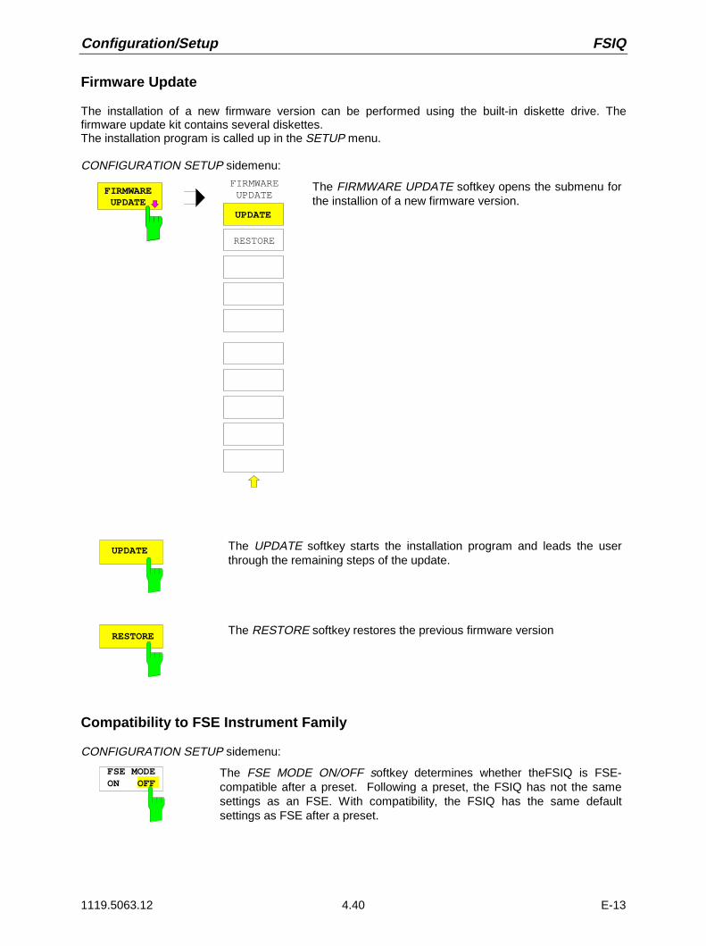
Configuration/Setup FSIQ
1119.5063.12 4.40 E-13
Firmware Update
The installation of a new firmware version can be performed using the built-in diskette drive. Thefirmware update kit contains several diskettes.The installation program is called up in the SETUP menu.
CONFIGURATION SETUP sidemenu:FIRMWARE UPDATE
UPDATE
FIRMWARE UPDATE
RESTORE
The FIRMWARE UPDATE softkey opens the submenu forthe installion of a new firmware version.
UPDATE The UPDATE softkey starts the installation program and leads the userthrough the remaining steps of the update.
RESTORE The RESTORE softkey restores the previous firmware version
Compatibility to FSE Instrument Family
CONFIGURATION SETUP sidemenu:
FSE MODEON OFF
The FSE MODE ON/OFF softkey determines whether theFSIQ is FSE-compatible after a preset. Following a preset, the FSIQ has not the samesettings as an FSE. With compatibility, the FSIQ has the same defaultsettings as FSE after a preset.

FSIQ Manual Control
1119.5063.12 4.41 E-13
Status Display-Remote/Manual Control – STATUS KeyGroup
STATUS
LOCAL
SRQ
REMOTE
The SRQ LED, the REMOTE LED and the LOCAL. key are contained in theSTATUS key group.
ì The SRQ LED indicates that a service request from the instrument hasbeen asserted on the IEC Bus.
ì The REMOTE LED indicates that the instrument is under remote control.
ì The LOCAL key switches the instrument from remote to manual control,with the assumption that the remote controller has not previously set theLOCAL LOCKOUT function.
A change in the control mode consists of:
- Enabling the Front Panel KeysUnder remote control, the soft-key menu is turned off and all keys, withthe exception of PRESET and LOCAL, are disabled. Returning tomanual mode enables all inactive keys. The soft key menu which isdisplayed is the main menu of the current mode.
- Turning off the REMOTE LED
- Generating the message OPERATION COMPLETEIf, at the time of pressing the LOCAL key, the synchronisationmechanism via *OPC, *OPC? or *WAI is active, the currently runningmeasurement procedure is aborted and synchronisation is achieved bysetting the corresponding bits in the registers of the status reportingsystem.
- Setting Bit 6 (User Request) of the Event Status RegisterWith a corresponding configuration of the status reporting system, thisbit immediately causes the generation of a service request (SRQ) whichis used to inform the software that the user wishes to return to front-panel control. This information can be used, e.g., to interrupt the controlprogram so that the user can make necessary manual corrections toinstrument settings. This bit is set each time the LOCAL key is pressedand is independent of whether or not the instrument is under remote ormanual control.
ì The LOCAL key aborts a running macro. The continuation of the macro isnot possible.

Documentation of Measurement Results FSIQ
1119.5063.12 4.42 E-13
Measurement Documentation – HARDCOPY Key Group
Printing Data – START Key
The instrument uses the printer function of Windows NT to output hardcopies. Any printer supported byWindows NT can be used. In addition, the instrument permits data output in the usual data formatsWMF, EWMF and BMP which enable hardcopies to be directly inserted into other documents. Networkprinters can be used if the instrument is connected to a network.
SE NG
START
HARDCOPY The START key initiates the printing of measurement/ instrument status data.The instrument can distinguish between two different output devices, each ofwhich may be individually configured, e.g., a laser printer and a ink jet printer.All documents are printed on the output device which is currently active.
Pressing the HARDCOPY START key initiates the print job. The printer parameters defined underWindows NT and in the HARDCOPY SETTINGS menu are used for setting up the printer configuration.After pressing the START key, all of the display items to be printed are written to the printer buffer ofWindows NT. Since the printer runs in the background, the instrument may be operated immediatelyafter pressing the START key.
With COPY SCREEN selected in menu HARDCOPY SETTINGS, all the diagrams with traces andstatus displays are printed as they occur on the screen. Softkeys, open tables and data entry fields arenot printed out. Function COPY TRACE allows to print out individual traces. With COPY TABLE tablescan be printed out.
If output device CLIPBOARD is active in menu HARDCOPY SETTINGS, submenu HARDCOPYDEVICE, the clipboard can be used to directly transfer hardcopies to Windows applications. The copy iswritten in the clipboard by pressing HARDCOPY START. The user can then change to another Worddocument and insert the clipboard content into the document via the menu EDIT - PASTE by using thekey combination CTRL+V.
If the PRINT TO FILE option in the HARDCOPY DEVICE submenu of the HARDCOPY SETTINGSmenu is selected then, upon pressing HARDCOPY START, the file name to which the output data are tobe written is requested. For this an entry field is opened for entering the file name. If no externalkeyboard is connected, the help line editor is activated.
If the START key is pressed again during an active print job, a second output can be released which canalso be joined to the printer queue. Any number of print jobs can be released consecutively.
Current print jobs can be aborted only by canceling the entries in the Windows NT printer queue. Afterstarting the print a printer symbol is displayed in the task bar near the time indication.
A double-click on this symbol opens a window containing the entries of the printer queue. The relevantprint order can be cancelled by marking it with the mouse and pressing the DEL key.

FSIQ Documentation of Measurement Results
1119.5063.12 4.43 E-13
While a print job is in progress, problems may occur in the output device. If, while printing, the outputdevice issues a PAPER OUT message, i.e., no more paper is available, the user will be prompted by thefollowing message
ERROR
Paper out on device LPT(manual feed)?
CONTINUEABORT
to load paper into the output device. The print job will then be either continued (CONTINUE selected) oraborted (ABORT selected).
Switchover between b/w and colored printouts is possible with softkey COLOR ON/OFF provided thatthe printer connected is able to output such prints. The colors of the printout correspond exactly to thoseof the screen, ie a red trace will be output in red.To change the colors of the objects on the printout, the screen colors have to be changedcorrespondingly in menu DISPLAY, submenu CONFIG DISPLAY. One exception is the color of thebackground and the color of the diagrams. The output background is always white irrespective of thescreen color and the diagrams are always black.If several traces are to be output one after the other on the same sheet different colors can be chosenfor each trace with the aid of softkey TRC COLOR AUTO INC (Trace Color Auto Increment).
On most b/w printers, a better printout of the color screen is obtained on hardcopies if the colorinformation is converted into gray shades. For this, the color output in menu HARDCOPY SETTINGS isto be activated (COLOR ON).

Documentation of Measurement Results FSIQ
1119.5063.12 4.44 E-13
Printing Configuration – SETTINGS Key
HARDCOPY SETTINGS menu:
TRC COLORAUTO INC
HARDCOPY
SETTINGS
STARTCOPYTRACE
SELECTITEMS
SELECTQUADRANT
COLORON OFF
HARDCOPYDEVICE
ENTERTEXT
HARDCOPYSETTINGS
COPYSCREEN
COPYSEL ITEMS
COPYTABLE
The SETTINGS key opens the menu to define the outputconfiguration for diagrams and measurement curves to thevarious output channels, e.g., printer, plotter or files.
The recommended procedure for configuring the output data isas follows:
• Configure the desired output device and select the interfaceover which the output is to take place by using Windows NTand the HARDCOPY DEVICE softkey.
• Select the display items to be printed via the COPY SCREEN,COPY TRACE softkeys.
• Select between coloured and b/w printouts via softkeysCOLOR ON/ OFF and TRC COLOR AUTO INC
• Enter commentary applicable to the diagram or add a title forthe overall print-out by using the ENTER TEXT softkey.
• Select the page format (QUADRANT, FULL PAGE) throughuse of the SELECT QUADRANT softkey.
The COPY SCREEN, COPY TRACE and COPY TABLEsoftkeys are selection switches, i.e., only one function can beenabled at any one time. The push buttons are used forselection only and do not initiate a print job. The actual printingof data is initiated by the HARDCOPY START key.
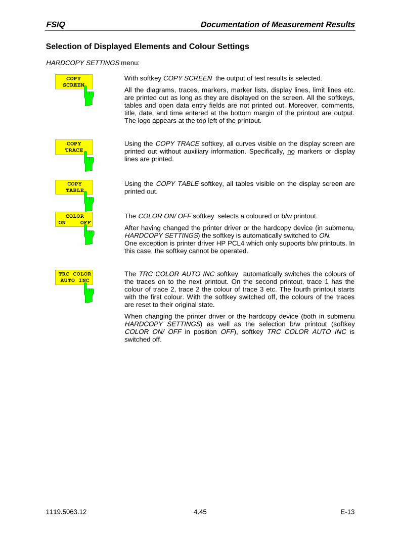
FSIQ Documentation of Measurement Results
1119.5063.12 4.45 E-13
Selection of Displayed Elements and Colour Settings
HARDCOPY SETTINGS menu:
COPYSCREEN
With softkey COPY SCREEN the output of test results is selected.
All the diagrams, traces, markers, marker lists, display lines, limit lines etc.are printed out as long as they are displayed on the screen. All the softkeys,tables and open data entry fields are not printed out. Moreover, comments,title, date, and time entered at the bottom margin of the printout are output.The logo appears at the top left of the printout.
COPYTRACE
Using the COPY TRACE softkey, all curves visible on the display screen areprinted out without auxiliary information. Specifically, no markers or displaylines are printed.
COPYTABLE
Using the COPY TABLE softkey, all tables visible on the display screen areprinted out.
COLORON OFF
The COLOR ON/ OFF softkey selects a coloured or b/w printout.
After having changed the printer driver or the hardcopy device (in submenu,HARDCOPY SETTINGS) the softkey is automatically switched to ON.One exception is printer driver HP PCL4 which only supports b/w printouts. Inthis case, the softkey cannot be operated.
TRC COLORAUTO INC
The TRC COLOR AUTO INC softkey automatically switches the colours ofthe traces on to the next printout. On the second printout, trace 1 has thecolour of trace 2, trace 2 the colour of trace 3 etc. The fourth printout startswith the first colour. With the softkey switched off, the colours of the tracesare reset to their original state.
When changing the printer driver or the hardcopy device (both in submenuHARDCOPY SETTINGS) as well as the selection b/w printout (softkeyCOLOR ON/ OFF in position OFF), softkey TRC COLOR AUTO INC isswitched off.
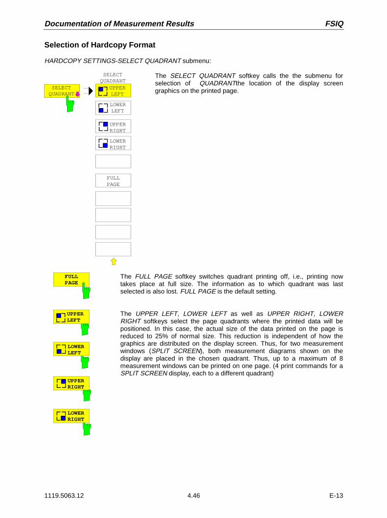
Documentation of Measurement Results FSIQ
1119.5063.12 4.46 E-13
Selection of Hardcopy Format
HARDCOPY SETTINGS-SELECT QUADRANT submenu:
SELECTQUADRANT
SELECTQUADRANT
UPPERLEFT
UPPERRIGHT
LOWERLEFT
LOWERRIGHT
FULLPAGE
The SELECT QUADRANT softkey calls the the submenu forselection of QUADRANTthe location of the display screengraphics on the printed page.
FULLPAGE
The FULL PAGE softkey switches quadrant printing off, i.e., printing nowtakes place at full size. The information as to which quadrant was lastselected is also lost. FULL PAGE is the default setting.
UPPERLEFT
LOWERLEFT
UPPERRIGHT
LOWERRIGHT
The UPPER LEFT, LOWER LEFT as well as UPPER RIGHT, LOWERRIGHT softkeys select the page quadrants where the printed data will bepositioned. In this case, the actual size of the data printed on the page isreduced to 25% of normal size. This reduction is independent of how thegraphics are distributed on the display screen. Thus, for two measurementwindows (SPLIT SCREEN), both measurement diagrams shown on thedisplay are placed in the chosen quadrant. Thus, up to a maximum of 8measurement windows can be printed on one page. (4 print commands for aSPLIT SCREEN display, each to a different quadrant)
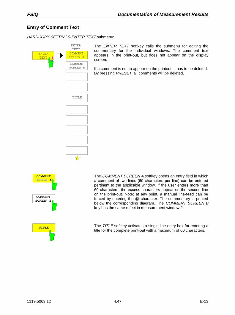
FSIQ Documentation of Measurement Results
1119.5063.12 4.47 E-13
Entry of Comment Text
HARDCOPY SETTINGS-ENTER TEXT submenu:
ENTERTEXT
ENTERTEXT
COMMENTSCREEN A
COMMENTSCREEN B
TITLE
The ENTER TEXT softkey calls the submenu for editing thecommentary for the individual windows. The comment textappears in the print-out, but does not appear on the displayscreen.
If a comment is not to appear on the printout, it has to be deleted.By pressing PRESET, all comments will be deleted.
COMMENTSCREEN A
COMMENTSCREEN B
The COMMENT SCREEN A softkey opens an entry field in whicha comment of two lines (60 characters per line) can be enteredpertinent to the applicable window. If the user enters more than60 characters, the excess characters appear on the second lineon the print-out. Note: at any point, a manual line-feed can beforced by entering the @ character. The commentary is printedbelow the corresponding diagram. The COMMENT SCREEN Bkey has the same effect in measurement window 2.
TITLE The TITLE softkey activates a single line entry box for entering atitle for the complete print-out with a maximum of 60 characters.
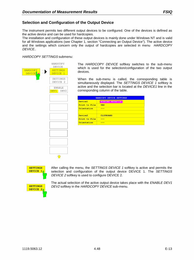
Documentation of Measurement Results FSIQ
1119.5063.12 4.48 E-13
Selection and Configuration of the Output Device
The instrument permits two different output devices to be configured. One of the devices is defined asthe active device and can be used for hardcopies.The installation and configuration of these output devices is mainly done under Windows NT and is validfor all Windows applications (see Chapter 1, section "Connecting an Output Device"). The active deviceand the settings which concern only the output of hardcopies are selected in menu HARDCOPYDEVICE..
HARDCOPY SETTINGS submenu:
HARDCOPYDEVICE
HARDCOPYDEVICESETTINGSDEVICE 1
SETTINGSDEVICE 2
ENABLEDEV1 DEV2
The HARDCOPY DEVICE softkey switches to the sub-menuwhich is used for the selection/configuration of the two outputdevices.
When the sub-menu is called, the corresponding table issimultaneously displayed. The SETTINGS DEVICE 1 softkey isactive and the selection bar is located at the DEVICE1 line in thecorresponding column of the table.
HARDCOPY DEVICE SETTINGS
Device1 WINDOWS METAFILE
Print to File YES
Orientation ---
Device2 CLIPBOARD
Print to File ---
Orientation ---
SETTINGSDEVICE 1
SETTINGSDEVICE 2
After calling the menu, the SETTINGS DEVICE 1 softkey is active and permits theselection and configuration of the output device DEVICE 1. The SETTINGSDEVICE 2 softkey is used to configure DEVICE 2.
The actual selection of the active output device takes place with the ENABLE DEV1DEV2 softkey in the HARDCOPY DEVICE sub-menu.

FSIQ Documentation of Measurement Results
1119.5063.12 4.49 E-13
Device
The selection of the output device/language for DEVICE 1 and DEVICE 2 is made inthis line.
Device1 WINDOWS METAFILE
Print to File YES
Orientation ---
Device2 CLIPBOARD
Print to File ---
Orientation ---
HARDCOPY DEVICE SETTINGS
DEVICE
CLIPBOARD
WINDOWS METAFILE
ENHANCED METAFILE
BITMAP FILE
HP DeskJet 660C
Three file formats and the Windows NT clipboard are always available, even if aprinter has not yet been installed under Windows NT. All installed printers are listedbelow in alphabetic order.The printer installation is described in Chapter 1, section 1.6.
CLIPBOARD When "Clipboard" is selected the hardcopies are copied to theWindows NT clipboard. This permits to obtain a printout of highquality which can be directly inserted into other Windowsapplications (menu EDIT | PASTE or key combination CTRL+V).The lines ’Print to File’, ’Orientation’ and ’GPIB Address’ aredeactivated.
WINDOWS METAFILE and ENHANCED METAFILE
WMF and EWMF are vector graphics formats which can beimported by most graphics and editing programs. EMF isrecommended for recent Windows32 applications.
BITMAP FILE BMP is a bitmap format which can also be imported by mostprograms.
When WMF, EWMF and BMP are selected, the line "Print to File" is automaticallyset to ON and line "Orientation" deactivated.
Print to File
With "Print to File" ON, the printout is directed to a file. In this case the user isprompted to enter a file name on calling up HARDCOPY START.
Note: This setting is coupled to the corresponding setting under Windows NT.
Orientation
In this line, the print format of the output page is set to either vertical (= PORTRAIT)or horizontal (= LANDSCAPE).
ENABLEDEV1 DEV2
The ENABLE DEV1 / DEV2 softkey determines the active output device. Thedefault output device is DEVICE 1, i.e., all output takes place on DEVICE 1.

Memory Configuration FSIQ
1119.5063.12 4.50 E-13
Saving and Recalling Data Sets – MEMORY Key Group
The keys in the MEMORY group call the following functions:
• Functions for management of storage media (CONFIG). Included are among others functions forlisting files, formatting storage media, copying, and deleting/renaming files.
• Storage/loading functions for storing (SAVE) instrument settings such as instrument configurations(measurement/display settings, etc.) and measurement results from working memory to permanentstorage media, or to load (RECALL) stored data into working memory.
The FSIQ is capable of internally storing complete instrument settings with instrument configurationsand measurement data in the form of data sets. The respective data are stored on the internal harddisk or, if selected, on a floppy. The hard-disk and floppy-disk drives are assigned logical names asusual in PC applications:
floppy disk A:hard disk C:
In addition to the saving and recalling of complete instrument settings, it is also possible to save/recallsubsets of settings. Configuration data and measurement values are stored in separate files. These fileshave the same name as the data set but however have a different extension. A data set thus consists ofseveral files which have the same name but different extensions (see Table 4-2).
When saving or loading a data set, the subsets which are to be saved or loaded can be selected in thecorresponding menus. This makes it easy to reconstruct specific instrument settings.
When saving and loading data via the SAVE and RECALL menus, data subsets are selected in a tablein the sub-menu SEL ITEMS TO SAVE/RECALL. The relationship between the designations in the tableand the contents of the data subsets is shown in Table 4-2.
The saved files of the data sets can be copied from one storage medium (e.g. drive C:) to anotherstorage medium (e.g. drive A:) or to another directory using the functions found in the MEMORYCONFIG menu. File names and extensions must however not be changed. The relationship betweenthe data subsets and the extensions is shown in Table 4-2 .
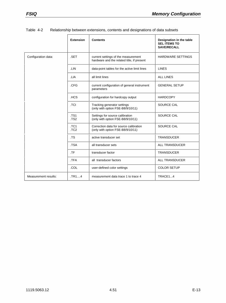
FSIQ Memory Configuration
1119.5063.12 4.51 E-13
Table 4-2 Relationship between extensions, contents and designations of data subsets
Extension Contents Designation in the tableSEL ITEMS TOSAVE/RECALL
Configuration data: .SET current settings of the measurementhardware and the related title, if present
HARDWARE SETTINGS
.LIN data-point tables for the active limit lines LINES
.LIA all limit lines ALL LINES
.CFG current configuration of general instrumentparameters
GENERAL SETUP
.HCS configuration for hardcopy output HARDCOPY
.TCI Tracking generator settings(only with option FSE-B8/9/10/11)
SOURCE CAL
.TS1
.TS2Settings for source calibration(only with option FSE-B8/9/10/11)
SOURCE CAL
.TC1
.TC2Correction data for source calibration(only with option FSE-B8/9/10/11)
SOURCE CAL
.TS active transducer set TRANSDUCER
.TSA all transducer sets ALL TRANSDUCER
.TF transducer factor TRANSDUCER
.TFA all transducer factors ALL TRANSDUCER
.COL user-defined color settings COLOR SETUP
Measurement results: .TR1....4 measurement data trace 1 to trace 4 TRACE1...4

Memory Configuration FSIQ
1119.5063.12 4.52 E-13
Configuration of Memory – CONFIG Key
MEMORY CONFIG menu:
MEMORY
RECALL
SAVE
CONFIG
The CONFIG key opens a menu for managing storage media and files.
Table Drive Management displays the name and label of the storagemedium as well as the available storage area.
Table File Management displays the files of the current directory andindicates if any subdirectories are present.
If a directory name is selected, the FSIQ automatically changes to thisdirectory. Selection of the entry ’..’ moves the FSIQ to the next higherdirectory level.
Note: It is not possible to change menus as long as a file operation isrunning.
USER
DRIVE MANAGEMENT
LABEL:
FILE MANAGEMENT
SIZEFILE NAME DATE
..SETTING1.DRWSETTING2.DRWSETTING3.DRWSETTING4.DRW
10.MAY.9315.MAY.9317.MAY.9328.MAY.93
68.175 kB73.283 kB174.315 kB1.236812 MB
PATH:
10:25:1813:08:2708:15:2117:05:42
TIME
EDITPATH
COPY
PAGE DOWN
MEMORYCONFIG
DELETE
RENAME
SORT MODE
MAKEDIRECTORY
UNDELETE
PAGE UP
DISKCOPY
DISKLABEL
PAGE DOWN
PAGE UP
FORMATDISK
C:\USER\CONFIG
DRIVE: HARDDISK C: FREE MEM: 394:510.336
EDITPATH
The EDIT PATH softkey activates the input of the directory which will be usedin subsequent file operations.
The new path is included in the FILE MANAGEMENT table.

FSIQ Memory Configuration
1119.5063.12 4.53 E-13
COPY The COPY softkey activates the input of the destination of the copy operation.
By entering a predefined disk drive (e.g. C:), a file can also be copied toanother storage medium. The files/directories selected by the cursor arecopied after the input is confirmed by pressing the ENTER key.
DELETE The DELETE softkey deletes the selected files.To prevent accidental deletion of data, confirmation by the user is requested.
RENAME The RENAME softkey activates the entry of a new name for the selected fileor directory.
MAKEDIRECTORY
The MAKE DIRECTORY softkey creates directories/sub-directories. Sub-directories are recommended for sorting files on the storage medium so thatthe structure is easier to comprehend.
The entry of an absolute path name (e.g.; "\USER\MEAS") as well as the pathrelative to the current directory (e.g., "..\MEAS") is possible.
SORT MODE The SORT MODE softkey activates the selection of the criteria according towhich the files listed in the FILE MANAGEMENT table may be sorted.
SORT MODE
by NAMEby DATE/TIMEby EXTENSION
Directory names are located at the top of the list after the entry for the nexthigher directory level ("..").
PAGE UP
PAGE DOWN
The PAGE UP or PAGE DOWN softkey sets the FILE MANAGEMENT tableto the next or the previous page.
FORMATDISK
The FORMAT DISK softkey formats diskettes located in drive A:.To prevent accidental destruction of diskette data, confirmation by the user isrequested.

Saving Data Sets FSIQ
1119.5063.12 4.54 E-13
Saving Data Sets – SAVE Key
The SAVE key activates a menu which contains all functions necessary for saving instrument data.
– Entry of the name of the data set which should be saved. Confirmation of the entry initiates asave operation to store the data set.
Data set names may contain both alphabetical and numeric characters, in the simplest caseonly numbers. The simplest example for the input of a data set name is illustrated by thefollowing key strokes:
<SAVE> <1> <units key>
– Entry of the directory in which the data set should be saved
– Input of data set description
– Selection of the data subsets to be saved (sub-menu SEL ITEMS TO SAVE)
– Indication of all available data sets
– Deletion of all available data sets
MEMORY SAVE menu
USER
SAVE DATA SET
PAGE DOWN
MEMORYSAVE
PAGE UP
SEL ITEMS TO SAVE
DATA SETLIST
EDITPATH
DATA SETCLEAR
DATA SETCLEAR ALL
EDITNAME
COMMENT: Radio Monitoring
PATH:C:\USER\CONFIGNAME: DATASET1
EDITCOMMENT
MEMORY
RE LL
SAVE
CONFIGEDIT NAME
DATASET1_
ITEMS: DEFAULT
The SAVE DATA SET table shows the current settings regarding the data set:
Name name of data set
Path directory in which the data set will be saved
Items indicates whether the default selection of the data subset(DEFAULT) or a user-defined selection (SELECTED) will besaved
Comment Commentary regarding the data set
The EDIT NAME softkey for entering the name of the data set to be saved is activatedautomatically.

FSIQ Saving Data Sets
1119.5063.12 4.55 E-13
Selecting the Data Set for Storage
MEMORY SAVE menu:
EDITNAME
The EDIT NAME softkey activates the entry of the name of the data set to besaved.
Data entry is concluded by pressing one of the units keys which initiates asave operation to store the data set.
EDITPATH
The EDIT PATH softkey activates the input of a directory name where thedata sets are to be stored.
EDITCOMMENT
The EDIT COMMENT softkey activates the entry of commentary concerningthe current data set. A total of 60 characters are available for this purpose.
DATA SET LIST
The DATA SET LIST softkey opens the DATA SET LIST/CONTENTS table.In addition, the DATA SET CLEAR and DATA SET CLEAR ALL softkeys aredisplayed.
DATA SET CONTENTS
DATASET1DATASET2DATASET3
COMMENT
GSM_MASK
COLOR SETUPHARDCOPY
DATA SET LIST
GENERAL SETUPHW-SETTINGSTRACE 1TRACE 2TRACE 3TRACE 4ACTIVE LINESALL LINES
MACROS
ACTIVE TRANSDUCERALL TRANSDUCER
CONTENTS
The DATA SET LIST column lists all of the data sets which are stored in theselected directory.
The CONTENTS and COMMENT lines in the DATA SET CONTENTScolumn indicate the saved data subsets and the commentary for the currentlyselected data set.
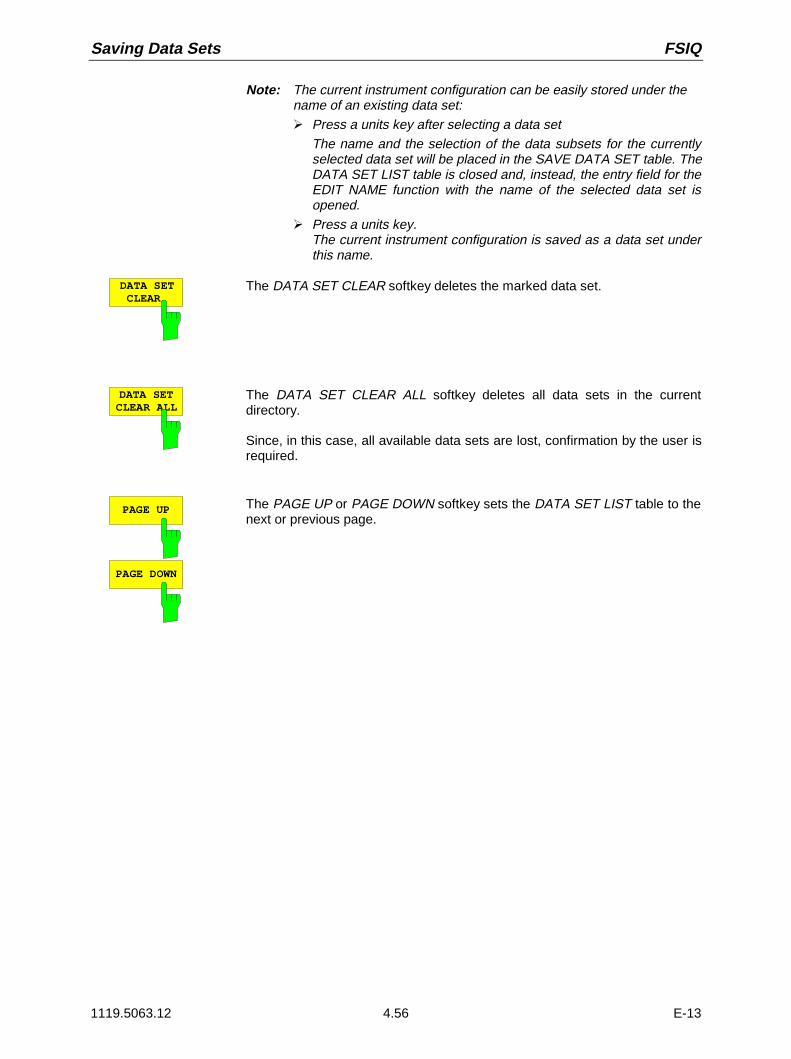
Saving Data Sets FSIQ
1119.5063.12 4.56 E-13
Note: The current instrument configuration can be easily stored under thename of an existing data set:À Press a units key after selecting a data set
The name and the selection of the data subsets for the currentlyselected data set will be placed in the SAVE DATA SET table. TheDATA SET LIST table is closed and, instead, the entry field for theEDIT NAME function with the name of the selected data set isopened.
À Press a units key.The current instrument configuration is saved as a data set underthis name.
DATA SET CLEAR
The DATA SET CLEAR softkey deletes the marked data set.
DATA SETCLEAR ALL
The DATA SET CLEAR ALL softkey deletes all data sets in the currentdirectory.
Since, in this case, all available data sets are lost, confirmation by the user isrequired.
PAGE UP
PAGE DOWN
The PAGE UP or PAGE DOWN softkey sets the DATA SET LIST table to thenext or previous page.
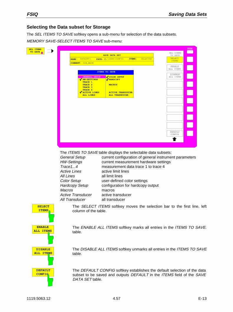
FSIQ Saving Data Sets
1119.5063.12 4.57 E-13
Selecting the Data subset for Storage
The SEL ITEMS TO SAVE softkey opens a sub-menu for selection of the data subsets.
MEMORY SAVE-SELECT ITEMS TO SAVE sub-menu:
SEL ITEMS TO SAVE
USER
ENABLEALL ITEMS
DISABLEALL ITEMS
SEL ITEMSTO SAVE
DEFAULTCONFIG
SELECTITEMS
SAVE DATA SET
COMMENT: GSM_MASK
PATH: C:\USER\CONFIGNAME: DATASET1 ITEMS: SELECTED
ITEMS TO SAVE
COLOR SETUPHARDCOPY
MACROS
ACTIVE TRANSDUCERALL TRANSDUCER
GENERAL SETUPHW-SETTINGSTRACE 1TRACE 2TRACE 3TRACE 4ACTIVE LINESALL LINES
The ITEMS TO SAVE table displays the selectable data subsets:General Setup current configuration of general instrument parametersHW-Settings current measurement hardware settingsTrace1...4 measurement data trace 1 to trace 4Active Lines active limit linesAll Lines all limit linesColor Setup user-defined color settingsHardcopy Setup configuration for hardcopy outputMacros macrosActive Transducer active transducerAll Transducer all transducer
SELECTITEMS
The SELECT ITEMS softkey moves the selection bar to the first line, leftcolumn of the table.
ENABLEALL ITEMS
The ENABLE ALL ITEMS softkey marks all entries in the ITEMS TO SAVE.table.
DISABLEALL ITEMS
The DISABLE ALL ITEMS softkey unmarks all entries in the ITEMS TO SAVEtable.
DEFAULTCONFIG
The DEFAULT CONFIG softkey establishes the default selection of the datasubset to be saved and outputs DEFAULT in the ITEMS field of the SAVEDATA SET table.
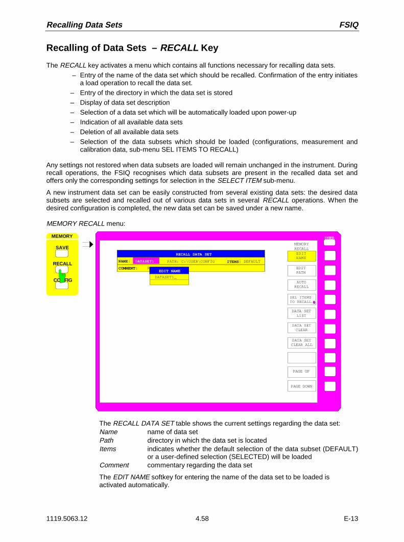
Recalling Data Sets FSIQ
1119.5063.12 4.58 E-13
Recalling of Data Sets – RECALL Key
The RECALL key activates a menu which contains all functions necessary for recalling data sets.
– Entry of the name of the data set which should be recalled. Confirmation of the entry initiatesa load operation to recall the data set.
– Entry of the directory in which the data set is stored
– Display of data set description
– Selection of a data set which will be automatically loaded upon power-up
– Indication of all available data sets
– Deletion of all available data sets
– Selection of the data subsets which should be loaded (configurations, measurement andcalibration data, sub-menu SEL ITEMS TO RECALL)
Any settings not restored when data subsets are loaded will remain unchanged in the instrument. Duringrecall operations, the FSIQ recognises which data subsets are present in the recalled data set andoffers only the corresponding settings for selection in the SELECT ITEM sub-menu.
A new instrument data set can be easily constructed from several existing data sets: the desired datasubsets are selected and recalled out of various data sets in several RECALL operations. When thedesired configuration is completed, the new data set can be saved under a new name.
MEMORY RECALL menu:
USER
PAGE DOWN
MEMORYRECALL
PAGE UP
SEL ITEMS TO RECALL
DATA SETLIST
EDITPATH
DATA SETCLEAR
DATA SETCLEAR ALL
EDITNAME
AUTORECALL
MEMORY
RECALL
SAVE
CO FIG
RECALL DATA SET
COMMENT: R
PATH: C:\USER\CONFIGNAME: DATASET1
EDIT NAME
DATASET1_
ITEMS: DEFAULT
The RECALL DATA SET table shows the current settings regarding the data set:Name name of data setPath directory in which the data set is locatedItems indicates whether the default selection of the data subset (DEFAULT)
or a user-defined selection (SELECTED) will be loadedComment commentary regarding the data set
The EDIT NAME softkey for entering the name of the data set to be loaded isactivated automatically.

FSIQ Recalling Data Sets
1119.5063.12 4.59 E-13
Selecting the Data Set for Recalling
MEMORY RECALL menu:
EDITNAME
The EDIT NAME softkey activates the entry of a data set name.The data input is terminated by pressing one of the units keys whichsimultaneously initiates the data set recall operation.
EDITPATH
The EDIT PATH softkey activates the entry of a directory name in which thedata set is located.
AUTORECALL
The AUTO RECALL softkey activates the selection of a data set which isautomatically loaded when the instrument is powered on. To this end thetable DATA SET LIST/CONTENT is opened (analog to DATA SET LIST).
AUTO RECALL SET CONTENT
DATASET1DATASET2DATASET3
COMMENT
GSM_MASK
DATA SET LIST
GENERAL SETUPHW-SETTINGSTRACE 1TRACE 2TRACE 3TRACE 4LINES
CONTENTS
COLOR SETUPHARDCOPY
MACROS
TRANSDUCER
The DATA SET LIST column displays all data sets present in the selecteddirectory.
The CONTENTS and COMMENT lines in the AUTO RECALL CONTENTScolumn indicate the saved data subsets and the commentary for the currentlyselected data set.
In addition to the data sets stored by the user, the data set FACTORY, whichspecifies the settings of the instrument before it was last switched off(Standby), is always present.
If a data set other than FACTORY is chosen then, at the time of instrumentpower on, the available data subsets of the selected data set are recalled.The data subsets which are not present in this data set are taken from theFACTORY data set.
Note: The specified data set is also loaded upon PRESET if AUTORECALL is active. The preset settiongs can thus be arbitrarilymodified.

Recalling Data Sets FSIQ
1119.5063.12 4.60 E-13
DATA SET LIST
see Chapter "Saving Data Sets"
DATA SET CLEAR
see Chapter "Saving Data Sets"
DATA SETCLEAR ALL
see Chapter "Saving Data Sets"
PAGE UP
PAGE DOWN
The PAGE UP or PAGE DOWN softkey sets the DATA SET LIST table to thenext or previous page.
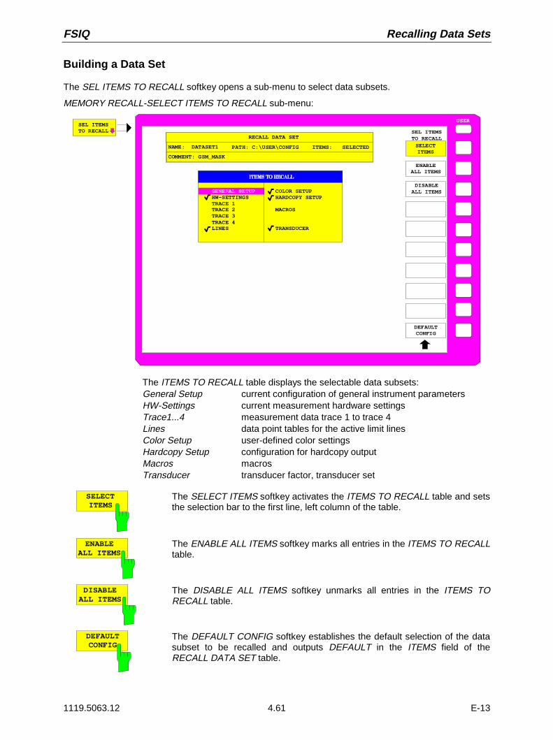
FSIQ Recalling Data Sets
1119.5063.12 4.61 E-13
Building a Data Set
The SEL ITEMS TO RECALL softkey opens a sub-menu to select data subsets.
MEMORY RECALL-SELECT ITEMS TO RECALL sub-menu:
SEL ITEMS TO RECALL
USER
ENABLEALL ITEMS
DISABLEALL ITEMS
SEL ITEMSTO RECALL
DEFAULTCONFIG
SELECTITEMS
RECALL DATA SET
COMMENT: GSM_MASK
PATH: C:\USER\CONFIGNAME: DATASET1 ITEMS: SELECTED
COLOR SETUPHARDCOPY SETUP
MACROS
TRANSDUCER
GENERAL SETUPHW-SETTINGSTRACE 1TRACE 2TRACE 3TRACE 4LINES
The ITEMS TO RECALL table displays the selectable data subsets:General Setup current configuration of general instrument parametersHW-Settings current measurement hardware settingsTrace1...4 measurement data trace 1 to trace 4Lines data point tables for the active limit linesColor Setup user-defined color settingsHardcopy Setup configuration for hardcopy outputMacros macrosTransducer transducer factor, transducer set
SELECTITEMS
The SELECT ITEMS softkey activates the ITEMS TO RECALL table and setsthe selection bar to the first line, left column of the table.
ENABLEALL ITEMS
The ENABLE ALL ITEMS softkey marks all entries in the ITEMS TO RECALLtable.
DISABLEALL ITEMS
The DISABLE ALL ITEMS softkey unmarks all entries in the ITEMS TORECALL table.
DEFAULTCONFIG
The DEFAULT CONFIG softkey establishes the default selection of the datasubset to be recalled and outputs DEFAULT in the ITEMS field of theRECALL DATA SET table.

Macros FSIQ
1119.5063.12 4.62 E-13
Macros – USER Key
The FSIQ menus are so designed that the analyzer can be easily applied to most of the usualmeasurement tasks with a minimum number of key operations. However, the USER menu also permitsa tailored adaptation of any necessary setup and measurement functions needed for specialapplications. Here, a sequence of key operations, which may occur repeatedly, can be listed in theUSER menu as a key macro, then stored in memory and recalled as required by the application.
Fundamentals
Macros are defined as arbitrary key sequences which need to be defined only once and then can berecalled as often as desired. Through the use of macros, often-needed measurement functions orinstrument setups, which may require a large number of key operations, can be easily performed. Thewriting of macros is possible only under manual control. Macro generation is not possible under remotecontrol (e.g. via the IEC Bus interface).
A total of 7 different macros can be programmed and assigned to the individual softkeys of the USERmenu. Each macro has a title (arbitrarily defined by the user ) which is also used as a label for thecorresponding softkey. To indicate that a macro has not yet been programmed, the soft-key labelappears in parenthesis (e.g. (MACRO 1)). After a key-sequence macro has been defined, theparenthesis are removed and the softkey is replaced by the titel specified by the user.
A macro is executed by pressing the corresponding softkey.
During execution of macros, the key actions are repeated in exactly the same sequence as they wereprogrammed. The sequential execution of a macro may be interrupted by using the PAUSE instruction.As soon as a macro is interrupted, adjustments on the Unit Under Test (UUT) may be made, etc. Theinterrupted macro is allowed to continue by pressing CONTINUE in the message window and is abortedby pressing ABORT.
MESSAGE
Macro "MACRO 1" stopped !
CONTINUE ABORT
A running macro can be aborted by pressing the LOCAL key. At this time, the following message isdisplayed:
WARNING
Execution of macro "MACRO 1" aborted
OK
During the time a macro is executing, manual operations on the instrument are not possible, and thesoft-key panel is disabled. After interruption or conclusion of a macro, the applicable soft-key panel isenabled (i.e., menu state at the conclusion of the macro).

FSIQ Macros
1119.5063.12 4.63 E-13
Starting Macros
USER menu
USER
USER MENU
(MACRO 1)
(MACRO 2)
(MACRO 3)
(MACRO 4)
(MACRO 5)
(MACRO 6)
(MACRO 7)
DEFINEMACRO
The USER key opens a menu for selection and starting ofmacros. The macros can be defined in the DEFINE MACROsubmenu.
(MACRO 1)
(MACRO 7)
The MACRO 1 to 7 softkeys start the execution of the macros.

Macros FSIQ
1119.5063.12 4.64 E-13
Defining Macros
In the DEFINE MACRO menu, all necessary softkeys needed for macro management are available.Included are functions for starting and ending macro programming, editing of a macro title, etc.
USER DEFINE MACRO menu
DEFINEMACRO
DEFINEMACRO
SELECTMACRO
DEFINEPAUSE
DELETEMACRO
MACROTITLE
RECORDON OFF
The DEFINE MACRO softkey calls the sub-menu to definethe macros.
The SELECT MACRO softkey is active and opens the box toselect the macro to be edited. In case no selection is made,MACRO 1 is automatically selected.
RECORDON OFF
The RECORD ON/OFF starts or stops the recording of the macro.
ON All key actions are recorded until the softkey is changed to OFF . Toindicate that macro record is enabled, the enhancement labelMAC is displayed.
The number of actions which can be stored in a macro is limited. Ifthe limit is exceeded, the error message "Macro too long.Recording aborted" is output and the recording operation is aborted,however, the actions already recorded do remain stored.
OFF The recording is stopped. The key actions are stored under themacro chosen by the SELECT MACRO softkey.
DEFINEPAUSE
The DEFINE PAUSE softkey inserts a pause instruction into the macrosequence which is being recorded. A running macro will pause when itreaches this instruction, at which point settings on the unit under test could forexample be made. CONTINUE in the message window is used to continuethe macro execution.

FSIQ Macros
1119.5063.12 4.65 E-13
DELETEMACRO
The DELETE MACRO softkey deletes the macro which was previouslyselected by the SELECT MACRO softkey. The softkey of the deleted title nowcarries its default label (MACRO X, X = macro number)
MACROTITLE
The MACRO TITLE softkey activates the entry of the title for the selectedmacro .
Because the macro title is used for labelling the corresponding softkey, amaximum of only 20 characters is allowed. All text after the 10 th character iswritten to the second line. However, entering the character @ forces a newline at any point in the softkey title.
SELECTMACRO
The SELECT MACRO softkey open the selection box with a list of all 7macros. All soft-key functions of this menu are related to this macro.
SELECT MACRO
Macro 1 (Macro 2)
(Macro 4)(Macro 5)(Macro 6)(Macro 7)
(Macro 3)

Frequency and Span - Analyzer FSIQ
1119.5063.12 4.66 E-13
Analyzer Mode
The analyzer mode is activated in the CONFIGURATION MODE menu (see also Section ’ModeSelection - MODE Key’
CONFIGURATION
MODE
SETUP
ANALYZER
RECEIVER
TRACKINGGENERATOR
VECTORANALYZER
FFT
TRACKINGGENERATOR
MODE The ANALYZER softkey selects the ANALYZER mode.
This mode is the default setting of the FSIQ.
The functions provided correspond to those of aconventional spectrum analyzer. The analyzer measuresthe frequency spectrum of the test signal over theselected frequency range with the selected resolution andsweep time, or, for a fixed frequency, displays thewaveform of the video signal.
Note: If two displays (screen A and screen B) are opened after switch-on of signal analysis, theanalyzer mode is only set for the display activated for entry (marked at the top right cornerof diagram). For the other display, the previous settings remain valid.Storage and display of measured values is sequential: first in the upper and then in thelower display.

FSIQ Analyzer - Frequency and Span
1119.5063.12 4.67 E-13
Frequency and Span Selection – FREQUENCY Key Group
The FREQUENCY key group is used to specify the frequency axis of the active measurement window.The frequency axis can be defined either by the start and stop frequency or by the center frequency andspan. For the case when two measurement windows (SPLIT-SCREEN) are displayed simultaneously,data entered are always related to the window selected in the SYSTEM-DISPLAY menu.After pressing one of the keys CENTER, SPAN, START or STOP, the value of the correspondingparameter can be defined in the appropriate dialog window. At the same time, a softkey menu appears,which allows selecting the optional parameters.
Start Frequency – START Key
FREQUENCY – START menu:
CENTER SPAN
START STOP
FREQUENCY
FIXED
START
CENTERFIXED
SPAN
START FREQ
MANUAL
STOPFIXED
FREQ AXISLIN LOG
The START key opens a menu which displays the variousoptions for setting the start frequency of the sweep.The START MANUAL softkey is automatically active andopens the entry window for manual input of the startfrequency. At the same time, the coupling of the parameters isset to STOP FIXED
The STOP FIXED, SPAN FIXED and CENTER FIXEDsoftkeys are mutually exclusive selection switches. Only oneof these switches may be active at any one time. Thefrequency coupling selected by the softkeys defines which ofthe dependent parameters stop frequency, center frequencyand span is to remain constant when a change in the startfrequency is made.
The FREQ AXIS LIN/LOG softkey switches between linearand logarithmic scaling of the frequency axis.
STARTMANUAL
The START MANUAL softkey activates manual entry of the start frequency.
The allowed range of values for the start frequency is:
0 Hz <= fstart <= fmax - minspan/2 fstart start frequency
minspan smallest selectable span)
fmax max. frequency
STOPFIXED
If the STOP FIXED key is active, the stop frequency remains constant whenthe start frequency is changed. The center frequency is adjusted to the newfrequency range. STOP FIXED coupling is the default setting.
SPANFIXED
If the SPAN FIXED softkey is active, the span remains constant when thestart frequency is changed. The stop frequency is adjusted to the newfrequency range.

Frequency and Span - Analyzer FSIQ
1119.5063.12 4.68 E-13
CENTERFIXED
If the CENTER FIXED softkey is active, the center frequency remainsconstant when the start frequency is changed. The stop frequency is adjustedto the new frequency range.
FREQ AXISLIN LOG
The FREQ AXIS LIN/LOG softkey switches between linear and logarithmicscaling of the frequency axis.
When the log scale is used, the following restrictions apply:
• For the start/stop frequency ratio the following holds:Stopfrequency
Startfrequency≥ 14.
At ratios below 1.4, a linear frequency scale is automatically selected.
• Up to five decades can be set.
510≤encyStartfrequ
ncyStopfreque
When the start or stop frequency is changed, the stop or start frequency isadapted to the settable range, as required.
• A frequency offset is not allowed.
• The CHANNEL POWER, C/N, C/N0, ADJACENT CHAN POWER andOCCUPIED PWR BANDW measurements are disabled.
Note: The function of a limit line is influenced by the FREQ AXIS LIN/LOGsetting at the time of the definition.Limit lines are entered as tabulated values (level and frequency).Most regulations and standards prescribe the linking of values bystraight lines both for the linear and logarithmic display. When thelimit line is defined with the desired frequency scale selected, this isautomatically taken into account (linear interpolation).To be able to use the correct limit values among the tabulatedvalues after a scale switchover, the limit line is recalculated after theswitchover.

FSIQ Analyzer - Frequency and Span
1119.5063.12 4.69 E-13
Stop Frequency – STOP Key
FREQUENCY – STOP menu:
CENTER SPAN
START STOP
FREQUENCYSTOPMANUAL
STARTFIXED
CENTERFIXED
SPANFIXED
STOP FREQ
FREQ AXISLIN LOG
The STOP key opens a menu which displays the variousoptions for setting the stop frequency of the sweep .
The STOP MANUAL softkey is automatically active and opensthe entry window for manual input of the stop frequency. At thesame time, parameter coupling is set to START FIXED.
The START FIXED, CENTER FIXED and SPAN FIXEDsoftkeys are mutually exclusive selection switches. Only oneswitch can be active at any one time. The softkeys are used toselect the frequency coupling. The frequency coupling defineswhich of the dependent parameters start frequency, centerfrequency or span is to remain constant when the stopfrequency is changed.
STOPMANUAL
The STOP MANUAL softkey activates the manual entry window for the stopfrequency.
The allowed range of values for the stop frequency is:
minspan ≤ fstop ≤ fmax fstop stop frequency
minspan smallest selectable span (10Hz)
fmax max. frequency
STARTFIXED
If the START FIXED softkey is active, the start frequency remains constantwhen the stop frequency is changed. The center frequency is adjusted to thenew frequency range. The START FIXED coupling is the default setting.
CENTERFIXED
If the CENTER FIXED softkey is active, the center frequency remainsconstant when the stop frequency is changed. The start frequency is adjustedto the new frequency range.
SPANFIXED
If the SPAN FIXED softkey is active, the span remains constant when thestop frequency is changed. The start frequency is adjusted to the newfrequency range.
FREQ AXISLIN LOG
The FREQ AXIS LIN/LOG softkey switches between linear and logarithmicscaling of the frequency axis (see START key).

Frequency and Span - Analyzer FSIQ
1119.5063.12 4.70 E-13
Center Frequency – CENTER Key
FREQUENCY – CENTER menu:
FIXED
CENTERMANUAL
STARTFIXED
SPAN
CENTER
CENTER SPAN
START STOP
FREQUENCY
FREQ AXISLIN LOG
STOPFIXED
FREQUENCYOFFSET
The CENTER softkey opens a menu which displays thevarious options for setting the center frequency of the sweep.
The CENTER MANUAL softkey is automatically active andopens the entry window for manual input of the centerfrequency. At the same time, the coupling of the parameters isset to SPAN FIXED.
The START FIXED, STOP FIXED and SPAN FIXED softkeysare mutually exclusive selection switches. Only one switch canbe active at any one time. The softkeys are used to select thefrequency coupling. The frequency coupling defines which ofthe dependent parameters start frequency, stop frequency orspan remains constant when the center frequency is changed.
CENTERMANUAL
The CENTER MANUAL softkey activates the manual entry window forentering the center frequency.
The allowed range of values for the center frequency is:
for the frequency domain (span > 0):
0 Hz <= fcenter <= fmax – minspan/2
and for the time domain (span = 0)
0 Hz ≤ fcenter ≤ fmax fcenter center frequency
minspan smallest selectable span (10Hz)
fmax max. frequency

FSIQ Analyzer - Frequency and Span
1119.5063.12 4.71 E-13
SPANFIXED
If the SPAN FIXED softkey is active, the span remains constant when thecenter frequency is changed. The start and stop frequency are adjusted tothe new frequency range. SPAN FIXED coupling is the default setting.
STARTFIXED
If the START FIXED softkey is active, the start frequency remains constantwhen the center frequency is changed. The span is adjusted to the newfrequency range.
STOPFIXED
If the STOP FIXED softkey is active, the stop frequency remains constantwhen the center frequency is changed. The span is adjusted to the newfrequency range.
FREQ AXISLIN LOG
The FREQUENCY OFFSET softkey activates the entry window for anarithmetical frequency offset which is added to the frequency axis labelling.The allowable range of input values is -100 GHz to 100 GHz. The defaultsetting is 0 Hz.
FREQ AXISLIN LOG
The FREQ AXIS LIN/LOG softkey switches between linear and logarithmicscaling of the frequency axis (see START key).

Frequency and Span - Analyzer FSIQ
1119.5063.12 4.72 E-13
Center Frequency Step Size
The STEP key in the DATA VARIATION key group opens a menu for setting the step size of the centerfrequency. The step size can be coupled to the span (frequency domain) or the resolution bandwidth(time domain) or it can be manually set to a fixed value.
In order to change the step size, the entry window for the center frequency must already be active. Afterpressing the STEP key, the CENTER STEP menu appears. The softkeys are presented according to theselected domain (frequency or time).
The softkeys are mutually exclusive selection switches. Only one switch can be active at any one time.
Control is returned to the FREQUENCY CENTER menu via the menu key .
DATA VARIATION - STEP menu for span ≠ 0 for span = 0
STEP
DATA VARIATION
HOLD
AUTO
STEPSIZECENTER
0.1 * SPAN
AUTO
AUTO
STEPSIZE
0.5 * SPAN
X * SPAN
MANUAL
STEPSIZE= CENTER
AUTO
STEPSIZECENTER
0.1 * RBW
AUTO
AUTO
STEPSIZE
0.5 * RBW
X * RBW
MANUAL
STEPSIZE= CENTER
AUTO0.1 * SPAN
AUTO0.1 * RBW
Frequency domain: The AUTO 0.1 * SPAN softkey sets the step size of the center frequency entry to 10% of the span.
Time domain: The AUTO 0.1 * RBW softkey sets the step size of the center frequency entry to 10% of the resolution bandwidth
AUTO 0.1 * RBW is the default setting.
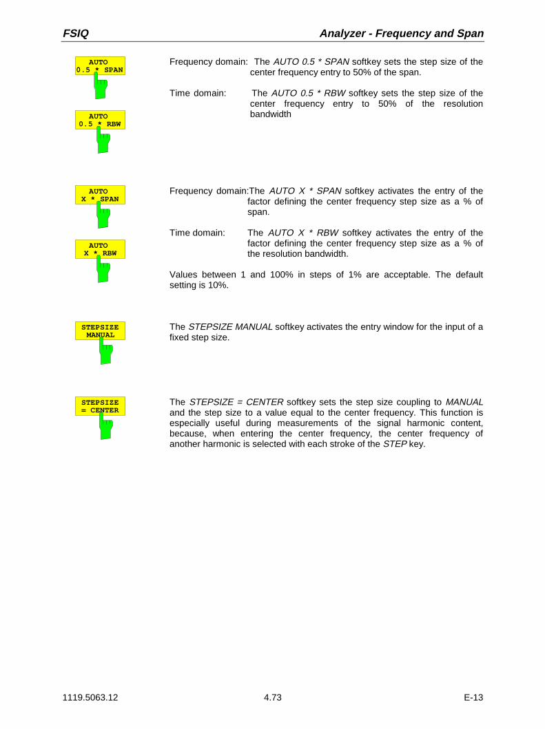
FSIQ Analyzer - Frequency and Span
1119.5063.12 4.73 E-13
AUTO0.5 * SPAN
AUTO0.5 * RBW
Frequency domain: The AUTO 0.5 * SPAN softkey sets the step size of the center frequency entry to 50% of the span.
Time domain: The AUTO 0.5 * RBW softkey sets the step size of the center frequency entry to 50% of the resolution bandwidth
AUTOX * SPAN
AUTOX * RBW
Frequency domain:The AUTO X * SPAN softkey activates the entry of thefactor defining the center frequency step size as a % ofspan.
Time domain: The AUTO X * RBW softkey activates the entry of thefactor defining the center frequency step size as a % ofthe resolution bandwidth.
Values between 1 and 100% in steps of 1% are acceptable. The defaultsetting is 10%.
STEPSIZEMANUAL
The STEPSIZE MANUAL softkey activates the entry window for the input of afixed step size.
STEPSIZE= CENTER
The STEPSIZE = CENTER softkey sets the step size coupling to MANUALand the step size to a value equal to the center frequency. This function isespecially useful during measurements of the signal harmonic content,because, when entering the center frequency, the center frequency ofanother harmonic is selected with each stroke of the STEP key.

Frequency and Span - Analyzer FSIQ
1119.5063.12 4.74 E-13
Frequency Span – SPAN Key
FREQUENCY – SPAN menu:
CENTER SPAN
START STOP
FREQUENCY SPAN
SPANMANUAL
STARTFIXED
CENTERFIXED
STOPFIXED
ZERO SPAN
FULL SPAN
LAST SPAN
ZOOM
FREQ AXISLIN LOG
The SPAN key opens a menu which displays variousoptions for the selection of sweep span.
The SPAN MANUAL softkey is automatically active andopens the entry window for manual input of the span. Atthe same time, the parameter coupling is set to CENTERFIXED.
The START FIXED, CENTER FIXED and STOP FIXEDsoftkeys are mutually exclusive selection switches. Onlyone switch can be active at any one time. The frequencycoupling is selected with these softkeys. The frequencycoupling defines which of the dependent parameters startfrequency, center frequency or stop frequency is to remainconstant when the span is changed
SPANMANUAL
The SPAN MANUAL softkey activates the manual entry of the span.
The allowed range of input values for span are:time domain (span = 0):
0 Hz
frequency domain (span > 0):
minspan ≤ fspan ≤ fmax fspan frequency span
minspan smallest selectable span (10Hz)
fmax max. frequency
ZERO SPAN The ZERO SPAN softkey sets the span value to 0 Hz. The x axis becomesthe time axis. The axis labelling corresponds to the sweep time (on the left, 0ms, on the right, the current sweep time (SWT)).
FULL SPAN The FULL SPAN softkey sets the span value to the maximum span of theFSIQ.
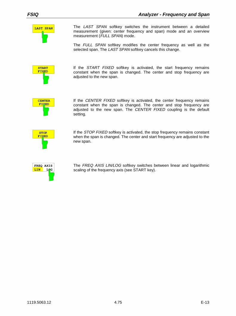
FSIQ Analyzer - Frequency and Span
1119.5063.12 4.75 E-13
LAST SPAN The LAST SPAN softkey switches the instrument between a detailedmeasurement (given: center frequency and span) mode and an overviewmeasurement (FULL SPAN) mode.
The FULL SPAN softkey modifies the center frequency as well as theselected span. The LAST SPAN softkey cancels this change.
STARTFIXED
If the START FIXED softkey is activated, the start frequency remainsconstant when the span is changed. The center and stop frequency areadjusted to the new span.
CENTERFIXED
If the CENTER FIXED softkey is activated, the center frequency remainsconstant when the span is changed. The center and stop frequency areadjusted to the new span. The CENTER FIXED coupling is the defaultsetting.
FIXEDSTOP If the STOP FIXED softkey is activated, the stop frequency remains constant
when the span is changed. The center and start frequency are adjusted to thenew span.
FREQ AXISLIN LOG
The FREQ AXIS LIN/LOG softkey switches between linear and logarithmicscaling of the frequency axis (see START key).

Frequency and Span - Analyzer FSIQ
1119.5063.12 4.76 E-13
Display Zoom
FREQUENCY SPAN- ZOOM submenu:
ZOOM
MOVE ZOOMWINDOW
ZOOM
MOVE ZOOMSTOP
ZOOMOFF
MOVE ZOOMSTART
The ZOOM softkey activates the zoom mode and opens asub-menu to define the zoom span.
Two frequency lines, which show and define the frequencyrange to be zoomed, appear in the active measurementwindow when the zoom mode is switched on. The defaultsetting is a zoom span of 10% to the left and 10% to the rightof the center frequency. The zoomed display is shown in thesecond measurement window.The settings for the second measurement window are takenfrom the original window. The second measurement windowthus becomes the active measurement window and itssettings can now be changed.
If only one window is active when the zoom function isselected, SPLIT SCREEN mode is automatically switched on.
The zoom span can be edited by using the softkeys of thesub-menu to change the position of the frequency lines.
The softkey ZOOM OFF switches off the zoom.
MOVE ZOOMWINDOW
The MOVE ZOOM WINDOW softkey shifts the full zoom window. Thewindow can shifted until the upper frequency line has reached the stopfrequency or the lower frequency line has reached the start frequency of theoriginal window.
MOVE ZOOMSTART
The MOVE ZOOM START softkey shifts the lower frequency line. Thus, thestart frequency of the zoomed display can be modified. The frequency linecan be shifted down to the start frequency of the original window or up to theupper frequency line (= zero span).
MOVE ZOOM
STOPThe MOVE ZOOM STOP softkey shifts the upper frequency line. Thus, thestop frequency of the zoomed display can be modified. The frequency linecan be shifted up to the stop frequency of the original window or down to thelower frequency line (= zero span).
ZOOMOFF
The ZOOM OFF softkey switches the zoom function off and then returnscontrol to the main menu.The frequency lines for indicating the zoom range are deleted, SPLITSCREEN mode remains active, the settings of both measurement windowsare retained and the coupling of the two measurement windows is cancelled.

FSIQ Analyzer - Level Display/RF Input
1119.5063.12 4.77 E-13
Level Display and RF Input Configuration – LEVEL Key Group
The REF and RANGE keys are used to set the reference level (= maximum RF input level, = overloadlimit), the maximum level (= upper grid level) , and the display range of the active window. The INPUTkey sets the characteristics of the RF input (input impedance and input attenuation).
Reference Level – REF key
In addition to the reference level (maximum RF input level), the FSIQ provides a function to define amaximum level (uppermost grid line on the display):For a spectrum analyzer, the upper boundary of the measurement diagram (maximum level) is also thelimit of its dynamic range (reference level). This means, that a signal which goes beyond the upper gridline also overdrives the analyzer.
For compensation of frequency or antenna characteristics, transducer factors can be applied to increasethe signal level. In this case, the calculated values can be above the reference level without actuallybeing physically applied to the instrument. In order to display these signals on the grid, an upper gridlevel which is different from the reference level of the analyzer can be entered.
LEVEL REF menu:
LEVEL
REF
RA E
REF LEVEL
REF LEVEL
GRIDABS / REL
UNIT
MAX LEVELAUTO
MAX LEVELMANUAL
REF LEVELOFFSET
RF ATTENMANUAL
ATTEN AUTONORMAL
ATTEN AUTOLOW NOISE
ATTEN AUTOLOW DIST
MIXERLEVEL
REF LEVEL
ATTEN STEP1dB 10dB
The REF key opens a menu to set thereference level and the input attenuationfor the active measurement window .
The REF LEVEL soft key isautomatically active with the menucalled up and opens the entry windowfor manual input of the reference level.
At the same time various settingsconcerning the level and the attenuationdisplay can be made.
The functions for setting the attenuationare identical to those under the INPUTkey and are described in Section"Configuration of the RF Input - INPUTKey". Softkey ATTEN STEP 10dB/1dBis only available when the FSIQ isequiped with option FSE-B13, 1dBattenuator (see ’Option 1 dB Attenuator- FSE-B13’ at the end of this Section.)

Level Display/RF Input - Analyzer FSIQ
1119.5063.12 4.78 E-13
REF LEVEL The REF LEVEL soft key activates the entry of the reference level. The inputis made in the currently active units (dBm, dBµV, etc.).
If the MAX LEVEL MANUAL softkey is active, a change of the reference levelcauses an equal amount of change in maximum level Thus, the separationbetween the overload limit of the analyzer to the upper grid edge remains thesame. Thus, with only one entry, it is possible to make a change to thedisplay and simultaneously to perform an adjustment to the amplifier.
REF LEVELOFFSET
The REF LEVEL OFFSET soft key activates the entry of an arithmetic offset (±200 dB in 0,1 dB steps) to the level. The offset is added to the measuredlevel dependent upon the selected units. The scaling of the y axis is changedaccordingly.
GRIDABS REL
The GRID ABS/REL soft key switches between absolute and relative scalingof the level axis. GRID ABS is the default setting.
For absolute scaling the labelling of the level lines is referenced to theabsolute value of the reference level.
For relative scaling, the upper line of the grid is always at 0 dB and the scaleunits are in dB. In contrast, the reference level is always displayed in the setunits (dBm, dBµV,..).
The soft key is not displayed for setting LIN / % (linear scaling, labelling in %)in the LEVEL-RANGE menu since the % unit itself implies a relative scale.
The MAX LEVEL MANUAL and MAX LEVEL AUTO soft keys are mutually exclusive selection switches.Only one switch can be active at one time. The soft keys are used to select whether reference level andmaximum level are identical or not:
MAX LEVEL AUTO
When MAX LEVEL AUTO soft key is active, the reference level andmaximum level are identical.In this case, the reference level is displayed above the upper left corner of thegrid in the corresponding function field.
MAX LEVEL AUTO is the default setting.
If the MAX LEVEL MANUAL soft key was active prior to pressing the MAXLEVEL AUTO soft key, the upper boundary of the grid is set to the referencelevel.
MAX LEVEL MANUAL
The MAX LEVEL MANUAL soft key activates the entry of the maximum level.The range of input values is ± 200dBm with 0.1 dB resolution.
If the MAX LEVEL MANUAL soft key is activated, the maximum level isdisplayed in addition to the reference level to the right above the grid.
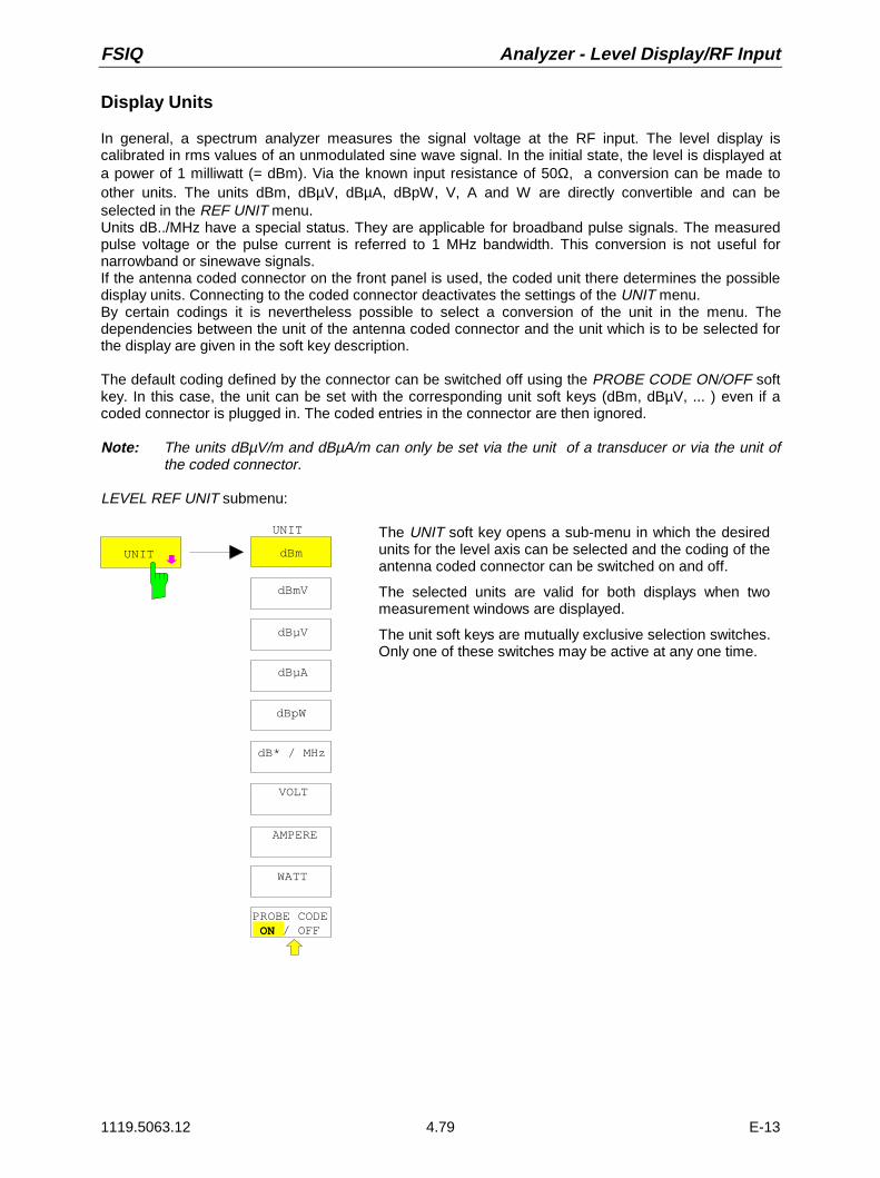
FSIQ Analyzer - Level Display/RF Input
1119.5063.12 4.79 E-13
Display Units
In general, a spectrum analyzer measures the signal voltage at the RF input. The level display iscalibrated in rms values of an unmodulated sine wave signal. In the initial state, the level is displayed ata power of 1 milliwatt (= dBm). Via the known input resistance of 50Ω, a conversion can be made toother units. The units dBm, dBµV, dBµA, dBpW, V, A and W are directly convertible and can beselected in the REF UNIT menu.Units dB../MHz have a special status. They are applicable for broadband pulse signals. The measuredpulse voltage or the pulse current is referred to 1 MHz bandwidth. This conversion is not useful fornarrowband or sinewave signals.If the antenna coded connector on the front panel is used, the coded unit there determines the possibledisplay units. Connecting to the coded connector deactivates the settings of the UNIT menu.By certain codings it is nevertheless possible to select a conversion of the unit in the menu. Thedependencies between the unit of the antenna coded connector and the unit which is to be selected forthe display are given in the soft key description.
The default coding defined by the connector can be switched off using the PROBE CODE ON/OFF softkey. In this case, the unit can be set with the corresponding unit soft keys (dBm, dBµV, ... ) even if acoded connector is plugged in. The coded entries in the connector are then ignored.
Note: The units dBµV/m and dBµA/m can only be set via the unit of a transducer or via the unit ofthe coded connector.
LEVEL REF UNIT submenu:
dBm
dBµV
dBµA
VOLT
AMPERE
WATT
UNIT
PROBE CODE ON / OFF
UNIT
dBpW
dB* / MHz
dBmV
The UNIT soft key opens a sub-menu in which the desiredunits for the level axis can be selected and the coding of theantenna coded connector can be switched on and off.
The selected units are valid for both displays when twomeasurement windows are displayed.
The unit soft keys are mutually exclusive selection switches.Only one of these switches may be active at any one time.

Level Display/RF Input - Analyzer FSIQ
1119.5063.12 4.80 E-13
dBm
dBmV
dB Vµ
dB Aµ
dBpW
The dBm, dBµV, dBmV, dBµA, dBpW soft keys set the display units to thecorresponding logarithmic units. The dBm unit is the default unit in analyzermode.
The units dBm, dBµV, dBmV, dBµA cannot be selected when the codedantenna connector or the used transducer defines a unit.
Only for coding dB, the conversion to the desired units is permitted.
dB* / MHz The dB*/MHz softkey activates/disactivates the display of results in unitsrelative to the bandwidth. Those units can be derived from the logarithmicunits dBµV, dBµV/m, dBµA and dBµA/m.
This leads to the following relative units:dBmV ⇒ dBmV/MHzdBµV ⇒ dBµV/MHzdBµV/m ⇒ dBµV/mMHzdBµA ⇒ dBµA/MHzdBµA/m ⇒ dBµA/mMHz
Switching over is possible also if a coded antenna connector or a transducerfixes the unit to be used.
Conversion to 1 MHz is via the pulse bandwidth of the selected resolutionbandwidth Bimp according to the following equation (example for dBµV) :
P / ( dB V / MHz) 20 logB / MHz
1MHzP / ( dB V )impµ µ= ⋅ + ,
where P = display level
The dBµV/MHz unit can be combined with the following coded connector ortransducer units
dB (the unit dBµV/MHz remains )
µV/m (yields the display unit dBµV/mMHz)
analogous for dBµA/MHz:
dB and µA (the unit dBµA/MHz remains)
Other combinations are not allowed.

FSIQ Analyzer - Level Display/RF Input
1119.5063.12 4.81 E-13
VOLT
AMPERE
WATT
The VOLT, AMPERE, WATT soft keys set the display units to thecorresponding linear units.
The units VOLT, AMPERE, WATT cannot be selected when the codedantenna connector or the transducer table defines one of the following asunits:
µV/mµA
For coding dB, the conversion to the desired units is permitted.
PROBE CODEON OFF
The PROBE CODE ON/OFF soft key enables or disables the units defined bythe coded connector.

Level Display/RF Input - Analyzer FSIQ
1119.5063.12 4.82 E-13
Level Range – RANGE Key
LEVEL RANGE menu:
LEVEL
REF
RANGE
LOG 100 dB
LOG 50 dB
LOG 20 dB
LOG 10 dB
LINEAR/dB
LINEAR/ %
LEVEL RANGE
LOG MANUAL
LOG 120 dB
GRIDABS REL
The RANGE key calls a menu in which the range, linear orlogarithmic the display scale, absolute or relative and thelevel units for the active window can be selected.
The display range of the analyzer can be set in 10 dBsteps from 10 to 200 dB.The default setting is 100 dB.
The most often used settings (120 dB, 100 dB, 50 dB,20 dB and 10 dB) are each directly selectable by a softkey.All other ranges are chosen with the LOG MANUAL softkey.
After pressing the RANGE key, the LOG MANUAL entrywindow is enabled if the display range is not set to LIN.
LOG MANUAL
The LOG MANUAL soft key activates the entry of the level display range.Display ranges from 10 to 200 dB are allowed in 10-dB steps. Values whichare not permissible are rounded to the next valid number.
LINEAR/dB The LINEAR/dB soft key switches the display range of the analyzer to linearscaling. The horizontal lines are labelled according to the selection GRIDABS/REL in dB* or *.
LINEAR/ % The LINEAR/% soft key switches the display range of the analyzer to linearscaling. The horizontal lines are labelled in %. The grid is divided intodecades.
GRIDABS REL
The GRID ABS/REL soft key switches between absolute and relative scalingof the level axis. GRID ABS is the default setting.
ABS The labelling of the level lines is referenced to the absolute value of thereference level.
REL The upper line of the grid is always at 0 dB and the scale units are indB. In contrast, the reference level is always displayed in the set units(dBm, dBµV,..).
The soft key is not displayed for setting LIN / % (linear scaling, labelling in %)since the % unit itself implies a relative scale.

FSIQ Analyzer - Level Display/RF Input
1119.5063.12 4.83 E-13
RF Input Configuration – INPUT Key
In addition to manual entry of the input attenuation, the FSIQ provides an option which allows the RFattenuation, dependent on the selected reference level, to be automatically set. Thus, it is guaranteedthat an optimum combination of RF attenuation and IF amplification is always used. For the automaticselection process, three modes are provided. The AUTO LOW NOISE mode selects theamplification/attenuation combination so that the display of noise on the FSIQ is at a minimum. Thesignal/noise ratio is maximised. The AUTO LOW DISTORTION mode is tuned for minimisation of theinternally generated interference products. This causes, however, a lower signal/noise ratio. The ATTENAUTO NORMAL mode is a compromise between low noise and low distortion.
INPUT menu:
INPUT
ATTEN AUTONORMAL
ATTEN AUTOLOW NOISE
ATTEN AUTO LOW DIST
MIXERLEVEL
INPUTSELECT
INPUTRF ATTEN MANUAL
ATTEN STEP1 dB 10dB
The INPUT key opens the menu for configuring the RFinput. It contains the input attenuator and mixer level formatching the RF input to the input signal.
The RF ATTEN MANUAL, ATTEN AUTO NORMAL,ATTEN AUTO LOW NOISE and ATTEN AUTO LOWsoft keys are mutually exclusive selection switches. onlyone can be active at any one time.Softkey ATTEN STEP 10dB/1dB is only available whenthe FSIQ is equiped with option FSE-B13, 1dB attenuator(see ’Option 1 dB Attenuator - FSE-B13’ at the end ofthis Section.)
The INPUT SELECT soft key calls a submenu forselection of the input impedance.
ATTEN AUTONORMAL
The RF ATTEN MANUAL soft key activates the entry of an attenuation factorindependent of the reference level.
The attenuation can be modified in 10 dB steps between 0 and 70 dB.
Other inputs will be rounded to the next higher integer value.
If the defined reference level cannot be set for the given RF attenuation, thereference level will be adjusted accordingly and the warning "Limit reached"will be output.

Level Display/RF Input - Analyzer FSIQ
1119.5063.12 4.84 E-13
ATTEN AUTONORMAL
The ATTEN AUTO NORMAL soft key sets the RF attenuation automaticallyindependent of the selected reference level.
ATTEN AUTOLOW NOISE
The ATTEN AUTO LOW NOISE soft key sets the RF attenuation always10dB lower than in the RF ATTEN AUTO mode. Therefore, for 10 dB RFattenuation, the maximum reference level is -10 dBm. For reference levelswhich are lower, at least 10 dB is always set (see above).
Setting Low Noise means that the indicated inherent noise level is low. Thissetting is recommended if signals with a low level have to be measured asthe highest S/N ratio is then obtained.
ATTEN AUTO LOW DIST
The ATTEN AUTO LOW DIST soft key sets the RF attenuation 10 dB higherthan in RF ATT AUTO mode. This means that for 10 dB RF attenuation, themaximum reference level is -30 dBm (-40 dBm at the mixer).
This setting is recommended whenever a small signal is to be measured inthe presence of larger signals. Here, the intermodulation-free range of theFSIQ is large and the internal distortion products are minimised.
MIXER LEVEL
The MIXER LEVEL soft key activates the entry of the maximum mixer levelattainable for a given reference level. At the same time it enables soft keysATTEN AUTO LOW NOISE and ATTEN AUTO LOW DIST .
Range of input values is -10 to -100 dBm

FSIQ Analyzer - Level Display/RF Input
1119.5063.12 4.85 E-13
INPUT INPUT SELECT submenu:
RF INPUT 50 OHM
RF INPUT75 OHM/RAZ
RF INPUT75 OHM/RAM
INPUT SELECT
INPUTSELECT
The INPUT SELECT soft key calls a submenu for selection ofthe input impedance of the RF input.
The basic setting is 50 Ohm. By connecting an impedanceconverter RAM or RAZ ahead, the 50-Ohm input can betransformed to 75 Ohm. FSIQ automatically takes thecorresponding correction values for the level display intoaccount.
The soft keys used to select the input impedance are selectionswitches. Only one of them can be active at any one time
RF INPUT50 OHM
The RF INPUT 50 OHM soft key sets the input impedance to 50Ohm (= default setting). All level indications are referenced to 50Ohm.
RF INPUT75 OHM/RAM
The RF INPUT 75 OHM/RAM soft key sets the input impedanceof the FSIQ to 75 Ohm including the matching element RAM. Alllevel indications are referenced to 75 Ohm.
RF INPUT75 OHM/RAZ The RF INPUT 75 OHM/RAZ soft key sets the input impedance
of the FSIQ to 75 Ohm including the matching element RAZ. Alllevel indications are referenced to 75 Ohm.

Level Display/RF Input - Analyzer FSIQ
1119.5063.12 4.86 E-13
Option 1 dB Attenuator - FSE-B13
The option 1 dB Attenuator FSE-B13 is used to set the attenuator with a step size of 1 dB up to an upperlimit frequency of 7 GHz.The attenuator with 1 dB stepping is connected in series after the main attenuator.
Instruments with an Upper Limit Frequency of up to 7 GHz
The optional attenuator is in the signal path for all settable frequencies in instruments with a maximumupper limit frequency of 7 GHz. When it is activated, it is used without any restriction for setting the inputattenuation or the reference level.
dB dB to RF converter
RF-input Attenuator 0 to 70 dB FSE-B13, 1 dB attenuator,0 to 9 dB
Instruments with an Upper Limit Frequency of more than 7 GHz
In instruments with an upper limit frequency of more than 7 GHz a diplexer is placed before the optionalattenuator for separating the frequency ranges ≤ 7GHz and > 7 GHz. The optional attenuator is in thesignal path only for frequencies ≤ 7 GHz.
dB dB to RF converter
to YIG and microwave unitt
Diplexer
RF input Attenuator0 to 70 dB
FSE-B13, 1 dB attenuator0 to 9 dB

FSIQ Analyzer - Level Display/RF Input
1119.5063.12 4.87 E-13
On changing the frequency range for the stop frequency, the attenuator can be set as follows:
Instrument setting: ATTENUATOR AUTO- After switching from Fstop ≤ 7 GHz to Fstop > 7 GHz the reference level is re-calculated provided
the attenuation previously set contained 1 dB steps. A warning is not displayed.
- After switching from Fstop > 7 GHz to Fstop ≤ 7 GHz the reference level is re-calculated. Awarning is not displayed.
Instrument setting: ATTENUATOR MANUAL- After switching from Fstop ≤ 7 GHz to Fstop > 7 GHz, the attenuation is rounded off to a value
divisible by 10 provided the attenuation previously set contained 1 dB steps. A warning isdisplayed:
WARNING
1dB Stepsize Attenuator only available for stop frequencies <= 7 GHz
OK
- After switching from Fstop > 7 GHz to Fstop ≤ 7 GHz the current value of the input attenuation ismaintained.
The 1 dB attenuator is inactive as default. In this case the attenuation can be set only in 10 dB steps, iethe attenuation of the optional attenuator is fixed at 0 dB.
The optional attenuator is activated either in the INPUT menu or in the REF LEVEL menu (the twosettings are equivalent):
ATTEN STEP1dB 10db
The ATTEN STEP 1dB/10dB softkey switches between the 10 dB step and 1dB step settings.
After activating the optional attenuator with the ATTEN STEP 10dB/1dBsoftkey, setting in 1 dB steps is possible, the total attenuation is divided into
- a 10 dB contribution from the main attenuator and
- a residual contribution of 0 to 9 dB from the optional attenuator.
The attenuation setting range in the instrument remains to be 0 to 70 dB, it isnot extended by the optional attenuator.
After a reset the attenuator step size is automatically set to 10 dB.

Main Markers - Analyzer FSIQ
1119.5063.12 4.88 E-13
Marker Functions – MARKER Key Group
The markers are used for marking points on measurement curves, reading out measurement valuesand for quickly selecting a display screen segment. Preselected measurement routines can be called bypressing a key in the marker menu. The FSIQ provides four markers and four delta markers permeasurement window. The currently activated marker can be shifted with the cursor keys, the roll-key orthe softkeys. The softkeys are defined according to the type of display representation selected(frequency or time domain).
The marker which can be moved by the user is defined as the active marker.
Examples:
1 3
2
T1
marker active marker temporary marker
delta marker
The measurement values of the active marker (also called marker values) are displayed in the markerfield. In the marker info list, the measurement values from all enabled markers are sorted in ascendingorder. The marker info list can be switched off with the MARKER INFO softkey so that only the valuesfor the active marker are shown.
The summary markers have a special function. They read out the rms or average value of the currenttrace or the trace averaged over several sweeps in the marker info list. These markers are notdisplayed.
Main Markers– NORMAL Key
The NORMAL key calls a menu which contains all standard functions. The current state of the markersis indicated by a colored illumination of the softkeys. If no marker is enabled prior to pressing theNORMAL key, MARKER 1 will be enabled as the reference marker and a peak search on themeasurement curve is carried out (assumption: at least one measurement curve is active). Otherwise,the peak search is omitted and the entry window for the reference marker is activated.
The marker field at the upper left of the display screen shows the marker location (here, frequency), thelevel and the currently selected measurement curve.
MARKER 1 [T1]
123.4567 MHz-27.5 dBm

FSIQ Analyzer - Main Markers
1119.5063.12 4.89 E-13
MARKER NORMAL menu:
MARKERNORMAL
MARKER 2
MARKER 3
SIGNALCOUNT
NOISE
SIGNALTRACK
MARKERNORMAL
MARKERDEMOD
MARKER 1
MARKER 4
ALL MARKER OFF
COUNTER RESOL
MARKER INFO
MARKER ZOOM
MARKER
NORMAL SEARCH
DE A MKR
C / No
C / N
MARKERNORMAL
POWER MEASSETTING
CHANNELPOWER
SET CPREFERENCE
ADJACENTCHAN POWER
ADJUST CPSETTINGS
OCCUPIEDPWR BANDW
CP / ACPABS REL
MARKERNORMAL
MARKER 2
MARKER 3
ON
MARKER 1
MARKER 4
The MARKER 1 to MARKER 4 softkeys switch the corresponding markeron/off or activate it as the reference marker. If the marker is activated as areference marker, an entry field for manually setting the position of thereference marker is opened simultaneously. If the marker is disabled, thesoftkey is not illuminated. Enabled markers and the reference marker areindicated by illuminating the corresponding softkeys in different colors.(Inthe instrument default state, the active reference marker is displayed in redand enabled markers are displayed in green.)
Operating example:
MARKER 1 is shown as the reference marker by the colored backgroundillumination. MARKER 2 through MARKER 4 are turned off.
MARKERNORMAL
MARKERNORMAL
MARKER 2
MARKER 3
ON
MARKER 1
MARKER 2
MARKER 3
MARKER 1

Main Markers - Analyzer FSIQ
1119.5063.12 4.90 E-13
Pressing the MARKER 3 softkey switches MARKER 3 on and it becomesthe reference maker. The previous reference marker remains enabled andthe softkey remains illuminated. However, the entry mode for this marker isnot now active. Instead, the entry window for MARKER 3 is opened and theposition of MARKER 3 can be shifted.
MARKER 3123.4567 MHz
The information in the marker field also changes to describe the newreference marker.
MARKER 3 [T1]
23.4567891 MHz-27.5 dBm
MARKERNORMAL
MARKERNORMAL
MARKER 2
MARKER 3
MARKER 1
MARKER 2
MARKER 3
MARKER 1
Pressing the current reference marker (MARKER 3) softkey again switchesMARKER 3 off. If at least one marker is enabled, the marker with thesmallest number will be selected as the new reference marker (in theexample, MARKER 1). Switching off the last active marker also deletes aredelta markers.
When several measurement curves (traces) are being displayed, the marker is set to the maximumvalue (peak) of the active curve which has the lowest number (1 to 4). In case a marker is alreadylocated there, it will be set to the frequency of the next highest level (next peak).
When the split screen display mode is active, the marker will be placed in the active window (forSCREEN A: trace 1 or 3, for SCREEN B: trace 2 or 4). Since markers are attached to a measurementcurve, the marker can only be enabled when at least one curve in the corresponding window is visible .
If a measurement curve is turned off, the corresponding markers and marker functions are also erased.If the curve is switched on again (VIEW, CLR/WRITE;..), these markers along with coupled functions willbe restored to their original positions. A prerequisite for the restoration of the marker positions is thatindividual markers have not been used on another measurement curve or that the sweep data(start/stop frequency for span > 0 or sweep time for span = 0) have not been changed.

FSIQ Analyzer - Main Markers
1119.5063.12 4.91 E-13
If a marker (or, delta marker) necessary for a marker function is not available, it will be automaticallychecked whether or not the enabling of the corresponding marker is possible (see above). If this is notthe case, a warning is issued.
No trace active
WARNING:
The activation of the desired marker function is then not possible.
On the other hand, if the marker can be enabled, a peak search is automatically performed. Thereafter,the desired marker function can be executed.
MARKER NORMAL menu:
ALL MARKER OFF
The ALL MARKER OFF softkey switches off all markers (reference and deltamarkers). Similarly, it switches off all functions and displays correlated withthe markers/delta markers (signal count, signal track, marker zoom, N dBdown, shape factor, marker list and marker info).
SIGNALTRACK
After each sweep, the SIGNAL TRACK softkey starts a search for themaximum signal level on the display screen (PEAK SEARCH) and then setsthe center frequency to this signal (MARKER ->CENTER).
If a threshold line is enabled, only signals above the threshold level areconsidered. If no signal is over the threshold, the center frequency remainsconstant until a signal is available which is over the threshold.
If no marker is switched to the active trace, the next unused marker isautomatically activated and positioned by the peak search routine.
In order to reduce the search range, it is possible to apply the SEARCH LIMITON/OFF function (see section: "Search Functions"). If the center frequency ischanged, the position of the frequency line relative to the center frequencyremains the same, ie its absolute position is correspondingly changed.
The softkey is only available in the frequency domain (spectrum) displaymode (span > 0.)

Main Markers - Analyzer FSIQ
1119.5063.12 4.92 E-13
MARKER ZOOM
The MARKER ZOOM softkey expands the area around the active marker.With the zoom function, more details of the spectrum can be seen. Thedesired display range can be defined in an entry window.
The following sweep is stopped at the position of the reference marker. Thefrequency of the signal is counted and the measured frequency becomes thenew center frequency. The zoomed display is then configured and the newsettings are used by the FSIQ for further measurements.
As long as switching to the new frequency display range has not yet takenplace, pressing the softkey will abort the procedure.
If no marker is activated when the softkey is pressed, then MARKER 1 isautomatically activated and set to the highest peak in the measurementwindow.
If an instrument setting is changed after selection of MARKER ZOOM, thefunction is aborted.
The MARKER ZOOM softkey is only available in the frequency domain (span > 0).
MARKER INFO
The MARKER INFO softkey opens the display of several markers within thegrid. In the upper right corner of the grid, a maximum of 4 markers/deltamarkers with the marker symbols ∆/∇, marker number (1 to 4), position andmeasurement value are listed. For the output of the marker position, thenumber or displayed characters will be limited as required.
If the number of lines available is not enough for all the enabled markers anddelta markers, first the markers and then the delta markers are entered intothe info list
In the SPLIT SCREEN display, the info list is partitioned into 2 partial lists andassigned to the corresponding measurement window (SCREEN A andSCREEN B). The info list for SCREEN A contains the markers which areassigned to trace 1 or trace 3. The info list for SCREEN B contains themarkers which are assigned to trace 2 and trace 4.
For the two measurement windows, it is not possible to turn the MARKERINFO function selectively on/off .
LF Demodulation
The FSIQ provides demodulators for AM and FM signals. With these demodulators, a displayed signalcan be identified acoustically through the use of the internal loudspeaker or with external headphones.The frequency at which the demodulation is enabled is coupled to the markers. The sweep stops at thefrequency determined by the set marker for the selected time and the RF signal is demodulated.
During a measurement in the time domain (span = 0) the demodulation is switched on continuously.

FSIQ Analyzer - Main Markers
1119.5063.12 4.93 E-13
MARKER NORMAL-MARKER DEMOD submenu:
MARKERDEMOD
MARKERDEMOD
AM
FM
MKRSTOP TIME
VOLUME
MKR DEMODON OFF
The MARKER DEMOD softkey calls a sub-menu in which thetype of demodulation desired, the duration of thedemodulation and the loudness may be selected
MKR DEMODON OFF
The MKR DEMOD ON/OFF softkey switches the demodulation on/off. Whenthe demodulation is on, the sweep is stopped at all marker frequencies,assuming the signal is over the threshold, and the signal is demodulated forthe duration of the defined stop time. A total of four stopping points (fourmarkers) can be programmed.
If no marker is set when the demodulation is switched on, the FSIQ switchesthe first marker on (MARKER 1) and sets it to the largest signal.
MKRSTOP TIME
The MKR STOP TIME softkey activates the entry window for setting the stoptime.
The FSIQ stops the sweep at the marker or the marker for the duration of thedefined stop time and then switches the demodulation on (see also MKRDEMOD ON/OFF).
FM
AM The AM and FM are selection switches of which only one can be activated atany one time. They are used to set the desired demodulation type, FM orAM. The default setting is AM.
VOLUME The VOLUME soft key opens the entry window for setting the loudness.The volume can be set between 0 and 100%.

Main Markers - Analyzer FSIQ
1119.5063.12 4.94 E-13
Frequency Measurement
In order to perform an exact determination of the frequency of a signal, the FSIQ is equipped with aninternal frequency counter. The frequency counter measures the frequency of the RF signal at theintermediate frequency. Using the value found at the intermediate frequency, the FSIQ calculates thefrequency of the RF signal by applying the known frequency conversion relationships.
The frequency measurement error depends only upon the accuracy of the frequency standard used(external or internal reference). Although the FSIQ always operates with a synchronous sweep,independent from the set span, the frequency counter delivers a more exact frequency measurementthan a measurement performed with a marker. This is explained by the following:
• The marker measures only the position of the pixel on the measurement curve (trace) and inferstherefrom the frequency of the signal. The trace, however, contains only a limited number of pixels.Each pixel, depending upon the selected span, may contain many measurement values which, as aconsequence, causes a limitation in the frequency resolution.
• The resolution with which the frequency can be measured is proportional to the measurement time.For measurement time reasons, the bandwidth is normally held as wide as possible and the sweeptime is set a short as possible. This results in a loss of frequency resolution.
For the measurement with the frequency counter, the sweep is stopped at the reference marker, thefrequency is counted with the desired resolution and then the sweep is allowed to continue (see alsoChapter 2, "Measurement Examples").
MARKER NORMAL menu:
SIGNALCOUNT
The SIGNAL COUNT softkey switches the frequency counter on/off.
The frequency is counted at the position of the reference marker. The sweepstops at the reference marker until the frequency counter has delivered aresult. The time required for a frequency measurement depends on theselected frequency resolution. The resolution is set in the COUNTER RESOLsub-menu.
If no marker is enabled when the SIGNAL COUNT softkey is pressed,MARKER 1 is switched on and set at the largest signal.
In addition, the SIGNAL COUNT function is displayed in the marker field onthe display screen with [T x CNT].
MARKER 2 [T1 CNT]
23.4567891 MHz-27.5 dBm
Switching the SIGNAL COUNT function off is accomplished by pressing thesoftkey once again.
Note: For digital resolution filters (RBW < 1kHz or softkey RBW 1kHz set toDIG), a analog prefilter of 2 kHz is active.
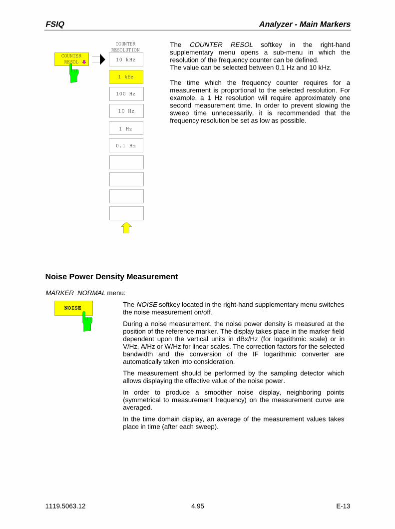
FSIQ Analyzer - Main Markers
1119.5063.12 4.95 E-13
COUNTERRESOL
COUNTERRESOLUTION
100 Hz
10 kHz
10 Hz
1 kHz
1 Hz
0.1 Hz
The COUNTER RESOL softkey in the right-handsupplementary menu opens a sub-menu in which theresolution of the frequency counter can be defined.The value can be selected between 0.1 Hz and 10 kHz.
The time which the frequency counter requires for ameasurement is proportional to the selected resolution. Forexample, a 1 Hz resolution will require approximately onesecond measurement time. In order to prevent slowing thesweep time unnecessarily, it is recommended that thefrequency resolution be set as low as possible.
Noise Power Density Measurement
MARKER NORMAL menu:
NOISE The NOISE softkey located in the right-hand supplementary menu switchesthe noise measurement on/off.
During a noise measurement, the noise power density is measured at theposition of the reference marker. The display takes place in the marker fielddependent upon the vertical units in dBx/Hz (for logarithmic scale) or inV/Hz, A/Hz or W/Hz for linear scales. The correction factors for the selectedbandwidth and the conversion of the IF logarithmic converter areautomatically taken into consideration.
The measurement should be performed by the sampling detector whichallows displaying the effective value of the noise power.
In order to produce a smoother noise display, neighboring points(symmetrical to measurement frequency) on the measurement curve areaveraged.
In the time domain display, an average of the measurement values takesplace in time (after each sweep).

Main Markers - Analyzer FSIQ
1119.5063.12 4.96 E-13
Channel Power Measurements
A modulated carrier is almost always used (exception e.g.,.: SSB-AM) for high-frequency transmissionof information. As a result carrier modulation with information, the modulated carrier now occupies afrequency spectrum which is defined by the modulation, the transmission data rate and the filtering ofthe signal. Each carrier is assigned, within a transmission band, to a channel corresponding to theseparameters. In order to make error-free transmission possible, each transmitter must adhere to thespecified transmission parameters. Among others, these are:
• output power,
• occupied bandwidth, i.e., the bandwidth within which a defined percentage of the power must becontained and
• power output in the neighboring channels.
Using the power measurement function, the FSIQ is capable of measuring all the specified parameterswith high precision and at high speed.
The settings for the power measurements are performed in the left-hand supplementary menuMARKER NORMAL.
MARKER NORMAL menu:
C / No
C / N
MARKERNORMAL
POWER MEASSETTINGS
CHANNELPOWER
SET CPREFERENCE
ADJACENTCHAN POWER
ADJUST CPSETTINGS
OCCUPIEDPWR BANDW
CP / ACPABS REL
The following measurements can be made:
• channel power (CHANNEL POWER)
• signal / noise power (C/N)
• signal / noise power density (C/No)
• adjacent channel power (ADJACENT CHAN POWER)
• occupied bandwidth (OCCUPIED PWR BANDWIDTH)
The channel power and the adjacent channel power can be measured eitherrelative (CP/ACP REL) to the power in the utilised channel or in absolute terms(CP/ACP ABS).
Channel configuration is via sub menu POWER MEAS SETTINGS.
The above mentioned power measurements can be carried out alternately.

FSIQ Analyzer - Main Markers
1119.5063.12 4.97 E-13
Channel Configuration
For all power measurements, a specified channel configuration is assumed which is, e.g. oriented on aspecific radio communications system.The channel configuration is defined by the nominal channel frequency ( = center frequency of theFSIQ), the channel bandwidth (CHANNEL BANDWIDTH) and the channel spacing (CHANNELSPACING).The channel is indicated on the display screen by vertical lines located at a half-channel bandwidth tothe left and to the right of the channel frequency.For the adjacent channel power measurement, the adjacent channels are also indicated by verticallines. The lines of the utilised channel are labelled with CO for easier recognition.Depending on the radio communication service, the power of the 1st alternate channel and/or 2nd
alternate channel can be measured in addition (softkey SET NO.OF ADJ CHAN’S).
With the ACP STANDARD softkey, the channel configuration can be set automatically according to theregulations of different digital mobile-radio standards.For some standards, the channel power has to be evaluated by means of a root-cosine filtercorresponding to the transmit filter. This filter is switched on automatically if the correspondingstandards are selected but can be switched off manually (softkey CH FILTER ON/OFF).
MARKER NORMAL - POWER MEAS SETTINGS submenu:
POWER MEASSETTING
POWER MEASSETTINGS
CHANNELBANDWIDTH
CHANNELSPACING
% POWERBANDWIDTH
SET NO. OFADJ CHAN’S
CH FILTERON OFF
ACPSTANDARD
EDITACP LIMITS
LIMITCHECK
The POWER MEAS SETTINGS softkey calls the sub-menufor the definition of the channel configuration.
SET NO. OFADJ CHAN’S The SET NO. OF ADJ CHAN’S softkey activates the input of number ±n
adjacent channels to be considered for adjacent channel powermeasurement
The individual powers are indicated separately. Example n=3:
CH0 Pwr -20.00 dBmACP UP -45.23 dBmACP LOW -52.11 dBmALT1 UP -60.04 dBmALT1 LOW -61.00 dBmALT2 UP -63.34 dBmALT2 LOW -64.00 dBm
1, 2 or 3 adjacent channels are possible. ALT1 andALT2 (Alternate Channel Power) indicate the channelpower at ± 2 × channel spacing and ± 3 × channelspacing from the center of the channel.
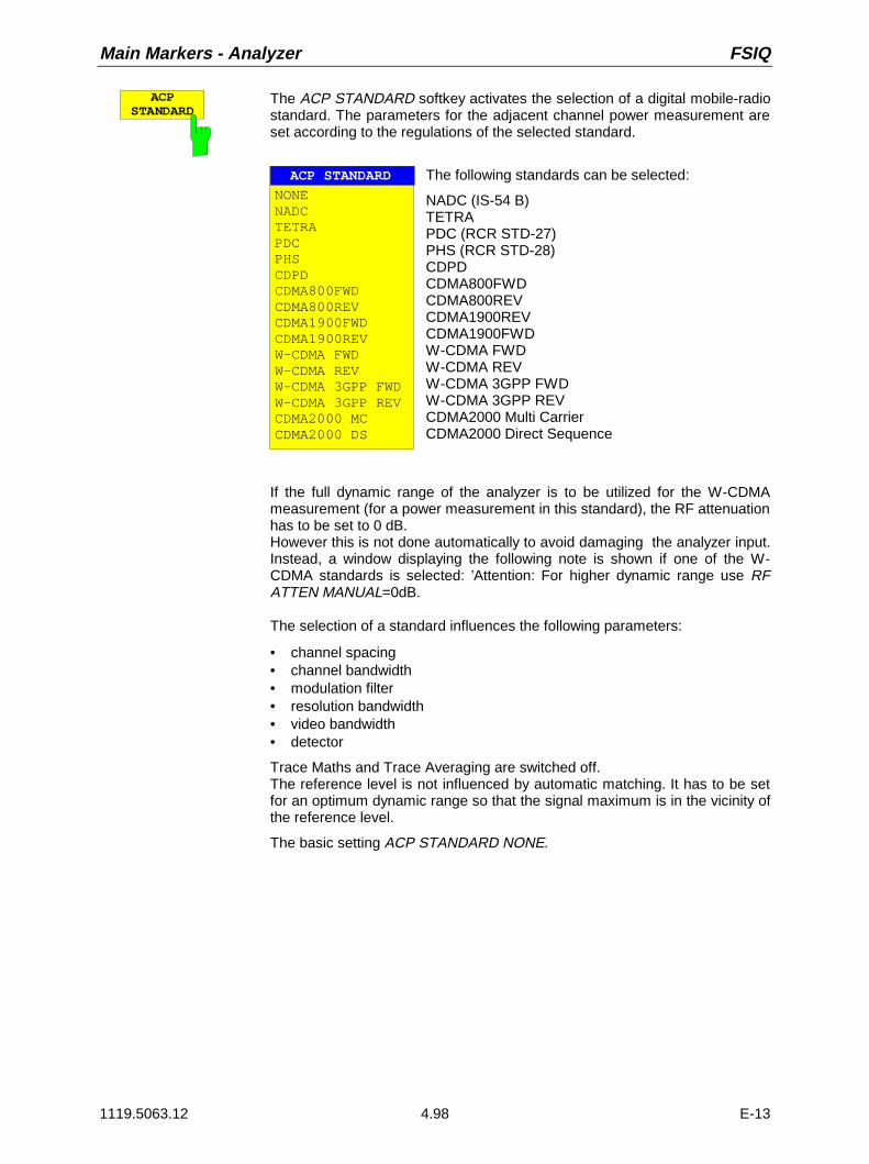
Main Markers - Analyzer FSIQ
1119.5063.12 4.98 E-13
ACPSTANDARD
The ACP STANDARD softkey activates the selection of a digital mobile-radiostandard. The parameters for the adjacent channel power measurement areset according to the regulations of the selected standard.
ACP STANDARD
NONENADCTETRAPDCPHSCDPDCDMA800FWDCDMA800REVCDMA1900FWDCDMA1900REVW-CDMA FWDW-CDMA REVW-CDMA 3GPP FWDW-CDMA 3GPP REVCDMA2000 MCCDMA2000 DS
The following standards can be selected:
NADC (IS-54 B)TETRAPDC (RCR STD-27)PHS (RCR STD-28)CDPDCDMA800FWDCDMA800REVCDMA1900REVCDMA1900FWDW-CDMA FWDW-CDMA REVW-CDMA 3GPP FWDW-CDMA 3GPP REVCDMA2000 Multi CarrierCDMA2000 Direct Sequence
If the full dynamic range of the analyzer is to be utilized for the W-CDMAmeasurement (for a power measurement in this standard), the RF attenuationhas to be set to 0 dB.However this is not done automatically to avoid damaging the analyzer input.Instead, a window displaying the following note is shown if one of the W-CDMA standards is selected: ’Attention: For higher dynamic range use RFATTEN MANUAL=0dB.
The selection of a standard influences the following parameters:
• channel spacing• channel bandwidth• modulation filter• resolution bandwidth• video bandwidth• detector
Trace Maths and Trace Averaging are switched off.The reference level is not influenced by automatic matching. It has to be setfor an optimum dynamic range so that the signal maximum is in the vicinity ofthe reference level.
The basic setting ACP STANDARD NONE.

FSIQ Analyzer - Main Markers
1119.5063.12 4.99 E-13
CH FILTERON OFF
The CH FILTER ON/OFF softkey switches a modulation filter for the channelpower and adjacent channel power measurement on or off.
When selecting the digital mobile-radio standards NADC and TETRA usingthe ADC STANDARD softkey, the softkey is automatically set to ON. Whenthe other standards are selected, weighting is not selectable and the softkeyis not available.
CH FILTER ON The channel bandwidth is defined by the filter weightingalone. Therefore, the CHANNEL BANDWIDTH softkeycannot be operated.
The activated modulation filter influences the channeland adjacent channel power measurement.
Within the definition range of the filter, the individualpixels are weighted with the calculated filter attenuationas a function of the spacing to the channel center. Theweighted display points are then added to the totalchannel power.
CH FILTER OFF No modulation filter is switched on.
CHANNELBANDWIDTH
The CHANNEL BANDWIDTH softkey opens an entry window for setting thechannel bandwidth for the transmission channel and the correspondingadjacent channels.
For all channels, the default setting is 14 kHz.
ACP CHANNEL BW
CHAN BANDWIDTHCH 14 kHzADJ 14 kHzALT1 14 kHzALT2 14 kHz
Note: If the bandwidth of one channel is changed, the new value is alsoassigned to all subsequent channels in the table. The bandwidthsfor the individual channels can be set independently, however, byoverwriting the table from the top to the bottom.
CHANNELSPACING
The CHANNEL SPACING softkey opens an table for defining the channelspacing. The channel spacing is the spacing of the center frequency of agiven channel relative to the center of the transmission channel.
The default setting for channel spacing is 20 kHz.
CHANNEL SPACING
CHAN SPACINGADJ 20 kHzALT1 40 kHzALT2 60 kHz
Note: Channel spacings can be selected separately for each channel. If aspacing value is changed in the table, the following values arechanged automatically.

Main Markers - Analyzer FSIQ
1119.5063.12 4.100 E-13
EDITACP LIMITS
The EDIT ACP LIMITS opens a table for defining the limits for ACP-measurement.
ACP LIMITS
CHAN CHECK LOWER CHANNEL LIMIT UPPER CHANNEL LIMITADJ -50 dB -50 dBALT1 -60 dB -60 dBALT2
The limit values are defined either in units of dB (forCP/ACP REL) or in dBm(for CP/ACP ABS).
Note: Measured values that exceed one of the limits are marked with anpreceding asterisk.
LIMITCHECK
The LIMIT CHECK softkey switches on or off the limit check of the ACpmeasurement.
% POWERBANDWIDTH
The % POWER BANDWIDTH softkey opens an entry window for defining thepercentage of the power with respect to the total power in the displayedfrequency range. This defines the occupied bandwidth (percent of the totalpower).
The permitted range is 10 % - 99,9 %

FSIQ Analyzer - Main Markers
1119.5063.12 4.101 E-13
Channel Power Measurement
The CHANNEL POWER measurement is performed by an integration of the measurement points withinthe channel bandwidth. The channel is marked by two vertical lines to the left and to the right of thecenter frequency as defined by the channel bandwidth (see Fig. 4-5).
Ref Lvl-20 dBm
RBW 300 HzVBW 300 HzSWT 100 ms
Marker [T1]200.0100 MHz-22.4 dBm
Span 100 kHz
0
-20
-40
-60
-80
-10010 kHz/
-10
-30
-50
-70
-90
1
Center 200 MHz
RF ATT 10 dBMixer -30 dBmUnit dBm
channel width
CH BW 30.0 kHzCH PWR -18.0 dBm
1 -24.5 dBm200.000590 MHz
Fig. 4-5 Determination of the channel width
MARKER NORMAL menu:
CHANNEL POWER
The CHANNEL POWER softkey initiates the calculation of the power in themeasurement channel. The display takes place in the units of the y axis, e.g.,in dBm, dBµV.
The calculation is performed by summing the power at the pixels within thespecified channel.
The measurement is either absolute or relative to a reference power (see theCP/ACP ABS/ REL softkey).

Main Markers - Analyzer FSIQ
1119.5063.12 4.102 E-13
CP/ACPABS REL
The CP/ACP ABS/REL softkey (Channel Power/Adjacent Channel PowerAbsolute /Relative) switches between an absolute and relative display of thepower measured in the channel or adjacent channel.
Channel power measurement
CP ABS The absolute value of the power is displayed in theunit of the Y axis, eg in dBm, dBV.
CP REL The power of a freely selected channel is measured.This power is set in relation to the power of areference channel. The reference channel power isselected beforehand using the SET CPREFERENCE softkey, ie:1. Declare the power in the currently measured
channel as the reference value using the SET CPREFERENCE softkey.
2. Set the channel of interest by changing thechannel frequency (FSIQ center frequency).
In case of linear scale of the Y axis the relativepower (CP/CPref) of the new channel is displayedin addition to the reference channel. In case ofdB scale, the logarithmic ratio 20×log (CP/CPref)is displayed.
Thus, the relative channel power measurement canalso be used for universal adjacent channel powermeasurements.
Example:Measurement of the 1597-QCDMA adjacent channelpower. The useful channel and the adjacentchannels have different bandwidths (1.23 MHz or 30kHz).
Adjacent channel power measurementThe power of the adjacent channels is measured.The reference value is the power of the usefulchannels (see measurement of the adjacent channelpower). The useful channel is marked by two verticallines that are labelled with C0.
ACP ABS The powers of the useful channel and of theadjacent channels are displayed as absolute valuesin the unit of the Y axis.
ACP REL The logarithmic ratio 20×log (CP/CP0) of the powersof the adjacent channels to the useful channel isdisplayed
The softkey is not available for OCCUPIED PWR BANDWIDTH, C/N andC/N0
.SET CP
REFERENCEFor an activated CHANNEL POWER power measurement, the SET CPREFERENCE softkey sets the reference value to the currently measuredchannel power.

FSIQ Analyzer - Main Markers
1119.5063.12 4.103 E-13
Signal / Noise Power Measurement
MARKER NORMAL menu:
C / N The C/N (Carrier to Noise) softkey calculates the ratio of carrier power tonoise power and the power of interference signals in the channel definedunder POWER MEAS SETTING. For the measurement, a marker must beset to the carrier of interest.
The unit of C/N is dB when the display is logarithmic. When the display islinear, C/N is shown without a unit.
C / N0The C/N0 softkey starts the C/N0 measurement.In contrast to the C/N measurement, C/N0 calculates the ratio of carrierpower to noise and interference signals based on a 1 Hz bandwidth in thechannel defined under POWER MEAS SETTING.
The unit of C/No is dB/Hz when the display is logarithmic and 1/Hz when thedisplay is linear.
Measurement procedure:
1. Activate a marker and position it to the peak of the carrier signal (e.g., with the Marker -> Peaksoftkey).
2. Select With the desired frequency range (channel) with the FREQUENCY CENTER and CHANNELBANDWIDTH (POWER MEAS SETTING sub-menu) softkeys.
3. Press the C/N or C/N0 softkey. The marker is set to reference fixed and activates eachmeasurement. It must be observed that the carrier is either located outside of the measurementchannel or turned off at the UUT (Unit Under Test).
4. Press the ADJUST CP SETTINGS softkey to active the default settings with modified channelparameters.
The measurement values for C/N or C/No are displayed in the marker info field.
Notes: – If no carrier marker was set, only N or No with the appropriate units is displayed.– Is the carrier located inside the measurement channel, C/C+N or C/C+N0 will be displayed

Main Markers - Analyzer FSIQ
1119.5063.12 4.104 E-13
Example:
The signal-to-noise ratio of the carrier (f = 199.9 MHz) in the channel with +100 kHz separation from 200MHz (channel center frequency) is to be measured. The channel bandwidth is 150 kHz.
1. Using the CENTER key, set the center frequency to the channel center frequency 200 MHz.
2. Using the SPAN key, set the span, e.g., to 1 MHz (carrier must be visible).
3. Using the MARKER NORMAL key, activate MARKER 1 (If Marker 1 was not yet active, the functionMARKER→ PEAK is automatically executed. In this case, skip step 4.)
4. Using the MARKER→ PEAK key, set MARKER 1 on the carrier (assumption: the 200 MHz carrier hasthe highest level in the selected span).
5. Press the MARKER NORMAL key and change to the left-hand supplementary menu.
6. Using the POWER MEAS SETTING softkey, call the sub-menu for defining the measurement channel.
7. Using the CHANNEL BANDWIDTH: softkey, set the bandwidth to 150 kHz (The channel spacingdoes not need to be entered for this measurement). Then press ⇑ menu change key.
8. Using the C/N softkey, start the C/N measurement. In the marker info field, the outputs CHANNELCENTER, CHANNEL BANDWIDTH as well as the corresponding C/N measurement values appear.MARKER 1 is also set to reference fixed.
9. Using the ADJUST CP SETTINGS softkey, activate the default settings with modified channelparameters (channel bandwidth = 150kHz) for the correct C/N measurement (span = 2 × channelbandwidth = 300 kHz, RBW = 3 kHz, VBW = 10 kHz, detector: sampling ).
Two vertical lines mark the channel 200 MHz ± 75 kHz in which the noise measurement is performed(see Fig.4-6). The reference value is the measurement from MARKER 1 (Reference Fixed).
Ref Lvl-20 dBm
RBW 3 kHzVBW 10 kHzSWT 100 ms
Marker [T1] -24.4 dBm199.9020 MHz
Span 300 kHz
0
-20
-40
-60
-80
-10030 kHz/
-10
-30
-50
-70
-90
1
Center 200 MHz
RF ATT 10 dB
Unit dBm
CHANNELBANDWIDTH
CH BW 150.00000000 kHzC/N 65.43 dB
1 -24.4 dBm 199.90200000 MHz
FXD -20.702 dBm
FXD
Fig.4-6 Example: measurement of the signal/noise power

FSIQ Analyzer - Main Markers
1119.5063.12 4.105 E-13
Adjacent Channel Power
MARKER NORMAL menu:
ADJACENTCHAN POWER
The ADJACENT CHAN POWER softkey starts the measurement of theadjacent channel power.The ADJACENT CHAN POWER measures the power which the transmitterdelivers to the two adjacent channels (upper channel , lower channel). Themeasurement values are displayed according to the setting of the CH/ACDABS/REL softkey as absolute values in the scale of the X axis (see Fig.) or asa logarithmic ratio of adjacent channel to useful channel in dB (20 × log(CP/CP0).
If the power of the other neighbouring channels is to be measured in additionto the adjacent channel power, the number of adjacent channels can beextended (on one side only) using SET NO. OF ADJ CHAN’S in the submenuPOWER MEAS SETTINGS.
A prerequisite for the correct measurement of the adjacent channel power is the correct setting of theFSIQ center frequency, the channel bandwidth and the channel spacing.The CHANNEL SPACING and CHANNEL BANDWIDTH are defined in the POWER MEAS SETTINGSsub-menu.For an activated measurement of adjacent channel power, the analyzer itself optimally sets all othervalues (span, resolution bandwidth, detector, etc.) after the ADJUST CP SETTINGS softkey is pressed.The carrier power in the utilised channel, the power (absolute or relative to the utilised channel) in theupper and lower adjacent channels as well as the largest of the two power values and the channel rasterwith channel spacing and bandwidth are displayed as the result of the measurement. The C0 lines markthe bandwidth of the carrier channel. Other unlabelled frequency lines mark the adjacent channels (seeFig.4-7). With SET NO. OF ADJ CHAN’S 2 selected, the other two neighbouring channels (1st AlternateChannels) are displayed as well, with SET NO. OF ADJ CHAN’S 3 selected, an additional channel each(2nd Alternate Channels).The measurement values are updated and displayed until the ADJACENT CHAN POWER softkey ispressed again and the measurement of the adjacent channel power is stopped.
Ref Lvl-20 dBm
RBW 300 HzVBW 300 HzSWT 100 ms
Marker [T1]-28.4 dBm200.0100 MHz
Span 100 kHz
0
-20
-40
-60
-80
-10010 kHz/
-10
-30
-50
-70
-90
1
Center 200 MHz
RF ATT 10 dBMixer -30 dBmUnit dBm
Channel BW
C0 C0
Channel BWChannel BW
ChannelSpacing
ChannelSpacing
UpperChannel
LowerChannel
TransmitChannel
1 -28.4 dBm 200.0100 MHz
CH0 PWR -18.3 dBmACP Max -67.23 dBmACP UP -67.23 dBmACP LOW -69.45 dBmCH Space 30 kHzCh BW 24 kHz
Fig.4-7 Measurement of the adjacent channel power.
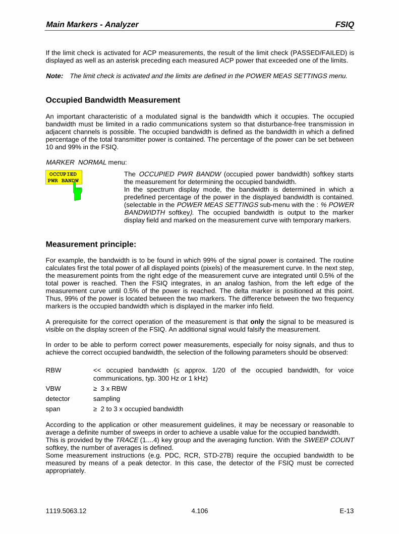
Main Markers - Analyzer FSIQ
1119.5063.12 4.106 E-13
If the limit check is activated for ACP measurements, the result of the limit check (PASSED/FAILED) isdisplayed as well as an asterisk preceding each measured ACP power that exceeded one of the limits.
Note: The limit check is activated and the limits are defined in the POWER MEAS SETTINGS menu.
Occupied Bandwidth Measurement
An important characteristic of a modulated signal is the bandwidth which it occupies. The occupiedbandwidth must be limited in a radio communications system so that disturbance-free transmission inadjacent channels is possible. The occupied bandwidth is defined as the bandwidth in which a definedpercentage of the total transmitter power is contained. The percentage of the power can be set between10 and 99% in the FSIQ.
MARKER NORMAL menu:
OCCUPIEDPWR BANDW
The OCCUPIED PWR BANDW (occupied power bandwidth) softkey startsthe measurement for determining the occupied bandwidth.In the spectrum display mode, the bandwidth is determined in which apredefined percentage of the power in the displayed bandwidth is contained.(selectable in the POWER MEAS SETTINGS sub-menu with the : % POWERBANDWIDTH softkey). The occupied bandwidth is output to the markerdisplay field and marked on the measurement curve with temporary markers.
Measurement principle:
For example, the bandwidth is to be found in which 99% of the signal power is contained. The routinecalculates first the total power of all displayed points (pixels) of the measurement curve. In the next step,the measurement points from the right edge of the measurement curve are integrated until 0.5% of thetotal power is reached. Then the FSIQ integrates, in an analog fashion, from the left edge of themeasurement curve until 0.5% of the power is reached. The delta marker is positioned at this point.Thus, 99% of the power is located between the two markers. The difference between the two frequencymarkers is the occupied bandwidth which is displayed in the marker info field.
A prerequisite for the correct operation of the measurement is that only the signal to be measured isvisible on the display screen of the FSIQ. An additional signal would falsify the measurement.
In order to be able to perform correct power measurements, especially for noisy signals, and thus toachieve the correct occupied bandwidth, the selection of the following parameters should be observed:
RBW << occupied bandwidth (≤ approx. 1/20 of the occupied bandwidth, for voicecommunications, typ. 300 Hz or 1 kHz)
VBW ≥ 3 x RBW
detector sampling
span ≥ 2 to 3 x occupied bandwidth
According to the application or other measurement guidelines, it may be necessary or reasonable toaverage a definite number of sweeps in order to achieve a usable value for the occupied bandwidth.This is provided by the TRACE (1....4) key group and the averaging function. With the SWEEP COUNTsoftkey, the number of averages is defined.Some measurement instructions (e.g. PDC, RCR, STD-27B) require the occupied bandwidth to bemeasured by means of a peak detector. In this case, the detector of the FSIQ must be correctedappropriately.
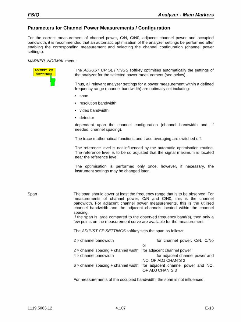
FSIQ Analyzer - Main Markers
1119.5063.12 4.107 E-13
Parameters for Channel Power Measurements / Configuration
For the correct measurement of channel power, C/N, C/N0, adjacent channel power and occupiedbandwidth, it is recommended that an automatic optimisation of the analyzer settings be performed afterenabling the corresponding measurement and selecting the channel configuration (channel powersettings).
MARKER NORMAL menu:
ADJUST CPSETTINGS
The ADJUST CP SETTINGS softkey optimises automatically the settings ofthe analyzer for the selected power measurement (see below).
Thus, all relevant analyzer settings for a power measurement within a definedfrequency range (channel bandwidth) are optimally set including:
• span
• resolution bandwidth
• video bandwidth
• detector
dependent upon the channel configuration (channel bandwidth and, ifneeded, channel spacing).
The trace mathematical functions and trace averaging are switched off.
The reference level is not influenced by the automatic optimisation routine.The reference level is to be so adjusted that the signal maximum is locatednear the reference level.
The optimisation is performed only once, however, if necessary, theinstrument settings may be changed later.
Span The span should cover at least the frequency range that is to be observed. Formeasurements of channel power, C/N and C/N0, this is the channelbandwidth. For adjacent channel power measurements, this is the utilisedchannel bandwidth and the adjacent channels located within the channelspacing.If the span is large compared to the observed frequency band(s), then only afew points on the measurement curve are available for the measurement.
The ADJUST CP SETTINGS softkey sets the span as follows:
2 × channel bandwidth for channel power, C/N, C/Noor
2 × channel spacing + channel width for adjacent channel power4 × channel bandwidth for adjacent channel power and
NO. OF ADJ CHAN‘S 26 × channel spacing + channel width for adjacent channel power and NO.
OF ADJ CHAN‘S 3
For measurements of the occupied bandwidth, the span is not influenced.
Main Markers - Analyzer FSIQ
1119.5063.12 4.108 E-13
Resolution bandwidth (RBW)In order to achieve acceptable speed as well as the necessary selection (tosuppress spectral components outside of the frequency range to be measuredand, especially the adjacent channels), the resolution bandwidth should not bechosen too broad or too narrow.If the resolution bandwidth is too narrow, the measurement speed becomesvery slow and it is possible that relative spectral components are not displayed(due to the sampling detector necessary for power measurements and thefinite number of points).On the other hand, the resolution bandwidth should not be so broad that, dueto insufficient selection, spectral components outside of the observedfrequency range (from adjacent channel) falsify the measurement results.
The ADJUST CP SETTINGS softkey sets the resolution bandwidth (RBW)dependent upon the channel bandwidth as follows:
RBW ≤ 1/40 of the channel bandwidth. The largest possible RBW, with dueregard to the 1, 2, 3, 5 step size and the requirement RBW ≤ 1/40 will beselected.
The RBW is not influenced by measurements of the occupied bandwidth.
Video bandwidth (VBW) Since a power measurement of the noise components is also necessary(otherwise, errors occur due to the logarithmic characteristics of the spectrumanalyzer), the video bandwidth should be chosen substantially larger than theresolution bandwidth.
The ADJUST CP SETTINGS softkey adjusts the video bandwidth (VBW)dependent upon the channel bandwidth as follows:
VBW ≥ 3* RBW. The smallest VWB with regard to the available 1, 2, 3, 5 stepsize is selected.
Grid scale The ADJUST CP SETTINGS softkey sets the grid scale to the 100-dB range.Thereby, a wide dynamic range in channel power measurements is achieved.
Detector The ADJUST CP SETTINGS softkey selects the sampling detector.The sampling detector is to be selected, above all, for correct powermeasurements of noisy signals within the observed frequency range.
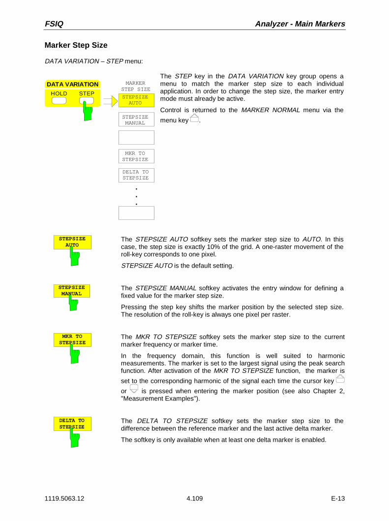
FSIQ Analyzer - Main Markers
1119.5063.12 4.109 E-13
Marker Step Size
DATA VARIATION – STEP menu:
STEPSIZE MANUAL
MKR TOSTEPSIZE
MARKERSTEP SIZE
STEP
DATA VARIATION
HOLDSTEPSIZE AUTO
.
.
.
DELTA TOSTEPSIZE
The STEP key in the DATA VARIATION key group opens amenu to match the marker step size to each individualapplication. In order to change the step size, the marker entrymode must already be active.
Control is returned to the MARKER NORMAL menu via the
menu key .
STEPSIZE AUTO
The STEPSIZE AUTO softkey sets the marker step size to AUTO. In thiscase, the step size is exactly 10% of the grid. A one-raster movement of theroll-key corresponds to one pixel.
STEPSIZE AUTO is the default setting.
STEPSIZE MANUAL
The STEPSIZE MANUAL softkey activates the entry window for defining afixed value for the marker step size.
Pressing the step key shifts the marker position by the selected step size.The resolution of the roll-key is always one pixel per raster.
MKR TOSTEPSIZE
The MKR TO STEPSIZE softkey sets the marker step size to the currentmarker frequency or marker time.
In the frequency domain, this function is well suited to harmonicmeasurements. The marker is set to the largest signal using the peak searchfunction. After activation of the MKR TO STEPSIZE function, the marker is
set to the corresponding harmonic of the signal each time the cursor key
or is pressed when entering the marker position (see also Chapter 2,"Measurement Examples").
DELTA TOSTEPSIZE
The DELTA TO STEPSIZE softkey sets the marker step size to thedifference between the reference marker and the last active delta marker.
The softkey is only available when at least one delta marker is enabled.

Delta Markers - Analyzer FSIQ
1119.5063.12 4.110 E-13
Delta Markers – DELTA Key
The delta markers are used to measure a level or frequency referred to a reference marker. They arealways referenced to the marker whose position was last changed. A delta marker is displayedas an empty symbol. The reference marker is displayed as a filled symbol.
MARKER DELTA menu:
NORMAL SEARCH
MARKER
DELTA MKR
DELTAMARKER
DELTA 2
DELTA 3
PHASENOISE
DELTA 1
REFERENCE FIXED
DELTA 4
ALL DELTA OFF
REFERENCE POINT
DELTA MKRABS REL
The DELTA key switches a delta marker on and calls themenu for its control. If no marker is enabled, MARKER 1 isautomatically activated when the delta marker is switched on.The delta marker activated to entry mode is shown on thedisplay screen as a filled symbol.
DE A 2
DELTA 3
DELTA 1
DELTA 4
The DELTA 1 to 4 softkeys are used to enable delta markers 1...4. Thecontrol of the delta markers corresponds to that of the markers. After a deltamarker has been enabled, all entries are now applicable to this marker. Themain marker must be activated anew if its position is to be changed.
The delta marker field on the display screen contains the delta markernumber, the difference frequency from the delta marker to reference markerand the level difference between the active delta markers and referencemarkers.
The indicated differences are, in general, referred to the reference marker. Ifthe PHASE NOISE or REFERENCE FIXED functions are enabled, thereference values under REFERENCE POINT are applicable.

FSIQ Analyzer - Delta Markers
1119.5063.12 4.111 E-13
DELTA MKRABS REL
The DELTA ABS REL softkey switches between relative and absolute entrymodes for the delta-marker frequency.
In the REL position, the delta marker frequency is entered relative to thereference marker. In this case, the entry mode for the delta-markerfrequencies is also relative.
In the ABS position, the entry of the delta-marker frequency is in terms ofabsolute frequency.
The default setting is REL.
ALL DELTA OFF
The ALL DELTA OFF softkey switches off all active delta markers and anyassociated functions (e.g. REFERENCE FIXED, PHASE NOISE).
REFERENCEFIXED
The REFERENCE FIXED softkey enables/disables relative measurementswith respect to a fixed, measurement-curve-independent reference value.
The information in the delta-marker field on the display screen is referencedto this fixed reference value. For the generation of the marker lists usingMARKER INFO list, the delta markers are also output relative to a fixedreference. In the lists, the REFERENCE POINT is tagged by the number ofthe reference marker (only one enabled)
When REFERENCE FIXED is enabled, the current settings of the referencemarker become the reference values. If no marker is active, MARKER 1 (withpeak search) is activated. After transferring the reference values, all markersare deleted, and the active delta marker is set to the position of the referencevalue. Additional delta markers can be switched on.
The reference value can be subsequently changed
1. by shifting it in the REFERENCE POINT sub-menu.
2. by starting a search:In the MARKER NORMAL menu the REF POINT is handled as a referencemarker (even though it is not bound to the measurement curve). Thismeans, that it will be shown as enabled and can also be changed inposition. The co-ordinates of the REF POINT are overwritten by the markervalues (they lie, by definition, on the measurement curve). Thus, it ispossible, even for an enabled REFERENCE FIXED, to define a newreference point function with search functions.
The REFERENCE FIXED function is particularly useful for measurementswhich are performed relative to a reference signal that is not available duringthe whole measurement time (e. g. harmonics measurements, see chapter"Measurement Example").

Delta Markers - Analyzer FSIQ
1119.5063.12 4.112 E-13
MARKER DELTA- REFERENCE POINT submenu:
REFERENCEPOINT
REFERENCEPOINT
REF POINT LEVEL
REF POINTLVL OFFSET
REF POINTFREQUENCY
REF POINTTIME
The REFERENCE POINT softkey opens a sub-menu in whichthe reference value the REFERENCE FIXED and PHASENOISE functions can be modified.
The position of the reference value is indicated by twoadditional display lines (horizontal and vertical). In addition, anoffset level may be defined which is added to each differenceduring output.
The softkey is only available when the REFERENCE FIXED orPHASE NOISE function is switched on.
REF POINTLEVEL
The REF POINT LEVEL softkey activates an entry box for setting thereference level relevant to the REFERENCE FIXED or PHASE NOISE.functions.
REF POINTFREQUENCY
The REF POINT FREQUENCY softkey activates the entry box for the input ofa reference frequency for the REFERENCE FIXED or PHASE NOISE.functions.
REF POINTLVL OFFSET
The REF POINT LVL OFFSET softkey activates the entry box for the entry ofan additional offset level during output when the REFERENCE FIXED orPHASE NOISE. functions are enabled.
The offset level is set to 0 dB when the REFERENCE FIXED or PHASENOISE. functions are switched on.
REF POINT TIME
The REF POINT TIME softkey activates the entry box for the input of areference time for the REFERENCE FIXED function in the time domain(span = 0).
The entry of a reference time for the PHASE NOISE function is not possible.

FSIQ Analyzer - Delta Markers
1119.5063.12 4.113 E-13
Phase Noise Measurement
MARKER DELTA menu:
PHASENOISE
The PHASE NOISE softkey switches the PHASE NOISE function on/off.
Enabling the PHASE NOISE function causes the frequency and level of thereference marker to be transferred as reference values, that means, theREFERENCE FIXED function is activated.
The difference between this reference point and the active delta markers isdetermined. The correction factors for bandwidth and the logarithmicconverter are automatically taken into consideration. The sampling detector isalso enabled to allow the effective noise power to be displayed. Themeasured values are displayed in the delta marker field in units of dBc/Hz.
If several delta markers are enabled, only the measurement value output ofthe active marker is shown in the marker field. Using MARKER INFO andMARKER LIST the measurement data of all delta markers can be displayed.
If no marker is present when the PHASE NOISE function is enabled,MARKER 1 is automatically switched on (peak search), and the markervalues are saved as reference values. The reference value can be changedlater in the NORMAL menu, SEARCH menu or REFERENCE POINT sub-menu (see REFERENCE FIXED softkey).
Turning on an additional marker causes the PHASE NOISE function to bedisabled.

Delta Markers - Analyzer FSIQ
1119.5063.12 4.114 E-13
Delta-Marker Step Size - STEP Key
STEP-DELTA STEP menu:
STEPSIZEMANUAL
DELTASTEP SIZE
STEP
DATA VARIATION
HOLD STEPSIZEAUTO
DELTA TOSTEPSIZE
.
.
.
The STEP key in the DATA VARIATION key group opens amenu to match the step size of the individual delta markersto the specific application. In order to change the step size,the entry mode for a delta marker must already be active.
Control is returned to the DELTA MARKER menu via the
menu key .
STEPSIZE AUTO
The STEPSIZE AUTO softkey sets the delta marker step size to AUTO. Inthis case, the step size of the delta marker is exactly 10% of the grid. Theroll-key corresponds to 1/500, i.e., for each rotational pulse, the deltamarker is shifted one pixel position.
STEPSIZE MANUAL
The STEPSIZE MANUAL softkey permits the entry of a fixed value for thedelta marker step size.
Pressing the step-key shifts the marker position by the selected step size.The roll-key resolution, however, always remains constant at 1 pixel.
DELTA TOSTEPSIZE
The DELTATO STEPSIZE softkey sets the delta marker step size to aquantity equal to the difference between the delta and reference markers.
The softkey is only presented when at least one delta marker is switchedon.

FSIQ Analyzer - Search Functions
1119.5063.12 4.115 E-13
Search Functions – SEARCH Key
The FSIQ offers numerous functions useful for peak/min. peak searching. The search functions can beused for marker as well as delta marker functions.
The setups applicable to the available search functions are performed in the MARKER-SEARCH menu.
The search functions are always related to the currently active marker. If the SEARCH key is pressedwhile the marker entry mode is active, then all search functions are related to the current referencemarker. If the entry mode of a delta marker is active, then the functions will be applied to thecorresponding delta marker. For the case where no marker is active, MARKER 1 will be automaticallyenabled (with peak search). The ACTIVE MKR / DELTA softkey allows toggling between the activemarker and the active delta marker.
If the threshold line is turned on, the peak/min. search functions will only evaluate signals which have alevel above/below the selected threshold. In addition, the search range can also be limited (SEARCHLIM ON/OFF softkey) by the frequency/time lines (FREQUENCY LINE 1/2, TIME LINE 1/2).
For all peak search functions, the first local oscillator is omitted at 0 Hz if it happens to be displayed.
In the time domain display, the summary markers can be activated and set in addition to the searchfunctions in menu MARKER-SEARCH.
MARKER SEARCH menu:
MARKER
DELTA MKR
NORMAL SEARCH MARKERSEARCH
N DB DOWN
SHAPE FACT60 /6 DB
MARKERSEARCH
NEXT PEAK
NEXT PEAKRIGHT
NEXT PEAKLEFT
MIN
NEXT MIN
NEXT MINRIGHT
MARKERSEARCH
SELECTMARKER
SHAPE FACT60 /3 DB
ACTIVEMKR DELTA
NEXT MINLEFT
PEAK
PEAKEXCURSION
ACTIVEMKR DELTA
ACTIVEMKR DELTA
SEARCH LIMON OFF
SUM MKR
ON OFF
SUMMARYMARKER
RMS
SUMMARYMARKER
AVERAGE
SWEEPCOUNT
ALL SUMMKR OFF
MEAN
ON OFF
PEAK HOLD
ON OFF
SELECTMARKER
SELECTMARKER
EXCLUDE LOON OFF

Search Functions - Analyzer FSIQ
1119.5063.12 4.116 E-13
ACTIVEMKR DELTA
The ACTIVE MKR / DELTA softkey toggles between the active marker andthe active delta marker.
If DELTA is illuminated, the following search functions are performed with theactive delta marker.
Note: Switching between marker and delta marker entry modes mayalso be performed using the NORMAL and DELTA keys.
SELECTMARKER
The SELECT MARKER softkey activates the selection of the marker/deltamarkers. The selection box lists the currently enabled markers/delta markers.
MARKER SELECT
MARKER 1MARKER 3MARKER 4
DELTA SELECT
DELTA 1DELTA 2DELTA 3
PEAK The PEAK softkey sets the active marker/delta marker to the maximumdisplayed value on the corresponding trace.
NEXT PEAK The NEXT PEAK softkey sets the active marker/delta marker to the nextlower peak value on the corresponding curve.
NEXT PEAK The NEXT PEAK RIGHT softkey sets the active marker to the next peak tothe right of the current marker position.
NEXT PEAK RIGHT
The NEXT PEAK LEFT softkey sets the active marker to the next peak to theleft of the current marker position.
MIN The MIN softkey sets the active marker to the lowest displayed peak on thecorresponding measurement curve.

FSIQ Analyzer - Search Functions
1119.5063.12 4.117 E-13
NEXT MIN The NEXT MIN softkey sets the active marker to the next higher of the lowpeaks on the corresponding measurement curve.
NEXT MINRIGHT
The NEXT MIN RIGHT softkey set the active marker to the next low peak tothe right of the current marker position.
NEXT MINLEFT
The NEXT MIN LEFT softkey sets the active marker to the next low peak tothe left of the current marker position.
EXCLUDE LOON OFF
The EXCLUDE LO ON/OFF softkey switches between a restriced (ON) andan unrestricted search range (OFF).
ON Because of non-ideal input mixer, the first LO of any analyzer can beseen at 0 Hz. The search functions can possibly respond to this LOlevel, in particular in the preset setting (FULL SPAN). To avoid this,the search range is restricted according to the following formula:
Search range ≥ 6 × resolution bandwidth
OFF No restriction to the search range. The search functions find alsosignals below the frequency limit quoted above.
PEAKEXCURSION
The PEAK EXCURSION softkey activates the entry box which sets theminimum amount a signal level must decrease/increase before it isrecognised by the search functions (except PEAK and MIN) as a maximum orminimum.
Input values from 0 dB to 80 dB are allowed with a resolution of 0.1 dB.
The peak excursion is preset to 6 dB. This is completely sufficient for thefunctions NEXT PEAK (or NEXT MIN) as always the next smaller (or higher)signal is searched four.
Functions NEXT PEAK LEFT and NEXT PEAK RIGHT (or NEXT MIN LEFTand NEXT MIN RIGHT) search for the next relative maximum (or minimum)independent of the current signal amplitude.As for wide bandwidths, the set 6-dB level change is already reached by thenoise indication of the analyzer, the noise values are also identified as peak. Inthis case, PEAK EXCURSION has to be selected with a higher value than thedifference between the highest and lowest noise indication values.
The following example shows the effect of different PEAK EXCURSIONsettings.

Search Functions - Analyzer FSIQ
1119.5063.12 4.118 E-13
Marker [T1]199.0140 MHz-22.4 dBm
0
-20
-40
-60
-80
-100
-10
-30
-50
-70
-90
1
42dB 30dB 46dB
1
2
3
4
Fig. 4-8 Example for level measurements at differentpeak excursion settings
Maximum relative level change of the measured signals:Signal 2: 42dBSignal 3 30dBSignal 4: 46dB
Setting Peak Excursion 40dB causes signal 2 and 4 to be detected withNEXT PEAK or NEXT PEAK RIGHT. Signal 3 is not detected since it is onlydecreased by 30 dB before the level rises again.
Order of signals found:PEAK: Signal 1NEXT PEAK: Signal 2NEXT PEAK: Signal 4
orPEAK: Signal 1NEXT PEAK RIGHT: Signal 2NEXT PEAK RIGHT: Signal 4
Setting Peak Excursion 20dB causes signal 3 to be detected since its highestlevel change of 30 dB is now higher than the set peak excursion.
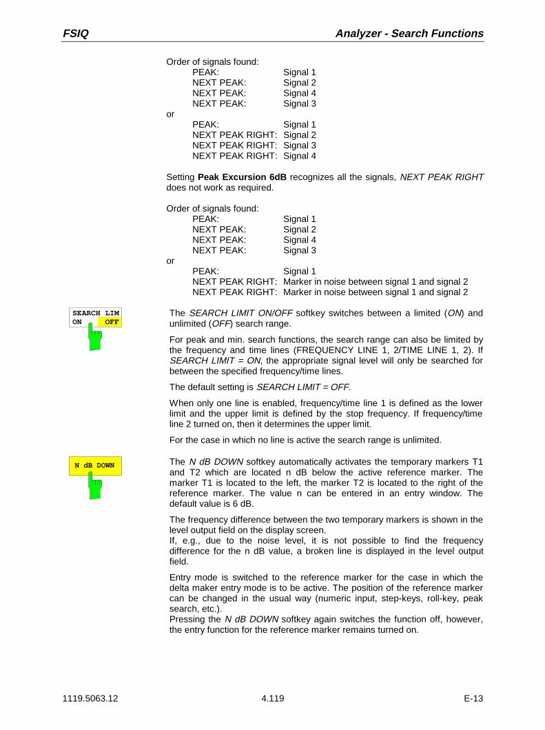
FSIQ Analyzer - Search Functions
1119.5063.12 4.119 E-13
Order of signals found:PEAK: Signal 1NEXT PEAK: Signal 2NEXT PEAK: Signal 4NEXT PEAK: Signal 3
orPEAK: Signal 1NEXT PEAK RIGHT: Signal 2NEXT PEAK RIGHT: Signal 3NEXT PEAK RIGHT: Signal 4
Setting Peak Excursion 6dB recognizes all the signals, NEXT PEAK RIGHTdoes not work as required.
Order of signals found:PEAK: Signal 1NEXT PEAK: Signal 2NEXT PEAK: Signal 4NEXT PEAK: Signal 3
orPEAK: Signal 1NEXT PEAK RIGHT: Marker in noise between signal 1 and signal 2NEXT PEAK RIGHT: Marker in noise between signal 1 and signal 2
SEARCH LIMON OFF
The SEARCH LIMIT ON/OFF softkey switches between a limited (ON) andunlimited (OFF) search range.
For peak and min. search functions, the search range can also be limited bythe frequency and time lines (FREQUENCY LINE 1, 2/TIME LINE 1, 2). IfSEARCH LIMIT = ON, the appropriate signal level will only be searched forbetween the specified frequency/time lines.
The default setting is SEARCH LIMIT = OFF.
When only one line is enabled, frequency/time line 1 is defined as the lowerlimit and the upper limit is defined by the stop frequency. If frequency/timeline 2 turned on, then it determines the upper limit.
For the case in which no line is active the search range is unlimited.
N dB DOWN The N dB DOWN softkey automatically activates the temporary markers T1and T2 which are located n dB below the active reference marker. Themarker T1 is located to the left, the marker T2 is located to the right of thereference marker. The value n can be entered in an entry window. Thedefault value is 6 dB.
The frequency difference between the two temporary markers is shown in thelevel output field on the display screen.If, e.g., due to the noise level, it is not possible to find the frequencydifference for the n dB value, a broken line is displayed in the level outputfield.
Entry mode is switched to the reference marker for the case in which thedelta maker entry mode is to be active. The position of the reference markercan be changed in the usual way (numeric input, step-keys, roll-key, peaksearch, etc.).Pressing the N dB DOWN softkey again switches the function off, however,the entry function for the reference marker remains turned on.
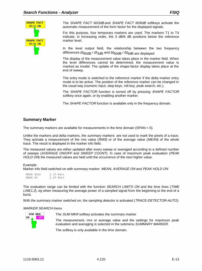
Search Functions - Analyzer FSIQ
1119.5063.12 4.120 E-13
SHAPE FACT60/3 DB
SHAPE FACT60/6 DB
The SHAPE FACT 60/3dB.and SHAPE FACT 60/6dB softkeys activate theautomatic measurement of the form factor for the displayed signals.
For this purpose, four temporary markers are used. The markers T1 to T4indicate, in increasing order, the 3 dB/6 dB positions below the referencemarker level.
In the level output field, the relationship between the two frequencydifferences ∆f60dB / ∆f3dB and ∆f60dB / ∆f6dB are displayed
The display of the measurement value takes place in the marker field. Whenthe level differences cannot be determined, the measurement value ismarked as invalid. The update of the shape-factor display takes place at theend of sweep.
The entry mode is switched to the reference marker if the delta marker entrymode is to be active. The position of the reference marker can be changed inthe usual way (numeric input, step-keys, roll-key, peak search, etc.).
The SHAPE FACTOR function is turned off by pressing SHAPE FACTORsoftkey once again, or by enabling another marker.
The SHAPE FACTOR function is available only in the frequency domain.
Summary Marker
The summary markers are available for measurements in the time domain (SPAN = 0).
Unlike the markers and delta markers, the summary markers are not used to mark the pixels of a trace.They activate a measurement of the rms value (RMS) or of the average value (MEAN) of the wholetrace. The result is displayed in the marker info field.
The measured values are either updated after every sweep or averaged according to a defined numberof sweeps (AVERAGE ON/OFF and SWEEP COUNT). In case of maximum peak evaluation (PEAKHOLD ON) the measured values are held until the occurrence of the next higher value.
Example:Marker info field switched on with summary marker: MEAN, AVERAGE ON and PEAK HOLD ON
MEAN HOLD 2.33 Watt MEAN AV 2.29 Watt
The evaluation range can be limited with the function SEARCH LIMITS ON and the time lines (TIMELINE1,2), eg when measuring the average power of a sampled signal from the beginning to the end of aburst.
With the summary marker switched on, the sampling detector is activated (TRACE-DETECTOR-AUTO).
MARKER SEARCH menu
SUM MKRON OFF
The SUM MKR softkey activates the summary marker
The measurement, rms or average value and the settings for maximum peakevaluation and averaging is selected in the submenu SUMMARY MARKER.
The softkey is only available in the time domain.

FSIQ Analyzer - Search Functions
1119.5063.12 4.121 E-13
MARKER SEARCH menu
SUMMARYMARKER
RMS
SUMMARYMARKER
AVERAGE
SWEEPCOUNT
ALL SUMMKR OFF
MEAN
ON OFF
PEAK HOLDON OFF
The SUMMARY MARKER softkey calls up the submenu forselecting the summary marker measurements.
The softkey is only available in the time domain.
RMS The RMS softkey selects the measurement of the rms value of the signal persweep.
In case of maximum peak evaluation the highest rms value since the activation ofPEAK HOLD ON is displayed.
In case of AVERAGE ON the rms values of a trace are averaged and displayedover several sweeps.
The number of sweeps is set with the SWEEP COUNT softkey. If PEAK HOLD =ON is active at the same time, the display is held until the occurrence of the nexthigher average value.
MEANThe MEAN softkey selects the measurement of the average value of the signal persweep.
Thus, the mean power can be measured, for example during a GSM burst.
In case of maximum peak evaluation, the highest average value since theactivation of PEAK HOLD ON is displayed.
In case of AVERAGE ON, the average values of a trace are averaged anddisplayed over several sweeps.
The number of sweeps is set with the SWEEP COUNT softkey. If PEAK HOLD =ON is active at the same time, the display is held until the occurrence of the nexthigher average value.

Search Functions - Analyzer FSIQ
1119.5063.12 4.122 E-13
PEAK HOLDON OFF
The PEAK HOLD ON/OFF softkey switches the maximum peak evaluation on andoff.
For all active summary markers, the displays are updated after each sweep only ifhigher values have occurred.
The measured values can be reset by switching the PEAK HOLD ON / OFFsoftkey on and off again.
AVERAGEON OFF
The AVERAGE ON/OFF softkey switches the averaging of the summary markerson and off.
The measured values can be reset by switching the AVERAGE HOLD ON / OFFsoftkey on and off again.
SWEEPCOUNT
The SWEEP COUNT softkey activates the entry of the number of sweeps in theSINGLE SWEEP mode.
The permissible range of values is 0 to 32767.
In case of AVERAGE ON:
If an averaging has been selected, SWEEP COUNT also determines thenumber of measurements required for averaging.
SWEEP COUNT = 0 10 measured values are required for runningaveraging.
SWEEP COUNT = 1 No averaging is carried out.
SWEEP COUNT > 1 An averaging is carried out over the set number ofmeasured values.
In the CONTINUOUS SWEEP mode averaging is performed until the numberof sweeps set under SWEEP COUNT is attained and then running averagingis performed.
The maximum peak evaluation is infinite independent of the entry under SWEEPCOUNT.
Note: This setting is equivalent to the settings of the number of sweeps of menusTRACE and SWEEP-SWEEP.
ALL SUMMKR OFF
The ALL SUM MKR OFF softkey switches all the summary markers off.

FSIQ Analyzer - Marker È Menu
1119.5063.12 4.123 E-13
Instrument Parameter Changes via Markers – MKR Ð Key
MARKER MKR →menu:
NORMAL SEARCH
DELTA MKR
MARKER PEAK
ACTIVEMKR DELTA
SELECTMARKER
MKR->STOP
MKR->TRACE
MKT->START
MKR->CFSTEPSIZE
MKR->REF LEVEL
MKR->CENTER
MARKER-> The MKR → menu offers functions through which instrumentparameters can be changed with the aid of the currentlyactive marker. Exactly as in the SEARCH menu, thesefunctions can also be applied to the delta markers.
The choice between marker and delta marker is madeaccording to the currently active frequency entry mode for themarker/delta marker. If no entry mode is active, the markerwith the lowest number will be activated as the referencemarker.
ACTIVEMKR DELTA
The ACTIVE MKR /DELTA softkey toggles between the active marker andthe active delta marker.
If DELTA is illuminated, the following marker functions are carried out with theactive delta marker.
Note: Switching between marker and delta marker can also be done withthe NORMAL and DELTA keys.
PEAK To simplify control, the PEAK search function (see section "Search Functions- SEARCH Key") is also available in the MRK→ menu. Thus, the mostimportant functions MARKER→PEAK, MKR→CENTER and MKR→REFLEVEL can be selected in one menu.
MKR->CENTER
The MKR→CENTER softkey sets the center frequency for the currentmarker/delta marker .
The softkey is not available in the time domain.

MarkerÈ Menu - Analyzer FSIQ
1119.5063.12 4.124 E-13
MKR->REF LEVEL
The MKR→REF LEVEL softkey sets the reference level to that of the currentmarker.
MKR->CFSTEPSIZE
The MKR→CF STEPSIZE softkey sets the step size for the center frequencyentry mode to the current marker frequency, and also sets step-sizeadaptation to MANUAL. The CF STEP SIZE remains at this value until thecenter frequency entry mode in the STEP menu is switched from MANUAL toAUTO again.
The MKR→CF STEPSIZE function is, above all, helpful in the measurementof harmonics with large dynamic range (narrow bandwidth and narrow span).
The softkey is not available in the time domain.
MKR->START
The MKR→START softkey sets the start frequency to the current markerfrequency.
The softkey is not available in the time domain.
MKR->STOP
The MKR→STOP softkey sets the stop frequency to the current markerfrequency.
The softkey is not available in the time domain.
MKR->TRACE
The MKR→TRACE softkey opens a selection window through which themarker can be set to a new measurement curve. The traces available forselection appear in the window.
TRACE1
TRACE3TRACE4
SELECT TRACE
TRACE2
FSIQ Analyzer - Display and Limit Lines
1119.5063.12 4.125 E-13
Setup of Display and Limit Lines – LINES Key Field
Display Lines – D LINES Key
Display lines are aids which, similar to markers, make the evaluation of measurement curve data moreconvenient. The function of display lines is similar to that of a movable scale which can be used tomeasure absolute and differential values on measurement curves.In addition, the display lines can also be used to limit the range of search for marker functions.
The FSIQ provides four different types of display lines:
• two horizontal threshold lines for setting levels or for defining level search ranges – Display Line 1/2,
• two vertical frequency/time lines for indicating frequencies/times or for determining frequency or timesearch ranges – Frequency/Time Line 1/2,
• a threshold line which, for example, sets the search threshold for maximum levels (Peak Search) –Threshold Line
• a reference line which serves as the basis for mathematical correlation between measurement curves– Reference Line
For purposes of clarity, each line is annotated on the right side of the display diagram by the followingabbreviations:
D1 Display Line 1 T1 Time Line 1D2 Display Line 2 T2 Time Line 2F1 Frequency Line 1 TH Threshold LineF2 Frequency Line 2 REF Reference Line
The lines for level, threshold and reference are displayed as continuous, horizontal lines over the fullwidth of the diagram. They are movable in the y-direction.The lines for frequency and time are displayed as vertical, continuous lines over the total height of thediagram. They are movable in the x-direction.
For measurement operations in two separate windows, (Split Screen-Modus), the display lines areavailable independently in both windows. In the currently active window, the display lines can beactivated and/or shifted. Lines previously defined in the currently inactive window remain unchanged.
The LINES-D LINES menu, used for switching on and setting the display lines, is dedicated to thechosen display in the active measurement window (span or time). For the display of a spectrum (span ≠0), the FREQUENCY LINE 1 and FREQUENCY LINE 2 softkeys appear, For the time display (span =0), the TIME LINE 1 and TIME LINE 2 softkeys are displayed.

Display and Limit Lines - Analyzer FSIQ
1119.5063.12 4.126 E-13
Note: The softkeys for setting and switching the display lines on and off operate similar to a three-position switch:Initial condition: The line is switched off (softkey has grey background)1st press: The line is switched on (softkey has red background) and data entry is
activated. The position of the display line can be adjusted by using the roll-key, the step keys or through direct numerical inputs via the data-entrykeypad. If some other arbitrary function is requested, the data-entry keypad isdisabled. In this case, the display line remains switched on (softkey has greenbackground).
2nd press: The display line is switched off (softkey has grey background).
Initial condition: The line is switched on (softkey has green background)1st press: The line is switched on (softkey has red background) and data entry is
activated. The position of the display line can be adjusted by using the roll-key, the step keys or through direct numerical inputs via the data-entrykeypad. If any other arbitrary function is requested, the data-entry keypad isdisabled. In this case, the display line remains switched on (softkey has greenbackground).
2nd press: The display line is switched off (softkey has grey background).
Menu LINES-D-LINES for Span ≠ 0 for Span = 0
LINES
D LINES
LIMITS
DISPLAYLINES
DISPLAYLINE 2
FREQUENCY LINE 1
DISPLAY LINE 1
FREQUENCY LINE 2
DISPLAYLINE 2
DISPLAY LINE 1
TIMELINE 1
TIMELINE 2
REFERENCELINE
REFERENCELINE
THRESHOLDLINE
THRESHOLDLINE
DISPLAYLINES
BASELINECLIPPING
BASELINECLIPPING

FSIQ Analyzer - Display and Limit Lines
1119.5063.12 4.127 E-13
DISPLAYLINE 1
DISPLAYLINE 2
The DISPLAY LINE 1/2 softkeys switch the display lines on/off and activatethe entry of the line location.
The display lines mark the selected levels in the measurement window.
THRESHOLDLINE
The THRESHOLD LINE softkey switches the threshold line on/off andactivates the entry of the line location.
The threshold line is a display line which defines a threshold value. Thisthreshold value serves as a lower search limit for maximums/minimums inthe marker functions (MAX PEAK, MIN PEAK, NEXT PEAK etc.). For signaltracking (SIGNAL TRACK function), this threshold value defines the lowersearch limit (see section "Marker Functions")..
REFERENCELINE
The REFERENCE LINE softkey switches the reference line on/off andactivates the entry of the line position.
The reference line serves as the basis for mathematical correlation betweenmeasurement curve data (see section "Mathematical Operations onMeasurement Curves"
FREQUENCYLINE 1
FREQUENCYLINE 2
The FREQUENCY LINE 1/2 softkeys switch the frequency lines 1/2 on/offand activate the entry of the line locations.
The frequency lines mark the selected frequencies in the measurementwindow or define search ranges (see section "Marker Functions").
TIMELINE 1
TIMELINE 2
The TIME LINE 1/2 softkeys switch the time lines 1/2 on/off and activate theentry of line locations.
The time lines mark the selected times or define the search range (seesection "Marker Functions").
Display and Limit Lines - Analyzer FSIQ
1119.5063.12 4.128 E-13
BASELINECLIPPING
The BASELINE CLIPPING softkey switches on or off the BASELINECLIPPING function and allows a limit value to be entered.
The BASELINE CLIPPING function is for blanking measured values (forexample noise) which are below a preset threshold.If the BASELINE CLIPPING function is active and a measured value is belowthe preset threshold, the value is set to a lower boundary (-400 dBm).Measured values above the clipping level are not changed.
Note: It is advisable not to combine the BASELINE CLIPPING functionwith the AUTOPEAK detector.If the set clipping value is within the displayed noise band(AUTOPEAK detector), activation of the CLIPPING function andthe resulting clipping of the MIN PEAK values will lead to a drasticenlargement of the displayed noise band.

FSIQ Analyzer - Display and Limit Lines
1119.5063.12 4.129 E-13
Limit Lines – LIMITS Key
Limit lines are used to define amplitude curves or spectral distribution boundaries on the display screenwhich are not to be exceeded. They indicate, for example, the upper limits for interference radiation orspurious waves which are permissible from a Unit Under Test (UUT). For transmission of information inTDMA (e.g., GSM), the amplitude of the bursts in a time slot must adhere to a curve which must fallwithin a specified tolerance band. The lower and upper limits may each be specified by a limit line. Then,the amplitude curve can be controlled either visually or automatically for any violations of the upper orlower limits (GO/NOGO test).The FSIQ instrument supports up to 300 limit lines, each of which may have a maximum of 50 datapoints. For each limit line, the following characteristics must be defined:
• The name of the limit line. The limit line data are stored under this name and can be examined in thetable LIMIT LINES.
• The domain in which the limit line is to be used. Here, a distinction is made between the time domain(span = 0 Hz) and the frequency domain (span > 0 Hz).
• The reference of the interpolation points to the X-axis. The limit line may be specified either forabsolute frequencies or times or for frequencies which are related to the set center frequency andtimes related to the time on the left edge of the diagram.
• The reference of the interpolation points to the Y-axis. The limit line can be selected either forabsolute levels or voltages or referred to the set maximum level (Ref Lvl or Max Lvl). If the referenceline is switched on, it is used as reference when relative setting has been selected.
• The type of limit line (upper or lower limit). With this information and the active limit checking function(LIMIT CHECK), the FSIQ checks for compliance with each limit.
• The limit line units to be used. The units of the limit line must be compatible with the level axis in theactive measurement window.
• The measurement curve (trace) to which the limit line is assigned. For the FSIQ, this defines thecurve to which the limit is to be applied when several traces are simultaneously displayed.
• For each limit line, a margin can be defined which serves as a threshold for automatic evaluation.
• In addition, commentary can be written for each limit line, e.g., a description of the application.
In the LINES LIMIT menu, the compatible limit lines can be enabled in the LIMIT LINES table. TheSELECTED LIMIT LINE display field provides information concerning the characteristics of the markedlimit lines. New limit lines can be specified and edited in the NEW LIMIT LINE and EDIT LIMIT LINEsub-menus, respectively.

Display and Limit Lines - Analyzer FSIQ
1119.5063.12 4.130 E-13
LINES LIMIT menu
USER
LIMITLINES
EDIT LIMITLINE
SELECTLIMIT LINE
PAGE UP
PAGE DOWN
SELECETED LIMIT LINE
NAME
LP1GHz
Press ENTER to activate / deactivate Limit Line
TRACE
11 0 dB
LP1GHz 1 0 dB
LIMIT CHECK
LINES
D LINES
LIMITS
off on off
MIL461A 2 off -10 dB
GSM22UP
MARGIN
LIMIT LINES
0 dB
COMPATIBLE COPYLIMIT LINE
NEW LIMIT LINE
DELETELIMIT LINE
Name: GSM22UP Limit: LOWERDomain: FREQUENCY X-Axis: LOGUnit: dB X-Scaling: ABSOLUTE Comment: Line 1 Y-Scaling: RELATIVE
X OFFSET
Y OFFSET
Limit Line Selection
The SELECTED LIMIT LINES table provides information about thecharacteristics of the marked limit line :
Name nameDomain frequency or timeLimit upper/lower limitX-Axis linear or logarithmic interpolationX-Scaling absolute or relative frequencies/timesY-Scaling absolute or relative Y-unitsUnit vertical scaleComment commentary
The characteristics of the limit line are set in the EDIT LIMIT LINE (=NEWLIMIT LINE) sub-menu.
SELECT LIMIT LINE
The SELECT LIMIT LINE softkey activates the LIMIT LINES table and theselection bar jumps to the uppermost name in the table.
The following informations are offered in the columns of the table:
Name Enable the limit line.
Compatible Indicates if the limit line is compatible with the measurementwindow of the given trace.
Limit Check Activate automatic violation check for upper/lower limits.
Trace Select the measurement curve to which the limit is assigned.
Margin Define margin.

FSIQ Analyzer - Display and Limit Lines
1119.5063.12 4.131 E-13
Name and Compatible - Enabling limit lines
A maximum of 8 limit lines can be enabled at any one time. A check mark atthe left edge of a cell indicates that this limit line is enabled. A limit line canonly be enabled when it has a check mark in the Compatible column, i.e.,only when the horizontal display (time or frequency) and vertical scales areidentical to those of the display in the measurement window.
Lines with the unit dB are compatible to all dB(..) settings of the Y-axis.If the trace assigned to a line is not switched on, the line is displayed in thewindow the trace would be displayed in.
Example:In split screen mode, trace 2 is assigned measuring window B. A lineassigned to trace 2 is always displayed in measurement window B.
If the scale of the y-axis or the domain (frequency or time axis) are changed,all non-compatible limit lines are automatically switched off in order to avoidmisinterpretation. The limit lines must be enabled anew when the originaldisplay is re-displayed.
Limit Check - Activate automatic limit violation check
When LIMIT CHECK ON is activated, a GO/NOGO test is performed. In thecenter of the diagram, a display window appears which indicates the resultsof the limit check test:
LIMIT CHECK: PASSED No violations of active limits.
LIMIT CHECK: FAILED One or more active limit lines were violated. Themessage contains the names of the limit lineswhich were violated or whose margins were notcomplied with.
LIMIT CHECK: MARGIN The margin of at least one active limit lines wasnot complied with, however, no limit line wasviolated. The message contains the names of thelimit lines whose margins were not complied with.
The following example shows three active limit lines:
LIMIT CHECK: FAILED
LINE VHF_MASK: FailedLINE UHF2MASK: Margin
A check for violations of limit lines takes place only if the limit line of theassigned measurement curve (trace) is enabled.If LIM CHECK is set to OFF for all active limit lines, then the limit line check isnot executed and the display window is activated.
Trace - Select the measurement curve to which the limit line isassigned.
The selection of the measurement curve (trace) takes place in an entrywindow. Allowed are the integer entries 1, 2, 3 or 4. The default setting istrace 1. If the selected limit line is not compatible with the assignedmeasurement curve, then the limit line is disabled. (display and limit check).

Display and Limit Lines - Analyzer FSIQ
1119.5063.12 4.132 E-13
Margin - Setting a margin.
The margin is defined as the signal-level distance to the limit line . When thelimit line is defined as an upper limit, the margin means that the level is belowthe limit line. When the limit line is defined as a lower limit, the margin meansthat the level is above the limit line. The default setting is 0 dB (i.e., nomargin).
COPY LIMIT LINE
The COPY LIMIT LINE softkey copies the data file describing the markedlimit line and saves it under a new name. In this way, a new limit line can beeasily generated by parallel translation or editing of an existing limit line. Thename can be arbitrarily chosen and input via an entry window (max. of 8characters).
LIMIT LINE DELETE Pressing the DELETE LIMIT LINE softkey erases the selected limit line.
Before deletion, a message appears requesting confirmation.
X OFFSET The X OFFSET softkey is used to horizontally shift a limit line which has beenspecified for relative frequencies or times (X-axis). The softkey opens anentry window, where the value for shifting may be entered numerically or viathe roll-key.
Note: When changing the start or stop frequencies, the line on thedisplay is only retained, if SPAN FIXED is set.
Y OFFSET The Y OFFSET softkey is used to vertically shift a limit line, which has relativevalues for the Y-axis (levels or linear units such as volt). The softkey opensan entry window where the value for shifting may be entered numerically orvia the roll-key.
PAGE UP Pressing the PAGE UP softkey sets the limit line table to the next page.
PAGE DOWN Pressing the PAGE DOWN softkey sets the limit line table to the previouspage.

FSIQ Analyzer - Display and Limit Lines
1119.5063.12 4.133 E-13
Entry and Editing of Limit Lines
A limit line is characterized by
• its name
• the assignment of domain (frequency or time)
• the scaling in absolute or relative times or frequencies
• linear or logarithmic interpolation
• the vertical unit
• the vertical scaling
• the definition of the limit line as either upper or lower limit.
• the data points for frequency/time and level
At the time of entry, the FSIQ immediately checks that all limit lines are in accordance with certainguidelines. These guidelines must be observed if specified operation is to be guaranteed.
• The frequencies/times for each data point must be entered in ascending order, however, for anysingle frequency/time, twodata points may be input (vertical segment of a limit line).
The data points are allocated in order of ascending frequency/time. Gaps are not allowed. If gaps aredesired, two separate limit lines must be defined and then both enabled.
• The entered frequencies/times must not necessarily be selectable in FSIQ. A limit line may alsoexceed the specified frequency or time domains. The minimum frequency for a data point is 0 Hz, themaximum frequency is 200 GHz. For the time domain representation, negative times may also beentered. The allowable range is -1000 s to +1000 s.
• The minimum/maximum value for a limit line is -200 dB to +200 dB for the logarithmic or 10-20 to10+20 or-99.9% to + 999.9% for the linear amplitude scales.

Display and Limit Lines - Analyzer FSIQ
1119.5063.12 4.134 E-13
LINES LIMIT-EDIT LIMIT LINE menu
EDIT LIMITLINE
NEW LIMITLINE
The EDIT LIMIT LINE and NEW LIMIT LINE softkeys both call the EDITLIMIT LINE sub-menu used for editing limit lines. In the table heading,the characteristics of the limit line can be entered. The data points forfrequency/time and level values are entered in the columns.
Name Enter name.
Domain Select domain.
Unit Select units.
X-Axis Selection of interpolation
X-Scaling Entry of absolute or relative values for the X-axis
Y-Scaling Entry of absolute or relative values for the Y-axis
Limit Select upper/lower limit.
Comment Enter comments.
Time/Frequency Enter time/frequency for the data points.
Limit/dBm Enter magnitudes for the data points.
25
26
4950
USER EDITLIMIT LINE
NAME
FREQUENCY LIMIT/dBuV/m
VALUES
Name: Limit_22
EDIT LIMIT LINE TABLE
Press ENTER to edit field.
SAVELIMIT LINE
DELETE VALUE
SHIFT X LIMIT LINE
INSERTVALUE
PAGE UP
PAGE DOWN
30.000 MHz230.000 MHz230.000 MHz 1.000 GHz
30.000030.000037.000037.0000
Domain: FREQUENCYUnit: dBuV/mX-Axis: LOGX-Scaling: ABSOLUTEY-Scaling: ABSOLUTELimit: UPPERComment: Limit 22
SHIFT Y LIMIT LINE

FSIQ Analyzer - Display and Limit Lines
1119.5063.12 4.135 E-13
NAME The NAME softkey enables the entry of characteristics in the table heading.
Name - Enter name
A maximum of 8 characters are permitted for each name. All names must becompatible with the MS DOS conventions for file names. The instrumentstores all limit lines with the .LIM extension.
Domain - Select time or frequency domain
A change in domain (frequency/time) is only permitted when the data pointtable is empty. The default setting is frequency.
X-Axis - Indication of interpolation
Linear or logarithmic interpolation can be carried out between the frequencyreference points of the table. Selection is via the ENTER key which is toggledbetween LIN and LOG (toggle function).
Scaling - selection of absolute or relative scaling
The limit line can either be scaled in absolute (frequency or time) or relativeunits. Any of the unit keys may be used to toggle between ABSOLUTE andRELATIVE, the cursor must be positioned in the X-Scaling or the Y-Scalingline
X-Scaling ABSOLUTE The frequencies or times are interpreted asabsolute physical units.
X-Scaling RELATIVE In the data point table, the frequencies are referredto the currently set center frequency. In timedomain mode, the left boundary of the diagramconstitutes the reference.
Y-Scaling ABSOLUTE The limit values refer to absolute levels orvoltages.
Y-Scaling RELATIVE The limit values refer to the reference level (RefLevel) or, in case a reference line is set, to thereference line.Limit values with the units dB or % are alwaysrelative values.
The RELATIVE scaling is always suitable, if masks for bursts are to bedefined in the time domain, or if masks for modulated signals are required inthe frequency domain.An X-offset with half the sweep time may be entered in order to shift themask in the time domain into the center of screen.
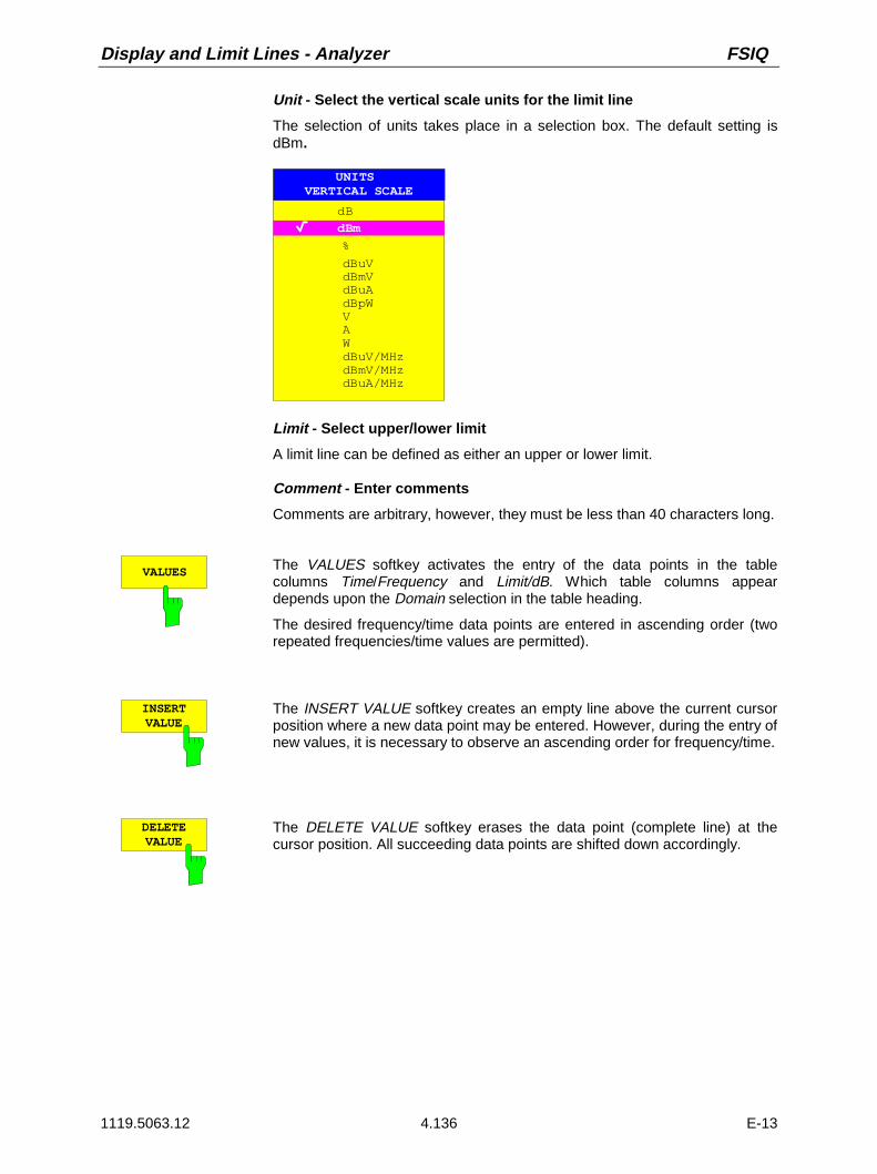
Display and Limit Lines - Analyzer FSIQ
1119.5063.12 4.136 E-13
Unit - Select the vertical scale units for the limit line
The selection of units takes place in a selection box. The default setting isdBm.
UNITS VERTICAL SCALE
dB
dBm
dBuVdBmVdBuAdBpWVAWdBuV/MHzdBmV/MHzdBuA/MHz
%
Limit - Select upper/lower limit
A limit line can be defined as either an upper or lower limit.
Comment - Enter comments
Comments are arbitrary, however, they must be less than 40 characters long.
VALUES The VALUES softkey activates the entry of the data points in the tablecolumns Time/Frequency and Limit/dB. Which table columns appeardepends upon the Domain selection in the table heading.
The desired frequency/time data points are entered in ascending order (tworepeated frequencies/time values are permitted).
INSERTVALUE
The INSERT VALUE softkey creates an empty line above the current cursorposition where a new data point may be entered. However, during the entry ofnew values, it is necessary to observe an ascending order for frequency/time.
DELETE VALUE
The DELETE VALUE softkey erases the data point (complete line) at thecursor position. All succeeding data points are shifted down accordingly.

FSIQ Analyzer - Display and Limit Lines
1119.5063.12 4.137 E-13
SHIFT XLIMIT LINE
The SHIFT X LIMIT LINE softkey calls an entry window where the completelimit line may be shifted parallel in the horizontal direction.
The shift takes place according to the horizontal scale:
– in the frequency domain in Hz, kHz, MHz or GHz
– in the time domain in ns, µs, ms or s
In this manner, a new limit line can be easily generated based upon anexisting limit line which has been shifted horizontally and stored (SAVE LIMITLINE softkey) under a new name (NAME softkey).
SHIFT YLIMIT LINE
The SHIFT Y LIMIT LINE softkey calls an entry window where the completelimit line may be shifted parallel in the vertical direction.
The shift takes place according to the vertical scale:
– for logarithmic units, relative, in dB
– for linear units, as a factor
In this manner, a new limit line can be easily generated based upon anexisting limit line which has been shifted vertically and stored (SAVE LIMITLINE softkey) under a new name (NAME softkey).
SAVELIMIT LINE
The SAVE LIMIT LINE softkey stores the currently edited limit line . Thename can be entered in an input window (max. 8 characters)
PAGE UP Pressing the PAGE UP softkey displays the next page of data points.
PAGE DOWN Pressing the PAGE DOWN softkey displays the previous page of data points.
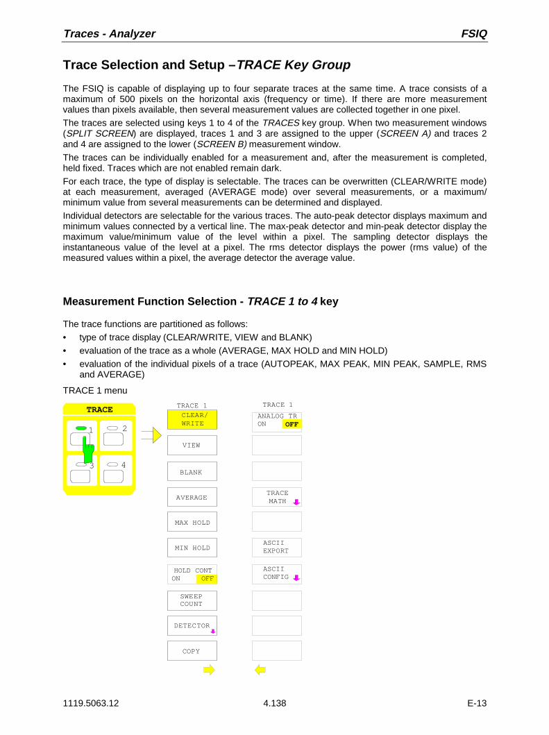
Traces - Analyzer FSIQ
1119.5063.12 4.138 E-13
Trace Selection and Setup – TRACE Key Group
The FSIQ is capable of displaying up to four separate traces at the same time. A trace consists of amaximum of 500 pixels on the horizontal axis (frequency or time). If there are more measurementvalues than pixels available, then several measurement values are collected together in one pixel.
The traces are selected using keys 1 to 4 of the TRACES key group. When two measurement windows(SPLIT SCREEN) are displayed, traces 1 and 3 are assigned to the upper (SCREEN A) and traces 2and 4 are assigned to the lower (SCREEN B) measurement window.
The traces can be individually enabled for a measurement and, after the measurement is completed,held fixed. Traces which are not enabled remain dark.
For each trace, the type of display is selectable. The traces can be overwritten (CLEAR/WRITE mode)at each measurement, averaged (AVERAGE mode) over several measurements, or a maximum/minimum value from several measurements can be determined and displayed.
Individual detectors are selectable for the various traces. The auto-peak detector displays maximum andminimum values connected by a vertical line. The max-peak detector and min-peak detector display themaximum value/minimum value of the level within a pixel. The sampling detector displays theinstantaneous value of the level at a pixel. The rms detector displays the power (rms value) of themeasured values within a pixel, the average detector the average value.
Measurement Function Selection - TRACE 1 to 4 key
The trace functions are partitioned as follows:• type of trace display (CLEAR/WRITE, VIEW and BLANK)• evaluation of the trace as a whole (AVERAGE, MAX HOLD and MIN HOLD)• evaluation of the individual pixels of a trace (AUTOPEAK, MAX PEAK, MIN PEAK, SAMPLE, RMS
and AVERAGE)
TRACE 1 menu
3
1 2
43
TRACE CLEAR/ WRITE
MAX HOLD
MIN HOLD
AVERAGETRACEMATH
VIEW
BLANK
TRACE 1
DETECTOR
SWEEPCOUNT
TRACE 1
COPY
ANALOG TRON OFF
HOLD CONTON OFF
ASCIIEXPORT
ASCIICONFIG

FSIQ Analyzer - Traces
1119.5063.12 4.139 E-13
The TRACE keys 1...4 call a menu which presents the options for the selected trace.
In this menu, the method to be used for compressing the measurement data in the frequency or timedomain to the 500 representable points of the display is determined.
At the beginning of the measurement, each trace can be displayed either completely new or based onprevious measurement results.
Traces can be displayed, blanked and copied.
By applying mathematical functions, the traces can also be corrected.
The measurement detector for each of the display types may be chosen either directly or selectedautomatically by the FSIQ.
All activated traces are marked with a LED at the corresponding key (here, TRACE 1). The defaultsetting is TRACE 1 with CLEAR / WRITE selected. The remaining traces 2...4 are switched off(BLANK). For the split screen display, the selection of the trace automatically selects the correspondingscreen for entry.
The CLEAR/WRITE, MAX HOLD, MIN HOLD, AVERAGE, VIEW, and BLANK are mutually exclusiveselection switches.
CLEAR/ WRITE
The CLEAR/WRITE softkey activates the clear/write display mode.The trace is displayed without additional trace evaluation. The trace memoryis overwritten by each sweep. If more than one data point falls within a pixel,the trace is displayed in bar form with the maximum and minimum values in apixel connected. In the clear/write display mode, all the available detectorsare selectable. The autopeak detector is selected in the default mode(detector to AUTO).
After each CLEAR/WRITE softkey action, the FSIQ clears the selected tracememory and starts the measurement anew.
VIEW The VIEW softkey freezes the current contents of the trace memory anddisplays them on the display screen.
If the trace data were formed through MAX HOLD, MIN HOLD or AVERAGE,the sweep is restarted and the trace contents are cleared, after switching tothese trace modes.
If a trace is frozen by VIEW, the instrument settings can be modified withoutmodifying the displayed trace. The fact that the trace and the currentinstrument setting do not agree anymore is indicated by an enhancementlabel "*" at the right edge of the grid. The initial instrument setting can berestored using the ADJUST TO TRACE softkey in the TRACE MATH sub-menu.
If LEVEL RANGE or REF LEVEL is changed in the VIEW display mode, theFSIQ adjusts the measurement data to the changed display range. Thus, anamplitude zoom can be performed after the measurement so that details ofthe trace can be seen better.
BLANK The BLANK softkey removes the trace from the display screen. However, thetrace data remain stored in memory and can be displayed again by VIEW.The markers for the blanked trace are also erased. If the trace is activatedagain (with VIEW, CLEAR / WRITE, MAX HOLD, MIN HOLD, AVERAGE) themarkers will be restored to their original positions.

Traces - Analyzer FSIQ
1119.5063.12 4.140 E-13
AVERAGE The AVERAGE softkey enables the trace averaging function. The average istaken from several foregoing measurements. The average can be calculatedfor each available detector. In case the detector is automatically selected bythe FSIQ , the sampling detector is chosen.
After enabling the averaging mode, the first trace is recorded inCLEAR/WRITE mode with the selected detector. After the second sweep, theaverage is then formed for each succeeding sweep. Here, the average isformed over the samples/pixels, i.e., according to the LIN or LOG setting,over amplitudes or levels.
The average always starts anew when one of the AVERAGE softkeys ispressed. The trace memory is also cleared. This is also the case when thetrace is switched from the setting AVERAGE to VIEW or BLANK
Description of the averaging procedure:
Averaging is carried out using the pixels which are derived from the measurement value samples.These pixels may in some cases be comprised of several combined measurement values. This meansthat the average is formed over linear amplitude values when the level display is linear and over levelswhen the level display is logarithmic. Because of this, the trace must be measured anew when changingbetween the LIN and LOG display mode. The settings CONT/SINGLE SWEEP and the running averageapply to the average display analogously.
Two calculation procedures are available for averaging. For SWEEP COUNT= 0 , a running average iscalculated according to the following equation:
TRACE9 * TRACE MEAS_ VALUE
10= +
Because of the distribution of the weighting between the new measurement value and the traceaverage, the measurement history has essentially no influence on the displayed trace after around 10sweeps have taken place. For this setting, the signal noise is effectively reduced without the need forrestarting the averaging process even if the signal is changed.
If, for SWEEP COUNT a value >1 is entered, the averaging takes place over the selected number ofsweeps. In this case, the displayed trace is determined during averaging according to the followingequation:
TRACE(n 1) * TRACE MEAS_ VALUE
n= − +
where n is the number of the current sweep (n = 2 ... SWEEP COUNT). For the first sweep, an averageis not calculated. The measurement values are stored directly in trace memory. With growing n, thedisplayed trace is increasingly smoothed since more individual trace data are available for averaging.The average trace is stored in trace memory after the defined number of sweeps. Until this number ofsweeps is reached, a preliminary average is displayed.
After completion of averaging, ie if the averaging length defined with SWEEP COUNT is attained, arunning averaging is continued with CONTINUOUS SWEEP according to the following formula:
, where Trace = new traceTraceold = old traceN = SWEEP COUNT
The display "Sweep 200 of 200" then remains constant until a new start is made.
Trace(N 1) Trace meas
Nold= − ⋅ + . value
FSIQ Analyzer - Traces
1119.5063.12 4.141 E-13
In SINGLE SWEEP mode, SWEEP START initiates n single sweeps. The sweeps are stopped as soonas the selected number of sweeps is reached. The number of the current sweep and the total number ofsweeps are shown in the display: "Sweep 3 of 200".
SWEEPCOUNT
The SWEEP COUNT softkey activates the entry of the number of sweeps,over which an average is to be calculated.The permitted range for SWEEP COUNT is 0 through 32767. For 0, the FSIQperforms a running average over 10 sweeps. For 1, no averaging takesplace.
The default setting is 10 sweeps. The programming naturally influences thesweep duration. The number of sweeps which are used in the averagingprocess or the averaging time are valid for all 4 traces.
Note : The setting of the SWEEP COUNT in the trace menu is equivalentto the setting in the sweep menu.
MAX HOLD The MAX HOLD softkey activates the max hold mode.In this display mode, the FSIQ saves for each sweep the largest of thepreviously stored/currently measured values in the trace memory. Thedetector is set automatically to MAX PEAK. In this way, the maximum valueof a signal can be determined over several sweeps.
This is especially useful in the measurement of modulated or pulsed signals.The signal spectrum is filled at each sweep until all signal components havebeen captured.
By pressing of the MAX HOLD softkey again, the trace memory is clearedand the maximum value accumulation begins anew.
If MAX HOLD is enabled, a new start is made after clearing the trace memoryfor each frequency change, (start frequency, stop frequency, centerfrequency or frequency span), a reference level change or switching betweenlinear/logarithmic scales.
MIN HOLD The MIN HOLD softkey activates the min hold mode.In this display mode, the FSIQ saves for each sweep the smallest of thepreviously stored/currently measured values in the trace memory. Thedetector is set automatically to MIN PEAK. In this way, the minimum value ofa signal can be determined over several sweeps. This function is, e.g., usefulin making an unmodulated carrier in a mix of signals visible. Noise,interference signals or modulated signals are suppressed by the MIN HOLDfunction while a CW signal maintains a constant level.
Pressing the MIN HOLD softkey clears the trace memory and the minimumvalue function starts anew.

Traces - Analyzer FSIQ
1119.5063.12 4.142 E-13
HOLD CONTON OFF
The HOLD CONT softkey defines whether the traces in the average modeand min hold/max hold mode are reset after some definite parameterchanges.
OFF The traces are reset after some definite parameter changes.
ON This mechanism is switched off.
In general, parameter changes require a restart of the measurement beforeresults are evaluated (e. g. with markers). For those changes that are knownto require a new measurement (e. g. modification of the span), the trace isautomatically reset so that erroneous evaluations of previous results areavoided.This mechanism can be switched off for those exceptional cases where thedescribed behavior is unwelcome.
COPY.. The COPY softkey copies the contents of the display screen for the currenttrace to another trace memory. A table appears in which the desired copyprocedure can be selected.
COPY TRACE 1 TO
TRACE 2TRACE 3TRACE 4
For only one window, the selected trace can be copied to any of the othertrace memories since here, all four traces are displayed in one diagram withthe same frequency boundaries.In the split screen display, this is only possible as long as the frequencies ofscreen A and screen B are identical. If this is not the case, the selected tracecan only be copied to the corresponding trace memory, i.e., trace 1 to trace 3and trace 2 to trace 4 or vice versa. In this case, only the available trace isdisplayed.
After copying, the contents of the destination memory are lost. Thedestination memory now changes automatically to view mode with the newdata.

FSIQ Analyzer - Traces
1119.5063.12 4.143 E-13
Detector Selection
The FSIQ detectors are realised by pure digital techniques . The detectors available are the max-peakdetector which delivers the maximum value from a number of sample values, the min-peak detectorwhich delivers the minimum value from a number of sample values and the sampling detector. Thesampling detector can transfer the sampled data without modification or can perform a data reduction bysuppressing non-displayable values. For the peak detectors, the current value is compared with themaximum/minimum levels of the previously sampled data. When the number of samples defined by theinstrument settings is reached, the samples are collected into the available pixels. Thus, each of the 500pixels of the display represents 1/500 of the sweep range and contains, in compressed form, all of theindividual measurements (frequency samples) in this sub-range. Even though the recording rate is high,there are no recording gaps thanks to the internal pipeline structure. According to the trace displaymode, an optimised detector is automatically applied. Since the peak detectors and the sample detectorare connected in parallel, a single sweep is sufficient for recording and displaying four traces with fourdetectors.
Peak value detectors(MAX PEAK / MIN PEAK)
Peak value detectors are implemented by digital comparators,which determine the largest of all positive (max peak) or thesmallest of all negative (min peak) peak values of the levelsmeasured at the different frequencies which are displayed in oneof the 500 pixels. This is repeated for each pixel so that, for widefrequency spans and inspite of the limited display resolution, alarge number of measurements can be taken into considerationfor the display of the spectrum.
AUTOPEAK detector The AUTOPEAK detector combines the two peak detectors. Themax-peak detector and min-peak detector determine themaximum and minimum level at a displayed test point at thesame time and display it as a common measurement value. Themaximum and minimum level at a frequency point are joined witha vertical line.
SAMPLE detector The SAMPLE detector transfers all sampled data without furtherevaluation and either displays them directly or, for reasons ofspeed (short sweep times), first writes them into a memory andsubsequently processes them.
Data reduction, i.e., summing of measurement values ofneighbouring frequencies or time samples is not performed here.If, during a sweep, more measurement values are generatedthan can be displayed, measurement values will be lost. Discretesignals can thus be lost
Therefore, the sampling detector can only be recommended for aratio of span-to-resolution bandwidth of up to approximately 250.Iit is thereby guaranteed that no signal will be suppressed(example: span 1 MHz --> min. bandwidth 5 kHz).

Traces - Analyzer FSIQ
1119.5063.12 4.144 E-13
RMS detector The rms detector forms the rms value of the measured valueswithin a pixel.To this effect FSIQ uses the linear display voltage after theenvelope detection. The linear values are squared, summed andthe sum is divided through the number of samples (= root meansquare). In case of logarithmic display, the logarithm is thenformed from the square sum. In case of linear display the rootmean square is displayed directly. Each pixel thus correspondsto the power of the measured values summed up in the pixel.The rms detector supplies the power of the signal independentof the waveform (CW carrier, modulated carrier, white noise orpulse signal). The correction factors required by other detectorsfor the power measurement of the different signal classes areomitted.
Average detector The average detector forms the average value of measuredvalues within a pixel.To this effect, FSIQ uses the linear display voltage after theenvelope detection. The linear sample values are summed upand the sum is divided by the number of measurement samples(= linear average value). In case of logarithmic display, thelogarithm is then formed from the average value. In case oflinear display the average value is displayed directly. Each pixelthus corresponds to the average value of the measured valuessummed up in the pixel.The average detector supplies the average value of the signalindependent of the waveform (CW carrier, modulated carrier,white noise or pulse signal).
Note: During a sweep, the FSIQ switches the first oscillator in steps which are smaller thanapproximately 1/10 of the bandwidth. This guarantees that the level of a signal is correctlymeasured. For narrow bandwidths and wide spans, a very large number of measurement valuesare generated. The number of frequency steps is, however, always a multiple of 500 (= numberof displayable points). In the sampling mode, only every nth value is displayed. The quantity ndepends upon the number of measurement values, i.e on the span, resolution bandwidth andthe measurement rate.

FSIQ Analyzer - Traces
1119.5063.12 4.145 E-13
TRACE 1-DETECTOR submenu
AUTOSELECT
DETECTORSAMPLE
TRACE 1 DETECTOR
DETECTORAUTO PEAK
DETECTORMIN PEAK
DETECTORMAX PEAK
DETECTOR
CAPT MEMOFFON
DETECTORRMS
DETECTORAVERAGE
The DETECTOR softkey opens a submenu to select thedetector.
The detector type may be independently selected for eachtrace. Mode AUTO SELECT sets the best suitable detectorfor the type of trace display (Clear Write, Max Hold oder MinHold).
The softkeys are mutually exclusive selection switches.
AUTOSELECT
The AUTO SELECT softkey (= default) selects the optimum detectordependent upon the trace mode (clear write, max hold, min hold).
Trace-mode DetectorClear/Write AutopeakAverage SampleMax Hold Max PeakMin Hold Min Peak
DETECTORAUTOPEAK
DETECTORMAX PEAK
DETECTORMIN PEAK
The DETECTOR AUTOPEAK softkey selects the autopeak detector.
The DETECTOR MAX PEAK softkey selects the max peak detector. It isrecommended if pulse-shaped signals are to be measured.
The DETECTOR MIN PEAK softkey selects the min peak detector. Weaksinewave signals become clearly visible in noise by using this detector. For acomposite signal made up of sinewave and pulse signals the pulse signalsare suppressed.
Traces - Analyzer FSIQ
1119.5063.12 4.146 E-13
DETECTOR SAMPLE
The DETECTOR SAMPLE softkey selects the sample detector.
It is used if uncorrelated signals like noise are to be measured. The powercan be determined by means of fixed correction factors for evaluation and thelog amplifier.
DETECTORRMS
The DETECTOR RMS softkey activates the rms detector.
The rms detector supplies the power of the signal independent of thewaveform. To this effect the root mean square of all sampled level values isformed during the sweep of a pixel. The sweep time thus determines thenumber of averaged values so that the trace can be better averaged withincreasing sweep time. The rms detector is thus an alternative for averagingover several sweeps (see TRACE AVERAGE).
In the time domain (SPAN = 0), the rms detector is only available for sweeptimes ≥ 5 ms. Moreover, the combination of the rms detector with thepretrigger function and the gaped sweep function is not permissible.
The video bandwidth has to be set to at least 10 times the resolutionbandwidth (RBW) so that the rms value of the signal is not invalidated byvideo filtering.
DETECTORAVERAGE
The DETECTOR AVERAGE softkey activates the average detector.
In contrast to the rms detector, the average detector supplies the linearaverage of all sampled level values during the sweep of a pixel.
The same restrictions as those of the rms detector apply (see above).
Quasi Analog Display
Normally, measurement points are displayed interconnected by a continuous line. The leads to acontinuous curve which is erased and rewritten for each new sweep. However, in the domain of analogmeasurement technology, display screen persistence leads to statistical emphasis which is related tothe relative frequency of occurrence of a signal. Thus, on the display screen, frequently occurring eventsappear much brighter than rarely occurring curve segments.
Using the ANALOG TRACE function, the characteristics of an analog display are simulated. In this case,a measurement value is displayed as a single pixel on the display screen. This pixel is reset only byexplicitly clearing the trace with CLEAR / WRITE. The overwriting of several sweeps is now possible anda frequency-of-occurrence distribution of the measurement values can be observed.
TRACE 1 side menu
ANALOG TRON OFF
The ANALOG TR ON/OFF softkey enables/disables theANALOG TRACE function for each trace.
The measurement is always made with the selected detector.

FSIQ Analyzer - Traces
1119.5063.12 4.147 E-13
Mathematical Functions for Traces
TRACE 1-TRACE MATH submenu:
TRACE MATH OFF
T1-T2+REF -> T1
T1-REF ->T1
TRACE MATH
T1-T3+REF -> T1
T1-T4+REF -> T1
ADJUST TO TRACE
TRACEMATH
The TRACE MATH softkey opens a sub-menu in which adifferential curve for the selected trace is calculated.
T1-T2+REF -> T1
T1-REF ->T1
TRACE MATH
T1-T3+REF -> T1
T1-T4+REF -> T1
The T1-T2+REF, T1-T3+REF, T1-T3+REF and T1-REF softkeys subtract thecorresponding traces and add the set level to the difference. If the referenceline is switched on (see key D LINES), the level value of the reference lineinstead of the reference level is added to the difference. Thus, the differentialcurve can be positioned anywhere on the screen by shifting the referenceline. The difference of the two traces with respect to the reference line isdisplayed.
The T1-REF softkey subtracts the level of the reference line from the tracelevel.
To indicate that the trace has been obtained by a differential curve, acorresponding enhancement label is displayed at the right margin of themeasurement value diagram (1-2, 1-3, 1-4, 1-R). In TRACE 1 main menu, theTRACE MATH softkey is on a coloured background to show that the functionis being used.
Important: For a display with two measurement windows, not allcombinations are allowed if the sweep data for screen A andscreen B are not the same. Only the traces allowed in the screencan be combined (in screen A, only trace 1 with trace 3; inscreen B, only trace 2 with trace 4).

Traces - Analyzer FSIQ
1119.5063.12 4.148 E-13
TRACE MATHOFF
The TRACE MATH OFF softkey switches the enabled differential curve off.The softkey is only available when a conversion function is enabled.
ADJUST TO TRACE
The ADJUST TO TRACE softkey restores the original instrument settingswhen the corresponding trace is set to VIEW and the current instrumentsettings are different than those of the trace data.
If a trace is frozen with VIEW, changes in the instrument settings can bemade without influencing the trace. An asterisk( * ) at the edge of the displayscreen indicates that the current instrument settings are different than thosein effect when the trace was recorded. In this case, the ADJUST TO TRACEsoftkey is presented with which the original instrument setting can berestored.
Trace Export
TRACE menu:
ASCIIEXPORT
In analyzer mode, the ASCII EXPORT softkey stores the corresponding trace in afile with ASCII format.Upon pressing the ASCII EXPORT softkey, a file name can be entered. Thedefault name is TRACE.DAT. Then the measured data of the trace are stored.The function can be configured in the ASCII CONFIG submenu.
TRACE menu:
ASCIICONFIG
ASCIICONFIG
NEWAPPEND
HEADERON OFF
EDIT PATH
DECIM SEP . ,
The ASCII CONFIG softkey calls a submenu for various settings forthe TRACE ASCII EXPORT function.

FSIQ Analyzer - Traces
1119.5063.12 4.149 E-13
EDIT PATH The EDIT PATH softkey defines the directory in which the file is to bestored.
DECIM SEP. ,
The DECIM SEP softkey selects the separator for the ASCII file:’.’ (decimal point) or ’,’ (comma).Different language versions of analysis programs may require differentnotations of the decimal point. .
NEWAPPEND
The APPEND NEW softkey defines whether output data are to bewritten to an existing file or a new file.
• With APPEND, the data are added to an existing file.
• With NEW, either a new file is generated or an existing file isoverwritten by storage of the data.
EDITON OFF
The HEADER ON/OFF softkey defines whether important instrumentsettings should be stored at the beginning of the file.
Structure of the ASCII file:
The file consists of the header containing important scaling parameters and a data section containingthe trace data.
The data of the file header consist of three columns, each separated by a semicolon:parameter name; numeric value; basic unit
The data section starts with the keyword " Trace <n> " (<n> = number of stored trace), followed by themeasured data in one or several columns (depending on measurement) which are also separated by asemicolon.This format can be read in from spreadsheet calculation programs, eg MS-Excel. It is necessary todefine ’;’ as a separator.

Traces - Analyzer FSIQ
1119.5063.12 4.150 E-13
Content of file Description
File header Type;FSEA30;
Version;1.91;
Date;01.Jul 1999;
Mode;Spectrum;
Start;10000;HzStop;100000;Hz
Center Freq;55000;Hz
Span;90000;Hz
Freq Offset;0;Hz
x-Axis;LIN;
y-Axis;LOG;
Ref.Level;-30;dBm
Level Offset;0;dB
Max Level
Level Range;100;dB
RF Att;20;dB
RBW;100000;Hz
VBW;30000;Hz
SWT;0.005;s
Trace Mode;AVERAGE;
Detector;SAMPLE;
Sweep Count;20;
Instrument model
Firmware version
Date of data set storage
Instrument mode
Start/stop of the display range.Unit: Hz for span > 0, s for span = 0,
Center frequency
Frequency range (0 Hz with zero span)
Frequency offset
Scaling of x axis linear (LIN) or logarithmic (LOG)
Scaling of y axis linear (LIN) or logarithmic (LOG)
Reference level
Level offset
Maximium level
Display range in y direction. Unit: dB with x axis LOG, %with x axis LIN
Input attenuation
Resolution bandwidth
Video bandwidth
Sweep time
Display mode of trace:CLR/WRITE,AVERAGE,MAXHOLD,MINHOLD
Detector set:AUTOPEAK,MAXPEAK,MINPEAK,AVERAGE,RMS,SAMPLE
Number of sweeps set
Data section of the file Trace 1:;;
x-Unit;Hz;
y-Unit;dBm;
Values;500;
10000;-10.3;-15.7
10180;-11.5;-16.9
10360;-12.0;-17.4
...;...;
Selected trace
Unit of x values:Hz with span > 0; s with span = 0;dBm/dB with statistics measurements
Unit of y values:dB*/V/A/W depending on the selected unit with y axisLOG or % with y axis LIN
Number of test points
Measured values:
<x value>, <y1>, <y2>
<y2> being available only with detector AUTOPEAK andcontaining in this case the smallest of the two measuredvalues for a test point.
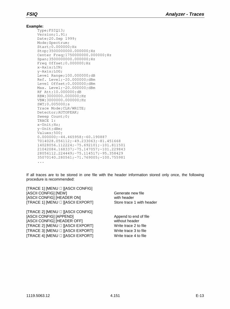
FSIQ Analyzer - Traces
1119.5063.12 4.151 E-13
Example:Type;FSIQ13;Version;1.91;Date;20.Sep 1999;Mode;Spectrum;Start;0.000000;HzStop;3500000000.000000;HzCenter Freq;1750000000.000000;HzSpan;3500000000.000000;HzFreq Offset;0.000000;Hzx-Axis;LIN;y-Axis;LOG;Level Range;100.000000;dBRef. Level;-20.000000;dBmLevel Offset;0.000000;dBmMax. Level;-20.000000;dBmRF Att;10.000000;dBRBW;3000000.000000;HzVBW;3000000.000000;HzSWT;0.005000;sTrace Mode;CLR/WRITE;Detector;AUTOPEAK;Sweep Count;0;TRACE 1:x-Unit;Hz;y-Unit;dBm;Values;500;0.000000;-44.465958;-60.1908877014028.056112;-49.233063;-81.45166814028056.112224;-75.692101;-101.81150121042084.168337;-75.147057;-101.22984328056112.224449;-75.114517;-95.35842935070140.280561;-71.769005;-100.755981...
If all traces are to be stored in one file with the header information stored only once, the followingprocedure is recommended:
[TRACE 1] [MENU ⇒][ASCII CONFIG][ASCII CONFIG] [NEW] Generate new file[ASCII CONFIG] [HEADER ON] with header[TRACE 1] [MENU ⇒][ASCII EXPORT] Store trace 1 with header
[TRACE 2] [MENU ⇒][ASCII CONFIG][ASCII CONFIG] [APPEND] Append to end of file[ASCII CONFIG] [HEADER OFF] without header[TRACE 2] [MENU ⇒][ASCII EXPORT] Write trace 2 to file[TRACE 3] [MENU ⇒][ASCII EXPORT] Write trace 3 to file[TRACE 4] [MENU ⇒][ASCII EXPORT] Write trace 4 to file

Coupled Settings - Analyzer FSIQ
1119.5063.12 4.152 E-13
Sweep Control – SWEEP Key Group
Using the SWEEP key group, the parameters are entered which determine the sweep characteristics.These are the coupled functions resolution bandwidth, video bandwidth and sweep time (COUPLINGkey), the trigger used for starting the sweep (TRIGGER key) and the type of sweep (SWEEP key).
Coupled Settings – COUPLING Key
The COUPLING key calls a menu for entering the sweep parameters resolution bandwidth (RBW),video bandwidth (VBW) and sweep time (SWT). The parameters can be set dependent upon the span(stop - start frequency), coupled to each other or arbitrarily defined by the user. The settings for the splitscreen display mode are valid only for the window which is active for entries.
The FSIQ offers the resolution bandwidths 1 Hz to 10 MHz in 1, 2, 3, 5steps:
The FSIQ resolution bandwidths up to 1 kHz have been implemented using digital filters with Gaussiancharacteristics. They behave like analog filters. The 1-kHz filter has been implemented both as adecoupled quartz filter and as a digital filter. One of the two filter types can be selected. The bandwidthsfrom 2 kHz to 30 kHz have been implemented using decoupled quartz filters, the bandwidths between50 kHz and 5 MHz using decoupled LC filters. These filters consist of 5 circuits, their shape factor is <12, typ. 9.5.
The 10-MHz filter is a critically coupled LC filter.
For bandwidths up to about 1 kHz, the FFT-algorithm, as compared to other filter methods with identicalsettings, offers clear advantages with respect to the measurement time. This is due to the fact that foranalog filters the time required for a given display range is proportional to (Span/RBW2). The FFT-algorithm reduces that time to a value proportional to (Span/RBW).
FFT-filters are provided for bandwiths between 1 Hz and 1kHz as an alternative to the analog filters.The video bandwidths are available in 1/2/3/5 steps between 1 Hz and 10 MHz. They can be setindependent of the resolution bandwidth. Video bandwidths between 1 Hz and 10 kHz are available forresolution bandwidths up to 1 kHz and video bandwidths between 1 Hz and 10 MHz are available forresolution bandwidths greater than or equal to 2 kHz. The video filters are used to smooth the traces.Small video bandwidths in relation to the resolution bandwidth average out noise peaks pulse-likesignals such that only the average value of the signals is displayed. A large video bandwidth in relationto the resolution bandwidth is therefore recommended when measuring pulsed signals (VBW ≥ 10 xRBW) so that the amplitude of pulses can be measured correctly.

FSIQ Analyzer - Coupled Settings
1119.5063.12 4.153 E-13
Setting and Coupling the Coupling Resolution, Video Bandwidth and SweepTime
SWEEP COUPLING menu
COUPLINGDEFAULT
COUPLING
TRIGGER
SWEEP
RBW
VBW
SWT
SWEEPCOUPLED
FUNCTIONS
RES BWMANUAL
RES BWAUTO
VIDEO BWMANUAL
VIDEO BWAUTO
SWEEP TIMEAUTO
SWEEP TIMEMANUAL
COUPLINGRATIO
COUPLEDFUNCTIONS
RBW<=1 KHZNORM FFT
MAIN PLLBANDWIDTH
RBW 1 KHZANA DIG
The COUPLING key calls a menu and asupplementary menu for setting the resolutionbandwidth, video bandwidth, sweep time and theircouplings.
The various AUTO softkeys are used to couplethe functions. The coupling ratios are selected inthe COUPLING RATIO sub-menu.
The various MANUAL softkeys request that therespective parameter be entered in the entrywindow. This parameter is not coupled to theother parameters.
RES BWAUTO
The RES BW AUTO softkey couples the resolution bandwidth to the selectedspan. Changing the span causes automatic compensation of the resolutionbandwidth.
Automatic coupling of resolution bandwidth to span is always recommendedwhen, for the measurement problem on hand, a favorable setting of theresolution bandwidth in relation to the selected span is desired.
The coupling ratio is set in the COUPLING RATIO sub-menu.
The coupling is indicated by illumination of the softkey and the active RBWLED.
The RES BW AUTO softkey is only available in the frequency domain (span> 0 Hz). The softkey is blanked in the time domain.
RES BWMANUAL
The RES BW MANUAL softkey activates the manual entry mode for theresolution bandwidth.The lower limit of the bandwidth is 1 Hz.For numerical inputs, the values are always rounded to the next validbandwidth. For roll-key or the UP/DOWN key inputs, the bandwidth isadjusted in steps either upwards or downwards.For manual input of the resolution bandwidth (coupling off), on the front panelremains off.

Coupled Settings - Analyzer FSIQ
1119.5063.12 4.154 E-13
VIDEO BWAUTO
The VIDEO BW AUTO softkey couples the video bandwidth of the FSIQ tothe resolution bandwidth. If the resolution bandwidth is changed, the videobandwidth is automatically adjusted.
The coupling of the video bandwidth is always recommended when themaximum sweep time for a selected resolution bandwidth is to be achieved.Lower video bandwidths require longer sweep times due to the longer settlingtime. Wider bandwidths reduce the signal/noise ratio.
The coupling ratio is set in the COUPLING RATIO menu.
The coupling is indicated by illumination of the softkey and the lighted VBWLED on the front panel.
The coupling of the video bandwidth to the resolution filter is also permittedfor display in the time domain (span = 0).
VIDEO BWMANUAL
The VIDEO BW MANUAL softkey activates the manual input mode for thevideo bandwidth.
The video bandwidth is selectable in 1/2/3/5 steps between 1 Hz and 10 MHz.For bandwidths up to 1 kHz, the maximum video bandwidth is 10 kHz, forlarger resolution bandwidths, there is no restriction to the video bandwidth.
For numerical inputs, rounding is made to the next possible bandwidth. Forroll-key or UP/DOWN entries, the bandwidth is switched in steps eitherdownwards or upwards.
For manual input, the video bandwidth (coupling disabled) VBW LED on thefront panel is turned off.
SWEEP TIMEAUTO
The SWEEP TIME AUTO softkey couples the sweep time to the span, videobandwidth (VBW) and resolution bandwidth (RBW). For a change in span,the resolution bandwidth or the video bandwidth is automatically matched tothe sweep time. The FSIQ always selects the fastest sweep time which ispossible without falsifying the level display.
The coupling is indicated by illumination of the softkey and turning on theSWT LED.
The softkey is only available in the frequency domain (span > 0 Hz). Thesoftkey is blanked in the time domain.

FSIQ Analyzer - Coupled Settings
1119.5063.12 4.155 E-13
SWEEP TIMEMANUAL
The SWEEP TIME MANUAL softkey activates the manual input mode for thesweep time. At the same time, the coupling of the sweep is canceled and theSWT LED is turned off. Other couplings (VIDEO BW, RES BW) remain ineffect.
In the frequency domain (span > 0 Hz) and for resolution bandwidths ≥ 1 kHz,the allowed sweep times range from 5 ms through 16000 s in steps of 5% ofthe sweep time at maximum. The digital resolution filters from 10 Hz to 1 kHzallow a minimum sweep time of 20 ms.
If an FFT-filter is used the sweep time is fixed by the display range andresolution bandwidth selected and therefore can not be set.
For displays in the time domain (span = 0 Hz), the range of sweep times 1 µsto 2500 s is selectable in steps of 5% of the sweep time at maximum.
For numerical inputs, rounding is made to the next possible sweep time. Forroll-key or UP/DOWN entries, the sweep time is switched in steps eitherdownwards or upwards.
If the selected sweep time is too small for the selected span and bandwidth,measurement errors will occur. This happens because the available settlingtime for the resolution filter or the video filter is too short. In this case, theFSIQ outputs UNCAL on the display
COUPLINGDEFAULT
The COUPLING DEFAULT softkey sets all coupled functions to AUTO. Inaddition, the ratio RBW / VBW is set to SINE [1] and the ratio SPAN/RBW isset to 50 in the COUPLING RATIO submenu (default setting, COUPLINGRATIO softkey not illuminated).
The relevant softkeys are then illuminated.
RBW 1KHZANA DIG
The RBW 1kHz ANA/DIG softkey enables either the analog quartz filter(ANA) or the digital filter (DIG) for the instruments's resolution bandwidth of 1kHz. In the default setting, the instrument uses the analog IF filter for the 1-kHz bandwidth.

Coupled Settings - Analyzer FSIQ
1119.5063.12 4.156 E-13
RBW <=1KHZNORM FFT
The RBW<=1kHz NORM/FFT softkey switches between fixed filter and FFT-filter.
NORM For resolution bandwidths up to 1 kHz fixed IF-filters are used.
FFT An FFT is performed. To this end, the filtered IF-signal isdigitalized by the 3-kHz resolution filters and then transformedinto the spectral domain via FFT. The transformation range isequal to the selected display range but covers 4 kHz atmaximum. If the display range is larger than the transformationrange, serveral subsequent transformations are performed, theresults are appended to each other in the spectral domain. Thiscompensates for the frequency response of the 3-kHzpreselection filter so that the amplitude response within thetransformation range is offset. A flattop window seves as awindow in the time domain so that a high amplitude precisionwith good selection is achieved.
Span:- minimum display range: 50× resolution bandwidth selected- maximum display range:
Resolution bwidths > 20 Hz: 2 MHz (500 FFT-transf./sweepat maximum)
Resolution bwidths < 20Hz: Reduction to 125 kHz at 1 Hz resolution bandwidth
Level display range: 100 dB at max. A larger display rangeimplies that the trace is tilted at –100 dBfrom the reference level.
Sweep time: fixed by the bandwidth selected and thedisplay range.(Reason: an FFT-filter represents a blocktransformation). The sweep time can notbe changed (softkey inactive).
Detector All settings of the sample detector arefixed, no other detector can be selected(softkeys inactive)
Video bandwidth not defined for FFT-transf. so that it cannot be set (softkeys inactive).
Compared to fixed filters, FFT-filters lead to markedly reducedsweep times. For a display range of 50 kHz and a resolutionbandwith of 100 Hz, e. g., the sweep time is reduced from 25 s to520 ms. FFT-filters are particularly suitable for stationary signals(sinusoidal signals or signals that are continuously modulated intime). For burst signals (TDMA) or pulses, fixed filters should bepreferred. The FFT is a block transformation so that the resultdepends on the time relation between the dataset to betransformed and the burst or pulse signal. A 'gated sweep'measurement for TDMA signals is therefore not provided if FFT-filters are used.

FSIQ Analyzer - Coupled Settings
1119.5063.12 4.157 E-13
MAIN PLLBANDWIDTH
The MAIN PLL BANDWIDTH softkey opens a selection window for settingthe PLL control bandwidth.
MAIN PLL BANDWIDTH
HIGH
MEDIUM
LOW
AUTO
The first local oscillator is synchronized with the PLL control bandwidth. Thecontrol bandwidth determines the characteristic of the phase noise. Amedium or high control bandwidth improves the phase noise for frequencydifferences smaller than 10 kHz to the carrier, whereas a low controlbandwidth improves the phase noise for frequency differences larger than100 kHz to the carrier. If the control bandwidth is set unfavorably, the phasenoise is deteriorated.
The PLL bandwidth is set in the AUTO mode depending on the RBW andSPAN according to the following tables:
MAIN PLL BANDWIDTH SPAN ≤ 100 kHzand RBW < 3kHz
SPAN > 100 kHzor RBW ≥ 3kHz
HIGH XMEDIUM XLOW
The setting is chosen such that the phase noise for small spans with smallresolution bandwidth near the carrier is optimized.
For measurements with small span but with a relatively large frequencydifference to the carrier (>100kHz), the automatic bandwidth settingdeteriorates the phase noise relative to the optimal setting. The MAIN PLLBANDWIDTH softkey allows to by-pass this automatic setting. Optimalsettings are, as a function of the carrier difference @:
MAIN PLL BANDWIDTH @ ≤ 10 kHz 10 kHz < @ < 100kHz
@ ≥ 100 kHz
HIGH XMEDIUM XLOW X
If a larger control bandwidth is needed due to the sweep velocity, theprocessor automatically increases the control bandwidth as far asnecessary.

Coupled Settings - Analyzer FSIQ
1119.5063.12 4.158 E-13
Sweep Coupling Ratio
SWEEP COUPLING-COUPLING RATIO submenu:
COUPLINGRATIO
RBW / VBWPULSE [.1]
RBW / VBWSINE [1]
RBW / VBWNOISE [10]
SPAN / RBWAUTO [50]
RBW / VBWMANUAL
COUPLINGRATIO
SPAN / RBWMANUAL
The COUPLING RATIO softkey opens a sub-menu inwhich the coupling ratio between resolution bandwidth,video bandwidth and the span can be defined.
These settings are effective only for the selectedparameters in ...AUTO of the main menu.
The softkeys RBW/VBW PULSE, RBW/VBW SINE, RBW/VBW NOISE, RBW/VBW MANUAL are selection keys.Only one softkey can be enabled (illuminated) at any onetime.
The same is valid for the softkeys SPAN/RWB AUTO [50]and SPAN / RWB MANUAL.
RBW / VBWSINE [1]
The RBW / VBW SINE [1] softkey always sets the video bandwidth equal tothe resolution bandwidth.
This is the default setting for the coupling ratio resolution bandwidth to videobandwidth.
This coupling ratio is recommended when sine-wave signals are to bemeasured.
This setting is only effective for the VBW AUTO selection in the main menu.

FSIQ Analyzer - Coupled Settings
1119.5063.12 4.159 E-13
RBW / VBWPULSE [.1]
The RBW / VBW PULSE softkey sets the following coupling ratio:
video bandwidth = 10 x resolution bandwidthorvideo bandwidth = 10 MHz (= maximum video bandwidth).
This coupling ratio is always to be recommended when the amplitude ofpulsed signal shape is to be measured. The IF filter characteristics alonedetermine the pulse shape. No additional weighting takes place via the videofilter.
This setting is only effective for the VBW AUTO selection in the main menu.
RBW / VBWNOISE [10]
The RBW / VBW NOISE softkey sets the following coupling ratio:video bandwidth = resolution bandwidth/10
With this setting, noise and pulsed signals are suppressed in the videosection. For noise signals, the FSIQ displays the average value.
This setting is only effective for the VBW AUTO selection in the main menu.
RBW / VBWMANUAL
The RBW / VBW MANUAL softkey activates the entry of the coupling ratio forresolution bandwidth to video bandwidth.
The ratio of resolution bandwidth to video bandwidth can be set in the rangefrom 0,001 to 1000.
This setting is only effective for the VBW AUTO selection in the main menu.
SPAN / RBWAUTO [50]
The SPAN / RBW AUTO [50] softkey sets the following coupling:resolution bandwidth = span/50
This coupling corresponds to the default state.
This setting is only effective for the RBW AUTO selection in the main menu.
SPAN / RBWMANUAL
The SPAN / RBW MANUAL softkey activates the manual entry mode for thecoupling of resolution bandwidth and span.
The ratio of span to resolution bandwidth can be in the range from 1 to10000.
This setting is only effective for the RBW AUTO selection in the main menu.

Sweep Trigger - Analyzer FSIQ
1119.5063.12 4.160 E-13
Sweep Trigger – TRIGGER Key
SWEEP TRIGGER menu:
COUPLING
TRIGGER
SW P
RBW
VBW
SWT
SWEEPTRIGGER
FREE RUN
VIDEO
LINE
EXTERN
TRIGGERDELAY
RF POWER
SLOPEPOS NEG
The TRIGGER key opens a menu for selection of thevarious trigger sources and the trigger polarity. The activetrigger mode is indicated by illumination of the correspondingsoftkey.
For triggering modes in which the trigger threshold can beentered, the corresponding entry window is activated and, ifappropriate, a horizontal trigger line is displayed.
The FREE RUN, VIDEO, LINE, EXTERN and RF-POWERsoftkeys are selection switches. Only one key can beenabled at any one time (illuminated). For sweep operationscontrolled by a gate signal, the FREE RUN setting is the onlysetting possible.
If triggering has taken place, the trigger LED is turned on atthe beginning of the sweep and then turned off at the end ofsweep.
To indicate that the FSIQ is set for triggering (= not free run),the enhancement label TRG is shown on the display. If twomeasurement windows are displayed, TRG appears next tothe window which is configured for triggering.
FREE RUN The FREE RUN softkey activates the free-run sweep mode (default setting).
In free-run sweep mode there is no triggering at the start of sweep.
VIDEO The VIDEO softkey activates triggering by the displayed voltage.
For the video triggering mode, a level line showing the trigger threshold isdisplayed. Using the level line, the threshold can be adjusted with the roll-keyor the UP/DOWN keys.
LINE The LINE softkey activates triggering derived from the mains (line) frequency.The power supply generates a trigger pulse at the line frequency which isused to trigger a new sweep.

FSIQ Analyzer - Sweep Trigger
1119.5063.12 4.161 E-13
EXTERN The EXTERN softkey activates triggering via an external voltage
(-5V...+5V) at the input connector EXT TRIGGER/GATE on the rear panel.
The trigger threshold can be set in an entry window within a rangeof -5V...+5V.
External triggering in the sweep mode "gated sweep" (SWEEP SWEEP-GATE ON) is not possible, because the EXT TRIG/GATE connector is usedto control the sweep. The softkey is not illuminated in these modes.
RF POWER The RF POWER softkey activates triggering of the measurement via signals
which are outside the measurement channel.
The FSIQ uses a level detector at the intermediate frequency. The detectorthreshold is approximately -20 dBm at the input mixer. This means that theactual trigger level at the RF input is approx. -20 dBm plus the set RFattenuation.
The bandwidth at the intermediate frequency is approximately 60 MHz formodel FSIQ3, approx. 160 MHz for FSIQ7, FSIQ26 and FSIQ40. Triggeringtakes place when the trigger threshold is exceeded within a 100 MHzbandwidth about the selected frequency. Thus, the measurement of noiseemissions, e.g., for pulsed carriers, is possible. The carrier itself issuppressed via the selected resolution filter.
TRIGGERDELAY
The TRIGGER DELAY softkey activates the entry window for delay time or apretrigger.
The triggering is delayed or advanced relative to the trigger signal by theentered delay time. The delay time can be set in the range from -100 s to 100s (default = 0 s).
Note: A negative delay time (pretrigger) can be set in the time domain(SPAN < 0 Hz) only. The maximum permissible range and themaximum resolution of the pretrigger is limited by the set sweeptime:max. range = - 499/500 x sweep timemax. resolution = sweep time/500.Pretriggering is not possible when the rms or the average detectoris activated.
SLOPEPOS NEG
The SLOPE POS/NEG softkey selects the trigger slope.
The sweep starts after a positive or negative edge of the trigger signal. Theselected setting is illuminated.
The selection is valid for all trigger modes with the exception of FREE RUN.
The default mode is SLOPE POS.

Sweep Control - Analyzer FSIQ
1119.5063.12 4.162 E-13
Sweep Setup – SWEEP Key
SWEEP SWEEP menu:
COUPLING
TRIGGER
SWEEP
R
VBW
SWT
SWEEP SWEEP
CONTINUOUS SWEEP
SINGLESWEEP
GAP SWEEPSETTINGS
GAP SWEEPON OFF
SWEEPCOUNT
SWEEP TIMEMANUAL
SGL SWEEPDISP OFF
SWEEP TIMEAUTO
GATEON OFF
GATESETTINGS
The SWEEP key calls a menu in which the type of sweep(sweep mode) is determined. In split screen mode, the entriesare valid only for the active measurement window.
In the menu, continuous or single sweep mode, gap-sweepsettings or the external gate function can be selected.
The CONTINUOUS SWEEP and SINGLE SWEEP softkeysare selection switches. Only one softkey can be active(illuminated) at any one time.
CONTINUOUS
SWEEPThe CONTINUOUS SWEEP softkey sets the continuous sweep mode. Thismeans, that the sweep takes place continuously according to the triggerconditions.
In case of split screen display with different settings in each measurementwindow, screen A is swept first and then screen B. After pressing the softkey,the sweep is initialized and restarted.
CONTINUOUS SWEEP is the default setting of FSIQ.
SINGLESWEEP
The SINGLE SWEEP softkey starts a series of n sweeps according to thetriggering definition. The number of sweeps, n, is determined by the SWEEPCOUNT softkey.
In split screen display mode, the spans of each window are sweptsequentially. If a displayed curve is averaged, the span is swept n times (n =sweep count). For n = 0, a single sweep takes place.
To indicate that the FSIQ is set for single sweep, the enhancment label SGLis shown on the display.
FSIQ Analyzer - Sweep Control
1119.5063.12 4.163 E-13
SWEEPTIMEMANUAL
SWEEPTIME
AUTOThe SWEEPTIME AUTO and SWEEPTIME MANUAL softkeys activate theautomatic or manual selection of the sweep time. These functions areidentical to the entries in the COUPLING menu (see section "Setting andCoupling the Coupling Resolution, Video Bandwidth and Sweep Time").
SGL SWEEPDISP OFF
The SGL SWEEP DISP OFF softkey switches off the display during a singlesweep. The trace is displayed when the sweep has terminated.
SWEEPCOUNT
The SWEEP COUNT softkey activates the entry of the number of sweepsperformed by the FSIQ after the start of a single sweep. If trace average, maxhold or min hold is switched on, this also fixed the number of averaging orminimum/maximum search procedures.
Example:[TRACE1: MAX HOLD][SWEEP: SWEEP COUNT: 10 ENTER][SINGLE SWEEP]
The FSIQ performs the max hold function over 10 sweeps.
The permissible range for the sweep count is 0 through 32767. For sweepcount = 0 or 1, a sweep is performed. For trace averaging (AVERAGE),sweep count = 0 and continuous sweep, the FSIQ performs a runningaverage over 10 sweeps in average mode. For sweep count = 1, noaveraging takes place.
The default setting totals 10 sweeps.
Note: The setting for the number of sweeps in the TRACE menu isequivalent to the setting in the SWEEP menu. In SINGLE SWEEPmode, the measurement is stopped after reaching the chosennumber of sweeps.

Sweep Control - Analyzer FSIQ
1119.5063.12 4.164 E-13
Gated Sweep
By using a gate in sweep mode and stopping the measurement while the gate signal is inactive, thespectrum for pulsed carriers can be displayed without overlaid frequency components caused by theon/off switching procedure. Similarly, the spectrum can also be examined for an inactive carrier. Thesweep can be controlled by an external gate or by the internal power trigger.
Fig. 4-9 Pulsed signal GATE
Fig 4-10 TDMA-signal with GATE ON
The ’gated sweep’ mode is activated by the GATE ON/OFF softkey. The setting of the mode takes placein the GATE SETTINGS sub-menu.

FSIQ Analyzer - Sweep Control
1119.5063.12 4.165 E-13
SWEEP SWEEP menu:
GATEON OFF
The GATE ON / OFF softkey switches the sweep mode with an internal orexternal gate on/off.
When GATE ON is selected, a signal applied to the rear panel connector EXTTRIGGER/GATE or the internal RF power detector controls the sweep of theanalyzer. The sweep can be stopped and then continued. A switch from anedge triggered to a level triggered mode can also be made.
RF
ext. Gate
Meas. active
Delay Length
Gate Mode LEVEL Gate Mode EDGE
Delay
Fig. 4-11 Interaction of the parameters GATE MODE, GATE DELAY andGATE LENGTH
The softkey is only available in the frequency domain (span > 0).
GATE ON is only possible when the trigger mode is set to FREE RUN(SWEEP TRIGGER menu) .
To indicate that the FSIQ is set for sweep mode with external gate, theenhancement label GAT is shown on the display. GAT appears next to thewindow which is configured for sweep mode with external gate.

Sweep Control - Analyzer FSIQ
1119.5063.12 4.166 E-13
SWEEP SWEEP-GATE SETTINGS sub-menu:
GATELEVEL
GATE MODELEVEL EDGE
GATEDELAY
GATE POLPOS NEG
GATE SETTINGS
GATESETTINGS
GATELENGTH
GATEEXTERN
GATERF POWER
GATEADJUST
In the GATE SETTINGS sub-menu, all settings are madewhich are necessary for ’gated sweep’ operation.
On switching to the time domain, the GATE DELAY andGATE LENGTH times are displayed by horizontal time lineswhich allow simple adjustment of the gate time.
The softkeys GATE EXTERN and GATE RF POWER providealternative settings, only one of them can be active at onetime.
GATELEVEL
The GATE LEVEL softkey activates the entry window for defining thethreshold value of the external gate signal.
The threshold can be set between -5V and +5V.
GATE MODELEVEL EDGE
The GATE MODE LEVEL/EDGE softkey selects the trigger mode. The sweepmode GATE can be operated either as level or as edge triggered.
For level triggering, the GATE LENGTH softkey is deactivated and can not beused.
GATE POLPOS NEG
The GATE POL softkey determines the polarity of the GATE control line.
If level triggering with GATE POL POS is set, the sweep is stopped when thegate signal is a logic ´ 0 ' (input signal < gate level) at the EXTTRIGGER/GATE input and then, when the gate signal goes to a logic ' 1 ', thesweep is continued after a delay time of GATE DELAY.
For edge triggering and a change from ' 0 ' to ' 1 ', i.e., the positive edge ofthe EXT TRIGGER/GATE input signal, the sweep is continued after a delay ofGATE DELAY for a duration which was set by the GATE LENGTH softkey.

FSIQ Analyzer - Sweep Control
1119.5063.12 4.167 E-13
GATEDELAY
The GATE DELAY softkey activates the entry window for setting the delaytime between the gate signal and the continuation of the sweep.
Thus, e.g., delays between the gate signal and the stabilization of an RFcarrier can be taken into consideration.
For the gate delay time, values can be selected between 1 µs and 100 s. Theresolution is dependent upon the absolute value of the delay time:
Gate delay Resolution
0 - 500 µs 1 µs0.5 - 5 ms 5 µs5 - 50 ms 50 µs
50 - 500 ms 500 µs0.5 - 5 s 5 ms5 - 50 s 50 ms
50 - 100 s 500 ms
In the time domain, a time line is displayed separated from the trigger point bythe gate delay time. This simplifies the adjustment of the necessary delaytime.
The values for GATE DELAY and GATE LENGTH are displayed by two timelines. The duration of the active sweep for span > 0 (continuation of sweep:GATE DELAY line, stopping of sweep: GATE LENGTH line) is described bythese two lines. A change in parameters causes a shift of the correspondingline position. After switching to span > 0, the selected times for the gatedsweep are effective.
GATELENGTH
For edge triggering, the GATE LENGTH softkey activates the entry windowfor defining the FSIQ sweep duration.
GATE LENGTH can be set to values between 1µs and 100 s. The resolutionis dependent upon the absolute value of the gate length:
Gate length Resolution
0 - 500 µs 1 µs0.5 - 5 ms 5 µs5 - 50 ms 50 µs
50 - 500 ms 500 µs0.5 - 5 s 5 ms5 - 50 s 50 ms
50 - 100 s 500 ms
In the time domain (ZERO SPAN), a time line is displayed separated from theGATE DELAY time by the GATE LENGTH time.
The softkey is only available for the GATE MODE EDGE setting (edgetriggering). It is disabled for the GATE MODE LEVEL setting (level triggering).
GATE EXTERN
The GATE EXTERN softkey selects a signal applied to the EXTTRIGGER/GATE connector on the rear panel of the instrument as a gatesource.
GATERF POWER
The GATE RF POWER softkey selects the internal RF power detector as agate source.

Sweep Control - Analyzer FSIQ
1119.5063.12 4.168 E-13
Setting the Gate Times
SWEEP SWEEP- GATE SETTINGS - GATE ADJUST submenu:
GATELEVEL
GATE MODELEVEL EDGE
GATEDELAY
GATE POLPOS NEG
GATELENGTH
GATEADJUST
SWEEPTIMEMANUAL
RES BWMANUAL
VIDEO BWMANUAL
VIDEO BWAUTO
GATEADJUST
The GATE ADJUST softkey opens a submenu comprising allsoftkeys that are used to set the parameters relevant for the’gated sweep’ function.
On pressing this softkey, the display is switched to the timedomain (zero span setting) so that all necessary times can bechecked by means of cursor lines.
The values for Res BW, Video BW and sweep time are takenfrom the corresponding settings in the frequency domain.
To make sure that the times can be set correctlycorresponding to the conditions in the frequency domain, thesettings for the resolution bandwidth and the video bandwidthshould not be changed.
The sweep time must be selected such that, e. g., a full burstis displayed. It usually differs from the sweep time in thefrequency range.
Finally, GATE DELAY and GATE LENGTH can be used toset the times in such a way that the desired section in thespectral range is covered.
On quitting the submenu, the original settings in thefrequency range are restored so that the measurement canbe directly performed with the required parameters.
Measurement example:
The modulation spectrum of a GSM or PCS1900 signal to be measured using the ’gated sweep’function. The signal is generated by the test sender SME03. Its RF-output is directly connected to theRF input of the FSIQ.
Settings on the SME03:
FREQ: 802 MHzLevel: 0 dBm: ReturnDigital Mod: Select: GMSK: SelectSource: Select: PRBS: Select: ReturnLevel Attenuation: Select: 60 dB: Return
The SME03 provides a GMSK-modulated TDMA-signal (GSM)

FSIQ Analyzer - Sweep Control
1119.5063.12 4.169 E-13
Operation steps on the FSIQ:
[PRESET][CENTER: 802 MHz][SPAN 3.6 MHz][REF LVL: 0 dBm: RF ATTEN MANUAL: 10 dB][COUPLING: RES BW MANUAL: 30 kHz][TRACE 1: DETECTOR: RMS][SWEEP: SWEEPTIME MANUAL: 50 ms;
GATE ONGATE SETTINGS: GATE MODE EDGE: GATE POL POS: GATE RF POWER
GATE ADJUST: SWEEPTIME MANUAL 1 ms: GATE DELAY 300 µs :GATE LENGTH: 250 µs]
Note: [KEY] Menu called by the KEY. All indications inside the bracket refer to this menu.Number Numeric value to be entered for the corresponding parameterSOFTKEY Softkey used to select a parameter or enter a value.
The following figure shows the screen display for gate parameter setting: The vertical lines for gatedelay (GL) and gate length (GL) can be adapted to the burst signal by entering numbers of by means ofthe rollkey.
Fig. 4-12 Setting the GATE DELAY and GATE LENGTH times in the time domain using the GDand GL lines
On quitting the menu GATE ADJUST, the FSIQ returns to spectral representation.

Sweep Control - Analyzer FSIQ
1119.5063.12 4.170 E-13
Sweep Blanking – Gap Sweep
For measurements in the time domain, the GAP SWEEP function offers a high degree of flexibility withregard to the display of measurement data. With the PRE TRIGGER softkey, it is possible to displaymeasurements taken before the trigger time. With the GAP TIME softkey, the measurements within apredefined time range can be blanked. Thus, it is possible to display the rising and falling edge of asignal with high resolution on a single diagram.
Trigger
Time
Gap
Time
(not displayed)Displayed picture Displayed picture
Pre-Trigger Trigger to Gap
Time
Fig 4-13 Trace blanking in sweep mode.– Gap Sweep
Ref Lev-10.0 dBm
RBW 1 MHzVBW 300 kHzSWT 800 µs
RF Att 20 dB
Unit (dBm)
Span 0 Hz 80 µs / Div Center 914 MHz
Fig. 4-14 Display of a burst without gaps

FSIQ Analyzer - Sweep Control
1119.5063.12 4.171 E-13
Span 0 Hz 50 us / Div Center 914 MHz
Ref Lev-10.0 dBm
RBW 100 kHzVBW 100 kHzSWT 500 us
RF Att 20 dB
Unit (dBm)
Fig. 4-15 Display of a burst with a gap
The GAP SWEEP measurement is activated by the GAP SWEEP ON/OFF softkey. The mode settingsare made in the GAP SWEEP SETTINGS sub-menu.
SWEEP SWEEP menu:
GAP SWEEPON OFF
The GAP SWEEP ON/OFF softkey switches the GAP SWEEP measurementon/off.
The softkey is available only in the time domain.

Sweep Control - Analyzer FSIQ
1119.5063.12 4.172 E-13
SWEEP SWEEP-GAP SWEEP SETTINGS sub-menu:
TRIGGER LEVEL
PRETRIGGER
GAPLENGTH
TRG TO GAPTIME
GAP SWEEP SETTINGS
GAP SWEEPSETTINGS
The GAP SWEEP SETTINGS softkey opens a sub-menu inwhich the parameters for the gap can be selected.
The trigger time corresponds to t = 0. Events occurringbefore the trigger time are displayed in negative time.
TRIGGERLEVEL
The TRIGGER LEVEL softkey activates the entry window for trigger level.
This function corresponds to the setting in the trigger menu.
PRETRIGGER
The PRE TRIGGER softkey activates the entry window for the pre-triggertime. The pre-trigger time defines the separation between the left edge of thegrid and the trigger time (t = 0).At the same time the gap sweep is switched on (exception : entry t = 0)
The minimum pre-trigger time is −100 s, the maximum pre-trigger timedepends on the sweep time and the trigger to gap time (max = 100 s). Themaximum resolution is 50 ns.
The PRE TRIGGER value can be entered in the frequency domain (span > 0)as well as in the time domain and GAP SWEEP OFF mode. It is, however,only effective when the GAP SWEEP measurement is enabled.
FSIQ Analyzer - Sweep Control
1119.5063.12 4.173 E-13
TRG TO GAP
TIMEThe TRG TO GAP TIME softkey opens an entry window for defining thedistance between the trigger time and the beginning of the gap.
The TRIGGER TO GAP TIME range is from 0 to 100 s with a resolution of 50ns. The length of the gap is defined by GAP LENGTH. If the GAP LENGTH is0 s, the entered value of TRG TO GAP TIME is only stored.
The TRG TO GAP TIME value can be entered in the frequency domain (span> 0) as well as in the time domain and for the GAP SWEEP OFF mode. It hasan effect on the measurement only after the GAP SWEEP ON is switched on.
GAPLENGTH
The GAP LENGTH softkey activates the entry window for defining the gapwithin which the measurement values are to be blanked.
The beginning of the gap is defined by TRG TO GAP TIME.
GAP LENGTH can be set to values between 150 ns and 100 s in 1/2/3/5steps. The resolution is dependent upon the absolute value of the gap length:
Gap length Resolution
150 ns - 50 µs 50 ns50 - 500 µs 500 ns0.5 - 5 ms 5 µs5 - 50 ms 50 µs
50 - 500 ms 500 µs0.5 - 5 s 5 ms5 - 50 s 50 ms
50 - 100 s 500 ms
The GAP LENGTH value can be entered in the frequency domain (span > 0)as well as in the time domain and for the GAP SWEEP OFF mode. It has aneffect on the measurement only after the GAP SWEEP ON is switched on.

Vector Analyzer - Mode Selection FSIQ
1119.5063.12 4.174 E-13
Vector Analyzer Mode
The Vector Signal Analyzer in the FSIQ allows the analysis of analog and digital modulations. For thispurpose, the FSIQ samples the IF signal which is band-limited by the resolution bandwidth (RBW) andmixes it into the complex baseband. The real and imaginary section of the signal is then digitally filteredand further processed in digital signal processors. The complex baseband contains the whole signalinformation which can be evaluated according to the different criteria.
A
D
Phi90o
Dig LO
Decimate
Decimate
Memory DSP
4x56002
IF filter 20 to25.6 MHz
Fig. 4-16 Block diagram of FSIQ vector signal analyzer
Three types of analysis are distinguished in the vector signal analyzer:
• In the analog demodulation mode, the amplitude (AM), frequency (FM) or phase (PM) demodulatedsignal is represented as a function of time. Alternatively, display of a table containing the numericaldemodulation parameters can be selected (RESULT DISPLAY).
• For digitally modulated signals, the most commonly used demodulators are available to evaluate themodulation parameters.
• In the DIGITAL DEMODULATION mode, the magnitude of the non-demodulated signal can also bedisplayed (MAGNITUDE CAP BUFFER).
The vector analyzer mode is activated in the CONFIGURATION MODE menu(See section: "Selecting the Operating Mode" - MODE key)

FSIQ Mode Selection - Vector Analyzer Mode
1119.5063.12 4.175 E-13
Selecting the Operating Mode
CONFIGURATION
MODE
SE P
MODE
ANALYZER
VECTORANALYZER
The MODE key calls up the menu for selecting theoperating mode.
The type of analysis is selected in the VECTOR ANALYZER sub menu.
IFBANDWDITH
VECTORANALYZER
VECTORANALYZER
MODULATIONPARAMETER
MEASRESULT
DIGITALSTANDARDS
ANALOGDEMOD
TRIGGER
RANGE
SWEEPTIME
DEMODBANDWDITH
DIGITALDEMOD
The VECTOR ANALYZER softkey calls up a submenu.The specific settings for the vector analyzer are enteredinto this submenu.
The menus for the test parameter settings lying belowthese keys (FREQUENCY, LEVEL, MARKER, TRACE,COUPLING, TRIGGER) are adapted to the specificcapabilities of the vector signal analyzer.
The DIGITAL STANDARDS, DIGITAL DEMOD andANALOG DEMOD softkeys are selectors with which therequired type of analysis is set.
The MODULATION PARAMETER softkey sets therequired modulation parameters for the demodulation ofdigitally modulated signals.
The MEAS RESULT softkey calls up a submenu in whichthe required evaluation of the selected type of analysis isset. For digital demodulation, for example, this is theevaluation of the signal itself or the reference signal, I/Q orvector errors etc.
The TRIGGER softkey calls up a menu equal to theSWEEP TRIGGER menu.
The RANGE softkey calls up the same menu called by theRANGE key in the LEVEL key group.
The IF BANDWIDTH softkey calls up a submenu in whichthe analog IF Bandwidth is set.

Vector Analyzer - Mode Selection FSIQ
1119.5063.12 4.176 E-13
Note: If two displays (screen A and screen B) are opened after switch-on of the vector signalanalysis, the vector analyzer mode is only set for the display activated for entry (marked atthe top right corner of diagram). For the other display, the previous settings remain valid.Storage and display of measured values is sequential: first in the upper and then in thelower display.
The configuration of the vector analysis is performed in four steps:
1. Setting the type of analysis: Analog demodulation of the signal (ANALOG DEMOD), generaldemodulation of digitally modulated signals (DIGITAL DEMOD) or setting as required by a specifictransmission mode (DIGITAL STANDARDS, in this case, step no. 2 can be skipped).
2. Selecting the modulation parameters (MODULATION PARAMETER).
3. Selecting the required measurement results (MEAS RESULT).
4. Selecting the output format for measurement results (RESULT DISPLAY).

FSIQ Vector Analyzer - Analog demodulation methods
1119.5063.12 4.177 E-13
Analog Demodulation Methods
With amplitude, frequency and phase demodulation, the FSIQ provides all demodulation methods whichcan be used for analog RF carrier modulation or which may impair a carrier. The bandwidth used fordemodulation depends on the demodulation bandwidth selected. Make sure that the entire modulationspectrum is included in the demodulation bandwidth. Otherwise, signal distortions that impair themodulation will be caused by analog prefiltering with the IF filters of the FSIQ and digital filtering forsuppression of aliasing products due to sampling or data reduction. Correct measurement of themodulation parameters will no longer be possible.
For correct demodulation make sure that only the signal to be analyzed is located within thedemoduation bandwidth (DEMOD BANDWIDTH) of the FSIQ. Otherwise, the demodulation would beimpaired by adjacent signals. Spectral components of adjacent signals should be at a distance of atleast 1.285 times the (demodulation bandwidth)/2 from the center frequency (= carrier frequency).
Depending on the demodulation bandwidth set (DEMOD BANDWIDTH), two modes of demodulation areprovided:With DEMOD BANDWIDTH ≤ 200 kHz real-time (REAL TIME ON) or offline (REAL TIME OFF)demodulation can be selected, with DEMOD BANDWIDTH > 200 kHz only offline demodulation ispossible.Real-time and offline demodulation differ as follows:
• Real-time demodulation (REAL TIME ON)
- The bandwidth of the demodulated signal can be reduced in the AF region using switchablehighpass, lowpass or weighting filters (CCITT or C-message filter) to enable spurious modulationmeasurements for analog radio systems in line with the standard; moreover, deemphases canalso be switched on for FM (and AM). A deemphasis, if switched on, has an effect on the audiosignal (provided via loudspeaker or headphones connector) and on the result display or on theaudio signal only. The switchable filters, however, always have an effect on the display andAF/loudspeaker output.
- The demodulated signal can be monitored via the built-in loudspeaker or via the headphonesoutput.
- In addition, the demodulated signal (parts of it) or a summary of numerical modulation parameterscan be displayed on the sceen. With the aid of the split screen display, the demodulated signaland the summery of numerical modulation parameters can be displayed at the same time.
• Offline demodulation (REAL TIME OFF)
- The demodulation is not carried out continuously, but in blocks, ie a data block is written into thememory and then demodulated and displayed:
- The measurement result displayed on the screen is the time function of the demodulated AFsignal and/or a summary of numerical modulation parameters.
- The internal loudspeaker, the headphones output is switched off.
- No highpass filters and no weighting filters can be activated.Deemphases cannot be switched on.
- To restrict the noise bandwidth, AF lowpass filters can be selected, standardized to thedemodulation bandwidth (cutoff frequency = 5, 10 or 25 % of demodulation bandwidth).
The two demodulation modes provided are designed for the following main applications:
• Real-time demodulation (REAL TIME ON) for demodulation bandwidths up to max. 200 kHz formodulation measurements to the standard on analog radio systems and also for monitoring.
• Offline demodulation (REAL TIME OFF), especially for measurement of transients (e.g. frequencysettling of oscillators and synthesizers).
The following diagram shows the menus which permit to set the parameters and the result display withanalog demodulation.

Analog demodulation methods - Vector Analyzer FSIQ
1119.5063.12 4.178 E-13
Menu: CONFIGURATION MODE - VECTOR ANALYZER - ANALOG DEMOD (with REAL TIME ON)
VECTORANALYZER
VECTORANALYZER
ANALOGDEMOD
DIGITALDEMOD
MEASRESULT
DIGITALSTANDARDS
AF FILTER
TRIGGER
DEMODSETTINGS
HIGH PASSAF FILTER
SQUELCHON OFF
RANGE
VIDEO
TRIGGER
FREE RUN
TRIGGEROFFFSET
EXTERN
SLOPEPOS NEG
AF SIGNAL
AM/FM DEEMPH
DEEMPHASIS
MEAS RESULT
FM SIGNAL
PM SIGNAL
VOLUME
AM/FM DEEMPHASIS
50 us
DEMOD BANDWIDTH
IF BANDWIDTH
75 us
750 us
REAL TIMEON OFF
AF COUPL’GAC DC
SQUELCH LEVEL
MODULATION SUMMARY
SUMMARYSETTINGS
INDICATION
ABS REL
AM SIGNAL
SET REFERENCE
HIGH PASS
NONE30 Hz300 Hz
LOW PASSAF FILTER
WEIGHTINGAF FILTER
AF FILTERLOW PASS
NONE3 kHz15 kHz
CCITT
C-Message
AF FILTERWEIGHTING
PRE DISPLON OFF
SUMMARYSETTINGS
SINAD 1kHzON OFF
MEAS->REF
NORM INV
ON OFF
SIDE BAND
SUMMARYMEAS TIME
SWEEP COUNT
AVERAGE/ HOLD ON
REL UNIT d B %
SENSITIV AF OUTPUT
SWEEP TIME
REF VALUEY AXIS
REF VALUEPOSITION
RANGESCALE
Y PER DIV
SCALEUNIT
SENSITIVAF OUTPUT
VOLUME
MODULATIONPARAMETER
IF BWAUTO
IF BWMANUAL
REF VALUEX AXIS
UNIT
Y UNITLOG[dB]
Y UNITLINEAR
SCALE
Y UNIT dBm
Y UNIT VOLT
Y UNIT WATT
Y UNIT RAD
X UNITTIME
X UNITSYMBOL
Y UNIT DEG
Fig. 4-17 Menu structure for setting the demodulation with analog-modulated signals

FSIQ Vector Analyzer - Analog demodulation methods
1119.5063.12 4.179 E-13
ANALOGDEMOD
The ANALOG DEMOD softkey activates the analog demodulation mode.
The demodulation (AM, FM and PM demodulation) is performed in parallel.
The type of demodulation or display (AM, FM or PM or numerical display) isset under MEAS RESULT.
MODULATION PARAMETER
See section "Selecting the Modulation Parameters"
MEASRESULT
See section "Selecting the Audio Signal"
TRIGGER See section "Triggering with Analog Demodulation - Softkey TRIGGER orHardkey TRIGGER"
RANGE See section "Setting the Display Range and the Scaling - Softkey RANGE orHardkey RANGE"
SWEEPTIME See section "Sweep Menu with Analog Demodulation - Softkey SWEEP TIMEor Hardkey SWEEP"
DEMODBANDWIDTH
The DEMOD BANDWIDTH softkey calls up a field for entering thedemodulation bandwidth.
The spectrum to be demodulated should be located completely within thisbandwidth, if possible (check in spectrum analyzer mode) in order to avoiddemodulation distortions. Spurious signals outside the spectrum to bedemodulated do not cause any demodulation errors if the frequency spacingwith respect to the tuning frequency is (CENTER FREQUENCY) Delta f ≥1.28 x (DEMOD BANDWIDTH)/2.
The DEMOD BANDWIDTH can be set in steps of 1, 2, 3 and 5 in the rangefrom 5 kHz to 5 MHz or, if different entries are made, it will be rounded off tothe nearest possible step.
With FM demodulation the maximum deviation that can be measured isrestricted to (0.4 x DEMOD BANDWIDTH).

Analog demodulation methods - Vector Analyzer FSIQ
1119.5063.12 4.180 E-13
IFBANDWIDTH
O
IF BW AUTO
IF BW MANUAL
The IF BANDWIDTH softkey opens up a submenu where thebandwidth of the analog IF filters is set (corresponds to theresolution bandwidth in spectrum analyzer mode).
IF BW AUTO
The IF BW AUTO softkey is used to set the IF bandwidth tothe maximum possible value 10 MHz (irrespective of thedemodulation bandwidth).
IF BWMANUAL
The IF BW MANUAL softkey permits to restrict the analog IFbandwidth specifically.
To avoid modulation distortions and errors it is recommendedto set the IF bandwidth as large as possible (IF BANDWIDTH≥ 5 x DEMOD BANDWIDTH).
If spurious signals are to be suppressed outside the usefulmodulation spectrum, IF BW MANUAL can be used toreduce the IF bandwidth down to a value equal to thedemodulation bandwidth.
Possible input values: ≥ DEMOD BANDWIDTH, 5 kHz to 10MHz.

FSIQ Vector Analyzer - Analog demodulation methods
1119.5063.12 4.181 E-13
Selecting the Modulation Parameters
Submenu: CONFIGURATION MODE - VECTOR ANALYZER - ANALOG DEMOD
MODULATIONPARAMETER
The MODULATION PARAMETER softkey calls up a submenu which permits toselect the modulation parameters for analog demodulation.
Which menu is displayed depends on whether real-time demodulation isactivated (REAL TIME ON) or not (REAL TIME OFF).
MODULATION PARAMETER
AF FILTER
MODULATIOJNPARAMETER
HIGH PASSAF FILTER
SQUELCHON OFF
AF COUPL’GAC DC
HIGH PASS
NONE30 Hz300 Hz
LOW PASSAF FILTER
WEIGHTINGAF FILTER
AF FILTERLOW PASS
NONE3 kHz15 kHz
CCITT
C-Message
AF FILTERWEIGHTING
AM/FM DEEMPH
DEEMPHASIS
AM/FM DEEMPHASIS
50 us
75 us
750 us
PRE DISPLON OFF
SIDE BANDNORM INV
ON OFF
SQUELCH LEVEL
REAL TIME ON: REAL TIME OFF:
HIGH PASSAF FILTER
SQUELCHON OFF
AF COUPL’GAC DC
LOW PASSAF FILTER
WEIGHTINGAF FILTER
AF FILTERLOW PASS
NONE 5 % [DEMOD BW]10 % [DEMOD BW]25 % [DEMOD BW]
AM/FM DEEMPH
DEEMPHASIS
SIDE BANDNORM INV
ON OFF
SQUELCH LEVEL
MODULATION PARAMETER
MODULATIOJNPARAMETER
Note: The dashed softkeys cannot be activated in the operating mode selected
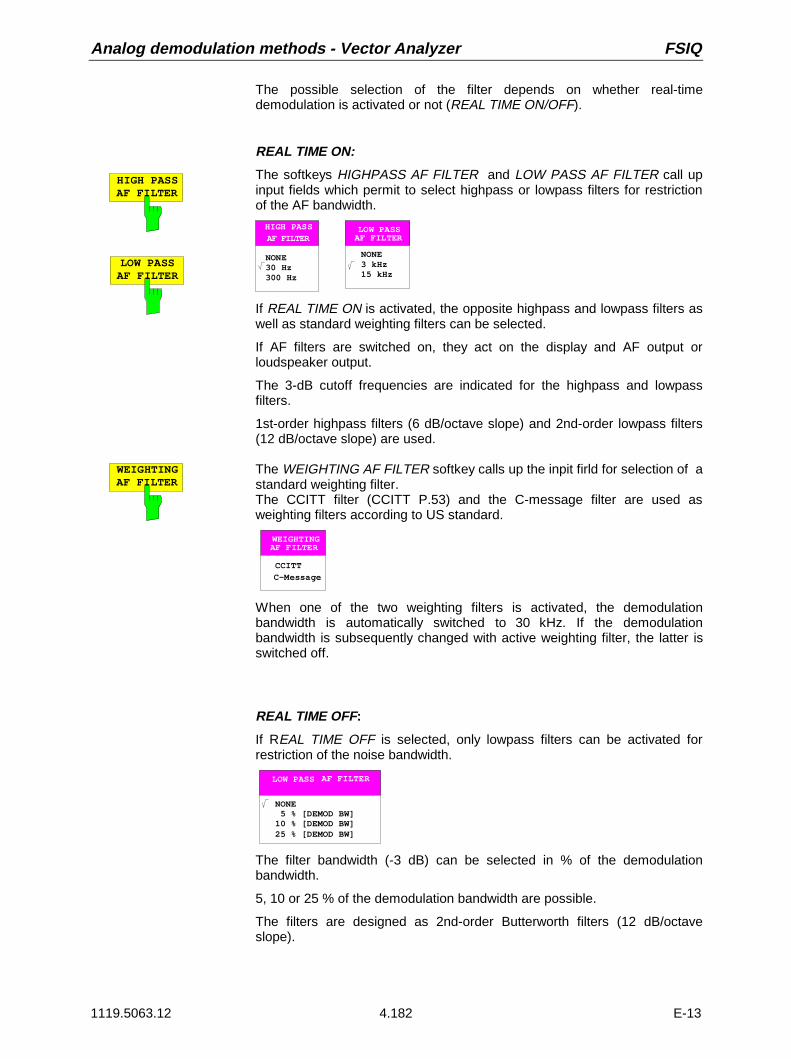
Analog demodulation methods - Vector Analyzer FSIQ
1119.5063.12 4.182 E-13
The possible selection of the filter depends on whether real-timedemodulation is activated or not (REAL TIME ON/OFF).
LOW PASSAF FILTER
HIGH PASSAF FILTER
REAL TIME ON:
The softkeys HIGHPASS AF FILTER and LOW PASS AF FILTER call upinput fields which permit to select highpass or lowpass filters for restrictionof the AF bandwidth.
AF FILTERLOW PASS
NONE3 kHz15 kHz
AF FILTER
HIGH PASS
NONE30 Hz300 Hz
If REAL TIME ON is activated, the opposite highpass and lowpass filters aswell as standard weighting filters can be selected.
If AF filters are switched on, they act on the display and AF output orloudspeaker output.
The 3-dB cutoff frequencies are indicated for the highpass and lowpassfilters.
1st-order highpass filters (6 dB/octave slope) and 2nd-order lowpass filters(12 dB/octave slope) are used.
WEIGHTINGAF FILTER
The WEIGHTING AF FILTER softkey calls up the inpit firld for selection of astandard weighting filter.The CCITT filter (CCITT P.53) and the C-message filter are used asweighting filters according to US standard.
CCITT
C-Message
AF FILTERWEIGHTING
When one of the two weighting filters is activated, the demodulationbandwidth is automatically switched to 30 kHz. If the demodulationbandwidth is subsequently changed with active weighting filter, the latter isswitched off.
REAL TIME OFF:
If REAL TIME OFF is selected, only lowpass filters can be activated forrestriction of the noise bandwidth.
AF FILTERLOW PASS
NONE 5 % [DEMOD BW]10 % [DEMOD BW]25 % [DEMOD BW]
The filter bandwidth (-3 dB) can be selected in % of the demodulationbandwidth.
5, 10 or 25 % of the demodulation bandwidth are possible.
The filters are designed as 2nd-order Butterworth filters (12 dB/octaveslope).

FSIQ Vector Analyzer - Analog demodulation methods
1119.5063.12 4.183 E-13
AF COUPL’GAC DC
The AF COUPL’G AC/DC softkey switches the AF analysis stages after thedemodulators to DC or AC voltage coupling.
FM:
With FM, AC coupling (AF COUPL’G AC) is achieved by determining thecenter frequency of the signal to be measured and correcting thedemodulated signal accordingly.
With AF COUPL’G DC the center frequency of the FSIQ is assumed as thecarrier frequency, and no frequency correction is performed. The AF signalis DC-coupled.
PM:
With PM, AC coupling (AF COUPL’G AC) is achieved by estimating both thefrequency offset and the phase offset and setting them to zero.
Only with REAL TIME OFF:
With AF COUPL’G DC, if the center frequency of the signal to be measureddeviates, the phase varies with a period corresponding to the differencebetween applied and set center frequency (0 to 360°).If the frequency is consistent (e.g. in the case of synchronization to acommon reference frequency) the phase is constant on an offset in therange from 0 to 360°. The PM demodulator is DC-coupled.
AM:
As a mere envelope demodulator, the AM demodulator is insensitive tofrequency errors as long as carrier and sidebands are within the setfrequency display range.
In the case of AC coupling (AF COUPL’G AC), the demodulated AF signalis standardized to the DC voltage (corresponds to the average carrier value)and the DC component is removed.
The amplitude of the AF signal is directly proportional to the AM modulationdepth.
In the case of DC coupling (AF COUPL’G DC), the amplitude of thedemodulated signal is proportional both to the AM depth and to the level,there is no standardization to the average carrier value. The measuredvalue is displayed in absolute level units.

Analog demodulation methods - Vector Analyzer FSIQ
1119.5063.12 4.184 E-13
SQUELCHON OFF
REAL TIME ON:
The SQUELCH ON softkey mutes the loudspeaker or headphones outputprovided that the level falls below a threshold that can be entered underSQUELCH LEVEL. The trace of the demodulated signal is also set to zeroat this point in time. The muting circuit responds with a delay that isdesigned such that a signal modulated with ≥ 30 Hz AM does not cause thecircuit to respond in a modulation low status.
Loudspeaker or headphones output are only active if real-time demodulationis selected.
REAL TIME OFF:
With MEAS RESULT: AM-, FM SIGNAL or :PM SIGNAL the frequency orphase deviation is set to zero when the value falls below the squelch. Themuting circuit responds without delay, which is why it is suitable for transientmeasurements in particular.
SQUELCH LEVEL
SQUELCH LEVEL permits to enter an absolute level in the unit dBm, belowwhich the SQUELCH function is activated (only with SQUELCH ON).
SIDEBANDNORM INV
The softkey SIDEBAND INV (INVERTED) demodulates and inverts thesignal received.
Thus, with FM or PM demodulation, a receive signal with increasingfrequency at the FSIQ input leads to a falling AF signal.
Default status is SIDEBAND NORM (normal): A receive signal withincreasing frequency at the FSIQ input leads to an increasing AF signal.

FSIQ Vector Analyzer - Analog demodulation methods
1119.5063.12 4.185 E-13
AM/FM DEEMPH
AM/FM DEEMPHASIS
50 us
75 us
750 us
PRE DISPLON OFF
REAL TIME ON only
The AM/FM DEEMPH softkey opens the submenu in which adeemphasis can be selected for FM (or AM) demodulation(An AM deemphasis is prescribed in a few regulations formeasurement of synchronous amplitude modulation on FMtransmitters.).
Deemphases with the time constants 50 µs, 75 µs (used forradio broadcasting) and 750 µs (used for radiocommunication) are provided.
If switched on, the deemphasis acts on the audio output.
50 us
75 us
750 us
REAL TIME ON only
The 50us, 75 us and 750 us softkeys select the timeconstant of the deemphasis.
The default setting is 50 µs.
PRE DISPLON OFF
REAL TIME ON only
The PRE DISPL ON/OFF softkey switches on or off theeffect of the deemphasis to the result display.
Via the function PRE DISP ON (PRE DISPLAY ON) theeffect of the deemphasis can also be extended to the resultdisplay to enable spurious modulation measurementscomplying with the standard.
To be able to measure the correct deviation of the signalapplied in spite of the corrected audio signal, the activedeemphasis can be switched off via PRE DISP OFF for theresult display.
DEEMPHASISON OFF
REAL TIME ON only
The DEEMPHASIS ON/OFF softkey switches the demphasis selectedunder AM/FM DEEMPHASIS on or off.
In the default status, the deemphasis is switched off.

Analog demodulation methods - Vector Analyzer FSIQ
1119.5063.12 4.186 E-13
Selecting the Audio Signal
Submenu: CONFIGURATION: MODE - VECTOR ANALYZER - ANALOG DEMOD
MEASRESULT
MEAS RESULT
FM SIGNAL
PM SIGNAL
VOLUME
REAL TIMEON OFF
SENSITIVAF OUTPUT
MODULATION SUMMARY
AM SIGNAL
SUMMARYSETTINGS
REAL TIMEON OFF
SUMMARYMEAS TIME
The MEAS RESULT softkey opens up a submenu forselection of the AM, FM, or PM demodulated audio signal(display and audio output).
AM SIGNAL The AM SIGNAL softkey is used to display the AM-demodulated time signalprovided that MODULATION SUMMARY is not active. If MODULATIONSUMMARY is active, the modulation parameters will be numericallydisplayed with main signal AM (see MODULATON SUMMARY).

FSIQ Vector Analyzer - Analog demodulation methods
1119.5063.12 4.187 E-13
The AM-demodulated signal is applied to the audio output (if REAL TIMEON).
FM SIGNAL The FM SIGNAL softkey displays the FM-demodulated time signal providedthat MODULATION SUMMARY is not active. If MODULATION SUMMARYis active, the modulation parameter will be numerically displayed with mainsignal FM (see MODULATION SUMMARY).
The FM-demodulated signal is present at the audio output (in the case ofreal-time demodulation).
PM SIGNAL The PM SIGNALL softkey displays the PM-demodulated time signalprovided that MODULATION SUMMARY is not active. If MODULATIONSUMMARY is active, the modulation parameter will be numerically displayedwith main signal PM (see MODULATION SUMMARY).
In the case of REAL TIME ON the PM-demodulated signal is present at theaudio output.
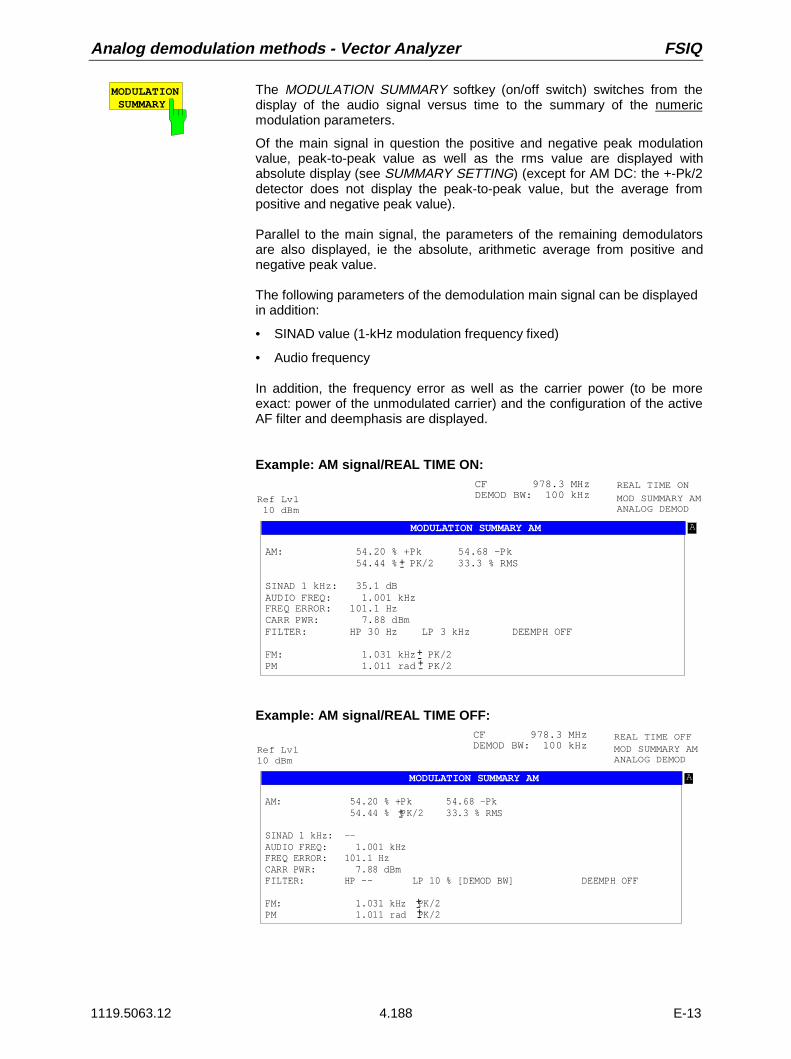
Analog demodulation methods - Vector Analyzer FSIQ
1119.5063.12 4.188 E-13
MODULATION SUMMARY
The MODULATION SUMMARY softkey (on/off switch) switches from thedisplay of the audio signal versus time to the summary of the numericmodulation parameters.
Of the main signal in question the positive and negative peak modulationvalue, peak-to-peak value as well as the rms value are displayed withabsolute display (see SUMMARY SETTING) (except for AM DC: the +-Pk/2detector does not display the peak-to-peak value, but the average frompositive and negative peak value).
Parallel to the main signal, the parameters of the remaining demodulatorsare also displayed, ie the absolute, arithmetic average from positive andnegative peak value.
The following parameters of the demodulation main signal can be displayedin addition:
• SINAD value (1-kHz modulation frequency fixed)
• Audio frequency
In addition, the frequency error as well as the carrier power (to be moreexact: power of the unmodulated carrier) and the configuration of the activeAF filter and deemphasis are displayed.
Example: AM signal/REAL TIME ON:
Symbol TableBit No.
Ref Lvl 10 dBm
MOD SUMMARY AMANALOG DEMOD
A
MODULATION SUMMARY AM
CF 978.3 MHzDEMOD BW: 100 kHz
AM: 54.20 % +Pk 54.68 -Pk 54.44 % PK/2 33.3 % RMS
SINAD 1 kHz: 35.1 dBAUDIO FREQ: 1.001 kHzFREQ ERROR: 101.1 HzCARR PWR: 7.88 dBmFILTER: HP 30 Hz LP 3 kHz DEEMPH OFF
FM: 1.031 kHz PK/2 PM 1.011 rad PK/2
-+
-+-+
REAL TIME ON
Example: AM signal/REAL TIME OFF:
Symbol TableBit No.
Ref Lvl10 dBm
MOD SUMMARY AMANALOG DEMOD
A
MODULATION SUMMARY AM
CF 978.3 MHzDEMOD BW: 100 kHz
AM: 54.20 % +Pk 54.68 -Pk 54.44 % PK/2 33.3 % RMS
SINAD 1 kHz: --AUDIO FREQ: 1.001 kHzFREQ ERROR: 101.1 HzCARR PWR: 7.88 dBmFILTER: HP -- LP 10 % [DEMOD BW] DEEMPH OFF
FM: 1.031 kHz PK/2 PM 1.011 rad PK/2
-+
-+-+
REAL TIME OFF

FSIQ Vector Analyzer - Analog demodulation methods
1119.5063.12 4.189 E-13
Example: FM signal, relative measurement:
In the case of relative measurement, the absolute arithmetic average frompositive and negative peak value as well as the rms value of the main signalare also displayed. The separate display of positive and negative peak valueis omitted. Instead, the reference value is additionally displayed as peak andrms value.
Symbol TableBit No.
Ref Lvl10 dBm
MOD SUMMARY FMANALOG DEMOD
A
MODULATION SUMMARY FM
CF 978.3 MHzDEMOD BW: 100 kHz
FM RELATIV: -45.21 dB PK/2 -58 dB RMSREF Deviation: 10.00 kHz Pk 7.07 kHz RMS
SINAD 1 kHz: OFFAUDIO FREQ: 1.001 kHzFREQ ERROR: 101.1 HzCARR PWR: 7.88 dBmFILTER: CCITT DEEMPH 50us PRE DISP ON
AM: 1.031 % PK/2 PM 1.011 rad PK/2
-
+-
+-+-
REAL TIME ON
Example: AVERAGE/ HOLD ON:
Symbol TableBit No.
Ref Lvl10 dBm
MOD SUMMARY FMANALOG DEMOD
A
MODULATION SUMMARY FM
CF 978.3 MHzDEMOD BW: 100 kHz
FM RELATIV: -45.21 dB PK/2 HLD -58 dB RMS AVREF Deviation: 10.00 kHz Pk HLD 7.07 kHz RMS AV
SINAD 1 kHz: OFFAUDIO FREQ: 1.001 kHz AVFREQ ERROR: 101.1 Hz AVCARR PWR: 7.88 dBm FILTER: CCITT DEEMPH 50us PRE DISP ON
AM: 1.031 % PK/2 PM 1.011 rad PK/2
+-
+-+-
REAL TIME ON

Analog demodulation methods - Vector Analyzer FSIQ
1119.5063.12 4.190 E-13
SUMMARYSETTINGS
SUMMARYSETTINGS
INDICATION
ABS REL
SET REFERENCE
SINAD 1kHzON OFF
MEAS->REF
REL UNIT
% dB
AVERAGE/HOLD ON
SWEEPCOUNT
The SUMMARY SETTINGS softkey opens up thesubmenu for configuration of the summary of all numericmeasured values.
AVERAGE/HOLD ON
The AVERAGE/HOLD ON softkey permits to average alldisplay values obtained in the number of sweeps definedunder Sweep Count except for the Pk values with SingleSweep (the display No of Measurements appears in themodulation summary, AV is indicated after the units).
The Pk values are displayed in the Pk Hold mode(display Hold after the Pk units).
In the case of a restart, the Pk values and AV values arereset by means of Single Sweep or by switching TRACEAVERAGE/HOLD ON off and on.
SWEEPCOUNT
The SWEEP COUNT softkey sets the number ofsweeps used to determine the average or PK Holdvalues (see also the corresponding softkey in analyzermode)).
REL UNIT
dB %The REL UNIT dB/% softkey softkey selects the unit (%and dB) with relative display (INDICATION REL) .

FSIQ Vector Analyzer - Analog demodulation methods
1119.5063.12 4.191 E-13
INDICATION
ABS RELThe INDICATION ABS REL softkey switches betweenabsolute (ABS, default setting) and relative display(REL). The reference value for the relative display canbe entered by means of SET REFERENCE or MEAS→REF.
Only the main signal can be displayed in relative mode,the other signals are indicated in absolute display in anycase.
For relative indication, the default unit is dB and can bechanged from dB to % via the softkey REL UNIT%.
SETREFERENCE
The SET REFERENCE softkey opens up a field for inputof a reference modulation (for main signal).
The peak value of the modulation is to be entered. Therms reference value will then be peak value/√2.
MEAS-> REFThe MEAS→REF softkey is used to represent thecurrent absolute measured values of the mainmodulation signal (+-PK/2 and RMS) as referencevalues for the relative display.
SINAD 1kHzON OFF
REAL TIME ON only.
The SINAD 1 kHz ON softkey activates the SINADmeasurement for the main modulation signal.
Irrespective of the signal applied, the main modulationsignal is compared with the main modulation signalwhich is filtered by a 1-kHz notch filter. The display unitis dB.
When a signal modulated with 1 kHz is applied, theSINAD value is thus displayed correctly.Default setting is SINAD 1 kHz OFF.
With REAL TIME OFF (no real-time demodulation) noSINAD measurement is possible, the softkey cannot beoperated.
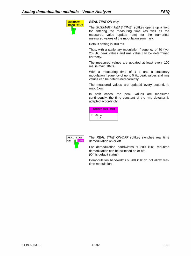
Analog demodulation methods - Vector Analyzer FSIQ
1119.5063.12 4.192 E-13
SUMMARYMEAS TIME
REAL TIME ON only.
The SUMMARY MEAS TIME softkey opens up a fieldfor entering the measuring time (as well as themeasured value update rate) for the numericalmeasured values of the modulation summary.
Default setting is 100 ms
Thus, with a stationary modulation frequency of 30 (typ.20) Hz, peak values and rms value can be determinedcorrectly.
The measured values are updated at least every 100ms, ie max. 10x/s.
With a measuring time of 1 s and a stationarymodulation frequency of up to 5 Hz peak values and rmsvalues can be determined correctly.
The measured values are updated every second, iemax. 1x/s.
In both cases, the peak values are measuredcontinuously, the time constant of the rms detector isadapted accordingly.
SUMMARY MEAS TIME
100 ms 1 s
REAL TIMEON OFF
The REAL TIME ON/OFF softkey switches real timedemodulation on or off.
For demodulation bandwidths ≤ 200 kHz, real-timedemodulation can be switched on or off.(Off is default status).
Demodulation bandwidths > 200 kHz do not allow real-time modulation.

FSIQ Vector Analyzer - Analog demodulation methods
1119.5063.12 4.193 E-13
SENSITIVAF OUTPUT
REAL TIME ON only.
The SENSITIV AF OUTPUT softkey sets the scaling ofthe AF output for real-time modulation. Depending onMEAS RESULT (AM, FM or PM signal), an input fieldappears, where the modulation amplitude is to beentered so that the dynamic range of the AF output isfully utilized.(Peak voltage 1V):
m[%] FOR FULL SCALE SIGNAL
20
FM DEV FOR FULL SCALE SIGNAL
100
PM DEV FOR FULL SCALE SIGNAL
1
SENSITIV AF OUTPUT also has an effect on thevolume of the loudspeaker and on the headphonesoutput.
VOLUME REAL TIME ON only
The VOLUME softkey sets the volume of thedemodulated signal (loudspeaker and headphonesoutput) according to the slope of the AF output.
With REAL TIME OFF (no real-time demodulation) theoutputs are switched off.
Note: If the modulation depth / deviation is verysmall, the scaling of the AF output (softkeySENSITIV AF OUTPUT) is to be matchedto achieve a usable volume.
On the other hand, the modulation depth /deviation must not be greater than the full-scale setting under SENSITIV AFOUTPUT, or a distorted signal will beobtained at the loudspeaker/headphonesoutput even with the volume reduced.

Analog demodulation methods - Vector Analyzer FSIQ
1119.5063.12 4.194 E-13
Triggering with Analog Demodulation - Softkey TRIGGER or Hardkey TRIGGER
Submenu: CONFIGURATION MODE - VECTOR ANALYZER - ANALOG DEMOD
VIDEO
TRIGGER
FREE RUN
TRIGGEROFFSET
EXTERN
SLOPEPOS NEG
AF SIGNAL
TRIGGER
SWEEP
TRIGGER
RBW
VBW
SW T
COUPLING
SWEEP
or
The TRIGGER softkey as well as the TRIGGER hardkeypermit to call up the menu for setting the trigger.
FREE RUN The FREE RUN softkey activates a measurement without trigger. After ameasurement has been terminated, data acquisition for a newmeasurement takes place immediately.
VIDEOREAL TIME OFF only.
The VIDEO softkey starts the measurement by means of the video voltageof the analog path of the spectrum analyzer. For this purpose, the analogvideo voltage of the spectrum analyzer is analyzed parallel to the vectorsignal analyzer.
Video triggering is of particular use for frequency settling measurements onsynthesizers.
Video triggering requires the trigger threshold to be entered. It is identicalwith the trigger threshold of the spectrum analyzer. The trigger threshold isentered numerically into the data input field in % of the last grid that wasactive in spectrum analysis mode.
The appropriate value for the trigger threshold can be determined in thespectrum analysis mode.
EXTERN REAL TIME OFF only.
The EXTERN softkey activates triggering via an external voltage in therange from - 5 V to + 5 V at the BNC connector EXT TRIGGER / GATE(rear panel). Enter the desired value in the data input field.

FSIQ Vector Analyzer - Analog demodulation methods
1119.5063.12 4.195 E-13
AFSIGNAL
The AF SIGNAL softkey opens up a data input field where the level of theAF signal is entered as the trigger level for display of the time signal.
The AF trigger level is entered in %, Hz, deg or rad according to the currentdemodulation AM, FM or PM (in the case of AM DC in the current absolutelevel unit).
Triggering on the AF signal is similarly possible with REAL TIME ON/OFF.
TRIGGEROFFSET
REAL TIME OFF only
The TRIGGER OFFSET softkey opens up an input window for entry of thedesired offset with video trigger or external trigger (only with ).
The softkey cannot be operated with REAL TIME ON and REAL TIME OFFin conjunction with AF trigger.
The trigger offset is used to determine the start of data acquisition relative tothe trigger event. Both positive values for a trigger delay and negativevalues for a pretrigger are permissible.
The input is made in absolute time irrespective of the scale selected for theX-axis.
Depending on the demodulation bandwidth, values from 1µs to at least 10ms are permissible for positive values of the trigger offset (trigger delay).The value range for negative trigger offset values (pretrigger) depends onthe sweep time and is maximally half the sweep time.
SLOPEPOS NEG
The SLOPE POS/NEG softkey determines the trigger edge for triggering ymeans of the video signal, AF signal or external trigger.The measurement run is started on a positive or negative edge of thetrigger signal. With free-running trigger (FREE RUN), the setting is not ofany significance.
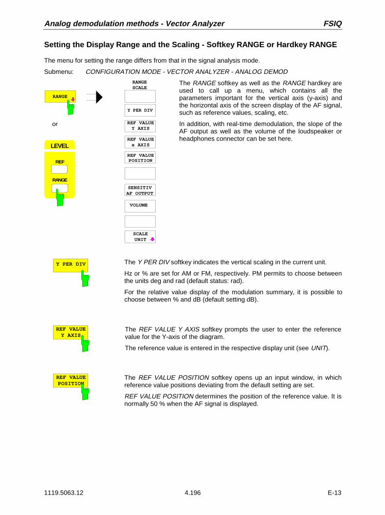
Analog demodulation methods - Vector Analyzer FSIQ
1119.5063.12 4.196 E-13
Setting the Display Range and the Scaling - Softkey RANGE or Hardkey RANGE
The menu for setting the range differs from that in the signal analysis mode.
Submenu: CONFIGURATION MODE - VECTOR ANALYZER - ANALOG DEMOD
REF VALUEY AXIS
REF VALUEPOSITION
RANGESCALE
Y PER DIV
SCALEUNIT
SENSITIVAF OUTPUT
VOLUME
RANGE
LEVEL
RANGE
REF
or
REF VALUEx AXIS
The RANGE softkey as well as the RANGE hardkey areused to call up a menu, which contains all theparameters important for the vertical axis (y-axis) andthe horizontal axis of the screen display of the AF signal,such as reference values, scaling, etc.
In addition, with real-time demodulation, the slope of theAF output as well as the volume of the loudspeaker orheadphones connector can be set here.
Y PER DIV The Y PER DIV softkey indicates the vertical scaling in the current unit.
Hz or % are set for AM or FM, respectively. PM permits to choose betweenthe units deg and rad (default status: rad).
For the relative value display of the modulation summary, it is possible tochoose between % and dB (default setting dB).
REF VALUEY AXIS
The REF VALUE Y AXIS softkey prompts the user to enter the referencevalue for the Y-axis of the diagram.
The reference value is entered in the respective display unit (see UNIT).
REF VALUEPOSITION
The REF VALUE POSITION softkey opens up an input window, in whichreference value positions deviating from the default setting are set.
REF VALUE POSITION determines the position of the reference value. It isnormally 50 % when the AF signal is displayed.

FSIQ Vector Analyzer - Analog demodulation methods
1119.5063.12 4.197 E-13
SENSITIVAF OUTPUT
The SENSITIV AF OUTPUT (sensitivity AF output) softkey is used to setthe scaling of the AF output with real-time demodulation. Depending onMEAS RESULT (AM, FM, or PM signal), an input field appears, where themodulation amplitude is to be entered at which the dynamic range of the AFoutput is fully utilized.(Peak voltage 1V):
m[%] FOR FULL SCALE SIGNAL
20
FM DEV FOR FULL SCALE SIGNAL
100
PM DEV FOR FULL SCALE SIGNAL
1
SENSITIV AF OUTPUT also affects the volume of the loudspeaker and theheadphones output.
VOLUME REAL TIME ON only
The VOLUME softkey sets the volume of the demodulated signal(loudspeaker and headphones output) according to the slope of the AFoutput.
With REAL TIME OFF (no real-time demodulation) the outputs are switchedoff.
Note: If the modulation depth / deviation is very small, the scaling ofthe AF outputs (Softkey SENSITIV AF OUTPUT) is to bematched to achieve a usable volume.
On the other hand, the modulation depth / deviation must notbe greater than the full-scale setting under SENSITIV AFOUTPUT, or a distorted signal will be obtained at theloudspeaker/headphones output even with reduced volume.
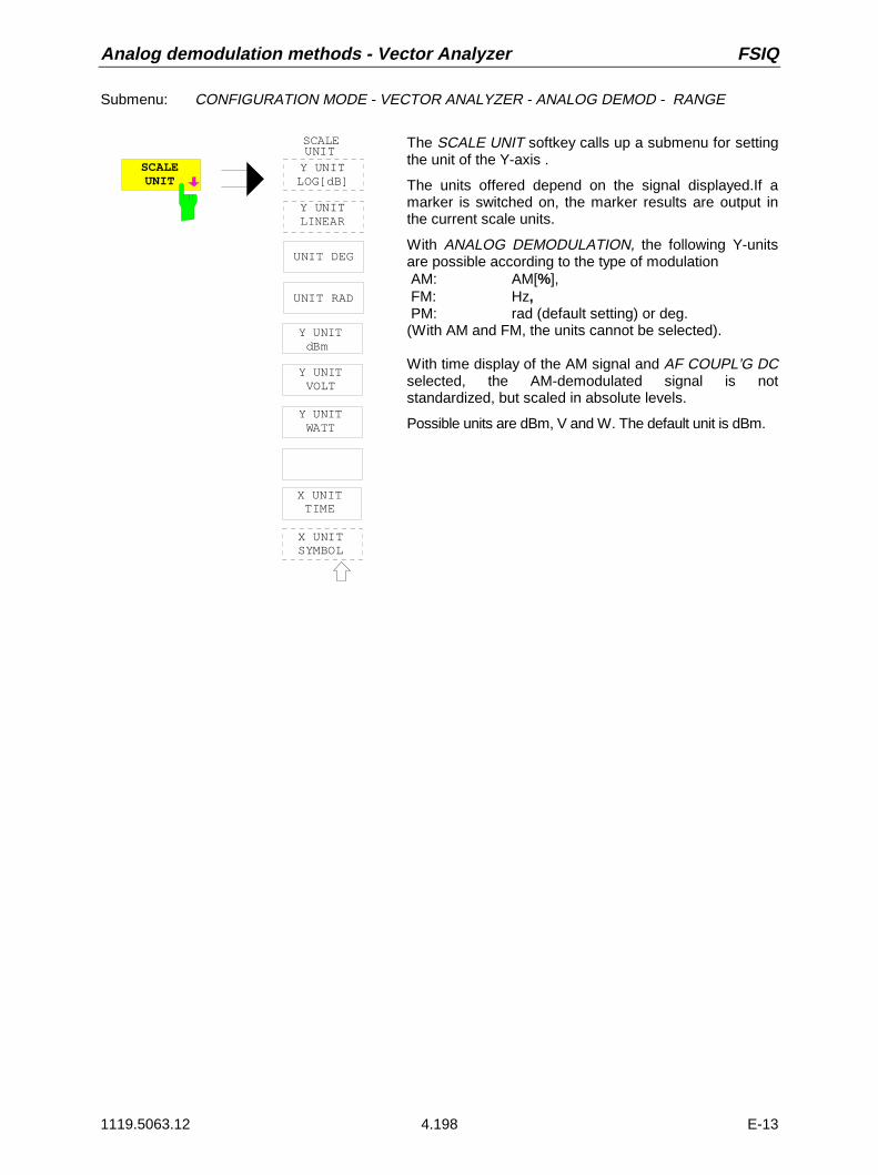
Analog demodulation methods - Vector Analyzer FSIQ
1119.5063.12 4.198 E-13
Submenu: CONFIGURATION MODE - VECTOR ANALYZER - ANALOG DEMOD - RANGE
UNITY UNITLOG[dB]
Y UNITLINEAR
SCALE
Y UNIT dBm
Y UNIT VOLT
Y UNIT WATT
UNIT DEG
UNIT RAD
X UNITTIME
X UNITSYMBOL
SCALEUNIT
The SCALE UNIT softkey calls up a submenu for settingthe unit of the Y-axis .
The units offered depend on the signal displayed.If amarker is switched on, the marker results are output inthe current scale units.
With ANALOG DEMODULATION, the following Y-unitsare possible according to the type of modulation AM: AM[%], FM: Hz, PM: rad (default setting) or deg.(With AM and FM, the units cannot be selected).
With time display of the AM signal and AF COUPL’G DCselected, the AM-demodulated signal is notstandardized, but scaled in absolute levels.
Possible units are dBm, V and W. The default unit is dBm.

FSIQ Vector Analyzer - Analog demodulation methods
1119.5063.12 4.199 E-13
Sweep Menu with Analog Demodulation - Softkey SWEEP TIME or HardkeySWEEP
Submenu: CONFIGURATION MODE - VECTOR ANALYZER - ANALOG DEMOD
SINGLESWEEP
SWEEP
CONTINOUSSWEEP
SWEEP
TRIGGER
RBW
VBW
SWT
COUPLING
SWEEP
SWEEPCOUNT
SWEEPTIME
oder
SWEEPTIME
The SWEEP key calls up a menu, which permits todetermine the type of measurement - singlemeasurement or continuous measurement - and thelength of the measurement results to be displayed interms of time.
CONTINOUSSWEEP
The CONTINUOUS SWEEP softkey starts a continuous measurement inaccordance with the trigger condition and the selected test settings.Triggering is followed by data acquisition first and then by evaluation anddisplay on the screen.
If, with split screen display, vector analysis mode is used for measurementin both windows, the data in the measurement RAM are used for bothevaluations.
SINGLESWEEP
The SINGLE SWEEP softkeystarts n measurements in accordance with thetrigger settings. The number of measurement runs n is determined bymeans of SWEEP COUNT. The measurement stops after n measurements.It can be restarted by pressing the SINGLE SWEEP or CONTINUOUSSWEEP softkey again.

Analog demodulation methods - Vector Analyzer FSIQ
1119.5063.12 4.200 E-13
SWEEPCOUNT
The SWEEP COUNT softkey opens up an input field in which the number ofmeasurements is determined for the SINGLE SWEEP.
The number of measurements can be selected between 0 and 32767.
If averaging of the measured values is set (AVG/HOLD ON, MODULATIONMARKER: RMS to be found under the MARKER SEARCH key), SWEEPCOUNT also determines the number of measurements used for averaging.
If SWEEP COUNT = 0, 10 measured values are always used for floatingaveraging.
If SWEEP COUNT = 1, no averaging takes place.
If SWEEP COUNT >1, the average is taken of the set number of measuredvalues.
SWEEPTIME
SWEEP TIME is used to define the time during which the demodulatedsignal is to be displayed.The maximum time is determined by the demodulation bandwidth set andthe buffer length for the demodulated signal, which is 5000 points withanalog demodulation.Thus, the following settable maximum time is obtained:
SWEEP TIME max = 5000
0 8. * ( _ )DEMOD BW [s]
A minimum of 10 points can be displayed, which means for the minimumsettable time:
SWEEP TIME min = 10
0 8. * ( _ )DEMOD BWExample:With Demod BW 1kHz, the maximum and minimum time scale is asfollows:TIME/DIV max = 6.25 sTIME/DIV min = 12.5 ms
RESULTLENGTH
The RESULT LENGTH softkey cannot be operated with ANALOGDEMODULATION.

FSIQ Vector Analyzer - Analog demodulation methods
1119.5063.12 4.201 E-13
Example: Measurement of amplitude modulation
Measurement of a carrier modulated with 1 kHz, 50 % at 100 MHz, level 0 dBm
1. [PRESET] Default setting
2. [CENTER: 100 MHz] Frequency setting
3. [REF: REF LEVEL: +6 dBm] Level setting (the max. level of AM-modulated signals is 6 dBabove the nominal level with 100 % AM).
4. [MODE: VECTOR ANALYSIS] Selection of vector analysis mode The FSIQ is in the analysismode DIGITAL DEMODULATION (default setting).
5. [ANALOG DEMODULATION] Switch to analog demodulation. The AM-modulated signalappears on the display (display in the time domain, the defaultsetting for [ANALOG DEMODULATION] is AM-SIGNAL). Thedemodulation bandwidth (analysis bandwidth) is 100 kHz in thedefault setting, i.e. audio signals up to max. 0.4* demodulationbandwidth can be demodulated.
6. [DEMOD BW: 30 kHz] The demodulation bandwidth is changed eg to 30 kHz
7. [TRIGGER:AF SIGNAL 0%] Trigger setting to achieve a stable display. The display of the AFsignal at the left edge of the screen starts at 0 %.
8. [SWEEP: SWEEPTIME 100 ms] Setting of the sweep time. The sweep time depends on thedemodulation bandwidth and the sampling points provided(=5000 with analog demodulation). With a demodulationbandwidth of 30 kHz, the max. sweep time is 208 ms in thedefault setting.
9. [SEARCH: SUM MKR ON] Activating the summary marker for numeric trace evaluation.

Digital Modulation Methods - Vector Analyzer FSIQ
1119.5063.12 4.202 E-13
Digital Demodulation Methods
Diagram for signal processing
In modern mobile radio networks digital transmission methods are used to avoid the disadvantages of atransmission channel in mobile communication and to be able to serve more subscribers in the availablefrequency spectrum. The FSIQ offers all commonly used demodulators for digitally modulated signals.All modulation parameters for standard transmission methods can be loaded as required by the user.The FSIQ determines all relevant modulation parameters such as frequency, phase, amplitude andvector errors, etc. Measurements are carried out on continuous as well as pulsed signals such as TDMAsignals. Bit patterns can be defined to be able to trigger to known bit sequences like preambles ormidambles. The demodulator requires neither a coherent carrier nor a symbol clock for demodulation. Itcomprises matched filters and synchronizes automatically to the carrier and to the symbol clock.Furthermore, the demodulator can generate the ideal I/Q signal from the demodulated bit stream andthus determine the errors of the analyzed signal.
For a correct demodulation of digital signals, a number of modulation parameters in addition to themodulation mode has to be specified for the signal to be analyzed. The most important are the symbolrate and the input filter. And in addition, the frequency of the FSIQ (approx. 2% of the symbol rate) hasto be tuned exactly to the frequency of the signal to be analyzed.
The bandwidth for demodulation is a function of the symbol rate and the selected oversampling method(POINTS PER SYMBOL). At least 4-fold oversampling is performed. If the number set under POINTSPER SYMBOL is reduced, fewer points are used in the display. The demodulation bandwidth for 1, 2and 4 points per symbol is 3.125 times the symbol rate, with 8 points per symbol 6.5 times and for 16points per symbol 13 times. It should be ensured that no modulation spectrum of adjacent signals iswithin the displayed range during demodulation, as this may introduce errors in the measurement ofmodulation parameters. If required, check for correct settings in the analyzer mode. The block diagrambelow shows the digital demodulator and its measurement capabilities:
A
D
DigitalFilter
DigitalLO
CaptureRAM
PulseSearch Digital
Demodulation
I
Q
IF6,4 MHz/1,4 MHz
I/Q Measured SiignalI/Q Reference SignalBits for Symbol TableI/Q
fa
90o
DigitalFilter
SYNCSEARCH
I/Q Measure Signal
I/Q-Reference Signal
Bit Strom
ErrorCalcutation
Graphik-Processing
Display
I/Q Amplitude ErrorI/Q Phase ErrorI/Q ErrorERROR VECTOR MAGNITUDE
Symbol Table
Fig. 4-18 Block diagram for signal processing during digital demodulation

FSIQ Vector Analyzer - Digital Modulation Methods
1119.5063.12 4.203 E-13
Symbol Mapping
The following types of symbol mapping are used for representing the results in the vector andconstellation diagrams (PSK, MSK, QAM) and for the time/frequency representations with FSKmodulation. The symbols are always in the binary code (MSB at left).
Phase Shift Keying (PSK)
With these modulation types, the symbol represents the absolute phase of the received signal at thedecision time. The following representations are given:• a constellation diagram containing all symbols• a table containing the symbol designations and the associated reference phases
With this type of phase modulation, transitions from any symbol to any other in the constellation diagramare permitted.
BPSK QPSK (WCDMA)
01
Q
I
Symbol Phase 0 0 1 Π
0001
11 10
Q
I
Symbol Phase 00 Π/4 01 3Π/4 11 5Π/4 10 7Π/4
QPSK (QCDMA FWD; WCDMA; APCO25) 8PSKOQPSK (QCDMA REV)
0001
11 10
Q
I
Symbol Phase 00 Π/4 01 3Π/4 11 5Π/4 10 7Π/4
Fig. 4-19 Symbol mapping - phase shift keying
001011
101 111
000
010
100
110
Q
I
Symbol Phase 000 0Π/4 001 1Π/4 010 2Π/4 011 3Π/4 100 4Π/4 101 5Π/4 110 6Π/4 111 7Π/4

Digital Modulation Methods - Vector Analyzer FSIQ
1119.5063.12 4.204 E-13
3PI/8-8PSK (EDGE)
For these modulation methods the digital information is NOT coded in the phase transitions but in theabsolute position of the constellation diagram. The constellation diagram consists of 16 points. For eachsymbol transition, an offset of 3pi/8 is inserted counterclockwise.The symbol allocation in the constellation diagram is thus only valid for the first symbol of the datarecord.Five symbol transitions with an offset of 3pi/8 each is given as an example. The modulated symbol "111"remains constant.This phase offset is taken into account during decoding and the display of symbols.
001
011
101
111
000
010
100
110
Q
I
3pi/8
3pi/8
3pi/8
3pi/8 3pi/8
Symbol Phase000 3pi/8001 4pi/8010 2pi/8011 1pi/8100 6pi/8101 5pi/8110 7pi/8111 0pi/8
Fig. 4-20 Symbol mapping - Phase Shift Keying - EDGE
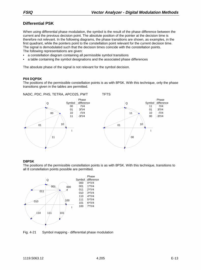
FSIQ Vector Analyzer - Digital Modulation Methods
1119.5063.12 4.205 E-13
Differential PSK
When using differential phase modulation, the symbol is the result of the phase difference between thecurrent and the previous decision point. The absolute position of the pointer at the decision time istherefore not relevant. In the following diagrams, the phase transitions are shown, as examples, in thefirst quadrant, while the pointers point to the constellation point relevant for the current decision time.The signal is demodulated such that the decision times coincide with the constellation points.The following representations are given:• a constellation diagram containing all permissible symbol transitions• a table containing the symbol designations and the associated phase differences
The absolute phase of the signal is not relevant for the symbol decision.
PI/4 DQPSKThe positions of the permissible constellation points is as with 8PSK. With this technique, only the phasetransitions given in the tables are permitted.
NADC, PDC, PHS, TETRA, APCO25, PWT TFTS
00
01 10
11
Q
I
Phase Symbol difference 00 Π/4 01 3Π/4 10 -Π/4 11 -3Π/4
11
01 10
00
Q
I
Phase Symbol difference 11 Π/4 01 3Π/4 10 -Π/4 00 -3Π/4
D8PSKThe positions of the permissible constellation points is as with 8PSK. With this technique, transitions toall 8 constellation points possible are permitted.
Q
I
001
011
010
110 111 101
100
000
Phase Symbol difference 000 0*Π/4 001 1*Π/4 011 2*Π/4 010 3*Π/4 110 4*Π/4 111 5*Π/4 101 6*Π/4 100 7*Π/4
Fig. 4-21 Symbol mapping - differential phase modulation

Digital Modulation Methods - Vector Analyzer FSIQ
1119.5063.12 4.206 E-13
Frequency Shift Keying (FSK)
When working with FSK demodulation, a frequency/time diagram will be displayed instead of theconstellation and vector diagrams. The symbol decision is based on the signal deviation at the decisiontimes.
2FSK (DECT, CT2; FLEX16_2; FLEX32_2)
With 2FSK, the symbol decision is taken by asimple frequency discriminator with the followingdecision threshold:
f = f
Symbol ="1" for f f
"0" for f f
T mid
E T
E T
≥<
fI = instantaneous frequency
fT = decision threshold
fMID = middle frequency of analyzer
T
"1"
RE
F_D
EV
IAT
ION
"0"
f
t
1
F0
4FSK (ERMES; MODACOM; APCO25; FLEX32_4; FLEX64_4)
With 4FSK the symbol decision is taken by afrequency discriminator using three decisionthresholds derived from the operating parameterREF_DEVIATION:
f = f -13
REF_ DEVIATION
f = f
f = f +13
REF_ DEVIATION
Symbol =
for f f
for f f
for f f
for f < f
T1 MID
T2 MID
T3 MID
E T3
E T3
T1 E
I T1
⋅
⋅
≥≤ <≤ <
" "
" "
" "
" "
11
10
01
00
2
2
f
fT
T
fI = instantaneous frequency
f f fT1 T2 T3, , = decision thresholds
fMID = middle frequency of analyzer
FT2
"11"
RE
F_
DE
VIA
TIO
N"10"
"01"
"00"
FT1
FT3
f
t
11
F10
F01
F00
Fig. 4-22 Symbol mapping - FSK demodulation

FSIQ Vector Analyzer - Digital Modulation Methods
1119.5063.12 4.207 E-13
Minimum Shift Keying (MSK), CDPD
0
Q
I
1
Phase Symbol difference 0 -Π/2 1 Π/2
Fig. 4-23 Symbol mapping - minimum shift keying (MSK)
DMSK (and the derived GSMK) uses additional difference coding of two subsequent symbols. Staticsymbol mapping therefore does not exist.
Quadrature Amplitude Modulation (QAM)
With the QAM technique, the symbols are counted linearly from right to left and from top to bottom(linear mapping).
Note: For reliable demodulation make sure the available symbols are utilized. If only some of thesymbols or only the symbols in one quadrant are utilized, demodulation errors may occur.
I
Q0000000100100011
0100010101100111
1011 1010 1001 1000
1111 1110 1101 1100
Fig. 4-24 Symbol mapping - 16QAM

Digital Modulation Methods - Vector Analyzer FSIQ
1119.5063.12 4.208 E-13
Selecting the Digital Demodulators
Submenu: CONFIGURATION MODE - VECTOR ANALYZER
DIGITALDEMOD The DIGITAL DEMOD softkey opens a list of all available demodulators .
DIGITALDEMODULATION
BPSKQPSKDQPSKPI/4DQPSKOQSK8PSKD8PSK3π/8-8PSKMSKDMSK2FSK4FSK16QAM4FSK APCO25
Demodulators are provided for the two-, four- and eight-level PSK modulationmodes BPSK, QPSK and 8PSK. For QPSK and 8PSK demodulation, thedemodulators for differential signals DQPSK and D8PSK can be selectedadditionally.
Demodulators are also availabe for the special versions of QPSK modulation,such as differential QPSK with π/4 phase offset (π/4-DQPSK) and offsetQPSK (OQPSK).
QPSK is used, for instance, by the IS95- CDMA for modulating signals fromthe base station to the mobile, OQPSK for signals from the mobile to thebase station. The American TDMA system NADC (IS54) uses π/4-DQPSK fordigital signal transmissions.
For higher-level modulation modes the demodulator for 16QAM is available.MSK (minimum shift keying) demodulators pertain to the group of continuous-phase demodulators. MSK with Gaussian filters (GMSK = Gaussian minimumshift keying) is used for the European mobile radio systems GSM andDCS1800 or PCS1900 in the USA. For correct bit detection for GSM, DCS1800 and PCS 1900 and 1800 the MSK demodulator with additionaldifferential decoding (DMSK) should be activated.
For FSK (frequency shift keying modulation, two-level (2FSK) and four-level(4FSK) demodulators can be selected.
2FSK modulation methods are used for instance for the digital cordlesstelephone to DECT standard, 4FSK for the paging system to ERMESstandard.
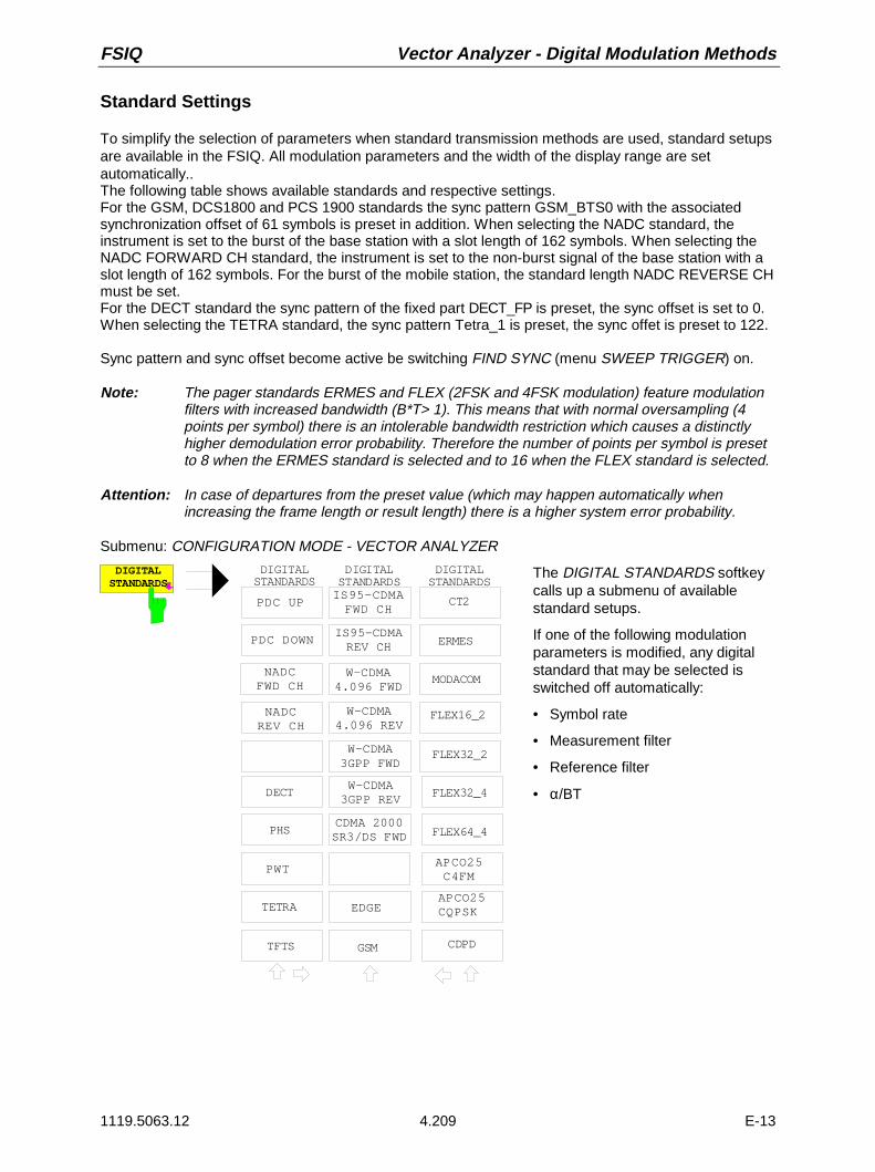
FSIQ Vector Analyzer - Digital Modulation Methods
1119.5063.12 4.209 E-13
Standard Settings
To simplify the selection of parameters when standard transmission methods are used, standard setupsare available in the FSIQ. All modulation parameters and the width of the display range are setautomatically..The following table shows available standards and respective settings. For the GSM, DCS1800 and PCS 1900 standards the sync pattern GSM_BTS0 with the associatedsynchronization offset of 61 symbols is preset in addition. When selecting the NADC standard, theinstrument is set to the burst of the base station with a slot length of 162 symbols. When selecting theNADC FORWARD CH standard, the instrument is set to the non-burst signal of the base station with aslot length of 162 symbols. For the burst of the mobile station, the standard length NADC REVERSE CHmust be set.For the DECT standard the sync pattern of the fixed part DECT_FP is preset, the sync offset is set to 0.When selecting the TETRA standard, the sync pattern Tetra_1 is preset, the sync offet is preset to 122.
Sync pattern and sync offset become active be switching FIND SYNC (menu SWEEP TRIGGER) on.
Note: The pager standards ERMES and FLEX (2FSK and 4FSK modulation) feature modulationfilters with increased bandwidth (B*T> 1). This means that with normal oversampling (4points per symbol) there is an intolerable bandwidth restriction which causes a distinctlyhigher demodulation error probability. Therefore the number of points per symbol is presetto 8 when the ERMES standard is selected and to 16 when the FLEX standard is selected.
Attention: In case of departures from the preset value (which may happen automatically whenincreasing the frame length or result length) there is a higher system error probability.
Submenu: CONFIGURATION MODE - VECTOR ANALYZER
DIGITALSTANDARDS
DIGITALSTANDARDS
GSM
PHS
TETRA
CDPD
DECT
APCO25
W-CDMA4.096 FWD
CT2
DIGITALSTANDARDS
ERMES
MODACOM
FLEX16_2
FLEX32_2
FLEX32_4
FLEX64_4
TFTS
DIGITALSTANDARDS
IS95-CDMAREV CH
APCO25 C4FM
APCO25CQPSK
NADCFWD CH
NADCREV CH
PDC UP
PDC DOWN
PWT
IS95-CDMAFWD CH
W-CDMA4.096 REV
EDGE
W-CDMA3GPP FWD
W-CDMA3GPP REV
CDMA 2000SR3/DS FWD
The DIGITAL STANDARDS softkeycalls up a submenu of availablestandard setups.
If one of the following modulationparameters is modified, any digitalstandard that may be selected isswitched off automatically:
• Symbol rate
• Measurement filter
• Reference filter
• α/BT

Digital Modulation Methods - Vector Analyzer FSIQ
1119.5063.12 4.210 E-13
Table 4-3 Standard settings
Modulation/Standard
Symbolrate
Measurementfilter
Referencefilter
AlphaBT
Synchro-nization
SyncPattern
SYNCOFFSET
Points/symbol
IS95-CDMAFWD CH QPSK
1.2288 MHz IS95_FM IS95_FR -- -- -- -- 4
IS95-CDMAREV CH OQPSK
1.2288 MHz IS95_FR IS95_RR -- -- -- -- 4
W-CDMA4.096 FWD QPSK
4.096 MHz ROOT RAISEDCOS
RAISED COS 0.22 -- -- -- 4
W-CDMA4.096 REV QPSK
4.096 MHz ROOT RAISEDCOS
RAISED COS 0.22 -- -- -- 4
W-CDMA3GPP FWD QPSK
3.84 MHz ROOT RAISEDCOS
RAISED COS 0.22 -- -- -- 4
W-CDMA3GPP REV QPSK
3.84 MHz ROOT RAISEDCOS
RAISED COS 0.22 -- -- -- 4
CDMA 2000SR3/DS FWD QPSK
3.6864 MHz IS95_FM IS95_FR -- -- -- -- 4
EDGE8π/8-8PSK
270.833 Hz EDGE_MES EDGE_REF -- BURSTSEARCH
EDGE_BT0 61 4
GSM, (DCS1800,PCS 1900) MSK
270.833kHz NONE GAUSSIAN 0.3 BURSTSEARCH
GSM_BTS0 61 4
NADC FWD CH*)π/4 DQPSK
24.3 kHz ROOT RAISEDCOS
RAISED COS 0.35 SYNCSEARCH
NADC_S1 0 4
NADC REV CHπ/4 DQPSK
24.3 kHz ROOT RAISEDCOS
RAISED COS 0.35 BURSTSEARCH
NADC_S1 8 4
PDC DOWNπ/4 DQPSK
21 kHz ROOT RAISEDCOS
RAISED COS 0.5 SYNCSEARCH
PDC_S1 57 4
PDC UPπ/4 DQPSK
21 kHz ROOT RAISEDCOS
RAISED COS 0.5 BURSTSEARCH
PDC_S1 57 4
PHS π/4 DQPSK 192 kHz ROOT RAISEDCOS
RAISED COS 0.5 BURSTSEARCH
PHS_DO1 32 4
CDPD MSK 19,2 kHz NONE GAUSSIAN 0.5 -- -- -- 4DECT 2-FSK 1152 kHz NONE GAUSSIAN 0.5 VIDEO
TRIGGER+ BURSTSEARCH
DECT_FP 0 4
TETRAπ/4-DQPSK
18 kHz ROOT RAISEDCOS
RAISED COS 0.35 BURSTSEARCH
TETRA_1 122 4
CT22-FSK
72 kHz NONE GAUSSIAN 0.5 BURST SEARCH
CT2_CFP 0 4
ERMES 4-FSK 3.125 kHz NONE BESSEL 1_25 -- -- -- 8MODACOM4-FSK
4.8 kHz ROOT RAISEDCOS
RAISED COS 0.2 -- -- -- 4
FLEX 16_2(FLEX 1600) 2-FSK
1.6 kHz NONE BESSEL 2_44 -- -- -- -- 16
FLEX 32_2(FLEX 3200) 2-FSK
3.2 kHz NONE BESSEL 1_22 -- -- -- -- 16
FLEX 32_4(FLEX 3200 4-FSK
1.6 kHz NONE BESSEL 2_44 -- -- -- -- 16
FLEX 64_4(FLEX 6400) 4-FSK
3.2 kHz NONE BESSEL 1_22 -- -- -- 16
PWTWCPE π/4 DQPSK
562.5 kHz ROOT RAISEDCOS
RAISED COS 0.5 BURSTSEARCH
WCPE_FP1 0 4
TFTSπ/4 DQPSK**)
22.1 kHz ROOT RAISEDCOS
RAISED COS 0.4 BURSTSEARCH
TFTS_G1 0
APCO25 C4FM 4.8 kHz NONE RAISED COS 0.2 -- -- 8APCO25 CQPSK 4.8 kHz APCO25FM RAISED COS 0.2 -- -- 4
*) The standard setting is matched to the slot of the NADC base station. As the base station doesn’t burst, the FIND BURSTfunction is disabled.
**) When selecting the TFTS standard, the special bit decoding is made according to the TFTS standard.
The standard settings are called up by means of the DIGITAL STANDARD softkey.

FSIQ Vector Analyzer - Digital Modulation Methods
1119.5063.12 4.211 E-13
Selecting Modulation Parameters for Digital Demodulation
Submenu: CONFIGURATION MODE - VECTOR ANALYZER
MODULATIONPARAMETERS
SYMBOLRATE
MODULATIONPARAMETERS
MEASFILTER
REFERENCEFILTER
ALPHA/BT
FSK REFDEVIATION
NORMALIZEON OFF
SIDE BANDNORM INV
The MODULATION PARAMETERS softkey calls up a submenu forsetting of the modulation parameters.
SYMBOLRATE
The SYMBOL RATE softkey opens a window for entering the symbol rate of thedigitally modulated signal to be measured.
The symbol rate is a function of the bit rate determined via the modulation level andcorresponds to the baud rate. With QPSK, for instance, the symbol ratecorresponds to half the bit rate (= 2 bits per symbol). Symbols are only valid whilethe signal is evaluated by the receiver. The time of demodulation is the point ofdecision. The demodulator of the FSIQ uses the set symbol rate to find the points ofdecision.
To be able to select the correct symbols, the symbol rate has to be entered exactly.The more complex (high-level) the modulation method, the more critical the exactdefinition of the symbol rate. An inaccurately defined symbol rate causesdemodulation errors. The settings below should also be observed for selecting thesymbol rate:
• Maximum possible symbol rate is 7 MHz.
• The number of points per symbol is limited to 8 for symbol rates >200 kHz and to4 for symbol rates >400 kHz.
• The demodulation bandwidth is limited to 8 MHz. If the symbol rate is set, theparameter ALPHA/BT may be adjusted accordingly.

Digital Modulation Methods - Vector Analyzer FSIQ
1119.5063.12 4.212 E-13
SIDEBANDNORM INV
The SIDE BAND NORM / INV (INVERTED) demodulates and inverts thesignal received.
Thus, with FSK demodulation, the frequency states are inverted, and, withnon-FSK modulation, the I and Q signal are inverted.
Default status is SIDEBAND NORM (normal).
MEASFILTER
The MEAS FILTER softkey selects the input filter for the signal to bemeasured. The required filter is selected in a table:
MEAS FILTER
NoneRaised CosRoot Raised CosGaussian
apco25fmedge_mesedge_refbess1_22 bess1_25 bess2_44 is95_fmis95_fris95_rmis95_rr
Further information is given in the description of the REFERENCE FILTERsoftkey.
REFERENCEFILTER
The REFERENCE FILTER softkey selects the filter for the ideal referencesignal for detecting modulation errors at the baseband level. The requiredfilter is selected in a table:
REFERENCE FILTER
Raised CosRoot Raised CosGaussian
apco25fmedge_mesedge_refbess1_22 bess1_25 bess2_44 IS95_fmIS95_frIS95_rmIS95_rr
Predefined filters are the squarewave filter (only for setting MEASFILTER:NONE), the raised cosine filter, the root raised cosine filter and theGaussian filter. Cosine filters are generally used for PSK modulation,Gaussian filters by MSK and FSK modulators.
The filter parameters are set via ALPHA/BT.

FSIQ Vector Analyzer - Digital Modulation Methods
1119.5063.12 4.213 E-13
The digital demodulator of FSIQ generates two signals at the I/Q level, thesignal to be measured (MEAS SIGNAL) and the reference signal(REFERENCE SIGNAL).
Frequency andsymbolsynchronization
Amplitude/phasecorrection
Measfilter
Symboldetector
Reference signalgenerator
Referencefilter
Referencesignal(I/Q)
Testsignal(I/Q)
Bits forsymboltable
The signal to be measured is present at the RF input after demodulation. Thereference signal is the signal that would be obtained in the case of an idealRF signal. A separate filter is provided for the signal and the reference signal.For digital transmissions, filtering can be carried out at the transmitter orreceiver end or be split up between both. The filter at the receiver is themeasurement filter. The reference filter is used for the total system.Depending on the configuration of filters, the following combinations can beused:
Filters of transmission system Filters to be selected
Transmitter Receiver MEAS FILTER REFERENCE FILTER
Root-raised cos Root-raised cos Root-raised cos Raised cos
Raised Cos none none Raised cos
Gaussian none none Gaussian
If no modulation filter is provided in the transmitter, it may also be useful toemploy a RAISED COS or GAUSSIAN filter as measurement filter.
However, the non-existing band limiting at the FSIQ input may causeunwanted aliasing products in the vector analyzer mode, which might impairthe measurement. A measurement without reference filter is not possible!

Digital Modulation Methods - Vector Analyzer FSIQ
1119.5063.12 4.214 E-13
ALPHA/BT The ALPHA/BT softkey opens a window where the roll-off factor (ALPHA) forthe cosine filters or the bandwidth/symbol period product BT for the Gaussianfilters is entered.
If an input filter is used for demodulation or a filter for generating thereference signal, the filter characteristic has to be determined by means ofALPHA/BT. With Nyquist filters ALPHA has to be specified, with Gaussianfilters the product of the symbol period T and bandwidth B (BT).
All filters are computed up to a length of 16 symbols. Permissible input valuesare 0.2 to 1 in steps of 0.05. The value for ALPHA/BT applies to themeasurement and to the reference filter. Values for ALPHA or BT aredetermined by the digital transmission system. These values should be usedfor measurements with FSIQ as higher demodulation errors could otherwiseoccur.
ALPHA describes the transmission characteristic of a Nyquist filter (cosinefilter). It is also designated as roll-off factor or bandwidth factor. The greaterALPHA, the greater is the bandwidth occupied by the digitally modulatedsignal relatives to the theoretical minimum. In digital transmission systemstypical bandwidth factors of 0.25 to 0.5 are used, ie the occupied bandwidth is25% to 50% larger than the theoretical minimum. The bandwidth/time productBT describes the characteristic or the bandwidth factor of Gaussian filters.
FSK REFDEVIATION
The FSK REF DEVIATION softkey opens a window for entering the referencedeviation for FSK demodulation.
FSK deviation is defined as the (unilateral) deviation from the centerfrequency occurring in the case of modulation with constant 0 or 1sequences, ie the stationary value.
For 4FSK, the modulation deviation is the deviation from the center frequencyfor the bit sequences causing maximum frequency deviation.The reference deviation is used for computing the deviation error inNORMALIZE ON mode

FSIQ Vector Analyzer - Digital Modulation Methods
1119.5063.12 4.215 E-13
NORMALIZEON OFF
The NORMALIZE ON/OFF softkey has the following effect:The measurement result in the vector and constellation diagram is alwaysnormalized to a circle, the radius of which corresponds to the mean distancebetween the center of the circle and the mid-points (of all groups of samplingvalues).This circle is defined as a unit circle with the radius 1.
Softkey NORMALIZE ON shifts the center of the unit circle by the I/Q offset tothe center for the group mid-points.
NORMALIZE ON is the default state:
Mid-point of a groupof sampling values
Center forgroup mid-points
Q
I
r=1
Diagram in the case of NORMALIZE OFF:
Q
I
I/Q Offsetr=1
Mid-point of a groupof sampling values
Center forgroup mid-points

Digital Modulation Methods - Vector Analyzer FSIQ
1119.5063.12 4.216 E-13
Selecting Measurement Results for Digital Demodulation
After entering all modulation parameters the required measurement is selected using the MEASRESULT softkey. The contents of the trace memory (magnitude), the demodulated measurementsignal, the reference signal, i.e. the ideal signal derived from the measurement signal, or the error signalcan be displayed as the measurement result. The I/Q error and the vector error are the two possibleerror signals. A table is available listing all errors together with the demodulated bits.
Submenu: CONFIGURATION MODE - VECTOR ANALYZER
MEASRESULT
RESULTLENGTH
POINTS PERSYMBOL
MEASRESULT
MEASSIGNAL
REFERENCESIGNAL
ERRORSIGNAL
SYMB TABLE/ERRORS
MEMORYSIZE
FRAMELENGTH
MAGNITUDECAP BUFFER
The MEAS RESULT softkey opens a submenu in which thedifferent displays for the measured signal can be selected.
The MAGNITUDE CAP BUFFER, MEAS SIGNAL,REFERENCE SIGNAL, ERROR SIGNAL and SYMBTABLE/ERRORS softkeys are selection switches, i.e. only oneof the measurement results offered can be selected per screen.If two screens are available, (split-screen mode) a differentmeasurement result can be displayed in each screen.
When the measurement signal, the reference signal and theerror signal are displayed, submenus are called up by thecorresponding softkeys and the associated parameter can beset.
Moreover, softkeys are available for setting the memory size,the number of bits to be demodulated and displayed.
Magnitude of Capture Buffer
The capture buffer is the memory comprising the samples that are entered during the storage ofmeasured values. These samples are used for demodulation but are retained over the completemeasurement. A reason for this is the loss in the dynamic range during the synchronization anddemodulation of the signal. For synchronization, an interpolation between the samples is necessary, forexample, for determining the symbol decision point accurately. Interpolation is always synonymous witha loss in the amplitude dynamic range. In case of synchronization, the signal has to be normalized. Thenormalization is also linked with a loss in the dynamic range.When measuring the power ramping of a TDMA burst, a maximum dynamic range is required. Thisdynamic range is obtained when using the capture buffer for samples.
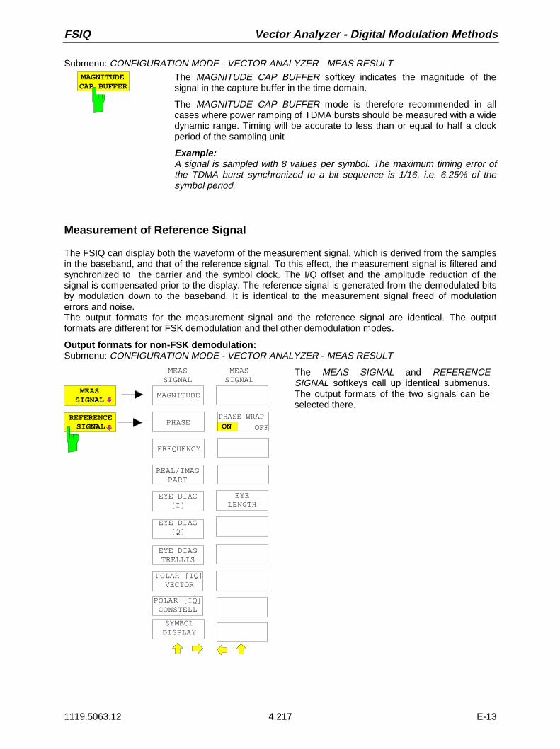
FSIQ Vector Analyzer - Digital Modulation Methods
1119.5063.12 4.217 E-13
Submenu: CONFIGURATION MODE - VECTOR ANALYZER - MEAS RESULTMAGNITUDECAP BUFFER
The MAGNITUDE CAP BUFFER softkey indicates the magnitude of thesignal in the capture buffer in the time domain.
The MAGNITUDE CAP BUFFER mode is therefore recommended in allcases where power ramping of TDMA bursts should be measured with a widedynamic range. Timing will be accurate to less than or equal to half a clockperiod of the sampling unit
Example:A signal is sampled with 8 values per symbol. The maximum timing error ofthe TDMA burst synchronized to a bit sequence is 1/16, i.e. 6.25% of thesymbol period.
Measurement of Reference Signal
The FSIQ can display both the waveform of the measurement signal, which is derived from the samplesin the baseband, and that of the reference signal. To this effect, the measurement signal is filtered andsynchronized to the carrier and the symbol clock. The I/Q offset and the amplitude reduction of thesignal is compensated prior to the display. The reference signal is generated from the demodulated bitsby modulation down to the baseband. It is identical to the measurement signal freed of modulationerrors and noise.The output formats for the measurement signal and the reference signal are identical. The outputformats are different for FSK demodulation and thel other demodulation modes.
Output formats for non-FSK demodulation:Submenu: CONFIGURATION MODE - VECTOR ANALYZER - MEAS RESULT
MEASSIGNAL
REFERENCESIGNAL
EYE DIAG[I]
POLAR [IQ]VECTOR
POLAR [IQ]CONSTELL
MAGNITUDE
EYE DIAG[Q]
EYE DIAGTRELLIS
REAL/IMAGPART
PHASE
FREQUENCY
MEASSIGNAL
EYELENGTH
SYMBOLDISPLAY
PHASE WRAP ON OFF
MEASSIGNAL
The MEAS SIGNAL and REFERENCESIGNAL softkeys call up identical submenus.The output formats of the two signals can beselected there.

Digital Modulation Methods - Vector Analyzer FSIQ
1119.5063.12 4.218 E-13
MAGNITUDE The MAGNITUDE softkey displays the magnitude of the demodulatedmeasurement or reference signal, which is normalized to 1, as a function oftime and symbol.
PHASE The PHASE softkey displays the phase of the measurement or referencesignal.
PHASE WRAPOFF ON
The PHASE WRAP ON/OFF softkey activates/deactivates a phase shift.
The phase of a signal can have very high values due to the modulation.Therefore, scaling should be very coarse to display the phase over manybits. FSIQ therefore offers the phase to be shifted by means of the PHASEWRAP ON/OFF softkey.
ON The FSIQ displays the phase in the range of ±180°. If the phaseexceeds +180°, for example, 360° is subtracted from the phasevalue so that >-180° is indicated. This avoids very high phasevalues to be displayed which would impair the reading accuracy.
OFF The phase is not shifted. It is displayed within the range of the Yaxis. Phase values above or below this range are cut off at thediagram edges.
FREQUENCY The FREQUENCY softkey displays the time or symbol-dependent frequencyresponse of the signal, i.e., the frequency-demodulated signal. The softkey isonly available for MSK demodulation.
The frequency display is suitable for measuring the frequency deviation byusing the markers.
REAL/IMAGPART
The REAL/IMAG PART softkey calls up the display of the real and imaginaryparts of the measurement or reference signal in separate diagrams.To this effect, the diagram is split up. The real part is displayed in the upperhalf whereas the imaginary part is displayed in the bottom half. The X axis(which is scaled in time units or symbols) is identical for the two diagrams.

FSIQ Vector Analyzer - Digital Modulation Methods
1119.5063.12 4.219 E-13
Fig. 4-25 Simultaneous display of inphase and quadrature component in a single diagram (here: screen A in split-screen display)
EYE DIAG[I]
EYE DIAG[Q]
EYE DIAGTRELLIS
The EYE DIAG [I], EYE DIAG [Q] and EYE DIAG TRELLIS softkeys selectthe various eye diagrams:
• eye diagram for the inphase signal,
• eye diagram for the quadrature signal and
• trellis diagram.
The eye diagram is the representation of inphase and quadrature signal(EYE DIAG [I] or EYE DIAG [Q]) as a function of time. It is triggered by thesymbol clock at the points of decision. The display range of the eyediagram (number of states on the time axis) is determined by softkey EYELENGTH.
The individual traces of the eye diagram are superimposed on each otheruntil the number of symbols specified with RESULT LENGTH is attained.The successive traces are the continuation of the trace written last, i.e. thetotal trace is displayed in a folded form. To obtain a complete eye diagram,all the states of a signal have to be traced at least once. The number ofeyes vertically corresponds to the number of modulation states less 1. Theeye aperture is a measure for differentiating between two decision levels. Asmall eye apertures indicate a high, large eye apertures a small bit errorrate.

Digital Modulation Methods - Vector Analyzer FSIQ
1119.5063.12 4.220 E-13
The trellis diagram is used for representing the states of continuous-phasemodulation methods (e.g. MSK). It indicates the phase versus time andpermits also phases above ±180° to be displayed. The trellis diagram issimilar to the eye diagram in that measured traces are superimposed ontoeach other in the display until the number of symbols defined by RESULTLENGTH is attained.
For the FSIQ, the trellis diagram is particularly useful for testing MSK andGMSK modulation. The symbols are spaced by 90°. A phase shift of +90°corresponds to logic 1, a shift of -90° to logic 0. A rising phase edgetherefore indicates a logic 1, a falling edge a logic 0. Same as with the eyediagram, the width of the trellis diagram is defined by EYE LENGTH. Toobtain a clear display, a minimum of 5 symbols should be selected asdisplay width.
The number of POINTS PER SYMBOL should be as high as possible toobtain a continuous trace in the eye diagram. 8 to 16 points arerecommended.
Ref Lvl 10 dBm
2
T1
-20 SYMBOLS 200
Meas SignalEye [Q]Demod DQPSK
CF 890.195 MHzSR 15.3 kHz
LN
Fig. 4-26 Eye diagram over 200 symbols of a DQPSK-modulated signal. Display range is five symbols.
EYELENGTH
The EYE LENGTH softkey determines the display width of the eye diagramin symbols. The number of symbols is entered in the field.
At least one symbol length or two states are required for a complete eye. Tobe able to detect the errors particularly at the zero crossings, two to fivesymbols are recommended. The number of symbols is limited with RESULTLENGTH. In the case of EYE LENGTH = RESULT LENGTH, however, thesignal versus time is displayed, the eyes are no longer visible.
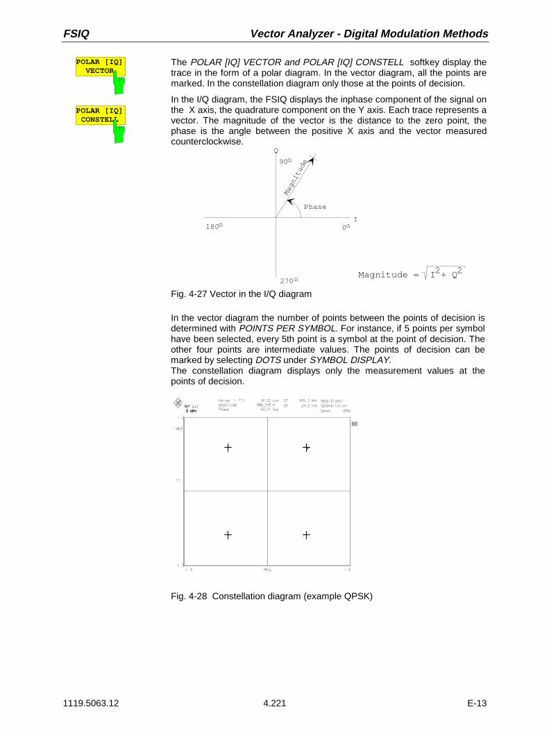
FSIQ Vector Analyzer - Digital Modulation Methods
1119.5063.12 4.221 E-13
POLAR [IQ]VECTOR
POLAR [IQ]CONSTELL
The POLAR [IQ] VECTOR and POLAR [IQ] CONSTELL softkey display thetrace in the form of a polar diagram. In the vector diagram, all the points aremarked. In the constellation diagram only those at the points of decision.
In the I/Q diagram, the FSIQ displays the inphase component of the signal onthe X axis, the quadrature component on the Y axis. Each trace represents avector. The magnitude of the vector is the distance to the zero point, thephase is the angle between the positive X axis and the vector measuredcounterclockwise.
0
90
180
270
o
o
o
oMagnitude
Phase
I
Q
Magnitude = I + Q22
Fig. 4-27 Vector in the I/Q diagram
In the vector diagram the number of points between the points of decision isdetermined with POINTS PER SYMBOL. For instance, if 5 points per symbolhave been selected, every 5th point is a symbol at the point of decision. Theother four points are intermediate values. The points of decision can bemarked by selecting DOTS under SYMBOL DISPLAY.The constellation diagram displays only the measurement values at thepoints of decision.
Fig. 4-28 Constellation diagram (example QPSK)
Digital Modulation Methods - Vector Analyzer FSIQ
1119.5063.12 4.222 E-13
SYMBOLDISPLAY
The SYMBOL DISPLAY softkey marks the symbol decision points in thedisplayed trace. The desired form of highlighting can be selected from thetable. Points of decision can be marked by vertical lines or by means of dots.
SYMBOL DISPLAY
offDotsLines
With off selected, the points of decision are not marked. When Dots areselected, points are drawn on the trace and for Lines, (except for vector andconstellation diagrams) vertical lines are drawn between the X axis and thetrace.
For vector and constellation diagrams dots are inserted with Dots and Lines.
For the constellation diagram dots are also displayed even in the off mode.
This function is used for displaying the time characteristic of measurementresults, e.g. as an I/Q characteristic or error signal.
Output formats with FSK demodulation:
Submenu: CONFIGURATION MODE - VECTOR ANALYZER - MEAS RESULTS
MEASSIGNAL
REFERENCESIGNAL
MAGNITUDE
FREQUENCY
MEASSIGNAL
EYELENGTH
SYMBOLDISPLAY
EYE DIAG[FREQ]
MAGNITUDEThe MAGNITUDE softkey displays the magnitude of the demodulatedmeasurement or reference signal as a function of time and symbol.

FSIQ Vector Analyzer - Digital Modulation Methods
1119.5063.12 4.223 E-13
FREQUENCY The FREQUENCY softkey displays the time- or symbol-dependentfrequency response of the signal, i.e., the frequency-demodulated signal.
The frequency display is for instance suitable for measuring the frequencydeviation by using the markers.
EYE DIAG[FREQ]
The EYE DIAG [FREQ] softkey displays the frequency-demodulated signalas a function of time. This signal is triggered by the symbol clock at thepoints of decision. The display range of the eye diagram (number of stateson the time axis) is determined by EYE LENGTH.
The individual traces of the eye diagram are superimposed on each otheruntil the number of symbols specified with RESULT LENGTH is attained.The successive traces are the continuation of the trace written last, i.e. thetotal trace is displayed in a folded form. To obtain a complete eye diagram,all the states of a signal have to be traced at least once. The number ofeyes corresponds to the number of modulation states less 1. The eyeaperture is a measure for differentiating between two decision levels. Asmall eye apertures indicate a high, large eye apertures a small bit errorrate.
EYELENGTH
The EYE LENGTH softkey determines the display width of the eye diagram insymbols. The number of symbols is entered in the field.
At least one symbol length or two states are required for a complete eye. Twoto five symbols are recommended however to detect the errors particularly atthe zero crossings. The number of symbols is limited by RESULT LENGTH.In the case of EYE LENGTH = RESULT LENGTH, however, the signalversus time is displayed, the eyes are no longer visible.
SYMBOLDISPLAY
The SYMBOL DISPLAY softkey marks the symbol decision points in thedisplayed trace. The desired form of highlighting can be selected from thetable. Points of decision can be marked by vertical lines or by dots..
SYMBOL DISPLAY
offDotsLines
With off selected, the points of decision are not highlighted. When Dots areselected, points are drawn on the trace and with Lines selected (except forvector and constellation diagrams), vertical lines are drawn between the Xaxis and the trace.

Digital Modulation Methods - Vector Analyzer FSIQ
1119.5063.12 4.224 E-13
Measurement of Modulation Errors
The FSIQ evaluates the modulation errors by comparing the measurement signal with the internallygenerated ideal reference signal. The output formats differ depending on whether FSK demodulation isselected or not. The different output formats of the error are selected by means of the ERROR SIGNALsoftkey.
Non-FSK demodulation:
The modulation error of the measurement signal can be displayed separately, i.e. according tomagnitude and phase, as I and Q error, error vector magnitude or, in polar diagrams, as vector orconstellation diagram.
The magnitude and phase error are determined according to the following equations:
Error signal magnitude = I Q2 2+ - I Qref2
ref2+ and
Error signal phase = arctanQI
arctanQI
ref
ref− , where
the real and imaginary part of the error signal are given as follows
Error signal real part = I - Iref and
Error signal imag part = Q - Qref
The magnitude of the error vector (error vector magnitude) is
EVM = ( I I ) ( Q Q )ref2
ref2− + −
I, Q = measured I/Q componentIref, Qref = I/Q components ideally calculated from the bit sequence.
The following vector diagram indicates the different types of errors resulting from the measurementsignal and the reference signal:
Referencevector
Measuredsymbol point
Idealsymbol point
Error vector
Amplitudeerror
Phaseerror
Inphase component
Quadraturecomponent
QQref
Iref I
Error vector shifted to its origin(polar diagram of error vector)
Phase oferror vector
Fig. 4-29 Graphic display of modulation errors by means of a point of decision

FSIQ Vector Analyzer - Digital Modulation Methods
1119.5063.12 4.225 E-13
Submenu: CONFIGURATION MODE - VECTOR ANALYZER - MEAS RESULT
ERRORSIGNAL MAGNITUDE
PHASE
FREQUENCY
ERRORSIGNAL
SYMBOLDISPLAY
REAL/IMAGPART
ERROR VECTMAGNITUDE
POLAR [IQ]VECTOR
POLAR [IQ]CONSTELL
The ERROR SIGNAL softkey opens the submenu for selectingthe type of error to be displayed.
The following types of error representation are available
• amplitude error (MAGNITUDE)
• phase error (PHASE)
• frequency error (FREQUENCY)
• error if the real part (REAL/IMAG PART) and
• error of the imaginary part (REAL/IMAG PART)
• magnitude error (ERROR VECTOR MAGNITUDE)
For error representation the FSIQ compares all the points of themeasurement and reference signal and displays them in theerror diagram (except for POLAR [IQ] CONSTELL). Thus, thenumber of measurement results depends on the number ofpoints per symbol. If only the errors are to be evaluated at thepoints of decision, the number of points per symbol has to beset to one.
To maintain the correct error for discontinuous transmission,e.g. for TDMA methods, make sure that only valid symbols aredisplayed. The result length and the trigger condition have to beset appropriately.
MAGNITUDEThe MAGNITUDE softkey starts the point by point comparison of themagnitude of the measurement signal with the magnitude of the ideal signal.The difference of the two magnitudes is displayed..
PHASEThe PHASE softkey starts the point by point comparison of the phase of themeasurement signal with the phase of the ideal signal. The difference of thetwo phases is displayed as phase error.
FREQUENCYThe FREQUENCY softkey displays the frequency error. The frequencyresponse of the measurement signal is compared with that of the idealreference signal and the difference between the two responses is displayedas a function of time and symbol. The softkey is only available for MSKdemodulation .
REAL/IMAGPART
The REAL/IMAG PART softkey displays the error of the real and imaginarypart in separate diagrams. To this effect, the measurement diagram is splitup. The real part is displayed in the top half and the imaginary part in thebottom half. The X axis (time or symbols) is identical for the two diagrams.

Digital Modulation Methods - Vector Analyzer FSIQ
1119.5063.12 4.226 E-13
ERROR VECTMAGNITUDE The ERROR VECT MAGNITUDE softkey displays the magnitude of the error
vector versus time or symbols.
POLAR [IQ]VECTOR
POLAR [IQ]CONSTELL
The POLAR [IQ] VECTOR and POLAR [IQ] CONSTELL softkeys display theerror vector in the polar diagram. The error vector diagram and the errorconstellation diagram.
With these forms of representation, the points of decision are all shifted backto the origin and are laid on top of each other. The errors at the points ofdecision can thus be seen at a glance.
FSK demodulation:
Submenu: CONFIGURATION MODE - VECTOR ANALYZER - MEAS RESULT
ERRORSIGNAL MAGNITUDE
FREQUENCY
ERRORSIGNAL
The ERROR SIGNAL softkey opens the submenu for selectingthe type of error to be displayed.
The following quantities can be displayed:
• Magnitude error (MAGNITUDE)
• Frequency error (FREQUENCY)
MAGNITUDEThe MAGNITUDE softkey starts the point by point comparison of themeasurement signal with the magnitude of the ideal signal.The difference of the two magnitudes is displayed.
FREQUENCY
The FREQUENCY softkey displays the frequency error.The frequency response of the measurement signal is compared with that ofthe ideal reference signal and the difference between the two responses isdisplayed as a function of time and symbol.
FSIQ Vector Analyzer - Digital Modulation Methods
1119.5063.12 4.227 E-13
Symbol Table and Table of Modulation Errors
The symbol table and the table with modulation errors are indicated in the same display. In this case, thetwo tables are assigned to a trace. Similar to the trace display, the corresponding trace can be frozen(VIEW) or faded out (BLANK).The range for the error calculation can be limited by means of the time lines (TIME LINES 1/2; MARKERSEARCH menu, SEARCH LIM ON/OFF menu).If only one window is displayed, the symbol table is assigned to trace 1 and the error table to trace 2.
Submenu: CONFIGURATION MODE - VECTOR ANALYZER - MEAS RESULT
SYMB TABLE/ERRORS
The SYMB TABLE / ERRORS softkey displays a table of demodulated bitsand a table of modulation errors of the measured signal.
The symbol table shows the demodulated bits of the signal. The number ofbits is defined under RESULT LENGTH in the same menu. Bits can berelated to the traces (in split screen mode) by means of the markercoupling. The marker on the trace and the associated symbol are markedat the same time.The indicated modulation errors differ depending on whether FSK signalsare demodulated or one of the other digital demodulators is active.
The following parameters are indicated as sum errors of the modulation(except with FSK demodulation):
• Frequency error
• Magnitude error
• Phase error
• Error vector magnitude
• I/Q offset
• I/Q imbalance and
• Amplitude droop
• Rho factor.
The FSIQ evaluates these errors within the result length or in a rangelimited by the vertical lines within the result length.
With FSK demodulation, the following parameters are indicated as sumerrors of the modulation:
• Frequency error
• Magnitude error
• FSK deviation
• FSK deviation error
The entered reference deviation is indicated in addition (FSK REFDEVIATION).

Digital Modulation Methods - Vector Analyzer FSIQ
1119.5063.12 4.228 E-13
Non-FSK demodulations:
Fig. 4-30 Symbol table and table of sum errors (not FSK demodulation)
Description of errors as follows (not FSK signals):
Magnitude error: The magnitude error is the amplitude difference of the I/Q components ofmeasurement signal and reference signal at the points of decision. For MSKmodulations, all the points are considered in the calculation. It is a measure for thequality of the amplitude component of the modulated signal.
Phase error: The phase error is the phase difference of the I/Q components of measurementsignal and reference signal at the points of decision. For MSK modulations, all thepoints are considered in the calculation.
Vector error: The error vector magnitude is the magnitude of the error vector which links themeasured I and Q value in the complex plane to the ideal I and Q value at the pointsof decision. The error is calculated according to the following equation:
Error vector magnitude (EVM) = I Qerr2
err2+ , where
Ierr = error of the inphase signal andQerr = error of the quadrature signal
Frequency error : The frequency error is the deviation of the FSIQ center frequency from themeasured carrier frequency. It is derived from the frequency shift to be effected forsynchronization to the carrier. The reference error of the FSIQ is also part of thefrequency error.
Amplitude droop: The amplitude droop indicates the amplitude variation of the signal between the twosymbols at the points of decision in dB. This parameter is very important for TDMAsignals and is a measure for the quality of pulse modulation.

FSIQ Vector Analyzer - Digital Modulation Methods
1119.5063.12 4.229 E-13
I/Q offset: The I/Q offset is a measure for the LO feedthrough with analog I/Q modulators. Itcan be seen through a shift of the zero point in the constellation diagram. Without LOfeedthrough (LO 100 % suppressed), the I/Q offset is zero. It is measured at thepoints of decision.
I/Q offset
I
Q
Fig. 4-31 Constellation diagram with I/Q offset
Amplitude and vector errors are given in %, phase errors in degrees (deg) or radian(rad). Prior to calculation, the measurement result is normalized in the vector orconstellation diagram to a circle around the center of the group mid-points, the radiuscorresponding to the mean distance of all group mid-points to the center. This circleis defined as a unit circle with the radius 1 (see NORMALIZE function in theMODULATION PARAMETER menu)Then, the errors at the points of decision are determined and the rms of theindividual error values is calculated. Since the constellation diagram is normalized,the result is the rms value of the error in %.
I/Q imbalance: The I/Q imbalance is a measure for the symmetry of the I/Q modulator to bemeasured. The I/Q gain error is the result of unequal gain factors in the I and Q pathof the transmitter. The I/Q imbalance is calculated from the square root of thequotient of the vector magnitude for the wanted and interfering signals averagedover all points of decision:
[ ]I / Q imbalance = 100 * Signal vector
%2
2i 1
n Interferencevector
=∑
Q
I
Ideal constellation point
Offset-correctedcenter
Signal vector
Interference vector
Fig. 4-32 Constellation diagram with I/Q imbalance

Digital Modulation Methods - Vector Analyzer FSIQ
1119.5063.12 4.230 E-13
Rho factor: Similar to the error vector magnitude, the Rho factor is a measure for the quality ofdigital modulation. It is determined by measurement of the normalized correlatedpower between the measured signal and reference signal (IS95-CDMA to USstandard IS-98) and is designated as waveform quality factor.The Rho factor can assume a maximum value of 1.0 (measured signal andreference signal are a 100% identical).
FSK demodulation:
Fig. 4-33 Symbol table and table of sum errors (FSK demodulation)
The various errors and measured values have the following meaning (FSK signals):
FSK deviation: The FSK deviation is determined by the square difference between measure-ment and reference signal being minimized. The reference signal is based isformed on the basis of the known demodulated bits and modulationparameters. The frequency offset is determined separately and indicatedunder Freq Error. The frequency error is not considered in the indicated FSKdeviation.
FSK deviation error: The FSK deviation error is the deviation difference between the measuredsignal and the reference signal, measured as an rms and peak value over allsymbols. Frequency errors (frequency offset) are part of the indicated FSKdeviation error.
Normalize ON The entered FSK reference deviation is used for scaling ofthe reference signal.
Normalize OFF The reference signal is automatically derived from themeasurement signal on the basis of the knowndemodulated symbols and modulation parameters so as toensure maximum agreement between measurement andreference signal.
Magnitude error: With FSK, the magnitude error is the deviation of the individual amplitudes ofthe AM envelope from the mean (rms) carrier amplitude, measured as an rmsvalue over all symbols displayed and as a peak value normalized to the rmsamplitude in %.
Frequency error: The frequency error is the deviation of the FSIQ center frequency from themeasured carrier frequency. It is derived from the frequency shift to beeffected for synchronization to the carrier. The reference error of the FSIQ isalso part of the frequency error.

FSIQ Vector Analyzer - Digital Modulation Methods
1119.5063.12 4.231 E-13
Selecting Memory Size, Demodulation Length and Display Range
The size of the capture buffer containing the stored samples, the frame length to be demodulated anddisplayed and the number of points per symbol can be set to allow an adaptation to the measurement orto optimize the measurement speed.At the beginning of a measurement, the FSIQ stores the samples into the capture buffer which can beselected between 1 and 16-k symbols. It then tries to find the suitable frame length for furtherprocessing according to the trigger condition (FIND BURST). The frame length to be displayed or usedfor error calculation is defined with RESULT LENGTH. It can be positioned within the frame length bysynchronization sequence triggering (FIND SYNC).
MEMORY SIZE
FRAMELENGTH
RESULTLENGTH
Trigger:Free RunVideoExtern
Find Burst Find Sync
Finally, the number of points per symbol can be set. This number defines the maximum number ofsymbols that can be processed in the FRAME LENGTH.
Submenu CONFIGURATION MODE - VECTOR ANALYZER - MEAS RESULT
MEMORYSIZE
The MEMORY SIZE softkey calls up a table in which the number of samplessaved in the capture buffer per measurement is determined. Within thememory size a burst, e.g. in the case of a TDMA signal, can be searchedfor (FIND BURST function).
MEMORY SIZE
16384 POINTS 8192 POINTS 4096 POINTS 2048 POINTS 1024 POINTS
Only the symbols entered under FRAME LENGTH are used fordemodulation.
For symbol rates > 1 MHz the data are stored in the memory without priorfiltering and reduction. The maximum memory size is therefore reduced to4096 points.

Digital Modulation Methods - Vector Analyzer FSIQ
1119.5063.12 4.232 E-13
FRAMELENGTH
The FRAME LENGTH softkey calls up a table in which the number ofsymbols to be demodulated or evaluated is defined.
LENGTHFRAME
1600 SYMBOLS1500 SYMBOLS1400 SYMBOLS1300 SYMBOLS1200 SYMBOLS1100 SYMBOLS1000 SYMBOLS 900 SYMBOLS 800 SYMBOLS 700 SYMBOLS 600 SYMBOLS 500 SYMBOLS 400 SYMBOLS 300 SYMBOLS 200 SYMBOLS 100 SYMBOLS
With up to 4 points per symbol a maximum of 1600 symbols can bedemodulated per measurement and their modulation parameters measured.With 8 points per symbol up to 800 symbols, and with 16 points per symbolup to 400 symbols can be handled.
With symbol rates >1 MHz to ≤1.20 MHz a maximum of 500 symbols can behandled. This is due to the fact that the data are stored in the memory withoutprior reduction. The subsequent reduction limits the FRAME LENGTH in thespecified frequency range.
The frame length markedly influences the time required for evaluating ameasurement signal. It is therefore recommended to choose the frame lengthas short as possible. 400 symbols, for example, are sufficient for determiningthe phase error of a GSM burst as only 147 symbols are to be evaluated. TheFSIQ automatically searches for the correct time domain by trigger functionsFIND BURST and FIND SYNC .
The choice of the frame length influences the maximum number of points persymbol. With up to 400 symbols a maximum of 16 points, with >400 up to800 symbols a maximum of 8 points and with >800 symbols a maximum of 4points per symbol is possible.
With symbol rates >1MHz to ≤1.20 MHz, the maximum number ofsymbols is 500!

FSIQ Vector Analyzer - Digital Modulation Methods
1119.5063.12 4.233 E-13
RESULTLENGTH
The RESULT LENGTH softkey opens a window for defining the number ofsymbols for display on the screen.
The maximum result length is identical to the frame length.
With the FIND SYNC function activated (synchronization to bit sequences inthe signal), the maximum result length can be reduced (or the frame lengthincreased).
POINTS PERSYMBOL
The POINTS PER SYMBOL softkey opens a window for entering the numberof points per symbol.
1, 2, 4, 8 and 16 points per symbol can be selected. With one point persymbol, each point in the display corresponds to a symbol sampled at thetime of decision. With n points per symbol, each n-th value is a point ofdecision. With 1 and 2 points per symbol, the FSIQ demodulates with 4 pointsper symbol for reasons of accuracy. Only one or two samples are output,however.For up to 4 points per symbol, a frame length of max. 1600 symbols ispossible, with 8 points per symbol a frame length of max. 800 symbols andwith 16 points per symbol of max. 400 symbols.
In the case of MSK demodulation, the number of points per symbolinfluences the result of the error measurement as all the points areconsidered in the calculation. With all other demodulators, only the valuesmeasured at the points of decision are taken into account. For GSM(DCS1800 and PCS1900) less than 4 points per symbol should not be used.
The number of points per symbol largely influences the measurement speedattained during the evaluation of the signal. If high measurement rates are tobe attained for automatic tests, for example, a low number of points persymbol is recommended.

Frequency Settings - Vector Analyzer FSIQ
1119.5063.12 4.234 E-13
Frequency Settings- FREQUENCY Key Group
Setting the Frequency - CENTER Key
In vector signal analysis, FSIQ is always set to a fixed frequency. The RF signal is analyzed byconverting the signal into the complex baseband.
The frequency of FSIQ is set in the same way as in the spectrum analysis mode, i.e. with the CENTERkey in the FREQUENCY key group.
FREQUENCY CENTER menu
CENTERFREQUENCY
CENTER
OFFSETFREQUENCY
CENTER SPAN
START STOP
FREQUENCY The CENTER key calls up the entry window for thecenter frequency .
For the demodulation of digitally modulated signals, theFSIQ frequency has to be accurately set to the frequency(carrier) of the signal to be measured so thatsynchronization to the carrier is possible. The requiredsetting accuracy depends on the symbol rate and mustnot exceed 2% of the symbol rate.
FREQUENCYOFFSET
The FREQUENCY OFFSET softkey activates the input of a frequencyoffset which can be added to the frequency-axis labeling. The displayedfrequency is shifted by the frequency offset. The range of values for theoffset is -100 GHz to +100 GHz.
Setting the Frequency Span - START, STOP, and SPAN Key
The SPAN, START and STOP keys are not assigned in vector signal analysis for the demodulation ofdigitally modulated signals since FSIQ is always set to a fixed frequency and the measurement resultsare displayed in the time domain. The analysis bandwidth by which the demodulation is performed ispredefined by the symbol rate and the number of sampling points.

FSIQ Vector Analyzer - Level Display/RF Input
1119.5063.12 4.235 E-13
Setting the Level Display and Configuring the RF Input
Setting the Reference Level
With spectrum analysis (ANALYZER mode) of the FSIQ, the level applied to the RF input is alwaysindicated on the display so that one can see the relationship between the setting of the reference leveland the measurement results on the display.
With vector signal analysis, this only applies to operating mode DIGITAL DEMODULATION, MAG CAPBUFFER In operating mode DIGITAL DEMODULATION with activated demodulation , e.g. when thedemodulated signal is displayed this relationship is not obvious. That is why a strict distinction has to bemade between setting the reference value which is an important reference point for the measured-value display and the reference level relating to the RF input.
To obtain a maximum dynamic range it is important for the signal level at the A/D converter to be closeto the maximum level of the converter. The maximum level of the converter corresponds to thereference level (REF LEVEL) in the spectrum analysis mode. This means that a signal whose amplitudeattains the reference level in the spectrum analysis mode is ideal for the vector analyzer mode. Animportant factor is the sum level within the IF bandwidth (=ANALOG BANDWIDTH in vector signalanalysis mode) of the analyzer.
The reference level can be manually set by checking the signal level in the spectrum analysis modeagainst the set frequency (at the same IF bandwidth!) and by operating the vector analyzer with thesame setting.The FSET can perform this in vector signal analysis but also by a single automatic setting of thereference level.
Certain settings of the spectrum analysis mode such as center frequency, reference level andattenuation are taken over by the vector signal analysis. Parameters that are not affected are span (invector signal analysis, the frequency span has a different meaning: it corresponds to the analysisbandwidth and is thus independent in the two operating modes), resolution bandwidth, ref. level offset aswell as trace and trigger settings
The reference value (REF VALUE) of the vector signal analysis is the reference point for scaling themeasured value. Apart from DIGITAL DEMODULATION-RESULT DISPLAY-MAGNITUDE CAPBUFFER it is decoupled from the setting of the reference level, i.e. a direct relationship cannot bedetermined.
With the REF key, the reference level can be set like in the spectrum analysis mode.
The RANGE key calls up a menu comprising all the settings required for scaling the measured valuesuch as auto scaling (AUTO SCALE), scaling (Y per Div), reference values in the X and Y direction(X/Y_REF VALUE) and the relative position of the reference value on the diagram (REF VALUEPOSITION).

Level Display/RF Input - Vector Analyzer FSIQ
1119.5063.12 4.236 E-13
LEVEL REF Menu
LEVEL
REF
RA E
REF LEVEL
REF LEVEL
MIXERLEVEL
ATTEN AUTOLOW DIST
ATTEN AUTOLOW NOISE
ATTEN AUTONORMAL
RF ATTENMANUAL
RF LEVELOFFSET
ATTEN STEP1dB 10dB
The REF key calls up the menu for setting the referencelevel and at the same time activates the level entry field.
Operation and softkey functions identical to analyzermode:
ATTEN STEP 1dB/10dBRF ATTEN MANUALATTEN AUTO NORMALATTEN AUTO LOW NOISEATTEN AUTO LOW DISTMIXER LEVEL
Softkey ATTEN STEP 1dB/10dB is only available whenthe FSIQ is equiped with option FSE-B13, 1dBattenuator
REF LEVEL The REF LEVEL softkey activates entry of the manual gain of the FSIQ. Fora maximum dynamic range, it has to be ensured that the A/D converter isdriven to its full range but not overdriven.
In the vector analyzer mode, this is indicated by the messages IF OVLD(overload) and UNLD (underrange) which inform on the dynamic rangewhen measured data are read in.When IF OVLD is displayed, the instrument or the A/D converter isoverdriven during data read-in and entered data are invalid.With UNLD displayed, the A/D converter is not sufficiently driven duringdata read-in (level <-6 dB of full range). Indicated values may have areduced dynamic range, i.e. have a greater error.
For a correct level setting in the case of IF OVLD, reduce the REF LEVEL(continuous sweep mode) in sufficiently small steps (e.g. 2 dB) until themessage disappears.Proceed analogously for increasing the REF LEVEL when UNLD isdisplayed until the message disappears.The maximum dynamic range is attained approx. 1 dB below the OVLDlevel.
The reference level can also be set to the test signal in the spectrumanalysis mode at the same IF bandwidth as in the vector signal analysismode (with COUPLED: ANALOG BW AUTO also 10 kHz) and vector signalanalysis can then be selected again.

FSIQ Vector Analyzer - Level Display/RF Input
1119.5063.12 4.237 E-13
REF LEVELOFFSET
The REF LEVEL OFFSET softkey activates the entry of a level offset.It is added to the measured level, irrespective of the unit used. The scalingof the Y axis is changed accordingly.This function is used to take into account the effect of an external attenuatoron the displayed values.The setting range is ± 200 dB in 0.1 dB steps.
Setting the Display Range and Scaling - RANGE Key
The menu for setting the display range is different from that of the spectrum analysis mode.
LEVEL RANGE menu
LEVEL
RANGEREF VALUEY AXIS
REF VALUEPOSITION
LEVELRANGE
Y PER DIV
SCALEUNIT
REF VALUEX AXIS
REF
The RANGE key calls up a menu comprising all theimportant display parameters such as reference value,scaling etc.
Y PER DIV The Y PER DIV softkey calls for the entry of the vertical scaling in thecurrent unit.
For vector or constellation diagrams, the corresponding X scaling is linkedwith Y scaling:
X PER DIV =5/4 *(Y PER DIV)
Reason: The diagram has 400 x 500 points. In case of a free X scaling circles would be reproduced as ellipses.
REF VALUEY AXIS
REF VALUEX AXIS
The REF VALUE Y AXIS and REF VALUE X AXIS softkeys call for the entryof the reference value for the Y or X axis of the measurement diagram. TheREF VALUE X AXIS softkey is only displayed if a polar diagram has beenselected for the trace.
The reference value is entered in the corresponding unit of the diagram(See UNIT).

Level Display/RF Input - Vector Analyzer FSIQ
1119.5063.12 4.238 E-13
Example 1: Constellation diagram: y reference value: +1.20; x reference value: - 0,35(reference position: 50%)
Fig. 4-33 Representation of the reference values in the constellation diagram
Example 2: Display of I and Q signals: Y reference value: -0.2 REF position: 50%
Fig. 4-34 Display of I and Q signals

FSIQ Vector Analyzer - Level Display/RF Input
1119.5063.12 4.239 E-13
REF VALUEPOSITION
The REF VALUE POSITION softkey opens a window for setting the referencepositions diverging from the basic setting.
REF VALUE POSITION defines the position of the reference value. It normallylies at 100%, i.e. the maximum displayable Y value is also the reference value.It is best to use this setting for displaying the magnitude which is then the basicsetting.
When, for example, the timing of I/Q signals or the phase spectrum is displayedit might be desirable to set the reference value to the center. The basic settingis thus 50% (also for polar diagrams).
Submenu: LEVEL RANGE
UNITY UNITLOG[dB]
Y UNITLINEAR
SCALE
Y UNIT dBm
Y UNIT VOLT
Y UNIT WATT
UNIT DEG
UNIT RAD
X UNITTIME
X UNITSYMBOL
SCALEUNIT
The SCALE UNIT softkey calls up a submenu in whichthe unit of the Y axis and the X axis are set.
The units offered depend on the setting of RESULTDISPLAY and MEAS RESULT.
The logarithmic unit dB (Y UNIT [dB] ) or dimensionlesslinear units (Y UNIT LINEAR) are permissible for the Yaxis.
ERROR and MAGNITUDE are displayed in the followingunits:
Y UNIT LOG [dB]: dB
Y UNIT LINEAR : %.
Errors of REAL/IMAG PART are always displayed in %.
Phase errors are displayed in DEG or RAD, frequencyerrors in Hz.
Units which are not allowed in the current operatingmode are disabled.
In polar diagrams, the units for the X-axis and Y-axis areequal. The softkeys X UNIT... are suppressed.
The time representation, the units time (X UNIT TIME) orsymbols (X UNIT SYMBOLS) can be used for theX-axis. The softkey for the X-axis unit are only shown intime representation.
If a marker is active, the marker values are read out inthe current scale units.
Only for MEAS RESULT: MAGNITUDE CAP BUFFER:
Possible display units: YUNIT LOG [dB], YUNIT LINEAR,dBm , Volt and Watt.

Level Display/RF Input - Vector Analyzer FSIQ
1119.5063.12 4.240 E-13
Table 4-4 Allocation table of selectable units or, in case of error display, of the displayed units inoperating mode DIGITAL DEMODULATION depending on RESULT DISPLAY and MEASRESULT
RESULTDISPLAY
-------------------MEAS RESULT
MAGNITUDECAP
BUFFER
MAGNI-TUDE
PHASE FREQUENCY[with FSK and
MSK only]
REAL/IMAGPART
EYEDIAG
POLAR[IQ]
VECTOR
POLAR[IQ]
CONSTELL
MEASSIGNAL
Y_UNITLINEARY-UNITLOG[dB]dBmVOLTWATT
Y_UNITLINEAR
Y-UNITLOG[dB]
DEG/RAD Hz Y_UNITLINEAR
Y_UNITLINEAR
Y_UNITLINEAR
Y_UNITLINEAR
REFERENCESIGNAL
-- likeMEASSIGNAL
likeMEASSIGNAL
likeMEASSIGNAL
likeMEASSIGNAL
likeMEASSIGNAL
likeMEASSIGNAL
likeMEASSIGNAL
ERROR
SIGNAL
-- [%]
[dB]
PHASEDEG/RAD
Hz -- - - -
VECTORERROR
-- [%]
[dB]
DEG/
RAD
-- [%] - [%] [%]
Configuration of RF Input in Vector Signal Analysis
This section is identical to that of the spectrum analysis mode.
INPUT
ATTEN AUTONORMAL
ATTEN AUTOLOW NOISE
ATTEN AUTO LOW DIST
MIXERLEVEL
INPUTSELECT
INPUT
RF ATTEN MANUAL
ATTEN STEP1 dB 10dB
Note: The operating mode recommended for the vectoranalyzer input is ATTEN AUTO NORMAL.If ATTEN AUTO LOW NOISE is set (or forMIXER LEVEL ≥ –30 dB), the higher signalmodulation occuring within the IF-bandwidthcauses a nonlinear behavior in the IF branch.This leads to increased measurement errors, inparticular for modulation types with a non-constant level (e.g. PSK).
FSIQ Vector Analyzer - Main Marker
1119.5063.12 4.241 E-13
MARKER Key Group
In the vector analyzer mode markers may be used for highlighting points in a trace and for reading outmeasured values.For detailed information see section ’Marker Function’ in chapter ’Analyzer Mode’.In the vector analyzer mode marker softkey functions depend on the selected measurement.
Main Marker - NORMAL Key
The main markers and their functions are selected with the NORMAL key.
MARKER NORMAL menu
MARKER
NORMAL SEARCH
D TA MKR
MARKERNORMAL
MARKER 2
MARKER 1
POLAR MKRR/I MA/PH
MARKER INFO
ALL MARKER OFF
COUPLEDMARKERS
POLAR MKRDEG RAD
The NORMAL key calls up a menu comprising allstandard marker functions.
Activated marker functions are indicated by a darkbackground of the softkeys. If no marker is activatedwhen the NORMAL key is pressed, MARKER 1 isactivated as a reference and set to the maximum valuein the curve. (automatic switch-on of peak searchfunction provided at least one trace is active; not withpolar diagram). In all other cases the reference marker isactivated but no automatic peak search is performed.
In the marker field the marker position (time), themeasured value or values (in the case of a complexdisplay) and the trace relevant for the marker (here [T1])are displayed.
Example:Marker display in the digital demodulation and I/Q displaymode:
Marker 1 [T1/3] 22.3 µs Real 0.998Imag -0.124
When the symbol table is displayed (softkey SYMBTABLE/ERRORS in submenu MEAS RESULT) themarker moves from symbol to symbol in the table. Theposition of the marker is indicated by a dark backgroundand its numerical value in inverse video.
In the marker field, the marker position and the decimalvalue of the symbol are displayed.
MARKERNORMAL
MARKER 2
MARKER 1
The MARKER 1 and MARKER 2 softkeys switch the respective marker on oroff or define it as an entry marker (reference marker).

Main Marker - Vector Analyzer FSIQ
1119.5063.12 4.242 E-13
POLAR MKRR/I MA/PH
The POLAR MARKER R/I / MA/PH softkey selects magnitude and phase(MA/PH) or real and imaginary part (R/I) for the numeric result display in thepolar diagram.When measured values are indicated versus time this softkey is disabled.
POLAR MKRDEG RAD
The POLAR MARKER DEG/RAD softkey selects the unit degree (DEG) orradiant (RAD) for indication of the phase of the marker in the respectivediagram.
COUPLED MARKERS
The COUPLED MARKER softkey couples markers (and delta markers) ofdifferent traces in the combined display mode REAL/IMAG PAR. In this casethe X position of corresponding markers is identical.This allows complex marker values to be displayed which correspond to thepolar display.
Marker 1 6.75 SYM [T1/3]RE 0.895IM 1.002If several windows are displayed, the markers of all windows are coupledwhen the COUPLED MARKERS function is active.

FSIQ Vector Analyzer - Main Marker
1119.5063.12 4.243 E-13
ALL MARKEROFF
The ALL MARKER OFF softkey switches all markers including reference anddelta markers off and closes the marker entry window. In addition theMARKER INFO softkey is switched off.
MARKERINFO
The MARKER INFO softkey allows several markers to be displayed in thegrid, in addition to the display of marker information in the marker field of thediagram headline.In the top right-hand corner of the grid the two markers or delta markers aredisplayed with symbols ∇/∆, marker number (1, 2), position and measuredvalue (may be complex). The number of symbols for specifying the markerposition is limited in certain cases.
If there are not enough lines for displaying all active markers and deltamarkers, the markers are listed first and then the delta markers.
In the SPLIT SCREEN display this list is divided into two lists, one forSCREEN A and one for SCREEN B.

Delta Marker - Vector Analyzer FSIQ
1119.5063.12 4.244 E-13
Delta Marker - DELTA Key
MARKER DELTA menu
NORMAL SEARCH
MARKER
DELTA MKR
DELTA MKRABS REL
ALL DELTAOFF
DELTAMARKER
DELTA 1
DELTA 2
The DELTA key in the MARKER key group selects thedelta markers.
Delta markers are always referenced to the activereference marker . When no marker is active, switchingon a delta marker automatically activates marker 1. Deltamarkers are displayed as an unfilled symbol . Whenthe delta marker is active for entry, a filled symbol isdisplayed.
DELTA 2
DELTA 1
DELTAMARKER
The DELTA 1 and DELTA 2 softkeys switch on delta markers 1 and 2.
Operation of delta markers is identical to that of markers. When a deltamarker is switched on, all entries apply to the delta marker. For changingthe position of the main marker, the main marker has to be reactivated.Displayed differences normally apply to the active reference marker.
In the delta marker field, the number of the delta marker, the timedifference to the reference marker and the difference of measured valuesbetween the active delta marker and reference marker are displayed.
DELTA MKRABS REL
The DELTA ABS / REL softkey switches between absolute (ABS) andrelative (REL) input of time of the delta marker.
Default setting is REL (input relative to the reference marker)
ALL DELTA OFF
The ALL DELTA OFF softkey switches off all active delta markers and anyassociated functions.

FSIQ Vector Analyzer - Search Menu
1119.5063.12 4.245 E-13
Search Functions (Marker Search menu) - SEARCH Key
The menus called up with SEARCH offer functions for a peak/min search and universal markerfunctions for overall evaluation of traces. The search functions can be used for markers and deltamarkers.
Important: With polar diagrams, peak/min. peak values refer to the vector length (with origin asreference), in all other cases to the Y deflection. In this diagram, summary markers cannotbe switched on or are not displayed.
Functions in the MARKER SEARCH menu refer to the marker or delta marker active during entry.Switchover between the active marker and delta marker is possible with the ACTIVE MKR DELTAsoftkey.If no marker is switched on when the SEARCH key is pressed, marker 1 is activated as referencemarker (by means of peak search).
The search range can be limited by time lines (TIME LINE 1/2) switched on with SEARCH LIM ON/OFF.The limitation of the search range is valid for all the marker search functions including the SUMMARYMARKERS and for error calculation during SYMB TABLE/ERRORS.The time lines are only visible for diagrams versus time, i.e. not for polar diagrams and for diagrams ofSYMB TABLE/ERRORS. The limitation of the search range is valid for SEARCH LIMITS ON for alldiagrams irrespective of whether the time lines are visible or not.
MARKER SEARCH menu
MARKER
DELTA MKR
NORMAL SEARCH
ON OFF
MKR DELTA
MARKERSEARCH
+ PEAK
MAX |PEAK|
RMS
SEARCH LIM
SELECT
ACTIVE
SUMMARYMARKER
- PEAK
PEAK
MIN
SUM MKR
ON OFF
MAX |PEAK|
AVERAGE
SWEEPCOUNT
SUMMARYMARKER
ALL SUMMKR OFF
MEAN
+- PEAK/2
ON OFF
PEAK HOLDON OFF
The search range can be limited by the time lines (TIME LINE 1/2) (softkey SEARCH LIM ON/OFF).The limitation of the search range extends to all marker search functions including the SUMMARYMARKER as well as to error calculation during SYMB TABLE/ERRORS.
The time lines are only visible for diagrams versus time, ie not for polar diagrams and for diagramsrepresenting SYMB TABLE/ERRORS . The limitation of the search range during SEARCH LIM ONextends to all types of representation, irrespective of whether the time lines are visible or not.The functions in the MARKER SEARCH menu refer to the marker or delta marker that is currently activefor entries. Softkey ACTIVE MKR DELTA may be used to switch between the active marker and theactive delta marker. If no marker is switched on before SEARCH is pressed, marker 1 will be activatedas reference marker (with peak search).

Search Menu - Vector Analyzer FSIQ
1119.5063.12 4.246 E-13
ACTIVEMKR DELTA
The ACTIVE MKR / DELTA softkey switches over between active markerand active delta marker.
With DELTA highlighted, subsequent search functions are carried out withthe active delta marker.
Note: Switchover between marker and delta marker entry is alsopossible with the NORMAL and DELTA keys.
SELECTMARKER
The SELECT MARKER softkey opens the table for selection of the markeror delta marker.
MAX |PEAK| The MAX |PEAK| softkey sets the active marker or delta marker to thehighest magnitude displayed (PEAK or MIN) in the associated curve.
For instance, the function searches for the maximum phase error of asignal, which may be positive or negative.
PEAK The PEAK softkey sets the active marker or delta marker to the highestvalue displayed in the associated measured curve.
MIN The MIN softkey sets the reference marker to the lowest value in theassociated curve.
SEARCH LIM ON OFF
The SEARCH LIMIT ON/OFF switches between limited (ON) and unlimited(OFF) search range.The search range can be limited by time lines (TIME LINE1/2) for peak-and min-search functions as well as for the summary markers.
If SEARCH LIMIT is ON, a search for the corresponding signals is onlyperformed between the two lines.
If only one line is switched on, TIME LINE 1 is valid as lower limit (theupper limit is the stop frequency), TIME LINE 2 defines the upper limitvalue.
If no line is active, lines 1 and 2 are switched on automatically andpositioned to 20 % and 80 % of the grid.
If the function is switched off, the lines continue to be switched on.
Time lines are not visible for polar diagrams and for Symb Table/Errors.The limitation of the search range, however, remains effective.
Default value is SEARCH LIMIT OFF.

FSIQ Vector Analyzer - Search Menu
1119.5063.12 4.247 E-13
The Summary Marker
MARKER SEARCH menu
SUM MKRON OFF
The SUM MKR softkey switches the display of the summary marker valuesin the marker info field on and off. The measured values are updated afterevery sweep end (in case of AVG/HOLD OFF).
If one trace is in AVERAGE, MAX HOLD or MIN HOLD mode, thesummary markers for this trace cannot be switched on.
On the other hand, the summary markers are switched off if the tracefunctions AVERAGE, MAX HOLD or MIN HOLD are activated (only validfor the same trace).
The maximum and average values can be maintained or displayed for allsummary markers by means of function HOLD ON/OFF or AVERAGEON/OFF if Sweep Count >0.
Example:Marker info field for :Summary Marker: + PEAK and MEAN switched on, PEAK HOLD ON andAVERAGE ON:
1 63. sym MAGN CAP 2.40 Watt+PEAK HOLD 2.55 Watt+PEAK AV 2.39 Watt MEAN HOLD 2.33 Watt MEAN AV 2.29 Watt
The measurement range can be restricted by means of the functionSEARCH LIMITS ON and the time lines (TIME LINE 1,2).
SUMMARYMARKER
RMS
SUMMARYMARKER
AVERAGE
SWEEPCOUNT
ALL SUMMKR OFF
MEAN
ON OFF
PEAK HOLDON OFF
MAX |PEAK|
+ PEAK
- PEAK
± PEAK/2
The SUMMARY MARKER softkey calls up the submenu forselecting the summary marker values to be displayed in themarker info field.
The measured values are updated for every sweep.(In case of setting SYMB TABLE/ERRORS the marker info fieldis not displayed).

Search Menu - Vector Analyzer FSIQ
1119.5063.12 4.248 E-13
MAX |PEAK| The MAX |PEAK| softkey selects the measurement of the magnitude of thehigher of the two peaks +PEAK and -PEAK per sweep.
The search range can be limited by means of function SEARCH LIMITSON.
With the PEAK HOLD function activated, the highest peak value that hasoccurred since the activation of PEAK HOLD is displayed.
With the AVERAGE function activated, the highest peak values areaveraged and displayed.
+PEAK The +PEAK softkey selects the measurement of the positive peak valueper sweep.
The search range can be limited with the function SEARCH LIMITS ON.
With the PK Hold function activated, the highest positive peak value thathas occurred since the activation of PEAK HOLD is displayed.
With the AVERAGE function activated, the positive peak values areaveraged and displayed.
-PEAK The -PEAK softkey selects the measurement of the negative peak valueper sweep.
The search range can be limited with the function SEARCH LIMITS ON.
With the peak hold function switched on, the highest negative peak valuethat has occurred since the activation of PEAK HOLD is displayed.
With the AVERAGE function switched on, the highest negative peaks areaveraged and displayed.
±PEAK/2 The ±PEAK softkey selects the measurement of the average value of thepositive and negative peak value per sweep.
The search range can be limited with the SEARCH LIMITS ON function.
With the peak hold function switched on, the highest average value thathas occurred since the activation of PEAK HOLD is displayed.
With the AVERAGE function switched on, the average values of thepositive and negative peak value (versus time) are averaged anddisplayed.
RMS The RMS softkey selects the measurement of the rms value of the signalper sweep.
The search range can be limited with the SEARCH LIMITS ON function.
With the peak hold function switched on, the highest rms value that hasoccurred since the activation of the PEAK HOLD function is displayed.
With the AVERAGE function switched on, the rms values are averagedversus time and displayed.

FSIQ Vector Analyzer - Search Menu
1119.5063.12 4.249 E-13
MEAN The MEAN softkey selects the measurement of the average value of thesignal per sweep. Thus, the average carrier power can be measured duringa GSM burst (during display of MAGNITUDE CAP BUFFER).
The search range can be limited with the SEARCH LIMITS ON function.
With the peak hold function switched on, the highest average value thathas occurred since the activation of PEAK HOLD is displayed.
With the AVERAGE function switched on, the average values (of a trace)are averaged versus time and displayed.
PEAK HOLDON OFF
The PEAK HOLD ON / OFF softkey switches the peak hold function of thesummary markers on or off.
All active summary markers are only updated after every sweep end ifhigher values have occurred.
The measured values can be reset by switching the PEAK HOLD ON /OFF softkey off and on again.
AVERAGEON OFF
The AVERAGE ON / OFF softkey switches the averaging of the summarymarkers on or off.
The measured values can be reset by switching the AVERAGE HOLD ON/ OFF softkey off and on again.
SWEEPCOUNT
The SWEEP COUNT softkey activates the entry of the number ofmeasurements (sweeps) in the SINGLE SWEEP mode.
The number of measurements can be selected between 0 and 32767.
If an averaging of measured values or the peak hold mode is set, SWEEPCOUNT also determines the number of measurements required foraveraging or maximum averaging.
SWEEP COUNT = 0 10 measured values are always required for arunning averaging.
SWEEP COUNT = 1 no averaging is performed.
SWEEP COUNT > 1 averaging is performed over the set number ofmeasured values.
In case of CONTINOUS SWEEP the FSET (AVERAGE ON) performs anaveraging until the number of sweeps set under SWEEP COUNT isattained and then performs a running averaging.
Maximum averaging is infinite irrespective of SWEEP COUNT.
Note : This setting is equivalent to the settings in the menus TRACE andSWEEP-SWEEP.
ALL SUMMKR OFF
The ALL SUM MKR OFF softkey switches off the summary markers.

MKR -> Menu - Vector Analyzer FSIQ
1119.5063.12 4.250 E-13
Varying Instrument Settings by means of Markers - MKRÐKey
MARKER MKRÐ menu
MARKER
DELTA MKR
NORMAL SEARCH
MKR-TRACE
PEAK
ACTIVEMKR DELTA
MARKER
SELECTMARKER
The MKR -> key calls up a menu which offers functionsfor varying instrument parameters by means of thecurrently active marker. Same as in the SEARCH menu,the functions are also valid for the delta markers.
The selection of marker or delta marker depends on thecurrently active frequency entry for marker or deltamarker. If no entry is active, the marker with the lowestnumber is activated as reference marker.
PEAK To simplify operation, the PEAK search function is also available in theMarker→ menu.
TRACEMKR The MKR → TRACE softkey opens a window in which the marker can be
positioned on a new trace. Only selectable traces are displayed in thewindow.
SELECTMARKER
The SELECT MARKER softkey opens the table for selection of the markeror delta marker.
ACTIVEMKR DELTA
The ACTIVE MKR / DELTA softkey is used for switchover between activemarker and delta marker.
With DELTA activated (highlighted), the following marker functions arecarried out with the active delta marker.
Note: Switchover between marker and delta marker entry is alsopossible by means of the NORMAL and DELTA keys.

FSIQ Vector Analyzer - Display Lines
1119.5063.12 4.251 E-13
Setup of Display and Limit Lines – LINES Key Field
Display Lines – D LINES Key
Display lines are aids which, similar to markers, make the evaluation of measurement curve data moreconvenient. The function of display lines is similar to that of a movable scale which can be used tomeasure absolute and differential values on measurement curves.In addition, the display lines can also be used to limit the range of search for marker functions.
In vector analyzer mode, the FSIQ provides four different types of display lines:
• two horizontal threshold lines for marking measurement values or for defining measurement valuesearch ranges – Display Line 1/2,
• two vertical time lines for marking times or for defining time search ranges – Time Line 1/2,
• a threshold line which, for example, sets the search threshold for maximum values (Peak Search) –Threshold Line
• a reference line – Reference Line
For purposes of clarity, each line is annotated on the right side of the display diagram by the followingabbreviations:
D1 Display Line 1 D2 Display Line 2T1 Time Line 1 T2 Time Line 2TH Threshold Line REF Reference Line
The lines for level, threshold and reference are displayed as continuous, horizontal lines over the fullwidth of the diagram. They are movable in the y-direction.The lines for time are displayed as vertical, continuous lines over the total height of the diagram. Theyare movable in the x-direction.
For measurement operations in two separate windows, (Split Screen-Modus), the display lines areavailable independently in both windows. In the currently active window, the display lines can beactivated and/or shifted. Lines previously defined in the currently inactive window remain unchanged.
Note: The softkeys for setting and switching the display lines on and off operate similar to a three-position switch:Initial condition: The line is switched off (softkey has grey background)1st press: The line is switched on (softkey has red background) and data entry is
activated. The position of the display line can be adjusted by using the roll-key, the step keys or through direct numerical inputs via the data-entrykeypad. If some other arbitrary function is requested, the data-entry keypad isdisabled. In this case, the display line remains switched on (softkey has greenbackground).
2nd press: The display line is switched off (softkey has grey background).
Initial condition: The line is switched on (softkey has green background)1st press: The line is switched on (softkey has red background) and data entry is
activated. The position of the display line can be adjusted by using the roll-key, the step keys or through direct numerical inputs via the data-entrykeypad. If any other arbitrary function is requested, the data-entry keypad isdisabled. In this case, the display line remains switched on (softkey has greenbackground).
2nd press: The display line is switched off (softkey has grey background).

Display Lines - Vector Analyzer FSIQ
1119.5063.12 4.252 E-13
Menu LINES-D-LINES
LINES
D LINES
LIMI
DISPLAYLINE 2
DISPLAY LINE 1
TIME/SYMBLINE 1
TIME/SYMBLINE 2
REFERENCELINE
THRESHOLDLINE
D LINES
DISPLAYLINE 1
DISPLAYLINE 2
The DISPLAY LINE 1/2 softkeys switch the display lines on/off and activatethe entry of the line location.
The display lines mark the selected levels in the measurement window.
THRESHOLDLINE
The THRESHOLD LINE softkey switches the threshold line on/off andactivates the entry of the line location.The threshold line is a display line which defines a threshold value. Thisthreshold value serves as a lower search limit for maximums/minimums inthe marker functions (MAX PEAK, MIN PEAK, NEXT PEAK etc.).
REFERENCELINE
The REFERENCE LINE softkey switches the reference line on/off andactivates the entry of the line position.
TIME/SYMBLINE 1
TIME/SYMBLINE 2
The TIME/SYMB LINE 1/2 softkeys switch the time lines 1/2 on/off andactivate the entry of line locations.
The time lines mark the selected times or define the search range (seesection "Marker Functions").

FSIQ Vector Analyzer - Limit Lines
1119.5063.12 4.253 E-13
Limit Lines – LIMITS Key
Limit lines are used to define amplitude curves or error boundaries on the display screen which are notto be exceeded. They indicate, for example, the upper limits for modulation errors which are permissiblefrom a Unit Under Test (UUT). For transmission of information in TDMA (e.g. GSM), the amplitude ofthe bursts in a time slot must adhere to a curve which must fall within a specified tolerance band. Thelower and upper limits may each be specified by a limit line. Then, the amplitude curve can be controlledeither visually or automatically for any violations of the upper or lower limits (GO/NOGO test).
The FSIQ supports up to 300 limit lines, each of which may have a maximum of 50 data points. Foreach limit line, the following characteristics must be defined:
• The name of the limit line. The limit line can be specified for time units or symbols. Time units can beentered as absolute time or time in relation to set reference time. Symbols can be entered asabsolute symbols or symbols in relation to set reference symbol
• The reference of the interpolation points to the X-axis. The limit line may be specified either forabsolute times or for times which are related to the time on the left edge of the diagram.
• The reference of the interpolation points to the Y-axis. The limit line can be selected either forabsolute levels or voltages or referred to the set maximum level (Ref Lvl). If the reference line isswitched on, it is used as reference when relative setting has been selected.
• The type of limit line (upper or lower limit). With this information and the active limit checking function(LIMIT CHECK softkey), the FSIQ checks for compliance with each limit.
• The limit line units to be used. The units of the limit line must be compatible with the vertical axis inthe active measurement window.
• The measurement curve (trace) to which the limit line is assigned. For the FSIQ, this defines thecurve to which the limit is to be applied when several traces are simultaneously displayed.
• For each limit line, a margin can be defined which serves as a threshold for automatic evaluation.
• In addition, commentary can be written for each limit line, e.g., a description of the application.
In the LINES LIMITS menu, the compatible limit lines can be enabled in the LIMIT LINES table. TheSELECTED LIMIT LINE display field provides information concerning the characteristics of the markedlimit lines. New limit lines can be specified and edited in the NEW LIMIT LINE and EDIT LIMIT LINEsub-menus, respectively.

Limit Lines - Vector Analyzer FSIQ
1119.5063.12 4.254 E-13
LINES LIMIT menu
USER
LIMITLINES
EDIT LIMITLINE
SELECTLIMIT LINE
PAGE UP
PAGE DOWN
SELECETED LIMIT LINE
NAME
Press ENTER to activate / deactivate Limit Line
TRACE
11 0 dB
LIMIT CHECK
LINES
D LINES
LIMITS
off on
GSM22UP
MARGIN
LIMIT LINES
0 dB
COMPATIBLE COPYLIMIT LINE
NEW LIMIT LINE
DELETELIMIT LINE
Name: GSM22UP Limit: LOWERDomain: TIME X-Axis: LOG Unit: dB X-Scaling: ABSOLUTE Comment: Line 1 Y-Scaling: RELATIVE
X OFFSET
Y OFFSET
GSM22LO
Limit Line Selection
The SELECTED LIMIT LINES table provides information about thecharacteristics of the marked limit line :
Name name
Domain time domain (unit: seconds or symbols)
Unit vertical unit
Comment commentary
Limit upper/lower limit
X-Axis linear or logarithmic interpolation
X-Scaling absolute or relative times
Y-Scaling absolute or relative Y-units
The characteristics of the limit line are set in the EDIT LIMIT LINE (= NEWLIMIT LINE) sub-menu.
SELECT LIMIT LINE
The SELECT LIMIT LINE softkey activates the LIMIT LINES table and theselection bar jumps to the uppermost name in the table.
The columns contain the following information:
Name Enable the limit line.
Compatible Indicate whether the limit line is compatible with themeasurement window of the given trace.
Limit Check Activate automatic violation check for upper/lower limits.
Trace Select the measurement curve to which the limit is assigned.
Margin Define margin.

FSIQ Vector Analyzer - Limit Lines
1119.5063.12 4.255 E-13
Name and Compatible - Enabling limit lines
A maximum of 8 limit lines can be enabled at any one time. A check mark atthe left edge of a cell indicates that this limit line is enabled. A limit line canonly be enabled when it has a check mark in the Compatible column, i.e.only when the vertical scales are identical to those of the display in themeasurement window.
Lines with the unit dB are compatible to all dB(..) settings of the Y-axis.
If the trace assigned to a line is not switched on, the line is displayed in thewindow the trace would be displayed in.
Example:In split screen mode, trace 2 is assigned measuring window B. A lineassigned to trace 2 is always displayed in measurement window B.
If the scale of the Y-axis is changed, all non-compatible limit lines areautomatically switched off in order to avoid misinterpretation. The limit linesmust be enabled anew when the original display is re-displayed.
Limit Check - Activate automatic limit violation check
When LIMIT CHECK ON is activated, a GO/NOGO test is performed. In thecenter of the diagram, a display window appears which indicates the resultsof the limit check test:
LIMIT CHECK: PASSED No violations of active limits.
LIMIT CHECK: FAILED One or more active limit lines were violated. Themessage contains the names of the limit lineswhich were violated or whose margins were notcomplied with.
LIMIT CHECK: MARGIN The margin of at least one active limit lines wasnot complied with, however, no limit line wasviolated. The message contains the names of thelimit lines whose margins were not complied with.
The following example shows 2 active limit lines:
LIMIT CHECK: FAILED
LINE VHF_MASK: FailedLINE UHF2MASK: Margin
A check for violations of limit lines takes place only if the limit line of theassigned measurement curve (trace) is enabled.If LIM CHECK is set to OFF for all active limit lines, then the limit line check isnot executed and the display window is activated.
Trace - Select the trace to which the limit line is assigned.
The selection of the measurement curve (trace) takes place in an entrywindow. Allowed are the integer entries 1, 2, 3 or 4. The default setting istrace 1. If the selected limit line is not compatible with the assignedmeasurement curve, then the limit line is disabled (display and limit check).

Limit Lines - Vector Analyzer FSIQ
1119.5063.12 4.256 E-13
Margin - Setting a margin.
The margin is defined as the signal-level distance to the limit line. When thelimit line is defined as an upper limit, the margin means that the level is belowthe limit line. When the limit line is defined as a lower limit, the margin meansthat the level is above the limit line. The default setting is 0 dB (i.e. nomargin).
COPY LIMIT LINE
The COPY LIMIT LINE softkey copies the data file describing the markedlimit line and saves it under a new name. In this way, a new limit line can beeasily generated by parallel translation or editing of an existing limit line. Thename can be arbitrarily chosen and input via an entry window (max. of 8characters).
X OFFSET The X OFFSET softkey activates the entry of the value for horizontally shiftinga limit line which has been specified for relative times (X-axis).
Y OFFSET The Y OFFSET softkey activates the entry of the value for vertically shifting alimit line, which has relative values for the Y-axis (levels or linear units suchas volt).
LIMIT LINE DELETE The DELETE LIMIT LINE softkey erases the selected limit line. Before
deletion, a message appears requesting confirmation.
PAGE UP The PAGE UP softkey sets the limit line table to the next page.
PAGE DOWN The PAGE DOWN softkey sets the limit line table to the previous page.
FSIQ Vector Analyzer - Limit Lines
1119.5063.12 4.257 E-13
Entry and Editing of Limit Lines
A limit line is characterized by
• its name
• the unit of the time data points
• the vertical unit
• linear or logarithmic interpolation
• the scaling in absolute or relative times
• the vertical scaling
• the definition of the limit line as either upper or lower limit.
• the data points for time and level or modulation measurement values.
At the time of entry, the FSIQ immediately checks that all limit lines are in accordance with certainguidelines. These guidelines must be observed if specified operation is to be guaranteed.
• The times for each data point must be entered in ascending order, however, for any single time, twodata points may be input (vertical segment of a limit line).
The data points are allocated in order of ascending time. Gaps are not allowed. If gaps are desired,two separate limit lines must be defined and then both enabled.
• The entered times must not necessarily be selectable in FSIQ. A limit line may also exceed thespecified time domain and negative times may also be entered. The allowable range is -1000 s to+1000 s.
• The minimum/maximum value for a limit line is -200 dB to +200 dB for the logarithmic or 10-20 to10+20 or-99.9% to + 999.9% for the linear amplitude scales.

Limit Lines - Vector Analyzer FSIQ
1119.5063.12 4.258 E-13
LINES LIMIT-EDIT LIMIT LINE menu
EDIT LIMITLINE
NEW LIMITLINE
The EDIT LIMIT LINE and NEW LIMIT LINE softkeys both call the EDITLIMIT LINE sub-menu used for editing limit lines. In the table heading,the characteristics of the limit line can be entered. The data points fortime and level values are entered in the columns.
Name Enter name.
x-Unit Selection of unit.
y-Unit Selection of vertical unit.
X-Axis Selection of interpolation
X-Scaling Entry of absolute or relative values for the X-axis
Y-Scaling Entry of absolute or relative values for the Y-axis
Limit Select upper/lower limit.
Comment Enter comments.
Time Enter time for the data points.
Limit/dB(..) Enter magnitudes for the data points.
25
NO.
26
4950
USER
EDITLIMIT LINE NAME
Time LIMIT/dB
VALUES
Name: GSM_MNMx-Unit: sy-Unit dBx-Axis LOGx-Scaling RELATIVEy-Scaling RELATIVE
EDIT LIMIT LINE TABLE
Comment: GSM PWR VS TIME. VSA MODE
Press ENTER to edit field.
Limit: LOWER
SAVELIMIT LINE
DELETE LINE
SHIFT X LIMIT LINE
INSERTLINE
EDIT
PAGE UP
PAGE DOWN
-271.380 us-271.380 us 271.380 us 271.380 us
-100 0000 -1 000 -1 000-100 0000 SHIFT Y
LIMIT LINE

FSIQ Vector Analyzer - Limit Lines
1119.5063.12 4.259 E-13
NAME The NAME softkey enables the entry of characteristics in the table heading.
Name - Enter name
A maximum of 8 characters are permitted for each name. All names must becompatible with the MS DOS conventions for file names. The instrumentstores all limit lines with the .LIM extension.
x-Unit - Select the unit (TIME)
Only time domain is available in vector analyzer mode. Possible units are s orSymb.
y-Unit - Select the vertical unit for the limit line (LIMIT)
The selection of the unit is made in the selection box. The default setting isdBm.
X-Axis - Indication of interpolation
Linear or logarithmic interpolation can be carried out between the referencepoints of the table. Selection is via the ENTER key which is toggled betweenLIN and LOG (toggle function).
Scaling - Select absolute or relative scaling
The limit line can either be scaled in absolute or relative units. Any of the unitkeys may be used to toggle between ABSOLUTE and RELATIVE, the cursormust be positioned in the X-Scaling or the Y-Scaling line.
X-Scaling ABSOLUTE The times are interpreted as absolute physicalunits.
X-Scaling RELATIVE In the data point table, the times are referred to theleft boundary of the diagram.
Y-Scaling ABSOLUTE The limit values refer to absolute levels orvoltages.
Y-Scaling RELATIVE The limit values refer to the reference level (RefLevel) or, in case a reference line is set, to thereference line.Limit values with the units dB or % are alwaysrelative values.
The RELATIVE scaling is always suitable, if masks for bursts are to bedefined.An X-offset with half the sweep time may be entered in order to shift themask into the center of screen.
Limit - Select upper/lower limit
A limit line can be defined as either an upper or lower limit.
Comment - Enter comments
Comments are arbitrary, however, they must be less than 40 characters long.

Limit Lines - Vector Analyzer FSIQ
1119.5063.12 4.260 E-13
VALUES The VALUES softkey activates the entry of the data points in the tablecolumns Time and Limit/dB..
The desired time data points are entered in ascending order (two repeatedtime values are permitted).
INSERTVALUE
The INSERT VALUE softkey creates an empty line above the current cursorposition where a new data point may be entered. However, during the entry ofnew values, it is necessary to observe an ascending order for time.
DELETE VALUE
The DELETE VALUE softkey erases the data point (complete line) at thecursor position. All succeeding data points are shifted down accordingly.
SHIFT XLIMIT LINE
The SHIFT X LIMIT LINE softkey calls an entry window where the completelimit line may be shifted parallel in the horizontal direction.
The shift takes place according to the horizontal scale in ns, µs, ms or s
In this manner, a new limit line can be easily generated based upon anexisting limit line which has been shifted horizontally and stored (SAVE LIMITLINE softkey) under a new name (NAME softkey).
SHIFT YLIMIT LINE
The SHIFT Y LIMIT LINE softkey calls an entry window where the completelimit line may be shifted parallel in the vertical direction.
The shift takes place according to the vertical scale:
– for logarithmic units, relative, in dB
– for linear units, as a factor
In this manner, a new limit line can be easily generated based upon anexisting limit line which has been shifted vertically and stored (SAVE LIMITLINE softkey) under a new name (NAME softkey).
SAVELIMIT LINE
The SAVE LIMIT LINE softkey stores the currently edited limit line. The namecan be entered in an input window (max. 8 characters)
PAGE UP The PAGE UP softkey displays the next page of data points.
PAGE DOWN The PAGE DOWN softkey displays the previous page of data points.

FSIQ Vector Analyzer - Traces
1119.5063.12 4.261 E-13
Selection and Setting of Traces - TRACE Key Group
The function of keys TRACE 1 to 4 in vector signal analysis is largely identical with the function inANALYZER mode as long as traces are displayed. If numeric values or tables (e.g. SYMBOL TABLE)are displayed, they are also linked with a trace (some of the trace functions are not available then).
Example: In diagram SYMB TABLE / ERRORS the symbol table refers to trace 1 and the error table totrace 2 (not for SPLIT SCREEN!) .
1 2
43
TRACE CLEAR/ WRITE
AVERAGE
VIEW
BLANK
TRACE 1
MIN HOLD
MAX HOLD
CONTINUOUS WRITE
SWEEPCOUNT
The TRACE keys 1 to 4 call up a menu in which theselected trace can be set.
CLEAR/WRITE
The CLEAR/WRITE softkey displays a new trace for each measurementor outputs a measured value. Values from previous measurements aredeleted.
VIEWThe VIEW softkey freezes the current contents of the trace memory anddisplays them. If the device setting is changed, the displayed trace doesnot change. The measurement data are then invalid with reference to thecurrent setting. This is shown by the enhancement label "*" at the right gridend.
BLANKThe BLANK softkey blanks the trace or the measured values on thedisplay. They are internally stored so that they can be displayed again withthe aid of VIEW. The markers linked to a trace are also deleted withBLANK, but restored after reactivating the trace with VIEW or CLEAR/WRITE.

Traces - Vector Analyzer FSIQ
1119.5063.12 4.262 E-13
CONTINUOUSWRITE
The CONTINUOUS WRITE softkey outputs measured values for eachsweep or displays a trace without clearing the previous measurements.This function can be useful for the display of the constellation or eyediagram, where test runs are required for in-depth information.
AVERAGE The AVERAGE softkey switches the trace averaging on. The average valueis derived from several sweeps.
After switch-on of averaging, the first trace is written in the CLEAR/WRITEmode. Successive averaging is performed from the second sweep.Averaging is restarted if the AVERAGE softkey is pressed. The tracememory is then deleted. This is also the case if the trace memory is set toVIEW or BLANK in the AVERAGE position.
If the AVERAGE function is active, the highest values are indicated for peakvalues (incl. AMPLITUDE DROOP) for the display of the error table. Asquare averaging is performed for RMS values. For all other displays a linearaveraging is performed.
Switch-on of function AVERAGE on a trace where the summary markers areactive results in a switch-off of summary markers.On the other hand, summary markers cannot be activated on a trace if one ofthe AVERAGE (or MAX HOLD or MIN HOLD) functions is switched to thistrace.
For description of average procedure see ’Traces - TRACE Key Group’ inchapter ’Analyzer mode.
SWEEPCOUNT
The SWEEP COUNT softkey activates the entry of the number of sweepsrequired to perform the averaging.The permissible range of values for the Sweep Count is 0 to 32767. In caseof 0, the FSIQ carries out a running averaging over 10 sweeps in the Averagemode. No averaging is performed in case of 1.
The default setting is 10 sweeps (Sweep Count = 0). Programming of courseinfluences the sweep duration. The number of sweeps required for averagingor the average time are identical for all 4 traces.
Note: This sweep number setting in the trace menu is equivalent to that ofthe sweep menu. If both averaging and hold functions of thesummary markers or trace averaging (or MAX HOLD or MIN HOLD)are active on different traces, the SWEEP COUNT countersimultaneously refers to summary markers and trace averaging.

FSIQ Vector Analyzer - Traces
1119.5063.12 4.263 E-13
MAX HOLD The MAX HOLD softkey activates peak-value averaging.For every sweep run, the FSIQ identifies the highest value and compares itwith the current value. The highest of the two values is then stored in theupdated trace memory. Thus, the maximum value of a signal can beevaluated over several test runs.
The trace memory is deleted by pressing the MAX HOLD softkey again.Peak-value averaging is started again.
MIN HOLD The MIN HOLD softkey activates minimum-value averaging. For every sweeprun, the FSiq identifies the smallest of the two values and compares it withthe current value. The smallest of the two values is then stored in the updatedtrace memory. Thus, the minimum value of a signal can be evaluated overseveral test runs.
The trace memory is deleted by pressing the MIN HOLD softkey again.Minimum averaging is stared again.

Sweep Setup - Vector Analyzer FSIQ
1119.5063.12 4.264 E-13
SWEEP Key Group
Setting the Analog Bandwidth - COUPLING Key
In the vector analysis mode, bandwidth limiting is not at the IF but in the baseband by means of digitalfiltering. The analog IF filters only serve for attenuating far off signals. The IF filters are set more broadlyas required by the signal to be measured in order to increase the measurement accuracy. Thus, themeasurement signal is less distorted by the amplitude and phase response of the IF filtering.
SWEEP COUPLING menu
IF BWAUTO
COUPLEDFUNCTIONIF BWAUTO
SWEEP
TRIGGER
RBW
VBW
SWT
COUPLING
SWEEP
The COUPLING key calls up the menu for setting the analogbandwidth.
The MAIN PLL BANDWIDTH softkey in the side menu is withoutfunction in vector analyzer mode.
IF BWAUTO
The IF BW AUTO, the FSIQ automatically sets the resolution bandwidth to themaximum 10-MHz bandwidth for digitally modulated signals.
IF BWMANUAL
The IF BW MANUAL softkey opens a window for entering the bandwidth for theanalog prefiltering.
With IF BW MANUAL, the FSIQ can be manually set. When the demodulatorsare used for digitally modulated signals, the minimum analog bandwidthcorresponds to the set symbol rate. Since modulation errors increase whennarrow analog bandwidths are selected because of the amplitude and phasedistortions, UNCAL is displayed for analog bandwidths below 10 times thesymbol rate.
Bandwidths below 1 kHz cannot be set as the smallest bandwidth implementedby analog filtering is 1 kHz. When a smaller bandwidth than permitted is set, theFSIQ signals:
RBW out of range
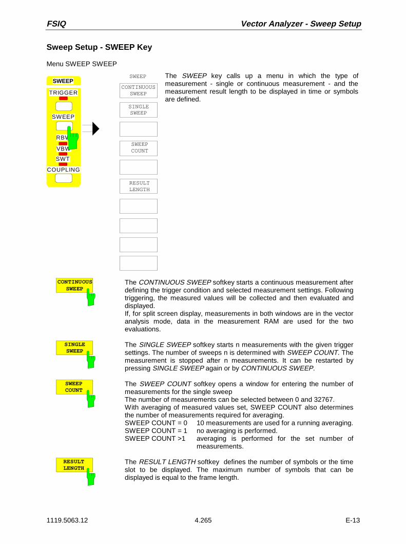
FSIQ Vector Analyzer - Sweep Setup
1119.5063.12 4.265 E-13
Sweep Setup - SWEEP Key
Menu SWEEP SWEEP
SINGLESWEEP
SWEEP
CONTINUOUSSWEEP
SWEEP
TRIGGER
RBW
VBW
SWT
COUPLING
SWEEP
SWEEPCOUNT
RESULTLENGTH
The SWEEP key calls up a menu in which the type ofmeasurement - single or continuous measurement - and themeasurement result length to be displayed in time or symbolsare defined.
CONTINUOUSSWEEP
The CONTINUOUS SWEEP softkey starts a continuous measurement afterdefining the trigger condition and selected measurement settings. Followingtriggering, the measured values will be collected and then evaluated anddisplayed.If, for split screen display, measurements in both windows are in the vectoranalysis mode, data in the measurement RAM are used for the twoevaluations.
SINGLESWEEP
The SINGLE SWEEP softkey starts n measurements with the given triggersettings. The number of sweeps n is determined with SWEEP COUNT. Themeasurement is stopped after n measurements. It can be restarted bypressing SINGLE SWEEP again or by CONTINUOUS SWEEP.
SWEEPCOUNT
The SWEEP COUNT softkey opens a window for entering the number ofmeasurements for the single sweepThe number of measurements can be selected between 0 and 32767.With averaging of measured values set, SWEEP COUNT also determinesthe number of measurements required for averaging.SWEEP COUNT = 0 10 measurements are used for a running averaging.SWEEP COUNT = 1 no averaging is performed.SWEEP COUNT >1 averaging is performed for the set number of
measurements.
RESULTLENGTH
The RESULT LENGTH softkey defines the number of symbols or the timeslot to be displayed. The maximum number of symbols that can bedisplayed is equal to the frame length.

Sweep Setup - Vector Analyzer FSIQ
1119.5063.12 4.266 E-13
Triggering Data Storage - TRIGGER Key
The trigger in the vector analyzer mode determines the time from which data are stored in the resultmemory. For the demodulation of digitally modulated signals, the time reference can also be obtained bysynchronization to a given bit sequence or, for TDMA signals, by searching for a burst in the resultmemory.
Menu: SWEEP TRIGGER
VIDEO
TRIGGER
FREE RUN
SWEEP
TRIGGER
RBW
VBW
SWT
COUPLING
S P
EXTERN
FIND BURSTON OFF
FIND SYNCON OFF
SYNCOFFSET
SYNCPATTERN
SLOPEPOS NEG
TRIGGEROFFSET
MEAS ONLYIF SYNC’D
The TRIGGER key opens a menu in which the different triggersources can be set and trigger slopes selected.
FREE RUN The FREE RUN softkey activates the measurement without trigger. After ameasurement, the memory is prepared to store data for a new measurement.
The free-run mode is recommended if a continuously modulated signal isapplied to the RF input or, for TDMA signals, the capture time is long enoughto enter a full burst into the result memory.
The capture time is influenced by the memory size (max. 16384 points), theset symbol rate as well as the number of points per symbol.
VIDEOThe VIDEO softkey starts the measurement by the video voltage of the analogpath of the spectrum analyzer. Parallel to the vector signal analyzer, the analogvideo voltage of the spectrum analyzer is evaluated.
Video triggering calls for the entry of the trigger threshold. It is identical to thetrigger threshold of the spectrum analyzer. The entry of the trigger thresholdinto the data window is numeric in % of the last grid which has been active inthe analyzer mode.To determine a suitable value for the trigger threshold it is possible to switch tothe display MAGNITUDE CAP BUFFER or to measure the threshold in theanalyzer mode.

FSIQ Vector Analyzer - Sweep Setup
1119.5063.12 4.267 E-13
EXTERNThe EXTERN softkey activates triggering by means of an external voltagebetween -5 V to +5 V at the rear BNC connector EXT TRIGGER / GATE. Thedesired value is to be entered into the window.
TRIGGEROFFSET
The TRIGGER OFFSET softkey opens a window for entering the desiredoffset.
With TRIGGER OFFSET, the start time for the data storage relative to thetrigger event is determined. Both positive values (for a trigger delay) andnegative values (for a pretrigger) are permitted.
Entry is in absolute time independent of the scaling of the X axis.
For positive values of the trigger offset (trigger delay), values from 1 µs to atleast 10 ms are permitted, depending on the symbol rate and the number ofpoints per symbol. The range of values for negative trigger offsets (pretrigger)depends on the selected memory size and is not more than half the memorysize.
MEAS ONLYIF SYNC’D
Softkey MEAS ONLY IF SYNC’D sets the vector analyzer so that measure-ments are performed if synchronization to the selected sync pattern waspossible.The measured values are displayed and taken into account in the error analysisonly if the set sync pattern is found. Bursts with a wrong sync pattern (sync notfound) are ignored.If an invalid sync pattern is found or if there is none, the measurement is haltedand continued in the presence of a valid sync pattern.
This softkey is available only if FIND SYNC = ON.The default setting is OFF. If the digital standard is changed, OFF is alwaysactivated.
Example:
An EDGE-compatible base station can send EDGE and GSM bursts at differenttimes. The demodulator thus sees EDGE (8PSK) and GSM bursts (GMSK).If GSM is activated in the vector analysis, the measurement and error analysisare disturbed by an EDGE burst. This can be prevented by activating softkeyMEAS ONLY IF SYNC’D. The EDGE bursts are ignored in the error analysis.
SLOPE
POS NEGThe SLOPE POS/NEG softkey determines the trigger slope in case oftriggering by means of the video signal or external trigger.
The sweep starts after a positive or negative slope of the trigger signal. With afree-running trigger the setting is irrelevant.

Sweep Setup - Vector Analyzer FSIQ
1119.5063.12 4.268 E-13
FIND BURSTON OFF
The FIND BURST ON/OFF softkey searches for a burst in the stored data(within the entered memory size), demodulates it within the entered framelength and displays it with the set result length.
The FIND BURST mode is particularly useful for TDMA signals if a burst is tobe completely displayed (and would otherwise not be demodulated due to themark-to-space ratio at the maximum setable frame length of 800 symbols). Thetime required for searching for a burst is determined with memory size.A burst must have a minimum length of 30 symbols to be identified.
Digital communication systems operating according to the TDMA accessmethods transmit or receive information in the form of bursts. The carrier poweris only switched on for a certain time. The transmitter switches the carrier on ifan information is to be transmitted and switches it off again.
Burstlength
Repeat time
Min. switch-off time
Min. switch-off time
The carrier power is switched off between two bursts. With FIND BURST, theFSIQ earches for a complete burst, i.e. for a carrier that can be switched onand off. If no complete burst is found within the search time, the messageBURST NOT FOUND is displayed.
If a trigger (video or extern) is used for the storage of the measured values, anegative trigger offset (pretrigger) is recommended so that a sufficiently longswitch-off time of the carrier is available at the beginning of the search time.
The search time has at least to be as long as the burst length plus twice theswitch-off time to ensure that the burst is found.
For a free-running trigger, set the length of the captured data (MEMORY SIZE)to a minimum (repeat time + 2 x switch-off time + burst length) so that the burstcan be found.
The FSIQ centers the number of symbols (FRAME LENGTH) required fordemodulation as well as the displayed symbols (RESULT LENGTH) to thecenter of the found burst (FIND SYNC OFF).
Burst length
Min. switch-off time
Min. switch-off time
Burstmiddle
RESULTLENGTH
FRAME LENGTH
MEMORY SIZE
Trigger(optional)

FSIQ Vector Analyzer - Sweep Setup
1119.5063.12 4.269 E-13
FIND SYNCON OFF
The FIND SYNC ON, softkey searches for a defined bit sequence (syncpattern) within the set frame length. The measurement result is displayed withthe set result length with reference to the first symbol of the synchronizationsequence.
If the synchronization sequence is not found, a result is still output according tothe set result length. The message: SYNC NOT FOUND is then output.
Centering the burst on the middle of the picture cannot be carried out if theburst is found at the very beginning of the data set (of the memory size) and aResult Length >Burst Length + 2×20 symbols is set. A precondition for burstrecognition is that before the rising edge measured values corresponding to atleast 20 symbols are present in the current trace memory. In this case, theburst is represented from the first measured value in the trace memory.If the consequent centering of the burst is indispensable for the user, the resultlength has to be reduced according to the above precondition.
In case of FIND BURST ON and FIND SYNC ON, the FSIQ only centers theframe length to the center of the burst while the result length is displayed fromthe beginning of the bit sequence (in case of SYNC OFFSET 0) or around theSYNC OFFSET.
Burst-length
Min. switch-off time
Min. switch-off time
Burst middle
RESULTLENGTH
FRAME LENGTH
MEMORY SIZE
SYNC PATTERN
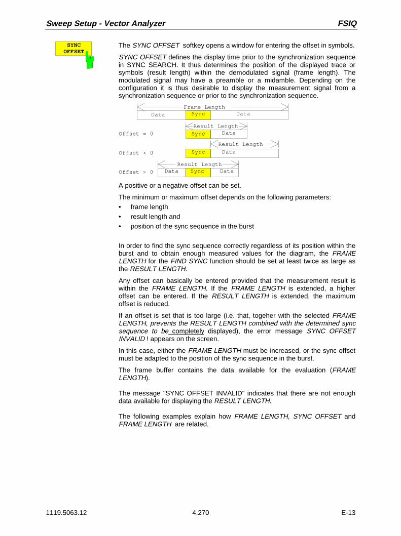
Sweep Setup - Vector Analyzer FSIQ
1119.5063.12 4.270 E-13
SYNCOFFSET
The SYNC OFFSET softkey opens a window for entering the offset in symbols.
SYNC OFFSET defines the display time prior to the synchronization sequencein SYNC SEARCH. It thus determines the position of the displayed trace orsymbols (result length) within the demodulated signal (frame length). Themodulated signal may have a preamble or a midamble. Depending on theconfiguration it is thus desirable to display the measurement signal from asynchronization sequence or prior to the synchronization sequence.
Frame Length
Data Sync Data
Sync
Sync
Sync
Data
Data
DataData
Result Length
Result Length
Result Length
Offset = 0
Offset < 0
Offset > 0
A positive or a negative offset can be set.
The minimum or maximum offset depends on the following parameters:• frame length• result length and• position of the sync sequence in the burst
In order to find the sync sequence correctly regardless of its position within theburst and to obtain enough measured values for the diagram, the FRAMELENGTH for the FIND SYNC function should be set at least twice as large asthe RESULT LENGTH.
Any offset can basically be entered provided that the measurement result iswithin the FRAME LENGTH. If the FRAME LENGTH is extended, a higheroffset can be entered. If the RESULT LENGTH is extended, the maximumoffset is reduced.
If an offset is set that is too large (i.e. that, togeher with the selected FRAMELENGTH, prevents the RESULT LENGTH combined with the determined syncsequence to be completely displayed), the error message SYNC OFFSETINVALID ! appears on the screen.
In this case, either the FRAME LENGTH must be increased, or the sync offsetmust be adapted to the position of the sync sequence in the burst.
The frame buffer contains the data available for the evaluation (FRAMELENGTH).
The message "SYNC OFFSET INVALID" indicates that there are not enoughdata available for displaying the RESULT LENGTH.
The following examples explain how FRAME LENGTH, SYNC OFFSET andFRAME LENGTH are related.

FSIQ Vector Analyzer - Sweep Setup
1119.5063.12 4.271 E-13
Example 1 (input signal without burst):
Device settings:• Input signal (without burst)• FIND BURST off• FIND SYNC on• FRAME LENGTH = 400• RESULT LENGTH = 200• SYNC OFFSET = 0
The start of the frame buffer is at symbol -300 (with respect to the sync pattern), the FSIQ displays theresults starting with symbol no. 0, but there are no more than 100 valid symbols in the file, 100 symbolsof the result length are invalid because they are located outside the frame buffer.
Sync Pattern
Valid Symbols Invalid Symbols,
FRAM E LEN G TH
RESULT LEN G TH
Symbol 0
End of the Frame BufferStart of the Frame Buffer
Located outside the Frame Buffer
-3 0 0 10 04 00
0 10 0 2 00
0
Solution: diminish result length to 100 symbols orextend frame length to 800 symbols.

Sweep Setup - Vector Analyzer FSIQ
1119.5063.12 4.272 E-13
Example 2 (input signal with burst):
Device settings:• Input signal (burst length 100 symbols)• FIND BURST on• FIND SYNC on• FRAME LENGTH = 400• RESULT LENGTH = 200• SYNC OFFSET = 0
After successful search of the burst, only the symbols inside the burst are marked as valid.The synchronization pattern is found in the burst (Symbol 0), the FSIQ displays starting with symbolno.0, but there are only 20 valid symbols in the burst, 180 symbols of the result length are invalidbecause they are located outside the burst.
Sync Pattern
Valid Symbols Invalid Symbols, Located outside the Burst
FRAM E LEN G TH
RESULT LEN G TH
Symbol 0
End of the BurstStart of the Burst
-8 0 2 0
0 2 0 2 0 0
4 0 0
Solution: diminish result length to 20 symbols.

FSIQ Vector Analyzer - Sweep Setup
1119.5063.12 4.273 E-13
Example 3 (input signal with burst):
Device settings:• Input signal (burst length 100 symbols)• FIND BURST on• FIND SYNC on• FRAME LENGTH = 400• RESULT LENGTH = 200• SYNC OFFSET = 90
After successful search of the burst, only the symbols inside the burst are marked as valid.The synchronization pattern is found in the burst (Symbol 0), the FSIQ displays starting with symbol no. -90 up to +19, the beginning of the display range is located before the start of the burst !
Sync Pattern
Valid SymbolsInvalid Symbols,
FRAME LENGTH
RESULT LENGTH
Symbol 0 End of the BurstStart of the Burst
SYNC OFFSET
Located outsidethe Burst
Invalid Symbols,Located outsidethe Burst
-80 20
400
-90 1100 20
Solution: diminish result length to 100 symbols (= burst length)
set sync offset to 80 (beginning of the burst lies 80 symbols before the sync-pattern).

Sweep Setup - Vector Analyzer FSIQ
1119.5063.12 4.274 E-13
Submenu: SWEEP TRIGGER
SYNCPATTERN
SELECTPATTERN
NEW SYNCPATTERN
EDIT SYNCPATTERN
DELETEPATTERN
PAGE UP
PAGE DOWN
SYNCPATTERN
The SYNC PATTERN softkey calls up a submenu, allowing toselect available patterns.
These patterns are displayed in the table PATTERN NAME. Ifa pattern is activated, the bit sequence of the selected patternis displayed in the table PATTERN VALUE.
The synchronization pattern defines a bit sequence which issearched for in the signal to be demodulated. When the FINDSYNC function is activated, this bit sequence is used forsynchronizing measurement results. The FSIQ demodulatesthe signal to be measured down to bit level and searches forthis predefined sequence. The first symbol in the bit sequenceis the reference time (for SYNC OFFSET = 0).
The bit sequence of digitally modulated signals often includes apreamble or midamble which is used on the one hand forassessing the channel impulse response and setting thechannel equalizer in the receiver and on the other hand tosynchronize the receiver. This bit sequence may be used in theFSIQ to find and display particular signal sections.
The maximum pattern length of the FSIQ is 200 bits . Thenumber of symbols depends on the significance of the modula-tion method. With QPSK, for instance, 200 bits correspond to100 symbols, with 16QAM to 50 symbols. The FSIQ alwaysuses an integral multiple of the bits per symbol. Bits which arenot multiples or exceed the maximum length are omitted.
SELECTPATTERN
The SELECT PATTERN softkey marks the first field in the PATTERN NAMEtable.
The bit sequence of the selected pattern is displayed simultaneously with thePATTERN VALUE table.
DELETEPATTERN
The DELETE PATTERN softkey clears the pattern marked by the cursor.To avoid the pattern being inadvertently deleted, a confirmation is required..
PAGE UP
PAGE DOWN
The PAGE UP/PAGE DOWN softkey causes the next/last page of the syncpattern table to be displayed.

FSIQ Vector Analyzer - Sweep Setup
1119.5063.12 4.275 E-13
Submenu: SWEEP TRIGGER - SYNC PATTERN
PATTERNEDIT SYNC NEW SYNC
PATTERNThe NEW PATTERN and EDIT PATTERN softkeys call upthe EDIT SYNC PATTERN submenu for generating syncpattern.In the head line of the table the name and comment of thesync pattern to be edited or modified can be entered.
The sync pattern is entered or modified in the VALUES field,using the DATA ENTRY keys "0", "1“ und ".“ .
USER EDIT SYNC PATTERN
NAME
COMMENT
EDIT SYNC PATTERN
0 00100101110000100010010111 32 64 96128
SAVEPATTERN
COMMENT: GSM BTS COLOR CODE 0
BIT No: VALUE:
NAME: GSM_BTS0VALUE
NAMEThe NAME softkey activates the input of the name of the sync pattern. Amaximum of eight characters can be entered.When the sync pattern is stored, the extension .PAT is automatically appended.
COMMENT The COMMENT softkey activates the input of a comment for the sync pattern.

Sweep Setup - Vector Analyzer FSIQ
1119.5063.12 4.276 E-13
VALUEThe VALUE softkey activates the input of the bit pattern of the sync pattern.
The sync pattern may include "don’t care bits" which are not considered whensearching for the valid bit pattern.. The don’t care bits are marked by an 'x' inthe VALUE field.
The sync pattern has to start and end with a valid bit, a don’t care bit can not bethe first or last bit of the sync pattern.
During burst search, the sync pattern has to start and to end 10 symbolesbefore the beginning and end of the burst, respectively.
maximum length ofsync pattern
10 symbolsat minimum
start of the burst
10 symbolsat minimum
end of the burst
sync sequence
SAVEPATTERN
The SAVE PATTERN softkey stores a newly edited pattern under the currentname.
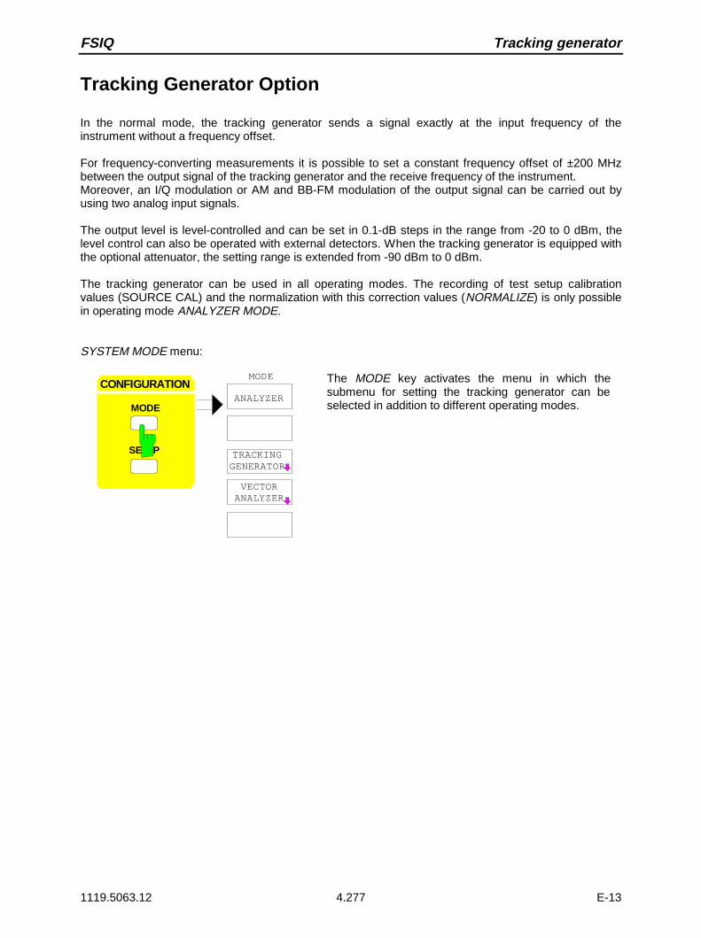
FSIQ Tracking generator
1119.5063.12 4.277 E-13
Tracking Generator Option
In the normal mode, the tracking generator sends a signal exactly at the input frequency of theinstrument without a frequency offset.
For frequency-converting measurements it is possible to set a constant frequency offset of ±200 MHzbetween the output signal of the tracking generator and the receive frequency of the instrument.Moreover, an I/Q modulation or AM and BB-FM modulation of the output signal can be carried out byusing two analog input signals.
The output level is level-controlled and can be set in 0.1-dB steps in the range from -20 to 0 dBm, thelevel control can also be operated with external detectors. When the tracking generator is equipped withthe optional attenuator, the setting range is extended from -90 dBm to 0 dBm.
The tracking generator can be used in all operating modes. The recording of test setup calibrationvalues (SOURCE CAL) and the normalization with this correction values (NORMALIZE) is only possiblein operating mode ANALYZER MODE.
SYSTEM MODE menu:
CONFIGURATION
MODE
SE P
ANALYZER
VECTORANALYZER
MODE
TRACKINGGENERATOR
The MODE key activates the menu in which thesubmenu for setting the tracking generator can beselected in addition to different operating modes.
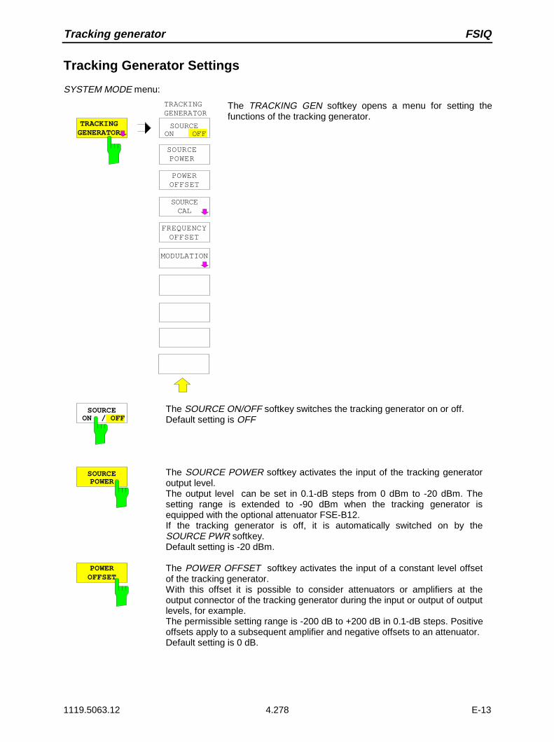
Tracking generator FSIQ
1119.5063.12 4.278 E-13
Tracking Generator Settings
SYSTEM MODE menu:
TRACKINGGENERATOR
SOURCEON OFF
SOURCE POWER
SOURCECAL
FREQUENCYOFFSET
MODULATION
POWEROFFSET
TRACKINGGENERATOR
The TRACKING GEN softkey opens a menu for setting thefunctions of the tracking generator.
SOURCEON / OFF
The SOURCE ON/OFF softkey switches the tracking generator on or off.Default setting is OFF
SOURCEPOWER
The SOURCE POWER softkey activates the input of the tracking generatoroutput level.The output level can be set in 0.1-dB steps from 0 dBm to -20 dBm. Thesetting range is extended to -90 dBm when the tracking generator isequipped with the optional attenuator FSE-B12.If the tracking generator is off, it is automatically switched on by theSOURCE PWR softkey.Default setting is -20 dBm.
POWEROFFSET
The POWER OFFSET softkey activates the input of a constant level offsetof the tracking generator.With this offset it is possible to consider attenuators or amplifiers at theoutput connector of the tracking generator during the input or output of outputlevels, for example.The permissible setting range is -200 dB to +200 dB in 0.1-dB steps. Positiveoffsets apply to a subsequent amplifier and negative offsets to an attenuator.Default setting is 0 dB.

FSIQ Tracking generator - Transmission measurement
1119.5063.12 4.279 E-13
Transmission Measurement
In this measurement, the transmission characteristic of a two-port network is measured. The built-intracking generator serves as a signal source. The tracking generator is connected to the input connectorof the DUT. The input of the instrument is fed from the output of the DUT.
RF INPUTGEN OUTPUT
DUT
Fig. 4-35 Test setup for reflection measurements
A calibration can be carried out to compensate for the effects from the test setup (eg. frequencyresponse of connecting cables).
Calibration of Transmission Measurement
SYSTEM MODE-TRACKING GENERATOR menu:
REF VALUE POSITION
SOURCE CAL
REF VALUE
SOURCECAL
NORMALIZE
CALTRANS
CAL REFLOPEN
RECALL
CAL REFLSHORT
The SOURCE CAL softkey opens a submenu comprisingthe calibration functions for the transmission and reflectionmeasurement.
The calibration of the reflection measurement is describedin section 2.13.3, its functioning in section 2.13.4 .
To carrry out a calibration for transmission measurementsthe whole test setup is through-connected (THRU).
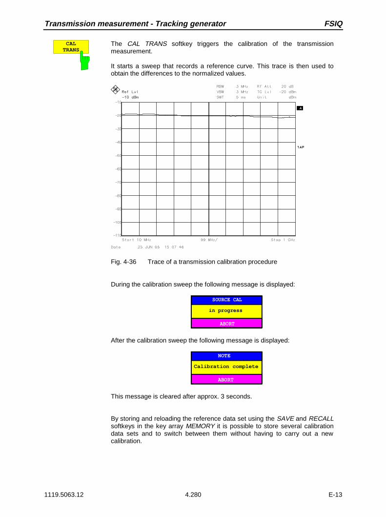
Transmission measurement - Tracking generator FSIQ
1119.5063.12 4.280 E-13
CALTRANS
The CAL TRANS softkey triggers the calibration of the transmissionmeasurement.
It starts a sweep that records a reference curve. This trace is then used toobtain the differences to the normalized values.
Fig. 4-36 Trace of a transmission calibration procedure
During the calibration sweep the following message is displayed:
SOURCE CAL
in progress
ABORT
After the calibration sweep the following message is displayed:
NOTE
Calibration complete
ABORT
This message is cleared after approx. 3 seconds.
By storing and reloading the reference data set using the SAVE and RECALLsoftkeys in the key array MEMORY it is possible to store several calibrationdata sets and to switch between them without having to carry out a newcalibration.
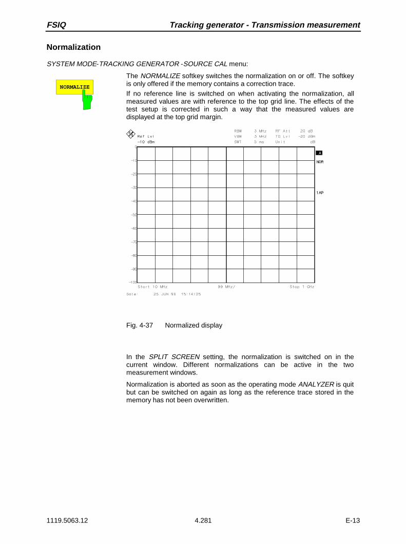
FSIQ Tracking generator - Transmission measurement
1119.5063.12 4.281 E-13
Normalization
SYSTEM MODE-TRACKING GENERATOR -SOURCE CAL menu:
NORMALIZE
The NORMALIZE softkey switches the normalization on or off. The softkeyis only offered if the memory contains a correction trace.
If no reference line is switched on when activating the normalization, allmeasured values are with reference to the top grid line. The effects of thetest setup is corrected in such a way that the measured values aredisplayed at the top grid margin.
Fig. 4-37 Normalized display
In the SPLIT SCREEN setting, the normalization is switched on in thecurrent window. Different normalizations can be active in the twomeasurement windows.
Normalization is aborted as soon as the operating mode ANALYZER is quitbut can be switched on again as long as the reference trace stored in thememory has not been overwritten.

Transmission measurement - Tracking generator FSIQ
1119.5063.12 4.282 E-13
It is now possible to shift the relative reference point within the grid by using the REF VALUE POSITIONsoftkey. Thus, the trace can be shifted from the top grid margin to the middle of the grid:
REF VALUEPOSITION
The REF VALUE POSITION softkey (reference position) marks a referenceposition in the active measurement window on which the normalization(difference formation with a reference curve) is performed.
If no reference line is switched on, the softkey switches on a reference lineand activates the input of its position. The line can be moved within the gridlimits.The reference line is switched off by pressing the softkey again.
The function of the reference line is explained in section 2.12.4 Functioningof Calibration.
Fig. 4-38 Normalized measurement, shifted with REF POSITION 50 %

FSIQ Tracking generator - Transmission measurement
1119.5063.12 4.283 E-13
REF VALUE The REF VALUE softkey activates the input of a level value which isassigned to the reference line.
With normalization switched on, all measured values are displayed relativeto the reference line, or if the latter is switched off relative to the top grid linewhich corresponds to 0 dB with default setting.
The value of REF VALUE is with reference to the actually activemeasurement window.
Fig. 4-39 Measurement with REF VALUE 20 dBand REF VALUEPOSITION 50%

Transmission measurement - Tracking generator FSIQ
1119.5063.12 4.284 E-13
If a 10dB-attenuator pad is measured, the reference line can be displayedwith a nominal attenuation after calibration by entering REF VALUE -10 dB.Departures from this nominal value are then displayed with high resolution(eg 1dB/Div) and with the absolute attenuation (eg 1 dB below nominalvalue = 11 dB attenuation).
Fig. 4-40 Measurement of a 10dB attenuator pad with 1 dB / Div
RECALL
The RECALL softkey restores the instrument setting with which thecalibration was carried out.This can be useful if the device setting was changed after calibration (egcenter frequency setting, frequency deviation, reference level, etc. ).
The softkey is only offered if:• the analyzer mode has been selected• the memory contains a calibration data set.

FSIQ Tracking generator - Reflection measurement
1119.5063.12 4.285 E-13
Reflection Measurement
Scalar reflection measurements can be carried out by means of a reflection-coefficient bridge.
RF INPUTGEN OUTPUT
DUT
BRIDGE
Fig. 4-41 Test setup for reflection measurements
Calibration of Reflection Measurement
This calibration essentially corresponds to that of the transmission measurement.
SYSTEM MODE-TRACKING-SOURCE CAL submenu
CAL REFL OPEN
CAL REFL SHORT
The CAL REFL OPEN softkey starts the open-circuit calibration.
During calibration the following message is displayed
SOURCE CAL
in progress
ABORT
The CAL REFL SHORT softkey starts the short-circuit calibration.
If both calibrations (open circuit, short circuit) are carried out, the calibrationcurve is formed by averaging the two measurements and stored in thememory. The order of measurements is optional.
The completion of the calibration is indicated by
NOTE
calibration complete
OK
The display is cleared after 3 seconds.
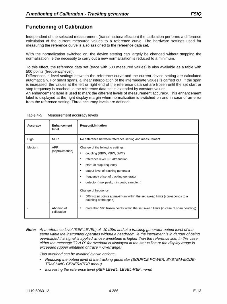
Functioning of Calibration - Tracking generator FSIQ
1119.5063.12 4.286 E-13
Functioning of Calibration
Independent of the selected measurement (transmission/reflection) the calibration performs a differencecalculation of the current measured values to a reference curve. The hardware settings used formeasuring the reference curve is also assigned to the reference data set.
With the normalization switched on, the device stetting can largely be changed without stopping thenormalization, ie the necessity to carry out a new normalization is reduced to a minimum.
To this effect, the reference data set (trace with 500 measured values) is also available as a table with500 points (frequency/level).Differences in level settings between the reference curve and the current device setting are calculatedautomatically. For small spans, a linear interpolation of the intermediate values is carried out. If the spanis increased, the values at the left or right end of the reference data set are frozen until the set start orstop frequency is reached, ie the reference data set is extended by constant values.An enhancement label is used to mark the different levels of measurement accuracy. This enhancementlabel is displayed at the right display margin when normalization is switched on and in case of an errorfrom the reference setting. Three accuracy levels are defined:
Table 4-5 Measurement accuracy levels
Accuracy Enhancementlabel
Reason/Limitation
High NOR No difference between reference setting and measurement
Medium APP(approximation)
Change of the following settings:
• coupling (RBW, VBW, SWT)
• reference level, RF attenuation
• start or stop frequency
• output level of tracking generator
• frequency offset of tracking generator
• detector (max peak, min peak, sample...)
Change of frequency:
• 500 frozen points at maximum within the set sweep limits (corresponds to adoubling of the span)
- Abortion ofcalibration
• more than 500 frozen points within the set sweep limits (in case of span doubling)
Note: At a reference level (REF LEVEL) of -10 dBm and at a tracking generator output level of thesame value the instrument operates without a headroom. ie the instrument is in danger of beingoverloaded if a signal is applied whose amplitude is higher than the reference line. In this case,either the message "OVLD" for overload is displayed in the status line or the display range isexceeded (upper limitation of trace = Overrange).
This overload can be avoided by two actions:• Reducing the output level of the tracking generator (SOURCE POWER, SYSTEM-MODE-
TRACKING GENERATOR menu)• Increasing the reference level (REF LEVEL, LEVEL-REF menu)

FSIQ Tracking generator - Frequency Converting Measurements
1119.5063.12 4.287 E-13
Frequency-Converting Measurements
For frequency-converting measurements (eg on converters) the tracking generator is able to set aconstant frequency offset between the output frequency of the tracking generator and the receivefrequency of the instrument. Up to an output frequency of 200 MHz the measurement can be carried outin inverted and normal position.
RF INPUTGEN OUTPUT
DUT
Fig. 4-42 Test setup for frequency-converting measurements
SYSTEM MODE-TRACKING GENERATOR menu:
FREQUENCY OFFSET
The FREQUENCY OFFSET softkey activates the input of the frequencyoffset between the output signal of the tracking generator and the inputfrequency of the instrument. The permissible setting range is ±200 MHz in1-Hz steps.The default setting is 0 Hz.
If a positive frequency offset is entered, the tracking generator generatesan output signal above the receive frequency of the instrument. In case of anegative frequency offset it generates a signal below the receive frequencyof the instrument. The output frequency of the tracking generator iscalculated as follows:
Tracking generator frequency = receive frequency + frequency offset.
A frequency offset cannot be entered if an external I/Q or FM modulation isswitched on. In this case, the FREQUENCY OFFSET softkey is blocked.

External Modulation - Tracking generator FSIQ
1119.5063.12 4.288 E-13
External Modulation of Tracking Generator
SYSTEM MODE-TRACKING GENERATOR menu:
MODULATION
EXT I/Q
EXT ALC
EXT AM
EXT FM
MODULATION
The MODULATION softkey opens a submenu forselecting the different modulation types.
The time characteristic of the output signal of the trackinggenerator can be influenced by means of externally fed-insignals (input voltage range -1 V to +1 V).
The functions for amplitude and frequency modulation andfor external level control are always available.
The function IQ modulation is only available in models oftracking generators that are equipped with the IQmodulator (FSE-B9 and FSE-B11).
Two BNC connectors at the rear panel are available assignal inputs. Their function can be changed according tothe modulation selected:
TG-INPUT I / AM / ALC and
TG-INPUT Q / FM
The types of modulation can partly be combined with each other and with the frequency offset function.The following table shows which types of modulation are possible at the same time and which can becombined with the frequency offset function.
Table 4-6 Simultaneous modes of modulation (tracking generator)
Modulation Frequencyoffset
EXT AM EXT ALC EXT FM EXT I/Q
Frequency offset • • •
EXT AM • •
EXT ALC •
EXT FM • •
EXT I/Q
• modulations can be combined

FSIQ Tracking generator - External modulation
1119.5063.12 4.289 E-13
EXT AM
The EXT AM softkey activates an AM modulation of the tracking generatoroutput signal.
The modulation signal is connected to the TG-INPUT AM connector. Aninput voltage of 1 V corresponds to 100% amplitude modulation.
Switching on an external AM deactivates the following functions:
– active external level control
– active I/Q modulation.
EXT ALC
The EXT ALC softkey activates the external level control.
In case of external level control the output level of the tracking generator isdetermined from the signal of an external detector. The external detectorhas to supply a negative voltage in the range of -0.1 to -1 V which is appliedto the TG-INPUT ALC connector. The setting of the output level is the sameas that of the internal level control but the output level depends on theexternal detector.
Switching on an external level control deactivates the following functions:
– active external AM
– active I/Q modulation.
EXT FM
The EXT FM softkey activates the FM modulation of the tracking generatoroutput signal.
The modulation frequency range is 100 kHz to 10 MHz, the deviation isapprox. 10 MHz at an input voltage of 1 V.The modulation signal is connected to the TG-INPUT FM connector.
Switching on an external FM deactivates the following function:
– active I/Q modulation.

External Modulation - Tracking generator FSIQ
1119.5063.12 4.290 E-13
EXT I/Q
The EXT I/Q softkey is only offered with I/Q modulator option built-in. Itactivates the external I/Q modulation of the tracking generator (FSE-B9 andFSE B-11).
The signals for modulation are connected to the two input connectors TG-INPUT IN and TG-INPUT Q at the rear of the unit. The input voltage rangeis ±1 V into 50 Ω.
Switching on an external I/Q modulation deactivates the following functions:
– active external AM
– active external level control
– active external FM or
– a level offset.
Functional description of quadrature modulator:
0°
90°
I channel
Q channel
I mod
Q mod
RF IN RF OUT
Fig. 4-43 I/Q modulation
I/Q modulation is performed by means of the built-in quadrature modulator.The RF signal is divided into the two orthogonal I and Q components(inphase and quadrature phase). Amplitude and phase are controlled ineach path by the I and Q modulation signal. A RF output signal controllablein amplitude and phase is obtained by adding the two components.

FSIQ Contents - Remote Control - Basics
1119.5063.12 I-5.1 E-1
Contents - Chapter 5 "Remote Control - "Basics"
5 Remote Control - Basics
Introduction...................................................................................................................................... 5.1
Brief Instructions ............................................................................................................................. 5.2
Switchover to Remote Control ....................................................................................................... 5.3Indications during Remote Control .......................................................................................... 5.3
Remote Control via IEC Bus.................................................................................................... 5.4Setting the Device Address ........................................................................................... 5.4Return to Manual Operation .......................................................................................... 5.4
Remote Control via RS-232-Interface ..................................................................................... 5.5Setting the Transmission Parameters ........................................................................... 5.5Return to Manual Operation .......................................................................................... 5.5Limitations ..................................................................................................................... 5.5
Remote Control via RSIB Interface ......................................................................................... 5.6Return to Manual Operation .......................................................................................... 5.6
Messages.......................................................................................................................................... 5.7IEE/IEEE-Bus Interface Messages.......................................................................................... 5.7
RSIB Interface Messages........................................................................................................ 5.7
Device Messages (Commands and Device Responses) ........................................................ 5.8
Structure and Syntax of the Device Messages ............................................................................. 5.9SCPI Introduction..................................................................................................................... 5.9
Structure of a Command ......................................................................................................... 5.9
Structure of a Command Line................................................................................................ 5.12
Responses to Queries ........................................................................................................... 5.12
Parameters ............................................................................................................................ 5.13
Overview of Syntax Elements................................................................................................ 5.14
Instrument Model and Command Processing ............................................................................ 5.15Input Unit ............................................................................................................................... 5.15
Command Recognition .......................................................................................................... 5.16
Data Set and Instrument Hardware ....................................................................................... 5.16
Status Reporting System ....................................................................................................... 5.16
Output Unit............................................................................................................................. 5.17
Command Sequence and Command Synchronization.......................................................... 5.17
Status Reporting System .............................................................................................................. 5.18Structure of an SCPI Status Register .................................................................................... 5.18
Overview of the Status Registers .......................................................................................... 5.20
Description of the Status Registers ....................................................................................... 5.21Status Byte (STB) and Service Request Enable Register (SRE)................................ 5.21IST Flag and Parallel Poll Enable Register (PPE)....................................................... 5.22Event-Status Register (ESR) and Event-Status-Enable Register (ESE)..................... 5.22STATus:OPERation Register ...................................................................................... 5.23STATus:QUEStionable Register ................................................................................. 5.24STATus QUEStionable:ACPLimit Register ................................................................. 5.25STATus QUEStionable:FREQuency Register............................................................. 5.26STATus QUEStionable:LIMit Register ........................................................................ 5.27STATus QUEStionable:LMARgin Register ................................................................. 5.28

Contents - Remote Control - Basics FSIQ
1119.5063.12 I-5.2 E-1
STATus QUEStionable:POWer Register .................................................................... 5.29STATus QUEStionable:SYNC Register ...................................................................... 5.30STATus QUEStionable:TRANsducer Register ........................................................... 5.31
Application of the Status Reporting Systems......................................................................... 5.32Service Request, Making Use of the Hierarchy Structure ........................................... 5.32Serial Poll .................................................................................................................... 5.32Parallel Poll.................................................................................................................. 5.32Query by Means of Commands................................................................................... 5.33Error-Queue Query...................................................................................................... 5.33
Resetting Values of the Status Reporting System................................................................. 5.34

FSIQ Introduction
1119.5063.12 5.1 E-13
5 Remote Control - Basics
In this chapter you find:
• instructions how to put the FSIQ into operation via remote control,
• a general introduction to remote control of programmable instruments. This includes the descriptionof the command structure and syntax according to the SCPI standard, the description of commandexecution and of the status registers,
• diagrams and tables describing the status registers used in the FSIQ.
In chapter 6, all remote control functions are described in detail. The subsystems are listed byalphabetical order according to SCPI. All commands and their parameters are listed by alphabeticalorder in the command list at the end of chapter 6.
Program examples for the FSIQ can be found in chapter 7.
The remote control interfaces and their interface functions are described in chapter 8.
Introduction
The instrument is equipped with an IEC-bus interface according to standard IEC 625.1/IEEE 488.2 andtwo RS-232 interfaces. The connectors are located at the rear of the instrument and permits to connecta controller for remote control.
The internal controller function may also be used as a controller (see chapter 1, section "Controllerfunction).In addition, the instrument is equipped with an RSIB interface that allows instrument control by Windowsapplications WinWord and Excel or by Visual C++ and Visual Basic programs
The instrument supports the SCPI version 1994.0 (Standard Commands for ProgrammableInstruments). The SCPI standard is based on standard IEEE 488.2 and aims at the standardization ofdevice-specific commands, error handling and the status registers (see section "SCPI Introduction").
This section assumes basic knowledge of IEC-bus programming and operation of the controller. Adescription of the interface commands is to be obtained from the relevant manuals. The RSIB interfacefunctions are matched to the function interface for IEC/IEEE-bus programming from NationalInstruments. The functions supported by the DLLs are listed in chapter 8.
The requirements of the SCPI standard placed on command syntax, error handling and configuration ofthe status registers are explained in detail in the respective sections. Tables provide a fast overview ofthe commands implemented in the instrument and the bit assignment in the status registers. The tablesare supplemented by a comprehensive description of every command and the status registers. Detailedprogram examples of the main functions are to be found in chapter 7.
The program examples for IEC-bus programming are all written in Quick BASIC.

Brief Instructions FSIQ
1119.5063.12 5.2 E-13
Brief Instructions
The short and simple operating sequence given below permits fast putting into operation of theinstrument and setting of its basic functions. As a prerequisite, the IEC-bus address, which is factory-setto 20, must not have been changed.
1. Connect instrument and controller using IEC-bus cable.
2. Write and start the following program on the controller:
CALL IBFIND("DEV1", analyzer%) ’Open port to the instrumentCALL IBPAD(analyzer%, 20) ’Inform controller about instrument addressCALL IBWRT(analyzer%, "*RST;*CLS") ’Reset instrumentCALL IBWRT(analyzer%, ’FREQ:CENT 100MHz’) ’Set center frequency to 100 MHzCALL IBWRT(analyzer%, ’FREQ:SPAN 10MHz’) ’Set span to 10 MHzCALL IBWRT(analyzer%, ’DISP:TRAC:Y:RLEV -10dBm’)
’Set reference level to -10 dBm
The instrument now performs a sweep in the frequency range of 95 MHz to 105 MHz.
3. To return to manual control, press the LOCAL key at the front panel

FSIQ Switchover to Remote Control
1119.5063.12 5.3 E-13
Switchover to Remote Control
On power-on, the instrument is always in the manual operating state ("LOCAL" state) and can beoperated via the front panel.It is switched to remote control ("REMOTE" state)
IEC-bus as soon as it receives an addressed command from a controller.
RS-232 as soon as it receives a command from a controller.
RSIB as soon as it receives an addressed command from a controller.
During remote control, operation via the front panel is disabled. The instrument remains in the remotestate until it is reset to the manual state via the front panel or via remote control interfaces. Switchingfrom manual operation to remote control and vice versa does not affect the remaining instrumentsettings.
Indications during Remote Control
Remote control mode is indicated by the LED "REMOTE" on the instrument’s front panel. In this modethe softkeys, the function fields and the diagram labelling on the display are not shown.
Note: Command SYSTem:DISPlay:UPDate ON activates all indications during remote control tocheck the instrument settings.

Switchover to Remote Control FSIQ
1119.5063.12 5.4 E-13
Remote Control via IEC Bus
Setting the Device Address
In order to operate the instrument via the IEC-bus, it must be addressed using the set IEC-bus address.The IEC-bus address of the instrument is factory-set to 20. It can be changed manually in the SETUP -GENERAL SETUP menu or via IEC bus. Addresses 0 to 30 are permissible.
Manually: Call SETUP - GENERAL SETUP menu
Enter desired address in table GPIB ADDRESS
Terminate input using one of the unit keys (=ENTER).
Via IEC bus:
CALL IBFIND("DEV1", analyzer%) ’Open port to the instrumentCALL IBPAD(analyzer%, 20) ’Inform controller about old addressCALL IBWRT(analyzer%, "SYST:COMM:GPIB:ADDR 18")’Set instrument to new addressCALL IBPAD(analyzer%, 18) ’Inform controller about new address
Return to Manual Operation
Return to manual operation is possible via the front panel or the IEC bus.
Manually: Press the LOCAL key.
Notes: – Before switchover, command processing must be completed asotherwise switchover to remote control is effected immediately.
– The LOCAL key can be disabled by the universal command LLO(see chapter 8) in order to prevent unintentional switchover. Inthis case, switchover to manual mode is only possible via the IECbus.
– The LOCAL key can be enabled again by deactivating the RENline of the IEC bus (see chapter 8).
Via IEC bus: ...CALL IBLOC(analyzer%) ’Set instrument to manual operation....

FSIQ Switchover to Remote Control
1119.5063.12 5.5 E-13
Remote Control via RS-232-Interface
Setting the Transmission Parameters
To enable an error-free and correct data transmission, the parameters of the unit and the controllershould have the same setting. Parameters can be manually changed in menu SETUP-GENERALSETUP in table COM PORT 1/2 or via remote control using the commandSYSTem:COMMunicate:SERial1|2:... .
The transmission parameters of the interfaces COM1 and COM2 are factory-set to the following values:baudrate = 9600, data bits = 8, stop bits = 1, parity = NONE and owner = INSTRUMENT.
Manually: Setting interface COM1|2
À Call SETUP-GENERAL SETUP menu
À Select desired baudrate, bits, stopbit, parity in table COM PORT 1/2.
À Terminate input using one of the unit keys (=ENTER).
Return to Manual Operation
Return to manual operation is possible via the front panel.
Manually: Press the LOCAL key.
Note: Before switchover, command processing must be completed asotherwise switchover to remote control is effected immediately.
Limitations
The following limitations apply if the unit is remote-controlled via the RS-232-C interface:
− No interface messages
− Only the Common Commands *OPC? can be used for command synchronization, *WAI and *OPCare not available.
− Block data cannot be transmitted.

Switchover to Remote Control FSIQ
1119.5063.12 5.6 E-13
Remote Control via RSIB Interface
To access the measuring instruments via the RSIB interface the DLLs should be installed in thecorresponding directories:
• RSIB.DLL in Windows NT system directory or control application directory.•RSIB32.DLL in Windows NT system32 directory or control application directory.On the measuring instrument the DLL is already installed in the corresponding directory.The control is performed via one of the Windows applications WinWord or Excel or with Visual C++ orVisual Basic programs. The local link to the internal controller is established with the name ’@local’.If aremote controller is used, the instrument IP address is to be indicated here.
Via VisualBasic: internal controller: ud = RSDLLibfind (’@local’, ibsta, iberr, ibcntl)
remote controller: ud = RSDLLibfind (’82.1.1.200’, ibsta, iberr, ibcntl)
Return to Manual Operation
The return to manual operation can be performed via the front panel (LOCAL key) or the RSIB interface.
Manually: Press the LOCAL key.
Note: Before switchover, command processing must be completed asotherwise switchover to remote control is effected immediately.
Via RSIB: ...ud = RSDLLibloc (ud, ibsta, iberr, ibcntl);...
FSIQ Messages
1119.5063.12 5.7 E-13
Messages
The messages transferred via the data lines of the IEC bus or the RSIB interface (see chapter 8) can bedivided into two groups:
– interface messages and– device messages.
For the RS-232 interface, no interface messages are defined.
IEE/IEEE-Bus Interface Messages
Interface messages are transferred on the data lines of the IEC bus, the "ATN" control line being active.They are used for communication between controller and instrument and can only be sent by acontroller which has the IEC-bus control. Interface commands can be subdivided into
– universal commands and– addressed commands.
Universal commands act on all devices connected to the IEC bus without previous addressing,addressed commands only act on devices previously addressed as listeners. The interface messagesrelevant to the instrument are listed in chapter 8.
RSIB Interface Messages
The RSIB interface enables the instrument to be controlled by Windows applications. The interfacefunctions are matched to the function interface for IEC/IEEE-bus programming from NationalInstruments.The functions supported by interface are listed in chapter 8.

Messages FSIQ
1119.5063.12 5.8 E-13
Device Messages (Commands and Device Responses)
Device messages are transferred on the data lines of the IEC bus, the "ATN" control line not beingactive. ASCII code is used. The device messages are more or less equal for the different interfaces.A distinction is made according to the direction in which they are sent on the IEC bus:
– Commands are messages the controller sends to the instrument. They operate the devicefunctions and request informations.The commands are subdivided according to two criteria::
1. According to the effect they have on the instrument:
Setting commands cause instrument settings such as reset of theinstrument or setting the center frequency.
Queries cause data to be provided for output on the IEC-bus,e.g. for identification of the device or polling themarker.
2. According to their definition in standard IEEE 488.2:
Common Commands are exactly defined as to their function andnotation in standard IEEE 488.2. They refer tofunctions such as management of the standar-dizedstatus registers, reset and selftest.
Device-specificcommands refer to functions depending on the features of the
instrument such as frequency setting. A majority ofthese commands has also been standardized by theSCPI committee (cf. Section 3.5.1).
– Device responses are messages the instrument sends to the controller after a query. They cancontain measurement results, instrument settings and information on theinstrument status (cf. Section 3.5.4).
Structure and syntax of the device messages are described in the following section. The commands arelisted and explained in detail in chapter 6.
FSIQ Structure and Syntax of the Device Messages
1119.5063.12 5.9 E-13
Structure and Syntax of the Device Messages
SCPI Introduction
SCPI (Standard Commands for Programmable Instruments) describes a standard command set forprogramming instruments, irrespective of the type of instrument or manufacturer. The goal of the SCPIconsortium is to standardize the device-specific commands to a large extent. For this purpose, a modelwas developed which defines the same functions inside a device or for different devices. Commandsystems were generated which are assigned to these functions. Thus it is possible to address the samefunctions with identical commands. The command systems are of a hierarchical structure.Fig. 5-1 illustrates this tree structure using a section of command system SOURce, which operates thesignal sources of the devices. The other examples concerning syntax and structure of the commandsare derived from this command system.SCPI is based on standard IEEE 488.2, i.e. it uses the same syntactic basic elements as well as thecommon commands defined in this standard. Part of the syntax of the device responses is defined withgreater restrictions than in standard IEEE 488.2 (see Section "Responses to Queries").
Structure of a Command
The commands consist of a so-called header and, in most cases, one or more parameters. Header andparameter are separated by a "white space" (ASCII code 0 to 9, 11 to 32 decimal, e.g. blank). Theheaders may consist of several key words. Queries are formed by directly appending a question mark tothe header.
Note: The commands used in the following examples are not in every case implemented in theinstrument.
Common commands Common commands consist of a header preceded by an asterisk "*"and one or several parameters, if any.
Examples: *RST RESET, resets the device*ESE 253 EVENT STATUS ENABLE, sets the bits of the
event status enable register*ESR? EVENT STATUS QUERY, queries the
contents of the event status register.

Structure and Syntax of the Device Messages FSIQ
1119.5063.12 5.10 E-13
Device-specific commands
Hierarchy: Device-specific commands are of hierarchical structure (seeFig. 5-1). The different levels are represented by combined headers.Headers of the highest level (root level) have only one key word. Thiskey word denotes a complete command system.
Example: SENSe This key word denotes the command systemSENSe.
For commands of lower levels, the complete path has to be specified,starting on the left with the highest level, the individual key words beingseparated by a colon ":".
Example: SENSe:FREQuency:SPAN:LINK STARt
This command lies in the fourth level of the SENSe system. Itdetermines which parameter remains unchanged when the span ischanged. If LINK is set to STARt, the values of CENTer and STOP areadjusted when the span is changed.
SENSe
BANDwidth FUNCtion FREQuency
STOP CENTer SPAN OFFSetSTARt
HOLD LINK
DETector
Fig. 5-1 Tree structure the SCPI command systems using the SENSe system by way of example
Some key words occur in several levels within one command system. Theireffect depends on the structure of the command, that is to say, at whichposition in the header of a command they are inserted.
Example: SOURce:FM:POLarity NORMalThis command contains key word POLarity in the thirdcommand level. It defines the polarity between modulator andmodulation signal.
SOURce:FM:EXTernal:POLarity NORMalThis command contains key word POLarity in the fourthcommand level. It defines the polarity between modulationvoltage and the resulting direction of the modulation only for theexternal signal source indicated.
FSIQ Structure and Syntax of the Device Messages
1119.5063.12 5.11 E-13
Optional key words: Some command systems permit certain key words to be optionally insertedinto the header or omitted. These key words are marked by squarebrackets in the description. The full command length must be recognizedby the instrument for reasons of compatibility with the SCPI standard.Some commands are considerably shortened by these optional key words.
Example: [SENSe]:BANDwidth[:RESolution]:AUTOThis command couples the resolution bandwidth of theinstrument to other parameters. The following command hasthe same effect:BANDwidth:AUTO
Note: An optional key word must not be omitted if its effect is specifiedin detail by a numeric suffix.
Long and short form: The key words feature a long form and a short form. Either the short formor the long form can be entered, other abbreviations are not permissible.
Beispiel: STATus:QUEStionable:ENABle 1= STAT:QUES:ENAB 1
Note: The short form is marked by upper-case letters, the long formcorresponds to the complete word. Upper-case and lower-casenotation only serve the above purpose, the instrument itselfdoes not make any difference between upper-case and lower-case letters.
Parameter: The parameter must be separated from the header by a "white space". Ifseveral parameters are specified in a command, they are separated by acomma ",". A few queries permit the parameters MINimum, MAXimum andDEFault to be entered. For a description of the types of parameter, refer toSection 3.5.5.
Example: SENSe:FREQuency:STOP? MAXimum Response: 3.5E9This query requests the maximal value for the stop frequency.
Numeric suffix: If a device features several functions or features of the same kind, e.g.inputs, the desired function can be selected by a suffix added to the com-mand. Entries without suffix are interpreted like entries with the suffix 1.
Example:. SYSTem:COMMunicate:SERial2:BAUD 9600This command sets the baudrate of the second serial interface.

Structure and Syntax of the Device Messages FSIQ
1119.5063.12 5.12 E-13
Structure of a Command Line
A command line may consist of one or several commands. It is terminated by a <New Line>, a <NewLine> with EOI or an EOI together with the last data byte. Quick BASIC automatically produces an EOItogether with the last data byte.
Several commands in a command line are separated by a semicolon ";". If the next command belongsto a different command system, the semicolon is followed by a colon.
Example:CALL IBWRT(analyzer, "SENSe:FREQuency:CENTer 100MHz;:INPut:ATTenuation 10")
This command line contains two commands. The first command is part of the SENSesystem and is used to specify the center frequency of the analyzer. The second commandis part of the INPut system and sets the attenuation of the input signal.
If the successive commands belong to the same system, having one or several levels in common, thecommand line can be abbreviated. To this end, the second command after the semicolon starts with thelevel that lies below the common levels (see also Fig. 5-1). The colon following the semicolon must beomitted in this case.
Example:CALL IBWRT(analyzer, "SENSe:FREQuency:STARt 1E6;:SENSe:FREQuency:STOP 1E9")
This command line is represented in its full length and contains two commands separatedfrom each other by the semicolon. Both commands are part of the SENSe commandsystem, subsystem FREQuency, i.e. they have two common levels.When abbreviating the command line, the second command begins with the level belowSENSe:FREQuency. The colon after the semicolon is omitted.
The abbreviated form of the command line reads as follows:
CALL IBWRT(analyzer, "SENSe:FREQuency:STARt 1E6;STOP 1E9")
However, a new command line always begins with the complete path.
Example: CALL IBWRT(analyzer, "SENSe:FREQuency:STARt 1E6")CALL IBWRT(analyzer, "SENSe:FREQuency:STOP 1E9")
Responses to Queries
A query is defined for each setting command unless explicitly specified otherwise. It is formed by addinga question mark to the associated setting command. According to SCPI, the responses to queries arepartly subject to stricter rules than in standard IEEE 488.2.
1 The requested parameter is transmitted without header.Example: INPut:COUPling? Response: DC
2. Maximum values, minimum values and all further quantities, which are requested via a special textparameter are returned as numerical values.Example: SENSe:FREQuency:STOP? MAX Response: 3.5E9
3. Numerical values are output without a unit. Physical quantities are referred to the basic units or to theunits set using the Unit command.Example: SENSe:FREQuency:CENTer? Response: 1E6 for 1 MHz
4. Truth values <Boolean values> are returned as 0 (for OFF) and 1 (for ON).Example: SENSe:BANDwidth:AUTO? Response: 1 for ON
5. Text (character data) is returned in a short form (see also Section 3.5.5).Example: SYSTem:COMMunicate:SERial:CONTrol:RTS? Response(for standard): STAN

FSIQ Structure and Syntax of the Device Messages
1119.5063.12 5.13 E-13
Parameters
Most commands require a parameter to be specified. The parameters must be separated from theheader by a "white space". Permissible parameters are numerical values, Boolean parameters, text,character strings and block data. The type of parameter required for the respective command and thepermissible range of values are specified in the command description (see Section 3.6).
Numerical values Numerical values can be entered in any form, i.e. with sign, decimal point andexponent. Values exceeding the resolution of the instrument are rounded up ordown. The mantissa may comprise up to 255 characters, the exponent must lieinside the value range -32000 to 32000. The exponent is introduced by an "E"or "e". Entry of the exponent alone is not permissible. In the case of physicalquantities, the unit can be entered. Permissible unit prefixes are G (giga), MA(mega), MOHM and MHZ are also permissible), K (kilo), M (milli), U (micro)and N (nano). It the unit is missing, the basic unit is used.
Example:SENSe:FREQuency:STOP 1.5GHz = SENSe:FREQuency:STOP 1.5E9
Special numerical The texts MINimum, MAXimum, DEFault, UP and DOWN are interpreted asvaluesspecial numerical values.
In the case of a query, the numerical value is provided.
Example: Setting command: SENSe:FREQuency:STOP MAXimumQuery: SENSe:FREQuency:STOP? Response: 3.5E9
MIN/MAX MINimum and MAXimum denote the minimum and maximum value.
DEF DEFault denotes a preset value which has been stored in the EPROM. Thisvalue conforms to the default setting, as it is called by the *RST command
UP/DOWN UP, DOWN increases or reduces the numerical value by one step. The stepwidth can be specified via an allocated step command for each parameterwhich can be set via UP, DOWN.
INF/NINF INFinity, Negative INFinity (NINF) Negative INFinity (NINF) represent thenumerical values -9.9E37 or 9.9E37, respectively. INF and NINF are only sentas device reponses.
NAN Not A Number (NAN) represents the value 9.91E37. NAN is only sent asdevice response. This value is not defined. Possible causes are the division ofzero by zero, the subtraction of infinite from infinite and the representation ofmissing values.
Boolean Parameters Boolean parameters represent two states. The ON state (logically true) isrepresented by ON or a numerical value unequal to 0. The OFF state (logicallyuntrue) is represented by OFF or the numerical value 0. 0 or 1 is provided in aquery.
Example: Setting command: DISPlay:WINDow:STATe ONQuery: DISPlay:WINDow:STATe? Response: 1

Structure and Syntax of the Device Messages FSIQ
1119.5063.12 5.14 E-13
Text Text parameters observe the syntactic rules for key words, i.e. they can beentered using a short or long form. Like any parameter, they have to beseparated from the header by a white space. In the case of a query, the shortform of the text is provided.
Example: Setting command: INPut:COUPling GROundQuery: INPut:COUPling? Response GRO
Strings Strings must always be entered in quotation marks (’ or ").
Example: SYSTem:LANGuage "SCPI" orSYSTem:LANGuage ’SCPI’
Block data Block data are a transmission format which is suitable for the transmission oflarge amounts of data. A command using a block data parameter has thefollowing structure:
Example: HEADer:HEADer #45168xxxxxxxx
ASCII character # introduces the data block. The next number indicates howmany of the following digits describe the length of the data block. In the examplethe 4 following digits indicate the length to be 5168 bytes. The data bytes follow.During the transmission of these data bytes all End or other control signs areignored until all bytes are transmitted..
Overview of Syntax Elements
The following survey offers an overview of the syntax elements.
:
;
,
?
*
"
#
The colon separates the key words of a command.In a command line the colon after the separating semicolon marks the uppermost commandlevel.
The semicolon separates two commands of a command line. It does not alter the path.
The comma separates several parameters of a command.
The question mark forms a query.
The asterix marks a common command.
Quotation marks introduce a string and terminate it.
The double dagger ( #) introduces block data
A "white space (ASCII-Code 0 to 9, 11 to 32 decimal, e.g.blank) separates header and parameter.
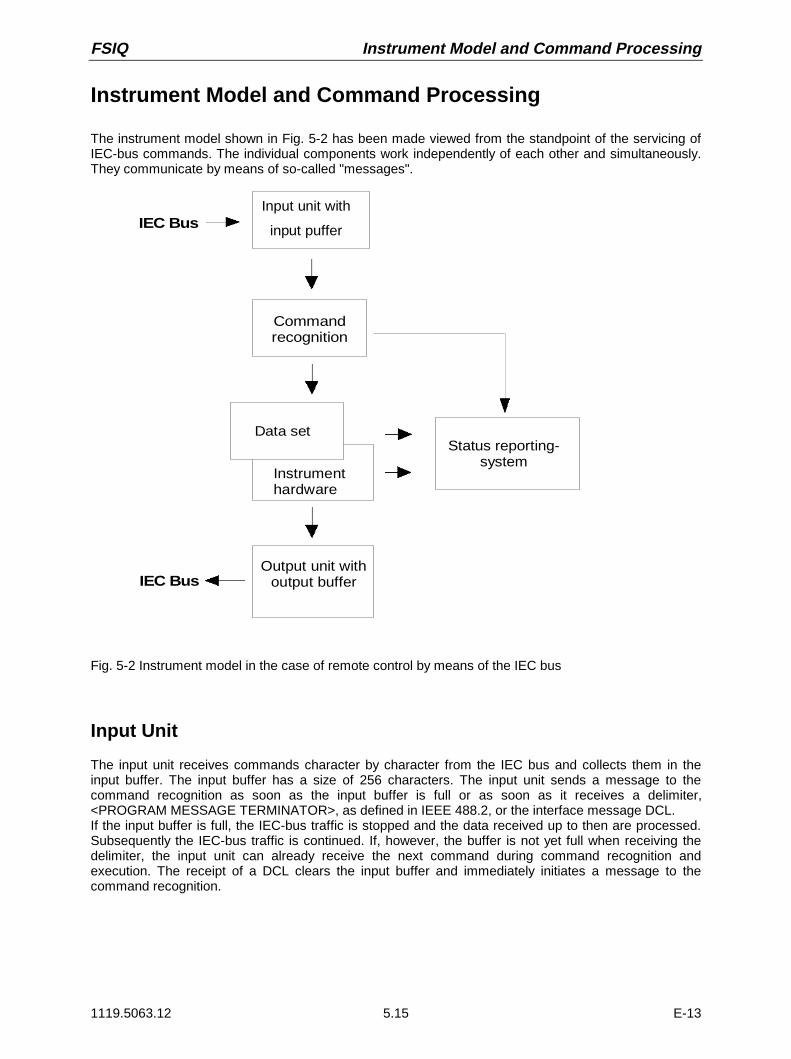
FSIQ Instrument Model and Command Processing
1119.5063.12 5.15 E-13
Instrument Model and Command Processing
The instrument model shown in Fig. 5-2 has been made viewed from the standpoint of the servicing ofIEC-bus commands. The individual components work independently of each other and simultaneously.They communicate by means of so-called "messages".
IEC Bus
Commandrecognition
Data set
Instrument hardware
IEC BusOutput unit with
output buffer
Input unit with
input puffer
Status reporting-system
Fig. 5-2 Instrument model in the case of remote control by means of the IEC bus
Input Unit
The input unit receives commands character by character from the IEC bus and collects them in theinput buffer. The input buffer has a size of 256 characters. The input unit sends a message to thecommand recognition as soon as the input buffer is full or as soon as it receives a delimiter,<PROGRAM MESSAGE TERMINATOR>, as defined in IEEE 488.2, or the interface message DCL.If the input buffer is full, the IEC-bus traffic is stopped and the data received up to then are processed.Subsequently the IEC-bus traffic is continued. If, however, the buffer is not yet full when receiving thedelimiter, the input unit can already receive the next command during command recognition andexecution. The receipt of a DCL clears the input buffer and immediately initiates a message to thecommand recognition.

Instrument Model and Command Processing FSIQ
1119.5063.12 5.16 E-13
Command Recognition
The command recognition analyses the data received from the input unit. It proceeds in the order inwhich it receives the data. Only a DCL is serviced with priority, a GET (Group Execute Trigger), e.g., isonly executed after the commands received before as well. Each recognized command is immediatelytransferred to the data set but without being executed there at once.Syntactical errors in the command are recognized here and supplied to the status reporting system. Therest of a command line after a syntax error is analysed further if possible and serviced.If the command recognition recognizes a delimiter or a DCL, it requests the data set to set thecommands in the instrument hardware as well now. Subsequently it is immediately prepared to processcommands again. This means for the command servicing that further commands can already beserviced while the hardware is still being set ("overlapping execution").
Data Set and Instrument Hardware
Here the expression "instrument hardware" denotes the part of the instrument fulfilling the actualinstrument function - signal generation, measurement etc. The controller is not included.
The data set is a detailed reproduction of the instrument hardware in the software.
IEC-bus setting commands lead to an alteration in the data set. The data set management enters thenew values (e.g. frequency) into the data set, however, only passes them on to the hardware whenrequested by the command recognition. As this is always only effected at the end of a command line,the order of the setting commands in the command line is not relevant.
The data are only checked for their compatibility among each other and with the instrument hardwareimmediately before they are transmitted to the instrument hardware. If the detection is made that anexecution is not possible, an "execution error" is signalled to the status reporting system. All alterationsof the data set are cancelled, the instrument hardware is not reset. Due to the delayed checking andhardware setting, however, it is permissible to set impermissible instrument states within one commandline for a short period of time without this leading to an error message. At the end of the command line,however, a permissible instrument state must have been reached again.
IEC-bus queries induce the data set management to send the desired data to the output unit.
Status Reporting System
The status reporting system collects information on the instrument state and makes it available to theoutput unit on request. The exact structure and function are described in the following section.

FSIQ Instrument Model and Command Processing
1119.5063.12 5.17 E-13
Output Unit
The output unit collects the information requested by the controller, which it receives from the data setmanagement. It processes it according to the SCPI rules and makes it available in the output buffer.The output buffer has a size of 4096 characters. If the information requested is longer, it is madeavailable "in portions" without this being recognized by the controller.If the instrument is addressed as a talker without the output buffer containing data or awaiting data fromthe data set management, the output unit sends error message "Query UNTERMINATED" to the statusreporting system. No data are sent on the IEC bus, the controller waits until it has reached its time limit.This behaviour is specified by SCPI.
Command Sequence and Command Synchronization
What has been said above makes clear that all commands can potentially be carried out overlapping.Equally, setting commands within one command line are not absolutely serviced in the order in whichthey have been received.
In order to make sure that commands are actually carried out in a certain order, each command mustbe sent in a separate command line, that is to say, with a separate IBWRT()-call.In order to prevent an overlapping execution of commands, one of commands *OPC, *OPC? or *WAImust be used. All three commands cause a certain action only to be carried out after the hardware hasbeen set and has settled. By a suitable programming, the contoller can be forced to wait for therespective action to occur (cf. Table 5-1).
Table 5-1 Synchronisation using *OPC, *OPC? and *WAI
Commnd Action after the hardware has settled Programming the controller
*OPC Setting the opteration-complete bit in the ESR - Setting bit 0 in the ESE- Setting bit 5 in the SRE- Waiting for service request (SRQ)
*OPC? Writing a "1" into the output buffer Addressing the instrument as a talker
*WAI Continuing the IEC-bus handshake Sending the next command
An example as to command synchronization can be found in chapter 7 "Program Examples".

Status Reporting System FSIQ
1119.5063.12 5.18 E-13
Status Reporting System
The status reporting system (cf. Fig. 5-3) stores all information on the present operating state of theinstrument, e.g. that the instrument presently carries out an AUTORANGE and on errors which haveoccurred. This information is stored in the status registers and in the error queue. The status registersand the error queue can be queried via IEC bus.
The information is of a hierarchical structure. The register status byte (STB) defined in IEEE 488.2 andits associated mask register service request enable (SRE) form the uppermost level. The STB receivesits information from the standard event status register (ESR) which is also defined in IEEE 488.2 withthe associated mask register standard event status enable (ESE) and registers STATus:OPERation andSTATus:QUEStionable which are defined by SCPI and contain detailed information on the instrument.
The IST flag ("Individual STatus") and the parallel poll enable register (PPE) allocated to it are also partof the status reporting system. The IST flag, like the SRQ, combines the entire instrument status in asingle bit. The PPE fulfills an analog function for the IST flag as the SRE for the service request.
The output buffer contains the messages the instrument returns to the controller. It is not part of thestatus reporting system but determines the value of the MAV bit in the STB and thus is represented inFig. 5-3.
Structure of an SCPI Status Register
Each SCPI register consists of 5 parts which each have a width of 16 bits and have different functions(cf. Fig. 5-2). The individual bits are independent of each other, i.e. each hardware status is assigned abit number which is valid for all five parts. For example, bit 3 of the STATus:OPERation register isassigned to the hardware status "wait for trigger" in all five parts. Bit 15 (the most significant bit) is set tozero for all parts. Thus the contents of the register parts can be processed by the controller as positiveinteger.
15 14 13 12 PTRansition part 3 2 1 0
15 14 13 12 EVENt part 3 2 1 0
15 14 13 12 ENABle part 3 2 1 0
& & & & & & & & & & & & & & & &
to higher-order register
Sum bit & = logical AND
= logical ORof all bits
+
+
15 14 13 12 NTRansition part 3 2 1 0
15 14 13 12 CONDition part 3 2 1 0
Fig. 5-2 The status-register model

FSIQ Status Reporting System
1119.5063.12 5.19 E-13
CONDition part The CONDition part is directly written into by the hardware or the sum bit ofthe next lower register. Its contents reflects the current instrument status. Thisregister part can only be read, but not written into or cleared. Its contents isnot affected by reading.
PTRansition part The Positive-TRansition part acts as an edge detector. When a bit of theCONDition part is changed from 0 to 1, the associated PTR bit decideswhether the EVENt bit is set to 1.PTR bit =1: the EVENt bit is set.PTR bit =0: the EVENt bit is not set.This part can be written into and read at will. Its contents is not affected byreading.
NTRansition part The Negative-TRansition part also acts as an edge detector. When a bit of theCONDition part is changed from 1 to 0, the associated NTR bit decideswhether the EVENt bit is set to 1.NTR-Bit = 1: the EVENt bit is set.NTR-Bit = 0: the EVENt bit is not set.This part can be written into and read at will. Its contents is not affected byreading.
With these two edge register parts the user can define which state transition ofthe condition part (none, 0 to 1, 1 to 0 or both) is stored in the EVENt part.
EVENt part The EVENt part indicates whether an event has occurred since the lastreading, it is the "memory" of the condition part. It only indicates eventspassed on by the edge filters. It is permanently updated by the instrument.This part can only be read by the user. During reading, its contents is set tozero. In linguistic usage this part is often equated with the entire register.
ENABle part The ENABle part determines whether the associated EVENt bit contributes tothe sum bit (cf. below). Each bit of the EVENt part is ANDed with theassociated ENABle bit (symbol ’&’). The results of all logical operations of thispart are passed on to the sum bit via an OR function (symbol ’+’).ENABle-Bit = 0: the associated EVENt bit does not contribute to the sum bitENABle-Bit = 1: if the associated EVENT bit is "1", the sum bit is set to "1" as
well.This part can be written into and read by the user at will. Its contents is notaffected by reading.
Sum bit As indicated above, the sum bit is obtained from the EVENt and ENABle partfor each register. The result is then entered into a bit of the CONDition part ofthe higher-order register.The instrument automatically generates the sum bit for each register. Thus anevent, e.g. a PLL that has not locked, can lead to a service request throughoutall levels of the hierarchy.
Note: The service request enable register SRE defined in IEEE 488.2 can be taken as ENABlepart of the STB if the STB is structured according to SCPI. By analogy, the ESE can betaken as the ENABle part of the ESR.

Status Reporting System FSIQ
1119.5063.12 5.20 E-13
Overview of the Status Registers
’
SRE STB
STATus:OPERation
PPE
IST flag
& = logical AND
= logical OR of all bits
ESE ESRError/event
queuebla
Outputbuffer
SRQ
RQS/MSSESBMAV
Power onUser RequestCommand ErrorExecution ErrorDevice Dependent Error
Query ErrorRequest Control
Operation Complete
1514131211109876543210
151413121110987654321
0
-&--&--&--&--&--&-
-&-
-&--&--&--&-
-&--&--&--&--&--&--&--&-
76543210
STATus:QUEStionable
not usedPROGram runningINSTrument summary bit
HCOPy in progressCORRectingWAIT for ARMWAIT for TRIGGERMEASuringSWEepingRANGingSETTling
CALibrating
not usedCOMMand warningTRANsducer breakACPLimitSYNCLMARginLIMitCALibration (= UNCAL)MODulationPHASeFREQuencyTEMPeraturePOWerTIMECURRentVOLTage
1514131211109876543
210
STATus:QUEStionable:LMARgin
1514131211109876543210
STATus:QUEStionable:POWer
1514131211109876543210
not used
IF_OVerload (screen B)UNDerload Option B7 (screen B)OVERload (screen B)
IF_OVerload (screen A)UNDerload Option B7 (screen A)OVERload (screen A)
STATus:QUEStionable:SYNC
not used
ALT2 LOWer FAIL (screen B)ALT2 UPPer FAIL (screen B)ALT1 LOWer FAIL (screen B)ALT1 UPPer FAIL (screen B)ADJ LOWer FAIL (screen B)ADJ UPPer FAIL (screen B)
ALT2 LOWer FAIL (screen A)ALT2 UPPer FAIL (screen A)ALT1 LOWer FAIL (screen A)ALT1 UPPer FAIL (screen A)ADJ LOWer FAIL (screen A)ADJ UPPer FAIL (screen A)
not used
LMARgin 8 FAILLMARgin 7 FAILLMARgin 6 FAILLMARgin 5 FAILLMARgin 4 FAILLMARgin 3 FAILLMARgin 2 FAILLMARgin 1 FAIL
not used
CARRier overloadNo carrierBURSt not foundSYNC not found
76543210
STATus:QUEStionable:ACPLimit
1514131211109876543210
STATus:QUEStionable:FREQuency
1514131211109876543210
not used
LO LEVel (screen B)LO UNLocked (screen B)
LO LEVel (screen A)LO UNLocked (screen A)bOVEN COLD
STATus:QUEStionable:LIMit
1514131211109876543210
not used
LIMit 8 FAILLIMit 7 FAILLIMit 6 FAILLIMit 5 FAILLIMit 4 FAILLIMit 3 FAILLIMit 2 FAILLIMit 1 FAIL
1514131211109876543210
STATus:QUEStionable:TRANsducer
not usedSubrange limit attained
Subrange 10Subrange 9Subrange 8Subrange 7Subrange 6Subrange 5Subrange 4Subrange 3Subrange 2Subrange 1
Fig. 5-3 Overview of the status registers
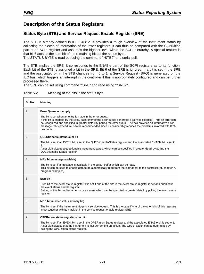
FSIQ Status Reporting System
1119.5063.12 5.21 E-13
Description of the Status Registers
Status Byte (STB) and Service Request Enable Register (SRE)
The STB is already defined in IEEE 488.2. It provides a rough overview of the instrument status bycollecting the pieces of information of the lower registers. It can thus be compared with the CONDitionpart of an SCPI register and assumes the highest level within the SCPI hierarchy. A special feature isthat bit 6 acts as the sum bit of the remaining bits of the status byte.The STATUS BYTE is read out using the command "*STB?" or a serial poll.
The STB implies the SRE. It corresponds to the ENABle part of the SCPI registers as to its function.Each bit of the STB is assigned a bit in the SRE. Bit 6 of the SRE is ignored. If a bit is set in the SREand the associated bit in the STB changes from 0 to 1, a Service Request (SRQ) is generated on theIEC bus, which triggers an interrupt in the controller if this is appropriately configured and can be furtherprocessed there.The SRE can be set using command "*SRE" and read using "*SRE?".
Table 5-2 Meaning of the bits in the status byte
Bit No. Meaning
2 Error Queue not empty
The bit is set when an entry is made in the error queue.If this bit is enabled by the SRE, each entry of the error queue generates a Service Request. Thus an error canbe recognized and specified in greater detail by polling the error queue. The poll provides an informative errormessage. This procedure is to be recommended since it considerably reduces the problems involved with IEC-bus control.
3 QUEStionable status sum bit
The bit is set if an EVENt bit is set in the QUEStionable-Status register and the associated ENABle bit is set to1.A set bit indicates a questionable instrument status, which can be specified in greater detail by polling theQUEStionable-Status register.
4 MAV bit (message available)
The bit is set if a message is available in the output buffer which can be read.This bit can be used to enable data to be automatically read from the instrument to the controller (cf. chapter 7,program examples).
5 ESB bit
Sum bit of the event status register. It is set if one of the bits in the event status register is set and enabled inthe event status enable register.Setting of this bit implies an error or an event which can be specified in greater detail by polling the event statusregister.
6 MSS bit (master status smmary bit)
The bit is set if the instrument triggers a service request. This is the case if one of the other bits of this registersis set together with its mask bit in the service request enable register SRE.
7 OPERation status register sum bit
The bit is set if an EVENt bit is set in the OPERation-Status register and the associated ENABle bit is set to 1.A set bit indicates that the instrument is just performing an action. The type of action can be determined bypolling the OPERation-status register.
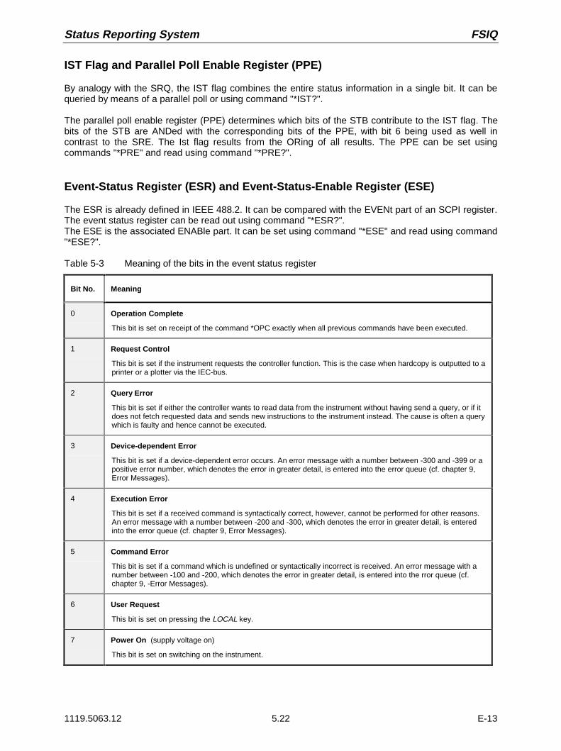
Status Reporting System FSIQ
1119.5063.12 5.22 E-13
IST Flag and Parallel Poll Enable Register (PPE)
By analogy with the SRQ, the IST flag combines the entire status information in a single bit. It can bequeried by means of a parallel poll or using command "*IST?".
The parallel poll enable register (PPE) determines which bits of the STB contribute to the IST flag. Thebits of the STB are ANDed with the corresponding bits of the PPE, with bit 6 being used as well incontrast to the SRE. The Ist flag results from the ORing of all results. The PPE can be set usingcommands "*PRE" and read using command "*PRE?".
Event-Status Register (ESR) and Event-Status-Enable Register (ESE)
The ESR is already defined in IEEE 488.2. It can be compared with the EVENt part of an SCPI register.The event status register can be read out using command "*ESR?".The ESE is the associated ENABle part. It can be set using command "*ESE" and read using command"*ESE?".
Table 5-3 Meaning of the bits in the event status register
Bit No. Meaning
0 Operation Complete
This bit is set on receipt of the command *OPC exactly when all previous commands have been executed.
1 Request Control
This bit is set if the instrument requests the controller function. This is the case when hardcopy is outputted to aprinter or a plotter via the IEC-bus.
2 Query Error
This bit is set if either the controller wants to read data from the instrument without having send a query, or if itdoes not fetch requested data and sends new instructions to the instrument instead. The cause is often a querywhich is faulty and hence cannot be executed.
3 Device-dependent Error
This bit is set if a device-dependent error occurs. An error message with a number between -300 and -399 or apositive error number, which denotes the error in greater detail, is entered into the error queue (cf. chapter 9,Error Messages).
4 Execution Error
This bit is set if a received command is syntactically correct, however, cannot be performed for other reasons.An error message with a number between -200 and -300, which denotes the error in greater detail, is enteredinto the error queue (cf. chapter 9, Error Messages).
5 Command Error
This bit is set if a command which is undefined or syntactically incorrect is received. An error message with anumber between -100 and -200, which denotes the error in greater detail, is entered into the rror queue (cf.chapter 9, -Error Messages).
6 User Request
This bit is set on pressing the LOCAL key.
7 Power On (supply voltage on)
This bit is set on switching on the instrument.

FSIQ Status Reporting System
1119.5063.12 5.23 E-13
STATus:OPERation Register
In the CONDition part, this register contains information on which actions the instrument is beingexecuting or, in the EVENt part, information on which actions the instrument has executed since the lastreading. It can be read using commands "STATus:OPERation:CONDition?" or "STATus:OPERation[:EVENt]?".
Table 5-4 Meaning of the bits in the STATus.OPERation register
Bit No. Meaning
0 CALibrating
This bit is set as long as the instrument is performing a calibration.
1 SETTling
This bit is set as long as the new status is settling after a setting command. It is only set if the settling time islonger than the command processing time.
2 RANGingThis bit is set as long as the instrument is changing a range (e.g. Autorange).
3 SWEeping
This bit is set while the instrument is performing a sweep.
4 MEASuring
This bit is set while the instrument is performing a measurement.
5 WAIT for TRIGGER
This bit is set as long as the instrument is waiting for a trigger event.
6 WAIT for ARM
This bit is set as long as the instrument is waiting for an arming event.
7 CORRecting
This bit is set while the instrument is performing a correction.
8 HardCOPy in progress
This bit is set while the instrument is printing a hardcopy.
9-12 Device dependent
13 INSTrument Summary Bit
This bit is set when one or more logical instruments is reporting a status message.
14 PROGram running
This bit is set while the instrument is performing a program.
15 This bit is always 0
The FSIQ supports bits 0 and 8.
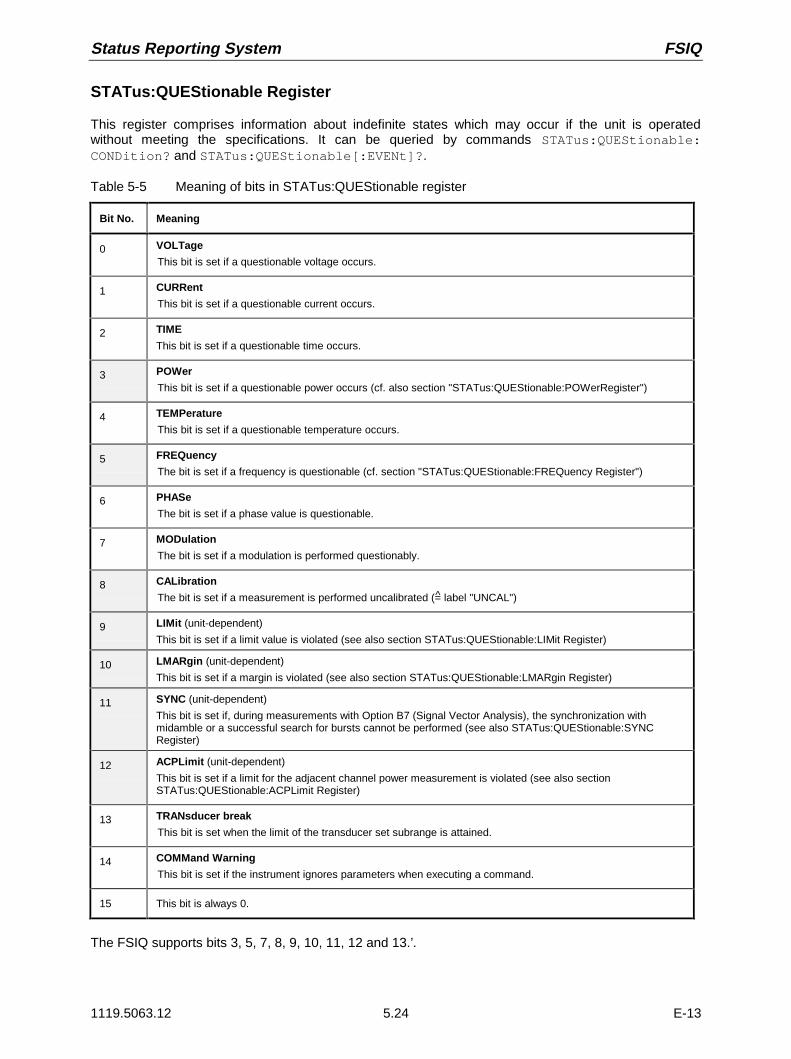
Status Reporting System FSIQ
1119.5063.12 5.24 E-13
STATus:QUEStionable Register
This register comprises information about indefinite states which may occur if the unit is operatedwithout meeting the specifications. It can be queried by commands STATus:QUEStionable:CONDition? and STATus:QUEStionable[:EVENt]?.
Table 5-5 Meaning of bits in STATus:QUEStionable register
Bit No. Meaning
0 VOLTage
This bit is set if a questionable voltage occurs.
1 CURRent
This bit is set if a questionable current occurs.
2 TIME
This bit is set if a questionable time occurs.
3 POWer
This bit is set if a questionable power occurs (cf. also section "STATus:QUEStionable:POWerRegister")
4 TEMPerature
This bit is set if a questionable temperature occurs.
5 FREQuency
The bit is set if a frequency is questionable (cf. section "STATus:QUEStionable:FREQuency Register")
6 PHASe
The bit is set if a phase value is questionable.
7 MODulation
The bit is set if a modulation is performed questionably.
8 CALibration
The bit is set if a measurement is performed uncalibrated (= label "UNCAL")
9 LIMit (unit-dependent)
This bit is set if a limit value is violated (see also section STATus:QUEStionable:LIMit Register)
10 LMARgin (unit-dependent)
This bit is set if a margin is violated (see also section STATus:QUEStionable:LMARgin Register)
11 SYNC (unit-dependent)
This bit is set if, during measurements with Option B7 (Signal Vector Analysis), the synchronization withmidamble or a successful search for bursts cannot be performed (see also STATus:QUEStionable:SYNCRegister)
12 ACPLimit (unit-dependent)
This bit is set if a limit for the adjacent channel power measurement is violated (see also sectionSTATus:QUEStionable:ACPLimit Register)
13 TRANsducer break
This bit is set when the limit of the transducer set subrange is attained.
14 COMMand Warning
This bit is set if the instrument ignores parameters when executing a command.
15 This bit is always 0.
The FSIQ supports bits 3, 5, 7, 8, 9, 10, 11, 12 and 13.’.

FSIQ Status Reporting System
1119.5063.12 5.25 E-13
STATus QUEStionable:ACPLimit Register
This register comprises information about the observance of limits during adjacent powermeasurements. It can be queried with commands ’STATus:QUEStionable:ACPLimit:CONDition?’ and ’STATus:QUEStionable:ACPLimit[:EVENt]?’
Table 5-6 Meaning of bits in STATus:QUEStionable:ACPLimit register
Bit No. Meaning
0 ADJ UPPer FAIL(Screen A)
This bit is set if the limit is exceeded in the upper adjacent channel.
1 ADJ LOWer FAIL (Screen A)
This bit is set if the limit is exceeded in the lower adjacent channel.
2 ALT1 UPPer FAIL (Screen A)
This bit is set if the limit is exceeded in the upper 1st alternate channel.
3 ALT1 LOWer FAIL (Screen A)
This bit is set if the limit is exceeded in the lower 1st alternate channel.
4 ALT2 UPPer FAIL (Screen A)
This bit is set if the limit is exceeded in the upper 2nd alternate channel.
5 ALT2 LOWer FAIL (Screen A)
This bit is set if the limit is exceeded in the lower 2nd alternate channel.
6 not used
7 not used
8 ADJ UPPer FAIL (Screen B)
This bit is set if the limit is exceeded in the upper adjacent channel.
9 ADJ LOWer FAIL (Screen B)
This bit is set if the limit is exceeded in the lower adjacent channel.
10 ALT1 UPPer FAIL (Screen B)
This bit is set if the limit is exceeded in the upper 1st alternate channel.
11 ALT1 LOWer FAIL (Screen B)
This bit is set if the limit is exceeded in the lower 1st alternate channel.
12 ALT2 UPPer FAIL (Screen B)
This bit is set if the limit is exceeded in the upper 2nd alternate channel.
13 ALT2 LOWer FAIL (Screen A)
This bit is set if the limit is exceeded in the lower 2nd alternate channel.
14 not used
15 This bit is always 0.

Status Reporting System FSIQ
1119.5063.12 5.26 E-13
STATus QUEStionable:FREQuency Register
This register comprises information about the reference and local oscillator.It can be queried with commands STATus:QUEStionable:FREQuency:CONDition? and "STATus:QUEStionable:FREQuency[:EVENt]?.
Table 5-7 Meaning of bits in STATus:QUEStionable:FREQuency register
Bit No. Meaning
0 OVEN COLD
This bit is set if the reference oscillator has not yet attained its operating temperature. ’OCXO’ will then bedisplayed.
1 LO UNLocked (Screen A)
This bit is set if the local oscillator no longer locks. ’LO unl’ will then be displayed.
2 LO LEVel (Screen A)
This bit is set if the level of the local oscillator is smaller than the nominal value. ’LO LVL’ will then be displayed.
3 not used
4 not used
5 not used
6 not used
7 not used
8 not used
9 LO UNLocked (Screen B)
This bit is set if the local oscillator no longer locks.’ LO unl’ will then be displayed.
10 LO LEVel (Screen B)
This bit is set if the level of the local oscillator is smaller than the nominal value. ’LO LVL’ will then be displayed.
11 not used
12 not used
13 not used
14 not used
15 This bit is always 0.

FSIQ Status Reporting System
1119.5063.12 5.27 E-13
STATus QUEStionable:LIMit Register
This register comprises information about the observance of limit lines. It can be queried withcommands STATus:QUEStionable:LIMit:CONDition? and STATus:QUEStionable:LIMit[:EVENt]?.
Table 5-8 Meaning of bits in STATus:QUEStionable:LIMit register
Bit No. Meaning
0 LIMit 1 FAIL
This bit is set if limit line 1 is violated.
1 LIMit 2 FAIL
This bit is set if limit line 2 is violated.
2 LIMit 3 FAIL
This bit is set if limit line 3 is violated.
3 LIMit 4 FAIL
This bit is set if limit line 4 is violated.
4 LIMit 5 FAIL
This bit is set if limit line 5 is violated.
5 LIMit 6 FAIL
This bit is set if limit line 6 is violated.
6 LIMit 7 FAIL
This bit is set if limit line 7 is violated.
7 LIMit 8 FAIL
This bit is set if limit line 8 is violated.
8 not used
9 not used
10 not used
11 not used
12 not used
13 not used
14 not used
15 This bit is always 0.

Status Reporting System FSIQ
1119.5063.12 5.28 E-13
STATus QUEStionable:LMARgin Register
This register comprises information about the observance of limit margins. It can be queried withcommands STATus:QUEStionable:LMARgin:CONDition? and "STATus:QUEStionable:LMARgin[:EVENt]?.
Table 5-9 Meaning of bits in STATus:QUEStionable:LMARgin register
Bit No. Meaning
0LMARgin 1 FAIL
This bit is set if limit margin 1 is violated.
1LMARgin 2 FAIL
This bit is set if limit margin 2 is violated.
2LMARgin 3 FAIL
This bit is set if limit margin 3 is violated.
3LMARgin 4 FAIL
This bit is set if limit margin 4 is violated.
4LMARgin 5 FAIL
This bit is set if limit margin 5 is violated.
5LMARgin 6 FAIL
This bit is set if limit margin 1 is violated.
6LMARgin 7 FAIL
This bit is set if limit margin 7 is violated.
7LMARgin 8 FAIL
This bit is set if limit margin 8 is violated.
8 not used
9 not used
10 not used
11 not used
12 not used
13 not used
14 not used
15 This bit is always 0.
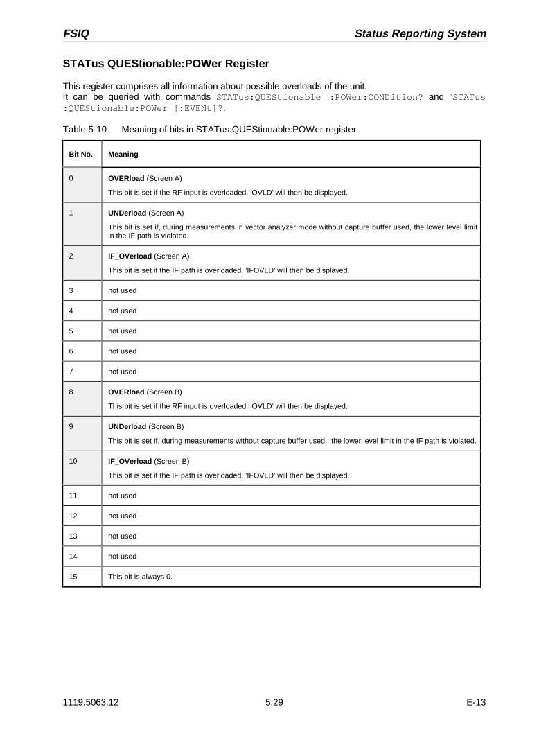
FSIQ Status Reporting System
1119.5063.12 5.29 E-13
STATus QUEStionable:POWer Register
This register comprises all information about possible overloads of the unit.It can be queried with commands STATus:QUEStionable :POWer:CONDition? and "STATus:QUEStionable:POWer [:EVENt]?.
Table 5-10 Meaning of bits in STATus:QUEStionable:POWer register
Bit No. Meaning
0 OVERload (Screen A)
This bit is set if the RF input is overloaded. ’OVLD’ will then be displayed.
1 UNDerload (Screen A)
This bit is set if, during measurements in vector analyzer mode without capture buffer used, the lower level limitin the IF path is violated.
2 IF_OVerload (Screen A)
This bit is set if the IF path is overloaded. ’IFOVLD’ will then be displayed.
3 not used
4 not used
5 not used
6 not used
7 not used
8 OVERload (Screen B)
This bit is set if the RF input is overloaded. ’OVLD’ will then be displayed.
9 UNDerload (Screen B)
This bit is set if, during measurements without capture buffer used, the lower level limit in the IF path is violated.
10 IF_OVerload (Screen B)
This bit is set if the IF path is overloaded. ’IFOVLD’ will then be displayed.
11 not used
12 not used
13 not used
14 not used
15 This bit is always 0.

Status Reporting System FSIQ
1119.5063.12 5.30 E-13
STATus QUEStionable:SYNC Register
This register comprises information about sync and burst events.It can be queried with commands STATus:QUEStionable:SYNC:CONDition? and "STATus:QUEStionable:SYNC[:EVENt]?.
Table 5-11 Meaning of bits in STATus:QUEStionable:SYNC register
Bit No. Meaning
0 SYNC not found
This bit is set if the sync sequence of midamble was not found.
1 BURSt not found
This bit is set if a burst was not found.
2 No carrier
This bit is set if a signal was not found after starting the GSM/DCS/PCS mobile (option FSE-K10) or base station(option FSE-K11) test.
3 Carrier overload
This bit is set if the sync sequence of midamble was not found after starting the GSM/DCS/PCS mobile(option FSE-K10) or base station (option FSE-K11) test.
4 not used
5 not used
6 not used
7 not used
8 not used
9 not used
10 not used
11 not used
12 not used
13 not used
14 not used
15 This bit is always 0.

FSIQ Status Reporting System
1119.5063.12 5.31 E-13
STATus QUEStionable:TRANsducer Register
This register indicates that a transducer hold point is attained (bit 15) and what range is to be sweptnext (bit 0 to 10). The sweep can be continued with command INITiate2:CONMeasure.It can be queried with commands STATus:QUEStionable:TRANsducer:CONDition? and "STATus:QUEStionable:TRANsducer[:EVENt]?.
Table 5-12 Meaning of bits in STATus:QUEStionable:TRANsducer register
Bit No. Meaning
0Range 1This bit is set when subrange 1 is attained.
1Range 2This bit is set when subrange 2 is attained.
2 Range 3This bit is set when subrange 3 is attained.
3 Range 4This bit is set when subrange 4 is attained.
4 Range 5This bit is set when subrange 1 is attained.
5 Range 6This bit is set when subrange 6 is attained.
6 Range 7This bit is set when subrange 7 is attained.
7 Range 8This bit is set when subrange 8 is attained.
8 Range 9This bit is set when subrange 9 is attained.
9 Range 10This bit is set when subrange 10 is attained.
10 not used
11 not used
12 not used
13 not used
14 Subrange limitThis bit is set when the transducer is at the point of changeover from one range to another.
15 This bit is always 0.

Status Reporting System FSIQ
1119.5063.12 5.32 E-13
Application of the Status Reporting Systems
In order to be able to effectively use the status reporting system, the information contained there mustbe transmitted to the controller and further processed there. There are several methods which arerepresented in the following. Detailed program examples are to be found in chapter 7, ProgramExamples.
Service Request, Making Use of the Hierarchy Structure
Under certain circumstances, the instrument can send a service request (SRQ) to the controller. Usuallythis service request initiates an interrupt at the controller, to which the control program can react withcorresponding actions. As evident from Fig. 5-3, an SRQ is always initiated if one or several of bits 2, 3,4, 5 or 7 of the status byte are set and enabled in the SRE. Each of these bits combines the informationof a further register, the error queue or the output buffer. The corresponding setting of the ENABle partsof the status registers can achieve that arbitrary bits in an arbitrary status register initiate an SRQ. Inorder to make use of the possibilities of the service request, all bits should be set to "1" in enableregisters SRE and ESE.
Examples (cf. Fig. 5-3 and chapter 7, Program Examples, as well):
Use of command "*OPC" to generate an SRQ at the end of a sweep.
À Set bit 0 in the ESE (Operation Complete)
À Set bit 5 in the SRE (ESB)?
After its settings have been completed, the instrument generates an SRQ.
The SRQ is the only possibility for the instrument to become active on its own. Each controller programshould set the instrument such that a service request is initiated in the case of malfunction. The programshould react appropriately to the service request. A detailed example for a service request routine is tobe found in chapter 7, Program Examples.
Serial Poll
In a serial poll, just as with command "*STB", the status byte of an instrument is queried. However, thequery is realized via interface messages and is thus clearly faster. The serial-poll method has alreadybeen defined in IEEE 488.1 and used to be the only standard possibility for different instruments to pollthe status byte. The method also works with instruments which do not adhere to SCPI or IEEE 488.2.
The quick-BASIC command for executing a serial poll is "IBRSP()". Serial poll is mainly used to obtain afast overview of the state of several instruments connected to the IEC bus.Parallel Poll
In a parallel poll, up to eight instruments are simultaneously requested by the controller by means of asingle command to transmit 1 bit of information each on the data lines, i.e., to set the data line allocatedto each instrument to logically "0" or "1". By analogy to the SRE register which determines under whichconditions an SRQ is generated, there is a parallel poll enable register (PPE) which is ANDed with theSTB bit by bit as well considering bit 6. The results are ORed, the result is then sent (possibly inverted)as a response in the parallel poll of the controller. The result can also be queried without parallel poll bymeans of command "*IST".

FSIQ Status Reporting System
1119.5063.12 5.33 E-13
The instrument first has to be set for the parallel poll using quick-BASIC command "IBPPC()". Thiscommand allocates a data line to the instrument and determines whether the response is to be inverted.The parallel poll itself is executed using "IBRPP()".
The parallel-poll method is mainly used in order to quickly find out after an SRQ which instrument hassent the service request if there are many instruments connected to the IEC bus. To this effect, SREand PPE must be set to the same value. A detailed example as to the parallel poll is to be found inchapter 7, Program Examples.
Query by Means of Commands
Each part of every status register can be read by means of queries. The individual commands areindicated in the detailed description of the registers. What is returned is always a number whichrepresents the bit pattern of the register queried. Evaluating this number is effected by the controllerprogram.
Queries are usually used after an SRQ in order to obtain more detailed information on the cause of theSRQ.
Error-Queue Query
Each error state in the instrument leads to an entry in the error queue. The entries of the error queueare detailed plain-text error messages which can be looked at in the ERROR menu via manual controlor queried via the IEC bus using command "SYSTem:ERRor?". Each call of "SYSTem:ERRor?"provides an entry from the error queue. If no error messages are stored there any more, the instrumentresponds with 0, "No error".
The error queue should be queried after every SRQ in the controller program as the entries describe thecause of an error more precisely than the status registers. Especially in the test phase of a controllerprogram the error queue should be queried regularly since faulty commands from the controller to theinstrument are recorded there as well.

Status Reporting System FSIQ
1119.5063.12 5.34 E-13
Resetting Values of the Status Reporting System
Table 5-13 comprises the different commands and events causing the status reporting system to bereset. None of the commands, except for *RST and SYSTem:PRESet influences the functionalinstrument settings. In particular, DCL does not change the instrument settings.
Table 5-13 Resettting instrument functions
Event Switching on supplyvoltage DCL,SDC
Power-On-Status-Clear
(Device Clear,Selected Device
Clear)
*RST orSYSTem:PRESet
STATus:PRESet *CLS
Effect 0 1
Clear STB,ESR yes yes
Clear SRE,ESE yes
Clear PPE yes
Clear EVENTt parts of theregisters
yes yes
Clear Enable parts of allOPERation andQUEStionable registers,Fill Enable parts of allother registers with "1".
yes yes
Fill PTRansition parts with"1" ,Clear NTRansition parts
yes yes
Clear error queue yes yes yes
Clear output buffer yes yes yes 1) 1) 1)
Clear commandprocessing and inputbuffer
yes yes yes
1) Every command being the first in a command line, i.e., immediately following a <PROGRAM MESSAGE TERMINATOR>clears the output buffer.

FSIQ Contents - Description of Commands
1119.5063.12 I-6.1 E-1
Contents - Chapter 6 "Remote Control - Descriptionof Commands"
6 Description of Commands
Notation ............................................................................................................................................ 6.1
Common Commands....................................................................................................................... 6.4
ABORt Subsystem ........................................................................................................................... 6.7
CALCulate Subsystem..................................................................................................................... 6.7CALCulate:DELTamarker Subsystem..................................................................................... 6.8
CALCulate:DLINe Subsystem ............................................................................................... 6.14
CALCulate:FEED Subsystem ................................................................................................ 6.18
CALCulate:FORMat Subsystem............................................................................................ 6.19
CALCulate:LIMit Subsystem.................................................................................................. 6.20
CALCulate:MARKer Subsystem ............................................................................................ 6.35
CALCulate:MATH Subsystem ............................................................................................... 6.60
CALCulate:UNIT Subsystem ................................................................................................. 6.61
CALibration Subsystem ................................................................................................................ 6.62
CONFigure Subsystem.................................................................................................................. 6.64CONFigure:BTS Subsystem.................................................................................................. 6.64
CONFigure:BURSt Subsystem.............................................................................................. 6.71
CONFigure:MS Subsystem ................................................................................................... 6.74
CONFigure:SPECtrum Subsystem........................................................................................ 6.80
CONFigure:SPURious Subsystem ........................................................................................ 6.82
DIAGnostic Subsystem ................................................................................................................. 6.84
DISPlay Subsystem........................................................................................................................ 6.86
FETCh Subsystem ......................................................................................................................... 6.96FETCh:BURSt Subsystem .................................................................................................... 6.96
FETCh:SPECtrum Subsystem ............................................................................................ 6.101
FETCh:SPURious Subsystem............................................................................................. 6.104
FETCh:PTEMplate Subsystem............................................................................................ 6.106
FORMat Subsystem..................................................................................................................... 6.107
HCOPy Subsystem ...................................................................................................................... 6.109
INITiate Subsystem...................................................................................................................... 6.114
INPut Subsystem ......................................................................................................................... 6.115
INSTrument Subsystem .............................................................................................................. 6.118
MMEMory Subsystem.................................................................................................................. 6.120
OUTPut Subsystem ..................................................................................................................... 6.131
READ Subsystem......................................................................................................................... 6.133READ:BURSt Subsystem .................................................................................................... 6.133
READ:SPECtrum Subsystem.............................................................................................. 6.141
READ:SPURious Subsystem .............................................................................................. 6.143

Contents - Description of Commands FSIQ
1119.5063.12 I-6.2 E-1
SENSe Subsystem ....................................................................................................................... 6.145SENSe:ADEMod Subsystem............................................................................................... 6.145
SENSe:AVERage Subsystem ............................................................................................. 6.147
SENSe:BANDwidth Subsystem........................................................................................... 6.149
SENSe:CORRection-Subsystem......................................................................................... 6.152
SENSe:DETector Subsystem.............................................................................................. 6.162
SENSe:DDEMod Subsystem............................................................................................... 6.163
SENSe:FILTer Subsystem .................................................................................................. 6.171
SENSe:FREQuency Subsystem.......................................................................................... 6.174
SENSe:MIXer - Subsystem ................................................................................................. 6.178
SENSe:MSUMmary Subsystem .......................................................................................... 6.182
SENSe:POWer Subsystem ................................................................................................. 6.184
SENSe:ROSCillator Subsystem .......................................................................................... 6.187
SENSe:SWEep Subsystem................................................................................................. 6.188
SOURce Subsystem .................................................................................................................... 6.192
STATus Subsystem ..................................................................................................................... 6.194
SYSTem Subsystem .................................................................................................................... 6.205
TRACe Subsystem....................................................................................................................... 6.211
TRIGger Subsystem..................................................................................................................... 6.213
UNIT Subsystem .......................................................................................................................... 6.216
Alphabetical List of Commands ................................................................................................. 6.217
Table of Softkeys with IEC/IEEE-Bus Command Assignment ................................................ 6.233Basic Instrument - Signal Analysis Mode ............................................................................ 6.233
FREQUENCY Key Group.......................................................................................... 6.233LEVEL Key Group ..................................................................................................... 6.235INPUT Key................................................................................................................. 6.236MARKER Key Group ................................................................................................. 6.237LINES Key Group ...................................................................................................... 6.241TRACE Key Group .................................................................................................... 6.242SWEEP Key Group ................................................................................................... 6.244
Basic Instrument - General Device Settings........................................................................ 6.247DATA VARIATION Key Group .................................................................................. 6.247SYSTEM Key Group.................................................................................................. 6.247CONFIGURATION Key Group .................................................................................. 6.250STATUS Key Group .................................................................................................. 6.252HARDCOPY Key Group ............................................................................................ 6.253MEMORY Key Group ................................................................................................ 6.254USER Key ................................................................................................................. 6.256
Vektor-Signal Analysis Mode............................................................................................... 6.257CONFIGURATION Key Group - Digital Demodulation.............................................. 6.257CONFIGURATION Key Group - Analog Demodulation ............................................ 6.261FREQUENCY Key Group.......................................................................................... 6.263LEVEL Key Group ..................................................................................................... 6.263INPUT Key................................................................................................................. 6.264MARKER Key Group ................................................................................................. 6.265LINES Key Group ...................................................................................................... 6.267TRACE Key Group .................................................................................................... 6.268

FSIQ Contents - Description of Commands
1119.5063.12 I-6.3 E-1
SWEEP Key Group ................................................................................................... 6.269TRIGGER Key - Digital Demodulation ...................................................................... 6.269TRIGGER Key - Analog Demodulation .................................................................... 6.270
Tracking Generator (Option FSE-B8 to B11).......................................................................... 271CONFIGURATION Key Group ..................................................................................... 271
GSM BTS Analysis (Option FSE-K11)................................................................................. 6.272CONFIGURATION Key Group .................................................................................. 6.272
GSM MS Analysis (Option FSE-K10) .................................................................................. 6.280CONFIGURATION Key Group .................................................................................. 6.280
External Mixer (Option FSE-B21) ........................................................................................ 6.288INPUT Key Group...................................................................................................... 6.288

Contents - Description of Commands FSIQ
1119.5063.12 I-6.4 E-1

FSIQ Notation
1119.5063.12 6.1 E-13
6 Description of Commands
Notation
In the following sections, all commands implemented in the instrument are first listed in tables and thendescribed in detail, separated according to the command system. The notation corresponds to the oneof the SCPI standards to a large extent. The SCPI conformity information can be taken from theindividual description of the commands.
Table of CommandsCommand: In the command column, the table provides an overview of the commands
and their hierarchical arrangement (see indentations).
Parameter: The parameter column indicates the requested parameters together withtheir specified range.
Unit: The unit column indicates the basic unit of the physical parameters.
Remark: In the remark column an indication is made on:– whether the command does not have a query form,– whether the command has only one query form– whether this command is implemented only with a certain option of the
instrument
Indentations The different levels of the SCPI command hierarchy are represented in thetable by means of indentations to the right. The lower the level is, thefarther the indentation to the right is. Please observe that the completenotation of the command always includes the higher levels as well.
Example: SENSe:FREQuency:CENTer is represented in the table asfollows:
SENSe first level:FREQuency second level
:CENTer third level
Individual description In the individual description, the complete notation of the command isgiven. An example for each command, the *RST value and the SCPIinformation is written out at the end of the individual description.The modes for which a command can be used are indicated by thefollowing abbreviations:
A Spectrum analysisA-F Spectrum analysis - frequency domain onlyA-Z Spectrum analysis - time domain only (zero span)VA Vector signal analysisVA-D Vector signal analysis - digital demodulation onlyVA-A Vector signal analysis - analog demodulation onlyBTS GSM BTS analysis (option FSE-K11)MS GSM MS analysis (option FSE-K10)
Note: The spectrum analysis (analyzer) and vector signal analysis(vector analyzer) modes are implemented in the basic unit. Forthe other modes, the corresponding options are required.

Notation FSIQ
1119.5063.12 6.2 E-13
Upper/lower case notation Upper/lower case letters serve to mark the long or short form of the keywords of a command in the description (see Chapter 5). The instrumentitself does not distinguish between upper and lower case letters.
Special characters | A selection of key words with an identical effect exists for severalcommands. These key words are indicated in the same line, they areseparated by a vertical stroke. Only one of these key words has to beindicated in the header of the command. The effect of the command isindependent of which of the key words is indicated.
Example:SENSe:FREQuency:CW|:FIXed
The two following commands of identical meaning can beformed. They set the frequency of the constantly frequent signalto 1 kHz:
SENSe:FREQuency:CW 1E3 = SENSe:FREQuency:FIXed 1E3
A vertical stroke in indicating the parameters marks alternative possibilitiesin the sense of "or". The effect of the command is different, depending onwhich parameter is entered.
Example:Selection of the parameters for the command
INPut:COUPling AC | DC
If parameter AC is selected, only the AC content is fed through, inthe case of DC, the DC as well as the AC content.
[ ] Key words in square brackets can be omitted when composing the header(cf. Chapter 5, Section "Optional Keywords"). The full command lengthmust be accepted by the instrument for reasons of compatibility with theSCPI standards.Parameters in square brackets can optionally be incorporated in thecommand or omitted as well.
Parameters in braces can optionally be incorporated in the command eithernot at all, once or several times.
Description of parameters Due to the standardization, the parameter section of SCPI commandsconsists always of the same syntactical elements. SCPI has specified aseries of definitions therefore, which are used in the tables of commands.In the tables, these established definitions are indicated in angled brackets(<...>) and will be briefly explained in the following (see also Chapter 5,Section "Parameters").
<Boolean> This indication refers to parameters which can adopt two states, "on" and"off". The "off" state may either be indicated by the keyword OFF or by thenumeric value 0, the "on" state is indicated by ON or any numeric valueother than zero. Parameter queries are always returned the numeric value0 or 1.

FSIQ Notation
1119.5063.12 6.3 E-13
<numeric_value><num> These indications mark parameters which may be entered as numeric
values or be set using specific keywords (character data).
The keywords given below are permitted:
MINimum This keyword sets the parameter to the smallest possiblevalue.
MAXimum This keyword sets the parameter to the largest possible value.
DEFault This keyword is used to reset the parameter to its defaultvalue.
UP This keyword increments the parameter value.
DOWN This keyword decrements the parameter.
The numeric values associated to MAXimum/MINimum/DEFault can bequeried by adding the corresponding keywords to the command. Theymust be entered following the quotation mark.
Example:SENSe:FREQuency:CENTer? MAXimum
returns the maximum possible numeric value of the center frequency asresult.
<arbitrary block program data>This keyword is provided for commands the parameters of which consist ofa binary data block.

Common Commands FSIQ
1119.5063.12 6.4 E-13
Common Commands
The common commands are taken from the IEEE 488.2 (IEC 625-2) standard. Same commands havethe same effect on different devices. The headers of these commands consist of an asterisk "*" followedby three letters. Many common commands refer to the status reporting system which is described indetail in Chapter 5.
Command Designation Parameter Remark
*CAL? Calibration Query query only
*CLS Clear Status no query
*ESE Event Status Enable 0 to 255
*ESR? Standard Event Status Query 0 to 255 query only
*IDN? Identification Query <string> query only
*IST? Individual Status Query 0 to 255 query only
*OPC Operation Complete
*OPT? Option Identification Query query only
*PCB Pass Control Back 0 to 30 no query
*PRE Parallel Poll Register Enable 0 to 255
*PSC Power On Status Clear 0 | 1
*RST Reset no query
*SRE Service Request Enable 0 to 255
*STB? Status Byte Query query only
*TRG Trigger no query
*TST? Self Test Query query only
*WAI Wait to continue no query
*CAL?CALIBRATION QUERY triggers a calibration of the instrument and subsequently query thecalibration status. Any responses > 0 indicate errors.
*CLSCLEAR STATUS sets the status byte (STB), the standard event register (ESR) and the EVENt-partof the QUEStionable and the OPERation register to zero. The command does not alter the mask andtransition parts of the registers. It clears the output buffer.
*ESE 0 to 255EVENT STATUS ENABLE sets the event status enable register to the value indicated. Query *ESE?returns the contents of the event status enable register in decimal form.

FSIQ Common Commands
1119.5063.12 6.5 E-13
*ESR?STANDARD EVENT STATUS QUERY returns the contents of the event status register in decimalform (0 to 255) and subsequently sets the register to zero.
*IDN?IDENTIFICATION QUERY queries the instrument identification.The instrument identification consists of the following elements which are separated by commas:
ManufacturerDevice (analyzer model)Serial number of the instrumentFirmware version numberExample: "Rohde&Schwarz, FSIQ3, 825082/007, 2.05"
*IST?INDIVIDUAL STATUS QUERY returns the contents of the IST flag in decimal form (0 | 1). The ISTflag is the status bit which is sent during a parallel poll (cf. Chapter 5).
*OPCOPERATION COMPLETE sets bit 0 in the event status register when all preceding commands havebeen executed. This bit can be used to initiate a service request (cf. Chapter 5).
*OPC?OPERATION COMPLETE QUERY writes message "1" into the output buffer as soon as allpreceding commands have been executed (cf. Chapter 5).
*OPT?OPTION IDENTIFICATION QUERY queries the options included in the instrument and returns a listof the options installed. The options are separated from each other by means of commas.
Position Option
1 reserved
2 FSE-B4 Low Phase Noise & OCXO
3 FSE-B5 FFT-Filter
4 reserved
5 FSE-B7 Vector Signal Analysis
6 FSE-B8 Tracking Generator 3.5 GHz
7 FSE-B9 Tracking Generator 3.5 GHz with I/Q modulator
8 FSE-B10 Tracking Generator 7 GHz
9 FSE-B11 Tracking Generator 7 GHz with I/Q modulator
10 FSE-B12 Output Attenuator for Tracking Generator
11 to 18 reserved
19 FSE-B21 External Mixer Output
Example: 0, FSE-B4, 0, 0, FSE-B7, 0, 0, 0, FSE-B11, FSE-B12, 0, 0, 0, 0, 0, 0, 0, 0, 0, 0, 0
Note: The standard FSIQ is equipped with options FSE-B4, FSE-B6 and FSE-B7.
*PCB 0 to 30PASS CONTROL BACK indicates the controller address which the IEC-bus control is to be returnedto after termination of the triggered action.
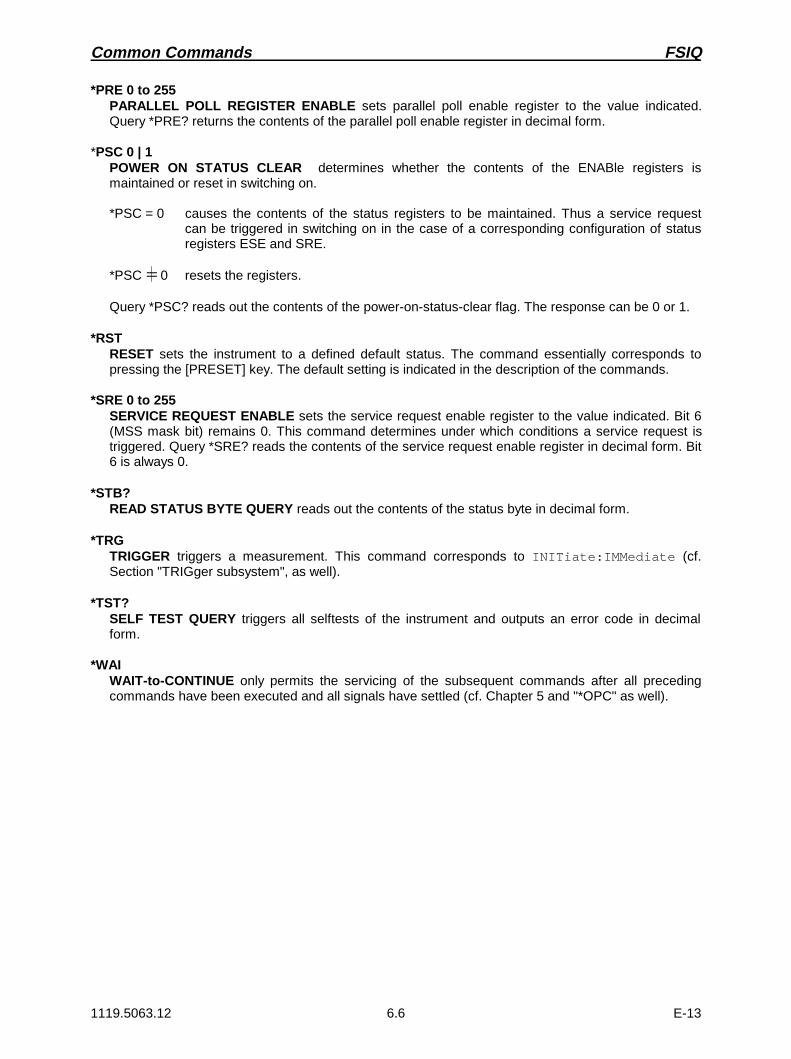
Common Commands FSIQ
1119.5063.12 6.6 E-13
*PRE 0 to 255PARALLEL POLL REGISTER ENABLE sets parallel poll enable register to the value indicated.Query *PRE? returns the contents of the parallel poll enable register in decimal form.
*PSC 0 | 1POWER ON STATUS CLEAR determines whether the contents of the ENABle registers ismaintained or reset in switching on.
*PSC = 0 causes the contents of the status registers to be maintained. Thus a service requestcan be triggered in switching on in the case of a corresponding configuration of statusregisters ESE and SRE.
*PSC = 0 resets the registers.
Query *PSC? reads out the contents of the power-on-status-clear flag. The response can be 0 or 1.
*RSTRESET sets the instrument to a defined default status. The command essentially corresponds topressing the [PRESET] key. The default setting is indicated in the description of the commands.
*SRE 0 to 255SERVICE REQUEST ENABLE sets the service request enable register to the value indicated. Bit 6(MSS mask bit) remains 0. This command determines under which conditions a service request istriggered. Query *SRE? reads the contents of the service request enable register in decimal form. Bit6 is always 0.
*STB?READ STATUS BYTE QUERY reads out the contents of the status byte in decimal form.
*TRGTRIGGER triggers a measurement. This command corresponds to INITiate:IMMediate (cf.Section "TRIGger subsystem", as well).
*TST?SELF TEST QUERY triggers all selftests of the instrument and outputs an error code in decimalform.
*WAIWAIT-to-CONTINUE only permits the servicing of the subsequent commands after all precedingcommands have been executed and all signals have settled (cf. Chapter 5 and "*OPC" as well).

FSIQ ABORt / CALCulate Subsystem
1119.5063.12 6.7 E-13
ABORt Subsystem
The ABORt subsystem contains the commands for aborting triggered actions. An action can betriggered again immediately after being aborted. All commands trigger events which is why they are notassigned any *RST value.
COMMAND PARAMETERS UNIT COMMENT
ABORt -- -- no query
ABORt
This command aborts a current measurement and resets the trigger system.
Example: "ABOR;INIT:IMM"
Features: *RST value: 0SCPI: conforming
Modes: A, VA, BTS, MS
CALCulate Subsystem
The CALCulate subsystem contains commands for converting instrument data, transforming andcarrying out corrections. These functions are carried out subsequent to data acquistion, i.e., followingthe SENSe subsystem.
In the split-screen representation, a distinction is made between CALCulate1 and CALCulate2:
CALCulate1 = screen A;
CALCulate2 = screen B

CALCulate Subsystem FSIQ
1119.5063.12 6.8 E-13
CALCulate:DELTamarker Subsystem
The CALCulate:DELTamarker subsystem checks the delta-marker functions in the instrument.
COMMAND PARAMETERS UNIT COMMENT
CALCulate<1|2>
:DELTamarker<1 to 4>
[:STATe]
:MODE
:AOFF
:TRACe
:X
:RELative?
:Y?
:MAXimum
[:PEAK]
:APEak
:NEXT
:RIGHt
:LEFT
:MINimum
[:PEAK]
:NEXT
:RIGHt
:LEFT
<Boolean>
ABSolute|RELative
<numeric_value>
<numeric_value>
--
--
--
--
--
--
--
--
--
--
--
--
--
HZ | S | SYM
--
--
--
--
--
--
--
--
--
--
--
no query
query only
query only
no query
no query (vector signal analysis)
no query
no query
no query
no query
no query
no query
no query
:FUNCtion
:FIXed
[:STATe]
:RPOint
:Y
:OFFSet
:X
:PNOise
[:STATe]
:RESult?
<Boolean>
<numeric_value>
<numeric_value>
<numeric_value>
<Boolean>
--
DBM
DB
HZ |S | SYM
-- query only
:STEP
[:INCRement]
:AUTO
<numeric_value>
<Boolean>
HZ |S | SYM
--
CALCulate<1|2>:DELTamarker<1 to 4>[:STATe] ON | OFF
This command switches on or off the selected delta marker. If no indication is made, delta marker 1is selected automatically.
Example: "CALC:DELT3 ON"
Features: *RST value: OFFSCPI: device-specific
Modes: A, VA, BTS, MS

FSIQ CALCulate Subsystem
1119.5063.12 6.9 E-13
CALCulate<1|2>:DELTamarker<1 to 4>:MODE ABSolute | RELative
This command switches over between relative and absolute input of frequency of the delta marker.
Example: "CALC:DELT:MODE ABS"
Features: *RST value: RELSCPI: device-specific
Modes: A, VA, BTS, MS
In the RELative mode, the frequency of the delta marker is programmed relative to the referencemarker. In the ABSolute mode, the frequency is defined by the absolute values.
CALCulate<1|2>:DELTamarker<1 to 4>:AOFF
This command switches off all active delta markers.
Example: "CALC:DELT:AOFF"
Features: *RST value: -SCPI: device-specific
Modes: A, VA, BTS, MS
CALCulate<1|2>:DELTamarker<1 to 4>:TRACe 1 to 4
This command assigns the selected delta marker to the indicated measuring curve.
Example: "CALC:DELT3:TRAC 2"
Features: *RST value: -SCPI: device-specific
Modes: A, VA, BTS, MS
CALCulate<1|2>:DELTamarker<1...4>:X 0 ... MAX (frequency | sweep time | symbols)
This command positions the selected delta marker to the indicated frequency (span > 0) or time(span = 0). The query always returns the absolute value of frequency or time.
Example: "CALC:DELT:X 10.7MHz"
Features: *RST value: -SCPI: device-specific
Modes: A, VA, BTS, MS
The SYM unit is only valid in Vector Signal Analysis mode.
CALCulate<1|2>:DELTamarker<1 to 4>:X:RELative?
This command queries the frequency (span > 0) or time (span = 0) of the selected delta markerrelative to the reference marker.
Example: "CALC:DELT:X:REL?"
Features: *RST value: -SCPI: device-specific
Modes: A, VA, BTS, MS

CALCulate Subsystem FSIQ
1119.5063.12 6.10 E-13
CALCulate<1|2>:DELTamarker<1 to 4>:Y?
This command queries the value of the selected marker.
Example: "CALC:DELT:Y?"
Features: *RST value: -SCPI: device-specific
Modes: A, VA, BTS, MS
In complex presentations (vector signal analysis - polar diagrams), the real and the imaginarycomponent as well as magnitude and phase are output separated by a comma.
CALCulate<1|2>:DELTamarker<1 to 4>:MAXimum[:PEAK]
This command positions the delta marker to the current maximum value in the trace memory.
Example: "CALC:DELT:MAX"
Features: *RST value: -SCPI: device-specific
Modes: A, VA, BTS, MS
This command is an event which is why it is not assigned an *RST value and has no query.
CALCulate<1|2>:DELTamarker<1 to 4>:MAXimum:APEak
This command positions the delta marker to the maximum absolute value of the trace.
Example: "CALC:DELT:MAX:APE"
Features: *RST value: -SCPI: device-specific
Modes: VA
This command is an event which is why it is not assigned an *RST value and has no query.
CALCulate<1|2>:DELTamarker<1 to 4>:MAXimum:NEXT
This command positions the delta marker to the next smaller maximum value in the trace memory.
Example: "CALC:DELT:MAX:NEXT"
Features: *RST value: -SCPI: device-specific
Modes: A, BTS, MS
This command is an event which is why it is not assigned an *RST value and has no query.
CALCulate<1|2>:DELTamarker<1 to 4>:MAXimum:RIGHt
This command positions the delta marker to the next smaller maximum value to the right of thecurrent value (i.e., in ascending X direction) in the trace memory.
Example: "CALC:DELT:MAX:RIGH"
Features: *RST value: -SCPI: device-specific
Modes: A, BTS, MS
This command is an event which is why it is not assigned an *RST value and has no query.

FSIQ CALCulate Subsystem
1119.5063.12 6.11 E-13
CALCulate<1|2>:DELTamarker<1 to 4>:MAXimum:LEFT
This command positions the delta marker to the next smaller maximum value to the left of thecurrent value (i.e., in descending X direction) in the trace memory.
Example: "CALC:DELT:MAX:LEFT"
Features: *RST value: -SCPI: device-specific
Modes: A, BTS, MS
This command is an event which is why it is not assigned an *RST value and has no query.
CALCulate<1|2>:DELTamarker<1 to 4>:MINimum[:PEAK]
This command positions the delta marker to the current minimum value in the trace memory.
Example: "CALC:DELT:MIN"
Features: *RST value: -SCPI: device-specific
Modes: A, VA, BTS, MS
This command is an event which is why it is not assigned an *RST value and has no query.
CALCulate<1|2>:DELTamarker<1 to 4>:MINimum:NEXT
This command positions the delta marker to the next higher minimum value in the trace memory.
Example: "CALC:DELT:MIN:NEXT"
Features: *RST value: -SCPI: device-specific
Modes: A, BTS, MS
This command is an event which is why it is not assigned an *RST value and has no query.
CALCulate<1|2>:DELTamarker<1 to 4>:MINimum:RIGHt
This command positions the delta marker to the next higher minimum value to the right of the currentvalue (ie in ascending X direction).
Example: "CALC:DELT:MIN:RIGH"
Features: *RST value: -SCPI: device-specific
Modes: A, BTS, MS
This command is an event which is why it is not assigned an *RST value and has no query.
CALCulate<1|2>:DELTamarker<1 to 4>:MINimum:LEFT
This command positions the delta marker to the next higher minimum value to the left of the currentvalue (ie in descending X direction).
Example: "CALC:DELT:MIN:LEFT"
Features: *RST value: -SCPI: device-specific
Modes: A, BTS, MS
This command is an event which is why it is not assigned an *RST value and has no query.
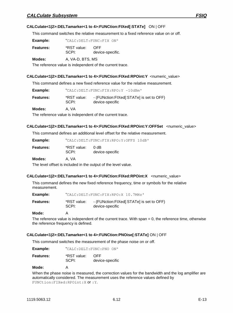
CALCulate Subsystem FSIQ
1119.5063.12 6.12 E-13
CALCulate<1|2>:DELTamarker<1 to 4>:FUNCtion:FIXed[:STATe] ON | OFF
This command switches the relative measurement to a fixed reference value on or off.
Example: "CALC:DELT:FUNC:FIX ON"
Features: *RST value: OFFSCPI: device-specific.
Modes: A, VA-D, BTS, MS
The reference value is independent of the current trace.
CALCulate<1|2>:DELTamarker<1 to 4>:FUNCtion:FIXed:RPOint:Y <numeric_value>
This command defines a new fixed reference value for the relative measurement.
Example: "CALC:DELT:FUNC:FIX:RPO:Y -10dBm"
Features: *RST value: - (FUNction:FIXed[:STATe] is set to OFF)SCPI: device-specific
Modes: A, VA
The reference value is independent of the current trace.
CALCulate<1|2>:DELTamarker<1 to 4>:FUNCtion:FIXed:RPOint:Y:OFFSet <numeric_value>
This command defines an additional level offset for the relative measurement.
Example: "CALC:DELT:FUNC:FIX:RPO:Y:OFFS 10dB"
Features: *RST value: 0 dBSCPI: device-specific
Modes: A, VA
The level offset is included in the output of the level value.
CALCulate<1|2>:DELTamarker<1 to 4>:FUNCtion:FIXed:RPOint:X <numeric_value>
This command defines the new fixed reference frequency, time or symbols for the relativemeasurement.
Example: "CALC:DELT:FUNC:FIX:RPO:X 10.7MHz"
Features: *RST value: - (FUNction:FIXed[:STATe] is set to OFF)SCPI: device-specific
Mode: A
The reference value is independent of the current trace. With span = 0, the reference time, otherwisethe reference frequency is defined.
CALCulate<1|2>:DELTamarker<1 to 4>:FUNCtion:PNOise[:STATe] ON | OFF
This command switches the measurement of the phase noise on or off.
Example: "CALC:DELT:FUNC:PNO ON"
Features: *RST value: OFFSCPI: device-specific
Mode: A
When the phase noise is measured, the correction values for the bandwidth and the log amplifier areautomatically considered. The measurement uses the reference values defined byFUNCtion:FIXed:RPOint:X or :Y.

FSIQ CALCulate Subsystem
1119.5063.12 6.13 E-13
CALCulate<1|2>:DELTamarker<1 to 4>:FUNCtion:PNOise:RESult?
This command queries the result of the phase noise measurement.
Example: "CALC:DELT:FUNC:PNO:RES?"
Features: *RST value: -SCPI: device-specific
Modes: A, BTS, MS
This command is only a query which is why it is not assigned an *RST value.
CALCulate<1|2>:DELTamarker<1 to 4>:STEP[:INCRement] <numeric_value>
This command defines the delta marker step width.
Example: "CALC:DELT:STEP 10kHz" (frequency domain)"CALC:DELT:STEP 5ms" (time domain)
Features: *RST value: - (STEP is set to AUTO)SCPI: device-specific
Mode: A
CALCulate<1|2>:DELTamarker<1 to 4>:STEP:AUTO ON | OFF
This command switches the automatic adaptation of the marker step width on or off.
Example: "CALC:DELT:STEP:AUTO OFF"
Features: *RST value: ONSCPI: device-specific
Mode: A
With AUTO ON, the step width is 10% of the span.

CALCulate Subsystem FSIQ
1119.5063.12 6.14 E-13
CALCulate:DLINe Subsystem
The CALCulate:DLINe subsystem checks the display lines in the instrument, i.e., the level, frequencyand time lines (depending on the X-axis) as well as threshold and reference lines.
COMMAND PARAMETERS UNIT COMMENT
CALCulate<1|2>
:DLINe<1|2>
:STATe
:THReshold
:STATe
:CTHReshold
:STATe
:RLINe
:STATe
:FLINe<1|2>
:STATe
:TLINe<1|2>
:STATe
<numeric_value>
<Boolean>
<numeric_value>
<Boolean>
<numeric_value>
<Boolean>
<numeric_value>
<Boolean>
<numeric_value>
<Boolean>
<numeric_value>
<Boolean>
DBM | DB | DEG | RAD | S |HZ | PCT
DBM | DB | DEG | RAD | S |HZ | PCT
DBM | DB | DEG | RAD | S |HZ | PCT
DBM | DB | DEG | RAD | S |HZ | PCT
HZ
S | SYM
CALCulate<1|2>:DLINe<1|2> MINimum to MAXimum (depending on current unit)
This command defines the position of the display line.
Example: "CALC:DLIN -20dBm"
Features: *RST value: - (STATe to OFF)SCPI: device-specific
Modes: A, VA, BTS, MS
The display lines mark the given level in the display.
The units DEG, RAD, S, and HZ are only valid in operating mode Vector Signal Analysis.
CALCulate<1|2>:DLINe<1|2>:STATe ON | OFF
This command switches the display line on or off.
Example: "CALC:DLIN2:STAT OFF"
Features: *RST value: OFFSCPI: device-specific
Modes: A, VA, BTS, MS

FSIQ CALCulate Subsystem
1119.5063.12 6.15 E-13
CALCulate<1|2>:THReshold MINimum to MAXimum (depending on current unit)
This command defines the position of the thresholds.
Example: "CALC:THR -82dBm"
Features: *RST value: - (STATe to OFF)SCPI: device-specific
Modes: A, VA, BTS, MS
For marker scan functions MAX PEAK, NEXT PEAK etc., the threshold serves as the lowest limit formaximum or minimum search.
The units DEG, RAD, S, and HZ are only valid in operating mode Vector Signal Analysis.
CALCulate<1|2>:THReshold:STATe ON | OFF
This command switches the threshold on or off.
Example: "CALC:THR:STAT ON"
Features: *RST value: OFFSCPI: device-specific
Modes: A, VA, BTS, MS
CALCulate<1|2>:CTHReshold MINimum to MAXimum (depending on the current unit)
This command defines the position of a threshold line (base line), below which all measured valuesare cleared.
Example: "CALC:CTHR -82dBm"
Features: *RST value: - (STATe to OFF)SCPI: device-specific
Mode: A, VA, BTS, MS
The units DEG, RAD, S, and HZ are only valid in operating mode Vector Signal Analysis.
CALCulate<1|2>:CTHReshold:STATe ON | OFF
This command is for switching on or off the threshold line (base line), below which all measuredvalues are cleared.
Example: "CALC:CTHR:STAT ON"
Features: *RST value: OFFSCPI: device-specific
Mode: A, VA, BTS, MS

CALCulate Subsystem FSIQ
1119.5063.12 6.16 E-13
CALCulate<1|2>:RLINe MINimum to MAXimum (depending on the current unit)
This command defines the position of the reference line.
Example: "CALC:RLIN -10dBm"
Features: *RST value: - (STATe to OFF)SCPI: device-specific
Modes: A, VA, BTS, MS
The reference line serves as a reference for the arithmetic operation of traces.
The units DEG, RAD, S, and HZ are only valid in operating mode Vector Signal Analysis.
CALCulate<1|2>:RLINe:STATe ON | OFF
This command switches the reference line on or off.
Example: "CALC:RLIN:STAT ON"
Features: *RST value: OFFSCPI: device-specific
Modes: A, VA, BTS, MS
CALCulate<1|2>:FLINe<1|2> 0 GHz to fmax
This command defines the position of the frequency lines.
Example: "CALC:FLIN2 120MHz"
Features: *RST value: - (STATe to OFF)SCPI: device-specific
Modes: A-F, VA, BTS, MS
The frequency lines mark the given frequencies in the display. Frequency lines are only valid for aSPAN >0.
CALCulate<1|2>:FLINe<1|2>:STATe ON | OFF
This command switches the frequency line on or off.
Example: "CALC:FLIN2:STAT ON"
Features: *RST value: OFFSCPI: device-specific
Modes: A-F, VA, BTS, MS

FSIQ CALCulate Subsystem
1119.5063.12 6.17 E-13
CALCulate<1|2>:TLINe<1|2> 0 to 1000s
This command defines the position of the time lines.
Example: "CALC:TLIN 10ms"
Features: *RST value: - (STATe to OFF)SCPI: device-specific
Modes: A-Z, VA, BTS, MS
The time lines mark the given times in the display. Time lines are only valid for a SPAN = 0.
CALCulate<1|2>:TLINe<1|2>:STATe ON | OFF
This command switches the time line on or off.
Example: "CALC:TLIN2:STAT ON"
Features: *RST value: OFFSCPI: device-specific
Modes: A-Z, VA, BTS, MS
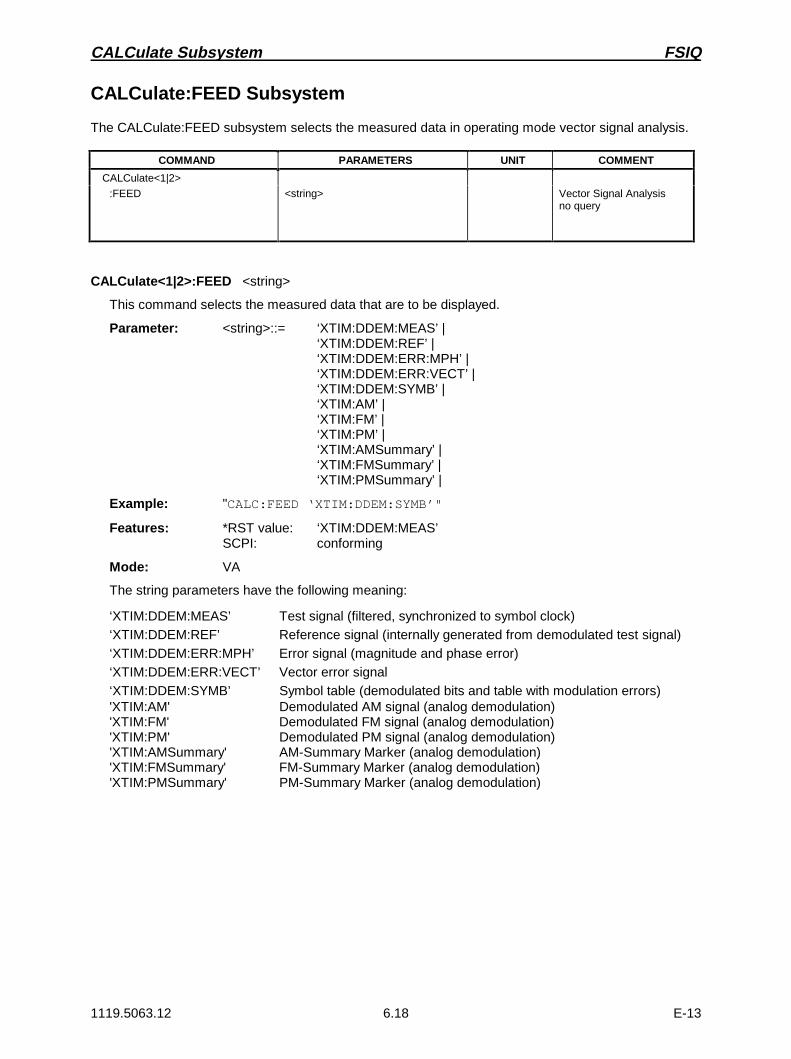
CALCulate Subsystem FSIQ
1119.5063.12 6.18 E-13
CALCulate:FEED Subsystem
The CALCulate:FEED subsystem selects the measured data in operating mode vector signal analysis.
COMMAND PARAMETERS UNIT COMMENT
CALCulate<1|2>
:FEED <string> Vector Signal Analysisno query
CALCulate<1|2>:FEED <string>
This command selects the measured data that are to be displayed.
Parameter: <string>::= ‘XTIM:DDEM:MEAS’ |‘XTIM:DDEM:REF’ |‘XTIM:DDEM:ERR:MPH’ |‘XTIM:DDEM:ERR:VECT’ |‘XTIM:DDEM:SYMB’ |‘XTIM:AM’ |‘XTIM:FM’ |‘XTIM:PM’ |‘XTIM:AMSummary’ |‘XTIM:FMSummary’ |‘XTIM:PMSummary’ |
Example: "CALC:FEED ‘XTIM:DDEM:SYMB’"
Features: *RST value: ‘XTIM:DDEM:MEAS’SCPI: conforming
Mode: VA
The string parameters have the following meaning:
‘XTIM:DDEM:MEAS’ Test signal (filtered, synchronized to symbol clock)‘XTIM:DDEM:REF’ Reference signal (internally generated from demodulated test signal)‘XTIM:DDEM:ERR:MPH’ Error signal (magnitude and phase error)‘XTIM:DDEM:ERR:VECT’ Vector error signal‘XTIM:DDEM:SYMB’ Symbol table (demodulated bits and table with modulation errors)'XTIM:AM' Demodulated AM signal (analog demodulation)'XTIM:FM' Demodulated FM signal (analog demodulation)'XTIM:PM' Demodulated PM signal (analog demodulation)'XTIM:AMSummary' AM-Summary Marker (analog demodulation)'XTIM:FMSummary' FM-Summary Marker (analog demodulation)'XTIM:PMSummary' PM-Summary Marker (analog demodulation)

FSIQ CALCulate Subsystem
1119.5063.12 6.19 E-13
CALCulate:FORMat Subsystem
The CALCulate:FORMat subsystem determines further processing and conversion of measured data inoperating mode vector signal analysis.
COMMAND PARAMETERS UNIT COMMENT
CALCulate<1|2>
:FORMat MAGNitude | PHASe | UPHase |RIMag | FREQuency | IEYE | QEYE |TEYE | FEYE | COMP | CONS
Vector Signal Analysis
:FSK
:DEViation
:REFerence <numeric_value> HZ Vector Signal Analysis
CALCulate<1|2>:FORMat MAGNitude | PHASe | UPHase | RIMag | FREQuency | IEYE | QEYE |TEYE | FEYE | COMP | CONS
This command defines the display of the traces.
Example: "CALC:FORM CONS"
Features: *RST value: MAGNitudeSCPI: conforming
Mode: VA-D
The parameters have the following meaning:
MAGNitude Display of the magnitude in the time domain
PHASe | UPHase Display of the phase in the time domain with or without (”unwrapped”)limitation to ±180°
RIMag Display of the time characteristic of inphase and quadraturecomponent
FREQuency Display of the frequency response in the time domain
IEYE | QEYE Eye diagram of the inphase or quadrature component
TEYE Display of the trellis diagram
FEYE Eye diagram of FSK modulation
COMP Display of the polar vector diagram (complex)
CONS Display of the polar vector diagaram (constellation)
CALCulate<1|2>:FSK:DEViation:REFerence <numeric_value>
This command defines the reference value of the frequency deviation for FSK modulation.
Example: "CALC:FSK:DEV:REF 20kHz"
Features: *RST value: -SCPI: device-specific
Mode: VA-D

CALCulate Subsystem FSIQ
1119.5063.12 6.20 E-13
CALCulate:LIMit Subsystem
The CALCulate:LIMit subsystem comprises the limit lines and the corresponding limit checks. Limit linescan be defined as upper and lower limit lines. The individual values of the limit lines correspond to thevalues of the X-axis (CONTrol) which have to have the same number.
COMMAND PARAMETERS UNIT COMMENT
CALCulate<1|2>
:LIMit<1 to 8>
:TRACe
:STATe:UNIT
CATalog?
:CONTrol
[:DATA]
:DOMain
:OFFSet
:MODE
:UNIT
[:TIME]
:SHIFt
:SPACing
:UPPer
[:DATA]
:STATe
:OFFSet
:MARGin
:MODE
:SHIFt
:SPACing
:LOWer
[:DATA]
:STATe
:OFFSet
:MARGin
:MODE
:SHIFt
:SPACing
:FAIL?
:CLEar
[:IMMediate]
:COMMent
:COPY
:NAME
:DELete
<numeric_value>
<Boolean>DBM | DBPW | WATT | DBUV | DBMV |VOLT | DBUA | AMPere | DB | DBUV_MHZ| DBMV_MHZ | DBUA_MHZ | DBUV_M |DBUA_M | DBUV_MMHZ | DBUA_MMHZ |DEG | RAD | S | HZ | PCT | UNITLESS
<numeric_value>,<numeric_value>..
FREQuency | TIME
<numeric_value>
RELative | ABSolute
S | SYM
<numeric_value>
LINear | LOGarithmic
<numeric_value>,<numeric_value>..
<Boolean>
<numeric_value>
<numeric_value>
RELative | ABSolute
<numeric_value>
LINear | LOGarithmic
<numeric_value>,<numeric_value>..
<Boolean>
<numeric_value>
<numeric_value>
RELative | ABSolute
<numeric_value>
LINear | LOGarithmic
--
<string>
1 to 8 | < name>
<string>
--
HZ | S | SYM
HZ | S | SYM
HZ | S | SYM
DBM | DB | DEG |RAD | S | HZ | PCT
--
DB | DEG | RAD |S | HZ | PCT
DB| DEG | RAD |S | HZ | PCT
--
DB | DEG | RAD|S | HZ | PCT
DBM | DB | DEG |RAD | S | HZ | PCT
--
DB| DEG | RAD |S | HZ | PCT
DB| DEG | RAD |S | HZ | PCT
--
DB | DEG | RAD |S | HZ | PCT
--
--
query only
Vector Signal Analysis
query only
no query
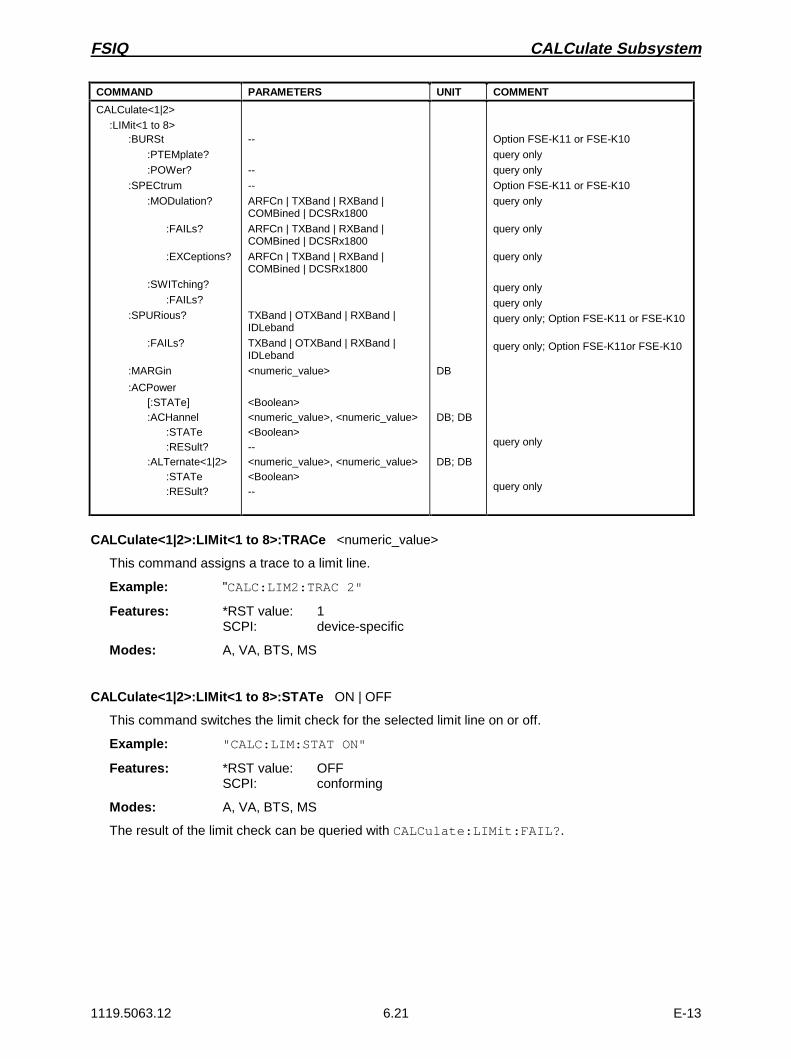
FSIQ CALCulate Subsystem
1119.5063.12 6.21 E-13
COMMAND PARAMETERS UNIT COMMENT
CALCulate<1|2>
:LIMit<1 to 8>:BURSt
:PTEMplate?
:POWer?
:SPECtrum
:MODulation?
:FAILs?
:EXCeptions?
:SWITching?
:FAILs?
:SPURious?
:FAILs?
:MARGin
:ACPower[:STATe]:ACHannel
:STATe:RESult?
:ALTernate<1|2>:STATe:RESult?
--
--
--
ARFCn | TXBand | RXBand |COMBined | DCSRx1800
ARFCn | TXBand | RXBand |COMBined | DCSRx1800
ARFCn | TXBand | RXBand |COMBined | DCSRx1800
TXBand | OTXBand | RXBand |IDLeband
TXBand | OTXBand | RXBand |IDLeband
<numeric_value>
<Boolean><numeric_value>, <numeric_value><Boolean>--<numeric_value>, <numeric_value><Boolean>--
DB
DB; DB
DB; DB
Option FSE-K11 or FSE-K10
query only
query only
Option FSE-K11 or FSE-K10
query only
query only
query only
query only
query only
query only; Option FSE-K11 or FSE-K10
query only; Option FSE-K11or FSE-K10
query only
query only
CALCulate<1|2>:LIMit<1 to 8>:TRACe <numeric_value>
This command assigns a trace to a limit line.
Example: "CALC:LIM2:TRAC 2"
Features: *RST value: 1SCPI: device-specific
Modes: A, VA, BTS, MS
CALCulate<1|2>:LIMit<1 to 8>:STATe ON | OFF
This command switches the limit check for the selected limit line on or off.
Example: "CALC:LIM:STAT ON"
Features: *RST value: OFFSCPI: conforming
Modes: A, VA, BTS, MS
The result of the limit check can be queried with CALCulate:LIMit:FAIL?.
CALCulate Subsystem FSIQ
1119.5063.12 6.22 E-13
CALCulate<1|2>:LIMit<1...8>:UNIT DBM | DBPW | WATT | DBUV | DBMV | VOLT |DBUA | AMPere |DB | DBUV_MHZ | DBMV_MHZ | DBUA_MHZ | DBUV_M |DBUA_M | DBUV_MMHZ | DBUA_MMHZ |DEG | RAD | S | HZ |PCT | UNITLESS|
This command defines the unit of the selected limit line.
Example: "CALC:LIM:UNIT DBUV"
Features: *RST value: DBMSCPI: device-specific
Modes: A, VA, BTS, MS
DBUV_MHZ and DBUA_MHZ denote the units DBUV/MHZ or DBUA/MHZ.Upon selection of the unit DB the limit line is automatically switched to the relative mode. For unitsdifferent from DB the limit line is automatically switched to the absolute mode.
The units DEG, RAD, S, HZ are available in the vector analysis mode only.
CALCulate:LIMit:CATalog?
This command reads out the names of all limit lines stored on the harddisk.
Example: "CALC:LIM:CAT?"
Feature: *RST value: -SCPI: device-specific
Mode: A, VA, BTS, MS
CALCulate<1|2>:LIMit<1 to 8>:CONTrol[:DATA] <numeric_value>,<numeric_value>..
This command defines the X-axis values (frequencies or times) of the upper or lower limit lines.
Example: "CALC:LIM:CONT 1MHz,30MHz,300MHz,1GHz"
Features: *RST value: - (LIMit:STATe is set to OFF)SCPI: conforming
Modes: A, VA, BTS, MS
The number of values for the CONTrol axis and the corresponding UPPer- and/or LOWer limit lineshave to be identical. Available units are HZ | S | SYM, SYM only for vector signal analyzer mode.
CALCulate<1|2>:LIMit<1 to 8>:CONTrol:DOMain FREQuency | TIME
This command defines the X-axis in the frequency or time domain.
Example: "CALC:LIM:CONT:DOM TIME"
Features: *RST value: FREQuencySCPI: device-specific
Modes: A, VA, BTS, MS
FSIQ CALCulate Subsystem
1119.5063.12 6.23 E-13
CALCulate<1|2>:LIMit<1 to 8>:CONTrol:OFFSet <numeric_value>
This command defines an offset for the X-axis value of the selected relative limit line in the frequencyor time domain.
Example: "CALC:LIM:CONT:OFFS 100us"
Features: *RST value: 0SCPI: device-specific
Modes: A, VA
CALCulate<1|2>:LIMit<1 to 8>:CONTrol:MODE RELative | ABSolute
This command selects the relative or absolute scaling for the X-axis of the selected limit line.
Example: "CALC:LIM:CONT:MODE REL"
Features: *RST value: ABSoluteSCPI: device-specific
Modes: A, VA, BTS, MS
Upon selection of RELative, the unit is switched to DB.
CALCulate<1|2>:LIMit<1 to 8>:CONTrol:UNIT[:TIME] S | SYM
This command defines the unit of the x-axis scaling of limit lines.
Example: "CALC:LIM:CONT:UNIT SYM"
Features: *RST value: SSCPI: device-specific
Mode: VA
CALCulate<1|2>:LIMit<1 to 8>:CONTrol:SHIFt <numeric_value>
This command shifts a limit line which has been specified for relative frequencies or times (X-axis).
Example: "CALC:LIM:CONT:SHIF 50kHz"
Features: *RST value: --SCPI: device-specific
Modes: A, VA, BTS, MS
This command is an event which is why it is not assigned an *RST value and has no query.
CALCulate<1|2>:LIMit<1 to 8>:CONTrol:SPACing LINear | LOGarithmic
This command makes a selection between linear and logarithmic interpolation for determining thelimit line from the frequency points.
Example: "CALC:LIM:CONT:SPAC LIN"
Features: *RST value: LINSCPI: device-specific
Modes: A, VA, BTS, MS
CALCulate Subsystem FSIQ
1119.5063.12 6.24 E-13
CALCulate<1|2>:LIMit<1 to 8>:UPPer[:DATA] <numeric_value>,<numeric_value>..
This command defines the values for the upper limit lines.
Example: "CALC:LIM:UPP -10,0,0,-10"
Features: *RST value: - (LIMit:STATe is set to OFF)SCPI: conforming
Modes: A, VA, BTS, MS
The number of values for the CONTrol axis and the corresponding UPPer limit line have to beidentical. If the measured values exceed the UPPer limit line, the limit check signals errors.The unit must be identical with the unit selected by CALC:LIM:UNIT.
The units DEG, RAD, S, and HZ are available in the vector signal analysis mode only.
CALCulate<1|2>:LIMit<1 to 8>:UPPer:STATe ON | OFF
This command defines the selected limit line as upper limit line.
Example: "CALC:LIM:UPPer:STAT ON"
Features: *RST value: OFFSCPI: conforming
Modes: A, VA, BTS, MS
The result of the limit check can be queried with CALCulate:LIMit<1 to 8>:FAIL?.
In analyzer and vector analyzer mode, the result of the limit check can be queried withCALCulate:LIMit<1 to 8>:FAIL?.
CALCulate<1|2>:LIMit<1 to 8>:UPPer:OFFSet <numeric_value>
This command defines an offset for the Y-axis of the selected relative upper limit line.
Example: "CALC:LIM:UPP:OFFS 3dB"
Features: *RST value: 0SCPI: device-specific
Modes: A, VA
CALCulate<1|2>:LIMit<1 to 8>:UPPer:MARGin <numeric_value>
This command defines the margin of the selected upper limit line.
Example: "CALC:LIM:UPP:MARG 10dB"
Features: *RST value: 0SCPI: device-specific
Modes: A, VA, BTS, MS
CALCulate<1|2>:LIMit<1 to 8>:UPPer:MODE RELative | ABSolute
This command selects the relative or absolute scaling for the Y-axis of the selected upper limit line.
Example: "CALC:LIM:UPP:MODE REL"
Features: *RST value: ABSoluteSCPI: device-specific
Modes: A, VA, BTS, MS

FSIQ CALCulate Subsystem
1119.5063.12 6.25 E-13
CALCulate<1|2>:LIMit<1 to 8>:UPPer:SHIFt <numeric_value>
This command shifts a limit line, which has relative values for the Y-axis (levels or linear units suchas volt).
Example: "CALC:LIM:UPP:SHIF 20dB"
Features: *RST value: --SCPI: device-specific
Modes: A, VA, BTS, MS
This command is an event which is why it is not assigned an *RST value and has no query.
CALCulate<1|2>:LIMit<1 to 8>:UPPer:SPACing LINear | LOGarithmic
This command makes a selection between linear and logarithmic interpolation for the upper limit line.
Example: "CALC:LIM:UPP:SPAC LIN"
Features: *RST value: LINSCPI: device-specific
Modes: A, VA, BTS, MS
CALCulate<1|2>:LIMit<1 to 8>:LOWer[:DATA] <numeric_value>,<numeric_value>..
This command defines the values for the selected lower limit line.
Example: "CALC:LIM:LOW -30,-40,-40,-30"
Features: *RST value: - (LIMit:STATe is set to OFF)SCPI: conforming
Modes: A, VA, BTS, MS
The number of values for the CONTrol axis and the corresponding LOWer limit line have to beidentical.If the measured values violate the LOWer limit line, the limit check signals errors.The unit must be identical with the unit selected by CALC:LIM:UNIT.
The units DEG, RAD, S, and HZ are available in the vector signal analysis mode only.
CALCulate<1|2>:LIMit<1 to 8>:LOWer:STATe ON | OFF
This command defines the selected limit line as lower limit line.
Example: "CALC:LIM:LOWer:STAT ON"
Features: *RST value: OFFSCPI: conforming
Modes: A, VA, BTS, MS
The result of the limit check can be queried with CALCulate:LIMit:FAIL?.
CALCulate Subsystem FSIQ
1119.5063.12 6.26 E-13
CALCulate<1|2>:LIMit<1 to 8>:LOWer:OFFSet <numeric_value>
This command defines an offset for the Y-axis of the selected relative lower limit line.
Example: "CALC:LIM:LOW:OFFS 3dB"
Features: *RST value: 0SCPI: device-specific
Modes: A, VA
CALCulate<1|2>:LIMit<1 to 8>:LOWer:MARGin <numeric_value>
This command defines the margin of the selected lower limit line.
Example: "CALC:LIM:LOW:MARG 10dB"
Features: *RST value: 0SCPI: device-specific
Modes: A, VA, BTS, MS
CALCulate<1|2>:LIMit<1 to 8>:LOWer:MODE RELative | ABSolute
This command selects the relative or absolute scaling for the Y-axis of the selected lower limit line.
Example: "CALC:LIM:LOW:MODE REL"
Features: *RST value: ABSoluteSCPI: device-specific
Modes: A, VA, BTS, MS
CALCulate<1|2>:LIMit<1 to 8>:LOWer:SHIFt <numeric_value>
This command shifts a limit line, which has relative values for the Y-axis (levels or linear units suchas volt).
Example: "CALC:LIM:LOW:SHIF 20dB"
Features: *RST value: --SCPI: device-specific
Modes: A, VA, BTS, MS
This command is an event which is why it is not assigned an *RST value and has no query.
CALCulate<1|2>:LIMit<1 to 8>:LOWer:SPACing LINear | LOGarithmic
This command makes a selection between linear and logarithmic interpolation for the lower limit line.
Example: "CALC:LIM:LOW:SPAC LIN"
Features: *RST value: LINSCPI: device-specific
Modes: A, VA, BTS, MS

FSIQ CALCulate Subsystem
1119.5063.12 6.27 E-13
CALCulate<1|2>:LIMit<1 to 8>:FAIL?
This command queries the result of the limit check.
Example: "CALC:LIM:FAIL?"
Features: *RST value: -SCPI: conforming
Modes: A, VA, BTS, MS
The result of the limit check responds with 0 in case of PASS and with 1 in case of FAIL.
CALCulate<1|2>:LIMit<1 to 8>:CLEar[:IMMediate]
This command deletes the result of the current limit check.
Example: "CALC:LIM:CLE"
Features: *RST value: -SCPI: conforming
Modes: A, VA, BTS, MS
This command is an event which is why it is not assigned an *RST value.
CALCulate<1|2>:LIMit<1 to 8>:COMMent <string>
This command defines a comment for the limit line selected.
Example: "CALC:LIM:COMM ’Upper limit for spectrum’"
Features: *RST value: blank commentSCPI: device-specific
Modes: A, VA, BTS, MS
CALCulate<1|2>:LIMit<1 to 8>:COPY 1 to 8 | <name>
This command copies one limit line onto another one.
Parameter: 1 to 8 ::= number of the new limit line or, alternatively:<name> ::= name of the new limit line given as a string
Example: "CALC:LIM1:COPY 2""CALC:LIM1:COPY ’GSM2’"
Features: *RST value: --SCPI: device-specific
Modes: A, VA, BTS, MS
The name of the limit line may contain a maximum of 8 characters. This command is an "event"which is why it is not assigned an *RST value and has no query.
CALCulate Subsystem FSIQ
1119.5063.12 6.28 E-13
CALCulate<1|2>:LIMit<1 to 8>:NAME <name of limit line>
This command assigns a name to a limit line numbered 1 to 8. If it doesn’t exist previously, a limitline with this name is created.
Example: "CALC:LIM1:NAME ’GSM1’"
Features: *RST value: ’REM1’ to ’REM8’ for lines 1 to 8SCPI: device-specific
Modes: A, VA, BTS, MS
The name of the limit line may contain a maximum of 8 characters.
CALCulate<1|2>:LIMit<1 to 8>:DELete
This command deletes the limit line selected.
Examples: "CALC:LIM1:DEL"
Features: *RST value: --SCPI: device-specific
Modes: A, VA, BTS, MS
This command is an "event" which is why it is not assigned an *RST value and has no query.
CALCulate<1|2>:LIMit<1 to 8>:BURSt:PTEMplate?
This command queries the result of the limit check for a power vs. time measurement.
Parameter: The result is displayed in character data form. Possible values are:PASSED limit not exceededFAILED limit exceededRUNNING measurement not completed
Examples: "CALC:LIM:BURS:PTEM?"
Features: *RST value: --SCPI: device-specific
Modes: BTS, MS
This command is a query and therefore not assigned a *RST value.If no measurement has been carried out yet, a query error is triggered off. The numeric suffixes<1|2> or <1 to 8> are not significant for this command.

FSIQ CALCulate Subsystem
1119.5063.12 6.29 E-13
CALCulate<1|2>:LIMit<1 to 8>:BURSt:POWer?
This command queries the total result of the carrier power measurement.
Parameter: The result is displayed in character data form. Possible values are:PASSED limit not exceededFAILED limit exceededABORTED measurement abortedRUNNING measurement not completed
Examples: "CALC:LIM:BURS:POW?"Result: PASSED
Features: *RST value: --SCPI: device-specific
Modes: BTS, MS
This command is a query and therefore not assigned a *RST value.If the command is triggered off before the carrier power measurement was started for the first time, aquery error results. The numeric suffixes <1|2> or <1 to 8> are not significant for this command.
CALCulate<1|2>:LIMit<1 to 8>:SPECtrum:MODulation? ARFCn | TXBand | RXBand | COMBined |DCSRx1800
This command queries the total result of the spectrum due to modulation measurement.
Parameter: The result is displayed in character data form. Possible values are:PASSED limit not exceededFAILED limit exceededABORTED measurement abortedRUNNING measurement not completed
Examples: "CALC:LIM:SPEC:MOD? RXB"Result: PASSED
Features: *RST value: --SCPI: device-specific
Modes: BTS, MS
ARFCn ARFCN ± 1.8 MHz TXBand TX-bandRXBand RX-band COMBined ARFCN ± 1.8 MHz / TX-bandDCSRx1800 RX-Band DCS 1800 (option FSE-K10 only)
This command is a query and therefore not assigned a *RST value.The numeric suffixes <1|2> or <1 to 8> are not significant for this command.

CALCulate Subsystem FSIQ
1119.5063.12 6.30 E-13
CALCulate<1|2>:LIMit<1 to 8>:SPECtrum:MODulation:FAILs? ARFCn | TXBand | RXBand |COMBined | DCSRx1800
This command queries the number of limit violations of the spectrum due to modulationmeasurement.
Examples: "CALC:LIM:SPEC:MOD:FAIL? RXB"
Features: *RST value: --SCPI: device-specific
Modes: BTS, MS
ARFCn ARFCN ± 1.8 MHzTXBand TX-bandRXBand RX-bandCOMBined ARFCN ± 1.8 MHz / TX-bandDCSRx1800 RX-Band DCS 1800 (option FSE-K10 only)
This command is a query and therefore not assigned a *RST valueThe numeric suffixes <1|2> or <1 to 8> are not significant for this command.
CALCulate<1|2>:LIMit<1 to 8>:SPECtrum:MODulation:EXCeptions? ARFCn | TXBand | RXBand |COMBined | DCSRx1800
This command queries the number of limit violations of the spectrum due to modulationmeasurement which are marked as exceptions.
Examples: "CALC:LIM:SPEC:MOD:EXC? RXB"
Features: *RST value: --SCPI: device-specific
Modes: BTS, MS
ARFCn ARFCN ± 1.8 MHzTXBand TX-bandRXBand RX-bandCOMBined ARFCN ± 1.8 MHz / TX-bandDCSRx1800 RX-Band DCS 1800 (option FSE-K10 only
This command is a query and therefore not assigned a *RST value. The numeric suffixes <1|2> or<1 to 8> are not significant for this command.

FSIQ CALCulate Subsystem
1119.5063.12 6.31 E-13
CALCulate<1|2>:LIMit<1 to 8>:SPECtrum:SWITching?
This command queries the total result of the spectrum due to switching transients measurements.
Parameter: The result is displayed in character data form. Possible values are:PASSED limit not exceededFAILED limit exceededABORTED measurement abortedRUNNING measurement not completed
Examples: "CALC:LIM:SPEC:SWIT?"Result: PASSED
Features: *RST value: --SCPI: device-specific
Modes: BTS, MS
This command is a query and therefore not assigned a *RST value. The numeric suffixes <1|2> or<1 to 8> are not significant for this command.
CALCulate<1|2>:LIMit<1 to 8>:SPECtrum:SWITching:FAILs?
This command queries the number of limit violations of the spectrum due to switching transientmeasurement.
Examples: "CALC:LIM:SPEC:SWIT:FAIL?"
Features: *RST value: --SCPI: device-specific
Modes: BTS, MS
This command is a query and therefore not assigned a *RST value. The numeric suffixes <1|2> or<1 to 8> are not significant for this command.
CALCulate<1|2>:LIMit<1 to 8>:SPURious? TXBand | OTXBand | RXBand | IDLeband
This command queries the total result of the spurious emissions measurement.
Parameter: The result is displayed in character data form. Possible values are:
PASSED limit not exceededFAILED limit exceededABORTED measurement abortedRUNNING measurement not completed
Examples: "CALC:LIM:SPUR? OTXB"Result:PASSED
Features: *RST value: --SCPI: device-specific
Modes: BTS, MS
TXBand TX-bandOTXBand Not TX-bandRXBand RX-band (option FSE-K11 only)IDLeband IDLeband (option FSE-K10 only)
This command is a query and therefore not assigned a *RST value. The numeric suffixes <1|2> or<1 to 8> are not significant for this command.
CALCulate Subsystem FSIQ
1119.5063.12 6.32 E-13
CALCulate<1|2>:LIMit<1 to 8>:SPURious:FAILs? TXBand | OTXBand | RXBand | IDLeband
This command queries the number of limit violations of the spurious emissions measurement.
Examples: "CALC:LIM:SPUR:FAIL? OTXB"
Features: *RST value: --SCPI: device-specific
Modes: BTS, MS
TXBand TX-bandOTXBand Not TX-bandRXBand RX-band (option FSE-K11 only)IDLeband IDLeband (option FSE-K10 only)
This command is a query and therefore not assigned a *RST value. The numeric suffixes <1|2> or<1 to 8> are not significant for this command.
CALCulate<1|2>:LIMit<1 to 8>:MARGin 0 to 100DB
This command sets/changes the value of the margin (safe difference to the actual limit) for the limitcheck.
Examples: "CALC:LIM:MARG 6DB"
Features: *RST value: 3DBSCPI: device-specific
Modes: BTS, MS
The numeric suffixes <1|2> or <1 to 8> are not significant for this command.
CALCulate<1|2>:LIMit<1 to 8>:ACPower[:STATe] ON | OFF
This command switches on and off the limit check for adjacent channel power measurements. Thecommands CALC:LIM:ACP:ACH:STAT or CALC:LIM:ACP:ALT:STAT must be used in addition tospecify whether the limit check is to be performed for the upper/lower adjacent channel or for thealternate adjacent channels.
Examples: "CALC:LIM:ACP ON"
Features: *RST value: OFFSCPI: device-specific
Modes: A, VA
The numeric suffixes <1|2> or <1 to 8> are not significant for this command.

FSIQ CALCulate Subsystem
1119.5063.12 6.33 E-13
CALCulate<1|2>:LIMit<1 to 8>:ACPower:ACHannel 0 to 100 dB, 0 to 100 dB
This command defines the limit for the upper/lower adjacent channel for adjacent channel powermeasurements.
Parameter: The first (second) numeric value is the limit for the upper (lower) adjacent channel.
Examples: "CALC:LIM:ACP:ACH 30DB, 30DB"
Features: *RST value: 0 dBSCPI: device-specific
Modes: A, VA
The numeric suffixes <1|2> or <1 to 8> are not significant for this command.
CALCulate<1|2>:LIMit<1 to 8>:ACPower:ACHannel:STATe ON | OFF
This command activates the limit check for the adjacent channel when adjacent channel powermeasurement is performed. Before, the limit check must be activated using CALC:LIM:ACP ON.
Examples: "CALC:LIM:ACP:ACH:STAT ON"
Features: *RST value: OFFSCPI: device-specific
Modes: A, VA
The numeric suffixes <1|2> or <1 to 8> are not significant for this command.
CALCulate<1|2>:LIMit<1 to 8>:ACPower:ACHannel:RESult?
This command queries the result of the limit check for the upper/ lower adjacent channel whenadjacent channel power measurement is performed.
Parameter: The result is returned in the form <result>, <result> where<result> = PASSED | FAILED, and where the first returned value denotes the lower, the second denotes the upper adjacent channel.
Examples: "CALC:LIM:ACP:ACH:RES?"
Features: *RST value: --SCPI: device-specific
Modes: A, VA
This command is a query and therefore not assigned a *RST value. If the power measurement of theadjacent channel is switched off, the command triggers a query error.The numeric suffixes <1|2> or <1 to 8> are not significant for this command.

CALCulate Subsystem FSIQ
1119.5063.12 6.34 E-13
CALCulate<1|2>:LIMit<1 to 8>:ACPower:ALTernate<1|2> 0 to 100DB, 0 to 100 dB.
This command defines the limit for the first /second alternate adjacent channel for adjacent channelpower measurements.
Parameter: The first (second) numeric value is the limit for the lower (upper) alternate adjacent channel. The numeric suffix after ALTernate<1|2> denotes the first or the second alternate channel.
Examples: "CALC:LIM:ACP:ALT2 30DB 30DB"
Features: *RST value: 0DBSCPI: device-specific
Modes: A, VA
The numeric suffixes <1|2> or <1 to 8> are not significant for this command.
CALCulate<1|2>:LIMit<1 to 8>:ACPower:ALTernate<1|2>:STATe ON | OFF
This command activates the limit check for the first /second alternate adjacent channel for adjacentchannel power measurements. Before, the limit check must be activated using CALC:LIM:ACP ON.
Examples: "CALC:LIM:ACP:ALT2:STAT ON"
Features: *RST value: OFFSCPI: device-specific
Modes: A, VA
The numeric suffixes <1|2> or <1 to 8> are not significant for this command.
CALCulate<1|2>:LIMit<1 to 8>:ACPower:ALTernate<1|2>:RESult?
This command queries the result of the limit check for the first /second alternate adjacent channel foradjacent channel power measurements.
Parameter: The result is returned in the form <result>, <result> where<result> = PASSED | FAILED and where the first (second) returned value denotes the lower (upper) alternate adjacent channel.
Examples: "CALC:LIM:ACP:ALT2:RES?"
Features: *RST value: --SCPI: device-specific
Modes: A, VA
This command is a query and therefore not assigned a *RST value. If the power measurement of theadjacent channel is switched off, the command triggers a query error.The numeric suffixes <1|2> or <1 to 8> are not significant for this command.

FSIQ CALCulate Subsystem
1119.5063.12 6.35 E-13
CALCulate:MARKer Subsystem
The CALCulate:MARKer subsystem checks the marker functions in the instrument.
COMMAND PARAMETERS UNIT COMMENT
CALCulate<1|2>
:MARKer<1 to 4>
[:STATe]
:AOFF
:TRACe
:X
:SLIMits
[:STATe]
:COUNt
:RESolution
:FREQuency?
:COUPled
[:STATe]
:SCOupled
[:STATe]
:LOEXclude
:Y?
:MAXimum
[:PEAK]
:APEak
:NEXT
:RIGHt
:LEFT
:MINimum
[:PEAK]
:NEXT
:RIGHt
:LEFT
:STEP
[:INCRement]
:AUTO
:PEXCursion
:READout
<Boolean>
<numeric_value>
<numeric_value>
<Boolean>
<Boolean>
<numeric_value>
--
<Boolean>
<Boolean>
<Boolean>
--
--
--
--
--
--
--
--
--
--
<numeric_value>
<Boolean>
<numeric_value>
MPHase | RIMaginary
--
--
HZ | S | SYM
--
HZ
--
--
--
--
--
--
--
--
--
--
--
HZ | S | SYM
--
DB
no query
query only
query only
no query
no query,Vector Signal Analysis
no query
no query
no query
no query
no query
no query
no query
Vector Signal Analysis
:FUNCtion
:NDBDown
:STATe
:RESult?
:FREQuency?
:ZOOM
:NOISe
[:STATe]
:RESult?:DEModulation
:SELect[:STATe]:HOLDoff
:SFACtor
:STATe
:RESult?
:FREQuency?
<numeric_value>
<Boolean>
--
--
<numeric_value>
<Boolean>
--
AM|FM<Boolean><numeric_value><expr>
<Boolean>
--
--
DB
--
--
HZ
--
S
--
--
query only
query only
no query
query only
query only
query only

CALCulate Subsystem FSIQ
1119.5063.12 6.36 E-13
COMMAND PARAMETERS UNIT COMMENT
CALCulate<1|2>
:MARKer
:FUNCtion
:STRack
[:STATe]
:ADEMod
:AM
[:RESult]?
:FM
[:RESult]?
:PM
[:RESult]?
:AFRequency
[:RESult]?
:FERRor
[:RESult]?
:SINad
[:STATe]
:RESult?
:CARRier
[:RESult]?
:DDEMod
:RESult?
:POWer
:SELect
:RESult?
:PRESet
:CFILter
[:STATe]
:SUMMary
:STATe
:MAXimum
[:STATe]
:RESult?
:AVERage
:RESult?
:PHOLd
RESult?:PPEak
[:STATe]:RESult?:AVERage
:RESult?:PHOLd
RESult?
<Boolean>
PPEak | MPEak | MIDDle | RMS
PPEak | MPEak | MIDDle | RMS | RDEV
PPEak | MPEak | MIDDle | RMS
<Boolean>
MERM | MEPK | MEPS | PERM | PEPK |PEPS |EVRM | EVPK | EVPS | IQOF |IQIM | ADR | FERR | DEV | FSRM |FSPK | FSPS | RHO |FEPK | DTTS
ACPower | CPOWer | OBANdwidth |OBWidth | CN | CN0
ACPower | CPOWer | OBANdwidth |OBWidth | CN | CN0
NADC | TETRA | PHS| PDC | CDPD |F8CDma | R8CDma | F19Cdma |R19Cdma | FWCDma | RWCDma |FW3Gppcdma | RW3Gppcdma |M2CDma | D2CDma | NONE
<Boolean>
OFF
<Boolean>
<Boolean>
<Boolean>
Vector Signal Analysis
query only
query only
query only
query only
query only
query only
query only
Vector Signal Analysis
query only
query only
Vector Signal Analysis
query only
query only
query onlyVector Signal Analysis
query only
query only
query only

FSIQ CALCulate Subsystem
1119.5063.12 6.37 E-13
COMMAND PARAMETERS UNIT COMMENT
CALCulate<1|2>
:MARKer
:FUNCtion:SUMMary
:MPEak[:STATe]:RESult?:AVERage
:RESult?:PHOLd
RESult?:MIDDle
[:STATe]:RESult?:AVERage
:RESult?:PHOLd
RESult?:RMS
[:STATe]:RESult?:AVERage
:RESult?:PHOLd
RESult?:MEAN
[:STATe]:RESult?:AVERage
:RESult?:PHOLd
RESult?:AOFF:PHOLd:AVERage
:CENTer
:CSTep
:STARt
:STOP
:MSTep
:REFerence
<Boolean>
<Boolean>
<Boolean>
<Boolean>
<Boolean><Boolean>
Vector Signal Analysis
query only
query only
query onlyVector Signal Analysis
query only
query only
query only
query only
query only
query only
query only
query only
query onlyno query
no query
no query
no query
no query
no query
no query
CALCulate<1|2>:MARKer<1 to 4>[:STATe] ON | OFF
This command switches on or off the currently selected marker. If no indication is made, marker 1 isselected automatically.
Example: "CALC:MARK3 ON"
Features: *RST value: OFFSCPI: device-specific
Modes: A, VA, BTS, MS

CALCulate Subsystem FSIQ
1119.5063.12 6.38 E-13
CALCulate<1|2>:MARKer<1 to 4>:AOFF
This command switches off all active markers.
Example: "CALC:MARK:AOFF"
Features: *RST value: -SCPI: device-specific
Modes: A, VA, BTS, MS
This command is an event which is why it is not assigned an *RST value and has no query.
CALCulate<1|2>:MARKer<1 to 4>:TRACe 1 to 4
This command assigns the selected marker (1 to 4) to the indicated test curve.
Example: "CALC:MARK3:TRAC 2"
Features: *RST value -SCPI: device-specific
Modes: A, VA, BTS, MS
CALCulate<1|2>:MARKer<1 to 4>:X 0 ... MAX (frequency | sweep time | symbols)
This command positions the selected marker to the indicated frequency (span > 0) or time (span = 0).
Example: "CALC:MARK:X 10.7MHz"
Features: *RST value: -SCPI: device-specific
Modes: A, VA, BTS, MS
The unit SYM is available only in the vector signal analysis mode.
CALCulate<1|2>:MARKer<1 to 4>:X:SLIMits[:STATe] ON | OFF
This command switches between a limited (ON) and unlimited (OFF) search range.
Example: "CALC:MARK:X:SLIM ON"
features: *RST value: OFFSCPI: device-specific
Modes: A, VA
CALCulate<1|2>:MARKer<1 to 4>:COUNt ON | OFF
This command switches on or off the frequency counter at the marker position.
Example: "CALC:MARK:COUN ON"
Features: *RST value: OFFSCPI: device-specific
Mode: A

FSIQ CALCulate Subsystem
1119.5063.12 6.39 E-13
CALCulate<1|2>:MARKer<1 to 4>:COUNt:RESolution 0.1 | 1 | 10 | 100 | 1000 | 10000 Hz
This command specifies the resolution of the frequency counter.
Example: "CALC:MARK:COUN:RES 1kHz"
Features: *RST value: 1kHzSCPI: device-specific
Mode: A
The numeric suffix in MARKer<1 to 4> is not significant.
CALCulate<1|2>:MARKer<1 to 4>:COUNt:FREQuency?
This command queries the result of the frequency counter.
Example: "CALC:MARK:COUN:FREQ?"
Features: *RST value: -SCPI: device-specific
Modes: A, BTS, MS
This command is only a query and thus has no *RST value.
CALCulate<1|2>:MARKer<1 to 4>:COUPled[:STATe] ON | OFF
This command switches the coupling of markers on or off.
Example: "CALC:MARK:COUP ON"
Features: *RST value: OFFSCPI: device-specific
Modes: VA
The numeric suffix in MARKer<1 to 4> is not significant.
CALCulate<1|2>:MARKer<1 to 4>:LOEXclude ON | OFF
This command switches the local oscillator suppression on or off.
Example: "CALC:MARK:LOEX ON"
Features: *RST value: OFFSCPI: device-specific
Mode: A-F
The numeric suffixes 1|2 and 1 to 4 are not significant.
CALCulate<1|2>:MARKer<1 to 4>:Y?
This command queries the selected marker value.
Example: "CALC:MARK:Y?"
Features: *RST value: -SCPI: device-specific
Modes: A, VA, BTS, MS

CALCulate Subsystem FSIQ
1119.5063.12 6.40 E-13
CALCulate<1|2>:MARKer<1 to 4>:MAXimum[:PEAK]
This command positions the marker to the current maximum value in the trace memory.
Example: "CALC:MARK:MAX"
Features: *RST value: -SCPI: device-specific
Modes: A, VA, BTS, MS
This command is an event which is why it is not assigned an *RST value and has no query.
CALCulate<1|2>:MARKer<1 to 4>:MAXimum:APEak
This command positions the marker to the maximum absolute value of the trace.
Example: "CALC:MARK:MAX:APE"
Features: *RST value: -SCPI: device-specific
Mode: VA
This command is an event which is why it is not assigned an *RST value and has no query.
CALCulate<1|2>:MARKer<1 to 4>:MAXimum:NEXT
This command positions the marker to the next lower maximum value in the trace memory.
Example: "CALC:MARK:MAX:NEXT"
Features: *RST value: -SCPI: device-specific
Modes: A, BTS, MS
This command is an event which is why it is not assigned an *RST value and has no query.
CALCulate<1|2>:MARKer<1 to 4>:MAXimum:RIGHt
This command positions the marker to the next smaller maximum value to the right of the currentvalue (i.e., in ascending X direction) in the trace memory.
Example: "CALC:MARK:MAX:RIGH"
Features: *RST value: -SCPI: device-specific
Modes: A, BTS, MS
This command is an event which is why it is not assigned an *RST value and has no query.
CALCulate<1|2>:MARKer<1 to 4>:MAXimum:LEFT
This command positions the marker to the next smaller maximum value to the left of the currentvalue (i.e., in descending X direction) in the trace memory.
Example: "CALC:MARK:MAX:LEFT"
Features: *RST value: -SCPI: device-specific
Modes: A, BTS, MS
This command is an event which is why it is not assigned an *RST value and has no query.

FSIQ CALCulate Subsystem
1119.5063.12 6.41 E-13
CALCulate<1|2>:MARKer<1 to 4>:MINimum[:PEAK]
This command positions the marker to the current minimum value in the trace memory.
Example: "CALC:MARK:MIN"
Features: *RST value: -SCPI: device-specific
Modes: A, VA, BTS, MS
This command is an event which is why it is not assigned an *RST value and has no query.
CALCulate<1|2>:MARKer<1 to 4>:MINimum:NEXT
This command positions the marker to the next higher minimum value in the trace memory.
Example: "CALC:MARK:MIN:NEXT"
Features: *RST value: -SCPI: device-specific
Modes: A, BTS, MS
This command is an event which is why it is not assigned an *RST value and has no query.
CALCulate<1|2>:MARKer<1 to 4>:MINimum:RIGHt
This command positions the marker to the next higher minimum value to the right of the currentvalue (ie in ascending X direction).
Example: "CALC:MARK:MIN:RIGH"
Features: *RST value: -SCPI: device-specific
Modes: A, BTS, MS
This command is an event which is why it is not assigned an *RST value and has no query.
CALCulate<1|2>:MARKer<1 to 4>:MINimum:LEFT
This command positions the marker to the next higher minimum value to the left of the current value(ie in descending X direction).
Example: "CALC:MARK:MIN:LEFT"
Features: *RST value: -SCPI: device-specific
Modes: A, BTS, MS
is command is an event which is why it is not assigned an *RST value and has no query.

CALCulate Subsystem FSIQ
1119.5063.12 6.42 E-13
CALCulate<1|2>:MARKer<1 to 4>:STEP[:INCRement] <numeric_value>
This command defines the marker step width.
Example: "CALC:MARK:STEP 10kHz" (frequency domain)CALC:MARK:STEP 5ms" (time domain)
Features: *RST value: - (STEP is set to AUTO)SCPI: device-specific
Mode: A
This command sets STEP:AUTO to OFF. The numeric suffix in MARKer<1 to 4> is not significant.
CALCulate<1|2>:MARKer<1 to 4>:STEP:AUTO ON | OFF
This command switches the automatic adaptation of the marker step width on or off.
Example: "CALC:MARK:STEP:AUTO OFF"
Features: *RST value: ONSCPI: device-specific
Mode: A
With AUTO ON, the step width is 10% of the span. The numeric suffix in MARKer<1 to 4> is notsignificant.
CALCulate<1|2>:MARKer<1 to 4>:PEXCursion <numeric_value>
This command defines the peak excursion.
Example: "CALC:MARK:PEXC 10dB"
Features: *RST value: 6dBSCPI: device-specific
Modes: A, VA, BTS, MS
The numeric suffix in MARKer<1 to 4> is not significant.
CALCulate<1|2>:MARKer<1 to 4>:READout MPHase | RIMaginary
This command determines the type of the marker display.
Example: "CALC:MARK:READ RIM"
Features: *RST value: -SCPI: device-specific
Mode: VA-D
The numeric suffix in MARKer<1 to 4> is not significant.
FSIQ CALCulate Subsystem
1119.5063.12 6.43 E-13
CALCulate<1|2>:MARKer<1 to 4>:FUNCtion:NDBDown <numeric_value>
This command defines the "N dB Down" value.
Example: "CALC:MARK:FUNC:NDBD 3dB"
Features: *RST value: 6dBSCPI: device-specific
Mode: A
The temporary markers T1 and T2 are positioned by n dB below the active reference marker. Thefrequency spacing of these markers can be queried with CALCulate:MARKer:FUNCtion:NDBDown:RESult?.
CALCulate<1|2>:MARKer<1 to 4>:FUNCtion:NDBDown:STATe ON | OFF
This command switches the "N dB Down" function on or off.
Example: "CALC:MARK:FUNC:NDBD:STAT ON"
Features: *RST value: OFFSCPI: device-specific
Modes: A, BTS, MS
CALCulate<1|2>:MARKer<1 to 4>:FUNCtion:NDBDown:RESult?
This command queries the frequency spacing (bandwidth) of the "N dB Down" markers.
Example: "CALC:MARK:FUNC:NDBD:RES?"
Features: *RST value: -SCPI: device-specific
Modes: A, BTS, MS
This command is only a query which is why it is not assigned an *RST value.
CALCulate<1|2>:MARKer<1 to 4>:FUNCtion:NDBDown:FREQuency?
This command queries the frequencies of the "N dB Down" marker.
Example: "CALC:MARK:FUNC:NDBD:FREQ?"
Features: *RST value: -SCPI: device-specific
Modes: A, BTS, MS
The two frequency values are separated by comma and indicated in ascending order. This commandis only a query which is why it is not assigned an *RST value.

CALCulate Subsystem FSIQ
1119.5063.12 6.44 E-13
CALCulate<1|2>:MARKer<1 to 4>:FUNCtion:ZOOM <numeric_value>
This command defines the range to be enlarged around the active marker.
Example: "CALC:MARK:FUNC:ZOOM 1kHz"
Features: *RST value: -SCPI: device-specific
Mode: A-F
The subsequent frequency sweep is stopped at the marker position and the frequency of the signal iscounted. This frequency becomes the new center frequency, the zoomed span is then set. Thiscommand is an event which is why it is not assigned an *RST value and has no query.
CALCulate<1|2>:MARKer<1 to 4>:FUNCtion:NOISe[:STATe] ON | OFF
This command switches the noise measurement on or off.
Example: "CALC:MARK:FUNC:NOIS ON"
Features: *RST value: OFFSCPI: device-specific
Mode: A
The noise power density is measured at the position of the markers. The result can be queried withCALCulate:MARKer:FUNCtion:NOISe:RESult?.
CALCulate<1|2>:MARKer<1 to 4>:FUNCtion:NOISe:RESult?
This command queries the result of the noise measurement.
Example: "CALC:MARK:FUNC:NOIS:RES?"
Features: *RST value: -SCPI: device-specific
Modes: A, BTS, MS
This command is an event which is why it is not assigned an *RST value and has no query.
CALCulate<1|2>:MARKer<1 to 4>:FUNCtion:DEModulation:SELect AM | FM
This command selects the demodulation type.
Example: "CALC:MARK:FUNC:DEM:SEL FM"
Features: *RST value: AMSCPI: device-specific
Mode: A
FSIQ CALCulate Subsystem
1119.5063.12 6.45 E-13
CALCulate<1|2>:MARKer<1 to 4>:FUNCtion:DEModulation[:STATe] ON | OFF
This command switches the demodulation on or off.
Example: "CALC:MARK:FUNC:DEM ON"
Features: *RST value: OFFSCPI: device-specific
Mode: A
With demodulation switched on, the frequency sweep is stopped at the marker position and thesignal is demodulated during the given stop time.
CALCulate<1|2>:MARKer<1 to 4>:FUNCtion:DEModulation:HOLDoff 10ms to 1000s
This command defines the duration of the stop time for the demodulation.
Example: "CALC:MARK:FUNC:DEM:HOLD 3s"
Features: *RST value: - (DEModulation is set to OFF)SCPI: device-specific
Mode: A
With demodulation switched on, the frequency sweep is stopped at the marker position and thesignal is demodulated during the given stop time.
CALCulate<1|2>:MARKer<1 to 4>:FUNCtion:SFACtor (60dB/3dB) | (60dB/6dB)
This command defines the shape factor measurement 60dB/6dB or 60dB/3dB.
Example: "CALC:MARK:FUNC:SFAC (60dB/3dB)"
Features: *RST value: (60dB/6dB)SCPI: device-specific
Modes: A, BTS, MS
The temporary markers T1 to T4 are positioned in pairs by 60dB and by 3dB or 6dB below the activereference marker. The frequency spacing ratio of these markers - the shape factor - can be queriedwith CALCulate:MARKer:FUNCtion:SFACtor:RESult?.
CALCulate<1|2>:MARKer<1 to 4>:FUNCtion:SFACtor:STATe ON | OFF
This command switches the shape factor measurement on or off.
Example: "CALC:MARK:FUNC:SFAC:STAT ON"
Features: *RST value: OFFSCPI: device-specific
Modes: A, BTS, MS
CALCulate Subsystem FSIQ
1119.5063.12 6.46 E-13
CALCulate<1|2>:MARKer<1 to 4>:FUNCtion:SFACtor:RESult?
This command queries the result of the shape factor measurement.
Example: "CALC:MARK:FUNC:SFAC:RES?"
Features: *RST value: -SCPI: device-specific
Modes: A, BTS, MS
This command is an event which is why it is not assigned an *RST value and has no query.
CALCulate<1|2>:MARKer<1 to 4>:FUNCtion:SFACtor:FREQuency?
This command queries the frequencies of the shape factor measurement.
Example: "CALC:MARK:FUNC:SFAC:FREQ?"
Features: *RST value: -SCPI: device-specific
Modes: A, BTS, MS
Four frequency values (at -60 dB, -6 or. -3 dB, -6 or -3 dB, -60dB) are indicated in ascending order.They are separated by a comma. This command is only a query which is why it is not assigned an*RST value.
CALCulate<1|2>:MARKer<1 to 4>:FUNCtion:STRack[:STATe] ON | OFF
This command switches the signal-track function on or off.
Example: "CALC:MARK:FUNC:STR ON"
Features: *RST value: OFFSCPI: device-specific
Mode: A-F
With SIGNAL TRACK function activated, the maximum signal is determined after each frequencysweep and the center frequency of this signal is set. With drifting signals the center frequency followsthe signal.
CALCulate<1|2>:MARKer<1 to 4>:FUNCtion:ADEMod:AM[:RESult]? PPEak| MPEak| MIDDle| RMS
This command queries the results of the AM modulation measurement of the analog demodulation.
Example: "CALC:MARK:FUNC:ADEM:AM? PPE"
Features: *RST value: -SCPI: device-specific
Mode: VA-A
PPEak Result of the measurement with detector +PKMPEak Result of the measurement with detector -PKMIDDle Result of averaging ±PK/2RMS Result of the measurement with detector RMS
In the modulation modes FM or PM query of the MIDDle-result is possible only.

FSIQ CALCulate Subsystem
1119.5063.12 6.47 E-13
CALCulate<1|2>:MARKer<1 to 4>:FUNCtion:ADEMod:FM[:RESult]? PPEak | MPEak | MIDDle |RMS | RDEV
This command queries the results of the FM modulation measurement of the analog demodulation.
Example: "CALC:MARK:FUNC:ADEM:FM? PPE"
Features: *RST value: -SCPI: device-specific
Mode: VA-A
PPEak Result of the measurement with detector +PKMPEak Result of the measurement with detector -PKMIDDle Result of averaging ±PK/2RMS Result of the measurement with detector RMS
In the modulation modes FM or PM query of the MIDDle-result is possible only.
CALCulate<1|2>:MARKer<1 to 4>:FUNCtion:ADEMod:PM[:RESult]? PPEak| MPEak| MIDDle|RMS
This command queries the results of the PM modulation measurement of the analog demodulation.
Example: "CALC:MARK:FUNC:ADEM:PM? PPE"
Features: *RST value: -SCPI: device-specific
Mode: VA-A
PPEak Result of the measurement with detector +PKMPEak Result of the measurement with detector -PKMIDDle Result of averaging ±PK/2RMS Result of the measurement with detector RMS
In the modulation modes FM or PM query of the MIDDle-result is possible only.
CALCulate<1|2>:MARKer<1 to 4>:FUNCtion:ADEMod:AFRequency[:RESult]?
This command queries the audio frequency of the analog demodulation.
Example: "CALC:MARK:FUNC:ADEM:AFR? "
Features: *RST value: -SCPI: device-specific
Mode: VA-A
CALCulate<1|2>:MARKer<1 to 4>:FUNCtion:ADEMod:FERRor[:RESult]?
This command queries the frequency error of the analog demodulation.
Example: "CALC:MARK:FUNC:ADEM:FERR? "
Features: *RST value: -SCPI: device-specific
Mode: VA-A
CALCulate Subsystem FSIQ
1119.5063.12 6.48 E-13
CALCulate<1|2>:MARKer<1 to 4>:FUNCtion:ADEMod:CARRier[:RESult]?
This command queries the results of the carrier frequency measurement.
Example: "CALC:MARK:FUNC:ADEM:CARR?"
Features: *RST value: -SCPI: device-specific
Mode: VA-A
CALCulate<1|2>:MARKer<1 to 4>:FUNCtion:ADEMod:SINad[:STATe] ON | OFF
This command switches the SINAD measurement on or off.
Example: "CALC:MARK:FUNC:ADEM:SIN ON"
Features: *RST value: OFFSCPI: device-specific
Mode: VA-A
This command is valid only in the analog demodulation mode with Real Time ON.
CALCulate<1|2>:MARKer<1 to 4>:FUNCtion:ADEMod:SINad:RESult?
This command queries the results of the SINAD measurement.
Example: "CALC:MARK:FUNC:ADEM:SIN:RES?"
Features: *RST value: -SCPI: device-specific
Mode: VA-A
This command is only a query and thus has no *RST value assigned.

FSIQ CALCulate Subsystem
1119.5063.12 6.49 E-13
CALCulate<1|2>:MARKer<1 to 4>:FUNCtion:DDEMod:RESult? MERM | MEPK | MEPS | PERM |PEPK | PEPS | EVRM | EVPK | EVPS | IQOF | IQIM | ADR | FERR | RHO
This command queries the error measurement results of digital demodulation.
Example: "CALC:MARK:FUNC:DDEM:RES? EVRM"
Features: *RST value: -SCPI: device-specific
Mode: VA-D
MERM magnitude error in %rms FERR frequency error in HzMEPK maximum of magnitude error in %pk FEPK maximum of frequency errorMEPS symbol number by which the maximum in Hz of the magnitude error occurred ADR amplitude drop in dB/symbolPERM phase error in deg RHO Rho-FactorPEPK maximum of phase error in deg DEV FSK deviation in HzPEPS symbol number by which the maximum
of the phase error occurred EVRM vector error in %rms FSPK maximum of FSK deviation errorEVPK maximum of vector error in %pk in HzEVPS symbol number by which the maximum FSRM FSK deviation error in Hz
of the vector error occurred FSPS symbol number by which theIQOF I/Q-offset error in % maximum of error occurredIQIM I/Q Imbalance in % DTTS trigger delay of synchronization
CALCulate<1|2>:MARKer<1...4>:FUNCtion:POWer:SELect ACPower | CPOWer | OBANdwidth |OBWidth | CN | CN0
This command selects the power measurement and switches it on.
Example: "CALC:MARK:FUNC:POW:SEL ACP"
Features: *RST value: -SCPI: device-specific
Mode: A-F
ACPower adjacent channel power measurementCPOWer channel power measurementOBANdwidth | OBWidth occupied bandwidth power measurementCN signal / noise power measurementCN0 signal-/ noise power measurement based on 1Hz bandwidth
This command is an event which is why it is not assigned an *RST value and query.

CALCulate Subsystem FSIQ
1119.5063.12 6.50 E-13
CALCulate<1|2>:MARKer<1...4>:FUNCtion:POWer:RESult? ACPower | CPOWer | OBANdwidth |OBWidth | CN | CN0
This command queries the results of the power measurement (see also CALCulate:MARKer:FUNCtion:POWer:SELect.)
Example: "CALC:MARK:FUNC:POW:RES? OBW"
Features: *RST value: -SCPI: device-specific
Modes: A, VA, BTS, MS
ACPower adjacent channel power measurement; Results are output separated by commasin the following order: Power of main channel
Power of lower adjacent channel 1Power of upper adjacent channel 1Power of lower adjacent channel 2Power of upper adjacent channel 2...
The number of results depends on the number of adjacent channels selected.With logarithmic scaling (RANGE LOG), the power is output in dBm, with linearscaling (RANGE LIN dB or LIN %) in W. If SENSe:POWer:ACHannel:MODE RELis selected, adjacent channel power is output in dB.
CPOWer channel power measurementWith logarithmic scaling (RANGE LOG), the channel power is output in dBm, withlinear scaling (RANGE LIN dB or LIN %) in W.
OBANdwidth | OBWidthoccupied bandwidth power measurementThe return value is the occupied bandwidth in Hz
CN signal / noise power measurementThe return value is always in dB..
CN0 signal-/ noise power measurement based on 1Hz bandwidthThe return value is always in dB/Hz
This command is only a query which is why it is not assigned an *RST value.
CALCulate<1|2>:MARKer<1 to 4>:FUNCtion:POWer[:STATe] OFF
This command switches the power measurement off.
Example: "CALC:MARK:FUNC:POW OFF"
Features: *RST value: -SCPI: device-specific
Modes: A-F, VA-D
This command is an event which is why it is not assigned an *RST value.

FSIQ CALCulate Subsystem
1119.5063.12 6.51 E-13
CALCulate<1|2>:MARKer<1...4>:FUNCtion:POWer:PRESet NADC | TETRA | PDC | PHS | CDPD |FWCDma | RWCDma | FW3Gppcdma| RW3Gppcdma| M2CDma | D2CDma |F8CDma | R8CDma | F19Cdma |R19Cdma | NONE
Example: "CALC:MARK:FUNC:POW:PRES NADC"
Features: *RST value: -SCPI: device-specific
Mode: A-F
F8CDma CDMA 800 forwardR8CDma CDMA 800 reverseF19Cdma CDMA 1900 forwardR19Cdma CDMA1900 reverseM2CDma CDMA 2000 Multi CarrierD2CDma CDMA 2000 Direct SequenceFWCDma W-CDMA, forwardRWCDma W-CDMA, reverseFW3Gppcdma W-CDMA 3GPP forwardRW3Gppcdma W-CDMA 3GPP reverse
The selection of a standard influences the parameters weighting filter, channel bandwidth andspacing, resolution and video bandwidth, as well as detector and sweep time.
CALCulate<1|2>:MARKer<1 to 4>:FUNCtion:POWer:CFILter ON | OFF
This command switches the weighting filter for the selected standard on or off.
Example: "CALC:MARK:FUNC:POW:CFIL ON"
Features: *RST value: OFFSCPI: device-specific
Mode: A-F
CALCulate<1|2>:MARKer<1 to 4>:FUNCtion:SUMMary:STATe ON | OFF
This command switches the messages selected by the summary marker (eg RMS and MEAN) onand off. One or several measurements can be selected with the commands listed in the followingand then switched jointly on and off with SUMMary:STATe.
Example: "CALC:MARK:FUNC:SUMM:STAT ON"
Features: *RST value: OFFSCPI: device-specific
Mode: A-Z, VA

CALCulate Subsystem FSIQ
1119.5063.12 6.52 E-13
CALCulate<1|2>:MARKer<1 to 4>:FUNCtion:SUMMary:MAXimum[:STATe] ON | OFF
This command switches on or off the measurement of the maximum of the absolute value.
Example: "CALC:MARK:FUNC:SUMM:MAX ON"
Features: *RST value: OFFSCPI: device-specific
Mode: VA
When the measurement is switched on, the summary marker is automatically activated (commandSUMMary:STATe set to ON). When it is switched off, the summary marker remains switched onprovided further measurements are selected. Otherwise the marker is switched off automatically.
CALCulate<1|2>:MARKer<1 to 4>:FUNCtion:SUMMary:MAXimum:RESult?
This command queries the results of the measurement of the maximum of the absolute value.Results of average calculation and peak hold are queried with commands...:MAXimum:AVERage:RESult? and ...:MAXimum:PHOLd:RESult?.
Example: "CALC:MARK:FUNC:SUMM:MAX:RES?"
Features: *RST value: -SCPI: device-specific
Mode: VA
This command is only a query and thus has no *RST value assigned.
CALCulate<1|2>:MARKer<1 to 4>:FUNCtion:SUMMary:MAXimum:AVERage:RESult?
This command is used to query the results of the measurement of the maximum of the absolutevalue if the average is calculated using the command CALCulate<1|2>:MARKer<1 to 4>:FUNCtion:SUMMary:AVERage.
Example: "CALC:MARK:FUNC:SUMM:MAX:AVER:RES?"
Features: *RST value: -SCPI: device-specific
Mode: VA
This command is only a query and thus has no *RST value assigned.
CALCulate<1|2>:MARKer<1 to 4>:FUNCtion:SUMMary:MAXimum:PHOLd:RESult?
This command is used to query the results of the measurement of the maximum of the absolutevalue when the peak hold function is switched on with command CALCulate<1|2>:MARKer<1 to 4>:FUNCtion:SUMMary:PHOLd.
Example: "CALC:MARK:FUNC:SUMM:MAX:PHOL:RES?"
Features: *RST value: -SCPI: device-specific
Mode: VA
This command is only a query and thus has no *RST value assigned.
FSIQ CALCulate Subsystem
1119.5063.12 6.53 E-13
CALCulate<1|2>:MARKer<1 to 4>:FUNCtion:SUMMary:PPEak[:STATe] ON | OFF
This command switches on or off the measurement of the positive peak value if the calculation and.
Example: "CALC:MARK:FUNC:SUMM:PPE ON"
Features: *RST value: OFFSCPI: device-specific
Mode: VA
When the measurement is switched on, the summary marker is automatically activated (commandSUMMary:STATe set to ON). When it is switched off, the summary marker remains switched onprovided further measurements are selected. Otherwise the marker is switched off automatically.
CALCulate<1|2>:MARKer<1 to 4>:FUNCtion:SUMMary:PPEak:RESult?
This command is used to query the result of the measurement of the positive peak value. Results ofaverage calculation and peak hold are queried with commands ...:PPEak:AVERage:RESult?and ...:PPEak:PHOLd:RESult?.
Example: "CALC:MARK:FUNC:SUMM:PPE:RES?"
Features: *RST value: -SCPI: device-specific
Mode: VA
This command is only a query and thus has no *RST value assigned.
CALCulate<1|2>:MARKer<1 to 4>:FUNCtion:SUMMary:PPEak:AVERage:RESult?
This command is used to query the result of the measurement of the positive peak value if theaverage is calculated using the command CALCulate<1|2>:MARKer<1 to 4>:FUNCtion:SUMMary:AVERage.
Example: "CALC:MARK:FUNC:SUMM:PPE:AVER:RES?"
Features: *RST value: -SCPI: device-specific
Mode: VA
This command is only a query and thus has no *RST value assigned.
CALCulate<1|2>:MARKer<1 to 4>:FUNCtion:SUMMary:PPEak:PHOLd:RESult?
This command is used to query the result of the measurement of the positive peak value if the peakhold function is switched on with command CALCulate<1|2>:MARKer<1 to 4>:FUNCtion:SUMMary:PHOLd.
Example: "CALC:MARK:FUNC:SUMM:PPE:PHOL:RES?"
Features: *RST value: -SCPI: device-specific
Mode: VA
This command is only a query and thus has no *RST value assigned.

CALCulate Subsystem FSIQ
1119.5063.12 6.54 E-13
CALCulate<1|2>:MARKer<1 to 4>:FUNCtion:SUMMary:MPEak[:STATe] ON | OFF
This command switches on or off the measurement of the negative peak value.
Example: "CALC:MARK:FUNC:SUMM:MPE ON"
Features: *RST value: OFFSCPI: device-specific
Mode: VA
When the measurement is switched on, the summary marker is automatically activated (commandSUMMary:STATe set to ON). When it is switched off, the summary marker remains switched onprovided further measurements are selected. Otherwise the marker is switched off automatically.
CALCulate<1|2>:MARKer<1 to 4>:FUNCtion:SUMMary:MPEak:RESult?
This command queries the result of the measurement of the negative peak value. Results of averagecalculation and peak hold are queried with commands ...:MPEak:AVERage:RESult? and...:MPEak:PHOLd:RESult?.
Example: "CALC:MARK:FUNC:SUMM:MPE:RES?"
Features: *RST- value: -SCPI: device-specific
Mode: VA
This command is only a query and thus has no *RST value assigned.
CALCulate<1|2>:MARKer<1 to 4>:FUNCtion:SUMMary:MPEak:AVERage:RESult?
This command queries the result of the measurement of the negative peak value if the average iscalculated using the command CALCulate<1|2>:MARKer<1 to 4>:FUNCtion:SUMMary:AVERage.
Example: "CALC:MARK:FUNC:SUMM:MPE:AVER:RES?"
Features: *RST- value: -SCPI: device-specific
Mode: VA
This command is only a query and thus has no *RST value assigned.
CALCulate<1|2>:MARKer<1 to 4>:FUNCtion:SUMMary:MPEak:PHOLd:RESult?
This command queries the result of the measurement of the negative peak value if the peak holdfunction is switched on with command CALCulate<1|2>:MARKer<1 to 4>:FUNCtion:SUMMary:PHOLd.
Example: "CALC:MARK:FUNC:SUMM:MPE:RES?"
Features: *RST- value: -SCPI: device-specific
Mode: VA
This command is only a query and thus has no *RST value assigned.

FSIQ CALCulate Subsystem
1119.5063.12 6.55 E-13
CALCulate<1|2>:MARKer<1 to 4>:FUNCtion:SUMMary:MIDDle[:STATe] ON | OFF
This command switches on or off the measurement of the arithmetical mean between positive andnegative peak value.
Example: "CALC:MARK:FUNC:SUMM:MIDD ON"
Features: *RST value: OFFSCPI: device-specific
Mode: VA
When the measurement is switched on, the summary marker is automatically activated (commandSUMMary:STATe set to ON). When it is switched off, the summary marker remains switched onprovided further measurements are selected. Otherwise the marker is switched off automatically.
CALCulate<1|2>:MARKer<1 to 4>:FUNCtion:SUMMary:MIDDle:RESult?
This command queries the result of the measurement of the arithmetical mean between positive andnegative peak value. Results of average calculation and peak hold are queried with commands...:MIDDle:AVERage:RESult? and ...:MIDDle:PHOLd:RESult?.
Example: "CALC:MARK:FUNC:SUMM:MIDD:RES? "
Features: *RST- value: -SCPI: device-specific
Mode: VA
This command is only a query and thus has no *RST value assigned
CALCulate<1|2>:MARKer<1 to 4>:FUNCtion:SUMMary:MIDDle:AVERage:RESult?
This command queries the result of the measurement of the arithmetical mean between positive andnegative peak value if the average is calculated using the command CALCulate<1|2>:MARKer<1 to 4>:FUNCtion:SUMMary:AVERage.
Example: "CALC:MARK:FUNC:SUMM:MIDD:AVER:RES? "
Features: *RST- value: -SCPI: device-specific
Mode: VA
This command is only a query and thus has no *RST value assigned
CALCulate<1|2>:MARKer<1 to 4>:FUNCtion:SUMMary:MIDDle:PHOLd:RESult?
This command queries the result of the measurement of the arithmetical mean between positive andnegative peak value if the peak hold function is switched on using the commandCALCulate<1|2>:MARKer<1 to4>:FUNCtion:SUMMary:PHOLd.
Example: "CALC:MARK:FUNC:SUMM:MIDD:PHOL:RES? "
Features: *RST- value: -SCPI: device-specific
Mode: VA
This command is only a query and thus has no *RST value assigned

CALCulate Subsystem FSIQ
1119.5063.12 6.56 E-13
CALCulate<1|2>:MARKer<1 to 4>:FUNCtion:SUMMary:RMS[:STATe] ON | OFF
This command switches on or off the measurement of the effective (rms) value of the total trace.
Example: "CALC:MARK:FUNC:SUM:RMS ON"
Features: *RST value: OFFSCPI: device-specific
Modes: A-Z, VA
When the measurement is switched on, the summary marker is automatically activated (commandSUMMary:STATe set to ON). When it is switched off, the summary marker remains switched onprovided further measurements are selected. Otherwise the marker is switched off automatically.
CALCulate<1|2>:MARKer<1 to 4>:FUNCtion:SUMMary:RMS:RESult?
This command queries the result of the measurement of the mean value of the total trace. Results ofaverage calculation and peak hold are queried with commands ...:RMS:AVERage:RESult? and...:RMS:PHOLd:RESult?..
Example: "CALC:MARK:FUNC:SUMM:RMS:RES?"
Features: *RST- value: -SCPI: device-specific
Modes: A-Z, VA
This command is only a query and thus has no *RST value assigned.
CALCulate<1|2>:MARKer<1 to 4>:FUNCtion:SUMMary:RMS:AVERage:RESult?
This command queries the result of the measurement of the mean value of the total trace if theaverage is calculated using the command CALCulate<1|2>:MARKer<1 to 4>:FUNCtion:SUMMary:AVERage.
Example: "CALC:MARK:FUNC:SUMM:RMS:AVER:RES?"
Features: *RST- value: -SCPI: device-specific
Modes: A-Z, VA
This command is only a query and thus has no *RST value assigned.
CALCulate<1|2>:MARKer<1 to 4>:FUNCtion:SUMMary:RMS:PHOLd:RESult?
This command queries the result of the measurement of the mean value of the total trace if the peakhold function is switched on using the command CALCulate<1|2>:MARKer<1 to 4>:FUNCtion:SUMMary:PHOLd.
Example: "CALC:MARK:FUNC:SUMM:RMS:PHOL:RES?"
Features: *RST- value: -SCPI: device-specific
Modes: A-Z, VA
This command is only a query and thus has no *RST value assigned.

FSIQ CALCulate Subsystem
1119.5063.12 6.57 E-13
CALCulate<1|2>:MARKer<1 to 4>:FUNCtion:SUMMary:MEAN[:STATe] ON | OFF
This command switches on or off the measurement of the mean value of the total trace.
Example: "CALC:MARK:FUNC:SUMM:MEAN ON"
Features: *RST value: OFFSCPI: device-specific
Modes: A-Z, VA
When the measurement is switched on, the summary marker is automatically activated (commandSUMMary:STATe set to ON). When it is switched off, the summary marker remains switched onprovided further measurements are selected. Otherwise the marker is switched off automatically.
CALCulate<1|2>:MARKer<1 to 4>:FUNCtion:SUMMary:MEAN:RESult?
This command queries the result of the measurement of the mean value of the total trace. Results ofaverage calculation and peak hold are queried with commands ...:MEAN:AVERage:RESult? and...:MEAN:PHOLd:RESult?..
Example: "CALC:MARK:FUNC:SUMM:MEAN:RES?"
Features: *RST- value: -SCPI: device-specific
Modes: A-Z, VA
This command is only a query and thus has no *RST value assigned.
CALCulate<1|2>:MARKer<1 to 4>:FUNCtion:SUMMary:MEAN:AVERage:RESult?
This command queries the result of the measurement of the mean value of the total trace if theaverage is calculated using the command CALCulate<1|2>:MARKer<1 to 4>:FUNCtion:SUMMary:AVERage.
Example: "CALC:MARK:FUNC:SUMM:MEAN:AVER:RES?"
Features: *RST- value: -SCPI: device-specific
Modes: A-Z, VA
This command is only a query and thus has no *RST value assigned.
CALCulate<1|2>:MARKer<1 to 4>:FUNCtion:SUMMary:MEAN:PHOLd:RESult?
This command queries the result of the measurement of the mean value of the total trace if the peakhold function is switched on using the command CALCulate<1|2>:MARKer<1 to 4>:FUNCtion:SUMMary:PHOLd.
Example: "CALC:MARK:FUNC:SUMM:MEAN:PHOL:RES?"
Features: *RST- value: -SCPI: device-specific
Modes: A-Z, VA
This command is only a query and thus has no *RST value assigned.
CALCulate Subsystem FSIQ
1119.5063.12 6.58 E-13
CALCulate<1|2>:MARKer<1 to 4>:FUNCtion:SUMMary:PHOLd ON | OFF
This command switches on or off the peak-hold function.
Example: "CALC:MARK:FUNC:SUMM:PHOL ON"
Features: *RST value: OFFSCPI: device-specific
Modes: A-Z, VA
The peak-hold function is reset by switching off and on, again.
CALCulate<1|2>:MARKer<1 to 4>:FUNCtion:SUMMary:AVERage ON | OFF
This command switches the calculation of the average value on or off.
Example: "CALC:MARK:FUNC:SUMM:AVER ON"
Features: *RST value: OFFSCPI: device-specific
Modes: A-Z, VA
The calculation of the average is reset by switching off and on, again.
CALCulate<1|2>:MARKer<1 to 4>:FUNCtion:SUMMary:AOFF
This command switches off all measuring functions.
Example: "CALC:MARK:FUNC:SUMM:AOFF"
Features: *RST value: _SCPI: device-specific
Modes: A-Z, VA
This command is an "event" and therefore has no *RST value assigned and no query.
CALCulate<1|2>:MARKer<1 to 4>:FUNCtion:CENTer
This command sets the center frequency to that of the current marker.
Example: "CALC:MARK:FUNC:CENT"
Features: *RST value: -SCPI: device-specific
Mode: A-F
This command is an "event" and therefore has no *RST value assigned and no query.
CALCulate<1|2>:MARKer<1 to 4>:FUNCtion:CSTep
This command sets the step width of the center frequency to the x-value of the current marker.
Example: "CALC:MARK:FUNC:CST"
Features: *RST value: -SCPI: device-specific
Mode: A-F
This command is an "event" and therefore has no *RST value assigned and no query.

FSIQ CALCulate Subsystem
1119.5063.12 6.59 E-13
CALCulate<1|2>:MARKer<1 to 4>:FUNCtion:STARt
This command sets the start frequency to the frequency of the current marker.
Example: "CALC:MARK:FUNC:STAR"
Features: *RST value: -SCPI: device-specific
Mode: A-F
This command is an "event" which is why it is not assigned an *RST value and has no query.
CALCulate<1|2>:MARKer<1 to 4>:FUNCtion:STOP
This command sets the stop frequency to the frequency of the current marker.
Example: "CALC:MARK:FUNC:STOP"
Features: *RST value: -SCPI: device-specific
Mode: A-F
This command is an "event" which is why it is not assigned an *RST value and has no query.
CALCulate<1|2>:MARKer<1 to 4>:FUNCtion:MSTep
This command sets the marker step width to the x-value of the current marker.
Example: "CALC:MARK:FUNC:MST"
Features: *RST value: -SCPI: device-specific
Modes: A, VA
This command is an "event" which is why it is not assigned an *RST value and has no query.
CALCulate<1|2>:MARKer<1 to 4>:FUNCtion:REFerence
This command sets the reference level to that of the current marker.
Example: "CALC:MARK:FUNC:REF"
Features: *RST value: -SCPI: device-specific
Modes: A, VA
This command is an "event" and therefore has no *RST value assigned and no query.

CALCulate Subsystem FSIQ
1119.5063.12 6.60 E-13
CALCulate:MATH Subsystem
The CALCulate:MATH - subsystem allows to process data from the SENSe-subsystem in numericexpressions.
COMMAND PARAMETERS UNIT COMMENT
CALCulate<1|2>
:MATH<1 to 4>
[:EXPRession]
[:DEFine]
:STATe
<expr>
<Boolean>
--
--
CALCulate<1|2>:MATH<1 to 4>[:EXPression][:DEFine] <expr>
This command defines the mathematical expression for relating traces and reference line. CommandCALCulate:MATH:STATe switches the mathematical relation of traces on or off .
Parameter: <expr>::= ‘OP1 - OP2 [ + RLINE]’OP1 ::= TRACE1 | TRACE2 | TRACE3 | TRACE4OP2 ::= TRACE1 | TRACE2 | TRACE3 | TRACE4 | RLINE
Examples: "CALC:MATH1 (TRACE1 - TRACE3 + RLINE)""CALC:MATH4 (TRACE4 - RLINE)"
Features: *RST value: -SCPI: conforming
Modes: A, VA
The operand [+ RLINE] may be used only if OP2 is different from RLINE. The numeric suffix inCALCULATE<1|2> is not significant. The numeric suffix in MATH<1 to 4> denotes the trace wherethe result of the mathematical operation is stored. The number must be identical to the number of theoperand OP1.
CALCulate<1|2>:MATH<1 to 4>:STATe ON | OFF
This command switches the mathematical relation of traces on or off.
Example: "CALC:MATH1:STAT ON"
Features: *RST value: OFFSCPI: conforming
Modes: A, VA
The numeric suffix in CALCULATE<1|2> is not significant. The numeric suffix in MATH<1 to 4>denotes the trace which the command refers to.

FSIQ CALCulate Subsystem
1119.5063.12 6.61 E-13
CALCulate:UNIT Subsystem
The CALCulate:Unit subsystem defines the units for vector signal analyzer mode and powermeasurements.
COMMAND PARAMETERS UNIT COMMENT
CALCulate<1|2>
:X
:UNIT
:TIME
:UNIT
:ANGLe
:POWer
S | SYM
DEG | RADDBM | V | W | DB |PCT | UNITLESS |DBPW | WATT |DBUV | DBMV | VOLT |DBUA | AMPereDBUV_MHZ | DBMV_MHZ |DBUA_MHZ | DBUV_M | DBUA_M |DBUV_MMHZ | DBUA_MMHZ
Vector Signal Analysis
Vector Signal Analysis
CALCulate<1|2>:X:UNIT:TIME S | SYM
This command selects seconds or symbols as an x-axis unit.
Example: "CALC:X:UNIT:TIME S"
Features: *RST value: SSCPI: device-specific
Mode: VA-D
CALCulate<1|2>: UNIT:ANGLe DEG | RAD
This command selects the unit for angular measurement.
Example: "CALC:UNIT:ANGL DEG"
Features: *RST- value: RADSCPI: device-specific
Mode: VA-D
CALCulate<1|2>: UNIT:POWer DBM | V | W | DB | PCT | UNITLESS | DBPW | WATT | DBUV |DBMV | VOLT | DBUA | AMPere| DBUV_MHZ | DBMV_MHZ |DBUA_MHZ | DBUV_M | DBUA_M |DBUV_MMHZ | DBUA_MMHZ
This command selects the unit for power.
Example: "CALC:UNIT:POW DBM"
Features: *RST value: _SCPI: device-specific
Modes: A, VA
The units DEG, RAD, S, and HZ are available only in the vector analyzer mode.
DBUV_MHZ and DBUA_MHZ denote the units DBUV/MHZ or DBUA/MHZ.

CALibration Subsystem FSIQ
1119.5063.12 6.62 E-13
CALibration Subsystem
The commands of the CALibration subsystem perform instrument calibrations.
COMMAND PARAMETERS UNIT COMMENT
CALibration
[:ALL]?
:BANDwidth
[:RESolution]?
:BWIDth
[:RESolution]?
:IQ?
:LDETector?
:LOSuppression?
:PPEak?:SHORt?
:STATe
--
--
--
--
--
--
----
<Boolean>
--
--
--
--
--
--
----
--
query only
query only
query only
query only /Vector Signal Analysis
query only
query only
query onlyFSIQ26/FSIQ40 only
query only
CALibration[:ALL]?
This command performs a complete calibration of the instrument. A "0" is returned if the calibrationwas successful.
Example: "CAL?"
Features: *RST value: -SCPI: conforming
Modes: A, VA, BTS, MS
CALibration:BANDwidth | BWIDth[:RESolution]?
This command performs a calibration of the filter bandwidths. A "0" is returned if the calibration wassuccessful.
Example: "CAL:BAND?"
Features: *RST value: -SCPI: device-specific
Modes: A, VA, BTS, MS
CALibration:IQ?
This command performs a calibration of the vector signal analyzer. A "0" is returned if the calibrationwas successful.
Example: "CAL:IQ?"
features: *RST value: -SCPI: device-specific
Modes: VA, BTS, MS

FSIQ CALibration Subsystem
1119.5063.12 6.63 E-13
CALibration:LDETector?
This command performs a calibration of the log module’s characteristic and of the detectors. A "0" isreturned if the calibration was successful.
Example: "CAL:LDET?"
Features: *RST value: -SCPI: device-specific
Modes: A, VA, BTS, MS
CALibration:LOSuppression?
This command performs a calibration of the local oscillator suppression. . A "0" is returned if thecalibration was successful.
Example: "CAL:LOS?"
Features: *RST value: -SCPI: device-specific
Modes: A, VA, BTS, MS
Modes: E, A, VA
CALibration:PPEak?
This command performs a calibration of the tracking YIG filter (preselector peaking). A "0" isreturned if the calibration was successful.
Example: "CAL:PPE?"
Features: *RST value: -SCPI: device-specific
Modes: A
This command is only valid by the models FSIQ26 and FSIQ40.
CALibration:SHORt?
This command performs a short calibration. A "0" is returned if the calibration was successful.
Example: "CAL:SHOR?"
Features: *RST value: -SCPI: device-specific
Modes: A, VA, BTS, MS
CALibration:STATe ON | OFF
This command determines whether (ON) or not (OFF) the current calibration data are taken intoconsideration.
Example: "CAL:STAT OFF"
Features: *RST value: -SCPI: conforming
Modes: A, VA, BTS, MS

CONFigure-Subsystem FSIQ
1119.5063.12 6.64 E-13
CONFigure Subsystem
The CONFigure subsystem contains commands for configuring complex measurement tasks, like thoseprovided by the options GSM BTS Analyzer (FSE-K11) or GSM MS Analyzer (FSE-K10). TheCONFigure subsystem is closely linked to the functions of the FETCH and READ subsystems, wherethe measurement cycles are started and/or the results of the measurements are queried.
CONFigure:BTS Subsystem
This subsystem provides the commands for configuring the GSM BTS Analyzer mode (Option FSE-K11)for analyzing the behavior of base stations corresponding to the standards P-GSM, E-GSM, R-GSM,DCS1800 or PCS1900.
COMMAND PARAMETERS UNIT COMMENT
CONFigure
[:BTS]
:MEASurement
:ARFCn
:AUTO
:LIMit
:PPEak
:PRMS
:FREQuency
:STANdard
:POWer
:CLASs
:COUPled
:STATic
:DYNamic
:EXPected
:LIMit
:SINGle
[:STATe]
:CLEar
:CHANnel
:SLOT
:AUTO
:TSC
:AUTO
:SFH
:NETWork
[:TYPE]
:PHASe
:COSiting
:TXSupp
:PRESet
:SWEeptime
<numeric_value>
ONCE
<numeric_value>
<numeric_value>
<numeric_value>
<Boolean>
<numeric_value> | M1 | M2 | M3
<Boolean>
<numeric_value>
<numeric_value>
<numeric_value>
<numeric_value>
<Boolean>
--
<numeric_value>
ONCE
<numeric_value>
<Boolean>
<Boolean>
PGSM | PGSM900| EGSM |EGSM900 | DCS | GSM1800 |PCS | GSM1900 | RGSM |RGSM900
1|2[,PLUS]
<Boolean>
<Boolean>
--
STANdard | AUTO
--
DEG
DEG
ppm
--
--
--
DBM
DBM
--
--
Option FSE-K11
no query
no query
no query
no query
no query

FSIQ CONFigure-Subsystem
1119.5063.12 6.65 E-13
CONFigure[:BTS]:MEASurement?
This command queries which measurement is currently set.
PFERror Phase-/Frequency ErrorPOWer Carrier PowerPTEMplate Power v. TimeMODulation Modulation SpectrumSWITching Transient SpectrumSPURious Spurious
Example: "CONF:MEAS?" Answer: "PFER"
Features: *RST-value: -SCPI: device-specific
Mode: BTS, MS
CONFigure[:BTS]:ARFCn <numeric_value>
This command selects the number of the transmission channel of the base station.
Parameter: <numeric_value>::= 1 to 124 (P-GSM phase I/II)0 to 124, 975 to 1023 (E-GSM)0 to 124, 955 to 1023 (R-GSM)512 to 885 (DCS1800 phase I/II/II+)512 to 810 (PCS1900)
Example: "CONF:ARFC 67"
Features: *RST value: 1 (P-GSM phase I/II)0 (E-GSM; R-GSM)512 (DCS1800 phase I/II/II+)512 (PCS1900)
SCPI: device-specific
Mode: BTS
CONFigure[:BTS]:ARFCn:AUTO ONCE
This command is used to search for the channel number of the transmission channel of the basestation automatically. This requires only one channel to be active.
Example: "CONF:ARFC:AUTO ONCE"
Features: *RST value: --SCPI: device-specific
Mode: BTS
This command is an event and thus has no query and no *RST value assigned.
CONFigure[:BTS]:LIMit:PPEak <numeric_value>
This command determines the phase error limits in degrees for the phase/frequency measurement(peak value).
Example: "CONF:LIM:PPE 66"
Feature: *RST value: depending on standardSCPI: device-specific
Mode: BTS

CONFigure-Subsystem FSIQ
1119.5063.12 6.66 E-13
CONFigure[:BTS]:LIMit:PRMS <numeric_value>
This command determines the phase error limits in degrees for the phase/frequency measurement(mean value).
Example: "CONF:LIM:PRMS 22"
Feature: *RST value: depending on standardSCPI: device-specific
Mode: BTS
CONFigure[:BTS]:LIMit:FREQuency <numeric_value>
This command determines the frequency error limits in ppm for the phase/frequency measurement.
Example: "CONF:LIM:FREQ 36"
Feature: *RST value: depending on standardSCPI: device-specific
Mode: BTS
CONFigure[:BTS]:LIMit:STANdard ON | OFF
This command switches between user-defined (OFF) and standard-defined (ON) limit values.
Example: "CONF:LIM:STAN ON"
Feature: *RST value: ONSCPI: device-specific
Mode: BTS
CONFigure[:BTS]:POWer:CLASs <numeric_value> | M1 | M2 | M3
This command defines the power class of the base station.
Parameter: <numeric_value> ::= 1 to 8 (P-GSM phase I/II, E-GSM, R-GSM)::= 1 to 4 (PCS1900, DCS1800 phase I/II/II+)
M1, M2, M3 ::= Power Classes for Micro BTS
Example: "CONF:POW:CLAS 4"
Features: *RST value: 4 (P-GSM phase I/II, E-GSM, R-GSM)1 (DCS1800, PCS1900)
SCPI: device-specific
Mode: BTS
FSIQ CONFigure-Subsystem
1119.5063.12 6.67 E-13
CONFigure[:BTS]:POWer:COUPled ON | OFF
This command switches between user-defined (OFF) and standard-defined (ON) level values.
Example: "CONF:POW:COUP ON"
Feature: *RST value: ONSCPI: device-specific
Mode: BTS
CONFigure[:BTS]:POWer:STATic 0 to 6
This command defines the static power control level of the base station.
Example: "CONF:POW:STAT 3"
Features: *RST value: 0SCPI: device-specific
Mode: BTS
CONFigure[:BTS]:POWer:DYNamic 0 to 15
This command defines the dynamic power control level of the base station.
Example: "CONF:POW:DYN 5"
Features: *RST value: 0SCPI: device-specific
Mode: BTS
CONFigure[:BTS]:POWer:EXPected <numeric_value>
This command enters directly the rated output level of the base station specified by themanufacturer.
Example: "CONF:POW:EXP 43DBM"
Features: *RST value: 46 dBm (P-GSM phase I/II, E-GSM, R-GSM)43 dBm (DCS1800, PCS1900)
SCPI: device-specific
Mode: BTS
CONFigure[:BTS]:POWer:LIMit <numeric_value>
This command defines the level for the selection of level-dependent limit lines.
Example: "CONF:POW:LIM 65DBM"
Feature: *RST value: depending on standardSCPI: device-specific
Mode: BTS
This command is only available for the setting CONFigure[:BTS]:POWer:COUPled OFF.

CONFigure-Subsystem FSIQ
1119.5063.12 6.68 E-13
CONFigure[:BTS]:POWer:SINGle[:STATe] ON | OFF
This command switches single measurement of carrier power on and off.
Example: "CONF:POW:SING ON"
Feature: *RST value: OFFSCPI: device-specific
Mode: BTS
CONFigure[:BTS]:POWer:SINGle:CLEar
This command clears the table containing the single-step carrier power measurements.
Example: "CONF:POW:SING:CLE"
Feature: *RST value: --SCPI: device-specific
Mode: BTS
This command is an event and has therefore neither *RST value nor query.
CONFigure[:BTS]:CHANnel:SLOT 0 to 7
This command selects the slot number within a transmission frame of the base station.
Example: "CONF:CHAN:SLOT 3"
Features: *RST value: 0SCPI: device-specific
Mode: BTS
On changing the slot number, the number of the midamble (TSC) is automatically adapted to the slot.
CONFigure[:BTS]:CHANnel:SLOT:AUTO ONCE
This command automatically searches for the slot number within a transmission frame of the basestation. This requires only one slot to be active.
Example: "CONF:CHAN:SLOT:AUTO ONCE"
Features: *RST value: --SCPI: device-specific
Mode: BTS
This command is an event and thus has no query and no *RST value assigned.
CONFigure[:BTS]:CHANnel:SFH ON | OFF
This command defines whether the base station uses slow frequency hopping or not.
Example: "CONF:CHAN:SFH ON"
Features: *RST value: OFFSCPI: device-specific
Mode: BTS
This command is available only when spurious or transient spectrum measurement is selected. Thesettings for spurious measurement are independent from those selected for transient spectrum.

FSIQ CONFigure-Subsystem
1119.5063.12 6.69 E-13
CONFigure[:BTS]:CHANnel:TSC:AUTO ON | OFF
This command couples the midamble (training sequence TSC_0 to 7) to the slot, i.e. if the slotnumber is changed the training sequence in the ON state is automatically adapted. In the OFF state,the training sequence set is conserved even if the slot number is changed.
Example: "CONF:CHAN:TSC:AUTO ON"
Features: *RST value: ONSCPI: device-specific
Mode: BTS
CONFigure[:BTS]:CHANnel:TSC 0 to 7
This command selects the midamble (training sequence TSC_0 to 7) of the active slot.
Example: "CONF:CHAN:TSC 3"
Features: *RST value: 0SCPI: device-specific
Mode: BTS
CONFigure[:BTS]:NETWork[:TYPE] PGSM | PGSM900 | EGSM |EGSM900 | DCS |GSM1800 |PCS|GSM1900 | RGSM | RGSM900
This command selects the standard type according to which the base station will work.
Example: "CONF:NETW DCS"
Features: *RST value: GSMSCPI: device-specific
Mode: BTS
CONFigure[:BTS]:NETWork:PHASe 1|2 [,PLUS]
This command selects the phase of the standard according to which the base station will work.
Example: "CONF:NETW:PHAS 2"
Features: *RST value: 1SCPI: device-specific
Mode: BTS
CONFigure[:BTS]:COSiting ON | OFF
This command selects whether the base station has the "cositing" feature.
Example: "CONF:COS ON"
Features: *RST value: OFFSCPI: device-specific
Mode: BTS
This command is available only if spurious emission measurement is selected.
CONFigure-Subsystem FSIQ
1119.5063.12 6.70 E-13
CONFigure[:BTS]:TXSupp ON | OFF
This command defines that an additional carrier suppression of min. 20dB is taken into account forthe measurement. If there is already suppression, a more sensitive setting of the instrument isselected.
Example: "CONF:TXS ON"
Features: *RST value: OFFSCPI: device-specific
Mode: BTS
For measurements in the RX-band the value is automatically set to ON.
CONFigure[:BTS]:PRESet
This command resets the parameters for the standard selected to their default values (DEFAULTSETTINGS).
Example: "CONF:PRES"
Features: *RST value: --SCPI: device-specific
Mode: BTS
This command is an event and has thus no query and no *RST value assigned.
CONFigure[:BTS]:SWEeptime STANdard | AUTO
This command selects the sweep-time computing mode for the spurious measurement:
Example: "CONF:SWE:STAN AUTO"
Feature: *RST value: STANdardSCPI: device-specific
Mode: BTS
STANdard The computation of the sweep time is based on a worst-case estimation
AUTO The sweep time is reduced by a factor of 8 (assuming all slots are on).

FSIQ CONFigure-Subsystem
1119.5063.12 6.71 E-13
CONFigure:BURSt Subsystem
This subsystem provides the commands for configuring the measurements in the GSM BTS Analyzermode (option FSE-K11) or GSM MS Analyzer mode (option FSE-K10) which are performed on individualbursts. (carrier power, phase/frequency error, power vs. time).
COMMAND PARAMETERS UNIT COMMENT
CONFigure
:BURSt
:PFERror
[:IMMediate]
:COUNt
:POWer
[:IMMediate]
:COUNt
:CONDition
:PTEMplate
[:IMMediate]
:COUNt
:SELect
:REFerence
:AUTO
--
<numeric_value>
--
<numeric_value>
NORMal | EXTReme
--
<numeric_value>
FULL | TOP | RISing | FALLing
<Boolean>
--
--
--
--
--
--
Option FSE-K11 or FSE-K10
no query
no query
no query
CONFigure:BURSt:PFERror[:IMMediate]
This command selects measurement of the phase and frequency error of the base station or mobile.
Example: "CONF:BURS:PFER"
Features: *RST value: --SCPI: device-specific
Modes: BTS, MS
This command is an event and thus has no query and no *RST value assigned.
CONFigure:BURSt:PFERror:COUNt 1 to 1000
This command sets the number of bursts used for the determination of average and maximum value.
Example: "CONF:BURS:PFER:COUN 100"
Features: *RST value: 500 (GSM/DCS1800 Phase I)200 otherwise
SCPI: device-specific
Modes: BTS, MS
CONFigure-Subsystem FSIQ
1119.5063.12 6.72 E-13
CONFigure:BURSt:POWer[:IMMediate]
This command selects measurement of the average carrier power of the base station or mobile.
Example: "CONF:BURS:POW"
Features: *RST value: --SCPI: device-specific
Modes: BTS, MS
This command is an event and thus has no query and no *RST value assigned.
CONFigure:BURSt:POWer:COUNt 1 to 1000
This command sets the number of bursts used for the determination of measured values.
Example: "CONF:BURS:POW:COUN 100"
Features: *RST value: 500 (GSM/DCS1800 phase I)200 otherwise
SCPI: device-specific
Modes: BTS, MS
CONFigure:BURSt:POWer:CONDition NORMal | EXTReme
This command defines the conditions for power measurement.
Example: "CONF:BURS:POW:COND EXTR"
Features: *RST value: NORMalSCPI: device-specific
Modes: BTS, MS
CONFigure:BURSt:PTEMplate[:IMMediate]
This command selects measurement of power of the base station or mobile vs. time.
Example: "CONF:BURS:PTEM"
Features: *RST value: --SCPI: device-specific
Modes: BTS, MS
This command is an event and thus has no query and no *RST value assigned.

FSIQ CONFigure-Subsystem
1119.5063.12 6.73 E-13
CONFigure:BURSt:PTEMPlate:COUNt 1 to 1000
This command defines the number of bursts used for determining the measured value.
Example: "CONF:BURS:PTEM:COUN 100"
Features: *RST value: 500 (GSM/DCS1800 phase I)200 otherwise
SCPI: device-specific
Modes: BTS, MS
CONFigure:BURSt:PTEMplate:SELect FULL | TOP | RISing | FALLing
This command defined the burst section to be measured.
Example: "CONF:BURS:PTEM:SEL TOP"
Features: *RST value: FULLSCPI: device-specific
Modes: BTS, MS
CONFigure:BURSt:REFerence:AUTO ON | OFF
This command switches between automatic and user-activated preview of power versus time. Whenswitched to AUTO, the preview is always performed, when switched to OFF it is omitted. Note: seeREAD:BURSt:REF:IMM
Example: "CONF:BURS:REF:AUTO ON"
Feature: *RST value: AUTOSCPI: device-specific
Mode: BTS, MS

CONFigure-Subsystem FSIQ
1119.5063.12 6.74 E-13
CONFigure:MS Subsystem
This subsystem provides the commands for configuring the GSM MS Analyzer mode (Option FSE-K10)for analyzing the behavior of mobiles corresponding to the standards P-GSM, E-GSM, R-GSM,DCS1800 or PCS1900.
COMMAND PARAMETERS UNIT COMMENT
CONFigure
[:MS]
:MEASurement
:ARFCn
:AUTO
:LIMit
:PPEak
:PRMS
:FREQuency
:STANdard
:POWer
:CLASs
:COUPled
:LEVel
:LIMit
:EXPected
:SINGle
[:STATe]
:CLEar
:SMALl
:CHANnel
:SFH
:TSC
:NETWork
[:TYPE]
:PHASe
:TXSupp
:PRESet
:SWEeptime
<numeric_value>
ONCE
<numeric_value>
<numeric_value>
<numeric_value>
<Boolean>
<Boolean>
<numeric_value>
<numeric_value>
<numeric_value>
<numeric_value>
<Boolean>
--
<Boolean>
<Boolean>
<numeric_value>
PGSM | PGSM900| EGSM |EGSM900 | DCS | GSM1800 |PCS | GSM1900 | RGSM |RGSM900
1 | 2[, PLUS]
<Boolean>
--
STANdard | AUTO
--
DEG
DEG
ppm
--
--
DBM
DBM
--
--
Option FSE-K10
no query
no query
no query
CONFigure[:MS]:MEASurement?
This command queries which measurement is currently set.
PFERror Phase-/Frequency ErrorPOWer Carrier PowerPTEMplate Power v. TimeMODulation Modulation SpectrumSWITching Transient SpectrumSPURious Spurious
Example: "CONF:MEAS?"answer: "PFER"
Features: *RST value: -SCPI: device specific
Mode: MS

FSIQ CONFigure-Subsystem
1119.5063.12 6.75 E-13
CONFigure[:MS]:ARFCn <numeric_value>
This command selects the number of the transmission channel of the mobile.
Parameter: <numeric_value>::= 1 to 124 (P-GSM phase I/II)0 to 124, 975 to 1023 (E-GSM)0 to 124, 955 to 1023 (R-GSM)512 to 885 (DCS1800 phase I/II/II+)512 to 810 (PCS1900)
Example: "CONF:ARFC 67"
Features: *RST value: 1 (P-GSM phase I/II)0 (E-GSM; R-GSM)512 (DCS1800 phase I/II/II+)512 (PCS1900)
SCPI: device-specific
Mode: MS
CONFigure[:MS]:ARFCn:AUTO ONCE
This command selects automatically the transmission channel of the mobile.
Example: "CONF:ARFC:AUTO ONCE"
Features: *RST value: -SCPI: device-specific
Mode: MS
CONFigure[:MS]:LIMit:PPEak <numeric_value>
This command determines the phase error limits in degrees for the phase/frequency measurement(peak value).
Example: "CONF:LIM:PPE 66"
Feature: *RST value: depending on standardSCPI: device-specific
Mode: MS
CONFigure[:MS]:LIMit:PRMS <numeric_value>
This command determines the phase error limits in degrees for the phase/frequency measurement(mean value).
Example: "CONF:LIM:PRMS 22"
Feature: *RST value: depending on standardSCPI: device-specific
Mode: MS

CONFigure-Subsystem FSIQ
1119.5063.12 6.76 E-13
CONFigure[:MS]:LIMit:FREQuency <numeric_value>
This command determines the frequency error limits in ppm for the phase/frequency measurement.
Example: "CONF:LIM:FREQ 36"
Feature: *RST value: depending on standardSCPI: device-specific
Mode: MS
CONFigure[:MS]:LIMit:STANdard ON | OFF
This command switches between user-defined (OFF) and standard-defined (ON) limit values.
Example: "CONF:LIM:STAN ON"
Feature: *RST value: ONSCPI: device-specific
Mode: MS
CONFigure[:MS]:POWer:CLASs <numeric_value>
This command defines the power class of the mobile.
Parameter: <numeric_value> ::= 1 to 5 (P-GSM phase I)2 to 5 (P-GSM phase II)2 to 5 (E-GSM; R-GSM)
1 to 2 (DCS1800 phase I)1 to 3 (DCS1800 phase II/II+)1 to 3 (PCS1900)
Example: "CONF:POW:CLAS 4"
Features: *RST value: 2 (P-GSM phase I/II, E-GSM, R-GSM)1 (DCS1800, PCS1900)
SCPI: device-specific
Mode: MS
CONFigure[:MS]:POWer:COUPled ON | OFF
This command switches between user-defined (OFF) and standard-defined (ON) level values.
Example: "CONF:POW:COUP ON"
Feature: *RST value: ONON standardOFF user-definedSCPI: device-specific
Mode: MS

FSIQ CONFigure-Subsystem
1119.5063.12 6.77 E-13
CONFigure[:MS]:POWer:LEVel 0 to 31
This command defines the power control level of the mobile.
Example: "CONF:POW:LEV 5"
Features: *RST value: 2 (P-GSM Phase I/II, E-GSM, R-GSM)0 (DCS1800, PCS1900)
SCPI: device-specific
Mode: MS
CONFigure[:MS]:POWer:LIMit <numeric_value>
This command defines the level for the selection of level-dependent limit lines.
Example: "CONF:POW:LIM 65DBM"
Feature: *RST value: depending on standardSCPI: device-specific
Mode: MS
This command is only available for the setting CONFigure[:MS]:POWer:COUPled OFF.
CONFigure[:MS]:POWer:EXPected <numeric_value>
This command enters directly the rated output level of the mobile.
Example: "CONF:POW:EXP 43DBM"
Features: *RST value: 46 dBm (P-GSM phase I/II, E-GSM; R-GSM)43 dBm (DCS1800, PCS1900)
SCPI: device-specific
Mode: MS
CONFigure[:MS]:POWer:SINGle[:STATe] ON | OFF
This command switches single measurement of carrier power on and off.
Example: "CONF:POW:SING ON"
Feature: *RST value: OFFSCPI: device-specific
Mode: MS
CONFigure[:MS]:POWer:SINGle:CLEar
This command clears the table containing the single-step carrier power measurements.
Example: "CONF:POW:SING:CLE"
Feature: *RST value: --SCPI: device-specific
Mode: MS
This command is an event and has therefore neither *RST value nor query.

CONFigure-Subsystem FSIQ
1119.5063.12 6.78 E-13
CONFigure[:MS]:POWer:SMALl ON | OFF
This command switches the limits for spurious measurement in the RGSM range. It is only availablefor phase 2+.
Example: "CONF:POW:SMAL ON"
Feature: *RST value: OFFSCPI: device-specific
Mode: MS
CONFigure[:MS]:CHANnel:SFH ON | OFF
This command switches slow-frequency hopping on or off.
Example: "CONF:CHAN:SFH ON"
Feature: *RST value: OFFSCPI: device-specific
Mode: MS
CONFigure[:MS]:CHANnel:TSC 0 to 7
This command selects the midamble used by the mobile.
Parameter: 0 to 7 (training sequence for the Normal Burst)
Example: "CONF:CHAN:TSC 3"
Features: *RST value: 0SCPI: device-specific
Mode: MS
CONFigure[:MS]:NETWork[:TYPE] PGSM | PGSM900 | EGSM |EGSM900 | DCS |GSM1800 |PCS|GSM1900 | RGSM | RGSM900
This command selects the standard type according to which the mobile will work.
Example: "CONF:NETW DCS"
Features: *RST value: GSMSCPI: device-specific
Mode: MS
CONFigure[:MS]:NETWork:PHASe 1 | 2 [,PLUS]
This command selects the phase of the standard according to which the mobile will work.
Example: "CONF:NETW:PHAS 2"
Features: *RST value: 1SCPI: device-specific
Mode: MS

FSIQ CONFigure-Subsystem
1119.5063.12 6.79 E-13
CONFigure[:MS]:TXSupp ON | OFF
This command defines that an additional carrier suppression of min. 20dB is taken into account forthe measurement. If there is already suppression, a more sensitive setting of the instrument isselected.
Example: "CONF:TXS ON"
Features: *RST value: OFFSCPI: device-specific
Mode: MS
For measurements in the RX-band the value is automatically set to ON.
CONFigure[:MS]:PRESet
This command resets the parameters for the standard selected to their default values (DEFAULTSETTINGS).
Example: "CONF:PRES"
Features: *RST value: --SCPI: device-specific
Mode: MS
This command is an event and has thus no query and no *RST value assigned.
CONFigure[:MS]:SWEeptime STANdard | AUTO
This command selects the sweep-time computing mode for the spurious measurement:
Example: "CONF:SWE AUTO"
Feature: *RST value: STANdardSCPI: device-specific
Mode: MS
STANdard The computation of the sweep time is based on a worst-case estimation
AUTO The sweep time is reduced by a factor of 8 (assuming all slots are on).
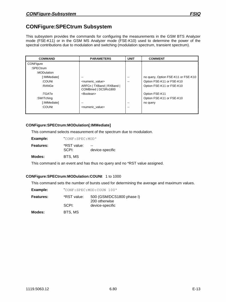
CONFigure-Subsystem FSIQ
1119.5063.12 6.80 E-13
CONFigure:SPECtrum Subsystem
This subsystem provides the commands for configuring the measurements in the GSM BTS Analyzermode (FSE-K11) or in the GSM MS Analyzer mode (FSE-K10) used to determine the power of thespectral contributions due to modulation and switching (modulation spectrum, transient spectrum).
COMMAND PARAMETERS UNIT COMMENT
CONFigure
:SPECtrum
:MODulation
[:IMMediate]
:COUNt
:RANGe
:TGATe
:SWITching
[:IMMediate]
:COUNt
--
<numeric_value>
ARFCn | TXBand | RXBand |COMBined | DCSRx1800
<Boolean>
--
<numeric_value>
--
--
--
--
no query, Option FSE-K11 or FSE-K10
Option FSE-K11 or FSE-K10
Option FSE-K11 or FSE-K10
Option FSE-K11
Option FSE-K11 or FSE-K10
no query
CONFigure:SPECtrum:MODulation[:IMMediate]
This command selects measurement of the spectrum due to modulation.
Example: "CONF:SPEC:MOD"
Features: *RST value: --SCPI: device-specific
Modes: BTS, MS
This command is an event and has thus no query and no *RST value assigned.
CONFigure:SPECtrum:MODulation:COUNt 1 to 1000
This command sets the number of bursts used for determining the average and maximum values.
Example: "CONF:SPEC:MOD:COUN 100"
Features: *RST value: 500 (GSM/DCS1800 phase I)200 otherwise
SCPI: device-specific
Modes: BTS, MS
FSIQ CONFigure-Subsystem
1119.5063.12 6.81 E-13
CONFigure:SPECtrum:MODulation:RANGe ARFCn | TXBand | RXBand | COMBined | DCSRx1800
This command selects the frequency range for the measurement.
Example: "CONF:SPEC:MOD:RANG TXB"
Features: *RST value: ARFCnSCPI: device-specific
Modes: BTS, MS
ARFCn ARFCN ± 1.8 MHzTXBand TX-BandRXBand RX-BandCOMBined ARFCN ± 1.8 MHz / TX-BandDCSRx1800 RX band DCS 1800 (option FSE-K10 only)
CONFigure:SPECtrum:MODulation:TGATe ON | OFF
This command switches on or off the operating mode gating for the TX band. For TGATe OFF, 8active slots are presumed.
Example: "CONF:SPEC:MOD:TGAT ON"
Features: *RST value: OFFSCPI: device-specific
Mode: BTS
CONFigure:SPECtrum:SWITching[:IMMediate]
This command selects measurement of the spectrum due to switching transients.
Example: "CONF:SPEC:SWIT"
Features: *RST value: --SCPI: device-specific
Modes: BTS, MS
This command is an event and has thus no query and no *RST value assigned.
CONFigure:SPECtrum:SWITching:COUNt 1 to 1000
This command defines the number of bursts used for determining the average and maximum values.
Example: "CONF:SPEC:SWIT:COUN 100"
Features: *RST value: 500 (GSM/DCS1800 phase I)200 otherwise
SCPI: device-specific
Modes: BTS, MS
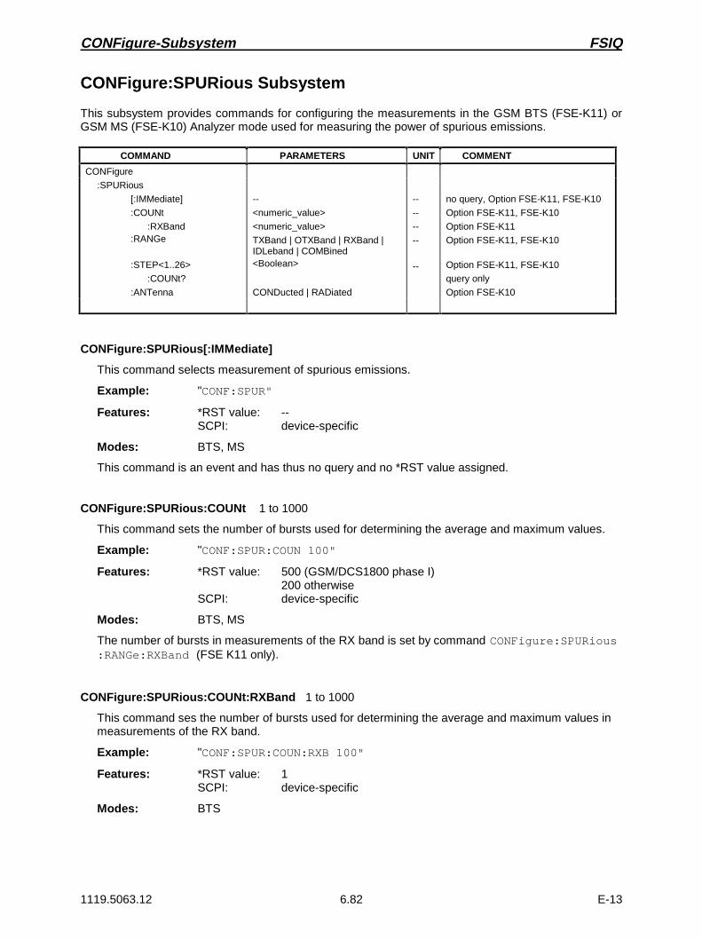
CONFigure-Subsystem FSIQ
1119.5063.12 6.82 E-13
CONFigure:SPURious Subsystem
This subsystem provides commands for configuring the measurements in the GSM BTS (FSE-K11) orGSM MS (FSE-K10) Analyzer mode used for measuring the power of spurious emissions.
COMMAND PARAMETERS UNIT COMMENT
CONFigure
:SPURious
[:IMMediate]
:COUNt
:RXBand:RANGe
:STEP<1..26>
:COUNt?
:ANTenna
--
<numeric_value>
<numeric_value>
TXBand | OTXBand | RXBand |IDLeband | COMBined<Boolean>
CONDucted | RADiated
--
--
--
--
--
no query, Option FSE-K11, FSE-K10
Option FSE-K11, FSE-K10
Option FSE-K11
Option FSE-K11, FSE-K10
Option FSE-K11, FSE-K10
query only
Option FSE-K10
CONFigure:SPURious[:IMMediate]
This command selects measurement of spurious emissions.
Example: "CONF:SPUR"
Features: *RST value: --SCPI: device-specific
Modes: BTS, MS
This command is an event and has thus no query and no *RST value assigned.
CONFigure:SPURious:COUNt 1 to 1000
This command sets the number of bursts used for determining the average and maximum values.
Example: "CONF:SPUR:COUN 100"
Features: *RST value: 500 (GSM/DCS1800 phase I)200 otherwise
SCPI: device-specific
Modes: BTS, MS
The number of bursts in measurements of the RX band is set by command CONFigure:SPURious:RANGe:RXBand (FSE K11 only).
CONFigure:SPURious:COUNt:RXBand 1 to 1000
This command ses the number of bursts used for determining the average and maximum values inmeasurements of the RX band.
Example: "CONF:SPUR:COUN:RXB 100"
Features: *RST value: 1SCPI: device-specific
Modes: BTS
FSIQ CONFigure-Subsystem
1119.5063.12 6.83 E-13
CONFigure:SPURious:RANGe TXBand | OTXBand | RXBand | IDLeband | COMBined
This command selects the frequency range used for the measurement.
Example: "CONF:SPUR:RANG OTX"
Features: *RST value: TXBSCPI: device-specific
Modes: BTS, MS
TXBand TX-BandOTXBand Not TX-BandRXBand RX-Band (option FSE-K11 only)IDLeband Idle band (option FSE-K10 only)COMBined TX-Band ± 2 MHz (option FSE-K11 only)
CONFigure:SPURious:STEP<1...26> ON | OFF
This command selects a subband of the selected band for a spurious measurement.
Each band is divided up into 1 to max. 26 subbands, which are selected by the numerical suffixfollowing STEP. A subband is selected for measurement by setting ON.
Example: "CONF:SPUR:STEP24 ON"
Feature: *RST value: ONSCPI: device-specific
Mode: BTS, MS
CONFigure:SPURious:STEP:COUNt?
This command queries the number of subbands of the currently selected band for a spuriousmeasurement.
Example: "CONF:SPUR:STEP:COUNT?"
Feature: *RST value: -SCPI: device-specific
Mode: BTS, MS
This command is a query and has therefore no *RST value assigned.
CONFigure:SPURious:ANTenna CONDucted | RADiated
This command selects the features of the measurement of spurious emmissions.
Example: "CONF:SPUR:ANT RAD"
Feature: *RST value: CONDSCPI: device-specific
Mode: MS

DIAGnostic Subsystem FSIQ
1119.5063.12 6.84 E-13
DIAGnostic Subsystem
The DIAGnostic subsystem contains the commands which support instrument diagnostics formaintenance, service and repair. In accordance with the SCPI standard, all of these commands aredevice-specific.
COMMAND PARAMETERS UNIT COMMENT
DIAGnostic
:SERVice
:INPut
[:SELect]
:FUNCtion
:NSOurce
:INFO
:CCOunt
:ATTenuation<1 to 3>?
CALibration | RF
<numeric_value>,>numeric_value>
<Boolean>
--
--
--
no query
query only
DIAGnostic:SERVice:INPut[:SELect] CALibration | RF
This command toggles between the RF input on the front panel and the internal 120-MHz referencesignal.
Example: "DIAG:SERV:INP CAL"
Features: *RST value: RFSCPI: device-specific
Modes: A, VA
DIAGnostic:SERVice:FUNCtion <numeric_value>,<numeric_value>...
This command activates a service function.
Example: "DIAG:SERV:FUNC 2,0,2,12,1"
Features: *RST value: -SCPI: device-specific
Modes: A, VA
The service function is selected via five parameters: functional group number, board number,function number, parameter 1 and parameter 2.
See service manual 1065.6016.24.
DIAGnostic:SERVice:NSOurce ON | OFF
This command switches the 28-V supply at the rear connector of the noise source on and off.
Example: "DIAG:SERV:NSO ON"
Features: *RST value: OFFSCPI: device-specific
Modes: A, VA
FSIQ DIAGnostic-Subsystem
1119.5063.12 6.85 E-13
DIAGnostic:INFO:CCOunt:ATTenuation<1 | 2 | 3>?
This command queries the cycle counters of the attenuators. The suffix selects the attenuator:
1: Basic Instrument 2: Tracking Generator 3: FSE-B13
The result is output as a list of values separated by a ’,’. The list starts with the date.
Example: "DIAG:INFO:CCO:ATT?"
Features: *RST value: --SCPI: device-specific
Modes: A, VA, MS, BTS
This command is a query and has therefore no *RST value assigned.

DISPlay Subsystem FSIQ
1119.5063.12 6.86 E-13
DISPlay Subsystem
The DISPLay subs ystem controls the selection and presentation of textual and graphic in formation aswell as of trace data on the displa y.The displa ys in the split-screen mode are assigned to WINDow 1 (screen A) or 2 (screen B) .
COMMAND PARAMETERS UNIT COMMENT
DISPlay
:FORMat
:PROgram
[:MODE]
:ANNotation
:FREQuen cy
:LOGO
:CMAP<1 to 13>
:DEFault
:HSL
:PDEFined
[:WINDow<1|2>]
:TEXT
[:DATA]
:STATe
:TIME
:MINFo
:TRACe<1 to 4>
:X
[:SCALe]
:RVALue
:ZOOM
[:FREQuency]
:STARt
:STOP
:CENTer
:SPACing
:Y
[:SCALe]
:MODE
:RLEVel
:OFFSet
:RVALue
:AUTO
:RPOSition
:PDIVision
:SPACing
SINGle | SPLit
<Boolean>
<Boolean>
<Boolean>
0 to 100,0 to 100,0 to 100
BLA Ck | BLUE | BROWn | GREen |CYAN | RED | MAGen ta | YELLo w |WHITe | DGRAy | LGRAy | LBLUe |LGREen | LCYan | LRED | LMAGen ta
<string>
<Boolean>
<Boolean>
<Boolean>
<numeric_value>
<Boolean>
<numeric_value>
<numeric_value>
<numeric_value>
LINear | LOGarith mic
<numeric_value>
ABSolute | RELati ve
<numeric_value>
<numeric_value>
<numeric_value>
<Boolean>
<numeric_value>
<numeric_value>
LINear|LOGarith mic|PERCent
HZ
HZ
HZ
--
DB
DBM
DB
DBM|DB|HZ|DEG|RAD
PCT
DBM|DB|HZ|DEG|RAD
--
Vector Signal Analy sis
Vector Signal Analy sis
Vector Signal Analy sis

FSIQ DISPlay Subsystem
1119.5063.12 6.87 E-13
COMMAND PARAMETERS UNIT COMMENT
DISPlay
[:WINDow<1|2>]
:TRACe<1...4>
:MODE
:CWRite
:ANALog
:HCONtinuous
[:STATe]
:SYMBol
:EYE
COUNt
:PSAVe
[:STATe]
HOLDoff
WRITe|VIEW|AVERage|MAXHold|MINHold|FRESults
<Boolean>
<Boolean>
<Boolean>
<Boolean>
DOTS | BARS | OFF
<numeric_value>
<Boolean>
<numeric_value>
--
--
--
--
--
SYM
Vector Signal Analysis
Vector Signal Analysis
Vector Signal Analysis
DISPlay:FORMat SINGle | SPLit
This command switches the test result display between FULL SCREEN and SPLIT SCREEN.
Example: "DISP:FORM SPL"
Features: *RST value: SINGleSCPI: device-specific
Modes: A, VA
DISPlay:PROGram[:MODE] ON | OFF
This command switches the display between the measuring instrument and the computer function.
Example: "DISP:PROG ON"
Features: *RST value: OFFSCPI: device-specific
Modes: A, VA, BTS, MS
DISPlay:ANNotation:FREQuency ON | OFF
This command switches the x-axis annotation on or off.
Example: "DISP:ANN:FREQ OFF"
Features: *RST value: ONSCPI: conforming
Modes: A, VA, BTS, MS
DISPlay:LOGO ON | OFF
This command switches the factory logo on the screen on or off.
Example: "DISP:LOGO OFF"
Features: *RST value: ONSCPI: device-specific
Modes: A, VA, BTS, MS

DISPlay Subsystem FSIQ
1119.5063.12 6.88 E-13
DISPlay:CMAP<1 to 13>:DEFault
This command resets the screen colors of the instrument to their default settings.
Example: "DISP:CMAP:DEF"
Features: *RST value: --SCPI: conforming
Modes: A, VA, BTS, MS
This command is an event and has thus no query and no *RST value assigned. The numeric suffix inCMAP<1 to 13> is not significant.
DISPlay:CMAP<1 to 13>:HSL <hue>,<sat>,<lum>
This command defines the color table of the instrument.
Parameter: hue = TINTsat = SATURATIONlum = BRIGHTNESS
The value range is 0.0 to 100.0 for all parameters.
Example: "DISP:CMAP2:HSL 0.3,0.8,1.0"
Features: *RST value: --SCPI: conforming
Modes: A, VA, BTS, MS
To each numeric suffix of CMAP is assigned one or several picture elements which can be modifiedby varying the corresponding color setting. The following assignment applies:
CMAP1 Trace 1 CMAP8 Softkey State Data EntryCMAP2 Trace 2 CMAP9 Softkey State OFFCMAP3 Trace 3 CMAP10 Softkey ShadeCMAP4 Trace 4 CMAP11 TextCMAP5 Marker CMAP12 TitleCMAP6 Grid CMAP13 BackgroundCMAP7 Softkey State On
The values set are not changed by *RST.
DISPlay:CMAP<1 to 13>:PDEFined BLACk | BLUE | BROWn | GREen | CYAN | RED | MAGenta |YELLow |WHITe | DGRAy | LGRAy | LBLUe | LGREen |LCYan |LRED | LMAGenta
This command defines the color table of the instrument using predefined color values. To eachnumeric suffix of CMAP is assigned one or several picture elements which can be modified byvarying the corresponding color setting. The same assignment as for DISPlay:CMAP<1 to13>:HSL applies.
Example: "DISP:CMAP2:PDEF GRE"
Features: *RST value: --SCPI: conforming
Modes: A, VA, BTS, MS
The values set are not changed by *RST.

FSIQ DISPlay Subsystem
1119.5063.12 6.89 E-13
DISPlay[:WINDow<1|2>]:MINFo ON | OFF
This command switches the marker info list on the screen on or off.
Example: "DISP:MINF ON"
Features: *RST value: OFFSCPI: device-specific
Modes: A, VA, BTS, MS
DISPlay[:WINDow<1|2>]:TEXT[:DATA] <string>
This command defines a comment (max. 50 characters) which can be displayed on the screen.
Example: "DISP:TEXT "signal/noise power measurement"
Features: *RST value: "" (empty)SCPI: conforming
Modes: A, VA, BTS, MS
The numeric suffix in WINDow<1|2> is not significant.
DISPlay[:WINDow<1|2>]:TEXT:STATe ON | OFF
This command switches on or off the screen display of the comment.
Example: "DISP:TEXT:STAT ON"
Features: *RST value: OFFSCPI: conforming
Modes: A, VA, BTS, MS
The numeric suffix in WINDow<1|2> is not significant.
DISPlay[:WINDow<1|2>]:TIME ON | OFF
This command switches on or off the screen display of date and time.
Example: "DISP:TIME ON"
Features: *RST value: OFFSCPI: device-specific
Modes: A, VA, BTS, MS
The numeric suffix in WINDow<1|2> is not significant.
DISPlay[:WINDow<1|2>]:TRACe<1 to 4>:X[:SCALe]:RVALue <numeric_value>
This command defines the reference value for the X-axis of the measuring diagram.
Example: "DISP:TRAC:X:RVAL 20SYM"
Features: *RST value: -SCPI: device-specific
Mode: VA-D

DISPlay Subsystem FSIQ
1119.5063.12 6.90 E-13
DISPlay[:WINDow<1|2>]:TRACe<1 to 4>:X[:SCALe]:ZOOM ON | OFF
This command displays the zoomed current frequency range in the opposite window of the splitscreen representation.
Example: "DISP:TRAC:X:ZOOM ON"
Features: *RST value: OFFSCPI: device-specific
Mode: A-F
The numeric suffix in TRACe<1 to 4> is not significant.
DISPlay[:WINDow<1|2>]:TRACe<1 to 4>:X[:SCALe]:ZOOM[:FREQuency]:STARt <numeric_value>
This command defines the start frequency of the zoomed display range. The value must lie betweenstart and stop frequency of the original range.
Example: "DISP:TRAC:X:ZOOM:STAR 100MHZ"
Features: *RST value: -- (depending on the current frequency setting)SCPI: device-specific
Mode: A-F
The numeric suffix in TRACe<1 to 4> is not significant.
DISPlay[:WINDow<1|2>]:TRACe<1 to 4>:X[:SCALe]:ZOOM[:FREQuency]:STOP <numeric_value>
This command defines the stop frequency of the zoomed display range. The value must lie betweenstart and stop frequency of the original range.
Example: "DISP:TRAC:X:ZOOM:STOP 200MHZ"
Features: *RST value: -- (depending on the current frequency setting)SCPI: device-specific
Mode: A-F
The numeric suffix in TRACe<1 to 4> is not significant.
DISPlay[:WINDow<1|2>]:TRACe<1 to 4>:X[:SCALe]:ZOOM[:FREQuency]:CENTer<numeric_value>
This command shifts the zoomed frequency range to the specified center frequency.
Example: "DISP:TRAC:X:ZOOM:CENT 1GHZ"
Features: *RST value: -- (depending on the current frequency setting)SCPI: device-specific
Mode: A-F
The numeric suffix in TRACe<1 to 4> is not significant.

FSIQ DISPlay Subsystem
1119.5063.12 6.91 E-13
DISPlay[:WINDow<1|2>]:TRACe<1 to 4>:X:SPACing LINear | LOGarithmic
This command toggles between linear and logarithmic display.
Example: "DISP:TRAC:X:SPAC LIN"
Features: *RST value: LOGarithmicSCPI: conforming
Mode: A
The numeric suffix in TRACe<1 to 4> is not significant.
DISPlay[:WINDow<1|2>]:TRACe<1 to 4>:Y[:SCALe] 10dB to 200dB
This command defines the display range of the Y-axis (level axis) with logarithmic scaling(DISP:TRAC:Y:SPAC LOG).
Example: "DISP:TRAC:Y 110dB"
Features: *RST value: 100dBSCPI: device-specific
Mode: A
For linear scaling, (DISP:TRAC:Y:SPAC LIN | PERC) the display range is fixed and cannot beset. The numeric suffix in TRACe<1 to 4> is not significant.
DISPlay[:WINDow<1|2>]:TRACe<1 to 4>:Y[:SCALe]:MODE ABSolute | RELative
This command defines the scale of the y-axis (absolute or relative).
Example: "DISP:TRAC:Y:MODE REL"
Features: *RST value: ABSSCPI: device-specific
Mode: A
As long as SYSTem:DISPlay is set to OFF, this command does not directly influence the screen.The numeric suffix in TRACe<1 to 4> is not significant.
DISPlay[:WINDow<1|2>]:TRACe<1 to 4>:Y[:SCALe]:RLEVel -200dBm to 200dBm
This command defines the reference level.
Example: "DISP:TRAC:Y:RLEV -60dBm"
Features: *RST value: -20dBmSCPI: conforming
Modes: A, VA
The numeric suffix in TRACe<1 to 4> is not significant.

DISPlay Subsystem FSIQ
1119.5063.12 6.92 E-13
DISPlay[:WINDow<1|2>]:TRACe<1 to 4>:Y[:SCALe]:RLEVel:OFFSet -200dB to 200dB
This command defines the offset of the reference level.
Example: "DISP:TRAC:Y:RLEV:OFFS -10dB"
Features: *RST value: 0dBSCPI: conforming
Modes: A, VA
The numeric suffix in TRACe<1 to 4> is not significant.
DISPlay[:WINDow<1|2>]:TRACe<1 to 4>:Y[:SCALe]:RVALue <numeric_value>
This command defines the reference value for the y-axis of the measurement diagram.This defines the upper limit of the display range, the corresponding parameters of the manual controlvary according to the measurement mode.
In the spectrum analysis mode the setting corresponds to the parameter MAX LEVEL.
In the vector signal analysis mode the setting corresponds to the parameter REFERENCE VALUE YAXIS.
IF option tracking generator is fitted and the normalization in the analyzer mode is activated, thevalue corresponds to the parameter REFERENCE VALUE.
Example: "DISP:TRAC:Y:RVAL -20dBm" (spectrum analysis)"DISP:TRAC:Y:RVAL +1.20" (vector signal analysis)"DISP:TRAC:Y:RVAL 0" (tracking generator)
Features: *RST value: - coupled to reference level0 (vector signal analysis)0 dB (tracking generator with active normalization)
SCPI: device specific
Modes: A, VA
The numeric suffix in TRACe<1 to 4> is not significant.
DISPlay[:WINDow<1|2>]:TRACe<1 to 4>:Y[:SCALe]:RVALue:AUTO ON | OFF
This command defines whether the reference value for the y-axis of the measured diagram iscoupled to the reference level (default) or can be set independently.
Example: "DISP:TRAC:Y:RVAL:AUTO ON"
Features: *RST value: ONSCPI: device-specific
Mode: A
This command is available in the analyzer mode only. The numeric suffix in TRACe<1 to 4> is notsignificant.
FSIQ DISPlay Subsystem
1119.5063.12 6.93 E-13
DISPlay[:WINDow<1|2>]:TRACe<1 to 4>:Y[:SCALe]:RPOSition 0 to 100PCT
This command defines the position of the reference value.
Example: "DISP:TRAC:Y:RPOS 50PCT"
Features: *RST value: 100PCT (tracking generator)50PCT (vector analyzer)
SCPI: conforming
Modes: A, VA
The numeric suffix in TRACe<1 to 4> is not significant. This command is only valid in conjunctionwith option Tracking Generator or in vector analyzer mode.
DISPlay[:WINDow<1|2>]:TRACe<1 to 4>:Y[:SCALe]:PDIVision <numeric_value>
This command defines the scaling of the Y-axis in the current unit.
Example: "DISP:TRAC:Y:PDIV +1.20"
Features: *RST value: -SCPI: conforming
Mode: VA
The numeric suffix in TRACe<1 to 4> is not significant.
DISPlay[:WINDow<1|2>]:TRACe<1 to 4>:Y:SPACing LINear | LOGarithmic | PERCent
This command toggles between linear and logarithmic display.
Example: "DISP:TRAC:Y:SPAC LIN"
Features: *RST value: LOGarithmicSCPI: conforming
Mode: A
The linear display can be LIN/% (PERCent) or LIN/dB (LINear). The numeric suffix in TRACe<1 to 4>is not significant.
DISPlay[:WINDow<1|2>]:TRACe<1 to 4>:MODE WRITe | VIEW | AVERage | MAXHold | MINHold
This command defines the type of display and the evaluation of the traces.
Example: "DISP:TRAC3:MODE MAXH"
Features: *RST value: WRITe for TRACe1, STATe OFF for TRACe2 to 4SCPI: device-specific
Modes: A, VA, BTS, MS
DISPlay[:WINDow<1|2>]:TRACe<1 to 4>:MODE:CWRite ON | OFF
This command selects continuous display of the measured values (continuous write).
Example: "DISP:TRAC3:MODE:CWR ON"
Features: *RST value: OFFSCPI: device-specific
Mode: VA

DISPlay Subsystem FSIQ
1119.5063.12 6.94 E-13
DISPlay[:WINDow<1|2>]:TRACe<1 to 4>:MODE:ANALog ON | OFF
This command selects continuous display of the measured values in the analyzer mode (analogtrace).
Example: "DISP:TRAC3:MODE:ANAL ON"
Features: *RST value: OFFSCPI: device-specific
Mode: A
DISPlay[:WINDow<1|2>]:TRACe<1 to 4>:MODE:HCONtinuous ON | OFF
This command defines whether the traces in the min hold/max hold mode are reset after somedefinite parameter changes.
Example: "DISP:TRAC3:MODE:HCON ON"
Features: *RST value: OFFSCPI: device-specific
Mode: A
OFF The traces are reset after some definite parameter changes.
ON This mechanism is switched off.
In general, parameter changes require a restart of the measurement before results are evaluated(e.g. with markers). For those changes that are known to require a new measurement (e.g.modification of the span), the trace is automatically reset so that erroneous evaluations of previousresults are avoided. This mechanism can be switched off for those exceptional cases where thedescribed behavior is unwelcome.
DISPlay[:WINDow<1|2>]:TRACe<1 to 4>[:STATe] ON | OFF
This command switches the display of the corresponding trace on or off.
Example: "DISP:TRAC3 ON"
Features: *RST value: ON for TRACe1, OFF for TRACe2 to 4SCPI: conforming
Modes: A, VA, BTS, MS
DISPlay[:WINDow<1|2>]:TRACe<1 to 4>:SYMBol DOTS | BARS | OFF
This command determines the display of the points of decision on the trace.
Example: "DISP:TRAC:SYMB BARS"
Features: *RST value: OFFSCPI: device-specific
Mode: VA-D

FSIQ DISPlay Subsystem
1119.5063.12 6.95 E-13
DISPlay[:WINDow<1|2>]:TRACe<1 to 4>:EYE:COUNt 1 to Result Length
This command determines the display range of the eye diagram in symbols.
Example: "DISP:TRAC:EYE:COUNt 5"
Features: *RST value: 2SCPI: device-specific
Mode: VA-D
DISPlay:PSAVe[:STATe] ON | OFF
This command switches the screen saver mode on or off.
Example "DISP:PSAV ON"
Features: *RST value: OFFSCPI: device-specific
Modes: A, VA, BTS, MS
DISPlay: PSAVe:HOLDoff <numeric_value>
This command determines the time after which the screen saver is switched on. Values are input inminutes, the valid range is 1 to 100 minutes.
Example: "DISP:PSAV:HOLD 10"
Features: *RST value: 1SCPI: device-specific
Modes: A, VA, BTS, MS

FETCh-Subsystem FSIQ
1119.5063.12 6.96 E-13
FETCh Subsystem
The FETCh subsystem contains commands for reading out results of complex measurement tasks likethose provided by options GSM BTS Analyzer, FSE-K11, or GSM MS Analyzer, FSE-K10. The FETCh-subsystem is closely linked to the functions of the CONFigure and READ-subsystems, where themeasurement sequences are configured, the measurements are started and their results are queried.
FETCh:BURSt Subsystem
This subsystem provides the commands for reading out results of measurements in the GSM BTS(option FSE-K11) or GSM MS (option FSE-K10) Analyzer mode, which are performed on individualbursts (Carrier Power, Phase/Frequency Error) without starting the measurement by themselves.
COMMAND PARAMETERS UNIT COMMENT
FETCh
:BURSt
:PERRor:RMS
:STATus?
:AVERage?
:MAXimum?:PEAK
:STATus?
:AVERage?
:MAXimum?:FERRor
:STATus?
:AVERage?
:MAXimum?
:POWer
[:IMMediate]?
:ALL?
--
--
--
--
--
--
--
--
--
Option FSE-K11 or FSE-K10
query only
query only
query only
query only
query only
query only
query only
query only
query only
query only
query only
FETCh:BURSt:PERRor:RMS:STATus?
This command reads out the status of the RMS-measurement of the phase error taken over theselected number of bursts.
0: failed, 1: passed
Example: "FETC:BURS:PERR:RMS:STAT?"
Features: *RST value: --SCPI: device-specific
Modes: BTS, MS
If no measurement has been performed yet, a query error results.This command is a query and has therefore no *RST value assigned.It is available only when measurement of the phase/frequency error is selected (seeCONFigure:BURSt:PFERror).

FSIQ FETCh-Subsystem
1119.5063.12 6.97 E-13
FETCh:BURSt:PERRor:RMS:AVERage?
This command reads out the average of the RMS-measurement of the phase error taken over theselected number of bursts.
Example: "FETC:BURS:PERR:RMS:AVER?"
Features: *RST value: --SCPI: device-specific
Modes: BTS, MS
If no measurement has been performed yet, a query error results.This command is a query and has therefore no *RST value assigned.It is available only when measurement of the phase/frequency error is selected (seeCONFigure:BURSt:PFERror).
FETCh:BURSt:PERRor:RMS:MAXimum?
This command reads out the maximum of the RMS-measurement of the phase error for the selectednumber of bursts.
Example: "FETC:BURS:PERR:RMS:MAX?"
Features: *RST value: --SCPI: device-specific
Modes: BTS, MS
If no measurement has been performed yet, a query error results.This command is a query only and therefore has no *RST value assigned. It is available only whenmeasurement of the phase/frequency error is selected (see CONFigure:BURSt:PFERror).
FETCh:BURSt:PERRor:PEAK:STATus?
This command reads out the status of the peak measurement of the phase error taken over theselected number of bursts.
0: failed, 1: passed
Example: "FETC:BURS:PERR:PEAK:STAT?"
Features: *RST value --SCPI: device-specific
Modes: BTS, MS
If no measurement has been performed yet, a query error results.This command is a query only and therefore has no *RST value assigned. It is available only ifmeasurement of the phase/frequency error is selected (see CONFigure:BURSt:PFERror).

FETCh-Subsystem FSIQ
1119.5063.12 6.98 E-13
FETCh:BURSt:PERRor:PEAK:AVERage?
This command reads out the average of the peak measurement of the phase error taken over theselected number of bursts.
Example: "FETC:BURS:PERR:PEAK:AVER?"
Features: *RST value: --SCPI: device-specific
Modes: BTS, MS
If no measurement has been performed yet, a query error results.This command is a query only and therefore has no *RST value assigned. It is available only ifmeasurement of the phase/frequency error is selected (see CONFigure:BURSt:PFERror).
FETCh:BURSt:PERRor:PEAK:MAXimum?
This command reads out the maximum of the peak measurement of the phase error for the selectednumber of bursts.
Example: "FETC:BURS:PERR:PEAK:MAX?"
Features: *RST value: --SCPI: device-specific
Modes: BTS, MS
If no measurement has been performed yet, a query error results.This command is a query only and therefore has no *RST value assigned. It is available only whenmeasurement of the phase/frequency error is selected (see CONFigure:BURSt:PFERror).
FETCh:BURSt:FERRor:STATus?
This command reads out the status of the measurement of the frequency error taken over theselected number of bursts.
0: failed, 1: passed
Example: "FETC:BURS:FERR:STAT?"
Features: *RST value: --SCPI: device specific
Modes: BTS, MS
If no measurement has been performed yet, a query error results.This command is a query only and therefore has no *RST value assigned. It is available only ifmeasurement of the phase/frequency error is selected (see CONFigure:BURSt:PFERror).

FSIQ FETCh-Subsystem
1119.5063.12 6.99 E-13
FETCh:BURSt:FERRor:AVERage?
This command reads out the average of the measurement of the frequency error taken over theselected number of bursts.
Example: "FETC:BURS:FERR:AVER?"
Features: *RST value: --SCPI: device-specific
Modes: BTS, MS
If no measurement has been performed yet, a query error results.This command is a query only and therefore has no *RST value assigned. It is available only ifmeasurement of the phase/frequency error is selected (see CONFigure:BURSt:PFERror).
FETCh:BURSt:FERRor:MAXimum?
This command reads out the maximum frequency error measured over the selected number ofbursts.
Example: "FETC:BURS:FERR:MAX?"
Features: *RST value: --SCPI: device-specific
Modes: BTS, MS
If no measurement has been performed yet, a query error results.This command is a query only and therefore has no *RST value assigned. It is available only ifmeasurement of the phase/frequency error is selected (see CONFigure:BURSt:PFERror).
FETCh:BURSt:POWer[:IMMediate]?
This command reads out the result of the last step performed during the measurement of the outputpower of the base station or mobile.
Parameter: The result is output as an ASCII string in the following format:
<Static Power Ctrl>,<Dyn Power Ctrl>,<Rat-Level>,<Act-Level>, <Delta>,<Status>
with
<Static Power Ctrl>: current static power control level<Dyn Power Ctrl>: current dynamic power control level<Rat-Level>: Rated value for the current power control level acc. to
standard dBm<Act-Level>: measured power in dBm<Delta>: Difference between the measured power and the power at the previous
static/dynamic power control level.<Status>: Result of limit check in character data form:
PASSED no limits exceededFAILED limit exceeded
Example: "FETC:BURS:POW?"Result: 0,0,43,44.1,0,PASSED
Features: *RST value: --SCPI: device-specific
Modes: BTS, MS
If no measurement has been performed yet, a query error results.This command is a query only and therefore has no *RST value assigned. It is available only ifmeasurement of the phase/frequency error is selected (see CONFigure:BURSt:PFERror).

FETCh-Subsystem FSIQ
1119.5063.12 6.100 E-13
FETCh:BURSt:POWer:ALL?
This command reads out the results of all individual steps during the measurement of the outputpower of the base station or mobile.
Parameter: The result is output as an ASCII string in the following format:
<Static Power Ctrl>,<Dyn Power Ctrl>,<Rat-Level>,<Act-Level>, <Delta>,<Status>
with
<Static Power Ctrl>: current static power control level<Dyn Power Ctrl>: current dynamic power control level<Rat-Level>: Rated value for the current power control level acc. to
standard dBm<Act-Level>: measured power in dBm<Delta>: Difference between the measured power and the power at the previous
static/dynamic power control level.<Status>: Result of limit check in character data form:
PASSED no limits exceededFAILED limit exceeded
Example: "FETC:BURS:POW:ALL?"Result:0,0,43,44.1,0,PASSED,1,0,41,42.5,1.6,PASSED,1,1,35,32.5,5.6,FAILED
Features: *RST value: --SCPI: device-specific
Modes: BTS, MS
If no measurement has been performed yet, a query error results.This command is a query only and therefore has no *RST value assigned. It is available only ifmeasurement of the phase/frequency error is selected (see CONFigure:BURSt:PFERror).

FSIQ FETCh-Subsystem
1119.5063.12 6.101 E-13
FETCh:SPECtrum Subsystem
This subsystem provides the commands for reading out results of measurements in the GSM BTS(FSE-K11) or GSM MS (FSE-K10) Analyzer mode, used to measure the power of the spectralcontributions due to modulation and switching (modulation spectrum, transient spectrum) without firstrestarting a new measurement.
COMMAND PARAMETERS UNIT COMMENT
FETCh Option FSE-K11 or FSE-K10
:SPECtrum
:MODulation
[:ALL]?
:REFerence?
:SWITching
[:ALL]?:REFerence?
ARFCn | TXBand | RXBand |COMBined | DCSRx1800
--
query only
query only
query only
query only
FETCh:SPECtrum:MODulation[:ALL]? ARFCn | TXBand | RXBand | COMBined | DCSRx1800
This command reads out the result of the measurement of the modulation spectrum of the basestation or mobile.
Parameter: The result is output as a list of partial result strings separated by ’,’ in the following(ASCII) format:
<Index>,<Freq1>,<Freq2>,<Level>,<Limit>, <Abs/Rel>,<Status> [,<Index>,<Freq1>,<Freq2>,<Level>,<Limit>, <Abs/Rel>,<Status>]...
where the parts between ’[...]’ denote a partial result string that can be repeated n times.
<Index>: 0, if the partial result string characterizes a measurement range
current number <>0,if the partial result string characterizes a singlelimit excess.
<Freq1>: Start frequency of the measurement range orfrequency where the limit line is exceeded
<Freq2>: Start frequency of the measurement range orfrequency exceeding the measurement range. The value of<Freq2> is equal to the value of <Freq1>, if either themeasurement is performed in the time domain or if thepartial result string contains a limit excess.
<Level>: Measured maximum level of the partial range ormeasured level at the test point.
<Limit>: Limit in the partial range or at the test point<Abs/Rel>: ABS <Level> and <Limit> are in absolute units (dBm)
REL <Level> and <Limit> are in absolute units (dBm)<Status>: Result of the limit check in character data form:
PASSED no limit exceededFAILED limit exceededMARGIN margin exceededEXC limit excess marked as an exception
The frequencies <Freq1> and <Freq2> are always absolute i. e. not referred to the carrier frequency.
FETCh-Subsystem FSIQ
1119.5063.12 6.102 E-13
Example: "FETC:SPEC:MOD? TXB"Result: 0,890E6,915E6,-87.4,-108.0,ABS,FAILED,
1,893.2E6,893.2E6,-83.2,-108.0,ABS,FAILED,2,895.7E6,895.7E6,-87.4,-108.0,ABS,FAILED
Features: *RST value: --SCPI: device-specific
Modes: BTS, MS
ARFCn ARFCN ± 1.8 MHzTXBand TX-BandRXBand RX-BandCOMBined ARFCN ± 1.8 MHz / TX-Band (option FSE-K11 only)DCSRx1800 RX band DCS 1800 (option FSE-K10 only)
If no measurement has been performed yet, a query error results.This command is a query only and therefore has no *RST value assigned. It is available only ifmeasurement of the modulation spectrum is selected (see CONFigure:SPECtrum:MODulation).
FETCh:SPECtrum:MODulation:REFerence?
This command reads out the result of the premeasurement.
Parameter: The result is output as a list of partial result strings separated by ’,’ in the following(ASCII) format:
<Level1>,<Level2>,<RBW>
<Level1>: measured level
<Level2>: level corrected by means of the bandwidth
<RBW>: bandwidth
Example: "FETC:SPEC:MOD:REF?"Result: 36.2,43.2,30000
Features: *RST value: --SCPI: device-specific
Modes: BTS, MS
If no measurement has been performed yet, a query error results.This command is a query only and therefore has no *RST value assigned. It is available only ifmeasurement of the modulation spectrum is selected (see CONFigure:SPECtrum:MODulation).

FSIQ FETCh-Subsystem
1119.5063.12 6.103 E-13
FETCh:SPECtrum:SWITching[:ALL]?
This command reads out the result of the measurement of the transient spectrum of the base stationor mobile.
Parameter: The result is output as a list of partial result strings separated by ’,’ as for thecommand FETCh:SPECtrum:MODulation[:ALL]?.
Example: "FETC:SPEC:SWIT?"Result: 0,833.4E6,833.4E6,37.4,-36.0,ABS,MARGIN,
1,834.0E6,834.0E6,-35.2,-36.0,ABS,FAILED,2,834.6E6,834.6E6,-74.3,-75.0,REL,FAILED0,835.0E6,835.0E6,-65,0,-60.0,REL,PASSED
Features: *RST value: --SCPI: device-specific
Modes: BTS, MS
If no measurement has been performed yet, a query error results.This command is a query only and therefore has no *RST value assigned. It is available only ifmeasurement of the transient spectrum is selected (see CONFigure:SPECtrum:SWITching).
FETCh:SPECtrum:SWITching:REFerence?
This command queries the result of the premeasurement
Parameter: The result is output as a list of partial result strings separated by ’,’ in the following(ASCII) format:
<Level1>,<Level2>,<RBW>
<Level1>: measured level
<Level2>: level corrected by means of the bandwidth
<RBW>: bandwidth
Example: "FETC:SPEC:SWIT:REF?"Result: 43.2,43.2,300000
Features: *RST value --SCPI: device specific
Modes: BTS, MS
If no measurement has been performed yet, a query error results.This command is a query only and therefore has no *RST value assigned. It is available only ifmeasurement of the transient spectrum is selected (see CONFigure:SPECtrum:SWITching).

FETCh-Subsystem FSIQ
1119.5063.12 6.104 E-13
FETCh:SPURious Subsystem
This subsystem provides the commands for reading out results of measurements in the GSM BTS(FSE-K11) or GSM MS (FSE-K10) Analyzer mode which are used to determine spurious emissions,without first restarting a new measurement.
COMMAND PARAMETERS UNIT COMMENT
FETCh Option FSE-K11 or FSE-K10
:SPURious
[:ALL]?
:STEP?
TXBand | OTXBand | RXBand |IDLeband
--
query only
query only
FETCh:SPURious[:ALL]? TXBand | OTXBand | RXBand | IDLeband
This command reads out the results of the measurement of spurious emissions of the base stationor mobile which is performed in the LIST mode.
Parameter: The result is output as a list of partial result strings separated by ’,’ in the following(ASCII) format:
<Index>,<Freq1>,<Freq2>,<Level>,<Limit>, <Abs/Rel>,<Status> [,<Index>,<Freq1>,<Freq2>,<Level>,<Limit>, <Abs/Rel>,<Status>]...
where the parts between ’[...]’ denote a partial result string that can be repeated n times.
<Index>: 0, if the partial result string characterizes a measurement rangecurrent number <>0,
if the partial result string characterizes a singlelimit excess.
<Freq1>: Start frequency of the measurement range orfrequency where the limit line is exceeded
<Freq2>: Start frequency of the measurement range orfrequency exceeding the measurement range. The value of<Freq2> is equal to the value of <Freq1>, if either themeasurement is performed in the time domain or if thepartial result string contains a limit excess.
<Level>: Measured maximum level of the partial range ormeasured level at the test point.
<Limit>: Limit in the partial range or at the test point<Abs/Rel>: ABS <Level> and <Limit> are in absolute units (dBm)
REL <Level> and <Limit> are in absolute units (dBm)<Status>: Result of the limit check in character data form:
PASSED no limit exceededFAILED limit exceededMARGIN margin exceeded

FSIQ FETCh-Subsystem
1119.5063.12 6.105 E-13
Example: "FETC:SPUR? TXB"Result: 0,890E6,915E6,-87.4,-108.0,ABS,FAILED,
1,893.2E6,893.2E6,-83.2,-108.0,ABS,FAILED,2,895.7E6,895.7E6,-87.4,-108.0,ABS,FAILED
Features: *RST value: --SCPI: device-specific
Modes: BTS, MS
TXBand TX-bandOTXBand Not TX-bandRXBand RX-band (option FSE-K11 only)IDLeband Idle band (option FSE-K10 only)
If no measurement has been performed yet, a query error results.
This command is a query only and therefore has no *RST value assigned. It is available only ifmeasurement of the spurious emissions is selected (see CONFigure:SPURious).
FETCh:SPURious:STEP?
This command reads out the result of the last single step of the measurement of spurious emissionsperformed in the STEP mode.
Parameter: The result is output as a list of partial result strings separated by ’,’ as for thecommand FETCh:SPURious[:ALL]?.
Example: "FETC:SPUR:STEP?"Result: 0,890E6,915E6,-87.4,-108.0,ABS,FAILED,
1,893.2E6,893.2E6,-83.2,-108.0,ABS,FAILED,2,895.7E6,895.7E6,-87.4,-108.0,ABS,FAILED
Features: *RST value: --SCPI: device-specific
Modes: BTS, MS
If no measurement has been performed yet, a query error results.This command is a query only and therefore has no *RST value assigned. It is available only ifmeasurement of the spurious emissions is selected (see CONFigure:SPURious).

FETCh-Subsystem FSIQ
1119.5063.12 6.106 E-13
FETCh:PTEMplate Subsystem
This subsystem provides the commands for reading out results of measurements in the GSM BTS(FSE-K11) or GSM MS (FSE-K10) Analyzer mode which are used to determine the carrier power of ,power versus time measurement without first restarting a new measurement.
COMMAND PARAMETER UNIT COMMENT
FETCh Option FSE-K11, FSE-K10
:PTEMplate
:REFerence? query only
FETCh:PTEMplate:REFerence?
This command reads out the results of the premeasurement
Parameter: The result is output as a list of partial result strings separated by ’,’ in the following(ASCII) format:
<Level1>,<Level2>,<RBW>
<Level1>: measured level
<Level2>: level corrected by means of the bandwidth
<RBW>: bandwidth
Example: "FETC:PTEM:REF?"Result: 43.2,43.2,1000000
Features: *RST value: --SCPI: devicespecific
Modes: BTS, MS
If no measurement has been performed yet, a query error results.This command is a query only and therefore has no *RST value assigned. It is available only ifmeasurement of Power versus Time is selected (see CONFigure:BURSt:PTEMplate).

FSIQ FORMat-Subsystem
1119.5063.12 6.107 E-13
FORMat Subsystem
The FORMat subsystem specifies the data format of the data transmitted from and to the instrument.
COMMAND PARAMETERS UNIT COMMENT
FORMat
[:DATA]
:DEXPort
:DSEParator
:HEADer
[:STATe]
APPend
[:STATe]
ASCii|REAL|UINT[,<numeric_value>]
POINt|COMMa
<Boolean>
<Boolean>
-
FORMat[:DATA] ASCii | REAL | UINT [, 32]
This command specifies the data format of the data transmitted from and to the instrument.
Example: "FORM REAL,32""FORM ASC"
Features: *RST value: ASCiiSCPI: conforming
Modes: A, VA, BTS, MS
The data format is either ASCii or one of the formats REAL or UINT (Unsigned Integer). ASCii dataare transmitted in plain text, separated by commas. REAL data are transmitted as 32-bit IEEE 754floating-point numbers in the "definite length block". The format UINT is only used in operating modeVector Signal Analysis, for the symbol table.
Format setting for the binary transmission of trace data (see also TRACE:DATA?):
Analyzer mode: REAL, 32
Vector analyzer: UINT, 8 with digital demodulation, symbol tableREAL, 32otherwise
Note: Incorrect format setting will result in numerical conversion, which may lead to incorrectresults.
If the format ”FORM REAL, 32” is selected for the above example, the data stream from the analyzerto the controller is as follows:
#432085334.....
||| ||
|||..|From here follow the data bytes of the data block, here 5334
||Number of bytes of data block stated in ASCII plain text, here 3208
|ASCII byte stating the length of the subsequent length counter, here 4
Head marker of binary data stream
For this example, the number of transmitted data bytes is as follows:
Number = number of test points * bytes/value* 2
3208 = 401 * 4* 2
The FORMat command is valid for the transmission of trace data. The data format of trace datareceived by the instrument is automatically recognized, regardless of the format which isprogrammed.
FORMat Subsystem FSIQ
1119.5063.12 6.108 E-13
FORMat:DEXPort:DSEParator POINt|COMMA
This command determines the decimal separator (decimal point or comma)for the output of themeasurement data in ASCII format. Thus, evaluation programms (i.e. MS-Exel) of different languageversions are supported.
Example: "FORM:DEXP:DSEP POIN
Features: *RST value: POINtSCPI: device specific
Modes: A, VA, BTS, MS
FORMat:DEXPort:HEADer[:STATe] ON|OFF
This commad determines if the output file starts with a header (start frequency, sweep time, detector,.. = ON) or not. OFF = only measurement data is output.
Example: "FORM:DEXP:HEAD OFF
Features: *RST value: ONSCPI: device specific
Modes: A, VA, BTS, MS
FORMat:DEXPort:APPend[:STATe] ON|OFF
This commad determines if the output file is overwritten or the data is added to the end of the file.
Example: "FORM:DEXP:APP OFF
Features: *RST value: ONSCPI: device-specific
Modes: A, VA, BTS, MS

FSIQ HCOPy Subsystem
1119.5063.12 6.109 E-13
HCOPy Subsystem
The HCOPy subsystem controls the output of display information for documentation purposes on outputdevices or files.
COMMAND PARAMETERS UNIT COMMENT
HCOPy
:ABORt
:DESTination<1|2>
:DEVice
:COLor
:LANGuage<1|2>
[:IMMediate<1|2>]
:ITEM
:ALL
:FFEed<1|2>
:STATe
:LABEL
:TEXT
:PFEed<1|2>
:STATe
:WINDow<1|2>
:TABle
:STATe
:TEXT
:TRACe
:STATe
:CAINcrement
:PAGE
:DIMensions
:QUADrant<1 to 4>
:FULL
:ORIentation<1|2>
--
‘SYST:COMM:PRIN’|’SYST:COMM:CLIP' | ’MMEM’
<Boolean>
WMF | GDI | EWMF | BMP
--
<Boolean>
<string>
<Boolean>
<Boolean>
<string>
<Boolean>
<Boolean>
LANDscape | PORTrait
no query
no query
no query
no query
no query
no query
HCOPy:ABORt
This command aborts a running hardcopy output.
Example: "HCOP:ABOR"
Features: *RST value: -SCPI: conforming
Modes: A, VA, BTS, MS
This command is an event which is why it is not assigned an *RST value and no query.

HCOPy Subsystem FSIQ
1119.5063.12 6.110 E-13
HCOPy:DESTination<1|2> <string>
This command selects the device for outputting the hardcopy. The availability of the parametersdepends on the selected data format (see command HCOPy:DEVice:LANGuage).
Parameter: <string>::= ’MMEM’ |’SYST:COMM:PRIN’ |’SYST:COMM:CLIP’
Example: "HCOP:DEST2 ’MMEM’"
Features: *RST value: -SCPI: conforming
Modes: A, VA, BTS, MS
This command is an event which is why it is not assigned an *RST value and no query.
’MMEM’ creates a file for the hardcopy output. Command MMEM:NAME<file_name> defines the file name. All formats can be selected forHCOPy:DEVice:LANGuage.
’SYST:COMM:PRIN’ directs the hardcopy to the printer. The printer is selected withcommand SYSTEM:COMMunicate:PRINter:SELect .GDI should be selected for HCOPy:DEVice:LANGuage .
’SYST:COMM:CLIP’ directs the hardcopy to the clipboard. EWMF should be selected forHCOPy:DEVice:LANGuage .
HCOPy:DEVice:COLor ON|OFF
This command selects between color and monochrome hardcopy of the screen.
Example: "HCOP:DEV:COL ON"
Features: *RST value: OFFSCPI: conforming
Modes: A, VA, BTS, MS
HCOPy:DEVice:LANGuage<1|2> WMF| EWMF | GDI | BMP
This command determines the data format of the printout.
Example: "HCOP:DEV:LANG WMF"
Features: *RST value: -SCPI: conforming
Modes: A, VA, BTS, MS
WMF and (WINDOWS Metafile and Enhanced Metafile Format)EWMF Data formats for output files which can at a later time be integrated in
corresponding programs for documentation purposes.
BMP (Bitmap) Data format for output files.
GDI (Graphics Device Interface) Default format for the output to a printer configuredunder Windows. For the output file the printer driver configured under Windows isused and thus a printer-specific format is generated.

FSIQ HCOPy Subsystem
1119.5063.12 6.111 E-13
HCOPy[:IMMediate<1|2>]
This command starts a hardcopy output.
Example: "HCOP"
Features: *RST value: -SCPI: conforming
Modes: A, VA, BTS, MS
HCOP[1] starts the hardcopy output to device 1 (default), HCOP2 starts the output to device 2.This command is an event which is why it is not assigned an *RST value and has no query.
HCOPy:DEVice:ITEM:ALL
This command selects the complete screen to be output.
Example: "HCOP:DEV:ITEM:ALL"
Features: *RST value: OFFSCPI: conforming
Modes: A, VA, BTS, MS
The hardcopy output is always provided with comments, title, time and date. As an alternative to thewhole screen, only traces (commands ’HCOPy:DEVice:WINDow:TRACe: STATe ON’) or tables(command ’HCOPy:DEVice:WINDow:TABLe:STATe ON’) can be output.
HCOPy:DEVice:ITEM:FFEed<1|2>:STATe ON|OFF
The command adds a form feed command to the hardcopy output of the screen.
Example: "HCOP:DEV:ITEM:FFE2:STAT ON"
Features: *RST value: OFFSCPI: conforming
Modes: A, VA, BTS, MS
HCOPy:DEVice:ITEM:LABel:TEXT <string>
This command defines the title of the screen with a maximum of 60 characters.
Example: "HCOP:DEV:ITEM:LAB:TEXT ’My Title’"
Features: *RST value: OFFSCPI: conforming
Modes: A, VA, BTS, MS

HCOPy Subsystem FSIQ
1119.5063.12 6.112 E-13
HCOPy:DEVice:ITEM:PFEed<1|2>:STATe ON|OFF
This command adds a paper feed command to the hardcopy output of the screen (ON).
Example: "HCOP:DEV:ITEM:PFE2:STAT ON"
Features: *RST value: OFFSCPI: device-specific
Modes: A, VA, BTS, MS
HCOPy:DEVice:ITEM:WINDow<1|2>:TABle:STATe ON | OFF
This command selects the output of the currently displayed tables (ON).
Example: "HCOP:DEV:ITEM:WIND:TABL:STAT ON"
Features: *RST value: OFFSCPI: device-specific
Modes: A, VA, BTS, MS
The command HCOPy:DEVice:ITEM:WINDow<1|2>:TABle:STATe OFF same as commandHCOPy:DEVice:ITEM:ALL enables the output of the whole screen.
HCOPy:DEVice:ITEM:WINDow<1|2>:TEXT <string>
This command defines the comment text for printout to trace 1 or 2 with a maximum of 100characters.
Example: "HCOP:DEV:ITEM:WIND2:TEXT ‘comment’"
Features: *RST value: -SCPI: device-specific
Modes: A, VA, BTS, MS
HCOPy:DEVice:ITEM:WINDow<1|2>:TRACe:STATe ON | OFF
This command selects the output of the currently displayed trace (ON).
Example: "HCOP:DEV:ITEM:WIND:TRACe:STAT ON"
Features: *RST value: OFFSCPI: device-specific
Modes: A, VA, BTS, MS
The command HCOPy:DEVice:ITEM:WINDow<1|2>:TRACe:STATe OFF same as commandHCOPy:DEVice:ITEM:ALL enables the output of the whole screen.
FSIQ HCOPy Subsystem
1119.5063.12 6.113 E-13
HCOPy:DEVice:ITEM:WINDow<1|2>:TRACe:CAINcrement ON | OFF
The command automatically changes the colour of the currently displayed trace after printout (ON).
Example: "HCOP:DEV:ITEM:WIND:TRACe:CAIN ON"
Features: *RST value: OFFSCPI: device-specific
Modes: A, VA, BTS, MS
The automatic change of colour of the trace allows outputting to a plotter of several traces of thesame diagram. For a better distinction, the colour of the trace is changed (”Color Auto Increment”).
HCOPy:PAGE:DIMensions:QUADrant<1 to 4>
The command defines the quadrant which is allocated to the screen output.
Example: "HCOP:PAGE:DIM:QUAD1"
Features: *RST value: -SCPI: conforming
Modes: A, VA, BTS, MS
The quadrants are defined as QUAD1 at the top right, QUAD2 at the top left, QUAD3 at the bottomleft and QUAD4 at the bottom right. This command is an event which is why it is not assigned an*RST value and has no query.
HCOPy:PAGE:DIMensions:FULL
This command defines that the full screen is to be printed out.
Example: "HCOP:PAGE:DIM:FULL"
Features: *RST value: -SCPI: device-specific
Modes: A, VA, BTS, MS
This command is an event which is why it is not assigned and *RST value and has no query.
HCOPy:PAGE:ORIentation<1|2> LANDscape | PORTrait
The command selects the format of the output (portrait and landscape) (hardcopy unit 1 or 2).
Example: "HCOP:PAGE:ORI LAND"
Features: *RST value: -SCPI: conforming
Modes: A, VA, BTS, MS

INITiate Subsystem FSIQ
1119.5063.12 6.114 E-13
INITiate Subsystem
The INITiate subsystem checks the initialization of the trigger subsystem.In the split-screen representation, a distinction is made between INITiate1 (screen A) and INITiate2(screen B)
COMMAND PARAMETERS UNIT COMMENT
INITiate<1|2>
:CONTinuous
:CONMeas
[:IMMediate]
:DISPlay
<boolean>
--
--
<boolean>
--
--
--
--
no query
no query
INITiate<1|2>:CONTinuous ON | OFF
This command determines if the trigger system is continuously initiated ("Free Run").
Example: "INIT:CONT OFF"
Features: *RST value: ONSCPI: conforming
Modes: A, VA, BTS, MS
Setting "INITiate:CONTinuous ON" corresponds to function SWEEP CONTinuous, ie the sweepof the analyzer is cyclically repeated. The setting "INITiate:CONTinuous OFF" corresponds tofunction SWEEP SINGLE.
INITiate<1|2>:CONMeas
This command continues the sweep from the current sweep position.
Example: "INIT:CONM"
Features: *RST value: -SCPI: device-specific
Modes: A, VA, BTS, MS
This command is an event and therefore has no *RST value and no query.Sweeps are stopped, for example, in the case of transducer sets between the different transducerfactors.
INITiate<1|2>[:IMMediate]
The command initiates a new sweep or starts a single sweep.
Example: "INIT"
Features: *RST value: -SCPI: conforming
Modes: A, VA, BTS, MS
This command is an event which is why it is not assigned an *RST value and has no query.
INITiate<1|2>:DISPlay ON | OFF
This command switches the display on or off during a single sweep.
Example: "INIT:DISP OFF"
Features: *RST value: ONSCPI: device-specific
Modes: A, VA, BTS, MS

FSIQ INPut Subsystem
1119.5063.12 6.115 E-13
INPut Subsystem
The INPut subsystem checks the input features of the instrument. In the split-screen representation, adistinction is made between INPut1 (screen A) and INPut2 (screen B).
COMMAND PARAMETERS UNIT COMMENT
INPut<1|2>
:ATTenuation
:AUTO
:MODE
:STEPsize
:UPORt<1|2>
[:VALue]?
:STATe:IMPedance
:CORRection:MIXer
<numeric_value>
<Boolean>
NORMal | LNOise|LDIStortion
1 | 10
--
<Boolean>50 | 75RAM | RAZ<numeric_value>
DB
--
--
dB
--
--OHM
DBM
Option 1-dB attenuator
query only
INPut<1|2>:ATTenuation 0 to 70 dB
This command programs the input attenuator.
Example: "INP:ATT 40dB"
Features: *RST value: - (AUTO is set to ON)SCPI: conforming
Modes: A, VA
The attenuation of the input calibration line can be programmed in steps of 10 dB. If the attenuationis programmed directly, the coupling to the reference level is switched off.
INPut<1|2>:ATTenuation:AUTO ON | OFF
This command automatically couples the input attenuation to the reference level.
This command automatically couples the input attenuation to the reference level (analyzer).
Example: "INP:ATT:AUTO ON"
Features: *RST value: ONSCPI: conforming
Modes: A, VA
INPut<1|2>:ATTenuation:AUTO:MODE NORMal | LNOise | LDIStortion
This command optimizes the coupling of the input attenuation to the reference level to high sensitivityor to high intermodulation immunity.
Example: "INP:ATT:AUTO:MODE LDIS"
Features: *RST value: ONSCPI: device-specific
Modes: A, VA
For LNOise, the input attenuator value is set 10 dB lower than for INPut:ATTenuation:AUTO:MODE NORMal, for LDIStortion it is set 10 dB higher.

INPut Subsystem FSIQ
1119.5063.12 6.116 E-13
INPut<1|2>:ATTenuation:STEPsize 1dB | 10dB
This command defines the attenuator stepsize.
Example: "INP:ATT:STEP 1dB"
Features: *RST value: 10dBSCPI: device-specific
Mode: A, VA, BTS, MS
This command is only available in conjunction with option FSE-B13, 1-dB attenuator.
INPut<1|2>:UPORt<1|2>[:VALue]?
This command queries the control lines of the user ports.
Example: "INP:UPOR2?"
Features: *RST value: -SCPI: device-specific
Modes: A, VA, BTS, MS
This command is a query command which is why it is not assigned an *RST value.
INPut<1|2>:UPORt<1|2>:STATe ON | OFF
This command toggles the control lines of the user ports between INPut and OUTPut.
Example: "INP:UPOR2:STAT ON"
Features: *RST value: ONSCPI: device-specific
Modes: A, VA, BTS, MS
With ON, the user port is switched to INPut, with OFF to OUTPut.
INPut<1|2>:IMPedance 50 | 75
This command sets the nominal input impedance of the instrument.
Example: "INP:IMP 75"
Features: *RST value: 50SCPI: conforming
Modes: A, VA, BTS, MS
Switching the input impedance to 75 Ω includes the matching elements RAM or RAZ selected by thecommand INPut:IMPedance:CORRection.

FSIQ INPut Subsystem
1119.5063.12 6.117 E-13
INPut<1|2>:IMPedance:CORRection RAM | RAZ
This command selects the matching element for 75 Ω input impedance.
Example: "INP:IMP:CORR RAM"
Features: *RST value: - (INPut:IMPedance = 50 Ω)SCPI: device-specific
Modes: A, VA, BTS, MS
INPut<1|2>:MIXer -10 to -100 dBm
This command defines the nominal mixer level of the instrument.
Example: "INP:MIX -30"
Features: *RST value: -SCPI: device-specific
Modes: A, VA

INSTrument Subsystem FSIQ
1119.5063.12 6.118 E-13
INSTrument Subsystem
The INSTrument subsystem selects the operating mode of the unit either via text parameters or fixednumbers. In the split-screen representation, a distinction is made between INSTrument1 (screen A) andINSTrument2 (screen B).
COMMAND PARAMETERS UNIT COMMENT
INSTrument<1|2>
[:SELect]
:NSELect
:COUPle
SANalyzer | DDEMod | ADEMod |BSGM | MGSM
<numeric_value>
NONE | MODE | X | Y | CONTrol |XY | XCONtrol | YCONtrol | ALL
Vector Signal AnalysisFSE-K11 or FSE-K10,
INSTrument<1|2>[:SELect] SANalyzer | DDEMod | ADEMod | BGSM | MSGM
This command switches between the operating modes by means of text parameters.
Parameter: SANalyzer: spectrum analysisDDEMod: vector signal analysis, digital demodulationADEMod: vector signal analysis, analog demodulationBGSM: GSM BTS analysisMGSM: GSM MS analysis
Example: "INST DDEM"
Features: *RST value: SANalyzerSCPI: conforming
Modes: A, VA, BTS, MS
Switchover to BGSM is only possible in conjunction with option FSE-K11, GSM BTS AnalyzerSwitchover to MGSM is only possible in conjunction with option FSE-K10, GSM MS Analyzer
INSTrument<1|2>:NSELect 1 to 5
This command switches between the two modes by means of numbers.
Example: "INST:NSEL 2"
Features: *RST value: 1SCPI: conforming
Modes: A, VA, BTS, MS
1: spectrum analysis2: vector signal analysis, digital demodulation3: vector signal analysis, analog demodulation4: GSM BTS analysis5: GSM MS analysisSwitchover to 4 is only possible in conjunction with option FSE-K11, GSM BTS AnalyzerSwitchover to 5 is only possible in conjunction with option FSE-K10, GSM MS Analyzer

FSIQ INSTrument Subsystem
1119.5063.12 6.119 E-13
INSTrument<1|2>:COUPle NONE | MODE | X | Y | CONTrol | XY | XCONtrol | YCONtrol | ALL
This command defines the coupling between the two measurement windows screen A and B.
Example: "INST:COUP NONE"
Features: *RST value: ALLSCPI: device specific
Modes: A, VA
NONE no coupling.
MODE the operating mode of the two screens is coupled.
X or Y the scaling of the x- or y axis of the two screens is coupled.
CONTrol the trigger and gate parameter ,and the sweep parameters SINGle/ CONTinousand COUNt of the two screens are coupled.
XY the scaling of the x- and y-axis of the two screens are coupled.
XCONTrol bzw. the trigger and gate parameter, and the sweep parameters SINGle CONTinous/YCONTrol COUNt of the two screens are coupled.
ALL the scaling of the x- or y axis the trigger and gate parameter and the sweepparameters SINGle/ CONTinous/ COUNt of the two screens are coupled.

MMEMory Subsystem FSIQ
1119.5063.12 6.120 E-13
MMEMory Subsystem
The MMEMory (mass memory) subsystem provides commands which allow for access to the storagemedia of the instrument and for storing and loading various instrument settings.The NAME command stores the HCOPy outputs in a file.
The various drives can be addressed via the mass storage unit specifier <msus> using the conventionalDOS syntax. The internal hard disk is addressed by "C:", the floppy-disk drive installed by "A:".The file names <file_name> are indicated as string parameters with the commands being enclosed inquotation marks. They correspond to the DOS conventions.
DOS file names consist of max. 8 ASCII characters and an extension of up to three charactersseparated from the file name by a colon "." Both, the colon and the extension are optional. The colon isnot part of the file name. DOS file names do not differ between uppercase and lowercase notation. Allletters and digits are permitted as well as the special characters "_", "^", "$", "~", "!", "#", "%", "&", "-", "","", "(", ")", "@" and "‘ ". Reserved file names are CLOCK$, CON, AUX, COM1 to COM4, LPT1 to LPT3,NUL and PRN.
The two characters "*" and "?" have the function of so-called "wildcards", i.e., they are variables forselection of several files. The question mark "?" replaces exactly one character which may be any, theasterisk means any of the remaining characters in the file name. "*.*" thus means all files in a directory.
COMMAND PARAMETERS UNIT COMMENT
MMEMory
:CATalog
:CDIRectory
:COPY
:DATA
:DELete
:INITialize
:LOAD
:STATe
:AUTO
:MDIRectory
:MOVE
:MSIS
:NAME
:RDIRectory
:STORe
:STATe
:TRACe
:CLEar
:STATe
:ALL
<string>
<directory_name>
<file_name>,<file_name>
<file name>[,<block>]
<file_name>
<msus>
1,<file_name>
1,<file_name>
<directory_name>
<file_name>,<file_name>
<msus>
<file_name>
<directory_name>
1,<file_name>
<numeric_value>, <file_name>
1,<file_name>
--
--
--
--
--
--
--
--
--
--
--
--
--
--
no query
no query
no query
no query
no query
no query
no query
no query
no query
no query
no query
no query
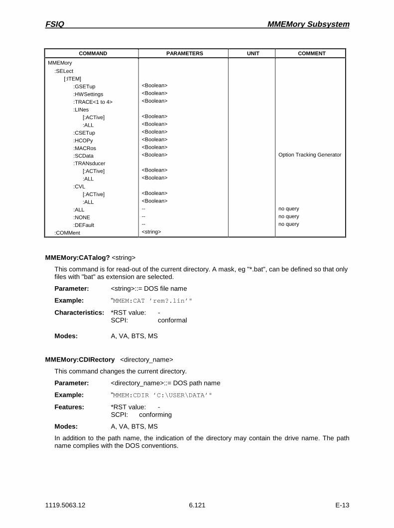
FSIQ MMEMory Subsystem
1119.5063.12 6.121 E-13
COMMAND PARAMETERS UNIT COMMENT
MMEMory
:SELect
[:ITEM]
:GSETup
:HWSettings
:TRACE<1 to 4>
:LINes
[:ACTive]
:ALL
:CSETup
:HCOPy
:MACRos:SCData:TRANsducer
[:ACTive]
:ALL
:CVL
[:ACTive]
:ALL
:ALL
:NONE
:DEFault
:COMMent
<Boolean>
<Boolean>
<Boolean>
<Boolean>
<Boolean>
<Boolean>
<Boolean>
<Boolean><Boolean>
<Boolean>
<Boolean>
<Boolean>
<Boolean>
--
--
--
<string>
Option Tracking Generator
no query
no query
no query
MMEMory:CATalog? <string>
This command is for read-out of the current directory. A mask, eg "*.bat", can be defined so that onlyfiles with "bat" as extension are selected.
Parameter: <string>::= DOS file name
Example: "MMEM:CAT ’rem?.lin’"
Characteristics: *RST value: -SCPI: conformal
Modes: A, VA, BTS, MS
MMEMory:CDIRectory <directory_name>
This command changes the current directory.
Parameter: <directory_name>::= DOS path name
Example: "MMEM:CDIR ’C:\USER\DATA’"
Features: *RST value: -SCPI: conforming
Modes: A, VA, BTS, MS
In addition to the path name, the indication of the directory may contain the drive name. The pathname complies with the DOS conventions.

MMEMory Subsystem FSIQ
1119.5063.12 6.122 E-13
MMEMory:COPY <file_source>,<file_destination>
This command copies the files indicated.
Parameter: <file_source>,<file_destination> ::= <file_name><file_name> ::= DOS file name
Example: "MMEM:COPY ’C:\USER\DATA\SETUP.CFG’,’A:’"
Features: *RST value: -SCPI conforming
Modes: A, VA, BTS, MS
The indication of the file name may include the path and the drive. The file names and pathinformation must be in accordance with the DOS conventions. This command is an event which iswhy it is not assigned an *RST value and has no query.
MMEMory:DATA <file_name>[,<block data>]
This command writes block data to the specified file.
Syntax: MMEMory:DATA <file_name>,<block data>MMEMory:DATA? <file_name>
Example: "MMEM:DATA? ’TEST01.HCP’""MMEM:DATA ’TEST01.HCP’, #217This is the file"
Features: *RST value: -SCPI: conforming
Modes: A, VA, BTS, MS
Each <block> starts with the character ‘#’, followed by the value stating the length of the lengthinformation. This is followed by one or several characters for the length information; then come thedata themselves. The end character must be set to EOI to ensure correct data transmission.
MMEMory:DELete <file_name>
This command deletes the files indicated.
Parameter: <file_name> ::= DOS file name
Example: "MMEM:DEL ’TEST01.HCP’"
Features: *RST value: -SCPI: conforming
Modes: A, VA, BTS, MS
The indication of the file name contains the path and, optionally, the drive. Indication of the pathcorresponds to the DOS conventions. The file name includes indication of the path and may alsoinclude the drive. The path name corresponds to the DOS conventions. This command is an eventwhich is why it is not assigned an *RST value and has no query.
FSIQ MMEMory Subsystem
1119.5063.12 6.123 E-13
MMEMory:INITialize ’A:’
This command formats the disk in drive A.
Example: "MMEM:INIT ’A:’"
Features: *RST value: -SCPI: conforming
Modes: A, VA, BTS, MS
Formatting deletes all data stored on the floppy disk. This command is an event which is why it is notassigned an *RST value and has no query.
MMEMory:LOAD:STATe 1,<file_name>
This command loads instrument settings from files.
Parameter: <file_name> ::= DOS file name without extension
Example: "MMEM:LOAD:STAT 1,’A:TEST’"
Features: *RST value: -SCPI: conforming
Modes: A, VA, BTS, MS
The contents of the file is loaded and set as new instrument state. The file name includes indicationof the path and may also include the drive. The path name corresponds to the DOS conventions.This command is an event which is why it is not assigned an *RST value and has no query.
MMEMory:LOAD:AUTO 1,<file_name>
This command defines which device setting is automatically loaded after the instrument is switchedon.
Parameter: <file_name> ::= DOS file name without extension;FACTORY denotes the data set previously in theinstrument
Example: "MMEM:LOAD:AUTO 1,’C:\USER\DATA\TEST’"
Features: *RST value: -SCPI: device-specific
Modes: A, VA, BTS, MS
The contents of the file are read after switching on the instrument and used to define the new devicestate. The file name includes indication of the path and may also include the drive. The path namecorresponds to the DOS conventions. This command is an event which is why it is not assigned an*RST value and has no query.

MMEMory Subsystem FSIQ
1119.5063.12 6.124 E-13
MMEMory:MDIRectory <directory_name>
This command creates a new directory.
Parameter: <directory_name>::= DOS path name
Example: "MMEM:MDIR ’C:\USER\DATA’"
Features: *RST value: -SCPI: device-specific
Modes: A, VA, BTS, MS
The file name includes indication of the path and may also include the drive. The path namecorresponds to the DOS conventions. This command is an event which is why it is not assigned an*RST value and has no query.
MMEMory:MOVE <file_source>,<file_destination>
This command renames existing files.
Parameter: <file_source>,<file_destination> ::= <file_name><file_name> ::= DOS file name
Example: "MMEM:MOVE ’TEST01.CFG’,’SETUP.CFG’"
Features: *RST value: -SCPI: conforming
Modes: A, VA, BTS, MS
The file name includes indication of the path and may also include the drive. The path namecorresponds to the DOS conventions. This command is an event which is why it is not assigned an*RST value and has no query.
MMEMory:MSIS ’A:’ | ’C:’
This command changes to the drive indicated.
Example: "MMEM:MSIS ’A:’"
Features: *RST value: "C:’SCPI: conforming
Modes: A, VA, BTS, MS
The drive may be the internal hard disk C: or the floppy-disk drive A:. The drive is indicated accordingto the DOS conventions.

FSIQ MMEMory Subsystem
1119.5063.12 6.125 E-13
MMEMory:NAME <file_name>
This command specifies a file which is printed or plotted to.
Parameter: <file_name> ::= DOS filename
Example: "MMEM:NAME ’PLOT1.HPG’"
Features: *RST value: -SCPI: conforming
Modes: A, VA, BTS, MS
The file name includes indication of the path and may also include the drive. The file name and pathinformation correspond to the DOS conventions. The output to the printer is routed into a file usingthe command "HCOP:DEST ’MMEM’".
MMEMory:RDIRectory <directory_name>
This command deletes the directory indicated.
Parameter: <directory_name>::= DOS path name
Example: "MMEM:RDIR ’C:\TEST’"
Features: *RST value: -SCPI: device-specific
Modes: A, VA, BTS, MS
The directory name includes indication of the path and may also include the drive. The path namecorresponds to the DOS conventions. This command is an event which is why it is not assigned an*RST value and has no query.
MMEMory:STORe:STATe 1,<file_name>
This command stores the current instrument setting in a file.
Parameter: <file_name> ::= DOS file name without extension
Example: "MMEM:STOR:STAT 1,’TEST’"
Features: *RST value: -SCPI: conforming
Modes: A, VA, BTS, MS
The current instrument state is stored as a file. The file name includes indication of the path and mayalso include the drive. The path name corresponds to the DOS conventions. This command is anevent which is why it is not assigned an *RST value and has no query.

MMEMory Subsystem FSIQ
1119.5063.12 6.126 E-13
MMEMory:STORe:TRACe 1 to 4,<file_name>
This command stores the selected trace (1 to 4) in ASCII format in a file.
Parameter: 1 to 4 := selected trace 1 to 4<file_name> := DOS file name
Example: "MMEM:STOR:TRAC 3,’A:\TEST.ASC’"
Features: *RST value: -SCPI: device-specific
Modes: A, VA, BTS, MS
The file name includes indication of the path and may also include the drive. The file name and pathinformation correspond to the DOS conventions.This command is an event which is why it is notassigned an *RST value and has no query.
MMEMory:CLEar:STATe 1,<file_name>
This command deletes the instrument setting denoted by <file_name>.
Parameter: <file_name> ::= DOS file name without extension
Example: "MMEM:CLE:STAT 1,’TEST’"
Features: *RST value: -SCPI: device-specific
Modes: A, VA, BTS, MS
The device data set specified is deleted. The file name includes indication of the path and may alsoinclude the drive. The path name corresponds to the DOS conventions. This command is an eventwhich is why it is not assigned an *RST value and has no query.
MMEMory:CLEar:ALL
This command deletes all instrument settings in the current directory.
Example: "MMEM:CLE:ALL"
Features: *RST value: -SCPI: device-specific
Modes: A, VA, BTS, MS
This command is an "event" which is why it is not assigned an *RST value and has no query.

FSIQ MMEMory Subsystem
1119.5063.12 6.127 E-13
MMEMory:SELect[:ITEM]:GSETup ON | OFF
This command includes the data of the general setup in the list of data subsets of a device setting tobe stored/loaded.
Example: "MMEM:SEL:GSET ON"
Features: *RST value: OFFSCPI: device-specific
Modes: A, VA, BTS, MS
MMEMory:SELect[:ITEM]:HWSettings ON | OFF
This command includes the hardware settings in the list of data subsets of a device setting to bestored/loaded.
Example: "MMEM:SEL:HWS ON"
Features: *RST value: ONSCPI: device-specific
Modes: A, VA, BTS, MS
Level and frequency lines are stored with this command as well.
MMEMory:SELect[:ITEM]:TRACe<1 to 4> ON | OFF
This command includes the data of the selected trace in the list of data subsets of a device setting tobe stored/loaded.
Example: "MMEM:SEL:TRACE3 ON"
Features: *RST value: OFF for all TracesSCPI: device-specific
Modes: A, VA, BTS, MS
MMEMory:SELect[:ITEM]:LINes[:ACTive] ON | OFF
This command includes the active limit lines in the list of data subsets of a device setting to bestored/loaded.
Example: "MMEM:SEL:LIN ON"
Features: *RST value: ONSCPI: device-specific
Modes: A, VA, BTS, MS
Upon MMEM:LOAD the limit lines which are not currently active but contained in the data set arerestored as well.

MMEMory Subsystem FSIQ
1119.5063.12 6.128 E-13
MMEMory:SELect[:ITEM]:LINes:ALL ON | OFF
This command includes all limit lines in the list of data subsets of a device setting to bestored/loaded.
Example: "MMEM:SEL:LIN:ALL ON"
Features: *RST value: ONSCPI: device-specific
Modes: A, VA, BTS, MS
This command includes selection of the active limit lines.
MMEMory:SELect[:ITEM]:CSETup ON | OFF
This command includes the current color setting in the list of partial datasets of a device setting to bestored/loaded.
Example: "MMEM:SEL:CSET ON"
Features: *RST value: ONSCPI: device-specific
Modes: A, VA, BTS, MS
MMEMory:SELect[:ITEM]:HCOPy ON | OFF
This command includes the hardcopy settings in the list of data subsets of a device setting to bestored/loaded.
Example: "MMEM:SEL:HCOPy ON"
Features: *RST value: ONSCPI: device-specific
Modes: A, VA, BTS, MS
MMEMory:SELect[:ITEM]:MACRos ON | OFF
This command includes the keyboard macros in the list of data subsets of a device setting to bestored/loaded.
Example: "MMEM:SEL:MACRos ON"
Features: *RST value: OFFSCPI: device-specific
Modes: A, VA, BTS, MS
MMEMory:SELect[:ITEM]:SCData ON | OFF
This command includes the tracking generator calibration data in the list of data subsets of a devicesetting to be stored/loaded.
Example: "MMEM:SEL:SCData ON"
Features: *RST value: OFFSCPI: device-specific
Modes: A, VA
This command only available in conjunction with the option Tracking Generator.

FSIQ MMEMory Subsystem
1119.5063.12 6.129 E-13
MMEMory:SELect[:ITEM]:TRANsducer[:ACTive] ON | OFF
This command includes the active transducer factors and set in the list of data subsets of a devicesetting to be stored/loaded.
Example: "MMEM:SEL:TRAN ON"
Features: *RST value: ONSCPI: device-specific
Modes: A, VA, BTS, MS
Upon MMEM:LOAD the transducer factors and sets which are not currently active but contained in thedata set are restored as well.
MMEMory:SELect[:ITEM]:TRANsducer:ALL ON | OFF
This command includes all transducer factors and sets in the list of data subsets of a device settingto be stored/loaded.
Example: "MMEM:SEL:TRAN:ALL ON"
Features: *RST value: ONSCPI: device-specific
Modes: A, VA, BTS, MS
This command is an event and therefore has no *RST value assigned.
MMEMory:SELect[:ITEM]:CVL[:ACTive] ON | OFF
This command includes the active conversion loss table into the list of data subrecords to be stored /loaded for a device setup.
Example: "MMEM:SEL:CVL ON"
Features: *RST value: OFFSCPI: device-specific
Modes: A, VA, BTS, MS
This command is available only in conjunction with option External Mixer Output, FSE-B21.
MMEMory:SELect[:ITEM]:CVL:ALL ON | OFF
This command includes all conversion loss table into the list of data subrecords to be stored / loadedfor a device setup.
Example: "MMEM:SEL:CVL ON"
Features: *RST value: OFFSCPI: device-specific
Modes: A, VA, BTS, MS
This command is available only in conjunction with option External Mixer Output, FSE-B21.

MMEMory Subsystem FSIQ
1119.5063.12 6.130 E-13
MMEMory:SELect[:ITEM]:ALL
This command includes all data subsets in the list of data subsets of a device setting to bestored/loaded.
Example: "MMEM:SEL:ALL"
Features: *RST value: --SCPI: device-specific
Modes: A, VA, BTS, MS
This command is an event and therefore has no *RST value assigned.
MMEMory:SELect[:ITEM]:NONE
This command deletes all data subsets in the list of data subsets of a device setting to bestored/loaded.
Example: "MMEM:SEL:NONE"
Features: *RST value: --SCPI: device-specific
Modes: A, VA, BTS, MS
This command is an event and therefore has no *RST value assigned.
MMEMory:SELect[:ITEM]:DEFault
This command sets the default list of the data subsets of a device setting to be stored/loaded.
Example: "MMEM:SEL:DEFault"
Features: *RST value: --SCPI: device-specific
Modes: A, VA, BTS, MS
This command is an event and therefore has no *RST value assigned.
MMEMory:COMMent <string>
This command defines a comment for a device setting to be stored.
Example: "MMEM:COMM ’Setup for GSM measurement’"
Features: *RST value: blank commentSCPI: device-specific
Modes: A, VA, BTS, MS

FSIQ OUTPut Subsystem
1119.5063.12 6.131 E-13
OUTPut Subsystem
The OUTPut subsystem checks the output features of the instrument.In conjunction with option tracking generator, in the split screen mode, a distinction is made betweenOUTPut1 (screen A) and OUTPut2 (screen B).
COMMAND PARAMETERS UNIT COMMENT
OUTPut<1|2>[:STATe]:UPORt<1|2>
[:VALue]
:STATe:AF
:SENSitivity
<boolean>
<binary>
<boolean>
<numeric_value
--
--
--
PCT |HZ | KHZ |DEG | RAD
Option Tracking Generator
Vector Signal Analysis
OUTPut<1|2>[:STATe] ON | OFF
This command switches the tracking generator on or off.
Example: "OUTP ON"
Features: *RST value: -SCPI: conforming
Modes: A, VA
This command is only valid in conjunction with one of the options tracking generator.
OUTPut<1|2>UPORt<1|2>[:VALue] #B00000000 to #B11111111
This command sets the control lines of the user ports.
Example: "OUTP:UPOR2 #B10100101"
Features: *RST value: -SCPI: device-specific
Modes: A, VA, BTS, MS
User port 1 or 2 is written with the given binary pattern. If the user port is programmed to INPutinstead of OUTPut, the output value is temporarily stored.
OUTPut<1|2>UPORt<1|2>:STATe ON | OFF
This command switches the control line of the user ports between INPut and OUTPut.
Example: "OUTP:UPOR:STAT ON"
Features: *RST value: OFFSCPI: device-specific
Modes: A, VA, BTS, MS
With ON, the user port is switched to OUTPut, with OFF to INPut.

OUTPut Subsystem FSIQ
1119.5063.12 6.132 E-13
OUTPut<1|2>AF:SENSitivity <numeric_value>
This command changes the sensitivity of the AF-output.
Parameter: <numeric_value> ::= 0.1 PCT to 100 PCT for AM0.1 KHZ to 100 KHZ for FM0.0 1RAD to 10 RAD for PM
Example: "OUTP:AF:SENS 20PCT"
Features: *RST value: 100 % for AM100 kHz for FM10 rad for PM
SCPI: device-specific
Mode: VA-A

FSIQ READ-Subsystem
1119.5063.12 6.133 E-13
READ Subsystem
The READ-subsystem contains commands for starting complex measurement tasks such as thoseprovided by options GSM BTS Analyzer (FSE-K11) or GSM MS Analyzer (FSE-K10), and for queryingthe results subsequently. The READ-subsystem is closely linked to the functions of the CONFigure- andFETCh-subsystems, where the measurement sequences are configured or the results are queriedwithout restarting a new measurement.
READ:BURSt SubsystemThis subsystem provides the commands for starting measurements in the GSM BTS Analyzer mode(option FSE-K11), which are performed on individual bursts (carrier power, phase/frequency error), andfor reading out the results subsequently.
COMMAND PARAMETERS UNIT COMMENT
READ
:BURSt
:PERRor
:RMS:STATus?
:AVERage?
:MAXimum?
:PEAK:STATus?
:AVERage?
:MAXimum?
:FERRor:STATus?
:AVERage?
:MAXimum?
:POWer?
:STATic?
:DYNamic?
:LEVel?:REFerence
[:IMMediate]?
--
--
--
--
--
--
--
--
----
--
Option FSE-K11 or FSE-K10
query only
query only
query only
query only
query only
query only
query only
query only
query only
query only
query only; FSE-K11 only
query only; FSE-K11 only
query only; FSE-K10 only
query only
query only<
READ:BURSt:PERRor:RMS:STATus?
This command starts the measurement of the phase and frequency error of the base station ormobile and reads out the status of the RMS-measurement of the phase error taken over the selectednumber of bursts.
0: failed, 1: passed
Example: "READ:BURS:PERR:RMS:STAT?"
Features: *RST value: --SCPI: device-specific
Modes: BTS, MS
When the measurement is started the instrument automatically assumes the SINGLE mode. Anongoing measurement can be aborted via the command ABORt. Further results of thephase/frequency error measurement can be then queried without restart of the measurement via theFETCh:BURSt-subsystem.
This command is a query only and therefore has no *RST value assigned. It is available only ifmeasurement of the phase/frequency error is selected (see CONFigure:BURSt:PFERror).

READ-Subsystem FSIQ
1119.5063.12 6.134 E-13
READ:BURSt:PERRor:RMS:AVERage?
This command starts the measurement of the phase and frequency error of the base station ormobile and reads out the average of the RMS-measurement of the phase error taken over theselected number of bursts.
Example: "READ:BURS:PERR:RMS:AVER?"
Features: *RST value: --SCPI: device-specific
Modes: BTS, MS
When the measurement is started the instrument automatically assumes the SINGLE mode. Anongoing measurement can be aborted via the command ABORt. Further results of thephase/frequency error measurement can be then queried without restart of the measurement via theFETCh:BURSt-subsystem.
This command is a query only and therefore has no *RST value assigned. It is available only ifmeasurement of the phase/frequency error is selected (see CONFigure:BURSt:PFERror).
READ:BURSt:PERRor:RMS:MAXimum?
This command starts the measurement of the phase and frequency error of the base station ormobile and reads out the maximum of the RMS-measurement of the phase error for the selectednumber of bursts.
Example: "READ:BURS:PERR:RMS:MAX?"
Features: *RST value: --SCPI: device-specific
Modes: BTS, MS
When the measurement is started the instrument automatically assumes the SINGLE mode. Anongoing measurement can be aborted via the command ABORt. Further results of thephase/frequency error measurement can be then queried without restart of the measurement via theFETCh:BURSt-subsystem.
This command is a query only and therefore has no *RST value assigned. It is available only ifmeasurement of the phase/frequency error is selected (see CONFigure:BURSt:PFERror).
READ:BURSt:PERRor:PEAK:STATus?
This command starts the measurement of the phase and frequency error of the base station ormobile and reads out the status of the peak measurement of the phase error taken over the selectednumber of bursts.
0: failed, 1: passed
Example: "READ:BURS:PERR:PEAK:STAT?"
Features: *RST value: --SCPI: device-specific
Modes: BTS, MS
When the measurement is started the instrument automatically assumes the SINGLE mode. Anongoing measurement can be aborted via the command ABORt. Further results of thephase/frequency error measurement can be then queried without restart of the measurement via theFETCh:BURSt-subsystem.
This command is a query only and therefore has no *RST value assigned. It is available only ifmeasurement of the phase/frequency error is selected (see CONFigure:BURSt:PFERror).
FSIQ READ-Subsystem
1119.5063.12 6.135 E-13
READ:BURSt:PERRor:PEAK:AVERage?
This command starts the measurement of the phase and frequency error of the base station ormobile and reads out the maximum of the peak measurement of the phase error taken over theselected number of bursts.
Example: "READ:BURS:PERR:PEAK:AVER?"
Features: *RST value: --SCPI: device-specific
Modes: BTS, MS
When the measurement is started the instrument automatically assumes the SINGLE mode. Anongoing measurement can be aborted via the command ABORt. Further results of thephase/frequency error measurement can be then queried without restart of the measurement via theFETCh:BURSt-subsystem.
This command is a query only and therefore has no *RST value assigned. It is available only ifmeasurement of the phase/frequency error is selected (see CONFigure:BURSt:PFERror).
READ:BURSt:PERRor:PEAK:MAXimum?
This command starts the measurement of the phase and frequency error of the base station ormobile and reads out the maximum of the peak measurement of the phase error for the selectednumber of bursts.
Example: "READ:BURS:PERR:PEAK:MAX?"
Features: *RST value: --SCPI: device-specific
Modes: BTS, MS
When the measurement is started the instrument automatically assumes the SINGLE mode. Anongoing measurement can be aborted via the command ABORt. Further results of thephase/frequency error measurement can be then queried without restart of the measurement via theFETCh:BURSt-subsystem.
This command is a query only and therefore has no *RST value assigned. It is available only ifmeasurement of the phase/frequency error is selected (see CONFigure:BURSt:PFERror).
READ:BURSt:FERRor:STATus?
This command starts the measurement of the phase and frequency error of the base station ormobile and reads out the status of the frequency error taken over the selected number of bursts.
0: failed, 1: passed
Example: "READ:BURS:FERR:STAT?"
Features: *RST value: --SCPI: device-specific
Modes: BTS, MS
When the measurement is started the instrument automatically assumes the SINGLE mode. Anongoing measurement can be aborted via the command ABORt. Further results of thephase/frequency error measurement can be then queried without restart of the measurement via theFETCh:BURSt-subsystem.
This command is a query only and therefore has no *RST value assigned. It is available only ifmeasurement of the phase/frequency error is selected (see CONFigure:BURSt:PFERror).

READ-Subsystem FSIQ
1119.5063.12 6.136 E-13
READ:BURSt:FERRor:AVERage?
This command starts the measurement of the phase and frequency error of the base station ormobile and reads out the average of the frequency error taken over the selected number of bursts.
Example: "READ:BURS:FERR:AVER?"
Features: *RST value: --SCPI: device-specific
Modes: BTS, MS
When the measurement is started the instrument automatically assumes the SINGLE mode.
An ongoing measurement can be aborted via the command ABORt. Further results of thephase/frequency error measurement can be then queried without restart of the measurement via theFETCh:BURSt-subsystem.
This command is a query only and therefore has no *RST value assigned. It is available only ifmeasurement of the phase/frequency error is selected (see CONFigure:BURSt:PFERror).
READ:BURSt:FERRor:MAXimum?
This command starts the measurement of the phase and frequency error of the base station ormobile and reads out the maximum of the frequency error for the selected number of bursts.
Example: "READ:BURS:FERR:MAX?"
Features: *RST value: --SCPI: device-specific
Modes: BTS, MS
When the measurement is started the instrument automatically assumes the SINGLE mode.
An ongoing measurement can be aborted via the command ABORt. Further results of thephase/frequency error measurement can be then queried without restart of the measurement via theFETCh:BURSt-subsystem.
This command is a query only and therefore has no *RST value assigned. It is available only ifmeasurement of the phase/frequency error is selected (see CONFigure:BURSt:PFERror).
FSIQ READ-Subsystem
1119.5063.12 6.137 E-13
READ:BURSt:POWer?
This command starts the measurement of the maximum output power of the base station or mobileand reads out the result.
Measurement of the maximum output power marks the beginning of a measurement cycle wheresubsequently the limits of the static and dynamic power control levels are checked step by step(READ:BURSt:STATic? or READ:BURSt:DYNamic?).
Parameter: The result is read out as an ASCII string in the following format:
<Static Power Ctrl>,<Dyn Power Ctrl>,<Rat-Level>,<Act-Level>, <Delta>,<Status>
<Static Power Ctrl>: 0<Dyn Power Ctrl>: 0<Rat-Level>: rated value for the current power control level acc.
to standard in dBm<Act-Level>: measured power in dBm<Delta>: 0<Status>: result of limit check in character data form:
PASSED no limits exceededFAILED limit exceeded
Example: "READ:BURS:POW?"Result: 0,0,43,44.1,0,PASSED
Features: *RST value: --SCPI: device-specific
Modes: BTS, MS
When the measurement is started any ongoing measurement cycle is aborted.
An ongoing measurement can be aborted with the command ABORT. This command is a query onlyand has therefore no *RST value assigned. It is available only when measurement of the maximumcarrier power is selected (see CONFigure:BURSt:POWer).

READ-Subsystem FSIQ
1119.5063.12 6.138 E-13
READ:BURSt:POWer:STATic?
This command increases the static power control level for the measurement by one step, measuresthe output power of the base station and reads out the result.
If the command READ:BURSt:POWer:STATic? is repeated after the maximum static powercontrol level is reached, the measurement sequence is terminated and the result of the maximumstatic power control level is read out again. In this case the value ’FINISHED’ indicating the status isread out. Before the status value ’FINISHED’ is read out, the value ’RUNNING’ is output if the totalresult of the limit check is queried via CALCulate<1|2>:LIMit<1 to 8>:BURSt:POWer?.
Parameter: The result is read out as an ASCII string in the following format:
<Static Power Ctrl>,<Dyn Power Ctrl>,<Rat-Level>,<Act-Level>, <Delta>,<Status>
<Static Power Ctrl>: current static power control level<Dyn Power Ctrl>: current dynamic power control level<Rat-Level>: rated value for the current power control level acc.
to standard in dBm<Act-Level>: measured power in dBm<Delta>: difference between the measured power and the power
at the previous static power control level.<Status>: result of the limit check in character data form:
PASSED no limit exceededFAILED limit exceededFINISHED measurement sequence terminated
Example: "READ:BURS:POW:STAT?"Result: 1,0,41,42.5,1.6,PASSED
Features: *RST value: --SCPI: device-specific
Mode: BTS
The command ABORt terminates an ongoing measurement and resets the static and dynamic powercontrol level to 0.
This command is only a query and therefore has no *RST value assigned. It is available only ifmeasurement of the maximum carrier power is selected. (see CONFigure:BURSt:POWer).

FSIQ READ-Subsystem
1119.5063.12 6.139 E-13
READ:BURSt:POWer:DYNamic?
This command increases the dynamic power control level for the measurement by one step,measures the output power of the base station and reads out the result.
Once the maximum dynamic power control level is reached the command is accepted only after thestatic power control level is increased by one step.
Note that the command is no longer accepted after the measurement sequence is terminated whichimplies that the static power control level was read out again with READ:BURSt:POWer:STATic?after the maximum value was reached and marked with the ’FINISHED’ status.
Parameter: The result is read out as an ASCII string in the following format:
<Static Power Ctrl>,<Dyn Power Ctrl>,<Rat-Level>,<Act-Level>, <Delta>,<Status>
<Static Power Ctrl>: current static power control level<Dyn Power Ctrl>: current dynamic power control level<Rat-Level>: rated value for the current power control level acc.
to standard in dBm<Act-Level>: measured power in dBm<Delta>: difference between the measured power and the power
at the previous dynamic power control level.<Status>: result of the limit check in character data form:
PASSED no limit exceededFAILED limit exceeded
Example: "READ:BURS:POW:DYN?"Result: 1,3,35,32.5,5.6,FAILED
Features: *RST value: --SCPI: device-specific
Mode: BTS
The command ABORt terminates an ongoing measurement and resets the static and dynamic powercontrol level to 0.
This command is only a query and therefore has no *RST value assigned. It is available only ifmeasurement of the maximum carrier power is selected. (see CONFigure:BURSt:POWer).

READ-Subsystem FSIQ
1119.5063.12 6.140 E-13
READ:BURSt:POWer:LEVel?
This command increases the power control level for the measurement by one step, measures theoutput power of the mobile and reads out the result.
Note that the command is no longer accepted after the measurement sequence is terminated whichimplies that the power control level was read out again with READ:BURSt:POWer:LEVel? after themaximum value was reached and marked with the ’FINISHED’ status.
Parameter: The result is read out as an ASCII string in the following format:
<0>, <Power Ctrl Level>,<Rat-Level>,<Act-Level>, <Delta>,<Status>
<0>: always 0<Power Ctrl Level>: current power control level<Rat-Level>: rated value for the current power control level acc.
to standard in dBm<Act-Level>: measured power in dBm<Delta>: difference between the measured power and the power
at the previous power control level.<Status>: result of the limit check in character data form:
PASSED no limit exceededFAILED limit exceeded
Example: "READ:BURS:POW:LEV?"Result: 0,3,35,32.5,5.6,FAILED
Features: *RST value: --SCPI: device-specific
Mode: MS
The command ABORt terminates an ongoing measurement and resets the power control level to 0.
This command is only a query and therefore has no *RST value assigned. It is available only ifmeasurement of the maximum carrier power is selected. (see CONFigure:BURSt:POWer).
READ:BURSt:REFerence[:IMMediate]?
This command starts the premeasurement and as a result provides the measured level in dBm.
Example: "READ:BURS:REF?"
Feature: *RST value: --SCPI: device-specific
Mode: MS, BTS
This is a query command only and therefore has no *RST value.
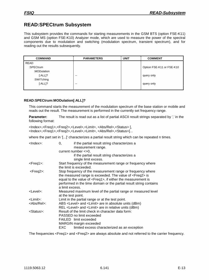
FSIQ READ-Subsystem
1119.5063.12 6.141 E-13
READ:SPECtrum Subsystem
This subsystem provides the commands for starting measurements in the GSM BTS (option FSE-K11)and GSM MS (option FSE-K10) Analyzer mode, which are used to measure the power of the spectralcomponents due to modulation and switching (modulation spectrum, transient spectrum), and forreading out the results subsequently.
COMMAND PARAMETERS UNIT COMMENT
READ
:SPECtrum
:MODulation
[:ALL]?
:SWITching
[:ALL]?
--
--
Option FSE-K11 or FSE-K10
query only
query only
READ:SPECtrum:MODulation[:ALL]?
This command starts the measurement of the modulation spectrum of the base station or mobile andreads out the result. The measurement is performed in the currently set frequency range.
Parameter: The result is read out as a list of partial ASCII result strings separated by ’,’ in thefollowing format:
<Index>,<Freq1>,<Freq2>,<Level>,<Limit>, <Abs/Rel>,<Status> [,<Index>,<Freq1>,<Freq2>,<Level>,<Limit>, <Abs/Rel>,<Status>]...
where the part set in ’[...]’ characterizes a partial result string which can be repeated n times.
<Index>: 0, if the partial result string characterizes ameasurement range.
current number <>0,if the partial result string characterizes asingle limit excess.
<Freq1>: Start frequency of the measurement range or frequency wherethe limit is exceeded.
<Freq2>: Stop frequency of the measurement range or frequency wherethe measured range is exceeded. The value of <Freq2> isequal to the value of <Freq1>, if either the measurement isperformed in the time domain or the partial result string containsa limit excess.
<Level>: Measured maximum level of the partial range or measured levelat the test point.
<Limit>: Limit in the partial range or at the test point.<Abs/Rel>: ABS <Level> and <Limit> are in absolute units (dBm)
REL <Level> and <Limit> are in relative units (dBm)<Status>: Result of the limit check in character data form:
PASSED no limit exceededFAILED limit exceededMARGIN margin exceededEXC limited excess characterized as an exception
The frequencies <Freq1> and <Freq2> are always absolute and not referred to the carrier frequency.

READ-Subsystem FSIQ
1119.5063.12 6.142 E-13
Example: "READ:SPEC:MOD?"Result: 0,890E6,915E6,-87.4,-108.0,ABS,FAILED,
1,893.2E6,893.2E6,-83.2,-108.0,ABS,FAILED,2,895.7E6,895.7E6,-87.4,-108.0,ABS,FAILED
Features: *RST value: --SCPI: device-specific
Modes: BTS, MS
The command ABORt aborts an ongoing measurement.
This command is only a query and therefore has no *RST value assigned. It is available only ifmeasurement of the modulation spectrum is selected. (see CONFigure:SPECtrum:MODulation).
READ:SPECtrum:SWITching[:ALL]?
This command starts the measurement of the transient spectrum of the base station or mobile andreads out the result.
Parameter: The result is read out as a list of partial ASCII result strings separated by ’,’ in theformat used for READ:SPECtrum:MODulation[:ALL]?.
Example: "READ:SPEC:SWIT?"Result: 0,833.4E6,833.4E6,37.4,-36.0,ABS,MARGIN,
1,834.0E6,834.0E6,-35.2,-36.0,ABS,FAILED,2,834.6E6,834.6E6,-74.3,-75.0,REL,FAILED0,835.0E6,835.0E6,-65,0,-60.0,REL,PASSED
Features: *RST value: --SCPI: device-specific
Modes: BTS, MS
The command ABORt aborts an ongoing measurement.
This command is only a query and therefore has no *RST value assigned. It is available only ifmeasurement of the transient spectrum is selected. (see CONFigure:SPECtrum:SWITCHing).

FSIQ READ-Subsystem
1119.5063.12 6.143 E-13
READ:SPURious Subsystem
This subsystem provides the commands for starting measurements in the GSM BTS (option FSE-K11)and GSM MS (option FSE-K10) Analyzer mode, which are used to measure the power of spuriousemissions, and for reading out the results subsequently.
COMMAND PARAMETERS UNIT COMMENT
READ
:SPURious
[:ALL]?
:STEP?
Option FSE-K11 or FSE-K10
query only
query only
READ:SPURious[:ALL]?
This command starts the measurement of the spurious emissions of the base station or mobile andreads out the result. The measurement is performed in the currently set frequency range.
Parameter: The result is read out as a list of partial ASCII result strings separated by ’,’ in thefollowing format:
<Index>,<Freq1>,<Freq2>,<Level>,<Limit>, <Abs/Rel>,<Status> [,<Index>,<Freq1>,<Freq2>,<Level>,<Limit>, <Abs/Rel>,<Status>]...
where the part set in ’[...]’ characterizes a partial result string which can be repeated n times.
<Index>: 0, if the partial result string characterizes ameasurement range.
current number <>0,if the partial result string characterizes asingle limit excess.
<Freq1>: Start frequency of the measurement range or frequency wherethe limit is exceeded.
<Freq2>: Stop frequency of the measurement range or frequency wherethe measured range is exceeded. The value of <Freq2> isequal to the value of <Freq1>, if either the measurement isperformed in the time domain or the partial result string containsa limit excess.
<Level>: Measured maximum level of the partial range or measured levelat the test point.
<Limit>: Limit in the partial range or at the test point.<Abs/Rel>: ABS <Level> and <Limit> are in absolute units (dBm)
REL <Level> and <Limit> are in absolute units (dBm)<Status>: Result of the limit check in character data form:
PASSED no limit exceededFAILED limit exceededMARGIN margin exceeded
Example: "READ:SPUR?"Result: 0,890E6,915E6,-87.4,-108.0,ABS,FAILED,
1,893.2E6,893.2E6,-83.2,-108.0,ABS,FAILED,2,895.7E6,895.7E6,-87.4,-108.0,ABS,FAILED

READ-Subsystem FSIQ
1119.5063.12 6.144 E-13
Features: *RST value: --SCPI: device-specific
Modes: BTS, MS
The command ABORt aborts an ongoing measurement.
This command is only a query and therefore has no *RST value assigned. It is available only ifmeasurement of the spurious emissions is selected. (see CONFigure:SPURious).
READ:SPURious:STEP?
This command starts the next single step for measuring the spurious emissions in the STEP modeand reads out the results. The measurement is performed in the currently set frequency range.
If the command READ:SPURious:STEP? is sent again after the last single step is reached, themeasurement sequence is terminated, the result of the last single step is output again andcharacterized by the value ’FINISHED’ indicating its status. Until the status value ’FINISHED’ isreturned, the value ’RUNNING’ is output when the total result of the limit check is queried with thecommand CALCulate<1|2>:LIMit<1 to 8>:SPURious?.
Afterwards, sending the command again causes a restart of the measurement.
Parameter: The measured result is read out as a list of partial result strings separated by ’,’and in the same format as for the command READ:SPURious[:ALL]?.The additional status value ’FINISHED’ marks the end of a measurement sequence.
Example: "READ:SPUR:STEP?"Result: First query: 0,890E6,915E6,-87.4,-108.0,ABS,FAILED
...Second-last query:1,893.2E6,893.2E6,-83.2,-108.0,ABS,FAILEDLast query: 1,893.2E6,893.2E6,-83.2,-108.0,ABS,FINISHED
Features: *RST value: --SCPI: device-specific
Modes: BTS, MS
The command ABORt aborts an ongoing measurement. If the command READ:SPURious:STEP? issent again, the instrument restarts with the first single step.
This command is only a query and therefore has no *RST value assigned. It is available only ifmeasurement of the spurious emissions is selected. (see CONFigure:SPURious).

FSIQ SENSe Subsystem
1119.5063.12 6.145 E-13
SENSe Subsystem
The SENSe subsystem is itself divided up into several subsystems. The commands of thesesubsystems directly control device-specific settings, they do not refer to the signal characteristics of themeasurement signal.The SENSe subsystem controls the essential parameters of the analyzer and vector analyzer. Inaccordance with the SCPI standard, it is for this reason optional, which means that it is not necessary toinclude the SENSe node in command sequences.
In the split-screen representation, a distinction is made between SENSe1 and SENSe2:
SENSe1 = screen A;
SENSe2 = screen B
SENSe:ADEMod Subsystem
This subsystem controls the parameters for analog demodulation.
COMMAND PARAMETERS UNIT COMMENT
[SENSe<1|2>]
:ADEMod
:AF
:COUPling
:SQUelch
[:STATe]
:LEVel
:SBANd
:RTIMe
AC | DC
<Boolean>
<numeric_value>
NORMal | INVerse
<Boolean>
DBM
Vector Signal Analysis
[SENSe<1|2>:]ADEMod:AF:COUPling AC | DC
This command selects coupling of the AF-branch.
Example: "ADEM:AF:COUP DC"
Features: *RST value: ACSCPI: device-specific
Mode: VA-A
[SENSe<1|2>:]ADEMod:SQUelch[:STATe] ON | OFF
This command switches the squelch for the audio branch on or off.
Example: "ADEM:SQU ON"
Features: *RST value: OFFSCPI: device-specific
Mode: VA-A

SENSe Subsystem FSIQ
1119.5063.12 6.146 E-13
[SENSe<1|2>:]ADEMod:SQUelch:LEVel 30 to -150 dBm
This command defines the switching threshold for the squelch referred to the measured signal.
Example: "ADEM:SQU -10DBM"
Features: *RST value: -40dBmSCPI: device-specific
Mode: VA-A
[SENSe<1|2>:]ADEMod:SBANd NORMal | INVerse
This command selects the side band for the demodulation.
Example: "ADEM:SBAN INV"
Features: *RST value: NORMalSCPI: device-specific
Mode: VA-A
[SENSe<1|2>:]ADEMod:RTIMe ON | OFF
This command selects whether the demodulation performed in real time or in blocks.
Example: "ADEM:RTIM ON"
Features: *RST value: ONSCPI: device-specific
Mode: VA-A

FSIQ SENSe Subsystem
1119.5063.12 6.147 E-13
SENSe:AVERage Subsystem
The SENSe:AVERage subsystem calculates the average of the data acquired. A new test result isobtained from various successive measurements. The amount of test points and the axis reference ofthe new result correspond to those of the original measurements.
COMMAND PARAMETERS UNIT COMMENT
[SENSe<1|2>]
:AVERage
:COUNt
:AUTO
[:STATe]
:TYPE
<numeric_value>
<Boolean>
<Boolean>
MAXimum | SCALar
--
--
--
--
[SENSe<1|2>:]AVERage:COUNt 0 to 32767
The command specifies the number of measurements which are combined.
Example: "AVER:COUN 16"
Features: *RST value: 0SCPI: conforming
Modes: A. VA-D
[SENSe<1|2>:]AVERage:COUNt:AUTO ON | OFF
AUTO ON selects a suitable number of :COUNt for the respective type of measurement.
Example: "AVER:COUN:AUTO ON"
Features: *RST value: OFFSCPI: conforming
Modes: A. VA-D
[SENSe<1|2>:]AVERage[:STATe] ON | OFF
The command switches on or off the average function.
Example: "AVER OFF"
Features: *RST value: OFFSCPI: conforming
Modes: A, VA, BTS, MS

SENSe Subsystem FSIQ
1119.5063.12 6.148 E-13
[SENSe<1|2>:]AVERage:TYPE MAXimum | MINimum | SCALar
The command selects the type of average function.
Example: "AVER:TYPE SCAL"
Features: *RST value: SCALarSCPI: conforming
Modes: A, VA, BTS, MS
The following average functions have been defined:
MAXimum (MAX HOLD): AVG(n) = MAX(X1 to .Xn)
MINimum (MIN HOLD): AVG(n) = Min(X1 to .Xn)
SCALar (AVERAGE): AVG nn
xii
n( )= ×
=∑
1
1

FSIQ SENSe Subsystem
1119.5063.12 6.149 E-13
SENSe:BANDwidth Subsystem
This subsystem controls the setting of the instrument’s filter bandwidths. Both groups of commands(BANDwidth and BWIDth) perform the same functions.
COMMAND PARAMETERS UNIT COMMENT
:BANDwidth
[:RESolution]
:AUTO:MODE
:FFT:RATio
:VIDeo
:AUTO
:RATio
:DEMod:PLL
:BWIDth
[:RESolution]
:AUTO:MODE
:FFT:RATio
:VIDeo
:AUTO
:RATio
:DEMod:PLL
<numeric_value>
<Boolean>ANALog|DIGital<Boolean><numeric_value>
<numeric_value>
<Boolean>
<numeric_value> | SINe | PULSe |NOISe<numeric_value>AUTO | HIGH | MEDium | LOW
<numeric_value>
<Boolean>ANALog|DIGital<Boolean><numeric_value>
<numeric_value>
<Boolean>
<numeric_value> | SINe | PULSe |NOISe<numeric_value>AUTO | HIGH | MEDium | LOW
HZ
--------
HZ
--
--
HZ
HZ
--------
HZ
--
--
HZ
Option FFT filter
Vector Signal Analysis
Option FFT filter
Vector Signal Analysis
[SENSe<1|2>:]BANDwidth|BWIDth[:RESolution] 1 Hz to 10 MHz
This command defines the analyzer’s resolution bandwidth.
Example: "BAND 1MHz"
Features: *RST value: - (AUTO is set to ON)SCPI: conforming
Modes: A, VA, BTS, MS
The values for the resolution bandwidth are rounded in 1 | 2 | 3 | 5 steps.
In the GSM BTS/MS ANALYZER mode with option FSE-K11/K10, the command is available forPOWER vs. TIME measurement. In this case, the parameters DEFault (bandwidth setting accordingto GSM standard), 300KHZ and 1MHZ are permitted.

SENSe Subsystem FSIQ
1119.5063.12 6.150 E-13
[SENSe<1|2>:]BANDwidth|BWIDth[:RESolution]:AUTO ON | OFF
This command either automatically couples the resolution bandwidth of the instrument to the span orcancels the coupling.
Example: "BAND:AUTO OFF"
Features: *RST value: ONSCPI: conforming
Modes: A, VA
The automatic coupling matches the resolution bandwidth to the currently set span according to therelationship between span and resolution bandwidth.
[SENSe<1|2>:]BANDwidth|BWIDth[:RESolution]:MODE ANALog | DIGital
This command toggles between analog and digital resolution filters for the 1-kHz bandwidth.
Example: "BAND:MODE DIG"
Features: *RST value: ANALogSCPI: device-specific
Mode: A
Depending on the bandwidth, the resolution filters are automatically toggled between digital filters(<1kHz) and analog filters (>1kHz). The 1-kHz bandwidth is present in the instrument as a digitalfilter and as an analog filter and can be toggled using this command. If the analog filter is selected forthe bandwidth 1kHz, the FFT-filtering for bandwidths ≤ 1kHz is switched off.
[SENSe<1|2>:]BANDwidth|BWIDth[:RESolution]:MODE:FFT ON | OFF
This command toggles the digital filters used for bandwidths ≤ 1 kHz between ordinary mode andFFT-filter mode.
Example: "BAND:MODE:FFT ON"
Features: *RST value: OFFSCPI: device-specific
Mode: A
The filter bandwidth of 1 kHz is switched to digital filtering for both ON and OFF. This command isonly available in conjunction with option FFT Filter.
[SENSe<1|2>:]BANDwidth|BWIDth[:RESolution]:RATio 0.0001 to 1
This command defines the ratio resolution bandwidth (Hz) / span (Hz).
Example: "BAND:RAT 0.1"
Features: *RST value: -- (AUTO is set to ON)SCPI: conforming
Modes: A, VA, R
The ratio to be entered is reciprocal to the ratio Span/RBW used in manual control.

FSIQ SENSe Subsystem
1119.5063.12 6.151 E-13
[SENSe<1|2>:]BANDwidth|BWIDth:VIDeo 1Hz to 10MHz
This command defines the instrument’s video bandwidth.
Example: "BAND:VID 10kHz"
Features: *RST value: - (AUTO is set to ON)SCPI: conforming
Mode: A
The values for the video bandwidth are rounded in 1 | 2 | 3 | 5 steps.
[SENSe<1|2>:]BANDwidth|BWIDth:VIDeo:AUTO ON | OFF
This command either automatically couples the instrument’s video bandwidth to the resolutionbandwidth or cancels the coupling.
Example: "BAND:VID:AUTO OFF"
Features: *RST value: ONSCPI: conforming
Mode: A
[SENSe<1|2>:]BANDwidth|BWIDth:VIDeo:RATIO 0.001to 1000 | SINe | PULSe | NOISe
This command defines the ratio video bandwidth (Hz) / resolution bandwidth (Hz).
Parameter: The parameters SINe, PULSe and NOISe may be used as synonyms for thefollowing values:SINe: 1PULSe: 10NOISe: 0.1
Example: "BAND:VID:RAT 10"
Features: *RST value: - (AUTO is set to ON)SCPI: conforming
Modes: A, VA
The ratio to be entered is reciprocal to the ratio RBW/VBW used in manual control.
[SENSe<1|2>:]BANDwidth|BWIDth:DEMod 5kHz to 200kHz (Real Time on) | 5kHz to 5MHz (RealTime off)
This command defines the demodulation bandwidth of the instrument for analog demodulation.
Example: "BAND:DEM 100KHZ"
Features: *RST value: 10KHZSCPI: device-specific
Mode: VA-A
The values for the demodulation bandwidth are rounded in steps of 1 | 2 | 3 | 5.
[SENSe<1|2>:]BANDwidth|BWIDth:PLL AUTO | HIGH | MEDium | LOW
This command defines the bandwidth of the main PLL of the instrument synthesizer.
Example: "BAND:PLL HIGH"
Features: *RST value: AUTOSCPI: device-specific
Mode: A

SENSe Subsystem FSIQ
1119.5063.12 6.152 E-13
SENSe:CORRection-Subsystem
The SENSe:CORRection-subsystem controls the correction of measured results by means offrequency-dependent correction factors (e. g. for antenna or cable attenuation).It also controls calibration and normalization during operation with the option Tracking Generator .
COMMAND PARAMETERS UNIT COMMENT
[SENSe<1|2>]:CORRection
:METHod:COLLect
[:ACQuire][:STATe]:RECall
TRANsmission | REFLexion
THRough | OPEN<Boolean>
option Tracking Generator
no query
no query
:TRANsducer
:CATalog?
:ACTive?
:SELect
:UNIT
:SCALing
:COMMent
:DATA
[:STATe]
:DELete
:TSET
:CATalog?
:ACTive?
:SELect
:UNIT
:BREak
:COMMent
:RANGe<1 to 10>
[:STATe]
:DELete
<name>
<string>
LINear | LOGarithmic
<string>
<freq> , <level> ..
<Boolean>
--
<name>
<string>
<Boolean>
<string>
<freq> , <freq>, <name> ..
<Boolean>
--
HZ , --
--
HZ, HZ, --
--
query only
query only
no query
query only
query only
no query:LOSS
:INPut
[:MAGNitude] <numeric_value> DB
option FSE-K11 orFSE-K10
:RXGain
:INPut
[:MAGNitude] <numeric_value> DB
option FSE-K11 orFSE-K10
:CVL
:CATalog?
:SELect
:MIXer
:SNUMber
:BAND
:TYPE
:PORTs
:BIAS
:COMMent
:DATA
:CLEar
<file_name>
<string>
<string>
A|Q|U|V|E|W|F|D|G|Y|J
ODD | EVEN | EODD
2 | 3
<numeric_value>
<string>
<freq> , <level> ..
--
A
HZ , DB
--
option external mixer output
query only
no query
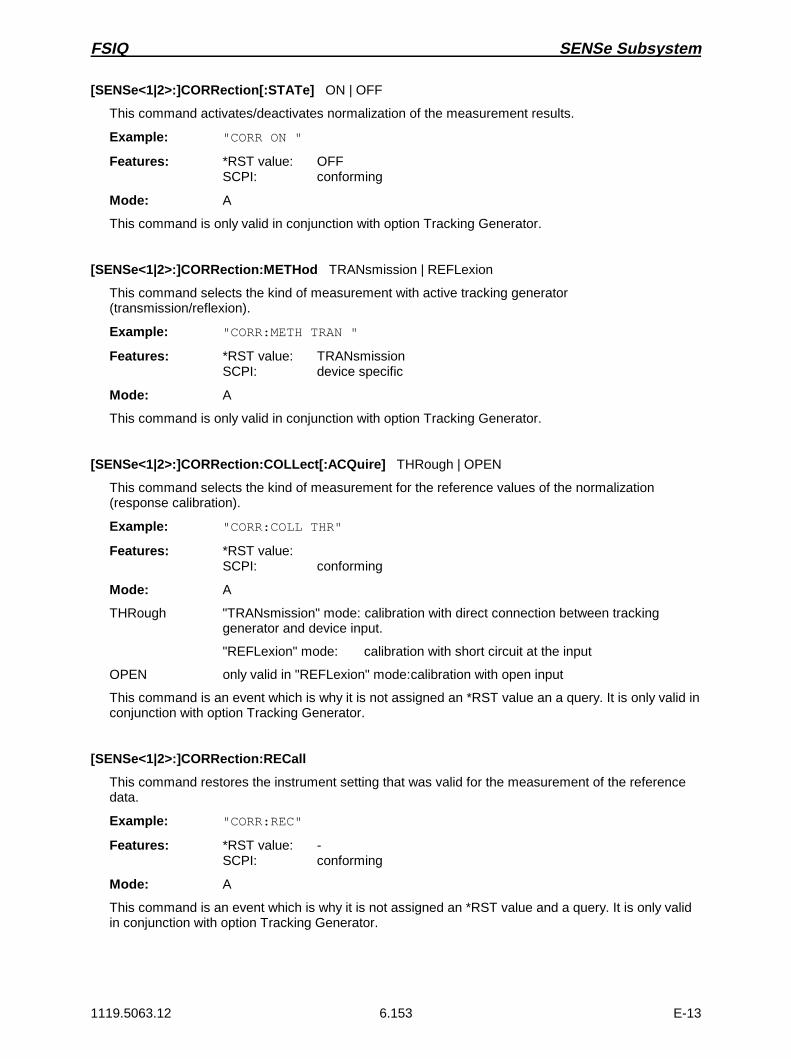
FSIQ SENSe Subsystem
1119.5063.12 6.153 E-13
[SENSe<1|2>:]CORRection[:STATe] ON | OFF
This command activates/deactivates normalization of the measurement results.
Example: "CORR ON "
Features: *RST value: OFFSCPI: conforming
Mode: A
This command is only valid in conjunction with option Tracking Generator.
[SENSe<1|2>:]CORRection:METHod TRANsmission | REFLexion
This command selects the kind of measurement with active tracking generator(transmission/reflexion).
Example: "CORR:METH TRAN "
Features: *RST value: TRANsmissionSCPI: device specific
Mode: A
This command is only valid in conjunction with option Tracking Generator.
[SENSe<1|2>:]CORRection:COLLect[:ACQuire] THRough | OPEN
This command selects the kind of measurement for the reference values of the normalization(response calibration).
Example: "CORR:COLL THR"
Features: *RST value:SCPI: conforming
Mode: A
THRough "TRANsmission" mode: calibration with direct connection between trackinggenerator and device input.
"REFLexion" mode: calibration with short circuit at the input
OPEN only valid in "REFLexion" mode:calibration with open input
This command is an event which is why it is not assigned an *RST value an a query. It is only valid inconjunction with option Tracking Generator.
[SENSe<1|2>:]CORRection:RECall
This command restores the instrument setting that was valid for the measurement of the referencedata.
Example: "CORR:REC"
Features: *RST value: -SCPI: conforming
Mode: A
This command is an event which is why it is not assigned an *RST value and a query. It is only validin conjunction with option Tracking Generator.

SENSe Subsystem FSIQ
1119.5063.12 6.154 E-13
[SENSe<1|2>:]CORRection:TRANsducer:CATalog?
This command reads out the names of all transducer factors stored on the harddisk.
Example: "CORR:TRAN:CAT?"
Feature: *RST value: -SCPI: device-specific
Mode: A
[SENSe<1|2>:]CORRection:TRANsducer:ACTive?
This command reveals the active transducer factor. If no transducer factor is switched on, a voidstring will be output.
Example: "CORR:TRAN:ACT?"
Feature: *RST value: -SCPI: device-specific
Mode: A
[SENSe<1|2>:]CORRection:TRANsducer:SELect <name>
This command selects the transducer factor designated by <name>. If <name> does not exist yet, anew transducer factor is created.
Parameter: <name>::= Name of the transducer factor in string data form with amaximum of 8 characters.
Example: "CORR:TRAN:SEL ’FACTOR1’"
Features: *RST value: -SCPI: device-specific
Mode: A
This command must be sent prior to the subsequent commands for modifying/activating transducerfactors.
[SENSe<1|2>:]CORRection:TRANsducer:UNIT <string>
This command defines the unit of the transducer factor selected.
Parameter: <string>::= ’DB’ | ’DBM’ | ’DBMV’ | ’DBUV’ | ’DBUV/M’ | ’DBUA’’DBUA/M’ | ’DBPW’ | ’DBPT’
Example: "CORR:TRAN:UNIT ’DBUV’"
Features: *RST value: ’DB’SCPI: device-specific
Mode: A
Prior to this command, the command SENS:CORR:TRAN:SEL must be sent.

FSIQ SENSe Subsystem
1119.5063.12 6.155 E-13
[SENSe<1|2>:]CORRection:TRANsducer:SCALing LINear | LOGarithmic
This command defines whether the frequency scaling of the transducer factor is linear or logarithmic.
Example: "CORR:TRAN:SCAL LOG"
Features: *RST value: LINearSCPI: device-specific
Mode: A
Prior to this command, the command SENS:CORR:TRAN:SEL must be sent.
[SENSe<1|2>:]CORRection:TRANsducer:COMMent <string>
This command defines the comment for the selected transducer factor.
Example: "CORR:TRAN:COMM ’FACTOR FOR ANTENNA’"
Features: *RST value ’’ (empty comment)SCPI: device specific
Mode: A
Prior to this command, the command SENS:CORR:TRAN:SEL must be sent.
[SENSe<1|2>:]CORRection:TRANsducer:DATA <freq>,<level>..
This command defines the test points for the selected transducer factor. The values are entered as aseries of frequency/level pairs. The frequencies must be in ascending order.
Example: "CORR:TRAN:TRANsducer:DATA 1MHZ,-30,2MHZ,-40"
Features: *RST value: -SCPI: device-specific
Mode: A
Prior to this command, the command SENS:CORR:TRAN:SEL must be sent. The level values aresent as dimensionless numbers; the unit is specified by means of the commandSENS:CORR:TRAN:UNIT.
[SENSe<1|2>:]CORRection:TRANsducer[:STATe] ON | OFF
This command switches the selected transducer factor on or off.
Example: "CORR:TRAN ON"
Features: *RST value: OFFSCPI: device-specific
Mode: A
Prior to this command, the command SENS:CORR:TRAN:SEL must be sent.

SENSe Subsystem FSIQ
1119.5063.12 6.156 E-13
[SENSe<1|2>:]CORRection:TRANsducer:DELete
This command deletes the selected transducer factor.
Example: "CORR:TRAN:DEL"
Features: *RST value: -SCPI: device-specific
Mode: A
This command is an event and therefore has no *RST value.Prior to this command, the command SENS:CORR:TRAN:SEL must be sent.
[SENSe<1|2>:]CORRection:TSET:CATalog?
This command polls the names of all transducer factors stored on the harddisk.
Parameter: none
Example: "CORR:TSET:CAT?"
Mode: A
Feature: *RST value: -SCPI: device-specific
[SENSe<1|2>:]CORRection:TSET:ACTive?
This command reveals the active transducer set. If no transducer set is switched on, a void string willbe output.
Example: "CORR:TSET:ACT?"
Feature: *RST value: -SCPI: device-specific
Mode: A
[SENSe<1|2>:]CORRection:TSET:SELect <name>
This command selected the transducer set designated by <name>. If <name> does not exist yet, anew set is created.
Parameter: <name>::= name of the transducer set in string data form with a maximumof 8 characters.
Example: "CORR:TSET:SEL ’SET1’"
Features: *RST value: -SCPI: device-specific
Mode: A
This command must be sent prior to the subsequent commands for changing/activating thetransducer sets.

FSIQ SENSe Subsystem
1119.5063.12 6.157 E-13
[SENSe<1|2>:]CORRection:TSET:UNIT ’DB’ | ’DBM’ | ’DBUV’ | ’DBUV/M’ | ’DBUA’ | ’DBUA/M’’ |DBPW’ | ’DBPT
This command defines the unit of the selected transducer sets. When assigning transducer factorsto the set, only factors which are compatible to the selected unit, i. e. factors with the same unit or theunit dB, are allowed.
Example: "CORR:TSET:UNIT ’DBUV’"
Features: *RST value: ’DB’SCPI: device-specific
Mode: A
Prior to this command, the command SENS:CORR:TSET:SEL must be sent.
[SENSe<1|2>:]CORRection:TSET:BREak ON | OFF
This command defines if the sweep is to be stopped on changeover from range to another.
Example: "CORR:TSET:BRE ON"
Features: *RST value: OFFSCPI: device-specific
Mode: A
Prior to the above command, the command SENS:CORR:TSET:SEL must be sent.
[SENSe<1|2>:]CORRection:TSET:COMMent <string>
This command defines the comment for the selected transducer set.
Example: "CORR:TSET:COMM ’SET FOR ANTENNA’"
Features: *RST value ’’ (empty comment)SCPI: device specific
Mode: A
Prior to this command, the command SENS:CORR:TSET:SEL must be sent.
[SENSe<1|2>:]CORRection:TSET:RANGe<1 to 10> <freq>,<freq>,<name>..
This command defines a partial range of the selected transducer set. The partial range is determinedby its start and stop frequencies plus a list of names of the assigned transducer factors. The ranges1 to 10 must be sent in ascending order.
Parameter: <freq>,<freq>::= start frequency, stop frequency of the range<name>...::= list of names for the assigned transducer factors.
The individual names must be characterized by singlequotation marks (’) and separated by commas.
Example: "CORR:TRAN:TSET:RANG 1MHZ,2MHZ,’FACTOR1,’FACTOR2’"
Features: *RST value: -SCPI: device-specific
Mode: A
Prior to this command, the command SENS:CORR:TSET:SEL must be sent.

SENSe Subsystem FSIQ
1119.5063.12 6.158 E-13
[SENSe<1|2>:]CORRection:TSET[:STATe] ON | OFF
This command switches the selected transducer set on or off.
Example: "CORR:TSET ON"
Features: *RST value: OFFSCPI: device-specific
Mode: A
Prior to this command, the command SENS:CORR:TSET:SEL must be sent.
[SENSe<1|2>:]CORRection:TSET:DELete
This command deletes the selected transducer set.
Example: "CORR:TSET:DEL"
Features: *RST value: -SCPI: device-specific
Mode: A
This command is an event and thus has no *RST value assigned.Prior to this command, the command SENS:CORR:TSET:SEL must be sent.
[SENSe<1|2>:]CORRection:LOSS:INPut[:MAGNitude] <numeric_value>
This command announces to the instrument a possibly needed external attenuation of the inputsignal, so that it is taken into account later when the level is set.
Parameter: <numeric_value>::= value of external attenuation in dB.
Example: "CORR:LOSS:INP 30DB "
Features: *RST value: 20dBSCPI: device-specific
Modes: BTS, MS
The external attenuation must be selected such that the input power of the analyzer does not exceed27 dBm.
[SENSe<1|2>:]CORRection:RXGain:INPut[:MAGNitude] <numeric_value>
This command announces to the instrument a possibly needed preamplification in the RX-band (RXBAND GAIN), so that it is taken into account later when the measured values are read out.
Parameter: <numeric_value>::= value of the amplification in dB.
Example: "CORR:RXG:INP 30DB "
Features: *RST value: 0 dBSCPI: device-specific
Modes: BTS, MS

FSIQ SENSe Subsystem
1119.5063.12 6.159 E-13
[SENSe<1|2>:]CORRection:CVL:CATalog?
This command polls the names of all conversion-loss tables stored on the harddisk.
Example: "CORR:CVL:CAT?"
Feature: *RST value: -SCPI: device-specific
Mode: A
This command is only valid in conjunction with option External Mixer Output, FSE-B21.
[SENSe<1|2>:]CORRection:CVL:SELect <file_name>
This command selects the Conversion Loss Table designated with <file_name>. If <file_name> isnot available, a new Conversion Loss Table will be created.
Parameter: <file_name>::= Name of Conversion Loss Table as string data witha maximum of 8 characters
Example: "CORR:CVL:SEL ’LOSS_TAB’"
Features: *RST value: -SCPI: device-specific
Mode: A
This command must be sent prior to the subsequent commands used to change/activate theConversion Loss files. It is only valid in conjunction with option External Mixer Output, FSE-B21.
[SENSe<1|2>:]CORRection:CVL:MIXer <string>
This command defines the type designation of the mixer in the Conversion Loss Table.
Parameter: <string>::= Type designation of mixer with a maximum of 16 characters
Example: "CORR:CVL:MIX ’FSE_Z60’"
Features: *RST value: -SCPI: device-specific
Mode: A
Command SENS:CORR:CVL:SEL must be sent prior to this command. This command is only validin conjunction with option External Mixer Output, FSE-B21.
[SENSe<1|2>:]CORRection:CVL:SNUMber <string>
This command defines the serial number of the mixer in the Conversion Loss Table.
Parameter: <string>::= Serial number of mixer with a maximum of 16 characters
Example: "CORR:CVL:SNUM ’123.4567’"
Features: *RST value: -SCPI: device-specific
Mode: A
Command SENS:CORR:CVL:SEL must be sent prior to this command. This command is only validin conjunction with option External Mixer Output, FSE-B21.

SENSe Subsystem FSIQ
1119.5063.12 6.160 E-13
[SENSe<1|2>:]CORRection:CVL:BAND A|Q|U|V|E|W|F|D|G|Y|J
This command defines the waveguide band in the Conversion Loss Table.
Example: "CORR:CVL:BAND E"
Features: *RST value: -SCPI: device-specific
Mode: A
Command SENS:CORR:CVL:SEL must be sent prior to this command. This command is only validin conjunction with option External Mixer Output, FSE-B21.
[SENSe<1|2>:]CORRection:CVL:TYPE ODD | EVEN | EODD
This command defines the type of harmonic in the Conversion Loss Table.
Example: "CORR:CVL:TYPE EODD"
Features: *RST value: -SCPI: device-specific
Mode: A
Command SENS:CORR:CVL:SEL must be sent prior to this command. This command is only validin conjunction with option External Mixer Output, FSE-B21.
[SENSe<1|2>:]CORRection:CVL:PORTs 2 | 3
This command defines the type of mixer in the Conversion Loss Table.
Example: "CORR:CVL:PORT 3"
Features: *RST value: -SCPI: device-specific
Mode: A
Command SENS:CORR:CVL:SEL must be sent prior to this command. This command is only validin conjunction with option External Mixer Output, FSE-B21.
[SENSe<1|2>:]CORRection:CVL:BIAS <numeric_value>
This command defines the bias current in the Conversion Loss Table.
Example: "CORR:CVL:BIAS 7mA"
Features: *RST value: -SCPI: device-specific
Mode: A
Command SENS:CORR:CVL:SEL must be sent prior to this command. This command is only validin conjunction with option External Mixer Output, FSE-B21.

FSIQ SENSe Subsystem
1119.5063.12 6.161 E-13
[SENSe<1|2>:]CORRection:CVL:COMMent <string>
This command defines the comment in the Conversion Loss Table.
Parameter: <string>::= Comment of mixer with a maximum of 60 characters
Example: "CORR:CVL:COMMENT ’MIXER FOR BAND U’"
Features: *RST value: -SCPI: device-specific
Mode: A
Command SENS:CORR:CVL:SEL must be sent prior to this command. This command is only validin conjunction with option External Mixer Output, FSE-B21.
[SENSe<1|2>:]CORRection:CVL:DATA <freq>,<level>..
This command defines the reference values of the selected Conversion Loss Tabels. The values areentered as a result of frequency/level pairs. The frequencies have to be sent in ascending order.
Example: "CORR:CVL:DATA 1MHZ,-30DB,2MHZ,-40DB"
Features: *RST value: -SCPI: device-specific
Mode: A
Command SENS:CORR:CVL:SEL must be sent prior to this command. This command is only validin conjunction with option External Mixer Output, FSE-B21.
[SENSe<1|2>:]CORRection:CVL:CLEar
This command deletes the selected Conversion Loss Table.
Example: "CORR:CVL:CLE"
Features: *RST value: -SCPI: device-specific
Mode: A
This command is an event which is why it is not assigned an *RST value.Command SENS:CORR:CVL:SEL must be sent prior to this command. This command is only validin conjunction with option External Mixer Output, FSE-B21.
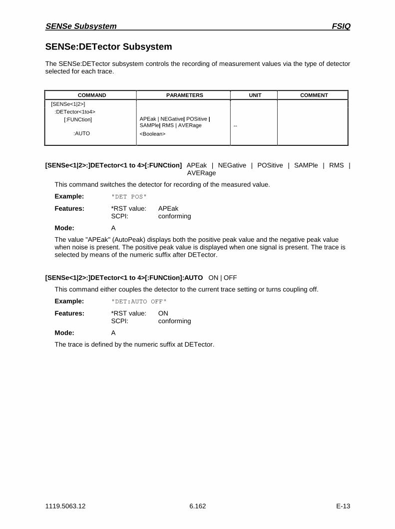
SENSe Subsystem FSIQ
1119.5063.12 6.162 E-13
SENSe:DETector Subsystem
The SENSe:DETector subsystem controls the recording of measurement values via the type of detectorselected for each trace.
COMMAND PARAMETERS UNIT COMMENT
[SENSe<1|2>]
:DETector<1to4>
[:FUNCtion]
:AUTO
APEak | NEGative| POSitive |SAMPle| RMS | AVERage
<Boolean>
--
[SENSe<1|2>:]DETector<1 to 4>[:FUNCtion] APEak | NEGative | POSitive | SAMPle | RMS |AVERage
This command switches the detector for recording of the measured value.
Example: "DET POS"
Features: *RST value: APEakSCPI: conforming
Mode: A
The value "APEak" (AutoPeak) displays both the positive peak value and the negative peak valuewhen noise is present. The positive peak value is displayed when one signal is present. The trace isselected by means of the numeric suffix after DETector.
[SENSe<1|2>:]DETector<1 to 4>[:FUNCtion]:AUTO ON | OFF
This command either couples the detector to the current trace setting or turns coupling off.
Example: "DET:AUTO OFF"
Features: *RST value: ONSCPI: conforming
Mode: A
The trace is defined by the numeric suffix at DETector.

FSIQ SENSe Subsystem
1119.5063.12 6.163 E-13
SENSe:DDEMod Subsystem
This subsystem controls the parameters for digital demodulation.
COMMAND PARAMETERS UNIT COMMENT
[SENSe<1|2>]
:DDEMod
:FORMat
:SBANd
:QPSK
:FORMat
:PSK
:NSTate
:FORMat
:MSK
:FORMat
:QAM
:NSTate
:FSK
:NSTate
:SRATe
:TIMe
:PRATe
:FILTer
:MEASurement
:REFerence
:ALPHa
:NORMalize
:PRESet
:SEARch
:PULSe
:STATe
:SYNC
:CATalog?
:SELect
:OFFSet
:PATTern
:STATe
:NAME
:COMMent
:DATA
:DELete
:MONLy
:TIME
QPSK | PSK | MSK | QAM | FSK
NORMal | INVerse
NORMal | DIFFerential | OFFSet | DPI4
2 | 8
NORMal | DIFFerential | N3Pi8
TYPE1 | TYPE2 |NORMal | DIFFerential
16
2 | 4
<numeric_value>
<numeric_value>
1 | 2 | 4 | 8 | 16
OFF | RCOSine | RRCosine | GAUSsian | B22 | B25| B44 | QFM | FM95 | QFR | FR95 | QRM |RM95 |QRR | RR95 | A25Fm | EMES | EREF
RCOSine | RRCosine | GAUSsian | B22 | B25 | B44| QFM | FM95 | QFR | FR95 | QRM | RM95 | QRR |RR95 | A25Fm | EMES | EREF
<numeric_value>
<Boolean>
GSM | TETRa | DCS1800 | PCS1900 | PHS |PDCup | PDCDown | APCO25CQPSK |APCO25C4FM | CDPD | DECT | CT2 | ERMes |MODacom | PWT | TFTS | F16 | F322 | F324 | F64 |FQCDma | F95Cdma | RQCDma | R95Cdma |FNADc | RNADc | EDGe | BPSK18 | GMSK18 |QPSK18 | GMSK36 | FWCDma | FCDMa4096 |RWCDma | RCDMa4096 | FW3Gppcdma |RW3Gppcdma | CDMA2000
<Boolean>
<string>
<numeric_value>
<string>
<Boolean>
<string>
<string>
<string>
<Boolean>
<numeric value>
HZ
SYM
SYM
SYM
Vector Signal Analysis
query only
:TCAPture
:LENGth <numeric_value>
Vector Signal Analysis

SENSe Subsystem FSIQ
1119.5063.12 6.164 E-13
[SENSe<1|2>:]DDEMod:FORMat QPSK | PSK | MSK | QAM | FSK
This command selects the digital demodulation type.
Example: "DDEM:FORM QPSK"
Features: *RST value: MSKSCPI: device-specific
Mode: VA-D
[SENSe<1|2>:]DDEMod:SBANd NORMal | INVerse
This command selects the sideband for the demodulation.
Example: "DDEM:SBAN INV"
Features: *RST value: NORMalSCPI: device-specific
Mode: VA-D
[SENSe<1|2>:]DDEMod:QPSK:FORMat NORMal | DIFFerential | OFFSet | DPI4
This command determines the specific demodulation type for QPSK.
Example: "DDEM:QPSK:FORM DPI4"
Features: *RST value: -SCPI: device-specific
Mode: VA-D
[SENSe<1|2>:]DDEMod:PSK:NSTate 2 | 8
This command determines the specific demodulation type for PSK.
Example: "DDEM:PSK:NST 2"
Features: *RST value: -SCPI: device-specific
Mode: VA-D
Value 2 (i.e. PSK2) corresponds to BPSK demodulation, value 8 the 8PSK demodulation.
[SENSe<1|2>:]DDEMod:PSK:FORMat NORMal | DIFFerential | N3Pi8
This command determines the specific demodulation type for PSK.
Example: "DDEM:PSK:FORM DIFF"
Features: *RST value: -SCPI: device-specific
Mode: VA-D

FSIQ SENSe Subsystem
1119.5063.12 6.165 E-13
[SENSe<1|2>:]DDEMod:MSK:FORMat TYPE1 | TYPE2 | NORMal | DIFFerential
This command determines the specific demodulation type for MSK.
Example: "DDEM:MSK:FORM TYPE2"
Features: *RST value: TYPE2 | DIFFerentialSCPI: device-specific
Mode: VA-D
TYPE1 | NORMal corresponds to MSK demodulation, TYPE2 | DIFFerential corresponds toDMSK demodulation.
[SENSe<1|2>:]DDEMod:QAM:NSTate 16
This command determines the specific demodulation type for QAM.
Example: "DDEM:QAM:NST 16"
Features: *RST value: 16SCPI: device-specific.
Mode: VA-D
[SENSe<1|2>:]DDEMod:FSK:NSTate 2 | 4
This command determines the specific demodulation type for FSK.
Example: "DDEM:FSK:NST 2"
Features: *RST- value: -SCPI: device-specific
Mode: VA-D
The parameter 2 corresponds to the demodulation type 2FSK, the parameter 4 to the demodulationtype 4FSK.
[SENSe<1|2>:]DDEMod:SRATe 160 Hz ...7 MHz
This command defines the symbol rate.
Example: "DDEM:SRAT 18kHz"
Features: *RST value: 270.833333kHzSCPI: device-specific
Mode: VA-D
[SENSe<1|2>:]DDEMod:TIME 1 to Frame Length
The command determines the number of displayed symbols (result length).
Example: "DDEM:TIME 80"
Features: *RST value: 147SCPI: device-specific
Mode: VA-D

SENSe Subsystem FSIQ
1119.5063.12 6.166 E-13
[SENSe<1|2>:]DDEMod:PRATe 1 | 2 | 4 | 8 | 16
This command determines the number of points per symbol.
Example: "DDEM:PRAT 8"
Features: *RST value: 4SCPI: device-specific
Mode: VA-D
[SENSe<1|2>:]DDEMod:FILTer:MEASurement OFF | RCOSine | RRCosine | GAUSsian| B22 | B25 |B44 | QFM | FM95 | QFR | FR95 | QRM | RM95 |QRR | RR95 | A25Fm | EMES | EREF
This command selects the input filter for the test signal.
B22 Bessel 22B25 Bessel 25B44 Bessel 44QFM or FM95 IS95-CDMA fmQFR or FR95 IS95-CDMA frQRM or RM95 IS95-CDMA rmQRR or RR95 IS95-CDMA rrA25Fm APCO 25 fmEMES EDGE mesEREF EDGE ref
Example: "DDEM:FILT:MEAS RCOS"
Features: *RST value: OFFSCPI: device-specific
Mode: VA-D
[SENSe<1|2>:]DDEMod:FILTer:REFerence RCOSine | RRCosine | GAUSsian| B22 | B25 | B44 |QFM | FM95 | QFR | FR95 | QRM | RM95 | QRR | RR95| A25Fm | EMES | EREF
This command selects the input filter for the reference signal.
Example: "DDEM:FILT:REF RCOS"
Features: *RST value: GAUSsianSCPI: device-specific
Mode: VA-D
[SENSe<1|2>:]DDEMod:FILTer:ALPHa 0.2 to 1
This command determines the filter characteristic (ALPHA/BT). Step width is 0.05.
Example: "DDEM:FILT:ALPH 0.5"
Features: *RST value: 0.3SCPI: device-specific
Mode: VA-D

FSIQ SENSe Subsystem
1119.5063.12 6.167 E-13
[SENSe<1|2>:]DDEMod:NORMalize ON | OFF
This command switches normalizing of the unit circle on or off using IQ offset.
Example: "DDEM:NORM OFF"
Features: *RST value: ONSCPI: device-specific
Mode: VA-D
[SENSe<1|2>:]DDEMod:SEARch:PULSe:STATe ON | OFF
This command switches the signal burst search on or off.
Example: "DDEM:SEAR:PULS:STAT OFF"
Features: *RST value: ONSCPI: device-specific
Mode: VA-D
[SENSe<1|2>:]DDEMod:SEARch:SYNC:CATalog?
This command polls the names of all sync-file data sets stored on the harddisk.
Example: "DDEM:SEAR:SYNC:CAT?"
Feature: *RST value: -SCPI: device-specific
Mode: VA-D
[SENSe<1|2>:]DDEMod:SEARch:SYNC:SELect <string>
This command selects a predefined sync file. A file that has been set previously by the commandDDEM:SEARch:SYNC:PATTern becomes invalid.
Example: "DDEM:SEAR:SYNC:SEL "PATT_1"
Feature: *RST value: ""SCPI: device-specific
Mode: VA-D
[SENSe<1|2>:]DDEMod:SEARch:SYNC:OFFSet <numeric_value>
This command defines the offset of the display with reference to the synchronization sequence.
Example: "DDEM:SEAR:SYNC:OFFS 10SYM"
Features: *RST value: 0 SYMSCPI: device-specific
Mode: VA-D

SENSe Subsystem FSIQ
1119.5063.12 6.168 E-13
[SENSe<1|2>:]DDEMod:SEARch:SYNC:PATTern <string>
This command defines the synchronization sequence.A file that has been set previously by thecommand DDEM:SEARch:SYNC:SELect becomes invalid.
Example: "DDEM:SEAR:SYNC:PATT "1101001"
Features: *RST value: ""SCPI: device-specific
Mode: VA-D
[SENSe<1|2>:]DDEMod:SEARch:SYNC:STATe ON | OFF
This command switches the search for a synchronization sequence on or off.
Example: "DDEM:SEARch:SYNC:STAT ON"
Features: *RST value: OFFSCPI: device-specific
Mode: VA-D
[SENSe<1|2>:]DDEMod:SEARch:SYNC:NAME <string>
This command selects a sync file to be edited or entered anew.
Example: "DDEM:SEAR:SYNC:NAME "PATT_NEW"
Feature: *RST value: ""SCPI: device-specific
Mode: VA-D
[SENSe<1|2>:]DDEMod:SEARch:SYNC:COMMent <string>
This command defines a comment on a sync file. This sync file must be previously selected by thecommand DDEM:SEARch:SYNC:NAME.
Example: "DDEM:SEAR:SYNC:COMM "PATTERN FOR PPSK"
Feature: *RST value: ""SCPI: device-specific
Mode: VA-D
[SENSe<1|2>:]DDEMod:SEARch:SYNC:DATA <string>
This command defines a synchronization pattern for the sync file. This sync file must be previouslyselected by the command DDEM:SEARch:SYNC:NAME.
Example: "DDEM:SEAR:SYNC:DATA "1101001"
Feature: *RST value: ""SCPI: device-specific
Mode: VA-D

FSIQ SENSe Subsystem
1119.5063.12 6.169 E-13
[SENSe<1|2>:]DDEMod:SEARch:SYNC:DELete <string>
This command deletes a synchronization pattern on the hard disk. This sync file must be previouslyselected by the command DDEM:SEARch:SYNC:NAME.
Example: "DDEM:SEAR:SYNC:DEL
Features: *RST-value: ""SCPI: device-specific
Mode: VA-D
[SENSe<1|2>:]DDEMod:SEARch:SYNC:MONLy ON | OFF
For setting ON, this command sets the analyzer so that the measured values are displayed andtaken into account in the error analysis only if the set sync pattern is found . Bursts with a wrong syncpattern (sync not found) are ignored.
Example: "DDEM:SEAR:SYNC:MONL ON"
Features: *RST value: OFFSCPI: device specific
Mode: VA-D
[SENSe<1|2>:]DDEMod:SEARch:TIME 100 to 1600
This command determines the number of symbols required for demodulation (frame length). Thevalues > 800 are only permissible if the number of points per symbol is <16, the values > 1600 only ifthe number of points per symbol is <8. Step width is 100.
Example: "DDEM:SEAR:TIME 800"
Features: *RST value: 400SCPI: device-specific
Mode: VA-D

SENSe Subsystem FSIQ
1119.5063.12 6.170 E-13
[SENSe<1|2>:]DDEMod:PRESet GSM | EDGe | TETRa | PHS | PDCup | PDCDown |APCO25CQPSK | APCO25C4FM | CDPD | DECT | CT2 | ERMes| MODacom | PWT | TFTS | F16 | F322 | F324 | F64 | FQCDma |F95Cdma | RQCDma | R95Cdma | FNADc | RNADc | FWCDma |FCDMa4096 | RWCDma | RCDMa4096 | FW3Gppcdma |RW3Gppcdma | CDMA2000
This command selects an automatic setting of all modulation parameters according to a standardtransmission method.
Example: "DDEM:PRES TETR"
Features: *RST value: FWCDmaSCPI: device-specific
Mode: VA-D
APCO25CQPSK APCO25 Continous Phase QPSKAPCO25C4FM APCO25Continous Phase 4FMF16 FLEX 1600 - 2FSKF322 FLEX 3200 - 2FSK,F324 FLEX 3200 - 4FSKF64 FLEX 6400 - 4FSKFNADc Forward NADCRNADc Reverse NADCFQCDma or F95Cdma Forward CDMA acc. to IS95 StandardRQCDma or R95Cdma Reverse CDMA acc. to IS95 StandardFWCDma or FCDMa4096 Forward W-CDMARWCDma or RCDMa4096 Reverse W-CDMAFW3Gppcdma Forward W-CDMA 3GPPRW3Gppcdma Reverse W-CDMA 3GPPCDMA2000 CDMA 2000
[SENSe<1|2>:]TCAPture:LENGth 1024 | 2048 | 4096 | 8192 | 16384
This command determines the number of sampling points that are written into the memory for eachmeasurement (memory size).
Example: "TCAP:LENG 1024"
Features: *RST value: 16384SCPI: device-specific
Mode: VA-D

FSIQ SENSe Subsystem
1119.5063.12 6.171 E-13
SENSe:FILTer Subsystem
The SENSe:FILTer subsystem selects the filters in the video signal path.This subsystem is active only inthe Vector Signal Analysis mode
COMMAND PARAMETERS UNIT COMMENT
[SENSe<1|2>]
:FILTer
:HPASs
[:STATe]
:FREQuency
<Boolean>
<numeric_value>
--
HZ
Vector Signal Analyzer
:LPASs[:STATe]:FREQuency
:CCITt[:STATe]
:CMESsage[:STATe]
:DEMPhasis[:STATe]:TCONstant:LINK
<Boolean><numeric_value>
<Boolean>
<Boolean>
<Boolean><numeric_value>DISPlay | AUDio
--HZ | PCT
--
--
S
Vector Signal Analyzer
[SENSe<1|2>:]FILTer:HPASs[:STATe] ON | OFF
This command activates the high-pass filter in the AF-branch for analog demodulation.
Example: "FILT:HPAS ON"
Features: *RST value: OFFSCPI: conforming
Mode: VA-A
[SENSe<1|2>:]FILTer:HPASs:FREQuency 30 Hz | 300 Hz
In the Vector Signal Analysis mode with analog demodulation, this command defines the frequencylimit of the high-pass filter in the AF-branch. For REAL TIME ON absolute frequencies are entered,for REAL TIME OFF, the frequencies are entered relative to the demodulation bandwidth.
Example: "FILT:HPAS:FREQ 300HZ"
Features: *RST value: - (STATe = OFF)SCPI: conforming
Mode: VA-A

SENSe Subsystem FSIQ
1119.5063.12 6.172 E-13
[SENSe<1|2>:]FILTer:LPASs[:STATe] ON | OFF
This command activates the low-pass filter in the AF-branch with analog demodulation.
Example: "FILT:LPAS ON"
Features: *RST value: OFFSCPI: conforming
Mode: VA-A
On switching to ON, a bandwidth of 3 kHz for REAL TIME ON and a bandwidth of 5 PCT for REALTIME OFF is set automatically.
[SENSe<1|2>:]FILTer:LPASs:FREQuency <numeric_value>
This command defines the frequency limit of the low-pass filter in the NF-branch for analogdemodulation.
Parameter: <numeric_value> ::= 3 kHz | 15 kHz for REAL TIME ON5 PCT | 10 PCT | 25 PCT for REAL TIME OFF
Example: "FILT:LPAS:FREQ 3KHZ" for REAL TIME ON"FILT:LPAS:FREQ 25PCT" for REAL TIME OFF
Features: *RST value: - (STATe = OFF)SCPI: conforming
Mode: VA-A
[SENSe<1|2>:]FILTer:CCITt[:STATe] ON | OFF
This command activates the weighting filter according to CCITT-recommendation in the AF-branchfor analog demodulation.
Example: "FILT:CCIT ON"
Features: *RST value: OFFSCPI: conforming
Mode: VA-A
[SENSe<1|2>:]FILTer:CMESsage[:STATe] ON | OFF
This command activates the C-message weighting filter according to CCITT-recommendation in theAF-branch for analog demodulation.
Example: "FILT:CMES ON"
Features: *RST value: OFFSCPI: conforming
Mode: VA-A
This command is valid only with REAL TIME OFF.

FSIQ SENSe Subsystem
1119.5063.12 6.173 E-13
[SENSe<1|2>:]FILTer:DEMPhasis[:STATe] ON | OFF
This command activates the selected de-emphasis for analog demodulation.
Example: "FILT:DEMP ON"
Features: *RST value: OFFSCPI: conforming
Mode: VA-A
[SENSe<1|2>:]FILTer:DEMPhasis:TCONstant 50US | 75US | 750US
This command sets the time constant of the de-emphasis for analog demodulation.
Example: "FILT:DEMP:TCON 75US"
Features: *RST value: 50usSCPI: conforming
Mode: VA-A
[SENSe<1|2>:]FILTer:DEMPhasis:LINK DISPlay | AUDio
For analog demodulation, this command selects whether the de-emphasis set is to be active in theaudio branch only or in addition for the display of measured values.
Example: "FILT:DEMP:LINK DISP"
Features: *RST value: AUDioSCPI: device-specific
Mode: VA-A
AUDio De-emphasis effective in the audio branch onlyDISPlay De-emphasis effective in the audio branch and in the display of measured values

SENSe Subsystem FSIQ
1119.5063.12 6.174 E-13
SENSe:FREQuency Subsystem
The SENSe:FREQuency subsystem defines the frequency axis of the active display. The frequency axiscan either be defined via the start/stop frequency or via the center frequency and span.
COMMAND PARAMETERS UNIT COMMENT
[SENSe<1|2>]
:FREQuency
:CENTer
:LINK
:STEP
:LINK
:FACTor
:SPAN
:FULL
:LINK
:STARt
:LINK
:STOP
:LINK
:MODE
:OFFSet
<numeric_value>
STARt | STOP | SPAN
<numeric_value>
SPAN | RBW | OFF
<numeric_value>
<numeric value>
--
CENTer | STARt | STOP
<numeric_value>
CENTer | STOP | SPAN
<numeric_value>
CENTer | STARt |SPAN
CW | FIXed | SWEep
<numeric_value>
HZ
--
HZ
--
PCT
HZ
--
--
HZ
--
HZ
--
--
HZ
[SENSe<1|2>:]FREQuency:CENTer 0 GHz to fmax
This command defines the center frequency of the analyzer.
Example: "FREQ:CENT 100MHz"
Features: *RST value: fmax / 2SCPI: conforming
Modes: A, VA, MS, BTS
The automatic coupling of the parameters is set to SPAN FIXED.
[SENSe<1|2>:]FREQuency:CENTer:LINK STARt | STOP | SPAN
This command defines the coupling of the center frequency to the start, stop frequency or thefrequency span.
Example: "FREQ:CENT:LINK STAR"
Features: *RST value: SPANSCPI: device-specific
Mode: A

FSIQ SENSe Subsystem
1119.5063.12 6.175 E-13
[SENSe<1|2>:]FREQuency:CENTer:STEP 0 to fmax
This command defines the step width of the center frequency.
Example: "FREQ:CENT:STEP 120MHz"
Features: *RST value: - (AUTO 0.1 × SPAN is switched on)SCPI: conforming
Modes: A, VA, BTS, MS
[SENSe<1|2>:]FREQuency:CENTer:STEP:LINK SPAN | RBW | OFF
This command couples the step width of the center frequency to span (span >0) or to the resolutionbandwidth (span = 0) or cancels the couplings.
Example: "FREQ:CENT:STEP:LINK SPAN"
Features: *RST value: SPANSCPI: device-specific
Modes: A, BTS, MS
[SENSe<1|2>:]FREQuency:CENTer:STEP:LINK:FACTor 1 to 100 PCT
This command couples the step width of the center frequency with a factor to the span (span >0) orto the resolution bandwidth (span = 0).
Example: "FREQ:CENT:STEP:LINK:FACT 20PCT"
Features: *RST value: - (AUTO 0.1 × SPAN is switched on)SCPI: device-specific
Modes: A, BTS, MS
[SENSe<1|2>:]FREQuency:SPAN 0 GHz to fmax
This command defines the frequency span of the analyzer.
Example: "FREQ:SPAN 10MHz"
Features: *RST value: fmaxSCPI: conforming
Mode: A
The automatic coupling of the parameters is set to CENTER FIXED.

SENSe Subsystem FSIQ
1119.5063.12 6.176 E-13
[SENSe<1|2>:]FREQuency:SPAN:FULL
This command sets the maximum frequency span of the analyzer.
Example: "FREQ:SPAN:FULL"
Features: *RST value: -SCPI: conforming
Mode: A
This command is an event which is why it is not assigned an *RST value and has no query.
[SENSe<1|2>:]FREQuency:SPAN:LINK CENTer | START | STOP
This command defines the coupling for frequency-span changes.
Example: "FREQ:SPAN:LINK STOP"
Features: *RST value: CENTerSCPI: conforming
Mode: A
[SENSe<1|2>:]FREQuency:STARt 0 GHz to fmax
This command defines the start frequency of the analyzer.
Example: "FREQ:STAR 20MHz"
Features: *RST value: 0SCPI: conforming
Mode: A
The automatic coupling of the parameters is set to STOP FIXED.
[SENSe<1|2>:]FREQuency:STARt:LINK CENTer | STOP | SPAN
This command defines the coupling for start-frequency changes.
Example: "FREQ:STAR:LINK SPAN"
Features: *RST value: STOPSCPI: device-specific
Mode: A
[SENSe<1|2>:]FREQuency:STOP 0 GHz to fmax
This command defines the stop frequency of the scan in receiver mode or the stop frequency of theanalyzer.
Example: "FREQ:STOP 2000MHz"
Features: *RST value: fmaxSCPI: conforming
Mode: A
The automatic coupling of the parameters is set to STARt FIXED.

FSIQ SENSe Subsystem
1119.5063.12 6.177 E-13
[SENSe<1|2>:]FREQuency:STOP:LINK CENTer | STARt | SPAN
This command defines the coupling for stop-frequency changes.
Example: "FREQ:STOP:LINK SPAN"
Features: *RST value: STARtSCPI: device-specific
Mode: A
[SENSe<1|2>:]FREQuency:MODE CW | FIXed | SWEep
This command switches between frequency (SWEep) and time (CW | FIXed) domain in the analyzermode.
Example: "FREQ:MODE SWE"
Features: *RST value: CWSCPI: conforming
Mode: A
For CW and FIXed, the frequency setting is via command FREQuency:CENTer. In the SWEepmode, the setting is via commands FREQuency:STARt, STOP, CENTer and SPAN.
[SENSe<1|2>:]FREQuency:OFFSet <numeric_value>
This command defines the frequency offset of the instrument.
Example: "FREQ:OFFS 1GHZ"
Features: *RST value: 0 HzSCPI: conforming
Modes: A, VA

SENSe Subsystem FSIQ
1119.5063.12 6.178 E-13
SENSe:MIXer - Subsystem
The SENSe:MIXer subsystem controls the settings of the external mixer. It is only active in Analyzermode (INSTrument SANalyzer). The suffix in SENSe<1|2> is not significant in this subsystem.
COMMAND PARAMETERS UNIT COMMENT
[SENSe<1|2>:]:MIXer
[:STATe]:BLOCk:PORTs:SIGNal:THReshold:HARMonic
:TYPE:BAND
:LOSS[:LOW]:HIGH:TABLe
:BIAS:LIMit
[:MAX]:MIN
<Boolean><Boolean>2 | 3OFF | ON | AUTO<numeric_value><numeric_value>ODD | EVEN | EODDA|Q|U|V|E|W|F|D|G|Y|J
<numeric_value><numeric_value><file_name><numeric_value>
<numeric_value><numeric_value>
--
--
DBDB
A
AA
Only query in band lock onNot in band lock offNot in band lock off
Not in band lock off
Not in band lock onNot in band lock on
[SENSe<1|2>:]MIXer[:STATe] ON | OFF
This command activates or shuts off the external mixer.
Example: "MIX ON"
Features: *RST value: OFFSCPI: device-specific
Mode: A
This command is available only in conjunction with option FSE-B21, External Mixer Output.
[SENSe<1|2>:]MIXer:BLOCk ON | OFF
This command activates the BAND LOCK ON or BAND LOCK OFF mode.
Example: "MIX:BLOC ON"
Features: *RST value: OFFSCPI: device-specific
Mode: A
This command is available only if the external mixer (option FSE-B21) is switched on.
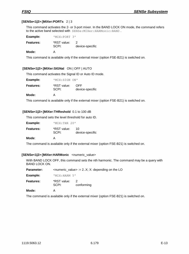
FSIQ SENSe Subsystem
1119.5063.12 6.179 E-13
[SENSe<1|2>:]MIXer:PORTs 2 | 3
This command activates the 2- or 3-port mixer. In the BAND LOCK ON mode, the command refersto the active band selected with SENSe:MIXer:HARMonic:BAND .
Example: "MIX:PORT 3"
Features: *RST value: 2SCPI: device-specific
Mode: A
This command is available only if the external mixer (option FSE-B21) is switched on.
[SENSe<1|2>:]MIXer:SIGNal ON | OFF | AUTO
This command activates the Signal ID or Auto ID mode.
Example: "MIX:SIGN ON"
Features: *RST value: OFFSCPI: device-specific
Mode: A
This command is available only if the external mixer (option FSE-B21) is switched on.
[SENSe<1|2>:]MIXer:THReshold 0.1 to 100 dB
This command sets the level threshold for auto ID.
Example: "MIX:THR 20"
Features: *RST value: 10SCPI: device-specific
Mode: A
The command is available only if the external mixer (option FSE-B21) is switched on.
[SENSe<1|2>:]MIXer:HARMonic <numeric_value>
With BAND LOCK OFF, this command sets the nth harmonic. The command may be a query withBAND LOCK ON.
Parameter: <numeric_value> := 2..X; X: depending on the LO
Example: "MIX:HARM 5"
Features: *RST value: 2SCPI: conforming
Mode: A
The command is available only if the external mixer (option FSE-B21) is switched on.

SENSe Subsystem FSIQ
1119.5063.12 6.180 E-13
[SENSe<1|2>:]MIXer:HARMonic:TYPE ODD | EVEN | EODD
With BAND LOCK ON, this command sets the type of harmonic.
Example: "MIX:HARM:TYPE EODD"
Features: *RST value: EVENSCPI: device-specific
Mode: A
The command is available only if the external mixer (option FSE-B21) is switched on.
[SENSe<1|2>:]MIXer:HARMonic:BAND A|Q|U|V|E|W|F|D|G|Y|J
With BAND LOCK ON, this command sets the active band.
Example: "MIX:HARM:BAND E"
Features: *RST value: USCPI: device-specific
Mode: A
The command is available only if the external mixer (option FSE-B21) is switched on.
[SENSe<1|2>:]MIXer:LOSS[:LOW] <numeric_value>
This command sets the conversion loss of the mixer.
Example: "MIX:LOSS -12DB"
Features: *RST value: 0 dBSCPI: conforming
Mode: A
The command is available only if the external mixer (option FSE-B21) is switched on.
[SENSe<1|2>:]MIXer:LOSS:HIGH <numeric_value>
With BAND LOCK ON, this command sets the conversion loss of the mixer for higher harmonics inbands with two harmonics (band A: even harmonics, band Q: odd harmonics).
Example: "MIX:LOSS:HIGH -14DB"
Features: *RST value: 0 dBSCPI: device-specific
Mode: A
The command is available only if the external mixer (option FSE-B21) is switched on.
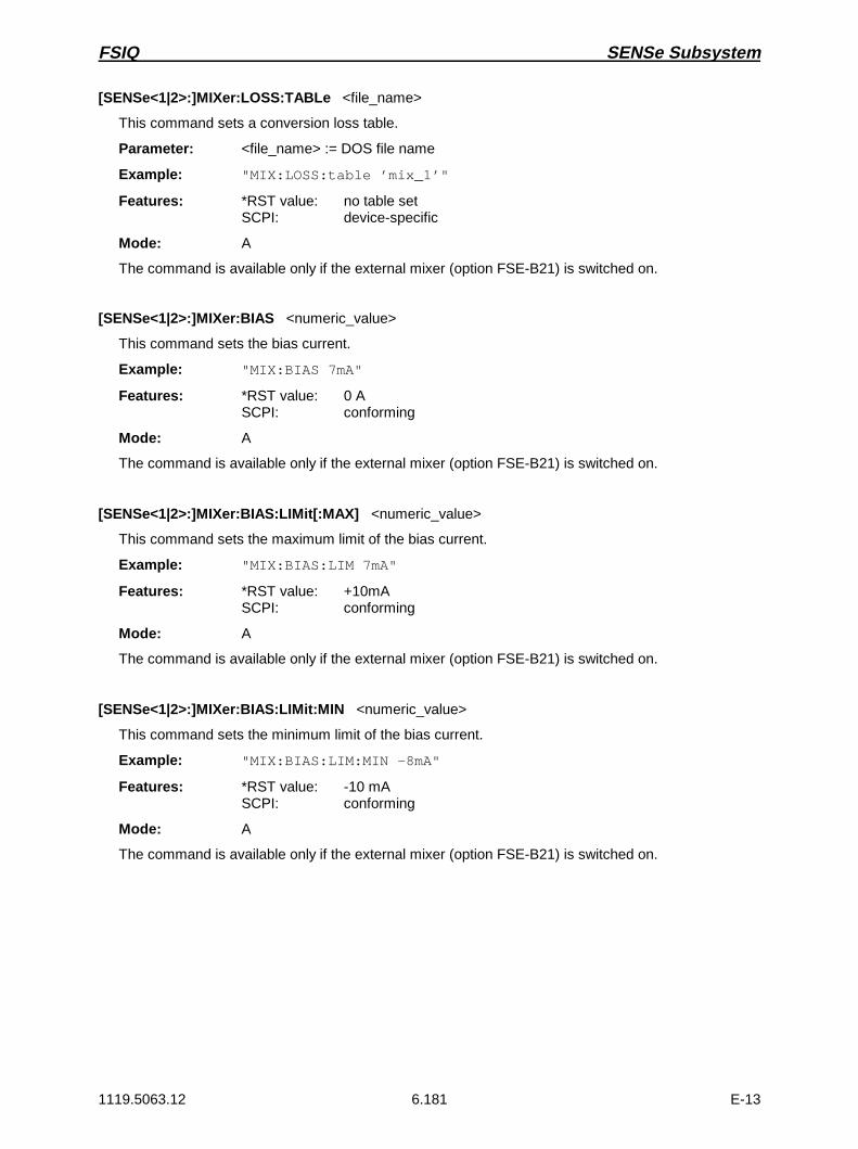
FSIQ SENSe Subsystem
1119.5063.12 6.181 E-13
[SENSe<1|2>:]MIXer:LOSS:TABLe <file_name>
This command sets a conversion loss table.
Parameter: <file_name> := DOS file name
Example: "MIX:LOSS:table ’mix_1’"
Features: *RST value: no table setSCPI: device-specific
Mode: A
The command is available only if the external mixer (option FSE-B21) is switched on.
[SENSe<1|2>:]MIXer:BIAS <numeric_value>
This command sets the bias current.
Example: "MIX:BIAS 7mA"
Features: *RST value: 0 ASCPI: conforming
Mode: A
The command is available only if the external mixer (option FSE-B21) is switched on.
[SENSe<1|2>:]MIXer:BIAS:LIMit[:MAX] <numeric_value>
This command sets the maximum limit of the bias current.
Example: "MIX:BIAS:LIM 7mA"
Features: *RST value: +10mASCPI: conforming
Mode: A
The command is available only if the external mixer (option FSE-B21) is switched on.
[SENSe<1|2>:]MIXer:BIAS:LIMit:MIN <numeric_value>
This command sets the minimum limit of the bias current.
Example: "MIX:BIAS:LIM:MIN -8mA"
Features: *RST value: -10 mASCPI: conforming
Mode: A
The command is available only if the external mixer (option FSE-B21) is switched on.

SENSe Subsystem FSIQ
1119.5063.12 6.182 E-13
SENSe:MSUMmary Subsystem
This subsystem controls the modulation summary setting for analog demodulation.
COMMAND PARAMETERS UNIT COMMENT
[SENSe<1|2>]:MSUMmary
:AHOLd[:STATe]
:MODE:RUNit:REFerence
:AUTO:MTIMe
<Boolean>ABSolute | RELativePCT | DB<numeric_value>ONCE<numeric_value>
PCT | HZ | DEG | RAD
S
Vector Signal Analysis
no query
[SENSe<1|2>:]MSUMmary:AHOLd[:STATe] ON | OFF
This command switches on the average/peak hold mode.
Example: "MSUM:AHOL ON"
Features: *RST value: OFFSCPI: device-specific
Mode: VA-A
[SENSe<1|2>:]MSUMmary:MODE ABSolute | RELative
This command selects the absolute or relative indication of the summary marker values.
Example: "MSUM:MODE REL"
Features: *RST value: ABSoluteSCPI: device-specific
Mode: VA-A
[SENSe<1|2>:]MSUMmary:RUNit PCT | DB
This command selects the relative unit of the summary marker in the relative result display.
Example: "MSUM:RUN DB"
Features: *RST value: DBSCPI: device-specific
Mode: VA-A
[SENSe<1|2>:]MSUMmary:REFerence <numeric_value>
This command selects the reference modulation.
Parameter: <numeric_value> := 0.001 PCT to 1000 PCT for AM0.1 HZ to 10 MHZ for FM0.0001 RAD to 1000 RAD for PM
Example: "MSUM:REF 50PCT"
Features: *RST value: 100 PCT for AM100 KHZ for FM10 RAD for PM
SCPI: device-specific
Mode: VA-A

FSIQ SENSe Subsystem
1119.5063.12 6.183 E-13
[SENSe<1|2>:]MSUMmary:REFerence:AUTO ONCE
This command sets the current absolute measured values of the main modulation signal asreference values for the relative indication.
Example: "MSUM:REF:AUTO ONCE"
Features: *RST value: --SCPI: device-specific
Mode: VA-A
This command is an event and has therefore no query and no *RST value assigned.
[SENSe<1|2>:]MSUMmary:MTIMe 0.1 s | 1 s
This command selects the measurement time for the summary markers.
Example: "MSUM:MTIM 100US"
Features: *RST value: 0.1SSCPI: device-specific
Mode: VA-A

SENSe Subsystem FSIQ
1119.5063.12 6.184 E-13
SENSe:POWer Subsystem
This subsystem controls the setting of the instrument’s power measurements.
COMMAND PARAMETER UNIT COMMENT
[SENSe<1|2>]
:POWer:ACHannel
:SPACing[:UPPer]:ACHannel:ALTernate<1|2>
:ACPairs:BANDwidth
[:CHANnel]:ACHannel:ALTernate<1|2>
:BWIDth[:CHANnel]:ACHannel:ALTernate<1|2>
:MODE:REFerence
:AUTO:PRESet
:BANDwidth
:BWIDth
<numeric_value><numeric_value><numeric_value>1 | 2 | 3
<numeric_value><numeric_value><numeric_value>
<numeric_value><numeric_value><numeric_value>ABSolute | RELative
ONCEACPower | CPOWer | OBANdwidth |OBWidth | CN | CN0<numeric_value>
<numeric_value>
HZHZHZ
HZHZHZ
HZHZHZ
PCT
PCT
no query
[SENSe<1|2>:]POWer:ACHannel:SPACing[:UPPer] 0 Hz to 1000 MHz
This command defines the channel spacing of adjacent channel to carrier.
Example: "POW:ACH:SPAC 28kHz"
Features: *RST value: 24 kHzSCPI: conforming
Mode: A-F
[SENSe<1|2>:]POWer:ACHannel:SPACing:ACHannel 0 Hz to 1000 MHz
This command defines the channel spacing of adjacent channel to carrier. This command has thesame effect as POW:ACH:SPAC.
Example: "POW:ACH:SPAC:ACH 338kHz"
Features: *RST value: 24 kHzSCPI: device-specific
Mode: A-F
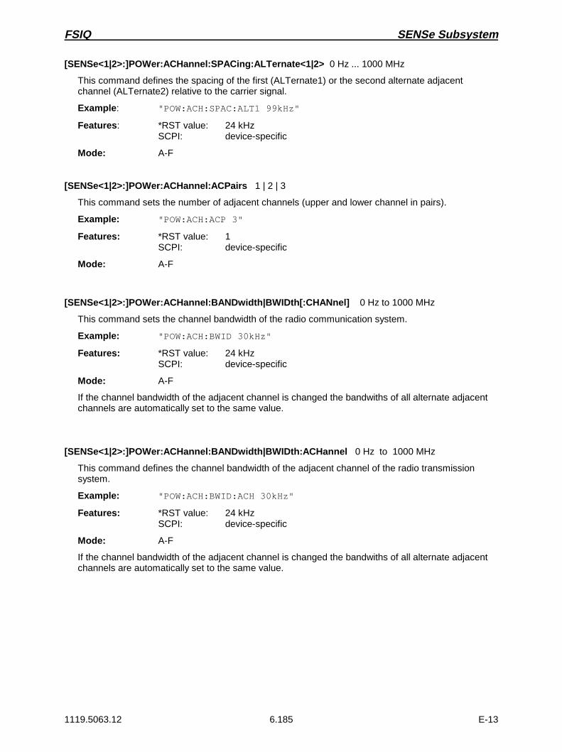
FSIQ SENSe Subsystem
1119.5063.12 6.185 E-13
[SENSe<1|2>:]POWer:ACHannel:SPACing:ALTernate<1|2> 0 Hz ... 1000 MHz
This command defines the spacing of the first (ALTernate1) or the second alternate adjacentchannel (ALTernate2) relative to the carrier signal.
Example: "POW:ACH:SPAC:ALT1 99kHz"
Features: *RST value: 24 kHzSCPI: device-specific
Mode: A-F
[SENSe<1|2>:]POWer:ACHannel:ACPairs 1 | 2 | 3
This command sets the number of adjacent channels (upper and lower channel in pairs).
Example: "POW:ACH:ACP 3"
Features: *RST value: 1SCPI: device-specific
Mode: A-F
[SENSe<1|2>:]POWer:ACHannel:BANDwidth|BWIDth[:CHANnel] 0 Hz to 1000 MHz
This command sets the channel bandwidth of the radio communication system.
Example: "POW:ACH:BWID 30kHz"
Features: *RST value: 24 kHzSCPI: device-specific
Mode: A-F
If the channel bandwidth of the adjacent channel is changed the bandwiths of all alternate adjacentchannels are automatically set to the same value.
[SENSe<1|2>:]POWer:ACHannel:BANDwidth|BWIDth:ACHannel 0 Hz to 1000 MHz
This command defines the channel bandwidth of the adjacent channel of the radio transmissionsystem.
Example: "POW:ACH:BWID:ACH 30kHz"
Features: *RST value: 24 kHzSCPI: device-specific
Mode: A-F
If the channel bandwidth of the adjacent channel is changed the bandwiths of all alternate adjacentchannels are automatically set to the same value.

SENSe Subsystem FSIQ
1119.5063.12 6.186 E-13
[SENSe<1|2>:]POWer:ACHannel:BANDwidth|BWIDth:ALTernate<1|2> 0 Hz to 1000 MHz
This command defines the channel bandwidth of the first/second alternate adjacent channel of theradio transmission system.
Example: "POW:ACH:BWID:ALT2 30kHz"
Features: *RST value: 24 kHzSCPI: device-specific
Mode: A-F
If the channel bandwidth of the alternate adjacent channel no. 1is changed the bandwith of thealternate adjacent channel no. 2 is automatically set to the same value.
[SENSe<1|2>:]POWer:ACHannel:MODE ABSolute | RELative
This command toggles between absolute and relative measurement.
Example: "POW:ACH:MODE REL"
Features: *RST value: ABSoluteSCPI: device-specific
Mode: A-F
For the relative measurement the reference value is set to the currently measured channel power bycommand POW:ACH:REF:AUTO ONCE.
[SENSe<1|2>:]POWer:ACHannel:REFerence:AUTO ONCE
This command sets the reference value to the currently measured channel power.
Example: "POW:ACH:REF:AUTO ONCE"
Features: *RST value: -SCPI: device-specific
Mode: A-F
This command is an event which is why it is not assigned an *RST value and has no query.
[SENSe<1|2>:]POWer:ACHannel:PRESet ACPower | CPOWer | OBANdwidth|OBWidth | CN | CN0
This command selects the type of power measurement.
Example: "POW:ACH:REF:PRES ACP"
Features: *RST value: -SCPI: device-specific
Mode: A-F
[SENSe<1|2>:]POWer:BANDwidth|BWIDth 0 to 100PCT
This command defines the percentage of the power with respect to the total power.
Example: "POW:BWID 95PCT"
Features: *RST value: 99PCTSCPI: device-specific
Mode: A-F
This value defines the occupied bandwidth (measurement POW:ACH:PRES OBW).

FSIQ SENSe Subsystem
1119.5063.12 6.187 E-13
SENSe:ROSCillator Subsystem
This subsystem controls the reference oscillator. The suffix in SENSe<1|2> is not significant in thissubsystem.
COMMAND PARAMETERS UNIT COMMENT
[SENSe<1|2>]
:ROSCillator
:SOURce
:EXTernal
:FREQuency
[:INTernal]
:TUNe
:SAVe
INTernal | EXTernal
<numeric_value>
<numeric_value>
--
HZ
no query
[SENSe<1|2>:]ROSCillator:SOURce INTernal | EXTernal
This command controls selection of the reference oscillator.
Example: "ROSC:SOUR EXT"
Features: *RST value: –SCPI: conforming
Modes: A, VA, BTS, MS
If the external reference oscillator is selected, the reference signal must be connected to the rearpanel of the instrument. *RST has no influence on this setting.
[SENSe<1|2>:]ROSCillator:EXTernal:FREQuency 1MHz to 16MHz
This command defines the frequency of the external reference oscillator.
Example: "ROSC:EXT:FREQ 5MHz"
Features: *RST value: 10MHzSCPI: conforming
Modes: A, VA, BTS, MS
The value of the external reference frequency (1MHz to 16MHz) is rounded in steps of 1MHz.
[SENSe<1|2>:]ROSCillator[:INTernal]:TUNe 0 to 4095
This command defines the value for the tuning of the internal reference oscillator.
Example: "ROSC:TUN 128"
Features: *RST value: –SCPI: device-specific
Modes: A, VA, BTS, MS
The reference oscillator should be tuned only if an error has been detected in the frequency accuracycheck. After PRESET or switching on the instrument, the saved value of the reference frequency isrestored.
[SENSe<1|2>:]ROSCillator[:INTernal]:TUNe:SAVeThis command saves the new value for the tuning of the internal reference oscillator. The factory-setvalue in the EEPROM is overwritten.
Example: "ROSC:TUN:SAV"
Features: *RST value: –SCPI: device-specific
Modes: A, VA, BTS, MS

SENSe Subsystem FSIQ
1119.5063.12 6.188 E-13
SENSe:SWEep Subsystem
This subsystem controls the sweep parameters.
COMMAND PARAMETERS UNIT COMMENT
[SENSe<1|2>]
:SWEep
:TIME
:AUTO
:COUNt
:EGATe
:LEVel
:TYPE
:POLarity
:HOLDoff
:LENGth:SOURce
:GAP
:PRETrigger
:TRGTogap
:LENGth
:SPACing
<numeric_value>
<Boolean>
<numeric_value>
<Boolean>
<numeric_value>
LEVel | EDGE
POSitive|NEGative
<numeric_value>
<numeric_value>EXTernal | RFPower<Boolean>
<numeric_value>
<numeric_value>
<numeric_value>LINear | LOGarithmic
S
--
--
--
V
--
--
S
S----
S
S
S
[SENSe<1|2>:]SWEep:TIME <numeric_value>
This command defines the duration of the sweep.The allowed value range depends on the selected domain and, for frequency domain, on the setresolution bandwith (see Chapter 4, Softkey SWEEP TIME MANUAL).
Example: "SWE:TIME 10s"
Features: *RST value - (AUTO is set to ON)SCPI: conforming
Modes: A, VA-A
If SWEep:TIME is directly programmed, automatic coupling is switched off.
[SENSe<1|2>:]SWEep:TIME:AUTO ON | OFF
This command switches the automatic coupling of the sweep time for the frequency span orbandwidth settings.
Example: "SWE:TIME:AUTO ON"
Features: *RST value: ONSCPI: conforming
Mode: A
If SWEep:TIME is directly programmed, automatic coupling is switched off.

FSIQ SENSe Subsystem
1119.5063.12 6.189 E-13
[SENSe<1|2>:]SWEep:COUNt 0 to 32767
This command defines the number of sweeps started with single sweep.
Example: "SWE:COUNT 64"
Features: *RST value: 0SCPI: conforming
Modes: A, VA-D
This parameter defines the number of sweeps or the number of averaging procedures. In theaverage mode, the value 0 defines a running averaging of measurement data over 10 sweeps.
[SENSe<1|2>:]SWEep:EGATe ON | OFF
This command controls the sweep with the external gate signal.
Example: "SWE:EGAT ON"
Features: *RST value: OFFSCPI: device-specific
Mode: A
[SENSe<1|2>:]SWEep:EGATe:LEVel -5V to +5V
This command determines the threshold for the external gate signal.
Example: "SWE:EGAT:LEV 3V"
Features: *RST value: 2VSCPI: device-specific
Mode: A
If SWEep:TIME is directly programmed, automatic coupling is switched off.
[SENSe<1|2>:]SWEep:EGATe:TYPE LEVel | EDGE
This command sets the type of triggering (level or edge) by the external gate signal.
Example: "SWE:EGAT:TYPE EDGE"
Features: *RST value: EDGESCPI: device-specific
Mode: A
Parameter EGATe:LENGth is not used for level triggering.
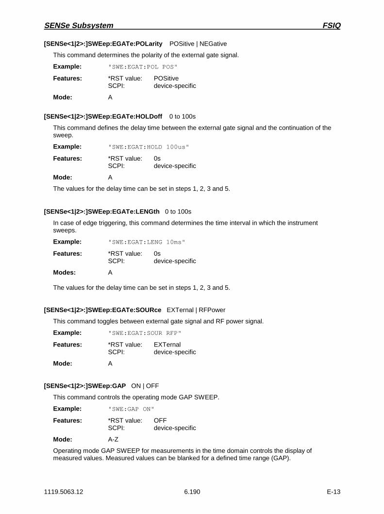
SENSe Subsystem FSIQ
1119.5063.12 6.190 E-13
[SENSe<1|2>:]SWEep:EGATe:POLarity POSitive | NEGative
This command determines the polarity of the external gate signal.
Example: "SWE:EGAT:POL POS"
Features: *RST value: POSitiveSCPI: device-specific
Mode: A
[SENSe<1|2>:]SWEep:EGATe:HOLDoff 0 to 100s
This command defines the delay time between the external gate signal and the continuation of thesweep.
Example: "SWE:EGAT:HOLD 100us"
Features: *RST value: 0sSCPI: device-specific
Mode: A
The values for the delay time can be set in steps 1, 2, 3 and 5.
[SENSe<1|2>:]SWEep:EGATe:LENGth 0 to 100s
In case of edge triggering, this command determines the time interval in which the instrumentsweeps.
Example: "SWE:EGAT:LENG 10ms"
Features: *RST value: 0sSCPI: device-specific
Modes: A
The values for the delay time can be set in steps 1, 2, 3 and 5.
[SENSe<1|2>:]SWEep:EGATe:SOURce EXTernal | RFPower
This command toggles between external gate signal and RF power signal.
Example: "SWE:EGAT:SOUR RFP"
Features: *RST value: EXTernalSCPI: device-specific
Mode: A
[SENSe<1|2>:]SWEep:GAP ON | OFF
This command controls the operating mode GAP SWEEP.
Example: "SWE:GAP ON"
Features: *RST value: OFFSCPI: device-specific
Mode: A-Z
Operating mode GAP SWEEP for measurements in the time domain controls the display ofmeasured values. Measured values can be blanked for a defined time range (GAP).

FSIQ SENSe Subsystem
1119.5063.12 6.191 E-13
[SENSe<1|2>:]SWEep:GAP:PRETrigger 0 to 100s
This command defines the evaluation time for measured values before the pretrigger time(resolution: 50 ns).
Example: "SWE:GAP:PRET 100us"
Features: *RST value: 0sSCPI: device-specific
Mode: A
[SENSe<1|2>:]SWEep:GAP:TRGTogap 0 to 100s
This command defines the time between the pretrigger time and the beginning of the gap (trigger-to-gap time) (resolution: 50 ns).
Example: "SWE:GAP:TRGT 50us"
Features: *RST value: 0sSCPI: device-specific
Mode: A
[SENSe<1|2>:]SWEep:GAP:LENGth 0 to 100s
This command defines the gap length.
Example: "SWE:GAP:LENG 400us"
Features: *RST value: 0sSCPI: device-specific
Mode: A
The gap length can be programmed from 0 to 100s in steps of 1, 2, 3 and 5.
[SENSe<1|2>:]SWEep:SPACing LINear | LOGarithmic
This command toggle between linear and logarithmic sweep.
Example: "SWE:SPAC LOG"
Features: *RST value: LINSCPI: conforming
Modes: A,
The frequency axis is set to linear or logarithmic scaling accordingly.

SOURce Subsystem FSIQ
1119.5063.12 6.192 E-13
SOURce Subsystem
The SOURce subsystem controls the output signals of the analyzer when the option Tracking Generatoris installed (FSE-B8 to FSE-B11). In the split screen mode, a distinction is made between SOURce1(screen A) and SOURce2 (screen B).
COMMAND PARAMETERS UNIT COMMENT
SOURce<1|2>:AM
:STATe:DM
:STATe:FM
:STATe:FREQuency
:OFFSet:POWer
:ALC:SOURce
[:LEVel][:IMMediate]
[:AMPLitude]:OFFSet
<Boolean>
<Boolean>
<Boolean>
<numeric_value>
INTernal | EXTernal
<numeric_value><numeric_value>
HZ
DBMDB
Option Mitlaufgenerator
SOURce<1|2>:AM:STATe ON | OFF
This command switches on or off the external amplitude modulation of the tracking generator.
Example: "SOUR:AM:STAT ON "
Features: *RST-value: OFFSCPI: conforming
Modes: A, VA
External ALC and external I/Q-modulation is switched off, if active. This command is only valid inconjunction with option Tracking Generator.
SOURce<1|2>:DM:STATe ON | OFF
This command switches on or off the external delta modulation of the tracking generator.
Example: "SOUR:DM:STAT ON "
Features: *RST- value: OFFSCPI: conforming
Modes: A, VA
External AM, external ALC, external FM and external frequency offset are switched off, if active. Thiscommand is only valid in conjunction with option Tracking Generator.
SOURce<1|2>:FM:STATe ON | OFF
This command switches on or off the external frequency modulation of the tracking generator.
Example: "SOUR:FM:STAT ON "
Features: *RST-value: OFFSCPI: conforming
Modes: A, VA
External AM, external I/Q-modulation and frequency offset are switched off, if active. This commandis only valid in conjunction with option Tracking Generator.

FSIQ SOURce Subsystem
1119.5063.12 6.193 E-13
SOURce<1|2>:FREQuency:OFFSet -200MHz to 200MHz
This command defines a frequency offset of the tracking generators to the current instrumentfrequency.
Example: "SOUR:FREQ:OFFS "
Features: *RST-value: 0 HzSCPI: conforming
Modes: A, VA
External delta modulation is switched off, if active. This command is only valid in conjunction withoption Tracking Generator.
SOURce<1|2>:POWer:ALC:SOURce INTernal | EXTernal
This command switches on or off the external level control (ALC).
Example: "SOUR:POW:ALC:SOUR INT "
Features: *RST- value: INTSCPI: conforming
Modes: A, VA
External AM and external delta modulation are switched off, if active. This command is only valid inconjunction with option Tracking Generator.
SOURce<1|2>:POWer[:LEVel][:IMMediate][:AMPLitude] -20dBm to 0dBm / Option FSE-B12: -90dBm to 0dBm
This command defines the level of the tracking generator.
Example: "SOUR:POW -20dBm"
Features: *RST- value:SCPI: conforming
Modes: A, VA
This command is only valid in conjunction with option Tracking Generator.
SOURce<1|2>:POWer[:LEVel][:IMMediate]:OFFSet -200dB to +200dB
This command defines a level offset for the tracking generator.
Example: "SOUR:POW:OFFS -10dB"
Features: *RST- value: 0dBSCPI: conforming
Modes: A, VA
This command is only valid in conjunction with option Tracking Generator.

STATus Subsystem FSIQ
1119.5063.12 6.194 E-13
STATus Subsystem
The STATus subsystem contains the commands for the status reporting system (see Chapter 5, Section"Status Reporting System"). *RST does not influence the status registers.
COMMAND PARAMETERS UNIT COMMENT
STATus
:OPERation
[:EVENt]?
:CONDition?
:ENABle
:PTRansition
:NTRansition
:PRESet
--
--
0 to 65535
0 to 65535
0 to 65535
--
--
--
--
--
--
--
:QUEStionable
[:EVENt]?
:CONDition?
:ENABle
:PTRansition
:NTRansition
:POWer
[:EVENt]?
:CONDition?
:ENABle
:PTRansition
:NTRansition
:LIMit
[:EVENt]?
:CONDition?
:ENABle
:PTRansition
:NTRansition
:LMARgin
[:EVENt]?
:CONDition?
:ENABle
:PTRansition
:NTRansition
:SYNC
[:EVENt]?
:CONDition?
:ENABle
:PTRansition
:NTRansition:ACPLimit
[:EVENt]?:CONDition?:ENABle:PTRansition:NTRansition
--
--
0 to 65535
0 to 65535
0 to 65535
--
--
0 to 65535
0 to 65535
0 to 65535
--
--
0 to 65535
0 to 65535
0 to 65535
--
--
0 to 65535
0 to 65535
0 to 65535
--
--
0 to 65535
0 to 65535
0 to 65535
----0 to 655350 to 655350 to 65535
--
--
--
--
--
--
--
--
--
--
--
--
--
--
--
--
--
--
--
--
--
--
--
--
--
----------
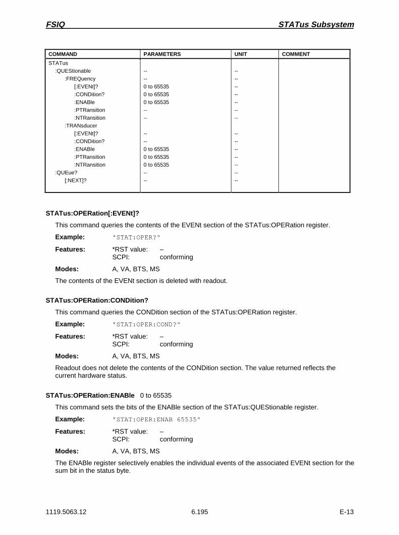
FSIQ STATus Subsystem
1119.5063.12 6.195 E-13
COMMAND PARAMETERS UNIT COMMENT
STATus
:QUEStionable
:FREQuency
[:EVENt]?
:CONDition?
:ENABle
:PTRansition
:NTRansition
:TRANsducer
[:EVENt]?
:CONDition?
:ENABle
:PTRansition
:NTRansition
:QUEue?
[:NEXT]?
--
--
0 to 65535
0 to 65535
0 to 65535
--
--
--
--
0 to 65535
0 to 65535
0 to 65535
--
--
--
--
--
--
--
--
--
--
--
--
--
--
--
--
STATus:OPERation[:EVENt]?
This command queries the contents of the EVENt section of the STATus:OPERation register.
Example: "STAT:OPER?"
Features: *RST value: –SCPI: conforming
Modes: A, VA, BTS, MS
The contents of the EVENt section is deleted with readout.
STATus:OPERation:CONDition?
This command queries the CONDition section of the STATus:OPERation register.
Example: "STAT:OPER:COND?"
Features: *RST value: –SCPI: conforming
Modes: A, VA, BTS, MS
Readout does not delete the contents of the CONDition section. The value returned reflects thecurrent hardware status.
STATus:OPERation:ENABle 0 to 65535
This command sets the bits of the ENABle section of the STATus:QUEStionable register.
Example: "STAT:OPER:ENAB 65535"
Features: *RST value: –SCPI: conforming
Modes: A, VA, BTS, MS
The ENABle register selectively enables the individual events of the associated EVENt section for thesum bit in the status byte.

STATus Subsystem FSIQ
1119.5063.12 6.196 E-13
STATus:OPERation:PTRansition 0 to 65535
This command sets the edge detectors of all bits of the STATus:OPERation register from 0 to 1 forthe transitions of the CONDition bit.
Example: "STAT:OPER:PTR 65535"
Features: *RST value: –SCPI: conforming
Modes: A, VA, BTS, MS
STATus:OPERation:NTRansition 0 to 65535
This command sets the edge detectors of all bits of the STATus:OPERation register from 1 to 0 forthe transitions of the CONDition bit.
Example: "STAT:OPER:NTR 65535"
Features: *RST value: –SCPI: conforming
Modes: A, VA, BTS, MS
STATus:PRESet
This command resets the edge detectors and ENABle parts of all registers to a defined value. AllPTRansition parts are set to FFFFh, i.e., all transitions from 0 to 1 are detected. All NTRansitionparts are set to 0, i.e., a transition from 1 to 0 in a CONDition bit is not detected. The ENABle part ofthe STATus:OPERation and STATus:QUEStionable registers are set to 0, i.e., all events in theseregisters are not passed on.
Example: "STAT:PRES"
Features: *RST value: –SCPI: conforming
Modes: A, VA, BTS, MS
STATus:QUEStionable[:EVENt]?
This command queries the contents of the EVENt section of the STATus:QUEStionable register.
Example: "STAT:QUES?"
Features: *RST value: –SCPI: conforming
Modes: A, VA, BTS, MS
Readout deletes the contents of the EVENt section.
STATus:QUEStionable:CONDition?
This command queries the CONDition section of the STATus:QUEStionable register.
Example: "STAT:QUES:COND?"
Features: *RST value: –SCPI: conforming
Modes: A, VA, BTS, MS
Readout does not delete the contents of the CONDition section.

FSIQ STATus Subsystem
1119.5063.12 6.197 E-13
STATus:QUEStionable:ENABle 0 to 65535
This command sets the bits of the ENABle section of the STATus-QUEStionable register.
Example: "STAT:QUES:ENAB 65535"
Features: *RST value: –SCPI: conforming
Modes: A, VA, BTS, MS
The ENABle register selectively enables the individual events of the associated EVENt section for thesum bit in the status byte.
STATus:QUEStionable:PTRansition 0 to 65535
This command sets the edge detectors of all bits of the STATus:OPERation register from 0 to 1 forthe transitions of the CONDition bit.
Example: "STAT:QUES:PTR 65535"
Features: *RST value: –SCPI: conforming
Modes: A, VA, BTS, MS
STATus:QUEStionable:NTRansition 0 to 65535
This command sets the edge detectors of all bits of the STATus:OPERation register from 1 to 0 forthe transitions of the CONDition bit.
Example: "STAT:QUES:NTR 65535"
Features: *RST value: –SCPI: conforming
Modes: A, VA, BTS, MS
STATus:QUEStionable:POWer[:EVENt]?
This command queries the contents of the EVENt section of the STATus:QUEStionable:POWerregister.
Example: "STAT:QUES?"
Features: *RST value: –SCPI: conforming
Modes: A, VA, BTS, MS
Readout deletes the contents of the EVENt section.
STATus:QUEStionable:POWer:CONDition?
This command queries the content of the CONDition section of the STATus:QUEStionable:POWerregister.
Example: "STAT:QUES:COND?"
Features: *RST value: –SCPI: conforming
Modes: A, VA, BTS, MS
Readout does not delete the contents of the CONDition section.
STATus Subsystem FSIQ
1119.5063.12 6.198 E-13
STATus:QUEStionable:POWer:ENABle 0 to 65535
This command sets the bits of the ENABle section of the STATus:QUEStionable:POWer register.
Example: "STAT:QUES:ENAB 65535"
Features: *RST value: –SCPI: conforming
Modes: A, VA, BTS, MS
The ENABle register selectively enables the individual events of the associated EVENt section for thesum bit in the status byte.
STATus:QUEStionable:POWer:PTRansition 0 to 65535
This command sets the edge detectors of all bits of the STATus:QUEStionable:POWer register from0 to 1 for the transitions of the CONDition bit.
Example: "STAT:QUES:PTR 65535"
Features: *RST-value: –SCPI: conforming
Modes: A, VA, BTS, MS
STATus:QUEStionable:POWer:NTRansition 0 to 65535
This command sets the edge detectors of all bits of the STATus:QUEStionable:POWer register from1 to 0 for the transitions of the CONDition bit.
Example: "STAT:QUES:NTR 65535"
Features: *RST value: –SCPI: conforming
Modes: A, VA, BTS, MS
STATus:QUEStionable:LIMit[:EVENt]?
This command queries the contents of the EVENt section of the STATus:QUEStionable:LIMitregister.
Example: "STAT:QUES?"
Features: *RST value: –SCPI: device-specific
Modes: A, VA, BTS, MS
Readout deletes the contents of the EVENt section.
STATus:QUEStionable:LIMit:CONDition?
This command queries the contents of the CONDition section of the STATus:QUEStionable:LIMitregister.
Example: "STAT:QUES:COND?"
Features: *RST value: –SCPI: device-specific
Modes: A, VA, BTS, MS
Readout does not delete the contents of the CONDition section.

FSIQ STATus Subsystem
1119.5063.12 6.199 E-13
STATus:QUEStionable:LIMit:ENABle 0 to 65535
This command sets the bits of the ENABle section of the STATus:QUEStionable register.
Example: "STAT:QUES:ENAB 65535"
Features: *RST value: –SCPI: device-specific
Modes: A, VA, BTS, MS
The ENABle register selectively enables the individual events of the associated EVENt section for thesum bit in the status byte.
STATus:QUEStionable:LIMit:PTRansition 0 to 65535
This command sets the edge detectors of all bits of the STATus:QUEStionable:LIMit register from 0to 1 for the transitions of the CONDition bit.
Example: "STAT:QUES:PTR 65535"
Features: *RST value: –SCPI: device-specific
Modes: A, VA, BTS, MS
STATus:QUEStionable:LIMit:NTRansition 0 to 65535
This command sets the edge detectors of all bits of the STATus:QUEStionable:LIMit register from 1to 0 for the transitions of the CONDition bit.
Example: "STAT:QUES:NTR 65535"
Features: *RST value: –SCPI: device-specific
Modes: A, VA, BTS, MS
STATus:QUEStionable:LMARgin[:EVENt]?
This command queries the contents of the EVENt section of the STATus:QUEStionable:LMARginregister.
Example: "STAT:QUES?"
Features: *RST value: –SCPI: device-specific
Modes: A, VA, BTS, MS
Readout deletes the contents of the EVENt section.
STATus:QUEStionable:LMARgin:CONDition?
This command queries the contents of the CONDition section of theSTATus:QUEStionable:LMARgin register.
Example: "STAT:QUES:COND?"
Features: *RST value: –SCPI: device-specific
Modes: A, VA, BTS, MS
Readout does not delete the contents of the CONDition section.

STATus Subsystem FSIQ
1119.5063.12 6.200 E-13
STATus:QUEStionable:LMARgin:ENABle 0 to 65535
This command sets the bits of the ENABle section of the STATus:QUEStionable:LMARgin register.
Example: "STAT:QUES:ENAB 65535"
Features: *RST value: –SCPI: device-specific
Modes: A, VA, BTS, MS
The ENABle register selectively enables the individual events of the associated EVENt section for thesum bit in the status byte.
STATus:QUEStionable:LMARgin:PTRansition 0 to 65535
This command sets the edge detectors of all bits of the STATus:QUEStionable: LMARgin registerfrom 0 to 1 for the transitions of the CONDition bit.
Example: "STAT:QUES:PTR 65535"
Features: *RST value: –SCPI: device-specific
Modes: A, VA, BTS, MS
STATus:QUEStionable:LMARgin:NTRansition 0 to 65535
This command sets the edge detectors of all bits of the STATus:QUEStionable: LMARgin registerfrom 1 to 0 for the transitions of the CONDition bit.
Example: "STAT:QUES:NTR 65535"
Features: *RST value: –SCPI: device-specific
Modes: A, VA, BTS, MS
STATus:QUEStionable:SYNC[:EVENt]?
This command queries the contents of the EVENt section of the STATus:QUEStionable:SYNCregister.
Example: "STAT:QUES?"
Features: *RST value: –SCPI: device-specific
Modes: A, VA, BTS, MS
Readout deletes the contents of the EVENt section.
STATus:QUEStionable:SYNC:CONDition?
This command queries the contents of the CONDition section of the STATus:QUEStionable:SYNCregister.
Example: "STAT:QUES:COND?"
Features: *RST value: –SCPI: device-specific
Modes: A, VA, BTS, MS
Readout does not delete the contents of the CONDition section.
FSIQ STATus Subsystem
1119.5063.12 6.201 E-13
STATus:QUEStionable:SYNC:ENABle 0 to 65535
This command sets the bits of the ENABle section of the STATus:QUEStionable: SYNC register.
Example: "STAT:QUES:ENAB 65535"
Features: *RST value: –SCPI: device-specific
Modes: A, VA, BTS, MS
The ENABle register selectively enables the individual events of the associated EVENt section for thesum bit in the status byte.
STATus:QUEStionable:SYNC:PTRansition 0 to 65535
This command sets the edge detectors of all bits of the STATus:QUEStionable: SYNC register from0 to 1 for the transitions of the CONDition bit.
Example: "STAT:QUES:PTR 65535"
Features: *RST value: –SCPI: device-specific
Modes: A, VA, BTS, MS
STATus:QUEStionable:SYNC:NTRansition 0 to 65535
This command sets the edge detectors of all bits of the STATus:QUEStionable: SYNC register from1 to 0 for the transitions of the CONDition bit.
Example: "STAT:QUES:NTR 65535"
Features: *RST value: –SCPI: device-specific
Modes: A, VA, BTS, MS
STATus:QUEStionable:ACPLimit[:EVENt]?
This command queries the contents of the EVENt section of the STATus:QUEStionable:ACPLimitregister.
Example: "STAT:QUES:ACPL?"
Features: *RST value: –SCPI: device-specific
Modes: A, VA, BTS, MS
Readout deletes the contents of the EVENt section.
STATus:QUEStionable:ACPLimit:CONDition?
This command queries the contents of the CONDition section of theSTATus:QUEStionable:ACPLimit register.
Example: "STAT:QUES:ACPL:COND?"
Features: *RST value: –SCPI: device-specific
Modes: A, VA, BTS, MS
Readout does not delete the contents of the CONDition section.
STATus Subsystem FSIQ
1119.5063.12 6.202 E-13
STATus:QUEStionable:ACPLimit:ENABle 0 to 65535
This command sets the bits of the ENABle section of the STATus:QUEStionable:ACPLimit register.
Example: "STAT:QUES:ACPL:ENAB 65535"
Features: *RST value: –SCPI: device-specific
Modes: A, VA, BTS, MS
The ENABle register selectively enables the individual events of the associated EVENt section for thesum bit in the status byte.
STATus:QUEStionable:ACPLimit:PTRansition 0 to 65535
This command sets the edge detectors of all bits of the STATus:QUEStionable: ACPLimit registerfrom 0 to 1 for the transitions of the CONDition bit.
Example: "STAT:QUES:ACPL:PTR 65535"
Features: *RST value: –SCPI: device-specific
Modes: A, VA, BTS, MS
STATus:QUEStionable:ACPLimit:NTRansition 0 to 65535
This command sets the edge detectors of all bits of the STATus:QUEStionable: ACPLimit registerfrom 1 to 0 for the transitions of the CONDition bit.
Example: "STAT:QUES:ACPL:NTR 65535"
Features: *RST value: –SCPI: device-specific
Modes: A, VA, BTS, MS
STATus:QUEStionable:FREQuency[:EVENt]?
This command queries the contents of the EVENt section of the STATus:QUEStionableFREQuencyregister.
Example: "STAT:QUES:FREQ?"
Features: *RST value: –SCPI: device-specific
Modes: A, VA, BTS, MS
Readout deletes the contents of the EVENt section.
STATus:QUEStionable:FREQuency:CONDition?
This command queries the contents of the CONDition section of theSTATus:QUEStionable:FREQuency register.
Example: "STAT:QUES:FREQ:COND?"
Features: *RST value: –SCPI: device-specific
Modes: A, VA, BTS, MS
Readout does not delete the contents of the CONDition section.
FSIQ STATus Subsystem
1119.5063.12 6.203 E-13
STATus:QUEStionable:FREQuency:ENABle 0 to 65535
This command sets the bits of the ENABle section of the STATus:QUEStionable:FREQuencyregister.
Example: "STAT:QUES:FREQ:ENAB 65535"
Features: *RST value: –SCPI: device-specific
Modes: A, VA, BTS, MS
The ENABle register selectively enables the individual events of the associated EVENt section for thesum bit in the status byte.
STATus:QUEStionable:FREQuency:PTRansition 0 to 65535
This command sets the edge detectors of all bits of the STATus:QUEStionable:FREQuency registerfrom 0 to 1 for the transitions of the CONDition bit.
Example: "STAT:QUES:FREQ:PTR 65535"
Features: *RST value: –SCPI: device-specific
Modes: A, VA, BTS, MS
STATus:QUEStionable:FREQuency:NTRansition 0 to 65535
This command sets the edge detectors of all bits of the STATus:QUEStionable:FREQuency registerfrom 1 to 0 for the transitions of the CONDition bit.
Example: "STAT:QUES:FREQ:NTR 65535"
Features: *RST value: –SCPI: device-specific
Modes: A, VA, BTS, MS
STATus:QUEStionable:TRANsducer[:EVENt]?
This command queries the contents of the EVENt section of theSTATus:QUEStionable:TRANsducer register.
Example: "STAT:QUES:TRAN?"
Features: *RST value: –SCPI: device-specific
Modes: A, VA, BTS, MS
Readout deletes the contents of the EVENt section.
STATus:QUEStionable:TRANsducer:CONDition?
This command queries the contents of the CONDition section of theSTATus:QUEStionable:FREQuency register.
Example: "STAT:QUES:TRAN:COND?"
Features: *RST value: –SCPI: device-specific
Modes: A, VA, BTS, MS
Readout does not delete the contents of the CONDition section.

STATus Subsystem FSIQ
1119.5063.12 6.204 E-13
STATus:QUEStionable:TRANsducer:ENABle 0 to 65535
This command sets the bits of the ENABle section of the STATus:QUEStionable:TRANsducerregister.
Example: "STAT:QUES:TRAN:ENAB 65535"
Features: *RST value: –SCPI: device-specific
Modes: A, VA, BTS, MS
The ENABle register selectively enables the individual events of the associated EVENt section for thesum bit in the status byte.
STATus:QUEStionable:TRANsducer:PTRansition 0 to 65535
This command sets the edge detectors of all bits of the STATus:QUEStionable:TRANsducer registerfrom 0 to 1 for the transitions of the CONDition bit.
Example: "STAT:QUES:TRAN:PTR 65535"
Features: *RST value: –SCPI: device-specific
Modes: A, VA, BTS, MS
STATus:QUEStionable:TRANsducer:NTRansition 0 to 65535
This command sets the edge detectors of all bits of the STATus:QUEStionable:TRANsducer registerfrom 1 to 0 for the transitions of the CONDition bit.
Example: "STAT:QUES:TRAN:NTR 65535"
Features: *RST value: –SCPI: device-specific
Modes: A, VA, BTS, MS
STATus:QUEue[:NEXT]?
This command queries the earliest entry to the error queue, thus deleting it.
Example: "STAT:QUE?"
Features: *RST value: –SCPI: conforming
Modes: A, VA, BTS, MS
Positive error numbers indicate device-specific errors, negative error numbers are error messagesdefined by SCPI (cf. Chapter 9). If the error queue is empty, the error number 0, "no error", isreturned. This command is identical with the command SYSTem:ERRor.

FSIQ SYSTem Subsystem
1119.5063.12 6.205 E-13
SYSTem Subsystem
This subsystem comprises a series of commands for general functions.
COMMAND PARAMETERS UNIT COMMENT
SYSTem
:COMMunicate
:GPIB
[:SELF]
:ADDRess
:RTERminator
:RDEVice<1|2>
:ADDRess
:SERial<1|2>
:CONTrol
:DTR
:RTS
[:RECeive]
:BAUD
:BITS
:PARity
[:TYPE]
:SBITs
:PACE
:PRINter1|2>
:ENUMerate
[:NEXT]?
:FIRSt?
:SELect
:DATE
:DISPlay
:UPDate
:ERRor?
:PASSword
[:CENable]
:PRESet
:COMPatible
:SET:SPEaker<1|2>
:VOLume:TIME
:VERSion?
:BINFo?
0 to 30
LFEoi | EOI
0 to 30
IBFull | OFF
IBFull | OFF
<numeric_value>
7 | 8
EVEN | ODD | NONE
1 | 2
XON | NONE
<printer_name>
<num>, <num>, <num>
ON | OFF
--
<string>
--
FSE | OFF
<block>
<numeric_value>0 to 23, 0 to 59, 0 to 59
--
--
--
--
--
--
--
--
--
--
----
--
--
query only
query only
query only
no query
no query
query only
query only
SYSTem:COMMunicate:GPIB[:SELF]:ADDRess 0 to 30
This command changes the IEC/IEEE-bus address of the unit.
Example: "SYST:COMM:GPIB:ADDR 18"
Features: *RST value: - (no influence on this parameter)SCPI: conforming
Modes: A, VA, BTS, MS
SYSTem Subsystem FSIQ
1119.5063.12 6.206 E-13
SYSTem:COMMunicate:GPIB[:SELF]:RTERminator LFEOI | EOI
This command changes the delimiter.
Example: "SYST:COMM:GPIB:RTER EOI"
Features: *RST value: LFEOISCPI: device-specific
Modes: A, VA, BTS, MS
The instrument contains a DMA-channel for communication via IEC-bus. This ensures maximumspeed for the transfer of commands and data. The parser for command decoding integrated in theinstrument is, however, only activated by the delimiter when the command is completely transferred.In order to make this possible for the transfer of binary data, too (e. g. trace data which areretransferred into the instrument), the delimiter recognition must be switched to the EOI signal priorto the transfer. Output of binary data from the instrument does not require such a switching.
SYSTem:COMMunicate:GPIB:RDEVice<1|2>:ADDRess 0 to 30
This command changes the IEC/IEEE-bus address of the unit which is selected as hardcopy device1 or 2, provided that the IEC/IEEE-bus interface of this unit is set as an interface.
Example: "SYST:COMM:GPIB:RDEV2:ADDR 5"
Features: *RST value: 4SCPI: conforming
Modes: A, VA, BTS, MS
SYSTem:COMMunicate:SERial<1|2>:CONTrol:DTR IBFull | OFFSYSTem:COMMunicate:SERial<1|2>:CONTrol:RTS IBFull | OFF
These commands switch the hardware handshake procedure for the given serial interface off (OFF)or on (IBFull).
Examples: "SYST:COMM:SER:CONT:DTR OFF""SYST:COMM:SER2:CONT:RTS IBF"
Features: *RST value: OFFSCPI: conforming
Modes: A, VA, BTS, MS
The two commands have the same meaning. SERial1 and SERial 2 correspond to device COM1andCOM2, respectively.
SYSTem:COMMunicate:SERial<1|2>[:RECeive]:BAUD 75 | 150 | 300 | 600 | 1200 | 2400 | 9600
This command sets the transmission speed for the given serial interface.
Example: "SYST:COMM:SER:BAUD 2400"
Features: *RST value: 9600SCPI: conforming
Modes: A, VA, BTS, MS
SERial1 and SERial 2 correspond to device interface COM1 and COM2, respectively. Permissiblevalues are 75 Baud, 150 Baud, 300 Baud, 600 Baud, 1200 Baud, 2400 Baud, 4800 Baud, 9600Baud.
FSIQ SYSTem Subsystem
1119.5063.12 6.207 E-13
SYSTem:COMMunicate:SERial<1|2>[:RECeive]:BITS 7 | 8
This command defines the number of data bits per data word for the given serial interface.
Example: "SYST:COMM:SER2:BITS 7"
Features: *RST value: 8SCPI: conforming
Modes: A, VA, BTS, MS
SERial1 and SERial 2 correspond to device interface COM1 and COM2, respectively.
SYSTem:COMMunicate:SERial<1|2>[:RECeive]:PARity[:TYPE] EVEN | ODD | NONE
This command defines the parity check for the given serial interface.
Example: "SYST:COMM:SER:PAR EVEN"
Features: *RST value: NONESCPI: conforming
Modes: A, VA, BTS, MS
SERial1 and SERial 2 correspond to device interface COM1 and COM2, respectively. Permissiblevalues are: EVEN even parity
ODD odd parityNONE no parity check.
SYSTem:COMMunicate:SERial<1|2>[:RECeive]:SBITs 1|2
This command defines the number of stopbits per data word for the given serial interface.
Example: "SYST:COMM:SER:SBITs 2"
Features: *RST value: 1SCPI: conforming
Modes: A, VA, BTS, MS
SERial1 and SERial 2 correspond to device interface COM1 and COM2, respectively.
SYSTem:COMMunicate:SERial<1|2>[:RECeive]:PACE XON | NONE
This command switches on or off the software handshake for the given serial interface.
Example: "SYST:COMM:SER:PACE XON"
features: *RST value: NONESCPI: conforming
Modes: A, VA, BTS, MS
SERial1 and SERial 2 correspond to device interface COM1 and COM2, respectively.
SYSTem Subsystem FSIQ
1119.5063.12 6.208 E-13
SYSTem:COMMunicate:PRINter<1|2>:ENUMerate:FIRSt?
This command queries the name of the first printer (in the list of printers) under Windows NT.
The names of other installed printers can be queried with command SYSTem:COMMunicate:PRINter:ENUMerate:NEXT?.
If no printer is configured an empty string is output. The numeric suffix in PRINter<1|2> is notsignificant.
Example: "SYST:COMM:PRIN:ENUM:FIRS?"
Features: *RST value: -SCPI: device-specific
Modes: A, VA, BTS, MS
SYSTem:COMMunicate:PRINte<1|2>r:ENUMerate:NEXT?
This command queries the name of the next printer installed under Windows NT.
This command can only be sent after command SYSTem:COMMunicate:PRINter:ENUMerate:FIRSt?.
An empty string is output after all printer names have been output. The numeric suffix inPRINter<1|2> is not significant.
Example: "SYST:COMM:PRIN:ENUM:NEXT?"
Features: *RST value: -SCPI: device-specific
Modes: A, VA, BTS, MS
SYSTem:COMMunicate:PRINter<1|2>:SELect <printer_name>
This command selects one of the printers installed under Windows NT.
The name of the first printer is queried with FIRSt?. After that the names of other installed printerscan be queried with NEXT?. The numeric suffix in PRINter<1|2> selects the device.
Parameter: <printer_name> ::= string which has been queried with commandsSYSTem:COMMunicate :PRINter:ENUMerate:FIRSt? and NEXT?.
Example: "SYST:COMM:PRIN:SEL ‘HP_DESKJET660’"
Features: *RST value: -SCPI: device-specific
Modes: A, VA, BTS, MS
SYSTem:DATE 1980 to 2099, 1 to 12, 1 to 31
This command is used to enter the date for the internal calendar.
Example: " SYST:DATE 1994,12,1"
Features: *RST value: –SCPI: conforming
Modes: A, VA, BTS, MS
The sequence of entry is year, month, day.

FSIQ SYSTem Subsystem
1119.5063.12 6.209 E-13
SYSTem:DISPlay:UPDate ON | OFF
This command switches on or off the update of all display elements.
Example: " SYST:DISP:UPD ON
Features: *RST value: OFFSCPI: device specific
Modes: A, VA, BTS, MS
SYSTem:ERRor?
This command queries the earliest entry to the error queue, thus deleting it. .
Example: "SYST:ERR?"
Features: *RST value: –SCPI: conforming
Modes: A, VA, BTS, MS
Positive error numbers indicate device-specific errors, negative error numbers are error messagesdefined by SCPI (cf. Chapter 9). If the error queue is empty, the error number 0, "no error", isreturned. This command is identical with the command STATus:QUEue:NEXT?. This command is aquery which is why it is not assigned an *RST value.
SYSTem:PASSword[:CENable] <string>
This command enables access to the service functions by means of the password.
Example: "SYST:PASS ’XXXX’"
Features: *RST value: –SCPI: conforming
Modes: A, VA, BTS, MS
This command is an event which is why it is not assigned an *RST value and has no query.
SYSTem:PRESet
This command triggers an instrument reset.
Example: "SYST:PRES"
Features: *RST value: –SCPI: conforming
Modes: A, VA, BTS, MS
The effect of this command corresponds to that of the PRESET key with manual control or to the*RST command.
SYSTem:PRESet:COMPatible FSE | OFF
This command determines whether the unit is FSE-compatible after a preset. Following a preset, anFSIQ is not in the same mode as an FSE. With compatibility, FSIQ has the same default settings asFSE after a preset.
Example: "SYST:PRES:COMP FSE"
Features: *RST value: OFFSCPI: device-specific
Mode: A, VA, BTS, MS

SYSTem Subsystem FSIQ
1119.5063.12 6.210 E-13
SYSTem:SET <block>
The query SYSTem:SET? causes the data of the current instrument setting to be transmitted to thecontroller in binary form (SAVE function). The data can be read back into the instrument (RECALLfunction) by means of command SYSTem:SET <block>. If the data records are stored on theinstrument harddisk with SAVE/RECALL (MMEMory:STORe bzw. MMEMory:LOAD), it is possible tostore the data in an external computer by means of SYSTem:SET.
Example: "SYST:SET "
Features: *RST value: –SCPI: conforming
Modes: A, VA, BTS, MS
The receive terminator has to be set to EOI to ensure reliable transfer of data (settingSYST:COMM:GPIB:RTER EOI).
SYSTem:SPEaker<1|2>:VOLume 0 to 1
This command sets the volume of the built-in loudspeaker for demodulated signals. The numericsuffix selects the measurement window.
Example: "SYST:SPE:VOL 0.5"
Features: *RST value: 0SCPI: device-specific
Modes: A
The value 0 is the lowest volume, the value 1 is the highest volume.
SYSTem:TIME 0 to 23, 0 to 59, 0 to 59
This command sets the internal clock.
Example: "SYST:TIME 12,30,30"
Features: *RST value: –SCPI: conforming
Modes: A, VA, BTS, MS
The sequence of entry is hour, minute, second.
SYSTem:VERSion?This command queries the number of the SCPI version, which is relevant for the instrument.
Example: "SYST:VERS?"
Features: *RST value: –SCPI: conforming
Modes: A, VA, BTS, MS
This command is a query which is why it is not assigned an *RST value.
SYSTem:BINFo?This command queries all present modules with variant, main index and subordinate index. Entriesare separated by commas.
Return format: module1, model1, main index1, subordinate index1, module2, model 2, main index2,subordinate index2, module3,...,moduleN, modelN, main indexN, subordinate indexN
Example: "SYST:BINF?"
Features: *RST value: –SCPI: device-specific
Modes: A, VA, BTS, MS

FSIQ TRACe Subsystem
1119.5063.12 6.211 E-13
TRACe Subsystem
The TRACe subsystem controls access to the instrument’s internal trace memory.
COMMAND PARAMETERS UNIT COMMENT
TRACe
[:DATA]
:COPY
TRACE1 | TRACE2 | TRACE3 | TRACE4,<block>|<numeric_value>...
TRACE1|TRACE2|TRACE3|TRACE4,TRACE1|TRACE2|TRACE3|TRACE4
-
TRACe[:DATA] TRACE1| TRACE2| TRACE3| TRACE4, <block> | <numeric_value>
This command transfers trace data from the controller to the instrument, the query reads trace dataout of the instrument.
Example: "TRAC TRACE1,"+A$ (A$: data list in the current format)"TRAC? TRACE1"
Features: *RST value: -SCPI: conforming
Modes: A, VA, BTS, MS
The trace data are transferred in the current format (corresponding to the command FORMatASCii|REAL). The device-internal trace memory is addressed using the trace names ’TRACE1’ to’TRACE4’.The parameter of the query is the trace name TRACE1 to TRACE4, it indicates which trace memorywill be read out.The transfer of trace data from the controller to the instrument takes place by indicating the tracename and then the data to be transferred. In ASCII format, these data are values separated bycommas. If the transfer takes place using the format real (REAL 32), the data are transferred in blockformat (see FORMat subsystem).
Saving and recalling trace data together with the device settings to/from the device-internal hard diskor to/from a floppy is controlled via the commands "MMEMory:STORe:STATe" and"MMEMory:LOAD:STATe" respectively. Trace data are selected with"MMEMory:SELect[:ITEM]:ALL" or ""MMEMory:SELect[:ITEM]:TRACe". Trace data inASCII format (ASCII FILE EXPORT) are exported with the command "MMEM:STORe:TRACe".
The transfer format for the trace data depends on the instrument setting
Analyzer mode (span >0 and zero span):
500 results are output in the unit selected for display.
Note: With AUTO PEAK detector, only positive peak values can be read out.Trace data can be read into instrument with logarithmic display only in dBm, withlinear display only in volts.
FORMAT REAL,32 is to be used as format for binary transmission.

TRACe Subsystem FSIQ
1119.5063.12 6.212 E-13
Vector analyzer mode, digital demodulation
The number of data transferred (except for the symbol table) is determined by the followingformula
number of results = result length * points per symbol
Max. 6400 results can be transferred (for example result length 1600, points per symbol 4).
In all cartesian diagrams (MAGNITUDE CAP BUFFER, MAGNITUDE, PHASE,FREQUENCY, REAL/IMAG, EYE[I], EYE[Q], ERROR VECT MAGNITUDE) test data aretransferred in the unit selected for display.
FORMAT REAL,32 is to be used for binary transmission.
Note: In the case of the eye pattern, results are simply superimposed in the display, iethe EYE representation is the same as the REAL/IMAG representation.
In the polar diagrams (POLAR CONSTELL, POLAR VECTOR) the real and the imaginarycomponent are transferred as a pair for each result.
FORMAT REAL,32 is to be used for binary transmission.
With the SYMB TABLES / ERRORS setting, the displayed symbols can be read out astraces. Trace assignment is as follows:
Full screen Trace 1Split screen, screen A: Trace 1Split screen, screen B: Trace 2
One byte (8 bits) is read out for each symbol.
FORMAT UINT,8 is to be used for binary transmission.
Vector analyzer mode, analog demodulation
The number of results transferred depends on the SWEEP TIME and DEMOD BWsettings. Max. 5000 and min. 10 points are available. The unit for the results depends onthe selected demodulation:
AM unit %FM unit HzPM unit rad or deg
FORMAT REAL,32 is to be used for binary data transmission.
TRACe:COPY TRACe:COPY TRACE1| TRACE2| TRACE3| TRACE4 , TRACE1| TRACE2| TRACE3| TRACE4
This command copies data from one trace to another. The second operand designates the source,the first operand the destination of the data to be copied.
Example: "TRAC:COPY TRACE1,TRACE2"
Features: *RST value:SCPI: conforming
Modes: A, VA, BTS, MS
This command is an event and therefore has no query and no *RST value assigned.

FSIQ TRIGger Subsystem
1119.5063.12 6.213 E-13
TRIGger Subsystem
The TRIGger subsystem is used to synchronize instrument actions with events. This makes it possibleto control and synchronize the start of a sweep. An external trigger signal can be fed to the connector atthe rear panel of the instrument. In split screen mode, a distinction is made between TRIGger1 (screenA) and TRIGger2 (screen B).
COMMAND PARAMETERS UNIT COMMENT
TRIGger<1|2>
[:SEQuence]
:SOURce
:LEVel
[:EXTernal]
:VIDeo
:AF
:HOLDoff
:SLOPe
:SYNChronize
:ADJust
:FRAMe
:AUTO
:SLOT
:AUTO
:SOURCe
IMMediate | LINE | EXTernal |VIDeo |RFPower | AF
<numeric_value>
<numeric_value>
<numeric_value>
<numeric_value>
POSitive|NEGative
<numeric_value>
ONCE
<numeric_value>
ONCE
FRAMe | TSC
--
V|MV|UV
PCT
PCT
S
--
s
s
Option FSE-K11
Option FSE-K11
Option FSE-K11
Option FSE-K11
Option FSE-K11or FSE-K10
TRIGger<1|2>[:SEQuence]:SOURce IMMediate | LINE | EXTernal | VIDeo | RFPower | AF
This command selects the trigger source for the start of a sweep.
Example: "TRIG:SOUR EXT"
Features: *RST value: IMMediateSCPI: conforming
Modes: A, VA, BTS, MS
The value IMMediate corresponds to the "FREE RUN" setting. Selecting the parameter AF ispossible only in the vector signal analysis mode with analog demodulation.
TRIGger<1|2>[:SEQuence]:LEVel[:EXTernal] –5.0 to +5.0V
This command sets the level of the external trigger source.
Example: "TRIG:LEV 2V"
Features: *RST value: –5.0VSCPI: conforming
Modes: A, VA, BTS, MS
TRIGger<1|2>[:SEQuence]:LEVel:VIDeo 0 to 100PCT
This command sets the level of the video trigger source.
Example: "TRIG:LEV:VID 50PCT"
Features: *RST value: 50 PCTSCPI: device-specific
Modes: A, VA, BTS, MS

TRIGger Subsystem FSIQ
1119.5063.12 6.214 E-13
TRIGger<1|2>[:SEQuence]:LEVel:AF -120 to +120PCT
This command defines the level of the demodulated trigger source.
Example: "TRIG:LEV:AF 50PCT"
Features: *RST value: 0 PCTSCPI: device specific
Mode: VA-A
TRIGger<1|2>[:SEQuence]:HOLDoff -100 to 100s
This command defines the length of the trigger delay.
Example: "TRIG:HOLD 500us"
Features: *RST value: 0sSCPI: conforming
Modes: A, VA
A negative delay time (pretrigger) can be set in the time domain (SPAN < 0 Hz) only. The maximumpermissible range and the maximum effective resolution of the pretrigger are limited by the setsweep time (max range= - 499/500 x sweep time; max. resolution = sweep time/500). Pretriggeringis not possible when the rms or the average detector is activated.
TRIGger<1|2>[:SEQuence]:SLOPe POSitive | NEGative
This command selects the slope of the trigger signal.
Example: "TRIG:SLOP NEG"
Features: *RST value: POSitiveSCPI: conforming
Modes: A, VA, BTS, MS
The selected trigger slope applies to all trigger signal sources.
TRIGger<1|2>[:SEQuence]:SYNChronize:ADJust:FRAMe -100µs to 100s
This command defines the correction value for the time offset between the frame trigger and themidamble of the slot selected. The value set is corrected by means of the calculated offsets of theother slots and used as a base value for the correction of all slots.This correction value is necessary in order to conserve the exact time relation between the triggerevent and the midamble of the slot in question in cases where there is no midamble triggering.
Example: "TRIG:SYNC:ADJ:FRAM 30us"
Features: *RST value: -- (depending on the slot selected)SCPI: device-specific
Modes: BTS
The numeric suffix in TRIGger<1|2> is not significant.
FSIQ TRIGger Subsystem
1119.5063.12 6.215 E-13
TRIGger<1|2>[:SEQuence]:SYNChronize:ADJust:FRAMe:AUTO ONCE
This command determines once the correction value for the time offset between the frame triggerand the midamble of the slot selected. The value set is corrected by means of the calculated offsetsof the other slots and used as a base value for the correction of all slots.This correction value is necessary in order to conserve the exact time relation between the triggerevent and the midamble of the slot in question in cases where there is no midamble triggering.
Example: "TRIG:SYNC:ADJ:FRAMe:AUTO ONCE"
Features: *RST value: --SCPI: device-specific
Modes: BTS
The numeric suffix in TRIGger<1|2> is not significant.
TRIGger<1|2>[:SEQuence]:SYNChronize:ADJust:SLOT -100µs to 100s
This command defines the correction value for the time offset between the frame trigger and themidamble of the slot selected, without influencing the correction values of the other slots.This correction value is necessary in order to conserve the exact time relation between the triggerevent and the midamble of the slot in question in cases where there is no midamble triggering. Thevalue set is corrected by means of the calculated offsets of the other slots and used as a base valuefor the correction of all slots.
Example: "TRIG:SYNC:ADJ:SLOT 30us"
Features: *RST value: -- (depending on slot selected)SCPI: device-specific
Modes: BTS
The numeric suffix in TRIGger<1|2> is not significant.
TRIGger<1|2>[:SEQuence]:SYNChronize:ADJust:SLOT:AUTO ONCE
This command defines the correction value for the time offset between the frame trigger and themidamble of the slot selected. The value set is corrected by means of the calculated offsets of theother slots and used as a base value for the correction of all slots.This correction value is necessary in order to conserve the exact time relation between the triggerevent and the midamble of the slot in question in cases where there is no midamble triggering.
Example: "TRIG:SYNC:ADJ:SLOT:AUTO ONCE"
Features: *RST value: --SCPI: device-specific
Modes: BTS
The numeric suffix in TRIGger<1|2> is not significant.
TRIGger<1|2>[:SEQuence]:SYNChronize:SOURce FRAME | TSC
This command defines the trigger reference point for measurements in the time domain (carrierpower, power vs. time). The frame trigger of the base station or mobile may be selected as well asthe relation to the midamble (TSC) of the slot to be measured.
Example: "TRIG:SYNC:SOURce TSC"
Features: *RST value: FRAMESCPI: device-specific
Modes: BTS, MS
The numeric suffix in TRIGger<1|2> is not significant.

UNIT Subsystem FSIQ
1119.5063.12 6.216 E-13
UNIT Subsystem
The UNIT subsystem is used to switch the basic unit of setting parameters. In split screen mode, adistinction is made between UNIT1 (screen A) and UNIT2 (screen B).
COMMAND PARAMETERS UNIT COMMENT
UNIT<1|2>
:POWer
:PROBe
DBM | DBPW | WATT |DBUV | DBMV | VOLT |DBUA | AMPereV | W | DB | PCT | UNITLESS |DBUV_MHZ | DBMV_MHZ |DBUA_MHZ | DBUV_M | DBUA_M |DBUV_MMHZ | DBUA_MMHZ
<Boolean>
UNIT<1|2>:POWer DBM | DBPW | WATT | DBUV | DBMV | VOLT | DBUA | AMPere | V | W | DB | PCT| UNITLESS | DBUV_MHZ |DBMV_MHZ | DBUA_MHZ | DBUV_M | DBUA_M |DBUV_MMHZ | DBUA_MMHZ
This command selects the default unit for input and output.
Example: "UNIT:POW DBUV"
Features: *RST value: DBMSCPI: conforming
Mode: A
UNIT<1|2>:PROBe ON | OFF
This command determines whether the coding of a probe which is connected to the front panel istaken into consideration (ON) or not (OFF).
Example: "UNIT:PROB OFF"
Features: *RST value: ONSCPI: device-specific
Mode: A

FSIQ Alphabetical List of Commands
1119.5063.12 6.217 E-13
Alphabetical List of Commands
n the following, all remote-control commands are listed with their parameters and page numbers.Generally, they are arranged alphabetically according to the keywords of the command.
Command Parameter Page
ABORt 6.7
CALCulate<1|2>:CTHReshold MIN to MAX(depending on current unit)
6.15
CALCulate<1|2>:CTHReshold:STATe ON | OFF 6.15
CALCulate<1|2>:DELTamarker<1 to 4>:AOFF 6.9
CALCulate<1|2>:DELTamarker<1 to 4>:FUNCtion:FIXed:RPOint:X <numeric_value> 6.12
CALCulate<1|2>:DELTamarker<1 to 4>:FUNCtion:FIXed:RPOint:Y 6.12
CALCulate<1|2>:DELTamarker<1 to 4>:FUNCtion:FIXed:RPOint:Y:OFFSet <numeric_value> 6.12
CALCulate<1|2>:DELTamarker<1 to 4>:FUNCtion:FIXed[:STATe] ON | OFF 6.12
CALCulate<1|2>:DELTamarker<1 to 4>:FUNCtion:PNOise:RESult? 6.13
CALCulate<1|2>:DELTamarker<1 to 4>:FUNCtion:PNOise[:STATe] ON | OFF 6.12
CALCulate<1|2>:DELTamarker<1 to 4>:MAXimum:APEak 6.10
CALCulate<1|2>:DELTamarker<1 to 4>:MAXimum:LEFT 6.11
CALCulate<1|2>:DELTamarker<1 to 4>:MAXimum:NEXT 6.10
CALCulate<1|2>:DELTamarker<1 to 4>:MAXimum[:PEAK] 6.10
CALCulate<1|2>:DELTamarker<1 to 4>:MAXimum:RIGHt 6.10
CALCulate<1|2>:DELTamarker<1 to 4>:MINimum:LEFT 6.11
CALCulate<1|2>:DELTamarker<1 to 4>:MINimum:NEXT 6.11
CALCulate<1|2>:DELTamarker<1 to 4>:MINimum[:PEAK] 6.11
CALCulate<1|2>:DELTamarker<1 to 4>:MINimum:RIGHt 6.11
CALCulate<1|2>:DELTamarker<1 to 4>:MODE ABSolute | RELative 6.9
CALCulate<1|2>:DELTamarker<1 to 4>[:STATe] ON | OFF 6.8
CALCulate<1|2>:DELTamarker<1 to 4>:STEP:AUTO ON | OFF 6.13
CALCulate<1|2>:DELTamarker<1 to 4>:STEP[:INCRement] <numeric value> 6.13
CALCulate<1|2>:DELTamarker<1 to 4>:TRACe 1 to 4 6.9
CALCulate<1|2>:DELTamarker<1 to 4>:X:RELative? 6.9
CALCulate<1|2>:DELTamarker<1 to 4>:Y? 6.10
CALCulate<1|2>:DELTamarker<1...4>:X 0 to MAX(frequency | sweep time | symbols)
6.9
CALCulate<1|2>:DLINe<1|2> MIN to MAX(depending on current unit)
6.14
CALCulate<1|2>:DLINe<1|2>:STATe ON | OFF 6.14
CALCulate<1|2>:FEED ‘XTIM:DDEM:MEAS’ |‘XTIM:DDEM:REF’ |‘XTIM:DDEM:ERR:MPH’ |‘XTIM:DDEM:ERR:VECT’ |‘XTIM:DDEM:SYMB’ | 'XTIM:AM' |'XTIM:FM' | 'XTIM:PM' |'XTIM:AMSummary' |'XTIM:FMSummary' |'XTIM:PMSummary' ’
6.18
CALCulate<1|2>:FLINe<1|2> 0 GHz to fmax 6.16
CALCulate<1|2>:FLINe<1|2>:STATe ON | OFF 6.16
CALCulate<1|2>:FORMat MAGNitude | PHASe | UPHase |RIMag | FREQuency | IEYE |QEYE | TEYE | FEYE | COMP |CONS
6.19

Alphabetical List of Commands FSIQ
1119.5063.12 6.218 E-13
Command Parameter Page
CALCulate<1|2>:FSK:DEViation:REFerence <numeric_value> 6.19
CALCulate<1|2>:LIMit<1 to 8>:ACPower:ACHannel 0 to 100 dB, 0 to 100 dB 6.33
CALCulate<1|2>:LIMit<1 to 8>:ACPower:ACHannel:RESult? 6.33
CALCulate<1|2>:LIMit<1 to 8>:ACPower:ACHannel:STATe ON | OFF 6.33
CALCulate<1|2>:LIMit<1 to 8>:ACPower:ALTernate<1|2> 0 to 100 DB, 0 to 100 DB 6.34
CALCulate<1|2>:LIMit<1 to 8>:ACPower:ALTernate<1|2>:STATe ON | OFF 6.34
CALCulate<1|2>:LIMit<1 to 8>:ACPower[:STATe] ON | OFF 6.32
CALCulate<1|2>:LIMit<1 to 8>:BURSt:POWer? 6.29
CALCulate<1|2>:LIMit<1 to 8>:BURSt:PTEMplate? 6.28
CALCulate<1|2>:LIMit<1 to 8>:CLEar[:IMMediate] 6.27
CALCulate<1|2>:LIMit<1 to 8>:COMMent <string> 6.27
CALCulate<1|2>:LIMit<1 to 8>:CONTrol[:DATA] <numeric_value>,<numeric_value>..
6.22
CALCulate<1|2>:LIMit<1 to 8>:CONTrol:DOMain FREQuency | TIME 6.22
CALCulate<1|2>:LIMit<1 to 8>:CONTrol:MODE RELative | ABSolute 6.23
CALCulate<1|2>:LIMit<1 to 8>:CONTrol:OFFset <numeric_value> 6.23
CALCulate<1|2>:LIMit<1 to 8>:CONTrol:SHIFt <numeric_value> 6.23
CALCulate<1|2>:LIMit<1 to 8>:CONTrol:SPACing LINear < LOGarithmic 6.23
CALCulate<1|2>:LIMit<1 to 8>:CONTrol:UNIT[:TIME] S | SYM 6.23
CALCulate<1|2>:LIMit<1 to 8>:COPY 1 to 8 | <name> 6.27
CALCulate<1|2>:LIMit<1 to 8>:DELete 6.28
CALCulate<1|2>:LIMit<1 to 8>:FAIL? 6.27
CALCulate<1|2>:LIMit<1 to 8>:LOWer[:DATA] <numeric_value> 6.25
CALCulate<1|2>:LIMit<1 to 8>:LOWer:MARGin <numeric_value> 6.26
CALCulate<1|2>:LIMit<1 to 8>:LOWer:MODE RELative | ABSolute 6.26
CALCulate<1|2>:LIMit<1 to 8>:LOWer:OFFset <numeric_value> 6.26
CALCulate<1|2>:LIMit<1 to 8>:LOWer:SHIFt <numeric_value> 6.26
CALCulate<1|2>:LIMit<1 to 8>:LOWer:SPACing LINear | LOGarithmic 6.26
CALCulate<1|2>:LIMit<1 to 8>:LOWer:STATe ON | OFF 6.25
CALCulate<1|2>:LIMit<1 to 8>:MARGin 0 to 100DB 6.32
CALCulate<1|2>:LIMit<1 to 8>:NAME 1 to 8 | <string> 6.28
CALCulate<1|2>:LIMit<1 to 8>:SPECtrum:MODulation:EXCeptions? ARFCn | TXBand | RXBand |COMBined | DCSRx1800
6.30
CALCulate<1|2>:LIMit<1 to 8>:SPECtrum:MODulation:FAILs? ARFCn | TXBand | RXBand |COMBined | DCSRx1800
6.30
CALCulate<1|2>:LIMit<1 to 8>:SPECtrum:MODulation? ARFCn | TXBand | RXBand |COMBined | DCSRx1800
6.29
CALCulate<1|2>:LIMit<1 to 8>:SPECtrum:SWITching:FAILs? 6.31
CALCulate<1|2>:LIMit<1 to 8>:SPECtrum:SWITching? 6.31
CALCulate<1|2>:LIMit<1 to 8>:SPURious:FAILs? TXBand | OTXBand | RXBand |IDLeband
6.32
CALCulate<1|2>:LIMit<1 to 8>:SPURious? ARFCn | TXBand | RXBand |IDLeband
6.31
CALCulate<1|2>:LIMit<1 to 8>:STATe ON | OFF 6.21
CALCulate<1|2>:LIMit<1 to 8>:TRACe 1 to 4 6.21
CALCulate<1|2>:LIMit<1 to 8>:UPPer[:DATA] <numeric_value>,<numeric_value>..
6.24
CALCulate<1|2>:LIMit<1 to 8>:UPPer:MARGin <numeric_value> 6.24
CALCulate<1|2>:LIMit<1 to 8>:UPPer:MODE RELative | ABSolute 6.24
CALCulate<1|2>:LIMit<1 to 8>:UPPer:OFFset <numeric_value> 6.24
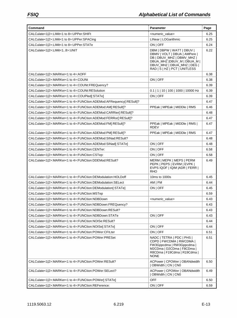
FSIQ Alphabetical List of Commands
1119.5063.12 6.219 E-13
Command Parameter Page
CALCulate<1|2>:LIMit<1 to 8>:UPPer:SHIFt <numeric_value> 6.25
CALCulate<1|2>:LIMit<1 to 8>:UPPer:SPACing LINear | LOGarithmic 6.25
CALCulate<1|2>:LIMit<1 to 8>:UPPer:STATe ON | OFF 6.24
CALCulate<1|2>:LIMit<1..8>:UNIT DBM | DBPW | WATT | DBUV |DBMV | VOLT | DBUA | AMPere |DB | DBUV_MHZ | DBMV_MHZ |DBUA_MHZ |DBUV_M | DBUA_M |DBUV_MHZ | DBUA_MHZ | DEG |RAD | S | HZ | PCT | UNITLESS
6.22
CALCulate<1|2>:MARKer<1 to 4>:AOFF 6.38
CALCulate<1|2>:MARKer<1 to 4>:COUNt ON | OFF 6.38
CALCulate<1|2>:MARKer<1 to 4>:COUNt:FREQuency? 6.39
CALCulate<1|2>:MARKer<1 to 4>:COUNt:RESolution 0.1 | 1 | 10 | 100 | 1000 | 10000 Hz 6.39
CALCulate<1|2>:MARKer<1 to 4>:COUPled[:STATe] ON | OFF 6.39
CALCulate<1|2>:MARKer<1 to 4>:FUNCtion:ADEMod:AFRequency[:RESult]? 6.47
CALCulate<1|2>:MARKer<1 to 4>:FUNCtion:ADEMod:AM[:RESult]? PPEak | MPEak | MIDDle | RMS 6.46
CALCulate<1|2>:MARKer<1 to 4>:FUNCtion:ADEMod:CARRier[:RESult]? 6.48
CALCulate<1|2>:MARKer<1 to 4>:FUNCtion:ADEMod:FERRor[:RESult]? 6.47
CALCulate<1|2>:MARKer<1 to 4>:FUNCtion:ADEMod:FM[:RESult]? PPEak | MPEak | MIDDle | RMS |RDEV
6.47
CALCulate<1|2>:MARKer<1 to 4>:FUNCtion:ADEMod:PM[:RESult]? PPEak | MPEak | MIDDle | RMS 6.47
CALCulate<1|2>:MARKer<1 to 4>:FUNCtion:ADEMod:SINad:RESult? 6.48
CALCulate<1|2>:MARKer<1 to 4>:FUNCtion:ADEMod:SINad[:STATe] ON | OFF 6.48
CALCulate<1|2>:MARKer<1 to 4>:FUNCtion:CENTer: ON | OFF 6.58
CALCulate<1|2>:MARKer<1 to 4>:FUNCtion:CSTep: ON | OFF 6.58
CALCulate<1|2>:MARKer<1 to 4>:FUNCtion:DDEMod:RESult? MERM | MEPK | MEPS | PERMPEPK | PEPS | EVRM | EVPK |EVPS IQOF | IQIM |ADR | FERR |RHO
6.49
CALCulate<1|2>:MARKer<1 to 4>:FUNCtion:DEModulation:HOLDoff 10ms to 1000s 6.45
CALCulate<1|2>:MARKer<1 to 4>:FUNCtion:DEModulation:SELect AM | FM 6.44
CALCulate<1|2>:MARKer<1 to 4>:FUNCtion:DEModulation[:STATe] ON | OFF 6.45
CALCulate<1|2>:MARKer<1 to 4>:FUNCtion:MSTep 6.59
CALCulate<1|2>:MARKer<1 to 4>:FUNCtion:NDBDown <numeric_value> 6.43
CALCulate<1|2>:MARKer<1 to 4>:FUNCtion:NDBDown:FREQuency? 6.43
CALCulate<1|2>:MARKer<1 to 4>:FUNCtion:NDBDown:RESult? 6.43
CALCulate<1|2>:MARKer<1 to 4>:FUNCtion:NDBDown:STATe ON | OFF 6.43
CALCulate<1|2>:MARKer<1 to 4>:FUNCtion:NOISe:RESult? 6.44
CALCulate<1|2>:MARKer<1 to 4>:FUNCtion:NOISe[:STATe] ON | OFF 6.44
CALCulate<1|2>:MARKer<1 to 4>:FUNCtion:POWer:CFILter ON | OFF 6.51
CALCulate<1|2>:MARKer<1 to 4>:FUNCtion:POWer:PRESet NADC | TETRA | PDC | PHS |CDPD | FWCDMA | RWCDMA |FW3Gppcdma | RW3Gppcdma |M2CDma | D2CDma | F8CDma |R8CDma | F19Cdma | R19Cdma |NONE
6.51
CALCulate<1|2>:MARKer<1 to 4>:FUNCtion:POWer:RESult? ACPower | CPOWer | OBANdwidth| OBWidth | CN | CN0
6.50
CALCulate<1|2>:MARKer<1 to 4>:FUNCtion:POWer:SELect? ACPower | CPOWer | OBANdwidth| OBWidth | CN | CN0
6.49
CALCulate<1|2>:MARKer<1 to 4>:FUNCtion:POWer[:STATe] OFF 6.50
CALCulate<1|2>:MARKer<1 to 4>:FUNCtion:REFerence: ON | OFF 6.59

Alphabetical List of Commands FSIQ
1119.5063.12 6.220 E-13
Command Parameter Page
CALCulate<1|2>:MARKer<1 to 4>:FUNCtion:SFACtor (60dB/3dB) | (60dB/6dB) 6.45
CALCulate<1|2>:MARKer<1 to 4>:FUNCtion:SFACtor:FREQuency? 6.46
CALCulate<1|2>:MARKer<1 to 4>:FUNCtion:SFACtor:RESult? 6.46
CALCulate<1|2>:MARKer<1 to 4>:FUNCtion:SFACtor:STATe ON | OFF 6.45
CALCulate<1|2>:MARKer<1 to 4>:FUNCtion:STARt 6.59
CALCulate<1|2>:MARKer<1 to 4>:FUNCtion:STOP 6.59
CALCulate<1|2>:MARKer<1 to 4>:FUNCtion:STRack[:STATe] ON | OFF 6.46
CALCulate<1|2>:MARKer<1 to 4>:FUNCtion:SUMMary:AOFF 6.58
CALCulate<1|2>:MARKer<1 to 4>:FUNCtion:SUMMary:AVERage ON | OFF 6.58
CALCulate<1|2>:MARKer<1 to 4>:FUNCtion:SUMMary:MAXimum:AVERage:RES? 6.52
CALCulate<1|2>:MARKer<1 to 4>:FUNCtion:SUMMary:MAXimum:PHOLd:RESult? 6.52
CALCulate<1|2>:MARKer<1 to 4>:FUNCtion:SUMMary:MAXimum:RESult? 6.52
CALCulate<1|2>:MARKer<1 to 4>:FUNCtion:SUMMary:MAXimum[:STATe] ON | OFF 6.52
CALCulate<1|2>:MARKer<1 to 4>:FUNCtion:SUMMary:MEAN:AVERage:RESult? 6.57
CALCulate<1|2>:MARKer<1 to 4>:FUNCtion:SUMMary:MEAN:PHOLd:RESult? 6.57
CALCulate<1|2>:MARKer<1 to 4>:FUNCtion:SUMMary:MEAN:RESult? 6.57
CALCulate<1|2>:MARKer<1 to 4>:FUNCtion:SUMMary:MEAN[:STATe] ON | OFF 6.57
CALCulate<1|2>:MARKer<1 to 4>:FUNCtion:SUMMary:MIDDle:AVERage:RESult? 6.55
CALCulate<1|2>:MARKer<1 to 4>:FUNCtion:SUMMary:MIDDle:PHOLd:RESult? 6.55
CALCulate<1|2>:MARKer<1 to 4>:FUNCtion:SUMMary:MIDDle:RESult? 6.55
CALCulate<1|2>:MARKer<1 to 4>:FUNCtion:SUMMary:MIDDle[:STATe] ON | OFF 6.55
CALCulate<1|2>:MARKer<1 to 4>:FUNCtion:SUMMary:MPEak:AVERage:RESult? 6.54
CALCulate<1|2>:MARKer<1 to 4>:FUNCtion:SUMMary:MPEak:PHOLd:RESult? 6.54
CALCulate<1|2>:MARKer<1 to 4>:FUNCtion:SUMMary:MPEak:RESult? 6.54
CALCulate<1|2>:MARKer<1 to 4>:FUNCtion:SUMMary:MPEak[:STATe] ON | OFF 6.54
CALCulate<1|2>:MARKer<1 to 4>:FUNCtion:SUMMary:PHOLd ON | OFF 6.58
CALCulate<1|2>:MARKer<1 to 4>:FUNCtion:SUMMary:PPEak:AVERage:RESult? 6.53
CALCulate<1|2>:MARKer<1 to 4>:FUNCtion:SUMMary:PPEak:PHOLd:RESult? 6.53
CALCulate<1|2>:MARKer<1 to 4>:FUNCtion:SUMMary:PPEak:RESult? 6.53
CALCulate<1|2>:MARKer<1 to 4>:FUNCtion:SUMMary:PPEak[:STATe] ON | OFF 6.53
CALCulate<1|2>:MARKer<1 to 4>:FUNCtion:SUMMary:RMS:AVERage:RESult? 6.56
CALCulate<1|2>:MARKer<1 to 4>:FUNCtion:SUMMary:RMS:PHOLd:RESult? 6.56
CALCulate<1|2>:MARKer<1 to 4>:FUNCtion:SUMMary:RMS:RESult? 6.56
CALCulate<1|2>:MARKer<1 to 4>:FUNCtion:SUMMary:RMS[:STATe] ON | OFF 6.56
CALCulate<1|2>:MARKer<1 to 4>:FUNCtion:SUMMary:STATe ON | OFF 6.51
CALCulate<1|2>:MARKer<1 to 4>:FUNCtion:ZOOM <numeric_value> 6.44
CALCulate<1|2>:MARKer<1 to 4>:LOEXclude ON | OFF 6.39
CALCulate<1|2>:MARKer<1 to 4>:MAXimum:APEak 6.40
CALCulate<1|2>:MARKer<1 to 4>:MAXimum:LEFT 6.40
CALCulate<1|2>:MARKer<1 to 4>:MAXimum:NEXT 6.40
CALCulate<1|2>:MARKer<1 to 4>:MAXimum[:PEAK] 6.40
CALCulate<1|2>:MARKer<1 to 4>:MAXimum:RIGHt 6.40
CALCulate<1|2>:MARKer<1 to 4>:MINimum:LEFT 6.41
CALCulate<1|2>:MARKer<1 to 4>:MINimum:NEXT 6.41
CALCulate<1|2>:MARKer<1 to 4>:MINimum[:PEAK] 6.41
CALCulate<1|2>:MARKer<1 to 4>:MINimum:RIGHt 6.41
CALCulate<1|2>:MARKer<1 to 4>:PEXCursion <numeric_value> 6.42

FSIQ Alphabetical List of Commands
1119.5063.12 6.221 E-13
Command Parameter Page
CALCulate<1|2>:MARKer<1 to 4>:READout MPHase | RIMaginary 6.42
CALCulate<1|2>:MARKer<1 to 4>[:STATe] ON | OFF 6.37
CALCulate<1|2>:MARKer<1 to 4>:STEP:AUTO ON | OFF 6.42
CALCulate<1|2>:MARKer<1 to 4>:STEP[:INCRement] <numeric_value> 6.42
CALCulate<1|2>:MARKer<1 to 4>:TRACe 1 to 4 6.38
CALCulate<1|2>:MARKer<1 to 4>:X 0 to MAX(frequency | sweep time | symbols)
6.38
CALCulate<1|2>:MARKer<1 to 4>:X:SLIMits[:STATe] ON | OFF 6.38
CALCulate<1|2>:MARKer<1 to 4>:Y? 6.39
CALCulate<1|2>:MATH<1 to 4>[:EXPRession][:DEFine] <expr> 6.60
CALCulate<1|2>:MATH<1 to 4>:STATe ON | OFF 6.60
CALCulate<1|2>:RLINe MIN to MAX (depending on current unit)
6.16
CALCulate<1|2>:RLINe:STATe ON | OFF 6.16
CALCulate<1|2>:THReshold MIN to MAX(depending on current unit)
6.15
CALCulate<1|2>:THReshold:STATe ON | OFF 6.15
CALCulate<1|2>:TLINe<1|2> 0 to 1000s 6.17
CALCulate<1|2>:TLINe<1|2>:STATe ON | OFF 6.17
CALCulate<1|2>:UNIT:ANGLe DEG | RAD 6.61
CALCulate<1|2>:UNIT:POWer DBM | V | W | DB | PCT |UNITLESS | DBPW | WATT |DBUV | DBMV | VOLT | DBUA |AMPere | DBUV_MHZ |DBMV_MHZ | DBUA_MHZ |DBUV_M | DBUA_M |DBUV_MMHZ | DBUA_MMHZ
6.61
CALCulate<1|2>:X:UNIT:TIME S | SYM 6.61
CALibration[:ALL] 6.62
CALibration:BANDwidth| BWIDth[:RESolution]? 6.62
CALibration:IQ? 6.62
CALibration:LDETector? 6.63
CALibration:LOSuppression? 6.63
CALibration:PPEak? 6.63
CALibration:SHORt? 6.63
CALibration:STATe ON | OFF 6.63
CONFigure:BURSt:PFERror:COUNt 1 to 1000 6.71
CONFigure:BURSt:PFERror[:IMMediate] 6.71
CONFigure:BURSt:POWer:CONDition NORMal | EXTReme 6.72
CONFigure:BURSt:POWer:COUNt 1 to 1000 6.72
CONFigure:BURSt:POWer[:IMMediate] 6.72
CONFigure:BURSt:PTEMplate:COUNt 1 to 1000 6.73
CONFigure:BURSt:PTEMplate[:IMMediate] 6.72
CONFigure:BURSt:PTEMplate:SELect FULL | TOP | RISing | FALLing 6.73
CONFigure:BURSt:REFerence:AUTO ON | OFF 6.73
CONFigure:SPECtrum:MODulation:COUNt 1 to 1000 6.80
CONFigure:SPECtrum:MODulation[:IMMediate] 6.80
CONFigure:SPECtrum:MODulation:RANGe ARFCn | TXBand | RXBand |COMBined | DCSRx1800
6.81
CONFigure:SPECtrum:MODulation:TGATe ON | OFF 6.81
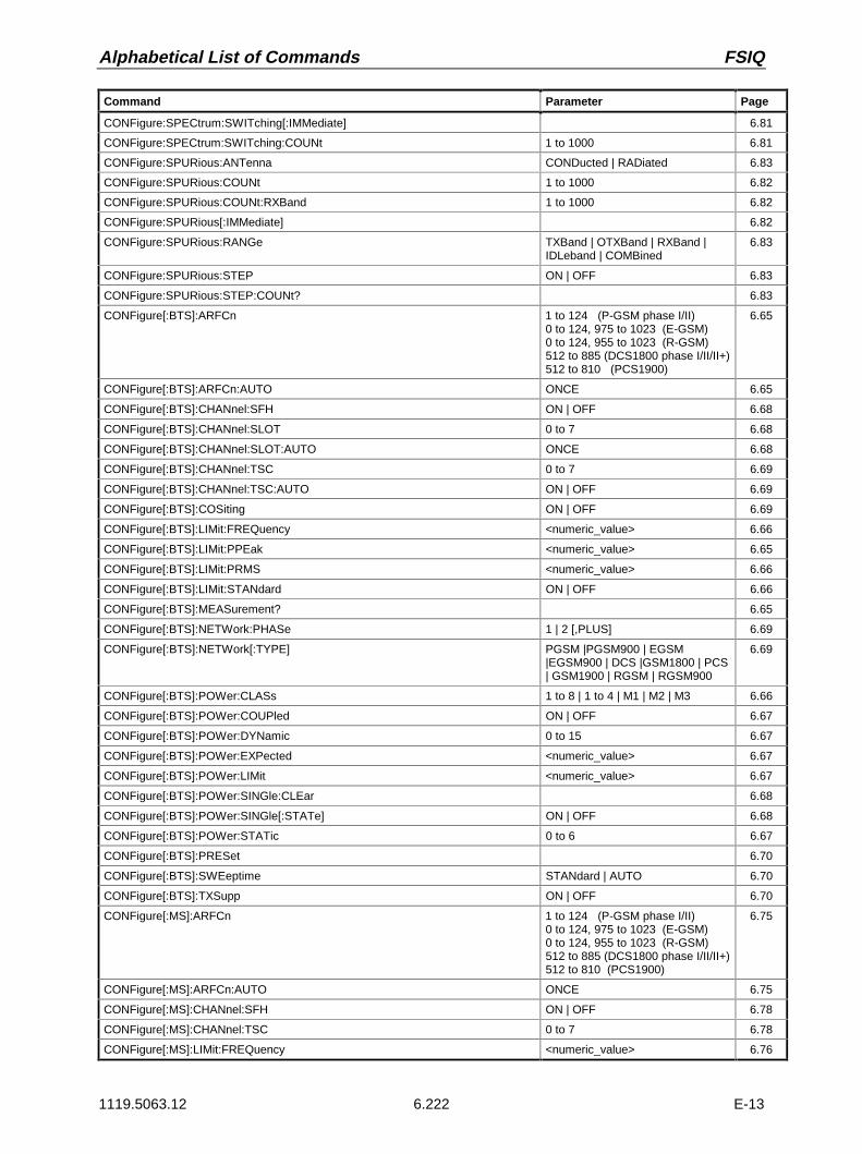
Alphabetical List of Commands FSIQ
1119.5063.12 6.222 E-13
Command Parameter Page
CONFigure:SPECtrum:SWITching[:IMMediate] 6.81
CONFigure:SPECtrum:SWITching:COUNt 1 to 1000 6.81
CONFigure:SPURious:ANTenna CONDucted | RADiated 6.83
CONFigure:SPURious:COUNt 1 to 1000 6.82
CONFigure:SPURious:COUNt:RXBand 1 to 1000 6.82
CONFigure:SPURious[:IMMediate] 6.82
CONFigure:SPURious:RANGe TXBand | OTXBand | RXBand |IDLeband | COMBined
6.83
CONFigure:SPURious:STEP ON | OFF 6.83
CONFigure:SPURious:STEP:COUNt? 6.83
CONFigure[:BTS]:ARFCn 1 to 124 (P-GSM phase I/II)0 to 124, 975 to 1023 (E-GSM)0 to 124, 955 to 1023 (R-GSM)512 to 885 (DCS1800 phase I/II/II+)512 to 810 (PCS1900)
6.65
CONFigure[:BTS]:ARFCn:AUTO ONCE 6.65
CONFigure[:BTS]:CHANnel:SFH ON | OFF 6.68
CONFigure[:BTS]:CHANnel:SLOT 0 to 7 6.68
CONFigure[:BTS]:CHANnel:SLOT:AUTO ONCE 6.68
CONFigure[:BTS]:CHANnel:TSC 0 to 7 6.69
CONFigure[:BTS]:CHANnel:TSC:AUTO ON | OFF 6.69
CONFigure[:BTS]:COSiting ON | OFF 6.69
CONFigure[:BTS]:LIMit:FREQuency <numeric_value> 6.66
CONFigure[:BTS]:LIMit:PPEak <numeric_value> 6.65
CONFigure[:BTS]:LIMit:PRMS <numeric_value> 6.66
CONFigure[:BTS]:LIMit:STANdard ON | OFF 6.66
CONFigure[:BTS]:MEASurement? 6.65
CONFigure[:BTS]:NETWork:PHASe 1 | 2 [,PLUS] 6.69
CONFigure[:BTS]:NETWork[:TYPE] PGSM |PGSM900 | EGSM|EGSM900 | DCS |GSM1800 | PCS| GSM1900 | RGSM | RGSM900
6.69
CONFigure[:BTS]:POWer:CLASs 1 to 8 | 1 to 4 | M1 | M2 | M3 6.66
CONFigure[:BTS]:POWer:COUPled ON | OFF 6.67
CONFigure[:BTS]:POWer:DYNamic 0 to 15 6.67
CONFigure[:BTS]:POWer:EXPected <numeric_value> 6.67
CONFigure[:BTS]:POWer:LIMit <numeric_value> 6.67
CONFigure[:BTS]:POWer:SINGle:CLEar 6.68
CONFigure[:BTS]:POWer:SINGle[:STATe] ON | OFF 6.68
CONFigure[:BTS]:POWer:STATic 0 to 6 6.67
CONFigure[:BTS]:PRESet 6.70
CONFigure[:BTS]:SWEeptime STANdard | AUTO 6.70
CONFigure[:BTS]:TXSupp ON | OFF 6.70
CONFigure[:MS]:ARFCn 1 to 124 (P-GSM phase I/II)0 to 124, 975 to 1023 (E-GSM)0 to 124, 955 to 1023 (R-GSM)512 to 885 (DCS1800 phase I/II/II+)512 to 810 (PCS1900)
6.75
CONFigure[:MS]:ARFCn:AUTO ONCE 6.75
CONFigure[:MS]:CHANnel:SFH ON | OFF 6.78
CONFigure[:MS]:CHANnel:TSC 0 to 7 6.78
CONFigure[:MS]:LIMit:FREQuency <numeric_value> 6.76

FSIQ Alphabetical List of Commands
1119.5063.12 6.223 E-13
Command Parameter Page
CONFigure[:MS]:LIMit:PPEak <numeric_value> 6.75
CONFigure[:MS]:LIMit:PRMS <numeric_value> 6.75
CONFigure[:MS]:LIMit:STANdard ON | OFF 6.76
CONFigure[:MS]:MEASurement? 6.74
CONFigure[:MS]:NETWork:PHASe 1 | 2 [,PLUS] 6.78
CONFigure[:MS]:NETWork[:TYPE] PGSM |PGSM900 | EGSM|EGSM900 | DCS |GSM1800 | PCS| GSM1900 | RGSM | RGSM900
6.78
CONFigure[:MS]:POWer:CLASs 1 to 8 | 1 to 4 | M1 | M2 | M3 6.76
CONFigure[:MS]:POWer:COUPled ON | OFF 6.76
CONFigure[:MS]:POWer:EXPected <numeric_value> 6.77
CONFigure[:MS]:POWer:LEVel 0 to 31 6.77
CONFigure[:MS]:POWer:LIMit <numeric_value> 6.77
CONFigure[:MS]:POWer:SINGle:CLEar 6.77
CONFigure[:MS]:POWer:SINGle[:STATe ON | OFF 6.77
CONFigure[:MS]:POWer:SMALl ON | OFF 6.78
CONFigure[:MS]:PRESet 6.79
CONFigure[:MS]:SWEeptime STANdard | AUTO 6.79
CONFigure[:MS]:TXSupp ON | OFF 6.79
DIAGnostic:INFO:CCOunt:ATTenuation<1|2|3>? 6.85
DIAGnostic:SERVice:FUNCtion numeric_value>,<numeric_value>... 6.84
DIAGnostic:SERVice:INPut[:SELect] CALibration | RF 6.84
DIAGnostic:SERVice:NSOurce ON | OFF 6.84
DISPlay:ANNotation:FREQuency ON | OFF 6.87
DISPlay:CMAP<1 to 13>:DEFault 6.88
DISPlay:CMAP<1 to 13>:HSL 0.0 to 100.0 (tint),0.0 to 100.0 (saturation),0.0 to 100.0 (brightness)
6.88
DISPlay:CMAP<1 to 13>:PDEFined BLACk | BLUE | BROWn | GREen |CYAN | RED | MAGenta | YELLow|WHITe | DGRAy | LGRAy | LBLUe| LGREen | LCYan | LRED |LMAGenta
6.88
DISPlay:FORmat SINGle | SPLit 6.87
DISPlay:LOGO ON | OFF 6.87
DISPlay:PROGram[:MODE] ON | OFF 6.87
DISPlay:PSAVe:HOLDoff 6.95
DISPlay:PSAVe[:STATe] ON | OFF 6.95
DISPlay[:WINDow<1|2>]:MINFo ON | OFF 6.89
DISPlay[:WINDow<1|2>]:TEXT[:DATA] <string> 6.89
DISPlay[:WINDow<1|2>]:TEXT:STATe ON | OFF 6.89
DISPlay[:WINDow<1|2>]:TIME ON | OFF 6.89
DISPlay[:WINDow<1|2>]:TRACe<1 to 4>:EYE:COUNt 1 to Result Length 6.95
DISPlay[:WINDow<1|2>]:TRACe<1 to 4>:MODE WRITe | VIEW | AVERage |MAXHold | MINHold
6.93
DISPlay[:WINDow<1|2>]:TRACe<1 to 4>:MODE:ANALog ON | OFF 6.94
DISPlay[:WINDow<1|2>]:TRACe<1 to 4>:MODE:CWRite ON | OFF 6.93
DISPlay[:WINDow<1|2>]:TRACe<1 to 4>:MODE:HCONtinuous ON | OFF 6.94
DISPlay[:WINDow<1|2>]:TRACe<1 to 4>[:STATe] ON | OFF 6.94
DISPlay[:WINDow<1|2>]:TRACe<1 to 4>:SYMBol DOTS | BARS | OFF 6.94

Alphabetical List of Commands FSIQ
1119.5063.12 6.224 E-13
Command Parameter Page
DISPlay[:WINDow<1|2>]:TRACe<1 to 4>:X[:SCALe]:RVALue <numeric_value> 6.89
DISPlay[:WINDow<1|2>]:TRACe<1 to 4>:X[:SCALe]:ZOOM ON | OFF 6.90
DISPlay[:WINDow<1|2>]:TRACe<1 to 4>:X[:SCALe]:ZOOM[:FREQuency]:CENTer <numeric_value> 6.90
DISPlay[:WINDow<1|2>]:TRACe<1 to 4>:X[:SCALe]:ZOOM[:FREQuency]:STARt <numeric_value> 6.90
DISPlay[:WINDow<1|2>]:TRACe<1 to 4>:X[:SCALe]:ZOOM[:FREQuency]:STOP <numeric_value> 6.90
DISPlay[:WINDow<1|2>]:TRACe<1 to 4>:X:SPACing LINear | LOGarithmic 6.91
DISPlay[:WINDow<1|2>]:TRACe<1 to 4>:Y[:SCALe] 10dB to 200dB 6.91
DISPlay[:WINDow<1|2>]:TRACe<1 to 4>:Y[:SCALe]:MODE ABSolute | RELative 6.91
DISPlay[:WINDow<1|2>]:TRACe<1 to 4>:Y[:SCALe]:PDIVision <numeric_value> 6.93
DISPlay[:WINDow<1|2>]:TRACe<1 to 4>:Y[:SCALe]:RLEVel -200dBm to 200dBm 6.91
DISPlay[:WINDow<1|2>]:TRACe<1 to 4>:Y[:SCALe]:RLEVel:OFFSet -200dB to 200dB 6.92
DISPlay[:WINDow<1|2>]:TRACe<1 to 4>:Y[:SCALe]:RPOSition 0 to 100 PCT 6.93
DISPlay[:WINDow<1|2>]:TRACe<1 to 4>:Y[:SCALe]:RVALue <numeric_value> 6.92
DISPlay[:WINDow<1|2>]:TRACe<1 to 4>:Y[:SCALe]:RVALue:AUTO ON | OFF 6.92
DISPlay[:WINDow<1|2>]:TRACe<1 to 4>:Y:SPACing LINear | LOGarithmic | PERCent 6.93
FETCh:BURSt:FERRor:AVERage? 6.99
FETCh:BURSt:FERRor:MAXimum? 6.99
FETCh:BURSt:FERRor:STATus? 6.98
FETCh:BURSt:PERRor:PEAK:AVERage? 6.98
FETCh:BURSt:PERRor:PEAK:MAXimum? 6.98
FETCh:BURSt:PERRor:PEAK:STATus? 6.97
FETCh:BURSt:PERRor:RMS:AVERage? 6.97
FETCh:BURSt:PERRor:RMS:MAXimum? 6.97
FETCh:BURSt:PERRor:RMS:STATus? 6.96
FETCh:BURSt:POWer:ALL? 6.100
FETCh:BURSt:POWer[:IMMediate]? 6.99
FETCh:PTEMplate:REFerence? TXBand 6.106
FETCh:SPECtrum:MODulation[:ALL]? ARFCn | TXBand | RXBand |COMBined | DCSRx1800
6.101
FETCh:SPECtrum:MODulation:REFerence? TXBand 6.102
FETCh:SPECtrum:SWITching[:ALL]? 6.103
FETCh:SPECtrum:SWITching:REFerence? TXBand 6.103
FETCh:SPURious[:ALL]? TXBand OTXBand | RXBand |IDLeband
6.104
FETCh:SPURious:STEP? 6.105
FORMat[:DATA] ASCii | REAL | UINT [,32] 6.107
FORMat:DEXPort:APPend[:STATe] ON | OFF 6.108
FORMat:DEXPort:DSEParator POINt|COMMa 6.108
FORMat:DEXPort:HEADer[:STATe] ON | OFF 6.108
HCOPy:ABORt 6.109
HCOPy:DESTination<1|2> 'MMEM’ | ‘SYST:COMM:PRIN’ |‘SYST:COMM:CLIP’
6.110
HCOPy:DEVice:COLor ON | OFF 6.110
HCOPy:DEVice:ITEM:ALL 6.111
HCOPy:DEVice:ITEM:FFEed<1|2>:STATe ON | OFF 6.111
HCOPy:DEVice:ITEM:LABel:TEXT <string> 6.111
HCOPy:DEVice:ITEM:PFEed<1|2>:STATe ON | OFF 6.112
HCOPy:DEVice:ITEM:WINDow<1|2>:TABle:STATe ON | OFF 6.112
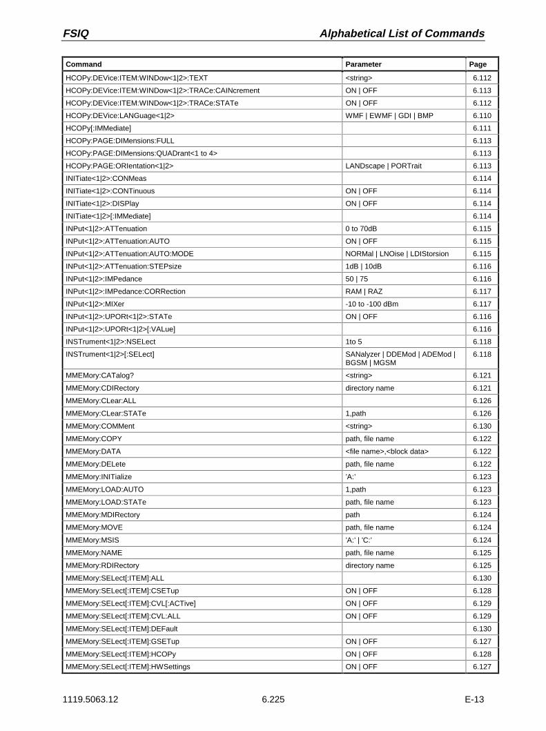
FSIQ Alphabetical List of Commands
1119.5063.12 6.225 E-13
Command Parameter Page
HCOPy:DEVice:ITEM:WINDow<1|2>:TEXT <string> 6.112
HCOPy:DEVice:ITEM:WINDow<1|2>:TRACe:CAINcrement ON | OFF 6.113
HCOPy:DEVice:ITEM:WINDow<1|2>:TRACe:STATe ON | OFF 6.112
HCOPy:DEVice:LANGuage<1|2> WMF | EWMF | GDI | BMP 6.110
HCOPy[:IMMediate] 6.111
HCOPy:PAGE:DIMensions:FULL 6.113
HCOPy:PAGE:DIMensions:QUADrant<1 to 4> 6.113
HCOPy:PAGE:ORIentation<1|2> LANDscape | PORTrait 6.113
INITiate<1|2>:CONMeas 6.114
INITiate<1|2>:CONTinuous ON | OFF 6.114
INITiate<1|2>:DISPlay ON | OFF 6.114
INITiate<1|2>[:IMMediate] 6.114
INPut<1|2>:ATTenuation 0 to 70dB 6.115
INPut<1|2>:ATTenuation:AUTO ON | OFF 6.115
INPut<1|2>:ATTenuation:AUTO:MODE NORMal | LNOise | LDIStorsion 6.115
INPut<1|2>:ATTenuation:STEPsize 1dB | 10dB 6.116
INPut<1|2>:IMPedance 50 | 75 6.116
INPut<1|2>:IMPedance:CORRection RAM | RAZ 6.117
INPut<1|2>:MIXer -10 to -100 dBm 6.117
INPut<1|2>:UPORt<1|2>:STATe ON | OFF 6.116
INPut<1|2>:UPORt<1|2>[:VALue] 6.116
INSTrument<1|2>:NSELect 1to 5 6.118
INSTrument<1|2>[:SELect] SANalyzer | DDEMod | ADEMod |BGSM | MGSM
6.118
MMEMory:CATalog? <string> 6.121
MMEMory:CDIRectory directory name 6.121
MMEMory:CLear:ALL 6.126
MMEMory:CLear:STATe 1,path 6.126
MMEMory:COMMent <string> 6.130
MMEMory:COPY path, file name 6.122
MMEMory:DATA <file name>,<block data> 6.122
MMEMory:DELete path, file name 6.122
MMEMory:INITialize ’A:’ 6.123
MMEMory:LOAD:AUTO 1,path 6.123
MMEMory:LOAD:STATe path, file name 6.123
MMEMory:MDIRectory path 6.124
MMEMory:MOVE path, file name 6.124
MMEMory:MSIS ’A:’ | ’C:’ 6.124
MMEMory:NAME path, file name 6.125
MMEMory:RDIRectory directory name 6.125
MMEMory:SELect[:ITEM]:ALL 6.130
MMEMory:SELect[:ITEM]:CSETup ON | OFF 6.128
MMEMory:SELect[:ITEM]:CVL[:ACTive] ON | OFF 6.129
MMEMory:SELect[:ITEM]:CVL:ALL ON | OFF 6.129
MMEMory:SELect[:ITEM]:DEFault 6.130
MMEMory:SELect[:ITEM]:GSETup ON | OFF 6.127
MMEMory:SELect[:ITEM]:HCOPy ON | OFF 6.128
MMEMory:SELect[:ITEM]:HWSettings ON | OFF 6.127

Alphabetical List of Commands FSIQ
1119.5063.12 6.226 E-13
Command Parameter Page
MMEMory:SELect[:ITEM]:LINes[:ACTive] ON | OFF 6.127
MMEMory:SELect[:ITEM]:LINes:ALL ON | OFF 6.128
MMEMory:SELect[:ITEM]:MACRos ON | OFF 6.128
MMEMory:SELect[:ITEM]:NONE 6.130
MMEMory:SELect[:ITEM]:SCData ON | OFF 6.128
MMEMory:SELect[:ITEM]:TRACe<1 to 4> ON | OFF 6.127
MMEMory:SELect[:ITEM]:TRANsducer[:ACTive] ON | OFF 6.129
MMEMory:SELect[:ITEM]:TRANsducer:ALL ON | OFF 6.129
MMEMory:STORe:STATe path, file name 6.125
MMEMory:STORe:TRACe 1 to 4, path 6.126
OUTPut:AF:SENSitivity 0.1 PCT to 100 PCT for AM0.1 KHZ to 100 KHZ for FM0.0 1RAD to 10 RAD for PM
6.132
OUTPut[:STATe] ON | OFF 6.131
OUTPut:UPORt<1|2>:STATe ON | OFF 6.131
OUTPut:UPORt<1|2>[:VALue] #B00000000 to #B11111111 6.131
READ:BURSt:FERRor:AVERage? 6.136
READ:BURSt:FERRor:MAXimum? 6.136
READ:BURSt:FERRor:STATus? 6.135
READ:BURSt:PERRor:PEAK:AVERage? 6.135
READ:BURSt:PERRor:PEAK:MAXimum? 6.135
READ:BURSt:PERRor:PEAK:STATus? 6.134
READ:BURSt:PERRor:RMS:AVERage? 6.134
READ:BURSt:PERRor:RMS:MAXimum? 6.134
READ:BURSt:PERRor:RMS:STATus? 6.133
READ:BURSt:POWer:DYNamic? 6.139
READ:BURSt:POWer:POWer:LEVel? 6.140
READ:BURSt:POWer:STATic? 6.138
READ:BURSt:POWer? 6.137
READ:BURSt:REFerence[:IMMediate?] 6.140
READ:SPECtrum:MODulation[:ALL]? 6.141
READ:SPECtrum:SWITching[:ALL]? 6.142
READ:SPURious[:ALL]? 6.143
READ:SPURious:STEP? 6.144
[SENSe<1|2>:]ADEMod:AF:COUPling AC | DC 6.145
[SENSe<1|2>:]ADEMod:RTIMe ON | OFF 6.146
[SENSe<1|2>:]ADEMod:SBANd NORMal | INVerse 6.146
[SENSe<1|2>:]ADEMod:SQUelch:LEVel 30 to -150 dBm 6.146
[SENSe<1|2>:]ADEMod:SQUelch[:STATe] ON | OFF 6.145
[SENSe<1|2>:]AVERage:AUTO ON | OFF 6.147
[SENSe<1|2>:]AVERage:COUNt 0 to 256 6.147
[SENSe<1|2>:]AVERage[:STATe] ON | OFF 6.147
[SENSe<1|2>:]AVERage:TYPE MAXimum | SCALar 6.148
[SENSe<1|2>:]BANDwidth|BWIDth:DEMod 5 kHz to 200 kHz (Real Time on)5 kHz to 5 MHz (Real Time off)
6.151
[SENSe<1|2>:]BANDwidth|BWIDth:PLL AUTO | HIGH | MEDium | LOW 6.151
[SENSe<1|2>:]BANDwidth|BWIDth[:RESolution] 1Hz to 10MHz 6.149
[SENSe<1|2>:]BANDwidth|BWIDth[:RESolution]:AUTO ON | OFF 6.150

FSIQ Alphabetical List of Commands
1119.5063.12 6.227 E-13
Command Parameter Page
[SENSe<1|2>:]BANDwidth|BWIDth[:RESolution]:MODE ANALog | DIGital 6.150
[SENSe<1|2>:]BANDwidth|BWIDth[:RESolution]:MODE:FFT ON | OFF 6.150
[SENSe<1|2>:]BANDwidth|BWIDth[:RESolution]:RATio 0.0001 to 1 6.150
[SENSe<1|2>:]BANDwidth|BWIDth:VIDeo 1Hz to 10MHz 6.151
[SENSe<1|2>:]BANDwidth|BWIDth:VIDeo:AUTO ON | OFF 6.151
[SENSe<1|2>:]BANDwidth|BWIDth:VIDeo:EXTernal[:STATe] ON | OFF 6.151
[SENSe<1|2>:]BANDwidth|BWIDth:VIDeo:RATio 0.001 to 1000 | SINe | PULSe |NOISe
6.151
[SENSe<1|2>:]CORRection:COLLect[:ACQuire] THRough | OPEN 6.153
[SENSe<1|2>:]CORRection:CVL:BAND A|Q|U|V|E|W|F|D|G|Y|J] 6.160
[SENSe<1|2>:]CORRection:CVL:BIAS <numeric_value> 6.160
[SENSe<1|2>:]CORRection:CVL:CATalog? 6.159
[SENSe<1|2>:]CORRection:CVL:CLEar 6.161
[SENSe<1|2>:]CORRection:CVL:COMMent <string> 6.161
[SENSe<1|2>:]CORRection:CVL:DATA <freq>,<level>.. 6.161
[SENSe<1|2>:]CORRection:CVL:MIXer <string> 6.159
[SENSe<1|2>:]CORRection:CVL:PORTs 2 | 3 6.160
[SENSe<1|2>:]CORRection:CVL:SELect <file_name> 6.159
[SENSe<1|2>:]CORRection:CVL:SNUMber <string> 6.159
[SENSe<1|2>:]CORRection:CVL:TYPE ODD | EVEN | EODD 6.160
[SENSe<1|2>:]CORRection:LOSS:INPut[:MAGNitude] <value of ext. attenuation in dB> 6.158
[SENSe<1|2>:]CORRection:METHod TRANsmission | REFLexion 6.153
[SENSe<1|2>:]CORRection:RECall 6.153
[SENSe<1|2>:]CORRection:RXGain:INPut[:MAGNitude] <value of the amplification in dB> 6.158
[SENSe<1|2>:]CORRection[:STATe] ON | OFF 6.153
[SENSe<1|2>:]CORRection:TRANsducer:ACTive? 6.154
[SENSe<1|2>:]CORRection:TRANsducer:CATalog? 6.154
[SENSe<1|2>:]CORRection:TRANsducer:COMMent <string> 6.155
[SENSe<1|2>:]CORRection:TRANsducer:DATA <freq>,<level>.. 6.155
[SENSe<1|2>:]CORRection:TRANsducer:DELete 6.156
[SENSe<1|2>:]CORRection:TRANsducer:SCALing LINear | LOGarithmic 6.155
[SENSe<1|2>:]CORRection:TRANsducer:SELect <name> 6.154
[SENSe<1|2>:]CORRection:TRANsducer[:STATe] ON | OFF 6.155
[SENSe<1|2>:]CORRection:TRANsducer:UNIT <string> 6.154
[SENSe<1|2>:]CORRection:TSET:ACTive? 6.156
[SENSe<1|2>:]CORRection:TSET:BREak ON | OFF 6.157
[SENSe<1|2>:]CORRection:TSET:CATalog? 6.156
[SENSe<1|2>:]CORRection:TSET:COMMent <string> 6.157
[SENSe<1|2>:]CORRection:TSET:DELete 6.158
[SENSe<1|2>:]CORRection:TSET:RANGe<1 to 10> <freq>,<freq>,<name>.. 6.157
[SENSe<1|2>:]CORRection:TSET:SELect <name> 6.156
[SENSe<1|2>:]CORRection:TSET:UNIT <string> 6.157
[SENSe<1|2>:]CORRection:TSET[:STATe] ON | OFF 6.158
[SENSe<1|2>:]DDEMod:FILTer:ALPHa 0.2 to 1 6.166
[SENSe<1|2>:]DDEMod:FILTer:MEASurement OFF | RCOSine | RRCosine |GAUSsian | B22 | B25 | B44 | QFM| FM95 | QFR | FR95 | QRM | RM95| QRR | RR95 | A25Fm | EMES |EREF
6.166

Alphabetical List of Commands FSIQ
1119.5063.12 6.228 E-13
Command Parameter Page
[SENSe<1|2>:]DDEMod:FILTer:REFerence RCOSine | RRCosine | GAUSsian |B22 | B25 | B44 | QFM | FM95 |QFR | FR95 | QRM | RM95 | QRR |RR95 | A25Fm | EMES | EREF
6.166
[SENSe<1|2>:]DDEMod:FORMat QPSK | PSK | MSK | QAM | FSK 6.164
[SENSe<1|2>:]DDEMod:FSK:NSTate 2 | 4 6.165
[SENSe<1|2>:]DDEMod:MSK:FORMat TYPE1 | TYPE2 | NORMal |DIFFerential
6.165
[SENSe<1|2>:]DDEMod:NORMalize ON | OFF 6.167
[SENSe<1|2>:]DDEMod:PRATe 1 | 2 | 4 | 8 | 16 6.166
[SENSe<1|2>:]DDEMod:PRESet GSM | EDGe | NADC | TETRa |PHS | PDCup | PDCDown |APCO25CQPSK | APCO25C4FM |CDPD | DECT | CT2 | ERMes |MODacom | PWT | TFTS | F16 |F322 | F324 | F64 F64 | FQCDma |F95Cdma | RQCDma | R95Cdma |FNADc | RNADc | FWCDma |FCDMa4096 | RWCDma |RCDMa4096 | FW3Gppcdma |RW3Gppcdma | CDMA2000
6.170
[SENSe<1|2>:]DDEMod:PSK:FORMat NORMal | DIFFerential | N3Pi8 6.164
[SENSe<1|2>:]DDEMod:PSK:NSTate 2 | 8 6.164
[SENSe<1|2>:]DDEMod:QAM:NSTate 16 6.165
[SENSe<1|2>:]DDEMod:QPSK:FORMat NORMal | DIFFerential | OFFSet |DPI4
6.164
[SENSe<1|2>:]DDEMod:SBANd NORMal | INVerse 6.164
[SENSe<1|2>:]DDEMod:SEARch:PULSe:STATe ON | OFF 6.167
[SENSe<1|2>:]DDEMod:SEARch:SYNC:CATalog? 6.167
[SENSe<1|2>:]DDEMod:SEARch:SYNC:COMMent <string> 6.168
[SENSe<1|2>:]DDEMod:SEARch:SYNC:DATA <string> 6.168
[SENSe<1|2>:]DDEMod:SEARch:SYNC:DELete <string> 6.169
[SENSe<1|2>:]DDEMod:SEARch:SYNC:MONLy ON | OFF 6.169
[SENSe<1|2>:]DDEMod:SEARch:SYNC:NAME <string> 6.168
[SENSe<1|2>:]DDEMod:SEARch:SYNC:OFFSet <numeric_value> 6.167
[SENSe<1|2>:]DDEMod:SEARch:SYNC:PATTern <string> 6.168
[SENSe<1|2>:]DDEMod:SEARch:SYNC:SELect <string> 6.167
[SENSe<1|2>:]DDEMod:SEARch:SYNC:STATe ON | OFF 6.168
[SENSe<1|2>:]DDEMod:SEARch:TIME 100 to 1600 6.169
[SENSe<1|2>:]DDEMod:SRATe 160 Hz to 7 MHz 6.165
[SENSe<1|2>:]DDEMod:TIME 1 to Frame Length 6.165
[SENSe<1|2>:]DETector<1 to 4>[:FUNCtion] APEak |NEGative | POSitive |SAMPle | RMS | AVERage
6.162
[SENSe<1|2>:]DETector<1 to 4>[:FUNCtion]:AUTO ON | OFF 6.162
[SENSe<1|2>:]FILTer:CCITt[:STATe] ON | OFF 6.172
[SENSe<1|2>:]FILTer:CMESsage[:STATe] ON | OFF 6.172
[SENSe<1|2>:]FILTer:DEMPhasis:LINK DISPlay | AUDio 6.173
[SENSe<1|2>:]FILTer:DEMPhasis[:STATe] ON | OFF 6.173
[SENSe<1|2>:]FILTer:DEMPhasis:TCONstant <numeric_value> 6.173
[SENSe<1|2>:]FILTer:HPASs:FREQuency 30 Hz | 300 HZ 6.171
[SENSe<1|2>:]FILTer:HPASS[:STATe] ON | OFF 6.171
[SENSe<1|2>:]FILTer:LPASs:FREQuency 3 kHz | 15 kHz (real time on)5PCT|10PCT|25PCT (real time off)
6.172

FSIQ Alphabetical List of Commands
1119.5063.12 6.229 E-13
Command Parameter Page
[SENSe<1|2>:]FILTer:LPASs[:STATe] ON | OFF 6.172
[SENSe<1|2>:]FREQuency:CENTer 0 GHz to fmax 6.174
[SENSe<1|2>:]FREQuency:CENTer:LINK STARt | STOP | SPAN 6.174
[SENSe<1|2>:]FREQuency:CENTer:STEP 0 to fmax 6.175
[SENSe<1|2>:]FREQuency:CENTer:STEP:LINK SPAN | RBW | OFF 6.175
[SENSe<1|2>:]FREQuency:CENTer:STEP:LINK:FACTor 1 to 100 PCT 6.175
[SENSe<1|2>:]FREQuency:MODE CW|FIXed | SWEep 6.177
[SENSe<1|2>:]FREQuency:OFFSet <numeric_value> 6.177
[SENSe<1|2>:]FREQuency:SPAN 0 GHz to fmax 6.175
[SENSe<1|2>:]FREQuency:SPAN:FULL 6.176
[SENSe<1|2>:]FREQuency:SPAN:LINK CENTer | STOP | SPAN 6.176
[SENSe<1|2>:]FREQuency:STARt 0 GHz to fmax 6.176
[SENSe<1|2>:]FREQuency:STARt:LINK CENTer | STOP | SPAN 6.176
[SENSe<1|2>:]FREQuency:STOP 0 GHz to fmax 6.176
[SENSe<1|2>:]FREQuency:STOP:LINK CENTer | STARt | SPAN 6.177
[SENSe<1|2>:]MIXer:BIAS <numeric_value> 6.181
[SENSe<1|2>:]MIXer:BIAS:LIMit[:MAX] <numeric_value> 6.181
[SENSe<1|2>:]MIXer:BIAS:LIMit:MIN <numeric_value> 6.181
[SENSe<1|2>:]MIXer:BLOCk ON | OFF 6.178
[SENSe<1|2>:]MIXer:HARMonic 2..X; X: depending on the LO 6.179
[SENSe<1|2>:]MIXer:HARMonic:BAND A |Q | U | V | E | W | F | D | G | Y | J 6.180
[SENSe<1|2>:]MIXer:HARMonic:TYPE ODD | EVEN | EODD 6.180
[SENSe<1|2>:]MIXer:LOSS:HIGH <numeric_value> 6.180
[SENSe<1|2>:]MIXer:LOSS[:LOW] <numeric_value> 6.180
[SENSe<1|2>:]MIXer:LOSS:TABLE <file_name> 6.181
[SENSe<1|2>:]MIXer:PORTs 2 | 3 6.179
[SENSe<1|2>:]MIXer:SIGNal ON | OFF | AUTO 6.179
[SENSe<1|2>:]MIXer[:STATe] ON | OFF 6.178
[SENSe<1|2>:]MIXer:THReshold 0.1 to 100 dB 6.179
[SENSe<1|2>:]MSUMmary:AHOLd[:STATe] ON | OFF 6.182
[SENSe<1|2>:]MSUMmary:MODE ABSolute | RELative 6.182
[SENSe<1|2>:]MSUMmary:MTIMe 0.1 s | 1 s 6.183
[SENSe<1|2>:]MSUMmary:REFerence <numeric_value> 6.182
[SENSe<1|2>:]MSUMmary:RUNit PCT | DB 6.182
[SENSe<1|2>:]POWer:ACHannel:ACPairs 1 to 3 6.185
[SENSe<1|2>:]POWer:ACHannel:BANDwidth|BWIDth:ACHannel 0 to 1000MHz 6.185
[SENSe<1|2>:]POWer:ACHannel:BANDwidth|BWIDth:ALTernate<1|2> 0 to 1000MHz 6.186
[SENSe<1|2>:]POWer:ACHannel:BANDwidth|BWIDth[:CHANnel] 0 to 1000 MHz 6.185
[SENSe<1|2>:]POWer:ACHannel:MODE ABSolute | RELative 6.186
[SENSe<1|2>:]POWer:ACHannel:PRESet ACPower | CPOWer | OBANdwidth| OBWidth | CN | CN0
6.186
[SENSe<1|2>:]POWer:ACHannel:REFerence:AUTO ONCE 6.186
[SENSe<1|2>:]POWer:ACHannel:SPACing:ACHannel 0 to 1000 MHz 6.184
[SENSe<1|2>:]POWer:ACHannel:SPACing:ALTernate<1|2> 0 to 1000 MHz 6.185
[SENSe<1|2>:]POWer:ACHannel:SPACing[:UPPer] 0 to 1000 MHz 6.184
[SENSe<1|2>:]POWer:BANDwidth|BWIDth 0 to 100 PCT 6.186
[SENSe<1|2>:]ROSCillator:EXTernal:FREQuency 1 MHz to 16 MHz 6.187
[SENSe<1|2>:]ROSCillator[:INTernal]:TUNe 0 to 4095 6.187

Alphabetical List of Commands FSIQ
1119.5063.12 6.230 E-13
Command Parameter Page
[SENSe<1|2>:]ROSCillator[:INTernal]:TUNe:SAVe 6.187
[SENSe<1|2>:]ROSCillator:SOURce INTernal | EXTernal 6.187
[SENSe<1|2>:]SWEep:COUNt 0 to 32767 6.189
[SENSe<1|2>:]SWEep:EGATe ON | OFF 6.189
[SENSe<1|2>:]SWEep:EGATe:HOLDoff 0 to 100s 6.190
[SENSe<1|2>:]SWEep:EGATe:LENGth 0 to 100s 6.190
[SENSe<1|2>:]SWEep:EGATe:LEVel -5V to +5V 6.189
[SENSe<1|2>:]SWEep:EGATe:POLarity POSitive | NEGative 6.190
[SENSe<1|2>:]SWEep:EGATe:SOURce EXTernal | RFPower 6.190
[SENSe<1|2>:]SWEep:EGATe:TYPE LEVel | EDGE 6.189
[SENSe<1|2>:]SWEep:GAP ON | OFF 6.190
[SENSe<1|2>:]SWEep:GAP:LENGth 0 to 100s 6.191
[SENSe<1|2>:]SWEep:GAP:PRETrigger 0 to 100s 6.191
[SENSe<1|2>:]SWEep:GAP:TRGTogap 0 to 100s 6.191
[SENSe<1|2>:]SWEep:TIME <numeric_value> 6.188
[SENSe<1|2>:]SWEep:TIME:AUTO ON | OFF 6.188
[SENSe<1|2>:]TCAPture:LENGth 1024 | 2048 | 4096 | 8192 | 16384 6.170
SOURce:AM:STATe ON | OFF 6.192
SOURce:DM:STATe ON | OFF 6.192
SOURce:FREQuency:OFFSet -200 MHz to 200 MHz 6.193
SOURce:POWer:ALC:SOURce INTernal | EXTernal 6.193
SOURce:POWer[:LEVel][:IMMediate][:AMPLitude] 20dBm to 0dBm / OptionFSE-B12: -90dBm to 0dBm
6.193
SOURce:POWer[:LEVel][:IMMediate]:OFFSet -200 dB to +200 dB 6.193
STATus:OPERation:CONDition? 6.195
STATus:OPERation:ENABle 0 to 65535 6.195
STATus:OPERation[:EVENt]? 6.195
STATus:OPERation:NTRansition 0 to 65535 6.196
STATus:OPERation:PTRansition 0 to 65535 6.196
STATus:PRESet 6.196
STATus:QUEStionable:ACPLimit:CONDition? 6.201
STATus:QUEStionable:ACPLimit:ENABle 0 to 65535 6.202
STATus:QUEStionable:ACPLimit[:EVENt]? 6.201
STATus:QUEStionable:ACPLimit:NTRansition 0 to 65535 6.202
STATus:QUEStionable:ACPLimit:PTRansition 0 to 65535 6.202
STATus:QUEStionable:CONDition? 6.196
STATus:QUEStionable:ENABle 0 to 65535 6.197
STATus:QUEStionable[:EVENt]? 6.196
STATus:QUEStionable:NTRansition 0 to 65535 6.197
STATus:QUEStionable:PTRansition 0 to 65535 6.197
STATus:QUEStionable:FREQuency:CONDition? 6.202
STATus:QUEStionable:FREQuency:ENABle 0 to 65535 6.203
STATus:QUEStionable:FREQuency[:EVENt]? 6.202
STATus:QUEStionable:FREQuency:NTRansition 0 to 65535 6.203
STATus:QUEStionable:FREQuency:PTRansition 0 to 65535 6.203
STATus:QUEStionable:LIMit:CONDition? 6.198
STATus:QUEStionable:LIMit:ENABle 0 to 65535 6.199

FSIQ Alphabetical List of Commands
1119.5063.12 6.231 E-13
Command Parameter Page
STATus:QUEStionable:LIMit[:EVENt]? 6.198
STATus:QUEStionable:LIMit:NTRansition 0 to 65535 6.199
STATus:QUEStionable:LIMit:PTRansition 0 to 65535 6.199
STATus:QUEStionable:LMARgin:CONDition? 6.199
STATus:QUEStionable:LMARgin:ENABle 0 to 65535 6.200
STATus:QUEStionable:LMARgin[:EVENt]? 6.199
STATus:QUEStionable:LMARgin:NTRansition 0 to 65535 6.200
STATus:QUEStionable:LMARgin:PTRansition 0 to 65535 6.200
STATus:QUEStionable:POWer:CONDition? 6.197
STATus:QUEStionable:POWer:ENABle 0 to 65535 6.198
STATus:QUEStionable:POWer[:EVENt]? 6.197
STATus:QUEStionable:POWer:NTRansition 0 to 65535 6.198
STATus:QUEStionable:POWer:PTRansition 0 to 65535 6.198
STATus:QUEStionable:SYNC:CONDition? 6.200
STATus:QUEStionable:SYNC:ENABle 0 to 65535 6.201
STATus:QUEStionable:SYNC[:EVENt]? 6.200
STATus:QUEStionable:SYNC:NTRansition 0 to 65535 6.201
STATus:QUEStionable:SYNC:PTRansition 0 to 65535 6.201
STATus:QUEStionable:TRANsducer:CONDition? 6.203
STATus:QUEStionable:TRANsducer:ENABle 0 to 65535 6.204
STATus:QUEStionable:TRANsducer:NTRansition 0 to 65535 6.204
STATus:QUEStionable:TRANsducer:PTRansition 0 to 65535 6.204
STATus:QUEStionable:TRANsducer[:EVENt]? 6.203
STATus:QUEue[:NEXT]? 6.204
SYSTem:BINFo? 6.210
SYSTem:COMMunicate:GPIB:RDEVice<1|2>:ADDRess 0 to 30 6.206
SYSTem:COMMunicate:GPIB[:SELF]:ADDRess 0 to 30 6.205
SYSTem:COMMunicate:GPIB[:SELF]:RTERminator LFEOI | EOI 6.206
SYSTem:COMMunicate:PRINter<1|2>:ENUMerate:FIRSt? 6.208
SYSTem:COMMunicate:PRINter<1|2>:ENUMerate:NEXT? 6.208
SYSTem:COMMunicate:PRINter<1|2>:SELect <printer_name> 6.208
SYSTem:COMMunicate:SERial<1|2>:CONTrol:DTR IBFull | OFF 6.206
SYSTem:COMMunicate:SERial<1|2>:CONTrol:RTS IBFull | OFF 6.206
SYSTem:COMMunicate:SERial<1|2>[:RECeive]:BAUD <numeric_value> 6.206
SYSTem:COMMunicate:SERial<1|2>[:RECeive]:BITS 7 | 8 6.207
SYSTem:COMMunicate:SERial<1|2>[:RECeive]:PACE XON | NONE 6.207
SYSTem:COMMunicate:SERial<1|2>[:RECeive]:PARity[:TYPE] EVEN | ODD | NONE 6.207
SYSTem:COMMunicate:SERial<1|2>[:RECeive]:SBITs 1 | 2 6.207
SYSTem:DATE 1980 to 2099, 1 to 12, 1 to 31 6.208
SYSTem:ERRor? 6.209
SYSTem:PASSword[:CENable] ’password’ 6.209
SYSTem:PRESet 6.209
SYSTem:PRESet:COMPatible FSE | OFF 6.209
SYSTem:SET <block> 6.210
SYSTem:SPEaker<1|2>:VOLume 0 to 1 6.210
SYSTem:TIME 0 to 23, 0 to 59, 0 to 59 6.210
SYSTem:UPDate ON | OFF 6.209
SYSTem:VERSion? 6.210

Alphabetical List of Commands FSIQ
1119.5063.12 6.232 E-13
Command Parameter Page
SYSTem:VERSion? 6.210
TRACe:COPY TRACE1 | TRACE2 | TRACE3 |TRACE4 ,TRACE1 | TRACE2 |TRACE3 | TRACE4
6.212
TRACe[:DATA] TRACE1 | TRACE2 | TRACE3 |TRACE4, <block> |<numeric_value>
6.211
TRIGger<1|2>[:SEQuence]:HOLDoff -100 to 100 s 6.214
TRIGger<1|2>[:SEQuence]:LEVel:AF -120 to +120PCT 6.214
TRIGger<1|2>[:SEQuence]:LEVel[:EXTernal] –5.0 V to +5.0 V 6.213
TRIGger<1|2>[:SEQuence]:LEVel:VIDeo 0 to 100 PCT 6.213
TRIGger<1|2>[:SEQuence]:SLOPe POSitive | NEGative 6.214
TRIGger<1|2>[:SEQuence]:SOURce IMMediate | LINE | EXTernal |VIDeo | RFPower | AF
6.213
TRIGger<1|2>[:SEQuence]:SYNChronize:ADJust:FRAMe -100µs to 100 s 6.214
TRIGger<1|2>[:SEQuence]:SYNChronize:ADJust:FRAMe:AUTO ONCE 6.215
TRIGger<1|2>[:SEQuence]:SYNChronize:ADJust:SLOT -100µs to 100 s 6.215
TRIGger<1|2>[:SEQuence]:SYNChronize:ADJust:SLOT:AUTO ONCE 6.215
TRIGger<1|2>[:SEQuence]:SYNChronize:SOURce FRAMe | TSC 6.215
UNIT<1|2>:POWer DBM | DBPW | WATT | DBUV |DBMV | VOLT | DBUA | AMP | DB |PCT | UNITLESS | DBUV_MHZ |DBMV_MHZ | DBUA_MHZ |DBUV_M | DBIA_M | DBUV_MMHZ| DBUA_MMHZ
6.216
UNIT<1|2>:PROBe ON | OFF 6.216

FSIQ Command Assignment: Signal Analysis
1119.5063.12 6.233 E-13
Table of Softkeys with IEC/IEEE-Bus Command Assignment
Basic Instrument - Signal Analysis Mode
FREQUENCY Key Group
START
STARTMANUAL
[SENSe<1|2>:]FREQuency:STARt <num_value>
CENTERFIXED
[SENSe<1|2>:]FREQuency:STARt:LINK CENTer
SPANFIXED
[SENSe<1|2>:]FREQuency:STARt:LINK SPAN
STOPFIXED
[SENSe<1|2>:]FREQuency:STARt:LINK STOP
START ATFREQ LINE
[SENSe<1|2>:]FREQuency:STARt:FLINe[:STATe] ON | OFF
FREQ AXISLIN LOG
[SENSe<1|2>:]SWEep:SPACing LIN | LOG
STOP
STOPMANUAL
[SENSe<1|2>:]FREQuency:STOP <num_value>
STARTFIXED
[SENSe<1|2>:]FREQuency:STOP:LINK STARt
CENTERFIXED
[SENSe<1|2>:]FREQuency:STOP:LINK CENTer
SPANFIXED
[SENSe<1|2>:]FREQuency:STOP:LINK SPAN
SPANFIXED
[SENSe<1|2>:]FREQuency:STOP:LINK SPAN
STOP ATFREQ LINE
[SENSe<1|2>:]FREQuency:STOP:FLINe[:STATe] ON | OFF
FREQ AXISLIN LOG
[SENSe<1|2>:]SWEep:SPACing LIN | LOG
CENTER
CENTERMANUAL
[SENSe<1|2>:]FREQuency:CENTer <num_value>
STARTFIXED
[SENSe<1|2>:]FREQuency:CENTer:LINK STARt
SPANFIXED
[SENSe<1|2>:]FREQuency:CENTer:LINK SPAN

Command Assignment: Signal Analysis FSIQ
1119.5063.12 6.234 E-13
STOPFIXED
[SENSe<1|2>:]FREQuency:CENTer:LINK STOP
FREQUENCYOFFSET
[SENSe<1|2>:]FREQuency:OFFSet <num_value>
FREQ AXISLIN LOG
[SENSe<1|2>:]SWEep:SPACing LIN | LOG
STEP
AUTO0.1 * SPAN
or
[SENSe<1|2>:]FREQuency:CENTer:STEP:LINK SPAN;[SENSe<1|2>:]FREQuency:CENTer:STEP:LINK:FACTor 10PCT
AUTO0.1 * RBW
[SENSe<1|2>:]FREQuency:CENTer:STEP:LINK RBW;[SENSe<1|2>:]FREQuency:CENTer:STEP:LINK:FACTor 10PCT
AUTO0.5 * SPAN
or
[SENSe<1|2>:]FREQuency:CENTer:STEP:LINK SPAN;[SENSe<1|2>:]FREQuency:CENTer:STEP:LINK:FACTor 50PCT
AUTO0.5 * RBW
[SENSe<1|2>:]FREQuency:CENTer:STEP:LINK RBW;[SENSe<1|2>:]FREQuency:CENTer:STEP:LINK:FACTor 50PCT
AUTOX * SPAN
or
[SENSe<1|2>:]FREQuency:CENTer:STEP:LINK SPAN;[SENSe<1|2>:]FREQuency:CENTer:STEP:LINK:FACTor <num_value>
AUTOX * RBW
[SENSe<1|2>:]FREQuency:CENTer:STEP:LINK RBW;[SENSe<1|2>:]FREQuency:CENTer:STEP:LINK:FACTor <num_value>
STEPSIZEMANUAL
[SENSe<1|2>:]FREQuency:CENTer:STEP <num_value>
STEPSIZE= CENTER
no corresponding IEC/IEEE-bus command
SPAN
SPANMANUAL
[SENSe<1|2>:]FREQuency:SPAN <num_value>
STARTFIXED
[SENSe<1|2>:]FREQuency:SPAN:LINK START
CENTERFIXED
[SENSe<1|2>:]FREQuency:SPAN:LINK CENTer
STOPFIXED
[SENSe<1|2>:]FREQuency:SPAN:LINK STOP
ZEROSPAN
[SENSe<1|2>:]FREQuency:SPAN 0HZ or[SENSe<1|2>:]FREQuency:MODE CW | FIXed
FULLSPAN
[SENSe<1|2>:]FREQuency:SPAN:FULL
LASTSPAN
no corresponding IEC/IEEE-bus command
ZOOMDISPlay[:WINDow<1|2>]:TRACe<1...4>:X[:SCALe]:ZOOM ON| OFF
MOVE ZOOMWINDOW
DISPlay[:WINDow<1|2>]:TRACe<1...4>:X[:SCALe]:ZOOM[:FREQuency]:CENTer <num_value>

FSIQ Command Assignment: Signal Analysis
1119.5063.12 6.235 E-13
MOVE ZOOMSTART
DISPlay[:WINDow<1|2>]:TRACe<1...4>:X[:SCALe]:ZOOM[:FREQuency]:STARt <num_value>
MOVE ZOOMSTOP
DISPlay[:WINDow<1|2>]:TRACe<1...4>:X[:SCALe]:ZOOM[:FREQuency]:STOP <num_value>
ZOOM OFFDISPlay[:WINDow<1|2>]:TRACe<1...4>:X[:SCALe]:ZOOM OFF
FREQ AXISLIN LOG
[SENSe<1|2>:]SWEep:SPACing LIN | LOG
LEVEL Key Group
REF
REFLEVEL
DISPlay[:WINDow<1|2>]:TRACe<1...4>:Y[:SCALe]:RLEVel <num_value>
REF LEVELOFFSET
DISPlay[:WINDow<1|2>]:TRACe<1...4>:Y[:SCALe]:RLEVel:OFFSet <num_value>
GRIDABS/REL
DISPlay[:WINDow<1|2>]:TRACe<1...4>:Y[:SCALe]:MODE ABSolute|RELative
UNIT--
dBmCALCulate<1|2>:UNIT:POWer DBM
dBmVCALCulate<1|2>:UNIT:POWer DBMV
dBµVCALCulate<1|2>:UNIT:POWer DBUV
dBµACALCulate<1|2>:UNIT:POWer DBUA
dBpWCALCulate<1|2>:UNIT:POWer DBPW
dB*/MHzCALCulate<1|2>:UNIT:POWer DBUV_MHZCALCulate<1|2>:UNIT:POWer DBUA_MHZCALCulate<1|2>:UNIT:POWer DBMV_MHZ
VOLTCALCulate<1|2>:UNIT:POWer VOLT
AMPERECALCulate<1|2>:UNIT:POWer AMPere
WATTCALCulate<1|2>:UNIT:POWer WATT
PROBE CODEON / OFF
UNIT<1|2>:PROBe ON | OFF
ATTEN STEPMANUAL
INPut<1|2>:ATTenuation:STEPsize 1|10 (nur mit Option FSE-B13)
RF ATTENMANUAL
INPut<1|2>:ATTenuation <num_value>

Command Assignment: Signal Analysis FSIQ
1119.5063.12 6.236 E-13
ATTEN AUTONORMAL
INPut<1|2>:ATTenuation:AUTO:MODE NORMal;INPut<1|2>:ATTenuation:AUTO ON
ATTEN AUTOLOW NOISE
INPut<1|2>:ATTenuation:AUTO:MODE LNOise;INPut<1|2>:ATTenuation:AUTO ON
ATTEN AUTOLOW DIST
INPut<1|2>:ATTenuation:AUTO:MODE LDIStortion;INPut<1|2>:ATTenuation:AUTO ON
MIXERLEVEL
INPut<1|2>:MIXer <num_value>
MAX LEVELAUTO
DISPlay[:WINDow<1|2>]:TRACe<1...4>:Y[:SCALe]:RVALue:AUTO ON
MAX LEVELMANUAL
DISPlay[:WINDow<1|2>]:TRACe<1...4>:Y[:SCALe]:RVALue:AUTO OFF;DISPlay[:WINDow<1|2>]:TRACe<1...4>:Y[:SCALe]:RVALue <num_value>
RANGE
LINEAR/%DISPlay[:WINDow<1|2>]:TRACe<1...4>:Y:SPACing PERCent
LINEAR/dBDISPlay[:WINDow<1|2>]:TRACe<1...4>:Y:SPACing LINear
LOG MANUALDISPlay[:WINDow<1|2>]:TRACe<1...4>:Y:SPACing LOGarithmic;DISPlay[:WINDow<1|2>]:TRACe<1...4>:Y[:SCALe] <num_value>
INPUT Key
INPUT
RF ATTENMANUAL
INPut<1|2>:ATTenuation <num_value>
ATTEN AUTONORMAL
INPut<1|2>:ATTenuation:AUTO:MODE NORMal;INPut<1|2>:ATTenuation:AUTO ON
ATTEN AUTOLOW NOISE
INPut<1|2>:ATTenuation:AUTO:MODE LNOise;INPut<1|2>:ATTenuation:AUTO ON
ATTEN AUTOLOW DIST
INPut<1|2>:ATTenuation:AUTO:MODE LDIStortion;INPut<1|2>:ATTenuation:AUTO ON
MIXERLEVEL
INPut<1|2>:MIXer <num_value>
INPUTSELECT
--
RF INPUT50 OHM
INPut<1|2>:IMPedance 50
RF INPUT75 OHM/RAM
INPut<1|2>:IMPedance:CORRection RAM
RF INPUT75OHM/RAZ
INPut<1|2>:IMPedance:CORRection RAZ

FSIQ Command Assignment: Signal Analysis
1119.5063.12 6.237 E-13
MARKER Key Group
NORMAL
MARKER1..4
CALCulate<1|2>:MARKer<1...4>[:STATe] ON | OFF;CALCulate<1|2>:MARKer<1...4>:X <num_value>;CALCulate<1|2>:MARKer<1...4>:Y?
SIGNALCOUNT
CALCulate<1|2>:MARKer<1...4>:COUNt ON | OFF;CALCulate<1|2>:MARKer<1...4>:COUNt:FREQuency?
MARKERDEMOD
MKR DEMODON/OFF
CALCulate<1|2>:MARKer<1...4>:FUNCtion:DEModulation[:STATe] ON | OFF
AMCALCulate<1|2>:MARKer<1...4>:FUNCtion:DEModulation:SELect AM
FMCALCulate<1|2>:MARKer<1...4>:FUNCtion:DEModulation:SELect FM
MKR STOPTIME
CALCulate<1|2>:MARKer<1..4>:FUNCtion:DEModulation:HOLDoff <num_value>
VOLUMESYSTem:SPEaker<1|2>:VOLume <num_value>
MARKERZOOM
CALCulate<1|2>:MARKer<1...4>:FUNCtion:ZOOM <num_value>
MARKERINFO
DISPlay:WINDow<1|2>:MINFo ON | OFF (indication)
ALL MARKEROFF
CALCulate<1|2>:MARKer<1...4>:AOFF
POWER MEASSETTINGS
--
SET NO OFADJ CHAN’S
[SENSe<1|2>:]POWer:ACHannel:ACPairs <num_value>
ACPSTANDARD
CALCulate<1|2>:MARKer<1...4>:FUNCtion:POWer:PRESet NADC| TETRA| PDC|PHS| CDPD| FWCDma | RWCDma| F8CDma| R8CDma| F19Cdma| R19Cdma |FW3Gppcdma | RW3Gppcdma | M2CDma | D2CDma | NONE
CH FILTERON/OFF
CALCulate<1|2>:MARKer<1...4>:FUNCtion:POWer:CFILter ON | OFF
CHANNELBANDWIDTH
[SENSe<1|2>:]POWer:ACHannel:BANDwidth|BWIDth[:CHANnel] <num_value>[SENSe<1|2>:]POWer:ACHannel:BANDwidth|BWIDth:ACHannel <num_value>[SENSe<1|2>:]POWer:ACHannel:BANDwidth|BWIDth:ALTernate<1|2> <num_value>
CHANNELSPACING
[SENSe<1|2>:]POWer:ACHannel:SPACing[:UPPer] <num_value>[SENSe<1|2>:]POWer:ACHannel:SPACing:ACHannel <num_value>[SENSe<1|2>:]POWer:ACHannel:SPACing:ALTernate<1|2> <num_value>
EDITACP LIMITS
CALCulate<1|2>:LIMit<1...8>:ACPower:ACHannel <num_value>,<num_value>CALCulate<1|2>:LIMit<1...8>:ACPower:ACHannel:STATe ON | OFFCALCulate<1|2>:LIMit<1...8>:ACPower:ALTernate<1|2> <num_val>,<num_val>CALCulate<1|2>:LIMit<1...8>:ACPower:ALTernate<1|2>:STATe ON | OFF
LIMITCHECK
CALCulate<1|2>:LIMit:ACPower[:STATe] ON | OFFCALCulate<1|2>:LIMit<1...8>:ACPower:ACHannel:RESult?CALCulate<1|2>:LIMit<1...8>:ACPower:ALTernate<1|2>:RESult?
% POWERBANDWIDTH
[SENSe<1|2>:]POWer: BANDwidth|BWIDth <num_value>
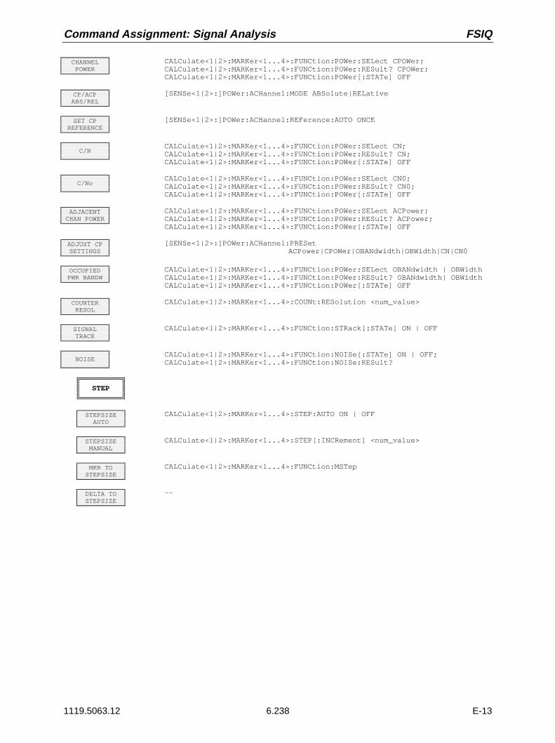
Command Assignment: Signal Analysis FSIQ
1119.5063.12 6.238 E-13
CHANNELPOWER
CALCulate<1|2>:MARKer<1...4>:FUNCtion:POWer:SELect CPOWer;CALCulate<1|2>:MARKer<1...4>:FUNCtion:POWer:RESult? CPOWer;CALCulate<1|2>:MARKer<1...4>:FUNCtion:POWer[:STATe] OFF
CP/ACPABS/REL
[SENSe<1|2>:]POWer:ACHannel:MODE ABSolute|RELative
SET CPREFERENCE
[SENSe<1|2>:]POWer:ACHannel:REFerence:AUTO ONCE
C/NCALCulate<1|2>:MARKer<1...4>:FUNCtion:POWer:SELect CN;CALCulate<1|2>:MARKer<1...4>:FUNCtion:POWer:RESult? CN;CALCulate<1|2>:MARKer<1...4>:FUNCtion:POWer[:STATe] OFF
C/NoCALCulate<1|2>:MARKer<1...4>:FUNCtion:POWer:SELect CN0;CALCulate<1|2>:MARKer<1...4>:FUNCtion:POWer:RESult? CN0;CALCulate<1|2>:MARKer<1...4>:FUNCtion:POWer[:STATe] OFF
ADJACENTCHAN POWER
CALCulate<1|2>:MARKer<1...4>:FUNCtion:POWer:SELect ACPower;CALCulate<1|2>:MARKer<1...4>:FUNCtion:POWer:RESult? ACPower;CALCulate<1|2>:MARKer<1...4>:FUNCtion:POWer[:STATe] OFF
ADJUST CPSETTINGS
[SENSe<1|2>:]POWer:ACHannel:PRESetACPower|CPOWer|OBANdwidth|OBWidth|CN|CN0
OCCUPIEDPWR BANDW
CALCulate<1|2>:MARKer<1...4>:FUNCtion:POWer:SELect OBANdwidth | OBWidthCALCulate<1|2>:MARKer<1...4>:FUNCtion:POWer:RESult? OBANdwidth| OBWidthCALCulate<1|2>:MARKer<1...4>:FUNCtion:POWer[:STATe] OFF
COUNTERRESOL
CALCulate<1|2>:MARKer<1...4>:COUNt:RESolution <num_value>
SIGNALTRACK
CALCulate<1|2>:MARKer<1...4>:FUNCtion:STRack[:STATe] ON | OFF
NOISECALCulate<1|2>:MARKer<1...4>:FUNCtion:NOISe[:STATe] ON | OFF;CALCulate<1|2>:MARKer<1...4>:FUNCtion:NOISe:RESult?
STEP
STEPSIZEAUTO
CALCulate<1|2>:MARKer<1...4>:STEP:AUTO ON | OFF
STEPSIZEMANUAL
CALCulate<1|2>:MARKer<1...4>:STEP[:INCRement] <num_value>
MKR TOSTEPSIZE
CALCulate<1|2>:MARKer<1...4>:FUNCtion:MSTep
DELTA TOSTEPSIZE
--

FSIQ Command Assignment: Signal Analysis
1119.5063.12 6.239 E-13
DELTA
DELTA1...4
CALCulate<1|2>:DELTamarker<1...4>[:STATe] ON | OFFCALCulate<1|2>:DELTamarker<1...4>:X <num_value>CALCulate<1|2>:DELTamarker<1...4>:X:RELative?CALCulate<1|2>:DELTamarker<1...4>:Y?
PHASENOISE
CALCulate<1|2>:DELTamarker<1...4>:FUNCtion:PNOise[:STATe] ON | OFFCALCulate<1|2>:DELTamarker<1...4>:FUNCtion:PNOise:RESult?
REFERENCEPOINT
--
REF POINTLEVEL
CALCulate<1|2>:DELTamarker<1..4>:FUNCtion:FIXed:RPOint:Y <num_value>
REF POINTLVL OFFSET
CALCulate<1|2>:DELTamarker<1..4>:FUNCtion:FIXed:RPOint:Y:OFFSet<num_value>
REF POINTFREQUENCY
CALCulate<1|2>:DELTamarker<1..4>:FUNCtion:FIXed:RPOint:X <num_value>
REF POINTTIME
CALCulate<1|2>:DELTamarker<1..4>:FUNCtion:FIXed:RPOint:X <num_value>
REFERENCEFIXED
CALCulate<1|2>:DELTamarker<1...4>:FUNCtion:FIXed[:STATe] ON | OFF
DELTA MKRABS REL
CALCulate<1|2>:DELTamarker<1...4>:MODE ABSolute | RELative
ALL DELTAOFF
CALCulate<1|2>:DELTamarker<1...4>:AOFF
STEP
STEPSIZEAUTO
CALCulate<1|2>:DELTamarker<1...4>:STEP:AUTO ON | OFF
MANUALSTEPSIZE
CALCulate<1|2>:DELTamarker<1...4>:STEP[:INCRement] <num_value>
DELTA TOSTEPSIZE
--
SEARCH
PEAKCALCulate<1|2>:MARKer<1...4>:MAXimum[:PEAK]CALCulate<1|2>:DELTamarker<1...4>:MAXimum[:PEAK]
NEXTPEAK
CALCulate<1|2>:MARKer<1...4>:MAXimum:NEXTCALCulate<1|2>:DELTamarker<1...4>:MAXimum:NEXT
NEXT PEAKRIGHT
CALCulate<1|2>:MARKer<1...4>:MAXimum:RIGHtCALCulate<1|2>:DELTamarker<1...4>:MAXimum:RIGHt
NEXT PEAKLEFT
CALCulate<1|2>:MARKer<1...4>:MAXimum:LEFTCALCulate<1|2>:DELTamarker<1...4>:MAXimum:LEFT
SUM MKRON/OFF
CALCulate<1|2>:MARKer<1...4>:FUNCtion:SUMMary[:STATe] ON | OFF

Command Assignment: Signal Analysis FSIQ
1119.5063.12 6.240 E-13
SUMMARYMARKER
RMSCALCulate<1|2>:MARKer<1...4>:FUNCtion:SUMMary:RMS[:STATe] ON | OFFCALCulate<1|2>:MARKer<1...4>:FUNCtion:SUMMary:RMS:RESult?CALCulate<1|2>:MARKer<1...4>:FUNCtion:SUMMary:RMS:AVERage:RESult?CALCulate<1|2>:MARKer<1...4>:FUNCtion:SUMMary:RMS:PHOLd:RESult?
MEANCALCulate<1|2>:MARKer<1...4>:FUNCtion:SUMMary:MEAN[:STATe] ON | OFFCALCulate<1|2>:MARKer<1...4>:FUNCtion:SUMMary:MEAN:RESult?CALCulate<1|2>:MARKer<1...4>:FUNCtion:SUMMary:MEAN:AVERage:RESult?CALCulate<1|2>:MARKer<1...4>:FUNCtion:SUMMary:MEAN:PHOLd:RESult?
PEAK HOLDON/OFF
CALCulate<1|2>:MARKer<1...4>:FUNCtion:SUMMary:PHOLd ON | OFF
AVERAGEON/OFF
CALCulate<1|2>:MARKer<1...4>:FUNCtion:SUMMary:AVERage ON | OFF
SWEEPCOUNT
[SENSe<1|2>:]SWEep:COUNt <num_value>
ALL SUM MKROFF
CALCulate<1|2>:MARKer<1...4>:FUNCtion:SUMMary:AOFF
SEARCH LIMON/OFF
CALCulate<1|2>:MARKer<1...4>:X:SLIMits[:STATe] ON | OFF
SELECTMARKER
no corresponding IEC/IEEE-bus command
ACTIVEMKR/DELTA
no corresponding IEC/IEEE-bus command
MINCALCulate<1|2>:MARKer<1...4>:MINimum[:PEAK]CALCulate<1|2>:DELTamarker<1...4>:MINimum[:PEAK]
NEXTMIN
CALCulate<1|2>:MARKer<1...4>:MINimum:NEXTCALCulate<1|2>:DELTamarker<1...4>:MINimum:NEXT
NEXT MINLEFT
CALCulate<1|2>:MARKer<1...4>:MINimum:LEFTCALCulate<1|2>:DELTamarker<1...4>:MINimum:LEFT
NEXT MINRIGHT
CALCulate<1|2>:MARKer<1...4>:MINimum:RIGHtCALCulate<1|2>:DELTamarker<1...4>:MINimum:RIGHt
EXCLUDE LOON/OFF
CALCulate<1|2>:MARKer<1...4>:LOEXclude ON | OFF
PEAKEXCURSION
CALCulate<1|2>:MARKer<1...4>:PEXCursion <num_value>
N dB DOWNCALCulate<1|2>:MARKer<1...4>:FUNCtion:NDBDown <num_value>CALCulate<1|2>:MARKer<1...4>:FUNCtion:NDBDown:STATe ON | OFFCALCulate<1|2>:MARKer<1...4>:FUNCtion:NDBDown:RESult?CALCulate<1|2>:MARKer<1...4>:FUNCtion:NDBDown:FREQuency?
SHAPE FACT60/3 dB
CALCulate<1|2>:MARKer<1...4>:FUNCtion:SFACtor (60dB/3dB)CALCulate<1|2>:MARKer<1...4>:FUNCtion:SFACtor:STATe ON | OFFCALCulate<1|2>:MARKer<1...4>:FUNCtion:SFACtor:RESult?CALCulate<1|2>:MARKer<1...4>:FUNCtion:SFACtor:FREQuency?
SHAPE FACT60/6 dB
CALCulate<1|2>:MARKer<1...4>:FUNCtion:SFACtor (60dB/6dB)CALCulate<1|2>:MARKer<1...4>:FUNCtion:SFACtor:STATe ON | OFFCALCulate<1|2>:MARKer<1...4>:FUNCtion:SFACtor:RESult?CALCulate<1|2>:MARKer<1...4>:FUNCtion:SFACtor:FREQuency?

FSIQ Command Assignment: Signal Analysis
1119.5063.12 6.241 E-13
MKR->
PEAKCALCulate<1|2>:MARKer<1...4>:MAXimum[:PEAK]CALCulate<1|2>:DELTamarker<1...4>:MAXimum[:PEAK]
MKR->CENTER
CALCulate<1|2>:MARKer<1...4>:FUNCtion:CENTer
MKR->REF LEVEL
CALCulate<1|2>:MARKer<1...4>:FUNCtion:REFerence
MKR->CF STEPSIZE
CALCulate<1|2>:MARKer<1...4>:FUNCtion:CSTep
MKR->START
CALCulate<1|2>:MARKer<1...4>:FUNCtion:STARt
MKR->STOP
CALCulate<1|2>:MARKer<1...4>:FUNCtion:STOP
MKR->TRACE
CALCulate<1|2>:MARKer<1...4>:TRACe <num_value>CALCulate<1|2>:DELTamarker<1...4>:TRACe <num_value>
LINES Key Group
D LINES
DISPLAYLINE 1/2
CALCulate<1|2>:DLINe<1|2>:STATe ON | OFF;CALCulate<1|2>:DLINe<1|2> <num_value>
THRESHOLDLINE
CALCulate<1|2>:THReshold ON | OFF;CALCulate<1|2>:THReshold <num_value>
REFERENCELINE
CALCulate<1|2>:RLINe:STATe ON | OFF;CALCulate<1|2>:RLINe <num_value>
FREQUENCYLINE 1/2
or
CALCulate<1|2>:FLINe<1|2>:STATe ON | OFF;CALCulate<1|2>:FLINe<1|2> <num_value>
TIMELINE 1/2
CALCulate<1|2>:TLINe<1|2>:STATe ON | OFF;CALCulate<1|2>:TLINe<1|2> <num_value>
BASELINECLIPPING
CALCulate<1|2>:CTHReshold:STATe ON | OFFCALCulate<1|2>:CTHReshold <num_value>
LIMITS
SELECTLIMIT LINE
CALCulate<1|2>:LIMit<1...8>:NAME <string>;CALCulate<1|2>:LIMit<1...8>:STATe ON | OFF
NEWLIMIT LINE
s. EDIT LIMIT LINE
NAMECALCulate<1|2>:LIMit<1...8>:NAME <string>
VALUESno corresponding IEC/IEEE-bus command

Command Assignment: Signal Analysis FSIQ
1119.5063.12 6.242 E-13
INSERTVALUE
no corresponding IEC/IEEE-bus command
DELETEVALUE
no corresponding IEC/IEEE-bus command
SHIFT XLIMIT LINE
CALCulate<1|2>:LIMit<1...8>:CONTrol:SHIFt <num_value>
SHIFT YLIMIT LINE
CALCulate<1|2>:LIMit<1...8>:UPPer:SHIFt <num_value>CALCulate<1|2>:LIMit<1...8>:LOWer:SHIFt <num_value>
SAVELIMIT LINE
automatically executed during IEC/IEEE-bus operation
EDIT LIMITLINE
CALCulate<1|2>:LIMit<1...8>:UNIT DBM| DBPW| WATT| DBUV| VOLT|DBUA| AMPere| DB| DBUV_MHZ| DBUA_MHZ| UNITLESS
CALCulate<1|2>:LIMit<1...8>:COMMent ’string’CALCulate<1|2>:LIMit<1...8>:TRACe <num_value>CALCulate<1|2>:LIMit<1...8>:CONTrol[:DATA] <num_value>, <num_value>..CALCulate<1|2>:LIMit<1...8>:CONTrol:DOMain FREQuency|TIMECALCulate<1|2>:LIMit<1...8>:CONTrol:OFFset <num_value>CALCulate<1|2>:LIMit<1...8>:CONTrol:MODE RELative | ABSoluteCALCulate<1|2>:LIMit<1...8>:CONTrol:SPACing LINear | LOGarithmicCALCulate<1|2>:LIMit<1...8>:UPPer[:DATA] <num_value>, <num_value>..CALCulate<1|2>:LIMit<1...8>:UPPer:STATe ON | OFFCALCulate<1|2>:LIMit<1...8>:UPPer:OFFset <num_value>CALCulate<1|2>:LIMit<1...8>:UPPer:MARGin <num_value>CALCulate<1|2>:LIMit<1...8>:UPPer:MODE RELative | ABSoluteCALCulate<1|2>:LIMit<1...8>:UPPer:SPACing LINear | LOGarithmicCALCulate<1|2>:LIMit<1...8>:LOWer[:DATA] <num_value>,<num_value>..CALCulate<1|2>:LIMit<1...8>:LOWer:STATe ON | OFFCALCulate<1|2>:LIMit<1...8>:LOWer:OFFset <num_value>CALCulate<1|2>:LIMit<1...8>:LOWer:MARGin <num_value>CALCulate<1|2>:LIMit<1...8>:LOWer:MODE RELative | ABSoluteCALCulate<1|2>:LIMit<1...8>:LOWer:SPACing LINear | LOGarithmicCALCulate<1|2>:LIMit<1...8>:FAIL?CALCulate<1|2>:LIMit<1...8>:CLEar[:IMMediate]
COPYLIMIT LINE
CALCulate<1|2>:LIMit<1...8>:COPY 1...8 | <name>
DELETELIMIT LINE
CALCulate<1|2>:LIMit<1...8>:DELete
X OFFSETCALCulate<1|2>:LIMit<1...8>:CONTrol:OFFset <num_value>
Y OFFSETCALCulate<1|2>:LIMit<1...8>:UPPer:OFFset <num_value>CALCulate<1|2>:LIMit<1...8>:LOWer:OFFset <num_value>
TRACE Key Group
TRACE 1
CLEAR/WRITE
DISPlay[:WINDow<1|2>]:TRACe<1...4>:MODE WRITe
VIEWDISPlay[:WINDow<1|2>]:TRACe<1...4>:MODE VIEW
BLANKDISPlay[:WINDow<1|2>]:TRACe<1...4>[:STATe] OFF
AVERAGEDISPlay[:WINDow<1|2>]:TRACe<1...4>:MODE AVERage or[SENSe<1|2>:]AVERage:MODE SCALe
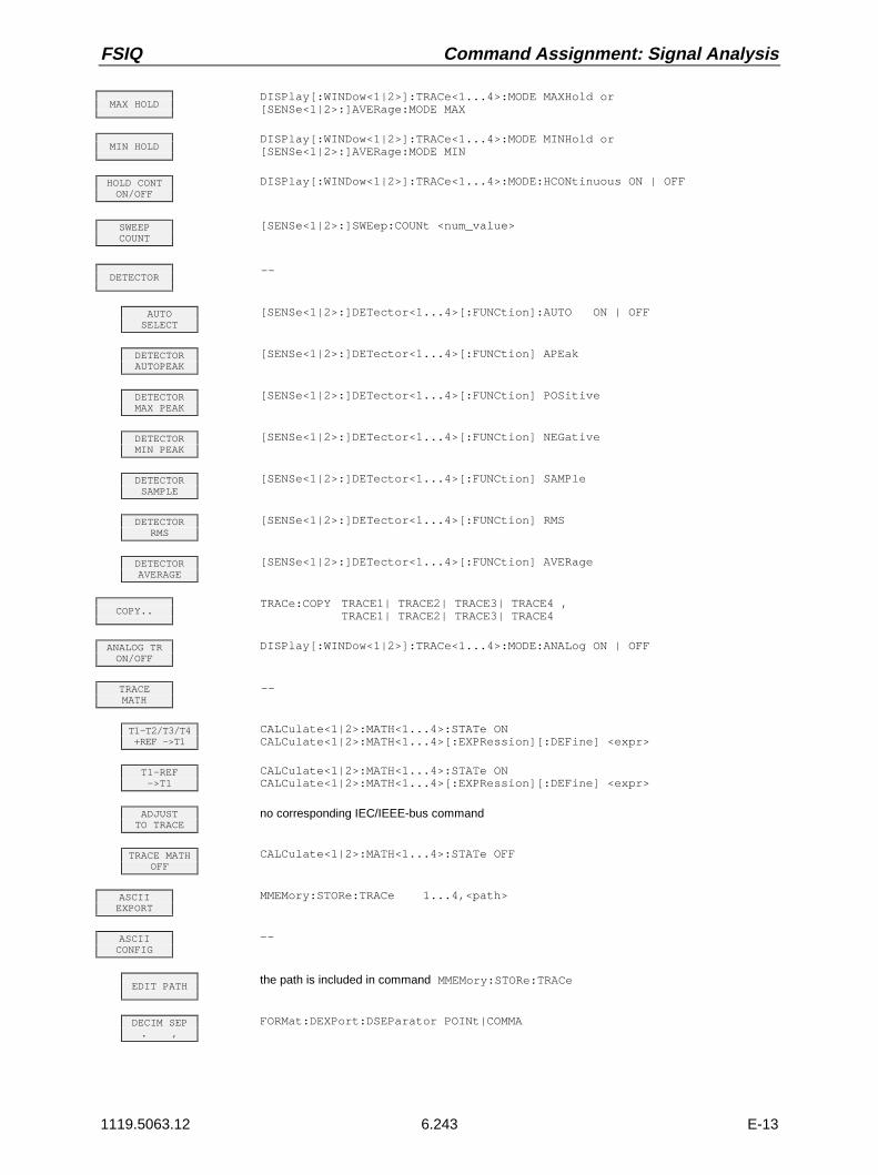
FSIQ Command Assignment: Signal Analysis
1119.5063.12 6.243 E-13
MAX HOLDDISPlay[:WINDow<1|2>]:TRACe<1...4>:MODE MAXHold or[SENSe<1|2>:]AVERage:MODE MAX
MIN HOLDDISPlay[:WINDow<1|2>]:TRACe<1...4>:MODE MINHold or[SENSe<1|2>:]AVERage:MODE MIN
HOLD CONTON/OFF
DISPlay[:WINDow<1|2>]:TRACe<1...4>:MODE:HCONtinuous ON | OFF
SWEEPCOUNT
[SENSe<1|2>:]SWEep:COUNt <num_value>
DETECTOR--
AUTOSELECT
[SENSe<1|2>:]DETector<1...4>[:FUNCtion]:AUTO ON | OFF
DETECTORAUTOPEAK
[SENSe<1|2>:]DETector<1...4>[:FUNCtion] APEak
DETECTORMAX PEAK
[SENSe<1|2>:]DETector<1...4>[:FUNCtion] POSitive
DETECTORMIN PEAK
[SENSe<1|2>:]DETector<1...4>[:FUNCtion] NEGative
DETECTORSAMPLE
[SENSe<1|2>:]DETector<1...4>[:FUNCtion] SAMPle
DETECTORRMS
[SENSe<1|2>:]DETector<1...4>[:FUNCtion] RMS
DETECTORAVERAGE
[SENSe<1|2>:]DETector<1...4>[:FUNCtion] AVERage
COPY..TRACe:COPY TRACE1| TRACE2| TRACE3| TRACE4 ,
TRACE1| TRACE2| TRACE3| TRACE4
ANALOG TRON/OFF
DISPlay[:WINDow<1|2>]:TRACe<1...4>:MODE:ANALog ON | OFF
TRACEMATH
--
T1-T2/T3/T4+REF ->T1
CALCulate<1|2>:MATH<1...4>:STATe ONCALCulate<1|2>:MATH<1...4>[:EXPRession][:DEFine] <expr>
T1-REF->T1
CALCulate<1|2>:MATH<1...4>:STATe ONCALCulate<1|2>:MATH<1...4>[:EXPRession][:DEFine] <expr>
ADJUSTTO TRACE
no corresponding IEC/IEEE-bus command
TRACE MATHOFF
CALCulate<1|2>:MATH<1...4>:STATe OFF
ASCIIEXPORT
MMEMory:STORe:TRACe 1...4,<path>
ASCIICONFIG
--
EDIT PATHthe path is included in command MMEMory:STORe:TRACe
DECIM SEP. ,
FORMat:DEXPort:DSEParator POINt|COMMA

Command Assignment: Signal Analysis FSIQ
1119.5063.12 6.244 E-13
NEWAPPEND
FORMat:DEXPort:APPend[:STATe] ON | OFF
HEADERON OFF
FORMat:DEXPort:HEADer[:STATe] ON | OFF
SWEEP Key Group
COUPLING
RES BWMANUAL
[SENSe<1|2>:]BANDwidth|BWIDth[:RESolution] <num_value>
RES BWAUTO
[SENSe<1|2>:]BANDwidth|BWIDth[:RESolution]:AUTO ON | OFF
VIDEO BWMANUAL
[SENSe<1|2>:]BANDwidth|BWIDth:VIDeo <num_value>
VIDEO BWAUTO
[SENSe<1|2>:]BANDwidth|BWIDth:VIDeo:AUTO ON | OFF
SWEEP TIMEMANUAL
[SENSe<1|2>:]SWEep:TIME <num_value>
SWEEP TIMEAUTO
[SENSe<1|2>:]SWEep:TIME:AUTO ON | OFF
COUPLINGDEFAULT
[SENSe<1|2>:]BANDwidth|BWIDth[:RESolution]:AUTO ON;[SENSe<1|2>:]BANDwidth|BWIDth:VIDeo:AUTO ON;[SENSe<1|2>:]SWEep:TIME:AUTO ON
COUPLINGRATIO
[SENSe<1|2>:]BANDwidth|BWIDth[:RESolution]:RATio 0.02[SENSe<1|2>:]BANDwidth|BWIDth:VIDeo:RATio SINe
RBW / VBWSINE [1]
[SENSe<1|2>:]BANDwidth|BWIDth:VIDeo:RATio SINe
RBW / VBWPULSE [.1]
[SENSe<1|2>:]BANDwidth|BWIDth:VIDeo:RATio PULSe
RBW / VBWNOISE [10]
[SENSe<1|2>:]BANDwidth|BWIDth:VIDeo:RATio NOISe
RBW / VBWMANUAL
[SENSe<1|2>:]BANDwidth|BWIDth:VIDeo:RATio <num_value>
SPAN / RBWAUTO [50]
[SENSe<1|2>:]BANDwidth|BWIDth[:RESolution]:RATio 0.02
SPAN / RBWMANUAL
[SENSe<1|2>:]BANDwidth|BWIDth[:RESolution]:RATio <num_value>
RBW 1kHzANA/DIG
[SENSe<1|2>:]BANDwidth|BWIDth[:RESolution]:MODE ANALog | DIGital
RBW <=1kHzFFT/NORM
[SENSe<1|2>:]BANDwidth|BWIDth[:RESolution]:MODE:FFT ON | OFF
MAIN PLLBANDWIDTH
[SENSe<1|2>:]BANDwidth|BWIDth:PLL AUTO|HIGH|MEDium|LOW
TRIGGER

FSIQ Command Assignment: Signal Analysis
1119.5063.12 6.245 E-13
FREE RUNTRIGger<1|2>[:SEQuence]:SOURce IMMediate
VIDEOTRIGger<1|2>[:SEQuence]:SOURce VIDeoTRIGger<1|2>[:SEQuence]:LEVel:VIDeo <num_value>
LINETRIGger<1|2>[:SEQuence]:SOURce LINE
EXTERNTRIGger<1|2>[:SEQuence]:SOURce EXTernalTRIGger<1|2>[:SEQuence]:LEVel[:EXTernal] -5.0...+5.0V
RF POWERTRIGger<1|2>[:SEQuence]:SOURce RFPower
TRIGGERDELAY
TRIGger<1|2>[:SEQuence]:HOLDoff <num_value>
SLOPEPOS/NEG
TRIGger<1|2>[:SEQuence]:SLOPe POSitive|NEGative
SWEEP
CONTINUOUSSWEEP
INITiate<1|2>:CONTinuous ON; INITiate[:IMMediate]
SINGLESWEEP
INITiate<1|2>:CONTinuous OFF; INITiate[:IMMediate]
SWEEP TIMEAUTO
[SENSe<1|2>:]SWEep:TIME:AUTO ON | OFF
SWEEP TIMEMANUAL
[SENSe<1|2>:]SWEep:TIME <num_value>
SWEEPCOUNT
[SENSe<1|2>:]SWEep:COUNt <num_value>
GAP SWEEPON/OFF
[SENSe<1|2>:]SWEep:GAP ON | OFF
GAP SWEEPSETTINGS
--
TRIGGERLEVEL
TRIGger<1|2>[:SEQuence]:LEVel:VIDeo <num_value>
PRE TRIGGER[SENSe<1|2>:]SWEep:GAP:PRETrigger <num_value>
TRG TOGAP TIME
[SENSe<1|2>:]SWEep:GAP:TRGTogap <num_value>
GAPLENGTH
[SENSe<1|2>:]SWEep:GAP:LENGth <num_value>
GATEON / OFF
[SENSe<1|2>:]SWEep:EGATe ON | OFF

Command Assignment: Signal Analysis FSIQ
1119.5063.12 6.246 E-13
GATESETTINGS
--
GATELEVEL
[SENSe<1|2>:]SWEep:EGATe:LEVel <num_value>
GATE MODELEVEL/EDGE
[SENSe<1|2>:]SWEep:EGATe:TYPE LEVel | EDGE
GATE POLPOS/NEG
[SENSe<1|2>:]SWEep:EGATe:POLarity POSitive | NEGative
GATEDELAY
[SENSe<1|2>:]SWEep:EGATe:HOLDoff <num_value>
GATELENGTH
[SENSe<1|2>:]SWEep:EGATe:LENGth <num_value>
GATEEXTERN
[SENSe<1|2>:]SWEep:EGATe:SOURce EXTernal
GATERF POWER
[SENSe<1|2>:]SWEep:EGATe:SOURce RFPower
GATEADJUST
GATELEVEL
[SENSe<1|2>:]SWEep:EGATe:LEVel <num_value>
GATE MODELEVEL/EDGE
[SENSe<1|2>:]SWEep:EGATe:TYPE LEVel | EDGE
GATE POLPOS/NEG
[SENSe<1|2>:]SWEep:EGATe:POLarity POSitive | NEGative
GATEDELAY
[SENSe<1|2>:]SWEep:EGATe:HOLDoff <num_value>
GATELENGTH
[SENSe<1|2>:]SWEep:EGATe:LENGth <num_value>
SWEEP TIMEMANUAL
[SENSe<1|2>:]SWEep:TIME <num_value>
RES BWMANUAL
[SENSe<1|2>:]BANDwidth|BWIDth[:RESolution] <num_value>
VIDEOMANUAL
[SENSe<1|2>:]BANDwidth|BWIDth:VIDeo <num_value>
VIDEOAUTO
[SENSe<1|2>:]BANDwidth|BWIDth:VIDeo:AUTO ON | OFF
SGL SWEEPDISP OFF
INITiate<1|2>:DISPlay ON | OFFINITiate[:IMMediate]

FSIQ Command Assignment: General Device Settings
1119.5063.12 6.247 E-13
Basic Instrument - General Device Settings
DATA VARIATION Key Group
HOLD
UNLOCKno corresponding IEC/IEEE-bus command
LOCK DATAno corresponding IEC/IEEE-bus command
LOCK ALLno corresponding IEC/IEEE-bus command
STEPif needed, the step width is entered in the subsystem of the corresponding parameter.
STEPSIZEAUTO
--
STEPSIZEMANUAL
--
SYSTEM Key Group
DISPLAY
FULL SCREENDISPlay:FORmat SINGle
SPLITSCREEN
DISPlay:FORmat SPLit
ACTIVESCREEN A
The screen is selected via the numeric suffix of the individual commands.
SCREENCOUPLING
--
MODECOUPLED
INSTrument<1|2>:COUPle MODE
HORIZONTALSCALING
INSTrument<1|2>:COUPle X
VERTICALSCALING
INSTrument<1|2>:COUPle Y
COUPLINGCONTROL
INSTrument<1|2>:COUPle CONTrol
SCREENSUNCOUPLED
INSTrument<1|2>:COUPle NONE | ALL

Command Assignment: General Device Settings FSIQ
1119.5063.12 6.248 E-13
CONFIGDISPLAY
--
SELECTOBJECT
--
BRIGHTNESSDISPlay:CMAP:HSL <hue>,<sat>,<lum>
TINTDISPlay:CMAP<1...13>:HSL <hue>,<sat>,<lum>
SATURATIONDISPlay:CMAP<1...13>:HSL <hue>,<sat>,<lum>
DEFAULTCOLORS
DISPlay:CMAP<1...13>:DEFault
PREDEFINEDCOLORS
DISPlay:CMAP<1...13>:PDEFined BLACk| BLUE| BROWn| GREen| CYAN| RED |MAGenta| YELLow| WHITe| DGRAy| LGRAy|LBLUe| LGREen| LCYan| LRED| LMAGenta
LOGOON/OFF
DISPlay:LOGO ON | OFF
FREQUENCYON/OFF
DISPlay:ANNotation:FREQuency ON | OFF
DATA ENTRYFIELD
--
DATAENTRYX
no corresponding IEC/IEEE-bus command
DATAENTRYY
no corresponding IEC/IEEE-bus command
DEFAULTPOSITION
no corresponding IEC/IEEE-bus command
DATAENTRYOPAQUE
no corresponding IEC/IEEE-bus command
TIMEON OFF
DISPlay[:WINDow<1|2>]:TIME ON | OFF
DISPLAYCOMMENT
DISPlay[:WINDow<1|2>]:TEXT[:DATA] <string>DISPlay[:WINDow<1|2>]:TEXT:STATe ON | OFF
SCR.SAVERON OFF
DISPlayPSAVer[:STATe] ON | OFF
SCR.SAVERTIME
DISPlayPSAVer:HOLDoff <num_value>
CAL
CALSHORT
CALibration:SHORt?
CALTOTAL
CALibration[:ALL]?
CALRES BW
CALibration:BANDwidth|BWIDth[:RESolution]?
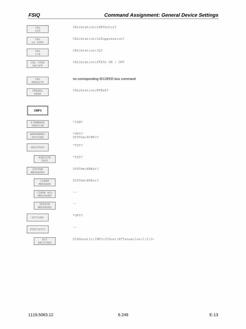
FSIQ Command Assignment: General Device Settings
1119.5063.12 6.249 E-13
CALLOG
CALibration:LDETector?
CALLO SUPP
CALibration:LOSuppression?
CALI/Q
CALibration:IQ?
CAL CORRON/OFF
CALibration:STATe ON | OFF
CALRESULTS
no corresponding IEC/IEEE-bus command
PRESELPEAK
CALibration:PPEak?
INFO
FIRMWAREVERSION
*IDN?
HARDWARE+OPTIONS
*OPT?SYSTem:BINFo?
SELFTEST*TST?
EXECUTETEST
*TST?
SYSTEMMESSAGES
SYSTem:ERRor?
CLEARMESSAGE
SYSTem:ERRor?
CLEAR ALLMESSAGES
--
UPDATEMESSAGES
--
OPTIONS*OPT?
STATISTIC--
ATTSWITCHES
DIAGnostic:INFO:CCOunt:ATTenuation<1|2|3>

Command Assignment: General Device Settings FSIQ
1119.5063.12 6.250 E-13
CONFIGURATION Key Group
MODEThe sub menus are described under the associated operating modes.
ANALYZERINSTrument<1|2>[:SELect] SANalyzerINSTrument<1|2>:NSELect 1
TRACKINGGENERATOR
OUTPut[:STATe] ON | OFF
VECTORANALYZER
INSTrument<1|2>[:SELect] ADEMod | DDEModINSTrument<1|2>:NSELect 2 | 3
GSM MSANALYZER
INSTrument<1|2>[:SELect] MGSMINSTrument<1|2>:NSELect 5
GSM BTSANALYZER
INSTrument<1|2>[:SELect] BGSMINSTrument<1|2>:NSELect 4
SETUP
TRANSDUCER--
TRANSDUCERFACTOR
[SENSe<1|2>:]CORRection:TRANsducer:SELect <name>[SENSe<1|2>:]CORRection:TRANsducer[:STATe] ON | OFF
TRANSDUCERSET
[SENSe<1|2>:]CORRection:TSET:SELect <name>[SENSe<1|2>:]CORRection:TSET[:STATe] ON | OFF
EDIT TRDFACTOR
[SENSe<1|2>:]CORRection:TRANsducer:SCALingLINear|LOGarithmic[SENSe<1|2>:]CORRection:TRANsducer:COMMent <string>
TRD FACTORNAME
[SENSe<1|2>:]CORRection:TRANsducer:SELect <name>
TRD FACTORUNIT
[SENSe<1|2>:]CORRection:TRANsducer:UNIT <string>
TRD FACTORVALUES
[SENSe<1|2>:]CORRection:TRANsducer:DATA <freq>,<level>..
INSERTLINE
no corresponding IEC/IEEE-bus command
DELETELINE
no corresponding IEC/IEEE-bus command
SAVE TRDFACTOR
automatically executed during IEC/IEEE-bus operation
EDIT TRDSET
[SENSe<1|2>:]CORRection:TSET:BREak ON | OFF[SENSe<1|2>:]CORRection:TSET:COMMent <string>
TRANSD SETNAME
[SENSe<1|2>:]CORRection:TSET:SELect <name>
TRANSD SETUNIT
[SENSe<1|2>:]CORRection:TSET:UNIT <string>

FSIQ Command Assignment: General Device Settings
1119.5063.12 6.251 E-13
TRANSD SETRANGES
[SENSe<1|2>:]CORRection:TSET:RANGe<1...10> <freq>,<freql>,<name>..
INSERTLINE
no corresponding IEC/IEEE-bus command
DELETELINE
no corresponding IEC/IEEE-bus command
SAVE TRDSET
automatically executed during IEC/IEEE-bus operation
NEWFACT/SET
see EDIT TRD FACTOR or EDIT TRD SET
DELETEFACTOR/SET
[SENSe<1|2>:]CORRection:TRANsducer:DELete[SENSe<1|2>:]CORRection:TSET:DELete
OPTIONSno corresponding IEC/IEEE-bus command
REFERENCEINT/EXT
[SENSe<1|2>:]ROSCillator:SOURce INTernal|EXTernal
EXT REFFREQUENCY
[SENSe<1|2>:]ROSCillator:EXTernal:FREQuency <num_value>
SERVICE--
INPUT RFDIAGnostic:SERVice:INPut[:SELect] RF
INPUT CALDIAGnostic:SERVice:INPut[:SELect] CALibration
NOISESOURCE
DIAGnostic:SERVice:NSOurce ON | OFF
REFERENCEADJUST
--
REFERENCE[SENSe<1|2>:]ROSCillator:[INTernal:]TUNe <num_value>
REFERENCEPROG
[SENSe<1|2>:]ROSCillator:[INTernal:]TUNe:SAVe
SERVICEFUNCTION
DIAGnostic:SERVice:FUNCtion <num_value>,<num_value>...
ENTERPASSWORD
SYSTem:PASSword[:CENable] <string>
GENERALSETUP
--
GPIBADDRESS
SYSTem:COMMunicate:GPIB[:SELF]:ADDRess 0...30
USER PORTA/B
INPut<1|2>:UPORt<1|2>[:VALue]?INPut<1|2>:UPORt<1|2>:STATe ON | OFFOUTPut<1|2>:UPORt<1|2>:STATe ON | OFFOUTPut<1|2>:UPORt<1|2>[:VALue] <Binary>

Command Assignment: General Device Settings FSIQ
1119.5063.12 6.252 E-13
COM PORT1/2
SYSTem:COMMunicate:SERial<1|2>:CONTrol:DTR IBFull | OFFSYSTem:COMMunicate:SERial<1|2>:CONTrol:RTS IBFull | OFFSYSTem:COMMunicate:SERial<1|2>[:RECeive]:BAUD <numeric_value>SYSTem:COMMunicate:SERial<1|2>[:RECeive]:BITS 7 | 8SYSTem:COMMunicate:SERial<1|2>[:RECeive]:PARity[:TYPE] EVEN| ODD| NONESYSTem:COMMunicate:SERial<1|2>[:RECeive]:SBITs 1|2SYSTem:COMMunicate:SERial<1|2>[:RECeive]:PACE XON | NONE
TIMESYSTem:TIME 0...23, 0...59, 0...59
DATESYSTem:DATE <num>,<num>,<num>
MONITORCONNECTED
no corresponding IEC/IEEE-bus command
KEY CLICKON/OFF
no corresponding IEC/IEEE-bus command
MODE FSEON/OFF
SYSTem:PRESet:COMPatible OFF | FSE
STATUS Key Group
LOCALdevice message "Go to LOCAL (GTL)"

FSIQ Command Assignment: General Device Settings
1119.5063.12 6.253 E-13
HARDCOPY Key Group
STARTHCOPy[:IMMediate<1|2>]
SETTINGS
COPYSCREEN
HCOPy:ITEM:ALL
COPYTRACE
HCOPy:ITEM:WINDow<1|2>:TRACe:STATe ON | OFF
COPYTABLE
HCOPy:ITEM:WINDow<1|2>:TABle:STATe ON | OFF
SELECTQUADRANT
--
UPPERLEFT
HCOPy:PAGE:DIMensions:QUADrant 1
LOWERLEFT
HCOPy:PAGE:DIMensions:QUADrant 2
UPPERRIGHT
HCOPy:PAGE:DIMensions:QUADrant 3
LOWERRIGHT
HCOPy:PAGE:DIMensions:QUADrant 4
FULLPAGE
HCOPy:PAGE:DIMensions:FULL
ENTERTEXT
--
COMMENTSCREEN A/B
HCOPy:ITEM:WINDow<1|2>:TEXT <string>
TITLEHCOPy:ITEM:LABel:TEXT <string>
HARDCOPYDEVICE
HCOPy:DEVice:LANGuage WMF|EWMF | BMP | GDI
SETTINGSDEVICE 1/2
HCOPy:DESTination<1|2> <string>MMEMory:NAME <file_name>HCOPy:ITEM:FFEed<1|2>:STATe ON | OFFHCOPy:PAGE:ORIentation<1|2> LANDscape | PORTrait
ENABLEDEV1/DEV2
the numeric suffix after HCOPy:IMMediate denotes the first or second device.
COLORON/OFF
HCOPy:DEVice:COLor ON | OFF
TRC COLORAUTO INC
HCOPy:ITEM:WINDow<1|2>:TRACe:CAINcrement ON | OFF

Command Assignment: General Device Settings FSIQ
1119.5063.12 6.254 E-13
MEMORY Key Group
CONFIG
EDITPATH
MMEMory:MSIS <device>MMEMory:CDIRectory <directory_name>
DELETEMMEMory:DELete <file_name>MMEMory:RDIRectory <directory_name>
FORMATDISK
MMEMory:INITialize <msus>
MAKEDIRECTORY
MMEMory:MDIRectory <directory_name>
RENAMEMMEMory:MOVE <file_source>,<file_destination>
SORTMODE
no corresponding IEC/IEEE-bus command
COPYMMEMory:COPY <file_source>,<file_destination>
SAVE
EDITNAME
MMEMory:STORe:STATe 1,<file_name>
EDITPATH
the path is included in the file name.
EDITCOMMENT
MMEMory:COMMent <string>
SELECT ITEMSTO SAVE
--
SELECTITEMS
MMEMory:SELect[:ITEM]:GSETup ON | OFFMMEMory:SELect[:ITEM]:HWSettings ON | OFFMMEMory:SELect[:ITEM]:TRACe<1...4> ON | OFFMMEMory:SELect[:ITEM]:LINes[:ACTive] ON | OFFMMEMory:SELect[:ITEM]:LINes:ALL ON | OFFMMEMory:SELect[:ITEM]:CSETup ON | OFFMMEMory:SELect[:ITEM]:HCOPy ON | OFFMMEMory:SELect[:ITEM]:MACRos ON | OFFMMEMory:SELect[:ITEM]:SCData ON | OFFMMEMory:SELect[:ITEM]:TRANsducer[:ACTive] ON | OFFMMEMory:SELect[:ITEM]:TRANsducer:ALL ON | OFFMMEMory:SELect[:ITEM]:CVL[:ACTive] ON | OFFMMEMory:SELect[:ITEM]:CVL:ALL ON | OFF
ENABLEALL ITEMS
MMEMory:SELect[:ITEM]:ALL
DISABLEALL ITEMS
MMEMory:SELect[:ITEM]:NONE
DEFAULTCONFIG
MMEMory:SELect[:ITEM]:DEFault
DATA SETLIST
--

FSIQ Command Assignment: General Device Settings
1119.5063.12 6.255 E-13
DATA SETCLEAR
MMEMory:CLEar:STATe 1,<file_name>
DATA SETCLEAR ALL
MMEMory:CLEar:ALL
RECALL
EDITNAME
MMEMory:LOAD:STATe 1,<file_name>
EDITPATH
the path is included in the file name.
AUTORECALL
MMEMory:LOAD:AUTO 1,<file_name>
SELECT ITEMSTO RECALL
--
SELECTITEMS
MMEMory:SELect[:ITEM]:GSETup ON | OFFMMEMory:SELect[:ITEM]:HWSettings ON | OFFMMEMory:SELect[:ITEM]:TRACe<1...4> ON | OFFMMEMory:SELect[:ITEM]:LINes[:ACTive] ON | OFFMMEMory:SELect[:ITEM]:LINes:ALL ON | OFFMMEMory:SELect[:ITEM]:CSETup ON | OFFMMEMory:SELect[:ITEM]:HCOPy ON | OFFMMEMory:SELect[:ITEM]:CDATa ON | OFFMMEMory:SELect[:ITEM]:MACRos ON | OFFMMEMory:SELect[:ITEM]:SCData ON | OFFMMEMory:SELect[:ITEM]:TRANsducer[:ACTive] ON | OFFMMEMory:SELect[:ITEM]:TRANsducer:ALL ON | OFFMMEMory:SELect[:ITEM]:CVL[:ACTive] ON | OFFMMEMory:SELect[:ITEM]:CVL:ALL ON | OFF
ENABLEALL ITEMS
MMEMory:SELect[:ITEM]:ALL
DISABLEALL ITEMS
MMEMory:SELect[:ITEM]:NONE
DEFAULTCONFIG
MMEMory:SELect[:ITEM]:DEFault
DATA SETLIST
--
DATA SETCLEAR
MMEMory:CLEar:STATe 1,<file_name>
DATA SETCLEAR ALL
MMEMory:CLEar:ALL

Command Assignment: General Device Settings FSIQ
1119.5063.12 6.256 E-13
USER Key
USER
MACRO1...7
no corresponding IEC/IEEE-bus command
DEFINEMACRO
no corresponding IEC/IEEE-bus command
RECORDON/OFF
no corresponding IEC/IEEE-bus command
DEFINEPAUSE
no corresponding IEC/IEEE-bus command
DELETEMACRO
no corresponding IEC/IEEE-bus command
MACROTITLE
no corresponding IEC/IEEE-bus command
SELECTMACRO
no corresponding IEC/IEEE-bus command
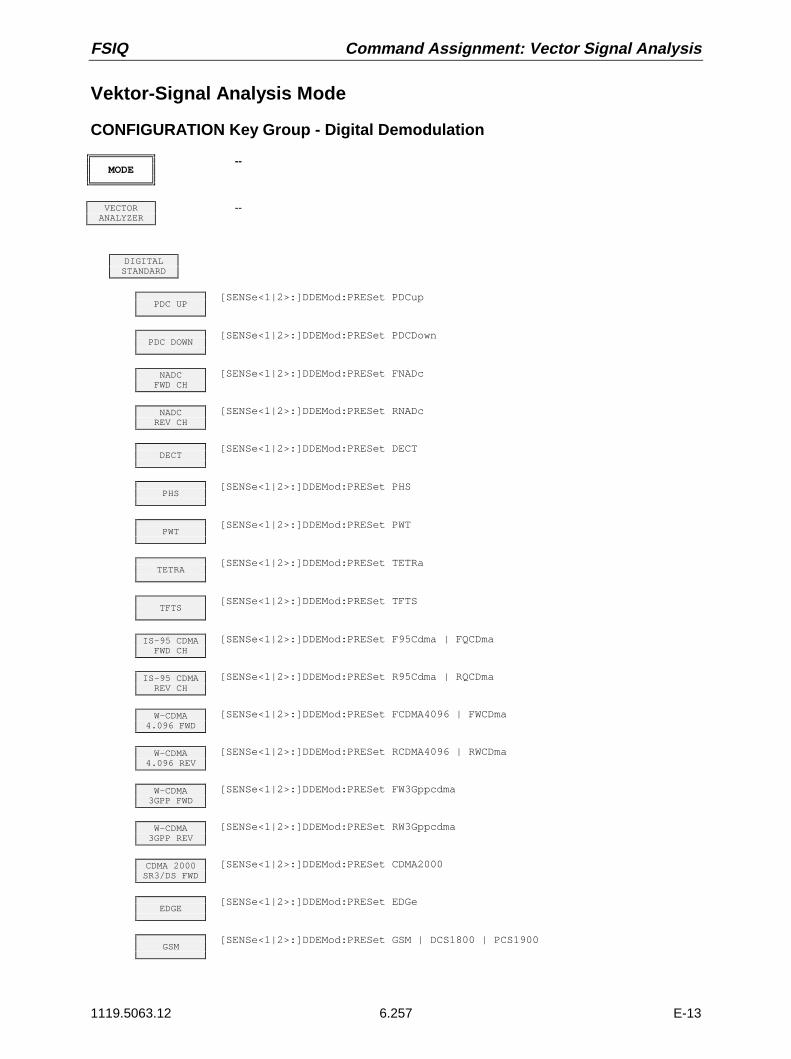
FSIQ Command Assignment: Vector Signal Analysis
1119.5063.12 6.257 E-13
Vektor-Signal Analysis Mode
CONFIGURATION Key Group - Digital Demodulation
MODE--
VECTORANALYZER
--
DIGITALSTANDARD
PDC UP[SENSe<1|2>:]DDEMod:PRESet PDCup
PDC DOWN[SENSe<1|2>:]DDEMod:PRESet PDCDown
NADCFWD CH
[SENSe<1|2>:]DDEMod:PRESet FNADc
NADCREV CH
[SENSe<1|2>:]DDEMod:PRESet RNADc
DECT[SENSe<1|2>:]DDEMod:PRESet DECT
PHS[SENSe<1|2>:]DDEMod:PRESet PHS
PWT[SENSe<1|2>:]DDEMod:PRESet PWT
TETRA[SENSe<1|2>:]DDEMod:PRESet TETRa
TFTS[SENSe<1|2>:]DDEMod:PRESet TFTS
IS-95 CDMAFWD CH
[SENSe<1|2>:]DDEMod:PRESet F95Cdma | FQCDma
IS-95 CDMAREV CH
[SENSe<1|2>:]DDEMod:PRESet R95Cdma | RQCDma
W-CDMA4.096 FWD
[SENSe<1|2>:]DDEMod:PRESet FCDMA4096 | FWCDma
W-CDMA4.096 REV
[SENSe<1|2>:]DDEMod:PRESet RCDMA4096 | RWCDma
W-CDMA3GPP FWD
[SENSe<1|2>:]DDEMod:PRESet FW3Gppcdma
W-CDMA3GPP REV
[SENSe<1|2>:]DDEMod:PRESet RW3Gppcdma
CDMA 2000SR3/DS FWD
[SENSe<1|2>:]DDEMod:PRESet CDMA2000
EDGE[SENSe<1|2>:]DDEMod:PRESet EDGe
GSM[SENSe<1|2>:]DDEMod:PRESet GSM | DCS1800 | PCS1900

Command Assignment: Vector Signal Analysis FSIQ
1119.5063.12 6.258 E-13
CT2[SENSe<1|2>:]DDEMod:PRESet CT2
ERMES[SENSe<1|2>:]DDEMod:PRESet ERMes
MODACOM[SENSe<1|2>:]DDEMod:PRESet MODacom
FLEX16_2[SENSe<1|2>:]DDEMod:PRESet F16
FLEX32_2[SENSe<1|2>:]DDEMod:PRESet F322
FLEX32_4[SENSe<1|2>:]DDEMod:PRESet F324
FLEX64_4[SENSe<1|2>:]DDEMod:PRESet F64
APCO25C4FM
[SENSe<1|2>:]DDEMod:PRESet APCO25C4FM
APCO25CQPSK
[SENSe<1|2>:]DDEMod:PRESet APCO25CQPSK
CDPD[SENSe<1|2>:]DDEMod:PRESet CDPD
DIGITALDEMOD
INSTrument[:SELect] DDEMod[SENSe<1|2>:]DDEMod:FORMat QPSK | PSK | MSK |QAM | FSK[SENSe<1|2>:]DDEMod:QPSK:FORMat NORMal | DIFFerential | OFFSet | DPI4[SENSe<1|2>:]DDEMod:PSK:NSTate 2 | 8[SENSe<1|2>:]DDEMod:PSK:FORMat NORMal | DIFFerential | N3Pi8[SENSe<1|2>:]DDEMod:MSK:FORMat TYPE1 | TYPE2 | NORMal | DIFFerential[SENSe<1|2>:]DDEMod:QAM:NSTate 16[SENSe<1|2>:]DDEMod:FSK:NSTate 2 | 4
CALCulate<1|2>:MARKer<1...2>:FUNCtion:DDEMod:RESult? MERM| MEPK| MEPS| PERM| PEPK| PEPS| EVRM| EVPK| EVPS| IQOF| IQIM| ADR| FERR| DEV|FSRM| FSPK| FSPS| RHO| FEPK
MODULATIONPARAMETERS
--
SYMBOLRATE
[SENSe<1|2>:]DDEMod:SRATe <num_value>
SIDE BANDNORM INV
[SENSe<1|2>:]DDEMod:SBANd NORMal|INVerse
MEASFILTER
[SENSe<1|2>:]DDEMod:FILTer:MEASurement OFF | RCOSine | RRCosine |GAUSsian | B22 | B25 | B44 |QFM|FM95 | QFR|FR95 | QRM|RM95 |QRR|RR95 | A25Fm | EMES | EREF
REFERENCEFILTER
[SENSe<1|2>:]DDEMod:FILTer:REFerence RCOSine | RRCosine | GAUSsian |B22 | B25 | B44 | QFM|FM95 |QFR|FR95 | QRM|RM95 | QRR|RR95 |A25Fm | EMES | EREF
ALPHA/BT[SENSe<1|2>:]DDEMod:FILTer:ALPHa <num_value>
FSK REFDEVIATION
CALCulate<1|2>:FSK:DEViation:REFerence <num_value>
NORMALIZEON / OFF
[SENSe<1|2>:]DDEMod:NORMalize ON | OFF

FSIQ Command Assignment: Vector Signal Analysis
1119.5063.12 6.259 E-13
MEAS RESULT--
MAGNITUDECAP BUFFER
CALCulate<1|2>:FEED ‘TCAP’
MEASSIGNAL
CALCulate<1|2>:FEED ‘XTIM:DDEM:MEAS’
MAGNITUDECALCulate<1|2>:FORMat MAGNitude
PHASECALCulate<1|2>:FORMat PHASe
FREQUENCYCALCulate<1|2>:FORMat FREQuency
REAL/IMAGPART
CALCulate<1|2>:FORMat RIMag
EYE DIAG [FREQ]
CALCulate<1|2>:FORMat FEYE
EYE DIAG [I]
CALCulate<1|2>:FORMat IEYE
EYE DIAG [Q]
CALCulate<1|2>:FORMat QEYE
EYE DIAGTRELLIS
CALCulate<1|2>:FORMat TEYE
POLAR [IQ]VECTOR
CALCulate<1|2>:FORMat COMP
POLAR [IQ]CONSTELL
CALCulate<1|2>:FORMat CONS
SYMBOLDISPLAY
DISPLay[:WINDow<1|2>]:TRACe<1...4>:SYMBol DOTS | BARS |OFF
PHASE WRAPON/OFF
CALCulate<1|2>:FORMat PHASe | UPHase
EYELENGTH
DISPlay[:WINDow<1|2>]:TRACe<1...4>:EYE:COUNt <num_value>
REFERENCESIGNAL
CALCulate<1|2>:FEED ‘XTIM:DDEM:REF’
MAGNITUDECALCulate<1|2>:FORMat MAGNitude
PHASECALCulate<1|2>:FORMat PHASe
FREQUENCYCALCulate<1|2>:FORMat FREQuency
REAL/IMAGPART
CALCulate<1|2>:FORMat RIMag
EYE DIAG [FREQ]
CALCulate<1|2>:FORMat FEYE
EYE DIAG [I]
CALCulate<1|2>:FORMat IEYE

Command Assignment: Vector Signal Analysis FSIQ
1119.5063.12 6.260 E-13
EYE DIAG [Q]
CALCulate<1|2>:FORMat QEYE
EYE DIAGTRELLIS
CALCulate<1|2>:FORMat TEYE
POLAR [IQ]VECTOR
CALCulate<1|2>:FORMat COMP
POLAR [IQ]CONSTELL
CALCulate<1|2>:FORMat CONS
SYMBOLDISPLAY
DISPLay[:WINDow<1|2>]:TRACe<1...4>:SYMBol DOTS | BARS |OFF
PHASE WRAPON/OFF
CALCulate<1|2>:FORMat PHASe | UPHase
EYELENGTH
DISPlay[:WINDow<1|2>]:TRACe<1...4>:EYE:COUNt <num_value>
ERRORSIGNAL
CALCulate<1|2>:FEED ‘XTIM:DDEM:ERR:MPH’
CALCulate<1|2>:MARKer<1...2>:FUNCtion:DDEMod:RESult? MERM| MEPK| MEPS| PERM| PEPK| PEPS| EVRM| EVPK| EVPS| IQOF| IQIM| ADR| FERR| DEV|FSRM| FSPK| FSPS| RHO| FEPK
MAGNITUDECALCulate<1|2>:FORMat MAGNitude
PHASECALCulate<1|2>:FORMat PHASe
FREQUENCYCALCulate<1|2>:FORMat FREQuency
REAL/IMAGPART
CALCulate<1|2>:FORMat RIMag
ERROR VECTMAGNITUDE
CALCulate<1|2>:FORMat MAGNitudeCALCulate<1|2>:FEED ‘XTIM:DDEM:ERR:VECT’
POLAR [IQ]VECTOR
CALCulate<1|2>:FORMat COMPCALCulate<1|2>:FEED ‘XTIM:DDEM:ERR:VECT’
POLAR [IQ]CONSTELL
CALCulate<1|2>:FORMat CONSCALCulate<1|2>:FEED ‘XTIM:DDEM:ERR:VECT’
SYMBOLDISPLAY
DISPLay[:WINDow<1|2>]:TRACe<1...4>:SYMBol DOTS | BARS | OFFCALCulate<1|2>:MARKer<1...2>:FUNCtion:DDEMod:RESult?
MERM| MEPK| MEPS|PERM| PEPK| PEPS| EVRM| EVPK| EVPS| IQOF| IQIM|ADR| FERR| DEV|FSRM| FSPK| FSPS| RHO| FEPK
SYMB TABLE/ ERRORS
CALCulate<1|2>:FEED ‘XTIM:DDEM:SYMB’
MEMORYSIZE
[SENSe<1|2>:]TCAPture:LENGth 1024 | 2048 | 4096 | 8192 | 16384
FRAMELENGTH
[SENSe<1|2>:]DDEMod:SEARch:TIME <num_value>
RESULTLENGTH
[SENSe<1|2>:]DDEMod:TIME <num_value>
POINTSPER SYMBOL
[SENSe<1|2>:]DDEMod:PRATe 1| 2| 4| 8| 16
TRIGGERsee section "SWEEP - TRIGGER"

FSIQ Command Assignment: Vector Signal Analysis
1119.5063.12 6.261 E-13
RANGEsee section "LEVEL - RANGE"
IFBANDWIDTH
--
IF BWAUTO
[SENSe<1|2>:]BANDwidth|BWIDth:RESolution:AUTO ON | OFF
IF BWMANUAL
[SENSe<1|2>:]BANDwidth|BWIDth:RESolution <num_value>
CONFIGURATION Key Group - Analog Demodulation
MODE--
VECTORANALYZER
--
ANALOGDEMOD
INSTrument<1|2>[:SELect] ADEMod
MODULATIONPARAMETER
--
HIGH PASSAF FILTER
SENSe<1|2>:FILTer:HPASs[:STATe] ON | OFFSENSe<1|2>:FILTer:HPASs:FREQuency <num_value>
LOW PASSAF FILTER
SENSe<1|2>:FILTer[:LPASs][:STATe] ON | OFFSENSe<1|2>:FILTer[:LPASs]:FREQuency <num_value>
WEIGHTINGAF FILTER
SENSe<1|2>:FILTer:CCITt[:STATe] ON | OFFSENSe<1|2>:FILTer:CMESsage[:STATe] ON | OFF
AF COUPL’GAC DC
SENSe<1|2>:ADEMod:AF:COUPling AC|DC
SQUELCHON OFF
SENSe<1|2>:ADEMod:SQUelch[:STATe] ON | OFF
SQUELCHLEVEL
SENSe<1|2>:ADEMod:SQUelch:LEVel <num_value>
SIDE BANDNORM INV
SENSe<1|2>:ADEMod:SBANd NORMal|INVerse
AM/FMDEEMPH
SENSe<1|2>:FILTer:DEMPhasis:TCONstant <num_value>
PRE DISPLON OFF
SENSe<1|2>:FILTer:DEMPhasis:LINK DISPlay|AUDio
MEASRESULT
--
AMSIGNAL
CALCulate<1|2>:FEED ‘XTIM:AM’
FMSIGNAL
CALCulate<1|2>:FEED ‘XTIM:FM’
PMSIGNAL
CALCulate<1|2>:FEED ‘XTIM:PM’

Command Assignment: Vector Signal Analysis FSIQ
1119.5063.12 6.262 E-13
MODULATIONSUMMARY
CALCulate<1|2>:FEED ‘XTIM:AMSummary’CALCulate<1|2>:FEED ‘XTIM:FMSummary’CALCulate<1|2>:FEED ‘XTIM:PMSummary’CALCulate<1|2>:MARKer<1...4>:FUNCtion:ADEMod:AM[:RESult?]
PPEak | MPEak | MIDDle | RMSCALCulate<1|2>:MARKer<1...4>:FUNCtion:ADEMod:FM[:RESult?]
PPEak | MPEak | MIDDle | RMS | RDEVCALCulate<1|2>:MARKer<1...4>:FUNCtion:ADEMod:PM[:RESult?]
PPEak | MPEak | MIDDle | RMSCALCulate<1|2>:MARKer<1...4>:FUNCtion:ADEMod:AFRequency[:RESult?]CALCulate<1|2>:MARKer<1...4>:FUNCtion:ADEMod:FERRor [:RESult?]CALCulate<1|2>:MARKer<1...4>:FUNCtion:ADEMod:SINad:RESult?CALCulate<1|2>:MARKer<1...4>:FUNCtion:ADEMod:CARRier[:RESult?]
SUMMARYSETTINGS
--
AVERAGEHOLD ON
SENSe<1|2>:MSUMmary:AHOLd[:STATe] ON | OFF
SWEEPCOUNT
SENSe<1|2>:SWEep:COUNt <num_value>
RELUNITDB %
SENSe<1|2>:MSUMmary:RUNit PCT | DB
INDICATIONABS REL
SENSe<1|2>:MSUMmary:MODE ABSolute | RELative
SETREFERENCE
SENSe<1|2>:MSUMmary:REFerence <num_value>
MEAS->REF
SENSe<1|2>:MSUMmary:REFerence:AUTO ONCe
SINAD 1kHzON OFF
CALCulate<1|2>:MARKer<1...4>:FUNCtion:ADEMod:SINad[:STATe]CALCulate<1|2>:MARKer<1...4>:FUNCtion:ADEMod:SINad:RESult?
SUMMARYMEAS TIME
SENSe<1|2>:MSUMmary:MTIMe <num_value>
REAL TIMEON OFF
SENSe<1|2>:ADEMod:RTIMe[:STATe] ON | OFF
SENSITIVAF OUTPUT
OUTPut<1|2>:AF:SENSitivity <num_value>
VOLUMESYSTem:SPEaker<1|2>:VOLume <num_value>
DEMODBANDWIDTH
SENSe<1|2>:BANDwidth|BWIDth:DEMod <num_value>
DEEMPHASISON OFF
SENSe<1|2>:FILTer:DEMPhasis[:STATe] ON | OFF

FSIQ Command Assignment: Vector Signal Analysis
1119.5063.12 6.263 E-13
FREQUENCY Key Group
CENTER[SENSe<1|2>:]FREQuency:CENTer <num_value>
CENTERFREQUENCY
[SENSe<1|2>:]FREQuency:CENTer <num_value>
FREQUENCYOFFSET
[SENSe<1|2>:]FREQuency:OFFSet <num_value>
LEVEL Key Group
REF--
REFLEVEL
DISPlay[:WINDow<1|2>]:TRACe<1...4>:Y[:SCALe]:RLEVel <num_value>
REF LEVELOFFSET
DISPlay[:WINDow<1|2>]:TRACe<1...4>:Y[:SCALe]:RLEVel:OFFSet <num_value>
RF ATTENMANUAL
INPut<1|2>:ATTenuation <num_value>
ATTEN AUTONORMAL
INPut<1|2>:ATTenuation:AUTO:MODE NORMal;INPut<1|2>:ATTenuation:AUTO ON
ATTEN AUTOLOW NOISE
INPut<1|2>:ATTenuation:AUTO:MODE LNOise;INPut<1|2>:ATTenuation:AUTO ON
ATTEN AUTOLOW DIST
INPut<1|2>:ATTenuation:AUTO:MODE LDIStortion;INPut<1|2>:ATTenuation:AUTO ON
MIXERLEVEL
INPut<1|2>:MIXer <num_value>
RANGE--
Y PER DIVDISPlay[:WINDow<1|2>]:TRACe<1...4>:Y[:SCALe]:PDIVision <num_value>
REF VALUEY AXIS
DISPlay[:WINDow<1|2>]:TRACe<1...4>:Y[:SCALe]:RVALue <num_value>
REF VALUEX AXIS
DISPlay[:WINDow<1|2>]:TRACe<1...4>:X[:SCALe]:RVALue <num_value>
REF VALUEPOSITION
DISPlay[:WINDow<1|2>]:TRACe<1...4>:Y[:SCALe]:RPOSition 0...100PCT
SCALE UNIT--
Y UNITLOG[dB]
CALCulate<1|2>:UNIT:POWer DB
Y UNITLINEAR
CALCulate<1|2>:UNIT:POWer UNITLESS
Y UNITDEG
CALCulate<1|2>:UNIT:ANGLe DEG

Command Assignment: Vector Signal Analysis FSIQ
1119.5063.12 6.264 E-13
Y UNITRAD
CALCulate<1|2>:UNIT:ANGLe RAD
Y UNITDBM
CALCulate<1|2>:UNIT:POWer DBM
Y UNITVOLT
CALCulate<1|2>:UNIT:POWer VOLT
Y UNITWATT
CALCulate<1|2>:UNIT:POWer WATT
X UNITTIME
CALCulate<1|2>:X:UNIT:TIME S
X UNITSYMBOL
CALCulate<1|2>:X:UNIT:TIME SYMB
SENSITIVAF OUTPUT
OUTPut<1|2>:AF:SENSitivity <num_value>
VOLUMESYSTem:SPEaker:VOLume <num_value>
INPUT Key
INPUT
RF ATTENMANUAL
INPut<1|2>:ATTenuation <num_value>
ATTEN AUTONORMAL
INPut<1|2>:ATTenuation:AUTO:MODE NORMal;INPut<1|2>:ATTenuation:AUTO ON
ATTEN AUTOLOW NOISE
INPut<1|2>:ATTenuation:AUTO:MODE LNOise;INPut<1|2>:ATTenuation:AUTO ON
ATTEN AUTOLOW DIST
INPut<1|2>:ATTenuation:AUTO:MODE LDIStortion;INPut<1|2>:ATTenuation:AUTO ON
MIXERLEVEL
INPut<1|2>:MIXer <num_value>
INPUTSELECT
--
RF INPUT50 OHM
INPut<1|2>:IMPedance 50
RF INPUT75 OHM/RAM
INPut<1|2>:IMPedance:CORRection RAM
RF INPUT75OHM/RAZ
INPut<1|2>:IMPedance:CORRection RAZ

FSIQ Command Assignment: Vector Signal Analysis
1119.5063.12 6.265 E-13
MARKER Key Group
NORMAL
MARKER1..2
CALCulate<1|2>:MARKer<1...2>[:STATe] ON | OFF;CALCulate<1|2>:MARKer<1...2>:X <num_value>;CALCulate<1|2>:MARKer<1...2>:Y?
POLAR MARKERR/I / MA/PH
CALCulate<1|2>:MARKer<1...2>:READout MPHase | RIMaginary
POLAR MARKERDEG/ RAD
CALCulate<1|2>:UNIT:ANGLe DEG | RAD
COUPLEDMARKER
CALCulate<1|2>:MARKer<1...2>:COUPled[:STATe] ON | OFF
MARKERINFO
DISPlay:WINDow<1|2>:MINFo ON | OFF (indication)
ALL MARKEROFF
CALCulate<1|2>:MARKer<1...2>:AOFF
DELTA
DELTA1/2
CALCulate<1|2>:DELTamarker<1...2>:AOFF
DELTA MKRABS / REL
CALCulate<1|2>:DELTamarker<1...2>:MODE ABSolute | RELative
ALL DELTAOFF
CALCulate<1|2>:DELTamarker<1...2>[:STATe] ON | OFFCALCulate<1|2>:DELTamarker<1...2>:X <num_value>CALCulate<1|2>:DELTamarker<1...2>:Y?
MARKERSEARCH
PEAKCALCulate<1|2>:MARKer<1...2>:MAXimum[:PEAK]CALCulate<1|2>:DELTamarker<1...2>:MAXimum[:PEAK]
ACTIVE MKR/ DELTA
--
MINCALCulate<1|2>:MARKer<1...2>:MINimum[:PEAK]CALCulate<1|2>:DELTamarker<1...2>:MINimum[:PEAK]
MAX |PEAK|CALCulate<1|2>:MARKer<1...2>:MAXimum:APEakCALCulate<1|2>:DELTamarker<1...2>:MAXimum:APEak
SUMMARYON OFF
CALCulate<1|2>:MARKer<1..2>:FUNCtion:SUMMary[:STATe] ON | OFF
SUMMARYMARKER
--
MAX |PEAK|CALCulate<1|2>:MARKer<1..,2>:FUNCtion:SUMMary:MAXimum[:STATe] ON | OFFCALCulate<1|2>:MARKer<1...2>:FUNCtion:SUMMary:MAXimum:RESult?CALCulate<1|2>:MARKer<1...2>:FUNCtion:SUMMary:MAXimum:AVERage:RESult?CALCulate<1|2>:MARKer<1...2>:FUNCtion:SUMMary:MAXimum:PHOLd:RESult?

Command Assignment: Vector Signal Analysis FSIQ
1119.5063.12 6.266 E-13
+PEAKCALCulate<1|2>:MARKer<1...2>:FUNCtion:SUMMary:PPEak[:STATe] ON | OFFCALCulate<1|2>:MARKer<1...2>:FUNCtion:SUMMary:PPEak:RESult?CALCulate<1|2>:MARKer<1...2>:FUNCtion:SUMMary:PPEak:AVERage:RESult?CALCulate<1|2>:MARKer<1...2>:FUNCtion:SUMMary:PPEak:PHOLd:RESult?
-PEAKCALCulate<1|2>:MARKer<1...2>:FUNCtion:SUMMary:MPEak[:STATe] ON | OFFCALCulate<1|2>:MARKer<1...2>:FUNCtion:SUMMary:MPEak:RESult?CALCulate<1|2>:MARKer<1...2>:FUNCtion:SUMMary:MPEak:AVERage:RESult?CALCulate<1|2>:MARKer<1...2>:FUNCtion:SUMMary:MPEak:PHOLd:RESult?
±PEAK/2CALCulate<1|2>:MARKer<1...2>:FUNCtion:SUMMary:MIDDle[:STATe] ON | OFFCALCulate<1|2>:MARKer<1...2>:FUNCtion:SUMMary:MIDDle:RESult?CALCulate<1|2>:MARKer<1...2>:FUNCtion:SUMMary:MIDDle:AVERage:RESult?CALCulate<1|2>:MARKer<1...2>:FUNCtion:SUMMary:MIDDle:PHOLd:RESult?
RMSCALCulate<1|2>:MARKer<1...2>:FUNCtion:SUMMary:RMS[:STATe] ON | OFFCALCulate<1|2>:MARKer<1...2>:FUNCtion:SUMMary:RMS:RESult?CALCulate<1|2>:MARKer<1...4>:FUNCtion:SUMMary:RMS:AVERage:RESult?CALCulate<1|2>:MARKer<1...4>:FUNCtion:SUMMary:RMS:PHOLd:RESult?
MEANCALCulate<1|2>:MARKer<1...2>:FUNCtion:SUMMary:MEAN[:STATe] ON | OFFCALCulate<1|2>:MARKer<1...2>:FUNCtion:SUMMary:MEAN:RESult?CALCulate<1|2>:MARKer<1...4>:FUNCtion:SUMMary:MEAN:AVERage:RESult?CALCulate<1|2>:MARKer<1...4>:FUNCtion:SUMMary:MEAN:PHOLd:RESult?
PEAK HOLDON / OFF
CALCulate<1|2>:MARKer<1...2>:FUNCtion:SUMMary:PHOLd ON | OFF
AVERAGE/HOLDON / OFF
CALCulate<1|2>:MARKer<1...2>:FUNCtion:SUMMary:AVERage ON | OFF
SWEEPCOUNT
[SENSe<1|2>:]SWEep:COUNt <num_value>
ALL SUM MKROFF
CALCulate<1|2>:MARKer<1...2>:FUNCtion:SUMMary:AOFF
SEARCH LIMITON/OFF
CALCulate<1|2>:MARKer<1...2>:X:SLIMits[:STATe] ON | OFF
SELECTMARKER
--
MKR ->
PEAKCALCulate<1|2>:MARKer<1...2>:MAXimum[:PEAK]CALCulate<1|2>:DELTamarker<1...2>:MAXimum[:PEAK]
MKR →TRACE
CALCulate<1|2>:MARKer<1...4>:TRACe <num_value>
SELECTMARKER
--
ACTIVE MKR/ DELTA
no corresponding IEC/IEEE-bus command

FSIQ Command Assignment: Vector Signal Analysis
1119.5063.12 6.267 E-13
LINES Key Group
D LINES--
DISPLAYLINE 1/2
CALCulate<1|2>:DLINe<1|2>:STATe ON | OFF;CALCulate<1|2>:DLINe<1|2> <num_value>
REFERENCELINE
CALCulate<1|2>:RLINe:STATe ON | OFF;CALCulate<1|2>:RLINe <num_value>
THRESHOLDLINE
CALCulate<1|2>:THReshold ON | OFF;CALCulate<1|2>:THReshold <num_value>
TIME/SYMB1/2
CALCulate<1|2>:TLINe<1|2>:STATe ON | OFF;CALCulate<1|2>:TLINe<1|2> <num_value>
LIMITS
SELECT LIMITLINE
CALCulate<1|2>:LIMit<1...8>:NAME <string>;CALCulate<1|2>:LIMit<1...8>:STATe ON | OFF
NEW LIMITLINE
s. EDIT LIMIT LINE
NAMECALCulate<1|2>:LIMit<1...8>:NAME <string>
VALUES no corresponding IEC/IEEE-bus command
INSERTVALUE
no corresponding IEC/IEEE-bus command
DELETEVALUE
no corresponding IEC/IEEE-bus command
SHIFT XLIMIT LINE
CALCulate<1|2>:LIMit<1...8>:CONTrol:SHIFt <num_value>
SHIFT YLIMIT LINE
CALCulate<1|2>:LIMit<1...8>:UPPer:SHIFt <num_value>CALCulate<1|2>:LIMit<1...8>:LOWer:SHIFt <num_value>
SAVELIMIT LINE
automatically executed during IEC/IEEE-bus operation

Command Assignment: Vector Signal Analysis FSIQ
1119.5063.12 6.268 E-13
EDIT LIMITLINE
CALCulate<1|2>:LIMit<1...8>:UNIT DB| DBM | RAD | DEG | PCT | HZ | S |VOLT | WATT | UNITless
CALCulate<1|2>:LIMit<1...8>:TRACe <num_value>CALCulate<1|2>:LIMit<1...8>:COMMent ’string’CALCulate<1|2>:LIMit<1...8>:CONTrol[:DATA] <num_value>,<num_value>..CALCulate<1|2>:LIMit<1...8>:CONTrol:DOMain FREQuency|TIMECALCulate<1|2>:LIMit<1...8>:CONTrol:OFFset <num_value>CALCulate<1|2>:LIMit<1...8>:CONTrol:MODE RELative | ABSoluteCALCulate<1|2>:LIMit<1...8>:CONTrol:UNIT[:TIME] S | SYMCALCulate<1|2>:LIMit<1...8>:CONTrol:SPACing LINear | LOGarithmicCALCulate<1|2>:LIMit<1...8>:UPPer[:DATA] <num_value>,<num_value>..CALCulate<1|2>:LIMit<1...8>:UPPer:STATe ON | OFFCALCulate<1|2>:LIMit<1...8>:UPPer:OFFset <num_value>CALCulate<1|2>:LIMit<1...8>:UPPer:MARGin <num_value>CALCulate<1|2>:LIMit<1...8>:UPPer:MODE RELative | ABSoluteCALCulate<1|2>:LIMit<1...8>:UPPer:SPACing LINear | LOGarithmicCALCulate<1|2>:LIMit<1...8>:LOWer[:DATA] <num_value>,<num_value>..CALCulate<1|2>:LIMit<1...8>:LOWer:STATe ON | OFFCALCulate<1|2>:LIMit<1...8>:LOWer:OFFset <num_value>CALCulate<1|2>:LIMit<1...8>:LOWer:MARGin <num_value>CALCulate<1|2>:LIMit<1...8>:LOWer:MODE RELative | ABSoluteCALCulate<1|2>:LIMit<1...8>:LOWer:SPACing LINear | LOGarithmicCALCulate<1|2>:LIMit<1...8>:FAIL?CALCulate<1|2>:LIMit<1...8>:CLEar[:IMMediate]
COPY LIMITLINE
CALCulate<1|2>:LIMit<1...8>:COPY 1...8 | <name>
DELETE LIMITLINE
CALCulate<1|2>:LIMit<1...8>:DELete
X OFFSETCALCulate<1|2>:LIMit<1...8>:CONTrol:OFFset <num_value>
Y OFFSETCALCulate<1|2>:LIMit<1...8>:UPPer:OFFset <num_value>CALCulate<1|2>:LIMit<1...8>:LOWer:OFFset <num_value>
TRACE Key Group
TRACE--
CLEAR/WRITEDISPlay[:WINDow<1|2>]:TRACe<1...4>:MODE WRITe
VIEWDISPlay[:WINDow<1|2>]:TRACe<1...4>:MODE VIEW
BLANKDISPlay[:WINDow<1|2>]:TRACe<1...4>[:STATe] OFF
CONTINUOUSWRITE
DISPlay[:WINDow<1|2>]:TRACe<1...4>:MODE:CWRite ON | OFF
AVERAGEDISPlay[:WINDow<1|2>]:TRACe<1...4>:MODE AVERage or[SENSe<1|2>:]AVERage:MODE SCALe
MAX HOLDDISPlay[:WINDow<1|2>]:TRACe<1...4>:MODE MAXHold or[SENSe<1|2>:]AVERage:MODE MAX
MIN HOLDDISPlay[:WINDow<1|2>]:TRACe<1...4>:MODE MINHold or[SENSe<1|2>:]AVERage:MODE MIN
SWEEP COUNT[SENSe<1|2>:]SWEep:COUNt <num_value>

FSIQ Command Assignment: Vector Signal Analysis
1119.5063.12 6.269 E-13
SWEEP Key Group
COUPLING--
IF BWAUTO
[SENSe<1|2>:]BANDwidth|BWIDth[:RESolution]:AUTO ON | OFF
IF BWMANUAL
[SENSe<1|2>:]BANDwidth|BWIDth[:RESolution] <num_value>
MAIN PLLBANDWIDTH
[SENSe<1|2>:]BANDwidth|BWIDth:PLL AUTO|HIGH|MEDium|LOW
SWEEP
CONTINUOUSSWEEP
INITiate<1|2>:CONTinuous ON; INITiate[:IMMediate]
SINGLESWEEP
INITiate<1|2>:CONTinuous OFF; INITiate[:IMMediate]
SWEEPCOUNT
[SENSe<1|2>:]SWEep:COUNt <num_value>
RESULTLENGTH
[SENSe<1|2>:]DDEMod:TIME <num_value>
TRIGGER Key - Digital Demodulation
TRIGGER
FREE RUNTRIGger<1|2>[:SEQuence]:SOURce IMMediate
VIDEOTRIGger<1|2>[:SEQuence]:SOURce VIDeoTRIGger<1|2>[:SEQuence]:LEVel:VIDeo <num_value>
EXTERNTRIGger<1|2>[:SEQuence]:SOURce EXTernalTRIGger<1|2>[:SEQuence]:LEVel:EXTernal <num_value>
TRIGGEROFFSET
TRIGger<1|2>[:SEQuence]:HOLDoff <num_value>
SLOPEPOS NEG
TRIGger<1|2>[:SEQuence]:SLOPe POSitive|NEGative
MEAS ONLYIF SYNC’D
[SENSe<1|2>:]DDEMod:SEARch:SYNC:MONLy ON | OFF
FIND BURSTON OFF
[SENSe<1|2>:]DDEMod:SEARch:PULSe:STATe ON | OFF
FIND SYNCON OFF
[SENSe<1|2>:]DDEMod:SEARch:SYNC:STATe ON | OFF
SYNCOFFSET
[SENSe<1|2>:]DDEMod:SEARch:SYNC:OFFSet <num_value>
SYNCPATTERN
--
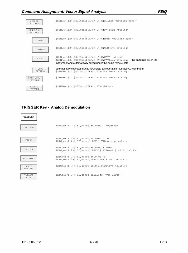
Command Assignment: Vector Signal Analysis FSIQ
1119.5063.12 6.270 E-13
SELECTPATTERN
[SENSe<1|2>:]DDEMod:SEARch:SYNC:SELect <pattern_name>
NEW SYNCPATTERN
[SENSe<1|2>:]DDEMod:SEARch:SYNC:PATTern <string>
NAME[SENSe<1|2>:]DDEMod:SEARch:SYNC:NAME <pattern_name>
COMMENT[SENSe<1|2>:]DDEMod:SEARch:SYNC:COMMent <string>
VALUE[SENSe<1|2>:]DDEMod:SEARch:SYNC:DATA <string>[SENSe<1|2>:]DDEMod:SEARch:SYNC:PATTern <string> (the pattern is set in theinstrument and automatically saved under the name remote.pat)
SAVEPATTERN
automatically executed during IEC/IEEE-bus operation (see above, command[SENSe<1|2>:]DDEMod:SEARch:SYNC:PATTern <string>)
EDIT SYNCPATTERN
[SENSe<1|2>:]DDEMod:SEARch:SYNC:PATTern <string>
DELETEPATTERN
[SENSe<1|2>:]DDEMod:SEARch:SYNC:DELete
TRIGGER Key - Analog Demodulation
TRIGGER
FREE RUNTRIGger<1|2>[:SEQuence]:SOURce IMMediate
VIDEOTRIGger<1|2>[:SEQuence]:SOURce VIDeoTRIGger<1|2>[:SEQuence]:LEVel:VIDeo <num_value>
EXTERNTRIGger<1|2>[:SEQuence]:SOURce EXTernalTRIGger<1|2>[:SEQuence]:LEVel[:EXTernal] -5.0...+5.0V
AF SIGNALTRIGger<1|2>[:SEQuence]:SOURce AFTRIGger<1|2>[:SEQuence]:LEVel:AF -120...+120PCT
SLOPEPOS/NEG
TRIGger<1|2>[:SEQuence]:SLOPe POSitive|NEGative
TRIGGEROFFSET
TRIGger<1|2>[:SEQuence]:HOLDoff <num_value>

FSIQ Command Assignment: Tracking Generator
1119.5063.12 271 E-13
Tracking Generator (Option FSE-B8 to B11)
CONFIGURATION Key Group
MODE
TRACKINGGEN
--
SOURCEON/OFF
OUTPut<1|2>[:STATe] ON | OFF
SOURCEPOWER
SOURce:POWer[:LEVel][:IMMediate][:AMPLitude] <num_value>
POWEROFFSET
SOURce:POWer[:LEVel][:IMMediate]:OFFSet <num_value>
SOURCECAL
--
CAL TRANS[SENSe<1|2>:]CORRection:METHod TRANsmission[SENSe<1|2>:]CORRection:COLLect[:ACQuire] THRough
CAL REFLSHORT
[SENSe<1|2>:]CORRection:METHod REFLexion[SENSe<1|2>:]CORRection:COLLect[:ACQuire] THRough
CAL REFLOPEN
[SENSe<1|2>:]CORRection:METHod REFLexion[SENSe<1|2>:]CORRection:COLLect[:ACQuire] OPEN
NORMALIZE[SENSe<1|2>:]CORRection[:STATe] ON | OFF
REF VALUEPOSITION
DISPlay[:WINDow<1|2>]:TRACe<1...4>:Y[:SCALe]:RPOSition 0...100PCT
REF VALUEDISPlay[:WINDow<1|2>]:TRACe<1...4>:Y[:SCALe]:RVALue <num_value>
RECALL[SENSe<1|2>:]CORRection:RECall
FREQUENCYOFFSET
SOURce:FREQuency:OFFSet <num_value>
MODULATION--
EXT AMSOURce:AM:STATe ON | OFF
EXT ALCSOURce:POWer:ALC:SOURce INTernal | EXTernal
EXT FMSOURce:FM:STATe ON | OFF
EXT I/QSOURce:DM:STATe ON | OFF

Command Assignment: GSM BTS Analysis FSIQ
1119.5063.12 6.272 E-13
GSM BTS Analysis (Option FSE-K11)
CONFIGURATION Key Group
MODE
GSM BTSANALYZER
INSTrument<1|2>[:SELect] BGSM
SETTINGS--
EXTERNALATTEN
[SENSe<1|2>:]CORRection:LOSS:INPut[:MAGNitude] <num_value>
ARFCN /FREQUENCY
--
ARFCNCONFigure[:BTS]:ARFCn <num_value>
ARFCNAUTOSELECT
CONFigure[:BTS]:ARFCn:AUTO ONCE
FREQUENCYSENSe<1|2>:FREQuency:CENTer <num_value>
POWERSETTINGS
--
EXTERNALATTEN
SENSe<1|2>:CORRection:LOSS:INPut[:MAGNitude] <num_value>
NOMINALOUTPUT PWR
CONFigure[:BTS]:POWer:EXPected <num_value>
POWERCLASS
CONFigure[:BTS]:POWer:CLASs <num_value> | M1 | M2 | M3
STATIC PWRCTRL LEVEL
CONFigure[:BTS]:POWer:STATic <num_value>
DYNAM PWRCTRL LEVEL
CONFigure[:BTS]:POWer:DYNamic <num_value>
LIMIT/PWRCOUPLED
CONFigure[:BTS]:POWer:COUPled ON | OFF
SIGNALPOWER
CONFigure[:BTS]:POWer:EXPected <num_value>
LIMIT LINEREF POWER
CONFigure[:BTS]:POWer:LIMit <num_value>
LIMITMARGIN
CALCulate<1|2>:LIMit<1...8>:MARGin <num_value>
SLOT NO.--
SLOT NO.CONFigure[:BTS]:CHANnel:SLOT 0...7
SLOT NO.AUTOSELECT
CONFigure[:BTS]:CHANnel:SLOT:AUTO ONCE

FSIQ Command Assignment: GSM BTS Analysis
1119.5063.12 6.273 E-13
MIDAMBLECONFigure[:BTS]:CHANnel:TSC 0...7CONFigure[:BTS]:CHANnel:TSC:AUTO ON | OFF
TRIGGER--
FREE RUNTRIGger<1|2>[:SEQuence]:SOURce IMMediate
EXTERNTRIGger<1|2>[:SEQuence]:SOURce EXTernalTRIGger<1|2>[:SEQuence]:LEVel[:EXTernal] -5.0...+5.0V
SLOPEPOS NEG
TRIGger<1|2>[:SEQuence]:SLOPe POSitive|NEGative
TRIGGERADJUST
--
FRAMECOARSE
TRIGger<1|2>[:SEQuence]:SYNChronize:ADJust:FRAMe <num_value>
FRAMEFINE
TRIGger<1|2>[:SEQuence]:SYNChronize:ADJust:FRAMe <num_value>
AUTO FRAMEADJUST
TRIGger<1|2>[:SEQuence]:SYNChronize:ADJust:FRAMe:AUTO ONCE
SLOTADJUST
TRIGger<1|2>[:SEQuence]:SYNChronize:ADJust:SLOT <num_value>
AUTO SLOTADJUST
TRIGger<1|2>[:SEQuence]:SYNChronize:ADJust:SLOT:AUTO ONCE
TRIGGERLEVEL
TRIGger<1|2>[:SEQuence]:LEVel[:EXTernal] <num_value>
SLOPEPOS NEG
TRIGger<1|2>[:SEQuence]:SLOPe POSitive|NEGative
DEFAULTSETTINGS
CONFigure[:BTS]:PRESet
P-GSM 900CONFigure[:BTS]:NETWork[:TYPE] PGSM | PGSM900
GSM 1800(DCS 1800)
CONFigure[:BTS]:NETWork[:TYPE] DCS | GSM1800
GSM 1900(PCS 1900)
CONFigure[:BTS]:NETWork[:TYPE] PCS | GSM1900
R-GSM 900CONFigure[:BTS]:NETWork[:TYPE] RGSM | RGSM900
R-GSM 900CONFigure[:BTS]:NETWork[:TYPE] RGSM
PHASE ICONFigure[:BTS]:NETWork:PHASe 1
PHASE IICONFigure[:BTS]:NETWork:PHASe 2
PHASE II+CONFigure[:BTS]:NETWork:PHASe 2,PLUS
PHASE/FREQERROR
CONFigure:BURSt:PFERror[:IMMediate]
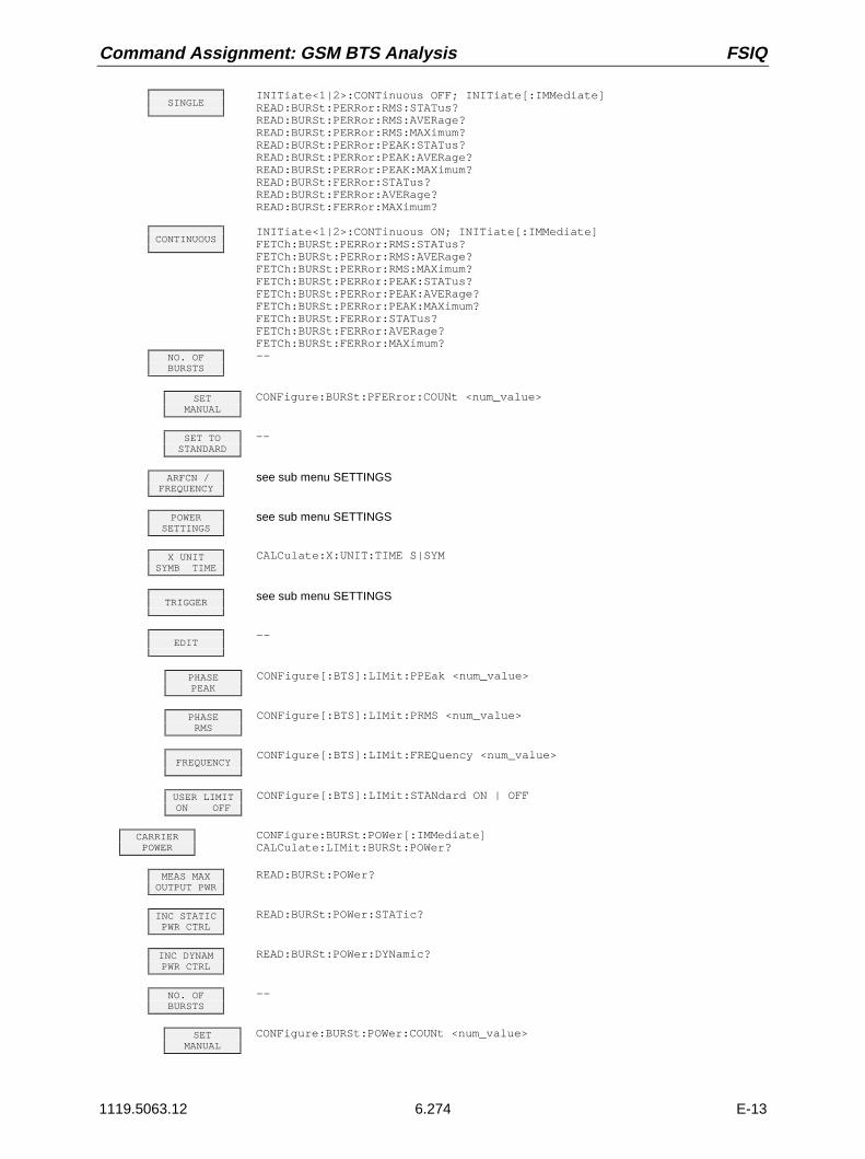
Command Assignment: GSM BTS Analysis FSIQ
1119.5063.12 6.274 E-13
SINGLEINITiate<1|2>:CONTinuous OFF; INITiate[:IMMediate]READ:BURSt:PERRor:RMS:STATus?READ:BURSt:PERRor:RMS:AVERage?READ:BURSt:PERRor:RMS:MAXimum?READ:BURSt:PERRor:PEAK:STATus?READ:BURSt:PERRor:PEAK:AVERage?READ:BURSt:PERRor:PEAK:MAXimum?READ:BURSt:FERRor:STATus?READ:BURSt:FERRor:AVERage?READ:BURSt:FERRor:MAXimum?
CONTINUOUSINITiate<1|2>:CONTinuous ON; INITiate[:IMMediate]FETCh:BURSt:PERRor:RMS:STATus?FETCh:BURSt:PERRor:RMS:AVERage?FETCh:BURSt:PERRor:RMS:MAXimum?FETCh:BURSt:PERRor:PEAK:STATus?FETCh:BURSt:PERRor:PEAK:AVERage?FETCh:BURSt:PERRor:PEAK:MAXimum?FETCh:BURSt:FERRor:STATus?FETCh:BURSt:FERRor:AVERage?FETCh:BURSt:FERRor:MAXimum?
NO. OFBURSTS
--
SETMANUAL
CONFigure:BURSt:PFERror:COUNt <num_value>
SET TOSTANDARD
--
ARFCN /FREQUENCY
see sub menu SETTINGS
POWERSETTINGS
see sub menu SETTINGS
X UNITSYMB TIME
CALCulate:X:UNIT:TIME S|SYM
TRIGGERsee sub menu SETTINGS
EDIT--
PHASEPEAK
CONFigure[:BTS]:LIMit:PPEak <num_value>
PHASERMS
CONFigure[:BTS]:LIMit:PRMS <num_value>
FREQUENCYCONFigure[:BTS]:LIMit:FREQuency <num_value>
USER LIMITON OFF
CONFigure[:BTS]:LIMit:STANdard ON | OFF
CARRIERPOWER
CONFigure:BURSt:POWer[:IMMediate]CALCulate:LIMit:BURSt:POWer?
MEAS MAXOUTPUT PWR
READ:BURSt:POWer?
INC STATICPWR CTRL
READ:BURSt:POWer:STATic?
INC DYNAMPWR CTRL
READ:BURSt:POWer:DYNamic?
NO. OFBURSTS
--
SETMANUAL
CONFigure:BURSt:POWer:COUNt <num_value>

FSIQ Command Assignment: GSM BTS Analysis
1119.5063.12 6.275 E-13
SET TOSTANDARD
--
SGL MEASON OFF
CONFigure[:BTS]:POWer:SINGle[:STATe] ON | OFF
MEAS SGLPWR LEVEL
READ:BURSt:POWer?
STATIC PWRCTRL LEVEL
CONFigure[:BTS]:POWer:STATic <num_value>
DYNAM PWRCTRL LEVEL
CONFigure[:BTS]:POWer:DYNamic <num_value>
CLEAR SGLRESULT TAB
CONFigure[:BTS]:POWer:SINGle:CLEar
SIGNALPOWER
CONFigure[:BTS]:POWer:EXPected <num_value>
ARFCN /FREQUENCY
see sub menu SETTINGS
POWERSETTINGS
see sub menu SETTINGS
CONDITIONSNORM EXTR
CONFigure:BURSt:POWer:CONDition NORMal | EXTReme
MEASBANDWIDTH
[SENSe<1|2>:]BANDwidth|BWIDth[:RESolution] DEF | 300 kHz | 1 MHz
SYNC TOMIDAMBLE
TRIGger<1|2>[:SEQuence]:SYNChronize:SOURce FRAMe | TSC
TRIGGERsee sub menu SETTINGS
POWER VSTIME
CONFigure:BURSt:PTEMplate[:IMMediate]CALCulate:LIMit:BURSt:PTEMplate?
SINGLEINITiate<1|2>:CONTinuous OFF; INITiate[:IMMediate]
CONTINUOUSINITiate<1|2>:CONTinuous ON; INITiate[:IMMediate]
BURST HIGHRESOLUTION
CONFigure:BURSt:PTEMplate:SELect TOP
NO. OFBURSTS
--
SETMANUAL
CONFigure:BURSt:PTEMplate:COUNt <num_value>
SET TOSTANDARD
--
FULL BURSTCONFigure:BURSt:PTEMplate:SELect FULL
RISINGEDGE
CONFigure:BURSt:PTEMplate:SELect RISing
FALLINGEDGE
CONFigure:BURSt:PTEMplate:SELect FALLing
STARTREF MEAS
READ:BURSt:REFerence[:IMMediate]?

Command Assignment: GSM BTS Analysis FSIQ
1119.5063.12 6.276 E-13
REF MEASAUTO USER
CONFigure:BURSt:REFerence:AUTO ON | OFF
ARFCN /FREQUENCY
see sub menu SETTINGS
POWERSETTINGS
see sub menu SETTINGS
X UNITSYMB TIME
CALCulate:X:UNIT:TIME S|SYM
MEASBANDWIDTH
[SENSe<1|2>:]BANDwidth|BWIDth[:RESolution] DEF | 300 kHz | 1 MHz
SYNC TOMIDAMBLE
TRIGger<1|2>[:SEQuence]:SYNChronize:SOURce FRAMe | TSC
TRIGGERsee sub menu SETTINGS
EDIT--
LIMIT LINEFILTER
--
NEW LIMITLINE
see Basic Instrument - Signal Analysis
EDIT LIMITLINE
see Basic Instrument - Signal Analysis
COPYLIMIT LINE
see Basic Instrument - Signal Analysis
DELETELIMIT LINE
see Basic Instrument - Signal Analysis
USER LIMITON OFF
CONFigure[:BTS]:LIMit:STANdard ON | OFF
PAGE UP--
PAGE DOWN--
MODULATIONSPECTRUM
CONFigure:SPECtrum:MODulation[:IMMediate]CALCulate:LIMit:SPECtrum:MODulation? ARFCn|TXBand|RXBand|COMBinedCALCulate:LIMit:SPECtrum:MODulation:FAILs? ARFCn|TXBand|RXBand|COMBinedCALCulate:LIMit:SPECtrum:MODulation:EXCeptions? ARFCn|TXBand|RXBand|
COMBined
SINGLEFREQ SWEEP
INITiate<1|2>:CONTinuous OFF; INITiate[:IMMediate]
CONTINUOUSFREQ SWEEP
INITiate<1|2>:CONTinuous ON; INITiate[:IMMediate]
STARTLIST
READ:SPECtrum:MODulation[:ALL]?
NO. OFBURSTS
--
SETMANUAL
CONFigure:SPECtrum:MODulation:COUNt <num_value>
SET TOSTANDARD
--
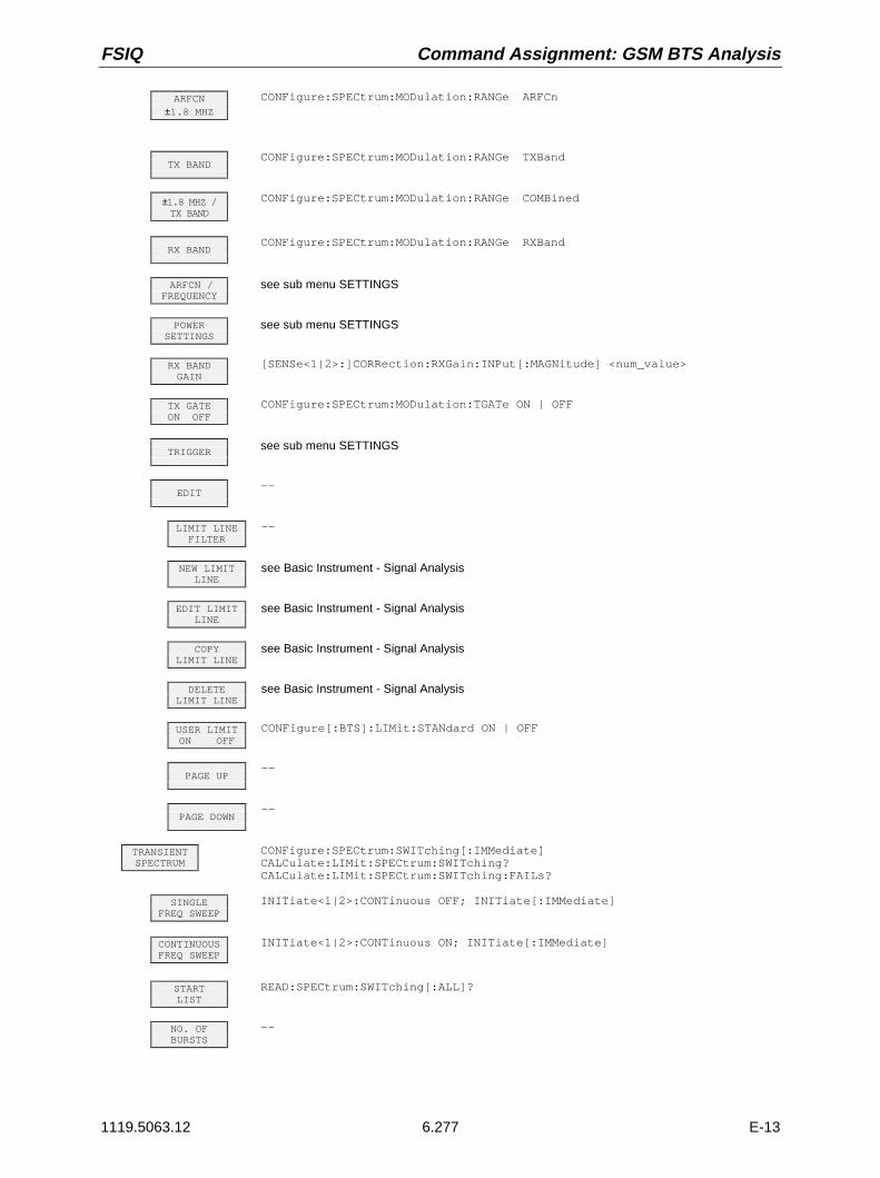
FSIQ Command Assignment: GSM BTS Analysis
1119.5063.12 6.277 E-13
ARFCN±1.8 MHZ
CONFigure:SPECtrum:MODulation:RANGe ARFCn
TX BANDCONFigure:SPECtrum:MODulation:RANGe TXBand
±1.8 MHZ /TX BAND
CONFigure:SPECtrum:MODulation:RANGe COMBined
RX BANDCONFigure:SPECtrum:MODulation:RANGe RXBand
ARFCN /FREQUENCY
see sub menu SETTINGS
POWERSETTINGS
see sub menu SETTINGS
RX BANDGAIN
[SENSe<1|2>:]CORRection:RXGain:INPut[:MAGNitude] <num_value>
TX GATEON OFF
CONFigure:SPECtrum:MODulation:TGATe ON | OFF
TRIGGERsee sub menu SETTINGS
EDIT--
LIMIT LINEFILTER
--
NEW LIMITLINE
see Basic Instrument - Signal Analysis
EDIT LIMITLINE
see Basic Instrument - Signal Analysis
COPYLIMIT LINE
see Basic Instrument - Signal Analysis
DELETELIMIT LINE
see Basic Instrument - Signal Analysis
USER LIMITON OFF
CONFigure[:BTS]:LIMit:STANdard ON | OFF
PAGE UP--
PAGE DOWN--
TRANSIENTSPECTRUM
CONFigure:SPECtrum:SWITching[:IMMediate]CALCulate:LIMit:SPECtrum:SWITching?CALCulate:LIMit:SPECtrum:SWITching:FAILs?
SINGLEFREQ SWEEP
INITiate<1|2>:CONTinuous OFF; INITiate[:IMMediate]
CONTINUOUSFREQ SWEEP
INITiate<1|2>:CONTinuous ON; INITiate[:IMMediate]
STARTLIST
READ:SPECtrum:SWITching[:ALL]?
NO. OFBURSTS
--

Command Assignment: GSM BTS Analysis FSIQ
1119.5063.12 6.278 E-13
SETMANUAL
CONFigure:SPECtrum:SWITching:COUNt <num_value>
SET TOSTANDARD
--
ARFCN /FREQUENCY
see sub menu SETTINGS
POWERSETTINGS
see sub menu SETTINGS
BTS SFHON OFF
CONFigure[:BTS]:CHANnel:SFH ON | OFF
MEASBANDWIDTH
[SENSe<1|2>:]BANDwidth|BWIDth[:RESolution] DEF | 300 kHz | 1 MHz
TRIGGERsee sub menu SETTINGS
EDIT--
LIMIT LINEFILTER
--
NEW LIMITLINE
see Basic Instrument - Signal Analysis
EDIT LIMITLINE
see Basic Instrument - Signal Analysis
COPYLIMIT LINE
see Basic Instrument - Signal Analysis
DELETELIMIT LINE
see Basic Instrument - Signal Analysis
USER LIMITON OFF
CONFigure[:BTS]:LIMit:STANdard ON | OFF
PAGE UP--
PAGE DOWN--
SPURIOUSCONFigure:SPURious[:IMMediate]CALCulate:LIMit:SPURious? TXBand | OTXBand | RXBandCALCulate:LIMit:SPURious:FAILs? TXBand | OTXBand | RXBand
START LISTSGL STEP
ABORT;READ:SPURious:STEP?
CONT LISTSGL STEP
READ:SPURious:STEP?
STARTLIST
READ:SPURious [:ALL]?
SWEEPCOUNT
--
SWP COUNTTX / <> TX
CONFigure:SPURious:COUNt <num_value>
SWP COUNTRX BAND
CONFigure:SPURious:COUNt:RXBand <num_value>
SET TOSTANDARD
--
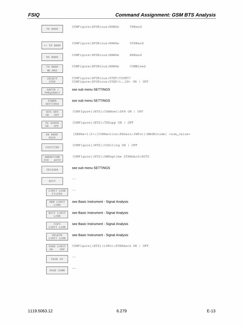
FSIQ Command Assignment: GSM BTS Analysis
1119.5063.12 6.279 E-13
TX BANDCONFigure:SPURious:RANGe TXBand
<> TX BANDCONFigure:SPURious:RANGe OTXBand
RX BANDCONFigure:SPURious:RANGe RXBand
TX BAND±2.MHZ
CONFigure:SPURious:RANGe COMBined
SELECTSTEP
CONFigure:SPURious:STEP:COUNT?CONFigure:SPURious:STEP<1..26> ON | OFF
ARFCN /FREQUENCY
see sub menu SETTINGS
POWERSETTINGS
see sub menu SETTINGS
BTS SFHON OFF
CONFigure[:BTS]:CHANnel:SFH ON | OFF
TX SUPPRON OFF
CONFigure[:BTS]:TXSupp ON | OFF
RX BANDGAIN
[SENSe<1|2>:]CORRection:RXGain:INPut[:MAGNitude] <num_value>
COSITINGCONFigure[:BTS]:COSiting ON | OFF
SWEEPTIMESTD AUTO
CONFigure[:BTS]:SWEeptime STANdard|AUTO
TRIGGERsee sub menu SETTINGS
EDIT--
LIMIT LINEFILTER
--
NEW LIMITLINE
see Basic Instrument - Signal Analysis
EDIT LIMITLINE
see Basic Instrument - Signal Analysis
COPYLIMIT LINE
see Basic Instrument - Signal Analysis
DELETELIMIT LINE
see Basic Instrument - Signal Analysis
USER LIMITON OFF
CONFigure[:BTS]:LIMit:STANdard ON | OFF
PAGE UP--
PAGE DOWN--

Command Assignment: GSM MS Analysis FSIQ
1119.5063.12 6.280 E-13
GSM MS Analysis (Option FSE-K10)
CONFIGURATION Key Group
MODE
GSM MSANALYZER
INSTrument<1|2>[:SELect] MGSM
SETTINGS--
EXTERNALATTEN
[SENSe<1|2>:]CORRection:LOSS:INPut[:MAGNitude] <num_value>
ARFCN /FREQUENCY
--
ARFCNCONFigure[:MS]:ARFCn <num_value>
ARFCNAUTOSELECT
CONFigure[:MS]:ARFCn:AUTO ONCE
FREQUENCY[SENSe<1|2>:]FREQency:CENTer <num_value>
POWERSETTINGS
--
EXTERNALATTEN
[SENSe<1|2>:]CORRection:LOSS:INPut[:MAGNitude] <num_value>
OUTPUTMS POWER
CONFigure[:MS]:POWer:EXPected <num_value>
POWERCLASS
CONFigure[:MS]:POWer:CLASs <num_value>
POWERCTRL LEVEL
CONFigure[:MS]:POWer:LEVel <num_value>
SMALL MSON OFF
CONFigure[:MS]:POWer:SMALl ON | OFF
SMALL MSON OFF
CONFigure[:MS]:POWer:SMALl ON | OFF
LIMIT/PWRCOUPLED
CONFigure[:MS]:POWer:COUPled ON | OFF
SIGNALPOWER
CONFigure[:MS]:POWer:EXPected <num_value>
LIMIT LINEREF POWER
CONFigure[:MS]:POWer:LIMit <num_value>
LIMITMARGIN
CALCulate:LIMit:MARGin <num_value>
MIDAMBLECONFigure[:MS]:CHANnel:TSC 0...7
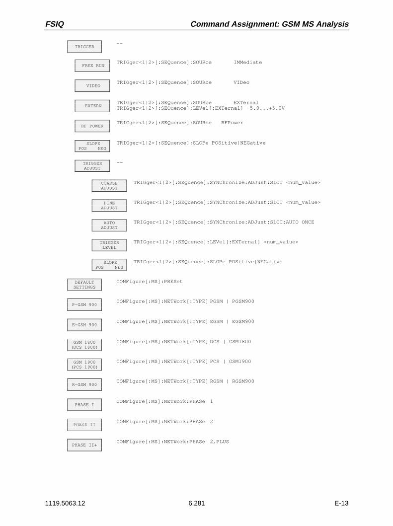
FSIQ Command Assignment: GSM MS Analysis
1119.5063.12 6.281 E-13
TRIGGER--
FREE RUNTRIGger<1|2>[:SEQuence]:SOURce IMMediate
VIDEOTRIGger<1|2>[:SEQuence]:SOURce VIDeo
EXTERNTRIGger<1|2>[:SEQuence]:SOURce EXTernalTRIGger<1|2>[:SEQuence]:LEVel[:EXTernal] -5.0...+5.0V
RF POWERTRIGger<1|2>[:SEQuence]:SOURce RFPower
SLOPEPOS NEG
TRIGger<1|2>[:SEQuence]:SLOPe POSitive|NEGative
TRIGGERADJUST
--
COARSEADJUST
TRIGger<1|2>[:SEQuence]:SYNChronize:ADJust:SLOT <num_value>
FINEADJUST
TRIGger<1|2>[:SEQuence]:SYNChronize:ADJust:SLOT <num_value>
AUTOADJUST
TRIGger<1|2>[:SEQuence]:SYNChronize:ADJust:SLOT:AUTO ONCE
TRIGGERLEVEL
TRIGger<1|2>[:SEQuence]:LEVel[:EXTernal] <num_value>
SLOPEPOS NEG
TRIGger<1|2>[:SEQuence]:SLOPe POSitive|NEGative
DEFAULTSETTINGS
CONFigure[:MS]:PRESet
P-GSM 900CONFigure[:MS]:NETWork[:TYPE] PGSM | PGSM900
E-GSM 900CONFigure[:MS]:NETWork[:TYPE] EGSM | EGSM900
GSM 1800(DCS 1800)
CONFigure[:MS]:NETWork[:TYPE] DCS | GSM1800
GSM 1900(PCS 1900)
CONFigure[:MS]:NETWork[:TYPE] PCS | GSM1900
R-GSM 900CONFigure[:MS]:NETWork[:TYPE] RGSM | RGSM900
PHASE ICONFigure[:MS]:NETWork:PHASe 1
PHASE IICONFigure[:MS]:NETWork:PHASe 2
PHASE II+CONFigure[:MS]:NETWork:PHASe 2,PLUS

Command Assignment: GSM MS Analysis FSIQ
1119.5063.12 6.282 E-13
PHASE/FREQERROR
CONFigure:BURSt:PFERror[:IMMediate]
SINGLEINITiate<1|2>:CONTinuous OFF; INITiate[:IMMediate]
CONTINUOUSINITiate<1|2>:CONTinuous ON; INITiate[:IMMediate]
NO. OFBURSTS
SETMANUAL
CONFigure:BURSt:PFERror:COUNt <num_value>
SET TOSTANDARD
--
ARFCN /FREQUENCY
see sub menu SETTINGS
POWERSETTINGS
see sub menu SETTINGS
X UNITSYMB TIME
CALCulate<1|2>::X:UNIT:TIME S|SYM
TRIGGERsee sub menu SETTINGS
EDIT--
PHASEPEAK
CONFigure[:MS]:LIMit:PPEak <num_value>
PHASERMS
CONFigure[:MS]:LIMit:PRMS <num_value>
FREQUENCYCONFigure[:MS]:LIMit:FREQuency <num_value>
USER LIMITON OFF
CONFigure[:MS]:LIMit:STANdard ON | OFF
CARRIERPOWER
CONFigure:BURSt:POWer[:IMMediate]CALCulate:LIMit:BURSt:POWer?
MEAS MAXOUTPUT PWR
READ:BURSt:POWer?
INC PWRCTRL LEVEL
READ:BURSt:POWer:LEVel?
NO. OFBURSTS
--
SETMANUAL
CONFigure:BURSt:POWer:COUNt <num_value>
SET TOSTANDARD
--
SGL MEASON OFF
CONFigure[:MS]:POWer:SINGle[:STATe] ON | OFF

FSIQ Command Assignment: GSM MS Analysis
1119.5063.12 6.283 E-13
MEAS SGLPWR LEVEL
READ:BURSt:POWer?
POWERCTRL LEVEL
CONFigure[:MS]:POWer:LEVel <num_value>
CLEAR SGLRESULT TAB
CONFigure[:MS]:POWer:SINGle:CLEar
SIGNALPOWER
CONFigure[:MS]:POWer:EXPected <num_value>
ARFCN /FREQUENCY
see sub menu SETTINGS
POWERSETTINGS
see sub menu SETTINGS
CONDITIONSNORM EXTR
CONFigure:BURSt:POWer:CONDition NORMal | EXTReme
MEASBANDWIDTH
[SENSe<1|2>:]BANDwidth|BWIDth[:RESolution] DEF | 300 kHz | 1 MHz
SYNC TOMIDAMBLE
TRIGger<1|2>[:SEQuence]:SYNChronize:SOURce FRAMe | TSC
TRIGGERsee sub menu SETTINGS
POWER VSTIME
CONFigure:BURSt:PTEMplate[:IMMediate]CALCulate:LIMit:BURSt:PTEMplate?
SINGLEINITiate<1|2>:CONTinuous OFF; INITiate[:IMMediate]
CONTINUOUSINITiate<1|2>:CONTinuous ON; INITiate[:IMMediate]
BURST HIGHRESOLUTION
CONFigure:BURSt:PTEMplate:SELect TOP
NO. OFBURSTS
--
SETMANUAL
CONFigure:BURSt:PTEMplate:COUNt <num_value>
SET TOSTANDARD
--
FULL BURSTCONFigure:BURSt:PTEMplate:SELect FULL
RISINGEDGE
CONFigure:BURSt:PTEMplate:SELect RISing
FALLINGEDGE
CONFigure:BURSt:PTEMplate:SELect FALLing
STARTREF MEAS
READ:BURst:REFerence[:IMMediate]?
REF MEASAUTO USER
CONFigure:BURst:REFerence:AUTO ON | OFF

Command Assignment: GSM MS Analysis FSIQ
1119.5063.12 6.284 E-13
ARFCN /FREQUENCY
see sub menu SETTINGS
POWERSETTINGS
see sub menu SETTINGS
X UNITSYMB TIME
CALCulate<1|2>:X:UNIT:TIME S|SYM
MEASBANDWIDTH
[SENSe<1|2>:]BANDwidth|BWIDth[:RESolution] DEF | 300 kHz | 1 MHz
SYNC TOMIDAMBLE
TRIGger<1|2>[:SEQuence]:SYNChronize:SOURce FRAMe | TSC
TRIGGERsee sub menu SETTINGS
EDIT--
LIMIT LINEFILTER
--
EDIT LIMITLINE
see Basic Instrument - Signal Analysis
USER LIMITON OFF
CONFigure[:MS]:LIMIt:STANdard ON | OFF
PAGE UP--
PAGE DOWN--
MODULATIONSPECTRUM
CONFigure:SPECtrum:MODulation[:IMMediate]CALCulate:LIMit:SPECtrum:MODulation?
ARFCn|TXBand|RXBand|COMBined|DCSRx1800CALCulate:LIMit:SPECtrum:MODulation:FAILs?
ARFCn|TXBand|RXBand|COMBined|DCSRx1800CALCulate:LIMit:SPECtrum:MODulation:EXCeptions?
ARFCn|TXBand|RXBand|COMBined|DCSRx1800
SINGLEFREQ SWEEP
INITiate<1|2>:CONTinuous OFF; INITiate[:IMMediate]
CONTINUOUSFREQ SWEEP
INITiate<1|2>:CONTinuous ON; INITiate[:IMMediate]
STARTLIST
READ:SPECtrum:MODulation[:ALL]?
NO. OFBURSTS
--
SETMANUAL
CONFigure:SPECtrum:MODulation:COUNt <num_value>
SET TOSTANDARD
--
ARFCN± 1.8 MHz
CONFigure:SPECtrum:MODulation:RANGe ARFCn
TX BANDCONFigure:SPECtrum:MODulation:RANGe TXBand

FSIQ Command Assignment: GSM MS Analysis
1119.5063.12 6.285 E-13
±1.8 MHZTX BAND
CONFigure:SPECtrum:MODulation:RANGe COMBined
RX BANDGSM 900
CONFigure:SPECtrum:MODulation:RANGe RXBand
RX BANDDCS 1800
CONFigure:SPECtrum:MODulation:RANGe DCSRx1800
RX BANDCONFigure:SPECtrum:MODulation:RANGe RXBand
ARFCN /FREQUENCY
see sub menu SETTINGS
POWERSETTINGS
see sub menu SETTINGS
RX BANDGAIN
[SENSe<1|2>:]CORRection:RXGain:INPut[:MAGNitude] <num_value>
TRIGGERsee sub menu SETTINGS
EDIT--
LIMIT LINEFILTER
--
EDIT LIMITLINE
see Basic Instrument - Signal Analysis
USER LIMITON OFF
CONFigure[:MS]:LIMIt:STANdard ON | OFF
PAGE UP--
PAGE DOWN--
TRANSIENTSPECTRUM
CONFigure:SPECtrum:SWITching[:IMMediate]CALCulate:LIMit:SPECtrum:SWITching? ARFCn|TXBand|RXBand|COMBinedCALCulate:LIMit:SPECtrum:SWITching:FAILs? ARFCn|TXBand|RXBand|COMBined
SINGLEFREQ SWEEP
INITiate<1|2>:CONTinuous OFF; INITiate[:IMMediate]
CONTINUOUSFREQ SWEEP
INITiate<1|2>:CONTinuous ON; INITiate[:IMMediate]
STARTLIST
READ:SPECtrum:SWITching[:ALL]?
NO. OFBURSTS
--
SETMANUAL
CONFigure:SPECtrum:SWITching:COUNt <num_value>
SET TOSTANDARD
--
ARFCN /FREQUENCY
see sub menu SETTINGS

Command Assignment: GSM MS Analysis FSIQ
1119.5063.12 6.286 E-13
POWERSETTINGS
see sub menu SETTINGS
MS SFHON OFF
CONFigure[:MS]:CHANnel:SFH ON | OFF
MEASBANDWIDTH
[SENSe<1|2>:]BANDwidth|BWIDth[:RESolution] DEF | 300 kHz | 1 MHz
TRIGGERsee sub menu SETTINGS
EDIT--
LIMIT LINEFILTER
--
EDIT LIMITLINE
see Basic Instrument - Signal Analysis
USER LIMITON OFF
CONFigure[:MS]:LIMIt:STANdard ON | OFF
PAGE UP--
PAGE DOWN--
SPURIOUSCONFigure:SPURious[:IMMediate]CALCulate:LIMit:SPURious? TXBand | OTXBand | IDLebandCALCulate:LIMit:SPURious:FAILs? TXBand | OTXBand | IDLeband
START LISTSGL STEP
ABORT;READ:SPURious:STEP?
CONT LISTSGL STEP
READ:SPURious:STEP?
STARTLIST
READ:SPURious [:ALL]?
SWEEPCOUNT
--
SWP COUNTTX / <>TX
CONFigure:SPURious:COUNt <num_value>
TX BANDCONFigure:SPURious:RANGe TXBand
<> TX BANDCONFigure:SPURious:RANGe OTXBand
IDLEMODE
CONFigure:SPURious:RANGe IDLeband
TX BAND±2.0 MHZ
CONFigure:SPURious:RANGe COMBined
SELECTSTEP
CONFigure:SPURious:STEP:COUNT?CONFigure:SPURious:STEP<1..26> ON | OFF
ARFCN /FREQUENCY
see sub menu SETTINGS

FSIQ Command Assignment: GSM MS Analysis
1119.5063.12 6.287 E-13
POWERSETTINGS
see sub menu SETTINGS
MS SFHON OFF
CONFigure[:MS]:CHANnel:SFH ON | OFF
TX SUPPRON OFF
CONFigure[:MS]:TXSupp ON | OFF
ANTENNACOND RAD
CONFigure:SPURious:ANTenna CONDucted|RADiated
SWEEPTIMESTD AUTO
CONFigure[:MS]:SWEeptime STANdard|AUTO
TRIGGERsee sub menu SETTINGS
EDIT--
LIMIT LINEFILTER
--
EDIT LIMITLINE
see Basic Instrument - Signal Analysis
USER LIMITON OFF
CONFigure[:MS]:LIMIt:STANdard ON | OFF
PAGE UP--
PAGE DOWN--
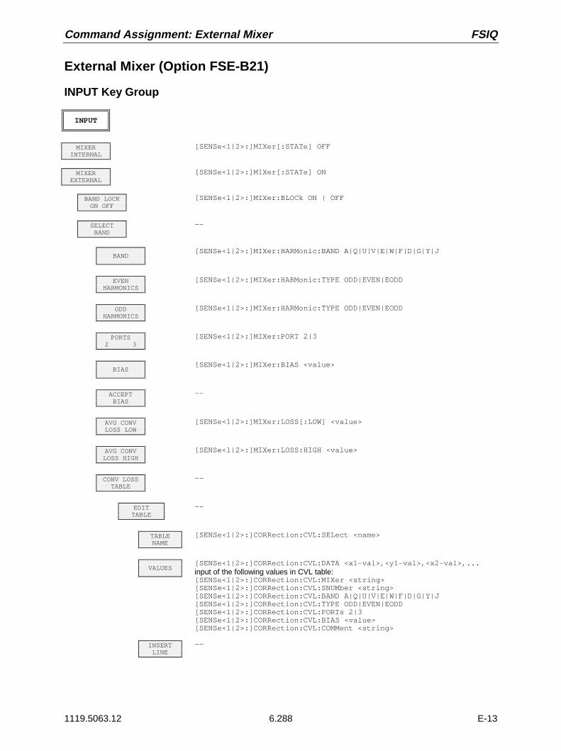
Command Assignment: External Mixer FSIQ
1119.5063.12 6.288 E-13
External Mixer (Option FSE-B21)
INPUT Key Group
INPUT
MIXERINTERNAL
[SENSe<1|2>:]MIXer[:STATe] OFF
MIXEREXTERNAL
[SENSe<1|2>:]MIXer[:STATe] ON
BAND LOCKON OFF
[SENSe<1|2>:]MIXer:BLOCk ON | OFF
SELECTBAND
--
BAND[SENSe<1|2>:]MIXer:HARMonic:BAND A|Q|U|V|E|W|F|D|G|Y|J
EVENHARMONICS
[SENSe<1|2>:]MIXer:HARMonic:TYPE ODD|EVEN|EODD
ODDHARMONICS
[SENSe<1|2>:]MIXer:HARMonic:TYPE ODD|EVEN|EODD
PORTS2 3
[SENSe<1|2>:]MIXer:PORT 2|3
BIAS[SENSe<1|2>:]MIXer:BIAS <value>
ACCEPTBIAS
--
AVG CONVLOSS LOW
[SENSe<1|2>:]MIXer:LOSS[:LOW] <value>
AVG CONVLOSS HIGH
[SENSe<1|2>:]MIXer:LOSS:HIGH <value>
CONV LOSSTABLE
--
EDITTABLE
--
TABLENAME
[SENSe<1|2>:]CORRection:CVL:SELect <name>
VALUES[SENSe<1|2>:]CORRection:CVL:DATA <x1-val>,<y1-val>,<x2-val>,...input of the following values in CVL table:[SENSe<1|2>:]CORRection:CVL:MIXer <string>[SENSe<1|2>:]CORRection:CVL:SNUMber <string>[SENSe<1|2>:]CORRection:CVL:BAND A|Q|U|V|E|W|F|D|G|Y|J[SENSe<1|2>:]CORRection:CVL:TYPE ODD|EVEN|EODD[SENSe<1|2>:]CORRection:CVL:PORTs 2|3[SENSe<1|2>:]CORRection:CVL:BIAS <value>[SENSe<1|2>:]CORRection:CVL:COMMent <string>
INSERTLINE
--

FSIQ Command Assignment: External Mixer
1119.5063.12 6.289 E-13
DELETELINE
--
COPYTABLE
--
SAVETABLE
table is saved with every change of values.
PAGEUP
--
PAGEDOWN
--
NEWTABLE
see softkey EDIT TABLE
LOADTABLE
--
DELETETABLE
[SENSe<1|2>:]CORRection:CVL:CLEar
PAGEUP
--
PAGEDOWN
--
DEFAULTSETTINGS
--
HARMONIC#[SENSe<1|2>:]MIXer:HARMonic <value>
PORTS2 3
[SENSe<1|2>:]MIXer:PORT 2|3
AVG CONVLOSS
[SENSe<1|2>:]MIXer:LOSS[:LOW] <num_value>
BIAS--
BIAS[SENSe<1|2>:]MIXer:BIAS <num_value>
BIAS OFF--
SIGNAL ID--
SIGNAL ID[SENSe<1|2>:]MIXer:SIGNal OFF | ON
AUTO ID[SENSe<1|2>:]MIXer:SIGNal OFF | AUTO
AUTO IDTHRESHOLD
[SENSe<1|2>:]MIXer:THReshold <value>


FSIQ Contents - Programming Examples
1119.5063.12 I.7.1 E-1
Contents - Chapter 7 "Remote Control - ProgrammingExamples"
7 Programming Examples
Programming via IEC/IEEE Bus...................................................................................................... 7.1Including IEC-Bus Library for QuickBasic................................................................................ 7.1
Initialization and Default Status ............................................................................................... 7.1Initiate Controller ........................................................................................................... 7.1Initiate Instrument.......................................................................................................... 7.1
Transmission of Instrument Setting Commands ..................................................................... 7.2
Switchover to Manual Control.................................................................................................. 7.2
Reading out Instrument Settings ............................................................................................. 7.2
Positioning a Marker and Displaying Values ........................................................................... 7.2
Command synchronization ...................................................................................................... 7.3
Service Request ...................................................................................................................... 7.4
Programming via the RSIB Interface ............................................................................................. 7.6Visual Basic ............................................................................................................................. 7.6
C / C++ .................................................................................................................................... 7.8
WinWord (Word Basic) ......................................................................................................... 7.10
Excel ...................................................................................................................................... 7.12

Contents - Programming Examples FSIQ
1119.5063.12 I-7.2 E-1

FSIQ Programming Examples
1119.5063.12 7.1 E-13
7 Programming Examples
The examples explain the programming of the instrument and can serve as a basis to solve morecomplex programming tasks.
QuickBASIC has been used as programming language. However, the programs can be translated intoother languages.
Programming via IEC/IEEE Bus
Including IEC-Bus Library for QuickBasic
REM ----------- Include IEC-bus library for quickbasic ----------------’$INCLUDE: ’c:\qbasic\qbdecl4.bas’
Initialization and Default Status
The IEC bus as well as the settings of the instrument are brought into a defined default status at thebeginning of every program. Subroutines "InitController" and "InitDevice" are used to thiseffect.
Initiate Controller
REM ------------ Initiate controller -----------REM InitControlleriecaddress% = 20 ’IEC-bus address of the
’instrumentCALL IBFIND("DEV1", analyzer%) ’Open port to the instrumentCALL IBPAD(analyzer%, iecaddress%) ’Inform controller on instrument
’addressCALL IBTMO(analyzer%, 11) ’Response time to 1 secREM ************************************************************************
Initiate Instrument
The IEC-bus status registers and instrument settings of the instrument are brought into the defaultstatus.
REM ------------ Initiate instrument --------------REM InitDeviceCALL IBWRT(analyzer%, "*CLS") ’Reset status registerCALL IBWRT(analyzer%, "*RST") ’Reset instrumentREM*************************************************************************

Programming Examples FSIQ
1119.5063.12 7.2 E-13
Transmission of Instrument Setting Commands
Center frequency, span, and reference level of the instrument are set in this example.
REM -------- Instrument setting commands -------------CALL IBWRT(analyzer%, "FREQUENCY:CENTER 120MHz") ’Center frequency 120 MHzCALL IBWRT(analyzer%, "FREQUENCY:SPAN 10MHZ") ’Span 10 MHzCALL IBWRT(analyzer%, "DISPLAY:TRACE:Y:RLEVEL -10dBm") ’Reference level -10dBmREM ***********************************************************************
Switchover to Manual Control
REM -------- Switch instrument over to manual control -----------CALL IBLOC(analyzer%) ’Set instrument to Local stateREM ***********************************************************************
Reading out Instrument Settings
The settings made in example 3 are read out here. The abbreviated commands are used.
REM --------- Reading out instrument settings ---------CFfrequency$ = SPACE$(20) ’Provide text variables (20 characters)CALL IBWRT(analyzer%, "FREQ:CENT?") ’Request center frequencyCALL IBRD(analyzer%, CFfrequency$) ’Read value
CFspan$ = SPACE$(20) ’Provide text variables (20 characters)CALL IBWRT(analyzer%, "FREQ:SPAN?") ’Request spanCALL IBRD(analyzer%, CFspan$) ’Read value
RLevel$ = SPACE$(20) ’Provide text variables (20 characters)CALL IBWRT(analyzer%, "DISP:TRAC:Y:RLEV?") ’Request reference levelCALL IBRD(analyzer%, RLevel$) ’Read value
REM -------- Display values on the screen -----------PRINT "Center frequency: "; CFfrequency$,PRINT "Span: "; CFspan$,PRINT "Reference level: "; RLevel$,REM*************************************************************************
Positioning a Marker and Displaying Values
REM -------- Examples of marker functions -----------CALL IBWRT(analyzer%, "CALC:MARKER ON;MARKER:MAX")
’Activate marker1 and start peak searchMKmark$ = SPACE$(30) ’Provide text variables (30 characters)CALL IBWRT(analyzer%, "CALC:MARK:X?;Y?") ’Request frequency and levelCALL IBRD(analyzer%, MKmark$) ’Read value
REM -------- Display values on the screen -----------PRINT "Center frequency / level "; MKmark$,REM **********************************************************************

FSIQ Programming Examples
1119.5063.12 7.3 E-13
Command synchronization
The possibilities for synchronization implemented in the following example are described in Chapter 5,Section "Command Order and Command Synchronization".
REM -------- Examples of command synchronization ---------REM The command INITiate[:IMMediate] starts a single sweep if the commandREM INIT:CONT OFF was previously sent. It should be ensured that the nextREM command is only then executed when the entire sweep is complete.
CALL IBWRT(analyzer%, "INIT:CONT OFF")
REM -------- First possibility: Use of *WAI ---------CALL IBWRT(analyzer%, "ABOR;INIT:IMM; *WAI")
REM -------- Second possibility: Use of *OPC? ---------OpcOk$ = SPACE$(2) ’Space for *OPC? - Provide responseCALL IBWRT(analyzer%, "ABOR;INIT:IMM; *OPC?")REM -------- here the controller can service other instruments ---------CALL IBRD(analyzer%, OpcOk$) ’Wait for "1" from *OPC?
REM -------- Third possibility: Use of *OPC ---------REM In order to be able touse the service request function in conjugationREM with a National Instruments GPIB driver, the setting "DisableREM Auto Serial Poll" must be changed to "yes" by means of IBCONF!
CALL IBWRT(analyzer%, "*SRE 32") ’Permit service request for ESRCALL IBWRT(analyzer%, "*ESE 1") ’Set event-enable bit for ’operation-complete bitON PEN GOSUB OpcReady ’Initialization of the ’service request routinePEN ONCALL IBWRT(analyzer%, "ABOR;INIT:IMM; *OPC")
REM Continue main program hereSTOP ’End of program
OpcReady:REM As soon as the sweep has ended, this subroutine is activatedREM Program suitable reaction to the OPC service request.ON PEN GOSUB OpcReady ’Enable service request routine againRETURNREM ***********************************************************************
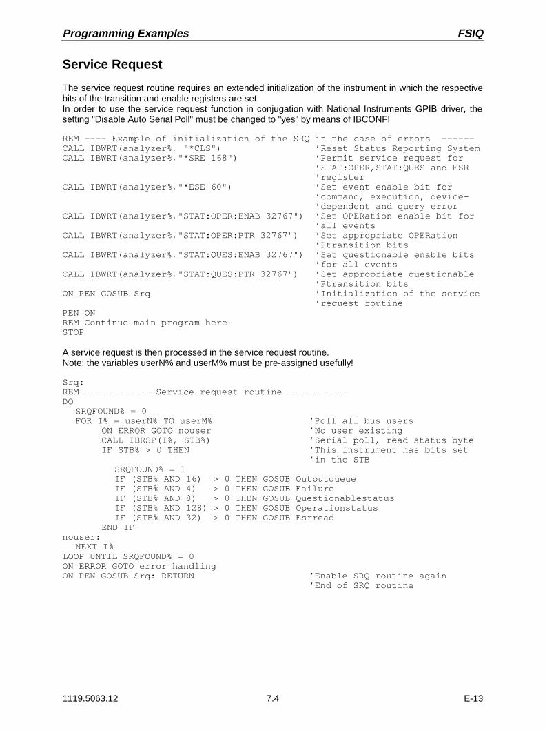
Programming Examples FSIQ
1119.5063.12 7.4 E-13
Service Request
The service request routine requires an extended initialization of the instrument in which the respectivebits of the transition and enable registers are set.In order to use the service request function in conjugation with National Instruments GPIB driver, thesetting "Disable Auto Serial Poll" must be changed to "yes" by means of IBCONF!
REM ---- Example of initialization of the SRQ in the case of errors ------CALL IBWRT(analyzer%, "*CLS") ’Reset Status Reporting SystemCALL IBWRT(analyzer%,"*SRE 168") ’Permit service request for ’STAT:OPER,STAT:QUES and ESR ’registerCALL IBWRT(analyzer%,"*ESE 60") ’Set event-enable bit for ’command, execution, device- ’dependent and query errorCALL IBWRT(analyzer%,"STAT:OPER:ENAB 32767") ’Set OPERation enable bit for ’all eventsCALL IBWRT(analyzer%,"STAT:OPER:PTR 32767") ’Set appropriate OPERation ’Ptransition bitsCALL IBWRT(analyzer%,"STAT:QUES:ENAB 32767") ’Set questionable enable bits ’for all eventsCALL IBWRT(analyzer%,"STAT:QUES:PTR 32767") ’Set appropriate questionable ’Ptransition bitsON PEN GOSUB Srq ’Initialization of the service ’request routinePEN ONREM Continue main program hereSTOP
A service request is then processed in the service request routine.Note: the variables userN% and userM% must be pre-assigned usefully!
Srq:REM ------------ Service request routine -----------DO
SRQFOUND% = 0FOR I% = userN% TO userM% ’Poll all bus users
ON ERROR GOTO nouser ’No user existingCALL IBRSP(I%, STB%) ’Serial poll, read status byteIF STB% > 0 THEN ’This instrument has bits set
’in the STBSRQFOUND% = 1IF (STB% AND 16) > 0 THEN GOSUB OutputqueueIF (STB% AND 4) > 0 THEN GOSUB FailureIF (STB% AND 8) > 0 THEN GOSUB QuestionablestatusIF (STB% AND 128) > 0 THEN GOSUB OperationstatusIF (STB% AND 32) > 0 THEN GOSUB Esrread
END IFnouser:
NEXT I%LOOP UNTIL SRQFOUND% = 0ON ERROR GOTO error handlingON PEN GOSUB Srq: RETURN ’Enable SRQ routine again
’End of SRQ routine

FSIQ Programming Examples
1119.5063.12 7.5 E-13
Reading out the status event registers, the output buffer and the error/event queue is effected insubroutines.
REM -------- Subroutines for the individual STB bits ------Outputqueue: ’Reading the output bufferMessage$ = SPACE$(100) ’Make space for responseCALL IBRD(analyzer%, Message$)PRINT "Message in output buffer :"; Message$RETURN
Failure: ’Read error queueERROR$ = SPACE$(100) ’Make space for error variableCALL IBWRT(analyzer%, "SYSTEM:ERROR?")CALL IBRD(analyzer%, ERROR$)PRINT " Error text :"; ERROR$RETURN
Questionablestatus: ’Read questionable status registerQues$ = SPACE$(20) ’Preallocate blanks to text variableCALL IBWRT(analyzer%, "STATus:QUEStionable:EVENt?")CALL IBRD(analyzer%, Ques$)PRINT "Questionable Status:"; Ques$RETURN
Operationstatus: ’Read operation status registerOper$ = SPACE$(20) ’Preallocate blanks to text variableCALL IBWRT(analyzer%, "STATus:OPERation:EVENt?")CALL IBRD(analyzer%, Oper$)PRINT "Operation Status:"; Oper$RETURN
Esrread: ’Read event status registerEsr$ = SPACE$(20) ’Preallocate blanks to text variableCALL IBWRT(analyzer%, "*ESR?") ’Read ESRCALL IBRD(analyzer%, Esr$)IF (VAL(Esr$) AND 1) > 0 THEN PRINT "Operation complete"IF (VAL(Esr$) AND 4) > 0 THEN GOTO FailureIF (VAL(Esr$) AND 8) > 0 THEN PRINT "Device dependent error"IF (VAL(Esr$) AND 16) > 0 THEN GOTO FailureIF (VAL(Esr$) AND 32) > 0 THEN GOTO FailureIF (VAL(Esr$) AND 64) > 0 THEN PRINT "User request"IF (VAL(Esr$) AND 128) > 0 THEN PRINT "Power on"RETURNREM **********************************************************************
REM ------------- Error routine ----------------Error handling:PRINT "ERROR ’Output error messageSTOP ’Stop software

Programming Examples FSIQ
1119.5063.12 7.6 E-13
Programming via the RSIB Interface
The following hints apply to both the 16-bit and the 32-bit DLL versions (RSIB.DLL and RSIB32.DLL)unless an explicit distinction is made.
The RSIB interface supports links to max. 16 measuring instruments at the same time.
Visual Basic
Programming Hints:
• Access to RSIB.DLL functions
To generate Visual Basic control applications, the file RSIB.BAS for 16 bit basic programs orRSIB32.BAS for 32 bit basic programs (C:/R_S/INSTR/RSIB)is added to a project to enable call-upof the RSIB.DLLor RSIB32.DLL functions.
• Declaration of DLL functions as procedures
All DLL functions return an integer value. All functions in the file RSIB.BAS are therefore declared asfollows:
Declare Function RSDLLxxx Lib "rsib.dll" ( ... ) As Integer
The function value with the status variable ibsta must be assigned a variable for every call. Sincethis value is also returned via a reference parameter of the functions, it is possible to declare thefunctions as procedures in the following way:
Declare Sub RSDLLxxx Lib "rsib.dll" ( ... )
• Generation of reply buffer
Since the DLL returns zero-terminated strings as replies, a string of sufficient length must begenerated before functions RSDLLibrd() and RSDLLilrd() are called because Visual Basicassigns the strings a length value which is not updated by the DLL. The string length data can begenerated with one of the following:
-Dim Rd as String * 100
-Dim Rd as StringRd = Space$(100)

FSIQ Programming Examples
1119.5063.12 7.7 E-13
• Reading trace data in real format
When the function declarations of the file RSIB.BAS are used, replies from the instrument can beassigned to only one string. Trace data can be read faster and processing is simpler, however, ifdata are read in real format into float arrays. Data can be assigned to an array with float values asfollows:
Function declaration of RSDLLibrd() in RSIB.BAS:
Declare Function RSDLLibrd Lib "rsib.dll" (ByVal ud%, ByVal Rd$, ibsta%, iberr%, ibcntl&) As Integer
To read data directly into an array with real numbers, the string variable must be replaced by asuitable structure which can be defined as follows:
Type TRACEREAL len As String * 6 ’ Header of real data "#42000" Points(500) As Single ’ Float-ArrayEnd Type
Note: the structure must be defined in a code module.
To be able to transfer the structure as a reference parameter to the DLL, a special functiondeclaration must be created.
eg Declare Function RSDLLibrdTraceReal Lib "rsib.dll" Alias "RSDLLibrd" (ByVal ud%, rd as Any, ibsta%, iberr%, ibcntl&) As Integer
Using this function, trace data can be read into a reply buffer of the type TRACEREAL. Thismechanism is operational only for 16-bit Basic versions. With 32-bit Basic programs the header anduseful data must be read by means of two separate function calls.
Programming examples:
• In the following example, the start frequency of the local instrument is queried.
Dim ibsta As Integer ’ Status variable Dim iberr As Integer ’ Error variable Dim ibcntl As Long ’ Count variable Dim ud As Integer ’ Handle for measuring instrument Dim Cmd As String ’ Command string
’ Setting up link to measuring instrument ud = RSDLLibfind("@local", ibsta, iberr, ibcntl) If (ud < 0) Then ’ error handling End If
’ Sending query command to instrument Cmd = "SENS:FREQ:STAR?" If (RSDLLibwrt(ud, Cmd, ibsta, iberr, ibcntl) And IBSTA_ERR) Then ’ error handling End If
’ Making space for response Response = Space$(100)
’ Querying response of instrument If (RSDLLibrd(ud, Response, ibsta, iberr, ibcntl) And IBSTA_ERR) Then ’ error handling End If

Programming Examples FSIQ
1119.5063.12 7.8 E-13
• In the following example, save and recall of the instrument settings is made.
Dim ibsta As Integer ’ Status variable Dim iberr As Integer ’ Error variable Dim ibcntl As Long ’ Count variable Dim ud As Integer ’ Handle for measuring instrument Dim Cmd As String ’ Command string
’ Setting up link to measuring instrument ud = RSDLLibfind("@local", ibsta, iberr, ibcntl) If (ud < 0) Then ’ error handling End If
’ Querying instrument settings Cmd = "SYST:SET?" RSDLLibwrt(ud, Cmd, ibsta, iberr, ibcntl) And IBSTA_ERR ’ Saving response of instrument in file RSDLLibrdf(ud, "C:\db.sav", ibsta, iberr, ibcntl)
’ Resetting the instrument RSDLLibwrt(ud, "*RST", ibsta, iberr, ibcntl)
’ and recalling the previous settings ’ Disabling END message for this purpose RSDLLibeot(ud, 0, ibsta, iberr, ibcntl) And IBSTA_ERR ’ Sending command first RSDLLibwrt(ud, "SYST:SET ", ibsta, iberr, ibcntl) And IBSTA_ERR ’ Enabling the END message RSDLLibeot(ud, 1, ibsta, iberr, ibcntl) And IBSTA_ERR ’ and sending the data RSDLLibwrtf(ud, "C:\db.sav", ibsta, iberr, ibcntl)
C / C++
Programming Hint:
Access to RSIB.DLL functions
The functions of RSIB.DLL are declared in the header file RSIBC.H. The DLL functions can beincorporated in a C/C++ program in three different ways:
1. By generating the import library RSIB.LIB by means of IMPLIB.EXE from RSIB.DLL andadding the library to the project.
2. By specifying the functions of RSIB.DLL in the module definition file (*.def) under IMPORTS.
3. By loading the library with the LoadLibrary() function while the program is running anddetermining the pointers of the DLL functions with GetProcAddress(). Prior to program end,RSIB.DLL must be freed with function FreeLibrary().
For the first two ways of incorporating a DLL, the latter will be automatically loaded immediatelybefore the start of the application. At the end of the program, the DLL will be freed provided it is notused by other applications.
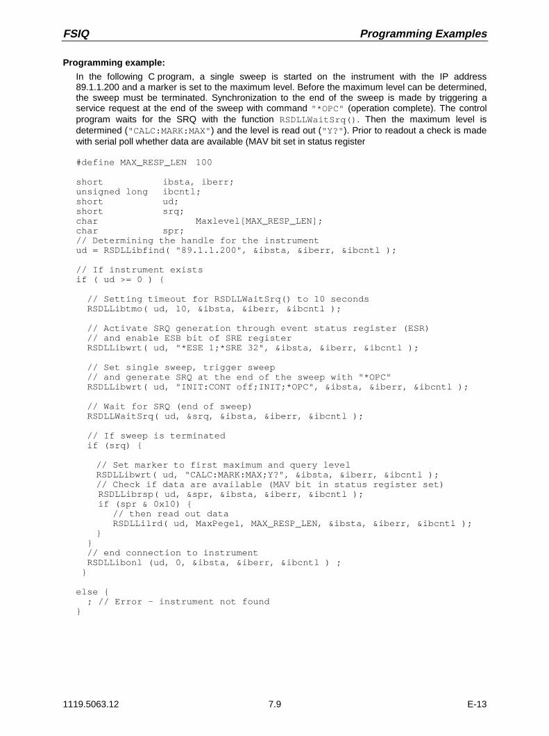
FSIQ Programming Examples
1119.5063.12 7.9 E-13
Programming example:
In the following C program, a single sweep is started on the instrument with the IP address89.1.1.200 and a marker is set to the maximum level. Before the maximum level can be determined,the sweep must be terminated. Synchronization to the end of the sweep is made by triggering aservice request at the end of the sweep with command "*OPC" (operation complete). The controlprogram waits for the SRQ with the function RSDLLWaitSrq(). Then the maximum level isdetermined ("CALC:MARK:MAX") and the level is read out ("Y?"). Prior to readout a check is madewith serial poll whether data are available (MAV bit set in status register
#define MAX_RESP_LEN 100
short ibsta, iberr;unsigned long ibcntl;short ud;short srq;char Maxlevel[MAX_RESP_LEN];char spr;// Determining the handle for the instrumentud = RSDLLibfind( "89.1.1.200", &ibsta, &iberr, &ibcntl );
// If instrument existsif ( ud >= 0 )
// Setting timeout for RSDLLWaitSrq() to 10 seconds RSDLLibtmo( ud, 10, &ibsta, &iberr, &ibcntl );
// Activate SRQ generation through event status register (ESR) // and enable ESB bit of SRE register RSDLLibwrt( ud, "*ESE 1;*SRE 32", &ibsta, &iberr, &ibcntl );
// Set single sweep, trigger sweep // and generate SRQ at the end of the sweep with "*OPC" RSDLLibwrt( ud, "INIT:CONT off;INIT;*OPC", &ibsta, &iberr, &ibcntl );
// Wait for SRQ (end of sweep) RSDLLWaitSrq( ud, &srq, &ibsta, &iberr, &ibcntl );
// If sweep is terminated if (srq)
// Set marker to first maximum and query levelRSDLLibwrt( ud, "CALC:MARK:MAX;Y?", &ibsta, &iberr, &ibcntl );// Check if data are available (MAV bit in status register set)
RSDLLibrsp( ud, &spr, &ibsta, &iberr, &ibcntl ); if (spr & 0x10)
// then read out data RSDLLilrd( ud, MaxPegel, MAX_RESP_LEN, &ibsta, &iberr, &ibcntl );
// end connection to instrument RSDLLibonl (ud, 0, &ibsta, &iberr, &ibcntl ) ;
else ; // Error - instrument not found

Programming Examples FSIQ
1119.5063.12 7.10 E-13
WinWord (Word Basic)
Programming Hints:
• Access to RSIB.DLL functions
The functions of DLL RSIB.DLL can be utilized from a WinWord macro (WinWord 2.0/6.0) withcertain restrictions. The function declarations for WinWord are defined in the module rsibwb.basand must be copied into the macro when a WinWord macro is created.
• Examples of macros in the file RSIB.DOT
The following programming examples show examples of the macros SetStartFreq andGetStartFreq, by which setting commands are sent to the instrument or instrument settings canbe queried. The two macros are contained in the document pattern rsib.dot.
• Restrictions for WinWord macros
Parameters of the integer type can be defined only as value parameters in the declaration of the DLLfunctions with the statement Declare. However, the functions of DLL RSIB.DLL expect, for thevariables ibsta, iberr and ibcntl, references via which the DLL can return values to the caller.To be able to specify variable references for these parameters, the functions are to be declared withthe string parameter type.By declaring the variables ibsta, iberr and ibcntl as strings, attempts to access undefinedmemory ranges are avoided. This method, however, makes the querying of parameters moredifficult. For example, the error code is returned in the event of an error in the variable iberr. In thisprocess, the two bytes of the integer value are copied into the string. WinWord however does not usethe length information to handle strings but expects a zero at the end of the string. Therefore, for aninteger value whose low-byte is equal to zero, the high-byte will not be queried since the low-byte withthe zero is regarded as the end of the string.
Low-Byte High-Byte00h XXh
Interpretation as integer → XX00hInterpretation as string → ""
Problem of variable declaration in WinWord
Querying error variables with values other than zero is nevertheless possible since error codes withthe first character being less than 100h can be queried (iberr=ASC(iberr$)).Querying the status variable, on the other hand, is not possible in the manner described since thelow-byte of the status variable is always zero. The status byte is however returned also by the DLLfunction value so that an error check can be made.For the use of the DLL RSIB.DLL from WinWord, it would be expedient to generate a DLL whoseinterface functions are adapted to the capabilities of WinWord.
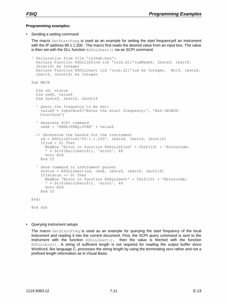
FSIQ Programming Examples
1119.5063.12 7.11 E-13
Programming examples:
• Sending a setting command
The macro SetStartFreq is used as an example for setting the start frequencyof an instrumentwith the IP address 89.1.1.200 . The macro first reads the desired value from an input box. The valueis then set with the DLL function RSDLLibwrt() via an SCPI command.
’ Declaration from file "rsibwb.bas": Declare Function RSDLLibfind Lib "rsib.dll"(udName$, ibsta$, iberr$, ibcntl$) As Integer Declare Function RSDLLibwrt Lib "rsib.dll"(ud As Integer, Wrt$, ibsta$, iberr$, ibcntl$) As Integer
Sub MAIN
Dim ud, status Dim cmd$, value$ Dim ibsta$, iberr$, ibcntl$
’ Query the frequency to be set: value$ = InputBox$("Enter the start frequency:", "R&S-IECBUS-
Interface")
’ Generate SCPI command cmd$ = "SENS:FREQ:STAR" + value$
// Determine the handle for the instrument ud = RSDLLibfind("89.1.1.200", ibsta$, iberr$, ibcntl$) If(ud < 0) Then MsgBox "Error in function RSDLLibfind" + Chr$(10) + "Errorcode: " + Str$(Asc(iberr$)), ’error’, 48 Goto End End If
’ Send command to instrument parser status = RSDLLibwrt(ud, cmd$, ibsta$, iberr$, ibcntl$) If(status <> 0) Then MsgBox "Error in function RSDLLibwrt" + Chr$(10) + "Errorcode: " + Str$(Asc(iberr$)), ’error’, 48 Goto End End If
End:
End Sub
• Querying instrument setups
The macro GetStartFreq is used as an example for querying the start frequency of the localinstrument and reading it into the current document. First, the SCPI query command is sent to theinstrument with the function RSDLLibwrt(), then the value is fetched with the functionRSDLLibrd(). A string of sufficient length is not required for reading the output buffer sinceWinWord, like language C, processes the string length by using the terminating zero rather and not aprefixed length information as in Visual Basic.

Programming Examples FSIQ
1119.5063.12 7.12 E-13
’ Declaration from file "rsibwb.bas" Declare Function RSDLLibfind Lib "rsib.dll"(udName$, ibsta$, iberr$, ibcntl$) As Integer Declare Function RSDLLibwrt Lib "rsib.dll"(ud As Integer, Wrt$, ibsta$, iberr$, ibcntl$) As Integer Declare Function RSDLLilrd Lib "rsib.dll"(ud As Integer, Rd$, cnt As Long, ibsta$, iberr$, ibcntl$) As Integer
Sub MAIN
Dim ud, status Dim buffer$, cmd$ Dim ibsta$, iberr$, ibcntl$
// Determine the handle for the instrument ud = RSDLLibfind("@local", ibsta$, iberr$, ibcntl$) If(ud < 0) Then MsgBox "Error in function ibfind" + Chr$(10) + "Errorcode: " +Str$(Asc(iberr$)), ’error’, 48 Goto End End If
’ Generate SCPI command for querying the start frequency cmd$ = "SENS:FREQ:STAR?"
’ Send command to instrument parser status = RSDLLibwrt(ud, cmd$, ibsta$, iberr$, ibcntl$) If(status <> 0) Then MsgBox "Error in function ibwrt" + Chr$(10) + "Errorcode: " +Str$(Asc(iberr$)), ’error’, 48 Goto End End If
’ Read reply from parser status = RSDLLilrd(ud, buffer$, 10, ibsta$, iberr$, ibcntl$) If(status <> 0) Then MsgBox "Error in function ibrd" + Chr$(10) + "Errorcode: " +Str$(Asc(iberr$)), ’error’, 48 Goto End End If
’ Insert reply into document Insert buffer$ + "Hz"
End:End Sub
Excel
The use of DLL functions in the macro language of Excel 4.0 has not been examined.Excel 5.0 uses VBA (Visual Basic for Applications) as macro language, which can create Excel macrossame as Visual Basic programs.
FSIQ Contents - Maintenance and Instrument Interfaces
1119.5063.12 I-8.1 E-1
Contents - Chapter 8 "Maintenance and InstrumentInterfaces"
8 Maintenance and Instrument Interfaces
Maintenance ..................................................................................................................................... 8.1Mechanical Maintenance......................................................................................................... 8.1
Electrical Maintenance............................................................................................................. 8.1Testing the Level Measuring Accuracy ......................................................................... 8.1Testing the Frequency Accuracy................................................................................... 8.1
Instrument Interfaces ...................................................................................................................... 8.2IEC Bus Interface .................................................................................................................... 8.2
Interface Characteristics................................................................................................ 8.2Bus Lines....................................................................................................................... 8.3Interface Functions........................................................................................................ 8.4IEC Bus Messages........................................................................................................ 8.4Interface Messages ....................................................................................................... 8.4Instrument Messages.................................................................................................... 8.5
RS-232-C Interface.................................................................................................................. 8.6Interface Characteristics................................................................................................ 8.6Signal Lines ................................................................................................................... 8.6Transmission Parameters ............................................................................................. 8.7Handshake .................................................................................................................... 8.8
RSIB Interface Functions....................................................................................................... 8.10Variables ibsta, iberr, ibcntl ......................................................................................... 8.11List of Interface Functions ........................................................................................... 8.12Description of Interface Functions............................................................................... 8.13
User Interface (USER)........................................................................................................... 8.19
Printer Interface (LPT) ........................................................................................................... 8.20
Measurement Converters (PROBE CODE)........................................................................... 8.21
Probe Connector (PROBE POWER)..................................................................................... 8.21
AF-Output (AF OUTPUT) ...................................................................................................... 8.22
IF Output 21.4 MHz (21.4 MHz OUT).................................................................................... 8.22
Video Output (VIDEO OUT) .................................................................................................. 8.22
Reference Output/Input (EXT REF IN/OUT) ......................................................................... 8.22
Sweep Output (SWEEP) ....................................................................................................... 8.22
External Trigger Input (EXT TRIGGER/GATE) ..................................................................... 8.22
Noise Source Control (NOISE SOURCE) ............................................................................. 8.22
External Keyboard (KEYBOARD).......................................................................................... 8.23
Mouse Connector (MOUSE).................................................................................................. 8.23
Monitor Connector (MONITOR)............................................................................................. 8.23

Contents - Maintenance and Instrument Interfaces FSIQ
1119.5063.12 8.2 E-13

FSIQ Maintenance
1119.5063.12 8.1 E-13
8 Maintenance and Instrument Interfaces
The following chapter contains information on the maintenance of the FSIQ and on the instrumentinterfaces.
The address of our support center and a list of all Rohde & Schwarz service centers can be found at thebeginning of this manual.
Maintenance
Mechanical Maintenance
The FSIQ does not require any mechanical maintenance. The front panel can be cleaned from time totime using a damp, soft cloth.
Electrical Maintenance
Testing the Level Measuring Accuracy
Due to the total calibration facility by means of the built-in calibration generator, high long-term stabilityof the level measuring characteristics is guaranteed. It is recommended to check the measuringaccuracy every two years according to the performance test. Reprogramming of the correction data by aR&S servicing shop is necessary, if tolerances are exceeded.
Testing the Frequency Accuracy
The frequency accuracy of the reference oscillator is to be checked once a year according to section 5.It is not necessary to perform this test if the instrument is operated using an external reference.
Test utility: Frequency counter of signal generator
Test setup: Measurement with frequency counterConnect frequency counter to the REF OUT/IN socket at the rear of theinstrument.
Measurement with signal generatorApply signal with 1GHz, -10dBm to RFin.
Measurement: Settings on FSIQ:[CENTER 1000 MHz][SPAN 0 MHz][REF REF LEVEL -10 dBm][MARKER COUNT ONCOUNTER RESOL 0.1 Hz]
Activate internal frequency counter (marker function)

Instrument Interfaces FSIQ
1119.5063.12 8.2 E-13
Instrument Interfaces
IEC Bus Interface
The standard instrument is equipped with an IEC/IEEE Bus connector. An IEEE 488 interface connectoris located on the rear panel of the FSIQ. An external controller for remote control of the instrument canbe connected via the IEEE 488 interface connector using a shielded cable.
A further optional IEC/IEEE-bus interface can be installed in the FSIQ and is assigned to the computer.This interface can be controlled by standard software (R&S-Basic, QUICK-Basic, etc.). It enables theremote control of the instrument via an external link to the two IEC/IEEE-bus interfaces and in additionthe control of other equipment via the IEC/IEEE-bus connector at the rear of the unit (eg control of acomplete test setup).
The following section describes the first IEC Bus interface over which the instrument can be remotelycontrolled. The characteristics of the PC2A/PC-AT controller interface depend upon the user-installedsoftware running on the processor and is, therefore, not described here.
Interface Characteristics
• 8-bit parallel data transfer
• bidirectional data transfer
• three-line handshake
• high data transfer rate of max. 350 kbyte/s
• up to 15 instruments can be connected
• maximal length of the interconnecting cables 15 m (single connection, 2m)
• wired-OR connection if several instruments are connected in parallel.
12 11324
SHIELD SRQ NDAC DAV DIO4 DIO2
LOGIC GND GND(10) GND(8) GND(6) DIO8 DIO6 GND(11) GND(9) GND(7) REN DIO7 DIO5
ATN IFC NRFD EOI DIO3 DIO1
Fig. 8-1 Pin assignment of IEC-Bus interface
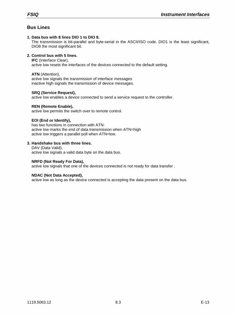
FSIQ Instrument Interfaces
1119.5063.12 8.3 E-13
Bus Lines
1. Data bus with 8 lines DIO 1 to DIO 8.The transmission is bit-parallel and byte-serial in the ASCII/ISO code. DIO1 is the least significant,DIO8 the most significant bit.
2. Control bus with 5 lines.IFC (Interface Clear),active low resets the interfaces of the devices connected to the default setting.
ATN (Attention),active low signals the transmission of interface messagesinactive high signals the transmission of device messages.
SRQ (Service Request),active low enables a device connected to send a service request to the controller.
REN (Remote Enable),active low permits the switch over to remote control.
EOI (End or Identify),has two functions in connection with ATN:active low marks the end of data transmission when ATN=highactive low triggers a parallel poll when ATN=low.
3. Handshake bus with three lines.DAV (Data Valid),active low signals a valid data byte on the data bus.
NRFD (Not Ready For Data),active low signals that one of the devices connected is not ready for data transfer .
NDAC (Not Data Accepted),active low as long as the device connected is accepting the data present on the data bus.

Instrument Interfaces FSIQ
1119.5063.12 8.4 E-13
Interface Functions
Instruments which can be remote controlled via the IEC bus can be equipped with different interfacefunctions. Table 8-1 lists the interface functions appropriate for the instrument.
Table 8-1 Interface functions
Control character Interface function
SH1 Handshake source function (source handshake), full capability
AH1 Handshake sink function (acceptor handshake), full capability
L4 Listener function, full capability, deaddressed by MTA.
T6 Talker function, full capability, ability to respond to serial poll, deaddressed by MLA
SR1 Service request function (Service Request), full capability
PP1 Parallel poll function, full capability
RL1 Remote/Local switch over function, full capability
DC1 Reset function (Device Clear), full capability
DT1 Trigger function (Device Trigger), full capability
C12 Controller function, capability to send interface messages, to accept or relinquish thecontroller function
IEC Bus Messages
The messages transferred via the data lines of the IEC bus can be divided into two groups:
– interface messagesand– instrument messages.
Interface Messages
Interface messages are transferred on the data lines of the IEC Bus when the "ATN" control line isactive (LOW). They are used for communication between controller and instruments and can only besent by the controller which currently has control of the IEC Bus.

FSIQ Instrument Interfaces
1119.5063.12 8.5 E-13
Universal Commands
The universal commands are encoded 10 - 1F hex. They affect all instruments connected to the buswithout addressing.
Table 8-2 Universal Commands
Command QuickBASIC command Effect on the instrument
DCL (Device Clear) IBCMD (controller%, CHR$(20)) Aborts the processing of the commands just receivedand sets the command processing software to adefined initial state. Does not change the instrumentsettings.
IFC (Interface Clear) IBSIC (controller%) Resets the interfaces to the default setting.
LLO (Local Lockout) IBCMD (controller%, CHR$(17)) The LOC/IEC ADDR key is disabled.
SPE (Serial Poll Enable) IBCMD (controller%, CHR$(24)) Ready for serial poll.
SPD (Serial Poll Disable) IBCMD (controller%, CHR$(25)) End of serial poll.
PPU (Parallel PollUnconfigure)
IBCMD (controller%, CHR$(21)) End of the parallel-poll state.
Addressed Commands
The addressed commands are encoded 00 - 0F hex. They are only effective for instruments addressedas listeners.
Table 8-3 Addressed Commands
Command QuickBASIC command Effect on the instrument
SDC (Selected Device Clear) IBCLR (device%) Aborts the processing of the commands just receivedand sets the command processing software to adefined initial state. Does not change the instrumentsetting.
GTL (Go to Local) IBLOC (device%) Transition to the "Local" state (manual control).
PPC (Parallel Poll Configure) IBPPC (device%, data%) Configure instrument for parallel poll. Additionally, theQuickBASIC command executes PPE/PPD.
Instrument Messages
Instrument messages are transferred on the data lines of the IEC bus when the "ATN" control line is notactive. ASCII code is used.Structure and syntax of the instrument messages are described in Chapter 5. The commands are listedand explained in detail in Chapter 6.

Instrument Interfaces FSIQ
1119.5063.12 8.6 E-13
RS-232-C Interface
The standard FSIQ is equipped with two serial interfaces (RS-232-C). The interfaces can be set upmanually in the SETUP-GENERAL SETUP menu in the COM PORT1/2 table.
Each of the active RS-232-C interfaces is assigned to one of the 9-pin connectors located on the rearpanel. Interface 1 is assigned to the connector COM1 and Interface 2 is assigned to the connectorCOM2.
Interface Characteristics
• Serial data transmission in asynchronous mode
• Bidirectional data transfer via two separate lines
• Transmission rate selectable from 110 to 19200 baud
• Logic ’0’ signal from+3 V to +15 V
• Logic ’1’ signal from -15 V to -3 V
• An external instrument (controller) can be connected.
• Software handshake (XON, XOFF)
• Hardware handshake
1 5
6 7 8 9
2 3 4
DCD
RxD
TxD
DTR
SG
DSR
RTS
CTS
RI
Fig. 8-2 Pin assignment of the RS-232-C interface
Signal Lines
1. Data linesThe data transmission is bit-serial in ASCII code starting with the LSB. Two lines, RxD and TxD arenecessary as the minimum requirement for transmission; however, no hardware handshake ispossible. For handshaking, only the XON/XOFF software handshake protocol can be used .
RxD (Receive Data)Input, LOW = logic ’1’, HIGH = logic ’0’.Data line, local terminal receives data from remote station.
TxD (Transmit Data)Output, LOW = logic ’1’, HIGH = logic ’0’.Data line, local terminal transmits data to remote station.

FSIQ Instrument Interfaces
1119.5063.12 8.7 E-13
2. Control linesDCD (Data Carrier Detect),Not used in FSIQ.Input; active LOW.Using this signal, the local terminal recognises that the modem of the remote station receives validsignals with sufficient level. DCD is used to disable the receiver in the local terminal and preventreading of false data if the modem cannot interpret the signals of the remote station.
DTR (Data Terminal Ready),Output, active LOW,Indicates that the local terminal is ready to receive data.
DSR (Data Set Ready),Input, active LOW,Indicates that the remote station is ready to receive data.
RTS (Request To Send),Output, active LOW.Indicates that the local terminal wants to transmit data.
CTS (Clear To Send),Input, active LOW.Used to tell the local terminal that the remote station is ready to receive data.
RI (Ring Indicator),Not used in FSIQ.Input, active LOW.Used by a modem to indicate that a remote station wants to establish a connection.
Transmission Parameters
To ensure error-free data transmission, the parameters of the instrument and the controller must havethe same settings. The parameters are defined in the SETUP-GENERAL SETUP menu.
Transmission rate the following transmission rates can be set in the analyzer:(baud rate) 110, 300, 600, 1200, 2400, 4800, 9600, 19200.
Data bits Data transmission is in 7- or 8-bit ASCII code. The first bit transmitted is the LSB (least significant bit).
Start bit Each data byte starts with a start bit. The falling edge of the startbit indicates the beginning of the data byte.
Parity bit In order to detect errors, a parity bit may be transmitted. Noparity, even parity or odd parity may be selected. In addition, theparity bit can be set to logic ’0’ or to logic ’1’.
Stop bits The transmission of a data byte is terminated by 1, 1,5 or 2 stop bits.
Example:Transmission of character ’A’ (41 hex) in 7-bit ASCII code, with even parity and 2 stop bits:
01 02 03 04 05 06 07 08 09 10 11Bit 01 Bit 02...08 Bit 09 Bit 10...11Start bit Data bits Parity bit Stop bits

Instrument Interfaces FSIQ
1119.5063.12 8.8 E-13
Handshake
Software handshake
In the software handshake mode of operation, the data transfer is controlled using the two controlcharacters XON / XOFF.
The instrument uses the control character XON to indicate that it is ready to receive data. If the receivebuffer is full, it sends the XOFF character via the interface to the controller. The controller then interruptsthe data output until it receives another XON from the instrument. The controller indicates to theinstrument that it is ready to receive data in the same way.
Cable required for software handshake
The connection of the instrument with a controller for software handshake is made by crossing the datalines. The following wiring diagram applies to a controller with a 9-pin or 25-pin configuration.
1
2
3
4
5
6
7
8
9
DSUB connector female / 9 poles
1
2
3
4
5
6
7
8
9
DSRRxDRTSTxDCTSDTR GND
DSUB connector female / 9 poles
Instrument Controller
DSRRxDRTSTxDCTSDTR GND
Instrument Controller / PC
1
2
3
4
5
6
7
8
9
DSRRxDRTSTxDCTSDTR GND
1
2
3
4
5
14
15
16
17
6
7
8
9
18
19
20
21
10
11
12
22
23
24
1325
TxD
RxD
RTS
CTS
DSR
GNDDTRDSUB connector female / 9 poles
DSUB connector female / 25 poles
Fig. 8-3 Wiring of the data lines for software handshake

FSIQ Instrument Interfaces
1119.5063.12 8.9 E-13
Hardware handshake
For hardware handshake, the instrument indicates that it is ready to receive data via the lines DTR andRTS. A logic ’0’ on both lines means ’ready’ and a logic ’1’ means ’not ready’. The RTS line is alwaysactive (logic ’0’) as long as the serial interface is switched on. The DTR line thus controls the readinessof the instrument to receive data.
The readiness of the remote station to receive data is reported to the instrument via the CTS and DSRline. A logic ’0’ on both lines activates the data output and a logic ’1’ on both lines stops the data outputof the instrument. The data output takes place via the TxD line.
Cable for hardware handshake
The connection of the instrument to a controller is made with a so-called zero modem cable. Here, thedata, control and acknowledge lines must be crossed. The following wiring diagram applies to acontroller with a 9-pin or 25-pin configuration.
1
2
3
4
5
6
7
8
9
DSUB connector, 9 poles / female
1
2
3
4
5
6
7
8
9
DSRRxDRTSTxDCTSDTR GND
Instrument Controller / PC
DSRRxDRTSTxDCTSDTR GND
Instrument Controller / PC
1
2
3
4
5
6
7
8
9
DSRRxDRTSTxDCTSDTR GND
1
2
3
4
5
14
15
16
17
6
7
8
9
18
19
20
21
10
11
12
22
23
24
1325
TxD
RxD
RTS
CTS
DSR
GNDDTR
DSUB connector, 9 poles / female
DSUB connector, 9 poles / female
DSUB connector, 25 poles / female
Fig. 8-4 Wiring of the data, control and acknowledge lines for hardware handshake

Instrument Interfaces FSIQ
1119.5063.12 8.10 E-13
RSIB Interface Functions
The RSIB interface allows the control of FSIQ by Windows applications WinWord and Excel or by VisualC++ and VisualBasic programs. The functions for the programming of control applications are providedby DLLs RSIB32.DLL (for 32-bit applications) and RSIB.DLL (for 16-bit applications).
Control applications may run locally on the measuring instrument as well as on a remote controller in anetwork. With local control, the name ’@local’ is specified for link setup by means of functionRSDLLibfind(). If ’@local’ is not specified, the RSIB.DLL interprets the name as an IP addressand attempts to set up a link to the device via the Winsock interface.
Remote controller(Windows NT or Windows 95) FSIQ
0
1 2 3
4 5 6
7 8 9
. -
CLR BACK
GHz
MHz
kHz
Hz
EXP
-d BmVs
dBm
mVms
dBµVµs
dB..
nVns
AF OUTPUT PROBE POWER PROBE / CODE
30 d Bm+ DC 0 VMAX
M ADE IN GER MAN Y
HOLD ST EP
50 W
SYSTEM
CONFIGURATION
PRESET CAL
DISPLAY INFO
MODE
SETUP
SETT ING
START
HARDCOPY
STATUS
SRQ
REMOTE
LOCAL
FREQUENCY LEVEL DATA ENTRYCENTER / SPAN /
UNIT
ST ART ST OP RANGE
MARKER LINES
NORMAL SEARCH D LINES
DELTA LIMIT SMKR
TRACE SWEEP DATA VARIATIONTRIGGER
SWEEP /
1 2
3 4
RBW
VBW
SWT
MENU
MEMORY
CONFIG
SAVE
RECALL
INPUT
FREQ ZOOM
SCAN
COUPLING /RUN
GEN OUTPUT 50W RF INPUT 1
MAX
REF /
REM OTE
EMI TEST RECEIVER 20 Hz . . . 7 GHz ESI 1088.7490. . 07
RF INPUT 2 20Hz ... 1GHz
30 dBm+MAX
50 W
To access the measuring instruments via the RSIB interface the DLLs should be installed inthecorresponding directories:
• RSIB.DLL in Windows NT system directory or control application directory.
• RSIB32.DLL in Windows NT system32 directory or control application directory.
The DLLs are already installed in the corresponding directories on the measuring instruments.
For the different programming languages, files exist containing the declarations for the DLL functionsand the error code definitions.
Visual Basic (16 bit): ’RSIB.BAS’ (C:/R_S/Instr/RSIB)Visual Basic (32 bit): ’RSIB32.BAS’ (C:/R_S/Instr/RSIB)C: ’RSIBC.H’ (C:/R_S/Instr/RSIB)Winword: ’RSIBWB.BAS’ (C:/R_S/Instr/RSIB)
Thus, the RSIB directory features a program ‘RSIBCNTR.EXE’ with SCPI commands which can be sentto the instrument by the RSIB interface. This program can be used as a test for the function of theinterface. Transit-time module VBRUN3200.DLL in the path or the Windows directory are required.
This following sections describe all functions of DLL 'RSIB.DLL’ orby means of which controlapplications can be written.
Remotecontrol vianetwork
16-bit app.16-bit application
32-bit app.
32-bit application
Localapplicationson instrument
RSIB network interface
RSIB DLL
RSIB.DLL RSIB32.DLLRSIB32.DLL

FSIQ Instrument Interfaces
1119.5063.12 8.11 E-13
Variables ibsta, iberr, ibcntl
Same as with the National Instrument interface, successful execution of a command can be checked bymeans of the variables ibsta, iberr and ibcntl. To this end, references to the three variables aretransferred to all RSIB functions. In addition, the status word ibsta is returned as a function value by allfunctions.
Status word ibstaAll functions send back a status word that provides information on the status of the RSIB interface. Thefollowing bits are defined:
Bit name Bit Hex code Description
ERR 15 8000 This bit is set if an error occurs during a function call. If this bit is set, iberrcontains an error code which specifies the error.
TIMO 14 4000 This bit is set if a timeout occurs during a function call. A timeout may occur inthe following situations:
• while waiting for an SRQ with the function RSDLLWaitSrq().
• if no acknowledgment is received for data sent to an instrument withRSDLLibwrt() or RSDLLilwrt().
• if no response from server to a data request with function RSDLLibrd() orRSDLLilrd().
CMPL 8 0100 This bit is set if the reply of the IEC/IEEE-bus parser is completely read. If areply of the parser is read with the function RSDLLilrd() and the bufferlength is not sufficient, the bit is cleared.
Error variable iberrIf the ERR bit (8000h) is set in the status word, iberr contains an error code that specifies the error.The RSIB has error codes of its own independent of the National Instrument interface.
Error Error code Description
IBERR_DEVICE_REGISTER 1 RSIB.DLL cannot register any new device.
IBERR_CONNECT 2 Link to the device has failed.
IBERR_NO_DEVICE 3 An interface function was called with an invalid device handle.
IBERR_MEM 4 No free memory available.
IBERR_TIMEOUT 5 Timeout has occurred.
IBERR_BUSY 6 The RSIB interface is blocked by a function not yet completed.
Windows is not blocked, for example, by function RSDLLibrd() if data are stillto be transmitted in response to this function. In this case a new call ispossible. Further calls are however rejected by RSIB.DLL with error codeIBERR_BUSY.
IBERR_FILE 7 Error in reading from or writing to a file.
Count variable - ibcntlThe variable ibcntl is updated with the number of bytes transmitted on every read and write function call.

Instrument Interfaces FSIQ
1119.5063.12 8.12 E-13
List of Interface Functions
The DLL functions are matched to the interface functions for IEC/IEEE-bus programming from NationalInstruments. Functions supported by the DLLs are listed in the following table.
Function Description
RSDLLibfind() Provides a handle for accessing a device.
RSDLLibwrt() Sends a string terminated with a null to a device.
RSDLLilwrt() Sends a specific number of bytes to a device.
RSDLLibwrtf() Sends the contents of a file to a device.
RSDLLibrd() Reads data from a device into a string.
RSDLLilrd() Reads a specific number of bytes from a device.
RSDLLibrdf() Reads data from a device into a file.
RSDLLibtmo() Sets timeout period for RSIB functions.
RSDLLibsre() Switches a device to local or remote.
RSDLLibloc() Switches a device temporarily to local.
RSDLLibeot() Enables/disables END message in write operations.
RSDLLibrsp() Starts a serrial poll and reads the status byte
RSDLLibonl() Switches the instrument online/offline
RSDLLTestSrq() Checks if a device has generated an SRQ.
RSDLLWaitSrq() Waits until a device generates an SRQ.

FSIQ Instrument Interfaces
1119.5063.12 8.13 E-13
Description of Interface Functions
RSDLLibfind()The function provides a handle for accessing the instrument with the name udName.
VB format: Function RSDLLibfind (ByVal udName$, ibsta%, iberr%, ibcntl&)As Integer
C format: short FAR PASCAL RSDLLibfind( char far *udName, short far*ibsta, short far *iberr, unsigned long far *ibcntl)
Parameter: udName Instrument name
Example: ud = RSDLLibfind ("@local", ibsta, iberr, ibcntl)
The function must be called before all other interface functions.
The function supplies a handle as a return value. The handle must be specified in all functions foraccessing the instrument. If no instrument with the name udName is found, the handle will take on anegative value.
The local link on the instrument is established with the name ’@local’. For setting up a link via anetwork, on the other hand, the IP address of the instrument must be given (eg ’89.1.1.200’)
RSDLLibwrt
The function sends data to the instrument with the handle ud.
VB format: Function RSDLLibwrt (ByVal ud%, ByVal Wrt$, ibsta%, iberr%,ibcntl&) As Integer
C format: short FAR PASCAL RSDLLibwrt( short ud, char far *Wrt, shortfar *ibsta, short far *iberr, unsigned long far *ibcntl )
Parameter: ud Device handle
Wrt String sent to the instrument.
Example: RSDLLibwrt(ud, "SENS:FREQ:STAR?", ibsta, iberr, ibcntl)
The function allows setting and query commands to be sent to the measuring instruments. The functionRSDLLibeot() is used for defining whether the data are interpreted as a complete command.
RSDLLilwrt
The function sends Cnt bytes to the instrument with the handle ud.
VB format: Function RSDLLilwrt (ByVal ud%, ByVal Wrt$, ByVal Cnt&,ibsta%, iberr%, ibcntl&) As Integer
C format: short FAR PASCAL RSDLLilwrt( short ud, char far *Wrt,unsigned long Cnt, short far *ibsta, short far *iberr,unsigned long far *ibcntl)
Parameter: ud Device handle
Wrt String sent to the IEC/IEEE-bus parser.
Cnt Number of bytes sent to the instrument.
Example: RSDLLilwrt (ud, ’......’, 100, ibsta, iberr, ibcntl)
This function sends data to an instrument same as function RSDLLibwrt() but with the difference thatbinary data, too, can be sent. The length of the data is determined not by a zero-terminated string but bythe definition of Cnt bytes. If the data are to be terminated with EOS (0Ah), the EOS byte must beappended to the string.

Instrument Interfaces FSIQ
1119.5063.12 8.14 E-13
RSDLLibwrtf
The function sends the contents of a file to the instrument with the handle ud.
VB format: Function RSDLLibwrtf (ByVal ud%, ByVal file$, ibsta%, iberr%,ibcntl&) As Integer
C format: short FAR PASCAL RSDLLibwrtf( short ud, char far *Wrt, shortfar *ibsta, short far *iberr, unsigned long far *ibcntl )
Parameter: ud Device handle
file File whose contents are sent to the instrument.
Example: RSDLLibrdf(ud, "C:\db.sav", ibsta, iberr, ibcntl)
The function allows setting and query commands to be sent to the measuring instruments. The functionRSDLLibeot() is used for defining whether the data are interpreted as a complete command.
RSDLLibrd()
The function reads data from the instrument into the string Rd with the handle ud.
VB format: Function RSDLLibrd (ByVal ud%, ByVal Rd$, ibsta%, iberr%,ibcntl&) As Integer
C format: short FAR PASCAL RSDLLibrd( short ud, char far *Rd, short far*ibsta, short far *iberr, unsigned long far *ibcntl )
Parameter: ud Device handle
Rd String into which the read data are copied.
Example: RSDLLibrd (ud, Rd, ibsta, iberr, ibcntl)
This function fetches replies of the IEC/IEEE-bus parser in response to a query command.
For this, a string of sufficient length must be generated when programming in Visual Basic. This can beaccomplished in the definition of the string or with the command Space$().Generation of a string of the length 100: - Dim Rd as String * 100
- Dim Rd as StringRd = Space$(100)
RSDLLilrd
The function reads Cnt bytes from the instrument with the handle ud.
VB format: Function RSDLLilrd (ByVal ud%, ByVal Rd$, ByVal Cnt&, ibsta%,iberr%, ibcntl&) As Integer
C format: short FAR PASCAL RSDLLilrd( short ud, char far *Rd, unsignedlong Cnt, short far *ibsta, short far *iberr, unsigned longfar *ibcntl )
Parameter: ud Device handle
cnt Maximum number of bytes copied to target string Rd by the DLL.
Example: RSDLLilrd (ud, RD, 100, ibsta, iberr, ibcntl)
The function reads data from an instrument same as function RSDLLibrd() but with the difference thathere the maximum number of bytes is allowed to be copied to target string Rd to be defined with Cnt.Writing beyond a string can thus be prevented with this function. The number of bytes cut off is lost.
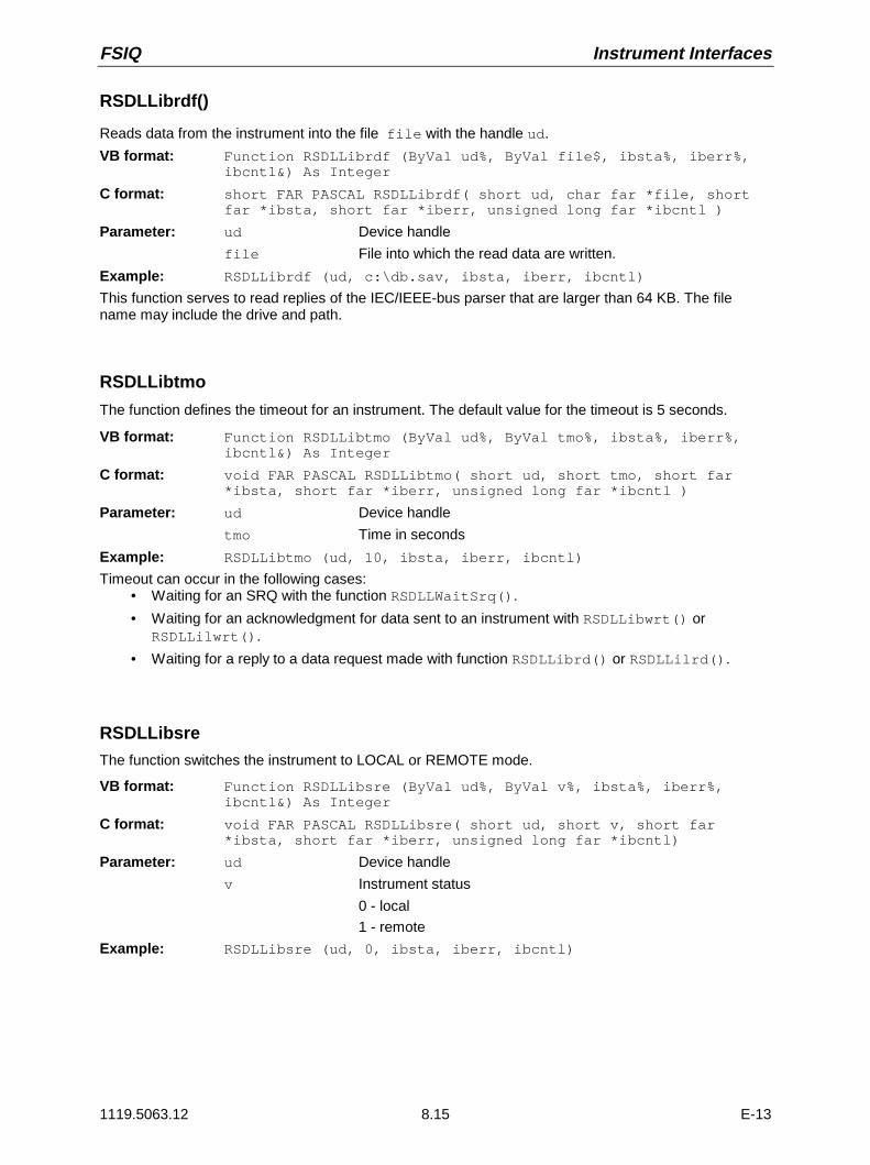
FSIQ Instrument Interfaces
1119.5063.12 8.15 E-13
RSDLLibrdf()
Reads data from the instrument into the file file with the handle ud.
VB format: Function RSDLLibrdf (ByVal ud%, ByVal file$, ibsta%, iberr%,ibcntl&) As Integer
C format: short FAR PASCAL RSDLLibrdf( short ud, char far *file, shortfar *ibsta, short far *iberr, unsigned long far *ibcntl )
Parameter: ud Device handle
file File into which the read data are written.
Example: RSDLLibrdf (ud, c:\db.sav, ibsta, iberr, ibcntl)
This function serves to read replies of the IEC/IEEE-bus parser that are larger than 64 KB. The filename may include the drive and path.
RSDLLibtmo
The function defines the timeout for an instrument. The default value for the timeout is 5 seconds.
VB format: Function RSDLLibtmo (ByVal ud%, ByVal tmo%, ibsta%, iberr%,ibcntl&) As Integer
C format: void FAR PASCAL RSDLLibtmo( short ud, short tmo, short far*ibsta, short far *iberr, unsigned long far *ibcntl )
Parameter: ud Device handle
tmo Time in seconds
Example: RSDLLibtmo (ud, 10, ibsta, iberr, ibcntl)
Timeout can occur in the following cases:• Waiting for an SRQ with the function RSDLLWaitSrq().
• Waiting for an acknowledgment for data sent to an instrument with RSDLLibwrt() orRSDLLilwrt().
• Waiting for a reply to a data request made with function RSDLLibrd() or RSDLLilrd().
RSDLLibsre
The function switches the instrument to LOCAL or REMOTE mode.
VB format: Function RSDLLibsre (ByVal ud%, ByVal v%, ibsta%, iberr%,ibcntl&) As Integer
C format: void FAR PASCAL RSDLLibsre( short ud, short v, short far*ibsta, short far *iberr, unsigned long far *ibcntl)
Parameter: ud Device handle
v Instrument status
0 - local
1 - remote
Example: RSDLLibsre (ud, 0, ibsta, iberr, ibcntl)

Instrument Interfaces FSIQ
1119.5063.12 8.16 E-13
RSDLLibloc
The function switches the instrument temporarily to LOCAL mode.
VB format: Function RSDLLibloc (ByVal ud%, ibsta%, iberr%, ibcntl&) AsInteger
C format: void FAR PASCAL RSDLLibloc( short ud, short far *ibsta, shortfar *iberr, unsigned long far *ibcntl)
Parameter: ud Device handle
Example: RSDLLibloc (ud, ibsta, iberr, ibcntl)
After switchover the instrument can be manually operated from the front panel. On the next access tothe instrument by means of one of the functions of the RSIB.DLL, the instrument is switched again to theREMOTE state.
RSDLLibeot
The function enables the END message after write operations or disables it.
VB format: Function RSDLLibeot (ByVal ud%, ByVal v%, ibsta%, iberr%,ibcntl&) As Integer
C format: void FAR PASCAL RSDLLibeot( short ud, short v, short far*ibsta, short far *iberr, unsigned long far *ibcntl)
Parameter: ud Device handle.
v 0 - no END message
1 - send END message
Example: RSDLLibeot (ud, 1, ibsta, iberr, ibcntl)
If the END message is disabled, the data of a command can be sent by means of several successivewrite function calls. The END message must be enabled prior to the last data block.
RSDLLibrsp
The function carries out a Serial Poll and outputs the instrument status.
VB format: Function RSDLLibrsp(ByVal ud%, spr%, ibsta%, iberr%, ibcntl&)As Integer
C format: void FAR PASCAL RSDLLibrsp( short ud, char far* spr, short far*ibsta, short far *iberr, unsigned long far *ibcntl)
Parameter: ud Device handle.spr Reference to status byte
Example: RSDLLibrsp(ud, spr, ibsta, iberr, ibcntl)

FSIQ Instrument Interfaces
1119.5063.12 8.17 E-13
RSDLLibonl
The function switches the instrument to the 'online' or 'offline' state. When switching to ‘offline’ theinterface is enabled and the device handle made invalid. The next call of RSDLLibfind sets up thecommunication again.
VB format: Function RSDLLibonl (ByVal ud%, ByVal v%, ibsta%, iberr%,ibcntl&) As Integer
C format: void FAR PASCAL RSDLLibonl( short ud, short v, short far*ibsta, short far *iberr, unsigned long far *ibcntl)
Parameter: ud Device handle.v Status of instrument
0 - local1 - remote
Example: RSDLLibonl(ud, 0, ibsta, iberr, ibcntl)
RSDLLTestSRQ
The function checks the status of the SRQ bit.
VB format: Function RSDLLTestSrq (ByVal ud%, Result%, ibsta%, iberr%,ibcntl&) As Integer
C format: void FAR PASCAL RSDLLTestSrq( short ud, short far *result,short far *ibsta, short far *iberr, unsigned long far *ibcntl)
Parameter: ud Device handle
result Reference to an integer value in which the libraryreturns the status of the SRQ bit.
0 - no SRQ
1 - SRQ active, instrument has output a service request
Example: RSDLLTestSrq (ud, result%, ibsta, iberr, ibcntl)
The function corresponds to the function RSDLLWaitSrq but with the difference that RSDLLTestSRQreturns immediately the current status of the SRQ bit whereas RSDLLWaitSrq waits for an SRQ tooccur.
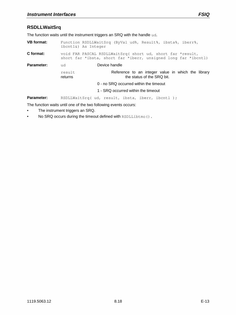
Instrument Interfaces FSIQ
1119.5063.12 8.18 E-13
RSDLLWaitSrq
The function waits until the instrument triggers an SRQ with the handle ud.
VB format: Function RSDLLWaitSrq (ByVal ud%, Result%, ibsta%, iberr%,ibcntl&) As Integer
C format: void FAR PASCAL RSDLLWaitSrq( short ud, short far *result,short far *ibsta, short far *iberr, unsigned long far *ibcntl)
Parameter: ud Device handle
result Reference to an integer value in which the libraryreturns the status of the SRQ bit.
0 - no SRQ occurred within the timeout
1 - SRQ occurred within the timeout
Parameter: RSDLLWaitSrq( ud, result, ibsta, iberr, ibcntl );
The function waits until one of the two following events occurs:
• The instrument triggers an SRQ.
• No SRQ occurs during the timeout defined with RSDLLibtmo().

FSIQ Instrument Interfaces
1119.5063.12 8.19 E-13
User Interface (USER)
The user interface, located on the rear panel of the FSIQ, is a 25 pin Cannon connector which providesaccess to the two user ports (Port A and Port B). Each port is 8 bits wide (A0 - A7 and B0 -B7) and canbe configured either as output or as input. The voltage levels are TTL levels (Low < 0,4 V, High > 2 V).
In addition, an internal +5 V power supply voltage is provided. The maximum load current is 100 mA.
The pin assignments for the USER connector can be seen in the following diagram:
1
14
13
25
A0A1
A2
A3
A4
A5
A6
A7GND
GND
GND
GND
+5 V
B7B6
B5
B4
B3
B2
B1
B0
+5 V
Fig. 8-5 Pin assignments for the USER connector.
The configuration of the user ports takes place in the SETUP menu (SETUP key) in the GENERALSETUP sub-menu.

Instrument Interfaces FSIQ
1119.5063.12 8.20 E-13
Printer Interface (LPT)
The 25-pin LPT connector on the rear panel of the FSIQ is provided for the connection of a printer.. TheLPT interface is compatible with the CENTRONICS printer interface.
1
14
13
25
D0
D1
D2
D3
D4
D5
D6
D7
ACK
BUSY
PE
SELECT STROBE
AUTOFEED
ERROR
INIT
SELECT IN
GND
GNDGND
GND
GND
GND
GND
GND
Pin Signal Input (I)Output (O)
Description
1 STROBE O Pulse for transmitting a data byte, min. 1µs pulse width(active LOW)
2 D0 O Data Line 0
3 D1 O Data Line 1
4 D2 O Data Line 2
5 D3 O Data Line 3
6 D4 O Data Line 4
7 D5 O Data Line 5
8 D6 O Data Line 6
9 D7 O Data Line 7
10 ACK I Indicates that the printer is ready to receive the next byte.(active LOW)
11 BUSY I Signal is active when the printer cannot accept data.(active HIGH)
12 PE I Signal is active when the paper tray is empty.(active HIGH)
13 SELECT I Signal is active when the printer is selected.(active HIGH)
14 AUTOFEED O When signal is active, the printer automatically performs alinefeed after each line.(active LOW)
15 ERROR I This signal is high when the printer has no paper, is notselected or has an error status. (active LOW)
16 INIT O Initialise the printer.(active LOW)
17 SELECT IN O If signal is active, the codes DC1/DC3 are ignored by theprinter.(active LOW).
18 - 25 GND Ground connection.
Fig. 8-6 Pin assignments for the LPT connector.

FSIQ Instrument Interfaces
1119.5063.12 8.21 E-13
Measurement Converters (PROBE CODE)
The PROBE CODE connector is used for supplying power to measurement converters and the providingthe correct conversion factor coding to the FSIQ. Using it, the conversion factors for high-impedanceprobes, current converters and antennas can be encoded in 10dB steps. In addition, the quantity to bemeasured (field strength, current and voltage) is also passed to the FSIQ. Active converters can besupplied with ±10 V via the PROBE CODE connector. The following R&S accessories are deliverablewith the applicable coding:
· Wide band dipole 20...80 MHz HUF-Z2
· HF current converter 100 kHz..30 MHz ESH2-Z1
· VHF current converter 20...300 MHz ESV-Z1
· Current converter 20 Hz...100 MHz EZ-17
· Preamplifier 20...1000 MHz ESV-Z2.
The pins of the PROBE CODE connector are assigned as follows:
Pin Signal
A ground
B +10 V, max. 50 mA
C µV/m (elec. field strength)
D µA
E 10 dB
F 20 dB
G 40 dB
H 80 dB
K - 10 V, max. 50 mA
M factor sign inversion
Fig 8-7 Pin assignment for the 12-pin Tuchel connector.
A 12-pin connector is used for coding (manufacturer: Tuchel, R&S part number 0018.5362.00, Tucheltype number: T3635/2). The input pins for implementing the code are connected to ground.
Example: An antenna for measurement of the electromagnetic field strength has an antenna factor of10 dB, i.e., a field strength of 10 dBµV/m produces a voltage at the RF input of 0 dBµV.
-> Pins C and E are connected to ground.
Probe Connector (PROBE POWER)
To allow the connection of probes, the FSIQ provides the PROBE POWER power connector. It deliversthe power supply voltages +15 V and -12,6 V and ground.The connector is also suited for powering the high-impedance probes from Hewlett Packard.
Pin Signal
1 GND
2 -12,6 V; max 150 mA
1
23
3 +15 V; max 150 mA
A B
C
D
EFG
H
J
K
L
M

Instrument Interfaces FSIQ
1119.5063.12 8.22 E-13
AF-Output (AF OUTPUT)
A miniature telephone jack can be used at the AF OUTPUT connector to connect an externalloudspeaker, a headphone set or, e.g., a LF voltmeter. The internal resistance is 10 ohms and theoutput voltage can be controlled in the MARKER DEMOD menu. When a jack is plugged in, the internalloudspeaker is automatically turned off.
IF Output 21.4 MHz (21.4 MHz OUT)
The 21,4 MHz IF signal of the FSIQ is available at the IF 21.4 MHz OUT BNC connector. The bandwidthcorresponds to the selected bandwidth for a resolution bandwidth between 2 kHz and 10 MHz. For aresolution bandwidth below 2 kHz, the bandwidth of the output is 5 kHz.The signal level at the IF output is 0 dBm for signals which correspond to the selected reference level.
Video Output (VIDEO OUT)
The video output delivers the logarithmic envelope curve of the IF signal independent of the level scalingon the display screen (linear or logarithmic). The bandwidth of the video signal always corresponds toone-half of the IF bandwidth and is not limited by the video filter in the measurement path.
Reference Output/Input (EXT REF IN/OUT)
When the FSIQ is operated with the internal reference, the internal 10 MHz reference signal is alsoavailable at the REF IN/OUT connector and thus provides the capability of, e.g., synchronisation ofexternal instruments to the FSIQ. The level is 1 V RMS at 50 ohms source impedance.For operation with an external reference, this connector becomes an input connector. The internalreference oscillator is then synchronised to the reference applied to the connector. The referencefrequency can be between 1 and 16 MHz in 1 MHz steps. The necessary level is > 0 dBm.The selection of internal or external references takes place in the SETUP menu.
Sweep Output (SWEEP)
The SWEEP BNC connector delivers a saw-tooth voltage between - 5V and + 5 V which, for thefrequency spectrum display, is proportional to the instantaneous frequency. The selected start frequencycorresponds to a voltage of -5 V and the stop frequency corresponds to a voltage of +5 V.
External Trigger Input (EXT TRIGGER/GATE)
The EXT TRIG/GATE connector is used for controlling the measurement via an external signal.Trigger voltage range:: -5 V ... +5 V
Noise Source Control (NOISE SOURCE)
Using the NOISE SOURCE connector, an external noise source can be switched on/off, in order, e.g., tomeasure the noise figure of Units Under Test (UUTs). Usual noise sources require a +28 V signal to beturned on. At 0 V, they are turned off. These switching voltages are delivered by the connector.
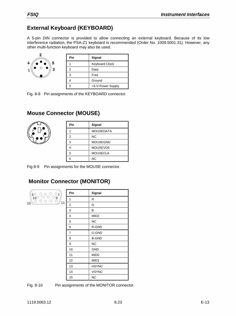
FSIQ Instrument Interfaces
1119.5063.12 8.23 E-13
External Keyboard (KEYBOARD)
A 5-pin DIN connector is provided to allow connecting an external keyboard. Because of its lowinterference radiation, the PSA-Z1 keyboard is recommended (Order No. 1009.5001.31). However, anyother multi-function keyboard may also be used.
Pin Signal
1 Keyboard Clock
2 Data
3 Free
4 Ground
5 +5-V-Power Supply
Fig. 8-8 Pin assignments of the KEYBOARD connector.
Mouse Connector (MOUSE)
Pin Signal
1 MOUSEDATA
2 NC
3 MOUSEGND
4 MOUSEVD5
5 MOUSECLK
6 NC
Fig 8-9 Pin assignments for the MOUSE connector.
Monitor Connector (MONITOR)
Pin Signal
1 R
2 G
3 B
4 MID2
5 NC
6 R-GND
7 G-GND
8 B-GND
9 NC
10 GND
11 MID0
12 MID1
13 HSYNC
14 VSYNC
15 NC
Fig. 8-10 Pin assignments of the MONITOR connector.
15
15 11
610


FSIQ Contents - Error Messages
1119.5063.12 I-9.1 E-1
Contents - Chapter 9 "Error Messages"
9 List of Error Messages
SCPI-Specific Error Messages........................................................................................................ 9.1Command Error - Faulty command; sets bit 5 in the ESR register. ........................................ 9.1
Execution Error - Error on execution of a command; sets bit 4 in the ESR register................ 9.4
Device Specific Error; sets bit 3 in the ESR register ............................................................... 9.7
Query Error - Error in data request; sets bit 2 in the ESR register .......................................... 9.7

Contents - Error Messages FSIQ
1119.5063.12 I-9.2 E-1

FSIQ List of Error Messages
1119.5063.12 9.1 E-1
9 List of Error Messages
The following list contains the error messages for errors occurring in the instrument. The meaning ofnegative error codes is defined in SCPI, positive error codes mark errors specific of the instrument.
Error messages are entered in the error/event queue of the status reporting system in the remotecontrol mode and can be queried with the command SYSTem:ERRor?. The answer format of FSIQ tothe command is as follows:
<error code>, "<error text with queue query>; <remote control command concerned>"
The indication of the remote control command with prefixed semicolon is optional.
Example:
The command "TEST:COMMAND" generates the following answer to the query SYSTem:ERRor? :
-113,"Undefined header;TEST:COMMAND"
The table contains the error code in the left-hand column. In the right-hand column the error text beingentered into the error/event queue or being displayed is printed in bold face. Below the error text, thereis an explanation as to the respective error.
SCPI-Specific Error Messages
No Error
Error codeError text in the case of queue poll
Error explanation
0 No error
This message is output if the error queue does not contain any entries.
Command Error - Faulty command; sets bit 5 in the ESR register.
Error code Error text in the case of queue pollError explanation
-100 Command Error
The command is faulty or invalid.
-101 Invalid Character
The command contains an invalid sign.
Example: A header contains an ampersand, "SENSe&".
-102 Syntax error
The command is invalid.
Example: The command contains block data the instrument does not accept.
-103 Invalid separator
The command contains an impermissible sign instead of a separator.
Example: A semicolon is missing after the command.

List of Error Messages FSIQ
1119.5063.12 9.2 E-1
Continuation: Command Error
Error code Error text in the case of queue pollError explanation
-104 Data type error
The command contains an invalid value indication.
Example: ON is indicated instead of a numeric value for frequency setting.
-105 GET not allowed
A Group Execute Trigger (GET) is within a command line.
-108 Parameter not allowed
The command contains too many parameters.
Example: Command SENSe:FREQuency:CENTer permits only one frequency indication.
-109 Missing parameter
The command contains too few parameters.
Example: The command SENSe:FREQuency:CENTer requires a frequency indication.
-110 Command header error
The header of the command is faulty.
-111 Header separator error
The header contains an impermissible separator.
Example: the header is not followed by a "White Space", "*ESE255"
-112 Program mnemonic too long
The header contains more than 12 characters.
-113 Undefined header
The header is not defined for the instrument.
Example: *XYZ is undefined for every instrument.
-114 Header suffix out of range
The header contains an impermissible numeric suffix.
Example: SENSe3 does not exist in the instrument.
-120 Numeric data error
The command contains a faulty numeric parameter.
-121 Invalid character in number
A number contains an invalid character.
Example: An "A" in a decimal number or a "9" in an octal number.
-123 Exponent too large
The absolute value of the exponent is greater than 32000.
-124 Too many digits
The number includes too many digits.
-128 Numeric data not allowed
The command includes a number which is not allowed at this position.
Example: The command INPut:COUPling requires indication of a text parameter.
-130 Suffix error
The command contains a faulty suffix.
-131 Invalid suffix
The suffix is invalid for this instrument.
Example: nHz is not defined.
-134 Suffix too long
The suffix contains more than 12 characters.

FSIQ List of Error Messages
1119.5063.12 9.3 E-1
Continuation: Command Error
Error code Error text in the case of queue pollError explanation
-138 Suffix not allowed
A suffix is not allowed for this command or at this position of the command.
Example: The command *RCL does not permit a suffix to be indicated.
-140 Character data error
The command contains a faulty text parameter
-141 Invalid character data
The text parameter either contains an invalid character or it is invalid for this command.
Example: Write error with parameter indication;INPut:COUPling XC.
-144 Character data too long
The text parameter contains more than 12 characters.
-148 Character data not allowed
The text parameter is not allowed for this command or at this position of the command.
Example: The command *RCL requires a number to be indicated.
-150 String data error
The command contains a faulty string.
-151 Invalid string data
The command contains a faulty string.
Example: An END message has been received prior to the terminating apostrophe.
-158 String data not allowed
The command contains a valid string at a position which is not allowed.
Example: A text parameter is set in quotation marks, INPut:COUPling "DC"
-160 Block data error
The command contains faulty block data.
-161 Invalid block data
The command contains faulty block data.
Example: An END message was received prior to reception of the expected number of data.
-168 Block data not allowed
The command contains valid block data at an impermissible position.
Example: The command *RCL requires a number to be indicated.
-170 Expression error
The command contains an invalid mathematical expression.
-171 Invalid expression
The command contains an invalid mathematical expression.
Example: The expression contains mismatching parentheses.
-178 Expression data not allowed
The command contains a mathematical expression at an impermissible position.
-180 Macro error
A faulty macro has been defined, or an error has occurred during execution of a macro.
-181 Invalid outside macro definition
A macro parameter placeholder was encountered outside of a macro definition.
-183 Invalid inside macro definition
A macro definition is syntactically wrong.
-184 Macro parameter error
A command inside the macro definition has the wrong number or type of parameters.

List of Error Messages FSIQ
1119.5063.12 9.4 E-1
Execution Error - Error on execution of a command; sets bit 4 in the ESRregister
Error code Error text in the case of queue pollError explanation
-200 Execution error
Error on execution of the command.
-201 Invalid while in local
The command is not executable while the device is in local due to a hard local control.
Example: The device receives a command which would change the rotary knob state, but the device is inlocal so the command can not be executed.
-202 Settings lost due to rtlA setting associated with hard local control was lost when the device changed to LOCS from REMS or toLWLS from RWLS.
-210 Trigger error
Error on triggering the device.
-211 Trigger ignored
The trigger (GET, *TRG or trigger signal) was ignored because of device timing considerations.
Example: The device was not ready to respond.
-212 Arm ignored
An arming signal was ignored by the device.
-213 Init ignored
Measurement initialisation was ignored as another measurement was already in progress.
-214 Trigger deadlock
The trigger source for the initiation of measurement is set to GET and subsequent measurement is
received. The measurement cannot be started until a GET is received, but the GET would cause an
interrupted-error)
-215 Arm deadlock
The trigger source for the initiation of measurement is set to GET and subsequent measurement is
received. The measurement cannot be started until a GET is received, but the GET would cause an
interrupted-error.
-220 Parameter error
The command contains a faulty or invalid parameter.
-221 Settings conflict
There is a conflict between setting of parameter value and instrument state.
-222 Data out of range
The parameter value lies out of the permissible range of the instrument.
-223 Too much data
The command contains too many data.
Example: The instrument does not have sufficient storage space.
-224 Illegal parameter value
The parameter value is invalid.
Example: The text parameter is invalid , TRIGger:SWEep:SOURce TASTe

FSIQ List of Error Messages
1119.5063.12 9.5 E-1
Continuation: Execution Error
Error code Error text in the case of queue pollError explanation
-230 Data corrupt or stale
The data are incomplete or invalid.
Example: The instrument has aborted a measurement.
-231 Data questionable
The measurement accuracy is suspect.
-240 Hardware error
The command cannot be executed due to problems with the instrument hardware.
-241 Hardware missing
Hardware is missing.
Example: An option is not fitted.
-250 Mass storage error
A mass storage error occured.
-251 Missing mass storage
The mass storage is missing.
Example: An option is not installed.
-252 Missing media
The media is missing.
Example: There is no floppy in the floppy disk drive.
-253 Corrupt media
The media is corrupt.
Example: The floppy is bad or has the wrong format.
-254 Media full
The media is full.
Example: There is no room on the floppy.
-255 Directory full
The media directory is full.
-256 File name not found
The file name cannot be found on the media.
-257 File name error
The file name is wrong.
Example: An attempt is made to copy to a duplicate file name.
-258 Media protected
The media is protected.
Example: The write-protect tab on the floppy is present.
-260 Expression error
The expression contains an error.
-261 Math error in expression
The expression contains a math error.
Example: Divide-by-zero.

List of Error Messages FSIQ
1119.5063.12 9.6 E-1
Continuation: Execution Error
Error code Error text in the case of queue pollError explanation
-270 Macro error
Error on the execution of a macro.
-271 Macro syntax error
The macro definition contains a syntax error.
-272 Macro execution error
The macro definition contains an error.
-273 illegal macro label
An illegal macro label is defined in the *DMC command.
Example: The label is too long. The label is identical with the common command header or contains aninvalid header syntax.
-274 Macro parameter error
The macro definition improperly uses a macro parameter placeholder.
-275 Macro definition too long
The macro definition is too long.
-276 Macro recursion error
The command sequence defined by the macro is trapped in a program loop.
Example: The event that would allow the loop to be exited does not occur.
-277 Macro redefinition not allowed
The macro label defined in the *DMC command is already defined elsewhere.
-278 Macro header not found
The macro label in the *GMC? query is not yet defined.
-280 Program error
Error on the execution of a down-loaded program.
-281 Cannot create program
The program cannot be created.
-282 illegal program name
The name of the programm is illegal.
Example: The name relates to a non-existing program.
-283 illegal variable name
The inputted variable does not exist in the program.
-284 Program currently running
The desired operation is not possible while the program is running.
Example: A running program cannot be deleted.
-285 Program syntax error
The down-loaded program contains a syntax error.
-286 Program runtime error
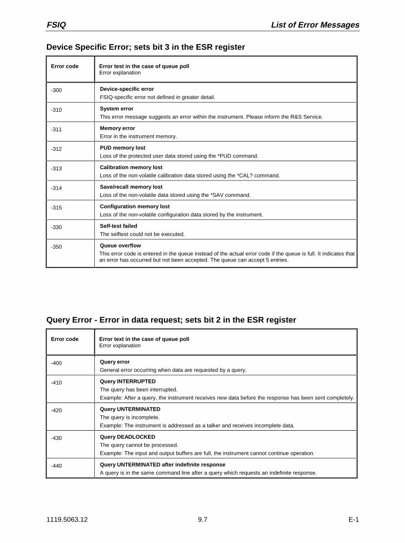
FSIQ List of Error Messages
1119.5063.12 9.7 E-1
Device Specific Error; sets bit 3 in the ESR register
Error code Error test in the case of queue pollError explanation
-300 Device-specific error
FSIQ-specific error not defined in greater detail.
-310 System error
This error message suggests an error within the instrument. Please inform the R&S Service.
-311 Memory error
Error in the instrument memory.
-312 PUD memory lost
Loss of the protected user data stored using the *PUD command.
-313 Calibration memory lost
Loss of the non-volatile calibration data stored using the *CAL? command.
-314 Save/recall memory lost
Loss of the non-volatile data stored using the *SAV command.
-315 Configuration memory lost
Loss of the non-volatile configuration data stored by the instrument.
-330 Self-test failed
The selftest could not be executed.
-350 Queue overflowThis error code is entered in the queue instead of the actual error code if the queue is full. It indicates thatan error has occurred but not been accepted. The queue can accept 5 entries.
Query Error - Error in data request; sets bit 2 in the ESR register
Error code Error text in the case of queue pollError explanation
-400 Query error
General error occurring when data are requested by a query.
-410 Query INTERRUPTED
The query has been interrupted.
Example: After a query, the instrument receives new data before the response has been sent completely.
-420 Query UNTERMINATED
The query is incomplete.
Example: The instrument is addressed as a talker and receives incomplete data.
-430 Query DEADLOCKED
The query cannot be processed.
Example: The input and output buffers are full, the instrument cannot continue operation.
-440 Query UNTERMINATED after indefinite response
A query is in the same command line after a query which requests an indefinite response.


FSIQ Index
1119.5063.12 10.1 E-1
10 Index
A
Aborthardcopy ................................................................ 4.42macro ..................................................................... 4.41
ACP, absolut/relativ .................................................... 4.102Addressed command...................................................... 8.5Administrator identification............................................ 1.23Adjacent channel power measurement ......................... 4.97AF demodulation...................................................4.18, 4.19Alpha (roll-off factor) ................................................... 4.214Alphanumeric parameter, editing .................................. 3.17AM signal.................................................................... 4.186AM-demodulated time signal....................................... 4.186Amplitude droop (sum error) ....................................... 4.228Amplitude modulation ................................................. 4.201Analog demodulation .................................................. 4.179Analysis bandwidth..................................................... 4.234Ascii #........................................................................... 5.14Attenuator (tracking generator) ................................... 4.278Audio signal ................................................................ 4.186AUI connector............................................................... 1.43Average ............................................................4.140, 4.190
carrier power ........................................................ 4.249single sweep ........................................................ 4.141sweep count ......................................................... 4.140value, display ....................................................... 4.121
Averaging .........................................................4.200, 4.262continuous sweep................................................. 4.140summary markers................................................. 4.249
B
Bandwidthanalog .................................................................. 4.264analog demodulation ............................................ 4.179analog IF filters..................................................... 4.180channel................................................................... 4.99IF.......................................................................... 4.264occupied............................................................... 4.106resolution.............................................................. 4.153video .................................................................... 4.154
Bandwidth/symbol period product ............................... 4.214Beeper.......................................................................... 4.39Block data..................................................................... 5.14BNC connector ............................................................. 1.42Boolean parameter ....................................................... 5.13BPSK.......................................................................... 4.208BT............................................................................... 4.214Burst search ............................................................... 4.268
C
Calibrate..........................................................................4.9Capture buffer .................................................. 4.216, 4.231CCITT filter..................................................................4.182CD-ROM installation......................................................1.34CDPD............................................................... 4.207, 4.209Center frequency................................................ 4.70, 4.234Channel
bandwidth ...............................................................4.99power measurement .............................................4.101spacing ...................................................................4.99
Characters, special .........................................................6.2Clear/Write ..................................................................4.139Colon.............................................................................5.14COM1/2 interface ..........................................................4.36Comma .........................................................................5.14Command
#..............................................................................5.14addressed .................................................................8.5alphabetical list .....................................................6.217assignment ...........................................................6.233colon .......................................................................5.14comma....................................................................5.14header.....................................................................5.10line ..........................................................................5.12list .........................................................................6.217long form.................................................................5.11overlapping execution .............................................5.17query.......................................................................5.12question mark ................................................5.12, 5.14quotation mark ........................................................5.14recognition ..............................................................5.16sequence ................................................................5.17short form................................................................5.11structure....................................................................5.9suffix .......................................................................5.11synchronization .......................................................5.17syntax elements ......................................................5.14univeral .....................................................................8.5white space.............................................................5.14
Common commands .......................................................6.4CONDition register part .................................................5.19Configuration.................................................................4.20
save ........................................................................4.50Constellation diagram..................................................4.221Controller function .........................................................1.23Copy file ........................................................................4.53Coupling......................................................................4.152
DC or AC ..............................................................4.183default settings......................................................4.155define....................................................................4.158
CT2 .............................................................................4.209Cursor keys...................................................................3.14
Note:
- The softkeys are listed alphabetically under the keyword "Softkey".- For each softkey, the page in chapter 6 containing the description of the corresponding remote
command is quoted in addition.- The assignment between IEEE-bus commands and softkeys is described in Chapter 6, Section
"Table of Softkeys with IEC/IEEE-Bus Command Assignment".- Chapter 6 contains an alphabetical list of all IEEE-bus commands

Index FSIQ
1119.5063.12 10.2 E-1
D
D Lines .............................................................4.126, 4.252D8PSK........................................................................ 4.208DQPSK....................................................................... 4.208Data set
creation .................................................................. 4.58partial ..................................................................... 4.57recall ...................................................................... 4.58save ....................................................................... 4.54
Date.............................................................................. 4.38dB*/MHz ....................................................................... 4.80dBµA/MHz .................................................................... 4.80dBµA/mMHz ................................................................. 4.80dBµV/MHz .................................................................... 4.80dBµV/mMHz ................................................................. 4.80dBmV/MHz ................................................................... 4.80DC coupling ................................................................ 4.183DCL .............................................................................. 5.16DCS1800.................................................................... 4.209Decision point ............................................................. 4.223DECT standard........................................................... 4.208Deemphasis................................................................ 4.185Delete file ..................................................................... 4.53Delta marker .....................................................4.110, 4.244
step size ............................................................... 4.114Demodulation ............................................................... 4.92
analog .................................................................. 4.179bandwidth............................................................. 4.179digital.................................................................... 4.208
Detectorautopeak .............................................................. 4.145average ................................................................ 4.146max peak.............................................................. 4.145min peak............................................................... 4.145RMS ..................................................................... 4.146sample.................................................................. 4.146
Device reset (overall)...................................................... 4.2Differential PSK .......................................................... 4.205Digital demodulator..................................................... 4.208Digital modulation methods......................................... 4.202Digital standard........................................................... 4.209Directory
create ..................................................................... 4.53rename ................................................................... 4.53
Disablefront panel .............................................................. 3.19keyboard ................................................................ 3.19
Diskette, format ............................................................ 4.53Display
configuration............................................................. 4.3mean value........................................................... 4.121range.................................................................... 4.237rms value.............................................................. 4.121
Display mode.................................................................. 4.3full screen................................................................. 3.9split Screen .............................................................. 3.8
Display width (eye diagram)..............................4.220, 4.223DMSK......................................................................... 4.208Driver software ............................................................. 1.37
ethernet adapter ..................................................... 1.43firmware ................................................................. 1.36printer ..................................................................... 1.28second IEC/IEEE-bus interface .............................. 1.38service pack ........................................................... 1.37
Double dagger .............................................................. 5.14DQPSK....................................................................... 4.208Dynamic range ........................................................... 4.236
E
EDGE..........................................................................4.204Electrostatic discharge ..................................................1.20ENABle register part......................................................5.19Enhancement labels........................................................3.6Entry
abortion...................................................................3.16alphanumeric parameters........................................3.17numeric parameter ..................................................3.16table........................................................................3.18termination ..............................................................3.16
Entry window.................................................................3.15mouse control .........................................................3.22
ERMES standard ........................................................4.209Error
constellation diagram ............................................4.226frequency ..............................................................4.225frequency (FSK)....................................................4.226magnitude .............................................................4.225magnitude (FSK)...................................................4.226magnitude of error vector ......................................4.226phase....................................................................4.225real and imaginary part..........................................4.225vector diagram ......................................................4.226
Error messages...............................................................9.1Error signal..................................................................4.225Error-queue query .........................................................5.33ESE (event status enable register) ................................5.22ESR (event status register) ...........................................5.22Ethernet Adapter ...........................................................1.42EVENt register part .......................................................5.19Event status enable register (ESE) ...............................5.22Event status register (ESR)...........................................5.22Ext Trig/Gate, input .......................................................8.22External triggering .......................................................4.267Eye diagram..................................................... 4.219, 4.223Eye length ...................................................................4.220
F
FFT-Filter ....................................................................4.156File
copy ........................................................................4.53delete......................................................................4.53rename....................................................................4.53sort..........................................................................4.53
Filterinput......................................................................4.212reference...............................................................4.212
Find burst ....................................................................4.268Find sync.....................................................................4.269Firmware
update............................................................1.36, 4.40version ....................................................................4.13
FLEX...........................................................................4.209Floating averaging.......................................................4.200FM signal ....................................................................4.187FM-demodulated time signal .......................................4.187Frame length ...............................................................4.232Free-running trigger.....................................................4.266Frequency
axis labelling .............................................................3.8carrier....................................................................4.234counter....................................................................4.94demodulated signal .................................... 4.218, 4.223error ......................................................................4.225error (FSK)................................................. 4.226, 4.230error (sum error)....................................................4.228line ........................................................................4.125

FSIQ Index
1119.5063.12 10.3 E-1
measurement window............................................. 4.67offset ............................................................4.71, 4.234setting .................................................................. 4.234setting accuracy ................................................... 4.234shift keying ........................................................... 4.206zoom ...................................................................... 4.76
Front paneldisable.................................................................... 3.19keyboard emulation ........................................3.21, 3.23
FSK ..................................................................4.206, 4.209deviation.....................................................4.214, 4.230deviation error ...................................................... 4.230
FTP operation............................................................... 1.53Full screen...................................................................... 3.9Fuse ............................................................................. 1.21
G
GET (Group Execute Trigger) ....................................... 5.16Group mid-points ........................................................ 4.215GSM ........................................................................... 4.209
H
Handshake ..................................................................... 8.8Hardcopy
abort ....................................................................... 4.42comments............................................................... 4.47format ..................................................................... 4.49output device.......................................................... 4.48position................................................................... 4.46settings................................................................... 4.44start ........................................................................ 4.42
Hardware options, installed........................................... 4.13Hardware settings, indication.......................................... 3.5Header.......................................................................... 5.10Help line editor.............................................................. 3.17High pass AF filter ...................................................... 4.182
I
I/Q diagram................................................................. 4.221I/Q imbalance (sum error) ........................................... 4.229I/Q modulation ............................................................ 4.290I/Q offset (sum error) .................................................. 4.229IEC bus
address .................................................................. 4.34interface ................................................................... 8.2interface functions .................................................... 8.4
IF bandwidth............................................................... 4.264IF filter ........................................................................ 4.180Indication
hardware settings ..................................................... 3.5instrument settings ................................................... 3.6marker information.................................................... 3.5
Inphase component .................................................... 4.221Input
buffer...................................................................... 5.15Ext Trig/Gate .......................................................... 8.22external reference................................................... 8.22filter ...................................................................... 4.212
Instrument functions ....................................................... 4.1Instrument settings, indication ........................................ 3.6Interfaces........................................................................ 8.2
functionsIEC-bus .............................................................. 8.4RSIB ................................................................ 8.10
Interrupt ........................................................................ 5.32IST flag......................................................................... 5.22
K
KeyCAL...........................................................................4.9CENTER...................................................... 4.70, 4.234CONFIG..................................................................4.52COUPLING ................................................ 4.152, 4.264cursor......................................................................3.14D LINES..................................................... 4.125, 4.251DELTA ....................................................... 4.110, 4.244DISPLAY...................................................................4.3HOLD......................................................................3.19INFO .......................................................................4.13INPUT.....................................................................4.83LIMITS ....................................................... 4.129, 4.254LOCAL....................................................................4.41MENU .....................................................................3.12MKR........................................................... 4.123, 4.250MODE.......................................................... 4.18, 4.175NORMAL ..................................................... 4.88, 4.241numeric keypad.......................................................3.13PRESET ........................................................4.2, 6.209RANGE........................................................ 4.82, 4.196RECALL..................................................................4.58REF ............................................................. 4.77, 4.236roll-key ....................................................................3.14SAVE......................................................................4.54SEARCH...............................................................4.115SETTINGS..............................................................4.44SETUP....................................................................4.20SPAN......................................................................4.74START (frequency) .................................................4.67START (hardcopy) ....................................... 4.42, 6.111STEP ......................................................................3.20STOP......................................................................4.69SWEEP...................................................... 4.162, 4.265TRACE....................................................... 4.138, 4.261TRIGGER .................................................. 4.160, 4.266USER......................................................................4.62
Keyboardconnection ..............................................................1.25connector ................................................................8.23disable ....................................................................3.19external ...................................................................3.21
L
Levelcontrol, external ....................................................4.289line ............................................................. 4.127, 4.252maximum ................................................................4.78mixer.......................................................................4.84offset (tracking generator) .....................................4.278range.......................................................................4.82reference.................................................................4.77unit..........................................................................4.79
LF demodulation............................................................4.92Limit line
copy ........................................................... 4.132, 4.256delete......................................................... 4.132, 4.256edit........................................................................4.133save ........................................................... 4.137, 4.260select ......................................................... 4.130, 4.254shift .......................................................................4.137value .......................................................... 4.136, 4.260
Linedisplay 1,2.................................................. 4.127, 4.252frequency 1, 2 .......................................................4.127limit ............................................................ 4.130, 4.253reference.................................................... 4.127, 4.252threshold .................................................... 4.127, 4.252time 1, 2 ..................................................... 4.127, 4.252

Index FSIQ
1119.5063.12 10.4 E-1
Login (NT controller) ..................................................... 1.23Logout (NT controller) ................................................... 1.23Low pass AF filter ....................................................... 4.182Lower case ..................................................................... 6.2LPT inteface ................................................................. 8.20
M
Macroabort ....................................................................... 4.41definition................................................................. 4.64start ........................................................................ 4.62
Magnitudecapture buffer ....................................................... 4.217error............................................................4.225, 4.226error (FSK) ........................................................... 4.230error (sum error) ................................................... 4.228measurement signal ............................................. 4.218peak ..................................................................... 4.248reference signal.................................................... 4.218
Maintenance................................................................... 8.1Manual control
switch to ................................................................. 4.41return to.................................................................... 5.4
Marker ........................................................................ 4.241center ................................................................... 4.123coupled................................................................. 4.242delta ...........................................................4.110, 4.244demodulation.......................................................... 4.93indication .................................................................. 3.5info ......................................................................... 4.92Marker ->.............................................................. 4.250n-dB-down............................................................ 4.119normal .................................................................... 4.88peak ...........................................................4.116, 4.123phase indication ................................................... 4.242polar diagram ....................................................... 4.242search ........................................................4.115, 4.245search limit .................................................4.119, 4.246signal track ............................................................. 4.91step size ............................................................... 4.109zoom ...................................................................... 4.92
Max hold...........................................................4.141, 4.263Mean .......................................................................... 4.249Mean power (GSM burst)............................................ 4.121Measurement
converters, connector ............................................. 8.21curve
minimum-value averaging............................... 4.263peak-value averaging ..................................... 4.263
digital demodulation.............................................. 4.216filter ...................................................................... 4.212frequency-converting ............................................ 4.287save ....................................................................... 4.50signal, phase ........................................................ 4.218transmission ......................................................... 4.279window ..................................................................... 4.3
Measuring time ........................................................... 4.192Memory
battery-powered ..................................................... 1.22configuration........................................................... 4.52size....................................................................... 4.231
Menu switching............................................................. 3.11MICROSOFT NET........................................................ 1.47Min hold............................................................4.141, 4.263Minimum
search .................................................................. 4.116shift keying ........................................................... 4.207value averaging .................................................... 4.263
Mixer level .................................................................... 4.84
MODACOM.................................................................4.209Mode.............................................................................4.18
signal analysis ........................................................4.66tracking generator .................................................4.277vector signal analysis............................................4.174
Modification level of modules ........................................4.13Modulation
error ......................................................................4.224filter.........................................................................4.99I/Q.........................................................................4.290parameters................................................. 4.181, 4.211summary ...............................................................4.188
Monitorconnecting ..............................................................4.39connection ..............................................................1.26connector ................................................................8.23
Mouseconnection ..............................................................1.24connector ................................................................8.23control .....................................................................3.22display elements .....................................................3.23
MSK ................................................................. 4.207, 4.208
N
NADC (IS54) ...............................................................4.209Network operating system
FTP.........................................................................1.53MICROSOFT NET ..................................................1.47NOVELL NETWARE...............................................1.47TCP/IP ....................................................................1.52
Noise power density measurement ...............................4.95Normalization ..............................................................4.215NT controller..................................................................1.23NTRansition register part...............................................5.19Number of sweeps ......................................................4.249Numeric keypad ............................................................3.13Numeric parameter, editing ...........................................3.16Numerical values (command) ........................................5.13Nyquist filter ................................................................4.214
O
Offset frequency............................................................4.71Option
FSE-B5 - FFT Filter.................................................1.41FSE-B8/9/10/11/12 - Tracking Generator ..............4.277FSE-B13 - 1 dB Attenuator .....................................2.86FSE-B16 - Ethernet Adapter ...................................1.42FSE-B17 - Second IEC/IEEEE-bus interface ..........1.38FSE-B70 - DSP and IQ Memory Extension.............1.54
OQPSK .......................................................................4.208Output
AF...........................................................................8.22buffer ......................................................................5.17formats (digital demodulation) ...............................4.217IF ............................................................................8.22level control...........................................................4.278noise source control ................................................8.22reference.................................................................8.22sweep .....................................................................8.22video out .................................................................8.22
P
Parallel poll ...................................................................5.32Parallel poll enable register (PPE).................................5.22Parameter
block data ...............................................................5.14boolean ...................................................................5.13numerical values .....................................................5.13
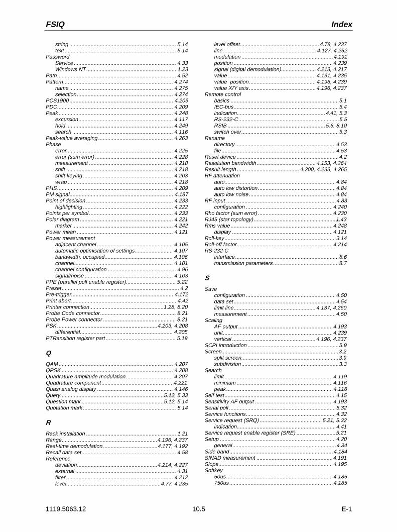
FSIQ Index
1119.5063.12 10.5 E-1
string ...................................................................... 5.14text ......................................................................... 5.14
PasswordService ................................................................... 4.33Windows NT........................................................... 1.23
Path.............................................................................. 4.52Pattern........................................................................ 4.274
name .................................................................... 4.275selection ............................................................... 4.274
PCS1900 .................................................................... 4.209PDC............................................................................ 4.209Peak ........................................................................... 4.248
excursion.............................................................. 4.117hold ...................................................................... 4.249search .................................................................. 4.116
Peak-value averaging ................................................. 4.263Phase
error...................................................................... 4.225error (sum error) ................................................... 4.228measurement ....................................................... 4.218shift ...................................................................... 4.218shift keying ........................................................... 4.203wrap ..................................................................... 4.218
PHS............................................................................ 4.209PM signal.................................................................... 4.187Point of decision ......................................................... 4.233
highlighting ........................................................... 4.222Points per symbol ....................................................... 4.233Polar diagram ............................................................. 4.221
marker .................................................................. 4.242Power mean ............................................................... 4.121Power measurement
adjacent channel .................................................. 4.105automatic optimisation of settings......................... 4.107bandwidth, occupied............................................. 4.106channel................................................................. 4.101channel configuration ............................................. 4.96signal/noise .......................................................... 4.103
PPE (parallel poll enable register)................................. 5.22Preset ............................................................................. 4.2Pre-trigger................................................................... 4.172Print abort ..................................................................... 4.42Printer connection.................................................1.28, 8.20Probe Code connector.................................................. 8.21Probe Power connector ................................................ 8.21PSK ..................................................................4.203, 4.208
differential............................................................. 4.205PTRansition register part .............................................. 5.19
Q
QAM ........................................................................... 4.207QPSK ......................................................................... 4.208Quadrature amplitude modulation ............................... 4.207Quadrature component ............................................... 4.221Quasi analog display .................................................. 4.146Query....................................................................5.12, 5.33Question mark ......................................................5.12, 5.14Quotation mark ............................................................. 5.14
R
Rack installation ........................................................... 1.21Range...............................................................4.196, 4.237Real-time demodulation ....................................4.177, 4.192Recall data set.............................................................. 4.58Reference
deviation.....................................................4.214, 4.227external .................................................................. 4.31filter ...................................................................... 4.212level..............................................................4.77, 4.235
level offset.................................................... 4.78, 4.237line ............................................................. 4.127, 4.252modulation ............................................................4.191position .................................................................4.239signal (digital demodulation)....................... 4.213, 4.217value .......................................................... 4.191, 4.235value position............................................ 4.196, 4.239value X/Y axis ............................................ 4.196, 4.237
Remote controlbasics .......................................................................5.1IEC-bus.....................................................................5.4indication..........................................................4.41, 5.3RS-232-C..................................................................5.5RSIB ................................................................5.6, 8.10switch over................................................................5.3
Renamedirectory ..................................................................4.53file ...........................................................................4.53
Reset device ...................................................................4.2Resolution bandwidth ....................................... 4.153, 4.264Result length ......................................... 4.200, 4.233, 4.265RF attenuation
auto.........................................................................4.84auto low distortion ...................................................4.84auto low noise.........................................................4.84
RF input ........................................................................4.83configuration .........................................................4.240
Rho factor (sum error) .................................................4.230RJ45 (star topology) ......................................................1.43Rms value ...................................................................4.248
display ..................................................................4.121Roll-key .........................................................................3.14Roll-off factor...............................................................4.214RS-232-C
interface....................................................................8.6transmission parameters ...........................................8.7
S
Saveconfiguration ...........................................................4.50data set ...................................................................4.54limit line...................................................... 4.137, 4.260measurement ..........................................................4.50
ScalingAF output ..............................................................4.193unit........................................................................4.239vertical ....................................................... 4.196, 4.237
SCPI introduction ............................................................5.9Screen.............................................................................3.2
split screen................................................................3.9subdivision ................................................................3.3
Searchlimit .......................................................................4.119minimum ...............................................................4.116peak......................................................................4.116
Self test.........................................................................4.15Sensitivity AF output ...................................................4.193Serial poll ......................................................................5.32Service functions...........................................................4.32Service request (SRQ) .........................................5.21, 5.32
indication.................................................................4.41Service request enable register (SRE) ..........................5.21Setup ............................................................................4.20
general....................................................................4.34Side band....................................................................4.184SINAD measurement ..................................................4.191Slope...........................................................................4.195Softkey
50us......................................................................4.185750us....................................................................4.185
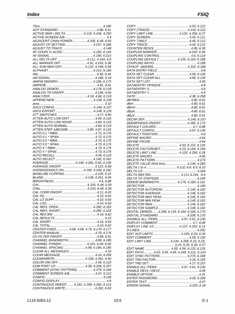
Index FSIQ
1119.5063.12 10.6 E-1
75us ..................................................................... 4.185ACP STANDARD ...........................................4.98, 6.51ACTIVE MKR / DELTA....................4.116, 4.246, 4.250ACTIVE SCREEN A/B.............................................. 4.4ADJACENT CHAN POWER................4.105, 6.49, 6.50ADJUST CP SETTING...............................4.107, 6.186ADJUST TO TRACE ............................................ 4.148AF COUPL’G AC/DC..................................4.183, 6.145AF SIGNAL ................................................4.195, 6.213ALL DELTA OFF .................................4.111, 4.244, 6.9ALL MARKER OFF .............................4.91, 4.243, 6.38ALL SUM MKR OFF..........................4.122, 4.249, 6.58ALPHA/BT..................................................4.214, 6.166AM..................................................................4.93, 6.44AM SIGNAL..................................................4.186, 6.18AM/FM DEEMPH .......................................4.185, 6.173AMPERE........................................................4.81, 6.61ANALOG DEMOD ......................................4.179, 6.118ANALOG TR ON/OFF ..................................4.146, 6.94ANALYZER .........................................4.18, 4.66, 6.118APPEND NEW ...........................................4.149, 6.108area........................................................................ 3.10ASCII CONFIG...........................................4.148, 6.107ASCII EXPORT ..........................................4.148, 6.126ATT SWITCHES.............................................4.17, 6.84ATTEN AUTO LOW DIST ............................4.84, 6.115ATTEN AUTO LOW NOISE .........................4.84, 6.115ATTEN AUTO NORMAL ..............................4.84, 6.115ATTEN STEP 1dB/10dB......................4.85, 4.87, 6.116AUTO 0.1 * RBW..........................................4.72, 6.175AUTO 0.1 * SPAN ........................................4.72, 6.175AUTO 0.5 * RBW..........................................4.73, 6.175AUTO 0.5 * SPAN ........................................4.73, 6.175AUTO X * RBW ............................................4.73, 6.175AUTO X * SPAN...........................................4.73, 6.175AUTO RECALL ............................................4.59, 6.123AUTO SELECT ..........................................4.145, 6.162AVERAGE.............................. 4.140, 4.262, 6.93, 6.148AVERAGE ON/OFF .....................................4.122, 6.58AVERAGE/HOLD ON......................4.190, 4.249, 6.182BASELINE CLIPPING ..................................4.128, 6.15BLANK ..............................................4.139, 4.261, 6.94BRIGHTNESS................................................. 4.6, 6.88C/N......................................................4.103, 6.49, 6.50C/No....................................................4.103, 6.49, 6.50CAL CORR ON/OFF ......................................4.11, 6.63CAL I/Q ..........................................................4.10, 6.62CAL LO SUPP................................................4.10, 6.63CAL LOG........................................................4.10, 6.63CAL REFL OPEN .......................................4.285, 6.153CAL REFL SHORT.....................................4.285, 6.153CAL RES BW .................................................4.10, 6.62CAL RESULTS....................................................... 4.12CAL SHORT...................................................4.10, 6.63CAL TOTAL....................................................4.10, 6.62CENTER FIXED.............. 4.68, 4.69, 4.75, 6.176, 6.177CENTER MANUAL.......................................4.70, 6.174CH FILTER ON/OFF ......................................4.99, 6.51CHANNEL BANDWIDTH..............................4.99, 6.185CHANNEL POWER.............................4.101, 6.49, 6.50CHANNEL SPACING ........................4.99, 6.184, 6.185CLEAR ALL MESSAGES....................................... 4.16CLEAR MESSAGE.......................................4.16, 6.209CLEAR/WRITE..................................4.139, 4.261, 6.93COLOR ON/ OFF .........................................4.45, 6.110COM PORT 1/2 .................................4.36, 6.206, 6.207COMMENT (SYNC PATTERN) ..................4.275, 6.168COMMENT SCREEN A/B ............................4.47, 6.112CONFIG ............................................................... 4.148CONFIG DISPLAY ................................................... 4.6CONTINUOUS SWEEP ....... 4.162, 4.199, 4.265, 6.114CONTINUOUS WRITE.................................4.262, 6.93
COPY .......................................................... 4.53, 6.122COPY (TRACE) ......................................... 4.142; 6.212COPY LIMIT LINE............................. 4.132, 4.256, 6.27COPY SCREEN........................................... 4.45, 6.111COPY TABLE .............................................. 4.45, 6.112COPY TRACE.............................................. 4.45, 6.112COUNTER RESOL ........................................4.95, 6.39COUPLED MARKER ................................... 4.242, 6.39COUPLING CONTROL..................................4.5, 6.119COUPLING DEFAULT .................... 4.155, 6.150, 6.188COUPLING RATIO ...............................................4.158CP/ACP ABS/REL .................................... 4.102, 6.186DATA ENTRY FIELD ................................................4.8DATA SET CLEAR ...................................... 4.56, 6.126DATA SET CLEAR ALL ............................... 4.56, 6.126DATA SET LIST......................................................4.55DATAENTRY OPAQUE............................................4.8DATAENTRY X.........................................................4.8DATAENTRY Y.........................................................4.8DATE ........................................................... 4.38, 6.208dB*/MHz.........................................................4.80, 6.61dBm ...............................................................4.80, 6.61dBmV.............................................................4.80, 6.61dBµA..............................................................4.80, 6.61dBµV..............................................................4.80, 6.61DECIM SEP ............................................... 4.149, 6.107DEEMPHASIS ON/OFF............................. 4.185, 6.173DEFAULT COLORS.........................................4.7, 6.88DEFAULT CONFIG...................................... 4.57, 6.130DEFAULT POSITION................................................4.8DEFINE MACRO ....................................................4.64DEFINE PAUSE......................................................4.64DELETE............................................ 4.53, 6.122, 6.125DELETE FACTOR/SET .................... 4.23, 6.156, 6.158DELETE LIMIT LINE......................... 4.132, 4.256, 6.28DELETE MACRO....................................................4.65DELETE PATTERN ..............................................4.274DELETE VALUE (limit line) ........................ 4.136, 4.260DELTA 1 to 4 ................................. 4.110, 6.8, 6.9, 6.10DELTA 1/2 ............................................................4.244DELTA ABS REL ................................ 4.111,4.244, 6.9DELTA TO STEPSIZE ..........................................4.109DEMOD BANDWIDTH.................... 4.179, 4.180; 6.151DETECTOR ..........................................................4.145DETECTOR AUTOPEAK........................... 4.145, 6.162DETECTOR AVERAGE............................. 4.146, 6.162DETECTOR MAX PEAK............................ 4.145, 6.162DETECTOR MIN PEAK ............................. 4.145, 6.162DETECTOR RMS ...................................... 4.146, 6.162DETECTOR SAMPLE................................ 4.146, 6.162DIGITAL DEMOD.......4.208, 6.118, 6.164, 6.165, 6.170DIGITAL STANDARD ................................ 4.209, 6.170DISABLE ALL ITEMS ......................... 4.57, 4.61, 6.130DISPLAY COMMENT ......................................4.7, 6.89DISPLAY LINE 1/2............................ 4.127, 4.252, 6.14D-LINES................................................................4.252EDIT ACP LIMITS............................... 4.100, 6.33, 6.34EDIT COMMENT ......................................... 4.55, 6.130EDIT LIMIT LINE..................... 4.134, 4.258, 6.22, 6.23,.................................................... 6.24, 6.25, 6.26, 6.27EDIT NAME ............................. 4.55, 4.59, 6.123, 6.125EDIT PATH...........4.52, 4.55, 4.59, 4.149, 6.121, 6.124EDIT SYNC PATTERN .............................. 4.275, 6.168EDIT TRD FACTOR..................................... 4.24, 6.155EDIT TRD SET ............................................ 4.27, 6.157ENABLE ALL ITEMS .......................... 4.57, 4.61, 6.130ENABLE DEV1 / DEV2 ...........................................4.49ENABLE OPTION...................................................4.31ENTER PASSWORD................................... 4.33, 6.209ENTER TEXT .........................................................4.47ERROR SIGNAL.......................................... 4.225, 6.18

FSIQ Index
1119.5063.12 10.7 E-1
ERROR VECT MAGNITUDE........................4.226, 6.18EXCLUDE LO ON/OFF ................................4.117, 6.39EXECUTE TESTS........................................... 4.15, 6.6EXT ALC ....................................................4.289, 6.193EXT AM......................................................4.289, 6.193EXT FM......................................................4.289, 6.193EXT I/Q ......................................................4.290, 6.193EXT REF FREQUENCY...............................4.31, 6.187EXTERN ............................... 4.161, 4.194, 4.267 6.213EYE DIAG [FREQ] .......................................4.223, 6.19EYE DIAG [I] ................................................4.219, 6.19EYE DIAG [Q] ..............................................4.219, 6.19EYE DIAG TRELLIS.....................................4.219, 6.19EYE LENGTH....................................4.220, 4.223, 6.95FIND BURST ON/OFF ...............................4.268, 6.167FIND SYNC ON/OFF..................................4.269, 6.168FIRMWARE UPDATE ............................................ 4.40FIRMWARE VERSION.................................... 4.13, 6.5FM..................................................................4.93, 6.44FM SIGNAL..................................................4.187, 6.18FORMAT DISK.............................................4.53, 6.123FRAME LENGTH .......................................4.232, 6.169FREE RUN........................... 4.160, 4.194, 4.266, 6.213FREQ AXIS LIN/LOG .....................................4.68, 6.91FREQUENCY ..............................................4.225, 6.19FREQUENCY (FSK demodulation)...............4.223, 6.19FREQUENCY (MSK demodulation)..............4.218, 6.19FREQUENCY LINE 1/2 ................................4.127, 6.16FREQUENCY OFFSET.......... 4.71, 4.234, 4.287, 6.177FREQUENCY ON/OFF ................................... 4.7, 6.87FSE MODE ON/OFF ....................................4.40, 6.209FSK REF DEVIATION..................................4.214, 6.19FULL PAGE .................................................4.46, 6.113FULL SCREEN................................................ 4.4, 6.87FULL SPAN..................................................4.74, 6.176GAP LENGTH ............................................4.173, 6.191GAP SWEEP ON/OFF ...............................4.171, 6.190GAP SWEEP SETTINGS..................................... 4.172GATE ADJUST..................................................... 4.168GATE DELAY.............................................4.167, 6.190GATE EXTERN..........................................4.167, 6.190GATE LENGTH..........................................4.167, 6.190GATE LEVEL .............................................4.166, 6.189GATE MODE LEVEL/EDGE.......................4.166, 6.189GATE ON / OFF.........................................4.165, 6.189GATE POL .................................................4.166, 6.190GATE RF POWER .....................................4.167, 6.190GATE SETTINGS................................................. 4.166GENERAL SETUP ................................................. 4.34GPIB ADDRESS ..........................................4.34, 6.205GRID ABS/REL .....................................4.78, 4.82, 6.91HARDCOPY DEVICE...................................4.48, 6.110HARDWARE+OPTIONS ................................. 4.14, 6.5HEADER ON/OFF......................................4.149, 6.108HIGHPASS AF FILTER..............................4.182, 6.171HOLD CONT ON/OFF..................................4.142, 6.94HORIZONTAL SCALING................................4.5, 6.119IF BANDWIDTH ................................................... 4.180IF BW AUTO ...................................4.180, 4.264, 6.150IF BW MANUAL ..............................4.180, 4.264, 6.149INDICATION ABS REL...............................4.191, 6.182INPUT CAL ....................................................4.32, 6.84INPUT RF.......................................................4.32, 6.84INSERT VALUE (limit line) .........................4.136, 4.260KEY CLICK ON/OFF .............................................. 4.39LAST SPAN ........................................................... 4.75LIMIT CHECK.............................4.100, 6.32, 6.33, 6.34LINE (trigger)..............................................4.160, 6.213LINEAR/% ......................................................4.82, 6.93LINEAR/dB.....................................................4.82, 6.93LOCK ALL .............................................................. 3.19
LOCK DATA ...........................................................3.19LOG MANUAL ...................................... 4.82, 6.91, 6.93LOG 10dB/20dB/50dB/100dB/120dB ......................4.82LOGO ON/OFF ................................................4.7, 6.87LOW PASS AF FILTER ............................. 4.182, 6.172LOWER LEFT.............................................. 4.46, 6.113LOWER RIGHT............................................ 4.46, 6.113MACRO 1 to 7.........................................................4.63MACRO TITLE........................................................4.65MAGNITUDE ......................... 4.218, 4.222,4.225, 6.19MAGNITUDE CAP BUFFER........................ 4.21, 76.18MAIN PLL BANDWIDTH............................ 4.157, 6.151MAKE DIRECTORY..................................... 4.53, 6.124MARKER 1 to 4................. 4.89, 4.241, 6.37, 6.38, 6.39MARKER DEMOD ..................................................4.93MARKER INFO................ 4.92, 4.243, 6.13, 6.43, 6.44,................................. 6.46, 6.49, 6.50, 6.52, 6.53, 6.54,.................................................... 6.55, 6.56, 6.57, 6.89MARKER ZOOM............................................4.92, 6.44MAX |PEAK|.....................4.246, 4.248, 6.10, 6.40, 6.52MAX HOLD ............................ 4.141, 4.263, 6.93, 6.148MAX LEVEL AUTO........................................4.78, 6.92MAX LEVEL MANUAL ...................................4.78, 6.92MEAN ............................................... 4.121, 4.249, 6.57MEAS FILTER ........................................... 4.212, 6.166MEAS ONLY IF SYNC’D............................ 4.267, 6.169MEAS RESULT.......................................... 4.186, 4.216MEAS SIGNAL ............................................ 4.217, 6.18MEAS→REF.............................................. 4.191, 6.183MEMORY SIZE.......................................... 4.231, 6.170MIN.......................................... 4.116, 4.246, 6.11, 6.41MIN HOLD ............................ 4.141, 4.263, 6.93,. 6.148MIXER LEVEL ............................................. 4.84, 6.117MKR -> CENTER......................................... 4.123, 6.58MKR -> CF STEPSIZE................................. 4.124, 6.58MKR -> REF LEVEL .................................... 4.124, 6.59MKR -> START............................................ 4.124, 6.59MKR -> STOP.............................................. 4.124, 6.59MKR ->TRACE .......................... 4.124, 4.250, 6.9, 6.38MKR DEMOD ON/OFF ..................................4.93, 6.45MKR STOP TIME...........................................4.93, 6.45MKR TO STEPSIZE..................................... 4.109, 6.59MODE COUPLED..........................................4.5, 6.119MODULATION......................................................4.288MODULATION PARAMETERS.................. 4.181, 4.211MODULATION SUMMARY4.188, 6.18, 6.46, 6.47, 6.48MONITOR CONNECTED........................................4.39MOVE ZOOM START....................................4.76, 6.90MOVE ZOOM STOP......................................4.76, 6.90MOVE ZOOM WINDOW................................4.76, 6.90N dB DOWN ................................................ 4.119, 6.43NAME (limit line) ............................... 4.135, 4.259, 6.28NAME (SYNC PATTERN).......................... 4.275; 6.168NEW FACT/SET ..................... 4.24, 4.27, 6.154, 6.156NEW LIMIT LINE ....................................... 4.134, 4.258NEW SYNC PATTERN.............................. 4.275, 6.168NEXT MIN........................................... 4.117, 6.11, 6.41NEXT MIN LEFT................................. 4.117, 6.11, 6.41NEXT MIN RIGHT............................... 4.117, 6.11, 6.41NEXT PEAK........................................ 4.116, 6.10, 6.40NEXT PEAK LEFT.............................. 4.116, 6.11, 6.40NEXT PEAK RIGHT............................ 4.116, 6.10, 6.40NOISE ...........................................................4.95, 6.44NOISE SOURCE ...........................................4.32, 6.84NORMALIZE................................... 4.215, 4.281, 6.167OCCUPIED PWR BANDW ................. 4.106, 6.49, 6.50OPTIONS................................................ 4.14, 4.31, 6.5PEAK....................................... 4.116, 4.246, 6.10, 6.40+PEAK......................................................... 4.248, 6.53±PEAK ......................................................... 4.248, 6.55-PEAK.......................................................... 4.248, 6.54

Index FSIQ
1119.5063.12 10.8 E-1
PEAK EXCURSION .....................................4.117, 6.42PEAK HOLD ON/OFF .......................4.122, 4.249, 6.58PHASE.............................................4.218, 4.225, 6.19PHASE NOISE.............................................4.113, 6.12PHASE WRAP ON/OFF...............................4.218, 6.19PM SIGNAL..................................................4.187, 6.18POINTS PER SYMBOL..............................4.233, 6.166POLAR [IQ] CONSTELL....................4.221, 4.226, 6.19POLAR [IQ] VECTOR........................4.221, 4.226, 6.19POLAR MARKER DEG/ RAD.......................4.242, 6.61POLAR MARKER R/I / MA/PH .....................4.242, 6.42% POWER BANDWIDTH...........................4.100, 6.186POWER MEAS SETTINGS.................................... 4.97POWER OFFSET................................................. 4.278PRE DISPL ON/OFF ..................................4.185, 6.173PRE TRIGGER (gap sweep) ......................4.172, 6.191PREDEFINED COLORS ................................. 4.7, 6.88PRESEL PEAK ..............................................4.11, 6.63PROBE CODE ON/OFF ...............................4.81, 6.216RANGE ......................................................4.196, 4.237RBW / VBW MANUAL................................4.159, 6.151RBW / VBW NOISE....................................4.159, 6.151RBW / VBW PULSE...................................4.159, 6.151RBW / VBW SINE [1] .................................4.158, 6.151RBW <= NORM/FFT ..................................4.156, 6.150RBW 1kHz ANA/DIG ..................................4.155, 6.150REAL TIME ON/OFF..................................4.192, 6.146REAL/IMAG PART ............................4.218, 4.225, 6.19RECORD ON/OFF ................................................. 4.64REF LEVEL.........................................4.78, 4.236, 6.91REF LEVEL OFFSET..........................4.78, 4.237, 6.92REF POINT FREQUENCY...........................4.112, 6.12REF POINT LEVEL ......................................4.112, 6.12REF POINT LVL OFFSET............................4.112, 6.12REF POINT TIME.........................................4.112, 6.12REF VALUE ......................................................... 4.283REF VALUE POSITION ......... 4.196, 4.239, 4.282, 6.93REF VALUE X AXIS.....................................4.237, 6.89REF VALUE Y AXIS..........................4.196, 4.237, 6.92REFERENCE ...............................................4.33, 6.187REFERENCE FILTER................................4.212, 6.166REFERENCE FIXED....................................4.111, 6.12REFERENCE INT/EXT.................................4.31, 6.187REFERENCE LINE ...........................4.127, 4.252, 6.16REFERENCE POINT ...................................4.112, 6.12REFERENCE PROG....................................4.33, 6.187REFERENCE SIGNAL .................................4.217, 6.18REL UNIT..........................................4.190, 6.61, 6.182RENAME......................................................4.53, 6.124RES BW AUTO ..........................................4.153, 6.150RES BW MANUAL .....................................4.153, 6.149RESTORE.............................................................. 4.40RESULT LENGTH................ 4.200, 4.233, 4.265, 6.165RF ATTEN MANUAL....................................4.83, 6.115RF INPUT 50 OHM.......................................4.85, 6.116RF INPUT 75 OHM/RAM..............................4.85, 6.117RF INPUT 75 OHM/RAZ ..............................4.85, 6.117RF POWER (trigger)...................................4.161, 6.213RMS ..................................................4.121, 4.248, 6.56SATURATION ................................................. 4.7, 6.88SAVE LIMIT LINE.......................................4.137, 4.260SAVE PATTERN.................................................. 4.276SCALE UNIT ..............................................4.198, 4.239SCR. SAVER .................................................. 4.7, 6.95SCR. SAVER TIME ......................................... 4.7, 6.95SCREEN COUPLING............................................... 4.5SCREENS UNCOUPLED...............................4.5, 6.119SEARCH LIMIT ON/OFF...................4.119, 4.246, 6.38SELECT ITEMS ............ 4.57, 4.61, 6.127, 6.128, 6.129SELECT LIMIT LINE ................ 4.130, 4.254, 6.21, 6.28SELECT MACRO ................................................... 4.65SELECT MARKER .....................................4.116, 4.246
SELECT OBJECT.....................................................4.6SELECT PATTERN ..............................................4.274SELECT QUADRANT.............................................4.46SELFTEST.......................................................4.15, 6.6SENSITIV AF OUTPUT .................. 4.193, 4.197, 6.132SERVICE.......................................................4.32, 6.84SET CP REFERENCE............................... 4.102, 6.186SET NO. OF ADJ CHAN’S........................... 4.97, 6.185SET REFERENCE..................................... 4.191, 6.182SETTINGS DEVICE 1/2............................... 4.48, 6.110SGL SWEEP DISP OFF ............................ 4.163, 6.114SHAPE FACT 60/3dB .................................. 4.120, 6.45SHAPE FACT 60/6dB ................................... 4.120,6.45SHIFT X LIMIT LINE ......................... 4.137, 4.260, 6.23SHIFT Y LIMIT LINE ................ 4.137, 4.260, 6.25, 6.26SIDE BAND NORM / INV..... 4.184, 4.212, 6.146, 6.164SIGNAL COUNT ................................... 4.94, 6.38, 6.39SIGNAL TRACK.............................................4.91, 6.46SINAD 1 kHz ON.......................................... 4.191, 6.48SINGLE SWEEP.................. 4.162, 4.199, 4.265, 6.114SLOPE POS/NEG................ 4.161, 4.195, 4.267, 6.214SORT MODE ..........................................................4.53SOURCE CAL.......................................................4.279SOURCE ON/OFF ..................................... 4.278, 6.131SOURCE POWER ..................................... 4.278, 6.193SPAN / RBW AUTO [50] ............................ 4.159, 6.150SPAN / RBW MANUAL.............................. 4.159, 6.150SPAN FIXED ........4.67, 4.69, 4.71, 6.174, 6.176, 6.177SPAN MANUAL ........................................... 4.74, 6.175SPLIT SCREEN...............................................4.4, 6.87SQUELCH LEVEL ..................................... 4.184, 6.146SQUELCH ON ........................................... 4.184, 6.145START FIXED ......4.69, 4.71, 4.75, 6.174, 6.176, 6.177START MANUAL ......................................... 4.67, 6.176STATISTICS ..................................................4.17, 6.85STEPSIZE = CENTER............................................4.73STEPSIZE AUTO.................................. 3.20, 6.13, 6.42STEPSIZE MANUAL.................. 4.73, 6.13, 6.42, 6.175STOP FIXED ...................4.67, 4.71, 4.75, 6.174, 6.176STOP MANUAL ........................................... 4.69, 6.176SUM MKR......................................... 4.120, 4.247, 6.51SUMMARY MARKER ................................ 4.121, 4.247SUMMARY MEAS TIME............................ 4.192, 6.183SUMMARY SETTINGS.........................................4.190SWEEP.................................................................4.199SWEEP COUNT .......4.122, 4.141, 4.163, 4.190, 4.200,............................................ 4.249, 4.262, 4.265, 6.188SWEEP TIME ............................................ 4.200, 6.189SWEEP TIME AUTO ................................. 4.154, 6.188SWEEP TIME MANUAL ............................ 4.155, 6.188SYMB TABLE / ERRORS ............................ 4.227, 6.18SYMBOL DISPLAY...................................... 4.222, 6.94SYMBOL RATE ......................................... 4.211, 6.165SYNC OFFSET.......................................... 4.270, 6.167SYNC PATTERN ..................................................4.274SYSTEM MESSAGES................................. 4.16, 6.209T1-REF ........................................................ 4.147, 6.60T1-T2+REF.................................................. 4.147, 6.60T1-T3+REF.................................................. 4.147, 6.60THRESHOLD LINE.................. 4.127, 4.252, 6.15, 6.16TIME ................................................................4.7, 6.89TIME LINE 1/2 ........................... 4.7, 4.127, 4.252, 6.17TIME ON/OFF............................................. 4.38, 6.210TINT.................................................................4.7, 6.88TITLE........................................................... 4.47, 6.111TRACE MATH.......................................................4.147TRACE MATH OFF ..................................... 4.148, 6.60TRACKING GENERATOR..... 4.18, 4.278, 6.118, 6.131TRANSD SET NAME................................... 4.28, 6.156TRANSD SET RANGES .............................. 4.29, 6.157TRANSD SET UNIT..................................... 4.28, 6.157TRANSDUCER FACTOR............................. 4.22, 6.155

FSIQ Index
1119.5063.12 10.9 E-1
TRANSDUCER SET..........................4.22, 6.156, 6.158TRC COLOR AUTO INC ..............................4.45, 6.113TRD FACTOR NAME...................................4.25, 6.155TRD FACTOR UNIT .....................................4.25, 6.154TRD FACTOR VALUES ...............................4.26, 6.155TRG TO GAP TIME....................................4.173, 6.191TRIGGER............................................................. 4.194TRIGGER DELAY ......................................4.161, 6.214TRIGGER LEVEL (gap sweep) ..................4.172, 6.213TRIGGER OFFSET....................................4.195, 4.267UNIT.............................................................4.79, 6.216UNLOCK ................................................................ 3.19UPDATE................................................................. 4.40UPDATE MESSAGES............................................ 4.16UPPER LEFT ...............................................4.46, 6.113UPPER RIGHT.............................................4.46, 6.113USER PORT A/B...............................4.35, 6.116, 6.131VALUE (SYNC PATTERN).........................4.276, 6.168VALUES (limit line)............................4.136, 4.260, 6.25VECTOR ANALYZER........................4.19, 4.175, 6.118VERTICAL SCALING .....................................4.5, 6.119VIDEO.................................. 4.160, 4.194, 4.266, 6.214VIDEO BW AUTO ......................................4.154, 6.151VIDEO BW MANUAL .................................4.154, 6.151VIEW.................................................4.139, 4.261, 6.93VOLT..............................................................4.81, 6.61VOLUME................................ 4.93, 4.193, 4.197, 6.210WATT.............................................................4.81, 6.61WEIGHTING AF FILTER............................4.182, 6.172X OFFSET.........................................4.132, 4.256, 6.23X UNIT SYMBOL.................................................... 6.61Y OFFSET................................4.132, 4.256, 6.24, 6.26Y PER DIV ........................................4.196, 4.237, 6.93Y UNIT DBM ................................................4.239, 6.61Y UNIT DEG.................................................4.239, 6.61Y UNIT LINEAR............................................4.239, 6.61Y UNIT LOG(dB) ..........................................4.239, 6.61Y UNIT VOLT ...............................................4.239, 6.61Y UNIT WATT ..............................................4.239, 6.61ZERO SPAN ................................................4.74, 6.175ZOOM ............................................................4.76, 6.90ZOOM OFF ....................................................4.76, 6.90
Span............................................................................. 4.74measurement window............................................. 4.67
Special characters .......................................................... 6.2Split Screen ............................................................. 3.9, 4.4Squelch ...................................................................... 4.184SRE (service request enable register) .......................... 5.21SRQ (service request) ..........................................5.21, 5.32Start frequency ............................................................. 4.67Start-Up ........................................................................ 1.20Status byte (STB) ......................................................... 5.21Status information........................................................... 3.4Status register
CONDition part ....................................................... 5.19ENABle part ........................................................... 5.19ESE........................................................................ 5.22ESR........................................................................ 5.22EVENt part ............................................................. 5.19NTRansition part .................................................... 5.19overview................................................................. 5.20PPE........................................................................ 5.22PTRansition part..................................................... 5.19SRE........................................................................ 5.21STATus:OPERation ............................................... 5.23STATus:QUEStionable........................................... 5.24
FREQuency ..................................................... 5.26LIMit ................................................................. 5.27LMARgin .......................................................... 5.28POWer ............................................................. 5.29SYNC............................................................... 5.30TRANsducer..................................................... 5.31
STB.........................................................................5.21structure..................................................................5.18sum bit ....................................................................5.19
Status reporting system.................................................5.18resetting values.......................................................5.34
Status informationDIFOVL.....................................................................3.4ExtRef.......................................................................3.4IFOVLD.....................................................................3.4LO LvD......................................................................3.4LO Lvl .......................................................................3.4LO unl .......................................................................3.4OCXO .......................................................................3.4OVLD........................................................................3.4UNCAL......................................................................3.4
STB (status byte) ..........................................................5.21Step size
center frequency .....................................................4.72delta marker ..........................................................4.114marker...................................................................4.109setting .....................................................................3.20
Stop frequency ..............................................................4.69String ............................................................................5.14Suffix.............................................................................5.11Sum bit..........................................................................5.19Sum level ....................................................................4.235Summary, numeric measured values ..........................4.190Summary Marker.........................................................4.247Sweep
continuous ................................................. 4.199, 4.265count.................................... 4.141, 4.163, 4.249, 4.262coupling ................................................................4.152gap........................................................................4.170gap length .............................................................4.173gated.....................................................................4.164mode.....................................................................4.162number....................................................... 4.190, 4.200single .............................................. 4.162, 4.199, 4.265time............................................................ 4.154, 4.200
Switching operations .....................................................4.17Symbol
decision points ......................................................4.222mapping ................................................................4.203rate .......................................................................4.211table......................................................................4.227
Syncoffset.....................................................................4.270pattern...................................................................4.274search...................................................................4.269
Synchronization sequence ..........................................4.269Syntax elements, command ..........................................5.14System messages.........................................................4.16
T
Table entry ....................................................................3.18TCP/IP operation...........................................................1.52Test, functional..............................................................1.22TETRA ........................................................................4.209Text parameter..............................................................5.14TFTS...........................................................................4.209Thick Ethernet ...............................................................1.43Thin Ethernet.................................................................1.42Threshold line..............................................................4.252Time, input ....................................................................4.38Time lines....................................................................4.252Time signal
AM-demodulated...................................................4.186FM-demodulated...................................................4.187PM-demodulated...................................................4.187
Trace...........................................................................4.138

Index FSIQ
1119.5063.12 10.10 E-1
copy ..................................................................... 4.142detector ................................................................ 4.143export ................................................................... 4.148mathematics ......................................................... 4.147
Transducer ................................................................... 4.20entry ....................................................................... 4.23set .......................................................................... 4.27switch on ................................................................ 4.21
Transmission measurement........................................ 4.279Transmission parameters, RS-232-C.............................. 8.7Trellis diagram............................................................ 4.219Trigger ........................................................................ 4.266
AF signal .............................................................. 4.195delay ..........................................................4.161, 4.267edge, pos./neg............................................4.195, 4.267external ......................................................4.194, 4.267free running .....................................4.160, 4.194, 4.266gap sweep............................................................ 4.172line ....................................................................... 4.160offset ..........................................................4.195, 4.267pre-trigger............................................................. 4.172RF power.............................................................. 4.161slope ..........................................................4.161, 4.195threshold .............................................................. 4.266video ..........................................................4.160, 4.266video voltage ........................................................ 4.194
U
Unit .....................................................................4.79, 4.239circle..................................................................... 4.215relative display...................................................... 4.190Y-axis ................................................................... 4.198
Universal command ........................................................ 8.5Upper case ..................................................................... 6.2User interface ............................................................... 8.19User port configuration ................................................. 4.35
V
Vector analyzer mode .........................................4.19, 4.174Vector diagram ........................................................... 4.221Vector error (sum error) .............................................. 4.228Video bandwidth ......................................................... 4.154Video trigger ............................................................... 4.266View ........................................................................... 4.139Volume ...............................................................4.93, 4.193
W
WCPE ........................................................................ 4.209Weighting filter............................................................ 4.182White space.................................................................. 5.14Windows NT ................................................................. 1.23
administrator........................................................... 1.23login ....................................................................... 1.23password................................................................ 1.23
Z
Zero span ..................................................................... 4.74Zoom ..................................................................4.76, 4.139
amplitude.............................................................. 4.139