R&S®Series4200 Software Defined Radios - Rohde & Schwarz
24
Product Brochure Version 08.00 VHF/UHF radio family for ATC communications R&S®Series4200 SOFTWARE DEFINED RADIOS
-
Upload
khangminh22 -
Category
Documents
-
view
19 -
download
0
Transcript of R&S®Series4200 Software Defined Radios - Rohde & Schwarz

Product Brochure Version 08.00
VHF/UHF radio family for ATC communications
R&S®Series4200 SOFTWARE DEFINED RADIOS

2
AVAILABLE VERSIONS OF THE R&S®Series4200 RADIO FAMILY
R&S®XU4200 VHF transceiver
R&S®XD4200 UHF transceiver
At a glance ► page 4
User interface ► page 6
Rear panel connections ► page 7
Easy to use even in challenging environments ► page 8
Maintenanc e-free operation ► page 10
Straightforward operation and configuration ► page 11
Flexibility for system integration ► page 12
Small footprint due to compact, modular design ► page 14
Tower application ► page 17
Radio site ► page 18
VoIP for air traffic control ► page 20
Data application ► page 22
Product overview ► page 23
CONTENTS

Rohde & Schwarz R&S®Series4200 Software Defined Radios 3
AVAILABLE VERSIONS OF THE R&S®Series4200 RADIO FAMILY
R&S®EU4200C compact VHF receiver
R&S®SU4200 VHF transmitter
VHF (112 MHz to 156 MHz)
R&S®ED4200C compact UHF receiver
R&S®SD4200 UHF transmitter
UHF (225 MHz to 400 MHz)

R&S®XU4200 VHF transceiver.
4
AT A GLANCE
Equipment for the VHF and UHF frequency rangesThe R&S®Series4200 is available in six versions. Rohde & Schwarz offers trans ceivers, transmitters and compact receivers for the VHF frequency range (112 MHz to 156 MHz) and the UHF frequency range (225 MHz to 400 MHz), ensuring the communications with all types of aircraft present in the controlled airspace.
Wide application range and simplified radio planning, even in challenging environmentsThe R&S®Series4200 offers an extremely wide range of possible configurations, allowing optimal adaptation to the desired application scenario.The radios were implemented on a software basis in order to provide users of the R&S®Series4200 with the widest possible range of applications. New functions are imple-mented through software upgrades that Rohde & Schwarz makes available.
All radios of the R&S®Series4200 are multichannel radios, but they can also be software-configured for reliable oper-ation as single-channel radios. Redundant operation of two radios in order to boost the channel availability is possible without any external monitoring and switching equipment.
Standard functions include 8.33/25 kHz channel spacing for VHF and 8.33/12.5/25 kHz channel spacing for UHF, carrier offset 1 to 5 (VHF), ACARS and VDL mode 2 data mode (VHF), LAN remote-control interface, serial interface for controlling automatic filters, and in-band signaling for push-to-talk (PTT) and squelch (SQ) with the capability to set different tones.
The R&S®Series4200 radios support digital voice trans-mission using the ITU-T G.703 PCM interface and VoIP in accordance with EUROCAE specifications.
The R&S®Series4200 represents the latest generation of stationary radios for air traffic control. Possible applications range from small airport emergency systems requiring only a few radio channels to countrywide communications systems with several hundred radio channels.
R&S®XD4200 UHF transceiver.
Rohde & Schwarz R&S®Series4200 Software Defined Radios 5
Key facts ► VHF frequency range from 112 MHz to 156 MHz ► UHF frequency range from 225 MHz to 400 MHz ► Output power of 50 W for VHF and UHF ► Automatic main/standby operation ► USB service port for configuration and software downloads
► Remote control and remote monitoring via Ethernet interface
► Best signal selection in the receiver ► Data transmission in line with VDL mode 2 standard ► VoIP in line with EUROCAE ED-137 ► Detection of simultaneous transmissions in the receiver
Up to seven VoIP sessions can be established to the receiver or transmitter, allowing multiple VCS or remote audio units to access the radio simultaneously. The radio can be connected to a maximum of two VoIP voice recorders.
One of the highlights of the R&S®Series4200 is the receiver's ability to detect simultaneous transmissions and alert air traffic controllers. Simultaneous transmis-sions most often occur on radio channels with high traffic volume and can present a safety risk.

6
USER INTERFACEFRONT VIEW OF THE R&S®Series4200 TRANSCEIVERS AND TRANSMITTERS
LC display
LEDs
Keypad
Headset connector
Loudspeaker
Power switch
Volume controlFor headset and loudspeaker
USB service port
Loudspeaker
Headset connector
USB service port
LEDs
LC display
Keypad
FRONT VIEW OF THE R&S®Series4200 COMPACT RECEIVERS
Rohde & Schwarz R&S®Series4200 Software Defined Radios 7
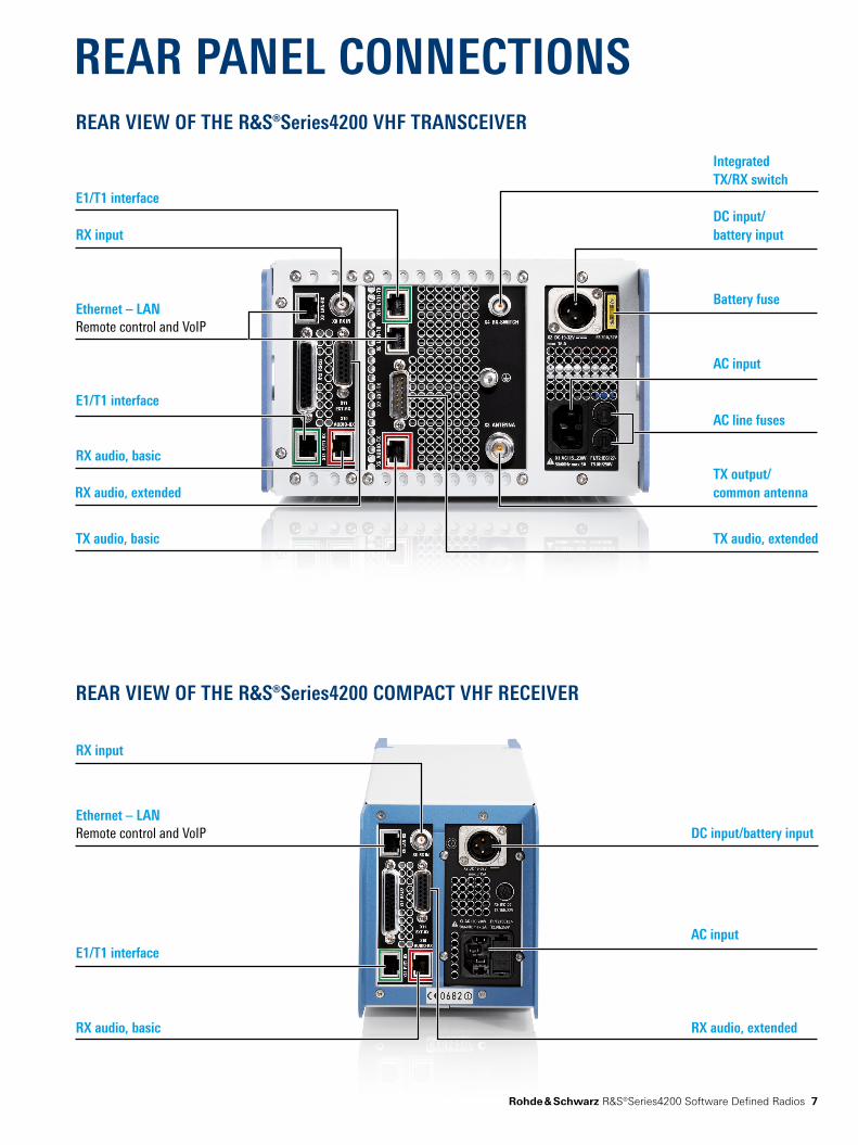
REAR PANEL CONNECTIONSREAR VIEW OF THE R&S®Series4200 VHF TRANSCEIVER
REAR VIEW OF THE R&S®Series4200 COMPACT VHF RECEIVER
RX input
Ethernet – LAN Remote control and VoIP
RX audio, extended RX audio, basic
DC input/battery input
AC inputE1/T1 interface
Battery fuse
DC input/ battery input
AC input
TX output/ common antenna
TX audio, basic TX audio, extended
AC line fuses
RX audio, basic
RX audio, extended
RX input
Integrated TX/RX switch
Ethernet – LAN Remote control and VoIP
E1/T1 interface
E1/T1 interface

8
EASY TO USE EVEN IN CHALLENGING ENVIRONMENTS
Demanding system requirements of civil air traffic control are met or exceededThe transmitters and receivers of the R&S®Series4200 perform as required, particularly in challenging environ-ments. They exhibit outstanding technical character-istics which simplify radio planning. All VHF radios of the R&S®Series4200 comply with or exceed the appli-cable standards from ICAO (Annex 10, Vol. III) and ETSI (EN 300676).
Excellent RF characteristicsThe VHF transmitters use an I/Q modulator with a Cartesian feedback loop. This ensures that the VHF trans-mitters have excellent RF characteristics. The following provides a detailed overview of the RF characteristics.
Adjacent-channel power better than required by ETSI standardThe adjacent-channel power is –70 dB at 25 kHz and –60 dB at 8.33 kHz. This means that these values are 10 dB better than required by the ETSI standard. Receiving stations in the vicinity therefore experience hardly any inter ference, which gives users increased system reserves and safety of planning.
Very low transmitter noiseThe transmitter noise is very low with a value of typ. –145 dBc (1 Hz) at 300 kHz from the carrier or –155 dBc (1 Hz) at 1 % from the carrier. This minimizes spurious emissions from the transmitter, helping to reduce receiver interference particularly in installations involving collocation.
High intermodulation rejectionDue to the high intermodulation rejection, an external cir-culator is not required in many cases. If an external circula-tor is used nevertheless, the radio allows evaluation of an external VSWR measurement required in such cases.
High output power at high modulation depthThe 50 W output power at the high modulation depth of 90 % is available even under challenging ambient condi-tions (temperature, VSWR). The modulation distortion is max. 5 % for a modulation depth of 90 %. A limiter at 95 % prevents overdrive.
The transmitter is designed for 50 W continuous operation (100 % duty cycle). This makes the R&S®Series4200 also ideal for ATIS or VOLMET transmitters.
Particularly in the civil sector, air traffic control places very demanding requirements on the radios used. The VHF radios are operated under conditions involving significant RF interference. High-quality communications are required even in the presence of strong interference. Of course, the radios themselves should generate as little interference as possible.

¸EU4200Creceiver
¸SU4200transmitter
ETSI-complianttransmitter
ETSI-compliant receiver
Minimum required distance(approx. 5 times larger)
Minimum requireddistance
¸EU4200Creceiver
¸SU4200transmitter
ETSI-complianttransmitter
ETSI-compliant receiver
Minimum required distance(approx. 5 times larger)
Minimum requireddistance
Rohde & Schwarz R&S®Series4200 Software Defined Radios 9
Crossmodulation rejection better than required by ETSI standardThe crossmodulation rejection of 95 dB, which is 15 dB above the value specified by ETSI, reduces undesired crossmodulation due to interfering signals. This makes the receiver less susceptible to interference that can hardly be eliminated. External filters are therefore not required in many cases.
Two squelch criteria availableThe receiver includes two squelch criteria which can be logically combined (AND, OR). The squelch criterion can be based on the receive power, the S/N ratio of the demodulated useful signal or a logical combination of these two criteria. Both thresholds can be set indepen-dently in a wide range.
Low noise/low distortion receiver modeIn an environment with a high noise or interference level, reducing the receiver sensitivity may be necessary in order to achieve better large-signal characteristics. This step makes the receiver less sensitive to interferences. The lower sensitivity is less critical than the gain in signal quality. The R&S®Series4200 receivers can be configured in the low noise mode or in the low distortion mode; in the low distortion mode, sensitivity is reduced by 6 dB.
Minimum distance required between transmitter and receiver sites for same SINAD
Parameter ETSI EN 300676 R&S®Series4200Broadband noise of transmitter (±300 kHz) ≤ –130 dBc typ. ≤ –145 dBc
Desensitization of receiver ≥ 80 dB ≥ 95 dB
Minimum distance required approx. 1.5 km approx. 350 m
Very low receiver noiseThe VHF receiver has a very low noise factor to provide outstanding reception even under tough conditions. It also offers excellent immunity to interference. In many cases, frequency replanning is therefore not necessary when adding additional channels to existing radio sites.
The receive sensitivity is –107 dBm (measured in accor-dance with EN 300676). The required –93 dBm receive power in accordance with ICAO Annex 10, Vol. III, provides high planning reserves. This means that high antenna cable losses or insertion losses of receive filters can be tolerated without any impact on receive quality.
Receiver with excellent immunity to interferenceThe permissible interfering signal for maximum desensiti-zation of 6 dB has a power level of –12 dBm, measured in accordance with EN 300676. This value is 15 dB above the limit specified by ETSI. This ensures reliable and secure re-ception even under challenging collocation conditions.
The minimum required distance between
transmitter and receiver is about five times
larger (worse) in ETSI-compliant radios
compared to the R&S®Series4200.
Distance between transmitter and receiver
10
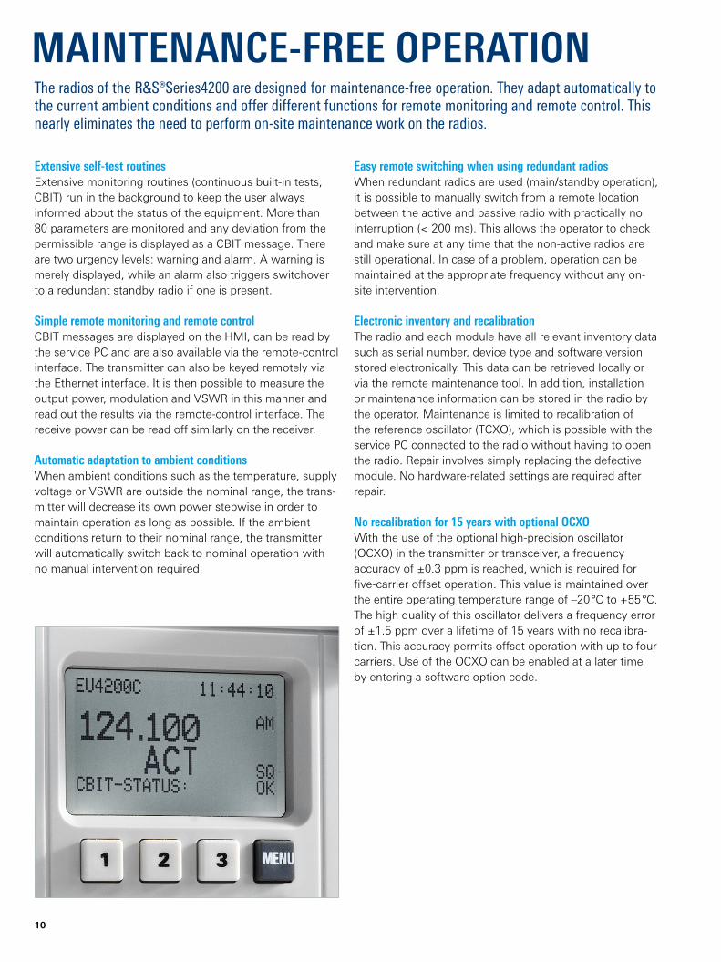
Easy remote switching when using redundant radiosWhen redundant radios are used (main/standby operation), it is possible to manually switch from a remote location between the active and passive radio with practically no interruption (< 200 ms). This allows the operator to check and make sure at any time that the non-active radios are still operational. In case of a problem, operation can be maintained at the appropriate frequency without any on-site intervention.
Electronic inventory and recalibrationThe radio and each module have all relevant inventory data such as serial number, device type and software version stored electronically. This data can be retrieved locally or via the remote maintenance tool. In addition, installation or maintenance information can be stored in the radio by the operator. Maintenance is limited to recalibration of the reference oscillator (TCXO), which is possible with the service PC connected to the radio without having to open the radio. Repair involves simply replacing the defective module. No hardware-related settings are required after repair.
No recalibration for 15 years with optional OCXOWith the use of the optional high-precision oscillator (OCXO) in the transmitter or transceiver, a frequency accuracy of ±0.3 ppm is reached, which is required for five-carrier offset operation. This value is maintained over the entire operating temperature range of –20 °C to +55 °C. The high quality of this oscillator delivers a frequency error of ±1.5 ppm over a lifetime of 15 years with no recalibra-tion. This accuracy permits offset operation with up to four carriers. Use of the OCXO can be enabled at a later time by entering a software option code.
MAINTENANC E-FREE OPERATION
Extensive self-test routinesExtensive monitoring routines (continuous built-in tests, CBIT) run in the background to keep the user always informed about the status of the equipment. More than 80 parameters are monitored and any deviation from the permissible range is displayed as a CBIT message. There are two urgency levels: warning and alarm. A warning is merely displayed, while an alarm also triggers switchover to a redundant standby radio if one is present.
Simple remote monitoring and remote controlCBIT messages are displayed on the HMI, can be read by the service PC and are also available via the remote- control interface. The transmitter can also be keyed remotely via the Ethernet interface. It is then possible to measure the output power, modulation and VSWR in this manner and read out the results via the remote-control interface. The receive power can be read off similarly on the receiver.
Automatic adaptation to ambient conditionsWhen ambient conditions such as the temperature, supply voltage or VSWR are outside the nominal range, the trans-mitter will decrease its own power stepwise in order to maintain operation as long as possible. If the ambient conditions return to their nominal range, the transmitter will automatically switch back to nominal operation with no manual intervention required.
The radios of the R&S®Series4200 are designed for maintenance-free operation. They adapt automatically to the current ambient conditions and offer different functions for remote monitoring and remote control. This nearly eliminates the need to perform on-site maintenance work on the radios.

R&S®ZS4200 service and maintenance tool.
Rohde & Schwarz R&S®Series4200 Software Defined Radios 11
STRAIGHTFORWARD OPERATION AND CONFIGURATION
PC based tools with graphical user interfaceThe radios are configured using the service PC's graphical user interface in conjunction with the R&S®ZS4200 service and maintenance tool. There is no need to open the radio, e.g. to make configuration settings using DIP switches or jumpers. Different configurations can be created on the PC for subsequent on-site loading into the radio. To ensure that a faulty radio can be exchanged quickly, its configu-ration can be cloned and transferred to a new radio. This means that such an exchange is performed very fast ( typically in 15 minutes).
Reliable protection against operation errorsAll radio versions can be operated in fixed-channel mode. This mode makes it impossible to change the set frequen-cy via HMI or remote control without proper authorization. The radio is configured accordingly using the service PC. If frequency settings are allowed, the user can exclude one or more channels in the VHF or UHF band from the list of possible configurations. The required frequency block-ing table is configured using the service PC and is loaded into the radio. This prevents the radio from accidentally operating on a frequency that is not permitted, e.g. the frequency of a radionavigation system.
Warning messages in case of unauthorized local operationTo prevent unauthorized local operation, a CBIT warning message can be activated that indicates if the radio is switched to local mode or the service PC is connected to the radio. At the same time, such activities are recorded in the radio's internal event log. This makes it possible to track all activities involving the radio at any time. The event log can be read locally or from a remote site.
Easy remote control and monitoring via IP connectionRemote control and monitoring are handled via an Ethernet connection between the radio and the manage-ment system. To ensure that only authorized users can connect to the radio, an access control list is saved in the radio. It contains the IP addresses with which the radio is allowed to communicate. Communications requests from other IP addresses are rejected.
The radios of the R&S®Series4200 offer many diverse functions that help ensure straightforward, secure and error-free operation.

12
FLEXIBILITY FOR SYSTEM INTEGRATION
Flexibility in management system selectionThe radios of the R&S®Series4200 can be controlled and monitored using the Rohde & Schwarz protocol or the simple network management protocol (SNMP). This ensures that users have maximum flexibility when selecting a management system.
Possible choices include the R&S®RCMS II remote control and monitoring system or any commercially available system that is based on SNMP. It is also possible to switch from SNMP to the R&S®RCMS II (or vice versa) at a later point in time. Alternatively, both management systems can be used in parallel.
Adaptation of in-band signaling for PTT and squelch to existing voice communications systemsThe in-band signaling for PTT and squelch can be adapted to existing voice communications systems (VCS), making it unnecessary to reconfigure or exchange any of the VCS components.
Signaling techniques that allow quality evaluation of the receive level can also be implemented in a straightforward manner. The in-band signaling used in the radio does not require any external components. Tone generation, filter-ing and evaluation are all performed by the software using a DSP.
The radios of the R&S®Series4200 provide flexibility when connected to a voice communications system (VCS) and a management system. Software upgrades ensure future viability of the radios.
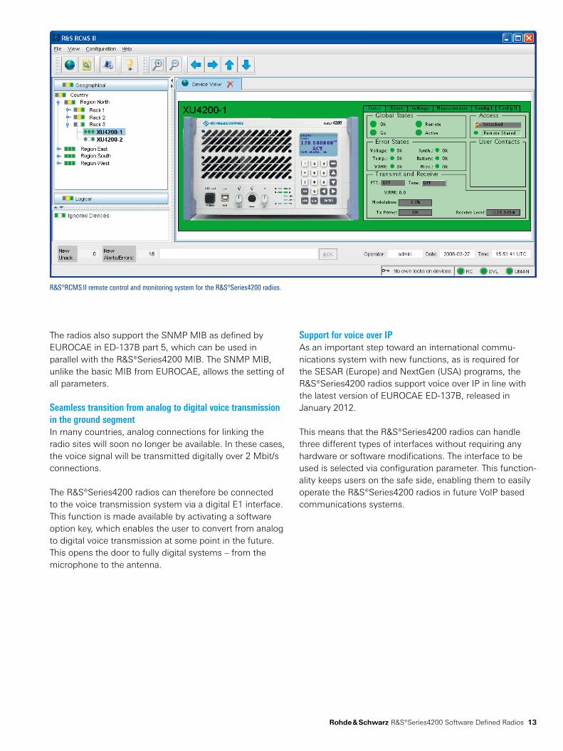
R&S®RCMS II remote control and monitoring system for the R&S®Series4200 radios.
Rohde & Schwarz R&S®Series4200 Software Defined Radios 13
Support for voice over IPAs an important step toward an international commu-nications system with new functions, as is required for the SESAR (Europe) and NextGen (USA) programs, the R&S®Series4200 radios support voice over IP in line with the latest version of EUROCAE ED-137B, released in January 2012.
This means that the R&S®Series4200 radios can handle three different types of interfaces without requiring any hardware or software modifications. The interface to be used is selected via configuration parameter. This function-ality keeps users on the safe side, enabling them to easily operate the R&S®Series4200 radios in future VoIP based communications systems.
The radios also support the SNMP MIB as defined by EUROCAE in ED-137B part 5, which can be used in parallel with the R&S®Series4200 MIB. The SNMP MIB, unlike the basic MIB from EUROCAE, allows the setting of all parameters.
Seamless transition from analog to digital voice transmission in the ground segmentIn many countries, analog connections for linking the radio sites will soon no longer be available. In these cases, the voice signal will be transmitted digitally over 2 Mbit/s connections.
The R&S®Series4200 radios can therefore be connected to the voice transmission system via a digital E1 interface. This function is made available by activating a software option key, which enables the user to convert from analog to digital voice transmission at some point in the future. This opens the door to fully digital systems – from the microphone to the antenna.

14
SMALL FOOTPRINT DUE TO COMPACT, MODULAR DESIGN
R&S®EU4200C compact VHF receiver.
Very compact designSpace requirements are 19"/2, three height units for one transmitter or one receiver (UHF only) or one transceiver. To further decrease the space required, a compact receiver is available as an alternative. This receiver type is accom-modated in a housing of half the size, i.e. 19"/4 width. The receiver module is the same as in the standard housing. This means that the following equipment can be arranged in one 19" row of three height units:
► Two transceivers or two transmitters or any combination of these devices
► Four compact receivers
Up to 24 transmitters or transceivers can be accom-modated in the ¸KG4200 standard 19" rack (or up to 48 compact receivers). No external components are
required for operation except any desired optional filters or multicouplers. For remote monitoring, all that is needed is an additional Ethernet switch or router.
Three basic modules: transmitter, receiver, power supply unitThe design of the R&S®Series4200 is based on a modu-lar structure consisting of three modules. These modules are the transmitter, the receiver and the power supply unit. Depending on the required configuration, these modules are accommodated in the appropriate housing. The housing is equipped with keypad, eight-line display, loud speaker, headset connector and LEDs. The housing is the same for all configurations and frequency bands and is very compact, which enables flexible deployment. It is suitable for 19" system rackmounting.
Due to its very compact and lightweight design, the R&S®Series4200 makes it possible to add new channels at existing sites without having to perform any construction work. New radio installations can also be designed to be smaller, which helps to cut construction costs.

Rohde & Schwarz R&S®Series4200 Software Defined Radios 15
Transmitter and receiverThe transmitter and receiver are designed as independent, EMC-shielded modules that contain all required exter-nal interfaces. The transmitter, receiver and HMI control-ler communicate via the USB bus with the R&S®ZS4200 service and maintenance tool.
The transmit and receive modules each contain an Ethernet interface (100BaseT) that is used for control and remote monitoring of the transmitter/receiver.
The transmitter and receiver have independent synthesiz-ers that are synchronized to the TCXO reference signal. This allows the transceivers to operate simultaneously in transmit and receive mode, which serves as a basis for true side tone or relay operation.
Integrated transmit/receive switchThe transmit module contains an integrated, wear-free PIN diode switch for switching between transmit and receive mode. This allows users at transceiver sites to choose whether they wish to use separate transmit and receive antennas or a common transmit/receive antenna. No configuration changes or settings are needed on the radio.
Modular design of the R&S®EU4200C compact VHF receiver
R&S®EU4250 receiver module with interface
Backplane
Front panel
Fan
R&S®KK4250C housing
HMI controller
R&S®IN4210 power supply unit

16
Power supplyThe modules are powered via the backplane, or (in the case of the power amplifier) directly by the power sup-ply module. The power supply is an independent, EMC-shielded module that contains all required external inter-faces. It allows operation of the radio from AC, DC or a combination of the two. Interruption-free switchover occurs in case of failure of the AC supply.
The power supply has a wide supply voltage range and can be operated with 230 V AC or 115 V AC without manual switchover. The user stays informed about the availability (or dropout) of the supply voltages using LEDs on the radio as well as warning messages to the manage-ment system. The power supply is available as a 400 W and as a 45 W version. The 400 W power supply is used in the transmitter and transceiver while the smaller 45 W power supply is used in the receiver.
Housing with HMI controllerThe HMI controller is part of the housing. It includes the control of the radio and the interface to the user. The HMI controller allows the radio to be operated using the integrated keypad and display. Configuration of the radio is possible via the USB interface. Software updates and upgrades are handled via the USB bus as well. The HMI controller with identical functionality is used both in the standard housing and in the compact housing.
Modular design of the R&S®XU4200 VHF transceiver
R&S®KK4250 housing
Front panel
HMI controller
Backplane
Fan
R&S®IN4240 power supply unit
R&S®EU4250 receiver module with interface
R&S®VU4250 transmitter module with interface

¸GB208 remoteaudio unit
¸Series4200 radio
¸GB208 remote audio unit
¸Series4200 radio
• • •
¸Series4200 radio
Controller Controller
¸Series4200 radio
Controller
Antenna
Remote operation
Local operation
Rohde & Schwarz R&S®Series4200 Software Defined Radios 17
TOWER APPLICATIONThe R&S®Series4200 transceivers are ideal for stand-alone applications without a voice communications system (VCS) being necessary. The transceivers can be used directly as desktop radios merely by connecting an antenna and a headset or microphone. For remote opera-tion, an audio panel that can be integrated into an operator console is available.
If a controller needs to access multiple radios, the R&S®GB208 remote audio unit allows up to eight trans-ceivers to be connected. Cascading of the R&S®GB208 enables multiple controllers to share a set of radios.
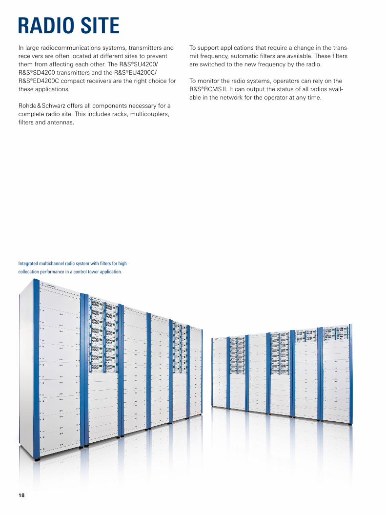
Integrated multichannel radio system with filters for high
collocation performance in a control tower application.
18
To support applications that require a change in the trans-mit frequency, automatic filters are available. These filters are switched to the new frequency by the radio.
To monitor the radio systems, operators can rely on the R&S®RCMS II. It can output the status of all radios avail-able in the network for the operator at any time.
In large radiocommunications systems, transmitters and receivers are often located at different sites to prevent them from affecting each other. The R&S®SU4200/R&S®SD4200 transmitters and the R&S®EU4200C/R&S®ED4200C compact receivers are the right choice for these applications.
Rohde & Schwarz offers all components necessary for a complete radio site. This includes racks, multicouplers, filters and antennas.
RADIO SITE

Rohde & Schwarz R&S®Series4200 Software Defined Radios 19
VCS,e.g. R&S®VCS-4G
¸KG4200 ATC system rack
Area control center
¸EU4200Ccompact VHF receiver
TX radiosite
RX radiosite
¸SU4200 VHF transmitter
Radio site
¸XD4200 UHF transceiver
¸HK014VHF/UHF antenna
¸HK012 VHF antenna
TX radiosite
RX radiosite
¸ATCMC16 VHF/UHF receive multicoupler
VCS,e.g. R&S®VCS-4G R&S®RCMS II
Radio site configuration
Remote control and monitoring system

20
In the past, TDM based systems relied on large centralized switching nodes. In contrast, modern IP based systems make use of distributed network intelligence and do not require a central switching entity thereby providing pay-as-you-grow scalability. As a result, ATC authorities no longer need to invest in large systems right from the start. This has a direct impact on your return on investment.
Increased reliabilityReliability in TDM systems typically depended on duplicating high cost centralized equipment. VoIP systems , however, migrate intelligence away from the network core to peripheral equipment. With the intelligence distributed over various elements, a failure at one part of the system does not affect operation in the rest of the system. The direct result is higher reliability and availability.
InteroperabilityThe EUROCAE issued the standard ED-137 which specifies the use of IP for voice communications in ATC environments. This standard was defined jointly between EUROCAE, ATC authorities and ATC equip-ment manufacturers. Customers that select equipment which meets this standard can be assured that the various system components interoperate properly with one another.
VOIP FOR AIR TRAFFIC CONTROLATC on its way to Voice over IPThe ATC world is standing before a game changing development in voice communications infrastructure. There are two key factors driving this change.
► Telecom service providers are now phasing out their leased line TDM services
► Eurocontrol, the Federal Aviation Administration and other organizations are mandating interoperability requirements in order to handle increased air traffic
ATC authorities need to understand how these factors will affect their business and make plans now for system interoperability, flexible assignment of airspace and cost-effectiveness.
VoIP as a key ATC technologyThe challenges now facing the ATC world will be met with the increasing use of IP technology. VoIP offers operational functionality and flexibility which would have been unthinkable with the TDM based systems of the past. It also provides significant financial advantages.
Reduced system costsMany ATC system operators are already using IP networks to transmit radar and flight plan data. Using this IP infrastructure for voice as well creates synergies in procurement, operation and maintenance; all of which lead to significant savings.

LAN
R&S®GB5400controllerworkingposition
R&S®GB5400controllerworkingposition
Remote radio stationwith R&S®Series4200 radios
R&S®RCMS II
R&S®GB5400controllerworkingposition
Managementterminal
¸DB5400database
¸RS5400radio server
R&S®GB5400controller workingposition
R&S®GB5400controller workingposition
R&S®GB5400controller workingposition
Tower/backup system with ¸VCS-4G
Area control center with ¸VCS-4G
LANRecorder
R&S®Series4200 R&S®Series4200R&S®Series4200
R&S®GB4000T
Small tower/backup system with ¸GB4000T/¸GB4000V
R&S®GB4000V
•••
LAN
R&S®Series4200 R&S®Series4200R&S®Series4200
•••
Recorder
Remote radio station with R&S®Series4200 radios
WAN
Remote radio station with R&S®Series4200 radios
Rohde & Schwarz R&S®Series4200 Software Defined Radios 21
From the microphone to the antennaRohde & Schwarz offers a wide selection of VoIP based products designed specifically for the needs of ATC customers around the world. Rohde & Schwarz provides system solutions from the microphone to the antenna. This eliminates the need for complex and costly integration work and helps to keep project risks to a minimum.
IP based VCSThe R&S®VCS-4G is a voice communications system (VCS), that takes full advantage of IP technology to provide a scalable, cost-effective, future-proof VCS. It fulfills the needs of both small-scale and large-scale area control centers (ACCs) as well as backup systems and tower installations. The R&S®VCS-4G meets the highest standards for availability, reliability and safety. It supports traditional VCS services, such as air-to-ground communications, intercom and telephony services. The IP based distributed architecture provides additional benefits, such as the integration of new services (e.g. video) and pay-as-you-grow scalability. The R&S®VCS-4G adheres to EUROCAE ED-137.
IP based radio remote control unitsThe R&S®GB4000T control unit and the R&S®GB4000V audio unit are IP based components for small-scale systems that consist of only a few working positions for air-to-ground communications. Their compact design minimizes space requirements in operator consoles. The R&S®GB4000V adheres to EUROCAE ED‑137.
VoIP radiosThe R&S®Series4200 radio family is one of the newest available on the ATC market. The radios have been deployed across the globe and have earned themselves a reputation for a high level of reliability and dependability. The latest model of the R&S®Series4200 is fully VoIP enabled and adheres to EUROCAE ED-137.
IP based remote control and monitoringThe R&S®RCMS II remote control & monitoring system serves as a single software solution for remote monitoring of the R&S®VCS-4G system and R&S®Series4200 radios. It can also monitor 3rd party SNMP-capable devices, making it the tool of choice for a complete situational overview of remote radio and VCS sites.
Application scenarios for Rohde & Schwarz VoIP solutions

Airline operational communications
¸HK012 VHF antenna
¸XU4200 VHF transceiver
Router
¸XU4200 VHF transceiver
¸HK012VHF antenna
Router
WAN
Dispatcher
22
DATA APPLICATIONData communications between the aircraft and the airline’s flight operations center can be sent over communications networks operated by commercial service providers. The radio systems operate in the same VHF frequency range as the voice communications for air traffic control (ATC) so that the same radios can be used on board the aircraft.
Data communications on the ground are handled by the VHF radios from the R&S®Series4200. These trans-ceivers can be operated both in the ACARS mode and in VDL mode 2.

Rohde & Schwarz R&S®Series4200 Software Defined Radios 23
PRODUCT OVERVIEWDesignation TypeR&S®Series4200 VHF multichannel radios
VHF transceiver50 W, 112 MHz to 156 MHz R&S®XU4200
VHF transmitter50 W, 112 MHz to 156 MHz R&S®SU4200
Compact VHF receiver112 MHz to 156 MHz R&S®EU4200C
R&S®Series4200 UHF multichannel radios
UHF transceiver50 W, 225 MHz to 400 MHz R&S®XD4200
UHF transmitter50 W, 225 MHz to 400 MHz R&S®SD4200
Compact UHF receiver225 MHz to 400 MHz R&S®ED4200C
Accessories (external options)Service and maintenance tool R&S®ZS4200
Headset, dynamic microphone R&S®GA4200D
Microphone, mini-DIN connector R&S®GA016H1
Adapter for standard headset R&S®GA4220
Mating connector set for the R&S®XU4200 R&S®ZF4200
Mating connector set for the R&S®SU4200/R&S®SD4200 R&S®ZF4200
Mating connector set for the R&S®EU4200C/R&S®ED4200C R&S®ZF4200
Mating connector Set for the R&S®XD4200 R&S®ZF4200
Filler plate 19"/2 R&S®BP4201
Filler plate 19"/4 R&S®BP4202
System componentsAntennas
VHF/UHF automatic filters and multicouplers R&S®FU221/R&S®FD221
Adapter, R&S®Series4200 to R&S®FU221/R&S®FD221 R&S®KG42-Z75
Cavity antenna filter R&S®HS9043
Circulator module/frame R&S®KR420
VHF/UHF receive multicoupler R&S®ATCMC
VHF power amplifier, 200 W
AF control unit R&S®GB208
AF distribution splitter/combiner R&S®GH215
Control unit R&S®GB4000T
Audio unit R&S®GB4000V
Multi-link controller R&S®GV4000
ATC system rack R&S®KG4200
IP based voice communications system (VCS) R&S®VCS-4G
Remote control and monitoring system R&S®RCMS II
For data sheets, see 5213.5700.22 and PD 5214.0118.22 and www.rohde-schwarz.com
The radio systems described are hardware- and software-configurable. The system delivered has the configuration as confirmed in the order.

R&S® is a registered trademark of Rohde & Schwarz GmbH & Co. KG Trade names are trademarks of the owners PD 5213.5700.12 | Version 08.00 | January 2020 (ch) R&S®Series4200 Software Defined Radios Data without tolerance limits is not binding | Subject to change© 2009 - 2020 Rohde & Schwarz GmbH & Co. KG | 81671 Munich, Germany
Service that adds value► Worldwide► Local und personalized► Customized and flexible► Uncompromising quality► Long-term dependability
5213
.570
0.12
08.
00 P
DP
1 e
n
Sustainable product design ► Environmental compatibility and eco-footprint ► Energy efficiency and low emissions ► Longevity and optimized total cost of ownership
Certified Quality Management
ISO 9001
Rohde & Schwarz customer supportwww.rohde-schwarz.com/support
Rohde & SchwarzThe Rohde & Schwarz electronics group offers innovative solutions in the following business fields: test and mea-surement, broadcast and media, secure communications, cybersecurity, monitoring and network testing. Founded more than 80 years ago, the independent company which is headquartered in Munich, Germany, has an extensive sales and service network with locations in more than 70 countries.
www.rohde-schwarz.com
Rohde & Schwarz trainingwww.training.rohde-schwarz.com
Certified Environmental Management
ISO 14001
5213570012


![De Re / De Dicto [Ezra Keshet & Florian Schwarz]](https://static.fdokumen.com/doc/165x107/631d49de1c5736defb028aa3/de-re-de-dicto-ezra-keshet-florian-schwarz.jpg)