Aerodynamic Design and Testing of an Axial Flow ... - CiteSeerX
10
A. R. Wadia e-mail: [email protected] D. P. Wolf F. G. Haaser GE Aircraft Engines, Cincinnati, OH 45215 Aerodynamic Design and Testing of an Axial Flow Compressor With Pressure Ratio of 23.3:1 for the LM25001 Gas Turbine The LM25001 gas turbine, rated between 39,000 – 40,200 shaft horsepower (shp), was introduced for field service in 1998. This growth aero-derivative gas turbine is suitable for a variety of power generation applications, such as co-generation and combined cycle, as well as mechanical drive applications. At the heart of the LM25001 25% power increase is an up-rated derivative 17-stage axial compressor. This paper describes the aerody- namic design and development of this high-pressure ratio single-spool compressor for the LM25001 gas turbine. The compressor is derived by zero-staging the highly efficient and reliable LM2500 compressor to increase the flow by 23% at a pressure ratio of 23.3:1. The aerodynamic efficiency of the compressor is further improved by using three- dimensional, custom-tailored airfoil designs similar to those used in the CF6-80C2 high- pressure compressor. The compressor achieved a peak polytropic efficiency above 91%, meeting all its operability objectives. The technical requirements and overall aerodynamic design features of the compressor are presented first. Next, the zero stage match point selection is described and the procedure used to set up the vector diagrams using a through-flow code with secondary flow and mixing is outlined. Detailed design results for the new transonic airfoils in the compressor using three-dimensional viscous analysis are presented. The compressor instrumentation and performance test results are discussed. The performance of the zero stage is separated from that of the baseline compressor with the CF6-80C2 airfoils to show the improvement in efficiency with the new airfoils. @DOI: 10.1115/1.1464562# Introduction Application of aero-engine technology to ground-based gas tur- bines has increased rapidly, especially in the last decade, as docu- mented in the works of Scalzo @1#, Kashiwabara @2#, Sehra @3#. Smed @4#, Janssen @5#, and Stringham @6#. The LM2500 gas tur- bine, derived from the CF6-6/TF39 aircraft engines, has also le- veraged off aircraft engine technology development to facilitate the increase in its industrial power rating from the original 24,000 shp to the current 31,200 shp. Market studies initiated in the late eighties and early nineties showed that the LM2500 industrial gas turbine needed additional power ~39,000 shp at ISO conditions! to meet customer requirements ~Farmer @7#!. This up-rated power version of the LM2500 was named the LM25001 gas turbine. The LM25001 gas turbine 3-D cutaway presented in Fig. 1 high- lights the key modifications made to the engine relative to the LM2500 base engine. In March 1994, after a series of preliminary design studies on how to achieve the required power increase, it was decided to launch the LM25001 which was chosen from four candidate con- figurations based on a cost-and-risk assessment comparison. The preliminary design team evaluated power enhancement techniques such as inter-cooling, inlet supercharging, recuperation and other refinements. The team, however, decided on the basis of design simplicity, program schedule, technology risks and development cost and customer price that increasing the inlet mass flow through the engine was the simplest and most conservative way of increasing the power output. The increased mass flow could be achieved by zero-staging the current production LM2500 com- pressor. Simultaneously, the increase in the turbine rotor inlet tem- peratures could be minimized to approximately 35°C ~65°F!~Va- lent @8#! by going to a more efficient compressor design using three-dimensional analytical tools and incorporating custom- tailored compressor airfoils from the CF6-80C2 aircraft engine. It was apparent that this design approach best met the goals of using proven technology at minimal risk. Also, keeping a strong funda- mental LM2500 design heritage facilitated product support while meeting the objectives of a base load hot section inspection inter- val of 25,000 h with engine overhauls at 50,000 h. Compressor Technical Requirements Summary The performance requirements for the LM25001 compressor were less stringent relative to those required by commercial or military aircraft engines. While aircraft engines have multiple op- erating points such as take-off, cruise, etc., where performance is crucial, the LM25001 is required to operate at close to its peak efficiency near its high-speed design point. While no specific per- formance requirements at other speeds were specified, it was de- sirable for the compressor to preserve good efficiency over a range of speeds. Additionally, the LM25001 compressor was also required to operate stall-free with both a single annular combustor ~SAC!, which results in a smooth compressor operating line, and with a dry low emissions ~DLE! combustor, which results in a compres- sor operating line with steps corresponding to the staging in the combustor. The compressor operating line can vary by as much as 2% below and above the nominal operating line, from the start of the combustor staging to the end of the staging sequence, respec- tively. The customer-supplied inlet systems used with industrial gas turbines, such as the LM25001, are generally quite aerodynami- cally ‘‘clean’’ and use a light wire screen mesh to prevent any Contributed by the International Gas Turbine Institute and presented at the Inter- national Gas Turbine and Aeroengine Congress and Exhibition, Indianapolis, Indiana, June 6 –9, 1999. Manuscript received by the IGTI, January 1999; revised manuscript received January 24, 2002. Paper No. 1999-GT-210. Review Chair: D. Wisler. Copyright © 2002 by ASME Journal of Turbomachinery JULY 2002, Vol. 124 Õ 331 Downloaded From: https://turbomachinery.asmedigitalcollection.asme.org on 07/01/2019 Terms of Use: http://www.asme.org/about-asme/terms-of-use
-
Upload
khangminh22 -
Category
Documents
-
view
0 -
download
0
Transcript of Aerodynamic Design and Testing of an Axial Flow ... - CiteSeerX
sfor
le, as
rody-or thet and.3:1.hree-igh-91%,
amicpoint
ing as foris areussed.r withew
Downloaded From
A. R. Wadiae-mail: [email protected]
D. P. Wolf
F. G. Haaser
GE Aircraft Engines,Cincinnati, OH 45215
Aerodynamic Design and Testingof an Axial Flow Compressor WithPressure Ratio of 23.3:1 for theLM25001 Gas TurbineThe LM25001 gas turbine, rated between 39,000–40,200 shaft horsepower (shp), waintroduced for field service in 1998. This growth aero-derivative gas turbine is suitablea variety of power generation applications, such as co-generation and combined cycwell as mechanical drive applications. At the heart of the LM25001 25% power increaseis an up-rated derivative 17-stage axial compressor. This paper describes the aenamic design and development of this high-pressure ratio single-spool compressor fLM25001 gas turbine. The compressor is derived by zero-staging the highly efficienreliable LM2500 compressor to increase the flow by 23% at a pressure ratio of 23The aerodynamic efficiency of the compressor is further improved by using tdimensional, custom-tailored airfoil designs similar to those used in the CF6-80C2 hpressure compressor. The compressor achieved a peak polytropic efficiency abovemeeting all its operability objectives. The technical requirements and overall aerodyndesign features of the compressor are presented first. Next, the zero stage matchselection is described and the procedure used to set up the vector diagrams usthrough-flow code with secondary flow and mixing is outlined. Detailed design resultthe new transonic airfoils in the compressor using three-dimensional viscous analyspresented. The compressor instrumentation and performance test results are discThe performance of the zero stage is separated from that of the baseline compressothe CF6-80C2 airfoils to show the improvement in efficiency with the nairfoils. @DOI: 10.1115/1.1464562#
a
l
t
dn.q
em-
ingm-. Itsinga-ileter-
l orp-e is
aker-de-
r a
to
h as-theh ast ofpec-
gasi-ny
nis
IntroductionApplication of aero-engine technology to ground-based gas
bines has increased rapidly, especially in the last decade, as dmented in the works of Scalzo@1#, Kashiwabara@2#, Sehra@3#.Smed@4#, Janssen@5#, and Stringham@6#. The LM2500 gas tur-bine, derived from the CF6-6/TF39 aircraft engines, has alsoveraged off aircraft engine technology development to facilitthe increase in its industrial power rating from the original 24,0shp to the current 31,200 shp. Market studies initiated in theeighties and early nineties showed that the LM2500 industrialturbine needed additional power~39,000 shp at ISO conditions! tomeet customer requirements~Farmer @7#!. This up-rated powerversion of the LM2500 was named the LM25001 gas turbine.The LM25001 gas turbine 3-D cutaway presented in Fig. 1 higlights the key modifications made to the engine relative toLM2500 base engine.
In March 1994, after a series of preliminary design studieshow to achieve the required power increase, it was decidelaunch the LM25001 which was chosen from four candidate cofigurations based on a cost-and-risk assessment comparisonpreliminary design team evaluated power enhancement technisuch as inter-cooling, inlet supercharging, recuperation and orefinements. The team, however, decided on the basis of desimplicity, program schedule, technology risks and developmcost and customer price that increasing the inlet mass flthrough the engine was the simplest and most conservative waincreasing the power output. The increased mass flow couldachieved by zero-staging the current production LM2500 co
Contributed by the International Gas Turbine Institute and presented at the Inational Gas Turbine and Aeroengine Congress and Exhibition, Indianapolis, IndJune 6–9, 1999. Manuscript received by the IGTI, January 1999; revised manureceived January 24, 2002. Paper No. 1999-GT-210. Review Chair: D. Wisler.
Copyright © 2Journal of Turbomachinery
: https://turbomachinery.asmedigitalcollection.asme.org on 07/01/2019 Terms of
tur-ocu-
le-te
00ategas
h-he
onto
-Theues
thersignentowy ofbe
m-
pressor. Simultaneously, the increase in the turbine rotor inlet tperatures could be minimized to approximately 35°C~65°F! ~Va-lent @8#! by going to a more efficient compressor design usthree-dimensional analytical tools and incorporating custotailored compressor airfoils from the CF6-80C2 aircraft enginewas apparent that this design approach best met the goals of uproven technology at minimal risk. Also, keeping a strong fundmental LM2500 design heritage facilitated product support whmeeting the objectives of a base load hot section inspection inval of 25,000 h with engine overhauls at 50,000 h.
Compressor Technical Requirements SummaryThe performance requirements for the LM25001 compressor
were less stringent relative to those required by commerciamilitary aircraft engines. While aircraft engines have multiple oerating points such as take-off, cruise, etc., where performanccrucial, the LM25001 is required to operate at close to its peefficiency near its high-speed design point. While no specific pformance requirements at other speeds were specified, it wassirable for the compressor to preserve good efficiency overange of speeds.
Additionally, the LM25001 compressor was also requiredoperate stall-free with both a single annular combustor~SAC!,which results in a smooth compressor operating line, and witdry low emissions~DLE! combustor, which results in a compresor operating line with steps corresponding to the staging incombustor. The compressor operating line can vary by as muc2% below and above the nominal operating line, from the starthe combustor staging to the end of the staging sequence, restively.
The customer-supplied inlet systems used with industrialturbines, such as the LM25001, are generally quite aerodynamcally ‘‘clean’’ and use a light wire screen mesh to prevent a
ter-ana,cript
002 by ASME JULY 2002, Vol. 124 Õ 331
Use: http://www.asme.org/about-asme/terms-of-use

u
nl
tt
eeo
2ut
wr
-
v
e
r
s
p
i
lt
1
tingk
eroist-
t forres-llure
thedrgyas
r-la-geus a
pectandtionaticor-
s anpointeh is
ing
turenletedea-
ating
Downloaded From
large objects being ingested by the compressor. Maneuverscross-wind inlet distortion issues are almost nonexistent on thland/marine-based engines, thus easing the operability reqments. Installation design manuals suggest the inlet distortiondex to be of the order of 2% or less as most of the operatiowith a straight bellmouth or radial volute. To account for any indistortion that might be encountered in the field, the compreswas designed with a slight tip radial~i.e., total pressure deficit athe tip! inlet total pressure profile to realistically simulate theaerodynamic loading level on the zero stage blade.
Acoustics plays an economic role in land/marine-based systdesign, and the goal for the LM25001 was to maintain the saminlet noise sound pressure level in spite of the 23% higher airflThis requirement set the vane/blade ratios and the axial spabetween the rotor and the stator using an ‘‘acoustic cutoff’’ descriteria.
The compressor operating line was set with a minimum of 1stall margin to account for any operating line migration that wooccur in service during the life of the engine. Start times forengine are of the order of 2 min, which is less stringent thanaircraft engines. A 4-deg open stator stall margin requirementconservatively set for the LM25001 to account for variable statovanes ~VSV! control/rigging variation and deterioration in thfield.
Compressor Aerodynamic Design FeaturesThe detailed aerodynamic design of the original CF6
LM2500 compressor has been reported by Klapproth et al.@9#. Toachieve the increased power output rating, the LM25001 requireda 23% increase in airflow. The 23% increase in flow was achieby adding an additional compression stage~zero stage! to theLM2500 and flaring the flowpath in front of the existing compresor to form an overall 17-stage axial compressor unit. Figurshows the changes incorporated into the LM25001 relative to thebase compressor. As a result of zero staging of the compressoLM25001 increased in length by 34.3 cm~13.5 in.! and theweight of the engine increased by about 363 kg~800 lb! Table 1shows the comparison of key aerodynamic design parameterthe LM2500 compressor with those selected for the design ofLM25001 compressor.
Zero Stage Match Point SelectionTechnical information on zero-staging compressors in the o
literature is limited. Some of the principles in the developmentfront stages of axial flow compressors has been reported by Eberg@10# and Katoh@11#. A recent compressor zero-staging appcation to the Taurus 60 axial flow compressor that increasesinlet mass flow by approximately 20% and raises the pressratio from 11.2:1 to 16:1 has been reported by Van Leuven@12#and Rocha et al.@13#.
The CF6-6/LM2500 compressor performance map has bpresented in@9#. The LM2500 compressor achieved a peak potropic efficiency of 90.7% along the engine operating line a
Fig. 1 LM2500¿ gas turbine unique features
332 Õ Vol. 124, JULY 2002
: https://turbomachinery.asmedigitalcollection.asme.org on 07/01/2019 Terms of
andeseire-in-is
etsor
ip
ms
w.cingign
%ldheinas
e
6/
ed
s-2
, the
forthe
enof
sen-li-theure
eeny-a
compressor inlet corrected flow of 60 kg/s~132 lb/s! and pressureratio of 15:1. The 88.9% polytropic efficiency shown in Table~does not include the compressor exit diffuser losses! representsthe compressor performance at the maximum power operapoint of the LM2500 engine, which is different from the peaefficiency point on the compressor map.
To achieve maximum compressor performance with the zstage, the point corresponding to the peak efficiency of the exing LM2500 compressor would be selected as the match pointhe LM25001 compressor design. This sets the zero stage psure ratio such that the LM25001 compressor achieves its overacompression ratio goal. In order to achieve this optimum pressratio, the zero stage’s ‘‘stage effectivity,’’ as calculated usingapproach formulated by Koch@14#, exceeded that demonstrateby the first stage of the compressor in GE Aircraft Engine’s eneefficient engine (E3), which has a similar overall pressure ratiothat for the LM25001.
The term ‘‘stage effectivity’’ is a correlation that is used intenally within GE Aircraft Engines to assess a stage’s loading retive to the loading at stall. It is synonymous to the peak stastatic pressure rise coefficient and has been correlated versparameter involving stage average values of solidity and asratio. The correlation serves as an aerodynamic loading limit,accounts for factors such as blade speed, axial velocity, reacratio, clearance and Reynolds number to form a systemmethod for analysis or prediction of compressor stall perfmance.
The selection of the pressure ratio, for the zero stage, waiterative process to achieve a balance between the designpressure ratio and its ‘‘stage effectivity’’ at stall. This iterativprocess yielded a zero stage pressure ratio of 1.438, whicslightly less than optimum.
The efficiency potential of the zero stage was determined usthe principles outlined by Koch and Smith@15# and the corre-sponding work input assigned to it. The resultant exit temperaand pressure from Rotor 0 provided the input to calculate the iconditions into the following stator. Inlet corrected flow and speat Stator 0 inlet were then calculated and compared to the msured flow at speed along the base LM2500 compressor oper
Fig. 2 LM2500¿ high pressure compressor improvementsrelative to the base „LM2500… compressor
Table 1 Compressor aerodynamic design operating point
Transactions of the ASME
Use: http://www.asme.org/about-asme/terms-of-use

i
l
f
ai
o
le
y
s
d
tn
J
e
f
-si
sto
edheerode-
thepart
IGVnaludefer-the
tailthe
it-inefitsrts
andfor
s-
dy-their-
m-y
for-
e
m arlier.
thedet-ick-ping2.hec
Downloaded From
line. The calculations converged quickly to provide a realisaxial match between the new zero stage and the downstreamisting compressor.
The aforementioned approach, substantiated by past experon the E3 engine and test data from the LM2500 compressresulted in matching the LM25001 zero stage to the originaLM2500 compressor at an inlet corrected flow of about 62.7 k~137 lbs/s! ~corresponding to an inlet corrected speed of 8,9rpm! at 90.3% polytropic efficiency.
Compressor Design Vector DiagramsThe vector diagrams used to design the new front stages o
LM25001 compressor were derived from a data match of a fuinstrumented, CF6-80C2 core engine using the circumferentiaveraged, through-flow code with secondary flow and mix~Adkins and Smith@16#!. Next, the new zero stage was addedthe through-flow analysis. The new set of vector diagramstained were such that the velocity triangle quantities—such asinlet relative flow angle, inlet relative Mach number and inmeridional Mach number into stage 2 blade—were the samthe data match values.
The axial distribution of solidity, aspect ratio, axial velocitdiffusion factor, Mach number, inlet and exit flow angles and afoil camber and stagger angles for all the LM2500 blading hbeen published@9#. Table 2 summarizes some of the key airfogeometry and vector diagram quantities for the first three stagethe LM25001 compressor.
A preliminary design analysis resulted in the selection ofblades~Rotor 0! for the zero stage. The selection of the numberinlet guide vanes and the number of zero stage vanes~vane/bladecut-off ratio!, and the axial gaps between the inlet guide vanRotor 0 and Stator 0 were set by the technical requirements fo‘‘acoustic cut-off’’ in order to prevent higher inlet noise levelThis resulted in larger-than-normal axial gaps on both sides ofzero stage blade, as shown in Fig. 2. These large gaps aremental to compressor performance, making the aerodynamicsign of the compressor even more challenging.
The following sections summarize the detailed design ofnew front stages of the LM25001 compressor with emphasis othe zero stage and the first stage blade designs. Three-dimensviscous analysis using the computer program developed bynions and Turner@17# was used extensively in the design of thcompressor blading.
Front Frame and Inlet Guide Vane DesignThe LM25001 front frame is very similar to the original engin
frame. It is a five-strut~four thin struts and one thick strut!, 17-4steel casting and retains the same inner and outer front forwflange configuration for inlet commonality as shown in Fig. 2. Tframe’s inner and outer flowpath walls were flared to increaseflow area through the frame to prevent a higher pressure lossto a possible flow restriction. The original front frame struts abi-convex airfoils, which for the LM25001 were made moreaerodynamic using NACA 65-series airfoils. Thickness and aircontour changes lowered the front frame losses as verifiedthree-dimensional viscous analysis of the frame.
The inlet guide vane~IGV! airfoil design was done with a conventional profile. The correlation of NACA 63-series airfoil cacade data by Dunavant was used with the IGV solidity vary
Table 2 Rotor and stator pitch line design parameterssummary
Journal of Turbomachinery
: https://turbomachinery.asmedigitalcollection.asme.org on 07/01/2019 Terms of
ticex-
enceor,
g/s50
thellylly
ngtob-the
etas
,ir-asils of
16of
es,r an.theetri-de-
he
ionalen-e
ardhetheduere
oilby
-ng
from 0.89 at the tip of 1.2 at the hub. The IGV exit swirl wavaried almost linearly from about 18 deg of pre-swirl at the tip215 deg of counterswirl at the hub. The tip pre-swirl providMach number relief to the downstream rotor at the tip, while thub counterswirl helped lower the hub Mach number into the zstage vane. The IGV design was important because it has toliver the required swirl distribution to the zero stage blade atdesign condition and it has to be able to operate adequately atspeed when the airfoil is closed by as much as 60 deg. Theairfoil was analyzed at the design point with the three-dimensioviscous analysis. This analysis was done to verify the magnitand radial distribution of pressure loss assumed in the circumentially averaged through-flow analysis and its ability to meetexit swirl requirements.
Zero Stage Blade DesignPreliminary mechanical design studies showed that dove
stresses on a traditional zero stage blade design would limitminimum radius ratio to 0.45. A blisk version of the rotor permted a reduction in the radius ratio to 0.368. This reductionradius ratio also provided some aerodynamic performance benby lowering the inlet specific flow. The blisk also provided a pacount reduction by replacing 401 parts with a single part, andeliminated the wear issue of a midspan shroud, blade and diskdovetails. Although blisk technology has been in existence201 years, its inclusion in the LM25001 represents the first in-troduction of a blisk to GE Aircraft Engines’ Marine and Indutrial engines product line.
Table 3 shows the comparison of the geometric and aeronamic design parameters between the zero stage rotor forLM25001 compressor and the first stage blade from the GE Acraft Engines E3 compressor. As illustrated by the thickness coparisons in Table 3, the LM25001 blades were considerablthicker ~ruggedized! to increase foreign object damage~FOD! tol-erance. The location of maximum thickness was also movedward on the LM25001 airfoil, in a similar manner as illustrated inthe paper by Wadia and Law@18#, to provide improved resistancto leading edge foreign body impact.
Rotor 0 was designed to the vector diagrams created frodata match of the CF6-80C2 core compressor as reported eaTransonic airfoil design principles presented in@18# were appliedto custom tailor the mean camber lines to alleviate some ofperformance penalties associated with the ruggedization. Therimental effect on performance due to the large increase in thness, especially near the hub, was also reduced by scallo~area-ruling! the hub flowpath within the blade as shown in Fig.
The inlet relative Mach number is transonic over most of tblade span of the LM25001 Rotor 0. The efficiency of a transoni
Table 3 Zero stage blade key aerodynamic design parameters
JULY 2002, Vol. 124 Õ 333
Use: http://www.asme.org/about-asme/terms-of-use
a
s
l
ai
a
vta
e
ls
t.
e
l
ei
ngleree-
atac-
Downloaded From
blade is heavily influenced by shock losses, which may exceedlosses due to cascade diffusion and secondary flow effects.Mach number just ahead of the leading edge passage shock cinfluenced by the shape of the blade suction surface ahead oshock. Increasing the average suction surface angle, as meafrom axial, ahead of the shock reduces the average Mach numupstream of the shock through external compression and shreduce the shock losses. However, this type of airfoil can resua reduced cascade throat area. If the throat is too small, thecade will not pass the design flow and may not achieve thetached shock pattern desired for minimum loss. The lesslearned in transonic rotor performance studies by WadiaCopenhaver@19#, with different cascade area ratios, were applto set the throat margin, internal contraction and trailing edcamber of the zero stage blade. The blade was designed withthroat margin.
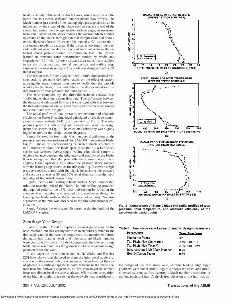
The design was further analyzed with a three-dimensionalcous code to get more definitive results on the effect of custailoring the mean camber lines and to verify that the cascwould pass the design flow and deliver the design intent exitdial profiles of total pressure and temperature.
The flow computed by the three-dimensional analysis w1.05% higher than the design flow rate. This difference betwthe design and calculated flow rate is consistent with that betwthe three-dimensional analysis and measured flow on other simtransonic blade row designs.
The radial profiles of total pressure, temperature and adiabefficiency~at Stator 0 leading edge! calculated by the three dimensional viscous analysis~3-D! are illustrated in Fig. 3. The totapressure profile is hub strong and agrees well with the deintent also shown in Fig. 3. The calculated efficiency was slighhigher relative to the design vector diagrams.
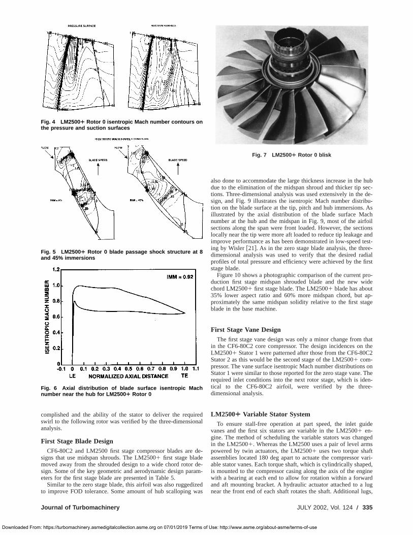
Figure 4 shows the isentropic Mach number distribution onpressure and suction surfaces of the LM25001 zero stage bladeFigure 5 shows the corresponding calculated shock structurtwo immersions along the blade span. Near the tip, a two-shsystem was selected over a single leading edge shock patteobtain a balance between the efficiency and stability of the blaIt was recognized that the peak efficiency would occur onslightly higher operating line where the passage shock merwith the leading edge shock. At the midspan, Fig. 5 shows a sinpassage shock structure with the shock intersecting the presand suction surfaces at 30 and 65% axial distance from the ling edge of the airfoil, respectively.
Figure 6 shows the isentropic blade surface Mach numbertribution near the hub of the blade. The hub scalloping providthe required relief to the 13% thick hub section by lowering taverage Mach number and resulted in a shock-free designkeeping the blade surface Mach numbers below unity. No flseparation at the hub was observed in the three-dimensionaculations.
Figure 7 shows the zero stage blisk used in the first build ofLM25001 engine.
Zero Stage Vane DesignStator 0 on the LM25001 replaces the inlet guide vane on th
base machine but has aerodynamic characteristics similar tofirst stage vane in the baseline compressor. As mentioned bethe stator hub loading levels and inlet absolute Mach numbwere controlled by using215 deg counterswirl into the zero stagblade. Table 4 summarizes the geometric and aerodynamic deparameters for the vane.
In the paper on three-dimensional relief, Wadia and Beac@20# have shown that the need to align the inlet metal angle pcisely with the skewed inlet flow angles at the endwall~at the riskof placing a significant spanwise twist gradient in the blade sface near the endwall! appears to be less than might be implifrom two-dimensional cascade analyses. While some recognof the high air angles that exist at the endwalls was considere
334 Õ Vol. 124, JULY 2002
: https://turbomachinery.asmedigitalcollection.asme.org on 07/01/2019 Terms of
theThen be
f theuredber
ouldt incas-at-
onsnd
edge5%
is-omde
ra-
asen
eenilar
atic-
igntly
he
e atockrn tode.a
gedglesuread-
dis-edhe
byowcal-
the
ethe
fore,ersesign
herre-
ur-dtiond in
the design of the zero stage vane, extreme leading edge agradients were not required. Figure 8 shows the calculated thdimensional vane surface isentropic Mach number distributionthe tip, pitch and hub. A shock-free diffusion at the hub was
Fig. 3 Comparison of Stage 0 blade exit radial profiles of totalpressure, total temperature, and adiabatic efficiency at theaerodynamic design point
Table 4 Zero stage vane key aerodynamic design parameters
Transactions of the ASME
Use: http://www.asme.org/about-asme/terms-of-use
r
r
izw
hubec-de-
bu-. Aschfoiltionsandtest-e-
dialfirst
ro-ide
ap-ge
thatthe
C2
s onThen-
e-
ide
geds
tvari-ed,
ginerdluggs,
Downloaded From
complished and the ability of the stator to deliver the requiswirl to the following rotor was verified by the three-dimensionanalysis.
First Stage Blade DesignCF6-80C2 and LM2500 first stage compressor blades are
signs that use midspan shrouds. The LM25001 first stage blademoved away from the shrouded design to a wide chord rotorsign. Some of the key geometric and aerodynamic design paeters for the first stage blade are presented in Table 5.
Similar to the zero stage blade, this airfoil was also ruggedto improve FOD tolerance. Some amount of hub scalloping
Fig. 4 LM2500¿ Rotor 0 isentropic Mach number contours onthe pressure and suction surfaces
Fig. 5 LM2500¿ Rotor 0 blade passage shock structure at 8and 45% immersions
Fig. 6 Axial distribution of blade surface isentropic Machnumber near the hub for LM2500 ¿ Rotor 0
Journal of Turbomachinery
: https://turbomachinery.asmedigitalcollection.asme.org on 07/01/2019 Terms of
edal
de-
de-am-
edas
also done to accommodate the large thickness increase in thedue to the elimination of the midspan shroud and thicker tip stions. Three-dimensional analysis was used extensively in thesign, and Fig. 9 illustrates the isentropic Mach number distrition on the blade surface at the tip, pitch and hub immersionsillustrated by the axial distribution of the blade surface Manumber at the hub and the midspan in Fig. 9, most of the airsections along the span were front loaded. However, the seclocally near the tip were more aft loaded to reduce tip leakageimprove performance as has been demonstrated in low-speeding by Wisler@21#. As in the zero stage blade analysis, the thredimensional analysis was used to verify that the desired raprofiles of total pressure and efficiency were achieved by thestage blade.
Figure 10 shows a photographic comparison of the current pduction first stage midspan shrouded blade and the new wchord LM25001 first stage blade. The LM25001 blade has about35% lower aspect ratio and 60% more midspan chord, butproximately the same midspan solidity relative to the first stablade in the base machine.
First Stage Vane DesignThe first stage vane design was only a minor change from
in the CF6-80C2 core compressor. The design incidences onLM25001 Stator 1 were patterned after those from the CF6-80Stator 2 as this would be the second stage of the LM25001 com-pressor. The vane surface isentropic Mach number distributionStator 1 were similar to those reported for the zero stage vane.required inlet conditions into the next rotor stage, which is idetical to the CF6-80C2 airfoil, were verified by the thredimensional analysis.
LM2500¿ Variable Stator SystemTo ensure stall-free operation at part speed, the inlet gu
vanes and the first six stators are variable in the LM25001 en-gine. The method of scheduling the variable stators was chanin the LM25001. Whereas the LM2500 uses a pair of level armpowered by twin actuators, the LM25001 uses two torque shafassemblies located 180 deg apart to actuate the compressorable stator vanes. Each torque shaft, which is cylindrically shapis mounted to the compressor casing along the axis of the enwith a bearing at each end to allow for rotation within a forwaand aft mounting bracket. A hydraulic actuator attached to anear the front end of each shaft rotates the shaft. Additional lu
Fig. 7 LM2500¿ Rotor 0 blisk
JULY 2002, Vol. 124 Õ 335
Use: http://www.asme.org/about-asme/terms-of-use

tgi
dedthat
thetatorquiredm-
f thero
nddule
11.ide
ctionofandas
Downloaded From
one for each variable stator stage, are bolted along the lengthe shaft. As the shaft turns, a turnbuckle bolted to each lupushed or pulled to rotate a multipiece, 360-deg ring to wheach stator vane lever arm is connected, opening or closing
Fig. 8 Axial distribution of Stage 0 vane surface isentropicMach number
Table 5 First stage blade key aerodynamic designparameters
336 Õ Vol. 124, JULY 2002
: https://turbomachinery.asmedigitalcollection.asme.org on 07/01/2019 Terms of
h ofis
chthe
VSV. The key benefit derived by using the torque tube is its adflexibility to schedule each stage with stator angle schedulesare nonlinear to each other.
The variable stator schedule is controlled as a function ofcompressor inlet corrected speed, with the second stage sangle used as the reference. Stage characteristic data sets acfrom core engine tests of the CF6-80C2 and the LM2500 copressor were used to assemble a pitch line off-design model oLM25001 compressor with the new inlet guide vane and zestage, and the mixture of airfoils from the CF6-80C2 aLM2500. This model was used to develop a pretest stator schefor the LM25001.
The change in Stator 2 angle~pretest! from the design nominalas a function of compressor corrected speed is shown in Fig.The change in the setting angles from design for the inlet guvanes and Stators 0, 1, and 3–6 are shown in Fig. 12 as a funof the Stator 2 ‘‘master’’ angle. While the linear relationshipStators 0–6 with Stator 2 was retained from the CF6-80C2the LM2500 experience, the inlet guide vane relationship whighly nonlinear with respect to the ‘‘master’’ stator angle.
Fig. 9 Axial distribution of blade surface isentropic Machnumber for Rotor 1
Transactions of the ASME
Use: http://www.asme.org/about-asme/terms-of-use

t
u
a.
i
r
bladetage
oolnew
re-atorrep-tion
thede-the
able
%,
ic-ffi-and
n-00
agekesargeran-ly-
ignxednted
nd
re atnalhan
de-ff-
ssorgherl vari-
theme-
Downloaded From
Test Compressor Instrumentation SummaryThe first engine with the LM25001 compressor was tested as
gas generator with a conic nozzle at GE Aircraft Enginesfacilities in Evendale with a dry low emissions~DLE! combustionsystem.
The overall compressor performance was measured usingfive-element combined inlet total pressure and total temperarakes and three five-element rakes at the compressor dischOther performance measurements included the compressor sand inlet flow, which was measured with a calibrated bellmowith inlet rakes. All compressor bleed flows were measured uscalibrated pipes.
Interstage compressor instrumentation was extensive. Estage in the compressor had leading edge total pressure andtemperature instrumentation. All the compressor airfoils werestrumented with either flame-sprayed or thin film strain gages,light probe instrumentation was included over Rotors 0 and 1
Two vane stem-mounted potentiometers per stage were useall variable stators to monitor stator position during the test. Trmer motors were provided for all variable stators to individuavary the stator settings for performance/aeromechanical optimtion.
Tip clearance measurements were obtained over the rotostages 0, 1, 2, 6, 11, and 16. All the compressor airfoils inLM25001 that were common to the base engine were from
Fig. 10 Comparison between the LM2500 ¿ wide chord Rotor 1and the LM2500 Rotor 1 with the midspan shroud
Fig. 11 LM2500¿ compressor stator schedule
Journal of Turbomachinery
: https://turbomachinery.asmedigitalcollection.asme.org on 07/01/2019 Terms of
aest
fourturearge.peedthing
achtotalin-nd
d onm-llyiza-
s inthe
a
lease pool engine~which had about 700 h run time!, including therear compressor case. The measured average clearance toheight, at design speed, varied between 0.7–1.%, except for s16 which had significantly larger clearances~;5%!. The clear-ances on the new airfoils and on the airfoils from the lease pengine were somewhat larger than one would expect in aengine.
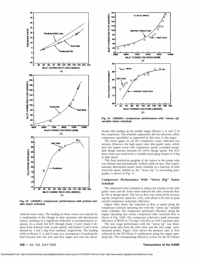
Compressor Test Performance ResultsFigure 13~a! shows the comparison of the measured and p
dicted compressor operating lines with the pretest variable stschedule. The distinct steps in the compressor operating lineresent the different stages of operation of the DLE combussystem, which uses compressor discharge bleed to controlcombustion flame temperature. The compressor achieved thesign flow at the design speed, and the agreement betweencalculated and measured flow at speed with the pretest varistator schedule as shown in Fig. 13~b! was very good. The com-pressor achieved its peak polytropic efficiency, slightly over 91near its aerodynamic design point as shown in Fig. 13~c!. The testdata shown in Fig. 13~c! is as measured, while the pretest predtion line includes an estimated 0.5 points derate in target eciency due to compressor instrumentation, hardware qualityclearances.
The individual performance for the blisk and that of the dowstream compressor with the mixture of CF6-80C2 and LM25airfoils was separated in the following manner. The zero stperformance was determined by using data from the inlet raand the zero stage, vane-mounted probes. In spite of the lclearances and the significant amount of ruggedization in the tsonic Rotor 0, the IGV-Rotor 0 combination achieved a peak potropic efficiency of 90.5%, which was 2.8% better than desintent. The downstream compressor performance with the miairfoils, as determined by using the zero stage, vane-mouprobes and the exit rakes~and referred to as the ‘‘rear block’’ inthis paper!, also achieved the desired match point for the flow aefficiency goal relative to the baseline compressor.
The measured radial profile of total pressure and temperatuRotor 0 exit was in good agreement with the three-dimensiocalculations and the measured efficiency was slightly higher tthe calculations near the tip.
Aeromechanically, the first two new stages performed persign intent over the entire operating range including vane oschedule operation. However, among all the other compreblades, strain gage signals on Rotors 2, 3, and 4 indicated hithan desired stresses between 83–90% design speed. A smalable stator schedule adjustment, using the trimmer motors onvariable stators, provided an acceptable solution to the aero
Fig. 12 LM2500¿ compressor pretest variable stator gangrelation
JULY 2002, Vol. 124 Õ 337
Use: http://www.asme.org/about-asme/terms-of-use
e
e
g
ffectr.lowhichcept-IGVdeg
beeri-inletara-
inletflowas-eak
helethe
isic
.er-ane-
er-or
Downloaded From
chanical stress issue. The loading on these rotors was reducea combination of the change in their upstream and downstrstators, resulting in a significant reduction in aeromechanicalsponse. As a result, the IGV through Stator 2 were closed 3grees from nominal~only at part speed!, and Stators 5 and 6 weropened by 3 and 5 deg from nominal, respectively. The loadrelief on Rotors 2, 3, and 4 came as a consequence of pushinload forward onto the zero and first stages and onto the do
Fig. 13 LM2500¿ compressor performance with pretest vari-able stator schedule
338 Õ Vol. 124, JULY 2002
: https://turbomachinery.asmedigitalcollection.asme.org on 07/01/2019 Terms of
d byamre-de-
ingthe
wn-
stream side loading up the middle stages~Rotors 5, 6, and 7! ofthe compressor. The schedule adjustment did not adversely acompressor operability as supported by data later in this pape
The strain gages on all the compressor vanes indicatedstresses. However, the high aspect ratio inlet guide vanes, whave the largest travel with compressor speed, exceeded acable design stresses between 93–101% design speed. Thestress issue was resolved by a variable stator gang closure of 3at high speed.
This final production ganging of the stators to the torque tuwas defined and mechanically verified while on test. This expmentally determined master stator schedule as a function ofcorrected speed, labeled as the ‘‘stress rig’’ in succeeding pgraphs, is shown in Fig. 11.
Compressor Performance With ‘‘Stress Rig’’ StatorSchedule
The optimized stator schedule to reduce the stresses in theguide vanes and the front rotors reduced the inlet correctedby 6% at design speed. The loss in flow was retrieved by increing the compressor speed by 1.4%, with about 0.3% loss in poverall compressor polytropic efficiency.
Figure 14~a! shows the reduction in flow at speed along tcompressor nominal operating line with the ‘‘stress rig’’ variabstator schedule. The compressor polytropic efficiency alongengine operating line versus compressor inlet corrected flowshown in Fig. 14~b!. The compressor achieved a peak polytropefficiency of 90.8% at 73.6 kg/s~162 lb/s! at 19.8:1 pressure ratio
The zero stage performance with the ‘‘stress rig’’ was detmined using data from the inlet rakes and the zero stage, vmounted probes. Figure 15~a! shows the pressure ratio at flowachieved by the IGV-Rotor 0 combination along the engine opating line. The corresponding efficiency at flow for the IGV-Rot
Fig. 14 LM2500¿ compressor performance with ‘‘stress rig’’variable stator schedule
Transactions of the ASME
Use: http://www.asme.org/about-asme/terms-of-use
tre
uo
emno
s
a
tsta-sorSVssorssor. Atd tosor.at
Theugh
Downloaded From
0 combination is shown in Fig. 15~b! with the peak polytropicefficiency dropping to 89.5% due to the change in the variastator schedule.
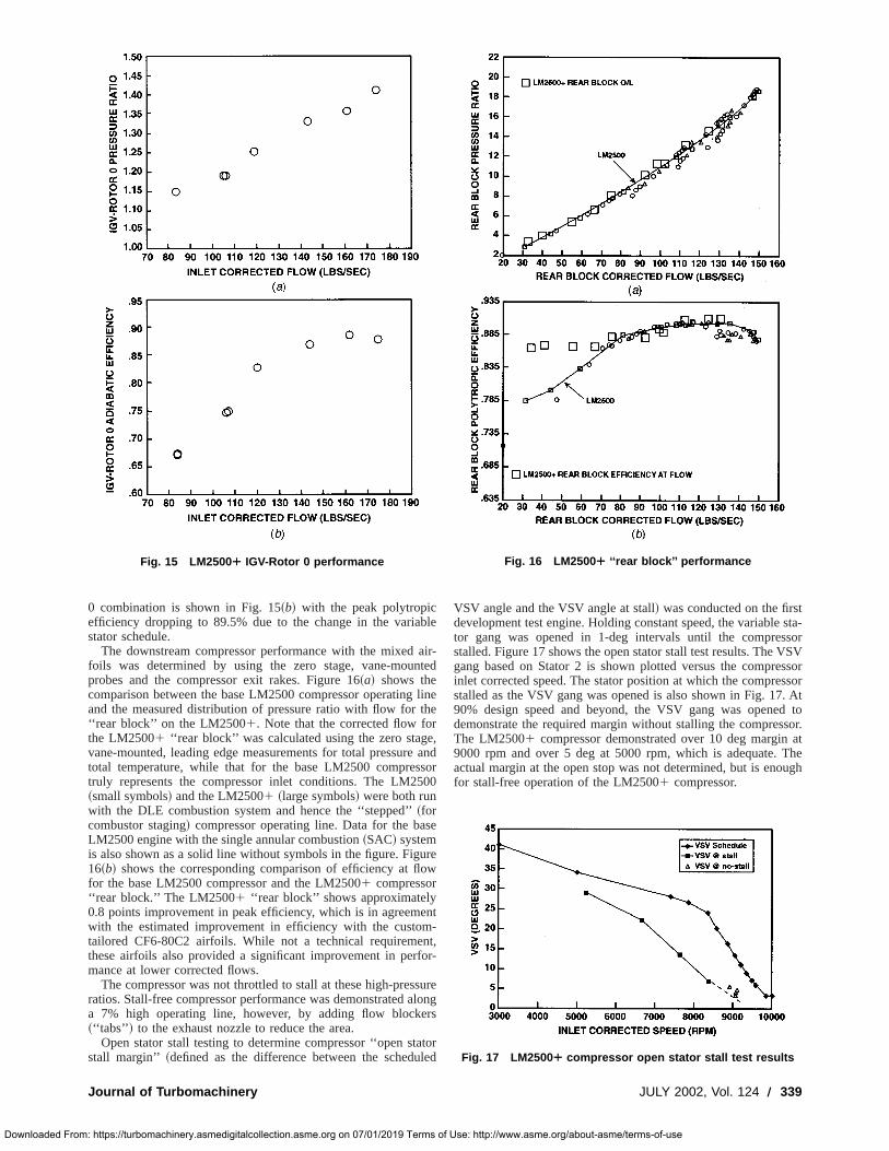
The downstream compressor performance with the mixedfoils was determined by using the zero stage, vane-mounprobes and the compressor exit rakes. Figure 16~a! shows thecomparison between the base LM2500 compressor operatingand the measured distribution of pressure ratio with flow for‘‘rear block’’ on the LM25001. Note that the corrected flow fothe LM25001 ‘‘rear block’’ was calculated using the zero stagvane-mounted, leading edge measurements for total pressuretotal temperature, while that for the base LM2500 comprestruly represents the compressor inlet conditions. The LM25~small symbols! and the LM25001 ~large symbols! were both runwith the DLE combustion system and hence the ‘‘stepped’’~forcombustor staging! compressor operating line. Data for the baLM2500 engine with the single annular combustion~SAC! systemis also shown as a solid line without symbols in the figure. Fig16~b! shows the corresponding comparison of efficiency at flfor the base LM2500 compressor and the LM25001 compressor‘‘rear block.’’ The LM25001 ‘‘rear block’’ shows approximately0.8 points improvement in peak efficiency, which is in agreemwith the estimated improvement in efficiency with the custotailored CF6-80C2 airfoils. While not a technical requiremethese airfoils also provided a significant improvement in perfmance at lower corrected flows.
The compressor was not throttled to stall at these high-presratios. Stall-free compressor performance was demonstrated aa 7% high operating line, however, by adding flow blocke~‘‘tabs’’ ! to the exhaust nozzle to reduce the area.
Open stator stall testing to determine compressor ‘‘open ststall margin’’ ~defined as the difference between the schedu
Fig. 15 LM2500¿ IGV-Rotor 0 performance
Journal of Turbomachinery
: https://turbomachinery.asmedigitalcollection.asme.org on 07/01/2019 Terms of
ble
air-ted
linehe
,and
sor00
se
rew
nt-t,r-
urelongrs
torled
VSV angle and the VSV angle at stall! was conducted on the firsdevelopment test engine. Holding constant speed, the variabletor gang was opened in 1-deg intervals until the compresstalled. Figure 17 shows the open stator stall test results. The Vgang based on Stator 2 is shown plotted versus the compreinlet corrected speed. The stator position at which the comprestalled as the VSV gang was opened is also shown in Fig. 1790% design speed and beyond, the VSV gang was openedemonstrate the required margin without stalling the compresThe LM25001 compressor demonstrated over 10 deg margin9000 rpm and over 5 deg at 5000 rpm, which is adequate.actual margin at the open stop was not determined, but is enofor stall-free operation of the LM25001 compressor.
Fig. 16 LM2500¿ ‘‘rear block’’ performance
Fig. 17 LM2500¿ compressor open stator stall test results
JULY 2002, Vol. 124 Õ 339
Use: http://www.asme.org/about-asme/terms-of-use

r
io
s
r
y
n
om-
pli-E,
De-ur-
r-
l-per
rial
e-us-
ine
the
s-
ial44.
esm-
rs:sor
ofrnal
o-
ghes
hick
Downloaded From
Concluding RemarksThe aerodynamic design of the 17-stage, 23.3:1 pressure
single-spool axial compressor for the LM25001 gas turbine hasbeen reported. The new zero stage and stage 1 compressor band vanes were designed using three-dimensional computatmethods. Advanced compressor airfoils from the CF6-80C2 cpressor were also integrated successfully with the baseLM2500 compressor airfoils. The compressor achieved a ppolytropic efficiency slightly over 91% and met all its design oerability objectives.
In spite of the significant ruggedization of the front-stage afoils operating in the transonic flow regime, advanced design towere able to provide accurate guidance during the design phaachieve the level of compressor efficiency required for the scessful field implementation of the LM25001 at its full maturepower rating. Production engine data have duplicated the pemance predictions based on the development engine.
AcknowledgmentThe authors would like to thank GE Aircraft Engines for pe
mission to publish this paper.
Nomenclature
blisk 5 bladed diskC 5 airfoil section chord
IMM 5 radial immersion~05tip, 15hub!Tmax 5 airfoil section max thickness
Z 5 axial distance~inches!
References@1# Scalzo, A., and Mori, Y., 1988, ‘‘A New 150 MW High Efficiency Heavy Dut
Combustion Turbine,’’ ASME, Paper No. 88-GT-162.@2# Kashiwabara, Y., Katoh, Y., Ishii, H., Hattori, T., Matsura, Y., and Sasada,
1990, ‘‘Developments Leading to an Axial Flow Compressor for a 25MClass High Efficiency Gas Turbine,’’ ASME, Paper No. 90-GT-238.
@3# Sehra, A., Bettner, J., and Cohn, A., 1991, ‘‘Design of a High PerformaAxial Compressor for Utility Gas Turbine,’’ ASME, Paper No. 91-GT-145.
340 Õ Vol. 124, JULY 2002
: https://turbomachinery.asmedigitalcollection.asme.org on 07/01/2019 Terms of
atio
ladesonalm-lineeakp-
ir-olse to
uc-
for-
r-
T.,W
ce
@4# Smed, J., Pisz, F., Kain, J., Yamaguchi, N., Umemura, S., 1991, ‘‘501F Cpressor Development Program,’’ ASME, Paper No. 91-GT-226.
@5# Janssen, M., Zimmermann, H., Kopper, F., and Richardson, J., 1995, ‘‘Apcation of Aero-Engine Technology to Heavy Duty Gas Turbines,’’ ASMPaper No. 95-GT-133.
@6# Stringham, G., Cassem, T., Prince, T., and Yeung, P., 1998, ‘‘Design andvelopment of a Nine Stage Axial Flow Compressor for Industrial Gas Tbines,’’ ASME, Paper No. 98-GT-140.
@7# Farmer, R., 1994, ‘‘GE Launches LM25001 Rated at 39 MW and 38% Ther-mal Efficiency,’’ Gas Turbine World, May/June 1994, pp. 24–32.
@8# Valenti, M., 1998, ‘‘Luxury Liners Go Green,’’ ASME Mechanical Engineeing, July, pp. 72–73.
@9# Klapproth, J. F., Miller, M. L., and Parker, D. E., 1979, ‘‘Aerodynamic Deveopment and Performance of the CF6-6/LM2500 Compressor,’’AIAA, PaNo. 79-7030.
@10# Eisenberg, B., 1993, ‘‘Development of a New Front Stage for an IndustAxial Flow Compressor,’’ ASME, Paper No. 93-GT-327.
@11# Katoh, Y., Kashiwabara, Y., Ishii, H., Tsuda, Y., and Yanagida, M., 1993, ‘‘Dvelopment of a Transonic Front Stage of an Axial Flow Compressor for Indtrial Gas Turbines,’’ ASME, Paper No. 93-GT-304.
@12# Van Leuven, V., 1994, ‘‘Solar Turbines Incorporated Taurus 60 Gas TurbDevelopment,’’ ASME, Paper No. 94-GT-115.
@13# Rocha, G., Saadatmand, M., and Bolander, G., 1995, ‘‘Development ofTaurus 70 Industrial Gas Turbine,’’ ASME, Paper No. 95-GT-411.
@14# Koch, C. C., 1981, ‘‘Stalling Pressure Rise Capacity of Axial Flow Compresor Stages,’’ ASME Journal of Engineering for Power, October 1981.
@15# Koch, C. C., and Smith, L. H., 1975, ‘‘Loss Sources and Magnitudes in AxFlow Compressors,’’ GE Aircraft Engines Technical, Report No. R75AEG3
@16# Adkins, G. G., and Smith, L. H., 1982, ‘‘Spanwise Mixing in Axial FlowTurbomachines,’’ ASME Journal of Engineering for Power,104, pp. 97–110.
@17# Jennions, I. K., and Turner, M. G., 1993, ‘‘Three-Dimensional Navier StokComputations of Transonic Fan Flow Using an Explicit Flow Solver and Iplicit k-e Solver,’’ ASME Journal of Turbomachinery,115, pp. 261–272.
@18# Wadia, A. R., and Law, C. H., 1993, ‘‘Low Aspect Ratio Transonic RotoPart 2-Influence of Location of Maximum Thickness on Transonic CompresPerformance,’’ ASME Journal of Turbomachinery,115, pp. 226–239.
@19# Wadia, A. R., and Copenhaver, W. W., 1996, ‘‘An Investigation of the EffectCascade Area Ratios on Transonic Compressor Performance,’’ ASME Jouof Turbomachinery,118, October 1996, pp. 760–770.
@20# Wadia, A. R., and Beacher, B. F., 1990, ‘‘Three-Dimensional Relief in Turbmachinery Blading,’’ ASME Journal of Turbomachinery,12, No. 4, pp. 587–598.
@21# Wisler, D. C., 1985, ‘‘Loss Reduction in Axial-Flow Compressors ThrouLow Speed Model Testing,’’ ASME Journal of Engineering for Gas Turbinand Power,107, pp. 354–363.
@22# Dunavant, J. C., ‘‘Cascade Investigation of a Related Series of 6 Percent TGuide Vane Profile and Design Charts,’’ NACA-TN-3959.
Transactions of the ASME
Use: http://www.asme.org/about-asme/terms-of-use