Advanced Drilling Solutions : Lessons from the FSU, Volume 1
326
-
Upload
khangminh22 -
Category
Documents
-
view
0 -
download
0
Transcript of Advanced Drilling Solutions : Lessons from the FSU, Volume 1


ADVANCED DRILLING SOLUTIONS
LESSONS FROM THE FORMER SOVIET UNION
VOLUME I
gelfgat i-xii.qxd 2/10/03 2:00 PM Page i

gelfgat i-xii.qxd 2/10/03 2:00 PM Page ii

ADVANCED DRILLING SOLUTIONS
LESSONS FROM THE FORMER SOVIET UNION
VOLUME I
Yakov A. GelfgatMikhail Y. Gelfgat
Yuri S. Lopatin
gelfgat i-xii.qxd 2/10/03 2:00 PM Page iii

Copyright© 2003 by
PennWell Corporation
1421 South Sheridan Road
Tulsa, Oklahoma 74112-6600 USA
800.752.9764
+1.918.831.9421
www.pennwell-store.com
www.pennwell.com
Book design by Robin Remaley
Cover design by Amy Spehar
Managing Editor: Marla Patterson
Production Editor: Sue Rhodes Dodd
Library of Congress Cataloging-in-Publication Data
Gelfgat, Yakov A.
Advanced drilling solutions : lessons from the former Soviet Union /
by Yakov A. Gelfgat, Mikhail Y. Gelfgat, and Yuri S. Lopatin
p. cm.
Includes index
ISBN 0-87814-786-1
1. Oil well drilling--Russia (Federation) 2. Oil well drilling--Former Soviet Republics.
I. Gelfgat, Mikhail Y. II. Lopatin, Yuri S. III. Title.
TN871.2 G45 2003
622' .3382'0947--dc21 2002154490
All rights reserved. No part of this book may be reproduced, stored in a retrieval system,
or transcribed in any form or by any means, electronic or mechanical, including
photocopying and recording, without the prior written permission of the publisher.
Printed in the United States of America
1 2 3 4 5 07 06 05 04 03
gelfgat i-xii.qxd 2/10/03 2:00 PM Page iv

CONTENTS
Volume I
Preface . . . . . . . . . . . . . . . . . . . . . . . . . . . . . . . . . . . . . . . . . . . . . . . . . . . . . . .ix
Acknowledgments . . . . . . . . . . . . . . . . . . . . . . . . . . . . . . . . . . . . . . . . . . . . .xii
1. Introduction to Drilling Technologies for Oil and Gas in Russia and the FSU . . . . . . . . . . . . . . . . . . . . . . . . . . . . . . . . . . . . . . . .1
Progress of Well Drilling Technology in the Second Halfof the 19th Century and the Beginning of the 20th Century . . . . . . . .1
Milestones of Drilling Technology Development in the FSU after Nationalization of the Oil Industry (1920–1945) . . . . . . . . .7
Principal Stages of Drilling Technology Development in the FSU and Drilling Operations Management in the Postwar Period . . . . . . . . . . . . . . . . . . . . . . . . . . . . . . . . . . . . . . . . . . . . .15
Development and implementation of turbodrilling for vertical and directional single and cluster wells . . . . . . . . . . . . . .15
Development and implementation of electrodrilling technology for drilling single and cluster vertical and directional wells . . . . . . . . . . . . . . . . . . . . . . . . . . . . . . . . . . . . . . . .25
New trends in drilling technology and commercial application of downhole motors . . . . . . . . . . . . . . . . . . . . . . . . . . .27
v
gelfgat i-xii.qxd 2/10/03 2:00 PM Page v

ADVANCED DRILLING SOLUTIONSLESSONS FROM THE FORMER SOVIET UNION
Main Components and Management of Drilling Operations, Personnel Training, Scientific Research, and Design Work in the FSU . . . . . . . . . . . . . . . . . . . . . . . . . . . . . . . . . . . . . . . . . . .30
Exploratory and key stratigraphic drilling . . . . . . . . . . . . . . . . . . .30
Management of drilling operations in the oil and gas industry . . . . . . . . . . . . . . . . . . . . . . . . . . . . . . . . . . . . . . . . . . .34
Occupational training in the oil industry . . . . . . . . . . . . . . . . . . .35
Scientific work . . . . . . . . . . . . . . . . . . . . . . . . . . . . . . . . . . . . . . . . .36
Negative Trends in FSU Drilling Industry Developments . . . . . . . . . . .38
Significant decline in the growth of geological exploration . . . . . . . . . . . . . . . . . . . . . . . . . . . . . . . . . . . . . . . . . . . .38
Insufficient capital investments . . . . . . . . . . . . . . . . . . . . . . . . . . .39
Rigid planning of drilling activity . . . . . . . . . . . . . . . . . . . . . . . . .40
Absence of private property ownership, private entrepreneurship, and initiative . . . . . . . . . . . . . . . . . . . . . . . . . . .42
Did a new era begin in Russia? . . . . . . . . . . . . . . . . . . . . . . . . . . . .44
Value of Scientific Research and Design and the Feasibility of Their Use in Modern Drilling Practices . . . . . . . . . . . . . . . . . . . . . . .46
Why We Decided to Write This Book . . . . . . . . . . . . . . . . . . . . . . . . . . .48
References . . . . . . . . . . . . . . . . . . . . . . . . . . . . . . . . . . . . . . . . . . . . . . . .50
2. Downhole Motor Drilling Technology and Applications . . . . . . . .53
Development of Turbodrills—Characteristics and Fields of Application . . . . . . . . . . . . . . . . . . . . . . . . . . . . . . . . . . . . . . . .53
From a gear-reduction turbodrill with a single-stage turbine to a multistage hydro-turbine motor . . . . . . . . . . . . . . . .53
Development of the multistage turbine theory . . . . . . . . . . . . . . .64
Development trends of hydraulic downhole motors in the FSU . . . . . . . . . . . . . . . . . . . . . . . . . . . . . . . . . . . . . . . . . . . . .82
Turbodrill design evolution . . . . . . . . . . . . . . . . . . . . . . . . . . . . . . .91
Geared turbodrills—new winds of development . . . . . . . . . . . .126
vi
gelfgat i-xii.qxd 2/10/03 2:00 PM Page vi

TABLE OF CONTENTS
Turbodrilling experience in the 1990s—a new challenge . . . . . . . . . . . . . . . . . . . . . . . . . . . . . . . . . . . . . . .138
Positive Displacement (Screw) Downhole Motors . . . . . . . . . . . . . . .154
PDM principal design . . . . . . . . . . . . . . . . . . . . . . . . . . . . . . . . . .154
PDM working cycle . . . . . . . . . . . . . . . . . . . . . . . . . . . . . . . . . . . .155
Low-speed high-torque PDM application . . . . . . . . . . . . . . . . . .161
PDM case studies . . . . . . . . . . . . . . . . . . . . . . . . . . . . . . . . . . . . . .165
Sectional PDM . . . . . . . . . . . . . . . . . . . . . . . . . . . . . . . . . . . . . . . .169
Workover and other PDM applications . . . . . . . . . . . . . . . . . . . .172
Electrodrills . . . . . . . . . . . . . . . . . . . . . . . . . . . . . . . . . . . . . . . . . . . . . .172
Prehistory . . . . . . . . . . . . . . . . . . . . . . . . . . . . . . . . . . . . . . . . . . . .172
First 10 years of field applications experience . . . . . . . . . . . . . .174
Improved commercial electrodrilling systems (1963–1970) . . . . . . . . . . . . . . . . . . . . . . . . . . . . . . . . . . . . . . . . .176
Electrodrilling technology . . . . . . . . . . . . . . . . . . . . . . . . . . . . . . .186
Future developments . . . . . . . . . . . . . . . . . . . . . . . . . . . . . . . . . . .188
Electrodrill as a bottomhole transmitter . . . . . . . . . . . . . . . . . . .190
Conclusions . . . . . . . . . . . . . . . . . . . . . . . . . . . . . . . . . . . . . . . . . . . . . .192
References . . . . . . . . . . . . . . . . . . . . . . . . . . . . . . . . . . . . . . . . . . . . . . .193
3. Well Drilling Optimization Methods in the FSU . . . . . . . . . . . . . . .199
Mission Statement and Substantiation of the Necessity for Developing a New Method of Well Drilling Technology Optimization . . . . . . . . . . . . . . . . . . . . . . . . . . . . . . . . . . . . . . . . . . . . .199
KTW Drilling Principles and Procedures for Implementation . . . . .202
Development of a Mathematical Model of Well Deepening and Its Use in KTW Drilling . . . . . . . . . . . . . . . . . . . . . . . . . . . . . . . . .205
Analysis of existing optimization techniques of the well-deepening process . . . . . . . . . . . . . . . . . . . . . . . . . . . . . . . . .205
Test studies and development of a mathematical model of the well-deepening process . . . . . . . . . . . . . . . . . . . . . . . . . . . .210
vii
gelfgat i-xii.qxd 2/10/03 2:00 PM Page vii

ADVANCED DRILLING SOLUTIONSLESSONS FROM THE FORMER SOVIET UNION
Analysis of the effect of round trip speed on levels ofthe main regulated drilling parameters—bit weight and rotational speed . . . . . . . . . . . . . . . . . . . . . . . . . . . . . . . . . . . . . . .226
Well-deepening optimization techniques when drilling with blade-type drag bits . . . . . . . . . . . . . . . . . . . . . . . . . . . . . . . .232
Results of Drilling Experimental and KTWs and Application of the KTW Technique in Developing Certain Fields . . . . . . . . . . . . .242
Wells drilled in Azerbaijan . . . . . . . . . . . . . . . . . . . . . . . . . . . . . .242
Wells drilled in the Samara Region . . . . . . . . . . . . . . . . . . . . . . .250
Wells drilled in the Bashkiriya region . . . . . . . . . . . . . . . . . . . . .257
Drilling wells in the Urals-Volga oil and gas province using dynamic processes to intensify rock destruction at the bottomhole . . . . . . . . . . . . . . . . . . . . . . . . . . . . . . . . . . . . .264
Experience from KTW Drilling and Results of Its Implementation . . . . . . . . . . . . . . . . . . . . . . . . . . . . . . . . . . . . . . . . . . .267
Areas of Feasible Application of Various Drilling Methods—Rotary, DHM, and Electrodrilling . . . . . . . . . . . . . . . . . . .272
Drill bit rotational speed as optimization criteria . . . . . . . . . . . .272
Test wells drilling in 1979–1980 . . . . . . . . . . . . . . . . . . . . . . . . .276
Typical areas of application for rotary drilling . . . . . . . . . . . . . .281
Typical areas of application for hydraulic DHM . . . . . . . . . . . . .281
Typical areas of application for electrodrilling . . . . . . . . . . . . . .282
Drilling Optimization System Conclusions . . . . . . . . . . . . . . . . . . . . .283
References . . . . . . . . . . . . . . . . . . . . . . . . . . . . . . . . . . . . . . . . . . . . . . .285
Volume I Conclusion . . . . . . . . . . . . . . . . . . . . . . . . . . . . . . . . . . . . . . . . . .291
Acronyms . . . . . . . . . . . . . . . . . . . . . . . . . . . . . . . . . . . . . . . . . . . . . . . . . . .293
Appendix: Contents for Volume II . . . . . . . . . . . . . . . . . . . . . . . . . . . . .297
Index . . . . . . . . . . . . . . . . . . . . . . . . . . . . . . . . . . . . . . . . . . . . . . . . . . . . . . .301
viii
gelfgat i-xii.qxd 2/10/03 2:00 PM Page viii

PREFACEWe are very happy to present this two-volume book to our respected readers. It isour hope that these volumes will be of interest to all professionals in the drillingindustry. It is intended for those who work in the field, at the computer, asmanagers in the oil industry, university professors and students, and anyone whois interested in the history of the development of drilling technologies. We believeall readers will find something useful in these volumes, both in their current andfuture activities.
Three years ago we submitted a proposal to write this book for PennWellPublishing. That proposal was accepted, thanks to the unwavering encourage-ment and assistance of Dean Gaddy, a former drilling editor for the Oil & GasJournal. We were also supported in this project commencing by the opinions ofseveral drilling experts from different USA institutions—Dr. William Maurer(Maurer Engineering); Bill Gwilliam and Roy Long (DOE); Donald Dreesen (LANL)and Professor Stefan Miska from the University of Tulsa. We appreciate thePennWell team’s endless patience and help in the preparation, editing, and format-ting of the manuscript to the present form.
The objective of the book is to acquaint petroleum and drilling industry specialistswith the well construction processes and new drilling technologies of the formerU.S.S.R. and Russia. Following is the synopsis for these two volumes, which showsthat the authors worked hard to create a book of interest to the oil & gas industryand to fulfill their commitment to PennWell.
Volume 1 of this series has three chapters, which cover historical trends and twomajor aspects of drilling technologies development in Russia—downhole motorsand oil well drilling optimization.
ix
gelfgat i-xii.qxd 2/10/03 2:00 PM Page ix

ADVANCED DRILLING SOLUTIONSLESSONS FROM THE FORMER SOVIET UNION
Chapter 1 covers the goals of this volume and gives a detailed and comprehensivehistory of oil production in Russia. In the U.S.S.R., unlike in the United States andother countries primarily using rotary drilling, there are widely used downholehydraulic and electrical motors, with oil and gas well footage drilled about 80%.
Chapter 2 discusses turbodrills, positive-displacement motors and electrodrillbasics, design features, and operational results. The use of downhole motors bringssubstantial changes in borehole drilling and deepening technology as well asoptimization methods development. The methods of directional and cluster drillinggained wide acceptance as far back as the World War II years, and at present are thedominant methods in Russia. The electrodrill application for drilling horizontal,branch, and other wells is one of the most important subjects presented in thesevolumes. This method has a unique advantage over hydraulic motor drilling; itsperformance is not dependent on the characteristics of the drilling fluid. Air andfoams are widely used as circulation agents with electrodrills.
The so-called Key technological wells (KTW) drilling method, one of the mostefficient methods of well construction optimization, is presented in Chapter 3. Thechapter contains the mathematical model for the well deepening process as well asresults of KTW technique application in development of several major oilfields inFSU. This chapter gives the rationale for three different drilling methods: rotary,hydraulic, and electrical downhole motors.
Volume 2 of this series consists of four other Chapters, which provide detaileddescriptions and case studies of several technologies developed and widely used inRussia. There are directional drilling, deep and super-deep well construction, under-balanced drilling, rotary-turbine drills, underreamers, and retractable drill bits.
Chapter 4 covers all aspects of directional, cluster, horizontal and multi-lateraldrilling technologies used in FSU and Russia. The details on the first horizontal andmulti-lateral wells drilling in the world are given. Even though the FSU was thebirthplace of horizontal drilling, the U.S.S.R. failed to bring the method tocommercial application in the 1960s and 1970s, and now Russia is trying to catchup on modern technologies.
Chapter 5 presents the specific features of applications of downhole motors insuper-deep drilling (6 to 7.5 km TVD), including rotary-turbine (RTB) drills usedfor large diameter vertical drilling. This chapter also contains the results of
x
gelfgat i-xii.qxd 2/10/03 2:00 PM Page x

PREFACE
applications of under-reaming technology and the main results of ultra-deepdrilling for scientific purposes. The world’s deepest borehole, Kola SG-3 (12 kmTVD), as well as Krivoy Rog SG-8 and others, were based on the utilization ofdownhole motors and aluminum drillpipe.
The underbalanced deep drilling technology is described in one section of chapter 5,as well as in chapter 6, which specifically discusses air, foam, and aerated muddrilling techniques, including booster pump technology features.
The development and usage, on land as well as offshore, of casing drilling (theoriginal drilling with retractable bits without pulling out drillpipe), is the subject ofconsideration in Chapter 7.
The data presented in these two volumes is based on actual examples of carefullyselected wells drilled in different time periods throughout the FSU/Russiaproducing areas—from West Ukraine to Far East and from Azerbaijan to NorthEurope and Siberia.
xi
gelfgat i-xii.qxd 2/10/03 2:00 PM Page xi

ACKNOWLEDGMENTSYakov A. Gelfgat wrote Chapters 3 and 4. He wrote Chapters 1, 2, and 5 withMikhail Y. Gelfgat, who also wrote Chapter 7. Yuri S. Lopatin wrote Chapter 6.Boris Volkovoy translated the Russian text written by Yakov Gelfgat and YuriLopatin. The authors express their great appreciation for Volkovoy’s efforts infinding solutions for difficult-to-translate technical text. Mikhail Gelfgat did thetechnical review of the English text.
The authors acknowledge the invaluable help of several prominent Russiandrilling specialists in commenting, advising, and reviewing different book chaptersand sections, namely:
Valeriy Petrovich Shumilov—section on turbodrills in Chapter 2, especially“multistage turbine theory development”
Dmitry Fedorovich Baldenko—section on positive displacement motors(PDM) in Chapter 2
Bairas Ibragimovich Abyzbaev—section on electrodrills in Chapter 2 andsection on electrodrills application in directional drilling in Chapter 4
Bronislav Vasilievich Baidyuk—Chapter 3
Rudolf Stepanovich Alikin—under-reaming technology section in Chapter 5and retractable bit design and application features sections in Chapter 7
Vladimir Solomonovich Basovich—section on the ultra-deep scientificdrilling experience in Chapter 5
This manuscript could never have been delivered to the editor without significantsupport from the Aquatic Company staff in Moscow, especially that of Mrs. ElmiraMinasovna Pogosyan, who typed most of the Russian text. We appreciate the helpand efforts of our colleagues in Houston, Mr. Alex Adelman and Mrs. OlgaKazantseva, who provided assistance in many aspects of the book’s preparation.
The authors will appreciate comments from readers to be used in further work.
xii
gelfgat i-xii.qxd 2/10/03 2:00 PM Page xii

INTRODUCTION TO DRILLINGTECHNOLOGIES FOR OIL AND GAS
IN RUSSIA AND THE FSU
Progress of Well Drilling Technology in the Second Half of the 19th Century and the
Beginning of the 20th Century 1 2
Russia and the Former Soviet Union (FSU) have taken the lead in the history of thedevelopment of world hydrocarbon resources more than once.
Historical facts indicate that in the eighth century, oil was produced from shallowwells in areas where it seeped to the surface in Azerbaijan. In 1729, oil-producingwells on the Apsheron peninsula were marked on a map. Oil production near theUkhta River in the North-European part of Russia (now the Komi Republic) startedin 1742. During the next century, in 1858, oil was produced on the Chelekenpeninsula (Western Turkmeniya).
The official start of the oil industry is considered to be 1859—the first well drilled byentrepreneur E. Drake in Pennsylvania, USA, using the percussion drilling method.The well opened a new era of a wide-scale oil production. However, in 1848 in theBibi-Eibat area of the Apsheron peninsula, a group led by F. A. Semyonov, an officialfrom the Mining Directorate had drilled the first well using a mechanical drillingmethod. In 1864, Colonel A. N. Novoseltsev drilled the first productive well usingthe percussion method near Kudako village of the Kuban region.
The industrial boom in Russia began after the abolition of serfdom in 1861, whichenabled tremendous growth in the oil industry.
1
gelfgat 001-052.qxd 2/10/03 2:01 PM Page 1

ADVANCED DRILLING SOLUTIONSLESSONS FROM THE FORMER SOVIET UNION
The shallow well method and the drilling techniques developed later were widelyused in the Russian mining industry long before the first oil wells were drilled.These methods were utilized to build wells for the production of salt and water andto explore mineral reserves, particularly coal. For example, four water wells, 36 to189 m in depth, were drilled in 1831 in Odessa, Ukraine. Similar drilling wasconducted in St. Petersburg, in the Crimea and in some other regions. All thesewells were drilled using the percussion method.
Rapid growth of the oil industry resulted in the emergence of a number of top-notch professional mining engineers and toolpushers specializing in well drillingtechnology. Their cumulative experience was summarized in a number of booksand publications. For example, one of the most outstanding books, The Mining ArtCourse by A. I. Uzatis, was published in 1849 in St. Petersburg. Surprisingly, thebook forecasted many ideas that were used many years later in Russia and abroad.The author described percussion and rotary drilling techniques, well-casingtechnology, rod-tools, and rope drilling methods. Along with vertical wells, anumber of directional wells were drilled, initially from inside the mines and laterfrom the surface. One section of the book classified the wells as vertical, direction-al, and horizontal.3
For almost forty years, until the publication of The Reference Book for MiningEngineers and Technicians by Professor G. Y. Doroshenko in 1880, Uzatis’s workremained the reference book for mining specialists, including oilmen. Later,between 1904 and 1911, one of the most prominent Russian mining engineers, I. N. Glushkov, published a four-volume classical work, Well Drilling Manual.
Based on these facts, it is clear that a large number of mining engineers wereavailable and ready to manage oil and gas well drilling operations in Russia. Afterserfdom was abolished in Russia, the availability of hired labor also stimulated thedevelopment of the country’s oil industry. In 1862, the Russian oil industryproduced 5500 tons of oil, and by 1872, production had increased fivefold to25,600 tons.
By 1880, extensive drilling experience allowed for rapid growth in oil productionin the ensuing years. In 1885 for example, the main oil-producing region, Baku,had 500 producing wells, most of which had been drilled using the percussion roddrilling method. The rest were drilled with the rope (or Pennsylvania cable)technique. By 1899, the 944 percussion-drilled rigs belonged both to Russian andforeign operators in that area and included 881 percussion rod and 63 ropedrilling rigs. These rigs drilled 174,300 m.
2
gelfgat 001-052.qxd 2/10/03 2:01 PM Page 2

INTRODUCTION TO DRILLING TECHNOLOGIESFOR OIL AND GAS IN RUSSIA AND THE FSU
A number of outstanding mining engineers who worked during that period developedunique drilling methods and equipment to drill for both water and oil. G. D.Romanovsky, a mining engineer and leading scientist, was the first geologist to predictlarge oil deposits in the Mid Povolzhye (Volga River area) region in 1868. In 1866, hedeveloped and applied the freefall drillstring bottom or cable end that automaticallyturned at a certain angle each time it hit the bottomhole. After the design of this toolhad been improved by Dudin and Lents (one an engineer and the other a technician),it was widely used in percussion drilling. The development and use of the self-turning,freefall tool marked a significant step forward in drilling technology.
In the 1880s and 1890s, a series of new Molot drilling rigs with an improveddesign were developed by Mukhtarov and Lents.
S. G. Voyislav, a prominent mining engineer, made a major contribution to drillingtechnology. In 1885, he invented and built a special well borer for drilling largediameter upper-well sections. The tool used a reaming technology and alloweddrillers to achieve a seven-times faster penetration rate and drill a large diameterhole as much as 22 m in depth.
In 1898, Voyislav and L. Kulesh invented and patented a rig with a diamonddrilling system for drilling rock with various degrees of hardness by applyingconstant pressure. The rig design provided for automatic regulation of the pene-tration rate, depending on the hardness of the drilled rock. This rotary drilling righad rotational speeds up to 7000 revolutions per minute (rpm). Voyislav signifi-cantly improved the diamond drillbit design, using a special method for diamondpositioning and attachment in the bit body matrix, which achieved much betterresults when drilling. Thanks to these outstanding accomplishments, Voyislav isconsidered the originator of diamond drilling technology in Russia. Thetechnology was also used in drilling exploratory oil wells.
In 1894, Voyislav was the first to use directional borehole drilling to drill a waterwell near the city of Bryansk. He was also the first to introduce the box joint toconnect the steel drilling rod and eliminate the thread connections plane of weak-ness, which helped prevent a large number of rod connection failures.
The need to drill deeper wells in order to bring deep oil-bearing reservoirs intoproduction prompted drilling engineers to develop rig power drives (such as steam,diesel, and electrical engines) to be used instead of a hand drive and horse traction.Data from the Baku region illustrates the progress of increasing well depths. In 1873,the average well depth was 22 m; in 1883, it was 59 m; and in 1893, it was 113.8 m.
3
gelfgat 001-052.qxd 2/10/03 2:01 PM Page 3

ADVANCED DRILLING SOLUTIONSLESSONS FROM THE FORMER SOVIET UNION
Romanovsky pioneered the development of a drilling rig power drive by intro-ducing the steam engine drive. In 1859, a water well in Podolsk, Moscow regionwas the first well drilled by a steam-driven rig. It was drilled at about the same timethat Drake drilled his first well using a manually driven rig and wooden drill rods.The second steam-driven well was drilled between 1865 and 1869 near theBatrakov village, and the third well was drilled in the Crimea in 1877. This last wellset a record depth of 750 m. Romanovsky’s work was a breakthrough in the oilpatch, primarily because of his achievements in mechanizing drilling operations.
In Baku, Grozny, and other regions of Russia, drillers were progressively movingtowards the use of drilling rigs with steam engine drives which, by the end of the19th century, completely replaced the manual and horse drives. Still, the steamengines at that time had a low efficiency factor (2–3%) and consumed a significantamount of fuel (up to 13% of the produced oil volume). Therefore, by the early20th century, oil producers were using internal combustion engines and electricmotors. Along with increased in-well depth, drillers began using rotary instead ofpercussive drilling techniques.
In 1902, a rotary rig equipped with a drilling mud circulating system drilled itsfirst well in Russia near Grozny. The well depth was 345 m. In 1908, the company,Shpis, made a second attempt to drill several wells using a rotary drilling rig buteventually refused to use these rigs further. In 1906, a company owned by theNobel brothers in cooperation with the Nafta Company made their first (andunsuccessful) attempt to drill a well with a rotary rig. The two wells were drilled to520 m and 720 m and had deviated boreholes up to 30–40°. The attempts failedbecause of the poorly designed primitive rotary drilling rig and lack of experiencein applying the new drilling technique. In 1911, oil producer Gaber managed toachieve a positive result when two of the eight wells he started were drilled to totaldepth of the well (TD) and put into production. Unlike the progress of thepercussion drilling method in the 19th century, development of rotary drilling inRussia in the early 20th century was rather slow. For example, of the 14 compa-nies working in the Surakhansky region near Baku, only one used a rotary drillingrig. One of the first companies started by the Nobel brothers exclusively used thepercussion drilling method. Before the oil industry was nationalized in 1920, thiscompany had drilled only 12 wells with rotary drilling rigs.
The most probable explanation of this fact is a series of dramatic social andpolitical events, such as Russia’s defeat in the war with Japan (from 1904 to1905), the Revolutions in 1905 and 1917, and the World War I from 1914 to1918. All these events were alarming for oil business people and provided little
4
gelfgat 001-052.qxd 2/10/03 2:01 PM Page 4

INTRODUCTION TO DRILLING TECHNOLOGIESFOR OIL AND GAS IN RUSSIA AND THE FSU
encouragement for investment in the improvement of drilling equipment andtechnology. The development of capitalism in Russia, which had producedextremely high results in the second half of the 19th century, slowed rapidly.
Introduction of the well-cementing method was among the achievements of thedrilling technology at this time. Romanovsky was among the first to apply thistechnology. While drilling a water well in 1859, he ran a special cylindricalcontainer with cement slurry in the hole. After the cement filled the borehole andshrank, a new hole was drilled through the cement column. Thus, the new
5
Fig. 1–1 Oil production in Russia and in U.S.S.R. until the end of WWII
gelfgat 001-052.qxd 2/10/03 2:01 PM Page 5

ADVANCED DRILLING SOLUTIONSLESSONS FROM THE FORMER SOVIET UNION
borehole walls were stabilized by the cement sheath and eliminated the need torun a casing string. A casing cementing method was patented by the Russianengineer Bogushevsky and was similar to the method developed by Perkins. Thismethod was first used in Russia in 1906.
According to a law adopted in 1908, oil producers were obliged to cement casingstrings in wells to isolate oil-bearing horizons from water zones. However, therequirements of this law were ignored for several years, which resulted in dramaticflooding of the highly productive horizons and the loss of significant oil reserves.Later, the need for cement jobs was recognized, and cementing was performed inall drilled wells.
The Russian drilling boom previously described ensured steady oil productiongrowth. Diagrams in Figures 1–1 and 1–2 indicate that 276,500 m were drilled in1913, compared with 100 m and 190,100 m drilled in 1871 and 1900 respec-tively. Corresponding oil production increased from 25,600 tons in 1872 to 12million tons in 1901. This was the highest oil production level in Russia beforeWWI, and Russia became the number one world oil producer in the beginning ofthe 20th century. In 1905, world production was 26 million tons. However, by1917, the oil production level in Russia was down to 6.9 million tons a year.
6
Fig. 1–2 Oil and gas drilling volumes in Russia and in the U.S.S.R. before the end of WWII (thousand meters)
gelfgat 001-052.qxd 2/10/03 2:01 PM Page 6

INTRODUCTION TO DRILLING TECHNOLOGIESFOR OIL AND GAS IN RUSSIA AND THE FSU
Milestones of Drilling Technology Development in theFSU after Nationalization of the Oil Industry (1920–1945)
During the October Revolution in 1917 and the Civil War in Russia, drillingactivity and oil production continued to decline. In 1918, only 5600 m weredrilled. Oil production in 1922 amounted to 4.7 million tons. The Russian oilindustry was set back about 30 years. After the oil industry was nationalized in1920, an effort was made to revive the ruined industry and raise drilling activityand oil production. As had been done before, special significance was given to theBaku region, because it was the main producer and supplier of oil and oil products.
Azneft, the production association, was formed. The company managed regionaloil production divisions that were formed by bringing together the oil wells, drillingrigs, and other industrial facilities expropriated from their former owners. Asimilar management scheme was adopted in other regions such as Grozny andKrasnodar. The state financed drilling and production operations.
Despite the country’s devastation and economic woes, the government understoodthe strategic role of the oil industry in the country’s economy revival andmanaged to allocate financial resources for its development. Before the 1917 Rev-olution, western companies provided a significant part of the total investment inthe Russian oil sector (up to 56% or 460 million rubles). The British (37% of thetotal investment) and French (13%) companies owned 60% of produced oil andtook 75% of the oil products market in Russia.4 Obviously, the state had to findsignificant financial resources to invest in the oil industry. In the early 1920s,money was used to rehabilitate the Russian oil industry. Development and im-provement of drilling technology and oil recovery methods were among the highpriority objectives.
These objectives were achieved by replacing old methods and technologies withnewer and advanced ones; for example, rotary drilling was used instead of per-cussion drilling, downhole air injection and gas lift well operation were usedinstead of bailing. During those 10–15 years when Russia was struggling throughdramatic events, the United States and other oil-producing countries hadsucceeded in developing these new techniques.
A. P. Serebrovskyi, a prominent Russian statesman with a mining engineeringbackground, was appointed Director of the Azneft Company. He was alsoChairman of the Board of the All-Russia Oil Syndicate and Deputy Chairman of
7
gelfgat 001-052.qxd 2/10/03 2:01 PM Page 7

ADVANCED DRILLING SOLUTIONSLESSONS FROM THE FORMER SOVIET UNION
the All-Russia National Economic Council (VSNKh). He was a man of markedinitiative and intellect and managed Azneft from 1920 to 1926. He sought outhighly qualified and dynamic specialists and placed them in charge of oilfieldproduction facilities, drilling companies, and auxiliary service enterprises.
A great deal of effort on the part of Azneft personnel yielded positive results. ByOctober 1920, 71 drilling rigs were assembled and put into operation in Baku,including 62 percussion and 9 rotary rigs. Still, manufacture of percussiondrilling rigs had not been fully resumed, and rotary drilling rigs were not built inthe country at that time. Azneft decided to import rotary drilling rigs with all thenecessary tools and materials from the United States and to contract qualifieddrilling consultants. The development program also called for the import ofproduction equipment such as submersible pumps.
In 1921 and 1922, Serebrovskyi, much trusted by V. I. Lenin, Chairman of theNational Commissars Council (Sovnarkom), received the required financing andsuccessfully completed the modernization program. The fast and successfulcompletion of this critically important work did much to improve the situation inthe oil industry of the Azerbaijan Republic. After Serebrovskyi visited the UnitedStates, he wrote a book, The American Oil and Gas Industry. It was the first detailedcoverage of the U.S. oil industry development. From 1923 to 1924, the proportionof the operating rotary rigs increased rapidly and resulted in faster penetrationrates and more drilling.
Figure 1–3 shows the proportion of wells drilled by rotary and percussion drillingrigs from 1913 to 1935. The diagrams clearly indicate that by the end of thisperiod, all wells were drilled using the rotary technique, which allowed an increasein working efficiency as well as overall drilling rates (Fig. 1–4) 5.
Application of the imported drilling rigs and other equipment gave an impetus tothe development and improvement of drilling technology. Several innovationswere introduced. One was the blade bit RKh (fishtail) with the heat-treated or hardfaced blades. Simpler well designs resulted in a lower number of casing strings anda longer open-hole section drilled below the previous string shoe. The latterinnovative technique enabled the significant reduction of steel consumption perdrilled meter. Thus, steel consumption in the Azneft Company went down from320 kg/m in 1926 and 1927 to 100 kg/m in 1931. The corresponding figures forGrozneft were 210 kg/m and 60 kg/m.
8
gelfgat 001-052.qxd 2/10/03 2:01 PM Page 8

INTRODUCTION TO DRILLING TECHNOLOGIESFOR OIL AND GAS IN RUSSIA AND THE FSU
The industry began using the well cementing method developed by Perkins ratherthan the annulus cementing method or the technique that squeezed the casingshoe into the clay rock. Drillers applied chemicals to accelerate thickening of thecement slurry, which reduced the waiting-on-cement (WOC) time in 1928 from14 to 7 days. After a few years the WOC time was reduced to 72 hours. In 1939,wooden derricks were replaced with steel structures. Their design wascontinuously improved, and they became much lighter. Steel bracing members ofthe derrick were introduced in the early 1940s. Corner supports and derrick girthwere made of drillpipe. Rigging-up methods for the derrick were also improved.Derricks were assembled from the top down using the Kershenbaum technique.Derrick-bracing members were moved around on special carriages.
In the meantime, the industry began using new higher capacity rigs with threeand four drive gears instead of the old two-gear design.
9
Fig. 1–3 Utilization of percussion and rotary drilling methods in Russia and FSU in 1913–1935
gelfgat 001-052.qxd 2/10/03 2:01 PM Page 9

ADVANCED DRILLING SOLUTIONSLESSONS FROM THE FORMER SOVIET UNION
In the late 1920s and early 1930s, Russian plants started manufacturing variousdrilling equipment, such as drillbits and the materials and tools used in drilling. Themanufacturers mostly used American designs for these items. The plant in Baku,named after Lieutenant Schmidt began manufacturing 60-, 100-, and 150-tontwo-speed and four-speed drawworks. The components of the block and tacklesystem were made at other mills in Baku. The Krasnyi Molot plant in Groznyproduced mud pumps. In 1933, domestic manufacturers delivered most of the two-speed drawworks, open-type rotary tables, and mud pumps. Until the end of the1940s, the development of the oil-related manufacturing industry and drillingtechnology in Russia followed the path of the U.S. oil industry, lagging behindslightly. The related imports continuously declined and practically ceased in the1940s. At the same time, measures were implemented that aimed at revival anddevelopment of the oil industry in the FSU. These measures promoted the rapidgrowth of drilling and oil production rates. Information in Figures 1–1 and 1–2shows the maximum levels of drilled footage (meterage)—more than 2,000,000 mper year—were achieved in 1936 and 1941. Oil production reached its maximumlevel of 33.0 million tons in 1941.
10
Fig. 1–4a Performance of drilling operations in 1913–1937; penetration per one worker inmeters
gelfgat 001-052.qxd 2/10/03 2:01 PM Page 10

INTRODUCTION TO DRILLING TECHNOLOGIESFOR OIL AND GAS IN RUSSIA AND THE FSU
The drilling slowdown in 1937 and 1938 was due to the J. Stalin’s repression. Forevery case of drillpipe failure, toolpushers and drillers were arrested. To avoid suchfailures, they had to lower the bit weight and drillstring rotational speed, whichresulted in a reduced penetration rate. The penetration rate caught up withprevious levels only in 1941. Table 1–1 presents detailed information for everyyear and region. 6
11
Fig. 1–4b Performance of drilling operations in 1913–1937; overall drilling rate (m/rig per month)
gelfgat 001-052.qxd 2/10/03 2:01 PM Page 11

AD
VA
NC
ED D
RILLIN
G S
OLU
TION
SLES
SO
NS
FRO
M TH
E FOR
MER
SO
VIET U
NIO
N
TABLE 1–1Drilling Volumes in Russia and FSU by Regions in 1871—1941
EmbaAzerbaijan Krasnodar Regions Middle Urals-Volga
Year and Georgia Grozny Region (Kazakhstan) Turkmeniya Asia Sakhalin Province Total1871 0.1 – – – – – – – 0.11872 - – – – – – – – –1873 2.7 – – – – – – – 2.71874 3.0 – – – – – – – 3.01875 1.6 – – – – – – – 1.61876 2.9 – – – – – – – 2.91877 1.7 – – – – – – – 1.71878 5.3 – – – – – – – 5.31879 7.1 – – – – – – – 7.11880 2.8 – – – – – – – 2.81881 4.8 – – – – – – – 4.81882 6.5 – – – – – – – 6.51883 5.0 – – – – – – – 5.01884 11.0 – – – – – – – 11.01885 12.6 – – – – – – – 12.61886 14.1 – – – – – – – 14.11887 20.6 – – – – – – – 20.61888 17.9 – – – – – – – 17.91889 29.0 – – – – – – – 29.01890 31.6 – – – – – – – 31.61891 42.7 – – – – – – – 42.71892 25.0 – – – – – – – 25.01893 23.3 0.1 – – – – – – 23.41894 25.4 0.1 – – – – – – 25.51895 43.5 0.5 – – – – – – 44.01896 59.8 5.8 – – – – – – 65.61897 84.8 – – – – – – – 84.81898 122.4 7.7 – – – – – – 130.11899 174.1 10.3 – – – – – – 184.41900 176.9 13.2 – – – – – – 190.11901 161.2 16.2 – – – – – – 177.41902 85.5 9.3 – – – – – – 94.81903 104.7 13.6 – – – – – – 118.31904 132.7 11.4 – – – – – – 144.11905 75.9 10.9 – – – – – – 86.81906 102.4 11.7 – – – – – – 114.11907 130.3 16.1 – – – – – – 146.4
12
gelfgat 001-052.qxd 2/10/03 2:01 PM Page 12

INTR
OD
UC
TION
TO D
RILLIN
G TEC
HN
OLO
GIES
FOR
OIL A
ND
GA
S IN
RU
SS
IA A
ND
THE FS
U
1908 130.0 19.3 – – – – – – 149.31909 116.0 25.2 – – – – – – 141.21910 108.0 26.7 9.6 – – – – – 144.31911 104.0 21.8 25.5 1.4 – – – – 152.71912 133.0 36.2 22.3 3.4 – – – – 194.91913 171.8 62.9 30.9 9.2 – 1.8– – – 276.61914 142.5 85.0 13.0 9.6 – – – – 250.11915 126.0 54.4 11.6 7.8 – – – – 199.81916 118.5 48.6 5.5 8.7 – – – – 181.31917 69.5 38.7 – 2.2 – – – – 110.41918 5.4 – – 0.2 – – – – 5.61919 13.2 – – – – – – – 13.21920 6.2 1.3 – – – – – – 7.5
1920–1921 3.4 1.8 0.5 0.2 – – – – 5.91921–1922 15.0 3.4 0.5 0.2 – – – – 19.11922–1923 50.5 16.8 1.9 0.5 – – – – 69.71923–1924 77.6 40.5 3.5 1.6 – – – – 123.21924–1925 118.8 57.0 2.4 3.9 – 0.1 – – 182.21925–1926 200.8 74.9 5.0 5.7 – 1.5 – – 287.91926–1927 253.1 104.8 8.7 12.2 0.4 2.5 – – 381.71927–1928 260.6 74.7 11.7 13.1 0.3 1.7 – – 362.11928–1929 320.5 87.8 13.5 18.0 0.3 3.2 2.7 – 446.01929–1930 404.8 106.6 18.5 29.6 2.2 6.8 5.4 11.7 585.6
1930* 117.9 29.0 6.6 10.5 0.4 2.3 0.3 3.5 170.51931 455.3 122.0 38.5 49.0 2.0 13.9 8.1 18.4 707.21932 490.7 101.1 49.0 44.6 2.9 18.5 17.6 20.3 744.71933 540.6 137.5 47.2 36.3 2.5 19.4 18.3 33.7 835.51934 807.2 243.9 65.9 47.0 5.2 24.4 20.8 39.2 1,253.61935 969.6 266.0 103.5 48.0 7.4 19.4 22.6 69.1 1,505.61936 1,404.91 270.6 151.0 56.7 18.7 32.6 39.4 86.5 2,060.41937 1,202.1 219.1 124.2 64.4 24.4 43.3 40.6 119.4 1,837.51938 954.9 215.7 124.2 74.7 20.3 46.6 25.2 149.1 1,610.71939 923.1 221.9 124.5 77.7 19.9 43.9 18.4 186.5 1,615.91940 1,002.7 287.4 120.1 87.2 16.5 39.6 14.4 223.2 1,791.11941 929.8 349.3 130.4 120.1 42.3 38.4 19.7 254.5 1,884.5
*Special quarter was added to start recording from the January 1 next year.
13
gelfgat 001-052.qxd 2/10/03 2:01 PM Page 13

ADVANCED DRILLING SOLUTIONSLESSONS FROM THE FORMER SOVIET UNION
By 1945, an even faster decline in oil production took place during World War II.Despite the difficult times, certain positive features stood out among theconventional world oil industry practices. These related to the development ofdrilling equipment and technology in Russia and included the following aspects.
(1) The introduction drilling rigs driven by electric motors for greater effi-ciency and power saving. By 1931, drillers in Baku had replaced all thesteam engines on drilling rigs with electric motor drives. In Grozny, 88.3%of the drilling rigs used an electric motor drive.
(2) The large scale use of electric motors allowed the application ofindependent rotary drives (IRD), which resulted in higher bit rpm andmore efficient control of drillbits rotational speed. In the late 1930s andearly 1940s, the rotary speed in upper intervals of the well was as high as180–200 rpm and resulted in significantly increased penetration rates.
(3) In 1924 and 1925, an artificial onshore field was built in Bibi-Eibat nearBaku. Well No. 61 was drilled on the island to a depth of 460 m andflowed with oil. This discovery triggered work on expanding the onshorearea into the sea by filling a large littoral area in Ilyich Bay with soilbrought from other areas. The new oilfield increased the oil reserves andcommercial oil production.
(4) Starting in 1922, downhole drilling motors with hydraulic and electricdrives were developed intensively. By 1941, efficient hydraulic turbodrillswere built and used to drill numerous pilot deep wells on the ApsheronPeninsula. In addition, the first electric downhole motor (EDM) wasdeveloped and used to drill a well to a depth of 1500 m. The developmentand wide use of downhole motors (DHM) reflected the evolution of theRussian drilling technology and resulted in the formation of the basicfeatures of domestic drilling industry.
(5) The turbodrills were used to drill experimental directional wells in 1939 inGrozny and in 1941 in Baku. They proved to be more efficient for directionalapplications compared to rotary drilling combined with whipstocks.
(6) During World War II in 1943, the Russian drilling industry pioneered theuse of turbodrills for cluster directional drilling while developing theKrasnokamskoye oilfield near the City of Krasnokamsk in the Permregion of the North Urals.
14
gelfgat 001-052.qxd 2/10/03 2:01 PM Page 14

INTRODUCTION TO DRILLING TECHNOLOGIESFOR OIL AND GAS IN RUSSIA AND THE FSU
Principal Stages of Drilling Technology Development inthe FSU and Drilling Operations Management
in the Postwar Period
Development and implementation of turbodrilling for vertical anddirectional single and cluster wells
After nationalization of the oil industry from 1922 to 1941, engineers andresearchers consistently developed reliable designs of hydraulic downhole motors(HDHM) and EDMs. By 1941, these tools successfully drilled several wells in theBaku region. Work was conducted on a commercial basis by the specialists of theExperimental Turbine Drilling Bureau (EKTB) of the Ordzhonikidzeneft Companyin Surakhany, Baku region, starting in 1934.
The EKTB was reorganized in 1939 and placed under the authority of the U.S.S.R.Oil Ministry (NARKOMNEFT) in Moscow, which provided research and development(R & D) work at an appropriate level and ensured significant contributions toward itssuccess. The EKTB formed in Baku indicated the emphasis of the Russian OilMinistry and the government on the importance of turbine drilling development. 7 8
By 1941, the industry was using a large number of these efficiently operatingturbodrills with designs that featured multi-stage turbines and rubber-metal axialand radial plain bearings, as well as all the tools to service this equipment.
After the war began, EKTB was relocated to Krasnokamsk, the Perm region,including all personnel and equipment. A large oilfield with oil deposits located ina carboniferous zone of Paleozoic at depths of 950–1000 m had been discoveredin this region. A company established earlier in that region had been drilling wellsusing rotary drilling rigs. Afterwards, the joint Turbine Drilling Bureau wasfounded. The bureau became the first drilling company that used the turbodrillingmethod to drill exploration and development wells. Application of the new methodallowed considerable improvement of vertical drilling results.
However, a significant breakthrough in the development of drilling operations didnot take place until 1943 when turbodrilling technology was used for directionalsingle and cluster wells. 9 The improvement in drilling efficiency was so great thatby the end of 1943 and the beginning of 1944, the cluster pattern of developmentwells was used for the entire field. 10 11 12 In wartime conditions, this outstandingevent marked a milestone of development in the FSU drilling industry. Vertical anddirectional turbodrilling as well as cluster well drilling became widely used incommercial drilling applications for oil and gas in all regions of the country.
15
gelfgat 001-052.qxd 2/10/03 2:01 PM Page 15
ADVANCED DRILLING SOLUTIONSLESSONS FROM THE FORMER SOVIET UNION
By the late 1950s, 80% of the wells in the FSU were drilled with turbine drillingtechnology. To aid in implementing this technology, a special Department ofTurbine Drilling was formed in 1942 at the NARKOMNEFT. R. A. Ioannesyan andM. G. Gusman, the inventors of the turbodrill, headed this department. Thedepartment’s objective was to implement turbodrill technology for vertical anddirectional wells in various regions of the country.
In 1944, special Turbine Drilling Bureaus were formed in many cities and regionsof the FSU, such as Baku, Grozny, Kuibyshev, and the Republics of Dagestan,Bashkiriya, and Tatariya. The bureaus aimed at improving and implementingturbodrill technology in these regions. The bureaus used the facilities and qualifieddrilling personnel of the rotary drilling departments. Turbodrill specialists from theEKTB in Baku and the Bureau of Turbine Drilling in Krasnokamsk were appointedto management positions in the new bureaus. From 1944 to 1946, the Departmentof Turbine Drilling arranged and coordinated efforts to supply the required drillingequipment to the new companies. The equipment included turbodrills, importedmud pumps, high-pressure mud hoses, various auxiliary tools, and spare parts. TheMyasnikov plant in Baku carried out full-scale turbodrill manufacturing. In 1941,the plant was evacuated from Baku to Pavlovsk, a town in the Perm region.
Besides the technological and organizational problems encountered during thewide-scale deployment of turbodrilling methods, other factors affected the develop-ment of this technology in Russia. Opponents of the method cited the experience ofdrilling industries in the United States and other countries, saying that the Russiandrilling industry had followed the wrong trend. According to them, this trend wouldresult in lowering the standards of the metallurgical and other industries withrespect to manufacturing high-strength drillpipe and drillcollars (DRC), reliablerotary units, swivels, and other equipment used on a rotary rig.
In fairness, we should say that in the second half of the 1940s and in the 1950s,some of the skeptics’ critical remarks were validated, because, in some cases,rotary drilling had more advantages than turbodrilling. As happened in manyother cases under the Soviet regime, when influenced by the general euphoria ofthe success of a new technology, the officials imposed the use of turbodrilling inthe southern regions of the country. For deep wells (3000–3500 m TD) in theregions of Baku, Krasnodar, and Stavropol, this was certainly a mistake. Diamondbits, low-speed high-torque turbodrills, and positive displacement motors (PDMs)were not available yet, and rotary drilling proved to be more efficient in the lowerintervals of these wells.
16
gelfgat 001-052.qxd 2/10/03 2:01 PM Page 16

INTRODUCTION TO DRILLING TECHNOLOGIESFOR OIL AND GAS IN RUSSIA AND THE FSU
The geological sections of the southern oil-producing region featured relativelyyoung Neozoic and Mesozoic deposits primarily composed of soft and medium sandyargillaceous rock. The turbines available at that time were not capable of providingthe high torque and low rpm required to efficiently destroy rock with roller-cone orblade-type drag bits. The bit rotational speed was too high (600–800 rpm), and thetorque level was limited, which resulted in reduced penetration per bit due to low-bitdurability and shorter bit-on-bottom time. Therefore, by the late 1950s, in theseregions as well as in other southern regions, turbodrilling was used primarily indirectional wells with depths of 2000–2500 m, especially offshore Caspian nearBaku and Dagestan. Later in the 1960s and 1970s, DHMs became more widelyused, thanks to the introduction of the two- and three-section turbodrills and PDMswith low rotational speed and high torque as well as high-speed diamond bits.
Further experience proved the expedience of a high priority development plan forDHM drilling technology, which could be explained as follows.
The state of the postwar metallurgical and machine building industries did notallow for the wide-scale production or use of rotary drilling rigs. The mainindustrial potential in metallurgy and mechanical engineering were concentratedin the military-industrial establishment (MIE) of the FSU. For a few years, MIE wasapplied to the oil industry (after 1945), but this was terminated by the beginningof the Cold War. Only a few oilfield equipment items were not affected by theindustry conversion to defense-oriented production.
The Uralmash plant in Sverdlovsk (now Yekaterinburg) produced certain units ofheavy duty drilling rigs. The Barrikady plant in Volgagrad manufactured light-weight, compact drilling rigs and DRCs. The Motovilikha plant in Perm producedsmall batches of turbodrills. The plants, operated under the authority of theMinistry of Oil and Petrochemical Engineering, supplied most of the tools andequipment to the drilling companies.
At the same time, production of the tri-cone roller bits at the Dzerzhinsky plant inBaku and the Verkhne-Sergiyevsky plant in the Urals faced some serious problems.The quality of the Russian drillbits was much lower, compared to the bits of theleading U.S. bit manufacturers such as Hughes, Reed, and Security. However, thelimited number of trips and related auxiliary handling operations for 2000–2500m turbodrilled wells suggested that rate of penetration (ROP) was the main factoraffecting the overall drilling speed and well cost. The penetration rate of turbo-drilling is normally higher than the rotary drilling penetration rate.
17
gelfgat 001-052.qxd 2/10/03 2:01 PM Page 17

ADVANCED DRILLING SOLUTIONSLESSONS FROM THE FORMER SOVIET UNION
In the 1950s and 1960s, the issue of turbodrilling efficiency compared to trueAmerican rotary drilling was discussed more than once. Tests related to the issuewere performed with the participation of U.S. drilling experts, such as the test fordrilling vertical wells in the Tatariya and Bashkiriya regions. Unlike the test forturbodrilling, most of the tests for rotary drilling used western bits. Despite the lowquality of the drillbits made in Russia, in most cases the turbodrilling test resultswere on the same level with rotary test results or even better. After the tests, thedrilling experts, including the U.S. specialists, concluded it was not advisable to userotary drilling technology instead of turbodrilling in these regions.
The rapid growth of directional and cluster well drilling activity confirmed theadvantages of DHM drilling technology in most of the oil- and gas-producingregions. Most of the directional cluster wells were drilled in onshore oil and gasfields. This can be explained by specific geographic conditions in the FSU, such asremote oil and gas fields, poorly developed field infrastructure, and large territoriesof tundra, marshes, and permafrost (Fig. 1–5). In these conditions, the ability todrill three, four, or more wells from one location reduced the number of drillinglocations, expedited field development, and lowered operating cost. The methodproved to be particularly efficient in Western Siberia where most of the factors thatcomplicated the drilling process were found.
From the second half of the 1960s until today, practically all the Siberian oilfieldswere developed by cluster well drilling using HDHM. This was the key factor for thetremendous growth of the drilling and oil production volumes in the FSU duringthose decades, which made the FSU the world’s leading producer of hydrocarbonproducts. The data on oil and gas production is presented in Figures 1–6 and 1–7,and the charts in Figure 1–8 describe the drilling activity in the FSU.
Most prominent was the implementation of turbodrilling at the end of the 1950swhen it grew to 80% of total drilling volume. This happened simultaneously withdevelopment in Western Siberia. The data available clearly indicates a correlationbetween the rapid growth of drilling volumes in Western Siberia and the increasein oil production in the FSU (Fig. 1–9 and 1–10).
The new fields in the FSU provinces that were developed after WWII—Volga-Uralsand Western Siberia—could be categorized as normal pressure, while the fields inprovinces such as Azerbaijan, North Caucases, and Turkmeniya required drillingunder high-temperature and high-pressure (HTHP) conditions. The discoveriesmade recently in West Kazakhstan and the North Caspian areas were in theHTHP category with additional hydrogen sulfide (H2S) conditions. The averagewell depth in a conventional field exceeded 3000 m, and HTHP wells exceeded4500 m in depth.
18
gelfgat 001-052.qxd 2/10/03 2:01 PM Page 18

INTRODUCTION TO DRILLING TECHNOLOGIESFOR OIL AND GAS IN RUSSIA AND THE FSU
19
Fig. 1–6 Oil production in FSU after WWII (million tons)
Fig. 1–7 Gas production in FSU (trillion m3)
gelfgat 001-052.qxd 2/10/03 2:01 PM Page 19

ADVANCED DRILLING SOLUTIONSLESSONS FROM THE FORMER SOVIET UNION
The advantages of the widely used DHM technology were so obvious that thetechnology itself managed to survive through another strong rotary drillingcampaign. This campaign was triggered by the introduction in the United States ofthe more durable tri-cone tungsten carbide insert (TCI) bit design with sealedbearings. The bit found supporters among the officials of the FSU Oil Ministry.
Introduction of the new bits was a breakthrough in the improvement of rotarydrilling and resulted in the higher efficiency of deep well drilling because of the
20
Fig. 1–8a Drilling activity after WWII: drilling volumes and rig count
gelfgat 001-052.qxd 2/10/03 2:01 PM Page 20

INTRODUCTION TO DRILLING TECHNOLOGIESFOR OIL AND GAS IN RUSSIA AND THE FSU
reduced trip time. However, this innovation failed to improve penetration rates andeven slowed down the overall drilling speed in some cases because drillbits withsealed bearings required lower drillstring rotation speed. This proved thedominating effect of the ROP on the overall drilling parameters for the wells withTDs of up to 2500 m, when higher ROP achieved by higher drillbit rpm. Thehigher rpm in turn required application of appropriate DHM, not rotary method.
21
Fig. 1–8b Drilling activity after WWII: utilization of different drilling methods
gelfgat 001-052.qxd 2/10/03 2:01 PM Page 21

22
Fig. 1–8c Drilling activity after WWII: average wells depth and overall drilling rate
ADVANCED DRILLING SOLUTIONSLESSONS FROM THE FORMER SOVIET UNION
gelfgat 001-052.qxd 2/10/03 2:01 PM Page 22

INTRODUCTION TO DRILLING TECHNOLOGIESFOR OIL AND GAS IN RUSSIA AND THE FSU
23
Fig. 1–9 Drilling operational results for West Siberia
gelfgat 001-052.qxd 2/10/03 2:01 PM Page 23

ADVANCED DRILLING SOLUTIONSLESSONS FROM THE FORMER SOVIET UNION
Attempts of the drilling companies in some regions, including Western Siberia, toreturn to using the rotary drilling method failed completely. In 1979 and 1980,engineers from the All-Union Scientific and Research Institute of DrillingTechnology (VNIIBT) conducted a special study to compare the results ofturbodrilling and rotary drilling using the sealed bearing bit. The study convinc-ingly proved the validity of the functional dependency of overall drillingparameters on ROP. Chapter 3 presents details of this study.
The soundness of using DHMs, both turbodrills and PDMs, in the FSU wassupported by their increasing use in the West due to the rapid development ofoffshore drilling. Most offshore wells were drilled from one location and had
24
Fig. 1–10 Drilling volumes comparison in Russia and West Siberia (million meters)
gelfgat 001-052.qxd 2/10/03 2:01 PM Page 24

INTRODUCTION TO DRILLING TECHNOLOGIESFOR OIL AND GAS IN RUSSIA AND THE FSU
directional boreholes. The potential of drilling deep wells using low rotary speedroller-cone bits was practically spent, since further increases in penetration per bitrun failed to produce tangible improvements. The ROP level set the limit for furtherincrease of a drilling speed that requires higher bit rpm. Use of the low speed, high-torque multi-lobe PDM, developed in the 1970s, improved the situation but notsignificantly. The growing application of polycrystalline diamond compacts (PDC)bits during the last decade indicated the possibilities for serious improvements indrilling performance, but they also required higher rotational speed along withhigh torque. These parameters can be provided at the same time by using the newgeneration of DHMs (see Chapter 2).
Development and implementation of electrodrilling technology fordrilling single and cluster vertical and directional wells
In 1941, Russian engineers and designers built the first efficiently workingelectrodrill that was used for drilling wells with TDs of 1500 m. The successfulapplication of turbodrills in Krasnokamsk stimulated work toward furtherimprovement of electrodrill technology, because of its potential merits comparedto the hydraulic motor. Some of these qualities are presented as follows.
• the constant bit weight while drilling regardless of the parameters ofdrilling mud circulation
• the possibility of monitoring bit performance and condition from thesurface, as well as controlling the rock destruction process
• the possibility of obtaining information about the properties of the drilledrock by analyzing of the bit performance
However, achievement of these advantages hinged upon the successful solution tocertain technical problems related to channeling the two parallel energy streamsto the bottomhole: the electrical current for the bit rotation and the fluid or airflows for cleaning the bottomhole.
As a result of scientific research and engineering work that was resumed in 1947,the designs of the electrodrill, the power cable, and other auxiliary tools andinstruments were significantly improved. From 1948 through 1951, the first pilotcommercial operations using electrodrills took place in Azerbaijan and Bashkiriya.As the whole electrodrilling system was improved and the normal series of motorswas developed from 1952 to 1963, electrodrilling became widely used in oilfieldsof the Ukraine, Kuibyshev (now Samara) region, and Turkmeniya.
25
gelfgat 001-052.qxd 2/10/03 2:01 PM Page 25

ADVANCED DRILLING SOLUTIONSLESSONS FROM THE FORMER SOVIET UNION
The experience gained from the extensive application of electrodrilling during thedecade (nearly 500,000 m) in various geological conditions allowed the evalu-ation of the merits and shortcomings of electrodrill technology. The results ofdrilling several wells in Bashkiriya using electrodrills were 15–20% highercompared to the results of turbodrilling. However, lack of steady improvement ofthese results failed to stimulate the wide use of electrodrilling, which wouldrequire setting up special service and repair shops, as well as organizing advancedprofessional training of electrical engineers. Certain additional work was requiredto make substantial improvement in the electrodrilling system and, mostimportant, to identify the most efficient areas of application where electrodrillswould have a significant advantage compared to HDHM.
This work was performed from 1963 through 1970 by VNIIBT in cooperationwith and incorporating significant input from the Special Design and Techno-logical Bureau of Submersible Electro-motors, including Electrodrills (SKTBE) ofthe Ministry of Electrical Engineering in Kharkov, Ukraine. The work resulted inthe development of improved design 127–290-mm outside diameter (OD) electro-drills, with speed-reducers capable of reducing rotational speeds to 70 rpm, and aborehole deflecting tool. The primary achievement of this work was thedevelopment and introduction of the world’s first successfully operating cabletelemetry system (STE). The system used the power cable to transmit signals to thesurface, which allowed receipt of real-time information about the borehole pathparameters, such as the direction and inclination, as well as the deflector position.Operation of the new system promoted the expansion of the application of electro-drills for drilling directional and horizontal wells.
Electrodrills successfully drilled wells to depths in excess of 5000 m with compli-cated geological conditions that necessitated the use of heavy mud. Utilization ofelectrodrills when drilling with foam, air, gas, or aerated mud also indicated that,in many cases, they were unrivaled. Detailed information about electrodrilling ispresented in Chapter 2 and in the second volume of this series.
Improvements in electrodrill technology resulted in increased volumes up to600,000–1,000,000 m per year (see the diagram in Figure 1–8b). When correctlyapplied, electrodrilling applications can recoup the additional operating costs themethod requires.
The comparatively low proportion of wells drilled using electrodrills can beexplained not only by the need for qualified personnel and special facilities toservice the equipment, but for purely political reasons. Certain high-ranking
26
gelfgat 001-052.qxd 2/10/03 2:01 PM Page 26

INTRODUCTION TO DRILLING TECHNOLOGIESFOR OIL AND GAS IN RUSSIA AND THE FSU
officials from the U.S.S.R. Oil Ministry used their influence to block the develop-ment and implementation of this method. However, development of electrodrillingtechnology continued, thanks to the efforts of advocates of the method such as N.K. Baibakov, the FSU State Planning Committee of the U.S.S.R. (GOSPLAN) Chief,the specialists from the VNIIBT and the SKTBE Institutes, and some oil companies,the best example of which was Bashneft.
The development of the oil and gas well drilling technology in the FSU during thepostwar period featured application of the three drilling methods that aresummarized in sections of this chapter.
• rotary drilling
• turbodrilling
• electrodrilling
The predominance of downhole mud motor technology has radically influencedthe development of the oil-producing industry in the FSU. Development, improve-ment, and implementation of the new trends of drilling technology involve thewide application of downhole mud motors. Use of the DHM technology encour-aged a large number of new trends in the development of drilling methods. Someof them seem to preserve the interest of the oil industry specialist. The main trendsare outlined as follows, and chapters in Volume 2 provide detailed descriptions.
New trends in drilling technology and commercial application of DHMs
Horizontal and multilateral borehole drilling. In 1953 in the Ishimbai region ofBashkiriya, a multilateral well was drilled with 10 horizontal boreholes. In 1973,the electrodrill method was used to drill a multilateral well with five horizontalboreholes in the Dolina oilfield in the Western Ukraine. Later, this trend was usedwidely in many regions of the FSU and in the West. Electrodrill technology was themost promising because it enabled the use of gaseous agents and foam whiledrilling through the productive zone.
Extended reach drilling (ERD). In 1968, an exploratory well was drilled near theMarkovo village in Eastern Siberia. The actual well depth was 2800 m, whereasthe true vertical depth was 2100 m, and the length of the horizontal section was632 m. An additional directional hole was sidetracked from the main horizontalinterval to penetrate through the productive zone.
27
gelfgat 001-052.qxd 2/10/03 2:01 PM Page 27

ADVANCED DRILLING SOLUTIONSLESSONS FROM THE FORMER SOVIET UNION
Horizontal boreholes sidetracking through a cased hole. In 1969 in the Zybza fieldin the Krasnodar region, a directional hole was sidetracked through a casingwindow in well No. 90. The directional borehole with a maximum inclination of81°, and a length of 290 m was drilled through the productive zone.
Volume 2 in this set presents comprehensive data on directional and horizontaldrilling technologies.
Aluminum drillpipe (ADP). The first research work and experiments with ADP,started in the second half of 1950s, produced positive results. During thefollowing years, ADP was widely used, especially in drilling directional wellscombined with both hydraulic and electrical motors. ADP accounted for 60% ofthe total drillpipe consumption. Wide use of ADP enabled a substantial reductionof loads applied to hoisting equipment on drilling rigs, reduced trip time, loweredhydraulic losses in the borehole, and reduced mud pump loads, as well as lowertransportation costs. ADP was successfully used in rotary drilling as well. (SeeChapter 2 in the second volume for more ADP details.)
In addition, aluminum alloy was used to manufacture casing pipe. Aluminumcasing string has been successfully operating in one well for nearly 20 years.
Tubing-conveyed, small HDHMs for well workover and completion operations.The first successful pilot-commercial work was done in 1940 and 1941 in Baku.The work involved running a 125-mm turbodrill, 140-mm two-cone bits, andsome other tools through the 6-in. production string. After their introduction,PDMs were used for the same purpose in smaller size casing strings. Thistechnology proved especially efficient in offshore producing wells where the use oftubing combined with DHMs rather than drillpipe and workover units significantlyimproved the economics. 13
Drilling 394–1000 mm diameter upper intervals of deep wells using the rotary-turbodrill system (RTB). The RTB is essentially a monolith unit connecting twin-turbines (parallel assembled). The RTB technology has many advantagescompared to rotary drilling using large-size drillcollars. The large diameter of theunit, along with high rotational speed and eccentricity of drillbits, provides a highpenetration rate at a lower bit weight, which enables drilling nearly verticalboreholes. This method of drilling improves borehole conditions and, conse-quently, the quality of casing and cementing jobs.
28
gelfgat 001-052.qxd 2/10/03 2:01 PM Page 28

INTRODUCTION TO DRILLING TECHNOLOGIESFOR OIL AND GAS IN RUSSIA AND THE FSU
In 1967, RTBs were used in the oil and gas production industry for the first time(earlier they were used by the mining industry) to drill well SG-2 Biikzhal inWestern Kazakhstan with a TD of 7000 m. The RTB was successfully used to drilltwo intervals of the well. RTB8-920 drilled the first interval with a diameter of920 mm from 18–362 m. The interval with the zero inclination was successfullycased with a 720-mm welded casing string and cemented. RTB2-640 drilled thesecond 640-mm diameter interval of 362–1369 m. The interval with aninclination of 1°30' was cased by a 426-mm string. This successful experience gavestrong impetus to the use of RTBs for drilling the upper section in hundreds of deepwells in various regions throughout the FSU, from the Western Ukraine to therepublics of Middle Asia, including several super-deep scientific boreholes. RTBtechnology details are presented in Volume 2.
Drilling without pulling out pipe with HDHMs and retractable drillbits (RBs)casing drilling. From 1948 through 1952, several experimental intervals in somewells were drilled near Krasnokamsk and in the Saratov region using the casingdrilling technique. The method involved use of the 85 ⁄8-in. (219 mm) casing stringand a pilot expandable underreamer (EUR). The diameter of the interval was 295mm. About 1000 m were drilled in three wells, proving the operating capability ofthe drilling method.
During the following years, engineers designed, fabricated, and tested variousmodifications of the retractable two-cone and tri-cone bits. From 1964 through1975, the Saratovneftegaz Company used these bits in the lower intervals of wellswith TDs of 2000, 2500, and 3000 m. The new method was used to drill 30 wellswith a total penetration of 50,000 m. Wells with diameters of 295 mm and 220mm were drilled using 85 ⁄8-in. and 65 ⁄8-in. (168 mm) special pipe. Meanwhile, newdrilling technology and equipment was developed and used. Among these werespecial thin-walled tool joints for casing pipe with stabilizing shoulders, a retrievabletools system for running in and pulling out of the hole using straight and reversecirculation of drilling mud.
In the mid-1970s, Western and Russian geoscientists introduced a new method tostudy Earth’s crust. The method was to drill ultra-deep wells with continuouscoring, which required a large number of trips for core recovery. From 1975 to1979, Russian engineers and designers developed a system of retractable tools fordrilling in crystalline rock. A new drilling technique that enabled drilling withoutpulling out a drillstring was tested in a satellite borehole near the Kola ultra-deephole. From 1985 through 1992, the method was successfully used to drill a sectionin the Krivoy Rog super-deep well to a depth of 5450 m with continuous coring.
29
gelfgat 001-052.qxd 2/10/03 2:01 PM Page 29

ADVANCED DRILLING SOLUTIONSLESSONS FROM THE FORMER SOVIET UNION
Since 1991, the method has been used to drill offshore scientific and stratigraphicboreholes (detailed description in the last chapter of Volume 2).
Super-deep well drilling for scientific purposes. Drilling was completed in 1983 onthe world’s deepest SG-3 borehole on the Kola Peninsula. The hole was drilled to adepth of 12,242 m.
The borehole penetrated through the basement crystalline rock to obtaininformation on the structure and composition of the deep zones of the ancientcontinental Earth crust. The borehole was drilled with continuous coring usingvarious multi-section and reduction gear turbodrills as well as ADP. A similartechnology is currently used for drilling scientific wells in crystalline rock (seeVolume 2).
Main Components and Management of Drilling Operations, Personnel Training,
Scientific Research, and Design Work in the FSU
Exploratory and key stratigraphic drilling
The centralized management structure, set up after nationalization of the oilindustry, contributed greatly to the successful development of the industry. Besidessignificant progress in the development of drilling technology and equipment, thesystem of drilling operations management also contributed to its success. First, thegeological service was set up. This was an extremely important step that enabledthe systematic growth of exploratory drilling volumes and the development ofnew methods for exploration activity. In addition to the need to expand theamount of discovered and recoverable oil reserves, the need for such developmentwas dictated by the requirement to work out certain methods that would resolvethe problem of production from flooded oilfields. These were primarily the fieldsnear Baku and Grozny that had been flooded in the early 20th century.
Under the Russian government, the Geological Committee received moreauthority. The committee had existed before the revolution of 1917 but had littleinfluence in the regions. A special department for hydrocarbon exploration wasestablished within the committee. The relevant geological services were organizedin the oil-producing regions. Drilling companies boosted exploration drilling andincreased its proportion in total oil well drilling. In 1923 and 1924, only 360 m of
30
gelfgat 001-052.qxd 2/10/03 2:01 PM Page 30

INTRODUCTION TO DRILLING TECHNOLOGIESFOR OIL AND GAS IN RUSSIA AND THE FSU
exploratory wells were drilled, whereas in 1927 and 1928, 69,300 m were drilled.Exploratory drilling increased correspondingly from 0.3% to 19.1%.
This tendency increased even more in the following years. The total meterage ofdrilled exploratory wells was 124,400 m in 1929, and by 1932, this had grown to239,500 m. The corresponding exploratory percentages were 27.9% and 32.2%.Still, exploratory work was conducted primarily in the old fields, which involveddrilling and completing in deeper horizons. The proportion of exploration activityin new fields was relatively low.
In the following years, more exploration work was done in new areas, especially inthe Urals-Volga oil and gas province. Total meterage of exploratory wells in 1937was 460,700 m, and in 1940, it amounted to 501,800 m. This did not slow downwith the discovery of a large number of new fields. Between 1920 and 1933, 15new fields were discovered in the FSU, whereas 12 fields were discovered in 1938alone. From 1934 to 1939, 47 new fields were discovered, including many largeoilfields with high potential. Among them was the Kara-Dag field near Baku, theStarogroznenskoye field near Grozny, the Tuimazinsky field in Bashkiriya, theSyzranskoye field in the Samara region, the Krasnokamskoye field in the Permregion, the West Nebit-Dag field in Turkmeniya, and the Andizhan field inUzbekistan. The postwar period witnessed even more intensive exploration drilling(Table 1–2) 14
TABLE 1–2Main Characteristics of Exploratory Works
After WWII (1940–1955)
Drilled, Areas inYear Thousand Meters Exploration Drill Rigs
% ofNew Exploratory
Total Areas Drilling Total New Total Exploratory1940 501.8 137.5 27.3 133 55 399 1721945 383.0 183.5 42.6 139 97 262 1601950 1,980.0 1,280.0 49.7 379 376 1,079 800
In addition to the significant growth of exploration drilling, the oil industry in theFSU marked other achievements. Among them was the program of drilling deepkey stratigraphic wells that was implemented in the first decade after the war. Theprogram was initiated and developed by the academician I. M. Gubkin, the founderof the highly developed geological service in the FSU. The wells were drilled to the
31
gelfgat 001-052.qxd 2/10/03 2:01 PM Page 31

ADVANCED DRILLING SOLUTIONSLESSONS FROM THE FORMER SOVIET UNION
crystalline basement, and the objectives were to obtain information about the deepsubsurface structure of the country’s subsoil and to develop oil- and gas-prospecting programs. As a result of key stratigraphic drilling, Russian petroleumgeologists received an enormous amount of data about the FSU subsurfacegeology. This data allowed a better evaluation of oil and gas prospecting work invarious regions of the vast country. Table 1–3 gives an idea of key stratigraphicdrilling activity. 15
TABLE 1–3Key Stratigraphic Wells Drilling
After WWII (1946–1955), Thousand Meters
1946–1950 1951–1955Drilled Completed Drilled Completed
Areas Thousand Meters Wells Thousand Meters WellsCaucuses 32.0 5 47.1 24Urals 24.2 3 13.3 12Central 43.4 25 44.8 28Siberia 15.0 1 71.8 26Other Regions 31.0 6 42.4 22Total 145.6 40 219.4 112
The information obtained from key stratigraphic drilling brought new explana-tions about the deep subsurface structures in many regions and clarified thestructure of both the Russian platform and its entire depositional sequence. Addi-tionally, geologists received data from stratigraphic drilling in the southern part ofthe Eastern Siberian Plain. In some regions, stratigraphic drilling identified newstructures as potential targets for deep exploratory drilling. Besides theseachievements, this period witnessed a significant growth of structure test drillingwith coring that played an important role in preparing the structures forexploratory drilling. In 1946, 214,200 m of cored wells were drilled, and in 1955,cored wells totaled 2,050,000 m. About 800 structures were identified during thisperiod as targets for further exploratory drilling.
The rapid development of exploration activity in the postwar period from 1946through 1955 resulted in the discovery of 254 new oil and gas deposits in previ-ously developed fields. The amount of proven recoverable reserves increasedfivefold during this period. The newly discovered oil areas included such majorfields as the Bavlinskoye and the Romashkinskoye fields in Tatariya; theMukhanovskoye in the Samara region; the Shkapovskoye and the Belebeyevskoyefields in Bashkiriya; and the Tashkalinskoye and the Ozek-Suatskoye field in the
32
gelfgat 001-052.qxd 2/10/03 2:01 PM Page 32

INTRODUCTION TO DRILLING TECHNOLOGIESFOR OIL AND GAS IN RUSSIA AND THE FSU
Grozny region. The Berezovskoye field—the first large gas field—was discovered inWestern Siberia. Further increase of exploratory drilling volumes in WesternSiberia in the second half of the 1950s and early 1960s led to the discovery ofsuch major oilfields as the Ust-Balykskoye, the Surgutskoye, the Nefteyuganskoyefields, and the giant Samotlor field, one of the world’s largest.
These discoveries show that the visionary policy of the FSU government, themanagement of the Oil and Gas Ministry, and the Ministry of Natural Resources inthe postwar period helped build the large proven reserve base. The discoveries havestimulated rapid development of the industry and still contribute much to thesuccessful work of oil industries in Russia and other Commonwealth IndependentStates (CIS) countries despite the substantial decrease in the amount of explora-tion drilling in subsequent years.
After World War II, the government introduced a vertical management structurein the FSU Geological Survey and streamlined the organization’s work. Thegovernment formed the U.S.S.R. Ministry of Geology that governed the work of theMinistries of Geology of the FSU Republics. The Ministries of the Republicscontrolled the exploration activity in mineral ore and hydrocarbon products. Thestructure of the Ministries of Geology included exploration drilling companies,geological and geophysical services, and organizations that participated inprospecting for oil and gas. The exploration drilling companies formed geologicalexploration expeditions and individual exploration groups.
The major task of the country’s and the republics’ Ministries of Geology was todiscover and explore oil and gas fields in remote areas that had not been covered byoil and gas producing companies. For example, the companies and organizationsof the Russian Federation Ministry of Geology carried out initial exploration workand discovered a number of fields in Siberia. The oil- and gas-producingcompanies, set up in the explored regions, worked on additional appraisals of theidentified structures and completion of the deeper productive horizons. Theproducing companies had their own geological exploration services.
Successful development of geological exploration activity in the FSU and thebreakthroughs achieved in this field owe much to a group of people who used theirtalent and effort to enable these achievements. This group included prominentgeologists and mining engineers with experience from the pre- and post-revolutionperiod. Among them were I. M. Gubkin, S. M. Androsov, M. V. Abramovich, D. V.Golubyatnikov, A. Ya. Krems, A. A. Bakirov, N. B. Vassoyevich, K. A. Mashkovich,
33
gelfgat 001-052.qxd 2/10/03 2:01 PM Page 33

ADVANCED DRILLING SOLUTIONSLESSONS FROM THE FORMER SOVIET UNION
M. B. Mirchink, A. N. Mustafinov, V. S. Melik-Pashayev, P. A. Trofimuk, N. S.Yerofeyev, K.Y. Ervye, E. A. Kozlovsky, and F. K. Salmanov.
Management of drilling operations in the oil and gas industry
Similar to the geological exploration sector, the oil-producing industry also had avertical management structure. The Ministry of Oil Industry included MainDirectorates of Oil Production that controlled production work in certain terri-tories. These directorates included Deputy Drilling Managers and drillingdepartments consisting of qualified and experienced specialists. The ChiefEngineer and the oil production department specialists managed routine issues ofthe oil production process. The Main Directorates included the Equipment andMaterials Procurement Departments, the Planning and Financial Department,and the Accounting Department.
The oil-producing associations, formed in the oil-producing regions, reporteddirectly to the Ministry’s Directorates that also included drilling and geologicalservices. The oil-producing associations included producing trusts that, in turn,consisted of a drilling bureau. The associations that carried out a large amount ofexploration drilling included oil and gas exploratory drilling trusts with their owndrilling exploration bureau.
The Ministry of Oil Industry included the General Geological Department as well.The task of this unit was to coordinate and inspect the regional geological servicesand to define the trends of exploratory and development drilling patterns in theexplored fields.
One distinctive feature of field development stands out against the background ofthe general dissimilarity between management of drilling operations in the FSUand in the West. This is related to the centralized state management and planningof the industry’s activity in the FSU. Only one drilling contractor carried outdrilling activity on a discovered field during the entire period of field developmentafter its delineation, whereas in the West several independent contractors may bedrilling wells in the same field. This situation, from our viewpoint, may reflectnegatively on the general drilling strategy and field development on the whole.
The FSU government and officials in the Ministry of Oil Industry understood theessential role of drilling in the oil-producing industry and paid strict attention toits development. The issue of drilling received high priority among other activities
34
gelfgat 001-052.qxd 2/10/03 2:01 PM Page 34

INTRODUCTION TO DRILLING TECHNOLOGIESFOR OIL AND GAS IN RUSSIA AND THE FSU
in the oil industry. Significant capital investments were made in drilling operations(see Table 1–4). 16
TABLE 1–4FSU Capital Spending in Oil Industry
and Well Drilling (1923–1955)
Total CapitalSpending in Including % ofOil Industry Well Drilling Total
Period (Mil Rubles) (Mil Rubles) Volume1923–1927 1,047 450.4 43.01928–1932 2,151 685.7 31.91933–1937 4,304 1,586.0 36.41938–1940 3,487 1,011.0 29.01941–1945 5,566 1,008.6 18.11946–1950 22,898 7,681.1 33.51951–1955 53,066 18,720.8 35.3
The dynamics of capital investments provided the impetus for successfulexploration and development drilling. In 1922, 4.7 million tons of oil wereproduced, whereas in 1941, production was 33.0 million tons; in 1958, it was 38million tons; in 1960, it was 160 million tons. The pace of oil development inWestern Siberia resulted in the peak oil production in the FSU—624 million tonsin 1988 (see Fig. 1–6).
Occupational training in the oil industry
The rapid development of the oil and gas industry after the October Revolution of1917 and after World War II resulted in increased demand for highly qualifiedspecialists for the industry. The issue was resolved by a number of factors. First,most of the mining and oil industry specialists stayed in Russia after therevolution. They were able to share their experience with the young engineers andtechnicians during the post-revolution period.
Second, the government placed an emphasis on improvement of the generaleducational level of the population by fighting illiteracy. Before 1917, the rate ofilliteracy in Russia was 70%. However, by the 1930s, the situation had drasticallyimproved, and in the 1940s, practically the entire population in Russia wasliterate. The number of educational establishments significantly increased, suchas secondary schools (especially in the rural areas), vocational training schools,and colleges and universities. The universities usually had part-time educationprograms for working people as well as correspondence training programs for
35
gelfgat 001-052.qxd 2/10/03 2:01 PM Page 35

ADVANCED DRILLING SOLUTIONSLESSONS FROM THE FORMER SOVIET UNION
students who lived in cities and villages that did not have universities or colleges.Secondary and higher education were free, thus providing a major incentive forstudents to improve their level of competence.
A large number of specialized mining and petroleum schools and universities wereformed in the country. Among the oldest and largest universities were theAzerbaijanian Industrial Institute in Baku, the Petroleum Institute in Grozny, theMoscow Petroleum Institute named after Gubkin, the Moscow Institute of Geologyand Exploration that was spun off from the Moscow Mining Academy, and theMining Institutes in Leningrad (St. Petersburg) and Sverdlovsk (Ekaterinburg).
Some major universities, such as Moscow State, St. Petersburg, and Ekaterinburghad mining colleges. All these measures resulted in a larger number of youngprofessionals who graduated in the late 1920s and early 1930s. Later, some ofthem became prominent managers and founders of drilling companies and out-standing scientists and academicians in the oil and gas industry.
Scientific work
Along with the formation and development of drilling companies in the postwarperiod (in the second half of the 1940s through the 1950s), a large network ofscientific and research institutes and design bureaus were set up. These organi-zations undertook the development of new equipment and technology for drillingoil and gas wells. In 1949, three special design bureaus (SKB) were formed: SKB-1for the development of electrodrills, SKB-2 for the elaboration of new turbodrilland bit designs for high rotation speed drilling, and SKB-3 for the development ofthe cable electrodrilling system. The VNIIneft Scientific and Research Institute hadlaboratories that developed the composition of drilling fluids and cement slurries.The Institute of Fossil Fuels (the former Institute of Oil) also had laboratories thatconcentrated on the development of drilling process stages.
In 1953, all the scientific, research, and design bureaus and organizations locatedin Moscow were joined together to form the world’s first All-Union Scientific andResearch Institute of Drilling Technology, VNIIBT. The institute’s activity includedthe development of all issues related to the oil and gas well drilling process. TheInstitute intensively developed and implemented advanced drilling equipment andtechnologies. The VNIIBT had a subsidiary in Perm and more than 10 groupsworking in other oil-producing regions in the FSU. The Institute’s assets includedexperimental plants in the Moscow and Volgograd regions and a large test facilityin the Moscow region. The test base was equipped with full-size rigs for drilling test
36
gelfgat 001-052.qxd 2/10/03 2:01 PM Page 36

INTRODUCTION TO DRILLING TECHNOLOGIESFOR OIL AND GAS IN RUSSIA AND THE FSU
wells in blocks of rock (mainly marble and granite). The 500-m depth cased bore-hole was also available for experiments there.
At present, the Institute has been transformed into the joint-stock company (JSC),NPO Burovaya Tekhnika, which preserved the VNIIBT structure, with the excep-tion of groups outside Russia. The main activity of the new company includes thedevelopment and fabrication of drilling tools, such as drillbits (including PDCtype), core barrels, packers, PDMs, and others. The company also provides direc-tional drilling services including well design and certification testing of drillingtools and equipment. 17
In addition to the VNIIBT, the Regional Scientific and Research (NIPI) were formedin all major oil and gas producing regions. The institutes undertook well planningand drilling research with special attention to the regional specifics.
For many years, VNIIBT coordinated the activity of these institutes related todrilling issues. In addition to the Research Institutes, several large engineering anddesign institutes for the development of drilling and production equipment wereset up. Among them were institutes such as Giproneftemash in Moscow andAzINMASh in Baku that provided engineering plants with the necessarydocumentation for the new equipment prototypes. These plants included a groupof equipment manufacturers, such as the plant named after Schmidt, theUralmash in Ekaterinburg, and the Barrikady plant in Volgograd. Theseengineering plants had their own large design bureaus that developed anddesigned different drilling equipment.
Professional drilling engineers appeared in the oil patch in the post–World War IIperiod. Their knowledge base served as a source of original ideas as well asscientific and research developments for the creation of a number of advanceddrilling technologies. Unfortunately, some of these ideas were not used by thedrilling industries in the FSU and abroad for reasons that are highlighted later inthis chapter. However, information about these ideas and technical solutions willbe of interest and use, since many of them are relevant even today.
Despite the achievements in the FSU oil industry, certain negative trends appearedin the course of its development. As time went by, these negative trends becamestronger and had a negative effect on the development of the industry. The initialpositive role of centralized planning and management of the oil industry turnednegative. The most significant disadvantages are described in the following sectionof this chapter.
37
gelfgat 001-052.qxd 2/10/03 2:01 PM Page 37
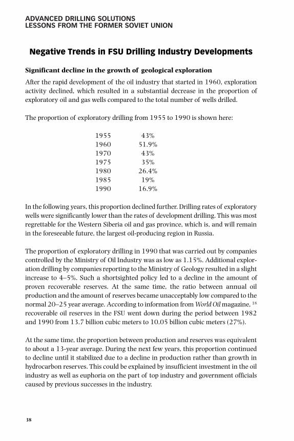
ADVANCED DRILLING SOLUTIONSLESSONS FROM THE FORMER SOVIET UNION
Negative Trends in FSU Drilling Industry Developments
Significant decline in the growth of geological exploration
After the rapid development of the oil industry that started in 1960, explorationactivity declined, which resulted in a substantial decrease in the proportion ofexploratory oil and gas wells compared to the total number of wells drilled.
The proportion of exploratory drilling from 1955 to 1990 is shown here:
1955 43%1960 51.9%1970 43%1975 35%1980 26.4%1985 19%1990 16.9%
In the following years, this proportion declined further. Drilling rates of exploratorywells were significantly lower than the rates of development drilling. This was mostregrettable for the Western Siberia oil and gas province, which is, and will remainin the foreseeable future, the largest oil-producing region in Russia.
The proportion of exploratory drilling in 1990 that was carried out by companiescontrolled by the Ministry of Oil Industry was as low as 1.15%. Additional explor-ation drilling by companies reporting to the Ministry of Geology resulted in a slightincrease to 4–5%. Such a shortsighted policy led to a decline in the amount ofproven recoverable reserves. At the same time, the ratio between annual oilproduction and the amount of reserves became unacceptably low compared to thenormal 20–25 year average. According to information from World Oil magazine, 18
recoverable oil reserves in the FSU went down during the period between 1982and 1990 from 13.7 billion cubic meters to 10.05 billion cubic meters (27%).
At the same time, the proportion between production and reserves was equivalentto about a 13-year average. During the next few years, this proportion continuedto decline until it stabilized due to a decline in production rather than growth inhydrocarbon reserves. This could be explained by insufficient investment in the oilindustry as well as euphoria on the part of top industry and government officialscaused by previous successes in the industry.
38
gelfgat 001-052.qxd 2/10/03 2:01 PM Page 38

INTRODUCTION TO DRILLING TECHNOLOGIESFOR OIL AND GAS IN RUSSIA AND THE FSU
Insufficient capital investments
Plans called for a large increase in oil production, which required related growthin development drilling volumes, but the limited amount of investment curtailedexploratory drilling. Although revenues from oil exports amounted to billions ofpetrodollars and were the main source of hard currency earned for the country’sbudget, the industry received a very small share of those revenues. This portionwas insufficient to import needed equipment and materials that were unavailabledomestically.
The main reason for this state of affairs was the priority given to financing themilitary industry for several decades, which consumed large amounts of moneyduring the Cold War. Another large portion of the country’s budget went to supportthe governments in countries building socialism, such as Cuba, Vietnam, andEastern European countries. Significant resources were used to finance Communistparties in a number of countries as well as the military action in Afghanistan.
The decline of capital investments also affected the civil engineering and metallurgicalindustries. As a result, the fixed assets of some of the engineering plants that manu-factured oilfield equipment were not replaced for several decades. This negativelyaffected the quality and quantity of their production and resulted in laggingdevelopment and production of advanced equipment. During these years, drillingcompanies in the FSU incurred many losses due to downtime as well as the shortage ofimported high-strength casing and drillpipe with new pressure-tight threadconnections, durable tri-cone bits, BOP equipment, chemicals, and other equipment.
The quality of drilling rigs made by the Uralmash and Barrikady plants wassignificantly lower compared to the quality of American-made rigs. These factorsincluded the load capacity, maximum allowable mud pump pressure, efficiency ofthe mud-cleaning system, and durability of rig parts and assemblies. Some diesel-driven rigs used aircraft and tank engines, since the domestic producers did notmake low-speed, high-capacity engines with the long service life that was requiredby the Russian drilling industry. This complicated the design of drilling rigs usedfor exploratory drilling in areas without an available power supply. It made themheavier and raised drilling costs.
These circumstances contributed greatly to a substantial level of downtime for rigsand crews and accounted for 18–20% of the total drilling time.
In total, during the period from 1965 to 1990, the level of annual drilled footageincreased 9.16 times. Of this increase, 50% was due to the fact that the number of
39
gelfgat 001-052.qxd 2/10/03 2:01 PM Page 39

ADVANCED DRILLING SOLUTIONSLESSONS FROM THE FORMER SOVIET UNION
operating drilling rigs grew from 782 to 2353. The remaining 50% increase indrilled footage was due to a higher average overall drilling rate (in Russia it’s calledcommercial rate of drilling or CDR) that went up from 495.5 m/rig-month to 1508.7m/rig-month. In other words, the development of the industry had a semi-extensiveand semi-intensive nature. However, this conclusion is only true on the surface.
The principal increase in overall drilling rate was achieved because of thesignificant growth of drilling volumes in Western Siberia. The region featuresfavorable geological drilling conditions: the presence of large intervals composedof easily drillable sandy-argillaceous deposits, the absence of horizons with abnor-mally high pressure, no lost circulation problems, and an average well depthbetween 2500 m and 2700 m. These factors contributed to the CDR increase from1500 in 1965 to 5000 m/rig-months in 1990 (3.3 times growth). Drilled meter-age grew from 190,000 m to 25,000,000 m (132.6 times growth).
In other regions of the FSU during this 35-year period from 1955 to 1990, theaverage CDR increased from 495.5 m/rig-month to 784.7 m/rig-month, or 1.58times. During the same period, the number of meters drilled annually went from4,650,000 to 17,400,000, or 3.74 times, whereas the number of operating rigsgrew at a rate of 2.36 times.
The differences in drilling results achieved in Western Siberia and in the older oil-producing regions of the FSU can be partially explained. The major portion,7,000,000 m out of 7,200,000 m, of the exploratory drilling in 1990 took placein the old regions. Most of the deep and ultra-deep wells that normally accountedfor rather low CDR (250–300) were drilled in these regions.
Along with a lack of financial investment, other factors contributed to the nega-tive trends in the development of the drilling industry, such as an inefficientproduction pattern and low labor efficiency under the existing economic system.
Rigid planning of drilling activity
In the rigid standardized state plans, one of the main indicators of drilling activitywas the amount of drilled meters.
Rigid planning was unlike the normal planning used in most countries. Instead ofbeing based on scientifically grounded forecasts and recommendations, planningin the FSU was made in the form of law and order. The government’s plan ofindustry development was adopted as a law. Failure to comply with and implement
40
gelfgat 001-052.qxd 2/10/03 2:01 PM Page 40

INTRODUCTION TO DRILLING TECHNOLOGIESFOR OIL AND GAS IN RUSSIA AND THE FSU
this law could sometimes entail extremely serious consequences for the company’stop management. This dogmatic approach to planning completely reversed theessence of sound action. This was especially true for planning that set forth faultyobjectives, as in the case of drilling activity.
In addition, the levels of wages and bonuses fully depended upon successful imple-mentation of the plan. As a result of this “race” for meters, drilling companiesused to start drilling before the rig installation was completed or the drillingequipment fully tested, which caused failures and downtime and affected thequality of the well.
While drilling an open hole through high pressure horizons, the mud propertiesdid not correspond to what was required due to lack of weighting agents, such asbarite, hematite, and other chemicals. In addition, often this drilling was donewithout having prepared and tested casing pipe available at the rig because of theshortage of casing pipe. Frequently, the casing string was run too late, when theopen hole encountered problems, which did not allow the casing shoe to reach theplanned depth. The quality of cementing jobs and operations to isolate water- andgas-bearing horizons was poor. All these factors led to uncontrolled oil and gasshows and blowouts.
The requirement to report the results of the plan fulfillment to the governmentprompted drilling companies to falsify information reported by overstating themeterage actually drilled. Sometimes a specialist from a drilling company evenbribed the geophysical contractor specialists to have them falsify well directionalsurveys to report that the well had reached the target. This caused a decrease infield production, premature water influx, and other negative events.
In addition, this type of planning significantly complicated the work on testingand implementation of new well drilling technologies and equipment. Exposed tothe pressure from existing drilling plans, managers of the drilling companies andtoolpushers opposed the program of new equipment testing, since they had noconfidence in the positive results of the experiments. In many cases, they wouldstart the test under orders from top management but discontinue it at the earliestopportunity.
This was the case with testing of various drilling equipment, such as turbodrills,directional drilling tools, electrodrills, and some other innovative drilling tools thatlater became widely used by the industry. There were many examples when the oil-producing companies and drilling organizations failed to find an application for
41
gelfgat 001-052.qxd 2/10/03 2:01 PM Page 41

ADVANCED DRILLING SOLUTIONSLESSONS FROM THE FORMER SOVIET UNION
promising and efficient technologies and methods that were developed, designed,and fully tested with very positive results.
A good example of the companies’ reluctance to apply new technologies was theirunwillingness to use horizontal well drilling which is currently one of the mostpopular techniques used around the world.
As previously mentioned, the world’s first multilateral horizontal well was success-fully drilled in 1953 by a drilling group from the Ishimbaineft Company fromBashkiriya, headed by A. M. Grigoryan, the drilling engineer. After that, in 1957and in 1960, more multilateral horizontal wells were successfully drilled inBorislav (West Ukraine) and Krasnodar. In 1968, the same group drilled ahorizontal well near Markovo, a village in Eastern Siberia, which set the worldrecord for horizontal section length—632 m.
Despite the proven efficiency of this method for completing the productive zone,both the drilling companies and Ministry officials were reluctant to promote itswide application and further development. The Ministry management wasconcerned that an increased investment would cause GOSPLAN (the stateplanning agency) to curtail budgets and impose higher oil production levels ifhorizontal drilling was widely used by the industry. At the same time, the oil-producing bureau management was afraid to see the same actions from the oilcompanies. They all failed to understand that horizontal drilling requires muchattention and involves an additional amount of work to drill and complete a well.
Hence, for more than 20 years, the new method of oilfield development that couldsignificantly increase well flow rates and enable more oil recovery was not used inthe FSU where it was developed. Only in the late 1980s did the Russian drillingindustry follow the example of the United States and other countries and beginusing this technology in various regions (see Volume 2).
Unfortunately, the list of such examples is quite long.
Absence of private property ownership, private entrepreneurship, and initiative
One of the fundamental disadvantages of state ownership of all means of produc-tion and productive forces was that a producer did not own the products he made.Whether he was very efficient or totally inefficient had little impact on his wealth,which hinged only on his salary level as prescribed in the payroll table and a small
42
gelfgat 001-052.qxd 2/10/03 2:01 PM Page 42

INTRODUCTION TO DRILLING TECHNOLOGIESFOR OIL AND GAS IN RUSSIA AND THE FSU
bonus if production targets were achieved. Therefore, any improvements inproduction processes due to new technology did not affect his financial position.
At the same time, testing and implementing new equipment and technologyrequired extra effort, initiative, and sometimes involved risk. The absence ofcompensation for these efforts substantially slowed the development of drillingtechnology. Of course, the industry saw many hardworking professionals withmarked initiative who tried to implement new technology. Yet, the enthusiasmshown by some individuals did not always lead to acceptance or use of the innova-tions throughout the industry.
A typical example of this situation was the development and application of electro-drilling technology for drilling multilateral horizontal wells in the Dolina oilfield inWestern Ukraine. Volume 2 describes this work in detail. The 11 multilateralhorizontal wells were drilled under the technical guidance of VNIIBT engineers.Most of the wells were successful, however, the management of the company thatdeveloped the field kept well production information carefully under wraps andwas very unwilling to release the information even to the VNIIBT specialists whodesigned the wells and managed their construction. The institute was unable toobtain any data for the most successful well, No. 350. Only the production fore-man shared some information about the actual flow rate on the condition that thisdata would not be released.
During an informal meeting with the company’s management, one of the authorsof this book (Y. A. Gelfgat) asked questions about the reasons for such secrecy andthe unwillingness of the company to drill more of these wells. The manager of thecompany answered that, if he had informed top management about such highflow rates, the oil production level planned for the following month would beincreased, whereas he was not sure whether new wells would be as successful. Healso cited the lack of incentive for him and his people to put in the additional effortto complete these wells and raise oil production.
In addition, he said that since the work on commercial implementation of thenew method would take several years and he was going to retire soon, he did notsee any personal benefit for promoting such work. At the same time, he describedan imaginary situation in which he was the owner of the company thatdeveloped this field and could hand it down to his son. In this case, his motivationwould be sufficient to advocate this work strongly. These reasons were hard toargue with. Even advocates of a socialist society and the elimination of privateownership would have had a hard time coming up with sound counter
43
gelfgat 001-052.qxd 2/10/03 2:01 PM Page 43

ADVANCED DRILLING SOLUTIONSLESSONS FROM THE FORMER SOVIET UNION
44
arguments. Consequently, the work on drilling multilateral horizontal wells atthis field was halted.
Did a new era begin in Russia?
In 1985, perestroika (or reorganization) was started in the FSU, which, up to 1991,was mainly related to the government’s domestic and foreign political activity. Thefollowing years witnessed economic reforms such as privatization of industry,introduction of a free market economy, and elimination of government price controls.
However, economic reforms in the first several years of the transition period failedto improve the Russian economy. According to information from the RussianFederation Committee on Statistics, the level of oil and gas condensate productiondropped to 305 million tons in 1997, gas production fell to 544 billion cubicmeters, and only 8,300,000 m were drilled.
It is difficult to predict when the situation will change, but the transition to privateownership of production will eventually yield positive results. During the transitionfrom the FSU to the Russian Federation, vertical integrated oil companies weredeveloped: Lukoil, UKOS, Surgutneftegaz, Sibneft, TNK, Rosneft, Slavneft, andSidanco, and regional oil companies were strengthened Tatneft, Bashneft, and others.
Since 1996, production rates increased (see Table 1–5), but drilling activity had atendency to change. It was decreasing in 1998, but since 1999, drilling activitystarted growing again (see Table 1–7). Several publications provided a goodopportunity to follow the story of modern developments in the oil and gasindustry. World Oil magazine, regular publications of the FSU/Eastern EuropeReports, and other sources (primarily Oil & Gas Journal) have published articles onRussian drilling activities/technologies along with new Russian publications likeNeft I Kapital (Oil & Capital) magazine. Tables 1–5, 1–6, and 1–7 summarize someof the data on production and drilling activity in Russia during the last decade ormore. 19 20 21 22 23
Evidence of structural changes in the drilling industry is clear, but the formationof independent drilling contractors and integrated service firms still facesdifficulties. The primary goals of the new oil companies were to enhanceproduction with minimal investments, but the time has come to renewinvestments in drilling and exploratory activities. We strongly believe thatresearch capital gained by the Russian drilling industry in the past should beunconditionally demanded for this purpose.
gelfgat 001-052.qxd 2/10/03 2:01 PM Page 44

INTRODUCTION TO DRILLING TECHNOLOGIESFOR OIL AND GAS IN RUSSIA AND THE FSU
45
TABLE 1–5Crude Oil and Condensate Production
in FSU Countries (1994–2000)
Barrels per DayCountry 1994 1995 1996 1997 1998 1999 2000Russia 6,280,100 6,090,000 5,980,000 5,907,602 6,041,071 6,070,948 6,451,000Kazakhstan 434,000 409,186 462,817 518,007 571,232 604,172 700,320Remainder 502,369 541,350 564,278 577,18 586,297 600,947 687,246
of FSUArmenia 0 0 0 0 0 0 0Azerbaijan 192,100 182,473 190,000 179,698 180,291 179,105 278,298Belarus 40,234 38,481 36,948 36,269 36,466 36,649 36,600Estonia 0 0 0 0 0 0 0Georgia 1,800 1,500 3,000 1,992 2,190 2,180Kyrgizia 1,640 2,000 1,990 1,694 1,535 1,530 2,179Latvia 0 0 0 0 0 0 0Lithuania 1,655 3,097 3,235 4,231 5,474 4,641 6,303Moldova 0 0 0 0 0 0 0Tajikistan 1,000 2,000 1,800 520 400 395 366Turkmeniya 75,700 78,500 86,805 111,130 121,250 139,425 141,030Ukraine 79,240 79,299 69,000 84,560 77,679 75,688 73,495Uzbekistan 109,000 154,000 171,500 157,093 161,012 161,334 148,975Total FSU 7,216,469 7,040,536 7,007,095 7,002,796 7,198,600 7,276,067 7,838,566
Thousand tons per year (1 bpd = 49.8 ton per year)Country 1994 1995 1996 1997 1998 1999 2000Russia 312,749 303,282 297,804 294,199 300,845 302,333 321,260Kazakhstan 21,613 20,377 23,048 25,797 28,447 30,088 34,876Remainder 25,018 26,959 28,101 28,744 29,198 29,927 34,225
of FSUArmenia 0 0 0 0 0 0 0Azerbaijan 9,567 9,087 9,42 8,949 8,98 8,919 13,859Belarus 2,004 1,916 1,840 1,806 1,816 1,825 1,823Estonia 0 0 0 0 0 0 0Georgia 90 75 149 99 109 109 0Kyrgizia 82 100 99 84 7 76 109Latvia 0 0 0 0 0 0 0Lithuania 82 154 161 211 273 231 314Moldova 0 0 0 0 0 0 0Tajikistan 50 100 90 26 20 20 18Turkmeniya 3,770 3,909 4,323 5,534 6,038 6,943 7,023Ukraine 3,946 3,949 3,436 4,211 3,868 3,769 3,660Uzbekistan 5,428 7,669 8,541 7,823 8,018 8,034 7,419Total FSU 359,380 350,619 348,953 348,739 358,490 362,348 390,361
gelfgat 001-052.qxd 2/10/03 2:01 PM Page 45

ADVANCED DRILLING SOLUTIONSLESSONS FROM THE FORMER SOVIET UNION
TABLE 1–6Horizontal Drilling Activity in Russia (1990–2001)
Total Number ofWells Drilled Wells Completed
1990 14 141991 39 521992 50 1081993 43 1511994 68 2191995 91 3101996 102 4121997 114 5261998 128 6541999 143 7972000 198 9952001 (first 9 months) 135 1127
TABLE 1–7Drilling Volumes in Russia (1994–2000)
Footage drilled (ft) Number of Wells____________________________________ ______________________________________Year Exploratory Development Total Exploratory Development Total1994 3,831,040 39,500,000 43,331,040 no data available no data available no data available1995 3,622,924 34,508,360 38,131,284 no data available no data available no data available1996 3,600,000 23,900,000 27,500,000 no data available no data available no data available1997 no data available no data available 28,990,000 no data available no data available 4,4601998 2,590,000 14,140,000 16,730,000 400 2,175 2,5751999 4,100,000 16,600,000 20,700,000 no data available no data available 3,1852000 3,330,000 27,180,000 30,510,000 no data available no data available 3,405
Value of Scientific Research and Design and theFeasibility of Their Use in Modern Drilling Practices
The successful development of vocational training for industry specialists and theeffective work of scientific and research organizations have created a comprehen-sive engineering knowledge base for developing the oil industry as a whole anddrilling technology in particular. For several decades, thousands of engineers andresearchers worked on improving drilling technology and equipment. Theindustry saw the successful development and application of various new
46
gelfgat 001-052.qxd 2/10/03 2:01 PM Page 46

INTRODUCTION TO DRILLING TECHNOLOGIESFOR OIL AND GAS IN RUSSIA AND THE FSU
technologies, such as the HDHM and EDM, directional and clustered well drilling,etc. Yet, the work on further improvements in the drilling process has slowed.
At the same time, the number of the new technologies developed, tested andprepared for commercial application by the scientific research institutes anddesign bureaus increased through the years. This led to some paradoxicalsituations where new technological processes and equipment that were success-fully tested by the industry were not used by the companies or promoted by theMinistry officials. Meanwhile, unique developments related to oil and gas drillingaccumulated during several decades, and hundreds of inventions represented asignificant asset of drilling science. Unfortunately, that knowledge has never foundits way into the industry despite its great potential.
A few more examples illustrate these new technologies. Among them were suchinnovative techniques as dual-bore drilling, i.e., drilling two wells simultaneouslyusing one rig and one drilling crew. This technology was discontinued by order ofthe Central Committee of the U.S.S.R. Communist Party because of fierce disputeson the work financing issue. Other developments included air, gas, and foamdrilling, and casing drilling using retrievable drilling tools.
The Iron Curtain existed for many years around the FSU. Not only did it block thefree flow of information from the West, but it also put an even bigger obstacle in theway of informing Western engineers about achievements in the FSU. For example,only in the last few years were Western specialists able to learn about suchachievements as the high level of electrodrilling technology development, successfulutilization of the ADP, and wide application of the cluster well drilling method. Evenmore, they were not aware of the developments that proved efficient when used inthe pilot-commercial drilling but were not widely used by the industry.
Indicative of this situation is information from the Canadian company TescoDrilling Technologies 24 about the development of casing drilling technology thatthe company has been carrying out for several years. The information shows thatTesco repeated the development path that had been completed by Russianengineers long ago. Moreover, the design of the retractable drilling tools used forthis method is very similar to the one developed in Russia in the 1950s.
The truth is that scientific, technical, cultural, and art achievements cannot bekept within territorial borders. Sooner or later they become the domain of allhumankind. The sooner it happens, the better. While paying tribute to theoutstanding progress of drilling technology in the United States and other
47
gelfgat 001-052.qxd 2/10/03 2:01 PM Page 47

ADVANCED DRILLING SOLUTIONSLESSONS FROM THE FORMER SOVIET UNION
countries with a well-developed oil and gas industry, we believe that these drillingprofessionals would gain much from learning about some of the achievements ofRussian scientists and engineers working in this field.
Why We Decided to Write This Book
From time to time, visiting U.S. specialists expressed interest in the U.S.S.R. oil andgas industry. This was possible during the “warm periods” in the internationalpolitical situation. In 1974, John Rowley, a prominent drilling engineer, visitedMoscow with a group of U.S. oilfield experts. They also went to the Western Siberiacities of Tumen and Nizhnevartovsk as well as Tatariya and Bashkiriya Republics.The results of this visit were presented at a Society of Petroleum Engineers (SPE)conference in Denver in the fall of 1977. The major topics were oilfielddevelopment, drilling technology, and equipment. 25 This was perhaps the first lookat Russian technology such as turbodrilling, cluster wells, super-deep drilling withaluminum pipe, multi-lobe PDM, etc.
A delegation from the U.S. Department of Energy (DOE) visited the U.S.S.R. duringperestroika. This was actually the first time that the authors of this book coulddirectly discuss different technology features with specialists from the UnitedStates. Most of the subjects mentioned in this chapter were presented at aworkshop in the VNIIBT followed by informal discussion. At the time, it becameclear that the DOE had an interest in turbodrilling and other developments, but itwas clear also that there was a great lack of information between the parties.
The idea of writing this book became a relevant question more than a decade agowhen Western oil and gas specialists began looking at the FSU as a potentialmarket for exploration and development opportunities. Strong interest led theauthors to give a presentation to the Petroleum Industry Forum concerning the“Features of Russian Drilling Technology Development,” as arranged by theBritish Geological Survey in Edinburgh (October 1993). Additionally, in Paris(1995), we held a workshop for the Institute Francaise du Petrole on the sametopic, attracting a great deal of interest. This experience strengthened our resolveto write the book.
Since 1995, one of the authors (M. Ya. Gelfgat) has participated in severalconferences outside Russia arranged by the SPE, International Association of
48
gelfgat 001-052.qxd 2/10/03 2:01 PM Page 48

INTRODUCTION TO DRILLING TECHNOLOGIESFOR OIL AND GAS IN RUSSIA AND THE FSU
Drilling Contractors (IADC), and American Society of Mechanical Engineers(ASME) to introduce the advantages of Russian drilling technologies to Westernengineers. 26 27 From these presentations, it became apparent that the subject ofthe book would greatly benefit the oil and gas industry, especially since knowledgeof the innovative technologies remained closed to the world.
We would like to add that certain Russian technologies have already receivedvarying levels of support for future R&D in the United States, based on cooperativeactivities involving Maurer Engineering, Inc. (MEI) and the DOE. 28 These jointprojects, held from 1996 to 1998, resulted in the DOE targeting several Russianadvanced technologies for potential commercial development. Among them wereones we have already mentioned: electrodrilling, ADP, RBs, and reduction gearturbodrills. Industry interest in these subjects is exhibited by the attendance of keyoperating and managerial personnel at the demonstrations held at MEI in 1999 onRB and ADP technologies. 29 As these and other technologies are used on a com-mercial basis in the West, this book will serve to answer technical questions thatare certain to arise.
During the workshops, seminars, and industrial meetings held during the last fewyears, the authors received additional confidence that problems in modern drillingpractices such as hard- and/or hot-rock drilling, borehole walls instability, super-deep/long drilling, drilling rate improvement, development of complicated fields,and others may be resolved better by understanding the experiences presented inthis book.
49
gelfgat 001-052.qxd 2/10/03 2:01 PM Page 49

ADVANCED DRILLING SOLUTIONSLESSONS FROM THE FORMER SOVIET UNION
50
References
1 Lisichkin, S. M., Overview of the Domestic Oil Industry Development (before therevolution time), Gostoptekhizdat, Moscow-Leningrad, 1954.
2 Dinkov, V. A., “Petroleum Industry,” Mining Encyclopaedia, Moscow, SovetskayaEncyclopaedia, v.3 pp 475–478, 1987.
3 Lisichkin, S. M., 1954.
4 Dinkov, V. A., 1987.
5 Shatsov, N.I., “Introduction,” Oilwell Drilling Handbook, edited by M.A. Evseenko,Gostoptekhizdat, Moscow-Leningrad, 1947.
6 Ibid.
7 Gelfgat, Y.A., “On the history of directional wells drilling and oilfielddevelopment with cluster drilling techniques using turbodrills in the U.S.S.R.,”Of the U.S.S.R. Oil and Gas Induty History–Veterans memoirs, Issue 1, pp. 37–43,Moscow, VNIIOENG, 1991.
8 Shumilov, P.P., Theory of Turbodrilling, Gostoptekhizdat, Moscow-Leningrad,1943.
9 Shatsov, N.I., 1947.
10 Ioanessyan, R.A., Turbodrilling of Vertical and Directional Wells, Gostoptekhizdat,Moscow, 1945
11 Bronzov, A.S., Cluster Wells Construction at Oil and Gas Fields, Gostoptekhizdat,Moscow, 1962.
12 Grigoryan, A.M., Drilling-in with Multilateral and Horizontal Wells, NedraPublishing, Moscow, 1969.
13 Gelfgat, Y.A., Drilling-out Cementing Plugs with Turbodrill, Gostoptekhizdat,Moscow-Leningrad, 1949.
14 Lisichkin, S.M., Overview of the Oil Production Industry in the U.S.S.R., U.S.S.R.Academy of Sciences Publishing, Moscow, 1958.
15 Ibid.
16 Ibid.
17 Production Catalog of OAO NPO Burovaya Tekhnika, VNIIBT, Moscow, 2001.
gelfgat 001-052.qxd 2/10/03 2:01 PM Page 50

INTRODUCTION TO DRILLING TECHNOLOGIESFOR OIL AND GAS IN RUSSIA AND THE FSU
18 “Oil and Gas Industry Status,” World Oil, v.212, August 1991.
19 “FSU/Eastern Europe Report,” World Oil, August, 1996, 1997, 1998, 1999,2000, 2001.
20 Gaddy D.E., “Pioneering work, economic factors provide insights into Russiandrilling technology,” Oil & Gas Journal, July 6, 1998.
21 Gaddy D.E., “Russian test facility allows direct inspection of bottomholeassemblies under in situ conditions,” Oil & Gas Journal, December 7, 1998.
22 Gaddy D.E., “Russia shares technical know-how with U.S.,” Oil & Gas Journal,March 8, 1999.
23 Bureniye (Drilling) – Special attachment to Neft I Kapital (Oil & Capital) #2,November, 2001.
24 Tessari, Bob, Garret Madell, and Tommy Warren, “Drilling with casing promisesmajor benefits,” (Tesco Drilling Technology), Oil & Gas Journal, May 17, 1999.
25 Rowley, John and J. Wade Watkins, “A Tour of Russian Oilfield Technology,” SPE6718, 52nd Annual Fall Technical Conference, Denver, Colorado, USA, 1977.
26 Mnatsakanov, A. V., M. Ya. Gelfgat, and R. S. Alikin, “Technology and techniquefor scientific drilling in crystalline rocks: experience and perspectives,”IADC/SPE paper #023912, New Orleans, Louisiana, USA, February 17–21,1992.
27 Gelfgat, M.Y., Papers presented at ASME Petroleum Division DrillingSymposiums in Houston: “Drilling Tools for Continuous Offshore Operations”(1995); “Retractable Bits Development and Application” (1996); “HydraulicHammer Drilling Technology: Developments and Capabilities” (1997); “AluminumTubular In Deep Water Drilling Application” (1999).
28 Maurer W., “Russian Drilling Technologies,” Natural Gas Conference (U.S. DOE),Houston, USA, 1997.
29 Gaddy D.E., “Russia shares technical know-how with U.S.,” Oil & Gas Journal,March 8, 1999.
51
gelfgat 001-052.qxd 2/10/03 2:01 PM Page 51

gelfgat 001-052.qxd 2/10/03 2:01 PM Page 52

DOWNHOLE MOTOR DRILLINGTECHNOLOGY AND APPLICATIONS
Development of Turbodrills—Characteristics and Fields of Application
From a gear-reduction turbodrill with a single-stage turbine to amultistage hydro-turbine motor
Initial tests. The first turbodrill capable of operation was developed and built by theengineers M. A. Kapelyushnikov, S. M. Volok, and M. A. Kornev in 1922 and1923. 1 The first prototype was tested by drilling various rock blocks at the surface.The prototype was essentially a single-stage 3 to 4 horsepower turbine with arotational speed of 1600–1800 rpm. A special hydroturbine reduction gear wasused to transfer the rotational effect to a drillbit.
The first tests showed positive results, which enabled manufacturing a small seriesof turbodrills (8 in. and 11 in. diameter) at the metallurgical plant in Leningrad.In 1925 and 1926, drilling departments of the Azneft production company inBaku began using these turbodrills for drilling wells in the oilfields of theSurakhany region. From 1925 to 1934, the Kapelyushnikov-designed turbodrillsthat were used to drill nearly 100,000 m in wells with depths of 670–1300 m.
During this period, significant improvements were introduced to the turbodrilldesign, such as replacement of the reaction turbine with the impulse turbine andreplacement of a reducing device with a multistage planetary gear, which wasdeveloped by engineer B. G. Lyubimov. The reduction gear and bearings
2
gelfgat 053-198.qxd 2/10/03 2:05 PM Page 53
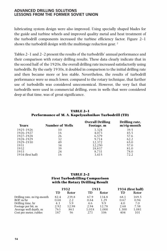
ADVANCED DRILLING SOLUTIONSLESSONS FROM THE FORMER SOVIET UNION
lubricating system design were also improved. Using specially shaped blades forthe guide and turbine wheels and improved quality metal and heat treatment ofthe turbodrill components increased the turbine efficiency factor. Figure 2–1shows the turbodrill design with the multistage reduction gear. 2
Tables 2–1 and 2–2 present the results of the turbodrills’ annual performance andtheir comparison with rotary drilling results. These data clearly indicate that inthe second half of the 1920s, the overall drilling rate increased satisfactorily usingturbodrills. By the early 1930s, it doubled in comparison to the initial drilling rateand then became more or less stable. Nevertheless, the results of turbodrillperformance were so much lower, compared to the rotary technique, that furtheruse of turbodrills was considered uneconomical. However, the very fact thatturbodrills were used in commercial drilling, even in wells that were considereddeep at that time, was of great significance.
TABLE 2–1Performance of M. A. Kapelyushnikov Turbodrill (TD)
Overall Drilling Drilling rate,Years Number of Wells Footage, m m/rig-month
1925–1926 10 1,324 39.51926–1927 16 4,073 45.51927–1928 26 6,579 57.61928–1929 32 9,714 62.21929–1930 49 12,372 65.01931 34 12,250 57.01932 39 18,837 81.01933 24 8,731 78.01934 (first half) 16 3,415 72.2
TABLE 2–2First Turbodrilling Comparison with the Rotary Drilling Result
1932 1933 1934 (first half)TD Rotor TD Rotor TD Rotor
Drilling rate, m/rig-month 82.4 239.8 67.9 134.8 68.1 169.5ROP, m/hr 0.68 2.2 0.64 1.29 0.67 0.94Drilling time, hr 4.3 5.9 4.6 9.9 4.0 7.0Footage per bit, m 2.92 12.98 2.94 12.78 2.68 7.58Average well depth, m 763 863 1,018 1,000 1,300 1,081Cost per meter, rubles 187 56 271 106 404 101
54
gelfgat 053-198.qxd 2/10/03 2:05 PM Page 54

DOWNHOLE MOTOR DRILLING TECHNOLOGY AND APPLICATIONS
In the second half of the 1920s, when the application ofturbodrilling technology had made good progress, someAmerican companies showed an interest in this drillingmethod. M. A. Kapelyushnikov was invited to the UnitedStates to perform demonstration test drilling of wellsusing a turbodrill. Kapelyushnikov came with a drillingcrew that had experience in turbodrill application.However, the drilling was discontinued after the inventorof the turbodrill was injured in a car accident. After along medical treatment in the United States, he returnedto the FSU.
The main reason for unsatisfactory performance resultsfrom the turbodrill designed by Kapelyushnikov was thelow durability of a single-stage turbine. Adequate powerof 10–12 hp could be achieved by increasing the drillingmud circulation rate, which provided the turbine wheelrotational speed of 3000 rpm at a drilling mud flowvelocity of 100 m/sec. At such velocities, turbine bladeswere affected by intense erosion, and the maximumdurability was as low as 3–5 hr. After that shortoperating period, the turbodrill had to be replaced. Inaddition, the wear of the turbine fluid during drillingsignificantly reduced the power and slowed down thepenetration rate during a single bit run.
Another weak point of the turbodrill design was themultistage reduction gear system with a gear ratio from7 to 150. Rapid wear on the system’s components,especially when they were affected by drilling mud, alsoresulted in the early pullout of a drillstring (DS) forturbodrill replacement. These fundamental drawbacksof the turbodrill design prompted suspension of furtherdevelopment of a single-stage turbodrill.
55
Fig. 2–1 Turbodrill of Kapelyushnikov with three-stage reductiongear (1925–34)
gelfgat 053-198.qxd 2/10/03 2:05 PM Page 55

ADVANCED DRILLING SOLUTIONSLESSONS FROM THE FORMER SOVIET UNION
56
Fig. 2–2 A Direct-drive 100-stagenot geared 12-in. turbodrill(1934–1935)
gelfgat 053-198.qxd 2/10/03 2:05 PM Page 56

DOWNHOLE MOTOR DRILLING TECHNOLOGY AND APPLICATIONS
The new engineering team conducted further studies and development workrelated to turbodrilling technology. This team included P. P. Shumilov, a young sci-entist from the State Research Institute of Oil (GINI) in Moscow, and E. I. Tagiyev,R. A. Ioannesyan, and M. T. Gusman, young engineers from the State ResearchInstitute of Oil Engineering (GIINMash), along with Lyubimov, an experiencedengineer from the same institute who worked closely with Kapelyushnikov. Theirjoint efforts initially resulted in the development of a 6- to 8-stage turbodrill witha reduction gear system. The turbine had significantly higher power, compared toa single-stage design, and featured much lower wear intensity by the fluid flows.However, the reduction gear system turned out to be the weak link of this high-powered turbodrill design and did not obtain acceptable results.
New multistage design. Since the geared turbodrill idea failed to be reliable,engineers Shumilov, Tagiyev, Ioannesyan, and Gusman from the turbodrillingbureau in Azneft joined efforts in 1934 and 1935 in developing a 100-stage directdrive 12-in. turbodrill (see Fig. 2–2). 3
A thread connection on the turbodrill nipple jointed to the body and compressedthe group of stators; friction held the turbine stator and rotor and preventedthem from turning inside the housing and on the shaft. A special nut was used tocompress the rotors together on the shaft. In addition, they had special slots thatwere used to set them on a key that was fixed in a slot along the entire length ofthe turbodrill shaft. The turbodrill design featured an oil-lubricated axial ballbearing located in the lower shaft section under the turbine, as well as alubricated radial centering roller bearing on the upper shaft end. The internalshaft space contained lubricant that was squeezed out by a special piston. Specialseals prevented mud from getting to the inside space of the lower ball bearing andthe upper friction bearing.
Power for this new design turbodrill was about 100 horsepower at a shaftrotational speed of 600 rpm. In 1935 and 1936, a small series of these motorswere tested in Baku during the oilfield development of the KaganovichneftProduction Company. The turbodrills proved to be efficient and showed betterresults, such as higher penetration rates, compared to the turbodrills with gearreducers (with low number of stages).
Table 2–3 illustrates the comparison between the results of the multistage gearreduction turbodrills (8 stages) and the first multistage (100 stages) direct driveturbodrill.
57
gelfgat 053-198.qxd 2/10/03 2:05 PM Page 57

ADVANCED DRILLING SOLUTIONSLESSONS FROM THE FORMER SOVIET UNION
TABLE 2–3The Comparison of Gear Reduction and Regular Turbodrills
Performance at Kaganovichneft Company (1935–1936)
Multistage MultistageGear Reduction Direct-drive
Turbodrill TurbodrillRPM 150 600Power on the bit (HP) 57 92Torque (kg m) 275 110ROP (m/hr) 4.6 7.4Average performance per run (m) 39 40Drill time (hr) 8.5 5.4
The test results allowed the following main conclusions:
• erosion wear of the turbine fluid paths was not observed in all the stages
• durability of the turbines was no longer a restricting factor for the drillingprogress
The tests pioneered the successful application of RKh drag bits at a rotationalspeed of 600 rpm. Bit weights were reduced because of the low torque of theturbodrill and high torque power of the RKh bit.
Contraction of the stators and rotors using thread connections proved to be quiteeffective. The bearings turned out to be a weak link in the turbodrill design. Failureof both the lower axial ball bearing because of the poor lubricating system designor the upper radial friction bearing caused low turbodrill serviceability. This wasespecially true of the lower bearing, which had to be replaced as frequently asevery 10–12 hours.
The new turbodrill designs featured the innovative rubber-metal bearing. Thelower turbodrill nipple that served to compress stators of all stages was bored fromthe inside. The inside surface of the bored-out space was rubber faced byvulcanization. This rubber face was in contact with the special polished surfacebushing.
The first time the drilling mud lubricated rubber-metal radial bearing was used, itwas a complete success. Its durability improved and the service life increased to100–150 hours. The design used axial ball bearing in the upper turbodrill sectioninstalled inside the oil lubrication chamber, which also allowed the use of standardindustrially manufactured rather than the backyard-made ball bearings.
58
gelfgat 053-198.qxd 2/10/03 2:05 PM Page 58

DOWNHOLE MOTOR DRILLING TECHNOLOGY AND APPLICATIONS
Using the work describedpreviously, the firstmultistage turbodrill T6-150-93⁄4" (Fig.2–3) wasbuilt. This turbodrillcould be manufacturedby the industry and usedto drill wells. Theturbodrill design featured150 turbine stages. Theturbine itself is built inthe form of a circulationvane cascade withstraight blades. Therotary disc body wasmilled to make thestraight turbine blades.Next, steel rims were fiton the heated blades.This was a forced choicebecause the level ofcasting technology inBaku at that time did notallow steel casting ofrotors with formedblades. In the case of astraight vane cascadedesign, the stage lengthwas as low as 25–36mm, which enabledinstallation of 150 stagesinside the turbodrillcasing. The T6-150-93⁄4"turbodrill was used bythe drilling industry in1938 and 1939.
Drillbits for turbodrilling—first approach. By this time, the rock cone bits foundtheir application along with the widely used cutting-shearing type bits. Thesenew bits proved to be especially efficient in turbodrilling, considering the fact
59
Fig. 2–3 First commercial multistage turbodrill T6-150-9 3⁄4" (1935–36)
gelfgat 053-198.qxd 2/10/03 2:05 PM Page 59

ADVANCED DRILLING SOLUTIONSLESSONS FROM THE FORMER SOVIET UNION
that, for example, the combination of the turbodrill and RKh-type bit was notgood in rocks with medium hardness. At high rotational speeds, these bits tendedto wear under gage quickly, which led to a much slower ROP and made turbo-drilling uneconomical.
Neither satisfied the turbodrilling requirements met by some other bit types, suchas the disc bit, the Zublin-design bit, and the FD-type four-point roller cone bit.That was due to the fact that the kinematics of these bits featured intensive conesliding on the bottomhole, which required high torque and failed to comply withthe high rotational speed of a turbodrill. Therefore, engineers from theExperimental Turbodrilling Bureau (EKTB), which was formed in 1939 under thespecial ordinance from the FSU government, pioneered development of tri-conebits with conical-shaped cones that provided slide-free or almost slide-free bottom-hole cone rolling.
Unlike the normal drilling bureaus, this bureau included an efficient designdepartment, an experimental production facility for manufacturing turbodrills,and other related equipment, including a special drilling test bench for testing newturbodrill designs. The bureau was given the right to lease drilling rigs with crewsanywhere in Azerbaijan in order to perform field tests of turbodrills. The designgroup of the bureau developed this type of bit, fabricated it, and tested it. Later, twospecialized plants—the Dzerzhinsky plant in Baku and the Verkhne-Sergiyevskyplant in the Ural region—began manufacturing this type of bit.
Thanks to the low torque power of tri-cone bits with conical-shaped cones, theirapplication allowed the introduction of significant changes to turbodrillingpractices by increasing bit weight, which contributed much to the improvement ofthe penetration rate. In the following years, the tri-cone drillbit became the maintool for destroying rock used by the drilling industry all around the world,including the United States and other countries. At the same time, this innovativetool required the introduction of substantial changes to the turbodrill design.
First design improvements. Several things demanded turbodrill design changes, forexample, failure of the axial ball bearing to comply with the drilling conditions.The bearing was designed to withstand the downward load, since the increased bitweight often overcame the hydraulic load. This suggested the necessity of creatinga double-thrust bearing capable of withstanding upward bottomhole reactionloads. The experience also revealed that the bit weight increase resulted inbuckling of the shaft, which was indicated by the intensive wear of the rotor discrims as well as by the turbine blade failures. This prompted the use of the
60
gelfgat 053-198.qxd 2/10/03 2:05 PM Page 60

DOWNHOLE MOTOR DRILLING TECHNOLOGY AND APPLICATIONS
intermediate radial rubber-metal bearing that had a design similar to the lowerradial bearing. These changes led to the development of a new T10-100-93⁄4"turbodrill design, shown in Figure 2–4. 4
The industry manufactured this turbodrill design in 1940, and it was used by suchcompanies as Azneft in Azerbaijan, Ishimbaineft in Bashkiriya, Krasnokamskneftin the Perm region, and Grozneft in Chechnya. Despite design improvements, theaxial ball bearing remained the weak link of the turbodrill design. In this regard,the creators of the turbodrill came up with an idea to use a rubber-metal axialbearing that was quite unique for the world turbodrill manufacturing industryconsidering its very small diameter.
In 1941, the engineers built the rubber coated turbodrill T12- 93⁄4". It featured anoriginal design, shown in Figure 2–5. The turbine rotor, consisting of 100 discs,was essentially a collar thrust bearing. The stator was made in the form of arubber-coated collar thrust bearing, i.e., an axial and simultaneously radialjournal bearing because both the end surface and the internal radial surface of thestators were rubber coated. The simple and elegant design solution was quiteappealing, especially considering the significantly longer mean time betweenfailures (MTBF) of the rubber-metal axial journal bearing compared to the ballbearing, which was shown by the very first tests in Baku.
61
Fig. 2–4 The T10-100-9 3⁄4" turbodrill was in serial production in 1940–48
gelfgat 053-198.qxd 2/10/03 2:05 PM Page 61

ADVANCED DRILLING SOLUTIONSLESSONS FROM THE FORMER SOVIET UNION
At the same time, the tests revealed a number of serious disadvantages related tothe combined functions of the motor and the support elements. The designersfailed to achieve an even distribution of axial load on the stator along the entireturbodrill length. The support elements of the upper turbine end were the first towear, which did not allow using the full potential of the multistage support. Whenreplacement of the worn-out elements was required, the entire turbine had to beremoved from inside the housing, which complicated execution of the routinerepair at the rig. Worse still, the material that was used for manufacturing therotor disc had low durability because of insufficient abrasive strength and couldnot be used for this purpose. Exposed to significant vibration loads while drillingthrough hard rock, the rotor discs sheared the key and began turning on the shaft.
It was then that the engineers came up with the design of the collar step rubber-metal bearing separate from the turbine and located at the upper end of theturbodrill, similar to the T-10 turbodrill design but without the lubricating system.In this design, a drilling mud flow served to lubricate the bearing. The designfeatured step bearings with special mud courses for lubricating the surface and theheat-treated steel discs with smooth surfaces located between the step bearings.The latter was in the form of 8 to 10 rings abutted against the turbodrill housing.It was gripped by its upper sub and attached to the housing using a straight threadconnection. The discs, together with the spacer rings that were used as the upperradial bearing, were fit on the upper end of the turbodrill shaft and held in positionby a nut and a lock nut.
Figure 2–6 shows the T14-93⁄4" turbodrill design with the upper rubber-metalbearing. Figure 2–7 shows the rubber-coated step bearing design with 12 fluidcourses. The T14 turbodrill was the last model of a HDHM, which the industrystarted manufacturing before 1941. During World War II and in the postwarperiod through 1948, T10 and T14 turbodrills remained the most used modelsand were manufactured by the industry to satisfy the needs of turbodrillingcarried out in some regions of the FSU.
62
Fig. 2–5 Turbodrill T12-9 3⁄4" with rubber-coated stator discs (1941)
gelfgat 053-198.qxd 2/10/03 2:05 PM Page 62

DOWNHOLE MOTOR DRILLING TECHNOLOGY AND APPLICATIONS
63
Fig. 2–6 The T14-9 3⁄4" turbodrill with the upper rubber-metal bearing was in serialproduction in 1941–1948
Fig. 2–7 Rubber-coated bearing disc with 12 fluid courses part of axial rubber-metalbearing in T14 turbodrill
gelfgat 053-198.qxd 2/10/03 2:05 PM Page 63

ADVANCED DRILLING SOLUTIONSLESSONS FROM THE FORMER SOVIET UNION
Development of the multistage turbine theory
Background. During the period previously described, active work to improve theturbodrill design went parallel with the research work of the group led byShumilov to develop the multistage turbodrill theory and design components.Shumilov set forth the main provisions of this theory in his works Oil WellTurbodrilling, Volume I and II, published in 1936 5 and Fundamentals of Turbo-drilling Theory, published in 1943. 6 Tragically, the latter was the last book byShumilov, who died in 1942. In 1968 his sons, V. P. Shumilov and L. P. Shumilov,who were oilfield industry engineers also, published the book Oil Well Turbodrilling;Selected Works, 7 which was essentially a collection of the elder Shumilov’s works.The book aimed at making primary sources available to a new generation ofengineers since by that time these sources had become rare books.
A brief description of the most important postulates of the multistage turbodrillturbine theory, based on Shumilov’s works, is given as follows. Nearly all coursesrelated to turbine theory and designs include brief information on the axial flow(cylindrical) turbines. However, this information is not sufficient for developmentof a multistage turbine design useful for drilling wells. These turbines must possesssuch characteristics, as high power, low speed, small flow rates, high pressure, andthe power to operate in contaminated flow conditions. Also, they must have asmall diameter. These conditions of oil well drilling required development of thespecial theory and the method of designing axial flow multistage turbine. Thistheory is based on the following fundamental postulates.
Postulate of identity of individual stage action. A pair of neighboring discs, aguide disc and a working disc, forms a turbine stage. The working discs are fit onthe turbine shaft and make the same number of turns. The guide discs are locatedwith certain required clearances between the working discs and are fixed in thestationary turbodrill housing. While designing the hydraulic multistage turbine,the engineers assumed full identity of the action of all sequentially located stages.
The condition of the action and design identity of all stages allowed the basic cal-culation of a multistage turbine based on the hydraulic and mechanical analysisof one stage.
Postulate of Symmetry of the guide and working vanes. The principle of symme-try in the turbine stator and rotor interaction pattern postulates the following. Thefield of velocities of the relative flow pattern in the rotor discs fluid course must bea mirror reflection of the field of velocities of the absolute flow pattern in the stator
64
gelfgat 053-198.qxd 2/10/03 2:05 PM Page 64

DOWNHOLE MOTOR DRILLING TECHNOLOGY AND APPLICATIONS
discs courses. If this condition is met, the turbinelength can be optimized through installation of themaximum number of possible stages. Using vaneswith a mirror reflection pattern fulfills this condition.The rotor disc vane profiles (left-handed vanes) areessentially mirror reflections of the stator guide discprofiles (right-handed vanes). Figure 2–8 shows anexample of such a profile. 8
The uniform size theory of axial flow turbine appli-cation. The fluid flow through the turbine courses isa complex phenomenon with its parameters varyingin time and space. The flow inside the turbine withrotating rotor and regularly blocking stator coursespulsates periodically, which affects the mechanicalflow properties. In addition, the plunger mud pumpoperation pulsates as well. 9 The notion of theconstant average value of the flow velocity in thestator and the flow velocity in any other area of theturbine is used here.
This method of the simplification issue regarding bothtime (disregarding pulsation) and space (the notion ofaverage stream) is the essence of the uniform sizetheory of turbines.
The postulates specified previously were used to develop the reduced forms of themain Eiler equation of the theory of turbines that is important from a practicalstandpoint. The analysis of the axial flow turbines used for drilling wells is basedon the uniform size theory.
The theory of turbine equations. The fundamental equation of the Eiler theory ofturbines can be written in two forms
C1uU1 – C2uU2---------------------------- = H1 2.1g
C12 – C2
2 U12 – U2
2 w22 – w1
2
------------------ + ------------------- + ------------------ = H1 2.22g 2g 2g
65
Fig. 2–8 The plain bladerotor/stator discs vaneprofile
gelfgat 053-198.qxd 2/10/03 2:05 PM Page 65

ADVANCED DRILLING SOLUTIONSLESSONS FROM THE FORMER SOVIET UNION
where
C1 is the absolute velocity of the stream at the stator outlet and the rotorinlet
C2 is the absolute velocity of the stream at the rotor outlet and the statorinlet
w1w2 are the relative velocities
U1, U2 are the peripheral velocities at the turbine rotor inlet and outlet
u is the mean projection onto the peripheral velocity direction
H1 is effectively used flow pressure in one stage of the turbine
g is the acceleration of gravity
For the axial flow turbines with blades of constant radial length, the peripheralvelocities U1 and U2 are equal; therefore, the formula takes the following form:
(C1u – C2u)U----------------------- = H1 2.3
g
C12 – C2
2 w22 – w1
2
------------------ + ------------------- = H1 2.42g 2g
The axial flow turbine analysis is based on these forms of the Eiler equation. Theresult H1 is an effective power transmitted by every kilogram of the workflow to theturbine blades, regardless of the turbine efficiency factor. The effective power, W1,transmitted to the axial flow blades can be described by the following formula:
(C1u – C2u)UW1 = ------------------------ Q 2.5
gγ
where
Q is the volumetric flow rate
γ is the fluid specific gravity
66
gelfgat 053-198.qxd 2/10/03 2:05 PM Page 66

DOWNHOLE MOTOR DRILLING TECHNOLOGY AND APPLICATIONS
Power divided by the angular velocity of the turbine rotation equals effectivetorque, M1, applied to the turbine blades.
(C1u – C2u)rM1 = ------------------------ Q γ 2.6
g
where
r is the radius of the cylindrical surface of the workflow average streammovement
Analyzing the Eiler theory of turbines with regard to the multistage turbines,Shumilov studied the relevance of these equations to the adverse losses of theworkflow power. In this connection, he made some important conclusions relatedto the issue of the effect of the turbine efficiency factor on its effective power. Theseconclusions stated that additional (hydraulic) losses in actual conditions reducedthe effective power and torque because of the lower flow rate in the case ofspontaneous workflow through the turbine, which varied depending on the levelof resistance forces to be overcome.
In the case of forced flow (the work fluid flow rate that is not dependent on theadditional resistance force level), the effective power and torque of the turbineblades do not depend on the losses in the turbine.
In conditions of forced flow, the type of fluid (viscosity level) and the manufac-turing imperfections of the blades’ work surface affect only the additional pressureloss level and not the realized effective power (and torque).
These comments are of value for turbodrilling that involves operation in forced flowconditions with a fixed rate in the turbine due to its generation by the piston pumps.
The hydraulic and impact pressure losses in the turbine increase its pressureconsumption (thus reducing the efficiency factor). However, these losses do notaffect the pressure effectively realized at the blades represented by Equations 2.1and 2.2. The Eiler equations allow singling out the turbine flow mechanicsanalysis (effective power and torque) from the turbine hydraulics analysis, whichinvolves complex efficiency factor analysis problems.
Vortex type flow in an operating turbine—“degree of circulation.” The workflowenters the stator fluid courses carrying certain energy density content (energy per
67
gelfgat 053-198.qxd 2/10/03 2:05 PM Page 67

ADVANCED DRILLING SOLUTIONSLESSONS FROM THE FORMER SOVIET UNION
kilogram of fluid). In the beginning of the stator fluid courses, this energy densitycontent mainly takes the form of the hydraulic head. Along the length of the statorcourse, the hydraulic head gradually transforms into a velocity head because ofthe reducing cross-section area. At the end of the stator courses, the entire flow isinvolved in rotation around the turbine axis as a result of the blades turning. Atthe outflow point, the stator generates a high intensity vortex that has an axis thatcoincides with the turbine axis. The spinning rotor, taking in the ordered vortex,reduces its intensity level or even generates a counter-vortex.
The flow mechanics theory indicates the possibility of generating a vortex using acertain torque that affects the flow. Conversely, reduction of the vortex intensity orits sign reversal is also related to generations of certain torque. Moving the flowround the turbine axis, the stator blades are affected by the counter-directionreactive torque, which must be dampened by fixing the stator system. Reducingthe intensity of the vortex flow around the turbine axis (or even reversing thevortex sign), the rotor blades are affected by a reactive torque reverse to thedirection of the vortex flow and dampened in the stator.
Because the rotor is fixed on the turbine shaft and can rotate around the turbineaxis, the reactive torque applied to the rotor blades, generated by the decrease ofthe vortex flow intensity, is capable of performing effective work. In the multistageaxial flow turbines, the vortex flow intensity at the rotor outlet equals the vortexflow intensity at the next stage stator inlet. Thus, in this case, the vortex intensityincrease in the stator equals the intensity decrease in the rotor. Obviously, theturbine effective power equals the torque generated in the rotor by the decrease ofthe vortex intensity multiplied by the rotor angular velocity. The higher theamplitude of the vortex intensity fluctuation in the stator and rotor, the higher thereactive (working) torque generated in the rotor, and, consequently, the lower theangular velocity of the turbine rotation can be taken for the same turbine power.
The problem of construction of the slow speed axial flow turbines with hightorque can be resolved by generating substantial amplitude of the vortex flowintensity fluctuation in the stator and rotor.
The theory developed by Shumilov allowed the introduction of the term degree ofcirculation, which represents a ratio between dynamic and kinematic factors ofpower and is described by the equation:
(C1u – C2u)rσ = ------------------------ 2.7
U
68
gelfgat 053-198.qxd 2/10/03 2:05 PM Page 68

DOWNHOLE MOTOR DRILLING TECHNOLOGY AND APPLICATIONS
The low-speed turbine with a high dynamic factor of power has a high degree ofcirculation when operating on an optimal (non-impact) regime. In contrast, thehigh-speed turbine with a low dynamic factor features a low degree of circulationbut at an optimal operational regime.
These regularities are very important in selecting the type of turbine that meetsturbodrilling requirements.
Selection of the degree of circulation hinges upon the turbine operatingconditions and the requirements it must meet. When the workflow pressure is lowwith the simultaneously high rate and the turbine speed must be high, so theturbine must have a low degree of circulation. Conversely, in low rate and highpressure flow conditions, a high degree of circulation is required to build a slowspeed turbine. These are typical turbodrilling conditions.
Figure 2–9 shows the blade degradation diagram, determining the range of σvariation from 0 to ∞, which ensures a variety of turbine parameters. Figure 2–10presents schematic blade types symmetrical with the five types of high circulationmultistage turbines (shown in Figure 2–9) that begin with the ultimate σ = ∞ andend with straight vanes. Since the angles α0 and β2 (the diameter and the radialheight of the blade) are constant, the torque Mst and the number of revolutionsnfreerun remain the same for all types.
69
Fig. 2–9 The blade degradation diagram
gelfgat 053-198.qxd 2/10/03 2:05 PM Page 69

ADVANCED DRILLING SOLUTIONSLESSONS FROM THE FORMER SOVIET UNION
Figure 2–11 presents the diagram pattern, number of revolutions, and efficiencyfactor (n,η) for the five types of turbines. Figure 2–12 shows the operationalpressure vs. rotational speed curve.
Profile No. 2 features slight pressure increases when the operating mode of theturbine is changed from stall to free run point.
Profile No. 3 features an almost constant pressure level.
Profile No. 4 features pressure decrease during the turbine mode changing fromthe stall to the free run point.
Profile No. 5 generates the highest pressure at the turbine inlet, at constant rate,and at the stall mode, and the lowest pressure at no-load operation.
The extreme types of profiles that featured essential pressure variation when theturbodrill rotational speed increased were attractive because, at a fixed flow rategenerated by the piston pumps, these pressure variations indicated the drillingmode of the turbodrill. However, this was the only attractive feature of theseprofiles since, as mentioned previously, they featured the lowest turbine efficiencyfactor. True, the low efficiency factor at the fixed flow rate did not affect the turbinepower but only increased the hydraulic head (pump pressure). However, the pumppower also had its limits. The maximum surge pressure while using No. 1 and No.5 profiles was a negative factor and resulted in activation of the pump relief valvesand interruption of the drilling process.
During the practical implementation of these conclusions, all the profile typeswere used. The first type, produced by the industry and used in commercial
70
Fig. 2–10 Schematic of five blade types (I, II, III, IV, V) with different degree of circulationapplicable for the multistage turbines design
gelfgat 053-198.qxd 2/10/03 2:05 PM Page 70

DOWNHOLE MOTOR DRILLING TECHNOLOGY AND APPLICATIONS
71
Fig. 2–11 The diagram of efficiency factor (η , %) vs. free run revolutions (n, rpm) for thefive different types of turbines with identical flow rate (Q)
Fig. 2–12 Differential pressure at the turbine stage (p) vs. rotational speed (n) when flowrate (Q) is not changed
gelfgat 053-198.qxd 2/10/03 2:05 PM Page 71

ADVANCED DRILLING SOLUTIONSLESSONS FROM THE FORMER SOVIET UNION
drilling, was essentially a vane cascade turbine with straight blades. Shumilovpioneered application of this type of turbine and raised a lot of negative commentsfrom many experts in flow mechanics (regarding the efficiency factor level).
One of them was Academician L. S. Leibenzon, a prominent scholar in the fields ofmechanics and hydrodynamics who was a scientific mentor of Shumilov when thelatter was a student at the Moscow State University. In 1940, Leibenzon headed aspecial committee in Narkomneft (the former name of the Russian Oil Ministry) tooversee bench tests of multistage turbines developed by the engineers of the EKTB.The tests aimed at determining the power, efficiency factor, and torque of theturbines. Before the tests, the academician joked that if the efficiency factor of thevane cascade with straight blades exceeded 10–15%, he would take a universitycourse again.
Shumilov was convinced that the efficiency factor of the straight vane cascadewould be at an acceptable level. The bench tests proved his belief. Shumilov’s desireto use straight vanes could be explained partly by the drawbacks of the existingcasting technology, which did not allow production of a high-quality cast bladeprofile. Still, the main reason for his wish to use these type blades was that due tothe shorter stage for the same length of the turbine shaft, they allowed an increasein the number of stages to 150 and, correspondingly, increased the dynamiccomponent of power.
Bench tests of turbodrills and mathematical derivations of power characteristics.The specialists from the EKTB installed a test bench at their drilling rig for testwork. The pump unit included two pumps manufactured at the Krasnyi Molotengineering plant in Grozny with a 180 kW induction motor drive. A hydraulicbrake was used to measure the characteristics.
Figure 2–13 presents a schematic drawing of the hydraulic brake. 10 The brakeconsisted of a housing installed on the rotary table and partially filled with water.The impeller with a shaft rotated in the rubber-metal bearings was installed in thehousing and connected to the turbine shaft. The turbodrill was positionedvertically and hung on a rotary hook, the turbodrill was moved up and down alongits axis using the drawworks. Slowdown of the turbine rotation was achieved bylowering the impeller into the water inside the housing. The housing was filledwith water up to a certain level so that it allowed idle rotation of the turbine shaftin the uppermost position.
72
gelfgat 053-198.qxd 2/10/03 2:05 PM Page 72

DOWNHOLE MOTOR DRILLING TECHNOLOGY AND APPLICATIONS
The steel guide ropes, attached to the corners of the derrick, dampened thereactive torque of the turbodrill housing. The flaw rate was measured by thevolumetric method. It was possible to determine the differential pressure levelusing the difference in readings of the two pressure gauges installed at the inletand outlet of the turbine. The torque, applied to the rotary table, was transmittedto the rotary bed using two brake cylinders. The pressure registered in thecylinders has been used to calculate the torque generated by the turbine.
73
Fig. 2–13 Schematic drawing of the hydraulic brake used at the test facility in Baku forturbines characteristics study (end of 1930s)
1– pressure hose2–turbodrill3 and 4–pressure gauges5–flexible connection6–tachometer7–universal joint8 and 17–housing9–rib10 and 16–impeller11–rotary table12–rotary table frame13–brake manometer14 and 19–brake cylinders15 and 18–pistons20–drain hose
gelfgat 053-198.qxd 2/10/03 2:05 PM Page 73

ADVANCED DRILLING SOLUTIONSLESSONS FROM THE FORMER SOVIET UNION
The number of RPM was determined using a tachometer, attached to a sheavewheel that was connected through a flexible joint to the turbine shaft. Testoperators, located at each of the instruments previously mentioned, continuouslyregistered the instrument readings. The readings and calculation results wereplotted on the board with the following coordinate system: n (number ofrevolutions) plotted on the abscissa, W (power), M (torque), η (efficiency factor),and P (differential pressure) plotted on the ordinate. Figures 2–14, 2–15 11, 2–16,and 2–17 12 present some of the resulting curves.
The T6-type turbodrills with straight blades used by the drilling industry weretested first. Next, the same type turbodrill with special profile blades were tested(Fig. 2–15). The T10 type turbodrills with special profile blades only were tested aswell (Fig. 2–16 and 2–17).
The tests indicated a sufficiently high efficiency factor of about 60% for theturbines with straight blades. Still, the efficiency factor of the turbines withprofiled blades was higher (65%), even considering the low quality of the cast. Theblades had a rough and non-streamlined surface. Shumilov presumed that givenbetter quality of the cast turbine discs, the efficiency factor might be higher than75%. Construction and testing of precision cast and plastic turbines proved thislater. Besides determining the efficiency factor, the tests also indicated thepossibility of high power generation at lower fluid rates by using a higherdifferential pressure level in turbines with profiled blades. On the whole,considering the hydraulic losses inside the DS and the borehole, this reached ahigher general efficiency factor in the drilling process.
74
Fig. 2–14 Experimental operational characteristics of commercial turbine T6-150 - 93⁄4"150 turbine stages with straight blades at water flow 45.6 l/sec
W (power – kW)M (torque – kg m)η (efficiency factor – %)p (differential pressure–kg/cm2)n – RPM
gelfgat 053-198.qxd 2/10/03 2:05 PM Page 74

DOWNHOLE MOTOR DRILLING TECHNOLOGY AND APPLICATIONS
75
Fig. 2–15 Experimental working characteristics of test turbine T6-100-93⁄4" 100 turbinestages with profiled blades at water flow 37 l/sec
Fig. 2–16 Experimental working characteristics of turbine T10-93⁄4" at water flow 36 l/sec
W (power – kW)M (torque – kg m)η (efficiency factor – %)p (differential pressure–kg/cm2)n – RPM
W (power – hp)M (torque – kg m)η (efficiency factor – %)p (differential pressure–kg/cm2)n – RPM
gelfgat 053-198.qxd 2/10/03 2:05 PM Page 75

ADVANCED DRILLING SOLUTIONSLESSONS FROM THE FORMER SOVIET UNION
The conclusions described previously prompted all manufactured turbines to bedesigned with special profile blades. The majority of blades used were type III andIV (see Fig. 2–10). However, attempts to develop a turbodrill with stablecharacteristics in the braking mode at lower rpm and higher torque resulted in theuse of the type “A” turbodrill with type “I” turbines, which are described in detailin the following sections. As Shumilov predicted, this type of turbodrill had aspecial valve enabling relief of a certain amount of fluid to avoid turbine increasedspeeds during idle operation.
Regarding the turbodrill bench tests, it should be noted, that in addition to the testbench with the hydraulic brake, a test bench with a steel bottomhole was built toprovide the maximum close simulation of the actual turbodrill downholeoperating conditions while drilling hard rock. For this purpose, the large sizerotary bushing was replaced with a steel borehole simulator (round-shaped steelpig). The weight on bit (WOB) was made by fitting specially molded round pigs,gripped together by long bolts on the turbodrill. The test results built curvesshowing dependence of the turbine rpm, power, torque, and efficiency factors fromthe bit weight level.
76
Fig. 2–17 Experimental working characteristics of turbine T10-93⁄4" at water flow 23,3 l/sec
W (power)M (torque)η (efficiency factor)p (differential pressure–kg/cm2)n – RPM
gelfgat 053-198.qxd 2/10/03 2:05 PM Page 76

DOWNHOLE MOTOR DRILLING TECHNOLOGY AND APPLICATIONS
One of the important features of the test bench with a steel bottomhole and weightapplied to the tested turbodrill was the possibility of establishing the dependencebetween the bit weight level and the torque applied to the turbodrill shaft whileusing various type drillbits. Using this dependence, the engineers calculatedspecific torque levels for each bit type, which is important for selection of anoptimum bit type.
The theoretical and experimental studies conducted by Shumilov were instru-mental in developing the methods for calculating multistage hydraulic turbinesand obtaining resultant equations to calculate power, torque, differential pressure,and rotational speed for various design and hydraulic parameters of vane cascadesand various fluid rates. Figure 2–18 13 shows design parameters of the vanecascade with special profile blades.
With the axially directed flow at the stator (absolute motion) and the rotor (relativemotion) the level of the velocity work component Cu, included in the Eilerequation, is equal to the blade peripheral velocity u for the average design diameterd of the turbine. Therefore, the Eiler equation for the multistage turbines may takethe following form:
ηm g PmCu • u = u2 = ------- ------ --------- 2.8ηM γ K
77
Fig. 2–18 Design parameters of the vane cascade with special profile blades
gelfgat 053-198.qxd 2/10/03 2:05 PM Page 77

ADVANCED DRILLING SOLUTIONSLESSONS FROM THE FORMER SOVIET UNION
where
Pm is the differential pressure in the turbine, bar
K is the number of stages
ηm and ηM are the full and mechanical efficiency factors of a turbodrill
Following is the equation for the axial component Cz (Fig. 2–18):
1 – ξ QCz = --------------------- 2.9
χ πdh
From Figure 2–18, the following equation is derived:
u = Cu = Cz tgβ 2.10
Substituting variables u and Cz in Equation 2.8 and resolving it for Pm, we obtainthe equation to calculate the differential pressure level in the turbine using the rateand design parameters for the optimum operating mode:
γ ηM 1 – ξ tgβPm = K ---- ------- (----------- -------- Q)2 2.11
g ηm χ πdh
where
ξ is the factor of fluid leak through clearances between the work and theguide discs
χ is the factor of workflow cross-section area constriction in the turbinefluid courses, accounting for blades and zones of turbulent flow aroundblades
h is the radial width of a fluid course, m
β is the hydro-mechanical angle between the centerline of the flow at thestator outlet in absolute motion (or at the rotor outlet in relative motion)and vertical flow
78
gelfgat 053-198.qxd 2/10/03 2:05 PM Page 78

DOWNHOLE MOTOR DRILLING TECHNOLOGY AND APPLICATIONS
The formula of the effective power at the bottomhole is derived from the knownequation:
PmQ k γ 1–ξ tgβ 2
Wm = -------- ηm ; Wm = -------- ---- ηMax ( ----------- -------- ) Q3 2.12102 102 g χ πdh
The rpm for the turbine is determined from the known equation:
60u 1–ξ tgβn = --------- ; n = 60 --------- -------------- Q 2.13
πd χ (πd)2 η
Bit torque is calculated using the following equation:
Wm 30 WmMm = 102 --------- = 102 ------- ------ 2.14aω π n
where
ω is angular velocity
Next, variables Wm and n are substituted with the corresponding equations:
γ 1–ξ tgβMm = K ---- η Mex --------- ---------- Q2 2.14b
g χ 2πd
The variable β is the angle between the flow stream centerline and the vertical line.To develop a turbine design, the blade design angle β0 between the vertical line andthe tangent to the blade profile at its end point must be known (see Fig. 2–18). Theblade design angle β0 is always bigger than the flow angle βbecause the blade doesnot fully deviate the stream. Shumilov, using the ideas of Pfleiderer andSpanchake, suggested using the following equations:
SinβSinβ0 = ------------------------------- 2.15
τ a1– --- --- Sinβ02 1
SinβSinβ = ------------------------------- 2.16
τ a1+ --- --- Sinβ02 1
79
gelfgat 053-198.qxd 2/10/03 2:05 PM Page 79

ADVANCED DRILLING SOLUTIONSLESSONS FROM THE FORMER SOVIET UNION
where
τ is the coefficient determined from tests and varies between 0.6 and 0.9mm
l is the blade radial heightπd
a = ------- is blade pitchz
z is the number of blades in a turbine stage
Equations 2.15 and 2.16 calculate the blade design angle β0 using the streamdeviation angle and vice versa.
After Shumilov had developed these equations for the main power characteristicsof turbodrill turbines, he suggested a method to recalculate multistage turbinedesigns for various operating conditions.
The formulas shown as follows are used to calculate the design parameters for theturbines with special profile blades. These formulas were derived from Equations2.11–2.14. All primed symbols denote values related to the experimental turbine,whereas the unprimed symbols denote values related to a commercially producedturbine, the characteristics of which are determined using the parameters of theexperimental turbine.
Wm Kγ tgβ d'h' 2 Q 3
--------- = -------- = (--------- ------ ) (-----) 2.17W'm K'γ' tgβ' d•h Q'
Mm Kγ tgβ d'h' 2 Q 2
--------- = -------- = (--------- ------ ) (-----) 2.18M'm K'γ' tgβ' d•h Q'
Pm Kγ tgβ d'h' 2 Q 2
--------- = -------- = (--------- ------ ) (-----) 2.19P'm K'γ' tgβ' d•h Q'
n tgβ d'2 h' Q------ = --------- ---------- ------ 2.20n' tgβ' d2•h Q'
These equations are used to calculate turbine designs for various operatingconditions when considering minor changes to the vane design parameters. Theequations show the relationship between the main design parameters of the majoroperating modes. In a particular case of turbine recalculation with changed flowrate, the following equations are used:
80
gelfgat 053-198.qxd 2/10/03 2:05 PM Page 80

DOWNHOLE MOTOR DRILLING TECHNOLOGY AND APPLICATIONS
Wm Q 3
--------- = (------) 2.21W'm Q'
Mm Q 2
--------- = (------) 2.22M'm Q'
Pm Q 2
------- = (------) 2.23P'm Q'
n Q----- = ----- 2.24n' Q'
The relationship between the values W, M, and P for the optimum slowdown and no-load operating modes for turbines with special blades profile at σ = 1 are shown as:
nstall = 0 nfree = 2noptimal
Mstall = 2Moptimal Mfree = 0
Wstall = 0 Wnl = 0
Pstall = Poptimal Pfree = Poptimal
The following shows the relationship between the main power characteristics ofvarious diameter turbines for these types of modes at constant rotational speed. 14
M2 D25
------ = (------) 2.25M1 D1
P2 D22
------ = (------) 2.26P1 D1
W2 D25
------ = (------) 2.27W1 D1
Earlier in this chapter, the transitional period in the development of turbodrilldesigns from 1934 to 1941 were described. Table 2–4 presents characteristics ofthe turbodrills that were commercially produced in 1941. These characteristicswere obtained from theoretical studies and bench tests.
81
gelfgat 053-198.qxd 2/10/03 2:05 PM Page 81

ADVANCED DRILLING SOLUTIONSLESSONS FROM THE FORMER SOVIET UNION
TABLE 2–4Technical Characteristics of the Turbodrills
Turbodrill TypesT10-93/4" T12-93/4" T14-93/4" T14-73/4" T14-7" T9-50-5"
Flow rate (l/sec) 40 40 40 30 22 10-12Effective power (HP) 190 180 189 100 55 10-15RPM at maximal power 650 600 600 685 665 1,500Torque (kg.m) 205 205 205 105 60 5-7Pressure drop at turbine 6.83 6.12 6.12 5.61 4.08 3.06
(MPa)Efficiency (%) 55 50 50 45 40 40
Dimensions:OD (mm) 250 255 250 205 180 125Length (mm) 8,160 7,145 7,525 7,550 6,455 2,700Mass (kg) 2,200 1,800 2,200 1,300 1,000 225
Development trends of HDHMs in the FSU
The information presented in this section is based on a book by Gusman,Lyubimov, G. M. Nikitin, I. V. Sobkina, and V. P. Shumilov, Calculation, Design, andOperation of Turbodrills published in 1976. 15 Prof. Gusman, one of the creators ofthe first multistage turbodrill design was the principal author. The book gives acomprehensive description of the development of HDHM technology in thepostwar period and presents some results of its implementation.
Application conditions. In 1949, Russian research engineers resumed work forimproving existing turbodrill designs and developing new ones; SKB-2 fordeveloping turbodrill and bit technologies was formed in Moscow. In 1953, specialgroups were set up within the VNIIBT (formerly SKB-2) structure to developturbodrills and other types of HDHM designs.
During the postwar period, results of the commercial application of turbodrills inKrasnokamsk (Perm region), Ishimbai in the Bashkiriya region, and in some otherregions allowed engineers to identify shortcomings of turbodrills and concentrateefforts to overcome them. In addition, the analysis of these results wasinstrumental in forming new development trends of HDHM technology.
All improvements of turbodrill designs and new research developments wereaimed at meeting the requirements of developing large oilfields. A large number ofdifferent types of DHMs were required for various geological conditions to meetspecific well drilling requirements.
82
gelfgat 053-198.qxd 2/10/03 2:05 PM Page 82
DOWNHOLE MOTOR DRILLING TECHNOLOGY AND APPLICATIONS
Turbodrilling was quite important for the development of the main oil-producingregions in the FSU. By implementing the turbodrilling well technology, the Russianoil and gas industry made significant progress in exploration and development ofoil and gas fields. Wide utilization of the turbodrilling technology wasinstrumental in the rapid development of oil producing regions in the Ural-Volgaprovince as well as in discovery and development of new fields in Western Siberia.
Application of the turbodrilling technology while developing oilfields in Tatariya,Bashkiriya, and the Tyumen region resulted in achieving a four to sixfoldenhancement of the penetration rate compared to the state-of-the-art rotarydrilling rate in the same geological conditions. Meanwhile, the penetration per bitrun was 60–100% of the rotary drilling level. As a result, well construction ratesincreased twofold or threefold at a lower cost per foot.
In the 1950s and early 1960s, turbodrilling technology was used most effectivelyin the oil and gas fields in the Republic of Tatariya. Local drillers carried out a largenumber of engineering studies and identified the most efficient drilling practices.High bit weight and rotational speed facilitated efficient rock destruction in thefields of Tatariya. A large amount of field test work was carried out to select a bittype for high-speed turbodrilling applications. Considerable attention was paid tothe selection of the correct type of jet nozzle systems to optimize bit hydraulics.The use of water as drilling mud gave new impetus to improvement of bitperformance and drilling economics.
In the late 1950s, the Russian drilling industry turned to wide usage of smallerdiameter bits for the main well intervals. This was caused by several factors, suchas the necessity to drill deep wells with a large number of intermediate casingstrings and intensive shallow well drilling in the oil-rich fields. The change wasmade in order to use 269-mm (105 ⁄8-in.), 214-mm (87⁄16-in.), and 190-mm (71 ⁄2-in.)drillbits for the main well interval rather than 295-mm (115 ⁄8-in.) bits.
Turbine characteristics and perfection of turbodrill design. Progress in drillingtechnology required a change in the characteristics of turbodrills and improvingtheir designs. First of all, these design improvements were aimed at achieving ahigh proportion between torque and rotational speed (M/n). The analysis of theturbodrilling application results allowed engineers to determine these proportions,which set the direction of the turbodrill design development and the turbine flowmechanics research.
83
gelfgat 053-198.qxd 2/10/03 2:05 PM Page 83

ADVANCED DRILLING SOLUTIONSLESSONS FROM THE FORMER SOVIET UNION
Specific operating regimes of small size turbodrill turbines, as well as themultistage turbine pattern, required development of the turbine design theory, aspreviously noted. The classical studies by Shumilov assisted in getting this work offthe ground. His studies, along with development of the issues related toconstructing small size multistage turbines, dealt with the range of problemsrelated to fluid flowing through the mud circulation system of the rig. Theresearch engineers used these studies to develop a scientifically based approach tothe selection of drilling tools and mud pumps. The specialists from the turbinelaboratory of VNIIBT carried out a significant amount of theoretical and testwork, which made it possible to calculate reliable turbine parameters and enabledthe design of their main power characteristics.
The studies conducted in the FSU and in the West in the mid-1950s indicated theconsiderable importance of well hydrostatic pressure in deep wells and its strongaffect on the drilling process. Therefore, to achieve efficient rock destruction, bitweight had to be increased and rotational speed slowed down to achieve longerbit life.
High torque and low rotational bit speed in the no-gear turbodrill can be achievedprimarily by increasing the number of the turbine stages. The first step in thisdirection was the development of a sectional turbodrill design with a total numberof turbine stages of 200 to 500. This took place between 1953 and 1956.
The system that included a turbine with a high degree of circulation (the“slowdown to the brake” trend of the pressure curve) and a valve unit was firstsuggested by Shumilov in 1936. In 1960, the system was developed andimplemented on a practical basis. By reducing the amount of fluid pumpeddownhole when the differential pressure level in the turbine increased, these typesof systems could operate in smooth mud pump drive conditions.
The torque curve inflexion was also achieved in cases of fixed flow rate in certainpropeller type wheel turbines, but the gain in torque was accompanied by a rapiddifferential pressure increase in the turbine.
In 1966, engineers developed a combination turbine design that featured bladerows with both an active profile including a pressure line drop in the slowdownmode and a propeller type profile. These turbines showed the curving torque lineat an almost horizontal pressure line.
84
gelfgat 053-198.qxd 2/10/03 2:05 PM Page 84

DOWNHOLE MOTOR DRILLING TECHNOLOGY AND APPLICATIONS
Other work done by researchers to turn the left part of the high-speed turbinecharacteristics into a working zone was the development of the turbine hydro-braking system (HBS). By combining a brake vane cascade with a high-speedturbine, engineers managed to build a slow-speed motor with a sufficient torquelevel. At the same time, the efficiency factor was essentially lower compared to theslow-speed precision cast turbines.
The results of a wide scale testing program of various types of turbodrills indicatedthat the 3TSSh-195TL spindle-type turbodrills with precision cast turbines met therequirements of the high-speed drilling practices used in oilfields of the Tyumenregion. These tests were carried out by specialists from GlavtyumenneftegazCompany. A comparatively low differential pressure in the precision cast turbineallowed the application of jet bits with a differential pressure of 60–80 kg/cm2,which was quite important for the geological conditions of the Tyumen region. Afurther increase of the differential pressure level in the jet bit (up to 100–140 bar)during a test at Nizhnevartovsk field led to additional improvements in drillingresults. The spindle turbodrill design contributed greatly to successful drilling in theTyumen region. Taking the poor infrastructure in the region into consideration, thedesign reduced transportation of the turbodrills to a minimum.
Turbodrill design analysis. The requirement to extend turbodrill service lifeprompted the introduction of significant improvements in their designs and gaveimpetus to scientific research work related to rubber-metal and ball bearings.
While working on the issue of turbine hydraulics, research engineers could use theresults of a large volume of theoretical and experimental work related to generalhydraulic engineering, but they could use nothing except their own experiencewhen studying the issue of bearing friction in an abrasive media. Therefore, theyhad to develop the main theoretical provisions to calculate turbodrill bearingdesigns and build special test stands.
Bench tests were carried out for a period of more than 20 years, along with ananalysis of the field application results for various types of turbodrill bearings,which enabled development of the scientifically based methods of designing theturbodrill bearings with improved friction characteristics.
The issues related to calculation of the mechanical parameters of the turbodrilldesign have not been fully resolved yet. The most crucial are issues such as the fitof friction type rotors inside the stator system. Studies by VNIIBT specialiststouched upon these issues.
85
gelfgat 053-198.qxd 2/10/03 2:05 PM Page 85

ADVANCED DRILLING SOLUTIONSLESSONS FROM THE FORMER SOVIET UNION
Neither low-pressure turbines nor hydraulic vane cascade brake systems enableddrilling using high torque at rotational speeds of 100–150 rpm. In this regard, thedesigners were trying to use the volumetric hydrostatic motor design as a basis fordeveloping a low-speed, high-torque motor.
Development of high torque and low-speed hydraulic motors. In 1932, Lyubimovpioneered the development in designing a volumetric DHM. However, neither thismotor nor the ones that followed were successful. In 1962, after 12 years ofdevelopment work, the Smith International Company in the United States built ascrew motor called Dyna-Drill. The motor was essentially a reverse single screwpump invented by the French engineer Muano in 1936. Dyna-Drill motors foundwide utilization in the United States in directional drilling application. The motor’scharacteristics differ little from the parameters of the current design turbodrills.Among its advantages are smaller length and lower cost compared to theturbodrills.
In 1966, specialists from the VNIIBT Branch in Perm developed a screw motordesign featuring a combination of a multiple thread screw and an eccentricplanetary gear. This combination decreased the rotational speed of the rotor,connected through a number of hinges to the spindle shaft, to 100–200 rpm and,at the same time, significantly increased torque. This simple design motor wascapable of effectively drilling in combination with certain type bits in rock wherehigh-speed motor drilling proved to be inefficient. One of the interesting featuresof the new design was the possibility of building a small diameter motor with goodpower characteristics. For example, an 85-mm motor with unique powercharacteristics was designed for workover operations and exploratory drilling. Thiskind of motor, PDM, has wide application nowadays (see later sections in thischapter for a description of PDM development).
Along with the development of the PDMs, Russian design engineers carried outconsiderable work to improve gear type motor designs. Significant success wasachieved in improving the system and protecting working elements of the gearfrom the circulating fluid, which promoted further development for improvedgeared turbodrill designs. In later sections of this chapter, the current status ispresented.
Directional drilling and other turbodrill applications. Growing amounts ofdirectional drilling in the FSU, especially in Siberia, gave impetus to the furtherdevelopment of turbodrilling technology. Furthermore, directional drillingtechnology is most widely used in offshore drilling operations. Development of
86
gelfgat 053-198.qxd 2/10/03 2:05 PM Page 86

DOWNHOLE MOTOR DRILLING TECHNOLOGY AND APPLICATIONS
new HDHM designs promoted wide utilization of the directional drilling methodand assisted in improving its cost efficiency. Both Russian and Western researchengineers contributed extensively to the improvement of the directional drillingtechnology and equipment. They designed special turbodrills for variousdirectional drilling applications. The first chapter of Volume 2 of this series isdevoted to this trend of drilling technology.
Especially important is the issue of utilization of DHMs for drilling deep wells. Theresults of drilling well No. 100 in Azerbaijan in 1965 to a depth of 6500 m, whichis described in the following material, proved the significance of this issue. Whileusing turbodrills in combination with diamond bits, drillers achieved a highpenetration rate.
Turbodrills of different kinds, including gear reduction, were successfully used fordrilling Kola super-deep SD-3 borehole and achieved the world record depth of12,262 m. The elaboration of successful design solutions for mud pumps andother involved systems continuously exposed to high pressures of 250–300 barwas the necessary prerequisite for improvement of the deep well turbodrillingapplication.
Based on the turbodrilling application from 1949 to 1958, engineers in the FSUdeveloped the so-called reactive-turbine drilling method for drilling large diameterboreholes for the oil industry as well as for other industries. The new RTB typedrills found their successful application especially in the top sections of super-deepboreholes (see Volume 2 for more details).
The turbodrilling method in directional and horizontal applications highlypromotes its further improvement. Certain challenges must be met, such asdrilling extended reach wells (ERW) with targets displaced by several kilometersfrom the point where the well is spud in. The experience gained in construction toimprove the design of DHMs and to develop new drilling technology will assist inthe achievement of these goals.
Even if the significant increase in bit life is achieved, cutback or elimination oftripping operations still remains one of the crucial tasks. This becomes especiallyimportant while drilling deep or highly deviated directional wells. Development ofefficiently working retractable bits run by retrievable DHMs allows the mostradical solution for this task. The experience related to the RB technologypresented in the last chapter of Volume 2 indicates the possibility of successfulapplications for this method.
87
gelfgat 053-198.qxd 2/10/03 2:05 PM Page 87

ADVANCED DRILLING SOLUTIONSLESSONS FROM THE FORMER SOVIET UNION
Some of the important trends of the drilling technology enhancement includedevelopment of a telemetry system to control DHM parameters and boreholetrajectory. The turbodrilling process automation systems should provide for therequired bit operating parameters, especially for those related to the bit rotationalspeed and weight stabilization dependent on the actual well drilling conditions. Inaddition to the usage of the conventional hydraulic and electrical methods ofdrilling parameters registration, the research engineers should study thepossibility of using acoustic seismic equipment for these purposes.
Initial field tests of Russian turbodrills in the West. The success of the FSUengineers in developing the turbodrilling technology attracted the attention ofWestern specialists. Using the developments of Russian designers, Frenchengineers built a turbodrill similar to the T14 design.
In 1956, this turbodrill was used in test drilling. Additional research work in theFSU led to the introduction of certain changes to this design. From 1957 to 1959,both French and Russian built turbodrills were used to drill a number of wells inLak field in France. This project was the first time the turbodrill was used incombination with diamond bits. The bits proved to be quite efficient at highrotational speeds. In 1956, the All-Union Machinoexport Association sold thelicense for manufacturing turbodrills to Dresser Industries, USA, a drillingindustry equipment manufacturer. Two German companies, Salz-GitterMachinenbau and Ganiel und Lueg, have purchased this license also. All thesecompanies purchased a series of various-sized Russian-made turbodrills.
In 1957, the turbodrill was used to drill oil wells for the first time in Germany. From1957 to 1959, Dresser Industries carried out work for test drilling in variousconditions in the United States using the FSU-made turbodrills. In late 1959, theturbodrills were also tested in Italy.
In most cases, the cost of drilling using single-section and two-section turbodrillswith rotational speeds of 600–800 rpm was higher compared to rotary drilling.The Russian-made turbodrills showed good performance results such as longservice life of the main components and easy servicing. Nevertheless, theseparameters did not affect drilling cost greatly. However, the reduction inpenetration per bit run while using turbodrilling resulted in higher drilling costscompared to rotary drilling. Higher penetration rates achieved while using thenew drilling method were not sufficient to compensate for the decline in drilledfootage. Still, the turbodrilling technology showed better results compared to therotary method in the following cases:
88
gelfgat 053-198.qxd 2/10/03 2:05 PM Page 88

DOWNHOLE MOTOR DRILLING TECHNOLOGY AND APPLICATIONS
• drilling through hard, non-abrasive rock
• drilling well sections with limited bit weight to avoid a bottomholedeviation
• directional well drilling
• using diamond bits
Certain factors, such as lack of information about the bit rotational speed and lowaccuracy of the weight indicator readings, highly complicate the task ofestablishing required drilling conditions that would assist in achieving betterresults with the turbodrilling method. Therefore, experience in drilling certaintypes of wells is of great importance.
The turbodrills exported from the FSU to the Western countries from 1956 to1959 lacked characteristics that would allow combining high rotational speedwith high torque. Therefore, the turbodrilling technology showed successfulresults only in certain conditions. A similar situation was encountered during thefirst years when turbodrilling technology was applied in the FSU. Whereturbodrilling showed successful results in the Urals and the Volga region, it wassignificantly less efficient in other regions.
The initial unsuccessful experience with turbodrilling application in the West in noway suggested that the ideas behind the technology were wrong. Still, in mostconditions, penetration per bit run had to be increased by 60–70% to achieve goodresults.
Improvements in the drilling technology and turbodrill characteristics, along withnew developments in low speed motor designs, were instrumental in achievingthese results. Combining the high rotational speed and high torque, engineersincreased the penetration rate fourfold to fivefold. This resulted in the significantincrease of the average drilling rate and assisted in lowering drilling costs. Millionsof meters drilled in Tatariya and Western Siberia, with average penetration rates of25–50 m/hr and penetration per bit run of 40–400 m, proved it was possible toachieve these parameters. While drilling in the same conditions in the UnitedStates, the penetration rate was 4–10 m/hr.
The application of turbodrilling technology in the West was not limited to the ex-perimental drilling carried out from 1956 to 1959. From 1965 to 1969, a similar
89
gelfgat 053-198.qxd 2/10/03 2:05 PM Page 89

ADVANCED DRILLING SOLUTIONSLESSONS FROM THE FORMER SOVIET UNION
project using the Russian-made turbodrills was done in Mexico. In 1965, thethree-sectional turbodrill TS5B-71 ⁄2-in. was used to drill an interval up to 1300 min depth composed of hard and highly abrasive rock. In these geologicalconditions, the penetration rate increased fivefold to sixfold, whereas the footageper bit run dropped by 10–20%, which proved to be cost efficient. In 1969, the3TSSh-195TL with low speed precision cast turbines was used. WOB was lowbecause of the risk of borehole deviation. At a rotational speed of 300 rpm, thepenetration rate increased twofold compared to rotary drilling, where the footageper bit run did not change.
Both turbodrills and PDMs were widely used in the West primarily for drilling“build-the-angle” intervals of directional wells. Due to the new generation ofdrillbits—cone type, PDC, and diamond—that appeared in the last 10 years,different types of PDM and turbodrills became very competitive with rotarydrilling for tangent sections as well.
Drillbit selection for turbodrilling. The wide application of bits with sealedbearings set new challenges for turbodrilling technology. The main problem wasthat the bearing seal assembly of the commonly used bits was not designed to workat high rotational speeds. However, the task here was not to limit the rotationalspeed of the DHMs in an attempt to adjust it to the operational capabilities of theexisting cone bit designs. The task was to develop new, improved sealed-bearingassembly designs to accommodate these types of bits to work with DHMs. Theresults of pilot applications by the Tatariya and Glavtyumenneftegaz Companyusing various DHM designs combined with the sealed bearing bits proved the highpotential of this development trend.
Drillers from Glavtyumenneftegaz successfully used the 3TSSh-195TL turbodrillswith rotational speed of 350–450 rpm in combination with the Russian-made AVtype tri-cone bits with bearings capable of operating at high rotational speed andteeth with reduced contact surface. Penetration per bit increased by twofoldcompared to the best results previously achieved in this region.
On the other hand, the progress made by the artificial diamond industry helpedreduce the diamond production costs and promoted their use in manufacturingdiamond and PDC bits that are used widely in turbodrilling.
The development of all types of DHMs and bits aim at achieving the mainobjective, which is the proportional increase of the drilling penetration rate withan increase in rotational speed. Finding technical solutions for this problem
90
gelfgat 053-198.qxd 2/10/03 2:05 PM Page 90

DOWNHOLE MOTOR DRILLING TECHNOLOGY AND APPLICATIONS
involves more than just improving turbodrill and bit designs. It also requiresreduction or elimination of differential bottomhole pressure, improvement ofbottomhole cleaning, use of optimum volumes of drilling fluid and its flowvelocities at the bit jet-nozzle outlets, and improvement of other drillingtechnology parameters.
The quality of drilling mud plays an important role in this respect. Oil-baseddrilling mud and LubriFilm drilling mud additives increase the efficiency factor ofthe motor and bit mechanics. Use of new bearing designs assists in improving oiland heat resistance to enable normal operation in this type of fluid.
More details and the case studies are given in the next sections of this chapter andother chapters in these volumes.
Turbodrill design evolution
This section presents an analysis of the development of the motor designs andtypes, as well as the ultimate characteristics achieved, thanks to the research workcarried out in the 1970s and 1980s. 16
Turbodrill bearing assembly. Currently, the axial bearing assemblies are amongthe most crucial elements of the turbodrill designs and determine the success of itsapplication. Quite impressive results, such as the average service life of a bearingassembly, increased several times compared to the previous data and wereachieved thanks to successful studies and research for a long period of time. Thiswas possible due to the proper selection of the relevant grade of steel for the axialthrust bearing’s discs, heat treatment, surface case-hardening, and theimprovement of the rubber lining design of the thrust bearing. In addition,optimizing the number and size of fluid courses to achieve good lubricating effectswith drilling mud, enhancement of the used rubber service life, and methods ofvulcanization on metal were applied.
In the 1950s and 1960s, the MTBF for the rubber-metal thrust bearing was10–15 hrs, and for the radial bearing it was about 40–50 hours while drilling withnormal density mud. Whereas in mid-1970s, these parameters reached levelscorresponding to GOST (State Standard) 4671-70 (see Table 2–5), which was fivetimes higher. While drilling using diamond bits, the axial bearing service lifeincreased one and a half to two times thanks to the significant reduction ofdynamic vibration loads.
91
gelfgat 053-198.qxd 2/10/03 2:05 PM Page 91

ADVANCED DRILLING SOLUTIONSLESSONS FROM THE FORMER SOVIET UNION
TABLE 2–5Lifetime of Turbodrill Bearings
Depending on Drill Mud Parameters
Mud Parameters Mean-time-between-failures (hr)Axial bearing Radial bearing
Water 100 200Mud γ < 1.5 g/cm3 with sand content up to 2% 65 180Mud γ < 2.2 g/cm3 with sand content up to 3% 55 160
Bear in mind that these results were achieved in the mid-1970s before drillersstarted using the new technologies that allowed reduction of the drilling mud solidphase to a minimum, meaning the sophisticated mud-processing systemsdeveloped later. Currently existing drilling mud technology guarantees asignificant increase in this parameter, so 150 hours of life is not a problem for thestandard rubber-metal bearing pack even with a mud weight up to 1.7 kg/m3.
During the 1970s, engineers introduced a number of improvements in theexisting turbodrill designs such as the development of thrust-to-seal axial bearingsthat were placed below the turbine as opposed to the conventional unsealed axialbearings located at the top of the turbine. The new design performed the functionof a thrust bearing as well as a seal and could be operated with 50–60 bardifferential pressure, which enabled the turbodrill operation to be combined witha jet bit.
Figures 2–19 and 2–20 show the elements of the open-thrust bearing and thethrust-to-seal bearing. Next, new improvements in the rubber-metal thrust-bearing design were introduced. A thrust bearing with a buried rubber lining wasdesigned. This design did away with the rubber that pressed out from under thedisc and enveloped its edges and preserved the edges and forms of the fluidcirculation courses, which made for better cleaning of the friction surface andbetter lubricating with the fluid. Figure 2–21 shows the thrust-bearing designwith buried (flush-mounted) rubber. The system was successfully used both in theopen-thrust bearing and for the thrust-to-seal bearing and resulted in improvedparameters compared to the conventional rubber-metal discs.
It is worth noting the successful application of the replaceable rubber elementsthat proved to be especially efficient in the medium- and lower-radial bearings.This design innovation helped reduce their cost of operation and enhanced theirability to operate in high temperature downhole conditions. Previously, this factorhad a negative effect on the bond strength of rubber that was vulcanized to metal,
92
gelfgat 053-198.qxd 2/10/03 2:05 PM Page 92

DOWNHOLE MOTOR DRILLING TECHNOLOGY AND APPLICATIONS
93
Fig. 2–19 The elements of the rubber-to-metal thrust bearing, “open type”
Fig. 2–20 The elements of the rubber-to-metal thrust-to-seal bearing.
gelfgat 053-198.qxd 2/10/03 2:05 PM Page 93

ADVANCED DRILLING SOLUTIONSLESSONS FROM THE FORMER SOVIET UNION
which at 100° C decreases by 40–50% and at 150° C decreases by 60–80%compared to the initial bond strength. When the replaceable rubber elements arefixed mechanically, the temperature limitation for the bonded rubber is eliminatedand the use of special heat-resistant rubber material provides the level of servicelife required of rubber liners at 140–160° C.
The return to the use of frictionless bearings with improved designs—multi-row,non-sealed, lubricated by drill mud—was a serious step toward developing a newsolution for the turbodrill thrust bearings. Two types of multi-row (10–20) ballbearings were designed: a double-acting thrust radial bearing shown in Figure2–22, and an axial double-thrust ball bearing with a rubber-metal bumper shownin Figure 2–23. Both types of the multi-row ball bearings are usually installed onthe sectional turbodrill spindle. This type of turbodrill design is analyzed in thefollowing sections.
94
Fig. 2–21 The thrust-bearing design with buried (flush-mounted) rubber
Fig. 2–22 The double-action thrust-radial ball bearing system
1–external ring2–internal ring3–ball4–external distance
ring5–internal distance
ring
gelfgat 053-198.qxd 2/10/03 2:05 PM Page 94

DOWNHOLE MOTOR DRILLING TECHNOLOGY AND APPLICATIONS
When drilling with roller-cone bits, the ShShO-type design with a spindle, double-thrust ball bearings, and rubber bumpers (shock-absorbers) provided a more uniformload distribution between the bearing rows and resulted in an increased bearing lifecompared to the conventional rubber-metal thrust bearing design (Table 2–6).
TABLE 2–6Comparative Test Results for ShSh01-195, ShSh01-172,
and Sh1 Spindles (Comparison made by the Spindles Operated with Identical Types of Drill-bits)
Totalnumber of Drilling Drilling Drilling Drilling
Interval bearings in volume time volume time MTBFCompany Spindle (m) operation (m) (hr) Number (m) (hr) (hr)
Nizhne- ShSh01-195 800-3,200 22 14,164 4,270 5 3,220 970 194volzhskneft
Sh1-195 800-3,200 39 6,320 2,180 55ShSh01-172 1,770-3,200 4 1,810 824 206
Sh1-172 1,770-3,200 8 2,324 2,324 21 1,385 657 31.3Tatneft ShSh01-195 300-1,700 10 13,200 836 3 6,697 470 156
Sh1-195ShSh01-195 300-1,700 42 43,000 3,440 82
Sh1-195 300-1,700 8 15,743 1,375 2 4,260 434 217Bashneft ShSh01-172 100-2,150 7 13,379 1,283 2 5,713 450 225
Sh1-172 100-2,150 48 58,600 5,100 104Permneft ShSh01-172 250-2,100 2 4,988 730 2 4,988 760 380
Sh1-172 250-2,100 15 4,720 705 47
The evolution of the thrust-bearing designs contributed greatly to the develop-ment of new turbodrill designs used through the 1990s. Some of their designs andcharacteristics are presented as follows.
95
Fig. 2–23 The axial double-thrust ball bearing with a rubber-metal damper
1–middle ring2–ball3–free ring
gelfgat 053-198.qxd 2/10/03 2:05 PM Page 95

ADVANCED DRILLING SOLUTIONSLESSONS FROM THE FORMER SOVIET UNION
Single-section turbodrills. The T14-93 ⁄4-in. turbodrill was the main type turbodrillused during World War II and the postwar periods. As mentioned before, this designhad the advantage of using a rubber-metal collar thrust bearing that was separatedfrom the turbine and installed in the upper part of the turbodrill. The thrustbearings were fixed in place by the upper sub and joined to the turbodrill housingthrough the straight thread, which was the weak link of this design. Because ofvibration, the threads usually twisted off, and the turbodrills were left in the hole.
The drillers had to tolerate this while bearing service life was low. It requiredfrequent inspection and replacement of the bearing at the rig. However, when therubber-metal bearing service life achieved 50–100 hours, the designers had anopportunity to change the design to eliminate the drawback. They returned to theT12 turbodrill design, relocated the thrust bearing inside the turbodrill housing,and fixed it to the turbine using a nipple. Thus the T12M1, T12M2, and T12M3turbodrills appeared following a series of modifications and tests. The latter modelbecame the main one in batch production of single-stage turbodrills. This designmade it possible to connect the crossover sub to the turbodrill housing by means ofa high-powered, thick-walled tapered thread, which simplified the turbodrilldesign considerably and excluded the risk of failure. Figure 2–24 shows theT12M3B turbodrill, the characteristics of which are presented in Table 2–7.
TABLE 2–7T12M3B Turbodrill Characteristics
PressureStage Mud drop at
number flow maximalper (l/sec) Shaft Rotation Power power
Type of TD turbine γ=1g/cm3 speed (rpm) Torque (kg.m) (HP) (kg/m2)At max. Free At max.power run power Stall
T12M3B-240 104 50 660 1,320 200 400 185 4055 725 1,450 240 480 240 45
T12M3B-215 99 40 545 1,090 110 220 85 2545 610 1,220 140 280 120 35
T12M3B-195 100 30 660 1,320 85 170 80 3535 770 1,540 115 230 125 45
T12M3E-172 121 25 625 1,250 65 130 55 3028 700 1,400 80 160 75 40
In the 1950s, when the amount of turbodrilling and its proportion in the totaldrilled footage was rapidly growing, certain major drawbacks of the application of
96
gelfgat 053-198.qxd 2/10/03 2:05 PM Page 96

DOWNHOLE MOTOR DRILLING TECHNOLOGY AND APPLICATIONS
a multistage turbine wereidentified. The systemrequired continuous fineadjustment of clearancesbetween the rotor andstator discs, which werehard to accommodatebecause the axial bearingswore out. In addition, con-tinued tightening of thestator reduced, resulting instator twist and slump.These negative factors ledto axial wear of the turbinediscs, which in turn neces-sitated removal of the tur-bine from the housing toreplace the discs.
Further, this operation fre-quently was complicatedbecause in the course oftime, the drilling mud got inthe clearance between thestator rims and the turbo-drill housing and formed afirm cement crust, whichthen required a great dealof force to remove theturbine. Given the shortageof service and repair basesfor turbodrills that existedat that time, they had to be
repaired at the rig site using a drawworks that was capable of providing therequired force. When the force created by the drawworks was not sufficient,drillers utilized a special method, shown in Figure 2–25 17, that employed a DSweight. At the repair depot, failed turbines were removed using a hydraulic press.
These difficulties prompted another design idea—development of a multistageturbine with a radial-axial fluid inlet to the vane system instead of an axial inlet.
97
Fig. 2–24 The T12M3B turbodrill
gelfgat 053-198.qxd 2/10/03 2:05 PM Page 97

ADVANCED DRILLING SOLUTIONSLESSONS FROM THE FORMER SOVIET UNION
This allowed construc-tion of a no-end-face no-crown vane cascade tur-bine with stator androtor blades located atvarious diameters (Fig.2–2618). This designafforded free movementof the shaft with theturbine rotors inside thehousing with built-instators. Displacement ofthe rotor mean positionby a maximum of 3.5mm from the stator didnot cause any significantchange in the turbinecharacteristics, but theefficiency of the radial-axial turbine was nothigher than 50% becauseof the change in flowdirection at each stage.
The T25-93 ⁄4-in. turbo-drill (Fig. 2–2719) wascommercially manufac-tured and mostly used inTatariya, Bashkiriya,and in the Samararegion, where theyproved to be quiteefficient. For example,the MTBF for this typeturbine in some cases
reached 500–600 hours. Its maintenance was quite simple and resulted in thedecrease of their operative cost by 15–20% compared to turbodrills with theconventional axial flow turbine. However, the analysis of their operation resultsindicated that their efficiency was reduced during the course of time, which wascaused by a larger radial clearance between the rotor and the stator. The efficiency
98
Fig. 2–25 The method of turbodrill disassembling at the rig floor
turbodrill housing
turbodrill shaft attached tothe drillstring
gelfgat 053-198.qxd 2/10/03 2:05 PM Page 98

DOWNHOLE MOTOR DRILLING TECHNOLOGY AND APPLICATIONS
factor was reduced as much as 35–40%. Because of the greater length of the stagein this type turbodrill, the total number of stages was lower, which negativelyaffected torque. The negative moments outweighed the positive ones, whichprompted drillers to refuse to use this type of turbodrill for regular applications.
Yet, turbodrills were successfully applied in casing drilling using retractable bitswhere they proved to have significant advantages compared to regular turbodrills(see the last chapter in Volume 2 for details).
Single-section turbodrills were subjected to a new stage of development after theintroduction of turbodrills with the spindle type design and the new type ofturbine (TVSh-type) in the late 1980s and 1990s. These are described later in thischapter.
Sectional turbodrills. The growing amount of deep well drilling (wells of3000–3500 m) again brought up the issue of increasing torque and reducing theturbodrill shaft rotational speed. The theory of multistage turbodrills indicatedthat the increase in the number of stages was the main option for achieving thisgoal while using turbodrills without gear reduction.
99
Fig. 2–26 Turbine stator and rotor of radial-axial turbodrill
gelfgat 053-198.qxd 2/10/03 2:05 PM Page 99
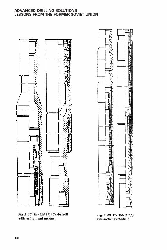
ADVANCED DRILLING SOLUTIONSLESSONS FROM THE FORMER SOVIET UNION
100
Fig. 2–27 The T25 93/4" Turbodrillwith radial-axial turbine
Fig. 2–28 The TS6 (65/8")two-section turbodrill
gelfgat 053-198.qxd 2/10/03 2:05 PM Page 100

DOWNHOLE MOTOR DRILLING TECHNOLOGY AND APPLICATIONS
In the case of the single-section turbodrill, this option faced a number ofessential problems related to design features as well as inconveniences associatedwith the manufacture and operation of long turbodrills (more than 10–11 m).For this reason, the engineers conceived of a sectional turbodrill during 1940and 1941 that was based on the theoretical works by Shumilov. However, thepractical implementation of this idea did not commence until the late 1940s andearly 1950s.
During this period, the research and design engineers developed and built first atwo-section turbodrill, followed by the three- and four-section turbodrills. The TS1-8-in. turbodrill, which was the first two-section turbodrill capable of operating,was field-tested in 1953 near Baku. The tests revealed a number of drawbacks inthe components design, such as the shafts joint assembly, bearings and theirlocation, etc.
From 1954 to 1955, the engineers developed and built the TS3 and TS4 turbodrillsin an attempt to eliminate the drawbacks. These turbodrills featured 180–200stages. In 1956, drillers commenced using the first three-section TS4-5-in.turbodrill with 240 stages. Next, the three-section 3TS5B and 3TS5E turbodrillwith diameters of 65 ⁄8-in., 71⁄2-in., 8-in., and 9-in. were successfully tested.
An important design solution was implemented during this period that concernedthe relocation of the axial bearing to the lower part of the turbodrill. This was builtas a no-flow-through thrust bearing, which made it possible to use jet bits (seediscussion later in this chapter), and was realized in the TS6 (65 ⁄8-in.) two-sectionturbodrill design shown in Figure 2–28 20.
The field and bench tests of this turbodrill design indicated that at a differentialpressure level of 40–50 bar in the bit, fluid leakage did not exceed 2–3%compared to 40% in turbodrills with a conventional radial bearing. Table 2–8summarizes the characteristics of the TS-type sectional turbodrills that featurethe lower axial no-flow rubber-metal thrust bearing, including TS4A-127 andTS4A-104.5 turbodrills, used to drill small diameter exploration wells and forworkover operations.
101
gelfgat 053-198.qxd 2/10/03 2:05 PM Page 101

ADVANCED DRILLING SOLUTIONSLESSONS FROM THE FORMER SOVIET UNION
TABLE 2–8Characteristics of the Two- and
Three-Section Turbodrills
PressureStage Mud drop at
number flow maximalper (l/sec) Shaft Rotation Power power
Type of TD turbine γ=1g/cm3 speed (rpm) Torque (kg.m) (HP) (kg/m2)At max. Free At Max.power run power Stall
TS 5B-240 210 38 500 1,000 230 460 160 4540 525 1,050 260 520 190 50
TS 5B-215 212 30 405 810 130 260 75 3035 470 940 175 350 115 45
TS 5B-195 177 25 550 1,100 100 200 78 4028 615 1,230 130 260 110 50
TS 5E-172 239 20 500 1,000 80 160 55 4022 550 1,100 95 190 70 50
3TS 5B-240 311 32 420 840 250 500 150 5034 450 900 280 560 180 55
3TS 5B-215 325 28 380 760 175 350 95 4530 405 810 200 400 115 50
3TS 5B-195 272 22 485 970 120 240 80 5024 530 1,060 145 290 105 60
3TS 5E-172 352 18 450 900 90 180 60 5020 500 1,000 115 230 80 60
TS4A-127 240 12 740 1,480 35 70 35 5013 800 1,600 40 80 40 60
TS4A-104,5 212 8 870 1,740 15 30 20 459 980 1,960 20 40 25 55
Placement of the thrust bearing at the lower part of the turbodrill shaft had twofaults:
1. the reduced diameter of the turbodrill shaft at the bearing installationarea (and consequently the shaft’s strength)
2. operational inconveniences associated with the need to remove theturbodrill shaft when replacing the bearing
These shortcomings were eliminated in the 3TSSh-type turbodrill design thatincorporated a number of important achievements in the turbodrill design process(Fig. 2–29). The spindle design, preserving all the advantages of the TS6, allowedsignificant simplification of manufacturing and operation of the turbodrills. Bymoving an axial bearing into an independent spindle assembly, the design engineersfacilitated and sped up the assembly replacement, which could be done now directlyat the rig site without disassembling the turbine section. This system significantlyreduced transportation costs associated with hauling turbodrills to repair bases.
102
gelfgat 053-198.qxd 2/10/03 2:05 PM Page 102

DOWNHOLE MOTOR DRILLING TECHNOLOGY AND APPLICATIONS
Furthermore, it relieved these bases from performing preventive maintenance onthe motors and the need to repair housings, shafts, and other components. Thisallowed them to focus on the major turbodrill repairs that were required afterprolonged operation. The spindle-type turbodrill application proved their efficiencyand promoted their further wide utilization.
A significant step forward in the enhancement of turbodrill designs was theimprovement in manufacturing quality of turbine discs—especially blade quality.The methods used initially, one-piece cast steel discs using sand molds, were verylabor-intensive and failed to produce high quality blades, both in terms of theouter edge thickness (1–1.2 mm) and the surface cleanliness that determined thehydraulic loss level.
In addition, this method of sand mold casting did not ensure that the cast turbinesmet the parameters of the prototype. Therefore, characteristics of the batchproduction turbodrills were often significantly different from the requirements. Achange from the sand mold casting to the precision cast method (melted modelcasting or wax casting) brought about considerable improvement in the quality ofthe blade system. The turbine batch production method differed from thetechnique used originally because the precision cast method sometimes, especiallyfor large size turbines, was used only for production of the circular flow-throughelement (blades crown). Hubs were made of round billets and then were jointed tothe setting section using a hot-pressing technique. The studies performedindicated that the hydraulic friction factor of the precision cast turbines was0.15–0.18 compared to 0.26–0.33 for the conventionally manufactured turbines.
103
Fig. 2–29 Turbodrill 3TSSh-type
gelfgat 053-198.qxd 2/10/03 2:05 PM Page 103

ADVANCED DRILLING SOLUTIONSLESSONS FROM THE FORMER SOVIET UNION
Blade crowns made ofpolymer materials provedto be quite efficient. Thecrown itself was essen-tially a replaceable partinstalled in reusable steelhubs. The polymer tur-bine blade system fea-tured extreme clean-liness of the flow surfacesand precision in thegeometry and size of theblades. These qualitiesensured a low hydraulicfriction factor of theturbine stages. The char-acteristics of the batch-produced turbine andtheir pilot prototypeswere almost the same,which added the desiredstability characteristics.A major advantage ofplastic turbine was itslow cost compared tosteel stages and its simpleand easy manufacturingtechnology. Polymer uti-
lization required a large volume of research work aimed at developing a materialthat met the tough requirements of the drilling technology, such as high strengthand resistance to vibration, heat, wear, and chemicals. The material composed ofPolyamid-12 met these requirements, which assured the successful commercialapplication of turbines made from it.
Further improvement of the three-section turbodrill design resulted in developmentof the unified turbodrill 3TSSh-1. Depending on the actual drilling conditions, thatmachine provided an opportunity to use all the turbodrill design innovationsdeveloped by that time that had been tested and used in commercially manufacturedturbodrills. Figure 2–30 presents the design of this turbodrill with rubber-metalthrust bearing. Figure 2–31 shows the spindle-only with two types of bearings:radial-thrust ball bearing and thrust ball bearing with rubber shock absorbers.
104
Fig. 2–30 Unified turbodrill 3TSSh-1 with a spindle thathas a rubber-metal thrust bearing
gelfgat 053-198.qxd 2/10/03 2:05 PM Page 104

DOWNHOLE MOTOR DRILLING TECHNOLOGY AND APPLICATIONS
The characteristics of the sectional spindle turbodrills are given in Table 2–9. Bythe mid-1970s and in the 1980s, these types of turbodrills were used most widelyby drilling companies in the FSU—especially in Western Siberia. The data in Table2–10 indicates that utilization of three-section turbodrills compared to single-section turbodrills, allowed for a 1.4–1.6 times reduction of flaw rate. Similarreduction rates were achieved in the shaft rotational speed, at the same time
105
Fig. 2–31 Spindle with rolling-contactbearings (radial-thrust bearing and thrustball bearing with shock absorbers)
gelfgat 053-198.qxd 2/10/03 2:05 PM Page 105
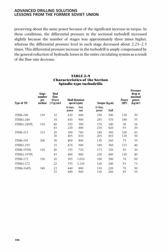
ADVANCED DRILLING SOLUTIONSLESSONS FROM THE FORMER SOVIET UNION
preserving about the same power because of the significant increase in torque. Inthese conditions, the differential pressure in the sectional turbodrill increasedslightly because the number of stages was approximately three times higher,whereas the differential pressure level in each stage decreased about 2.25–2.5times. This differential pressure increase in the turbodrill is amply compensated bythe general reduction of hydraulic losses in the entire circulating system as a resultof the flaw rate decrease.
TABLE 2–9Characteristics of the Section
Spindle-type turbodrills
PressureStage Mud drop at
number flow maximalper (l/sec) Shaft Rotation Power power
Type of TD turbine γ=1g/cm3 speed (rpm) Torque (kg.m) (HP) (kg/m2)At max. Free At Max.power run power Stall
3TSSh-240 318 32 420 840 250 500 150 50
3TSSh1-240 34 450 900 285 570 180 55
3TSSh1-240TL 318 40 195 390 170 340 50 1645 220 440 210 420 65 20
3TSSh-215 333 28 380 760 180 360 100 4530 405 810 205 410 120 50
3TSSh-195 306 30 400 800 130 260 75 35
3TSSh1-195 35 470 940 180 360 115 40
3TSSh-195TL 318 40 355 710 175 350 85 30
3TSSh1-195TL 45 400 800 220 440 120 40
3TSSh-172 336 20 505 1,010 100 200 70 60
3TSSh1-172 22 555 1,110 120 240 93 73
3TSSh-164TL 348 23 440 880 110 220 70 5025 480 960 130 260 85 55
106
gelfgat 053-198.qxd 2/10/03 2:05 PM Page 106

DOWNHOLE MOTOR DRILLING TECHNOLOGY AND APPLICATIONS
TABLE 2–10Characteristics of One- and Three-sectional
Spindle Turbodrills Comparison
DifferentialStage Mud pressure
number flow at max.per (l/sec) Shaft Rotation Power power
Type of TD turbine γ=1g/cm3 speed (rpm) Torque (kg.m) (HP) (kg/m2)At max. Free At Max.power run power Stall
T12M3B-240 104 50 660 1,320 200 400 185 4055 725 1,450 240 480 240 45
3TSSh-240 318 32 420 840 250 500 150 503TSSh1-240 34 450 900 285 570 180 553TSSh1-240TL 318 40 195 390 170 340 50 16
45 220 440 210 420 65 20T12M3B-215 99 40 545 1,090 110 220 85 25
45 610 1,220 140 280 120 353TSSh-215 333 28 380 760 180 360 100 45
30 405 810 205 410 120 50T12M3B-195 100 30 660 1,320 85 170 80 35
35 770 1,540 115 230 125 453TSSh1-195 306 22 470 940 180 360 115 403TSSh1-195TL 318 45 400 800 220 440 120 40T12P3E-172 121 25 625 1,250 65 130 55 30
28 760 1,400 80 160 75 403TSSh1-172 336 22 555 1,110 120 240 93 733TSSh1-164TL 348 25 480 960 130 260 85 55
Deep drilling application. Significantly lower rotational speeds of the turbodrill shaftand bit, along with increased torque, promoted use of three-section turbodrills indeep wells. The first experience using three-section turbodrills for drilling at depthsof 4500–5000 m in complicated geological conditions were well Nos. 144 and 153of the Karadag field in Baku, which proved to be quite positive. 21 The 3TS5B-9-in.turbodrills were used for drilling well No. 144 in 1961 and 1962. Turbodrilling wasapplied in the interval below the 11-in. intermediate casing string from 2200 to4800 m TD. Table 2–11 presents a comparison between the performance resultsfrom this well and the earlier best rotary well under the same conditions.
TABLE 2–11Turbodrilling in Well No. 144 (Karadag Field, Azerbaijan)
Comparison with the Earlier Best Rotary DrillingResults in the Same Conditions (1961–1962)
Drilling Number Footage ROP Drilling runBorehole No. interval (m) of runs per bit (m) (m/hr) rate (m/hr)
144 50-4000 174 24.9 4.20 1.63166 110-3898 99 34.5 2.42 1.45
107
gelfgat 053-198.qxd 2/10/03 2:05 PM Page 107

ADVANCED DRILLING SOLUTIONSLESSONS FROM THE FORMER SOVIET UNION
After these results, the 3TS5B-9-in. turbodrill was planned for use in drilling testwell No. 153 in the same field. The drilling program provided for utilization ofevery technique that would allow the most efficient application of turbodrilling.Among them were jet bits with various types of cutting structures, specialbottomhole assemblies (BHAs) to increase bit weight, and mud pumps with higherpressure capacity. Drilling this well was planned within the framework of aprogram to drill three test wells each using a different method: turbodrilling,rotary drilling, and electrodrilling (see Chapter 3).
The interval below the 11-in. casing of this well from a depth of 2300 m was drilledmostly using the 3TS5B-9-in. and partially a prototype of the 3TS7-8-in. turbodrill.In some intervals, the actual bit rotational speed was measured using a pulsetachometer. For example, in the interval from 3654 to 3664 m, while using the3TS5B-9-in. turbodrill with a ball-type spindle, at 16–18 tons bit weight and 36 l/sec flow rate, the registered bit rotational speed was 435 rpm. While drillingwith the 3TS7-8-in. turbodrill in the interval from 4091 to 4107 m, the rotationalspeed was 350–355 rpm, which corresponds to the parameters shown in Table 2–8.
While drilling the interval below the 8-in. liner from a depth of 4534 m and using1.85 g/cm3 density mud, the 3TS6-61 ⁄2-in. turbodrill was used in combinationwith cone bits and, in the lower part of the interval, with diamond bits. Table 2–12presents the comparison between the drilling results from well No. 153 and thetwo adjacent wells that were drilled using the rotary method.
TABLE 2–12The Comparison Between the Turbodrilling
Results from Well No. 153 (Karadag Field) and the Two Adjacent Wells Drilled
Using the Rotary Method
Borehole No. 153 199 187Borehole depth (m) 4,745 4,853 4,647ROP (m/hr) 3.0 1.41 1.75Drilling run rate (m/hr) 1.01 0.58 0.75Number of runs 266 396 309Footage per bit below 3000 m depth (m) 14.0 6.2 7.9Note: Drilling run rate takes into consideration tripping time - vR = run length / (drilling time + tripping time).
After the drilling of well Nos. 144 and No.153 was finished, hundreds of wellswere drilled across the entire Karadag field (except for the earlier developed part),using three-section turbodrills. This was the beginning of the wide scale utilization
108
gelfgat 053-198.qxd 2/10/03 2:05 PM Page 108

DOWNHOLE MOTOR DRILLING TECHNOLOGY AND APPLICATIONS
of turbodrilling technology for drilling deep wells in all regions of the FSU. Thistechnology was used most intensively for offshore vertical and directionalapplications in the Azerbaijan sector of the Caspian Sea.
The results of lower interval drilling in well No.153 confirmed the problemsencountered while using the turbodrilling technology with drilling mud densitythat exceeded 1.5–1.6 g/cm3. The problems encountered were specially studied byDrilling Department No.3 of the Turkmenburneft Company in 1953 while drillingwell No. 455 in Turkmeniya. 22 Barite (BaSO4), a mineral with a high specificgravity of 4.3–4.5 g/cm3, was used as a drilling mud-weighting additive. Thepulverized barite did not contain large and abrasive particles.
The T12M1-8-in. turbodrill was used to drill this well. The drilling revealed that asa rule, the turbine was plugged up and the pressure increased because ofcontinuous interruptions of the drilling process and mud circulation, as well asduring the procedure to increase mud weight. During such breaks in the drillingprocess, barite particles precipitated from the mud, built up on the blades, andplugged up the turbine. Therefore, the number of interruptions to mud circulationwhile drilling should be reduced to a minimum, and mud should be thoroughlycleaned from the solid phase. Also, mud should be circulated more frequentlythrough the well and turbine during tripping operations. In the case of a forcedinterruption of the drilling process, prior to breaking circulation, the DS should berotated with the turbodrill housing to stall the turbodrill in conditions ofsignificant weight simultaneously applied to the drillbit. This would result in therotation of stator discs around the fixed rotor discs.
By measuring the turbodrill shaft speed during the test at various pump rates, itwas determined that friction of the axial rubber-metal bearing caused a significantloss of power. Using turbodrills with ball bearings for drilling with heavy mud isrecommended.
In the case of well No. 455, the drilling mud density was maintained at 1.8 g/cm3.Extensive experience in deep well turbodrilling allowed drilling wells with a muddensity of 2.0 g/cm3 and greater. Yet the current official recommendations limitthe mud density level to 1.7–1.8 g/cm3.
Experience with precision-casting turbines in Western Siberia. As mentioned, theprecision-cast turbines proved to be very successful while drilling in WesternSiberia. The precision-cast low-speed turbine has a number of design featuresrelated to the need to reduce the rotational speed. Among these features are the
109
gelfgat 053-198.qxd 2/10/03 2:05 PM Page 109

ADVANCED DRILLING SOLUTIONSLESSONS FROM THE FORMER SOVIET UNION
high blade pitch angles of 72°–75° compared to 62°–65° in the regular turbines.Another feature is the thin outer rim of the blade.
Data in Table 2–9 indicates that because of these factors and the smoother bladesurface, the differential pressure went down Rather than up for turbodrills withprecision cast turbines at higher flow rates of 30% or more. In addition, therotational speed of the turbodrill shaft essentially decreased, whereas torque wentup. The possibility for increasing the circulation rate was quite important fordrilling wells in Western Siberia because it allowed directional well cleaningimprovement, especially in wells with a high degree of inclination. Also, a pressuredecrease in the turbine enabled utilization of jet bits.
Figure 2–32 23 shows an example of two different wax casting turbine profiles. Thedesign featured a shorter stage and blade length and allowed for a significantincrease in the number of stages per turbodrill section, which allowed significantchanges in the turbodrill characteristics as presented in Table 2–13.
110
Fig. 2–32 Precision-casting turbine stages of different profiles
28/18-195 quantity-producedturbine (18 mm height)
34/11-195 new design turbine(11 mm height)
gelfgat 053-198.qxd 2/10/03 2:05 PM Page 110

DOWNHOLE MOTOR DRILLING TECHNOLOGY AND APPLICATIONS
TABLE 2–13Comparison of 3TSSh-195TL Turbodrill with the
Turbines 28/18-195 and 34/11-195
Turbinetype blades Number
number/ Number of stages Pressure Effectiveblade of per Torque drop power Efficiency
Type of TD thickness) sections turbodrill RPM (kg m) kg/cm2) (HP) factor
3TSSh-195TL 28/18-195 3 330 259 117.5 18.7 41.1 0.553TSSh-195TL 34/11-195 3 445 290 153.5 26.9 51.4 0.48
Turbodrills featuring pressure descending towards the stall. As mentioned in thischapter, turbines with a degree of circulation σ >1 still would find an applicationbecause the differential pressure in the turbine at reduced rotational speed allowedthe pumping of more fluid through the turbine at low rotational speed andresulted in higher torque. Drillers can control the mud circulation rate throughthe turbine, characterized by the pressure curve descending toward the brakingmode (stall), using special downhole or surface devices. Flexible drive mud pumps,which are direct current (DC) electrical motors and a diesel engine with a trans-former turbine, control the circulation rate at the surface. Special equipment suchas pressure-reducing valves, ejector type hydraulic flow multipliers, or flowdividing systems enables downhole mud circulation control.
At first, turbodrills with such turbines were equipped with pressure-reducingvalves. In large diameter turbodrills, the valve was installed in the turbodrillhollow shaft, whereas in small diameter turbodrills, it was installed in the speciallyattached section above the turbodrill.
Turbodrills characterized by a declining pressure curve later became widely usedat constant flow rates without the pressure reducing valves even though thecharacteristics of these turbodrills became slightly worse. The pump outletpressure varied depending upon the operating regime.
The industry produced three types of turbodrills with declining pressure curvecharacteristics—A9K5Sa, A7N4S, and A6K3S with ODs of 240 mm, 195 mm,and 164 mm respectively.
The A9K5Sa and A7N4S turbodrills (Fig. 2–33) were built similar to the TS6sectional turbodrills but differed from the latter in bearing assembly design. Arubber-metal bearing was replaced with the multi-row (12 to 15 rows) axial thrustball bearing (see Fig. 2–22) that took up all axial loads and was installed in the
111
gelfgat 053-198.qxd 2/10/03 2:05 PM Page 111

ADVANCED DRILLING SOLUTIONSLESSONS FROM THE FORMER SOVIET UNION
turbodrill lower section. Single row radial ball bearings were installed in themidsection of the turbodrill. The end seal, installed above the radial-thrustbearing, prevented large abrasive particles from getting inside the bearing bylimiting the mudflow rate through it. The seal allowed for utilization of turbodrillsin combination with high-pressure bits.
112
Fig. 2–33 Turbodrills of “A” type
gelfgat 053-198.qxd 2/10/03 2:05 PM Page 112

DOWNHOLE MOTOR DRILLING TECHNOLOGY AND APPLICATIONS
The A6K3S turbodrill design featured an independent shaft suspension on axialbearing in each section. The 10-row radial-thrust ball bearing took up thehydraulic load in the upper section. The radial-thrust bearing in the lower sectiontook up the hydraulic load and bit weight.
The HBS was used to reduce the shaft rotational speed. The system consisted ofstators and rotors with blades that (unlike the turbine stator and rotor blades) hadan angle identical to the plane and perpendicular to the turbine shaft axis. In theHBS, part of the hydraulic flow energy transformed into mechanical energy thatwas used for the turbodrill shaft braking. The HBS installed in the turbodrill tookoff a certain amount of torque created by the turbine. The higher the turbinerotational speed, the more torque was taken off by the HBS stages. By varying theproportion between the number of turbine stages and the number of HBS stages,it was possible to reduce the shaft rotational speed in the no-load mode to therequired level. However, a reduction of the shaft rotational speed in the speedupmode occurred due to a power decrease in the turbodrill and resulted in a lowerefficiency factor. Three types of turbodrills equipped with the HBS were producedcommercially: A9GT, A7GT, and A6GT (with corresponding diameters of 240mm, 195 mm, and 164 mm).
The A9Sh, A7Sh, A6Sh, A9GTSh, A7GTSh, and A6GTSh turbodrills, equippedwith an HBS, were manufactured with the axial bearing fit in a separate spindlesimilar to the 3TSSh sectional turbodrills previously described. Table 2–14 showscharacteristics of the A-type turbodrills operated using water circulation.
TABLE 2–14Turbodrills with Descending Pressure Curve Characteristic
Number ofturbine/ Pressure
hydro- Mud drop atbreaks flow Max. max.
per (l/sec) Power powerType of TD turbine γ=1g/cm3 RPM Torque (kg m) (HP) (kg/m2)
At max. Free At max.power run power Stall
A9K5Sa 203 45 200–30 600 200–300 610 90 50A7N4S 226 33 300–500 1,000 180–280 455 130 70A6K3S 220 18 300–400 1,200 70–90 150 34 70A9GT 334/104 45 250 620 345 690 122 64A7GT 353/119 30 300 725 190 380 80 72A6GT 335/121 20 280 620 75 150 28 41A9Sh 210 45 400 975 310 620 180 68A7Sh 236 30 520 1,200 190 380 140 82
113
gelfgat 053-198.qxd 2/10/03 2:05 PM Page 113

ADVANCED DRILLING SOLUTIONSLESSONS FROM THE FORMER SOVIET UNION
Turbodrills for diamond drilling applications. Development of the low-speedturbodrills was determined by the capabilities of the roller-cone bits, or theirbearings to be more specific. Another trend in the turbodrilling technologydevelopment was the design and construction of DHMs capable of working withcutting-shearing type no-bearing matrix bits, such as natural or artificialdiamond, composite inserts, and later PDC bits.
In 1957 and 1958, the first experimental wells were drilled using turbodrills incombination with diamond bits in France and the United States. One of the mostimportant parameters of the efficiency of drilling using diamond bits atsignificant levels of footage per bit was ROP (vM) that depended on such factors asrock and bit type, bit rotational speed (n), bit weight (G), and the level ofbottomhole cleaning.
The increase of n and G values leads to growth in ROP. For example, the results ofexperimental drilling, carried out by specialists from the Prikarpatburneft DrillingCompany, using electrodrills in combination with 215-mm diamond bits, 24
revealed ROP linear growth at n increasing from 170 rpm to 900 rpm, and Graising from 2 to 17 tons (Q = 23 liters/sec). The energy consumption for the rockdestruction process reduced at higher n, whereas it remained constant atincreased G. This allowed a conclusion about the expediency of diamond bitdrilling application and rotational speed increases of more than 500 rpm.
Yet, the conclusion was accurate only in conditions of perfect bottomholecleaning. Otherwise, bit weight increase at medium rotational speed levels wasmore efficient. In turn, quality of the bottomhole cleaning depended on a varietyof reasons, such as mud circulation rate Q, pressure differential of the bit, anddifferential pressure level at the bottomhole.
When using a turbodrill to rotate a bit, the function vM = f (G) cannot be linear andis calculated according to the formula for turbodrill power characteristics (N ). Itreaches its maximum level at a certain bit weight, the level of which hinges on aspecific combination: turbodrill–bit–rock and is determined while drilling.
ROP is dependent on the level of power, applied at the bit:
vM = CaN z 2.28
114
gelfgat 053-198.qxd 2/10/03 2:05 PM Page 114

DOWNHOLE MOTOR DRILLING TECHNOLOGY AND APPLICATIONS
where
z is an exponent, dependent on such factors as bottomhole cleaning qualitylevel, bit weight, and rotational speed
Ca is a constant, dependent on the type of bit
The maximum ROP closely matches the maximum turbodrill effective power Nef
Nef = ptQηt 2.29
Equation 2.29 indicates that pump pressure and the turbodrill efficiency factormust be increased to achieve high Nef and penetration rate levels.
The requirements of a turbodrill design and the characteristics of diamond bitturbodrilling applications differ slightly from those for regular bit applications.Since diamond bits do not have bearings, their rotational speed is limited only bybit-cutting structure and matrix wear. According to the available information,the limits on rotational speed are quite high, in the range of 800 rpm to 1000rpm (for 212-mm bits). Requirements for torque in diamond drilling applicationsare much higher compared to the roller-cone bits. For most types of rock, thespecific torque level for cutting-shearing type bits is 2–2.5 times highercompared to the analog values for roller-cone bits. The possibility of drilling athigh rotational speeds and the need to increase torque require a significantincrease in the effective power of a turbodrill. Construction of a high wear-resistant turbodrill with long service life (that would not limit bit-operating time)could extend this time to hundreds hours.
The existing turbine designs for 195-mm diameter turbodrills did not fully complywith the set requirements, so the 21/16.5 precision cast turbine was developed. Table2–15 shows the turbine characteristics operating at maximum power and, for com-parison, characteristics of other turbines in wells of various depths. For 1.2 g/cm3
density mud, the pump flow rate was determined to be a constant pressure of 170-180 kg/cm2 in 141-mm OD drillpipe (DP) with ZSh(FH) type tool joints. A 25-stagerubber-metal seal bearing installed in the Sh2-195 spindle served as a turbodrill axialbearing. Width of the bearing surface was increased by 50% compared to the bearingof the batch produced Sh1-195 spindle, which helped increase the bearing life byreducing specific loads and improving fluid lubrication friction.
115
gelfgat 053-198.qxd 2/10/03 2:05 PM Page 115

ADVANCED DRILLING SOLUTIONSLESSONS FROM THE FORMER SOVIET UNION
TABLE 2–15Turbodrills of 195 mm OD Characteristics
Number ofsections/ Efficiencystages in factor Borehole depth (m)
Turbine Type turbodrill % 2000 3000 4000
Q n M ∆p Q n M ∆p Q n M ∆p
21/16,5 2/228 75 33 795 305 105 31 745 270 90 30 725 250 85vax casting
21/16,5, 3/342 75 29 700 355 125 28 675 330 110 26 625 285 95vax casting
33/11, 3/408 56 39 450 355 75 36 415 305 65 34 390 270 60vax casting
21/20,5, 3/288 58 30 660 285 110 29 640 265 105 27 595 230 90sand casting
28/18 3/330 55 46 390 275 45 41 345 220 35 38 320 190 30vax casting
24/18, 3/342 48 43 430 285 60 39 390 235 50 36 360 200 45plastic
Note: M=torque (kg.m), ∆p- pressure drop (MPa).
The Saratovneftegaz, Kuibyshevneft, Ukrneft, and Nizhnevolzhskneft Companiescarried out commercial test drilling using the 3TSShA-195TL turbodrills.Penetration rates while using this type of turbodrill in combination with diamondbits increased by 30–100% compared to the regular turbodrills. The Archedinskand Zhirnovsk drilling subsidiaries of the Nizhnevolzhskneft Company tested theseturbodrills with diamond bits of Russian and French design made by ChristensenCompany (bits with differential pressure of 40 kg/cm2 were used). The drillers useddrilling mud with a weight of 1.2-1.3 g/cm3 (Table 2–15). The bit weight level wasselected to achieve the maximum penetration rate and was brought up to 20 tons.For the two-section turbodrills, the optimum bit weight was 8–11 tons, whereasfor the three-section turbodrills it was 10–16 tons.
Diamond and PDC bit technologies hold promise for deep turbodrillingapplications. Diamond bits meet the requirements of turbodrilling applicationsperfectly. They operate in a wide range of rotational speeds including high-speed.Introduction of the oil-filled roller-cone bits limited utilization of diamond bits to acertain extent; however, until a special cone seal is designed that enables operationat high rotational speeds, the low speed roller-cone bits should be compared tohigh-speed diamond bits. The main factor in improving diamond bit economics isthe need to achieve higher penetration rate.
An efficient and relatively simple method for increasing diamond bit rotational speedusing special turbodrill sectioning was invented and is presented in Figure 2–34. 25
116
gelfgat 053-198.qxd 2/10/03 2:05 PM Page 116

DOWNHOLE MOTOR DRILLING TECHNOLOGY AND APPLICATIONS
The upper section shaft (1) was connected to the lower section housing (2). Aproperly sized end-face collar seal (3), installed in the lower part of the uppersection turbine, prevented fluid leak into the annulus under differential pressure inthe lower section (2) and in the diamond bit (4). Due to the fact that the stator ofthe lower section was not fixed but rotated in the same direction as the rotor, theabsolute rotational speed of the rotor increased and the stator speed was added tothe relative speed of the rotor. The resulting bitrotational speed totaled the sum of the rotationalspeeds of all shafts in all sections. Unfortunately, thesuggested new turbodrill design was only tested onceon a test stand. It was never tested in the field and hasnot been used so far.
Turbodrills for coring applications. Coring usingturbodrills with a core barrel attached to theturbodrill shaft did not provide appropriate resultsbecause of the high level of vibrations that damagedthe core in the core barrel. Therefore, the turbo-coring application was very limited, especially in looseformations of productive horizons. In addition, thelimited length of the recovered core sample neces-sitated frequent tripping operations when coring longintervals using diamond bits.
In 1949, the engineers R. A. Ioannesyan and Gusmandesigned and built a special turbo-coring unit, calledturbobit, for wireline coring operations. The KTD3 coreturbobit design (Fig. 2–35) was similar to the T12M3turbodrill. The only difference was a hollow shaft witha wireline core barrel installed inside. The barrel wasfitted into the shaft and set in a special tapered surfaceseat secured inside the turbodrill housing. Hydraulicforce was generated by differential pressure in theturbine, and the bit held the core barrel against theseat. The generated friction forces prevented the barrelfrom rotating. The core barrel had a relief valve thatdiverted fluid from the inner barrel space to theclearance between the shaft and the barrel when a coreentered the barrel. A small clearance of 1 mm betweenthe barrel and the shaft hole and the significant length
117
Fig. 2–34 The method forincreasing diamond bitrotational speed
gelfgat 053-198.qxd 2/10/03 2:05 PM Page 117
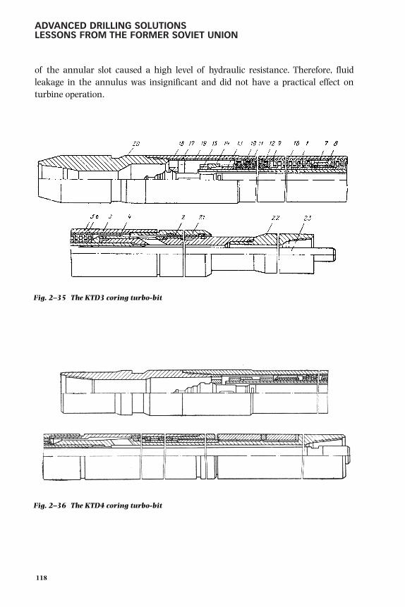
ADVANCED DRILLING SOLUTIONSLESSONS FROM THE FORMER SOVIET UNION
of the annular slot caused a high level of hydraulic resistance. Therefore, fluidleakage in the annulus was insignificant and did not have a practical effect onturbine operation.
118
Fig. 2–35 The KTD3 coring turbo-bit
Fig. 2–36 The KTD4 coring turbo-bit
gelfgat 053-198.qxd 2/10/03 2:05 PM Page 118

DOWNHOLE MOTOR DRILLING TECHNOLOGY AND APPLICATIONS
Utilization of the standard turbodrill components for the turbobits, such as aturbine, axial bearings, and radial bearings, enabled recovery of core samples bythe KTD3-172 and KTD3-255 turbobits with diameters from 33 mm to 50 mmrespectively. The KTD4 core turbobit was later designed and built and was used torecover larger diameter cores (Fig. 2–36). This became possible, thanks to theincrease in shaft diameter. KTD4 also had higher torque due to the increasednumber of turbine stages. Its axial bearing was located at the lower end of the shaft,and its core barrel length could be adjusted depending on the core bit type used.
The industry produced several standard types and sizes of turbobits: KT3-240-265/48, KTD4-195-214/60, KTD4M-172-190/40, and KTD4S-172-190/40.The first digit represented the housing diameter in mm; the two others were for theborehole/core diameter. Unlike the other listed turbobits, the KTD4S-172-190/40(Fig. 2–37) had two sections, which helped increase torque by increasing thenumber of the turbine stages. The core length it was possible to recover increasedup to 7 m compared to 4 m recovered by a single-section turbobit. The KTD4S-172-190/40 turbobit design was similar to the TS5B two-sectional turbodrill. Anaxial turbobit bearing, installed in the lower section, took up the hydraulic loadfrom both sections. The housings of the two sections were connected to each otherusing a tapered thread sub, whereas the shafts were connected through taperedspline couplings. Table 2–16 presents technical and power characteristics of thelatest version of core turbobit designs (1980s) for the water circulation regime.
119
Fig. 2–37 The KTD4S-172-190/40 two section coring turbo-bit
gelfgat 053-198.qxd 2/10/03 2:05 PM Page 119
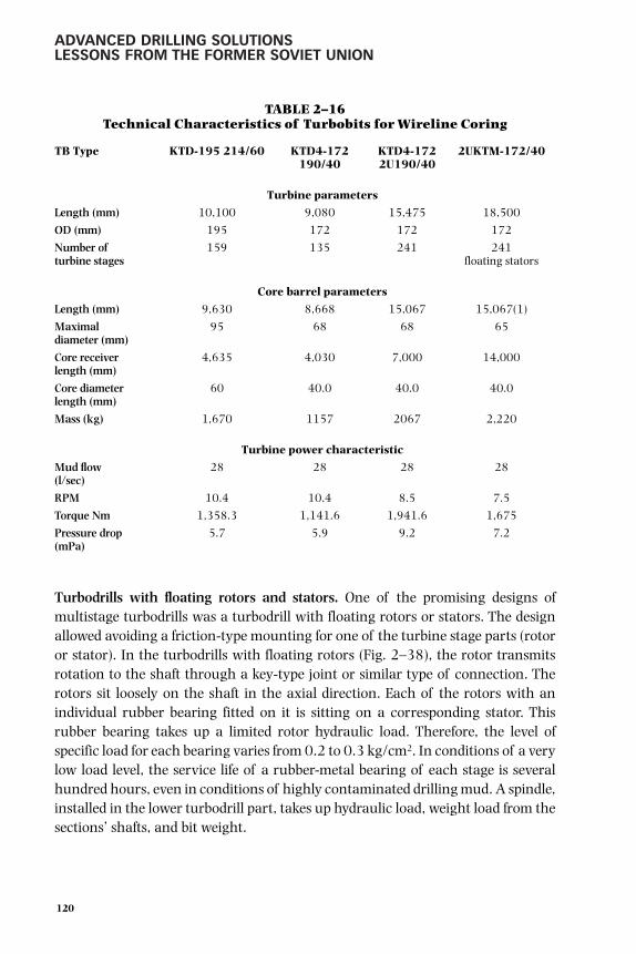
ADVANCED DRILLING SOLUTIONSLESSONS FROM THE FORMER SOVIET UNION
TABLE 2–16Technical Characteristics of Turbobits for Wireline Coring
TB Type KTD-195 214/60 KTD4-172 KTD4-172 2UKTM-172/40190/40 2U190/40
Turbine parameters
Length (mm) 10,100 9,080 15,475 18,500
OD (mm) 195 172 172 172
Number of 159 135 241 241turbine stages floating stators
Core barrel parameters
Length (mm) 9,630 8,668 15,067 15,067(1)
Maximal 95 68 68 65diameter (mm)
Core receiver 4,635 4,030 7,000 14,000length (mm)
Core diameter 60 40.0 40.0 40.0length (mm)
Mass (kg) 1,670 1157 2067 2,220
Turbine power characteristic
Mud flow 28 28 28 28(l/sec)
RPM 10.4 10.4 8.5 7.5
Torque Nm 1,358.3 1,141.6 1,941.6 1,675
Pressure drop 5.7 5.9 9.2 7.2(mPa)
Turbodrills with floating rotors and stators. One of the promising designs ofmultistage turbodrills was a turbodrill with floating rotors or stators. The designallowed avoiding a friction-type mounting for one of the turbine stage parts (rotoror stator). In the turbodrills with floating rotors (Fig. 2–38), the rotor transmitsrotation to the shaft through a key-type joint or similar type of connection. Therotors sit loosely on the shaft in the axial direction. Each of the rotors with anindividual rubber bearing fitted on it is sitting on a corresponding stator. Thisrubber bearing takes up a limited rotor hydraulic load. Therefore, the level ofspecific load for each bearing varies from 0.2 to 0.3 kg/cm2. In conditions of a verylow load level, the service life of a rubber-metal bearing of each stage is severalhundred hours, even in conditions of highly contaminated drilling mud. A spindle,installed in the lower turbodrill part, takes up hydraulic load, weight load from thesections’ shafts, and bit weight.
120
gelfgat 053-198.qxd 2/10/03 2:05 PM Page 120

DOWNHOLE MOTOR DRILLING TECHNOLOGY AND APPLICATIONS
121
Fig. 2–38 Turbodrill with “floating” rotor
gelfgat 053-198.qxd 2/10/03 2:05 PM Page 121

ADVANCED DRILLING SOLUTIONSLESSONS FROM THE FORMER SOVIET UNION
The floating stator features another concept in that type of turbine. The stators fitinto the housing by means of the keys on each stator disk and the keyway cutalong the internal housing surface. A keyed joint takes up reactive torque from thestator. The turbodrill design with the floating stator led to a considerably increasedaverage diameter in the turbine, thanks to the absence of the stator thrust faces,which significantly improved the turbine characteristics.
Bearings installed in each turbine stage sufficiently reduced axial clearancesbetween the rotor and the stator. In regular turbines, axial clearances arenormally 14–20 mm compared to 5–8 mm in the turbodrills with floatingworking elements. As a result, the number of turbine stages in a section could beincreased significantly. One of the main advantages of the floating workingelements design was that they do not require an adjustment of the turbine axialclearances, thus making it possible to increase the number of turbodrill stages.
Figures 2–39, 2–40, and 2–41 show a general view of a turbodrill with a floatingstator, a turbine stage, and a stator position inside the turbodrill housing. Table2–17 presents characteristics of turbodrills with floating stators and rotors.
122
Fig. 2–39 Turbodrill with “floating” stator
gelfgat 053-198.qxd 2/10/03 2:05 PM Page 122

DOWNHOLE MOTOR DRILLING TECHNOLOGY AND APPLICATIONS
123
Fig. 2–40 Turbine stage of floating stator turbodrill
1–bushing2–stator3–rotor4/5–metal-rubber thrust bearing
Fig. 2–41 Floating stator position in turbodrill section housing
1–housing2–stator
gelfgat 053-198.qxd 2/10/03 2:05 PM Page 123

ADVANCED DRILLING SOLUTIONSLESSONS FROM THE FORMER SOVIET UNION
TABLE 2–17Turbodrills with Floating-Type Stators and Floating-Type Rotors
(3T-105K) Characteristics (Drill Mud–Water)
Parameters at operating modeNo. of No. of Flow Pressure
OD turbine turbine Length Weight rate Torque dropTurbodrills type (mm) stages sections (mm) (kg) (l/sec) RPS (kg m) (MPa)
TSSh-1M1-195 195 425 3 25,800 4,200 28 5.4 1,788 3.8TPS-195M 195 380 2 18,400 3,085 32 6.2 1,563 3.3TPS-172 172 426 3 26,250 3,325 25 6.7 1,697 4.8TPS-172M 172 432 2 18,500 2,180 25 83 1,668 6.8TPS-105 105 420 3 15,500 765 12 10 412 5.43T-105K 105 303 3 12,700 590 12 11.6 430 6.8
A comparison between the data shown in Table 2–17 and the information fromTable 2–9 (showing characteristics of three-section turbodrills including thosewith precision cast turbines) indicates that the development of turbodrills withfloating stators is another step toward the improvement of M/n (torque/rpm)ratio, i.e., the dynamic characteristics of turbodrills. This conclusion can be madeafter comparing the turbodrill designs presented in Table 2–18.
TABLE 2–18Sectional Turbodrills Characteristics as Compared to
Floating Stators Turbodrills (Operational Mode)
No. of No. of PressureTurbine turbine turbine Flow Torque drop
Turbodrills type type sections stages (l/sec) ROP (kg m) kg/cm3
TSSh-1M1-195 Floating stator 3 425 28 324 178.8 38
TPS-195M Floating stator 2 380 32 372 156.3 33
3TSSh-195 Serial 3 306 30 400 130 35
TPS-172 Floating stator 3 426 25 400 169.7 48
TPS-172M Floating stator 2 432 25 498 166.8 68
3TSSh1-172 Serial 3 336 22 555 120 73
The TSSh-1-M1-195 turbodrills with floating stators were field-tested inGlavtyumenneftegaz, Western Siberia. The test results indicated a significantimprovement of bit performance (2 to 3 times) and increased MTBF compared tothe standard turbodrills. This type of turbodrill was also tested by theKuibyshevneft Company, while drilling experimental well No. 163 (this drilling testis described in Chapter 3).
124
gelfgat 053-198.qxd 2/10/03 2:05 PM Page 124

DOWNHOLE MOTOR DRILLING TECHNOLOGY AND APPLICATIONS
In 1982 and 1983, the Kaliningradmorneftegaz Company carried out a largeamount of drilling work using this type of turbodrill to drill 18 wells in variousfields offshore. 26 An interval was drilled below the intermediate casing into theCambrian deposits from depths of 1100–1200 m to the TD at 2300 m. The drillingmud density was 1.18-–1.2 g/cm3. Jet bits with a differential pressure of 3 to 5MPa drilled a total of 7000 m in 1800 hours. The results of this test drilling withTSSh-1-M1-195 floating stators turbodrills revealed for tri-cone bits applicationan increase in the penetration per bit by 59%, and ROP by 24% in comparison withstandard drilling that used the A7Sh turbodrills (mostly utilized by the company).
During the test drilling, seven ISM-212-type bits (ISM means drag type bit withdiamond composite inserts manufactured by Institute of Super-hard Materials inKiev, Ukraine) were also used to drill 2140 m during 840 hours. The averagefootage per bit was 305 m at an average penetration rate of 2.55 m/hr. Theaverage bit on bottom time was 120 hours. No cases of the turbodrill failure wereregistered. The average service life of turbines in the tested TSSh-1-M1-195turbodrills was 550 hours. The MTBF of the ShShO-type spindle section with aroller bearing with rubber absorbers was 277 hours compared to 85 hours for aregular turbodrill. These improved parameters were especially important foroffshore drilling applications.
Based on the test results, the following are some conclusions about the advantagesof turbodrills with floating stators compared to regular sectional turbodrills:
• Improved power characteristics due to the larger average diameter of theturbine and an increased number of stages in each section.
• Elimination of the most complicated and labor consuming operationsfrom the turbodrill assembly and adjustment process.
• Longer spindle MTBF, thanks to the elimination of the limits on allowableaxial backlash of a spindle bearing.
• Longer turbine section MTBF brought about by the elimination of thewear on the blade cascade by fitting the rotor on the stator.
Shifting to the wide utilization of the new design turbodrills was, undoubtedly, oneof the most challenging and rewarding tasks for engineers and drilling companies.Unfortunately, this task has never been fulfilled. The design features of turbodrillswith a floating stator/rotor required a significantly different manufacturing
125
gelfgat 053-198.qxd 2/10/03 2:05 PM Page 125

ADVANCED DRILLING SOLUTIONSLESSONS FROM THE FORMER SOVIET UNION
procedure and different materials. Because the use of rubber and plastic was amandatory requirement for achieving advanced characteristics in the turbinestage design, operational temperatures have limited the turbodrills with floatingstators application.
Geared turbodrills—new winds of development
Design attempts in 1960s and 1970s—promising tests. An analysis of themethods of improvement of the sectional turbodrills characteristics just reviewedmade it evident that the lowest allowable rotational speed in the turbodrill shaft is250–300 rpm, which was proven in operations. However, both rpm and torquewere not sufficient to drill deep wells efficiently using roller-cone bits. Therefore,scientific, research, and design organizations have addressed the issue of thedevelopment of gear-reduction turbodrills once again using new achievements inmechanical engineering.
In the 1960s and early 1970s, several research institutes, such as the VNIIBT andOil and Gas University (MINKh or MING) in Moscow, the Perm Branch of theVNIIBT, and the Kungur Engineering Plant, developed a number of gear-reductionturbodrills. The prototype tests revealed that engineers had not designed asufficiently reliable oil-filled reduction gear or durable non-sealed gear.
However, some positive results were obtained from the experience gained in theconstruction of reduction gear inserts for electrodrills (discussed later in thischapter). The SKTBE of the Ministry of Electrical Engineering Industry of the FSUdeveloped reduction gear inserts for electrodrills of all standard sizes with gearratios of 2, 3.14, and 9. When used in Turkmeniya and Bashkiriya, they helpedincrease footage per drillbit and penetration rate by 15–20% compared to non-reduction gear electrodrills. 27
As a part of the electrodrill oil-filled system, the gear insert located between themotor and the spindle operated in most favorable conditions. This ensured the highoperating efficiency of the electrodrill. Using these developments, the VNIIBT inconjunction with SKB, developed and built a spindle-type reduction gear turbodrillwith the RT-195 attached reducer (Fig. 2–42). The reducer had a double-rowplanetary gear (gear ratio 2.92) with straight involute gearing. A bevel gear(differential), working as a torque divider, distributed torque between the rows.
The oil-filled reduction gear system included a no-inertia diaphragm lubricator. Astack of radial rubber collars and sequentially installed end-face seal bearings with
126
gelfgat 053-198.qxd 2/10/03 2:05 PM Page 126

DOWNHOLE MOTOR DRILLING TECHNOLOGY AND APPLICATIONS
hard-alloy rings wereused as seal elements.The reducer shaft wasconnected to the ShShO1-195 spindle (dis-cussed in this section)through a spline cou-pling with an indepen-dent lubrication system.The reduction gear withthe spindle was connect-ed to one, two, or threeturbine sections. Table2–19 presents powercharacteristics of thistype turbodrill for mudwith a weight of 1.8g/cm3. Using tachome-ters, the KaspmorneftCompany tested thisturbodrill in wells withdepths of more than3000 m and had stableturbodrill operations at130–170 rpm. ROP washigher compared torotary drilling.
TABLE 2–19Turbodrill with Planetary Gear Insert RT-195
Number of Mud flow Pressure dropTurbine Sections Turbine type rate (l/sec) RPM Torque (kg m) kg/cm2
1 33/11 34 130 410 302 33/11 32 110 720 52
The turbodrill reducer insert with the stack type oil-filled system was the mostpromising development of the turbodrill for deep well drilling applications. It usedregular seals and special labyrinth type seals.
127
Fig. 2–42 The RT-195spindle-reducer of newgeared turbodrill(1960s)
1–coupling2–lubricator3–seals4–shaft5–gear differential6–carrier7–low speed shaft
gelfgat 053-198.qxd 2/10/03 2:05 PM Page 127

ADVANCED DRILLING SOLUTIONSLESSONS FROM THE FORMER SOVIET UNION
In 1970, specialists from the Kungur Engineering Plant and engineers from theVNIIBT Branch in Perm developed the TR2Sh-195 non-sealed reduction gearturbodrill. The turbodrill consisted of two turbine sections and one axial bearingsection (spindle). A multi-row planetary friction type gear reducer was installed ineach turbine section. Each row of the reducer consisted of the turbine stator androtor discs with races and balls. The balls were located in a separator connectedthrough a key-joint to a section shaft. The load, generated by a differential pressurein the rotor, provided the pressing force required for torque transmission. Since thereducing gear used the normal turbine circulation degree of a regular turbodrill,the pressing force of the friction couple was not dependent on the transmittedtorque level and was practically constant in any operating regime.
Table 2–20 shows characteristics of the TR2Sh-195 turbodrill with the regularturbine 21/20.5. 28 In conditions with no sliding, the reducer gear ratio was 2–7.However, in conditions of vibration, there was always a risk of sliding, whichresulted in a decrease in the dynamic gear ratio at low rotational speed. The TR2Shprototype field tests indicated that the service life of the main gear elements, suchas balls and their bearings in carriers, was about 50 hours. 29
TABLE 2–20Characteristics of the TR2Sh-195 Turbodrill with
Ball-Type Gear Reducer (Turbine Type 21/20.5)
Number of Number of Mud flow Pressure dropTurbine Sections Turbine stages rate (l/sec) RPM Torque (kg m) kg/cm2
1 58 45 290 250 492 116 40 258 258 77
35 225 225 60
In the other designs, the RSh-195 non-sealed friction type gear reducer, the sametype gear was built as a separate spindle and located between the turbine and thebearing (Fig. 2–43). The reducer was built according to the multi-row schemewith a joint carrier. To provide equal distribution of the friction gear pressing forceagainst the rows, the reduction gear assembly was rolled on under load in abrasivemedia or special compensating elastic elements were used. The gear reducerkinematic gear ratio was 2.5. Depending on bit operating conditions, the gearboxmechanical efficiency factor varied from 0.55 to 0.7, which resulted in significantvariation of the dynamic gear ratio. The gear reducer tests indicated a lowoperating life of 40–50 hours in abrasive mud because of inadequate durability ofthe solids of revolution (steel rolling bodies) and their bearings in the carrier.
128
gelfgat 053-198.qxd 2/10/03 2:05 PM Page 128

DOWNHOLE MOTOR DRILLING TECHNOLOGY AND APPLICATIONS
However, continued research work in this field has confirmed good prospects fordeveloping oil filled gear reducers with enhanced seal design. Engineers from thePerm Branch of VNIIBT (N. D. Derkach, E. N. Krutik, et al.) designed and built theRM-195 gear reducer, and its tests produced positive results. 30 This appeared to bethe first commercial reduction geared turbodrill.
TRM-195 gear reduction turbodrill application—first commercial success. From1975 to 1978, the Perm Branch of VNIIBT pioneered the development of the 195-mm diameter gear reduction turbodrill, TRM-195, with oil-filled gear reducer RM-195. 31 Commencing in 1978 through 1985, this turbodrill was field-tested inBashkiriya and Tatariya, Western Siberia and in the ultra-deep wells drilled in theFSU according to the Scientific Continental Drilling Program (see Volume 2).
A diagram of this turbodrill is shown in Figure 2–44. The TRM-195 includes theturbine section (A), top and bottom spindles (B, D) with the oil-filled gearbox (C)mounted between them. The gearbox contains input and output shafts installed onbearing assemblies and the planetary gear positioned between the shafts. The gearprotection system consists of the two face seals and a lubricator to transfer themud pressure inside the oil-filled chamber that incorporated the gear andbearings. The shafts are interconnected with the spindle shafts by virtue ofclutches. The gear reducer transforms the rotation of the turbine section shaft andoutputs it to the spindle shaft and drillbit while reducing the rotating speedproportionally to its gear ratio (3–69) and increasing the torque proportionally.
129
Fig. 2–43 Reducer-spindle RSh-195 of planetary friction-balltype reduction gear turbodrill (1970)
gelfgat 053-198.qxd 2/10/03 2:05 PM Page 129

ADVANCED DRILLING SOLUTIONSLESSONS FROM THE FORMER SOVIET UNION
130
Fig. 2–44 The TRM-195 turbodrill with planetary gear reducer
A– turbine sectionB–thrust bearing spindle–
intermediateC–reduction gear boxD–bottom spindleE–drill bit
The box (c) contains input7 and output 9 shaftsinstalled on rollingbearings 6 and radialsliding bearings 2.Planetary gear 8positioned between shafts7 and 9; oil protectionsystem consisting of twoface seals 5 and lubricator4 to transmit mud pressureinside oil-filled chamberincorporating gear andbearings. Mud passesthrough circular portinside housing 10(direction is shown byarrow). Oil is filledthrough orifice 3 inhousing 10 being plugged.The shafts 7 and 9 areinterconnected withspindle shafts by virtue ofhalf-clutch 1.
gelfgat 053-198.qxd 2/10/03 2:05 PM Page 130

DOWNHOLE MOTOR DRILLING TECHNOLOGY AND APPLICATIONS
The production of oil-filled gear reducers RM-195 in quantity started in 1986 atthe Polymermash plant in Tambov with an annual output of 100–230 sets. Themain customers for the TRM-195 were the drilling enterprises of WesternSiberia. Between 1987 and 1991, more than 10 service centers for maintenanceof the gear reduction turbodrills were organized in oil companies likeNoyabrskneftegas and Nizhnevartovskneftegas. In 1989 and 1990, the volume ofdrilling using the gear reduction turbodrills increased from several tens ofthousands of m to 500,000–600,000 m annually. TRM was used most effectivelyin the hard formations below 2000 m depth. Since 1987, more than 3.5 millionm have been drilled.
The heat resistant (250–300° C) TRM-195 version enabled the drilling of the Kolaultra-deep well to a record depth of 12,262 m. The TRM-195 turbodrill wassuccessfully used in drilling the Saatlinskaya (Azerbaijan), Uralskaya,Tyumenskaya (Russia), Krivorozhskaya, and Dneprovo-Donetskaya (the Ukraine)ultra-deep wells.
Different types of turbines may be used in the gear reduction turbodrill TRM-195(see data in Table 2–21). The best ROP was achieved when using assemblies twoand five as specified in this table. In the intervals of 2000–3000 m at the WesternSiberia fields, the TRM turbodrills allowed drillers to maximize footage per bit(Russian production) by 30–50% and trip speed by 20–30% compared to theregular turbodrills. Average MTBF of the gearbox in conjunction with the twospindles constituted 120–130 hours (per data from Noyabrsk Service Center). Themost typical reason for failure in this case was spindle wear. Average overhaul lifeof the RM-195 oil filled gear was 170–220 hours; however, sometimes the failureinterval exceeded 300 hours. The average guaranteed failure interval of RM-195until write off constituted 900 hours but this procedure usually took place after2000 hours of operation.
TABLE 2–21TRM-195 Gear Reduction Turbodrill Characteristics with
Different Turbine Types
No. of Operating ConditionsAssembly Turbine turbine Gear Mud flow M op n op P op M st N n-1Number type sections ratio rate (l/sec) (N.m) (Mpa) (min-1) (N.m) (min-1)
1 TSSh1-195 2 3.69 32 3,720 111 4.4 7,440 2222 TSSh1-195 3 3.69 32 5,580 111 5.9 11,160 2223 A7Sh 1 3.69 32 3,300 161 6.0 6,600 3224 TSShA-195TL 1 3.69 32 3,780 206 5.4 7,560 4125 TSShA-195TL 2 3.69 24 4,252 155 6.1 8,504 3106 TSShA-195TL 0.5 3.69 2 1,890 206 3.8 3,780 412
131
gelfgat 053-198.qxd 2/10/03 2:05 PM Page 131

ADVANCED DRILLING SOLUTIONSLESSONS FROM THE FORMER SOVIET UNION
TRM-195 with drillbits from USA—operational experience. The oil productioncompanies in Russia had a chance to use high quality foreign-made drillbits in the1990s. Despite the high price of the rolling cutter bits from such companies asReed Tool, Smith International, and Hughes Christensen Co., they proved theirefficiency in the lower borehole intervals of the Western Siberian fields. Highquality bit bearings could run at the bottom at up to 200 rpm for 70–100 hours inaverage. Table 2–22 represents field examples of drillbit performances withdifferent motors, and Table 2–23 represents the average results of PDM and TRMmotor applications with the advanced drillbits used in Western Siberia fieldsduring 1994 and 1995.
TABLE 2–22Drillbit Records, West Siberia, 2000–3000 m Deep Sections
Avg. BitOil Company Bit Number penetr. life, ROP,Contractor Motor type Bit specs. manufacturer of bits (m) (hr) (m/hr)
UKOS, NUBR-1 D2-195 S83F Dresser Security 1 565 135 4.2EHP-51A Reed Tool Co. 1 522 76 6.9MF-15 Smith Int. 2 782.5 115 6.8215.9 MS-GNU Volgoburmash 170 83.2 16.8 5.0
UKOS, NUBR-2 MF-15 Smith Int. 11 612.6 15.6 5.8215.9 MS-GNU Volgoburmash 50 83.7 16.4 5.1
UKOS, MUBR EHP-51A Reed Tool Co. 1 774 96 8.0ATM-P-11H Hughes 1 301 47 6.4MF-15 Smith Int. 10 651.8 140.4 4.6215.9 MS-GNU Volgoburmash 168 83.3 19.8 4.2
UKOS, SUBR ATM-P-11H Hughes 1 917 73 12.6MF-15 Smith Int. 12 653.9 75.4 8.7215.9 SGV-2 Volgoburmash 98 97.7 6.7 14.6
SLAVNEFT, MF-15 Smith Int. 2 559.5 93 6.0Megionneftegas
D1-195 MF-15 Smith Int. 1 365 80 4.56
Povkhovskoye UBR D2-195 (84%) MF-15 Smith Int. 11 596.1 99 6.02TRM-195 (16%)
Mirnensky UBR TRM-195 (76%) MF-15 Smith Int. 13 742 94.4 7.862xD2-195 (24%)
Purneftegas TRM-195 MF-15 Smith Int. 6 658 103.9 6.33S83F Dresser Security 3 674 85.5 7.88ATM-P-11H Hughes 1 436 38.5 11.3
SIBNEFT, TRM-195 (81%) MF-15 Smith Int. 14 478.5 44.2 10.8Noyabrskneftegas D2-195 (19%)SUBR-1
Kholmogorskoye TRM-195 ATM-P-11H Hughes 17 664.2 79.8 8.32UBR
132
gelfgat 053-198.qxd 2/10/03 2:05 PM Page 132

DOWNHOLE MOTOR DRILLING TECHNOLOGY AND APPLICATIONS
TABLE 2–23U.S. Drillbit Performance with Russian Downhole Motors,
West Siberia 1994–1995
Average AverageNumber penetration bit life ROP
Bit specs. Bit manufacturer Motor type of bits (m) (hr) (m/hr)
MF-15 Smith International D2-195 48 632.2 103.6 6.10MF-15 Smith International TRM-195 33 614.9 74.8 8.22ATM-P-11H Hughes Christensen TRM-195 18 651.5 77.5 8.41
Efficiency calculations were made of ATM-11H (Hughes Christensen 81 ⁄2-in.diameter bits). A comparison was made to the Russian SGV, R45, R54, and MZGVbits used in the interval between 2000 and 3100 m. The price of the Russian bitwas in the range of $700 to $2000 USD, depending on the class. Average drillingrig costs were approximately $300 USD per hour.
Average ATM-11H bit performance was as follows:
• the average footage per bit was 632.5 m and exceeded the average footageof Russian bits by a factor of 9 times;
• the average bit life was 76.1 hours and exceeded the life of Russian bits bya factor of 7.7 times;
• the cost to drill one meter was $49.90 USD, a reduction of 27.6%compared to Russian bits.
Drilling the 2000–3100 m interval with the Hughes Christensen bit saved about$12,064 USD. Based on experience, it was determined that the best drive for thesebits in the conditions of Western Siberia was the gear reduction turbodrill. The lifeand reliability of the TRM-195 turbodrill could run the bit completely to thebottom, and the stability of the turbodrill provided optimal drilling throughout theentire run. 32
Development of new generation gear reduction turbodrills. Throughout the timeit took to master production and increase drilling volumes using the gearreduction turbodrills, massive work was done to improve their design—taking intoaccount the drilling conditions. The turbodrill on the bottom featured thegeneration of substantial dynamic loads due to longitudinal, torsion, and lateralvibrations of the lower section of the DS. These conditions brought up theproblems of dynamics and hydrodynamics and the need for comprehensive studyand evaluation of the dynamic processes to assure the reliability of the gearreduction turbodrill.
133
gelfgat 053-198.qxd 2/10/03 2:05 PM Page 133

ADVANCED DRILLING SOLUTIONSLESSONS FROM THE FORMER SOVIET UNION
For several years, the Perm Branch of VNIIBT and later JSC Neftegaztechnika, incooperation with a number of other research companies in Perm, performedtheoretical and experimental studies of DHM dynamics. Mathematical models ofa downhole drive with a gear reduction and oil protection system were developed.Model calculations improved the primary part of the double-row planetary gearusing Novikov’s helical gearing. Protection for the gear and satellite bearings fromoverloads and impact of WOB vibrations was introduced into the design. The oilprotection system was improved significantly. The following were included inthese studies:
• calculation of the face seal critical mass including hydraulic resistance
• calculation of the effect of hydrodynamic vibrations on the reliability ofthe face seal
• determination of an optimum ratio of hydro-discharge coefficients of thetop and bottom seals
This resulted in the development of design and production technology of the sealsto assure their reliability in an abrasive environment at intensive axial and radialvibrations and mud pressure pulsation. Methods to increase the reliability of gearreduction and extend the failure interval to 500–600 hours were developed aswell. Technological equipping of production shops and improved quality ofmanufacturing were required in addition to the high level of design needed tohandle the dynamic loads. 33
This work formed the basis of the development of a new generation of gearreduction turbodrills. Since the overhaul period of the RM-195 oil-filled gearboxwas twice as large as the overhaul period of the top and bottom spindles thatworked in mud, it was natural to mount axial bearings in the oil-filled chamber ofthe gearbox. This new assembly, called the gear reduction spindle RSh, wasconnected to a serial production turbodrill instead of a conventional spindle at thesite. It could be used in one, two, or even three turbine sections with the gearreduction spindle—depending on drilling conditions and the power required forthe bits used. A diagram of the gear reduction turbodrill with RSh spindle is shownin Figure 2–45.
The 195-mm gear reducer spindle of the design previously mentioned wasdeveloped in 1987. It was field-tested in the Perm Region and Udmurtiya, andquantity production started in 1992. The overhaul time for the gear reduction
134
gelfgat 053-198.qxd 2/10/03 2:05 PM Page 134

DOWNHOLE MOTOR DRILLING TECHNOLOGY AND APPLICATIONS
135
Fig. 2–45 The TRSh type gear reduction turbodrill
Oil-filled chamber of the gearreduction-spindle protected by topseal 4 and bottom seal 5 containsaxial bearings–top 6 and bottom 7,planetary gear reduction 8 and radialbearings 9. High-speed shaft 10 isinterconnected with turbine shaft 11by virtue of bevel spline clutch; bit 3is connected to low-speed shaft 12
11
1
10
4
6
8
9
12
5 3
7
2
gelfgat 053-198.qxd 2/10/03 2:05 PM Page 135

ADVANCED DRILLING SOLUTIONSLESSONS FROM THE FORMER SOVIET UNION
spindle was about 200 hours. The RSh-105, RSh-145 (or -142) RSh2-195,RSh2-240 gear reduction spindles were developed and manufactured analogousto the design previously described. At present, the RSh2-240 gear reductionspindle has two more modifications: RSh3-240 and RSh5-240. Gear reductionspindle characteristics are shown in Table 2–24. The TR-145 was designed basedon TRV-142 experience.
TABLE 2–24Turbodrills with RSh-Type Gear Reduction
Spindle Characteristics
PressureOD Length Flow rate, torque Operating drop Poer
Turbodrill assembly (mm) (M) (l/sec) (N.m) RPM (MPa) (kW)
RSh-105 + two TSSh-105 sections 105 2,7 8 1,040 250 7,3 14RSh-145 + TRV-142 section 145 2,9 22 3,500 220 5,0 40RSh2-195 + two TSSh1-195 sect. 195 4,8 34 10,100 210 6,0 65RSH5-240 + TSSh1-240 section 240 3,9 45 11,700 205 6,1 120
The TRV-142 reduction gear turbodrill was designed to work in combination withretractable bits without pulling out the DS (see Table 7–4 in Chapter 7 of Volume 2)and was developed in accordance with the RSh principle. This type of turbodrill wassuccessfully used for drilling the Krivoy Rog super-deep borehole in the Ukraine. Theimportant feature of the reducing spindle of this design was that the flow bypassedthe gearbox outside the housing, which provided a very reliable seal design. InVolume 2, Chapters 5 and 7 contain more information about this application.
Advanced geared turbodrills for horizontal drilling. Since directional andhorizontal drilling found wide application around the world in the 1980s and1990s, new requirements were imposed for DHMs. Short length motors with abent in the lower section were needed. Both high rpm and torque were required todrill horizontal well intervals with diamond and PDC bits.
Another generation of gear reduction turbodrills was developed to do this. Thedesign concept of the new gear reduction turbodrills was based on thecombination of a super high-speed turbine (1800–4000 rpm depending onturbine diameter) and a reducing planetary gear with a gear ratio of 3.4 to 3.6,which provided the needed power. The turbine was selected from the newlydeveloped turbodrills that followed improved drillbit designs and technologydemands (see the next section in this chapter). Four standard sizes of TR-typeturbodrills had been developed—120-, 178-, 195-, and 240-mm OD. The market
136
gelfgat 053-198.qxd 2/10/03 2:05 PM Page 136

DOWNHOLE MOTOR DRILLING TECHNOLOGY AND APPLICATIONS
demanded the development of an 88- to 95-mm OD gear reduced turbodrill aswell. The 120-mm gear reduction turbodrill was designed jointly with the Germancompany TIEBO Tiefbohrservices within the framework of the “Thermie”European Commission project under the Contract OG-201-98: “Hot ResistantGear Reduction Turbodrills for Efficient Exploration of Hydrocarbons” in 1998and 1999 and presented at Offshore Technology Conference in 2000. 34
The designs of 120-mm and 178-mm (TR2-120G and TR2-178G) featuredturbine-gear reduction and spindle sections interconnected by a bent sub. Thedrive shaft and planetary gear were mounted in the upper section. The followingparts were assembled on the shaft: multiple stages of high-speed turbine (up to100), an oil protection system, and a multi-row toroidal bearing assembly. Thedrive shaft radial bearings were faced with hard alloy materials and were reliableat increased rotating speeds and in various drilling mud environments.
The spindle section included the radial bearings, multi-row axial bearing, andlower face seal oil-mud. To reduce mud leakage along the spindle shaft, a longerhard alloy radial bearing was used, and the clearance created slot ring packing.The transfer of rotation from the planetary gear drive to the spindle shaft wasprovided through an intermediate shaft designed to allow no more than twodegrees of axes misalignment. All the units worked in the common environmentof the oil-filled chamber, including the planetary gear, drive and driven shafts,support bearings, and intermediate shaft.
The 195-mm and 240-mm gear reduction turbodrills were the simplified versionof this design. The turbine section had 140–150 stages of high power turbineswith independent suspension on the separate axial bearing assembly. The turbinesection was joined with the gear reduction spindle section by virtue of crossclutches working in the open mud environment. Toroidal axial bearings werereplaced with special roller thrust bearings of increased load capacity. In otherrespects, the design was analogous to that previously described.
The TR2 turbodrills were given the most efficient power characteristics andoperated in the range of 260 to 470 rpm depending on the diameter and flow rate.These parameters relate favorably to modern PDC drillbit applications in differentwell environments, including hard rock and high temperatures.
In a number of cases, sealed cone bits were used to drill directional and horizontalwells, which required moderate rotating speeds of less then 200 rpm. The TR3-120G, TR3-178G and TR3-195G gear reduction turbodrills were equipped with
137
gelfgat 053-198.qxd 2/10/03 2:05 PM Page 137

ADVANCED DRILLING SOLUTIONSLESSONS FROM THE FORMER SOVIET UNION
double stage planetary gears to meet this requirement. Half the turbine stageswere installed in the turbine section, and the total turbodrill length was reduced todrill high build rate intervals with sufficient turbodrill power. Parameters of theTR-type turbodrill are given in Table 2–25. These turbodrills were producedconventionally to be used at bottomhole temperatures up to 150° C and to be heatresistant in applications up to 300° C.
TABLE 2–25Characteristics of Gear Reduction Turbodrills for
Directional and Horizontal Wells Drilling (Mud Density—1,2 g/cm3)
RPMLength of Length of Flow at free Stall Output
Diameter spindle turbine rate Pressure rotation torque powerTurbodrill code (mm) (m) (m) (l/sec) (MPa) (min-1) (N.m) (kW)
TR2-120G 120 1.65 5.35 12 54 820 2,010 3914 74 956 2,730 62
TR3-120G 120 1.65 4.55 10 16 217 1,840 1012 24 261 2,640 16
TR2-178G 118 1.56 7.2 23 77 574 5,860 8827 106 674 8,070 142
TR3-178G 178 1.56 4.4 27 35 175 10,380 4730 44 194 12,820 65
TR2-195 195 2.56 7.2 28 87 480 7,100 8030 100 523 8,150 99
TR3-195 195 2.56 5.2 30 38 142 11,280 3732 43 151 12,840 45
TR2-240 240 2.10 5.2 70 53 531 16,860 234
The new generation of gear reduction turbodrills was field-tested in Russia,Germany, the United States, Canada, Venezuela, Egypt, and Saudi Arabia. The testresults demonstrated that it was possible to develop turbodrills to meet the require-ments of modern bit drives and achieve improved drilling results.
Turbodrilling experience in the 1990s—a new challenge
Modern trends of turbodrill design, development, and application. During morethan 50 years in the development and use of commercial turbodrilling methods,research and design engineers have been striving to resolve the main issue relatedto the level of worldwide competitiveness. They applied themselves to designing abit drive for optimum borehole deepening without the limitations of durability.
138
gelfgat 053-198.qxd 2/10/03 2:05 PM Page 138

DOWNHOLE MOTOR DRILLING TECHNOLOGY AND APPLICATIONS
The existing drilling techniques had at least two mutually exclusive DHM designand power characteristics used with drillbits of essentially different designs.Directional and horizontal drilling applications increasingly dictated the necessityof developing a drive with the smallest possible axial dimensions for both low rpmroller-cones and high rpm PDCs and diamond drillbits. Theoretically andpractically, such a design solution had long been developed, that is, a relativelyshort turbodrill with an oil-filled gearbox or a spindle type reducer (described inthe previous section). The fact that the wide-scale production of a reliable gearreduction turbodrill remained problematic prompted design engineers to developalternate solutions.
A number of designs for low speed turbodrills were available in Russia. Thosedesigns controlled the rpm of the turbodrill shaft by using such techniques ascombinations of different speed turbines, a turbine and a PDM drive (screw pair)on one shaft—compound motor, and installing a mechanical multiplicationdevice. Still, none of the existing designs fully resolved the problem since the rpmwas controlled at the expense of a reduction in power. Moreover, they did notsignificantly reduce the motor length. When a compound motor (Fig. 2–46) wasused for rpm control, the turbodrill drawbacks were typical for PDMs, such aslimited operating temperature (120° C) and durability.
Without a comprehensive solution, these systems were considered feasible giventhe level of industry development at the time. Table 2–26 presents powercharacteristics of the compound motors used during the last few years usingstandard turbine sections at a maximum diametric clearance of 0.3 mm in thePDM section. 35
TABLE 2–26Turbine-PDM Compound Motors Characteristics
Downhole motor external diameter, mm
172 195 240
RPM 60–110 70–120 110–170160–250 160–260 240–300
Torque (N.m) 2,400–5,000 3,000–6,500 6,000–11,000
Flow rate (l/sec) 18–24 20–28 30–40
Pressure drop (MPa), 6.9–9.1 6.5–8.7 6.2–8.5mud SG 1100 kg/m3
Length (m) 13.5 (20.8) 13.5 (20.8) 13.5 (20.8)
Mass (kg) 2,010 (3100) 2,600 (3950) 3,900 (6050)
Bit diameter recommended (mm) 190.5–215.9 215.9–244.5 269.9–363.7
The length and mass for compound with two turbine sections are indicated in brackets.
139
gelfgat 053-198.qxd 2/10/03 2:05 PM Page 139

ADVANCED DRILLING SOLUTIONSLESSONS FROM THE FORMER SOVIET UNION
140
Fig. 2–46 Compound PDM plus turbodrill downhole motor
1–spindle2–turbine section3–PDM4/5–PDM power section (rotor/stator)6–flexible shaft7–clutch8–turbine shaft9–turbine stages10–thrust bearing11–drillbit
gelfgat 053-198.qxd 2/10/03 2:05 PM Page 140

DOWNHOLE MOTOR DRILLING TECHNOLOGY AND APPLICATIONS
Obviously, the engineers were not able to change the characteristics of the non-geared turbodrills by using various types of turbines that were fabricated usingconventional steel casting technologies. Turbodrill designers were searching for asolution by developing various designs, which enabled an increase in powercharacteristics per turbodrill unit length. This development work resulted inturbodrill designs that were commercially tested. They combined a high-speedhigh torque turbine with the hydro-mechanical or mechanical brake mechanisms(including mechanical transducers) and controlled the output characteristics, theextreme of which coincided with the zone of the optimum bit rotational speed.Another solution to the problem was the development of the multistage designconcept with floating stators or rotors previously described.
Simultaneously, the engineers continued working on improving the turbine stageby reducing its height without affecting its power characteristics and performanceresults. These studies were carried out at the early phases of multistage turbodrillsdevelopment but failed to find practical implementation in the designs ofcommercially manufactured turbodrills. Nevertheless, the increase in the numberof stages as a natural way of improving the power characteristics of a turbodrillwithout gear-reduction could not be achieved without finding a solution to thisproblem. Reducing the turbine stage height was possible by reducing the statorand rotor blade cascade size, by reducing the turbine axial clearance, or both. Theturbodrills with floating stators or rotors provided the best opportunity to do this.
In conventional turbodrill design, stage height could be decreased by reducing thecascade axial dimension blades. The risk of losing axial clearance and rotorinterference with the stator is higher for a stage with smaller axial clearance. Theobjective was to determine a feasible method to decrease the blade cascade height,which would also ensure sufficient improvement in power of multistage turbines(standard three-section design) or to reduce the length of the turbodrill.
Given the geometrical similarity of the original and the reduced size blades, thepower characteristics of a stage were preserved with few changes. However, in thiscase, the number of blades was higher, they were thicker, and the blade flowpassage area was smaller. This complicated their operation in mud with high solidscontent and created problems when manufacturing the turbines. Therefore,during the development of these blade cascades, instead of the original bladeprofiles, those with a higher thickness ratio (c = c/b) were used at a higher pitchration, compared to the optimum blade pitch ratio (t = t/b). Here, c represents thethickest blade profile, t represents the blade pitch in the average diameter zone, andb represents the blade profile chord. 36
141
gelfgat 053-198.qxd 2/10/03 2:05 PM Page 141

ADVANCED DRILLING SOLUTIONSLESSONS FROM THE FORMER SOVIET UNION
Naturally, a decrease of power was possible at such deviation compared to theoriginal stage. Compensation for these losses might be achieved using special bladecascade designs. These methods achieved the following:
• the radial component, directed toward the turbine axis, was given to thestator outflow velocity
• the radial component, directed off the turbine axis, was given to the rotoroutflow velocity
• the fluid loss through radial clearances was reduced
• the flow variation of blade passages from the blade root to blade head wasreduced
142
Fig. 2–47 Modern turbodrill torque (1) and efficiency (2) versus pitch-chord ratio of turbinestage: 1 and 2 for classical turbine design; 1* and 2* for special design development
η
gelfgat 053-198.qxd 2/10/03 2:05 PM Page 142

DOWNHOLE MOTOR DRILLING TECHNOLOGY AND APPLICATIONS
On the whole, this achieved a more regular flow pattern in the flow passage alongthe turbine wheel radius and reduced the possibility of the flow “falling-through,”i.e., reduced the deflecting ability at higher cascade pitch-chord ratios.
For such turbines, the high density and viscosity of drilling mud was a positivefactor because it excluded the possibility of the flow “falling-through,” and at ahigh cascade pitch-chord ratio, it helped reduce the need to slug the blade passage.
The diagram in Figure 2–47 shows experimentally built curves of the turbine stalltorque M and its efficiency versus a cascade pitch-chord ratio t.
Curves (1) and (2) were built for M(t) and η(t) for the reduced blade cascadelength based on the classical form of the geometrical similarity principle. Curves(1*) and (2*) were built in the same way for the new special blade designs. It isobvious from this diagram that in the second case, the increase of the cascadepitch-cord ratio t did not result in a substantial loss in the power characteristics ofthese turbines.
Considering the experience in designing reduced length turbines, the minimumacceptable blade cascade axial dimension for the low circulation degree (andpropeller-type) turbines h = 8…9 mm. The blades cascade with h = 9…12 mm is forthe high circulation degree turbine. This allowed building a standard design stagewith height of H = 30…40 mm, preserving the conventional axial clearance of theturbine of up to 16 mm, or making it significantly smaller due to facilitated controlof the reduced length turbodrill.
Use of the new turbines for both low-speed (with gear reducer) and high-speedturbodrills proved that this development trend was quite promising forturbodrilling applications.
Table 2–27 presents parameters of turbodrills 1T-240 and 1T-178 designed by theAquatic Company (Russia) from 1996 to 1998 for TIEBO Tiefbohrservices(Germany) and Borais Petroleum Investments (Egypt) directional drillingcompanies. These designs were made in close cooperation with the customers toachieve the best performance and reduce the cost per meter to drill deep directionalwells offshore and onshore. Some examples of these applications are presented inthe next section.
143
gelfgat 053-198.qxd 2/10/03 2:05 PM Page 143

ADVANCED DRILLING SOLUTIONSLESSONS FROM THE FORMER SOVIET UNION
TABLE 2–27Modern Turbodrills Operational Characteristics
(Mud Weight 1.2kg/dm3)
RPMLength of Length of Flow at free Stall Output
Diameter spindle turbine rate Pressure rotation torque powerTurbodrill code (mm) (m) (m) (l/sec) (MPa) (min-1) (Nm) (kW)
1T-178S 178 2,8 10,2 24 6,0 1,320 2,000 7027 7,6 1,485 2,530 100
2T-178S 178 2,8 14,0 24 9,0 1,320 3,100 11025 9,8 1,375 3,360 125
1T-240S 240 2,6 10,8 40 7,5 1,200 4,800 15045 9,5 1,350 6,100 215
1T-240P 240 2,6 10,8 40 7,0 990 4,660 12545 8,9 1,115 5,900 180
2T-240P 240 2,6 18,2 36 9,7 890 6,610 14040 12,0 990 8,160 190
Modern turbodrill application outside Russia. Several foreign companies startedstudying the Russian turbodrills market in the early 1990s. Unfortunately,Russian turbodrills, especially the 91 ⁄2-in., did not meet the requirements for deepdirectional well drilling in steerable mode. Finally, the prototype turbodrill designwith K-type low height turbine stages was selected along with the Perm BranchVNIIBT geared turbodrill. These were the only tools with characteristics promisingenough to compete with turbodrills available for worldwide steerable drilling.
The first two test runs of Russian 240-mm turbodrills were made by BoraisPetroleum Investment Company offshore Egypt in 1996. The 121 ⁄4-in. PDC M73BPtype drillbits were used in both runs.
Run 1. Turbodrill TO-240KE was similar to 1T-240 (see Table 2–27), except thesection spindle connection. It was a flexible shaft instead of a U-joint. One-degree bent housing was used in this run. Cement plug in 133 ⁄8-in. casing and5079–6177 foot interval were drilled out. Total time consumed was 54.4 hoursincluding 6.7 hours through the cement plug and 44 hours pure drilling.Average ROP evaluation was 28 foot per hour (fph), which was similar tocompetitive turbines.
Drilling practices were as follows: 660 gpm, 10,000–15,000 pounds-force (lbf)WOB, 70–80 rpm top drive, mud pressure 3600-4000 psi. The mud densityincreased from 8.9 to 13 ppg during the run. After building up the angle to 12°,
144
gelfgat 053-198.qxd 2/10/03 2:05 PM Page 144

DOWNHOLE MOTOR DRILLING TECHNOLOGY AND APPLICATIONS
the BHA was pulled out of the hole (POOH) because the pressure increased 35%more than calculated.
The bit showed significant wear on gage and peripheral cutters possibly caused bycement plug drilling. The turbodrill was disassembled onshore later, and theturbine was 10–15% plugged with cement slurry.
The manifold was cleaned out and a second run was conducted with a gearedturbodrill and new bit.
Run 2. The TO-240R turbodrill consisted of a turbine section with the same typeturbine and the TRSh-240 reduction gear spindle section. The connection wasmade with a conventional coupling, but the turbine had a thrust bearingsuspension to reduce the axial load on the connection. A one-degree bent housingwas used in this run.
The 6177–10,000 foot interval was drilled out. Total time consumed was 106hours including reaming and washing. Average ROP was 36 fph, more during thesteering operation and less when sliding. Sometimes ROP achieved 140 fph. Theresults were better than competitive turbines in the similar conditions.
Drilling practices were as follows: 660 gpm; 20,000–28,000 lbf WOB, 80–90 rpmtop drive, 3600–4000 psi. Mud density was 13.5 ppg. After finishing the section,the BHA was POOH. The reducer was in good enough shape to be used longer.
Since 1997, 1T-240 type turbodrills were used extensively with PDC bits toachieve significant ROP improvement compared to PDM drilling. The 1T-172design turbodrills were tested as well by the Borais Company in 1999-2000 withdiamond impregnated bits.
The TIEBO Company, Germany, approached the Russian market aware ofRussian drilling technology features, including turbo-drilling, because ofscientific super-deep drilling experience. Specialists from TIEBO studied the latestresults and trends in Russian turbodrilling R & D efforts with the help of theAquatic Company and VNIIBT engineers in 1995 and 1996. TIEBO startedtesting Russian 240-mm turbines in 1997 in Germany and later in TheNetherlands and Saudi Arabia. These turbodrills were equipped with U-joints toconnect turbine and spindle shafts. After gaining experience, some modificationswere implemented in 1999 to enhance turbine durability for applications insteerable and performance drilling technology.
145
gelfgat 053-198.qxd 2/10/03 2:05 PM Page 145

ADVANCED DRILLING SOLUTIONSLESSONS FROM THE FORMER SOVIET UNION
One of the major tasks of TIEBO was the development of a 43⁄4-in. turbodrill forhard and hot rock applications. The new 120-mm design of geared turbodrills washeavily tested in different conditions during 1998 and 1999. Significantimprovements were implemented, mainly in high-speed axial and radial bearings.Table 2–28 presents the results of some turbine runs made by the TIEBO Companyfrom 1996 through 1999.
TABLE 2–28Tiebo/Aquatic/Neftegaztechnika Turbodrills Field Examples
Depth Depth Mud Flow Avg. BITRIH POOH Hours weight rate, Pressure WOB ROP size
RIH POOH (m) (m) Bend drilling (kg/cm3) (l/min) (bar) RPM (t) (m/hr) BIT (inch)
1T240S 25.07.97 3,642 3,720 0.5° 52 1.67 2,100 285 100 16 1.50 GDK35X 12 1/41T240P 08.08.97 17.08.97 3,835 4,124 0 159,5 1.69 2,000 285 110 16 1.81 DBSTBT601 12 1/41T240S 02.09.97 11.09.97 4,131 4,520 0 172,5 1.69 2,200 285 120 13 2.55 DBSTBT601 121/4TR120P 29.12.97 02.01.98 3,130 3,258 0 57 1.2 850 150 40 4 2.25 S279G8 6TR120S 11.04.98 13.04.98 5,206 5,303 0 30 1.42 800 240 100 6 3.2 CDPS279G 57/81TR-240S 27.04.98 02.05.98 3,892 4,146 0 112,5 1.65 1,910-2,390 275 65 9–12.5 2.25 AG 547 121TR-240S 01.06.98 03.06.98 1,922 2,554 0 69,5 1.0 2,890 186 120 9–13.5 9.01 AG 437 121TR-240S 31.10.98 08.11.98 4,191 4,379 0 135,5 1.81 2,700 320 130 16 1.73 TBT 601 121/41TR120P 18.11.98 21.11.98 3,011 3,065 0.75 54,5 1.55 620 186 70 4 1.0 Hy733XG 57/81TR240S 27.01.99 29.01.99 2,008 2,540 0 44,5 1.0 2,839 158 90 11,3 11.9 AG 437 121TR240S 30.01.99 02.02.99 2,540 2,825 0 57 1.0 2,800 206 90 11,3 5.0 AG 437 12
Locations were in Germany, Netherlands, and Saudi Arabia.
In March 1999, the Hughes Christensen 121 ⁄4-in. S280 G2 used impregnated bitdrills for a world record ROP with TIEBO turbodrill 1T-240S. This was the ClydePetroleum well P/9-8 drilled from the Noble Lynda Bossler jack-up rig offshore TheNetherlands. The registered ROP was 7.18 m/hr on average in 2880–3002 mintervals that consisted of Lower Cretaceous Vlieland sandstone.
The 172- to 178-mm turbodrills became the subject of tests in 2000 withdiamond impregnated bits. Following is an example of multiple turbine use in oneof the deep wells in Germany in the year 2000.
Deep Gas Well Verden Ost Z1, Wintershall, Germany, turbodrill experience. The wellVerden Ost Z1 is a rotliegend sandstone gas well in the northern part of Germany.The total vertical depth (TVD) was 5100 m with a departure of 96 m to azimuthof 186°. The geological profile, the casing/liner depths, and the horizontal andvertical projection of the well are shown in the Figure 2–48.
146
gelfgat 053-198.qxd 2/10/03 2:05 PM Page 146

DOWNHOLE MOTOR DRILLING TECHNOLOGY AND APPLICATIONS
147
Fig. 2–48 The well Verden Ost Z1, Germany drilled with turbodrills application
gelfgat 053-198.qxd 2/10/03 2:05 PM Page 147

ADVANCED DRILLING SOLUTIONSLESSONS FROM THE FORMER SOVIET UNION
The long 121 ⁄4-in. section was planned to be vertical and could be drilled in theupper section with a 400 to 800 rpm PDC bit. This is an ideal case for the 95⁄8-in.(1T-240) turbine without a gear reduction unit. In the lower part of the 121 ⁄4-in.hole section, the formations are harder so that the PDC needed more torque. Thiswas the case for the 91 ⁄2-in. turbine with gear reducer (TR-240).
In the 83 ⁄8-in. hole section, hard and abrasive Buntsandstein rocks were drilled. Thebit was an impregnated type driven by a 63 ⁄4-in. turbine without gear reduction(rpm 600–1000).
The 57⁄8-in. hole section composed of hard abrasive sandstone was successfullydrilled with an impregnated bit (500–1000 rpm up to 1500 rpm depending onflow rate) and TR-120 geared turbodrill.
Table 2–29 presents details of turbodrill runs, and Figures 2–49a and 2–49bpresent the time/depth graph.
TABLE 2–29Turbodrill Runs in Verden Ost Z1 Well, Germany in 2000
Depth Depth Avg. Max. Flow- Mud ReasonRIH POOH, Drilled Circ. ROP, ROP, rate density, for
Turbine Drillbit Serial # m m m Hours m/h m/h l/min kg/1 POOH1T240S PDC 1,903,088 1,689.3 1,919 229.7 27 9.57 16.6 3,000 1.14 Build up
w/reamer -DD BHASD65M
1T240S PDC 1,903,088 2,174 3,016 842 160 5.59 26.2 3,000 1.39 Bit wornw/reamerSD65M
1T240S PDC 1,963,202 3,389.5 3,692 302.5 129 3.6 11.8 2,900 1.4 Bit gotSD646 stuck in
salt1TR240 PDC 97,300 3,791 3,965 174 52.5 9.16 21.4 2,500 1.6 Bit and
bi-center turbine gotSR144 stuck in
salt1T-178S Impregn. 1,211,397 4,085 4,505 420 194 2.21 5.2 1,600 1.46 Pressure
S28 G8 increase60 bar,bit worn
TR-120 Impregn. 1,211,618 4,711 4,783 72 46.5 1.87 4.0 780 1.45 Bit wornS279 G8
TR-120 Impregn. 1,211,713 4,820 5,048.5 228.5 82 3.09 11 720 1.45 FinishS279 G8 section
148
gelfgat 053-198.qxd 2/10/03 2:05 PM Page 148

DOWNHOLE MOTOR DRILLING TECHNOLOGY AND APPLICATIONS
149
Fig. 2–49a The well Verden OstZ1 time-depth diagram, up to 4000 m depth
Fig. 2–49b The well Verden Ost Z1 time-depth diagram, up to 4700 m depth
gelfgat 053-198.qxd 2/10/03 2:05 PM Page 149

ADVANCED DRILLING SOLUTIONSLESSONS FROM THE FORMER SOVIET UNION
The well was drilled with a 16-in. section by rotary drilling method from 0–950 m.A 133 ⁄8-in. casing was run and cemented to the surface. The mud system waschanged to oil based with 1.20 g/cm3, and the 121 ⁄4-in. section was drilled rotaryto 1690 m total measured depth (TMD) through flint stone. Then a fully stabilizedBHA with a 91 ⁄2-in. 1T240S TIEBO Turbine was run with a SD65 pilot PDC bit(Figs. 2–50a, 2–50b, and 2–50c). The well was drilled to 1919 m TMD (229.70 min 27 hours) through the chalk. The inclination was building continuously due toa 10–12° formation dip. The BHA was POOH to run a steering assembly with amotor plus TCI rock bit prior to drilling into the Lias formation. At 2174 m TMD,the BHA was POOH while the mud weight was increased to 1.4 g/cm3.
After the steering assembly run, a full-stabilized BHAwith a 1T240S turbine (the same power section as inthe first run, but a new spindle) was used. Thisturbine drilled from 2174 m TMD to 3016 m TMDwith the same pilot bit. The total penetration was 842m in 160 hours through the Lias/Keuper into theRäth sandstone. Here, the PDC pilot was completelyworn Figure 2–50c.
The Räth sandstone was drilled with a PDM and acone bit, code ATM22 to 3135 m TMD into Keuper-Steinmergelkeuper. The BHA was POOH because oflow ROP and changed to a DPI PDC-bit SD65M with aPDM. This BHA drilled to 3389.5 m TMD and wasPOOH because of a washout in the box of a 121 ⁄8-in.string stabilizer.
The third turbine run was also with a DPI PDC lowtorque SD646 pilot bit. This bit is similar to the DPISD65M equipped with 19-mm cutters but withsmaller cutters. The bit drilled through Keuper, chalk,and upper Buntsandstein into salt before it got stuck.The drillbit was released after 58 hours of jarring; theflow rate was 2900 l/min with mud weight 1.4 kg/l.
150
Fig. 2–50a PDC bit SD65 used with 1T240 turbodrill in thewell Verden Ost Z1, turbodrill assembled with turbo-backstabilizer and PDC bit—the special key is still on the turbineshaft above the stabilizer
gelfgat 053-198.qxd 2/10/03 2:05 PM Page 150

DOWNHOLE MOTOR DRILLING TECHNOLOGY AND APPLICATIONS
151
Fig. 2–50b PDC bit SD65 used with 1T240 turbodrill in the well Verden Ost Z1, PDC pilot bit SD65 (new)
Fig. 2–50c PDC bit SD65 used with 1T240 turbodrill in the well Verden Ost Z1, SD65M bitserial # 1903088 after two turbodrill runs, total penetration 1071.7 m in 174.5 hours
gelfgat 053-198.qxd 2/10/03 2:06 PM Page 151
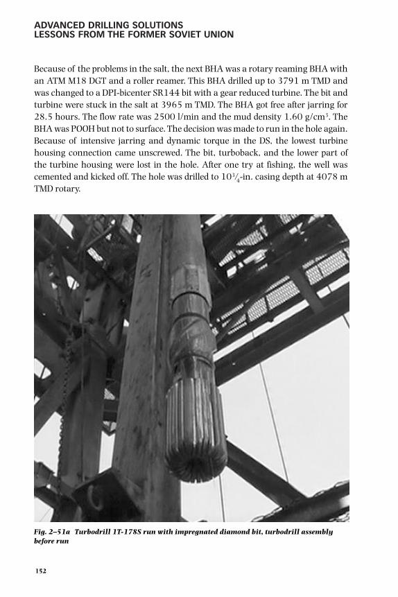
ADVANCED DRILLING SOLUTIONSLESSONS FROM THE FORMER SOVIET UNION
Because of the problems in the salt, the next BHA was a rotary reaming BHA withan ATM M18 DGT and a roller reamer. This BHA drilled up to 3791 m TMD andwas changed to a DPI-bicenter SR144 bit with a gear reduced turbine. The bit andturbine were stuck in the salt at 3965 m TMD. The BHA got free after jarring for28.5 hours. The flow rate was 2500 l/min and the mud density 1.60 g/cm3. TheBHA was POOH but not to surface. The decision was made to run in the hole again.Because of intensive jarring and dynamic torque in the DS, the lowest turbinehousing connection came unscrewed. The bit, turboback, and the lower part ofthe turbine housing were lost in the hole. After one try at fishing, the well wascemented and kicked off. The hole was drilled to 103 ⁄4-in. casing depth at 4078 mTMD rotary.
152
Fig. 2–51a Turbodrill 1T-178S run with impregnated diamond bit, turbodrill assemblybefore run
gelfgat 053-198.qxd 2/10/03 2:06 PM Page 152

DOWNHOLE MOTOR DRILLING TECHNOLOGY AND APPLICATIONS
After drilling into the cement with rotary BHA 63 ⁄4-in. turbine, 1T178S was usedtogether with an impregnated diamond bit and drilled 420 m before the bit wasworn. Figures 2–51a and 2–51b show the 1T-178S turbodrill with bit andstabilizer before the run and the worn drillbit. There had never been a run throughthis Buntsandstein formation with one bit. The last 200 m to 75⁄8-in. casing depthwere drilled with rotary techniques through the salt and sandstone.
In the 57⁄8'' hole section, a 1TR120 gear-reduced 43 ⁄4'' turbine was used with animpregnated bit of the same type as previously described (see Table 2–29).
The experience of the TIEBO and Borais companies shows the possibilities for theapplication of modern turbodrills in different borehole conditions, includingheavy mud and deep wells. The 240-mm turbodrills had never been used in Russiaat depths of more than 2000 m, but now we have good examples of successfulapplications of the 1T-240 turbodrill at depths of more than 4000 m. The 43 ⁄4-in.turbodrill should be efficient in high temperature deep wells including horizontalones. That size turbodrill had never been used for the performance drilling. Ingeneral, there is a logical tendency to enhance turbodrilling operations because ofthe significant growth in the use of PDC and diamond bits. Published recordsindicate that more than 30% of the bits used worldwide in year 2000 were thesetypes of bits, which had increased tenfold over the last decade.
153
Fig. 2–51b Turbodrill 1T-178S run with impregnated diamond bit, worn bit after 420meters in 194 hours run
gelfgat 053-198.qxd 2/10/03 2:06 PM Page 153

ADVANCED DRILLING SOLUTIONSLESSONS FROM THE FORMER SOVIET UNION
PDM (Screw) DHMs
PDM principal design
As mentioned earlier, PDMs hold promise for various drilling applications. Thissubsection presents a description of various PDM designs, as well as the theoryand principles of their operation, characteristics, and spheres of application.
From 1966 through 1975, designers and engineers carried out development workand built the commercially produced D-series PDM. Initially, engineers built andtested the motors with diameters of 85 mm and 127 mm. Experience indicatesthat PDMs perfectly match current drilling practices. They do not require use ofspecial drilling tools, pumps, or other equipment. 37
All PDMs had a uniform principal design. The D-type DHM (Fig. 2–52) consisted oftwo sections: a motor and a spindle.
The motor section included a stator (1), a rotor (2) that was essentially aneccentric screw mechanism, and a double-hinged joint (3). The stator was madeas steel housing with a rubber faced inside surface that had 10 specially shapedspiral teeth. The stator was connected to a string of pipes through a sub. The steelrotor had one tooth less than the stator, and its axis was offset from the stator axisby an eccentric value. The two-step working elements (stator and rotor) were usedin the motor.
154
Fig. 2–52 Downhole motor D-type (PDM)
gelfgat 053-198.qxd 2/10/03 2:06 PM Page 154

DOWNHOLE MOTOR DRILLING TECHNOLOGY AND APPLICATIONS
The screw surfaces profile could be based on the centroid and off-centroid hypo- andepicycloidal engagements. The rotor and stator screw surfaces were left-handed toenable clockwise rotation of the rotor (relative to its axis). Through a double-hingedjoint (3), torque was transmitted from the rotor to the output shaft (4) installed inthe spindle section. Besides the shaft, the spindle section contained a housing (5),multi-row axial bearing (6), radial rubber-metal bearing (7), and a seal (8).
Similar to the turbodrill spindle, the PDM spindle transmitted the axial load to abit, takes up the hydraulic load, applied it to the motor’s rotor, and sealed the shaftlower end. This helped create the required differential pressure at the bit. Also,bearings took up the radial loads generated by the drive shaft.
PDM working cycle
Although the screw motors had a simple design, their working cycle was quite involved.The main principles are described briefly as follows. 38 This issue was described in moredetail in the book by D. F. Baldenko, F. D. Baldenko, and A. N. Gnoevykh. 39
155
Fig. 2–53 Pressure distribution in the multi-lobe PDM working elements hollows—the crosssections along the X-axis on the T-pitch length; rotating angle of the rotor screw surface:1–high pressure; 2–low pressure
gelfgat 053-198.qxd 2/10/03 2:06 PM Page 155

ADVANCED DRILLING SOLUTIONSLESSONS FROM THE FORMER SOVIET UNION
The rotor and stator screw surfaces divided the power volume into several hollows.The fluid chambers, Z1 , existed in any cross-section and divided by contact lines(Fig. 2–53). During the operation of the motor, each of the Z1 chambersperiodically communicated with the high- and low-pressure hollows. Theoreti-cally, the separation of the hollows with fluid, located above and below the motor’sworking elements, occurred at the distance equal to the stator pitch length. Theunbalanced force R1, applied to the rotor, is created in each transverse section ofthe working elements at the rotor pitch length (Fig. 2–54).
When a second cross-section is at a distance of dx from the one in question, thehydraulic force dR1, applied to the singled out element is
dR1 = pΠdx 2.30
where
p is the differential pressure in the motor
Π is the length of an area to which the hydraulic force is applied
The analysis of the hydraulic force effect in the rotor and stator screw surfacesections from ϕp = 0–40 indicated that normally the area began from theengagement line—in the point of contact between the two circles. For a multiplethread screw mechanism, the area length is accurately determined using theequation
156
Fig. 2–54 Multi-lobe PDM forces in power sectionschematics
Tpy and Tpz – hydraulic force partsTj–force of inertiaR–sum of radial forces
gelfgat 053-198.qxd 2/10/03 2:06 PM Page 156

DOWNHOLE MOTOR DRILLING TECHNOLOGY AND APPLICATIONS
ϕpΠ = Dsin ------- 2.312
where
D is the designed diameter of the eccentric rotor mechanism
D = 2eZ1 2.32
In the previous and following equations, the variable e is the eccentricity of theeccentric mechanism.
Specialists from the VNIIBT carried out a theoretical study and derived thefollowing formula for torque calculation:
M = M0pDet 2.33
where
M0 is the specific torque and is found from the equation
Z2 – 1 2M0 = ------------ +------ 2.34
2 ππce
Hence, the specific torque M0 is a function of the rotor settings number Z2 and anon-dimensional parameter Ce, found from a proportion between e and toothingradius r.
The physical meaning of specific torque stems from Equation 2.33. It is a torque ofthe eccentric mechanism with unit dimensions (D, e, and t) and unit pressure.
For a mechanism with a single start rotor (Z2 = 1), this parameter has a minimumvalue (M0 = 3.16 at Ce = 0.2). Increase of the rotor settings number results inhigher M0.
Using values of the designed diameter D and the non-dimensional parameter Ct
(where Ct = t/D) for the Equation 2.33, the following formula is derived:
pC1D3
M = M0 ------------ 2.352Z1
157
gelfgat 053-198.qxd 2/10/03 2:06 PM Page 157

ADVANCED DRILLING SOLUTIONSLESSONS FROM THE FORMER SOVIET UNION
An analysis of factors affecting screw motor rotational speed n is presented asfollows. The following equation is true for all volumetric motors including screwmotors:
Qn = --------- 2.36
V0
where
Q is the flow rate
V0 is the volumetric power of the motor (fluid volume per rotation)
For the eccentric rotor mechanism,
V0 = FchTZ2 2.33
Since a kinematic pattern determines the proportion between the transportationand the relative motions as
ωTr--------- = Z2 2.38ωRel
In the eccentric rotor mechanisms, designed based on the hypocycloidal centroidengagement, the effective cross-section of the work element (chamber area) iscalculated using the following formula:
Fch = 2πe2(Z2-1)+8er 2.39
Certain substitutions and transformations of Equation 2.36 allow deriving theformula for calculation of the screw motor output shaft rotational speed as
Qn = n0 --------- 2.40
e2T
where
n0 is the output shaft specific rotational speed, calculated using the equation:
1n0 = ----------------------------------------- 2.41
8[2π(Z2 – 1) + ------ ] Z2Ce
158
gelfgat 053-198.qxd 2/10/03 2:06 PM Page 158

DOWNHOLE MOTOR DRILLING TECHNOLOGY AND APPLICATIONS
Like M0, n0 is a non-dimensional parameter and is a function of the mechanism’snumber of starts (Z2) and the Ce coefficient. The physical meaning of this value isthe rotational speed of an eccentric rotor mechanism with unit dimensions andunit flow rate.
Single start or single lobe rotor mechanisms—high-speed motors—have thehighest n0 value (n0 = 0.25).
Research engineers from VNIIBT carried out a special analytical study to comparethe operational characteristics of downhole screw motors at various kinematicratios and their working elements. At the first stage of the study, the researchersanalyzed geometrically similar eccentric rotor mechanisms with constant Ce andCt parameters, assuming constant differential pressure and flow rate.
In particular, they calculated output parameters of the motors with a diameter Dδε
= 172 mm. The flow rate was Q = 25 liters/sec, where the differential pressure forone pitch, ∆p = 10 kg/cm2. Figure 2–55 presents the results obtained for motorswith similar geometry. The results of these studies were first published by Gusmanand D. F. Baldenko in the article. 40 Their analysis was further developed in thebook. 41 These results demonstrate the principal advantages of the multi-lobescrew motors. In the following years, many western companies used similardiagrams as impressive graphics for multi-lobe PDM presentations.
159
Fig. 2–55 Diagram of PDM characteristic dependency on the mechanism kinematics,number of lobes
gelfgat 053-198.qxd 2/10/03 2:06 PM Page 159

ADVANCED DRILLING SOLUTIONSLESSONS FROM THE FORMER SOVIET UNION
Accordingly, motors with eccentric rotor mechanisms and few starts achievedhigh rotational speed and low torque. An increase in the number of rotor starts(lobes) resulted in an increased torque and a decline in rotational speed becausethe multiple thread eccentric rotor mechanism was essentially a combination of ahydraulic motor and a planetary reduction gear with a gear ratio proportional tothe number of rotor starts. This is extremely important for the output parametersand the motor load-carrying capacity.
The contact lines of the working elements in volumetric motors were quite long.During DHM operation, when abrasive fluids were pumped along the contact lines,fluid started leaking out of the working chambers.
As in all volumetric motors, the output shaft rotational speed theoretically is notdependent on torque. In reality, screw motors feature a relatively flexibleparameter n = f(M), compared to other volumetric motors, due to variations inrotor alignment.
Variable rotor alignment means that the elastic facing of the stator becomesradially deformed, affected by hydraulic and inertial forces, and redistributes theinitial tension between the rotor and the stator. The resulting gap allows fluid toflow from the working elements’ chambers toward the low pressure hollow.
The volume of the fluid leak, qyT, for the definite design of the working elements,hinges on the differential pressure level, the tension between the rotor and thestator, the viscosity of the pumped fluid, and the hardness and thickness of thestator elastic facing
---------------------2gpqyT = µQcpLQ --------------------- 2.42
γf [2Z – 1]√where
µ is the flow rate coefficient
Qm is the average size of clearance between a rotor and a stator
LQ is the length of the clearance
γf is the fluid specific gravity
Z is the number of working element stages (Z = L/T)
L is the length of the working elements
160
gelfgat 053-198.qxd 2/10/03 2:06 PM Page 160

DOWNHOLE MOTOR DRILLING TECHNOLOGY AND APPLICATIONS
Using Equation 2.42, the analytical dependence of the volumetric efficiency factorfrom operating conditions can be determined using the formula:
----S √p
η0 ≈ 1– --------- 2.43Vn
where
S is the clearance area outlined by the contact lines of the working elements
V is the operational volume of the motor
Equation 2.43 indicates that the differential pressure increase results in a decreasein the volumetric efficiency factor proportional to the decline in motor torque. Incontrast, rotational speed increase causes growth in the efficiency factor.
Characteristic flexibility and output power of a volumetric motor are dependent, toa large extent, on the stability of the volumetric efficiency factor. Therefore, motorswith a rotor usually feature high rotational speed.
Low-speed high-torque PDM application
Under the conditions in question, when low-speed motors were used to achieve theoptimum roller-cone bit operation, the only way to maintain the level of thevolumetric efficiency factor was by an increase in effective power. However, anincrease in the effective power caused a linear increase in the clearance area,which prevented achievement of desirable results.
An increase in the number of starts (see Fig. 2–56) caused an abrupt reduction inthe length of the working elements and in the required eccentricity level (which,in turn, limited the service life of the rotor-to-output shaft joint assembly).
Using the multiple thread eccentric rotor mechanisms, we can design a range ofhigh-torque motors with acceptable dimensions that are capable of operating atrotational speeds of 100–200 rpm or less and have high load-carrying capacity.
The design of the eccentric screw rotor mechanism has potential with regard tovariation of the DHM output parameters. By changing the rotor-stator gear ratio,it is possible to vary the degree of torque reduction and rotational speed of theoutput shaft.
161
gelfgat 053-198.qxd 2/10/03 2:06 PM Page 161

ADVANCED DRILLING SOLUTIONSLESSONS FROM THE FORMER SOVIET UNION
An advantage of the multiple-thread screw, or a multi-lobe motor, is lessdependence between the torque and the diameter of the motor. A 172-mmdiameter motor has higher torque compared to the same diameter turbodrill. Thisenables drilling with 214-mm and 243-mm diameter bits and maintains higherclearance between the motor and the borehole wall. One important issue is theimproved durability of the motor’s working element, which is achieved byenhancing the motor design, increasing rotor strength, and using wear- and heat-resistant rubber facing elements for stators.
In 1974 the industry began producing two motors of standard type and size,D2-172M and D-85, and in 1976, the D1-54 was produced. The batchproduction of motors became possible thanks to a large volume of scientificR&D work carried out by specialists from the VNIIBT and its branch in Perm.Initially, large amounts of experience were accumulated during field testing ofthe D2-172M and D-85. In the late 1990s, screw-type DHMs found thefollowing applications in Russia:
• standard well drilling
• directional and horizontal drilling
• well workover
Tables 2–30, 2–31, and 2–32 show characteristics of the motors in commercialuse with rotary and turbodrilling methods by drilling companies in Russia today.
162
Fig. 2–56 PDM design parameters dependency on rotor/stator lobes ratio: e– eccentricity; l – rotor-stator length
gelfgat 053-198.qxd 2/10/03 2:06 PM Page 162

DOWNHOLE MOTOR DRILLING TECHNOLOGY AND APPLICATIONS
From 1969 through 1997, the motors made 350,000 runs in combination withroller-cone, blade, and diamond bits with diameters from 190 mm to 269 mm indepth intervals from 150 m to 5560 m. More than 26,000,000 m were drilledmostly in Tatariya, Bashkiriya, the Perm region, in Azerbaijan and Kazakhstan. 42
By 1997, the annual penetration volume of PDMs was 10% of the total footagedrilled in the country (Table 2–33).
TABLE 2–30General Duty PDM Parameters
Activestator Recommendedpart bit Flow Pressure
OD, Length, Mass, Cinematic length, diameter, rate, drop, Torque,Code mm mm kg ratio mm mm l/sec RPM MPa kNm
D1-127 127 5,800 420 9:10 2,000 139.7–158.7 15-20 200–250 5.5–8.5 2.2–3.0D1-145 145 4,670 418 7:8 1,800 158.7–190.5 15-20 120–180 7.0–9.0 3.0–4.5D-155 155 4,870 500 7:8 2,100 190.5–215.9 24-30 125–160 6.5–7.5 3.5–4.0DM-172 172 12,000 1300 7:8 6,300 190.5–215.9 18-32 180–200 8.0–10.0 6.0–7.0DM1-172 172 12,540 1200 7:8 5,700 190.5–215.9 20-25 110–135 10.0–12.0 6.0–7.0DN-172 172 3,900 490 9:10 1,800 190.5–215.9 25-35 80–110 4.5–7.0 4.5–6.0D_-172 172 6,800 912 9:10 1,800 190.5–215.9 25-35 80–110 3.9–4.9 3.1–3.7D5-172 172 6,220 770 9:10 1,800 190.5–215.9 25-35 80–110 4.5–7.0 4.5–6.0D5-172_ 172 6,720 830 9:10 2,400 190.5–215.9 25-35 90–120 7.2–9.7 7.4–9.8DV-172 172 5,420 650 6:7 2,400 190.5–215.9 24-32 180–220 6.2–9.2 5.0–6.5D2-195 195 6,550 1100 9:10 1,800 215.9–244.5 25-35 90–115 4.3–6.7 5.2–7.0D5-195 195 7,265 1200 9:10 2,400 215.9–244.5 25-35 80–110 7.9–9.9 9.5–11.0D3-195 195 7,940 1300 9:10 3,000 215.9–244.5 25-35 80–130 9.2–11.2 10.5–13.7D1-240 240 7,570 1746 7:8 3,000 269.9–295.3 30-50 70–130 6.0–8.0 10.0–14.0
TABLE 2–31Parameters of PDM for Directional and Horizontal Drilling
Activestator Recommendedpart bit Flow Pressure Maximum
OD, Length, Mass, Cinematic length, diameter, rate, drop, Torque, bentCode mm mm kg ratio mm mm l/sec RPM MPa kNm grad
DG-60 60 2,300 34 5:6 755 76.0–98.4 1–2 180–360 4.5–5.5 0.06–0.08 1,5DO-88 88 3,570 85 5:6 1,080 112.0–120.6 5–7 180–300 5.8–7.0 0.4–0.6 5DG-95 95 2,640 41 6:7 1,420 112.0–139.7 6–10 120–200 4.5–6.0 0.6–0.9 4,0DGU-95 95 4,500 150 6:7 1,420 112.0–139.7 6–10 120–180 4.0–5.0 0.6–0.9 4,0DG-105 106 2,355 120 6:7 1,000 120.6–139.7 6–10 170–240 5.0–8.0 0.6–1.0 5DG-108 108 2,565 147 7:8 1,400 120.6–151.0 6–12 80–150 3.5–5.5 0.8–1.3 4DG-155 155 4,330 466 7:8 2,100 190.5–215.9 24–30 125–160 6.5–7.5 3.5–4.0 3,5DG1-172 172 3,870 455 6:7 1,460 190.5–215.9 24–35 150–190 5.8–7.8 3.5–4.0 3
163
gelfgat 053-198.qxd 2/10/03 2:06 PM Page 163

ADVANCED DRILLING SOLUTIONSLESSONS FROM THE FORMER SOVIET UNION
TABLE 2–32PDM for Workover Operations
Activestator Recommendedpart bit Flow Pressure
OD, Length, Mass, Cinematic length, diameter, rate, drop, Torque,Code mm mm kg ratio mm mm l/sec RPM MPa kNm
D-35 35 1,600 15 4:5 560 Special bit 0.8–1.0 450 4.0–5.0 0.02–0.025D-48 48 1,850 18 7:8 685 59–76 1.2–2.6 245–400 4.0–5.0 0.08–0.1D1-54 54 1,890 27 5:6 530 59–76 1.0–2.5 180–450 4.5–5.5 0.07–0.11D-85 88 3,230 110 9:10 870 98.4–120.6 5.0–7.0 225–290 4.0–5.0 0.5–0.6D1-88 88 3,225 110 5:6 1,220 98.4–120.6 4.5–7.0 160–300 5.8–7.0 0.8–0.095D-95 95 3,000 90 6:7 1,420 112.0–139.7 6–10 120–180 4.0–5.0 0.6–0.9D1-105 106 3,740 180 5:6 1,500 120.6–151.0 6–10 155–230 5.0–8.0 0.8–1.4D-106 106 4,200 215 7:8 2,000 120.6–151.0 4–12 35–125 4.0–8.0 0.9–2.0D1-106 106 5,255 275 7:8 2,000 120.6–151.0 4–12 35–125 4.0–8.0 0.9–2.0D-108 108 2,900 150 7:8 1,400 120.6–151.0 6–12 80–150 3.5–5.5 0.8–1.3DK-108-1 108 5,000 250 14:15 1,400 120.6–139.7 3–6 20–40 5.5–7.5 2.0–2.7D_-108-2 108 3,000 150 7:8 1,400 120.6–139.7 6–12 80–150 3.5–5.5 0.8–1.3D_-108-3 108 3,000 150 4:5 1,400 120.6–139.7 6–12 120–240 3.0–5.0 0.5–0.8D1-108 108 3,110 170 7:8 1,400 120.6–151 6–12 80–150 3.5–5.5 0.8–1.3D-110 110 4,200 235 9:10 2,000 120.6–151.0 4–12 25–100 3.0–7.5 1.1–2.3D-120 120 3,735 245 7:8 2,000 139.7–151.0 8–12 90–125 6.0–9.0 1.5–2.5
TABLE 2–33PDM Application in FSU (Until 1990)
and Russia (1991–1997)
1976–1980 1981–1985 1986–1990 1991–1995 1996–1997
PDM drilling volume, 0.4 5.3 12.6 6.5 1.75million meters
PDM drilling volume in 0.6 4.2 6.6 6.9 10.0percents of total oil and gaswells drilling in the country
PDMs were successfully used for deep vertical and directional drilling applications,as well as for drilling with coring using the Nedra core barrel (Russian analogue toChristensen 250P system).
The D2-172 motor successfully made 40 runs at the depth from 4332 m to 9040m in the Kola Super-deep SG-3 borehole (see Volume 2, Chapter 5).
The experience gained in using volumetric motors made it possible to single outthe following areas of efficient application:
164
gelfgat 053-198.qxd 2/10/03 2:06 PM Page 164

DOWNHOLE MOTOR DRILLING TECHNOLOGY AND APPLICATIONS
• drilling lower well intervals when turbodrill utilization fails to beeconomical because of the low durability of tri-cone bits, i.e., when theoptimum rotational speed should be less than 200–250 rpm
• drilling using heavy mud with a specific gravity of 2.0 g/cm3 and higher
• drilling directional and horizontal well applications with severeinclinations in the angle of the build section using a small diameter andshort length motor
• sidetracking from shut-in wells
• using the motor for well workover operations, such as cement drill out inproduction casing
The case study examples that follow illustrate the effects of using the screw motorsfor these applications. 43
PDM case studies
In Tatariya, a typical geological section is primarily composed of hard rockconfined to Paleozoic, from Upper Carboniferous to Frasnian deposits. The motorswere used in combination with Russian sealed and non-sealed bearing bits andWestern sealed bearing bits. The wells average depth was 1700 m, and drillingintervals below the conductor casing from 1350–1400 m. The results arepresented in Table 2–34.
TABLE 2–34PDM Application in Tatariya
Bit type Open bearing 1V-190T, 1V-190K Sealed bearing, Journalhome made bearing2AN-215.9 USA 81 ⁄2"
Bit drive rotor Turbodrill PDM D2-172N3TS5.B-168
Average penetration 70 30 60 175.8 274.8per bit (m)
Average ROP, m/hr 7.5 20.0 10 14.7 15.7
Number of bits 20 46.6 23.3 8 5
Note: Open bearing bits were 190-mm diameter against the 215.9-mm for sealed bits. Nevertheless, the comparison wasvery informative.
165
gelfgat 053-198.qxd 2/10/03 2:06 PM Page 165

ADVANCED DRILLING SOLUTIONSLESSONS FROM THE FORMER SOVIET UNION
Use of an improved design D1-195 motor with a 195-mm diameter achieved evenbetter results. Drilling two wells in similar geological sections using the motor withthe M-88 and 8 1 ⁄2-in. diameter drillbits required only 2.5 bits per well. Later, thistype of motor was widely used in drilling. Table 2–35 presents a comparison ofbench test data for characteristics of the D2-172M and D1-195 motors at waterflow rates of 25–35 liters/sec. 44
TABLE 2–35PDM of 172 and 195 mm OD Parameters Comparison
Operating mode D1-195 D2-172MIdle:
RPM 100–140 150–210Pressure drop (MPa) 1.7–2.8 1.5–2.5
Maximal power:RPM 80–110 120–150Torque (N m) 3,200–3,800 3,000–3,600Power (Kw) 26–43 37–55
Stall:Torque (N m) 6,000–7,000 4,000–4,800Pressure drop (MPa) 9–10 7.5–8.5
Table 2–36 compares results of the wells drilled by Almetyevsk DrillingDepartment using 215.9-mm diameter bits with a different type of drive. TheTKZTsV-215.9 Russian-made open-bearing bits were used here only forturbodrilling, whereas the Russian GNU-215.9 and U.S.-made M-88-81 ⁄2 bits withsealed bearings were used with other types of drives. The information in Table2–36 indicates that the worst results for penetration rates regarding trip time (bitrun speed) were shown in rotary drilling, whereas the best results were recordedwhen using the D1-195 with U.S.-made bits.
TABLE 2–36215.9 mm (81⁄2") Drillbits Performance
with Different Types of Drive
Penetration Bit runDrilling per run ROP speed
Downhole Motors interval (m) (m) (m/hr) (m/hr)
Unified turbodrill 200–1,700 57.9 22.9 10.1TSSh1-195
PDM regular D2-172M 600–1,700 105 13.2 9.1+ sealed bearing bit ofGNU type
PDM D1-195 300–1,700 147.3 14.9 11.0+ bit GNU
PDM D1-195 404–1,716 404 17.9 14.1+ USA-made bits
Rotor (80 RPM) 213–1,600 154 11.2 7.3+ bits of GNU type
166
gelfgat 053-198.qxd 2/10/03 2:06 PM Page 166

DOWNHOLE MOTOR DRILLING TECHNOLOGY AND APPLICATIONS
Most drilling during the following years was carried out using homemade bits.Still, the drilling results using motors with sealed bearing bits were always better,compared to non-sealed bearing bits. However, in the Urals and the Volga region,drillers used turbodrills to drill upper well intervals from 1000 m to 2000–2500m, and PDMs for drilling the lower intervals. This combination helped achieve thehighest drillbit run speed for the entire well interval (see Chapter 3 for parameterdetails). The results of D2-172M motor tests, performed while drilling deep wellsoffshore Azerbaijan on the Caspian Sea shelf, were quite positive. 45
In 1975 and 1976, drilling companies used the motors to drill intervals from 4028m to 4965 m in offshore well Nos. 20 and 26 in the Bulla-More field. Totals of 1411m were drilled in both wells during 1202 hours. Total operating time for themotors, taking into account borehole reaming and conditioning, was 1552 hours.Although the specific gravity of the mud was 1.9–2.1 g/cm3, the motor MTBF was99.6 hrs. In addition, torque backup made it possible to use of 269-mm bits.
Table 2–37 presents a comparison of drilling results achieved while usingscrew motors, turbodrills, and rotary drives in similar geological conditions.The D2-172M motor with diamond bits was tested on other wells in this field.The test results proved the feasibility of using the motor when drilling withhigh density mud, when the complications mentioned previously prevented theuse of turbodrills. Compared to rotary drilling, it shows better performanceresults thanks to higher bit rotational speed and increased penetration rate. Yet,while drilling with bits of 269-mm diameter, the results can only be achieved byusing the advanced design, high-powered D1-195 motors that feature a spindleshaft seal to enable jet bits operation. During the following years, this BHAfound practical applications.
TABLE 2–37Comparison of Drilling Results
Offshore Azerbaijan, Bulla-More Field
Borehole No.
20 21 26 28D2-172M Turbodrill D2-172M Rotor
Drilling interval (m) 4,028–4,965 4,196–4,976 3,364–4,182 3,309–4,379
Total penetration (m) 914 690 497 623
Penetration per bit (m) 23.4 14.4 33.1 27.8
ROP (m/hr) 1.05 1.62 1.5 1.05
Average bit run speed: 0.42 0.32 0.6 0.46penetration / (drilling + tripping time) (m/h)
Flow rate 22–28 l/sec; mud weight 1.75–2.15: open bearing 269.9mm drillbits.
167
gelfgat 053-198.qxd 2/10/03 2:06 PM Page 167

ADVANCED DRILLING SOLUTIONSLESSONS FROM THE FORMER SOVIET UNION
The results of the PDM tests carried out by the Neftekumsk Drilling Division in theStavropol region were quite noteworthy. These tests were important for tworeasons: high downhole temperature typical of the regional geology and the use ofoil-based mud. Therefore, these tests allowed drillers to obtain valuableinformation about the performance of the motors in these conditions. During thetests, 5 motors were used to drill intervals in 10 wells. The total penetration was4924 m in 834.5 hours in the interval from 1264 m to 3625 m. Total motoroperating time, including borehole reaming and conditioning, was 1009 hours. Inthe lower sections of the wells, the bottomhole temperatures were from 113° C to142° C at non-circulating drill mud regime, where mud temperatures at thesurface were from 50° C to 70° C. The drilling mud contained 1–4% cuttings andup to 9% oil.
The results of the tests indicated that thanks to use of the PDM, the averagefootage per bit run increased by 14%, and penetration rate and drilling speedincreased correspondingly by 37% and 27%. These results agree with the resultsof the studies carried out by drillers from Stavropolneftegas Company when theydrilled key technological wells (see Chapter 3).
The studies revealed that the optimum bit rotational speed for the larger part of thewell interval was 120–150 rpm, which corresponded to the motor characteristics.This proved for the first time in the Stavropol region that drilling with the PDMcould be more efficient than rotary drilling in some well intervals. 46
The MTBF of the motor was 71 hours and was determined mainly by the rotor andstator durability. Therefore, research engineers carried out special work to improvethe stator durability. Four types of rubber and polyurethane were used to make thestator’s elastic liner. Stators showed the best results with an elastic liner made ofIRP-1226 nitrile rubber. Seven rotors were used with this type stator during 495hours of the stator service life. Stators with liners from polyurethane and othermaterials did not show positive performance results.
One method to extend the total motor operating period at normal conditions usedby the engineers was to increase the diameters of replaceable rotors that wereinstalled in sequence inside the stator. This compensated for stator wear,maintained the required clearance between the rotor and the stator, andmaintained a longer period of needed power characteristics without increasing themud circulation rate.
168
gelfgat 053-198.qxd 2/10/03 2:06 PM Page 168

DOWNHOLE MOTOR DRILLING TECHNOLOGY AND APPLICATIONS
In addition to these examples of successful PDM use, drilling companies in the FSUachieved good results using these motors in regions such as Bashkiriya,Kazakhstan, Western Siberia, and Perm.
The PDMs built by Russian engineers won worldwide recognition in the drillingindustry. This acceptance was proved when the Drilex Company bought severallicenses for manufacturing Russian-designed motors, which later became top-ranked tools in the drilling industry.
Sectional PDM
The results of PDM operation in FSU regions where medium- and heavyweightdrilling mud was used for bottomhole cleaning showed that the working elementsand other motor assemblies lacked durability, which affected their economics.Further improvements in the motor design were introduced to the second-generation motor design, such as multi-pitch pattern utilization, strengtheningthe rotor work surface, quality improvement of stator rubber lining andattachment to the housing.
However, all these improvements were insufficient to significantly advancePDM technology, which prompted research engineers to begin work toward thedesign and construction of sectional motors. Work focused on the 195-mmdiameter, which was used most often. The research work indicated that theincreased length of the working elements, i.e., the multistage pattern, had apositive effect on the power and durability of the motors. Yet, the developmentof a single multistage motor faced as many difficulties as constructing amultistage turbodrill.
The engineers suggested a practical solution that sectioned the PDM, similar to themethod that had been used before. They also drew on the experience gained fromthe development of sectional turbodrills when they expanded the new designs.After several years of continuous R & D work, the engineers built sectional PDMsthat were successfully tested and that found wide drilling applications. 47
Figure 2–57 shows the D1-195 motor design that consists of three assemblies: amotor section (2), a spindle section (3), and a relief valve (1). Figure 2–58 showsa sectional PDM with rotors connected through hinged joints. Figure 2–59presents a sectional motor with rotors connected through a flexible shaft.
169
gelfgat 053-198.qxd 2/10/03 2:06 PM Page 169

ADVANCED DRILLING SOLUTIONSLESSONS FROM THE FORMER SOVIET UNION
170
Fig. 2–57 The D1-195 motor design1–relief valve, 2–motor section, 3–a spindle section
Fig. 2–58 The Sectional PDM with rotors connected through hinged joints1–rotor, 2–hinge, 3–shaft, 4–spindle
gelfgat 053-198.qxd 2/10/03 2:06 PM Page 170
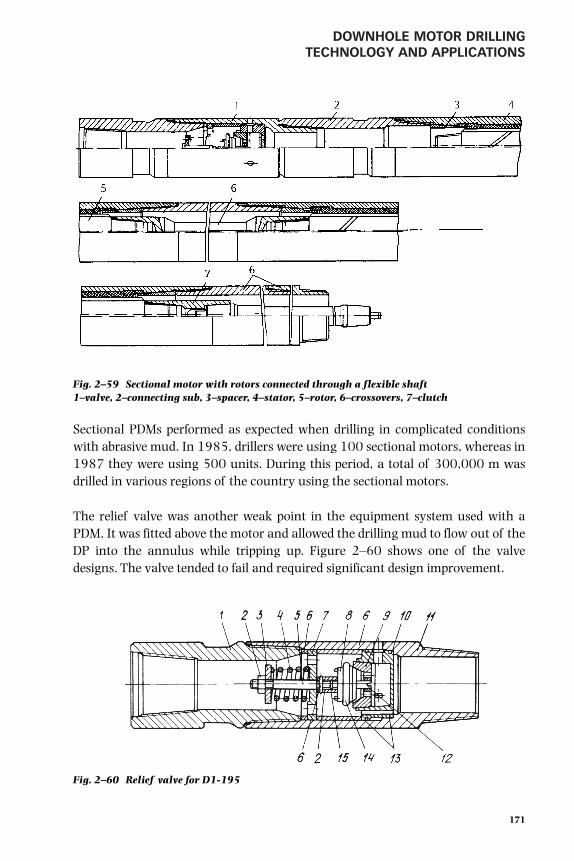
DOWNHOLE MOTOR DRILLING TECHNOLOGY AND APPLICATIONS
Sectional PDMs performed as expected when drilling in complicated conditionswith abrasive mud. In 1985, drillers were using 100 sectional motors, whereas in1987 they were using 500 units. During this period, a total of 300,000 m wasdrilled in various regions of the country using the sectional motors.
The relief valve was another weak point in the equipment system used with aPDM. It was fitted above the motor and allowed the drilling mud to flow out of theDP into the annulus while tripping up. Figure 2–60 shows one of the valvedesigns. The valve tended to fail and required significant design improvement.
171
Fig. 2–59 Sectional motor with rotors connected through a flexible shaft1–valve, 2–connecting sub, 3–spacer, 4–stator, 5–rotor, 6–crossovers, 7–clutch
Fig. 2–60 Relief valve for D1-195
gelfgat 053-198.qxd 2/10/03 2:06 PM Page 171

ADVANCED DRILLING SOLUTIONSLESSONS FROM THE FORMER SOVIET UNION
Workover and other PDM applications
PDMs found a broad sphere of application in well workover operations, such asdrilling out cement or compacted sand plugs and removing salt and paraffindeposits from internal surfaces of casing and tubing strings. In the 1940, oper-ators performed these jobs by running 127-mm turbodrills on a tubing string, 48
but these jobs could only be performed in a 65 ⁄8-in. or larger diameter casing stringusing special jars. This kept a low load level on the turbodrill.
Turbodrills such as the TS4A-104.5 and TS4A-127 that were built for theseapplications in the following years required a high mud circulation rate and pumppressure. Besides, they were high-speed and low-torque turbodrills. That is whyoilfield personnel had to use rotary drilling methods in these operations. Thisconsumed considerably more time and money because of the need to installadditional equipment and use DP and was especially costly in offshore drilling. Theengineers built PDMs with diameters of 54 mm, 85 mm, and 127 mm and fullyresolved the problem for operations in both casing and tubing strings. The D-54,D-85, and D-127 DHMs are used nowadays for workover jobs in almost everyproducing region of Russia to provide a faster and cheaper workover method.
In summary, during the 40-year period after WWII, engineers managed to developand build a series of HDHMs that met virtually every requirement of oil and gasdrilling technologies (special types of these motors for new applications aredescribed in the relevant chapters of the book. Yet, this does not mean that thework for their improvement has been finished. Emerging applications requirecontinued development of new drilling technologies for this type of equipment.
Electrodrills 49 50 51
Prehistory
The development of an electric downhole motor (EDM) is based on the idea ofusing electric energy as a more effective power for drilling operations. This kind ofenergy has the following advantages:
• It is cheap and convenient for long-distance transmission.
• It is easily transformed into other kinds of energy with high efficiency,allowing the use of automatic technologies and remote control.
172
gelfgat 053-198.qxd 2/10/03 2:06 PM Page 172

DOWNHOLE MOTOR DRILLING TECHNOLOGY AND APPLICATIONS
• It maintains constant power by increasing the voltage to compensate forpower losses in transmission lines.
All these reasons allow the development of highly effective DHMs for drivingdrillbits and automating the drilling process.
During the last 100 years, experts from the United States, Germany, France,Austria/Hungary, Romania, and Russia have tried to develop drilling machineswith electric motors. The first efficient EDM for deep drilling was developed in theU.S.S.R. between 1937 and 1940. The desire to develop these motors was drivenby the numerous advantages of the electric motor:
• power transmitted to the bit was high, constant, and independent of fluidflow conditions
• bit performance and rock destruction at the well bottom were controlledfrom the surface
• properties of the penetrated rock were conveyed by bit performance
Naturally, these advantages were accompanied by additional technical problemsrelated to directing two parallel flows of energy to the bottom for bit rotation andbottomhole cleaning.
The first electrodrill consisted of a 3-phase, 4-pole motor with a capacity of 70 kW,a planetary gear that reduced rotation speed from 1450 to 363 rpm, and a spindleconnecting the gear with a bit. The diameter and length of the electrodrill were324 mm and 8.5 m respectively. The housing was filled with oil under pressure toprotect the mechanism from the environment. The oil level was kept stable by acompensator. Drilling mud was pumped to the bit through an annular clearancebetween electrodrill case and the motor and mechanism housing.
Current was supplied through coaxial sections of a three-strand cable placed in DP.The cable sections were connected to each other by sleeves and pins when making upDP joints. At the same time an electro-differential bit feed regulator was developed.
In 1940 in the village of Kala near Baku, a well using this system was drilled forthe first time anywhere in the world. The well was 1500 m deep. All parts of theEDM system passed this first field test. Based on this test result, the followingconclusions were made:
173
gelfgat 053-198.qxd 2/10/03 2:06 PM Page 173

ADVANCED DRILLING SOLUTIONSLESSONS FROM THE FORMER SOVIET UNION
• the electrodrill could operate successfully in an aggressive liquid mediumunder great hydrostatic pressure and dynamic load
• the system for current supply could use discrete power cables placed in DP
• substantial power at the bit improved bit performance, especially thepenetration rate, compared to rotary drilling
Disadvantages uncovered during the tests were as follows:
• the electrodrill diameter was large, but the capacity was insufficient
• the planetary gear was a weak part of the system
• the cable connections broke down frequently
• the mud pump pressure increased due to the large diameter of the cable
Continued research was required to improve the electrodrill and the whole system.World War II suspended the research for six years. It was resumed in 1947 whenthe new non-gear 250 mm electrodrills were manufactured.
First 10 years of field applications experience
Electrodrills with cable section in pipe joints. Field tests performed in Azerbaijanduring 1948 to 1950 and in Bashkiriya from 1950 to 1951 proved the effective-ness of the new electrodrill. In 1952, both test and commercial drilling started inBashkiriya. By this time, a 215-mm non-gear electrodrill was developed. Thecapacity of the 215-mm electrodrill was 96–145 kW at 600–750 rpm corre-spondingly depending on the number of poles (10–8), whereas the capacity of the250-mm electrodrill was 145–230 kW at 600–1000 rpm correspondinglydepending on the number of poles (10–6).
Between 1952 and 1963, these electrodrills were used in the Ukraine, in theKuibyshev (now Samara) area, and in Turkmeniya. By drilling about 500,000 min field tests and commercial drilling for 10 years and in different geologicalconditions, the advantages and disadvantages of electrodrilling were fullyevaluated. For a number of completed wells (mostly in Bashkiriya), the drillingperformances were 15–20% higher compared to turbodrilling. However, theseimproved performances were not the rule and did not lead to the commercialapplication of electrodrilling. To apply electrodrilling widely, special repair shops
174
gelfgat 053-198.qxd 2/10/03 2:06 PM Page 174

DOWNHOLE MOTOR DRILLING TECHNOLOGY AND APPLICATIONS
with the required equipment and highly qualified electricians had to be in place. Inaddition, higher performance was limited by the following substantialdisadvantages of electrodrilling.
The low resistance of cable connections and the frequent breakdowns of the currentsupply system. There were up to four breakdowns of a new current lead per1200–1700 m of deep wells in Bashkiriya. During the depreciable life of a currentlead (15 wells) there were 10 or more breakdowns. This resulted in idle round tripsand substantial loss of time. The situation was much worse in deeper wells. Arecord of 319 current lead breakdowns was made while drilling well No. 157(4368 m). The well was drilled in difficult geological conditions with weightedmud in the Azerbaijan Karadag-Damba oilfield. The time lost because of thesebreakdowns amounted to 5000 hours.
Substantial pressure losses, especially in connections of current lead sections inDP joints (the outer diameter of the cable connection and the tree-strand cable was65 mm and 43 mm respectively). At a depth of more than 4000 m in well No. 157,pump pressure was 120–140 kg/cm2 at a flow rate of 20–23 l/sec. In well No.153, which was drilled by turbodrill in similar conditions, the pressure level wasthe same.
High rotation speed of the motor shaft dramatically decreased roller-cone bit life,especially in deep wells.
Electrodrill overhaul time was 25–30 hours in 1956, while in wells more than4000 m deep it averaged 3–4 hours.
Small diameter electrodrills were not available for drilling lower intervals in deepwells and lateral branches in cased wells.
Cable in DP prevented the use of wireline instruments for BHA orientation. Efficiencywas low for bent electrodrills when used for directional drilling. The same was trueof the instruments used for its orientation (AOSU) as well as impulse inclinometers(type EE). For this reason, electrodrills were used only in vertical wells before 1963.
The technical and technological features of electrodrills were not taken into consideration.Competition with HDHMs and rotary drilling in shallow wells could notdemonstrate the advantages of electrodrills.
175
gelfgat 053-198.qxd 2/10/03 2:06 PM Page 175

ADVANCED DRILLING SOLUTIONSLESSONS FROM THE FORMER SOVIET UNION
These disadvantages were thoroughly studied and taken into account by expertsand companies who were involved in the development and application ofelectrodrills. This paid off in future designs.
Cable electrodrilling without pipe. Between 1947 and 1954 in the U.S.S.R., a cableline system of electrodrilling was also developed. Bit reactive torque in this systemwas counterbalanced by the inertia of the electrodrill housing. The spindle shaft,together with the drilling bit, rotated alternately in both directions up to a presetrotation speed, while reversal was controlled from a surface board. A pump builtinto the electrodrill was used to wash the well bottom. The pump sucked mud fromthe well and discharged it through the bit to wash the bottom. Mud with cuttingsflowed into a sludge pit, where it was cleaned and redirected into the well. Testdrilling was performed in a shallow well in Krasnokamsk. However, this originaland unusual system appeared inefficient because of extremely poor bitperformance, which could not be compensated for by fast round trip operations tochange the bit.
Improved commercial electrodrilling systems (1963–1970)
General characteristics of electrodrilling systems. Between 1963 and 1970, anelectrodrill standard was worked out. It included specifications for electrodrillswith diameters from 127 mm to 240 mm as well as optional equipment forcommercial electrodrilling applications. The first commercial electrodrillingsystem is shown in Figure 2–61.
The system consists of the following basic units:
• electrodrill and other parts of the downhole DS assembly
• telemetric system (STE)
• DS with power cable
• automatic bit feed regulator
• control station and board
• transformer for the electrodrill power supply
176
gelfgat 053-198.qxd 2/10/03 2:06 PM Page 176

DOWNHOLE MOTOR DRILLING TECHNOLOGY AND APPLICATIONS
177
Fig. 2–61 Electrodrilling set-up
1– bit2–electro drill3–drillpipe string4–rotory table5–stationary external cable6–flexible rubber insulated cable7–swivel8–collector unit9–kelly10–H.V. cubicle11–drawworks12–automatic electro-differential
bit-feed regulator13–electro-drill control board14–power transformer
15–H.V. switch16–electrodrill control station17–tool joint18–rubber-insulated feeder cable19–bit-feed control unit20–electrodrill motor control21–selector switch for stepwise
bit feed control22–current meter23–watt meter24–volt meter25–control for electro-differential
bit feed regulator26–slush pump control27–electrodrill load-control unit
gelfgat 053-198.qxd 2/10/03 2:06 PM Page 177

ADVANCED DRILLING SOLUTIONSLESSONS FROM THE FORMER SOVIET UNION
A conventional rotary drilling rig was used with a set of downhole and surfaceequipment prefabricated as attachments to the basic equipment. Surfaceequipment included special power transformers for electrodrilling, electrodrillcontrol stations and boards, current collectors, an automatic bit feed regulator,gadgets for the electrodrill, and the current lead. In areas with no central powersupply, a diesel generator unit was used.
Downhole equipment included electrodrills, electrodrill gear inserts, attachmentsfor coring, check valves, devices for insulation inspection, mechanisms for wellpath control, tools for borehole path stabilization, logging tools, and telemetricsystems (Fig. 2–62).
178
Fig. 2–62 Electrodrilling assembly
gelfgat 053-198.qxd 2/10/03 2:06 PM Page 178

DOWNHOLE MOTOR DRILLING TECHNOLOGY AND APPLICATIONS
Telemetric systems were the most important part of an electrodrilling system.Together with an electrodrill, they provided a new advantage, i.e., drilling could becontrolled based upon on-line information about the bottomhole drillingparameters.
Power was supplied to the electrodrill through a cable built into the DPs (Fig. 2–63). The cable led into a current collector (Fig. 2–64). The slippingcontacts of the collector could rotate the DS if necessary.
Research carried out by the Kharkov SKTBE from 1963 to 1970 determined thedesign that is currently available for the electrodrill system. Proposals for furtherdevelopment of this system to improve efficiency, to develop DC applications, andto develop small diameter electrodrills did not find support in the U.S.S.R. or inother countries.
179
Fig. 2–63 Drillpipes with cable sections for electrodrilling
gelfgat 053-198.qxd 2/10/03 2:06 PM Page 179

ADVANCED DRILLING SOLUTIONSLESSONS FROM THE FORMER SOVIET UNION
Electrodrills. An electrodrill (see Fig. 2–65 and Fig. 2–66) has a tubular body andconsists of two basic units: a subsurface induction squirrel cage motor and an oil-filled spindle. If necessary, a mechanism for well path control and/or a gear insert(Fig. 2–67) for reducing bit rotation speed and for increasing electrodrill torque areinstalled between the motor and the spindle. Axial load from compressed part ofthe DS is transmitted through electrodrill housing and bypasses the motor rotor.Torque from the motor is transmitted to the bit through the spindle shaft.Specifications for the electrodrill are given in Table 2–38.
180
Fig. 2–64 Current collector for electrodrilling
1–slip ring2–collector body3–stationary copper-graphite
brushes4–stationary collector housing5–stationary external cable6–feeder cable7–flange8–feeder line contact bushing9–feeder cable strands10–brush holder
gelfgat 053-198.qxd 2/10/03 2:06 PM Page 180

DOWNHOLE MOTOR DRILLING TECHNOLOGY AND APPLICATIONS
181
Fig. 2–65 Electrodrill schematics
gelfgat 053-198.qxd 2/10/03 2:06 PM Page 181

ADVANCED DRILLING SOLUTIONSLESSONS FROM THE FORMER SOVIET UNION
182
Fig. 2–66 Electrodrill design
1–hollow motor shaft2–radial ball bearing3–thrust ball bearing4–rotor section5–radial ball bearing6–stator section7–stator winding8–diamagnetic pack9–housing10–electric motor frame11–motor adapter piece, lower12–motor adapter piece, upper13–lubricator body14–upper sub15–transformer oil lubricator, compensator16–lubricator piston17–lubricator spring18–shaft seal, lower19–shaft seal, upper20–rotary seal member pair, upper21–cable entrance head22–contact plug23–cable entrance seal24–protecting cup25–contact plug mounting26–heavy oil lubrication, compensator27–spindle body28–toothed coupling29–radial roller bearing30–hollow spindle shaft31–thrust ball bearing32–rubber cushion33–spindle lubricator34–lubricator piston35–lubricator spring36–bushing, rubber-sealed37–spindle shaft seal38–sub39–bit
gelfgat 053-198.qxd 2/10/03 2:06 PM Page 182

183
TABLE 2–38Commercial Electrodrills
Parameters:
Electrodrilltype ER127- ER164- E164- ER190-4M4B5 E190- E215- ER240- E240- ER290- E290-
4B5 4M6B5 8M7B5 (M1B5) 8M7B5 8M7B5 4M1B5 8M7B5 6M7B5 12AMB5
Power, kW 31,2 71 65 50 (110) 125 175 170 210 180 180
Voltage, V 750 1,350 1,100 1,000 1,300 1,550 1,350 1,700 1,550 1,750
Current, A 52 52 89 50 (107) 125 131 113 144 100 123
RPM* 430 140 /437 675 162 (162/477) 675 680 181 / 505 690 300 450
Torque*, Nm 330 4,100 / 1,500* 1,100 2,600 (5,300/2,160) 1,800 2,500 6,230 / 3,210 3,000 7,000 5,100
Efficiency 0.73 0.74 0.61 0.75 0.60 0.72 0.79 0.75 0.79 0.72
OD, mm 127 164 164 190 190 215 240 240 290 290
Length, mm 10,100 9,684 12,000 8,600 (11,450) 13,000 13,800 11,200 13,700 10,300 12,800
Mass, kg 850 1,100 1,500 1,400 (1,950) 2,200 2,920 3,000 3,640 3,700 4,600
* Figures divided by slash correspond with different gear ratio (approximately 1:9 / 1:3).
DO
WN
HO
LE MO
TOR
DR
ILLING
TEC
HN
OLO
GY
AN
D A
PP
LICA
TION
S
gelfgat 053-198.qxd 2/10/03 2:06 PM Page 183

ADVANCED DRILLING SOLUTIONSLESSONS FROM THE FORMER SOVIET UNION
Current lead. Power supply systems made up of two conductors in DP marked asubstantial improvement in the current lead. Power to a three-phase electrodrillmotor is supplied through a double-wire cable and DP (see Fig. 2–62). Thediameter of the double-wire cable connection was reduced to 50 mm and had anoval cross-section of 35 x 15 mm. Pressure losses were reduced substantially whenthis cable was employed. Modernization of the cable connections sharply reducedthe number of breakdowns in the current lead.
The current lead was designed for voltage up to 3000 V and for current up to165 A with spikes up to 400 A for 3 seconds. Cable sections can operate athydrostatic pressures of up to 115 MPa and at environmental temperatures of100–130° C. Each section of the current lead cable ended with a contact bushinginstalled in a tool joint box on one side and with a current lead contact pininstalled in a tool joint nipple on the other side. A safety sleeve protected thecontact pin from damage (see Fig. 2–63).
Cable sections were used with 114-, 127- and 140-mm DP and with 129-mm ADPwith internal upset ends.
Telemetric systems STE for directional and horizontal electrodrilling. Acommunication channel with the surface was the most important part of the STE
184
Fig. 2–67 Gear reduction box (insert) for electrodrill
gelfgat 053-198.qxd 2/10/03 2:06 PM Page 184

DOWNHOLE MOTOR DRILLING TECHNOLOGY AND APPLICATIONS
to control downhole parameters. For the first time, telemetric systems formeasuring geometric and geophysical parameters were applied in electrodrilling.This was made possible by using the DP as the communication channel for thecable. The (STE) was developed between 1966 and 1968. In 1968, it was used fordirectional electrodrilling in Bashkiriya for the first time worldwide and later inother areas of the U.S.S.R.
STE is designed to measure the geometric parameters of the well path geometric—the inclination, azimuth, and bent sub position. The STE consists of submersibleand surface apparatus. The submersible part includes a survey meter that has a setof meter sensors and electronic apparatus. These sensors send electric signals thatcontain information on measured downhole parameters. The surface part consistsof a receiving board for recording and visual inspection of subsurface parameters,and a connecting filter for connecting the receiving board to the electrodrillcurrent lead and for separating the frequency of the power line current (50 Hz)from the system frequency. The survey meter is placed in a separate diamagneticpipe, which is installed immediately above the electrodrill (see Fig. 2–62). Theelectrodrill current lead serves as a communication channel.
The telemetric system can measure inclinations up to 110°, azimuth and tool facefrom 0° to 360°. The margin of error for measurements is not more than 2.5%.Specifications for the STE are given in Table 2–39. The STE receiving board has anoutlet for connecting standard instruments to record the measured parameters. Italso has remote instruments installed near the driller’s console. Design details andapplications for the STE are presented in Chapter 4, Volume 2.
TABLE 2–39Cable Telemetric Systems
System Type Length, mm OD, mm Zenith Azimuth and Mass, kgAngle* tool face*
For drilling with turbodrills and PDM
STT - 108 6,300 108 0 - 60; 60 - 120 0 - 360 231
STT - 127 5,290 127 234
STT3P - 127M1G 8,195 172 - 695
STT3P - 190M1G 8,195 190 845
STT3P - 215M1G 8,195 215 942
For electrodrilling
1STE - 164U3 8,355 164 563
1STE - 185U3 8,355 185 967
1STE - 215U3 8,272 215 1065
* Same parameters for all system types.
185
gelfgat 053-198.qxd 2/10/03 2:06 PM Page 185

ADVANCED DRILLING SOLUTIONSLESSONS FROM THE FORMER SOVIET UNION
Electrodrilling technology
General concept. In the early 1970s, the U.S.S.R. was the only country in theworld where all three methods of drilling were used on a commercial scale, i.e.,rotary, turbo- and electrodrilling. For this reason, it was important to estimate theratio of application for each of the three drilling methods. As mentioned before,turbodrilling footage reached 80% of the total drilling volume in the U.S.S.R. bythe late 1950s. As for electrodrills, discussion on expediency of their applicationhas been going on until the present.
However, fundamental research of the key test (technological) wells (KTWs)carried out by the VNIIBT in the 1960s and the 1970s proved the suitability for allthree drilling methods to be available to local drilling companies. The task was toapply each of the methods in those conditions where all the potential advantagescould be used (see Chapter 3 for details). In that respect, electrodrilling in the FSUfound its proper niche market. Examples of effective electrodrill applications aregiven as follows as well as in other sections of this book (see Chapter 3 in thisvolume and Chapters 4–6 in Volume 2.)
Deep drilling with weighted mud in Turkmeniya (1970–1980). The followingwells were drilled with an optimal bit rotation speed and a mud density of 2.3g/cm: (a) No. 808 with a depth of 5042 m and No. 809 with a depth of 4700 min the Kotur Tepe oilfield; (b) No. 27 with a depth of 4803 m, No. 31 at 4616 m,and No. 32 at 5250 m in the Komsomolskaya oilfield. The last well was a record interms of rates. Overall drilling rate was 1.8 times higher compared to well Nos. 52,28 and 404 drilled by the rotary method.
According to data gathered from 1975 to 1976, the reliability index of theelectrodrilling system increased substantially. Average mean-time-between-failures (MTBF) of electrodrills was 50 hours, the number of breakdowns of thecurrent lead was 2.5 per 1000 m of boring while drilling deep wells withweighted mud.
Directional and branched lateral drilling in complicated geological conditions inAzerbaijan and the Ukraine (1960–1980). Well No. 1183 of about 4000 m in theZagly-Zeiva oilfield, Azerbaijan, was drilled in steeply dipping formations wherethe angle of entry provided for a decrease in curvature. The well was drilled to thetarget due to continuous control of the azimuth and curvature.
186
gelfgat 053-198.qxd 2/10/03 2:06 PM Page 186

DOWNHOLE MOTOR DRILLING TECHNOLOGY AND APPLICATIONS
Electrodrills were so successful in steeply dipping formations that in the westernUkraine more than 10 directional wells, which had been spud in by turbodrills,were drilled to the target by electrodrills. Exploratory multilateral well No. 801 wasdrilled at the Dolina oilfield, in the western Ukraine. In total, 12 horizontal andbranched lateral wells including 11 development wells were drilled at Dolina.Initial daily production rates of the branched lateral wells reached 70–150 tonscompared to 8–10 tons for vertical wells, because the latter wells could not alwaysbe directed to the project target in the given geological conditions.
Drilling with gaseous agents in complicated geological conditions (1970–1980).A classical example of using different circulating agents while electrodrilling is thedirectional 2813-m well No. 726 with a vertical deviation of 930 m in the Bitkovoilfield, the Western Ukraine. Surface hole drilling to a depth of 196 m was per-formed with foam due to lost circulation. An interval of hard rock from 196 to1452 m was drilled with air, while mud circulation was used in the interval from1452 m to 2813 m. The combination of electrodrills with the application ofgaseous agents sped up drilling substantially and reduced the number of days inthe drilling program by 52.
Interesting results were also obtained while electrodrilling a cluster of threedirectional wells (Nos. 1270, 1271 and 1272) in the Zagly-Zeiva oilfield,Azerbaijan, in 1977. The average depth of the wells was 2200 m. Two of the threewells were drilled with foam to a depth of 1100 m. Drilling rates of this clusterwere much higher than of a similar cluster of wells (Nos. 1313, 1236 and 1237)drilled with turbodrills. The bit footage, penetration rate, and overall drilling ratewere respectively 1.2, 1.7 and 1.67 times higher. It should be pointed out that thedirectional well path followed by the electrodrill with a STE is much more accuratethan a turbodrill without a telemetric system.
Research and KTW drilling. Many years of experience in KTW drilling in theU.S.S.R. showed that electrodrilling was the most effective method for suchoperations (see Chapter 3). It provided the largest volume of information requiredfor choosing optimal drilling methods and practices. Moreover, informationobtained while KTW electrodrilling could be used successfully in other methodsof drilling.
A good example of electrodrill research is a unique experiment drilling a deep wellin a crystalline basement carried out in Bashkiriya. Borehole No. 2000 was drilledby electrodrill in 1964 in the southeast wing of the Tuimazi structure to investigatethe earth crust in the Volga-Ural oil and gas province. The crystalline basement was
187
gelfgat 053-198.qxd 2/10/03 2:06 PM Page 187

ADVANCED DRILLING SOLUTIONSLESSONS FROM THE FORMER SOVIET UNION
drilled in the interval from 1798 to 4041 m. The basement was composed ofinhomogeneous, frequently alternating rocks like gneiss, granite, and diorite.
In the interval between 2156 and 4036 m, researchers investigated the influenceof drilling operating variables on bit performance. Drilling operating variables,capacity, current, and voltage consumed by the electrodrill were recorded in 100research runs. Drilling was performed with E215/8 and E250/10 electrodrillsusing 295-mm TCI bits for hard rock. Motor shaft rotation speed was adjusted bythe current frequency regulator. Drillbit rpm was varied from 285 to 680 by usingelectrodrills with different numbers of poles and by adjusting current frequency.Axial load varied from 50 to 300 KN. Researchers established the dependence ofthe bit penetration rate on axial load and rotation speed, as well as the optimalmeaning of these parameters for maximum penetration per bit.
Horizontal drilling (1979–1990). When well No. 196 Uzibash was drilled in 1979,it was the first horizontal borehole drilled with an electrodrill in Bashkiriya.Conventional drilling equipment and tools were used. The kick-off point wasbetween 1950 and 2130 m; the lateral section ran from 2130 to 2385 m; themaximum zenith angle was 102.4°; and the final vertical deviation was 607 m.
The drilling results from well No. 196 proved it was possible to drill horizontalwells with conventional electrodrilling equipment. However, the recommence-ment of horizontal electrodrilling did not occur until 1988. One of the wells wasdrilled in the New-Uzibash field and four experimental wells were drilled in theLemesinskaya oilfield. Currently, electrodrilling is used in Bashkiriya and Tatariyawhere horizontal wells are drilled in pay formations with a thickness of 1.5–2 m.Another horizontal well, the Kotur-Tepe No. 1630, was drilled successfully undercomplicated geological conditions in Turkmeniya. This well reached a depth of3653 m with a lateral section of 145 m. In the Salymskoye oilfield of WesternSiberia, horizontal well No. 578 was drilled to a measured depth of 3330 m withmore than 300 m of deviation. A 127-mm electrodrill was used in this well for thefirst time (see Volume 2, Chapter 4 for more details).
Future developments 52 53
Research in the 1980s showed that an optimal rotation speed range couldn't beprovided in rotary drilling. The search for a new drive entered naturally into theconventional drilling technology. The PDM was adopted by those involved indrilling technology as the motor able to improve drilling practices and to controlthe well path in horizontal drilling. However, in spite of large investments and high
188
gelfgat 053-198.qxd 2/10/03 2:06 PM Page 188

DOWNHOLE MOTOR DRILLING TECHNOLOGY AND APPLICATIONS
quality research, the technique that was developed appears to be an imperfectsolution. Hydraulic motors cannot provide the required range or smoothadjustment of rotation speed. Both the transmission of information and control ofthe well path in the hydraulic system are more expensive, less accurate, and haveless communication capacity compared to a cable system.
In this situation, it was appropriate to consider developing an integral systembased on electrodrilling to further advance progress in drilling. At first,development of electrodrilling was worthwhile in the construction of oil and gaswells in complicated geological conditions when gas, foam, and weighted mudwith a density greater than 2000–2500 kg/m3 were used. Even now, an electro-drilling system developed in the 1960s can successfully compete with any kind ofmodern drive when drilling with PDC bits.
A record of 12,000,000 m drilled proved the considerable potential ofelectrodrilling for deep, directional, horizontal, and multilateral drilling. Thegreatest advancement is expected in re-entry drilling including laterals from a casedparent, out-of-operation or marginal wells in old oilfields, and in offshore drilling.
Research and KTW drilling performed in different oil and gas fields of the U.S.S.R.from the 1960s through the 1980s were oriented to electrodrilling as a primaryresearch method. KTW drilling promoted the development and adoption of themost effective drilling methods, practices, and machinery.
The field experience and research results gave sufficient information to encouragethe use of electrodrilling as a well construction method. The extension of KTWdrilling results allowed realistic proposals to use electrodrilling as a universalmethod for modern drilling. Electrodrilling combined the advantages of bothrotary and DHM drilling and, at the same time, it lacked some of the disadvantagesof the latter. Drilling experience in Bashkiriya, Turkmeniya, Azerbaijan, and in theUkraine strongly suggested that electrodrilling provided savings of energy andmaterials. Electrodrill applications decreased environmental pollution and savedreservoir properties that in turn, reduced time to completion.
The DC electrodrill is very promising. This system uses the more reliable and space-saving single-conductor current lead, which decreases pressure losses in DP andpermits the use of a fishing tool when necessary. In addition, the DC electrodrillcan be adjusted smoothly across a wide range of rotation speeds. A DC electrodrillcan be overloaded to a greater extent than an alternating current (AC) electrodrill,and this enables an increase in the net motor power.
189
gelfgat 053-198.qxd 2/10/03 2:06 PM Page 189

ADVANCED DRILLING SOLUTIONSLESSONS FROM THE FORMER SOVIET UNION
Application of an integral cable instead of a discrete one is the other attractiveaspect. This combines well with modern coiled tubing drilling (CTD) drillingtechnology. However, such a combination requires the development of a small(less than 5-in.) diameter electrodrill and research in the field of power cableimplementation in CTD system. Recent studies, both in Russia and abroad, showpositive prospects for the development of 3–4 inch diameter electrodrills for CTDapplications.
Due to its characteristics, electrodrilling may find a wide application in the coalindustry, mining, underground railways, laying trenchless pipe, and otherbranches of industry.
Electrodrill as a bottomhole transmitter
When considering electrodrilling prospects, it should be remembered that electro-drills were used in the framework of technologies developed for the rotary tableand turbodrill as bit drives. These drives lack the main electrodrill advantage,meaning they do not optimize drilling operations under variable conditions.
An electrodrill serves a dual function (informative and executive), which is notaccessible for either modern drilling systems or measurement while drilling(MWD). Signals created by special sensors (similar to MWD) are transmittedthrough the electrical communication channel. In addition, bit performance isevaluated by the signal strength.
An electrodrill serves as a sensitive transmitter of the bottom process and respondsto all drilling alterations and deviations. It allows operational control of thedrilling process. This advantage of electrodrilling creates the prerequisite toautomate drilling.
A board of instruments was developed and manufactured by VNIIBT to recorddetails of the electrodrilling technological and energy parameters. The boardrecorded voltage at the current collector, the current in each of the three phases,the active power consumed by the electrodrill, the reactive power, the axial load,the meterage (in time), the pressure in the manifold, and the drilling mud flowrate. In addition, watt-hour and var-hour m were installed in the board ofinstruments.
To control the drilling process, a telemetric system, STE1-I, was tested in theShebelinskoye gas field in 1969. It generated data about the magnitude of the
190
gelfgat 053-198.qxd 2/10/03 2:06 PM Page 190

DOWNHOLE MOTOR DRILLING TECHNOLOGY AND APPLICATIONS
bottomhole axial load and load dynamics, as well as the amplitude and frequencyof vibrations. Surface instruments recorded the dynamics of the bottomhole axialload (by oscillography), static (average) meaning of the bottomhole axial load,amplitude and frequency of the DS vibrations (oscillography using a sensorinstalled above the electrodrill), and other parameters.
Later telemetric systems STE-164, STE-185, and STE-215 were developed fordirectional drilling purposes and approved for batch manufacturing. This type ofsystem records and shows the azimuth, zenith angle of the well, and bent subposition (see Chapter 4, Volume 2 for details).
The instrument metering board records the drilling technological and energyparameters and combines with the STE to acquire information to develop thecorrelation between the drilling indicators.
Bottomhole information obtained by STE can be used for different purposes, forexample, to improve a drillbit run. The task is to keep the drilling operationvariables that provide the maximum efficiency of by-bit energy consumption. Themaximum penetration rate Vm at a similar power consumption Np indicates theoptimal mode of rock destruction. Most energy is spent for rock destruction, whilethe remaining smaller amount of energy is wasted on drillbit destruction and wearas well as other unproductive work.
Electrodrilling controls an effective rock bit break-in procedure and determines theend of the bit run. This is made possible by on-line recording of phase currentmagnitude I1, I2, I3 and power N. Variations in the records help develop standardprocedures for effective drillbit runs in specific geological cross-sections. Thecombination of the loading mode and optimal bit rotation speed that weredetermined by a frequency unit considerably increased drillbit performance.
It is possible to judge a drilling process by the character of power and currentrecords. A smooth record indicates an optimal mode of rock destruction.Vibrations of the DS produce small peaks. When a bit bearing is worn out, powerand current grow dramatically and the records are characterized by sharp peaks.On occasion, the current protection switches off the electrodrill. That is how it ispossible to determine bit condition by the character of records, the end of bit run,and bit bearing failure.
An electrodrill determines a more precise meaning of WOB. As it is known, WOBmeasurement errors can be significant, especially in highly deviated and
191
gelfgat 053-198.qxd 2/10/03 2:06 PM Page 191

ADVANCED DRILLING SOLUTIONSLESSONS FROM THE FORMER SOVIET UNION
horizontal boreholes. As the magnitude of power Np solely depends on themagnitude of WOB, it is possible to determine the WOB accurately by adjusting theload through the meaning of Np : Np = b x (WOB), where WOB = Np/b. Thecoefficient of proportionality b is in direct relationship with the specific torque ofrock destruction Ms. Ms can be determined in experiments with WOB by adjustingMy = 975(Np1-Np2)/(WOB1-WOB2)n, where n is rpm.
Adjusting the load by 2–5 times, it is possible to determine the magnitude ofspecific torque Ms and, therefore, the full magnitude of WOB during one bit run.
The magnitude of the specific torque Ms in the well depth function determinesadequately drilled rock. If the composition of drilled rock is known, better controlof bottomhole destruction is available from the electrodrill’s on-line information.
Adaptation of this technology helps to develop new advantages in modernelectrodrilling. The advantages are connected with seeking new solutions based onthe theory of bottomhole boring and destruction. Practical MWD possibilities arelargely based on a comparison of the drilled section with experience from wellsdrilled earlier. This empirical approach significantly limits the possibilities offurther scientific and technical progress in drilling. That is why drilling practiceinevitably has begun to change in favor of a more wide application ofelectrodrilling, which was ahead of its time. Now this system should be perfected,and new electrodrilling applications should be put into practice.
Conclusions
Electrodrilling technology can be considered a commercial drilling method similarto the worldwide use of rotary and HDHMs technology. Electrodrilling combinessome of the advantages of both rotary and HDHM methods, including:
• a large range of drillbit rotation speed
• independence of energy transmitted to the drillbit from the fluid flow
• use of different borehole cleaning agents
• controlled drilling of deviated and horizontal boreholes
192
gelfgat 053-198.qxd 2/10/03 2:06 PM Page 192

DOWNHOLE MOTOR DRILLING TECHNOLOGY AND APPLICATIONS
An electrodrilling system is effectively applied in complicated geological conditionsand old reservoirs where weighted mud or different mud mixtures must be used.
The application of electrodrills is very promising in directional, horizontal,multilateral, and research boreholes.
EDM for CTD is one of the best opportunities to overcome the current CTDproblems. That is the area where all the disadvantages of EDM with standardsingle joint pipe vanish. On the other hand, the best cable electrodrilling ideascould be realized in CTD, so we could now be back on the right path.
193
gelfgat 053-198.qxd 2/10/03 2:06 PM Page 193

ADVANCED DRILLING SOLUTIONSLESSONS FROM THE FORMER SOVIET UNION
References
1 Ioannesyan, R. A., Fundamentals of Turbodrilling Theory and Technique, Moscowand Leningrad: Gostoptekhizdat Publishing House, 1953.
2 Ibid.
3 Ibid.
4 Antonov, N. V., Ya. A. Gelfgat, and M. T. Gusman, “Chapter XXIV, Oil WellDrilling Guide,” Turbodrilling, Moscow and Leningrad: GostoptekhizdatPublishing House, 1947.
5 Shumilov, P. P., Oil Well Turbodrilling, Volume I and II, U.S.S.R.: ONTI NKTP,1936.
6 Shumilov, P. P., Fundamentals of Turbodrilling Theory, Gostoptekhizdat, 1943.
7 Shumilov, P. P., Oil Well Turbodrilling: Selected Works, Moscow: NedraPublishing House, 1968.
8 Ibid.
9 Ioannesyan, 1953.
10 Shumilov, 1968.
11 Ibid.
12 Antonov, 1947.
13 Shumilov, 1943.
14 Gusman, M. T., B. G. Lyubimov, G. M. Nikitin, I. V. Sobkina, and V. P. Shumilov.Calculation, Design, and Operation of Turbodrills. Moscow: Nedra PublishingHouse, 1976.
15 Ibid.
194
gelfgat 053-198.qxd 2/10/03 2:06 PM Page 194

DOWNHOLE MOTOR DRILLING TECHNOLOGY AND APPLICATIONS
16 Ibid.
17 Antonov, 1947.
18 Shumilov, 1968.
19 Shumilov, 1968.
20 Shumilov, 1968.
21 Gelfgat, Ya. A., A. V. Orlov, G. M. Finkilshtein (VNIIBT), A. S. Shafutin, and M. N.Yadulayev (AzNIPI), “Summary Results of Drilling Test Wells in the Karadag-Damba Field,” VNIIBT Transactions, Issue XIV. Moscow: Nedra Publishing House,1965.
22 Gelfgat, Ya. A., “Turbodrilling Application Experience in Heavy MudConditions,” Neftyanoye Khozyaistvo (Oil Industry) Magazine, No. 8, Moscow,1953.
23 Gusman, 1976.
24 Kurepin, V. I., F. N. Fomenko, and G. S. Gevorkov, “Study of Operating Regimes ofElectrodrills Used in Combination with Diamond Bits on PrikarpatburneftCompany oil-rigs,” Neftyanoye Khozyaistvo (Oil Industry) Magazine, No. 9,Moscow, 1969.
25 Barshai, G. S., and N. I. Buyanovsky, Theory and Practice of Turbodrilling, Moscow:Gostoptekhizdat Publishing House, 1961.
26 Litvyak, V. A., , L. I. Brai, and V. F. Ryzhenko, “The Results of Turbodrills withFloating Stators Testing,” Neftyanoye Khozyaistvo (Oil Industry) Magazine, No. 8,Moscow, 1984.
27 Fomenko, F. N., Boreholes Drilling With Electrodrills, Moscow: Nedra PublishingHouse 1974.
28 Vadetskiy, Yu. V., N. D. Nikomarov, and N. D. Derkach, “The Significance andProspects of Low-speed Down-Hole-Motor in Well Drilling Technological
195
gelfgat 053-198.qxd 2/10/03 2:06 PM Page 195

ADVANCED DRILLING SOLUTIONSLESSONS FROM THE FORMER SOVIET UNION
Progress,” Neftyanoye Khozyaistvo (Oil Industry) Magazine, No. 1, Moscow:Nedra, 1975.
29 Sabirzyanov, A. K., V. M. Safarov, and N. G. Anikin, “Reduction Gear TurbodrillTR2Sh-195 Commercial Tests in Zapsibburneft Oil Company,” Bureniye(Drilling) Magazine, No. 10, Moscow, VNIIOENG, 1972.
30 Derkach, N. D. and E. N. Krutik, “Industry Designs of Reduction GearTurbodrills,” Oil and Gas Wells Construction Onshore and Offshore, ProceedingsVNIIOENG, Issue No. 2–3, Moscow, 1992.
31 Derkach, N. D. and E. N. Krutik, “Gear Reduction Turbodrills Improve DrillingResults” SPE 49258, SPE Annual Technical Conference and Exhibition, NewOrleans, Louisiana, USA, 27–30 September, 1998.
32 Ibid.
33 Ibid.
34 European Commission, New Solutions in Energy Supply–Heat Resistant GearReduction Turbodrills (OG/201/98/DE/UK/RU), Energy publication series No.234, Brussels, 2000.
35 Budyanskyi, V. S. and S. Yu. Brudnyi-Chelyadinov, “Modular Turbine-ScrewMotors,” Neftyanoye Khozyaistvo (Oil Industry) Magazine, No.1, Moscow: Nedra,1993.
36 Lyubimov, B. G., A. N. Shindin, and V. P. Shumilov, “On the Problem of TurbineDesign with reduced Axial Dimensions for Hydraulic Down-hole Motors,” Oiland Gas Wells Construction Onshore and Offshore, Proceedings VNIIOENG, Issue No.2–3, Moscow, p.30–35, 1992.
37 Gusman, M. T., D. F. Baldenko, A. M. Kochnev, and S. S. Nikomarov, DownholeScrew Motors for Boreholes Drilling, Moscow: Nedra Publishing 1981.
38 Gusman, M. T. and D. F. Baldenko, “Screw Downhole Motors,” Bureniye(Drilling), Issue #6, Moscow: VNIIOENG, 1972.
39 Baldenko, D. F., F. D. Baldenko, and A. N. Gnoevykh, Screw Downhole Motors,Moscow: Nedra Publishing, 1999.
196
gelfgat 053-198.qxd 2/10/03 2:06 PM Page 196

DOWNHOLE MOTOR DRILLING TECHNOLOGY AND APPLICATIONS
40 Gusman, 1972.
41 Baldenko, 1999.
42 Ibid.
43 Gusman, 1981.
44 Vadetskiy, Yu. V., M. T. Gusman, D. F. Baldenko, and S. S. Nikomarov, “TheProspects of Downhole Screw Motors Application in 11th Five-year Plan,”Neftyanoye Khozyaistvo (Oil Industry) Magazine, No.11, Moscow: Nedra, 1981.
45 Ibid.
46 Gusman 1981.
47 Baldenko 1999.
48 Antonov, 1947.
49 Abysbayev, B .I., N. K. Baibakov, Y. A. Gelfgat, and M .Y. Gelfgat, “Electrodrilling:Past Experience and Present Opportunities” SPE 38624, SPE AnnualConference, San Antonio, USA, October 6–8, 1997.
50 Abysbayev, B. I., N. K. Baibakov, Y. A. Gelfgat, and M. Y. Gelfgat, “Electro drillprovides alternative drilling system, Oil & Gas Journal, Feb. 9 1998.
51 Ibid.
52 Abysbayev, B. I. and B. V. Baidyuk, “Study on the Drillbit WOB-RPM RationalCorrespondence and the Tasks on Intensive Drilling Technology Development,”VNIIBT Proceedings, Issue 66. Moscow: Nedra, 1988.
53 Abysbayev, B. I. and B. V. Baidyuk, “Electrodrill as a Transmitter of DownholeInformation and a Research Tool,” Proceedings of Russian Scientific Conference onthe Oil and Gas Basic Problems, vol. 3, Moscow, 1996.
197
gelfgat 053-198.qxd 2/10/03 2:06 PM Page 197

gelfgat 053-198.qxd 2/10/03 2:06 PM Page 198

WELL DRILLING OPTIMIZATIONMETHODS IN THE FSU
Mission Statement and Substantiation of the Necessityfor Developing a New Method of Well Drilling
Technology Optimization
In the late 1950s and during the 1960s, the oil industry in the FSU witnessed asignificant growth in the number and depth of oil and gas wells being drilled. Forexample, the total drilled footage of oil and gas wells in 1961 was 8,360,000 m.By 1971 the footage increased by 42% (11,800,000 m), and by 1974 it hadincreased 71% (300,000 m). In addition, the average development well depthincreased from 1792 m in 1961 to 1980 m in 1971 and 2012 m in 1974.Exploratory wells grew from 1995 m to 2554 m and 2675 m for these same years.During this 15-year period, the overall drilling rate increased 20% from 544m/rig-month to 652 m/rig-month, whereas cost per meter went from 87.7 rublesto 162.0 rubles, an 85% increase.
In 1961, 18 deep wells (greater than 4500 m) were drilled, whereas 125 deepwells were drilled in 1973. During the same period, the annual penetrationvolume of deep wells increased from 85,000 m to 611,000 m with an averageoverall drilling rate of 200–300 m/rig-month and an average depth of 4750 to4890 m.
This data indicates that the growth of oil and gas production was impeded by theslow growth rate of overall drilling speeds and resulted in a significant increase incost per foot.
3
gelfgat 199-292.qxd 2/10/03 2:15 PM Page 199

ADVANCED DRILLING SOLUTIONSLESSONS FROM THE FORMER SOVIET UNION
Lack of a comprehensive approach to optimizing well drilling technology was oneof the main reasons for the low drilling rate. Meanwhile, such issues as the timelyand valid selection of drillbits, optimum parameters of drilling methods andpractices, selection of a DHM, well design, and required equipment and toolsbecame more important. At that time, solutions for these issues were determinedfrom experience by analyzing data from hundreds of drilled wells. This approachresulted in the development of numerous facts about the oilfields and oil provincesbefore the drilling techniques were in place. For many years, such techniques wereonly applied in very large fields.
The existing methods of designing drilling techniques (a detailed descriptionfollows) included a number of drawbacks and were based mainly on the analysisof statistical data from bit runs in offset wells and adjoining fields. Unlike thestatistical data accumulated by Western drilling contractors, the informationobtained by Russian companies was not as objective. As a result, progress inoptimizing drilling technology in the FSU was rather slow and ineffective.
Our investigation and analysis of the available data concluded that the process ofoptimized well drilling in the United States was also based on statisticalinformation from previously drilled wells or from individual bit runs, and it allowedfor prompt adjustment of drilling parameters. We believe the efficiency of thisapproach was due to a number of features that relate to organizational andtechnical issues, including:
• a consistently high level of drilling technology and equipment providedby equipment and material supply companies
• availability and smooth operation of instrumentation and recordingequipment for drilling operations
• exclusive use of the rotary drilling method that facilitates theoptimization of drilling parameters within the acceptable range ofrotational bit speed variation
• a reliable system of payment for drilling crews that was not dependent ondrilling results
These circumstances contributed extensively to the objectivity of the statisticalinformation from the rigs that served as a basis for drilling process optimization.In the FSU, the statistical data was based on drilling reports by foremen and was
200
gelfgat 199-292.qxd 2/10/03 2:15 PM Page 200

WELL DRILLING OPTIMIZATIONMETHODS IN THE FSU
not reliable. It could not be used as the only source of information or the basis foroptimizing the drilling process because:
• Russian rigs did not have sufficiently advanced and reliable workingequipment to achieve or maintain high quality drilling operations.
• Russian rigs lacked reliable instrumentation, recording equipment, aswell as maintenance tools or systems.
• Russian drillers used several drilling methods, and the most widely usedmethod, turbodrilling, did not produce information about rotational bit speed.
• The method of payment for drilling crews significantly affectedinformation in the official reports and produced a lack of objectivity;hence it could not be used as the only source of data to plan drillingprocess optimization.
These circumstances led us to the conclusion that in order to obtain objective andvalid information for drilling parameter optimization, we would have to drillspecially designated wells. This work was started by the VNIIBT in 1961.
The plan provided for drilling certain wells in oilfields under the control andguidance of the VNIIBT specialists who would be free from the negative factorstypical of a wide-scale drilling operation. Next, it employed an integratedapproach to developing well design and actual well drilling. The plan provided forefficient use of modern drilling equipment and techniques. Specific conditions ofthe optimized drilling program were elaborated and implemented during the wide-scale development of a field. As mentioned in Chapter 1, this was made possiblebecause, unlike the West, the FSU could employ a single contractor to conductdevelopment drilling on individual fields throughout the entire life of the field. Ina very few cases, two or more drilling companies participated in the developmentof large-size unique fields. Even in these cases, the work of each drilling contractorwas limited to assigned sectors of the field.
The principal difference between the drilling program for these types of wells andthe numerous “fast” or “demonstration” wells was that scientific and researchwork was built into the drilling program. One of the goals of the plan was to collectcomprehensive information for use in further development, improvement, andimplementation of drilling technologies.
201
gelfgat 199-292.qxd 2/10/03 2:15 PM Page 201

ADVANCED DRILLING SOLUTIONSLESSONS FROM THE FORMER SOVIET UNION
Therefore, several years after a large number of experimental wells had beendrilled with the participation of the VNIIBT specialists, the wells that were used foraccumulation of drilling experience and relevant information were KTW, incontrast to key stratigraphic wells that were aimed at obtaining geologicalinformation. Later on, the name KTW became generally accepted and receivedofficial status as well as the right to be used in publications. It was also registeredin the Mining Encyclopedia as a specific type of oil and gas well. 1
KTW Drilling Principles and Procedures for Implementation
In accordance with the latest drilling procedure dated 1981, the name KTW wasgiven to a well on which an active test was performed throughout the entire wellborehole length, or at certain individual intervals, with the goal of collecting basicprimary data required to adjust existing wells or develop new well designs anddrilling procedures.
KTW were normally drilled on promising large fields where delineation drillingwas carried out to obtain enough information in the early stages of field develop-ment to support selection of the following items using the most advancedequipment available for the drilling industry:
• well design
• bits and DHM types and designs
• drilling method
• optimum drilling practices
• BHA type
• methods of preventing and eliminating downhole problems
• other integral elements of the drilling process
202
gelfgat 199-292.qxd 2/10/03 2:15 PM Page 202

WELL DRILLING OPTIMIZATIONMETHODS IN THE FSU
On partially drilled oilfields that were in operation but had a sufficient volume ofdrilling remaining, KTW were constructed using an additional drilling programwith new drilling equipment and technologies.
Drilling companies always carried out KTW construction in cooperation withNIPI, which developed feasibility studies for KTW drilling in a specific field and alsoprovided scientific and technical support and guidance to drilling operations. Torealize that support, the measurement and control instruments and recordingequipment were installed on the rigs. The term rig is used here and throughout thebook to mean a complex of derrick, drilling equipment, BOP stack, mud circu-lation and cleaning system, power supply, and other facilities necessary for wellconstruction. NIPI conducted the necessary tests and studies and also processedand analyzed test results.
Specialists recommended using rotary and electrodrilling methods to drill KTWbecause these methods ensured compliance with the main conditions of tests suchas independence of the main drilling parameters (WOB and rpm) from each otherand from the drilling fluid circulation rate and properties. They also provided therequired range of bit rpm; however, this recommendation did not preclude use ofhydraulic DHMs for KTW drilling.
Optimized drilling parameters that were obtained when drilling the KTW withelectrodrills were used in later development drilling of fields that employedelectrodrills as well as turbodrills and PDMs. In these cases, the motor type andcharacteristics could be specified along the intervals in geological sections of thewell, which maintained the recommended drilling parameters. Intervals wherebest results were obtained using rotary drilling were drilled using this method andthe same drilling parameters.
The KTW drilling operations were financed in accordance with the “Method ofAdditional Cost Calculation for Construction of the KTW.” This document wasissued by the Ministry of Oil Industry on September 10, 1975, and approved by theDepartment of Cost Estimate Norms and Price Setting in Construction Workwithin Gosstroi (State Committee on Construction) of the FSU. In 1968, specialistsfrom the VNIIBT institute developed and published the first version of the KTWDrilling Procedure.2 In 1971, after incorporating comments and suggestions fromvarious organizations, a second version of the Procedure was published. 3 The first
203
gelfgat 199-292.qxd 2/10/03 2:15 PM Page 203

ADVANCED DRILLING SOLUTIONSLESSONS FROM THE FORMER SOVIET UNION
two editions were aimed primarily at optimizing borehole deepening technology,i.e., selection of a drilling method and parameters based on information obtainedabout bit type, BHA, and DHM for various well intervals.
However, experience from the growing volume of KTW drilling data in variousregions indicated that the KTW drilling program should not be confined merely tooptimizing the well borehole deepening process. On their own initiative, researchinstitutes and drilling companies in the regions carried out KTW drilling toidentify the most efficient methods of eliminating drilling problems, selecting welldesign, and other elements of the drilling process. As a result of this work, a thirdenlarged edition of the KTW Drilling Procedures was published in 1976. The thirdedition included a number of specific techniques for obtaining the requiredinformation on the entire well drilling process such as:
• selecting well design
• developing classified well geological and technological sections
• selecting bit types
• determining optimum types of drilling mud and drilling parameters
• eliminating drilling problems
• drilling in a productive horizon
• other elements of the well drilling process4
Specific techniques developed by G. M. Finkelshtein for optimizing drilling prac-tices with blade (drag) bits were described for the first time in an attachment tothis edition.
Methods of KTW Drilling was reworked and published in 1982 as a shortenedguideline (document designation RD-39-2-642-81). The document was approvedby the Ministry of Oil Industry and was in force through 1987.
204
gelfgat 199-292.qxd 2/10/03 2:15 PM Page 204

WELL DRILLING OPTIMIZATIONMETHODS IN THE FSU
Development of a Mathematical Model of WellDeepening and Its Use in KTW Drilling
Analysis of existing optimization techniques of the well-deepening process
Based on a study of more than 100 publications, techniques (the term techniquesbeing defined as design techniques, optimization techniques, or methods) fordrilling parameters in Russia and in the West were divided into two groups:
1. Techniques developed on the basis of laboratory and bench testsincluding destruction studies of rock specimens
2. Techniques based on full-scale tests and studies of well drilling processes
The second group included:
a. techniques for effective and prompt determination of optimumdrilling parameters and drillbit pull-out moment for a specific bit run,drilling method, bit type, and other design conditions
b. techniques based on statistical data from previously drilled wells thatwas analyzed and processed using various methods (this analysis hasbeen done using computers during the past 20 to 25 years)
c. techniques based on drilling process optimization using dataobtained from active tests
The drilling process optimization techniques of “c” type were developed using theempiric basic dependencies between the bit performance results and controlledparameters of a drilling process. Further study of these dependencies with thepurpose to find extremum, allowed the determination of optimum values ofcontrolled drilling parameters that took into account all factors that affect the welldeepening rate for specific geological conditions in a given well.
The first group includes the technique that was the most widely used in the FSUand was developed by a group of scientists led by professors L. A. Shreiner, N. N.Pavlova, and B. V. Baidyuk. The technique was based on rock hardness analysisusing indentation of a flat bottom cylindrical die. Development of this techniquemade it possible to perform prompt analysis and evaluation of the entire complexof rock properties that affect the drilling process. 5 6
205
gelfgat 199-292.qxd 2/10/03 2:15 PM Page 205

ADVANCED DRILLING SOLUTIONSLESSONS FROM THE FORMER SOVIET UNION
These studies paved the way for investigating physical and mechanical rockproperties in the oilfield sections. For example, they first introduced the concept ofrock surface and volumetric (or solid) failures dependent on the applied axial staticload. The rock properties, which were determined by the studies, were generalizedand used to forecast drillbit performance. However, because these dependencieswere separated from the real drilling process, they were used for overall classifi-cation of geological sections as applied to the fundamental selection of drillingtechnology and equipment. The principal importance of this technique was that itprovided an opportunity for a large-scale study and the practical application ofphysical and mechanical rock properties in drilling operations for various regionsof the country.
Another technique used in the first group was one developed by professors R. M.Eigeles and R. V. Strekalova. 7 It was used to calculate the penetration rate by utilizingresults of bench tests to determine the dependence of rock failure strength on thepenetration depth of an individual bit tooth when taking dynamic loading intoaccount. However, the system of equations designated to determine drillbit operatingfeatures only reflected the entire bit operation schematically. Furthermore, it did notreflect the bit interaction with drill mud that was important for the rock destructionprocess at the bottomhole, the pattern of change over time, the performance of thebit cutting structure and bearings, etc.
A group of techniques that were based on field data found wider utilizationbecause they had the advantage of taking into account all factors that affected thedrilling process under field conditions, and these could not be imitated using laband bench tests.
The techniques for prompt determination of optimum drilling parameters forspecific bit runs, were, in turn, subdivided into two main groups, the “Model” and“Prospecting.” 8
The first group of techniques took into account the necessity of step changing bitweight P at constant bit rpm n to establish the dependence of penetration rate Vm
from P, and at constant P establish the dependence of Vm from n by changing thelatter parameter. While determining the effect of these variables on bit durability,the optimum values of controlled drilling parameters were identified to achievethe best level of optimization criteria. The parameters selected for the latter weremainly maximum penetration per bit and minimum cost per foot. The maximumbit run speed was seldom used. Various researchers used different numbers oftest runs. The combinations and matrix tables built up the number of methods.
206
gelfgat 199-292.qxd 2/10/03 2:15 PM Page 206

WELL DRILLING OPTIMIZATIONMETHODS IN THE FSU
Yet because the tests and studies were done while drilling standard commercialwells, their results were limited and did not always allow optimizing wellborehole deepening through the entire length of the borehole.
The type of prompt optimization previously described was used in the FSU by suchresearchers as V. S. Fedorov, 9 M. P. Gulizade, 10 G. D. Brevdo, 11 and others. In theUnited States, the best known techniques in that area were developed by scientists andresearchers E. M. Galle, H. B. Woods, 12 13 14 F. S. Young,15 16 and M. Bingham. 17
Due to their large number, not all of the “prompt modeling” techniques could bementioned in this book, but they were applied and used by drilling companies inthe FSU and drilling contractors in the United States. However, in the FSU theywere used primarily in exploratory drilling, which is explained by some of thefollowing negative aspects:
1. These techniques were developed mainly for rotary drilling method,which dominated in exploratory, especially deep wells, and had a limitedrpm range.
2. As mentioned previously, several parameters were selected foroptimization criteria such as maximum penetration per bit run and mini-mum cost per foot. Maximum bit run speed was seldom used as analternative criterion, which, as shown later in this chapter, is moreacceptable for large-scale development of well drilling in a field.
3. A significant amount of additional cost and time for the research workwas unacceptable during commercial drilling, which did not allow findingthe extremum for these dependencies to establish optimum levels of themain controlled drilling parameters.
4. The most serious drawback was the fact that the tests and studies wereperformed using equipment and technology designed for commercialdrilling such as drillbit selections, drilling fluids, circulating rate, andother factors that affect bit performance results. This complex ofparameters must be specifically selected to achieve optimization of thewell borehole deepening process.
The drawbacks, noted in items 3 and 4, were also true for the second group oftechniques for prompt determination of the optimum drilling parameters, the“prospecting” group. Rather than constructing mathematical models of a well-deepening process, these techniques were based on test drilling during one bit runand registering the levels of penetration rate and drilling time with this bit that
207
gelfgat 199-292.qxd 2/10/03 2:15 PM Page 207

ADVANCED DRILLING SOLUTIONSLESSONS FROM THE FORMER SOVIET UNION
were considered optimum at each individual combination of bit weight and rpm.Parameters such as minimum cost per foot for a particular bit run, maximum bitrunning speed, and maximum penetration rate may be used for this criterion.
A large number of scientists and researchers in both the FSU and United Statesparticipated in development, testing, and utilization of prospecting methods of thewell borehole deepening optimization. Among them were M. A. Fingerit, E. A.Volgemut, 18 M. G. Eskin, 19 E. A. Kozlovsky, 20 Gulizade, 21 and other scientists inthe FSU as well as American scientists such as C. D. Rodgers, 22 V. Edelberg, 23
Bingham, A. Lubinsky, and others.
It is difficult to make comparisons between the efficiency levels of the two groupsof techniques for prompt determination of optimum drilling parameters. However,it is worth mentioning that these techniques were quite useful, especially forprospective and exploratory drilling, when there was little information about thegeological sections of wells that were being drilled.
At the same time, during routine development drilling in an explored field, theefficiency of both groups of on-the-fly techniques was relatively low compared tothe techniques that were based on the entire complex of factors used for drillingspecial key wells. From our point of view, that method may provide no more than10 to 15% of the total effect of complex optimization processes. Still, they could beuseful in exploratory drilling.
While describing the techniques based on the use of statistical data frompreviously drilled wells, it should be said that they once played a positive role in thearrangement of the data documenting system for results of bit runs and helped toidentify the best ones that provided a basis for development of new well designs. Inthe last 10 to 15 years, such data has been processed and analyzed using moderncomputer equipment and software.
In the FSU, these optimization techniques were developed and used in the 1950sand 1960s by a number of scientists and research engineers. Among them wereN. I. Shatsov from the Moscow Institute of Oil and Gas (MING), now Moscow Oiland Gas Academy, Fedorov from the Petroleum Institute in Grozny, and, in lateryears, professors Eigeles and Strekalova. A. S. Bronzov, V. I. Volfson and A. M.Yasashin from VNIIBT dealt with techniques within the Automated System forControl of a Drilling Process (ASUT) development.
208
gelfgat 199-292.qxd 2/10/03 2:15 PM Page 208

WELL DRILLING OPTIMIZATIONMETHODS IN THE FSU
One of the essential drawbacks to these techniques was the fact that they werebased on processing the results of the “passive” experiments, which required alarge volume of statistical data and covered a relatively small range of independentvariable factors.
In addition, the original documentation in the FSU that was used for selectingdrilling parameters was insufficient in the majority of cases. Another reason isthat a large amount of drilling used turbines, and the operating data did notinclude parameters such as bit rpm.
As previously mentioned, drilling process optimization in the United States is basedon information from previously drilled wells. The methods of drilling operationsused in the United States obtained high quality original data; however, recentpublications indicate that these methods also had certain disadvantages. Forexample, the first part of an article titled “Drilling optimization: If it ain’t broke, fixit!” in World Oil 24 magazine contained the following introduction, “The frustra-tions and limitations of trial and error planning, even with experience from offsetwells, are formidable.”
The authors of this article cited data published earlier in paper number SPE 15362presented by J. F. Brett and K. K. Millheim at a 1986 conference in New Orleansand related to the “Learning Curve” theory. The theory was illustrated byinformation from the study of 2010 deep wells drilled in various fields in fourdifferent regions around the world. The study indicated that as soon as the numberof drilled wells increased from 1 to 11, drilling time decreased almost twofold.
Probably the issue of learning was important for American companies becauseexploration and development drilling in a field was done by several drillingcontractors rather than by one drilling company. Some of them were spud-in newwells in fields where other contractors had already drilled wells. Moreover, theyhad to get new experience and information from drilling at these fields.
Nevertheless, their experience also proved that improvement and optimization ofdrilling technology used in a certain fields took quite a long time. One of the keystatements from the article was quite specific: “Of all the factors that retard anorganization’s movement toward optimized drilling, the worst is inability to iterateenough cases.”
209
gelfgat 199-292.qxd 2/10/03 2:15 PM Page 209

ADVANCED DRILLING SOLUTIONSLESSONS FROM THE FORMER SOVIET UNION
The second part of this article titled “Drilling optimization: Practice makes perfect”was an attempt to present a computer’s ability to improve the optimization process.The idea was based on a software application that could help find solutions. Thesystem contained modules for hydraulic analysis, drag and torque, casing design,etc. The well planning process became an iterative computer simulation ofsituations used to find optimal decisions. So, the conclusion again was that“Optimized drilling is approached through trial, implementation, and evaluationexperience gained from drilling similar wells of those drilled in a given area.”
With that background, we would like to consider the most substantiated andpromising technique of well borehole deepening, the one that uses data obtained fromvarious active experiments to determine the basic dependence of bit performanceresults from controlled drilling parameters throughout the entire length of theborehole. This technique was developed by taking into account all factors affecting thewell borehole deepening process and included further study of these dependencies’extremum to determine the optimum levels of controlled drilling parameters.However, such field research work can only be done using special experiments andKTWs drilled after or during outpost wells drilled in hydrocarbon fields, whichincludes required information about the geological section.
The program for drilling these wells should provide for additional financing of thework and should not have a restricted time frame. In the 1960s and the 1970s,specialists from VNIIBT implemented a method of well-deepening processoptimization. The program planned to recoup additional investments later, whichproved to be the case.
Test studies and development of a mathematical modelof the well-deepening process
Three regions were selected for drilling the first test wells using the three methods(rotary, turbodrilling, and electrodrilling). All these regions featured differentgeological conditions and well depths and had the infrastructure and specialistsrequired to do the work. Particular attention was paid to the availability of theservice bases for repairing electrodrills and the personnel experienced withelectrodrilling, since, as mentioned earlier, this type of DHM fit the planned testwork best.
The three regions selected for the test well drilling were the Samara region,Azerbaijan, and Bashkiriya. In Azerbaijan, the program provided for drilling wellswith a design depth of 5000 m in the Karadag and Karadag-Damba field (the field
210
gelfgat 199-292.qxd 2/10/03 2:15 PM Page 210

WELL DRILLING OPTIMIZATIONMETHODS IN THE FSU
had a manmade dam that encompassed part of the field located beneath theCaspian Sea). In terms of geology, the field was similar to many adjacent fields,which, later on allowed a comparison to the test work results. Two fields, theDmitrovsky and the Sosnovsky, were chosen for the test well drilling program inthe Samara region, and in Bashkiriya, exploratory test wells were drilled in theDuvaiskaya Zona field as well as the exploration company activity area.
The researchers who performed the test program were to identify the followingfour functional dependencies in order to build the well borehole deepening model:
1) Vm = f1(P) at (n) and Q - const;
2) Vm = f2(n) at P and Q - const;
3) T = F1(P) at P and Q - const;
4) T = F2(n) at (n) and Q - const
where
Vm is the drilling penetration rate
T is the bit on bottom time
P is the WOB
n is the bit rpm
Q is the drilling mud circulation rate
These are conditional on a complete and thorough bottomhole cleaning byselecting the required Q and the corresponding velocity of drilling fluid coming outof the bit nozzle and the nozzle’s cleaning pattern.
Two methods were used to determine the first of the dependencies:
1. A drillbit was pre-selected for the test drilling based on information aboutthe type of rock in a certain well interval. The bit was broken-in for aboutfour to five minutes at low bit weight. Next, bit weight was continuouslyincreased according to a pre-designed pattern in steps of equal timeintervals, or after drilling every 0.5 m, it was increased up to the level thatprovided maximum Vm. The penetrated section length and time weremeasured for these short stepped intervals.
211
gelfgat 199-292.qxd 2/10/03 2:15 PM Page 211

ADVANCED DRILLING SOLUTIONSLESSONS FROM THE FORMER SOVIET UNION
These operations were carried out in the beginning, middle, and end of a bitrun. When the penetrated well intervals were composed of homogenousrocks, the desired dependence was built in rectangular coordinates usingthe information received without any additional data. If the interval wascomposed of intercalating rocks with various physical and mechanicalproperties, establishing the dependence required the use of geophysical logdata and identifying stringers with equal durability levels. 25
2. The method was suggested by the American research scientist Lubinsky.The method provides for the use of Hooke’s law for an elastic rod typedeformation of a DS because of changing bit weight:
where
∆l is the longitudinal strain of a compressed DS from a drillbit operation, m
∆P is the bit weight change, kg
l is the DS length, m
F is the DP cross-section area, cm2
E is the modulus of elasticity, kg/cm2
Elongation (∆l) of the compressed string during a period of time (∆t) is an averagedrilling penetration rate during the same period (∆t):
where
Vt is the bit weight change speed that determines the penetration rate, whichis directly proportional because of the effects of Hooke’s law
The following procedure was used for the test:
• bit weight was increased to the required level
• drawworks drum was put on brake
V tPt EF
VtEF
CVtm = = • = • =∆∆
∆∆
� � �
∆ ∆�
�=
PEF
212
gelfgat 199-292.qxd 2/10/03 2:15 PM Page 212

WELL DRILLING OPTIMIZATIONMETHODS IN THE FSU
• time of bit unloading at each point was measured using a weightindicator
The data from these measurements was used to build bit weight variation in thetime curve and calculate the penetration rate, which allowed building a diagramof its dependence from the bit weight.
One of the advantages of this method is the ability to determine the dependenceVm=f1(P) in a short interval (0.1 to 0.3 m), which is important when drilling wellsin areas with frequent intercalated stringers of different drillability.
The method was used in the Samara region. A total of 25 measurements weretaken in various horizons of the Upper Carboniferous and Bavlinian suites at a bitweight variation of 5 to 14 tons and rotary speeds of 75 to 90 rpm while drillingwith a 161-mm bit. Figure 3–1 presents one of the diagrams built with distinctlydelimitated sections and corresponding to various rock failure modes: surface (1),fatigue (2), and volumetric (3).
213
Fig. 3–1: Dependence (P) determined upon A. Lubinsky’s method (1) surface, (2) fatigue, and(3) volumetric rock fracture modes
gelfgat 199-292.qxd 2/10/03 2:15 PM Page 213

ADVANCED DRILLING SOLUTIONSLESSONS FROM THE FORMER SOVIET UNION
The second dependence Vm=f2(n) for the rotary drilling method was determinedusing the same technique that was applied to find dependence Vm=f1(P), i.e., a stepchange of bit rotational speed at constant P.
The third dependence of bit durability from bit weight, all other parameters beingconstant, was determined using the results from a number of bit runs at various bitrotational speeds and weights, with each weight level constant during drilling. Forthis purpose, intervals with the same drillable level were selected whenever possible.
Dependence of bit durability from rotational speed was also determined usingresults from a number of bit runs at various rotational speeds and bit weights thatwere constant during one run.
While determining the third and fourth dependencies, the researchers simulta-neously studied the penetration rate variation at the time of each bit run withother drilling parameters remaining constant.
The drillers also used electrodrills such as ES215/2 (two-section), E215/10, andE215/8 for drilling test wells, which allowed them to control the shaft rotationalspeed. At 50 Hz, the E215/8 and E215/10 electrodrill rotational speed levels were 680rpm and 530 rpm respectively, whereas with a frequency converter, the rotationalspeed levels were 380 rpm and 450 rpm at the corresponding frequency levels of 28Hz and 34.5 Hz. A two-section electrodrill at 450 rpm was used to drill the test well incombination with a frequency converter at 34.5 Hz. The researchers determined alldependencies and functions using the same method that was applied when drilling therotary test well except in cases where Lubinsky’s method was used.
For the latter method, the DS must be rotated to eliminate the effect of a DShanging up because of friction against the borehole walls. However, at that time,constant DS rotation while running electrodrills was not desirable because itnegatively affected the condition of the power and data transmitting cables.
The study using turbodrills was more difficult. Nevertheless, it was conductedusing turbine tachometers, regulating the drilling fluid circulation rate, andmaintaining the rate within acceptable limits to have complete bottomholecleaning. However, main dependencies used for building the model were based onthe data from drilling test wells using rotary and electrodrilling methods.
In Azerbaijan, test well No. 198 in the Karadag and Karadag-Damba fields wasdrilled with an electrodrill. In addition, three KTWs, Nos. 156, 157, and 153, were
214
gelfgat 199-292.qxd 2/10/03 2:15 PM Page 214

WELL DRILLING OPTIMIZATIONMETHODS IN THE FSU
drilled using the rotary, electrodrilling, and turbodrilling methods respectively.Researchers also used information from commercial well No. 166 that was drilledusing a rotary method.
Test well drilling in the Dmitriyevsky field of the Samara region and an adjacentfield that featured a similar geological section included KTW Nos. 156, 90, and157 using rotary drill method, well Nos. 154 and 90 with turbodrills, and No. 168with an electrodrill. KTW No. 403 in the Sosnovsky field was drilled using rotarydrill method and small diameter bits.
In the Tuimazinsky field in Bashkiriya, test well Nos. 1283, 1249, and 1524 weredrilled using electrodrilling. Well No. 39 in the Duvansky Zone field was drilledusing rotary and turbodrilling methods with 161-mm drillbits.
The research drilling in all these regions commenced in 1961 and was completedin 1964 and 1965 with a total of 20 wells drilled in various geological conditionsat a wide range of well depths. This test drilling obtained the principal basicdependencies listed previously.
For optimization criteria, the researchers took the maximum penetration per bitrun and the maximum bit run speed. It is worth mentioning the reasons that theminimum cost per foot was not selected as an optimization criterion. We believethis criterion is only acceptable for evaluating the efficiency of drilling one well ora small group of wells because the drilling penetration rate usually decreased afterdrilling costs were minimized.
For example, this occurred while drilling wells with depths of 2000 to 2500 musing rotary and turbodrilling methods in the Tatariya and Bashkiriya regionsof the Urals-and-Volga oil province. Normally, wells drilled using the rotarymethod were cheaper than similar wells drilled with DHMs, yet in the latter casethe well deepening was faster. From the cost efficiency point of view, however,the method that allowed a faster penetration rate was more advantageous whendrilling a large number of wells in a field or region. This is because it enabledfaster field development while using the same number of drilling rigs, otherwisethe number of rigs would have to be increased to achieve the same fielddevelopment rate. In either case, total drilling cost is lower when using themethod that provides faster penetration rate. This concept was based on specificcalculations and was published in an article in “Neftyanoye Khozyaistvo” (OilEconomy and Management) Magazine. 26
215
gelfgat 199-292.qxd 2/10/03 2:15 PM Page 215

ADVANCED DRILLING SOLUTIONSLESSONS FROM THE FORMER SOVIET UNION
When the organizational and technical support conditions of a drilling processwere equal, penetration rate was the factor that affected overall drilling speed.Therefore, it was selected as a criterion for KTW drilling optimization since such awell would serve as a model for large-scale development drilling in the field.
To determine optimum levels of the main drilling parameters, such as bit weightand rotational speed, equations of basic functions Vm=f1(P,n) and T=f2(P,n) weredeveloped using the results of drilling experimental and KTWs and were analyzedfor their extremum. Assumed results of bit runs were calculated using theoptimum parameter levels that were determined and that allowed achievingmaximum values of the selected criteria. Next, validity of these assumed bit resultswas checked by drilling development wells. This method of building amathematical model of a well-deepening process was used as a basis for thecorresponding section of all editions of the Techniques of KTW Drilling. The effectof factors such as dynamic load, differential pressure, bottomhole cleaningpattern, etc. had not been studied yet. They were reflected in the basic functions asconstants and experimentally determined from drilling KTW.
Basic dependencies identified using the results of the test well drilling in the threeregions mentioned previously, have the following form.
Average penetration rate dependence from bit weight and rotational speed:
Vmav. = k·n�(P–Po)m 3.1
where
n is bit rotational speed, rpm
P is the bit weight, tons
Po is Vm= f (P) straight line X-intercept, characterizing the moment of a rockfailure pattern change during a transition from the surface-and-fatigue(sections 1 and 2 in Figure 3–1) to the volumetric failure (section 3 inFigure 3–1)
k is the proportionality factor, depending on a level of bottomhole cleaningand bit tooth wear rate
m is the exponent, depending on physical and mechanical characteristics ofdrilled rock, bit type, and level of bottomhole cleaning; in most cases it is≈ or = 1
216
gelfgat 199-292.qxd 2/10/03 2:15 PM Page 216

WELL DRILLING OPTIMIZATIONMETHODS IN THE FSU
Test well drilling in the Karadag field in Baku 27 indicated that in similar geologicalconditions, the exponent m equaled 1 for the majority of bit runs. Rotationalspeeds varied from 70 rpm in well No. 156, drilled using the rotary method, to300, 380, 450, and 680 rpm in well No. 198, drilled with an electrodrill. Inaddition, while drilling well No. 156, the researchers clearly determined that thisregularity occurred only at bit weight levels below 14 to 15 tons when standardbits with low drilling fluid velocity at jet outlets were used. Use of jet nozzle bitsensured a direct proportion between Vm and P at bit weight levels up to 26 tons,which obviously proved the dependence of the exponent m on the quality ofbottomhole cleaning.
Figure 3–2 shows the dependence Vm=f(P) determined while drilling well No. 198using an electrodrill with a rotational speed of 680 rpm. Similar dependencieswere found at rotational speed levels of 300, 380, 450, and 530 rpm. All testswere carried out in the interval 2684–3832 m in the Sabunchinsky andBalakhinsky suites of Cenozoic productive thickness. The rock that made up thisinterval could be characterized as having medium hardness. The lithologicalcomposition was quite homogenous.
217
Fig. 3–2 Penetration rate dependence from WOB, Karadag field (Azerbaijan), well No. 198,electrodrill E 215/8; type B11S bit rotational speed of 680 rpm; interval 2684–2952m in theSabunchinsky suite (the measurements within one bit run are indicated with the same symbol)
gelfgat 199-292.qxd 2/10/03 2:15 PM Page 217

ADVANCED DRILLING SOLUTIONSLESSONS FROM THE FORMER SOVIET UNION
Information obtained from these tests and studies agreed with the conclusions ofGalle and Woods who used field test results to show that m=0.6 for very soft rockand m=1 for the remaining rock categories. This conclusion was also supported bythe results of studies made while drilling KTW Nos. 90 and No. 157 in the Samararegion using the rotary method and well No. 168 using an electrodrill (Fig. 3–3and 3–4). 28 These wells were drilled in the Dmitrovsky field that featured a cross-section composed of medium, hard, and very hard rock in Paleozoic deposits fromUpper Carboniferous to Turonian, Frasnian, and Kynovian horizons.
The � exponent depends on the bit type, physical and mechanical properties of therock, quality of bottomhole cleaning, and differential pressure level �p at thebottomhole. In the majority of cases, its level is below 1. Sometimes it equals 1 at�p →0, for example, in air drilling.
The tests performed to determine the dependence Vm=f2(n) indicated it did notconform with the linear law, and the curve reached a plateau when n increased(Fig. 3–5). 29
The actual level of � was determined by taking the logarithm of Equation 3.2,determined in two points at actual levels of Vm, at similar and different loads. 30
218
Fig. 3–3 Penetration rate dependence from WOB while drilling rocks of different strengthsat bit rotational speed of n=60 rpm–Dmitrovsky field, Samara region, wells No. 90 and No. 157, Interval 557-2,494 m, up to 2000–2200 m drilling using water circulation
1 - medium rocks2 - hard rocks3 - very hard rocks
gelfgat 199-292.qxd 2/10/03 2:15 PM Page 218

WELL DRILLING OPTIMIZATIONMETHODS IN THE FSU
The researchers found that the main reasons for the decrease of � were the increase ofrock hardness and well depth, especially �p (differential pressure). These were theprimary reasons rather than a concept popular at the time that attributed a decrease indeepening the level per bit revolution to the lack of sufficient time for a bit tooth to makecontact with the rock. This did occur, but it was not a primary reason for the decrease.In the Karadag field, � varied from 0.2–0.3 to 0.9–1.0.
219
Fig. 3–4 Penetration rate dependence from WOB while drilling rocks of different strengths(electrodrill E 215/8, bit rotational speed of 680 rpm)
Fig. 3–5 Penetration rate dependence from bit rotational speed while drilling at differentlevels of WOB, Karadag field (Azerbaijan), well No. 198, electrodrills E 215/8, E 215/10, ES 215/2 in combination with frequency converter; Sabunchinsky and Balakhinsky suites;interval 2684–3832 m
gelfgat 199-292.qxd 2/10/03 2:15 PM Page 219

ADVANCED DRILLING SOLUTIONSLESSONS FROM THE FORMER SOVIET UNION
Since the level of P was significantly greater than P0 in most cases and P0 was closeto zero when drilling rocks that were easy to drill, Equation 3.1 was used in thefollowing form:
Vmav. =K•n�Pm 3.2
Equation 3.1 should be still used for very hard rock, when P0 is quite high.
To summarize the information about determining Vm dependence from P, theapparent contradictions between Figures 3–1, 3–2, 3–3, and 3–4 should beexplained. It is worth mentioning that in accordance with the modern viewsexpressed by Bingham in Figures 3–1 and 3–3, the range of the Vm=f(P) dependenceplateau has not been reached due to insufficient bottomhole cleaning, whereas thepattern of rock failure at the bottomhole in Figure 3–4 dominated because of thehigh bit rotational speed. For the same reason, volumetric and volumetric-fatiguerock failure in Figure 3–4 probably was not observed. In a quite generalized approachused by Galle and Woods and also in our studies, exponent m and the presence orabsence of P0 were among the features accounted for in this case.
Bit time on bottom dependence from bit weight and rotational speed (bit bearingsfailure):
T= T0 – ap – �n 3.3
where
T is bit on bottom time in hours (bearing durability)
T0 is the formal empirical parameter characterizing original durability of tri-cone bit bearings, depending on bit size and operating conditions; itsvariation is directly proportional to a bit diameter
a, � are coefficients, determined for specific drilling conditions, characterizingthe intensity of T variation depending on P• and n
Equation 3.3 is essentially an approximation of a linear function and standardhyperbolic dependence of bit durability from its rotational speed (more specifically,its upper and lower levels) at a given bit weight:
C = T•n = Const 3.4
220
gelfgat 199-292.qxd 2/10/03 2:15 PM Page 220

WELL DRILLING OPTIMIZATIONMETHODS IN THE FSU
This approximation simplified the model and facilitated the determination ofoptimum levels of the main parameters, within a certain range of bit rotationalspeed and weight levels, without detriment to the results.
Figure 3–6 shows the dependence of a bit durability in time T from its rotationalspeed n at constant bit weight and the average for the number of bit runs in wellNo. 198 in the Karadag field. Figure 3–7 presents the same dependencies atvarious axial loads, which indicate a substantial effect of the latter on T. 31
221
Fig. 3–6 Dependence of bit durability in time from its rotational speed (at WOB 10–11 t);Karadag field (Azerbaijan), well No. 198, Sabunchinsky and Balakhinsky suites; electrodrills E 215/8, E 215/10, ES 215/2 in combination with frequency converter; bit B11S type
Fig. 3–7 Dependence of bit durability in time from its rotational speed at various WOB
gelfgat 199-292.qxd 2/10/03 2:15 PM Page 221

ADVANCED DRILLING SOLUTIONSLESSONS FROM THE FORMER SOVIET UNION
Figure 3–8 and 3–9 present the form of Equation 3.3 dependencies that char-acterize the joint effect of bit rotational speed and weight on T. 32
222
Fig. 3–8 Dependence of a bit durability in time from WOB at various rotational speeds; Karadagfield (Azerbaijan), well No. 198, electrodrills E 215/8, E 215/10, ES 215/2 in combination withfrequency converter; Sabunchinsky and Balakhinsky suites; bit B11S type
Fig. 3–9 Dependence of bit durability in time from WOB at rotational speed of n=680 rpm;Dmitrovsky field, Samara region, wells No. 168; drilling with electrodrill E 213/8, Interval557–2494 m
gelfgat 199-292.qxd 2/10/03 2:15 PM Page 222

WELL DRILLING OPTIMIZATIONMETHODS IN THE FSU
Current penetration rate level in the case of its significant decrease during a bitrun is determined from the equation:33
3.5
where
A, B are constants dependent on the properties of the drilled rock, bit type,and borehole cleaning conditions
tk is the overall bit on bottom time
T is the durability of bit bearings
In the technique developed in 1976,34 a polynomial quadratic model was used for thecurrent penetration rate level.
Vm=K•Pm•n�(1+a1t+a2t2) 3.6
where
t is the running time in hours
To determine Popt and nopt, the researchers used a matrix experiment design basedon four carefully prepared bit runs.
In the most frequent cases, when the tri-cone bit bearings that determine the bittime on bottom are worn out faster than the cutting structure, correspondingdependencies were made and analyzed for their extremum to determine optimumlevels of bit weight and rotational speed to ensure maximum penetration per bitrun and bit run speed. 35
When Equations 3.2 and 3.3 are used, penetration per bit H takes the following form:
H = Vmav.•T = k•n�pm(T0–ap–an) 3.7
Bit run speed Vr:
3.8bnapTT
bnapTnpkTTTV
Vtrip
m
trip
mav
r ----+----••
=+•
=0
0 )(α
mP
Bt
m PnAeVk
••=
---
α
223
gelfgat 199-292.qxd 2/10/03 2:15 PM Page 223

ADVANCED DRILLING SOLUTIONSLESSONS FROM THE FORMER SOVIET UNION
where
Ttrip. is the trip time of one bit run, including time for related auxiliaryoperations
By studying the extremum in Equations 3.7 and 3.8, equations for Popt and nopt weredeveloped to ensure the achievement of maximum levels of H and Vr. Theseequations have the following forms:
For the maximum penetration per bit achievement:
a) One of the parameters fixed:
3.9
and in the majority of cases at m=1, Equation 3.9 takes the following form:
3.10
b) for both parameters controlled:
3.11
and at m=1 will have the form:
3.12)2(
0
α+=P
a
Topt
( )( )α
α+
--=
10
b
aPTn opt
)1(0
α++=P
ma
mTopt
a
bn•TPopt 2
0 --=
)1()( 0
αα
+
--=
b
aPTn opt
)1(
)( 0
ma
bnTmPopt +
--=
224
gelfgat 199-292.qxd 2/10/03 2:15 PM Page 224

WELL DRILLING OPTIMIZATIONMETHODS IN THE FSU
For the maximum bit run speed achievement:
a) one of the parameters is fixed:
3.13
3.14
b) both parameters controlled:
3.15
3.16
The optimum values of the drilling process parameters are calculated usingEquations 3.9–3.16 based on the coefficient levels of the basic functions, whichwere determined while drilling the KTW. The further calculations on theEquations 3.7 and 3.8 by substitution of the optimal parameters nopt and Popt
allowed us to forecast maximum penetration per bit H and bit run speed Vr levelsfor new wells drilled in the same and adjacent fields that had similar geologicalconditions and to achieve maximum borehole deepening rates while developingwell drilling programs.
( )
( ) ( )
+
++++--++
+=
α
αα
αα
m
mmT
T
TTmb
ntrip
tripopt
20
0
14112
2
( )
( ) ( )
+
++++--
+++
=α
αα
α m
mmT
T
TTmam
Ptrip
tripopt
20
0
141
122
( ) ( ) ( ) ( )
--++----++= bPTTTbPÒT
abn triptriptripopt 0
20 4121
21 αααα
( ) ( ) ( ) ( ) --++----++= bnTmTmTbnTmmT
maP triptriptripopt 0
220 4121
21
225
gelfgat 199-292.qxd 2/10/03 2:15 PM Page 225

ADVANCED DRILLING SOLUTIONSLESSONS FROM THE FORMER SOVIET UNION
Figure 3–10 shows an example of the utilization of Equations 3.9 and 3.10 in theStavropol region. Since the study did not address the case of bit failure due to wearof cutting structures when tk<T,3 it should be said that if calculations for this caseare to be made, Equations 3.7 and 3.8 must be analyzed for the extremums of thethree variables: P, n and tk. The levels of Popt and nopt obtained from thesecalculations by and large exceeded the practical allowable levels. Therefore, in thecase of wear on the bit cutting structure is predominant, the maximum practicalmagnitude allowable for this bit size using the drilling parameters corresponds tothe maximum penetration per bit and bit run speed.
Analysis of the effect of round trip speed on levels of the mainregulated drilling parameters—bit weight and rotational speed
Equations 3.13–3.16 include Ttrip trip time per bit run as a constant component,which includes time for related auxiliary operations. The advancement of drilling
226
Fig. 3–10 Dependence of penetration per bit 2K214SG from WOB and rotational speed;Mirnensky field, Stavropol region; interval 2050–2300
gelfgat 199-292.qxd 2/10/03 2:15 PM Page 226

WELL DRILLING OPTIMIZATIONMETHODS IN THE FSU
technologies involved significant amounts of scientific and research work aimed atreducing Ttrip. The researchers were interested in the effect of this parameterdecrease on the main regulated parameters of the drilling process, P and n.
It should be mentioned that measures like the following allowed average round triptime reduction by 50 to 60% for wells with depths of 3000–3200 m:
• increase of a drilling rig drive capacity
• use of aluminum DPs
• increase of drilling rig height to 53 m and joint length to 37 m
• automation of round trip operations using a special tool handling system
Even more significant reductions (5–6 and more times) of trip time and time forrelated auxiliary operations were achieved by using retractable bits, which do notrequire DP round trips to replace a bit (see Chapter 7 in Volume 2 for details). Thismethod quite distinctly demonstrates the effects of this factor on Popt and nopt. Theissue has been studied and the corresponding reports published. The studies werebased on information from test runs of retractable two-cone bits in the Saratovregion 36 and in the Karadag field 37 using data obtained from drilling well No. 198with an electrodrill, which was mentioned earlier. Slightly simplified forms ofEquations 3.13 and 3.14 were used for building diagrams of Functions Popt=f3
(Ttrip, n) and nopt=f4(T�, P) with exponents m and α equal to 1.
In this case they take the following forms:
3.17
3.18
In the conditions of the Karadag field, T0 for 269-mm bits was 23–24 hours,whereas a=0.45 and �=0.02. 38
( )bPTTTbPTTab
n triptriptripopt --+----+= 02
0
1
)(1
02
0 bnTTTanTTa
P triptriptripopt --+----+=
227
gelfgat 199-292.qxd 2/10/03 2:15 PM Page 227

ADVANCED DRILLING SOLUTIONSLESSONS FROM THE FORMER SOVIET UNION
Diagrams of these functions are shown in Figures 3–11 and 3–12. 39
228
Fig. 3–11 Dependence of optimal WOB from trip time at various rotational speeds
Fig. 3–12 Dependence of optimal rotational speed from bit trip time at WOB 20
gelfgat 199-292.qxd 2/10/03 2:15 PM Page 228

WELL DRILLING OPTIMIZATIONMETHODS IN THE FSU
Figure 3–11 shows a graphical representation of the function Popt=f3(Ttrip, n)indicating that at various n, the level of Popt went up when Ttrip decreased, especiallyat Tcn�
< 4 to 6 hours. Furthermore, the rate of this increase was more substantialat lower n.
Figure 3–12 presents nopt=fn(Ttrip, P) the curve for the exponent α=1 and α=0.5.The curve indicates that at very low Ttrip, the difference of nopt for these levels of αshowed a substantial decrease, which meant less significant effect of rock physicaland mechanical characteristics on nopt levels for these conditions.
Figures 3–13, 3–14, and 3–15 show bit run speed versus Popt and nopt curves forvarious Ttrip.
229
Fig. 3–13 Dependence of bit run speed from WOB at different bit trip times at rotationalspeed of 680 rpm
gelfgat 199-292.qxd 2/10/03 2:15 PM Page 229

ADVANCED DRILLING SOLUTIONSLESSONS FROM THE FORMER SOVIET UNION
230
Fig. 3–15 Dependence of bit run speed from rotational speed at different bit trip times atWOB 20 tons and coefficient α=1
Fig. 3–14 Dependence of bit run speed from WOB at different bit trip times at rotationalspeed 300 rpm
gelfgat 199-292.qxd 2/10/03 2:15 PM Page 230

WELL DRILLING OPTIMIZATIONMETHODS IN THE FSU
Figure 3–16 presents a chart, built using the functions shown, which allowedreaching Vr max with the possibility to change both, Popt and nopt at various Ttrip.
The Vr=f(n) curve peaks will correspond to the absolute maximum levels of bit runspeed for the given drilling conditions and given Ttrip. This chart was built for thedrilling conditions in the Karadag field for the intervals drilled with tri-cone bits.
For example, the chart indicates that for Ttrip≈2 hours, the absolute maximum levelof the bit run speed of approximately 4 m/hr was achieved at a bit rotational speedof 360 rpm and a bit weight of 34 tons. The axial load was determined byrestoring a perpendicular line from the Vr-max point to the point of crossing with thePopt = f(n) curve, which corresponded to Ttrip=2 hours. The dependencies of theoptimum drilling process parameters that were established from the time requiredfor a drillbit change were true for the specific drilling conditions in the Karadagfield. Obviously the accepted technique of the test data processing and thefollowing analysis could be used for other drilling conditions.
231
Fig. 3–16 Dependence of bit run speed and optimal WOB from rotational speed at variousbit trip times
gelfgat 199-292.qxd 2/10/03 2:15 PM Page 231

ADVANCED DRILLING SOLUTIONSLESSONS FROM THE FORMER SOVIET UNION
Well-deepening optimization techniques when drillingwith blade-type drag bits
It is well known that rocks with high plasticity (potter’s clay and sandy shale)and viscosity are best drilled using blade type bits that apply a dragging actionon the formation. The actual data confirming this statement is presented later inthis section.
These types of rocks occurred widely in the southern regions of the FSU,particularly in Azerbaijan, where most of the sections were composed of Tertiaryand Quaternary Cenozoic deposits. Therefore, blade bits can be applied efficientlyin these regions.
According to L. A. Schreiner’s classification, the measured hardness of the high-plastic and elasto-plastic rock was 20–50 kg/mm2 using the flat bottom cylinderdie indentation method and the plasticity factor (�pf) was infinity to 1.8–1.2. Theprogram of drilling test wells in Azerbaijan included test runs of blade bits in wellsdrilled in the Karadag field and the adjacent Pirsagat field to evaluate theirperformance in various intervals of a cross-section and to determine optimumdrilling parameters. Since this type of bit design did not include bearings, their on-bottom time was limited only by the cutting structure wear and by bit gauge loss.The bit gage loss resulted in reduced penetration rate and gage loss of a boreholeand also necessitated reaming.
Similar to the tri-cone bits, the solution in this case could be found by determiningbasic dependencies of the penetration rate from the main parameters P and n, bitwear in time, and power characteristics. The test runs were made in theSurakhansky and the Sabunchinsky suites of the Karadag field and in the entirecross-section of the Pirsagat field while drilling wells using the rotary andelectrodrilling methods. 40 41
During the test studies, the researchers determined the following dependencies:
Vm(P), Wb(P), M(P), and Asp(P) at n=const
Vm(n), Vm(t), and Wb(t) at P=const
where
Wb is the bit operating power
Asp is the specific power consumed per drilled unit volume of formation
t is the bit on bottom time
232
gelfgat 199-292.qxd 2/10/03 2:15 PM Page 232

WELL DRILLING OPTIMIZATIONMETHODS IN THE FSU
Test bit runs were made in the interval 200–2300 m using 3L and 3LG three-bladejet nozzle bits of 394 mm diameter, whereas 3LG and IRG scraping-cutting type jetbits of 269 mm diameter were run in the interval 2300–3000 m. Figures 3–17and 3–18 show the designs of these bits. 42
233
Fig. 3–17 Three-blade bit type 3L and 3LG a) with conventional circulation type 3Lb) with jet nozzle type 3LG, designed by VNIIBT c) with jet nozzle type 3LG, designed byAzINMASh
gelfgat 199-292.qxd 2/10/03 2:15 PM Page 233

ADVANCED DRILLING SOLUTIONSLESSONS FROM THE FORMER SOVIET UNION
The 3LG bits were used with jet nozzles designed by engineers from the OilIndustry Engineering Institute of Azerbaijan (AzINMASh).
The researchers determined dependencies of penetration rate and powercharacteristics from the drilling parameters by step changing bit weight at variousbit rotational speed.
A number of bit runs were made at constant drilling parameters to determine awear pattern for the blade bits. Figure 3–19 shows the functions that weredetermined using the technique previously described.
234
Fig. 3–18 Multi-blade scraping-cutting-type bits types IR and IRG a) with jet nozzle typeIR, designed by AzINMASh b) with conventional circulation (IR)
1 – body2, 3, 4 – regular blades5, 6, 7 – short blades8 – jet nozzle, designed by AzINMASh
gelfgat 199-292.qxd 2/10/03 2:15 PM Page 234

WELL DRILLING OPTIMIZATIONMETHODS IN THE FSU
The established function Vm(P) was approximated by the equation:
Vm=kP� 3.19
where
k is the proportionality factor, depending on the physical and mechanicalcharacteristics of the rock, drilling fluid type or its circulation rate, and bit size
� is the exponent of P, depending on the physical and mechanicalcharacteristics of the rock, drilling parameters, and bit design
Unlike the exponent m for tri-cone bits, the exponent in this case may exceed 1and, for example, vary between 1.2 and 2.08 for given conditions. A high level of� is explained by the fact that the drag bits realized the most effective way for therock volumetric failure and bottomhole cleaning.
The conclusion was that while drilling with blade bits, the level of P should beincreased to the maximum possible limit restricted only by the operational
235
Fig. 3–19 Different drilling parameters dependencies on WOB, Pirsagat field, bit 3LG-394,drilling interval 1100–1650 m, Q=50 l/sec, n=70 rpm; d=16 mm, clay formations
gelfgat 199-292.qxd 2/10/03 2:15 PM Page 235

ADVANCED DRILLING SOLUTIONSLESSONS FROM THE FORMER SOVIET UNION
parameters of the equipment, bit and DS strength, and an acceptable level of thewell borehole curvature. This is the drilling parameter’s optimization forconditions of the bit cutting structure wear that was described earlier in thischapter when analyzing the mathematical model for the tri-cone bits.
Function Vm(n), at various levels of P, found in the course of the tests and studiesare shown in Figure 3–20.
This function is described by the following equation:
Vm= A2ne-�n 3.20
where
A2,� are empirically found coefficients, depending on bit design, drillingparameters, rock physical and mechanical characteristics, and type ofdrilling fluid
236
Fig. 3–20 Rate of penetration dependencies on rotational speed at various WOB values,Karadag field, Surakhansky suite, bit 3LG-394, drilling interval 1600–1850 m
gelfgat 199-292.qxd 2/10/03 2:15 PM Page 236

WELL DRILLING OPTIMIZATIONMETHODS IN THE FSU
Similar to the tri-cone bits model, these coefficients were determined by taking thelogarithm of this equation after obtaining two actual levels of Vm at two differentlevels of n, all other conditions being equal.
The ROP reduction in time, when using blade type bits, occurred exclusively due tothe bit cutting structure wear, i.e., change of the bit contact surface area.
Figures 3–21, 3–22, 3–23, and 3–24 show functions Vm(t) determined from tests.The diagrams indicate that the drilling penetration rate during a bit run, whenusing blade type bits, went up from the original level to the maximum and thendecreased smoothly. This fact could be explained as follows. Penetration rateincrease occurred as a result of the bit contact surface area reduction duringbreak-in because of the hard facing exposure and the ridge type surface formation.Later on as the cutting surface was worn out, the area of bit contact with aborehole increased, but the area load levels went down, which led to a lowerpenetration rate.
237
Fig. 3–21 Rate of penetration dependencies on drilling time, Karadag field, Surakhanskysuite, drilling interval 1600–1850 m, bit 3L-394, n=70 rpm
gelfgat 199-292.qxd 2/10/03 2:15 PM Page 237
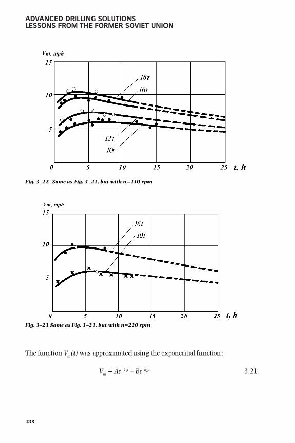
ADVANCED DRILLING SOLUTIONSLESSONS FROM THE FORMER SOVIET UNION
The function Vm(t) was approximated using the exponential function:
Vm = Ae–k1t – Be–k2t 3.21
238
Fig. 3–23 Same as Fig. 3–21, but with n=220 rpm
Fig. 3–22 Same as Fig. 3–21, but with n=140 rpm
gelfgat 199-292.qxd 2/10/03 2:15 PM Page 238

WELL DRILLING OPTIMIZATIONMETHODS IN THE FSU
where
t is the bit on bottom time
e is the natural logarithm base
A, k1, k2 are coefficients, dependent on rock physical and mechanicalcharacteristics, type of drilling fluid, drilling process parameters, andbit design size
B is the coefficient for designed constant rotational speed, depending onrock physical and mechanical characteristics, and bit design and size
The latter coefficient accounts for a specific pattern of change in the form of thebit blade to a tapered form (wear starts at the gage row which has the fastestperipheral speed and continues toward the middle).
The diagrams in Figures 3–21, 3–22, 3–23, and 3–24 indicate that an increase inP resulted in faster bit wear. In the area located to the right of the maximumpenetration rate level, the absolute values of the function Be–k2t were so small theydid not affect the pattern of Vm change for practical purposes. Therefore, Equation3.21 at high P values can be reduced to the following form:
VM = Ae–k2t = V0e–k1t 3.22
where
k1 is the decrement of drilling speed decrease due to bit wear
V0 is the initial drilling speed
239
Fig. 3–24 Same as Fig. 3–21, but with n=680 rpm
gelfgat 199-292.qxd 2/10/03 2:15 PM Page 239

ADVANCED DRILLING SOLUTIONSLESSONS FROM THE FORMER SOVIET UNION
This equation complies with the currently accepted exponential law of speedchange during a bit run.
The diagram in Figure 3–25 shows power variation while drilling with blade bits.43
Functions W(t) (curve 3) and Asp (curve 4) indicate that before the maximumpenetration rate, curve 1 was achieved. Power W required for rock destruction wasincreasing, whereas specific energy consumption per drilled out rock unit volumeAsp, was going down.
The maximum power used and the minimum energy rate corresponded to themaximum Vm level. With the decrease of Vm, W went down and Asp went up.
This identified the principal basic functions of controlled drilling parameters whendrilling with blade bits, 44 as well as numerical values of the basic functions’
240
Fig. 3–25 Drilling parameters dependencies on drilling time, Pirsagat field, drillinginterval 2600–3000 m, bit 3LG-269
gelfgat 199-292.qxd 2/10/03 2:15 PM Page 240
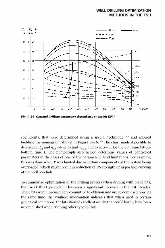
WELL DRILLING OPTIMIZATIONMETHODS IN THE FSU
coefficients, that were determined using a special technique, 45 and allowedbuilding the nomograph shown in Figure 3–26. 46 The chart made it possible todetermine Popt and nopt values to find Vr-max and to account for the optimum bit-on-bottom time t. The nomograph also helped determine values of controlledparameters in the cases of one of the parameters’ level limitations. For example,this was done when P was limited due to certain components of the system beingoverloaded, which might result in reduction of DS strength or in possible curvingof the well borehole.
To summarize optimization of the drilling process when drilling with blade bits,the use of this type rock bit has seen a significant decrease in the last decades.These bits were unreasonably committed to oblivion and are seldom used now. Atthe same time, the available information indicates that when used in certaingeological conditions, the bits showed excellent results that could hardly have beenaccomplished when running other types of bits.
241
Fig. 3–26 Optimal drilling parameters dependency on the bit RPM
gelfgat 199-292.qxd 2/10/03 2:15 PM Page 241

ADVANCED DRILLING SOLUTIONSLESSONS FROM THE FORMER SOVIET UNION
Results of Drilling Experimental and KTWs and Applicationof the KTW Technique in Developing Certain Fields
Wells Drilled in Azerbaijan 47
The first experimental wells drilled in Azerbaijan, Samara province, and Bashkiriya in1961 and 1962 were constructed with planned test activities and goals aimed atobtaining information on rotary, turbodrilling, and electrodrilling technology.
The program of drilling testwells in Azerbaijan wasdeveloped by the VNIIBT incooperation with the scien-tific and research instituteAzNIIburneft and the Azneftproduction company fromBaku.
From 1961 through 1964,three wells were drilled in theKaradag-Damba area usingvarious drilling methods: No.156 (rotary), No. 153 (tur-bodrilling), and No. 157(electrodrilling), with TDs of4800 m.
Figure 3–27 48 presents ageological cross-section ofthe Karadag-Damba fieldalong with the test welldesign.
242
Fig. 3–27 Lithology section and design of test wells No. 156, 153, and 157
a – suite
b – lithologicsection
c – rockhardness
d – well design
1 –clays
2 –sands
3 –soft rock
4 –hard rock
5 –sandstone
6 –sands withgas and oilpresence
7 –medium-hard rock
8 –very hardrocks
gelfgat 199-292.qxd 2/10/03 2:15 PM Page 242

WELL DRILLING OPTIMIZATIONMETHODS IN THE FSU
Drilling conditions in the southeastern part of the Karadag structure, where thetest wells were drilled, were quite complicated because of gas shows, holesloughing, tight sections, and formation arching, which led to DP dragging,sticking, and keyseating problems.
Besides the standard measuring and control equipment, the following instrumentswere installed on the rig to enable control and analysis of the results of the drillingprocess: the KPB-3 driller’s control console, recorders (ammeter, voltmeter,wattmeter), and the RGR-4 flow meter. These instruments allowed continuousregistration on chart strips of penetration rate, bit weight, pump discharge operatingpressure, power input, amperage, and voltage. Drilling the test well involved usingthe Uralmash 43-61 drilling rigs with three U8-4 pumps, two shale shaker-and-conveyor combination units, the AKB-3 DP tongs, the PKR-Sch8 pipe slips, thePIRSh-4 rotary drive. In addition, the rig that drilled well No. 157 (electrodrilling)included such equipment as drillbit feed control mechanism AVE-1 and a frequencyconverter unit that enabled control of the electrodrill shaft rotational speed bybringing the electrical frequency down from 50 Hz to 34.5 Hz.
Well No. 156 was drilled using DRCs with diameters of 273 mm, 203 mm, and178 mm. Total length of the DRC section was from 140 m to 240 m, which madepossible an axial load increase up to 25 tons. While drilling this well, the drillersused such tools as jet nozzle bits (both three-blade and tri-cone bits) and higherpower-consuming M and MS-type cone bits instead of the commonly used bitswith S-type cutting structure. They also used strength category E steel DPs, andthe most effective chemical (at that time) for mud treatment—polyphenol wood-chemical (PFLK).
Use of the specially selected equipment and optimized drilling and mud circulationparameters when drilling well No. 156, spud-in December 1961, achieved muchbetter results compared to well No. 166 drilled earlier in the Karadag-Damba fieldusing the rotary drilling method (Table 3–1). At some intervals, the drilling resultswere even more impressive.
243
gelfgat 199-292.qxd 2/10/03 2:15 PM Page 243

ADVANCED DRILLING SOLUTIONSLESSONS FROM THE FORMER SOVIET UNION
TABLE 3–1Experimental Well No. 156 Drilled in Azerbaijan at Karadag-Damba
Field in Compared with Best Well No. 166 Drilled Before, Rotary Method Used in Both Cases
Drilled Number of Average penetration Penetration Bit runWell No. interval bit runs per bit, m rate, m/hr speed, m/hr
156 50–3,852 78 50.5 4.25 2.18166 110–3,898 99 34.5 2.42 1.45
Note: The drilling results are compared only for the interval drilled to the setting depth of the 219-mmstring. A serious downhole failure occurred in well No. 156 at 4071 m related to a pipe being stuck, whichresulted in drilling a second hole that also never reached the TD. For technical reasons, both holes wereplugged and abandoned.
A representative example is the interval that was drilled in the Apsheron-Akchagalsuite deposits from below the 426-mm conductor casing in which three-blade bitswere run. During the first run, a 14-mm jet bit with ceramic nozzles penetrated 944m with an average penetration rate of 87.2 m/hr, i.e., the entire interval was drilled in10.8 hours. This allowed drilling a 1000-m interval in approximately 15–18 hours.This was accomplished by providing the required bit weight level of up to 20–25 tons,jet nozzle outflow velocity up to 110 m/sec, and a DS rotational speed up to 220 rpm.Not one of the wells that had been drilled previously exceeded 15 m/hr with theturbodrilling method or 34 m/hr with the rotary method.
The unique results from drilling in Apsheron-Akchagal deposits allowed aconclusion about the high potential performance results and the application oflow cost of jet nozzle blade bits in this and similar deposits at deeper intervals. Thisconclusion was enhanced by the possibility of achieving even better results byincreasing bit weight, improving borehole cleaning with higher mud circulationrate, and by using a drillbit feed control device. Therefore, the facts encouragedpromoting wide use of these bits.
The analysis of the data, along with simple calculations, indicated that just 9bits (Rather than 15–17) could drill the interval for a 299-mm intermediatecasing in 120–130 hours at an average penetration rate of 18–24 m/hr. Byexcluding the downtime, reducing the time of round trips and mud pumprepair, and reducing downhole failures such as DP sticking, drillers couldachieve an overall drilling speed of 5000–6000 m/rig-month while drilling theinterval for the intermediate casing. This meant that the interval could bedrilled and cased in only two weeks.
244
gelfgat 199-292.qxd 2/10/03 2:15 PM Page 244

WELL DRILLING OPTIMIZATIONMETHODS IN THE FSU
The B11MGL bits and jet nozzle 269 mm diameter blade type bits showedexcellent results when drilling below the 11-in. (299-mm) intermediate string.Comparisons between the best results from wells drilled using turbodrills in thisinterval of the Balakhansky suite and the “medium series” (i.e., to the depth ofthe second intermediate string) showed the advantage of using the rotarydrilling method when running high power-consuming tri-cone jet nozzle bitswith long teeth.
These type bits were also run in combination with an electrodrill in well No. 157 thatwas spud-in on March 7, 1962. In this well, however, blade bits drilled much smallerintervals, whereas a larger number of the B11MGL and B11MSG type tri-cone bitswith high power consumption were used. In some sections of the borehole, the bitswere used in combination with two-section electrodrills. High mud pump pressureand forced drilling practices were also used while drilling this well.
The performance results from the well were better than any of the otherelectrodrilled wells, but they were not as good as the results from drilling well No.156 using the rotary method. Table 3–2 shows data from the wells drilled usingthe electrodrill method.
TABLE 3–2Drilling in Azerbaijan at Karadag-Damba Field with Electrodrills:
Experimental well No. 157 Compared with Previous well No. 198
Drilled Number of Average penetration Penetration Bit runWell No. interval bit runs per bit, m rate, m/hr speed, m/hr
157 97–4,000 124 29.2 4.05 1.75198 100–4,003 171 22.2 2.96 1.26
The electrodrill process experienced many difficulties because of low durability ofthe electrical cables and the electrodrilling motors themselves at that time. A totalof more than 40 cable faults were revealed in various sections of the cable andmotor. As a result, 10 bit runs were not completed. This fact significantly affectedthe general performance results of electrodrills.
245
gelfgat 199-292.qxd 2/10/03 2:15 PM Page 245

ADVANCED DRILLING SOLUTIONSLESSONS FROM THE FORMER SOVIET UNION
While drilling the interval below the first intermediate string, the drillers could usea frequency control unit, which allowed them to reduce the speed of the high-torque two-section electrodrills from 680 rpm to 450 rpm. This new techniquesubstantially improved drilling results even though the B11S non-jet nozzle bitswith medium tooth length were run instead of the B11MGL and B11PSG bits, thelatter being unavailable. These results are shown in Table 3–3, 49 which indicatesthat due to a high bit weight of 20–25 tons and good borehole cleaning (Q=31–35liters/sec), drillers were able to increase the penetration rate and the penetrationper bit by 2–2.5 times.
TABLE 3–3Comparison of Drilling Results from Well No. 157,
Drilled with Standard “E” and sectional “ES” Electrodrills
AverageType of Nos. penetra- Average Averageelectro- of bit tion per time of a ROP, Bit
Interval, m drill runs bit, m bit run, hr m/hr type Drilling parameters
Pressuredrop, kg/ Current,
WOB rpm sec • m2 ampere
2,399–2,508 E215/8 5 21.8 9.05 2.41 B11S 14–20 450–680 125 140
2,508–2,550 ES215/2 1 42.0 8.50 4.95 B11S 20–23 450 125 140
2,550–2,597 E215/8 2 23.5 7.10 3.31 B11S 16–20 450 125 140
2,597–2,639 ES215/2 1 42.0 6.25 6.62 B11S 18–22 450 130 110–120
Increase of the well depth to 4000 m and deeper while drilling in the “mediumseries,” frequent cable faults, and a 30–40% reduction rate of circulation fluid dueto large hydraulic losses significantly worsened the drilling results to the pointwhere further well deepening became unfeasible. For that reason, drilling wasstopped at the depth previously noted. Next, the production string was run in toenable production from horizon VIII of the medium series.
The experience from drilling this well gave an impetus to further development andimprovement of the entire electrodrilling method. This development and improve-ment work was instrumental in eliminating the noted drawbacks and achieving verygood results using the electrodrills for deep well drilling. The technology of electrodrill
246
gelfgat 199-292.qxd 2/10/03 2:15 PM Page 246

WELL DRILLING OPTIMIZATIONMETHODS IN THE FSU
sectioning and frequency control units have not found wide application sincereduction gear inserts technology proved to be simpler and more reliable in achievinghigher bit torque and lower rotational speed (see Chapter 2 for more details).
The drilling of well No. 153 began in March 1962. It was drilled using theturbodrilling method and was the only well of this kind that was drilled to the TD.Table 3–4 presents drilling results from this well compared to the best wells drilledto the running depth of the second intermediate string using turbodrills.
TABLE 3–4Experimental Well No. 153 Drilled in Azerbaijan at Karadag-Damba Field
Drilled with Turbodrills Compared to Previous Wells
Number of Average penetration ROP, Bit runWell No. Interval, m bit runs per bit, m m/hr speed, m/hr
153 62–4,018 140 27.1 5.6 1.95
143 45–4,050 174 22.8 2.4 1.21
144 50–4,000 155 24.9 4.2 1.63
As mentioned in Chapter 2, the three-section turbodrills 3TS5B-9" were tested forthe first time in well No. 144 in combination with the B11S bits. This test aimed atevaluating their efficiency prior to running them in well No. 153. In well No. 143,drillers used only the TS5B-9" two-section turbodrills. The 3TS5B-9" turbodrillsproved to be quite efficient, which contributed greatly to an increased penetrationrate and successful completion of well No. 144.
This type of turbodrill was used in well No. 153 combined with more efficienthigh-power consumption bits such as types B11MGL and B11MSG. During theirrunning, higher mud pump pressure levels of up to 170–180 kg/cm2 were used.In certain intervals, lower rotational speeds of 350–435 rpm were employed,which resulted in even better drilling results (see Chapter 2 for more details).
The drillers were not able to achieve good commercial results from drilling testwells, because of a number of organizational problems, downhole failures, and thelarge amount of repair work that was required. However, the excellent technicalresults and the large amount of research work allowed a number of important
247
gelfgat 199-292.qxd 2/10/03 2:15 PM Page 247

ADVANCED DRILLING SOLUTIONSLESSONS FROM THE FORMER SOVIET UNION
conclusions about drilling in the Karadag field and a number of other fields inAzerbaijan with similar drilling conditions that included:
1. Integrated use of properly combined available technology and equipmentproved to be one of the powerful methods for improving drilling resultsand well economics.
2. Rotary drilling with running jet nozzle blade and cone bits with long teeth(M-type) combined with certain drilling parameters were the mosteffective method of drilling to depths of 3700–4000 m.
3. In deep intervals, the results of turbodrilling using diamond bits werebetter, compared to rotary drilling, even with heavy mud.
4. Design and operational characteristics of certain commercially produceddrilling equipment, as well as of some measuring and control equipmentand instrumentation, did not meet the requirements of the existing deepwell drilling technology.
The experience with drilling the first test wells in the Karadag-Damba field wasused for wide-scale development drilling on this and other fields in Azerbaijan (theAlyatsk Ridge field, the Pirsagat field, etc.). This experience was applied mostsuccessfully while drilling well No. 57 in the Alyatsk Ridge field of the Prikuriandepression. The TD of the well was 5000 m. Drillers used the rotary drillingmethod and drilling tools such as the jet nozzle blade and tri-cone bits, TBVK140strength category L and M DP, and balanced DRCs of 254 mm and 203 mmdiameter. Bit weight, when drilling to the depth of 4300 m, was up to 27 tons witha rotational speed of 140 rpm compared to 12–14 tons and 70 rpm in the previouswells. As a result, the well drilled in 1967 set a record for overall drilling speed ofapproximately 500 m/rig-month. The actual well depth was 4900 m.
Table 3–5 presents a comparison of the drilling results from this well with otherwells drilled with good results both before and after.
248
gelfgat 199-292.qxd 2/10/03 2:15 PM Page 248

WELL DRILLING OPTIMIZATIONMETHODS IN THE FSU
TABLE 3–5The Drilling Speed Record-holder Deep Well No. 57 in Comparison with
Other Wells Drilled in Azerbaijan
Number OverallWell, of bit Penetration ROP, drilling speed,
Well No. Depth, m runs per run, m m/hr Finished in m/rig • month
57 the Alyatsk 4,900 70 70 2.4 1967 500Ridge
29 the Alyatsk 4,911 130 37.8 1.33 1966 331.8Ridge
46 Karabagly 5,005 120 41.7 2.03 1965 327
83 Kyurovdag 5,001 207 24 1.92 1965 175.4
30 Kyanizdag 5,022 98.0 51.8 1.41 1966 207
401 Kyurovdag 5,000 178 28 2.11 1967 244.4
427 Kyurovdag 5,021 218 23 2.12 1967 259.2
2 Umbaki 5,000 117 42.7 1.98 1967 276
75 Bulla 5,260 164 31.9 1.52 1968 348.3
61 Karabagly 5,110 128 39.2 2.02 1968 233
The results of drilling well No. 57 indicated a high potential for improving resultsof deep well drilling in Azerbaijan and some other regions. In the followed years,the experience from drilling well Nos. 153, 156, 157, and 57 was used successfullyat such fields as the Pirsagat, the Sangachaly and others that featured similarcomplicated geological conditions, which required use of weighted drill mud witha density of >2.0 gr/cm3. Although the overall drilling rate of 500 m/rig-month(i.e., drilling 1 well during a 10-month period) nowadays cannot be considered anoutstanding achievement, but more than 30 years ago, it was impressive. All thesewells were exploratory. They were drilled in remote regions with no access roads orother infrastructure, which led to a significant amount of downtime because ofproblems with materials supply, a large amount of repair work, and other reasons.
The purpose of showing this data here is to prove that even with problems, acarefully developed and implemented drilling program achieved relatively goodresults. This approach would prove even more efficient today.
249
gelfgat 199-292.qxd 2/10/03 2:15 PM Page 249

ADVANCED DRILLING SOLUTIONSLESSONS FROM THE FORMER SOVIET UNION
Wells drilled in the Samara Region 50
Technique of well drilling using water circulation. Before describing results of thetest well drilling in the Samara region, it is important to touch upon one of the mostdistinctive features of the well drilling technique in the Urals and Volga oil and gasprovinces where the Samara region is located. This feature was the utilization ofwater, rather than clay mud, for cleaning the borehole while drilling.
The first attempts at using water for borehole cleaning were made in 1937 and1938 in the Tuimazin field in Bashkiriya region. This was a forced measurebecause of the poor supply of clay and chemicals. At that time, these attemptswere not very successful because drillers used rotary drills and low capacity mudpumps that could not provide the required quality of borehole cleaning, whichresulted in a number of drilling problems. Still, the very possibility of drilling withwater circulation was quite important. As is often the case in the history of scienceand technology developments around the world, it was merely a coincidence thatresulted in launching and developing a new trend of well drilling technology in theUrals and the Volga regions. Combined with the turbodrilling method, this newtechnology proved very cost efficient. 51
Besides the obvious advantages of using water rather than clay mud, such aseliminating the cost of clay and chemicals, no transportation requirements,reduced wear rate on mud pump components, and fewer hydraulic pressure lossesin the circulation system, the main gain was both a higher penetration rate andhigher penetration per bit, other conditions being equal. Furthermore, theincrease of the two latter parameters was even higher for turbodrilling comparedto rotary drilling.
This can be explained by the decrease of the differential pressure �P in the well-and-formation system. When it approached the zero level, it resulted in a linearincrease in penetration rate, depending on the bit rotational speed, without aplateau level at high rotational speed as is shown in Figure 3–5. The wide use ofwater circulation became an important factor in cleaning drill cuttings from theborehole of wells drilled in the Urals and Volga oil provinces.
In 1952, 32,000 m were drilled using water circulation, whereas more than1,500,000 m were drilled in 1955. In the following years, the amount of drillingthat used water circulation increased even more as drillers applied ways of usingspecial additives for the circulating water treatment, which reduced fluid loss in aformation and efficiently drilled even thin clay and marl stringers that werenormally destroyed (washed out) by water.
250
gelfgat 199-292.qxd 2/10/03 2:15 PM Page 250

WELL DRILLING OPTIMIZATIONMETHODS IN THE FSU
The fact is that the geological section of fields located in these oil provinces wasprimarily composed of old Paleozoic deposits, primarily carbonaceous rocks thatfeatured a high level of hardness and stability. This last fact was extremelyimportant, because it helped maintain the stability of a well borehole whendrilling with water circulation.
We believe that the differential pressure decrease to zero, while drilling throughcarbonaceous rock with water circulation, was related to a phenomenon studiedby the academician P. A. Rebinder, professor K. F. Zhigach, and professor Schreinerthat was highlighted in the scientific report they wrote. 52 The report suggested thefollowing explanation of the mechanism of water-affected rock destruction.
During a mechanical failure of a solid body, affected by external forces,transmitted to the body by some tool, an intensive fracturing zone was created inthe so-called pre-failure area of the layers, adjacent to the failure surface. The pre-failure zone contains a pattern of wedge-shaped micro-fractures, formed aroundcrystal lattice defects or weak points. When external forces were not applied anymore, deep fracture zones became smaller, fracture thickness through the entiredepth was getting smaller, so that the fracture acquired primordial form and mighteven close up.
When a solid body failed in a liquid medium with minimum viscosity, dissolvedsurfactants penetrated into the system of micro-fractures and slowed down theirspontaneous closing after external forces were not applied any more. When conebits were used for rock destruction, their teeth periodically affected rock by hittingit. Part of the energy of this blow was used to cut pieces out of a rock mass, theremaining energy was used to form a weakened pre-failure zone.
The authors assumed that the presence of an active medium, such as pure wateror water with some surfactants, extended the life of the weakened pre-failure zoneand, when one impact followed another, the accumulated effect improved theefficiency of bit performance.
We do not deny a certain positive effect of this factor. Yet, we believe the process ofrapid equalization of formation pressure with water column hydrostatic pressurewas the main benefit in the formation of a pre-failure zone that featured anintensive fracture pattern, i.e., the formation of conditions at which �P equaledzero. This provided the prerequisites for the sizeable increase of penetration rate,especially at forced drilling modes with high bit weight and the rotational speed ofturbodrills and other types of DHMs.
251
gelfgat 199-292.qxd 2/10/03 2:15 PM Page 251

ADVANCED DRILLING SOLUTIONSLESSONS FROM THE FORMER SOVIET UNION
As previously mentioned, the 1950s witnessed a rapid growth in drilling volumesthat used water circulation for borehole cleaning. According to the data from1959, this technology was used in drilling 93% of the wells in the Tatariya region,65% in Bashkiriya, 40% in the Samara region, and 50% in the Perm region withmore than 2 million meters total footage drilled in these regions alone. Acombination of the water borehole cleaning technique with forced drillingpractices achieved truly outstanding results in a number of wells.
From 1957 to 1959 the overall drilling rate in Tatariya was 5000–5500 m/rig-month in wells that showed the best drilling results with TD of 1700–1800 m,meaning each well was drilled in 10 days. However, the actual bit-on-bottom timewas only 60–70 hours at an average penetration rate of 25–30 m/hr. These resultswere shown in rocks with a Shreiner hardness of 150–400 kg/mm2. Furthermore,the hardness of certain chert-bearing limestone and dolomite stringers was muchhigher than that shown.
Implementation of the water circulation drilling technique faced problems thathad to be overcome, such as the stability of drilled clay stringers, complicated wellelectrical logging due to water salinization when drilling through water-saturatedformations, and a number of other problems. Several research institutes carriedout work to find solutions for these problems, which allowed developing variousadditives and chemicals for the water-based mud treatment.
Even though utilization of water as a drilling fluid was quite efficient, the measurestaken could not provide a comprehensive solution for the overall well drillingoptimization process. Rather, these measures suggested only a partial solution.Therefore, the KTW drilling program aimed at developing a more comprehensivesolution for the issue.
Experimental well drilling. Test wells were drilled in the Samara region from 1962through 1965 under the programs jointly developed by engineers from theVNIIBT institute and specialists from KuibyshevNIIneft and Pervomaiburneftdrilling company.
Most of these wells were drilled in the Dmitrov field such as well Nos. 156, 90, and157 drilled using the rotary method, well Nos. 154, 149, 150, 186, and 250 usingthe turbodrilling method, and No. 168 using the electrodrilling method. The wellsfeatured a single string design, a conductor casing of 11-in. to 12-in. diameter setat a depth of 300–320 m, and a production string with a diameter of 5-in. or 6-in. run to the depth of 3000 m. The wells were drilled using an Uralmash 4E-61
252
gelfgat 199-292.qxd 2/10/03 2:15 PM Page 252

WELL DRILLING OPTIMIZATIONMETHODS IN THE FSU
rigs with two U8-4 mud pumps. The rigs were equipped with a KPB-3 driller’sconsole, as well as with electrical measuring and control instrumentation such asammeter, voltmeter, and wattmeter. The interval from the surface to the top of theTula horizon at a depth of 2000–2100 m was drilled using water circulation toclean drill cuttings from the borehole.
DSs run in these wells included 200–280 m of 178 mm diameter DC, 140 mm DPof electromagnetic (EM) strength steel, aluminum DP, and drillbits with a diameterof 214 mm that had various types of cutting structures made by the Samara bitplant. Well No. 156 and well No. 90 were drilled at an operating pressure of120–160 bar from the mud pumps with a drill mud outflow velocity from bit jetnozzles of 100–140 m/sec. Bit weight varied between 20 tons and 28 tons.Because of steel DP failures and serious lost circulation problems, well No. 156reached a depth of only 1772 m, and well No. 90 reached 2475 m.
When drilling well No. 157, drillers used the RPD-2A bit feed control mechanismand aluminum DP. The mud pump output rate was 40–52 liters/sec. The bitweight, applied to 214-mm bits, varied in the range of 18–28 tons at a rotationalspeed of 35–60 rpm. The well was drilled to a TD of 2963 m.
The rotary drilling method had never been used in this area before, and so theresults from well No. 157 could not be compared to those from any other wellsdrilled using the same drilling method. However, it is worth mentioning that theoverall drilling rate of 593 m/rig-month exceeded the average results from wellsdrilled in that region using turbodrills.
Drillers ran the E215-8 electrodrill on 146-mm DPs combined with a frequencyregulated unit while drilling well No. 168. The frequency regulator enabled areduction in rotational speed of the electrodrill from 680 rpm to 340 rpm. In addition,the AVT bit feed control unit was used. Electrical power was supplied to the electrodrillthrough a two wire cable and a DP that performed the function of the third wire. Thepower cable sections were equipped with KST-1 connecting plugs.
Because of the low durability of electrodrills in these wells, drillers were not able toachieve high results. However, the research work that was carried out whiledrilling the wells was of great value.
The rig that drilled well No. 154 had been outfitted with some additional equipmentsuch as the AVE-1 bit feed control unit, the ASP-3 automatic pipe handling unit, andhydro-cyclones for the cuttings removal system. The TS5B-9" type two-section
253
gelfgat 199-292.qxd 2/10/03 2:15 PM Page 253

ADVANCED DRILLING SOLUTIONSLESSONS FROM THE FORMER SOVIET UNION
turbodrills were run in the well, keeping the mud pump pressure up to 140–180kg/cm2. Drillers ran in 269 mm diameter bits with various types of cutting structures.Use of some enhanced equipment, along with optimized drilling practices, allowed asignificant improvement in the drilling results of well No. 154 compared to the wellspreviously drilled in the Dmitrov field using the turbodrilling method (Table 3–6).
TABLE 3–6Experimental Well No. 154 Compared to Best Wells Drilled Previously in
Samara Region, Dmitrovsky Field, Turbodrilling
Bit run OverallWell, Bit Penetration ROP, speed, drilling rate,
Well No. Depth, m runs per bit, m m/hr m/hr m/rig • month
154 2,967 169 17.6 8.2 2.45 972
Wells with best drilling results306 2,955 215 13.8 7.26 1.93 744344 2,950 215 13.7 6.74 1.90 789
Average resultsFor 11 wells 2,959 212 14.0 6.5 1.61 456
In the next wells, the drilling process was even more optimized thanks to the wideruse of advanced drilling equipment and techniques. For example, rigs with aderrick height of 53 m were used to drill well Nos. 149, 150, and 186, whichallowed handling joints with lengths of 35–37 m.
In addition, while drilling these wells, the drillers used equipment such asaluminum DP 147x11 and the ASP-3 automatic pipe handling unit. The rig thatdrilled well No. 186 was also outfitted with the RPD-type bit feed control unit andran three-section 9-in. and four-section 71/2-in. turbodrills.
The drilling process parameters were monitored and recorded using equipment suchas the KPB-3 driller’s console outfitted with instruments that indicated parameters ofbit feeding, hook load, standpipe pressure, and the RGR-7 induction flow meter andelectrical measuring and control instruments. In well No. 186, the interval down to2148 m was drilled using bits with a diameter of 269 mm. Next a welded liner wasrun into the well to isolate lost circulation zones. Finally, a 214-mm bit was run anddrilled the well to the TD. Bits with a diameter of 269 mm were run mainly incombination with the 3TS5B-9" three-section turbodrills in the bit weight range of22–37 tons and a mud pump pressure of 120–130 kg/cm2.
After running in a 400-meter 245-mm liner and isolating the lost circulationzones, the interval below 2148 m was drilled using a 214-mm bit in combination
254
gelfgat 199-292.qxd 2/10/03 2:15 PM Page 254

WELL DRILLING OPTIMIZATIONMETHODS IN THE FSU
with 4TSSh 7-1/2" four-section turbodrills at a bit weight of 25–30 tons and apump pressure of 180–190 kg(f)/cm2. Table 3–7 shows a comparison between thedrilling results from this well and well No. 154.
TABLE 3–7Experimental Well No. 186 Drilled with Modern Drill Rig
and ADP Compared with Well No. 154
Number Bit run OverallWell of bit Penetration ROP, speed, drilling rate,
Well No. depth, m runs per bit, m m/hr m/hr m/rig • month
154 2,967 169 17.6 8.2 2.45 972
186 2,960 166 17.8 12.8 4.27 1583
This set a record for these types of wells drilled in the Samara region. However, analysisof the drilling process of well No. 186 revealed a potential for further improvement. Inthe first place, this improvement could be achieved by using effective lost-circulationcontrol methods rather than running in a liner to isolate lost-circulation zones, whichwould enable running a 214-mm bit. In addition, various auxiliary operations could bedone faster. These measures were fully implemented in 1965 when drilling the nextwell, No. 250. Table 3–8 presents the dynamics of drilling results from all drilled wells.53
TABLE 3–8KTW Drilling Results in Samara Region
(Former Kuyibyshevskaya Oblast) at Dmitrovsky Field
Overalldrilling
Bit No. of Penetra- Bit run rate,Drilling diameter, Well Bit tion per ROP, speed, m/rig •
Well No. method mm depth, m runs bit, m m/hr m/hr month
Average resultsFor 11 Turbodrill 269 2,959 212 14.0 6.5 1.61 456wells
Best results from previously drilled wells306 Turbodrill 269 2,955 215 13.6 7.26 1.93 744344 Turbodrill 269 2,950 215 13.7 6.74 1.90 789
Results from KTWs168 Electrodrill 269 2,970 193 15.3 4.6 1.60 560157 Rotor 214 2,963 137 21.8 2.6 1.46 590154 Turbodrill 269 2,967 169 17.6 8.2 2.45 972149 Turbodrill 269 2,982 199 15.08 11.8 3.2 1,188150 Turbodrill 269 2,989 205 14.6 11.0 3.2 1,210186 Turbodrill 269 * 214 2,960 168 17.6 12.87 4.27 1,583250 Turbodrill 269 3,000 146 20.55 14.85 4.73 2,013
* Two drill bit sizes were used
255
gelfgat 199-292.qxd 2/10/03 2:15 PM Page 255

ADVANCED DRILLING SOLUTIONSLESSONS FROM THE FORMER SOVIET UNION
Thus, the experience gained from drilling the experimental and KTWs in theSamara region for a three-year period allowed an almost threefold increase in theoverall drilling rate in the Dmitrov field. Positive results achieved in well No. 250,attributable to the combination of forced drilling practices and reduced round triptime, were correlated with the results of the optimum drilling parameterscalculations for drilling conditions in the Samara region. The researchers who haddone these calculations used Equations 3.8 and 3.17 in a mathematical model andaccounted for coefficients a, T0 and � for the Podolian, the Vereian, and the Tulianhorizons and a rotational speed of 350–450 rpm for the 3TS5B-9 turbodrill. Theresults obtained are shown in Table 3–9.
TABLE 3–9KTW Actual Drilling Data Compared with Analytical Studies
Round–trip Bit runHorizon Interval, m Well No. time, hrs WOB, tons speed, m/hr
Estimated Actual Actual Estimated
Podolskyi 1,355–1,462 250 1.27 40 30 13.0 16.0150 1.75 32 18–20 6.4 11.0
Verelskyi 1,579–1,648 250 2.0 38 34 10.8 14.1150 2.17 28.7 18 4.7 8.9
Tulskyi 2,138–2,206 250 2.25 42.5 35 3.1 4.75150 2.95 29.5 18.20 2.44 4.0
Table 3–9 indicates that the fastest bit run speed was achieved in well No. 250since the actual bit weight levels in this well most closely matched the estimatedlevels for this round trip speed. In addition, the estimated bit run speed was quiteclose to its actual level, which proved the validity of the suggested mathematicalmodel of a well borehole deepening process.
An analysis of the results from the work previously described support thefollowing conclusions:
1. The results of KTW drilling in the Samara region convincingly provedthat thorough, integrated utilization of advanced drilling equipment andtechnologies could lead to significant improvement in drilling results.
2. Use of the turbodrilling method, combined with optimized drillingpractices when drilling wells up to 3000 m in the Samara region,achieved the best drilling results.
256
gelfgat 199-292.qxd 2/10/03 2:15 PM Page 256

WELL DRILLING OPTIMIZATIONMETHODS IN THE FSU
3. In these conditions, full transfer to rotary drilling was not feasible becauseit would require a significant upgrade of the drilling equipment such ashigh strength balanced DC and rotary tables and swivels with improvedreliability. Use of this drilling method for drilling wells up to 3000 m, evenwith the upgraded equipment, would not be economical because it couldnot achieve high enough results to offset the cost of the equipmentupgrade. Selective application of the rotary drilling method for drillinglower well intervals may prove cost efficient.
The experience gained from the ADP application in well No. 157 wasextremely important and proved the possibility of successful operation inrotary drilling with its potential fully used by forced drilling practices,high bit weight (applied to tri-cone and jet nozzle bits), high drilling fluidoutflow velocity from bit nozzles, and high differential pressure levels.
4. Currently, the electrodrilling application is feasible only for researchpurposes. Additional work is required to significantly improve operationof the power supply cable as well as the reliability and durability ofelectrodrills before these machines have a wide commercial application.
The results from drilling experimental and KTWs were widely used for later drillingin the Dmitrov field as well as in some other fields in the Samara region that hadsimilar geological conditions.
Wells drilled in the Bashkiriya region
Well No. 2000 in the Tuimazin Field. In 1964, well No. 2000 was spud-in on thesoutheastern wing of the Tuimazin structure to make a comprehensive study of adeep earth crust structure in the Volga-Urals oil and gas province. The study includedthe composition as well as characteristics of the crystalline basement structure. Theentire well interval was drilled using the electrodrilling method exclusively to conductthe required research work in crystalline rock. This type of drilling research work hadnever been done before either in Russia or anywhere else in the world and was,therefore, of great interest. It is described here because the well borehole deepeningprocess confirmed the functions developed during the research work in sedimentaryrocks, the results of which are shown in the previous pages.
Drilling through the crystalline basement was carried out in the interval of1798–4041.2 m. It was mainly composed of non-homogenous intensivelyinterbedded fractured rocks both acidic and basic, such as gneiss, granite, anddiorite. Various direction fractures—from horizontal to vertical—were filled withvarious ferrous and other compounds. Specialists from the Ufa Oil Research
257
gelfgat 199-292.qxd 2/10/03 2:15 PM Page 257

AD
VA
NC
ED D
RILLIN
G S
OLU
TION
SLES
SO
NS
FRO
M TH
E FOR
MER
SO
VIET U
NIO
N
Institu
te (UFN
II) laboratory determin
ed rock mech
anical ch
aracteristics usin
g the
inden
tation m
ethod. In
dentation
hardn
ess P�
varied between
88
kg/mm
2and 5
30
kg/mm
2, wh
ereas the plasticity factor varied betw
een 1
.2 an
d 2.6
and You
ng’s
modu
lus (1
.2–4
.4)*1
05
kg/cm2.
258
Bottomholedepth, m
Penetrationper run, m
Drillingtime, hr
ROPm/hr
Drillbittype RPM
WOB,ton
Flowrate,l/sec
Powerat thedrill bit,kW
Drillbittorque,kg.m
Power usedfor rockdestruction,kW
Torque on Specific workthe rockdestruction,kg.m
torque,kg.m/ton
for rockSpecificdestruction,kg.m/cm3
2,326 4,30 2,0 1,83 1V-12K 680 25 31 90 129 60 86 3,44 1712,331 5,1 2,67 2,0 1V-12K 680 25 31 111,5 160 81,5 117 4,68 2202,346 6,68 3,08 1,67 1V-12K 680 25 31 104,5 149 74,5 106,5 4,26 2402,353 6,4 3,33 2,0 1V-12K 680 25 31 78 112 48 68 4,6 1402,936 8,0 2,67 3,0 U-12K 680 18–20 31 100 143 70 100 5,26 1262,944 7,9 2,73 2,89 U-12K 680 18–20 31 100 143 70 100 5,26 1302,954 7,8 2,92 2,68 U-12K 680 20 31 112 160 82 117 5,08 1642,962 10,0 3,17 3,16 U-12K 680 18–20 31 97 139 67 96 5,05 1142,972 10,3 3,42 3,02 U-12K 680 18–20 31 97 139 67 96 5,05 1193,101 5,0 2,4 2,08 1V-12K 680 20–22 32 90 129 60 86 4,10 1553,106 6,3 1,92 3,28 U-12K 680 16–18 32 97 139 67 96 5,64 1003,127 13,8 4,04 3,42 U-12K 680 20 32 104 149 74 106 5,03 1163,148 6,1 2,5 2,44 U-12K 680 20 32 113 162 83 119 5,10 1833,154 9,8 3,77 2.6 U-12K 680 21–22 32 96 137 66 94 4,37 1363,167 11,5 3,73 3,1 1V-12K 680 19–20 32 92 131 62 88,5 4,55 1083,195 8,7 3,5 2,5 U-12K 680 19,5 32 95 136 65 93 4,76 1403,582 17,7 6,23 2,84 U-12K 450 20 19,5 57 124 37 81 4,06 703,603 11,9 3,22 3,7 U-12K 680 26 35 100 143 70 100 3,85 1023,615 16,35 7,2 2,3 U-12K 375 26 35 49 127 32 84 3,2 753,636 20 8,92 2,25 U-12K 300 25 19,5 41 121 24 78 3,2 583,905 6,3 1,81 3.48 U-12K 530 17 19,5 70 129 47 86 5,0 733,930 7,8 3,5 2,21 U-12K 346 25 24 52 118,5 27 75,5 3,0 663,942 10,0 4,13 2,42 U-12K 406 27 24 65 156 47 113 4,2 104,53,963 4,8 1,19 4,07 U-12K 530 19 24 65 116 40 73 3,85 533,968 4,5 1,94 2,31 U-12K 406 17 24 57 137 39 94 5,53 913,972 4,4 1,35 3,25 U-12K 466 20 24 61 127 40 84 4,2 663,977 6,2 2,83 2,19 U-12K 466 17 24 47 98 26 55 3,24 643,985 6,1 1,8 3,38 U-12K 680 21 24 90 129 60 86 4,1 963,994 4,0 1,33 3 U-12K 450 27 24 78 170 59 127 4,7 1064,001 3,2 2,16 1.47 U-12K 346 22 24 44 116 26 73 3,3 95
TABLE 3-10Some Data Recorded at the Experimental Well No. 2000, Tuimazinsky Field, Tatariya
gelfgat 199-292.qxd 2/10/03 2:15 PM Page 258

WELL DRILLING OPTIMIZATIONMETHODS IN THE FSU
While drilling the interval of 2156–4036 m, the researchers studied the effect ofthe drilling process parameters on the results of bit runs. For this purpose, theymade 95 test bit runs using special instrumentation and recorders to registerparameters of the drilling process, electrodrill input power level, amperage, andvoltage (Table 3–10). 54
Actual power consumed by the drilling bit is shown in Table 3.10. It was calculatedusing the formula, suggested by F. N. Fomenko: 55
3.23
where
Nsurf is power used on the surface by an electrodrill, including losses inthe power cable, KW
IA, IB, IC are phase currents, A
R is power cable resistance, om for cable with a diameter of 50 mm2 R=0.38Lfor cable with a diameter of 35 mm2 R=0.5L
L is well depth, km
� is the electrodrill motor efficiency factor
NFR is friction losses at no-load shaft run
P is bit weight, kg
f is the conventional coefficient of friction in the trust bearing = 0.003
d is the shaft diameter, mm
n is the bit rotational speed, rpm
While drilling the well, the drillers ran the E215/8 and E250/10 electrodrills incombination with 295-mm U-12K and 1V-12K drill bits with K-type cuttingstructures for hard rocks. Figure 3–28 shows an example of the U-12K bit thatwas used. The drillers used a frequency control unit to control the rotational speedof the electrodrills. By changing frequency and using electrodrills with a differentnumber of poles, the drillers were able to change the rotational speed within therange of 285–680 rpm. The bit weight range was from 5 tons to 30 tons.
( )5
2223 105.1910
1•
--N--
I+I+I--N=N
PfdnR FRCBÀsurfDB η
259
gelfgat 199-292.qxd 2/10/03 2:15 PM Page 259

ADVANCED DRILLING SOLUTIONSLESSONS FROM THE FORMER SOVIET UNION
Figures 3–29, 3–30, 3–31,and 3–32 show the types offunctions of penetrationrate, penetration per bit run,and other parameters of bitweight and rotational speed.The researchers determinedthe optimum levels of thetwo parameters mentionedthat would allow achievingmaximum penetration perbit run. The diagrams indi-cate that these functionsagreed with the well bottom-hole deepening model sug-gested in this chapter. Aplateau tendency of the
penetration rate curve at higher bit weight could probably be explained by insufficientbottomhole cleaning because drillbits were run without jet nozzles.
260
Fig. 3–29 Dependence of penetration (h), penetration rate (v) and bit trip time (T) fromweight on bit P at n=680 rpm; Bashkiriya, Tuimazinsky field, well No. 2000; interval2156–4036 m
Fig. 3–28 Bit U-12K, worked in the interval of3972.2 – 3976.9 m
gelfgat 199-292.qxd 2/10/03 2:15 PM Page 260

WELL DRILLING OPTIMIZATIONMETHODS IN THE FSU
261
Fig. 3–30 Dependence of specific torque (Msp ) and specific power (Asp) for rock destruction,bit torque (Mb) and rate of penetration (Vm) from weight on bit at n=680 rpm; Bashkiriya,Tuimazinsky field, well No. 2000
Fig. 3–31 Dependence of penetration rate (Vm), penetration (h) and bit trip time (T) fromrotational speed (n, rpm) at weight on bit of 20 tone (interval 3530–3800 m); Bashkiriya,Tuimazinsky field
gelfgat 199-292.qxd 2/10/03 2:15 PM Page 261

ADVANCED DRILLING SOLUTIONSLESSONS FROM THE FORMER SOVIET UNION
At the same time, it should be mentioned that while drilling this well, regularimprovement in the drillability of the crystalline rock at greater depths was notedfor the first time. This can be explained by the fact that the rock pressure wassignificantly higher than the drilling mud hydrostatic pressure. This phenomenonwas later recognized while drilling the Kola SD-3 well (see Chapter 5 in Volume 2).
Small Diameter Wells. 56 In the early 1960s, the drilling industry in the FSU facedthe task of increasing the overall drilling speed and reducing the cost ofconstructing stratigraphic and shallow exploratory wells in remote regions. Toachieve this task, specialists from VNIIBT started R & D work in 1962 to improvesmall diameter well drilling technology, which was especially important for thecompanies involved in exploratory drilling.
The researchers selected drillbit No. 7 (according to the Russian bit size classification)with a diameter of 161 mm that was commercially produced by the industry at thattime. This type of bit featured improved strength compared with bits No. 5 and 6 (140mm and 125 mm) that were normally used in stratigraphic well drilling. At the same
262
Fig. 3–32 Dependence of penetration rate (Vm), penetration (h) and bit trip time fromrotational speed at weight on bit of 25–26 tone (interval 3600–3685 m); Bashkiriya,Tuimazinsky field
gelfgat 199-292.qxd 2/10/03 2:15 PM Page 262

WELL DRILLING OPTIMIZATIONMETHODS IN THE FSU
time, bit No. 7 could be used in combination with lightweight DP, small diameter DRC,and low capacity drilling rigs. The Birsk geological-exploratory department (GPK) ofthe Bashneft Company began test drilling a stratigraphic well with a depth of1800–2500 m. This type of well was normally drilled using bits No. 6B incombination with the TC4A-5" two- or three-section turbodrills mentioned earlier.Nowadays drillers use PDMs for this type of application.
By utilizing No. 7 bits and a combination of turbodrilling (to a depth of1300–1500 m) and rotary drilling (to TD) as well as the optimized drillingparameters, drillers were able to achieve significantly higher results in a numberof wells. Table 3–11 presents a comparison of these results and the best resultsfrom the previously drilled well No. 14 in which No. 7 bits were used.
TABLE 3–11Small Diameter 161-mm Experimental Prospecting Wells Drilling inBashkiriya Compared with Existing Well No. 14, Turbodrilling Up to
1300–1500 m Depth, Then Rotary Drilling
Parameter Well No.
30 32* 32 39* 39 14
Well depth, m 1,828 1,833 2,424 1,900 2,283 1,889
Number of bit runs: 120 137 197 207 247 237including full-size drillbits 103 112 150 169 198 190
Penetration per full-size bit 17.21 14.7 14.4 10.3 10.51 8.87
Penetration rate, m/hr 4.66 4.14 3.37 6.17 5.06 5.68
Bit run speed, m/hr 1.98 1.92 1.38 1.62 1.4 1.64
Overall drilling rate, m/rig month 608 840 538.7 585 457 472
*Additional results for wells No. 32 and No. 39 are shown to a depth of 1833 m and 1900 m respectively for comparisonwith well No. 14.
While drilling the test wells, the following equipment and instruments were used.
1) BU-50Br1 drilling rig with a diesel-electrical drive, two B14/200 mudpumps, and all other necessary equipment. The Giproneftemash DesignInstitute specially developed the rig with a capacity rated at 50 tons.Several rigs of this type were built as a trial series for the stratigraphic welldrilling application. The rig consisted of six mobile modules, whichgreatly facilitated its transportation in areas with a complicatedlandscape pattern. The rig featured improved operating parameters,which allowed successful drilling of test wells and was equipped with air,electrical, and mechanical control of various units.
263
gelfgat 199-292.qxd 2/10/03 2:15 PM Page 263

ADVANCED DRILLING SOLUTIONSLESSONS FROM THE FORMER SOVIET UNION
2) DRC with a diameter of 127/67 mm and 140/74 mm.
3) External upset DP from steel grade D with a wall thickness of 8 mm butt-welded to ZU-120 tool-joint with a high performance premium thread.
The rigs primarily used water as a drilling fluid. When running turbodrills, thedrilling parameters were WOB 8–10 tons with a flow rate of 15–18 liters/sec. Forrotary drilling, the parameters were WOB 8–14 tons, flow rate 16–19 liters/sec,and rotational speed of 60–90 rpm. The experience gained from drilling thesewells was greatly extended in the Birsk GPK.
While drilling well Nos. 39 and 30 using the rotary method, the researchers carriedout work to determine the dependence of penetration rate from bit weight level, otherparameters being equal, using Lubinsky’s method previously mentioned.
Drilling wells in the Urals-Volga oil and gas province using dynamicprocesses to intensify rock destruction at the bottomhole57
The theoretical and experimental work carried out from 1970 through 1979 byresearch engineers from the VNIIBT institute revealed that the intensity of themechanical destruction of rock using cone bits depended greatly on the dynamicload level applied to the rock.
The researchers conducted the test work in the lab using special test benchmachines. In addition, full-scale tests were performed in a special well simulator ofthe SKTBE in Kharkov, the Ukraine, while running the E-185 electrodrill machinewith a rotational speed of 220 rpm and 680 rpm combined with the 2K214SGand 2K214TKZ cone bits. 58
The STE-1I downhole telemetry system provided information about the drillingprocess. The DS included DP with a diameter of 140 mm with a power cable inside.Remote sensors measured axial forces P(t) in the DS cross-section above theelectrodrill during continuous increase and decrease of a bit weight. This allowedestablishing a dynamic load P dependence from the variation of static load P anddetermining the amplitude and range of the dynamic load.
Russian specialists carried out a certain amount of research work and reviewed anumber of studies related to the phenomenon of non-linear propagation ofoscillations in rods with a gap in a particular area of the rod connection. As aresult, they concluded that this phenomenon, increasing mechanical resistance ofoscillations propagation in the string (the so-called impedance), allowed them to
264
gelfgat 199-292.qxd 2/10/03 2:15 PM Page 264

WELL DRILLING OPTIMIZATIONMETHODS IN THE FSU
increase the bit weight dynamic component and achieve a significantly higherpenetration rate and penetration per bit run.
The studies 59 60 present descriptions of the DS divider designs developed byengineers from the VNIIBT, along with their test results and theoretical studies ofthe divider optimum position in a DS. The tests were carried out in a SKTBEsimulator well in Kharkov, the Ukraine, as well as in a commercially drilled well inthe Abdrakhmanov field in the Tatariya region. The tests proved their conclusionabout bit performance improvement.
At the same time, the tests revealed that the various designs of DS dividers couldnot be used widely by the industry because of their complex design and lowdurability. Then the idea came to use DP made of different materials to achieve anon-linear effect, rather than using a divider to form a gap section. For thispurpose, a number of steel DP were installed above the DHM, and the remainingpart of the DS was made up of ADP. According to information from the study, 61
the distance between the transitional section and the bit should be equal to the oddnumber of parts representing a quarter wave length of the bit oscillationsfrequency component, i.e., this distance should provide the maximum DSimpedance level. When using this DS design, engineers have to observe theparameters of the drilling process, used for that distance calculations.
The main volume of research works, testing, and implementing the techniquewere arranged in Tatneft oil association. They ran the 3TSSh-195 turbodrills incombination with 214-mm bits that were normally used in that region. Theresearch engineers developed the final DS design faced some problems related tothe utilization of such DS commercially. One of the problems was the necessity tomaintain the required static load level and the proper level of the entire drillingprocess because there was only one boundary between the steel and aluminummaterials. The final design included the broadband reflector, which in a certain DSsection consisted of a set of alternating steel and aluminum DP.
The experience in drilling the Tatneft wells using a controlled dynamic bit weightindicated that the average penetration per bit increase was 15% in 1975 at anannual drilling volume of 500,000 m. Further improvement of the method mayallow an additional increase of this parameter by 30–40%. According to the datapresented in the work, 62 this method was used by drillers from the TatneftCompany since 1972 and saved 2000 bits. Also, the same year, drillers from thePermneft Company began using this method.
265
gelfgat 199-292.qxd 2/10/03 2:15 PM Page 265

ADVANCED DRILLING SOLUTIONSLESSONS FROM THE FORMER SOVIET UNION
The theoretical and test research work showed that assessment of DS dynamicsallowed control of a drilling process by registering elastic oscillations formed as aresult of bit operation and propagation in the DS and the rock. This assessmentmay also obtain data about bit rotational speed, physical and mechanicalcharacteristics of drilled rock, expected problems, etc.
Drillers sometimes use information on elastic oscillations propagation obtainedfrom monitoring bit performance to determine coordinates of a bottomholeposition without running special measuring instruments into a well. 63
When using the rotary drilling method, drillers in the United States control thedynamic load applied to a drillbit. As for drilling using the DHMs, a control similarto this has never been studied in the West. Considering the fact that DRCs are usedwidely by Western drillers with diameters that are significantly different fromthose of DP and that the transition boundary also serves as a wave oscillationreflector, this type of DS may be regarded as a means to control the dynamic loadapplied to a drillbit. Calculations indicated that the ratio between DRC length andbit rotational speed used in U.S. drilling practices stayed within a range thatensured the maximum dynamic load level. This was due to the maximumimpedance of a DS bottom section. Although there are no specific indications inrelated studies and reports that show a conscious approach of the Western drillingindustry to select the DS bottom section design in order to achieve maximummechanical resistance of the DS bottom section, the coincidence should not beregarded as accidental.
The results of the theoretical and experimental studies related to use of elasticoscillations generated in a DS, surrounding media, and rocks indicated that thisdevelopment trend held promise for improvement of drilling process efficiency.
According to available information, American and French researchers startedobtaining data about downhole dynamic processes using acoustic measurementstaken at the surface.
266
gelfgat 199-292.qxd 2/10/03 2:15 PM Page 266

WELL DRILLING OPTIMIZATIONMETHODS IN THE FSU
Experience from KTW Drilling and Results of Its Implementation
After construction of the test wells was completed in Azerbaijan, the Samara region,and the Bashkiriya region, the suggested mathematical model of the well boreholedeepening process was tested and experience was accumulated. Researchers, inconjunction with drillers, started the next phase of this work that was related tocompany-wide use of KTW drilling results for development of the entire field or regionRather than for individual wells. This method was especially efficient when used fordrilling KTWs immediately after the first exploratory wells that proved the presence ofoil-bearing formations in a field at the drilling delineation well stage. In this case, theresults and experience from the KTW construction could be used for drilling all otherwells in the field, which, unlike with the existing practice, immediately increased theaverage drilling penetration rate in the field.
In this respect, a good example is the experience and results from drilling KTWs inthe Kudinov field of the Volgograd region where the drilling was carried out byArchedin UBR (drilling directorate) of Nizhnevolzhskneft association. During aperiod of several years, the primary results from wells drilled by this companyimproved twofold, which is shown in Table 3–12.
TABLE 3–12KTW Drilling Results in Nizhnevolzhskneft at Kudinov Field
1965 1966 1967 1968 1969
Average Average Average Average Averagefrom From from From from From from From from From
drilled KTW drilled KTW drilled KTW drilled KTW drilled KTWResults wells No. 90 wells No. 108 wells No. 98 wells No. 15 wells No. 8
Depth, m 3,360 3,210 3,247 3,170 3,243 3,458 3,189 3,193 3,225 3,200
Total footage 45,426 – 57,518 – 63,258 – 66,396 – 67,923 –drilled, m
Number of 13 – 18 – 20 – 21 – 21 –drilled wells
Penetration 9.14 14.27 11.51 14.95 13.61 19.32 15.98 20.0 17.04 19.4per bit, m
Overall drilling rate, 360 456 493 688 526 720 575 912 670 948m/rig•month
Average annual 4,130 – 4,793 – 5,751 – 6,640 – 8,490 –drilled footage per drilling crew, m
Cost per meter, 117.46 115.8 108.83 101.2 100.5 83.5 94.0 79.09 93.7 78.25rubles
267
gelfgat 199-292.qxd 2/10/03 2:15 PM Page 267

ADVANCED DRILLING SOLUTIONSLESSONS FROM THE FORMER SOVIET UNION
The table presents the best results from wells drilled each year. Actually, each yeardrillers constructed two to three KTWs. Also, it should be mentioned thatsignificant improvement of drilling results was achieved as early as 1966 whenthe registered average penetration rate exceeded the penetration rate in wellNo. 90, which was drilled in 1965.
Continuous efforts of specialists to implement the most positive experience fromdrilling KTWs for the entire field development achieved annual improvements indrilling results. In 1969, the efforts of the specialists from the VNIIBT andVolgogradNIPI research institutes jointly with the engineers from the UBR andassociation showed an annual penetration increase of 1.5 times for the UBRcompared with the results from 1965. During the same period, the number ofdrilling crews was reduced from 11 to 8 while average annual penetration percrew increased more than twofold.
Utilization of the conventional trial-and-error method of drilling technologyimprovement would, in the best-case scenario, result in improvement of drillingresults by 30–40% (which does not happen very often). However, the Archedin UBRCompany in the Volgograd region used the experience from KTW drilling in 1969 andsaved nearly 1,000,000 rubles. This economic effect was achieved by using drillbittypes selected for the corresponding lithological characteristics of rock in the entirewell section, running three-section turbodrills instead of two-section and optimizingthe drilling process parameters. Additional benefits were achieved by using aerateddrilling mud while drilling a large part of the well interval and other innovativetechniques that had been tested earlier in some KTWs.
Similar work was carried out in the Antipov-Balakleyev field by specialists from theNizhnevolzhskneft association, in the Rechitsa field by the Belorusneft association,and in the Orenburg and Shatlyk gas fields, as well as in other fields.
The nominal drilling speed levels achieved in the Kudinov field, for example, may notseem as high when compared with the results from drilling wells of this depth in otheroil producing countries around the world, such as the United States. However, itshould be noted that the geological section in the fields of the Volga-Urals province ismainly composed of hard and very hard rock of the Paleozoic sedimentary cover. Yet,the most important negative factor, as mentioned in Chapter 1, was poormanagement of the drilling operations. This led to significant time losses due tocontinuous shortage of required equipment and materials, poor condition of accessroads, low durability of certain pieces of equipment (especially mud pumps), as well
268
gelfgat 199-292.qxd 2/10/03 2:15 PM Page 268

WELL DRILLING OPTIMIZATIONMETHODS IN THE FSU
as bad planning, and poor motivation for drilling crews. By eliminating all theseproblems, drillers could easily improve the results by 1.5–2 times.
These problems did not affect the importance of adopting the method of drilling processoptimization using experience from KTW drilling, which, undoubtedly, would be asefficient when used under other conditions of drilling process management.
In 1969, scientific and research institutes in six regions of the FSU carried out this work,using as a guide the first edition of Technique for KTW Drilling, published in 1968.
In 1970, the Board of the Ministry of Oil Industry reviewed the joint report by theVNIIBT and Nizhnevolzhskneft Company on results of KTW drilling in theKudinov and the Antipov-Balakleyev fields of the Volgograd region. The Ministry’sBoard approved this experience and issued the Order of the Ministry of OilIndustry No. 384, dated July 29, 1970. The Order instructed all drillingcompanies, in cooperation with the regional scientific and research institutes, tocarry out work for the development and commercial use of well drilling technolo-gy using the experience from KTW drilling.
New drilling technology and equipment used for drilling KTWs achievedsignificant cost and time savings; even though the planned R & D work to be doneby the specialists from VNIIBT required additional time.
A typical example of such work is drilling KTWs in the Orenburg gas field. In1971, the average overall drilling rate was 454 m/rig-month, whereas the maxi-mum level of this parameter, achieved in well No. 175, was 465 m/rig-month. In1971 and 1972, drillers achieved the following levels of overall drilling speedwhile drilling several wells:
No. 170 655 m/rig-month;
No. 174 675 m/rig-month;
No. 177 886 m/rig-month;
No. 166 1028 m/rig-month.
During the same period, penetration per bit increased from 26.9 to 39.2 m, andthe penetration rate increased from 3.55 m/hr to 7.75 m/hr.
269
gelfgat 199-292.qxd 2/10/03 2:15 PM Page 269

ADVANCED DRILLING SOLUTIONSLESSONS FROM THE FORMER SOVIET UNION
While drilling the interval from the surface down to 3000 m in KTW No. 3 in theSevernaya field operated by the Krasnodarneftegaz Company in 1974, drillersachieved a reduction of the overall drilling time of 41 days. This compared to 89and 73 days respectively to complete the same interval in well No. 1 and well No.2 in the same field. Faster drilling speed in the interval from the surface down to3107 m made it possible to set one string without running a conductor casingdown to 1100 m. In well No. 3, drillers reached 5000 m in 9 months compared to14.5 months for well No. 1. In addition, the number of bits per well went downfrom 188 to 130.
The number of drillbits used for drilling KTW No. 22 and other wells in theKrasnoborsk field operated by the Belorusneft Company was reduced to 37 from67, whereas the overall drilling rate increased from 532 m/rig-month to1017m/rig-month. In 1974 the economic effect of implementing the new tech-nology totaled 1,037,000 rubles.
By January 1, 1976, a total of 132 KTWs had been drilled in the fields operated by14 companies, including 93 wells drilled from 1971 through 1975. During thisfive-year period, drillers used the optimized well drilling process based on KTWdrilling to drill 2,000,000 m. According to incomplete data from annual reportsby the NIPI research institutes, the total economic effect for the increase was16,700,000 rubles.
In 1976, VNIIBT published a third edition of Technique for KTW Drilling, approved bythe Ministry of Oil Industry, which covered all main well drilling operations. By thattime, a number of regional NIPI institutes in cooperation with drilling companies ontheir own initiative extended the scope of research work carried out while drillingKTW. This was not limited to the issues of selecting drillbits, drilling methods, anddrilling practices. For example, while drilling KTWs in the Kudinov field, drillersstarted using aerated drill mud and humate-potassium instead of coal-alkali fordrilling fluid. The well designs were changed in a number of regions.
This advanced experience was summarized and developed in a new technique,which was introduced in 1976 and 1977. Table 3–13 indicates that for a period offour years from 1976 through 1979, companies operating under the supervisionof the Ministry of Oil Industry drilled 124 KTW. According to information fromthe NIPI institutes, recommendations that were based on the analysis of resultsfrom drilling KTW were implemented, and drilling wells with a total of 1.5 millionmeters achieved an economic effect in excess of 20.0 million rubles.
270
gelfgat 199-292.qxd 2/10/03 2:15 PM Page 270

WELL DRILLING OPTIMIZATIONMETHODS IN THE FSU
TABLE 3–13Number of KTW Drilled in 1976–1979
ResearchOil company Area of activity organization 1976 1977 1978 1979 Total
Nizhnevolzhskneft South Volga, VolgogradNIPI 3 2 2 4 11North Caspian,North-WestKazakhstan
Komineft North-East Russia PechorNIPIneft 6 2 2 2 12
Stavropolneftegaz North Caucuses SevKavNIPI 2 2 2 1 7
Ukrneft and Ukraine and UkrGiproNIIneft 3 3 4 2 12Belorusneft Byelorussia
Permneft Volga-Urals – North PermNIPI and 7 3 2 3 15Perm Division of VNIIBT
Glavtyumenneftegaz Western Siberia SibNIPI 7 2 4 5 18
Bashneft Bashkiriya BashNIPIneft 2 3 4 3 12
Kuibyshevneft Volga-Urals – South GiproVostokneft 3 3 4 4 15and Orenburgneft
Saratovneftegaz Middle-Volga SKB Saratovneftegaz 1 2 3 3 9
Sakhalinneft Sakhalin island 2 3 No data available 5(NDA)
Krasnodarneft South Russia TermNIPIneft NDA 1 2 1 4
Turkmenneft Turkmeniya TurkmenNIPI 2 2 NDA 4
All FSU 124
For the period from 1968 (publication year of the first edition of Technique for KTWDrilling) through 1980, the number of KTW was calculated to be around 300, andthe new techniques based on KTW drilling results analysis were implemented inwells with an overall penetration of about 4,000,000 m. This had an economiceffect of nearly 40.0 million rubles.
At the same time, analyses indicates that KTW efficiency can be substantiallyimproved by increasing amount of research work in such trends as wellcompletion, well designs, elimination of downhole problems, etc., which have notbeen addressed sufficiently by NIPI research institutes jointly with the operatingand drilling companies.
271
gelfgat 199-292.qxd 2/10/03 2:15 PM Page 271

ADVANCED DRILLING SOLUTIONSLESSONS FROM THE FORMER SOVIET UNION
In 1981, the Ministry of Oil Industry published the fourth edition of Technique for KTWDrilling. The book was designated as a Management Directive of industrial level RD-39-2-642-81. More than 20 publications related to the issue of KTW drilling were releasedfrom 1971 through 1980 and confirmed that a large volume of related research andexperimental work was being carried out jointly by scientific and research institutes anddrilling companies.
The information presented in this section offers the following conclusions:
1. More than 10 years of experience acquired by drilling KTWs in various regionsof the country, along with the results from implementing recommendationsbased on the experience, convincingly proved the feasibility and high efficiencyof this technique of development well drilling optimization. It allowed fasterdevelopment of fields containing hydrocarbon reserves.
2. Researchers who carry out experimental work and studies while drilling KTWshould focus on obtaining information related to well design, drilling throughproductive zones, well completion, and elimination of downhole problems tostreamline the entire process of drilling these wells.
3. Drillers should continue to use positive experience from small diameterrunning drillbits of 161 mm, and a combination of rotary and DHM drillingmethods as well as develop and use the experience for exploratory drilling inregions using mobile drilling rigs of modern design.
To summarize this section, this trend of R & D work was continuously slowed down andfinally terminated in the 1980s. This occurred due to a series of changes in the organi-zational structure of the Ministry of Oil Industry and of scientific and researchorganizations. The changes included reshuffling of management and dissolution of theDepartment of Drilling Technologies of the VNIIBT. The latter ceased performing itsmanagerial and coordinating functions related to regional scientific and research insti-tutes in KTW drilling, which is a perfect example of the negative tendencies that werementioned in Chapter 1.
Areas of Feasible Application of Various DrillingMethods—Rotary, HDHM, and Electrodrilling
Drillbit rotational speed as optimization criteria
For a long period of time, the FSU remained the only country in the worldwhere drillers used these three methods described for commercial well
272
gelfgat 199-292.qxd 2/10/03 2:15 PM Page 272

WELL DRILLING OPTIMIZATIONMETHODS IN THE FSU
drilling. During the same period, various opinions on the issue were ex-pressed and advocated.
At the same time, a proper scientific approach to this issue and to the entireprocess of well drilling based on the analysis of KTW drilling results Rather thanon arbitrary decisions of a few individuals may allow the elimination of theuncertainty. A vast amount of experience accumulated during KTW drilling usingthe three drilling methods made it possible to perform the required analysis andwork out specific recommendations related to optimum application for each of thethree methods.
The main criterion for selecting a drilling method was the optimum bit rotationalspeed that, along with other optimum parameters, enabled achieving maximumbit run speed or minimum cost per meter.
The optimum drilling parameters were dependent on the bit type, rock physical andmechanical characteristics, drilling mud properties, and well depth. This last factordetermined geological conditions of a section as well as the time required for roundtrips and auxiliary operations. A certain optimum proportion of these drilling param-eters can be achieved. The selected drilling method, as well as drilling equipment andtools for its implementation, must meet these requirements.
Accordingly, researchers developed this procedure. Optimum drilling parameters anddownhole power characteristics were determined while drilling KTW. Next, they wereused to select the optimum drilling method, and finally they were used to determinethe DP and DRC parameters, drilling rig, and all related surface equipment.
The experience gained from drilling KTW and analysis of the well deepeningregularities showed that drilling parameters should change as the well depthincreased. We have taken into consideration that when the well depth increased,more time would be required for round trips and auxiliary operations, and itsproportion to bit on bottom time would increase consequently, that is why thedrillbit rotational speed should be lower to achieve greater bit-on-bottom time andfinally better bit run speed.
3.24ϕ+=
1m
r
VV
273
gelfgat 199-292.qxd 2/10/03 2:15 PM Page 273

ADVANCED DRILLING SOLUTIONSLESSONS FROM THE FORMER SOVIET UNION
where
Vm drilling penetration rate, m/hr
ϕ a non-dimensional parameter, which is a proportion between cumulativetime for round trips and related auxiliary operations Ttrip and bit-on-bottom time Tdr
3.25
Figure 3–33 indicates that at small well depth levels, when ϕ is small (ϕ<3), thepenetration rate factor plays a major role for Vr increase, since, in this case, Vr
strongly depends on Vm. As the well depth and ϕ increase, further growth of thepenetration rate would no longer be a decisive factor. To achieve ϕ reduction,drillers should increase penetration per bit and bit-on-bottom time. Accordingly,drillers should run high-speed DHMs in the upper intervals, slower DHMs in themiddle, and use rotary drilling to drill deep intervals.
When PDC and diamond bits are used, the ϕ parameter is quite low andpenetration rate becomes the main factor determining the efficiency of runningthese bits, which prompted the use of diamond bits in combination with high-speed DHMs. We found this effect of well depth on variation of the optimal bitrotational speed during the analysis and mathematical processing of results fromdrilling large numbers of regular wells using rotary and electrodrilling methods inthe Kotur-Tepe field operated by the Turkmenneft Company in 1969 and 1970. 64
The analyzed data were collected in the interval 2200–3700 m, composed of redbeds, at bit rotational speed changes from 70 rpm to 680 rpm for the B11S type bit,and with constant bit weight in the range of 14–17 tons. Figure 3–34 shows theresults of processing data from 500 bit runs.
The diagrams in Figure 3–34 indicate that the optimum levels of a tri-cone bitrotational speed, required to achieve the maximum penetration per bit, stayed withinthe range of 70–80 rpm for any well depth. Whereas, to achieve the maximum bit runspeed, they changed from a maximum level of 325–350 rpm at a depth of 2000 m tolower levels at greater well depths. At 4000 m, the optimum bit rotational speed was250–260 rpm and decreased to 80–100 rpm at greater depths.
The accumulated experience allows a conclusion that, considering the greatvariety of drilling conditions in Russian oilfields and the entire world, the optimum
dr
trip
T
T=ϕ
274
gelfgat 199-292.qxd 2/10/03 2:15 PM Page 274

WELL DRILLING OPTIMIZATIONMETHODS IN THE FSU
275
Fig. 3–33 Dependence of bit run speed (Vr) on parameter ϕ (well depth characterizationfactor) at various penetration rates (Vm)
Fig. 3–34 Dependence of drilling performance from rotational speed at various depths: a) penetration b) bit run speed1, 2, 3, 4, 5 – 2000, 2500, 3000, 3500, and 4000 m correspondinglyKotur-Tepe field, Turkmeniya
gelfgat 199-292.qxd 2/10/03 2:15 PM Page 275

ADVANCED DRILLING SOLUTIONSLESSONS FROM THE FORMER SOVIET UNION
level of bit rotational speed varies from 40–50 rpm to 700–800 rpm. Accordingly,use of the following drilling methods and DHMs is recommended, depending onthe optimum levels of bit rotational speed (rpm):
Drillbitrotational Rotary speed, rpm drilling Drilling with DHM
40–100 Yes Electrodrill or turbodrill with two-step gear reducerwithout
limitations
100–250 Yes PDM, electrodrill, or turbodrill with gear reducerlimited with the well depth and
equipment available
250–500 No Three-section spindle-type turbodrill with a precision-cast turbine, or turbine with a pressure line falling towards the break; electrodrill with a gear reducer; super high-speed turbodrill with gear reducer
500–800 No Turbodrills and electrodrills for diamond drilling applicationand more
Hence, when designing an optimum drilling process, a rotary drive and a DHMshould be regarded as tools that complement each other rather than fully oppositetools with significantly different levels of rotational speed, although this was thecase at the initial stage of running turbodrills. Drillers now have a new paradigmof optimization as a possibility for selecting a drilling method and the corre-sponding equipment using the optimum drilling parameters for given conditions,rather than vice versa.
Test wells drilling in 1979–1980
The principle of gradual reduction of a cone bit rotational speed with depth and theproper combination of various types of DHMs with the rotary drilling method is also truefor utilization of modern design low-speed cone bits with sealed journal bearings.
In 1979 and 1980, this principle was proved by drilling special experimental wells inthe fields operated by Samaraneft in the Volga-Urals and Surgutneftegaz in theWestern Siberia oil provinces using a combination of rotary drilling with varioustypes of HDHMs. 65 This work was also necessary in light of the fact that introductionof low-speed bits in the FSU triggered a “rotary drilling mania,” a new campaign for
276
gelfgat 199-292.qxd 2/10/03 2:15 PM Page 276

WELL DRILLING OPTIMIZATIONMETHODS IN THE FSU
using the rotary drilling method exclusively. During this campaign, the Ministry of OilIndustry decided to completely transfer to the low-speed drilling technique in allregions of the country including Western Siberia. To do this, imported high strengthDP and DRC and modern drillbits were supplied to regions where drillers normallyused turbodrills, such as the Samara and Orenburg regions, the Surgut area of theTyumen region, etc. At that time, this equipment was limited in supply, and drillersneeded them to drill deep wells in other regions.
In addition, the Ministry significantly cut the supply of ADP, turbodrills, andspares for them to the regions where the turbodrilling method was predom-inantly used.
Table 3–14 and Figure 3–35 show the results of drilling the experimental wells inSamara region at Tverskaya field: experimental well No. 163 using theturbodrilling method and well No. 176 using the rotary drilling method, as well asKaragaisk field well Nos. 178, using rotary drilling with imported bits.
TABLE 3–14Experimental Wells Drilled in Samara area by Kuibyshevneft Company
in 1979–1980 (see Figure 3–35)
Tverskaya field Karagaisk field
Well No. 178, rotaryWell No. 163, Well No. 176 drilling with imported
Parameters Units turbine drilling rotary drilling tri-cone bits
TVD m 3164 3104 2855
Number of drillbits 76 33 14
Drillbit run m 41.6 94.1 267.1 (8-1/2" bit)
ROP m/hr 10.97 4.74 6.85
Drillbit run speed m/hr 4.10 3.35 5.41
Overall drilling rate m/rig-month 1,910 1,658 1,982
Total time on well, including: hours 1,337 1,345 1,037
Machine drilling hours 308 655 416
Tripping hours 464 271 109
Casing hours 110 47 134
Preparation/auxiliary hours 436 339 241
Down-time hours 19 33 137
277
gelfgat 199-292.qxd 2/10/03 2:15 PM Page 277

ADVANCED DRILLING SOLUTIONSLESSONS FROM THE FORMER SOVIET UNION
Table 3–15 presents data from Fedorovsky field developed by Surgutneftegaz: wellNo. 1825 with vertical borehole drilled using the rotary method in compare withresults from directional wells Nos. 2873 and 2875 drilled using the 3TSSh1-195TL turbodrills.
TABLE 3–15Experimental Wells Drilled on Fedorovsky Field in Western Siberia by
Surgutneftegaz Company in 1979–1980
Cluster 131 Cluster 107
Well No. 1825, Well No. 2873 Well No. 2875,Parameters Units rotary, vertical turbine, directional turbine, directional
TVD m 2,384 2,400 2,566
Number of drillbits 5 9 10(one is 11-5/8" and (11-5/8” bit runother 8-1/2" bits) with turbine)
Average drillbit run m 476.8 266.7 256.0
Average 8-1/2" bit run m 495.8 249.3 240.2
Average ROP m/hr 21.82 35.29 35.64
Average 8-1/2" bit ROP m/hr 18.96 31.24 32.65
Drillbit run speed m/hr 13.66 19.50 19.00
Overall drilling rate m/rig-month 4,918 7,059 7,128
Total time on well, including: hours 349 244 260
Machine drilling hours 109.3 68.0 72.0
Tripping hours 27.0 28.0 35.0
DP making-up hours 39.0 27.0 28.0
Casing hours 74.6 55.0 46.0
Preparation/auxiliary hours 62.2 56.0 75.0
Down-time hours 36.9 10.0 4.0
Rigs that drilled the experimental wells were outfitted with all modern equipmentand used advanced technologies, which allowed maximum use of each methodpotential and showed better drilling results. This is indicated by the results thatwere achieved by drillers from the Samaraneft Company and compared with thebest results from wells drilled previously. This proved that the drillers selected theright equipment and technology for those particular applications.
Drilling the experimental wells showed that DHMs used with Russian bits stillallowed drillers to achieve faster bit run speed and lower cost per well drilled,even though fewer bit runs were made when the rotary drilling method was usedin combination with modern design domestic drillbits or even more durable
278
gelfgat 199-292.qxd 2/10/03 2:15 PM Page 278

WELL DRILLING OPTIMIZATIONMETHODS IN THE FSU
279
Fig. 3–35 Drilling times of wells No. 163, 176, and 178, Samaraneft Company:1 – well No. 163, Tverskaya field (turbodrilling method)2 – well No. 176, Tverskaya field (rotary drilling method)3 – well No. 178, Karagaisk field (rotary drilling method, Western bit)4 – well No. 178, Karagaisk field (rotary drilling method, western bit)(Numbers at the points on graphs represent how many bit runs)
gelfgat 199-292.qxd 2/10/03 2:15 PM Page 279

ADVANCED DRILLING SOLUTIONSLESSONS FROM THE FORMER SOVIET UNION
foreign-made bits. This fact supported the conclusion shown regarding the effectof a well depth factor and related non-dimensional parameter ϕ. At ϕ < 3.0, theeffect of the penetration rate predominates, and drillers should use a drillingmethod that achieves the highest level of this parameter. At higher ϕ, drillersshould choose a method that enables the achievement of longer bit-on-bottomtime and greater penetration per bit run. Hence, in most cases DHM applicationis feasible for drilling wells with depths of 3000–3500 m, whereas the rotarydrilling method or DHMs with gear reducer, and multi-sectional turbodrillsshould be run in deeper wells.
One more important conclusion follows: the introduction of low-speed bits in no casemeans a rejection of standard Russian bits use with an unsealed bearing. These bitsare still required for drilling upper well intervals in combination with high rotationalspeed motors (n=350–400 rpm) because they can achieve high penetration ratesand well deepening speeds at minimum cost due to their low price.
A growing number of complaints from drilling companies and toolpushers workingin Western Siberia in particular, forced the abandonment of this old-fashionedpractice. At the same time, a positive outcome of the commercial production of tri-cone bits with a sealed bearing at the Samara bit plant achieved very good results byselectively using these bits in applications where they were best suited.
Some positive examples of tri-cone bit selection tendencies were demonstratedlater in the mid 1990s (see Chapter 2) when the Russian market opened todifferent techniques and operators were able to optimize drilling practices in thenew economic conditions. They still use high-speed domestic made tri-cone bitsalong with foreign made low-speed ones. Furthermore, all major bitmanufacturers were offering high-speed (200–220 rpm) journal bearing sealedtri-cone bits in the late 1990s to optimize performance, which fully correspondedto the study made more than 20 years earlier.
In this section, we have analyzed only one criterion for a drilling methodselection—bit rotational speed. A number of other factors, such as a well profile(vertical or directional and horizontal), also affect selection of one drillingmethod or another. DHMs, especially those types that could be run incombination with a telemetering system, such as electrodrills, are most efficientin directional and horizontal well drilling applications. A rotary drive or aturbodrill with gear reducers show best results in deep well intervals due tohigher temperatures. Turbodrills cannot be used when weighted drilling mud
280
gelfgat 199-292.qxd 2/10/03 2:15 PM Page 280

WELL DRILLING OPTIMIZATIONMETHODS IN THE FSU
with a density exceeding 1.7–1.8 g/cm3 is required or if air must be used toclean drill cuttings from the well borehole.
Drilling research specialists, using the experience from drilling KTW and variousexperimental wells and the analysis of all factors affecting the selection of adrilling method, determined the following areas of efficient use of the threedrilling methods in question. 66
Typical areas of application for rotary drilling
Select the rotary drilling method for the following conditions:
• running cone bits in deep well intervals with depths greater than3000–3500 m when bit-on-bottom time is a significant factor and the bitrotational speed does not exceed 100 rpm
• drilling thick layers of plastic clays, dense shale, and other type of rock inwhich blade-type or tri-cone bits with long milled teeth show best resultsin combination with high velocity fluid outflow from jet nozzles(100–120 m/sec)
• drilling hard, highly abrasive rock
• running cone bits with a diameter of less than 190 mm (except formultilateral and horizontal wells)
• drilling wells with weighted drill mud with a density of more than1.7–1.8 g/cm3 if the electrodrill cannot be used
• drilling wells with high bottomhole temperatures (more than 140–150°C) and serious downhole problems, such as rock sloughing and caving,and major loss of circulation
• regular coring, primarily spot coring
• air and foam drilling when running an electrodrill is not possible
• KTW drilling
Typical areas of application for HDHM
HDHMs show best results in the following applications:
• drilling wells, both vertical and directional up to 3000–3500 m and insome cases even deeper, using 190–445 mm diameter tri-cone bits with
281
gelfgat 199-292.qxd 2/10/03 2:15 PM Page 281

ADVANCED DRILLING SOLUTIONSLESSONS FROM THE FORMER SOVIET UNION
drilling mud density up to 1.7–1.8 g/cm3 (possibly higher with PDM)when optimum levels of bit rotational speed exceed 100 rpm
• drilling with natural diamond and ISM (also PDC nowadays) drillbits indeep wells with mud density of 1.7–1.8 g/cm3 (with the exception ofPDM) and at temperatures up to 140–150° C (if DHM is equipped withrubber coated components)
• inclination angle buildup in directional wells until the well path isstabilized, irrespective of optimum rotational speed levels
• tailing in by horizontal and multilateral wells, as well as sidetracking fromexisting boreholes, to stabilize and increase production from wells withlow flow rates
• upper interval of large diameter deep wells using the RTB double-turbinedrills
• foam drilling using low aerated mud to eliminate lost circulationregardless of the rotational speed optimum levels and to improve resultsof bit runs with optimum rotational speed levels
• cement drilling out in the casing using tubing as a DS
Typical areas of application for electrodrilling
Prior to listing feasible electrodrilling applications, it should be mentioned that theindustry saw significant improvement of the design and operational reliability ofelectrodrills and all auxiliary equipment during the past 15 years since the firstexperimental wells were drilled with electrodrills in the fields operated by Azneft,Samaraneft, and Bashneft, (for details see Chapter 2).
Electrodrills are recommended for the following applications:
• drilling deep wells using weighted drill mud with a density up to 2.3gr/cm3 and bits with a diameter of 190 mm and larger when it isnecessary to achieve optimum bit rotational speed levels for the entirewell interval at bottomhole temperatures of 100–120° C
282
gelfgat 199-292.qxd 2/10/03 2:15 PM Page 282

WELL DRILLING OPTIMIZATIONMETHODS IN THE FSU
• drilling directional and vertical wells in combination with telemeteringsystems, especially wells with complex geological conditions, providingoptimal bit rotational speeds for all intervals of the entire well
• KTWs
• drilling horizontal and multilateral wells, especially at depths greaterthan 2000–2500 m when complicated conditions do not allow runningDHM because of difficulties in a telemetering system application
• air, foam, and aerated drilling mud with a high degree of mud aeration
• drilling with ISM and natural diamond bits
Drilling Optimization System Conclusions
Information in this chapter leads to the following conclusions:
1. The availability of three drilling methods is a great advantage for drillingcompanies and promotes further development of drilling equipment andtechnologies.
The objective is to find the proper application for each method, use itsmaximum potential, and make every effort to develop it.
2. Development of the well construction optimization process using KTW tech-niques is probably the fastest and most effective way to achieve the bestpossible conditions for development of a field in terms of time and money.
3. Development of a field by a single contractor creates the most favorableenvironment to realize the potential of the KTW method. If this is notpossible, then it is suggested that the continuity of experience and resultsof KTW drilling be made available to all contractors.
4. The lightweight mud application, including water, provides the bestresults in combination with high-speed DHM. This has to be accounted forby the fact that the ROP has a linear dependency on bit rotational speedwhen differential pressure decreases.
283
gelfgat 199-292.qxd 2/10/03 2:15 PM Page 283

ADVANCED DRILLING SOLUTIONSLESSONS FROM THE FORMER SOVIET UNION
5. The ROP of tri-cone bits can be significantly increased in hard rock by theinstallation of the proper dynamic wave reflectors. These are the wavesthat are created by the interaction of the bit with the rock.
6. In principal, use of bits with sealed bearings, which allow increasingefficiency of low rotational speed drilling, does not change theconclusions about the usefulness and spheres of efficient application ofthe three drilling methods in question.
To summarize, the conclusions we should evaluate are whether the KTWtechnique was just a historical example or whether it could be useful in the frameof modern trends in the drilling industry. Consider the statement by KeithMillheim in the Oil & Gas Journal, September 17, 2001: “Proactively manageddrilling operations optimize company performance.” 67 The example offered by theauthor of a proactive company was an aggressive approach in a new drillingsituation for high-risk wells when significant efforts in data acquisition andanalysis were made with the first two wells. Further, this achieved very sound timesavings when the next four wells were drilled. This reflected the KTW idea verywell. What was called a “drilling performance system” (see Figure 3 in the OGJarticle) actually could be considered as KTW techniques with up-to-dateequipment and information technologies, which would provide much faster, andfinally, on-line analysis and decision making.
We also believe that the information collected during KTW drilling would be ofhelp for the operators in the areas where those wells were constructed. Suggestionsfor the modern drilling data base systems in Russia were based first on the KTWdrilling data.
284
gelfgat 199-292.qxd 2/10/03 2:15 PM Page 284

WELL DRILLING OPTIMIZATIONMETHODS IN THE FSU
285
gelfgat 199-292.qxd 2/10/03 2:15 PM Page 285

gelfgat 199-292.qxd 2/10/03 2:15 PM Page 286

WELL DRILLING OPTIMIZATIONMETHODS IN THE FSU
References
1 Gelfgat, Ya. A. and S. P. Maksimov, “Stratigraphic Well Drilling.” MiningEncyclopedia, Volume 3. Moscow: Soviet Encyclopedia Publishing, 575, 1987.
2 Gelfgat, Ya. A., Yu. S. Vasilyev, A. V. Orlov, F. N. Fomenko, et al., Technique for KTWDrilling, Proceedings of VNIIBT, Issue XXXXIII. Moscow: VNIIBT Publishing,1968.
3 Gelfgat, Ya. A., Yu. S. Vasilyev, B. A. Vasilyev, A. V. Orlov, F. N. Fomenko, et al.,KTW Drilling Technique, Proceedings of VNIIBT, Issue 61. Moscow: VNIIBTPublishing, 1971.
4 Vasilyev, Yu. S., Yu. S. Zmozhin, Yu. D. Semenov, G. V. Podkolzin, V. A. Kildibekov,and Ya. A. Gelfgat, Technique for KTW Drilling, includes 15 appendices withtechniques, developed by Heads of corresponding VNIIBT departments,Moscow: VNIIBT Publishing, 1976.
5 Baidyuk, B. V., Zaretsky, et al. Methodical Guidance for Determining and Utilizationof Rock Characteristics for Drilling. RD 39-30679. Moscow: Minnefteprompublishing, 1983.
6 Baidyuk, B. V., Physical-and-Mechanical Fundamentals of Well Drilling Processes.Moscow: Gazprom Publishing, 1993.
7 Eigeles, R. M. and R. V. Strekalova, Well Drilling Processes Calculation andOptimization. Moscow: Nedra Publishing, 1977.
8 Dmitriyev, V. N., “Prompt Optimization of Drilling Exploratory and ProspectiveWells for Oil and Gas.” Synopsis of a PhD Thesis, Moscow Institute of Oil andGas, 1986.
9 Fedorov, V. S., Development of Drilling Practices Design. Moscow: GostoptekhizdatPublishing, 1958.
10 Gulizade, M. P., et al. “Method of Determining Mechanical Drilling ModelCoefficients and Drilling Practice Parameters’ Limitations for Field Conditions.”Scientific Reports. Baku: Azneftekhim Publishing, No.1, 1976.
287
gelfgat 199-292.qxd 2/10/03 2:15 PM Page 287

ADVANCED DRILLING SOLUTIONSLESSONS FROM THE FORMER SOVIET UNION
11 Brevdo, G. D. and K. Gersh. “Drilling Practice Parameters Optimization.” Surveyof Information Bureniye (Drilling) Magazine VNIIOENG Publishing, Moscow,1968.
12 Galle, E. M. and H. B. Woods, “How to Calculate Bit Weight and Rotary Speed forLowest Cost Drilling,” Oil and Gas Journal, Volume 58, issue 46, 1960.
13 “Practical Ways to Find Proper Bit Weight and Rotary Speed,” Oil and GasJournal, volume 58, issue 47, 1960.
14 “Best Constant Bit Weight and Rotary Speed.” Oil and Gas Journal, volume 61,issue 41, 1963.
15 Young, F. S. “Computerized Drilling Control.” Journal of Petroleum Technology.volume 21, issue 4, 1969.
16 Bourgoune, A. T. and F. S. Young, “A Multiple Regression Approach to OptimalDrilling and Abnormal Pressure Detection,” SPE Journal, August 1974.
17 Bingham, M. G., “A New Approach To Interpreting Rock Drillability,” Oil and GasJournal, volume 62, issues 44–52, volume 63, issues 1–3, 1964–1965.
18 Fingerit, M. A. Proper Procedure of Cone Bit Running. Moscow: Nedra Publishing,1965.
19 Volgemut, E. A., M. G. Eskin, V. Kh. Isachenko, et al. Bit Feed Mechanism forDrilling Oil and Gas Wells. Moscow: Nedra Publishing, 1969.
20 Kozlovsky, Ye. A. and V. M. Pitersky, Results of Scientific and Research Work forDrilling Operations Optimization. Moscow: VIEMS Publishing, 1982.
21 Gulizade, M. P., et al. Modified Simplex Method for Solution of Drilling OptimizationProblems. Collection of Proceedings. IX Series No. 2. Baku: AzineftekhimPublishing, 1979.
22 Rodgers, C. D. and I. A. Fowler, “Drilling Optimization Searching and ControlMethod.” Pat. 4.195.699 (USA) MKU E21B3/06, 1980.
288
gelfgat 199-292.qxd 2/10/03 2:15 PM Page 288

WELL DRILLING OPTIMIZATIONMETHODS IN THE FSU
23 Edelberg V. “Drilling—Cost Charts Mean Cheaper Wells,” Oil and Gas Journal,Volume 59, issue 16, 1961.
24 Hill, Tom H. and Gary Lee Jr. “Drilling optimization: If it ain’t broke, fix it!” WorldOil 220, March 1999.
25 Dyukov, L. M., V. I. Volkov, and Yu. D. Semenov, Rock Drillability Evaluation UsingData from Geophysical Survey Revisited. Proceedings of VNIIBT, issue XIVMoscow: Nedra Publishing, 1965.
26 Gelfgat, Ya. A. and M. A. Alexandrov, “Overall Drilling Rate and Cost per Foot asCriterion of Drilling Process Economic Efficiency.” “Neftyanoye Khozyaistvo” (OilEconomy and Management) Magazine 1. Moscow: Nedra Publishing, 1972.
27 Gelfgat, Ya. A., A. V. Orlov, G. V. Finkelshtein, and V. V. Cherkayev, EstablishingCertain Empirical Dependencies of Bit Performance Results from Drilling Parametersin the Field Conditions Revisited, Proceedings of VNIIBT, issue IX. Moscow:Gostoptekhizdat Publishing, 1963.
28 Dyukov, Volkov, and Semenov, 1965.
29 Gelfgat, Orlov, Finkelshtein, and Cherkayev, 1963.
30 Orlov, A. V, Determining Optimum Combination of Bit Weight and Rotational Speedfor Deep Well Drilling, Proceedings of VNIIBT, issue XIII. Moscow: NedraPublishing, 1964.
31 Gelfgat, Orlov, Finkelshtein, and Cherkayev, 1963.
32 Orlov, 1964.
33 Gelfgat, Vasilyev, Orlov, Fomenko, et al., 1971.
34 Vasilyev, Zmozhin, Semenov, Podkolzin, Kildibekov, and Gelfgat, 1976.
35 Gelfgat, Vasilyev, Vasilyev, Orlov, Fomenko, et al., 1971.
289
gelfgat 199-292.qxd 2/10/03 2:15 PM Page 289

ADVANCED DRILLING SOLUTIONSLESSONS FROM THE FORMER SOVIET UNION
36 Gelfgat, Ya. A., “The Effect of Round Trips Speed on Optimum DrillingParameters.” Neftyanoye Khozyaistvo (Oil Economy and Management) Magazine12, 1966.
37 Barshai, G. S., Ya. A. Gelfgat, A. Z. Romanov, Turbodrilling without Pulling OutDrill Pipes. Moscow: Nedra Publishing, 1967.
38 Orlov, 1964.
39 Barshai, Gelfgat, Romanov, 1967.
40 Finkelshtein, G. M., On Effect of Drilling Parameters on Power Characteristics andOverall Performance of Blade Bits in High Plasticity Low Abrasive Rock. Proceedingsof VNIIBT, issue XXVIII Moscow: VNIIBT Publishing, 1971.
41 Finkelshtein, G. M., “Planning of Experiment for Determining BasicDependencies Coefficient for Drilling Model.” Technique for KTW Drilling.Attachment 10, Section B. Moscow: VNIIBT Publishing, 1976.
42 Palii, P. A. Drilling Engineer’s Handbook. Volume 1, Chapter 5. Moscow: NedraPublishing, 1973.
43 Finkelshtein, 1971.
44 Ibid.
45 Finkelshtein, 1976.
46 Ibid.
47 Gelfgat, Ya. A., A. V. Orlov, G. M. Finkelshtein, G. S. Sharutin, and N. N.Yadullayev, Summarized Results of Experimental-Demonstration Well Drilling in theKaradag-Damba Field. Proceedings of VNIIBT, issue XIV Moscow: NedraPublishing, 1965.
48 Ibid.
49 Ibid.
290
gelfgat 199-292.qxd 2/10/03 2:15 PM Page 290

WELL DRILLING OPTIMIZATIONMETHODS IN THE FSU
50 Gelfgat, Ya. A., L. M. Dyukov, V. I. Volkov, Yu. D. Semyonov, and N. P. Levchenko,Results of Test Well Drilling in the Samara Region, Proceedings of VNIIBT issueXVII. Moscow: Nedra Publishing, 1967.
51 Barshai, G. S. and N. I. Buyanovsky, Theory and Practice of Turbodrilling, Moscow:Gostoptekhizdat Publishing House, 1961.
52 Rebinder, P A., K. F. Zhigach and A. A. Shreiner, Hardness Reducers for DrillingOperations. U.S.S.R. Academy of Science Publishing, 1944.
53 Gelfgat, Dyukov, Volkov, Semyonov, and N. P. Levchenko, 1967.
54 Gelfgat, Ya. A., F. M. Fomenko, V. I. Kurepin, B. I. Abyzbayev, V. F. Sabayev, Studyof Electrodrilling Practices for Drilling through Crystalline Basement in Well No.2000 in the Bashkiria Region, Proceedings of VNIIBT issue XIX , Moscow: NedraPublishing, 1968.
55 Fomenko, F. N. Electrodrills for Drilling Oil and Gas Wells. Moscow:Gostoptekhizdat Publishing, 1961.
56 Volfson, V. I., Ya. A. Gelfgat, A. V. Orlov and Ye. G. Chervonsky, Results of WellsDrilling Using 161 mm Bits. Proceedings of VNIIBT issue XIV Moscow: NedraPublishing, 1965.
57 Gelfgat, Ya. A., On New Operational Procedures for Drilling Deep Wells and ProductiveHorizons. Proceedings of VNIIBT, issue XLI. Moscow: VNIIBT Publishing, 1978.
58 Vasilyev, Yu. S., Yu. S. Zmozhin, E. P. Kaidanov and V. A. Kildibekov, On PossibleReason for Inadequacy of Bit Performance Results Representation Using StandardEmpirical Dependencies. Proceedings of VNIIBT, issue XLI. Moscow: VNIIBTPublishing, 1978.
59 Vasilyev, Yu. S., V. P. Kaidanov, and Yu. Yu. Nikitin, Analysis of Drillstrings withDividers Dynamics, Proceedings of VNIIBT, issue XLI, Moscow: VNIIBTPublishing, 1978.
60 Vasilyev, Yu. S., Ya. A. Gelfgat, E. P. Kaidanov, and Yu. Yu. Nikitin, Test Studies ofEffect of Dynamic Load Non-Linear Pattern on Drilling Results. Proceedings ofVNIIBT, issue XLI. Moscow: VNIIBT Publishing, 1978.
291
gelfgat 199-292.qxd 2/10/03 2:15 PM Page 291

ADVANCED DRILLING SOLUTIONSLESSONS FROM THE FORMER SOVIET UNION
61 Vasilyev, Kaidanov, and Nikitin, 1978.
62 Perov, A. V., “Fruitful Collaboration.” Bureniye Magazine 6. Moscow: VNIIOENGPublishing, 1978.
63 Gelfgat, Ya. A., G. V. Rogotskii, V. B. Razumov, S. V. Solomennikov and A. L.Kunakh, Application of Seismic Method for DHM Direction Finding DuringDirectional Wells Turbodrilling in Fields Operated by Orenburgneft, Proceedings ofVNIIBT, issue XLI Moscow: VNIIBT Publishing, 1978.
64 Gelfgat, Ya. A., F. N. Fomenko, and A. U. Yafarov, Mathematical Statistics Methodsfor Determining Optimum Drilling Parameters for Fields in Turkmenistan,Proceedings of VNIIBT, issue XXVIII. Moscow: VNIIBT Publishing, 1971.
65 Gelfgat, Ya. A., “Selection of Efficient Applications for Various Drilling MethodsRevisited.” Oil Industry Magazine 12, Moscow: Nedra Publishing, 1981.
66 Gelfgat, Ya. A., A. V. Orlov, and F. N. Fomenko, “On Selection of EfficientApplications for Various Drilling Methods.” Neftyanoye Khozyaistvo Magazine 11.Moscow: Nedra Publishing, 1974.
67 Millheim, Keith, “Proactively Managed Drilling Operations Optimize CompanyPerformance,” Oil & Gas Journal, September 17, 2001.
292
gelfgat 199-292.qxd 2/10/03 2:15 PM Page 292

CONCLUSION
We hope that Volume 1 of this book provided thorough discussion of drillingtechnologies in the former U.S.S.R. and Russia. These three chapters covered thebasics in historical, economical, and technical aspects of drilling technologiesdevelopment in the FSU. The availability of downhole motors technology alongwith drilling optimization techniques provided the foundation for advances indrilling processes development. These include cluster directional drilling,horizontal and multilateral wells construction, drilling of super-deep wells, usingair, foam and aerated mud techniques, and retractable drillbit technology. Thesetechnologies are covered in detail in Volume 2, Chapters 4, 5, 6, and 7.
gelfgat 293-302.qxd 2/10/03 2:20 PM Page 293

gelfgat 293-302.qxd 2/10/03 2:20 PM Page 294

ACRONYMSAC alternating current
ADP aluminum drillpipe
AHP abnormal high pressure
ASME American Society of Mechanical Engineers
BHA bottomhole assembly
CCS complete coring system
CDR commercial rate of drilling, meter per rig-month (overall drilling rate)
CIS Commonwealth Independent States
CT(D) coiled tubing (drilling) system
DC direct current (electric motor)
DHM downhole motor
DOE U.S. Department of Energy
DP Drillpipe
DPS dynamic positioning system
DRC drillcollar
DS Drillstring
D/S drill ship
DT deflecting tool
DWPP drill without pulling out the pipe
EDM electric downhole motor (electrodrill)
EKTB Experimental Turbine Drilling Bureau
EM electromagnetic (signal)
EOR enhanced oil recovery
ESP electric submersible pump
ERD extended reach drilling
ERW extended reach well
EUR expandable underreamer
295
gelfgat 293-302.qxd 2/10/03 2:20 PM Page 295

ADVANCED DRILLING SOLUTIONSLESSONS FROM THE FORMER SOVIET UNION
FPH foot per hour
FSU former Soviet Union countries
GKNT State Committee on Sciences and Technology of the U.S.S.R.
GOSPLAN State Planning Committee of the U.S.S.R.
GOST State standard both in U.S.S.R. and Russia
HBS hydro-braking system (or stages) in a turbodrill
HDHM hydraulic downhole motor
HH hydraulic hammer
HTHP high temperature and high pressure
H2S hydrogen sulfide
IADC International Association of Drilling Contractors
ID inside diameter
ISM drag type drill bit with diamond composite inserts (design of theInstitute of Super-hard Materials, Kiev, Ukraine
JSC joint-stock company
KTW key test (technological) well
LBF pounds-force
MEI Maurer Engineering Incorporated
MIE military-industrial establishment
MINKh Oil and Gas University (later Academy) in Moscow(or MING)
MTBF mean time between failures
MWD measurement while drilling
NIPI Regional Scientific Research and Production Institute in FSU
NPU oil production unit (department) within the oil company in FSU
OD outside diameter
ODP Ocean Drilling Program
PDC polycrystalline diamond compacts
PDM positive displacement motor
POOH pulled out of hole
R & D Research and development
296
gelfgat 293-302.qxd 2/10/03 2:20 PM Page 296

ACRONYMS
RB retractable drillbit
RBHA retrievable BHA
RDCB rotary drilling core barrel
RKh “fishtail” drag type drill bit
RPM (rpm) revolutions per minute rotational speed
ROP rate of penetration
RPS rapid piston sampler
RTB rotary-turbine drill or rotary-turbodrill unit
RR retractable reamer
RRA, RRB different types of EURsand RRV
SAMT steering and angle measuring tool
SG (or SD) super-deep borehole (used for well numbers)
SKB Special Design Bureau
SKTBE Special Design and Technological Bureau of Submersible Electro-motors including Electrodrills
SPE Society of Petroleum Engineers
STE cable telemetric system developed for electrodrilling
STT cable telemetric system developed for turbodrilling
TCI tungsten carbide insert
TD total depth of the well
TMD total measured depth
TMDB downhole motor coring
TVD total vertical depth
TRB tri-cone retractable drillbit
UVU casing cutting universal tool
VNIIBT All-Union Scientific and Research Institute of Drilling Technology
WOB weight on bit
WOC waiting on cement
WWII World War II
297
gelfgat 293-302.qxd 2/10/03 2:20 PM Page 297

gelfgat 293-302.qxd 2/10/03 2:20 PM Page 298

CONTENTS OF VOLUME II
Preface
Acknowledgments
4. Development of Directional, Cluster, and Horizontal Drilling TechnologyUsing Downhole MotorsField Application Background of Directional Cluster Turbodrilling
Drilling results from the Krasnokamsk Field and other areas of theUrals-Volga oil province (1942–1960)
Technology for process control of directional well drillingDrilling cluster directional wells in western Siberia (1965–1980)Dual bore well drillingInnovations related to cluster well drilling not yet applied
Use of Directional Drilling Technology in Oilfields with Tectonic FaultsWell drilling results from fields developed by the Grozneft CompanyResults from drilling fields developed by Komineft
Results of Drilling Horizontal and Multilateral Wells Using the HydraulicDHMIntroductionResearch work and pilot commercial tests for the development of
multilateral and horizontal well drilling technology in the FSU:Phase One (1940s–1970s)
Extended reach wells (ERW) drillingHorizontal and multilateral drilling technology development: Phase Two
(1980s)Development and implementation of the cased-hole sidetracking method
Technology and Experience in Drilling Directional, Multilateral, andHorizontal Wells with ElectrodrillsDeveloping deflectors and centralizersDevelopment of a telemetric system (STE)Industry use of the STE to drill directional wellsElectrodrilling of horizontal and multilateral wellsElectrodrilling of underwater crossings for various pipelines
ConclusionsReferences
299
gelfgat 293-302.qxd 2/10/03 2:20 PM Page 299

ADVANCED DRILLING SOLUTIONSLESSONS FROM THE FORMER SOVIET UNION
5. Deep and Ultra-Deep Well Drilling Technology in the FSUDrilling Experience—Case Studies
Deep drilling technology and operations management—analysis andevaluation
Drilling technology development and construction of pilot experimentalultra-deep wells
Development of Deep Well Drilling Technology with Differential PressureControl in the Well-to-Formation SystemDifferential pressure (∆P) control system—advantages and efficiencyDevelopment and use of differential pressure control drilling technology
in the FSUApplication of differential pressure control techniques in AHP
conditions—experimental drilling resultsApplication of Rotary-Turbine Drills for Straight Borehole Drilling
General informationRTB design and principle of operationRTB operations resultsRTB drilling results in Krivoy Rog SG-8 boreholeResults of Urals SG-4 borehole drilling using RTB
Underreaming Technology for Deep Complicated Wells ConstructionIntroduction and field of applicationExisting types and designs of EURsRRB utilization by the industryResults of RRB underreamers operations in Grozneft Drilling and
Production CompanyResults of RRB underreamers operations in Prikaspiiburneft Drilling
CompanyResults of RRB Underreamers operations in Azneft Drilling and
Production Company RRB operations resumeRRB technology prospects—monobore borehole, an undeveloped
inventionSuper-Deep Scientific Boreholes Drilling Experience
IntroductionGeneral principles of super-deep boreholes drilling in crystalline rocksBorehole design
CoringDrillstringBorehole path controlBottomhole assemblies
300
gelfgat 293-302.qxd 2/10/03 2:20 PM Page 300

APPENDIX
Drilling problems and complicationsSuper-deep Scientific Drilling OutcomeGeneral ConclusionsReferences
6. Development of Well Drilling and Completion Technology Using Air, AeratedMud, and Foam Drilling MethodsIntroductionDrilling Technology with Air and Foam-Mist Development and ApplicationField Tests and Implementation of Drilling with Aerated Mud CirculationDevelopment and Application of Foam Drilling TechniquesTechnology Features of the Electrodrilling with Gaseous Agents UtilizationExperience of Air, Foam, and Aerated Fluid Application When Drilling in
Permafrost ConditionsDrilling-in the Reservoir Using Gaseous Circulating Agents
Basic considerationsDrilling-in oil reservoirsGas field reservoirs drilling-in experienceSummary
Development and Field Application of Gas-Boosting Pumps and OtherSpecial Equipment for Aerated Fluids and Foams CirculationGeneral idea and design principlesGas-boosting pumps application experience in Volga-Urals provinceEast Siberia experience with gas-boosting technologyDrilling-in reservoir using booster pumpsOther booster pump applications and general summary
General conclusion on Gaseous Agents’ Application for the WellConstruction
References
7. Retractable Drillbit Technology—Drilling without Pulling out DrillpipeIntroductionHistorical Review of Drilling with Retractable Bits (RB)
Developments outside RussiaDevelopments in the USSRRecent developments in Russia
RB Design General requirements and classificationRB componentsRetractable diamond reamer design featuresDesigns of industry-manufactured RBs
301
gelfgat 293-302.qxd 2/10/03 2:20 PM Page 301

ADVANCED DRILLING SOLUTIONSLESSONS FROM THE FORMER SOVIET UNION
Special Features of Drilling with RBsDrillstringDrillingTripping operationsCoringOffshore coring operations with CCSFishing Operations
RB Test and Field Applications Results First test runs and intervals drilled with 12-in. RB (1948–1956)Test borehole drilling with 10-in. RB (1957–1964)Oilfield test and industrial drilling (1965–1971)Drilling with casing field test (1974–1975)The scientific test drilling in crystalline rocks of borehole “Sputnik SD-3”
(1973–1979)Krivoy Rog SD-8 pilot borehole drillingD/S "Bavenit" scientific drilling campaign in the Atlantic (1991) Offshore stratigraphic drillingTRB-300 bench test for ODPTri-cone retractable bit demonstration test at Maurer Engineering Inc.
test facilityConclusion—RB Technology ProspectsReferences
Acronyms
302
gelfgat 293-302.qxd 2/10/03 2:20 PM Page 302

AAir injection, 7
All-Union Scientific and Research Institute ofDrilling Technology (VNIIBT), 36-37
Aluminum drillpipe, 28
Antipov-Balakleyev field (KTW drilling), 268-269
Application area recommendations, 272-283:drillbit rotational speed, 272-276; test wellsdrilling (1979–1980), 276-281; rotarydrilling, 281; HDHM drilling, 281-282;electrodrilling, 282-283
Axial flow turbine application, 65
Azerbaijan field experiments (KTW tech-nique), 242-249
Azneft Company, 7-8
BBashkiriya region field experiments (KTW
technique), 257-264: Tuimazin field (WellNo. 2000), 257-262; small diameter wells,262-264
Bearing assembly (turbodrill), 91-95, 102-103:placement, 102-103
Bench tests (multistage turbine), 72-82
Bit performance, 25
Bit selection, 90-91
Bit weight, 25, 76, 191-192, 226-231
Bit (rock), 3, 8, 17, 20-21, 25, 29-30, 59-60,76, 90-91, 95, 114-117, 132-133, 137,139, 150-153, 191-192, 211-214, 232-241, 264, 272-276: diamond bit, 3,114-117, 150-153; fishtail bit, 8; cone bit,17, 25, 29, 59-60, 137, 264; tungstencarbide insert bit, 20; performance, 25;weight, 25, 76, 191-192; retractable bit,29-30; selection, 90-91; USA bit, 132; dragbit, 232-241
Blade/fishtail bit, 8
Blades (turbine), 70-72
Blade-type drag bit, 232-241: rock properties,232; drilling parameters, 234-241
Bottomhole transmitter (electrodrill), 190-192
Branched lateral drilling (Azerbaijan andUkraine, 1960-1980), 186-187
CCable drilling, 2, 176: electrodrilling, 176
Cable electrodrilling without pipe, 176
Capital investment, 7, 35, 39-40
Case studies (PDM), 165-169
Casing drilling, 29-30, 47
Cementing, 5-6, 9: early period, 5-6; national-ization period, 9
Cluster drilling, 14-30
Coiled tubing drilling, 190, 193
Commercial rate of drilling/footage, 10, 13,22, 40, 46
INDEX
gelfgat index 303-312.qxd 2/10/03 2:23 PM Page 303

ADVANCED DRILLING SOLUTIONSLESSONS FROM THE FORMER SOVIET UNION
304
Condensate production, 44-45
Cone bits, 17, 25, 29, 59-60, 137, 264
Continuous coring, 29
Coring (turbodrill), 117-120
Coring, 29, 117-120: continuous, 29;turbodrill, 117-120
Crude oil production, 2, 5-7, 10, 14, 18-19,44-45
Current lead (electrodrill), 184
Current supply (electrodrilling), 175, 184:current lead, 184
DDeep drilling, 3-4, 20, 25, 28-32, 107-109,
116, 186-188: turbodrill, 107-109; Turk-meniya (1970-1980), 186
Degree of circulation, 67-72
Design/development, 30-48, 53-198: drillingoperations, 30-48; downhole motor, 53-198; turbodrill, 53-153; positivedisplacement motor, 154-172; electricdownhole motor, 172-192
Development trends (HDWM), 82-91
Diamond drilling, 3, 114-117, 150-153:turbodrill, 114-117
Directional well/drilling, 2-3, 14, 86-88, 184-187: Azerbaijan and Ukraine (1960–1980), 186-187
Discs (turbine), 64-65
Downhole motor (DHM) drilling, 53-198:turbodrill development, 53-153; positivedisplacement (screw) downhole motor, 154-172, electrodrills/electric downhole
motor, 172-192; conclusions, 192-193;references, 195-198
Downhole motor (DHM), 14-18, 20-21, 24-30, 53-198: tubing-conveyed, 28;hydraulic DHM, 15, 18, 26, 28-29; drilling,53-198
Drag bit, 232-241
Drawworks, 10
Drill bit, 3, 8, 17, 20-21, 25, 29-30, 59-60,76, 90-91, 95, 114-117, 132-133, 137,139, 150-153, 191-192, 211-214, 232-241, 264, 272-276: diamond bit, 3,114-117, 150-153; blade/fishtail bit, 8;cone bit, 17, 25, 29, 59-60, 137, 264;tungsten carbide insert bit, 20; perform-ance, 25; weight, 25, 76, 191-192;retractable bit, 29-30; selection, 90-91;USA bit, 132; drag bit, 232-241
Drill collar, 16-17
Drilling activity, 1-8, 10-14, 18, 20-24, 40-42, 44, 46: early period, 1-6; national-ization period, 7-8, 10-14; postwar period,18, 20-24; planning, 40-42
Drilling equipment manufacture, 10
Drilling experiments (KTW technique), 242-266: Azerbaijan, 242-249; Samararegion, 250-257; Bashkiriya region, 257-264; Urals-Volga province, 264-266
Drilling industry change, 44
Drilling method application, 272-283: drillbitrotational speed, 272-276; test wells drilling(1979–1980), 276-281; rotary drillingapplication areas, 281; HDHM drillingapplication areas, 281-282; electrodrillingapplication areas, 282-283
Drilling methods, 1-9, 11, 14, 272-283: earlyperiod, 1-6; nationalization period, 7-9, 11,14; application area recommendations,272-283
gelfgat index 303-312.qxd 2/10/03 2:23 PM Page 304

INDEX
Drilling model, 205-241: mathematical model,205-241; optimization techniques analysis,205-210; test studies and development ofmodel, 210-226; functional dependencies,211-226, 234-241; round trip speed effecton drilling parameters, 226-231; blade-typedrag bits, 232-241
Drilling mud, 4, 10, 186
Drilling operations management, 33-35
Drilling operations training, 35-36
Drilling operations, 30-37: exploratorydrilling, 30-34; stratigraphic drilling, 30-34; management, 33-35; personneltraining, 35-36; scientific work/research,36-37
Drilling optimization, 199-292: missionstatement, 199-202; KTW drillingprinciples/procedures, 202-204; mathe-matical model (well deepening), 205-241;drilling experiments (KTW technique), 242-266; KTW drilling experience/results,267-272; drilling method applications,272-283; conclusions, 283-284; refer-ences, 287-292
Drilling parameters, 206, 211-231, 234-241:model parameters, 206-207; prospectingparameters, 206-208; drilling model, 211-226; round trip speed effect, 226-231;blade-type drag bits, 234-241
Drilling rate, 11-13, 20-24, 199, 232-241,249
Drilling research, 36-37, 46-48, 187-188:value/use, 46-48; KTW drilling, 187-188
Drilling rig power drive, 3-4
Drilling rig, 2-4, 8-10, 14, 39-40: early period,2-4; nationalization period, 9-10
Drilling data/statistics, 199-202, 205, 209
Drilling technologies, 1-52: history andprogress, 1-30; 19th–early 20th centuries,
1-6; mid-20th century (nationalization), 7-14; postwar period, 15-30; drillingoperations, 30-37; negative trends, 38-46;scientific work/research, 46-48; technologytransfer, 48-49; references, 51-52
Drillpipe, 28
Dual-bore drilling, 47
EEarly period (19th–early 20th centuries)
technology, 1-6: mining industry, 1-3;drilling activity, 1-6; drilling methods, 1-6
Electric downhole motor (EDM), 14-15, 172-192: prehistory, 172-174; early fieldapplications, 174-176; cable electrodrillingwithout pipe, 176; improved systems(1963-1970), 176-186; electrodrill design,181-184; electrodrilling technology, 186-188; future developments, 188-190;electrodrill as transmitter, 190-192
Electrodrill, 172-192: history, 172-174; fieldexperience, 174-176; disadvantages, 175-176; system characteristics, 176-180;design, 181-184; bottomhole transmitter,190-192
Electrodrilling technology, 186-188: generalconcept, 186; deep drilling (Turkmeniya,1970–1980), 186; weighted mud, 186;directional drilling (Azerbaijan and Ukraine,1960–1980), 186-187; branched lateraldrilling (Azerbaijan and Ukraine,1960–1980), 186-187; drilling withgaseous agents (1970-1980), 187; researchand KTW drilling, 187-188; horizontaldrilling, 188
Electrodrilling, 21, 25-27, 43, 172-192, 282-283: vertical drilling, 25; directionaldrilling, 25; cluster drilling, 25; bit weight,25; bit performance, 25; rock properties, 25;
305
gelfgat index 303-312.qxd 2/10/03 2:23 PM Page 305

ADVANCED DRILLING SOLUTIONSLESSONS FROM THE FORMER SOVIET UNION
without pipe, 176; improved systems(1963–1970), 176-186; technology, 186-188; future developments, 188-192;bottomhole transmitter, 190-192; appli-cation, 282-283
Entrepreneurship, 42-44
Expandable underreamer, 29
Experimental drilling (KTW technique), 242-266: Azerbaijan, 242-249; Samararegion, 250-257; Bashkiriya region, 257-264; Urals-Volga province, 264-266
Exploratory drilling, 30-34, 38
Extended reach drilling, 27, 87
FField application experience (electrodrilling),
174-176
Field experiments (Russia/FSU), 242-272,276-281: Azerbaijan, 242-249; Samararegion, 250-257; Bashkiriya region, 257-264; Urals-Volga province, 264-266;KTW drilling, 267-272; test wells, 276-281
Field tests in West (HDHM), 88-90
Fishtail bit, 8
Floating rotors and stators (turbodrill), 120-126
Footage, 10, 13, 22, 40, 46
Former Soviet Union (FSU) oil industry, 1-52:history and progress, 1-30; 19th-early 20thcenturies, 1-6; mid-20th century (national-ization), 7-14; postwar period, 15-30;drilling operations, 30-37; negative trends,38-46; scientific research and design, 46-48; technology transfer, 48-49;references, 51-52
Freefall drillstring, 3
Full-scale tests/studies (drilling optimization),205, 207-209
Functional dependencies, 211-231, 234-241:drilling model, 211-226; round trip speedeffect, 226-231; drilling parameters, 234-241
GGas lift, 7
Gas producing, 18-19
Gas/gaseous agents drilling (1970-1980), 187
Geared turbodrill, 53-63, 126-138: designattempt/test, 126-129; gear-reductionturbodrill (TRM-195), 129-133; newgeneration, 133-136; horizontal drilling,136-138
Gear-reduction turbodrill, 53-63, 129-138:initial tests, 53-57; multistage design, 57-59; drill bit, 59-60; design improve-ments, 60-63; TRM-195, 129-133; hori-zontal drilling, 136-138
Gear-reduction turbodrill TRM-195, 129-133:USA drillbit, 132-133
Geological exploration, 30-34, 38
Guide/working vanes symmetry, 64-65
HHigh temperature/high pressure conditions,
18
High torque/low speed HDHM, 86
High torque/low speed PDM, 161
306
gelfgat index 303-312.qxd 2/10/03 2:23 PM Page 306
INDEX
History and progress (drilling technology), 1-30: 19th–early 20th centuries, 1-6; mid-20th century, 7-14; postwar period, 15-30
Horizontal well/drilling, 2, 27-28, 42, 46, 86-88, 136-138, 184-185, 188: gearedturbodrill, 136-138; 1979-1990, 188
Hydraulic brake, 72-74
Hydraulic downhole motor (HDHM), 15, 82-91, 192-193: development, 81-91;application, 82-83, 86-88; turbine charac-teristics, 83-85; turbodrill design/designanalysis, 83-86; high torque/low speed, 86;directional/horizontal drilling, 86-88; fieldtests in West, 88-90; drillbit selection, 90-91
Hydraulic downhole motor drilling, 82-83, 86-88, 192-193, 281-282
Hydroturbine motor (multistage), 64-82
I-JIndependent rotary drive, 14
Individual stage action (turbine), 64
Investment, 7, 35, 39-40
KKTW drilling experience/results, 267-272:
Kudinov field, 267-268; Antipov-Balakleyevfield, 268-269; Orenburg field, 269-270
KTW drilling principles/procedures, 202-204:strategy and equipment, 202-204
KTW drilling, 187-189, 202-204, 267-272,284: research, 187-189; principles/procedures, 202-204; experience/results,267-272; technique, 284
Kudinov field (KTW drilling), 267-268
LLaboratory/bench tests (drilling optimization),
205-207
Low speed/high torque HDHM, 86
Low speed/high torque PDM, 161
MMathematical model (well deepening),
205-241: optimization techniques analysis,205-210; test studies and development ofmodel, 210-226; functional dependencies,211-226, 234-241; round trip speed effecton drilling parameters, 226-231; blade-typedrag bits, 232-241
Measurement while drilling, 190
Mid-20th century (nationalization period)technology, 7-14: nationalization (1920–1945), 7-14; drilling activity, 7-8, 10-14; oilproducing, 7, 10, 14; Azneft Company, 7-8; investment, 7; drilling methods, 7-9,11, 14; modernization, 8; cementing, 9;drilling rigs, 9-10; drilling equipmentmanufacture, 10
Military-industrial establishment, 17
Mining industry/engineering, 1-3
Mission statement (drilling technology optimi-zation), 199-202
Model development (well deepening), 210-226:functional dependencies, 211-226
Modernization, 8, 46, 199-202
Motor characteristics (turbodrill), 139, 141-144
Mud system, 4, 10
Multilateral drilling, 27, 42, 186-187
307
gelfgat index 303-312.qxd 2/10/03 2:23 PM Page 307

ADVANCED DRILLING SOLUTIONSLESSONS FROM THE FORMER SOVIET UNION
308
Multistage guide/working vanes (symmetry),64-65
Multistage hydroturbine motor, 57-59, 64-82:multistage turbine theory development, 64-82
Multistage turbine fluid inlet, 97-98
Multistage turbine theory (development), 64-82: background, 64; identity ofindividual stage action, 64; symmetry ofguide and working vanes, 64-65; uniformsize theory (axial flow turbine application),65; turbine equations theory, 65-67; vortex-type flow/degree of circulation, 67-72;bench tests, 72-82; power characteristics,72-82
NNationalization period (1920–1945) tech-
nology, 7-14: drilling activity, 7-8, 10-14;oil producing, 7, 10, 14; Azneft Company, 7-8; investment, 7; drilling methods, 7-9,11, 14; modernization, 8; cementing, 9;drilling rigs, 9-10; drilling equipmentmanufacture, 10
Natural gas production, 18-19
Negative trends, 38-46: geological exploration,38; capital investment, 39-40; drillingactivity planning, 40-42; state vs. privateownership/initiative, 42-44; reorganizationresults, 44-46
NPO Burovaya Tekhnika, 37
OOccupational training, 35-36
Oil producing, 2, 5-7, 10, 14, 18-19, 44-45:early period, 2, 5-6; nationalization period,7, 10, 14; postwar period, 18-19
Optimization methods (FSU drilling), 199-292:mission statement, 199-202; KTW drillingprinciples/procedures, 202-204; mathe-matical model (well deepening), 205-241;drilling experiments (KTW technique), 242-266; KTW drilling experience/results,267-272; drilling method applications,272-283; conclusions, 283-284; refer-ences, 287-292
Optimization techniques (analysis), 205-210:laboratory/bench tests, 205-207; full-scaletests/studies, 205, 207-209
Orenburg field (KTW drilling), 269-270
Ownership/initiative, 42-44
P–QPercussion drilling, 2, 4, 8-9
Personnel training, 35-36
Polycrystalline diamond compact bit, 150-153
Positive displacement (screw) downhole motor(PDM), 16-17, 21, 24, 86, 154-172: design,154-155; working cycle, 155-161; lowspeed/high torque application, 161; casestudies, 165-169; sectional PDM, 169-171;workover application, 172
Postwar period technology, 15-30: turbo-drilling, 15-25; downhole motors, 15-16,18, 20-21, 24-25, 27-30; high tempera-ture/high pressure conditions, 18; oilproducing, 18-19; gas producing, 18-19;drilling activity, 18, 20-24; electrodrilling,25-27; bit weight, 25; bit performance, 25;rock properties, 25; trends, 27-30; hori-zontal drilling, 27; multilateral drilling, 27;extended reach drilling, 27; sidetracking,
gelfgat index 303-312.qxd 2/10/03 2:23 PM Page 308

28; aluminum drillpipe, 28; tubing-conveyed downhole motors, 28; wellworkover/completion, 28; rotary-turbodrillsystem, 28-29; casing drilling, 29-30;retractable drillbits, 29-30; deep drilling 29-30
Power characteristics, 72-82, 139, 141-144
Precision-casting turbine (Siberia), 109-111
Prehistory (electrodrilling), 172
Pressure descending towards stall (turbodrill),111-113
Private vs. state ownership/initiative, 42-44
RReamer/reaming borer, 3, 29
Regional Scientific and Research Institutes(NIPI), 37
Reorganization (perestroika) results, 44-46
Research, 36-37, 41-42, 46-48, 187-188
Retractable drillbit, 29-30
Rig power, 3-4
Rock properties, 25, 232
Roller cone bit, 25
Rope drilling, 2
Rotary drilling, 3-4, 7-9, 16, 18, 20-21, 27,272-283
Rotary-turbodrill system, 28-29
Rotational speed (drill bit), 226-231, 272-276
Rotors and stators (turbodrills), 120-126
Round trip speed effect (drilling parameters),226-231
Russian oil industry, 1-52: history andprogress, 1-30; 19th–early 20th centuries,1-6; mid-20th century (nationalization), 7-14; postwar period, 15-30; drillingoperations, 30-37; negative trends, 38-46;scientific work/research, 46-48; technologytransfer, 48-49; references, 51-52
SSamara region field experiments (KTW
technique), 250-257: water circulationtechnique, 250-252; experimental drilling,252-257
Scientific work/research, 36-37, 41-42, 46-48, 187-188: value/use, 46-48; KTWdrilling, 187-188: scientific design bureaus,36
Screw motor, 154-172: design, 154-155;working cycle, 155-161; low speed/hightorque application, 161; case studies, 165-169; sectional motor, 169-171;workover application, 172
Sectional PDM, 169-171
Sectional turbodrill, 99-107
Self-turning/freefall drillstring, 3
Sidetracking, 28
Simulation (well), 264-266
Single well drilling, 15-30
Single-section turbodrill, 96-100
Single-stage turbine, 53-63
Small diameter wells, 262-264
Spindle-type turbodrills, 104-107
State vs. private ownership/initiative, 42-44
309
gelfgat index 303-312.qxd 2/10/03 2:23 PM Page 309
ADVANCED DRILLING SOLUTIONSLESSONS FROM THE FORMER SOVIET UNION
Statistical information (drilling data), 199-201,205, 209
Stators and rotors (turbodrills), 120-126
STE/telemetry systems, 26, 179, 184-185,190-191, 264
Stratigraphic drilling, 30-34
Symmetry (multistage guide/working vanes),64-65
TTechnology history/progress, 1-30, 49:
19th–early 20th centuries, 1-6; mid-20thcentury, 7-14; postwar period, 15-30;technology transfer, 48-49
Technology transfer (from Russia/FSU), 48-49
Telemetric/STE systems (electrodrilling), 26,179, 184-185, 190-191, 264
Test wells (experiments), 276-281
Training (occupational), 35-36
Trend (turbodrill technology), 138-144
Trends (negative), 38-46: geological explora-tion, 38; capital investment, 39-40; drillingactivity planning, 40-42; state vs. privateownership/initiative, 42-44; reorganizationresults, 44-46
Trends (postwar period), 27-30: downholemotors, 27-30; horizontal drilling, 27;multilateral drilling, 27; extended reachdrilling, 27; sidetracking, 28; aluminumdrillpipe, 28; tubing-conveyed downholemotors, 28; well workover, 28; wellcompletion, 28; rotary-turbodrill system,28-29; casing drilling, 29; retractabledrillbits, 29; deep drilling, 29-30
Tri-cone roller bit, 17, 29
Tubing-conveyed downhole motor, 28
Tuimazin field (Well No. 2000), 257-262
Tungsten carbide insert bit, 20
Turbine characteristics (HDHM), 83-85
Turbine equations theory, 65-67
Turbine theory development, 64-82
Turbobit, 117-120
Turbodrill bearing assembly, 91-95, 102-103:placement, 102-103
Turbodrill design evolution, 91-126: bearingassembly, 91-95; single-section turbodrill,96-100; sectional turbodrill, 99-107; deepdrilling application, 107-109; precision-casting turbine in Siberia, 109-111;pressure descending towards stall, 111-113; diamond drilling application,114-117; turbobit, 117-120; coringapplication, 117-120; floating rotors andstators, 120-126
Turbodrill design/development application,53-153: design analysis (HDHM), 83-86;design evolution, 91-126; modern trends,138-144; application outside Russia, 144-153
Turbodrill development, 53-153: gear-reduction turbodrill, 53-63; single-stageturbine, 53-63; multistage hydroturbinemotor, 57-59, 64-82; drillbit, 59-60; designimprovement, 60-63; multistage turbinetheory, 64-82; bench tests, 72-82; powercharacteristics, 72-82; hydraulic downholemotor, 82-91; Western field tests, 88-90;turbodrill design evolution, 91-126; gearedturbodrill, 126-138; 1990s experience,138-153
Turbodrill performance, 54-55, 57-58: weakpoints, 55
Turbodrilling, 14-25, 27: vertical drilling, 15;directional drilling, 15; cluster drilling, 15;
310
gelfgat index 303-312.qxd 2/10/03 2:23 PM Page 310

APPENDIX
downhole motors, 15-16, 18, 20-21, 24-25; high temperature/high pressureconditions, 18; oil producing, 18-19; gasproducing, 18-19; drilling activity, 18, 20-24
Two-cone bit, 29
UUniform size theory (axial flow turbine), 65
Urals-Volga province field experiments (KTWtechnique), 264-266
VVertical well/drilling, 2
Vortex-type flow, 67-72
W–ZWaiting on cement, 9
Water circulation technique, 250-252
Weight on bit, 25, 76, 191-192, 226-231
Weighted mud, 186
Well completion, 28
Well deepening model, 210-226: functionaldependencies, 211-226
Well workover, 28, 172: application, 172
Western field tests (turbodrills), 88-90
Wireline instruments, 175
Working cycle (PDM), 155-161
311
gelfgat index 303-312.qxd 2/10/03 2:23 PM Page 311

gelfgat index 303-312.qxd 2/10/03 2:23 PM Page 312