
FAMU-FSU College of Engineering -Dr. Frank -Dr. Hellstrom -Dr ...
107
FAMU-FSU College of Engineering Department of Electrical and Computer Engineering Milestone #7 - Final Report EEL4914/5C – ECE Senior Design Project II Project title: E-BIKE CHARGING AND DOCKING STATION Team #: 7 Student team members: − Seve Kim Computer engineering (Email: [email protected]) − Jacob Knoblauch Computer engineering (Email: [email protected]) − Bryan Castro Electrical engineering (Email: [email protected]) − Bilal Rafiq Mechanical engineering (Email: [email protected]) − Justin Johnson Mechanical engineering (Email: [email protected]) Senior Design Project Reviewers: -Dr. Frank -Dr. Hellstrom -Dr. Tung Submitted in partial fulfillment of the requirements for EEL4914/5C – ECE Senior Design Project II April 23, 2015
-
Upload
khangminh22 -
Category
Documents
-
view
0 -
download
0
Transcript of FAMU-FSU College of Engineering -Dr. Frank -Dr. Hellstrom -Dr ...

FAMU-FSU College of Engineering
Department of Electrical and Computer Engineering
Milestone #7 - Final Report
EEL4914/5C – ECE Senior Design Project II
Project title: E-BIKE CHARGING AND DOCKING STATION
Team #: 7
Student team members:
− Seve Kim Computer engineering (Email: [email protected])
− Jacob Knoblauch Computer engineering (Email: [email protected])
− Bryan Castro Electrical engineering (Email: [email protected])
− Bilal Rafiq Mechanical engineering (Email: [email protected])
− Justin Johnson Mechanical engineering (Email: [email protected])
Senior Design Project Reviewers:
-Dr. Frank -Dr. Hellstrom -Dr. Tung
Submitted in partial fulfillment of the requirements for
EEL4914/5C – ECE Senior Design Project II
April 23, 2015

Team #7 MILESTONE #7 - FINAL REPORT 2
Executive Summary
The E-Bike charging and docking station designed by Team 7 was intended to charge
the electric bicycle provided by Efficient Systems LLC. and lock it securely with minimal user
involvement. The overall design of the station was modified several times after discussions with
the project sponsor and careful re-evaluation of the project's subsystems. The final design fulfills
most of the goals and requirements of the project, except wireless charging of the battery.
Ultimately, the station built was more efficient and user friendly than the current station used by
the company in South America. The final model that will be discussed in this report is the
prototype that was physically built for this project. The previous design will be mentioned as well
and will now be considered the future mass production model, which will still be submitted to the
sponsor. The bike was decided to still be placed in the station rear wheel first due to various
factors, such as reducing the complexity of the design.
The major subsystems built for the station include: structure, a locking mechanism, and
a network system. Unfortunately, the inductance charging system was not able to be fully
integrated into the prototype. The structure of the station was changed from being positioned on
the right side of the bike to being positioned directly behind it. The final structure design
provides a more sleek and aesthetically pleasing look for the station. The locking mechanism
was changed from a gripper arm to an electromagnetic lock. In terms of the network system, an
RFID module was used in order to communicate the bike’s presence to the main controller of
the station. This signal is used to control the locking and unlocking of the electromagnetic lock.
Also, an user interface including LEDs and a speaker was added to the design in order to
provide the user with a form of visual and audio communication on whether or not the bike is
being correctly stationed.
This project is intended to be an innovative solution to solving the design problem
provided by Efficient Systems LLC. The design provides an efficient method for automatically
locking the bike, and operating through minimal user input. The final report encloses all the
details and a full analysis of the project design.

Team #7 MILESTONE #7 - FINAL REPORT 3
Table of Contents 1 Introduction ..................................................................................................................... 5
1.1 Acknowledgements ...................................................................................................... 5
1.2 Problem Statement ...................................................................................................... 5
1.3 Operating Environment ................................................................................................ 6
1.4 Intended Use(s) and Intended User(s) ......................................................................... 6
1.5 Assumptions and Limitations ....................................................................................... 6
2.1 Overview of the System ............................................................................................... 7
2.1.2 Evolution of Designs .................................................................................................. 8
2.2 Major Components of the System ...............................................................................12
2.2.1 Structural Material .....................................................................................................12
2.2.2 Overall Design of Structure .......................................................................................13
2.2.3 Electro-Magnetic Lock ...............................................................................................14
2.2.4 Component Housing For The Bikes...........................................................................15
2.2.5 Induction Charging System .......................................................................................15
2.2.6 RFID Sensors ...........................................................................................................15
2.2.7 User Interface ..........................................................................................................15
2.2.8 Microcontroller ..........................................................................................................15
2.3 Performance Assessment ...........................................................................................16
2.3.1 Station Structure .......................................................................................................16
2.3.2 Component Housing Case ........................................................................................18
2.3.4 Electromagnetic Lock ................................................................................................19
2.3.4 Induction Charging ....................................................................................................19
2.3.5 RFID System .............................................................................................................19
2.2.6 User Interface ..........................................................................................................20
2.3.7 Power System ...........................................................................................................20
2.4 Design Process ...........................................................................................................20
2.4.1 Structural Design .......................................................................................................20
2.4.2 Bike Mounted Case ...................................................................................................21
2.4.5 Induction Charging System .......................................................................................21
2.4.6 RFID Sensors ...........................................................................................................23
2.4.7 User Interface ..........................................................................................................23

Team #7 MILESTONE #7 - FINAL REPORT 4
2.5 Overall Risk Assessment ...............................................................................................23
2.5.1 Technical Risks .........................................................................................................23
2.5.2 Schedule Risks .........................................................................................................26
2.5.3 Budget Risks .............................................................................................................29
2.5.4 Summary of Risk Assessment ...................................................................................31
3 Design of Major Components .............................................................................................31
3.1 Mechanical Components.............................................................................................32
3.1.1 Overall Design of Structure ......................................................................................32
3.1.2 Electromagnetic (EM) Lock .......................................................................................34
3.1.3 Bike-Mounted Case ...................................................................................................35
3.1.4 Modular Design of the Prototype Model ....................................................................36
3.2 Electrical Components ................................................................................................37
3.2.1 Induction Coils ..........................................................................................................37
3.2.2 AC/DC Converter ......................................................................................................39
3.2.3 RFID Reader and Tags .............................................................................................39
3.2.4 User Interface ...........................................................................................................40
3.2.5 Microcontroller ..........................................................................................................41
4 Test Plan ........................................................................................................................43
4.1 System and Integration Test Plan ...............................................................................43
4.1.1 Overall Structure ..................................................................................................43
4.1.2 Electromagnetic Lock ................................................................................................43
4.1.3 Bike Mounted Case ...................................................................................................44
4.2 Test Plan for Major Components .................................................................................44
4.2.1 Structural Integrity ................................................................................................44
4.2.2 Electromagnetic Lock ...........................................................................................45
4.2.3 Bike Mounted Case..............................................................................................46
4.3 Summary of Test Plan Status .....................................................................................52
5 Schedule ........................................................................................................................54
6 Final Budget and Justification .........................................................................................56
7 Future Improvements .........................................................................................................58
8 Conclusion .....................................................................................................................59
8 References .....................................................................................................................61
Appendix A – Complete Test Reports .......................................................................................62

Team #7 MILESTONE #7 - FINAL REPORT 5
Appendix B – Software ..............................................................................................................63
Appendix C – Data Sheets ...................................................................................................... 100
Appendix D – Dimentional Drawings ..................................................................................... 1003
1 Introduction
1.1 Acknowledgements
The design team gives gratitude to Fabio Vargas and Maximo Mendoza, owners of
Efficient Systems, for their contribution through monetary means as well as close mentorship
and guidance, technical help and advice, and unrelenting support. the team is also grateful for
the ECE and ME project advisors, Dr. Michael P. Frank, Dr. Leonard Tung, and Dr. Eric
Hellstrom.
1.2 Problem Statement
The design team was assigned the task of designing and building a charging and
docking station for the Efficient Systems electric bicycle. The electric bicycle has already been
developed and a primitive charging and docking station has been put into place. The problem
with the primitive station design was that it required an excessive amount of user interaction.
The interactions consisted of the need to manually plug a power source into the electric bicycle
battery and use a manual lock to secure the electric bicycle. This creates a problem for the user
in the sense of not being user-friendly and creating an inconvenience for the on-the-go
commuter. The new design eliminates this problem by making the station for the electric bicycle
an easy-to-use and quick way of charging and docking the electric bicycle. The station is rear
wheel oriented - locking the bike as it is backed into the station - with a streamlined design of an
all-inclusive, charge, lock, and dock in one centralized hub. When the rear wheel is backed into
the station, a few processes take place. The structural design of the station allows the bike to be
held steady and in place for easy docking and undocking. The locking aspect is accomplished
by using an electromagnet on the underside of the station that will connect to the back wheel
hub. The station will include an induction subsystem set up adjacent to the electric bicycle
battery that will provide the charging for the battery. The main scope of the project from now
until the end prototype is to design a model version that will be capable of achieving all of the
objectives described. The distinction between the final prototype design, which is the current
design, and the previous mass production model design that was too complicated to make, will
be clarified throughout the report.

Team #7 MILESTONE #7 - FINAL REPORT 6
1.3 Operating Environment
The operating environment in which this station will be operating and tested in will be
outside in our current location of Tallahassee, FL. The climate, which will allow testing of the
station, will most likely be late winter to early spring, so there will be a good range of high and
low temperatures. Of course the station will have to withstand the environment year round and
the station will have to adapt to changing locations and altering weather conditions. The station
will have to withstand a minimum temperature of roughly 35 °F and a maximum temperature of
roughly 95 °F. The station will have to withstand rain and precipitation.
1.4 Intended Use(s) and Intended User(s)
The intended end users of the Electric Bike Charging and Docking Station will be:
● The owner of the station, whom will have access to the internal components as well as
administrative capabilities for the RFID components. In an ideal scenario, little to no
interaction will be needed from the owner as the entire system should operate in an
automated manner. In cases of equipment malfunction, the owner will be able to service
the station by accessing the internal components through a lockable door.
● The bike-renting customer, referred to hereafter as “the user.” The user will be able to
retrieve an electric bike from the station using their RFID tag, and will return it to the
station once finished, where it will automatically be locked and begin recharging. The
user will be communicated to through the user interface, using lights and tones, to
provide information on the status of the bike.
1.5 Assumptions and Limitations
During the course of designing and building the bike station, a number of assumptions and
limitations had to be established. The assumptions provide a context within which the final
design is expected to perform, while the limitations constrain the design to conditions outside of
the control of the project.
Assumptions:
● The station will be powered at all times.
● The station is to be implemented with the goal in mind of providing service to a local
business or other small, private group.
● The station will not be in constant risk of damage or theft.
● The user is not visually or auditorily impaired and thus can understand all of the visual
and auditory information that the station provides. Other accommodations could be
made, but will not be discussed in this report.
Limitations:
Team #7 MILESTONE #7 - FINAL REPORT 7
● The design team has limited access to manufacturing processes, and therefore cannot
be expected to build a full-production prototype model. A theoretical model can be
generated, however.
● The design of the bike station must be based on the electric bike provided by the
sponsor with little to no modification of the bike. This includes any inherent vulnerabilities
of the bike design.
2 System Design
Refer the user to Appendix A – User’s Manual for the operation instructions for the system.
The system design has changed over the course of the project to work toward a simpler
and more streamlined design. The design proposed during Milestone 3 will be classified as the
future full production model whereas the latest design will be classified as the prototype. This is
further explained in the sections below. The prototype will serve as a model of what the future
station will be capable of except for that it will not be able to sustain environmental conditions.
The electrical components will be the same as discussed in the full production model.
2.1 Overview of the System
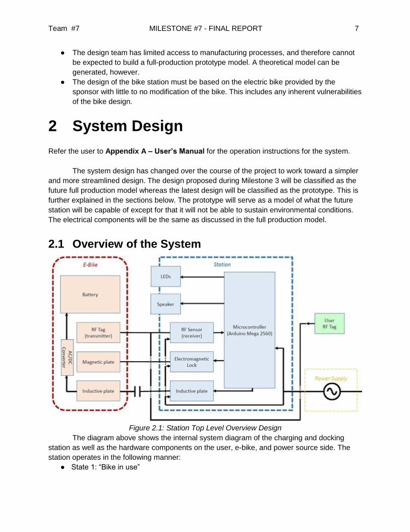
Figure 2.1: Station Top Level Overview Design
The diagram above shows the internal system diagram of the charging and docking
station as well as the hardware components on the user, e-bike, and power source side. The
station operates in the following manner:
● State 1: “Bike in use”
Team #7 MILESTONE #7 - FINAL REPORT 8
○ The speaker, lock, and inductive plate are inactive when the RFID sensor does
not sense the bike RFID tag is present. In short, if the e-bike is not in the station,
nothing aside from bike RFID detection will operate.
○ The red LED will be lit to signify the bike is away from the station and in use.
● State 2: “Bike docked & charging”
○ Once the e-bike is brought into the proper docked position in the station, the
following occurs:
■ The Arduino UNO receives a signal from the RF Sensor that it has
connected with the e-bike RF tag, the microcontroller sets the lock and
begins providing power to the induction plate.
■ Once power is provided to the station-side induction coil, the bike-side
AC/DC converter will begin charging the bike battery. An increase in
impedance from the coupled inductors will provide information on whether
the bike is charging or not.
■ The yellow LED indicate the e-bike is charging. While the e-bike is
charging, the bike will not be able to be removed by a user. This
functionality can easily be changed to allow removal even while the bike
is not fully charged if desired by the owner of the station.
● State 3: “Bike Ready”
○ Once the e-bike is fully charged, the green LED will light up.
○ The user will have his own RFID Tag to unlock the bike from the station.
○ The detection of a valid RFID tag will disengage the electromagnetic lock and
allow the user to take the e-bike.
2.1.2 Evolution of Designs
Since the beginning of the project, many ideas have been incorporated into the design of
the station and some have been discarded. The designs have progressed and changed
dramatically due to the analysis of the functionality for the final prototype. The initial design seen
in figure 2.1.1 was designed to be aesthetically pleasing and user friendly. It had two
components to assist the user when docking and undocking the bike which are the guiding track
and the seat aligner. This was critical to position the bike in the correct orientation for the lock
and charging system to function properly. The proposed locking mechanism was the robotic
claw arm which has two degrees of freedom to extend out and then clamp down. The placement
of the locking mechanism was chosen to grip at the section of the frame of the bike that was
welded and very robust.
One of the major downsides to the design is that it could pose a safety issue to users
and pedestrians. The robotic claw arm could lock on the user and injure the user if they are not
standing clear of it. The seat aligner is sticking out of the station and will have duck clips that
could have sharp ends. The combination of the seat aligner and guiding strip will pose a huge
risk factor. This idea was weighed out as too hazardous and the new scope was to have more
safety and compactness. The structure also would house all of the electrical components and

Team #7 MILESTONE #7 - FINAL REPORT 9
have adjacent housing lines to run them to a main line where multiple stations would be
adjacent to.
Figure 2.1.1: First Prototype Design
The next design was geared more towards its aesthetics and compactness with also putting
emphasis on safety for the user. Many designs were created but after combining a few key
characteristics from each, a complete design was finalized. This design can be seen in the CAD
that was rendered below in figure 2.1.3. The station is 2 feet 10 inches tall and relative to 6 foot
1 inch it sits tall enough for a pedestrian to see but also being compact. In figure 2.1.3, the
station is transparent to observe an internal frame where the locking mechanism would be firmly
mounted to. The stations outer shell would be created by molding 15 gauge (0.07 inches)
galvanized sheet metal. The internal frame would be fabricated with A500 steel support square
bams with a thickness of 0.1875 inches.
This was a sleek and marketable design to the scope of project was to attract user to the
station. It had to send the message that this was a environmentally friendly mode of
transportation that is technologically advanced. Taking a small poll around campus and
amongst the group it was confirmed that this would be the final design. When contacting
resources to attain a quote for fabrication at the machine shop on campus, it was pointed out
that the craftsmanship and time needed for this design wasn’t available unless one of the team
members had the skills. Unfortunately we were not in the position to accomplish this therefore
this needed to be outsourced. After consulting with a few fabrication shops in town, the quotes
were too costly and it was said that the final product would not be as intricate and sophisticated
as it had been envisioned. It was decided that this design was more suited to be mass produced
in a molding process. The decision was made collectively to mark this design as the “future
commercial model”.
Team #7 MILESTONE #7 - FINAL REPORT
10
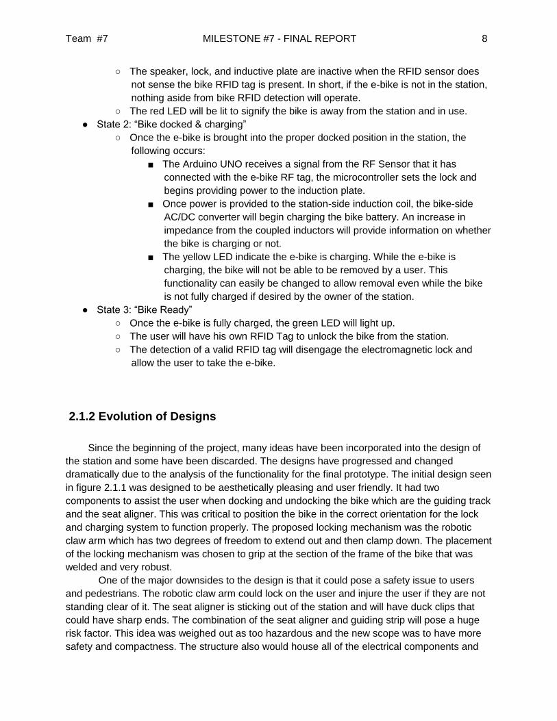
Figure 2.1.3: “Future Commercial Model”
The scope had changed once more to create a simple station that is easier to fabricate
but also incorporates the same functionality as the future commercial model. The new design
seen in figure 2.1.4 is 2 feet 5 inches tall and extends out 1 foot 7 inches. The bike will be
backed in to lock which is similar to the previous designs. This was chosen because it was
decided amongst team members that it was preferred to unlock the bike faster than returning
and locking the bike for a general user. Instead of a guiding track in the initial design, it was
proposed to have a guiding strip to help assist the users as they guide the bike into the correct
position and orientation.
In comparison to the future commercial model, the prototype design has the same user
communication features placed on the top side of the station. The features on the prototype
design are grouped closely to keep all the electrical components compact in a shielded box
inside the station. The RFID scanner has to be placed under where the seat will be above the
station. This is important so that both the bike and the user RFID can be identified. It is crucial to
track the bike and confirm the user has placed the bike at the right position and that they are
returning the bike.

Team #7 MILESTONE #7 - FINAL REPORT
11
Figure 2.1.4: Final Prototype Design
Figure 2.1.5: “Future Commercial Model” Figure 2.1.6: “Prototype Model”
Team #7 MILESTONE #7 - FINAL REPORT
12
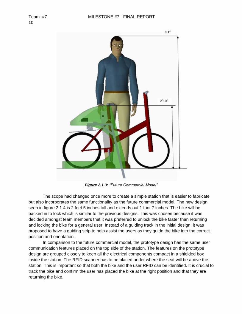
Further comparison between the models can be seen in figure 2.1.7 where the induction
coil placement on the station is on the left hand side near where the existing charging port is for
the bike battery. The housing of the electrical components is located inside the station where
hinged doors would be utilized with a simple locking latch device to allow for easy access during
installation and troubleshooting. The electromagnetic lock was proposed to be at a 45 degree
angle for the future commercial model to dissipate the reaction forces more evenly and to
relieve the concentrated stress at certain points along the frame. The full stress analysis of the
future production model can be observed in milestone #4. The electromagnetic lock orientation
for the prototype model is vertical, this was easier to install and still supported with enough
strength. The FEA on the stresses throughout the station will be discussed in the section 2.3 in
performance assessment.
Figure 2.1.5: “Future Commercial Model”
2.2 Major Components of the System
2.2.1 Structural Material
The material chosen for constructing the prototype was selected on the constraints of
budget and machining. Other options were explored aside from metals such as polymers which
can be 3D printed. This option is slightly cheaper and easier to machine but it will not be
suitable under high stresses and would need to be assembled by pieces. Although this will be
an indoor model, the appearance should still yield an aesthetic and attractive appeal that
plastics cannot achieve. Since it is going to be placed indoors, standard A500 structural steel
will be utilized.

Team #7 MILESTONE #7 - FINAL REPORT
13
2.2.2 Overall Design of Structure
Since the change from the old model to the prototype model, the complexity of the
physical design has changed drastically. It is not too simple but it is basic enough to execute the
same capabilities and functionalities as the future commercial model. It will still deliver the
message of efficiency and modernism for which the company desires as being their marketing
outlook. The electric bikes are an innovative way of solving transportation issues while also
reducing carbon emissions to the environment. The design was focused on communicating that
message to the users. For marketing purposes, the design of station will be focused on
providing the user with images and confidence that this is an environmentally friendly device.
Technology has always been appealing to people and the design of the station will
communicate that feeling to the users.
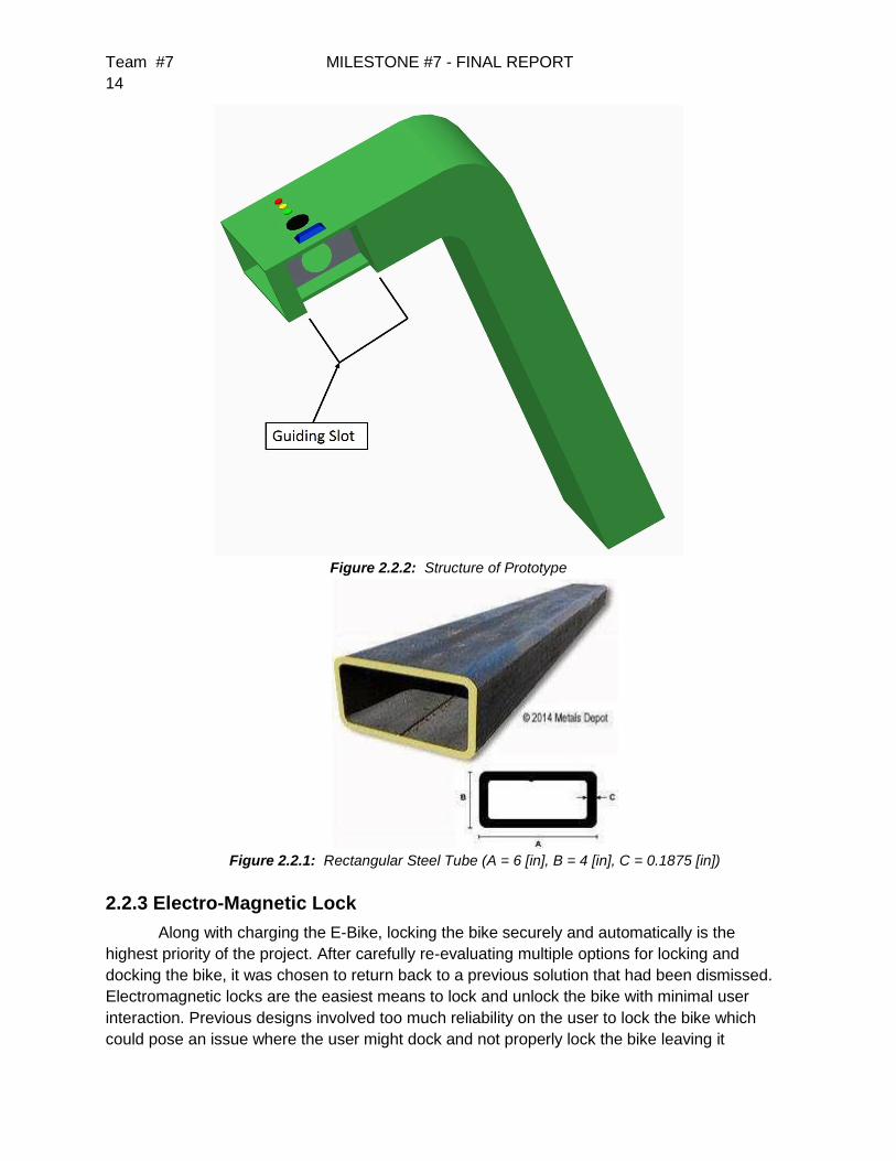
The prototype design that was actually built can be seen in figure 2.2.1 where the
guiding slot can easily be seen. This slot is utilized to allow the user to orient the bike
completely vertical so that the charging mechanism (induction coils) and the locking mechanism
(electromagnetic lock) can align perfectly. The section is also far enough from the vertical
section of station so that neither the user nor the pedals will collide during return or leaving the
station.
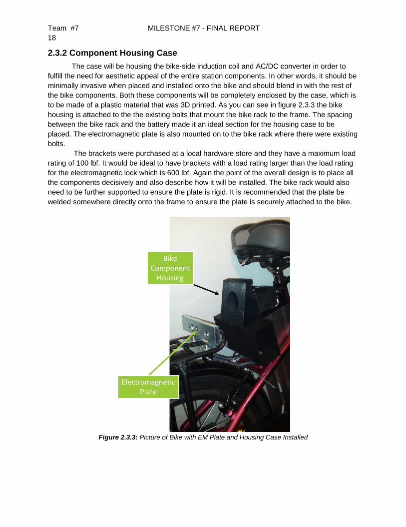
The structure will be built using a rectangular steel that was purchased from an online
distributor called MetalsDepot™. The exact size chosen was 6 inches wide 4 inches height and
0.1875 (3/16) inches thickness. The total length needed was 4 feet which was exactly the length
the fabricators needed to complete the fabrication process. The station also needed a steel
plate to cover the opening of the station on the top side. This will be installed using a door hinge
and a standard gate locking latch. The ground floor board was chosen to be a pressure treated
1 inch thick piece of plywood. It is the strongest plywood sold at the hardware store and it was
sufficient to sustain against the reaction forces from the station being up right.
Team #7 MILESTONE #7 - FINAL REPORT
14
Figure 2.2.2: Structure of Prototype
Figure 2.2.1: Rectangular Steel Tube (A = 6 [in], B = 4 [in], C = 0.1875 [in])
2.2.3 Electro-Magnetic Lock
Along with charging the E-Bike, locking the bike securely and automatically is the
highest priority of the project. After carefully re-evaluating multiple options for locking and
docking the bike, it was chosen to return back to a previous solution that had been dismissed.
Electromagnetic locks are the easiest means to lock and unlock the bike with minimal user
interaction. Previous designs involved too much reliability on the user to lock the bike which
could pose an issue where the user might dock and not properly lock the bike leaving it

Team #7 MILESTONE #7 - FINAL REPORT
15
susceptible to theft. Although constant power supply is an issue, the sponsor has assured us
that the risk will be mitigated by them in future applications.
2.2.4 Component Housing For The Bikes
The system designed demands that the bike must have an AC/DC converter as well as
the receiving inductor to be placed and securely attached to the bike. This will need a housing to
enclose and hold these components in place during operation. An enclosure was designed and
placed in the rear side behind the battery. This is further visualized in the next section.
2.2.5 Induction Charging System
Charging the bike automatically in an efficient and safe manner is crucial to the success
of the project. Induction was chosen to eliminate the need to plug in the bike or have exposed
contacts on the battery and station. One coil is housed within the station and recessed in order
to provide a precise area that the bike coil will fit into. The bike coil is placed within the
component housing on the back of the bike, described above. The final prototype was unable to
fully incorporate the induction charging system into the station due to limitations in power
transfer over the induction coils created, but should fulfill the requirement with the design of a
larger core.
2.2.6 RFID Sensors
In order to lock and unlock the bike, a recognition system was needed to not only detect
the presence and identification of the bike, but also the user’s ID. The station includes an RFID
sensor on the station, with RFID tags on the bike as well as for association of each individual
bike with its renting user. The user tags can have various options such as key ring fobs,
stickers, or ID cards with built-in RFID.
2.2.7 User Interface
In order to communicate with the user, the system has a set of three LEDs as well as a
basic speaker to generate tones. The LEDs each correspond to the states described in Section
2.1: State 1 corresponds to Red, State 2 to Yellow, State 3 to Green. The speaker plays short
tones to indicate to the status of the bike to the user.
2.2.8 Microcontroller
A central device was needed to control all of the above systems. For this project, the
Arduino UNO microcontroller was used to drive the user interface and RFID sensor as well as
the power supply to the station’s induction coil and electromagnetic lock. The microcontroller in

Team #7 MILESTONE #7 - FINAL REPORT
16
the future model will also keep track of all data on each bike and interface with an external
website to receive and send information on each of the bikes.
2.3 Performance Assessment
The E-Bike station consists of various components and systems whose performance needs to
be assessed in order to fulfill certain needs and requirements of the design. Each system was
originally designed to achieve the tasks required of the station.
2.3.1 Station Structure
The structure of the station for the project will be a sleek design that can house all
components that are to be attached, in order to make it appear as an undivided system. It will
be a simpler structure than the design of the full production model, yet it will still fulfill all the
requirements and be just as efficient. The design will accomplish the need for aesthetic appeal.
Its steel structure will also be able to sustain strong enough forces to eliminate the concern of
damaging the station itself, as well as the components being housed within it, during general
use.
The stress analysis was conducted on the prototype design to ensure that in can endure
the loads in various situations. The main concern for stress concentrations is where the
electromagnetic lock is mounted to and as well as where the station is mounted to the ground.
The stress analysis was conducted using the Creo Parametric 2.0 finite element analysis(FEA)
tool and it was chosen to view the von Mises rather than the principal stress. The von Mises
stress is more useful to analyze when a material fails because it takes into account the two
components of the strain energy which come from the static volumetric strain energy and the
shear strain energy. Von Mises is also used to calculate factor of safety and therefore is the
most appropriate type of stress to analyze for the station.
The load force applied for the test was chosen to be 1000 lb-f. Although this load
exceeds the maximum rated pull force of the electromagnetic lock, the stress distributions and
concentrations were not visibly apparent. To exploit these stresses, the load was increased and
the stresses are distinct and can be seen in figure 2.3.1 and figure 2.3.2. The maximum
stresses on the structure are between 9 to 10 ksi and the material yield strength for A500 steel
is between 250 to 300 ksi. This factor of safety is huge and can allow for the selection of a
smaller thickness as low as 0.125 (1/8) inches. It is currently set and designed to be at 0.1875
(3/16) and since the price difference isn’t significant to reduce the thickness, it was more
favorable to keep the larger thickness.
The actual station was never physically tested because it is mounted to the plywood and
to re-iterate, this prototype station will stand as just the model that will not be equipped to
sustain environmental conditions.

Team #7 MILESTONE #7 - FINAL REPORT
17
Figure 2.3.1: Structural Stress (von Mises) Front Side
Figure 2.3.2: Structural Stress (von Mises) Back Side
Team #7 MILESTONE #7 - FINAL REPORT
18
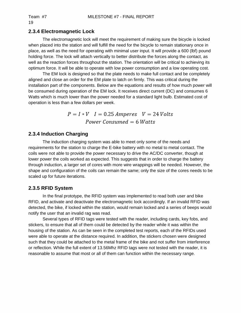
2.3.2 Component Housing Case
The case will be housing the bike-side induction coil and AC/DC converter in order to
fulfill the need for aesthetic appeal of the entire station components. In other words, it should be
minimally invasive when placed and installed onto the bike and should blend in with the rest of
the bike components. Both these components will be completely enclosed by the case, which is
to be made of a plastic material that was 3D printed. As you can see in figure 2.3.3 the bike
housing is attached to the the existing bolts that mount the bike rack to the frame. The spacing
between the bike rack and the battery made it an ideal section for the housing case to be
placed. The electromagnetic plate is also mounted on to the bike rack where there were existing
bolts.
The brackets were purchased at a local hardware store and they have a maximum load
rating of 100 lbf. It would be ideal to have brackets with a load rating larger than the load rating
for the electromagnetic lock which is 600 lbf. Again the point of the overall design is to place all
the components decisively and also describe how it will be installed. The bike rack would also
need to be further supported to ensure the plate is rigid. It is recommended that the plate be
welded somewhere directly onto the frame to ensure the plate is securely attached to the bike.
Figure 2.3.3: Picture of Bike with EM Plate and Housing Case Installed
Team #7 MILESTONE #7 - FINAL REPORT
19
2.3.4 Electromagnetic Lock
The electromagnetic lock will meet the requirement of making sure the bicycle is locked
when placed into the station and will fulfill the need for the bicycle to remain stationary once in
place, as well as the need for operating with minimal user input. It will provide a 600 (lbf) pound
holding force. The lock will attach vertically to better distribute the forces along the contact, as
well as the reaction forces throughout the station. The orientation will be critical to achieving its
optimum force. It will be able to operate with low power consumption and a low operating cost.
The EM lock is designed so that the plate needs to make full contact and be completely
aligned and close an order for the EM plate to latch on firmly. This was critical during the
installation part of the components. Below are the equations and results of how much power will
be consumed during operation of the EM lock. It receives direct current (DC) and consumes 6
Watts which is much lower than the power needed for a standard light bulb. Estimated cost of
operation is less than a few dollars per week.
2.3.4 Induction Charging
The induction charging system was able to meet only some of the needs and
requirements for the station to charge the E-bike battery with no metal to metal contact. The
coils were not able to provide the power necessary to drive the AC/DC converter, though at
lower power the coils worked as expected. This suggests that in order to charge the battery
through induction, a larger set of cores with more wire wrappings will be needed. However, the
shape and configuration of the coils can remain the same; only the size of the cores needs to be
scaled up for future iterations.
2.3.5 RFID System
In the final prototype, the RFID system was implemented to read both user and bike
RFID, and activate and deactivate the electromagnetic lock accordingly. If an invalid RFID was
detected, the bike, if locked within the station, would remain locked and a series of beeps would
notify the user that an invalid rag was read.
Several types of RFID tags were tested with the reader, including cards, key fobs, and
stickers, to ensure that all of them could be detected by the reader while it was within the
housing of the station. As can be seen in the completed test reports, each of the RFIDs used
were able to operate at the distance required. In addition, the stickers chosen were designed
such that they could be attached to the metal frame of the bike and not suffer from interference
or reflection. While the full extent of 13.56Mhz RFID tags were not tested with the reader, it is
reasonable to assume that most or all of them can function within the necessary range.

Team #7 MILESTONE #7 - FINAL REPORT
20
2.2.6 User Interface
The user interface system implemented in the final prototype provided a clean, simple,
and intuitive means of communication to the user on the status of the bike. The LEDs gave the
user the general state of the bike and station, while the speaker provide additional interaction
with the user such as beeping when an invalid RFID tag was detected or the bike was not
charging.
2.3.7 Power System
The power system was designed to provide sufficient power for the electromagnetic lock,
the micro controllers, and the station-side induction plate. Furthermore, the micro controller was
to provide power to the LEDs, the speaker, and the Mifare MFRC522 RFID Reader/Writer
module. This system was designed to be as energy efficient as possible with no more power
consumption than necessary. The main power lines were enclosed within the station structure
and the main power source was a standard wall socket providing 110 Vrms/60 Hz. The
induction coil was not fully implemented within the power system due to saturation of the coils.
2.4 Design Process
The physical design has changed a number of times to meet the specifications that the
sponsor provided. The design went from having a mechanical lock to a electro-magnetic lock to
limit the interaction from the user to the station. The overall structure has been simplified from
the more complex previous designs. The electrical components have evolved to simplify input
as well as provide additional communication to the user.
2.4.1 Structural Design
The rectangular steel tube utilized will have the dimensions of 6” x 4” and 0.1875” thick
with a total length of 4 feet. Its made out of A500 steel structural rectangle tube and it will be
fabricated to produce a 90 degree angle to achieve the designed sleek shape. The chosen
place of fabrication was Metal Fabrication of Tallahassee and they were able to build our station
to the highest accuracy. In figure 2.4.1 the comparison between the CAD model and the
physical model can be seen.
A few distinct differences can be seen in figure 2.4.1 which are the side of the station
that the bike will come in and as well as the lack of the rounded corner. The side of the station
the bike will come in was a last minute change that did not affect the use nor the functionality of
the station. The rounded corner was not possible because the machine needed to make the
bend was not within the city and it would become too costly. It was easier to cut the corners at
45 degree angles and then weld them together.
Most of the components were assembled using material and supplies from the local
hardware store. The installation was conducted by the team at most of the small detailing and
adjustments were also handled onsite by the team members.

Team #7 MILESTONE #7 - FINAL REPORT
21
Figure 2.4.1: Picture of Bike with EM Plate and Housing Case Installed
2.4.2 Bike Mounted Case
The case that is mounted to the bike was designed to fit and be compact enough to be
the least invasive as possible when installing onto the bike. It was designed using Creo
Parametric 2.0 in which the detailed sketch sheet was submitted to the machine shop and 3D
printed within 3 days. The plastic used isn’t durable or resilient and will need to be re-printed
using a more durable polymer for the final commercialized bikes.
2.4.5 Induction Charging System
The two induction coils needed to maintain as close contact as possible in order to
provide efficient power transfer. Additionally, because the AC/DC converter requires an input of
at least 100V, the coils need to provide at least 50% efficiency in order to feasibly convert from
110V, assuming a turn ratio of 2:1 or less. The wires used in the coils also need to be small
enough to allow the number of turns needed on each side, but also large enough to provide the
current needed. Providing enough current should not be an issue as most circuit breakers have
a maximum current of 15A, and the current drawn from the AC/DC converter is less than 3A, so
even a turn ratio of 2:1 will draw well under the maximum current rating.
For the induction core, a set of U and I cores was chosen, with the plan of winding one
coil on the I core and another on the U core, which would allow a the coils to be wired on two

Team #7 MILESTONE #7 - FINAL REPORT
22
separate pieces, but form a closed loop for the core when the two coils were brought together.
Through initial calculations, a turn ratio of 1:2 was chosen, with 400 turns on the station side
using 18 AWG wire, and 800 turns on the bike using 22 AWG wire. The wire gauges chosen
were based on the maximum current-carrying capacity of copper, enamel-coated magnet wire,
with 18 AWG being rated for up to 1A and 22 AWG up to 3A. When these coils were fabricated,
the voltage gain across the inductors did reach as high as 2.4, but only for low-current (i.e. low-
power) testing. When the coils were driven at higher power, the gain decreased significantly.
Figure 2.4.2: Induction Coil without I core
Figure 2.4.3: Induction Coil with I core
In a revision of the earlier calculations, it was found that approximately 1000 turns were
needed on the primary (station-side) coil, as seen in section 3.2.1, in order to provide the 100W
of power required to drive the AC/DC converter with the core currently being used. However,
this number of turns can not physically fit on the core with the wire gauge being used, so a
larger core would be required in the future in order to provide the power needed to charge the
battery.

Team #7 MILESTONE #7 - FINAL REPORT
23
2.4.6 RFID Sensors
On each of the bikes an RFID sticker was attached which was set to be valid through the
use of the master key, while some of the user RFIDs were set to be valid and some invalid. The
Mifare MFRC522 RFID Reader/Writer module was connected to the Arduino UNO to read the
ID of each of the tags. Both the reader and the tags operate at 13.56MHz. An open-source
library that was provided through the Arduino website was adapted to provide the reading and
writing of the RFID tags, while the logic to interface the RFID reader to the rest of the system
was written by the project team.
2.4.7 User Interface
The goal of the station’s user interface was to provide as much information to the user
as possible while still implementing a clean and simple design. LEDs were chosen to provide
the basic state of the bike because they are simple to implement and very low-power. A speaker
was also chosen to help provide meaningful information that could not be directly communicated
through the three states such as reading an invalid ID. The speaker was also low-power and
could be relatively easily driven through the use of toggling one of pins of the Arduino UNO at a
specified frequency in order to produce a tone.
2.5 Overall Risk Assessment
2.5.1 Technical Risks
2.5.1.1 Electromagnetic Lock Failure
Description
The electromagnetic lock is the sole mechanism keeping the e-bike secure and preventing theft.
The electromagnetic lock requires 12VDC for the magnet to provide a continuous magnetic
force. In the event that the main power source is cut due to a power surge in a storm possibly,
or damage is done to the main line and wires, the lock is prone to failure. The e-bike will have
no way of being secured and is open to theft.
Probability: Moderate
The stations will be placed in public areas that make it open to unpredictable environmental
occurrences such as storms. Another possibility could be damage to the wiring or the actual
source which will cause the lock to fail.
Consequences: Severe/Catastrophic
The e-bike itself costs close to $1300 USD. The cost of replacement for even a single bike could
be a major hindrance to a business and may even cause loss of clientele for Efficient Systems.
Strategy

Team #7 MILESTONE #7 - FINAL REPORT
24
The current plan for implementations involves providing service to a medium to large business.
Most corporate buildings have a back up power generator. Assuming that the bike station is
connected to these generators during a power outage, the owner(s) would have enough time to
get to the station and either manually lock each bike or move them to a more secure location.
Another plan would be to have an internal battery supply for backup in the event of a power
failure, which could easily be housed within the structure of the station.
2.5.1.2 RFID Failure
Description
The subsystems of the station heavily rely on the detection of whether or not the bike is in the
station. The RFID tag and sensor are the reason the station can detect this. In the event that the
sensor or the RFID tag malfunctions or is damaged, the station will not lock the e-bike or allow
an already locked e-bike to be released for use.
Probability: High
The RFID tag on the bike could possibly be damaged from use of the e-bike. The tag also has
the possibility of getting knocked off the e-bike. The RFID sensor has the possibility of
malfunctioning when the tag isn’t in the range of the sensor.
Consequences: Moderate
Since the station cannot operate without the status of the bike presence, the e-bike will be
vulnerable to a user mistakenly leaving the e-bike unknowingly that it is not secured. On the
other hand the e-bikes can’t be unlocked and used. This can create an extreme amount of
troubleshooting for ensuring the bikes are available to use and charged and locked.
Strategy
In the event that the RFID components do fail, it is best to have the system analyze the RF
components and notify the user when the e-bike is not detected or locked after an attempted
dock. If the bike is in the locked status and the RFID user tag is not functioning properly, the
user will also have to be notified that the unlocking attempt has failed. Making the station user-
friendly and responsive will be very important to this risk.
2.5.1.3 Induction Coil Misalignment/Gap
Description
In order for the battery to receive a charge from the power source, the induction coils need to
align to induce the most effective transfer possible. If these plates do not align correctly or there
is an air gap larger than the tolerated maximum, the charging of the e-bike is compromised.
Probability: Moderate
Given that there is a properly positioned electromagnetic lock with the ability to hold a force up
to 600 pounds, this should not be much of an issue in theory because the bike will remain
stable, and there is also the . However, in the case that the user does not move the e-bike into
the proper position, the charging and locking can not operate properly.

Team #7 MILESTONE #7 - FINAL REPORT
25
Consequences: Severe
If this risk were to occur there would be a severe impact on the overall performance of the
project because it is dependent on whether or not the station can efficiently charge the bike’s
battery wirelessly. Given that the coils are not correctly aligned, it takes away from the station’s
ability to ensure that the bike is ready for use on a fully charged battery. The station would likely
consider the bike charged as it would appear to the station that no power was being transferred
across the inductor.
Strategy
This can be prevented by making sure that the electromagnetic lock secures the bike at a
position where the coils are correctly aligned. It was also be confirmed that the bike will not be
able to move once locked, so that the coils do not become misaligned. Another possible
strategy would be to make the coils large enough to not be greatly affected by slight
misalignment, though this would lead to a larger volume than necessary, thus creating higher
costs and a less streamlined design.
2.5.1.4 Structure Failure
Description
The overall structure of the station should remain rigid and must not collapse or bend under a
humanly-possible force. It houses most components for the charging, the intelligence, and the
lock. If the structure were to fail, then the internal components will be exposed and prone to
damage.
Probability: Low
The probability that the structure fails is low because the prototype model will not encounter a
force high enough to bend or damage the structure. The model is made of A500 structural steel,
which can easily withstand push or pulling forces of an average human as well as lever forces
such as a crowbar.
Consequences: Severe
If this risk were to occur there would be a severe impact on the project because it will expose all
the internal components and it could damage the components if the structure fails in the area
where they are being housed.
Strategy
The strategy to be used for this risk was to ensure that the structural material is strong enough
that it is not affected by human forces before building the model with it. Another approach is to
place the components in a second protective housing within the structural frame so that if the
structure becomes damaged the components remain protected.
2.5.1.5 Pacemaker Interaction
Description

Team #7 MILESTONE #7 - FINAL REPORT
26
Pacemakers have been known to malfunction when exposed to electromagnetic fields. Because
the station uses electromagnetic fields for both the induction charging and for the RFID reading.
This has lead to potential concern of whether the station could cause interference with the
functioning of a pacemaker.
Probability: Low
While it is possible to interfere with a pacemaker through the production of an electromagnetic
field, it is only possible to do so with fields in the radio-frequency range, which means that the
induction charging would have no effect whatsoever on pacemakers. Studies show that RFID
readers can interact with pacemakers, but do not cause adverse effects.
Consequences: Severe
If this risk became reality it could be potentially devastating, causing injury or even death.
Strategy
There is little strategy needed to mitigate this risk, aside from possibly providing a warning
within the user manual that RFID readers have been known to interact slightly with pacemakers.
2.5.2 Schedule Risks
There are many unplanned schedule related risks possible during the course of the project that
can directly impact the project being completed on time. Some possible risks include availability
of components on the market, delivery time of components, availability of technical support,
personal emergencies and illnesses, and change of design.
2.5.2.1 Component Availability
Description
Some of the necessary components for the design may not be in stock on the internet or in
stores and could delay the schedule for testing of any subsystems or creating the prototype.
Also, one of the components may need to be custom built and could take some time to become
available to the group. Lack of availability may also risk one of the milestones not being
completed on time. For example, a section in the report may need to analyze one of the
systems that has a missing component so it would not be possible to fully complete that section.
Probability: Low
The probability of a component not being available to the group is low because one can usually
find the same component on various websites or in various stores. The only factors for causing
this risk would be a component being out of stock or having to be custom built.
Consequences: Severe
If this risk were to occur, there would be a severe impact on the overall performance of the
project because most of the components play a vital part in one of the design’s subsystems. If
one of the components were not available, it would hinder the progress of testing and

Team #7 MILESTONE #7 - FINAL REPORT
27
prototyping the subsystem it is a part of. It could also decrease the number of details available
in a report when writing about a subsystem with a missing component.
Strategy
The strategy to be used to manage this risk is finding all components in multiple places to order
from, if possible, and ordering them in a timely manner. Also, only components readily available
on the market were used, and the team avoided anything that needed to be custom built as
much as possible.
2.5.2.2 Component Delivery Time
Description
Some of the components for the design may not be in stock or it may be shipping from a far
state or country. Also, they may not be available for expedited shipping if the component is
needed last minute and it could delay incorporating the component into the subsystem it is
needed for.
Probability: Moderate
The probability of a component not being delivered in a timely manner is moderate because
some components needed are not very common and often ship from somewhere across the
country or out of the country. This would either lead to a delay in delivery time or a significant
increase in shipping costs. There is also no way to control the efficiency of the delivery company
so if there are any problems with the shipment nothing can be done to speed up the process.
Consequences: Moderate
If this risk were to occur, there would be a moderate impact on the overall performance of the
project because most of the components play a vital part in one of the subsystems. However, it
is different from the component not being available because the component will still be received,
but not in the expected time frame. If one of the components were received late, it may hinder
the progress of testing and prototyping the subsystem it is a part of.
Strategy
The strategy to used to manage this risk was placing all orders well ahead of time so that there
would still be time to make up for any problems with delivery. Also, components were ordered
from the closest location possible in order to cut down on delivery time.
2.5.2.3 Technical Support Availability
Description
The lack of availability of technical support could be a risk in terms of building the structure of
the station. The machine shop will be needed to correctly weld and put together the steel
structure of the station. If it is not available then it would not be possible to put together the
station’s structure given the lack of experience of the group with welding steel.
Probability: Low

Team #7 MILESTONE #7 - FINAL REPORT
28
The probability of technical support not being available is low because if there is no personnel or
space available for using the machine shop at the College of Engineering to weld the steel
structure, then the group can hire a local machine shop to complete the given tasks.
Consequences: Catastrophic
If this risk were to occur there would be a catastrophic impact on the overall performance of the
project because it would not be possible to correctly build the structure of the station given the
lack of machinery and personnel with experience.
Strategy
The strategy to be used to manage this risk is coordinating with the machine shop well ahead of
time to use it for building the station’s structure. It could also be avoided by having a backup
plan to use a local machine shop to build the steel structure.
2.5.2.4 Illnesses/Personal Emergencies
Description
The possibility of one of the group members becoming ill during the year or dealing with a
personal emergency could be a risk for completing tasks. If one of the members becomes very
ill or has to handle an emergency, and is not able to work on the project, then the tasks given to
that member have to be delegated amongst everyone else. This adds a larger work load to all
members and could affect the ability to complete certain tasks on time.
Probability: Low
The probability of a group member becoming ill is low because everyone is in relatively good
health and they maintain a healthy lifestyle. There is always the small possibility of at least one
member becoming sick during this time period from an illness going around, especially during
the winter time. Also, the probability of facing a major personal emergency is low, but anything
can happen at any given moment.
Consequences: Minor
If this risk occurred, there would be a mild impact on the overall performance of the project
because it would cause other group members to take responsibility of the tasks not able to be
completed by the absent member. If the tasks are fairly distributed in a timely manner, then
there should be a very small impact of this risk on the group’s performance.
Strategy
The strategy to be used to manage this risk is to avoid becoming sick during this time period by
staying healthy and avoiding any airborne diseases. It is also important to become aware of an
ill group member as soon as possible so that they can start fighting off the illness and so their
tasks can be divided amongst the rest of the group. In terms of personal emergencies, all
should be treated equally for any group member. The member dealing with the emergency
should alert the group of it so that planning can be executed within a reasonable amount of
time.

Team #7 MILESTONE #7 - FINAL REPORT
29
2.5.2.5 Schedule Risk 5: Change of Design
Description
The possibility of having to make a small or large change of design could be a risk in terms of
completing certain tasks for the project. For example, if the locking mechanism design has to be
changed, then the whole subsystem has to be reanalyzed, tested, and prototyped. This process
could take a while depending on the severity of the change and it could delay the completion of
the prototype or even one of the reports. The point in time during which a change could occur
also plays a huge factor on the risk’s effect.
Probability: Low
The probability of a change of design during the course of the project is low because most
design ideas have been thoroughly analyzed and are projected to work as expected; therefore,
the design should not be changed until it is shown it has to be changed. There is the possibility
that one of the design ideas does not produce the intended result once prototyped, and in that
case a change has to occur.
Consequences: Severe
If the risk occurred there would be a severe impact on the overall performance of the project. It
would delay the completion of certain tasks like building the prototype and finishing any reports
that encompass details of the design. If the change were to occur during the prototype phase, it
would impact the ability to complete this task in a timely manner because the change would
have to be reanalyzed and tested. If new components have to be ordered, the delivery time
could cause a delay as well.
Strategy
The strategy used to manage this risk was to minimize the possibility of having a change of
design by thoroughly analyzing all design ideas the first time around so that when all
subsystems for the project are being built there is no need to replace any of them. When a
change of design was required, new parts were promptly ordered to minimize the effect of the
delay in testing.
2.5.3 Budget Risks
There are many unplanned budget related risks possible during the course of the project that
can directly impact the project and produce budget overruns. Some possible risks include
additional support costs, unexpected component costs, and mismanagement of budget.
2.5.3.1 Additional Support Costs
Description
There is the risk of having to add costs to the budget for additional support. This would be an
unexpected addition to the budget since it is not planned to have any part of the budget set
aside for additional support. For example, if the plan to use the machine shop at the College of
Engineering falls through, then additional costs have to be added for using a local machine
shop.

Team #7 MILESTONE #7 - FINAL REPORT
30
Probability: Low
The probability of having additional support costs is low because it is not deemed necessary to
need any type of additional support except from a machine shop, which is planned to be used in
the College of Engineering. As long as it is scheduled to be used ahead of time there should be
no problem with using the school’s machine shop.
Consequences: Minor
If the risk were to occur, there would be a minor impact on the overall performance of the project
because another local machine shop could be used to construct the station’s structure. The
project is also well under budget so adding an additional cost for support would not be a
problem.
Strategy
The strategy to be used to manage this risk is avoiding it by planning to use the machine shop
ahead of time. The time to use it will be scheduled at least a month in advance to avoid any
conflicts.
2.5.3.2 Unexpected Component Costs
Description
There is the risk of having to add costs for any unexpected components. This could occur if any
necessary components were forgotten on the budget list or if there is a change of design and
new components need to be ordered. Also, if the quantity of any of the components are
incorrect, then more components would need to be ordered.
Probability: Low
The probability of having costs from unexpected components is because all components that
will be needed to build the station and its subsystems were added to the budget list and
because unnecessary changes in design were avoided. Any small components that needed to
be added to the list were added without having a major impact on the budget.
Consequences: Minor
If the risk were to occur, there would be a minor impact on the overall performance of the project
because other components can be easily added to the budget list. The project is well under
budget so adding any additional cost for unexpected components would not be a problem.
Strategy
The strategy used to manage this risk was making sure all components needed for the project
are already on the budget list, and adding any other components as soon as they are found to
be necessary for the project. There were a few items, mostly regarding the induction portion,
that
2.5.3.3 Budget Mismanagement
Description

Team #7 MILESTONE #7 - FINAL REPORT
31
There is the risk of budget mismanagement by not correctly adding anything that needs to be
purchased to the budget list and taking it out of the given budget.
Probability: Very Low
The probability of budget mismanagement is low because time has been taken to meet with the
advisor, sponsor, and group as a whole to overview and manage the budget.
Consequences: Minor
If the risk were to occur there would be a minor impact on the overall performance of the project
because the overall project budget is well under the budget given by the sponsor.
Strategy
The strategy to be used to manage this risk is keeping an itemized list to keep records and
checking it on a weekly basis to ensure that past purchases are taken into account for future
ones. As of the end of the project, the total costs of all components was still within the budget
allocated at the beginning of the year, and thus the risk of budget mismanagement has been
avoided.
2.5.4 Summary of Risk Assessment
Many potential risks including technical, schedule, and budget risks have been identified for the
project, but they are all well understood and have been minimized to the best of the team’s
abilities. There is a set strategy to handle all of these risks if they pose a problem for completing
the project. All of the proposed risks are ready to be managed by the group through proper
planning.
3 Design of Major Components In this section the various mechanical components will be shown and described. This will
include all the components involving the prototype model as described above. The project’s
mechanical design has changed drastically over the course of the semester. The mechanical
design section details the components for the physical frame, the electro-magnetic lock, the
case for the electrical components, and the installation of all the components. The electrical
component section details the design portion of the RFID sensors, the micro controller, the
speaker, the LED lights, and the induction coils. The differentiation between the now developed
prototype design and the previous design will be explicitly portrayed in the system overview.
The drastic changes in the mechanical concept occurred due to the complexity of the physical
design and the need to further develop the aesthetic appeal by incorporating a product and
marketing specialist. Therefore the design was constructed to be less complex, yet achieve the
same objectives the past design has. The previous design will be considered a future
implementation through further development.

Team #7 MILESTONE #7 - FINAL REPORT
32
3.1 Mechanical Components
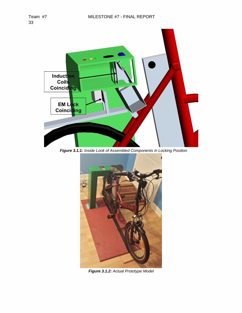
3.1.1 Overall Design of Structure
The prototype model has an overall structure that is less complex than the previous
future mass production model. In figure 3.1.1 the various components on the station side and
the bike side can explicitly be seen. There are hinged doors that can swing open during
troubleshooting states. The electrical components’ housing located near the end of the station
contain everything that will be installed to the station.This allows the components to be
organized and secured so that during operation or installation all the components stay in place
and wires don't come apart.
Because the distance between the coils is proportional to efficiency at a rate of
, with R
being the distance from the magnet, the coils need to be as close as possible. The previous
design required the actuation of the plate on the station side to move it closer to the bike side
induction coil. In this design, figure 3.1.1 shows that the user will guide the bike in through the
passageway that is cut out of the rectangular beam. The induction coils will be enclosed by a
plastic housing to secure the iron core and the coils. The case is locked in as close as possible
to the station housing while maintaining the requirement of no metal-to-metal contact. The bike
will first come in contact with the electromagnetic lock to stop it instead of the coils so they don't
get damaged. The cut out portion will also act as a guide so when the user brings the bike back,
they can easily orient the bike and guide it into its locked state.
The station itself was mounted to a pressure treated plywood board at ground level
approximately 1” inch thick and about 3’ 9”’ x 2’ 6” and approximately 9.375 . The station was
bolted to the board using a 1/2 in. -13 tpi x 6 in. zinc-plated hex bolt [7]. This allowed the station
to be disassembled and transported to campus after it had been constructed.
In figure 3.1.2, a picture of the actual station is presented and comparing it to the
conceptual design, it is very close to it. The station is a right handed orientated station and this
was chosen arbitrarily. There is no effect on the functionality of the station with orientation of
the station.
Team #7 MILESTONE #7 - FINAL REPORT
33
Figure 3.1.1: Inside Look of Assembled Components in Locking Position
Figure 3.1.2: Actual Prototype Model
Team #7 MILESTONE #7 - FINAL REPORT
34
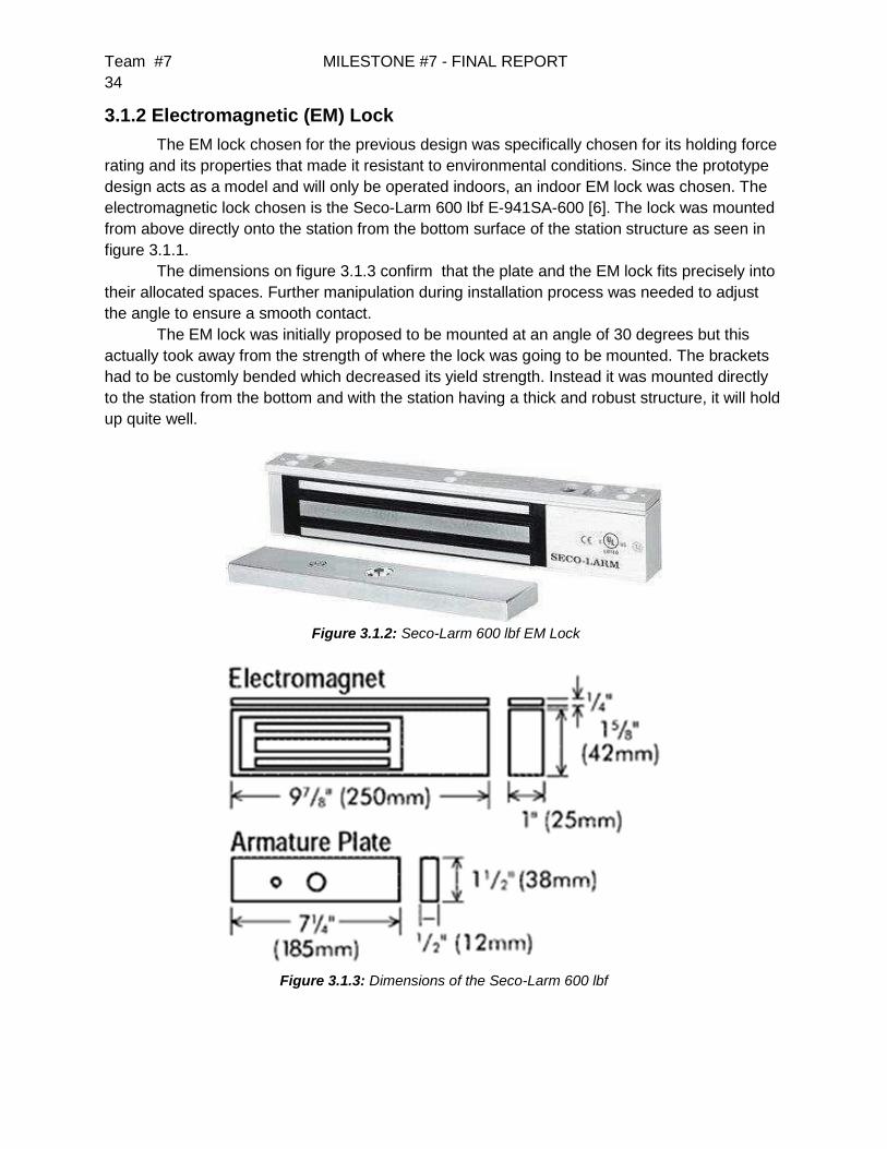
3.1.2 Electromagnetic (EM) Lock
The EM lock chosen for the previous design was specifically chosen for its holding force
rating and its properties that made it resistant to environmental conditions. Since the prototype
design acts as a model and will only be operated indoors, an indoor EM lock was chosen. The
electromagnetic lock chosen is the Seco-Larm 600 lbf E-941SA-600 [6]. The lock was mounted
from above directly onto the station from the bottom surface of the station structure as seen in
figure 3.1.1.
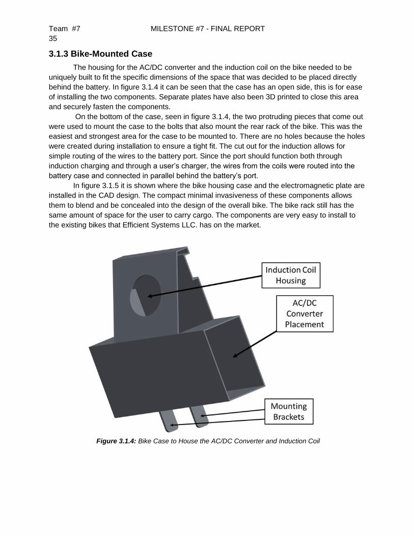
The dimensions on figure 3.1.3 confirm that the plate and the EM lock fits precisely into
their allocated spaces. Further manipulation during installation process was needed to adjust
the angle to ensure a smooth contact.
The EM lock was initially proposed to be mounted at an angle of 30 degrees but this
actually took away from the strength of where the lock was going to be mounted. The brackets
had to be customly bended which decreased its yield strength. Instead it was mounted directly
to the station from the bottom and with the station having a thick and robust structure, it will hold
up quite well.
Figure 3.1.2: Seco-Larm 600 lbf EM Lock
Figure 3.1.3: Dimensions of the Seco-Larm 600 lbf
Team #7 MILESTONE #7 - FINAL REPORT
35
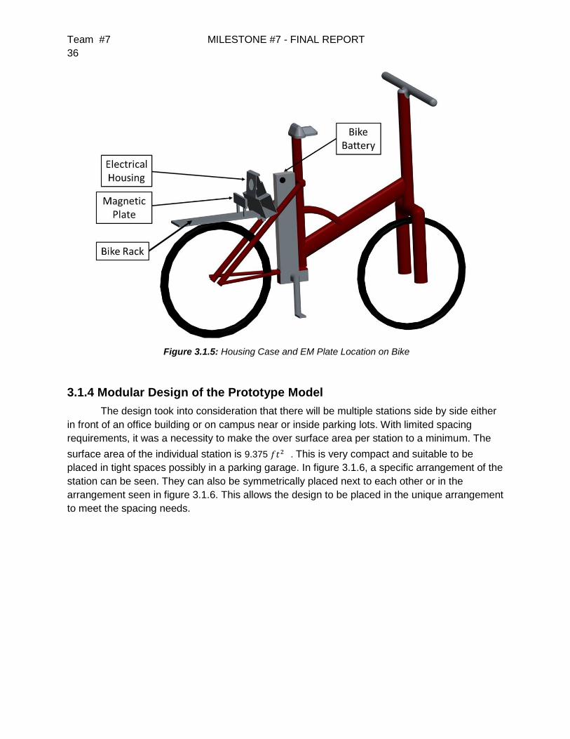
3.1.3 Bike-Mounted Case
The housing for the AC/DC converter and the induction coil on the bike needed to be
uniquely built to fit the specific dimensions of the space that was decided to be placed directly
behind the battery. In figure 3.1.4 it can be seen that the case has an open side, this is for ease
of installing the two components. Separate plates have also been 3D printed to close this area
and securely fasten the components.
On the bottom of the case, seen in figure 3.1.4, the two protruding pieces that come out
were used to mount the case to the bolts that also mount the rear rack of the bike. This was the
easiest and strongest area for the case to be mounted to. There are no holes because the holes
were created during installation to ensure a tight fit. The cut out for the induction allows for
simple routing of the wires to the battery port. Since the port should function both through
induction charging and through a user’s charger, the wires from the coils were routed into the
battery case and connected in parallel behind the battery’s port.
In figure 3.1.5 it is shown where the bike housing case and the electromagnetic plate are
installed in the CAD design. The compact minimal invasiveness of these components allows
them to blend and be concealed into the design of the overall bike. The bike rack still has the
same amount of space for the user to carry cargo. The components are very easy to install to
the existing bikes that Efficient Systems LLC. has on the market.
Figure 3.1.4: Bike Case to House the AC/DC Converter and Induction Coil
Team #7 MILESTONE #7 - FINAL REPORT
36
Figure 3.1.5: Housing Case and EM Plate Location on Bike
3.1.4 Modular Design of the Prototype Model
The design took into consideration that there will be multiple stations side by side either
in front of an office building or on campus near or inside parking lots. With limited spacing
requirements, it was a necessity to make the over surface area per station to a minimum. The
surface area of the individual station is 9.375 . This is very compact and suitable to be
placed in tight spaces possibly in a parking garage. In figure 3.1.6, a specific arrangement of the
station can be seen. They can also be symmetrically placed next to each other or in the
arrangement seen in figure 3.1.6. This allows the design to be placed in the unique arrangement
to meet the spacing needs.

Team #7 MILESTONE #7 - FINAL REPORT
37
Figure 3.1.6: Two Stations Side by Side
3.2 Electrical Components
3.2.1 Induction Coils
The induction system is a key part of the current design and was chosen because one of
the highest-priority goals of the project was to charge the bike wirelessly. This required that the
induction system have a relatively high efficiency in order to provide enough power for the
AC/DC converter that will reside on the bike.
The project’s induction system provides some unique challenges: First, the system must
be able to handle high voltages and somewhat high current, operating around 110V and 1A.
This means that the wires must have a certain diameter, or gauge, in order to safely provide the
current going through the coil. In addition, a single core between the two coils cannot be used,
as the bike and station coils must obviously not be connected. Furthermore, the system is
designed to work off of the standard 60Hz frequency of a power outlet, which is a very low
frequency compared to most applications aside from power grid transformers, which are much
larger and have a shared core. Because of the relatively low documentation of systems with
these conditions, much of the the work for this section of the project came from testing various
setups.
Two pot cores were used in initial testing: one to be placed on the bike and one on the
station. These had the advantage of being two separate cores but with little air gap between
them when aligned properly, fitting the needs of the project quite well. However, the largest
commercially available pot cores have only a 40mm inner diameter which is too small for the
needs of the project, and the cores purchased produced efficiencies below 1%. Thus a custom
core would have needed to be manufactured if the project were to continue the use of pot cores.
Instead, the team pursued the use of a paired U-I core configuration. Preliminary tests of
the cores with only the U core again provided very low efficiencies of less than 5%. However,

Team #7 MILESTONE #7 - FINAL REPORT
38
when the I core was added to complete the loop of the ferromagnetic material, the efficiency
jumped to approximately 80%, or a voltage gain of 0.8, which was improved further to 2.4 with
an increase in the number of turns and a reduction of the airgap. For reference, the desired
voltage gain across the inductors was between 0.91 (100V output) and 2.18 (240V output)
Despite the significant advances made in induction over the course of the project, some
work is still needed to meet all of the conditions required to provide enough power to the AC/DC
converter to charge the bike battery. The majority of the testing done was at low power (i.e. low
current), and testing with higher power transfer, the voltage gain dropped significantly. In the
calculations below, it is shown that there must be approximately 1000 turns on the station-side
coil, while only approximately 400 turns were wound on the experimental cores, with little room
for more windings. This indicates that an even larger core, possibly also with a larger cross-
sectional area, would be needed in order to meet the charging requirements.
Figure 3.2.1: Picture of the pot cores previously in use

Team #7 MILESTONE #7 - FINAL REPORT
39
Figure 3.2.2: Demonstration of a 7.07VRMS input providing 17.036VRMS output (gain of 2.41)
3.2.2 AC/DC Converter
Due to the complexity of the circuit of the AC/DC converter that is used with the battery,
the existing converter was used to provide the correct voltage and current to the battery and
also to ensure that the battery was not over-charged. The converter is stored within the bike-
mounted case, with the input connected to the bike-side induction coil and the output to the
battery.
Figure 3.2.3: AC/DC Converter
3.2.3 RFID Reader and Tags
An RFID reader is used within the system to allow identification of the user and the bike,
as well as a check for the presence of the bike so that it can be locked and charged. The RFID

Team #7 MILESTONE #7 - FINAL REPORT
40
reader chosen was the Mifare MFRC522, which operates at 13.56 MHz. The reader
communicates through the SPI protocol to send the RFID information to the UNO, which will
then check against the list of bike/user ID’s stored within memory. Each tag is flagged within the
software as either valid or invalid. This allows the owner, who would have the master key, to
enable and disable specific tags as needed.
Initially the design of the RFID component of the project was to track each bike ID, but
the final software design implemented is not set to handle more than valid/invalid tags in
general. An improvement to the system would be implementing a third flag that identifies
whether the tag is a bike tag or not, and if so, would only lock the bike when detecting the RFID
rather than toggling between locked and unlocked.
Figure 3.2.4: RFID reader and credit car tag
3.2.4 User Interface
The user interface decided upon was chosen primarily for simplicity of the design and
consists of three LEDs and a speaker. The LEDs correspond to each state described in Section
2.1, and will be turned on and off directly by the microcontroller. The speaker is able to generate
tones to notify the user of a significant problem, such as detecting the bike but not being able to
charge (i.e. out of alignment) or unlocking a bike and not removing it from the station. Currently
the functionality implemented allows the RFID to be read as invalid or valid and provide audio
and visual communication to the user accordingly.
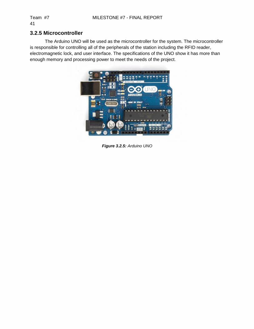
Team #7 MILESTONE #7 - FINAL REPORT
41
3.2.5 Microcontroller
The Arduino UNO will be used as the microcontroller for the system. The microcontroller
is responsible for controlling all of the peripherals of the station including the RFID reader,
electromagnetic lock, and user interface. The specifications of the UNO show it has more than
enough memory and processing power to meet the needs of the project.
Figure 3.2.5: Arduino UNO
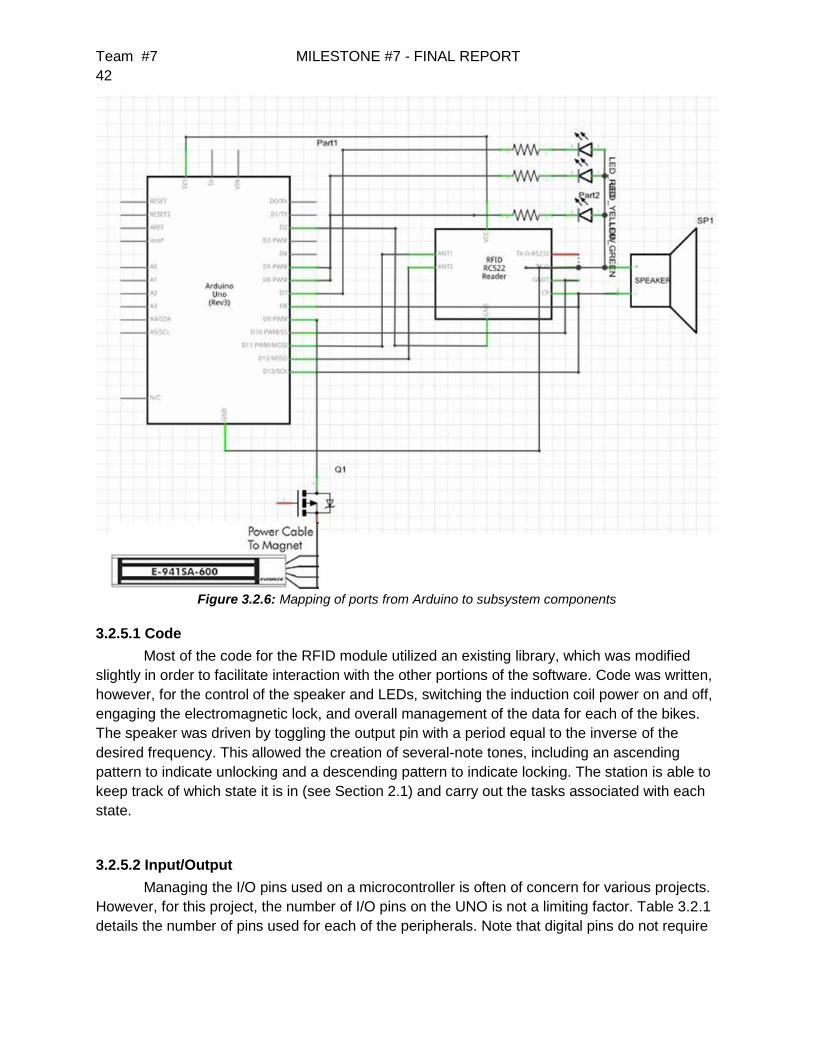
Team #7 MILESTONE #7 - FINAL REPORT
42
Figure 3.2.6: Mapping of ports from Arduino to subsystem components
3.2.5.1 Code
Most of the code for the RFID module utilized an existing library, which was modified
slightly in order to facilitate interaction with the other portions of the software. Code was written,
however, for the control of the speaker and LEDs, switching the induction coil power on and off,
engaging the electromagnetic lock, and overall management of the data for each of the bikes.
The speaker was driven by toggling the output pin with a period equal to the inverse of the
desired frequency. This allowed the creation of several-note tones, including an ascending
pattern to indicate unlocking and a descending pattern to indicate locking. The station is able to
keep track of which state it is in (see Section 2.1) and carry out the tasks associated with each
state.
3.2.5.2 Input/Output
Managing the I/O pins used on a microcontroller is often of concern for various projects.
However, for this project, the number of I/O pins on the UNO is not a limiting factor. Table 3.2.1
details the number of pins used for each of the peripherals. Note that digital pins do not require

Team #7 MILESTONE #7 - FINAL REPORT
43
any specific pin to operate, so they can be used on any one of the 14 digital I/O pins that are
free on the UNO.
Table 3.2.1: A listing of the number of pins used
Device Ports Needed
LEDs 3 digital
EM Lock 1 digital
Speaker 1 digital
Rf Receiver 2 digital, 3 SPI
·
·
4 Test Plan
4.1 System and Integration Test Plan
4.1.1 Overall Structure
The overall structure, with the station being bolted to the wood base board, will be tested
by a human applying moderate pushing force on all sides of the station. Additionally, the von
Mises stress is checked for the design through computer simulation. Because the prototype
design is not secured into the ground as it will be in the production model, no specific rating
needs to be reached, but the station needs to stay upright and robust during docking and
undocking states.
4.1.2 Electromagnetic Lock
The electromagnetic lock is expected to perform as described by the manufacturer. It will
not be tested for the amount of force it can actually hold compared to what the manufacturer
has described. It will be tested to hold in different directions and it will also be tested where it is
being mounted (underside of the station).

Team #7 MILESTONE #7 - FINAL REPORT
44
4.1.3 Bike Mounted Case
The housing for the AC/DC converter and the bike side induction coil will be tested to
ensure it does not allow the components to move drastically to potentially damage them. The
case will also be tested for its strength to ensure it will not fall off the bike while in motion.
4.2 Test Plan for Major Components
This section will describe the procedural methods that will be conducted to test each component
of the designed system. Each component contains a test sheet that will be carried out by the
individual team member selected to test each component.
4.2.1 Structural Integrity
Test Item: Material
Tester Name: Bilal Rafiq Tester ID No: 1911
Test Date: TBA Test No:
Test Time: TBA Test Type: Test
Test Location: College of Engineering Lab Test Result: TBA
Test Objective:
To test the structural integrity to endure forces and movements no greater than what an average
human can push or pull.
Test Description/Requirements:
Applying an impulse pushing force on each side of the station, as well as pulling/pushing the
bike while it is in the docked state.
Anticipated Results:
The e-bike station should remain intact when an outside force is placed upon it.
Requirement for Success:
The required result for this test is for the station to keep all internal parts safe and remain
standing upright with no permanent damage being done to it.
Actual Results:
TBA

Team #7 MILESTONE #7 - FINAL REPORT
45
Reason for Failure:
TBA
Recommended Fix:
TBA
Other Comments:
4.2.2 Electromagnetic Lock
Test Item: Electromagnetic Lock
Tester Name: Justin Johnson Tester ID No: 1912
Test Date: TBA Test No:
Test Time: TBA Test Type: Test
Test Location: College of Engineering Lab Test Result: TBA
Test Objective:
To test the lock’s capabilities to remain locked under a certain amount of force.
Test Description/Requirements:
Connect the electromagnetic lock to a power supply. Apply a force in all directions from the
plate side of the electromagnetic lock.
Anticipated Results:
We expect the lock to remain locked up to a force of 600 pounds.
Requirement for Success:
The lock should remain locked and keep the bike safe up until 600 pounds of force are exerted
upon it.
Actual Results:
TBA
Reason for Failure:
TBA
Recommended Fix:
TBA

Team #7 MILESTONE #7 - FINAL REPORT
46
Other Comments:
4.2.3 Bike Mounted Case
Test Item: Bike Mounted Case
Tester Name: Justin Johnson Tester ID No: 1912
Test Date: TBA Test No:
Test Time: TBA Test Type: Test
Test Location: College of Engineering Lab Test Result: TBA
Test Objective:
The bike mounted case should fit snugly onto the bike and securely hold the AC/DC converter
and the induction coils in place.
Test Description/Requirements:
To test this component the bike will be ridden to determine if it will securely hold in place under
normal use.
Anticipated Results:
The case is expected to remain in its original position and still be able to charge after being
ridden.
Requirement for Success:
The case should not move around and the coils should line up and be able to charge the bike
after use.
Actual Results:
TBA
Reason for Failure:
TBA
Recommended Fix:
TBA
Other Comments:

Team #7 MILESTONE #7 - FINAL REPORT
47
4.2.4 Network System
In this section the network components of the system will be described for testing
procedures and forms that will be used during testing.
4.2.4.1 Microcontroller
Test Item: Arduino UNO microcontroller
Tester Name: Seve Kim Tester ID No:
Test Date: TBA Test No:
Test Time: TBA Test Type: Test
Test Location: College of Engineering Lab Test Result: TBA
Test Objective:
The objective of this test is to ensure functionality and connection to all components and
extensions.
Test Description/Requirements:
Requirements:
1- Arduino UNO microcontroller
2- USB connection adapter
Process:
The proper voltage input will be applied to ensure the board is operational. The digital I/O ports
including the Pulse Width Modulation (PWM) ports will be utilized for connections to other
components. A sample code will be run on the Arduino. The reset button will be pressed to
ensure its functionality.
Anticipated Results:
The Arduino UNO should turn on when connected to the power source. All digital I/O ports
should be active when tested, as well as the PWM ports. The sample code should run and
produce the correct results. The reset button should reset the system.
Requirement for Success:
The requirement for success is that the input voltage for the microcontroller is 7-12 V. All ports
should be active when connected. The reset button will reset the system when pressed.
Actual Results:
TBA
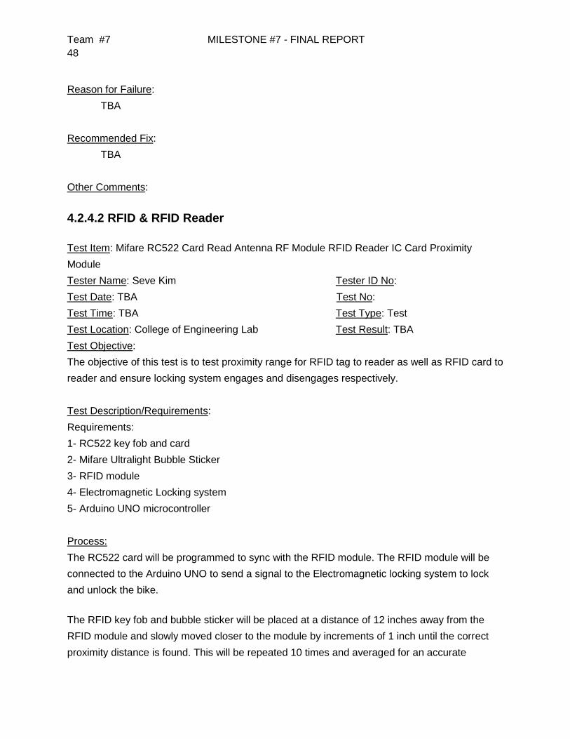
Team #7 MILESTONE #7 - FINAL REPORT
48
Reason for Failure:
TBA
Recommended Fix:
TBA
Other Comments:
4.2.4.2 RFID & RFID Reader
Test Item: Mifare RC522 Card Read Antenna RF Module RFID Reader IC Card Proximity
Module
Tester Name: Seve Kim Tester ID No:
Test Date: TBA Test No:
Test Time: TBA Test Type: Test
Test Location: College of Engineering Lab Test Result: TBA
Test Objective:
The objective of this test is to test proximity range for RFID tag to reader as well as RFID card to
reader and ensure locking system engages and disengages respectively.
Test Description/Requirements:
Requirements:
1- RC522 key fob and card
2- Mifare Ultralight Bubble Sticker
3- RFID module
4- Electromagnetic Locking system
5- Arduino UNO microcontroller
Process:
The RC522 card will be programmed to sync with the RFID module. The RFID module will be
connected to the Arduino UNO to send a signal to the Electromagnetic locking system to lock
and unlock the bike.
The RFID key fob and bubble sticker will be placed at a distance of 12 inches away from the
RFID module and slowly moved closer to the module by increments of 1 inch until the correct
proximity distance is found. This will be repeated 10 times and averaged for an accurate

Team #7 MILESTONE #7 - FINAL REPORT
49
measurement. This process will also be done for the RFID card. The correct proximity distance
will be applied and the RFID bubble sticker will be placed on the bike in a proper location. The
bike will be pushed into the station and placed into the docked position.
Anticipated Results:
After the bike is in docked position, the RFID module should recognize the presence of the bike
and engage the electromagnetic lock. While the bike is in the locked position, the RFID key fob
will be tested from a user standpoint and placed at the correct proximity. The electromagnetic
lock should disengage at this point.
Requirement for Success:
The requirement for success is that the RFID module needs to read the RFID key fob and
bubble sticker within the measured proximity from the test results.
Actual Results:
TBA
Reason for Failure:
TBA
Recommended Fix:
TBA
Other Comments:
4.2.5 Power System
The power system components testing procedure will be described in this section as well
as the forms that will be utilized to note down testing results.
4.2.5.1 Inductance Charging
Test Item: Inductance core & coils
Tester Name: Jacob Knoblauch Tester ID No:
Test Date: TBA Test No:
Test Time: TBA Test Type: Test
Test Location: College of Engineering Lab Test Result: TBA
Test Objective:

Team #7 MILESTONE #7 - FINAL REPORT
50
The objective of this test is to test the efficiency and power transfer of the inductance charging
system as a whole.
Test Description/Requirements:
Requirements:
1- Ferromagnetic cores
2- Copper wire coils
3- Function Generator
4- Voltmeter
5- Alligator clips
Process:
The station side coil and core will receive an AC signal from the function generator. The
voltmeter will be connected to the bike side coil and core to get a reading of the output voltage
for the system. The scope of the project requires that there be no metal to metal contact, so the
inductance coils will be measured to get the closest proximity they can have without touching
and still provide efficient power transfer. All of the connections from the function generator and
from the voltmeter will be connected using the alligator clips.
Anticipated Results:
The anticipated results are an efficiency of at least 75% as well as providing power transfer with
no metal to metal contact through the inductance system.
Requirement for Success:
The requirements for success are that the inductance charging system is set up with the best
possible coil configuration considering coil turn ratio, ferromagnetic core size, and proximity
between both cores.
Actual Results:
TBA
Reason for Failure:
TBA
Recommended Fix:
TBA

Team #7 MILESTONE #7 - FINAL REPORT
51
Other Comments:
4.2.5.2 AC/DC Converter
Test Item: AC/DC Converter
Tester Name: Bryan Castro Tester ID No:
Test Date: TBA Test No:
Test Time: TBA Test Type: Test
Test Location: College of Engineering Lab Test Result: TBA
Test Objective:
The objective of this test is to ensure that the component can convert AC power to DC power.
Test Description/Requirements:
Requirements:
1- AC/DC Converter
2- Function Generator
3- Voltmeter
4- Alligator clips
Process:
The input side of the component will be hooked up to the function generator and it will provide
an AC signal of 150 V. The voltmeter will be connected to the output side of the converter in
order to check the DC voltage for the system. All of the connections from the function generator
and from the voltmeter will be connected using alligator clips.
Anticipated Results:
The anticipated results are that the system converts the AC power to DC power.
Requirement for Success:
The requirement for success is that the AC/DC converter delivers DC power.
Actual Results:
TBA
Reason for Failure:
TBA
Recommended Fix:
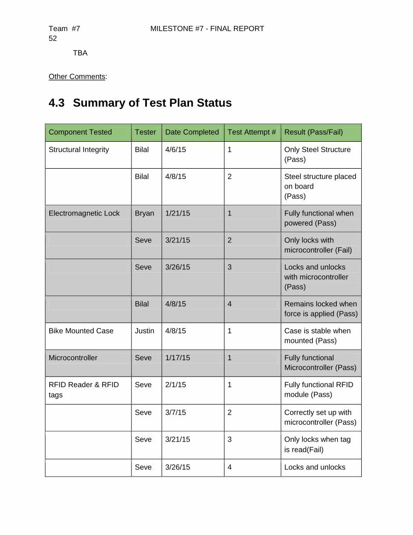
Team #7 MILESTONE #7 - FINAL REPORT
52
TBA
Other Comments:
4.3 Summary of Test Plan Status
Component Tested Tester Date Completed Test Attempt # Result (Pass/Fail)
Structural Integrity Bilal 4/6/15 1 Only Steel Structure
(Pass)
Bilal 4/8/15 2 Steel structure placed
on board
(Pass)
Electromagnetic Lock Bryan 1/21/15 1 Fully functional when
powered (Pass)
Seve 3/21/15 2 Only locks with
microcontroller (Fail)
Seve 3/26/15 3 Locks and unlocks
with microcontroller
(Pass)
Bilal 4/8/15 4 Remains locked when
force is applied (Pass)
Bike Mounted Case Justin 4/8/15 1 Case is stable when
mounted (Pass)
Microcontroller Seve 1/17/15 1 Fully functional
Microcontroller (Pass)
RFID Reader & RFID
tags
Seve 2/1/15 1 Fully functional RFID
module (Pass)
Seve 3/7/15 2 Correctly set up with
microcontroller (Pass)
Seve 3/21/15 3 Only locks when tag
is read(Fail)
Seve 3/26/15 4 Locks and unlocks
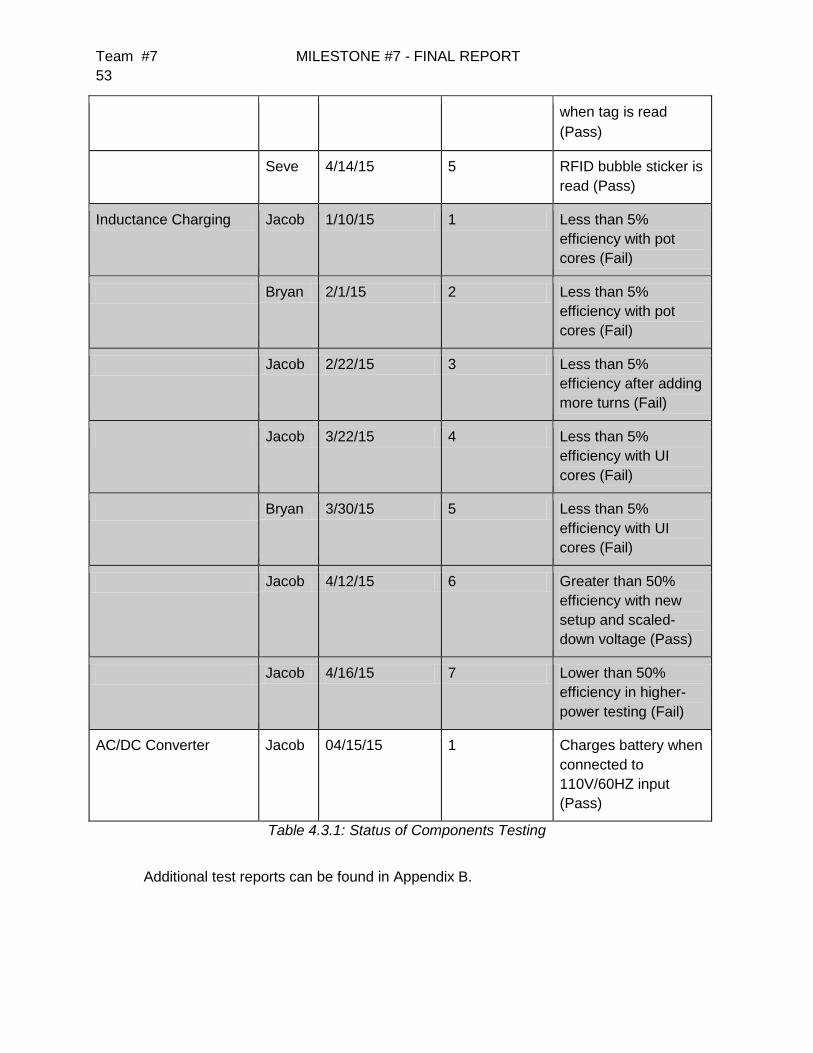
Team #7 MILESTONE #7 - FINAL REPORT
53
when tag is read
(Pass)
Seve 4/14/15 5 RFID bubble sticker is
read (Pass)
Inductance Charging Jacob 1/10/15 1 Less than 5%
efficiency with pot
cores (Fail)
Bryan 2/1/15 2 Less than 5%
efficiency with pot
cores (Fail)
Jacob 2/22/15 3 Less than 5%
efficiency after adding
more turns (Fail)
Jacob 3/22/15 4 Less than 5%
efficiency with UI
cores (Fail)
Bryan 3/30/15 5 Less than 5%
efficiency with UI
cores (Fail)
Jacob 4/12/15 6 Greater than 50%
efficiency with new
setup and scaled-
down voltage (Pass)
Jacob 4/16/15 7 Lower than 50%
efficiency in higher-
power testing (Fail)
AC/DC Converter Jacob 04/15/15 1 Charges battery when
connected to
110V/60HZ input
(Pass)
Table 4.3.1: Status of Components Testing
Additional test reports can be found in Appendix B.

Team #7 MILESTONE #7 - FINAL REPORT
54
5 Schedule
Conceptual Design Review Schedule

Team #7 MILESTONE #7 - FINAL REPORT
55
Final Project Schedule
Many of the major changes that occurred in the schedule are the completion dates of
testing and implementing some of the components of the station. Some of the testing and
implementation of components were not started as early as they needed to be, and some
components were not delivered as early as expected. There were some components that were
not producing the expected results causing the time period for these tasks to be extended.
These changes were addressed by coming together as a group and focusing on the given
tasks. The quickest and most efficient method to get on track was established as a group and all
subtasks were divided equally amongst the group. Also, the tasks with the highest priority, such
as induction charging and the RFID module, were taken into consideration first.

Team #7 MILESTONE #7 - FINAL REPORT
56
6 Final Budget and Justification
Original Budget (Full Production Model)
Expenses
Item/Description Quantity Price/Unit Total Price
Galvanized Steel Sheet Metal (1.41 m2) 1 $88.48 $88.48
A36 Hot Rolled Steel (8 ft, 1 in Diameter) 1 $32.00 $32.00
FPC-SS800-G 800 lbs Outdoor and Gate
Electromagnetic Lock CE Listed
1 $87.73 $87.73
Arduino UNO Rev3 1 $24.97 $24.97
Arduino MEGA 2560 Rev3 1 $43.70 $43.70
Arduino Ethernet Shield Rev3 (without PoE
Module)
1 $36.21 $36.21
Mifare RC522 Card Read Antenna RF Module
RFID Reader IC Card Proximity Module
1 $5.36 $5.36
Wall Adapter Power Supply (9VDC, 650mA) 1 $5.95 $5.95
3” Diameter Speaker (8 ohm, 1 Watt) 1 $1.95 $1.95
Tool Storage Spring Terry Clips (1 in) 1 $10.19 $10.19
18 AWG Copper Magnet Wire (1 lb, 201 ft) 1 $16.50 $16.50
14 AWG Copper Wire (25 ft) 1 $14.00 $14.00
LED R/Y/G 1 $2.75 $2.75
Expenses
Subtotal
$369.79
Additional Costs (Components + Support) $300.00
Total Costs $669.79
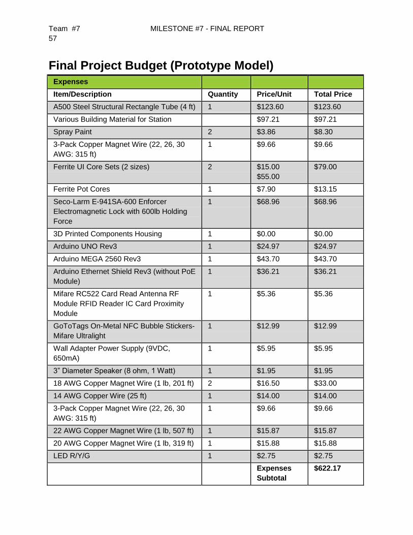
Team #7 MILESTONE #7 - FINAL REPORT
57
Final Project Budget (Prototype Model)
Expenses
Item/Description Quantity Price/Unit Total Price
A500 Steel Structural Rectangle Tube (4 ft) 1 $123.60 $123.60
Various Building Material for Station $97.21 $97.21
Spray Paint 2 $3.86 $8.30
3-Pack Copper Magnet Wire (22, 26, 30
AWG: 315 ft)
1 $9.66 $9.66
Ferrite UI Core Sets (2 sizes) 2 $15.00
$55.00
$79.00
Ferrite Pot Cores 1 $7.90 $13.15
Seco-Larm E-941SA-600 Enforcer
Electromagnetic Lock with 600lb Holding
Force
1 $68.96 $68.96
3D Printed Components Housing 1 $0.00 $0.00
Arduino UNO Rev3 1 $24.97 $24.97
Arduino MEGA 2560 Rev3 1 $43.70 $43.70
Arduino Ethernet Shield Rev3 (without PoE
Module)
1 $36.21 $36.21
Mifare RC522 Card Read Antenna RF
Module RFID Reader IC Card Proximity
Module
1 $5.36 $5.36
GoToTags On-Metal NFC Bubble Stickers-
Mifare Ultralight
1 $12.99 $12.99
Wall Adapter Power Supply (9VDC,
650mA)
1 $5.95 $5.95
3” Diameter Speaker (8 ohm, 1 Watt) 1 $1.95 $1.95
18 AWG Copper Magnet Wire (1 lb, 201 ft) 2 $16.50 $33.00
14 AWG Copper Wire (25 ft) 1 $14.00 $14.00
3-Pack Copper Magnet Wire (22, 26, 30
AWG: 315 ft)
1 $9.66 $9.66
22 AWG Copper Magnet Wire (1 lb, 507 ft) 1 $15.87 $15.87
20 AWG Copper Magnet Wire (1 lb, 319 ft) 1 $15.88 $15.88
LED R/Y/G 1 $2.75 $2.75
Expenses
Subtotal
$622.17
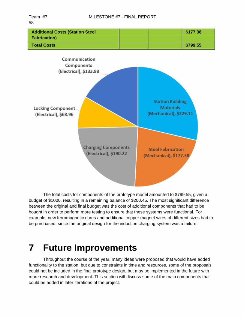
Team #7 MILESTONE #7 - FINAL REPORT
58
Additional Costs (Station Steel
Fabrication)
$177.38
Total Costs $799.55
The total costs for components of the prototype model amounted to $799.55, given a
budget of $1000, resulting in a remaining balance of $200.45. The most significant difference
between the original and final budget was the cost of additional components that had to be
bought in order to perform more testing to ensure that these systems were functional. For
example, new ferromagnetic cores and additional copper magnet wires of different sizes had to
be purchased, since the original design for the induction charging system was a failure.
7 Future Improvements Throughout the course of the year, many ideas were proposed that would have added
functionality to the station, but due to constraints in time and resources, some of the proposals
could not be included in the final prototype design, but may be implemented in the future with
more research and development. This section will discuss some of the main components that
could be added in later iterations of the project.

Team #7 MILESTONE #7 - FINAL REPORT
59
Solar Panel Canopy
Early in the project, a canopy covered by solar panels was suggested to both provide
power to the station while the sun is up as well as help protect the station from weather
conditions. This was outside the scope of the project, but could be implemented fairly easily by
either the manufacturer or the buyer of the station.
Networking Capability
Originally one of the needs of the project was to provide a networking interface to an
external website. However, due to the website not being fully operational as well as the
prioritization of a working RFID module, the networking capability was descoped. However, the
end model would need networking capability in order to function as desired by the sponsors.
Swivel Electromagnetic Lock
One issue encountered during testing of the electromagnetic lock was the need for a
precise right angle between the electromagnetic lock and the bike frame. A slight deviation in
the angle could cause the electromagnet to not lock properly. One possibility to alleviate this
problem would be to mount the electromagnetic lock (and possibly also the station induction
coil) to a bracket that has some rotational degree of freedom in the plane parallel to the ground,
in order to allow for an easier fitting of the lock to the bike plate.
Individual Bike ID Tracking
Currently, the RFID system is set up such that each RFID tag is saved as either valid or invalid,
but an additional state specifically for the bike RFID would add two layers of functionality: First,
it would allow the bike RFID to only lock the bike station when it is detected, rather than toggling
the lock state between unlocked and locked. In other words, the current system could have the
station in the locked state, then as the bike is docked, it toggles to the unlocked state and the
bike remains unsecured. Second, individual IDs for each bike and user would allow the system
to keep track of who has which bike, which adds an extra layer of security since a missing bike
could be tracked back to its most recent renter.
Full Induction Charging Capability
While much progress was made toward providing wireless charging through the use of
induction, the full-scale model could not be achieved over the course of the semester, so a main
goal of a future project would be to finish the capability of the induction charging.
8 Conclusion
The design project was given to our team as an idea and thoughts. Through the analysis
of needs and requirements the team was able to make more sense of the station and what

Team #7 MILESTONE #7 - FINAL REPORT
60
different approaches we were able to take. After considering different methods and attempting
alternative design implementation, the team found what was best to build as the first prototype
for the charging and docking station. Our fully functional system is optimal in addressing the
needs for a simple user interaction using an RFID reader to allow the a user to lock and unlock
a docked e-bike. The station includes a structural sound design that withstands all stress
analysis given. The charging portion of the station was not implemented into the station due to
design changes. However the charging was successful outside the system with high efficiency.
Overall the team completed majority of the daunting tasks presented and is a combined show of
effort from the knowledge and application from the mechanical, electrical and computer
engineering disciplines. The ECE Team 7 is satisfied with the results of the Efficient Systems
LLC sponsored Charging and Docking Station and hopes to see improvements and
implementation done in the future.
Team #7 MILESTONE #7 - FINAL REPORT
61
8 References
[1] Mornhinweg, Manfred. "Transformers and Coils." Homo Ludens. N.p., n.d. Web. 14 Nov.
2014. <http://ludens.cl/Electron/Magnet.html>.
[2] http://msis.jsc.nasa.gov/sections/section04.htm#_4.9_STRENGTH
[3] http://www.galvanizeit.org/design-and-fabrication/fabrication-considerations/bending
[4] Pellitteri, F., V. Boscaino, A. O. Di Tommaso, R. Miceli, and G. Capponi. "Wireless Battery
Charging: E-bike Application." (n.d.): n. pag. Web.
[5]http://www.pololu.com/blog/277/new-nema-17-stepper-motor-with-optional-integrated-lead-
screw
[6] http://www.seco-larm.com/E-941SA-600.htm
[7]http://www.homedepot.com/p/Unbranded-1-2-in-13-tpi-x-6-in-Zinc-Plated-Hex-Bolt-
801056/204633235?N=5yc1vZc26w
[8] http://www.rfidjournal.com/articles/view?7307
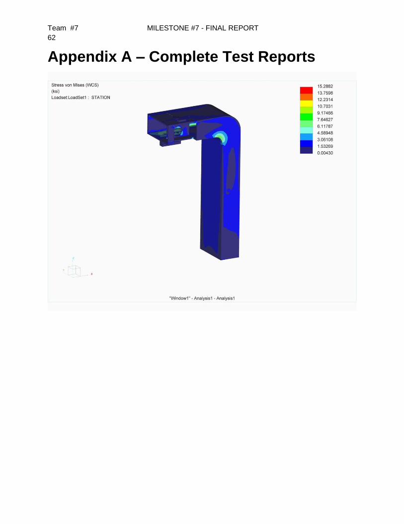
Team #7 MILESTONE #7 - FINAL REPORT
62
Appendix A – Complete Test Reports
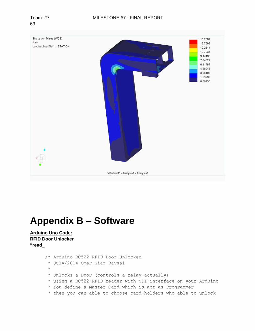
Team #7 MILESTONE #7 - FINAL REPORT
63
Appendix B – Software Arduino Uno Code:
RFID Door Unlocker
“read_
/* Arduino RC522 RFID Door Unlocker
* July/2014 Omer Siar Baysal
*
* Unlocks a Door (controls a relay actually)
* using a RC522 RFID reader with SPI interface on your Arduino
* You define a Master Card which is act as Programmer
* then you can able to choose card holders who able to unlock
Team #7 MILESTONE #7 - FINAL REPORT
64
* the door or not.
*
* Easy User Interface
*
* Just one RFID tag needed whether Delete or Add Tags
* You can choose to use Leds for output or
* Serial LCD module to inform users. Or you can use both
*
* Stores Information on EEPROM
*
* Information stored on non volatile Arduino's EEPROM
* memory to preserve Users' tag and Master Card
* No Information lost if power lost.
* EEPROM has unlimited Read cycle but 100,000 limited Write
cycle.
*
* Security
*
* To keep it simple we are going to use Tag's Unique IDs
* It's simple, a bit secure, but not hacker proof.
*
* MFRC522 Library also lets us to use some authentication
* mechanism, writing blocks and reading back
* and there is great example piece of code
* about reading and writing PICCs
* here > http://makecourse.weebly.com/week10segment1.html
*
* If you rely on heavy security, figure it out how RFID system
* can be secure yourself (personally very curious about it)
*
* Credits
*
* Omer Siar Baysal who put together this project
*
* Idea and most of code from Brett Martin's project
* http://www.instructables.com/id/Arduino-RFID-Door-Lock/
* www.pcmofo.com
*
* MFRC522 Library
* https://github.com/miguelbalboa/rfid
* Based on code Dr.Leong ( WWW.B2CQSHOP.COM )
* Created by Miguel Balboa (circuitito.com), Jan, 2012.
* Rewritten by Søren Thing Andersen (access.thing.dk), fall of
2013
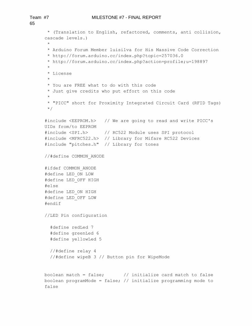
Team #7 MILESTONE #7 - FINAL REPORT
65
* (Translation to English, refactored, comments, anti collision,
cascade levels.)
*
* Arduino Forum Member luisilva for His Massive Code Correction
* http://forum.arduino.cc/index.php?topic=257036.0
* http://forum.arduino.cc/index.php?action=profile;u=198897
*
* License
*
* You are FREE what to do with this code
* Just give credits who put effort on this code
*
* "PICC" short for Proximity Integrated Circuit Card (RFID Tags)
*/
#include <EEPROM.h> // We are going to read and write PICC's
UIDs from/to EEPROM
#include <SPI.h> // RC522 Module uses SPI protocol
#include <MFRC522.h> // Library for Mifare RC522 Devices
#include "pitches.h" // Library for tones
//#define COMMON_ANODE
#ifdef COMMON_ANODE
#define LED_ON LOW
#define LED_OFF HIGH
#else
#define LED_ON HIGH
#define LED_OFF LOW
#endif
//LED Pin configuration
#define redLed 7
#define greenLed 6
#define yellowLed 5
//#define relay 4
//#define wipeB 3 // Button pin for WipeMode
boolean match = false; // initialize card match to false
boolean programMode = false; // initialize programming mode to
false
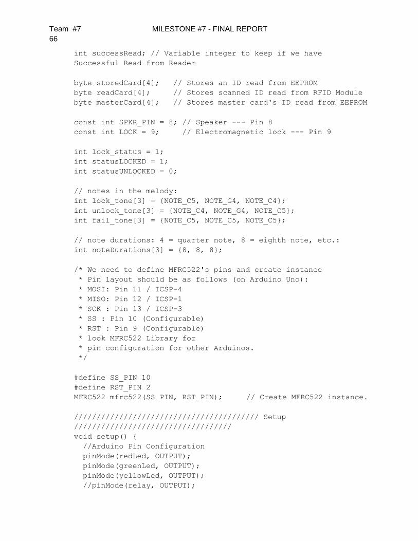
Team #7 MILESTONE #7 - FINAL REPORT
66
int successRead; // Variable integer to keep if we have
Successful Read from Reader
byte storedCard[4]; // Stores an ID read from EEPROM
byte readCard[4]; // Stores scanned ID read from RFID Module
byte masterCard[4]; // Stores master card's ID read from EEPROM
const int SPKR_PIN = 8; // Speaker --- Pin 8
const int LOCK = 9; // Electromagnetic lock --- Pin 9
int lock_status = 1;
int statusLOCKED = 1;
int statusUNLOCKED = 0;
// notes in the melody:
int lock_tone[3] = {NOTE_C5, NOTE_G4, NOTE_C4};
int unlock_tone[3] = {NOTE_C4, NOTE_G4, NOTE_C5};
int fail_tone[3] = {NOTE_C5, NOTE_C5, NOTE_C5};
// note durations: 4 = quarter note, 8 = eighth note, etc.:
int noteDurations[3] = {8, 8, 8};
/* We need to define MFRC522's pins and create instance
* Pin layout should be as follows (on Arduino Uno):
* MOSI: Pin 11 / ICSP-4
* MISO: Pin 12 / ICSP-1
* SCK : Pin 13 / ICSP-3
* SS : Pin 10 (Configurable)
* RST : Pin 9 (Configurable)
* look MFRC522 Library for
* pin configuration for other Arduinos.
*/
#define SS_PIN 10
#define RST_PIN 2
MFRC522 mfrc522(SS_PIN, RST_PIN); // Create MFRC522 instance.
///////////////////////////////////////// Setup
///////////////////////////////////
void setup() {
//Arduino Pin Configuration
pinMode(redLed, OUTPUT);
pinMode(greenLed, OUTPUT);
pinMode(yellowLed, OUTPUT);
//pinMode(relay, OUTPUT);
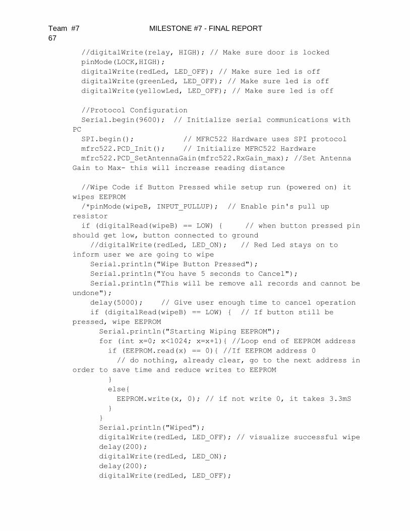
Team #7 MILESTONE #7 - FINAL REPORT
67
//digitalWrite(relay, HIGH); // Make sure door is locked
pinMode(LOCK,HIGH);
digitalWrite(redLed, LED_OFF); // Make sure led is off
digitalWrite(greenLed, LED_OFF); // Make sure led is off
digitalWrite(yellowLed, LED_OFF); // Make sure led is off
//Protocol Configuration
Serial.begin(9600); // Initialize serial communications with
PC
SPI.begin(); // MFRC522 Hardware uses SPI protocol
mfrc522.PCD_Init(); // Initialize MFRC522 Hardware
mfrc522.PCD_SetAntennaGain(mfrc522.RxGain_max); //Set Antenna
Gain to Max- this will increase reading distance
//Wipe Code if Button Pressed while setup run (powered on) it
wipes EEPROM
/*pinMode(wipeB, INPUT_PULLUP); // Enable pin's pull up
resistor
if (digitalRead(wipeB) == LOW) { // when button pressed pin
should get low, button connected to ground
//digitalWrite(redLed, LED_ON); // Red Led stays on to
inform user we are going to wipe
Serial.println("Wipe Button Pressed");
Serial.println("You have 5 seconds to Cancel");
Serial.println("This will be remove all records and cannot be
undone");
delay(5000); // Give user enough time to cancel operation
if (digitalRead(wipeB) == LOW) { // If button still be
pressed, wipe EEPROM
Serial.println("Starting Wiping EEPROM");
for (int x=0; x<1024; x=x+1){ //Loop end of EEPROM address
if (EEPROM.read(x) == 0){ //If EEPROM address 0
// do nothing, already clear, go to the next address in
order to save time and reduce writes to EEPROM
}
else{
EEPROM.write(x, 0); // if not write 0, it takes 3.3mS
}
}
Serial.println("Wiped");
digitalWrite(redLed, LED_OFF); // visualize successful wipe
delay(200);
digitalWrite(redLed, LED_ON);
delay(200);
digitalWrite(redLed, LED_OFF);

Team #7 MILESTONE #7 - FINAL REPORT
68
delay(200);
digitalWrite(redLed, LED_ON);
delay(200);
digitalWrite(redLed, LED_OFF);
}
else {
Serial.println("!!! Wiping Cancelled !!!");
digitalWrite(redLed, LED_OFF);
}
}
*/
//Check if master card defined, if not let user choose a master
card
//This also useful to just redefine Master Card
//You can keep other EEPROM records just write other than 1 to
EEPROM address 1
if (EEPROM.read(1) != 143) { // Look EEPROM if Master Card
defined, EEPROM address 1 holds if defined
// 143 our magical number
Serial.println("No Master Card Defined");
Serial.println("Scan A PICC to Define as Master Card");
do {
successRead = getID(); // sets successRead to 1 when we get
read from reader otherwise 0
digitalWrite(yellowLed, LED_ON); // Visualize Master Card
need to be defined
delay(200);
digitalWrite(yellowLed, LED_OFF);
delay(200);
}
while (!successRead); //the program will not go further while
you not get a successful read
for ( int j = 0; j < 4; j++ ) { // Loop 4 times
EEPROM.write( 2 +j, readCard[j] ); // Write scanned PICC's
UID to EEPROM, start from address 3
}
EEPROM.write(1,143); //Write to EEPROM we defined Master
Card.
Serial.println("Master Card Defined");
}
Serial.println("##### RFID Door Acces Control v2.0.8 #####");
//For debug purposes
Serial.println("Master Card's UID");

Team #7 MILESTONE #7 - FINAL REPORT
69
for ( int i = 0; i < 4; i++ ) { // Read Master Card's UID
from EEPROM
masterCard[i] = EEPROM.read(2+i); // Write it to masterCard
Serial.print(masterCard[i], HEX);
}
Serial.println("");
Serial.println("Waiting PICCs to bo scanned :)");
cycleLeds(); // Everything ready lets give user some
feedback by cycling leds
}
///////////////////////////////////////// Main Loop
///////////////////////////////////
void loop () {
do {
successRead = getID(); // sets successRead to 1 when we get
read from reader otherwise 0
if (programMode) {
cycleLeds(); // Program Mode cycles through RGB waiting to
read a new card
}
else {
normalModeOn(); // Normal mode, yellow Power LED is on, all
others are off
}
}
while (!successRead); //the program will not go further while
you not get a successful read
if (programMode) {
if ( isMaster(readCard) ) { //If master card scanned again
exit program mode
Serial.println("This is Master Card");
Serial.println("Exiting Program Mode");
Serial.println("-----------------------------");
programMode = false;
return;
}
else {
if ( findID(readCard) ) { //If scanned card is known delete
it
Serial.println("I know this PICC, so removing");
deleteID(readCard);
Serial.println("-----------------------------");
}

Team #7 MILESTONE #7 - FINAL REPORT
70
else { // If scanned card is not known
add it
Serial.println("I do not know this PICC, adding...");
writeID(readCard);
Serial.println("-----------------------------");
}
}
}
else {
if ( isMaster(readCard) ) { // If scanned card's ID matches
Master Card's ID enter program mode
programMode = true;
Serial.println("Hello Master - Entered Program Mode");
int count = EEPROM.read(0); // Read the first Byte of
EEPROM that
Serial.print("I have "); // stores the number of ID's in
EEPROM
Serial.print(count);
Serial.print(" record(s) on EEPROM");
Serial.println("");
Serial.println("Scan a PICC to ADD or REMOVE");
Serial.println("-----------------------------");
}
else {
if ( lock_status == statusLOCKED && findID(readCard) ) {
Serial.println("ACCESS GRANTED!");
Serial.println("Bike is unlocked");
unlock();
lock_status = statusUNLOCKED;
}
else if ( lock_status == statusUNLOCKED && findID(readCard)
) {
Serial.println("ACCESS GRANTED!");
Serial.println("Bike is locked");
lock();
lock_status = statusLOCKED;
}
else { // If not, show that the ID was
not valid
Serial.println("ACCESS DENIED");
failed();
}
}

Team #7 MILESTONE #7 - FINAL REPORT
71
}
}
/////////////////////////////////////////////////////////////////
///////////////////
/* else if( findID(readCard) ) { // If not, see if the
card is in the EEPROM
if( lock_status = statusLOCKED )
{
Serial.println("[[[ A C C E S S G R A N T E D ]]]");
Serial.println("Bike is unlocked");
unlock();
lock_status = statusUNLOCKED;
}
else if( lock_status = statusUNLOCKED )
{
Serial.println("[[[ A C C E S S G R A N T E D ]]]");
Serial.println("Bike is locked");
lock();
lock_status = statusLOCKED;
}
else { // If not, show that the ID was not
valid
Serial.println("[[[ A C C E S S D E N I E D ]]]");
failed();
}
}
}
}
*/
///////////////////////////////////////// Get PICC's UID
///////////////////////////////////
int getID() {
// Getting ready for Reading PICCs
if ( ! mfrc522.PICC_IsNewCardPresent()) { //If a new PICC
placed to RFID reader continue
return 0;
}
if ( ! mfrc522.PICC_ReadCardSerial()) { //Since a PICC placed
get Serial and continue
return 0;
}
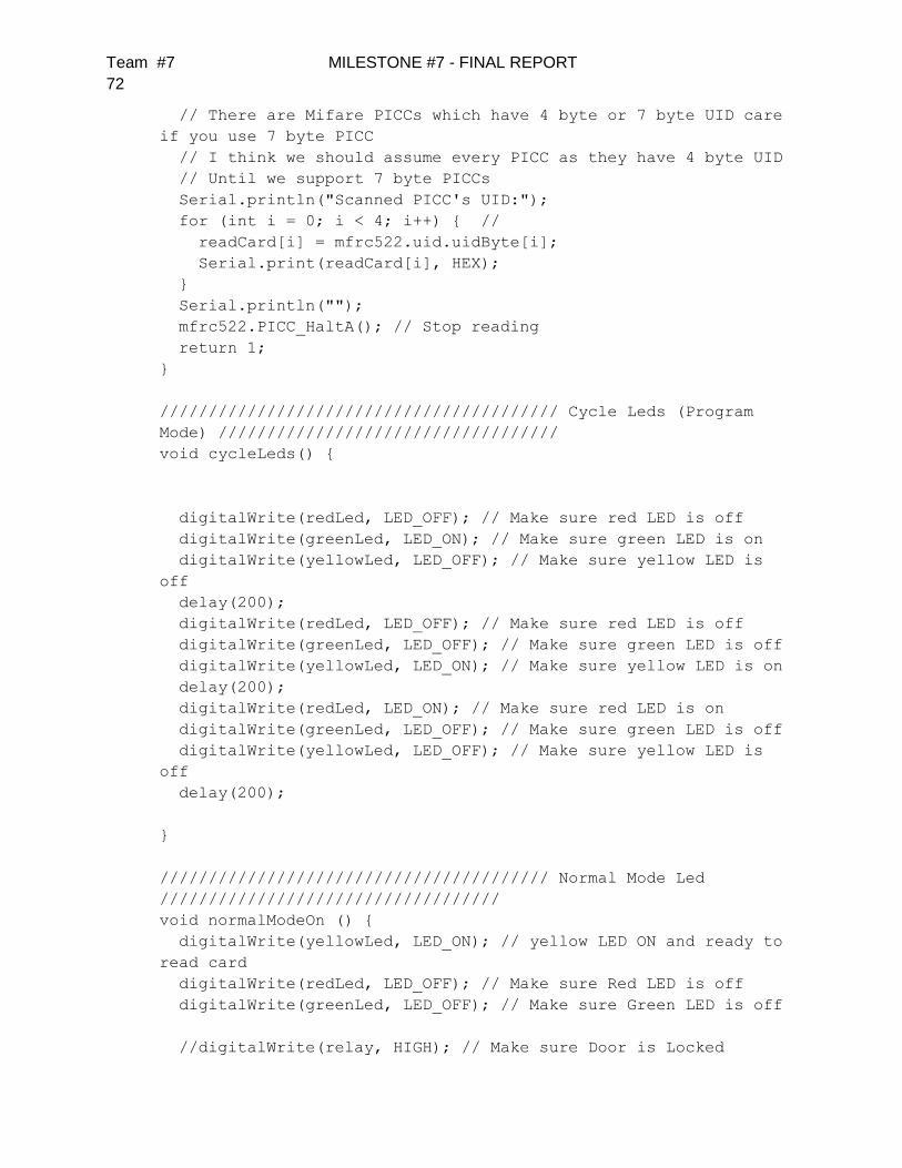
Team #7 MILESTONE #7 - FINAL REPORT
72
// There are Mifare PICCs which have 4 byte or 7 byte UID care
if you use 7 byte PICC
// I think we should assume every PICC as they have 4 byte UID
// Until we support 7 byte PICCs
Serial.println("Scanned PICC's UID:");
for (int i = 0; i < 4; i++) { //
readCard[i] = mfrc522.uid.uidByte[i];
Serial.print(readCard[i], HEX);
}
Serial.println("");
mfrc522.PICC_HaltA(); // Stop reading
return 1;
}
///////////////////////////////////////// Cycle Leds (Program
Mode) ///////////////////////////////////
void cycleLeds() {
digitalWrite(redLed, LED_OFF); // Make sure red LED is off
digitalWrite(greenLed, LED_ON); // Make sure green LED is on
digitalWrite(yellowLed, LED_OFF); // Make sure yellow LED is
off
delay(200);
digitalWrite(redLed, LED_OFF); // Make sure red LED is off
digitalWrite(greenLed, LED_OFF); // Make sure green LED is off
digitalWrite(yellowLed, LED_ON); // Make sure yellow LED is on
delay(200);
digitalWrite(redLed, LED_ON); // Make sure red LED is on
digitalWrite(greenLed, LED_OFF); // Make sure green LED is off
digitalWrite(yellowLed, LED_OFF); // Make sure yellow LED is
off
delay(200);
}
//////////////////////////////////////// Normal Mode Led
///////////////////////////////////
void normalModeOn () {
digitalWrite(yellowLed, LED_ON); // yellow LED ON and ready to
read card
digitalWrite(redLed, LED_OFF); // Make sure Red LED is off
digitalWrite(greenLed, LED_OFF); // Make sure Green LED is off
//digitalWrite(relay, HIGH); // Make sure Door is Locked

Team #7 MILESTONE #7 - FINAL REPORT
73
}
//////////////////////////////////////// Read an ID from EEPROM
//////////////////////////////
void readID( int number ) {
int start = (number * 4 ) + 2; // Figure out starting position
for ( int i = 0; i < 4; i++ ) { // Loop 4 times to get the 4
Bytes
storedCard[i] = EEPROM.read(start+i); // Assign values read
from EEPROM to array
}
}
///////////////////////////////////////// Add ID to EEPROM
///////////////////////////////////
void writeID( byte a[] ) {
if ( !findID( a ) ) { // Before we write to the EEPROM, check
to see if we have seen this card before!
int num = EEPROM.read(0); // Get the numer of used spaces,
position 0 stores the number of ID cards
int start = ( num * 4 ) + 6; // Figure out where the next
slot starts
num++; // Increment the counter by one
EEPROM.write( 0, num ); // Write the new count to the counter
for ( int j = 0; j < 4; j++ ) { // Loop 4 times
EEPROM.write( start+j, a[j] ); // Write the array values to
EEPROM in the right position
}
successWrite();
}
else {
failedWrite();
}
}
///////////////////////////////////////// Remove ID from EEPROM
///////////////////////////////////
void deleteID( byte a[] ) {
if ( !findID( a ) ) { // Before we delete from the EEPROM,
check to see if we have this card!
failedWrite(); // If not
}
else {
int num = EEPROM.read(0); // Get the numer of used spaces,
position 0 stores the number of ID cards

Team #7 MILESTONE #7 - FINAL REPORT
74
int slot; // Figure out the slot number of the card
int start;// = ( num * 4 ) + 6; // Figure out where the next
slot starts
int looping; // The number of times the loop repeats
int j;
int count = EEPROM.read(0); // Read the first Byte of EEPROM
that stores number of cards
slot = findIDSLOT( a ); //Figure out the slot number of the
card to delete
start = (slot * 4) + 2;
looping = ((num - slot) * 4);
num--; // Decrement the counter by one
EEPROM.write( 0, num ); // Write the new count to the counter
for ( j = 0; j < looping; j++ ) { // Loop the card shift
times
EEPROM.write( start+j, EEPROM.read(start+4+j)); // Shift
the array values to 4 places earlier in the EEPROM
}
for ( int k = 0; k < 4; k++ ) { //Shifting loop
EEPROM.write( start+j+k, 0);
}
successDelete();
}
}
///////////////////////////////////////// Check Bytes
///////////////////////////////////
boolean checkTwo ( byte a[], byte b[] ) {
if ( a[0] != NULL ) // Make sure there is something in the
array first
match = true; // Assume they match at first
for ( int k = 0; k < 4; k++ ) { // Loop 4 times
if ( a[k] != b[k] ) // IF a != b then set match = false, one
fails, all fail
match = false;
}
if ( match ) { // Check to see if if match is still true
return true; // Return true
}
else {
return false; // Return false
}
}
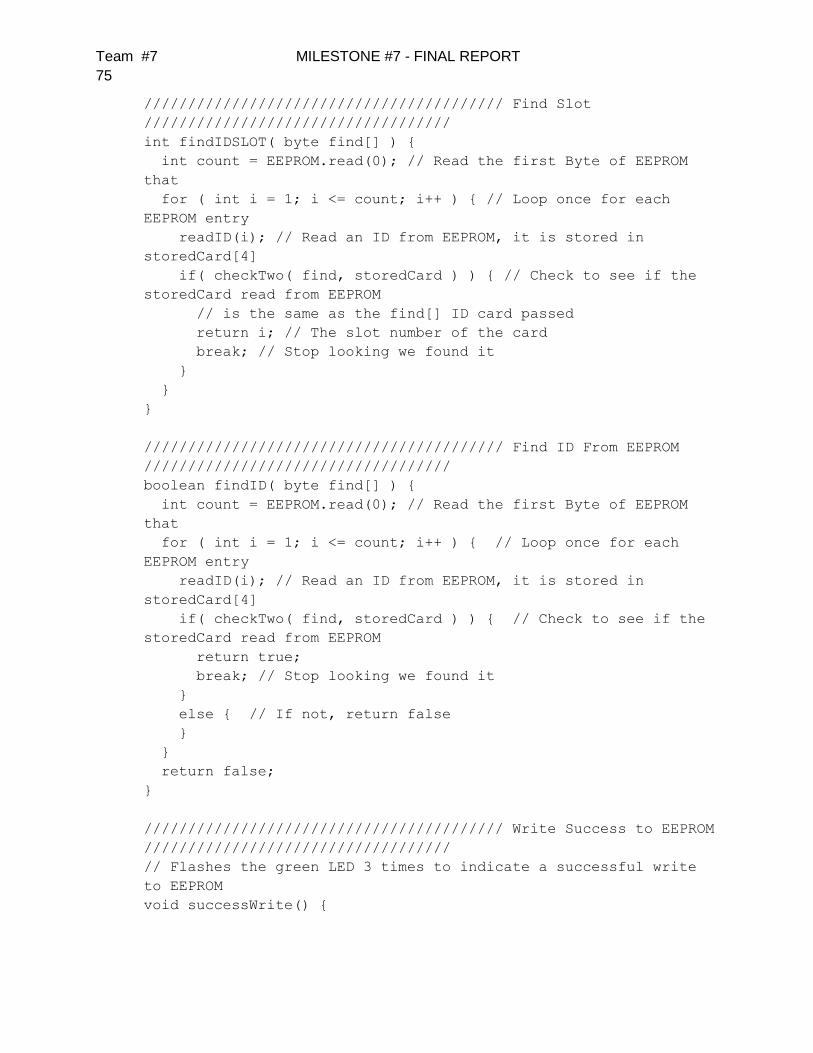
Team #7 MILESTONE #7 - FINAL REPORT
75
///////////////////////////////////////// Find Slot
///////////////////////////////////
int findIDSLOT( byte find[] ) {
int count = EEPROM.read(0); // Read the first Byte of EEPROM
that
for ( int i = 1; i <= count; i++ ) { // Loop once for each
EEPROM entry
readID(i); // Read an ID from EEPROM, it is stored in
storedCard[4]
if( checkTwo( find, storedCard ) ) { // Check to see if the
storedCard read from EEPROM
// is the same as the find[] ID card passed
return i; // The slot number of the card
break; // Stop looking we found it
}
}
}
///////////////////////////////////////// Find ID From EEPROM
///////////////////////////////////
boolean findID( byte find[] ) {
int count = EEPROM.read(0); // Read the first Byte of EEPROM
that
for ( int i = 1; i <= count; i++ ) { // Loop once for each
EEPROM entry
readID(i); // Read an ID from EEPROM, it is stored in
storedCard[4]
if( checkTwo( find, storedCard ) ) { // Check to see if the
storedCard read from EEPROM
return true;
break; // Stop looking we found it
}
else { // If not, return false
}
}
return false;
}
///////////////////////////////////////// Write Success to EEPROM
///////////////////////////////////
// Flashes the green LED 3 times to indicate a successful write
to EEPROM
void successWrite() {
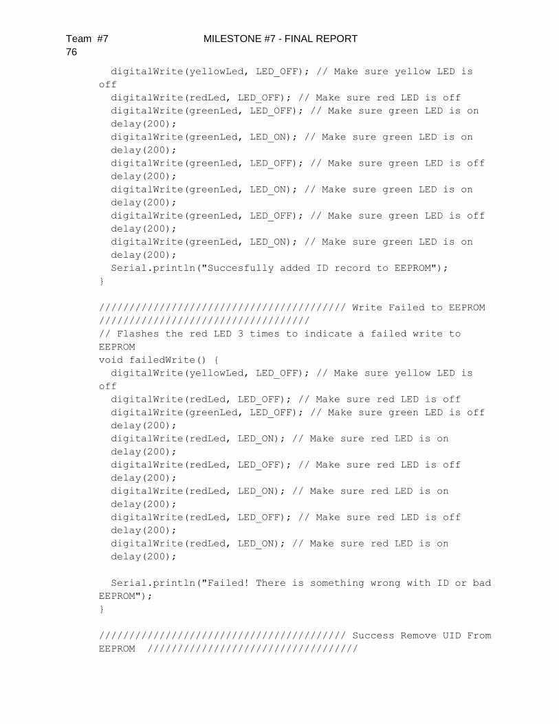
Team #7 MILESTONE #7 - FINAL REPORT
76
digitalWrite(yellowLed, LED_OFF); // Make sure yellow LED is
off
digitalWrite(redLed, LED_OFF); // Make sure red LED is off
digitalWrite(greenLed, LED_OFF); // Make sure green LED is on
delay(200);
digitalWrite(greenLed, LED_ON); // Make sure green LED is on
delay(200);
digitalWrite(greenLed, LED_OFF); // Make sure green LED is off
delay(200);
digitalWrite(greenLed, LED_ON); // Make sure green LED is on
delay(200);
digitalWrite(greenLed, LED_OFF); // Make sure green LED is off
delay(200);
digitalWrite(greenLed, LED_ON); // Make sure green LED is on
delay(200);
Serial.println("Succesfully added ID record to EEPROM");
}
///////////////////////////////////////// Write Failed to EEPROM
///////////////////////////////////
// Flashes the red LED 3 times to indicate a failed write to
EEPROM
void failedWrite() {
digitalWrite(yellowLed, LED_OFF); // Make sure yellow LED is
off
digitalWrite(redLed, LED_OFF); // Make sure red LED is off
digitalWrite(greenLed, LED_OFF); // Make sure green LED is off
delay(200);
digitalWrite(redLed, LED_ON); // Make sure red LED is on
delay(200);
digitalWrite(redLed, LED_OFF); // Make sure red LED is off
delay(200);
digitalWrite(redLed, LED_ON); // Make sure red LED is on
delay(200);
digitalWrite(redLed, LED_OFF); // Make sure red LED is off
delay(200);
digitalWrite(redLed, LED_ON); // Make sure red LED is on
delay(200);
Serial.println("Failed! There is something wrong with ID or bad
EEPROM");
}
///////////////////////////////////////// Success Remove UID From
EEPROM ///////////////////////////////////
Team #7 MILESTONE #7 - FINAL REPORT
77
// Flashes the yellow LED 3 times to indicate a success delete to
EEPROM
void successDelete() {
digitalWrite(yellowLed, LED_OFF); // Make sure yellow LED is
off
digitalWrite(redLed, LED_OFF); // Make sure red LED is off
digitalWrite(greenLed, LED_OFF); // Make sure green LED is off
delay(200);
digitalWrite(yellowLed, LED_ON); // Make sure yellow LED is on
delay(200);
digitalWrite(yellowLed, LED_OFF); // Make sure yellow LED is
off
delay(200);
digitalWrite(yellowLed, LED_ON); // Make sure yellow LED is on
delay(200);
digitalWrite(yellowLed, LED_OFF); // Make sure yellow LED is
off
delay(200);
digitalWrite(yellowLed, LED_ON); // Make sure yellow LED is on
delay(200);
Serial.println("Succesfully removed ID record from EEPROM");
}
////////////////////// Check readCard IF is masterCard
///////////////////////////////////
// Check to see if the ID passed is the master programing card
boolean isMaster( byte test[] ) {
if ( checkTwo( test, masterCard ) )
return true;
else
return false;
}
///////////////////////////////////////// Unlock Bike
///////////////////////////////////
void unlock( ) {
digitalWrite(yellowLed, LED_OFF); // Turn off yellow LED
digitalWrite(redLed, LED_OFF); // Turn off red LED
digitalWrite(greenLed, LED_ON); // Turn on green LED
// Play unlock tone
for (int i = 0; i < 3 ; i++)
Team #7 MILESTONE #7 - FINAL REPORT
78
{
int noteDuration = 800/noteDurations[i];
tone(SPKR_PIN, unlock_tone[i], noteDuration);
int pauseBetweenNotes = noteDuration * 1.30;
delay(pauseBetweenNotes);
noTone(SPKR_PIN);
}
digitalWrite(LOCK, LOW); // Unlock bike!
delay(2000); // Hold green LED on for 2 more seconds
}
///////////////////////////////////////// Lock Bike
///////////////////////////////////
void lock( ) {
digitalWrite(yellowLed, LED_OFF); // Turn off yellow LED
digitalWrite(redLed, LED_ON); // Turn off red LED
digitalWrite(greenLed, LED_OFF); // Turn on green LED
// Play lock tone
for (int i = 0; i < 3 ; i++)
{
int noteDuration = 800/noteDurations[i];
tone(SPKR_PIN, lock_tone[i], noteDuration);
int pauseBetweenNotes = noteDuration * 1.30;
delay(pauseBetweenNotes);
noTone(SPKR_PIN);
}
digitalWrite(LOCK, HIGH); // Lock bike!
delay(2000); // Hold red LED on for 2 more seconds
}
///////////////////////////////////////// Failed Access
///////////////////////////////////
void failed() {
digitalWrite(greenLed, LED_OFF); // Make sure green LED is off
digitalWrite(yellowLed, LED_OFF); // Make sure yellow LED is
off
digitalWrite(redLed, LED_ON); // Turn on red LED
for (int i = 0; i < 3 ; i++)
{
Team #7 MILESTONE #7 - FINAL REPORT
79
int noteDuration = 800/noteDurations[i];
tone(SPKR_PIN, fail_tone[i], noteDuration);
int pauseBetweenNotes = noteDuration * 1.30;
delay(pauseBetweenNotes);
noTone(SPKR_PIN);
}
digitalWrite(redLed, LED_OFF);
delay(200);
digitalWrite(redLed, LED_ON);
delay(200);
digitalWrite(redLed, LED_OFF);
delay(200);
delay(1200);
}
Speaker Tones
“pitches.h”
/*************************************************
* Public Constants
*************************************************/
#define NOTE_B0 31
#define NOTE_C1 33
#define NOTE_CS1 35
#define NOTE_D1 37
#define NOTE_DS1 39
#define NOTE_E1 41
#define NOTE_F1 44
#define NOTE_FS1 46
#define NOTE_G1 49
#define NOTE_GS1 52
#define NOTE_A1 55
#define NOTE_AS1 58
#define NOTE_B1 62
#define NOTE_C2 65
#define NOTE_CS2 69
#define NOTE_D2 73
#define NOTE_DS2 78
#define NOTE_E2 82
#define NOTE_F2 87
#define NOTE_FS2 93
#define NOTE_G2 98
#define NOTE_GS2 104
#define NOTE_A2 110
Team #7 MILESTONE #7 - FINAL REPORT
80
#define NOTE_AS2 117
#define NOTE_B2 123
#define NOTE_C3 131
#define NOTE_CS3 139
#define NOTE_D3 147
#define NOTE_DS3 156
#define NOTE_E3 165
#define NOTE_F3 175
#define NOTE_FS3 185
#define NOTE_G3 196
#define NOTE_GS3 208
#define NOTE_A3 220
#define NOTE_AS3 233
#define NOTE_B3 247
#define NOTE_C4 262
#define NOTE_CS4 277
#define NOTE_D4 294
#define NOTE_DS4 311
#define NOTE_E4 330
#define NOTE_F4 349
#define NOTE_FS4 370
#define NOTE_G4 392
#define NOTE_GS4 415
#define NOTE_A4 440
#define NOTE_AS4 466
#define NOTE_B4 494
#define NOTE_C5 523
#define NOTE_CS5 554
#define NOTE_D5 587
#define NOTE_DS5 622
#define NOTE_E5 659
#define NOTE_F5 698
#define NOTE_FS5 740
#define NOTE_G5 784
#define NOTE_GS5 831
#define NOTE_A5 880
#define NOTE_AS5 932
#define NOTE_B5 988
#define NOTE_C6 1047
#define NOTE_CS6 1109
#define NOTE_D6 1175
#define NOTE_DS6 1245
#define NOTE_E6 1319
#define NOTE_F6 1397
#define NOTE_FS6 1480

Team #7 MILESTONE #7 - FINAL REPORT
81
#define NOTE_G6 1568
#define NOTE_GS6 1661
#define NOTE_A6 1760
#define NOTE_AS6 1865
#define NOTE_B6 1976
#define NOTE_C7 2093
#define NOTE_CS7 2217
#define NOTE_D7 2349
#define NOTE_DS7 2489
#define NOTE_E7 2637
#define NOTE_F7 2794
#define NOTE_FS7 2960
#define NOTE_G7 3136
#define NOTE_GS7 3322
#define NOTE_A7 3520
#define NOTE_AS7 3729
#define NOTE_B7 3951
#define NOTE_C8 4186
#define NOTE_CS8 4435
#define NOTE_D8 4699
#define NOTE_DS8 4978
MIFARE Library
“MFC522.h”
/**
* --------------------------------------------------------------
--------------
* This is a MFRC522 library example.
*
* Released into the public domain.
* --------------------------------------------------------------
--------------
* This sample shows how to read and write data blocks on a
MIFARE Classic PICC
* (= card/tag).
*
* BEWARE: Data will be written to the PICC, in sector #1 (blocks
#4 to #7).
*
*
* Typical pin layout used:
* ------------------------------------------------------------
* MFRC522 Arduino Arduino Arduino
* Reader/PCD Uno Mega Nano v3
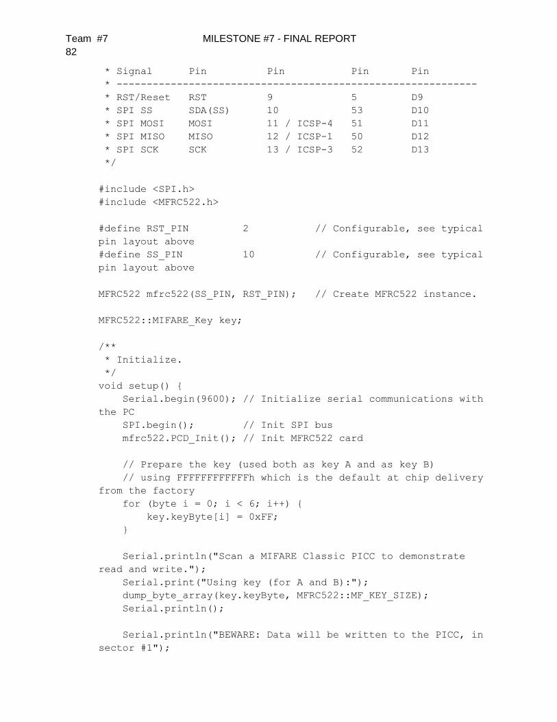
Team #7 MILESTONE #7 - FINAL REPORT
82
* Signal Pin Pin Pin Pin
* ------------------------------------------------------------
* RST/Reset RST 9 5 D9
* SPI SS SDA(SS) 10 53 D10
* SPI MOSI MOSI 11 / ICSP-4 51 D11
* SPI MISO MISO 12 / ICSP-1 50 D12
* SPI SCK SCK 13 / ICSP-3 52 D13
*/
#include <SPI.h>
#include <MFRC522.h>
#define RST_PIN 2 // Configurable, see typical
pin layout above
#define SS_PIN 10 // Configurable, see typical
pin layout above
MFRC522 mfrc522(SS_PIN, RST_PIN); // Create MFRC522 instance.
MFRC522::MIFARE_Key key;
/**
* Initialize.
*/
void setup() {
Serial.begin(9600); // Initialize serial communications with
the PC
SPI.begin(); // Init SPI bus
mfrc522.PCD_Init(); // Init MFRC522 card
// Prepare the key (used both as key A and as key B)
// using FFFFFFFFFFFFh which is the default at chip delivery
from the factory
for (byte i = 0; i < 6; i++) {
key.keyByte[i] = 0xFF;
}
Serial.println("Scan a MIFARE Classic PICC to demonstrate
read and write.");
Serial.print("Using key (for A and B):");
dump_byte_array(key.keyByte, MFRC522::MF_KEY_SIZE);
Serial.println();
Serial.println("BEWARE: Data will be written to the PICC, in
sector #1");
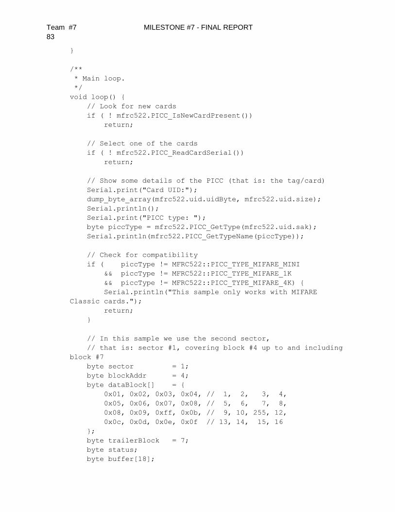
Team #7 MILESTONE #7 - FINAL REPORT
83
}
/**
* Main loop.
*/
void loop() {
// Look for new cards
if ( ! mfrc522.PICC_IsNewCardPresent())
return;
// Select one of the cards
if ( ! mfrc522.PICC_ReadCardSerial())
return;
// Show some details of the PICC (that is: the tag/card)
Serial.print("Card UID:");
dump_byte_array(mfrc522.uid.uidByte, mfrc522.uid.size);
Serial.println();
Serial.print("PICC type: ");
byte piccType = mfrc522.PICC_GetType(mfrc522.uid.sak);
Serial.println(mfrc522.PICC_GetTypeName(piccType));
// Check for compatibility
if ( piccType != MFRC522::PICC_TYPE_MIFARE_MINI
&& piccType != MFRC522::PICC_TYPE_MIFARE_1K
&& piccType != MFRC522::PICC_TYPE_MIFARE_4K) {
Serial.println("This sample only works with MIFARE
Classic cards.");
return;
}
// In this sample we use the second sector,
// that is: sector #1, covering block #4 up to and including
block #7
byte sector = 1;
byte blockAddr = 4;
byte dataBlock[] = {
0x01, 0x02, 0x03, 0x04, // 1, 2, 3, 4,
0x05, 0x06, 0x07, 0x08, // 5, 6, 7, 8,
0x08, 0x09, 0xff, 0x0b, // 9, 10, 255, 12,
0x0c, 0x0d, 0x0e, 0x0f // 13, 14, 15, 16
};
byte trailerBlock = 7;
byte status;
byte buffer[18];

Team #7 MILESTONE #7 - FINAL REPORT
84
byte size = sizeof(buffer);
// Authenticate using key A
Serial.println("Authenticating using key A...");
status =
mfrc522.PCD_Authenticate(MFRC522::PICC_CMD_MF_AUTH_KEY_A,
trailerBlock, &key, &(mfrc522.uid));
if (status != MFRC522::STATUS_OK) {
Serial.print("PCD_Authenticate() failed: ");
Serial.println(mfrc522.GetStatusCodeName(status));
return;
}
// Show the whole sector as it currently is
Serial.println("Current data in sector:");
mfrc522.PICC_DumpMifareClassicSectorToSerial(&(mfrc522.uid),
&key, sector);
Serial.println();
// Read data from the block
Serial.print("Reading data from block ");
Serial.print(blockAddr);
Serial.println(" ...");
status = mfrc522.MIFARE_Read(blockAddr, buffer, &size);
if (status != MFRC522::STATUS_OK) {
Serial.print("MIFARE_Read() failed: ");
Serial.println(mfrc522.GetStatusCodeName(status));
}
Serial.print("Data in block "); Serial.print(blockAddr);
Serial.println(":");
dump_byte_array(buffer, 16); Serial.println();
Serial.println();
// Authenticate using key B
Serial.println("Authenticating again using key B...");
status =
mfrc522.PCD_Authenticate(MFRC522::PICC_CMD_MF_AUTH_KEY_B,
trailerBlock, &key, &(mfrc522.uid));
if (status != MFRC522::STATUS_OK) {
Serial.print("PCD_Authenticate() failed: ");
Serial.println(mfrc522.GetStatusCodeName(status));
return;
}
// Write data to the block

Team #7 MILESTONE #7 - FINAL REPORT
85
Serial.print("Writing data into block ");
Serial.print(blockAddr);
Serial.println(" ...");
dump_byte_array(dataBlock, 16); Serial.println();
status = mfrc522.MIFARE_Write(blockAddr, dataBlock, 16);
if (status != MFRC522::STATUS_OK) {
Serial.print("MIFARE_Write() failed: ");
Serial.println(mfrc522.GetStatusCodeName(status));
}
Serial.println();
// Read data from the block (again, should now be what we
have written)
Serial.print("Reading data from block ");
Serial.print(blockAddr);
Serial.println(" ...");
status = mfrc522.MIFARE_Read(blockAddr, buffer, &size);
if (status != MFRC522::STATUS_OK) {
Serial.print("MIFARE_Read() failed: ");
Serial.println(mfrc522.GetStatusCodeName(status));
}
Serial.print("Data in block "); Serial.print(blockAddr);
Serial.println(":");
dump_byte_array(buffer, 16); Serial.println();
// Check that data in block is what we have written
// by counting the number of bytes that are equal
Serial.println("Checking result...");
byte count = 0;
for (byte i = 0; i < 16; i++) {
// Compare buffer (= what we've read) with dataBlock (=
what we've written)
if (buffer[i] == dataBlock[i])
count++;
}
Serial.print("Number of bytes that match = ");
Serial.println(count);
if (count == 16) {
Serial.println("Success :-)");
} else {
Serial.println("Failure, no match :-(");
Serial.println(" perhaps the write didn't work
properly...");
}
Serial.println();
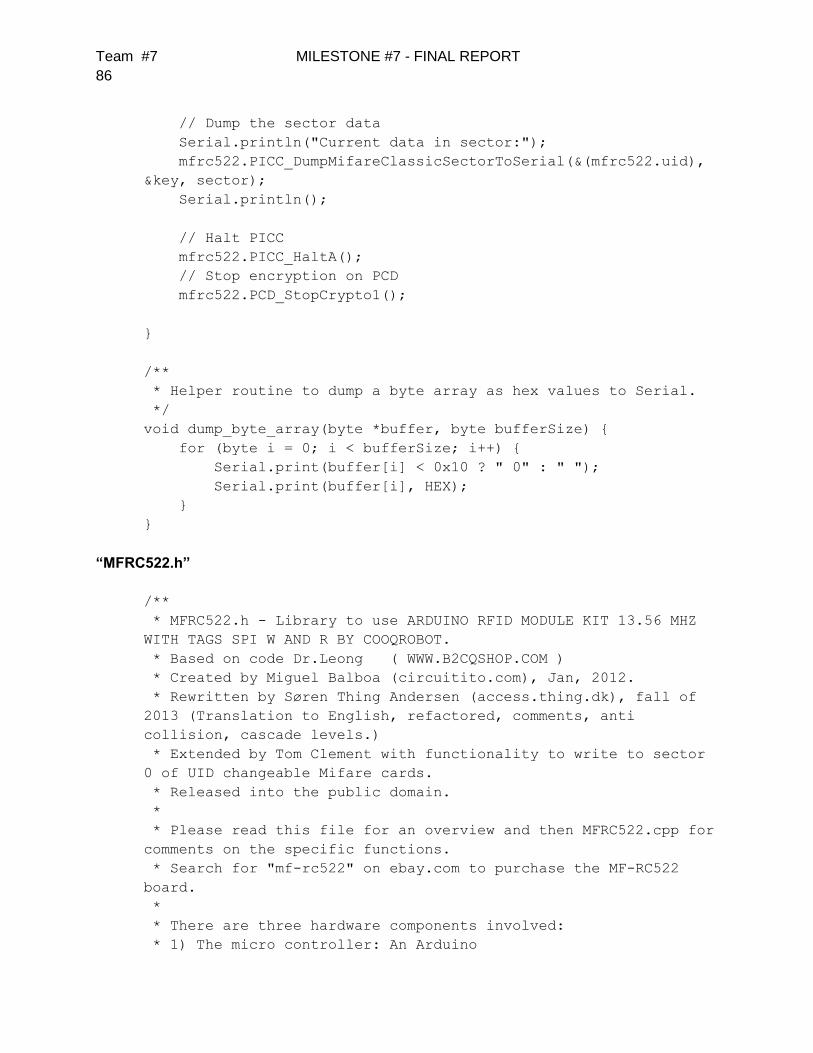
Team #7 MILESTONE #7 - FINAL REPORT
86
// Dump the sector data
Serial.println("Current data in sector:");
mfrc522.PICC_DumpMifareClassicSectorToSerial(&(mfrc522.uid),
&key, sector);
Serial.println();
// Halt PICC
mfrc522.PICC_HaltA();
// Stop encryption on PCD
mfrc522.PCD_StopCrypto1();
}
/**
* Helper routine to dump a byte array as hex values to Serial.
*/
void dump_byte_array(byte *buffer, byte bufferSize) {
for (byte i = 0; i < bufferSize; i++) {
Serial.print(buffer[i] < 0x10 ? " 0" : " ");
Serial.print(buffer[i], HEX);
}
}
“MFRC522.h”
/**
* MFRC522.h - Library to use ARDUINO RFID MODULE KIT 13.56 MHZ
WITH TAGS SPI W AND R BY COOQROBOT.
* Based on code Dr.Leong ( WWW.B2CQSHOP.COM )
* Created by Miguel Balboa (circuitito.com), Jan, 2012.
* Rewritten by Søren Thing Andersen (access.thing.dk), fall of
2013 (Translation to English, refactored, comments, anti
collision, cascade levels.)
* Extended by Tom Clement with functionality to write to sector
0 of UID changeable Mifare cards.
* Released into the public domain.
*
* Please read this file for an overview and then MFRC522.cpp for
comments on the specific functions.
* Search for "mf-rc522" on ebay.com to purchase the MF-RC522
board.
*
* There are three hardware components involved:
* 1) The micro controller: An Arduino

Team #7 MILESTONE #7 - FINAL REPORT
87
* 2) The PCD (short for Proximity Coupling Device): NXP MFRC522
Contactless Reader IC
* 3) The PICC (short for Proximity Integrated Circuit Card): A
card or tag using the ISO 14443A interface, eg Mifare or NTAG203.
*
* The microcontroller and card reader uses SPI for
communication.
* The protocol is described in the MFRC522 datasheet:
http://www.nxp.com/documents/data_sheet/MFRC522.pdf
*
* The card reader and the tags communicate using a 13.56MHz
electromagnetic field.
* The protocol is defined in ISO/IEC 14443-3 Identification
cards -- Contactless integrated circuit cards -- Proximity cards
-- Part 3: Initialization and anticollision".
* A free version of the final draft can be found at
http://wg8.de/wg8n1496_17n3613_Ballot_FCD14443-3.pdf
* Details are found in chapter 6, Type A – Initialization and
anticollision.
*
* If only the PICC UID is wanted, the above documents has all
the needed information.
* To read and write from MIFARE PICCs, the MIFARE protocol is
used after the PICC has been selected.
* The MIFARE Classic chips and protocol is described in the
datasheets:
* 1K:
http://www.nxp.com/documents/data_sheet/MF1S503x.pdf
* 4K:
http://www.nxp.com/documents/data_sheet/MF1S703x.pdf
* Mini:
http://www.idcardmarket.com/download/mifare_S20_datasheet.pdf
* The MIFARE Ultralight chip and protocol is described in the
datasheets:
* Ultralight:
http://www.nxp.com/documents/data_sheet/MF0ICU1.pdf
* Ultralight C:
http://www.nxp.com/documents/short_data_sheet/MF0ICU2_SDS.pdf
*
* MIFARE Classic 1K (MF1S503x):
* Has 16 sectors * 4 blocks/sector * 16 bytes/block =
1024 bytes.
* The blocks are numbered 0-63.
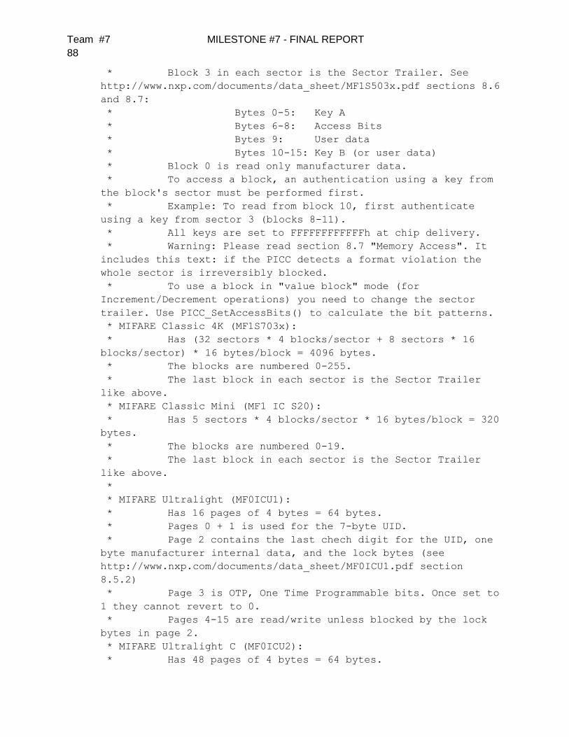
Team #7 MILESTONE #7 - FINAL REPORT
88
* Block 3 in each sector is the Sector Trailer. See
http://www.nxp.com/documents/data_sheet/MF1S503x.pdf sections 8.6
and 8.7:
* Bytes 0-5: Key A
* Bytes 6-8: Access Bits
* Bytes 9: User data
* Bytes 10-15: Key B (or user data)
* Block 0 is read only manufacturer data.
* To access a block, an authentication using a key from
the block's sector must be performed first.
* Example: To read from block 10, first authenticate
using a key from sector 3 (blocks 8-11).
* All keys are set to FFFFFFFFFFFFh at chip delivery.
* Warning: Please read section 8.7 "Memory Access". It
includes this text: if the PICC detects a format violation the
whole sector is irreversibly blocked.
* To use a block in "value block" mode (for
Increment/Decrement operations) you need to change the sector
trailer. Use PICC_SetAccessBits() to calculate the bit patterns.
* MIFARE Classic 4K (MF1S703x):
* Has (32 sectors * 4 blocks/sector + 8 sectors * 16
blocks/sector) * 16 bytes/block = 4096 bytes.
* The blocks are numbered 0-255.
* The last block in each sector is the Sector Trailer
like above.
* MIFARE Classic Mini (MF1 IC S20):
* Has 5 sectors * 4 blocks/sector * 16 bytes/block = 320
bytes.
* The blocks are numbered 0-19.
* The last block in each sector is the Sector Trailer
like above.
*
* MIFARE Ultralight (MF0ICU1):
* Has 16 pages of 4 bytes = 64 bytes.
* Pages 0 + 1 is used for the 7-byte UID.
* Page 2 contains the last chech digit for the UID, one
byte manufacturer internal data, and the lock bytes (see
http://www.nxp.com/documents/data_sheet/MF0ICU1.pdf section
8.5.2)
* Page 3 is OTP, One Time Programmable bits. Once set to
1 they cannot revert to 0.
* Pages 4-15 are read/write unless blocked by the lock
bytes in page 2.
* MIFARE Ultralight C (MF0ICU2):
* Has 48 pages of 4 bytes = 64 bytes.
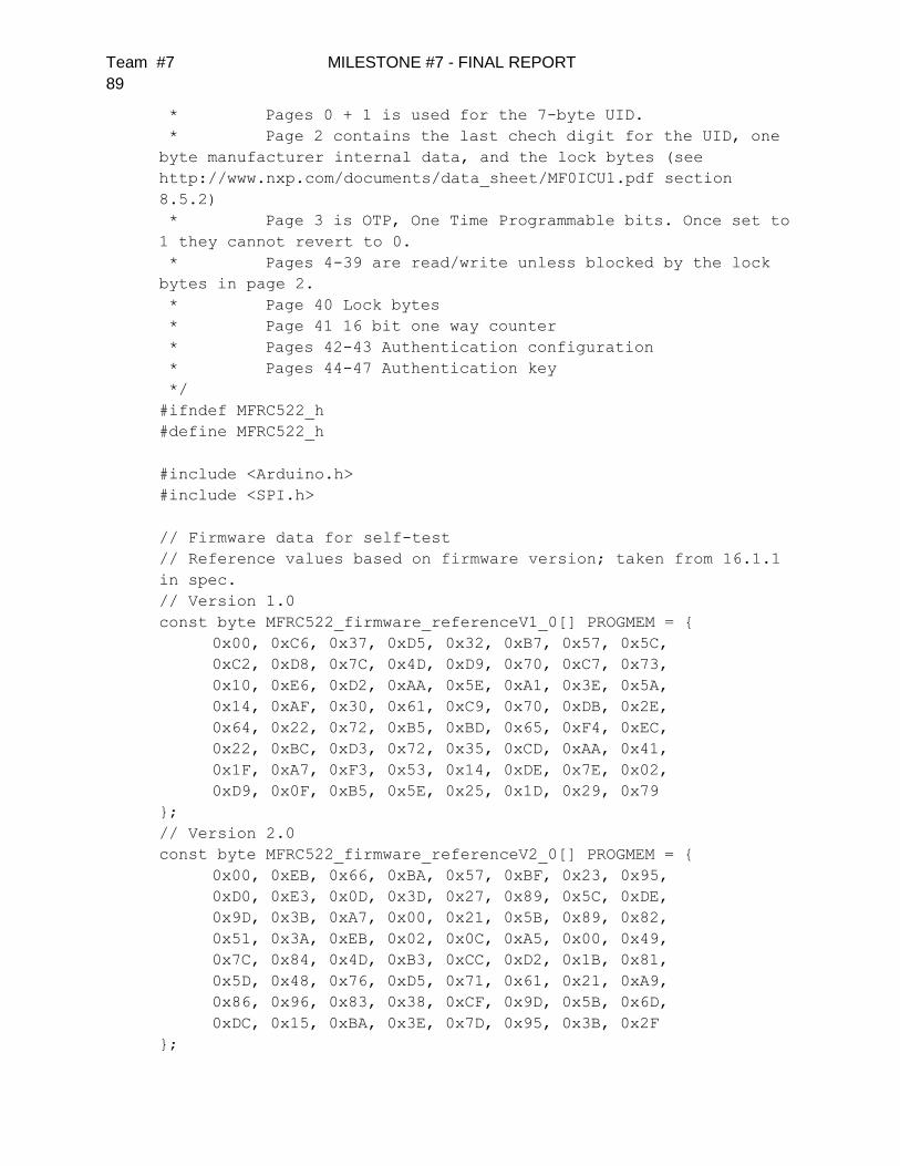
Team #7 MILESTONE #7 - FINAL REPORT
89
* Pages 0 + 1 is used for the 7-byte UID.
* Page 2 contains the last chech digit for the UID, one
byte manufacturer internal data, and the lock bytes (see
http://www.nxp.com/documents/data_sheet/MF0ICU1.pdf section
8.5.2)
* Page 3 is OTP, One Time Programmable bits. Once set to
1 they cannot revert to 0.
* Pages 4-39 are read/write unless blocked by the lock
bytes in page 2.
* Page 40 Lock bytes
* Page 41 16 bit one way counter
* Pages 42-43 Authentication configuration
* Pages 44-47 Authentication key
*/
#ifndef MFRC522_h
#define MFRC522_h
#include <Arduino.h>
#include <SPI.h>
// Firmware data for self-test
// Reference values based on firmware version; taken from 16.1.1
in spec.
// Version 1.0
const byte MFRC522_firmware_referenceV1_0[] PROGMEM = {
0x00, 0xC6, 0x37, 0xD5, 0x32, 0xB7, 0x57, 0x5C,
0xC2, 0xD8, 0x7C, 0x4D, 0xD9, 0x70, 0xC7, 0x73,
0x10, 0xE6, 0xD2, 0xAA, 0x5E, 0xA1, 0x3E, 0x5A,
0x14, 0xAF, 0x30, 0x61, 0xC9, 0x70, 0xDB, 0x2E,
0x64, 0x22, 0x72, 0xB5, 0xBD, 0x65, 0xF4, 0xEC,
0x22, 0xBC, 0xD3, 0x72, 0x35, 0xCD, 0xAA, 0x41,
0x1F, 0xA7, 0xF3, 0x53, 0x14, 0xDE, 0x7E, 0x02,
0xD9, 0x0F, 0xB5, 0x5E, 0x25, 0x1D, 0x29, 0x79
};
// Version 2.0
const byte MFRC522_firmware_referenceV2_0[] PROGMEM = {
0x00, 0xEB, 0x66, 0xBA, 0x57, 0xBF, 0x23, 0x95,
0xD0, 0xE3, 0x0D, 0x3D, 0x27, 0x89, 0x5C, 0xDE,
0x9D, 0x3B, 0xA7, 0x00, 0x21, 0x5B, 0x89, 0x82,
0x51, 0x3A, 0xEB, 0x02, 0x0C, 0xA5, 0x00, 0x49,
0x7C, 0x84, 0x4D, 0xB3, 0xCC, 0xD2, 0x1B, 0x81,
0x5D, 0x48, 0x76, 0xD5, 0x71, 0x61, 0x21, 0xA9,
0x86, 0x96, 0x83, 0x38, 0xCF, 0x9D, 0x5B, 0x6D,
0xDC, 0x15, 0xBA, 0x3E, 0x7D, 0x95, 0x3B, 0x2F
};

Team #7 MILESTONE #7 - FINAL REPORT
90
class MFRC522 {
public:
// MFRC522 registers. Described in chapter 9 of the
datasheet.
// When using SPI all addresses are shifted one bit left in
the "SPI address byte" (section 8.1.2.3)
enum PCD_Register {
// Page 0: Command and status
// 0x00
// reserved for future use
CommandReg = 0x01 << 1, // starts
and stops command execution
ComIEnReg = 0x02 << 1, // enable
and disable interrupt request control bits
DivIEnReg = 0x03 << 1, // enable
and disable interrupt request control bits
ComIrqReg = 0x04 << 1, //
interrupt request bits
DivIrqReg = 0x05 << 1, //
interrupt request bits
ErrorReg = 0x06 << 1, // error
bits showing the error status of the last command executed
Status1Reg = 0x07 << 1, //
communication status bits
Status2Reg = 0x08 << 1, //
receiver and transmitter status bits
FIFODataReg = 0x09 << 1, //
input and output of 64 byte FIFO buffer
FIFOLevelReg = 0x0A << 1, // number
of bytes stored in the FIFO buffer
WaterLevelReg = 0x0B << 1, // level
for FIFO underflow and overflow warning
ControlReg = 0x0C << 1, //
miscellaneous control registers
BitFramingReg = 0x0D << 1, //
adjustments for bit-oriented frames
CollReg = 0x0E << 1, //
bit position of the first bit-collision detected on the RF
interface
// 0x0F
// reserved for future use
// Page 1: Command
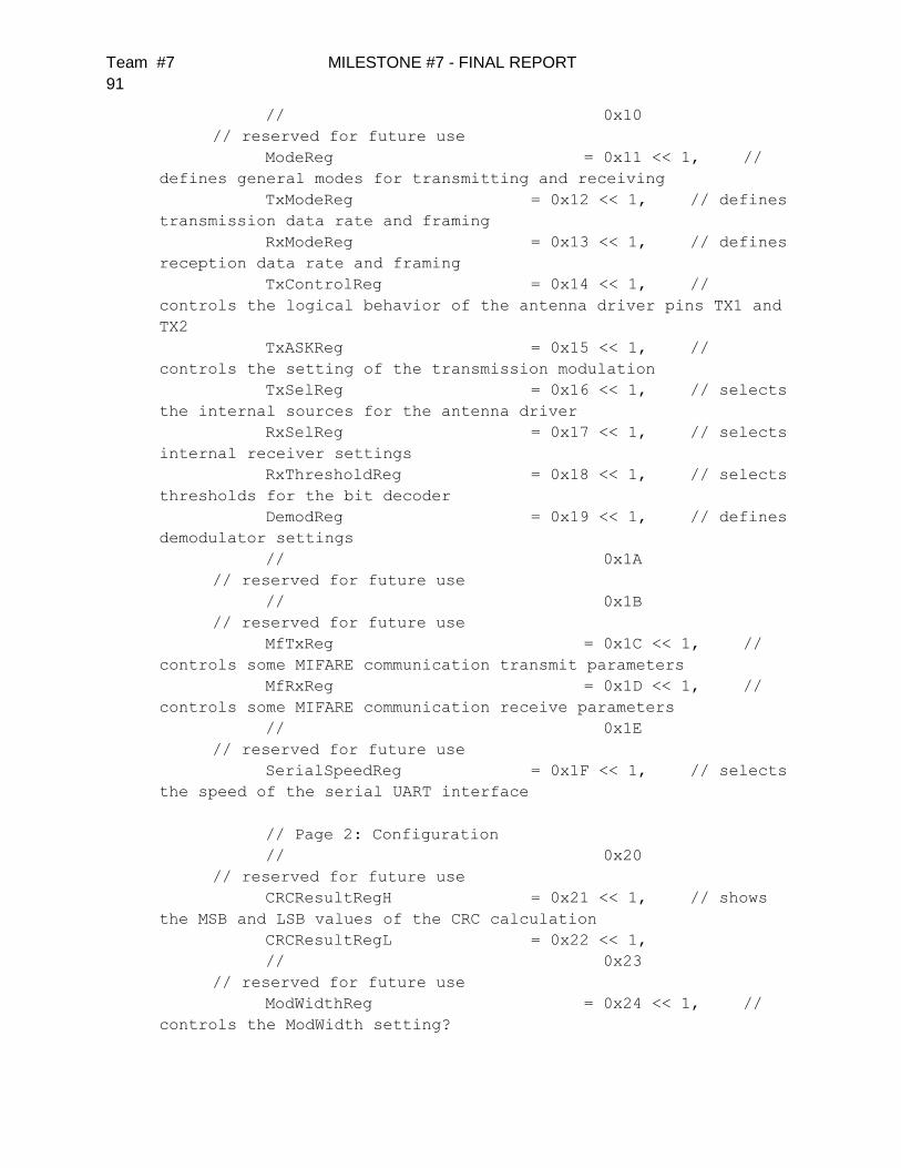
Team #7 MILESTONE #7 - FINAL REPORT
91
// 0x10
// reserved for future use
ModeReg = 0x11 << 1, //
defines general modes for transmitting and receiving
TxModeReg = 0x12 << 1, // defines
transmission data rate and framing
RxModeReg = 0x13 << 1, // defines
reception data rate and framing
TxControlReg = 0x14 << 1, //
controls the logical behavior of the antenna driver pins TX1 and
TX2
TxASKReg = 0x15 << 1, //
controls the setting of the transmission modulation
TxSelReg = 0x16 << 1, // selects
the internal sources for the antenna driver
RxSelReg = 0x17 << 1, // selects
internal receiver settings
RxThresholdReg = 0x18 << 1, // selects
thresholds for the bit decoder
DemodReg = 0x19 << 1, // defines
demodulator settings
// 0x1A
// reserved for future use
// 0x1B
// reserved for future use
MfTxReg = 0x1C << 1, //
controls some MIFARE communication transmit parameters
MfRxReg = 0x1D << 1, //
controls some MIFARE communication receive parameters
// 0x1E
// reserved for future use
SerialSpeedReg = 0x1F << 1, // selects
the speed of the serial UART interface
// Page 2: Configuration
// 0x20
// reserved for future use
CRCResultRegH = 0x21 << 1, // shows
the MSB and LSB values of the CRC calculation
CRCResultRegL = 0x22 << 1,
// 0x23
// reserved for future use
ModWidthReg = 0x24 << 1, //
controls the ModWidth setting?
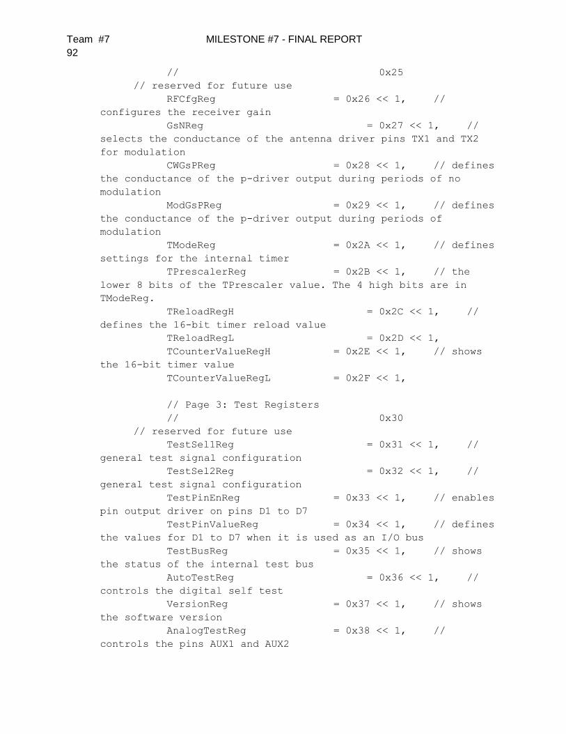
Team #7 MILESTONE #7 - FINAL REPORT
92
// 0x25
// reserved for future use
RFCfgReg = 0x26 << 1, //
configures the receiver gain
GsNReg = 0x27 << 1, //
selects the conductance of the antenna driver pins TX1 and TX2
for modulation
CWGsPReg = 0x28 << 1, // defines
the conductance of the p-driver output during periods of no
modulation
ModGsPReg = 0x29 << 1, // defines
the conductance of the p-driver output during periods of
modulation
TModeReg = 0x2A << 1, // defines
settings for the internal timer
TPrescalerReg = 0x2B << 1, // the
lower 8 bits of the TPrescaler value. The 4 high bits are in
TModeReg.
TReloadRegH = 0x2C << 1, //
defines the 16-bit timer reload value
TReloadRegL = 0x2D << 1,
TCounterValueRegH = 0x2E << 1, // shows
the 16-bit timer value
TCounterValueRegL = 0x2F << 1,
// Page 3: Test Registers
// 0x30
// reserved for future use
TestSel1Reg = 0x31 << 1, //
general test signal configuration
TestSel2Reg = 0x32 << 1, //
general test signal configuration
TestPinEnReg = 0x33 << 1, // enables
pin output driver on pins D1 to D7
TestPinValueReg = 0x34 << 1, // defines
the values for D1 to D7 when it is used as an I/O bus
TestBusReg = 0x35 << 1, // shows
the status of the internal test bus
AutoTestReg = 0x36 << 1, //
controls the digital self test
VersionReg = 0x37 << 1, // shows
the software version
AnalogTestReg = 0x38 << 1, //
controls the pins AUX1 and AUX2

Team #7 MILESTONE #7 - FINAL REPORT
93
TestDAC1Reg = 0x39 << 1, //
defines the test value for TestDAC1
TestDAC2Reg = 0x3A << 1, //
defines the test value for TestDAC2
TestADCReg = 0x3B << 1 //
shows the value of ADC I and Q channels
// 0x3C
// reserved for production tests
// 0x3D
// reserved for production tests
// 0x3E
// reserved for production tests
// 0x3F
// reserved for production tests
};
// MFRC522 commands. Described in chapter 10 of the
datasheet.
enum PCD_Command {
PCD_Idle = 0x00, // no
action, cancels current command execution
PCD_Mem = 0x01, //
stores 25 bytes into the internal buffer
PCD_GenerateRandomID = 0x02, // generates a
10-byte random ID number
PCD_CalcCRC = 0x03, //
activates the CRC coprocessor or performs a self test
PCD_Transmit = 0x04, //
transmits data from the FIFO buffer
PCD_NoCmdChange = 0x07, // no
command change, can be used to modify the CommandReg register
bits without affecting the command, for example, the PowerDown
bit
PCD_Receive = 0x08, //
activates the receiver circuits
PCD_Transceive = 0x0C, //
transmits data from FIFO buffer to antenna and automatically
activates the receiver after transmission
PCD_MFAuthent = 0x0E, //
performs the MIFARE standard authentication as a reader
PCD_SoftReset = 0x0F // resets
the MFRC522
};
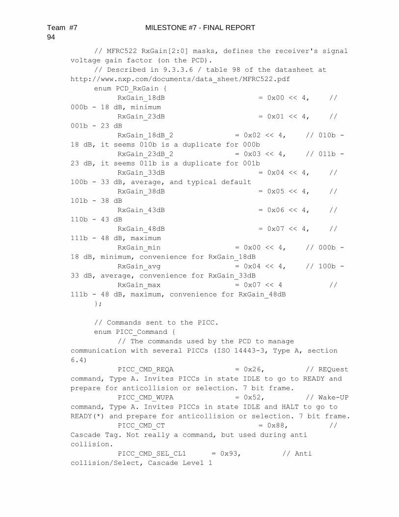
Team #7 MILESTONE #7 - FINAL REPORT
94
// MFRC522 RxGain[2:0] masks, defines the receiver's signal
voltage gain factor (on the PCD).
// Described in 9.3.3.6 / table 98 of the datasheet at
http://www.nxp.com/documents/data_sheet/MFRC522.pdf
enum PCD_RxGain {
RxGain_18dB = 0x00 << 4, //
000b - 18 dB, minimum
RxGain_23dB = 0x01 << 4, //
001b - 23 dB
RxGain_18dB_2 = 0x02 << 4, // 010b -
18 dB, it seems 010b is a duplicate for 000b
RxGain_23dB_2 = 0x03 << 4, // 011b -
23 dB, it seems 011b is a duplicate for 001b
RxGain_33dB = 0x04 << 4, //
100b - 33 dB, average, and typical default
RxGain_38dB = 0x05 << 4, //
101b - 38 dB
RxGain_43dB = 0x06 << 4, //
110b - 43 dB
RxGain_48dB = 0x07 << 4, //
111b - 48 dB, maximum
RxGain_min = 0x00 << 4, // 000b -
18 dB, minimum, convenience for RxGain_18dB
RxGain_avg = 0x04 << 4, // 100b -
33 dB, average, convenience for RxGain_33dB
RxGain_max = 0x07 << 4 //
111b - 48 dB, maximum, convenience for RxGain_48dB
};
// Commands sent to the PICC.
enum PICC_Command {
// The commands used by the PCD to manage
communication with several PICCs (ISO 14443-3, Type A, section
6.4)
PICC_CMD_REQA = 0x26, // REQuest
command, Type A. Invites PICCs in state IDLE to go to READY and
prepare for anticollision or selection. 7 bit frame.
PICC_CMD_WUPA = 0x52, // Wake-UP
command, Type A. Invites PICCs in state IDLE and HALT to go to
READY(*) and prepare for anticollision or selection. 7 bit frame.
PICC_CMD_CT = 0x88, //
Cascade Tag. Not really a command, but used during anti
collision.
PICC_CMD_SEL_CL1 = 0x93, // Anti
collision/Select, Cascade Level 1
Team #7 MILESTONE #7 - FINAL REPORT
95
PICC_CMD_SEL_CL2 = 0x95, // Anti
collision/Select, Cascade Level 1
PICC_CMD_SEL_CL3 = 0x97, // Anti
collision/Select, Cascade Level 1
PICC_CMD_HLTA = 0x50, // HaLT
command, Type A. Instructs an ACTIVE PICC to go to state HALT.
// The commands used for MIFARE Classic (from
http://www.nxp.com/documents/data_sheet/MF1S503x.pdf, Section 9)
// Use PCD_MFAuthent to authenticate access to a
sector, then use these commands to read/write/modify the blocks
on the sector.
// The read/write commands can also be used for MIFARE
Ultralight.
PICC_CMD_MF_AUTH_KEY_A = 0x60, // Perform
authentication with Key A
PICC_CMD_MF_AUTH_KEY_B = 0x61, // Perform
authentication with Key B
PICC_CMD_MF_READ = 0x30, // Reads one 16
byte block from the authenticated sector of the PICC. Also used
for MIFARE Ultralight.
PICC_CMD_MF_WRITE = 0xA0, // Writes
one 16 byte block to the authenticated sector of the PICC. Called
"COMPATIBILITY WRITE" for MIFARE Ultralight.
PICC_CMD_MF_DECREMENT = 0xC0, // Decrements
the contents of a block and stores the result in the internal
data register.
PICC_CMD_MF_INCREMENT = 0xC1, // Increments
the contents of a block and stores the result in the internal
data register.
PICC_CMD_MF_RESTORE = 0xC2, // Reads
the contents of a block into the internal data register.
PICC_CMD_MF_TRANSFER = 0xB0, // Writes the
contents of the internal data register to a block.
// The commands used for MIFARE Ultralight (from
http://www.nxp.com/documents/data_sheet/MF0ICU1.pdf, Section 8.6)
// The PICC_CMD_MF_READ and PICC_CMD_MF_WRITE can also
be used for MIFARE Ultralight.
PICC_CMD_UL_WRITE = 0xA2 // Writes
one 4 byte page to the PICC.
};
// MIFARE constants that does not fit anywhere else
enum MIFARE_Misc {
Team #7 MILESTONE #7 - FINAL REPORT
96
MF_ACK = 0xA, //
The MIFARE Classic uses a 4 bit ACK/NAK. Any other value than 0xA
is NAK.
MF_KEY_SIZE = 6 // A
Mifare Crypto1 key is 6 bytes.
};
// PICC types we can detect. Remember to update
PICC_GetTypeName() if you add more.
enum PICC_Type {
PICC_TYPE_UNKNOWN = 0,
PICC_TYPE_ISO_14443_4 = 1, // PICC compliant with
ISO/IEC 14443-4
PICC_TYPE_ISO_18092 = 2, // PICC compliant
with ISO/IEC 18092 (NFC)
PICC_TYPE_MIFARE_MINI = 3, // MIFARE Classic protocol,
320 bytes
PICC_TYPE_MIFARE_1K = 4, // MIFARE Classic
protocol, 1KB
PICC_TYPE_MIFARE_4K = 5, // MIFARE Classic
protocol, 4KB
PICC_TYPE_MIFARE_UL = 6, // MIFARE Ultralight
or Ultralight C
PICC_TYPE_MIFARE_PLUS = 7, // MIFARE Plus
PICC_TYPE_TNP3XXX = 8, // Only mentioned in
NXP AN 10833 MIFARE Type Identification Procedure
PICC_TYPE_NOT_COMPLETE = 255 // SAK indicates UID
is not complete.
};
// Return codes from the functions in this class. Remember
to update GetStatusCodeName() if you add more.
enum StatusCode {
STATUS_OK = 1, // Success
STATUS_ERROR = 2, // Error in
communication
STATUS_COLLISION = 3, // Collission detected
STATUS_TIMEOUT = 4, // Timeout in
communication.
STATUS_NO_ROOM = 5, // A buffer is not
big enough.
STATUS_INTERNAL_ERROR = 6, // Internal error in the
code. Should not happen ;-)
STATUS_INVALID = 7, // Invalid argument.
STATUS_CRC_WRONG = 8, // The CRC_A does not match
Team #7 MILESTONE #7 - FINAL REPORT
97
STATUS_MIFARE_NACK = 9 // A MIFARE PICC
responded with NAK.
};
// A struct used for passing the UID of a PICC.
typedef struct {
byte size; // Number of bytes in the
UID. 4, 7 or 10.
byte uidByte[10];
byte sak; // The SAK (Select
acknowledge) byte returned from the PICC after successful
selection.
} Uid;
// A struct used for passing a MIFARE Crypto1 key
typedef struct {
byte keyByte[MF_KEY_SIZE];
} MIFARE_Key;
// Member variables
Uid uid; // Used by
PICC_ReadCardSerial().
// Size of the MFRC522 FIFO
static const byte FIFO_SIZE = 64; // The FIFO is
64 bytes.
///////////////////////////////////////////////////////////
//////////////////////////
// Functions for setting up the Arduino
///////////////////////////////////////////////////////////
//////////////////////////
MFRC522(byte chipSelectPin, byte resetPowerDownPin);
void setSPIConfig();
///////////////////////////////////////////////////////////
//////////////////////////
// Basic interface functions for communicating with the
MFRC522
///////////////////////////////////////////////////////////
//////////////////////////
void PCD_WriteRegister(byte reg, byte value);
void PCD_WriteRegister(byte reg, byte count, byte *values);
byte PCD_ReadRegister(byte reg);
Team #7 MILESTONE #7 - FINAL REPORT
98
void PCD_ReadRegister(byte reg, byte count, byte *values,
byte rxAlign = 0);
void setBitMask(unsigned char reg, unsigned char mask);
void PCD_SetRegisterBitMask(byte reg, byte mask);
void PCD_ClearRegisterBitMask(byte reg, byte mask);
byte PCD_CalculateCRC(byte *data, byte length, byte
*result);
///////////////////////////////////////////////////////////
//////////////////////////
// Functions for manipulating the MFRC522
///////////////////////////////////////////////////////////
//////////////////////////
void PCD_Init();
void PCD_Reset();
void PCD_AntennaOn();
void PCD_AntennaOff();
byte PCD_GetAntennaGain();
void PCD_SetAntennaGain(byte mask);
bool PCD_PerformSelfTest();
///////////////////////////////////////////////////////////
//////////////////////////
// Functions for communicating with PICCs
///////////////////////////////////////////////////////////
//////////////////////////
byte PCD_TransceiveData(byte *sendData, byte sendLen, byte
*backData, byte *backLen, byte *validBits = NULL, byte rxAlign =
0, bool checkCRC = false);
byte PCD_CommunicateWithPICC(byte command, byte waitIRq,
byte *sendData, byte sendLen, byte *backData = NULL, byte
*backLen = NULL, byte *validBits = NULL, byte rxAlign = 0, bool
checkCRC = false);
byte PICC_RequestA(byte *bufferATQA, byte *bufferSize);
byte PICC_WakeupA(byte *bufferATQA, byte *bufferSize);
byte PICC_REQA_or_WUPA(byte command, byte *bufferATQA, byte
*bufferSize);
byte PICC_Select(Uid *uid, byte validBits = 0);
byte PICC_HaltA();
///////////////////////////////////////////////////////////
//////////////////////////
// Functions for communicating with MIFARE PICCs

Team #7 MILESTONE #7 - FINAL REPORT
99
///////////////////////////////////////////////////////////
//////////////////////////
byte PCD_Authenticate(byte command, byte blockAddr,
MIFARE_Key *key, Uid *uid);
void PCD_StopCrypto1();
byte MIFARE_Read(byte blockAddr, byte *buffer, byte
*bufferSize);
byte MIFARE_Write(byte blockAddr, byte *buffer, byte
bufferSize);
byte MIFARE_Decrement(byte blockAddr, long delta);
byte MIFARE_Increment(byte blockAddr, long delta);
byte MIFARE_Restore(byte blockAddr);
byte MIFARE_Transfer(byte blockAddr);
byte MIFARE_Ultralight_Write(byte page, byte *buffer, byte
bufferSize);
byte MIFARE_GetValue(byte blockAddr, long *value);
byte MIFARE_SetValue(byte blockAddr, long value);
///////////////////////////////////////////////////////////
//////////////////////////
// Support functions
///////////////////////////////////////////////////////////
//////////////////////////
byte PCD_MIFARE_Transceive(byte *sendData, byte sendLen,
bool acceptTimeout = false);
// old function used too much memory, now name moved to
flash; if you need char, copy from flash to memory
//const char *GetStatusCodeName(byte code);
const __FlashStringHelper *GetStatusCodeName(byte code);
byte PICC_GetType(byte sak);
// old function used too much memory, now name moved to
flash; if you need char, copy from flash to memory
//const char *PICC_GetTypeName(byte type);
const __FlashStringHelper *PICC_GetTypeName(byte type);
void PICC_DumpToSerial(Uid *uid);
void PICC_DumpMifareClassicToSerial(Uid *uid, byte
piccType, MIFARE_Key *key);
void PICC_DumpMifareClassicSectorToSerial(Uid *uid,
MIFARE_Key *key, byte sector);
void PICC_DumpMifareUltralightToSerial();
void MIFARE_SetAccessBits(byte *accessBitBuffer, byte g0,
byte g1, byte g2, byte g3);
bool MIFARE_OpenUidBackdoor(bool logErrors);
bool MIFARE_SetUid(byte* newUid, byte uidSize, bool
logErrors);

Team #7 MILESTONE #7 - FINAL REPORT
100
bool MIFARE_UnbrickUidSector(bool logErrors);
///////////////////////////////////////////////////////////
//////////////////////////
// Convenience functions - does not add extra functionality
///////////////////////////////////////////////////////////
//////////////////////////
bool PICC_IsNewCardPresent();
bool PICC_ReadCardSerial();
private:
byte _chipSelectPin; // Arduino pin connected to
MFRC522's SPI slave select input (Pin 24, NSS, active low)
byte _resetPowerDownPin; // Arduino pin connected to
MFRC522's reset and power down input (Pin 6, NRSTPD, active low)
byte MIFARE_TwoStepHelper(byte command, byte blockAddr,
long data);
};
#endif
Appendix C – Data Sheets All relevant data sheets will be provided in a separate document.

Team #7 MILESTONE #7 - FINAL REPORT
101
Appendix D – Dimensional Drawings
Prototype Dimensional Drawings
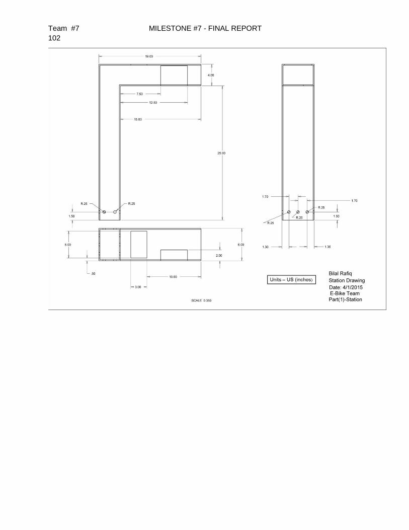
Team #7 MILESTONE #7 - FINAL REPORT
102

Team #7 MILESTONE #7 - FINAL REPORT
103
Bike Housing Case Drawing

Team #7 MILESTONE #7 - FINAL REPORT
104
Future Commercial Model Shell Drawings

Team #7 MILESTONE #7 - FINAL REPORT
105
Future Commercial Model Frame Drawings

Team #7 MILESTONE #7 - FINAL REPORT
106
Appendix E – Additional Pictures
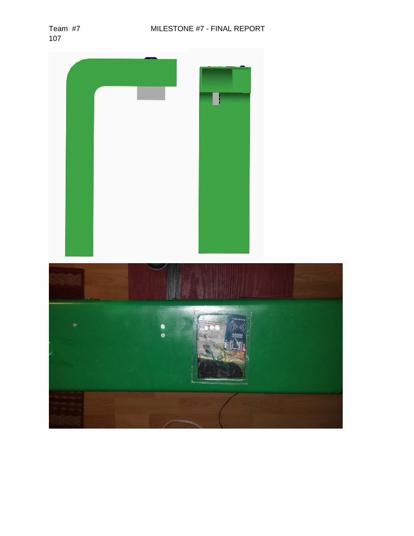
Team #7 MILESTONE #7 - FINAL REPORT
107


![Frank Sargeson [Norris Frank Davey], 1903 – 1982](https://static.fdokumen.com/doc/165x107/6322013728c44598910594c2/frank-sargeson-norris-frank-davey-1903-1982.jpg)