
THE ECONOMICS OF GRID-CONNECTED ELECTRICITY PRODUCTION FROM SOLAR PHOTOVOLTAIC SYSTEMS

1Vol 02, Issue 03; July 2011 International Journal of Engineering Sciences
and Research-IJESRhttp://technicaljournals.org
ISSN: 2230-8504; e-ISSN-2230-8512
ACTIVE AND REACTIVE POWER CONTROL OF GRIDCONNECTED PHOTOVOLTAIC SYSTEM
DR. TILAK THAKUR Sr. IEEE Member, KULDEEP SINGH BEDIDepartment Of Electrical Engineering PEC University of Technology, Chandigarh
[email protected], [email protected]
AbstractThe paper presents a control scheme which controls the active and reactive power flowfrom the photovoltaic system to grid connected load for single stage. Control schemeis implemented in such a manner that it provides maximum active power from the PV
module and reactive power as per the requirement of the load only. Photovoltaic modulesimulation is done using the basic equation. Photovoltaic module is taken as a currentsource supplying maximum power at constant voltage technique. To study the effect of
solar irradiation variation on the output power flow from photovoltaic system to grid.Reactive power is independent of the solar irradiation. Passive filter is used to
reduce the harmonic produced by two level inverter.Key words- Photovoltaic system, control, simulation, harmonic, active and reactive power.
I. IntroductionLimited fossil fuels reserves and increasing environmental pollution havepressed strongly during last decades in this world for development ofrenewable energy sources (RES). Availability of RES allows us to replace theconventional energy sources by the RES. At present, photovoltaic (PV)generation is assuming increased importance as a RES application because ofdistinctive advantages such as simplicity of allocation, high dependability,absence of fuel cost, low maintenance and lack of noise and wear due to theabsence of moving parts. Furthermore, the solar energy is a clean, pollutionfree and inexhaustible energy source. In addition to these factors are thecost and prices of solar modules are decreasing, an increasing efficiency ofsolar cells, manufacturing-technology improvements and economies of scale [1].Photovoltaic system is simulated using basic equations [2]. There are twotypes of techniques used in photovoltaic system (Single stage and two stagetechnique). In single stage technique only inverter is used to convert DC toAC. Two stages technique consist of one DC to DC converter and DC to ACconverter. In this paper we use single stage system which means only oneconverter is connected with the grid [3]-[4]. Control scheme uses Parkstransformation to control the active and reactive power of a grid connectedphotovoltaic modules. Parks transformation converts three phase system to twophase system without changing the power. Solar irradiation effect on outputvoltage of PV module is small therefore we can use constant voltage in [5]-[6]. Control strategy applied in this also controls the reactive power in theabsence solar irradiation [7].
2011 - TECHNICALJOURNALS®, Peer Reviewed International Journals-IJCEA, IJESR, RJCSE, PAPER, ERL -PBPC, India;
Indexing in Process - Scopus, EMBASE, COMPENDEX, EmCARE, Electronics & Communication Abstracts, SCIRUS, SPARC, GOOGLE Database, EBSCO,NewJour, Worldcat, DOAJ, and other major databases etc.,
2Vol 02, Issue 03; July 2011 International Journal of Engineering Sciences
and Research-IJESRhttp://technicaljournals.org
ISSN: 2230-8504; e-ISSN-2230-8512
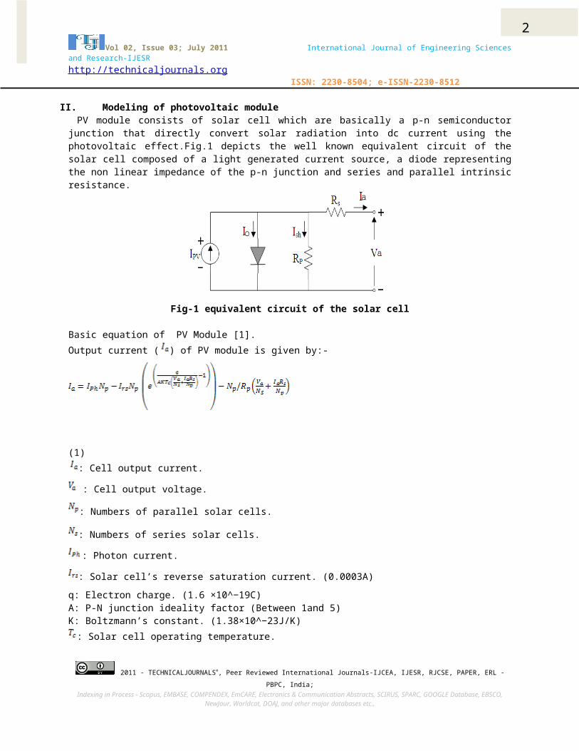
II. Modeling of photovoltaic module PV module consists of solar cell which are basically a p-n semiconductorjunction that directly convert solar radiation into dc current using thephotovoltaic effect.Fig.1 depicts the well known equivalent circuit of thesolar cell composed of a light generated current source, a diode representingthe non linear impedance of the p-n junction and series and parallel intrinsicresistance.
Fig-1 equivalent circuit of the solar cell
Basic equation of PV Module [1].Output current ( ) of PV module is given by:-
(1): Cell output current.
: Cell output voltage.
: Numbers of parallel solar cells.
: Numbers of series solar cells.
: Photon current.
: Solar cell’s reverse saturation current. (0.0003A)q: Electron charge. (1.6 ×10^−19C)A: P-N junction ideality factor (Between 1and 5)K: Boltzmann’s constant. (1.38×10^−23J/K): Solar cell operating temperature.
2011 - TECHNICALJOURNALS®, Peer Reviewed International Journals-IJCEA, IJESR, RJCSE, PAPER, ERL -PBPC, India;
Indexing in Process - Scopus, EMBASE, COMPENDEX, EmCARE, Electronics & Communication Abstracts, SCIRUS, SPARC, GOOGLE Database, EBSCO,NewJour, Worldcat, DOAJ, and other major databases etc.,

3Vol 02, Issue 03; July 2011 International Journal of Engineering Sciences
and Research-IJESRhttp://technicaljournals.org
ISSN: 2230-8504; e-ISSN-2230-8512
: Cell intrinsic series resistance. (0.001Ὼ)
: Cell intrinsic parallel resistance.
Where
(2) : Short circuit current at STC
: Cell temperature coefficient of the short-circuit current.
: Solar cell absolute temperature at standard testing condition (STC). (20°C): Total solar reference radiation at STC, 1000W/m^2
: Operating solar radiation.From the equation (1) & (2) simulation of PV module is done, which done in following manner Taking, =∞, =1, =1.
Equation become
(3) And the Output voltage of the solar cell
(4) Effect of solar irradiation and temperature on and is given by the
following equation.
(5)
(6)
(7)
2011 - TECHNICALJOURNALS®, Peer Reviewed International Journals-IJCEA, IJESR, RJCSE, PAPER, ERL -PBPC, India;
Indexing in Process - Scopus, EMBASE, COMPENDEX, EmCARE, Electronics & Communication Abstracts, SCIRUS, SPARC, GOOGLE Database, EBSCO,NewJour, Worldcat, DOAJ, and other major databases etc.,

4Vol 02, Issue 03; July 2011 International Journal of Engineering Sciences
and Research-IJESRhttp://technicaljournals.org
ISSN: 2230-8504; e-ISSN-2230-8512
(8)Therefore net change is as following
(9)
(10)
(11)
(12)New values of the and
(13)
(14) : Slope of the change in the cell operating temperature
Fitting factor A is used to adjust the I-V characteristics of the cellobtained from the equation to the actual characteristics obtained by testing.Using above equations we get the solar cell block which give two signals oneis solar output current and another is output voltage, with these two signalswe can make the solar cell to work as a current source or as a voltage source.To make the solar cell as a current source, output current signal is given acurrent controlled current source and for voltage source output voltage sourceis given to the voltage controlled voltage source. To study the effect ofsolar irradiation on the solar cell we operate this model at different solarirradiation. When the solar irradiation changes the output current varies moreas compare to voltage whose variation is small. For maximum power point we generate the data in which photovoltaic modulegenerate power at different solar irradiation. From this data we extractmaximum power point at a constant voltage and according to this we inject areference current in the photovoltaic module model and change the referencecurrent for different solar irradiation. With small variation in solarirradiation the current changes according to this reference current maximumpower point changes. Data is obtained by simulating the photovoltaic modulemodel at different solar irradiation. To implement this method we use lookup
2011 - TECHNICALJOURNALS®, Peer Reviewed International Journals-IJCEA, IJESR, RJCSE, PAPER, ERL -PBPC, India;
Indexing in Process - Scopus, EMBASE, COMPENDEX, EmCARE, Electronics & Communication Abstracts, SCIRUS, SPARC, GOOGLE Database, EBSCO,NewJour, Worldcat, DOAJ, and other major databases etc.,

5Vol 02, Issue 03; July 2011 International Journal of Engineering Sciences
and Research-IJESRhttp://technicaljournals.org
ISSN: 2230-8504; e-ISSN-2230-8512
table in which put the obtain data which change the reference currentaccording to the solar irradiation level at constant 900Volts. Fig-2shows theV-I curve of the PV modules a different solar irradiation level which showsthe effect of solar irradiation on output current. Fig-3shows P-V curve whichshows maximum power points of PV modules at constant 900volts at differentsolar irradiation.
0 200 400 600 800 1000 12000
10
20
30
40
50
60
70
Voltage (V)
Curre
nt (A
)
V-I curve of PV m odule
100%92%80%60%40%20%
power point at 900volts
solar irradiation
Fig-2 V-I curve of PV modules at different solar irradiations.
0 200 400 600 800 1000 12000
1
2
3
4
5
6x 10⁴
Voltage (V)
Powe
r (W)
100%92%80%60%40%20%
Solar irradiation
Power at 900 volts
Fig-3 V-P curve of PV module at different solar irradiations.
III. MPPT control approachAs the power supplied by the solar array depends on the insulations,temperature and array voltage, an important consideration in the design ofefficient solar array systems is to track maximum power point correctly. Thepurpose of the MPPT is to move the array operating voltage close to the MPPunder changing atmospheric conditions.
Control algorithmMany algorithms for tracking maximum power point had been proposed.Algorithms often used to achieve the MPPT are: 1. The perturbation and observation (P&O) method.
2011 - TECHNICALJOURNALS®, Peer Reviewed International Journals-IJCEA, IJESR, RJCSE, PAPER, ERL -PBPC, India;
Indexing in Process - Scopus, EMBASE, COMPENDEX, EmCARE, Electronics & Communication Abstracts, SCIRUS, SPARC, GOOGLE Database, EBSCO,NewJour, Worldcat, DOAJ, and other major databases etc.,

6Vol 02, Issue 03; July 2011 International Journal of Engineering Sciences
and Research-IJESRhttp://technicaljournals.org
ISSN: 2230-8504; e-ISSN-2230-8512
2. The incremental conductance (IC) method. 3. Fractional open-circuit voltage technique.4. Fractional short-circuit current technique.5. Constant voltage technique (Data based).
1. Perturbation and observation method.The perturbation and observation method has been widely used because of itssimple feedback structure and fewer measured parameters. The peak powertracker operates by periodically incrementing or decrementing the solar arrayvoltage. If a given perturbation leads to an increase (decrease) in arraypower, the subsequent perturbation is made in the same (opposite) direction.In this manner, the peak power tracker continuously hunts or seeks the peakpower conditions.
2. Incremental conductance method.The solar array terminal voltage can be adjusted relative to the MPP voltageby measuring the incremental and instantaneous array conductance (dZ/dY andZ/V, respectively). Although the incremental conductance method offers goodperformance under rapidly changing atmospheric conditions, four sensors arerequired to perform the computations. The drawback is that sensor devicesrequire more conversion time thus result in a large amount of power loss.
3. Fractional open-circuit voltage techniqueThe near linear relationship between VMPP and VOC of the PV array, under varyingirradiance and temperature levels, has given rise to the fractional open-circuit voltage method. VMPP = k VOC Where, k is a constant of proportionality. Since, k is dependent on thecharacteristics of the PV array being used; it usually has to be computedbeforehand by empirically determining VMPP and VOC for the specific PV array atdifferent irradiance and temperature levels. The factor k has been reported tobe between 0.71 and 0.78. Once k is known, VMPP can be computed using equationwith VOC measured periodically by momentarily shutting down the powerconverter. However, this incurs some disadvantages, including temporary lossof power. To prevent this, uses pilot cells from which VOC can be obtained.These pilot cells must be carefully chosen to closely represent thecharacteristics of the PV array. It is claimed that the voltage generated bypn-junction diodes is approximately 75% of VOC. This eliminates the need formeasuring VOC and computing VMPP.
4. Fractional short-circuit current technique
2011 - TECHNICALJOURNALS®, Peer Reviewed International Journals-IJCEA, IJESR, RJCSE, PAPER, ERL -PBPC, India;
Indexing in Process - Scopus, EMBASE, COMPENDEX, EmCARE, Electronics & Communication Abstracts, SCIRUS, SPARC, GOOGLE Database, EBSCO,NewJour, Worldcat, DOAJ, and other major databases etc.,

7Vol 02, Issue 03; July 2011 International Journal of Engineering Sciences
and Research-IJESRhttp://technicaljournals.org
ISSN: 2230-8504; e-ISSN-2230-8512
Fractional ISC results from the fact that, under varying atmosphericconditions, IMPP is approximately linearly related to the ISC of the PV array IMPP = k1 ISC
Where, k1 is proportionality constant. Just like in the fractional VOC
technique, k1 has to be determined according to the PV array in use. Theconstant k1 is generally found to be between 0.78 and 0.92. Measuring ISC
during operation is problematic. An additional switch usually has to be addedto the power converter to periodically short the PV array so that ISC can bemeasured using a current sensor. This increases the number of components andcost. A boost converter may be used, where the switch in the converter itselfcan be used to short the PV array.
5. Constant voltage technique (Data based) proposed work.In this technique we generate the data from the photovoltaic module bysimulating the module at different solar irradiation levels. With change inthe solar irradiation level the generated power of PV module changes. Outputpower of PV module depends upon output voltage. At constant solar irradiationlevel different power can extracts from the module by changing the outputvoltage of the module. By changing the output voltage we obtain the maximumpower point at different solar irradiation levels and converting these resultsinto data. From this data we generate optimum maximum power point for everysolar irradiation at a constant voltage. Merits: - cost effective, low maintenance, single stage, high efficiency athigh irradiation levels, dc to dc converter is not required.Demerits: - low efficiency at lower irradiation levels, data has to changeafter year minimum.
IV. Operational principleThe proposed work uses a PWM inverter to promote the interface of aphotovoltaic system with the ac system. The idea is to make this system tooperate as a controllable voltage source connected in parallel with the powergrid. By controlling the inverter output voltage phase angle (ɸ) and amplitudein relation to the grid voltage, it is possible to have the photovoltaicsystem supplying active (P) and reactive power (Q), independently of the solarirradiation level. In fact, the active power depends predominantly on thephase angle or load angle between the inverter voltage (Vi) and systemvoltages (Vs), and the reactive power is a function of the magnitudes of thesevoltages. Phase angle (ɸ) varies in such manner that it provides maximum powergenerated by the PV modules. Whenever inductive or capacitive load isconnected with grid connected photovoltaic system. The system will generatethe required reactive power by increasing or decreasing the voltage level ofthe inverter output voltage. When the output voltage of inverter is higher
2011 - TECHNICALJOURNALS®, Peer Reviewed International Journals-IJCEA, IJESR, RJCSE, PAPER, ERL -PBPC, India;
Indexing in Process - Scopus, EMBASE, COMPENDEX, EmCARE, Electronics & Communication Abstracts, SCIRUS, SPARC, GOOGLE Database, EBSCO,NewJour, Worldcat, DOAJ, and other major databases etc.,

8Vol 02, Issue 03; July 2011 International Journal of Engineering Sciences
and Research-IJESRhttp://technicaljournals.org
ISSN: 2230-8504; e-ISSN-2230-8512
than the grid voltage the reactive power is supplied by the PV system to grid.Reactive power is absorbed when inverse of action take place. Active power istransfer from leading to legging [4-5].
(15)
(16)
V. System configuration Fig-4 shows a single stage grid connected photovoltaic systems which consistof photovoltaic module with constant PV module voltage maximum power pointtechnique, DC link capacitor, inverter, filter, transformer, grid source andcontroller.
Fig-4 Power circuit
Control scheme: - Aim of the control scheme is to transfer maximum powergenerated by the photovoltaic modules. In order to transfer maximum power withsingle stage grid connected photovoltaic system we use constant voltagetechnique in which we analyze the constant voltage point at which maximumpower can be transferred at different solar irradiation (or near the maximumpoint)[5]. In this technique we keep the DC link voltage constant without anydc-dc converter which reduces the losses and cost due dc-dc converter and makethe control scheme simple to implement. To keep the DC link voltage constant aDC voltage controller is used to keep it constant and generate the referencesignal for the active power transfer to grid that is Idref. Idref is variedaccording to current injected by the photovoltaic DC current source whichfurther depends upon the solar irradiation. Idref is compared with Id whichcomes from the inverter output and generates an error ∆Id. To control
2011 - TECHNICALJOURNALS®, Peer Reviewed International Journals-IJCEA, IJESR, RJCSE, PAPER, ERL -PBPC, India;
Indexing in Process - Scopus, EMBASE, COMPENDEX, EmCARE, Electronics & Communication Abstracts, SCIRUS, SPARC, GOOGLE Database, EBSCO,NewJour, Worldcat, DOAJ, and other major databases etc.,

9Vol 02, Issue 03; July 2011 International Journal of Engineering Sciences
and Research-IJESRhttp://technicaljournals.org
ISSN: 2230-8504; e-ISSN-2230-8512
reactive power Iqref signal is generated from the load side in order get unitypower factor across load. Iqref signal is compare with the actual signal frominverter side Iq to generate an error ∆Iq. These signal are converted intoVd,Vq using Current controller. Vd,Vq signal which are further converter inphi(ɸ) and modulation index(m). The atan2 is four-quadrant inverse tangent. Asshown in figure.Modulation index (m) =√ ( )
(17)ɸ =atan2 ( ).
(18) Modulation index and phi generates the pulses for inverter circuit using PWMgenerator [3]. Where modulation index changes the magnitude of inverter outputvoltage to supply reactive power and phi changes the phase angle between theinverter voltage and grid voltage to supply the active power.
Fig-5 Control scheme
VI. Simulation resultsMatlab software package was used in all simulation accomplished here whichshows results obtained for voltage and current wave form, active and reactivepower on the ac side supplied to the grid.The inverter model has been used to supply active and reactive power from aphotovoltaic DC current source to a grid. The Matlab simulation studies, withthe control implementation. The main objective of the control scheme is totransfer maximum power to grid and gird connected load. For the development of this work, the modeling of the photovoltaic module isused to generate maximum of 50KW power at 1000W/m² (100%) solar irradiation at20°C. Constant voltage technique is used for maximum power tracking which keptDC link voltage to 900 Volts.
2011 - TECHNICALJOURNALS®, Peer Reviewed International Journals-IJCEA, IJESR, RJCSE, PAPER, ERL -PBPC, India;
Indexing in Process - Scopus, EMBASE, COMPENDEX, EmCARE, Electronics & Communication Abstracts, SCIRUS, SPARC, GOOGLE Database, EBSCO,NewJour, Worldcat, DOAJ, and other major databases etc.,

10Vol 02, Issue 03; July 2011 International Journal of Engineering Sciences
and Research-IJESRhttp://technicaljournals.org
ISSN: 2230-8504; e-ISSN-2230-8512
Power circuit parameters Table-1
Control system parametersDC voltage controller
Table-2
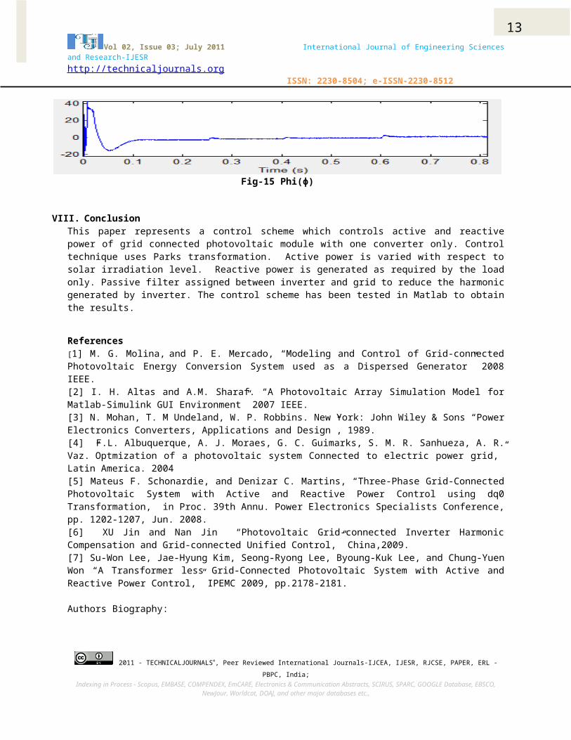
VII. Results and analysisThe PV system with 50KW power at1000W/m²and 40KW power supplied to gridconnected load and 9.5KW power supplied to grid with 0.5KW loss in inverter,filter and transformer. Fig-6 shows power generated by PV system at 0 W/m²,400 W/m², 600 W/m² and 1000 W/m² solar irradiation and power supplied by gridto load. Initially grid is supplying power to load. As irradiation levelreaches to 400W/m² and 600 W/m², PV system and grid both partially supply theload. Fig-7 shows reactive power supplied by the PV system. The PV systemgenerates reactive power as per the requirement of the load only. Suddenchange in solar irradiation level effect the reactive power which can be seenin fig-7. As per the power quality is concern harmonic are reduce by using thepassive filter. From the result it can seen that inverter current varies assolar irradiation level changes and its THD(Total Harmonic Distortion ) is0.71% as shown in fig-(8-9). Load current remain same even when solarirradiation level changes and its THD is 0% as shown in fig-(10-11). Gridcurrent and its THD is 1.06% as shown in fig-(12-13). Fig-14 shows the DC linkvoltage which is constant after transient period. Fig-15 shows the phase anglephi (ɸ) which changes with change in the Idref signal.
2011 - TECHNICALJOURNALS®, Peer Reviewed International Journals-IJCEA, IJESR, RJCSE, PAPER, ERL -PBPC, India;
Indexing in Process - Scopus, EMBASE, COMPENDEX, EmCARE, Electronics & Communication Abstracts, SCIRUS, SPARC, GOOGLE Database, EBSCO,NewJour, Worldcat, DOAJ, and other major databases etc.,
Fgrid
Vdc Cdc Vgrid
Vinv
60Hz 900V
1500µF
600V 480
DC voltage controller
Kp Ki
0.5 10
Current controller
Kp Ki
0.01 3

11Vol 02, Issue 03; July 2011 International Journal of Engineering Sciences
and Research-IJESRhttp://technicaljournals.org
ISSN: 2230-8504; e-ISSN-2230-8512
Fig-6 Active power
Fig-7 Reactive power
Fig-8 Inverter current
Fig-9 THD of inverter current
2011 - TECHNICALJOURNALS®, Peer Reviewed International Journals-IJCEA, IJESR, RJCSE, PAPER, ERL -PBPC, India;
Indexing in Process - Scopus, EMBASE, COMPENDEX, EmCARE, Electronics & Communication Abstracts, SCIRUS, SPARC, GOOGLE Database, EBSCO,NewJour, Worldcat, DOAJ, and other major databases etc.,

12Vol 02, Issue 03; July 2011 International Journal of Engineering Sciences
and Research-IJESRhttp://technicaljournals.org
ISSN: 2230-8504; e-ISSN-2230-8512
Fig-10 Load current
Fig-11 THD of load current
Fig-12 Grid current
Fig-13 THD of Grid current
Fig-14 DC link voltage
2011 - TECHNICALJOURNALS®, Peer Reviewed International Journals-IJCEA, IJESR, RJCSE, PAPER, ERL -PBPC, India;
Indexing in Process - Scopus, EMBASE, COMPENDEX, EmCARE, Electronics & Communication Abstracts, SCIRUS, SPARC, GOOGLE Database, EBSCO,NewJour, Worldcat, DOAJ, and other major databases etc.,
13Vol 02, Issue 03; July 2011 International Journal of Engineering Sciences
and Research-IJESRhttp://technicaljournals.org
ISSN: 2230-8504; e-ISSN-2230-8512
Fig-15 Phi(ɸ)
VIII. ConclusionThis paper represents a control scheme which controls active and reactivepower of grid connected photovoltaic module with one converter only. Controltechnique uses Parks transformation. Active power is varied with respect tosolar irradiation level. Reactive power is generated as required by the loadonly. Passive filter assigned between inverter and grid to reduce the harmonicgenerated by inverter. The control scheme has been tested in Matlab to obtainthe results.
References[1] M. G. Molina, and P. E. Mercado, “Modeling and Control of Grid-connectedPhotovoltaic Energy Conversion System used as a Dispersed Generator” 2008IEEE.[2] I. H. Altas and A.M. Sharaf. “A Photovoltaic Array Simulation Model forMatlab-Simulink GUI Environment” 2007 IEEE.[3] N. Mohan, T. M Undeland, W. P. Robbins. New York: John Wiley & Sons “PowerElectronics Converters, Applications and Design”, 1989. [4] F.L. Albuquerque, A. J. Moraes, G. C. Guimarks, S. M. R. Sanhueza, A. R.Vaz.”Optmization of a photovoltaic system Connected to electric power grid,”Latin America. 2004[5] Mateus F. Schonardie, and Denizar C. Martins, “Three-Phase Grid-ConnectedPhotovoltaic System with Active and Reactive Power Control using dq0Transformation,” in Proc. 39th Annu. Power Electronics Specialists Conference,pp. 1202-1207, Jun. 2008.[6] XU Jin and Nan Jin “Photovoltaic Grid-connected Inverter HarmonicCompensation and Grid-connected Unified Control,” China,2009.[7] Su-Won Lee, Jae-Hyung Kim, Seong-Ryong Lee, Byoung-Kuk Lee, and Chung-YuenWon “A Transformer less Grid-Connected Photovoltaic System with Active andReactive Power Control,” IPEMC 2009, pp.2178-2181.
Authors Biography:
2011 - TECHNICALJOURNALS®, Peer Reviewed International Journals-IJCEA, IJESR, RJCSE, PAPER, ERL -PBPC, India;
Indexing in Process - Scopus, EMBASE, COMPENDEX, EmCARE, Electronics & Communication Abstracts, SCIRUS, SPARC, GOOGLE Database, EBSCO,NewJour, Worldcat, DOAJ, and other major databases etc.,

14Vol 02, Issue 03; July 2011 International Journal of Engineering Sciences
and Research-IJESRhttp://technicaljournals.org
ISSN: 2230-8504; e-ISSN-2230-8512
Dr. Tilak Thakur is born in 1963. He graduated from B.I.T.Sindri, in Electrical engineering in 1987. He completed his Postgraduation in Power System from the same institute and achievedhis Ph.D in Electronic Instrumentation from Indian School ofMines, Dhanbad in Electronic Instrumentation in1999. Heserved as a lecturer in B.I.T., Sindri and NERIST Arunachal
Pardesh. Presently, he is Associate Professor in the Department of ElectricalEngineering, PEC UNIVERSITY OF TECHNOLOGY , Chandigarh, India.. He has ateaching experience of more than 23 years. He is involved in active Researchin Power &EnergySystem ,Mechatronics , Non –Conventional Energy. He haspublished more than 75 research and review papers in International andNational level such as IEEE , AMSE , IE Etc.
Kuldeep Singh Bedi is born in 1982.He done his Diploma from CCET, Chandigarh,and B.Tech from sddiet, Panchkula Haryana, INDIA affiliated to Kurukshetra University, in Electricalengineering in 2006. He completed his Post graduation (ME) in Power electronic and drivesfrom PEC UNIVERSITY OF TECHNOLOGY, Chandigarh, India in 2011. He worked as adesign and testing engineer with transformer manufacturing company from august2006 to august 2008. He worked as lecturer with BADDI University, Baddi, H.P,from august 2008 to July 2009
2011 - TECHNICALJOURNALS®, Peer Reviewed International Journals-IJCEA, IJESR, RJCSE, PAPER, ERL -PBPC, India;
Indexing in Process - Scopus, EMBASE, COMPENDEX, EmCARE, Electronics & Communication Abstracts, SCIRUS, SPARC, GOOGLE Database, EBSCO,NewJour, Worldcat, DOAJ, and other major databases etc.,
Copyright © 2022 FDOKUMEN