Central/Eastern Europe: The Long and Winding Road toward European Union
Upload
independentCategory
view
1download
0
Pergamon Robotics & Computer-Integrated Manufacturing, Vol. 12, No. 1, pp. 3-13, 1996
Copyright © 1995 Elsevier Science Ltd Printed in Great Britain. All fights re~crvcd
0736-5845/96 $15.00 + 0.00
0736-5845(95300025-9
• Paper
ACCURACY-SPEED RELATIONSHIPS OF A ROBOTIC FILAMENT WINDING CELL
S. CHAN, M. MUNRO and A. FAHIM
Department of Mechanical Engineering, University of Ottawa, Ottawa, Ontario KIN 6N5, Canada
Filament winding is a process in which tensioned resin-impregnated continuous fibers are placed on specified paths of a rotating mandrel to cover the entire surface thus formln~ a composite component. Traditionally, filament winding is carried out on multi-axis numerically controlled lathe-like machines. This paper describes the evaluation of a robot based filament winding cell consisting of an industrial robot (ASEA IRB 612) and an in-house fabricated mandrel drive mechanism, both being coordinated by a personal computer. As in many manufacturing processes, tradeotgs exist between accuracy and speed. The accuracy vs speed relationships of the robotic w l ~ i ~ cell were experimentally determined for discrete, fine and medium movement modes while traversing a segmented delivery eye path for a cylindrical mandrel in three configurations (in-line, offset and angled with respect to the axis of rotation). The results show that the robot windlne cell is appropriate for very accurate winding of fiber strands if the mandrel axis is concentric with the mandrel drive axis and the diserete mode (i.e. low speed) of the robot is used. For high speed wet winding all three eonflom~rations can be accurately wound in the discrete and fine modes.
1. INTRODUCTION Filament winding Filament winding is a process in which tensioned resin-impregnated continuous fibers are placed on specified paths of a rotating mandrel to cover the entire surface thus forming a composite component. A review of the process of filament winding is given in Ref. 12; however, the basic aspects of the process will be discussed here. A filament winding machine consists generally of fiber supply spools, fiber tensioner, resin impregnator, fiber delivery or delivery eye, and mandrel drive unit as shown in Fig. 1. During the winding process the fiber strands are supplied from one or more spools. The strands can be pre-impregnated with polymeric resin (termed "prepreg") or impregnated during the filament winding process (termed "wet winding"). In either form they are placed by the delivery eye on specified paths of a mandrel. When the winding is complete, the resin is cured either at room temperature or in an oven or autoclave if elevated temperature cure resins are used. The mandrel is generally removed after curing to leave a fiber reinforced composite shell, although it can remain as part of the component, as in the case of high pressure composite vessels. Filament winding is an economical, flexible process that can be used to fabricate a variety of shapes, sizes and quantities of components. Since the fibers are wound under tension onto the mandrel surface, depending on the surface geometry, the fibers may slip from the chosen position or direction. To prevent that either a stable path must be found or mechanical keying has to be employed. Mechanical keying
utilizes pins, tags or some form of anchoring mechanism to confine the fiber on the desired path. A stable path can be a geodesic one, which relies solely on the geometrical shape of the mandrel and is generally a unique one, or can be generated from the geodesic by considering the coefficient of friction between the fibers and the mandrel surface. A non- geodesic stable path is non-unique and fails in a band encompassing the unique geodesic path. Further details on fiber path calculation can be found in Ref. 2.
After the fiber paths have been determined, appropriate hardware is required for placing the fiber strands on the chosen paths. Traditionally, a filament winding machine resembled a lathe in which the cutting tool was replaced by a fiber delivery eye. As with lathes, mechanical gearing was used to position the fiber delivery eye. These machines produce simple axisymmetric geometric components such as cylindrical tubes, pressure vessels, and rocket motor casings.
As part shapes and/or winding patterns became more complex, positioning of the delivery eye required more flexibility. This was achieved by using many independently controlled axes such as in a numerieaUy controlled machine. These machines can produce complex asymmetric shapes such as turbine blades, pipe tees, aircraft fuselages, etc.
Filament winding with CNC machines The simplest Computerized Numerical Control (CNC) filament winding machines have two axes. One axis is used to rotate the mandrel and the other

Robotics & Computer-Integrated Manufacturing • Volume 12, Number 1, 1996
FIBRE SPOOL \ / RESIN IMPREGNATOR
FIBRE DELIVERY EYE (PAYOUT EYE)
TENSION CONTROLLER
MANDREL DRIVE UNIT
I _
Fig. 1. Components of a filament winding machine.
to translate the carriage with the fiber delivery eye. More axes can be added and are typically controlled by a microprocessor based control system which is capable of controlling both linear and non-linear motion of the fiber delivery eye.
The fiber delivery eye path and the mandrel rotation can be programmed either in the "Teach- in" method or generated theoretically and down loaded from an external computer. The "Teach-in" method requires an experienced operator to wind a complex geometry mandrel. The approach of using an external computer to calculate the fiber paths is an advanced technology for which commercial systems are available. 12
Filament winding and multi-axis robots A robotic filament winding cell is very similar in its basic function to the traditional Computer Numeri- cally Controlled (CNC) winding machine. The cell consists of a robot and mandrel drive or fixed support as shown in Fig. 1. For winding complex components six DOFs, or seven DOFs in the case of winding with tape, are required. These DOFs can be distributed such that a six DOF robot with a stationary mandrel may be used. 8'13 Alternatively, a five, or six, axis robot with a single axis rotating mandrel drive has also been employed. 9'1°'12'14 Elliman et aL 5 have also used a five axis robot in conjunction with a four axis filament winding machine in which the robot is used to assist with fiber placement on the filament winding mandrel.
Robotic filament winding is a very promising fabrication process that has been studied by many researchers. All found favourable results using a robotic filament winding cel l ; 1'8-10'12-14 however, none of these studies have sufficiently addressed the aspect of accuracy of the robotic winding cells for fiber placement on complex mandrels.
It is important at this point to differentiate between the accuracy of defining the stable path and the accuracy of placement of the fiber strands along that path. In the first instance the accuracy
depends on the methodology of calculating the path, 2 and is beyond the scope of this paper. Given a path, the accuracy of fiber placement depends on a large number of factors among which are the robot and mandrel drive accuracy, the coordination between these two devices, the standoff distance between the delivery eye and the mandrel, and the accuracy of defining the delivery eye path. Munro 12 has demon- strated that a rudimentary robotic winding cell was capable of the highly accurate filament winding of traditional simple shapes such as closed-end pressure vessels using prepreg tapes. In this case the high accuracy is required for two reasons: (1) the necessity of placing the fiber tapes side by side without overlaps or gaps, and (2) in a repeating pattern such that requirement (1) is satisfied even after a large number of circuits along the axis of the mandrel have been completed. These requirements were met 12 primarily because the robot speed was very consistent over the large cylindrical portion of the pressure vessel, and the coincidence of the axis of the cylinder with the axis of rotation. In general, however, complex rotationaUy symmetric or asymmetric components requiring a very high accuracy fiber placement would not possess the above mentioned qualities. Many typical filament wound components such as elbows, S-shaped pipes, and complex shaped manifolds 15 can be approximated by a series of regular shaped segments such as faceted or circular cylinders, or phrustum of cones. These segments can be aligned with the axis of rotation, offset from the axis, or at an angle to the axis and either intersecting or offset from it. For a given delivery eye standoff distance, the accuracy of winding of the component is primarily related to the extent and rate of movement of the robot with respect to the axis of rotation of the component, which can be directly inferred from the approximating segments and their location and orientation.
The objective of this work was to study the accuracy and repeatability as function of speed for a robotic composite filament winding cell developed
Robotic filament winding cell • S. CHAN et al.
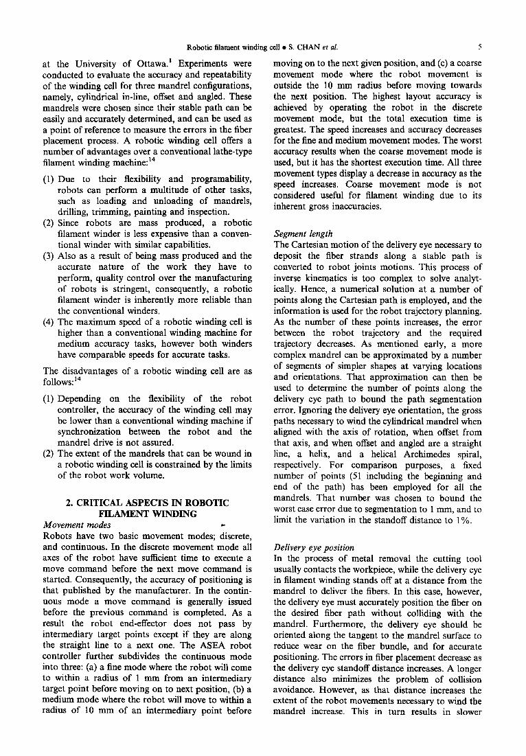
at the University of Ottawa. ~ Experiments were conducted to evaluate the accuracy and repeatability of the winding cell for three mandrel configurations, namely, cylindrical in-line, offset and angled. These mandrels were chosen since their stable path can be easily and accurately determined, and can be used as a point of reference to measure the errors in the fiber placement process. A robotic winding cell offers a number of advantages over a conventional lathe-type filament winding machine: 14
(1) Due to their flexibility and programability, robots can perform a multitude of other tasks, such as loading and unloading of mandrels, drilling, trimming, painting and inspection.
(2) Since robots are mass produced, a robotic filament winder is less expensive than a conven- tional winder with similar capabilities.
(3) Also as a result of being mass produced and the accurate nature of the work they have to perform, quality control over the manufacturing of robots is stringent, consequently, a robotic filament winder is inherently more reliable than the conventional winders.
(4) The maximum speed of a robotic winding cell is higher than a conventional winding machine for medium accuracy tasks, however both winders have comparable speeds for accurate tasks.
The disadvantages of a robotic winding cell are as follows: 14
(1) Depending on the flexibility of the robot controller, the accuracy of the winding cell may be lower than a conventional winding machine if synchronization between the robot and the mandrel drive is not assured.
(2) The extent of the mandrels that can be wound in a robotic winding cell is constrained by the limits of the robot work volume.
2. CRITICAL ASPECTS IN ROBOTIC FILAMENT WINDING
Movement modes ,- Robots have two basic movement modes; discrete, and continuous. In the discrete movement mode all axes of the robot have sufficient time to execute a move command before the next move command is started. Consequently, the accuracy of positioning is that published by the manufacturer. In the contin- uous mode a move command is generally issued before the previous command is completed. As a result the robot end-effector does not pass by intermediary target points except if they are along the straight line to a next one. The ASEA robot controller further subdivides the continuous mode into three: (a) a fine mode where the robot will come to within a radius of 1 mm from an intermediary target point before moving on to next position, (b) a medium mode where the robot will move to within a radius of 10 mm of an intermediary point before
5
moving on to the next given position, and (c) a coarse movement mode where the robot movement is outside the 10 mm radius before moving towards the next position. The highest layout accuracy is achieved by operating the robot in the discrete movement mode, but the total execution time is greatest. The speed increases and accuracy decreases for the fine and medium movement modes. The worst accuracy results when the coarse movement mode is used, but it has the shortest execution time. All three movement types display a decrease in accuracy as the speed increases. Coarse movement mode is not considered useful for filament winding due to its inherent gross inaccuracies.
Segment length The Cartesian motion of the delivery eye necessary to deposit the fiber strands along a stable path is converted to robot joints motions. This process of inverse kinematics is too complex to solve analyt- ically. Hence, a numerical solution at a number of points along the Cartesian path is employed, and the information is used for the robot trajectory planning. As the number of these points increases, the error between the robot trajectory and the required trajectory decreases. As mentioned early, a more complex mandrel can be approximated by a number of segments of simpler shapes at varying locations and orientations. That approximation can then be used to determine the number of points along the delivery eye path to bound the path segmentation error. Ignoring the delivery eye orientation, the gross paths necessary to wind the cylindrical mandrel when aligned with the axis of rotation, when offset from that axis, and when offset and angled are a straight line, a helix, and a helical Archimedes spiral, respectively. For comparison purposes, a fixed number of points (51 including the beginning and end of the path) has been employed for all the mandrels. That number was chosen to bound the worst case error due to segmentation to 1 mm, and to limit the variation in the standoff distance to 1%.
Delivery eye position In the process of metal removal the cutting tool usually contacts the workpiece, while the delivery eye in filament winding stands off at a distance from the mandrel to deliver the fibers. In this case, however, the delivery eye must accurately position the fiber on the desired fiber path without colliding with the mandrel. Furthermore, the delivery eye should be oriented along the tangent to the mandrel surface to reduce wear on the fiber bundle, and for accurate positioning. The errors in fiber placement decrease as the delivery eye standoff distance increases. A longer distance also minimizes the problem of collision avoidance. However, as that distance increases the extent of the robot movements necessary to wind the mandrel increase. This in turn results in slower
6
operation, and in the limit may cause the required movements to exceed the work volume of the robot.
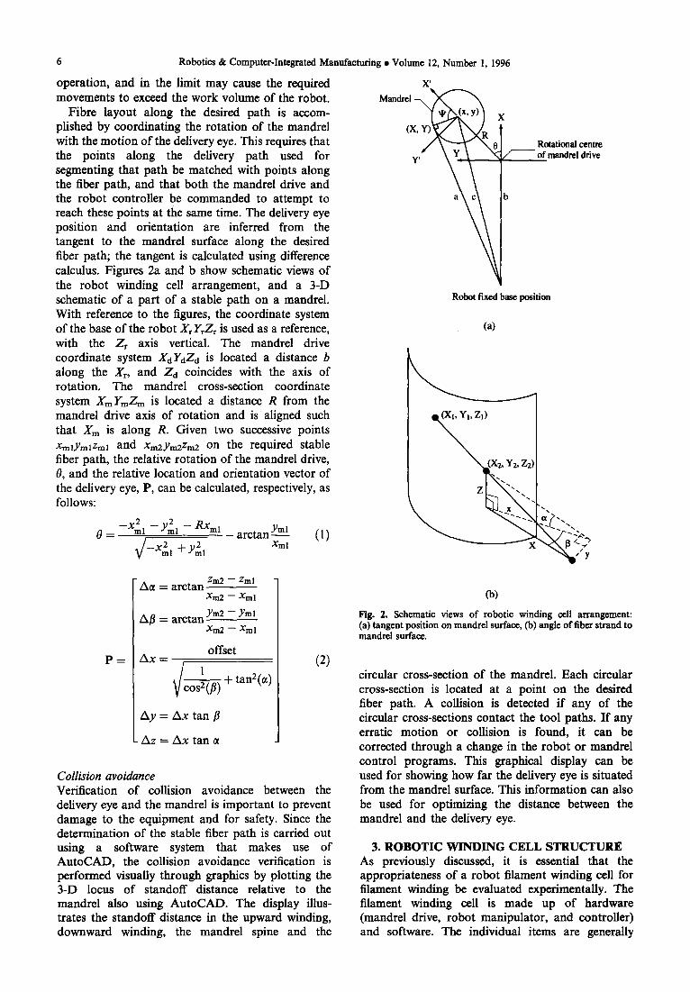
Fibre layout along the desired path is accom- plished by coordinating the rotation of the mandrel with the motion of the delivery eye. This requires that the points along the delivery path used for segmenting that path be matched with points along the fiber path, and that both the mandrel drive and the robot controller be commanded to attempt to reach these points at the same time. The delivery eye position and orientation are inferred from the tangent to the mandrel surface along the desired fiber path; the tangent is calculated using difference calculus. Figures 2a and b show schematic views of the robot winding cell arrangement, and a 3-D schematic of a part of a stable path on a mandrel. With reference to the figures, the coordinate system of the base of the robot Xr YrZr is used as a reference, with the Zr axis vertical. The mandrel drive coordinate system XaYdZa is located a distance b along the X~, and Za coincides with the axis of
Robotics & Computer-Integrated Manufactur ing • Volume 12, Number 1, 1996
X'
rotation. The mandrel cross-section coordinate system XmYmZm is located a distance R from the mandrel drive axis of rotation and is aligned such that Xm is along R. Given two successive points XmlYmlZml and Xm2Ym2Zm2 on the required stable fiber path, the relative rotation of the mandrel drive, 0, and the relative location and orientation vector of the delivery eye, P, can be calculated, respectively, as follows:
2 2 - -Xml - - Yml - - R X m l . . . . . . Yml /1",
0 = - - - - -- ttl~tiXa k I. } __X 2 , if_ y 2 , Xml
/ ~ l l U l l
Zm2 - - Zml A e = arctan
Xm2 - - Xml
Mandrel ~ X (X,
y,
Robot fixed base position
Rotational centre of mandrel drive
(a)
(b)
p = Aft = arctan ym2 - Yml
Xm2 - - Xml
offset Ax =
~ + tan2(°¢)
Ay = Ax tan//
Az = Ax tan
(2)
Collision avoidance Verification of collision avoidance between the delivery eye and the mandrel is important to prevent damage to the equipment and for safety. Since the determination of the stable fiber path is carried out using a software system that makes use of AutoCAD, the collision avoidance verification is performed visually through graphics by plotting the 3-D locus of standoff distance relative to the mandrel also using AutoCAD. The display illus- trates the standoff distance in the upward winding, downward winding, the mandrel spine and the
Fig. 2. Schematic views of robotic winding cell arrangement: (a) tangent position on mandrel surface, Co) angle o f fiber s t rand to mandrel surface.
circular cross-section of the mandrel. Each circular cross-section is located at a point on the desired fiber path. A collision is detected if any of the circular cross-sections contact the tool paths. If any erratic motion or collision is found, it can be corrected through a change in the robot or mandrel control programs. This graphical display can be used for showing how far the delivery eye is situated from the mandrel surface. This information can also be used for optimizing the distance between the mandrel and the delivery eye.
3. ROBOTIC WINDING CELL STRUCTURE As previously discussed, it is essential that the appropriateness of a robot filament winding cell for filament winding be evaluated experimentally. The filament winding cell is made up of hardware (mandrel drive, robot manipulator, and controller) and software. The individual items are generally

Robotic filament windin8 cell • S. CHAN et al.
very accurate and have high repeatability; however, these devices have to work together in a robotic winding cell. Therefore, the accuracy and repeat- ability depends on all the individual accuracies plus the accuracy in coordinating the individual items. It is important to determine the accuracy vs speed relationships for the different movement modes (discrete, fine and medium) using the three mandrel configurations already discussed. The following sections describe the hardware and software that has been developed to experimentally evaluate these relationships.
Robotic winding cell hardware The robotic winding cell at the University of Ottawa (Fig. 3a) consists of a five axis ASEA
7
IRB 6/2 industrial robot and an auxiliary mandrel drive. A single fiber spool is connected to a closed loop magnetic brake system (Magpowr Model TRAC-I) which is located on the output link close to joint 3. The delivery eye mechanism (Fig. 3b) is positioned on the roll axis of the wrist and has a spring loaded rocker arm to take up slack in the fiber strand. The mandrel drive unit has two 3- jaw chucks; the top chuck can move vertically while the lower chuck is connected through a ribbed belt to a Slo-Syn stepper motor. A PC21 Compumotor indexer card mounted in a 386 personal micro- computer provided commands to the translator (Slo-Syn TM600U) of the mandrel drive. The 386 PC is also connected to the robot controller via a serial port.
Fig. 3. Robotic winding cell: (a) robot and auxiliary mandrel drive, (b) delivery eye end-effector.

8
Control software for robotic filament winding The procedure for robotic filament winding 4 begins with defining the mandrel and its surface in AutoCAD. AutoLISP routines are then used to extract the pertinent data and pass them to processing routines written in C. These routines calculate the stable paths on the mandrel surface and return them back to AutoCAD for display and further processing. From these paths, selected coordinate points are extracted and stored in a .DXF file format. This file contains the coordinate points used to calculate the delivery eye positions.
As mentioned earlier, the delivery eye position is defined by the standoff distance along a vector pointing to and tangent to the path on the mandrel surface. The program TOOL creates the delivery eye file and the associated mandrel position file. A sequence and run file is also created and is required for the Robot Control Communication Software (RCCS) program to download the path fragments and control motion. For robot discrete movement, the robot's file mode format is used. The program control mode is used for the fine, medium and coarse movement modes.
4. CELL TESTING Experimental test procedures Experiments were conducted to determine the accuracy and repeatability of the entire system. Accuracy of the winding cell was tested for discrete, fine and medium movement modes in both up and down directions. A standoff distance of 100 mm was used. The delivery eye paths were divided into 50 equal length segments. Three different winding speeds for each movement type were used to evaluate the effect on accuracy. For each speed three tests were carried out to assess the repeatability of the results. Therefore, a total of 378 tests were carried out to assess the accuracy and repeatability of the robotic filament winding cell.
As discussed previously, three configurations were used for testing the winding cell (Fig. 4). These three configurations involved the basic mandrel orienta- tions that constitute many winding situations. The detail of the individual configurations are given below.
Robotics & Computer-Integrated Manufacturing • Volume 12, Number 1, 1996
~ n
(1) 1n-line cylindrical mandrel. This configuration uses a cylindrically shaped mandrel with a diameter of 63.5 mm and length of 178 mm, which was placed at the centre of rotation of the mandrel drive (Fig. 4a). The tolerance for the diameter of the cylindrical mandrel is _ 0.05 mm. The mandrel was wound at an angle of 66 ° to the axis of the mandrel which corresponds to two revolutions over the length.
(2) Offset cylindrical mandrel. This configuration used the same mandrel as for the in-line cylindrical mandrel configuration: however, the center-line of the mandrel was offset from the center of rotation of
(a)
I
Offset - - -
li--1 I
(b)
I
3R
(c) Pig. 4. Mandrel configurations: (a) in-line cylindrical, (b) offset cylindrical, (c) angled cylindrical.
the mandrel drive. Mandrel center-line offsets of 1, 2, and 3 times the radius of the mandrel were used for testing the ability of the winding cell to wind a mandrel moving in an eccentric motion (Fig. 4b). For each offset the location of the mandrel in the mandrel drive was within + 0.5 mm of the desired position. As in the first configuration, the mandrel was wound at an angle of 66 ° to the axis of mandrel.
(3) Angled cylindrical mandrel. In this experiment, the same mandrel was placed offset as in Configuration 2, except that it was also at an angle to the rotational center of the mandrel drive. The angle was created with unequal offsets at the top and bottom of the mandrel (Fig. 4¢). Differences of mandrel center-line offset of l, and 2 radii of the mandrel were used to create the angles. This configuration made the mandrel trace a conical shape. The location of the mandrel in the mandrel drive using the brackets was within _+0.5 mm. The mandrel was wound at an angle of 66 ° to the axis of mandrel.

Robotic filament winding cell • S. CHAN et al.
The initial position of the fiber strands for all three configurations is shown in Fig. 5. The alignment of the robot and the mandrel drive axes were measured using a dial gauge attached to the end effector of the robot, The absolute deviation along the length of the 178 mm long cylindrical mandrel was 0.1 mm in the x - z plane and 0.15 mm in the y-z plane.
Experimental data collection The experimental mandrel paths were determined using small diameter (0.25 mm) hard twine. Ink was impregnated onto the twine by a foam roller which had been soaked in ink (Fig. 3b). A sheet of paper on which the desired path had been drawn was taped to the cylindrical mandrel. In all cases the ink from the twine created a distinct line on the mandrel covering.
Path error estimation In all cases the actual path deviated from the desired path in a bow shape (Fig. 6). The accuracy can be judged by the maximum deviation between the desired and the experimental paths or the area between the two paths. These two methods were evaluated to determine which is a more appropriate estimate of path error.
The area between the two paths can be approxi- mated by a parabola, which is the height (maximum deviation distance) times 4/3 of the base (length of fiber path). 7 Since the base is common to all tests that were conducted, the only difference is the variable height. Therefore, the area between the desired and experimental paths and the maximum deviation differ by a scale factor of 4/3. Consequently, the area between the two paths or the maximum deviation distance can be used for indicating the error. In this research, the maximum deviation distance between the two paths was recorded as the error of the test.
The accuracy of the winding process was measured by determining the deviation between the wound path and the desired path as discussed in the previous section. Since the measuring device (a vernier caliper) is graduated to 0.5 mm, the errors were read to the
9
nearest 0.25 mm. This is reasonable as the twine used in the experiment has a diameter of 0.25 mm. Thus, an uncertainty of measurement of +0.25 mm is assumed.
5. RESULTS AND DISCUSSION The experimental results are presented in two forms, namely, a typical plot of error vs total time (in order to illustrate the concept of transition point) and figures which summarize the effect of mandrel configuration and movement mode on error and total time of the transition points. Figures 7a and b present the error vs total time relationships for winding with the in-line configuration for the discrete, fine and medium movement modes in the downward and upward directions, respectively. The curve for each movement mode shows that the error decreases with a decrease in winding speed, reaches an inflection point, and then remains constant. The inflection or "transition" point is the most significant point as it represents the smallest error for the highest speed for that movement mode. Therefore, only transition point values will be used for discussion in the following sections. For each mode, a number of command velocities in the middle of the range were selected in order to accurately define the transition point. The resulting total time and associated errors for the transition points and upper and lower velocities is shown in the figure. The vertical bars represent the range of errors for the three test runs at each velocity. In Fig. 7b the results from Fig. 7a have also been included as dotted lines to permit comparison of the results for the down- ward and upward directions.
There are five other similar sets of figures for the offset and angled mandrel configurations. 4 Since the transition point is of most interest, the results for Fig. 7 and the other five cases have been summarized in Figures 8 and 9. The bar graph has been selected as the presentation mode in order to permit qualitative comparisons of the results. The actual total time is given at the end of each bar. Since the winding times for the downward and upward directions varied at
Mandrel \ \ \ \
/ - 90 degrees
~ / 6 6 degrees
- - / j / Fibre
/ ,
Payout eye posit ion Payout eye posit ion
TOP VIEW
Fig. 5. Initial position of the fiber strand.
SIDE VIEW

E x p e r i m e n t a l pa th
~~ # ~ ~ p a t h
Robotics & Computer-Integrated Manufacturing • Volume 12, Number 1, 1996
J Angled IR/3R
Angled I R/2R
Offset 3R[
Offset 2R
Offset I R
10
[] Discre te [ ] F ine
In-lin [] M e d i u m
I [ I 0 I O 20 30 40 50 60
Fig. 8. Total time (see) as a function of mandrel configuration and robot movement mode. The actual times are given at the end of the bars.
Fig. 6. Typical tracing for cylindrical mandrel.
E
gfl
3.5- (a)
3.0
2.5
2 . 0 -
1 .5 -
1 .0 -
0 . 5 -
[ I 2 4
I I
D i s c r e t e movement - F i n e movement
- - - Medium movement
\
I I I t I I I I I I I 10 12 14 16 18 20 22 24 26 28 30
Total time (sec)
E
(b) 3.5
3.0
2.5
2.0
1.5--
1.0--
Discrete movement . . . . F i n e m o v e m e n t - - - Medium movement
o.5 ~- I I I I i I I [ J i 1 t I I I 2 4 6 8 l0 12 14 16 IS 20 22 24 26 28 30
Total time (see)
Fig. 7. Error vs total time for the robotic winding for the in-line cylindrical mandrel configuration: (a) downward winding, (b) upward winding (results o f (a) are in faint lines).
most by 1.5% (as typically shown in Fig. 7a), only a single value is reported.
Effect of movement mode on total time. The most obvious result from Fig. 8 is that, for all configurations, the order of increasing winding times is for the discrete, fine and then medium modes. The discrete movement mode total time was longest because the winding cell has to stop at every given point for communication between the robot and the microcomputer and the microcomputer and the PC-21 indexer card. The fine and medium
Angled IR/3R
Angled 1R/2R ]
Offset 3R ]
Offset 2R I
Offset I R !
In- l ine ]
0
i D i sere te i Fine I-'lMedium
14/5
12.5/21 I I I 2 3 4 5
Fig. 9. Path error (mm) as a function of mandrel configuration and robot movement mode. The path errors are given at the end of the bars for upward/downward directions, respectively.
movement modes do not require stopping between points but move on a continuous basis.
Effect of mandrel configuration on total speed. The in- line configuration had the shortest winding times for each of the three movement modes; the total time for the fastest case (medium movement mode) was 8 see which corresponds to a robot speed of 22 mm see- a. This very slow speed is due to the accuracy imposed on the robot to follow the delivery eye path. This problem is even worse for the angled mandrel with times of 16.7 and 15.4 sec for the 1R/2R and 1R/3R configurations, respectively. As will be seen later, very high accuracy was obtained only for the discrete mode; however, at significantly longer winding times. For comparison, the winding of the mandrels with single 260 mm long cylindrical segments was done at an average speed of 175 mm see -1 with very good accuracy./2 For the offset mandrels it can be seen that the winding times increase with increasing offsets. The results for the angled configurations are generally in between those of the smallest offset (1R) and the largest offset (3R) configurations. This is not unexpected since the orientations and resulting

Robotic filament winding cell • S. CHAN et al.
magnitudes of required robot movements are very similar.
Effect of movement mode on the winding error. The results of the experimental testing for path error are summarized in Fig. 9. It should be noted that the repeatability of the three tests for path errors for the transition points was +0.25 mm. This is equal to the accuracy of measurement as previously discussed. Since the selection of the movement mode will be a critical decision, the differences between the different movement modes are of particular importance. The discrete mode generally had the best accuracy with quite low errors especially for the in-line configuration, while the fine movement mode had increased error as compared to the discrete movement mode. The medium movement mode had the largest error, at times up to 2½ times the discrete mode. Hence, as expected, the errors increased as the movement mode changed from discrete to fine to medium.
The error in the discrete movement mode which is typically very small (0.5 mm) is probably due to the error in the set-up of the robot cell. Any misalign- ment or error in the initial conditions in the set-up will cause a difference in the values from the theoretical model. This error is very near the minimum value expected and therefore could be very difficult to improve on without elaborate control of set-up error. The errors for the fine and medium movement modes are due to the robot not reaching the desired positions (ends of segments). In the fine mode, the robot has a 1 mm error radius zone while the medium mode has a 10 mm error radius zone. These error zones give the robot the liberty of reaching the desired position or just coming within these zones depending on the previous speed and direction. Furthermore, the lack of coordination of motion between the robot and the mandrel con- tributed to the errors in the results. The other source of error is the assumption of constant velocity movement by the robot without the acceleration and deceleration portions.
Effect of mandrel configuration on path error. The results in Fig. 9 show that the path errors for the offset and angled configurations were on average approximately equal and were more than double those for the in-line configuration. For both upward and downward winding directions there was essentially no change in accuracy observed for the in-line configuration as was found for winding time in general. This similarity in error results is because motion of two arms only is required to guide the delivery eye along a straight line. However, for the other two mandrel configurations, there is a difference in error for upward and downward paths. In many cases the path errors for the two directions are the same or very similar. For differences in path error (up vs down) of 0.75 mm
11
or greater the downward direction had greater errors than the upward direction, in almost all cases. Since this project utilized an overbalanced robot, the upward motion will generally have less strain on the robot motor and result in a higher accuracy.
The error increased as the offset distance increased for configurations in which the mandrel axis is not colinear with the axis of rotation of the mandrel drive. This is because the robot has to follow the mandrel so as to keep the standoff distance constant. Such robot motion involves a higher number of DOFs of motion with longer distances to travel. Furthermore, as the offset distance increases so does the delivery eye path. Since a fixed number of segments along that path has been chosen, the error due to the approximation of a curvilinear path with straight paths for the 50 segments used increases.
Further discussion will consider the results in terms of practical applications.
Practical application of results Filament winding is a well-accepted fabrication
process for a large variety of fiber composite components. The required accuracy of fiber place- ment varies widely, primarily depending upon the tradeoff with speed (and resulting manufacturing cost) and structural considerations. Since the accuracy requirement is completely dependent on the particular component, it is not possible to make specific conclusions regarding the applicability of the present robotic cell. It is, though, possible to consider the cases for maximum and minimum accuracy. A review of the literature reveals very few references to actual achievable accuracies of fiber strand laydown. For aerospace components highly accurate filament winding using prepreg tape is typically required where the fiber strands are placed on the mandrel such that no overlaps exist and a maximum gap width is specified. A maximum allowable gap size of 0.25 mm has been reported by General Dynamics 3 and Cincinnati-Milacron, 6 typically for thin-walled shell-type structures where uniform wall thickness is a requirement. Other aerospace structures have high but slightly less demanding accuracies, typically involving a maximum gap width of 0.5 mm. Peters 16 has reported that for conventional helical winding on a cylindrical mandrel machine accuracies as high as 0.75 mm (99% confidence level) can be achieved. This value is obtained using fine diameter wires or polymer filaments through a small diameter delivery eye and thus does not include the inaccuracies associated with the fiber delivery eye with actual fiber strands. In addition, for winding rapidly varying sections requiring high accelerations, the accuracy will vary with the acceleration rates. Finally, it is important to appreciate that the typical variation in prepreg tape width is _+0.13 ram. 6 Considering the above points regarding the com- bined fiber delivery and winding machine positional errors and variation in prepreg tape width, it is

12
remarkable that actual maximum band gap widths can be as low as 0.25 mm.
It is appropriate to now consider the results of the experimental study in light of the previous discussion regarding highly accurate aerospace components. The results of this study showed that the experimental path was bow-shaped (Fig. 6) and was consistently on one side of the desired path. The errors between the desired and experimental paths were relatively large for the offset and angled configurations in all three movement modes and for the medium mode in the in-line configuration. The minimum error found in this study (0.5 mm) was for the discrete mode and in-line configuration, therefore, the cell cannot be used for applications requiring 0.25 mm accuracy. In the fine mode (in- line configuration) the error was only 1 mm. Since these values of 0.5 and 1 mm are very similar to the machine accuracy reported by Peters, ~6 the winding cell can probably be used with the discrete and fine movement modes to wind very accurate components in the in-line configuration. It should be noted that the maximum fiber tape feed rate for some of the aerospace components 3 is quite slow (0.6 m see-l).
The other end of the range of filament wound components are those which are wet wound at maximum fiber strand feed rates of 1.5 m see -1. For these components the accuracy of fiber lay- down is much lower due to the high accelerations and decelerations that occur. Middleton 11 has reported that the accuracy of the fiber strand placement must be kept to one fiber bandwidth in order to prevent slippage when the fiber strand is laid on the mandrel. For many components fabricated using conventional lathe-type filament winders wide tapes composed of a number of narrow (2-3 mm) tapes are used. It is relatively easy to tension the fiber tapes due to the high structural capabilities of the conventional winders. For robotic winding, since the load capabilities for tensioning can be much lower than the conven- tional winders, a single narrow tape is typically used. A single narrow tape is also a requirement for winding with prepreg tapes. The prepreg tape which is not shear deformable tends to wrinkle when traversing doubly-curved surfaces.
It is again appropriate to compare the accuracy results of this study with the requirements for this second case. Many fiber strands (either bare or pre- impregnated) are supplied in a common width of approximately 3 mm. If the criterion of Middleton is applied then all three movement modes for the in-line configuration have sufficient accuracy. In addition, if the fiber delivery errors are assumed to be negligible, then almost all the errors of the angled and offset configurations with the discrete and fine movement modes were less than 3 mm. The only exception to this is the single case of the down direction of the fine movement mode in the 1R/2R angled configuration
Robotics & Computer-Integrated Manufacturing • Volume 12, Number 1, 1996
(Fig. 9) for which an error value of 3.75 mm was found.
The previous discussions have centered on the magnitudes of error between the desired and experimental paths. Of equal importance are the winding speeds associated with these errors. For the two cases discussed above, typical maximum vertical winding speeds for the cylindrical mandrel ranged from 7 mm see-1 (discrete mode, in-line configura- tion) to 12 mm sec -1 (fine mode, 1R offset configuration). As mentioned previously these speeds are quite low in comparison to a maximum mandrel speed (175 mm sec -1) achieved in previous work. 12 This speed was for a single segment while the speeds of this study were for 50 individual segments. Thus it has been shown in this study that reasonable accuracies can be achieved with reasonable speeds. The main limitation to increasing the speeds is the closed nature of the ASEA controller. It is therefore recommended that a robot with a more accessible controller be evaluated.
6. CONCLUSIONS This work has shown that it is feasible, practical, and economical to integrate a standard industrial robot with a simple single axis mandrel drive and a microcomputer into a robotic filament winding cell for composite material fabrication. Such a cell was established and its accuracy tested on both simple cylindrical mandrels in three representative config- urations.
The accuracy and the repeatability of the robotic filament winding is high. The discrete movement mode of the robot gives the best accuracy followed by the fine and medium movement modes. In the discrete movement, the geometry of the mandrel does not affect the accuracy. The higher the complexity in the mandrel shape the larger the errors for the fine and medium movement modes. These errors, how- ever, can be reduced by shortening the approximat- ing segments of the delivery eye path so as to improve the approximation and achieve better coordination between the robot and the mandrel drive.
Tension and slack in the fiber does affect the accuracy in the placement of the fibers. The design of the fiber delivery system used in the experiments ensured no slack in the fiber strands, however, the tension was not tightly controlled. This approach resulted in the accuracy results being very reasonable. The accuracy may however be increased by having a fast acting tensioner controller.
Controlling the robot through a manufacturer supplied robot controller that is rigid and has limited accessibility does not allow a higher degree of coordination between the robot and the mandrel drive. Nevertheless, such an off-the-shelf ASEA industrial robot can be used in the filament winding of complex mandrels with reasonable accuracy.

Robotic filament winding cell • S. CHAN et al. 13
REFERENCES 1. Bernard, E., Fahim, A., Munro, M.: A CAD/CAM
approach to robotic filament winding. In Proceedings of CANCOM 91, Montreal, Quebec, 1991, pp. 2(24-1- 2C4-7.
2. Bernard, E., Fahim, A., Munro, M.: Fibre path calculation techniques for filament winding of rotationally symmetric structures. Part 1: Accuracy evaluation of differential equation technique (in preparation).
3. Campbell, J. H., Kittelson, J. L.: The tape winding process and applications. In Proceedings of 1991 SAMPE, San Diego, CA. 1991, pp. 791--805.
4. Chan, S.: Accuracy-speed relationships of a robotic filament winding cell. M.Sc. Thesis, Department of Mechanical Engineering, University of Ottawa, 1994.
5. Elliman, D. G., Sorenti, P., Brown, L., Shearing, M., Middleton, V., Owen, M. J.: A cell for the manufacture of composite components by filament winding. Adv. Mfg. Engng 1: 15-20, 1988.
6. Evans, D. O.: Design considerations for fiber placement. In Proceedings of 38th International SAMPE Symposium, Anaheim, CA. 1993, pp. 170- 181.
7. Korn, G. A.: Mathematical Handbook for Scientists and Engineers. New York, McGraw-Hill Book Company. 1968.
8. Smith, A., Anthony, D.: Robotic fiber placement in the fabrication of complex thermoplastic structures. In
Proceedings of 37th International SAMPE Symposium, Anaheim, CA. 1992, pp. 399-407.
9. Hummler, J., Lee, S-K., Steiner, K. V.: Recent advances in thermoplastic robotic filament winding. In Proceedings of 36th International SAMPE Sympo- sium. 1991, pp. 2142-2156.
10. Menges, G., Meise, E.: Use of industrial robots for filament winding. In Proceeding of 40th Annual Conference, Reinforced Plastics/Composites Institute, The Society of the Plastics Industry: 19-B. 1985, pp. 1-3.
11. Middleton, V., Young, K. W., EUiman, D. G., Owen, M. J.: Software for filament winding. In Proceedings of First International Conference on Automated Compo- sites, The Plastic, s and Rubber Institute, Nottingham, U.K. 1986, pp. 9/1-9/6.
12. Munro, M.: Review of manufacturing of fiber composite components by filament winding. Polymer Composites 9: 352-359, 1988.
13. Seereeram, S., Wan, J. T-Y.: An all-geodesic algorithm for filament winding of a T-shaped form. IEEE Trans. lndust. Electron. 38: 484-490, 1991.
14. Scholliers, J., Van Brussel, H., Van de Bruaene.: Robotic filament winding of asymmetric parts. Society of Manufacturing Engines, Paper No. EM90-662. 1990, pp. 1-14.
15. Sheppard, L. M.: The revolution of filament winding. Adv. Mat. Process. 132: 33, 1987.
16. Peters, S. T., Humphrey, W. D., Foral, R. F.: Filament Winding: Composite Structure Fabrication. Covina, CA., SAMPE. 1991.
Copyright © 2022 FDOKUMEN