Accuracy and reliability of 2D cephalometric analysis in orthodontics
Upload
louisvilleCategory
view
1download
0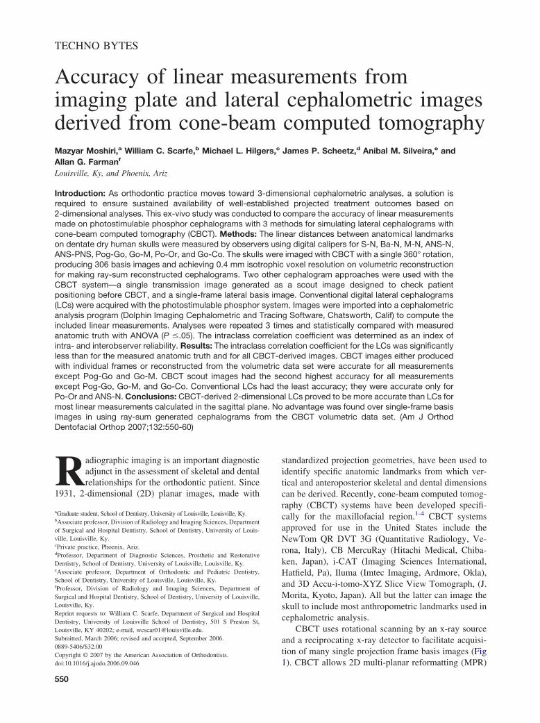
TECHNO BYTES
Accuracy of linear measurements fromimaging plate and lateral cephalometric imagesderived from cone-beam computed tomographyMazyar Moshiri,a William C. Scarfe,b Michael L. Hilgers,c James P. Scheetz,d Anibal M. Silveira,e andAllan G. Farmanf
Louisville, Ky, and Phoenix, Ariz
Introduction: As orthodontic practice moves toward 3-dimensional cephalometric analyses, a solution isrequired to ensure sustained availability of well-established projected treatment outcomes based on2-dimensional analyses. This ex-vivo study was conducted to compare the accuracy of linear measurementsmade on photostimulable phosphor cephalograms with 3 methods for simulating lateral cephalograms withcone-beam computed tomography (CBCT). Methods: The linear distances between anatomical landmarkson dentate dry human skulls were measured by observers using digital calipers for S-N, Ba-N, M-N, ANS-N,ANS-PNS, Pog-Go, Go-M, Po-Or, and Go-Co. The skulls were imaged with CBCT with a single 360° rotation,producing 306 basis images and achieving 0.4 mm isotrophic voxel resolution on volumetric reconstructionfor making ray-sum reconstructed cephalograms. Two other cephalogram approaches were used with theCBCT system—a single transmission image generated as a scout image designed to check patientpositioning before CBCT, and a single-frame lateral basis image. Conventional digital lateral cephalograms(LCs) were acquired with the photostimulable phosphor system. Images were imported into a cephalometricanalysis program (Dolphin Imaging Cephalometric and Tracing Software, Chatsworth, Calif) to compute theincluded linear measurements. Analyses were repeated 3 times and statistically compared with measuredanatomic truth with ANOVA (P �.05). The intraclass correlation coefficient was determined as an index ofintra- and interobserver reliability. Results: The intraclass correlation coefficient for the LCs was significantlyless than for the measured anatomic truth and for all CBCT-derived images. CBCT images either producedwith individual frames or reconstructed from the volumetric data set were accurate for all measurementsexcept Pog-Go and Go-M. CBCT scout images had the second highest accuracy for all measurementsexcept Pog-Go, Go-M, and Go-Co. Conventional LCs had the least accuracy; they were accurate only forPo-Or and ANS-N. Conclusions: CBCT-derived 2-dimensional LCs proved to be more accurate than LCs formost linear measurements calculated in the sagittal plane. No advantage was found over single-frame basisimages in using ray-sum generated cephalograms from the CBCT volumetric data set. (Am J Orthod
Dentofacial Orthop 2007;132:550-60)Radiographic imaging is an important diagnosticadjunct in the assessment of skeletal and dentalrelationships for the orthodontic patient. Since
1931, 2-dimensional (2D) planar images, made with
aGraduate student, School of Dentistry, University of Louisville, Louisville, Ky.bAssociate professor, Division of Radiology and Imaging Sciences, Departmentof Surgical and Hospital Dentistry, School of Dentistry, University of Louis-ville, Louisville, Ky.cPrivate practice, Phoenix, Ariz.dProfessor, Department of Diagnostic Sciences, Prosthetic and RestorativeDentistry, School of Dentistry, University of Louisville, Louisville, Ky.eAssociate professor, Department of Orthodontic and Pediatric Dentistry,School of Dentistry, University of Louisville, Louisville, Ky.fProfessor, Division of Radiology and Imaging Sciences, Department ofSurgical and Hospital Dentistry, School of Dentistry, University of Louisville,Louisville, Ky.Reprint requests to: William C. Scarfe, Department of Surgical and HospitalDentistry, University of Louisville School of Dentistry, 501 S Preston St,Louisville, KY 40202; e-mail, [email protected], March 2006; revised and accepted, September 2006.0889-5406/$32.00Copyright © 2007 by the American Association of Orthodontists.
doi:10.1016/j.ajodo.2006.09.046550
standardized projection geometries, have been used toidentify specific anatomic landmarks from which ver-tical and anteroposterior skeletal and dental dimensionscan be derived. Recently, cone-beam computed tomog-raphy (CBCT) systems have been developed specifi-cally for the maxillofacial region.1-4 CBCT systemsapproved for use in the United States include theNewTom QR DVT 3G (Quantitative Radiology, Ve-rona, Italy), CB MercuRay (Hitachi Medical, Chiba-ken, Japan), i-CAT (Imaging Sciences International,Hatfield, Pa), Iluma (Imtec Imaging, Ardmore, Okla),and 3D Accu-i-tomo-XYZ Slice View Tomograph, (J.Morita, Kyoto, Japan). All but the latter can image theskull to include most anthropometric landmarks used incephalometric analysis.
CBCT uses rotational scanning by an x-ray sourceand a reciprocating x-ray detector to facilitate acquisi-tion of many single projection frame basis images (Fig
1). CBCT allows 2D multi-planar reformatting (MPR)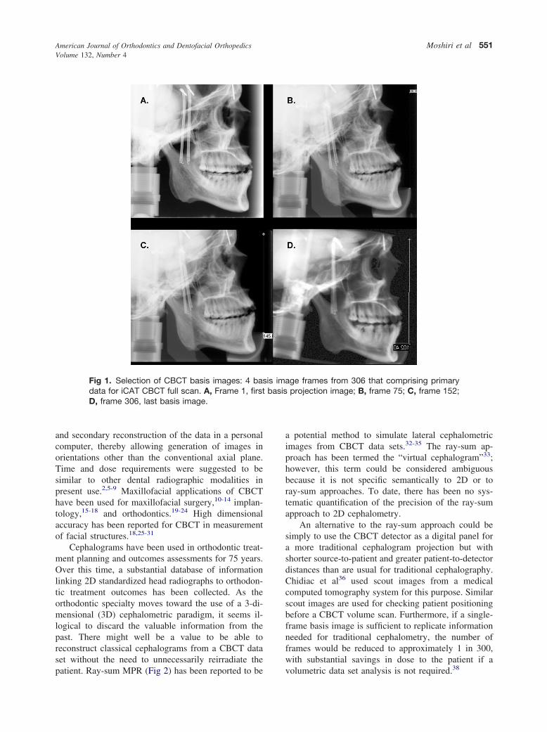
American Journal of Orthodontics and Dentofacial OrthopedicsVolume 132, Number 4
Moshiri et al 551
and secondary reconstruction of the data in a personalcomputer, thereby allowing generation of images inorientations other than the conventional axial plane.Time and dose requirements were suggested to besimilar to other dental radiographic modalities inpresent use.2,5-9 Maxillofacial applications of CBCThave been used for maxillofacial surgery,10-14 implan-tology,15-18 and orthodontics.19-24 High dimensionalaccuracy has been reported for CBCT in measurementof facial structures.18,25-31
Cephalograms have been used in orthodontic treat-ment planning and outcomes assessments for 75 years.Over this time, a substantial database of informationlinking 2D standardized head radiographs to orthodon-tic treatment outcomes has been collected. As theorthodontic specialty moves toward the use of a 3-di-mensional (3D) cephalometric paradigm, it seems il-logical to discard the valuable information from thepast. There might well be a value to be able toreconstruct classical cephalograms from a CBCT dataset without the need to unnecessarily reirradiate the
Fig 1. Selection of CBCT basis images: 4 basdata for iCAT CBCT full scan. A, Frame 1, firstD, frame 306, last basis image.
patient. Ray-sum MPR (Fig 2) has been reported to be
a potential method to simulate lateral cephalometricimages from CBCT data sets.32-35 The ray-sum ap-proach has been termed the “virtual cephalogram”33;however, this term could be considered ambiguousbecause it is not specific semantically to 2D or toray-sum approaches. To date, there has been no sys-tematic quantification of the precision of the ray-sumapproach to 2D cephalometry.
An alternative to the ray-sum approach could besimply to use the CBCT detector as a digital panel fora more traditional cephalogram projection but withshorter source-to-patient and greater patient-to-detectordistances than are usual for traditional cephalography.Chidiac et al36 used scout images from a medicalcomputed tomography system for this purpose. Similarscout images are used for checking patient positioningbefore a CBCT volume scan. Furthermore, if a single-frame basis image is sufficient to replicate informationneeded for traditional cephalometry, the number offrames would be reduced to approximately 1 in 300,with substantial savings in dose to the patient if a
ge frames from 306 that comprising primaryprojection image; B, frame 75; C, frame 152;
is imabasis
volumetric data set analysis is not required.38
American Journal of Orthodontics and Dentofacial OrthopedicsOctober 2007
552 Moshiri et al
The purpose of this study was to quantify thecephalometric measurement accuracy of cephalogramsderived from CBCT by using a ray-sum approach, ofCBCT scout images, and of CBCT single-frame basisimages compared with traditional cephalograms cap-tured on photostimulable phosphor (PSP) and to ana-tomic truth.
MATERIAL AND METHODS
This ex-vivo experiment with dry human skulls wasapproved by the Institutional Human Remains Commit-tee, Department of Anatomical Sciences and Neurobi-ology, at the University of Louisville. The samplecomprised 23 dry skulls with full permanent dentitionand stable and reproducible occlusion. No demographicdata was available; the skulls were not identified byage, sex, or ethnicity. Fifteen anatomical landmarks, of
Fig 2. Example of construction of 2D ray-sumdata and D-F, dry skull sample demonstratingtions of conventional cephalograms. Construcfrom gradual increase in sagittal reference prespectively.
which 4 were bilateral, were identified by consensus on
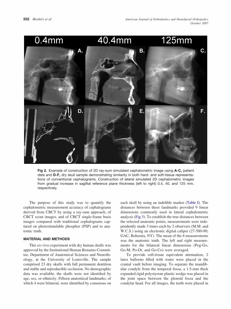
each skull by using an indelible marker (Table I). Thedistances between these landmarks provided 9 lineardimensions commonly used in lateral cephalometricanalysis (Fig 3). To establish the true distances betweenthe selected anatomic points, measurements were inde-pendently made 3 times each by 2 observers (M.M. andW.C.S.) using an electronic digital caliper (27-500-90;GAC, Bohemia, NY). The mean of the 6 measurementswas the anatomic truth. The left and right measure-ments for the bilateral linear dimensions (Pog-Go,Go-M, Po-Or, and Go-Co) were averaged.
To provide soft-tissue equivalent attenuation, 2latex balloons filled with water were placed in thecranial vault before imaging. To separate the mandib-ular condyle from the temporal fossa, a 1.5-mm thickexpanded rigid polystyrene plastic wedge was placed inthe joint space between the glenoid fossa and the
lated cephalometric image using A-C, patientrity in both hard- and soft-tissue representa-f lateral simulated 2D cephalometric imagesickness (left to right) 0.4, 40, and 125 mm,
simusimilation o
lane th
condylar head. For all images, the teeth were placed in
American Journal of Orthodontics and Dentofacial OrthopedicsVolume 132, Number 4
Moshiri et al 553
centric occlusion (maximum intercuspation), and thejaws were held closed by bilateral metal springs. Acustom plastic head holder, with a polyvinyl chloridepipe extension to place in the foramen magnum, wasconstructed to support the skulls during imaging.
Two modalities were used to image the skulls.CBCT images were acquired with the i-CAT system,operated at 3 to 8 mA (pulse mode) and 120 kV with ahigh-frequency generator with fixed anode and 0.5 mmnominal focal spot size. The anterior symphyseal re-gion of the mandible of each skull was placed in thechin holder, and vertical and horizontal lasers wereused to position the skull. Each specimen was orientedby adjustment of the chin support until the midsagittalplane was perpendicular to the floor, and the horizontallaser reference coincided with the intersection of theposterior maxillary teeth and the alveolar ridge. Lateralscout images were made, and head position was ad-justed so that discrepancies between bilateral structures(eg, posterior and inferior borders of the mandibularrami and zygomatic arches) were less than 5 mm. Asingle 360° rotation, 20-second scan, comprising 306basis projections was then made of each skull with a
Table I. Definition of anthropometric landmarks incephalometric analysis
Landmark(abbreviation) Definition
Sella (S) Midpoint of rim between anteriorclinoid process in median plane
Nasion (N) Midsagittal point at junction of frontaland nasal bones at nasofrontal suture
Orbitale* (Or) Most inferior point on infraorbital rimAnterior nasal spine
(ANS)Most anterior limit of floor of nose, at
tip of ANSPosterior nasal spine
(PNS)Point along palate immediately inferior
to pterygomaxillary fossaPogonion (Pog) Most anterior point along curvature of
chinMenton (M) Most inferior point along curvature of
chinGonion* (Go) Point along angle of mandible, midway
between lower border of mandibleand posterior ascending ramus
Basion (Ba) Most inferior point on anterior marginof foramen magnum, at base ofclivus
Porion* (Po) Most superior point of anatomicexternal auditory meatus (anatomicPo)
Condylion* (Co) Most posterior superior point ofmidplaned contour of mandibularcondyle
*Bilateral landmark.
17.0 cm (diameter) x 13.2 cm (height) field of view
with the i-CAT acquisition software (version 1.7.7).Control of acquisition parameters (mA, kVp) wasautomated. Primary reconstruction of the data, automat-ically performed immediately after acquisition, tookapproximately 60 seconds. Secondary reconstructionoccurred in real time and provided contiguous color-correlated perpendicular axial, coronal, and sagittal 2DMPR slices, with isotropic 0.4-mm voxels. Three meth-ods were used to create 2D simulated lateral skullprojection images with the CBCT system: (1) the scoutmethod involved the export of the final lateral scoutradiograph originally made to confirm positioning; (2)the basis frame method involved the selection of a basisimage with the least anatomic discrepancy between theright and left sides corresponding to a lateral cephalo-metric projection; and (3) the ray-sum technique in-volved generation of the image by using the entirevolumetric data set as previously described.32-35 Asimulated 2D lateral cephalogram can be produced byadjusting the sagittal reference plane on the axial imageto coincide with the midpoint of the sella turcica,bisecting the foramen magnum, and increasing the slice
Fig 3. Anatomic landmarks and planes used in analysissuperimposed on representative 2D ray-sum simulatedlateral cephalometric image generated from skull. Lin-ear distances were determined for the following dimen-sions: S-N, sella-nasion; Ba-N, basion-nasion; N-M,nasion-menton; ANS-N, anterior nasal spine-nasion;Pog-Go, pogonion-gonion; Go-M, gonion-menton;ANS-PNS, anterior nasal spine-posterior nasal spine;Po-Or, porion-orbitale; Go-Co, gonion-condylion.
thickness of this plane to a width of approximately 130

.57 � 4
American Journal of Orthodontics and Dentofacial OrthopedicsOctober 2007
554 Moshiri et al
to 150 mm. This provides an image composed of thesummed voxels—the ray-sum image (Fig 3).The win-dow and leveling of these images were adjusted to astandard window (3000/300, respectively). No en-hancement filters were used.
Traditional lateral cephalography was performedwith a Quint Sectograph (model QS 10-1627W; Denar,Anaheim, Calif) and 10:1 parallel grid. The source-to-midsagittal plane distance was maintained at 150 cm.The detector was positioned 15 cm from the midsagittalplane for all exposures. Exposure settings were 78 kVp,200 mA, and 2/15 seconds. For the lateral cephalogram(LC), the skull was stabilized by 2 ear rods in theexternal auditory meati and positioned with the Frank-fort plane parallel to the floor, the sagittal planeperpendicular to the x-ray beam, and the left sideclosest to the detector. The central ray was directed atthe right external auditory meatus.
Digital transmission images were acquired by usingan 8 x 10-in photostimulable storage phosphor imagingplate (Gendex, Des Plaines, Ill). Exposure parameterswere determined by subjective evaluation of imagequality of many images at various exposures on a skullwith a 1-cm thick Perspex attenuation material (LuciteInternational, Southampton, United Kingdom) over theexit beam. The plates were scanned at 300 dpi andsaved in 16-bit tagged image file format (TIFF) byusing the DenOptix imaging system (Gendex). Theimages were equalized and despeckled with proprietarysoftware (VixWin 2000, version 1.2; Gendex). CBCTimages were acquired with a 1024 � 1024 matrixhydrogenated amorphous silicon flat-panel detectorwith cesium iodide scintillator and stored as DICOMfiles. CBCT reconstructed images were reformattedfrom 306 basis projections, providing a cubic voxel sizeof 0.4 mm.
Specific CBCT images were selected, imported intoPhotoShop software (version 7.0; Adobe Systems, SanJose, Calif) and saved as 8-bit TIFF images. CBCTscout and single basis image LCs were inverted to
Table II. Features of imaging plate and CBCT digital i
ImageImage dimensio(width � heig
Modality TypeMatrix size
(pixels)Ph
Projectionradiograph
Lateralcephalometric
2847 � 2386
CBCT Scout 960 � 768 13Frame 480 � 384 6Reconstructed 476 � 330 6
produce black backgrounds. Traditional LC images
were exported from VixWin 2000 software and savedas 8-bit TIFF images. The resulting image matrixdimensions, image sizes, resolutions, and file sizesvaried depending on the modality (Table II). Imageswere imported into a cephalometric analysis program(Dolphin Imaging Cephalometric and Tracing Soft-ware, Chatsworth, Calif). Because of differences inimage dimensions and dpi, separate calibration wasnecessary for each image modality. Therefore, a100-mm radiographic film calibration ruler (model PN130-0168; Dolphin Imaging Cephalometric and Trac-ing Software) was placed in the midsagittal plane of askull perpendicular to the radiographic beam for eachmodality and imaged. These images were used tocalculate the image-casting magnification factor foreach modality and calibrate distances measured in thecephalometric analysis program. The calculated cali-bration magnification factors and resulting dpi used inthe software program are shown in Table II.
The images were coded and viewed on a 17-in flatpanel color active matrix TFT (Dell E171FPb FlatPanel Color Monitor; Dell, Round Rock, Tex) monitorscreen having a resolution of 1024 � 768 at 60 Hz anda 0.264 mm dot pitch, operated at 32-bit color. Acustom analysis in the program was developed to directthe observer to identify specific anatomic landmarks onthe images (Table I). Landmarks were identified byusing a cursor-driven pointer. The analysis providedspecific linear measurements (Fig 3) that were exportedas text data. Some anatomic landmarks required iden-tification of bilateral structures that are inherentlydifficult to view on conventional cephalograms. Forthose points, the observer was instructed to attempt todifferentiate between left and right features and con-struct a point midway between them. If the featurecould not be differentiated, the right and left condylelandmarks were considered coincident. Although theo-retically this would lead to differential magnification ofleft- and right-sided condylar images compared withthe midsagittal correction factor, the minimal influence
Image
Calibrationfactor Final dpi
size File size(kB) dpi
.96 6804 300 9.92% 327
0.67 759 72 0% 72.33 206 72 0% 72.58 178 72 �12.5% 63
mages
nsht)
ysical(in)
9.5 � 7
.33 � 1
.67 � 5
on absolute dimension in relation to the size of the
.77.
American Journal of Orthodontics and Dentofacial OrthopedicsVolume 132, Number 4
Moshiri et al 555
feature and the summation of these distances averagedthe effect.
Statistical analysis
All data were entered into Microsoft Excel 2004(Microsoft, Redmond, Wash). Means and standard devi-ations of 3 independent repeats from the 2 observers of the9 measurements were calculated for each skull and de-fined as anatomic truth. For each imaging mode, theaverage of 3 independent analyses was used. The data fileswere coded for use with the Statistical Package for theSocial Sciences (version 12.0; SPSS, Chicago, Ill). Todetermine intraobserver precision, the intraclass correla-tion coefficient (ICC) was determined. With the Student ttest, the ICC was compared between the 2 raters measur-ing skull dimensions. If no differences existed betweenraters, the ICC was then averaged for both raters andbetween sides. Modality differences were compared with1-way ANOVA by using the Scheffé post-hoc analysis.Modality measurement dimensions were determined to bedistributed normally by the Levene statistic, so the meanof the 3 repeat measurements was used in the analysis.The statistical methods consisted of 1-way ANOVA foreach measurement dimension at an à priori level ofsignificance of P � .05. The post-hoc survey was the
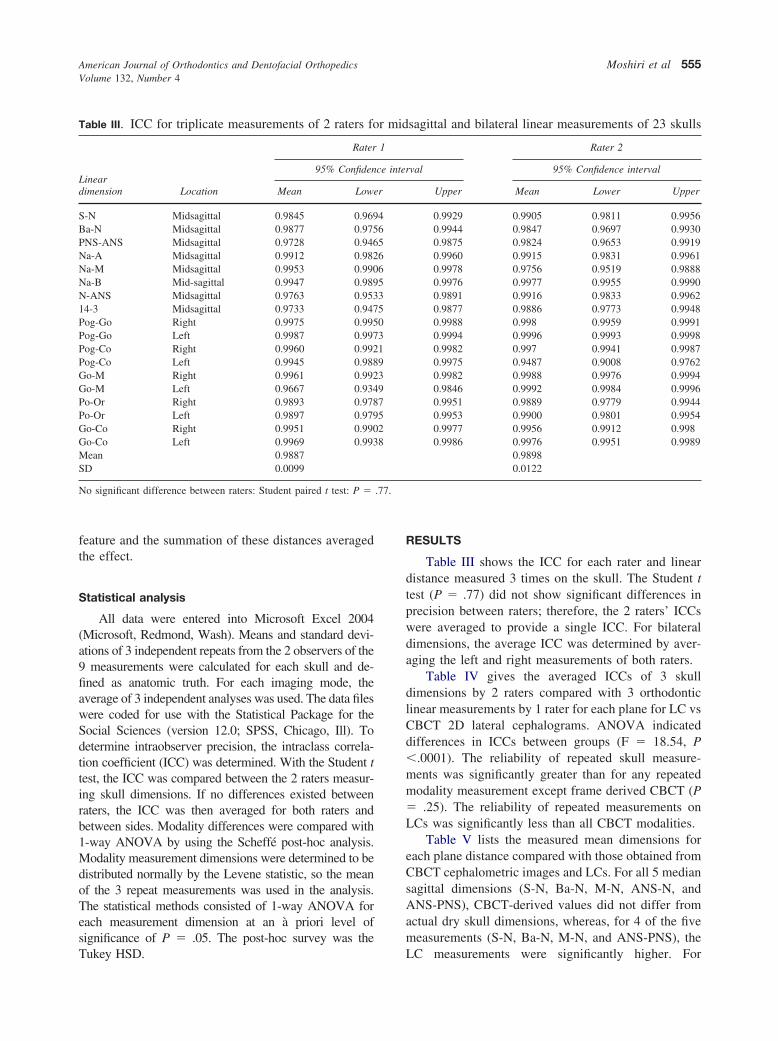
Table III. ICC for triplicate measurements of 2 raters fo
Lineardimension Location
Rater
95% Confiden
Mean Lowe
S-N Midsagittal 0.9845 0.969Ba-N Midsagittal 0.9877 0.975PNS-ANS Midsagittal 0.9728 0.946Na-A Midsagittal 0.9912 0.982Na-M Midsagittal 0.9953 0.990Na-B Mid-sagittal 0.9947 0.989N-ANS Midsagittal 0.9763 0.95314-3 Midsagittal 0.9733 0.947Pog-Go Right 0.9975 0.995Pog-Go Left 0.9987 0.997Pog-Co Right 0.9960 0.992Pog-Co Left 0.9945 0.988Go-M Right 0.9961 0.992Go-M Left 0.9667 0.934Po-Or Right 0.9893 0.978Po-Or Left 0.9897 0.979Go-Co Right 0.9951 0.990Go-Co Left 0.9969 0.993Mean 0.9887SD 0.0099
No significant difference between raters: Student paired t test: P �
Tukey HSD.
RESULTS
Table III shows the ICC for each rater and lineardistance measured 3 times on the skull. The Student ttest (P � .77) did not show significant differences inprecision between raters; therefore, the 2 raters’ ICCswere averaged to provide a single ICC. For bilateraldimensions, the average ICC was determined by aver-aging the left and right measurements of both raters.
Table IV gives the averaged ICCs of 3 skulldimensions by 2 raters compared with 3 orthodonticlinear measurements by 1 rater for each plane for LC vsCBCT 2D lateral cephalograms. ANOVA indicateddifferences in ICCs between groups (F � 18.54, P�.0001). The reliability of repeated skull measure-ments was significantly greater than for any repeatedmodality measurement except frame derived CBCT (P� .25). The reliability of repeated measurements onLCs was significantly less than all CBCT modalities.
Table V lists the measured mean dimensions foreach plane distance compared with those obtained fromCBCT cephalometric images and LCs. For all 5 mediansagittal dimensions (S-N, Ba-N, M-N, ANS-N, andANS-PNS), CBCT-derived values did not differ fromactual dry skull dimensions, whereas, for 4 of the fivemeasurements (S-N, Ba-N, M-N, and ANS-PNS), the
sagittal and bilateral linear measurements of 23 skulls
Rater 2
val 95% Confidence interval
Upper Mean Lower Upper
0.9929 0.9905 0.9811 0.99560.9944 0.9847 0.9697 0.99300.9875 0.9824 0.9653 0.99190.9960 0.9915 0.9831 0.99610.9978 0.9756 0.9519 0.98880.9976 0.9977 0.9955 0.99900.9891 0.9916 0.9833 0.99620.9877 0.9886 0.9773 0.99480.9988 0.998 0.9959 0.99910.9994 0.9996 0.9993 0.99980.9982 0.997 0.9941 0.99870.9975 0.9487 0.9008 0.97620.9982 0.9988 0.9976 0.99940.9846 0.9992 0.9984 0.99960.9951 0.9889 0.9779 0.99440.9953 0.9900 0.9801 0.99540.9977 0.9956 0.9912 0.9980.9986 0.9976 0.9951 0.9989
0.98980.0122
r mid
1
ce inter
r
465665350319397528
LC measurements were significantly higher. For

and sku
American Journal of Orthodontics and Dentofacial OrthopedicsOctober 2007
556 Moshiri et al
ANS-N, although the LC and CBCT modalities weresignificantly different, they were not different from theactual dry-skull dimensions. Of the 3 bilateral measure-ments, only Po-Or provided measurements similar tothe actual dry-skull dimensions with no differencesbetween modalities. For Pog-Go and Go-M, all modal-ities provided significantly smaller measurements fromthe actual dimensions with no differences between
Table IV. ICC of triplicate skull dimensions by 2 raters1 rater for each cephalometric plane for conventional icephalometric projections.
Lineardimension
Truth* Imaging plate
SkullLateral
cephalometric
S-N 0.9875 0.6215Ba-N 0.9862 0.5693N-M 0.9855 0.7673ANS-N 0.9839 0.5495ANS-PNS 0.9776 0.6955Pog-Go† 0.9985 0.7763Go-M† 0.9902 0.8461Po-Or† 0.9895 0.7519Go-Co† 0.9963 0.8428Means � SD 0.9884 � 0.00632‡ 0.7134 � 0.111§
*Mean value from measurements of 2 raters.†Mean value from measurements of both sides.‡Significant difference between skull and imaging plate lateral ceph§Significant difference between imaging plate lateral cephalometric
Table V. Mean length (mm � SD) of orthodontic lineadigital and CBCT-derived simulated lateral cephalome
Dimension
Mod
TruthImaging
plate
SkullLateral
cephalometric Sc
S-N 59.49 � 3.62 64.94 � 3.00† 60.95 �Ba-N 98.07 � 5.7 104.98 � 5.52† 98.14 �N-M 109.24 � 6.85 116.81 � 7.57† 109.81 �ANS-N 46.64 � 2.77 48.79 � 2.71‡ 45.84 �ANS-PNS 47.61 � 3.23 50.5 � 4.56† 45.93 �Pog-Go* 83.34 � 7.69c 77.94 � 6.57 74.78 �Go-M* 79.37 � 5.64§ 74.49 � 6.29 72.05 �Po-Or* 78.22 � 4.74 79.44 � 5.34 77.69 �Go-Co* 56.49 � 5.09 59.36 � 6.56‡ 51.3 �
*Mean value from measurements of both sides.†Significant difference from actual skull measurement and all CBCT‡Significant difference from all CBCT-derived dimensions only.§Significant difference of actual measurement from lateral cephalom¶Significant difference from actual dimensions.
modalities. For Go-Co, measurements from the CBCT
scout images were significantly less than the actualdimensions. In addition, for Go-Co, LC measurementswere significantly higher than all CBCT-derived mea-surements but were not significantly different fromactual measurements.
DISCUSSION
No single imaging technique has been readily
red with triplicate orthodontic linear measurements byg plate based and CBCT-derived 2D simulated lateral
Modality
CBCT
Scout Frame Reconstructed
0.9093 0.9421 0.87120.8212 0.9138 0.89340.9858 0.9848 0.94980.9491 0.9319 0.76050.7731 0.7922 0.81730.8500 0.9285 0.94560.8063 0.9077 0.91330.7971 0.9138 0.91870.8448 0.8750 0.8459
0.8596 � 0.073 0.9099 � 0.0531 0.8795 � 0.0626
ic and all CBCT modalities except frame derived.ll and all CBCT modailities.
ensions for each cephalometric plane for conventionalojections
Significance
CBCT
Frame ReconstructedF
value P
60.78 � 3.18 61.27 � 2.82 9.88 .00097.98 � 5.12 99.72 � 4.46 7.78 .000
109.03 � 6.85 110.43 � 7.11 4.69 .00245.19 � 2.94 46.41 � 2.58 5.79 .00046.12 � 3.53 46.73 � 2.71 6.48 .00073.36 � 5.71 74.9 � 6.26 8.68 .00070.55 � 5.57 71.50 � 5.82 8.16 .00077.83 � 5.6 76.16 � 4.00 1.33 .2752.46 � 5.01 54.74 � 4.48 8.8 .000
d dimensions.
d all CBCT-derived dimensions.
compamagin
alometr
r dimtric pr
ality
out
2.924.827.222.543.326.036.084.71
4.59¶
-derive
etric an
available to provide an accurate, easily interpreted
American Journal of Orthodontics and Dentofacial OrthopedicsVolume 132, Number 4
Moshiri et al 557
representation of all osseous aspects of the craniofacialregion in 1 exposure. Previously, a plain LC, occasion-ally combined with a coronal (posteroanterior) or axial(submentovertex) projection, was used for visualizationof jaw symmetry or asymmetry. The rapidly emergingavailability of maxillofacial CBCT allows clinicians toreformat the volumetric data set for conventional(scout, basis frame) or ray-sum wide-slice sectionssimulating plane projections such as cephalometric,submentovertex, and posteroanterior views—all with 1relatively short scan.
We compared the accuracy of linear measurementsmade on PSP cephalograms with 2D LCs derived fromvolumetric reconstruction CBCT data sets. We foundthat CBCT images either produced with individualframes or reconstructed from the volumetric data setwere accurate for all measurements except Pog-Go andGo-M. CBCT scout images had the second highestaccuracy for all measurements except Pog-Go, Go-M,and Go-Co. Conventional LCs had the least accuracy;they were accurate only for Po-Or and ANS-N. Ourresults differ with those of Chidiac et al,36 who foundreduced correlation to skull dimensions for transversemeasuresments for scout images of a medical fan-beamcomputed tomography compared with conventionalcephalograms.
There was a trend for our lateral cephalometricmeasurements to be statistically significantly greaterthan the skull measurements in 4 of the 5 midsagittal(S-N, Ba-N, N-M, ANS-PNS) and in 1 of the 4 bilateral(Go-Co) measurements. Magnification ranged from4.6% to 9.1%. Although this discrepancy could be due,in part, to a previously reported systematic error spe-cific to this software’s calculation algorithm,38 otherpotential sources of error include inherent differencesin image acquisition, head position,39,40 and linearprojective transformation. 41,42 Adams et al43 reportedsimilar findings: certain midsagittal measurements (Na-Gn, Na-B, Na-S, Na-A, and A-B) were significantlygreater than truth on 2D cephalograms (9.82, 8.32,6.22, 4.99, and 3.11 mm, respectively). The interactionof these factors could also result in the significantlyhigher ICCs of repeated measurements on PSP LCscompared with those derived from CBCT.
The projection geometries of the 2 generators usedin this study are intrinsically different. Conventionalcephalographic systems, both film and digital, incorpo-rate a long source-to-object distance, providing rela-tively parallel x-ray beam geometry resulting in aninherent differential magnification of bilateral struc-tures. Although midsagittal structures are commonlymagnified by as much as 10%, convention dictates that
when bilateral landmarks are identified (eg, Or, Po,Go), location for analytical purposes is determined byvisual approximation of the mental average of bothpositions. This introduces an inherent variability in thelocalization of these structures based on the observer’svisual acuity. In comparison, CBCT incorporates arelatively short source-to-object distance with rela-tively divergent x-ray beam geometry, producing aprojection with marked differential magnification.However, single-frame images are not based on imageprojection geometry alone. CBCT images are producedonly after application of a reconstruction algorithm,such as that of Feldkamp et al.44 Such algorithmsincorporate geometric correction factors compensatingfor differential distortion peripheral to the central x-raybeam projection along with back projection correctionsfor tube position, tube, object, and detector distances.Resultant single CBCT images are therefore correctedto produce orthogonal projections with no differentialmagnification between bilateral or midsagittal struc-tures. We believe that this correction accounts for theconsistent and remarkable (�2 mm) accuracy of CBCTimages for midsagittal linear dimensions, irrespectiveof derivation as compared with conventional lateralcephalometric images.
In addition to inherent x-ray projective beam ge-ometry differences between techniques, many otherpotential sources of error contribute to the relativeinaccuracy of conventional LCs.45 These include headmalpositioning,39,40,46,47 radiographic method of anal-ysis,39 error due to landmark identification,39 and intra-and interobserver errors.48 The skulls were positionedin the cephalostat, and the Frankfort horizontal wasadjusted visually before exposure compared with skullpositioning in the CBCT equipment, which used laserlevel indicators. In addition, digital scout images wereacquired to establish minimal bilateral discrepancybefore final CBCT acquisition. We expected that theaccuracy of the digital LCs might be greater than theCBCT-derived images because the former used PSPsprocessed at 300 dpi, substantially higher than theresolution used to screen capture CBCT images (72dpi). However, investigators indicated no quantitativedifferences in mean error distances in lateral cephalo-metrics at resolutions as low as 75 dpi.49,50
The method of establishing anatomic truth couldhave contributed to bias in the results because, althoughthe landmark identification and measurements on theradiographs were repeated, landmark identification onthe skulls was done only once, albeit by consensus.This reduced the error of point identification on theskulls, but the establishment of a consensus landmarklocation was necessary to provide a fiducial reference to
which we could compare the inherent clinical inaccu-
American Journal of Orthodontics and Dentofacial OrthopedicsOctober 2007
558 Moshiri et al
racies of both landmark identification and measurementassociated with the radiographic technique.
Regarding bilateral measurement accuracy, it wasexpected that these would be smaller in overall dimen-sions because 3D linear distances (eg, Pog-Go) areprojected onto a planar surface. This was generally truefor all dimensions except Po-Or, for which we found nodifferences in accuracy between modalities. This wasmost probably because the deviation of this dimensionfrom the midsagittal is minimal.
This study was limited in that soft tissue used forattenuation was minimal and consisted of a simulatedwater-based brain and separation of the condyle fromthe fossa with expanded rigid polystyrene plastic. Noeffort was made to simulate facial soft tissues becausethis would have increased structural noise and scatterradiation, potentially increasing the variability of land-mark identification. The image accuracy of the CBCTimages in this clinical simulation might have beenreduced because of decreased signal-to-noise ratio dueto scatter inherent in CBCT systems with increasingvolumetric exposure.
It would be tempting, based on the greater accuracyof dimensions obtained with simulated cephalometricimages generated from an entire CBCT volumetric dataset, to interpret our findings as advocating this modalityin orthodontic practice. Apart from greater accuracy,CBCT volumetric data sets can be reoriented so thatreconstructed lateral ray-sum images produce simu-lated cephalometric images with optimal orientation.However, our results also indicate only a marginaladvantage in the measurement accuracy of ray-sumreconstructions when compared with images generatedfrom a single CBCT scout projection or single-framebasis image. In addition, we did not take into accountcomparative radiation exposures required to producesuch images. A complete CBCT scan often requiresabout 300 successive basis image frame exposures.Because there were no differences in accuracy in thedimensions from a single-frame image and a recon-structed ray-sum image from 306 frames, this impliesup to a 306-fold increase in exposure to produce acomparable LC. In addition, perhaps statistical differ-ences producing conclusions of greater accuracy do notconsider the clinical significance of our findings. Ka-moen et al45 provided absolute repeatability guidelinesbased on a 95% confidence interval for commonly usedcephalometric variables and listed estimates of theminimal 99% critical difference in error for specificsample sizes. Although they did not provide guidelinesfor tolerances for their linear measurements, all mea-
surement discrepancies between conventional lateralcephalometric and anatomic measurements were 2 to 5mm, well within acceptable clinical tolerance.
Further studies are needed to investigate the clinicalefficacy of CBCT-derived conventional projections byusing the ray-sum reconstruction, particularly for pa-tients with craniofacial asymmetry. In addition, clinicalcost/benefit analyses incorporating exposure consider-ations should be made to assist in developing appropri-ate patient selection criteria for CBCT imaging incephalometric analysis.35 Nevetheless, our results indi-cate that CBCT manufacturers might consider permit-ting very low single-frame cephalograms in variousorientations beyond the lateral scout image. Such im-ages could act as a low-dose baseline. When 3Dinformation is required (eg, to assess dental impac-tions), this could then be restricted to as narrow a fieldof view as required to obtain the necessary diagnosticinformation. Then very high spatial resolution can beapplied.
CONCLUSIONS
For most 2D cephalometric measurements in thesagittal plane, simulated 2D lateral cephalometric pro-jections from CBCT proved to be more accurate thanconventional LCs. Although 2D cephalograms gener-ated from single CBCT basis projections improved theaccuracy of cephalometric measurements over conven-tional cephalography, there was no additional gain fromusing ray-sum images generated from the CBCT volu-metric data set.37
We thank April Styles, our 2005 summer researchassociate and graduate student in oral biology, andOana Bida Honey at the University of LouisvilleSchool of Dentistry for their valuable assistance in thisproject.
REFERENCES
1. Mozzo P, Procacci C, Tacconi A, Martini PT, Andreis IA. A newvolumetric CT machine for dental imaging based on the cone-beam technique: preliminary results. Eur Radiol 1998;8:1558-64.
2. Hashimoto K, Arai Y, Iwai K, Araki M, Kawashima S, TerakadoM. A comparison of a new limited cone beam computedtomography machine for dental use with a multidetector rowhelical CT machine. Oral Surg Oral Med Oral Pathol Oral RadiolEndod 2003;95:371-7.
3. Sukovic P. Cone beam computed tomography in craniofacialimaging. Orthod Craniofac Res 2003;6(Suppl 1):31-6.
4. Baba R, Ueda K, Okabe M. Using a flat-panel detector in highresolution cone beam CT for dental imaging. DentomaxillofacRadiol 2004;33:285-90.
5. Bianchi S, Anglesio S, Castellano S, Rizzi L, Ragona R.Absorbed doses and risk in implant planning: comparison be-tween spiral CT and cone-beam CT [abstract]. Dentomaxillofac
Radiol 2001;30(Suppl 1):S28.
American Journal of Orthodontics and Dentofacial OrthopedicsVolume 132, Number 4
Moshiri et al 559
6. Schulze D, Heiland M, Thurmann H, Adam G. Radiationexposure during midfacial imaging using 4- and 16-slice com-puted tomography, cone beam computed tomography systemsand conventional radiography. Dentomaxillofac Radiol 2004;33:83-6.
7. Ludlow JB, Davies-Ludlow LE, Brooks SL, Howerton WB.Dosimetry of 3 CBCT devices for oral and maxillofacial radiol-ogy: CB Mercuray, NewTom 3G and i-CAT. DentomaxillofacRadiol 2006;35:219-26.
8. Mah JK, Danforth RA, Bumann A, Hatcher D. Radiationabsorbed in maxillofacial imaging with a new dental computedtomography device. Oral Surg Oral Med Oral Pathol Oral RadiolEndod 2003;96:508-13.
9. Tsiklakis K, Donta C, Gavala S, Karayianni K, KamenopoulouV, Hourdakis CJ. Dose reduction in maxillofacial imaging usinglow dose cone beam CT. Eur J Radiol 2005;56:413-7.
10. Ziegler CM, Woertcher R, Brief J, Hassfeld S. Clinical indica-tions for digital volume tomography in oral and maxillofacialsurgery. Dentomaxillofac Radiol 2002;31:126-30.
11. Nakagawa Y, Kobayashi K, Ishii H, Mishima A, Ishii H, AsadaK, et al. Preoperative application of limited cone beam comput-erized tomography as an assessment tool before minor oralsurgery. Int J Oral Maxillofac Surg 2002;31:322-6.
12. Danforth RA, Peck J, Hall P. Cone beam volume tomography: animaging option for diagnosis of complex mandibular third molaranatomical relationships. J Calif Dent Assoc 2003;31:847-52.
13. Heiland M, Schmelzle R, Hebecker A, Schulze D. Intra-opera-tive 3D imaging of the facial skeleton using the SIREMOBILIso-C3D. Dentomaxillofac Radiol 2004;33:130-2.
14. Hamada Y, Kondoh T, Noguchi K, Iino M, Isono H, Ishii H, etal. Application of limited cone beam computed tomography toclinical assessment of alveolar bone grafting: a preliminaryreport. Cleft Palate Craniofac J 2005;42:128-37.
15. Hatcher DC, Dial C, Mayorga C. Cone beam CT for pre-surgicalassessment of implant sites. J Calif Dent Assoc 2003;31:825-33.
16. Sarment DP, Sukovic P, Clinthorne N. Accuracy of implantplacement with a stereolithographic surgical guide. Int J OralMaxillofac Implants 2003;18:571-7.
17. Sato S, Arai Y, Shinoda K, Ito K. Clinical application of a newcone-beam computerized tomography system to assess multipletwo-dimensional images for the preoperative treatment planningof maxillary implants: case reports. Quintessence Int 2004;35:525-8.
18. Kobayashi K, Shimoda S, Nakagawa Y, Yamamoto A. Accuracyin measurement of distance using limited cone-beam computer-ized tomography. Int J Oral Maxillofac Implants 2004;19:228-31.
19. Mah JD, Hatcher D. Current status and future needs in cranio-facial imaging. Orthod Craniofac Res 2003;6(Suppl 1):10-6.
20. Vannier MW. Craniofacial computed tomography scanning:technology, applications and future trends. Orthod Craniofac Res2003;6(Suppl 1):23-30.
21. Maki K, Inou N, Takanishi A, Miller AJ. Computer-assistedsimulations in orthodontic diagnosis and the application of a newcone beam x-ray computed tomography. Orthod Craniofac Res2003;6(Suppl 1):95-101.
22. Baumrind S, Carlson S, Beers A, Curry S, Norris K, Boyd RL.Using three-dimensional imaging to assess treatment outcomesin orthodontics: a progress report from the University of thePacific. Orthod Craniofac Res 2003;6(Suppl 1):132-42.
23. Aboudara CA, Hatcher D, Nielsen IL, Miller A. A three-dimensional evaluation of the upper airway in adolescents.
Orthod Craniofac Res 2003;6(Suppl 1):173-5.24. Danforth RA, Dus I, Mah J. 3-D volume imaging for dentistry:a new dimension. J Calif Dent Assoc 2003;31:817-23.
25. Lascala CA, Panella J, Marques MM. Analysis of the accuracy of linearmeasurements obtained by cone beam computed tomography (CBCT-NewTom). Dentomaxillofac Radiol 2004;33:291-4.
26. Marmulla R, Wortche R, Muhling J, Hassfeld S. Geometricaccuracy of the NewTom 9000 cone beam CT. DentomaxillofacRadiol 2005;34:28-31.
27. Tsiklakis KK, Syriopoulos K, Stamatakis HC. Radiographic exam-ination of the temporomandibular joint using cone beam computedtomography. Dentomaxillofac Radiol 2004;33:196-201.
28. Beason R, Brooks SL. TMJ imaging accuracy using alphaprototype of DentoCAT cone-beam CT [abstract]. J Dent Res2004;83(Spec Iss A):1938.
29. Honda K, Arai Y, Kashima M, Takano Y, Sawada K, Ejima K,et al. Evaluation of the usefulness of the limited cone-beam CT(3DX) in the assessment of the thickness of the roof of theglenoid fossa of the temporomandibular joint. DentomaxillofacRadiol 2004;33:391-5.
30. Honda K, Larheim TA, Johannessen S, Arai Y, Shinoda K,Westesson PL. Ortho cubic super-high resolution computedtomography: a new radiographic technique with application tothe temporomandibular joint. Oral Surg Oral Med Oral PatholOral Radiol Endod 2001;91:239-43.
31. Hilgers ML, Scarfe WC, Scheetz JP, Farman AG. Accuracy oflinear temporomandibular joint measurements with cone beamcomputed tomography and digital cephalometric radiography.Am J Orthod Dentofacial Orthop 2005;128:803-11.
32. Farman, AG, Scarfe WC, Hilgers MJ, Bida O, Moshiri M, SukovicP. Dentomaxillofacial cone-beam CT for orthodontic assessment.In: Lemke HU, Inamura K, Doi K, Vannier MK, Farman AG,editors. Computer assisted radiology and surgery. Proceedings ofthe 19th International Congress on Computer Assisted Radiologyand Surgery, Berlin, Germany, June 22–25, 2005. Amsterdam:Elsevier; 2005. p.1187-90. ISBN:0-444-51872-X.
33. Schuytser FA, Van Cleynenbreugel J. From 3-D volumetriccomputer tomography to 3-D cephalometry. In: Swennen GJ,Schuytser FA, Hausamen JE, editors. Three dimensional cepha-lometry: a color atlas and manual. Berlin: Springer GmbH; 2005.p. 2-11. ISBN: 3-540-25440-4.
34. Scarfe WC, Farman AG, Sukovic P. Clinical applications of conebeam computed tomography in dental practice. J Can Dent Assoc2006;72:75-80.
35. Farman AG, Scarfe WC. Development of imaging selectioncriteria and procedures should precede cephalometric assessmentwith cone-beam computed tomography. Am J Orthod Dentofa-cial Orthop 2006;130:257-65.
36. Chidiac JJ, Shofer FS, Al-Kutoub A, Laster LL, Ghafari J.Comparison of CT scanograms and cephalometric radiographs incraniofacial imaging. Orthod Craniofac Res 2002;5:104-13.
37. Farman AG. ALARA still applies. Oral Surg Oral Med OralPathol Oral Radiol Endod 2005;100:395-7.
38. Power G, Breckon J, Sherriff M, McDonald F. Dolphin imagingsoftware: an analysis of the accuracy of cephalometric digitiza-tion and orthognathic prediction. Int J Oral Maxillofac Surg2005;34:619-26.
39. Malkoc S, Sari Z, Usumez S, Koyuturk AE. The effect of headrotation on cephalometric radiographs. Eur J Orthod 2005;2:315-21.
40. Yoon YJ, Kim DH, Yu PS, Kim HJ, Choi EH, Kim KW. Effectof head rotation on posteroanterior cephalometric radiographs.Angle Orthod 2002;72:36-42.
41. Tsao DH, Kazanoglu A, McCasland JP. Measurability of radio-
graphic images. Am J Orthod 1983;84:212-6.
American Journal of Orthodontics and Dentofacial OrthopedicsOctober 2007
560 Moshiri et al
42. Tsao DH. Graphic description of figure representation of the teethand mandible in centric occlusion. J Prosthet Dent 1982;47:95-100.
43. Adams GL, Gansky SA, Miller AJ, Harrell WE Jr, Hatcher DC.Comparison between traditional 2-dimensional cephalometryand a 3-dimensional approach on human dry skulls. Am J OrthodDentofacial Orthop 2004;126:397-409.
44. Feldkamp LA, Davis LC, Kress JW. Practical cone-beam algo-rithm. J Opt Soc Am 1984;1:612-9.
45. Kamoen A, Dermaut L, Verbeeck R. The clinical significance oferror measurement in the interpretation of treatment results. EurJ Orthod 2001;23:569-78.
46. Cooke MS, Wei SH. Cephalometric errors: a comparison be-tween repeat measurements and retaken radiographs. Aust Dent
J 1991;36:38-43.47. Mori Y, Miyajima T, Minami K, Sakuda M. An accuratethree-dimensional cephalometric system: a solution for the cor-rection of cephalic malpositioning. J Orthod 2001;28:143-9.
48. Perillo M, Beideman R, Shofer F, Jacobsson-Hunt U, Higgins-Barber K, Laster L, et al. Effect of landmark identification oncephalometric measurements: guidelines for cephalometric anal-yses. Clin Orthod Res 2000;3:29-36.
49. Held CL, Ferguson DJ, Gallo MW. Cephalometric digitization: adetermination of the minimum scanner settings necessary forprecise landmark identification. Am J Orthod Dentofacial Orthop2001;119:472-81.
50. Halazonetis DJ. At what resolution should I scan cephalomet-ric radiographs? Am J Orthod Dentofacial Orthop 2004;125:
118-9.Copyright © 2022 FDOKUMEN