The Effect of Continuous Trapezoidal Straight Spoiler Plates ...

Research ArticleAC Loss Measurements of a Trapezoidal Shaped HTS CoilUsing an Electrical Method
G. Messina,1 L. Morici,1 U. Besi Vetrella,1 G. Celentano,1 M. Marchetti,1
R. Viola,1 and P. Sabatino2
1 ENEA, Unita Tecnica Fusione, ENEA C. R. Frascati, Via Enrico Fermi 45, Frascati, 00044 Roma, Italy2 Universita di Salerno, Via Giovanni Paolo II 132, Fisciano, 84084 Salerno, Italy
Correspondence should be addressed to G. Messina; [email protected] and L. Morici; [email protected]
Received 31 July 2014; Revised 11 November 2014; Accepted 12 November 2014; Published 2 December 2014
Academic Editor: Dong Qian
Copyright © 2014 G. Messina et al. This is an open access article distributed under the Creative Commons Attribution License,which permits unrestricted use, distribution, and reproduction in any medium, provided the original work is properly cited.
High temperature superconducting (HTS) coils of different shapes (typically circular or trapezoidal) wound on iron or ironlesscore are fundamental components of many superconducting electrical power devices. A 150-turn (75 turns/pancake) trapezoidalcoil in double pancake configuration has been designed and realized in our laboratory of ENEA Frascati. Various epoxy resinsand YBCO tapes have been tested in the temperature range room to liquid nitrogen, leading us to the choice of AmSC (AmericanSuperconductor) tape for the winding and araldite resin for the impregnation process. The trapezoidal shape has been chosenbecause of its suitable geometry for practical applications, the results being complementary to what was previously achieved onround shapedHTS coils.TheAC transport current losses have beenmeasured using a compensated electricalmethod and expressedin terms of a linearly frequency dependent resistance. A linear dependence of the losses resistance from frequency was expected andfound in agreement with previous results. The current-voltage curve has been measured in zero externally applied field condition,the results being in good agreement with a numerical simulation. The magnetic field distributions, at different air gaps from coiltop and zero externally applied filed condition, have been simulated and reported as well.
1. Introduction
Second generation (2G) high temperature superconducting(HTS) coils have a range of applications in electrical devices,such as superconducting fault current limiter (SFCL), super-conducting magnetic energy storage (SMES), and super-conducting generators and motors. The zero resistance ofany superconducting (SC) material is only observed in DCconditions; in an AC environment, any varying magneticfield interacts with the SC material giving rise to energydissipation: AC transport current losses if the magnetic fieldis self-generated and AC magnetization losses if the magneticfield is externally applied. AC losses give rise to a thermalload for the cryogenic system, resulting in a constraint forthe use and operation of superconducting materials and hardmeasures of interest in this paper. Critical currents, air-gapmagnetic flux density, and AC losses analysis of HTS coilscomponents are important steps in complex devices design,determining the application ranges of the rated currents andmagnetic fields of superconductingmaterial.AC losses, being
responsible of the cryogenic equipment required power, areamong the greatest factors influencing the overall economicimpact of SC devices. To increase air-gap magnetic fluxdensity in axial flux electrical machines, various shapes ofHTS coils have beenmanufactured and tested in our facilities.Cylindrical coils made with commercial coated conductorshave been largely studied in several works, either by mea-surements and/or computations [1–10], while the trapezoidalshape is taken into account here to optimize the stator-rotor system coupling. In this paper, a complete theoreticaland experimental study of a trapezoidal shape 2G HTScoil is reported. The paper is structured as follows: doublepancakeHTS coil manufacturing process presentation, liquidnitrogen temperature of the coil critical currents presentationand comparison with a FEM model simulation, an electricalmeasurement method description for the AC condition, ACtransport current losses results expressed in terms of anequivalent frequency dependent loss resistance, discussion,and final conclusions.
Hindawi Publishing CorporationInternational Journal of SuperconductivityVolume 2014, Article ID 391329, 6 pageshttp://dx.doi.org/10.1155/2014/391329

2 International Journal of Superconductivity
(a)
19
19 4989
58 94.5
R10
(b)
Figure 1: (a) Trapezoidal shape HTS coil. (b) All dimensions in mm: height = 13mm, maximum bending = 10mm.
2. Trapezoidal Coil Description
To manufacture our trapezoidal coil, we used a (4.8mm ×
0.2mm) magnetic substrate YBCO copper laminated certi-fied Amperium tape, manufactured by American Supercon-ductor (AmSC). The tape electrical self-field critical currentis 𝐼𝑐> 100A at 77K. About 35m of the Amperium tape
has been used to wind a 150-turn (75 turns per pancake)double pancake coil around a PVC trapezoidal shaped core,side by side. To avoid tape damages during bending, the corehas been designed considering the tape minimum acceptablecurvature radius. The winding process was carried out atroom temperature, starting at midsection, insulating eachwind with a Kapton tape, and stretching the tape with 1Nconstant force, the force being applied to avoid any lift-off issue around the corners. During HTS tape winding,the YBCO layer was outward oriented with an insulatingtape between adjacent turns. Once the winding process hasbeen carried out, an impregnation material (epoxy resina.k.a. araldite) has been applied to the coil. Finally, thefirst and last turns have been soldered to current leads [11].The impregnation material has been treated according tothe manufacturer preparation specifications; curing was notperformed, the samples being dried at room temperature.Voltage taps have been soldered at coil ends for overallvoltage measurement.TheHTS coil is pictured in Figure 1(a),geometric parameters being the following: larger size (blueline)𝐷 = 94.5mm, smaller size (red line) 𝑑 = 89mm, heightℎ = 13mm, winding thickness = 19mm.
3. Critical CurrentMeasurement and Simulation
To estimate the critical current of our HTS coil, the current-voltage characteristic at zero external field condition has beenmeasured using the 4 probes standard electrical method.The1 𝜇Vcm−1 criteria threshold has been used for 𝐼
𝑐determi-
nation; as shown in Figure 2(a), we measured 𝐼𝑐= 55.6A.
For simulation purposes, the coil trapezoidal shape hasbeen approximated with a circular shape (Figure 1(b)) [12].Accordingly, a two-dimensional (2D) axial symmetrical FEMmodel for the coil cross section, based on the𝐻-formulation,has been worked out using the software package COMSOLMultiphysics. With the usual meaning of the symbols, Fara-day’s andAmpere’s laws (∇×E = −𝜕B/𝜕t, ∇×B = 𝜇
0J), as well
as the material constitutive laws (B = 𝜇0𝜇𝑟H, E = 𝜌J), have
been implemented. In the 2D approximation, we use (𝑟, 𝑧)cylindrical coordinate for the coil cross section in order tohave only two variables in the 𝐻-formulation; that is, H =
(𝐻𝑟, 𝐻𝑧). The current 𝐽
𝜙of the coil flows in the 𝜙 direction
generating an azimuthal electric field, 𝐸 = 𝐸𝜙= 𝜌 ⋅ 𝐽
𝜙, while
Ampere and Faraday’s laws become, respectively,
𝐽𝜙= ∇ ×H =
𝜕𝐻𝑟
𝜕𝑧
−
𝜕𝐻𝑧
𝜕𝑟
,
∇ × E = (−
𝜕𝐸𝜙
𝜕𝑧
1
𝑟
𝜕 (𝑟𝐸𝜙)
𝜕𝑟
) = −𝜇0(
𝜕(𝜇𝑟𝐻𝑟)
𝜕𝑡
𝜕 (𝜇𝑟𝐻𝑧)
𝜕𝑡
) .
(1)
The ReBCO tape has been modeled using real thicknesses:1 𝜇mforYBCO layers and 75𝜇mformagnetic substrate layerswith 0.3𝜇m separation [13]. The 𝐸-𝐽 law has been definedseparately for the superconducting layer, where it is mainlynonlinear, from the other materials where resistivity (𝜌) is aconstant:
𝜌 (𝐵, 𝜃)
=
{{{{
{{{{
{
105
Ωm (air)𝐸𝑐
𝐽𝑐(𝐵, 𝜃)
⋅ (
𝐽𝜙
𝐽𝑐(𝐵, 𝜃)
)
(𝑛(𝐵,𝜃)−1)
(HTS)
5 𝜇Ωm (magnetic substrate) ,
(2)

International Journal of Superconductivity 3
0 10 20 30 40 50 60 70
0
50
100
150
Measurements
2D axisymmetric simulations
Ic = 55.6A Ic = 58.9A
n = 15.1n = 13.4
E(𝜇
V/m
)
I (A)
Ec = 10−4 V/m
Power law, fitted in [10, 100] (𝜇V/m)
(𝜇V/m)Power law, fitted in [10, 100]
(a)
0
0
0.01 0.02
0.02
0.03 0.04 0.05
−0.02
−0.01
0.01
z(m
)
r (m)
−0.015
0.015
−0.005
0.005
0
0.1
0.2
0.3
(b)
Figure 2: (a) Comparison of 𝐼𝑉 curve at 77 Kmeasured and numerically calculated. (b) Snapshot of magnetic field intensity 𝐵 (T) computedat the critical current 𝐼
𝑐= 59A.
𝜃 ≡ angle between tape 𝑐-axis (i.e., current direction) andmagnetic induction B. AmSC tape characteristic propertieshave been used, this way improving simulated and measureddata agreement; in particular, an elliptical composition ofparallel and perpendicular behavior, of both the critical cur-rent and the 𝑛-value, has been introduced for the anisotropicYBCO layer modeling [1, 11, 14]. The nonlinear 𝐵-𝐻 law ofthe substrate material (Ni-5at%W) has been implemented inthe FEM code defining the relative magnetic permeability asa function of magnetic field [15], while we used a unitarypermeability in the remaining materials:
𝜇𝑟(𝐻)
=
{{{{{{
{{{{{{
{
1 (HTS and air)
1 + 30600 (1 − exp(−( 𝐻
295
)
2.5
))
×𝐻−0.81
+ 45 exp(−( 𝐻
120
)
2.5
) (substrate) .
(3)
A code computed 𝐼-𝑉 curve of the double pancake coil hasbeen carried out to test the model. In the 2D simulation,the current is ramped up to a value 𝐼 at 𝑓 = 0.02Hz andthen kept constant for 1 s (in order to relax the calculatedvoltage). As can be seen in Figure 2(a), the experimental𝐼𝑐= 55.6A is roughly consistent with the simulated 𝐼
𝑐=
58.9A, discrepancies being due to coil section flatteningalong the radial coordinate (Figure 1(b)) producing a mag-netic field strength higher than the corresponding cylindricalconfiguration used in the simulation. Our model is validatedfrom the quite good approximation just described (onlyabout 6% error on 𝐼
𝑐), opening the possibility for AC losses
estimation. Finally, the total magnetic field in coil critical
current condition is shown in Figure 2(b). Experimental andsimulated results are in good agreement and can be useful forthe design of superconducting axial flux electrical machines(AFEM). In this regard, it is important to know the axialand radial profiles of the air-gap magnetic flux density fordifferent current values. In particular, the radial magneticfield distributions are useful to get estimations of the AClosses of a coil when the transport current is at peak value𝐼 [3, 4]. The calculated results are briefly summarized inFigure 3.
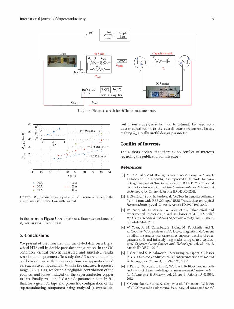
4. AC Transport Current Losses
4.1. Experimental Apparatus. A sketch of our measurementsetup is shown in Figure 4.Anonmetallic cryostat (not shownin the picture) keeps the superconducting coil, 𝑍coil, at liquidnitrogen temperature. As expected, no impedance comesfrom the coil at zero frequency, the impedance rising assoon as any frequency dependent driving signal is appliedto the SC coil. The 𝑍coil(𝑓) contains an undesired imaginarycomponent coming from the device inductance (𝐿coil =
2.06mH) and a real component which, being produced fromAC losses, is the measure of our interest. To measure the𝑍coil(𝑓) components we used a lock-in amplifier. Besides, tomaximize SNR, a compensation technique of the undesiredimaginary part of the signal has been implemented.Our com-pensation circuitry is made of a capacitors bank connected inseries to the SC coil, the bank capacitance being varied duringthe experiment in order to keep an acceptable SNR for a givenmeasurement frequency. Finally, part of our experimentalsetup is at liquid nitrogen temperature (the SC coil) and partis at room temperature (the compensating capacitors and aportion of the connection cables). Particular care is requiredfor circuitry parameters estimation, being the real part of the

4 International Journal of Superconductivity
0.000 0.025 0.050 0.075
0.00
0.05
0.10
0.15
Bz
(T)
Rin Rout−0.10
−0.05
r (m)
z = 0mm
20A30A
(a)
0.000 0.025 0.050 0.075
0.00
0.05
0.10
Air gaps
Rin Rout−0.05
r (m)
0mm1mm2mm
0mm1mm2mm
Bz,B
r(T
)
Icoil = 30A
(b)
Figure 3: (a) Comparison of computed axial component of 𝐵 as a function of distance from magnetic axis of the coil for different currentvalues. (b) Computed axial and radial components of 𝐵 as a function of distance from magnetic axis of the coil for different air gaps at𝐼coil = 30A.
impedance we are interested in, in a few milliohm range (i.e.,of the order of the copper connection cables resistance of ourcircuit), and for that reason we used a precision LCR meterto measure the bank capacitance at each frequency value.Accordingly, the two T switches in Figure 4 are there to avoidany circuitry configuration changes between measures. Togenerate an ohmic reference signal (𝑉shunt), a 40mΩ shuntresistance (𝑅shunt) has been included in the setup. The 𝑉totaland 𝑉shunt signals have been connected at lock-in CH-A andRef, respectively. For given current and frequency values, theexpressions reported in the following set of equations,
𝑍coil = 𝑅loss + 𝑗𝜔𝐿coil, (4)
𝑉total = (𝑍coil + 𝑍cable + 𝑍𝑐) ⋅ 𝐼
= [(𝑅loss + 𝑅cable + 𝑅𝑐) + 𝑗 (𝜔 ⋅ 𝐿coil −1
𝜔 ⋅ 𝐶
)] ⋅ 𝐼
Re (𝑉total) = (𝑅loss + 𝑅cable + 𝑅𝑐) ⋅ 𝐼,
(5)
have been used in our analysis to compute the coil resistance(𝑅loss), which is the parameter of our interest (being directlylinked to the superconductor AC losses), while the chosenbank of capacitors configuration is reported as follows.
Bank Capacitors Configuration. Consider the following:
(1) 𝐶1= 45mF and 𝐶
2= 45mF connected in parallel;
(2) 𝐶1= 45mF and 𝐶
2= 45mF connected in series;
(3) 𝐶1= 45mF.
4.2. Experimental Results. The high 𝑄 value of the resonantcircuit of our experimental apparatus determines, for a givencapacitance, a small range of frequency values measurablewith optimumSNR.As a result, the compensation impedance𝑍𝑐has to be varied in order to obtain the frequency span we
are interested in, this last requirement being fulfilled usinga capacitance bank. A first step to estimate the AC transportcurrent losses in the SC coil is tomeasure the current in phasecomponent of the overall voltage across the capacitance-coilimpedance series (Re(𝑉total)). By subtracting the 𝑅
𝑐contri-
bution as obtained from the LCR meter, a measure of thevoltage drop across the coil-copper connection cable series(𝑅loss + 𝑅cable) is obtained. The expected behavior of 𝑅loss is afrequency dependent contribution due to the superconductortape, plus a constant bias coming from the copper connectioncables. As is well known [16],𝑅loss(𝑓) has a linear dependencewith frequency whenever the copper tape conducting matrixloss contribution is negligible (𝑅Cu). In this case, a gooddescription of the system behavior is given by the expression:𝑅loss(𝑓, 𝐼) + 𝑅cable = 𝑅
0(𝐼) ⋅ 𝑓 + 𝑅cable (the frequency
dependence of the copper matrix being quadratic, whenratable). 𝑅cable is the undesired series resistance componentof the cables connecting the liquid nitrogen SC coil to theroom temperature T switch. Our experimental results for𝑅loss(𝑓) +𝑅cable are reported in Figure 5 for three driving rmscurrent values. As can be seen, the common value of the zerofrequency intercept of each line gives the connection cableresistance of our experimental setup (𝑅cable = 6mΩ in ourcase), while the slope of each line gives the 𝑅
0(𝐼) parameter.
The current dependence of 𝑅0(𝐼) is due to transport current
losses associated with the coil self-produced magnetic fieldand is coil geometric configuration dependent. As can be seen
International Journal of Superconductivity 5
R0 ∗ f
Im(V)
Reference
ACi(t) Ampl.freq.current
source
Lcoil
Rcable
Zcoil
Vshunt
Rshunt
Ref CH A Re(V)
Vtotal
Lock-in amplifier
Rcu
A
B
A
B
Zc
Rc
LCR meter
T T
HTS coil Capacitors bankC
Figure 4: Electrical circuit for AC losses measurements.
10A 10A20A 20A30A 30A
y = 0.5328x + 6
y = 0.3843x + 6
y = 0.2552x + 6
f (Hz)
I (A)
R0
(mΩ
/Hz)
(Rlo
ss+R
cabl
e) (
mΩ
)
00
00
10
0.2
0.4
0.6
10
20
20
20
30
30
40
4040
50
50
60
60
70 80 90
Figure 5:𝑅loss versus frequency at various rms current values; in theinsert, lines slope evolution with current.
in the insert in Figure 5, we obtained a linear dependence of𝑅0versus rms 𝐼 in our case.
5. Conclusions
We presented the measured and simulated data on a trape-zoidal HTS coil in double pancake configuration. In the DCcondition, critical current measured and simulated resultswere in good agreement. To study the AC superconductingcoil behavior, we settled up an experimental apparatus basedon reactance compensation. Within the analyzed frequencyrange (30–80Hz), we found a negligible contribution of theeddy current losses induced on the superconductor coppermatrix. Finally, we identified a single parameter, namely, 𝑅
0,
that, for a given SC tape and geometric configuration of thesuperconducting component being analyzed (a trapezoidal
coil in our study), may be used to estimate the supercon-ductor contribution to the overall transport current losses,making 𝑅
0a really useful design parameter.
Conflict of Interests
The authors declare that there is no conflict of interestsregarding the publication of this paper.
References
[1] M. D. Ainslie, V. M. Rodriguez-Zermeno, Z. Hong, W. Yuan, T.J. Flack, and T. A. Coombs, “An improved FEMmodel for com-puting transport AC loss in coilsmade of RABiTSYBCO coatedconductors for electric machines,” Superconductor Science andTechnology, vol. 24, no. 4, Article ID 045005, 2011.
[2] F. Gomory, J. Souc, E. Pardo et al., “AC loss in pancake coil madefrom 12 mm wide REBCO tape,” IEEE Transactions on AppliedSuperconductivity, vol. 23, no. 3, Article ID 5900406, 2013.
[3] W. Yuan, M. D. Ainslie, W. Xian et al., “Theoretical andexperimental studies on Jc and AC losses of 2G HTS coils,”IEEE Transactions on Applied Superconductivity, vol. 21, no. 3,pp. 2441–2444, 2011.
[4] W. Yuan, A. M. Campbell, Z. Hong, M. D. Ainslie, and T.A. Coombs, “Comparison of AC losses, magnetic field/currentdistributions and critical currents of superconducting circularpancake coils and infinitely long stacks using coated conduc-tors,” Superconductor Science and Technology, vol. 23, no. 8,Article ID 085011, 2010.
[5] F. Grilli and S. P. Ashworth, “Measuring transport AC lossesin YBCO-coated conductor coils,” Superconductor Science andTechnology, vol. 20, no. 8, pp. 794–799, 2007.
[6] E. Pardo, J. Souc, and J. Kovac, “AC loss in ReBCO pancake coilsand stacks of them:modelling andmeasurement,” Superconduc-tor Science and Technology, vol. 25, no. 3, Article ID 035003,2012.
[7] V. Grinenko, G. Fuchs, K. Nenkov et al., “Transport AC lossesof YBCO pancake coils wound from parallel connected tapes,”

6 International Journal of Superconductivity
Superconductor Science and Technology, vol. 25, no. 7, Article ID075006, 2012.
[8] M. Zhang, J. Kvitkovic, S. V. Pamidi, and T. A. Coombs, “Exper-imental and numerical study of a YBCO pancake coil witha magnetic substrate,” Superconductor Science and Technology,vol. 25, no. 12, Article ID 125020, 2012.
[9] M. Zhang, J. Kvitkovic, J.-H. Kim, C. H. Kim, S. V. Pamidi, andT. A. Coombs, “Alternating current loss of second-generationhigh-temperature superconducting coils with magnetic andnon-magnetic substrate,”Applied Physics Letters, vol. 101, ArticleID 102602, 2012.
[10] M. Polak, E. Demencik, L. Jansak et al., “Ac losses in a 𝑌 Ba2
Cu3𝑂7−𝑥
coil,” Applied Physics Letters, vol. 88, no. 23, Article ID232501, 2006.
[11] U. Besi Vetrella, G. Celentano, M. Marchetti et al., “HTS coilsfabrication from commercial 2G YBCO tapes: measurementsand simulation,” IEEE Transactions on Applied Superconductiv-ity, vol. 24, no. 3, Article ID 4600204, 2014.
[12] G. Messina, L. Morici, U. Besi Vetrella et al., “Modelling andmeasurements of circular and trapezoidal shape HTS coils forelectrical machines applications,” Journal of Physics: ConferenceSeries, vol. 507, Article ID 032031, 2014.
[13] A. Malozemoff, M. Rupich, and U. Schoop, “Scale-up of SecondGeneration HTS Wire (2G-YBCO Coated Conductor),” DOEPeer Review, 2004.
[14] G. Messina, L. Morici, U. Besi Vetrella et al., “AC transportcurrent losses in HTS coils for axial flux electrical machinesapplications,” IEEE Transactions on Applied Superconductivity,vol. 24, no. 3, Article ID 4602204, 2014.
[15] D. N. Nguyen, S. P. Ashworth, J. O.Willis, F. Sirois, and F. Grilli,“A new finite-element method simulation model for computingAC loss in roll assisted biaxially textured substrate YBCO tapes,”Superconductor Science and Technology, vol. 23, no. 2, Article ID025001, 2010.
[16] C. M. Magro, M. Neves, A. Sfetsos, J. Pina, and A. Goncalves,“Multipole superconducting synchronous generator,” in Pro-ceedings of the 6th European Conference on Applied Supercon-ductivity (EUCAS ’03), 2003.

Submit your manuscripts athttp://www.hindawi.com
Hindawi Publishing Corporationhttp://www.hindawi.com Volume 2014
High Energy PhysicsAdvances in
The Scientific World JournalHindawi Publishing Corporation http://www.hindawi.com Volume 2014
Hindawi Publishing Corporationhttp://www.hindawi.com Volume 2014
FluidsJournal of
Atomic and Molecular Physics
Journal of
Hindawi Publishing Corporationhttp://www.hindawi.com Volume 2014
Hindawi Publishing Corporationhttp://www.hindawi.com Volume 2014
Advances in Condensed Matter Physics
OpticsInternational Journal of
Hindawi Publishing Corporationhttp://www.hindawi.com Volume 2014
Hindawi Publishing Corporationhttp://www.hindawi.com Volume 2014
AstronomyAdvances in
International Journal of
Hindawi Publishing Corporationhttp://www.hindawi.com Volume 2014
Superconductivity
Hindawi Publishing Corporationhttp://www.hindawi.com Volume 2014
Statistical MechanicsInternational Journal of
Hindawi Publishing Corporationhttp://www.hindawi.com Volume 2014
GravityJournal of
Hindawi Publishing Corporationhttp://www.hindawi.com Volume 2014
AstrophysicsJournal of
Hindawi Publishing Corporationhttp://www.hindawi.com Volume 2014
Physics Research International
Hindawi Publishing Corporationhttp://www.hindawi.com Volume 2014
Solid State PhysicsJournal of
Computational Methods in Physics
Journal of
Hindawi Publishing Corporationhttp://www.hindawi.com Volume 2014
Hindawi Publishing Corporationhttp://www.hindawi.com Volume 2014
Soft MatterJournal of
Hindawi Publishing Corporationhttp://www.hindawi.com
AerodynamicsJournal of
Volume 2014
Hindawi Publishing Corporationhttp://www.hindawi.com Volume 2014
PhotonicsJournal of
Hindawi Publishing Corporationhttp://www.hindawi.com Volume 2014
Journal of
Biophysics
Hindawi Publishing Corporationhttp://www.hindawi.com Volume 2014
ThermodynamicsJournal of
Copyright © 2022 FDOKUMEN