Lecture 4- 18-4-2021- Moving Coil Instruments.pdf
27
Measuring Devices Prepared by: Dr. Eng. Montaser Abd El Sattar Department of Electrical Engineering Faculty of Engineering, South Valley University, Qena 18-4-2021 Health Technical Institute
-
Upload
khangminh22 -
Category
Documents
-
view
0 -
download
0
Transcript of Lecture 4- 18-4-2021- Moving Coil Instruments.pdf

Measuring Devices
Prepared by:
Dr. Eng. Montaser Abd El Sattar
Department of Electrical Engineering
Faculty of Engineering, South Valley University, Qena
18-4-2021
Health Technical Institute
2
Moving Coil Instruments
There are two types of moving coil
instruments namely:
Permanent magnet moving coil (PMMC)
type which can only be used for direct
current, voltage measurements
Dynamometer type which can be used on
either direct or alternating current, voltage
measurements.

3
Permanent Magnet Moving Coil (PMMC)
In PMMC meter or (D’Arsonval) meter or galvanometer all are the same instrument, a coil of fine wire is suspended in a magnetic field produced by permanent magnet.
The coil will rotate in the magnetic field when it carries an electric current by electromagnetic (EM) torque effect.
A pointer will deflect according to the amount of current to be measured which applied to the coil. The (EM) torque is counterbalance by the mechanical torque of control springs attached to the movable coil also.

4
PMMC Instruments

PMMC Instruments

The current flows through a coil in a
magnetic field.
The coil experiences a torque proportional to
current.
The movement of the coil is "opposed" by a
spring.
The deflection of the needle is proportional
to current.
6

Permanent Magnet Moving Coil Instruments
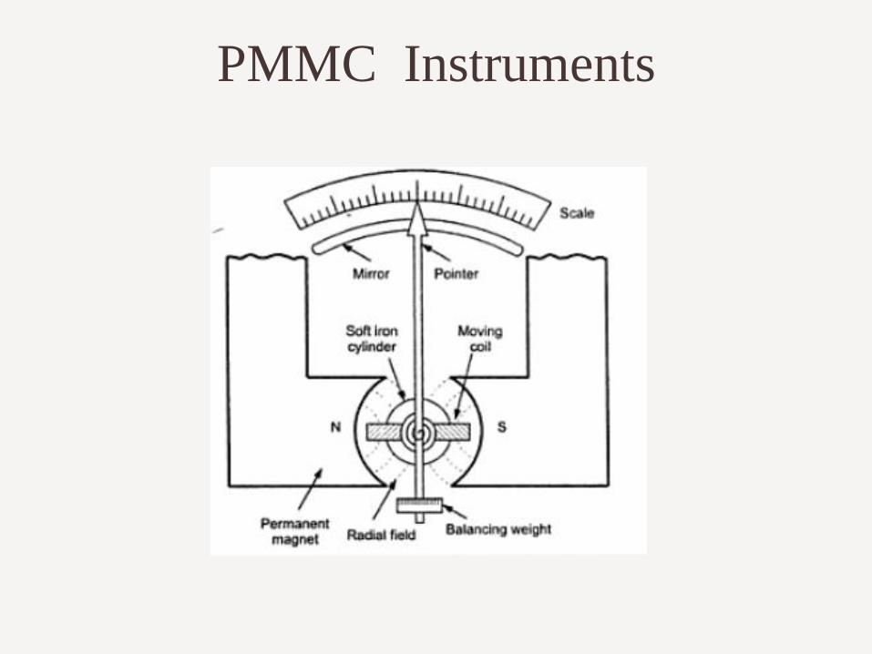
Construction It consists of permanent magnet which is stationary.
Moving system consists of a spindle attached to a rectangular aluminum frame. A coil made up of thin copper wire is wound over the frame. The current to be measured is passed through this coil.
A soft iron core is placed in the in the space within the aluminum frame.
Two spiral springs are mounted on the spindle to produce control torque. Control spring also serves an additional purpose & acts as control lead.
Pointer is mounted on spindle. Mirror is provided below the scale to avoid parallax error. The spindle is supported by jeweled bearings.

Permanent Magnet Moving Coil Instruments
Construction 1. It consists of permanent magnet which is stationary.
2. Moving system consists of a spindle attached to a rectangular aluminum frame. A coil made up of thin copper wire is wound over the frame. The current to be measured is passed through this coil.
3. A soft iron core is placed in the in the space within the aluminum frame. This core is stationary and is provided to reduce the reluctance of the magnetic path between two poles of the permanent magnet.
4. Two spiral springs are mounted on the spindle to produce control torque. The control spring also serves an additional purpose and acts as control lead. Pointer is mounted on spindle. Mirror is provided below the scale to avoid parallax error. The spindle is supported by jeweled bearings.
Working 1. The current to be measured is passed through moving coil via control springs.
2. A current carrying moving coil is now in a magnetic field. According to Flemings left hand rule, torque is produced on the coil and coil moves, pointer deflects.
3. Damping torque is provided by eddy current damping method.
Torque equation- Deflection is proportional to current.

PMMC Instruments
When the torques are balanced the moving
coil will stopped and its angular deflection
represent the amount of electrical current to
be measured against a fixed reference,
called a scale.
If the permanent magnet field is uniform and the spring linear, then the pointer deflection is also linear.
PMMC Instruments

PMMC Instruments

12
Torque Equation and Scale
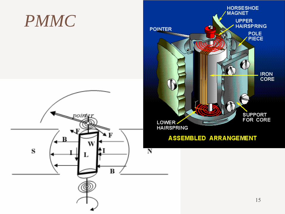
Assume there are (N) turns of wire and the coil is (L) in long by (W) in wide. The force F acting perpendicular to both the direction of the current flow and the direction of magnetic field is given by:
F=BIL Newtons
where N: turns of wire on the coil I: current in the movable coil , B: flux density in the air gap L: vertical length of the coil
Since the force acts on each side of the coil, the total force for a coil of N turns
F=2BILN Newtons

13
Torque Equation and Scale (cont.)
The force on each sides acts at a radius r,
producing deflecting turque
TD=2BILNr [N.m]
=BILN(2r)
=BILND [N.m]
where D is the coil diameter

Fleming's left-hand rule
14
Fleming's left-hand rule is used for electric motors, while Fleming's
right-hand rule is used for electric generators.
Separate hands need to be used for motors and generators because of
the differences between cause and effect.
In an electric motor, the electric current and magnet field exist
(which are the causes), and they lead to the force that creates the
motion (which is the effect), and so the left hand rule is used.
In an electric generator, the motion and magnetic field exist
(causes), and they lead to the creation of the electric current (effect),
and so the right hand rule is used.
15
PMMC
16
Torque Equation and Scale (cont.)
The controlling torque is proportional to the angle or deflection of the pointer
Tc= Kθ , K is constant
Deflecting torque = Controlling torque
Kθ =BILND
θ = C I , C is constant
The angular deflection proportional linearly with applied current.
17
Galvanometer
A galvanometer is a PMMC instrument designed to be
sensitive to extremely low current levels.
The galvanometer is the device used for detecting
the presence of small current and voltage or for
measuring their magnitude.
The simplest galvanometer is a very sensitive
instrument with the type of center-zero scale.
A typical galvanometer has a "full-scale-current"
(Ifs) of 10 A to 10 mA
The resistance of the coil is typically 10 to 1000 .

18
Galvanometers were the first instruments
used to detect and measure electric currents.
Sensitive galvanometers were used to detect
signals from long submarine cables, and
were used to discover the electrical activity
of the heart and brain.
Galvanometer (cont.)

19
– An ammeter is always connected in series.
– low internal resistance.
– maximum pointer deflection is produced by
a very small current.
– For a large currents, the instrument must be
modified by connecting a very low shunt
resister.
DC Ammeter
20
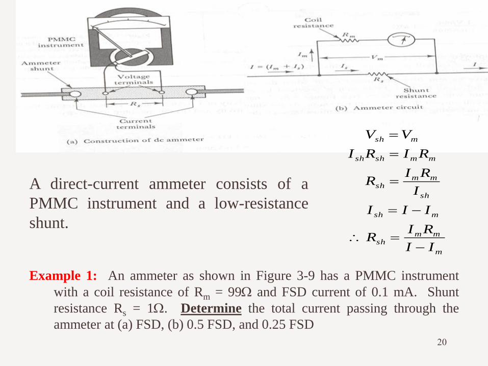
Example 1: An ammeter as shown in Figure 3-9 has a PMMC instrument
with a coil resistance of Rm = 99 and FSD current of 0.1 mA. Shunt
resistance Rs = 1. Determine the total current passing through the
ammeter at (a) FSD, (b) 0.5 FSD, and 0.25 FSD
m
mmsh
msh
sh
mmsh
mmshsh
msh
II
RIR
III
I
RIR
RIRI
VV
A direct-current ammeter consists of a
PMMC instrument and a low-resistance
shunt.
21
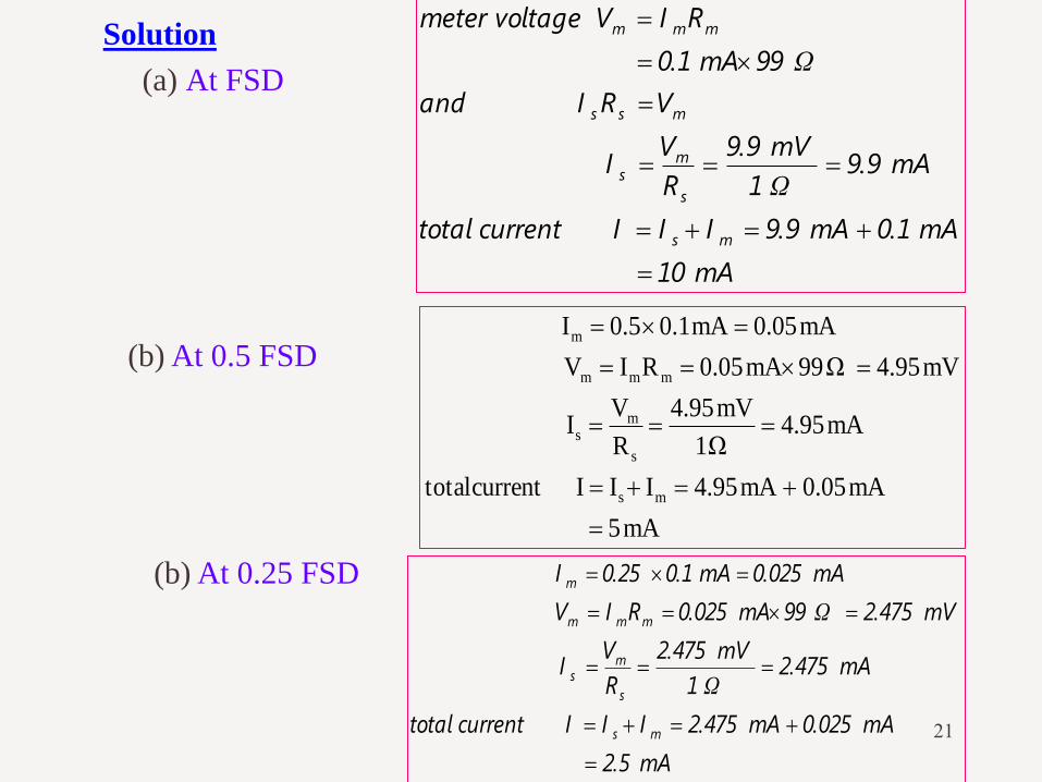
Solution
(a) At FSD
mA10
mA0.1mA9.9IIIcurrenttotal
mA9.9Ω1
mV9.9
R
VI
VRIand
Ω99mA0.1
RIVvoltagemeter
ms
s
ms
mss
mmm
(b) At 0.5 FSD
mA5
mA500.mA4.95IIIcurrenttotal
mA4.95Ω1
mV4.95
R
VI
mV4.95Ω99mA0.05RIV
mA0.05mA0.10.5I
ms
s
ms
mmm
m
(b) At 0.25 FSD
mA2.5
mA0.025mA2.475IIIcurrenttotal
mA2.475Ω1
mV2.475
R
VI
mV2.475Ω99mA0.025RIV
mA0.025mA0.10.25I
ms
s
ms
mmm
m

22
Example 2: A PMMC instrument has FSD of 100 A and a coil
resistance of 1 k. Calculate the required shunt resistance
value to convert the instrument into an ammeter with (a) FSD
= 100 mA and (b) FSD = 1 A.
Solution
(a) FSD = 100 mA
Ω1.001mA99.9
mV100
I
VR
mA99.9Aμ100mA100III
III
mV100kΩ1Aμ100RIV
s
ms
ms
ms
mmm
(b) FSD = 1 A
Ω0.1001mA999.9
mV100
I
VR
mA999.9Aμ100A1III
mV100RIV
s
ms
ms
mmm

23
Swamping Resistance
A PMMC instrument is wound with thin copper wire, and its resistance can
change significantly when its temperature changes.
The heating effect of the coil current may be enough to produce a resistance
change, which will introduce an error.
A swamping resistance made of manganin or constantan is connected in series
with the coil (resistance temperature coefficients very close to zero).
Manganin is a trademarked name for an alloy of typically 86% copper, 12%
manganese, and 2% nickel. It was first developed by Edward Weston in
1892.
Constantan is a copper-nickel alloy usually consisting of 55% copper and
45% nickel, 1887.
The ammeter shunt must also be made of manganin or constantan to avoid
shunt resistance variations with temperature.

24
• Make-before-break switch
• The instrument is not left without a shunt in
parallel with it.
• During switching there are actually two shunts
in parallel with the instrument.
Multi-range Ammeters

25
Ayrton Shunt
At B Total resistance R1+R2+R3
Meter resistance Rm
At C Total resistance R1+R2
Meter resistance Rm+R3
At D?

26
Example 3: A PMMC instrument has a three-resistor Ayrton
shunt connected across it to make an ammeter as shown
in Figure 3-13. The resistance values are R1 = 0.05, R2
= 0.45 and R3 = 4.5. The meter has Rm = 1k and
FSD = 50A. Calculate the three ranges of the
ammeter.
Solution
Switch at contact B:
mA10.05
mA10μA50III
mA10Ω4.5Ω0.45Ω0.05
mV50
RRR
VI
mV50kΩ1μA50RIV
sm
321
ss
mms

27
Switch at contact C:
mA100.05
mA100μA50III
mA100Ω0.45Ω0.05
mV50
RR
VI
mV50Ω4.5kΩ1μA50RRIV
sm
21
ss
3mms
Switch at contact C:
1.00005A
1A50μ0III
1A0.05Ω
50mV
R
VI
50mV0.45Ω4.5Ω1kΩ50μ0RRRIV
sm
1
ss
23mms