
ANFIS Prediction Model for the Mechanical Properties of Soil ...
Corresponding Author: RasliAbdGhani, Department of Electrical, Electronic and Systems Engineering, Faculty ofEngineering and Built Environment, University Kebangsaan Malaysia, Bangi Selangor, Malaysia43600.E-mail: [email protected]
A Sugeno-Type ANFIS Approach for Fast and Accurate Fault Diagnosis in aDistribution System
1Rasli AbdGhani, 1Azah Mohamed and 1Hussain Shareef
1Department of Electrical, Electronic and Systems Engineering UniversitiKebangsaan Malaysia,Bangi Selangor, Malaysia 43600
Abstract: Power consumers are always expecting quality and continuous electric supply from utilitiesin order to prevent financial losses. Therefore, utilities have to provide high quality and reliableelectricpower supply. For this purpose, an accurate and fast fault diagnosis in distribution systems should beprovided to reduce the customer average interruption duration index. This paper presents an intelligenttechnique for fast and accurate fault diagnosis of power distribution systems. The fault diagnosisfunctions include correct fault type classification, precise fault location, accurate identification of faultyprotection devices and current operation status of protection devices in a distribution system. Todetermine fault types and fault points, the proposed intelligent technique uses post-fault three-phaseroot-mean-square currents to train the Sugeno-type parallel-series adaptive neuro-fuzzy inferencesystem (ANFIS). Meanwhile, the current operating status of protection devices are presented as binaryones or zeros by ANFIS prediction using fault point geometrical coordinates. The simulation resultsshow that the technique has an average maximum percentage error of 0.02% for predicting the typeof faults and 2.8% in determining the fault points. Average maximum errors of 0.053 and 0.182 wereobtained for operating status of main and back up protection devices, respectively. The proposedtechnique is validated through simulations using the PSS-ADEPT commercial software package. Theresults showed thatthe Sugeno-type ANFIS approach provides fast and precise fault diagnosis that canbe implemented in a distribution network.
Key words: Fault diagnosis, sugeno-type neuro-fuzzy inference system, distribution system
INTRODUCTION
Power utilities are looking for better ways to provide high quality and reliable power to their customers.One of the indices that indicate reliability and quality of power is the customer average interruption index(CAIDI). Low CAIDI indicates high reliability of service. High reliability can be achieved by developing fastand accurate fault diagnosis techniques to locate and restore power to the affected areas. If fault symptoms areknown, fault section can be isolated and then repaired immediately to restore power delivery (Brown, 2009).Accurate fault diagnosis can also minimize power outage time and efficiently manage and record faults.Currently, most approaches developed for accurate fault diagnosis in distribution systems need improvementdue to time consuming, costly and tedious algorithms or methods used.
Many research works on fault diagnosis incorporate artificial intelligent approaches which process theinformation from alarms and protection relays in power distribution and transmission systems(Zhiwei et al.,2008; Souza et al., 2004; Mohamed andMazumder, 1999; Binh andTuyen, 2006).Sekine et al. (1992) developedan expert system which was in cooperated with SCADA and EMS to develop a more efficient and precisecentralized fault diagnosis system in transmission networks. The approach registers information such as faultlocation, causes of fault and identifies unwanted operation of protection devices. Voltage and current sensorswere installed on transmission lines for real time implementation and this involved a high cost due to sensorinstallations. Artificial neural network (ANN) based fault diagnosis method in distribution system was thendeveloped by Mohamed andMazumder (1999). Here, the purpose of the fault diagnosis was to locate the fault,identify the faulty protection devices and isolate the faulty sections. Fault location and fault states of lines andbus sections were obtained using the information from alarm relays. This technique provides effectiveinformation to the operator for decision making but most distribution systems are not completely equipped with
alarm relays. A combination of ANN and fuzzy logic has been used to process the information from alarmsand protection relays (Souza et al., 2004) for the purpose of identifying the faulted components and faulty linesections. A wavelet based ANN approach was developed by Silva et al. (2006) for fault detection andclassification. The approach uses oscillographic data from fault recorders and therefore it requirescommunication networks between remote power system and digital fault recorders.Jingbo andLonghua(2006)developed a substation fault diagnosis system using the Petri net theory. In this method, the information fromcircuit breakers and faulty protection devices are configured based on mathematical formulations to calculatethe precise fault section. Two Petri net concepts, namely, neural Petri net and fuzzy neural Petri net were usedfor locating faultsat the lines or sections(Binh andTuyen, 2006). However, these methods are not suitable forfault diagnosis in distribution systems due to lack of information of alarm and protective relays.
Sadeh andAfradi(2009) proposed a new and accurate fault location algorithm using adaptive neuro-fuzzyinference system (ANFIS) for a network with both transmission lines and under-ground cables. It usesfundamental frequency of three-phase current and neutral current as inputs while fault location are calculatedin term of kilometer distance. Although it has a good performance, there were some imperfections in faultlocation due to wide range in kilometer distance. Oliveira (2007) implemented an ANNbased fault diagnosismethod for an unbalanced underground distribution system. The method uses fundamental voltage and currentphasors as inputs to the ANN for locating faults in the line sections. Another ANN based approach whichcombines the ant colony optimization algorithm has been developed for fault section diagnosis in distributionsystems (Zhisheng and Yarning, 2007). The method locates faults in terms of the line sections but the exactfault points are still not known.
Another scheme for fault diagnosis has been introduced by using various tools such as wavelets, impedancemethod and ANN to analyze voltage and current signals which eventually provide information about faultlocation in terms of kilometer distance rather than the exact fault point (Salim et al., 2008). Anoptimizationbased fault diagnosis in power system has been developed by analyzing information from alarms and protectiverelays to provide information about latest operating status of all components in the system (Zhiwei et al.,2008). However, this approach is not practical for implementation in distribution systems because there is notenough information available from protective devices. Thomas and Joseph (2009) implemented a real-time faultdiagnosis system which automatically detects and locates faults in a distribution system. This real-time systeminvolves installation of detection modules on each line and busbar in which the module consists of voltage andcurrent sensors and a data processing unit. However, the installation of such modules is considered costly. This paper presents a Sugeno-type adaptive neuro-fuzzy inference system (ANFIS) approach for fast andaccurate fault diagnosis in distribution systems. The purpose is to help the operator in getting effectiveinformation when the fault occurs in power system. The information includes fault types, fault point and latestoperating status of protective devices in order to identify faulty devices. The proposed technique considersbasic protection system in a test distribution system and based on the configuration of the system, ANFIS blocksets are created as a fault diagnosis system to classify correct types of fault, precise fault points and identifyaccurate faulty devices.
MATERIALS AND METHODS
1. Proposed Fault Diagnosis Method:Basically, on-line fault diagnosis program manage fault classification, fault location, faulty devices
identification and fault isolation in a distribution system. Some of these distribution systems are equipped withautomated protection system and complicated alarm signals. The signals are interpreted to identify thesymptoms of faults by the operators. However, in most distribution networks, it is difficult to acquire adequateinformation from the network due to few installations of alarm and protective relays. Due to this, engineerscannot solely rely only on the provided alarm signals to identify the faults(Sekine et al., 1992).
Whenever a fault occurs in a distribution system, post-fault threephase RMS currents are recorded andprocessed to identify the type and location of fault. From identified fault points, a rule is created to determinethe current operating states of the protective devices. From the protection concept in such a distribution system,these operating states are analyzed to identify the faulty device and then followed immediately by faultisolation. The proposed fault diagnosis method considers classifying the type of fault, locating the fault pointsand identification of the fault points by using the recorded three phase currents. The type of faults arerepresented by integer numbers from 1 to 10, the fault points are calculated in terms of the XY geometricalcoordinates and the current operating states of protective devices are in terms of binary numbers for identifyingthe faulty device. Digit ‘1’ represents a faulty device while ‘0’ indicates a non-faulty device. For geometrical
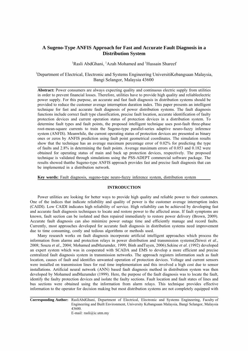
coordinate fault point location, the test distribution system is drawn in a two dimensional X and Y plane withpossible faults on lines, underground cables or bus bars. The types of faults considered are; A phase to ground(AG), B phase to ground (BG), C phase to ground (CG), three-phase (3P), A phase to B phase(AB), B phaseto C phase (BC), C phase to A phase (CA), AB phase to ground (ABG), BC phase to ground (BCG) and CAphase to ground (CAG) faults.
Fig. 1: The test distribution system
2.Test Distribution System:The IEEE 34-node test distribution system described in Butler andMarotti (2006) is used as a test system
for the proposed fault diagnosis method as shown in Figure 1. The system has a single feeder and eight laterallines including four lines in phase B, a line in phase A, a line in combination of phases ABC and B and thereserve is in phase ABC. The maximum length of the overhead line is 57.7 km from the substation to end ofthe feeder with two circuit breakers (CB1 and CB2). The circuit breakers are located at the substation and atdistance 41.5 km from the substation, respectively. There are also nine fuses which are located on each lateraland one just before end of the feeder. The fuses are labeled as F1, F2, F3, F4, F5, F6, F7, F8 and F9 asshown in Figure 1. This test distribution system does not have any backup line and radial circuit to restorepower through a second path. Post-fault three-phase RMS currents are collected at the substation with the helpof a metering network while operating status of the protective devices are obtained from the knowledge ofprotection system as logical ones or zeros. The backup protection for fuses F5, F6, F7, F8 and F9 is the circuitbreaker, CB2 whereas for fuses F1, F2, F3, F4 and CB2 is the circuit breaker, CB1.
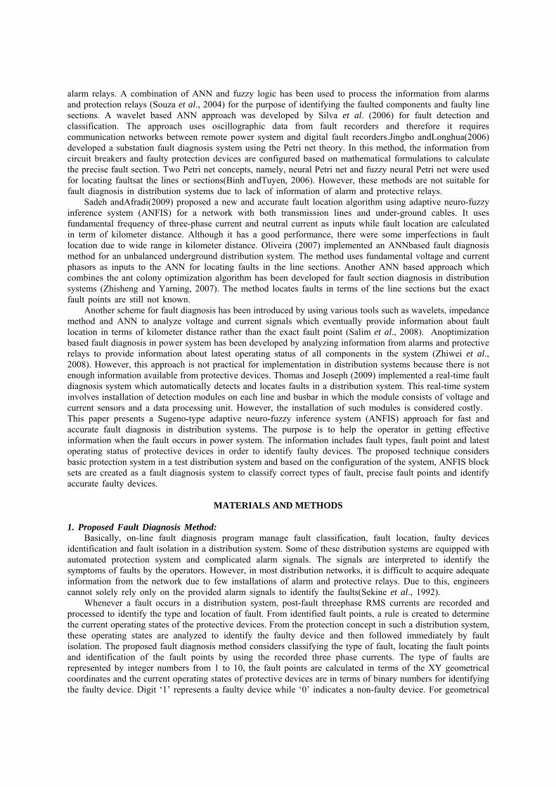
2.1. Fault Diagnosis Algorithm:Figure 2 shows the proposed fault diagnosis algorithm. The first step in the algorithm is to make a
comparison between the post-fault threephase RMS currents and the pre-fault threephase RMS currents. If thepost-fault current is greater than the pre-fault current in any of the phases, then the system is assumed to beundergoing a permanent fault at some point of the circuit. The post-fault threephase RMS currents are recorded,processed and analyzed by the trained ANFIS modules and sub-modules to predict the type of fault which isin terms of an integer between 1 to 10 and the fault points in terms of geometrical coordinates. These faultpoints are analyzed again by the next trained ANFIS modules to produce binary ones and zeros correspondingto the correct operating states of the main and backup protective devices. Looking at the operating states ofprotective devices and backup protective devices, the algorithm can determine faulty and non-faulty devices.For example, if the state of any backup protective device is ‘0’, then it means that there is no faulty device.Otherwise, if ‘1’ is encountered for any backup protective device (CB1 or CB2), then specify the protectivedevice group which is either CB1 group or CB2 group. If any protective device on the group has digit ‘1’,it means that it is a faulty device.
3. ANFIS Design for Fault Diagnosis in a Distribution SystemL:In the implementation of the proposed fault diagnosis method using ANFIS, various designs of ANFIS
block sets are created so as to classify the correct types of fault, identify precise fault points and identifycorrect faulty protection devices.
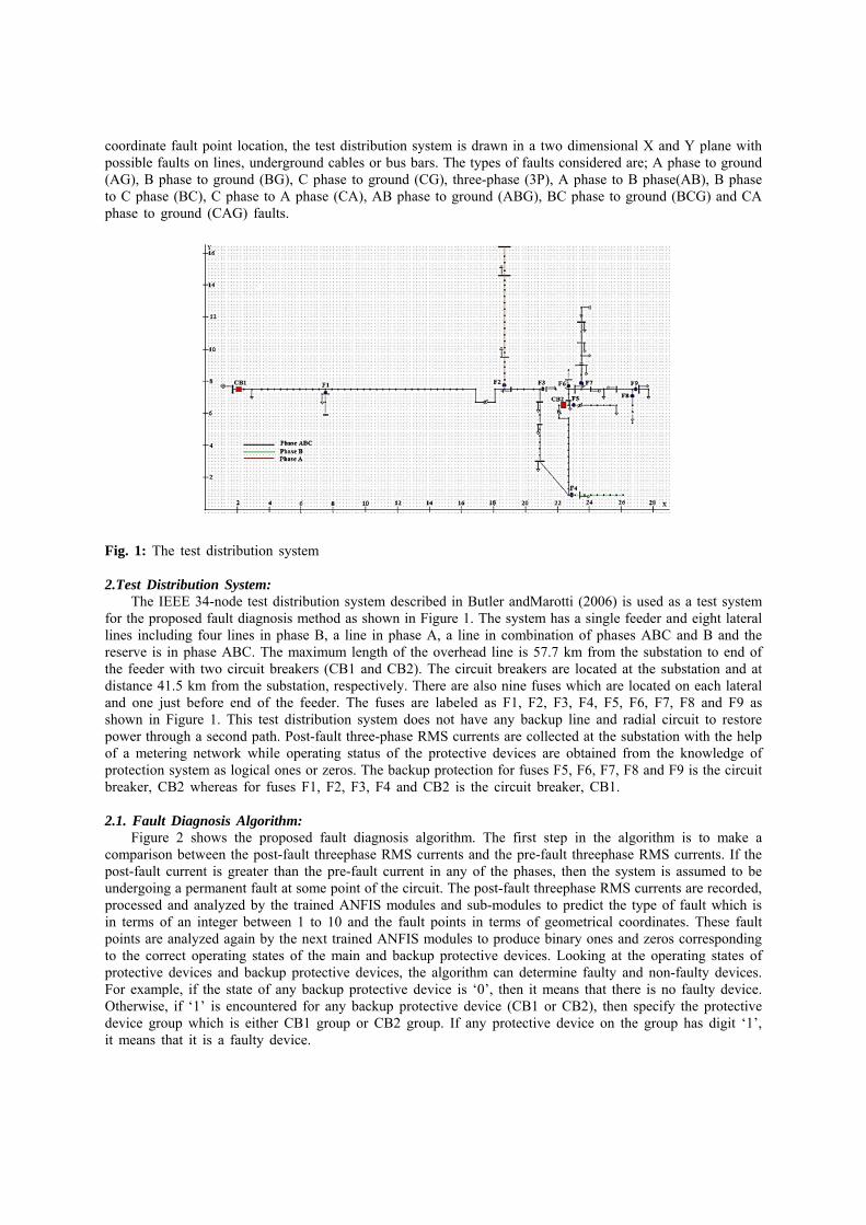
3.1. ANFIS Design for Classifying the Fault Types:The fault type classification function is implemented based on the concept of hierarchical distribution
ANFIS networks, as shown in Figure 3. It is designed to identify the correct type of fault with minimumprediction error. The configuration consists of 10 ANFIS blocks to represent each type of fault as an integernumber. For instance, block ANFIS1 shown in Figure 3 predicts value 1 for AG fault and followed by blocksANFIS2 to ANFIS10 representing BG, CG, 3P, AB, BC, CA, ABG, BCG and CAG faults, respectively.Parallel inputs which are post-fault three phase RMS currents are passed to each of these blocks. Thendepending on the type of fault, one of the blocks presents an integer number between 1 and 10 at a time witha tolerance of ±1%. Table I shows corresponding input and output parameters of each ANFIS module forclassifying the fault types.
Fig. 2: Fault diagnosis algorithm
Fig. 3: ANFIS design for classifying the fault type
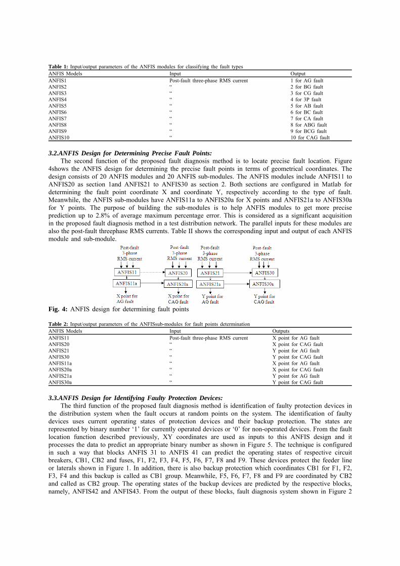
Table 1: Input/output parameters of the ANFIS modules for classifying the fault types ANFIS Models Input OutputANFIS1 Post-fault three-phase RMS current 1 for AG faultANFIS2 “ 2 for BG faultANFIS3 “ 3 for CG faultANFIS4 “ 4 for 3P faultANFIS5 “ 5 for AB faultANFIS6 “ 6 for BC faultANFIS7 “ 7 for CA faultANFIS8 “ 8 for ABG faultANFIS9 “ 9 for BCG faultANFIS10 “ 10 for CAG fault
3.2.ANFIS Design for Determining Precise Fault Points:The second function of the proposed fault diagnosis method is to locate precise fault location. Figure
4shows the ANFIS design for determining the precise fault points in terms of geometrical coordinates. Thedesign consists of 20 ANFIS modules and 20 ANFIS sub-modules. The ANFIS modules include ANFIS11 toANFIS20 as section 1and ANFIS21 to ANFIS30 as section 2. Both sections are configured in Matlab fordetermining the fault point coordinate X and coordinate Y, respectively according to the type of fault.Meanwhile, the ANFIS sub-modules have ANFIS11a to ANFIS20a for X points and ANFIS21a to ANFIS30afor Y points. The purpose of building the sub-modules is to help ANFIS modules to get more preciseprediction up to 2.8% of average maximum percentage error. This is considered as a significant acquisitionin the proposed fault diagnosis method in a test distribution network. The parallel inputs for these modules arealso the post-fault threephase RMS currents. Table II shows the corresponding input and output of each ANFISmodule and sub-module.
Fig. 4: ANFIS design for determining fault points
Table 2: Input/output parameters of the ANFISsub-modules for fault points determinationANFIS Models Input OutputsANFIS11 Post-fault three-phase RMS current X point for AG faultANFIS20 “ X point for CAG faultANFIS21 “ Y point for AG faultANFIS30 “ Y point for CAG faultANFIS11a “ X point for AG faultANFIS20a “ X point for CAG faultANFIS21a “ Y point for AG faultANFIS30a “ Y point for CAG fault
3.3.ANFIS Design for Identifying Faulty Protection Devices:The third function of the proposed fault diagnosis method is identification of faulty protection devices in
the distribution system when the fault occurs at random points on the system. The identification of faultydevices uses current operating states of protection devices and their backup protection. The states arerepresented by binary number ‘1’ for currently operated devices or ‘0’ for non-operated devices. From the faultlocation function described previously, XY coordinates are used as inputs to this ANFIS design and itprocesses the data to predict an appropriate binary number as shown in Figure 5. The technique is configuredin such a way that blocks ANFIS 31 to ANFIS 41 can predict the operating states of respective circuitbreakers, CB1, CB2 and fuses, F1, F2, F3, F4, F5, F6, F7, F8 and F9. These devices protect the feeder lineor laterals shown in Figure 1. In addition, there is also backup protection which coordinates CB1 for F1, F2,F3, F4 and this backup is called as CB1 group. Meanwhile, F5, F6, F7, F8 and F9 are coordinated by CB2and called as CB2 group. The operating states of the backup devices are predicted by the respective blocks,namely, ANFIS42 and ANFIS43. From the output of these blocks, fault diagnosis system shown in Figure 2
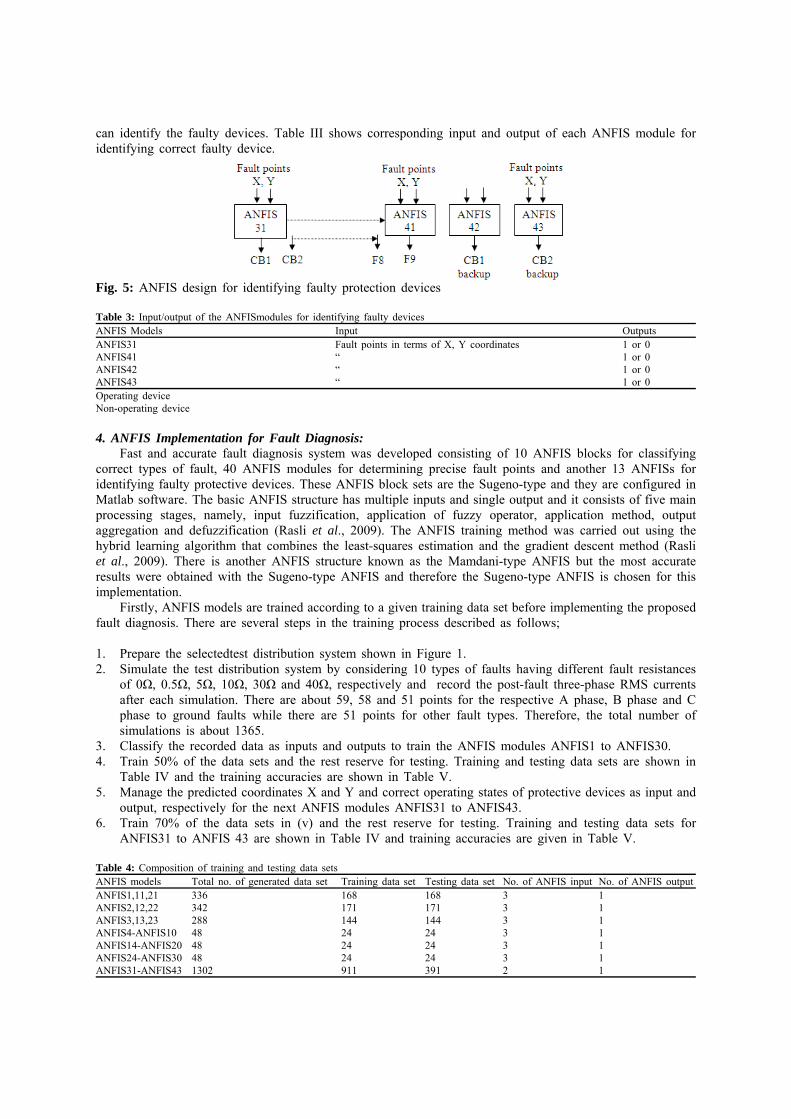
can identify the faulty devices. Table III shows corresponding input and output of each ANFIS module foridentifying correct faulty device.
Fig. 5: ANFIS design for identifying faulty protection devices
Table 3: Input/output of the ANFISmodules for identifying faulty devicesANFIS Models Input OutputsANFIS31 Fault points in terms of X, Y coordinates 1 or 0ANFIS41 “ 1 or 0ANFIS42 “ 1 or 0ANFIS43 “ 1 or 0Operating deviceNon-operating device
4. ANFIS Implementation for Fault Diagnosis:Fast and accurate fault diagnosis system was developed consisting of 10 ANFIS blocks for classifying
correct types of fault, 40 ANFIS modules for determining precise fault points and another 13 ANFISs foridentifying faulty protective devices. These ANFIS block sets are the Sugeno-type and they are configured inMatlab software. The basic ANFIS structure has multiple inputs and single output and it consists of five mainprocessing stages, namely, input fuzzification, application of fuzzy operator, application method, outputaggregation and defuzzification (Rasli et al., 2009). The ANFIS training method was carried out using thehybrid learning algorithm that combines the least-squares estimation and the gradient descent method (Rasliet al., 2009). There is another ANFIS structure known as the Mamdani-type ANFIS but the most accurateresults were obtained with the Sugeno-type ANFIS and therefore the Sugeno-type ANFIS is chosen for thisimplementation.
Firstly, ANFIS models are trained according to a given training data set before implementing the proposedfault diagnosis. There are several steps in the training process described as follows;
1. Prepare the selectedtest distribution system shown in Figure 1.2. Simulate the test distribution system by considering 10 types of faults having different fault resistances
of 0Ω, 0.5Ω, 5Ω, 10Ω, 30Ω and 40Ω, respectively and record the post-fault three-phase RMS currentsafter each simulation. There are about 59, 58 and 51 points for the respective A phase, B phase and Cphase to ground faults while there are 51 points for other fault types. Therefore, the total number ofsimulations is about 1365.
3. Classify the recorded data as inputs and outputs to train the ANFIS modules ANFIS1 to ANFIS30.4. Train 50% of the data sets and the rest reserve for testing. Training and testing data sets are shown in
Table IV and the training accuracies are shown in Table V.5. Manage the predicted coordinates X and Y and correct operating states of protective devices as input and
output, respectively for the next ANFIS modules ANFIS31 to ANFIS43.6. Train 70% of the data sets in (v) and the rest reserve for testing. Training and testing data sets for
ANFIS31 to ANFIS 43 are shown in Table IV and training accuracies are given in Table V.
Table 4: Composition of training and testing data setsANFIS models Total no. of generated data set Training data set Testing data set No. of ANFIS input No. of ANFIS outputANFIS1,11,21 336 168 168 3 1ANFIS2,12,22 342 171 171 3 1ANFIS3,13,23 288 144 144 3 1ANFIS4-ANFIS10 48 24 24 3 1ANFIS14-ANFIS20 48 24 24 3 1ANFIS24-ANFIS30 48 24 24 3 1ANFIS31-ANFIS43 1302 911 391 2 1
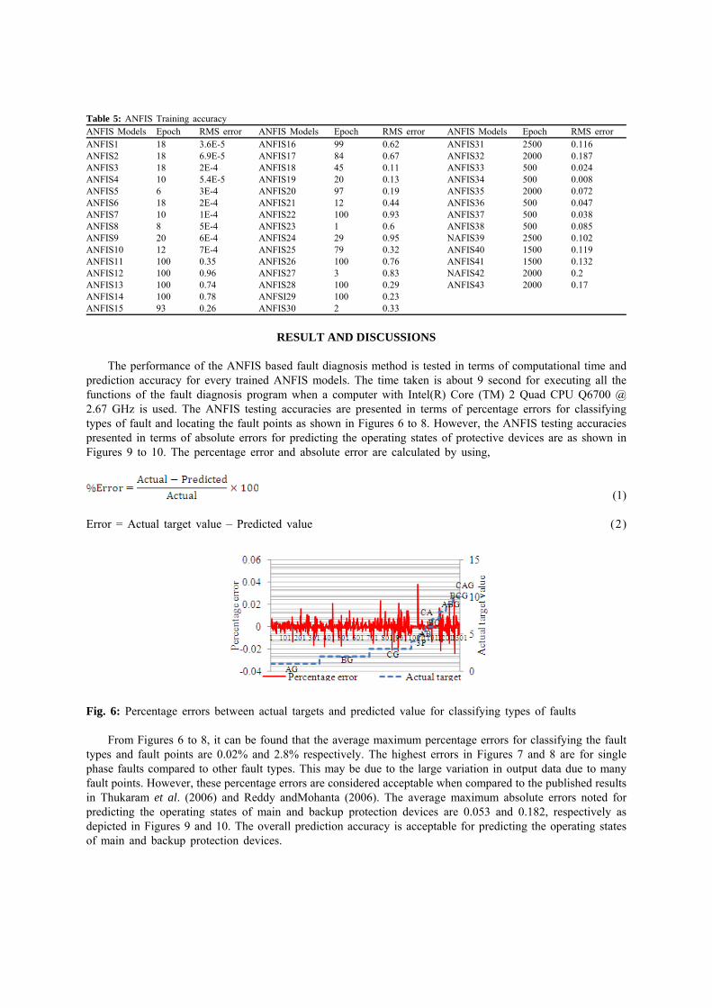
Table 5: ANFIS Training accuracyANFIS Models Epoch RMS error ANFIS Models Epoch RMS error ANFIS Models Epoch RMS errorANFIS1 18 3.6E-5 ANFIS16 99 0.62 ANFIS31 2500 0.116ANFIS2 18 6.9E-5 ANFIS17 84 0.67 ANFIS32 2000 0.187ANFIS3 18 2E-4 ANFIS18 45 0.11 ANFIS33 500 0.024ANFIS4 10 5.4E-5 ANFIS19 20 0.13 ANFIS34 500 0.008ANFIS5 6 3E-4 ANFIS20 97 0.19 ANFIS35 2000 0.072ANFIS6 18 2E-4 ANFIS21 12 0.44 ANFIS36 500 0.047ANFIS7 10 1E-4 ANFIS22 100 0.93 ANFIS37 500 0.038ANFIS8 8 5E-4 ANFIS23 1 0.6 ANFIS38 500 0.085ANFIS9 20 6E-4 ANFIS24 29 0.95 NAFIS39 2500 0.102ANFIS10 12 7E-4 ANFIS25 79 0.32 ANFIS40 1500 0.119ANFIS11 100 0.35 ANFIS26 100 0.76 ANFIS41 1500 0.132ANFIS12 100 0.96 ANFIS27 3 0.83 NAFIS42 2000 0.2ANFIS13 100 0.74 ANFIS28 100 0.29 ANFIS43 2000 0.17ANFIS14 100 0.78 ANFSI29 100 0.23ANFIS15 93 0.26 ANFIS30 2 0.33
RESULT AND DISCUSSIONS
The performance of the ANFIS based fault diagnosis method is tested in terms of computational time andprediction accuracy for every trained ANFIS models. The time taken is about 9 second for executing all thefunctions of the fault diagnosis program when a computer with Intel(R) Core (TM) 2 Quad CPU Q6700 @2.67 GHz is used. The ANFIS testing accuracies are presented in terms of percentage errors for classifyingtypes of fault and locating the fault points as shown in Figures 6 to 8. However, the ANFIS testing accuraciespresented in terms of absolute errors for predicting the operating states of protective devices are as shown inFigures 9 to 10. The percentage error and absolute error are calculated by using,
(1)
Error = Actual target value – Predicted value (2)
Fig. 6: Percentage errors between actual targets and predicted value for classifying types of faults
From Figures 6 to 8, it can be found that the average maximum percentage errors for classifying the faulttypes and fault points are 0.02% and 2.8% respectively. The highest errors in Figures 7 and 8 are for singlephase faults compared to other fault types. This may be due to the large variation in output data due to manyfault points. However, these percentage errors are considered acceptable when compared to the published resultsin Thukaram et al. (2006) and Reddy andMohanta (2006). The average maximum absolute errors noted forpredicting the operating states of main and backup protection devices are 0.053 and 0.182, respectively asdepicted in Figures 9 and 10. The overall prediction accuracy is acceptable for predicting the operating statesof main and backup protection devices.
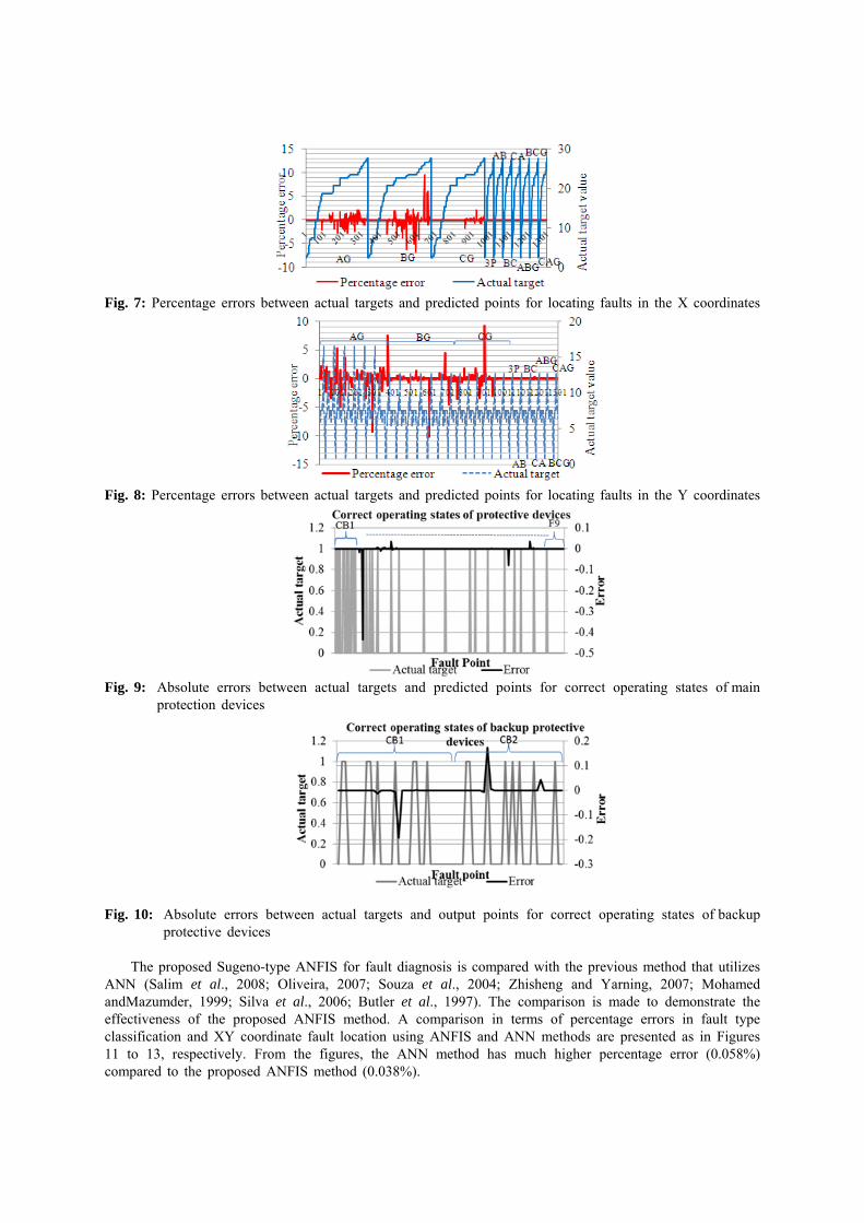
Fig. 7: Percentage errors between actual targets and predicted points for locating faults in the X coordinates
Fig. 8: Percentage errors between actual targets and predicted points for locating faults in the Y coordinates
Fig. 9: Absolute errors between actual targets and predicted points for correct operating states of mainprotection devices
Fig. 10: Absolute errors between actual targets and output points for correct operating states of backupprotective devices
The proposed Sugeno-type ANFIS for fault diagnosis is compared with the previous method that utilizesANN (Salim et al., 2008; Oliveira, 2007; Souza et al., 2004; Zhisheng and Yarning, 2007; MohamedandMazumder, 1999; Silva et al., 2006; Butler et al., 1997). The comparison is made to demonstrate theeffectiveness of the proposed ANFIS method. A comparison in terms of percentage errors in fault typeclassification and XY coordinate fault location using ANFIS and ANN methods are presented as in Figures11 to 13, respectively. From the figures, the ANN method has much higher percentage error (0.058%)compared to the proposed ANFIS method (0.038%).
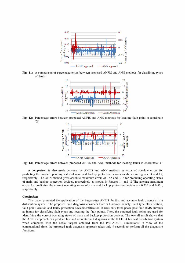
Fig. 11: A comparison of percentage errors between proposed ANFIS and ANN methods for classifying typesof faults
Fig. 12: Percentage errors between proposed ANFIS and ANN methods for locating fault point in coordinate‘X’
Fig. 13: Percentage errors between proposed ANFIS and ANN methods for locating faults in coordinate ‘Y’
A comparison is also made between the ANFIS and ANN methods in terms of absolute errors forpredicting the correct operating states of main and backup protection devices as shown in Figures 14 and 15,respectively. The ANN method gives absolute maximum errors of 0.55 and 0.18 for predicting operating statesof main and backup protection devices, respectively as shown in Figures 14 and 15.The average maximumerrors for predicting the correct operating states of main and backup protection devices are 0.236 and 0.521,respectively.
Conclusion:This paper presented the application of the Sugeno-typ ANFIS for fast and accurate fault diagnosis in a
distribution system. The proposed fault diagnosis considers three 3 functions namely, fault type classification,fault point location and faulty protection deviceidentification. It uses only three-phase post-fault RMS currentsas inputs for classifying fault types and locating the fault points. Then, the obtained fault points are used foridentifying the correct operating states of main and backup protection devices. The overall result shows thatthe ANFIS approach can produce fast and accurate fault diagnosis in the IEEE 34 bus test distribution systemwhen compared with the actual targets obtained from the PSS-ADEPT simulations. In view of thecomputational time, the proposed fault diagnosis approach takes only 9 seconds to perform all the diagnosticfunctions.
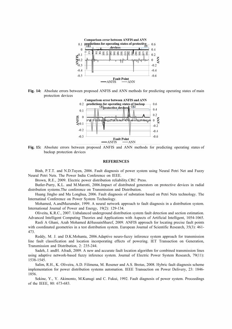
Fig. 14: Absolute errors between proposed ANFIS and ANN methods for predicting operating states of mainprotection devices
Fig. 15: Absolute errors between proposed ANFIS and ANN methods for predicting operating states ofbackup protection devices
REFERENCES
Binh, P.T.T. and N.D.Tuyen, 2006. Fault diagnosis of power system using Neural Petri Net and FuzzyNeural Petri Nets. The Power India Conference on IEEE.
Brown, R.E., 2009. Electric power distribution reliability.CRC Press.Butler-Purry, K.L. and M.Marotti, 2006.Impact of distributed generators on protective devices in radial
distribution systems.The conference on Transmission and Distribution.Huang Jingho and Ma Longhua, 2006. Fault diagnosis of substation based on Petri Nets technology. The
Internatinal Conference on Power System Technology.Mohamed, A.andMazumder, 1999. A neural network approach to fault diagnosis in a distribution system.
International Journal of Power and Energy, 19(2): 129-134.Oliveita, K.R.C., 2007. Unbalanced underground distribution system fault detection and section estimation.
Advanced Intelligent Computing Theories and Applications with Aspects of Artificial Intelligent, 1054-1065.Rasli A Ghani, Azah Mohamed &HussainSharef, 2009. ANFIS approach for locating precise fault points
with coordinated geometries in a test distribution system. European Journal of Scientific Research, 35(3): 461-473.
Reddy, M. J. and D.K.Mohanta, 2006.Adaptive neuro-fuzzy inference system approach for transmissionline fault classification and location incorporating effects of powering. IET Transaction on Generation,Transmission and Distribution, 2: 235-244.
Sadeh, J. andH. Afradi, 2009. A new and accurate fault location algorithm for combined transmission linesusing adaptive network-based fuzzy inference system. Journal of Electric Power System Research, 79(11):1538-1545.
Salim, R.H., K. Oliveira, A.D. Filimena, M. Resener and A.S. Bretas, 2008. Hybric fault diagnosis schemeimplementation for power distribution systems automation. IEEE Transaction on Power Delivery, 23: 1846-1856.
Sekine, Y., Y. Akimonto, M.Kunugi and C. Fukui, 1992. Fault diagnosis of power system. Proceedingsof the IEEE, 80: 673-683.

Silva, K.M., B.A. Souza &N.S.D. Brito,2006. Fault detection and classification in transmission lines basedon wavelet transform and ANN. IEEE Transaction on Power Delivery, 21: 2058-2063.
Souza, J.C.S., E.M. Meza, M.T. Sebilling andM.B.Do Corato,2004. Alarm processing in electrical powersystems through a Neuro-Fuzzy approach. IEEE Transaction on Power Delivery, 19(3): 537-544.
Thomas TamoTatietse and Joseph Voufo, 2009. Fault diagnosis on medium voltage (MV) electric powerdistribution networks: The case of the downstream network of the AES-SONEL Ngousso sub-station. Journalof Energies, 2: 243-257.
Thukaram, D., U.J. Shenoy and H.Ashagesstha,2006.Neural network approach for fault location inunbalanced distribution network with limited measurement.The Power India Conference on IEEE.
Zhisheng Zhang and Yarning Sun, 2007. Assessment on fault-tolerance performance using neural networkmodel based on ant colony optimization algorithm for fault diagnosis in distribution systems of electric powersystems. The 8th International Conference on Software Engineering, Artificial Intelligent, Networking andParallel Distributed Computing.
Zhiwei Liao, Fushuan Wen, WenxinGuo, Xiangzhen He, Wei Jiang, Taifu Dong, Junhui and BinghuaXu,2008. An analytic model and optimization technique based methods for fault diagnosis in power system. The3rd International Conference on electric Utility Deregulation and Restructuring and Power Technologies.
Copyright © 2022 FDOKUMEN