A study on thermal combustion of lean methane–air mixtures
9
Polish Academy of Sciences, Institute of Chemical Engineering From the SelectedWorks of Krzysztof Gosiewski 2009 A study on thermal combustion of lean methane–air mixtures: Simplified reaction mechanism and kinetic equations Krzysztof Gosiewski Anna Pawlaczyk Krzysztof Warmuzinski Manfred Jaschik Available at: hp://works.bepress.com/krzysztof_gosiewski/9/
-
Upload
khangminh22 -
Category
Documents
-
view
10 -
download
0
Transcript of A study on thermal combustion of lean methane–air mixtures

Polish Academy of Sciences, Institute of Chemical Engineering
From the SelectedWorks of Krzysztof Gosiewski
2009
A study on thermal combustion of leanmethane–air mixtures: Simplified reactionmechanism and kinetic equationsKrzysztof GosiewskiAnna PawlaczykKrzysztof WarmuzinskiManfred Jaschik
Available at: http://works.bepress.com/krzysztof_gosiewski/9/

Chemical Engineering Journal 154 (2009) 9–16
Contents lists available at ScienceDirect
Chemical Engineering Journal
journa l homepage: www.e lsev ier .com/ locate /ce j
A study on thermal combustion of lean methane–air mixtures:Simplified reaction mechanism and kinetic equations
Krzysztof Gosiewski ∗, Anna Pawlaczyk, Krzysztof Warmuzinski, Manfred JaschikInstitute of Chemical Engineering, Polish Academy of Sciences, ul. Baltycka 5, 44-100 Gliwice, Poland
a r t i c l e i n f o
Article history:Received 25 November 2008Received in revised form 2 February 2009Accepted 16 March 2009
Keywords:Chemical reactorsHomogeneous methane combustionKineticsReaction mechanismMonolith packingMine ventilation air
a b s t r a c t
Homogeneous combustion of lean methane–air mixtures occurs in both thermal and catalytic reverse-flow reactors. The modeling and design of such reactor requires a reliable and relatively simple kineticmodel of the combustion. Although a number of detailed descriptions of the kinetics of homogeneouscombustion are available in the literature (including those which take into account complex free-radicalreactions), their practical usefulness is doubtful. In the present study a simple one- or two-stage modelis proposed which directly describes global kinetics and neglects intermediates and radicals. Specialattention is paid to the mechanism of the possible formation of carbon monoxide. The studies were doneboth for the combustion in the free space and for the process taking place over a monolith packing.
© 2009 Elsevier B.V. All rights reserved.
1. Introduction
The combustion of lean methane–air mixtures combined withthe recovery of the heat of reaction is an important problem forthe mining industry, as methane concentration in mine ventila-tion air is usually below 1 vol.%. Since the flowrates of this airfrom a single ventilation shaft usually exceed 500,000 m3/h, themethane gas should be somehow utilized rather than released intothe atmosphere. One of the most reasonable options seems to bethe combustion of CH4 in reverse-flow reactors with the simultane-ous heat recovery. Both catalytic (CFRR) and non-catalytic (thermal)flow-reversal reactors (TFRR) are intensively studied. In both typesof reactors homogeneous combustion occurs partially (in CFRR) ortotally (in TFRR) in the gas phase. Therefore, the knowledge of themechanism and kinetics of the combustion is crucial in the designand simulation studies.
The results presented in the present paper include combustionboth in the free space and over a monolith. Conclusions are also pro-posed concerning a simplified description of the mechanism andkinetics of the process.
2. An overview of the combustion mechanisms for lowmolecular weight hydrocarbons
The processes of combustion are usually associated with amultitude of reactions with complex kinetics and, often, strongly
∗ Corresponding author. Tel.: +4832 2310811x126; fax: +4832 2310318.E-mail address: [email protected] (K. Gosiewski).
influenced by mass transfer and fluid flow phenomena. An exten-sive literature survey did not yield any unique kinetic mechanismfor the homogeneous combustion of methane. The chemical reac-tions themselves may be discussed using various levels of detail.The oxidation of methane is obviously a free-radical process thatmay include several (to several hundred) consecutive elementaryreactions (see, e.g., the complex scheme of a multi-stage reactionproposed in Ref. [1]). Free radicals which may form during theoxidation and the principal directions of the process producingstable products (e.g., carbon oxide or dioxide) can be generallydescribed as a series of consecutive reactions [2]. Some of thedetailed mechanisms based on numerical simulations are pre-sented in Table 1 (the table is taken from Ref. [3]). The numbersquoted in this table lead to a question about the most realisticmechanism. Highly detailed and complex combustion mechanismsobtained by several authors using numerical simulations may dif-fer widely. Moreover, the guidelines are missing that would suggestwhich of the published complex models should be employed ina given case. Therefore, we have to find a compromise betweensimple, one-step models and multi-stage models based on a largenumber of reactions. Such a compromise approach should yieldreliable values of the combustion temperature and concentrationsof the main species, and also predict the ignition and extinc-tion conditions. Additionally the model should contain a limitednumber of reactions that would be easy to validate experimen-tally, and should correctly predict the formation of the reactionproducts [4].
Consequently, alongside these complex kinetic models attemptshave been made to describe homogeneous combustion usinga simplified single-step (or containing less than ten steps, at
1385-8947/$ – see front matter © 2009 Elsevier B.V. All rights reserved.doi:10.1016/j.cej.2009.03.045
10 K. Gosiewski et al. / Chemical Engineering Journal 154 (2009) 9–16
Nomenclature
a, b, c exponents at methane concentration in the kineticequation
Ci concentration of component i (mol m−3)Ccalc
p,kconcentration of reaction product calculated from
kinetic equation for the k-th experiment (mol m−3)Cmeas
p,kconcentration of reaction product in the k-th exper-
iment (mol m−3)Econ
jactivation energy in the j-th kinetic equation for the
consecutive scheme (kJ mol−1)Epar
jactivation energy in the j-th kinetic equation for the
parallel scheme (kJ mol−1)kcon
jreaction rate constant in the j-th kinetic equation for
the consecutive scheme (mol(1−a) m−3(1−a) s−1)kcon
j,0 pre-exponential factor in the j-th kinetic equation
for the consecutive scheme (mol(1−a) m−3(1−a) s−1)kpar
jreaction rate constant in the j-th kinetic equation for
the parallel scheme (mol(1−a) m−3(1−a) s−1)kpar
j,0 pre-exponential factor in the j-th kinetic equation
for the parallel scheme (mol(1−a) m−3(1−a) s−1)k0 pre-exponential factor in kinetic equation
(mol(1−a) m−3(1−a) s−1)Lcomb length of the combustion zone (cm)n number of experimental points used in the estima-
tion of kineticsR gas constant (kJ mol−1 K−1)rmeask
reaction rate measured experimentally in the k-thexperiment (mol m−3 s−1)
rcalck
reaction rate calculated from kinetic equation for thek-th experiment (mol m−3 s−1)
t time (s)T temperature (K) or (◦C)Tav average temperature in the reaction zone of the
monolith (K) or (◦C)Tign ignition temperature (K) or (◦C)
Greek symbols˛CH4 average total conversion of methane (%)˛CH4/CO average total conversion of methane to carbon
monoxide (%)˛CH4/CO2
average total conversion of methane to carbon diox-ide (%)
�r average relative error (Eq. (9)) for the reaction rate(%)
�c average relative error (Eq. (10)) for the outlet con-centration (%)
most) model of the process. Furthermore, it is difficult to assessthe agreement between the equations proposed and the actualprocesses occurring during the combustion of methane under dif-ferent conditions. The initial attempts at describing the kineticsof the combustion were less than satisfactory. In further stud-ies, mechanisms were approximated using a single equation (orseveral equations at most). Selected simplified kinetic models formethane combustion, taken from the relevant literature are shownin Table 2. The kinetic parameters, E and ko, quoted in the tablepertain only to this reaction in which CH4 reacts directly withoxygen.
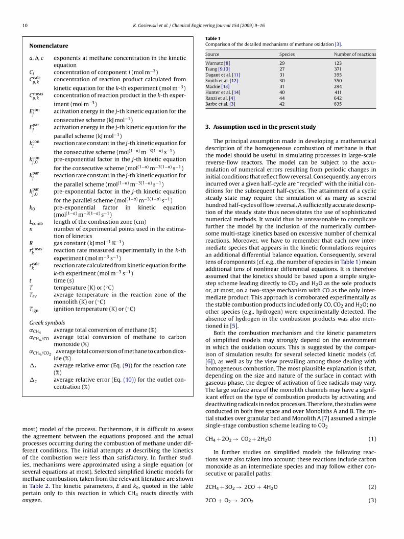
Table 1Comparison of the detailed mechanisms of methane oxidation [3].
Source Species Number of reactions
Warnatz [8] 29 123Tsang [9,10] 27 371Dagaut et al. [11] 31 395Smith et al. [12] 30 350Mackie [13] 31 294Hunter et al. [14] 40 411Ranzi et al. [4] 44 642Barbe et al. [3] 42 835
3. Assumption used in the present study
The principal assumption made in developing a mathematicaldescription of the homogeneous combustion of methane is thatthe model should be useful in simulating processes in large-scalereverse-flow reactors. The model can be subject to the accu-mulation of numerical errors resulting from periodic changes ininitial conditions that reflect flow reversal. Consequently, any errorsincurred over a given half-cycle are “recycled” with the initial con-ditions for the subsequent half-cycles. The attainment of a cyclicsteady state may require the simulation of as many as severalhundred half-cycles of flow reversal. A sufficiently accurate descrip-tion of the steady state thus necessitates the use of sophisticatednumerical methods. It would thus be unreasonable to complicatefurther the model by the inclusion of the numerically cumber-some multi-stage kinetics based on excessive number of chemicalreactions. Moreover, we have to remember that each new inter-mediate species that appears in the kinetic formulations requiresan additional differential balance equation. Consequently, severaltens of components (cf. e.g., the number of species in Table 1) meanadditional tens of nonlinear differential equations. It is thereforeassumed that the kinetics should be based upon a simple single-step scheme leading directly to CO2 and H2O as the sole productsor, at most, on a two-stage mechanism with CO as the only inter-mediate product. This approach is corroborated experimentally asthe stable combustion products included only CO, CO2 and H2O; noother species (e.g., hydrogen) were experimentally detected. Theabsence of hydrogen in the combustion products was also men-tioned in [5].
Both the combustion mechanism and the kinetic parametersof simplified models may strongly depend on the environmentin which the oxidation occurs. This is suggested by the compar-ison of simulation results for several selected kinetic models (cf.[6]), as well as by the view prevailing among those dealing withhomogeneous combustion. The most plausible explanation is that,depending on the size and nature of the surface in contact withgaseous phase, the degree of activation of free radicals may vary.The large surface area of the monolith channels may have a signif-icant effect on the type of combustion products by activating anddeactivating radicals in redox processes. Therefore, the studies wereconducted in both free space and over Monoliths A and B. The ini-tial studies over granular bed and Monolith A [7] assumed a simplesingle-stage combustion scheme leading to CO2
CH4 + 2O2 → CO2 + 2H2O (1)
In further studies on simplified models the following reac-tions were also taken into account; these reactions include carbonmonoxide as an intermediate species and may follow either con-secutive or parallel paths:
2CH4 + 3O2 → 2CO + 4H2O (2)
2CO + O2 → 2CO2 (3)
K. Gosiewski et al. / Chemical Engineering Journal 154 (2009) 9–16 11
Table 2Selected simplified reaction mechanisms available in the literature.
Ref. Number of stages E ko Application
[15] 1 130,000 2.6 × 10⁸ Lean combustion in porous
[16]1
318,1974.0 × 1020
Turbulent premixed2 1.0 × 10²¹ and 5.0 × 10¹⁶
3 6.7 × 10¹⁸
[17] 3 490,554 16 × 1018 Partial oxidation in inert[18] 1 130,038 7.74 × 10⁸ Methane diffusion flame[5] 2 427,064 1.24 × 10²¹ Combustion on small-diameter ceramic tubes
[19]1 202,641 1.3 × 10⁸
Numerical laminar flame model2 202,641 2.8 × 10⁹
1 global + 21 elementary reactions 202,641 4 × 10⁹
[20,21] 1 130,628 1.92 × 10¹⁸ Premixed, laminar, steady-state flames[2] 1 Not available Not available Not available[22] 4 Not available Not available Numerical description of hydrocarbon flames
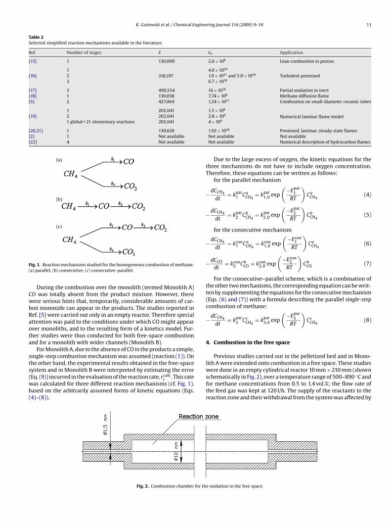
Fig. 1. Reaction mechanisms studied for the homogeneous combustion of methane:(a) parallel, (b) consecutive, (c) consecutive–parallel.
During the combustion over the monolith (termed Monolith A)CO was totally absent from the product mixture. However, therewere serious hints that, temporarily, considerable amounts of car-bon monoxide can appear in the products. The studies reported inRef. [5] were carried out only in an empty reactor. Therefore specialattention was paid to the conditions under which CO might appearover monoliths, and to the resulting form of a kinetics model. Fur-ther studies were thus conducted for both free-space combustionand for a monolith with wider channels (Monolith B).
For Monolith A, due to the absence of CO in the products a simple,single-step combustion mechanism was assumed (reaction (1)). Onthe other hand, the experimental results obtained in the free-spacesystem and in Monolith B were interpreted by estimating the error(Eq. (9)) incurred in the evaluation of the reaction rate, rcalc
i. This rate
was calculated for three different reaction mechanisms (cf. Fig. 1),based on the arbitrarily assumed forms of kinetic equations (Eqs.(4)–(8)).
Due to the large excess of oxygen, the kinetic equations for thethree mechanisms do not have to include oxygen concentration.Therefore, these equations can be written as follows:
for the parallel mechanism
−dCCH4
dt= kpar
1 CaCH4
= kpar1,0 exp
(−Epar
1RT
)Ca
CH4(4)
−dCCH4
dt= kpar
2 CbCH4
= kpar2,0 exp
(−Epar
2RT
)Cb
CH4(5)
for the consecutive mechanism
−dCCH4
dt= kcon
1 CaCH4
= kcon1,0 exp
(−Econ
1RT
)Ca
CH4(6)
−dCCO
dt= kcon
2 CbCO = kcon
2,0 exp
(−Econ
2RT
)Cb
CO (7)
For the consecutive–parallel scheme, which is a combination ofthe other two mechanisms, the corresponding equation can be writ-ten by supplementing the equations for the consecutive mechanism(Eqs. (6) and (7)) with a formula describing the parallel single-stepcombustion of methane:
−dCCH4
dt= kpar
3 CcCH4
= kpar3,0 exp
(−Epar
3RT
)Cc
CH4(8)
4. Combustion in the free space
Previous studies carried out in the pelletized bed and in Mono-lith A were extended onto combustion in a free space. These studieswere done in an empty cylindrical reactor 10 mm × 210 mm (shownschematically in Fig. 2), over a temperature range of 500–890 ◦C andfor methane concentrations from 0.5 to 1.4 vol.%; the flow rate ofthe feed gas was kept at 120 l/h. The supply of the reactants to thereaction zone and their withdrawal from the system was affected by
Fig. 2. Combustion chamber for the oxidation in the free space.

12 K. Gosiewski et al. / Chemical Engineering Journal 154 (2009) 9–16Ta
ble
3Th
ees
tim
ated
valu
esof
the
kin
etic
par
amet
ers.
Rea
ctio
nsy
stem
(ign
itio
nte
mp
erat
ure
)R
eact
ion
mec
han
ism
Rea
ctio
nE
[Jm
ol−1
]k o
[mol
(1−a
)m
−3(1
−a)s−1
]a,
b,c
Erro
rEq
.(9)
[%]
Erro
rEq
.(10
)[%
]
Free
spac
e(T
ign
≈83
0◦ C
)
Two-
stag
ePa
rall
el2C
H4
+3O
2k 1 −→
2CO
+4H
2O
222,
647
2.99
×10
101
6.24
5.31
CH
4+
2O2
k 2 −→C
O2
+2H
2O
1125
,422
1.52
×10
521
26.5
37.
51
Con
secu
tive
2CH
4+
3O2
k 1 −→2C
O+
4H2O
349,
189
7.59
×10
161.
59.
9613
.38
2CO
+O
2k 2 −→
2CO
257
1,53
21.
05×
1027
1.7
14.6
62.
91
Thre
e-st
age
Con
secu
tive
–par
alle
l2C
H4
+3O
2k 1 −→
2CO
+4H
2O
290,
651
8.74
×10
131.
49.
3711
.24
2CO
+O
2k 2 −→
2CO
252
7,10
11.
31×
1025
2.2
14.8
92.
35
CH
4+
2O2
k 3 −→C
O2
+2H
2O
999,
074
3.85
×10
471
23.5
12.
10
Mon
olit
hA
(Tig
n≈
530
◦ C)
Sin
gle-
stag
eC
H4
+2O
2k −→
CO
2+
2H2O
130,
622
6.86
×10
60.
946.
100.
9
Mon
olit
hB
(Tig
n≈
675
◦ C)
Two-
stag
ePa
rall
el2C
H4
+3O
2k 1 −→
2CO
+4H
2O
79,9
042.
84×
102
19.
380.
91
CH
4+
2O2
k 2 −→C
O2
+2H
2O
260,
304
8.71
×10
111
15.7
61.
41
Con
secu
tive
2CH
4+
3O2
k 1 −→2C
O+
4H2O
112,
996
2.52
×10
40.
920
.88
2.35
2CO
+O
2k 2 −→
2CO
213
7,38
82.
95×
106
1.1
13.7
87.
5
Thre
e-st
age
Con
secu
tive
–par
alle
l2C
H4
+3O
2k 1 −→
2CO
+4H
2O
127,
734
1.08
×10
50.
89.
670.
42
2CO
+O
2k 2 −→
2CO
217
0,95
27.
61×
107
113
.27
3.38
CH
4+
2O2
k 3 −→C
O2
+2H
2O
306,
927
5.38
×10
130.
718
.60
0.27
tubes of small diameters. At a suitably selected value of the flow ratethe considerable difference in linear velocities in transport tubes(18.9 m/s) and those in the reaction zone (0.42 m/s) exclude thecombustion in the transport conduits, limiting this process to thereaction zone itself. The study corroborates earlier results obtainedelsewhere [5], namely that the combustion in the free space, overcertain temperature ranges, occurs with the production of consider-able amounts of carbon monoxide, and only at higher temperaturesdoes it lead to carbon dioxide. It can therefore be assumed that theoxidation of methane in this system is a consecutive reaction. Acomparison between methane combustion in the free space and thesame process over a monolith reveals that the ignition temperaturesfor the mixture methane–air differ considerably. This temperatureis about 155–300 ◦C higher for the combustion in the free space(around 830 ◦C for the free-space oxidation 530 ◦C for Monolith Aand 675 ◦C for Monolith B). Furthermore, whereas the monolithcombustion is a fairly stable process, the free-space oxidation isunstable and the results may be difficult to reproduce.
During the combustion in the free space methane was oxidizedto carbon dioxide and carbon monoxide, with the conversion degreeto CO as high as 43%. Roughly, the results agree with those obtainedelsewhere (Ref. [5]) where the combustion occurred over a similarrange of temperatures. It is interesting, however, to note that theresults reported in [5] reveal a visible shift of CO2 formation towardshigher temperatures. This shift may suggest a clear domination ofthe consecutive mechanism or even (as assumed in [5]) the soleexistence of this particular mechanism. However, such a shift ishardly visible in Fig. 3.
This may be due to a simultaneous contribution of a parallelmechanism, or even its dominance. Therefore, the kinetic constantswere determined separately for the three mechanisms. The kineticparameters thus evaluated for both free-space combustion and oxi-dation over Monoliths A and B are shown in Table 3.
Examples of the experimental Arrhenius plots for the estimationof parameters of Eqs. (6) and (7) are shown in Figs. 4 and 5.
The ignition temperature for lean CH4–air mixtures (below1 vol.% of CH4) was about 825–830 ◦C; this may be seen in agraph illustrating the conversion of methane as a function oftemperature—Fig. 6.
The analysis of the values of kinetic parameters (activationenergy and pre-exponential factor), for the combustion in thefree space and for both the parallel and the consecutive–parallelschemes reveals that these values become physically meaninglessespecially for the reaction (1), of oxidation of CH4 to CO2.
Excessively large values of E and ko yield, upon insertion into therelevant kinetic equation, the result close to indeterminate form(∞ × 0). Since the usefulness of such a model is doubtful, it is bet-ter to assume that the combustion of methane in the free space
Fig. 3. Outlet concentration profiles vs. temperature for an empty reactor.

K. Gosiewski et al. / Chemical Engineering Journal 154 (2009) 9–16 13
Fig. 4. The Arrhenius plot for the consecutive scheme—combustion of methane tocarbon monoxide.
Fig. 5. The Arrhenius plot for the consecutive scheme—combustion of carbonmonoxide to carbon dioxide.
occurs according to a simplified scheme of consecutive reactions.Also, the consecutive–parallel scheme suggests that carbon dioxideoccurring during the combustion in the free space is a product ofthe consecutive oxidation of CO rather than a direct result of CH4oxidation. This is further supported by a very high values of theactivation energy and the pre-exponential factor for reaction (1),for both parallel and consecutive–parallel schemes. However, forthe oxidation of methane to CO (reaction (2)) the values of ko andE estimated based on data presented in Ref. [5] for the consecutivemechanism and the oxidation in the free space would be as fol-lows: kcon
1 = 1.24 × 10²¹ (l/s) and Econ1 = 427, 065 (J mol−1), that is,
would be close to the values shown in Table 3.The foregoing discussion shows that, for the combustion in
the free space, it is the consecutive mechanism, which should beassumed as a more reliable basis for the kinetic description.
Fig. 6. Conversion degree of methane vs. temperature for inlet concentrations ofCH4 of 0.53 and 0.5 vol.% (combustion in the free space).
Table 4Parameters of the monolith packing.
Quantity Unit Monolith A Monolith B
Diameter cm 3.9 6.5Length* cm 40 (4 × 10) 120 (4 × 30)Channel width mm 2 3Wall thickness mm 0.5 0.7Open frontal area (OFA) % 64 66Geometric surface area (GSA) m2/m3 1200 870Channels per square inch (CPSI) 1/in.2 ∼100 ∼50
* Note: The total length of the monolith is not the same as the combustion zone(hot zone), which was determined separately for each experiment.
5. Combustion over the monoliths
The experiments were done for two types of Monoliths A and B(cf. Table 4 and Fig. 7).
Kinetic experiments were carried out in a ceramic tube, packedin the middle section with monolith segments. The tube was placedin a temperature-controlled oven. The photographs (Fig. 8) showthe experimental installation and the positioning of the monolithsections in the reactor tube.
The results for Monolith A were already presented in Ref. [7]. Ithas to be stressed that, since no CO was detected during the com-bustion on this monolith, the relevant kinetics could be describedby a simple single-stage mechanism.
Kinetic experiments over Monolith B were conducted in aceramic tubular reactor of a diameter of 65 mm, symmetricallyplaced in an oven and packed with three monolith sections of a totallength of 900 mm. The experimental setup and the positioning ofthe monolith sections are shown in Fig. 8. The experiments werecarried out over the range of temperatures from 660 to 820 ◦C andfor the inlet methane concentrations between 0.38 and 1.2 vol.%;the flow rate was 0.8 m3(STP)/h.
Similarly as in [7], the length and volume of the combustionzone were determined based on this section of the temperatureprofile along the monolith for which the temperature exceeded theignition temperature. The temperature inside the reactor was mea-sured with thermocouples (1.5 mm in diameters) located close tothe axis of the reactor. To avoid placing too many thermocouples inthe monolith channels it is assumed that, for a given cross-section,the temperature remains constant along the radius of the reactor.The determination of the combustion temperature was done in thefollowing way. Since the total length of the monolith was largerthan that of the hot zone (where the combustion occurred), for eachexperiment carried out at the same preset temperature a tempera-ture profile along the monolith was measured. In the initial seriesof experiments the ignition temperature of the combustion wasdetermined as the highest monolith temperature for which (inde-
Fig. 7. Monoliths A and B.

14 K. Gosiewski et al. / Chemical Engineering Journal 154 (2009) 9–16
Fig. 8. Experimental installation to study combustion over the monolith packing.
Fig. 9. An example of the temperature profiles along the monolith for the constant preset temperature of the oven and various inlet methane concentrations [vol.%] duringkinetic experiments.
pendently of the inlet methane concentration) the combustion didnot start (i.e., methane conversion was equal to zero). This tempera-ture, Tign, is shown in Fig. 9 as a solid line. As can be seen from Fig. 9,the temperature profiles are practically independent of methaneconcentration.
It is even difficult to differentiate between the individual profilesfor different concentrations. The ignition temperature line makes itpossible to determine the length of the combustion zone, Lcomb, inthe monolith, i.e., a part of the monolith where the combustion canappear. For the case shown in Fig. 9 this zone was estimated roughlyas Lcomb ≈ 37 cm. Obviously, the higher the preset temperature inthe oven, the longer the “combustion zone”. As the temperatureof the homogeneous combustion an average temperature Tav in thecombustion zone was calculated, and this value was taken as a basisfor the determination of a single point in the Arrhenius plot (shownin Fig. 10 for the oxidation of methane to carbon monoxide (2) andfor the consecutive–parallel scheme).
In contrast to the experiments done over Monolith A, for Mono-lith B (similarly as for the free-space system) carbon monoxide wasdetected in the reaction products. The amount of CO depended on
temperature. The conversions of methane towards the individualproducts are shown in Fig. 11.
Similarly as for the free-space combustion, for Monolith B thekinetic constants were estimated separately for the three mecha-nisms (consecutive, parallel and consecutive–parallel). The values
Fig. 10. The Arrhenius plot for the consecutive–parallel scheme-conversion ofmethane to carbon monoxide.

K. Gosiewski et al. / Chemical Engineering Journal 154 (2009) 9–16 15
Fig. 11. Average conversions of methane: total (� ˛CH4 ), to carbon monoxide (� ˛CH4/CO) and to carbon dioxide (© ˛CH4/CO2) vs. average temperature in combustion zone.
of the activation energy and pre-exponential factor are shown inTable 3. The quality of the kinetic equations thus obtained wasassessed based on the average relative error of the reaction rate.The error was calculated using the following equations:
�r = 1n
n∑k=1
|rmeask
− rcalck
|rmeask
× 100% (9)
�c = 1n
n∑k=1
|Cmeasp,k
− Ccalcp,k
|Cmeas
p,k
× 100% (10)
The values of the errors shown in Table 3 were evaluated onlyfor such a range of temperatures for which methane conversionwas less than 25%. For this range, the amount of CO produced in thesystem was comparable with that of CO2. In some cases (for the par-allel scheme) the error of estimation drastically increases at highertemperatures, when CO content becomes close to zero. Therefore,a relatively small estimation error in Table 3 does not necessarilymean an enhanced practical usefulness of the corresponding kineticequation. We have to remember that formulae similar to Eq. (4)are unable yield reasonable simulation results in the range of tem-peratures over which the rate of CO formation drops (cf. Fig. 11).Consequently, the parallel scheme should be discarded in analyz-ing the results obtained. However, we can still try to determine thekinetic parameters for this scheme, provided a formula differentfrom Eq. (4) is used for the rate of oxidation to CO. The consecutivescheme can be rejected due to the errors larger than those for theconsecutive–parallel mechanism (over the range of temperaturesfor which the kinetics was determined for this scheme). Finally, forMonolith B the consecutive–parallel scheme seems to describe bestmethane oxidation to both CO2 and CO.
6. Conclusions
The kinetic results obtained for the combustion of leanmethane–air mixtures in three different systems (free space, Mono-lith A and Monolith B) clearly reveal a strong dependence of thekinetics of the oxidation upon the type of the experimental system.They also show that the surface area available for the gas phase mayplay an important role in activating and deactivating free radicals,
and thus alter reaction mechanisms and affect both the com-bustion kinetics and intermediate products. The widely divergentresults for Monolith A and B (which differ in geometric surface area(GSA) by around 330 m2/m3) suggest some form of pseudo-catalyticinfluence of the monolith walls on the homogeneous combus-tion of methane. The detailed conclusions may be summarized asfollows:
(a) The ignition temperature for the homogeneous combustion ofmethane strongly depends on the area of the surface in con-tact with the gas phase. The lower the surface area, the higherthe ignition temperature. For Monolith A, characterized by rel-atively narrow channels, this temperature was about 300 ◦Clower than for the oxidation in the free-space system.
(b) A simplified kinetic model should allow for the formation ofcarbon monoxide as an intermediate product, since under cer-tain conditions (free space or Monolith B with wide channels)considerable amounts of CO may temporarily form at lowertemperatures.
(c) If the parallel scheme is assumed (Eqs. (4) and (5)), the kineticmodel may generate terms close to the indeterminate form(∞ × 0), and thus lead to excessive errors in numerical calcu-lations. From the physical standpoint, for higher teperatures,such a model can simulate the situation in which CO2 is the finalproduct not accompanied by CO in only one way: by discardingthe oxidation of CH4 to CO altogether (reaction (2)) and substi-tuting the single-stage model for the two-stage scheme, withthe complete combustion of methane according to reaction (1).For the two-stage mechanism this type of kinetics should notbe taken into consideration.
(d) The consecutive–parallel scheme seems to be the most flexible.This scheme allows for both direct combustion of methane inaccordance with reaction (1) and the consecutive oxidation viareactions (2) and (3). However, in the case of combustion in thefree space this mechanism also yields a kinetic equation closeto the indeterminate form (∞ × 0), and the consecutive schememay thus prove superior.
(e) If the formation of carbon monoxide is not found experimentally(combustion in small narrow channels Monolith A), the single-stage mechanism (reaction (1)) is sufficiently accurate.

16 K. Gosiewski et al. / Chemical Engineering Journal 154 (2009) 9–16
Acknowledgements
This study was partly financed by the Polish Ministry of Scienceand Higher Education (grant No. R 14 020 02).
The monoliths used in the experiments were kindly suppliedfree of charge by the firm “Rauschert–Myslakowice”. The authorsgratefully acknowledge their assistance.
References
[1] M. De Joannon, P. Sabia, A. Tregrossi, A. Cavaliere, Dynamic behavior of methaneoxidation in premixed flow reactor, Combust. Sci. Technol. 176 (2004) 769–783.
[2] K. Annamalai, I.K. Puri, Combustion Science and Engineering, CRC Press Tay-lor&Francis Group, 2007.
[3] P. Barbe, F. Battin-Leclerc, G.M. Come, Experimental and modeling study ofmethane and ethane oxidation between 773 and 1573 K, J. Chim. Phys. 92 (1995)1666–1692.
[4] E. Ranzi, A. Sogaro, P. Gaffuri, G. Pennati, T. Faravelli, A wide range mod-eling study of methane oxidation, Combust. Sci. Technol. 96 (1994) 279–325.
[5] A.A. Slepterev, V.S. Salnikov, P.G. Tsyrulnikov, A.S. Noskov, V.N. Tomilov, N.A.Chumakova, A.N. Zagoruiko, Homogeneous high-temperature oxidation ofmethane, React. Kinet. Catal. Lett. 91 (2) (2007) 273–282.
[6] K. Gosiewski, K. Warmuzinski, M. Jaschik, M. Tanczyk, Kinetics of thermal com-bustion of lean methane–air mixtures in reverse flow reactors, Chem. ProcessEng. 28 (2007) 335–345.
[7] K. Gosiewski, Y.S. Matros, K. Warmuzinski, M. Jaschik, M. Tanczyk, Homoge-neous vs. catalytic combustion of lean methane–air mixtures in reverse-flowreactors, Chem. Eng. Sci. 63 (2008) 5010–5019.
[8] J. Warnatz, Combustion Chemistry, Springer Verlag, New York, 1984.
[9] W. Tsang, R.F. Hampson, Chemical kinetic data base for combustion chemistry.Part I. Methane and related compounds, J. Phys. Chem. Ref. Data 15 (1986)1087–1097.
[10] W. Tsang, Chemical kinetic data base for combustion chemistry. Part 2.Methanol, J. Phys. Chem. Ref. Data 16 (1987) 471–508.
[11] P. Dagaut, J.C. Boettner, M. Cathonnet, Methane oxidation: experimental andkinetic modeling study, Combust. Sci. Technol. 77 (1991) 127–148.
[12] G.P. Smith, M. Frenklach, H. Wang, T. Bowman, D. Golden, W. Gardiner, V. Lis-sianski, R. Serauskas, Combust. Res. Bull. 81 (1994).
[13] J.C. Mackie, Partial oxidation of methane: the role of the gas-phase reactions,Catal. Rev. - Sci. Eng. 33 (1991) 169–240.
[14] T.B. Hunter, H. Wang, T.A. Litzinger, M. Frenklach, The oxidation of methaneat elevated pressures: experiments and modeling, Combust. Flame 97 (1994)201–224.
[15] K. Hanamura, R. Echigo, S. Zhdanok, Superadiabatic combustion in porousmedium, Int. J. Heat Mass Transfer 36 (1993) 3201–3209.
[16] V.Y. Basevich, A.A. Belyaev, S.M. Frolov, Global kinetic mechanisms for simula-tion of turbulent reacting flows. Part 1 (in Russian), Russ. J. Phys. Chem. 17 (9)(1998) 117–129.
[17] K.V. Dobrego, N.N. Gnesdilov, S.H. Lee, H.K. Choi, Overall chemical kineticsmodel for partial oxidation of methane in inert porous media, Chem. Eng. J.144 (2008) 79–87.
[18] K.V. Dobrego, I.M. Kozlov, V.V. Vasiliev, J.P. Martin, P. Gillon, Influence of fuelfraction gradient on triple flame velocity in plain and axis-symmetrical chan-nels, Int. J. Heat Mass Transfer 51 (2008) 1962–1969.
[19] C.K. Westbrook, F.L. Dryer, Simplified reaction mechanisms for the oxidation ofhydrocarbon fuel in flames, Combust. Sci. Technol. 27 (1981) 31–43.
[20] T.P. Coffee, A.J. Kotlar, M.S. Miler, The overall reaction concept in premixed lam-inar steady-state flames. 2.Initial temperatures and pressures, Combust. Flame58 (1984) 59–67.
[21] T.P. Coffee, A.J. Kotlar, M.S. Miler, The overall reaction concept in premixed lami-nar steady-state flames. 1.Stoichiometries, Combust. Flame 54 (1983) 155–169.
[22] N. Peters, Numerical simulation of combustion phenomena, Lect. Notes Phys.241 (1985) 90–109.