
Molecular simulation and modelisation of methane/ethane mixtures adsorption onto a microporous...
10
Molecular simulation and modelisation of methane/ethane mixtures adsorption onto a microporous molecular model of kerogen under typical reservoir conditions Julien Collell a,b , Guillaume Galliero a,⇑ , François Gouth b , François Montel b , Magali Pujol b , Philippe Ungerer c , Marianna Yiannourakou c a Laboratoire des Fluides Complexes et leurs Réservoirs, UMR-5150 with CNRS and TOTAL, Université de Pau et des Pays de l’Adour, BP 1155, 64013 Pau, France b TOTAL SA, CSTJF, Avenue Larribau, 64018 Pau, France c Materials Design SARL, 18 rue de Saisset, 92120 Montrouge, France article info Article history: Received 9 January 2014 Received in revised form 15 May 2014 Accepted 14 June 2014 Available online 27 June 2014 Keywords: Mixture adsorption Kerogen Extended Langmuir IAS Theory abstract The prediction of mixture adsorption is a challenging task in gas industry when dealing with shales for both resources prospect or production forecast. In this work, we used molecular simulation and models to study the adsorption of methane/ethane mixtures onto a mature kerogen model under typical reser- voir conditions (338 K, up to 20 MPa). Using Molecular Dynamics, we first generated microporous struc- tures of kerogen, representative of field samples. Monte Carlo simulations in the Grand Canonical ensemble were used to produce pure compound and mixture adsorption isotherms on these adsorbent structures. The ability to predict simulation results of the Ideal Adsorbed Solution model and a modified statistical mechanical derivation of the Extended Langmuir model have been studied at low pressures (up to 1 MPa) where species are supposed ideal and at higher pressures (up to 20 MPa) where species non- ideality is partially introduced in the models. At low pressures, the adsorption isotherms predicted by the two models are in good agreement with the results from molecular simulation, independently of the con- finement. At higher pressures, this agreement is only valid for the less confined structures and worsened as the micropore size decreases. Ó 2014 Elsevier Inc. All rights reserved. 1. Introduction From the industrial revolution and the middle of the eighteenth century, the global energy consumption has been constantly increasing. Forecasts up to 2035 do not expect any change in this evolution [1]. Moreover natural gas represents almost a quarter of the global primary energy consumption. Up to now, the conven- tional resources have been the most exploited because it was not economically viable to produce gas from unconventional resources. However, as the conventional resources become scarce, the result- ing rise of the gas price allows the profitable exploitation of uncon- ventional resources (deep off-shore, tight gas or Shale gas). According to the annual report of the International Energy Agency [2], the shale gas production has led to a decrease of the US natural gas price, of approximately 65%, between 2010 and 2012. From a geochemical point of view, organic rich shales are grained materials composed of an organic phase known as kerogen spread in an inorganic matrix (mainly made of quartz, clays and car- bonates) [3]. Contrary to conventional resources, shales exhibit a poorly connected microporous network mainly located in the organic phase. The high degree of confinement suggests that in some shales approximately 50% of the stored fluid is adsorbed onto the kerogen (as in Barnett) [4], whereas the adsorbed gas in the inorganic matrix is generally supposed to be negligible [5,6]. Adsorption Selectivity and Non-Darcy gas flow through micropo- rous medium [7] are likely to induce an evolution of the produced gas composition. Thus, mixture adsorption is a leading criteria gov- erning shale gas production. This work provides a path of combining adsorption data (from experimental or simulation work) and theo- retical models in order to shed light to the mechanisms governing the sorption of gas on kerogen and therefore promotes understand- ing and predicting the behavior of such systems, at typical reservoir conditions (338 K and pressure up to 20 MPa). Under these thermo- dynamical conditions, the stored fluid (mostly composed of meth- ane, ethane and carbon dioxide) is in a supercritical state. This work is based on atomistic molecular simulations [8,9] with the use of both Monte Carlo (MC) and Molecular Dynamics http://dx.doi.org/10.1016/j.micromeso.2014.06.016 1387-1811/Ó 2014 Elsevier Inc. All rights reserved. ⇑ Corresponding author. Tel.: +33 (0)5 59 40 77 04. E-mail address: [email protected] (G. Galliero). Microporous and Mesoporous Materials 197 (2014) 194–203 Contents lists available at ScienceDirect Microporous and Mesoporous Materials journal homepage: www.elsevier.com/locate/micromeso
Transcript of Molecular simulation and modelisation of methane/ethane mixtures adsorption onto a microporous...

Microporous and Mesoporous Materials 197 (2014) 194–203
Contents lists available at ScienceDirect
Microporous and Mesoporous Materials
journal homepage: www.elsevier .com/locate /micromeso
Molecular simulation and modelisation of methane/ethane mixturesadsorption onto a microporous molecular model of kerogen undertypical reservoir conditions
http://dx.doi.org/10.1016/j.micromeso.2014.06.0161387-1811/� 2014 Elsevier Inc. All rights reserved.
⇑ Corresponding author. Tel.: +33 (0)5 59 40 77 04.E-mail address: [email protected] (G. Galliero).
Julien Collell a,b, Guillaume Galliero a,⇑, François Gouth b, François Montel b, Magali Pujol b,Philippe Ungerer c, Marianna Yiannourakou c
a Laboratoire des Fluides Complexes et leurs Réservoirs, UMR-5150 with CNRS and TOTAL, Université de Pau et des Pays de l’Adour, BP 1155, 64013 Pau, Franceb TOTAL SA, CSTJF, Avenue Larribau, 64018 Pau, Francec Materials Design SARL, 18 rue de Saisset, 92120 Montrouge, France
a r t i c l e i n f o
Article history:Received 9 January 2014Received in revised form 15 May 2014Accepted 14 June 2014Available online 27 June 2014
Keywords:Mixture adsorptionKerogenExtended LangmuirIAS Theory
a b s t r a c t
The prediction of mixture adsorption is a challenging task in gas industry when dealing with shales forboth resources prospect or production forecast. In this work, we used molecular simulation and modelsto study the adsorption of methane/ethane mixtures onto a mature kerogen model under typical reser-voir conditions (338 K, up to 20 MPa). Using Molecular Dynamics, we first generated microporous struc-tures of kerogen, representative of field samples. Monte Carlo simulations in the Grand Canonicalensemble were used to produce pure compound and mixture adsorption isotherms on these adsorbentstructures. The ability to predict simulation results of the Ideal Adsorbed Solution model and a modifiedstatistical mechanical derivation of the Extended Langmuir model have been studied at low pressures (upto 1 MPa) where species are supposed ideal and at higher pressures (up to 20 MPa) where species non-ideality is partially introduced in the models. At low pressures, the adsorption isotherms predicted by thetwo models are in good agreement with the results from molecular simulation, independently of the con-finement. At higher pressures, this agreement is only valid for the less confined structures and worsenedas the micropore size decreases.
� 2014 Elsevier Inc. All rights reserved.
1. Introduction
From the industrial revolution and the middle of the eighteenthcentury, the global energy consumption has been constantlyincreasing. Forecasts up to 2035 do not expect any change in thisevolution [1]. Moreover natural gas represents almost a quarter ofthe global primary energy consumption. Up to now, the conven-tional resources have been the most exploited because it was noteconomically viable to produce gas from unconventional resources.However, as the conventional resources become scarce, the result-ing rise of the gas price allows the profitable exploitation of uncon-ventional resources (deep off-shore, tight gas or Shale gas).According to the annual report of the International Energy Agency[2], the shale gas production has led to a decrease of the US naturalgas price, of approximately 65%, between 2010 and 2012.
From a geochemical point of view, organic rich shales aregrained materials composed of an organic phase known as kerogen
spread in an inorganic matrix (mainly made of quartz, clays and car-bonates) [3]. Contrary to conventional resources, shales exhibit apoorly connected microporous network mainly located in theorganic phase. The high degree of confinement suggests that insome shales approximately 50% of the stored fluid is adsorbed ontothe kerogen (as in Barnett) [4], whereas the adsorbed gas in theinorganic matrix is generally supposed to be negligible [5,6].Adsorption Selectivity and Non-Darcy gas flow through micropo-rous medium [7] are likely to induce an evolution of the producedgas composition. Thus, mixture adsorption is a leading criteria gov-erning shale gas production. This work provides a path of combiningadsorption data (from experimental or simulation work) and theo-retical models in order to shed light to the mechanisms governingthe sorption of gas on kerogen and therefore promotes understand-ing and predicting the behavior of such systems, at typical reservoirconditions (338 K and pressure up to 20 MPa). Under these thermo-dynamical conditions, the stored fluid (mostly composed of meth-ane, ethane and carbon dioxide) is in a supercritical state.
This work is based on atomistic molecular simulations [8,9]with the use of both Monte Carlo (MC) and Molecular Dynamics

J. Collell et al. / Microporous and Mesoporous Materials 197 (2014) 194–203 195
(MD) simulations of kerogen model structures. To do so, we usedthe molecular models of mature kerogen proposed by Yiannoura-kou et al. [10]. The kerogen models are created by MD in the iso-bar-isotherm (NPT) ensemble, starting from a low densityconfiguration and being compressed under typical reservoir condi-tions. The final densities are comparable to those that are experi-mentally observed. These models are subsequently used to obtainadsorption isotherms, using MC simulations in the Grand Canonicalensemble (GCMC). The simulations presented here have been com-puted using the MedeA� simulation package. MD simulations areconducted with MedeA/LAMMPS [11] software and MC simulationswith MedeA/GIBBS1 software. In the following, we use MolecularSimulations to generate adsorption data of mixtures under typicalreservoir conditions on structures that aims to reproduce the chem-ical and structural heterogeneity of kerogen, and we then study theability of the Extended Langmuir (EL) model [12] and the IdealAdsorbed Solution [13] (IAS) model to predict mixture adsorptionin kerogen structures presenting different degrees of confinement.
The EL model is an empirical extension of the pure compoundLangmuir model that describes the monolayer coverage of Ns
adsorption sites on a flat surface by a mixture. Several implemen-tations of the Extended Langmuir model, that include heterogene-ities in the adsorbate–adsorbent interactions, have been proposedin the literature. The Multi-Site (MS) Langmuir model developedby Nitta et al. [14] allows adsorbed molecules to occupy more thanone adsorption sites on a homogeneous surface. On the other hand,the Multi-Region (MR) Langmuir developed by Bai and Yang [15]assumes the possible existence of several regions. On some regionsall the species present in the mixture can be adsorbed, whileadsorption on other regions is species specific, due to entropic orenergetic effects. Bai and Yang [16] coupled both Multi-Site andMulti-Region (MR-MS) Extended Langmuir model. They concludedthat for similar species (mixtures of hydrocarbons) the MR-MSExtended Langmuir model only provides minor improvementsover the MS Langmuir model.
On the other hand, the IAS model considers a vapor liquid likeequilibrium between the adsorbed and free molecules. Speciesare supposed to behave as ideal gases which can lead to strongdeviations from experimental or simulated results as reported byMyers [17]. As for the Extended Langmuir model, several improve-ments have been proposed. Mixture non-ideality in the adsorbedphase can be introduced [18] (NIAL). Valenzuela et al. [19] intro-duced species-dependent fluid–solid interactions. In the following,we will apply the EL and the IAS models to describe mixtureadsorption in kerogen, because they do not require assumptionson the fluid–solid interaction energy distribution. We then proposemodifications to include fluid non-ideality that can be generalized,independently of the system or structure studied.
We discuss in Section 2 the force fields and the process used togenerate controlled adsorbent structure of kerogen and character-ize their porous volume and pore size distribution. In Section 3, wepropose to derive the Extended Langmuir model from a statisticalmechanics. We also detail the basic concepts of the Ideal AdsorbedSolution theory. In Section 4, we discuss the comparison of thesimulation data and the results predicted by the EL and IAS model.This section is split in two parts: first we discuss the resultsobtained at low pressure (from 0.1 to 1 MPa), where the fluidsand mixtures can be considered as ideal. Secondly, we extendour work to higher pressure (up to 20 MPa) and discuss aboutthe limitations of the ideal mixture model and the ways to reintro-duce the non-ideality of the gases. Conclusions of this work aregiven in Section 5.
1 MedeA/Gibbs license from IFP-EN and Laboratory of Chemical Physics, CNRS-Université Paris Sud.
2. Generation and characterization of kerogen structures
2.1. Force fields
Force fields are defined as a set of rules and parameters used toestimate interaction energies (MC) or forces (MD) between inter-acting particles. In this work, we take into account non-bondedinteratomic dispersion/repulsion interactions (Udisp=rep), electro-static interactions (Uel) and intramolecular interactions (Uint). Thetotal potential, is the sum in this three contributions(U ¼ Udisp=rep þ Uel þ Uint). The all atom pcff+ [20] force field wasused for the MD simulations with the Waldman and Hagler [21]combining rules. The TraPPE [22] force field and Möller et al. [23]force field for methane are used for MC simulations with Lorentz–Berthelot [24]. Both force fields are well known for their ability toreproduce with a high accuracy the thermodynamic properties oforganic compounds.
2.2. Kerogen models
Kerogen is defined as insoluble part of the sedimentary organicmatter present in shale reservoirs [25]. Depending on its originand the burial history of the reservoir, the chemical or topologicalstructure of kerogen samples may strongly differ [26]. Kerogen gen-eration occurs during the maturation of unconsolidated sediments.There are three different types depending on their origin (type I:algal, type II: liptinitic, type III: humic), leading to different elemen-tary composition [27]. Kerogens share similarities with pyrobitu-men, coals or asphaltenes depending on their maturity [28,29].The kerogen molecular model used for this work published by Yian-nourakou et al. [10] is based on structural and elemental analysispublished from Kelemen et al. [30]: this model mimics a generictype II mature kerogen at the end of the catagenetic process, wherechemical composition of the three different sources tends to con-verge to coals like structure made of polyaromatic clusters [30]. Thiskerogen is supposed to be a standard of a generic kerogen that can beencountered in mature shale as in the Barnett [31]. The global struc-ture is amorphous but polyaromatic cluster tends to stack in parallel(p stacking) or orthogonal planes [32]. As stacking increases the ker-ogen density, we used it as a criterion to check the consistency of thesupra-molecular structures obtained from molecular simulations.
2.2.1. Building a kerogen moleculeSeveral attempts have been made in the literature to represent
the chemical structure of kerogen depending their type and burialhistory [33,28] or by predicting the chemical structure of kerogenusing molecular simulation and reactive force fields [34]. Ourmodel is based on data from the literature (chemical structure, ele-mentary analysis and physical properties). First, model fragments(polyaromatic units) of kerogen are created which have the follow-ing characteristics (see Fig. 1a): H/C ratio from 0.5 to 0.8, O/C ratiofrom 0.05 to 0.1, and poly-aromatic cluster composed of 4–6 ben-zene rings with few short lateral alkyl chains. Then, macromole-cules of kerogen are created by linking 4–5 cluster units. Themolecular weight is approximately 1200 g/mol, quite low for suchcompounds [35,36] but adequate to describe the basic features ofthese systems at a reasonable cost. Examples of such cluster unitsand kerogen molecules are shown on Fig. 1b. Such a workflow hasbeen previously followed by Facelli et al. [37] to study the interac-tion of less mature type I kerogen and asphaltenes with theinorganic matrix present in shales.
2.2.2. Creation of an adsorbent structureWe created dense kerogen structures with the following
process: first kerogen molecules are relaxed individually (random

(a) Example of a kerogen fragment (b) Example of a kerogen molecule
Fig. 1. Molecular model of fragment and molecules of kerogen. (a) An example of one kerogen fragment used to generate complete kerogen molecules. (b) Presents one of thekerogen molecules representative of a mature kerogen. Theses molecules are obtained by linking of the kerogen fragments of figure (a). Atoms representation: black is forcarbon atoms, white for hydrogen, red for oxygen, yellow for sulfur and purple for nitrogen. (For interpretation of the references to color in this figure legend, the reader is referredto the web version of this article.)
Table 1Characteristics of the 6 different solid structures created by insertion of a dummy particle (DP) of various Lennard–Jones diameter. The pore volume is averaged on 5 results withdifferent initialization value of the random number generator.
Structure label Dummy particle L-J diameter [Å] Pore volume [%] Void radius [Å] Box length [Å]
1 rdp ¼ 0 0.706 ± 0.008 0 ± 0 24.402 rdp ¼ 9 2.28 ± 0.02 4.30 ± 0.04 24.603 rdp ¼ 11 4.78 ± 0.03 4.95 ± 0.04 24.894 rdp ¼ 13 6.39 ± 0.02 5.36 ± 0.04 25.295 rdp ¼ 15 7.97 ± 0.05 6.44 ± 0.04 25.486 rdp ¼ 17 11.06 ± 0.03 6.69 ± 0.04 26.27
3 3,5 4 4,5 5 5,5 6 6,5 7
Pore radius [Å]
0
10
20
30
40
50
60
70
PSD
[A
rbitr
ary
Scal
e]
Structure 2
Structure 3
Structure 4
Structure 5
Structure 6
Fig. 2. Pore size distribution (PSD) as predicted by the method of Gubbins. Thesphere-radius increment is 2� 10�3 Å and the y-axis represent the number ofsphere measured with the corresponding x-axis radius. The red curve is for thestructure with rdp ¼ 9 Å, blue for rdp ¼ 11 Å, brown for rdp ¼ 13 Å, green forrdp ¼ 15 Å and orange for rdp ¼ 17 Å. The PSD of the structure without dummyparticle (rdp ¼ 0 Å) is not represented here, the pore radius are below the minimalprobe radius investigated (methane with rij ¼ 3:73 Å [22]) and insertion is neveraccepted. (For interpretation of the references to color in this figure legend, thereader is referred to the web version of this article.)
196 J. Collell et al. / Microporous and Mesoporous Materials 197 (2014) 194–203
orientation and configuration) by MD in the NVT ensemble. Then, 8relaxed kerogen molecules are placed in a large simulation boxsuch that the density of the box is around 0:1 g=cm3, so interac-tions between molecules are initially weak and finally MD simula-tion are performed on low densities simulations boxes in the NPTensemble (338 K, 20 MPa) until equilibrium is reached and densityconverges to an average value of 1:24 g=cm3 which is close tomature shale experimental density (1:2—1:4 g=cm3) [38].
The effect of pressure and temperature (from 308 to 368 K andfrom 5 to 20 MPa) is negligible on the kerogen structures andwould not be discussed in the following. In previous work, Yian-nourakou et al. found qualitative agreements between their simu-lated adsorption isotherms and experimental data reported byGasparik et al. [39].
The average porosities have been measured with the simulationmethod proposed by Herrera et al. [40]. This simulation techniqueconsists of carrying out test insertions of a probe molecules (herehelium [22]) within the simulation box based on simple distancecriterion. If the probe molecule does not overlap with atoms fromthe solid (rij > rij), the test insertion is counted as accepted. Theporous volume (in percent) is equal to the number of acceptedinsertion divided by the total number of tried insertions:
Vporous½%� ¼nacc
ntotð1Þ
where nacc is the number of accepted insertions and ntot is the totalnumber of achieved insertion tests. Theses results are listed inTable 1. The PSD of this first sample has been simulated by themethod of sphere insertion proposed by Gubbins [41]. This consistsof picking points randomly distributed within the solid and to eval-uate the biggest sphere (radius rs) that contain this points withoutoverlapping with the solid such as:
rij Pri
2þ rs ð2Þ
where rij is the distance between the sphere center and a particlesfrom the solid, ri is the LJ diameter of the nearest particle from thesolid and rs is the sphere radius. We defined the void radius as theradius at the peak of the pore size distribution presented in Fig. 2with the method of Gubbins. This kerogen structure does not

J. Collell et al. / Microporous and Mesoporous Materials 197 (2014) 194–203 197
contains micropores (i.e. pores with diameters lower than 2 nm[42]) that can be considered as adsorption sites: the pore size distri-bution shows a peak below the Lennard–Jones radius of the small-est molecule we want to study (methane with r ¼ 3:73 Å [22]),leading to a low acceptance probability of the particle insertionduring the GCMC simulation. FIB-SEM [3] and Hg-porosimetry [5]experiments suggest the existence in kerogen of micropores largerthan 10 Å.
As our goal is to study the ability of multicomponent adsorptionmodel to represent adsorption in mature kerogen, we will considerpore sizes around this value. We expect that the less confined thestructure is, the better the model predictions are. Dummy particleswere inserted during the MD/NPT stage, whose diameter is set togenerate the desired pore size. Then, the dummy particle areremoved from the bulk kerogen structure, leaving a spherical voidvolume (i.e. a host micropore) where adsorption of gas moleculesis likely to occur. We have created 5 structures with different val-ues of the dummy particle Lennard–Jones diameter ranging from 9to 17 Å. The simulation box dimensions are ranging from 24 to27 Å depending on the pore size.
Fig. 3a shows a snapshot of a final structure obtained followingthe workflow described above, with a dummy particle diameter of9 Å. As in previous simulations [10,37] and experimental work[43], the occurrence of stacking in the kerogen structure leading
(a) Bulk kerogen structure as obtained bymolecular dynamic simulations.
(bm
Fig. 3. Supra-molecular structures of the kerogen structure with void radius of 6.44 Å. (gray sphere represents the pore created by the removal of the dummy-particle. (b) Presenthe solid structure has been removed. The black particles represent the CH3 groups of ethpore micropore. (For interpretation of the references to color in this figure legend, the r
0 0.2 0.4 0.6 0.8 1
Pressure [MPa]
0
0.1
0.2
0.3
0.4
0.5
0.6
0.7
Nad
s [m
mol
/g]
(a) Adsorbed amount of methane
Fig. 4. Comparison of absorbed quantities into kerogen structure with void radius of 4amount of ethane. On molar basis in the free phase: green: pure compound, blue: 90%Symbols represent results from molecular simulation. Solid lines: Langmuir fit of pure coquantities predicted by the IAS model. (For interpretation of the references to color in t
to a nematic like spacial organization of the polyaromatic kerogencluster can be seen.
The radius of the created voids are listed in Table 1. They aremeasured at the maximum of the pore size distribution (PSD) peakand the incertitude is defined as the half width of theses peaks (seeFig. 2).
We performed reproducibility tests of adsorption to estimatethe incertitude on the adsorbed quantities due to the solid struc-ture on structure 5 (with a dummy particle of 15 Å). The maximumdeviation of a structure to the average adsorbed amount representsless than 10% of the adsorbed quantities at 20 MPa. Consequently,the process used to generate kerogen structures is fairly reproduc-ible and the size of the kerogen structures is big enough to be con-sidered as a representative elementary volume for structuregenerated by dummy particle insertion.
In addition to this, Yiannourakou et al. [10], performedadsorption in simulation boxes containing one unit cell(� 25� 25� 25 Å) and on boxes containing 8 unit cells (boxdimensions � 50� 50� 50 Å), which did non reveal evidence offinite size effects on the adsorbed quantities.
One configuration of the adsorbed ethane in kerogen structure 5is given in Fig. 3b. These molecules generate a layer of adsorbedmolecules, with very few molecules at the center of the pore,materialized by the red sphere. On average, the gas molecules
) Configuration of adsorbed ethaneolecules onto kerogen.
a) Presents a kerogen structure as obtained by molecular dynamic simulations. Thets a configuration of ethane molecules adsorbed in the kerogen structure. For clarity,ane molecules. The red sphere is a guide for the eyes and represents the center of theeader is referred to the web version of this article.)
0 0.2 0.4 0.6 0.8 1
Pressure [MPa]
0
0.1
0.2
0.3
0.4
0.5
0.6
0.7
Nad
s [m
mol
/g]
(b) Adsorbed amount of ethane
.30 Å. (a) Reports the adsorbed amount of methane and (b) reports the adsorbedmethane/10% ethane, red: 70% methane/30% ethane and black: equimolar mixture.mpound, dashed lines are quantities predicted by the EL model and dotted lines arehis figure legend, the reader is referred to the web version of this article.)

0 0.2 0.4 0.6 0.8 1
Pressure [MPa]
0
0.02
0.04
0.06
0.08
0.1
Nad
s [m
mol
/g]
(a) Adsorbed amount of methane
0 0.2 0.4 0.6 0.8 1
Pressure [MPa]
0
0.02
0.04
0.06
0.08
0.1
Nad
s [m
mol
/g]
(b) Adsorbed amount of ethane
Fig. 5. Comparison of absorbed quantities into kerogen structure without void. See Fig. 4 for legends colors and patterns. (For interpretation of the references to color in thisfigure legend, the reader is referred to the web version of this article.)
198 J. Collell et al. / Microporous and Mesoporous Materials 197 (2014) 194–203
are preferentially located at the surface created by the removal ofthe dummy particle. By comparing the sorption capacities of thestructure 2 (dummy particle Lennard–Jones diameter of 9 Å, greencurves on Fig. 4) and the structure 1 (no dummy particle, greencurves on Fig. 5), we can consider that adsorption almost exclu-sively occurs at the surface due to the dummy particle removal.
From the study of methane sorption capacity, we found that thekerogen structures with dummy particle diameter from 9 to17 Å (structures 2–6) have a Langmuir monolayer capacity (rsNs
in Eq. 19) that scales almost linearly with the specific surface area,and that the corresponding inverse Langmuir pressure (Ca in Eq.19) is almost constant.
Gasparik et al. [39] and the Alberta Geological Survey [44,45](AGS) published adsorption data on shale samples whose kerogenmaturity is equivalent to ours. Assuming at the first order thatadsorption only occurs in the kerogen nodules [4], we can compareour structure to experimental samples, and find the one that is themost representative of shale samples. Gasparik et al. [39] reportedon Geverick shale sample a Langmuir pressure parameterPL ¼ ðCaÞ�1 of PL ¼ 3:0 MPa. The AGS [44,45] reported on Duvernayshale sample of same maturity PL ¼ 7:24 MPa. The average Lang-muir pressure we obtained on our structures (except structure 1,generated without dummy particle) is between these two reportedvalues at PL ¼ 5:40 MPa. The Langmuir pressure being related tothe solid/fluid interaction, this means that our kerogen model issuited to mimic the kerogen samples of similar maturity. In addi-tion, the Lanmguir monolayer capacity reported by Gasparicket al. and the AGS are respectively of rsNs ¼ 1:40 mmol=g andrsNs ¼ 1:64 mmol=g. Our kerogen structure generated with adummy particle of 9 Å is the closest to these values. Consequently,this structure seems as the best candidate to represent kerogensamples reported by Gasparik et al. [39] and the AGS [44,45].
3. Theory of multicomponent adsorption
Modeling of pure compound adsorption has been the subject ofnumerous works since the first attempt to provide a theoreticalapproach of Langmuir [46] in 1916. The different models devel-oped since can be divided in two families:
� The geometry independent models: the formulation is invariantwhatever the geometry of the porous structure is, such as theLangmuir model [46], the Ideal Adsorbed Solution model (IAS)[13], or the Brunauer–Emmett–Teller (BET) model [47].� The geometry dependent models: where a geometry and a fluid/
adsorbent interaction potential as to be determined. The Poten-tial Theory of Adsorption [48], the simplified local-density [49],
or the density functional theory [50] are examples of such mod-els. Geometry and interaction parameters are generallyobtained or matched from adsorption and pore sizedistributions.
It is clear from Fig. 3 that the morphology and pore characteris-tics of kerogen are rather complex. Therefore we choose to usegeometry independent models. Among them, the Extended Lang-muir (EL) and IAS models are very popular. In our systems, theadsorbed molecules are interacting with several surfaces due tothe morphology of the structures, whereas the EL and IAS modelsonly consider adsorption under the influence of one surface ofthe surface. Thus in the following, we detail theses two multicom-ponent models, check their consistency and provide some modifi-cations in order to improve their ability to predict adsorption ofsupercritical mixtures into kerogen under reservoir conditions.
3.1. The Extended Langmuir model
The pure compound Lanmguir model has been derived from thekinetic theory of gases [46]. It has been later empirically extendedto mixtures adsorption by considering the monolayer surface cov-erage of more than one species. Ally and Braunstein [51], then Dut-cher et al. [52] proposed an approach to derive multilayeradsorption from statistical mechanics. This enables to derive thepure compound BET isotherm model:
Nads ¼ Nmono � Cai
ð1� aiÞð1� ai þ CaiÞð3Þ
where Nads is the amount if i adsorbed (in mmol/g of solid), Nmono isthe monolayer maximum sorption capacity, C is an energy parame-ter for monolayer adsorption that represents the internal energychange due to the adsorption of one molecule of fluid and ai isthe activity of i defined as:
ai ¼fi
psatð4Þ
where fi is the fugacity of i at given (P; T) and psat is the saturationpressure. For a pure compound and at the limit of low fugacity,fi ’ P then 1� ai ’ 1 and:
Nads ¼ Nmono � C 0P1þ C0P
ð5Þ
with C0 ¼ C=psat . Eq. (5) is equivalent with the Langmuir model. Wepropose here is to extend the work of Ally and Braunstein andDutcher et al. to determine a theoretically consistent extension ofthe Langmuir adsorption model to binary mixtures.

J. Collell et al. / Microporous and Mesoporous Materials 197 (2014) 194–203 199
3.1.1. Statistical mechanical derivationLet us consider an adsorbed fluid composed of NA molecules of
A and NB molecules B. The adsorbent structure contains Ns poresper grams of solid, with rs sorption sites per pore. Let vA;1 be thenumber of molecules of A and vB;1 the number of molecules of Bsorbed into the first adsorbed layer, leaving rsNs � vA;1 � vB;1 sitesempty. Following Ally and Braunstein: the number of distinguish-able ways that vA;1 molecules can sorb into the rsNs sites of thefirst layer is:
XA;1 ¼ðrsNsÞ!
ðrsNs � vA;1Þ!ðvA;1Þ!ð6Þ
and the number of distinguishable ways that vB;1 molecules cansorb into the rsNs � vA;1 remaining empty sites is given by:
XB;1 ¼ðrsNs � vA;1Þ!
ðrsNs � vA;1 � vB;1Þ!ðvB;1Þ!ð7Þ
Assuming a BET behavior, adsorbed molecules are contained ina multilayer structure which contains va;2 molecules of a (a can beeither A or B). They are sorbed on top of the va;1 molecules of thefirst layer, with no limits on the number of molecules adsorbedinto the multilayer. The number of distinguishable ways that va;2molecules can sorbed on top of va;1 molecules is:
Xa;2 ¼ðva;1 þ va;2 � 1Þ!ðva;1 � 1Þ!ðva;2Þ!
�ðva;1 þ va;2Þ!ðva;1Þ!ðva;2Þ!
¼ ðNaÞ!ðva;1Þ!ðNa � va;1Þ!
ð8Þ
where Na ¼ va;1 þ va;2; the total number of distinguishable arrange-ment X of A and B into the mono- and multilayer is:
X ¼ XAXB with : XA ¼ XA;1XA;2 and XB ¼ XB;1XB;2 ð9Þ
Finally:
X ¼ ðrsNsÞ!ðNAÞ!ðNBÞ!ðrsNs � vA;1 � vB;1Þ!½ðvA;1Þ!�
2½ðvB;1Þ!�2ðNA � vA;1Þ!ðNB � vB;1Þ!
ð10Þ
The internal energy change due to adsorption is:
DE ¼ �vA;1�A;1 � vB;1�B;1 ð11Þ
with �a;1 ¼ Ea;1 � EL;a where Ea;1 is the energy of sorption of a mole-cule of a onto the first layer and EL;a is the energy of liquefaction ofspecie a. The underlying assumption of the BET theory is that for themultilayer, Ea;2 ¼ EL;a leading to �a;2 ¼ 0. The thermodynamicentropy using the Stirling approximation ðlnðN!Þ ¼ N ln N � NÞ is:
Sk¼ ln X ¼ rsNs ln
rsNs
rsNs � vA;1 � vB;1þ NA ln
NA
NA � vA;1
þ NB lnNB
NB � vB;1þ vA;1 ln
ðNA � vA;1ÞðrsNs � vA;1 � vB;1ÞðvA;1Þ
2
þ vB;1 lnðNB � vB;1ÞðrsNs � vA;1 � vB;1Þ
ðvB;1Þ2 ð12Þ
The Lagrangian multipliers method is used to satisfy the secondlaw of thermodynamic (maximum entropy):
@ ln X@va;1
�����rsNs ;Na ;Nb ;T;va;2 ;vb;1 ;vb;2
¼ 1kT
@E@va;1
������a;1 ;�b;1vb;1
ð13Þ
This results in a system of two equations (a can either be A or B):
ðva;1Þ2
ðNa � va;1ÞðrsNs � vA;1 � vB;1Þ¼ exp
�a;1kT
� �¼ Ca;1 ð14Þ
We get the most probable distribution X� by substitutingEq. (14) in Eq. (12):
ln X� ¼ rsNs lnrsNs
rsNs � vA;1 � vB;1þ NA ln
NA
NA � vA;1þ NB
� lnNB
NB � vB;1þ vA;1
�A;1
kTþ vB;1
�B;1
kTð15Þ
We are now looking for the expression of the activities of speciea , noted aa defined as:
ln aa ¼ lnfa
Pa;sat
� �¼ @G=kT
@Na
����Nb ;T
ð16Þ
where G is the Gibbs energy in the ðN; P; TÞ ensemble. Assuming thatthe therm PV is negligible (G=kT � E=kT � ln X�), Eq. (16) can bewritten as:
aa ¼Na � va;1
Nað17Þ
Eq. (17) is equivalent to Eq. (24) of Dutcher et al. in the frame ofthe BET theory. By substituting Eq. (17) in Eq. (14) one obtains:
Na ¼ Ca;1rsNsaa
ð1� aaÞ ð1� aaÞ þ Ca;1aa þ Cb;1ab1�aa1�ab
� �h i ð18Þ
For a single component one find the pure compound BET. At thelimit of low fugacity, (1� aa � 1� ab � 1), Eq. (18) can be rewrit-ten as:
Na ¼ CarsNsfa
1þ Cafa þ Cbfbð19Þ
where Ca ¼ Ca;1=Pa;sat with Pa;sat : the saturation pressure of specie a.We designate this model as the Improved Langmuir Model (IEL).Assuming fa ¼ Pa, (Pa being the partial pressure defined asPa ¼ xaP, where xa is the molar fraction of the specie a), we finallyfind the Extended Langmuir model [47] for a binary mixture:
Na ¼ Nmono CaPa
1þ CaPa þ CbPbð20Þ
By linking Eqs. (19) and (20), NMono ¼ rsNs : correspond to thesorption capacity of the first adsorbed layer and Ca ¼ Ca;1=Psat :represents the adsorption strength. It should be enlightened thatin the case of adsorption in spherical pore, the multilayer adsorp-tion will be limited due to the finite pore volume, leading to a trun-cated BET isotherm. This case is not considered here but may haveto be introduced depending on the system studied.
3.2. The IAS model
Introduced by Myers and Prausnitz [13] in 1964, the IdealAdsorbed Solution Theory (IAS Theory) represents the adsorptionof mixtures as a thermodynamic equilibrium between theadsorbed phase and the surrounding free gas phase. Similarly toa vapor–liquid equilibrium the adsorbed phase is subjected to aspreading pressure p constraining the adsorbed phase on the sur-face A of the porous adsorbent. The spreading pressure represents atwo dimensional confinement pressure of the adsorbed phaseagainst the adsorbent surface. The equation for the Gibbs freeenergy is then:
dGðN;p; TÞ ¼ �SdT þ AdpþX
i
lidNi ð21Þ
At equilibrium: �lgi ¼ �la
i , where �lgi is the excess chemical poten-
tial of specie i in the free gas phase and �lai the excess chemical
potential of the same specie in the adsorbed phase. According toMyers and Prausnitz, the equilibrium condition may be rewrittenas:
RT lnðyiP/iÞ ¼ RT lnðf 0i ðpÞcixiÞ ð22Þ
200 J. Collell et al. / Microporous and Mesoporous Materials 197 (2014) 194–203
where yi is the molar fraction of specie i in the free phase, P the bulkpressure, /i is the fugacity coefficient, xi the molar fraction of i inthe adsorbed phase, ci the activity coefficient and f 0
i ðpÞ is the fugac-ity of i in the adsorbed phase. It is generally assumed that the mix-ture is ideal, (ci ¼ 1) and that the free and adsorbed phases are alsoideal (/i ¼ 1 and f 0
i ðpÞ ¼ P0i ðpÞ). It implies that the spreading pres-
sure is the same for each specie in the adsorbed phase (pi ¼ pj for i; jspecies of the mixture). The spreading pressure is given by:
piðf 0i Þ ¼
RTA
Z f 0i
0Niðf Þd lnðf Þ ð23Þ
where Ni is the adsorbed amount of i. Contrary to the ExtendedLangmuir model, there is no constrain on the mathematical formu-lation of the pure compound adsorption isotherm, as the integrationin Eq. (23) can be done analytically or with a numerical procedure.
The effect of the confinement is not directly taken into accountin the IAST and EL models. However, as discussed earlier, the Lang-muir monolayer capacity of pure methane (rsNs in Eq. (19)) scalesalmost linearly with the specific surface area, except for thestructure without dummy particle (structure 1). On the other hand,the inverse Langmuir pressure (Ca in Eq. (19)) is almost constantexcept for structure 1. This indicates that the effects of confine-ment are weak, except for structure 1.
4. Results and discussion
In this section we compare results for mixture adsorptionobtained from molecular simulation with results predicted by theExtended Langmuir and Ideal Adsorbed Solution Theory. Our workis presented in two distinct parts. In the first part we compare sim-ulations and models at low pressure (0.1–1 MPa) where the fluidscan be treated as ideal gas (fi � xiP). This enables us to discussabout the ability of both EL and IAS formulation to model mixturesadsorption in amorphous and microporous solid. In the secondpart, models and simulations are compared at higher pressures(up to 20 MPa) to study the conjunction of non-ideality (fi – xiP)and confinement.
4.1. Mixture and thermodynamic conditions studied
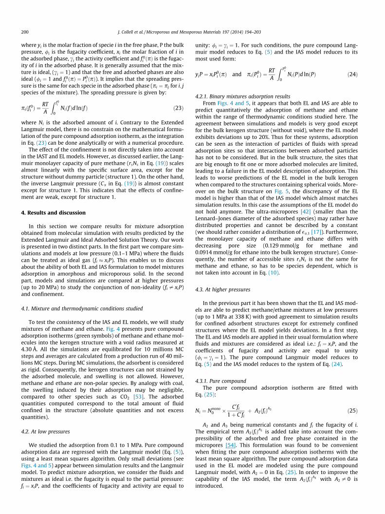
To test the consistency of the IAS and EL models, we will studymixtures of methane and ethane. Fig. 4 presents pure compoundadsorption isotherms (green symbols) of methane and ethane mol-ecules into the kerogen structure with a void radius measured at4.30 Å. All the simulations are equilibrated for 10 millions MCsteps and averages are calculated from a production run of 40 mil-lions MC steps. During MC simulations, the adsorbent is consideredas rigid. Consequently, the kerogen structures can not strained bythe adsorbed molecule, and swelling is not allowed. However,methane and ethane are non-polar species. By analogy with coal,the swelling induced by their adsorption may be negligible,compared to other species such as CO2 [53]. The adsorbedquantities computed correspond to the total amount of fluidconfined in the structure (absolute quantities and not excessquantities).
4.2. At low pressures
We studied the adsorption from 0.1 to 1 MPa. Pure compoundadsorption data are regressed with the Langmuir model (Eq. (5)),using a least mean squares algorithm. Only small deviations (seeFigs. 4 and 5) appear between simulation results and the Langmuirmodel. To predict mixture adsorption, we consider the fluids andmixtures as ideal i.e. the fugacity is equal to the partial pressure:fi ¼ xiP, and the coefficients of fugacity and activity are equal to
unity: /i ¼ ci ¼ 1. For such conditions, the pure compound Lang-muir model reduces to Eq. (5) and the IAS model reduces to itsmost used form:
yiP ¼ xiP0i ðpÞ and piðP0
i Þ ¼RTA
Z P0i
0NiðPÞd lnðPÞ ð24Þ
4.2.1. Binary mixtures adsorption resultsFrom Figs. 4 and 5, it appears that both EL and IAS are able to
predict quantitatively the adsorption of methane and ethanewithin the range of thermodynamic conditions studied here. Theagreement between simulations and models is very good exceptfor the bulk kerogen structure (without void), where the EL modelexhibits deviations up to 20%. Thus for these systems, adsorptioncan be seen as the interaction of particles of fluids with spreadadsorption sites so that interactions between adsorbed particleshas not to be considered. But in the bulk structure, the sites thatare big enough to fit one or more adsorbed molecules are limited,leading to a failure in the EL model description of adsorption. Thisleads to worse predictions of the EL model in the bulk kerogenwhen compared to the structures containing spherical voids. More-over on the bulk structure on Fig. 5, the discrepancy of the ELmodel is higher than that of the IAS model which almost matchessimulation results. In this case the assumptions of the EL model donot hold anymore. The ultra-micropores [42] (smaller than theLennard–Jones diameter of the adsorbed species) may rather havedistributed properties and cannot be described by a constant(we should rather consider a distribution of �a;1 [17]). Furthermore,the monolayer capacity of methane and ethane differs withdecreasing pore size (0.129 mmol/g for methane and0.0914 mmol/g for ethane into the bulk kerogen structure). Conse-quently, the number of accessible sites rsNs is not the same formethane and ethane, so has to be species dependent, which isnot taken into account in Eq. (10).
4.3. At higher pressures
In the previous part it has been shown that the EL and IAS mod-els are able to predict methane/ethane mixtures at low pressures(up to 1 MPa at 338 K) with good agreement to simulation resultsfor confined adsorbent structures except for extremely confinedstructures where the EL model yields deviations. In a first step,The EL and IAS models are applied in their usual formulation wherefluids and mixtures are considered as ideal i.e.: fi ¼ xiP, and thecoefficients of fugacity and activity are equal to unity(/i ¼ ci ¼ 1). The pure compound Langmuir model reduces toEq. (5) and the IAS model reduces to the system of Eq. (24).
4.3.1. Pure compoundThe pure compound adsorption isotherm are fitted with
Eq. (25):
Ni ¼ Nmono0 � C 0fi
1þ C 0fiþ A2ðfiÞA3 ð25Þ
A2 and A3 being numerical constants and fi the fugacity of i.The empirical term A2ðfiÞA3 is added take into account the com-pressibility of the adsorbed and free phase contained in themicropores [54]. This formulation was found to be convenientwhen fitting the pure compound adsorption isotherms with theleast mean square algorithm. The pure compound adsorption dataused in the EL model are modeled using the pure compoundLangmuir model, with A2 ¼ 0 in Eq. (25). In order to improve thecapability of the IAS model, the term A2ðfiÞA3 with A2 – 0 isintroduced.

0 4 8 12 16 20
Pressure [MPa]
0
1
2
3
4
Nad
s [m
mol
/g]
(a) Adsorbed amount of methane
0 4 8 12 16 20
Pressure [MPa]
0
1
2
3
4
Nad
s [m
mol
/g]
(b) Adsorbed amount of ethane
Fig. 6. Comparison of absorbed quantities of methane/ethane mixtures into kerogen structure with a void radius of 6.69 Å. See Fig. 4 for legends colors and patterns. (Forinterpretation of the references to color in this figure legend, the reader is referred to the web version of this article.)
J. Collell et al. / Microporous and Mesoporous Materials 197 (2014) 194–203 201
4.3.2. Binary mixtures adsorption resultsThe IAS and even more the EL model do not enable a consistent
representation of the results obtained by molecular simulations(see Fig. 6). The partial pressure is the thermodynamic variableused to estimate the adsorbed amount. But as expected from Eq.(19) for the IEL model and Eqs. (22) and (23) for the IAS model,the adsorbed amounts are a function of the fugacity, which onlyreduces to the partial pressure in the limit case of ideal gas. Inthe next part, we partially introduce the non-ideality of the fluids:the pure compound adsorption isotherms are fitted as a function offugacity instead of pressure. One remaining assumption is madeabout mixture fugacity in the free phase: it strongly simplify theresolution of the IAS system of equation to assume that:
f mixi ¼ yi f pure
i ð26Þ
where f mixi is the fugacity of i in the mixture and f pure
i is the fugacityof i as a pure compound. Thus the IAS model reduces to:
yi f purei ¼ xi f 0
i ðpÞ and piðf 0i Þ ¼
RTA
Z f 0i
0Niðf Þd lnðf Þ ð27Þ
Prediction of mixture adsorption is calculated from pure com-pound adsorption isotherms. This is achieved by the evaluationof the spreading pressure pðf 0
i Þ in Eq. (23). The pure compoundisotherm is integrated from 0 to a pseudo fugacity f 0
i .
0 5 10 15 20
Pressure [MPa]
0
0.5
1
1.5
2
2.5
3
Nad
s [m
mol
/g]
(a) Adsorbed amount of methane
Fig. 7. Comparison of absorbed quantities of methane/ethane mixtures into kerogen stru(b) reports the adsorbed amount of ethane. On molar basis in the free phase: blue: 90%Symbols represent results from molecular simulation. Dashed lines are quantities predfunction of the fugacity. (For interpretation of the references to color in this figure legen
4.4. High pressure adsorption isotherms as a function of the fugacity
Results obtained on kerogen structure with void radii equal to4.30 and 6.69 Å are given in Figs. 7 and 8. Predictions of theImproved Extended Langmuir model (Eq. (19)) are compared withthose obtained with the IAS model as a function of fugacity (systemof Eq. (27)).
There is a good agreement between simulation data andadsorbed quantities predicted by the IEL model for the less con-fined structure (Fig. 7) with a void radius measured at 6.69Å (see Table 1). It indicates that for such systems and supercriticalfluids where the structuration effect are weak, the adsorption canbe described with the Langmuir assumptions even for microporousstructure. As the confinement increases (Fig. 8), the accuracy of theIEL model worsen. At such scale this is not surprising but it shouldbe pointed out that the less confined structure has a 6.69 Å poreradius, which is lower than the pore size observed on experimentalspecimens [3,55]. The IAS model with partial inclusion of the fluidnon-ideality gives a better description of the adsorbed quantitiesthan the IEL model in the less confined structure. It enables to pre-dict the decrease of ethane sorption as the pressure increases. Itshould be noted that this behavior is not correctly reproduced withthe IEL model over the whole concentration range investigatedhere. For the kerogen structure with a 4.30 Å pore radius (seeFig. 8), the IAS model only enables to estimate the slope of thevariation of the adsorbed amount with pressure. The adsorbed
0 5 10 15 20
Pressure [MPa]
0
0.5
1
1.5
2
2.5
3
Nad
s [m
mol
/g]
(b) Adsorbed amount of ethane
cture with a void radius of 6.69 Å. (a) Reports the adsorbed amount of methane andmethane/10% ethane, red: 70% methane/30% ethane and black: equimolar mixture.icted by the IEL model and dotted lines are quantities predicted by the IAS modeld, the reader is referred to the web version of this article.)

0 5 10 15 20
Pressure [MPa]
0
0.1
0.2
0.3
0.4
0.5
0.6
Nad
s [m
mol
/g]
(a) Adsorbed amount of methane
0 5 10 15 20
Pressure [MPa]
0
0.1
0.2
0.3
0.4
0.5
0.6
Nad
s [m
mol
/g]
(b) Adsorbed amount of ethane
Fig. 8. Comparison of absorbed quantities of methane/ethane mixtures into kerogen structure with a void radius of 4.30 Å. See Fig. 7 for legends colors and patterns. (Forinterpretation of the references to color in this figure legend, the reader is referred to the web version of this article.)
202 J. Collell et al. / Microporous and Mesoporous Materials 197 (2014) 194–203
quantities are either underestimated (methane) or overestimated(ethane). Several sources of discrepancy for the IAS model havebeen reported in the literature. They are related to the non-idealityof fluids and to the adsorbent structure. We partially introducedthe non-ideality of the fluids in the free phase but the adsorbedphase is still considered as ideal (ci ¼ 1). This is equivalent to con-sidering the adsorbed species as demixed. Interaction betweenunlike species in the adsorbed phase can be introduced and pro-vide some good improvement in the case of strong non-ideal mix-tures [18,56]. On the other hand, the non-ideality is often tuned tofit experimental results and the activity coefficient of methane/ethane mixture is close to the unity.
Another issue may come from the surface heterogeneity. As thepore size decreases and its radius becomes of the order ofmagnitude of the adsorbed species, the interaction of the solid withthe fluid may become size dependent. This may imply competitionbetween adsorbed species on adsorption sites, which is notincluded in the IAS model where the same surface is available foreach species. A simple extension is to consider the available adsor-bent’s surface to be species dependent such as in the heteroge-neous ideal adsorbed solution (HIAS) theory [19]. For even morecomplex structure a distribution of the adsorbate–adsorbent inter-action energy can be introduced [57,17]. However, this distributionis dependent of the structure and confinement of the adsorbentsolid, and it cannot be generalized to any adsorbent topology. Acompetition between the adsorbed species on adsorption sitesmay also be introduced because of different asphericities or sterichindrances of the adsorbed species. Nevertheless, Cessford et al.[58] or Liu et al. [59] have found only small deviations with thestandard IAS model due to this effect.
5. Conclusions
In this work, we combine theoretical models and molecularsimulations, in order to highlight the mechanisms governing thecompetitive adsorption of gas on microporous kerogen. More pre-cisely, we discussed the suitability of the Extended Langmuir andIdeal Adsorbed Solution Theory to model binary mixture adsorp-tion on model of kerogen under reservoir conditions. To do so weemployed molecular simulations to generate adsorption isothermdata to be modeled. Different kerogen structures containingmicropores radii ranging from 0 (no pore created) to 6.69 Å havebeen created. These micropores are smaller than those experimen-tally observed in kerogen samples. However, we showed that theagreement between models and adsorption isotherm is improvedwhen the pore size is increased. The particularity of this study isthe wide range of pressures (up to 20 MPa) studied and the related
discussion about the assumptions generally made in order to sim-plify the extension to mixture adsorption isotherms. From recenttheoretical development of adsorption in the frame of statisticalphysics, we propose a theoretically founded formulation of theLangmuir adsorption model as a function of the fugacity whichreduces to the ‘‘regular’’ Langmuir adsorption model if the speciesare assumed ideal. This enables to compare both IAS model andExtended Langmuir model formulated as a function of the partialpressure or of the fugacity.
At low pressures (up to 1 MPa), the EL and IAS models are ingood agreement with molecular simulations except for the bulkkerogen. This can be explained by the fact that, due to the extremeconfinement of this structure, there is no site big enough to fit oneor more adsorbed molecule, leading to a failure in the EL descrip-tion of the adsorption mechanism. At higher pressures (up to20 MPa), the partial introduction of the non-ideality of the fluidsin the free phase enables, for the less confined structures, greatimprovement of the agreement between models and simulations.
Acknowledgments
The authors gratefully acknowledge TOTAL S.A. for financialsupport and for a grant for one of us (Julien Collell). Computer timefor this study was provided by the computing facilities MCIA(Mésocentre de Calcul Intensif Aquitain) of the Université deBordeaux and of the Université de Pau et des Pays de l’Adour.
References
[1] Y. Matsuo, A. Yanagisawa, Y. Yamashita, Energy Strategy Rev. 2 (2013) 79–91.[2] International Energy Agency, World Energy Outlook, vol. 23, 2011.[3] M.E. Curtis, R.J. Ambrose, D. Energy, C.H. Sondergeld, C.S. Rai, Soc. Petr. Eng.
137693 (2010).[4] F.P. Wang, R.M. Reed, J.A. Jackson, K.G. Jackson, Soc. Petr. Eng. 124253 (2009).[5] D.J.K. Ross, R.M. Bustin, Mar. Petr. Geol. 26 (2009) 916–927.[6] T. Zhang, G.S. Ellis, S.C. Ruppel, K. Milliken, R. Yang, Org. Geochem. 47 (2012)
120–131.[7] R. Krishna, J. Phys. Chem. C 113 (2009) 19756–19781.[8] M. Allen, D. Tildesley, Comput. Simul. Liquids (1989) 400.[9] D. Frenkel, B. Smit, Understanding Molecular Simulation – From Algorithms to
Applications, Academic p edition, 1996.[10] M. Yiannourakou, P. Ungerer, B. Leblanc, P. Saxe, S. Vidal-Gibert, F. Gouth, F.
Montel, Oil Gas Sci. Technol. (2013).[11] S. Plimpton, J. Comput. Phys. 117 (1995) 1–42.[12] C. Clarkson, R. Bustin, Int. J. Coal Geol. 42 (2000) 241–271.[13] A.L. Myers, J.M. Prausnitz, AIChE J. 11 (1964) 121–127.[14] T. Nitta, T. Shigetomi, M. Kuro-Oka, T. Katayama, J. Chem. Eng. Jpn. 17 (1984)
39–45.[15] R. Bai, R.T. Yang, J. Colloid Interface Sci. 239 (2001) 296–302.[16] R. Bai, R.T. Yang, Langmuir (2003) 2776–2781.[17] A.L. Myers, Chem. Biomol. Eng. (2004). 0–5.[18] A. Erto, A. Lancia, D. Musmarra, Micropor. Mesopor. Mater. 154 (2012) 45–50.[19] D.P. Valenzuela, A.L. Myers, O. Talu, I. Zwiebel, AIChE J. 34 (1988) 397–402.

J. Collell et al. / Microporous and Mesoporous Materials 197 (2014) 194–203 203
[20] H. Sun, S.J. Mumby, J.R. Maple, A.T. Hagler, J. Phys. Chem. 99 (1995) 5873–5882.
[21] M. Waldman, A.T. Hagler, J. Comput. Chem. 14 (1993) 1077–1084.[22] M.G. Martin, Fluid Phase Eq. 248 (2006) 50–55.[23] D. Möller, J. Óprzynski, A. Müller, J. Fischer, Mol. Phys. 75 (1992) 363–378.[24] H.A. Lorentz, Ann. Phys. 248 (1881) 127–136.[25] B.P. Tissot, D.H. Welte, Petroleum Formation and Occurrence, 1984.[26] B. Durand, Kerogen: Insoluble Organic Matter from Sedimentary Rocks,
Technip edition, 1980.[27] H. Ganz, W. Kalkreuth, Fuel 66 (1987) 708–711.[28] M. Vandenbroucke, Oil Gas Sci. Technol. – Revue de l’IFP 58 (2003) 243–269.[29] R.F. Meyer, W. de Witt, U.S. Geol. Surv. Bull. 1990 (1944) 1–13.[30] S.R. Kelemen, M. Afeworki, M.L. Gorbaty, M. Sansone, P.J. Kwiatek, C.C. Walters,
H. Freund, M. Siskin, A.E. Bence, D.J. Curry, M. Solum, R.J. Pugmire, M.Vandenbroucke, M. Leblond, F. Behar, Energy Fuels 21 (2007) 1548–1561.
[31] H. Zhao, N.B. Givens, B. Curtis, Am. Assoc. Petr. Geol. Bull. 91 (2007) 535–549.[32] A. Oberlin, J.L. Boulmier, B. Durand, Geochim. Cosmochim. Acta 38 (1974) 647–
650.[33] F. Behar, M. Vandenbroucke, Oil Gas Sci. Technol. 41 (1986) 173–188.[34] E. Salmon, Etude des mécanismes du craquage thermique par simulation
dynamique moléculaire de géopolymères organiques avec un champ de forceréactif – ReaxFF (Ph.D. Thesis), 2008.
[35] J. Russell, R. Cohn, Kerogen, Bookvika Publishing, 2012.[36] P.N. Kogerman, Shale Kerogen as a High-molecular-weight Substance and the
Origin of Shales, RJ-928, Associated Technical Services, 1957.[37] J.C. Facelli, J. Pugmire, Ronald, I.S. Pimienta, S. Badu, A.M. Orendt, Atomistic
Modeling of Oil Shale Kerogens and Asphaltenes along with their Interactionswith the Inorganic Mineral Matrix, Technical Report, Institute for Clean andSecure Energy, University of Utah, 2011.
[38] K.S. Okiongbo, A.C. Aplin, S.R. Larter, Energy Fuels 19 (2005) 2495–2499.[39] M. Gasparik, A. Ghanizadeh, P. Bertier, Y. Gensterblum, S. Bouw, B.M. Krooss,
Energy Fuels 26 (2012) 4995–5004.
[40] L. Herrera, D.D. Do, D. Nicholson, J. Colloid Interface Sci. 348 (2010) 529–536.[41] S. Bhattacharya, K.E. Gubbins, Langmuir: ACS J. Surf. Colloid 22 (2006) 7726–
7731.[42] Compendium of Chemical Therminology – Gold Book, International Union of
Pure and Applied Chemistry, 2012.[43] L. Zhang, M.L. Greenfield, Energy Fuels 21 (2007) 1102–1111.[44] A.P. Beaton, J.G. Pawlowicz, S.D.A. Anderson, H. Berhane, C.D. Rokosh,
Mineralogy, Permeametry, Mercury Porosimetry, Pycnometry and ScanningElectron Microscope Imaging of Duvernay and Muskwa Formations in Alberta:Shale Gas Data Release, Technical Report, 2010.
[45] A.P. Beaton, J.G. Pawlowicz, S.D.A. Anderson, H. Berhane, C.D. Rokosh, RockEvalTM, Total Organic Carbon and Adsorption Isotherms of the Duvernay andMuskwa Formations in Alberta: Shale Gas Data Release, Technical Report,2010.
[46] I. Langmuir, J. Am. Chem. Soc. 38 (1916) 2221–2295.[47] S. Brunauer, P.H. Emmett, E. Teller, J. Am. Chem. Soc. 60 (1938) 309–319.[48] M.A. Monsalvo, A.A. Shapiro, Fluid Phase Eq. 283 (2009) 56–64.[49] P. Chareonsuppanimit, S.A. Mohammad, R.L.R. Jr, K.A.M. Gasem, Int. J. Coal
Geol. 95 (2012) 34–46.[50] G. Shen, X. Ji, X. Lu, J. Chem. Phys. 138 (2013) 224706.[51] M.R. Ally, J. Braunstein, J. Chem. Thermodynam. 30 (1998) 49–58.[52] C.S. Dutcher, X. Ge, A.S. Wexler, S.L. Clegg, J. Phys. Chem. C 115 (2011) 16474–
16487.[53] S. Day, R. Fry, R. Sakurovs, Int. J. Coal Geol. 93 (2012) 40–48.[54] C.R.C. Jensen, N.A. Seaton, Langmuir 12 (1996) 2866–2867.[55] A.G. Adesida, I.Y. Akkutlu, D.E. Resasco, C.S. Rai, Soc. Petr. Eng. 147397 (2011)
1–14.[56] J. Heinonen, H.O. Rubiera Landa, T. Sainio, A. Seidel-Morgenstern, Sep. Purif.
Technol. 95 (2012) 235–247.[57] K. Wang, S. Qiao, X. Hu, Ind. Eng. Chem. Res. 39 (2000) 527–532.[58] N.F. Cessford, N.A. Seaton, T. Duren, Ind. Eng. Chem. Res. 51 (2012) 4911–4921.[59] J.-C. Liu, P.A. Monson, Adsorption 11 (2005) 5–13.


![Reactions of bis[1,2-bis(dialkylphosphino)ethane]-(dihydrogen)hydridoiron(1+) with alkynes](https://static.fdokumen.com/doc/165x107/63146d10c32ab5e46f0ce1ad/reactions-of-bis12-bisdialkylphosphinoethane-dihydrogenhydridoiron1-with.jpg)