A scalable yarn-based biobattery for biochemical ... - NSF PAR
9
Nano Energy 74 (2020) 104897 Available online 5 May 2020 2211-2855/© 2020 Elsevier Ltd. All rights reserved. A scalable yarn-based biobattery for biochemical energy harvesting in smart textiles Yang Gao , Jong Hyun Cho , Jihyun Ryu , Seokheun Choi * Bioelectronics & Microsystems Laboratory, Department of Electrical & Computer Engineering, State University of New York-Binghamton, Binghamton, NY, 13902, USA A R T I C L E INFO Keywords: Yarn-based biobatteries Microbial fuel cells Smart textile Fibertronics Electrogenic bacteria ABSTRACT Fiber-based and fiber-formed power sources that can be seamlessly integrated into fabrics are of great impor- tance to the development of smart textiles. In this regard, possible use of Microbial Fuel Cells (MFCs) and bio- batteries as power supplies has not been fully explored because of issues as large device footprint, low power density, difficulties in device integration and stack operations. Herein, an incorporable, flexible, and easily scalable yarn-based biobattery that generates green electricity from bacterial respiration is presented. This biobattery consists of one anodic and one cathodic yarn that are prepared with solution-processible materials for the ease of fabrication. The power output of this biobattery is easily scalable by controlling the length of the yarns for parallel connections or by connecting multiple yarns in series. The maximum current densities for 3 series, 2 parallel and single biobatteries are 110.65 A m 3 , 277.10 A m 3 and 315.45 A m 3 , respectively. The maximum power densities are 22.10 W m 3 , 19.14 W m 3 , and 22.12 W m 3 , respectively. Moreover, these yarn- based biobatteries can potentially be knitted or woven into smart packaging or embroidered into larger smart fabrics, energizing real-world applications such as Internet-of-things (IoT) devices and wearable electronics. 1. Introduction Textiles, the flexible materials mostly consisting of interconnected natural or artificial fibers, have evolved with us for at least 70,000 years [1–4]. From the early animal skins to the mechanized loom of the In- dustrial Revolution and to recent synthetic polymers or composites such as Kevlar or carbon fiber, textiles can be found in a myriad places such as clothing, carpeting, filters, membranes, medical implants, and even bulletproof vests. Recently, a formidable explosion of technological breakthroughs in diverse areas of interest has ushered a wave of evo- lution in the textile field. For instance, the growing awareness about eco-friendliness in the fashion industry has spawned new sustainable materials such as bacterial cellulose textile for the ‘ecological’ and ‘ethical’ garment [5,6]. An increasing number of synthetic biomimetic textiles have been developed for medical implants to replace or repair diseased tissues because of the limitations in their biological counter- parts for transplantation [7,8], and biohybrid textiles have been designed with complex properties such as self-regeneration or environ- ment responsiveness [9–11]. Furthermore, a diverse range of electro- fluidic and microfluidic platforms has blossomed in healthcare, providing “ASSURED” diagnostics (Affordable, Sensitive, Specific, User-friendly, Rapid and Robust, from the World Health Organization), treatment, or real-time patient monitoring [12–16]. Last but not least is the noteworthy advancement in smart textiles with the seamless inte- gration of electronics and actuators, making textiles as the new silicon wafers [17]. Contrary to the attachment-based methods, such integra- tion ultimately requires active components with complementary func- tions in textile-compliant forms, such as yarns and fibers, to be impalpably assembled into smart textiles [18]. Although widespread deployments of these extraordinary textile-based devices and platforms are not immediately foreseen, multiple technology breakthroughs are producing a new class of yarn- and fiber-based devices such as transis- tors [19,20], memory devices [21,22], displays [23,24], and the various sensors that measure electrical signals [25,26], electrochemical signals [27–29], movement [30,31], or actuators as heaters [32], and electro- mechanical fibers [33]. As these smart textiles become more potent, integrated and powerful, an equal power source that is self-sufficient, capable of continuous operation and, most important, being seam- lessly integrated into the textile ecosystem will project the smart textiles to new frontiers [34]. Fiber form energy harvesting devices have been developed with the aim for smart textile integration, such as photovoltaic cells for ambient * Corresponding author. E-mail address: [email protected] (S. Choi). Contents lists available at ScienceDirect Nano Energy journal homepage: http://www.elsevier.com/locate/nanoen https://doi.org/10.1016/j.nanoen.2020.104897 Received 25 March 2020; Received in revised form 15 April 2020; Accepted 26 April 2020
-
Upload
khangminh22 -
Category
Documents
-
view
3 -
download
0
Transcript of A scalable yarn-based biobattery for biochemical ... - NSF PAR
Nano Energy 74 (2020) 104897
Available online 5 May 20202211-2855/© 2020 Elsevier Ltd. All rights reserved.
A scalable yarn-based biobattery for biochemical energy harvesting in smart textiles
Yang Gao , Jong Hyun Cho , Jihyun Ryu , Seokheun Choi *
Bioelectronics & Microsystems Laboratory, Department of Electrical & Computer Engineering, State University of New York-Binghamton, Binghamton, NY, 13902, USA
A R T I C L E I N F O
Keywords: Yarn-based biobatteries Microbial fuel cells Smart textile Fibertronics Electrogenic bacteria
A B S T R A C T
Fiber-based and fiber-formed power sources that can be seamlessly integrated into fabrics are of great impor-tance to the development of smart textiles. In this regard, possible use of Microbial Fuel Cells (MFCs) and bio-batteries as power supplies has not been fully explored because of issues as large device footprint, low power density, difficulties in device integration and stack operations. Herein, an incorporable, flexible, and easily scalable yarn-based biobattery that generates green electricity from bacterial respiration is presented. This biobattery consists of one anodic and one cathodic yarn that are prepared with solution-processible materials for the ease of fabrication. The power output of this biobattery is easily scalable by controlling the length of the yarns for parallel connections or by connecting multiple yarns in series. The maximum current densities for 3 series, 2 parallel and single biobatteries are 110.65 A m�3, 277.10 A m�3 and 315.45 A m�3, respectively. The maximum power densities are 22.10 W m�3, 19.14 W m�3, and 22.12 W m�3, respectively. Moreover, these yarn- based biobatteries can potentially be knitted or woven into smart packaging or embroidered into larger smart fabrics, energizing real-world applications such as Internet-of-things (IoT) devices and wearable electronics.
1. Introduction
Textiles, the flexible materials mostly consisting of interconnected natural or artificial fibers, have evolved with us for at least 70,000 years [1–4]. From the early animal skins to the mechanized loom of the In-dustrial Revolution and to recent synthetic polymers or composites such as Kevlar or carbon fiber, textiles can be found in a myriad places such as clothing, carpeting, filters, membranes, medical implants, and even bulletproof vests. Recently, a formidable explosion of technological breakthroughs in diverse areas of interest has ushered a wave of evo-lution in the textile field. For instance, the growing awareness about eco-friendliness in the fashion industry has spawned new sustainable materials such as bacterial cellulose textile for the ‘ecological’ and ‘ethical’ garment [5,6]. An increasing number of synthetic biomimetic textiles have been developed for medical implants to replace or repair diseased tissues because of the limitations in their biological counter-parts for transplantation [7,8], and biohybrid textiles have been designed with complex properties such as self-regeneration or environ-ment responsiveness [9–11]. Furthermore, a diverse range of electro-fluidic and microfluidic platforms has blossomed in healthcare, providing “ASSURED” diagnostics (Affordable, Sensitive, Specific,
User-friendly, Rapid and Robust, from the World Health Organization), treatment, or real-time patient monitoring [12–16]. Last but not least is the noteworthy advancement in smart textiles with the seamless inte-gration of electronics and actuators, making textiles as the new silicon wafers [17]. Contrary to the attachment-based methods, such integra-tion ultimately requires active components with complementary func-tions in textile-compliant forms, such as yarns and fibers, to be impalpably assembled into smart textiles [18]. Although widespread deployments of these extraordinary textile-based devices and platforms are not immediately foreseen, multiple technology breakthroughs are producing a new class of yarn- and fiber-based devices such as transis-tors [19,20], memory devices [21,22], displays [23,24], and the various sensors that measure electrical signals [25,26], electrochemical signals [27–29], movement [30,31], or actuators as heaters [32], and electro-mechanical fibers [33]. As these smart textiles become more potent, integrated and powerful, an equal power source that is self-sufficient, capable of continuous operation and, most important, being seam-lessly integrated into the textile ecosystem will project the smart textiles to new frontiers [34].
Fiber form energy harvesting devices have been developed with the aim for smart textile integration, such as photovoltaic cells for ambient
* Corresponding author. E-mail address: [email protected] (S. Choi).
Contents lists available at ScienceDirect
Nano Energy
journal homepage: http://www.elsevier.com/locate/nanoen
https://doi.org/10.1016/j.nanoen.2020.104897 Received 25 March 2020; Received in revised form 15 April 2020; Accepted 26 April 2020
Nano Energy 74 (2020) 104897
2
light energy harvesting [35,36], thermoelectric conversion from the temperature differences [37,38], piezoelectric and triboelectric har-vesters for mechanical energy [39,40], and biological fuel cells (BFCs) that generate electricity from biodegradation of organic matters [41–44]. Among the emerging energy harvesting technologies, MFC, a subgroup of BFC, is arguably the least explored because of the low power output level and safety concerns about the microorganisms (exoelec-trogens) used therein. However, considering the fact that certain mi-croorganisms are considered Generally Recognized as Safe (GRAS) by the United States Food and Drug Administration (FDA), such as mold in blue cheese or lactic acid-producing bacteria in yogurt and bread, and the rapid discovery of exoelectrogens from the human body and the environment [10,45], the incorporation of bacteria into yarn- and fiber-based MFCs as power source is conceivable for smart textiles. Moreover, MFCs have several distinct advantages. First, exoelectrogens can self-regenerate and self-maintain themselves. Thus, the MFCs are resilient to environmental changes and could self-heal from disruptions. Second, various organic matters can be used as fuels to generate elec-tricity in MFCs, such as biomass in wastewater and soil, ammonia from human sweat, or properly prepared growth media. The wide range of fuel sources offers design flexibility and potential green electricity to the smart textiles. Third, MFCs can continuously generate electricity inde-pendent from light, motions, or temperature differences, making long-term autonomous operation possible.
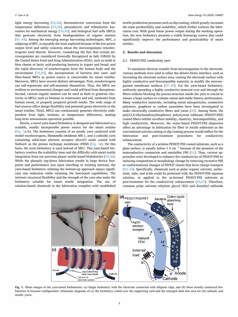
Herein, a novel yarn-based biobattery is designed and fabricated as a scalable, readily incorporable power source for the smart textiles (Fig. 1a–b). The biobattery consists of an anodic yarn catalyzed with model exoelectrogens, Shewanella oneidensis MR-1, and a cathodic yarn containing solid-state electron acceptor silver(I) oxide coated with Nafion® as the proton exchange membrane (PEM) (Fig. 1c). On this basis, the term biobattery is used instead of MFC. This yarn-based bio-battery resolves the scalability issue and the difficulty with smart textile integration from our previous planar textile-based biobatteries [34,46]. While the planarly top-down fabrication results in large device foot-prints and performance loss upon starching or twisting motions, the yarn-based biobattery utilizing the bottom-up approach enjoys signifi-cant size reduction while retaining the functional capabilities. The intrinsic structural flexibility and the strength of the yarn also make the biobattery suitable for smart textile integration. The use of solution-based chemicals in the fabrication complies with established
textile production processes such as dip-coating, which greatly increases the mass producibility and scalability, which further reduces the fabri-cation cost. With good linear power output during the stacking opera-tion, the new biobattery presents a viable bioenergy source that could significantly improve the performance and practicability of smart textiles.
2. Results and discussion
2.1. PEDOT:PSS conductivity yarn
To maximize electron transfer from microorganism to the electrode, various methods were used to talior the abiotic-biotic interface, such as increasing the electrode surface area, coating the electrode surface with highly conductive and biocompatible material, to modify the microor-ganism membrane surfaces [47–49]. For the yarn-based biobattery, uniformly spreading a highly conductive material over and through the fibers without blocking the porous structure inside the yarn is crucial to ensure a large surface-to-volume ration and stable battery performance. Many conductive materials, including metal nanoparticles, conductive polymers, graphene or carbon nanotubes have been investigated to make electrically conductive fibers and yarns [50]. Among them, the poly(3,4-ethylenedioxythiophene): polystyrene sulfonate (PEDOT:PSS) coated fibers exhibit excellent stability, elasticity, biocompatibility, and high conductivity. Moreover, the water-based PEDOT:PSS dispersion offers an advantage in fabrication for fiber or textile substrates as the conventional solvent-casting or dip-coating process would suffice for the fabrication and post-treatment procedures for conductivity enhancement.
The conductivity of a pristine PEDOT:PSS coated substrate, such as a glass surface, is usually below 1 S cm�1 because of the presence of the nonconductive counterion and emulsifier PSS [51]. Thus, various ap-proaches were developed to enhance the conductivity of PEDOT:PSS by inducing composition or morphology change by removing excessive PSS or conformational changes of PEDOT chains that favor charge transport [52–54]. Specifically, chemicals such as polar organic solvents, surfac-tants, salts, and acids could be premixed with the PEDOT:PSS aqueous solution, or applied to the as-formed PEDOT:PSS substrate as post-treatment for the conductivity enhancement [54,55]. Therefore, common polar solvents ethylene glycol (EG) and dimethyl sulfoxide
Fig. 1. Photo images of the yarn-based biobatteries. (a) Single biobattery with the electrode connected with alligator clips, and (b) three serially connected bio-batteries in bracelet configuration. Schematic diagrams of (c) the biobattery coiled over the supporting cord and the enlarged dash line area for (d) cathodic and anodic yarns.
Y. Gao et al.
Nano Energy 74 (2020) 104897
3
(DMSO) were compared for the post-treatment on the PEDOT:PSS coated yarns.
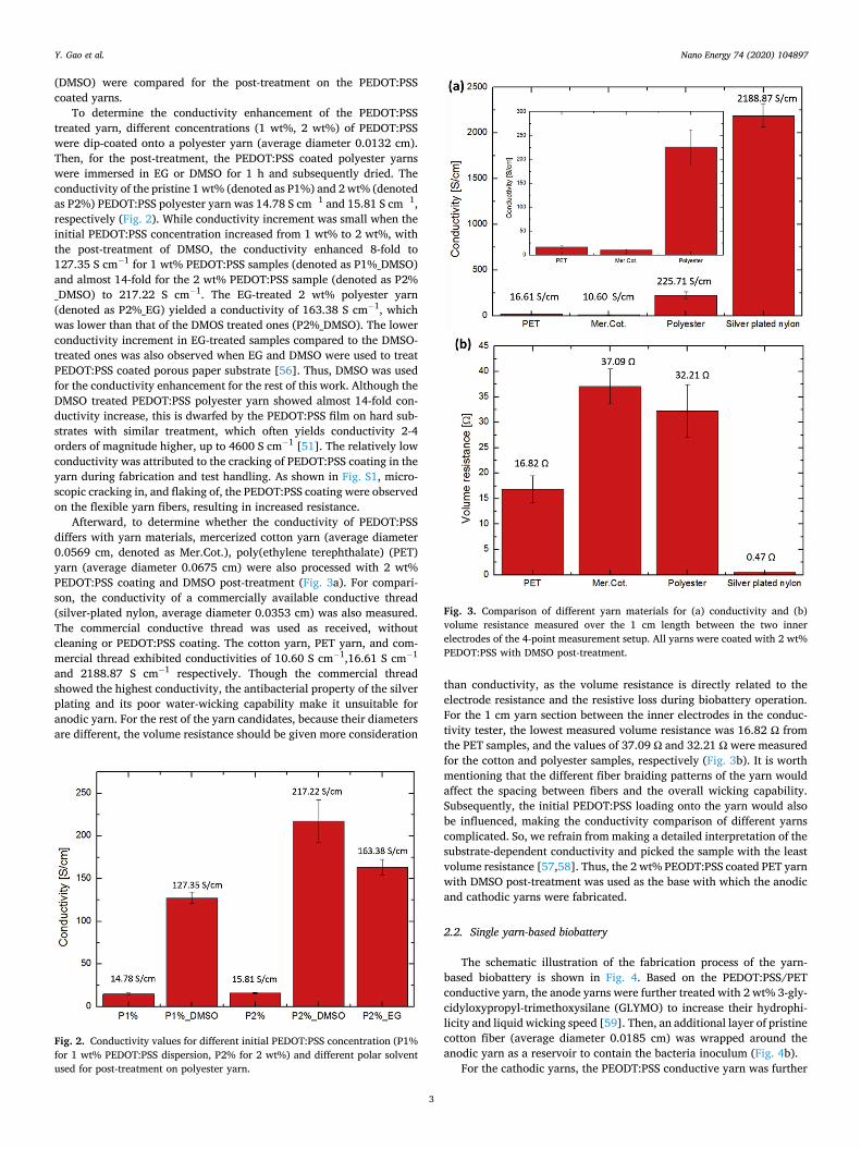
To determine the conductivity enhancement of the PEDOT:PSS treated yarn, different concentrations (1 wt%, 2 wt%) of PEDOT:PSS were dip-coated onto a polyester yarn (average diameter 0.0132 cm). Then, for the post-treatment, the PEDOT:PSS coated polyester yarns were immersed in EG or DMSO for 1 h and subsequently dried. The conductivity of the pristine 1 wt% (denoted as P1%) and 2 wt% (denoted as P2%) PEDOT:PSS polyester yarn was 14.78 S cm�1 and 15.81 S cm�1, respectively (Fig. 2). While conductivity increment was small when the initial PEDOT:PSS concentration increased from 1 wt% to 2 wt%, with the post-treatment of DMSO, the conductivity enhanced 8-fold to 127.35 S cm�1 for 1 wt% PEDOT:PSS samples (denoted as P1%_DMSO) and almost 14-fold for the 2 wt% PEDOT:PSS sample (denoted as P2% _DMSO) to 217.22 S cm�1. The EG-treated 2 wt% polyester yarn (denoted as P2%_EG) yielded a conductivity of 163.38 S cm�1, which was lower than that of the DMOS treated ones (P2%_DMSO). The lower conductivity increment in EG-treated samples compared to the DMSO- treated ones was also observed when EG and DMSO were used to treat PEDOT:PSS coated porous paper substrate [56]. Thus, DMSO was used for the conductivity enhancement for the rest of this work. Although the DMSO treated PEDOT:PSS polyester yarn showed almost 14-fold con-ductivity increase, this is dwarfed by the PEDOT:PSS film on hard sub-strates with similar treatment, which often yields conductivity 2-4 orders of magnitude higher, up to 4600 S cm�1 [51]. The relatively low conductivity was attributed to the cracking of PEDOT:PSS coating in the yarn during fabrication and test handling. As shown in Fig. S1, micro-scopic cracking in, and flaking of, the PEDOT:PSS coating were observed on the flexible yarn fibers, resulting in increased resistance.
Afterward, to determine whether the conductivity of PEDOT:PSS differs with yarn materials, mercerized cotton yarn (average diameter 0.0569 cm, denoted as Mer.Cot.), poly(ethylene terephthalate) (PET) yarn (average diameter 0.0675 cm) were also processed with 2 wt% PEDOT:PSS coating and DMSO post-treatment (Fig. 3a). For compari-son, the conductivity of a commercially available conductive thread (silver-plated nylon, average diameter 0.0353 cm) was also measured. The commercial conductive thread was used as received, without cleaning or PEDOT:PSS coating. The cotton yarn, PET yarn, and com-mercial thread exhibited conductivities of 10.60 S cm�1,16.61 S cm�1
and 2188.87 S cm�1 respectively. Though the commercial thread showed the highest conductivity, the antibacterial property of the silver plating and its poor water-wicking capability make it unsuitable for anodic yarn. For the rest of the yarn candidates, because their diameters are different, the volume resistance should be given more consideration
than conductivity, as the volume resistance is directly related to the electrode resistance and the resistive loss during biobattery operation. For the 1 cm yarn section between the inner electrodes in the conduc-tivity tester, the lowest measured volume resistance was 16.82 Ω from the PET samples, and the values of 37.09 Ω and 32.21 Ω were measured for the cotton and polyester samples, respectively (Fig. 3b). It is worth mentioning that the different fiber braiding patterns of the yarn would affect the spacing between fibers and the overall wicking capability. Subsequently, the initial PEDOT:PSS loading onto the yarn would also be influenced, making the conductivity comparison of different yarns complicated. So, we refrain from making a detailed interpretation of the substrate-dependent conductivity and picked the sample with the least volume resistance [57,58]. Thus, the 2 wt% PEODT:PSS coated PET yarn with DMSO post-treatment was used as the base with which the anodic and cathodic yarns were fabricated.
2.2. Single yarn-based biobattery
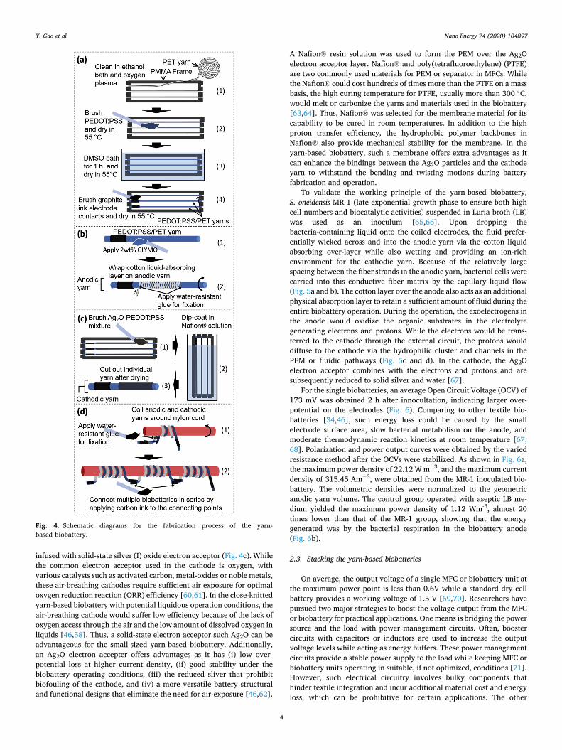
The schematic illustration of the fabrication process of the yarn- based biobattery is shown in Fig. 4. Based on the PEDOT:PSS/PET conductive yarn, the anode yarns were further treated with 2 wt% 3-gly-cidyloxypropyl-trimethoxysilane (GLYMO) to increase their hydrophi-licity and liquid wicking speed [59]. Then, an additional layer of pristine cotton fiber (average diameter 0.0185 cm) was wrapped around the anodic yarn as a reservoir to contain the bacteria inoculum (Fig. 4b).
For the cathodic yarns, the PEODT:PSS conductive yarn was further
Fig. 2. Conductivity values for different initial PEDOT:PSS concentration (P1% for 1 wt% PEDOT:PSS dispersion, P2% for 2 wt%) and different polar solvent used for post-treatment on polyester yarn.
Fig. 3. Comparison of different yarn materials for (a) conductivity and (b) volume resistance measured over the 1 cm length between the two inner electrodes of the 4-point measurement setup. All yarns were coated with 2 wt% PEDOT:PSS with DMSO post-treatment.
Y. Gao et al.
Nano Energy 74 (2020) 104897
4
infused with solid-state silver (I) oxide electron acceptor (Fig. 4c). While the common electron acceptor used in the cathode is oxygen, with various catalysts such as activated carbon, metal-oxides or noble metals, these air-breathing cathodes require sufficient air exposure for optimal oxygen reduction reaction (ORR) efficiency [60,61]. In the close-knitted yarn-based biobattery with potential liquidous operation conditions, the air-breathing cathode would suffer low efficiency because of the lack of oxygen access through the air and the low amount of dissolved oxygen in liquids [46,58]. Thus, a solid-state electron acceptor such Ag2O can be advantageous for the small-sized yarn-based biobattery. Additionally, an Ag2O electron accepter offers advantages as it has (i) low over-potential loss at higher current density, (ii) good stability under the biobattery operating conditions, (iii) the reduced sliver that prohibit biofouling of the cathode, and (iv) a more versatile battery structural and functional designs that eliminate the need for air-exposure [46,62].
A Nafion® resin solution was used to form the PEM over the Ag2O electron acceptor layer. Nafion® and poly(tetrafluoroethylene) (PTFE) are two commonly used materials for PEM or separator in MFCs. While the Nafion® could cost hundreds of times more than the PTFE on a mass basis, the high curing temperature for PTFE, usually more than 300 �C, would melt or carbonize the yarns and materials used in the biobattery [63,64]. Thus, Nafion® was selected for the membrane material for its capability to be cured in room temperatures. In addition to the high proton transfer efficiency, the hydrophobic polymer backbones in Nafion® also provide mechanical stability for the membrane. In the yarn-based biobattery, such a membrane offers extra advantages as it can enhance the bindings between the Ag2O particles and the cathode yarn to withstand the bending and twisting motions during battery fabrication and operation.
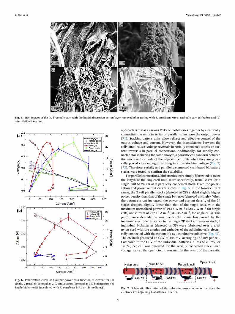
To validate the working principle of the yarn-based biobattery, S. oneidensis MR-1 (late exponential growth phase to ensure both high cell numbers and biocatalytic activities) suspended in Luria broth (LB) was used as an inoculum [65,66]. Upon dropping the bacteria-containing liquid onto the coiled electrodes, the fluid prefer-entially wicked across and into the anodic yarn via the cotton liquid absorbing over-layer while also wetting and providing an ion-rich environment for the cathodic yarn. Because of the relatively large spacing between the fiber strands in the anodic yarn, bacterial cells were carried into this conductive fiber matrix by the capillary liquid flow (Fig. 5a and b). The cotton layer over the anode also acts as an additional physical absorption layer to retain a sufficient amount of fluid during the entire biobattery operation. During the operation, the exoelectrogens in the anode would oxidize the organic substrates in the electrolyte generating electrons and protons. While the electrons would be trans-ferred to the cathode through the external circuit, the protons would diffuse to the cathode via the hydrophilic cluster and channels in the PEM or fluidic pathways (Fig. 5c and d). In the cathode, the Ag2O electron acceptor combines with the electrons and protons and are subsequently reduced to solid silver and water [67].
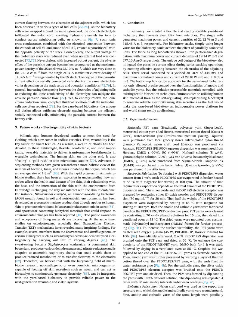
For the single biobatteries, an average Open Circuit Voltage (OCV) of 173 mV was obtained 2 h after innocultation, indicating larger over-potential on the electrodes (Fig. 6). Comparing to other textile bio-batteries [34,46], such energy loss could be caused by the small electrode surface area, slow bacterial metabolism on the anode, and moderate thermodynamic reaction kinetics at room temperature [67, 68]. Polarization and power output curves were obtained by the varied resistance method after the OCVs were stabilized. As shown in Fig. 6a, the maximum power density of 22.12 W m�3, and the maximum current density of 315.45 Am�3, were obtained from the MR-1 inoculated bio-battery. The volumetric densities were normalized to the geometric anodic yarn volume. The control group operated with aseptic LB me-dium yielded the maximum power density of 1.12 Wm-3, almost 20 times lower than that of the MR-1 group, showing that the energy generated was by the bacterial respiration in the biobattery anode (Fig. 6b).
2.3. Stacking the yarn-based biobatteries
On average, the output voltage of a single MFC or biobattery unit at the maximum power point is less than 0.6V while a standard dry cell battery provides a working voltage of 1.5 V [69,70]. Researchers have pursued two major strategies to boost the voltage output from the MFC or biobattery for practical applications. One means is bridging the power source and the load with power management circuits. Often, booster circuits with capacitors or inductors are used to increase the output voltage levels while acting as energy buffers. These power management circuits provide a stable power supply to the load while keeping MFC or biobattery units operating in suitable, if not optimized, conditions [71]. However, such electrical circuitry involves bulky components that hinder textile integration and incur additional material cost and energy loss, which can be prohibitive for certain applications. The other
Fig. 4. Schematic diagrams for the fabrication process of the yarn- based biobattery.
Y. Gao et al.
Nano Energy 74 (2020) 104897
5
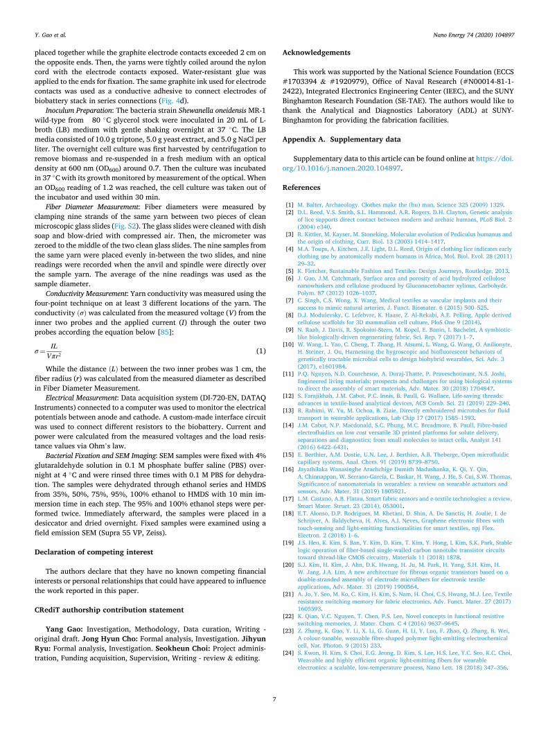
approach is to stack various MFCs or biobatteries together by electrically connecting the units in series or parallel to increase the output power [71]. Stacking battery units allows direct and effective control of the output voltage and current. However, the inconsistency between the cells often causes voltage reversals in serially connected stacks or cur-rent reversals in parallel connections. Additionally, for serially con-nected stacks sharing the same anolyte, a parasitic cell can form between the anode and cathode of the adjacent cell units when they are physi-cally placed close enough, resulting in a low stacking voltage (Fig. 7) [72]. Therefore, serially and parallelly connected yarn-based biobattery stacks were tested to confirm the scalability.
For parallel connections, biobatteries were simply fabricated to twice the length of the singlecell unit, more specifically, from 12 cm for a single unit to 24 cm as 2 parallelly connected stack. From the polari-zation and power output curves shown in Fig. 6, in the lower current range, the 2 cell parallel stacks (denoted as 2P) yielded slightly higher power density than that of the single batteries (denoted as single). When the output current increased, the power and current density of the 2P stacks dropped slightly lower than that of the single cells, with the maximum normalized power of 19.14 W m�3 (22.12 W m�3 for single cells) and current of 277.10 A m�3 (315.45 A m�3, for single cells). This performance degradation was due to the ohmic loss caused by the increased electrode resistance in the longer 2P stacks. In a series stack, 3 individual biobatteries (denoted as 3S) were fabricated over a craft nylon cord with the anodes and cathodes of the adjoining cells electri-cally connected with the carbon ink as a conductive adhesive (Fig. 4d). The 3S stack produced an OCV of 444 mV, averaging 148 mV per cell. Compared to the OCV of the individual batteries, a loss of 25 mV, or 14.5%, per cell was observed for the serially connected stack. Such voltage loss at the open circuit was mainly the result of the parasitic
Fig. 5. SEM images of the (a, b) anodic yarn with the liquid absorption cotton layer removed after testing with S. oneidensis MR-1, cathodic yarn (c) before and (d) after Nafion® coating.
Fig. 6. Polarization curve and output power as a function of current for (a) single, 2 parallel (denoted as 2P), and 3 series (denoted as 3S) biobatteries. (b) Single biobatteries inoculated with S. oneidensis MR1 or LB medium.). Fig. 7. Schematic illustration of the substrate cross conduction between the
electrodes of adjoining biobatteries in series.
Y. Gao et al.
Nano Energy 74 (2020) 104897
6
current flowing between the electrodes of the adjacent cells, which has been observed in various types of fuel cells [72–74]. As the biobattery cells were wrapped around the same nylon cord, the ion-rich electrolyte infiltrated the nylon cord, creating hydraulic channels for ions to conduct across neighboring cells. As shown in Fig. 7, such ionic cross-conductance, combined with the electrical connection between the cathode of cell #1 and anode of cell #2, created a parasitic cell with the opposite polarity of the stack. Consequently, the output voltage of the biobattery stack was reduced even when no external load was con-nected [72,75]. Nevertheless, with increased output current, the adverse effect of the parasitic current became less pronounced as the maximum power density of the 3S stack was 22.10 W m�3, which was very close to the 22.12 W m�3 from the single cells. A maximum current density of 110.65 A m�3 was generated by the 3S stack. The degree of the parasitic current effect on serially connected cells sharing the same electrolyte varies depending on the stack setup and operation conditions [72,76]. In general, increasing the spacing between the electrodes of adjoining cells or reducing the ionic conductivity of the electrolyte can mitigate the adverse parasitic current flow [77]. Yet, to entirely resolve the ionic cross-conduction issue, complete fluidical isolation of all the individual cells are often required [78]. For the yarn-based biobattery, the unique coil design allows sufficient electrode spacing between the adjacent serially connected cells, minimizing the parasitic current between the battery cells.
3. Future works - Electrogenicity of skin bacteria
Millenia ago, humans developed textiles to meet the need for clothing, which now comes in endless varieties. Thus, wearability is the key factor for smart textiles. As a result, a wealth of efforts has been devoted to these lightweight, flexible, comfortable, and most impor-tantly, wearable materials to deliver transformative breakthroughs in wearable technologies. The human skin, on the other end, is also “feeling” a “gold rush” in skin microbiome studies [79]. Advances in sequencing methods have given researchers a more holistic view of the millions of bacteria, fungi, and viruses inhabiting that organ, which has an average size of 1.8 m2 [80]. With the rapid progress in skin micro-biome studies, there has been an explosion in understanding how mi-crobes affect the health and disease of the skin, their relationship with the host, and the interaction of the skin with the environment. Such knowledge is changing the way we interact with the skin microbiome. For instance, Nitrosomonas eutropha, an ammonia-oxidizing bacterium (AOB) usually found in soil and nutrient-rich environments, has been developed as a cosmetic hygiene product that directly applies to human skin to promote microbiome balance and reduce ammonia in sweat [81]. And sportswear containing biohybrid materials that could respond to environmental changes has been reported [10]. The public awareness and acceptance of living materials are increasing. At the same time, studies on exoelectrogens, especially their Extracellular Electron Transfer (EET) mechanisms have revealed many inspiring findings. For example, several members from the Enterococcus and Bacillus genera, or certain eukaryotes such as saccharomyces cerevisiae demonstrated elec-trogenicity by carrying out EET to varying degrees [45]. The sweat-eating bacteria Staphylococcus epidermidis, a commensal skin bacterium, produces various dehydrogenase and nitrate reductase and is adaptive to anaerobic respiratory chains that could enable them to produce reduced metabolites or to transfer electrons to the electrodes [82]. Therefore, we believe that with the burgeoning field of micro-biome research, non-pathogenic or even beneficial microorganisms, capable of feeding off skin secretions such as sweat, and can act as biocatalyst to continuously generate electricity [83], can be integrated with the yarn-based biobattery to provide reliable power to the next-generation wearable and e-skin systems.
4. Conclusion
In summary, we created a flexible and readily scalable yarn-based biobattery that harvests electricity from microbes. The single cells generated maximum power and current densities of 22.12 W m-3 and 315.45 A m-3, respectively. For biobattery stacks, simply using longer yarns for the biobattery could achieve the effect of parallelly connected units. The twice as long biobatteries showed little performance degra-dation, with maximum power and current densities of 19.14 W m-3 and 277.10 A m-3 respectively. The unique coil design of the biobattery also mitigated the parasitic current effect during series stacking operations by creating effective spacing between the electrodes of the adjoining cells. Three serial connected cells yielded an OCV of 444 mV and maximum normalized power and current of 22.10 W m-3 and 110.65 A m-3. The bottom-up fabrication approach for the yarn-based biobattery not only allowed precise control over the functionalities of anodic and cathodic yarns, but the solution-processable materials complied with existing textile fabrication techniques. Future studies on utilizing human skin microbial flora as the self-regulating, self-replenishing biocatalyst to generate reliable electricity using skin secretions as the fuel would make the yarn-based biobattery an indispensable power platform for real-world smart textile applications.
3.1. Experimental section
Materials: PET yarn (Huxinpai), polyester yarn (Super-Lock), mercerized cotton yarn (Red Heart), mercerized cotton thread (Coats & Clark), water-resistant glue (Professional medium glazing, Liquitex) were purchased from local grocery stores. Silver-plated nylon thread (Jameco Valuepro), nylon craft cord (Darice) was purchased via Amazon. PEDOT:PSS (PH1000) aqueous dispersion was purchased from Heraeus. DMSO (�99%), EG (�99%), Nafion® solution (5 wt%), glutaraldehyde solution (70%), GLYMO (�98%) hexamethyldisilizane (HMDS, � 98%) were purchased from Sigma-Aldrich. Graphite ink (E3449) was purchased from Ercon. Silver (I) oxide (powder, � 99%) was purchased from Alfa Aesar.
Electrodes Fabrication: To obtain 2 wt% PEDOT:PSS dispersion, water content from 1 wt% stock PEDOT:PSS was evaporated in beaker heated at 65 �C with magnetic bar stirring at 100 rpm. The amount of time required for evaporation depends on the total amount of the PEODT:PSS dispersion used. The silver oxide and PEDOT:PSS electron acceptor was prepared by sonicating silver (I) oxide powder and PEDOT:PSS disper-sion (30 mg mL�1) for 30 min. Then half the weight of the PEDOT:PSS dispersion were evaporated by heating at 65 �C with magnetic bar stirring at 100 rpm. Both the anodic and cathodic yarns were fabricated based on the PEDOT:PSS/PET conductive yarn: PET yarns were cleaned by sonicating in 70 v/v% ethanol solutions for 15 min, then dried in a ventilated oven at 55 �C. The dried yarns were mounted over custom- made Poly(methyl methacrylate) (PMMA) frames for further process-ing (Fig. 4a). To increase the surface wettability, the PET yarns were treated with oxygen plasma (45 W, PDC-001-HP, Harrick Plasma) for 100s [84]. Immediately afterward, 2 wt% PEDOT:PSS dispersion was brushed onto the PET yarn and dried at 55 �C. To enhance the con-ductivity of the PEDOT:PSS/PET yarn, DMSO bath for 1 h was used, followed by drying in a ventilated oven at 55 �C. Graphite ink was applied to one end of the PEDOT:PSS/PET yarns as electrode contacts. Then, anodic yarn was further processed by warping a layer of the thin cotton thread over the PEDOT:PSS/PET yarn, with the ends fixed by water resistance glue (Fig. 4b). For the cathodic yarn, the silver oxide and PEDOT:PSS electron acceptor was brushed onto the PEDOT: PSS/PET yarn and air-dried. Then, the PEM was formed by dip-coating the yarns with 5 wt% Nafion® solution. The dip-coating was repeated 4 times with 30 min air-dry intervals in-between coatings (Fig. 4c).
Biobattery Fabrication: Nylon craft cord was used as the supporting structure onto which the anodic and cathodic yarns were wound around. First, anodic and cathodic yarns of the same length were parallelly
Y. Gao et al.
Nano Energy 74 (2020) 104897
7
placed together while the graphite electrode contacts exceeded 2 cm on the opposite ends. Then, the yarns were tightly coiled around the nylon cord with the electrode contacts exposed. Water-resistant glue was applied to the ends for fixation. The same graphite ink used for electrode contacts was used as a conductive adhesive to connect electrodes of biobattery stack in series connections (Fig. 4d).
Inoculum Preparation: The bacteria strain Shewanella oneidensis MR-1 wild-type from �80 �C glycerol stock were inoculated in 20 mL of L- broth (LB) medium with gentle shaking overnight at 37 �C. The LB media consisted of 10.0 g triptone, 5.0 g yeast extract, and 5.0 g NaCl per liter. The overnight cell culture was first harvested by centrifugation to remove biomass and re-suspended in a fresh medium with an optical density at 600 nm (OD600) around 0.7. Then the culture was incubated in 37 �C with its growth monitored by measurement of the optical. When an OD600 reading of 1.2 was reached, the cell culture was taken out of the incubator and used within 30 min.
Fiber Diameter Measurement: Fiber diameters were measured by clamping nine strands of the same yarn between two pieces of clean microscopic glass slides (Fig. S2). The glass slides were cleaned with dish soap and blow-dried with compressed air. Then, the micrometer was zeroed to the middle of the two clean glass slides. The nine samples from the same yarn were placed evenly in-between the two slides, and nine readings were recorded when the anvil and spindle were directly over the sample yarn. The average of the nine readings was used as the sample diameter.
Conductivity Measurement: Yarn conductivity was measured using the four-point technique on at least 3 different locations of the yarn. The conductivity ðσÞ was calculated from the measured voltage (V) from the inner two probes and the applied current (I) through the outer two probes according the equation below [85]:
σ ¼IL
Vπr2 (1)
While the distance ðLÞ between the two inner probes was 1 cm, the fiber radius (r) was calculated from the measured diameter as described in Fiber Diameter Measurement.
Electrical Measurement: Data acquisition system (DI-720-EN, DATAQ Instruments) connected to a computer was used to monitor the electrical potentials between anode and cathode. A custom-made interface circuit was used to connect different resistors to the biobattery. Current and power were calculated from the measured voltages and the load resis-tance values via Ohm’s law.
Bacterial Fixation and SEM Imaging: SEM samples were fixed with 4% glutaraldehyde solution in 0.1 M phosphate buffer saline (PBS) over-night at 4 �C and were rinsed three times with 0.1 M PBS for dehydra-tion. The samples were dehydrated through ethanol series and HMDS from 35%, 50%, 75%, 95%, 100% ethanol to HMDS with 10 min im-mersion time in each step. The 95% and 100% ethanol steps were per-formed twice. Immediately afterward, the samples were placed in a desiccator and dried overnight. Fixed samples were examined using a field emission SEM (Supra 55 VP, Zeiss).
Declaration of competing interest
The authors declare that they have no known competing financial interests or personal relationships that could have appeared to influence the work reported in this paper.
CRediT authorship contribution statement
Yang Gao: Investigation, Methodology, Data curation, Writing - original draft. Jong Hyun Cho: Formal analysis, Investigation. Jihyun Ryu: Formal analysis, Investigation. Seokheun Choi: Project adminis-tration, Funding acquisition, Supervision, Writing - review & editing.
Acknowledgements
This work was supported by the National Science Foundation (ECCS #1703394 & #1920979), Office of Naval Research (#N00014-81-1- 2422), Integrated Electronics Engineering Center (IEEC), and the SUNY Binghamton Research Foundation (SE-TAE). The authors would like to thank the Analytical and Diagnostics Laboratory (ADL) at SUNY- Binghamton for providing the fabrication facilities.
Appendix A. Supplementary data
Supplementary data to this article can be found online at https://doi. org/10.1016/j.nanoen.2020.104897.
References
[1] M. Balter, Archaeology. Clothes make the (hu) man, Science 325 (2009) 1329. [2] D.L. Reed, V.S. Smith, S.L. Hammond, A.R. Rogers, D.H. Clayton, Genetic analysis
of lice supports direct contact between modern and archaic humans, PLoS Biol. 2 (2004) e340.
[3] R. Kittler, M. Kayser, M. Stoneking, Molecular evolution of Pediculus humanus and the origin of clothing, Curr. Biol. 13 (2003) 1414–1417.
[4] M.A. Toups, A. Kitchen, J.E. Light, D.L. Reed, Origin of clothing lice indicates early clothing use by anatomically modern humans in Africa, Mol. Biol. Evol. 28 (2011) 29–32.
[5] K. Fletcher, Sustainable Fashion and Textiles: Design Journeys, Routledge, 2013. [6] J. Guo, J.M. Catchmark, Surface area and porosity of acid hydrolyzed cellulose
nanowhiskers and cellulose produced by Gluconacetobacter xylinus, Carbohydr. Polym. 87 (2012) 1026–1037.
[7] C. Singh, C.S. Wong, X. Wang, Medical textiles as vascular implants and their success to mimic natural arteries, J. Funct. Biomater. 6 (2015) 500–525.
[8] D.J. Modulevsky, C. Lefebvre, K. Haase, Z. Al-Rekabi, A.E. Pelling, Apple derived cellulose scaffolds for 3D mammalian cell culture, PloS One 9 (2014).
[9] N. Raab, J. Davis, R. Spokoini-Stern, M. Kopel, E. Banin, I. Bachelet, A symbiotic- like biologically-driven regenerating fabric, Sci. Rep. 7 (2017) 1–7.
[10] W. Wang, L. Yao, C. Cheng, T. Zhang, H. Atsumi, L. Wang, G. Wang, O. Anilionyte, H. Steiner, J. Ou, Harnessing the hygroscopic and biofluorescent behaviors of genetically tractable microbial cells to design biohybrid wearables, Sci. Adv. 3 (2017), e1601984.
[11] P.Q. Nguyen, N.D. Courchesne, A. Duraj-Thatte, P. Praveschotinunt, N.S. Joshi, Engineered living materials: prospects and challenges for using biological systems to direct the assembly of smart materials, Adv. Mater. 30 (2018) 1704847.
[12] S. Farajikhah, J.M. Cabot, P.C. Innis, B. Paull, G. Wallace, Life-saving threads: advances in textile-based analytical devices, ACS Comb. Sci. 21 (2019) 229–240.
[13] R. Rahimi, W. Yu, M. Ochoa, B. Ziaie, Directly embroidered microtubes for fluid transport in wearable applications, Lab Chip 17 (2017) 1585–1593.
[14] J.M. Cabot, N.P. Macdonald, S.C. Phung, M.C. Breadmore, B. Paull, Fibre-based electrofluidics on low cost versatile 3D printed platforms for solute delivery, separations and diagnostics; from small molecules to intact cells, Analyst 141 (2016) 6422–6431.
[15] E. Berthier, A.M. Dostie, U.N. Lee, J. Berthier, A.B. Theberge, Open microfluidic capillary systems, Anal. Chem. 91 (2019) 8739–8750.
[16] Jayathilaka Wanasinghe Arachchige Dumith Madushanka, K. Qi, Y. Qin, A. Chinnappan, W. Serrano-García, C. Baskar, H. Wang, J. He, S. Cui, S.W. Thomas, Significance of nanomaterials in wearables: a review on wearable actuators and sensors, Adv. Mater. 31 (2019) 1805921.
[17] L.M. Castano, A.B. Flatau, Smart fabric sensors and e-textile technologies: a review, Smart Mater. Struct. 23 (2014), 053001.
[18] E.T. Alonso, D.P. Rodrigues, M. Khetani, D. Shin, A. De Sanctis, H. Joulie, I. de Schrijver, A. Baldycheva, H. Alves, A.I. Neves, Graphene electronic fibres with touch-sensing and light-emitting functionalities for smart textiles, npj Flex. Electron. 2 (2018) 1–6.
[19] J.S. Heo, K. Kim, S. Ban, Y. Kim, D. Kim, T. Kim, Y. Hong, I. Kim, S.K. Park, Stable logic operation of fiber-based single-walled carbon nanotube transistor circuits toward thread-like CMOS circuitry, Materials 11 (2018) 1878.
[20] S.J. Kim, H. Kim, J. Ahn, D.K. Hwang, H. Ju, M. Park, H. Yang, S.H. Kim, H. W. Jang, J.A. Lim, A new architecture for fibrous organic transistors based on a double-stranded assembly of electrode microfibers for electronic textile applications, Adv. Mater. 31 (2019) 1900564.
[21] A. Jo, Y. Seo, M. Ko, C. Kim, H. Kim, S. Nam, H. Choi, C.S. Hwang, M.J. Lee, Textile resistance switching memory for fabric electronics, Adv. Funct. Mater. 27 (2017) 1605593.
[22] K. Qian, V.C. Nguyen, T. Chen, P.S. Lee, Novel concepts in functional resistive switching memories, J. Mater. Chem. C 4 (2016) 9637–9645.
[23] Z. Zhang, K. Guo, Y. Li, X. Li, G. Guan, H. Li, Y. Luo, F. Zhao, Q. Zhang, B. Wei, A colour-tunable, weavable fibre-shaped polymer light-emitting electrochemical cell, Nat. Photon. 9 (2015) 233.
[24] S. Kwon, H. Kim, S. Choi, E.G. Jeong, D. Kim, S. Lee, H.S. Lee, Y.C. Seo, K.C. Choi, Weavable and highly efficient organic light-emitting fibers for wearable electronics: a scalable, low-temperature process, Nano Lett. 18 (2018) 347–356.
Y. Gao et al.
Nano Energy 74 (2020) 104897
8
[25] S. Yao, P. Swetha, Y. Zhu, Nanomaterial-Enabled wearable sensors for healthcare, Adv. Healthc. Mater. 7 (2018) 1700889.
[26] K. Arquilla, A.K. Webb, A.P. Anderson, Textile electrocardiogram (ECG) electrodes for wearable health monitoring, Sensors 20 (2020) 1013.
[27] S. Farajikhah, J. Choi, D. Esrafilzadeh, J. Underwood, P.C. Innis, B. Paull, G. G. Wallace, 3D textile structures with integrated electroactive electrodes for wearable electrochemical sensors, J. Textil. Inst. (2020) 1–9.
[28] C. Zhao, S. Farajikhah, C. Wang, J. Foroughi, X. Jia, G.G. Wallace, 3D braided yarns to create electrochemical cells, Electrochem. Commun. 61 (2015) 27–31.
[29] W. Al-Graiti, Z. Yue, J. Foroughi, X. Huang, G. Wallace, R. Baughman, J. Chen, Probe sensor using nanostructured multi-walled carbon nanotube yarn for selective and sensitive detection of dopamine, Sensors 17 (2017) 884.
[30] J. Pan, M. Yang, L. Luo, A. Xu, B. Tang, D. Cheng, G. Cai, X. Wang, Stretchable and highly sensitive braided composite Yarn@ Polydopamine@ Polypyrrole for wearable applications, ACS Appl. Mater. Interfaces 11 (2019) 7338–7348.
[31] S. Afroj, N. Karim, Z. Wang, S. Tan, P. He, M. Holwill, D. Ghazaryan, A. Fernando, K.S. Novoselov, Engineering graphene flakes for wearable textile sensors via highly scalable and ultrafast yarn dyeing technique, ACS Nano 13 (2019) 3847–3857.
[32] M. Zhao, D. Li, J. Huang, D. Wang, A. Mensah, Q. Wei, A multifunctional and highly stretchable electronic device based on silver nanowire/wrap yarn composite for a wearable strain sensor and heater, J. Mater. Chem. C 7 (2019) 13468–13476.
[33] Y. Song, S. Zhou, K. Jin, J. Qiao, D. Li, C. Xu, D. Hu, J. Di, M. Li, Z. Zhang, Hierarchical carbon nanotube composite yarn muscles, Nanoscale 10 (2018) 4077–4084.
[34] S. Pang, Y. Gao, S. Choi, Flexible and stretchable biobatteries: monolithic integration of membrane-free microbial fuel cells in a single textile layer, Adv. Energy Mater. 8 (2018) 1702261.
[35] I. Hussain, A.R. Chowdhury, J. Jaksik, G. Grissom, A. Touhami, E.E. Ibrahim, M. Schauer, O. Okoli, M.J. Uddin, Conductive glass free carbon nanotube micro yarn based perovskite solar cells, Appl. Surf. Sci. 478 (2019) 327–333.
[36] G.R. Adams, O.I. Okoli, A review of perovskite solar cells with a focus on wire- shaped devices, Renew. Energy Focus 25 (2018) 17–23.
[37] L. Zhang, S. Lin, T. Hua, B. Huang, S. Liu, X. Tao, Fiber-based thermoelectric generators: materials, device structures, fabrication, characterization, and applications, Adv. Energy Mater. 8 (2018) 1700524.
[38] J.D. Ryan, A. Lund, A.I. Hofmann, R. Kroon, R. Sarabia-Riquelme, M. C. Weisenberger, C. Müller, All-organic textile thermoelectrics with carbon- nanotube-coated n-type yarns, ACS Appl. Energy Mater. 1 (2018) 2934–2941.
[39] K. Dong, J. Deng, W. Ding, A.C. Wang, P. Wang, C. Cheng, Y. Wang, L. Jin, B. Gu, B. Sun, Versatile core–sheath yarn for sustainable biomechanical energy harvesting and real-time human-interactive sensing, Adv. Energy Mater. 8 (2018) 1801114.
[40] S.H. Kim, C.S. Haines, N. Li, K.J. Kim, T.J. Mun, C. Choi, J. Di, Y.J. Oh, J.P. Oviedo, J. Bykova, S. Fang, N. Jiang, Z. Liu, R. Wang, P. Kumar, R. Qiao, S. Priya, K. Cho, M. Kim, M.S. Lucas, L.F. Drummy, B. Maruyama, D.Y. Lee, X. Lepro, E. Gao, D. Albarq, R. Ovalle-Robles, S.J. Kim, R.H. Baughman, Harvesting electrical energy from carbon nanotube yarn twist, Science 357 (2017) 773–778.
[41] I. Jeerapan, J.R. Sempionatto, J. Wang, On-body bioelectronics: wearable biofuel cells for bioenergy harvesting and self-powered biosensing, Adv. Funct. Mater. (2019) 1906243.
[42] H.J. Sim, D.Y. Lee, H. Kim, Y. Choi, H. Kim, R.H. Baughman, S.J. Kim, Stretchable fiber biofuel cell by rewrapping multiwalled carbon nanotube sheets, Nano Lett. 18 (2018) 5272–5278.
[43] S. Yin, Z. Jin, T. Miyake, Wearable high-powered biofuel cells using enzyme/ carbon nanotube composite fibers on textile cloth, Biosens. Bioelectron. 141 (2019) 111471.
[44] Y. Gao, L. Liu, J. Cho, S. Choi, Flexible and Scalable Biochemical Energy Harvesting: A Yarn-Based Biobattery, 2019, pp. 966–969.
[45] L.E. Doyle, E. Marsili, Weak electricigens: a new avenue for bioelectrochemical research, Bioresour. Technol. 258 (2018) 354–364.
[46] S. Pang, Y. Gao, S. Choi, Flexible and stretchable microbial fuel cells with modified conductive and hydrophilic textile, Biosens. Bioelectron. 100 (2018) 504.
[47] D. Guo, H. Wei, R. Song, J. Fu, X. Lu, R. Jelinek, Q. Min, J. Zhang, Q. Zhang, J. Zhu, N, S-doped carbon dots as dual-functional modifiers to boost bio-electricity generation of individually-modified bacterial cells, Nano Energy 63 (2019) 103875.
[48] R. Song, Y. Wu, Z. Lin, J. Xie, C.H. Tan, J.S.C. Loo, B. Cao, J. Zhang, J. Zhu, Q. Zhang, Living and conducting: coating individual bacterial cells with in situ formed polypyrrole, Angew. Chem. Int. Ed. 56 (2017) 10516–10520.
[49] V.B. Wang, J. Du, X. Chen, A.W. Thomas, N.D. Kirchhofer, L.E. Garner, M.T. Maw, W.H. Poh, J. Hinks, S. Wuertz, Improving charge collection in Escherichia coli–carbon electrode devices with conjugated oligoelectrolytes, Phys. Chem. Chem. Phys. 15 (2013) 5867–5872.
[50] C. Zhao, J. Wu, S. Kjelleberg, J.S.C. Loo, Q. Zhang, Employing a flexible and low- cost polypyrrole nanotube membrane as an anode to enhance current generation in microbial fuel cells, Small 11 (2015) 3440–3443.
[51] Z. Yu, Y. Xia, D. Du, J. Ouyang, PEDOT: PSS films with metallic conductivity through a treatment with common organic solutions of organic salts and their application as a transparent electrode of polymer solar cells, ACS Appl. Mater. Interfaces 8 (2016) 11629–11638.
[52] X. Crispin, F. Jakobsson, A. Crispin, P. Grim, P. Andersson, A. Volodin, C. Van Haesendonck, M. Van der Auweraer, W.R. Salaneck, M. Berggren, The origin of the high conductivity of poly (3, 4-ethylenedioxythiophene)�poly (styrenesulfonate) (PEDOT�PSS) plastic electrodes, Chem. Mater. 18 (2006) 4354–4360.
[53] Y. Xia, J. Ouyang, PEDOT: PSS films with significantly enhanced conductivities induced by preferential solvation with cosolvents and their application in polymer photovoltaic cells, J. Mater. Chem. 21 (2011) 4927–4936.
[54] T. Chou, S. Chen, Y. Chiang, Y. Lin, C. Chao, Highly conductive PEDOT: PSS films by post-treatment with dimethyl sulfoxide for ITO-free liquid crystal display, J. Mater. Chem. C 3 (2015) 3760–3766.
[55] S. J€onsson, J. Birgerson, X. Crispin, G. Greczynski, W. Osikowicz, Van Der Gon, A. W. Denier, W.R. Salaneck, M. Fahlman, The effects of solvents on the morphology and sheet resistance in poly (3, 4-ethylenedioxythiophene)–polystyrenesulfonic acid (PEDOT–PSS) films, Synth. Met. 139 (2003) 1–10.
[56] Y. Gao, S. Choi, Merging electric bacteria with paper, Adv. Mater. Technol. 3 (2018) 1800118.
[57] J.F. Franco-Gonzalez, N. Rolland, I.V. Zozoulenko, Substrate-dependent morphology and its effect on electrical mobility of doped poly (3, 4-ethylene-dioxythiophene)(PEDOT) thin films, ACS Appl. Mater. Interfaces 10 (2018) 29115–29126.
[58] A. Natori, C. Canestraro, L. Roman, A. Ceschin, Modification of the sheet resistance of ink jet printed polymer conducting films by changing the plastic substrate, Mater. Sci. Eng. B 122 (2005) 231–235.
[59] Y. Gao, S. Choi, Stepping toward self-powered papertronics: integrating biobatteries into a single sheet of paper, advanced materials technologies, Adv. Mater. Technol. 2 (2017) 1600194.
[60] K. Ai, Y. Liu, C. Ruan, L. Lu, G. Lu, Sp2 C-dominant N-doped carbon sub- micrometer spheres with a tunable size: a versatile platform for highly efficient oxygen-reduction catalysts, Adv. Mater. 25 (2013) 998–1003.
[61] X. Han, T. Zhang, J. Du, F. Cheng, J. Chen, Porous calcium–manganese oxide microspheres for electrocatalytic oxygen reduction with high activity, Chem. Sci. 4 (2013) 368–376.
[62] R. Rossi, D. Jones, J. Myung, E. Zikmund, W. Yang, Y.A. Gallego, D. Pant, P. J. Evans, M.A. Page, D.M. Cropek, Evaluating a multi-panel air cathode through electrochemical and biotic tests, Water Res. 148 (2019) 51–59.
[63] S. Cheng, H. Liu, B.E. Logan, Power densities using different cathode catalysts (Pt and CoTMPP) and polymer binders (Nafion and PTFE) in single chamber microbial fuel cells, Environ. Sci. Technol. 40 (2006) 364–369.
[64] Z. Pan, Y. Bi, L. An, A cost-effective and chemically stable electrode binder for alkaline-acid direct ethylene glycol fuel cells, Appl. Energy 258 (2020) 114060.
[65] Y. Yang, D.P. Harris, F. Luo, W. Xiong, M. Joachimiak, L. Wu, P. Dehal, J. Jacobsen, Z. Yang, A.V. Palumbo, Snapshot of iron response in Shewanella oneidensis by gene network reconstruction, BMC Genom. 10 (2009) 131.
[66] C. Wang, W. Chen, R. Huang, Influence of growth curve phase on electricity performance of microbial fuel cell by Escherichia coli, Int. J. Hydrogen Energy 35 (2010) 7217–7223.
[67] X. Xie, M. Ye, P.C. Hsu, N. Liu, C.S. Criddle, Y. Cui, Microbial battery for efficient energy recovery, Proc. Natl. Acad. Sci. U.S.A. 110 (2013) 15925–15930.
[68] B.E. Logan, B. Hamelers, R. Rozendal, U. Schr€oder, J. Keller, S. Freguia, P. Aelterman, W. Verstraete, K. Rabaey, Microbial fuel cells: methodology and technology, Environ. Sci. Technol. 40 (2006) 5181–5192.
[69] T. Kim, J. Yeo, Y. Yang, S. Kang, Y. Paek, J.K. Kwon, J.K. Jang, Boosting voltage without electrochemical degradation using energy-harvesting circuits and power management system-coupled multiple microbial fuel cells, J. Power Sources 410 (2019) 171–178.
[70] J. An, H. Lee, Occurrence and implications of voltage reversal in stacked microbial fuel cells, ChemSusChem 7 (2014) 1689–1695.
[71] B. Kim, S.V. Mohan, D. Fapyane, I.S. Chang, Controlling voltage reversal in microbial fuel cells, Trends Biotechnol. (2020) (in press).
[72] L. Zhuang, S. Zhou, Substrate cross-conduction effect on the performance of serially connected microbial fuel cell stack, Electrochem. Commun. 11 (2009) 937–940.
[73] R. O’Hayre, T. Fabian, S. Lee, F.B. Prinz, Lateral ionic conduction in planar array fuel cells, J. Electrochem. Soc. 150 (2003) A430–A438.
[74] E. Whiddon, H. Zhu, X. Zhu, Sodium-ion concentration flow cell stacks for salinity gradient energy recovery: power generation of series and parallel configurations, J. Power Sources 435 (2019) 226796.
[75] L. Zhuang, Y. Zheng, S. Zhou, Y. Yuan, H. Yuan, Y. Chen, Scalable microbial fuel cell (MFC) stack for continuous real wastewater treatment, Bioresour. Technol. 106 (2012) 82–88.
[76] Y. Yang, L. Yan, X. Lin, P. Li, M. Xu, Effects of unit distance and number on sediment microbial fuel cell stacks for practical power supply, Int. J. Energy Res. 43 (2019) 7287–7295.
[77] D. Kim, J. An, B. Kim, J.K. Jang, B.H. Kim, I.S. Chang, Scaling-up microbial fuel cells: configuration and potential drop phenomenon at series connection of unit cells in shared anolyte, ChemSusChem 5 (2012) 1086–1091.
[78] P. Ledezma, J. Greenman, I. Ieropoulos, MFC-cascade stacks maximise COD reduction and avoid voltage reversal under adverse conditions, Bioresour. Technol. 134 (2013) 158–165.
[79] H.H. Kong, J.A. Segre, Skin microbiome: looking back to move forward, J. Invest. Dermatol. 132 (2012) 933–939.
[80] A.L. Byrd, Y. Belkaid, J.A. Segre, The human skin microbiome, Nat. Rev. Microbiol. 16 (2018) 143.
[81] J. Scott, My No-Soap, No-Shampoo, Bacteria-Rich Hygiene Experiment, The New York Times, 2014.
[82] C. Uribe-Alvarez, N. Chiquete-F�elix, M. Contreras-Zentella, S. Guerrero-Castillo, A. Pe~na, S. Uribe-Carvajal, Staphylococcus epidermidis: metabolic adaptation and biofilm formation in response to different oxygen concentrations, Pathog. Dis. (2016) 74.
[83] M. Mohammadifar, M. Tahermia, J. Yang, A. Koh, S. Choi, A Skin-mountable bacteria-powered battery system for self-powered medical devices, in: Proceeding
Y. Gao et al.

Nano Energy 74 (2020) 104897
9
of IEEE 33rd International Conference on Micro Electro Mechanical Systems (MEMS), 2020, pp. 72–75.
[84] M. Cioffi, H. Voorwald, R.P. Mota, Surface energy increase of oxygen-plasma- treated PET, Mater. Char. 50 (2003) 209–215.
[85] T. Hou, J.P. Lynch, Electrical impedance tomographic methods for sensing strain fields and crack damage in cementitious structures, J. Intell. Mater. Syst. Struct. 20 (2009) 1363–1379.
Y. Gao et al.