A Proposed Method for Thermal Specific Bioimaging and Therapy Technique for Diagnosis and Treatment...
7
Hindawi Publishing Corporation Advances in Optical Technologies Volume 2008, Article ID 275080, 7 pages doi:10.1155/2008/275080 Research Article A Proposed Method for Thermal Specific Bioimaging and Therapy Technique for Diagnosis and Treatment of Malignant Tumors by Using Magnetic Nanoparticles Iddo M. Gescheit, Moshe Ben-David, and Israel Gannot Department of Biomedical Engineering, Faculty of Engineering, Tel-Aviv University, Tel-Aviv 69978, Israel Correspondence should be addressed to Israel Gannot, [email protected] Received 25 February 2008; Accepted 9 April 2008 Recommended by Stoyan Tanev The objective of this research program is to develop a novel, noninvasive, low-cost infrared (8–12 μm spectral range) imaging technique that would improve upon current methods using nanostructured core/shell magnetic/noble metal-based imaging and therapies. The biocompatible magnetic nanoparticles are able to produce heat under AC magnetic field. This thermal radiation propagates along the tissue by thermal conduction reaching the medium’s (tissue’s) surface. The surface temperature distribution is acquired by a thermal camera and can be analyzed to retrieve and reconstruct nanoparticles’ temperature and location within the tissue. The technique may function as a diagnostic tool thanks to the ability of specific bioconjugation of these nanoparticles to tumor’s outer surface markers. Hence, by applying a magnetic field, we could cause a selective elevation of temperature of the targeted nanoparticles up to 5 ◦ C, which detects the tumor. Furthermore, elevating the temperature over 65 ◦ C and up to 100 ◦ C stimulates a thermo ablating interaction which causes a localized irreversible damage to the cancerous site with no harm to the surrounding tissue. While functioning as a diagnostic tool, this procedure may serve as a targeted therapeutic tool under thermal feedback control as well. Copyright © 2008 Iddo M. Gescheit et al. This is an open access article distributed under the Creative Commons Attribution License, which permits unrestricted use, distribution, and reproduction in any medium, provided the original work is properly cited. 1. INTRODUCTION Cancer is a very prevalent disease with no satisfying cure and/or treatment. American Cancer Society statistics shows that about 1 399 790 new cancer cases were diagnosed in 2006. This number does not include carcinoma in situ (noninvasive cancer) or any site except urinary bladder, and does not include basal and squamous cell skin cancer. More than 1 million cases of basal and squamous cell skin cancers were diagnosed in 2006. In the same year, about 564 830 Americans died of cancer, more than 1500 people a day. Cancer is the second most common cause of death in the US, exceeded only by heart disease. In the US, cancer accounts for 1 out of every 4 deaths. The National Institute of Health (NIH) estimates overall costs for cancer in 2005 with $209.9 billion [1–3]. Conventional (anatomical, structural) imaging is insen- sitive to the presence of cancer, often failing to yield the very information needed for accurate diagnosis and staging, for proper treatment selection and monitoring or for effective followup after treatment. For example, small primary tumors go undetected. For many cancers, an internal, aggressive, noncalcified tumor under containing fewer than 500 000 cells (i.e., under 2 mm wide) is likely to pass undetected through most body-region scans, including CT, MRI, ultrasound, radionuclide, and metabolic PET. At this size, a tumor has effectively undergone 19 cell doublings about halfway through doubling toward a predicted lethal load of 10 10 −10 12 cells and is likely to be sufficiently repleted with gene defects so that it will undergo continued and uninterrupted growth if not treated [4]. While cancer may be suspected for a variety of reasons, the definitive diagnosis of most malignancies must be confirmed by histological examination of the cancerous cells by a pathologist. After obtaining tissue sample by a biopsy or surgery, the tissue diagnosis indicates the type of cell that is proliferating, its histological grade and other features of the tumor. Together, this information is useful
Transcript of A Proposed Method for Thermal Specific Bioimaging and Therapy Technique for Diagnosis and Treatment...

Hindawi Publishing CorporationAdvances in Optical TechnologiesVolume 2008, Article ID 275080, 7 pagesdoi:10.1155/2008/275080
Research ArticleA Proposed Method for Thermal Specific Bioimaging andTherapy Technique for Diagnosis and Treatment of MalignantTumors by Using Magnetic Nanoparticles
Iddo M. Gescheit, Moshe Ben-David, and Israel Gannot
Department of Biomedical Engineering, Faculty of Engineering, Tel-Aviv University, Tel-Aviv 69978, Israel
Correspondence should be addressed to Israel Gannot, [email protected]
Received 25 February 2008; Accepted 9 April 2008
Recommended by Stoyan Tanev
The objective of this research program is to develop a novel, noninvasive, low-cost infrared (8–12 μm spectral range) imagingtechnique that would improve upon current methods using nanostructured core/shell magnetic/noble metal-based imaging andtherapies. The biocompatible magnetic nanoparticles are able to produce heat under AC magnetic field. This thermal radiationpropagates along the tissue by thermal conduction reaching the medium’s (tissue’s) surface. The surface temperature distributionis acquired by a thermal camera and can be analyzed to retrieve and reconstruct nanoparticles’ temperature and location withinthe tissue. The technique may function as a diagnostic tool thanks to the ability of specific bioconjugation of these nanoparticlesto tumor’s outer surface markers. Hence, by applying a magnetic field, we could cause a selective elevation of temperature of thetargeted nanoparticles up to 5◦C, which detects the tumor. Furthermore, elevating the temperature over 65◦C and up to 100◦Cstimulates a thermo ablating interaction which causes a localized irreversible damage to the cancerous site with no harm to thesurrounding tissue. While functioning as a diagnostic tool, this procedure may serve as a targeted therapeutic tool under thermalfeedback control as well.
Copyright © 2008 Iddo M. Gescheit et al. This is an open access article distributed under the Creative Commons AttributionLicense, which permits unrestricted use, distribution, and reproduction in any medium, provided the original work is properlycited.
1. INTRODUCTION
Cancer is a very prevalent disease with no satisfying cureand/or treatment. American Cancer Society statistics showsthat about 1 399 790 new cancer cases were diagnosed in2006. This number does not include carcinoma in situ(noninvasive cancer) or any site except urinary bladder, anddoes not include basal and squamous cell skin cancer. Morethan 1 million cases of basal and squamous cell skin cancerswere diagnosed in 2006. In the same year, about 564 830Americans died of cancer, more than 1 500 people a day.Cancer is the second most common cause of death in the US,exceeded only by heart disease. In the US, cancer accountsfor 1 out of every 4 deaths. The National Institute of Health(NIH) estimates overall costs for cancer in 2005 with $209.9billion [1–3].
Conventional (anatomical, structural) imaging is insen-sitive to the presence of cancer, often failing to yield the veryinformation needed for accurate diagnosis and staging, for
proper treatment selection and monitoring or for effectivefollowup after treatment. For example, small primary tumorsgo undetected. For many cancers, an internal, aggressive,noncalcified tumor under containing fewer than 500 000 cells(i.e., under 2 mm wide) is likely to pass undetected throughmost body-region scans, including CT, MRI, ultrasound,radionuclide, and metabolic PET. At this size, a tumorhas effectively undergone 19 cell doublings about halfwaythrough doubling toward a predicted lethal load of 1010−1012
cells and is likely to be sufficiently repleted with gene defectsso that it will undergo continued and uninterrupted growthif not treated [4].
While cancer may be suspected for a variety of reasons,the definitive diagnosis of most malignancies must beconfirmed by histological examination of the cancerouscells by a pathologist. After obtaining tissue sample by abiopsy or surgery, the tissue diagnosis indicates the typeof cell that is proliferating, its histological grade and otherfeatures of the tumor. Together, this information is useful
2 Advances in Optical Technologies
to evaluate the prognosis of this patient and choose thebest treatment. However, current therapy techniques (e.g.,surgery, chemotherapy, radiation) still show poor results andtherefore, unfortunately, the standard of care is to blindlytreat with chemotherapy selected by convention using priorretrospective studies. A treatment is considered a successor failure only in retrospect (i.e., success is when a patientsurvives 5 years, and failure is when a relapse occurs).
Hence, the majority of diagnosis and therapy modalitiesis not capable of distinguishing between malignant cellsand healthy tissue (especially in early stages) and does notprovide the physician with adequate precision and specificity.Moreover, there is no real-time control referring to thephysiological margins distinguishing the malignant andbenign tissue. The implications of the latter are, for example,in surgery: if the surgeon does not remove all the malignantcells, the progression or recurrence of the disease is almostwithout doubt. On the other hand, if the surgeon removesmore than necessary, the “extra” tissue being removed is ahealthy tissue and may be vital for the organ-life cycle orpatient’s life.
2. MATERIALS AND METHODS
2.1. The system
The suggested system and method are schematically depictedin Figure 1. After the insertion of magnetic nanoparticlesinto a patient’s body (either locally to a suspected tissueor systematically to the blood stream by IV injection), thenanoparticles arrive in short proximity to the tumor anda process of bioconjugation occurs in compliance with apharmacokinetic profile. Thus, the tumor’s outer surfaceis bound with nanoparticles by virtue of strong chemicalbonds configured as antigen-antibody complex. Since thebiocompatible magnetic nanoparticles are able to produceheat under AC magnetic field, the region of interest (ROI) isplaced under a suitable field. This emitted thermal radiationpropagates along the tissue by thermal conduction reachingmedium’s (tissue’s) surface. The surface temperature distri-bution is acquired by a thermal camera and could be ana-lyzed to retrieve and reconstruct nanoparticles’ temperatureand location within the tissue. In future minimal invasiveapplications, the IR radiation can be “guided” from internalcompartments of the body to the outside by waveguidesand dedicated optical fibers, for example, thermal imagingbundles shown by Gannot et al. [5–8].
By elevating the temperature of the conjugated nanopar-ticles up to ∼5◦C, diagnosis is enabled while elevation oflocal temperature over 65◦C allows “clean treatment,” thatis, localized irreversible damage to the cancerous site almostwithout harming the surrounding tissue.
2.2. Bioconjugation
A fundamental issue lying on the basis of this systemis the fact that the magnetic nanoparticles are localizedspecifically and functions as mediators situated on theperiphery of the tumor. In order to target the tumor
Nanoparticlesinjection
Bio-conjugation
AC magnetic field
Therapyunder IR imaging IR camera Diagnosis
Analysis
End of process
Figure 1: Schematic description of the system employing a targetedimaging technique and a closed-loop system for therapy under real-time feedback.
Antibody Magneticnanoparticles Labeled
antibody
T cellLabeledantibody
Specificlocalization
Figure 2: Bioconjugation of magnetic nanopatricles by using thenatural immune system.
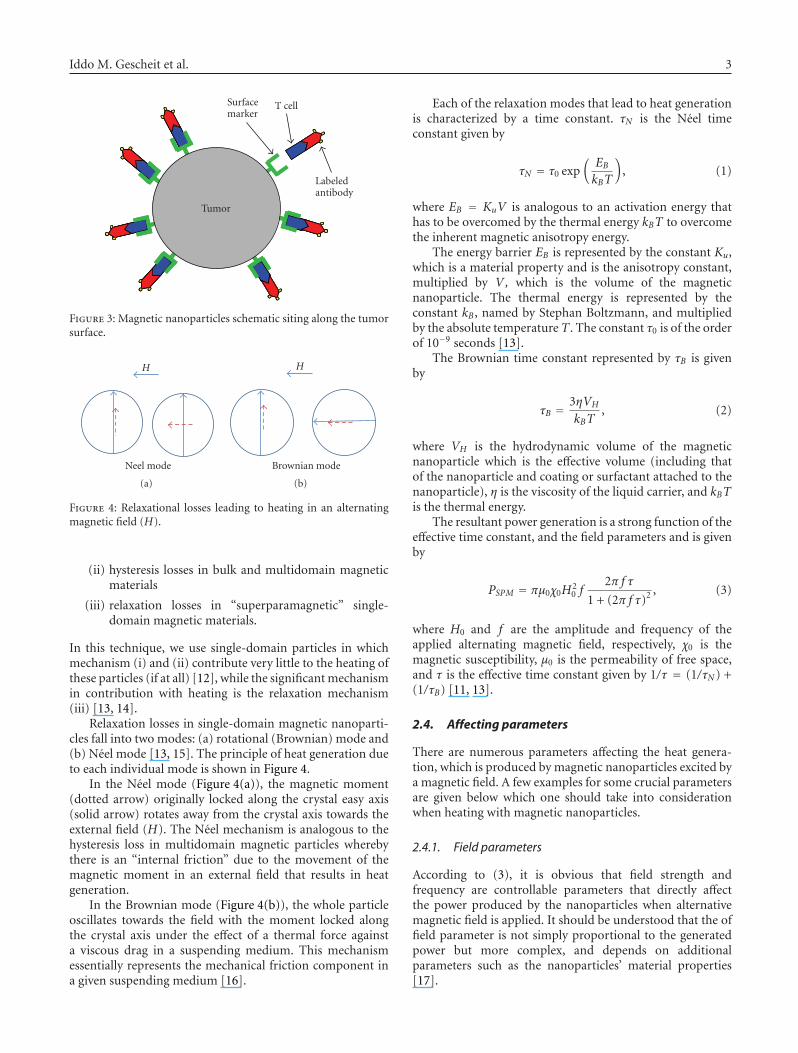
and deliver the nanoparticles reliably and specifically, thesuggested transportation leans on human’s immune system.The malignant tumor tends to present specific antigenson its outer surface. These antigens are able to commu-nicate with corresponding agents of the immune system(e.g., antibodies) to establish antigen-antibody complexeswhich are characterized in strong chemical bonds. Forinstance, we can bind the magnetic nanoparticles’ surfaceto the antibodies via adhering polymers (e.g., PEG) so thatantibodies transfer them towards the tumor being deliveredby immune agents (T-cell), and conjugate them to the tumor,retaining them along the tumor’s outer surface (Figures 2 and3).
This bioconjugation is analogous to that made withfluorophores in research conducted by Fibich et al. [9] andGannot et al. [10].
2.3. Heat generation
There exist at least three different mechanisms by whichmagnetic materials can generate heat in an alternating field[11]:
(i) generation of eddy currents in bulk magnetic materi-als;
Iddo M. Gescheit et al. 3
T cell
Labeledantibody
Surfacemarker
Tumor
Figure 3: Magnetic nanoparticles schematic siting along the tumorsurface.
H
Neel mode
(a)
H
Brownian mode
(b)
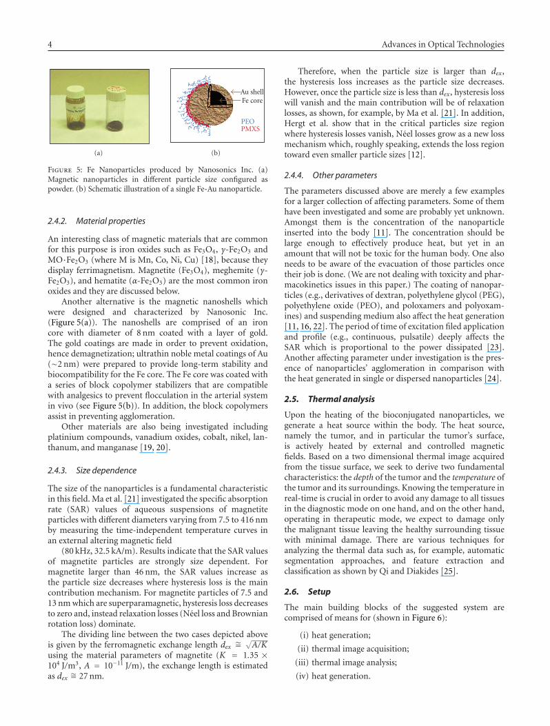
Figure 4: Relaxational losses leading to heating in an alternatingmagnetic field (H).
(ii) hysteresis losses in bulk and multidomain magneticmaterials
(iii) relaxation losses in “superparamagnetic” single-domain magnetic materials.
In this technique, we use single-domain particles in whichmechanism (i) and (ii) contribute very little to the heating ofthese particles (if at all) [12], while the significant mechanismin contribution with heating is the relaxation mechanism(iii) [13, 14].
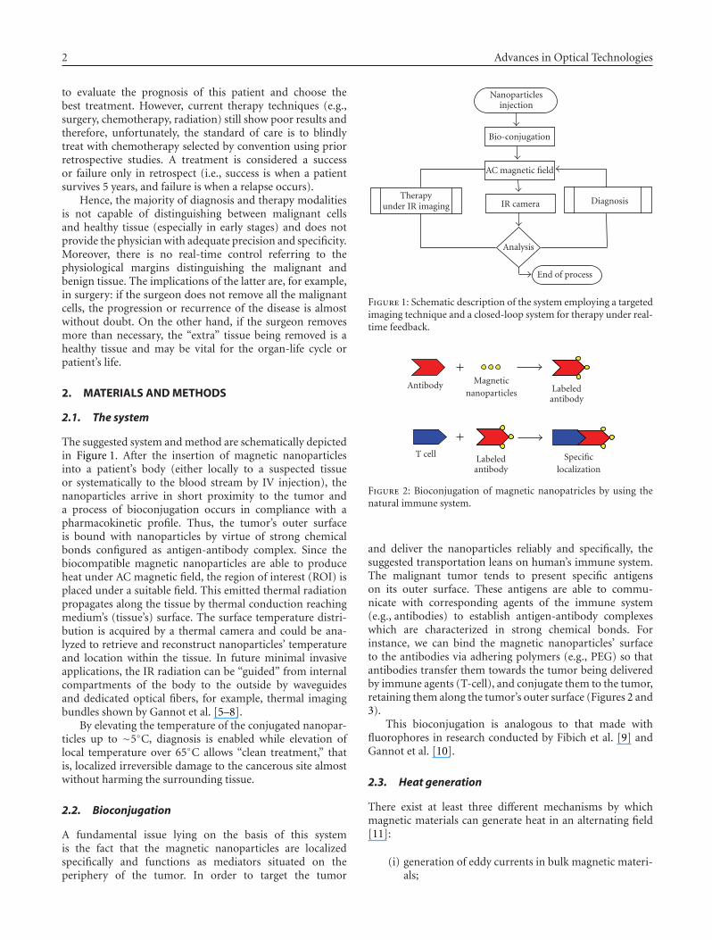
Relaxation losses in single-domain magnetic nanoparti-cles fall into two modes: (a) rotational (Brownian) mode and(b) Neel mode [13, 15]. The principle of heat generation dueto each individual mode is shown in Figure 4.
In the Neel mode (Figure 4(a)), the magnetic moment(dotted arrow) originally locked along the crystal easy axis(solid arrow) rotates away from the crystal axis towards theexternal field (H). The Neel mechanism is analogous to thehysteresis loss in multidomain magnetic particles wherebythere is an “internal friction” due to the movement of themagnetic moment in an external field that results in heatgeneration.
In the Brownian mode (Figure 4(b)), the whole particleoscillates towards the field with the moment locked alongthe crystal axis under the effect of a thermal force againsta viscous drag in a suspending medium. This mechanismessentially represents the mechanical friction component ina given suspending medium [16].
Each of the relaxation modes that lead to heat generationis characterized by a time constant. τN is the Neel timeconstant given by
τN = τ0 exp(EBkBT
), (1)
where EB = KuV is analogous to an activation energy thathas to be overcomed by the thermal energy kBT to overcomethe inherent magnetic anisotropy energy.
The energy barrier EB is represented by the constant Ku,which is a material property and is the anisotropy constant,multiplied by V , which is the volume of the magneticnanoparticle. The thermal energy is represented by theconstant kB, named by Stephan Boltzmann, and multipliedby the absolute temperature T . The constant τ0 is of the orderof 10−9 seconds [13].
The Brownian time constant represented by τB is givenby
τB =3ηVH
kBT, (2)
where VH is the hydrodynamic volume of the magneticnanoparticle which is the effective volume (including thatof the nanoparticle and coating or surfactant attached to thenanoparticle), η is the viscosity of the liquid carrier, and kBTis the thermal energy.
The resultant power generation is a strong function of theeffective time constant, and the field parameters and is givenby
PSPM = πμ0χ0H20 f
2π f τ
1 + (2π f τ)2 , (3)
where H0 and f are the amplitude and frequency of theapplied alternating magnetic field, respectively, χ0 is themagnetic susceptibility, μ0 is the permeability of free space,and τ is the effective time constant given by 1/τ = (1/τN ) +(1/τB) [11, 13].
2.4. Affecting parameters
There are numerous parameters affecting the heat genera-tion, which is produced by magnetic nanoparticles excited bya magnetic field. A few examples for some crucial parametersare given below which one should take into considerationwhen heating with magnetic nanoparticles.
2.4.1. Field parameters
According to (3), it is obvious that field strength andfrequency are controllable parameters that directly affectthe power produced by the nanoparticles when alternativemagnetic field is applied. It should be understood that the offield parameter is not simply proportional to the generatedpower but more complex, and depends on additionalparameters such as the nanoparticles’ material properties[17].
4 Advances in Optical Technologies
(a)
Au shellFe core
PEOPMXS
(b)
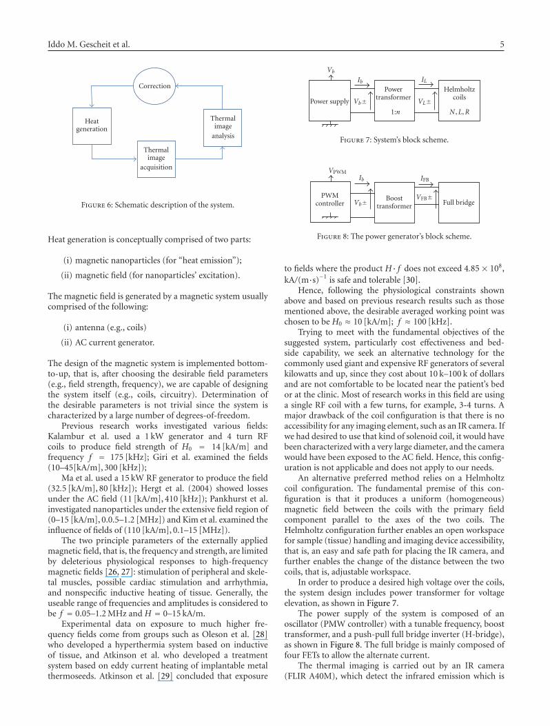
Figure 5: Fe Nanoparticles produced by Nanosonics Inc. (a)Magnetic nanoparticles in different particle size configured aspowder. (b) Schematic illustration of a single Fe-Au nanoparticle.
2.4.2. Material properties
An interesting class of magnetic materials that are commonfor this purpose is iron oxides such as Fe3O4, γ-Fe2O3 andMO·Fe2O3 (where M is Mn, Co, Ni, Cu) [18], because theydisplay ferrimagnetism. Magnetite (Fe3O4), meghemite (γ-Fe2O3), and hematite (α-Fe2O3) are the most common ironoxides and they are discussed below.
Another alternative is the magnetic nanoshells whichwere designed and characterized by Nanosonic Inc.(Figure 5(a)). The nanoshells are comprised of an ironcore with diameter of 8 nm coated with a layer of gold.The gold coatings are made in order to prevent oxidation,hence demagnetization; ultrathin noble metal coatings of Au(∼2 nm) were prepared to provide long-term stability andbiocompatibility for the Fe core. The Fe core was coated witha series of block copolymer stabilizers that are compatiblewith analgesics to prevent flocculation in the arterial systemin vivo (see Figure 5(b)). In addition, the block copolymersassist in preventing agglomeration.
Other materials are also being investigated includingplatinium compounds, vanadium oxides, cobalt, nikel, lan-thanum, and manganase [19, 20].
2.4.3. Size dependence
The size of the nanoparticles is a fundamental characteristicin this field. Ma et al. [21] investigated the specific absorptionrate (SAR) values of aqueous suspensions of magnetiteparticles with different diameters varying from 7.5 to 416 nmby measuring the time-independent temperature curves inan external altering magnetic field
(80 kHz, 32.5 kA/m). Results indicate that the SAR valuesof magnetite particles are strongly size dependent. Formagnetite larger than 46 nm, the SAR values increase asthe particle size decreases where hysteresis loss is the maincontribution mechanism. For magnetite particles of 7.5 and13 nm which are superparamagnetic, hysteresis loss decreasesto zero and, instead relaxation losses (Neel loss and Brownianrotation loss) dominate.
The dividing line between the two cases depicted aboveis given by the ferromagnetic exchange length dex ∼=
√A/K
using the material parameters of magnetite (K = 1.35 ×10⁴ J/m3, A = 10−11 J/m), the exchange length is estimatedas dex ∼= 27 nm.
Therefore, when the particle size is larger than dex,the hysteresis loss increases as the particle size decreases.However, once the particle size is less than dex, hysteresis losswill vanish and the main contribution will be of relaxationlosses, as shown, for example, by Ma et al. [21]. In addition,Hergt et al. show that in the critical particles size regionwhere hysteresis losses vanish, Neel losses grow as a new lossmechanism which, roughly speaking, extends the loss regiontoward even smaller particle sizes [12].
2.4.4. Other parameters
The parameters discussed above are merely a few examplesfor a larger collection of affecting parameters. Some of themhave been investigated and some are probably yet unknown.Amongst them is the concentration of the nanoparticleinserted into the body [11]. The concentration should belarge enough to effectively produce heat, but yet in anamount that will not be toxic for the human body. One alsoneeds to be aware of the evacuation of those particles oncetheir job is done. (We are not dealing with toxicity and phar-macokinetics issues in this paper.) The coating of nanopar-ticles (e.g., derivatives of dextran, polyethylene glycol (PEG),polyethylene oxide (PEO), and poloxamers and polyoxam-ines) and suspending medium also affect the heat generation[11, 16, 22]. The period of time of excitation filed applicationand profile (e.g., continuous, pulsatile) deeply affects theSAR which is proportional to the power dissipated [23].Another affecting parameter under investigation is the pres-ence of nanoparticles’ agglomeration in comparison withthe heat generated in single or dispersed nanoparticles [24].
2.5. Thermal analysis
Upon the heating of the bioconjugated nanoparticles, wegenerate a heat source within the body. The heat source,namely the tumor, and in particular the tumor’s surface,is actively heated by external and controlled magneticfields. Based on a two dimensional thermal image acquiredfrom the tissue surface, we seek to derive two fundamentalcharacteristics: the depth of the tumor and the temperature ofthe tumor and its surroundings. Knowing the temperature inreal-time is crucial in order to avoid any damage to all tissuesin the diagnostic mode on one hand, and on the other hand,operating in therapeutic mode, we expect to damage onlythe malignant tissue leaving the healthy surrounding tissuewith minimal damage. There are various techniques foranalyzing the thermal data such as, for example, automaticsegmentation approaches, and feature extraction andclassification as shown by Qi and Diakides [25].
2.6. Setup
The main building blocks of the suggested system arecomprised of means for (shown in Figure 6):
(i) heat generation;
(ii) thermal image acquisition;
(iii) thermal image analysis;
(iv) heat generation.
Iddo M. Gescheit et al. 5
Correction
Heatgeneration
Thermalimage
acquisition
Thermalimage
analysis
Figure 6: Schematic description of the system.
Heat generation is conceptually comprised of two parts:
(i) magnetic nanoparticles (for “heat emission”);
(ii) magnetic field (for nanoparticles’ excitation).
The magnetic field is generated by a magnetic system usuallycomprised of the following:
(i) antenna (e.g., coils)
(ii) AC current generator.
The design of the magnetic system is implemented bottom-to-up, that is, after choosing the desirable field parameters(e.g., field strength, frequency), we are capable of designingthe system itself (e.g., coils, circuitry). Determination ofthe desirable parameters is not trivial since the system ischaracterized by a large number of degrees-of-freedom.
Previous research works investigated various fields:Kalambur et al. used a 1 kW generator and 4 turn RFcoils to produce field strength of H0 = 14 [kA/m] andfrequency f = 175 [kHz]; Giri et al. examined the fields(10–45[kA/m], 300 [kHz]);
Ma et al. used a 15 kW RF generator to produce the field(32.5 [kA/m], 80 [kHz]); Hergt et al. (2004) showed lossesunder the AC field (11 [kA/m], 410 [kHz]); Pankhurst et al.investigated nanoparticles under the extensive field region of(0–15 [kA/m], 0.0.5–1.2 [MHz]) and Kim et al. examined theinfluence of fields of (110 [kA/m], 0.1–15 [MHz]).
The two principle parameters of the externally appliedmagnetic field, that is, the frequency and strength, are limitedby deleterious physiological responses to high-frequencymagnetic fields [26, 27]: stimulation of peripheral and skele-tal muscles, possible cardiac stimulation and arrhythmia,and nonspecific inductive heating of tissue. Generally, theuseable range of frequencies and amplitudes is considered tobe f = 0.05–1.2 MHz and H = 0–15 kA/m.
Experimental data on exposure to much higher fre-quency fields come from groups such as Oleson et al. [28]who developed a hyperthermia system based on inductiveof tissue, and Atkinson et al. who developed a treatmentsystem based on eddy current heating of implantable metalthermoseeds. Atkinson et al. [29] concluded that exposure
Power supply
Powertransformer
Helmholtzcoils
VbIb
Vb±
IL
VL±N ,L,R1:n
Figure 7: System’s block scheme.
PWMcontroller
Boosttransformer Full bridge
VPWMIb
Vb±
IFB
VFB±
Figure 8: The power generator’s block scheme.
to fields where the product H· f does not exceed 4.85× 10⁸,kA/(m·s)−1 is safe and tolerable [30].
Hence, following the physiological constraints shownabove and based on previous research results such as thosementioned above, the desirable averaged working point waschosen to be H0 ≈ 10 [kA/m]; f ≈ 100 [kHz].
Trying to meet with the fundamental objectives of thesuggested system, particularly cost effectiveness and bed-side capability, we seek an alternative technology for thecommonly used giant and expensive RF generators of severalkilowatts and up, since they cost about 10 k–100 k of dollarsand are not comfortable to be located near the patient’s bedor at the clinic. Most of research works in this field are usinga single RF coil with a few turns, for example, 3-4 turns. Amajor drawback of the coil configuration is that there is noaccessibility for any imaging element, such as an IR camera. Ifwe had desired to use that kind of solenoid coil, it would havebeen characterized with a very large diameter, and the camerawould have been exposed to the AC field. Hence, this config-uration is not applicable and does not apply to our needs.
An alternative preferred method relies on a Helmholtzcoil configuration. The fundamental premise of this con-figuration is that it produces a uniform (homogeneous)magnetic field between the coils with the primary fieldcomponent parallel to the axes of the two coils. TheHelmholtz configuration further enables an open workspacefor sample (tissue) handling and imaging device accessibility,that is, an easy and safe path for placing the IR camera, andfurther enables the change of the distance between the twocoils, that is, adjustable workspace.
In order to produce a desired high voltage over the coils,the system design includes power transformer for voltageelevation, as shown in Figure 7.
The power supply of the system is composed of anoscillator (PMW controller) with a tunable frequency, boosttransformer, and a push-pull full bridge inverter (H-bridge),as shown in Figure 8. The full bridge is mainly composed offour FETs to allow the alternate current.
The thermal imaging is carried out by an IR camera(FLIR A40M), which detect the infrared emission which is
6 Advances in Optical Technologies
Computeranalysis
2D thermalimage
Tissuephantom
IRcamera
Electromagneticcoils
ACgenerator
Feedback
Thermalinsulation
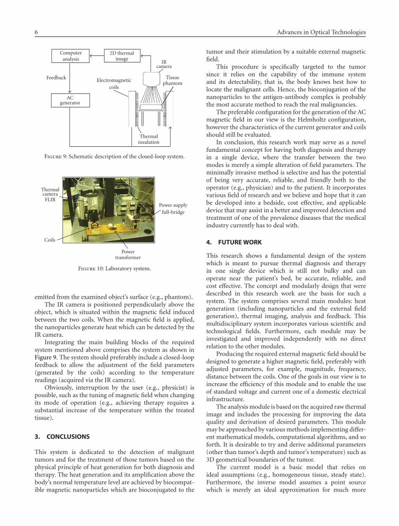
Figure 9: Schematic description of the closed-loop system.
ThermalcameraFLIR
Power supplyfull-bridge
Powertransformer
Coils
Figure 10: Laboratory system.
emitted from the examined object’s surface (e.g., phantom).The IR camera is positioned perpendicularly above the
object, which is situated within the magnetic field inducedbetween the two coils. When the magnetic field is applied,the nanoparticles generate heat which can be detected by theIR camera.
Integrating the main building blocks of the requiredsystem mentioned above comprises the system as shown inFigure 9. The system should preferably include a closed-loopfeedback to allow the adjustment of the field parameters(generated by the coils) according to the temperaturereadings (acquired via the IR camera).
Obviously, interruption by the user (e.g., physicist) ispossible, such as the tuning of magnetic field when changingits mode of operation (e.g., achieving therapy requires asubstantial increase of the temperature within the treatedtissue).
3. CONCLUSIONS
This system is dedicated to the detection of malignanttumors and for the treatment of those tumors based on thephysical principle of heat generation for both diagnosis andtherapy. The heat generation and its amplification above thebody’s normal temperature level are achieved by biocompat-ible magnetic nanoparticles which are bioconjugated to the
tumor and their stimulation by a suitable external magneticfield.
This procedure is specifically targeted to the tumorsince it relies on the capability of the immune systemand its detectability, that is, the body knows best how tolocate the malignant cells. Hence, the bioconjugation of thenanoparticles to the antigen-antibody complex is probablythe most accurate method to reach the real malignancies.
The preferable configuration for the generation of the ACmagnetic field in our view is the Helmholtz configuration,however the characteristics of the current generator and coilsshould still be evaluated.
In conclusion, this research work may serve as a novelfundamental concept for having both diagnosis and therapyin a single device, where the transfer between the twomodes is merely a simple alteration of field parameters. Theminimally invasive method is selective and has the potentialof being very accurate, reliable, and friendly both to theoperator (e.g., physician) and to the patient. It incorporatesvarious field of research and we believe and hope that it canbe developed into a bedside, cost effective, and applicabledevice that may assist in a better and improved detection andtreatment of one of the prevalence diseases that the medicalindustry currently has to deal with.
4. FUTURE WORK
This research shows a fundamental design of the systemwhich is meant to pursue thermal diagnosis and therapyin one single device which is still not bulky and canoperate near the patient’s bed, be accurate, reliable, andcost effective. The concept and modularly design that weredescribed in this research work are the basis for such asystem. The system comprises several main modules: heatgeneration (including nanoparticles and the external fieldgeneration), thermal imaging, analysis and feedback. Thismultidisciplinary system incorporates various scientific andtechnological fields. Furthermore, each module may beinvestigated and improved independently with no directrelation to the other modules.
Producing the required external magnetic field should bedesigned to generate a higher magnetic field, preferably withadjusted parameters, for example, magnitude, frequency,distance between the coils. One of the goals in our view is toincrease the efficiency of this module and to enable the useof standard voltage and current one of a domestic electricalinfrastructure.
The analysis module is based on the acquired raw thermalimage and includes the processing for improving the dataquality and derivation of desired parameters. This modulemay be approached by various methods implementing differ-ent mathematical models, computational algorithms, and soforth. It is desirable to try and derive additional parameters(other than tumor’s depth and tumor’s temperature) such as3D geometrical boundaries of the tumor.
The current model is a basic model that relies onideal assumptions (e.g., homogeneous tissue, steady state).Furthermore, the inverse model assumes a point sourcewhich is merely an ideal approximation for much more
Iddo M. Gescheit et al. 7
complicated scenarios that involve undefined tumor bound-aries, noise signals, physiological, anatomical abnormalities,and so forth.
The closed-loop feedback that allows control on theexternal magnetic field’s parameters (e.g., magnitude andfrequency) can be automatically adjusted based on thethermal imaging to maintain appropriate contrast and toachieve control on the heat expansion within the tissue inreal time in order not to harm surrounding healthy tissue.This can be carried out by a LabView dedicated program.
REFERENCES
[1] F. Bretagnol and L. de Calan, “Surgery treatment of rectalcancer,” Journal de Chirurgie, vol. 143, no. 6, pp. 366–372,2006.
[2] Cancer Facts and Figures, 2006.[3] L. J. Kleinsmith, D. Kerrigan, J. Kelly, and B. Hollen, “Under-
standing Cancer and Related Topics Understanding Cancer,”National Cancer Institute, 2007.
[4] D. A. Benaron, “The future of cancer imaging,” Cancer andMetastasis Reviews, vol. 21, no. 1, pp. 45–78, 2002.
[5] M. Ben-David, A. Inberg, I. Gannot, and N. Croitoru, “Theeffect of scattering on the transmission of infrared radiationthrough hollow waveguides,” Journal of Optoelectronics andAdvanced Materials, vol. 1, no. 3, pp. 23–30, 1999.
[6] I. Gannot, M. Ben-David, A. Inberg, and N. Croitoru,“Broadband omnidirectional IR flexible waveguides,” Journalof Optoelectronics and Advanced Materials, vol. 3, no. 4, pp.933–935, 2001.
[7] I. Gannot, M. Ben-David, A. Inberg, N. Croitoru, and R.W. Waynant, “Beam shape analysis of waveguide deliveredinfrared lasers,” Optical Engineering, vol. 41, no. 1, pp. 244–250, 2002.
[8] N. Croitoru, A. Inberg, M. Ben-David, and I. Gannot, “Broadband and low loss mid-IR flexible hollow waveguides,” OpticsExpress, vol. 12, no. 7, pp. 1341–1352, 2004.
[9] G. Fibich, A. Hammer, G. Gannot, A. Gandjbakhche, and I.Gannot, “Modeling and simulations of the pharmacokineticsof fluorophore conjugated antibodies in tumor vicinity for theoptimization of fluorescence-based optical imaging,” Lasers inSurgery and Medicine, vol. 37, no. 2, pp. 155–160, 2005.
[10] I. Gannot, A. Garashi, G. Gannot, V. Chernomordik, and A.Gandjbakhche, “In vivo quantitative three-dimensional local-ization of tumor labeled with exogenous specific fluorescencemarkers,” Applied Optics, vol. 42, no. 16, pp. 3073–3080, 2003.
[11] V. S. Kalambur, B. Han, B. E. Hammer, T. W. Shield, and J.C. Bischof, “In vitro characterization of movement, heatingand visualization of magnetic nanoparticles for biomedicalapplications,” Nanotechnology, vol. 16, no. 8, pp. 1221–1233,2005.
[12] R. Hergt, W. Andrae, C. G. d’Ambly, et al., “Physical limitsof hyperthermia using magnetite fine particles,” IEEE Transac-tions on Magnetics, vol. 34, no. 5, part 2, pp. 3745–3754, 1998.
[13] R. E. Rosensweig, “Heating magnetic fluid with alternatingmagnetic field,” Journal of Magnetism and Magnetic Materials,vol. 252, no. 1–3, pp. 370–374, 2002.
[14] A. Jordan, P. Wust, H. Fahling, W. John, A. Hinz, and R. Felix,“Inductive heating of ferrimagnetic particles and magneticfluids: physical evaluation of their potential for hyperthermia,”International Journal of Hyperthermia, vol. 9, no. 1, pp. 51–68,1993.
[15] P. C. Fannin and S. W. Charles, “Study of a ferrofluidexhibiting both Brownian and Neel relaxation,” Journal ofPhysics D, vol. 22, no. 1, pp. 187–191, 1989.
[16] C. C. Berry and A. S. G. Curtis, “Functionalisation of magneticnanoparticles for applications in biomedicine,” Journal ofPhysics D, vol. 36, no. 13, pp. R198–R206, 2003.
[17] G. Glockl, R. Hergt, M. Zeisberger, S. Dutz, S. Nagel, and W.Weitschies, “The effect of field parameters, nanoparticle prop-erties and immobilization on the specific heating power inmagnetic particle hyperthermia,” Journal of Physics: CondensedMatter, vol. 18, no. 38, pp. S2935–S2949, 2006.
[18] R. M. Cornell and U. Schwertmann, The Iron Oxides: Struc-ture, Properties, Reactions, Occurrence and Uses, John Wiley &Sons, New York, NY, USA, 1996.
[19] S. Vasseur, E. Duguet, J. Portier, et al., “Lanthanum manganeseperovskite nanoparticles as possible in vivo mediators formagnetic hyperthermia,” Journal of Magnetism and MagneticMaterials, vol. 302, no. 2, pp. 315–320, 2006.
[20] D. Bahadur, J. Giri, B. B. Nayak, et al., “Processing, propertiesand some novel applications of magnetic nanoparticles,”Pramana, vol. 65, no. 4, pp. 663–679, 2005.
[21] M. Ma, Y. Wu, J. Zhou, Y. Sun, Y. Zhang, and N. Gu, “Sizedependence of specific power absorption of Fe3O4 particlesin AC magnetic field,” Journal of Magnetism and MagneticMaterials, vol. 268, no. 1-2, pp. 33–39, 2004.
[22] H. Yin, H. P. Too, and G. M. Chow, “The effects of particlesize and surface coating on the cytotoxicity of nickel ferrite,”Biomaterials, vol. 26, no. 29, pp. 5818–5826, 2005.
[23] I. Baker, Q. Zeng, W. Li, and C. R. Sullivan, “Heat depositionin iron oxide and iron nanoparticles for localized hyperther-mia,” Journal of Applied Physics, vol. 99, no. 8, Article ID08H106, 3 pages, 2006.
[24] P. Keblinski, D. G. Cahill, A. Bodapati, C. R. Sullivan, and T.A. Taton, “Limits of localized heating by electromagneticallyexcited nanoparticles,” Journal of Applied Physics, vol. 100, no.5, Article ID 054305, 5 pages, 2006.
[25] H. Qi and N. A. Diakides, “Thermography,” in Encyclopedia ofMedical Devices and Instrumentation, J. G. Webster, Ed., JohnWiley & Sons, New York, NY, USA, 2nd edition, 2006.
[26] J. R. Oleson, T. C. Cetas, and P. M. Corry, “Hyperthermia bymagnetic induction: experimental and theoretical results forcoaxial coil pairs,” Radiation Research, vol. 95, no. 1, pp. 175–186, 1983.
[27] J. P. Reilly, “Principle of nerve and heart excitation by time-variyng magnetic fields,” Annals of the New York Academy ofSciences, vol. 649, pp. 96–117, 1992.
[28] J. R. Oleson, R. S. Heusinkveld, and M. R. Manning,“Hyperthermia by magnetic induction: II. Clinical experiencewith concentric electrodes,” International Journal of RadiationOncology Biology Physics, vol. 9, no. 4, pp. 549–556, 1983.
[29] W. J. Atkinson, I. A. Brezovich, and D. P. Chakraborty,“Usable frequencies in hyperthermia with thermal seeds,”IEEE Transactions on Biomedical Engineering, vol. 31, no. 1, pp.70–75, 1984.
[30] Q. A. Pankhurst, J. Connolly, S. K. Jones, and J. Dobson,“Applications of magnetic nanoparticles in biomedicine,”Journal of Physics D, vol. 36, no. 13, pp. R167–R181, 2003.