A Progressive Transmission Image Coder Using Linear Phase Uniform Filter Banks As Block Transforms
IEEE TRANSACTIONS ON IMAGE PROCESSING, VOL. 8, NO. 11, NOVEMBER 1999 1493
A Progressive Transmission ImageCoder Using Linear Phase Uniform
Filterbanks as Block TransformsTrac D. Tran and Truong Q. Nguyen
Abstract—This paper presents a novel image coding schemeusingMMM -channel linear phase perfect reconstruction filterbanks(LPPRFB’s) in the embedded zerotree wavelet (EZW) frameworkintroduced by Shapiro [1]. The innovation here is to replacethe EZW’s dyadic wavelet transform by MMM -channel uniform-band maximally decimated LPPRFB’s, which offer finer fre-quency spectrum partitioning and higher energy compaction. Thetransform stage can now be implemented as a block transformwhich supports parallel processing mode and facilitates region-of-interest coding/decoding. For hardware implementation, thetransform boasts efficient lattice structures, which employ aminimal number of delay elements and are robust under thequantization of lattice coefficients. The resulted compression algo-rithm also retains all attractive properties of the EZW coder andits variations such as progressive image transmission, embeddedquantization, exact bit rate control, and idempotency. Despite itssimplicity, our new coder outperforms some of the best imagecoders published recently in literature [1]–[4], for almost all testimages (especially natural, hard-to-code ones) at almost all bitrates.
Index Terms—Block transform coding, image coding, filter-banks, wavelet transform.
I. INTRODUCTION
BLOCK transform coding and subband coding have beentwo dominant techniques in existing image compression
standards and implementations. Both methods actually exhibitmany similarities: relying on a certain transform to convertthe input image to a more decorrelated representation, thenutilizing the same basic building blocks such as bit allocator,quantizer, and entropy coder to achieve compression.
Block transform coders enjoyed success first due to theirlow complexity in implementation and their reasonable per-formance. The most popular block transform coder leadsto the current image compression standard JPEG [5] whichutilizes the 8 8 discrete cosine transform (DCT) [6] at itstransformation stage. At high bit rates (1 b/pixel and up), JPEGoffers almost visually lossless reconstruction image quality.
Manuscript received June 4, 1997; revised March 4, 1998. This work wassupported in part by the National Science Foundation under Grant MIP-9626563. The associate editor coordinating the review of this manuscript andapproving it for publication was Dr. Christine Podilchuk.
T. D. Tran was with the Department of Electrical and Computer Engi-neering, University of Wisconsin, Madison, WI 53706 USA. He is now withthe Department of Electrical and Computer Engineering, The Johns HopkinsUniversity, Baltimore, MD 21218 USA (e-mail: [email protected]).
T. Q. Nguyen is with the Electrical and Computer Engineering Department,Boston University, Boston, MA 02215 USA.
Publisher Item Identifier S 1057-7149(99)08747-3.
However, when more compression is needed (i.e., at lowerbit rates), annoying blocking artifacts show up because oftwo reasons: 1) the DCT bases are short, nonoverlapped, andhave discontinuities at the ends and 2) JPEG processes eachimage block independently. So, interblock correlation has beencompletely abandoned.
The development of the lapped orthogonal transform (LOT)[7] and its generalized versions: the lapped biorthogonaltransform (LBT) [8], the generalized LOT (GenLOT) [9]–[11],and the generalized LBT (GLBT) [12]–[14] helps solve theblocking problem by borrowing pixels from the adjacentblocks to produce the transform coefficients of the currentblock. It has long been recognized that lapped transformsbelong to a subclass of linear phase perfect reconstruction filterbanks (LPPRFB’s): -channel systems with filter lengths
[7]. The DCT has channels and all filters oflength ; hence, its basis functions do not overlap. Lappedtransform outperforms the DCT on two counts: 1) from theanalysis viewpoint, it takes into account interblock correlation,hence, provides better energy compaction that leads to moreefficient entropy coding of the coefficients and 2) from thesynthesis viewpoint, its basis functions decay asymptotically tozero at the ends, reducing blocking discontinuities drastically.However, earlier lapped-transform-based image coders [7],[10], [15] have not utilized global information to their full ad-vantage: the quantization and the entropy coding of transformcoefficients are still independent from block to block.
Recently, subband coding has emerged as the leading stan-dardization candidate in future image compression systemsthanks to the development of the discrete wavelet transform.Wavelet representation with implicit overlapping and variable-length basis functions produces smoother and more perceptu-ally pleasant reconstructed images. Moreover, wavelet’s mul-tiresolution characteristics have created an intuitive foundationon which simple, yet sophisticated, methods of encodingthe transform coefficients are developed. Exploiting the re-lationship between the parent and the offspring coefficientsin a wavelet tree, progressive wavelet coders [1]–[3] caneffectively order the coefficients by bit planes and transmitmore significant bits first. This coding scheme results inan embedded bit stream along with many other advantagessuch as exact bit rate control and near-idempotency (perfectidempotency is obtained when the transform can map integersto integers). In these subband coders, global information istaken into account fully.
1057–7149/99$10.00 1999 IEEE
1494 IEEE TRANSACTIONS ON IMAGE PROCESSING, VOL. 8, NO. 11, NOVEMBER 1999
Fig. 1. Dyadic wavelet transform and its corresponding image decomposition.
From a frequency domain point of view, the wavelet trans-form simply provides an octave-band representation of sig-nals. The dyadic wavelet transform can be thought of as anonuniform-band lapped transform. It can sufficiently decor-relate smooth images; however, it has problems with imageswith well-localized high-frequency components—having lowenergy compaction in these cases. Several solutions have beenproposed to solve this problem, most notably the waveletpacket approach [16] which yielded significant gains in ob-jective performance.
In this work, we shall confirm that the embedded frameworkis not only limited to the wavelet transform and the waveletpacket; it can be utilized with multichannel uniform-bandfilterbanks as well. In fact, a judicious choice of -channelLPPRFB coupled with several levels of wavelet decompositionof the dc band can provide much finer frequency spectrumpartitioning, leading to significant improvement over currentwavelet coders. This paper also attempts to shed some lightonto a deeper understanding of wavelets, lapped transforms,their relation, and their performance in image compressionfrom a multirate filterbank perspective.
The outline of the paper is as follows. In Section II, weoffer a brief review of LPPRFB—its lattice structures and itsimplementation as block transform—as well as the wavelettransform and its role in progressive image coding. Section IIIdescribes the wavelet—block transform analogy, which leadsto a general zerotree data structure for block transform coeffi-cients and details of the design of high-performance transformsto take full advantage of the new coding scheme. Section IVpresents many coding examples to confirm the validity of thetheory. An extensive performance comparison between thenew coder and existing state-of-the-art ones is also included.Finally, the conclusions are drawn in Section V.
A. Notations
Boldfaced characters are used to denote vectors and ma-trices. and denote, respectively, the transpose and
the inverse of the matrix . Special matrices used extensivelyare the identity matrix , the reversal matrix , and the nullmatrix . When the size of a matrix is not clear from context,subscripts will be included to indicate its size. For example,
denotes the reversal matrix, and standsfor the null matrix. The impulse response of a filterand its discrete -transform are represented by and .For abbreviations, we use LP, PR, PU, and FB to denote,respectively,linear phase, perfect reconstruction, paraunitary(or orthogonal), and filterbanks. The letters arereserved for the number of wavelet decomposition levels, thenumber of channels, and the filter’s (or the input’s) length,respectively. The termsLPPRFB, block transform,andlappedtransformare used interchangeably in the paper.
II. REVIEW
A. The Wavelet Transform and ProgressiveImage Transmission
From a filterbank viewpoint, the wavelet transform is anoctave-band representation for signals; the discrete dyadicwavelet transform can be obtained by iterating on the lowpassoutput of a PR two-channel filterbank with enough regularity[17]–[19] as shown in Fig. 1. For a true wavelet decomposi-tion, one iterates on the lowpass output only, whereas for awavelet-packet decomposition, one may iterate on any output.The wavelet transform is, intuitively, a multiresolution decom-position of a signal into its coarse and detailed components. Inthe case of images, the wavelet representation is well-matchedto psychovisual models, and it has given rise to numerouscompression systems with superior subjective and objectivequality to others at medium and high compression ratios[19], [20].
Many of these aforementioned high-performance waveletcoders also offer the capability of progressive image transmis-sion. This coding approach relies on the fundamental idea thatmore important information (defined here as what decreases a
TRAN AND NGUYEN: PROGRESSIVE TRANSMISSION IMAGE CODER 1495
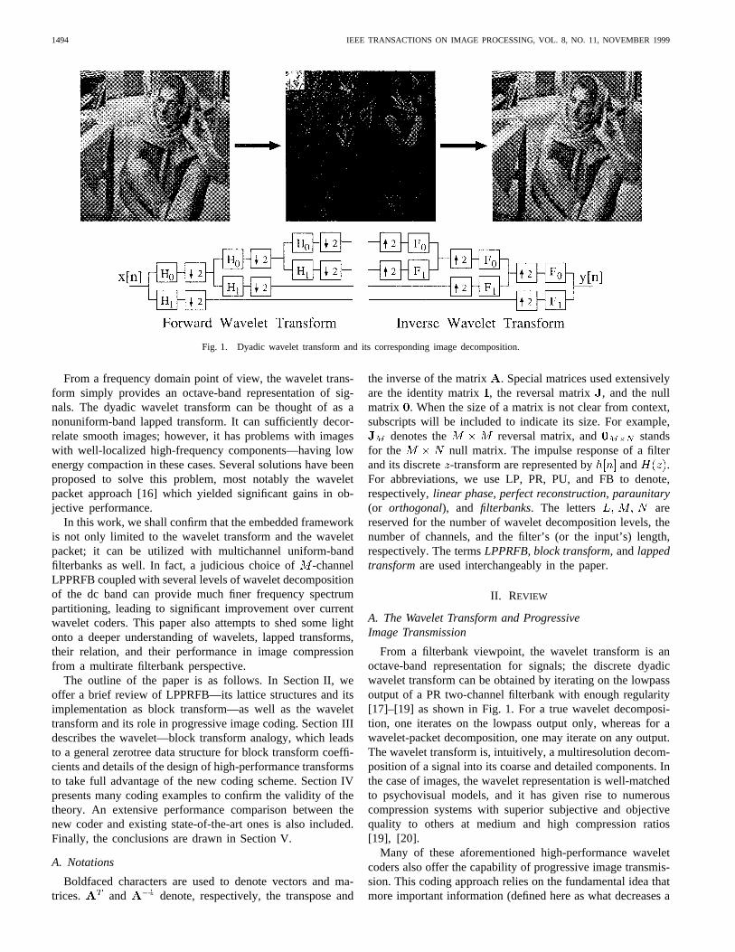
Fig. 2. Wavelet and block transform analogy.
certain distortion measure the most) should be transmitted first.Assume that the distortion measure is the mean-squared error(MSE), the transform is paraunitary, and transform coefficients
are transmitted one by one, it can be proven that themean squared error decreases by , where is thetotal number of pixels [21]. Therefore, larger coefficientsshould always be transmitted first. If one bit is transmittedat a time, this approach can be generalized to ranking thecoefficients by bit planes and the most significant bits aretransmitted first [22]. The progressive transmission schemeresults in an embedded bit stream (i.e., it can be truncatedat any point by the decoder to yield the best correspondingreconstructed image). The algorithm can be thought of as anelegant combination of a scalar quantizer with power-of-twostepsizes and an entropy coder to encode wavelet coefficients.
Embedded algorithm relies on the hierarchical coefficients’tree structure called awavelet tree—a set of wavelet coef-ficients from different scales that belong in the same spatiallocality. This is demonstrated in Fig. 2(a), where the tree in thevertical direction is circled. All of the coefficients in the lowestfrequency band make up thedc bandor the reference signal(located at the upper left corner). Besides these dc coefficients,in a wavelet tree of a particular direction, each lower-frequencyparent nodehas four corresponding higher-frequencyoffspringnodes. All coefficients below a parent node in the same spatiallocality is defined as itsdescendents. Define a coefficient
to be significantwith respect to a given threshold if, and insignificant otherwise. Meaningful image
statistics have shown that if a coefficient is insignificant, it isvery likely that its offspring and descendents are insignificantas well. Exploiting this fact, the most sophisticated embeddedwavelet coder SPIHT can output a single binary marker torepresent very efficiently a large, smooth image area (aninsignificant tree). For more details on the algorithm, the readeris referred to [1]–[3].
Although the wavelet tree provides an elegant hierarchicaldata structure which facilitates quantization and entropy cod-ing of the coefficients, the efficiency of the coder still dependsheavily on the transform’s ability in generating zerotrees. For
nonsmooth images that contain a lot of texture and edges,the wavelet transform is not as efficient in signal decorrelationcomparing to well-designed multichannel LPPRFB’s which weshall prove to provide finer frequency selectivity and superiorenergy compaction.
B. Linear Phase Perfect Reconstruction Filterbanks
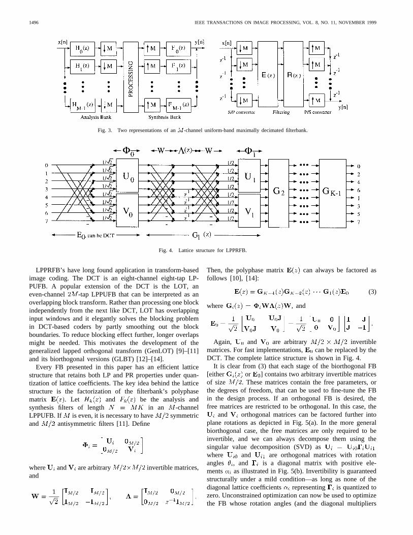
Two equivalent representations of an-channel filter bankare depicted in Fig. 3 [17], [18]. In this paper, we onlyconsider filterbanks with the following properties: perfectreconstruction, linear phase, finite impulse response (FIR), realcoefficient, maximally decimated, and uniform-band. Here areseveral of our justifications.
• The PR property is highly desirable since it provides alossless signal representation and it simplifies the erroranalysis significantly.
• In image processing, it is also crucial that all analysis andsynthesis filters have linear phase. Besides the eliminationof the phase distortion, linear phase systems allow us touse simple symmetric extension methods to accuratelyhandle the boundaries of finite-length signals. Further-more, the linear phase property can be exploited, leadingto faster and more efficient FB implementation.
• The filter length should be relatively short to preventringing artifacts in the reconstructed images and to keepthe transform fast.
• Since our interest is on compression, especially at low bitrates, we prefer maximally decimated FB’s which do notexpand the input signals.
From the polyphase representation in Fig. 3(b), perfectreconstruction can be loosely defined as the existence of anFIR matrix that satisfies the equation
(1)
We call these systemsbiorthogonal. An important subset ofPRFB isparaunitary FB, where is chosen to be
(2)
with being the order of .
1496 IEEE TRANSACTIONS ON IMAGE PROCESSING, VOL. 8, NO. 11, NOVEMBER 1999
Fig. 3. Two representations of anM -channel uniform-band maximally decimated filterbank.
Fig. 4. Lattice structure for LPPRFB.
LPPRFB’s have long found application in transform-basedimage coding. The DCT is an eight-channel eight-tap LP-PUFB. A popular extension of the DCT is the LOT, aneven-channel -tap LPPUFB that can be interpreted as anoverlapping block transform. Rather than processing one blockindependently from the next like DCT, LOT has overlappinginput windows and it elegantly solves the blocking problemin DCT-based coders by partly smoothing out the blockboundaries. To reduce blocking effect further, longer overlapsmight be needed. This motivates the development of thegeneralized lapped orthogonal transform (GenLOT) [9]–[11]and its biorthogonal versions (GLBT) [12]–[14].
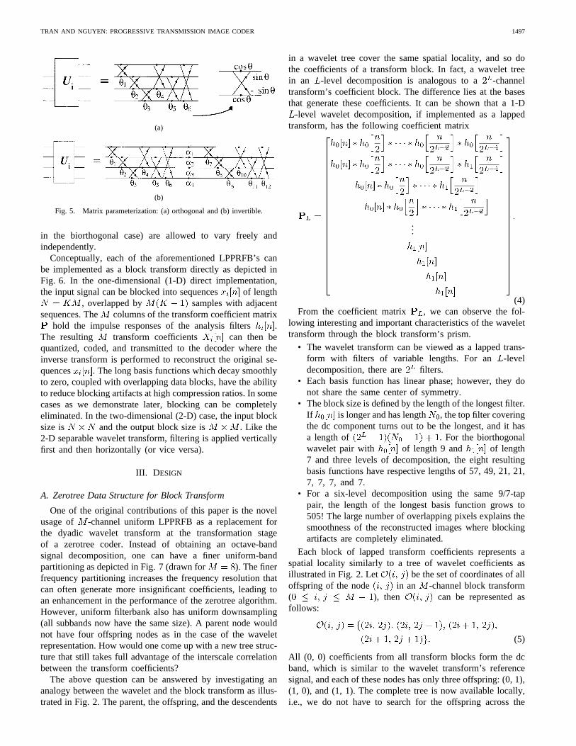
Every FB presented in this paper has an efficient latticestructure that retains both LP and PR properties under quan-tization of lattice coefficients. The key idea behind the latticestructure is the factorization of the filterbank’s polyphasematrix . Let and be the analysis andsynthesis filters of length in an -channelLPPUFB. If is even, it is necessary to have symmetricand antisymmetric filters [11]. Define
where and are arbitrary invertible matrices,and
Then, the polyphase matrix can always be factored asfollows [10], [14]:
(3)
where , and
Again, and are arbitrary invertiblematrices. For fast implementations, can be replaced by theDCT. The complete lattice structure is shown in Fig. 4.
It is clear from (3) that each stage of the biorthogonal FB[either or ] contains two arbitrary invertible matricesof size . These matrices contain the free parameters, orthe degrees of freedom, that can be used to fine-tune the FBin the design process. If an orthogonal FB is desired, thefree matrices are restricted to be orthogonal. In this case, the
and orthogonal matrices can be factored further intoplane rotations as depicted in Fig. 5(a). In the more generalbiorthogonal case, the free matrices are only required to beinvertible, and we can always decompose them using thesingular value decomposition (SVD) aswhere and are orthogonal matrices with rotationangles , and is a diagonal matrix with positive ele-ments as illustrated in Fig. 5(b). Invertibility is guaranteedstructurally under a mild condition—as long as none of thediagonal lattice coefficients representing is quantized tozero. Unconstrained optimization can now be used to optimizethe FB whose rotation angles (and the diagonal multipliers
TRAN AND NGUYEN: PROGRESSIVE TRANSMISSION IMAGE CODER 1497
(a)
(b)
Fig. 5. Matrix parameterization: (a) orthogonal and (b) invertible.
in the biorthogonal case) are allowed to vary freely andindependently.
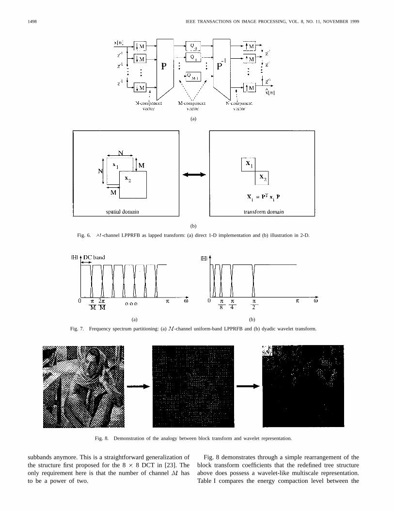
Conceptually, each of the aforementioned LPPRFB’s canbe implemented as a block transform directly as depicted inFig. 6. In the one-dimensional (1-D) direct implementation,the input signal can be blocked into sequences of length
, overlapped by samples with adjacentsequences. The columns of the transform coefficient matrix
hold the impulse responses of the analysis filters .The resulting transform coefficients can then bequantized, coded, and transmitted to the decoder where theinverse transform is performed to reconstruct the original se-quences . The long basis functions which decay smoothlyto zero, coupled with overlapping data blocks, have the abilityto reduce blocking artifacts at high compression ratios. In somecases as we demonstrate later, blocking can be completelyeliminated. In the two-dimensional (2-D) case, the input blocksize is and the output block size is . Like the2-D separable wavelet transform, filtering is applied verticallyfirst and then horizontally (or vice versa).
III. D ESIGN
A. Zerotree Data Structure for Block Transform
One of the original contributions of this paper is the novelusage of -channel uniform LPPRFB as a replacement forthe dyadic wavelet transform at the transformation stageof a zerotree coder. Instead of obtaining an octave-bandsignal decomposition, one can have a finer uniform-bandpartitioning as depicted in Fig. 7 (drawn for ). The finerfrequency partitioning increases the frequency resolution thatcan often generate more insignificant coefficients, leading toan enhancement in the performance of the zerotree algorithm.However, uniform filterbank also has uniform downsampling(all subbands now have the same size). A parent node wouldnot have four offspring nodes as in the case of the waveletrepresentation. How would one come up with a new tree struc-ture that still takes full advantage of the interscale correlationbetween the transform coefficients?
The above question can be answered by investigating ananalogy between the wavelet and the block transform as illus-trated in Fig. 2. The parent, the offspring, and the descendents
in a wavelet tree cover the same spatial locality, and so dothe coefficients of a transform block. In fact, a wavelet treein an -level decomposition is analogous to a -channeltransform’s coefficient block. The difference lies at the basesthat generate these coefficients. It can be shown that a 1-D
-level wavelet decomposition, if implemented as a lappedtransform, has the following coefficient matrix
...
(4)From the coefficient matrix , we can observe the fol-
lowing interesting and important characteristics of the wavelettransform through the block transform’s prism.
• The wavelet transform can be viewed as a lapped trans-form with filters of variable lengths. For an -leveldecomposition, there are filters.
• Each basis function has linear phase; however, they donot share the same center of symmetry.
• The block size is defined by the length of the longest filter.If is longer and has length , the top filter coveringthe dc component turns out to be the longest, and it hasa length of . For the biorthogonalwavelet pair with of length 9 and of length7 and three levels of decomposition, the eight resultingbasis functions have respective lengths of 57, 49, 21, 21,7, 7, 7, and 7.
• For a six-level decomposition using the same 9/7-tappair, the length of the longest basis function grows to505! The large number of overlapping pixels explains thesmoothness of the reconstructed images where blockingartifacts are completely eliminated.
Each block of lapped transform coefficients represents aspatial locality similarly to a tree of wavelet coefficients asillustrated in Fig. 2. Let be the set of coordinates of alloffspring of the node in an -channel block transform( ), then can be represented asfollows:
(5)
All (0, 0) coefficients from all transform blocks form the dcband, which is similar to the wavelet transform’s referencesignal, and each of these nodes has only three offspring: (0, 1),(1, 0), and (1, 1). The complete tree is now available locally,i.e., we do not have to search for the offspring across the
1498 IEEE TRANSACTIONS ON IMAGE PROCESSING, VOL. 8, NO. 11, NOVEMBER 1999
(a)
(b)
Fig. 6. M -channel LPPRFB as lapped transform: (a) direct 1-D implementation and (b) illustration in 2-D.
(a) (b)
Fig. 7. Frequency spectrum partitioning: (a)M -channel uniform-band LPPRFB and (b) dyadic wavelet transform.
Fig. 8. Demonstration of the analogy between block transform and wavelet representation.
subbands anymore. This is a straightforward generalization ofthe structure first proposed for the 8 8 DCT in [23]. Theonly requirement here is that the number of channelhasto be a power of two.
Fig. 8 demonstrates through a simple rearrangement of theblock transform coefficients that the redefined tree structureabove does possess a wavelet-like multiscale representation.Table I compares the energy compaction level between the
TRAN AND NGUYEN: PROGRESSIVE TRANSMISSION IMAGE CODER 1499
(a) (b)
(c) (d)
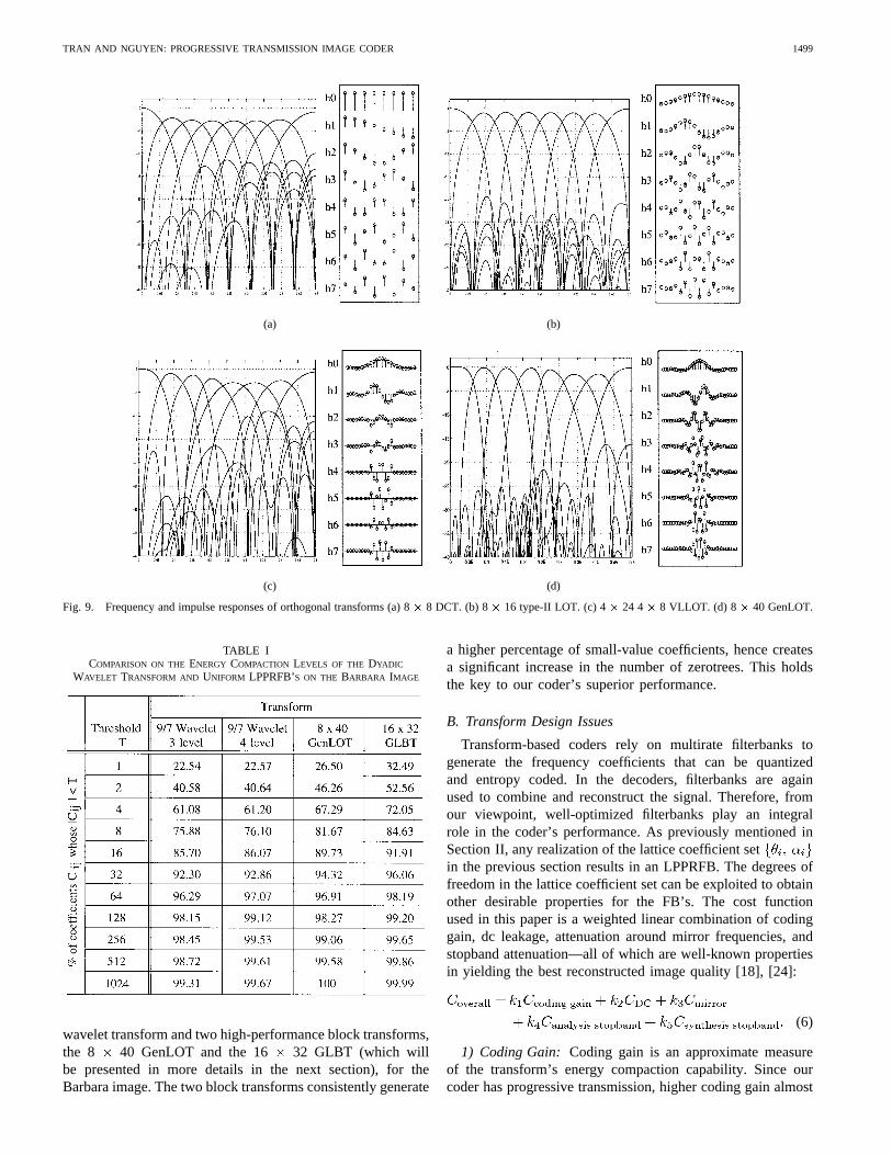
Fig. 9. Frequency and impulse responses of orthogonal transforms (a) 8� 8 DCT. (b) 8� 16 type-II LOT. (c) 4� 24 4� 8 VLLOT. (d) 8� 40 GenLOT.
TABLE ICOMPARISON ON THEENERGY COMPACTION LEVELS OF THE DYADIC
WAVELET TRANSFORM AND UNIFORM LPPRFB’S ON THE BARBARA IMAGE
wavelet transform and two high-performance block transforms,the 8 40 GenLOT and the 16 32 GLBT (which willbe presented in more details in the next section), for theBarbara image. The two block transforms consistently generate
a higher percentage of small-value coefficients, hence createsa significant increase in the number of zerotrees. This holdsthe key to our coder’s superior performance.
B. Transform Design Issues
Transform-based coders rely on multirate filterbanks togenerate the frequency coefficients that can be quantizedand entropy coded. In the decoders, filterbanks are againused to combine and reconstruct the signal. Therefore, fromour viewpoint, well-optimized filterbanks play an integralrole in the coder’s performance. As previously mentioned inSection II, any realization of the lattice coefficient setin the previous section results in an LPPRFB. The degrees offreedom in the lattice coefficient set can be exploited to obtainother desirable properties for the FB’s. The cost functionused in this paper is a weighted linear combination of codinggain, dc leakage, attenuation around mirror frequencies, andstopband attenuation—all of which are well-known propertiesin yielding the best reconstructed image quality [18], [24]:
(6)
1) Coding Gain: Coding gain is an approximate measureof the transform’s energy compaction capability. Since ourcoder has progressive transmission, higher coding gain almost
1500 IEEE TRANSACTIONS ON IMAGE PROCESSING, VOL. 8, NO. 11, NOVEMBER 1999
(a)
(b)
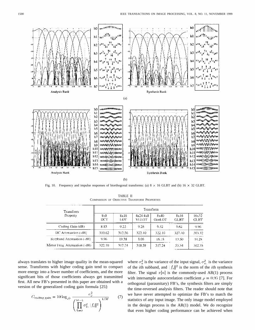
Fig. 10. Frequency and impulse responses of biorthogonal transforms: (a) 8� 16 GLBT and (b) 16� 32 GLBT.
TABLE IICOMPARISON OF OBJECTIVE TRANSFORM PROPERTIES
always translates to higher image quality in the mean-squaredsense. Transforms with higher coding gain tend to compactmore energy into a fewer number of coefficients, and the moresignificant bits of those coefficients always get transmittedfirst. All new FB’s presented in this paper are obtained with aversion of the generalized coding gain formula [25]:
(7)
where is the variance of the input signal, is the varianceof the th subband, and is the norm of theth synthesisfilter. The signal is the commonly-used AR(1) processwith intersample autocorrelation coefficient [7]. Fororthogonal (paraunitary) FB’s, the synthesis filters are simplythe time-reversed analysis filters. The reader should note thatwe have never attempted to optimize the FB’s to match thestatistics of any input image. The only image model employedin the design process is the AR(1) model. We do recognizethat even higher coding performance can be achieved when
TRAN AND NGUYEN: PROGRESSIVE TRANSMISSION IMAGE CODER 1501
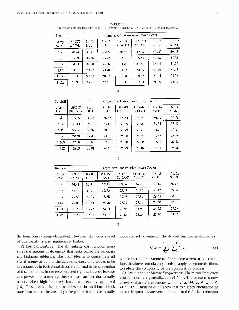
TABLE IIIOBJECTIVE CODING RESULTS (PSNR IN DECIBELS): (a) LENA, (b) GOLDHILL , AND (c) BARBARA
(a)
(b)
(c)
the transform is image-dependent. However, the coder’s levelof complexity is also significantly higher.
2) Low DC Leakage:The dc leakage cost function mea-sures the amount of dc energy that leaks out to the bandpassand highpass subbands. The main idea is to concentrate allsignal energy at dc into the dc coefficients. This proves to beadvantageous in both signal decorrelation and in the preventionof discontinuities in the reconstructed signals. Low dc leakagecan prevent the annoying checkerboard artifact that usuallyoccurs when high-frequency bands are severely quantized[18]. This problem is more troublesome in traditional blocktransform coders because high-frequency bands are usually
more coarsely quantized. The dc cost function is defined as
(8)
Notice that all antisymmetric filters have a zero at dc. There-fore, the above formula only needs to apply to symmetric filtersto reduce the complexity of the optimization process.
3) Attenuation at Mirror Frequencies:The mirror frequencycost function is a generalization of . The concern is nowat every aliasing frequencies , ,
. Ramstadet al. show that frequency attenuation atmirror frequencies are very important in the further reduction
1502 IEEE TRANSACTIONS ON IMAGE PROCESSING, VOL. 8, NO. 11, NOVEMBER 1999
of blocking artifacts: the filter responses should be small atthese mirror frequencies as well [24]. The corresponding costfunction is
(9)
Low dc leakage and high attenuation near the mirror frequen-cies are not as essential to the coder’s objective performanceas coding gain. However, they do improve the visual qualityof the reconstructed image significantly.
4) Stopband Attenuation:Stopband attenuation of the fil-ters is a classical performance criterion in filter design. In thispaper, the stopband attenuation criterion measures the sum ofall of the filters’ energy outside the designated passbands:
(10)
(11)
In the LPPUFB case, .The biorthogonal FB’s offer more flexibility. In the analysisbank, the stopband attenuation cost helps in improving thesignal decorrelation and decreasing the amount of aliasing. Inmeaningful images, we knowa priori that most of the energy isconcentrated in low frequency region. Hence, high stopbandattenuation in this part of the frequency spectrum becomesextremely desirable. In the synthesis bank, the reverse is true.Synthesis filters covering low-frequency bands need to havehigh stopband attenuation near and/or at to enhancetheir smoothness. The biased weighting can be enforced usingtwo simple linear functions and as shownin (10) and (11).
5) Transforms with Variable-Length Basis Functions:Theelegant factorization in Section II results in all filters of equallength. For images that contain a lot of strong edges, thelong basis functions covering high-frequency bands can causeexcessive ringing at low bit rates. On the other hand, the longerthe filter becomes, the higher the complexity of the FB gets.Since blocking is most noticeable in smooth image regions,in order to reduce blocking artifacts, filters covering high-frequency bands do not need long overlapping windows. Infact, they may not have to be overlapped at all. If the filterlength can be restricted mathematically, i.e., these coefficientsare structurally enforced to exact zeros, the complexity of theresulting FB can be reduced significantly. Efforts to reduceringing artifacts and to minimize the transform complexity canbe found in [26]–[28]. This class of transforms represents low-frequency components by longer overlapped basis functionsto prevent blocking, while reserving shorter basis functionsfor high-frequency components to minimize ringing. One of
(a)
(b)
(c)
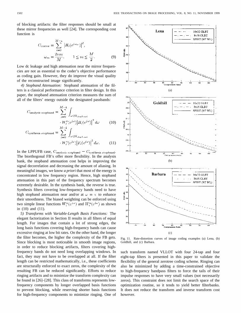
Fig. 11. Rate-distortion curves of image coding examples (a) Lena, (b)Goldhill, and (c) Barbara.
such transform named VLLOT with four 24-tap and foureight-tap filters is presented in this paper to validate theflexibility of the general zerotree coding scheme. Ringing canalso be minimized by adding a time-constrained objectiveto high-frequency bandpass filters to force the tails of theirimpulse responses to have very small values (not necessarilyzeros). This constraint does not limit the search space of theoptimization routine, so it tends to yield better filterbanks.It does not reduce the transform and inverse transform costhowever.
TRAN AND NGUYEN: PROGRESSIVE TRANSMISSION IMAGE CODER 1503
(a) (b)
(c) (d)
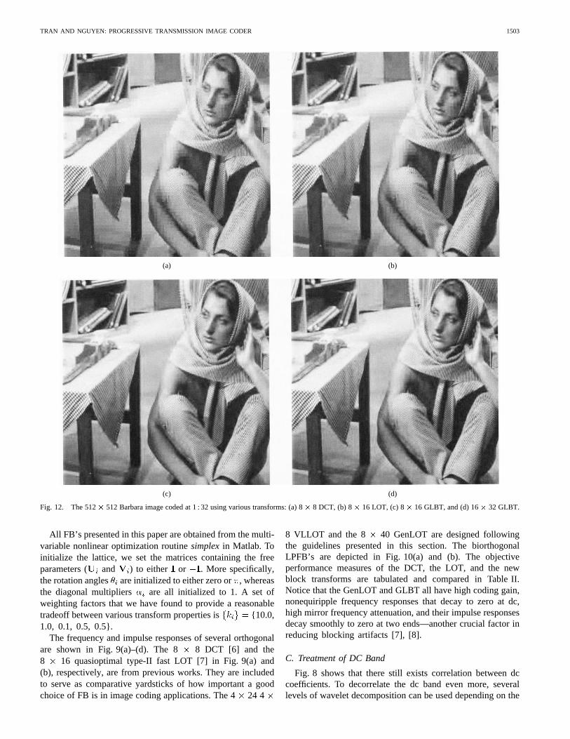
Fig. 12. The 512� 512 Barbara image coded at 1 : 32 using various transforms: (a) 8� 8 DCT, (b) 8� 16 LOT, (c) 8� 16 GLBT, and (d) 16� 32 GLBT.
All FB’s presented in this paper are obtained from the multi-variable nonlinear optimization routinesimplexin Matlab. Toinitialize the lattice, we set the matrices containing the freeparameters ( and ) to either or . More specifically,the rotation angles are initialized to either zero or, whereasthe diagonal multipliers are all initialized to 1. A set ofweighting factors that we have found to provide a reasonabletradeoff between various transform properties is {10.0,1.0, 0.1, 0.5, 0.5}.
The frequency and impulse responses of several orthogonalare shown in Fig. 9(a)–(d). The 8 8 DCT [6] and the8 16 quasioptimal type-II fast LOT [7] in Fig. 9(a) and(b), respectively, are from previous works. They are includedto serve as comparative yardsticks of how important a goodchoice of FB is in image coding applications. The 424 4
8 VLLOT and the 8 40 GenLOT are designed followingthe guidelines presented in this section. The biorthogonalLPFB’s are depicted in Fig. 10(a) and (b). The objectiveperformance measures of the DCT, the LOT, and the newblock transforms are tabulated and compared in Table II.Notice that the GenLOT and GLBT all have high coding gain,nonequiripple frequency responses that decay to zero at dc,high mirror frequency attenuation, and their impulse responsesdecay smoothly to zero at two ends—another crucial factor inreducing blocking artifacts [7], [8].
C. Treatment of DC Band
Fig. 8 shows that there still exists correlation between dccoefficients. To decorrelate the dc band even more, severallevels of wavelet decomposition can be used depending on the
1504 IEEE TRANSACTIONS ON IMAGE PROCESSING, VOL. 8, NO. 11, NOVEMBER 1999
(a) (b)
(c) (d)
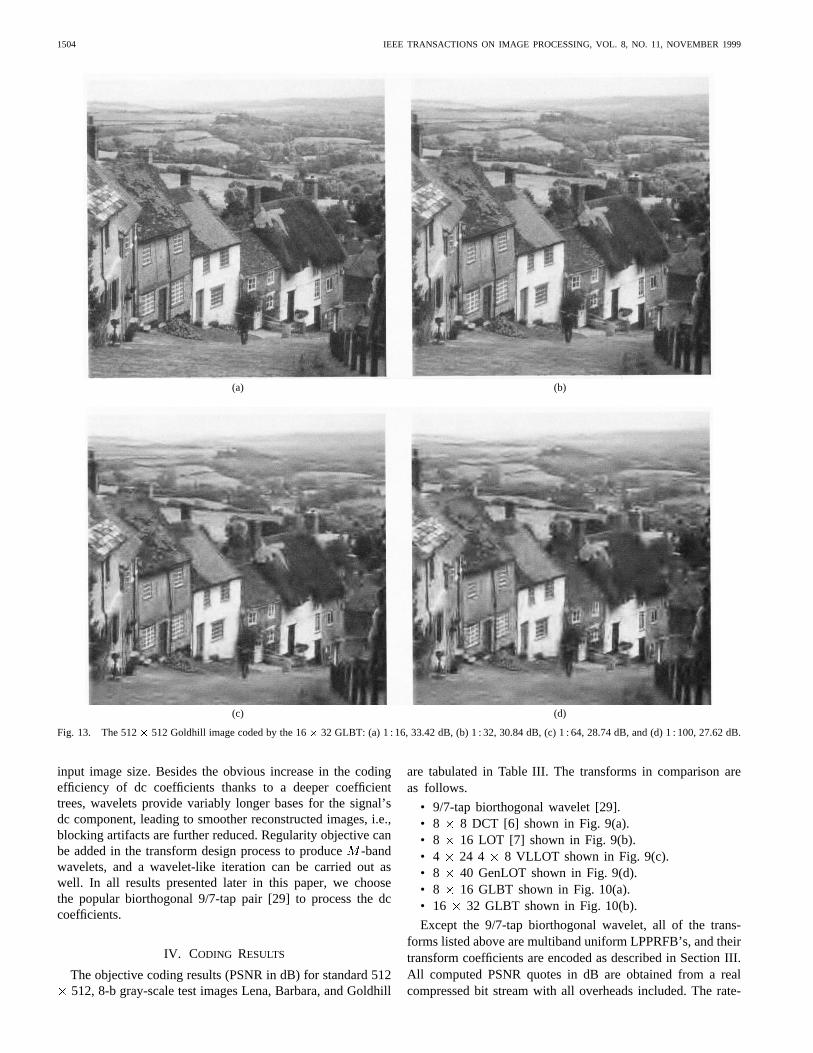
Fig. 13. The 512� 512 Goldhill image coded by the 16� 32 GLBT: (a) 1 : 16, 33.42 dB, (b) 1 : 32, 30.84 dB, (c) 1 : 64, 28.74 dB, and (d) 1 : 100, 27.62 dB.
input image size. Besides the obvious increase in the codingefficiency of dc coefficients thanks to a deeper coefficienttrees, wavelets provide variably longer bases for the signal’sdc component, leading to smoother reconstructed images, i.e.,blocking artifacts are further reduced. Regularity objective canbe added in the transform design process to produce-bandwavelets, and a wavelet-like iteration can be carried out aswell. In all results presented later in this paper, we choosethe popular biorthogonal 9/7-tap pair [29] to process the dccoefficients.
IV. CODING RESULTS
The objective coding results (PSNR in dB) for standard 512512, 8-b gray-scale test images Lena, Barbara, and Goldhill
are tabulated in Table III. The transforms in comparison areas follows.
• 9/7-tap biorthogonal wavelet [29].• 8 8 DCT [6] shown in Fig. 9(a).• 8 16 LOT [7] shown in Fig. 9(b).• 4 24 4 8 VLLOT shown in Fig. 9(c).• 8 40 GenLOT shown in Fig. 9(d).• 8 16 GLBT shown in Fig. 10(a).• 16 32 GLBT shown in Fig. 10(b).
Except the 9/7-tap biorthogonal wavelet, all of the trans-forms listed above are multiband uniform LPPRFB’s, and theirtransform coefficients are encoded as described in Section III.All computed PSNR quotes in dB are obtained from a realcompressed bit stream with all overheads included. The rate-
TRAN AND NGUYEN: PROGRESSIVE TRANSMISSION IMAGE CODER 1505
(a) (b) (c)
(d) (e) (f)
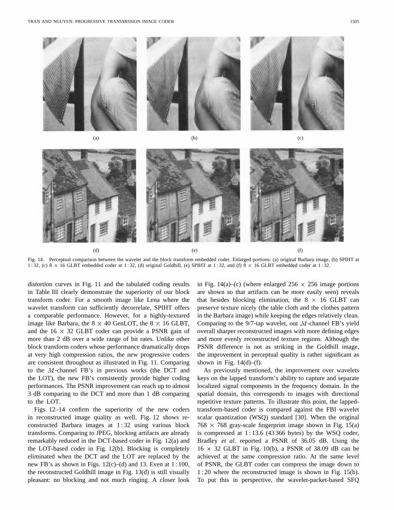
Fig. 14. Perceptual comparison between the wavelet and the block transform embedded coder. Enlarged portions: (a) original Barbara image, (b) SPIHTat1 : 32, (c) 8� 16 GLBT embedded coder at 1 : 32, (d) original Goldhill, (e) SPIHT at 1 : 32, and (f) 8� 16 GLBT embedded coder at 1 : 32.
distortion curves in Fig. 11 and the tabulated coding resultsin Table III clearly demonstrate the superiority of our blocktransform coder. For a smooth image like Lena where thewavelet transform can sufficiently decorrelate, SPIHT offersa comparable performance. However, for a highly-texturedimage like Barbara, the 8 40 GenLOT, the 8 16 GLBT,and the 16 32 GLBT coder can provide a PSNR gain ofmore than 2 dB over a wide range of bit rates. Unlike otherblock transform coders whose performance dramatically dropsat very high compression ratios, the new progressive codersare consistent throughout as illustrated in Fig. 11. Comparingto the -channel FB’s in previous works (the DCT andthe LOT), the new FB’s consistently provide higher codingperformances. The PSNR improvement can reach up to almost3 dB comparing to the DCT and more than 1 dB comparingto the LOT.
Figs. 12–14 confirm the superiority of the new codersin reconstructed image quality as well. Fig. 12 shows re-constructed Barbara images at 1 : 32 using various blocktransforms. Comparing to JPEG, blocking artifacts are alreadyremarkably reduced in the DCT-based coder in Fig. 12(a) andthe LOT-based coder in Fig. 12(b). Blocking is completelyeliminated when the DCT and the LOT are replaced by thenew FB’s as shown in Figs. 12(c)–(d) and 13. Even at 1 : 100,the reconstructed Goldhill image in Fig. 13(d) is still visuallypleasant: no blocking and not much ringing. A closer look
in Fig. 14(a)–(c) (where enlarged 256 256 image portionsare shown so that artifacts can be more easily seen) revealsthat besides blocking elimination, the 8 16 GLBT canpreserve texture nicely (the table cloth and the clothes patternin the Barbara image) while keeping the edges relatively clean.Comparing to the 9/7-tap wavelet, our-channel FB’s yieldoverall sharper reconstructed images with more defining edgesand more evenly reconstructed texture regions. Although thePSNR difference is not as striking in the Goldhill image,the improvement in perceptual quality is rather significant asshown in Fig. 14(d)–(f).
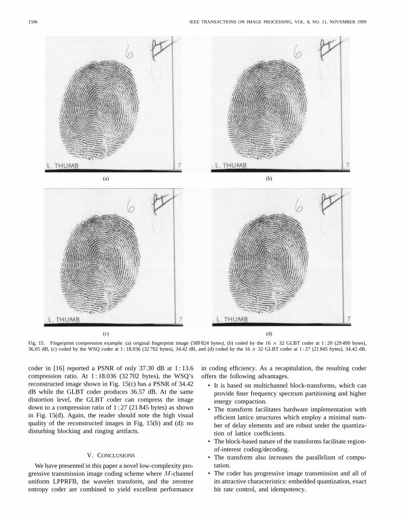
As previously mentioned, the improvement over waveletskeys on the lapped transform’s ability to capture and separatelocalized signal components in the frequency domain. In thespatial domain, this corresponds to images with directionalrepetitive texture patterns. To illustrate this point, the lapped-transform-based coder is compared against the FBI waveletscalar quantization (WSQ) standard [30]. When the original768 768 gray-scale fingerprint image shown in Fig. 15(a)is compressed at 1 : 13.6 (43 366 bytes) by the WSQ coder,Bradley et al. reported a PSNR of 36.05 dB. Using the16 32 GLBT in Fig. 10(b), a PSNR of 38.09 dB can beachieved at the same compression ratio. At the same levelof PSNR, the GLBT coder can compress the image down to1 : 20 where the reconstructed image is shown in Fig. 15(b).To put this in perspective, the wavelet-packet-based SFQ
1506 IEEE TRANSACTIONS ON IMAGE PROCESSING, VOL. 8, NO. 11, NOVEMBER 1999
(a) (b)
(c) (d)
Fig. 15. Fingerprint compression example: (a) original fingerprint image (589 824 bytes), (b) coded by the 16� 32 GLBT coder at 1 : 20 (29 490 bytes),36.05 dB, (c) coded by the WSQ coder at 1 : 18.036 (32 702 bytes), 34.42 dB, and (d) coded by the 16� 32 GLBT coder at 1 : 27 (21 845 bytes), 34.42 dB.
coder in [16] reported a PSNR of only 37.30 dB at 1 : 13.6compression ratio. At 1 : 18.036 (32 702 bytes), the WSQ’sreconstructed image shown in Fig. 15(c) has a PSNR of 34.42dB while the GLBT coder produces 36.57 dB. At the samedistortion level, the GLBT coder can compress the imagedown to a compression ratio of 1 : 27 (21 845 bytes) as shownin Fig. 15(d). Again, the reader should note the high visualquality of the reconstructed images in Fig. 15(b) and (d): nodisturbing blocking and ringing artifacts.
V. CONCLUSIONS
We have presented in this paper a novel low-complexity pro-gressive transmission image coding scheme where-channeluniform LPPRFB, the wavelet transform, and the zerotreeentropy coder are combined to yield excellent performance
in coding efficiency. As a recapitulation, the resulting coderoffers the following advantages.
• It is based on multichannel block-transforms, which canprovide finer frequency spectrum partitioning and higherenergy compaction.
• The transform facilitates hardware implementation withefficient lattice structures which employ a minimal num-ber of delay elements and are robust under the quantiza-tion of lattice coefficients.
• The block-based nature of the transforms facilitate region-of-interest coding/decoding.
• The transform also increases the parallelism of compu-tation.
• The coder has progressive image transmission and all ofits attractive characteristics: embedded quantization, exactbit rate control, and idempotency.
TRAN AND NGUYEN: PROGRESSIVE TRANSMISSION IMAGE CODER 1507
• It provides high subjective and objective performance,outperforms consistently the best progressive coders pub-lished recently in literature by a wide margin.
REFERENCES
[1] J. M. Shapiro, “Embedded image coding using zerotrees of waveletcoefficients,” IEEE Trans. Signal Processing,vol. 41, pp. 3445–3462,Dec. 1993.
[2] A. Said and W. A. Pearlman, “A new fast and efficient image codecbased on set partitioning in hierarchical trees,”IEEE Trans. CircuitsSyst. Video Technol.,vol. 6, pp. 243–250, June 1996.
[3] “Compression with reversible embedded wavelets,” RICOH Co. Ltd.,submission to ISO/IEC JTC1/SC29/WG1 for the JTC1.29.12 work item,1995. Available at: http://www.crc.ricoh.com/CREW.
[4] Z. Xiong, K. Ramchandran, and M. T. Orchard, “Space-frequencyquantization for wavelet image coding,”IEEE Trans. Image Processing,vol. 6, pp. 677–693, May 1997.
[5] W. B. Pennebaker and J. L. Mitchell,JPEG: Still Image CompressionStandard. New York: Van Nostrand Reinhold, 1993.
[6] K. R. Rao and P. Yip,Discrete Cosine Transform: Algorithms, Advan-tages, Applications. New York: Academic, 1990.
[7] H. S. Malvar,Signal Processing with Lapped Transforms.Boston, MA:Artech House, 1992.
[8] , “Biorthogonal and nonuniform lapped transforms for transformcoding with reduced blocking and ringing artifacts,”IEEE Trans. SignalProcessing, Spec. Issue Multirate Syst., Filter Banks, Wavelets, Applicat.,vol. 46, pp. 1043–1053, Apr. 1998.
[9] A. Soman, P. P. Vaidyanathan, and T. Q. Nguyen, “Linear phaseparaunitary filter banks,”IEEE Trans. Signal Processing,vol. 41, pp.3480–3496, Dec. 1993.
[10] R. L. de Queiroz, T. Q. Nguyen, and K. R. Rao, “The GenLOT:Generalized linear-phase lapped orthogonal transform,”IEEE Trans.Signal Processing,vol. 40, pp. 497–507, Mar. 1996.
[11] T. D. Tran and T. Q. Nguyen, “OnM -channel linear-phase FIR filterbanks and application in image compression,”IEEE Trans. SignalProcessing,vol. 45, pp. 2175–2187, Sept. 1997.
[12] S. C. Chan, “The generalized lapped transform (GLT) for subbandcoding applications,” inProc. IEEE Int. Conf. Acoustics, Speech, SignalProcessing,Detroit, MI, May 1995.
[13] T. D. Tran, R. de Queiroz, and T. Q. Nguyen, “The generalized lappedbiorthogonal transform,” inProc. IEEE Int. Conf. Acoustics, Speech, andSignal Processing,Seattle, WA, May 1997.
[14] , “Linear phase perfect reconstruction filter bank: Lattice struc-ture, design, and application in image coding,”IEEE Trans. SignalProcessing,to be published.
[15] S. Trautmann and T. Q. Nguyen, “GenLOT—Design and applicationfor transform-based image coding,” inProc. Asilomar Conf.,1995.
[16] Z. Xiong, K. Ramchandran, and M. T. Orchard, “Wavelet packetsimage coding using space-frequency quantization,”IEEE Trans. ImageProcessing,vol. 7, pp. 892–898, June 1998.
[17] P. P. Vaidyanathan,Multirate Systems and Filter Banks.EnglewoodCliffs, NJ: Prentice-Hall, 1993.
[18] G. Strang and T. Q. Nguyen,Wavelets and Filter Banks.Cambridge,MA: Wellesley-Cambridge, 1996.
[19] M. Vetterli and J. Kovacevic,Wavelets and Subband Coding.Engle-wood Cliffs, NJ: Prentice-Hall, 1995.
[20] P. N. Topiwala, Ed.,Wavelet Image and Video Compression.Boston,MA: Kluwer, June 1998.
[21] R. A. DeVore, B. Jawerth, and B. J. Lucier, “Image compression throughwavelet transform coding,”IEEE Trans. Inform. Theory,vol. 38, pp.719–746, Mar. 1992.
[22] M. Rabbani and P. W. Jones,Digital Image Compression Techniques.Bellingham, WA: SPIE, 1991.
[23] Z. Xiong, O. Guleryuz, and M. T. Orchard, “A DCT-based embeddedimage coder,”IEEE Signal Processing Lett.,vol. 3, pp. 289–290, Nov.1996.
[24] T. A. Ramstad, S. O. Aase, and J. H. Husoy,Subband Compression ofImages: Principles and Examples.New York: Elsevier, 1995.
[25] J. Katto and Y. Yasuda, “Performance evaluation of subband coding andoptimization of its filter coefficients,”SPIE Proc. Vis. Commun. ImageProcess.,1991.
[26] M. Ikehara, T. D. Tran, and T. Q. Nguyen, “Linear phase paraunitaryfilter banks with unequal-length filters,” inProc. IEEE Int. Conf. onImage Processing,Santa Barbara, CA, Oct. 1997.
[27] T. D. Tran, M. Ikehara, and T. Q. Nguyen, “Linear phase paraunitaryfilter bank with variable-length filters and its application in imagecompression,”IEEE Trans. Signal Processing,vol. 47, pp. 2730–2744,Oct. 1999.
[28] T. D. Tran, R. de Queiroz, and T. Q. Nguyen, “Variable-length gener-alized lapped biorthogonal transform,” inProc. IEEE Int. Conf. ImageProcessing,Chicago, IL, Oct. 1998.
[29] M. Antonini, M. Barlaud, P. Mathieu, and I. Daubechies, “Image codingusing the wavelet transform,”IEEE Trans. Image Processing,vol. 1, pp.205–220, Jan. 1992.
[30] J. N. Bradley, C. M. Brislawn, and T. Hopper, “The FBI wavelet/scalarquantization standard for gray-scale fingerprint image compression,” inProc. VCIP,Orlando, FL, Apr. 1993.
Trac D. Tran received the B.S. and M.S. degreesfrom the Massachusetts Institute of Technology,Cambridge, in 1994, and the Ph.D. degree from theUniversity of Wisconsin, Madison, WI, in 1998, allin electrical engineering.
He joined the faculty of The Johns HopkinsUniversity, Baltimore, MD, in July 1998, as an As-sistant Professor in the Department of Electrical andComputer Engineering. His research interests are inthe field of digital signal processing, particularly inmultirate systems, filterbanks, wavelets, and their
applications in signal representation, compression, and processing.
Truong Q. Nguyen received the B.S., M.S., and Ph.D. degrees in electricalengineering from the California Institute of Technology, Pasadena, in 1985,1986, and 1989, respectively.
He was with Massachusetts Institute of Technology (MIT) Lincoln Labora-tory from June 1989 to July 1994, as Member of Technical Staff. Duringthe academic year 1993–1994, he was a visiting lecturer at MIT and anAdjunct Professor at Northeastern University, Boston, MA. He was with theElectrical and Computer Engineering Department, University of Wisconsin,Madison, from August 1994 to April 1998. Since July 1996, he has beenwith the Electrical and Computer Engineering Department Department, BostonUniversity. His research interests are in digital and image signal processing,image and video compression, multirate systems, wavelets and applications,biomedical signal processing, filter design, and A/D converter. He is thecoauthor (with Prof. G. Strang) of the textbookWavelets and Filter Banks(Wellesley, MA: Cambridge Wellesley Press).
Prof. Nguyen was an Associate Editor for the IEEE TRANSACTIONS ON
SIGNAL PROCESSINGand for the IEEE TRANSACTIONS ONCIRCUITS AND SYSTEMS
II. He was a recipient of a fellowship from Aerojet Dynamics for advancedstudies. He received the IEEE TRANSACTIONS ON SIGNAL PROCESSINGPaperAward (image and multidimensional processing area) for the paper he co-authored (with P. P. Vaidyanathan) on linear-phase perfect-reconstructionfilterbanks (1992). He received the NSF Career Award in 1995. He servedon the DSP Technical Committee for the CAS Society. He is a member ofTau Beta Pi, Eta Kappa Nu, and Sigma Xi.
Copyright © 2022 FDOKUMEN