The History of a Falsified Mesoamerican Pictorial Manuscript
Upload
khangminh22Category
view
2download
0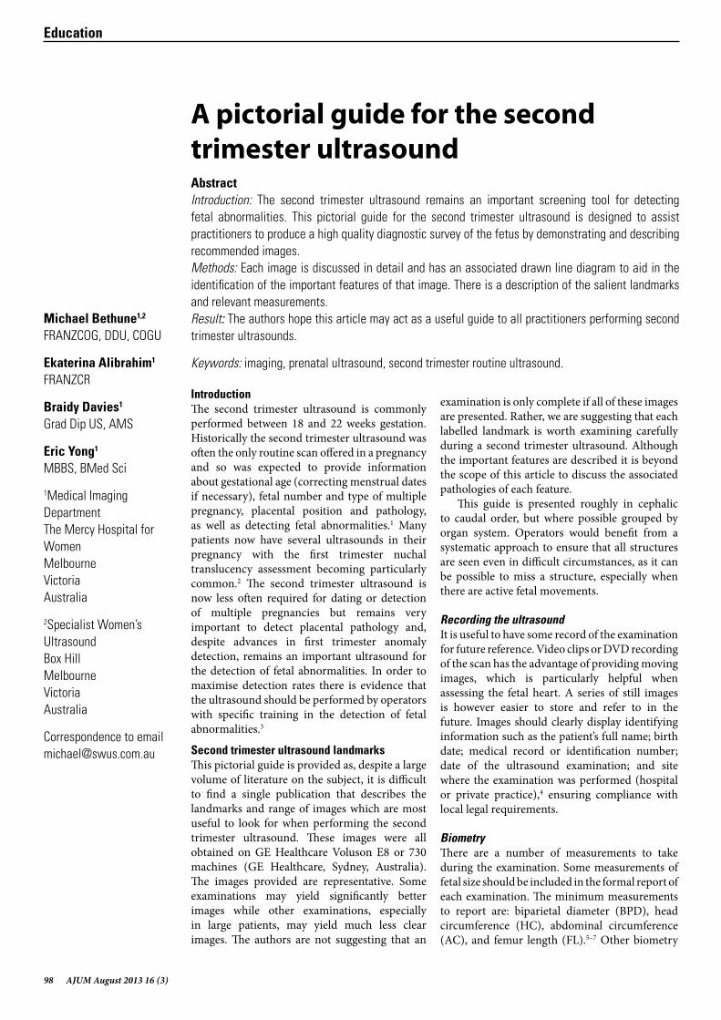
98 AJUM August 2013 16 (3)
Education
IntroductionThe second trimester ultrasound is commonly performed between 18 and 22 weeks gestation. Historically the second trimester ultrasound was often the only routine scan offered in a pregnancy and so was expected to provide information about gestational age (correcting menstrual dates if necessary), fetal number and type of multiple pregnancy, placental position and pathology, as well as detecting fetal abnormalities.1 Many patients now have several ultrasounds in their pregnancy with the first trimester nuchal translucency assessment becoming particularly common.2 The second trimester ultrasound is now less often required for dating or detection of multiple pregnancies but remains very important to detect placental pathology and, despite advances in first trimester anomaly detection, remains an important ultrasound for the detection of fetal abnormalities. In order to maximise detection rates there is evidence that the ultrasound should be performed by operators with specific training in the detection of fetal abnormalities.3
Second trimester ultrasound landmarksThis pictorial guide is provided as, despite a large volume of literature on the subject, it is difficult to find a single publication that describes the landmarks and range of images which are most useful to look for when performing the second trimester ultrasound. These images were all obtained on GE Healthcare Voluson E8 or 730 machines (GE Healthcare, Sydney, Australia). The images provided are representative. Some examinations may yield significantly better images while other examinations, especially in large patients, may yield much less clear images. The authors are not suggesting that an
Michael Bethune1,2 FRANZCOG, DDU, COGU
Ekaterina Alibrahim1
FRANZCR
Braidy Davies1 Grad Dip US, AMS
Eric Yong1 MBBS, BMed Sci
1Medical Imaging DepartmentThe Mercy Hospital for WomenMelbourneVictoriaAustralia
2Specialist Women’s Ultrasound Box Hill Melbourne VictoriaAustralia
Correspondence to email [email protected]
A pictorial guide for the second trimester ultrasoundAbstractIntroduction: The second trimester ultrasound remains an important screening tool for detecting fetal abnormalities. This pictorial guide for the second trimester ultrasound is designed to assist practitioners to produce a high quality diagnostic survey of the fetus by demonstrating and describing recommended images. Methods: Each image is discussed in detail and has an associated drawn line diagram to aid in the identification of the important features of that image. There is a description of the salient landmarks and relevant measurements. Result: The authors hope this article may act as a useful guide to all practitioners performing second trimester ultrasounds.
Keywords: imaging, prenatal ultrasound, second trimester routine ultrasound.
examination is only complete if all of these images are presented. Rather, we are suggesting that each labelled landmark is worth examining carefully during a second trimester ultrasound. Although the important features are described it is beyond the scope of this article to discuss the associated pathologies of each feature.
This guide is presented roughly in cephalic to caudal order, but where possible grouped by organ system. Operators would benefit from a systematic approach to ensure that all structures are seen even in difficult circumstances, as it can be possible to miss a structure, especially when there are active fetal movements.
Recording the ultrasoundIt is useful to have some record of the examination for future reference. Video clips or DVD recording of the scan has the advantage of providing moving images, which is particularly helpful when assessing the fetal heart. A series of still images is however easier to store and refer to in the future. Images should clearly display identifying information such as the patient’s full name; birth date; medical record or identification number; date of the ultrasound examination; and site where the examination was performed (hospital or private practice),4 ensuring compliance with local legal requirements.
BiometryThere are a number of measurements to take during the examination. Some measurements of fetal size should be included in the formal report of each examination. The minimum measurements to report are: biparietal diameter (BPD), head circumference (HC), abdominal circumference (AC), and femur length (FL).5–7 Other biometry
AJUM August 2013 16 (3) 99
which could be reported include: humerus length (HL), nasal bone length (NB), nuchal fold (NF), cerebellar diameter (TCD), cisterna magna and cervical length. A combination of BPD and HC measurements can be used to calculate an estimated date of delivery (EDD).8
General scanning principlesMany machine pre-sets are a compromise of resolution and persistence and it is important to have a high resolution pre-set available. A separate pre-set with higher frame rates and higher contrast is useful for cardiac images. When taking images the structure of interest should occupy about 75% of the screen to maximise resolution. Write zoom (pre-acquisition) is the zoom mode of choice as it has higher resolution than read zoom (post acquisition).
Because of the risk of artefacts it is often useful to visualise the major structures in at least two planes. The measurement techniques recommended here are widely accepted techniques, however some charts may use different techniques and each operator should measure in accordance with the charts agreed within their own work place and population.
Amniotic fluid assessment is usually subjective9 but maximum vertical pocket or amniotic fluid Index (AFI) can be used if there is concern about excess or insufficient amniotic fluid.
Fetal movements should be observed and commented upon. It is essential to see flexion or extension of a limb at least once during the scanning process to reduce the chance of missing a case of arthrogryposis.10 Similarly the opening of the hands to exclude clenched fingers is important to rule out several syndromes.11
The fetal headThe standard axial fetal brain planes include the biparietal diameter, the transventricular plane and the cerebellar plane (Figures 1–3). Many of the fetal measurements are taken from these planes including the BPD and HC. Measurements of the Cerebellum, Cisterna Magna and Nuchal fold can be useful. Further images of the head which may add value include the mid sagittal plane to view mid line brain structures, coronal cerebellum and coronal face (Figures 4–6).
Figure 1: Biparietal diameter planeThis is a cross section of the fetal head obtained at the level of the thalami. The cerebellum, orbits and ears should not be visualised in this scanning plane. The falx should be positioned horizontal and equidistant from both parietal bones to avoid acynclitism (head tilted to one side). The operator should look for a symmetrical appearance to both hemispheres. The continuous midline echo representing the falx is broken in the anterior third by the cavum septum pellucidum (CSP). Behind this in the middle of the falx a thin slit representing the third ventricle is often visible.
The BPD measurement is obtained from outer skull bone to inner skull bone (leading edge to leading edge), perpendicular to the falx at the maximum diameter.12 The HC is measured as an ellipse around the outside of the skull bones. Both of these measurements can be used to confirm gestational age. A head circumference measuring less than 3 standard deviations from the mean may indicate microcephaly.13
Slight gaps in the echogenic skull bone outline are evident and represent the skull sutures. There should be a normal oval skull shape with no depression of the petrous temporal bones and no angulation near the sutures. The normal bone density of the skull should be more echogenic than the falx.
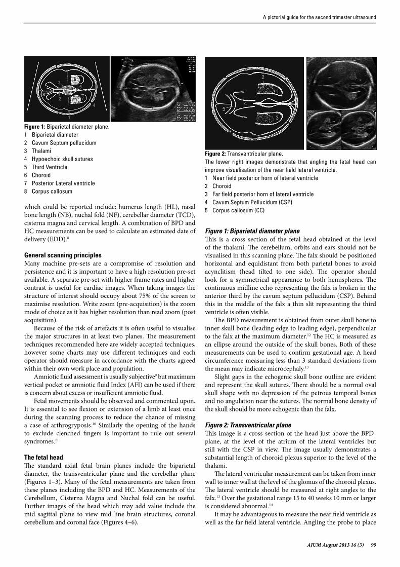
Figure 2: Transventricular planeThis image is a cross-section of the head just above the BPD-plane, at the level of the atrium of the lateral ventricles but still with the CSP in view. The image usually demonstrates a substantial length of choroid plexus superior to the level of the thalami.
The lateral ventricular measurement can be taken from inner wall to inner wall at the level of the glomus of the choroid plexus. The lateral ventricle should be measured at right angles to the falx.12 Over the gestational range 15 to 40 weeks 10 mm or larger is considered abnormal.14
It may be advantageous to measure the near field ventricle as well as the far field lateral ventricle. Angling the probe to place
Figure 1: Biparietal diameter plane.1 Biparietal diameter2 Cavum Septum pellucidum3 Thalami4 Hypoechoic skull sutures5 Third Ventricle6 Choroid7 Posterior Lateral ventricle8 Corpus callosum
Figure 2: Transventricular plane.The lower right images demonstrate that angling the fetal head can improve visualisation of the near field lateral ventricle.1 Near field posterior horn of lateral ventricle2 Choroid3 Far field posterior horn of lateral ventricle4 Cavum Septum Pellucidum (CSP)5 Corpus callosum (CC)
A pictorial guide for the second trimester ultrasound
100 AJUM August 2013 16 (3)
the falx at ~15° to horizontal may facilitate visualisation of the near field ventricle.
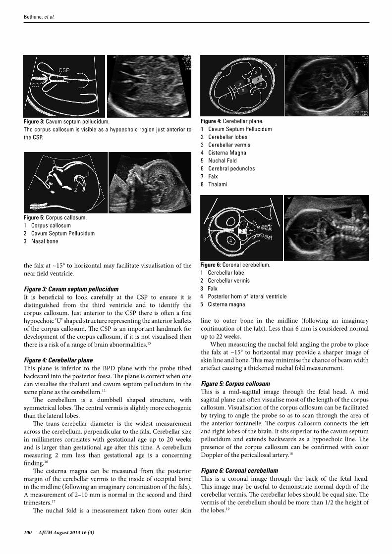
Figure 3: Cavum septum pellucidumIt is beneficial to look carefully at the CSP to ensure it is distinguished from the third ventricle and to identify the corpus callosum. Just anterior to the CSP there is often a fine hypoechoic ‘U’ shaped structure representing the anterior leaflets of the corpus callosum. The CSP is an important landmark for development of the corpus callosum, if it is not visualised then there is a risk of a range of brain abnormalities.15
Figure 4: Cerebellar planeThis plane is inferior to the BPD plane with the probe tilted backward into the posterior fossa. The plane is correct when one can visualise the thalami and cavum septum pellucidum in the same plane as the cerebellum.12
The cerebellum is a dumbbell shaped structure, with symmetrical lobes. The central vermis is slightly more echogenic than the lateral lobes.
The trans-cerebellar diameter is the widest measurement across the cerebellum, perpendicular to the falx. Cerebellar size in millimetres correlates with gestational age up to 20 weeks and is larger than gestational age after this time. A cerebellum measuring 2 mm less than gestational age is a concerning finding.16
The cisterna magna can be measured from the posterior margin of the cerebellar vermis to the inside of occipital bone in the midline (following an imaginary continuation of the falx). A measurement of 2–10 mm is normal in the second and third trimesters.17
The nuchal fold is a measurement taken from outer skin
line to outer bone in the midline (following an imaginary continuation of the falx). Less than 6 mm is considered normal up to 22 weeks.
When measuring the nuchal fold angling the probe to place the falx at ~15° to horizontal may provide a sharper image of skin line and bone. This may minimise the chance of beam width artefact causing a thickened nuchal fold measurement.
Figure 5: Corpus callosumThis is a mid-sagittal image through the fetal head. A mid sagittal plane can often visualise most of the length of the corpus callosum. Visualisation of the corpus callosum can be facilitated by trying to angle the probe so as to scan through the area of the anterior fontanelle. The corpus callosum connects the left and right lobes of the brain. It sits superior to the cavum septum pellucidum and extends backwards as a hypoechoic line. The presence of the corpus callosum can be confirmed with color Doppler of the pericallosal artery.18
Figure 6: Coronal cerebellumThis is a coronal image through the back of the fetal head. This image may be useful to demonstrate normal depth of the cerebellar vermis. The cerebellar lobes should be equal size. The vermis of the cerebellum should be more than 1/2 the height of the lobes.19
Figure 3: Cavum septum pellucidum.The corpus callosum is visible as a hypoechoic region just anterior to the CSP.
Figure 4: Cerebellar plane.1 Cavum Septum Pellucidum2 Cerebellar lobes3 Cerebellar vermis4 Cisterna Magna5 Nuchal Fold6 Cerebral peduncles7 Falx8 Thalami
Figure 5: Corpus callosum.1 Corpus callosum2 Cavum Septum Pellucidum3 Nasal bone
Figure 6: Coronal cerebellum.1 Cerebellar lobe2 Cerebellar vermis3 Falx4 Posterior horn of lateral ventricle5 Cisterna magna
Bethune, et al.
AJUM August 2013 16 (3) 101
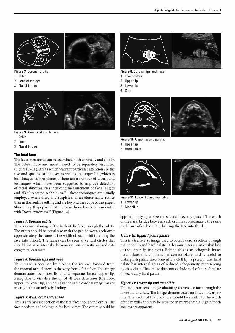
The fetal faceThe facial structures can be examined both coronally and axially. The orbits, nose and mouth need to be separately visualised (Figures 7–11). Areas which warrant particular attention are the size and spacing of the eyes as well as the upper lip (which is best imaged in two planes). There are a number of ultrasound techniques which have been suggested to improve detection of facial abnormalities including measurement of facial angles and 3D ultrasound techniques,20,21 these techniques are usually employed when there is a suspicion of an abnormality rather than in the routine setting and are beyond the scope of this paper. Shortening (hypoplasia) of the nasal bone has been associated with Down syndrome22 (Figure 12).
Figure 7: Coronal orbitsThis is a coronal image of the back of the face, through the orbits. The orbits should be equal size with the gap between each orbit approximately the same as the width of each orbit (dividing the face into thirds). The lenses can be seen as central circles that should not have internal echogenicity. Lens opacity may indicate congenital cataracts.
Figure 8: Coronal lips and noseThis image is obtained by moving the scanner forward from the coronal orbital view to the very front of the face. This image demonstrates two nostrils and a separate intact upper lip. Being able to visualise the tip of all four structures (the nose, upper lip, lower lip, and chin) in the same coronal image makes micrognathia an unlikely finding.
Figure 9: Axial orbit and lensesThis is a transverse section of the fetal face though the orbits. The face needs to be looking up for best views. The orbits should be
approximately equal size and should be evenly spaced. The width of the nasal bridge between each orbit is approximately the same as the size of each orbit – dividing the face into thirds.
Figure 10: Upper lip and palateThis is a transverse image used to obtain a cross section through the upper lip and hard palate. It demonstrates an intact skin line of the upper lip (no cleft). Behind this is an echogenic intact hard palate; this confirms the correct plane, and is useful to distinguish palate involvement if a cleft lip is present. The hard palate has internal areas of reduced echogenicity representing tooth sockets. This image does not exclude cleft of the soft palate or secondary hard palate.
Figure 11: Lower lip and mandibleThis is a transverse image obtaining a cross section through the lower lip and jaw. The image demonstrates an intact lower jaw line. The width of the mandible should be similar to the width of the maxilla and may be reduced in micrognathia. Again tooth sockets are apparent.
Figure 7: Coronal Orbits.1 Orbit2 Lens of the eye3 Nasal bridge
Figure 8: Coronal lips and nose1 Two nostrils2 Upper lip3 Lower lip4 Chin
Figure 9: Axial orbit and lenses.1 Orbit2 Lens3 Nasal bridge
Figure 10: Upper lip and palate.1 Upper lip2 Hard palate.
Figure 11: Lower lip and mandible.1 Lower lip2 Mandible
A pictorial guide for the second trimester ultrasound
102 AJUM August 2013 16 (3)
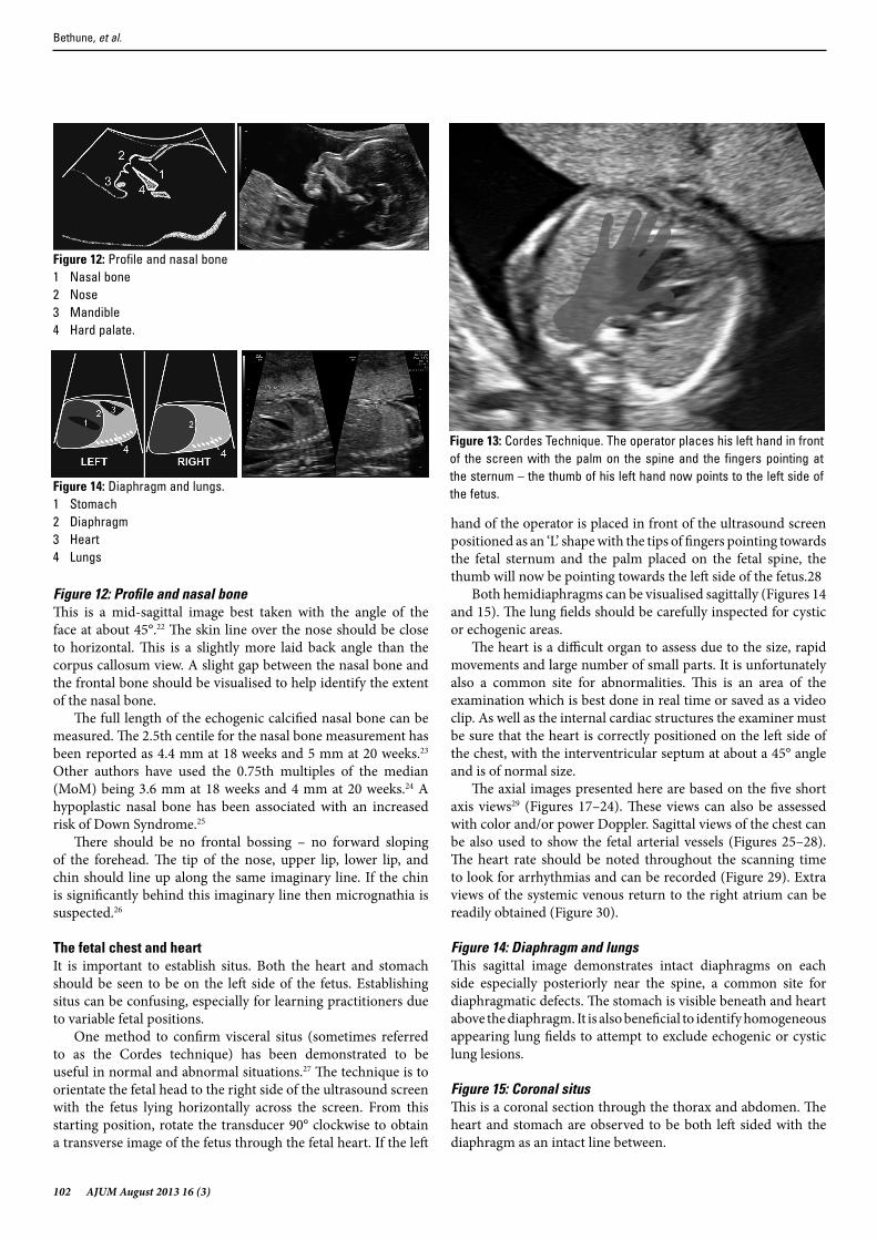
Figure 12: Profile and nasal boneThis is a mid-sagittal image best taken with the angle of the face at about 45°.22 The skin line over the nose should be close to horizontal. This is a slightly more laid back angle than the corpus callosum view. A slight gap between the nasal bone and the frontal bone should be visualised to help identify the extent of the nasal bone.
The full length of the echogenic calcified nasal bone can be measured. The 2.5th centile for the nasal bone measurement has been reported as 4.4 mm at 18 weeks and 5 mm at 20 weeks.23 Other authors have used the 0.75th multiples of the median (MoM) being 3.6 mm at 18 weeks and 4 mm at 20 weeks.24 A hypoplastic nasal bone has been associated with an increased risk of Down Syndrome.25
There should be no frontal bossing – no forward sloping of the forehead. The tip of the nose, upper lip, lower lip, and chin should line up along the same imaginary line. If the chin is significantly behind this imaginary line then micrognathia is suspected.26
The fetal chest and heartIt is important to establish situs. Both the heart and stomach should be seen to be on the left side of the fetus. Establishing situs can be confusing, especially for learning practitioners due to variable fetal positions.
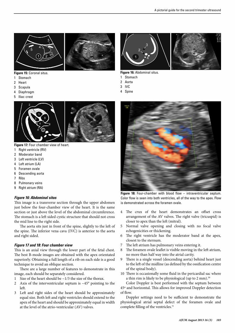
One method to confirm visceral situs (sometimes referred to as the Cordes technique) has been demonstrated to be useful in normal and abnormal situations.27 The technique is to orientate the fetal head to the right side of the ultrasound screen with the fetus lying horizontally across the screen. From this starting position, rotate the transducer 90° clockwise to obtain a transverse image of the fetus through the fetal heart. If the left
hand of the operator is placed in front of the ultrasound screen positioned as an ‘L’ shape with the tips of fingers pointing towards the fetal sternum and the palm placed on the fetal spine, the thumb will now be pointing towards the left side of the fetus.28
Both hemidiaphragms can be visualised sagittally (Figures 14 and 15). The lung fields should be carefully inspected for cystic or echogenic areas.
The heart is a difficult organ to assess due to the size, rapid movements and large number of small parts. It is unfortunately also a common site for abnormalities. This is an area of the examination which is best done in real time or saved as a video clip. As well as the internal cardiac structures the examiner must be sure that the heart is correctly positioned on the left side of the chest, with the interventricular septum at about a 45° angle and is of normal size.
The axial images presented here are based on the five short axis views29 (Figures 17–24). These views can also be assessed with color and/or power Doppler. Sagittal views of the chest can be also used to show the fetal arterial vessels (Figures 25–28). The heart rate should be noted throughout the scanning time to look for arrhythmias and can be recorded (Figure 29). Extra views of the systemic venous return to the right atrium can be readily obtained (Figure 30).
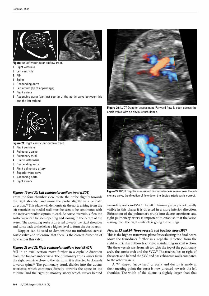
Figure 14: Diaphragm and lungsThis sagittal image demonstrates intact diaphragms on each side especially posteriorly near the spine, a common site for diaphragmatic defects. The stomach is visible beneath and heart above the diaphragm. It is also beneficial to identify homogeneous appearing lung fields to attempt to exclude echogenic or cystic lung lesions.
Figure 15: Coronal situsThis is a coronal section through the thorax and abdomen. The heart and stomach are observed to be both left sided with the diaphragm as an intact line between.
Figure 12: Profile and nasal bone1 Nasal bone2 Nose3 Mandible4 Hard palate.
Figure 13: Cordes Technique. The operator places his left hand in front of the screen with the palm on the spine and the fingers pointing at the sternum – the thumb of his left hand now points to the left side of the fetus.Figure 14: Diaphragm and lungs.
1 Stomach2 Diaphragm3 Heart4 Lungs
Bethune, et al.
AJUM August 2013 16 (3) 103
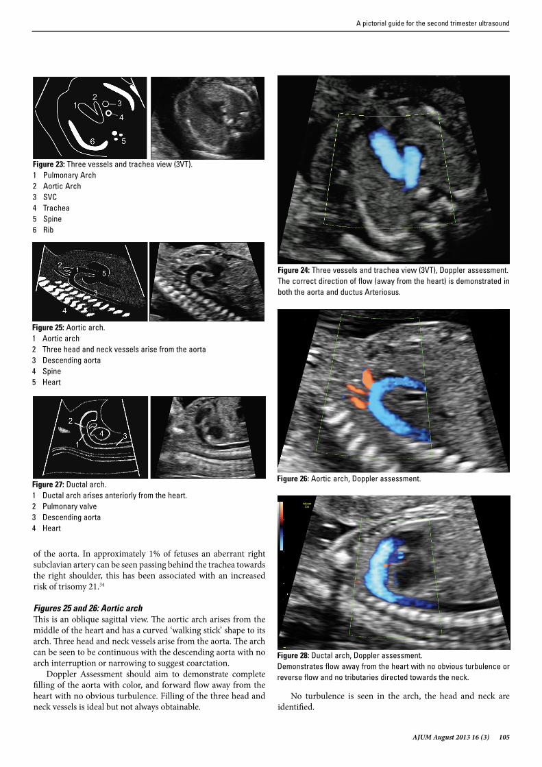
Figure 16: Abdominal situsThis image is a transverse section through the upper abdomen just below the four-chamber view of the heart. It is the same section or just above the level of the abdominal circumference. The stomach is a left sided cystic structure that should not cross the mid line to the right side.
The aorta sits just in front of the spine, slightly to the left of the spine. The inferior vena cava (IVC) is anterior to the aorta and right sided.
Figure 17 and 18: Four chamber viewThis is an axial view through the lower part of the fetal chest. The best B-mode images are obtained with the apex orientated superiorly. Obtaining a full length of a rib on each side is a good technique to avoid an oblique section.
There are a large number of features to demonstrate in this image, each should be separately considered.1 Size of the heart should be ~1/3 the size of the thorax.2 Axis of the interventricular septum is ~45° pointing to the
left.3 Left and right sides of the heart should be approximately
equal size. Both left and right ventricles should extend to the apex of the heart and should be approximately equal in width at the level of the atrio-ventricular (AV) valves.
4 The crux of the heart demonstrates an offset cross arrangement of the AV valves. The right valve (tricuspid) is closer to apex than the left (mitral).
5 Normal valve opening and closing with no focal valve echogenicities or thickening.
6 The right ventricle has the moderator band at the apex, closest to the sternum.
7 The left atrium has pulmonary veins entering it.8 The foramen ovale leaflet is visible moving in the left atrium,
no more than half way into the atrial cavity.9 There is a single vessel (descending aorta) behind heart just
to the left of the midline (as defined by the ossification centre of the spinal body).
10 There is occasionally some fluid in the pericardial sac where a thin rim is likely to be physiological (up to 2 mm).30
Color Doppler is best performed with the septum between 45º and horizontal. This allows for improved Doppler detection of flow.
Doppler settings need to be sufficient to demonstrate the physiological atrial septal defect of the foramen ovale and complete filling of the ventricles.31
Figure 15: Coronal situs.1 Stomach2 Heart3 Scapula4 Diaphragm5 Iliac crest
Figure 16: Abdominal situs.1 Stomach2 Aorta3 IVC4 Spine
Figure 17: Four chamber view of heart.1 Right ventricle (RV)2 Moderator band3 Left ventricle (LV)4 Left atrium (LA)5 Foramen ovale6 Descending aorta7 Ribs8 Pulmonary veins9 Right atrium (RA)
Figure 18: Four-chamber with blood flow – intraventricular septum. Color flow is seen into both ventricles, all of the way to the apex. Flow is demonstrated across the foramen ovale.
A pictorial guide for the second trimester ultrasound
104 AJUM August 2013 16 (3)
Figures 19 and 20: Left ventricular outflow tract (LVOT)From the four chamber view rotate the probe slightly towards the right shoulder and move the probe slightly in a cephalic direction.32 This plane will demonstrate the aorta arising from the left ventricle; its medial wall must be seen to be continuous with the interventricular septum to exclude aortic override. Often the aortic valve can be seen opening and closing in the centre of the vessel. The ascending aorta is directed towards the right shoulder and turns back to the left at a higher level to form the aortic arch.
Doppler can be used to demonstrate no turbulence across aortic valve and to ensure that there is the correct direction of flow across this valve.
Figures 21 and 22: Right ventricular outflow tract (RVOT)Still in an axial section move further in a cephalic direction from the four-chamber view. The pulmonary trunk arises from the right ventricle close to the sternum, it is directed backwards towards spine.32 The pulmonary trunk divides into the ductus arteriosus which continues directly towards the spine in the midline; and the right pulmonary artery which curves behind
ascending aorta and SVC. The left pulmonary artery is not usually visible in this plane; it is directed in a more inferior direction. Bifurcation of the pulmonary trunk into ductus arteriosus and right pulmonary artery is important to establish that the vessel arising from the right ventricle is going to the lungs.
Figures 23 and 24: Three vessels and trachea view (3VT)This is the highest transverse plane for evaluating the fetal heart. Move the transducer further in a cephalic direction from the right ventricular outflow tract view, maintaining an axial section. The three vessels are, from left to right: the top of the pulmonary arch, the aortic arch and the SVC.33 The trachea lies to right of the aorta and behind the SVC and has echogenic walls compared to the other vessels.
A ‘V’ shaped ‘arrowhead’ of aorta and ductus is made at their meeting point; the aorta is now directed towards the left shoulder. The width of the ductus is slightly larger than that
Figure 19: Left ventricular outflow tract.1 Right ventricle2 Left ventricle3 Rib4 Spine5 Descending aorta6 Left atrium (tip of appendage)7 Right atrium8 Ascending aorta (can just see tip of the aortic valve between this
and the left atrium)
Figure 20: LVOT Doppler assessment. Forward flow is seen across the aortic valve with no obvious turbulence.
Figure 21: Right ventricular outflow tract.1 Right ventricle2 Pulmonary valve3 Pulmonary trunk4 Ductus arteriosus5 Descending aorta6 Right pulmonary artery7 Superior vena cava8 Ascending aorta9 Right atrium
Figure 22: RVOT Doppler assessment. No turbulence is seen across the pul-monary valve, the direction of flow down the ductus arteriosus is correct.
Bethune, et al.
AJUM August 2013 16 (3) 105
of the aorta. In approximately 1% of fetuses an aberrant right subclavian artery can be seen passing behind the trachea towards the right shoulder, this has been associated with an increased risk of trisomy 21.34
Figures 25 and 26: Aortic archThis is an oblique sagittal view. The aortic arch arises from the middle of the heart and has a curved ‘walking stick’ shape to its arch. Three head and neck vessels arise from the aorta. The arch can be seen to be continuous with the descending aorta with no arch interruption or narrowing to suggest coarctation.
Doppler Assessment should aim to demonstrate complete filling of the aorta with color, and forward flow away from the heart with no obvious turbulence. Filling of the three head and neck vessels is ideal but not always obtainable.
No turbulence is seen in the arch, the head and neck are identified.
Figure 23: Three vessels and trachea view (3VT).1 Pulmonary Arch2 Aortic Arch3 SVC4 Trachea5 Spine6 Rib
Figure 24: Three vessels and trachea view (3VT), Doppler assessment.The correct direction of flow (away from the heart) is demonstrated in both the aorta and ductus Arteriosus.
Figure 25: Aortic arch.1 Aortic arch2 Three head and neck vessels arise from the aorta3 Descending aorta4 Spine5 Heart
Figure 26: Aortic arch, Doppler assessment.Figure 27: Ductal arch.1 Ductal arch arises anteriorly from the heart.2 Pulmonary valve3 Descending aorta4 Heart
Figure 28: Ductal arch, Doppler assessment.Demonstrates flow away from the heart with no obvious turbulence or reverse flow and no tributaries directed towards the neck.
A pictorial guide for the second trimester ultrasound
106 AJUM August 2013 16 (3)
Figures 27 and 28: Ductal archThis is a mid-sagittal view of the fetal chest, best obtained with the fetus lying supine. Shadowing from the spine can make this a difficult view to obtain when the fetus is prone. The ductal arch is directed straight back towards the spine with no head and neck vessels arising from it. The ductus arteriosus is continuous with the descending aorta. In contrast to the curved appearance of the aortic arch there is a straight ‘hockey stick’ appearance to the ductal arch. The pulmonary valve can often be visualised opening and closing. No head or neck vessels can be seen arising from this arch.
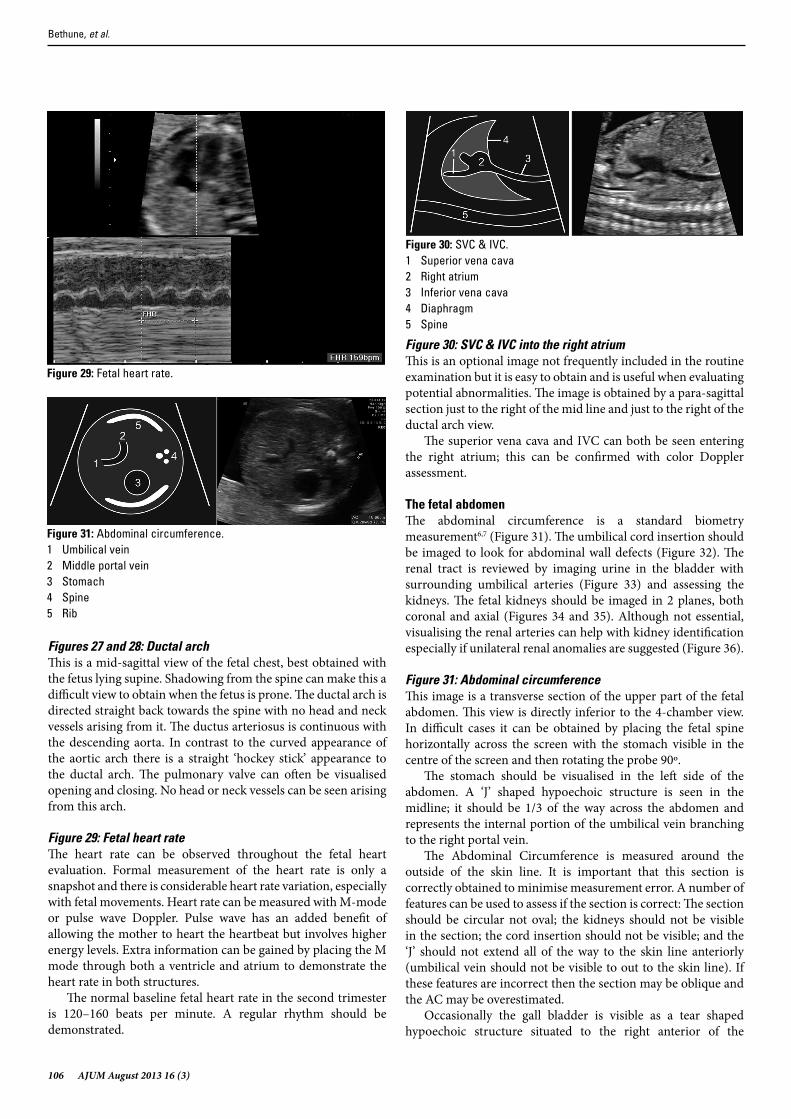
Figure 29: Fetal heart rateThe heart rate can be observed throughout the fetal heart evaluation. Formal measurement of the heart rate is only a snapshot and there is considerable heart rate variation, especially with fetal movements. Heart rate can be measured with M-mode or pulse wave Doppler. Pulse wave has an added benefit of allowing the mother to heart the heartbeat but involves higher energy levels. Extra information can be gained by placing the M mode through both a ventricle and atrium to demonstrate the heart rate in both structures.
The normal baseline fetal heart rate in the second trimester is 120–160 beats per minute. A regular rhythm should be demonstrated.
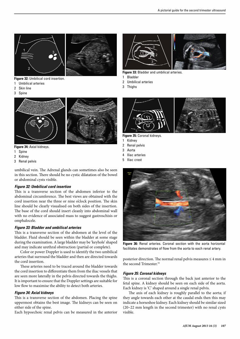
Figure 30: SVC & IVC into the right atriumThis is an optional image not frequently included in the routine examination but it is easy to obtain and is useful when evaluating potential abnormalities. The image is obtained by a para-sagittal section just to the right of the mid line and just to the right of the ductal arch view.
The superior vena cava and IVC can both be seen entering the right atrium; this can be confirmed with color Doppler assessment.
The fetal abdomenThe abdominal circumference is a standard biometry measurement6,7 (Figure 31). The umbilical cord insertion should be imaged to look for abdominal wall defects (Figure 32). The renal tract is reviewed by imaging urine in the bladder with surrounding umbilical arteries (Figure 33) and assessing the kidneys. The fetal kidneys should be imaged in 2 planes, both coronal and axial (Figures 34 and 35). Although not essential, visualising the renal arteries can help with kidney identification especially if unilateral renal anomalies are suggested (Figure 36).
Figure 31: Abdominal circumferenceThis image is a transverse section of the upper part of the fetal abdomen. This view is directly inferior to the 4-chamber view. In difficult cases it can be obtained by placing the fetal spine horizontally across the screen with the stomach visible in the centre of the screen and then rotating the probe 90º.
The stomach should be visualised in the left side of the abdomen. A ‘J’ shaped hypoechoic structure is seen in the midline; it should be 1/3 of the way across the abdomen and represents the internal portion of the umbilical vein branching to the right portal vein.
The Abdominal Circumference is measured around the outside of the skin line. It is important that this section is correctly obtained to minimise measurement error. A number of features can be used to assess if the section is correct: The section should be circular not oval; the kidneys should not be visible in the section; the cord insertion should not be visible; and the ‘J’ should not extend all of the way to the skin line anteriorly (umbilical vein should not be visible to out to the skin line). If these features are incorrect then the section may be oblique and the AC may be overestimated.
Occasionally the gall bladder is visible as a tear shaped hypoechoic structure situated to the right anterior of the
Figure 29: Fetal heart rate.
Figure 30: SVC & IVC.1 Superior vena cava2 Right atrium3 Inferior vena cava4 Diaphragm5 Spine
Figure 31: Abdominal circumference.1 Umbilical vein2 Middle portal vein3 Stomach4 Spine5 Rib
Bethune, et al.
AJUM August 2013 16 (3) 107
umbilical vein. The Adrenal glands can sometimes also be seen in this section. There should be no cystic dilatation of the bowel or abdominal cysts visible.
Figure 32: Umbilical cord insertionThis is a transverse section of the abdomen inferior to the abdominal circumference. The best views are obtained with the cord insertion near the three or nine o’clock position. The skin line should be clearly visualised on both sides of the insertion. The base of the cord should insert cleanly into abdominal wall with no evidence of associated mass to suggest gastroschisis or omphalocele.
Figure 33: Bladder and umbilical arteriesThis is a transverse section of the abdomen at the level of the bladder. Fluid should be seen within the bladder at some stage during the examination. A large bladder may be ‘keyhole’ shaped and may indicate urethral obstruction (partial or complete).
Color or power Doppler is used to identify the two umbilical arteries that surround the bladder and then are directed towards the cord insertion.
These arteries need to be traced around the bladder towards the cord insertion to differentiate them from the iliac vessels that are seen more laterally in the pelvis directed towards the thighs. It is important to ensure that the Doppler settings are suitable for low flow to maximise the ability to detect both arteries.
Figure 34: Axial kidneysThis is a transverse section of the abdomen. Placing the spine uppermost obtains the best image. The kidneys can be seen on either side of the spine. Each hypoechoic renal pelvis can be measured in the anterior
posterior direction. The normal renal pelvis measures ≤ 4 mm in the second Trimester.35
Figure 35: Coronal kidneysThis is a coronal section through the back just anterior to the fetal spine. A kidney should be seen on each side of the aorta. Each kidney is ‘C’ shaped around a single renal pelvis.
The axis of each kidney is roughly parallel to the aorta; if they angle towards each other at the caudal ends then this may indicate a horseshoe kidney. Each kidney should be similar sized (20–22 mm length in the second trimester) with no renal cysts visible.
Figure 32: Umbilical cord insertion.1 Umbilical arteries2 Skin line3 Spine
Figure 33: Bladder and umbilical arteries.1 Bladder2 Umbilical arteries3 Thighs
Figure 34: Axial kidneys.1 Spine2 Kidney3 Renal pelvis
Figure 35: Coronal kidneys.1 Kidney2 Renal pelvis3 Aorta4 Iliac arteries5 Iliac crest
Figure 36: Renal arteries. Coronal section with the aorta horizontal facilitates demonstrates of flow from the aorta to each renal artery.
A pictorial guide for the second trimester ultrasound
108 AJUM August 2013 16 (3)
Figure 36: Renal arteriesThis is a coronal section through the back just anterior to the fetal spine, the same section as Coronal Kidneys. Low flow settings are needed to detect both arteries. The arteries should extend all of the way into the renal pelvis.
The fetal musculoskeletal systemIt is beneficial to image the fetal spine throughout its length and the spine is best imaged in three planes: coronal, sagittal and axial (Figures 37–40).
Each of the twelve long bones should be separately visualised (Figures 42–47). Although both femurs could be measured it is probably sufficient to only measure one provided both have been seen to be of similar lengths. When imaging the long bones the operator should ensure they are not angulated or bowed, that they are echogenic and are of an appropriate length. If there is doubt about long bone length then they can each be individually measured and checked against standardised charts.36 Hands and feet should be separately imaged taking particular care to ensure that both left and right sides are separately seen (Figures 45 and 48).
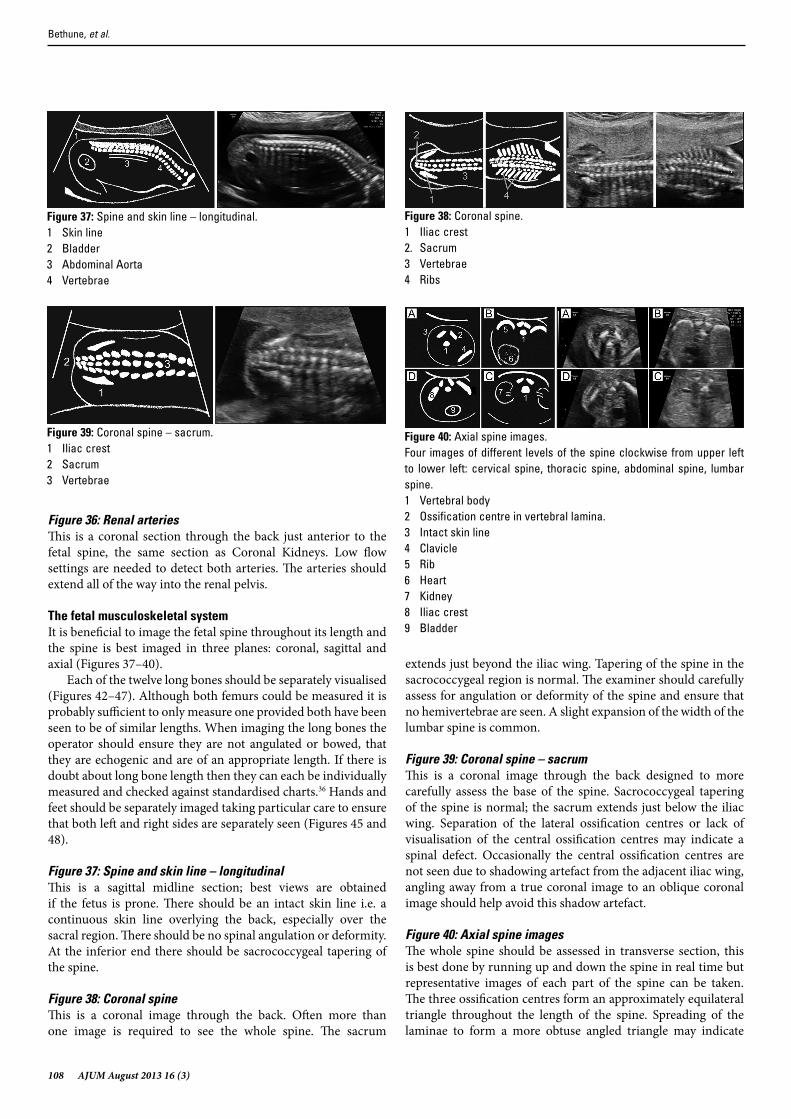
Figure 37: Spine and skin line – longitudinalThis is a sagittal midline section; best views are obtained if the fetus is prone. There should be an intact skin line i.e. a continuous skin line overlying the back, especially over the sacral region. There should be no spinal angulation or deformity. At the inferior end there should be sacrococcygeal tapering of the spine.
Figure 38: Coronal spineThis is a coronal image through the back. Often more than one image is required to see the whole spine. The sacrum
extends just beyond the iliac wing. Tapering of the spine in the sacrococcygeal region is normal. The examiner should carefully assess for angulation or deformity of the spine and ensure that no hemivertebrae are seen. A slight expansion of the width of the lumbar spine is common.
Figure 39: Coronal spine – sacrumThis is a coronal image through the back designed to more carefully assess the base of the spine. Sacrococcygeal tapering of the spine is normal; the sacrum extends just below the iliac wing. Separation of the lateral ossification centres or lack of visualisation of the central ossification centres may indicate a spinal defect. Occasionally the central ossification centres are not seen due to shadowing artefact from the adjacent iliac wing, angling away from a true coronal image to an oblique coronal image should help avoid this shadow artefact.
Figure 40: Axial spine imagesThe whole spine should be assessed in transverse section, this is best done by running up and down the spine in real time but representative images of each part of the spine can be taken. The three ossification centres form an approximately equilateral triangle throughout the length of the spine. Spreading of the laminae to form a more obtuse angled triangle may indicate
Figure 37: Spine and skin line – longitudinal.1 Skin line2 Bladder3 Abdominal Aorta4 Vertebrae
Figure 38: Coronal spine.1 Iliac crest2. Sacrum3 Vertebrae4 Ribs
Figure 39: Coronal spine – sacrum.1 Iliac crest2 Sacrum3 Vertebrae
Figure 40: Axial spine images.Four images of different levels of the spine clockwise from upper left to lower left: cervical spine, thoracic spine, abdominal spine, lumbar spine.1 Vertebral body2 Ossification centre in vertebral lamina.3 Intact skin line4 Clavicle5 Rib6 Heart7 Kidney8 Iliac crest9 Bladder
Bethune, et al.
AJUM August 2013 16 (3) 109
open spina bifida. The operator should look for an intact skin line over the spine throughout, taking particular attention to ensure that there are no cysts or masses visible on the back.
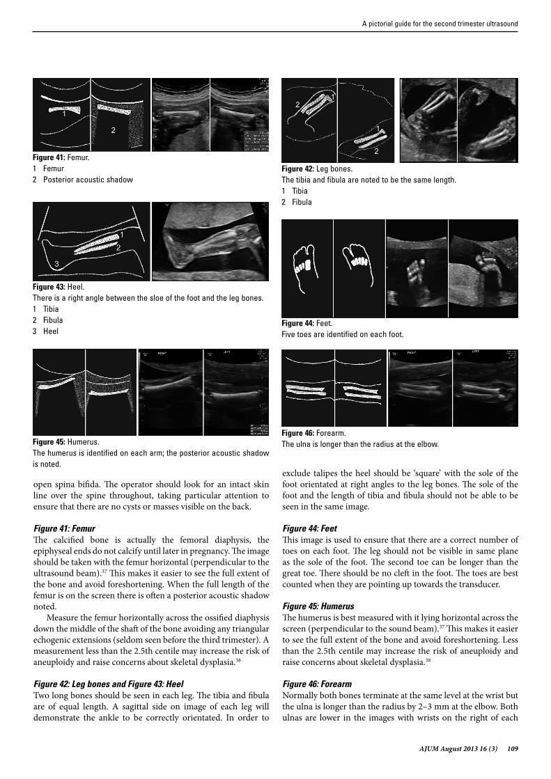
Figure 41: FemurThe calcified bone is actually the femoral diaphysis, the epiphyseal ends do not calcify until later in pregnancy. The image should be taken with the femur horizontal (perpendicular to the ultrasound beam).37 This makes it easier to see the full extent of the bone and avoid foreshortening. When the full length of the femur is on the screen there is often a posterior acoustic shadow noted.
Measure the femur horizontally across the ossified diaphysis down the middle of the shaft of the bone avoiding any triangular echogenic extensions (seldom seen before the third trimester). A measurement less than the 2.5th centile may increase the risk of aneuploidy and raise concerns about skeletal dysplasia.38
Figure 42: Leg bones and Figure 43: HeelTwo long bones should be seen in each leg. The tibia and fibula are of equal length. A sagittal side on image of each leg will demonstrate the ankle to be correctly orientated. In order to
exclude talipes the heel should be ‘square’ with the sole of the foot orientated at right angles to the leg bones. The sole of the foot and the length of tibia and fibula should not be able to be seen in the same image.
Figure 44: FeetThis image is used to ensure that there are a correct number of toes on each foot. The leg should not be visible in same plane as the sole of the foot. The second toe can be longer than the great toe. There should be no cleft in the foot. The toes are best counted when they are pointing up towards the transducer.
Figure 45: HumerusThe humerus is best measured with it lying horizontal across the screen (perpendicular to the sound beam).37 This makes it easier to see the full extent of the bone and avoid foreshortening. Less than the 2.5th centile may increase the risk of aneuploidy and raise concerns about skeletal dysplasia.38
Figure 46: ForearmNormally both bones terminate at the same level at the wrist but the ulna is longer than the radius by 2–3 mm at the elbow. Both ulnas are lower in the images with wrists on the right of each
Figure 41: Femur.1 Femur2 Posterior acoustic shadow
Figure 42: Leg bones.The tibia and fibula are noted to be the same length.1 Tibia2 Fibula
Figure 43: Heel.There is a right angle between the sloe of the foot and the leg bones.1 Tibia2 Fibula3 Heel
Figure 44: Feet.Five toes are identified on each foot.
Figure 45: Humerus.The humerus is identified on each arm; the posterior acoustic shadow is noted.
Figure 46: Forearm.The ulna is longer than the radius at the elbow.
A pictorial guide for the second trimester ultrasound
110 AJUM August 2013 16 (3)
image. It is important to identify the full length of the radius as radial ray defects can occur.39
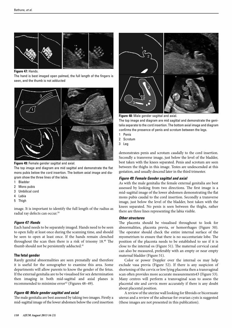
Figure 47: HandsEach hand needs to be separately imaged. Hands need to be seen to open fully at least once during the scanning time, and should be seen to open at least once. If the hands remain clenched throughout the scan then there is a risk of trisomy 18.40 The thumb should not be persistently adducted.41
The fetal genderRarely genital abnormalities are seen prenatally and therefore it is useful for the sonographer to examine this area. Some departments will allow parents to know the gender of the fetus. If the external genitalia are to be visualised for sex determination then imaging in both mid-sagittal and axial planes is recommended to minimise error42 (Figures 48–49).
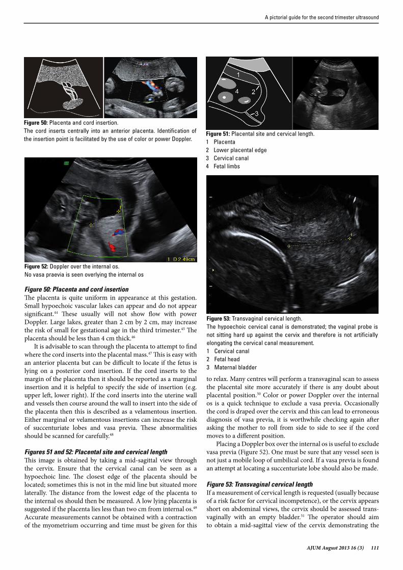
Figure 48: Male gender sagittal and axialThe male genitalia are best assessed by taking two images. Firstly a mid-sagittal image of the lower abdomen below the cord insertion
demonstrates penis and scrotum caudally to the cord insertion. Secondly a transverse image, just below the level of the bladder, best taken with the knees separated. Penis and scrotum are seen between the thighs in this image. Testes are undescended at this gestation, and usually descend later in the third trimester.
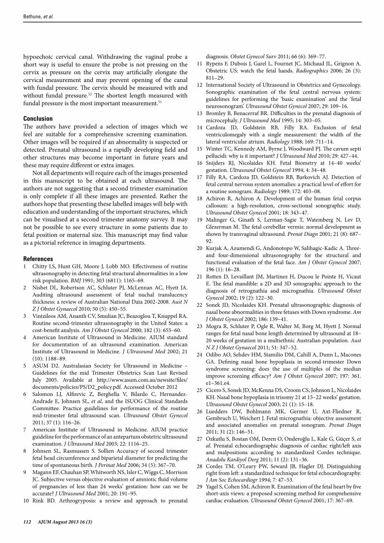
Figure 49: Female Gender sagittal and axialAs with the male genitalia the female external genitalia are best assessed by looking from two directions. The first image is a mid-sagittal image of the lower abdomen demonstrating the flat mons pubis caudal to the cord insertion. Secondly a transverse image, just below the level of the bladder, best taken with the knees separated. No penis is seen between the thighs, rather there are three lines representing the labia visible.
Other structuresThe placenta should be visualised throughout to look for abnormalities, placenta previa, or hemorrhages (Figure 50). The operator should check the entire internal surface of the myometrium to ensure that there is no succenturiate lobe. The position of the placenta needs to be established to see if it is close to the internal os (Figure 51). The maternal cervical canal can also be measured, preferably with an empty or near empty maternal bladder (Figure 51).
Color or power Doppler over the internal os may help exclude vasa previa (Figure 52). If there is any suspicion of shortening of the cervix or low lying placenta then a transvaginal scan often provides more accurate measurements43 (Figure 53). Many centres will perform a transvaginal scan to assess the placental site and cervix more accurately if there is any doubt about placental position.
A review of the uterine wall looking for fibroids or bicornuate uterus and a review of the adnexae for ovarian cysts is suggested (these images are not presented in this publication).
Figure 47: Hands.The hand is best imaged open palmed, the full length of the fingers is seen, and the thumb is not adducted
Figure 48: Male gender sagittal and axial.The top image and diagram are mid sagittal and demonstrate the geni-talia separate to the cord insertion. The bottom axial image and diagram confirms the presence of penis and scrotum between the legs.1 Penis2 Scrotum3 Leg
Figure 49: Female gender sagittal and axial.The top image and diagram are mid sagittal and demonstrate the flat mons pubis below the cord insertion. The bottom axial image and dia-gram show the three lines of the labia.1 Bladder2 Mons pubis3 Umbilical cord4 Labia5 Thigh
Bethune, et al.
AJUM August 2013 16 (3) 111
Figure 50: Placenta and cord insertionThe placenta is quite uniform in appearance at this gestation. Small hypoechoic vascular lakes can appear and do not appear significant.44 These usually will not show flow with power Doppler. Large lakes, greater than 2 cm by 2 cm, may increase the risk of small for gestational age in the third trimester.45 The placenta should be less than 4 cm thick.46
It is advisable to scan through the placenta to attempt to find where the cord inserts into the placental mass.47 This is easy with an anterior placenta but can be difficult to locate if the fetus is lying on a posterior cord insertion. If the cord inserts to the margin of the placenta then it should be reported as a marginal insertion and it is helpful to specify the side of insertion (e.g. upper left, lower right). If the cord inserts into the uterine wall and vessels then course around the wall to insert into the side of the placenta then this is described as a velamentous insertion. Either marginal or velamentous insertions can increase the risk of succenturiate lobes and vasa previa. These abnormalities should be scanned for carefully.48
Figures 51 and 52: Placental site and cervical lengthThis image is obtained by taking a mid-sagittal view through the cervix. Ensure that the cervical canal can be seen as a hypoechoic line. The closest edge of the placenta should be located; sometimes this is not in the mid line but situated more laterally. The distance from the lowest edge of the placenta to the internal os should then be measured. A low lying placenta is suggested if the placenta lies less than two cm from internal os.49 Accurate measurements cannot be obtained with a contraction of the myometrium occurring and time must be given for this
to relax. Many centres will perform a transvaginal scan to assess the placental site more accurately if there is any doubt about placental position.50 Color or power Doppler over the internal os is a quick technique to exclude a vasa previa. Occasionally the cord is draped over the cervix and this can lead to erroneous diagnosis of vasa previa, it is worthwhile checking again after asking the mother to roll from side to side to see if the cord moves to a different position.
Placing a Doppler box over the internal os is useful to exclude vasa previa (Figure 52). One must be sure that any vessel seen is not just a mobile loop of umbilical cord. If a vasa previa is found an attempt at locating a succenturiate lobe should also be made.
Figure 53: Transvaginal cervical lengthIf a measurement of cervical length is requested (usually because of a risk factor for cervical incompetence), or the cervix appears short on abdominal views, the cervix should be assessed trans-vaginally with an empty bladder.51 The operator should aim to obtain a mid-sagittal view of the cervix demonstrating the
Figure 50: Placenta and cord insertion.The cord inserts centrally into an anterior placenta. Identification of the insertion point is facilitated by the use of color or power Doppler.
Figure 51: Placental site and cervical length.1 Placenta2 Lower placental edge3 Cervical canal4 Fetal limbs
Figure 52: Doppler over the internal os.No vasa praevia is seen overlying the internal os
Figure 53: Transvaginal cervical length.The hypoechoic cervical canal is demonstrated; the vaginal probe is not sitting hard up against the cervix and therefore is not artificially elongating the cervical canal measurement.1 Cervical canal2 Fetal head3 Maternal bladder
A pictorial guide for the second trimester ultrasound
112 AJUM August 2013 16 (3)
hypoechoic cervical canal. Withdrawing the vaginal probe a short way is useful to ensure the probe is not pressing on the cervix as pressure on the cervix may artificially elongate the cervical measurement and may prevent opening of the canal with fundal pressure. The cervix should be measured with and without fundal pressure.52 The shortest length measured with fundal pressure is the most important measurement.51
ConclusionThe authors have provided a selection of images which we feel are suitable for a comprehensive screening examination. Other images will be required if an abnormality is suspected or detected. Prenatal ultrasound is a rapidly developing field and other structures may become important in future years and these may require different or extra images.
Not all departments will require each of the images presented in this manuscript to be obtained at each ultrasound. The authors are not suggesting that a second trimester examination is only complete if all these images are presented. Rather the authors hope that presenting these labelled images will help with education and understanding of the important structures, which can be visualised at a second trimester anatomy survey. It may not be possible to see every structure in some patients due to fetal position or maternal size. This manuscript may find value as a pictorial reference in imaging departments.
References1 Chitty LS, Hunt GH, Moore J, Lobb MO. Effectiveness of routine
ultrasonography in detecting fetal structural abnormalities in a low risk population. BMJ 1991; 303 (6811): 1165–69.
2 Nisbet DL, Robertson AC, Schluter PJ, McLennan AC, Hyett JA. Auditing ultrasound assessment of fetal nuchal translucency thickness: a review of Australian National Data 2002-2008. Aust N Z J Obstet Gynaecol 2010; 50 (5): 450–55.
3 Vintzileos AM, Ananth CV, Smulian JC, Beazoglou T, Knuppel RA. Routine second-trimester ultrasonography in the United States: a cost-benefit analysis. Am J Obstet Gynecol 2000; 182 (3): 655–60.
4 American Institute of Ultrasound in Medicine. AIUM standard for documentation of an ultrasound examination. American Institute of Ultrasound in Medicine. J Ultrasound Med 2002; 21 (10): 1188–89.
5 ASUM D2. Australasian Society for Ultrasound in Medicine – Guidelines for the mid Trimester Obstetrics Scan Last Revised July 2005. Available at http://www.asum.com.au/newsite/files/documents/policies/PS/D2_policy.pdf. Accessed October 2012
6 Salomon LJ, Alfirevic Z, Berghella V, Bilardo C, Hernandez-Andrade E, Johnsen SL, et al, and the ISUOG Clinical Standards Committee. Practice guidelines for performance of the routine mid-trimester fetal ultrasound scan. Ultrasound Obstet Gynecol 2011; 37 (1): 116–26.
7 American Institute of Ultrasound in Medicine. AIUM practice guideline for the performance of an antepartum obstetric ultrasound examination. J Ultrasound Med 2003; 22: 1116–25.
8 Johnsen SL, Rasmussen S. Sollien Accuracy of second trimester fetal head circumference and biparietal diameter for predicting the time of spontaneous birth. J Perinat Med 2006; 34 (5): 367–70.
9 Magann EF, Chauhan SP, Whitworth NS, Isler C, Wiggs C, Morrison JC. Subjective versus objective evaluation of amniotic fluid volume of pregnancies of less than 24 weeks’ gestation: how can we be accurate? J Ultrasound Med 2001; 20: 191–95.
10 Rink BD. Arthrogryposis: a review and approach to prenatal
diagnosis. Obstet Gynecol Surv 2011; 66 (6): 369–77.11 Rypens F, Dubois J, Garel L, Fournet JC, Michaud JL, Grignon A.
Obstetric US: watch the fetal hands. Radiographics 2006; 26 (3): 811–29.
12 International Society of Ultrasound in Obstetrics and Gynecology. Sonographic examination of the fetal central nervous system: guidelines for performing the ‘basic examination’ and the ‘fetal neurosonogram’. Ultrasound Obstet Gynecol 2007; 29: 109–16.
13 Bromley B, Benacerraf BR. Difficulties in the prenatal diagnosis of microcephaly. J Ultrasound Med 1995; 14: 303–05.
14 Cardoza JD, Goldstein RB, Filly RA. Exclusion of fetal ventriculomegaly with a single measurement: the width of the lateral ventricular atrium. Radiology 1988; 169: 711–14.
15 Winter TC, Kennedy AM, Byrne J, Woodward PJ. The cavum septi pellucidi: why is it important? J Ultrasound Med 2010; 29: 427–44.
16 Snijders RJ, Nicolaides KH. Fetal Biometry at 14–40 weeks’ gestation. Ultrasound Obstet Gynecol 1994; 4: 34–48.
17 Filly RA, Cardoza JD, Goldstein RB, Barkovich AJ. Detection of fetal central nervous system anomalies: a practical level of effort for a routine sonogram. Radiology 1989; 172: 403–08.
18 Achiron R, Achiron A. Development of the human fetal corpus callosum: a high-resolution, cross-sectional sonographic study. Ultrasound Obstet Gynecol 2001; 18: 343–47.
19 Malinger G, Ginath S, Lerman-Sagie T, Watemberg N, Lev D, Glezerman M. The fetal cerebellar vermis: normal development as shown by transvaginal ultrasound. Prenat Diagn 2001; 21 (8): 687–92.
20 Kurjak A, Azumendi G, Andonotopo W, Salihagic-Kadic A. Three- and four-dimensional ultrasonography for the structural and functional evaluation of the fetal face. Am J Obstet Gynecol 2007; 196 (1): 16–28.
21 Rotten D, Levaillant JM, Martinez H, Ducou le Pointe H, Vicaut E. The fetal mandible: a 2D and 3D sonographic approach to the diagnosis of retrognathia and micrognathia. Ultrasound Obstet Gynecol 2002; 19 (2): 122–30.
22 Sonek JD, Nicolaides KH. Prenatal ultrasonographic diagnosis of nasal bone abnormalities in three fetuses with Down syndrome. Am J Obstet Gynecol 2002; 186: 139–41.
23 Mogra R, Schluter P, Ogle R, Walter M, Borg M, Hyett J. Normal ranges for fetal nasal bone length determined by ultrasound at 18–20 weeks of gestation in a multiethnic Australian population. Aust N Z J Obstet Gynaecol 2011; 51: 347–52.
24 Odibo AO, Sehdev HM, Stamilio DM, Cahill A, Dunn L, Macones GA. Defining nasal bone hypoplasia in second-trimester Down syndrome screening: does the use of multiples of the median improve screening efficacy? Am J Obstet Gynecol 2007; 197: 361. e1–361.e4.
25 Cicero S, Sonek JD, McKenna DS, Croom CS, Johnson L, Nicolaides KH. Nasal bone hypoplasia in trisomy 21 at 15–22 weeks’ gestation. Ultrasound Obstet Gynecol 2003; 21 (1): 15–18.
26 Luedders DW, Bohlmann MK, Germer U, Axt-Fliedner R, Gembruch U, Weichert J. Fetal micrognathia: objective assessment and associated anomalies on prenatal sonogram. Prenat Diagn 2011; 31 (2): 146–51.
27 Ozkutlu S, Bostan OM, Deren O, Onderoğlu L, Kale G, Güçer S, et al. Prenatal echocardiographic diagnosis of cardiac right/left axis and malpositions according to standardized Cordes technique. Anadolu Kardiyol Derg 2011; 11 (2): 131–36.
28 Cordes TM, O’Leary PW, Seward JB, Hagler DJ. Distinguishing right from left: a standardized technique for fetal echocardiography. J Am Soc Echocardiogr 1994; 7: 47–53.
29 Yagel S, Cohen SM, Achiron R. Examination of the fetal heart by five short-axis views: a proposed screening method for comprehensive cardiac evaluation. Ultrasound Obstet Gynecol 2001; 17: 367–69.
Bethune, et al.

AJUM August 2013 16 (3) 113
30 Di Salvo DN, Brown DL, Doubilet P M, Benson CB, and Frates MC. Clinical significance of isolated fetal pericardial effusion. JUM 1994; 13: 291–3.
31. Eggebø TM, Heien C, Berget M, Ellingsen CL. Routine use of color Doppler in fetal heart scanning in a low-risk population. ISRN Obstet Gynecol 2012: 496935. Epub 2012 May 20.
32 International Society of Ultrasound in Obstetrics and Gynecology. Cardiac screening examination of the fetus: guidelines for performing the ‘basic’ and ‘extended basic’ cardiac scan. Ultrasound Obstet Gynecol 2006; 27: 107–13.
33 Yagel S, Arbel R, Anteby EY, Raveh D, Achiron R. The three vessels and trachea view (3VT) in fetal cardiac scanning. Ultrasound Obstet Gynecol 2002; 20 (4): 340–45.
34 Borenstein M, Minekawa R, Zidere V, Nicolaides KH, Allan LD. Aberrant right subclavian artery at 16 to 23 + 6 weeks of gestation: a marker for chromosomal abnormality. Ultrasound Obstet Gynecol 2010; 36: 548–52.
35 Benacerraf BR, Mandell J, Estroff JA, Harlow BL, Frigoletto FD Jr. Fetal pyelectasis: a possible association with Down syndrome. Obstet Gynecol 1990; 76: 58–60.
36 Chitty LS, Altman DG. Charts of fetal size: limb bones. BJOG 2002; 109 (8): 919–29.
37 Lessoway VA, Schulzer M, Wittmann BK. Sonographic measurement of the fetal femur: factors affecting accuracy. J Clin Ultrasound 1990; 18: 471–76.
38 Bethune M. Literature review and suggested protocol for managing ultrasound soft markers for Down syndrome: Thickened nuchal fold, echogenic bowel, shortened femur, shortened humerus, pyelectasis and absent or hypoplastic nasal bone. Australas Radiol 2007; 51: 218–25.
39 Kennelly MM, Moran P. A clinical algorithm of prenatal diagnosis of Radial Ray Defects with two and three dimensional ultrasound. Prenat Diagn 2007; 27 (8): 730–37.
40 Bronsteen R, Lee W, Vettraino IM, Huang R, Comstock CH. Second-trimester sonography and trisomy 18: the significance of isolated choroid plexus cysts after an examination that includes the fetal hands. J Ultrasound Med 2004; 23: 241–45.
41 Hisham Abdel Ghani. El-Naggar A, Hegazy M, Hanna A, Tarraf Y, Temtamy S. Characteristics of patients with congenital clasped
thumb: a prospective study of 40 patients with the results of treatment. J Child Orthop 2007; 1 (5): 313–22.
42 Meagher S, Davison G. Early second-trimester determination of fetal gender by ultrasound. Ultrasound Obstet Gynecol 1996; 8: 322–24.
43 Iams JD. Cervical ultrasonography. Ultrasound Obstet Gynecol 1997; 10: 156–60.
44 Thompson MO, Vines SK, Aquilina J, Wathen NC, Harrington K. Are placental lakes of any clinical significance? Placenta 2002; 23 (8–9): 685–90.
45 Hwang HS, Sohn IS, Kwon HS. The clinical significance of large placental lakes. Eur J Obstet Gynecol Reprod Biol 2012; 162 (2): 139–43.
46 Lee AJ, Bethune M, Hiscock RJ. Placental thickness in the second trimester: a pilot study to determine the normal range. J Ultrasound Med 2012; 31 (2): 213–18.
47 Sepulveda W, Rojas I, Robert JA, Schnapp C, Alcalde JL. Prenatal detection of velamentous insertion of the umbilical cord: a prospective color Doppler ultrasound study. Ultrasound Obstet Gynecol 2003; 21: 564–69.
48 Rao KP, Belogolovkin V, Yankowitz J, Spinnato JA 2nd. Abnormal placentation: evidence-based diagnosis and management of placenta previa, placenta accreta, and vasa previa. Obstet Gynecol Surv 2012; 67 (8): 503–19.
49 Bhide A, Thilaganathan B. Recent advances in the management of placenta previa. Curr Opin Obstet Gynecol 2004; 16 (6): 447–51.
50 Royal College of Obstetricians and Gynaecologists. Guideline No. 27. Placenta Praevia and Placenta Praevia Accreta: Diagnosis and Management. RCOG: London, October, 2005
51 Owen J, Yost N, Berghella V, Thom E, Swain GA, Dildy GA 3rd, et al. Mid-trimester endovaginal sonography in women at high risk for spontaneous preterm birth. JAMA 2001; 286: 1340–48.
52 Guzman ER, Rosenberg JC, Houlihan C, Ivan J, Waldron R, Knuppel R. A new method using vaginal ultrasound and transfundal pressure to evaluate the asymptomatic incompetent cervix. Obstet Gynecol 1994; 83: 248–52.
A pictorial guide for the second trimester ultrasound
Copyright © 2022 FDOKUMEN