Harmonic Balance, Melnikov method and nonlinear oscillators under resonant perturbation
Upload
independentCategory
view
9download
0
Journal of Applied Fluid Mechanics, Vol. 8, No. 1, pp. 123-132, 2015.
Available online at www.jafmonline.net, ISSN 1735-3572, EISSN 1735-3645.
A Numerical Study on Slip Flow Heat Transfer in
Micro-Poiseuille Flow using Perturbation Method
M. Saghafian1†
, I. Saberian1, R. Rajabi
1and E. Shirani
2
1Department of Mechanical Engineering, Isfahan University of Technology, Isfahan,8415683111, Iran
2 Foulad Institute of Technology, Fooladshahr, Isfahan, 8491663763, Iran
†Corresponding Author Email:[email protected]
(Received August 27, 2013; accepted March 6, 2014)
Abstract
In this study, slip-flow heat transfer in a laminar, steady state, two-dimensional incompressible flow between parallel
plates micro-channel is investigated numerically. A new method based on perturbation expansion for modeling of slip
micro-flows is presented. Navier-stokes equations are developed by using perturbation expansions of velocity,
pressure and temperature fields. Different orders of equations depending on the magnitude of Knudsen number are
obtained and each set of the equations are solved. The computations are performed for micro-channels with Constant
Wall Heat Flux (CWHF) and Constant Wall Temperature (CWT) boundary conditions to obtain heat transfer
characteristics of gaseous flow in slip regime. The effects of compressibility and viscous dissipation are neglected in
this study. The numerical methodology is based on Semi-Implicit Method for Pressure-Linked Equations (SIMPLE)
method. The effects of Knudsen number and thermal creep flow on Nusselt number are numerically investigated.This
study confirms that the perturbation method with different orders of Knudsen number can predict the velocity and
temperature fields with good accuracy. The obtained solutions are compared with both available numerical and
analytical results and good agreement is obtained.
Keywords:Heat transfer, slip-flow, micro-channel, parallel-plates, Nusselt number, perturbation expansion.
NOMENCLATURE
Specific heat at constant pressure, kJ kgK Fluid temperature at the wall,
Specific heat at constant volume, kJ kgK Bulk temperature of the fluid ,
Friction factor coefficient uin
inlet velocity,
Hydraulic diameter, m um Mean stream wise velocity,
h Heat transfer coefficient, 2W m K Uw Dimensionless wall velocity, /w mu u
H Distance between two plates, m Us Dimensionless fluid velocity adjacent to
the wall, /s mu u k Thermal conductivity, /W mK
Kn Knudsen number, / H
L Cannel length,m Greek Symbols
Nu Nusselt number, θ Dimensionless temperature
Pr Prandtl number, λ Molecular mean free path,
Po Poiseuille number, Dynamic viscosity,
Wall heat flux, 2/W m Density,
Re Reynolds number, Thermal accommodation coefficient
T Temperature, Momentum accommodation coefficient
Wall temperature, ν Kinematic viscosity,
1. INTRODUCTION
Due to the rapid developments in the electronic
industry, microfabrication technologies and biomedical
engineering in recent years the research interest on flow
and heat transfer phenomena in microchannels is widely
increased. Fabrication of small devices has increased
the needs of understanding of fluid flow and heat
transfer in micro-geometries. Microscale fluid flow and
heat transfer behavior differs greatly from that of
macroscale. Many experimental and numerical studies
on fluid flow and heat transfer in micro-channels have
been undertaken. It is known qualitatively that gaseous
flow in a micro-channel is affected by the rarefaction
(the slip on the surface), the surface roughness and the

M. Saghafian et al. /JAFM, Vol. 8, No. 1, pp. 123-132, 2015.
124
compressibility effects separately or simultaneously.
Rarefaction takes place by either the size or pressure of
a fluid system decreases resulting in a mean free path of
the fluid molecules that is comparable to the
characteristic length of the system itself. In such cases,
discontinuities between the fluid and the solid surface,
as well as other noncontinuum behavior begin to
develop. The very first parameters that are affected by
rarefaction are velocity slip and temperature jump.
Further Kn number, the ratio of mean free path to the
length characteristies of the flow, increases in the fluid
systems cause requirement of higher order and more
sophisticated models for sheer stress and heat flow.
Navier-stokes-based fluid dynamics solvers are often
inaccurate when applied to Micro Electro Mechanical
Device (MEMS). This inaccuracy stems from the
calculation of molecular transport effects, such as
viscous dissipation and thermal condition, from bulk
flow quantities, such as mean velocity and temperature.
The approximation of microscale phenomena using
macroscale information fails as the characteristic length
of the gaseous flow gradients (l) approaches the average
distance traveled by molecules between collisions.
Four different flow regims are observed based on the
value of the Knudsen number, continuum flow for Kn ≤
0.001; slip flow regime for 0.001≤ Kn ≤ 0.1; transition
regime for 0.1 ≤ Kn ≤ 10 and free molecular regime for
Kn ≥ 10 (Beskok and Kardianakis (1994) ). Kn
determines the degree of rarefaction and the degree of
the validity of the continuum approach. As Kn
increases, rarefaction effects become more important,
and eventually the continuum approach breaks down.
Palm (2001), Sobhan andGarimella (2001) and Obot
(2002) reviewed the experimental results in the existing
literature for the convective heat transfer in
microchannels. Morini (2004)presents an excellent
review of the experimental data for convective heat
transfer in microchannels. Barron et al. (1996) and
Barron et al. (1996) extended the Graetz problem to
slip-flow and developed simplified relationships to
describe the effect of slip-flow on the convection heat
transfer coefficient. Ameel et al. (1997) analytically
treated the problem of laminar gas flow in micro tubes
with a constant heat flux boundary condition at the wall
assuming a slip flow hydrodynamic condition and a
temperature jump thermal condition at the wall. They
found that the fully developed Nusselt number
decreased with Knudsen number. Tunc and Bayazitoglu
(2001)investigated steady laminar hydrodynamically
developed flow in microtubes with uniform temperature
and uniform heat flux boundary conditions using the
integral technique. They included temperature jump
condition at the wall and viscous heating within the
medium. Aydin and Aydin and Avci (2001)studied
laminar forced convective heat transfer of a Newtonian
fluid in a microchannel between two parallel plate
analytically. Sparrow and Line(1962) examined laminar
heat transfer in microtubes under slip-flow conditions
and Inman (1964)investigated laminar slip-flow heat
transfer in a parallel-plate channel with uniform wall
heating and cartesian a formula for calculation of
Nusselt number in this condition. Also
Hadjiconstantinou and Simek (2002) investigated the
constant-wall-temperature convection heat transfer
characteristics of a model gaseous flow in two-
dimensional micro and nano-channels under
hydrodynamically and thermally fully developed
conditions.They covered both the slip flow regime and
most of the transition regime. Their results shown that
the slip flow prediction is in good agreement with the
DSMC results for . They also show that the
Nusselt number decreases monotonically with
increasing Knudsen number in a fully accommodating
case, both in slip flow and transition regimes.
The aim of the present study is to present a new method
for modeling the slip velocity and temperature jump in
slip flow regime. For this purpose we numerically
investigate rarefied gas flow in a microchannel between
two parallel plates. Both the CWHF and CWT thermal
boundary conditions are applied at the wall. The
governing equations are solved in conjunction with the
velocity slip and temperature jump to account for
rarefaction effects in slip flow regime. Three-term
perturbation expansions of velocity, pressure and
temperature are used for developing of governing
equations. The equations with different orders of
Knudsen number are obtained. These equations are
solved using SIMPLE algorithm. We compare
Poiseuille number and Nusselt number with the results
obtained by others.
2. PROBLEM DESCRIPTION
The computations are performed a micro-channel with
constant heat flux (CWHF) and constant wall
temperature (CWT) boundary conditions. We
investigate hydrodynamically and thermally
developing, steady state, laminar, incompressible two-
dimensional flow with constant properties. The flow of
gas is considered through two horizontal parallel-plates
of length L that are a distance H apart and a cartesian
coordinate system as shown in Fig. 1. The effects of
compressibility and viscous dissipation are neglected
due to low speed flows associated with micro-channel.
A Channel length (L) is chosen much larger than its
height to ensure the thermally and hydrodynamically
fully developed flow condition at the channel exists. As
shown in Fig. 1, the velocity and temperature profiles
are uniform at inlet of the channel and are based on
. For constant and uniform heat flux boundary
condition, Nitrogen is used with constant properties.
For constant-wall temperature (CWT) boundary
condition, air with constant properties is selected as the
working fluid in the channel. Also we assumed λ, is
constant so Knudsen number varies by changing H.
y
x
H
L
T in
U in
Fig. 1. Channel geometry
qw or Tw

M. Saghafian et al. /JAFM, Vol. 8, No. 1, pp. 123-132, 2015.
125
3. PERTURBATION METHOD and
NUMERICAL SOLUTION
The macroscopic properties φ of the flow may be written
with an asymptotic expansionas a function of the
Knudsen number (Karniadakis and Beskok
(2004)andQin et al. (2007)):
(1)
Whereφ0 corresponds to the no-slip flow,φ1 , φ2 , φ3 are
the first, second and third order corrections of the φ0
respectively. Increase of the Knudsen number, i.e.
going from slip to free molecular flow regime, higher
corrections of theφ become important. In the slip flow
regime we can use Navier-Stokes equations with use
appropriate velocity slip and temperature jump
conditions (Karniadakis and Beskok (2004)).
In this paper, a new method for modeling of microflows
is introduced. Governing equations are developed by
using perturbation expansions of velocity, pressure and
temperature fields. Subsequently, different orders of
equations depending on the value of Knudsen number
are obtained. These set of equations are discretized in
two-dimensional state on a staggered grid using finite
volume method. In this study three-term perturbation
expansions are used. These equations are obtained for
up to second order magnitude respect to Kn. Total
algorithm of solution includes three steps and solved
with the SIMPLE algorithm.
Many second-order models have been proposed either
experimentally or numerically and some have proven
useful in increasing the range and accuracy of the slip
boundary condition representation of rarefaction. There
is currently insufficient experimental data to validate
the use of any particular second-order model. Presently,
however, there are few analytical or numerical
convective heat transfer solutions based on second-
order slip boundary condition models, and these are
often presented for limited values of Knudsen number,
momentum and thermal accommodation coefficients,
geometry and consequently have limited applicability.
In this research we use three-term expansions and
substitute these expansions into momentum and energy
equations and boundary conditions, Momentum and
energy equations are described as:
(2)
Perturbation expansions of velocity ( ), pressure and temperature fields are defined by
(Karniadakis and Beskok (2004)):
(3)
By substituting these expansions in Momentum and
energy equations, One can reach to three-order of
equations O(1), O(Kn), O( ) and their boundary
conditions, therefore for the zeroth-order equations and
their boundary conditions, we have:
*
( ) +
(4)
( )
In fact the above equations are the no-slip Navier-
Stokes and energy equations. The zeroth-order
boundary conditions on the wall are defined as:
(5)
Where U0=u0/um and um is mean stream wise velocity.
The first order O(Kn) equations and their boundary
conditions on the walls are described by:
*
( ) ( ) +
(6)
( ) ( )
(
)
(7)
(
)
Where U1=u1/um.Finally the second order equations
O( ) are presented as:
( ) ( ) ( )
(8)
( ) ( ) ( )
( )
And the boundary conditions for O( ) are defined as:
*
+
(9)
Where U2=u2/um. Also the first and second order
equations require corrections due to the velocity-slip
and temperature-jump. Total algorithm of solution
includes three steps: the first step is to solve Eq. (10)
and (11). The second step is to solve first order
equations and the third step is to solve the second order
equations. The SIMPLE algorithm is used for each step.
The final solution is the summation of , and . A
three-part computer program has been provided for
solving the three set of discretized equations. A uniform
300×50 staggered grid is employed for the present
study. The boundary conditions at the channel inlet are:
( ) ( )
(10)
( ) ( )
( ) ( )
( ) ( )

M. Saghafian et al. /JAFM, Vol. 8, No. 1, pp. 123-132, 2015.
126
4. ANALYTIC SOLUTIONS for FULLY
DEVELOPED FLOW in CHANNEL
4.1. Poiseuille Number using Second Order
Model
At high Knudsen number, no-slip boundary condition is
not a good assumption and slip boundary conditions
must be used. For isothermal flows with tangential
momentum accommodation coefficient , for
analytical solution we use the general second-order slip
condition with the following dimensionless form
(Karniadakis and Beskok (2004)):
(
) (
) (11)
The and are the slip constant coefficients.
Different researcher developed this coefficients and in
Table 1some of them shown. More information is
available in (Karniadakis and Beskok (2004)). The
analytical slip velocity profile is obtained using
momentum equation and the above slip model as
follows:
( )
*
( )+
[(
)
(
)
( )]
(12)
Poiseuille number for fully developed flow is:
( ) (13)
is wall friction coefficient.
Table 1 Coefficients for slip models
(Karniadakis and Beskok (2004))
Author(s)
Cercignani (Cercignani and Daneri 1963) 1.1466 0.9756 Revised Cercignani (Hadjiconstantinou 2003) 1.1466 0.647
Deissler (1964) 1 9/8
Hisa and Domoto (1983) 1 0.5
Schamberg (1947) 1 5 /12
Maxwell (Kennard 1938) 1 0
General form 1 -0.5
4.2 Analytical Solution using the Perturbation
Methods for the Fully Developed Flow
For the fully developed flow, v=0, u=u(y) and P=P(x).
Therefore:
0
(14)
( ) ( ) ( )
( ) ( ) ( )
Hence, different orders of tangential momentum
equations are solved with the corresponding boundary
conditions. For incompressible flow, slip does not
change the flow rate. That is:
(15)
For fully developed region we solve momentum
equations using perturbation expansion for every order
of Kn, sothe zeroth order of velocity and its corrections
become:
( ) [(
)
(
)]
(16)
( ) (
)
(
)
{ [(
)
(
)]
}
i is level or order number in perturbation expansion.
The final slip velocity profile is obtained by substituting
the Eq. (16) into the perturbation expansion of the
velocity:
( ) ∑ ( )( )
(
*
( )+
)
[(
)
(
)
( )]
(17)
We use and for investigate effects of this
coefficients on the analytical solution of Perturbation
Method and compare with results of other researcher. If
we use Eq.(17) to obtain Poiseuille number, the result is
Eq.(13) with C1=1 and C2=-0.5.
5. NUMERICAL RESULTS AND DISCUSSION
To assure that each numerical result is sufficiently
accurate, grid resolution studies have been performed
for each and . Fully developed Nu and Po
number for , and , obtained
from different grids, are shown in Table 2. For these
results we used slip-coefficients that proposed by Hisa
and Domoto (Karniadakis and Beskok (2004)). As
shown in Table 2, a grid with resolution, is
suitable, thus the following results are based on this
grid size.
Table 2. Grid study results
Grid resolution Nu Po
6.193 17.629
6.218 17.694
6.236 17.735
6.237 17.737
5.1 Hydrodynamics
5.1.1 Comparison Analytical Solution with Numerical
Solution using Perturbation Method
As mentioned and shown in Fig.1, the velocity and
temperature profiles are uniform at inlet of the channel.
In Fig. 2, Dimensionless form of the no-slip velocity
profile and the velocity corrections are compared with
the analytical solution at once of the sections that the
flow is fully developed .As shown, good agreement
isfound between the analyticaland numerical results. In
Fig.3, the slip velocity, no-slip velocity and

M. Saghafian et al. /JAFM, Vol. 8, No. 1, pp. 123-132, 2015.
127
Fig. 2. Zeroth, first and second order of corrections
velocity
correctional velocities are compared. Zeroth order of
velocity or noslip boundary condition velocity profile
(U0) is corrected by first order (U1) and second order
(U2) corrections to obtain slip velocity profile (U).
5.1.2 Comparison Analytical and Numerical Solution
with other Slip Models
In Fig. 4, the slip and no-slip fully developed velocity
profiles obtained by the numerical solution (using
perturbation method) and slip velocities obtained by the
Eq. (12) are shown. Good agreement isfound between
the results. For a better comparison between the
perturbation method results and the results produced by
different slip models, Fig. 5 shows normalized slip
Fig.3. Fully developed dimensionless slip velocity profile,
no-slip velocity and correctional velocities for Kn=0.06.
Fig. 4. Slip and no-slip velocities for Kn=0.06. velocities at the channel walls versus the Knudsen
number. If we use only the first order perturbation
expansions (φ= φ0+Kn φ1), the slip velocity is
overpredicted as Knudsen number increased. Also, if
we use first and second order perturbation expansions
(φ= φ0+Knφ1+Kn2φ2), with C1=1 and C2= -0.5 the slip
velocity is underpredicted as Knudsen number is
increased. However, if we use other slip coefficients
such as those proposed by Hisa and Domoto, the model
is more reliable compared to other available data.
Numerical results of perturbation method deviate from
the other results as Kn is increased. This reveals that
more corrections are needed in the perturbation method
as Kn is increased.
In Fig. 6 the result of numerical solution for Po and
analytical solution using Eq. (13) for all slip
coefficients that presented in(Karniadakis and Beskok
(2004)) are shown. In Fig.6 it is shown that fully
developed Po with Diessler’s slip coefficients has a
good agreement with corresponding analytical
solutions. Also it is seen that Po decreases with
increasing in Kn.
U
y/H
0 0.5 1 1.5 20
0.25
0.5
0.75
1
Numerical
Analytical
0
Kn=0.06
U
y/H
-4 -2 0 2 4 60
0.25
0.5
0.75
1
Numerical
Analytical
1
Kn=0.06
U
y/H
-50 -25 0 25 500
0.25
0.5
0.75
1
Numerical
Analytical
2
Kn=0.06
Normalized Velocity profile and its corrections
y/H
-0.5 0 0.5 1 1.5 20
0.25
0.5
0.75
1
U
KnU
Kn U
U
1
0
2
2
x=L/2
Kn=0.06
U
y/H
0 0.5 1 1.50
0.25
0.5
0.75
1
present work
Present work-Analytical(C1=1,C2=-0.5)
Hisa and Domoto
Cercignani(2003)
no slip

M. Saghafian et al. /JAFM, Vol. 8, No. 1, pp. 123-132, 2015.
128
Fig. 5. Dimensionless slip velocity versus Kn for
the Poiseuille flow.
Fig. 6. Variation of fully developed Powith Knudsen
number, for Re=1.
5.2. Heat Transfer
5.2.1. Constant Wall Heat Flux Boundary
Condition(CWHF)
The zeroth to second order perturbation equations
for Constant Wall Heat Flux (CWHF) with C1=1 and
C2= -0.5 are solved numerically using SIMPLE
algorithm. Finally the total temperature ( ) is calculated. Dimensionless
temperature profiles that are defined in Eq. (18) for
jump and no-jump conditions are shown in
Fig.7.This figure is for a section that the flow is
thermally fully developed
( )
( ) (18)
In Fig.8, Nusselt numbers obtained with different
models and for different Kn are shown and compared
with results of Aydinand Avci (2007) and Inman(1964).
Then different proposed values for when are
Fig.7. Fully developed dimensionless temperature
profiles for slip and no-slip conditions for ,
and
tested. The results are in Fig.8 and Table 3. It is found
that for low Kn, there is a good agreement between Nu
that obtained in present study and Nu values obtained
by Aydinand Avci (2007) and Inman (1964). When Kn
increases, the difference between Nu obtained in this
study and other results is increased.Fig.8 demonstrates
that Nu decreases with increased of Kn.
Fig. 8. Variation of fully developed Nu for CWHF
case with Kn when ,
Figure 9 shows that the local Nusselt number
decreases when proceeding along the channel. In this
figure, it is shown that Nusselt number decreases
rapidly at inlet of the channel and then tends to a
constant value and this is show developing of flow.
( ) And ( ) both decrease rapidly near
the inlet of channel but ( ) decrease much
more rapidly than ( ), so Nusselt number
decreases at first. One can understand from Fig.9 that
if Kn increases then thermal entry length increases. It
is noticeable that this Figure is for Re = 1 and we can
expect larger thermal entry length in larger Reynolds
numbers.
H
H
H
H
H
H
H
H
H
H
H
Kn
Us
0 0.02 0.04 0.06 0.08 0.10
0.2
0.4
0.6present(first order)
present(2nd order, C1=1,C2=-0.5)
Present(2nd order, Hisa & Domoto coeff.)
Analytical(C1=1,C2=-0.5)
Maxwell
Schamberg
Cercignani(2003)
Cercignani(1964)
Hisa and Domoto
Albertoni
Deissler
H
Kn
Po
=C
f.R
e
0 0.02 0.04 0.06 0.08 0.1 0.12
15
20
25
30Present Work - Beskok Coeff.
Present Work - Cerciagini Coeff.
Present Work - Hisa & Domoto
Present Work - Diessler Coeff.
Analytical - Beskok Coeff.
Analytical - Cerciagini Coeff.
Analytical - Hisa & Domoto Coeff.
Analytical - DisslerCoeff.
y/H
0 0.2 0.4 0.6 0.8 1 1.2 1.40
0.25
0.5
0.75
1
With Slip Boundary Condition
With No-Slip Boundary Condition
Kn
Nu
0 0.02 0.04 0.06 0.08 0.1
5
6
7
8
9
Present Work-Beskok Coeff.
Present Work-Cerciagini Coeff.
Present Work-Hisa&Domoto Coeff.
Present Work-Diessler Coeff.
Inman
Re = 1Pr = 0.7
M. Saghafian et al. /JAFM, Vol. 8, No. 1, pp. 123-132, 2015.
129
Fig. 9. Axial variation of local Nu for CWHF case at
,
5.2.2 Constant Wall Temperature Solution(CWT)
Axial variation of temperature is not linear in constant
wall temperature (CWT) boundary condition. Therefore
axial conduction can be important for CWT cases even
if the flow is thermally fully developed. The
significance of streamwise conduction is generally
established by the magnitude of the flow Peclet number.
The Peclet number, , represents the ratio of
the thermal energy convected to the fluid, to the thermal
energy axially conducted within the fluid. A low ,
which is common for micro flows, generally indicates
that streamwise conduction effects must be considered.
Since the Pein microchannels as much lower than 100
the effects of axial conduction should be taken into
account. In fact we except that for low Pe, contribution
of axial conduction is considerable compared to
convection heat transfer. Nu is lower than when axial
conduction is negligible. The variation of Nu with Kn
for different values of Pe for Constant Wall
Temperature (CWT) is shown in Fig.10, in this figure it
shown that for a fixed Pe, Nu decreases as Kn is
increased. Fig.10 shows effects of Pe on Nu in different
Kn. This figure shows good agreement between our
numerical results and results presented by
Hadjiconstantinou (2003). This figure shows that the
Nu decreases monotonically with increasing Kn at
constant Pe. The effect of axial heat conduction is to
increase the Nu throughout the slip flow regime. When
rarefaction is increasing in Kn, velocity slip increased
so convection heat transfer and Nu are decreased.
Fig. 10. Variation of fully developed Nu number
with Kn number for , and
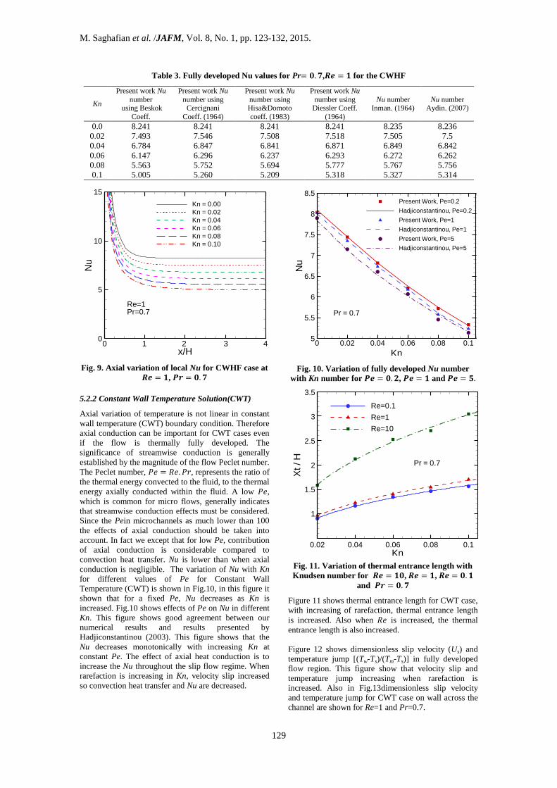
Fig. 11. Variation of thermal entrance length with
Knudsen number for , ,
and
Figure 11 shows thermal entrance length for CWT case,
with increasing of rarefaction, thermal entrance length
is increased. Also when is increased, the thermal
entrance length is also increased.
Figure 12 shows dimensionless slip velocity (Us) and
temperature jump [(Tw-Ts)/(Tm-Ts)] in fully developed
flow region. This figure show that velocity slip and
temperature jump increasing when rarefaction is
increased. Also in Fig.13dimensionless slip velocity
and temperature jump for CWT case on wall across the
channel are shown for Re=1 and Pr=0.7.
x/H
Nu
0
5
10
15
Kn = 0.00
Kn = 0.02
Kn = 0.04
Kn = 0.06
Kn = 0.08
Kn = 0.10
Re=1Pr=0.7
0 1 2 3 4
Kn
Nu
0 0.02 0.04 0.06 0.08 0.15
5.5
6
6.5
7
7.5
8
8.5Present Work, Pe=0.2
Hadjiconstantinou, Pe=0.2
Present Work, Pe=1
Hadjiconstantinou, Pe=1
Present Work, Pe=5
Hadjiconstantinou, Pe=5
Pr = 0.7
Kn
Xt/H
0.02 0.04 0.06 0.08 0.1
Re=0.1
Re=1
Re=10
Pr = 0.7
3.5
3
2.5
2
1.5
1
Table 3. Fully developed Nu values for Pr , for the CWHF
Kn
Present work Nu
number using Beskok
Coeff.
Present work Nu
number using Cercignani
Coeff. (1964)
Present work Nu
number using Hisa&Domoto
coeff. (1983)
Present work Nu
number using Diessler Coeff.
(1964)
Nu number Inman. (1964)
Nu number Aydin. (2007)
0.0
0.02
0.04
8.241
7.493
6.784
8.241
7.546
6.847
8.241
7.508
6.841
8.241
7.518
6.871
8.235
7.505
6.849
8.236
7.5
6.842
0.06 6.147 6.296 6.237 6.293 6.272 6.262
0.08
0.1
5.563
5.005
5.752
5.260
5.694
5.209
5.777
5.318
5.767
5.327
5.756
5.314

M. Saghafian et al. /JAFM, Vol. 8, No. 1, pp. 123-132, 2015.
130
Fig. 12. Velocity slip and temperature jump on wall
for and
Fig. 13. Velocity slip and temperature jump on wall
along the channel length
5.3 The Role of the Accommodation
Coefficients on Heat Transfer Rate
Momentum and energy transfer between the gas
molecules and the surface require specification of
interactions between the impinging gas molecules and
the surface. A detailed analysis of this is quiet
complicated and requires complete knowledge of the
scattering kernels. The thermal and momentum
accommodation coefficient s, and , are defined by
(19)
, denote energy fluxes of incoming and
reflected molecules per unit time respectively and
denotes the energy fluxes if the all incoming molecules
had been reemitted with the energy flux corresponding
to the surface temperature, (Karniadakis and Beskok
(2004)).
Fig. 14. Variation ofNu against Kn for various values
of thermal and momentum accommodation
coefficients
The effect of accommodation coefficients on heat
transfer is shown in Fig.14. Nu is increasing with
increasing in thermal accommodation coefficient and
decreasing in momentum accommodation coefficient.
5.4 The Effect of Thermal Creep on Flow and
Heat Transfer
Thermal creep occurs in gas flows when axial
temperature gradients are applied along the channel
walls Sone (2002). In channel flows, this boundary
treatment induces a tangential creep velocity (uc) in the
interior gas close to the walls, such that the gas flows in
the direction of the temperature gradient. The following
thermal creep uc should be added to slip velocity
(
)
(20)
This case is investigated in present work when constant
heat flux (CWHF) boundary condition is applied. The
effects of thermal creep flow on fully developed Po and
Nu are shown in Fig.15 and Fig.16 for and
⁄ (that means thermal creep is in
streamwise direction). The results are compared with
the available results of Van Rij et al. (2007). As shown
in Fig.15 and 16, if thermal creep flow has a same
direction with streamwise ( ( ) )
then it increases Nusselt number and decreases
Poiseuille number due to increasing slip in walls.
Kn
Slip
or
Ju
mp
0 0.02 0.04 0.06 0.08 0.10
0.1
0.2
0.3
0.4
0.5
Velocity Slip
Temperature Jump
Re = 1Pr = 0.7
x/H
Slip
or
Ju
mp
0 1 2 3 40
0.1
0.2
0.3
0.4
0.5
Dimesionless Slip Velocity
Dimensionless Temprature Jump
Re = 1Kn = 0.06
Kn
Nu
0 0.02 0.04 0.06 0.08 0.14
4.5
5
5.5
6
6.5
7
7.5
8
Kn
Nu
0 0.02 0.04 0.06 0.08 0.15
5.5
6
6.5
7
7.5
8

M. Saghafian et al. /JAFM, Vol. 8, No. 1, pp. 123-132, 2015.
131
Fig. 15. Effect of thermal creep flow on Poiseuille
number for various values of Knudsen number
Fig. 16. Effect of thermal creep flow on Nusselt
number for various values of Knudsen number
6. CONCLUSIONS
In this study slip-flow heat transfer in a laminar, steady
state, two-dimensional incompressible flow between
parallel plates micro-channel is investigated
numerically using perturbation method. Both
hydrodynamically and thermally developing flow cases
are examined. The Poiseuille and Nusselt numbers for
2-D microchannels with both constant wall heat flux
(CWHF) and constant wall temperature (CWT) thermal
boundary conditions for the slip flow regime have been
numerically investigated. The resulting , and
include the effects of second-order velocity slip and
temperature jump boundary conditions. In this study the
effects of viscous dissipation and compressibility are
neglected. The interactive effect of the rarefaction on
Nusselt number has been studied and found that the
Nusselt number decreases when rarefaction increases.
Also thermal entrance length is investigated and it is
found that increasing in Re or Kn, leads to increase in
thermal entrance length. For CWT case, Pe has a
significant role in heat transfer rate, for low Pe, thus we
should take in to account the effects of axial
conduction. Effects of axial conduction increase with
decreasing Pe and decrease with increasing of
rarefaction.
At the end, it is illustrated that when the effect of
thermal creep is accounted, if thermal creep has the
same direction with streemwise, since the slip velocity
at the wall increases, the momentum transfer increases
and so Nusselt number increase.
Finally one can conclude that perturbation method is
capable to simulate slip flow heat transfer in
micropoiseuille flow
REFERENCES
Ameel, T.A., X.M. Wang, R.F. Barron, R.O.
Warrington, (1997).Laminar forced convection in a
circular tube with constant heat flux and slip flow,
Microscale Thermal Engineering, 1 (4) 303–320.
Aydin, O., M. Avci, (2007).Analysis of laminar heat
transfer in micro-poiseuille flow, International
Journal of Thermal Science, 46 30-37.
Barron, R.F., X.. Wang, R.O. Warrington, T. Ameel,
(1996).Evaluation of the eigenvalues for the Graetz
problem in slip-flow, Int. Comm. Heat Mass
Transfer, 23 (4) 563–574.
Barron, R.F., X. Wang, T.A. Ameel, R.O. Warrington,
(1997).The Graetz problem extended to slip-flow,
International Journal of Heat and Mass Transfer,
40 (8) 1817–1823.
Beskok, A., G.E. Karniadakis, (1994).Simulation of
heat and momentum transfer in complex micro-
geometries, Journal of Thermophysics Heat
Transfer, 8 355–370.
Hadjiconstantinou, N. G., (2003).Comment on
Cercignani’s second-order slip coefficient, Phys.
Fluids, Vol. 15, pp. 2352-2354,
Hadjiconstantinou, N.G., O., Simek,(2002).Constant-
wall-temperature Nusselt Number in Micro and
Nano Channels. Journal of Heat Transfer, 124,
356-364,
Inman, R.M.,(1964) Laminar slip flow heat transfer in a
parallel-plate channel or a round tube with uniform
wall heating, NASA TD-2393.
Karniadakis, G., A. Beskok, N. Aluru,
,(2004).Microflows and Nanoflows Fundamentals
and Simulations, Springer
Morini, G.L.,(2004).Single-phase convective heat
transfer in microchannels: a review of
experimental results, International Journal of
Thermal Sciences 43631–651
Obot, N.T.,(2002).Toward a better understanding of
friction and heat/mass transfer in microchannels—
A literature review, Microscale Thermophysical
Engineering, 6 155–173.
Kn
Po
0 0.02 0.04 0.06 0.08 0.112
16
20
24Thermal creep- Present work
Thermal creep- Van Rij et al.
No creap results
Pe = 0.5u /u =0.25c m
Kn
Nu
0 0.02 0.04 0.06 0.08 0.15
6
7
8
Thermal creep- Present work
Thermal creep- Van Rij et al.
No creap results
Pe = 0.5u /u =0.25c m
M. Saghafian et al. /JAFM, Vol. 8, No. 1, pp. 123-132, 2015.
132
Palm, B.,(2001).Heat transfer in microchannels,
Microscale Thermophysical Engineering, 5 155–
175.
Qin, F. H., D. J., Sun, and X. Y., Yin, (2007)
Perturbation analysis on gas flow in a straight
microchannel, Physics of fluids, Vol. 19, pp
027103-14,.
Sobhan, C.B.,S.V. Garimella, (2001).A comparative
analysis of studies on heat transfer and fluid flow
in microchannels, Microscale Thermophysical
Engineering, 5 293–311.
Sone, Y., (2002).Kinetic Theory and fluid dynamics,
Birkhauser, Boston.
Sparrow, E.M., S.H. Lin, (1962).Laminar heat transfer
in tubes under slip-flow conditions, J. Heat
transfer, 84 (4) 363-369
Tunc, G. Y., Bayazitoglu,(2001).Heat transfer in
microtubes with viscous dissipation, International
Journal of Heat and Mass Transfer, 44 2395–
2403.
Van Rij, J.V., T., Harman, T. and Ameel, (2007).The
effect of creep flow on two-dimensional isoflux
microchannels,International Journal of Thermal
Sciences, 46, 1095-1103.
Copyright © 2022 FDOKUMEN