A Novel Method of Measuring Inherent Power System Charging Current
13
2330 IEEE TRANSACTIONS ON INDUSTRY APPLICATIONS, VOL. 47, NO. 6, NOVEMBER/DECEMBER 2011 A Novel Method of Measuring Inherent Power System Charging Current Dev Paul, Senior Member, IEEE, Peter E. Sutherland, Fellow, IEEE, and Sergio A. R. Panetta, Senior Member, IEEE Abstract—High-resistance grounded (HRG) power systems have been used in many industries to minimize equipment damage, including but not limited to mining, petrochemicals, shore-to-ship power supplies, and many others. The system charging current value should be known for designing an HRG power system. One method of determining the system charging current is to perform engineering calculations involving the inherent capacitance to ground for each of the power system components. However, this method may not provide accurate data as the sneak capacitance to ground for power system components cannot be determined due to their installation configuration. Therefore, it is essential to have a reliable method of measuring the system charging current. Before describing the proposed method of measuring the sys- tem charging current, fundamental concepts of system charging current and its mathematical analysis are provided. In addition, power system arcing faults and the associated damage when a fault remains line–ground faulted, particularly in the case of a medium-voltage power system, are included. Finally, a novel and suitable method of measuring the inherent power system charging current is presented. Index Terms—Arc hazard, capacitance to ground, charging current, current transformer (CT), grounded power system, high- resistance grounded (HRG), ungrounded power system. I. I NTRODUCTION E LECTRICAL arc hazards and their associated effects on equipment damage are unpredictable. An arc may occur when equipment insulation between phase to phase and/or phase to ground fails. The intensity of the arc damage is related to the fault current magnitude at insulation failure location. Power system fault statistics indicate that close to 75% of all faults involve ground [1], [2]. Therefore, making the ground fault current low by using the high-resistance grounded (HRG) power system can minimize the damage at the fault location as long as the fault is cleared by appropriate protection devices before it becomes a three-phase fault, which may cause more Manuscript received January 28, 2011; revised May 19, 2011; accepted June 26, 2011. Date of publication September 19, 2011; date of current version November 18, 2011. Paper 2010-PSEC-552.R1, presented at the 2011 IEEE/IAS Industrial and Commercial Power Systems Technical Conference, Newport Beach, CA, May 1–5, and approved for publication in the IEEE TRANSACTIONS ON INDUSTRY APPLICATIONS by the Power System Engi- neering Committee of the IEEE Industry Applications Society. D. Paul is with AECOM, Oakland, CA 94612 USA (e-mail: dev.paul@ aecom.com). P. E. Sutherland is with GE Energy Services, Schenectady, NY 12306 USA (e-mail: [email protected]). S. A. R. Panetta is with I-GARD Corporation, Mississauga, ON L5S 1A8 Canada (e-mail: [email protected]). Digital Object Identifier 10.1109/TIA.2011.2168510 damage. Before recent concerns of arc hazards in the indus- try, HRG power systems have been used in many industries, including but not limited to mining, petrochemicals, and shore- to-ship power supplies, to minimize equipment damage. Upon detection of a ground fault on the HRG low-voltage (LV) power systems, with relatively low system charging currents, an alarm or an orderly shutdown of the power system is commonly used. This paper provides a discussion of the line–ground arcing fault and associated damage and supports the conclusion that, for a medium-voltage (MV) HRG power system, the fault should be cleared immediately upon occurrence of a line-to-ground fault, particularly when the system charging current is ≥ 5.5 A for system voltages of 4.16 kV and above [2]. Higher system charging current may be due to an extended power system or a relatively longer parallel feeder cable system, which may result in additional damage if not tripped immediately upon sensing the line-to-ground fault. A combination of modern mi- croprocess relays with appropriate current transformers (CTs) can provide adequate ground fault protection for an HRG power system. For designing an HRG power system, the system charging current that affects the neutral resistor rating should be known. This paper suggests using a neutral resistor sized based upon the calculated system charging current [9] and then suggests performing measurements so that the sneak (unknown) capaci- tance to ground is included in the measurements. In the case of cold-ironing projects [4]–[6], ship capacitance may be defined as sneak capacitance as the ship authority will not provide such data needed for designing an HRG system at MV. First, this paper provides a discussion of system charging current for an ungrounded and an HRG system. Then, an analysis of arcing fault damage for an HRG system is included. Last, this paper provides various methods of measuring system charging current for both types of systems: 1) systems where a neutral point is available, such as a wye-connected system, and 2) systems where a neutral point is not available, such as delta- connected systems, where the neutral point is created by use of the grounding equipment [2], [3]. II. UNGROUNDED POWER SYSTEM In an ungrounded power system, either there is no intentional connection of neutral to ground or the neutral point is not avail- able for grounding purposes. Such a power system is coupled to ground by the uniformly distributed inherent capacitance of each phase to ground. In general, this distributed inherent capacitance (C) of each phase to ground is equal in magnitude, 0093-9994/$26.00 © 2011 IEEE
-
Upload
independent -
Category
Documents
-
view
1 -
download
0
Transcript of A Novel Method of Measuring Inherent Power System Charging Current
2330 IEEE TRANSACTIONS ON INDUSTRY APPLICATIONS, VOL. 47, NO. 6, NOVEMBER/DECEMBER 2011
A Novel Method of Measuring Inherent PowerSystem Charging Current
Dev Paul, Senior Member, IEEE, Peter E. Sutherland, Fellow, IEEE, andSergio A. R. Panetta, Senior Member, IEEE
Abstract—High-resistance grounded (HRG) power systemshave been used in many industries to minimize equipment damage,including but not limited to mining, petrochemicals, shore-to-shippower supplies, and many others. The system charging currentvalue should be known for designing an HRG power system. Onemethod of determining the system charging current is to performengineering calculations involving the inherent capacitance toground for each of the power system components. However, thismethod may not provide accurate data as the sneak capacitanceto ground for power system components cannot be determineddue to their installation configuration. Therefore, it is essential tohave a reliable method of measuring the system charging current.Before describing the proposed method of measuring the sys-tem charging current, fundamental concepts of system chargingcurrent and its mathematical analysis are provided. In addition,power system arcing faults and the associated damage when afault remains line–ground faulted, particularly in the case of amedium-voltage power system, are included. Finally, a novel andsuitable method of measuring the inherent power system chargingcurrent is presented.
Index Terms—Arc hazard, capacitance to ground, chargingcurrent, current transformer (CT), grounded power system, high-resistance grounded (HRG), ungrounded power system.
I. INTRODUCTION
E LECTRICAL arc hazards and their associated effects onequipment damage are unpredictable. An arc may occur
when equipment insulation between phase to phase and/orphase to ground fails. The intensity of the arc damage is relatedto the fault current magnitude at insulation failure location.Power system fault statistics indicate that close to 75% of allfaults involve ground [1], [2]. Therefore, making the groundfault current low by using the high-resistance grounded (HRG)power system can minimize the damage at the fault location aslong as the fault is cleared by appropriate protection devicesbefore it becomes a three-phase fault, which may cause more
Manuscript received January 28, 2011; revised May 19, 2011; acceptedJune 26, 2011. Date of publication September 19, 2011; date of currentversion November 18, 2011. Paper 2010-PSEC-552.R1, presented at the 2011IEEE/IAS Industrial and Commercial Power Systems Technical Conference,Newport Beach, CA, May 1–5, and approved for publication in the IEEETRANSACTIONS ON INDUSTRY APPLICATIONS by the Power System Engi-neering Committee of the IEEE Industry Applications Society.
D. Paul is with AECOM, Oakland, CA 94612 USA (e-mail: [email protected]).
P. E. Sutherland is with GE Energy Services, Schenectady, NY 12306 USA(e-mail: [email protected]).
S. A. R. Panetta is with I-GARD Corporation, Mississauga, ON L5S 1A8Canada (e-mail: [email protected]).
Digital Object Identifier 10.1109/TIA.2011.2168510
damage. Before recent concerns of arc hazards in the indus-try, HRG power systems have been used in many industries,including but not limited to mining, petrochemicals, and shore-to-ship power supplies, to minimize equipment damage. Upondetection of a ground fault on the HRG low-voltage (LV) powersystems, with relatively low system charging currents, an alarmor an orderly shutdown of the power system is commonly used.This paper provides a discussion of the line–ground arcing faultand associated damage and supports the conclusion that, fora medium-voltage (MV) HRG power system, the fault shouldbe cleared immediately upon occurrence of a line-to-groundfault, particularly when the system charging current is ≥ 5.5 Afor system voltages of 4.16 kV and above [2]. Higher systemcharging current may be due to an extended power system ora relatively longer parallel feeder cable system, which mayresult in additional damage if not tripped immediately uponsensing the line-to-ground fault. A combination of modern mi-croprocess relays with appropriate current transformers (CTs)can provide adequate ground fault protection for an HRG powersystem.
For designing an HRG power system, the system chargingcurrent that affects the neutral resistor rating should be known.This paper suggests using a neutral resistor sized based uponthe calculated system charging current [9] and then suggestsperforming measurements so that the sneak (unknown) capaci-tance to ground is included in the measurements. In the case ofcold-ironing projects [4]–[6], ship capacitance may be definedas sneak capacitance as the ship authority will not provide suchdata needed for designing an HRG system at MV.
First, this paper provides a discussion of system chargingcurrent for an ungrounded and an HRG system. Then, ananalysis of arcing fault damage for an HRG system is included.Last, this paper provides various methods of measuring systemcharging current for both types of systems: 1) systems where aneutral point is available, such as a wye-connected system, and2) systems where a neutral point is not available, such as delta-connected systems, where the neutral point is created by use ofthe grounding equipment [2], [3].
II. UNGROUNDED POWER SYSTEM
In an ungrounded power system, either there is no intentionalconnection of neutral to ground or the neutral point is not avail-able for grounding purposes. Such a power system is coupledto ground by the uniformly distributed inherent capacitanceof each phase to ground. In general, this distributed inherentcapacitance (C) of each phase to ground is equal in magnitude,
0093-9994/$26.00 © 2011 IEEE
PAUL et al.: A NOVEL METHOD OF MEASURING INHERENT POWER SYSTEM CHARGING CURRENT 2331
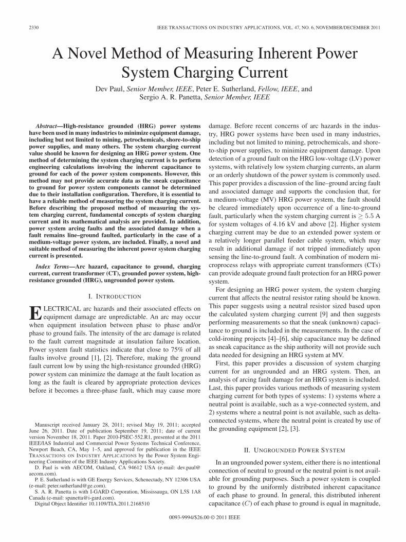
Fig. 1. (a) Ungrounded power system voltage and inherent capacitive currentvector diagram—Power system phase sequence clockwise. (b) Power systeminherent capacitive current vector diagram.
and the corresponding reactance is generally represented asXCO. Thus, for a 60-Hz power system, the value of XCO inohms will be (1/j2π60C), where C is in farads.
The system charging current of an ungrounded power systemwithout any ground fault is shown in Fig. 1(a). This systemcharging current can be detected by a zero-sequence CT onthe main circuit breaker at the time of closing the breaker. ThisCT should be a high-accuracy class or digital clamp on type CTwith a digital recorder. Once the system is energized, this CTwill not be able to measure the system charging current even ifa line–ground fault occurs.
Under the normal power system condition, the system charg-ing current from each phase to ground represented by (1)is shown in Fig. 1(a), and their vector addition is shown inFig. 1(b). See [2, Fig. 3.5] for additional clarifications
IAC = IBC = ICC = ICO = j wCEL−N (in amperes) (1)
whereEL−N line–neutral system voltage, in volts;C line-to-ground capacitance of each phase, in farads;w 377 (2πf) in the case of 60-Hz frequency.For a bolted line-to-ground fault on phase A, the vector
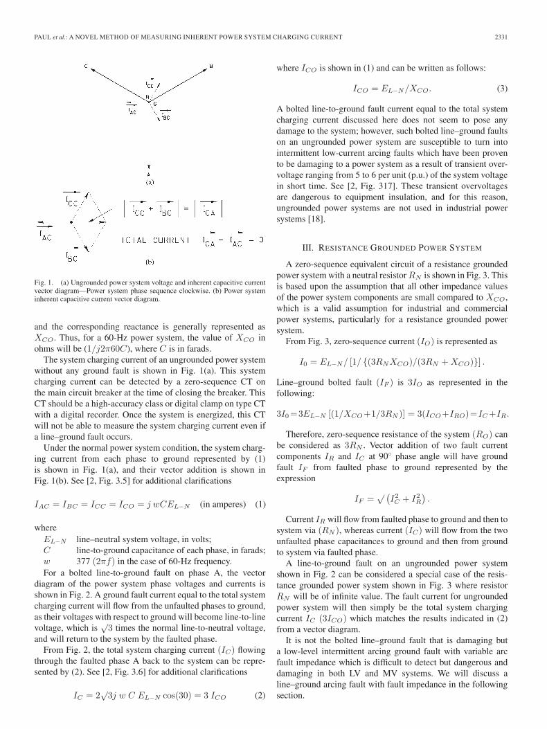
diagram of the power system phase voltages and currents isshown in Fig. 2. A ground fault current equal to the total systemcharging current will flow from the unfaulted phases to ground,as their voltages with respect to ground will become line-to-linevoltage, which is
√3 times the normal line-to-neutral voltage,
and will return to the system by the faulted phase.From Fig. 2, the total system charging current (IC) flowing
through the faulted phase A back to the system can be repre-sented by (2). See [2, Fig. 3.6] for additional clarifications
IC = 2√
3j w C EL−N cos(30) = 3 ICO (2)
where ICO is shown in (1) and can be written as follows:
ICO = EL−N/XCO. (3)
A bolted line-to-ground fault current equal to the total systemcharging current discussed here does not seem to pose anydamage to the system; however, such bolted line–ground faultson an ungrounded power system are susceptible to turn intointermittent low-current arcing faults which have been provento be damaging to a power system as a result of transient over-voltage ranging from 5 to 6 per unit (p.u.) of the system voltagein short time. See [2, Fig. 317]. These transient overvoltagesare dangerous to equipment insulation, and for this reason,ungrounded power systems are not used in industrial powersystems [18].
III. RESISTANCE GROUNDED POWER SYSTEM
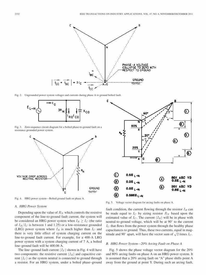
A zero-sequence equivalent circuit of a resistance groundedpower system with a neutral resistor RN is shown in Fig. 3. Thisis based upon the assumption that all other impedance valuesof the power system components are small compared to XCO,which is a valid assumption for industrial and commercialpower systems, particularly for a resistance grounded powersystem.
From Fig. 3, zero-sequence current (IO) is represented as
I0 = EL−N/ [1/ (3RNXCO)/(3RN + XCO)] .
Line–ground bolted fault (IF ) is 3IO as represented in thefollowing:
3I0 =3EL−N [(1/XCO+1/3RN )] = 3(ICO+IRO)=IC +IR.
Therefore, zero-sequence resistance of the system (RO) canbe considered as 3RN . Vector addition of two fault currentcomponents IR and IC at 90 phase angle will have groundfault IF from faulted phase to ground represented by theexpression
IF =√ (
I2C + I2
R
).
Current IR will flow from faulted phase to ground and then tosystem via (RN ), whereas current (IC) will flow from the twounfaulted phase capacitances to ground and then from groundto system via faulted phase.
A line-to-ground fault on an ungrounded power systemshown in Fig. 2 can be considered a special case of the resis-tance grounded power system shown in Fig. 3 where resistorRN will be of infinite value. The fault current for ungroundedpower system will then simply be the total system chargingcurrent IC (3ICO) which matches the results indicated in (2)from a vector diagram.
It is not the bolted line–ground fault that is damaging buta low-level intermittent arcing ground fault with variable arcfault impedance which is difficult to detect but dangerous anddamaging in both LV and MV systems. We will discuss aline–ground arcing fault with fault impedance in the followingsection.
2332 IEEE TRANSACTIONS ON INDUSTRY APPLICATIONS, VOL. 47, NO. 6, NOVEMBER/DECEMBER 2011
Fig. 2. Ungrounded power system voltages and currents during phase A to ground bolted fault.
Fig. 3. Zero-sequence circuit diagram for a bolted phase-to-ground fault on aresistance grounded power system.
Fig. 4. HRG power system—Bolted ground fault on phase A.
A. HRG Power System
Depending upon the value of RN which controls the resistivecomponent of the line-to-ground fault current, the system willbe considered an HRG power system when IR ≥ IC (the ratioof IR/IC is between 1 and 1.25) or a low-resistance grounded(LRG) power system where IR is much higher than IC andthere is very little effect of system charging current on theline-to-ground fault current. For example, for a 400-A LRGpower system with a system charging current of 7 A, a boltedline–ground fault will be 400.06 A.
The line–ground fault current (IF ) shown in Fig. 4 will havetwo components: the resistive current (IR) and capacitive cur-rent (IC) as the system neutral is connected to ground througha resistor. For an HRG system, under a bolted phase–ground
Fig. 5. Voltage vector diagram for arcing faults on phase A.
fault condition, the current flowing through the resistor IR canbe made equal to IC by sizing resistor RN based upon theestimated value of IC . The current (IR) will be in phase withneutral-to-ground voltage, which will be at 90 to the currentIC that flows from the power system through the healthy phasecapacitances to ground. Thus, these two currents, equal in mag-nitude and 90 apart, will have the vector sum of
√2 times IC .
B. HRG Power System—20% Arcing Fault on Phase A
Fig. 5 shows the phase voltage vector diagram for the 20%and 80% arcing faults on phase A on an HRG power system. Itis assumed that a 20% arcing fault on “A” phase shifts point Aaway from the ground at point Y. During such an arcing fault,
PAUL et al.: A NOVEL METHOD OF MEASURING INHERENT POWER SYSTEM CHARGING CURRENT 2333
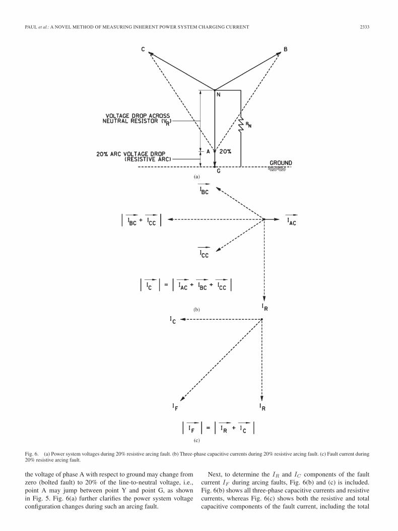
Fig. 6. (a) Power system voltages during 20% resistive arcing fault. (b) Three-phase capacitive currents during 20% resistive arcing fault. (c) Fault current during20% resistive arcing fault.
the voltage of phase A with respect to ground may change fromzero (bolted fault) to 20% of the line-to-neutral voltage, i.e.,point A may jump between point Y and point G, as shownin Fig. 5. Fig. 6(a) further clarifies the power system voltageconfiguration changes during such an arcing fault.
Next, to determine the IR and IC components of the faultcurrent IF during arcing faults, Fig. 6(b) and (c) is included.Fig. 6(b) shows all three-phase capacitive currents and resistivecurrents, whereas Fig. 6(c) shows both the resistive and totalcapacitive components of the fault current, including the total
2334 IEEE TRANSACTIONS ON INDUSTRY APPLICATIONS, VOL. 47, NO. 6, NOVEMBER/DECEMBER 2011
fault current. This analysis is based upon the assumption thatthis 20% resistive arcing fault is stationary and will not developdangerous transient overvoltage, considering that the conditionthat IR is greater than or equal to IC is maintained. Thisrelationship of IR equal to IC is represented by (4) and (5) andshown in Fig. 6(c).
This 20% arcing fault condition illustrates that the HRGsystem criterion is maintained, i.e., IR ≥ IC , if we select theresistor for a bolted fault condition with IR slightly higher thanIC . It is the authors’ opinion that many engineers have beendesigning a neutral resistor for HRG power systems by usingIR to be 1.25IC as a rule of thumb to avoid dangerous over-voltage during arcing faults. Equations (4) and (5) are derivedusing vector diagrams shown in Figs. 5 and 6(a). From theseequations, it is concluded that the displacement of A and G withrespect to neutral for a 20% arcing fault will keep IR > IC andthus will not lead to dangerous transient overvoltage conditions
IR = 0.8 p.u. = 0.8 × 3 ICO = 2.4 ICO (4)
where p.u. is the p.u. value “1” for IR under a boltedline–ground fault condition, which is 3ICO if the HRG systemis designed based upon the criterion of IR equal to IC . Usingthe data shown in Fig. 6(a), the reduced value of IC in the caseof 20% arcing fault is as follows:
tan(α) = 0.866/(0.5 + 0.8) = 0.866/1.3 = 0.666Length Y B =
√0.8662 + 1.32 = 1.562
α = tan−(0.666) = 33.67
IC = [2 cos(α) × 1.562 − 0.2] ICO = 2.4 ICO. (5)
In this 20% arcing fault, the fault current component IR
becomes 80% of the IR value for a bolted ground fault, andthe total capacitive component IC is also reduced to 80% ofthe total system charging current during the bolted ground faultcondition.
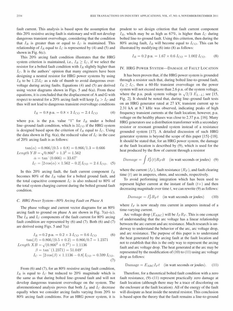
C. HRG Power System—80% Arcing Fault on Phase A
The phase voltage and current vector diagrams for an 80%arcing fault to ground on phase A are shown in Fig. 7(a)–(c).The IR and IC components of the fault current for 80% arcingfault condition are represented by (6) and (7). Both (6) and (7)are derived using Figs. 5 and 7(a)
IR = 0.2 p.u. = 0.2 × 3 ICO = 0.6 ICO (6)tan(β) = 0.866/(0.5 + 0.2) = 0.866/0.7 = 1.2371
Length XB =√
(0.8662 + 0.72) = 1.1136β = tan−(1.2371) = 51.049
IC = [2 cos(β) × 1.1136 − 0.8] ICO = 0.599 ICO.
(7)
From (6) and (7), for an 80% resistive arcing fault condition,IR is equal to IC but reduced to 20% magnitude which isthe same as that during bolted line–ground fault and will notdevelop dangerous transient overvoltage on the system. Theaforementioned analysis proves that both IR and IC decreaseequally when we consider arcing faults varying from 20% to80% arcing fault conditions. For an HRG power system, it is
prudent to set design criterion that fault current componentIR, which may be as high as 67%, is higher than IC duringbolted line-to-ground fault. Using this criterion, then during the80% arcing fault, IR will become equal to ICO. This can beillustrated by modifying (6) into (8) as follows:
IR = 0.2 p.u. = 1.67 × 0.6 ICO = 1.002 ICO. (8)
IV. HRG POWER SYSTEM—DAMAGE AT FAULT LOCATION
It has been proven that, if the HRG power system is groundedthrough a resistor such that, during bolted line-to-ground fault,IR ≥ IC , then a 60-Hz transient overvoltage on the powersystem will not exceed more than 2.6 p.u. of the system voltage,where the p.u. peak system voltage is
√2/3 EL−L; see [15,
Fig. 2]. It should be noted that, during line–ground fault testson an HRG generator rated at 27 kV, transient current up to2.31 kA at 8.7 kHz was observed, indicating peaks of highfrequency transient currents at the fault location; however, p.u.voltage on the healthy phases was close to 2.37 p.u. [16]. ManyHRG generators use a distribution transformer with a secondaryresistor or resonant grounded system instead of a resistancegrounded system [17]. A detailed discussion of such HRGgenerator systems is beyond the scope of this paper [15]–[18].It should be stated that, for an HRG power system, the damageat the fault location is described by (9), which is used for theheat produced by the flow of current through a resistor
Damage =∫
I2F (t)RF dt (in watt seconds or joules) (9)
where the current (IF ), fault resistance (RF ), and fault clearingtime (t) are in amperes, ohms, and seconds, respectively.
To avoid performing integration which has been used torepresent higher current at the instant of fault (t+) and thendecreasing magnitude over time t, we can rewrite (9) as follows:
Damage = I2F RF t (in watt seconds or joules) (10)
where IF is now steady rms current in amperes instead of atime-varying current.
Arc voltage drop (EARC) will be IF RF . This is one conceptof understanding that the arc voltage has a linear relationshipbetween the arc current and arc resistance. Much research is un-derway to understand the behavior of the arc, arc voltage drop,and arc resistance. The purpose of this paper is to understandthe heat generated by the arcing fault at the fault location andnot to establish that this is the only way to represent the arcingfault and arc voltage drop. The heat generated at the arc may berepresented by the modification of (10) to (11) using arc voltagedrop as follows:
Damage = EARCIF t (in watt seconds or joules). (11)
Therefore, for a theoretical bolted fault condition with a zerofault resistance, (9)–(11) represent practically zero damage atfault location (although there may be a trace of discoloring onthe enclosure at the fault location). All of the energy of the faultwill dissipate as heat inside the neutral resistor. This conclusionis based upon the theory that the fault remains a line-to-ground
PAUL et al.: A NOVEL METHOD OF MEASURING INHERENT POWER SYSTEM CHARGING CURRENT 2335
Fig. 7. (a) Power system voltages during 80% resistive arcing fault. (b) Three-phase capacitive current during 80% resistive arcing fault. (c) Fault current during80% resistive arcing fault.
fault. Under actual fault conditions, however, it is uncertainwhether there are bolted line-to-ground faults. An exceptionto this occurs where the system is energized with one phase
left grounded by a bolted grounding jumper. This suggests thatthere will be some fault impedance and some damage at thefault location under an actual bolted line-to-ground fault.
2336 IEEE TRANSACTIONS ON INDUSTRY APPLICATIONS, VOL. 47, NO. 6, NOVEMBER/DECEMBER 2011
TABLE IARCING FAULT DAMAGE IN p.u. ON AN HRG POWER SYSTEM DESIGNED
USING IR = 1.67IC CRITERION, INSTEAD OF USING IR = IC OR
IR = 1.25IC CRITERION
For analysis purposes on MV arcing line–ground faults withresistive arc, we will consider arc voltage drop from 20% to80% of the system voltage [12], [13]. The resistive arcing faultsat both of these extremes, i.e., 20% and 80%, were discussedat length earlier. It is uncertain whether only the resistive arcis the actual arcing fault condition or if, instead, it may justbe one specific arcing fault condition. We discussed the HRGpower system to reduce line-to-ground fault current but are stilluncertain about the transient overvoltage due to power systemdynamics as well as the system charging current interactingwith certain system inductance during arcing ground faults.For every ground fault condition, if we trip the power systemwithout any intentional time delay, then the risk of damagedue to arcing ground faults and faults involving other phasesis reduced.
For an HRG power system, under the arcing fault conditionsdiscussed, we noticed reduction in both components IR and IC
and the fault current IF . The total fault energy (damage at faultlocation) may be estimated by any of (9)–(11). Similarly, theheat generated inside the neutral resistor can be estimated by(9) or (10).
Using the criterion of IR equal to 1.67 IC during bolted line-to-ground fault condition, the resistor RN value can be derivedas follows:
IR = 1.67 IC = EL−N/RN (12)RN = EL−N/1.67 IC Ω. (13)
Using RN derived by (13), Table I provides fault damage andheat developed inside the neutral resistor in p.u. for varying re-sistive arc voltage drop EARC. This EARC is shown in Table I,column C1. The reduced current through RN during arcingfaults will become [(EL−N − EARC)/EL−N ] (IR), where IR
is the current under the bolted line-to-ground fault condition.This reduced IR is shown in column C2. The correspondingreduced IC is shown in column C3, and the fault current isshown in column C4. Columns C5 and C6 indicate the heatdeveloped at the fault location and inside the RN , respectively.The column C7 value is the sum of values indicated in columnsC5 and C6.
Assuming that we have an 11.0-kV power system with asystem charging current of 15 A and the ground fault clearingtime is 0.15 s, then the total heat generated may be calculatedusing the following:
Total Heat = (EARC) (IF )(t) + (EL−N − EARC) (IR)(t).(14)
Using (14), for a bolted fault condition and for a 20% arcingfault condition, the total heat will be 23.86 and 19.94 kJ,respectively. The same results can be obtained by applyinga multiplication factor of 14.28975 (0.15 × 15 × 11/
√3) to
the p.u. values indicated in column C7 of Table I. The samemultiplication factor can provide results to any of the values incolumns C5 and C6. The damage at the fault location seemsto be the highest for a 50% arcing fault, as seen in Table I,column C5. These theoretical data need validation by actualtest data.
The fault energy versus the fault damage at the fault locationin terms of such effects as spit marks, smoke marks, punctureinsulation, etc., is described in [14] and may be used with actualcalculated energy at the fault locations using Table I. It shouldbe stated that the results in Table I are based upon the stationaryfaults (i.e., persistent arc fault current at the system frequency).Some new insights on test results on intermittent line-to-ground fault current in the generator stator windings seem tocontain some high frequency current [16]. Practical knowledgeof such intermittent arcing fault energy in the case of HRGsystem requires further research and is beyond the scope ofthis paper.
The following questions will aid in selecting the proper RN
value and setting the ground fault relay pickup in the case of anHRG power system.
1) For the selected value of RN based upon the systemcharging current IC , do we expect transient overvoltagecondition during the arcing ground fault condition? Theanswer is no, if we select RN based upon the criterionof designing HRG system where IR ≥ IC for a boltedline–ground fault condition.
2) For an HRG power system designed based upon thecriterion of IR = IC during bolted line–ground fault andhaving IC of 10 A, it is noted that the fault current mayvary anywhere from 14.2 to 2.84 A, whereas the neutralground relay will see the change of current from 10 A inthe case of a bolted fault to 2.0 A in the case of an 80%arcing fault. This example indicates that the ground faultrelay should be sensitive and its pickup should be set at20% of the maximum expected bolted phase-to-groundfault current without any time delays for the MV powersystem.
V. POWER SYSTEM CHARGING
CURRENT MEASURING METHODS
Methods 1 and 2 have been described in the publishedliterature but may not be suitable as discussed hereinafter.
Method 1—Use an Isolated Variable 120-V Power Sourceat the Power System Transformer Neutral [1]: This methodis based upon the concept that, under an energized system,the system charging current may be obtained if the systemneutral is offset from the ground by injecting LV from anungrounded power source, as shown in Fig. 8(a). Fig. 8(b)shows an electrical equivalent circuit of the injected variablevoltage at the system neutral to facilitate recording of corre-sponding variable current through the parallel capacitances ofthe three phases. When a graph, as shown in Fig. 8(c), indicates
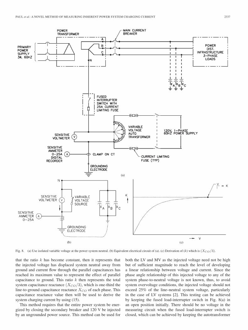
PAUL et al.: A NOVEL METHOD OF MEASURING INHERENT POWER SYSTEM CHARGING CURRENT 2337
Fig. 8. (a) Use isolated variable voltage at the power system neutral. (b) Equivalent electrical circuit of (a). (c) Derivation of (k) which is (XCO/3).
that the ratio k has become constant, then it represents thatthe injected voltage has displaced system neutral away fromground and current flow through the parallel capacitances hasreached its maximum value to represent the effect of parallelcapacitance to ground. This ratio k then represents the totalsystem capacitance reactance (XCO/3), which is one-third theline-to-ground capacitance reactance XCO of each phase. Thiscapacitance reactance value then will be used to derive thesystem charging current by using (15).
This method requires that the entire power system be ener-gized by closing the secondary breaker and 120 V be injectedby an ungrounded power source. This method can be used for
both the LV and MV as the injected voltage need not be highbut of sufficient magnitude to reach the level of developinga linear relationship between voltage and current. Since thephase angle relationship of this injected voltage to any of thesystem phase-to-neutral voltage is not known, thus, to avoidsystem overvoltage conditions, the injected voltage should notexceed 25% of the line–neutral system voltage, particularlyin the case of LV systems [2]. This testing can be achievedby keeping the fused load-interrupter switch in Fig. 8(a) inan open position initially. There should be no voltage in themeasuring circuit when the fused load-interrupter switch isclosed, which can be achieved by keeping the autotransformer
2338 IEEE TRANSACTIONS ON INDUSTRY APPLICATIONS, VOL. 47, NO. 6, NOVEMBER/DECEMBER 2011
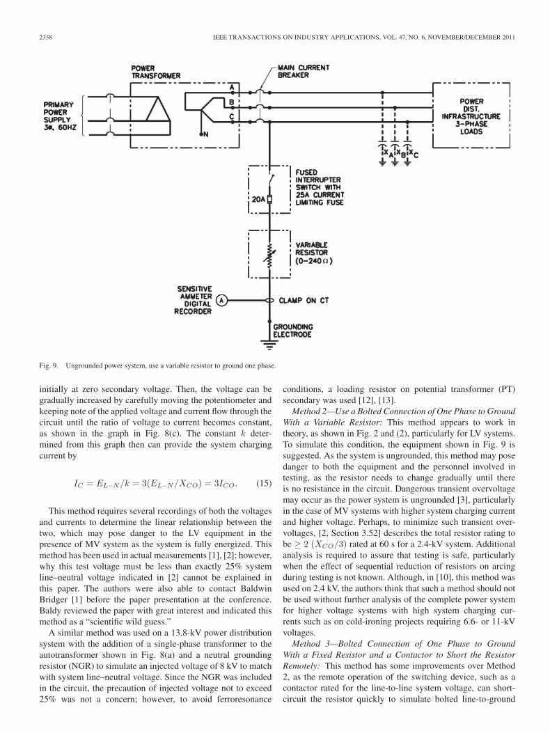
Fig. 9. Ungrounded power system, use a variable resistor to ground one phase.
initially at zero secondary voltage. Then, the voltage can begradually increased by carefully moving the potentiometer andkeeping note of the applied voltage and current flow through thecircuit until the ratio of voltage to current becomes constant,as shown in the graph in Fig. 8(c). The constant k deter-mined from this graph then can provide the system chargingcurrent by
IC = EL−N/k = 3(EL−N/XCO) = 3ICO. (15)
This method requires several recordings of both the voltagesand currents to determine the linear relationship between thetwo, which may pose danger to the LV equipment in thepresence of MV system as the system is fully energized. Thismethod has been used in actual measurements [1], [2]; however,why this test voltage must be less than exactly 25% systemline–neutral voltage indicated in [2] cannot be explained inthis paper. The authors were also able to contact BaldwinBridger [1] before the paper presentation at the conference.Baldy reviewed the paper with great interest and indicated thismethod as a “scientific wild guess.”
A similar method was used on a 13.8-kV power distributionsystem with the addition of a single-phase transformer to theautotransformer shown in Fig. 8(a) and a neutral groundingresistor (NGR) to simulate an injected voltage of 8 kV to matchwith system line–neutral voltage. Since the NGR was includedin the circuit, the precaution of injected voltage not to exceed25% was not a concern; however, to avoid ferroresonance
conditions, a loading resistor on potential transformer (PT)secondary was used [12], [13].
Method 2—Use a Bolted Connection of One Phase to GroundWith a Variable Resistor: This method appears to work intheory, as shown in Fig. 2 and (2), particularly for LV systems.To simulate this condition, the equipment shown in Fig. 9 issuggested. As the system is ungrounded, this method may posedanger to both the equipment and the personnel involved intesting, as the resistor needs to change gradually until thereis no resistance in the circuit. Dangerous transient overvoltagemay occur as the power system is ungrounded [3], particularlyin the case of MV systems with higher system charging currentand higher voltage. Perhaps, to minimize such transient over-voltages, [2, Section 3.52] describes the total resistor rating tobe ≥ 2 (XCO/3) rated at 60 s for a 2.4-kV system. Additionalanalysis is required to assure that testing is safe, particularlywhen the effect of sequential reduction of resistors on arcingduring testing is not known. Although, in [10], this method wasused on 2.4 kV, the authors think that such a method should notbe used without further analysis of the complete power systemfor higher voltage systems with high system charging cur-rents such as on cold-ironing projects requiring 6.6- or 11-kVvoltages.
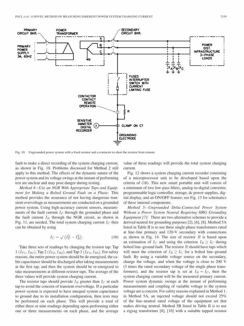
Method 3—Bolted Connection of One Phase to GroundWith a Fixed Resistor and a Contactor to Short the ResistorRemotely: This method has some improvements over Method2, as the remote operation of the switching device, such as acontactor rated for the line-to-line system voltage, can short-circuit the resistor quickly to simulate bolted line-to-ground
PAUL et al.: A NOVEL METHOD OF MEASURING INHERENT POWER SYSTEM CHARGING CURRENT 2339
Fig. 10. Ungrounded power system with a fixed resistor and a contactor to short the resistor from remote.
fault to make a direct recording of the system charging current,as shown in Fig. 10. Problems discussed for Method 2 stillapply to this method. The effects of the dynamic nature of thepower system and its voltage swings at the instant of performingtest are unclear and may pose danger during testing.
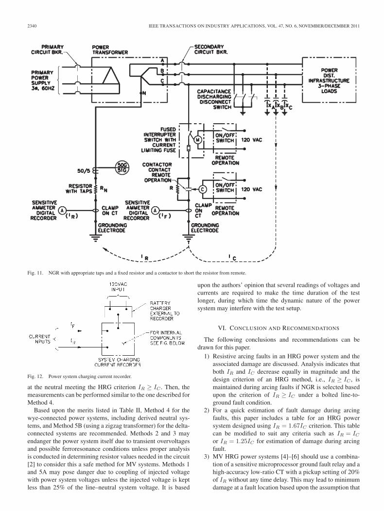
Method 4—Use an NGR With Appropriate Taps and Equip-ment for Making a Bolted Ground Fault on a Phase: Thismethod provides the assurance of not having dangerous tran-sient overvoltage as measurements are conducted on a groundedpower system. Using high-accuracy current sensors, measure-ments of the fault current IF through the grounded phase andthe fault current IR through the NGR circuit, as shown inFig. 11, are needed. The total system charging current IC thencan be obtained by using
IC =√ (
I2F − I2
R
). (16)
Take three sets of readings by changing the resistor tap: Tap1 (IF1, IR1), Tap 2 (IF2, IR2), and Tap 3 (IF3, IR3). For safetyreasons, the entire power system should be de-energized, the ca-ble capacitance should be discharged after taking measurementsat the first tap, and then the system should be re-energized totake measurements at different resistor taps. The average of thethree values will provide system charging current.
The resistor taps should provide IR greater than IC at eachtap to avoid the concern of transient overvoltage. If a particularpower system is expected to have unequal system capacitanceto ground due to its installation configuration, then tests maybe performed on each phase. This will provide a total ofeither three or nine readings depending upon performing eitherone or three measurements on each phase, and the average
value of these readings will provide the total system chargingcurrent.
Fig. 12 shows a system charging current recorder consistingof a microprocessor unit to be developed based upon thecriteria of (16). This new smart portable unit will consist ofa minimum of two low-pass filters, analog-to-digital converter,programmable logic controller, storage, dc power supplies, dig-ital display, and an ON/OFF feature; see Fig. 13 for schematicsof these internal components.
Method 5—Ungrounded Delta-Connected Power SystemWithout a Power System Neutral Requiring HRG GroundingEquipment [7]: There are two alternative schemes to provide aderived neutral for grounding purposes [2], [6], [8]. Method 5Alisted in Table II is to use three single-phase transformers ratedat line–line primary and 120-V secondary with connectionsas shown in Fig. 14. The size of resistor R is based uponan estimation of IC and using the criterion IR ≥ IC duringbolted line–ground fault. The resistor R should have taps whichwill meet the criterion of IR ≥ IC for a bolted line–groundfault. By using a variable voltage source on the secondary,change the voltage, and when the voltage is close to 200 V(3 times the rated secondary voltage of the single phase trans-formers), and the resistor tap is set at IR = IC , then thesystem charging current will be the measured primary current.Power system dynamic swings at the instant of performingmeasurements and coupling of variable voltage to the systemvoltage are a concern. For safety reasons explained in Method 1,in Method 5A, an injected voltage should not exceed 25%of the line–neutral rated voltage of the equipment set thatmakes driving neutral. Method 5B listed in Table II is to usea zigzag transformer [8], [10] with a suitable tapped resistor
2340 IEEE TRANSACTIONS ON INDUSTRY APPLICATIONS, VOL. 47, NO. 6, NOVEMBER/DECEMBER 2011
Fig. 11. NGR with appropriate taps and a fixed resistor and a contactor to short the resistor from remote.
Fig. 12. Power system charging current recorder.
at the neutral meeting the HRG criterion IR ≥ IC . Then, themeasurements can be performed similar to the one described forMethod 4.
Based upon the merits listed in Table II, Method 4 for thewye-connected power systems, including derived neutral sys-tems, and Method 5B (using a zigzag transformer) for the delta-connected systems are recommended. Methods 2 and 3 mayendanger the power system itself due to transient overvoltagesand possible ferroresonance conditions unless proper analysisis conducted in determining resistor values needed in the circuit[2] to consider this a safe method for MV systems. Methods 1and 5A may pose danger due to coupling of injected voltagewith power system voltages unless the injected voltage is keptless than 25% of the line–neutral system voltage. It is based
upon the authors’ opinion that several readings of voltages andcurrents are required to make the time duration of the testlonger, during which time the dynamic nature of the powersystem may interfere with the test setup.
VI. CONCLUSION AND RECOMMENDATIONS
The following conclusions and recommendations can bedrawn for this paper.
1) Resistive arcing faults in an HRG power system and theassociated damage are discussed. Analysis indicates thatboth IR and IC decrease equally in magnitude and thedesign criterion of an HRG method, i.e., IR ≥ IC , ismaintained during arcing faults if NGR is selected basedupon the criterion of IR ≥ IC under a bolted line-to-ground fault condition.
2) For a quick estimation of fault damage during arcingfaults, this paper includes a table for an HRG powersystem designed using IR = 1.67IC criterion. This tablecan be modified to suit any criteria such as IR = IC
or IR = 1.25IC for estimation of damage during arcingfault.
3) MV HRG power systems [4]–[6] should use a combina-tion of a sensitive microprocessor ground fault relay and ahigh-accuracy low-ratio CT with a pickup setting of 20%of IR without any time delay. This may lead to minimumdamage at a fault location based upon the assumption that
PAUL et al.: A NOVEL METHOD OF MEASURING INHERENT POWER SYSTEM CHARGING CURRENT 2341
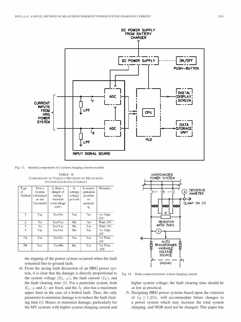
Fig. 13. Internal components of a system charging current recorder.
TABLE IICOMPARISON OF VARIOUS METHODS OF MEASURING
SYSTEM CHARGING CURRENT
the tripping of the power system occurred when the faultremained line-to-ground fault.
4) From the arcing fault discussion of an HRG power sys-tem, it is clear that the damage is directly proportional tothe system voltage (EL−N ), the fault current (IF ), andthe fault clearing time (t). For a particular system, bothEL−N and IC are fixed, and the IF also has a maximumupper limit in the case of a bolted fault. Thus, the onlyparameter to minimize damage is to reduce the fault clear-ing time (t). Hence, to minimize damage, particularly forthe MV systems with higher system charging current and
Fig. 14. Delta-connected power system charging current.
higher system voltage, the fault clearing time should beas low as practical.
5) Designing HRG power systems based upon the criterionof IR ≥ 1.25IC will accommodate future changes toa power system which may increase the total systemcharging, and NGR need not be changed. This paper has
2342 IEEE TRANSACTIONS ON INDUSTRY APPLICATIONS, VOL. 47, NO. 6, NOVEMBER/DECEMBER 2011
presented an analysis indicating that the fault damagemay not necessarily increase with the slight increase ofNRG current rating which is higher than system chargingcurrent, as it depends upon fault impedance. Maximumfault damage occurs when the fault resistance is suchthat voltage drop across the fault resistance is one-halfthe system voltage, as shown in Table II. Probabilityand sensitivity analysis of NGR rating which is higherthan the system charging current versus fault damage,taking into consideration the ground fault relay trippingtime affected by fault impedance, should be performed tooptimize NGR current rating.
6) A new novel method of measuring system chargingwithout using variable voltage source while keeping thepower grounded is considered safer, particularly for MVsystems. Direct digital reading is possible with the de-velopment of a device based upon the concept shown inFig. 13.
ACKNOWLEDGMENT
The authors would like to thank B. Chavdarian with the Portof Long Beach, who requested to review the existing literaturefor measuring the inherent system charging current of medium-voltage power systems, which resulted in this paper.
REFERENCES
[1] B. Bridger, “High-resistance grounding,” IEEE Trans. Ind. Appl., vol.IA-19, no. 1, pp. 15–21, Jan. 1983.
[2] J. R. Dunki-Jacobs, F. J. Shields, and C. St. Pierre, Industrial PowerSystem Grounding Design Handbook. Schenectady, NY: Conrad St.Pierre, 2007.
[3] D. D. Ship and F. J. Angelini, “Characteristics of Different Power SystemsNeutral Grounding Techniques: Fact & Fiction,” in Conf. Rec. IEEE IASAnnu. Meeting, 1988, vol. 2, pp. 1535–1544.
[4] D. Paul and V. Haddadian, “Shore-to-ship power supply system for acruise ship,” in Conf. Rec. IEEE IAS Annu. Meeting, Houston, TX,Oct. 2009, pp. 1–7.
[5] D. Paul, P. R. Ben Chavdarian, and V. Haddadian, “Cable-capacitancedischarge time with and without the application of grounding device,” inProc. I&CPS Conf., Tallahassee, FL, May 2010, pp. 1–6.
[6] D. Paul and B. Ben Chavdarian, “Closer look at the grounding of coldironing power system,” in Proc. I&CPS Conf., May 2009, pp. 1–7.
[7] P. Sutherland and A. Mansoor, “Conversion of ungrounded system to ahigh-resistance grounded power system,” in Proc. I&CPS Conf., Dear-born, MI, May 2006, pp. 1–6.
[8] E. R. Detjen and K. R. Shah, “Grounding transformer applications andassociated protection schemes,” IEEE Trans. Ind. Appl., vol. 28, no. 4,pp. 788–796, Jul./Aug. 1992.
[9] D. S. Baker, “Charging current data for guesswork-free design of high-resistance grounded systems,” IEEE Trans. Ind. Appl., vol. IA-15, no. 2,pp. 136–140, Mar. 1974.
[10] E. R. Detjen, “Grounding transformer applications and associated pro-tection schemes,” IEEE Trans. Ind. Appl., vol. 24, no. 4, pp. 788–796,Jul./Aug. 1992.
[11] J. A. Demcko, S. K. Younger, R. G. Farmer, and M. W. Schultz, “On-linemeasurement of auxiliary system capacitance to ground for groundingresistor sizing,” in Proc. Amer. Power Conf., 1991, vol. 53, no. 2,pp. 1443–1447.
[12] F. K. Fox and L. B. McClung, “Ground fault tests on high resistancegrounded 13.8 kV electrical distribution system of modern large chemicalplant, Part—1,” IEEE Trans. Ind. Appl., vol. IA-10, no. 5, pp. 581–600,Sep. 1974.
[13] L. B. McClung and B. W. Whittington, “Ground fault tests on high resis-tance grounded 13.8 kV electrical distribution system of modern largechemical plant, Part—11,” IEEE Trans. Ind. Appl., vol. IA-10, no. 5,pp. 601–617, Sep. 1974.
[14] L. J. Kingrey, R. Painter, and A. S. Locker, “Applying high resistanceneutral grounding in medium voltage systems,” in Proc. PCIC Conf.,San Antonio, TX, pp. 31–41.
[15] IEEE Guide for the Application of Neutral Grounding in Electric UtilitySystems, Part 11—Grounding Synchronous Generator Systems, IEEE Std.C62.92-1989, 1989.
[16] D. Braun and G. S. Koeppl, “Intermittent line-to-ground faults in genera-tor stator windings and consequences on neutral grounding,” IEEE Trans.Power Del., vol. 25, no. 2, pp. 876–881, Apr. 2010.
[17] P. G. Brown, I. B. Johnson, and J. R. Stevenson, “Generator neutralgrounding: Some aspects of application for distribution transformer withsecondary resistor and resonant types,” IEEE Trans. Power App. Syst.,vol. PAS-97, no. 3, pp. 683–694, May 1978.
[18] IEEE Recommended Practices for Grounding of Industrial and Commer-cial Power Systems, IEEE Std. 142-2007, 2007.
Dev Paul (M’73–SM’90) received the M.S. degreein electrical engineering from Punjab University,Chandigarh, India, in 1971.
In 1972, he joined Kaiser Engineers which wentthrough merging with other design engineering com-panies, and it is currently AECOM, Oakland, CA. Asa Design Engineer, he worked on a variety of heavyindustrial, Department of Defense, and Departmentof Energy facilities and commercial and electrifiedrapid transit projects. He is currently the SeniorProject Director with the Transportation Division,
AECOM, where he is responsible for electrical work related to cold-ironingprojects, airport projects, and ac/dc rail transit projects. He is the author of 20technical papers which have been published in American Public TransportationAssociation (APTA) and IEEE conferences proceedings.
Mr. Paul was a recipient of the Ralph H. Lee Award from the IEEE forhis paper on dc power systems grounding in 2002. He is the Vice-Chair ofDraft IEEE/ISO/IEC Standard P1713 on shore power connections to shipsand the Chairperson of Draft IEEE Standard P1627, “Standard for GroundingPractices for DC Electrification OCS Including Application of Lightning SurgeArresters.” He is an active member of many IEEE committees responsible forupgrading color book series into mother books. In the past, he served as a Vice-Chair for the IEEE Industry Applications Society (IAS) Oakland Chapter.
Peter E. Sutherland (S’77–M’79–SM’97–F’07) re-ceived the A.S. degree in electrical engineering tech-nology and the B.S. degree in electrical engineeringfrom The University of Maine, Orono, the M.Sc.E.degree in electrical engineering from the Universityof New Brunswick, Fredericton, NB, Canada, andthe Ph.D. degree in electric power engineering fromRensselaer Polytechnic Institute, Troy, NY.
In 1987, he joined General Electric (GE) Com-pany, Schenectady, NY, where he held a variety ofpositions, such as Senior Engineer in the GE Power
Systems Energy Consulting Department. In 2001, he joined Super Power,Inc., Schenectady, where he worked on applications of superconductivity toelectric power systems. In 2003, he joined EPRI, Schenectady, as a ConsultingEngineer. Since 2005, he has been a Lead Power Systems Engineer with GEEnergy Services, Schenectady. He is the author of numerous technical papers.
Dr. Sutherland is a member of Phi Kappa Phi, Eta Kappa Nu, and Tau BetaPi. He is a Registered Professional Engineer in Pennsylvania, New Jersey,Maine, and New York and a Certified Energy Engineer. He is active in the IEEEIndustry Applications Society and in the IEEE Schenectady Section.
Sergio A. R. Panetta (SM’04) received the B.Eng.and M.Eng. degrees in electrical and electronics en-gineering from McMaster University, Hamilton, ON,Canada, in 1983 and 1996, respectively.
Since graduation, he has been employed in thepower and relay protection field. He is currently withI-GARD Corporation, Mississauga, ON.
Mr. Panetta is a member of the Association ofProfessional Engineers of Ontario. He is active inseveral committees for Under Laborites, compliancesafety appliance, IEEE, and International Electro-
technical Commission (IEC).