
Splice site identification using probabilistic parameters and SVM classification
Upload
khangminh22Category
view
0download
0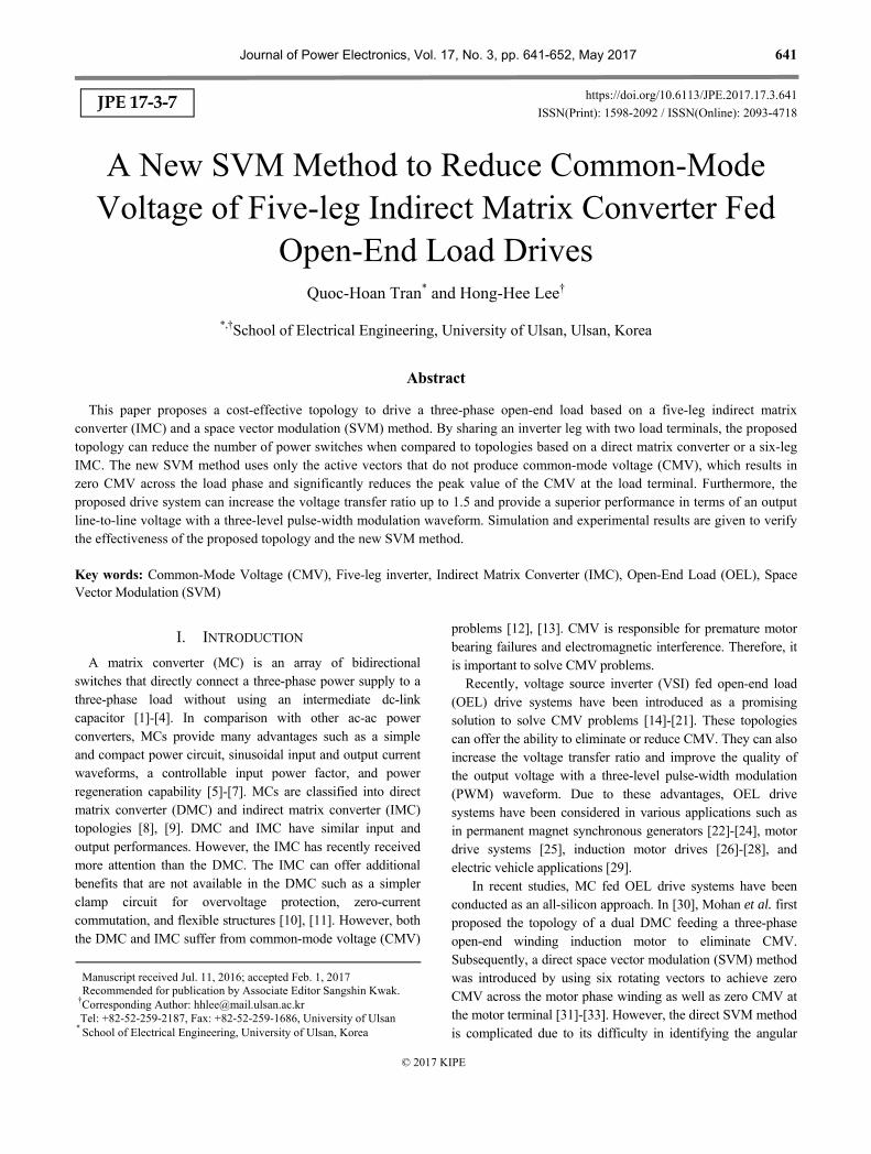
Journal of Power Electronics, Vol. 17, No. 3, pp. 641-652, May 2017 641
https://doi.org/10.6113/JPE.2017.17.3.641
ISSN(Print): 1598-2092 / ISSN(Online): 2093-4718
JPE 17-3-7
A New SVM Method to Reduce Common-Mode Voltage of Five-leg Indirect Matrix Converter Fed
Open-End Load Drives
Quoc-Hoan Tran* and Hong-Hee Lee†
*,†School of Electrical Engineering, University of Ulsan, Ulsan, Korea
Abstract
This paper proposes a cost-effective topology to drive a three-phase open-end load based on a five-leg indirect matrix converter (IMC) and a space vector modulation (SVM) method. By sharing an inverter leg with two load terminals, the proposed topology can reduce the number of power switches when compared to topologies based on a direct matrix converter or a six-leg IMC. The new SVM method uses only the active vectors that do not produce common-mode voltage (CMV), which results in zero CMV across the load phase and significantly reduces the peak value of the CMV at the load terminal. Furthermore, the proposed drive system can increase the voltage transfer ratio up to 1.5 and provide a superior performance in terms of an output line-to-line voltage with a three-level pulse-width modulation waveform. Simulation and experimental results are given to verify the effectiveness of the proposed topology and the new SVM method. Key words: Common-Mode Voltage (CMV), Five-leg inverter, Indirect Matrix Converter (IMC), Open-End Load (OEL), Space Vector Modulation (SVM)
I. INTRODUCTION
A matrix converter (MC) is an array of bidirectional switches that directly connect a three-phase power supply to a three-phase load without using an intermediate dc-link capacitor [1]-[4]. In comparison with other ac-ac power converters, MCs provide many advantages such as a simple and compact power circuit, sinusoidal input and output current waveforms, a controllable input power factor, and power regeneration capability [5]-[7]. MCs are classified into direct matrix converter (DMC) and indirect matrix converter (IMC) topologies [8], [9]. DMC and IMC have similar input and output performances. However, the IMC has recently received more attention than the DMC. The IMC can offer additional benefits that are not available in the DMC such as a simpler clamp circuit for overvoltage protection, zero-current commutation, and flexible structures [10], [11]. However, both the DMC and IMC suffer from common-mode voltage (CMV)
problems [12], [13]. CMV is responsible for premature motor bearing failures and electromagnetic interference. Therefore, it is important to solve CMV problems.
Recently, voltage source inverter (VSI) fed open-end load (OEL) drive systems have been introduced as a promising solution to solve CMV problems [14]-[21]. These topologies can offer the ability to eliminate or reduce CMV. They can also increase the voltage transfer ratio and improve the quality of the output voltage with a three-level pulse-width modulation (PWM) waveform. Due to these advantages, OEL drive systems have been considered in various applications such as in permanent magnet synchronous generators [22]-[24], motor drive systems [25], induction motor drives [26]-[28], and electric vehicle applications [29].
In recent studies, MC fed OEL drive systems have been conducted as an all-silicon approach. In [30], Mohan et al. first proposed the topology of a dual DMC feeding a three-phase open-end winding induction motor to eliminate CMV. Subsequently, a direct space vector modulation (SVM) method was introduced by using six rotating vectors to achieve zero CMV across the motor phase winding as well as zero CMV at the motor terminal [31]-[33]. However, the direct SVM method is complicated due to its difficulty in identifying the angular
Manuscript received Jul. 11, 2016; accepted Feb. 1, 2017 Recommended for publication by Associate Editor Sangshin Kwak.
†Corresponding Author: [email protected] Tel: +82-52-259-2187, Fax: +82-52-259-1686, University of Ulsan
* School of Electrical Engineering, University of Ulsan, Korea
© 2017 KIPE

642 Journal of Power Electronics, Vol. 17, No. 3, May 2017
Fig. 1. Topology of a five-leg IMC fed three-phase OEL drive.
position of the rotating vectors, which simultaneously rotate counterclockwise and clockwise in the complex plane. Alternatively, a carrier-based modulation method with a simple computation was recently proposed for a dual DMC topology that eliminates CMV [34]. In terms of multi-phase applications, the topologies of five-phase and seven-phase DMC have been used to remove the CMVs of five-phase and seven-phase open-end winding motor drives in [35] and [36], respectively. Despite the possibility of CMV elimination, an OEL drive based on dual DMC requires twice the number of power switches as that of the DMC for a conventional three-phase drive. In order to decrease the number of power switches, an IMC has been suggested for OEL drives. In [37]-[39], a three-phase OEL drive is fed by a six-leg IMC which is composed of a bidirectional rectifier stage and a six-leg inverter stage. In these studies, the SVM method is developed to remove the CMV across the load phase and to limit the peak
value of the CMV at the load terminal to 1 3 of the input
phase voltage amplitude. The drive based on a six-leg IMC can decrease the number of power switches by twelve when compared to one based on a dual DMC. However, the six-leg IMC topology still requires an extra six power switches when compared with the conventional IMC topology for a three-phase drive.
In an effort to decrease the number of power switches, this paper proposes a new topology to drive a three-phase OEL based on a five-leg IMC. Even though the basic idea of a five-leg IMC fed three-phase OEL drive system was succinctly introduced in [40], reduction of the CMV at the load terminal was not discussed profoundly, and experimental results were not provided. Fig. 1 shows the proposed five-leg IMC fed three-phase OEL drive, in which a five-leg inverter stage is used to supply power for the two sets of the load terminal. The proposed OEL drive topology with a five-leg IMC can decrease the number of power switches by 14 when compared to that with a dual DMC, and by 2 when compared to that with a six-leg IMC. Furthermore, a new SVM method to generate the desired output voltage is developed by using an appropriate pair of two active vectors instead of zero vectors, which reduces the peak value of the CMV at the load terminal by as much as 42%. Moreover, the proposed SVM method still achieves zero CMV across the load phase thanks to the selected
Fig. 2. Two-level space vector diagram of the individual inverter stages.
active vectors, which do not produce any CMV.
The performance of the proposed three-phase OEL drive system and the new SVM method are evaluated by simulation and experimental results.
II. FIVE-LEG IMC FED THREE-PHASE OEL DRIVE AND CMV ANALYSIS
A three-phase OEL drive can be obtained by opening the star-terminal of a traditional three-phase ac motor with the star-connected stator winding. Fig. 1 shows a three-phase OEL drive fed by a five-leg IMC topology which consists of a three-phase active front-end rectifier stage and a five-leg inverter stage. The rectifier stage is a standard current source rectifier with six bidirectional switches that can provide a positive dc-link voltage and synthesize a sinusoidal input current waveform [41]. Meanwhile, the five-leg inverter stage can operate as two independent three-phase inverters to supply a desired output voltage with an arbitrary frequency and amplitude for the OEL drive. In the five-leg IMC topology, an inverter leg is shared with two load terminals. As shown in Fig. 1, the two load terminals A2 and C1 are fed by the common inverter leg C. Therefore, the proposed five-leg IMC fed three-phase OEL drive can decrease the number of power switches when compared with those based on a dual DMC or a six-leg IMC. Moreover, the five-leg IMC fed three-phase OEL drive allows supplying power from both sides. As a result, the voltage transfer ratio can achieve a higher value than that of the IMC for a traditional three-phase drive.
A. Space Vector of a Three-phase OEL Drive
From Fig. 1, the five-leg inverter stage can be considered as a combination of two three-phase two-level inverters that share a common inverter leg. Each of the inverters can generate eight voltage vectors as depicted in Fig. 2. Space vector diagrams of the individual inverter stages are composed of six active vectors 1 6v v
with a fixed direction and two zero vectors
0 7,v v . The active vectors of each inverter stage have the
same magnitude but appear in opposite directions. Each voltage vector is denoted by a set of the switching functions
, ,AP BP CPS S S in the case of inverter stage-1 and
, ,CP DP EPS S S in the case of inverter stage-2. The switching
vc
Rectifier stage Five-leg inverter stage
Sap Sbp Scp
San Sbn Scn
SAP
SAN
SBP
SBN SCN
SCP SDP
SDN
SEP
SEN
Input filter
ia
ib
ic
va
vb
Cf
Lf
A1
B1
C1
A2
B2
C2
iA
iB
iC
Stage-1 Stage-2
1v
2v
3v
4v
7v
0v
5v
6v
4v
5v
6v
1v
2v
3v
0v
7v

A New SVM Method to Reduce Common-Mode Voltage of Five-leg Indirect Matrix Converter … 643
Fig. 3. Three-level space vector diagram of the five-leg inverter stage.
function of the upper switch in each leg is defined as follows:
XPXP
XP
1, S is ON stateS = , where X=A E.
0, S is OFF state
(1)
In order to explain the space vector modulation of the three-phase OEL drive, the voltage vectors of the two inverter stages are defined as follows:
2 3 4 32
31jj j
1 A1 B1 C1 1v v v e v e V e
(2)
2 3 4 32,
32jj j
2 A2 B2 C2 2v v v e v e V e
(3)
where A1v , B1v , C1v , A2v , B2v and C2v are the output
voltages measured at the load terminals with respect to the ground point of the power supply.
The total voltage vector of the OEL drive is synthesized by combining the two voltage vectors of the two inverter stages, which is represented as follows:
2 3 4 3
2 3 4 3
2
32
,3
o
o 1 2
j jA1 A2 B1 B2 C1 C2
jj jA1A2 B1B2 C1C2 o
v v v
v v v v e v v e
v v e v e V e
(4)
where A1A2v , B1B2v and C1C2v are the output phase voltages
of the OEL drive. Fig. 3 shows a space vector diagram of the five-leg inverter stage, which is a combination of those of the two three-phase inverters. The space vector , 0 7xyv x y
denotes the
voltage vector synthesized by the two voltage vectors xv
and
yv
of the inverter stage-1 and stage-2, respectively. The
combined space vector diagram has 64 voltage vectors because each inverter stage can generate eight voltage vectors. According to Fig. 3, a combined space vector diagram of the five-leg inverter stage is similar to that of a three-level inverter topology resulting in a three-level PWM output line-to-line voltage waveform [14]. Therefore, the output voltage
Fig. 4. CMV in five-leg IMC fed three-phase OEL drive.
performance becomes superior to that of the traditional IMC topology, which has a two-level PWM waveform.
B. CMV in a Three-Phase OEL Drive
In general, the CMV of a MC is defined as the voltage difference between the neutral point of the load and the ground point of the power supply. However, due to the absence of a neutral point, the CMVs of the MC in an OEL drive is typically classified into two types: the CMV at the load terminal, and the CMV across the load phase. The CMV at the load terminal is responsible for EMI problems, whereas the CMV across the load phase causes a circulating common-mode current in the OEL drive which affects the conduction loss in the stator winding resistance of ac motors [20], [42]. Fig. 4 illustrates the CMVs in a five-leg IMC fed three-phase OEL drive.
From Fig. 4, the CMVs at the two load terminals are defined
as 1CMv and 2CMv , and they are given as follows:
3A1 B1 C1
CM1
v v vv
(5)
.3
A2 B2 C2CM2
v v vv
(6)
The CMV across the load phase is defined as the difference in the voltages between the CMVs at the two load terminals:
.CM CM1 CM2v v v (7)
Among the 64 voltage space vector combinations shown in Fig. 3, certain vectors can generate zero CMV across the load phase. These vectors form a hexagon, as shown in Fig. 5, which consists of 12 active vectors and 8 zero vectors located at the peaks and center of the hexagon, respectively [14]. Table I summarizes the peak values of the CMVs at the load terminals and the corresponding CMV across the load phase of these vectors for all possible operating ranges. The zero CMV across the load phase is achieved because the CMVs generated at the two load terminals are equal and appear at the opposite ends of the load. In other words, the CMV across the load phase becomes zero when only these vectors are selected to modulate the five-leg inverter stage. Meanwhile, the peak value of the
CMV at the load terminal can be limited to 1 3 of the input
phase voltage amplitude when the appropriate active vectors are used to synthesize the reference output voltage. Consequently, the circulating common-mode current and its associated problems can be eliminated or reduced in the OEL drive.
14v
24v15v
25v
35v
26v
36v
46v
31v
41v
42v
51v
52v
62v
53v
63v
13v
64v
16v27v
20v
34v
05v 75v
21v
37v
30v
45v 06v76v
47v 32v
01v
71v
56v40v
00v
11v
70v
77v
55v
44v
33v
10v23v
04v
74v
65v 17v
57v
50v
61v02v72v
43v
12v
67v
60v54v
03v 73v
07v 22v
66v
vc
ia
ib
ic
va
vb
Cf
Lf
A1
B1
C1
A2
B2
C2
Rg
vCM1 vCM2
Rg
Motor Frame
Circulating common-mode current
Sap Sbp Scp SAP SBP SCP SD
P
SEP
San Sbn Scn SAN SBN SCN SDN SEN
644 Journal of Power Electronics, Vol. 17, No. 3, May 2017
TABLE I CMV AT THE LOAD TERMINAL AND CMV ACROSS THE LOAD
PHASE WITH SPECIFIC VOLTAGE VECTORS
Input current sector
Output voltage vector
Peak value of the CMV at the load terminal
CMV across the load phase
VCM1,peak VCM2,peak vCM
1, 3, 5
11 13 15
31 33 35
51 53 55
, , ,
, , ,
, ,
v v v
v v v
v v v
3iV 3iV 0
22 24 26
42 44 46
62 64 66
, , ,
, , ,
, ,
v v v
v v v
v v v
3iV 3iV 0
00v
3 2iV 3 2iV 0
77v
iV iV 0
2, 4, 6
11 13 15
31 33 35
51 53 55
, , ,
, , ,
, ,
v v v
v v v
v v v
3iV 3iV 0
22 24 26
42 44 46
62 64 66
, , ,
, , ,
, ,
v v v
v v v
v v v
3iV 3iV 0
00v
iV iV 0
77v
3 2iV 3 2iV 0
III. NEW SVM METHOD FOR A FIVE-LEG IMC FED THREE-PHASE OEL DRIVE
The newly proposed SVM method for five-leg IMC fed three-phase OEL drives utilizes four active vectors in each sampling period to generate a desired output voltage. These active vectors are selected from the simplified space vector diagram in Fig. 5. As a result, the CMV across the load phase is eliminated and the CMV at the load terminal is reduced.
A. SVM Method for the Rectifier Stage
The rectifier stage is connected to a three-phase power supply, which is assumed to be a sinusoidal and balanced voltage source as follows:
cosa i iv V t
(8)
cos 2 3b i iv V t (9)
cos 4 3c i iv V t (10)
where iV and i are the amplitude and angular frequency
of the input phase voltage, respectively. The SVM method for the rectifier stage is based on a space vector analysis of the input voltage and input current. The space vectors of the input voltage and input current are described as follows:
2 3 4 32
3ijj j
i a b c iv v v e v e V e
(11)
2 3 4 32
3ijj j
i a b c ii i i e i e I e
(12)
where iI and i are the amplitude and phase angle of the
Fig. 5. Simplified space vector diagram of the five-leg inverter stage with zero CMV across the load phase.
Fig. 6. Space vector diagram of the rectifier stage.
input phase current, respectively.
Fig. 6 shows a space vector diagram of the rectifier stage, which is composed of six active vectors and three zero vectors. Each current space vector represents a switching state of the
rectifier stage. For example, when the current vector abi
is
applied, the input phases a and b are connected to the positive pole and negative pole of the dc-link voltage, respectively. Table II shows all of the possible switching states corresponding to the input current space vectors.
For clarity, assume that the reference input current space vector is located in sector 1 6 6i and that the
following constraint is used to calculate the duty ratios:
.i R1 ab R2 aci d i d i
(13)
By projecting (13) onto the - axes, the following
equations are obtained:
cos cos 6 cos 6i i R1 ab R2 acI d I d I
(14)
sin sin 6 sin 6i i R1 ab R2 acI d I d I
(15)
Then the duty ratios of the two active vectors abi
and aci
are given from Fig. 6:
sin 6R1 i id m
(16)
sin 6R2 i id m
(17)
where i i dcm I I is the rectifier stage modulation index, dcI
15v24v
35v
26v
46v
31v
42v
51v
62v
53v
13v
64v
00v
11v22v
33v
44v
55v
66v
77v
ii
aci
bci
bai
cai
cbi
abi
aai bbi
cci
iv
ii
A New SVM Method to Reduce Common-Mode Voltage of Five-leg Indirect Matrix Converter … 645
TABLE II SWITCHING STATES ACCORDING TO THE INPUT CURRENT VECTORS
Input current vectors Switching states
ii
iI i Sap San Sbp Sbn Scp Scn
abi
2 3 dcI 6 1 0 0 1 0 0
aci
2 3 dcI 6 1 0 0 0 0 1
bci
2 3 dcI 2 0 0 1 0 0 1
bai
2 3 dcI 5 6 0 1 1 0 0 0
cai
2 3 dcI 7 6 0 1 0 0 1 0
cbi
2 3 dcI 3 2 0 0 0 1 1 0
aai
0 x 1 1 0 0 0 0
bbi
0 x 0 0 1 1 0 0
cci
0 x 0 0 0 0 1 1
is the average value of the dc-link current, and i i is
the displacement angle between the input voltage and the current space vectors.
In the rectifier stage modulation, the zero vectors are not
considered, and the modulation index im is usually kept at
unity. Therefore, the duty ratios of the two active vectors, abi
and aci
, are recalculated to complete a sampling period as
follows:
cos 2 3
cosiR1
abR1 R2 i
dd
d d
(18)
cos 4 3.
cosiR2
acR1 R2 i
dd
d d
(19)
The average value of the dc-link voltage is:
3
cos ,2 cos
idc ab a b ac a c
i
VV d v v d v v
(20)
where cos is the input power factor.
The maximum and minimum values of the average dc-link voltage are:
3 cosidc maxV V (21)
3
cos .2 idc minV V (22)
By utilizing the same approach, the duty ratios and the switching states for all of the sectors can be obtained.
B. New SVM Method for the Five-leg Inverter Stage to Reduce the CMV at the Load Terminal
For the CMV elimination across the load phase and the CMV reduction at the load terminal, the new SVM method employs only the active vectors, shown in Fig. 5, to synthesize the reference output voltage vector, which includes the vectors that generate zero CMV across the load phase.
In addition, the inverter leg C supplies both of the terminals C1 and A2 as shown in Fig. 1. Therefore, the dwell times of the switches related to these terminals must be equal at any instant.
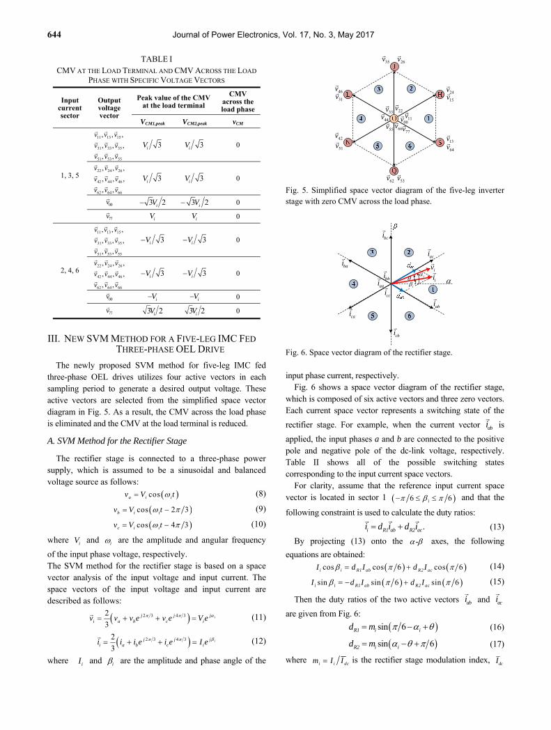
TABLE III SELECTED VECTORS ACCORDING TO THE OUTPUT VOLTAGE
SECTORS
Output voltage sector
Output voltage angle
Active vectors
Group I Group II
1 6 6 13 24,v v
64 15,v v
2 6 2 24 35,v v
15 26,v v
3 2 5 6 35 46,v v
26 31,v v
4 5 6 7 6 46 51,v v
31 42,v v
5 7 6 3 2 51 62,v v
42 53,v v
6 3 2 1 1 6 62 13,v v
53 64,v v
In order to fulfill this constraint, two appropriate switching
patterns are created for the five-leg inverter stage modulation. As shown in Fig. 5, each point of the hexagon has two active vectors, and they are divided into two groups to obtain the balanced power loss distribution on each inverter leg during each sampling period:
1) Group I includes the active vectors that generate the output voltage at inverter stage-1 with phase angle leads to that
at the inverter stage-2: 13v
, 24v
, 35v
, 46v
, 51v
and 62v
.
2) Group II includes the active vectors that generate the output voltage at inverter stage-1 with phase angle lags to that
at the inverter stage-2: 64v
, 15v
, 26v
, 31v
, 42v
and 53v
.
Group I is selected when the terminal voltage of inverter
stage-1 has a 120 phase difference when compared to that at
inverter stage-2, e.g., C1 and A2 are connected to leg C as shown in Fig. 1. Group II is selected when the phase difference
is 240 , e.g., C1 and B2 are connected to leg C. Table III
summarizes the selected active vectors in each group depending on the output voltage sectors that can be used to make the switching patterns for the five-leg inverter stage modulation.
With the aim of reducing the CMV at the load terminal, the zero vector is replaced with a pair of active vectors and a set of four active vectors is utilized to generate the desired output voltage for the five-leg inverter stage modulation. These four active vectors include the two active vectors nearest the reference output voltage vector and the two neighboring vectors. Without a loss of generality, the reference output
voltage vector is assumed to be in sector 1 6 6o ,
and the active vectors in group I are selected. The active
vectors at the points S and H, corresponding to 13v
and 24v
,
and their neighboring vectors at the points Q and J,
corresponding to 62v
and 35v
, are selected to synthesize the
reference output voltage vector as illustrated in Fig. 7. Therefore, the duty ratios of the four active vectors are calculated by the following expression:
.o I1 13 I2 24 I3 35 I4 62v = d v + d v + d v + d v
(23)
By projecting (23) onto the - axes and from the fact that
the sum of I1d , I2d , I3d and I4d should be unity, the

646 Journal of Power Electronics, Vol. 17, No. 3, May 2017
Fig. 7. Selected active vectors when reference output voltage is in sector 1 and group I is selected.
following equations are obtained:
coso o I1 dc I2 dcV d V d V (24)
1 1 2 2sin
3 3 3 3o o I1 dc I2 dc I3 dc I4 dcV d V d V d V d V
(25)
1I1 I2 I3 I4d d d d (26)
In addition, the duty ratios of the vectors 35v
and 62v
should satisfy the following relationship:
.I3 I4d d (27)
From (24)-(27), the duty ratios are given as follows:
sin 6oI1 o
dc
Vd
V
(28)
sin 6oI2 o
dc
Vd
V (29)
0.5 1I3 I4 I1 I2d d d d (30)
In order to achieve a balanced input current and output voltage, the switching events of the rectifier stage should be synchronized with those of the five-leg inverter stage in any sampling period. Moreover, the switching pattern should be arranged symmetrically to obtain a low output current distortion and to minimize the number of commutations. Fig. 8 shows the switching pattern for the proposed five-leg IMC fed three-phase OEL drive when the input current and output voltage vectors are in sector 1, and the active vectors are in group I.
The duty ratios for each of the vectors are recalculated as follows:
,
,
, ,
I1 ab I1 ab
I2 ab I2 ab
I3 ab I4 ab I3 ab I4 ab
d = d d
d = d d
d = d = d d d d
(31)
,
,
, , .
I1 ac I1 ac
I2 ac I2 ac
I3 ac I4 ac I3 ac I4 ac
d = d d
d = d d
d = d = d d d d
(32)
C. Maximum Voltage Transfer Ratio
Fig. 8. Proposed switching pattern for a five-leg IMC when the input current and output voltage vectors are in sector 1, and group I is selected.
Fig. 9. Relationship between the magnitudes of the voltage vectors.
Fig. 9 illustrates the relationship between the magnitudes of the voltage vectors for each of the inverter stages and the combined voltage vectors of the five-leg inverter stage. From Fig. 9, the magnitude of the voltage vector generated by each
of the inverter stages is 2 3 dcV , and the corresponding
magnitude of the combined voltage vector of the five-leg inverter stage is:
2 23 .
3 3xy dc dcV V V
(33)
The corresponding maximum amplitude of the output phase voltage is given by:
,
3 3 2.
2 2 3o max xy dc dcV V V V
(34)
When the voltage transfer ratio is defined as the ratio between the amplitude of the output phase voltage and the amplitude of the input phase voltage, the maximum voltage transfer ratio becomes:
, 3 2cos 1.5cos .
dc,mino max dc i
i i i i
V V V Vq
V V V V
(35)
The maximum voltage transfer ratio of the proposed five-leg IMC fed three-phase OEL drive is equal to that of drives based on the dual DMC or the six-leg IMC.
o
35v
24v
13v
62v
ov
SapSanSbp
SbnScp
Scn
SAP
SBP
SCP
,I4 abd ,I1 abd ,I2 abd ,I3 abd ,I3 acd ,I2 acd ,I1 acd
dab dac
,I4 acd
SDP
SEP
A1
B1
C1/A2
B2
C2
Ts
62v
13v
24v
35v
35v
24v
13v
62v
abi
aci
23 dcV
dcV
2 3 dcV
5v
1v
3v
1v
5v
3v
ov

A New SVM Method to Reduce Common-Mode Voltage of Five-leg Indirect Matrix Converter … 647
TABLE IV COMPARISON OF THE CMV WITH DIFFERENT TOPOLOGIES
Topology
Number of power switches (IGBTs)
Peak value of the CMV at the load terminal
CMV across the load phase
Dual DMC [30]-[34] 36 0 0
Six-leg IMC [37]-[39] 24 3iV 0
Five-leg IMC [40] 22 iV 0
Five-leg IMC with the new SVM method 22 3iV
0
TABLE V
SIMULATION AND EXPERIMENTAL PARAMETERS
Parameter Value
Power supply VL = 100 V (phase-to-phase)
Input frequency fi = 60 Hz
Input filter Lf = 1.2 mH, Cf = 27 F, Rd = 20 ΩOpen-end load R = 20 Ω, L = 15 mH
Voltage transfer ratio q = 1.2
Output frequency fo = 40 Hz
Switching frequency fs = 10 kHz (TPWM = 100 s)
Fig. 10. Simulation results of (a) the CMV at the load terminal vCM1, (b) the FFT analysis of vCM1, and (c) the CMV across the load phase vCM.
D. CMV Reduction or Elimination Comparison
Table IV summarizes the CMV values of three-phase OEL drive systems with the DMC, six-leg IMC and five-leg IMC topologies. From Table IV, the dual DMC topologies in [30]-[34] can eliminate the CMVs at the load terminal and across the load phase. Meanwhile, the six-leg IMCs in [37]-[39] can remove only the CMV across the load phase due to the decoupling topology of the IMC. In the case of the five-leg IMC, the SVM method in [40] cannot reduce the CMV at load terminal because the zero voltage vectors are still involved. However, the proposed SVM method can reduce the
CMV at the load terminal to 1 3 of the input phase voltage
thanks to the absence of the zero voltage vectors, which is same as that of the six-leg IMC.
Fig. 11. RMS values of the CMVs at the load terminal for the new SVM method and some previous SVM methods.
Fig. 12. Simulation results of (a) the dc-link voltage, (b) the input phase voltage/current, and (c) the three-phase output currents.
IV. SIMULATION RESULTS
In order to verify the effectiveness of the proposed SVM method, simulations are carried out using PSIM 9.0 software. The parameters used for the simulation are given in Table V.
CMV waveforms of the proposed three-phase OEL drive with an RL load are plotted in Fig. 10. In Fig. 10(a), the peak value of the CMV at the load terminal vCM1 decreases to 47.1 V,
corresponding to 1 3 of the input phase voltage amplitude.
The FFT analysis of the CMV in Fig. 10(b) shows that the new SVM method produces low harmonic components. Fig. 10(c) shows zero CMV across the load phase thanks to the voltage vectors that generate zero CMV across the load. The RMS values of the CMVs are shown in Fig. 11, where it can be seen that the new SVM method contributes to a smaller RMS value of the CMV when compared with the five-leg IMC in [40]. Therefore, the circulating common-mode current and the problems associated with the CMV are eliminated or reduced in the proposed OEL drive system by using the new SVM method.
Fig. 12 shows input/output waveforms of the proposed drive at a voltage transfer ratio of q = 1.2 and an output frequency of fo = 40 Hz. As shown in Fig. 12(a), the dc-link voltage waveform does not reach zero because the zero vectors are not used in the rectifier stage modulation. Fig. 12(b) shows the input current of the five-leg IMC. The input current is almost sinusoidal and slightly leads the input phase voltage due to the effect of the input LC filter. The three-phase output currents are
0.1 0.3 0.5 0.7 0.9 1.1 1.3 1.50
20
40
60
80
100
Voltage Transfer Ratio [q]
RM
S o
f C
MV
at
Loa
d T
erm
inal
[V
]
New SVM MethodSVM Method in [40]SVM Methods in [37],[39]

648 Journal of Power Electronics, Vol. 17, No. 3, May 2017
Fig. 13. Simulation results of (a) the output phase voltage vA1A2, and (b) the FFT analysis of vA1A2.
Fig. 14. Simulation results of (a) the output line-to-line voltage
, and (b) the FFT analysis of .
Fig. 15. Simulation results of the input/output waveforms at a load voltage step change from q = 0.6, fo = 30 Hz to q = 1.2, fo = 60 Hz and back.
Fig. 16. Simulation results of the input/output waveforms at a load condition step change from R = 20 Ω to R = 10 Ω and back.
TABLE VI THD OF THE PROPOSED SVM AND SOME OTHER METHODS
THD Proposed method
Method in [37], [39]
Method in [40]
Input current [%] 4.1 3.9 3.6 Output current [%] 2.2 1.9 1.5
Output voltage 1.05 0.97 0.83
balanced and sinusoidal waveforms with a low total harmonic distortion (THD) of 2.2% as can be seen in Fig. 12(c).
Figs. 13 and 14 show the output phase and line-to-line voltages, as well as their FFT analyses. As observed, the output line-to-line voltage has a three-level PWM voltage waveform. Therefore, the quality of the voltage is superior to that of the IMC for a traditional three-phase drive with a two-level PWM voltage waveform. In addition, FFT analyses of the output voltages show low harmonic components using the new SVM method.
Fig. 15 shows input/output waveforms of the proposed OEL drive system when it operates at a load input voltage step change from q = 0.6, fo = 30 Hz to q = 1.2, fo = 60 Hz and back. Fig. 16 shows the performance for the case of a load condition step change from R = 20 Ω, L = 15 mH to R = 10 Ω, L = 15 mH and back. It can be seen that the proposed SVM method can maintain sinusoidal input/output currents, a reduced CMV at the load terminal, and a good dynamic performance even when the load condition changes suddenly.
In order to comprehensively investigate the performance of the proposed method, the THDs of the input and output currents, and the output line-to-line voltage are summarized in Table VI. Even though the proposed OEL drive system shows slightly increased THD values when compared to the previous methods, this is an inevitable tradeoff due to the reduced number of power switches and CMV. However, the THD values of the proposed method comply with IEEE Std. 519-1992 (lower than 5%).
In order to evaluate the efficiency of the proposed OEL drive system, the total power loss is calculated with the aid of PSIM software. It is well-known that the power loss of each power switch consists of the switching loss and conduction loss in the insulated-gate bipolar transistor (IGBT) and the freewheeling diode.
The switching loss is calculated as follows:
,
,
IGBT switch sw on off
diode switch sw rr
P f E E
P f E
(36)
where swf is the switching frequency, and onE , offE and
rrE are the turn-on, turn-off and reverse recovery energy
losses, respectively. The conduction loss is given by:
,
,
IGBT cond CE C IGBT
diode cond d F diode
P V I D
P V I D
, (37)
A1A2 B1B2v v A1A2 B1B2v v
2A/div 50ms/div
100V/div 50ms/div
2A/div 50ms/div
50V/div 50ms/div
Load current
Load input voltage
CMV at load terminal
(a)
(b)
(c)
20R 10R 20R
A New SVM Method to Reduce Common-Mode Voltage of Five-leg Indirect Matrix Converter … 649
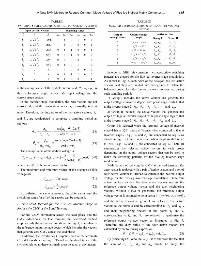
TABLE VII EFFICIENCIES OF FIVE-LEG AND SIX-LEG IMC SYSTEMS
Parameter Five-leg IMC Six-leg IMC
q = 0.6 q = 1.2 q = 0.6 q = 1.2Loss on the independent leg
(W) 1.9 6.1 2.1 6.4
Loss on the shared leg (W) 4.2 12.3 0 0
Total power loss (W) 23.9 78.7 23.4 79.6
Efficiency (%) 86.2% 88.7% 86.6% 88.5%
Fig. 17. Experimental setup of a five-leg IMC fed open-end RL load.
where CEV and dV are the collector-emitter voltage and the
diode voltage drop, CI and FI are the collector and diode
forward currents, and IGBTD and diodeD are the duty ratios
related to the conducting times of the IGBT and diode, respectively.
Finally, the total power loss is calculated by:
, , , ,loss IGBT cond diode cond IGBT switch diode switchP P P P P . (38)
Once the total power loss is determined, the system efficiency is calculated as follows:
% 100in loss
in
P P
P
. (39)
An IGBT model type IRG4PF50WD 900 V/51 A is used in this study. The total power loss and system efficiency of the five-leg IMC topology are compared to those of a six-leg IMC topology in Table VII.
V. EXPERIMENTAL RESULTS
In order to validate the performance of the proposed drive as well as the new SVM method, an experimental setup was implemented in the laboratory using a three-phase open-end RL load. The SVM method and the four-step commutation scheme are realized by a DSP 32-bit floating-point TI TMS320F28335 and a CPLD Altera EPM7128SLC84-15, respectively. The bidirectional power switches in the rectifier stage are implemented by two single discrete IGBTs IRG4PF50WD. The unidirectional power switches in the five-leg inverter stage are executed by IGBT FMG2G150US60 modules. The parameters used in the experiment are the same as those employed in the simulation. The laboratory prototype of a five-leg IMC fed three-phase open-end RL load drive is shown in Fig. 17.
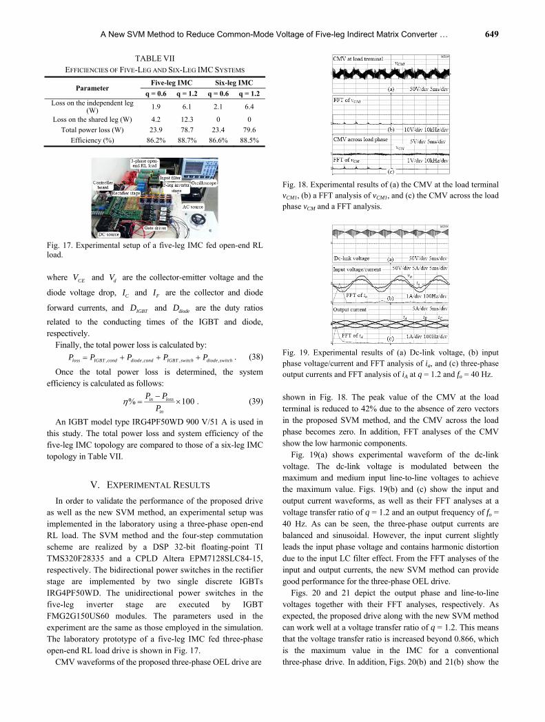
CMV waveforms of the proposed three-phase OEL drive are
Fig. 18. Experimental results of (a) the CMV at the load terminal vCM1, (b) a FFT analysis of vCM1, and (c) the CMV across the load phase vCM and a FFT analysis.
Fig. 19. Experimental results of (a) Dc-link voltage, (b) input phase voltage/current and FFT analysis of ia, and (c) three-phase output currents and FFT analysis of iA at q = 1.2 and fo = 40 Hz.
shown in Fig. 18. The peak value of the CMV at the load terminal is reduced to 42% due to the absence of zero vectors in the proposed SVM method, and the CMV across the load phase becomes zero. In addition, FFT analyses of the CMV show the low harmonic components.
Fig. 19(a) shows experimental waveform of the dc-link voltage. The dc-link voltage is modulated between the maximum and medium input line-to-line voltages to achieve the maximum value. Figs. 19(b) and (c) show the input and output current waveforms, as well as their FFT analyses at a voltage transfer ratio of q = 1.2 and an output frequency of fo = 40 Hz. As can be seen, the three-phase output currents are balanced and sinusoidal. However, the input current slightly leads the input phase voltage and contains harmonic distortion due to the input LC filter effect. From the FFT analyses of the input and output currents, the new SVM method can provide good performance for the three-phase OEL drive.
Figs. 20 and 21 depict the output phase and line-to-line voltages together with their FFT analyses, respectively. As expected, the proposed drive along with the new SVM method can work well at a voltage transfer ratio of q = 1.2. This means that the voltage transfer ratio is increased beyond 0.866, which is the maximum value in the IMC for a conventional three-phase drive. In addition, Figs. 20(b) and 21(b) show the

650 Journal of Power Electronics, Vol. 17, No. 3, May 2017
Fig. 20. Experimental results of (a) Output phase voltage vA1A2, and (b) FFT analysis of vA1A2 at q = 1.2 and fo = 40 Hz.
Fig. 21. Experimental results of (a) Output line-to-line voltage
A1A2 B1B2v v , and (b) FFT analysis of A1A2 B1B2v v at q =
1.2 and fo = 40 Hz.
Fig. 22. Experimental results of input/output waveforms at a load voltage step change from q = 0.6, fo = 30 Hz to q = 1.2, fo = 60 Hz and back.
Fig. 23. Experimental results of input/output waveforms at a load condition step change from R = 20 Ω to R = 10 Ω and back.
low voltage harmonic components, and they are similar to the simulated results shown in Figs. 13(b) and 14(b), respectively.
Figs. 22 and 23 show the experimental results of input/output waveforms corresponding to those of the
simulation results in Figs. 15 and 16, respectively. It is obviously that the proposed OEL drive system can work well under different load conditions.
VI. CONCLUSION
This paper presented a new three-phase OEL drive based on a five-leg IMC topology along with a suitable SVM method to solve CMV problems. The proposed topology can decrease the number of power switches by sharing an inverter leg with two load terminals. The new SVM method eliminates the CMV across the load phase and reduces the CMV at the load terminal. By excluding the zero vectors, the proposed SVM method can reduce the CMV peak value at the load terminal to 42%. In addition, the CMV across the load phase becomes zero because only the active vectors that do not produce CMV are used to modulate the five-leg inverter stage. Furthermore, the proposed OEL drive features the advantages of the conventional one such as an increased voltage transfer ratio up to 1.5 and a three-level PWM output voltage waveform. Simulation and experimental results show the good performance of the proposed OEL drive system.
ACKNOWLEDGMENT
This work was supported by the National Research Foundation of Korea Grant funded by the Korean Government (NRF- 2015R1D1A1A09058166).
REFERENCES
[1] S. Weerasinghe, U. K. Madawala, and D. J. Thrimawithana, “A matrix converter-based bidirectional contactless grid interface,” IEEE Trans. Power Electron., Vol. 32, No. 3, pp. 1755-1766, Mar. 2017.
[2] J. Lei, B. Zhou, J. Bian, J. Wei, Y. Zhu, J. Yu, and Y. Yang, “Feedback control strategy to eliminate the input current harmonics of matrix converter under unbalanced input voltages,” IEEE Trans. Power Electron., Vol. 32, No. 1, pp. 878-888, Jan. 2017.
[3] C. Xia, S. Li, Y. Yan, and T. Shi, “Research on linear output voltage transfer ratio for ultrasparse matrix converter,” IEEE Trans. Power Electron., Vol. 31, No. 3, pp. 1811-1815, Mar. 2016.
[4] J. Lei, B. Zhou, J. Bian, X. Qin, and J. Wei, “A simple method for sinusoidal input currents of matrix converter under unbalanced input voltages,” IEEE Trans. Power Electron., Vol. 31, No. 1, pp. 21-25, Jan. 2016.
[5] Y. Li, N. S. Choi, B. M. Han, and E. C. Nho, “Direct duty-ratio modulated fault-tolerant strategy for matrix converter-fed motor drives,” Journal of Power Electronics, Vol. 12, No. 1, pp. 24-32, Jan. 2012.
[6] C. Gu, H. S. Krishnamoorthy, P. N. Enjeti, Z. Zheng, and Y. Li, “A medium-voltage matrix converter topology for wind power conversion with medium frequency transformers,” Journal of Power Electronics, Vol. 14, No. 6, pp. 1166- 1177, Nov. 2014.
[7] S. S. Sebtahmadi, H. Pirasteh, S. H. A. Kaboli, A. Radan,
A New SVM Method to Reduce Common-Mode Voltage of Five-leg Indirect Matrix Converter … 651
and S. Mekhilef, “A 12-sector space vector switching scheme for performance improvement of matrix- converter-based DTC of IM drive,” IEEE Trans. Power Electron., Vol. 30, No. 7, pp. 3804-3817, Jul. 2015.
[8] D. T. Nguyen, H. H. Lee, and T. W. Chun, “A carrier-based pulse width modulation method for indirect matrix converters,” Journal of Power Electronics, Vol. 12, No. 3, pp. 448-457, May 2012.
[9] H. Tran, N. V. Nguyen, and H.-H. Lee, “An effective carrier-based modulation strategy to reduce the switching losses for indirect matrix converters,” Journal of Power Electronics, Vol. 15, No. 3, pp. 702-711, May 2015.
[10] M. Hamouda, H. F. Blanchette, and K. Al-Haddad, “Indirect matrix converters' enhanced commutation method,” IEEE Trans. Ind. Electron., Vol. 62, No. 2, pp. 671-679, Feb. 2015.
[11] M. Hamouda, H. F. Blanchette, and K. Al-Haddad, “Unity power factor operation of IMC tied to unbalanced grid,” IEEE Trans. Power Electron., Vol. 31, No. 2, pp. 1095- 1107, Feb. 2016.
[12] H.-N. Nguyen and H.-H. Lee, “A DSVM method for matrix converters to suppress common-mode voltage with reduced switching losses,” IEEE Trans. Power Electron., Vol. 31, No. 6, pp. 4020-4030, Jun. 2016.
[13] Q. Guan, P. Yang, Q. Guan, X. Wang, and Q. Wu, “A singular value decomposition based space vector modulation to reduce the output common-mode voltage of DMCs,” Journal of Power Electronics, Vol. 15, No. 6, pp. 936-945, Nov. 2015.
[14] M. R. Baiju, K. K. Mohapatra, R. S. Kanchan, and K. Gopakumar, “A dual two-level inverter scheme with common mode voltage elimination for an induction motor drive,” IEEE Trans. Power Electron., Vol. 19, No. 3, pp. 794-805, May 2004.
[15] V. T. Somasekhar, S. Srinivas, B. P. Reddy, C. N. Reddy, and K. Sivakumar, “Pulse width-modulated switching strategy for the dynamic balancing of zero-sequence current for a dual-inverter fed open-end winding induction motor drive,” IET Electric Power Applications, Vol. 1, No. 4, pp. 591-600, Jul. 2007.
[16] V. T. Somasekhar, S. Srinivas, and K. K. Kumar, “Effect of zero-vector placement in a dual-inverter fed open-end winding induction-motor drive with a decoupled space-vector PWM strategy,” IEEE Trans. Ind. Electron., Vol. 55, No. 6, pp. 2497-2505, Jun. 2008.
[17] K. R. Sekhar and S. Srinivas, “Discontinuous decoupled PWMs for reduced current ripple in a dual two-level inverter fed open-end winding induction motor drive,” IEEE Trans. Power Electron., Vol. 28, No. 5, pp. 2493- 2502, May 2013.
[18] S. Srinivas and K. R. Sekhar, “Theoretical and experimental analysis for current in a dual-inverter-fed open-end winding induction motor drive with reduced switching PWM,” IEEE Trans. Ind. Electron., Vol. 60, No. 10, pp. 4318-4328, Oct. 2013.
[19] N. Bodo, M. Jones, and E. Levi, “A space vector PWM with common-mode voltage elimination for open-end winding five-phase drives with a single DC supply,” IEEE Trans. Ind. Electron., Vol. 61, No. 5, pp. 2197-2207, May 2014.
[20] J. Kalaiselvi and S. Srinivas, “Bearing currents and shaft voltage reduction in dual-inverter-fed open-end winding induction motor with reduced CMV PWM methods,” IEEE Trans. Ind. Electron., Vol. 62, No. 1, pp. 144-152, Jan. 2015.
[21] P. Srinivasan, B. L. Narasimharaju, and N. V. Srikanth, “Space-vector pulse width modulation scheme for open-end winding induction motor drive configuration,” IET Power Electronics, Vol. 8, No. 7, pp. 1083-1094, Jul. 2015.
[22] H. Nian and Y. Zhou, “Investigation and suppression of current zero crossing phenomenon for a semicontrolled open-winding PMSG system,” IEEE Trans. Power Electron., Vol. 32, No. 1, pp. 602-612, Jan. 2017.
[23] H. Nian, Y. Zhou, and H. Zeng, “Zero-sequence current suppression strategy for open winding PMSG fed by semicontrolled converter,” IEEE Trans. Power Electron., Vol. 31, No. 1, pp. 711-720, Jan. 2016.
[24] Y. Zhou and H. Nian, “Zero-sequence current suppression strategy of open-winding PMSG system with common DC bus based on zero vector redistribution,” IEEE Trans. Ind. Electron., Vol. 62, No. 6, pp. 3399-3408, Jun. 2015.
[25] Q. An, J. Liu, Z. Peng, L. Sun, and L. Sun, “Dual-space vector control of open-end winding permanent magnet synchronous motor drive fed by dual inverter,” IEEE Trans. Power Electron., Vol. 31, No. 12, pp. 8329-8342, Dec. 2016.
[26] S. Chowdhury, P. W. Wheeler, C. Gerada, and C. Patel, “Model predictive control for a dual-active bridge inverter with a floating bridge,” IEEE Trans. Ind. Electron., Vol. 63, No. 9, pp. 5558-5568, Sep. 2016.
[27] M. Boby, S. Pramanick, R. S. Kaarthik, S. A. Rahul, K. Gopakumar, and L. Umanand, “Multilevel dodecagonal voltage space vector structure generation for open-end winding IM using a single DC source,” IEEE Trans. Ind. Electron., Vol. 63, No. 5, pp. 2757-2765, May 2016.
[28] A. Edpuganti and A. K. Rathore, “New optimal pulsewidth modulation for single DC-link dual-inverter fed open-end stator winding induction motor drive,” IEEE Trans. Power Electron., Vol. 30, No. 8, pp. 4386-4393, Aug. 2015.
[29] A. D. kiadehi, K. E. K. Drissi, and C. Pasquier, “Angular modulation of dual-inverter fed open-end motor for electrical vehicle applications,” IEEE Trans. Power Electron., Vol. 31, No. 4, pp. 2980-2990, Apr. 2016.
[30] K. K. Mohapatra and N. Mohan, “Open-end winding induction motor driven with matrix converter for common-mode elimination,” in International Conference on Power Electronics, Drives and Energy Systems(PEDES), pp. 1-6, Dec. 2006.
[31] R. K. Gupta, K. K. Mohapatra, A. Somani, and N. Mohan, “Direct-matrix-converter-based drive for a three-phase open-end-winding AC machine with advanced features,” IEEE Trans. Ind. Electron., Vol. 57, No. 12, pp. 4032-4042, Dec. 2010.
[32] J. Rzasa, “Research on dual MC feeding an open-end-winding load controlled with the use of rotating space vectors,” in 39th Annual Conference of the IEEE Industrial Electronics Society (IECON), pp. 4919-4924, Nov. 2013.
[33] J. Rzasa and G. Garus, “Research on dual MC feeding an open-end-winding load controlled with the use of rotating space vectors,” in 39th Annual Conference of the IEEE Industrial Electronics Society (IECON), pp. 4925-4930, Nov. 2013.
[34] R. Baranwal, K. Basu, and N. Mohan, “Carrier-based implementation of SVPWM for dual two-level VSI and dual matrix converter with zero common-mode voltage,” IEEE Trans. Power Electron., Vol. 30, No. 3, pp. 1471- 1487, Mar. 2015.
[35] S. M. Ahmed, H. Abu-Rub, and Z. Salam, “Common-mode

652 Journal of Power Electronics, Vol. 17, No. 3, May 2017
voltage elimination in a three-to-five-phase dual matrix converter feeding a five-phase open-end drive using space-vector modulation technique,” IEEE Trans. Ind. Electron., Vol. 62, No. 10, pp. 6051-6063, Oct. 2015.
[36] S. M. Ahmed, Z. Salam, and H. Abu-Rub, “Common-mode voltage elimination in a three-to-seven phase dual matrix converter feeding a seven phase open-end induction motor drive,” in IEEE Conference on Energy Conversion (CENCON), pp. 207-212, Oct. 2014.
[37] J. Riedemann, R. Pena, R. Cardenas, J. Clare, P. Wheeler, and M. Rivera, “Switching strategies for an indirect matrix converter fed open-end load,” in IEEE International Symposium on Industrial Electronics (ISIE), pp. 1-6, May 2013.
[38] J. Riedemann, J. C. Clare, P. W. Wheeler, R. Blasco-Gimenez, M. Rivera, and R. Pena, “Open-end winding induction machine fed by a dual-output indirect matrix converter,” IEEE Trans. Ind. Electron., Vol. 63, No. 7, pp. 4118-4128, Jul. 2016.
[39] A. Somani, R. K. Gupta, K. K. Mohapatra, K. Basu, and N. Mohan, “Modulation strategies for direct-link drive for open-end winding AC machines,” in IEEE International Electric Machines and Drives Conference (IEMDC), pp. 1863-1868, May 2009.
[40] Q.-H. Tran, T. D. Nguyen, and H.-H. Lee, “A SVM method for five-leg indirect matrix converters with open-end winding load,” in 9th International Conference on Power Electronics and ECCE Asia (ICPE-ECCE Asia), pp. 934- 939, Jun. 2015.
[41] M. P. Akter, S. Mekhilef, N. M. L. Tan, and H. Akagi, “Stability and performance investigations of model predictive controlled active-front-end (AFE) rectifiers for energy storage systems,” Journal of Power Electronics, Vol. 15, No. 1, pp. 202-215, Jan. 2015.
[42] A. Somani, R. K. Gupta, K. K. Mohapatra, and N. Mohan, “On the causes of circulating currents in PWM drives with open-end winding AC machines,” IEEE Trans. Ind. Electron., Vol. 60, No. 9, pp. 3670-3678, Sep. 2013.
Quoc-Hoan Tran was born in Vietnam, in 1983. He received his B.S. and M.S. degrees in Electrical Engineering from the Ho Chi Minh City University of Technology, Ho Chi Minh City, Vietnam, in 2007 and 2011, respectively. He is presently working towards his Ph.D. degree in the School of Electrical Engineering, University of Ulsan,
Ulsan, Korea. His current research interests include power electronics, power converters, and pulse-width modulation techniques.
Hong-Hee Lee received his B.S., M.S. and Ph.D. degrees in Electrical Engineering from Seoul National University, Seoul, Korea, in 1980, 1982 and 1990, respectively. From 1994 to 1995, he was a Visiting Professor at Texas A&M University, College Station, TX, USA. Since 1985, he has been a Professor in the Department of Electrical Engineering in
the School of Electrical Engineering, University of Ulsan. He is also the Director of the Network-based Automation Research Center (NARC), which is sponsored by the Ministry of Trade, Industry and Energy. His current research interests include power electronics, network-based motor control, and renewable energy. Dr. Lee is a Member of the Institute of Electrical and Electronics Engineers (IEEE), the Korean Institute of Power Electronics (KIPE), the Korean Institute of Electrical Engineers (KIEE), and the Institute of Control, Robotics and Systems (ICROS). He served as the President of KIPE in 2014.
Copyright © 2022 FDOKUMEN