A New Deformation Model of Hard α-Keratin Fibers at the Nanometer Scale: Implications for Hard...
10
A New Deformation Model of Hard -Keratin Fibers at the Nanometer Scale: Implications for Hard -Keratin Intermediate Filament Mechanical Properties L. Kreplak,* A. Franbourg, † F. Briki,* F. Leroy, † D. Dalle ´, ‡ and J. Doucet* *Laboratoire pour l’Utilisation du Rayonnement Electromagne ´ tique (LURE), Ba ˆ t 209D, Centre Universitaire Paris-Sud, 91898 Orsay Cedex, † L’Oreal Recherche, 92583 Clichy Cedex, and ‡ Laboratoire de Physique des Solides (LPS), Ba ˆ t 510, Centre Universitaire Paris-Sud, 91405 Orsay Cedex, France ABSTRACT The mechanical behavior of human hair fibers is determined by the interactions between keratin proteins structured into microfibrils (hard -keratin intermediate filaments), a protein sulfur-rich matrix (intermediate filaments asso- ciated proteins), and water molecules. The structure of the microfibril-matrix assembly has already been fully characterized using electron microscopy and small-angle x-ray scattering on unstressed fibers. However, these results give only a static image of this assembly. To observe and characterize the deformation of the microfibrils and of the matrix, we have carried out time-resolved small-angle x-ray microdiffraction experiments on human hair fibers stretched at 45% relative humidity and in water. Three structural parameters were monitored and quantified: the 6.7-nm meridian arc, which is related to an axial separation between groups of molecules along the microfibrils, the microfibril’s radius, and the packing distance between microfibrils. Using a surface lattice model of the microfibril, we have described its deformation as a combination of a sliding process and a molecular stretching process. The radial contraction of the matrix is also emphasized, reinforcing the hydrophilic gel nature hypothesis. INTRODUCTION Hard -keratin fiber is a hierarchically structured material that shows a fibrillar organization from the micrometer to the nanometer scale (Zahn et al., 1980). The main part of the fiber, called the cortex, is composed of spindle-shaped cortical cells, about 100 m long and 3 m wide, which contain macrofibrils, 0.3 m in diameter, glued together by an intermacrofibrillar matrix. A finest composite structure is found inside the macrofibril. It contains a two-dimensional (2D) array of cylindrical shaped units called the microfibrils (7.5 nm in diameter), embedded in a hydrophilic sulfur-rich protein matrix (Zahn et al., 1980). As for the other inter- mediate filaments (IFs), the microfibrils, or hard -keratin IFs, are built from a complex axial and longitudinal assem- bly of heterodimers (Parry and Steinert, 1999). The het- erodimer molecule, roughly 50 nm long, is characterized by a central rod domain composed of a double-stranded -he- lical coiled coil interrupted by nonhelical segments. The central rod domain is surrounded by head and tail domains of unknown structure. This extremely complex and well-defined structure gives rise to outstanding mechanical properties. Pushed by the textile industries, a large amount of work has been under- taken on wool, aiming at understanding the link between the fine microfibril-matrix texture and the macroscopic fiber properties (Feughelman, 1959). Nearly all the available models deal with the stress–strain curve of hard -keratin fiber in water. Bendit (1960) described the molecular mech- anism of microfibrils deformation as a gradual transition from -helical coiled coils to -sheet-like structures. Using this molecular mechanism as a basis, attempts were made to explain the elastic response of keratin fibers in terms of its two structural subcomponents, the microfibril and the ma- trix (Hearle, 2000). In Chapman’s model (Chapman, 1969), matrix proteins are supposed to be covalently linked to fundamental repeat units aligned along the microfibril. The stress–strain curve of the fiber is modeled as a combination of the stress–strain curves of the microfibril and of the matrix in permanent interaction. This model is in good agreement with the mechanical experiments. Bendit and Feughelman (1968) have developed the so-called series zone model in which the microfibril contains two kinds of alternating zones, named X and Y, endowed with different elastic properties. The mechanical properties of the matrix are supposed to be driven by an entanglement of the matrix chains due to disulphide bonds. This model also reasonably fits the experimental data. More recently, another model based on the swelling properties of the matrix has been proposed by Feughelman (1994). In this model, water mol- ecules are supposed to be ejected from the matrix at high stress levels, which leads to a matrix proteins compression between the microfibrils. Finally, Wortmann and Zahn (1994) have recently reinterpreted available biochemical data on the microfibril’s structure to derive a model that neglects the matrix proteins. The X and Y zones of the series zone model are assigned to specific amino acid se- quences along the length of the keratin molecule (Wort- mann and Zahn, 1994). These models are based on hypotheses, on the mechanical properties of the microfibril and of the matrix, and on their Submitted June 25, 2001 and accepted for publication December 27, 2001. Address reprint requests to Laurent Kreplak, Centre Universitaire Paris- Sud, LURE, Ba ˆt 209D-BP 34, 91898 Orsay Cedex, France. Tel.: 33-01- 64-46-8834; Fax: 33-01-64-46-8820; E-mail: [email protected]. © 2002 by the Biophysical Society 0006-3495/02/04/2265/10 $2.00 2265 Biophysical Journal Volume 82 April 2002 2265–2274
Transcript of A New Deformation Model of Hard α-Keratin Fibers at the Nanometer Scale: Implications for Hard...

A New Deformation Model of Hard �-Keratin Fibers at theNanometer Scale: Implications for Hard �-Keratin Intermediate FilamentMechanical Properties
L. Kreplak,* A. Franbourg,† F. Briki,* F. Leroy,† D. Dalle,‡ and J. Doucet**Laboratoire pour l’Utilisation du Rayonnement Electromagnetique (LURE), Bat 209D, Centre Universitaire Paris-Sud,91898 Orsay Cedex, †L’Oreal Recherche, 92583 Clichy Cedex, and ‡Laboratoire de Physique des Solides (LPS), Bat 510,Centre Universitaire Paris-Sud, 91405 Orsay Cedex, France
ABSTRACT The mechanical behavior of human hair fibers is determined by the interactions between keratin proteinsstructured into microfibrils (hard �-keratin intermediate filaments), a protein sulfur-rich matrix (intermediate filaments asso-ciated proteins), and water molecules. The structure of the microfibril-matrix assembly has already been fully characterizedusing electron microscopy and small-angle x-ray scattering on unstressed fibers. However, these results give only a staticimage of this assembly. To observe and characterize the deformation of the microfibrils and of the matrix, we have carriedout time-resolved small-angle x-ray microdiffraction experiments on human hair fibers stretched at 45% relative humidity andin water. Three structural parameters were monitored and quantified: the 6.7-nm meridian arc, which is related to an axialseparation between groups of molecules along the microfibrils, the microfibril’s radius, and the packing distance betweenmicrofibrils. Using a surface lattice model of the microfibril, we have described its deformation as a combination of a slidingprocess and a molecular stretching process. The radial contraction of the matrix is also emphasized, reinforcing thehydrophilic gel nature hypothesis.
INTRODUCTION
Hard �-keratin fiber is a hierarchically structured materialthat shows a fibrillar organization from the micrometer tothe nanometer scale (Zahn et al., 1980). The main part of thefiber, called the cortex, is composed of spindle-shapedcortical cells, about 100 �m long and 3 �m wide, whichcontain macrofibrils, 0.3 �m in diameter, glued together byan intermacrofibrillar matrix. A finest composite structure isfound inside the macrofibril. It contains a two-dimensional(2D) array of cylindrical shaped units called the microfibrils(7.5 nm in diameter), embedded in a hydrophilic sulfur-richprotein matrix (Zahn et al., 1980). As for the other inter-mediate filaments (IFs), the microfibrils, or hard �-keratinIFs, are built from a complex axial and longitudinal assem-bly of heterodimers (Parry and Steinert, 1999). The het-erodimer molecule, roughly 50 nm long, is characterized bya central rod domain composed of a double-stranded �-he-lical coiled coil interrupted by nonhelical segments. Thecentral rod domain is surrounded by head and tail domainsof unknown structure.
This extremely complex and well-defined structure givesrise to outstanding mechanical properties. Pushed by thetextile industries, a large amount of work has been under-taken on wool, aiming at understanding the link between thefine microfibril-matrix texture and the macroscopic fiberproperties (Feughelman, 1959). Nearly all the availablemodels deal with the stress–strain curve of hard �-keratin
fiber in water. Bendit (1960) described the molecular mech-anism of microfibrils deformation as a gradual transitionfrom �-helical coiled coils to �-sheet-like structures. Usingthis molecular mechanism as a basis, attempts were made toexplain the elastic response of keratin fibers in terms of itstwo structural subcomponents, the microfibril and the ma-trix (Hearle, 2000). In Chapman’s model (Chapman, 1969),matrix proteins are supposed to be covalently linked tofundamental repeat units aligned along the microfibril. Thestress–strain curve of the fiber is modeled as a combinationof the stress–strain curves of the microfibril and of thematrix in permanent interaction. This model is in goodagreement with the mechanical experiments. Bendit andFeughelman (1968) have developed the so-called serieszone model in which the microfibril contains two kinds ofalternating zones, named X and Y, endowed with differentelastic properties. The mechanical properties of the matrixare supposed to be driven by an entanglement of the matrixchains due to disulphide bonds. This model also reasonablyfits the experimental data. More recently, another modelbased on the swelling properties of the matrix has beenproposed by Feughelman (1994). In this model, water mol-ecules are supposed to be ejected from the matrix at highstress levels, which leads to a matrix proteins compressionbetween the microfibrils. Finally, Wortmann and Zahn(1994) have recently reinterpreted available biochemicaldata on the microfibril’s structure to derive a model thatneglects the matrix proteins. The X and Y zones of theseries zone model are assigned to specific amino acid se-quences along the length of the keratin molecule (Wort-mann and Zahn, 1994).
These models are based on hypotheses, on the mechanicalproperties of the microfibril and of the matrix, and on their
Submitted June 25, 2001 and accepted for publication December 27, 2001.
Address reprint requests to Laurent Kreplak, Centre Universitaire Paris-Sud, LURE, Bat 209D-BP 34, 91898 Orsay Cedex, France. Tel.: �33-01-64-46-8834; Fax: �33-01-64-46-8820; E-mail: [email protected].
© 2002 by the Biophysical Society
0006-3495/02/04/2265/10 $2.00
2265Biophysical Journal Volume 82 April 2002 2265–2274

interactions, that are difficult to probe experimentally. Dataon the mechanical deformation of the microfibril-matrixsystem at the nanometer scale can nevertheless be obtainedusing small-angle x-ray scattering (SAXS) on stretched�-keratin fibers.
The microfibril-matrix network gives rise to an intenseand well-defined small-angle scattering pattern shown onFig. 1
• In this study we have focused on the 6.7-nm arc along themeridian (fiber axis) which is related to an axial staggerbetween molecules or group of molecules along the mi-crofibril (Fraser et al., 1986; Steinert et al., 1993).
• The three broad peaks at 8.8, 4.5, and 2.95 nm along theequator (plane perpendicular to the fiber axis) arise fromthe dense lateral packing of the microfibrils embedded inthe matrix. The positions and the intensities of thesepeaks are characteristic of the microfibril diameter and ofthe mean center-to-center distance between microfibrils(Fraser et al., 1964). When the macroscopic fiber isimmersed in water, the first peak position (8.8 nm) in-creases, indicating a matrix swelling (Fraser et al., 1971;Franbourg et al., 1995).
• Early attempts were made to study the deformation ofthis SAXS pattern in stretched �-keratin fibers. Wilsonused several combinations of disulphide bonds reduction,silver staining, and fiber stretching in water to followwool fiber modifications (Wilson, 1972). However themechanical stretching effect could not be separated fromthe chemical treatments effects. The same kind of studyhas been performed for mohair fibers stretched in 2,2,2-trifluoroethanol (TFE) or in water (Spei, 1975). A strik-
ing displacement of the 6.7-nm arc was observed for thefibers in TFE, which follows the macroscopic strain until40%. However this behavior was not observed in water.The main drawbacks of these works result from the useof chemical reagents, the need of fiber plaits and the needof long exposure times. The last point is particularlyimportant because mechanical relaxation effects arelikely to be accompanied by structural changes.
• To reduce relaxation effects, we have performed a time-resolved SAXS study on single human-hair fibersstretched at constant speed using a 5-�m-diameter beam.Two humidity conditions were selected to investigate therole of water, 45% relative humidity (RH) and immersedin water within a glass capillary.
• For the two humidity conditions, the 6.7-nm arc behaviorhas been monitored and analyzed using a surface latticemodel of the microfibril (Fraser et al., 1976; Parry,1995). The successive equatorial SAXS patterns havebeen analyzed using a fit procedure developed by Briki etal. (1998). Equatorial SAXS pattern analysis allowedfollowing of two parameters of the microfibril-matrixnetwork, the radius of a cylindrically averaged microfi-bril, and the mean center-to-center distance between mi-crofibrils assuming a pseudohexagonal packing.
• Using these data, we have been able to characterize thelocal deformability of the two components at the twohumidity conditions. The matrix has been shown to with-stand a high lateral contraction at 45% RH and in water.The microfibril behavior is more complex, it is charac-terized by a much lower lateral compressibility than thematrix and by a deformability of its axial internal struc-ture, which is water-content dependent. On the basis ofthese results and of biochemical data on keratin filamentassembly, we propose a model of the microfibril internaldeformation in which the keratin molecules are submittedto a molecular stretching coupled with a sliding process,favored by water, which retains some features of themicrofibril’s internal structure.
MATERIALS AND METHODS
Samples
Data collections were carried out on virgin Caucasian human hair samples.The samples, approximately 0.07 mm in diameter, were analyzed at 24 �0.5°C (room temperature) and at two humidity conditions, 45 � 2% RH(room humidity) and in a glass capillary filled with water.
Mechanical set-up
A specific uniaxial extensometer compatible with synchrotron x-ray dif-fraction set-ups has been designed for this experiment. With such exten-someter, the fiber’s central zone is stretched without any displacement andcan be analyzed by x-ray diffraction without moving the beam.
The apparatus is composed of two L-shaped pieces aligned on a mo-torized bench and each supporting a clamp to hold the sample horizontally.A transducer is used to move simultaneously the two clamps; an electronic
FIGURE 1 Typical SAXS pattern of hard �-keratin fiber (human hair).The 6.7-nm arc is visible along the fiber axis direction (meridian). Twobroad peaks are visible perpendicular to the fiber axis (equator), one at 8.8nm and the other one at 4.5 nm, which is superimposed to a ring becauseof the lipid granules scattering (Franbourg et al., 1995).
2266 Kreplak et al.
Biophysical Journal 82(4) 2265–2274
device has been developed to pilot the transducer and to ensure a onemicrometer accuracy on the displacement. Because this apparatus is de-signed to be used with a microdiffraction set-up, particular attention hasbeen paid to ensure that the position of the sample does not changevertically during stretching.
The native length of the samples was fixed to 30 mm. A constantstretching speed of 2% of the initial length per minute has been applied tothe samples until failure. These conditions are matching the ones used intextile fibers standard tensile tests (ASTM, 1982).
X-ray scattering set-up
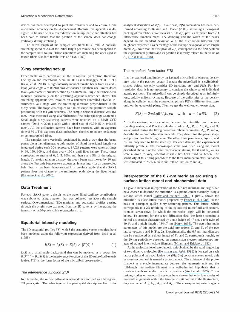
Experiments were carried out at the European Synchrotron RadiationFacility on the microfocus beamline ID13 (Lichtenegger et al., 1999;Riekel et al., 2000). A high-intensity monochromatic beam from an undu-lator (wavelength � � 0.0948 nm) was focused and then size-limited downto a 5-�m-diameter circular section by a collimator. Single hair fibers weremounted horizontally on the stretching apparatus described above. Thestretching apparatus was installed on a computer-controlled Physike In-strument’s X/Y stage with the stretching direction perpendicular to thex-ray beam. The stage was coupled to a microscope that permitted samplepositioning with 0.1-�m accuracy. The sample detector distance was 161mm, it was measured using silver behanate (first-order spacing: 5.838 nm).Small-angle x-ray scattering patterns were recorded on a MAR CCDcamera (2048 � 2048 pixels) with a pixel size of (0.06445 � 0.06445mm2). All the diffraction patterns have been recorded with an exposuretime of 30 s. This exposure duration has been checked to induce no damageon an unstretched fiber.
The samples were vertically positioned in such a way that the beampasses along their diameter. A deformation of 1% of the original length wasintegrated during each 30-s exposure. SAXS patterns were taken at times0, 60, 150, 300 s, and then every 150 s until fiber failure. These timescorrespond to strains of 0, 2, 5, 10%, and then every 5% of the originallength. To avoid radiation damage, the x-ray beam was moved by 20 �malong the fiber axis between two exposures. Interestingly for an unstretchedhair fiber, it has been demonstrated in a previous study that the SAXSpattern does not change at the millimeter scale along the fiber length(Baltenneck et al., 2000).
Data Treatment
For each SAXS pattern, the air- or the water-filled capillary contributionswas subtracted using a pattern that was collected just above the samplesurface. One-dimensional (1D) meridian and equatorial profiles passingthrough the origin were extracted from the 2D patterns by integrating theintensity on a 20-pixels-thick rectangular strip.
Equatorial intensity modeling
The 1D equatorial profiles I(S), with S the scattering vector modulus, havebeen modeled using the following expression derived from Briki et al.(1998):
I�S� � I0�S� � Z�S� � �F�S��2 (1)
I0(S) is a small-angle background that can be modeled as a power lawB1S�2.3 � B2. Z(S) is the interference function of the 2D microfibril-matrixlattice. F(S) is the form factor of the microfibril cross-section.
The interference function Z(S)
In this model, the microfibril-matrix network is described as a hexagonal2D paracrystal. The advantage of the paracrystal description lies in the
analytical derivation of Z(S). In our case, Z(S) calculation has been per-formed according to Busson and Doucet (2000), assuming a hexagonalpacking of microfibrils. We use a set of 1D Z(S) profiles extracted from 2Dinterference function maps. The damping and the width of the peaksdepend on the standard deviation � of the distribution between firstneighbors expressed as a percentage of the average hexagonal lattice lengthnoted, Am. Note that the first peak of Z(S) corresponds to the first peak onthe experimental profiles and its position is directly related to the value ofAm (Briki et al., 1998).
The microfibril form factor F(S)
It is the scattered amplitude by an isolated microfibril of electron density(r), with r the position vector. Because the microfibril is a cylindrical-shaped object, we only consider 1D functions (r) and F(S). For lowresolution data, it is not necessary to consider the whole set of individualatomic positions. The microfibril can be simply described as an infinitelylong, axially uniform cylinder. Because of the uniformity of the densityalong the cylinder axis, the scattered amplitude F(S) is different from zeroonly on the equatorial plane. Then we get the well-known expression,
F�S� � 2�R2J1�u�/u with u � 2RS. (2)
� is the electron density contrast between the microfibril and the sur-rounding matrix, and R is the cylinder’s radius. Am, R, �, �, B1, and B2
are adjusted during the fitting procedure. Three parameters, Am, R, and �,describe the microfibril-matrix network. They determine the peaks shapeand position for the fitting curve. The other three parameters, �, B1, andB2, are only used to fit the intensity. For each data set, the experimentalintensity profile at 0% macroscopic strain was fitted using the modeldescribed above. For the other macroscopic strains, the R and Am valueswere allowed to vary, whereas � value has been fixed to 32.5%. Thesensitivity of this fitting procedure to the three main parameters’ variationwas estimated to �2.5% on � and �0.025 nm on R and Am.
Interpretation of the 6.7-nm meridian arc using asurface lattice model and biochemical data
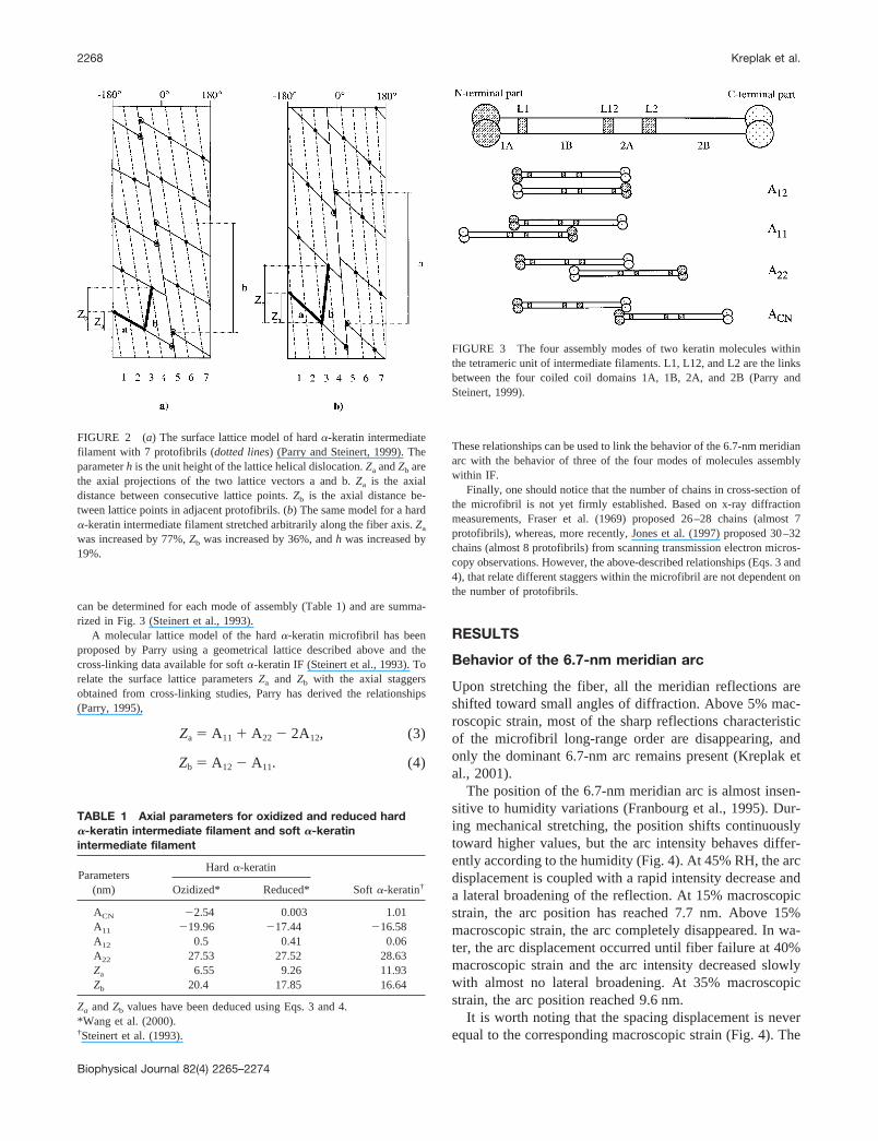
To give a molecular interpretation of the 6.7-nm meridian arc origin, wehave chosen to describe the microfibril’s supramolecular assembly using asurface lattice model (Parry and Steinert, 1999). Figure 2 shows themicrofibril surface lattice model proposed by Fraser et al. (1986) on thebasis of porcupine quill’s x-ray scattering pattern. This lattice, whichcorresponds to a 2D unfolding of the cylindrical microfibril architecture,contains seven rows, for which the molecular origin will be presentedbelow. To account for the x-ray diffraction data, the lattice contains ahelical dislocation characterized by a unit height of 47 nm, a unit twist of49.1°, and a pitch length of 344.7 nm (Parry, 1995). The two other mainparameters of this model are the axial projections Za and Zb of the twolattice vectors a and b (Fig. 2). Experimentally, the 6.7-nm meridian arccan be considered as a direct image of Za, and Zb corresponds roughly tothe 20-nm periodicity observed on transmission electron microscopy im-ages of stained intermediate filaments (Milam and Erickson, 1982).
At the molecular level, a tetrameric unit obtained by the axial staggeringof two dimeric molecules (Herrmann and Aebi, 1998) is located on eachlattice point and thus each lattice row (Fig. 2 a) contains one tetrameric unitin cross-section and is named a protofilament. The existence of the proto-filament as a stable intermediate between the tetrameric unit and thefull-length intermediate filament is a well-admitted hypothesis that isconsistent with some electron microscope data (Aebi et al., 1983). Cross-linking studies on various IF systems have shown that only four modes ofmolecule alignments within the tetrameric unit coexist in the IF structure,they are named A12, A11, A22, and ACN. The corresponding axial staggers
Microfibrils Mechanical Deformation 2267
Biophysical Journal 82(4) 2265–2274
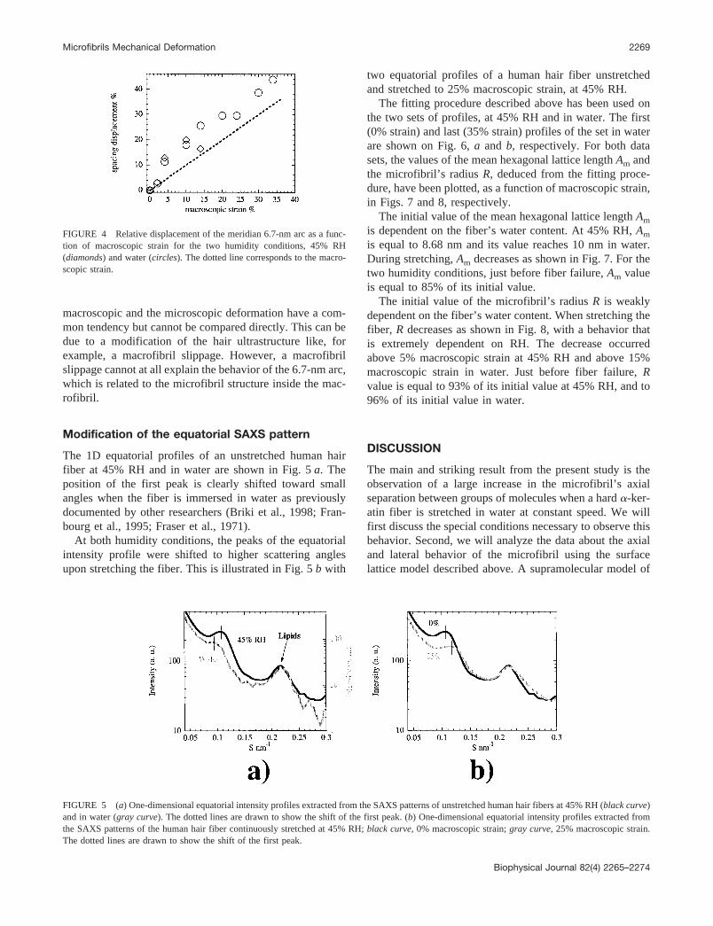
can be determined for each mode of assembly (Table 1) and are summa-rized in Fig. 3 (Steinert et al., 1993).
A molecular lattice model of the hard �-keratin microfibril has beenproposed by Parry using a geometrical lattice described above and thecross-linking data available for soft �-keratin IF (Steinert et al., 1993). Torelate the surface lattice parameters Za and Zb with the axial staggersobtained from cross-linking studies, Parry has derived the relationships(Parry, 1995),
Za � A11 � A22 � 2A12, (3)
Zb � A12 � A11. (4)
These relationships can be used to link the behavior of the 6.7-nm meridianarc with the behavior of three of the four modes of molecules assemblywithin IF.
Finally, one should notice that the number of chains in cross-section ofthe microfibril is not yet firmly established. Based on x-ray diffractionmeasurements, Fraser et al. (1969) proposed 26–28 chains (almost 7protofibrils), whereas, more recently, Jones et al. (1997) proposed 30–32chains (almost 8 protofibrils) from scanning transmission electron micros-copy observations. However, the above-described relationships (Eqs. 3 and4), that relate different staggers within the microfibril are not dependent onthe number of protofibrils.
RESULTS
Behavior of the 6.7-nm meridian arc
Upon stretching the fiber, all the meridian reflections areshifted toward small angles of diffraction. Above 5% mac-roscopic strain, most of the sharp reflections characteristicof the microfibril long-range order are disappearing, andonly the dominant 6.7-nm arc remains present (Kreplak etal., 2001).
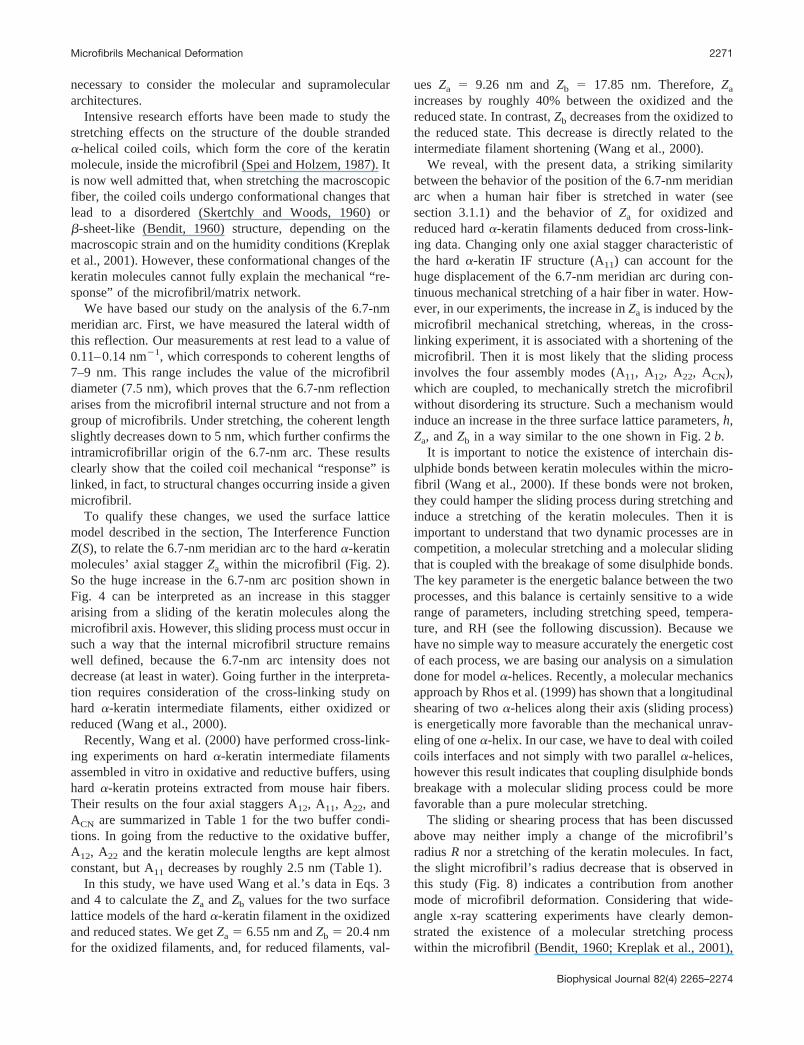
The position of the 6.7-nm meridian arc is almost insen-sitive to humidity variations (Franbourg et al., 1995). Dur-ing mechanical stretching, the position shifts continuouslytoward higher values, but the arc intensity behaves differ-ently according to the humidity (Fig. 4). At 45% RH, the arcdisplacement is coupled with a rapid intensity decrease anda lateral broadening of the reflection. At 15% macroscopicstrain, the arc position has reached 7.7 nm. Above 15%macroscopic strain, the arc completely disappeared. In wa-ter, the arc displacement occurred until fiber failure at 40%macroscopic strain and the arc intensity decreased slowlywith almost no lateral broadening. At 35% macroscopicstrain, the arc position reached 9.6 nm.
It is worth noting that the spacing displacement is neverequal to the corresponding macroscopic strain (Fig. 4). The
FIGURE 2 (a) The surface lattice model of hard �-keratin intermediatefilament with 7 protofibrils (dotted lines) (Parry and Steinert, 1999). Theparameter h is the unit height of the lattice helical dislocation. Za and Zb arethe axial projections of the two lattice vectors a and b. Za is the axialdistance between consecutive lattice points. Zb is the axial distance be-tween lattice points in adjacent protofibrils. (b) The same model for a hard�-keratin intermediate filament stretched arbitrarily along the fiber axis. Za
was increased by 77%, Zb was increased by 36%, and h was increased by19%.
TABLE 1 Axial parameters for oxidized and reduced hard�-keratin intermediate filament and soft �-keratinintermediate filament
Parameters(nm)
Hard �-keratin
Soft �-keratin†Ozidized* Reduced*
ACN �2.54 0.003 1.01A11 �19.96 �17.44 �16.58A12 0.5 0.41 0.06A22 27.53 27.52 28.63Za 6.55 9.26 11.93Zb 20.4 17.85 16.64
Za and Zb values have been deduced using Eqs. 3 and 4.*Wang et al. (2000).†Steinert et al. (1993).
FIGURE 3 The four assembly modes of two keratin molecules withinthe tetrameric unit of intermediate filaments. L1, L12, and L2 are the linksbetween the four coiled coil domains 1A, 1B, 2A, and 2B (Parry andSteinert, 1999).
2268 Kreplak et al.
Biophysical Journal 82(4) 2265–2274
macroscopic and the microscopic deformation have a com-mon tendency but cannot be compared directly. This can bedue to a modification of the hair ultrastructure like, forexample, a macrofibril slippage. However, a macrofibrilslippage cannot at all explain the behavior of the 6.7-nm arc,which is related to the microfibril structure inside the mac-rofibril.
Modification of the equatorial SAXS pattern
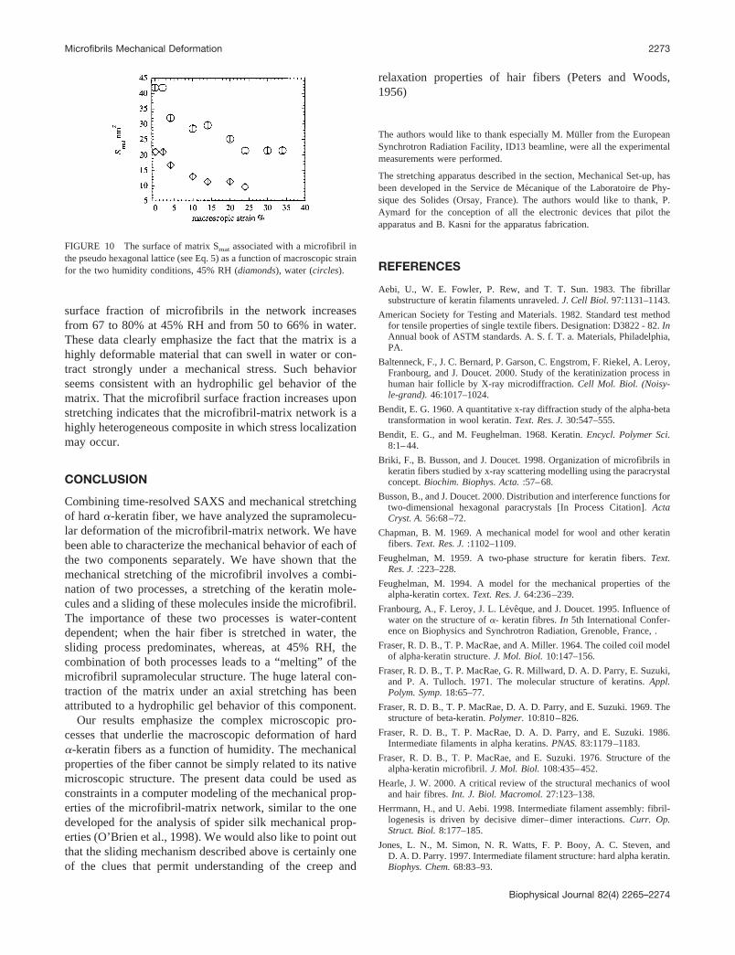
The 1D equatorial profiles of an unstretched human hairfiber at 45% RH and in water are shown in Fig. 5 a. Theposition of the first peak is clearly shifted toward smallangles when the fiber is immersed in water as previouslydocumented by other researchers (Briki et al., 1998; Fran-bourg et al., 1995; Fraser et al., 1971).
At both humidity conditions, the peaks of the equatorialintensity profile were shifted to higher scattering anglesupon stretching the fiber. This is illustrated in Fig. 5 b with
two equatorial profiles of a human hair fiber unstretchedand stretched to 25% macroscopic strain, at 45% RH.
The fitting procedure described above has been used onthe two sets of profiles, at 45% RH and in water. The first(0% strain) and last (35% strain) profiles of the set in waterare shown on Fig. 6, a and b, respectively. For both datasets, the values of the mean hexagonal lattice length Am andthe microfibril’s radius R, deduced from the fitting proce-dure, have been plotted, as a function of macroscopic strain,in Figs. 7 and 8, respectively.
The initial value of the mean hexagonal lattice length Am
is dependent on the fiber’s water content. At 45% RH, Am
is equal to 8.68 nm and its value reaches 10 nm in water.During stretching, Am decreases as shown in Fig. 7. For thetwo humidity conditions, just before fiber failure, Am valueis equal to 85% of its initial value.
The initial value of the microfibril’s radius R is weaklydependent on the fiber’s water content. When stretching thefiber, R decreases as shown in Fig. 8, with a behavior thatis extremely dependent on RH. The decrease occurredabove 5% macroscopic strain at 45% RH and above 15%macroscopic strain in water. Just before fiber failure, Rvalue is equal to 93% of its initial value at 45% RH, and to96% of its initial value in water.
DISCUSSION
The main and striking result from the present study is theobservation of a large increase in the microfibril’s axialseparation between groups of molecules when a hard �-ker-atin fiber is stretched in water at constant speed. We willfirst discuss the special conditions necessary to observe thisbehavior. Second, we will analyze the data about the axialand lateral behavior of the microfibril using the surfacelattice model described above. A supramolecular model of
FIGURE 4 Relative displacement of the meridian 6.7-nm arc as a func-tion of macroscopic strain for the two humidity conditions, 45% RH(diamonds) and water (circles). The dotted line corresponds to the macro-scopic strain.
FIGURE 5 (a) One-dimensional equatorial intensity profiles extracted from the SAXS patterns of unstretched human hair fibers at 45% RH (black curve)and in water (gray curve). The dotted lines are drawn to show the shift of the first peak. (b) One-dimensional equatorial intensity profiles extracted fromthe SAXS patterns of the human hair fiber continuously stretched at 45% RH; black curve, 0% macroscopic strain; gray curve, 25% macroscopic strain.The dotted lines are drawn to show the shift of the first peak.
Microfibrils Mechanical Deformation 2269
Biophysical Journal 82(4) 2265–2274

the microfibril deformation will be presented. Third, therole of water will be discussed using the above model.Finally, our data will be used to derive a mechanical modelof the matrix.
Relaxation effects in hair fiber
In earlier studies, it had been shown that the position of the6.7-nm meridian arc could be increased by 40% whenmohair fibers were stretched in 2,2,2-trifluoroethanol. Inwater, the displacement of the arc was only 5% (Spei andZahn, 1971; Spei, 1975). To get good quality SAXS pat-terns, it was necessary to use fiber plaits and long exposuretimes (at least one hour), allowing the fibers to relax. Suchrelaxation process, which is associated with a stress decay(Peters and Woods, 1956), could affect the structure of boththe microfibril and the matrix. Consequently, those resultswere probably biased by structural relaxation processes. Our
different results concerning the displacement of the 6.7-nmmeridian arc confirm this hypothesis.
In the present experimental set-up, the fiber was contin-uously stretched during the SAXS measurements becausedata collection only required 30 s. By avoiding the relax-ation of the fiber in water, we have been able to observe thetrue behavior of the 6.7-nm arc upon stretching (see Fig. 4).It appears that time-resolved studies are absolutely neces-sary to reveal the behavior of both the microfibril and thematrix during a standard tensile test.
A supramolecular model of the microfibrilmechanical deformation
We aim to understand how the microfibril can withstand thelarge increase of its axial separation between groups ofmolecules (Fig. 4), while being only slightly radially con-tracted (Fig. 8). Considering the microfibril as a homoge-nous cylinder is obviously a crude approximation, it is
FIGURE 7 The mean center to center distance between microfibrils Am
as a function of macroscopic strain, 45% RH (diamonds), water-filledcapillary (circles). For the two humidity conditions, the values of Am wereobtained from the intensity modeling described in the text.
FIGURE 8 The microfibril radius R as a function of macroscopic strain,45% RH (diamonds), water (circles). For the two humidity conditions thevalues of R were obtained from the intensity modeling described in the text.
FIGURE 6 One-dimensional equatorial intensity profiles extracted from the SAXS patterns of the human hair fiber continuously stretched in water. (a)Solid curve, experimental profile at 0% macroscopic strain; circles, intensity modeling derived from Eq. 1. (b) Solid curve, experimental profile at 35%macroscopic strain; circles, intensity modeling derived from Eq. 1.
2270 Kreplak et al.
Biophysical Journal 82(4) 2265–2274
necessary to consider the molecular and supramoleculararchitectures.
Intensive research efforts have been made to study thestretching effects on the structure of the double stranded�-helical coiled coils, which form the core of the keratinmolecule, inside the microfibril (Spei and Holzem, 1987). Itis now well admitted that, when stretching the macroscopicfiber, the coiled coils undergo conformational changes thatlead to a disordered (Skertchly and Woods, 1960) or�-sheet-like (Bendit, 1960) structure, depending on themacroscopic strain and on the humidity conditions (Kreplaket al., 2001). However, these conformational changes of thekeratin molecules cannot fully explain the mechanical “re-sponse” of the microfibril/matrix network.
We have based our study on the analysis of the 6.7-nmmeridian arc. First, we have measured the lateral width ofthis reflection. Our measurements at rest lead to a value of0.11–0.14 nm�1, which corresponds to coherent lengths of7–9 nm. This range includes the value of the microfibrildiameter (7.5 nm), which proves that the 6.7-nm reflectionarises from the microfibril internal structure and not from agroup of microfibrils. Under stretching, the coherent lengthslightly decreases down to 5 nm, which further confirms theintramicrofibrillar origin of the 6.7-nm arc. These resultsclearly show that the coiled coil mechanical “response” islinked, in fact, to structural changes occurring inside a givenmicrofibril.
To qualify these changes, we used the surface latticemodel described in the section, The Interference FunctionZ(S), to relate the 6.7-nm meridian arc to the hard �-keratinmolecules’ axial stagger Za within the microfibril (Fig. 2).So the huge increase in the 6.7-nm arc position shown inFig. 4 can be interpreted as an increase in this staggerarising from a sliding of the keratin molecules along themicrofibril axis. However, this sliding process must occur insuch a way that the internal microfibril structure remainswell defined, because the 6.7-nm arc intensity does notdecrease (at least in water). Going further in the interpreta-tion requires consideration of the cross-linking study onhard �-keratin intermediate filaments, either oxidized orreduced (Wang et al., 2000).
Recently, Wang et al. (2000) have performed cross-link-ing experiments on hard �-keratin intermediate filamentsassembled in vitro in oxidative and reductive buffers, usinghard �-keratin proteins extracted from mouse hair fibers.Their results on the four axial staggers A12, A11, A22, andACN are summarized in Table 1 for the two buffer condi-tions. In going from the reductive to the oxidative buffer,A12, A22 and the keratin molecule lengths are kept almostconstant, but A11 decreases by roughly 2.5 nm (Table 1).
In this study, we have used Wang et al.’s data in Eqs. 3and 4 to calculate the Za and Zb values for the two surfacelattice models of the hard �-keratin filament in the oxidizedand reduced states. We get Za � 6.55 nm and Zb � 20.4 nmfor the oxidized filaments, and, for reduced filaments, val-
ues Za � 9.26 nm and Zb � 17.85 nm. Therefore, Za
increases by roughly 40% between the oxidized and thereduced state. In contrast, Zb decreases from the oxidized tothe reduced state. This decrease is directly related to theintermediate filament shortening (Wang et al., 2000).
We reveal, with the present data, a striking similaritybetween the behavior of the position of the 6.7-nm meridianarc when a human hair fiber is stretched in water (seesection 3.1.1) and the behavior of Za for oxidized andreduced hard �-keratin filaments deduced from cross-link-ing data. Changing only one axial stagger characteristic ofthe hard �-keratin IF structure (A11) can account for thehuge displacement of the 6.7-nm meridian arc during con-tinuous mechanical stretching of a hair fiber in water. How-ever, in our experiments, the increase in Za is induced by themicrofibril mechanical stretching, whereas, in the cross-linking experiment, it is associated with a shortening of themicrofibril. Then it is most likely that the sliding processinvolves the four assembly modes (A11, A12, A22, ACN),which are coupled, to mechanically stretch the microfibrilwithout disordering its structure. Such a mechanism wouldinduce an increase in the three surface lattice parameters, h,Za, and Zb in a way similar to the one shown in Fig. 2 b.
It is important to notice the existence of interchain dis-ulphide bonds between keratin molecules within the micro-fibril (Wang et al., 2000). If these bonds were not broken,they could hamper the sliding process during stretching andinduce a stretching of the keratin molecules. Then it isimportant to understand that two dynamic processes are incompetition, a molecular stretching and a molecular slidingthat is coupled with the breakage of some disulphide bonds.The key parameter is the energetic balance between the twoprocesses, and this balance is certainly sensitive to a widerange of parameters, including stretching speed, tempera-ture, and RH (see the following discussion). Because wehave no simple way to measure accurately the energetic costof each process, we are basing our analysis on a simulationdone for model �-helices. Recently, a molecular mechanicsapproach by Rhos et al. (1999) has shown that a longitudinalshearing of two �-helices along their axis (sliding process)is energetically more favorable than the mechanical unrav-eling of one �-helix. In our case, we have to deal with coiledcoils interfaces and not simply with two parallel �-helices,however this result indicates that coupling disulphide bondsbreakage with a molecular sliding process could be morefavorable than a pure molecular stretching.
The sliding or shearing process that has been discussedabove may neither imply a change of the microfibril’sradius R nor a stretching of the keratin molecules. In fact,the slight microfibril’s radius decrease that is observed inthis study (Fig. 8) indicates a contribution from anothermode of microfibril deformation. Considering that wide-angle x-ray scattering experiments have clearly demon-strated the existence of a molecular stretching processwithin the microfibril (Bendit, 1960; Kreplak et al., 2001),
Microfibrils Mechanical Deformation 2271
Biophysical Journal 82(4) 2265–2274

it is straightforward that this process is associated with thesliding process described in this study.
The role of water in the mechanical behavior ofthe microfibril
When a hair fiber is stretched in water, the main deforma-tion process of the microfibrils is the internal sliding processdescribed above. Our experimental data (Fig. 4) prove thata microfibril embedded in a water-swollen matrix can with-stand a high amount of shear without loosing its supramo-lecular order, because the 6.7-nm arc can reach a 9.6-nmposition without disappearing. Such a huge displacementcan only be obtained by a sliding process of the keratinmolecules with respect to the four modes of interactionsA12, A11, A22, and ACN introduced above. However, thesemodes of interactions are dependent on the complex patternof positively and negatively charged residues located at thesurface of the keratin molecule. Such three-dimensionalcharge distribution is supposed to play a role in the forma-tion and stability of intermediate filaments through ionicinteractions (Meng et al., 1994; Mehrani et al., 2000).
In this context, the main role of the water moleculespresent inside and around the microfibril should be to screenthe charges, resulting in a decrease of the sliding-processenergy cost. This may explain why the microfibril elongatesin water without losing its internal structure below 40%macroscopic strain. Because of our stretching frame, higherstrain values could not be reached, the limit is generally60% macroscopic strain (Morton and Hearle, 1993;Meredith, 1956). However, we believe that, between 40 and60% macroscopic strain, the molecular stretching processwill predominate.
On the contrary, at 45% RH, the amount of water mole-cules that are present inside and around the microfibrilshould not be high enough to screen the charges, limitingthe amplitude of the sliding process. In that case, the defor-mation process mainly involves a molecular stretching lead-ing to a total disordering of the microfibril internal structure.The disordering of the keratin molecular structure has al-ready been analyzed in detail, using wide-angle x-ray scat-tering, for horse hair fibers stretched at 30% RH (Kreplak etal., 2001).
This study shows clearly that the mechanical behavior ofthe microfibril results from the combination of two pro-cesses that occur at different levels. The first process is astretching of the keratin molecules, which may be related tothe unraveling of the coiled coils (Kreplak et al., 2001) or tothe �-helix–�-sheet transition proposed by Bendit (Bendit,1960). The second process that occurs at the supramolecularlevel is the keratin molecules sliding along the microfibrilaxis. At 45% RH the two modes of deformation are com-bined, whereas, in water, the sliding process predominatesat least until 40% macroscopic strain.
Some aspects of the mechanical properties ofthe matrix
From experimental results on the behavior of the meancenter-to-center distance between microfibrils Am (Fig. 7),it is possible to deduce some information about the mechan-ical properties of the sulfur-rich matrix. A structural param-eter that is characteristic of the matrix is the closest edge-to-edge distance between microfibrils noted Dm. Dm is equalto Am-2R. The plot of Am versus Dm is shown on Fig. 9 forthe two humidity conditions. It is clear from this plot thatAm and Dm are linearly related to each other with a slopearound one. This remark proves that the microfibril plays aminor role in the contraction of the microfibril-matrix net-work. The decrease of Am with respect to the appliedmacroscopic strain is thus simply related to the matrixlateral contraction. The value of Am is directly linked to theposition of the first peak on the equatorial SAXS pattern(Fig. 1), indicating that, in first approximation, the matrixlateral contraction can be simply measured by following thedisplacement of the first equatorial peak without any com-plex intensity modeling. This result could be helpful toanalyze the matrix response under various mechanical andchemical stresses.
To characterize accurately the lateral behavior of thematrix, we can estimate from our data the surface of matrixSmat associated with a microfibril in the pseudo hexagonallattice:
Smat �Am
2 � �3
2� R2. (5)
The results are shown on Fig. 10 for the two humidityconditions. It is noteworthy that, in water, the surface ofmatrix is multiplied by 2. The initial value of Smat is dividedby 2 just before fiber failure for the two humidity condi-tions. The matrix is thus submitted to a huge lateral con-traction upon stretching the hair fiber. In other words, the
FIGURE 9 The mean center-to-center distance between microfibrils Am
as a function of Dm � Am-2R, for the two humidity conditions, 45% RH(open circles) and water (filled circles). The dotted line is a linear leastsquare fit.
2272 Kreplak et al.
Biophysical Journal 82(4) 2265–2274
surface fraction of microfibrils in the network increasesfrom 67 to 80% at 45% RH and from 50 to 66% in water.These data clearly emphasize the fact that the matrix is ahighly deformable material that can swell in water or con-tract strongly under a mechanical stress. Such behaviorseems consistent with an hydrophilic gel behavior of thematrix. That the microfibril surface fraction increases uponstretching indicates that the microfibril-matrix network is ahighly heterogeneous composite in which stress localizationmay occur.
CONCLUSION
Combining time-resolved SAXS and mechanical stretchingof hard �-keratin fiber, we have analyzed the supramolecu-lar deformation of the microfibril-matrix network. We havebeen able to characterize the mechanical behavior of each ofthe two components separately. We have shown that themechanical stretching of the microfibril involves a combi-nation of two processes, a stretching of the keratin mole-cules and a sliding of these molecules inside the microfibril.The importance of these two processes is water-contentdependent; when the hair fiber is stretched in water, thesliding process predominates, whereas, at 45% RH, thecombination of both processes leads to a “melting” of themicrofibril supramolecular structure. The huge lateral con-traction of the matrix under an axial stretching has beenattributed to a hydrophilic gel behavior of this component.
Our results emphasize the complex microscopic pro-cesses that underlie the macroscopic deformation of hard�-keratin fibers as a function of humidity. The mechanicalproperties of the fiber cannot be simply related to its nativemicroscopic structure. The present data could be used asconstraints in a computer modeling of the mechanical prop-erties of the microfibril-matrix network, similar to the onedeveloped for the analysis of spider silk mechanical prop-erties (O’Brien et al., 1998). We would also like to point outthat the sliding mechanism described above is certainly oneof the clues that permit understanding of the creep and
relaxation properties of hair fibers (Peters and Woods,1956)
The authors would like to thank especially M. Muller from the EuropeanSynchrotron Radiation Facility, ID13 beamline, were all the experimentalmeasurements were performed.
The stretching apparatus described in the section, Mechanical Set-up, hasbeen developed in the Service de Mecanique of the Laboratoire de Phy-sique des Solides (Orsay, France). The authors would like to thank, P.Aymard for the conception of all the electronic devices that pilot theapparatus and B. Kasni for the apparatus fabrication.
REFERENCES
Aebi, U., W. E. Fowler, P. Rew, and T. T. Sun. 1983. The fibrillarsubstructure of keratin filaments unraveled. J. Cell Biol. 97:1131–1143.
American Society for Testing and Materials. 1982. Standard test methodfor tensile properties of single textile fibers. Designation: D3822 - 82. InAnnual book of ASTM standards. A. S. f. T. a. Materials, Philadelphia,PA.
Baltenneck, F., J. C. Bernard, P. Garson, C. Engstrom, F. Riekel, A. Leroy,Franbourg, and J. Doucet. 2000. Study of the keratinization process inhuman hair follicle by X-ray microdiffraction. Cell Mol. Biol. (Noisy-le-grand). 46:1017–1024.
Bendit, E. G. 1960. A quantitative x-ray diffraction study of the alpha-betatransformation in wool keratin. Text. Res. J. 30:547–555.
Bendit, E. G., and M. Feughelman. 1968. Keratin. Encycl. Polymer Sci.8:1–44.
Briki, F., B. Busson, and J. Doucet. 1998. Organization of microfibrils inkeratin fibers studied by x-ray scattering modelling using the paracrystalconcept. Biochim. Biophys. Acta. :57–68.
Busson, B., and J. Doucet. 2000. Distribution and interference functions fortwo-dimensional hexagonal paracrystals [In Process Citation]. ActaCryst. A. 56:68–72.
Chapman, B. M. 1969. A mechanical model for wool and other keratinfibers. Text. Res. J. :1102–1109.
Feughelman, M. 1959. A two-phase structure for keratin fibers. Text.Res. J. :223–228.
Feughelman, M. 1994. A model for the mechanical properties of thealpha-keratin cortex. Text. Res. J. 64:236–239.
Franbourg, A., F. Leroy, J. L. Leveque, and J. Doucet. 1995. Influence ofwater on the structure of �- keratin fibres. In 5th International Confer-ence on Biophysics and Synchrotron Radiation, Grenoble, France, .
Fraser, R. D. B., T. P. MacRae, and A. Miller. 1964. The coiled coil modelof alpha-keratin structure. J. Mol. Biol. 10:147–156.
Fraser, R. D. B., T. P. MacRae, G. R. Millward, D. A. D. Parry, E. Suzuki,and P. A. Tulloch. 1971. The molecular structure of keratins. Appl.Polym. Symp. 18:65–77.
Fraser, R. D. B., T. P. MacRae, D. A. D. Parry, and E. Suzuki. 1969. Thestructure of beta-keratin. Polymer. 10:810–826.
Fraser, R. D. B., T. P. MacRae, D. A. D. Parry, and E. Suzuki. 1986.Intermediate filaments in alpha keratins. PNAS. 83:1179–1183.
Fraser, R. D. B., T. P. MacRae, and E. Suzuki. 1976. Structure of thealpha-keratin microfibril. J. Mol. Biol. 108:435–452.
Hearle, J. W. 2000. A critical review of the structural mechanics of wooland hair fibres. Int. J. Biol. Macromol. 27:123–138.
Herrmann, H., and U. Aebi. 1998. Intermediate filament assembly: fibril-logenesis is driven by decisive dimer–dimer interactions. Curr. Op.Struct. Biol. 8:177–185.
Jones, L. N., M. Simon, N. R. Watts, F. P. Booy, A. C. Steven, andD. A. D. Parry. 1997. Intermediate filament structure: hard alpha keratin.Biophys. Chem. 68:83–93.
FIGURE 10 The surface of matrix Smat associated with a microfibril inthe pseudo hexagonal lattice (see Eq. 5) as a function of macroscopic strainfor the two humidity conditions, 45% RH (diamonds), water (circles).
Microfibrils Mechanical Deformation 2273
Biophysical Journal 82(4) 2265–2274
Kreplak, L., J. Doucet, and F. Briki. 2001. Unraveling double strandedalpha-helical coiled coils: an x-ray diffraction study on hard alpha-keratin fibers. Biopolymers. 58:526–533.
Lichtenegger, H., M. Muller, O. Paris, C. Riekel, and P. Fratzl. 1999.Imaging of the helical arrangement of cellulose fibrils in wood bysynchrotron x-ray microdiffraction. J. Appl. Cryst. 32:1127–1133.
Mehrani, T., K. C. Wu, M. I. Morasso, J. T. Bryan, L. N. Marekov, D. A.Parry, and P. M. Steinert. 2001. Residues in the 1A rod domain segmentand the Linker L2 are required for stabilizing the A11 molecular align-ment mode in keratin intermediate filaments. J. Biol. Chem. 276:2088–2097.
Meng, J. J., S. Khan, and W. Ip. 1994. Charge interactions in the roddomain drive formation of tetramers during intermediate filament as-sembly. J. Biol. Chem. 269:18679–18685.
Meredith, R., editor. 1956. Mechanical Properties of Textile Fibres. North-Holland Publishing Co., Amsterdam, The Netherlands.
Milam, L., and H. P. Erickson. 1982. Visualization of a 21-nm axialperiodicity in shadowed keratin filaments and neurofilaments. J. CellBiol. 94:592–596.
Morton, W. E., and J. W. S. Hearle. 1993. Physical Properties of TextileFibres. The Textile Institute, Manchester, UK.
O’Brien, J. P., R. Fahnestock, Y. Termonia, and K. H. Gardner. 1998.Nylons from nature: synthetic analogs to spider silk. Adv. Mater. 10:1185–1194.
Parry, D. A. D. 1995. Hard alpha-keratin IF: a structural model lacking ahead-to-tail molecular overlap but having hybrid features characteristicof both epidermal keratin and vimentin IF. Proteins Struct. Funct. Genet.22:267–272.
Parry, D. A. D., and P. M. Steinert. 1999. Intermediate filaments: molec-ular architecture, assembly, dynamics and polymorphism. Quat. Rev.Biophys. 32:99–187.
Peters, L., and H. J. Woods. 1956. Creep and relaxation. In The MechanicalProperties of Textile Fibres. R. Meredith, editor. North-Holland Pub-lishing Co., Amsterdam, The Netherlands. 171–178.
Riekel, C., M. Burghammer, and M. Muller. 2000. Microbeam small-anglescattering experiments and their combination with microdiffraction.J. Appl. Cryst. 33:421–423.
Rohs, R., C. Etchebest, and R. Lavery. 1999. Unraveling proteins: amolecular mechanics study. Biophys. J. 5:2760–2768.
Skertchly, A. R. B., and H. J. Woods. 1960. The �3� transformation inkeratin. J. Textile Inst. 51:T517–T527.
Spei, M. 1975. Diffraction des rayons x aux petits angles de fibres kera-tiniques apres modification chimique et allongement. Forsch. West.2455:1–55.
Spei, M., and R. Holzem. 1987. Thermoanalytical investigations of ex-tended and annealed keratins. Coll. Polym. Sci. 265:965–970.
Spei, M., and H. Zahn. 1971. Small angle x-ray scattering on stretchedkeratin fibers. Monatsh. Chem. 102:1163.
Steinert, P. M., L. Marekov, R. D. B. Fraser, and D. A. D. Parry. 1993.Keratin intermediate filaments structure. Crosslinking studies yieldquantitative information on molecular dimension and mechanism ofassembly. J. Mol. Biol. 230:436–452.
Wang, H., D. A. Parry, L. N. Jones, W. W. Idler, L. N. Marekov, and P. M.Steinert. 2000. In vitro assembly and structure of trichocyte keratinintermediate filaments. A novel role for stabilization by disulfide bond-ing. J. Cell Biol. 151:1459–1468.
Wilson, G. A. 1972. Low angle x-ray diffraction studies of the effect ofextension on macromolecular organisation in keratin. Biochim. Biophys.Acta. 278:440–449.
Wortmann, F. J., and H. Zahn. 1994. The stress/strain curve of alpha-keratin fibers and the structure of the intermediate filament. Text. Res. J.64:737–743.
Zahn, H., J. Fohles, M. Nienhaus, A. Schwan, and M. Spei. 1980. Wool asa biological composite structure. Ind. Eng. Chem. Prod. Res. Dev.19:496–501.
2274 Kreplak et al.
Biophysical Journal 82(4) 2265–2274