Multicriteria approach for selecting human resources for projects
Upload
khangminh22Category
view
0download
0
Journal of Computational Design and Engineering, 2021, 8(2), 581–599
doi: 10.1093/jcde/qwaa097Journal homepage: www.jcde.org
RESEARCH ARTICLE
A multicriteria function for polymer gear designoptimizationJoze Tavcar , Borut Cerne, Joze Duhovnik and Damijan Zorko*
Faculty of Mechanical Engineering, University of Ljubljana, Ljubljana, Slovenia
*Corresponding author. E-mail: [email protected]
AbstractA reliable method of optimization of polymer gears remains, to date, an open challenge, due to the lack of specific materialcharacterization of polymers and to the complex nonlinear relations between different geometric and operatingparameters. For spur and helical gears, the authors herein have developed the optimization algorithm, which primarilyenables variation of geometry according to various criteria: the number of teeth (z1, z2), face width (b), helix angle (β), andnormal module (mn). The method enables a better insight into how design parameters influence the target criteria. Themain paper contribution is a newly developed multicriteria function that enables a simultaneous consideration of differentcriteria such as root/flank stress, gear bulk/flank temperature, wear, deformation, quality, cost, and volume.
Keywords: polymer gears; failure modes; multicriteria function; optimization; material characteristics
1. Introduction
Polymer gears dampen vibrations well, operate without lubrication, and can be manufactured at low costs in a multicavity tool bymeans of injection molding. A weak property of polymer gears is their sensitivity to higher temperatures, as well as a variety of failuremodes that depend on the load level and many other gear drive parameters (Senthilvelan & Gnanamoorthy, 2004; Singh et al., 2018;Cerne et al., 2020). The mechanical properties of a meshing polymer gear can be improved by using reinforcements such as glassfibers. Gear temperatures must be controlled for them to work properly. The durability of the gear pair can be increased by selectinga tribologically compatible polymer material pair (Mao et al., 2009). Metal gears have valid standards for calculating load capacity,such as DIN 3990: 1987 and ISO 6336: 2006. Such well-defined standards do not exist for plastic gears. The method for calculating thestrength of plastic gears was for several years the German guideline VDI 2545: 1981, which was introduced in 1981 and withdrawn in1996. In 2014, a new design guideline for plastic gears, the VDI 2736: 2014, was released. It is a simplified version of the metal gearsstandard DIN 3990: 1987, which is supplemented with gear temperature and a wear calculation model. However, the guideline still hasonly a very limited number of material data available. Designers therefore face a lack of material data and material characterizationguidelines for gear calculation and design.
Polymer gears fail due to different failure modes. The main types of failure include temperature-induced failure, wear, and fatigue(Singh et al., 2018; Jain et al., 2019). The types of polymer-gear failures can vary depending on the operating conditions – which inturn define the acting loads, the gear geometry, the material pairing, and the chosen type of lubrication. For example, an identicalmaterial pair at a relatively high load will fail due to an excessive temperature load, while at a lower load it will fail due to wear, andin the event of lubrication it might fail due to fatigue, i.e. tooth fracture (Singh et al., 2018). Due to the large variation of materials,mechanical characteristics, tribological conditions, and thermal conductivity, the failure behavior of polymer gears is very diverse.Das et al. proposed simultaneous selection of material and geometry to ensure a rational design of gears (Das et al., 2016). The gear
Received: 23 September 2020; Revised: 14 December 2020; Accepted: 22 December 2020
C© The Author(s) 2021. Published by Oxford University Press on behalf of the Society for Computational Design and Engineering. This is an Open Accessarticle distributed under the terms of the Creative Commons Attribution-NonCommercial License (http://creativecommons.org/licenses/by-nc/4.0/),which permits non-commercial re-use, distribution, and reproduction in any medium, provided the original work is properly cited. For commercialre-use, please contact [email protected]
581
Dow
nloaded from https://academ
ic.oup.com/jcde/article/8/2/581/6097077 by guest on 22 January 2022
582 A multicriteria function for polymer gear design optimization
designer’s additional knowledge and expertise over interrelations and specific properties of the materials and design criteria areimportant (Milani et al., 2013). Bravo et al. (2015) provided a review of the multiple damage modes for plastic gears. By applying arange of loads on a plastic gear, it was verified that the damage mode depends highly on the applied load (Bravo et al., 2015). Bravoet al. pointed out that the prediction accuracy of fatigue is limited due to the lack of operating data, which restricts further use ofpolymer gears in heavy-duty conditions (Bravo et al., 2015). It often happens that a combination of several types of failures occurs,e.g. the material melts and the tooth fractures or the tooth wears out and breaks at the root as a result of reduced tooth thickness.Various authors deal with the several types of defects and the conditions in which they occur in different ways: material melting andtooth deflection (Pogacnik & Tavcar, 2015; Singh et al., 2018; Trobentar et al., 2020), fatigue tooth root fracture (Zorko et al., 2017; Tavcaret al., 2018), wear (Zorko et al., 2019), and pitting on the active flank (Hasl et al., 2018). Experimental testing of gears provides an insightinto what type of failure should be expected in a real-life application. Gears should be designed according to the expected type offailure. Lupinetti et al. developed a framework for the retrieval of similar models based on geometry and design details (Lupinetti etal., 2018).
There is an increasing number of studies devoted to polymer gears. However, each such study is focused on a specific technicalissue and it is difficult to apply results generally to different industrial applications and operation conditions. Currently, the Ger-man guideline VDI 2736: 2014 for plastic gears offers the most comprehensive approach – it considers various failure modes andproposes models for calculation. However, a weak point of the VDI guideline is, apart from the lack of available material data, thatit fails to provide the user with a holistic picture, and it fails to consider all design criteria and interconnections between failuremodes.
The aim of this study was to provide a more comprehensive approach in the design and calculation of polymer gears. Thestudy starts with a review of failure modes and sensitivity on design parameters. The proposed optimization procedure is basedon the multicriteria function (MCF) that concurrently considers all key design criteria. The geometry variation algorithm and anovel MCF are demonstrated using software that enables simultaneous optimization of the root/flank stress, gear bulk/flank tem-perature, wear, deformation, quality, cost, and volume. The optimization procedure is based on iterative modifications of geargeometry, requests, and criteria checking; it still requires a design engineer in the loop. The accuracy of the calculation of rootstress, flank pressure, contact ratio, and deformation was compared and critically assessed by using the finite element method(FEM).
2. The Review of Failure Modes, Design Parameters, and Sensitivity on Polymer Gear AcceptanceCriteria
Polymer gears have, due to material specifics, several constraints that must be checked during the design process: root and flankstrength, temperature, wear, deformation, gear quality, and final quality of installation. The polymer gears’ design must considerall given criteria. The most critical criteria and failure mode are determined with the load level, used material pair, and operatingconditions (speed of rotation, environment temperature, and lubrication). Polymer gear design is not a straightforward procedure,but it is rather iterative and must consider and balance several criteria, which are in nonlinear interrelation (Singh et al., 2018). Thedesigner needs to understand the basic approaches how to improve specific criteria of a polymer gear pair (Tavcar et al., 2019). For amore illustrative presentation, the influence of the design parameters was investigated on a specific gear pair case (refer to Section5). The parameters were selected in specific ranges and they were applied to different material pairs. In the following sections, themodels for each of the criteria according to VDI 2736: 2014 are summarized. The rules on how to influence design criteria are presentedin Fig. 1. The corrective measures are based on the physical model of each criterion. The proposed optimization procedure is resultof comprehensive literature review and research experiences of the authors. The identified sensitivity of different design parameterswas evaluated with the OptiTooth software developed by the authors, and it is presented in several diagrams below (Figs 3, 6, and 7).The models for gear quality, quality of installation, and costs are the authors’ new contributions. A detailed presentation of theOptiTooth is given in Section 4.2.
2.1 Tooth root stress
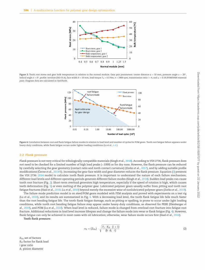
When tooth root stress is high, an increase of the normal module or gear face width linearly reduces root stress (equation 1). Suchmeasures also increase the size of the transmission drive, which is not always acceptable. The model for root stress calculationin equation (1) was defined in VDI 2736. An alternative solution is to use a reinforced polymer material that allows higher stresslevels (Tavcar et al., 2018). Tooth root stress can be reduced by modifying the tooth shape – such as a positive profile shift (x1). Thetooth root fracture failure mode is a consequence of bending fatigue or root stress overload (Fig. 2). The multicriteria optimizationalgorithm does not directly consider the various techniques employed to enhance polymer gear performance, such as asymmetrictooth profile (Karthik Pandian et al., 2020), variable face width (Duzcukoglu, 2009; Imrek, 2009), eccentric gears (Lin et al., 2020), orcooling inserts (Singh et al., 2017). Different enhancements can be applied additionally for improved robustness.
Figure 3 shows how the normal module influences the root stress. If the center distance is constant, the tooth root stress signifi-cantly increases as the normal module gets smaller (the number of teeth increases). However, root stress is not the only parameter.At the same time, the module size has a negative influence on gear temperature, especially on the pinion. A higher number of teeth(smaller module) improves transmission efficiency and therefore reduces the gear bulk temperature (Fig. 3). That means, if the hightemperature is critical for the gear pair failure mode, an increase of module size can make the situation even worse. The tooth rootstress level and temperature were calculated according to the VDI 2736 guideline. The root stress variation in Fig. 3 is a consequenceof different profile shifts (x1,2) as a mechanism to adapt to the fixed center distance.
Dow
nloaded from https://academ
ic.oup.com/jcde/article/8/2/581/6097077 by guest on 22 January 2022

Journal of Computational Design and Engineering, 2021, 8(2), 581–599 583
Figure 1: Gear pair optimization procedure and criteria influencing the gear pair design. The input data and preliminary calculation determine the initial materialselection and gear geometry. The optimization procedure is carried out as an iterative search for equilibrium between several criteria with support of the OptiTooth.
Figure 2: Root fatigue failure mode was identified on a PPS + CF (carbon fiber) polymer gear. PPS + CF has outstanding quasistatic mechanical characteristics, but it isdue to low root fatigue durability not being a good option for gears (Tavcar et al., 2018).
Tooth root stress:
σF = KF · YFa · YSa · Yε · Yβ · Ft
b · mn(1)
KF tooth root load factorYFa shape of tooth factorYSa tension concentration factorYε contact ratio factorYβ helix angle factorFt nominal tangential forceb face widthmn normal module
Dow
nloaded from https://academ
ic.oup.com/jcde/article/8/2/581/6097077 by guest on 22 January 2022
584 A multicriteria function for polymer gear design optimization
Figure 3: Tooth root stress and gear bulk temperature in relation to the normal module. Gear pair parameters: center distance a = 50 mm, pressure angle α = 20o,helical angle β = 0o, profile: involute (ISO 53 A), face width b = 10 mm, load torque Td = 0.5 Nm, n = 2400 rpm, transmission ratio i = 4, and μ = 0.18 (POM/PA66 materialpair). Diagram data are calculated in OptiTooth.
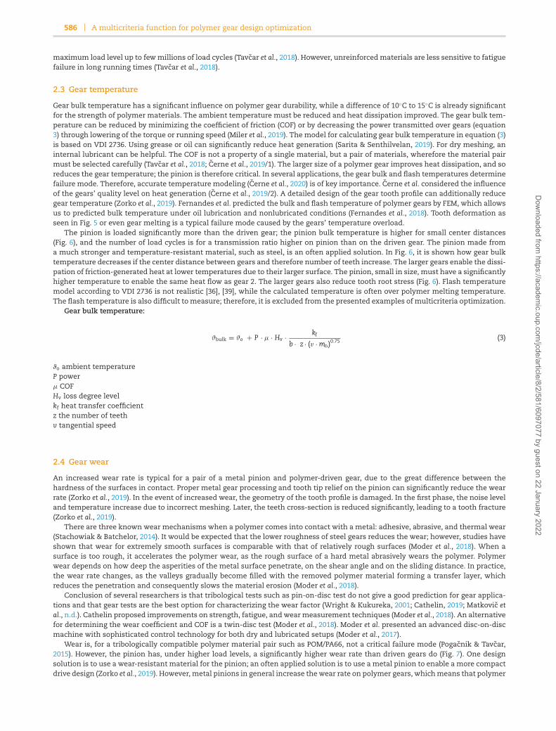
Figure 4: Correlation between root and flank fatigue failure modes in relation to load level and number of cycles for POM gears. Tooth root fatigue failure appears under
heavy-duty conditions, while flank fatigue occurs under lighter loading conditions (Lu et al., n.d.).
2.2 Flank pressure
Flank pressure is not very critical for tribologically compatible materials (Singh et al., 2018). According to VDI 2736, flank pressure doesnot need to be checked for a limited number of high load peaks (<1000) or for dry runs. However, the flank pressure can be reducedby carefully selecting the gear geometry (contact ratio and tooth contact curvature) (Zorko et al., 2017), and by adding suitable profilemodifications (Cerne et al., 2019/1). Increasing the gear face width and gear diameter reduces the flank pressure. Equation (2) presentsthe VDI 2736: 2014 model to calculate tooth flank pressure. It is important to understand the nature of each failure mechanism;different load levels and different operating periods generate different failure modes (Singh et al., 2018). Sudden load peaks can causetooth root fracture (Fig. 2). Short-term overload generates high temperature, especially if the speed of rotation is high, which causesteeth deformation (Fig. 5) or even melting of the polymer gear. Lubricated polymer gears usually suffer from pitting and tooth rootfatigue fractures (Hasl et al., 2018; Lu et al., 2019) beyond merely the excessive wear of nonlubricated polymer gears (Zorko et al., 2019).
The failure mode prediction model is on steel/POM gears modeled with FEM analysis and proved with experiments on a test rig(Lu et al., 2020), and its results are summarized in Fig. 4. With a decreasing load level, the tooth flank fatigue life falls much fasterthan the root bending fatigue life. The tooth flank fatigue damage, such as pitting or spalling, is prone to occur under light loadingconditions, while tooth root bending fatigue failure may appear under heavy-duty conditions, as observed for PEEK (Illenberger etal., 2019), and POM (Lu et al., 2020). When load level is reduced, failure mode is changed from overload root fracture into fatigue rootfracture. Additional reductions in load level increase lifespan and change the failure mode into wear or flank fatigue (Fig. 4). However,flank fatigue can only be achieved in most cases with oil lubrication; otherwise, wear failure mode occurs first (Hasl et al., 2018).
Tooth flank pressure:
σH = (ZHx) ·√
Ft · KH · (i + 1)(b · d1 · i )
(2)
ZHx set of factorsKH factor for flank loadi gear ratiod1 pinion diameter
Dow
nloaded from https://academ
ic.oup.com/jcde/article/8/2/581/6097077 by guest on 22 January 2022

Journal of Computational Design and Engineering, 2021, 8(2), 581–599 585
Figure 5: Tooth deformation due to thermal and root stress overload. The degradation of tooth geometry increases heat generation and gear’s temperature.
Figure 6: Gears’ bulk temperature and tooth root stress in relation to the center distance between gears. Gear pair parameters: module mn = 1.0 mm, pressure angle α =20o, helical angle β = 0o, profile: involute (ISO 53 A), face width b = 10 mm, load torque Td = 0.5 Nm, speed n = 2400 rpm, transmission ratio i = 4, ambient temperature
ϑo = 30◦C, and μ = 0.18 (POM/PA66). Diagram data are calculated in OptiTooth.
Figure 7: Wear in relation to gear width for POM/PA66 and for Steel/POM material pair. Gear pair’s parameters: z1 = 20, z2 = 80, mn = 1 mm, and NL = 107; Td = 0.5 Nm.Diagram data are calculated in OptiTooth.
Similar results were gained by Lu et al. on a steel/PEEK material pair (Lu et al., 2019). The wear measurements and the tooth surfacemicrotopography help us to identify that the micropits near the pitch line lead to the final tooth breakage under moderate loadingconditions (Lu et al., 2019). The gear’s material also determines failure modes, as Sarita and Senthilvelan observed pitting near thepitch region under dry conditions when the tested gear pairs of steel/PA66 were subjected to a low load (Sarita & Senthilvelan, 2019).Polymer material and fiber reinforcement have a significant influence on durability. Glass fiber reinforcement significantly increases
Dow
nloaded from https://academ
ic.oup.com/jcde/article/8/2/581/6097077 by guest on 22 January 2022
586 A multicriteria function for polymer gear design optimization
maximum load level up to few millions of load cycles (Tavcar et al., 2018). However, unreinforced materials are less sensitive to fatiguefailure in long running times (Tavcar et al., 2018).
2.3 Gear temperature
Gear bulk temperature has a significant influence on polymer gear durability, while a difference of 10◦C to 15◦C is already significantfor the strength of polymer materials. The ambient temperature must be reduced and heat dissipation improved. The gear bulk tem-perature can be reduced by minimizing the coefficient of friction (COF) or by decreasing the power transmitted over gears (equation3) through lowering of the torque or running speed (Miler et al., 2019). The model for calculating gear bulk temperature in equation (3)is based on VDI 2736. Using grease or oil can significantly reduce heat generation (Sarita & Senthilvelan, 2019). For dry meshing, aninternal lubricant can be helpful. The COF is not a property of a single material, but a pair of materials, wherefore the material pairmust be selected carefully (Tavcar et al., 2018; Cerne et al., 2019/1). The larger size of a polymer gear improves heat dissipation, and soreduces the gear temperature; the pinion is therefore critical. In several applications, the gear bulk and flash temperatures determinefailure mode. Therefore, accurate temperature modeling (Cerne et al., 2020) is of key importance. Cerne et al. considered the influenceof the gears’ quality level on heat generation (Cerne et al., 2019/2). A detailed design of the gear tooth profile can additionally reducegear temperature (Zorko et al., 2019). Fernandes et al. predicted the bulk and flash temperature of polymer gears by FEM, which allowsus to predicted bulk temperature under oil lubrication and nonlubricated conditions (Fernandes et al., 2018). Tooth deformation asseen in Fig. 5 or even gear melting is a typical failure mode caused by the gears’ temperature overload.
The pinion is loaded significantly more than the driven gear; the pinion bulk temperature is higher for small center distances(Fig. 6), and the number of load cycles is for a transmission ratio higher on pinion than on the driven gear. The pinion made froma much stronger and temperature-resistant material, such as steel, is an often applied solution. In Fig. 6, it is shown how gear bulktemperature decreases if the center distance between gears and therefore number of teeth increase. The larger gears enable the dissi-pation of friction-generated heat at lower temperatures due to their larger surface. The pinion, small in size, must have a significantlyhigher temperature to enable the same heat flow as gear 2. The larger gears also reduce tooth root stress (Fig. 6). Flash temperaturemodel according to VDI 2736 is not realistic [36], [39], while the calculated temperature is often over polymer melting temperature.The flash temperature is also difficult to measure; therefore, it is excluded from the presented examples of multicriteria optimization.
Gear bulk temperature:
ϑbulk = ϑo + P · μ · Hv · kf
b · z · (v · mn)0.75 (3)
ϑo ambient temperatureP powerμ COFHv loss degree levelkf heat transfer coefficientz the number of teethv tangential speed
2.4 Gear wear
An increased wear rate is typical for a pair of a metal pinion and polymer-driven gear, due to the great difference between thehardness of the surfaces in contact. Proper metal gear processing and tooth tip relief on the pinion can significantly reduce the wearrate (Zorko et al., 2019). In the event of increased wear, the geometry of the tooth profile is damaged. In the first phase, the noise leveland temperature increase due to incorrect meshing. Later, the teeth cross-section is reduced significantly, leading to a tooth fracture(Zorko et al., 2019).
There are three known wear mechanisms when a polymer comes into contact with a metal: adhesive, abrasive, and thermal wear(Stachowiak & Batchelor, 2014). It would be expected that the lower roughness of steel gears reduces the wear; however, studies haveshown that wear for extremely smooth surfaces is comparable with that of relatively rough surfaces (Moder et al., 2018). When asurface is too rough, it accelerates the polymer wear, as the rough surface of a hard metal abrasively wears the polymer. Polymerwear depends on how deep the asperities of the metal surface penetrate, on the shear angle and on the sliding distance. In practice,the wear rate changes, as the valleys gradually become filled with the removed polymer material forming a transfer layer, whichreduces the penetration and consequently slows the material erosion (Moder et al., 2018).
Conclusion of several researchers is that tribological tests such as pin-on-disc test do not give a good prediction for gear applica-tions and that gear tests are the best option for characterizing the wear factor (Wright & Kukureka, 2001; Cathelin, 2019; Matkovic etal., n.d.). Cathelin proposed improvements on strength, fatigue, and wear measurement techniques (Moder et al., 2018). An alternativefor determining the wear coefficient and COF is a twin-disc test (Moder et al., 2018). Moder et al. presented an advanced disc-on-discmachine with sophisticated control technology for both dry and lubricated setups (Moder et al., 2017).
Wear is, for a tribologically compatible polymer material pair such as POM/PA66, not a critical failure mode (Pogacnik & Tavcar,2015). However, the pinion has, under higher load levels, a significantly higher wear rate than driven gears do (Fig. 7). One designsolution is to use a wear-resistant material for the pinion; an often applied solution is to use a metal pinion to enable a more compactdrive design (Zorko et al., 2019). However, metal pinions in general increase the wear rate on polymer gears, which means that polymer
Dow
nloaded from https://academ
ic.oup.com/jcde/article/8/2/581/6097077 by guest on 22 January 2022
Journal of Computational Design and Engineering, 2021, 8(2), 581–599 587
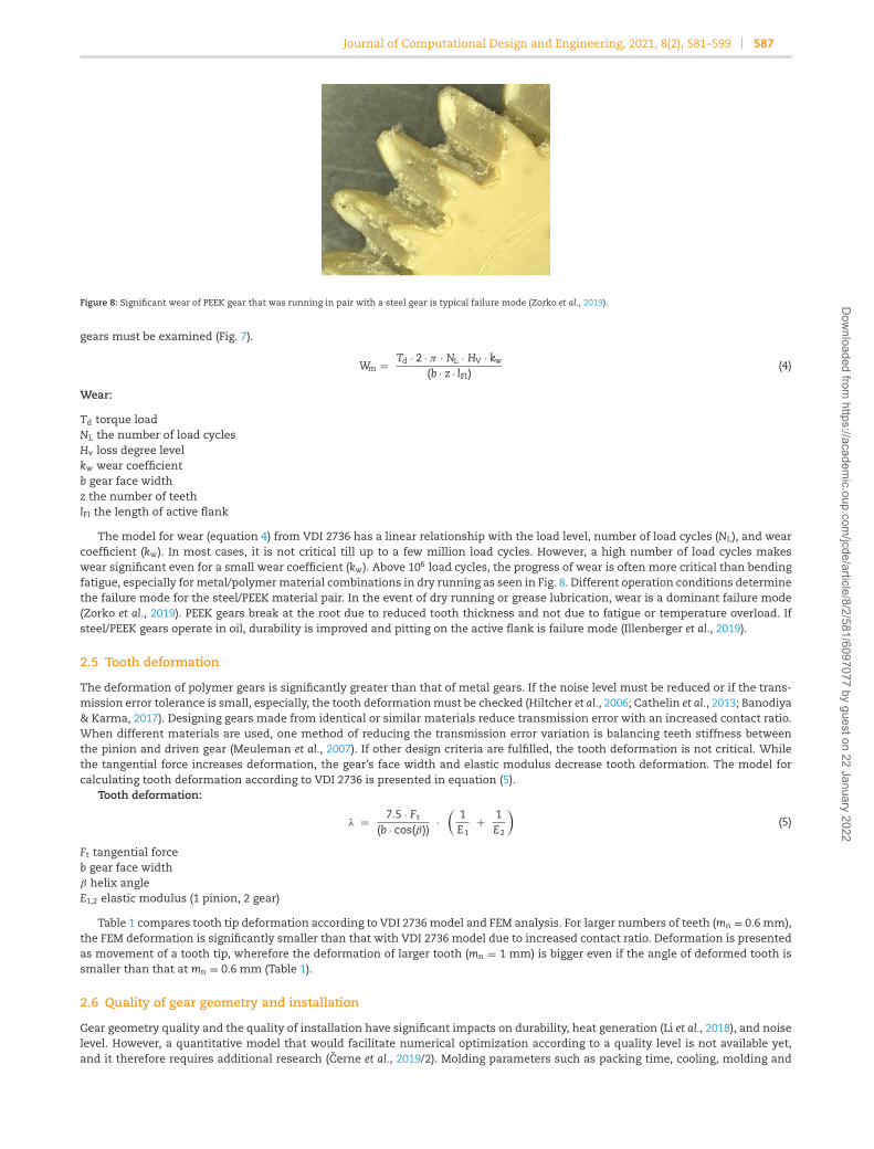
Figure 8: Significant wear of PEEK gear that was running in pair with a steel gear is typical failure mode (Zorko et al., 2019).
gears must be examined (Fig. 7).
Wm = Td · 2 · π · NL · HV · kw
(b · z · lFl)(4)
Wear:
Td torque loadNL the number of load cyclesHv loss degree levelkw wear coefficientb gear face widthz the number of teethlFl the length of active flank
The model for wear (equation 4) from VDI 2736 has a linear relationship with the load level, number of load cycles (NL), and wearcoefficient (kw). In most cases, it is not critical till up to a few million load cycles. However, a high number of load cycles makeswear significant even for a small wear coefficient (kw). Above 106 load cycles, the progress of wear is often more critical than bendingfatigue, especially for metal/polymer material combinations in dry running as seen in Fig. 8. Different operation conditions determinethe failure mode for the steel/PEEK material pair. In the event of dry running or grease lubrication, wear is a dominant failure mode(Zorko et al., 2019). PEEK gears break at the root due to reduced tooth thickness and not due to fatigue or temperature overload. Ifsteel/PEEK gears operate in oil, durability is improved and pitting on the active flank is failure mode (Illenberger et al., 2019).
2.5 Tooth deformation
The deformation of polymer gears is significantly greater than that of metal gears. If the noise level must be reduced or if the trans-mission error tolerance is small, especially, the tooth deformation must be checked (Hiltcher et al., 2006; Cathelin et al., 2013; Banodiya& Karma, 2017). Designing gears made from identical or similar materials reduce transmission error with an increased contact ratio.When different materials are used, one method of reducing the transmission error variation is balancing teeth stiffness betweenthe pinion and driven gear (Meuleman et al., 2007). If other design criteria are fulfilled, the tooth deformation is not critical. Whilethe tangential force increases deformation, the gear’s face width and elastic modulus decrease tooth deformation. The model forcalculating tooth deformation according to VDI 2736 is presented in equation (5).
Tooth deformation:
λ = 7.5 · Ft
(b · cos(β))·
(1E1
+ 1E2
)(5)
Ft tangential forceb gear face widthβ helix angleE1,2 elastic modulus (1 pinion, 2 gear)
Table 1 compares tooth tip deformation according to VDI 2736 model and FEM analysis. For larger numbers of teeth (mn = 0.6 mm),the FEM deformation is significantly smaller than that with VDI 2736 model due to increased contact ratio. Deformation is presentedas movement of a tooth tip, wherefore the deformation of larger tooth (mn = 1 mm) is bigger even if the angle of deformed tooth issmaller than that at mn = 0.6 mm (Table 1).
2.6 Quality of gear geometry and installation
Gear geometry quality and the quality of installation have significant impacts on durability, heat generation (Li et al., 2018), and noiselevel. However, a quantitative model that would facilitate numerical optimization according to a quality level is not available yet,and it therefore requires additional research (Cerne et al., 2019/2). Molding parameters such as packing time, cooling, molding and
Dow
nloaded from https://academ
ic.oup.com/jcde/article/8/2/581/6097077 by guest on 22 January 2022

588 A multicriteria function for polymer gear design optimization
Table 1: Comparison of tooth deformation for different load levels between VDI 2736 model and FEM analysis (POM/PA66 pair, face width b = 6mm, d1 = d2 = 20 mm).
Module = 1.0 mm z1 = z2 = 20 Module = 0.6 mm z1 = z2 = 34
Load level (Nm) Deform. VDI 2736 (mm) Deform. FEM (mm) Deform. VDI 2736 (mm) Deform. FEM (mm)
0.4 0.027 0.031 0.031 0.0200.5 0.039 0.034 0.039 0.0250.6 0.046 0.040 0.046 0.030
melting temperatures, packing and injection pressures, and fiberglass percentages are the most important factors affecting warpageand shrinkage – quality of gear geometry (Hakimian & Sulong, 2012). The model according to equation (6) considers the worst of thediscussed quality grades, according to ISO 1328 (ISO 1328-2:1997: Cylindrical Gears—ISO System of Accuracy—Part 2: Definitions &Allowable Values of Deviations Relevant to Radial Composite Deviations & Runout Information, 1997). The authors would like to raiseawareness about quality.
Quality level:
Q = max (Qgeom, Qinst) (6)
Qgeom quality level of gear geometryQinst quality level of gear installation
2.7 Cost and volume
In most cases, there is a request to have high-performance gears, at low cost, and in a small design volume. Gear characteristicssuch as root stress, temperature, wear, and deformation improve as gear size increases. However, larger gears increase the costand design volume. Selecting high-performance polymers with internal lubricants and reinforcements can reduce volume, but canalso significantly affect gear cost. Better gear and installation quality can also contribute to better gear performance (Cerne et al.,2019/2). Pairing with a metal pinion is a common solution for a compact design. The current model for gear cost is a product ofgear and additional processing volume for filling channels, specific mass, cost of gear material, and processing cost (equation 7a). Ifmanufacturing process with cutting is applied, the cost of cut-off volume is additionally considered in the equation (equation 7b).
Gear designers must find a balance between functional requests, material characteristics, volume, and costs. The authors proposeto determine processing and material costs according to the context of application and gear supplier capability. The cost awarenessin the conceptual design phase and checking of key design options as soon as possible is essential for commercial polymer gearapplications. The simultaneous considering of the technical and financial aspects of polymer gears is a unique approach in thescientific publications according to the authors’ knowledge.
Gear costs:
C ={
(V1,2 + Vp1,2) · ρ1,2 · (Ckg + Cpi
), (a) if injection molding is used
(Vc1,2 · ρ1,2 · Ckg + Vm1,2 · Cpm), (b) if machining (gear cutting) is used(7)
V1,2 volume of gear 1,2Vp1,2 additional processing volume (cold filling channels of gear 1,2)Vc1,2 volume of cylinder 1,2 for gear cuttingVm1,2 cutoff volume from cylinder 1,2ρ1,2 specific mass of gear material 1,2Ckg cost of material per kgCpi processing cost per kgCpm machining cost per dm3
2.8 Summary of failure modes and optimization criteria
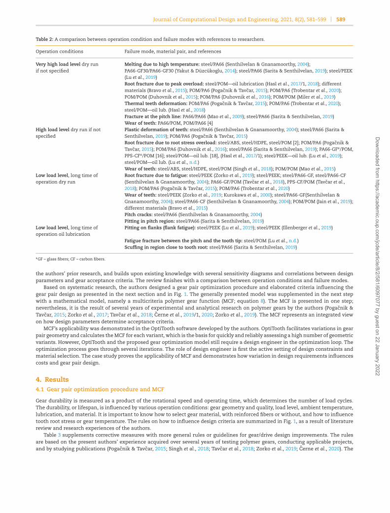
A summary of polymer-gear failure modes and references to researchers is presented in Table 2. Failure modes are determined withload level, type of lubrication, operation speed, and material pair. There are some differences between different polymer materials,though general design rules can be set. Temperature overload with gear deformation is critical for pairs of polymer gears in the eventof dry running, high load level, and high rotational speed. Running in oil reduces friction and dissipates heat better, and thereforeprevents thermal damages. Lifespan is significantly extended; pitting is a typical failure mode for running in oil. A root or pitch fatiguefracture is the expected failure mode for highly loaded polymer gears with grease lubrication. The wear failure mode is critical forpolymer gears in pairs with a steel pinion, moderate load level, and dry running or even with grease lubrication.
3. Research Method
Research on the design and optimization of polymer gears started with a comprehensive review of polymer gear design parameters,failure modes, and calculation models. The review summarizes the results of other researchers, design guidelines VDI 2736, and
Dow
nloaded from https://academ
ic.oup.com/jcde/article/8/2/581/6097077 by guest on 22 January 2022
Journal of Computational Design and Engineering, 2021, 8(2), 581–599 589
Table 2: A comparison between operation condition and failure modes with references to researchers.
Operation conditions Failure mode, material pair, and references
Very high load level dry runif not specified
Melting due to high temperature: steel/PA66 (Senthilvelan & Gnanamoorthy, 2004);PA66-GF30/PA66-GF30 (Yakut & Duzcukoglu, 2014); steel/PA66 (Sarita & Senthilvelan, 2019); steel/PEEK(Lu et al., 2019)Root fracture due to peak overload: steel/POM—oil lubrication (Hasl et al., 2017/1, 2018); differentmaterials (Bravo et al., 2015); POM/PA6 (Pogacnik & Tavcar, 2015); POM/PA6 (Trobentar et al., 2020);POM/POM (Duhovnik et al., 2015); POM/PA6 (Duhovnik et al., 2016); POM/POM (Miler et al., 2019)Thermal teeth deformation: POM/PA6 (Pogacnik & Tavcar, 2015); POM/PA6 (Trobentar et al., 2020);steel/POM—oil lub. (Hasl et al., 2018)Fracture at the pitch line: PA66/PA66 (Mao et al., 2009); steel/PA66 (Sarita & Senthilvelan, 2019)Wear of teeth: PA66/POM, POM/PA66 [4]
High load level dry run if notspecified
Plastic deformation of teeth: steel/PA66 (Senthilvelan & Gnanamoorthy, 2004); steel/PA66 (Sarita &Senthilvelan, 2019); POM/PA6 (Pogacnik & Tavcar, 2015)Root fracture due to root stress overload: steel/ABS, steel/HDPE, steel/POM [2]; POM/PA6 (Pogacnik &Tavcar, 2015); POM/PA6 (Duhovnik et al., 2016); steel/PA66 (Sarita & Senthilvelan, 2019); PA66-GFa/POM,PPS-CFa/POM [16]; steel/POM—oil lub. [18], (Hasl et al., 2017/1); steel/PEEK—oil lub. (Lu et al., 2019);steel/POM—oil lub. (Lu et al., n.d.)Wear of teeth: steel/ABS, steel/HDPE, steel/POM (Singh et al., 2018); POM/POM (Mao et al., 2015)
Low load level, long time ofoperation dry run
Root fracture due to fatigue: steel/PEEK (Zorko et al., 2019); steel/PEEK; steel/PA66-GF, steel/PA66-CF(Senthilvelan & Gnanamoorthy, 2004); PA66-GF/POM (Tavcar et al., 2018), PPS-CF/POM (Tavcar et al.,2018); POM/PA6 (Pogacnik & Tavcar, 2015); POM/PA6 (Trobentar et al., 2020)Wear of teeth: steel/PEEK (Zorko et al., 2019; Kurokawa et al., 2000); steel/PA66-GF(Senthilvelan &Gnanamoorthy, 2004); steel/PA66-CF (Senthilvelan & Gnanamoorthy, 2004); POM/POM (Jain et al., 2019);different materials (Bravo et al., 2015)Pitch cracks: steel/PA66 (Senthilvelan & Gnanamoorthy, 2004)Pitting in pitch region: steel/PA66 (Sarita & Senthilvelan, 2019)
Low load level, long time ofoperation oil lubrication
Pitting on flanks (flank fatigue): steel/PEEK (Lu et al., 2019); steel/PEEK (Illenberger et al., 2019)
Fatigue fracture between the pitch and the tooth tip: steel/POM (Lu et al., n.d.)Scuffing in region close to tooth root: steel/PA66 (Sarita & Senthilvelan, 2019)
aGF – glass fibers; CF – carbon fibers.
the authors’ prior research, and builds upon existing knowledge with several sensitivity diagrams and correlations between designparameters and gear acceptance criteria. The review finishes with a comparison between operation conditions and failure modes.
Based on systematic research, the authors designed a gear pair optimization procedure and elaborated criteria influencing thegear pair design as presented in the next section and in Fig. 1. The generally presented model was supplemented in the next stepwith a mathematical model, namely a multicriteria polymer gear function (MCF; equation 8). The MCF is presented in one step;nevertheless, it is the result of several years of experimental and analytical research on polymer gears by the authors (Pogacnik &Tavcar, 2015; Zorko et al., 2017; Tavcar et al., 2018; Cerne et al., 2019/1, 2020; Zorko et al., 2019). The MCF represents an integrated viewon how design parameters determine acceptance criteria.
MCF’s applicability was demonstrated in the OptiTooth software developed by the authors. OptiTooth facilitates variations in gearpair geometry and calculates the MCF for each variant, which is the basis for quickly and reliably assessing a high number of geometricvariants. However, OptiTooth and the proposed gear optimization model still require a design engineer in the optimization loop. Theoptimization process goes through several iterations. The role of design engineer is first the active setting of design constraints andmaterial selection. The case study proves the applicability of MCF and demonstrates how variation in design requirements influencescosts and gear pair design.
4. Results4.1 Gear pair optimization procedure and MCF
Gear durability is measured as a product of the rotational speed and operating time, which determines the number of load cycles.The durability, or lifespan, is influenced by various operation conditions: gear geometry and quality, load level, ambient temperature,lubrication, and material. It is important to know how to select gear material, with reinforced fibers or without, and how to influencetooth root stress or gear temperature. The rules on how to influence design criteria are summarized in Fig. 1, as a result of literaturereview and research experiences of the authors.
Table 3 supplements corrective measures with more general rules or guidelines for gear/drive design improvements. The rulesare based on the present authors’ experience acquired over several years of testing polymer gears, conducting applicable projects,and by studying publications (Pogacnik & Tavcar, 2015; Singh et al., 2018; Tavcar et al., 2018; Zorko et al., 2019; Cerne et al., 2020). The
Dow
nloaded from https://academ
ic.oup.com/jcde/article/8/2/581/6097077 by guest on 22 January 2022
590 A multicriteria function for polymer gear design optimization
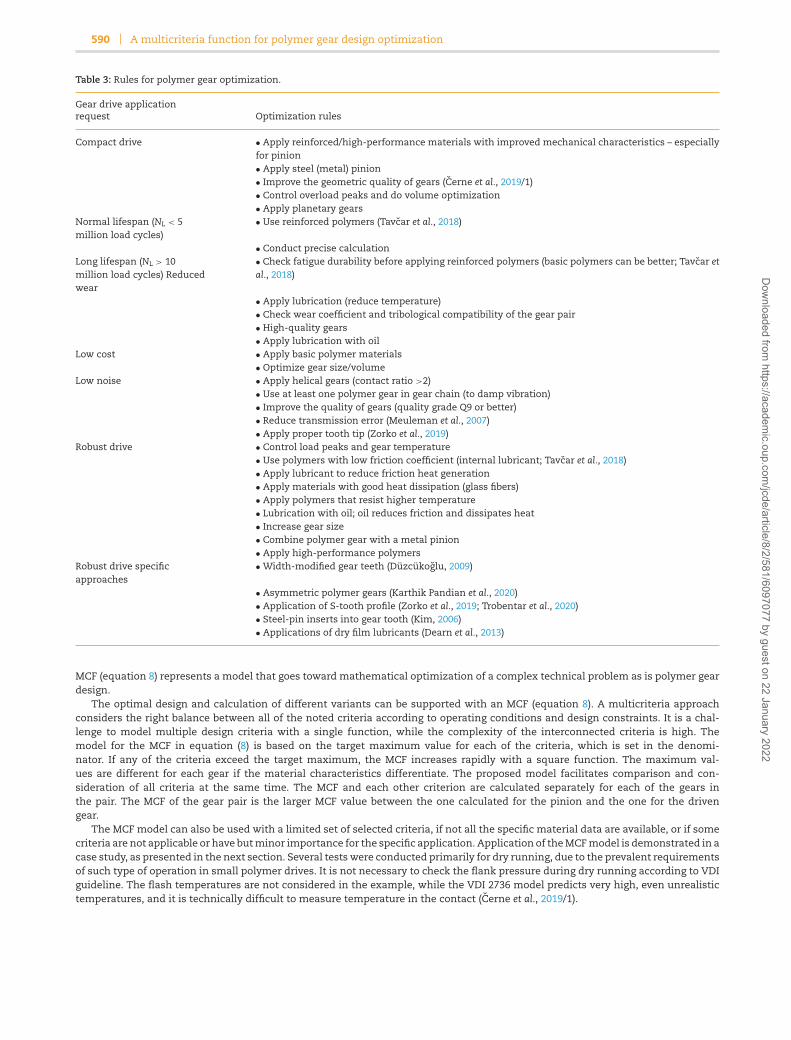
Table 3: Rules for polymer gear optimization.
Gear drive applicationrequest Optimization rules
Compact drive • Apply reinforced/high-performance materials with improved mechanical characteristics – especiallyfor pinion• Apply steel (metal) pinion• Improve the geometric quality of gears (Cerne et al., 2019/1)• Control overload peaks and do volume optimization• Apply planetary gears
Normal lifespan (NL < 5million load cycles)
• Use reinforced polymers (Tavcar et al., 2018)
• Conduct precise calculationLong lifespan (NL > 10million load cycles) Reducedwear
• Check fatigue durability before applying reinforced polymers (basic polymers can be better; Tavcar etal., 2018)
• Apply lubrication (reduce temperature)• Check wear coefficient and tribological compatibility of the gear pair• High-quality gears• Apply lubrication with oil
Low cost • Apply basic polymer materials• Optimize gear size/volume
Low noise • Apply helical gears (contact ratio >2)• Use at least one polymer gear in gear chain (to damp vibration)• Improve the quality of gears (quality grade Q9 or better)• Reduce transmission error (Meuleman et al., 2007)• Apply proper tooth tip (Zorko et al., 2019)
Robust drive • Control load peaks and gear temperature• Use polymers with low friction coefficient (internal lubricant; Tavcar et al., 2018)• Apply lubricant to reduce friction heat generation• Apply materials with good heat dissipation (glass fibers)• Apply polymers that resist higher temperature• Lubrication with oil; oil reduces friction and dissipates heat• Increase gear size• Combine polymer gear with a metal pinion• Apply high-performance polymers
Robust drive specificapproaches
• Width-modified gear teeth (Duzcukoglu, 2009)
• Asymmetric polymer gears (Karthik Pandian et al., 2020)• Application of S-tooth profile (Zorko et al., 2019; Trobentar et al., 2020)• Steel-pin inserts into gear tooth (Kim, 2006)• Applications of dry film lubricants (Dearn et al., 2013)
MCF (equation 8) represents a model that goes toward mathematical optimization of a complex technical problem as is polymer geardesign.
The optimal design and calculation of different variants can be supported with an MCF (equation 8). A multicriteria approachconsiders the right balance between all of the noted criteria according to operating conditions and design constraints. It is a chal-lenge to model multiple design criteria with a single function, while the complexity of the interconnected criteria is high. Themodel for the MCF in equation (8) is based on the target maximum value for each of the criteria, which is set in the denomi-nator. If any of the criteria exceed the target maximum, the MCF increases rapidly with a square function. The maximum val-ues are different for each gear if the material characteristics differentiate. The proposed model facilitates comparison and con-sideration of all criteria at the same time. The MCF and each other criterion are calculated separately for each of the gears inthe pair. The MCF of the gear pair is the larger MCF value between the one calculated for the pinion and the one for the drivengear.
The MCF model can also be used with a limited set of selected criteria, if not all the specific material data are available, or if somecriteria are not applicable or have but minor importance for the specific application. Application of the MCF model is demonstrated in acase study, as presented in the next section. Several tests were conducted primarily for dry running, due to the prevalent requirementsof such type of operation in small polymer drives. It is not necessary to check the flank pressure during dry running according to VDIguideline. The flash temperatures are not considered in the example, while the VDI 2736 model predicts very high, even unrealistictemperatures, and it is technically difficult to measure temperature in the contact (Cerne et al., 2019/1).
Dow
nloaded from https://academ
ic.oup.com/jcde/article/8/2/581/6097077 by guest on 22 January 2022
Journal of Computational Design and Engineering, 2021, 8(2), 581–599 591
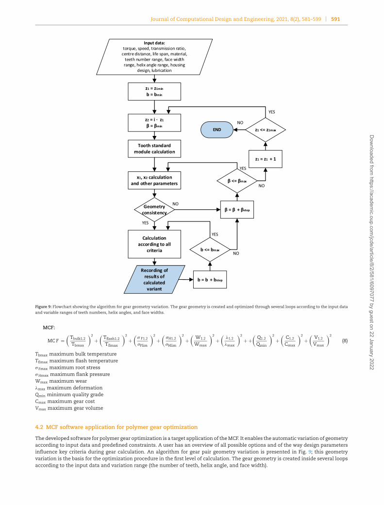
Figure 9: Flowchart showing the algorithm for gear geometry variation. The gear geometry is created and optimized through several loops according to the input dataand variable ranges of teeth numbers, helix angles, and face widths.
MCF:
MC F =(
Tbulk1,2
Tbmax
)2
+(
Tflash1,2
Tflmax
)2
+(
σ F1,2
σFlim
)2
+(
σH1,2
σHlim
)2
+(
W1,2
Wmax
)2
+(
λ1,2
λmax
)2
+ +(
Q1,2
Qmin
)2
+(
C1,2
Cmax
)2
+(
V1,2
Vmax
)2
(8)
Tbmax maximum bulk temperatureTflmax maximum flash temperatureσ Fmax maximum root stressσHmax maximum flank pressureWmax maximum wearλmax maximum deformationQmin minimum quality gradeCmax maximum gear costVmax maximum gear volume
4.2 MCF software application for polymer gear optimization
The developed software for polymer gear optimization is a target application of the MCF. It enables the automatic variation of geometryaccording to input data and predefined constraints. A user has an overview of all possible options and of the way design parametersinfluence key criteria during gear calculation. An algorithm for gear pair geometry variation is presented in Fig. 9; this geometryvariation is the basis for the optimization procedure in the first level of calculation. The gear geometry is created inside several loopsaccording to the input data and variation range (the number of teeth, helix angle, and face width).
Dow
nloaded from https://academ
ic.oup.com/jcde/article/8/2/581/6097077 by guest on 22 January 2022

592 A multicriteria function for polymer gear design optimization
Figure 10: Main user interface for OptiTooth with input parameters on the upper part of the window. The results of the first level calculation are presented in thecenter. The lower part of the window presents results according to different criteria. Critical values are marked in red. For the selected gear pair design option, adetailed calculation is made and exported as a report.
OptiTooth software was developed using Visual Basic for Applications (MS Excel). The platform offers a user-friendly interface,debugging tools, and sufficient performance. In calculating gears and for research purposes, flexibility is more important than com-putational power. Commercially available software such as KISSsoft also has an option to generate geometric variants of polymergears. However, KISSsoft does not have any function for the holistic assessment of gear variants such as an MCF. Therefore, thedesign engineer must select the optimal gear design manually on the basis of partial calculation results for each criterion.
The normal module is calculated in relation to the load level, material characteristics, proposed number of teeth, and relative facewidth as defined in VDI 2736. The next-largest standard normal module is used in the variation procedure. Checking for geometryconsistency includes calculating whether the proposed geometry fits into the requested center distance (Fig. 9). The gear calculationresults are presented even if some of the criteria are not fulfilled. Searching for an optimal design requires the gear designer to seethe whole picture, including gear design variants that, according to the specified safety specifications, fail to meet requirements. Byapplying different kinds of improvements, such gear designs can lead to the optimal solution.
The results of the first level calculation are presented in the main window in the center of the user interface (marked with ared-dashed rectangle; Fig. 10). In each line, one possible gear pair design variant is presented with the basic parameters: the numberof teeth (z1, z2), gear ratio (i), normal module (mn), face width (b), helix angle (β), gear diameter (d1, d2), profile shift (x1, x2), root stresssafety factor (sfn1, sfn2), total contact ratio factor (εtotal), and MCF value (multicriteria), as defined in Section 4.1.
For each selected gear pair, the user can modify the face width (b) and run calculations on the second level. This option for facewidth setting gives the designer additional possibility to check different options and sensitivity to design criteria. The results arepresented in the bottom of the window for Gear 1 and Gear 2 separately (marked with the blue dashed–dot rectangle) as shown inFig. 10. If any of the criteria [bulk or flank temperature (Tfu, Tfl), root stress (σ f), flank stress (σh), wear (Wm), or deformation (λ)] exceedsthe allowed limits, it is marked in red. Users have the option to switch each criterion on or off with a tick. If the selected criterionis switched on, it is considered in the MCF according to equation (7). The user also has the option to set a maximum value for the
Dow
nloaded from https://academ
ic.oup.com/jcde/article/8/2/581/6097077 by guest on 22 January 2022
Journal of Computational Design and Engineering, 2021, 8(2), 581–599 593
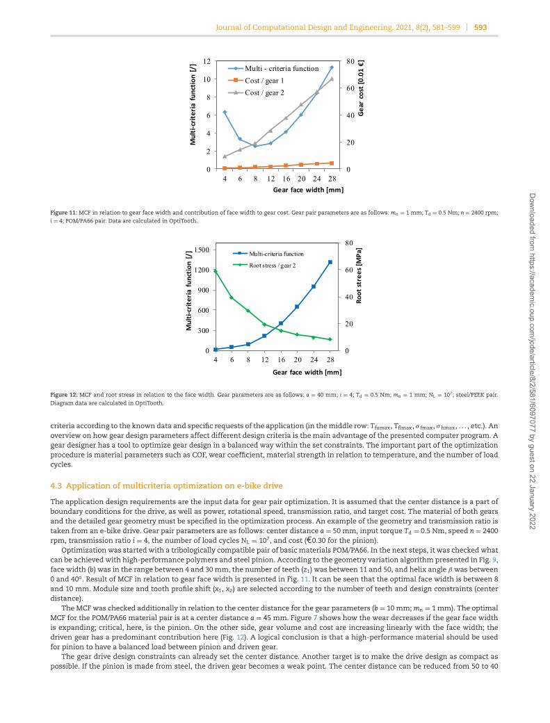
Figure 11: MCF in relation to gear face width and contribution of face width to gear cost. Gear pair parameters are as follows: mn = 1 mm; Td = 0.5 Nm; n = 2400 rpm;
i = 4; POM/PA66 pair. Data are calculated in OptiTooth.
Figure 12: MCF and root stress in relation to the face width. Gear parameters are as follows: a = 40 mm; i = 4; Td = 0.5 Nm; mn = 1 mm; NL = 107; steel/PEEK pair.Diagram data are calculated in OptiTooth.
criteria according to the known data and specific requests of the application (in the middle row: Tfumax, Tflmax, σ fmax, σhmax, . . . , etc.). Anoverview on how gear design parameters affect different design criteria is the main advantage of the presented computer program. Agear designer has a tool to optimize gear design in a balanced way within the set constraints. The important part of the optimizationprocedure is material parameters such as COF, wear coefficient, material strength in relation to temperature, and the number of loadcycles.
4.3 Application of multicriteria optimization on e-bike drive
The application design requirements are the input data for gear pair optimization. It is assumed that the center distance is a part ofboundary conditions for the drive, as well as power, rotational speed, transmission ratio, and target cost. The material of both gearsand the detailed gear geometry must be specified in the optimization process. An example of the geometry and transmission ratio istaken from an e-bike drive. Gear pair parameters are as follows: center distance a = 50 mm, input torque Td = 0.5 Nm, speed n = 2400rpm, transmission ratio i = 4, the number of load cycles NL = 107, and cost (€0.30 for the pinion).
Optimization was started with a tribologically compatible pair of basic materials POM/PA66. In the next steps, it was checked whatcan be achieved with high-performance polymers and steel pinion. According to the geometry variation algorithm presented in Fig. 9,face width (b) was in the range between 4 and 30 mm, the number of teeth (z1) was between 11 and 50, and helix angle β was between0 and 40o. Result of MCF in relation to gear face width is presented in Fig. 11. It can be seen that the optimal face width is between 8and 10 mm. Module size and tooth profile shift (x1, x2) are selected according to the number of teeth and design constraints (centerdistance).
The MCF was checked additionally in relation to the center distance for the gear parameters (b = 10 mm; mn = 1 mm). The optimalMCF for the POM/PA66 material pair is at a center distance a = 45 mm. Figure 7 shows how the wear decreases if the gear face widthis expanding; critical, here, is the pinion. On the other side, gear volume and cost are increasing linearly with the face width; thedriven gear has a predominant contribution here (Fig. 12). A logical conclusion is that a high-performance material should be usedfor pinion to have a balanced load between pinion and driven gear.
The gear drive design constraints can already set the center distance. Another target is to make the drive design as compact aspossible. If the pinion is made from steel, the driven gear becomes a weak point. The center distance can be reduced from 50 to 40
Dow
nloaded from https://academ
ic.oup.com/jcde/article/8/2/581/6097077 by guest on 22 January 2022
594 A multicriteria function for polymer gear design optimization
mm, but it is recommended to keep face width b = 10 mm due to root stress (Fig. 12). The steel pinion is, due to processing costs, insuch a configuration, more expensive than a driven gear made from POM and manufactured by injection molding.
If a high-performance material such as PEEK is used for a driven gear, the volume can be further reduced; at center distance a = 40mm, the face width can be reduced from 10 to 5 or even 4 mm. However, due to the high cost of PEEK material, the MCF in Fig. 12does not have a minimum any more. If the target cost remains at Cmax = €0.30, as it is in the POM/PA66 combination, then the costcriterion is so dominant that the MCF grows indefinitely along with the gear face width (and volume). In such cases, the target costshall be set to a realistic value or each of the criteria must be checked one by one.
5. Discussion
The paper’s main contribution is a holistic approach to polymer gear optimization. A good understanding of the expected failuremodes and how modifying design parameters can influence different criteria is essential for an effective optimization. Models fordifferent criteria are presented in the introduction section, while a summary of how to improve each individual design criterion isgiven in Fig. 1. The corrective measures are based on the physical model of each criterion. Table 3 supplements corrective measureswith more general rules or guidelines for gear/drive design improvements. The MCF (equation 8) represents a model that goes towardmathematical optimization of a complex technical problem as is polymer gear design. The case study in Section 5 demonstrates howgeometry parameters and material selection influence the gear design.
The idea of the MCF is fast feedback to the polymer gear design engineer. The current version of the program enables the designengineer to see the sensitivity of MCF and recognize the weak point of design parameters in relation to the constraints. The authorshave been experimenting with gear geometry variations on metal gears for several years already. MCF has made optimization withgeometric variation applicable also for polymer gears with a large number of criteria. Several applications have shown the advan-tage of using MCF in combination with geometry variation. MCF enables fast assessment of high number of geometric variants thatcannot be done manually. The result of checking the whole design space is better design – smaller volume or cost for the same gearperformance (durability).
The design engineer is expected to make decisions and set constraints, and in this way actively determine the solution space.The optimization procedure, therefore, assumes the active role of the design engineer in the iterative optimization loop. Some op-timization steps could be done automatically. For the specific constraints, the optimum of MCF could be calculated with numericaltools, e.g. a search for the minimum. However, for replacing design engineers and their broad knowledge, an advanced, expert systemwould be needed to combine different materials and design constraints. This is a new topic that poses a potential challenge for futureresearch.
5.1 Characterization of material data
The material characterization is conducted at specific gear geometry, temperature, and speed of rotation. If the geometry and op-erating conditions in the application differ significantly from the test gears, the reliability of lifespan predictions and the accuracyof calculations are lower. The optimization model is based on specific material characteristics. Without reliable material data, opti-mization cannot be conducted precisely, especially for different pairs of high-performance materials. Table 5 specifies the polymermaterial characteristics that are needed for accurate gear optimization. Testing a single polymer can take several months. Producing arealistic comparison between different polymer materials requires standardized procedures. In recent decades, several polymer ma-terials have been tested and analysed, but very often in a specific way as defined by researchers. Results therefore cannot be comparedand used in an optimization procedure. Most scientific durability tests take only up to a few million load cycles and have a specificresearch focus; such results cannot be used for applications where more than 10 million load cycles are needed. A step forward wasmade in the fourth part of the VDI 2736-4:2016 guideline, where gear samples and test conditions are specified. VDI 2736-4 proposestests with a steel pinion and polymer gear. Such tests are necessary, while a combination of a small metal pinion and polymer gearis very often a solution in applications. However, for the optimization of a polymer/polymer gear pair, the obtained information fromsuch test is insufficient. COF and wear factor are properties of a material pair and not of a single material (Tavcar et al., 2018). Besidesthe material characteristics from Table 5, there are some additional characteristics needed for gear optimization, such as the heattransfer coefficient, which in most cases is available on a material data sheet. Milani and Shanian propose six material performanceindices for material selection based on design criteria (Milani & Shanian, 2006).
5.2 Limitation of the conducted research
The optimization algorithm is derived by calculating the criteria based on models defined in VDI 2736. Due to the fact that the VDIguidelines originate from the metal gear standard, there are some shortcomings for polymer gears (Zorko et al., 2019). The root stresscalculated by the VDI 2736 model is prominently higher than that when calculated with the FEM. Details of the conducted FEManalyses are presented at the end of this section. The bending strength of polymer gears with a higher number of teeth and lowerYoung’s modulus withstands higher tooth root stresses according to VDI 2736 due to neglecting load-induced deflections (Hasl et al.,2017/2, 2018). The additional safety in the VDI 2736 model reduces the accuracy of the optimized gear geometry. There is room forupgrading the VDI 2736 gear calculation model, so that it will result in a better match between the calculated and experimental results.However, the authors argue that it does not change the proposed model for multicriteria optimization. If gear design is based on geartests results (material characteristics) with similar gear geometry and operational parameters as in the application, the influence ofthe calculation model is mitigated. An optional approach is to apply the VDI 2736 calculation model for conceptual design and FEManalysis for final validation.
Dow
nloaded from https://academ
ic.oup.com/jcde/article/8/2/581/6097077 by guest on 22 January 2022

Journal of Computational Design and Engineering, 2021, 8(2), 581–599 595
Table 4: Comparison of root stress, lifespan, total contact ratio, and gear’s bulk temperature between gear with the module 1.0 and 0.6 mm.The temperature was measured during the test using a thermal camera (Flir A320, Flir, USA), ϑambient = 23◦C.
Load level (Nm) 0.4 0.5 0.6
Root stress VDI 2736 (MPa) 20.3 25.4 30.5 mn = 1.0 mm; z1,2 = 20Root stress FEM (MPa) 21.0 24.0 27.5Life span (106) 5.5 2.3 0.04Total contact ration 1.814 1.831 1.868Gear’s bulk temp. VDI 2736 (◦C) 60 67 75Measured gear’s bulk temp. (◦C) 49.5 68 89Root stress VDI 2736 (MPa) 31.3 39.1 47.0 mn = 0.6 mm; z1,2 = 34Root stress FEM (MPa) 25.0 30.0 36.0Life span (106) 8.6 1.6 0.71Total contact ratio 2.078 2.145 2.171Gear’s bulk temp. VDI 2736 (◦C) 49 54 58Measured gear’s bulk temp. (◦C) 43 62.5 82
Table 5: Required polymer material characteristics for accurate gear optimization.
Material characteristics Type of testing Comment
Elastic modulus E(ϑ) (MPa) Universal testing machine withtemperature chamber
It is preferred to have E for differenttemperatures or at least for the operationtemperature of gears
Bending fatigue strength σ F (ϑ, NL) (MPa) Gear test on test rig in pair with steel gearor specific dynamic test that enablesapplication of cyclic load
In relation to temperature and number ofload cycles
Flank strength σH (ϑ, NL) (MPa) Gear testing on test rig, running in oil Test in oil is necessary; otherwise, otherfailure modes occur first
COFa μ (/) Gear testing on test rig + temperaturemeasurement
Material pair specific characteristic; COF isnot a property of a single material, but of apair of materials
Twin-disc test – secondary optionWear coefficienta kw (10−6 mm3/Nm) Gear testing on test rig + wear
measurementMaterial pair specific characteristic
Twin-disc test – secondary option
aIf application operates in extreme conditions, COF and kw must be measured at such extreme temperature and other conditions.
Motivation for the multicriteria polymer gear optimization approach was the results of gear tests with reduced module size. Theused gear testing rig had a limited maximum torque (Tavcar et al., 2018). Because of the plan for testing high-performance polymers,the test gear module was reduced from 1.0 to 0.6 mm (Tavcar et al., 2018). For applied loads of 0.6 Nm, root stress increased by 54.22%,up from 30.45 to 46.96 MPa according to VDI 2736 (Table 4). The tested gear pairs of POM/PA66 had the same diameter for drivingand driven gears (d1 = d2 = 20 mm), face width b = 6 mm, and involute profile with a pressure angle of α = 20o, without profile shift,z1 = z2 = 20 when mn = 1 mm and z1 = z2 = 34 when mn = 0.6 mm. The results of durability tests without temperature control on theopen-loop test rig have shown that lifespan of gears with module 0.6 mm is on average similar to gears with mn = 1 mm (Table 4).For a moderate load level (Td = 0.4 Nm), the lifespan of gears with mn = 1 mm was 5.8 million load cycles vs. 8.6 million load cycleswith the module 0.6 mm. For load level Td = 0.5 Nm, the durability of gears with the module 1 mm was better (Table 4). In all cases,the teeth root fatigue of POM gear was a failure mode. However, for the higher load level Td = 0.6 Nm, the thermal failure modedominated at gears with larger module. The gears’ bulk temperature measurements have shown that gears with the module 0.6 mmoperate on average at 7◦C lower than those with a larger module (Table 4). Based on the multicriteria approach and FEM analyses,these initially unexpected results could be explained. Additional FEM analysis has shown smaller difference in root stress (30.9% atdrive gear and 20% at driven gear) due to increased contact ratio in comparison with VDI 2736: (2014) (Table 4). In Fig. 13, differencein the duration of higher root stress level due to difference in the number of teeth can be seen. Higher number of teeth improveefficiency in the torque transmission and therefore reduce the gears’ temperature. 7◦C is already a significant difference, especiallyat the higher temperatures associated with polymer materials.
The FEM analysis in Fig. 14 shows a significant difference in flank pressure at the beginning and end of meshing between gearpairs with module 1.0 and 0.6 mm. The gear pair with the module 0.6 mm and a larger number of teeth (34) has, due to the contactratio of over 2, a lower flank pressure, which additionally influences the gears’ temperature and lifespan.
The numerical FEM models of meshing gear pairs were set up in ANSYS/19.2 (Ansys, Inc., USA) software. All simulations were runin 2D, taking into account a planar stress state. Quadratic-order PLANE183 elements were used to discretize gear geometry. CONTA172(drive gear) and TARGE169 (driven gear) elements were used to model the contact between the meshing flanks and a frictional contactwas considered. The used value of the COF was μ= 0.29 as determined for this material pair in the work of Pogacnik & Tavcar (2015).Mesh convergence was conducted with an h-refinement method, confirming the accuracy of the calculated stress. The accuracy of
Dow
nloaded from https://academ
ic.oup.com/jcde/article/8/2/581/6097077 by guest on 22 January 2022

596 A multicriteria function for polymer gear design optimization
Figure 13: Comparison of root stresses calculated using FEM, considering a module variation between 0.6 and 1.0 mm and different load levels: (a) for drive gear (POM)and (b) for driven gear (PA66). Due to contact ratio >2 at module mn = 0.6 mm, typical mesh points B and D do not exist.
Figure 14: Comparison of flank pressure between gear with module 1.0 and 0.6 mm for different load levels POM/PA66 gear pair. Due to the contact ratio >2 at mn = 0.6
mm, the typical mesh points B and D do not exist.
the calculated stress also depends on the element quality, wherefore a high-quality mesh with an average composite quality of 0.95was acquired.
The entire gear body was modeled, but only five teeth, where the postprocessing was done on the third tooth, which meshedthrough all characteristic meshing points. The hole of drive gear 1 was constrained to the fixed point A, located at the origin ofthe coordinate system X1Y1 (Fig. 15). Translations in the directions X1 and Y1 were constrained and only rotation around point Awas allowed. In the same manner, the drive gear was constrained to fixed point B, located at the origin of coordinate system X2Y2.Rotation was prescribed around point A on the drive gear, and torque was prescribed on the driven gear in the direction opposite torotation. Material properties were modeled as linearly elastic, since it was confirmed that such an assumption is appropriate for thenumerical modeling of polymer gear applications (Cerne et al., 2020). Elastic modulus EPOM = 3100 MPa and Poisson’s ratio νPOM = 0.35were considered for POM and EPA6 = 3400 MPa and νPA6 = 0.4 for PA6 gears.
5.3 Possibilities for further upgrades
The developed multicriteria optimization method fails to consider a wide variety of factors that can influence the polymer gear’sperformance, e.g. tooth profile modifications, chosen gear rim/web geometry, influence of fillers on the tribological properties, andthe gear’s thermal response. These factors can be studied using experimental and numerical analysis methods and the result dataextrapolated for an application inside the multicriteria method. The latter could, hence, be upgraded so as to consider the influenceof these additional factors on the main parameters defining the MCF function. This would presumably enable an even more refinedand optimal gear design.
Dow
nloaded from https://academ
ic.oup.com/jcde/article/8/2/581/6097077 by guest on 22 January 2022

Journal of Computational Design and Engineering, 2021, 8(2), 581–599 597
Figure 15: Numerical model of the gears and mesh refinement in the contact region.
6. Conclusions
This paper’s main contribution is the mathematical algorithm for the MCF (equation 8) and optimization procedure. The polymer gearoptimization procedure is based on a variation of polymer gear design parameters and the simultaneous consideration of criteria forroot and flank stress, gear temperature, wear, tooth deformation, quality, cost, and volume of each variant. The authors developedthe OptiTooth software, which demonstrates the applicability of the MCF in polymer gear optimization. Additionally, polymer geardesign guidelines and rules were established to accelerate the initial selection of the parameters and for better overview over possibleimprovement options during the optimization process.
The sensitivity of each design criterion on gear geometrical parameters is presented together with typical failure modes. Failuremodes depend on the load level, number of load cycles, lubrications, speed of rotation, material pair, and method of interrelation. Re-lationships between design criteria such as gear face width were investigated. A better understanding of sensitivity on design criteriaand failure modes is crucial for a successful optimization. An important conclusion is that a larger normal module reduces root stresslinearly, but at the same time bulk temperature increases. The bending strength of polymer gears increases with a higher numberof teeth due to load-induced deflection. Therefore, if gear diameter is unchanged, a higher number of teeth with a proportionatelysmaller module can, in some cases, result in better performance than larger module with a lower number of teeth. Sensitivity analyseshave shown that the pinion is critical for the temperature, and therefore using a metal pinion is often a good design solution.
The model for multicriteria polymer gear optimization is additionally presented with a case study. The demonstration includesinitial gear pair design constraints and a variant with a steel pinion and driven gear made from a high-performance polymer PEEK. Aprerequisite for the presented gear optimization model is the availability of material data. Required polymer material characteristicsand type of testing are specified for accurate gear optimization and good matching between calculated and experimental results. Ifthe COF or the wear coefficient for a specific pair of polymer materials is not available, then durability cannot be predicted in anydetail. Therefore, the authors’ research is now focused on the systematic testing of promising material pairs and collecting specificmaterial data. The authors see an additional challenge in gear profile optimization, with an aim for reduced contact pressure outsidethe kinematic point and for reduced frictional heat generation.
Acknowledgements
The research was financed partly by the MAP gears project (project is cofinanced by the Republic of Slovenia and the European Unionunder the European Regional Development Fund, contract number C3330-18-952014) and partly by the Slovenian Research Agency(contract number 630-33/2019-1).
Conflict of interest statement
None declared.
ReferencesBanodiya, B., & Karma, V. K. (2017). Measurement of transmission error in spur gears. International Research Journal of Engineering and
Technology, 4(8), 2369–2375.Bravo, A., Koffi, D., Toubal, L., & Erchiqui, F. (2015). Life and damage mode modeling applied to plastic gears. Engineering Failure Analysis,
58, 113–133. https://doi.org/10.1016/j.engfailanal.2015.08.040.Cathelin, J. (2019). Material data for advanced plastic gear simulation. In International Conference on Gears 2019(Vol. 2355, pp. 1379–1390).Cathelin, J., Letzelter, E., Guingand, M., de Vaujany, J.-P., & Chazeau, L. (2013). Experimental and numerical study of a loaded cylindrical
PA66 gear. Journal of Mechanical Design, 135(041007). https://doi.org/10.1115/1.4023634.
Dow
nloaded from https://academ
ic.oup.com/jcde/article/8/2/581/6097077 by guest on 22 January 2022

598 A multicriteria function for polymer gear design optimization
Cerne, B., Duhovnik, J., & Tavcar, J. (2019/1). Semi-analytical flash temperature model for thermoplastic polymer spur gears withconsideration of linear thermo-mechanical material characteristics. Journal of Computational Design and Engineering, 6(4), 617–628.https://doi.org/10.1016/j.jcde.2019.03.001.
Cerne, B., Zorko, D., Duhovnik, J., Tavcar, J., & Zavbi, R. (2019/2). Flash temperature analysis method for polymer gears with consider-ation of deviations in meshing kinematics. In IDETC-CIE2019. https://doi.org/10.1115/DETC2019-97824.
Cerne, B., Petkovsek, M., Duhovnik, J., & Tavcar, J. (2020). Thermo-mechanical modeling of polymer spur gears with experimentalvalidation using high-speed infrared thermography. Mechanism and Machine Theory, 146, 103734. https://doi.org/10.1016/j.mechmachtheory.2019.103734.
Das, D., Bhattacharya, S., & Sarkar, B. (2016). Decision-based design-driven material selection: A normative-prescriptive approach forsimultaneous selection of material and geometric variables in gear design. Materials & Design, 92, 787–793. https://doi.org/10.1016/j.matdes.2015.12.064.
Dearn, K. D., Hoskins, T. J., Andrei, L., & Walton, D. (2013). Lubrication regimes in high-performance polymer spur gears. Advances inTribology, 2013, 1–9. https://doi.org/10.1155/2013/987251.
DIN 3990. (1987). Calculation of load capacity of cylindrical gears. German National Standard.Duhovnik, J., Zorko, D., & Sedej, L. (2015). The effect of tooth flank geometry on the lifetime of injection moulded polymer gears. In
Proceedings of International Conference on High Performance Plastic Gears 2015(pp. 1203–1218).Duhovnik, J., Zorko, D., & Sedej, L. (2016). The effect of the teeth profile shape on polymer gear pair properties. Tehnicki Vjesnik - Technical
Gazette, 23(1), 199–207. https://doi.org/10.17559/TV-20151028072528.Duzcukoglu, H. (2009). PA 66 spur gear durability improvement with tooth width modification. Materials & Design, 30(4), 1060–1067.
https://doi.org/10.1016/j.matdes.2008.06.037.Fernandes, C. M. C. G., Rocha, D. M. P., Martins, R. C., Magalhaes, L., & Seabra, J. H. O. (2018). Finite element method model to predict
bulk and flash temperatures on polymer gears. Tribology International, 120, 255–268. https://doi.org/10.1016/j.triboint.2017.12.027.Hakimian, E., & Sulong, A. B. (2012). Analysis of warpage and shrinkage properties of injection-molded micro gears polymer compos-
ites using numerical simulations assisted by the Taguchi method. Materials & Design, 42, 62–71. https://doi.org/10.1016/j.matdes.2012.04.058.
Hasl, C., Oster, P., Tobie, T., & Stahl, K. (2017/1). Bending strength of oil-lubricated cylindrical plastic gears. Forschung Im Ingenieurwesen,81(2), 349–355. https://doi.org/10.1007/s10010-017-0224-2.
Hasl, C., Liu, H., Oster, P., Tobie, T., & Stahl, K., & Forschungsstelle fuer Zahnraeder und Getriebebau (Gear Research Centre). (2017/2).Method for calculating the tooth root stress of plastic spur gears meshing with steel gears under consideration of deflection-induced load sharing. Mechanism and Machine Theory, 111, 152–163. https://doi.org/10.1016/j.mechmachtheory.2017.01.015.
Hasl, C., Illenberger, C., Oster, P., Tobie, T., & Stahl, K. (2018). Potential of oil-lubricated cylindrical plastic gears. Journal of AdvancedMechanical Design, Systems, and Manufacturing, 12(1), JAMDSM0016–JAMDSM0016. https://doi.org/10.1299/jamdsm.2018jamdsm0016.
Hiltcher, Y., Guingand, M., & de Vaujany, J.-P. (2006). Load sharing of worm gear with a plastic wheel. Journal of Mechanical Design, 129(1),23–30. https://doi.org/10.1115/1.2359469.
Illenberger, C. M., Tobie, T., & Stahl, K. (2019). Flank load carrying capacity of oil-lubricated high performance plastic gears. ForschungIm Ingenieurwesen, 83(3), 545–552. https://doi.org/10.1007/s10010-019-00332-x.
Imrek, H. (2009). Performance improvement method for Nylon 6 spur gears. Tribology International, 42(3), 503–510. https://doi.org/10.1016/j.triboint.2008.08.011.
ISO 1328-2:1997. (1997). Cylindrical gears—ISO system of accuracy—Part 2: Definitions and allowable values of deviations relevant to radialcomposite deviations and runout information.
ISO 6336. (2006). Calculation of load capacity of spur and helical gears, Parts 1–6, International standard.Jain, M., Patil, S., & Ghosh, S. S. (2019). A review on failure characteristics of polymeric gears. AIP Conference Proceedings, 2148(1), 030057.
https://doi.org/10.1063/1.5123979.Karthik Pandian, A., Gautam, S. S., & Senthilvelan, S. (2020). Experimental and numerical investigation of the bending fatigue perfor-
mance of symmetric and asymmetric polymer gears. Proceedings of the Institution of Mechanical Engineers, Part L: Journal of Materials:Design and Applications, 234(6), 819–834, https://doi.org/10.1177/1464420720909486.
Kim, C. H. (2006). Durability improvement method for plastic spur gears. Tribology International, 39(11), 1454–1461. https://doi.org/10.1016/j.triboint.2006.01.020.
Kurokawa, M., Uchiyama, Y., & Nagai, S. (2000). Performance of plastic gear made of carbon fiber reinforced poly-ether-ether-ketone:Part 2. Tribology International, 33(10), 715–721. https://doi.org/10.1016/S0301-679X(00)00111-0.
Li, W., Zhai, P., Tian, J., & Luo, B. (2018). Thermal analysis of helical gear transmission system considering machining and installationerror. International Journal of Mechanical Sciences, 149, 1–17. https://doi.org/10.1016/j.ijmecsci.2018.09.036.
Lin, C., Wei, W., Wang, S., Xia, X., & Xin, Q. (2020). Bending stress analysis of eccentric straight and helical curve-face gear pair.International Journal of Mechanics and Materials in Design, 16(2), 401–414. https://doi.org/10.1007/s10999-019-09475-9.
Lu, Z., Zhu, C., Song, H., & Yu, G. (2020). The effect of injection molding lunker defect on the durability performance of polymer gears.International Journal of Mechanical Sciences, 180, https://doi.org/10.1016/j.ijmecsci.2020.105665.
Lu, Z., Liu, H., Zhu, C., Song, H., & Yu, G. (2019). Identification of failure modes of a PEEK-steel gear pair under lubrication. InternationalJournal of Fatigue, 125, 342–348. https://doi.org/10.1016/j.ijfatigue.2019.04.004.
Lu, Z., Liu, H., Wei, P., Zhu, C., Xin, D., & Shen, Y. (2020). The effect of injection molding lunker defect on the durability performanceof polymer gears. International Journal of Mechanical Sciences, 180, 105665. https://doi.org/10.1016/j.ijmecsci.2020.105665.
Lupinetti, K., Giannini, F., Monti, M., & Pernot, J.-P. (2018). Multi-criteria retrieval of CAD assembly models. Journal of ComputationalDesign and Engineering, 5(1), 41–53. https://doi.org/10.1016/j.jcde.2017.11.003.
Dow
nloaded from https://academ
ic.oup.com/jcde/article/8/2/581/6097077 by guest on 22 January 2022
Journal of Computational Design and Engineering, 2021, 8(2), 581–599 599
Mao, K., Li, W., Hooke, C. J., & Walton, D. (2009). Friction and wear behaviour of acetal and nylon gears. Wear, 267(1–4), 639–645.https://doi.org/10.1016/j.wear.2008.10.005.
Mao, K., Langlois, P., Hu, Z., Alharbi, K., Xu, X., Milson, M., Li, W., Hooke, C. J., & Chetwynd, D. (2015). The wear and thermal mechanicalcontact behaviour of machine cut polymer gears. Wear, 332–333, 822–826. https://doi.org/10.1016/j.wear.2015.01.084.
Matkovic, S., Pogacnik, A., & Kalin, M. (2019). Comparison between VDI 2736 wear calculation and experimentally obtained results. InInternational Conference on Gears 2019(Vol. 2355, pp. 1311–1321).
Meuleman, P. K., Walton, D., Dearn, K. D., Weale, D. J., & Driessen, I. (2007). Minimization of transmission errors in highly loadedplastic gear trains. Proceedings of the Institution of Mechanical Engineers, Part C: Journal of Mechanical Engineering Science, 221(9), 1117–1129. https://doi.org/10.1243/09544062JMES439.
Milani, A. S., & Shanian, A. (2006). Gear material selection with uncertain and incomplete data. Material performance indices anddecision aid model. International Journal of Mechanics and Materials in Design, 3(3), 209–222. https://doi.org/10.1007/s10999-007-9024-4.
Milani, A. S., Shanian, A., Lynam, C., & Scarinci, T. (2013). An application of the analytic network process in multiple criteria materialselection. Materials & Design, 44, 622–632. https://doi.org/10.1016/j.matdes.2012.07.057.
Miler, D., Hoic, M., Domitran, Z., & Zezelj, D. (2019). Prediction of friction coefficient in dry-lubricated polyoxymethylene spur gearpairs. Mechanism and Machine Theory, 138, 205–222. https://doi.org/10.1016/j.mechmachtheory.2019.03.040.
Moder, J., Grun, F., Stoschka, M., & Godor, I. (2017). A novel Two-Disc machine for high precision friction assessment. Advances inTribology, 2017, 1–16. https://doi.org/10.1155/2017/8901907.
Moder, J., Grun, F., Summer, F., Kohlhauser, M., & Wohlfahrt, M. (2018). Application of high performance composite polymers with steelcounterparts in dry rolling/sliding contacts. Polymer Testing, 66, 371–382. https://doi.org/10.1016/j.polymertesting.2018.01.009.
Pogacnik, A., & Tavcar, J. (2015). An accelerated multilevel test and design procedure for polymer gears. Materials & Design (1980-2015),65, 961–973. https://doi.org/10.1016/j.matdes.2014.10.016.
Sarita, B., & Senthilvelan, S. (2019). Effects of lubricant on the surface durability of an injection molded polyamide 66 spur gear pairedwith a steel gear. Tribology International, 137, 193–211. https://doi.org/10.1016/j.triboint.2019.02.050.
Senthilvelan, S., & Gnanamoorthy, R. (2004). Damage mechanisms in injection molded unreinforced, glass and carbon reinforcednylon 66 spur gears. Applied Composite Materials, 11(6), 377–397. https://doi.org/10.1023/B:ACMA.0000045313.47841.4e.
Singh, P. K.,Siddhartha, & Singh, A. K. (2017). An investigation on the effects of the various techniques over the performance anddurability of polymer gears. In Fifth International Conference of Materials Processing and Characterization (ICMPC 2016)(Vol. 4(2, Part A),pp. 1606–1614). https://doi.org/10.1016/j.matpr.2017.01.184.
Singh, P. K.,Siddhartha, & Singh, A. K. (2018). An investigation on the thermal and wear behavior of polymer based spur gears. TribologyInternational, 118, 264–272. https://doi.org/10.1016/j.triboint.2017.10.007.
Stachowiak, G. W., & Batchelor, A. W. (2014). Engineering tribology. (4th ed.) [Computer software]. BH, Butterworth-Heinemann/Elsevier.Tavcar, J., Grkman, G., & Duhovnik, J. (2018). Accelerated lifetime testing of reinforced polymer gears. Journal of Advanced Mechanical
Design, Systems, and Manufacturing, 12(1), JAMDSM0006–JAMDSM0006. https://doi.org/10.1299/jamdsm.2018jamdsm0006.Tavcar, J., Kos, J., Zorko, D., & Duhovnik, J. (2019). A multi-criteria polymer gears design optimisation procedure. In Proceedings of the
third International Conference on High Performance Plastic Gears 2019(pp. 1473–1484).Trobentar, B., Kulovec, S., Hlebanja, G., & Glodez, S. (2020). Experimental failure analysis of S-polymer gears. Engineering Failure Analysis,
111, 104496. https://doi.org/10.1016/j.engfailanal.2020.104496.VDI 2545. (1981). Zahnrader aus thermoplastischen Kunststoffen.VDI 2736. (2014). Blatt 2, Thermoplastische Zahnrader, Stirngetriebe, Tragfahigkeitsberechnung. VDI Richtlinien. VDI-Verlag GmbH, Duessel-
dorf.VDI 2736-4: 2016.(2016). Thermoplastic gear wheels—Determination of strength parameters on gears. Verlag des Vereins Deutscher Inge-
nieure.Wright, N. A., & Kukureka, S. N. (2001). Wear testing and measurement techniques for polymer composite gears. Wear, 251(1–12),
1567–1578. https://doi.org/10.1016/S0043-1648(01)00793-1.Yakut, R., & Duzcukoglu, H. (2014). Examining the abrasion behaviour of PA 66 gears in different cycles. Advances in Materials Science
and Engineering, 2014, 721731. https://doi.org/10.1155/2014/721731.Zorko, D., Kulovec, S., Tavcar, J., & Duhovnik, J. (2017). Different teeth profile shapes of polymer gears and comparison of their perfor-
mance. Journal of Advanced Mechanical Design, Systems, and Manufacturing, 11(6), JAMDSM0083–JAMDSM0083. https://doi.org/10.1299/jamdsm.2017jamdsm0083.
Zorko, D., Kulovec, S., Duhovnik, J., & Tavcar, J. (2019). Durability and design parameters of a Steel/PEEK gear pair. Mechanism andMachine Theory, 140, 825–846. https://doi.org/10.1016/j.mechmachtheory.2019.07.001.
Dow
nloaded from https://academ
ic.oup.com/jcde/article/8/2/581/6097077 by guest on 22 January 2022
Copyright © 2022 FDOKUMEN