Urban classification by pixel and object-based approaches for ...
A Modified Color JPEG Codec System Using inter pixel ...
11
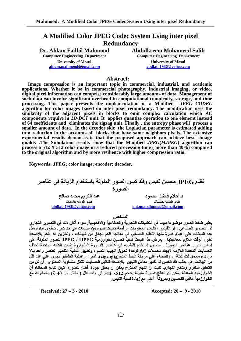
Mahmood: A Modified Color JPEG Codec System Using inter pixel Redundancy 117 A Modified Color JPEG Codec System Using inter pixel Redundancy Dr. Ahlam Fadhil Mahmood Abdulkreem Mohameed Salih Computer Engineering Department Computer Engineering Department University of Mosul University of Mosul [email protected] [email protected] Abstract: Image compression is an important topic in commercial, industrial, and academic applications. Whether it be in commercial photography, industrial imaging, or video, digital pixel information can comprise considerably large amounts of data. Management of such data can involve significant overhead in computational complexity, storage, and time processing. This paper presents the implementation of a Modified JPEG CODEC algorithm for color images based on inter pixel redundancy. The modification uses the similarity of the adjacent pixels in blocks to omit complex calculation which AC components require in 2D-DCT unit. It applies quantize operation to one element instead of 64 coefficients and eliminates the zigzag unit. Finally , the entropy phase will process a smaller amount of data. In the decoder side the Laplacian parameter is estimated adding to a reduction in the accounts of blocks that have same neighbors pixels. The extensive experimental results demonstrate that the proposed approach can achieve best image quality .The Simulation results show that the Modified JPEG(MJPEG) algorithm can process a 512 X 512 color image in a reduced processing time ( more than 40%) compared to the original algorithm and by more resilience with higher compression ratio. Keywords: JPEG; color image; encoder; decoder. ظاوJPEG يسغاص عادج فعرخذاو انضح تاهس ان كثظ انصفك نكثظ شسج انصذ صانرى يس عثذ انكشدو فاضم يس د.أزذعح زاعثاخ قغىذعح زاعثا قغى خ[email protected] [email protected] هخص انعرثش عضس ي ضغط انص ا ي احكادا حاعانص حنرداسخ اقا انرطث ف, ا ع ء أنرداسش ا انرص رنك ف كا أ ، ذ انف ، أاعش انص انرصم ذشش. زذ كثاخ إنا انثشج ياخ كثح كخ انشقياعه انط ذ إداسج يثم أاخ عها انثز عثاءشج كثا ينسغاتذ ا انرعق انثائم يندح انكى ان يعا ف اخ اذخض ، زا انكى ضافح تال نط انقد صو ان نعاند ا ر. ز عشض ا انسث ثزف ذ ن ذسغحاسصي خIJPEG / JPEG س نهص انح عهه م اعرخذوسج . انرعذش انصاصط ذكشاس ع أعا ان رشات فسجش انصاص ع انسجردا ان ض كرهازذج ح ان نسزفنسغاتاخ ا انصيحعقذج ان ادد خ يعايAC ج ذزذ ن س م انة ان دحهق عذطث ، او رى انركازذ تذ صش نع ي46 يعايم كرهح م نكنقضاء عها ، يشزهح ان خط انرعشج (zigzag) شا ، . أخحه ع انش رشف عذد عه ذدش أقم ياخ.ا انث نرثايم اش يعاقذ انكثظ ذى ذة فك خا فضافح تا نسرح اننسغاتاخ نهكرم يرغام ا رقه. أ كم يدجق خسق أك قرشذح ان انثد أنرداسب ذثئح ارا ظشم ان انرسه أفضمسج. نهص ذثساكاج أئح انرا ك عذنحح اناسصي انخ أح تسدىسج يه ذعانح ص212 x 212 قد أقم ف) تأكثش ي60 ٪ ) ح يعقاس تانقثم انرسغح يااسصي انخ يع أعهحش تادج صغثح انكثظ. Received: 27 – 3 - 2010 Accepted: 20 – 9 - 2010
-
Upload
khangminh22 -
Category
Documents
-
view
1 -
download
0
Transcript of A Modified Color JPEG Codec System Using inter pixel ...
Mahmood: A Modified Color JPEG Codec System Using inter pixel Redundancy
117
A Modified Color JPEG Codec System Using inter pixel
Redundancy Dr. Ahlam Fadhil Mahmood Abdulkreem Mohameed Salih
Computer Engineering Department Computer Engineering Department
University of Mosul University of Mosul
[email protected] [email protected]
Abstract: Image compression is an important topic in commercial, industrial, and academic applications. Whether it be in commercial photography, industrial imaging, or video, digital pixel information can comprise considerably large amounts of data. Management of such data can involve significant overhead in computational complexity, storage, and time processing. This paper presents the implementation of a Modified JPEG CODEC algorithm for color images based on inter pixel redundancy. The modification uses the similarity of the adjacent pixels in blocks to omit complex calculation which AC components require in 2D-DCT unit. It applies quantize operation to one element instead of 64 coefficients and eliminates the zigzag unit. Finally , the entropy phase will process a smaller amount of data. In the decoder side the Laplacian parameter is estimated adding to a reduction in the accounts of blocks that have same neighbors pixels. The extensive experimental results demonstrate that the proposed approach can achieve best image quality .The Simulation results show that the Modified JPEG(MJPEG) algorithm can process a 512 X 512 color image in a reduced processing time ( more than 40%) compared to the original algorithm and by more resilience with higher compression ratio.
Keywords: JPEG; color image; encoder; decoder.
ش نكثظ فك كثظ انصس انهح تاعرخذاو انضادج ف عاصيسغ JPEGظاو
انصسج د.أزالو فاضم يسد عثذ انكشى يسذ صانر
خ قغى ذعح زاعثا قغى ذعح زاعثاخ
[email protected] [email protected]
انهخصكا رنك ف انرصش انرداس أء عا ,ف انرطثقاخ انرداسح انصاعح األكادح اي اضغط انصس يضععرثش
إداسج يثم ذط انعهياخ انشقح كاخ كثشج ي انثااخ إن زذ كثش. ذشم انرصش انصاع ، أ انفذ ، أ
تاإلضافحزا انكى ، ذخض ااخ ف يعاندح انكى انائم ي انثانرعقذ انسغات ياكثشج عثاءز انثااخ عه أ
هح عه اننهصس IJPEG /JPEGخاسصيح ذسغ نذفز ثسثان اعشض ز. را عاندن انالصوقد ان نطل
نسزف ح انازذجكرهض انرداسج انعاصش انصسج ف رشات انأعاط ذكشاس عاصش انصسج . انرعذم اعرخذو
نعصش ازذ تذال انركى راو ، ذطثق عهح دة انانم سنزذج ذ ACيعايالخ إلدادعقذج انالصيح ان انسغاتاخ
أقم ذدش عه عذدرشفش انعهح . أخشا ، (zigzag)رعشجانخط ان يشزهح، انقضاء عه م نكم كرهح يعاي 46ي
ي كمأ . رقهم انسغاتاخ نهكرم يرغاح انسرن تاإلضافحف خاة فك انكثظ ذى ذقذش يعايم انرثا انثااخ.ي
رائح انساكاج أ ذث نهصسج. أفضم انرسهم انظش رائح انرداسب ذثثد أ انح انقرشذ ك أ سقق خدج
تانقاسح يع (٪ 60ي تأكثش (ف قد أقم 212x 212ذعانح صسج يهح تسدى أ انخاسصيح انعذنح ك
غثح انكثظ. صادجتشح أعه يع انخاسصيح ياقثم انرسغ
Received: 27 – 3 - 2010 Accepted: 20 – 9 - 2010
Al-Rafidain Engineering Vol.20 No. 3 June 2012
118
1. Introduction
JPEG (Joint Photographic Expert Group) is a well-known method for compressing still image and has been adopted as the compression standard for still photographic images [1]. The JPEG standard is very complex and allows many operation modes [2, 3]. The baseline is the mode widely used in both software and hardware implementations of JPEG encoder and decoder [4-6]. The baseline mode will also used as reference for the modified JPEG/MJPEG algorithm proposed in this paper. After many years of development, the JPEG image compression has gained widespread popularity for various industrial applications such as onboard digital camera storage and consumer digital imaging [7]. In this emerging trend, to improve that the JPEG compression performance plays an increasing important role due to many challenging research topics and potential applications. One category of recent research work has focused on the quantization table design [7], since the quantization table is one of the key factors influencing the performance of JPEG compression. The quantization table determines the compression ratio and decoded image quality simultaneously. Another category of approaches tries to optimize the reconstructed AC DCT coefficients during inverse quantization to improve the decoded image quality while maintaining the compression ratio [8]. H.Wang and S. Kwong proposed a practical variance based approach to estimate the Laplacian parameter λ from the quantized DCT coefficients in [9,10]. The proposed algorithm aims to reduce the processing time by reducing the number of operations required for some blocks in image that have similarity property with it's pixels. The rest of this paper is organized as follows: Section 2&3 overviews respectively the conventional JPEG reconstruction method specified in the JPEG standard and presents the optimal reconstruction method to decode image . In Section 4, the Modified CODEC system based on similarity in adjacent pixels is discussed. Extensive experimental results are given in Section 5. They demonstrate that the proposed MJPEG CODEC can achieve almost the best decoded image quality improvement when compared with other approaches. Finally, Section 6 concludes the paper.
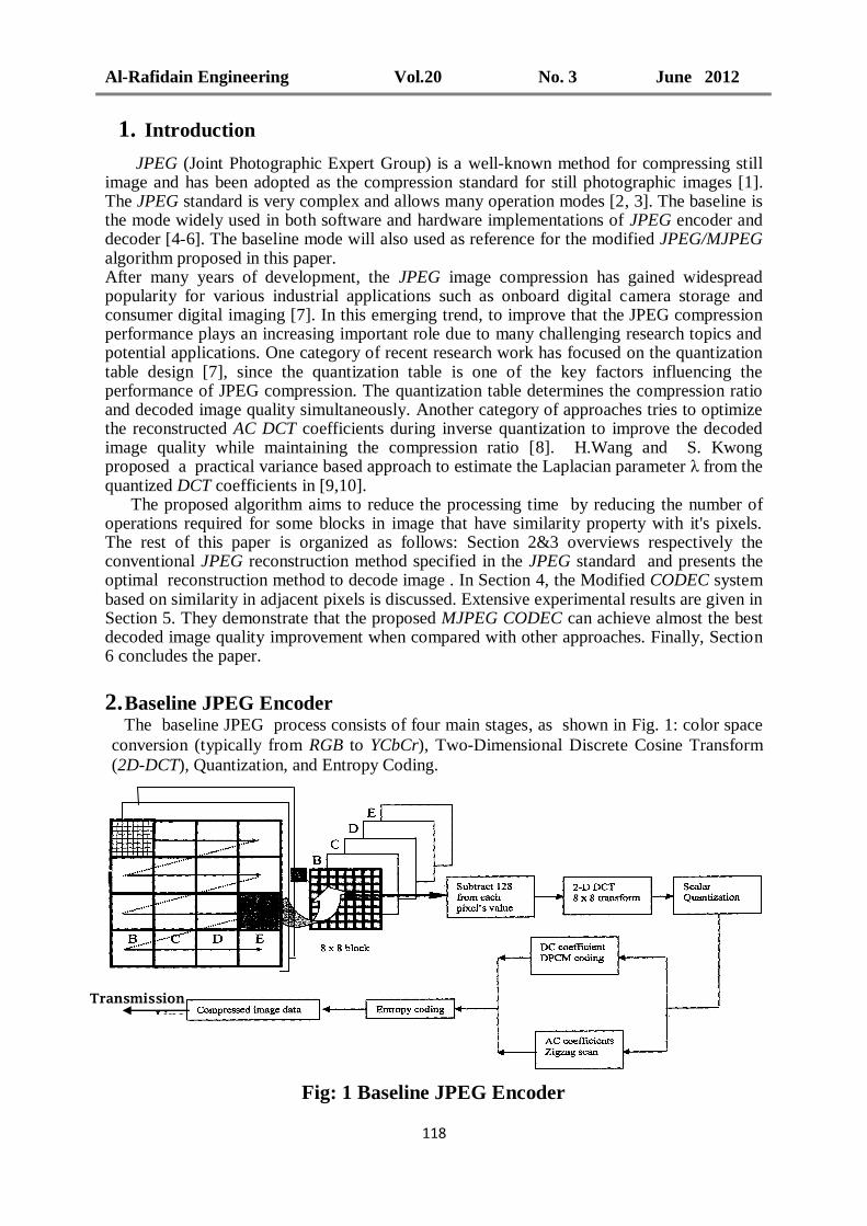
2. Baseline JPEG Encoder The baseline JPEG process consists of four main stages, as shown in Fig. 1: color space
conversion (typically from RGB to YCbCr), Two-Dimensional Discrete Cosine Transform
(2D-DCT), Quantization, and Entropy Coding.
Fig: 1 Baseline JPEG Encoder
Transmission
Line
Mahmood: A Modified Color JPEG Codec System Using inter pixel Redundancy
119
2.1 RGB Space to YCbCr Space
The purpose of color conversion is to reflect the color sensitivity according to the
characteristics of human eyes. The color space is converted from RGB to YCbCr in the JPEG
encoder. Then, the important energies are concentrated on Y channel.
Y = 0.257R + 0.504 G + 0.098 B+16 …….. (1)
Cb = -0.148 R – 0.291 G + 0.439 B +128 …….. (2)
Cr = 0.439 R – 0.368 G – 0.071 B + 128 …….. (3)
2.2 Encoder Level Shift:
This block reads the input samples from the YCbCr . The input to this block is 8-bit data.
Each input sample is subtracted by 128. This block makes the values to Zero-centre and
converts them from unsigned value to signed value. The level shifted output data is given to
DCT block.
2.3 The Two-Dimensional Discrete Cosine Transform Discrete cosine transform (DCT) represents the image as the sum of sinusoids of varying
magnitude and frequencies. The DCT calculation is fairly complex; in fact, this is the most
costly step in JPEG compression. DCT is used to produce uncorrelated coefficients, allowing
effective compression as each coefficient can be treated independently without putting
affecting compression efficiency at risk. The human visual system dependents on spatial
frequencies within the image. In fact, it is more sensitive to the lower frequencies than to the
higher ones. Thus, any information that is not perceptible to the human visual system can be
discarded keeping only important information. On its own, DCT is lossless.
The image data is divided up into 8x8 blocks of pixels. JPEG assumes that each block of
data input is 8x8 pixels, which are serially input in raster order. Similarly, each block is
sequentially input in raster order. A DCT is applied to each 8x8 block. DCT converts the
spatial image representation into a frequency map: the DC element (0,0) or "DC" term
represents the average value in the block, while successive higher-order "AC" terms represent
the amount of spectral power at each spatial frequency. The forward of Two Dimensional
Discrete Cosine Transform (2D-DCT) of a block of 8 x 8 is defined by[2, 8]:-
F(u,v) =
Where C(0)= ; C(k)=1 for k=1,2, …. ,N-1. ……… (4)
The DCT coefficients are organized into 64 quality layers: 1 DC layer followed by 63 AC
layers. The resolution and quality of the reconstructed image is improved when more layers
are decoded.
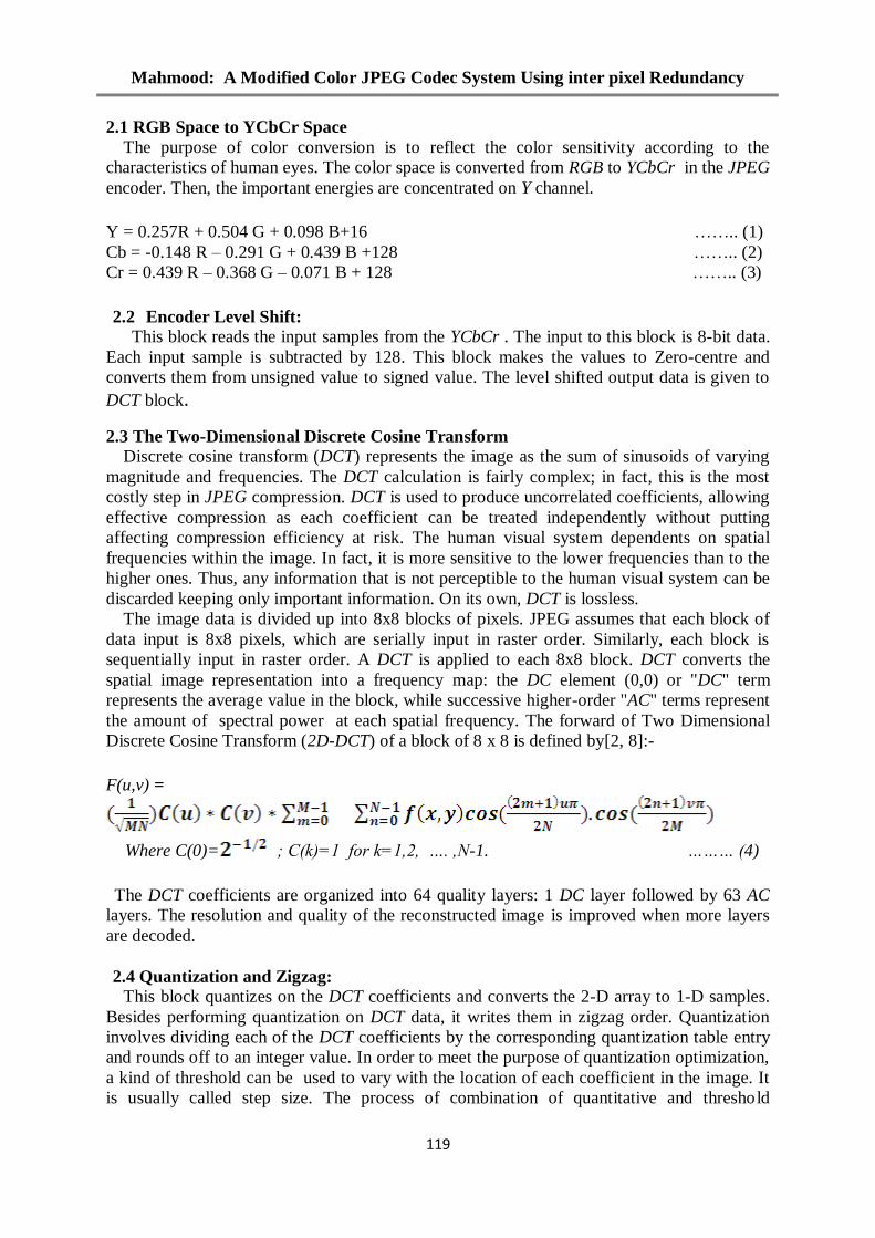
2.4 Quantization and Zigzag:
This block quantizes on the DCT coefficients and converts the 2-D array to 1-D samples.
Besides performing quantization on DCT data, it writes them in zigzag order. Quantization
involves dividing each of the DCT coefficients by the corresponding quantization table entry
and rounds off to an integer value. In order to meet the purpose of quantization optimization,
a kind of threshold can be used to vary with the location of each coefficient in the image. It
is usually called step size. The process of combination of quantitative and threshold
Al-Rafidain Engineering Vol.20 No. 3 June 2012
121
determines a step size according to each coefficient, and then the corresponding DCT
coefficient is divided by the step size, and is rounded as well[8]:
F(u,v) is the DCT coefficient. M(u,v) is the step size corresponding to the F(u,v). It is also
called quantization matrix that is a kind of coefficient matrix optimized by Human Visual
System(HVS). The luminance and chrominance table which are widely used in JPEG
standard are as illustrated in Table 1:
Table 1 : The luminance and chrominance tables
Luminance Chrominance
2.5 Entropy Coding Entropy coding uses differential coding, Run Length Encoding (RLE), and Huffman
coding:
2.5.1 Differential Pulse Code Modulation(DPCM)
Differential coder (DPCM) is used just with DC components and is the first operation in
entropy coding to these components. Differential coder performs a simple subtraction
between the current matrix DC component and the previous matrix DC component, at the
same color element.
…….. (6)
2.5.2 Run Length Encoding
Run Length Encoding (RLE) is used just for AC components and is simplified to be used
in JPEG compression operating like a zero’s counter. While the coder counts the zero’s
occurrences, the outputs are frozen. When a nonzero input is found, these outputs are updated
with a new pair “Run/AC Amplitude”.
There are two restrictions in RLE coder that are imposed by JPEG standard: The first one
is that the JPEG standard defines that the maximum value to the field Run is 15 and then the
zero’s counter has 4 bits. When there are more than 16 zero’s in sequence, the counter must
be restarted and the output pair “Run/AC Amplitude” must be the special pair 15/0. This
output indicates that there are 15 zero’s proceeded by another zero. The second restriction
occurs when an input matrix finishes with one zero. Then another special pair must be written
in the outputs. This pair is 0/0, indicating that the last matrix component is zero.
2.5.3 Huffman Encoding
According to shanon’s entropy any given set of raw data can be arranged in a more
efficient manner provided that the probability of each data symbol is known. The basic idea
Mahmood: A Modified Color JPEG Codec System Using inter pixel Redundancy
121
in Huffman algorithm is to assign a shorter codeword for a more frequent (probability) data
and to assign a longer codeword for a less frequent data. In color JPEG procedure , four
Huffman tables are utilized[1]: two for the DC and AC luminance components and two for
the DC and AC chrominance components.
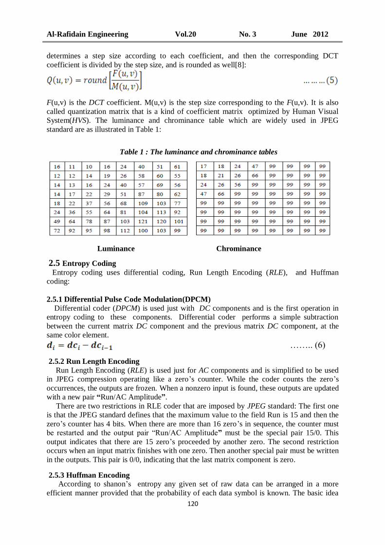
3. Baseline JPEG Decoder In the Decoder mode, the compressed data stream is applied to the JPEG decoder. As
compressed bit stream is read , and it passes to Huffman Decoder, De-Quantization &
IDCT , Level Shift and finally Color Converter. The block diagram of the decoder side is
shown in Fig. 2.
Fig.2 Baseline JPEG Decoder
3.1 Huffman Decoder
Huffman Decoder fetches the compressed data and sends the decoded samples to Run
length decoder which sends data rearrange in two dimension form using zigzag scan of the
AC coefficients and DPCM to DC term.
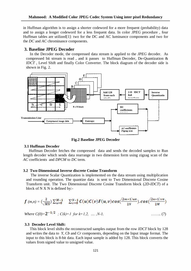
3.2 Two-Dimensional Inverse discrete Cosine Transform
The inverse Scalar Quantization is implemented on the data stream using multiplication
and rounding operation. The quantize data is sent to Two Dimensional Discrete Cosine
Transform unit. The Two Dimensional Discrete Cosine Transform block (2D-IDCT) of a
block of N X N is defined by:-
(m,n) =
Where C(0)= ; C(k)=1 for k=1,2, …. ,N-1. …….. (7)
3.3 Decoder Level Shift:
This block level shifts the reconstructed samples output from the row IDCT block by 128
and writes the data to Y, Cb and Cr components, depending on the Input image format. The
input to this block is 8-bit data. Each input sample is added by 128. This block converts the
values from signed value to unsigned value.
Add 128
from each
pixel’s
value
2-D IDCT
8x8
transform
Inverse
Quantizatio
n
Entropy
decoding
DC
coefficients
DPCM
decoding Transmission Line
Al-Rafidain Engineering Vol.20 No. 3 June 2012
122
3.4 YCbCr Space to RBG Space:
The last procedure in the JPEG decoder is a color converter , the YCrCb color space is
converted to the RGB color space using the following equation:
R = 1.164 Y + 1.596Cr – 222.912 …….. (8)
G = 1.164Y – 0.813Cr – 0.392 Cb +135.616 ……..(9)
B = 1.164 Y + 2.017Cb – 276.8 …….. (10)
4 The proposed Modified JPEG(MJPEG) CODER It can be realized as similar in large parts of the images and this property of similarity can
be taken into account in the compression process. In the color images representing the three
two-dimensional matrices a large number of adjacent pixels within the block in each matrix
have equal values. No doubt , taking into account the increase in the clusters that contain
similar pixels will reduce the many complex calculation in CODEC process which reduce
the processing time in addition to increase the compression ratio, which is the main goal of
the algorithm.
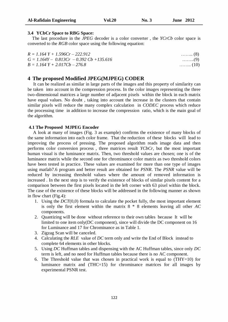
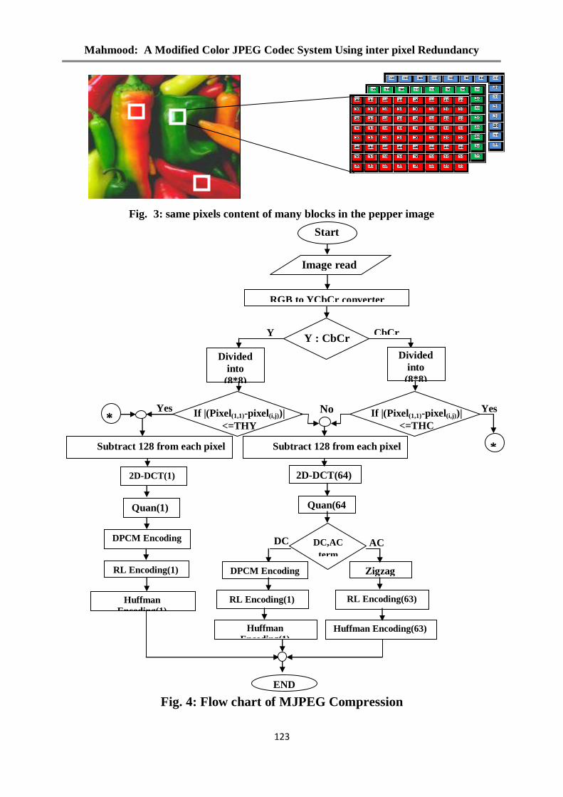
4.1 The Proposed MJPEG Encoder A look at many of images (Fig. 3 as example) confirms the existence of many blocks of
the same information into each color frame. That the reduction of these blocks will lead to
improving the process of pressing. The proposed algorithm reads image data and then
performs color conversion process , three matrices result YCbCr, but the most important
human visual is the luminance matrix. Then, two threshold values are chosen; one is of the
luminance matrix while the second one for chrominance color matrix as two threshold colors
have been tested in practice. These values are examined for more than one type of images
using matlab7.6 program and better result are obtained for PSNR. The PSNR value will be
reduced by increasing threshold values where the amount of removed information is
increased . In the next step is to verify the existence of blocks of similar pixels content for a
comparison between the first pixels located in the left corner with 63 pixel within the block.
The case of the existence of these blocks will be addressed in the following manner as shown
in flow chart (Fig.4):
1. Using the DCT(0,0) formula to calculate the pocket fully, the most important element
is only the first element within the matrix 8 * 8 elements leaving all other AC
components.
2. Quantizing will be done without reference to their own tables because It will be
limited to one item only(DC component), since will divide the DC component on 16
for Luminance and 17 for Chrominance as in Table 1.
3. Zigzag Scan will be canceled.
4. Calculating the RLE value of DC term only and write the End of Block instead to
complete 64 elements in other blocks.
5. Using DC Huffman tables and dispensing with the AC Huffman tables, since only DC
term is left, and no need for Huffman tables because there is no AC component.
6. The Threshold value that was chosen in practical work is equal to (THY=10) for
luminance matrix and (THC=15) for chrominance matrices for all images by
experimental PSNR test.
Mahmood: A Modified Color JPEG Codec System Using inter pixel Redundancy
123
Fig. 3: same pixels content of many blocks in the pepper image
: Flow chart of MJPEG Compression4Fig.
RGB to YCbCr converter
cconverterconverter
Converterconverte
Y : CbCr
Y CbCr
DC AC
Yes Yes
2D-DCT(1) 2D-DCT(64)
Quan(1) Quan(64
)
DPCM Encoding
RL Encoding(1)
Huffman
Encoding(1)
Subtract 128 from each pixel
value
If |(Pixel(1,1)-pixel(i,j))|
<=THY
Divided
into
(8*8)
blocks
If |(Pixel(1,1)-pixel(i,j))|
<=THC
Divided
into
(8*8)
blocks
No
Subtract 128 from each pixel
value *
*
DC,AC
term
DPCM Encoding Zigzag
RL Encoding(1)
Huffman
Encoding(1) Huffman Encoding(63)
RL Encoding(63)
Image read
END
Start
Al-Rafidain Engineering Vol.20 No. 3 June 2012
124
4.2 The Proposed MJPEG Decoder The Modified decoding steps which are the same as the standard inverse procedure except they apply on one element instead of (8x8) term, this especial is in similar content blocks. Added Hanli Wang and Sam Kwong suggest which improving the decoder side in Inverse Quantization stage based on estimate the Laplacian parameter[9],this will improve PSNR for reconstructed image through the theoretical analysis for Inverse quantization in the JPEG decoder, where the reconstructed DCT coefficient Ĉ (u, v) is obtained using inverse quantization by Ĉ(u,v)= L(u,v)x Q(u,v) ….(11) Where Ĉ (u, v) is reconstructed DCT coefficient L(u, v) is the quantized DCT coefficient Q (u, v) is the quantization bin width for the DCT coefficient Ĉ (u, v). Compared with the conventional reconstruction method given in equation(11), the optimum reconstructed coefficient C(u, v) given in (12) is equal to the bin center, L x Q, plus the adjustment term Δ C(u,v)=Ĉ(u,v)+Δ ….(12) Where Δ=-sgn(λ)+[Q/2 ⟨(1+ e^(-λQ))/(1- e^(-λQ) )⟩-1/λ] ….(13)
…. (14) λ is the Laplacian parameter.
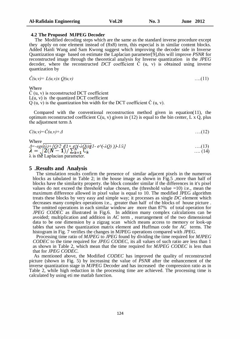
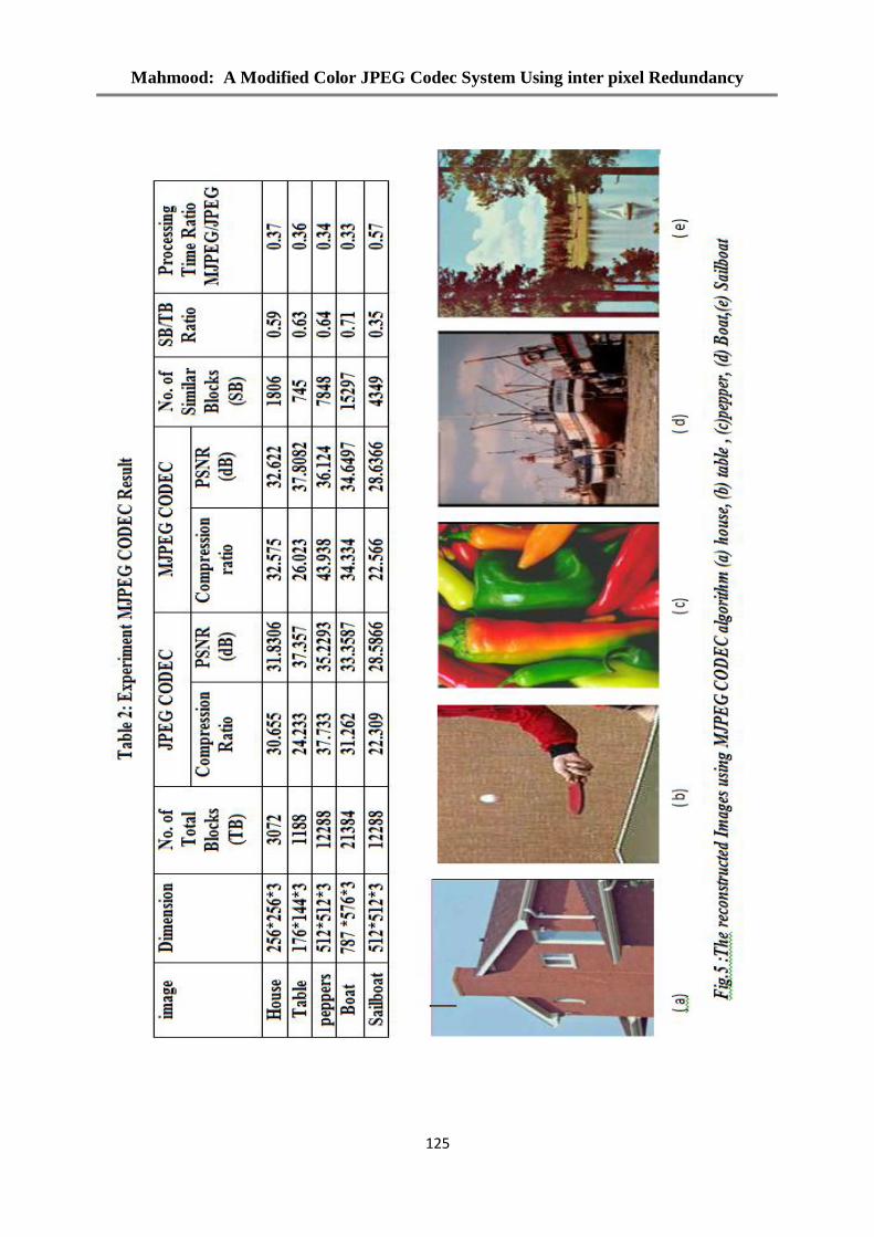
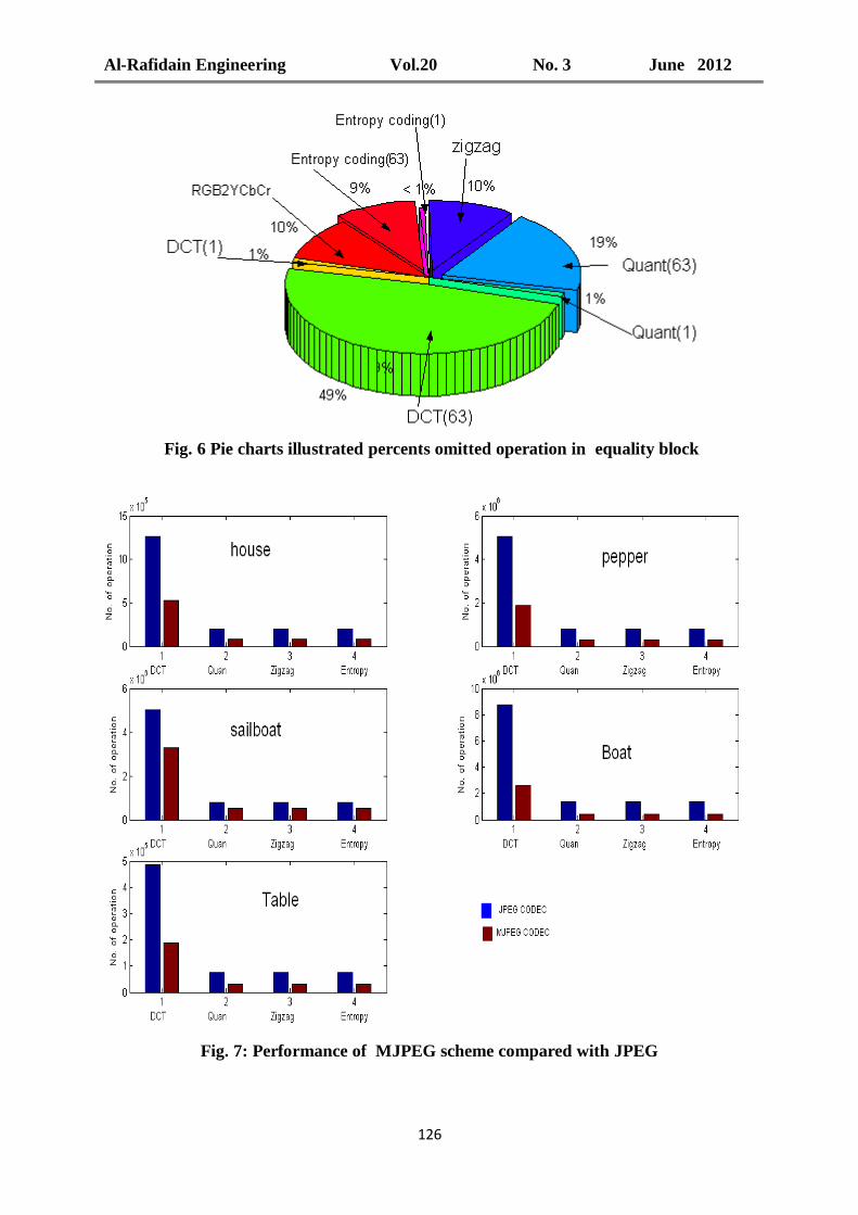
5 .Results and Analysis The simulation results confirm the presence of similar adjacent pixels in the numerous blocks as tabulated in Table 2; in the house image as shown in Fig.5 ,more than half of blocks have the similarity property. the block consider similar if the differences in it's pixel values do not exceed the threshold value chosen, the (threshold value =10) i:e., mean the maximum difference allowed in pixel value is equal to 10. The modified JPEG algorithm treats these blocks by very easy and simple way; it processes as single DC element which decreases many complex operations i:e., greater than half of the blocks of house picture . The omitted operations in each similar window are more than 87% of total operation for JPEG CODEC as illustrated in Fig.6. In addition many complex calculations can be avoided; multiplication and addition in AC term , rearrangement of the two dimensional data to be one dimension by a zigzag scan which means access to memory or look-up tables that saves the quantization matrix element and Huffman code for AC terms. The histogram in Fig. 7 verifies the changes in MJPEG operations compared with JPEG. Processing time ratio of MJPEG to JPEG found by dividing the time required for MJPEG CODEC to the time required for JPEG CODEC, its all values of such ratio are less than 1 as shown in Table 2, which mean that the time required for MJPEG CODEC is less than that for JPEG CODEC.
As mentioned above, the Modified CODEC has improved the quality of reconstructed picture (shown in Fig. 5) by increasing the value of PSNR after the enhancement of the inverse quantization stage in MJPEG Decoder and has increased the compression ratio as in Table 2, while high reduction in the processing time are achieved. The processing time is calculated by using eti me matlab function.
Mahmood: A Modified Color JPEG Codec System Using inter pixel Redundancy
125
Al-Rafidain Engineering Vol.20 No. 3 June 2012
126
Fig. 7: Performance of MJPEG scheme compared with JPEG
Fig. 6 Pie charts illustrated percents omitted operation in equality block
content
Mahmood: A Modified Color JPEG Codec System Using inter pixel Redundancy
127
6 Conclusions: A Modified method has been used for compression of adjacent pixels which are highly related to their neighbors (i.e it increases the redundancy of the pictures).These pixels can be differentially encoded and decoded rather than standard JPEG method. This paper has introduced the MJPEG CODEC by making modifications to both the JPEG baseline encoder and decoder separately. Extensive experimental results demonstrate that the proposed MJPEG can achieve almost the best decoded image quality improvement when compared with other approaches reported in the literatures. In addition, the proposed MJPEG CODEC provides a more efficient form to real time applications such as digital still camera, digital video frame, the digital surveillance, the mobile phone, the camera and other digital photography applications, since the processing time is much smaller than processing time required for standard JPEG CODEC as shown in Table 2. The ratio of the processing time required for MJPEG CODEC to the processing time required for standard JPEG CODEC is less than 1 a reduced number of operations required(i.e multiplication and addition )is required. This is suitable for any hardware design since it reduces the cost and complexity. MJPEG accelerates compression CODEC by about 50% of processing time in the worst case, besides when decoding, it can rebuild the image with almost 1 dB PSNR value higher than in standard JPEG. This is means that Its performance when compared to existing standard algorithms achieves superior results in compression ratio as well as in speed and PSNR. Finally, Our future work includes FPGA implementation of such MJPEG system, it can be designed as the standard JPEG and sharing microblaze or power PC to find blocks that have similar pixels.
References: [1]TinkuAchaya,Ping-Sing-Tsai“JPEG2000 Standard for Image Compression “Awiley-interscience publication,ISBN:0-471- 48422-9 (cloth) 2005. [2] James Rosenthal , “ JPEG Image Compression Using an FPGA”, MSc. Thesis, Electrical and Computer Engineering, University of California, 2006. [3] Ramesh Neelamani, “Inverse Problems in Image Processing”, Ph.D Electrical and Computer Engineering, Rice University, Houston, Texas (June 2003). [4] Luciano Volcan Agostini, Ivan Saraiva Silva and Sergio Bampi,” Pipelined Entropy Coders for JPEG Compression “, Proceedings of the 15 th Symposium on Integrated Circuits and Systems Design (SBCCI’02) 0-7695-1807-9/02 $17.00 © 2002 IEEE, Iraq Visual library. [5] Habeebuddin Quazi, Fayzan Qader, Muhammad Junaid Rasheed and Hasnain Mansoor, “ An Optimized Architecture Implementing the Standard JPEG Algorithm on FPGA Engineering Sciences and Technology, 2005. SCONEST 2005. Student Conference ,ISBN: 0-7803-9442-9/05. [6] Naveen Tiwari and Sagar Chaitanya Reddy, “Performance Measurement of a Fully Pipelined JPEG Codec on Emulation Platform”, Samsung India Software Operations Pvt. Ltd., 2010 IEEE 2nd International Advance Computing Conference. 978-1-4244-4791-6/10/$25.00 c_2010 IEEE, Iraq Visual library. [7] Lihan He, Haojun Chen, and Lawrence Carin, Fellow, IEEE, “Tree-Structured Compressive Sensing With Variational Bayesian Analysis”, IEEE SIGNAL PROCESSING LETTERS, VOL. 17, NO. 3, MARCH 2010. [8] Luo Zhifeng, Fu Changhong, Fan Xu, Qian Zhicong, Wu Shunxiang,”An Easy Image Compression Method and Its Realization Base on Matlab”, 978-1-4244-4994-1/09/$25.00 ©2009 IEEE ,Iraq Visual library. [9] Hanli Wang and Sam Kwong,”Novel Variance Based Approach to Improving JPEG Decoding”, 0-7803-9484-4/05/$20.00 ©2005 IEEE,Iraq Visual library. [10] En-hui Yang, Fellow, IEEE, and Longji Wang, Member, IEEE,”Joint Optimization of Run-Length Coding, Huf fman Coding, and Quantization Table With Complete Baseline JPEG Decoder Compatibility”, IEEE Transactions on Image Processing, VOL. 18, NO. 1, JANUARY 2009.
The work was carried out at the college of Engineering. University of Mosul