A low computational complexity algorithm for ECG signal compression
28
A low computational complexity algorithm for ECG signal compression Manuel Blanco-Velasco, a,∗ FernandoCruz-Rold´an, a FranciscoL´opez-Ferreras, a ´ Angel Bravo-Santos, a Dami´anMart´ ınez-Mu˜ noz b a Dep. Teor´ ıa de la Se˜ nal y Comunicaciones, Escuela Polit´ ecnica, Universidad de Alcal´ a, Alcal´ a de Henares (Madrid), Spain b Dep. de Electr´ onica, Escuela Universitaria Polit´ ecnica, Universidad de Ja´ en, Linares (Ja´ en), Spain Abstract In this work, a filter bank-based algorithm for electrocardiogram (ECG) signals compression is proposed. The new coder consists of three different stages. In the first one – the subband decomposition stage –, we compare the perfomance of a nearly perfect reconstruction (N-PR) cosine modulated filter bank with the Wa- velet Packet (WP) technique. Both schemes use the same coding algorithm, thus permitting an effective comparison. The target of the comparison is the quality of the reconstructed signal, which must remain within predetermined accuracy limits. We employ the most widely used quality criterion for the compressed ECG: the percentage root-mean-square difference (PRD). It is complemented by means of the maximum amplitude error (MAX). The tests have been done for the twelve princi- pal cardiac leads, and the amount of compression is evaluated by means of the mean number of bits per sample (MBPS) and the compression ratio (CR). The implemen- tation cost for both the filter bank and the WP technique have also been studied. The results show that the N-PR cosine modulated filter bank method outperforms the WP technique in both quality and efficiency. Key words: Electrocardiogram (ECG), ECG compression, Wavelet Packet (WP), filter bank, subband coding. ∗ Corresponding author. Tel.: +34 91 885 67 08 Email addresses: [email protected] (Manuel Blanco-Velasco,), [email protected](FernandoCruz-Rold´an,). Preprint submitted to Elsevier Preprint 9 July 2004
-
Upload
independent -
Category
Documents
-
view
1 -
download
0
Transcript of A low computational complexity algorithm for ECG signal compression

A low computational complexity algorithm for
ECG signal compression
Manuel Blanco-Velasco, a,∗ Fernando Cruz-Roldan, a
Francisco Lopez-Ferreras, a Angel Bravo-Santos, a
Damian Martınez-Munoz b
aDep. Teorıa de la Senal y Comunicaciones, Escuela Politecnica, Universidad deAlcala, Alcala de Henares (Madrid), Spain
bDep. de Electronica, Escuela Universitaria Politecnica, Universidad de Jaen,Linares (Jaen), Spain
Abstract
In this work, a filter bank-based algorithm for electrocardiogram (ECG) signalscompression is proposed. The new coder consists of three different stages. In thefirst one – the subband decomposition stage –, we compare the perfomance of anearly perfect reconstruction (N-PR) cosine modulated filter bank with the Wa-velet Packet (WP) technique. Both schemes use the same coding algorithm, thuspermitting an effective comparison. The target of the comparison is the quality ofthe reconstructed signal, which must remain within predetermined accuracy limits.We employ the most widely used quality criterion for the compressed ECG: thepercentage root-mean-square difference (PRD). It is complemented by means of themaximum amplitude error (MAX). The tests have been done for the twelve princi-pal cardiac leads, and the amount of compression is evaluated by means of the meannumber of bits per sample (MBPS) and the compression ratio (CR). The implemen-tation cost for both the filter bank and the WP technique have also been studied.The results show that the N-PR cosine modulated filter bank method outperformsthe WP technique in both quality and efficiency.
Key words: Electrocardiogram (ECG), ECG compression, Wavelet Packet (WP),filter bank, subband coding.
∗ Corresponding author. Tel.: +34 91 885 67 08Email addresses: [email protected] (Manuel Blanco-Velasco,),
[email protected] (Fernando Cruz-Roldan,).
Preprint submitted to Elsevier Preprint 9 July 2004
1 Introduction
ECG processing using subband and wavelet transforms is a subject of greatinterest. The digitized ECG is most commonly used in applications such asmonitoring or patient databases. Furthermore, long-term records have becomewidely used to extract or detect important information from heart signals. Inthese cases, large amounts of data have to be either stored or transmittedmaking compression necessary in order to reduce the bit rate.With this in mind, plenty of data compression techniques have been developedto encode digitized ECG signals. As most of them are unable to retrieve exac-tly the original signal, they are called lossy compression techniques. Severalauthors have classified these techniques into two groups [1; 2], but we proposea new classification with three different categories:
(1) Direct compression methods, where the ECG samples are processed di-rectly paying attention to the redundancy among them. Several schemessuch as the AZTEC (Amplitude Zone Epoch Coding), FAN, TP (TunningPoint) and CORTES (COordinate Reduction Time Encoding System)have been specifically developed for ECG data compression. A summaryof these can be found in [3]. Nowadays, research is still focusing on directcompression. An optimized time domain-coding scheme is presented in[1].
(2) Transform methods, where a data transformation is applied as a meansof extracting outstanding information by reducing the correlation amongsamples. The resulting set of coefficients is then encoded using differentcompression algorithms. Within this group, the methods based on theDiscrete Wavelet Transform (DWT) play an interesting role due to theireasy implementation and efficiency. In [4] and [5] bit allocation was chosenin a DWT diagram, as was the case in [6] and [7], where both the Em-bedded Zerotree Wavelet (EZW) and the Set Partitioning In HierarchicalTree (SPIHT) algorithms, both of which have shown very good results inimage coding, were applied to ECGs. In [8] and [9] WPs have been im-plemented as a valid transformation for comparison with the Karhunen-Loeve transform. It is interesting to note that in these two last papers,each heartbeat is treated separately. In [10], compression is performedby linear prediction and QRS detection is required. Recently a SPIHT-based ECG compression was published [11], where the main aim was tomaintain the quality of the recovered signal as close as possible to anestablished value.
(3) Other compression methods: In this category, a wide range of techni-ques can be included. The main feature being that the signal must bepre-processed to extract information. Hence, some are either parameterextractions [12]-[15] such as heartbeat averaging, long-term predictionand vector quantization, or subband decomposition techniques (exclu-
2
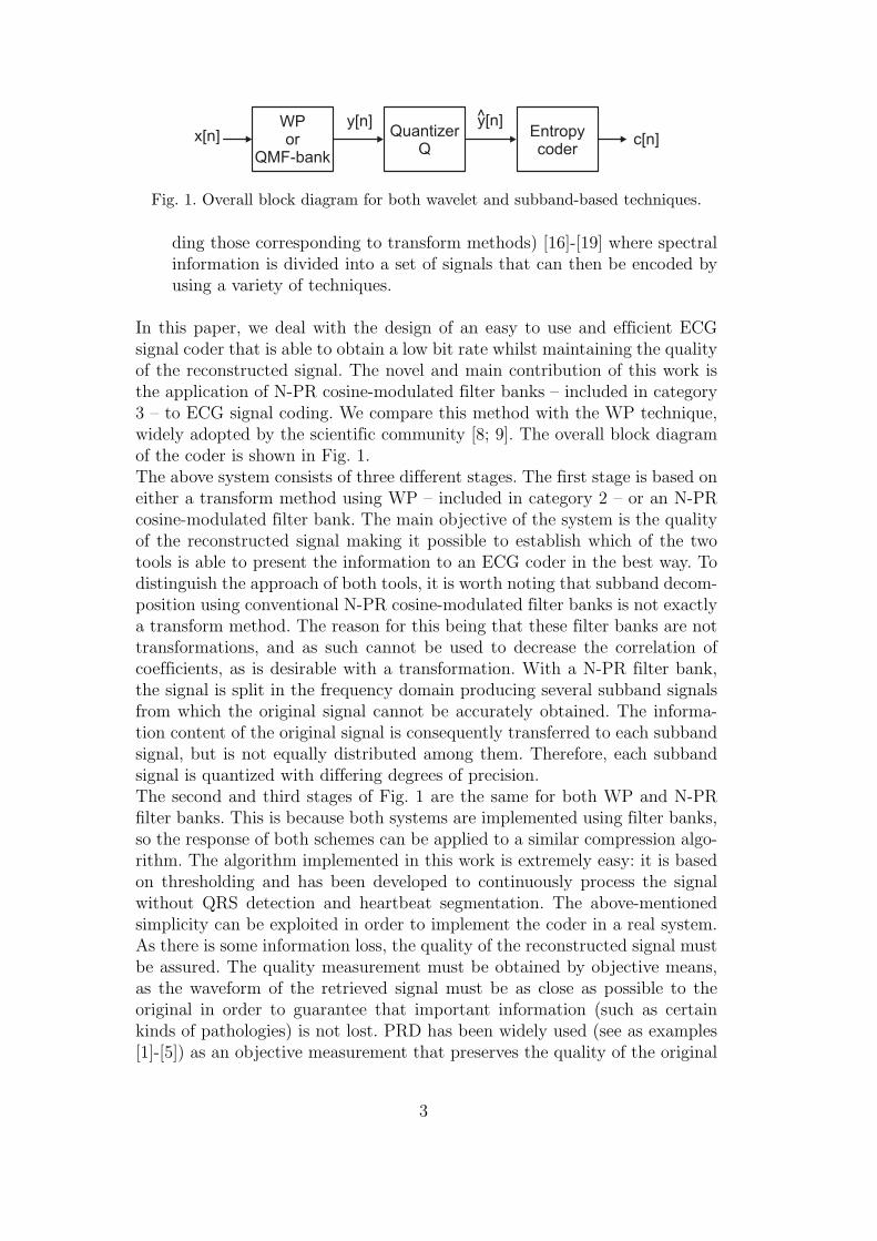
Fig. 1. Overall block diagram for both wavelet and subband-based techniques.
ding those corresponding to transform methods) [16]-[19] where spectralinformation is divided into a set of signals that can then be encoded byusing a variety of techniques.
In this paper, we deal with the design of an easy to use and efficient ECGsignal coder that is able to obtain a low bit rate whilst maintaining the qualityof the reconstructed signal. The novel and main contribution of this work isthe application of N-PR cosine-modulated filter banks – included in category3 – to ECG signal coding. We compare this method with the WP technique,widely adopted by the scientific community [8; 9]. The overall block diagramof the coder is shown in Fig. 1.The above system consists of three different stages. The first stage is based oneither a transform method using WP – included in category 2 – or an N-PRcosine-modulated filter bank. The main objective of the system is the qualityof the reconstructed signal making it possible to establish which of the twotools is able to present the information to an ECG coder in the best way. Todistinguish the approach of both tools, it is worth noting that subband decom-position using conventional N-PR cosine-modulated filter banks is not exactlya transform method. The reason for this being that these filter banks are nottransformations, and as such cannot be used to decrease the correlation ofcoefficients, as is desirable with a transformation. With a N-PR filter bank,the signal is split in the frequency domain producing several subband signalsfrom which the original signal cannot be accurately obtained. The informa-tion content of the original signal is consequently transferred to each subbandsignal, but is not equally distributed among them. Therefore, each subbandsignal is quantized with differing degrees of precision.The second and third stages of Fig. 1 are the same for both WP and N-PRfilter banks. This is because both systems are implemented using filter banks,so the response of both schemes can be applied to a similar compression algo-rithm. The algorithm implemented in this work is extremely easy: it is basedon thresholding and has been developed to continuously process the signalwithout QRS detection and heartbeat segmentation. The above-mentionedsimplicity can be exploited in order to implement the coder in a real system.As there is some information loss, the quality of the reconstructed signal mustbe assured. The quality measurement must be obtained by objective means,as the waveform of the retrieved signal must be as close as possible to theoriginal in order to guarantee that important information (such as certainkinds of pathologies) is not lost. PRD has been widely used (see as examples[1]-[5]) as an objective measurement that preserves the quality of the original
3
waveform to within an acceptable degree:
PRD =
√
√
√
√
∑
(x [n] − x [n])2
∑
(x [n])2 · 100. (1)
where x[n] and x[n] are the original and the reconstructed signals, respectively.As the PRD is a global criterion that minimize local effects which are oftenso significant in medical diagnosis based on signals, the measure of maximumdifferences has been added too by means of the maximum amplitude error(MAX) which is expressed as
MAX = maxn
{|x [n] − x [n]|} . (2)
The outline of the paper is as follows. Sections 2 and 3 present a brief re-view of WP and N-PR cosine-modulated filter banks respectively. In Section4, the implementation cost of the cosine-modulated filter bank is comparedwith the direct implementation of the WP-based filter banks. In Section 5 thecompression algorithm for both schemes is explained, and in Section 6 severalexamples are shown. Finally, in Section 7 our conclusions are presented.Notation: Letters in bold-type indicate vectors (lower case) and matrices (up-per case). Notation AT represents the transpose of A. Matrices I and J denote,respectively, the k × k identity matrix, and the k × k “reverse operator”:
J =
0 · · · 0 1
0 · · · 1 0...
. . ....
...
1 · · · 0 0
2 Brief review of the wavelet packets theory
Multiresolution analysis is a very important position from which to understandand apply wavelet analysis [20]-[22]. Using this overall theory, a function f(t) ∈L2(R) can be represented as a succession of approximations in several scales.A vector space is generated by scaling and translating two basic functions,ψ(t) and ϕ(t), defined as
ψj,k (t) = 2j/2ψ(
2jt − k)
, (3)
ϕj,k (t) = 2j/2ϕ(
2jt − k)
. (4)
4
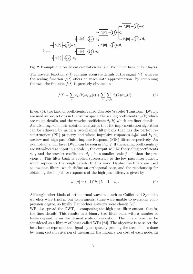
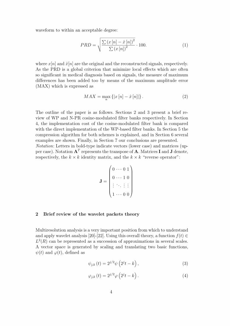
Fig. 2. Example of a coefficient calculation using a DWT filter bank of four layers.
The wavelet function ψ(t) contains accurate details of the signal f(t) whereasthe scaling function ϕ(t) offers an inaccurate approximation. By combiningthe two, the function f(t) is precisely obtained as
f(t) =∑
k
cj0(k)ϕj0,k(t) +∑
k
∞∑
j=j0
dj(k)ψj,k(t). (5)
In eq. (5), two kind of coefficients, called Discrete Wavelet Transform (DWT),are used as projections in the vector space: the scaling coefficients cj0(k) whichare rough details, and the wavelet coefficients dj(k) which are finer details.An advantage of multiresolution analysis is that the implementation algorithmcan be achieved by using a two-channel filter bank that has the perfect re-construction (PR) property and whose impulsive responses h0[n] and h1[n],are low and high-pass Finite Impulse Response (FIR) filters respectively. Anexample of a four layer DWT can be seen in Fig. 2. If the scaling coefficients cj
are introduced as input in a scale j, the output will be the scaling coefficientscj−1 and the wavelet coefficients dj−1 in a smaller scale j − 1 than the pre-vious j. This filter bank is applied successively to the low-pass filter output,which represents the rough details. In this work, Daubechies filters are usedas low-pass filters, which define an orthogonal base, and the relationship forobtaining the impulsive responses of the high-pass filters, is given by
h1 [n] = (−1)nh0 [L − 1 − n] . (6)
Although other kinds of orthonormal wavelets, such as Coiflet and Symmletwavelets were tried in our experiments, these were unable to overcome com-pression degree, so finally Daubechies wavelets were chosen [23].WP also spread the DWT, decomposing the high-pass filter output, that is,the finer details. This results in a binary tree filter bank with a number oflevels depending on the desired scale of resolution. The binary tree can beconsidered as a library of bases called WPs [24]. The objective is to select thebest base to represent the signal by adequately pruning the tree. This is doneby using certain criterion of measuring the information cost of each node. In
5
this paper, Shannon entropy has been used [24]:
H(x) = −∑
k
(
|vk [n]|2/
‖x [n]‖2)
log2
(
|vk [n]|2/
‖x [n]‖2)
, (7)
where vk[n] is the signal at some offspring node and x[n] is the input signal.Information cost must be compared between the root or parent node and thesum of the information cost of the following generations or offspring nodes inthe binary tree. The branches with a higher value are removed. Fig. 3a showsan example of a four-layered WP with the Shannon entropy calculated foreach node. The pruned tree obtained after entropy sum comparison is shownin Fig. 3b.On the other hand, the input signal is processed by taking non-overlappingblocks of samples whose size is taken to be a power of two [6; 7]. Each segmenthas its best base, so each one is processed by a different filter bank structure.For instance, there will be filters used for processing a particular segment thatwill disappear and so will not be used for the following segment. Therefore,in order to recover the signal without information loss, each segment mustbe processed independently. This is achieved by taking the periodic extensionof every segment, which is the same as considering each segment as a periodof a periodic signal. In this way, the same periodic signal, and therefore thesame segment, must be recovered by applying the corresponding synthesisfilter bank.
3 M -Channel N-PR cosine-modulated filter banks
Fig. 4 shows an M -channel maximally decimated filter bank with a parallelstructure. These systems have been extensively studied and they are used inmany applications from multicarrier modulation to data compression (see asexamples references included in [20] and [25]-[29]). Within these applications,several researchers have applied filter banks to solve biomedical problems suchas ECG beat detection [30], analysis/detection of vocal fold pathology [31] andanalysis and classification of infarcted myocardial tissue [32].
An important subclass of M -channel filter banks is the modulated filter bankgroup: all the analysis and synthesis filters are obtained by the modulationof lowpass prototype filters. In this work, we use conventional N-PR cosine-modulated filter banks [25; 33] to divide the incoming signal into separatesubband signals. These systems offer almost but not true PR; however, theyare an alternative to PR systems because the highly nonlinear optimization toobtain the prototype filter coefficients can be avoided. We will show how thistype of filter bank can be used as a viable alternative to WP for compressingECG signals.
6
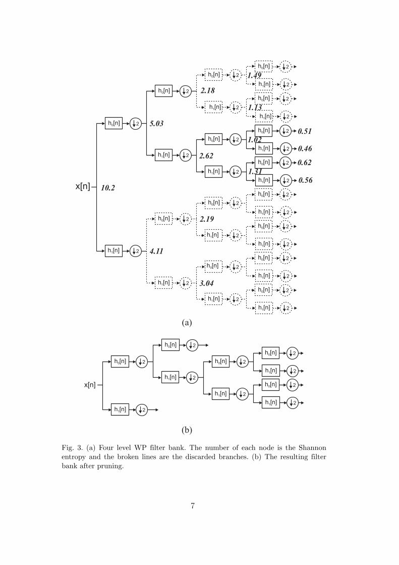
Fig. 3. (a) Four level WP filter bank. The number of each node is the Shannonentropy and the broken lines are the discarded branches. (b) The resulting filterbank after pruning.
7
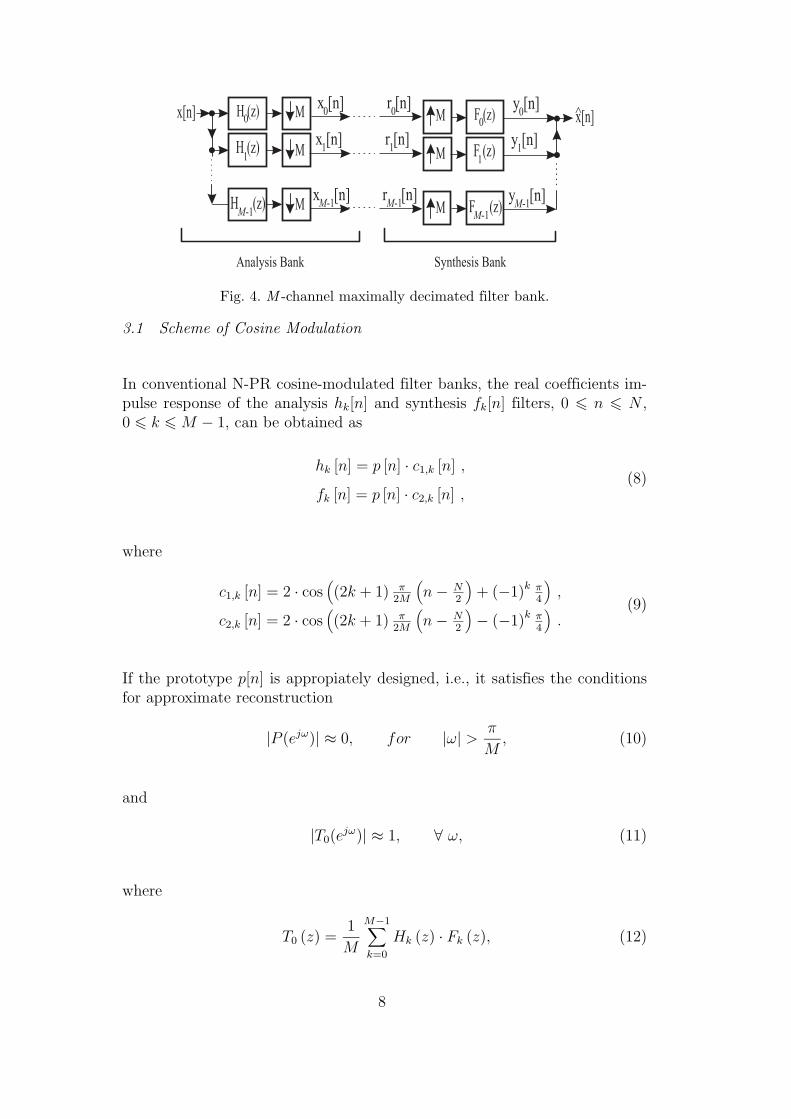
Fig. 4. M -channel maximally decimated filter bank.
3.1 Scheme of Cosine Modulation
In conventional N-PR cosine-modulated filter banks, the real coefficients im-pulse response of the analysis hk[n] and synthesis fk[n] filters, 0 6 n 6 N ,0 6 k 6 M − 1, can be obtained as
hk [n] = p [n] · c1,k [n] ,
fk [n] = p [n] · c2,k [n] ,(8)
where
c1,k [n] = 2 · cos(
(2k + 1) π2M
(
n − N2
)
+ (−1)k π4
)
,
c2,k [n] = 2 · cos(
(2k + 1) π2M
(
n − N2
)
− (−1)k π4
)
.(9)
If the prototype p[n] is appropiately designed, i.e., it satisfies the conditionsfor approximate reconstruction
|P (ejω)| ≈ 0, for |ω| >π
M, (10)
and
|T0(ejω)| ≈ 1, ∀ ω, (11)
where
T0 (z) =1
M
M−1∑
k=0
Hk (z) · Fk (z), (12)
8
all the significant aliasing terms are cancelled [25; 33]. Moreover, if the pro-totype filter is a linear-phase filter, the filter bank will be free from phasedistortion provided that the synthesis filters are chosen according to
fk [n] = hk [N − n] ,
0 ≤ n ≤ N ,
0 ≤ k ≤ M − 1.(13)
So, at the expense of allowing an acceptable margin of amplitude distortionand aliasing error, i. e., without satisfying the PR property, we simplify theeffort of designing the filter bank to that of designing a prototype filter.
3.2 Prototype Filter Design Techniques
Several methods have been proposed that facilitate the design of the prototypefilter. Creusere and Mitra proposed one such method [34], in which the pro-totype filter length, the relative error weighting and the stopband edge are allfixed before the optimization procedure is started, whilst the passband edgeis adjusted to minimize the following objective function:
φ = maxω
{
∣
∣
∣P(
ejω) ∣
∣
∣
2+
∣
∣
∣P(
ej(ω−π/M)) ∣
∣
∣
2 − 1}
, 0 < ω < π/M, (14)
where P (ejω) is the prototype filter frequency response.Another efficient designing technique, called the Kaiser Window Approach(KWA), was proposed in [35]. The design process is the following. Let p[n]be a linear phase filter obtained by using the Kaiser window technique. Next,G(ejω) is defined as G(ejω) = |P (ejω)|2. The process of designing the prototypefilter p[n] is reduced to the optimization of the ideal filter cutoff frequency ωc
in order to minimize the objective function given by
φnew = maxn,n6=0
| g [2Mn] | . (15)
This condition ensures that p[n] is approximately a spectral factor of a 2Mthband filter.Recently, a new prototype filter design method has been proposed [36]. Theproblem can be stated in several different ways, but the purpose consists inminimizing
φ =∣
∣
∣
∣
∣
∣P(
ejπ/2M) ∣
∣
∣ − 1/√
2∣
∣
∣ . (16)
9
When we use an appropriate FIR filter design technique (by windowing or bymeans of the Parks-McClellan algorithm), we can guarantee that the frequencyresponse of the prototype filter approximately satisfies the power complemen-tary property. In other words, this technique controls the position of the 3dBcutoff frequency of the prototype filter and sets it approximately at π
2M. In this
way, it is possible to reduce the amplitude distortion and the aliasing errorsintroduced in the filter bank.
3.3 Fast Algorithm of Implementation
One of the reasons why cosine-modulated filter banks are widely used is dueto the fact that efficient implementations of the analysis and synthesis bankscan be obtained. We express the prototype filter as
P (z) =2M−1∑
ℓ=0
z−ℓ · Gℓ
(
z2M)
=2M−1∑
ℓ=0
z−ℓ · Kℓ
(
z2M)
. (17)
where Gl(z) and Kl(z) are respectively the 2M types 1 and 2 polyphase com-ponents of the prototype filter P (z) [25; 37]. Using eqs. (8) and (9), the analysisfilters can be expressed as
hT (z) =
H0 (z)
H1 (z)...
HM−1 (z)
= CA ·
g0
(
−z2M)
z−Mg1
(
−z2M)
· e (z) , (18)
where
[ C A]k,ℓ = c1,k [ℓ] 0 ≤ k ≤ (M − 1) , 0 ≤ ℓ ≤ (2M − 1) , (19)
g0 (z) = diag[
G0 (z) G1 (z) · · · GM−1 (z)
]
, (20)
g1 (z) = diag[
GM (z) GM+1 (z) · · · G2M−1 (z)
]
, (21)
and
e (z) =[
1 z−1 · · · z−(M−1)
]
T . (22)
10

Fig. 5. Polyphase implementation of the cosine-modulated filter bank.
The equivalent vector of synthesis filters can be expressed as
f(z) = [F0(z) F1(z) . . . FM−1(z)] =
= z−(M−1) · eT (z−1) · [z−M k1(−z2M) k0(−z2M)] · CT
B , (23)
where
k0 (z) = diag[
KM−1 (z) KM−2 (z) · · · K0 (z)
]
, (24)
k1 (z) = diag[
K2M−1 (z) K2M−2 (z) · · · KM (z)
]
, (25)
and[
CB
]
k,l= c2,k [2M − 1 − ℓ] 0 ≤ k ≤ (M − 1) , 0 ≤ ℓ ≤ (2M − 1) . (26)
The corresponding polyphase realization of the filter bank is shown in Fig.5. A more simplified implementation of this bank can be derived from thepolyphase matrices when the prototype filter length (N + 1) and the numberof channels M are related as
N + 1 = 2mM. (27)
If we accept the above restriction, and assume that m is an even number, thecosine modulation matrix CA in the analysis bank of the structure in Fig. 5,can be expressed as [25]
CA =√
M · ΛC · C ·[
(I − J) − (I + J)
]
. (28)
ΛC is a diagonal matrix with elements
[ΛC]k,k = cos(π · (0.5 + k) · m), (29)
11
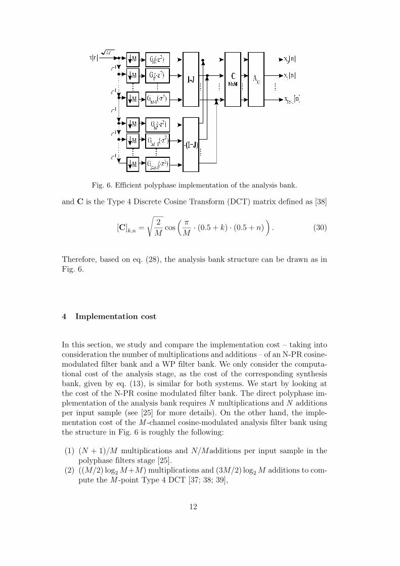
Fig. 6. Efficient polyphase implementation of the analysis bank.
and C is the Type 4 Discrete Cosine Transform (DCT) matrix defined as [38]
[C]k,n =
√
2
Mcos
(
π
M· (0.5 + k) · (0.5 + n)
)
. (30)
Therefore, based on eq. (28), the analysis bank structure can be drawn as inFig. 6.
4 Implementation cost
In this section, we study and compare the implementation cost – taking intoconsideration the number of multiplications and additions – of an N-PR cosine-modulated filter bank and a WP filter bank. We only consider the computa-tional cost of the analysis stage, as the cost of the corresponding synthesisbank, given by eq. (13), is similar for both systems. We start by looking atthe cost of the N-PR cosine modulated filter bank. The direct polyphase im-plementation of the analysis bank requires N multiplications and N additionsper input sample (see [25] for more details). On the other hand, the imple-mentation cost of the M -channel cosine-modulated analysis filter bank usingthe structure in Fig. 6 is roughly the following:
(1) (N + 1)/M multiplications and N/Madditions per input sample in thepolyphase filters stage [25].
(2) ((M/2) log2 M+M) multiplications and (3M/2) log2 M additions to com-pute the M -point Type 4 DCT [37; 38; 39],
12
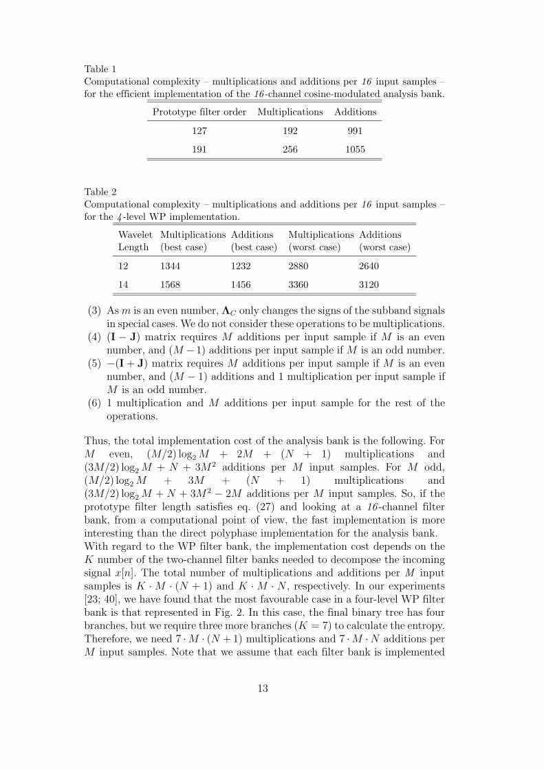
Table 1Computational complexity – multiplications and additions per 16 input samples –for the efficient implementation of the 16 -channel cosine-modulated analysis bank.
Prototype filter order Multiplications Additions
127 192 991
191 256 1055
Table 2Computational complexity – multiplications and additions per 16 input samples –for the 4 -level WP implementation.
WaveletLength
Multiplications(best case)
Additions(best case)
Multiplications(worst case)
Additions(worst case)
12 1344 1232 2880 2640
14 1568 1456 3360 3120
(3) As m is an even number, ΛC only changes the signs of the subband signalsin special cases. We do not consider these operations to be multiplications.
(4) (I − J) matrix requires M additions per input sample if M is an evennumber, and (M − 1) additions per input sample if M is an odd number.
(5) −(I + J) matrix requires M additions per input sample if M is an evennumber, and (M − 1) additions and 1 multiplication per input sample ifM is an odd number.
(6) 1 multiplication and M additions per input sample for the rest of theoperations.
Thus, the total implementation cost of the analysis bank is the following. ForM even, (M/2) log2 M + 2M + (N + 1) multiplications and(3M/2) log2 M + N + 3M2 additions per M input samples. For M odd,(M/2) log2 M + 3M + (N + 1) multiplications and(3M/2) log2 M + N + 3M2 − 2M additions per M input samples. So, if theprototype filter length satisfies eq. (27) and looking at a 16 -channel filterbank, from a computational point of view, the fast implementation is moreinteresting than the direct polyphase implementation for the analysis bank.With regard to the WP filter bank, the implementation cost depends on theK number of the two-channel filter banks needed to decompose the incomingsignal x[n]. The total number of multiplications and additions per M inputsamples is K · M · (N + 1) and K · M · N , respectively. In our experiments[23; 40], we have found that the most favourable case in a four-level WP filterbank is that represented in Fig. 2. In this case, the final binary tree has fourbranches, but we require three more branches (K = 7) to calculate the entropy.Therefore, we need 7 ·M · (N + 1) multiplications and 7 ·M ·N additions perM input samples. Note that we assume that each filter bank is implemented
13
using a direct polyphase implementation, and we have not taken into accountthe computational cost needed to obtain the Shannon entropy. On the otherhand, the worst case occurs when we use all the branches of the binary tree todecompose the incoming signal (Fig. 3a). In this case, we need 15 ·M · (N +1)multiplications and 15 · M · N additions per M input samples.Table 1 shows the computational complexity of 16 -channel cosine-modulatedanalysis banks designed with prototype filters of different lengths, consideringthe efficient implementation of Fig. 6. Table 2 also shows the computationalcomplexity needed to implement the four-level WP in its best and worst cases.These tables serve as a comparison of the computational cost of both systems.
5 Compression scheme
We reintroduce the block diagram of the proposed encoding system shown inFig. 1. As described before, in the first stage, two schemes for splitting theECG signals are used: a WP-based transform method using Daubechies filters,where the output samples y[n] are the transform coefficients, and an N-PRcosine-modulated filter bank, where the samples y[n] are now the subbandsignals. In order to calculate the WP, as explained in Section 2, the incomingsignal is segmented into consecutive blocks the lengths of which are powerof two. The compression algorithm is applied to a set of coefficients of thesame size as the corresponding segment. Therefore, to better compare bothmethods, the input signal is segmented in the same way as the compressionbased on the N-PR filter bank. The rest of the system, i. e., the quantizer andthe entropy coder are the same for both schemes.When the above schemes of subband decomposition are applied to ECG, mostof the energy is concentrated in a few coefficients, so a thresholding techniquecan be applied in order to obtain a good degree of compression. Coefficientswith an amplitude less than a threshold value are discarded. Only the largestare maintained thus assuring the quality for the reconstructed signal, which isselected before the compression is made as a predetermined PRD value. Thealgorithm begins by fixing an initial threshold value, which is the same for allsubbands, to check the target PRD. If it is not reached, a new threshold ischosen iterating the previous procedure until the target PRD is accomplished.The preceding technique is applied to each input segment. This algorithm isused as quantizer for both methods of subband decomposition, i.e., WP andN-PR filter banks.For the entropy coder stage, a run-length coding is used as a means of joiningthe void samples. The non-discarded samples of each processed segment aresent or stored without varying the original precision. Since the previous sectionis a thresholding technique, there will be unused codes in each set of processedsamples called escape codes. In this case, the threshold value can be used as an
14
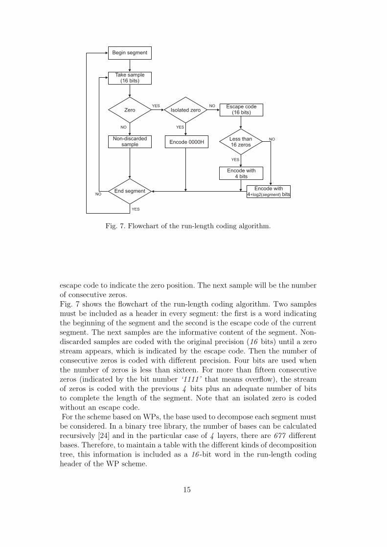
Fig. 7. Flowchart of the run-length coding algorithm.
escape code to indicate the zero position. The next sample will be the numberof consecutive zeros.Fig. 7 shows the flowchart of the run-length coding algorithm. Two samplesmust be included as a header in every segment: the first is a word indicatingthe beginning of the segment and the second is the escape code of the currentsegment. The next samples are the informative content of the segment. Non-discarded samples are coded with the original precision (16 bits) until a zerostream appears, which is indicated by the escape code. Then the number ofconsecutive zeros is coded with different precision. Four bits are used whenthe number of zeros is less than sixteen. For more than fifteen consecutivezeros (indicated by the bit number ‘1111’ that means overflow), the streamof zeros is coded with the previous 4 bits plus an adequate number of bitsto complete the length of the segment. Note that an isolated zero is codedwithout an escape code.For the scheme based on WPs, the base used to decompose each segment mustbe considered. In a binary tree library, the number of bases can be calculatedrecursively [24] and in the particular case of 4 layers, there are 677 differentbases. Therefore, to maintain a table with the different kinds of decompositiontree, this information is included as a 16 -bit word in the run-length codingheader of the WP scheme.
15
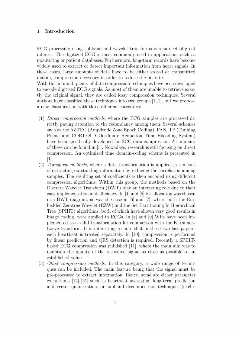
6 Results
In this section, we compare the behaviour of the WP-based compressionscheme with the corresponding N-PR filter bank based scheme. The data-base 1 used to carry out the test contains two sets of twelve standard leads.Each lead is sampled at 360 Hz and each sample is coded in PCM with 16bits per sample. Each set has a different length. Every lead of the first setlasts 10 minutes, whereas the signals of the second last 2 minutes. The signalsincluded in the database are cleaned from high frequency noise and some leadshave baseline fluctuations. Atrial fibrillation is the pathology contained in thedatabase.We have used two compression degree measurements in order to adequatelyshow the results. The first is the MBPS that evaluates the number of bits bymeans of each sample is encoded. The second is the CR, which is the ratiobetween the number of bits of the original signal and the number of bits ofthe retrieved signal. It can be calculated as follows
CR =N × 16
B, (31)
where N is the number of samples of every segment and B the number of bitsneeded to encode the corresponding segment.The WP-based compression scheme has been studied previously [23; 40]. Ittakes into account several free parameters: the order of filters, the numberof levels of the decomposition tree, the length of the signal segment and thePRD value. We have found that the CR increases with the filter order. Fig.8 shows the CR mean value as a function of the length of filters calculatedfor several target PRD and segment length values. The CR increases up toa filter length of 14 samples. On the other hand, there is no improvementin the decomposition level. Compression remains constant from the 4th layer,though it is not worth increasing the number of layers due to the increasein the number of operations required. Therefore, we chose WP of 14-lengthfilters and a decomposition level up to 4.Afterwards, in order to establish the features of the N-PR filter bank, the
WP is considered as a binary tree, which divides the spectral domain into16 subbands when the decomposition level is up to 4. By using the noblesidentities for multirate systems [25], the filter bank chosen to carry out thecomparison with the WP of 4 layers must have 16 -channels and the filterorder that takes into account a 14 WP filter length must be 196. As the orderis greater than 127, it is worthwhile using the fast implementation explainedin Section 4. For a 196-filter length eq. (27) does not hold true, so the final
1 This database has been supplied by the Electro-physiology Laboratory (Cardio-logy floor) group of the General Hospital Universitario Gregorio Maranon of Madrid.
16

6 8 10 12 14 16 18 20 22 245.4
5.5
5.6
5.7
5.8
5.9
6
6.1
6.2
6.3
6.4
Length of filters
CR
Fig. 8. CR mean value as a function of the length of filters.
configuration to be compared is:
• N-PR cosine-modulated filter bank: 16 channels and filter length 192.• WP: decomposition level up to 4 and 14-length Daubechies filters.
The tests were carried out with a set of filter banks, which were obtained usingthe three techniques explained in Section 3. They are called as follows:
• Clcam16192 when we use the ”Creusere and Mitra” method [34].• Clkwa16192 when we use the “Kaiser Window Approach” [35].• Clvb16192, clvk16192 or clvh16192 when we use the method proposed in
[36], using respectively the Blackman, the Kaiser or the Hamming windows.• Clpm16192 when we use the method proposed in [36], but with a Parks-
McClellan-based algorithm.
Apart from the length of the filters for both schemes and the decompositionlevel for WP, there are still two free parameters: the segment length, thatsplits the input signal, and the PRD value to select the quality of the recove-red signal.As the objective is quality, the recovered signal waveform must remain as closeas possible to the original signal. However, the PRD as a performance measureis not sufficient to decide whether the retrieved signal is suitable or not. Asa clinical expert will make the diagnosis, a clinical expert must also validatethe compression algorithm after visually inspecting the waveforms. High PRDvalues are unsuitable for ensuring that the retrieved waveform will be withinan acceptable error margin of the original. On the other hand, as far as noise is
17
1 2 3 4 5 6 7 8 9 10 11 120
0.05
0.1
0.15
0.2
0.25
0.3
0.35
0.4
0.45
0.5
0.55
0.6
0.65
0.7
0.75
Leads
PR
Dclcam16192clkwa16192clpm16192 clvb16192 clvh16192 clvk16192
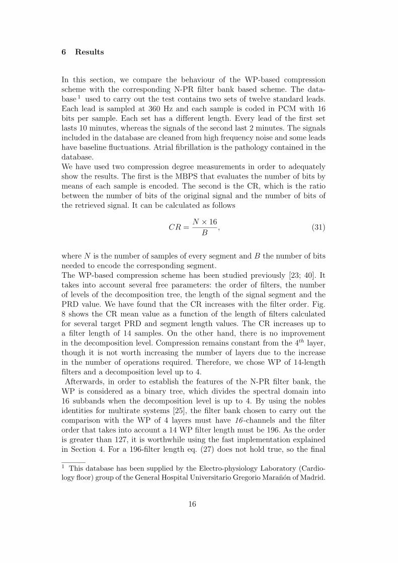
Fig. 9. PRD obtained without compression for the twelve standard leads tested(numbered from 1 to 12 along the X-axis).
concerned, thresholding-based compressors behave as a low-pass filter so thathigh CR values could be obtained by smoothing the ECG, which is not ourcase as the signals have got no high frequency noise added. So to ensure thatthe retrieved signal will remain close to the original signal, the target PRDselected must be low. For these reasons, we have decided to select only PRDvalues from 0.5% to 5%.It is interesting to note that unlike WPs, the N-PR filter bank used in thiswork does not have the property of PR. Fig. 9 shows the quality values ofthe recovered signals after applying the filter bank without compression. Eachlead is numbered from 1 to 12 along the X-axis. Since a PRD value of 0.5%is demanded by our test, the clvh16192 is rejected because it does not meetthis requirement.As far as segment length is concerned, the CR improves by increasing the
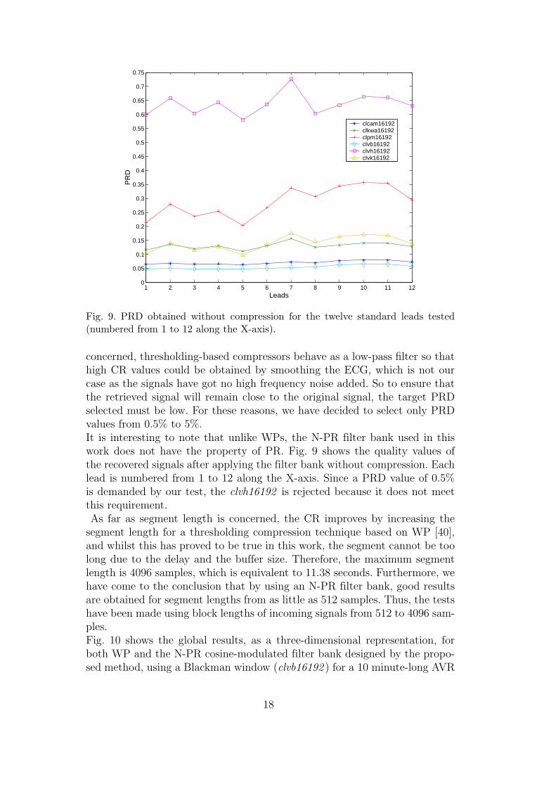
segment length for a thresholding compression technique based on WP [40],and whilst this has proved to be true in this work, the segment cannot be toolong due to the delay and the buffer size. Therefore, the maximum segmentlength is 4096 samples, which is equivalent to 11.38 seconds. Furthermore, wehave come to the conclusion that by using an N-PR filter bank, good resultsare obtained for segment lengths from as little as 512 samples. Thus, the testshave been made using block lengths of incoming signals from 512 to 4096 sam-ples.Fig. 10 shows the global results, as a three-dimensional representation, forboth WP and the N-PR cosine-modulated filter bank designed by the propo-sed method, using a Blackman window (clvb16192 ) for a 10 minute-long AVR
18
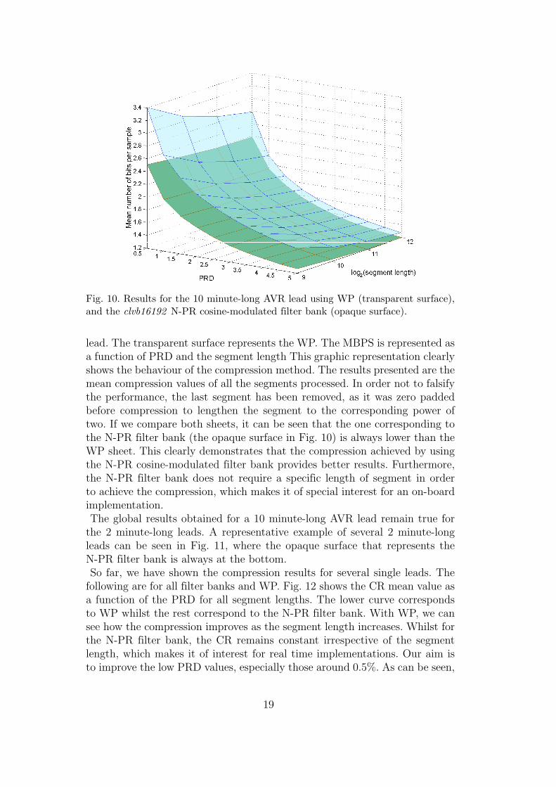
Fig. 10. Results for the 10 minute-long AVR lead using WP (transparent surface),and the clvb16192 N-PR cosine-modulated filter bank (opaque surface).
lead. The transparent surface represents the WP. The MBPS is represented asa function of PRD and the segment length This graphic representation clearlyshows the behaviour of the compression method. The results presented are themean compression values of all the segments processed. In order not to falsifythe performance, the last segment has been removed, as it was zero paddedbefore compression to lengthen the segment to the corresponding power oftwo. If we compare both sheets, it can be seen that the one corresponding tothe N-PR filter bank (the opaque surface in Fig. 10) is always lower than theWP sheet. This clearly demonstrates that the compression achieved by usingthe N-PR cosine-modulated filter bank provides better results. Furthermore,the N-PR filter bank does not require a specific length of segment in orderto achieve the compression, which makes it of special interest for an on-boardimplementation.The global results obtained for a 10 minute-long AVR lead remain true for
the 2 minute-long leads. A representative example of several 2 minute-longleads can be seen in Fig. 11, where the opaque surface that represents theN-PR filter bank is always at the bottom.So far, we have shown the compression results for several single leads. The
following are for all filter banks and WP. Fig. 12 shows the CR mean value asa function of the PRD for all segment lengths. The lower curve correspondsto WP whilst the rest correspond to the N-PR filter bank. With WP, we cansee how the compression improves as the segment length increases. Whilst forthe N-PR filter bank, the CR remains constant irrespective of the segmentlength, which makes it of interest for real time implementations. Our aim isto improve the low PRD values, especially those around 0.5%. As can be seen,
19

Fig. 11. Results for several 2 minute-long leads using WP (transparent surfaces),and the clvb16192 N-PR cosine-modulated filter bank (opaque surfaces).
0.5 1 1.5 2 2.5 3 3.5 4 4.5 54
5
6
7
8
9
10
Segment length: 512 samples
PRD
CR
mea
n va
lue
0.5 1 1.5 2 2.5 3 3.5 4 4.5 54
5
6
7
8
9
10
Segment length: 1024 samples
PRD
CR
mea
n va
lue
0.5 1 1.5 2 2.5 3 3.5 4 4.5 54
5
6
7
8
9
10
Segment length: 2048 samples
PRD
CR
mea
n va
lue
0.5 1 1.5 2 2.5 3 3.5 4 4.5 54
5
6
7
8
9
10
Segment length: 4096 samples
PRD
CR
mea
n va
lue
clcam16192clkaw16192clpm16192clvb16192clvk16192daub14level4
Fig. 12. CR mean value using WP and N-PR cosine-modulated filter banks.
all filter banks behave the same and improve at a PRD value of 0.5%.The maximum difference has been tested too by means eq. (2). The results
are shown in Fig.13 as function of PRD and the segment length. The trans-parent surface represents the MAX for WPs. As can be seen, both surfaces
20
Fig. 13. Maximum amplitude error for the 10 minute-long AVR lead using WP(transparent surface), and the clvb16192 N-PR cosine-modulated filter bank (opa-que surface).
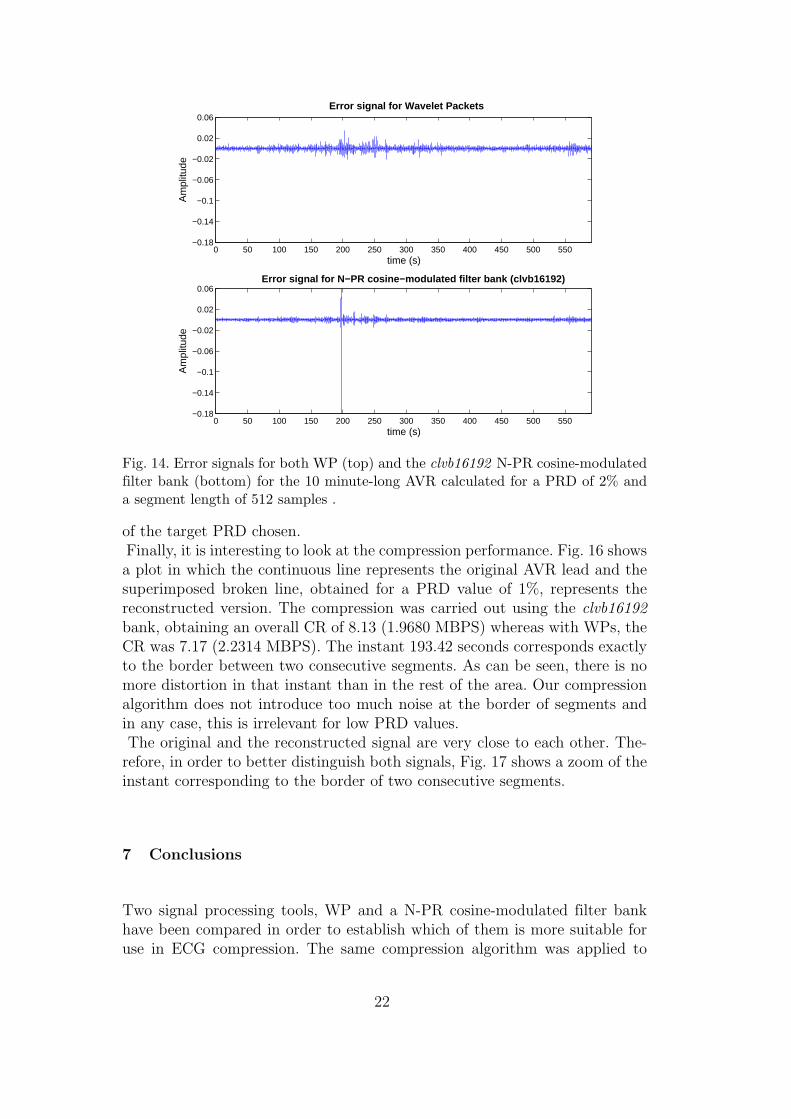
remains close, which means that the maximum differences are similar, exceptwhen the segment length is 512 samples. In this case, MAX is higher for N-PRcosine-modulated filter bank (opaque surfaces) within the PRD margin of 2%to 5%. These high values are locals and appear few times along the 10 minutesthat the signal lasts. In order to better illustrate this situation, Fig. 14 showsthe error signal for both WP (top) and the clvb16192 N-PR cosine-modulatedfilter bank (bottom) for the 10 minute-long AVR lead, calculated for a targetPRD of 2% with a segment length of 512 samples. As can be seen, the errorsignal for N-PR cosine-modulated filter bank(bottom) is even less than usingWP (top) outside the local points where the error signal increases. Particu-larly in this case, the greatest differences appear only once along 10 minutes.Therefore, the conclusions exposed before about the performance of the com-pression method are valid taking care of using a segment length greater than512 samples in order to avoid this effect.The compressor retrieves the incoming signal for a previously fixed quality
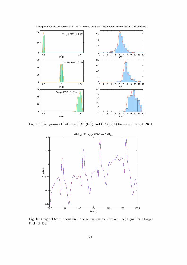
value. The input signal is processed using two power length blocks and thequality of each block will be within a 5% margin of the chosen PRD value(PRD ± 5%), which is specified by the algorithm. The target PRD is quicklyreached with just a few iterations of the compression algorithm. For those ca-ses that do not converge to the specified quality value, the number of iterationsis restricted to 25. To appreciate this behaviour, Fig. 15 shows the histogramsof both the PRD and the CR for three different target PRD: 0.5%, 1% and1.5%. As is shown, the PRD spreads around the target PRD selected beingwider as the target PRD increases. Nevertheless, it do not overcome the 5%
21
0 50 100 150 200 250 300 350 400 450 500 550−0.18
−0.14
−0.1
−0.06
−0.02
0.02
0.06
time (s)
Am
plitu
de
0 50 100 150 200 250 300 350 400 450 500 550−0.18
−0.14
−0.1
−0.06
−0.02
0.02
0.06
time (s)
Am
plitu
de
Error signal for Wavelet Packets
Error signal for N−PR cosine−modulated filter bank (clvb16192)
Fig. 14. Error signals for both WP (top) and the clvb16192 N-PR cosine-modulatedfilter bank (bottom) for the 10 minute-long AVR calculated for a PRD of 2% anda segment length of 512 samples .
of the target PRD chosen.Finally, it is interesting to look at the compression performance. Fig. 16 showsa plot in which the continuous line represents the original AVR lead and thesuperimposed broken line, obtained for a PRD value of 1%, represents thereconstructed version. The compression was carried out using the clvb16192
bank, obtaining an overall CR of 8.13 (1.9680 MBPS) whereas with WPs, theCR was 7.17 (2.2314 MBPS). The instant 193.42 seconds corresponds exactlyto the border between two consecutive segments. As can be seen, there is nomore distortion in that instant than in the rest of the area. Our compressionalgorithm does not introduce too much noise at the border of segments andin any case, this is irrelevant for low PRD values.The original and the reconstructed signal are very close to each other. The-
refore, in order to better distinguish both signals, Fig. 17 shows a zoom of theinstant corresponding to the border of two consecutive segments.
7 Conclusions
Two signal processing tools, WP and a N-PR cosine-modulated filter bankhave been compared in order to establish which of them is more suitable foruse in ECG compression. The same compression algorithm was applied to
22
0.5 1 1.50
50
100
PRD1 2 3 4 5 6 7 8 9 10 11 12
0
20
40
60
CR
0.5 1 1.50
20
40
60
PRD1 2 3 4 5 6 7 8 9 10 11 12
0
20
40
60
80
CR
0.5 1 1.50
20
40
60
PRD1 2 3 4 5 6 7 8 9 10 11 12
0
10
20
30
40
50
CR
Target PRD of 0.5%
Target PRD of 1%
Target PRD of 1.5%
Histograms for the compression of the 10 minute−long AVR lead taking segments of 1024 samples
Fig. 15. Histograms of both the PRD (left) and CR (right) for several target PRD.
192.5 193 193.5 194 194.5 195 195.5
−0.15
−0.1
−0.05
0
0.05
0.1
LeadAVR
/ PRD1%
/ clvb16192 / CR8.13
time (s)
Am
plitu
de
Fig. 16. Original (continuous line) and reconstructed (broken line) signal for a targetPRD of 1%.
23

193.3 193.4 193.5 193.6 193.7 193.8 193.9 194 194.1 194.2
−0.1
−0.08
−0.06
−0.04
−0.02
0
0.02
0.04
0.06
LeadAVR
/ PRD1%
/ clvb16192 / CR8.13
time (s)
Am
plitu
de
Fig. 17. Original (continuous line) and reconstructed (broken line) signal for a targetPRD of 1%.
both schemes whose objective was the quality of the retrieved signal. Thisalgorithm is thresholding-based, so it is very easy to implement in real time.Implementation cost of the subband decomposition stage, for both WP andcosine-modulated N-PR filter banks, has also been studied, with WP onceagain resulting the less efficient of the two. A lot of results have been obtainedas a function of the quality of the reconstructed signal and the segment lengthof the input signal. In conclusion, the scheme based on N-PR cosine-modulatedfilter banks always provides the best degree of compression, particularly whena small target PRD value (0.5%) is requested. Increasing the segment length,does not significantly improve the CR for an N-PR filter bank, which makesit of interest for use in real time implementations. The tests were done forthe twelve cardiac leads and the system behaved the same for all of them,obtaining similar results under the same conditions of compression.
Acknowledgment
The authors would like to thank the anonymous reviewers for their helpfulsuggestions, which have considerably improved the quality of this paper.This work was supported in part by CAM Grant 07T/0025/2001.
24
A List of acronyms and abbreviations
AZTEC Amplitude Zone Epoch Coding.CR Compression Ratio.CORTES COordinate Reduction Time Encoding System.DCT Discrete Cosine Transform.DWT Discrete Wavelet Transform.ECG Electrocardiogram.EZW Embedded Zerotree Wavelet.FIR Finite Impulsive Response.KWA Kaiser Window Approach.MAX Maximum amplitude error.MBPS Mean number of Bits per Sample.N-PR Nearly-Perfect Reconstruction.PCM Pulse Code Modulation.PR Perfect ReconstructionPRD Percentage Root-Mean-Square Difference.TP Tunning PointSPIHT Set Partitioning in Hierarchical Tree.WP Wavelet Packets.
References
[1] R. Nygaard, G. Melnikov, and A. K. Katsaggelos. A rate distortion opti-mal ECG coding algorithm. IEEE Transactions on Biomedical Enginee-
ring, 48(1):28–40, Jan 2001.[2] B. A. Rajoub. An efficient coding algorithm for the compression of ECG
signals using the wavelet transform. IEEE Transactions on Biomedical
Engineering, 49(4):355–362, Apr 2002.[3] S. M. S. Jalaleddine, C. G. Hutchens, R. D. Stranttan, and W.A. Co-
berly. ECG data compression techniques. A unified approach. IEEE
Transactions on Biomedical Engineering, 37(4):329–343, Apr 1990.[4] J. Chen, S. Itoh, and T. Hashimoto. ECG data compression by using
wavelet transform. IEICE Transactions on Information and Systems,E76D(12):1454–1461, Dec 1993.
[5] A. Djohan, T. Q. Nguyen, and W. J. Tompkins. ECG using discrete sym-metric wavelet transform. In Proc. of the 17th Annual International on
Conference of the IEEE Engineering in Medicine and Biology, volume 1,pages 167–168, 1997.
[6] M. L. Hilton. Wavelet and wavelet packets compression of electrocar-diogram. IEEE Transactions on Biomedical Engineering, 44(5):394–402,May 1997.
25
[7] Z. Lu, D. Y. Kim, and W. A. Pearlman. Wavelet compression of ECGsignals by the set partitioning in hierarchical trees algorithm. IEEE Tran-
sactions on Biomedical Engineering, 47(7):849–856, Jul 2000.[8] B. Bradie. Wavelet packets-based compression of single lead ECG. IEEE
Transactions on Biomedical Engineering, 43(5):493–501, May 1996.[9] J. Hall and J. Crowe. Ambulatory electrocardiogram compression using
wavelet packets to approximate the Karhunen-Loeve transform. Applied
Signal Processing, 3:25–36, 1996.[10] A. G. Ramakiishnan and S.Saha. ECG coding by wavelet-based linear
prediction. IEEE Transactions on Biomedical Engineering, 44(12):1253–1261, Dec 1997.
[11] S. G. Miaou and C. L. Lin. A quality-on-demand algorithm for wavelet-based compression of electrocardiogram signals. IEEE Transactions on
Biomedical Engineering, 49(3):233–239, Mar 2002.[12] P. S. Hamilton and W. J. Tompkins. Compression of the ambulatory ECG
by average beat subtraction an residual differencing. IEEE Transactions
on Biomedical Engineering, 38(3):253–259, Mar 1991.[13] G. Nave and A. Cohen. ECG compression using long-term prediction.
IEEE Transactions on Biomedical Engineering, 40(9):877–885, Sep 1993.[14] G. D. Barlas and E. S. Skordalakis. A novel family of compression al-
gorithms for ECG an other semiperiodical, one dimensional, biomedicalsignals. IEEE Transactions on Biomedical Engineering, 43(8):820–828,Aug 1996.
[15] Y. Zigel, A. Cohen, and A.Katz. ECG signal compression using analy-sis by synthesis coding. IEEE Transactions on Biomedical Engineering,47(10):1308–1313, Oct 2000.
[16] J. H. Husoy and T. Gjerde. Computationally efficient sub-band codingfor ECG signals. Medical Engineering and Physics, 18(2):132–142, Mar1996.
[17] M. C. Aydin, A. E. Cetin, and H. Koymen. ECG data compression bysub-band coding. Electronic Letters, 27:359–360, Feb 1991.
[18] S. C. Tai. Six-band sub-band coder on ECG waveforms. Medical and
Biological Engineering and Computing, 30(3):187–192, Mar 1992.[19] S. O. Aase. Filter bank design for subband compression of ECG signals.
In Proc. of NORSIG-95, Stavanger (Norway), 1995.[20] G. Strang and T. Q. Nguyen. Wavelets and Filter Banks. Wellesley-
Cambridge, Wellesley MA, 1996.[21] I. Daubechies. Orthonormal bases of compactly supported wavelets. Com-
munications on Pure and Applied Mathematics., 41:909–996, 1988.[22] M. Vetterli and C. Herley. Wavelets and filter banks: Theory and design.
IEEE Transactions on Signal Processing, 40(9):2207–2232, Sep 1992.[23] M. Blanco, F. Lopez, M. Rosa, and F. Cruz-Roldan. Periodic wavelet
packet implementation applied to ECG signals coding. In Proc. of Cir-
cuits, Systems, Communications and Computers, Vouliagmeni (Athens-Greece), Jul 2000.
26
[24] R. R. Coifman and M. V. Winckerhauser. Entropy-based algorithmsfor best basis selection. IEEE Transactions on Information Theory,38(2):713–718, Mar 1992.
[25] P. P. Vaidyanathan. Multirate Systems and Filter Banks. Prentice-HallEnglewood Cliffs, Englewood Cliffs NJ, 1993.
[26] N. J. Fliege. Multirate Digital Signal Processing: Multirate Systems, Filter
Banks, Wavelets. John Wiley & Sons, 1994.[27] A. N. Akansu and M. J. Smith (Edt.). Subband and Wavelet Transforms.
Kluwer Academic Publishers, Norwell MA, 1996.[28] A. N. Akansu and M. J. Medley (Edt.). Wavelet, Subband and Block
Transforms in Communications and Multimedia. Kluwer Academic Pu-blishers, Norwell MA, 1999.
[29] P. P. Vaidyanathan. Filter banks in digital communications. IEEE Cir-
cuits and Systems Magazine, 1(2):4–25, Second Quarter 2001.[30] V. X. Afonso, W. J. Tompkins, T. Q. Nguyen, and S. Luo. ECG beat de-
tection using filter banks. IEEE Transactions on Biomedical Engineering,46(2):192–202, Feb 1999.
[31] L. Gavidia-Ceballos and J. H. L. Hansen. Direct speech feature estimationusing an iterative EM algorithm for vocal fold pathology detection. IEEE
Transactions on Biomedical Engineering, 43(4):373–383, Apr 1996.[32] A. Mojsilovic, M. V. Popovic, A. N. Neskovic, and A. D. Popovic. Wavelet
image extension for analysis and classification of infarcted myocardialtissue. IEEE Transactions on Biomedical Engineering, 44(9):856–866,Sep 1997.
[33] J. H. Rothweiler. Polyphase quadrature filters – A new subband codingtechnique. In Proc. of Int. Conf. on Acoustics, Speech and Signal Proces-
sing, volume 83, pages 1280–1283, Boston (U.S.A.), Apr 1983.[34] C. D. Creusere and S. K. Mitra. Simple method for designing high-quality
prototype filters for M -band pseudo-QMF banks. IEEE Transactions on
Signal Processing, 46(4):1005–1007, 1995.[35] Y.-P. Lin and P. P. Vaidyanathan. A Kaiser window approach for the
design of prototype filters of cosine modulated filter banks. IEEE Signal
Processing Letters, 5(6):132–134, Jun 1998.[36] F. Cruz-Roldan, P. Amo-Lopez, S. Maldonado-Bascon, and S. S. Lawson.
An efficient and simple method for designing prototype filters for cosine-modulated pseudo-QMF banks. IEEE Signal Processing Letters, 9(1):29–31, Jan 2002.
[37] K. R. Rao and P. Yip. Discrete Cosine Transform: Algorithms, Advan-
tages, Applications. Academic Press, New York, 1990.[38] H. Malvar. Signal Processing with Lapped Transforms. Artech House,
Norwood MA, 1992.[39] P. Yip and K. R. Rao. Handbook of Digital Signal Processing, chapter
Signal Processing with Lapped Transforms. Academic Press, CA, 1992.[40] M. Blanco, F. Lopez, M. Rosa, and F. Cruz-Roldan. Electrocardiogram
signal characterization by using periodic wavelet packets. In Proc. of
27

World Multiconference on Systemics, Cybernetics and Informatics, vo-lume VI, pages 363–367, Orlando (USA), Jul 2000.
28