A local control system for the test masses of the Virgo gravitational wave detector
12
A local control system for the test masses of the Virgo gravitational wave detector Virgo Collaboration F. Acernese a , P. Amico b , N. Arnaud c , D. Babusci d , R. Barill e e , F. Barone a , L. Barsotti f , M. Barsuglia c , F. Beauville g , M.A. Bizouard c , C. Boccara h , F. Bondu i , L. Bosi b , C. Bradaschia f , L. Bracci j , S. Braccini f , A. Brillet i , V. Brisson c , L. Brocco k , D. Buskulic g , G. Calamai j , E. Calloni a , E. Campagna j , F. Cavalier c , G. Cella f , E. Chassande-Mottin i , F. Cleva i , T. Cokelaer i , G. Conforto j , C. Corda f , J.-P. Coulon i , E. Cuoco j , V. Dattilo e , M. Davier c , R. De Rosa a , L. Di Fiore a , A. Di Virgilio f , B. Dujardin i , A. Eleuteri a , D. Enard e , I. Ferrante f , F. Fidecaro f , I. Fiori j , R. Flaminio g , J.-D. Fournier i , S. Frasca k , F. Frasconi e,f , L. Gammaitoni b , A. Gennai e , A. Giazotto f , G. Giordano d , G. Guidi j , H. Heitmann i , P. Hello c , P. Heusse c , L. Holloway f , S. Kreckelbergh c , P. La Penna e , V. Loriette h , M. Loupias e , G. Losurdo j, * , J.-M. Mackowski l , E. Majorana f, * , C.N. Man i , F. Marion g , F. Martelli j , A. Masserot g , L. Massonnet g , M. Mazzoni j , L. Milano a , J. Moreau h , F. Moreau g , N. Morgado l , F. Mornet i , B. Mours g , J. Pacheco i , A. Pai i , C. Palomba k , F. Paoletti e,f , R. Passaquieti f , D. Passuello f , B. Perniola j , L. Pinard l , R. Poggiani f , M. Punturo b , P. Puppo k , K. Qipiani a , J. Ramonet g , P. Rapagnani k , V. Reita h , A. Remillieux l , F. Ricci k , I. Ricciardi a , G. Russo a , S. Solimeno a , R. Stanga j , A. Toncelli f , M. Tonelli f , E. Tournefier g , F. Travasso b , H. Trinquet b , M. Varvella a , D. Verkindt g , F. Vetrano j , O. Veziant g , A. Vicer e j , J.-Y. Vinet i , H. Vocca b , M. Yvert g a INFN, Sez. Napoli and/or Universit a di Napoli ‘‘Federico II’’, Complesso Universitario di Monte S. Angelo Via Cintia, I-80126 Napoli, Italy and/or Universit a di Salerno Via Ponte Don Melillo, I-84084 Fisciano (Salerno), Italy b INFN Sezione di Perugia and/or Universit a di Perugia, Via A. Pascoli, I-06123 Perugia, Italy c Laboratoire de l’Acc el erateur Lin eaire (LAL), IN2P3/CNRS-Universit e de Paris-Sud, B.P. 34, 91898 Orsay Cedex, France d INFN, Laboratori Nazionali di Frascati Via E. Fermi, 40, I-00044 Frascati (Roma), Italy e European Gravitational Observatory (EGO), Via E. Amaldi, I-56021 Cascina (Pi), Italy f INFN, Sezione di Pisa and/or Universit a di Pisa, Via Filippo Buonarroti, 2 I-56127 Pisa, Italy * Corresponding authors. Tel.: +39050752587; fax: +39050752550. E-mail addresses: losurdo@fi.infn.it (G. Losurdo), [email protected] (E. Majorana). 0927-6505/$ - see front matter Ó 2003 Elsevier B.V. All rights reserved. doi:10.1016/j.astropartphys.2003.10.001 Astroparticle Physics 20 (2004) 617–628 www.elsevier.com/locate/astropart
-
Upload
wwwuniroma1 -
Category
Documents
-
view
3 -
download
0
Transcript of A local control system for the test masses of the Virgo gravitational wave detector

Astroparticle Physics 20 (2004) 617–628
www.elsevier.com/locate/astropart
A local control system for the test masses ofthe Virgo gravitational wave detector
Virgo CollaborationF. Acernese a, P. Amico b, N. Arnaud c, D. Babusci d, R. Barill�e e, F. Barone a,L. Barsotti f, M. Barsuglia c, F. Beauville g, M.A. Bizouard c, C. Boccara h,F. Bondu i, L. Bosi b, C. Bradaschia f, L. Bracci j, S. Braccini f, A. Brillet i,
V. Brisson c, L. Brocco k, D. Buskulic g, G. Calamai j, E. Calloni a,E. Campagna j, F. Cavalier c, G. Cella f, E. Chassande-Mottin i, F. Cleva i,
T. Cokelaer i, G. Conforto j, C. Corda f, J.-P. Coulon i, E. Cuoco j, V. Dattilo e,M. Davier c, R. De Rosa a, L. Di Fiore a, A. Di Virgilio f, B. Dujardin i,
A. Eleuteri a, D. Enard e, I. Ferrante f, F. Fidecaro f, I. Fiori j, R. Flaminio g,J.-D. Fournier i, S. Frasca k, F. Frasconi e,f, L. Gammaitoni b, A. Gennai e,
A. Giazotto f, G. Giordano d, G. Guidi j, H. Heitmann i, P. Hello c, P. Heusse c,L. Holloway f, S. Kreckelbergh c, P. La Penna e, V. Loriette h, M. Loupias e,G. Losurdo j,*, J.-M. Mackowski l, E. Majorana f,*, C.N. Man i, F. Marion g,F. Martelli j, A. Masserot g, L. Massonnet g, M. Mazzoni j, L. Milano a,
J. Moreau h, F. Moreau g, N. Morgado l, F. Mornet i, B. Mours g, J. Pacheco i,
A. Pai i, C. Palomba k, F. Paoletti e,f, R. Passaquieti f, D. Passuello f, B. Perniola j,L. Pinard l, R. Poggiani f, M. Punturo b, P. Puppo k, K. Qipiani a, J. Ramonet g,P. Rapagnani k, V. Reita h, A. Remillieux l, F. Ricci k, I. Ricciardi a, G. Russo a,
S. Solimeno a, R. Stanga j, A. Toncelli f, M. Tonelli f, E. Tournefier g,F. Travasso b, H. Trinquet b, M. Varvella a, D. Verkindt g, F. Vetrano j,
O. Veziant g, A. Vicer�e j, J.-Y. Vinet i, H. Vocca b, M. Yvert g
a INFN, Sez. Napoli and/or Universit�a di Napoli ‘‘Federico II’’, Complesso Universitario di Monte S. Angelo Via Cintia,
I-80126 Napoli, Italy and/or Universit�a di Salerno Via Ponte Don Melillo, I-84084 Fisciano (Salerno), Italyb INFN Sezione di Perugia and/or Universit�a di Perugia, Via A. Pascoli, I-06123 Perugia, Italy
c Laboratoire de l’Acc�el�erateur Lin�eaire (LAL), IN2P3/CNRS-Universit�e de Paris-Sud, B.P. 34, 91898 Orsay Cedex, Franced INFN, Laboratori Nazionali di Frascati Via E. Fermi, 40, I-00044 Frascati (Roma), Italye European Gravitational Observatory (EGO), Via E. Amaldi, I-56021 Cascina (Pi), Italy
f INFN, Sezione di Pisa and/or Universit�a di Pisa, Via Filippo Buonarroti, 2 I-56127 Pisa, Italy
* Corresponding authors. Tel.: +39050752587; fax: +39050752550.
E-mail addresses: [email protected] (G. Losurdo), [email protected] (E. Majorana).
0927-6505/$ - see front matter � 2003 Elsevier B.V. All rights reserved.
doi:10.1016/j.astropartphys.2003.10.001

618 F. Acernese et al. / Astroparticle Physics 20 (2004) 617–628
g Laboratoire d’Annecy-le-Vieux de physique des particules Chemin de Bellevue-BP 110,
74941 Annecy-le-Vieux Cedex, Franceh ESPCI––10, rue Vauquelin, 75005 Paris, France
i Observatoire de la Cote d’Azur, D�epartement Fresnel, Interf�erom�etrie Laser pour la Gravitation et l’Astrophysique, BP 4229,
06304 Nice Cedex 4, Francej INFN-Sez. Firenze/Urbino, Via G.Sansone 1, I-50019 Sesto Fiorentino and/or Universit�a di Firenze, and/or Osservatorio Astrofisico di
Arcetri Largo E. Fermi 5, I-50125 Firenze and/or Universit�a di Urbino, Via S.Chiara, 27 I-61029 Urbino, Italyk INFN, Sezione di Roma and/or Universit�a ‘‘La Sapienza’’, P.le A. Moro 2, I-00185 Roma, Italy
l SMA, IPNL 22, Boulevard Niels Bohr, 69622 Villeurbanne, Lyon Cedex, France
Received 30 July 2003; received in revised form 4 October 2003; accepted 7 October 2003
Abstract
The mirrors of interferometric detectors of gravitational waves (GW) are suspended in order to be isolated from
external disturbances. A local control system able to keep them correctly aligned and to damp the angular modes of the
suspension is necessary. In this paper we present the solution adopted for Virgo based on a CCD camera sensor and on
digital controls. With this solution the mirrors are kept aligned at the level of less than 1 lrad rms, enough to lock theinterferometer and start the automatic alignment system.
� 2003 Elsevier B.V. All rights reserved.
PACS: 07.05.Dz; 04.80.Nn
Keywords: Gravitational wave detectors; Seismic isolation; Digital control
1. Introduction
New interferometric detectors of gravitational
waves (GW) [1–4] are presently being commis-
sioned. In such interferometers the mirrors aresuspended from a vibration isolator that filters the
natural seismic vibrations at frequencies larger
than those of the normal modes of the suspension
itself. In the operation of a detector one has to deal
with the problem of the resonant motions of the
vibration isolator. Usually such motions are re-
duced by means of local controls (LC), that is,
active control systems properly designed to per-form alignment tasks and damping of mirror sus-
pension resonance peaks by using error signals
derived from local sensors.
The vibration isolator designed for Virgo is
called the super-attenuator (SA) [5]. It is charac-
terized by very low frequency normal modes (all
are in the range 0.04–3 Hz). The SA passive fil-
tering action is such that the expected pendulumthermal noise becomes dominant over the seismic
noise above 4 Hz. Most of the normal modes of
the suspension are damped by a multi-dimensional
active system called inertial damping [6]. Never-
theless, the inertial damping cannot control some
internal angular modes of the suspension involving
the test mass. Therefore, we developed a dedicated
last-stage-suspension control system with the fol-lowing purposes:
• damping the unwanted angular modes involv-
ing the mirror;
• being able to set and recover the reference angu-
lar position of each mirror;
• keeping aligned the interferometer at the level
of about 1 lrad rms for the locking.
The system described in this paper makes use of
ground-based readout and internal-force action,
i.e. forces applied within the mirror suspension,
and it was used during the commissioning of the
central interferometer (CITF) [7]. The CITF was a
6 m arm-length Michelson interferometer with
power recycling, equipped with all the mainmechanical and control elements designed for
Virgo. In the following (Section 2) we describe the
readout system used to provide information about
F. Acernese et al. / Astroparticle Physics 20 (2004) 617–628 619
the position of the suspended mirrors. Then (Sec-
tion 3) we give a schematic description of the
digital control architecture, which is a key feature
of the Virgo design. Hence, we approach the prob-
lem of the control implementation by describing
the mechanical properties of the mirror suspension(Section 4) and the main servo-loop design strat-
egy (Section 5) and briefly discuss the performance
of the system (Section 6).
2. Position readout system
The scheme of position measurement designedto provide the error signals through a CCD-cam-
era as sensor is shown in Fig. 2. Six error signals, x,y, z, hx, hy , hz are referred to the mechanical ground
of the CCD-camera and reconstructed in a left-
handed reference frame with its origin in the mir-
ror barycenter and the z-axis oriented outward.
Similar schemes had been already successfully
tested and operated in the context of Virgo [8]. Theoverall local control position sensing system is
located in air, sitting on customized optical
benches rigidly fixed at the base of the vacuum
chamber. The mechanical stand of the CCD-
camera was designed in order to allow removal
and repositioning of the device within 20 lm.We used a Super Photon CCD-camera model
EEV-17CAM. A dedicated read-out board wasdeveloped in order to use this CCD-camera [10]
for real-time applications in the standard VME
crates of Virgo [9]. The CCD-chip is a scientific
grade square pixel matrix 512 · 512 with 7.7 · 7.7mm2 surface. The pixel width is 15 lm. The pixel,clock is set at 20 MHz and the system provides a
digital signal through a 8-bit ADC. The image is
gathered and converted in 16 ms. Thus, the max-imum speed is 60 frames/s. The frame grabbing,
triggered by a external timing control, is a key
feature of this system integrated in the real-time
local control standard crate of Virgo.
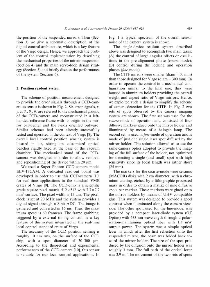
The accuracy of the CCD position sensing is
roughly 10 nm rms, on the surface of the CCD
chip, with a spot diameter of 30–300 lm.According to the theoretical and experimentalperformances of the CCD-camera [10], this sensor
is suitable for our local control applications. In
Fig. 1 a typical spectrum of the overall sensor
noise of the camera system is shown.
The single-device readout system described
above was designed to accomplish two main tasks:
(A) the control of large angular offsets or oscilla-
tions in the pre-alignment phase (coarse-mode);(B) control during the locking and operation
phases (fine-mode).
The CITF mirrors were smaller (diam¼ 50 mm)than those designed for Virgo (diam¼ 300 mm). Inorder to operate the control in a mechanical con-
figuration similar to the final one, they were
housed in aluminum holders providing the overall
weight and aspect ratio of Virgo mirrors. Hence,we exploited such a design to simplify the scheme
of camera detection for the CITF. In Fig. 2 two
sets of spots observed by the camera imaging
system are shown. The first set was used for the
coarse-mode of operation and consisted of four
diffusive markers glued onto the mirror holder and
illuminated by means of a halogen lamp. The
second set, is used in fine-mode of operation and ismade of just one single laser spot diffused by the
mirror holder. This solution allowed us to use the
same camera optics adopted to provide the imag-
ing of the full surface of the holder, not optimized
for detecting a single (and small) spot with high
sensitivity since its focal length was rather short
(25 mm).
The markers for the coarse-mode were ceramic(MACOR) disks with 2 cm diameter, with a chro-
mium coating, etched by a lithographic-processed
mask in order to obtain a matrix of nine diffusive
spots per marker. These markers were glued onto
the mirror holders by means of UHV compatible
glue. This system was designed to provide a good
contrast when illuminated along the camera view-
side. The other spot, used for the fine-mode, wasprovided by a compact laser-diode system (OZ
Optics) with 633 nm wavelength through a polar-
ization-maintaining optical fiber with 1.3 mW
output power. The system was a simple optical
lever in which after the first reflection onto the
suspended mirror, the beam was folded back to-
ward the mirror holder. The size of the spot pro-
duced by the diffusion onto the mirror holder wasroughly 3 mm. The full path of the optical lever
was 3.9 m. The movement of the two sets of spots

f [Hz]
µrad
/Sqr
t(H
z)
10
1
0.1
0.010.01 0.1 1 10
Fig. 1. Linear spectral density of the angular accuracy due to
the position noise on the camera chip. In this table-top mea-
surement an incoherent source illuminates a pinhole fixed on
the camera frame and we have about 0.7 lrad rms.
620 F. Acernese et al. / Astroparticle Physics 20 (2004) 617–628
(markers and laser) in the field of view of the
CCD-camera was used to produce suitable error-
signals for the local control system.
Fig. 2. Schematic side-view of the Virgo payload, lumped from the su
The coils providing marionetta control actuation are attached to the
themarionetta and the position readout layout. The mirror holder is su
the interferometer. The optical lever plane is rotated with respect to th
mirror is roughly 35�.
The mechanical adjustment range of the pay-
load system (see Fig. 2) (marionetta + reaction
mass +mirror) under pure rotations and transla-
tions was Dhx ¼ Dhz ’ �18 mm rad, Dhy ’ ½�18;þ40� m rad, and Dx ¼ Dz ’ �7 mm, Dy ’ �10mm where, according to the local left-handed ref-erence frame, z is the beam direction leading out-
ward from the mirror and hx and hy are the pitch
and yaw angular degrees of freedom.
The software dedicated to the real-time treat-
ment of CCD-camera data [11] operates hierarchi-
cally providing error signals for both coarse- and
fine-modes. It works as follows:
• first, the coarse computation makes independent
telemetric measurements, typically affected by a
small coupling among the mirror d.o.f. (few %)
[12]. Differential signals are derived from these
measurements at 50 Hz and passed to a digital
signal processing unit (DSP) until the control
accuracy provides 100 l rad rms and 100 lmrms. The range of linearity in the response of
per-attenuator (SA) and frontal-view of the mirror (top-right).
last mechanical filter (SA-F7). The mirror is suspended from
rrounded by the reaction mass, whose coils were used for locking
e horizontal one by 23�. The incidence angle of the laser on the

F. Acernese et al. / Astroparticle Physics 20 (2004) 617–628 621
this signal is large enough (tens of degrees) to
cover completely the range of angular variations
allowed by the mechanics. In the CITF setup
transversal (x) and longitudinal (z) signals wereonly provided in coarse-mode and their usewas limited to pre-alignment tasks and to the
damping of major excitations of the system
(dxrms ’ 2 l m, and dzrms ’ 80 lm).• Then, the fine error-signal computation of hx
and hy , obtained by a linear combination of
the variations along the two coordinates of
the CCD-camera chip (with a coupling of about
10%), automatically replaces the coarse compu-tation and the halogen illuminator is switched
off.
• If during the operation the control is switched
back from the fine to the coarse-mode, the cal-
ibration and offsets of coarse-mode are auto-
matically updated by matching the last (more
accurate) values provided by the fine measure-
ment.
The local control system cannot fulfil the stric-
ter alignment specifications for the operation of
the detector: once the interferometer is longitudi-
nally locked, the differential angular motion of the
mirrors results in higher order TEMik modes at the
detection port and can be detected by using
demodulated asymmetry signals from a quadrantphotodiode. We used this signal to actuate an
angular feedback on the marionetta of one curved
mirror of the CITF in order to keep the dark-
Fig. 3. A schematic view of the digital control chain of mirror susp
shown (For interpretation of the references in colour in this figure le
fringe stable [7]. In such a configuration, the
angular local control of that mirror was no longer
active. In Virgo, by means of a complete mapping
all the mirror misalignments, should be possible in
principle to switch from local to automatic angular
control of all the mirrors [13,14]. However, it iscrucial to reach angular local control performance
with accuracy allowing rms residual motion
smaller than 1 lrad for three main reasons:
• the longitudinal locking strategy is strongly
facilitated by the performance of the local con-
trol;
• the measurement of the automatic alignmentsignals matrix requires a good accuracy;
• the fully automatic alignment is a challenging
task. A good backup solution consists in having
one mirror under local control.
3. Basic scheme of the digital local control chain
In Fig. 3 the main elements of the local control
chain are shown. The VME crate is divided in two
sections, each equipped with a dedicated CPU
board (coded as A and B) [15]. The main process
running in the CPU-A is the DSP-server, a soft-
ware program designed to allow real-time com-
munication between two digital signal processing
boards (DSP-A and B) and a software programthat controls a set of ADC and DAC boards [5].
Both DSP units are also programmed to send data
ended mirrors. Actuation (blue) and read-out (red) points are
gend, the reader is referred to the web version of this article.).

622 F. Acernese et al. / Astroparticle Physics 20 (2004) 617–628
to the data acquisition system (DAQ) running
elsewere and to receive signals from the Global
control system [14] through digital optical link
boards (DOL) providing signals to glass fibers.
ADC-A receives analog signals from inertial
damping sensors at 10 kHz [5], DSP-A analyzesthem and computes digital correction signals sent
to DAC-A, whose outputs are finally sent to SA
actuator coil drivers.
CPU-B runs the GxServer [11]. This software
sets up the timing board [16] synchronization with
respect to the main Virgo timing system. GxServer
deals with the CCD-camera system [10], analyzes
its images, sampled at 50 Hz, reconstructs errorsignals and sends them to DSP-B. The latter board
is controlled by the DSP-server in order to com-
pute digital correction signals sent to DAC-B,
whose outputs are finally sent to the coil drivers of
the actuators acting at the level of the last sus-
pension stages to steer the mirror. Hence, in the
CITF we could distinguish among three different
sets of error signals which can be accessed by thedigital control program, downloadable by the
DSP-server, according to their source device: local
sensors of the SA (accelerometers and LVDT po-
sition sensors), local sensors for the mirror posi-
tion readout (CCD-camera), global control signals
(locking photodiodes and linear alignment quad-
rant photodiodes).
Fig. 4. Torque-to-angle transfer function of the Virgo payload
for the pitch and yaw modes. The torque is applied on the
marionetta. The motion is sensed at the mirror level.
4. Mechanical transfer functions
The last-stage of the Virgo mirror suspension,
which includes a steerable stage (the marionetta)
suspending the mirror and the reaction mass, is a
double pendulum with two parallel stages [17].
This system is suspended from the last filter of thesuper-attenuator (so called steering filter or F7)
[18]. The mirror position can be controlled either
from the reaction mass (by acting directly on it) or
from the steering filter (by acting on the marion-
etta). According to the configuration designed for
Virgo we used to apply local control angular cor-
rections between the steering filter and the mari-
onetta stages. The advantage of this solution isthat one further stage of mechanical filtering is
applied to the local control actuator noise at the
cost of a narrower control bandwidth. The main
duty of this system is to perform alignments of
suspended optics, without exciting the mechani-
cal modes of the mirror suspension last stages, in
order to set the detector in the interference con-
dition. Sometimes the local control is also useful tomisalign one mirror if only part of the interfer-
ometer is to be used (this may happen if one wants
to use the interferometer in simple Michelson
configuration).
Hence, in order to be effective the system has to
control the DC position of the mirrors and damp
its normal modes in two d.o.f.: hx (pitch) and hy

F. Acernese et al. / Astroparticle Physics 20 (2004) 617–628 623
(yaw). The simulated force-to-displacement trans-
fer functions for these modes are shown in Fig. 4.
The transfer functions, in very good agreement
with the simulated data, have been measured using
as sensor both the CCD-camera and a small
interferometer built on purpose [19]. The maincharacteristics of these transfer functions are:
structures: the yaw d.o.f. is characterized by five
modes which are relevant in the digital filter de-
sign. Three low frequency resonances respectively
involve the torsional motion of the overall SA
chain (14 mHz), that of the payload in opposition
of phase opposition with respect to the rest of the
SA chain (33 mHz), and an internal mode of theSA chain with small recoil on the marionetta (43
mHz). Two further resonances, at 0.85 and 1.2 Hz,
are due to internal modes of the payload.
asymptotic behavior: slope f �4 above the reso-
nances, as expected for a double pendulum system.
5. Control filters
The local control should be designed in order to
keep the mirror to a reference position within the
required accuracy and to damp the resonance,
limiting the re-injection of noise as much as pos-
sible. Therefore, the compensator CðsÞ should
have three main characteristics (in Fig. 5 a block
diagram of the servo is shown):
• keep the DC position: high DC gain is needed
(integral action);
M(s)
C(s)
x(s)
n(s)
o(s)
Fig. 5. Block diagram of the servo-loop: MðsÞ is the force-to-displacement transfer function of the mechanics, CðsÞ is thetransfer function of the digital compensator. xðsÞ is the outputof a noiseless sensor reading the angular position of the mirror,
nðsÞ is the sensor noise, oðsÞ is the resulting sensor output.
• damp all the modes: the unity gain frequency
must be set above the resonances, were the
mechanical transfer functionMðsÞ s�4. There-fore, the loop stability requires CðsÞ / s3;
• avoid the re-injection of sensor noise: a low passaction has to be provided in order to avoid sat-
uration and to reduce control noise re-injection
on the mirror. This is the main problem to face.
A compensator CðSÞ s3 amplifies the sensornoise. Adding poles to it will certainly filter off
the noise but will also reduce the phase margin
and the robustness of the control loop. A prop-
er compromise has to be found.
Fig. 6. Transfer function of the compensators used for the pitch
and yaw modes.

Table 1
Compensator for the yaw control
Yaw mode f (Hz) Q
Real pole 0
Complex poles 0.016 20
Complex zeroes 0.016 2
Complex zeroes 0.031 1
Real zero 0.06
Real pole 0.22
Complex poles 0.7 1.08
Complex poles 0.77 2.26
Complex poles 0.91 0.57
Complex zeroes 1.05 100
Complex zeroes 1.05 100
Complex poles 1.05 6
Real pole 3.08
Fig. 7. Open loop gain functions for the pitch and yaw degrees
of freedom.
Table 2
Compensator for the pitch control
Pitch mode f Q
Real pole 0
Real pole 0.01
Real zero 0.03
Complex poles 0.46 2.66
Complex poles 0.56 0.67
Real pole 1.92
624 F. Acernese et al. / Astroparticle Physics 20 (2004) 617–628
The compensator used is shown in Fig. 6 andthe corresponding list of poles and zeroes is pro-
vided in Tables 1 and 2. The open loop gain
function are shown in Fig. 7.
In the case of the yaw mode servo, all the open
loop gain function shows the modes are damped,
but the gain at 10 Hz is less than 10�9 thanks to a
steep low pass filter included in the compensator.
The design of such filters was not straightforward.In order to obtain a stable loop, we used a design
approach that we defined double loop technique
[20]. The description of such technique will be the
subject of a forthcoming paper. Such a method
allows to optimize the design of the low pass fil-
tering action of the compensator. It is based on a
simple idea: the s3 slope of the compensator ex-tends well above the unity gain frequency. This isrequired for stability reasons but is unnecessary
from the point of view of the control force. Then,
just the low passed part of the correction signal
can be sent to the actual mechanical system, while
the high frequency part feeds a branch made of thesimulated suspension mechanics in order to pre-
serve the loop stability. In this way there is more
freedom, with some cautions, in the choice of the
loop gain and bandwidth without saturating
actuator drivers and noise re-injection.
For the pitch mode, we decided not to control
the resonances at 2.4 and 3.2 Hz. The reason for
this choice was that such modes are quite stiff anddifficult to excite. When they were excited for any
reasons (typically because of a mechanical shock),
we had the possibility to damp them by switching
the control authority to a servo noisier but with
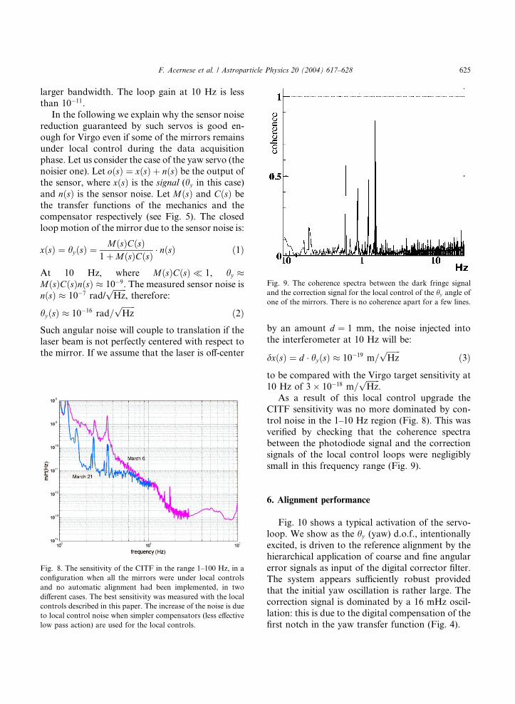
Fig. 9. The coherence spectra between the dark fringe signal
and the correction signal for the local control of the hy angle of
one of the mirrors. There is no coherence apart for a few lines.
F. Acernese et al. / Astroparticle Physics 20 (2004) 617–628 625
larger bandwidth. The loop gain at 10 Hz is less
than 10�11.
In the following we explain why the sensor noise
reduction guaranteed by such servos is good en-
ough for Virgo even if some of the mirrors remains
under local control during the data acquisitionphase. Let us consider the case of the yaw servo (the
noisier one). Let oðsÞ ¼ xðsÞ þ nðsÞ be the output ofthe sensor, where xðsÞ is the signal (hy in this case)
and nðsÞ is the sensor noise. Let MðsÞ and CðsÞ bethe transfer functions of the mechanics and the
compensator respectively (see Fig. 5). The closed
loop motion of the mirror due to the sensor noise is:
xðsÞ ¼ hyðsÞ ¼MðsÞCðsÞ
1þMðsÞCðsÞ � nðsÞ ð1Þ
At 10 Hz, where MðsÞCðsÞ 1, hy �MðsÞCðsÞnðsÞ � 10�9. The measured sensor noise is
nðsÞ � 10�7 rad/ffiffiffiffiffiffiffi
Hzp
, therefore:
hyðsÞ � 10�16 rad=ffiffiffiffiffiffiffi
Hzp
ð2ÞSuch angular noise will couple to translation if the
laser beam is not perfectly centered with respect to
the mirror. If we assume that the laser is off-center
Fig. 8. The sensitivity of the CITF in the range 1–100 Hz, in a
configuration when all the mirrors were under local controls
and no automatic alignment had been implemented, in two
different cases. The best sensitivity was measured with the local
controls described in this paper. The increase of the noise is due
to local control noise when simpler compensators (less effective
low pass action) are used for the local controls.
by an amount d ¼ 1 mm, the noise injected into
the interferometer at 10 Hz will be:
dxðsÞ ¼ d � hyðsÞ � 10�19 m=ffiffiffiffiffiffiffi
Hzp
ð3Þ
to be compared with the Virgo target sensitivity at
10 Hz of 3� 10�18 m=ffiffiffiffiffiffiffi
Hzp
.As a result of this local control upgrade the
CITF sensitivity was no more dominated by con-
trol noise in the 1–10 Hz region (Fig. 8). This was
verified by checking that the coherence spectra
between the photodiode signal and the correction
signals of the local control loops were negligibly
small in this frequency range (Fig. 9).
6. Alignment performance
Fig. 10 shows a typical activation of the servo-
loop. We show as the hy (yaw) d.o.f., intentionally
excited, is driven to the reference alignment by the
hierarchical application of coarse and fine angular
error signals as input of the digital corrector filter.The system appears sufficiently robust provided
that the initial yaw oscillation is rather large. The
correction signal is dominated by a 16 mHz oscil-
lation: this is due to the digital compensation of the
first notch in the yaw transfer function (Fig. 4).

Fig. 10. Activation of hy servo-loop when the modes of yaw
d.o.f were highly excited. The upper line is the correction signal
and the one below the error signal. In the first phase the loop is
open (no correction), then a phase in which the error signal
provided to the corrector is automatically switched from coarse
to fine and backward, then, as the signal is reduced within the
fine-mode range the control is operated by means of only the
fine error-signal and the illumination on the mirror is switched
off.
Fig. 11. Pitch and yaw signals in fine-mode with open and
closed loop for the North Input mirror local control of the
CITF.
626 F. Acernese et al. / Astroparticle Physics 20 (2004) 617–628
The effect of the servo-loop on the spectra of the
fine-mode signals is shown in Fig. 11. The two
signals show a 10% sensing cross-talk, but this
coupling was small enough to operate efficiently
the control. However, we also notice the damping
effect of the last-stage internal modes and anoverall noise reduction in the low frequency range
when the servo-loop is closed.
Further elements for the characterization can
be deduced from the study of the spectral
behavior of the rms. In Fig. 12 hx (pitch) and hy
(yaw) rms are shown for the three suspensions
under angular local control involved in the CITF
operation during the last engineering run (E4).The fourth mirror (West Input) was automati-
cally controlled, i.e. forced to follow the other
curved mirror (North Input), by means of the
global control.
The good stability of the angular control
accuracy is demonstrated by the histograms of
the distribution of the rms angular error signals.
Typical rms distributions (NI mirror), computed
over time-chunks of increasing length are shown
in Fig. 13. The stability achieved for the CITF is
demonstrated by the fact that the median val-
ues of the distributions are not significantly dif-ferent.
7. Conclusions and perspectives
The system we developed and implemented for
the local control of suspended mirrors matched the
requirements for the CITF operation since the

Fig. 12. The local control system provides residual error signals
whose spectral contributes to the overall rms are plotted for
both pitch and yaw of three mirror suspensions during CITF
operation (NI¼ North Input, PR¼Power Recycling, BS¼Beam Splitter).
Fig. 13. Local control accuracy on pitch and yaw of the mirror
using the F7-marionetta actuators. Four-hour time period is
divided in a variable number of chunks and the statistics of the
rms values is reported in the different cases.
F. Acernese et al. / Astroparticle Physics 20 (2004) 617–628 627
interferometer final sensitivity was not limited by
the local control performance.
However, from the experience gained with the
CITF, we learned that some improvements are
needed in view of the transition to the full scale
experiment (Virgo). Above all, a wider control
bandwidth can make the interferometer operationfaster. To achieve such a wider bandwidth without
control noise re-injection one can sense also the
marionetta angular position. Moreover, in this
way the gain of the servo-loop slope will be opti-
mized in order to damp more efficiently the lowest
torsional mode of the suspension. Such a system,
requiring further read-out devices, is currently
being tested.
References
[1] F. Acernese et al., Class. Quant. Gravity 19 (7) (2002) 1421.
[2] B. Willke et al., Class. Quant. Gravity 19 (7) (2002)
1377.
[3] D. Sigg et al., Class. Quant. Gravity 19 (7) (2002) 1429.
[4] K. Kuroda et al., in: Progress in Gravitational Wave
Detection: Interferometers, Nucl. Phys. B Proc. Suppl. 110
(2002).
[5] G. Ballardin et al., Rev. Sci. Instrum. 79 (9) (2001) 3643.
[6] G. Losurdo et al., Rev. Sci. Instrum 79 (9) (2001) 3653–
3661.

628 F. Acernese et al. / Astroparticle Physics 20 (2004) 617–628
[7] F. Acernese, R. Flaminio, et al., submitted.
[8] C. Drezen, H. Heitmann, Rev. Sci. Instrum. 68 (8) (2001)
3197.
[9] A VME/VSB board for real-time positioning and image
analysis, Laboratoire d�Annecy-le-Vieux de physique desparticules Chemin de Bellevue-LAPP-Internal Report,
1995.
[10] F. Bellacchia et al., Nucl. Instrum. Methods Phys. Res. A
413 (1998) 151.
[11] F. Chollet, R. Flaminio, E. Majorana, A. Masserot, B.
Mours, The Camera Software (GxServer v3r70), Virgo
Internal Report, 2002, see <http://www.virgo.infn.it/Pub-
licDoc/VIR-LIS-LAP-5200-106.pdf>.
[12] E. Bompiani, E. Majorana, F. Ricci, G. Testi, Phys. Lett.
A 295 (2002) 92.
[13] D. Babusci, H. Fang, G. Giordano, G. Matone, V.
Sannibale, Phys. Lett. A 226 (1997) 394.
[14] F. Cavalier, Le controle globale de Virgo, th�ese d�habili-tation a diriger des recherches, Universit�e Paris Sud, LAL
01-69, 2001.
[15] Creative Electronic Systems: Power-PC based RISC I/O
Board for VME real-time purposes, running LynxOs,
Available from <http://www.ces.ch>.
[16] D. Boget, F. Bellachia, B. Mours, The Virgo Timing Board
system, Virgo Internal Report, 1997, see <http://www.
virgo.infn.it/PublicDoc/VIR-TRE-5200-103.pdf>.
[17] A. Bernardini, E. Majorana, P. Puppo, P. Rapagnani, F.
Ricci, G. Testi, Rev. Sci. Instrum. 70 (8) (1999) 3463–3472.
[18] G. Ballardin et al., Rev. Sci. Instrum. 79 (9) (2001) 3635–
3642.
[19] A. Bozzi et al., Rev. Sci. Instrum. 73 (5) (2002) 2143–2149.
[20] G. Losurdo, D. Passuello, Noisy sensors in control loops,
Virgo Internal Report, 2003, see <http://www.virgo.infn.it/
PublicDoc/VIR-NOT-FIR-1390-256.pdf>.